AC SERVO DRIVES Sigma-7 SERIES
548
AC SERVO DRIVES SERIES JQA-EM0202 JQA-0422 Certified for ISO9001 and ISO14001
-
Upload
khangminh22 -
Category
Documents
-
view
1 -
download
0
Transcript of AC SERVO DRIVES Sigma-7 SERIES
AC SERVO DRIVESSERIES
JQA-EM0202JQA-0422
Certified for
ISO9001 and
ISO14001

Everyone’s preferred choice of Servo Drives
Series of AC Servo Drives
Since the release of the first series of Servo Drives in 1992, Yaskawa Electric has
consistently made innovations to existing technologies to find solutions for problems
that users experience. Users have always sought high-speed, high-accuracy, and
easy-to-use products, and this demand rises every year.
In 2013, the series of Servo Drives evolved into the Servo Drives, which provides
users with the ultimate experience in seven key areas and delivers the optimal solutions
that only Yaskawa can offer. With the superlative performance and outstanding ease of
use of the series, Yaskawa can offer solutions that will make the Servo Drives
the preferred choice of customers at any point in the life cycle of their systems.
Refer to pages M-6 and M-7 for examples
of the high performance of the series in
“pick and place”applications. Contact
Yaskawa for details on this and additional
applications.
1Superlative performance with improved
efficiency and speed
pages M-4 to M-7
Attention developers/engineers
Ultimate system performance
You can check the level of performance of actual operations with
the use of demonstrat ion units. Contact Yaskawa for a
demonstration.
2 page M-8
Attention developers/engineers maintenance personnelproduction
Ultimate ease of use
No tuning required with the series upgraded tuning-less
function to achieve stable movement with no vibration.
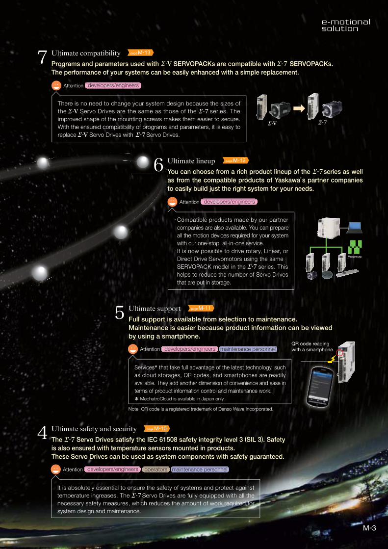
3 Ultimate environmental performance page M-9
operatorsAttention developers/engineers
Each product has improved specifications to meet even the most
stringent environmental requirements. Servo Drives can now be used in
different countries and regions, and under a variety of conditions.
* At this altitude, the servo drives will operate at reduced ratings.
Are there any operating environments that you have given up on? The servos
have an increased ability to cope with temperature rises in systems, comply with
the IP67 resistance to water immersion rating, and have greater global support (AC
240 V input and operable at an altitude of 2,000 meters*). Compact and energy
saving systems can also be easily built with the two-axis SERVOPACKs.
2
page M-10
operatorsdevelopers/engineers
4Attention maintenance personnel
Ultimate safety and security
It is absolutely essential to ensure the safety of systems and protect against
temperature increases. The Servo Drives are fully equipped with all the
necessary safety measures, which reduces the amount of work required for
system design and maintenance.
The Servo Drives satisfy the IEC 61508 safety integrity level 3 (SIL 3). Safety
is also ensured with temperature sensors mounted in products.
These Servo Drives can be used as system components with safety guaranteed.
page M-126Attention developers/engineers
Ultimate lineup
Compatible products made by our partner
companies are also available. You can prepare
all the motion devices required for your system
with our one-stop, all-in-one service.
It is now possible to drive rotary, Linear, or
Direct Drive Servomotors using the same SERVOPACK model in the series. This
helps to reduce the number of Servo Drives
that are put in storage.
You can choose from a rich product lineup of the series as well
as from the compatible products of Yaskawa’s partner companies
to easily build just the right system for your needs.
page M-137Attention developers/engineers
Ultimate compatibility
Programs and parameters used with SERVOPACKs are compatible with SERVOPACKs.
The performance of your systems can be easily enhanced with a simple replacement.
There is no need to change your system design because the sizes of
the Servo Drives are the same as those of the series. The
improved shape of the mounting screws makes them easier to secure.
With the ensured compatibility of programs and parameters, it is easy to
replace Servo Drives with Servo Drives.
QR code readingwith a smartphone.
page M-11
Services* that take full advantage of the latest technology, such
as cloud storages, QR codes, and smartphones are readily
available. They add another dimension of convenience and ease in
terms of product information control and maintenance work.
5Attention developers/engineers maintenance personnel
Ultimate support
Full support is available from selection to maintenance.
Maintenance is easier because product information can be viewed
by using a smartphone.
Note: QR code is a registered trademark of Denso Wave Incorporated.
* MechatroCloud is available in Japan only.
3

3.1 kHz response frequency
Optimized for specific applications: New models in EX and FT series to be released
Improved vibration suppression
Two-axis SERVOPACKs (200 W x 2 axes to 1 kW x 2 axes)
3.1 kHz response frequency
Improved vibration suppression
Ultimate system performance
1
Ripple compensation
Single-axis SERVOPACKs
Two-axis SERVOPACKs
The high-performance of SERVOPACKs translates into ultra-high-speed
and ultra-high-accuracy control, which maximizes system performance.
SERVOPACKs can reduce speed
ripples caused by motor cogging,
even for machines for which speed
loop gains cannot be set high. This
ensures smooth operation.
★ 3.1 kHz response frequency
★ Build small-scale equipment system
without PLC using one SERVOPACK.
Two-axis SERVOPACKs with Built-in Controllers
Ks
Enhanced vibration suppression function
Notch filter
Suppresses high-frequency vibrations of 500 Hz or higher.
Number of filters increased from 2 to 5.
Anti-resonance control
Suppresses vibrations at frequencies ranging from
several hundred Hz to 1 kHz.
Vibrations can now be suppressed at multiple
frequencies in comparison with one frequency in
earlier models.
Vibration suppression
Suppresses vibrations at low frequencies (30 Hz and lower).
Vibrations can now be suppressed at two different
frequencies (in comparison with one frequency in
earlier models).
These functions can be adjusted automatically using
the autotuning function.
4
Refer to pages M-18 to M-21 for the details on the features of Direct Drive
Servomotors and Linear Servomotors.
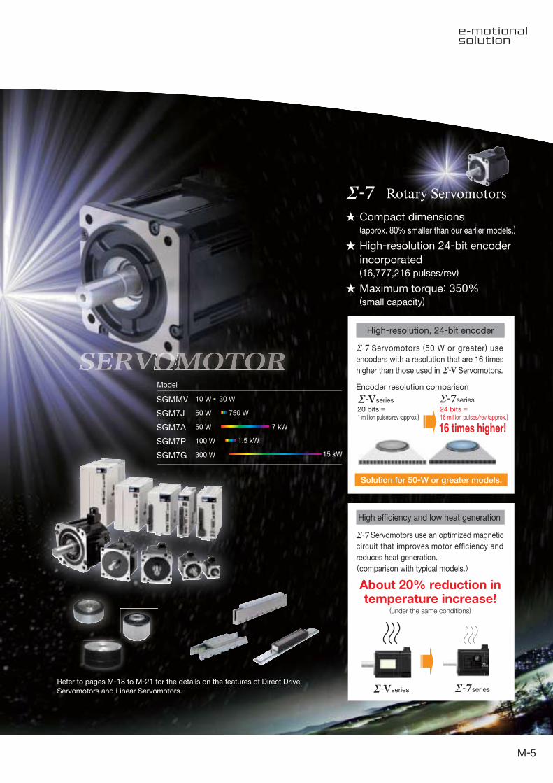
Encoder resolution comparisonModel
20 bits =1 million pulses/rev (approx.)
24 bits =16 million pulses/rev (approx.)
16 times higher!
Solution for 50-W or greater models.
About 20% reduction intemperature increase!
series series
series series
(under the same conditions)
Compact dimensions (approx. 80% smaller than our earlier models.)
High-resolution 24-bit encoder
incorporated(16,777,216 pulses/rev)
Maximum torque: 350%(small capacity)
Rotary Servomotors
High-resolution, 24-bit encoder
High efficiency and low heat generation
Servomotors (50 W or greater) use
encoders with a resolution that are 16 times
higher than those used in Servomotors.
Servomotors use an optimized magnetic
circuit that improves motor efficiency and
reduces heat generation.
(comparison with typical models.)
SGMMV
SGM7J
SGM7A
SGM7P
SGM7G
10 W
50 W
50 W
100 W
300 W
7 kW
750 W
30 W
1.5 kW
15 kW
5
Example
Problem
Issue
Issue
Issue
Issue
Solution
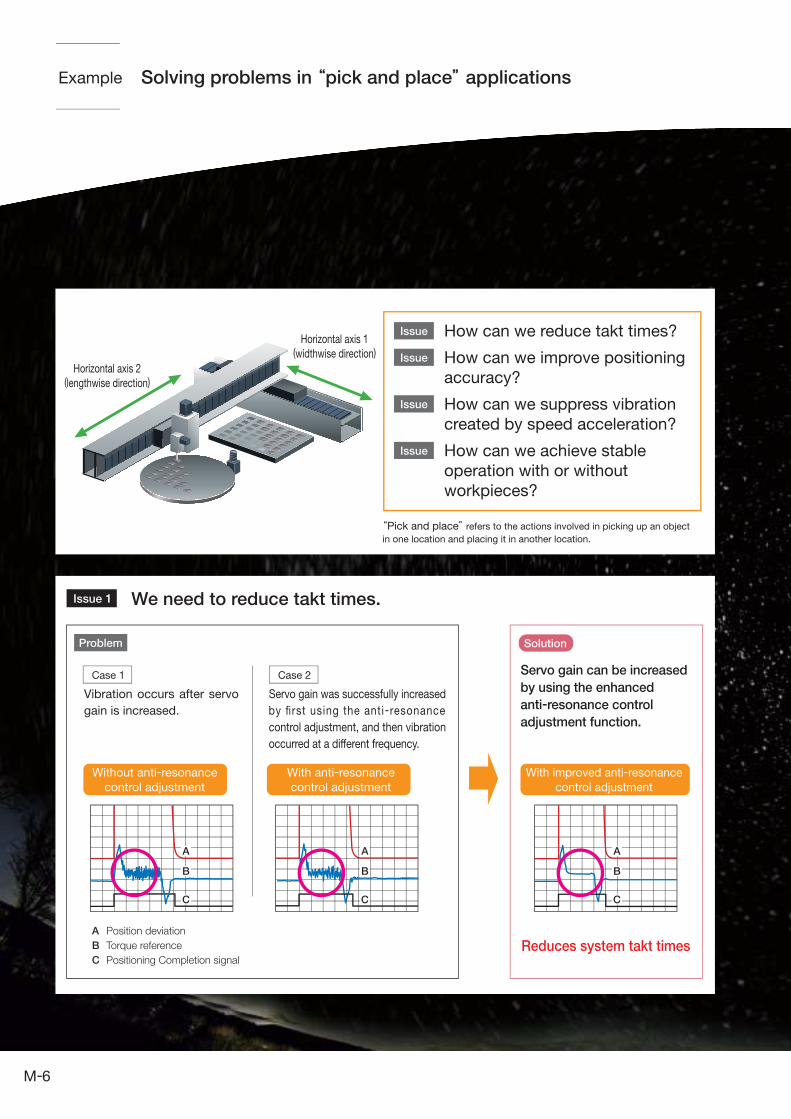
“Pick and place” refers to the actions involved in picking up an object
in one location and placing it in another location.
Reduces system takt times
Solving problems in “pick and place” applications
We need to reduce takt times.Issue 1
Case 1 Case 2
Vibration occurs after servo
gain is increased.
Servo gain was successfully increased
by first using the anti-resonance
control adjustment, and then vibration
occurred at a different frequency.
Servo gain can be increased
by using the enhanced
anti-resonance control
adjustment function.
Without anti-resonance
control adjustment
With anti-resonance
control adjustment
With improved anti-resonance
control adjustment
Horizontal axis 1(widthwise direction)
Horizontal axis 2(lengthwise direction)
A Position deviation
B Torque reference
C Positioning Completion signal
A
B
C
A
B
C
A
B
C
How can we reduce takt times?
How can we improve positioning
accuracy?
How can we suppress vibration
created by speed acceleration?
How can we achieve stable
operation with or without
workpieces?
6
Issue 3
Solution
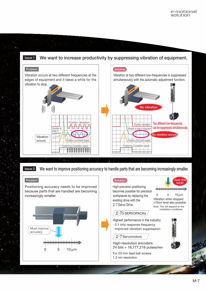
We want to increase productivity by suppressing vibration of equipment.Issue 1
We want to improve positioning accuracy to handle parts that are becoming increasingly smaller.Issue 2
Solution
3.1 kHz response frequency
Improved vibration suppression
0 5
Highest performance in the industry
For 20 mm lead ball screws
1.2 nm resolution
High-resolution encoders24 bits = 16,777,216 pulses/rev
No vibration
Two different low-frequenciescan be suppressed simultaneously.
Vibration
occurs.
SERVOPACKs
Servomotors
Positioning accuracy needs to be improved
because parts that are handled are becoming
increasingly smaller.
High-precision positioning
becomes possible for precision
workpieces by replacing the
existing drive with the
Servo Drive.
Must improveaccuracy
10 mμ
Just thetrick!
0 5 10 mμVibration when stopped±10nm level also possible
Note: This will depend on the installation conditions.
Vibration occurs at two different frequencies at the
edges of equipment and it takes a while for the
vibration to stop.
Vibration at two different low-frequencies is suppressed
simultaneously with the automatic adjustment function.
Position deviationPosition deviation
Vibration at edge of equipment
Position command speed
Positioning Completion signal
Position command speed
Positioning Completion signal
Vibration atedge ofequipment
No vibration occurs
Problem
Problem
7

No need to adjust servo gains
When the allowable load moment of inertia ratio is 30 times:
Yaskawa’s original tuning-less function has undergone further development.
Stable operations can be achieved without having to adjust gains.2
Allowable load moment of inertia ratio
30 times (max.)
Series Series
Max. control gainSpeed loop gain 40 Hz (approx.)
30 times (max.)
Speed loop gain 70 Hz (approx.)
Takt timereduced
Setup timereduced
RobotSolution Example
0,000 200,000 400,000 600,000 800,000 1000,000
4500
4000
3500
3000
2500
2000
1500
1000
500
0
-500
Time [ms]
Previous speedresponse
0,000 200,000 400,000 600,000 800,000 1000,000
4500
4000
3500
3000
2500
2000
1500
1000
500
0
-500
Time [ms]
Speed response when
tuning-less functions
Feedback speed
PositioningCompletion signal
Positioncommand speed
Feedback speed
PositioningCompletion signal
Positioncommand speed
Feedback speed
PositioningCompletion signal
Positioncommand speed
Feedback speed
PositioningCompletion signal
Positioncommand speed
With Yaskawa’s original tuning-less function, systems can run without
vibration for a load with 30 times (max.) of load moment of inertia.
Systems remain stable even with load changes during operation.
The robot’s arm maintains stable movements even when the moment
of inertia changes due to changes in the robot’s posture.
Improved response
Response is about twice as fast as before and requires no adjustment.
Improved stability
Stable operation is assured even in systems with load fluctuations.
No need for gain adjustments
High-level performance is assured although no tuning is required.
Ultimate ease of use
[min-1] [min-1]
8
Waterproof protective structure upgradeto IP67 rating[SGM7J, SGM7A (IP22 for 7.0 kW), and SGM7G models]
Satisfies specifications for use overseasand in harsh operating conditions
3
Protective Structure (IEC 60034-5)
I P 67* Derating required.
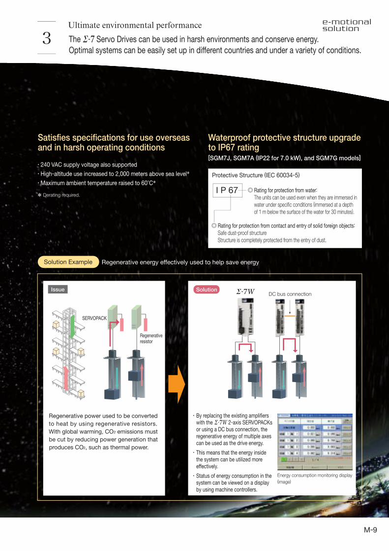
Regenerativeresistor
SERVOPACK
DC bus connection
Energy consumption monitoring display
(image)
Regenerative energy effectively used to help save energySolution Example
SolutionIssue
240 VAC supply voltage also supported
High-altitude use increased to 2,000 meters above sea level*Maximum ambient temperature raised to 60°C*
Rating for protection from water:
The units can be used even when they are immersed in water under specific conditions (immersed at a depth of 1 m below the surface of the water for 30 minutes).
Rating for protection from contact and entry of solid foreign objects:
Safe dust-proof structureStructure is completely protected from the entry of dust.
Ultimate environmental performance
Regenerative power used to be converted
to heat by using regenerative resistors.
With global warming, CO2 emissions must
be cut by reducing power generation that
produces CO2, such as thermal power.
The Servo Drives can be used in harsh environments and conserve energy.
Optimal systems can be easily set up in different countries and under a variety of conditions.
By replacing the existing amplifiers with the 2-axis SERVOPACKs or using a DC bus connection, the regenerative energy of multiple axes can be used as the drive energy.
This means that the energy inside the system can be utilized more effectively.
Status of energy consumption in the system can be viewed on a display by using machine controllers.
9

Systems can be operated safely because the Servo Drives comply with safety standards
and safety is ensured by monitoring.4
Satisfies requirements of the SIL 3 of the IEC 61508 functional safety standards (first in Japan)
Conventional machine safety system
New machine safety system
EN ISO13849-1
IEC 60204-1
IEC 61508
IEC 62061
IEC 61800-5-2
Safety standards
Safety of
machinery
Functional
safety
Performance level & category
PLe (CAT3)
Stop Category 0
SIL 3
SIL CL3
STO
Temperature monitoring display(image)
Built-intemperature
sensor
Protection from abnormal temperatures
Ultimate safety and security
Protect systems from high temperatures
SERVOPACKs and Servomotors are equipped with
temperature sensors that can directly monitor temperatures
of machines and detect abnormalities to prevent failures.
Real-time temperatures can be viewed on a display by using
Machine Controllers.
Certification will make it easier to set up systems that conform to safety standards for press machines and other
systems in Europe and other regions. Certification also helps reduce the number of hours required for wiring and of
peripheral devices.
Safety door switch
Safety unit
Safety relay
Monitoring
Monitoring
-Safety relay no longer needed
-Less wiring required because the monitoring function is built inside the SERVOPACKs.
Complies with Stop Category 0 (Safe Torque Off)
The safety function works even for a single problem.
The safety function is enhanced with compliance with
the EN ISO 13849-1 PLe (performance level e).
Note: Although the safety performance level of the series Servo Drives is PLd (performance level d), the benefits described in the figure on the left apply.
Systems that need to satisfy the required performance
level e (PLr e) can easily be configured.
10
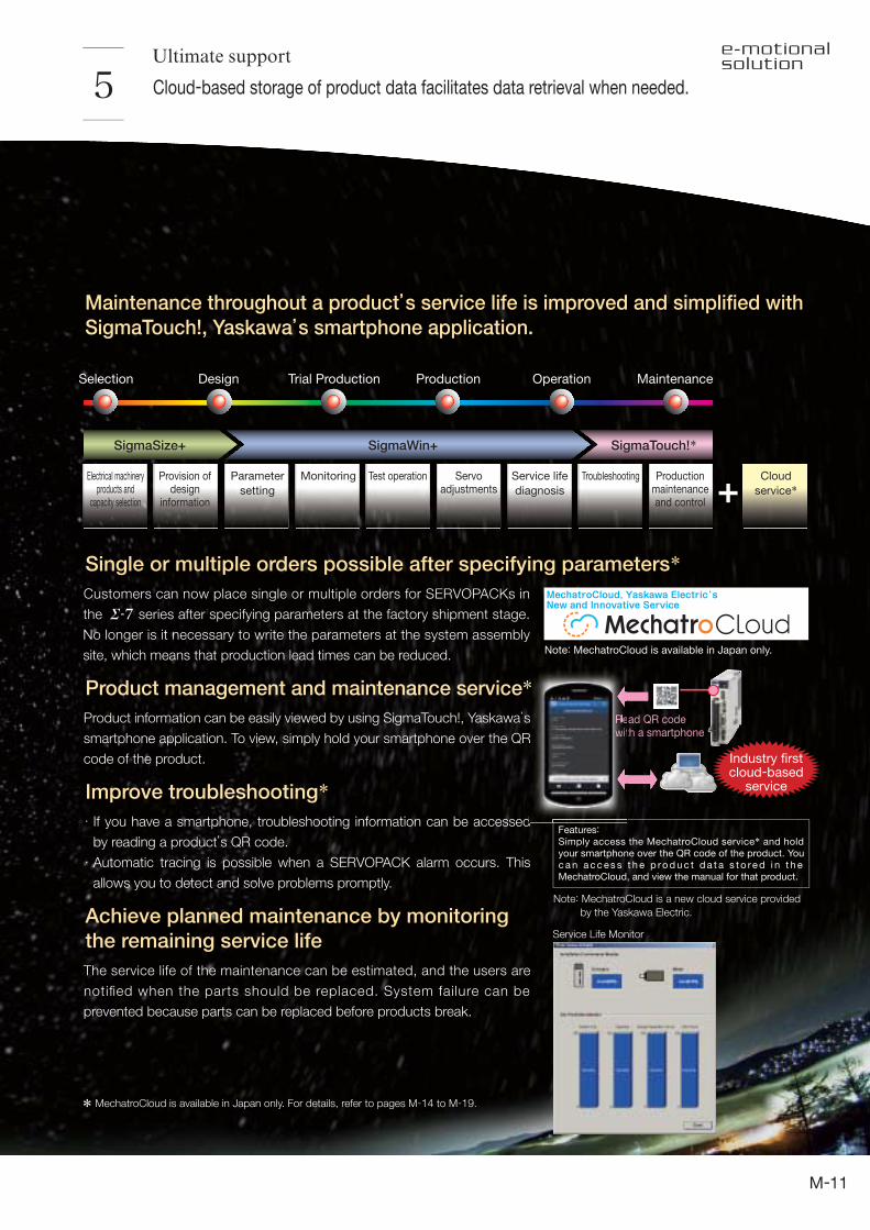
Customers can now place single or multiple orders for SERVOPACKs in
the series after specifying parameters at the factory shipment stage.
No longer is it necessary to write the parameters at the system assembly
site, which means that production lead times can be reduced.
Features: Simply access the MechatroCloud service* and hold your smartphone over the QR code of the product. You c a n a c c es s t h e p ro d u c t d a t a s t o re d i n t h e MechatroCloud, and view the manual for that product.
Ultimate support
Cloud-based storage of product data facilitates data retrieval when needed. 5
Single or multiple orders possible after specifying parameters*
Industry firstcloud-based
service
Maintenance throughout a product’s service life is improved and simplified with
SigmaTouch!, Yaskawa’s smartphone application.
Note: MechatroCloud is available in Japan only.
MechatroCloud, Yaskawa Electric's New and Innovative Service
Selection
SigmaSize+ SigmaWin+ SigmaTouch!*
Design Trial Production Production Operation Maintenance
Electrical machineryproducts and
capacity selection
Provision ofdesign
information
Parameter
setting
Monitoring Test operation Servoadjustments
Service life
diagnosis
Troubleshooting Productionmaintenanceand control
Cloud
service*
Service Life Monitor
Product management and maintenance service*Product information can be easily viewed by using SigmaTouch!, Yaskawa’s
smartphone application. To view, simply hold your smartphone over the QR
code of the product.
Improve troubleshooting*If you have a smartphone, troubleshooting information can be accessed
by reading a product’s QR code.
Automatic tracing is possible when a SERVOPACK alarm occurs. This
allows you to detect and solve problems promptly.
Achieve planned maintenance by monitoring
the remaining service life
The service life of the maintenance can be estimated, and the users are
notified when the parts should be replaced. System failure can be
prevented because parts can be replaced before products break.
Read QR codewith a smartphone
Note: MechatroCloud is a new cloud service provided
by the Yaskawa Electric.
*s
R
d
RRRRReewwwwwitt
* MechatroCloud is available in Japan only. For details, refer to pages M-14 to M-19.
11
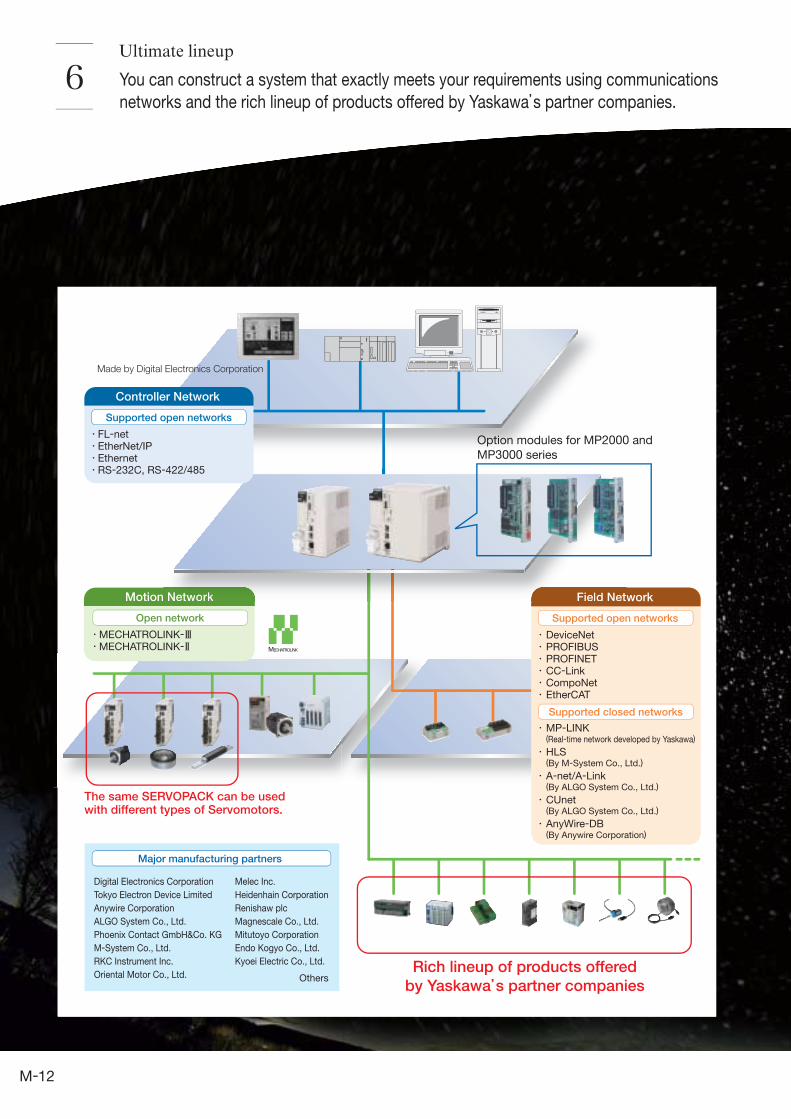
You can construct a system that exactly meets your requirements using communications
networks and the rich lineup of products offered by Yaskawa’s partner companies.6
Motion Network
Open network
Major manufacturing partners
Rich lineup of products offered
by Yaskawa’s partner companies
The same SERVOPACK can be usedwith different types of Servomotors.
Made by Digital Electronics Corporation
Melec Inc.
Heidenhain Corporation
Renishaw plc
Magnescale Co., Ltd.
Mitutoyo Corporation
Endo Kogyo Co., Ltd.
Kyoei Electric Co., Ltd.
Others
MECHATROLINK-MECHATROLINK-
Digital Electronics Corporation
Tokyo Electron Device Limited
Anywire Corporation
ALGO System Co., Ltd.
Phoenix Contact GmbH&Co. KG
M-System Co., Ltd.
RKC Instrument Inc.
Oriental Motor Co., Ltd.
DeviceNetPROFIBUSPROFINETCC-LinkCompoNetEtherCAT
MP-LINK(Real-time network developed by Yaskawa)
HLS(By M-System Co., Ltd.)
A-net/A-Link(By ALGO System Co., Ltd.)
CUnet(By ALGO System Co., Ltd.)
AnyWire-DB(By Anywire Corporation)
Supported closed networks
Field Network
Supported open networks
Network Field Net
Option modules for MP2000 and
MP3000 series
Controller Network
FL-netEtherNet/IPEthernetRS-232C, RS-422/485
Supported open networks
Ultimate lineup
12

7
SERVOPACK
Servomotor
Mounting holes on topMounting holes on top
Mounting holes on bottomMounting holes on bottom
200 W 60 mm200 W 60 mm
Ultimate compatibility
Installation interchangeability with the models in
the SERVOPACK having the same capacity is
featured for the SERVOPACKs.
The SERVOPACKs have improved shapes for
mounting holes. With this new shape, it is much
easier to insert a screwdriver.
A parameter conversion mode is provided.
The parameters of the SERVOPACKs
can be used with the SERVOPACKs,
when using the SigmaWin+ parameter
converter.
Compatibility with earlier series is assured. You can improve the performance
of your system by replacing devices currently used with Servo Drives.
The SERVOPACKs are compatible with models of
the same capacity in the series SERVOPACKs.
13
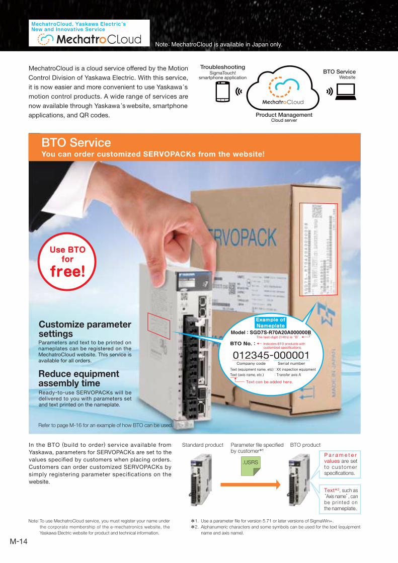
MechatroCloud is a cloud service offered by the Motion
Control Division of Yaskawa Electric. With this service,
it is now easier and more convenient to use Yaskawa's motion control products. A wide range of services are
now available through Yaskawa's website, smartphone
applications, and QR codes.
WebsiteBTO Service
Cloud serverProduct Management
SigmaTouch!smartphone application
Troubleshooting
Use BTOfor
free!
BTO No.:
Model:SGD7S-R70A20A000000BThe last digit (14th) is “B”.
Text (equipment name, etc):XX inspection equipmentText (axis name, etc.) :Transfer axis A
012345-000001Company code Serial number
Text can be added here.
MechatroCloud, Yaskawa Electric'sNew and Innovative Service
You can order customized SERVOPACKs from the website!
In the BTO (build to order) service available from
Yaskawa, parameters for SERVOPACKs are set to the
values specified by customers when placing orders.
Customers can order customized SERVOPACKs by
simply registering parameter specifications on the
website.
To use MechatroCloud service, you must register your name under
the corporate membership of the e-mechatronics website, the
Yaskawa Electric website for product and technical information.
Standard product BTO productParameter file specifiedby customer*1
.USRS
P a r a m e t e r values are set to customer specifications.
Text*2, such as “Axis name”, can be pr inted on the nameplate.
BTO Service
Refer to page M-16 for an example of how BTO can be used.
Example ofNameplate
Indicates BTO products with customized specifications.
Note:
Note: MechatroCloud is available in Japan only.
Customize parameter settingsParameters and text to be printed on nameplates can be registered on the MechatroCloud website. This service is available for all orders.
Reduce equipment assembly timeReady-to-use SERVOPACKs will be delivered to you with parameters set and text printed on the nameplate.
Use a parameter file for version 5.71 or later versions of SigmaWin+.
Alphanumeric characters and some symbols can be used for the text (equipment
name and axis name).
*1.
*2.
14

BTO Service
SolutionIssue
Delivery
Assembly
Parameterwriting
The SERVOPACKs are delivered with
the customer-specified parameters
already written prior to shipment.
This reduces the man-hours
involved in system assembly work.
The names of the axes are printed
on the boxes in which the products
are delivered. This ensures that
these are no mistakes made when
installing the axes.
No need to writethe parameters
Customers can now place single or multiple orders for SERVOPACKs in the series after specifying parameters at the factory shipment stage.
It is no longer necessary to write the parameters at the system assembly site, which means that production lead times can be reduced.
Single or multiple orders possible after specifying parameters (BTO)
DoneDoneDoneDone
DoneDoneDoneDone
DoneDoneDone
DDDDDDDDDDDDDDDDDDDDDDDDDDDDDDDoooooooooooneee DDDDDDDDDDDDDDDDDDDDDDDDDDDDDDDDDDDDDDDDDDDDDDDDDDoooooooooooneeeo DDDDDDDDDDDDDDDDDDDDDDDDDDDDDDDDDDDDDDDDDDDDoooooooooooneo neo
DoneDoneDoneDone
DoneDoneDoneDone DDDDDDDDDDDDDDDDDDDDDDDDDDDDDDDDDDDDoooooooooooooneeee DDDDDDDDDDDDDDDDDDDDDDDDDDDDDDDDDDDDDDDDDDDDDDDDooooooooooneeeo
DoneDoneDoneDone
DDDDDDDDDDDDDDDDDDDDDDDDDDDDDDDDDDDDDDDDDDDDDoooooooooooooone DDDDDDDDDDDDDDDDDDDDDDDDDDDDDDDDDDDDDDDDDDDDDDoooooooooooooneo DDDDDDDDDDDDDDDDDDDDDDDDDDDDDDDDDDDDDDDDDDDDDDDDDDDDDDDDDDDDooooooooooooooooooooonne nen
DoneDoneDoneDone
Writing the parameters foreach unit means time is wasted
Production lineWriting parameters must take a lot of time.
With Yaskawa's BTO service, you can do it in no time.
I'll use test equipment to determine the parameters.
All you have to do is upload the parameters to MechatroCloud…
…to order our customized BTO products.
It's that easy!
Napping on the Cloud
the Cloud
Narumi Narumi
MechatroCloud Introduction Videos – Now on YouTube
Use the standard bar code reader on your smartphone to
read these codes and view videos on YouTube.
Note:“YouTube” is a trademark or a registered trademark of Google Inc.
BTO service SigmaTouch!
15

MechatroCloud, Yaskawa Electric'sNew and Innovative Service
Note: MechatroCloud is available in Japan only.
Register required information under the corporate membership of the e-mechatronics website, the Yaskawa Electric
website for product and technical information. For example, information on Yaskawa's BTO service can be shared
by members of the same corporate membership by registering persons at the same company and/or persons at
related companies under the same corporate membership.
How to use Yaskawa's BTO service
A person who is added as a corporate member
by the Corporate Manager.
●Corporate Users (company employees) are authorized to:
・Issue or delete BTO numbers.
Corporate Members
Management Group
Corporate User group
A person who is added as a corporate member
by the Corporate Manager.
●Corporate users (system integrators) are authorized to:
・Issue or delete BTO numbers.
A person who is added as a corporate member
by the Corporate Manager.
●Corporate Users (sales representatives) are authorized to:
・Issue or delete BTO numbers.
Corporate User (company employees)
Corporate Manager
Corporate User (system integrators)
Corporate User (sales representatives)
* Corporate member registration for MechatroCloud use
There are two types of corporate membership: Corporate Manager and Corporate User. The member(s) in charge of Corporate Members is called the Corporate Manager. The Corporate Manager is the first person to register as a Corporate Member. Persons who are invited to become Corporate Members under the same corporate membership are called “Corporate Users.” A Corporate User can issue BTO numbers.
The Corporate Manager is in charge of the members that are
registered under the company's corporate membership. The first
person who registers as a corporate member is the Corporate
Manager. There must be at least one Corporate Manager for each
corporate membership.
●Corporate Managers are authorized to:
・Add or delete Corporate Managers or Corporate Users.
・Issue or delete BTO numbers.
BTO Service
Register required information under a corporate membership on the e-mechatronics website.*Determine parameters for your equipment.
Upload the parameter file to the MechatroCloud website and issue BTO numbers and BTO order numbers.
Provide the BTO order number to your Yaskawa representative when requesting estimates and placing orders.
Note: Use a parameter file for SigmaWin+ version 5.71 or later versions to upload parameter files.
16

QR code
SigmaTouch!
Innovative servicethat links users tocloud data!Yaskawa is striving to incorporate the needs of our customers into our services in a timely manner. With the use of SigmaTouch!, users can quickly and easily access the MechatroCloud server, which contains the latest product information from Yaskawa Electric's plants and maintenance information from the e-mechatronics website. Yaskawa Electric's service will continue to be enhanced to accommodate the needs and expectations of our customers.
Easily search forproduct informationusing SigmaTouch!Users can search for troubleshooting information for a specific model and view product manuals on a smartphone by using a smartphone camera to simply read the QR code of the product.
UseSigmaTouch!
for
free!
Simply readthe QR code!
Easy troubleshooting with SigmaTouch!Anytime, Anywhere
MechatroCloud
SigmaTouch!
YaskawaElectric plant
e-mechatronicswebsite for product& technology
Cloudserver
Information
Service
" S i g m a To u c h ! " i s a s m a r t p h o n e
application for MechatroCloud. Product
information, such as manufacturing
information and parameter lists, can be
viewed by simply reading the QR codes
of Yaskawa Electric’s products with a
smartphone camera. Alarm details and
troubleshooting information can also be
viewed on the smartphone, which can
greatly reduce recovery time.
Inquiries
Alarm list
Parameter list
etc.
Product
manuals
The QR codes can be read with Android OS
4.0.3 or later versions. The Android must be
connected to the network to use this service.
Note:
17
SigmaTouch!
MechatroCloud, Yaskawa Electric'sNew and Innovative Service
Note: MechatroCloud is available in Japan only.
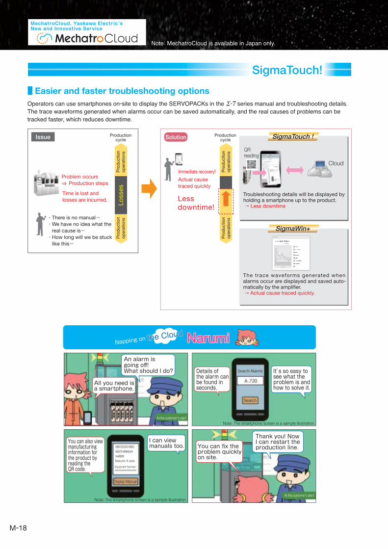
Easier and faster troubleshooting options
All you need is a smartphone.
An alarm is going off! What should I do?
You can fix the problem quickly on site.
Thank you! Now I can restart the production line.
You can also view manufacturing information for the product by reading the QR code.
I can view manuals too.
Details of the alarm can be found in seconds.
It’s so easy to see what the problem is and how to solve it.
Napping on the Cloud
the Cloud
Narumi Narumi
Cloud
SolutionIssue
There is no manual ・・・We have no idea what the
real cause is・・・How long will we be stuck
like this・・・
Lessdowntime!
Immediate recovery!
Actual cause
traced quickly
Productioncycle
Time is lost and
losses are incurred.
QRreading
SigmaTouch !
SigmaWin+
Problem occurs
Production steps
Pro
du
ctio
no
pera
tio
ns
Pro
ductio
no
pera
tio
ns
Productioncycle
Pro
du
ctio
no
pera
tio
ns
Pro
ductio
no
pera
tio
ns
Lo
sses
The trace waveforms generated when alarms occur are displayed and saved auto-matically by the amplifier. Actual cause traced quickly.
Troubleshooting details will be displayed by holding a smartphone up to the product. Less downtime
Operators can use smartphones on-site to display the SERVOPACKs in the series manual and troubleshooting details.The trace waveforms generated when alarms occur can be saved automatically, and the real causes of problems can be tracked faster, which reduces downtime.
Note: The smartphone screen is a sample illustration.
Note: The smartphone screen is a sample illustration.
At the customer's plant
At the customer's plant
Search Alarms
Search
Narumi X axis
Display Manual
Equipment Number:
xxxxxxxxxxxxxxxxxx
18
SigmaTouch!
Download SigmaTouch!
from the Google Play Store for free.
Note: “Android” and “Google Play” are trademarks or registered trademarks of Google Inc.
Use the various functions and services of SigmaTouch! using your smartphone.
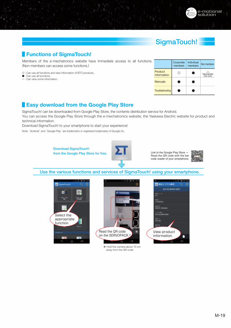
SigmaTouch! can be downloaded from Google Play Store, the contents distribution service for Android.
You can access the Google Play Store through the e-mechatronics website, the Yaskawa Electric website for product and
technical information.
Download SigmaTouch! to your smartphone to start your experience!
Link to the Google Play Store →Read the QR code with the bar code reader of your smartphone.
Select the appropriate function.
Read the QR code on the SERVOPACK.*
* Hold the camera about 10 cm away from the QR code.
View product information.
Members of the e-mechatronics website have immediate access to all functions.
(Non-members can access some functions.)
: Can use all functions and view information of BTO products.: Can use all functions.: Can view some information.
Functions of SigmaTouch!
Easy download from the Google Play Store
Corporatemembers
Individualmembers
Non-members
Productinformation
Troubleshooting
Manuals
Nameplateinfo only
19

Direct Drive Servomotors
◎ Built-in 20-bit encoder.
◎ Low cogging with a core-less system provides smooth
operation free from speed
variations.
Coreless, inner rotorSmall capacity: SGMCS
◎ Built-in 20-, 22-, or 24-bit encoder.◎ Compact design with small rotor diameter.◎ High-speed, high-frequency positioning.◎ Low inertia. ◎ Low heat generation.
With core, inner rotorSmall capacity: SGMCV, SGM7F*1
Medium capacity: SGMCS
With core, outer rotorSmall and medium capacity: SGM7D
Inner rotor Inner rotor Outer rotor*2
Fe
atu
res
Str
uc
ture
sA
pp
lic
ati
on
s
Use a direct drive to supply high torque at low speeds, obtain precise positioning at high
speeds without any slippage and backlash, and simplify your machine's configuration and
maintenance.
◎ Spinning (CMP equipment
and washing machines)
◎ Printing rolls
◎ Indexers
◎ Sorters and bonders
◎ Rotary tables
(Can handle large loads.)
◎ Semiconductor manufacturing
equipment
◎ Machine tools
The inside of the motor rotates.The inside of the motor rotates. The outside of the motor rotates.
Ideal for applications that
require smooth movement
without speed fluctuations.
Ideal for applications that
require downsizing and a
shorter takt time.
Ideal for applications that
require high torque, high
precision, and high rigidity.
*1: The SGM7F is the next-generation series following the SGMCV. Medium-capacity models will be available in the near future.
Compatible with the former Yokogawa
Electric DYNASERV Series.
*2: A magnetic bias is used that places a strong permanent magnet between the stator and core.Note: Use the motor with a Σ-7S SERVOPACK that has a FT82/FT83 specification.
◎ Built-in 24-bit encoder.◎ Application to large loads possible with a high allowable load moment of inertia ratio.◎ Large center aperture design provides more space available for wiring connections.◎ High rigidity.
20

Features of Direct Drive Servomotor
Direct Drive
Servomotor
Technical improvements:・Improved positioning accuracy
with direct connection to a load
・Low noise
・Clean room use (No gear means no lubrication.)
・Reduced number of parts
・Easy wiring and piping based on the motor’s hollow design
■ Motor with Gear
Table
Bearing
Coupling
Gear
Motor
Table
Hollow Gear
Hollow Motor
Hollow Space
Table
Pulley
Timing BeltMotor
■ Motor + Timing Belt ■ Direct Drive Servomotor
■ Direct Drive Servomotor(Large center aperture)■ Hollow Motor + Hollow Gear
Table
Table
Hollow Space
Current limitations:・Reduced accuracy in positioning with
excessive slippage and backlash
・Noise
・Maintenance for wear and tear or for lubrication
The load is mounted directly to the motor, so the motor accuracy becomes
the equipment accuracy, which contributes greatly to increasing the
equipment accuracy. Furthermore, there is no drop in efficiency due to the
presence of a reduction gear or other parts, which helps to save energy.
The motor's compact size also enables reducing the equipment size, which
helps to reduce both the design process time and maintenance costs.
The desired operation angle and number of divisions can easily be set,
simply by changing the command values.
Example: Index table Index table
Reduction gear +encoder
Coupling
AC Servomotor
Encoder
Compact equipmentsize saves space
Typical Servo Drive System
Servomotor
High accuracy
Maintenance-free
Reduced design process timeg p
No slippage or backlash
Energy saving
Direct Drive System
21

Linear ServomotorsF
ea
ture
sS
tru
ctu
res
Ap
plic
ati
on
s
Linear Servo Drives contribute to improved machine functionality and performance with
exceptional features such as high speed, fast acceleration, long-stroke compatible, constant
speed, stability, clean operation, low noise, and low maintenance.
Magnet Track(Stationary
Member)
Magnet Track(Stationary
Member)
Coil
Magnets
LaminatedIron-core
N S N S N S N S
S N S N S N S N
CoilWindings
Magnets
The Moving Coil has no core, and
is made of accurately molded
resin windings
The Magnetic Way is made of two
facing plates with accurately
placed magnets secured on the
sides.
・
・
・
・
The Moving Coil consists of
laminated core and pre-wound coil
bobbins inserted into slots located
in the laminated core and
encapsulated in resin.
The Magnetic Way is made of a
row of magnets accurately placed
on the core side of the carrier plate.
・
・
The Moving Coil consists of
laminated core and pre-wound coil
bobbins inserted into slots located
in the laminated core and
encapsulated in resin.
The Magnetic Way is made of a row of
magnets accurately placed on carrier
plates on both sides of the core.
N S N S N S N S
Coil Windings
LaminatedIron-core
Magnets
S N S N S N S N
N S N S N S N S
Coil Windings
LaminatedIron-core
Magnets
Moving Coil
Magnetic Way
Magnetic Way
Moving CoilMoving Coil
MagneticWayMagnetic
Way
MagneticWay
Magnet Track(Stationary Member)
Coil
MoldedResin
MagnetsCoil
MoldedResin
LaminatedIron-core
Magnets
◎ Multiple headsDevices used in LCD and OLED manufacturing(dispensers, inspection equipment,repair equipment, etc.)
Devices used in LCD and OLED manufacturing(for G5.5 or larger glass substrates andfor long strokes) and semiconductormanufacturing devices (probers, etc.)
◎ Linear stages (X, Y, )θ
◎ GantriesDevices for electronic parts manufacturing(high-speed chip mounters, etc.)
Coreless Model Model with F-type Iron Cores Model with T-type Iron Cores(SGLG) (SGLF) (SGLT)
The lack of magnetic attraction force
helps to extend the life of the linear
motion guides and minimize operational
noise in applications that require high
precision with a small force.
The compact profiles of the FW Linear
Motors save installation space. The
magnetic attraction between the Moving
Coil and Magnetic Way allows the linear
motion guides to be highly rigid.
Yaskawa's unique structure negates the
effects of magnetic attraction.
This reduces concerns for the structural
strength of the linear motion guides and
machinery.
22
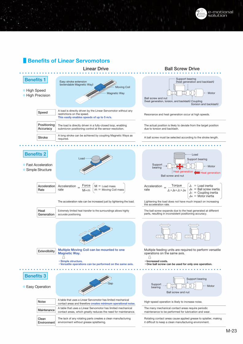
Benefits of Linear ServomotorsLinear Drive Ball Screw Drive
● High Speed● High Precision
● Fast Acceleration● Simple Structure
JL = Load inertiaJB = Ball screw inertiaJC = Coupling inertiaJM = Motor inertia
Torque
JL+JB+JC+JM
・Increased costs.・One ball screw can be used for only one operation.
Support bearing
Supportbearing
Ball screw and nut
Heat generationHeat generation
Support bearing
Supportbearing
Load
Ball screw and nut
Support bearing(heat generation and backlash)
Ball screw and nut(heat generation, torsion, and backlash) Coupling
(torsion and backlash)
Benefits 2
● Easy Operation
Benefits 3
Benefits 1
Accelerationrate
= Accelerationrate
=Force
M+mM = Load mass
m = Moving Coil mass
Multiple Moving Coil can be mounted to oneMagnetic Way.
・Simple structure.・Versatile operations can be performed on the same axis.
PositioningAccuracy
Stroke
Speed
CleanEnvironment
Maintenance
Noise
Extendibility
HeatGeneration
AccelerationRate
Moving Coil
Easy stroke extension(extendable Magnetic Way)
Gap
Load
Magnetic Way
Motor
Motor
Motor
A load is directly driven by the Linear Servomotor without any restrictions on the speed. This easily enables speeds of up to 5 m/s.
A table that uses a Linear Servomotor has limited mechanical
contact areas and therefore creates minimum operational noise.High-speed operation is likely to increase noise.
The many mechanical contact areas require periodic
maintenance to be performed for lubrication and wear.
Rotating contact areas cause applied grease to splatter, making
it difficult to keep a clean manufacturing environment.
A table that uses a Linear Servomotor has limited mechanical
contact areas, which greatly reduces the need for maintenance.
The lack of any rotating parts creates a clean manufacturing
environment without grease splattering.
The load is directly driven in a fully-closed loop, enabling submicron positioning control at the sensor resolution.
A long stroke can be achieved by coupling Magnetic Ways as required.
Resonance and heat generation occur at high speeds.
The actual position is likely to deviate from the target position due to torsion and backlash.
A ball screw must be selected according to the stroke length.
The acceleration rate can be increased just by lightening the load.
Extremely limited heat transfer to the surroundings allows highly
accurate positioning.
Multiple feeding units are required to perform versatile operations on the same axis.
Lightening the load does not have much impact on increasing the acceleration rate.
The ball screw expands due to the heat generated at different parts, resulting in inconsistent positioning accuracy.
23
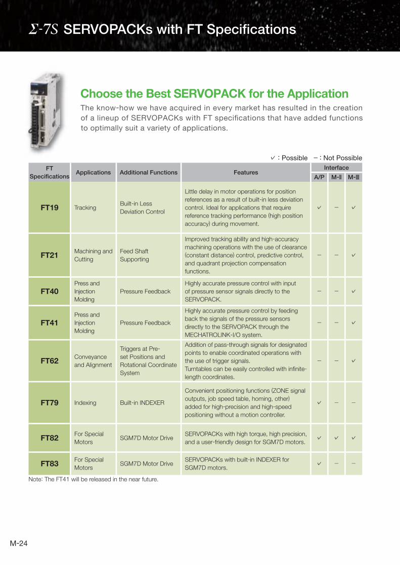
SERVOPACKs with FT Specifications
The know-how we have acquired in every market has resulted in the creation
of a lineup of SERVOPACKs with FT specifications that have added functions
to optimally suit a variety of applications.
Choose the Best SERVOPACK for the Application
Note: The FT41 will be released in the near future.
FT
Specifi cationsApplications Additional Functions Features
Interface
A/P M- M-
FT19 TrackingBuilt-in Less
Deviation Control
Little delay in motor operations for position
references as a result of built-in less deviation
control. Ideal for applications that require
reference tracking performance (high position
accuracy) during movement.
✓ - ✓
FT21 Machining and
Cutting
Feed Shaft
Supporting
Improved tracking ability and high-accuracy
machining operations with the use of clearance
(constant distance) control, predictive control,
and quadrant projection compensation
functions.
- - ✓
FT40Press and
Injection
Molding
Pressure Feedback
Highly accurate pressure control with input
of pressure sensor signals directly to the
SERVOPACK.
- - ✓
FT41Press and
Injection
Molding
Pressure Feedback
Highly accurate pressure control by feeding
back the signals of the pressure sensors
directly to the SERVOPACK through the
MECHATROLINK-I/O system.
- - ✓
FT62 Conveyance
and Alignment
Triggers at Pre-
set Positions and
Rotational Coordinate
System
Addition of pass-through signals for designated
points to enable coordinated operations with
the use of trigger signals.
Turntables can be easily controlled with infi nite-
length coordinates.
- - ✓
FT79 Indexing Built-in INDEXER
Convenient positioning functions (ZONE signal
outputs, job speed table, homing, other)
added for high-precision and high-speed
positioning without a motion controller.
✓ - -
FT82 For Special
MotorsSGM7D Motor Drive
SERVOPACKs with high torque, high precision,
and a user-friendly design for SGM7D motors.✓ ✓ ✓
FT83 For Special
MotorsSGM7D Motor Drive
SERVOPACKs with built-in INDEXER for
SGM7D motors.✓ - -
✓ : Possible − : Not Possible
24

New Two-Axis SERVOPACKswith Built-in Controllers!
Simple, All-in-One System Configuration
Features
Four external axes
Two internal axes
Ethernet
● No separate controller is required (no connection cables or battery is required).
● Width reduced by 34 mm (system comparison to MP3300 + ).
High-Speed Response
◎ High-speed response frequency of 3.1 kHz has been achieved.
◎ High-speed I/O used for the Controller Function Module.
◎ The command/response delay is minimized with the two internal axes.
These axes can be synchronized with the external axes.
Less system space required◎ Configure up to six axes.
◎ Build small-scale equipment system without PLC using one SERVOPACK.
◎ Expand functionality by mounting an option unit.
◎ Reduce burden of designing software when part of the equipment changes.
Equipment modularization and distributed control system
Option Unit
MP2000-seriesOptional Module
24-V power supplyconnector for option
-Series SERVOPACKs C
C
Yaskawa's newest two-axis SERVOPACKs with built-in controllers offer the
ideal configuration to control small-scale equipment and mechanisms to meet
the increasing needs of component downsizing, equipment modularization,
and system distribution.
MECHATROLINK-
25

SGM7P100W-1.5kW
SGMMV10W-30W
Low inertia
Coreless model
With core, outer rotor With core, inner rotor Coreless, inner rotor
Medium inertia
Model with iron core
SGM7A50W-7kW
SGM7J50W-750W
SGM7G300W-15kW
SGMCS(Small capacity)
2.00N·m-35.0N·m
SGM7F/SGMCV4.00N·m-35.0N·m
SGM7D2.06N·m-240N·m
SGMCS(Medium capacity)
45.0N·m-200N·m
SGLG12.5N-750N
SGLT130N-900N
SGLFW25N-1120N
SGLFW245N-1680NSGLFWW2
SGMGMCSSGMM7F7F/SGMMCCV SGMMCSC
SGMMSG 7A7A SGM7J7J SGMS 7GSGGM7PSGMMVV
回転形サーボドライブ
26
● Rotary Servomotors
● Direct Drive Servomotors
● Linear Servomotors
Product Lineup
Servomotors

MECHATROLINK-3Communications ReferenceSGD7W- A20A
EECHHHATTHATTROLLLINNKINNK-3333Analog Voltage/Pulse Train ReferenceSGD7S- 00A
INDEXER Module-MountedSGD7S E0A 10
MECHATROLINK-2Communications ReferenceSGD7S- 10A
DeviceNet Module-MountedSGD7S E0A 50SGD7S E0A 60
FT Specifi cations
MECHATROLINK-3Communications ReferenceSGD7S- 20A
Fully-Closed ModuleSGDV-OFA01A
Safety ModuleSGDV-OSA01A
● (Two-axis)● (Single-axis)
Two-axis SERVOPACKs with Built-in Controllers,Bus Connection ReferenceSGD7C- AMAA
Refer to page M-24 for the line-up.
● (Two-axis)
Combination of SERVOPACKs and Option Modules
SERVOPACK (Model Number)
Option Module
Fully-Closed Module
(SGDV-OFA01A)Safety Module
(SGDV-OSA01A)
Single-axis Analog Voltage/Pulse Train Reference Type (SGD7S-□□□□00A) *1 *1
Single-axis MECHATROLINK-2 Communications Reference Type (SGD7S-□□□□10A) *1 *1
Single-axis MECHATROLINK-3 Communications Reference Type (SGD7S-□□□□20A) *1 *1
Two-axis MECHATROLINK-3 Communications Reference Type (SGD7W-□□□A20A) − −
SERVOPACK(Model Number of Set)
SERVOPACK(Model Number)
Command Option Module(Model Number)
−Single-axis INDEXERModule-Mounted Type(SGD7S E0A 10 )
Command Option Attachable Type
(SGD7S- E0A)
INDEXER (SGDV-OCA03A)
Single-axis DeviceNet Module-Mounted Type(SGD7S E0A 50 )*2
(SGD7S E0A 60 )*3
DeviceNet*2(SGDV-OCA04A) −
DeviceNet*3(SGDV-OCA05A) −
: Possible − : Not Possible
*1. You cannot use a Fully-Closed Module and a Safety Module together.
*2. Driven by control power supply
*3. Driven by external power supply
VV l /P l ECHHATTTTRRROOLINK ECHHATATROOLINK
TTTTwoo-owww iaxixiixiaxis Ss Ss Ss Ss Ss Ss SSSEEEERVVVERVOOP
( )
27
● Option Modules
SERVOPACKs

I/O Signal Cable
External devices such as LED indicators
CN1
CN6
CN3
CN7
CN8
CN2
DigitalOperator
Computer Cable
Note: When not using the safety function, leave the safety jumper connector connected to the SERVOPACK.
Servomotor MainCircuit Cable
Direct Drive Servomotor
Encoder CableHolding Brake Power Supply Unit
Servomotor MainCircuit Cable
Encoder Cable
Battery Case(Required when anabsolute encoder isused.)
Magnetic Contactor
ExternalRegenerativeResistor
Noise Filter
Molded-casecircuit breaker(MCCB)
Magnetic Contactor
R S T
Turns the servoON and OFF.Install a surge absorber.
Turns the brake power supplyON and OFF.Install a surge absorber.
Used for a servomotor with a brake.
(Wiring required for the brake)
Power supplyThree-phase 200 VAC
Protects the power supply line by shutting the circuit OFF when overcurrent is detected.
Used to eliminateexternal noise fromthe power line.
Connect an external regenerative resistor to terminals B1 and B2 if the regenerative capacity is insufficient.
To
MECHATROLINK Communications Cable
Digital Operator Cable
Safety FunctionDevices Cable
To next MECHATROLINK- station
Rotary Servomotor
Single-axis MECHATROLINK-Communications Reference SERVOPACK
28
Combination of SERVOPACK and Rotary Servomotor/Direct Drive Servomotor
System Confi guration Example
1For MECHATROLINK-3 Communications
Three-phase 200 VAC
Power supplyThree-phase 200 VAC
R S T
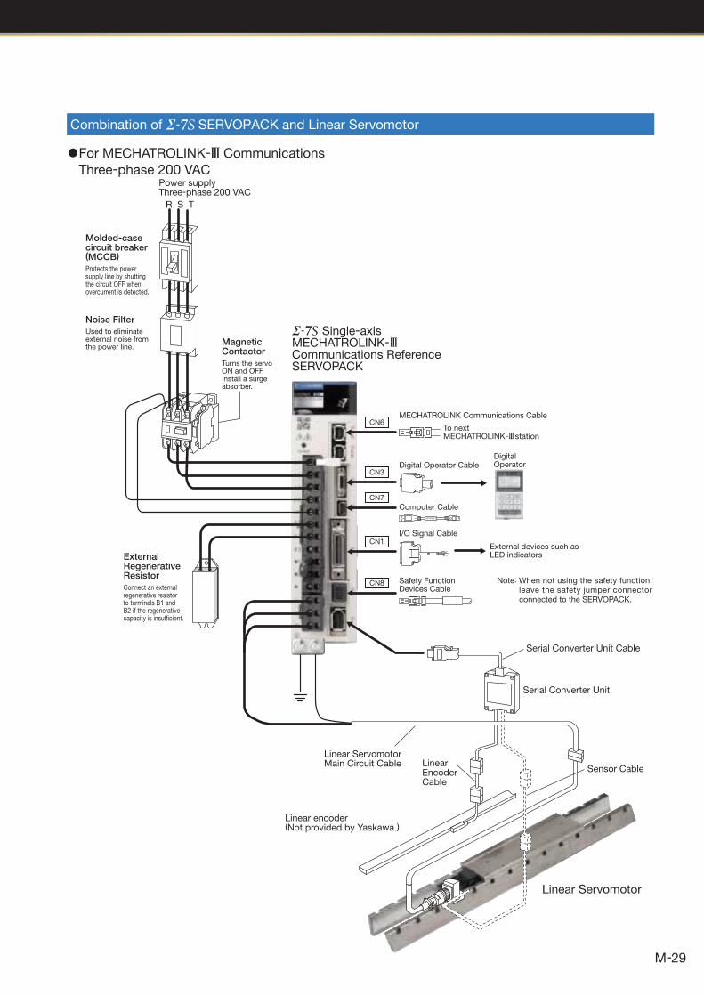
Linear Servomotor
Linear encoder(Not provided by Yaskawa.)
Sensor CableLinear Encoder Cable
Linear ServomotorMain Circuit Cable
Serial Converter Unit
Serial Converter Unit Cable
Noise Filter
Molded-casecircuit breaker(MCCB)
Protects the power supply line by shutting the circuit OFF when overcurrent is detected.
Used to eliminateexternal noise fromthe power line.
Magnetic Contactor
Turns the servoON and OFF.Install a surge absorber.
Single-axis MECHATROLINK-Communications Reference SERVOPACK
CN1
CN6
CN3
CN7
CN8
ExternalRegenerativeResistor
Connect an external regenerative resistor to terminals B1 and B2 if the regenerative capacity is insufficient.
I/O Signal Cable
External devices such as LED indicators
DigitalOperator
Computer Cable
Note: When not using the safety function, leave the safety jumper connector connected to the SERVOPACK.
MECHATROLINK Communications Cable
Digital Operator Cable
Safety FunctionDevices Cable
To next MECHATROLINK- station
回転形サーボドライブ
29
Combination of SERVOPACK and Linear Servomotor
1For MECHATROLINK-3 Communications
Three-phase 200 VAC
30
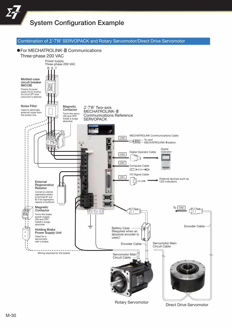
CN1
CN6
CN3
CN7
DigitalOperator
External devices such as LED indicators
Holding Brake Power Supply Unit
Magnetic Contactor
ExternalRegenerativeResistor
Turns the brake power supplyON and OFF.Install a surge absorber.
Used for a servomotor with a brake.
Connect an external regenerative resistor to terminals B1 and B2 if the regenerative capacity is insufficient.
R S T
Power supplyThree-phase 200 VAC
Noise Filter
Molded-casecircuit breaker(MCCB)
Protects the power supply line by shutting the circuit OFF when overcurrent is detected.
Used to eliminateexternal noise fromthe power line.
Magnetic Contactor
Turns the servoON and OFF.Install a surge absorber.
Two-axis MECHATROLINK-Communications Reference SERVOPACK
(Wiring required for the brake)
Battery Case(Required when anabsolute encoder isused.)
Encoder Cable
Encoder Cable
Servomotor MainCircuit Cable
Servomotor MainCircuit Cable
Rotary ServomotorDirect Drive Servomotor
CN2To
I/O Signal Cable
Computer Cable
MECHATROLINK Communications Cable
Digital Operator Cable
To next MECHATROLINK- station
System Confi guration Example
Combination of SERVOPACK and Rotary Servomotor/Direct Drive Servomotor
1For MECHATROLINK-3 Communications
Three-phase 200 VAC
31
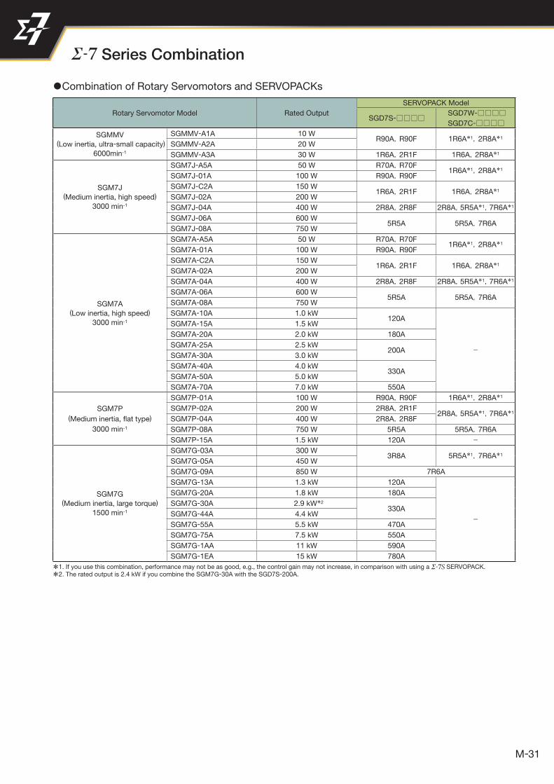
Series Combination
1Combination of Rotary Servomotors and SERVOPACKs
Rotary Servomotor Model Rated Output
SERVOPACK Model
SGD7S-SGD7W-
SGD7C-
SGMMV
(Low inertia, ultra-small capacity)
6000min-1
SGMMV-A1A 10 WR90A,R90F 1R6A*1,2R8A*1
SGMMV-A2A 20 W
SGMMV-A3A 30 W 1R6A,2R1F 1R6A,2R8A*1
SGM7J(Medium inertia, high speed)
3000 min-1
SGM7J-A5A 50 W R70A,R70F1R6A*1,2R8A*1
SGM7J-01A 100 W R90A,R90F
SGM7J-C2A 150 W1R6A,2R1F 1R6A,2R8A*1
SGM7J-02A 200 W
SGM7J-04A 400 W 2R8A,2R8F 2R8A,5R5A*1,7R6A*1
SGM7J-06A 600 W5R5A 5R5A,7R6A
SGM7J-08A 750 W
SGM7A (Low inertia, high speed)
3000 min-1
SGM7A-A5A 50 W R70A,R70F1R6A*1,2R8A*1
SGM7A-01A 100 W R90A,R90F
SGM7A-C2A 150 W1R6A,2R1F 1R6A,2R8A*1
SGM7A-02A 200 W
SGM7A-04A 400 W 2R8A,2R8F 2R8A,5R5A*1,7R6A*1
SGM7A-06A 600 W5R5A 5R5A,7R6A
SGM7A-08A 750 W
SGM7A-10A 1.0 kW120A
−
SGM7A-15A 1.5 kW
SGM7A-20A 2.0 kW 180A
SGM7A-25A 2.5 kW200A
SGM7A-30A 3.0 kW
SGM7A-40A 4.0 kW330A
SGM7A-50A 5.0 kW
SGM7A-70A 7.0 kW 550A
SGM7P
(Medium inertia, fl at type)
3000 min-1
SGM7P-01A 100 W R90A,R90F 1R6A*1,2R8A*1
SGM7P-02A 200 W 2R8A,2R1F2R8A,5R5A*1,7R6A*1
SGM7P-04A 400 W 2R8A,2R8F
SGM7P-08A 750 W 5R5A 5R5A,7R6A
SGM7P-15A 1.5 kW 120A −
SGM7G (Medium inertia, large torque)
1500 min-1
SGM7G-03A 300 W3R8A 5R5A*1,7R6A*1
SGM7G-05A 450 W
SGM7G-09A 850 W 7R6A
SGM7G-13A 1.3 kW 120A
−
SGM7G-20A 1.8 kW 180A
SGM7G-30A 2.9 kW*2
330ASGM7G-44A 4.4 kW
SGM7G-55A 5.5 kW 470A
SGM7G-75A 7.5 kW 550A
SGM7G-1AA 11 kW 590A
SGM7G-1EA 15 kW 780A
*1. If you use this combination, performance may not be as good, e.g., the control gain may not increase, in comparison with using a SERVOPACK.
*2. The rated output is 2.4 kW if you combine the SGM7G-30A with the SGD7S-200A.
回転形サーボドライブ
32
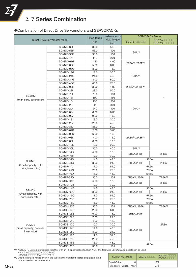
Direct Drive Servomotor ModelRated Torque
N·m
Instantaneous
Max. Torque
N·m
SERVOPACK Model
SGD7S-SGD7W-SGD7C-
SGM7D
(With core, outer rotor)
SGM7D-30F 30.0 50.0
120A*1
−
SGM7D-58F 58.0 100
SGM7D-90F 90.0 150
SGM7D-1AF 110 200
SGM7D-01G 1.30 4.002R8A*1,2R8F*1
SGM7D-05G 5.00 6.00
SGM7D-08G 8.00 15.0
120A*1
SGM7D-18G 18.0 30.0
SGM7D-24G 24.0 45.0
SGM7D-34G 34.0 60.0
SGM7D-45G 45.0 75.0
SGM7D-03H 3.00 4.00 2R8A*1,2R8F*1
SGM7D-28I 28.0 50.0
120A*1
SGM7D-70I 70.0 100
SGM7D-1ZI 100 150
SGM7D-1CI 130 200
SGM7D-2BI 220 300
SGM7D-2DI 240 400
SGM7D-06J 6.00 8.00
SGM7D-09J 9.00 15.0
SGM7D-18J 18.0 30.0
SGM7D-20J 20.0 45.0
SGM7D-38J 38.0 60.0
SGM7D-02K 2.06 5.00
2R8A*1,2R8F*1
SGM7D-06K 6.00 10.0
SGM7D-08K 8.00 15.0
SGM7D-06L 6.00 10.0
SGM7D-12L 12.0 20.0
SGM7D-30L 30.0 40.0 120A*1
SGM7F
(Small capacity, with
core, inner rotor)
SGM7F-04B 4.00 12.02R8A,2R8F 2R8A
SGM7F-10B 10.0 30.0
SGM7F-14B 14.0 42.0 5R5A
SGM7F-08C 8.00 24.0 2R8A,2R8F 2R8A
SGM7F-17C 17.0 51.0 5R5A
SGM7F-25C 25.0 75.0 7R6A
SGM7F-16D 16.0 48.0 5R5A
SGM7F-35D 35.0 105 7R6A*2,120A 7R6A*2
SGMCV(Small capacity, with
core, inner rotor)
SGMCV-04B 4.00 12.02R8A,2R8F 2R8A
SGMCV-10B 10.0 30.0
SGMCV-14B 14.0 42.0 5R5A
SGMCV-08C 8.00 24.0 2R8A,2R8F 2R8A
SGMCV-17C 17.0 51.0 5R5A
SGMCV-25C 25.0 75.0 7R6A
SGMCV-16D 16.0 48.0 5R5A
SGMCV-35D 35.0 105 7R6A*2,120A 7R6A*2
SGMCS(Small capacity, coreless,
inner rotor)
SGMCS-02B 2.00 6.00
2R8A,2R1F
2R8A
SGMCS-05B 5.00 15.0
SGMCS-07B 7.00 21.0
SGMCS-04C 4.00 12.0
2R8A,2R8F
SGMCS-10C 10.0 30.0
SGMCS-14C 14.0 42.0
SGMCS-08D 8.00 24.0
SGMCS-17D 17.0 51.0
SGMCS-25D 25.0 75.0
SGMCS-16E 16.0 48.05R5A
SGMCS-35E 35.0 105
SERVOPACK Model SGD7S-□□□□ SGD7W-□□□□ SGD7C-□□□□
Rated Output W 1000
Rated Motor Speed min-1 270
Series Combination
1Combination of Direct Drive Servomotors and SERVOPACKs
*1 An SGM7D Servomotor is used together with an FT-specifi cation SERVOPACK. The following SERVOPACK models can be used. ・SGD7S-□□□□□□ A□□□ F82□ ・SGD7S-□□□□ 00A□□□ F83□
*2 Use the derated values given in the table on the right for the rated output and rated motor speed of this combination.

33
Direct Drive Servomotor ModelRated Torque
N·m
Instantaneous
Max. Torque
N·m
SERVOPACK Model
SGD7S-SGD7W-SGD7C-
SGMCS
(Medium capacity, with
core, inner rotor)
SGMCS-45M 45.0 135 7R6A
SGMCS-80M 80.0 240 120A
−SGMCS-1AM 110 330 180A
SGMCS-80N 80.0 240 120A
SGMCS-1EN 150 450200A
SGMCS-2ZN 200 600
Linear Servomotor ModelRated Force
N
Max. Force
N
SERVOPACK Model
SGD7S-SGD7W-SGD7C-
SGLG (Coreless model, with
standard magnetic way)
SGLGW-30A050C 12.5 40 R70A,R70F
1R6ASGLGW-30A080C 25 80
R90A,R90FSGLGW-40A140C 47 140
SGLGW-40A253C 93 280 1R6A,2R1F
SGLGW-40A365C 140 420 2R8A,2R8F 2R8A
SGLGW-60A140C 70 220 1R6A,2R1F 1R6A
SGLGW-60A253C 140 440 2R8A,2R8F 2R8A
SGLGW-60A365C 210 660 5R5A
SGLGW-90A200C 325 1300 120A
−SGLGW-90A370C 550 2200 180A
SGLGW-90A535C 750 3000 200A
SGLG (Coreless model, with
high-force magnetic way)
SGLGW-40A140C 57 230 1R6A,2R1F 1R6A
SGLGW-40A253C 114 460 2R8A,2R8F 2R8A
SGLGW-40A365C 171 690 3R8A 5R5A
SGLGW-60A140C 85 360 1R6A,2R1F 1R6A
SGLGW-60A253C 170 720 3R8A 5R5A
SGLGW-60A365C 255 1080 7R6A
SGLF(Model with F-type iron
core)
SGLFW-20A090A 25 86
1R6A,2R1F 1R6ASGLFW-20A120A 40 125
SGLFW-35A120A 80 220
SGLFW-35A230A 160 440 3R8A 5R5A
SGLFW-50A200B 280 600 5R5A
SGLFW-50A380B560 1200 120A −SGLFW-1ZA200B
SGLFW-1ZA380B 1120 2400 200A
SGLFW2-30A070A 45 1351R6A,2R1F 1R6A
SGLFW2-30A120A 90 270
SGLFW2-30A230A180 540 3R8A −170 500 2R8A,2R8F 2R8A
SGLFW2-45A200A 280 840 5R5A
SGLFW2-45A380A 5601680 180A
−
1500120A
SGLFW2-90A200A 560 1680
SGLFW2-90A380A 1120 3360 200A
SGLFW2-90A560A 1680 5040 330A
SGLFW2-1DA380A 1680 5040 200A
SGLFW2-1DA560A 2520 7560 330A
SGLT(Model with T-type iron
core)
SGLTW-20A170A 130 380 3R8A 5R5A
SGLTW-20A320A 250 760 7R6A
SGLTW-20A460A 380 1140 120A −SGLTW-35A170A 220 660
5R5ASGLTW-35A170H 300 600
SGLTW-35A320A 440 1320120A
−SGLTW-35A320H 600 1200
SGLTW-35A460A 670 2000180A
SGLTW-40A400B 670 2600
SGLTW-40A600B 1000 4000 330A −SGLTW-50A170H 450 900 5R5A
SGLTW-50A320H 900 1800 120A
−SGLTW-80A400B 1300 5000 330A
SGLTW-80A600B 2000 7500 550A
1Combination of Direct Drive Servomotors and SERVOPACKs
1Combination of Linear Servomotors and SERVOPACKs

34
◆ Incremental Linear Encoders
: Possible − : Not possible
◆Absolute Rotary Encoder
Output Signal ManufacturerLinear
Encoder Type
Model Resolution Maximum Speed*
Scale Sensor HeadBits min-1
Encoder for
Yaskawa’s
Serial Interface
Magnescale
Co., Ltd.Sealed
RU77-4096ADF 20 2000
RU77-4096AFFT01 22 2000
* The maximum speeds given in the above table are the maximum applicable speeds of the encoders when combined with a Yaskawa SERVOPACK.The actual speed will be restricted by either the maximum speed of the Linear Servomotor or the maximum speed of the Linear Encoder (given above).
Note: Confirm detailed specifications, such as the tolerances, dimensions, and operating environment, with the manufacturer of the Encoder before you use it.
◆Absolute Linear Encoder
Output Signal ManufacturerLinear
Encoder Type
Model Linear Encoder
Pitch
Resolution Maximum Speed*3
Support for
Polarity Sensor Input
Applicationto
LinearMotors
Applicationto
Fully-Closed Loop
ControlScale
Sensor Head
Interpolator (Serial Converter Unit) μm nm m/s
Encoder for
Yaskawa’s
Serial
Interface*2
Magnescale
Co., Ltd.Sealed
SR77-□□□□□LF − 80 9.8 3.33 −SR77-□□□□□MF − 80 78.1 3.33 −SR87-□□□□□LF − 80 9.8 3.33 −SR87-□□□□□MF − 80 78.1 3.33 −
Mitutoyo
CorporationExposed
ST781A − 256 500 5 −ST782A − 256 500 5 −ST783A − 51.2 100 5 −ST784A − 51.2 100 5 −ST788A − 51.2 100 5 −
ST789A*9 − 25.6 50 5 −ST1381 − 5.12 10 8 −ST1382 − 0.512 1 3.6*10 −
Heidenhain
Corporation
Exposed LIC4100 seriesEIB3391Y*7
20.48 5 10 −Sealed LC115 40.96 10 3 −
* 1. You must also use a Yaskawa Serial Converter Unit. The output signal will be multiplied by 8 bits (256 divisions) or 12 bits (4,096 divisions) in the Serial Converter Unit.
* 2. The multiplier (number of divisions) depends on the Linear Encoder. Also, you must write the motor constant file to the Linear Encoder in advance.
* 3. The maximum speeds given in the above table are the maximum applicable speeds of the encoders when combined with a Yaskawa SERVOPACK.The actual speed will be restricted by either the maximum speed of the Linear Servomotor or the maximum speed of the Linear Encoder (given above).
* 4. If you use the origin signals with a Linear Encoder from Renishaw plc, the origin may sometimes be falsely detected. If that occurs, use the BID/DIR signal to output the origin signal only in one direction.
* 5. Use this model number to purchase the Serial Converter Unit.
* 6. Use this model number to purchase the Sensor Head with Interpolator.
* 7. Use this model number to purchase the Interpolator.
* 8. Contact your Yaskawa representative.
* 9. Contact Mitutoyo Corporation for details on the Linear Encoders.
*10.The speed is restricted for some SERVOPACKs.Note: Confirm detailed specifications, such as the tolerances, dimensions, and operating environment, with the manufacturer of the Encoder before you use it.
Output Signal ManufacturerLinear
Encoder Type
Model Linear Encoder
Pitch
Resolution Maximum Speed*3
Support for
Polarity Sensor Input
Applicationto
LinearMotors
Applicationto
Fully-Closed Loop
ControlScale
Sensor Head
Interpolator (Serial Converter Unit) μm nm m/s
1 Vp-p
Analog
Voltage*1
Heidenhain
CorporationExposed
LIDA48JZDP-H003/-H006*5
2078.1 5
JZDP-J003/-J006*5 4.9 2 *8
LIF48JZDP-H003/-H006*5
415.6 1
JZDP-J003/-J006*5 1.0 0.4 *8 *8
Renishaw plc*4 Exposed RGS20 RGH22BJZDP-H005/-H008*5
2078.1 5
JZDP-J005/-J008*5 4.9 2 *8
Encoder for
Yaskawa’s
Serial
Interface*2
Magnescale
Co., Ltd.
Exposed
SL7 0PL101-RY*6
800 97.7 10−
PL101 MJ620-T13*7 *8
SQ10 PQ10MQ10-FLA
400 48.83 3−
MQ10-GLA −
Sealed
SR75- LF − 80 9.8 3.33 −SR75- MF − 80 78.1 3.33 −SR85- LF − 80 9.8 3.33 −SR85- MF − 80 78.1 3.33 −
Recommended Encoders
: Possible
: Possible

35
Model Designations
SGM7J
3Without Gears 3With Gears
SGM7J - 01 A 7 A 2 1 SGM7J - 01 A 7 A H 1 2 1Series
Servomotors:
SGM7J
Series
Servomotors:
SGM7J
SGM7A
3Without Gears 3With Gears
SGM7A - 01 A 7 A 2 1 SGM7A - 01 A 7 A H 1 2 1Series
Servomotors:
SGM7A
Series
Servomotors:
SGM7ACode Specifi cationA5 50 W01 100 WC2 150 W02 200 W04 400 W06 600 W08 750 W10 1.0 kW15 1.5 kW20 2.0 kW25 2.5 kW30 3.0 kW40 4.0 kW50 5.0 kW70 7.0 kW
1st+2nd digits Rated Output
Code Specifi cationA 200 VAC
3rd digit Power Supply Voltage
6th digit Gear Type
Code Specifi cation7 24-bit absoluteF 24-bit incremental
4th digit Serial Encoder
Code Specifi cationA 200 VAC
3rd digit Power Supply Voltage
Code Specifi cation7 24-bit absoluteF 24-bit incremental
4th digit Serial Encoder
Code Specifi cationA 200 VAC
3rd digit Power Supply Voltage
Code Specifi cation2 17-bit absolute
4th digit Serial Encoder
Code Specifi cationA 200 VAC
3rd digit Power Supply Voltage
Code Specifi cation7 24-bit absoluteF 24-bit incremental
4th digit Serial Encoder
Code Specifi cation2 Straight without key6 Straight with key and tap
B* With two fl at seats
6th digit Shaft End
Code Specifi cation2 Straight without key6 Straight with key and tapB With two fl at seats
6th digit Shaft End
Code Specifi cation2 StraightA Straight with fl at seats
6th digit Shaft End
Code Specifi cation0 Flange output2 Straight without key6 Straight with key and tap
8th digit Shaft End
Code Specifi cation0 Flange output2 Straight without key6 Straight with key and tap
8th digit Shaft End
Code Specifi cation1 Without options
CWith holding brake(24 VDC)
EWith oil seal and holding brake (24 VDC)
S With oil seal
7th digit Options
Code Specifi cation1 Without options
CWith holding brake(24 VDC)
EWith oil seal and holding brake (24 VDC)
S With oil seal
7th digit Options
Code Specifi cation1 Without options
CWith holding brake(24 VDC)
7th digit Options
Code Specifi cation1 Without options
CWith holding brake(24 VDC)
9th digit Options
Code Specifi cation1 Without options
CWith holding brake(24 VDC)
9th digit Options
Code Specifi cationB 1/11*1
C 1/211 1/52 1/9*2
7 1/33
7th digit Gear Ratio
Code Specifi cationB 1/11*1
C 1/211 1/52 1/9*2
7 1/33
7th digit Gear Ratio
*1. This specifi cation is not supported for models with a rated output of 50 W.
*2. This specifi cation is supported only for models with a rated output of 50 W.
*1. This specifi cation is not supported for models with a rated output of 50 W.
*2. This specifi cation is supported only for models with a rated output of 50 W.
* Code B is not supported for models with a rated output of 1.5 kW or higher.
Note: SGM7A-70A Servomotors with holding brakes are not available.
Note: Contact your Yaskawa representative for models of 1.5 kW or higher.
1st+2nd 3rd 4th 5th 6th1st+2nd 3rd 4th 5th 6th 7th digit digit7th 8th 9th
1st+2nd 3rd 4th 5th 6th 7th digit 1st+2nd 3rd 4th 5th 6th digit7th 8th 9th
1Rotary Servomotors
Code Specifi cationA5 50 W01 100 WC2 150 W02 200 W04 400 W06 600 W08 750 W10 1.0 kW
1st+2nd digits Rated Output
Code Specifi cationA5 50 W01 100 WC2 150 W02 200 W04 400 W06 600 W08 750 W
1st+2nd digits Rated Output
Code Specifi cationA1 10 WA2 20 WA3 30 W
1st+2nd digits Rated Output
Code Specifi cationA 200 VAC
3rd digit Power Supply Voltage
Code Specifi cation7 24-bit absoluteF 24-bit incremental
4th digit Serial Encoder
Code Specifi cationA5 50 W01 100 WC2 150 W02 200 W04 400 W06 600 W08 750 W
1st+2nd digits Rated Output
5th digit Design Revision OrderA
5th digit Design Revision OrderA
5th digit Design Revision OrderA
5th digit Design Revision OrderA
Code Specifi cation
HHDS planetarylow-backlash gear
6th digit Gear Type
5th digit Design Revision OrderA
Code Specifi cation
HHDS planetarylow-backlash gear
SGMMV
SGMMV - A1 A 2 A 2 1mini Series
Servomotors:
SGMMV
1st+2nd 3rd 4th 5th 6th 7th digit
36
Model Designations
Code Specifi cationA 200 VAC
3rd digit Power Supply Voltage
Code Specifi cation7 24-bit absoluteF 24-bit incremental
4th digit Serial Encoder
Code Specifi cation2 Straight without key6 Straight with key and tap
6th digit Shaft End
Code Specifi cation1 Without options
CWith holding brake(24 VDC)
EWith oil seal and holding brake (24 VDC)
S With oil seal
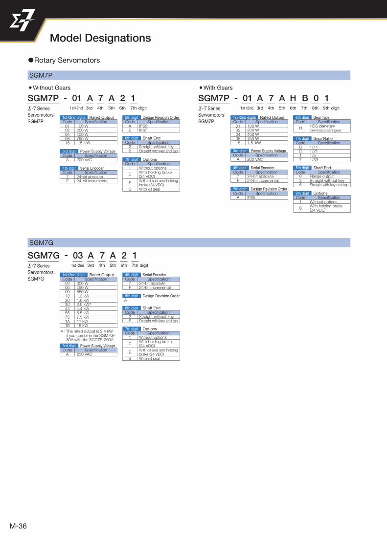
7th digit Options* : The rated output is 2.4 kW if you combine the SGM7G-30A with the SGD7S-200A.
1st+2nd 3rd 4th 5th 6th 7th digit
SGM7G
SGM7G - 03 A 7 A 2 1Series
Servomotors:
SGM7G
1Rotary Servomotors
Code Specifi cation03 300 W05 450 W09 850 W13 1.3 kW20 1.8 kW30 2.9 kW*44 4.4 kW55 5.5 kW75 7.5 kW1A 11 kW1E 15 kW
1st+2nd digits Rated Output
5th digit Design Revision OrderA
8th digit Shaft End
7th digit Gear Ratio
6th digit Gear Type
5th digit Design Revision Order
4th digit Serial Encoder
6th digit Shaft End
3rd digit Power Supply Voltage
7th digit Options
9th digit Options
SGM7P
3Without Gears 3With Gears
SGM7P - 01 A 7 A 2 1 SGM7P - 01 A 7 A H B 0 1Series
Servomotors:
SGM7P
Series
Servomotors:
SGM7PCode Specifi cation01 100 W02 200 W04 400 W08 750 W15 1.5 kW
Code Specifi cation01 100 W02 200 W04 400 W08 750 W15 1.5 kW Code Specifi cation
B 1/11C 1/211 1/57 1/33
Code Specifi cationA IP55
Code Specifi cationA 200 VAC
Code Specifi cation2 Straight without key6 Straight with key and tap
Code Specifi cation0 Flange output2 Straight without key6 Straight with key and tap
Code Specifi cation1 Without options
CWith holding brake(24 VDC)
EWith oil seal and holding brake (24 VDC)
S With oil seal
Code Specifi cation1 Without options
CWith holding brake(24 VDC)
Code Specifi cation7 24-bit absoluteF 24-bit incremental
Code Specifi cationA IP65E IP67
Code Specifi cation7 24-bit absoluteF 24-bit incremental
1st+2nd 1st+2nd3rd 3rd4th 4th5th 5th6th 6th7th 7th 8th 9thdigit
1st+2nd digits Rated Output
Code Specifi cationA 200 VAC
3rd digit Power Supply Voltage
4th digit Serial Encoder
5th digit Design Revision Order
digit
1st+2nd digits Rated OutputCode Specifi cation
HHDS planetarylow-backlash gear
37
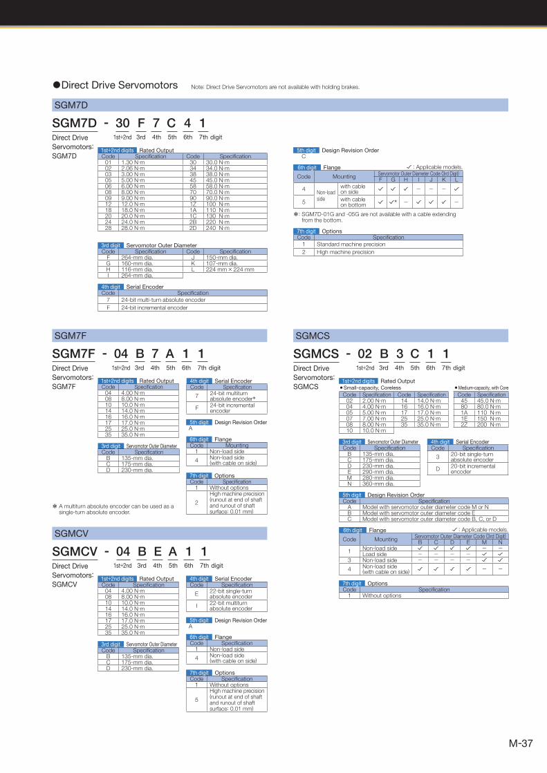
SGM7D
SGM7F
SGM7F - 04 B 7 A 1 1Direct Drive
Servomotors:
SGM7F1st+2nd digits Rated OutputCode Specifi cation
04 4.00 N· m08 8.00 N ·m10 10.0 N ·m14 14.0 N ·m16 16.0 N ·m17 17.0 N ·m25 25.0 N ·m35 35.0 N ·m
6th digit FlangeCode Mounting
1 Non-load side
4 Non-load side(with cable on side)
7th digit OptionsCode Specifi cation
1 Without options
2
High machine precision (runout at end of shaft and runout of shaft surface: 0.01 mm)
3rd digit Servomotor Outer DiameterCode Specifi cation
B 135-mm dia.C 175-mm dia.D 230-mm dia.
4th digit Serial EncoderCode Specifi cation
7 24-bit multiturn absolute encoder*
F24-bit incremental encoder
1 Direct Drive Servomotors
SGM7D - 30 F 7 C 4 1Direct Drive
Servomotors:
SGM7D
1st+2nd 3rd 4th 5th 6th 7th digit
Code Specifi cation Code Specifi cationF 264-mm dia. J 150-mm dia.G 160-mm dia. K 107-mm dia.H 116-mm dia. L 224 mm × 224 mmI 264-mm dia.
Code Specifi cation
7 24-bit multi-turn absolute encoder
F 24-bit incremental encoder
3rd digit Servomotor Outer Diameter
4th digit Serial Encoder
C5th digit Design Revision Order
Note: Direct Drive Servomotors are not available with holding brakes.
* A multiturn absolute encoder can be used as a single-turn absolute encoder.
Code Specifi cation
1 Standard machine precision
2 High machine precision
7th digit Options
1st+2nd digits Rated OutputCode Specifi cation Code Specifi cation
01 1.30 N· m 30 30.0 N ·m02 2.06 N· m 34 34.0 N· m03 3.00 N· m 38 38.0 N· m05 5.00 N ·m 45 45.0 N· m06 6.00 N ·m 58 58.0 N· m08 8.00 N ·m 70 70.0 N· m09 9.00 N· m 90 90.0 N· m12 12.0 N· m 1Z 100 N ·m18 18.0 N· m 1A 110 N· m20 20.0 N· m 1C 130 N· m24 24.0 N· m 2B 220 N ·m28 28.0 N ·m 2D 240 N ·m
Code MountingServomotor Outer Diameter Code (3rd Digit)F G H I J K L
4Non-load side
with cable on side
- - -
5 with cable on bottom * - -
6th digit Flange
*: SGM7D-01G and -05G are not available with a cable extending from the bottom.
: Applicable models.
SGMCV
SGMCV - 04 B E A 1 1Direct Drive
Servomotors:
SGMCV Code Specifi cation04 4.00 N· m08 8.00 N ·m10 10.0 N ·m14 14.0 N ·m16 16.0 N ·m17 17.0 N ·m25 25.0 N ·m35 35.0 N ·m
5th digit Design Revision OrderA
Code Specifi cationB 135-mm dia.C 175-mm dia.D 230-mm dia.
3rd digit Servomotor Outer Diameter
Code Specifi cation
E22-bit single-turn absolute encoder
I22-bit multiturn absolute encoder
4th digit Serial Encoder
1st+2nd 3rd 4th 5th 6th 7th digit
Code Specifi cation1 Non-load side
4 Non-load side(with cable on side)
6th digit Flange
Code Specifi cation1 Without options
5
High machine precision (runout at end of shaft and runout of shaft surface: 0.01 mm)
7th digit Options
1st+2nd digits Rated Output
SGMCS
SGMCS - 02 B 3 C 1 1Direct Drive
Servomotors:
SGMCS 3Small-capacity, Coreless 3Medium-capacity, with Core
Code Specifi cation Code Specifi cation Code Specifi cation02 2.00 N· m 14 14.0 N ·m 45 45.0 N · m04 4.00 N ·m 16 16.0 N ·m 80 80.0 N· m05 5.00 N ·m 17 17.0 N ·m 1A 110 N· m07 7.00 N ·m 25 25.0 N ·m 1E 150 N · m08 8.00 N ·m 35 35.0 N ·m 2Z 200 N · m10 10.0 N ·m
Code Specifi cationB 135-mm dia.C 175-mm dia.D 230-mm dia.E 290-mm dia.M 280-mm dia.N 360-mm dia.
Code Specifi cationA Model with servomotor outer diameter code M or NB Model with servomotor outer diameter code EC Model with servomotor outer diameter code B, C, or D
Code Specifi cation
3 20-bit single-turnabsolute encoder
D20-bit incremental encoder
Code MountingServomotor Outer Diameter Code (3rd Digit)
B C D E M N
1Non-load side - -Load side - - - -
3 Non-load side - - - -
4 Non-load side(with cable on side) - -
: Applicable models.
3rd digit Servomotor Outer Diameter 4th digit Serial Encoder
5th digit Design Revision Order
Code Specifi cation1 Without options
7th digit Options
1st+2nd 3rd 4th 5th 6th 7th digit
1st+2nd digits Rated Output
6th digit Flange
1st+2nd 3rd 4th 5th 6th 7th digit
5th digit Design Revision OrderA

38
Model Designations
3Moving Coil 3Magnetic Way
S G L G M - 30 108 A Linear
Series
Linear
Servomotors
Code Specifi cation090 90 mm108 108 mm216 216 mm225 225 mm252 252 mm360 360 mm405 405 mm432 432 mm450 450 mm504 504 mm
1 Linear Servomotors
SGLG (Coreless Models)
S G L G W - 30 A 050 C P Linear
Series
Linear
Servomotors
CodeSpecifi cations
Applicable ModelsPolarity Sensor Cooling Method
None None Self-cooled All modelsC None Air-cooled
SGLGW-40A, -60A, -90AH Yes Air-cooledP Yes Self-cooled All models
Code Specifi cation Applicable ModelsNone Standard-force All models-M High-force SGLGM-40, -60
Note: This information is provided to explain model numbers. It is not meant to imply that models are available for all combinations of codes.
9th digit Design Revision OrderA, B · · ·
* The SGLGM-40 and SGLGM-60 also have a CT code.・C = Without mounting holes on the bottom・CT = With mounting holes on the bottom
3rd+4th2nd1st 5th 9th6th+7th+8th 10th digit11th 3rd+4th2nd1st 5th+6th+7th 8th digit9th
Code Specifi cationG Coreless model
1st digit Servomotor Type
Code Specifi cationW Moving Coil
2nd digit Moving Coil/Magnetic Way
Code Specifi cationA 200 VAC
5th digit Power Supply Voltage
Code Specifi cation30 30 mm40 40 mm60 60 mm90 86 mm
3rd+4th digits Magnet Height
Code Specifi cationG Coreless model
1st digit Servomotor Type
Code Specifi cationM Magnetic Way
2nd digit Moving Coil/Magnetic Way
Code Specifi cation30 30 mm40 40 mm60 60 mm90 86 mm
3rd+4th digits Magnet Height
Code Specifi cation050 50 mm080 80 mm140 140 mm200 199 mm253 252.5 mm365 365 mm370 367 mm535 535 mm
6th+7th+8th digits Length of Moving Coil
8th digit Design Revision OrderA, B , C *· · ·
5th+6th+7th digits Length of Magnetic Way
10th digit Sensor Specifi cation and Cooling Method
9th digit Options
Code Specifi cation Applicable Models
NoneConnector from TycoElectronics Japan G.K.
All models
DConnector fromInterconnectron GmbH
SGLGW-30A, -40A, -60A
11th digit Connector for Servomotor Main Circuit Cable
3rd+4th2nd1st 5th 9th6th+7th+8th 10th digit11th
Code Specifi cationF With F-type iron core
1st digit Servomotor Type
Code Specifi cationM Magnetic Way
2nd digit Moving Coil/Magnetic Way
Code Specifi cation30 30 mm45 45 mm90 90 mm1D 135 mm
3rd+4th digits Magnet Height
8th digit Design Revision OrderA
Code Specifi cation270 270 mm306 306 mm450 450 mm510 510 mm630 630 mm714 714 mm
Code Specifi cationF With F-type iron core
1st digit Servomotor Type
Code Specifi cationW Moving Coil
2nd digit Moving Coil/Magnetic Way
Code Specifi cationA 200 VAC
5th digit Power Supply Voltage
Code Specifi cation30 30 mm45 45 mm90 90 mm1D 135 mm
3rd+4th digits Magnet Height
9th digit Design Revision OrderA
Code Specifi cation070 70 mm120 125 mm200 205 mm230 230 mm380 384 mm560 563 mm
10th digit Sensor Specifi cationCode Specifi cation
S With polarity sensor and thermal protectorT Without polarity sensor, with thermal protector
3rd+4th2nd1st 5th+6th+7th digit8th
6th+7th+8thdigits
Length of Moving Coil
5th+6th+7thdigits
Length of Magnetic Way
11th digit Cooling MethodCode Specifi cationNone Self-cooled
L Water-cooled*
SGLFW2 (Models with F-type Iron Cores)
3Magnetic Way3Moving Coil
S G L F W2 - 30 A 070 A T S G L F M2 - 30 270 ALinear
Series
Linear
Servomotors
Linear
Series
Linear
Servomotors
* Contact your Yaskawa representative for information on water-cooled models.
Note: This information is provided to explain model numbers. It is not meant to imply that models are available for all combinations of codes.

39
3Moving Coil 3Magnetic Way
S G L T M - 20 324 A Linear
Series
Linear
Servomotors
3rd+4th2nd1st 5th 9th6th+7th+8th 10th digit11th 3rd+4th2nd1st 5th+6th+7th 8th digit9th
Code Specifi cationA 200 VAC
5th digit Power Supply VoltageCode Specifi cation
T With T-type iron core
1st digit Servomotor Type
Code Specifi cationW Moving Coil
2nd digit Moving Coil/Magnetic Way
Code Specifi cation20 20 mm35 36 mm40 40 mm50 51 mm80 76.5 mm
3rd+4th digits Magnet Height
6th+7th+8thdigits
Length of Moving Coil
5th+6th+7thdigits
Length of Magnetic WayCode Specifi cation
T With T-type iron core
1st digit Servomotor Type
Code Specifi cationM Magnetic Way
2nd digit Moving Coil/Magnetic Way
Code Specifi cation20 20 mm35 36 mm40 40 mm50 51 mm80 76.5 mm
3rd+4th digits Magnet Height
9th digit Design Revision OrderA, B · · · H: High-effi ciency model
Code Specifi cation170 170 mm320 315 mm400 394.2 mm460 460 mm600 574.2 mm
CodeSpecifi cations
Applicable ModelsPolarity Sensor Cooling Method
None None Self-cooled All modelsC* None Water-cooled
SGLTW-40, -80H* Yes Water-cooledP Yes Self-cooled All models
10th digit Sensor Specifi cation and Cooling Method
8th digit Design Revision OrderA, B · · · H: High-effi ciency model
Code Specifi cation324 324 mm405 405 mm540 540 mm675 675 mm756 756 mm945 945 mm
11th digit Connector for Servomotor Main Circuit Cable
SGLFW (Models with F-type Iron Cores)
3Magnetic Way3Moving Coil
S G L F W - 20 A 090 A P S G L F M - 20 324 A Linear
Series
Linear
Servomotors
Linear
Series
Linear
Servomotors
3rd+4th2nd1st 5th 9th6th+7th+8th 10th digit11th
9th digit Design Revision OrderA, B · · ·
8th digit Design Revision OrderA, B · · ·
Code Specifi cationF With F-type iron core
1st digit Servomotor TypeCode Specifi cation
F With F-type iron core
1st digit Servomotor Type
Code Specifi cationW Moving Coil
2nd digit Moving Coil/Magnetic WayCode Specifi cation
M Magnetic Way
2nd digit Moving Coil/Magnetic Way
Code Specifi cationA 200 VAC
5th digit Voltage
Code Specifi cation20 20 mm35 36 mm50 47.5 mm1Z 95 mm
3rd+4th digits Magnet HeightCode Specifi cation
20 20 mm35 36 mm50 47.5 mm1Z 95 mm
3rd+4th digits Magnet Height
10th digit Sensor Specifi cation
Code Specifi cation Applicable Models
NoneConnector from TycoElectronics Japan G.K.
All models
DConnector fromInterconnectron GmbH
SGLFW-35, -50, -1Z 200B
11th digit Connector for Servomotor Main Circuit Cable
Code Specifi cationP With polarity sensor
None Without polarity sensor
9th digit OptionsCode Specifi cationNone Without options
C With magnet cover
3rd+4th2nd1st 5th+6th+7th 8th digit9th
5th+6th+7thdigits
Length of Magnetic Way
Code Specifi cation324 324 mm405 405 mm540 540 mm675 675 mm756 756 mm945 945 mm
6th+7th+8thdigits
Length of Moving Coil
Code Specifi cation090 91 mm120 127 mm200 215 mm230 235 mm380 395 mm
Note: This information is provided to explain model numbers. It is not meant to imply that models are available for all combinations of codes.
Code Specifi cation Applicable Models
None
Connector from TycoElectronics Japan G.K.
SGLTW -20A ,-35A
MS connectorSGLTW -40A B ,
-80A BLoose lead wires withno connector
SGLTW -35A H ,-50A H
SGLT (Models with T-type Iron Cores)
S G L T W - 20 A 170 A P Linear
Series
Linear
Servomotors
9th digit OptionsCode Specifi cation Applicable ModelsNone Without options −
C With magnet cover All modelsY With base and magnet cover SGLTM-20, -35*, -40, -80
* Contact your Yaskawa representative for the characteristics, dimensions, and other details on Servomotors with these specifi cations.
Note: This information is provided to explain model numbers. It is not meant to imply that models are available for all combinations of codes.
* The SGLTM-35 H (high-effi ciency models) do not support this specifi cation.
1 Linear Servomotors
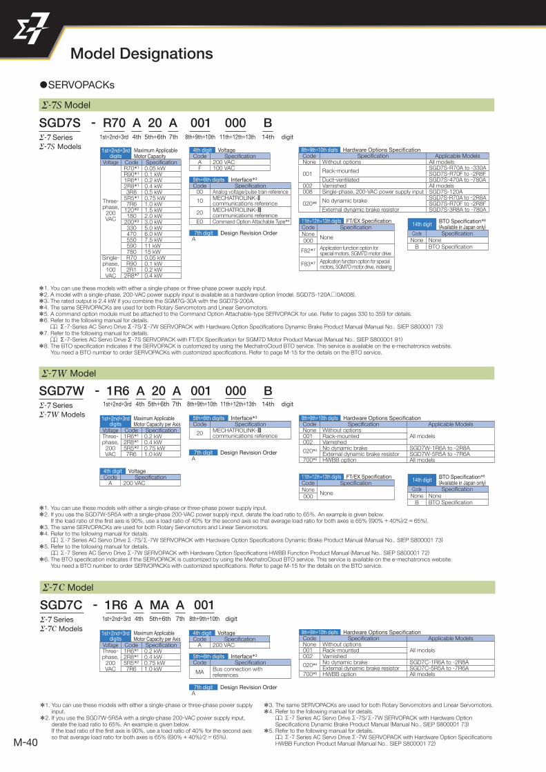
40
C Model
SGD7C - 1R6 A MA A 001Series
C Models
*1. You can use these models with either a single-phase or three-phase power supply input.
*2. If you use the SGD7W-5R5A with a single-phase 200-VAC power supply input, derate the load ratio to 65%. An example is given below.If the load ratio of the fi rst axis is 90%, use a load ratio of 40% for the second axis so that average load ratio for both axes is 65% ((90% + 40%)/2 = 65%).
*3. The same SERVOPACKs are used for both Rotary Servomotors and Linear Servomotors.
*4. Refer to the following manual for details. Σ-7 Series AC Servo Drive Σ-7S/Σ-7W SERVOPACK with Hardware Option
Specifi cations Dynamic Brake Product Manual (Manual No.. SIEP S800001 73)
*5. Refer to the following manual for details. Σ-7 Series AC Servo Drive Σ-7W SERVOPACK with Hardware Option Specifi cations
HWBB Function Product Manual (Manual No.. SIEP S800001 72)
1 SERVOPACKs
Model
Model
SGD7S - R70 A 20 A 001 000 B
SGD7W - 1R6 A 20 A 001 000 B
Series
Models
Series
Models
digit
digit
14th
14th
11th+12th+13th
11th+12th+13th
*1. You can use these models with either a single-phase or three-phase power supply input.
*2. A model with a single-phase, 200-VAC power supply input is available as a hardware option (model. SGD7S-120A□0A008).
*3. The rated output is 2.4 kW if you combine the SGM7G-30A with the SGD7S-200A.
*4. The same SERVOPACKs are used for both Rotary Servomotors and Linear Servomotors.
*5. A command option module must be attached to the Command Option Attachable-type SERVOPACK for use. Refer to pages 330 to 359 for details.
*6. Refer to the following manual for details. Σ-7-Series AC Servo Drive Σ-7S/Σ-7W SERVOPACK with Hardware Option Specifi cations Dynamic Brake Product Manual (Manual No.. SIEP S800001 73)
*7. Refer to the following manual for details. Σ-7-Series AC Servo Drive Σ-7S SERVOPACK with FT/EX Specifi cation for SGM7D Motor Product Manual (Manual No.. SIEP S800001 91)
*8. The BTO specifi cation indicates if the SERVOPACK is customized by using the MechatroCloud BTO service. This service is available on the e-mechatronics website. You need a BTO number to order SERVOPACKs with customized specifi cations. Refer to page M-15 for the details on the BTO service.
*1. You can use these models with either a single-phase or three-phase power supply input.
*2. If you use the SGD7W-5R5A with a single-phase 200-VAC power supply input, derate the load ratio to 65%. An example is given below. If the load ratio of the fi rst axis is 90%, use a load ratio of 40% for the second axis so that average load ratio for both axes is 65% ((90% + 40%)/2 = 65%).
*3. The same SERVOPACKs are used for both Rotary Servomotors and Linear Servomotors.
*4. Refer to the following manual for details. Σ-7 Series AC Servo Drive Σ-7S/Σ-7W SERVOPACK with Hardware Option Specifi cations Dynamic Brake Product Manual (Manual No.. SIEP S800001 73)
*5. Refer to the following manual for details. Σ-7 Series AC Servo Drive Σ-7W SERVOPACK with Hardware Option Specifi cations HWBB Function Product Manual (Manual No.. SIEP S800001 72)
*6. The BTO specifi cation indicates if the SERVOPACK is customized by using the MechatroCloud BTO service. This service is available on the e-mechatronics website. You need a BTO number to order SERVOPACKs with customized specifi cations. Refer to page M-15 for the details on the BTO service.
11th+12th+13th digits FT/EX Specifi cationCode Specifi cationNone
None000
F82*7 Application function option for special motors, SGM7D motor drive
F83*7 Application function option for special motors, SGM7D motor drive, indexing
11th+12th+13th digits FT/EX Specifi cationCode Specifi cationNone
None000
14th digitBTO Specifi cation*8
(Available in Japan only)
Code Specifi cationNone None
B BTO Specifi cation
14th digitBTO Specifi cation*6
(Available in Japan only)
Code Specifi cationNone None
B BTO Specifi cation
1st+2nd+3rd 4th 7th 8th+9th+10th5th+6th
1st+2nd+3rd 4th 7th 8th+9th+10th5th+6th
1st+2nd+3rddigits
Maximum ApplicableMotor Capacity
Voltage Code Specifi cation
Three-phase,
200 VAC
R70*1 0.05 kWR90*1 0.1 kW1R6*1 0.2 kW2R8*1 0.4 kW3R8 0.5 kW
5R5*1 0.75 kW7R6 1.0 kW
120*2 1.5 kW180 2.0 kW
200*3 3.0 kW330 5.0 kW470 6.0 kW550 7.5 kW590 11 kW780 15 kW
Single-phase,
100 VAC
R70 0.05 kWR90 0.1 kW2R1 0.2 kW
2R8*7 0.4 kW
Code Specifi cationA 200 VACF 100 VAC
4th digit Voltage
5th+6th digits Interface*3
Code Specifi cation00 Analog voltage/pulse train reference
10 MECHATROLINK-2 communications reference
20 MECHATROLINK-3 communications reference
E0 Command Option Attachable Type*4
7th digit Design Revision OrderA
8th+9th+10th digits Hardware Options Specifi cationCode Specifi cation Applicable ModelsNone Without options All models
001Rack-mounted
SGD7S-R70A to -330ASGD7S-R70F to -2R8F
Duct-ventilated SGD7S-470A to -780A002 Varnished All models008 Single-phase, 200-VAC power supply input SGD7S-120A
020*6 No dynamic brakeSGD7S-R70A to -2R8ASGD7S-R70F to -2R8F
External dynamic brake resistor SGD7S-3R8A to -780A
Voltage Code Specifi cationThree-phase,
200 VAC
1R6*1 0.2 kW2R8*1 0.4 kW5R5*2 0.75 kW7R6 1.0 kW
1st+2nd+3rddigits
Maximum ApplicableMotor Capacity per Axis
Code Specifi cationA 200 VAC
4th digit Voltage
5th+6th digits Interface*3
Code Specifi cation
20 MECHATROLINK-3 communications reference
7th digit Design Revision OrderA
8th+9th+10th digits Hardware Options Specifi cationCode Specifi cation Applicable ModelsNone Without options
All models001 Rack-mounted002 Varnished
020*4 No dynamic brake SGD7W-1R6A to -2R8AExternal dynamic brake resistor SGD7W-5R5A to -7R6A
700*5 HWBB option All models
Model Designations
digit1st+2nd+3rd 4th 7th 8th+9th+10th5th+6th
8th+9th+10th digits Hardware Options Specifi cationCode Specifi cation Applicable ModelsNone Without options
All models001 Rack-mounted002 Varnished
020*4 No dynamic brake SGD7C-1R6A to -2R8AExternal dynamic brake resistor SGD7C-5R5A to -7R6A
700*5 HWBB option All models
Voltage Code Specifi cationThree-phase,
200 VAC
1R6*1 0.2 kW2R8*1 0.4 kW5R5*2 0.75 kW7R6 1.0 kW
1st+2nd+3rddigits
Maximum ApplicableMotor Capacity per Axis Code Specifi cation
A 200 VAC
4th digit Voltage
5th+6th digits Interface*3
Code Specifi cation
MABus connection with references
7th digit Design Revision OrderA
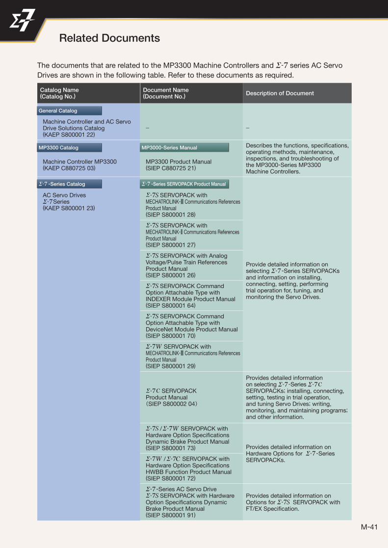
41
The documents that are related to the MP3300 Machine Controllers and series AC Servo
Drives are shown in the following table. Refer to these documents as required.
Catalog Name(Catalog No.)
Document Name(Document No.)
Description of Document
Machine Controller and AC Servo Drive Solutions Catalog(KAEP S800001 22)
− −
Describes the functions, specifi cations,operating methods, maintenance,inspections, and troubleshooting ofthe MP3000-Series MP3300Machine Controllers.
Machine Controller MP3300(KAEP C880725 03)
MP3300 Product Manual(SIEP C880725 21)
AC Servo DrivesSeries
(KAEP S800001 23)
SERVOPACK withMECHATROLINK-3 Communications References Product Manual(SIEP S800001 28)
Provide detailed information onselecting -Series SERVOPACKsand information on installing,connecting, setting, performingtrial operation for, tuning, and monitoring the Servo Drives.
SERVOPACK withMECHATROLINK-2 Communications ReferencesProduct Manual(SIEP S800001 27)
SERVOPACK with AnalogVoltage/Pulse Train ReferencesProduct Manual(SIEP S800001 26)
SERVOPACK Command Option Attachable Type with INDEXER Module Product Manual(SIEP S800001 64)
SERVOPACK Command Option Attachable Type with DeviceNet Module Product Manual(SIEP S800001 70)
SERVOPACK withMECHATROLINK-3 Communications ReferencesProduct Manual(SIEP S800001 29)
C SERVOPACKProduct Manual(SIEP S800002 04)
Provides detailed information on selecting -Series C SERVOPACKs; installing, connecting, setting, testing in trial operation, and tuning Servo Drives; writing, monitoring, and maintaining programs; and other information.
/ SERVOPACK with Hardware Option Specifi cations Dynamic Brake Product Manual (SIEP S800001 73) Provides detailed information on
Hardware Options for -Series SERVOPACKs. / SERVOPACK with
Hardware Option Specifi cations HWBB Function Product Manual (SIEP S800001 72)
-Series AC Servo Drive SERVOPACK with Hardware
Option Specifi cations Dynamic Brake Product Manual(SIEP S800001 91)
Provides detailed information on Options for SERVOPACK with FT/EX Specifi cation.
General Catalog
MP3300 Catalog
-Series Catalog -Series SERVOPACK Product Manual
MP3000-Series Manual
Related Documents
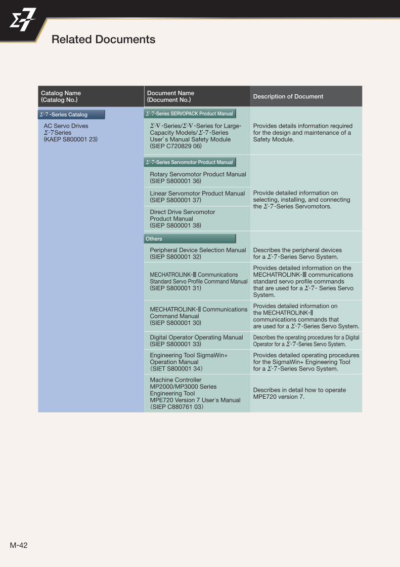
Catalog Name(Catalog No.)
Document Name(Document No.)
Description of Document
AC Servo DrivesSeries
(KAEP S800001 23)
-Series/ -Series for Large-Capacity Models/ -SeriesUser’s Manual Safety Module(SIEP C720829 06)
Provides details information required for the design and maintenance of a Safety Module.
Rotary Servomotor Product Manual(SIEP S800001 36)
Provide detailed information onselecting, installing, and connectingthe -Series Servomotors.
Linear Servomotor Product Manual(SIEP S800001 37)
Direct Drive ServomotorProduct Manual(SIEP S800001 38)
Peripheral Device Selection Manual(SIEP S800001 32)
Describes the peripheral devicesfor a -Series Servo System.
MECHATROLINK-3 CommunicationsStandard Servo Profi le Command Manual(SIEP S800001 31)
Provides detailed information on the MECHATROLINK-3 communications standard servo profi le commands that are used for a - Series Servo System.
MECHATROLINK-2 CommunicationsCommand Manual(SIEP S800001 30)
Provides detailed information onthe MECHATROLINK-2communications commands thatare used for a -Series Servo System.
Digital Operator Operating Manual(SIEP S800001 33)
Describes the operating procedures for a Digital Operator for a -Series Servo System.
Engineering Tool SigmaWin+ Operation Manual(SIET S800001 34)
Provides detailed operating proceduresfor the SigmaWin+ Engineering Toolfor a -Series Servo System.
Machine ControllerMP2000/MP3000 SeriesEngineering ToolMPE720 Version 7 User’s Manual(SIEP C880761 03)
Describes in detail how to operateMPE720 version 7.
-Series Catalog
Others
Related Documents
-Series Servomotor Product Manual
-Series SERVOPACK Product Manual
42
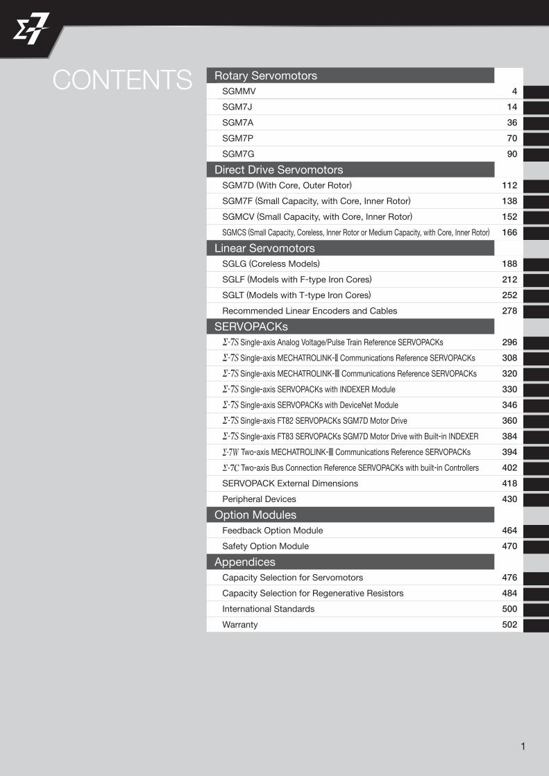
1
CONTENTS Rotary Servomotors
SGMMV 4
SGM7J 14
SGM7A 36
SGM7P 70
SGM7G 90
Direct Drive Servomotors
SGM7D (With Core, Outer Rotor) 112
SGM7F (Small Capacity, with Core, Inner Rotor) 138
SGMCV (Small Capacity, with Core, Inner Rotor) 152
SGMCS (Small Capacity, Coreless, Inner Rotor or Medium Capacity, with Core, Inner Rotor) 166
Linear Servomotors
SGLG (Coreless Models) 188
SGLF (Models with F-type Iron Cores) 212
SGLT (Models with T-type Iron Cores) 252
Recommended Linear Encoders and Cables 278
SERVOPACKs
Single-axis Analog Voltage/Pulse Train Reference SERVOPACKs 296
Single-axis MECHATROLINK-2 Communications Reference SERVOPACKs 308
Single-axis MECHATROLINK-3 Communications Reference SERVOPACKs 320
Single-axis SERVOPACKs with INDEXER Module 330
Single-axis SERVOPACKs with DeviceNet Module 346
Single-axis FT82 SERVOPACKs SGM7D Motor Drive 360
Single-axis FT83 SERVOPACKs SGM7D Motor Drive with Built-in INDEXER 384
Two-axis MECHATROLINK-3 Communications Reference SERVOPACKs 394
Two-axis Bus Connection Reference SERVOPACKs with built-in Controllers 402
SERVOPACK External Dimensions 418
Peripheral Devices 430
Option Modules
Feedback Option Module 464
Safety Option Module 470
Appendices
Capacity Selection for Servomotors 476
Capacity Selection for Regenerative Resistors 484
International Standards 500
Warranty 502

2
SGMMV .................................................................. 4
SGM7J ................................................................. 14
SGM7A ................................................................. 36
SGM7P ................................................................. 70
SGM7G ................................................................. 90
Rotary Servomotors

Rotary Servomotors
4
SGMMV
Model Designations
1
2
2A
A
3rd digit Power Supply Voltage
4th digit Serial Encoder
5th digit Design Revision Order
Code
17-bit absolute
Specification
Code Specification
6th digit Shaft End
7th digit Options
Without options
With holding brake (24 VDC)
Straight
Code Specification
Straight with flat seats
Code SpecificationCode Specification
C
A 200 VAC
1st+2nd digits Rated Output
-V mini Series Servomotors: SGMMV
SGMMV - A1 A 2 A 2 11st+2nd
digits3rd digit
4th digit
5th digit
6th digit
7th digit
A1 10 W
A2 20 W
A3 30 W

Rotary Servomotors SGMMV
5
SG
MM
V
Specifications and Ratings
Specifications
*1. A vibration class of V15 indicates a vibration amplitude of 15 μm maximum on the Servomotor without a load at the rated motor speed.
*2. The given values are for when the Servomotor shaft is mounted horizontally and shock or vibration is applied in the directions shown in the following figures.The strength of the vibration that the Servomotor can withstand depends on the application. Always check the vibration acceleration rate that is applied to the Servomotor with the actual equipment.
*3. If you use a Servomotor together with a Σ-7W or Σ-7C SERVOPACK, the control gain may not increase as much as with a Σ-7S SERVOPACK and other performances may be lower than those achieved with a Σ-7S SERVOPACK.
Voltage 200 V
Model SGMMV- A1A A2A A3A
Time Rating Continuous
Thermal Class B
Insulation Resistance 500 VDC, 10 MΩ min.
Withstand Voltage 1,500 VAC for 1 minute
Excitation Permanent magnet
Mounting Flange-mounted
Drive Method Direct drive
Rotation Direction Counterclockwise (CCW) for forward reference when viewed from the load side
Vibration Class*1 V15
Environmen-tal Condi-tions
Surrounding Air Temperature 0°C to 40°C
Surrounding Air Humidity 20% to 80% relative humidity (with no condensation)
Installation Site
• Must be indoors and free of corrosive and explosive gases.• Must be well-ventilated and free of dust and moisture. • Must facilitate inspection and cleaning.• Must have an altitude of 1,000 m or less.• Must be free of strong magnetic fields.
Storage Environment Store the Servomotor in the following environment if you store it with the power cable disconnected.Storage Temperature: -20°C to 60°C (with no freezing) Storage Humidity: 20% to 80% relative humidity (with no condensation)
Shock Resistance*2
Impact Acceleration Rate at Flange 490 m/s2
Number of Impacts 2 times
Vibration Resistance*2
Vibration Acceleration Rate at Flange 49 m/s2
Applicable SERVOPACKs
SGD7S- R90A, R90F 1R6A, 2R1F
SGD7W-SGD7C- 1R6A*3, 2R8A*3 1R6A, 2R8A*3
Vertical
Shock Applied to the Servomotor Vibration Applied to the Servomotor
Vertical
Horizontal directionSide to side
Front to back
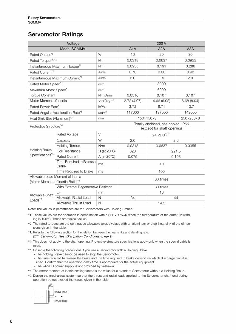
Rotary ServomotorsSGMMV
6
Servomotor Ratings
Note: The values in parentheses are for Servomotors with Holding Brakes.
*1. These values are for operation in combination with a SERVOPACK when the temperature of the armature wind-ing is 100°C. These are typical values.
*2. The rated torques are the continuous allowable torque values with an aluminum or steel heat sink of the dimen-sions given in the table.
*3. Refer to the following section for the relation between the heat sinks and derating rate.Servomotor Heat Dissipation Conditions (page 9)
*4. This does not apply to the shaft opening. Protective structure specifications apply only when the special cable is used.
*5. Observe the following precautions if you use a Servomotor with a Holding Brake.• The holding brake cannot be used to stop the Servomotor.• The time required to release the brake and the time required to brake depend on which discharge circuit is
used. Confirm that the operation delay time is appropriate for the actual equipment.• The 24-VDC power supply is not provided by Yaskawa.
*6. The motor moment of inertia scaling factor is the value for a standard Servomotor without a Holding Brake.
*7. Design the mechanical system so that the thrust and radial loads applied to the Servomotor shaft end during operation do not exceed the values given in the table.
Voltage 200 V
Model SGMMV- A1A A2A A3A
Rated Output*1 W 10 20 30
Rated Torque*1, *2 Nm 0.0318 0.0637 0.0955
Instantaneous Maximum Torque*1 Nm 0.0955 0.191 0.286
Rated Current*1 Arms 0.70 0.66 0.98
Instantaneous Maximum Current*1 Arms 2.0 1.9 2.9
Rated Motor Speed*1 min-1 3000
Maximum Motor Speed*1 min-1 6000
Torque Constant Nm/Arms 0.0516 0.107 0.107
Motor Moment of Inertia ×10-7 kgm2 2.72 (4.07) 4.66 (6.02) 6.68 (8.04)
Rated Power Rate*1 kW/s 3.72 8.71 13.7
Rated Angular Acceleration Rate*1 rad/s2 117000 137000 143000
Heat Sink Size (Aluminum)*3 mm 150×150×3 250×250×6
Protective Structure*4 Totally enclosed, self-cooled, IP55(except for shaft opening)
Holding Brake Specifications*5
Rated Voltage V 24 VDCCapacity W 2.0 2.6Holding Torque Nm 0.0318 0.0637 0.0955Coil Resistance Ω (at 20°C) 320 221.5Rated Current A (at 20°C) 0.075 0.108Time Required to Release Brake
ms 40
Time Required to Brake ms 100Allowable Load Moment of Inertia (Motor Moment of Inertia Ratio)*6 30 times
With External Regenerative Resistor 30 times
Allowable Shaft Loads*7
LF mm 16Allowable Radial Load N 34 44Allowable Thrust Load N 14.5
+10%
0
LF
Radial load
Thrust load

Rotary Servomotors SGMMV
7
SG
MM
V
Torque-Motor Speed Characteristics
* The characteristics are the same for three-phase 200 V, single-phase 200 V, and single-phase 100 V input.
Note: 1. These values (typical values) are for operation in combination with a SERVOPACK when the temperature of the armature winding is 100°C.
2. The characteristics in the intermittent duty zone depend on the power supply voltage.
3. If the effective torque is within the allowable range for the rated torque, the Servomotor can be used within the intermittent duty zone.
4. If you use a Servomotor Main Circuit Cable that exceeds 20 m, the intermittent duty zone in the torque-motor speed characteristics will become smaller because the voltage drop increases.
Servomotor Overload Protection CharacteristicsThe overload detection level is set for hot start conditions with a Servomotor surrounding air tem-perature of 40°C.
Note: The above overload protection characteristics do not mean that you can perform continuous duty operation with an output of 100% or higher. Use the Servomotor so that the effective torque remains within the contin-uous duty zone given in Torque-Motor Speed Characteristics (page 7).
SGMMV-A3A
A B
4000
3000
2000
1000
0
5000
6000
7000
0 0.1 0.2 0.3 0.4
SGMMV-A1A
A B
4000
3000
2000
1000
0
5000
6000
7000
0 0.04 0.08 0.12 0.16
SGMMV-A2A
A B
4000
3000
2000
1000
0
5000
6000
7000
0 0.08 0.16 0.24 0.32
Continuous duty zone
Intermittent duty zone*A :
B :
Mot
or s
peed
(min
-1)
Torque (N·m)M
otor
spe
ed (m
in-1)
Torque (N·m)
Mot
or s
peed
(min
-1)
Torque (N·m)
1000
100
10
1100 200 300
SGMMV-A1 ,-A2 ,-A3
Det
ectio
n tim
e (s
)
Torque reference (percent of rated torque) (%)

Rotary ServomotorsSGMMV
8
Allowable Load Moment of InertiaThe allowable load moments of inertia (motor moment of inertia ratios) for the Servomotors are given in the Servomotor Ratings (page 6). The values are determined by the regenerative energy process-ing capacity of the SERVOPACK and are also affected by the drive conditions of the Servomotor. Perform the required Steps for each of the following cases.
Use the SigmaJunmaSize+ AC Servo Drive Capacity Selection Program to check the driving condi-tions. Contact your Yaskawa representative for information on this program.
Exceeding the Allowable Load Moment of InertiaUse one of the following measures to adjust the load moment of inertia to within the allowable value.• Reduce the torque limit.• Reduce the deceleration rate.• Reduce the maximum motor speed.
If the above steps is not possible, install an external regenerative resistor.
SERVOPACKs without Built-in Regenerative ResistorsThe following graph shows the allowable load moment of inertia scaling factor of the motor speed (reference values for deceleration operation at or above the rated torque). Application is possible without an external regenerative resistor within the allowable value. However, an External Regenera-tive Resistor is required in the shaded areas of the graphs.
Note: Applicable SERVOPACK models: SGD7S-R90A, -1R6A, -R90F, and -2R1F
When an External Regenerative Resistor Is RequiredInstall the External Regenerative Resistor. Refer to the following section for the recommended products.
External Regenerative Resistors (page 456)
An Overvoltage Alarm (A.400) is likely to occur during deceleration if the load moment of iner-tia exceeds the allowable load moment of inertia. SERVOPACKs with a built-in regenerative resistor may generate a Regenerative Overload Alarm (A.320). Refer to Built-In Regenerative Resistor (page 456) for the regenerative power (W) that can be processed by the SERVO-PACKs. Install an External Regenerative Resistor when the built-in regenerative resistor cannot pro-cess all of the regenerative power.
Information
SGMMV-A1A, -A2A, -A3A
0 1000 2000 3000 4000 5000 6000 7000
35
30
25
20
15
10
5
0
Motor speed (min-1)
Allo
wab
le lo
ad m
omen
t of i
nerti
a sc
alin
g fa
ctor
(tim
es)
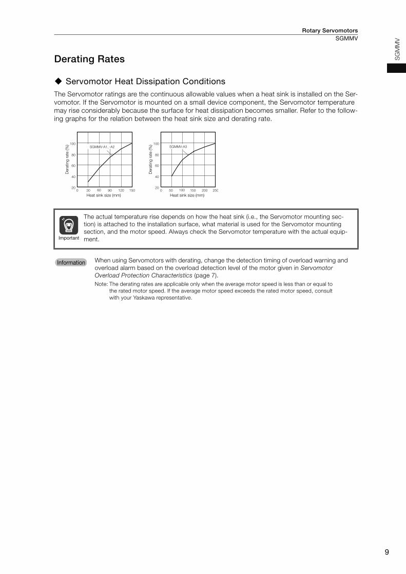
Rotary Servomotors SGMMV
9
SG
MM
V
Derating Rates
Servomotor Heat Dissipation ConditionsThe Servomotor ratings are the continuous allowable values when a heat sink is installed on the Ser-vomotor. If the Servomotor is mounted on a small device component, the Servomotor temperature may rise considerably because the surface for heat dissipation becomes smaller. Refer to the follow-ing graphs for the relation between the heat sink size and derating rate.
The actual temperature rise depends on how the heat sink (i.e., the Servomotor mounting sec-tion) is attached to the installation surface, what material is used for the Servomotor mounting section, and the motor speed. Always check the Servomotor temperature with the actual equip-ment.
When using Servomotors with derating, change the detection timing of overload warning and overload alarm based on the overload detection level of the motor given in Servomotor Overload Protection Characteristics (page 7).Note: The derating rates are applicable only when the average motor speed is less than or equal to
the rated motor speed. If the average motor speed exceeds the rated motor speed, consult with your Yaskawa representative.
90 15012060300 150 250200100500
100
80
60
40
20
100
80
60
40
20
SGMMV-A1, -A2 SGMMV-A3
Der
atin
g ra
te (%
)
Heat sink size (mm)
Der
atin
g ra
te (%
)
Heat sink size (mm)
Important
InformationInformation

Rotary ServomotorsSGMMV
10
External Dimensions
Servomotors without Holding Brakes
SGMMV-A1, -A2 and -A3
Model SGMMV-
L L1 L2Flange
Dimensions Approx.Mass [kg]
S LB
A1A2A1 70 54 27.5 5 20 0.13
A2A2A1 80 64 37.5 5 20 0.17
A3A2A1 90 74 47.5 5 20 0.21
Shaft End Specification Connector Specifications• Straight with Flat Seats • Encoder Connector
* A battery is required only for an absolute encoder.
Model: 55102-0600Manufacturer: Molex Japan LLCMating connector: 54280-0609
• Servomotor Connector
Receptacle: 43025-0400Manufacturer: Molex Japan LLC
28 Dia.
25
16
45°
2.5
16
26.5
12
L2
L
L1
2-M3 Tapped Holes, Depth 7
0.04 Dia. AA
0.02
0.04 A
4
LB D
ia.
S D
ia.
300 ±30
Encoder Cable, 4 Dia.UL20276
Protective Tube 5 Dia., Black
Motor Lead AWG24,UL10095 or UL3266
±30300
Servomotor connector
Encoder connector
0-0.008
0-0.021
0
-0.008
0
-0.021
0-0.008
0-0.021
10
S D
ia.
LB D
ia.
0.5 4.5
A
0.02
4
2
6
3
1
51 PG5V Red2 PG0V Black3* BAT Orange4* BAT0 Orange/white5 PS Light blue6 /PS Light blue/white
Connector case
FG (frame ground) Shield
3 4
1 2
1 Phase U2 Phase V3 Phase W4 FG (frame ground)

Rotary Servomotors SGMMV
11
SG
MM
V
Servomotors with Holding Brakes
SGMMV-A1, -A2 and -A3
Model SGMMV-
L L1 L2Flange
Dimensions Approx.Mass [kg]
S LB
A1A2AC 94.5 78.5 27.5 5 20 0.215
A2A2AC 108.5 92.5 37.5 5 20 0.27
A3A2AC 118.5 102.5 47.5 5 20 0.31
Shaft End Specification Connector Specifications• Straight with Flat Seats • Encoder Connector
* A battery is required only for an absolute encoder.
Model: 55102-0600Manufacturer: Molex Japan LLCMating connector: 54280-0609
• Servomotor Connector
Receptacle: 43025-0600Manufacturer: Molex Japan LLC
300 ±30
±30300
28 Dia.
25
16
4
45°
2.5
1612
26.5
L1
L
L2
2-M3 Tapped Holes, Depth 7
A
0.02
0.04 A
0.04 Dia. A
Encoder Cable, 4 Dia.UL20276
Protective Tube 5 Dia., Black
Motor Lead AWG24,UL10095 or UL3266
LB D
ia.
S D
ia.
Servomotor connector
Encoder connector
0-0.008
0-0.021
0-0.008
0-0.021
0-0.008
0-0.021
10
S D
ia.
LB D
ia.
0.5 4.5
A
0.02
4
2
6
3
1
51 PG5V Red2 PG0V Black3* BAT Orange4* BAT0 Orange/white5 PS Light blue6 /PS Light blue/white
Connector case
FG (frame ground) Shield
4 5
1 2
6
3
1 Phase U2 Phase V3 Phase W4 FG (frame ground)5 Brake6 Brake
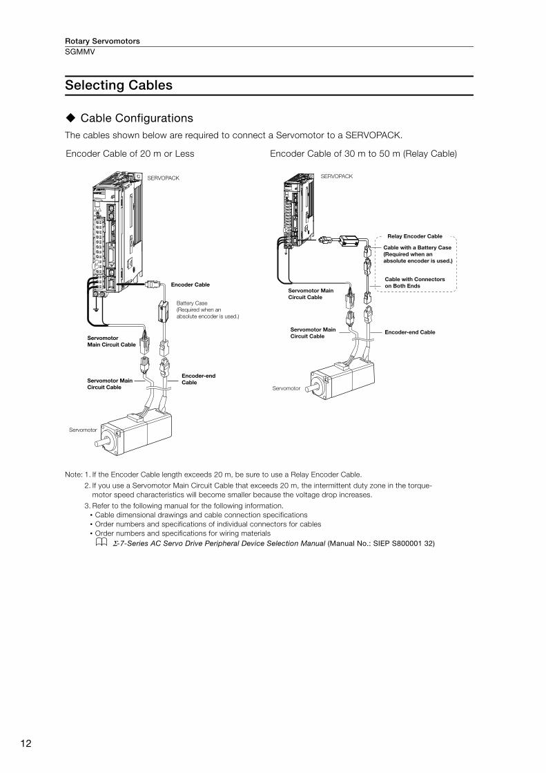
Rotary ServomotorsSGMMV
12
Selecting Cables
Cable ConfigurationsThe cables shown below are required to connect a Servomotor to a SERVOPACK.
Note: 1. If the Encoder Cable length exceeds 20 m, be sure to use a Relay Encoder Cable.
2. If you use a Servomotor Main Circuit Cable that exceeds 20 m, the intermittent duty zone in the torque-motor speed characteristics will become smaller because the voltage drop increases.
3. Refer to the following manual for the following information.• Cable dimensional drawings and cable connection specifications• Order numbers and specifications of individual connectors for cables• Order numbers and specifications for wiring materials
Σ-7-Series AC Servo Drive Peripheral Device Selection Manual (Manual No.: SIEP S800001 32)
Encoder Cable of 20 m or Less Encoder Cable of 30 m to 50 m (Relay Cable)
SERVOPACK
Encoder Cable
Battery Case (Required when an absolute encoder is used.)
Servomotor Main Circuit Cable
Servomotor
Servomotor Main Circuit Cable
Encoder-endCable
SERVOPACK
Cable with a Battery Case (Required when an absolute encoder is used.)
Cable with Connectors on Both Ends
Encoder-end CableServomotor Main Circuit Cable
Servomotor Main Circuit Cable
Servomotor
Relay Encoder Cable

Rotary Servomotors SGMMV
13
SG
MM
V
Servomotor Main Circuit Cables
Encoder Cables of 20 m or Less
Relay Encoder Cables of 30 m to 50 m
* This Cable is not required if a battery is connected to the host controller.
Name Length (L)
Order NumberAppearance
Standard Cable Flexible Cable*
For Servomotors with-out Holding Brakes
3 m JZSP-CF2M00-03-E JZSP-CF2M20-03-E
5 m JZSP-CF2M00-05-E JZSP-CF2M20-05-E
10 m JZSP-CF2M00-10-E JZSP-CF2M20-10-E
15 m JZSP-CF2M00-15-E JZSP-CF2M20-15-E
20 m JZSP-CF2M00-20-E JZSP-CF2M20-20-E
30 m JZSP-CF2M00-30-E JZSP-CF2M20-30-E
40 m JZSP-CF2M00-40-E JZSP-CF2M20-40-E
50 m JZSP-CF2M00-50-E JZSP-CF2M20-50-E
For Servomotors with Holding Brakes
3 m JZSP-CF2M03-03-E JZSP-CF2M23-03-E
5 m JZSP-CF2M03-05-E JZSP-CF2M23-05-E
10 m JZSP-CF2M03-10-E JZSP-CF2M23-10-E
15 m JZSP-CF2M03-15-E JZSP-CF2M23-15-E
20 m JZSP-CF2M03-20-E JZSP-CF2M23-20-E
30 m JZSP-CF2M03-30-E JZSP-CF2M23-30-E
40 m JZSP-CF2M03-40-E JZSP-CF2M23-40-E
50 m JZSP-CF2M03-50-E JZSP-CF2M23-50-E
* Use Flexible Cables for moving parts of machines, such as robots. The recommended bending radius (R) is 90 mm or larger.
NameLength
(L)Order Number
AppearanceStandard Cable Flexible Cable*
Cables with Connectors on Both Ends(for incremental encoder)
3 m JZSP-CMP00-03-E JZSP-CMP10-03-E
5 m JZSP-CMP00-05-E JZSP-CMP10-05-E
10 m JZSP-CMP00-10-E JZSP-CMP10-10-E
15 m JZSP-CMP00-15-E JZSP-CMP10-15-E
20 m JZSP-CMP00-20-E JZSP-CMP10-20-E
Cables with Connectors on Both Ends(for absolute encoder: With Battery Case)
3 m JZSP-CSP19-03-E JZSP-CSP29-03-E
5 m JZSP-CSP19-05-E JZSP-CSP29-05-E
10 m JZSP-CSP19-10-E JZSP-CSP29-10-E
15 m JZSP-CSP19-15-E JZSP-CSP29-15-E
20 m JZSP-CSP19-20-E JZSP-CSP29-20-E
* Use Flexible Cables for moving parts of machines, such as robots. The recommended bending radius (R) is 68 mm or larger.
NameLength
(L)Order Number Appearance
Cables with Connectors on Both Ends (for incremental or absolute encoder)
30 m JZSP-UCMP00-30-E
40 m JZSP-UCMP00-40-E
50 m JZSP-UCMP00-50-E
Cable with a Battery Case (Required when an absolute encoder is used.)*
0.3 m JZSP-CSP12-E
LSERVOPACK end Motor end
LSERVOPACK end Motor end
LSERVOPACK end Encoder end
LSERVOPACK end Encoder end
Battery Case(battery included)
SERVOPACK
end
Encoder end
L
mol
ex
SERVOPACK
end
Encoder end
Battery Case
(battery included)
L
mol
ex

Rotary Servomotors
14
SGM7J
Model Designations
Without Gears
With Gears
1
C
E
S
7
F
A
2
B
6
A 200 VACA5
01
C2
02 200 W
150 W
50 W
04 400 W
06 600 W
08 750 W
100 W
3rd digit
4th digit
6th digit
-7 Series
Servomotors:
SGM7J
Rated Output
Code Specification Code
Code
Specification
Specification
24-bit absolute
24-bit incremental
Code
Code Specification
Without options
With holding brake (24 VDC)
With oil seal and holding
brake (24 VDC)
With oil seal
Specification
Straight without key
Straight with key and tap
With two flat seats
Power Supply Voltage
Serial Encoder
5th digit Design Revision Order
Shaft End
7th digit Options
1st+2nd digits
SGM7J - 01 A 7 A 2 11st+2nd
digits3rd digit
4th digit
5th digit
6th digit
7th digit
A5
01
C2
02 200 W
150 W
50 W
04 400 W
06 600 W
08 750 W
0
2
6
1
CB 1/11*1
C 1/21
1 1/5
1/9*22
7
H
7
F
A 200 VAC
A
1/33
100 W
-7 Series
Servomotors:
SGM7J
Rated Output 5th digit Design Revision Order
6th digit Gear Type
7th digit Gear Ratio
3rd digit Power Supply Voltage
4th digit Serial Encoder
SpecificationCode
Specification
24-bit absolute
24-bit incremental
Code
Code Specification
*1. This specification is not supported for
models with a rated output of 50 W.
*2. This specification is supported only for
models with a rated output of 50 W.
9th digit Options
Without options
With holding brake (24 VDC)
Code Specification
Code Specification
Flange output
Straight without key
Straight with key and tapCode Specification
HDS planetary low-backlash gear
Code Specification
8th digit Shaft End1st+2nd digits
SGM7J - 01 A 7 A H 1 2 11st+2nd
digits3rd digit
4th digit
5th digit
6th digit
7th digit
8th digit
9th digit

Rotary Servomotors SGM7J
15
SG
M7
J
Specifications and Ratings
Specifications
*1. A vibration class of V15 indicates a vibration amplitude of 15 μm maximum on the Servomotor without a load at the rated motor speed.
*2. The given values are for when the Servomotor shaft is mounted horizontally and shock or vibration is applied in the directions shown in the following figures.The strength of the vibration that the Servomotor can withstand depends on the application. Always check the vibration acceleration rate that is applied to the Servomotor with the actual equipment.
*3. Refer to the following section for the derating rates.Derating Rates (page 22)
*4. If you use a Servomotor together with a Σ-7W or Σ-7C SERVOPACK, the control gain may not increase as much as with a Σ-7S SERVOPACK and other performances may be lower than those achieved with a Σ-7S SERVOPACK.
Voltage 200 VModel SGM7J- A5A 01A C2A 02A 04A 06A 08A
Time Rating Continuous Thermal Class UL: A, CE: BInsulation Resistance 500 VDC, 10 MΩ min. Withstand Voltage 1,500 VAC for 1 minute Excitation Permanent magnet Mounting Flange-mounted Drive Method Direct drive
Rotation Direction Counterclockwise (CCW) for forward reference when viewed from the load
side
Vibration Class*1 V15
Environmen-tal Condi-tions
Surrounding Air Temperature 0°C to 40°C (With derating, usage is possible between 40°C and 60°C.)*3
Surrounding Air Humidity 20% to 80% relative humidity (with no condensation)
Installation Site
• Must be indoors and free of corrosive and explosive gases.• Must be well-ventilated and free of dust and moisture.• Must facilitate inspection and cleaning.• Must have an altitude of 1,000 m or less. (With derating, usage
is possible between 1,000 m and 2,000 m.)*3
• Must be free of strong magnetic fields.
Storage Environment Store the Servomotor in the following environment if you store it with the power cable disconnected.Storage Temperature: -20°C to 60°C (with no freezing)Storage Humidity: 20% to 80% relative humidity (with no condensation)
Shock Resistance*2
Impact Acceleration Rate at Flange 490 m/s2
Number of Impacts 2 times Vibration Resistance*2
Vibration Acceleration Rate at Flange 49 m/s2
Applicable SERVO-PACKs
SGD7S-R70A, R70F
R90A, R90F
1R6A, 2R1F2R8A, 2R8F
5R5A
SGD7W-SGD7C- 1R6A*4, 2R8A*4 1R6A, 2R8A*4
2R8A,5R5A*4,7R6A*4
5R5A, 7R6A
Vertical
Shock Applied to the Servomotor Vibration Applied to the Servomotor
Vertical
Horizontal directionSide to side
Front to back
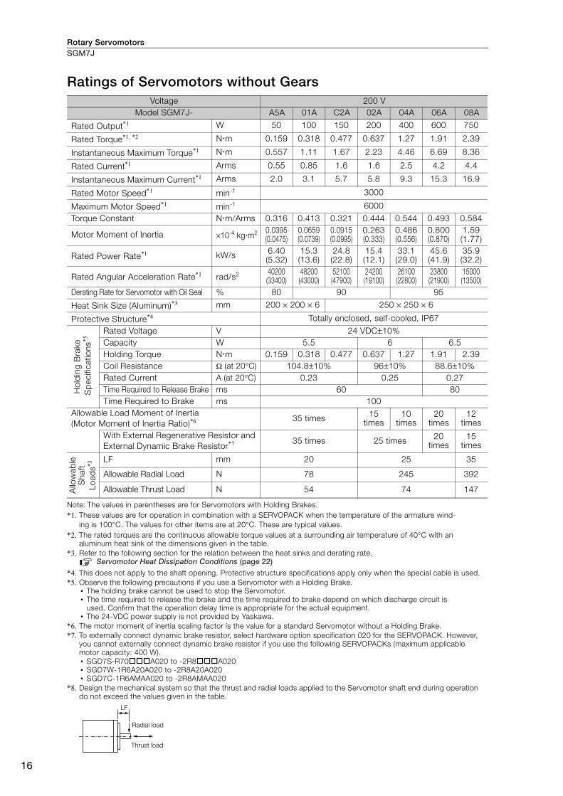
Rotary ServomotorsSGM7J
16
Ratings of Servomotors without Gears
Note: The values in parentheses are for Servomotors with Holding Brakes. *1. These values are for operation in combination with a SERVOPACK when the temperature of the armature wind-
ing is 100°C. The values for other items are at 20°C. These are typical values. *2. The rated torques are the continuous allowable torque values at a surrounding air temperature of 40°C with an
aluminum heat sink of the dimensions given in the table.*3. Refer to the following section for the relation between the heat sinks and derating rate.
Servomotor Heat Dissipation Conditions (page 22)
*4. This does not apply to the shaft opening. Protective structure specifications apply only when the special cable is used.*5. Observe the following precautions if you use a Servomotor with a Holding Brake.
• The holding brake cannot be used to stop the Servomotor. • The time required to release the brake and the time required to brake depend on which discharge circuit is
used. Confirm that the operation delay time is appropriate for the actual equipment. • The 24-VDC power supply is not provided by Yaskawa.
*6. The motor moment of inertia scaling factor is the value for a standard Servomotor without a Holding Brake.*7. To externally connect dynamic brake resistor, select hardware option specification 020 for the SERVOPACK. However,
you cannot externally connect dynamic brake resistor if you use the following SERVOPACKs (maximum applicable motor capacity: 400 W).• SGD7S-R70A020 to -2R8A020• SGD7W-1R6A20A020 to -2R8A20A020• SGD7C-1R6AMAA020 to -2R8AMAA020
*8. Design the mechanical system so that the thrust and radial loads applied to the Servomotor shaft end during operation do not exceed the values given in the table.
Voltage 200 VModel SGM7J- A5A 01A C2A 02A 04A 06A 08A
Rated Output*1 W 50 100 150 200 400 600 750
Rated Torque*1, *2 Nm 0.159 0.318 0.477 0.637 1.27 1.91 2.39
Instantaneous Maximum Torque*1 Nm 0.557 1.11 1.67 2.23 4.46 6.69 8.36
Rated Current*1 Arms 0.55 0.85 1.6 1.6 2.5 4.2 4.4
Instantaneous Maximum Current*1 Arms 2.0 3.1 5.7 5.8 9.3 15.3 16.9
Rated Motor Speed*1 min-1 3000
Maximum Motor Speed*1 min-1 6000Torque Constant Nm/Arms 0.316 0.413 0.321 0.444 0.544 0.493 0.584
Motor Moment of Inertia ×10-4 kgm2 0.0395(0.0475)
0.0659(0.0739)
0.0915(0.0995)
0.263(0.333)
0.486(0.556)
0.800(0.870)
1.59(1.77)
Rated Power Rate*1 kW/s 6.40(5.32)
15.3(13.6)
24.8(22.8)
15.4(12.1)
33.1(29.0)
45.6(41.9)
35.9(32.2)
Rated Angular Acceleration Rate*1 rad/s2 40200(33400)
48200(43000)
52100(47900)
24200(19100)
26100(22800)
23800(21900)
15000(13500)
Derating Rate for Servomotor with Oil Seal % 80 90 95
Heat Sink Size (Aluminum)*3 mm 200 × 200 × 6 250 × 250 × 6
Protective Structure*4 Totally enclosed, self-cooled, IP67
Hol
din
g B
rake
Sp
ecifi
catio
ns*5
Rated Voltage V 24 VDC±10%Capacity W 5.5 6 6.5Holding Torque Nm 0.159 0.318 0.477 0.637 1.27 1.91 2.39Coil Resistance Ω (at 20°C) 104.8±10% 96±10% 88.6±10%Rated Current A (at 20°C) 0.23 0.25 0.27Time Required to Release Brake ms 60 80Time Required to Brake ms 100
Allowable Load Moment of Inertia (Motor Moment of Inertia Ratio)*6
35 times 15 times
10 times
20 times
12 times
With External Regenerative Resistor and External Dynamic Brake Resistor*7 35 times 25 times 20
times15
times
Allo
wab
le
Sha
ft
Load
s*3
LF mm 20 25 35
Allowable Radial Load N 78 245 392
Allowable Thrust Load N 54 74 147
LF
Radial load
Thrust load

Rotary Servomotors SGM7J
17
SG
M7
J
Torque-Motor Speed Characteristics
*1. The characteristics are the same for single-phase 200 V and single-phase 100 V input.
*2. The characteristics are the same for three-phase 200 V and single-phase 200 V input.
Note: 1. These values (typical values) are for operation in combination with a SERVOPACK when the temperature of the armature winding is 100°C.
2. The characteristics in the intermittent duty zone depend on the power supply voltage.
3. If the effective torque is within the allowable range for the rated torque, the Servomotor can be used within the intermittent duty zone.
4. If you use a Servomotor Main Circuit Cable that exceeds 20 m, the intermittent duty zone in the torque-motor speed characteristics will become smaller because the voltage drop increases.
SGM7J-A5A*1
A B
0 0.15 0.3 0.45 0.6 0.750
1000
2000
3000
4000
5000
6000
7000SGM7J-01A
A B
0 0.25 0.5 0.75 1 1.250
1000
2000
3000
4000
5000
6000
7000SGM7J-C2A*2
A B
0 0.5 1 1.5 2 2.50
1000
2000
3000
4000
5000
6000
7000
SGM7J-04A
A B
0 1 2 3 4 50
1000
2000
3000
4000
5000
6000
7000SGM7J-06A
A B
0 2 4 6 8 100
1000
2000
3000
4000
5000
6000
7000
SGM7J-08A
A B
0 2 4 6 8 100
1000
2000
3000
4000
5000
6000
7000
SGM7J-02A
A B
0 0.5 1 1.5 2 2.50
1000
2000
3000
4000
5000
6000
7000
Continuous duty zone
Intermittent duty zone
(solid lines): With three-phase 200-V or single-phase 230-V input
(dotted lines): With single-phase 200-V input
(dashed-dotted lines): With single-phase 100-V input
A :
B :
Torque (N�m)
Mo
tor
sp
eed
(m
in-1)
Torque (N�m)M
oto
r sp
eed
(m
in-1)
Torque (N�m)
Mo
tor
sp
eed
(m
in-1)
Torque (N�m)
Mo
tor
sp
eed
(m
in-1)
Torque (N�m)
Mo
tor
sp
eed
(m
in-1)
Torque (N�m)
Mo
tor
sp
eed
(m
in-1)
Torque (N�m)
Mo
tor
sp
eed
(m
in-1)
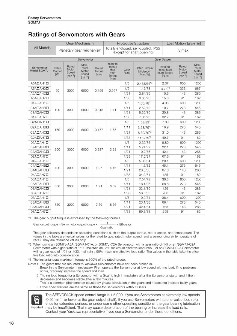
Rotary ServomotorsSGM7J
18
Ratings of Servomotors with Gears
*1. The gear output torque is expressed by the following formula.
The gear efficiency depends on operating conditions such as the output torque, motor speed, and temperature. The values in the table are typical values for the rated torque, rated motor speed, and a surrounding air temperature of 25°C. They are reference values only.
*2. When using an SGM7J-A5A, SGM7J-01A, or SGM7J-C2A Servomotor with a gear ratio of 1/5 or an SGM7J-C2A Servomotor with a gear ratio of 1/11, maintain an 85% maximum effective load ratio. For an SGM7J-C2A Servomotor with a gear ratio of 1/21 or 1/33, maintain a 90% maximum effective load ratio. The values in the table take the effec-tive load ratio into consideration.
*3. The instantaneous maximum torque is 300% of the rated torque.Note: 1. The gears that are mounted to Yaskawa Servomotors have not been broken in.
Break in the Servomotor if necessary. First, operate the Servomotor at low speed with no load. If no problems occur, gradually increase the speed and load.
2. The no-load torque for a Servomotor with a Gear is high immediately after the Servomotor starts, and it then decreases and becomes stable after a few minutes.This is a common phenomenon caused by grease circulation in the gears and it does not indicate faulty gears.
3. Other specifications are the same as those for Servomotors without Gears.
All Models Gear Mechanism Protective Structure Lost Motion [arc-min]
Planetary gear mechanism Totally enclosed, self-cooled, IP55 (except for shaft opening) 3 max.
Servomotor Model SGM7J-
Servomotor Gear Output
Rated Output
[W]
Rated Motor Speed [min-1]
Maxi-mum Motor Speed [min-1]
Rated Torque [N⋅m]
Instanta-neous Maxi-mum
Torque [N⋅m]
Gear Ratio
Rated Torque/Efficiency*1
[N⋅m/%]
Instanta-neous Maxi-mum Torque
[N⋅m]
Rated Motor Speed [min-1]
Maxi-mum Motor Speed [min-1]
A5AAH1
50 3000 6000 0.159 0.557
1/5 0.433/64*2 2.37 600 1200
A5AAH2 1/9 1.12/78 3.78*3 333 667
A5AAHC 1/21 2.84/85 10.6 143 286A5AAH7 1/33 3.68/70 15.8 91 182
01AAH1
100 3000 6000 0.318 1.11
1/5 1.06/78*2 4.96 600 1200
01AAHB 1/11 2.52/72 10.7 273 54501AAHC 1/21 5.35/80 20.8 143 28601AAH7 1/33 7.35/70 32.7 91 182
C2AAH1
150 3000 6000 0.477 1.67
1/5 1.68/83*2 7.80 600 1200
C2AAHB 1/11 3.53/79*2 16.9 273 545
C2AAHC 1/21 6.30/70*2 31.0 143 286
C2AAH7 1/33 11.2/79*2 49.7 91 182
02AAH1
200 3000 6000 0.637 2.23
1/5 2.39/75 9.80 600 120002AAHB 1/11 5.74/82 22.1 273 54502AAHC 1/21 10.2/76 42.1 143 28602AAH7 1/33 17.0/81 67.6 91 18204AAH1
400 3000 6000 1.27 4.46
1/5 5.35/84 20.1 600 120004AAHB 1/11 11.5/82 45.1 273 54504AAHC 1/21 23.0/86 87.0 143 28604AAH7 1/33 34.0/81 135 91 18206AAH1
600 3000 6000 1.91 6.69
1/5 7.54/79 30.5 600 120006AAHB 1/11 18.1/86 68.6 273 54506AAHC 1/21 32.1/80 129 143 28606AAH7 1/33 53.6/85 206 91 18208AAH1
750 3000 6000 2.39 8.36
1/5 10.0/84 38.4 600 120008AAHB 1/11 23.1/88 86.4 273 54508AAHC 1/21 42.1/84 163 143 28608AAH7 1/33 69.3/88 259 91 182
The SERVOPACK speed control range is 1:5,000. If you use Servomotors at extremely low speeds (0.02 min-1 or lower at the gear output shaft), if you use Servomotors with a one-pulse feed refer-ence for extended periods, or under some other operating conditions, the gear bearing lubrication may be insufficient. That may cause deterioration of the bearing or increase the load ratio. Contact your Yaskawa representative if you use a Servomotor under these conditions.
1Gear output torque = Servomotor output torque × × EfficiencyGear ratio
Important
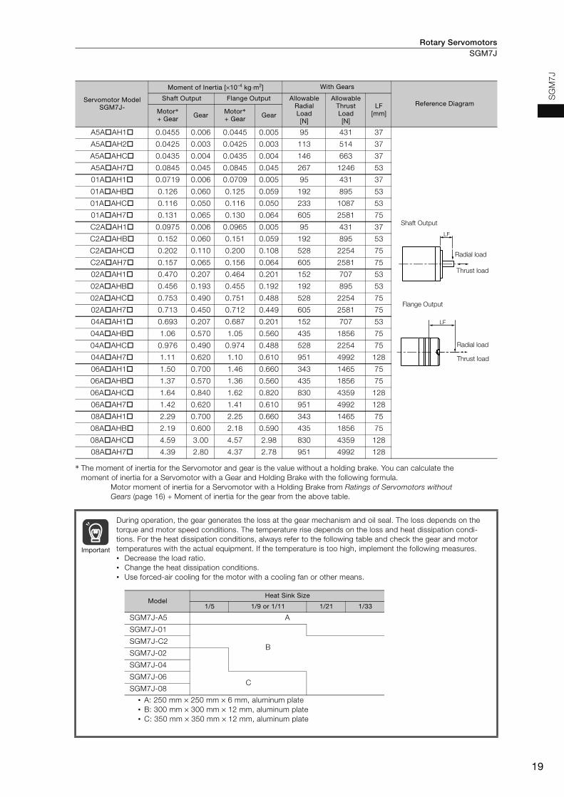
Rotary Servomotors SGM7J
19
SG
M7
J
* The moment of inertia for the Servomotor and gear is the value without a holding brake. You can calculate the moment of inertia for a Servomotor with a Gear and Holding Brake with the following formula.
Motor moment of inertia for a Servomotor with a Holding Brake from Ratings of Servomotors without Gears (page 16) + Moment of inertia for the gear from the above table.
Servomotor Model SGM7J-
Moment of Inertia [×10-4 kg⋅m2] With Gears
Reference Diagram Shaft Output Flange Output Allowable
Radial Load [N]
Allowable Thrust Load [N]
LF [mm]Motor*
+ Gear Gear Motor* + Gear Gear
A5AAH1 0.0455 0.006 0.0445 0.005 95 431 37
A5AAH2 0.0425 0.003 0.0425 0.003 113 514 37
A5AAHC 0.0435 0.004 0.0435 0.004 146 663 37
A5AAH7 0.0845 0.045 0.0845 0.045 267 1246 53
01AAH1 0.0719 0.006 0.0709 0.005 95 431 37
01AAHB 0.126 0.060 0.125 0.059 192 895 53
01AAHC 0.116 0.050 0.116 0.050 233 1087 53
01AAH7 0.131 0.065 0.130 0.064 605 2581 75
C2AAH1 0.0975 0.006 0.0965 0.005 95 431 37
C2AAHB 0.152 0.060 0.151 0.059 192 895 53
C2AAHC 0.202 0.110 0.200 0.108 528 2254 75
C2AAH7 0.157 0.065 0.156 0.064 605 2581 75
02AAH1 0.470 0.207 0.464 0.201 152 707 53
02AAHB 0.456 0.193 0.455 0.192 192 895 53
02AAHC 0.753 0.490 0.751 0.488 528 2254 75
02AAH7 0.713 0.450 0.712 0.449 605 2581 75
04AAH1 0.693 0.207 0.687 0.201 152 707 53
04AAHB 1.06 0.570 1.05 0.560 435 1856 75
04AAHC 0.976 0.490 0.974 0.488 528 2254 75
04AAH7 1.11 0.620 1.10 0.610 951 4992 128
06AAH1 1.50 0.700 1.46 0.660 343 1465 75
06AAHB 1.37 0.570 1.36 0.560 435 1856 75
06AAHC 1.64 0.840 1.62 0.820 830 4359 128
06AAH7 1.42 0.620 1.41 0.610 951 4992 128
08AAH1 2.29 0.700 2.25 0.660 343 1465 75
08AAHB 2.19 0.600 2.18 0.590 435 1856 75
08AAHC 4.59 3.00 4.57 2.98 830 4359 128
08AAH7 4.39 2.80 4.37 2.78 951 4992 128
During operation, the gear generates the loss at the gear mechanism and oil seal. The loss depends on the torque and motor speed conditions. The temperature rise depends on the loss and heat dissipation condi-tions. For the heat dissipation conditions, always refer to the following table and check the gear and motor temperatures with the actual equipment. If the temperature is too high, implement the following measures. • Decrease the load ratio. • Change the heat dissipation conditions. • Use forced-air cooling for the motor with a cooling fan or other means.
LF
Shaft Output
Radial load
Thrust load
LF
Flange Output
Radial load
Thrust load
Important
• A: 250 mm × 250 mm × 6 mm, aluminum plate• B: 300 mm × 300 mm × 12 mm, aluminum plate • C: 350 mm × 350 mm × 12 mm, aluminum plate
Model Heat Sink Size
1/5 1/9 or 1/11 1/21 1/33
SGM7J-A5 A
SGM7J-01
BSGM7J-C2
SGM7J-02
SGM7J-04
SGM7J-06C
SGM7J-08
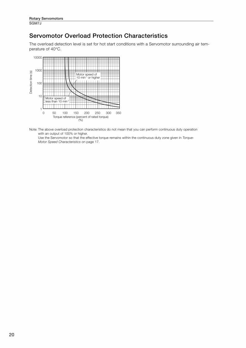
Rotary ServomotorsSGM7J
20
Servomotor Overload Protection Characteristics The overload detection level is set for hot start conditions with a Servomotor surrounding air tem-perature of 40°C.
Note: The above overload protection characteristics do not mean that you can perform continuous duty operation with an output of 100% or higher. Use the Servomotor so that the effective torque remains within the continuous duty zone given in Torque-Motor Speed Characteristics on page 17.
0 50 100 150 200 250 300 350
10000
1000
100
10
1
Dete
ctio
n t
ime (s)
Motor speed of 10 min-1 or higher
Motor speed of less than 10 min-1
Torque reference (percent of rated torque) (%)

Rotary Servomotors SGM7J
21
SG
M7
J
Allowable Load Moment of InertiaThe allowable load moments of inertia (motor moment of inertia ratios) for the Servomotors are given in the Ratings of Servomotors without Gears (page 16). The values are determined by the regenera-tive energy processing capacity of the SERVOPACK and are also affected by the drive conditions of the Servomotor. Perform the required Steps for each of the following cases.
Use the SigmaJunmaSize+ AC Servo Drive Capacity Selection Program to check the driving condi-tions. Contact your Yaskawa representative for information on this program.
Exceeding the Allowable Load Moment of InertiaUse one of the following measures to adjust the load moment of inertia to within the allowable value.• Reduce the torque limit.• Reduce the deceleration rate.• Reduce the maximum motor speed.
If the above steps is not possible, install an external regenerative resistor.
SERVOPACKs without Built-in Regenerative ResistorsThe following graph shows the allowable load moment of inertia scaling factor of the motor speed (reference values for deceleration operation at or above the rated torque). Application is possible without an external regenerative resistor within the allowable value. However, an External Regenera-tive Resistor is required in the shaded areas of the graphs.
Note: Applicable SERVOPACK models: SGD7S-R70A, -R90A, -1R6A, -2R8A, -R70F, -R90F, -2R1F, and -2R8F
When an External Regenerative Resistor Is RequiredInstall the External Regenerative Resistor. Refer to the following section for the recommended products.
External Regenerative Resistors (page 456)
An Overvoltage Alarm (A.400) is likely to occur during deceleration if the load moment of iner-tia exceeds the allowable load moment of inertia. SERVOPACKs with a built-in regenerative resistor may generate a Regenerative Overload Alarm (A.320). Refer to Built-In Regenerative Resistor (page 456) for the regenerative power (W) that can be processed by the SERVO-PACKs. Install an External Regenerative Resistor when the built-in regenerative resistor cannot pro-cess all of the regenerative power.
Information
SGM7J-A5A
0 1000 2000 3000 4000 5000 6000 70000
5
10
15
20
25
30
40
35
SGM7J-C2A
0 1000 2000 3000 4000 5000 6000 70000
5
10
15
20
25
30
40
35
SGM7J-04A
0 1000 2000 3000 4000 5000 6000 7000
SGM7J-01A
0 1000 2000 3000 4000 5000 6000 70000
5
10
15
20
25
30
40
35
0
5
10
15
20
25
30
0
5
10
15
20
25
30SGM7J-02A
0 1000 2000 3000 4000 5000 6000 7000
Motor speed (min-1)
Allo
wab
le lo
ad m
om
ent
of in
ertia
sc
alin
g fac
tor
(tim
es)
Motor speed (min-1)
Allo
wab
le lo
ad m
om
ent
of in
ertia
sc
alin
g fac
tor
(tim
es)
Motor speed (min-1)
Allo
wab
le lo
ad m
om
ent
of in
ertia
sc
alin
g fac
tor
(tim
es)
Motor speed (min-1)
Allo
wab
le lo
ad m
om
ent
of in
ertia
sc
alin
g fac
tor
(tim
es)
Motor speed (min-1)
Allo
wab
le lo
ad m
om
ent
of in
ertia
sc
alin
g fac
tor
(tim
es)

Rotary ServomotorsSGM7J
22
Derating Rates
Servomotor Heat Dissipation Conditions The Servomotor ratings are the continuous allowable values at a surrounding air temperature of 40°C when a heat sink is installed on the Servomotor. If the Servomotor is mounted on a small device component, the Servomotor temperature may rise considerably because the surface for heat dissipation becomes smaller. Refer to the following graphs for the relation between the heat sink size and derating rate.
Applications Where the Surrounding Air Temperature Exceeds 40°C The Servomotor ratings are the continuous allowable values at a surrounding air temperature of 40°C. If you use a Servomotor at a surrounding air temperature that exceeds 40°C (60°C max.), apply a suitable derating rate from the following graphs.
Applications Where the Altitude Exceeds 1,000 m The Servomotor ratings are the continuous allowable values at an altitude of 1,000 m or less. If you use a Servomotor at an altitude that exceeds 1,000 m (2,000 m max.), the heat dissipation effect of the air is reduced. Apply the appropriate derating rate from the following graphs.
The actual temperature rise depends on how the heat sink (i.e., the Servomotor mounting section) is attached to the installation surface, what material is used for the Servomotor mounting section, and the motor speed. Always check the Servomotor temperature with the actual equipment.
When using Servomotors with derating, change the detection timing of overload warning and overload alarm based on the overload detection level of the motor given in Servomotor Overload Protection Characteristics (page 20).Note: 1. Use the combination of the SERVOPACK and Servomotor so that the derating conditions
are satisfied for both the SERVOPACK and Servomotor.
2. The derating rates are applicable only when the average motor speed is less than or equal to the rated motor speed. If the average motor speed exceeds the rated motor speed, consult with your Yaskawa representative.
100
80
120 120
60
40
200
100
80
60
40
20150 250 300200100500
120
100
80
60
40
20150 250 300200100500
SGM7J-A5 and -01
SGM7J-C2
SGM7J-08
150 250 30020010050
SGM7J-02 and -04
SGM7J-06
Dera
ting
rate
(%
)
Heat sink size (mm) Heat sink size (mm) Heat sink size (mm)
Dera
ting
rate
(%
)
Dera
ting
rate
(%
)
Important
100
80
120 120
60
40
00
100
80
60
40
0
20 20
10 20 30 40 50 60 70 0 10 20 30 40 50 60 70
SGM7J-01 and -C2
SGM7J-A5
SGM7J-02 and -04
SGM7J-06 and -08
Dera
ting
rate
(%
)
Dera
ting
rate
(%
)
Surrounding air temperature (°C) Surrounding air temperature (°C)
100
80
120 120
60
40
0
100
80
60
40
0
20 20
0 500 1000 1500 2000 2500 0 500 1000 1500 2000 2500
SGM7J-A5, -01, and -C2
SGM7J-02, -04, and -06
SGM7J-08
Dera
ting
rate
(%
)
Altitude (m) Altitude (m)
Dera
ting
rate
(%
)
InformationInformation
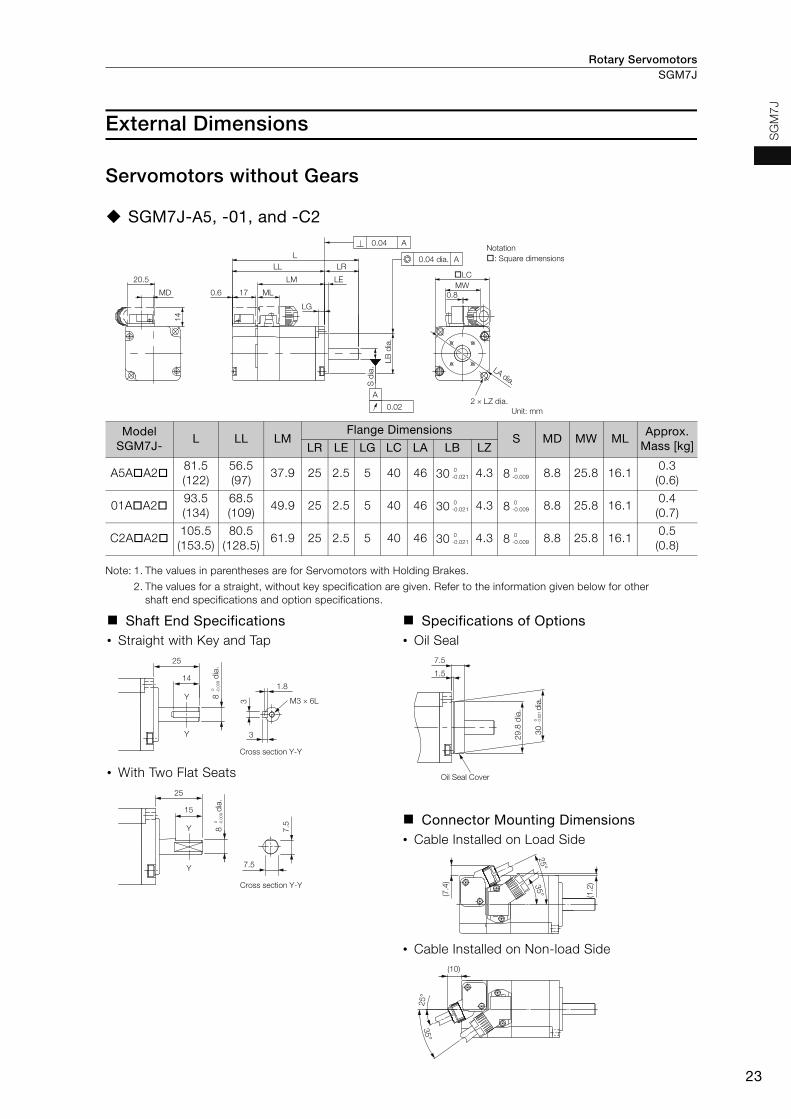
Rotary Servomotors SGM7J
23
SG
M7
J
External Dimensions
Servomotors without Gears
SGM7J-A5, -01, and -C2
Note: 1. The values in parentheses are for Servomotors with Holding Brakes.
2. The values for a straight, without key specification are given. Refer to the information given below for other shaft end specifications and option specifications.
ModelSGM7J-
L LL LMFlange Dimensions
S MD MW MLApprox.
Mass [kg]LR LE LG LC LA LB LZ
A5AA281.5(122)
56.5(97)
37.9 25 2.5 5 40 46 30 4.3 8 8.8 25.8 16.10.3(0.6)
01AA293.5(134)
68.5(109)
49.9 25 2.5 5 40 46 30 4.3 8 8.8 25.8 16.10.4(0.7)
C2AA2105.5(153.5)
80.5(128.5)
61.9 25 2.5 5 40 46 30 4.3 8 8.8 25.8 16.10.5(0.8)
Shaft End Specifications• Straight with Key and Tap
• With Two Flat Seats
Specifications of Options • Oil Seal
Connector Mounting Dimensions• Cable Installed on Load Side
• Cable Installed on Non-load Side
LG
LA dia.S d
ia.
14
ML170.6
LM LE
LRLL
L
0.8MW
�LC
MD
20.5
0.02
0.04 A
ALB
dia
.
0.04 dia. A
2 × LZ dia.
Notation
�: Square dimensions
Unit: mm
0-0.021
0-0.009
0-0.021
0-0.009
0-0.021
0-0.009
14
Y
Y
25
3
3
1.8
Cross section Y-Y
M3 × 6L
8
dia
.0
-0.0
09
15
Y
Y
25
7.5
7.5
Cross section Y-Y
8
dia
.0
-0.0
09
1.5
7.5
Oil Seal Cover
29
.8 d
ia.
30
d
ia.
0
- 0
.02
1
(7.4
)
25°
35° (1
.2)
25°
35°
(10)

Rotary ServomotorsSGM7J
24
SGM7J-02, -04, and -06
Note: 1. The values in parentheses are for Servomotors with Holding Brakes.
2. The values for a straight, without key specification are given. Refer to the information given below for other shaft end specifications and option specifications.
Model SGM7J-
L LL LMFlange Dimensions
S MD MW MH MLApprox.
Mass [kg]LR LE LG LC LA LB LZ
02AA299.5(140)
69.5(110)
51.2 30 3 6 60 70 50 5.5 14 8.5 28.7 14.7 17.10.8(1.4)
04AA2115.5(156)
85.5(126)
67.2 30 3 6 60 70 50 5.5 14 8.5 28.7 14.7 17.11.1(1.7)
06AA2137.5(191.5)
107.5(161.5)
89.2 30 3 6 60 70 50 5.5 14 8.5 28.7 14.7 17.11.6(2.2)
Shaft End Specifications• Straight with Key and Tap
• With Two Flat Seats
Specifications of Options • Oil Seal
Connector Mounting Dimensions• Cable Installed on Load Side
• Cable Installed on Non-load Side
14
0.6 17 LG
LE
LRLL
L
LB
dia
.
S d
ia.
�LC
LA d
ia.
ML
MH
MW
LM
MD
20.5
0.04 A
A
0.02
0.04 dia. A
4 × LZ dia. Unit: mm
0-0.025
0-0.011
0-0.025
0-0.011
0-0.025
0-0.011
14
Y
Y
30
5
5
3
M5 × 8L 14
d
ia.
Cross section Y-Y
0
-0.0
11
Cross section Y-Y
15
Y
Y
30
13
13
14
d
ia.
0
-0.0
11
47
dia
.
35
dia
.
35.2
10
Oil Seal Cover
25°
35°
25°
35°
(10)
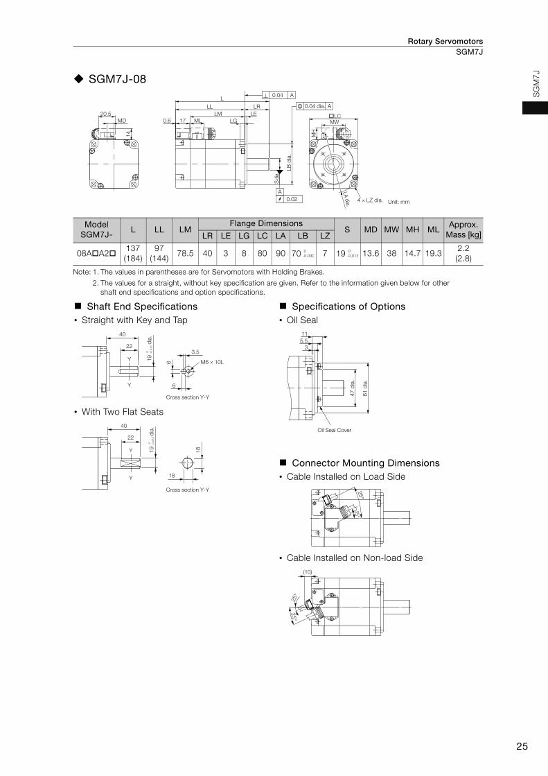
Rotary Servomotors SGM7J
25
SG
M7
J
SGM7J-08
Note: 1. The values in parentheses are for Servomotors with Holding Brakes.
2. The values for a straight, without key specification are given. Refer to the information given below for other shaft end specifications and option specifications.
ModelSGM7J-
L LL LMFlange Dimensions
S MD MW MH MLApprox.
Mass [kg]LR LE LG LC LA LB LZ
08AA2137(184)
97(144)
78.5 40 3 8 80 90 70 7 19 13.6 38 14.7 19.32.2(2.8)
Shaft End Specifications• Straight with Key and Tap
• With Two Flat Seats
Specifications of Options • Oil Seal
Connector Mounting Dimensions• Cable Installed on Load Side
• Cable Installed on Non-load Side
14
0.6 17 LG
LE
LRLL
L
LB
dia
.
S d
ia.
�LC
LA d
ia.
ML
MH
MW
LM
MD
20.5
0.04 A
A
0.02
0.04 dia. A
4 × LZ dia. Unit: mm
0-0.030
0-0.013
Cross section Y-Y
22
Y
Y
40
6
6
3.5
M6 × 10L 19
d
ia.
0
-0.0
13
Cross section Y-Y
22
Y
Y
40
18
18
19
d
ia.
0
-0.0
13
61
dia
.
47
dia
.3
5.5
11
Oil Seal Cover
25°
25°
25°
25°
(10)
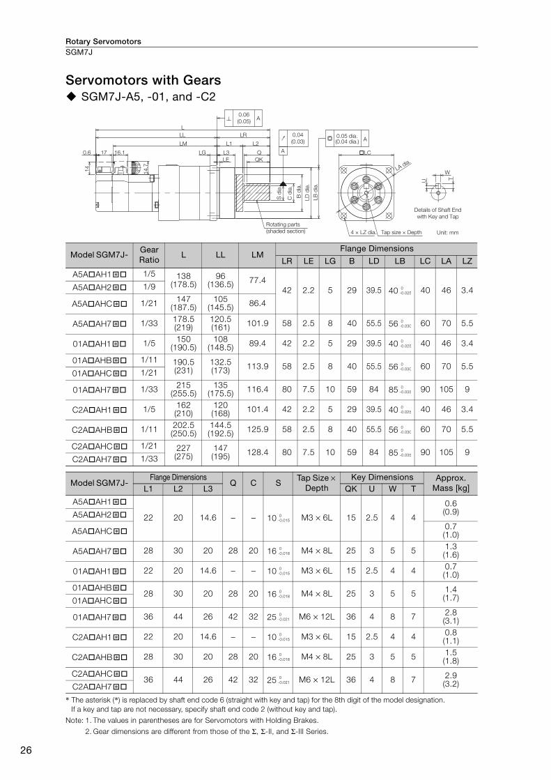
Rotary ServomotorsSGM7J
26
Servomotors with Gears SGM7J-A5, -01, and -C2
* The asterisk (*) is replaced by shaft end code 6 (straight with key and tap) for the 8th digit of the model designation. If a key and tap are not necessary, specify shaft end code 2 (without key and tap).
Note: 1. The values in parentheses are for Servomotors with Holding Brakes.
2. Gear dimensions are different from those of the Σ, Σ-II, and Σ-III Series.
Model SGM7J- Gear Ratio
L LL LMFlange Dimensions
LR LE LG B LD LB LC LA LZ
A5AAH1 1/5 138(178.5)
96(136.5) 77.4
42 2.2 5 29 39.5 40 40 46 3.4A5AAH2 1/9
A5AAHC 1/21 147(187.5)
105(145.5) 86.4
A5AAH7 1/33 178.5(219)
120.5(161) 101.9 58 2.5 8 40 55.5 56 60 70 5.5
01AAH1 1/5 150(190.5)
108(148.5) 89.4 42 2.2 5 29 39.5 40 40 46 3.4
01AAHB 1/11 190.5(231)
132.5(173) 113.9 58 2.5 8 40 55.5 56 60 70 5.5
01AAHC 1/21
01AAH7 1/33 215(255.5)
135(175.5) 116.4 80 7.5 10 59 84 85 90 105 9
C2AAH1 1/5 162(210)
120(168) 101.4 42 2.2 5 29 39.5 40 40 46 3.4
C2AAHB 1/11 202.5(250.5)
144.5(192.5) 125.9 58 2.5 8 40 55.5 56 60 70 5.5
C2AAHC 1/21 227(275)
147(195) 128.4 80 7.5 10 59 84 85 90 105 9
C2AAH7 1/33
Model SGM7J- Flange Dimensions
Q C STap Size ×
Depth Key Dimensions Approx.
Mass [kg]L1 L2 L3 QK U W T
A5AAH1
22 20 14.6 − − 10 M3 × 6L 15 2.5 4 4
0.6(0.9)A5AAH2
A5AAHC 0.7(1.0)
A5AAH7 28 30 20 28 20 16 M4 × 8L 25 3 5 5 1.3(1.6)
01AAH1 22 20 14.6 − − 10 M3 × 6L 15 2.5 4 4 0.7(1.0)
01AAHB 28 30 20 28 20 16 M4 × 8L 25 3 5 5 1.4
(1.7)01AAHC
01AAH7 36 44 26 42 32 25 M6 × 12L 36 4 8 7 2.8(3.1)
C2AAH1 22 20 14.6 − − 10 M3 × 6L 15 2.5 4 4 0.8(1.1)
C2AAHB 28 30 20 28 20 16 M4 × 8L 25 3 5 5 1.5(1.8)
C2AAHC 36 44 26 42 32 25 M6 × 12L 36 4 8 7 2.9
(3.2)C2AAH7
16.1170.6
LL
LM
LG
LE
L
QK
QL3
L1 L2
14
14.7
LC
LR
A
0.04
(0.03)
0.06
(0.05)A
A
T
W
U
0.05 dia.
Details of Shaft End
with Key and Tap
Rotating parts
(shaded section) 4 × LZ dia. Tap size × Depth Unit: mm
LB
dia
.
LD
dia
.
B d
ia.
C d
ia.
S d
ia.
(0.04 dia.)
LA dia.
�* 0-0.025
�*
�*
�* 0-0.030
�* 0-0.025
�* 0-0.030
�*
�* 0-0.035
�* 0-0.025
�* 0-0.030
�* 0-0.035
�*
�* 0-0.015
�*
�*
�* 0-0.018
�* 0-0.015
�* 0-0.018
�*
�* 0-0.021
�* 0-0.015
�* 0-0.018
�* 0-0.021
�*
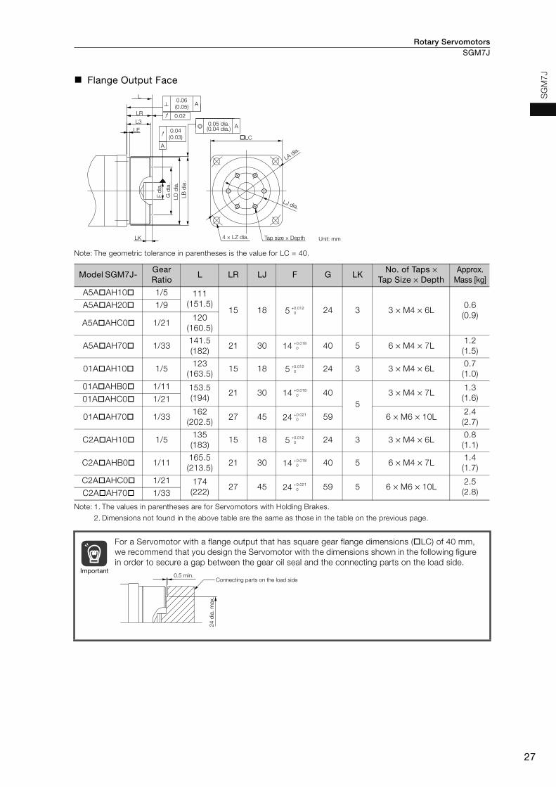
Rotary Servomotors SGM7J
27
SG
M7
J
Flange Output Face
Note: The geometric tolerance in parentheses is the value for LC = 40.
Note: 1. The values in parentheses are for Servomotors with Holding Brakes.
2. Dimensions not found in the above table are the same as those in the table on the previous page.
Model SGM7J- Gear Ratio
L LR LJ F G LKNo. of Taps ×
Tap Size × Depth Approx.
Mass [kg]
A5AAH10 1/5 111(151.5)
15 18 5 24 3 3 × M4 × 6L0.6(0.9)
A5AAH20 1/9
A5AAHC0 1/21120
(160.5)
A5AAH70 1/33141.5(182)
21 30 14 40 5 6 × M4 × 7L1.2(1.5)
01AAH10 1/5123
(163.5)15 18 5 24 3 3 × M4 × 6L
0.7(1.0)
01AAHB0 1/11 153.5(194)
21 30 14 405
3 × M4 × 7L1.3(1.6)01AAHC0 1/21
01AAH70 1/33162
(202.5)27 45 24 59 6 × M6 × 10L
2.4(2.7)
C2AAH10 1/5135(183)
15 18 5 24 3 3 × M4 × 6L0.8(1.1)
C2AAHB0 1/11165.5(213.5)
21 30 14 40 5 6 × M4 × 7L1.4(1.7)
C2AAHC0 1/21 174(222)
27 45 24 59 5 6 × M6 × 10L2.5(2.8)C2AAH70 1/33
For a Servomotor with a flange output that has square gear flange dimensions (LC) of 40 mm, we recommend that you design the Servomotor with the dimensions shown in the following figure in order to secure a gap between the gear oil seal and the connecting parts on the load side.
LC
LK
L3
LE
LR
L
A
0.04(0.03)
0.02
A
A0.06(0.05)
0.05 dia.(0.04 dia.)
4 × LZ dia.
LB
dia
.
LD
dia
.
G d
ia.
F d
ia.
Tap size × Depth Unit: mm
LJ dia.
LA dia.
+0.012 0
+0.018 0
+0.012 0
+0.018 0
+0.021 0
+0.012 0
+0.018 0
+0.021 0
Important0.5 min.
Connecting parts on the load side
24
dia
. m
ax.
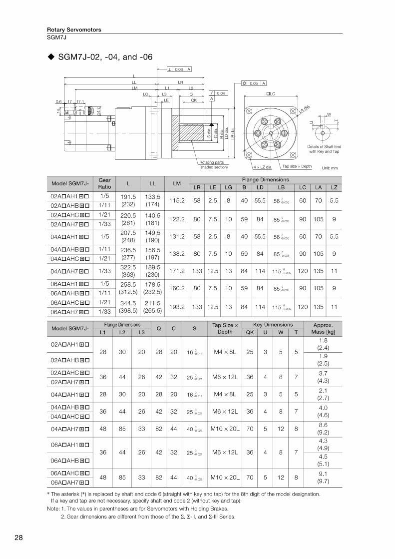
Rotary ServomotorsSGM7J
28
SGM7J-02, -04, and -06
* The asterisk (*) is replaced by shaft end code 6 (straight with key and tap) for the 8th digit of the model designation.If a key and tap are not necessary, specify shaft end code 2 (without key and tap).
Note: 1. The values in parentheses are for Servomotors with Holding Brakes.
2. Gear dimensions are different from those of the Σ, Σ-II, and Σ-III Series.
Model SGM7J- Gear Ratio
L LL LMFlange Dimensions
LR LE LG B LD LB LC LA LZ
02AAH1 1/5 191.5(232)
133.5(174)
115.2 58 2.5 8 40 55.5 56 60 70 5.502AAHB 1/11
02AAHC 1/21 220.5(261)
140.5(181)
122.2 80 7.5 10 59 84 85 90 105 902AAH7 1/33
04AAH1 1/5207.5(248)
149.5(190)
131.2 58 2.5 8 40 55.5 56 60 70 5.5
04AAHB 1/11 236.5(277)
156.5(197)
138.2 80 7.5 10 59 84 85 90 105 904AAHC 1/21
04AAH7 1/33322.5(363)
189.5(230)
171.2 133 12.5 13 84 114 115 120 135 11
06AAH1 1/5 258.5(312.5)
178.5(232.5)
160.2 80 7.5 10 59 84 85 90 105 906AAHB 1/11
06AAHC 1/21 344.5(398.5)
211.5(265.5)
193.2 133 12.5 13 84 114 115 120 135 1106AAH7 1/33
Model SGM7J- Flange Dimensions
Q C STap Size ×
Depth Key Dimensions Approx.
Mass [kg]L1 L2 L3 QK U W T
02AAH1 28 30 20 28 20 16 M4 × 8L 25 3 5 5
1.8(2.4)
02AAHB 1.9(2.5)
02AAHC 36 44 26 42 32 25 M6 × 12L 36 4 8 7
3.7(4.3)02AAH7
04AAH1 28 30 20 28 20 16 M4 × 8L 25 3 5 52.1(2.7)
04AAHB 36 44 26 42 32 25 M6 × 12L 36 4 8 7
4.0(4.6)04AAHC
04AAH7 48 85 33 82 44 40 M10 × 20L 70 5 12 88.6(9.2)
06AAH1 36 44 26 42 32 25 M6 × 12L 36 4 8 7
4.3(4.9)
06AAHB 4.5(5.1)
06AAHC 48 85 33 82 44 40 M10 × 20L 70 5 12 8
9.1(9.7)06AAH7
0.6 17 LE
LG L3
L1
LL
LM
14
.7
14
L
L2
Q
QK
LC
LR
17.1
0.06 A
0.04
0.05 A
A
U
W
T
Details of Shaft End
with Key and Tap
LB
dia
.
LD
dia
.
B d
ia.
C d
ia.
S d
ia.
Unit: mmTap size × Depth4 × LZ dia.
Rotating parts
(shaded section)
LA dia.
�* 0-0.030
�*
�* 0-0.035
�*
�* 0-0.030
�* 0-0.035
�*
�* 0-0.035
�* 0-0.035
�*
�* 0-0.035
�*
�* 0-0.018
�*
�* 0-0.021
�*
�* 0-0.018
�* 0-0.021
�*
�* 0-0.025
�* 0-0.021
�*
�* 0-0.025
�*

Rotary Servomotors SGM7J
29
SG
M7
J
Flange Output Face
Note: 1. The values in parentheses are for Servomotors with Holding Brakes.
2. Dimensions not found in the above table are the same as those in the table on the previous page.
Model SGM7J- Gear Ratio
L LR LJ F GNo. of Taps ×
Tap Size × Depth Approx.
Mass [kg]
02AAH10 1/5154.5(195)
21 30 14 40 6 × M4 × 7L
1.7(2.3)
02AAHB0 1/111.8(2.4)
02AAHC0 1/21 167.5(208)
27 45 24 59 6 × M6 × 10L3.3(3.9)02AAH70 1/33
04AAH10 1/5170.5(211)
21 30 14 40 6 × M4 × 7L2.0(2.6)
04AAHB0 1/11 183.5(224)
27 45 24 59 6 × M6 × 10L3.6(4.2)04AAHC0 1/21
04AAH70 1/33224.5(265)
35 60 32 84 6 × M8 × 12L7.2(7.8)
06AAH10 1/5205.5(259.5)
27 45 24 59 6 × M6 × 10L
3.9(4.5)
06AAHB0 1/114.1(4.7)
06AAHC0 1/21 246.5(300.5)
35 60 32 84 6 × M8 × 12L7.7(8.3)06AAH70 1/33
LC
5
LE
LR
L
L3 A
0.06 A
A
0.04
0.02
0.05 dia.
Unit: mmTap size × Depth4 × LZ dia.
LB
dia
.
LD
dia
.
G d
ia.
F d
ia.
LJ dia.
LA dia.
+0.018 0
+0.021 0
+0.018 0
+0.021 0
+0.025 0
+0.021 0
+0.025 0
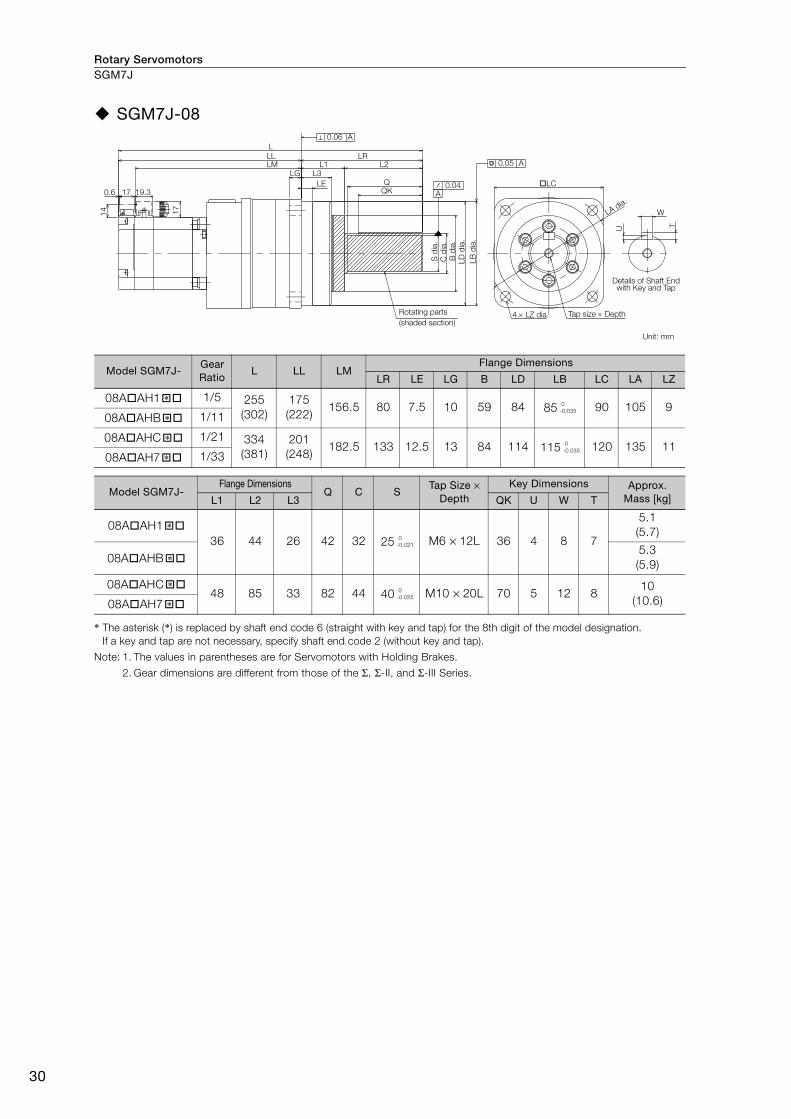
Rotary ServomotorsSGM7J
30
SGM7J-08
* The asterisk (*) is replaced by shaft end code 6 (straight with key and tap) for the 8th digit of the model designation.If a key and tap are not necessary, specify shaft end code 2 (without key and tap).
Note: 1. The values in parentheses are for Servomotors with Holding Brakes.
2. Gear dimensions are different from those of the Σ, Σ-II, and Σ-III Series.
Model SGM7J- Gear Ratio
L LL LMFlange Dimensions
LR LE LG B LD LB LC LA LZ
08AAH1 1/5 255(302)
175(222)
156.5 80 7.5 10 59 84 85 90 105 908AAHB 1/11
08AAHC 1/21 334(381)
201(248)
182.5 133 12.5 13 84 114 115 120 135 1108AAH7 1/33
Model SGM7J- Flange Dimensions
Q C STap Size ×
Depth Key Dimensions Approx.
Mass [kg]L1 L2 L3 QK U W T
08AAH1 36 44 26 42 32 25 M6 × 12L 36 4 8 7
5.1(5.7)
08AAHB 5.3(5.9)
08AAHC 48 85 33 82 44 40 M10 × 20L 70 5 12 8
10(10.6)08AAH7
17
17
14
0.6 19.3
L
L3LE
L1 L2LR
QQK
LGLM
C d
ia.
B d
ia.
LD d
ia.
LB d
ia.
S d
ia.
LL
LA dia.
LC
W
U T
0.05 A
0.04A
0.06 A
4 LZ dia.
Details of Shaft End with Key and Tap
Unit: mm
Tap size DepthRotating parts (shaded section)
�* 0-0.035
�*
�* 0-0.035
�*
�* 0-0.021
�*
�* 0-0.025
�*
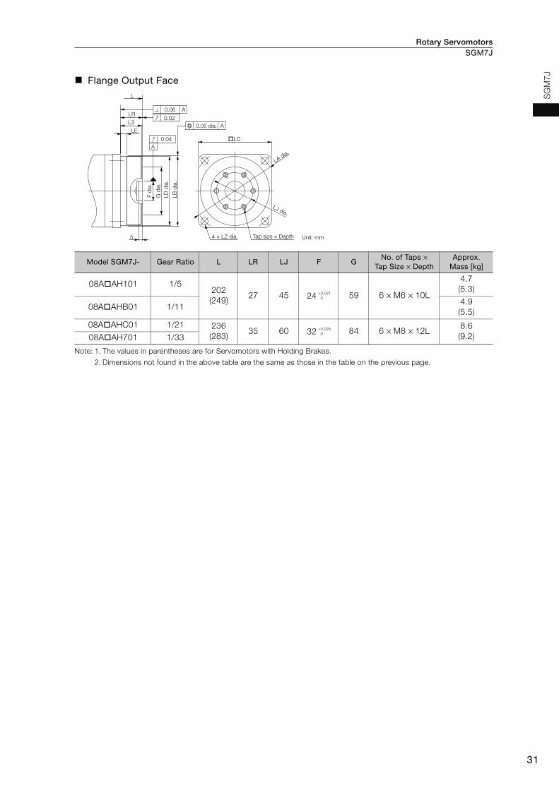
Rotary Servomotors SGM7J
31
SG
M7
J
Flange Output Face
Note: 1. The values in parentheses are for Servomotors with Holding Brakes.
2. Dimensions not found in the above table are the same as those in the table on the previous page.
Model SGM7J- Gear Ratio L LR LJ F GNo. of Taps ×
Tap Size × Depth Approx.
Mass [kg]
08AAH101 1/5202(249)
27 45 24 59 6 × M6 × 10L
4.7(5.3)
08AAHB01 1/114.9(5.5)
08AAHC01 1/21 236(283)
35 60 32 84 6 × M8 × 12L8.6(9.2)08AAH701 1/33
LC
5
LE
LR
L
L3A
0.06 A
A
0.04
0.02
0.05 dia.
Unit: mmTap size × Depth4 × LZ dia.
LB
dia
.
LD
dia
.
G d
ia.
F d
ia.
LA dia.
LJ dia.
+0.021 0
+0.025 0

Rotary ServomotorsSGM7J
32
Selecting Cables
Cable ConfigurationsThe cables shown below are required to connect a Servomotor to a SERVOPACK.
Note: 1. If the Encoder Cable length exceeds 20 m, be sure to use a Relay Encoder Cable.
2. If you use a Servomotor Main Circuit Cable that exceeds 20 m, the intermittent duty zone in the torque-motor speed characteristics will become smaller because the voltage drop increases.
3. Refer to the following manual for the following information.• Cable dimensional drawings and cable connection specifications• Order numbers and specifications of individual connectors for cables• Order numbers and specifications for wiring materials
Σ-7-Series AC Servo Drive Peripheral Device Selection Manual (Manual No.: SIEP S800001 32)
Encoder Cable of 20 m or Less Encoder Cable of 30 m to 50 m (Relay Cable)
There are different order numbers for the Servomotor Main Circuit Cables and Encoder Cables depending on the cable installation direction. Confirm the order numbers before you order.
SERVOPACK
Encoder Cable
Servomotor Main Circuit Cable
Servomotor
Battery Case
(Required when an
absolute encoder is used.)
SERVOPACK
Cable with a Battery Case (Required when an absolute encoder is used.)
Cable with Connectors on Both Ends
Encoder-end CableServomotor Main Circuit Cable
Servomotor
Relay Encoder Cable
Important Cable Installed toward Load Cable Installed away from Load
U
V
W
G
U
V
W
G
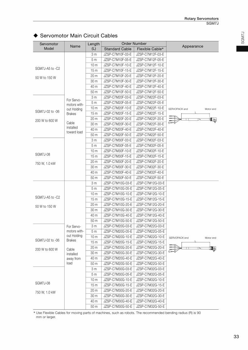
Rotary Servomotors SGM7J
33
SG
M7
J
Servomotor Main Circuit Cables
Servomotor Model
NameLength
(L)Order Number
AppearanceStandard Cable Flexible Cable*
SGM7J-A5 to -C2
50 W to 150 W
For Servo-motors with-out Holding Brakes
Cable installed toward load
3 m JZSP-C7M10F-03-E JZSP-C7M12F-03-E5 m JZSP-C7M10F-05-E JZSP-C7M12F-05-E
10 m JZSP-C7M10F-10-E JZSP-C7M12F-10-E15 m JZSP-C7M10F-15-E JZSP-C7M12F-15-E20 m JZSP-C7M10F-20-E JZSP-C7M12F-20-E30 m JZSP-C7M10F-30-E JZSP-C7M12F-30-E40 m JZSP-C7M10F-40-E JZSP-C7M12F-40-E50 m JZSP-C7M10F-50-E JZSP-C7M12F-50-E
SGM7J-02 to -06
200 W to 600 W
3 m JZSP-C7M20F-03-E JZSP-C7M22F-03-E5 m JZSP-C7M20F-05-E JZSP-C7M22F-05-E
10 m JZSP-C7M20F-10-E JZSP-C7M22F-10-E15 m JZSP-C7M20F-15-E JZSP-C7M22F-15-E20 m JZSP-C7M20F-20-E JZSP-C7M22F-20-E30 m JZSP-C7M20F-30-E JZSP-C7M22F-30-E40 m JZSP-C7M20F-40-E JZSP-C7M22F-40-E50 m JZSP-C7M20F-50-E JZSP-C7M22F-50-E
SGM7J-08
750 W, 1.0 kW
3 m JZSP-C7M30F-03-E JZSP-C7M32F-03-E5 m JZSP-C7M30F-05-E JZSP-C7M32F-05-E
10 m JZSP-C7M30F-10-E JZSP-C7M32F-10-E15 m JZSP-C7M30F-15-E JZSP-C7M32F-15-E20 m JZSP-C7M30F-20-E JZSP-C7M32F-20-E30 m JZSP-C7M30F-30-E JZSP-C7M32F-30-E40 m JZSP-C7M30F-40-E JZSP-C7M32F-40-E50 m JZSP-C7M30F-50-E JZSP-C7M32F-50-E
SGM7J-A5 to -C2
50 W to 150 W
For Servo-motors with-out Holding Brakes
Cable installed away from load
3 m JZSP-C7M10G-03-E JZSP-C7M12G-03-E5 m JZSP-C7M10G-05-E JZSP-C7M12G-05-E
10 m JZSP-C7M10G-10-E JZSP-C7M12G-10-E15 m JZSP-C7M10G-15-E JZSP-C7M12G-15-E20 m JZSP-C7M10G-20-E JZSP-C7M12G-20-E30 m JZSP-C7M10G-30-E JZSP-C7M12G-30-E40 m JZSP-C7M10G-40-E JZSP-C7M12G-40-E50 m JZSP-C7M10G-50-E JZSP-C7M12G-50-E
SGM7J-02 to -06
200 W to 600 W
3 m JZSP-C7M20G-03-E JZSP-C7M22G-03-E5 m JZSP-C7M20G-05-E JZSP-C7M22G-05-E
10 m JZSP-C7M20G-10-E JZSP-C7M22G-10-E15 m JZSP-C7M20G-15-E JZSP-C7M22G-15-E20 m JZSP-C7M20G-20-E JZSP-C7M22G-20-E30 m JZSP-C7M20G-30-E JZSP-C7M22G-30-E40 m JZSP-C7M20G-40-E JZSP-C7M22G-40-E50 m JZSP-C7M20G-50-E JZSP-C7M22G-50-E
SGM7J-08
750 W, 1.0 kW
3 m JZSP-C7M30G-03-E JZSP-C7M32G-03-E5 m JZSP-C7M30G-05-E JZSP-C7M32G-05-E
10 m JZSP-C7M30G-10-E JZSP-C7M32G-10-E15 m JZSP-C7M30G-15-E JZSP-C7M32G-15-E20 m JZSP-C7M30G-20-E JZSP-C7M32G-20-E30 m JZSP-C7M30G-30-E JZSP-C7M32G-30-E40 m JZSP-C7M30G-40-E JZSP-C7M32G-40-E50 m JZSP-C7M30G-50-E JZSP-C7M32G-50-E
* Use Flexible Cables for moving parts of machines, such as robots. The recommended bending radius (R) is 90 mm or larger.
U
V
W
G
Motor endSERVOPACK end
L
SERVOPACK end Motor end
U
V
W
G
L
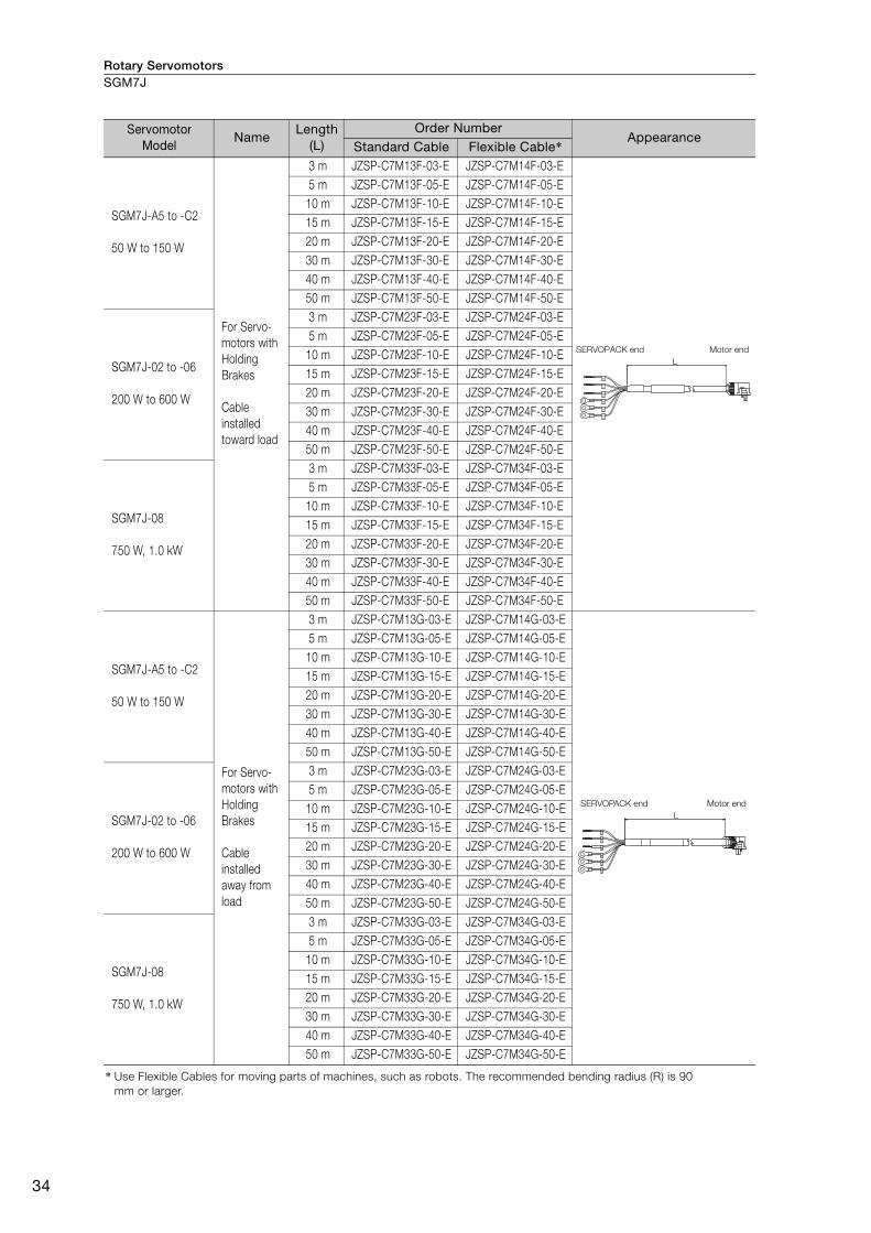
Rotary ServomotorsSGM7J
34
SGM7J-A5 to -C2
50 W to 150 W
For Servo-motors with Holding Brakes
Cable installed toward load
3 m JZSP-C7M13F-03-E JZSP-C7M14F-03-E5 m JZSP-C7M13F-05-E JZSP-C7M14F-05-E
10 m JZSP-C7M13F-10-E JZSP-C7M14F-10-E15 m JZSP-C7M13F-15-E JZSP-C7M14F-15-E20 m JZSP-C7M13F-20-E JZSP-C7M14F-20-E30 m JZSP-C7M13F-30-E JZSP-C7M14F-30-E40 m JZSP-C7M13F-40-E JZSP-C7M14F-40-E50 m JZSP-C7M13F-50-E JZSP-C7M14F-50-E
SGM7J-02 to -06
200 W to 600 W
3 m JZSP-C7M23F-03-E JZSP-C7M24F-03-E5 m JZSP-C7M23F-05-E JZSP-C7M24F-05-E
10 m JZSP-C7M23F-10-E JZSP-C7M24F-10-E15 m JZSP-C7M23F-15-E JZSP-C7M24F-15-E20 m JZSP-C7M23F-20-E JZSP-C7M24F-20-E30 m JZSP-C7M23F-30-E JZSP-C7M24F-30-E40 m JZSP-C7M23F-40-E JZSP-C7M24F-40-E50 m JZSP-C7M23F-50-E JZSP-C7M24F-50-E
SGM7J-08
750 W, 1.0 kW
3 m JZSP-C7M33F-03-E JZSP-C7M34F-03-E5 m JZSP-C7M33F-05-E JZSP-C7M34F-05-E
10 m JZSP-C7M33F-10-E JZSP-C7M34F-10-E15 m JZSP-C7M33F-15-E JZSP-C7M34F-15-E20 m JZSP-C7M33F-20-E JZSP-C7M34F-20-E30 m JZSP-C7M33F-30-E JZSP-C7M34F-30-E40 m JZSP-C7M33F-40-E JZSP-C7M34F-40-E50 m JZSP-C7M33F-50-E JZSP-C7M34F-50-E
SGM7J-A5 to -C2
50 W to 150 W
For Servo-motors with Holding Brakes
Cable installed away from load
3 m JZSP-C7M13G-03-E JZSP-C7M14G-03-E5 m JZSP-C7M13G-05-E JZSP-C7M14G-05-E
10 m JZSP-C7M13G-10-E JZSP-C7M14G-10-E15 m JZSP-C7M13G-15-E JZSP-C7M14G-15-E20 m JZSP-C7M13G-20-E JZSP-C7M14G-20-E30 m JZSP-C7M13G-30-E JZSP-C7M14G-30-E40 m JZSP-C7M13G-40-E JZSP-C7M14G-40-E50 m JZSP-C7M13G-50-E JZSP-C7M14G-50-E
SGM7J-02 to -06
200 W to 600 W
3 m JZSP-C7M23G-03-E JZSP-C7M24G-03-E5 m JZSP-C7M23G-05-E JZSP-C7M24G-05-E
10 m JZSP-C7M23G-10-E JZSP-C7M24G-10-E15 m JZSP-C7M23G-15-E JZSP-C7M24G-15-E20 m JZSP-C7M23G-20-E JZSP-C7M24G-20-E30 m JZSP-C7M23G-30-E JZSP-C7M24G-30-E40 m JZSP-C7M23G-40-E JZSP-C7M24G-40-E50 m JZSP-C7M23G-50-E JZSP-C7M24G-50-E
SGM7J-08
750 W, 1.0 kW
3 m JZSP-C7M33G-03-E JZSP-C7M34G-03-E5 m JZSP-C7M33G-05-E JZSP-C7M34G-05-E
10 m JZSP-C7M33G-10-E JZSP-C7M34G-10-E15 m JZSP-C7M33G-15-E JZSP-C7M34G-15-E20 m JZSP-C7M33G-20-E JZSP-C7M34G-20-E30 m JZSP-C7M33G-30-E JZSP-C7M34G-30-E40 m JZSP-C7M33G-40-E JZSP-C7M34G-40-E50 m JZSP-C7M33G-50-E JZSP-C7M34G-50-E
* Use Flexible Cables for moving parts of machines, such as robots. The recommended bending radius (R) is 90 mm or larger.
Servomotor Model
NameLength
(L)Order Number
AppearanceStandard Cable Flexible Cable*
U
V
W
G
B
B
Motor endSERVOPACK end
L
U
V
W
G
B
B
L
SERVOPACK end Motor end

Rotary Servomotors SGM7J
35
SG
M7
J
Encoder Cables of 20 m or Less
Relay Encoder Cable of 30 m to 50 m
* This Cable is not required if a battery is connected to the host controller.
Servomo-tor Model
NameLength
(L)
Order NumberAppearance
Standard Cable Flexible Cable*1
All SGM7J models
For incremental encoder
Cable installed toward load
3 m JZSP-C7PI0D-03-E JZSP-C7PI2D-03-E
5 m JZSP-C7PI0D-05-E JZSP-C7PI2D-05-E
10 m JZSP-C7PI0D-10-E JZSP-C7PI2D-10-E
15 m JZSP-C7PI0D-15-E JZSP-C7PI2D-15-E
20 m JZSP-C7PI0D-20-E JZSP-C7PI2D-20-E
For incremental encoder
Cable installed away from load
3 m JZSP-C7PI0E-03-E JZSP-C7PI2E-03-E
5 m JZSP-C7PI0E-05-E JZSP-C7PI2E-05-E
10 m JZSP-C7PI0E-10-E JZSP-C7PI2E-10-E
15 m JZSP-C7PI0E-15-E JZSP-C7PI2E-15-E
20 m JZSP-C7PI0E-20-E JZSP-C7PI2E-20-E
For absolute encoder: With Battery Case*2
Cable installed toward load
3 m JZSP-C7PA0D-03-E JZSP-C7PA2D-03-E
5 m JZSP-C7PA0D-05-E JZSP-C7PA2D-05-E
10 m JZSP-C7PA0D-10-E JZSP-C7PA2D-10-E
15 m JZSP-C7PA0D-15-E JZSP-C7PA2D-15-E
20 m JZSP-C7PA0D-20-E JZSP-C7PA2D-20-E
For absolute encoder: With Battery Case*2
Cable installed away from load
3 m JZSP-C7PA0E-03-E JZSP-C7PA2E-03-E
5 m JZSP-C7PA0E-05-E JZSP-C7PA2E-05-E
10 m JZSP-C7PA0E-10-E JZSP-C7PA2E-10-E
15 m JZSP-C7PA0E-15-E JZSP-C7PA2E-15-E
20 m JZSP-C7PA0E-20-E JZSP-C7PA2E-20-E
*1. Use Flexible Cables for moving parts of machines, such as robots. The recommended bending radius (R) is 90 mm or larger.
*2. If a battery is connected to the host controller, the Battery Case is not required. If so, use a cable for incremental encoders.
Servomotor Model
NameLength
(L)Order Number Appearance
All SGM7J models
Encoder-end Cable (for incremental or absolute encoder)Cable installed toward load
0.3 m JZSP-C7PRCD-E
Encoder-end Cable (for incremental or absolute encoder)Cable installed away from load
0.3 m JZSP-C7PRCE-E
Cables with Connectors on Both Ends (for incremental or absolute encoder)
30 m JZSP-UCMP00-30-E
40 m JZSP-UCMP00-40-E
50 m JZSP-UCMP00-50-E
Cable with a Battery Case (Required when an absolute encoder is used.*)
0.3 m JZSP-CSP12-E
Encoder endSERVOPACK end L
SERVOPACK end
Encoder endL
SERVOPACK end
Encoder end
Battery Case (battery included)
L
LSERVOPACK end
Encoder end
Battery Case
(battery included)
Encoder endSERVOPACK endL
SERVOPACK end Encoder endL
LSERVOPACK end Encoder end
SERVOPACK end Encoder end
Battery Case
(battery included)
L
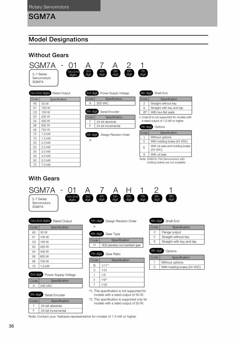
Rotary Servomotors
36
SGM7A
Model Designations
Without Gears
With Gears
Note: Contact your Yaskawa representative for models of 1.5 kW or higher.
1
C
E
S
7
F
2
B*6
A
A 200 VAC
SGM7A - 01 A 7 A 2 1
*
1st+2nd digits
1st+2nd digits 3rd digitRated Output Power Supply Voltage
4th digit Serial Encoder
5th digit Design Revision Order
7th digit Options
Code Specification
Without options
With holding brake (24 VDC)
With oil seal and holding brake
(24 VDC)
With oil seal
6th digit Shaft End
Straight without key
Straight with key and tap
With two flat seats
Code B is not supported for models with
a rated output of 1.5 kW or higher.
Code Specification
Code Specification
24-bit absolute
24-bit incremental
Code Specification
3rd digit
4th digit
5th digit
6th digit
7th digit-7 Series
Servomotors:
SGM7A
A5
01
C2
02 200 W
50 W
04 400 W
06 600 W
08 750 W
15
20 2.0 kW
25 2.5 kW
30 3.0 kW
40 4.0 kW
50 5.0 kW
70 7.0 kW
10
100 W
150 W
1.0 kW
1.5 kW
SpecificationCode
Note: SGM7A-70A Servomotors with
holding brakes are not available.
A5 50 W
01 100 W
C2
02 200 W
04 400 W
08 750 W
06 600 W
10 1.0 kW
SGM7A - 01 A 7 A H 1 2 1
0
2
6
1
CB 1/11*1
C 1/21
1 1/5
2 1/9*2
7 1/33
H
7
F
A 200 VAC
Specification A
150 W
1st+2nd digits
1st+2nd digits
-7 Series
Servomotors:
SGM7A
Rated Output 5th digit Design Revision Order 8th digit Shaft End
9th digit Options
Code Specification
Flange output
Code Specification
Without options
With holding brake (24 VDC)
Straight without key
Straight with key and tap
6th digit Gear Type
7th digit Gear Ratio
Specification
HDS planetary low-backlash gear
Code
Specification
*1. This specification is not supported for
models with a rated output of 50 W.
*2. This specification is supported only for
models with a rated output of 50 W.
Code
3rd digit Power Supply Voltage
4th digit Serial Encoder
Code Specification
Code Specification
24-bit absolute
24-bit incremental
Code
3rd digit
4th digit
5th digit
6th digit
7th digit
8th digit
9th digit

Rotary Servomotors SGM7A
37
SG
M7
ASpecifications and Ratings
Specifications
*1. A vibration class of V15 indicates a vibration amplitude of 15 μm maximum on the Servomotor without a load at the rated motor speed.
*2. The given values are for when the Servomotor shaft is mounted horizontally and shock or vibration is applied in the directions shown in the following figures.The strength of the vibration that the Servomotor can withstand depends on the application. Always check the vibration acceleration rate that is applied to the Servomotor with the actual equipment.
*3. Refer to the following section for the derating rates.Derating Rates (page 46)
*4. If you use a Servomotor together with a Σ-7W or Σ-7C SERVOPACK, the control gain may not increase as much as with a Σ-7S SERVOPACK and other performances may be lower than those achieved with a Σ-7S SERVOPACK.
Voltage 200 V
Model SGM7A- A5A 01A C2A, 02A
04A06A, 08A
10A 15A 20A25A, 30A
40A, 50A
70A
Time Rating Continuous Thermal Class UL: A, CE: B UL: F, CE: FInsulation Resistance 500 VDC, 10 MΩ min. Withstand Voltage 1,500 VAC for 1 minute Excitation Permanent magnet Mounting Flange-mounted Drive Method Direct drive Rotation Direction Counterclockwise (CCW) for forward reference when viewed from the load side
Vibration Class*1 V15
Env
ironm
enta
l Con
diti
ons
Surrounding Air Temperature 0°C to 40°C (With derating, usage is possible between 40°C and 60°C.)*3
Surrounding Air Humidity
20% to 80% relative humidity (with no condensation)
Installation Site
• Must be indoors and free of corrosive and explosive gases.• Must be well-ventilated and free of dust and moisture.• Must facilitate inspection and cleaning.• Must have an altitude of 1,000 m or less. (With derating, usage is possible
between 1,000 m and 2,000 m.)*3
• Must be free of strong magnetic fields.
Storage Environment
Store the Servomotor in the following environment if you store it with the power cable disconnected.Storage Temperature: -20°C to 60°C (with no freezing) Storage Humidity: 20% to 80% relative humidity (with no condensation)
Sho
ck
Res
ista
nce*2 Impact Acceler-
ation Rate at Flange
490 m/s2
Number of Impacts
2 times
Vib
ratio
n R
esis
tanc
e*2
Vibration Accel-eration Rate at Flange
49 m/s2 (Models 15A to 50A: 24.5 m/s2 front to back)14.7 m/s2
Applicable SERVOPACKs
SGD7S-R70A,R70F
R90A,R90F
1R6A,2R1F
2R8A,2R8F
5R5A 120A 180A 200A 330A 550A
SGD7W-SGD7C- 1R6A*4, 2R8A*4 1R6A,
2R8A*4
2R8A, 5R5A*4, 7R6A*4
5R5A,7R6A
–
Vertical
Shock Applied to the Servomotor Vibration Applied to the Servomotor
Vertical
Horizontal directionSide to side
Front to back
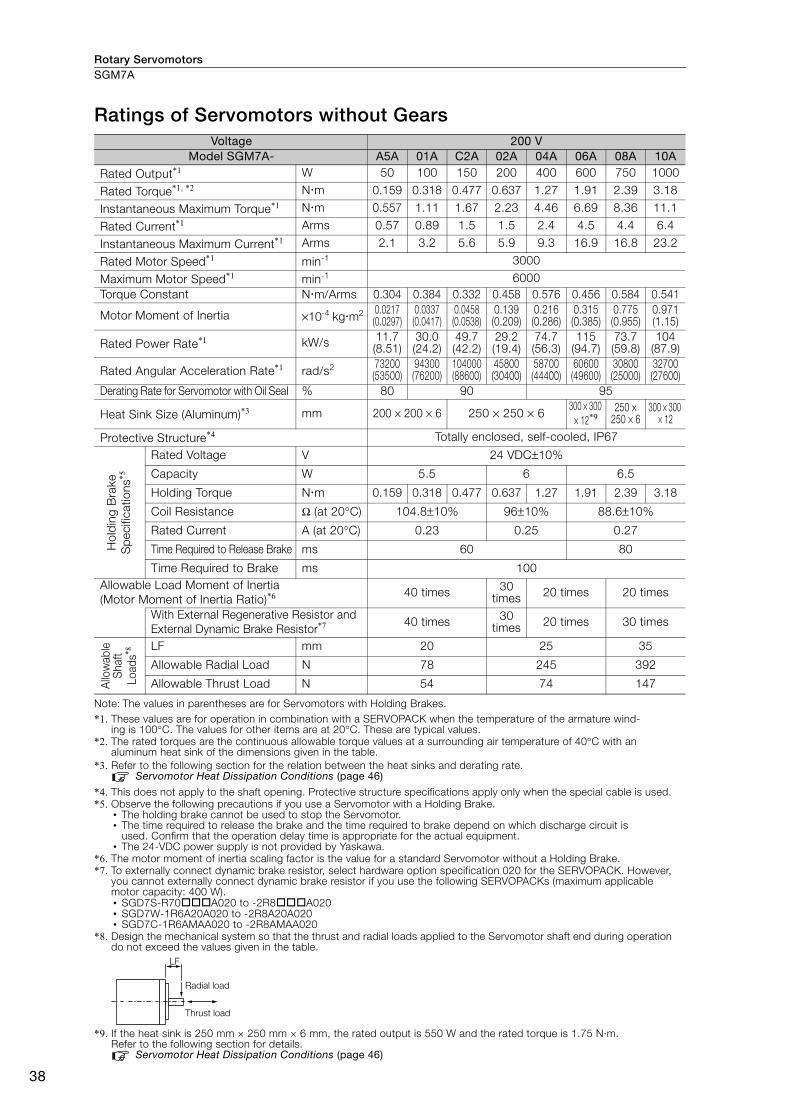
Rotary ServomotorsSGM7A
38
Ratings of Servomotors without Gears
Note: The values in parentheses are for Servomotors with Holding Brakes. *1. These values are for operation in combination with a SERVOPACK when the temperature of the armature wind-
ing is 100°C. The values for other items are at 20°C. These are typical values. *2. The rated torques are the continuous allowable torque values at a surrounding air temperature of 40°C with an
aluminum heat sink of the dimensions given in the table.*3. Refer to the following section for the relation between the heat sinks and derating rate.
Servomotor Heat Dissipation Conditions (page 46)
*4. This does not apply to the shaft opening. Protective structure specifications apply only when the special cable is used. *5. Observe the following precautions if you use a Servomotor with a Holding Brake.
• The holding brake cannot be used to stop the Servomotor. • The time required to release the brake and the time required to brake depend on which discharge circuit is
used. Confirm that the operation delay time is appropriate for the actual equipment. • The 24-VDC power supply is not provided by Yaskawa.
*6. The motor moment of inertia scaling factor is the value for a standard Servomotor without a Holding Brake.*7. To externally connect dynamic brake resistor, select hardware option specification 020 for the SERVOPACK. However,
you cannot externally connect dynamic brake resistor if you use the following SERVOPACKs (maximum applicable motor capacity: 400 W).• SGD7S-R70A020 to -2R8A020• SGD7W-1R6A20A020 to -2R8A20A020• SGD7C-1R6AMAA020 to -2R8AMAA020
*8. Design the mechanical system so that the thrust and radial loads applied to the Servomotor shaft end during operation do not exceed the values given in the table.
*9. If the heat sink is 250 mm × 250 mm × 6 mm, the rated output is 550 W and the rated torque is 1.75 N·m.Refer to the following section for details.
Servomotor Heat Dissipation Conditions (page 46)
Voltage 200 VModel SGM7A- A5A 01A C2A 02A 04A 06A 08A 10A
Rated Output*1 W 50 100 150 200 400 600 750 1000
Rated Torque*1, *2 Nm 0.159 0.318 0.477 0.637 1.27 1.91 2.39 3.18
Instantaneous Maximum Torque*1 Nm 0.557 1.11 1.67 2.23 4.46 6.69 8.36 11.1
Rated Current*1 Arms 0.57 0.89 1.5 1.5 2.4 4.5 4.4 6.4
Instantaneous Maximum Current*1 Arms 2.1 3.2 5.6 5.9 9.3 16.9 16.8 23.2
Rated Motor Speed*1 min-1 3000
Maximum Motor Speed*1 min-1 6000Torque Constant Nm/Arms 0.304 0.384 0.332 0.458 0.576 0.456 0.584 0.541
Motor Moment of Inertia ×10-4 kgm2 0.0217(0.0297)
0.0337(0.0417)
0.0458(0.0538)
0.139(0.209)
0.216(0.286)
0.315(0.385)
0.775(0.955)
0.971(1.15)
Rated Power Rate*1 kW/s 11.7 (8.51)
30.0 (24.2)
49.7 (42.2)
29.2 (19.4)
74.7 (56.3)
115 (94.7)
73.7 (59.8)
104 (87.9)
Rated Angular Acceleration Rate*1 rad/s2 73200(53500)
94300(76200)
104000(88600)
45800(30400)
58700(44400)
60600(49600)
30800(25000)
32700(27600)
Derating Rate for Servomotor with Oil Seal % 80 90 95
Heat Sink Size (Aluminum)*3 mm 200 × 200 × 6 250 × 250 × 6300 × 300
× 12*9250 ×
250 × 6300 × 300
× 12
Protective Structure*4 Totally enclosed, self-cooled, IP67
Hol
din
g B
rake
S
pec
ifica
tions
*5
Rated Voltage V 24 VDC±10%
Capacity W 5.5 6 6.5
Holding Torque Nm 0.159 0.318 0.477 0.637 1.27 1.91 2.39 3.18
Coil Resistance Ω (at 20°C) 104.8±10% 96±10% 88.6±10%
Rated Current A (at 20°C) 0.23 0.25 0.27
Time Required to Release Brake ms 60 80
Time Required to Brake ms 100Allowable Load Moment of Inertia (Motor Moment of Inertia Ratio)*6 40 times 30
times 20 times 20 times
With External Regenerative Resistor and External Dynamic Brake Resistor*7 40 times 30
times 20 times 30 times
Allo
wab
le
Shaf
t Lo
ads*8 LF mm 20 25 35
Allowable Radial Load N 78 245 392
Allowable Thrust Load N 54 74 147
LF
Radial load
Thrust load

Rotary Servomotors SGM7A
39
SG
M7
A
Torque-Motor Speed Characteristics
*1. The characteristics are the same for single-phase 200 V and single-phase 100 V input.
*2. A single-phase power input can be used in combination with the SGD7S-120AA008.
Note: 1. These values (typical values) are for operation in combination with a SERVOPACK when the temperature of the armature winding is 100°C.
2. The characteristics in the intermittent duty zone depend on the power supply voltage. 3. If the effective torque is within the allowable range for the rated torque, the Servomotor can be used within
the intermittent duty zone. 4. If you use a Servomotor Main Circuit Cable that exceeds 20 m, the intermittent duty zone in the torque-
motor speed characteristics will become smaller because the voltage drop increases.
SGM7A-A5A*1
A B
0 0.15 0.3 0.45 0.6 0.750
1000
2000
3000
4000
5000
6000
7000SGM7A-01A*1
A B
0 0.25 0.5 0.75 1 1.250
1000
2000
3000
4000
5000
6000
7000SGM7A-C2A
A B
0 0.5 1 1.5 2 2.50
1000
2000
3000
4000
5000
6000
7000
SGM7A-06A
A B
0 2 4 6 8 100
1000
2000
3000
4000
5000
6000
7000
SGM7A-08A
A B
0 2 4 6 8 100
1000
2000
3000
4000
5000
6000
7000
SGM7A-02A
A B
0 0.5 1 1.5 2 2.50
1000
2000
3000
4000
5000
6000
7000
SGM7A-10A*2
A B
0 2.5 5 7.5 10 12.50
1000
2000
3000
4000
5000
6000
7000
22
SGM7A-04A
A B
0 1 2 3 4 50
1000
2000
3000
4000
5000
6000
7000
A :
B :
Continuous duty zone (solid lines): With three-phase 200-V or single-phase 230-V input
(dotted lines): With single-phase 200-V input
(dashed-dotted lines): With single-phase 100-V inputIntermittent duty zone
Torque (N�m)
Mo
tor
sp
eed
(m
in-1)
Torque (N�m)M
oto
r sp
eed
(m
in-1)
Torque (N�m)
Mo
tor
sp
eed
(m
in-1)
Torque (N�m)
Mo
tor
sp
eed
(m
in-1)
Torque (N�m)
Mo
tor
sp
eed
(m
in-1)
Torque (N�m)
Mo
tor
sp
eed
(m
in-1)
Torque (N�m)
Mo
tor
sp
eed
(m
in-1)
Torque (N�m)
Mo
tor
sp
eed
(m
in-1)
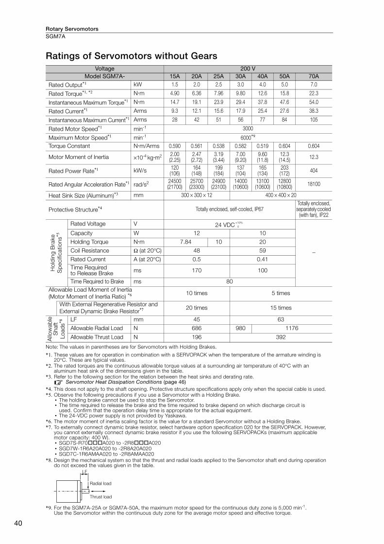
Rotary ServomotorsSGM7A
40
Ratings of Servomotors without Gears
Note: The values in parentheses are for Servomotors with Holding Brakes.
*1. These values are for operation in combination with a SERVOPACK when the temperature of the armature winding is 20°C. These are typical values.
*2. The rated torques are the continuous allowable torque values at a surrounding air temperature of 40°C with an aluminum heat sink of the dimensions given in the table.
*3. Refer to the following section for the relation between the heat sinks and derating rate.Servomotor Heat Dissipation Conditions (page 46)
*4. This does not apply to the shaft opening. Protective structure specifications apply only when the special cable is used. *5. Observe the following precautions if you use a Servomotor with a Holding Brake.
• The holding brake cannot be used to stop the Servomotor. • The time required to release the brake and the time required to brake depend on which discharge circuit is
used. Confirm that the operation delay time is appropriate for the actual equipment. • The 24-VDC power supply is not provided by Yaskawa.
*6. The motor moment of inertia scaling factor is the value for a standard Servomotor without a Holding Brake.*7. To externally connect dynamic brake resistor, select hardware option specification 020 for the SERVOPACK. However,
you cannot externally connect dynamic brake resistor if you use the following SERVOPACKs (maximum applicable motor capacity: 400 W).• SGD7S-R70A020 to -2R8A020• SGD7W-1R6A20A020 to -2R8A20A020• SGD7C-1R6AMAA020 to -2R8AMAA020
*8. Design the mechanical system so that the thrust and radial loads applied to the Servomotor shaft end during operation do not exceed the values given in the table.
*9. For the SGM7A-25A or SGM7A-50A, the maximum motor speed for the continuous duty zone is 5,000 min-1.Use the Servomotor within the continuous duty zone for the average motor speed and effective torque.
Voltage 200 VModel SGM7A- 15A 20A 25A 30A 40A 50A 70A
Rated Output*1 kW 1.5 2.0 2.5 3.0 4.0 5.0 7.0
Rated Torque*1, *2 Nm 4.90 6.36 7.96 9.80 12.6 15.8 22.3
Instantaneous Maximum Torque*1 Nm 14.7 19.1 23.9 29.4 37.8 47.6 54.0
Rated Current*1 Arms 9.3 12.1 15.6 17.9 25.4 27.6 38.3
Instantaneous Maximum Current*1 Arms 28 42 51 56 77 84 105
Rated Motor Speed*1 min-1 3000
Maximum Motor Speed*1 min-1 6000*9
Torque Constant Nm/Arms 0.590 0.561 0.538 0.582 0.519 0.604 0.604
Motor Moment of Inertia ×10-4 kgm2 2.00 (2.25)
2.47(2.72)
3.19(3.44)
7.00 (9.20)
9.60 (11.8)
12.3(14.5) 12.3
Rated Power Rate*1 kW/s 120 (106)
164 (148)
199 (184)
137 (104)
165 (134)
203 (172) 404
Rated Angular Acceleration Rate*1 rad/s2 24500(21700)
25700(23300)
24900(23100)
14000(10600)
13100(10600)
12800(10800) 18100
Heat Sink Size (Aluminum)*3 mm 300 × 300 × 12 400 × 400 × 20
Protective Structure*4 Totally enclosed, self-cooled, IP67 Totally enclosed, separately cooled
(with fan), IP22
Hol
din
g B
rake
S
pec
ifica
tions
*5
Rated Voltage V 24 VDC
−
Capacity W 12 10
Holding Torque Nm 7.84 10 20
Coil Resistance Ω (at 20°C) 48 59
Rated Current A (at 20°C) 0.5 0.41Time Required to Release Brake ms 170 100
Time Required to Brake ms 80Allowable Load Moment of Inertia (Motor Moment of Inertia Ratio) *6 10 times 5 times
With External Regenerative Resistor and External Dynamic Brake Resistor*7 20 times 15 times
Allo
wab
le
Sha
ft Lo
ads*8 LF mm 45 63
Allowable Radial Load N 686 980 1176
Allowable Thrust Load N 196 392
+10% 0
LF
Radial load
Thrust load

Rotary Servomotors SGM7A
41
SG
M7
A
Torque-Motor Speed Characteristics
* A single-phase power input can be used in combination with the SGD7S-120AA008.
Note: 1. These values (typical values) are for operation in combination with a SERVOPACK when the temperature of the armature winding is 20°C.
2. The characteristics in the intermittent duty zone depend on the power supply voltage.
3. If the effective torque is within the allowable range for the rated torque, the Servomotor can be used within the intermittent duty zone.
4. If you use a Servomotor Main Circuit Cable that exceeds 20 m, the intermittent duty zone in the torque-motor speed characteristics will become smaller because the voltage drop increases.
SGM7A-15A*
A B
0 5 10 15 20 5 10 15 200
1000
2000
3000
4000
5000
6000
7000SGM7A-20A
A B
00
1000
2000
3000
4000
5000
6000
7000SGM7A-25A
A B
0 7.5 15 22.5 300
1000
2000
3000
4000
5000
6000
7000
SGM7A-30A
A B
0 10 20 30 400
1000
2000
3000
4000
5000
6000
7000SGM7A-40A
A B
0 10 20 30 40 15 30 45 60
15 30 45 60
0
1000
2000
3000
4000
5000
6000
7000SGM7A-50A
A B
00
1000
2000
3000
4000
5000
6000
7000
SGM7A-70A
A B
00
1000
2000
3000
4000
5000
6000
7000
A :
B :
Continuous duty zone
Intermittent duty zone(solid lines): With three-phase 200-V or single-phase 230-V input
(dotted lines): With single-phase 200-V input
Torque (N�m)
Mo
tor
sp
eed
(m
in-1)
Torque (N�m)
Mo
tor
sp
eed
(m
in-1)
Torque (N�m)
Mo
tor
sp
eed
(m
in-1)
Torque (N�m)
Mo
tor
sp
eed
(m
in-1)
Torque (N�m)
Mo
tor
sp
eed
(m
in-1)
Torque (N�m)
Mo
tor
sp
eed
(m
in-1)
Torque (N�m)
Mo
tor
sp
eed
(m
in-1)

Rotary ServomotorsSGM7A
42
Ratings of Servomotors with Gears
*1. The gear output torque is expressed by the following formula.
The gear efficiency depends on operating conditions such as the output torque, motor speed, and temperature. The values in the table are typical values for the rated torque, rated motor speed, and a surrounding air temperature of 25°C. They are reference values only.
*2. When using an SGM7A-A5A, SGM7A-01A, or SGM7A-C2A Servomotor with a gear ratio of 1/5 or an SGM7A-C2A Servomotor with a gear ratio of 1/11, maintain an 85% maximum effective load ratio. For an SGM7A-C2A Servomotor with a gear ratio of 1/21 or 1/33, maintain a 90% maximum effective load ratio. The values in the table take the effective load ratio into consideration.
*3. The instantaneous maximum torque is 300% of the rated torque.Note: 1. The gears that are mounted to Yaskawa Servomotors have not been broken in.
Break in the Servomotor if necessary. First, operate the Servomotor at low speed with no load. If no problems occur, gradually increase the speed and load.
2. The no-load torque for a Servomotor with a Gear is high immediately after the Servomotor starts, and it then decreases and becomes stable after a few minutes. This is a common phenomenon caused by grease circulation in the gears and it does not indicate faulty gears.
3. Contact your Yaskawa representative for information on Servomotor with Gears with a rated output of 1.5 kW or higher.4. Other specifications are the same as those for Servomotors without Gears.
All Models Gear Mechanism Protective Structure Lost Motion [arc-min]
Planetary gear mechanism Totally enclosed, self-cooled, IP55 (except for shaft opening) 3 max.
Servomotor Model SGM7A-
Servomotor Gear Output
Rated Output [W]
Rated Motor Speed [min-1]
Maximum Motor Speed [min-1]
Rated Torque [N⋅m]
Instanta-neous Maxi-mum Torque
[N⋅m]
Gear Ratio
Rated Torque/Efficiency*1
[N⋅m/%]
Instantaneous Maximum
Torque [N⋅m]
Rated Motor Speed [min-1]
Maximum Motor Speed [min-1]
A5AAH1
50 3000 6000 0.159 0.557
1/5 0.433/64*2 2.37 600 1200A5AAH2 1/9 1.12/78 3.78*3 333 667A5AAHC 1/21 2.84/85 10.6 143 286
A5AAH7 1/33 3.68/70 15.8 91 18201AAH1
100 3000 6000 0.318 1.11
1/5 1.06/78*2 4.96 600 120001AAHB 1/11 2.52/72 10.7 273 54501AAHC 1/21 5.35/80 20.8 143 28601AAH7 1/33 7.35/70 32.7 91 182C2AAH1
150 3000 6000 0.477 1.67
1/5 1.68/83*2 7.80 600 1200C2AAHB 1/11 3.53/79*2 16.9 273 545C2AAHC 1/21 6.30/70*2 31.0 143 286C2AAH7 1/33 11.2/79*2 49.7 91 18202AAH1
200 3000 6000 0.637 2.23
1/5 2.39/75 9.80 600 120002AAHB 1/11 5.74/82 22.1 273 54502AAHC 1/21 10.2/76 42.1 143 28602AAH7 1/33 17.0/81 67.6 91 18204AAH1
400 3000 6000 1.27 4.46
1/5 5.35/84 20.1 600 120004AAHB 1/11 11.5/82 45.1 273 545
04AAHC 1/21 23.0/86 87.0 143 28604AAH7 1/33 34.0/81 135 91 18206AAH1
600 3000 6000 1.91 6.69
1/5 7.54/79 30.5 600 120006AAHB 1/11 18.1/86 68.6 273 54506AAHC 1/21 32.1/80 129 143 28606AAH7 1/33 53.6/85 206 91 18208AAH1
750 3000 6000 2.39 8.36
1/5 10.0/84 38.4 600 120008AAHB 1/11 23.1/88 86.4 273 54508AAHC 1/21 42.1/84 163 143 28608AAH7 1/33 69.3/88 259 91 18210AAH1
1000 3000 6000 3.18 11.1
1/5 13.7/86 52.5 600 120010AAHB 1/11 29.1/83 111 273 54510AAHC 1/21 58.2/87 215 143 28610AAH7 1/33 94.5/90 296*3 91 182
The SERVOPACK speed control range is 1:5,000. If you use Servomotors at extremely low speeds (0.02 min-1 or lower at the gear output shaft), if you use Servomotors with a one-pulse feed refer-ence for extended periods, or under some other operating conditions, the gear bearing lubrication may be insufficient. That may cause deterioration of the bearing or increase the load ratio. Contact your Yaskawa representative if you use a Servomotor under these conditions.
1Gear output torque = Servomotor output torque ×
Gear ratio× Efficiency
Important

Rotary Servomotors SGM7A
43
SG
M7
A
* The moment of inertia for the Servomotor and gear is the value without a holding brake. You can calculate the moment of inertia for a Servomotor with a Gear and Holding Brake with the following formula.
Motor moment of inertia for a Servomotor with a Holding Brake from Ratings of Servomotors without Gears (page 38) + Moment of inertia for the gear from the above table.
Servomotor Model SGM7A-
Moment of Inertia [×10-4 kg⋅m2] With Gears
Reference Diagram Shaft Output Flange Output Allowable
Radial Load [N]
Allowable Thrust Load [N]
LF[mm]Motor*
+ Gear Gear Motor* + Gear Gear
A5AAH1 0.0277 0.006 0.0267 0.005 95 431 37A5AAH2 0.0247 0.003 0.0247 0.003 113 514 37A5AAHC 0.0257 0.004 0.0257 0.004 146 663 37A5AAH7 0.0667 0.045 0.0667 0.045 267 1246 5301AAH1 0.0397 0.006 0.0387 0.005 95 431 3701AAHB 0.0937 0.060 0.0927 0.059 192 895 5301AAHC 0.0837 0.050 0.0837 0.050 233 1087 5301AAH7 0.0987 0.065 0.0977 0.064 605 2581 75C2AAH1 0.0518 0.006 0.0508 0.005 95 431 37C2AAHB 0.106 0.060 0.105 0.059 192 895 53C2AAHC 0.156 0.110 0.154 0.108 528 2254 75C2AAH7 0.111 0.065 0.110 0.064 605 2581 7502AAH1 0.346 0.207 0.340 0.201 152 707 5302AAHB 0.332 0.193 0.331 0.192 192 895 5302AAHC 0.629 0.490 0.627 0.488 528 2254 7502AAH7 0.589 0.450 0.588 0.449 605 2581 7504AAH1 0.423 0.207 0.417 0.201 152 707 5304AAHB 0.786 0.570 0.776 0.560 435 1856 7504AAHC 0.706 0.490 0.704 0.488 528 2254 7504AAH7 0.836 0.620 0.826 0.610 951 4992 12806AAH1 1.02 0.700 0.975 0.660 343 1465 7506AAHB 0.885 0.570 0.875 0.560 435 1856 7506AAHC 1.16 0.840 1.14 0.820 830 4359 12806AAH7 0.935 0.620 0.925 0.610 951 4992 12808AAH1 1.48 0.700 1.44 0.660 343 1465 7508AAHB 1.38 0.600 1.37 0.590 435 1856 7508AAHC 3.78 3.00 3.76 2.98 830 4359 12808AAH7 3.58 2.80 3.57 2.79 951 4992 12810AAH1 1.67 0.700 1.63 0.660 343 1465 7510AAHB 4.37 3.40 4.31 3.34 684 3590 12810AAHC 3.97 3.00 3.95 2.98 830 4359 12810AAH7 3.77 2.80 3.76 2.79 951 4992 128
During operation, the gear generates the loss at the gear mechanism and oil seal. The loss depends on the torque and motor speed conditions. The temperature rise depends on the loss and heat dissipation condi-tions. For the heat dissipation conditions, always refer to the following table and check the gear and motor temperatures with the actual equipment. If the temperature is too high, implement the following measures. • Decrease the load ratio. • Change the heat dissipation conditions.• Use forced-air cooling for the motor with a cooling fan or other means.
LF
Shaft Output
Radial load
Thrust load
Flange Output
Radial load
Thrust load
LF
Important
• A: 250 mm × 250 mm × 6 mm, aluminum plate • B: 300 mm × 300 mm × 12 mm, aluminum plate • C: 350 mm × 350 mm × 12 mm, aluminum plate
ModelHeat Sink Size
1/5 1/9 or 1/11 1/21 1/33
SGM7A-A5 A
SGM7A-01
BSGM7A-C2
SGM7A-02
SGM7A-04
SGM7A-06
CSGM7A-08
SGM7A-10A

Rotary ServomotorsSGM7A
44
Servomotor Overload Protection Characteristics The overload detection level is set for hot start conditions with a Servomotor surrounding air tem-perature of 40°C.
Note: The above overload protection characteristics do not mean that you can perform continuous duty operation with an output of 100% or higher. Use the Servomotor so that the effective torque remains within the contin-uous duty zone given in Torque-Motor Speed Characteristics on page 39 or page 41.
SGM7A-A5, -01, -C2, -02, -04, -06, -08, and -10
0 50 100 150 200 300250 350
10000
1000
100
10
1
Dete
ctio
n t
ime (s)
Motor speed of 10 min-1 or higher
Motor speed of less than 10 min-1
Torque reference (percent of rated torque) (%)
Dete
ctio
n t
ime (s)
Torque reference (percent of rated torque) (%)
SGM7A-15, -20, -25, -30, -40, -50, and -70
0 50 100 150 200 250 300
10000
1000
100
10
1
SGM7A-15, -20, -25,
-30, -40, and -50
SGM7A-70

Rotary Servomotors SGM7A
45
SG
M7
A
Allowable Load Moment of InertiaThe allowable load moments of inertia (motor moment of inertia ratios) for the Servomotors are given in the Ratings of Servomotors without Gears (pages 38 and 40). The values are determined by the regenerative energy processing capacity of the SERVOPACK and are also affected by the drive con-ditions of the Servomotor. Perform the required Steps for each of the following cases.
Use the SigmaJunmaSize+ AC Servo Drive Capacity Selection Program to check the driving condi-tions. Contact your Yaskawa representative for information on this program.
Exceeding the Allowable Load Moment of InertiaUse one of the following measures to adjust the load moment of inertia to within the allowable value.• Reduce the torque limit.• Reduce the deceleration rate.• Reduce the maximum motor speed.
If the above steps is not possible, install an external regenerative resistor.
SERVOPACKs without Built-in Regenerative ResistorsThe following graph shows the allowable load moment of inertia scaling factor of the motor speed (reference values for deceleration operation at or above the rated torque). Application is possible without an external regenerative resistor within the allowable value. However, an External Regenera-tive Resistor is required in the shaded areas of the graphs.
Note: Applicable SERVOPACK models: SGD7S-R70A, -R90A, -1R6A, -2R8A, -R70F, -R90F, -2R1F, and -2R8F
When an External Regenerative Resistor Is RequiredInstall the External Regenerative Resistor. Refer to the following section for the recommended products.
External Regenerative Resistors (page 456)
An Overvoltage Alarm (A.400) is likely to occur during deceleration if the load moment of iner-tia exceeds the allowable load moment of inertia. SERVOPACKs with a built-in regenerative resistor may generate a Regenerative Overload Alarm (A.320). Refer to Built-In Regenerative Resistor (page 456) for the regenerative power (W) that can be processed by the SERVO-PACKs. Install an External Regenerative Resistor when the built-in regenerative resistor cannot pro-cess all of the regenerative power.
Information
0
5
10
15
20
25
30
35
40
45
0
SGM7A-A5A SGM7A-C2A
0
5
10
15
20
25SGM7A-04A
1000 2000 3000 4000 5000 6000 7000 0 1000 2000 3000 4000 5000 6000 70000
5
10
15
20
25
30
35
40
45
0 1000 2000 3000 4000 5000 6000 7000
0
5
10
15
20
25
30
35
40
45
0
SGM7A-01A
SGM7A-02A
1000 2000 3000 4000 5000 6000 7000
0 1000 2000 3000 4000 5000 6000 70000
5
10
15
20
25
30
35
Motor speed (min-1)
Allo
wab
le lo
ad m
om
ent
of in
ertia
sc
alin
g fac
tor
(tim
es)
Motor speed (min-1)
Allo
wab
le lo
ad m
om
ent
of in
ertia
sc
alin
g fac
tor
(tim
es)
Motor speed (min-1)
Allo
wab
le lo
ad m
om
ent
of in
ertia
sc
alin
g fac
tor
(tim
es)
Motor speed (min-1)
Allo
wab
le lo
ad m
om
ent
of in
ertia
sc
alin
g fac
tor
(tim
es)
Motor speed (min-1)
Allo
wab
le lo
ad m
om
ent
of in
ertia
sc
alin
g fac
tor
(tim
es)
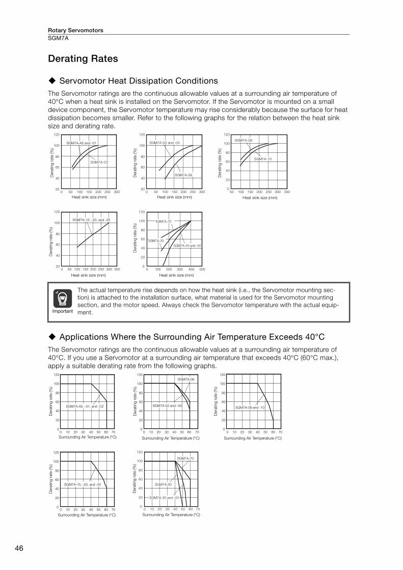
Rotary ServomotorsSGM7A
46
Derating Rates
Servomotor Heat Dissipation Conditions The Servomotor ratings are the continuous allowable values at a surrounding air temperature of 40°C when a heat sink is installed on the Servomotor. If the Servomotor is mounted on a small device component, the Servomotor temperature may rise considerably because the surface for heat dissipation becomes smaller. Refer to the following graphs for the relation between the heat sink size and derating rate.
Applications Where the Surrounding Air Temperature Exceeds 40°C The Servomotor ratings are the continuous allowable values at a surrounding air temperature of 40°C. If you use a Servomotor at a surrounding air temperature that exceeds 40°C (60°C max.), apply a suitable derating rate from the following graphs.
The actual temperature rise depends on how the heat sink (i.e., the Servomotor mounting sec-tion) is attached to the installation surface, what material is used for the Servomotor mounting section, and the motor speed. Always check the Servomotor temperature with the actual equip-ment.
Dera
ting
rate
(%
)D
era
ting
rate
(%
)
Dera
ting
rate
(%
)
Heat sink size (mm)
Heat sink size (mm) Heat sink size (mm)
Heat sink size (mm) Heat sink size (mm)
Dera
ting
rate
(%
)
Dera
ting
rate
(%
)100
80
120
60
40
200 150 250 35030020010050 300 5004002001000
0
20
40
60
80
100
120
SGM7A-30
SGM7A-40 and -50
SGM7A-70
100
80
120 120
60
40
200
100
80
60
40
20150 250 300200100500 150 250 300 35020010050150 250 30020010050
SGM7A-C2
0
20
40
60
80
100
120
SGM7A-10
SGM7A-08SGM7A-02 and -04
SGM7A-06
SGM7A-A5 and -01
SGM7A-15, -20, and -25
Important
Dera
ting
rate
(%
)D
era
ting
rate
(%
)
Dera
ting
rate
(%
)D
era
ting
rate
(%
)
Dera
ting
rate
(%
)
Surrounding Air Temperature (C) Surrounding Air Temperature (C) Surrounding Air Temperature (C)
Surrounding Air Temperature (C) Surrounding Air Temperature (C)
0
20
40
60
80
100
120
0
20
40
60
80
100
120
0
20
40
60
80
100
120
0
20
40
60
80
100
120
0 10 20 30 40 50 60 70
0 10 20 30 40 50 60 70 0 10 20 30 40 50 60 70 0 10 20 30 40 50 60 70
SGM7A-A5, -01, and -C2
SGM7A-15, -20, and -25
SGM7A-02 and -04
SGM7A-06
SGM7A-08 and -10
0
20
40
60
80
100
120
0 10 20 30 40 50 60 70
SGM7A-50
SGM7A-30 and -40
SGM7A-70
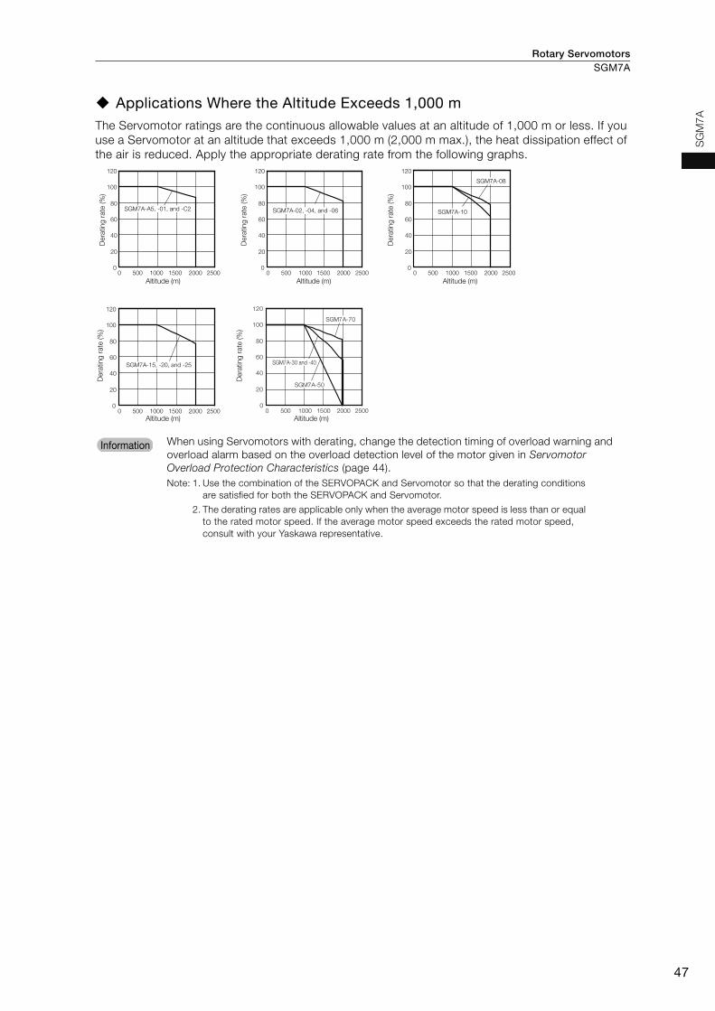
Rotary Servomotors SGM7A
47
SG
M7
A
Applications Where the Altitude Exceeds 1,000 m The Servomotor ratings are the continuous allowable values at an altitude of 1,000 m or less. If you use a Servomotor at an altitude that exceeds 1,000 m (2,000 m max.), the heat dissipation effect of the air is reduced. Apply the appropriate derating rate from the following graphs.
When using Servomotors with derating, change the detection timing of overload warning and overload alarm based on the overload detection level of the motor given in Servomotor Overload Protection Characteristics (page 44).Note: 1. Use the combination of the SERVOPACK and Servomotor so that the derating conditions
are satisfied for both the SERVOPACK and Servomotor.
2. The derating rates are applicable only when the average motor speed is less than or equal to the rated motor speed. If the average motor speed exceeds the rated motor speed, consult with your Yaskawa representative.
Dera
ting
rate
(%
)D
era
ting
rate
(%
)
Dera
ting
rate
(%
)D
era
ting
rate
(%
)
Altitude (m)
Altitude (m) Altitude (m)
Altitude (m) Altitude (m)
Dera
ting
rate
(%
)
0
20
40
60
80
100
120
0
20
40
60
80
100
120
0
20
40
60
80
100
120
0
20
40
60
80
100
120
0 500 1000 1500 25002000 0 500 1000 1500 25002000
0 500 1000 1500 25002000
0 500 1000 1500 25002000
SGM7A-08
SGM7A-10SGM7A-02, -04, and -06
SGM7A-15, -20, and -25
SGM7A-A5, -01, and -C2
0
20
40
60
80
100
120
0 500 1000 1500 25002000
SGM7A-30 and -40
SGM7A-50
SGM7A-70
InformationInformation
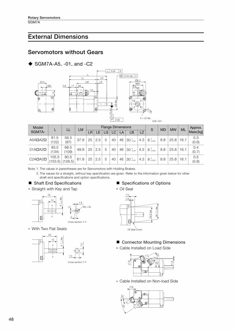
Rotary ServomotorsSGM7A
48
External Dimensions
Servomotors without Gears
SGM7A-A5, -01, and -C2
Note: 1. The values in parentheses are for Servomotors with Holding Brakes.
2. The values for a straight, without key specification are given. Refer to the information given below for other shaft end specifications and option specifications.
Model SGM7A-
L LL LMFlange Dimensions
S MD MW MLApprox.
Mass [kg] LR LE LG LC LA LB LZ
A5AA281.5(122)
56.5(97)
37.9 25 2.5 5 40 46 30 4.3 8 8.8 25.8 16.10.3(0.6)
01AA293.5(134)
68.5(109)
49.9 25 2.5 5 40 46 30 4.3 8 8.8 25.8 16.10.4(0.7)
C2AA2105.5(153.5)
80.5(128.5)
61.9 25 2.5 5 40 46 30 4.3 8 8.8 25.8 16.10.5(0.8)
Shaft End Specifications• Straight with Key and Tap
• With Two Flat Seats
Specifications of Options • Oil Seal
Connector Mounting Dimensions• Cable Installed on Load Side
• Cable Installed on Non-load Side
�LC
LG
LA dia.S d
ia.
14
ML170.6
LM LE
LRLL
L
0.8MW
MD
20.5
0.02
0.04 A
ALB
dia
.
0.04 dia. A
2 × LZ dia.
Unit: mm
0-0.021
0-0.009
0-0.021
0-0.009
0-0.021
0-0.009
14
Y
Y
25
3
3
1.8
Cross section Y-Y
M3 × 6L
8
dia
.0
-0.0
09
15
Y
Y
25
7.5
7.5
Cross section Y-Y
8
dia
.0
-0.0
09
1.5
7.5
Oil Seal Cover
29
.8 d
ia.
30
d
ia.
0
- 0
.02
1
(7.4
)
25°
35° (1
.2)
25°
35°
(10)

Rotary Servomotors SGM7A
49
SG
M7
A
SGM7A-02, -04, and -06
Note: 1. The values in parentheses are for Servomotors with Holding Brakes.
2. The values for a straight, without key specification are given. Refer to the information given below for other shaft end specifications and option specifications.
Model SGM7A-
L LL LMFlange Dimensions
S MD MW MH MLApprox. Mass [kg]LR LE LG LC LA LB LZ
02AA299.5(140)
69.5(110)
51.2 30 3 6 60 70 50 5.5 14 8.5 28.7 14.7 17.10.8(1.4)
04AA2115.5(156)
85.5(126)
67.2 30 3 6 60 70 50 5.5 14 8.5 28.7 14.7 17.11.2(1.8)
06AA2137.5(191.5)
107.5(161.5)
89.2 30 3 6 60 70 50 5.5 14 8.5 28.7 14.7 17.11.6(2.2)
Shaft End Specifications• Straight with Key and Tap
• With Two Flat Seats
Specifications of Options • Oil Seal
Connector Mounting Dimensions• Cable Installed on Load Side
• Cable Installed on Non-load Side
14
0.6 17 LG
LE
LRLL
L
LB
dia
.
S d
ia.
�LC
LA d
ia.
ML
MH
MW
LM
MD
20.5
0.04 A
A
0.02
0.04 dia. A
4 × LZ dia. Unit: mm
0-0.025
0-0.011
0-0.025
0-0.011
0-0.025
0-0.011
14
Y
Y
30
5
5
3
M5 × 8L 14
d
ia.
Cross section Y-Y
0
-0.0
11
Cross section Y-Y
15
Y
Y
30
13
13
14
d
ia.
0
-0.0
11
47
dia
.
35
dia
.
35.2
10
Oil Seal Cover
25°
35°
25°
35°
(10)
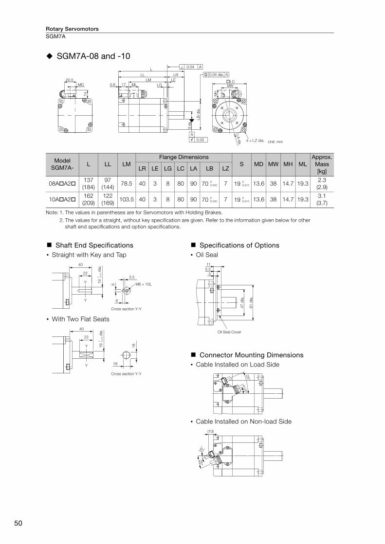
Rotary ServomotorsSGM7A
50
SGM7A-08 and -10
Note: 1. The values in parentheses are for Servomotors with Holding Brakes.
2. The values for a straight, without key specification are given. Refer to the information given below for other shaft end specifications and option specifications.
Model SGM7A-
L LL LMFlange Dimensions
S MD MW MH MLApprox. Mass [kg]LR LE LG LC LA LB LZ
08AA2137(184)
97(144)
78.5 40 3 8 80 90 70 7 19 13.6 38 14.7 19.32.3(2.9)
10AA2162(209)
122(169)
103.5 40 3 8 80 90 70 7 19 13.6 38 14.7 19.33.1(3.7)
Shaft End Specifications• Straight with Key and Tap
• With Two Flat Seats
Specifications of Options • Oil Seal
Connector Mounting Dimensions• Cable Installed on Load Side
• Cable Installed on Non-load Side
14
0.6 17 LG
LE
LRLL
L
LB
dia
.
S d
ia.
�LC
LA d
ia.
ML
MH
MW
LM
MD
20.5
0.04 A
A
0.02
0.04 dia. A
4 × LZ dia. Unit: mm
0-0.030
0-0.013
0-0.030
0-0.013
Cross section Y-Y
22
Y
Y
40
6
6
3.5
M6 × 10L 19
d
ia.
0
-0.0
13
Cross section Y-Y
22
Y
Y
40
18
18
19
d
ia.
0
-0.0
13
61
dia
.
47
dia
.
35.5
11
Oil Seal Cover
25°
25°
25°
25°
(10)

Rotary Servomotors SGM7A
51
SG
M7
A
Servomotors without Gears and without Holding Brakes SGM7A-15, -20, and -25
Note: 1. The values in parentheses are for Servomotors with Holding Brakes.
2. The values for a straight, without key specification are given. Refer to the information given below for other shaft end specifications and option specifications.
Model SGM7A- L LL LM LR KB1 KB2 KL115AA21 202 157 121 45 107 145 9420AA21 218 173 137 45 123 161 9425AA21 241 196 160 45 146 184 94
Model SGM7A-Flange Dimensions Shaft End Dimensions Approx.
Mass [kg] LA LB LC LE LG LH LZ S Q
15AA21 115 95 100 3 10 130 7 24 40 4.6
20AA21 115 95 100 3 10 130 7 24 40 5.4
25AA21 115 95 100 3 10 130 7 24 40 6.8
Shaft End Specifications Connector Specifications
• Straight with Key and Tap • Encoder Connector (24-bit Encoder)
* A battery is required only for an absolute encoder.
Receptacle: CM10-R10P-DApplicable plug: Not provided by Yaskawa.Plug:CM10-AP10S--D for Right-angle Plug
CM10-SP10S--D for Straight Plug( depends on the applicable cable size.)
Manufacturer: DDK Ltd.
• Servomotor Connector
Manufacturer: DDK Ltd.
R1
Q
S d
ia.
30 d
ia.
LE
LR
45
dia
.
Unit: mm
17
LG
LB
dia
.
S d
ia.
KB1
50
KL1
106.5
KB2
LA dia.LC
LE
LR
LH dia.
4 LZ dia.
79
dia
.
0.02
0.5
36
L
LL
LM
40
65
dia
.
A
0.04 A
0.04 dia. A
Shaft End Details
0-0.035
0-0.013
0-0.035
0-0.013
0-0.035
0-0.013
45
40
32
4
R1
M8 × 16L
7
8
24
dia
.0
-0.0
13
3
7
10 8
4
11 PS 6* BAT(+)2 /PS 7 −3 − 8 −4 PG5V 9 PG0V5* BAT(−) 10 FG (frame ground)
A
BC
D
A Phase U C Phase WB Phase V D FG (frame ground)

Rotary ServomotorsSGM7A
52
SGM7A-30, -40, and -50
Note: 1. The values in parentheses are for Servomotors with Holding Brakes.
2. The values for a straight, without key specification are given. Refer to the information given below for other shaft end specifications and option specifications.
Model SGM7A- L LL LM LR KB1 KB2 KL130AA21 257 194 158 63 145 182 11440AA21 296 233 197 63 184 221 11450AA21 336 273 237 63 224 261 114
Model SGM7A-Flange Dimensions Shaft End Dimensions Approx.
Mass [kg] LA LB LC LE LG LH LZ S Q
30AA21 145 110 130 6 12 165 9 28 55 10.5
40AA21 145 110 130 6 12 165 9 28 55 13.5
50AA21 145 110 130 6 12 165 9 28 55 16.5
Shaft End Specifications Connector Specifications
• Straight with Key and Tap • Encoder Connector (24-bit Encoder)
* A battery is required only for an absolute encoder.
Receptacle: CM10-R10P-DApplicable plug: Not provided by Yaskawa.Plug:CM10-AP10S--D for Right-angle Plug
CM10-SP10S--D for Straight Plug( depends on the applicable cable size.)
Manufacturer: DDK Ltd.
• Servomotor Connector
Manufacturer: DDK Ltd.
R1
Q
S d
ia.
30
dia
.
LE
LR
45
dia
.
Shaft End Details
Unit: mm
A
1.5
55
LA dia.
LC
LH dia.
17
79
dia
.5
0
KL1
KB1
KB2
LB
dia
.
65
dia
.
S d
ia.
0.02
36
LELG
LM
LL
L
LR
0.04 A
0.04 dia. A
4 LZ dia.
0-0.035
0-0.013
0-0.035
0-0.013
0-0.035
0-0.013
63
55
50
4
R1
M8 × 16L
7
8
28 d
ia.
0
-0.0
13
3
7
10 8
4
11 PS 6* BAT(+)2 /PS 7 −3 − 8 −4 PG5V 9 PG0V5* BAT(−) 10 FG (frame ground)
A
BC
D
A Phase U C Phase WB Phase V D FG (frame ground)
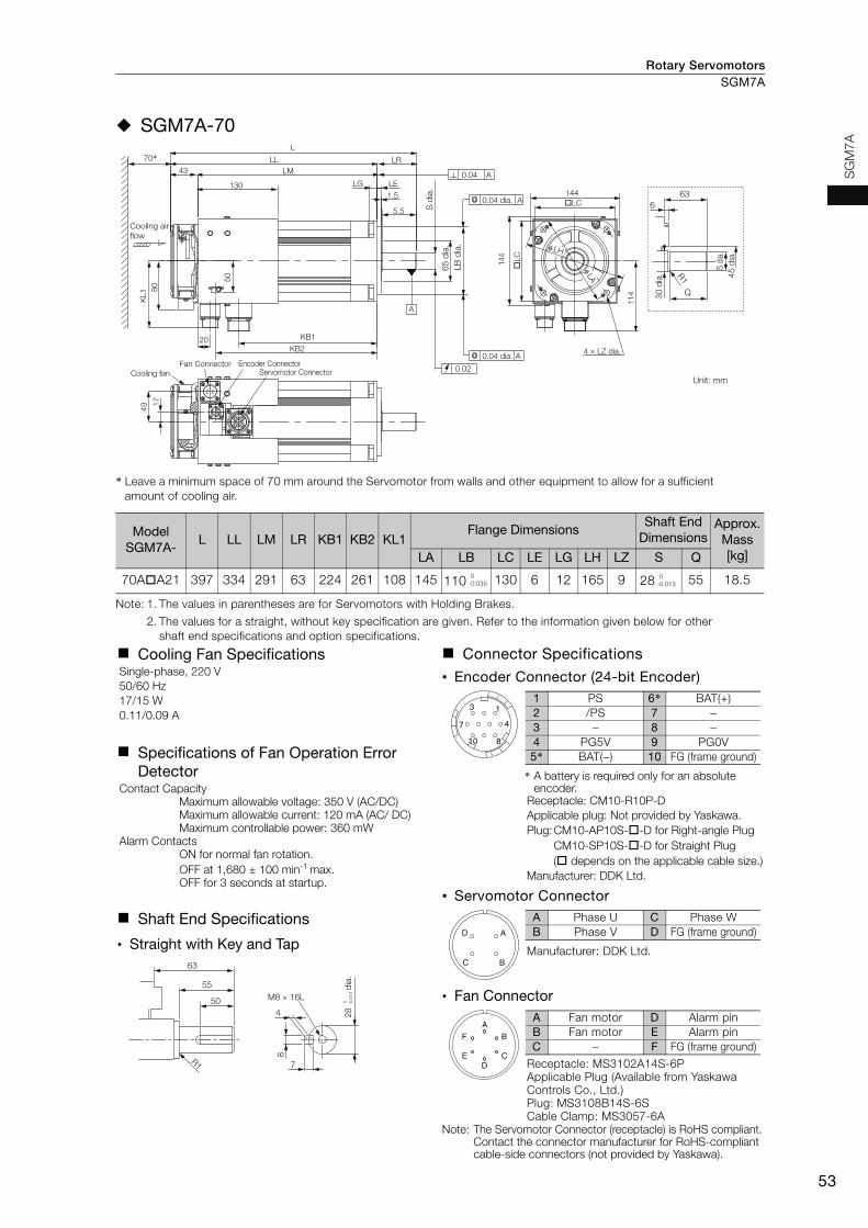
Rotary Servomotors SGM7A
53
SG
M7
A
SGM7A-70
* Leave a minimum space of 70 mm around the Servomotor from walls and other equipment to allow for a sufficient amount of cooling air.
Note: 1. The values in parentheses are for Servomotors with Holding Brakes.
2. The values for a straight, without key specification are given. Refer to the information given below for other shaft end specifications and option specifications.
Model SGM7A-
L LL LM LR KB1 KB2 KL1Flange Dimensions
Shaft End Dimensions
Approx. Mass [kg]LA LB LC LE LG LH LZ S Q
70AA21 397 334 291 63 224 261 108 145 110 130 6 12 165 9 28 55 18.5
Cooling Fan SpecificationsSingle-phase, 220 V50/60 Hz17/15 W0.11/0.09 A
Specifications of Fan Operation Error Detector
Contact CapacityMaximum allowable voltage: 350 V (AC/DC)Maximum allowable current: 120 mA (AC/ DC)Maximum controllable power: 360 mW
Alarm ContactsON for normal fan rotation.OFF at 1,680 ± 100 min-1 max.OFF for 3 seconds at startup.
Shaft End Specifications
• Straight with Key and Tap
Connector Specifications
• Encoder Connector (24-bit Encoder)
* A battery is required only for an absolute encoder.
Receptacle: CM10-R10P-DApplicable plug: Not provided by Yaskawa.Plug:CM10-AP10S--D for Right-angle Plug
CM10-SP10S--D for Straight Plug( depends on the applicable cable size.)
Manufacturer: DDK Ltd.
• Servomotor Connector
Manufacturer: DDK Ltd.
• Fan Connector
Receptacle: MS3102A14S-6PApplicable Plug (Available from Yaskawa Controls Co., Ltd.)Plug: MS3108B14S-6SCable Clamp: MS3057-6A
Note: The Servomotor Connector (receptacle) is RoHS compliant.Contact the connector manufacturer for RoHS-compliant cable-side connectors (not provided by Yaskawa).
Unit: mm
R1
30
dia
.
Q
63
6
S d
ia.
45
dia
.
Fan ConnectorCooling fan
144
A
LR
5.5
130
43
L
LL
LM0.04 A
50
KB1
KB2
LE
1.5
LG
0.02
�LC
Cooling air
flow
KL1 8
070*
Encoder ConnectorServomotor Connector
20
17
49
0.04 dia.
LB
dia
.
A
0.04 dia. A
11
4
4 × LZ dia.
�LC
144
φLA
φ LH
65
dia
.
S d
ia.
0-0.035
0-0.013
63
55
50
4
R1
M8 × 16L
7
8
28 d
ia.
0
-0.0
13
3
7
10 8
4
11 PS 6* BAT(+)2 /PS 7 −3 − 8 −4 PG5V 9 PG0V5* BAT(−) 10 FG (frame ground)
A
BC
D
A Phase U C Phase WB Phase V D FG (frame ground)
D
A
E
F
C
B
A Fan motor D Alarm pinB Fan motor E Alarm pinC – F FG (frame ground)

Rotary ServomotorsSGM7A
54
Servomotors without Gears and with Holding Brakes
SGM7A-15 to -25
Note: 1. The values in parentheses are for Servomotors with Holding Brakes. 2. The values for a straight, without key specification are given. Refer to the information given below for other
shaft end specifications and option specifications.
Model SGM7A- L LL LM LR KB1 KB2 KB3 KL1
15AA2C 243 198 162 45 107 186 139 10220AA2C 259 214 178 45 123 202 155 10225AA2C 292 247 211 45 156 235 188 102
Model SGM7A-
Flange Dimensions Shaft End Dimensions Approx. Mass [kg]LA LB LC LE LG LH LZ S Q
15AA2C 115 95 100 3 10 130 7 24 40 6.0
20AA2C 115 95 100 3 10 130 7 24 40 6.8
25AA2C 115 95 100 3 10 130 7 24 40 8.7
Shaft End Specifications Connector Specifications
• Straight with Key and Tap • Encoder Connector (24-bit Encoder)
* A battery is required only for an absolute encoder.Receptacle: CM10-R10P-DApplicable plug: Not provided by Yaskawa.Plug:CM10-AP10S--D for Right-angle Plug
CM10-SP10S--D for Straight Plug( depends on the applicable cable size.)
Manufacturer: DDK Ltd.
• Servomotor Connector
Manufacturer: DDK Ltd.
• Brake Connector
Note: There is no voltage polarity for the brake terminals.
Receptacle: CM10-R10P-DApplicable plug: Not provided by Yaskawa.Plug:CM10-AP2S--D for Right-angle Plug
CM10-SP2S--D for Straight Plug( depends on the applicable cable size.)Manufacturer: DDK Ltd.
Q
R1
LE
LR
30
dia
.
S d
ia.
45
dia
.
Shaft End Details
Unit: mm
A
36
L
LL LR
LG LE
0.5
40
LM0.04 A
50
80
KL1
φ 115
LH dia.φ 1307
9 d
ia.
17
A0.04 dia.
�LC
S d
ia.
LB
dia
.
65
dia
.
0.02 4 × LZ dia.
LA dia.
KB2
KB3
KB1
0-0.035
0-0.013
0-0.035
0-0.013
0-0.035
0-0.013
45
40
32
4
R1
M8 × 16L
7
8
24
dia
.0
-0.0
13
3
7
10 8
4
11 PS 6* BAT(+)2 /PS 7 −3 − 8 −4 PG5V 9 PG0V5* BAT(−) 10 FG (frame ground)
A
BC
D
A Phase U C Phase WB Phase V D FG (frame ground)
1
2
1 Brake terminal2 Brake terminal
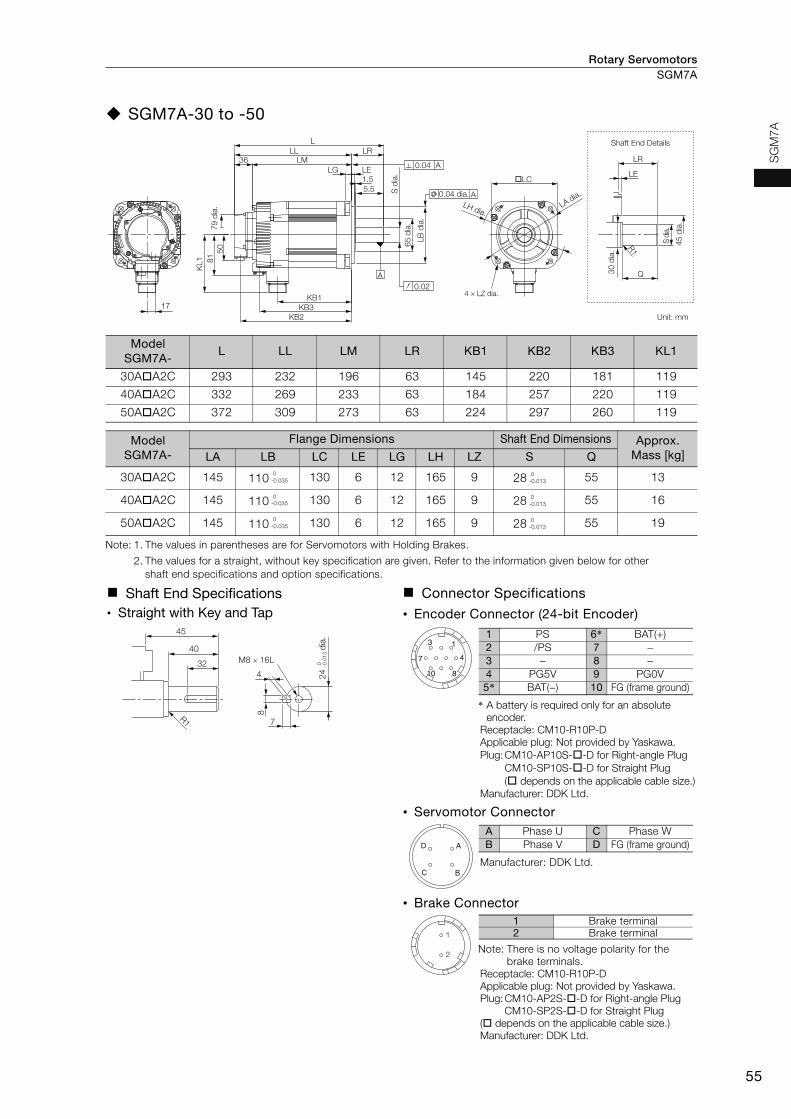
Rotary Servomotors SGM7A
55
SG
M7
A
SGM7A-30 to -50
Note: 1. The values in parentheses are for Servomotors with Holding Brakes.
2. The values for a straight, without key specification are given. Refer to the information given below for other shaft end specifications and option specifications.
Model SGM7A-
L LL LM LR KB1 KB2 KB3 KL1
30AA2C 293 232 196 63 145 220 181 119
40AA2C 332 269 233 63 184 257 220 119
50AA2C 372 309 273 63 224 297 260 119
Model SGM7A-
Flange Dimensions Shaft End Dimensions Approx. Mass [kg]LA LB LC LE LG LH LZ S Q
30AA2C 145 110 130 6 12 165 9 28 55 13
40AA2C 145 110 130 6 12 165 9 28 55 16
50AA2C 145 110 130 6 12 165 9 28 55 19
Shaft End Specifications Connector Specifications• Straight with Key and Tap • Encoder Connector (24-bit Encoder)
* A battery is required only for an absolute encoder.
Receptacle: CM10-R10P-DApplicable plug: Not provided by Yaskawa.Plug:CM10-AP10S--D for Right-angle Plug
CM10-SP10S--D for Straight Plug( depends on the applicable cable size.)
Manufacturer: DDK Ltd.
• Servomotor Connector
Manufacturer: DDK Ltd.
• Brake Connector
Note: There is no voltage polarity for the brake terminals.
Receptacle: CM10-R10P-DApplicable plug: Not provided by Yaskawa.Plug:CM10-AP2S--D for Right-angle Plug
CM10-SP2S--D for Straight Plug( depends on the applicable cable size.)Manufacturer: DDK Ltd.
A
17
KL1 81
50
36
LG LE1.5
5.5
LMLL LR
L
KB2
KB3
KB1
79
dia
.
0.04 A
A0.04 dia.
0.02
LB
dia
.
65
dia
.
S d
ia.
LH dia.
�LC
LA dia.
4 × LZ dia.
Q
R1
LE
LR
30
dia
.
S d
ia.
45
dia
.
Shaft End Details
Unit: mm
0-0.035
0-0.013
0-0.035
0-0.013
0-0.035
0-0.013
45
40
32
4
R1
M8 × 16L
7
8
24
dia
.0
-0.0
13
3
7
10 8
4
11 PS 6* BAT(+)2 /PS 7 −3 − 8 −4 PG5V 9 PG0V5* BAT(−) 10 FG (frame ground)
A
BC
D
A Phase U C Phase WB Phase V D FG (frame ground)
1
2
1 Brake terminal2 Brake terminal
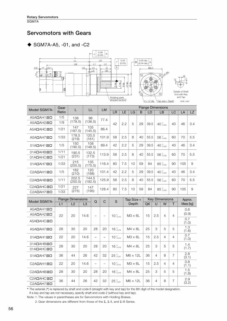
Rotary ServomotorsSGM7A
56
Servomotors with Gears
SGM7A-A5, -01, and -C2
* The asterisk (*) is replaced by shaft end code 6 (straight with key and tap) for the 8th digit of the model designation. If a key and tap are not necessary, specify shaft end code 2 (without key and tap).
Note: 1. The values in parentheses are for Servomotors with Holding Brakes.
2. Gear dimensions are different from those of the Σ, Σ-II, and Σ-III Series.
Model SGM7A-Gear Ratio
L LL LMFlange Dimensions
LR LE LG B LD LB LC LA LZ
A5AAH1 1/5 138(178.5)
96(136.5) 77.4
42 2.2 5 29 39.5 40 40 46 3.4A5AAH2 1/9
A5AAHC 1/21 147(187.5)
105(145.5) 86.4
A5AAH7 1/33 178.5(219)
120.5(161) 101.9 58 2.5 8 40 55.5 56 60 70 5.5
01AAH1 1/5 150(190.5)
108(148.5) 89.4 42 2.2 5 29 39.5 40 40 46 3.4
01AAHB 1/11 190.5(231)
132.5(173) 113.9 58 2.5 8 40 55.5 56 60 70 5.5
01AAHC 1/21
01AAH7 1/33 215(255.5)
135(175.5) 116.4 80 7.5 10 59 84 85 90 105 9
C2AAH1 1/5 162(210)
120(168) 101.4 42 2.2 5 29 39.5 40 40 46 3.4
C2AAHB 1/11 202.5(250.5)
144.5(192.5) 125.9 58 2.5 8 40 55.5 56 60 70 5.5
C2AAHC 1/21 227(275)
147(195) 128.4 80 7.5 10 59 84 85 90 105 9
C2AAH7 1/33
Model SGM7A-Flange Dimensions
Q C STap Size ×
Depth Key Dimensions Approx.
Mass [kg]L1 L2 L3 QK U W T
A5AAH1
22 20 14.6 − − 10 M3 × 6L 15 2.5 4 4
0.6(0.9)A5AAH2
A5AAHC 0.7(1.0)
A5AAH7 28 30 20 28 20 16 M4 × 8L 25 3 5 5 1.3(1.6)
01AAH1 22 20 14.6 − − 10 M3 × 6L 15 2.5 4 4 0.7(1.0)
01AAHB 28 30 20 28 20 16 M4 × 8L 25 3 5 5 1.4
(1.7)01AAHC
01AAH7 36 44 26 42 32 25 M6 × 12L 36 4 8 7 2.8(3.1)
C2AAH1 22 20 14.6 − − 10 M3 × 6L 15 2.5 4 4 0.8(1.1)
C2AAHB 28 30 20 28 20 16 M4 × 8L 25 3 5 5 1.5(1.8)
C2AAHC 36 44 26 42 32 25 M6 × 12L 36 4 8 7 2.9
(3.2)C2AAH7
16.1170.6
LL
LM
LG
LE
L
QK
QL3
L1 L2
C d
ia.
B d
ia.
LD d
ia.
LB d
ia.
S d
ia.
14
14.7
LA dia.
LC
LR
A
4 LZ dia.
0.04
(0.03)
0.06
(0.05)A
A0.05 dia.
(0.04 dia.)
T
W
U
Details of Shaft
End with Key
and TapRotating parts
(shaded section) Tap size Depth Unit: mm
�* 0-0.025
�*
�*
�* 0-0.030
�* 0-0.025
�* 0-0.030
�*
�* 0-0.035
�* 0-0.025
�* 0-0.030
�* 0-0.035
�*
�* 0-0.015
�*
�*
�* 0-0.018
�* 0-0.015
�* 0-0.018
�*
�* 0-0.021
�* 0-0.015
�* 0-0.018
�* 0-0.021
�*

Rotary Servomotors SGM7A
57
SG
M7
A
Flange Output Face
Note: The geometric tolerance in parentheses is the value for LC = 40.
Note: 1. The values in parentheses are for Servomotors with Holding Brakes.
2. Dimensions not found in the above table are the same as those in the table on the previous page.
Model SGM7A-Gear Ratio
L LR LJ F G LKNo. of Taps ×
Tap Size × Depth Approx.
Mass [kg]
A5AAH10 1/5 111(151.5)
15 18 5 24 3 3 × M4 × 6L0.6(0.9)
A5AAH20 1/9
A5AAHC0 1/21120
(160.5)
A5AAH70 1/33141.5(182)
21 30 14 40 5 6 × M4 × 7L1.2(1.5)
01AAH10 1/5123
(163.5)15 18 5 24 3 3 × M4 × 6L
0.7(1.0)
01AAHB0 1/11 153.5(194)
21 30 14 405
3 × M4 × 7L1.3(1.6)01AAHC0 1/21
01AAH70 1/33162
(202.5)27 45 24 59 6 × M6 × 10L
2.4(2.7)
C2AAH10 1/5135(183)
15 18 5 24 3 3 × M4 × 6L0.8(1.1)
C2AAHB0 1/11165.5(213.5)
21 30 14 40 5 6 × M4 × 7L1.4(1.7)
C2AAHC0 1/21 174(222)
27 45 24 59 5 6 × M6 × 10L2.5(2.8)C2AAH70 1/33
For a Servomotor with a flange output that has square gear flange dimensions (LC) of 40 mm, we recommend that you design the Servomotor with the dimensions shown in the following figure in order to secure a gap between the gear oil seal and the connecting parts on the load side.
LC
LA dia.
LD
dia
.
LB
dia
.
F d
ia.
LJ dia.
LK
L
L3
LE
LR
4 LZ dia.
A
0.04(0.03)
0.020.05 dia.
A
A0.06(0.05)
(0.04 dia.)
G d
ia.
Tap size Depth Unit: mm
+0.012 0
+0.018 0
+0.012 0
+0.018 0
+0.021 0
+0.012 0
+0.018 0
+0.021 0
Important0.5 min.
Connecting parts on the load side
24
dia
. m
ax.
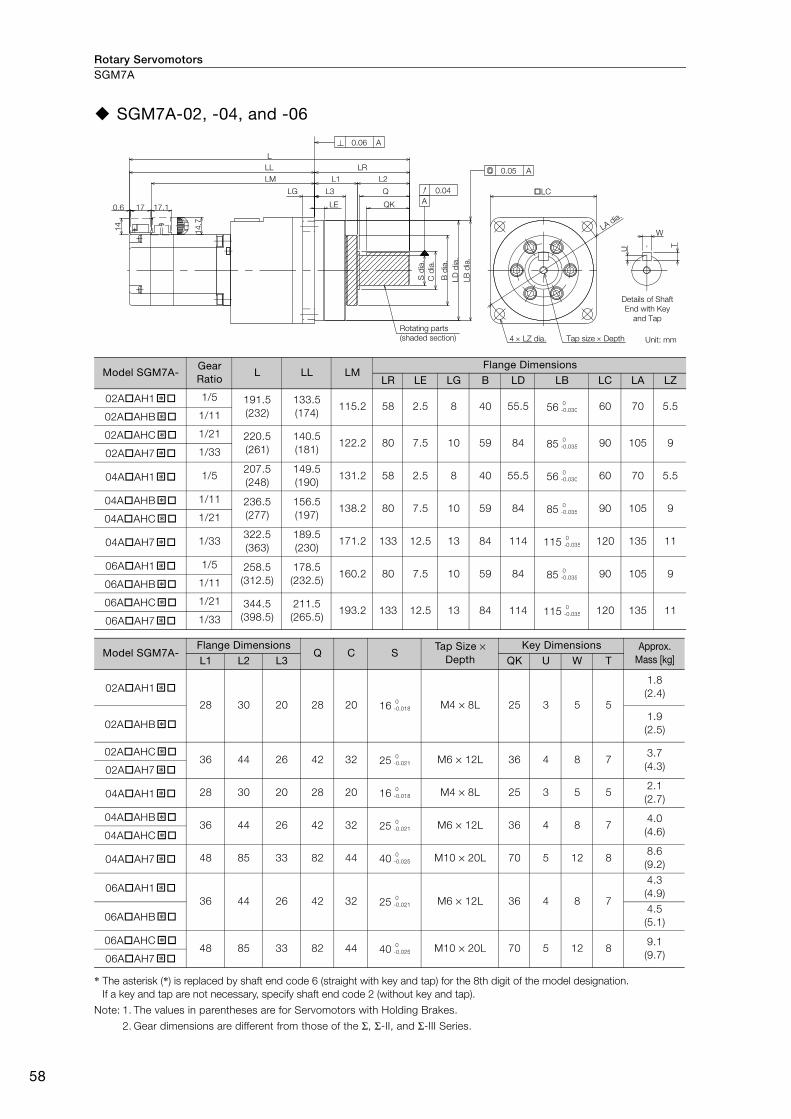
Rotary ServomotorsSGM7A
58
SGM7A-02, -04, and -06
* The asterisk (*) is replaced by shaft end code 6 (straight with key and tap) for the 8th digit of the model designation.If a key and tap are not necessary, specify shaft end code 2 (without key and tap).
Note: 1. The values in parentheses are for Servomotors with Holding Brakes.
2. Gear dimensions are different from those of the Σ, Σ-II, and Σ-III Series.
Model SGM7A-Gear Ratio
L LL LMFlange Dimensions
LR LE LG B LD LB LC LA LZ
02AAH1 1/5 191.5 (232)
133.5 (174)
115.2 58 2.5 8 40 55.5 56 60 70 5.502AAHB 1/11
02AAHC 1/21 220.5(261)
140.5(181)
122.2 80 7.5 10 59 84 85 90 105 902AAH7 1/33
04AAH1 1/5207.5(248)
149.5(190)
131.2 58 2.5 8 40 55.5 56 60 70 5.5
04AAHB 1/11 236.5(277)
156.5(197)
138.2 80 7.5 10 59 84 85 90 105 904AAHC 1/21
04AAH7 1/33322.5(363)
189.5(230)
171.2 133 12.5 13 84 114 115 120 135 11
06AAH1 1/5 258.5(312.5)
178.5(232.5)
160.2 80 7.5 10 59 84 85 90 105 906AAHB 1/11
06AAHC 1/21 344.5(398.5)
211.5(265.5)
193.2 133 12.5 13 84 114 115 120 135 1106AAH7 1/33
Model SGM7A-Flange Dimensions
Q C STap Size ×
Depth Key Dimensions Approx.
Mass [kg]L1 L2 L3 QK U W T
02AAH1
28 30 20 28 20 16 M4 × 8L 25 3 5 5
1.8(2.4)
02AAHB 1.9(2.5)
02AAHC 36 44 26 42 32 25 M6 × 12L 36 4 8 7
3.7(4.3)02AAH7
04AAH1 28 30 20 28 20 16 M4 × 8L 25 3 5 52.1(2.7)
04AAHB 36 44 26 42 32 25 M6 × 12L 36 4 8 7
4.0(4.6)04AAHC
04AAH7 48 85 33 82 44 40 M10 × 20L 70 5 12 88.6(9.2)
06AAH1 36 44 26 42 32 25 M6 × 12L 36 4 8 7
4.3(4.9)
06AAHB 4.5(5.1)
06AAHC 48 85 33 82 44 40 M10 × 20L 70 5 12 8
9.1(9.7)06AAH7
0.6 17 LE
LG L3
L1
LL
LM
14
.7
14
L
L2
Q
QK
C d
ia.
B d
ia.
LD
dia
.
LB
dia
.
LC
LA dia.
S d
ia.
LR
17.1
4 LZ dia.
0.06 A
0.04
0.05 A
A
U
W
T
Details of Shaft
End with Key
and Tap
Rotating parts
(shaded section) Tap size Depth Unit: mm
�* 0-0.030
�*�* 0
-0.035
�*
�* 0-0.030
�* 0-0.035
�*
�* 0-0.035
�* 0-0.035
�*�* 0
-0.035
�*
�* 0-0.018
�*
�* 0-0.021
�*
�* 0-0.018
�* 0-0.021
�*
�* 0-0.025
�* 0-0.021
�*
�* 0-0.025
�*
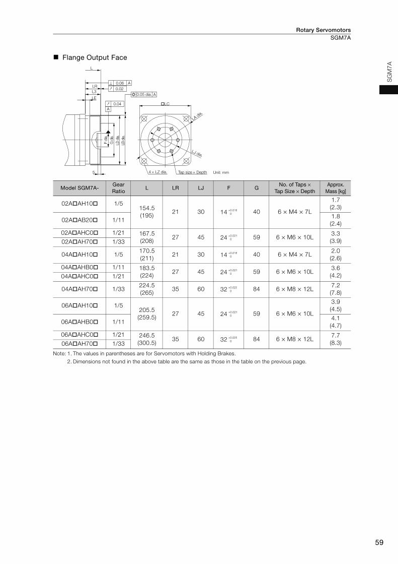
Rotary Servomotors SGM7A
59
SG
M7
A
Flange Output Face
Note: 1. The values in parentheses are for Servomotors with Holding Brakes.
2. Dimensions not found in the above table are the same as those in the table on the previous page.
Model SGM7A-Gear Ratio
L LR LJ F GNo. of Taps ×
Tap Size × DepthApprox.
Mass [kg]
02AAH10 1/5154.5(195)
21 30 14 40 6 × M4 × 7L
1.7(2.3)
02AAB20 1/111.8(2.4)
02AAHC0 1/21 167.5(208)
27 45 24 59 6 × M6 × 10L3.3(3.9)02AAH70 1/33
04AAH10 1/5170.5(211)
21 30 14 40 6 × M4 × 7L2.0(2.6)
04AAHB0 1/11 183.5(224)
27 45 24 59 6 × M6 × 10L3.6(4.2)04AAHC0 1/21
04AAH70 1/33224.5(265)
35 60 32 84 6 × M8 × 12L7.2(7.8)
06AAH10 1/5205.5(259.5)
27 45 24 59 6 × M6 × 10L
3.9(4.5)
06AAHB0 1/114.1(4.7)
06AAHC0 1/21 246.5(300.5)
35 60 32 84 6 × M8 × 12L7.7(8.3)06AAH70 1/33
LE
L
LR
L30.02
A0.06
A
0.04
0.05 dia. A
LC
LA dia.
LJ dia.
4 LZ dia.5
LB d
ia.
G d
ia.
F d
ia.
LD d
ia.
Tap size Depth Unit: mm
+0.018 0
+0.021 0
+0.018 0
+0.021 0
+0.025 0
+0.021 0
+0.025 0
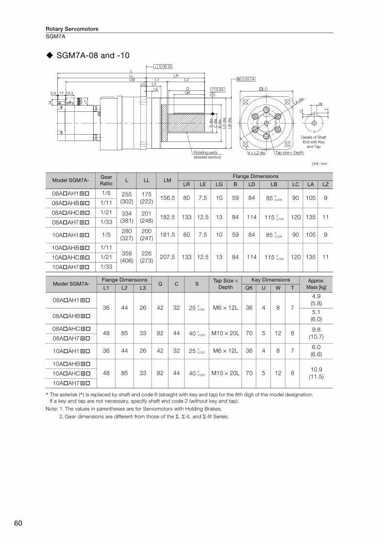
Rotary ServomotorsSGM7A
60
SGM7A-08 and -10
* The asterisk (*) is replaced by shaft end code 6 (straight with key and tap) for the 8th digit of the model designation. If a key and tap are not necessary, specify shaft end code 2 (without key and tap).
Note: 1. The values in parentheses are for Servomotors with Holding Brakes.
2. Gear dimensions are different from those of the Σ, Σ-II, and Σ-III Series.
Model SGM7A-Gear Ratio
L LL LMFlange Dimensions
LR LE LG B LD LB LC LA LZ
08AAH1 1/5 255(302)
175(222)
156.5 80 7.5 10 59 84 85 90 105 908AAHB 1/11
08AAHC 1/21 334(381)
201(248)
182.5 133 12.5 13 84 114 115 120 135 1108AAH7 1/33
10AAH1 1/5280(327)
200(247)
181.5 80 7.5 10 59 84 85 90 105 9
10AAHB 1/11359(406)
226(273)
207.5 133 12.5 13 84 114 115 120 135 1110AAHC 1/21
10AAH7 1/33
Model SGM7A-Flange Dimensions
Q C STap Size ×
Depth Key Dimensions Approx.
Mass [kg]L1 L2 L3 QK U W T
08AAH1 36 44 26 42 32 25 M6 × 12L 36 4 8 7
4.9(5.8)
08AAHB 5.1(6.0)
08AAHC 48 85 33 82 44 40 M10 × 20L 70 5 12 8
9.8(10.7)08AAH7
10AAH1 36 44 26 42 32 25 M6 × 12L 36 4 8 76.0(6.6)
10AAHB
48 85 33 82 44 40 M10 × 20L 70 5 12 810.9(11.5)10AAHC
10AAH7
17
17
14
0.6 19.3
L
L3LE
L1 L2LR
QQK
LGLM
C d
ia.
B d
ia.
LD d
ia.
LB d
ia.
S d
ia.
LL
LA dia.
LC
W
U T
0.05 A
0.04A
0.06 A
4 LZ dia.
Details of Shaft End with Key
and Tap
Rotating parts (shaded section)
Tap size Depth
Unit: mm
�* 0-0.035
�*
�* 0-0.035
�*
�* 0-0.035
�* 0-0.035�*
�*
�* 0-0.021
�*
�* 0-0.025
�*
�* 0-0.021
�* 0-0.025�*
�*
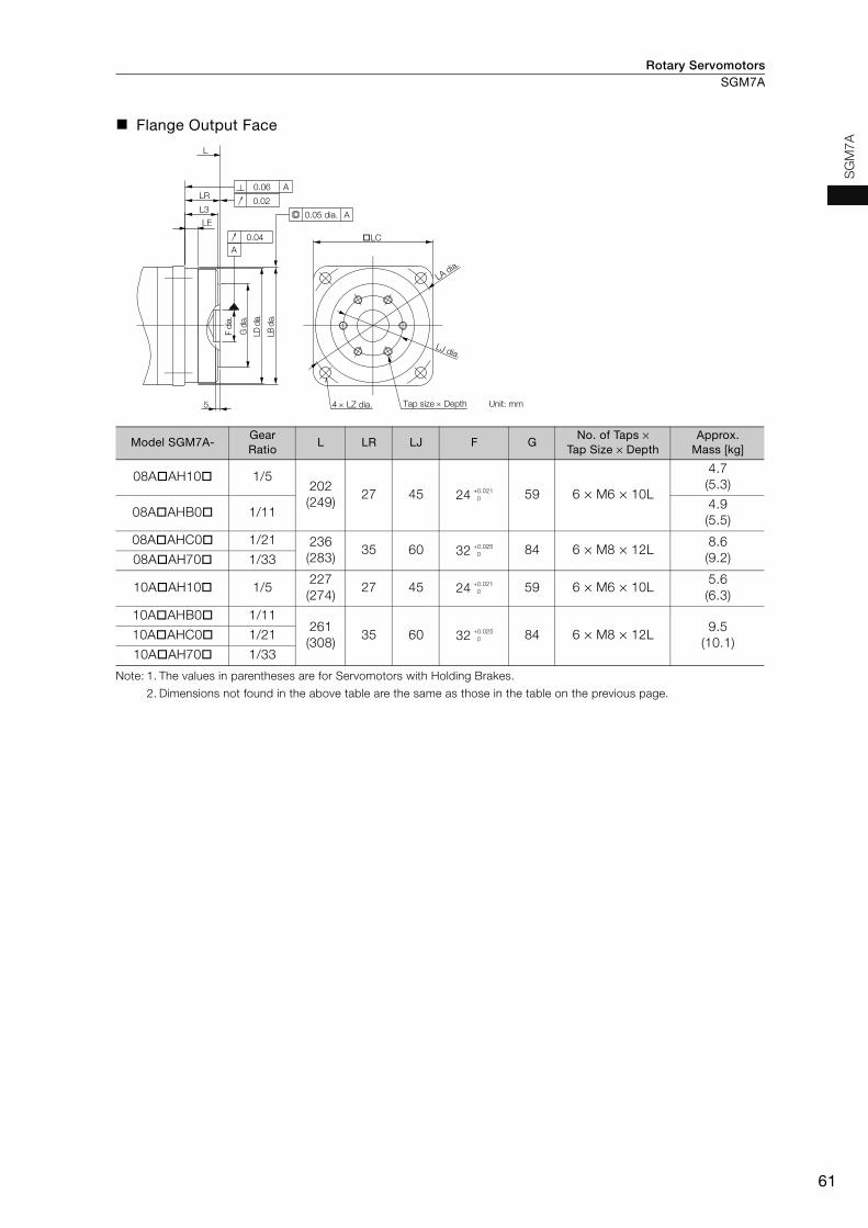
Rotary Servomotors SGM7A
61
SG
M7A
Flange Output Face
Note: 1. The values in parentheses are for Servomotors with Holding Brakes.
2. Dimensions not found in the above table are the same as those in the table on the previous page.
Model SGM7A-Gear Ratio
L LR LJ F GNo. of Taps ×
Tap Size × Depth Approx.
Mass [kg]
08AAH10 1/5202(249)
27 45 24 59 6 × M6 × 10L
4.7(5.3)
08AAHB0 1/114.9(5.5)
08AAHC0 1/21 236(283)
35 60 32 84 6 × M8 × 12L8.6(9.2)08AAH70 1/33
10AAH10 1/5227(274)
27 45 24 59 6 × M6 × 10L5.6(6.3)
10AAHB0 1/11261(308)
35 60 32 84 6 × M8 × 12L9.5
(10.1)10AAHC0 1/21
10AAH70 1/33
LC
LA dia.LD
dia.
LB d
ia.
LJ dia.
F di
a.
G d
ia.
5
LE
L3
LR
L
0.06 A
0.04
0.05 dia. A
4 LZ dia.
A
0.02
Tap size Depth Unit: mm
+0.021 0
+0.025 0
+0.021 0
+0.025 0
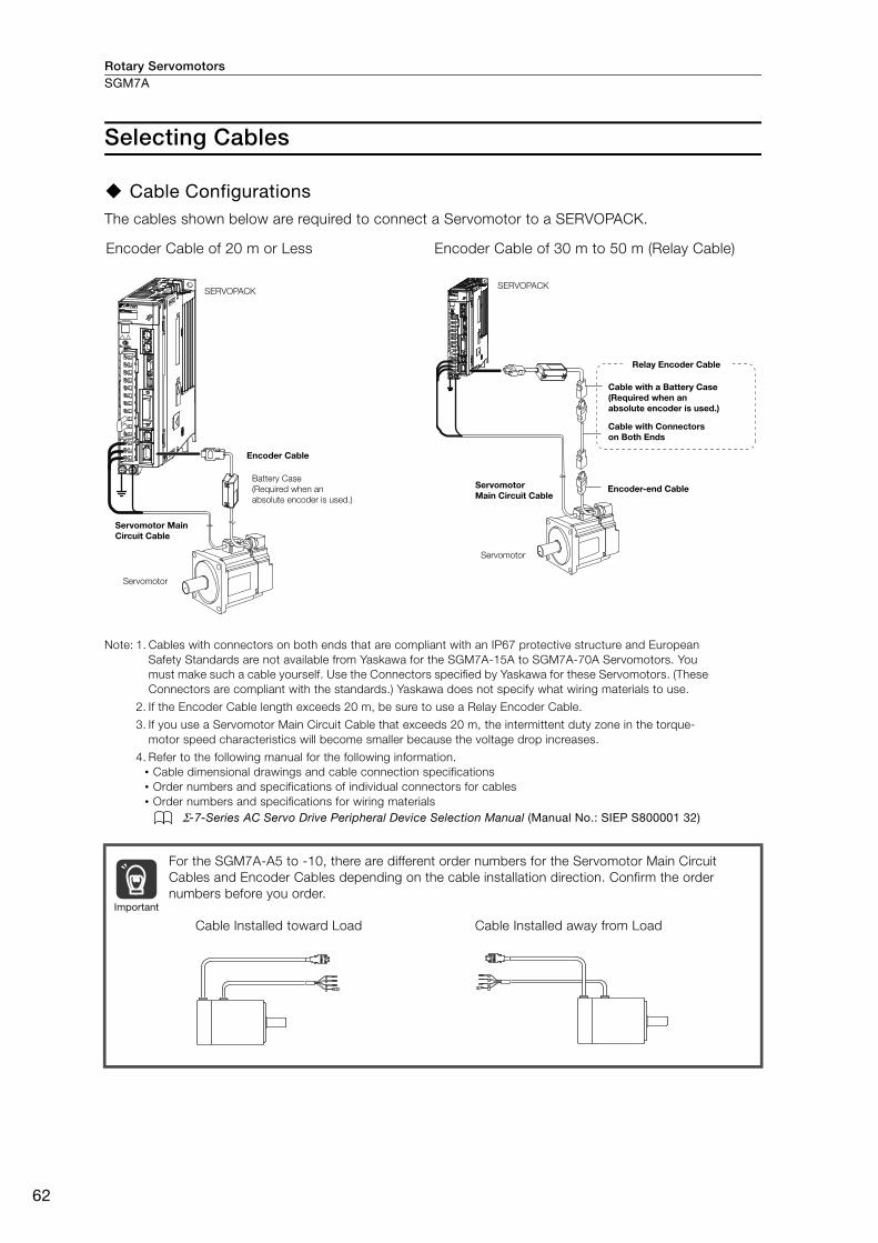
Rotary ServomotorsSGM7A
62
Selecting Cables
Cable ConfigurationsThe cables shown below are required to connect a Servomotor to a SERVOPACK.
Note: 1. Cables with connectors on both ends that are compliant with an IP67 protective structure and European Safety Standards are not available from Yaskawa for the SGM7A-15A to SGM7A-70A Servomotors. You must make such a cable yourself. Use the Connectors specified by Yaskawa for these Servomotors. (These Connectors are compliant with the standards.) Yaskawa does not specify what wiring materials to use.
2. If the Encoder Cable length exceeds 20 m, be sure to use a Relay Encoder Cable.
3. If you use a Servomotor Main Circuit Cable that exceeds 20 m, the intermittent duty zone in the torque-motor speed characteristics will become smaller because the voltage drop increases.
4. Refer to the following manual for the following information.• Cable dimensional drawings and cable connection specifications• Order numbers and specifications of individual connectors for cables• Order numbers and specifications for wiring materials
Σ-7-Series AC Servo Drive Peripheral Device Selection Manual (Manual No.: SIEP S800001 32)
Encoder Cable of 20 m or Less Encoder Cable of 30 m to 50 m (Relay Cable)
For the SGM7A-A5 to -10, there are different order numbers for the Servomotor Main Circuit Cables and Encoder Cables depending on the cable installation direction. Confirm the order numbers before you order.
SERVOPACK
Encoder Cable
Servomotor Main Circuit Cable
Servomotor
Battery Case (Required when an absolute encoder is used.)
SERVOPACK
Cable with a Battery Case (Required when an absolute encoder is used.)
Cable with Connectors on Both Ends
Encoder-end CableServomotor Main Circuit Cable
Servomotor
Relay Encoder Cable
Important
Cable Installed toward Load Cable Installed away from Load
U
V
W
G
U
V
W
G
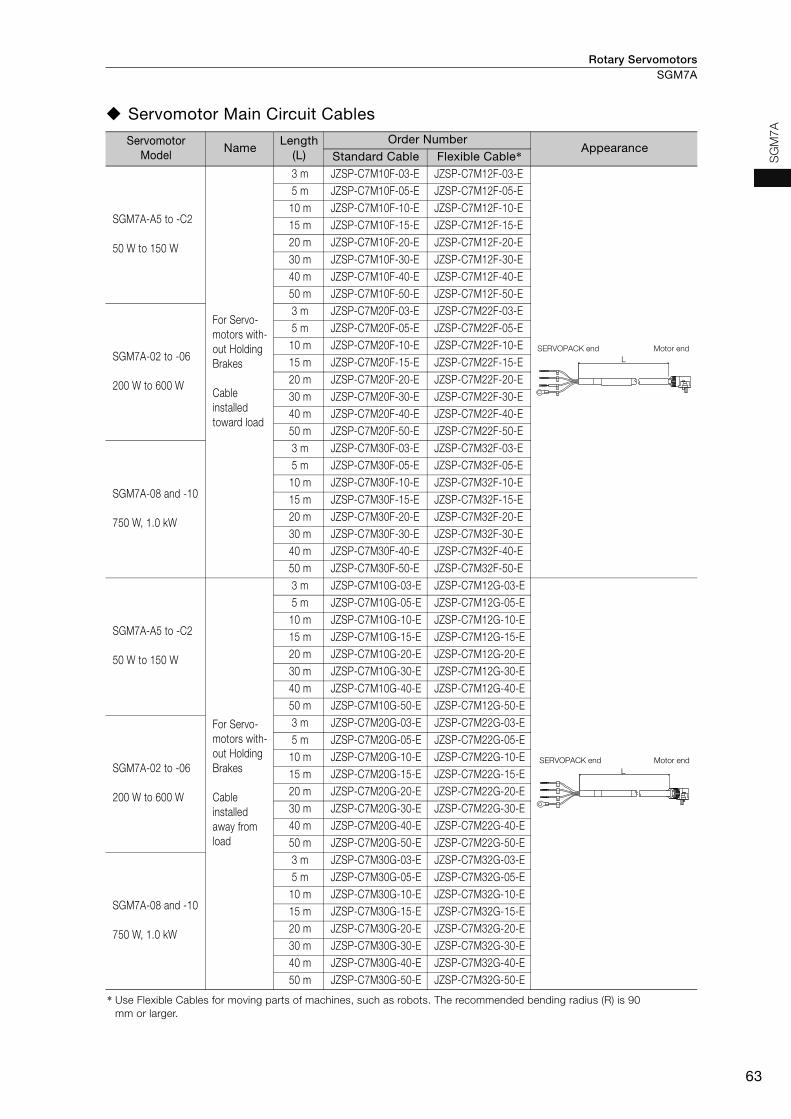
Rotary Servomotors SGM7A
63
SG
M7A
Servomotor Main Circuit Cables
Servomotor Model
NameLength
(L)Order Number
AppearanceStandard Cable Flexible Cable*
SGM7A-A5 to -C2
50 W to 150 W
For Servo-motors with-out Holding Brakes
Cable installed toward load
3 m JZSP-C7M10F-03-E JZSP-C7M12F-03-E5 m JZSP-C7M10F-05-E JZSP-C7M12F-05-E
10 m JZSP-C7M10F-10-E JZSP-C7M12F-10-E15 m JZSP-C7M10F-15-E JZSP-C7M12F-15-E20 m JZSP-C7M10F-20-E JZSP-C7M12F-20-E30 m JZSP-C7M10F-30-E JZSP-C7M12F-30-E40 m JZSP-C7M10F-40-E JZSP-C7M12F-40-E50 m JZSP-C7M10F-50-E JZSP-C7M12F-50-E
SGM7A-02 to -06
200 W to 600 W
3 m JZSP-C7M20F-03-E JZSP-C7M22F-03-E5 m JZSP-C7M20F-05-E JZSP-C7M22F-05-E
10 m JZSP-C7M20F-10-E JZSP-C7M22F-10-E15 m JZSP-C7M20F-15-E JZSP-C7M22F-15-E20 m JZSP-C7M20F-20-E JZSP-C7M22F-20-E30 m JZSP-C7M20F-30-E JZSP-C7M22F-30-E40 m JZSP-C7M20F-40-E JZSP-C7M22F-40-E50 m JZSP-C7M20F-50-E JZSP-C7M22F-50-E
SGM7A-08 and -10
750 W, 1.0 kW
3 m JZSP-C7M30F-03-E JZSP-C7M32F-03-E5 m JZSP-C7M30F-05-E JZSP-C7M32F-05-E
10 m JZSP-C7M30F-10-E JZSP-C7M32F-10-E15 m JZSP-C7M30F-15-E JZSP-C7M32F-15-E20 m JZSP-C7M30F-20-E JZSP-C7M32F-20-E30 m JZSP-C7M30F-30-E JZSP-C7M32F-30-E40 m JZSP-C7M30F-40-E JZSP-C7M32F-40-E50 m JZSP-C7M30F-50-E JZSP-C7M32F-50-E
SGM7A-A5 to -C2
50 W to 150 W
For Servo-motors with-out Holding Brakes
Cable installed away from load
3 m JZSP-C7M10G-03-E JZSP-C7M12G-03-E5 m JZSP-C7M10G-05-E JZSP-C7M12G-05-E
10 m JZSP-C7M10G-10-E JZSP-C7M12G-10-E15 m JZSP-C7M10G-15-E JZSP-C7M12G-15-E20 m JZSP-C7M10G-20-E JZSP-C7M12G-20-E30 m JZSP-C7M10G-30-E JZSP-C7M12G-30-E40 m JZSP-C7M10G-40-E JZSP-C7M12G-40-E50 m JZSP-C7M10G-50-E JZSP-C7M12G-50-E
SGM7A-02 to -06
200 W to 600 W
3 m JZSP-C7M20G-03-E JZSP-C7M22G-03-E5 m JZSP-C7M20G-05-E JZSP-C7M22G-05-E
10 m JZSP-C7M20G-10-E JZSP-C7M22G-10-E15 m JZSP-C7M20G-15-E JZSP-C7M22G-15-E20 m JZSP-C7M20G-20-E JZSP-C7M22G-20-E30 m JZSP-C7M20G-30-E JZSP-C7M22G-30-E40 m JZSP-C7M20G-40-E JZSP-C7M22G-40-E50 m JZSP-C7M20G-50-E JZSP-C7M22G-50-E
SGM7A-08 and -10
750 W, 1.0 kW
3 m JZSP-C7M30G-03-E JZSP-C7M32G-03-E5 m JZSP-C7M30G-05-E JZSP-C7M32G-05-E
10 m JZSP-C7M30G-10-E JZSP-C7M32G-10-E15 m JZSP-C7M30G-15-E JZSP-C7M32G-15-E20 m JZSP-C7M30G-20-E JZSP-C7M32G-20-E30 m JZSP-C7M30G-30-E JZSP-C7M32G-30-E40 m JZSP-C7M30G-40-E JZSP-C7M32G-40-E50 m JZSP-C7M30G-50-E JZSP-C7M32G-50-E
* Use Flexible Cables for moving parts of machines, such as robots. The recommended bending radius (R) is 90 mm or larger.
U
V
W
G
Motor endSERVOPACK endL
SERVOPACK end Motor end
U
V
W
G
L

Rotary ServomotorsSGM7A
64
SGM7A-A5 to -C2
50 W to 150 W
For Servo-motors with Holding Brakes
Cable installed toward load
3 m JZSP-C7M13F-03-E JZSP-C7M14F-03-E5 m JZSP-C7M13F-05-E JZSP-C7M14F-05-E
10 m JZSP-C7M13F-10-E JZSP-C7M14F-10-E15 m JZSP-C7M13F-15-E JZSP-C7M14F-15-E20 m JZSP-C7M13F-20-E JZSP-C7M14F-20-E30 m JZSP-C7M13F-30-E JZSP-C7M14F-30-E40 m JZSP-C7M13F-40-E JZSP-C7M14F-40-E50 m JZSP-C7M13F-50-E JZSP-C7M14F-50-E
SGM7A-02 to -06
200 W to 600 W
3 m JZSP-C7M23F-03-E JZSP-C7M24F-03-E5 m JZSP-C7M23F-05-E JZSP-C7M24F-05-E
10 m JZSP-C7M23F-10-E JZSP-C7M24F-10-E15 m JZSP-C7M23F-15-E JZSP-C7M24F-15-E20 m JZSP-C7M23F-20-E JZSP-C7M24F-20-E30 m JZSP-C7M23F-30-E JZSP-C7M24F-30-E40 m JZSP-C7M23F-40-E JZSP-C7M24F-40-E50 m JZSP-C7M23F-50-E JZSP-C7M24F-50-E
SGM7A-08 and -10
750 W, 1.0 kW
3 m JZSP-C7M33F-03-E JZSP-C7M34F-03-E5 m JZSP-C7M33F-05-E JZSP-C7M34F-05-E
10 m JZSP-C7M33F-10-E JZSP-C7M34F-10-E15 m JZSP-C7M33F-15-E JZSP-C7M34F-15-E20 m JZSP-C7M33F-20-E JZSP-C7M34F-20-E30 m JZSP-C7M33F-30-E JZSP-C7M34F-30-E40 m JZSP-C7M33F-40-E JZSP-C7M34F-40-E50 m JZSP-C7M33F-50-E JZSP-C7M34F-50-E
SGM7A-A5 to -C2
50 W to 150 W
For Servo-motors with Holding Brakes
Cable installed away from load
3 m JZSP-C7M13G-03-E JZSP-C7M14G-03-E5 m JZSP-C7M13G-05-E JZSP-C7M14G-05-E
10 m JZSP-C7M13G-10-E JZSP-C7M14G-10-E15 m JZSP-C7M13G-15-E JZSP-C7M14G-15-E20 m JZSP-C7M13G-20-E JZSP-C7M14G-20-E30 m JZSP-C7M13G-30-E JZSP-C7M14G-30-E40 m JZSP-C7M13G-40-E JZSP-C7M14G-40-E50 m JZSP-C7M13G-50-E JZSP-C7M14G-50-E
SGM7A-02 to -06
200 W to 600 W
3 m JZSP-C7M23G-03-E JZSP-C7M24G-03-E5 m JZSP-C7M23G-05-E JZSP-C7M24G-05-E
10 m JZSP-C7M23G-10-E JZSP-C7M24G-10-E15 m JZSP-C7M23G-15-E JZSP-C7M24G-15-E20 m JZSP-C7M23G-20-E JZSP-C7M24G-20-E30 m JZSP-C7M23G-30-E JZSP-C7M24G-30-E40 m JZSP-C7M23G-40-E JZSP-C7M24G-40-E50 m JZSP-C7M23G-50-E JZSP-C7M24G-50-E
SGM7A-08 and -10
750 W, 1.0 kW
3 m JZSP-C7M33G-03-E JZSP-C7M34G-03-E5 m JZSP-C7M33G-05-E JZSP-C7M34G-05-E
10 m JZSP-C7M33G-10-E JZSP-C7M34G-10-E15 m JZSP-C7M33G-15-E JZSP-C7M34G-15-E20 m JZSP-C7M33G-20-E JZSP-C7M34G-20-E30 m JZSP-C7M33G-30-E JZSP-C7M34G-30-E40 m JZSP-C7M33G-40-E JZSP-C7M34G-40-E50 m JZSP-C7M33G-50-E JZSP-C7M34G-50-E
* Use Flexible Cables for moving parts of machines, such as robots. The recommended bending radius (R) is 90 mm or larger.
Servomotor Model
NameLength
(L)Order Number
AppearanceStandard Cable Flexible Cable*
U
V
W
G
B
B
Motor endSERVOPACK endL
U
V
W
G
B
B
LSERVOPACK end Motor end

Rotary Servomotors SGM7A
65
SG
M7A
Servo-motor Model
NameConnec-tor Spec-ifications
Length (L)
Order Number Appearance
Standard Cable Flexible Cable*1
SGM7A-15
1.5 kW
For Servomotors without Holding Brakes
Straight
3 m JZSP-UVA101-03-E JZSP-UVA121-03-E
5 m JZSP-UVA101-05-E JZSP-UVA121-05-E
10 m JZSP-UVA101-10-E JZSP-UVA121-10-E
15 m JZSP-UVA101-15-E JZSP-UVA121-15-E
20 m JZSP-UVA101-20-E JZSP-UVA121-20-E
Right-angle
3 m JZSP-UVA102-03-E JZSP-UVA122-03-E
5 m JZSP-UVA102-05-E JZSP-UVA122-05-E
10 m JZSP-UVA102-10-E JZSP-UVA122-10-E
15 m JZSP-UVA102-15-E JZSP-UVA122-15-E
20 m JZSP-UVA102-20-E JZSP-UVA122-20-E
For Servomotors with Holding Brakes
(Set of Two Cables*2)
Straight
3 m JZSP-UVA131-03-E JZSP-UVA141-03-E
5 m JZSP-UVA131-05-E JZSP-UVA141-05-E
10 m JZSP-UVA131-10-E JZSP-UVA141-10-E
15 m JZSP-UVA131-15-E JZSP-UVA141-15-E
20 m JZSP-UVA131-20-E JZSP-UVA141-20-E
Right-angle
3 m JZSP-UVA132-03-E JZSP-UVA142-03-E
5 m JZSP-UVA132-05-E JZSP-UVA142-05-E
10 m JZSP-UVA132-10-E JZSP-UVA142-10-E
15 m JZSP-UVA132-15-E JZSP-UVA142-15-E
20 m JZSP-UVA132-20-E JZSP-UVA142-20-E
SGM7A-20
2.0 kW
For Servomotors without Holding Brakes
Straight
3 m JZSP-UVA301-03-E JZSP-UVA321-03-E
5 m JZSP-UVA301-05-E JZSP-UVA321-05-E
10 m JZSP-UVA301-10-E JZSP-UVA321-10-E
15 m JZSP-UVA301-15-E JZSP-UVA321-15-E
20 m JZSP-UVA301-20-E JZSP-UVA321-20-E
Right-angle
3 m JZSP-UVA302-03-E JZSP-UVA322-03-E
5 m JZSP-UVA302-05-E JZSP-UVA322-05-E
10 m JZSP-UVA302-10-E JZSP-UVA322-10-E
15 m JZSP-UVA302-15-E JZSP-UVA322-15-E
20 m JZSP-UVA302-20-E JZSP-UVA322-20-E
For Servomotors with Holding Brakes
(Set of Two Cables*2)
Straight
3 m JZSP-UVA331-03-E JZSP-UVA341-03-E
5 m JZSP-UVA331-05-E JZSP-UVA341-05-E
10 m JZSP-UVA331-10-E JZSP-UVA341-10-E
15 m JZSP-UVA331-15-E JZSP-UVA341-15-E
20 m JZSP-UVA331-20-E JZSP-UVA341-20-E
Right-angle
3 m JZSP-UVA332-03-E JZSP-UVA342-03-E
5 m JZSP-UVA332-05-E JZSP-UVA342-05-E
10 m JZSP-UVA332-10-E JZSP-UVA342-10-E
15 m JZSP-UVA332-15-E JZSP-UVA342-15-E
20 m JZSP-UVA332-20-E JZSP-UVA342-20-E
*1. Use Flexible Cables for moving parts of machines, such as robots. The recommended bending radius (R) is 90 mm or larger.
*2. This order number is for a set of two cables (Main Power Supply Cable and Holding Brake Cable).When you purchase them separately, the order numbers for Main Power Supply Cables are the same as for a Servomotor without a Holding Brake. The following order numbers are for a Holding Brake Cable. These Standard Cables are Flexible Cables.• Cable with Straight Plug: JZSP-U7B23--E• Cable with Right-angle Plug: JZSP-U7B24--E
L
SERVOPACK end
Motor end
L
SERVOPACK end
Motor end
LSERVOPACK end Motor end
LSERVOPACK end Brake end
LSERVOPACK end Motor end
LBrake end Motor end
L
SERVOPACK end
Motor end
L
SERVOPACK end
Motor end
LSERVOPACK end Motor end
LSERVOPACK end Brake end
LSERVOPACK end Motor end
LBrake end Motor end
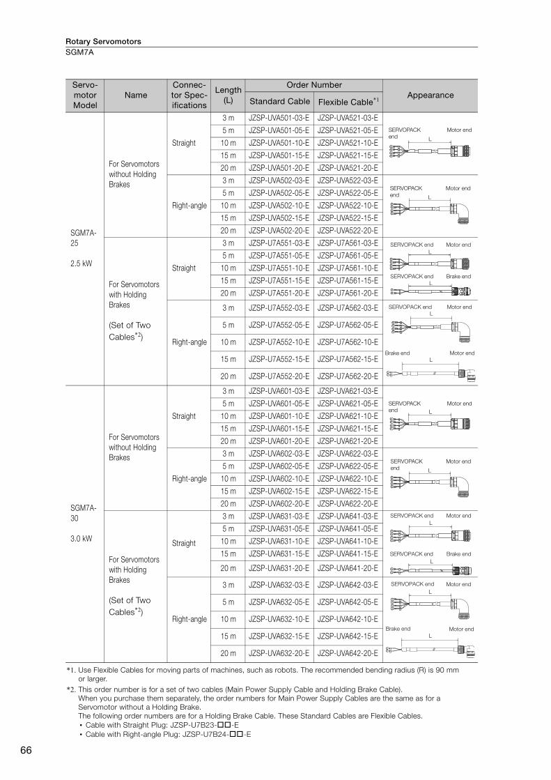
Rotary ServomotorsSGM7A
66
Servo-motor Model
NameConnec-tor Spec-ifications
Length (L)
Order Number Appearance
Standard Cable Flexible Cable*1
SGM7A-25
2.5 kW
For Servomotors without Holding Brakes
Straight
3 m JZSP-UVA501-03-E JZSP-UVA521-03-E
5 m JZSP-UVA501-05-E JZSP-UVA521-05-E
10 m JZSP-UVA501-10-E JZSP-UVA521-10-E
15 m JZSP-UVA501-15-E JZSP-UVA521-15-E
20 m JZSP-UVA501-20-E JZSP-UVA521-20-E
Right-angle
3 m JZSP-UVA502-03-E JZSP-UVA522-03-E
5 m JZSP-UVA502-05-E JZSP-UVA522-05-E
10 m JZSP-UVA502-10-E JZSP-UVA522-10-E
15 m JZSP-UVA502-15-E JZSP-UVA522-15-E
20 m JZSP-UVA502-20-E JZSP-UVA522-20-E
For Servomotors with Holding Brakes
(Set of Two Cables*2)
Straight
3 m JZSP-U7A551-03-E JZSP-U7A561-03-E
5 m JZSP-U7A551-05-E JZSP-U7A561-05-E
10 m JZSP-U7A551-10-E JZSP-U7A561-10-E
15 m JZSP-U7A551-15-E JZSP-U7A561-15-E
20 m JZSP-U7A551-20-E JZSP-U7A561-20-E
Right-angle
3 m JZSP-U7A552-03-E JZSP-U7A562-03-E
5 m JZSP-U7A552-05-E JZSP-U7A562-05-E
10 m JZSP-U7A552-10-E JZSP-U7A562-10-E
15 m JZSP-U7A552-15-E JZSP-U7A562-15-E
20 m JZSP-U7A552-20-E JZSP-U7A562-20-E
SGM7A-30
3.0 kW
For Servomotors without Holding Brakes
Straight
3 m JZSP-UVA601-03-E JZSP-UVA621-03-E
5 m JZSP-UVA601-05-E JZSP-UVA621-05-E
10 m JZSP-UVA601-10-E JZSP-UVA621-10-E
15 m JZSP-UVA601-15-E JZSP-UVA621-15-E
20 m JZSP-UVA601-20-E JZSP-UVA621-20-E
Right-angle
3 m JZSP-UVA602-03-E JZSP-UVA622-03-E
5 m JZSP-UVA602-05-E JZSP-UVA622-05-E
10 m JZSP-UVA602-10-E JZSP-UVA622-10-E
15 m JZSP-UVA602-15-E JZSP-UVA622-15-E
20 m JZSP-UVA602-20-E JZSP-UVA622-20-E
For Servomotors with Holding Brakes
(Set of Two Cables*2)
Straight
3 m JZSP-UVA631-03-E JZSP-UVA641-03-E
5 m JZSP-UVA631-05-E JZSP-UVA641-05-E
10 m JZSP-UVA631-10-E JZSP-UVA641-10-E
15 m JZSP-UVA631-15-E JZSP-UVA641-15-E
20 m JZSP-UVA631-20-E JZSP-UVA641-20-E
Right-angle
3 m JZSP-UVA632-03-E JZSP-UVA642-03-E
5 m JZSP-UVA632-05-E JZSP-UVA642-05-E
10 m JZSP-UVA632-10-E JZSP-UVA642-10-E
15 m JZSP-UVA632-15-E JZSP-UVA642-15-E
20 m JZSP-UVA632-20-E JZSP-UVA642-20-E
*1. Use Flexible Cables for moving parts of machines, such as robots. The recommended bending radius (R) is 90 mm or larger.
*2. This order number is for a set of two cables (Main Power Supply Cable and Holding Brake Cable).When you purchase them separately, the order numbers for Main Power Supply Cables are the same as for a Servomotor without a Holding Brake. The following order numbers are for a Holding Brake Cable. These Standard Cables are Flexible Cables.• Cable with Straight Plug: JZSP-U7B23--E• Cable with Right-angle Plug: JZSP-U7B24--E
L
SERVOPACK end
Motor end
L
SERVOPACK end
Motor end
LSERVOPACK end Motor end
LSERVOPACK end Brake end
LSERVOPACK end Motor end
LBrake end Motor end
L
SERVOPACK end
Motor end
L
SERVOPACK end
Motor end
LMotor endSERVOPACK end
LBrake endSERVOPACK end
LMotor endSERVOPACK end
LMotor endBrake end
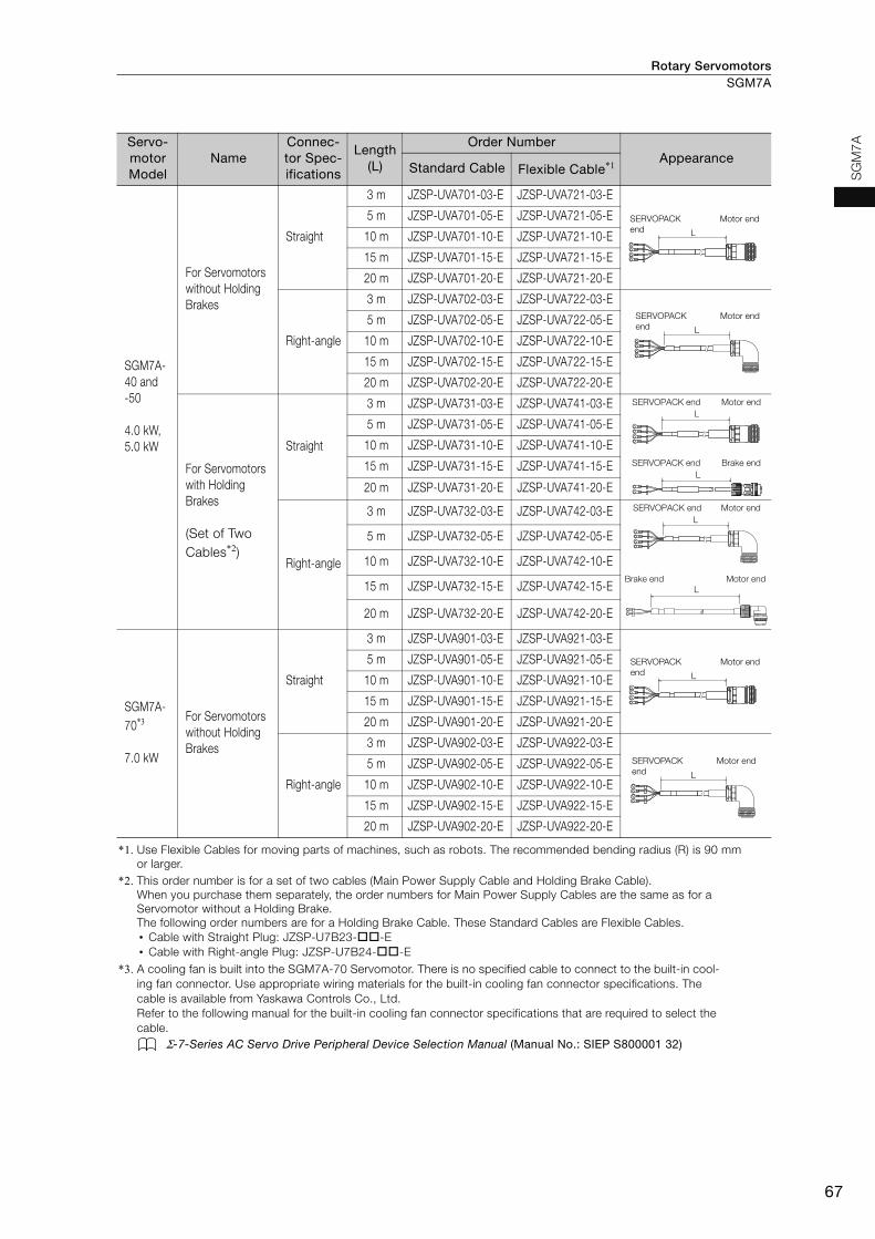
Rotary Servomotors SGM7A
67
SG
M7AServo-
motor Model
NameConnec-tor Spec-ifications
Length (L)
Order Number Appearance
Standard Cable Flexible Cable*1
SGM7A-40 and-50
4.0 kW, 5.0 kW
For Servomotors without Holding Brakes
Straight
3 m JZSP-UVA701-03-E JZSP-UVA721-03-E
5 m JZSP-UVA701-05-E JZSP-UVA721-05-E
10 m JZSP-UVA701-10-E JZSP-UVA721-10-E
15 m JZSP-UVA701-15-E JZSP-UVA721-15-E
20 m JZSP-UVA701-20-E JZSP-UVA721-20-E
Right-angle
3 m JZSP-UVA702-03-E JZSP-UVA722-03-E
5 m JZSP-UVA702-05-E JZSP-UVA722-05-E
10 m JZSP-UVA702-10-E JZSP-UVA722-10-E
15 m JZSP-UVA702-15-E JZSP-UVA722-15-E
20 m JZSP-UVA702-20-E JZSP-UVA722-20-E
For Servomotors with Holding Brakes
(Set of Two Cables*2)
Straight
3 m JZSP-UVA731-03-E JZSP-UVA741-03-E
5 m JZSP-UVA731-05-E JZSP-UVA741-05-E
10 m JZSP-UVA731-10-E JZSP-UVA741-10-E
15 m JZSP-UVA731-15-E JZSP-UVA741-15-E
20 m JZSP-UVA731-20-E JZSP-UVA741-20-E
Right-angle
3 m JZSP-UVA732-03-E JZSP-UVA742-03-E
5 m JZSP-UVA732-05-E JZSP-UVA742-05-E
10 m JZSP-UVA732-10-E JZSP-UVA742-10-E
15 m JZSP-UVA732-15-E JZSP-UVA742-15-E
20 m JZSP-UVA732-20-E JZSP-UVA742-20-E
SGM7A-70*3
7.0 kW
For Servomotors without Holding Brakes
Straight
3 m JZSP-UVA901-03-E JZSP-UVA921-03-E
5 m JZSP-UVA901-05-E JZSP-UVA921-05-E
10 m JZSP-UVA901-10-E JZSP-UVA921-10-E
15 m JZSP-UVA901-15-E JZSP-UVA921-15-E
20 m JZSP-UVA901-20-E JZSP-UVA921-20-E
Right-angle
3 m JZSP-UVA902-03-E JZSP-UVA922-03-E
5 m JZSP-UVA902-05-E JZSP-UVA922-05-E
10 m JZSP-UVA902-10-E JZSP-UVA922-10-E
15 m JZSP-UVA902-15-E JZSP-UVA922-15-E
20 m JZSP-UVA902-20-E JZSP-UVA922-20-E
*1. Use Flexible Cables for moving parts of machines, such as robots. The recommended bending radius (R) is 90 mm or larger.
*2. This order number is for a set of two cables (Main Power Supply Cable and Holding Brake Cable).When you purchase them separately, the order numbers for Main Power Supply Cables are the same as for a Servomotor without a Holding Brake. The following order numbers are for a Holding Brake Cable. These Standard Cables are Flexible Cables.• Cable with Straight Plug: JZSP-U7B23--E• Cable with Right-angle Plug: JZSP-U7B24--E
*3. A cooling fan is built into the SGM7A-70 Servomotor. There is no specified cable to connect to the built-in cool-ing fan connector. Use appropriate wiring materials for the built-in cooling fan connector specifications. The cable is available from Yaskawa Controls Co., Ltd.Refer to the following manual for the built-in cooling fan connector specifications that are required to select the cable.
Σ-7-Series AC Servo Drive Peripheral Device Selection Manual (Manual No.: SIEP S800001 32)
L
SERVOPACK end
Motor end
L
SERVOPACK end
Motor end
LSERVOPACK end Motor end
LSERVOPACK end Brake end
LSERVOPACK end Motor end
LBrake end Motor end
L
SERVOPACK
end
Motor end
L
SERVOPACK
end
Motor end
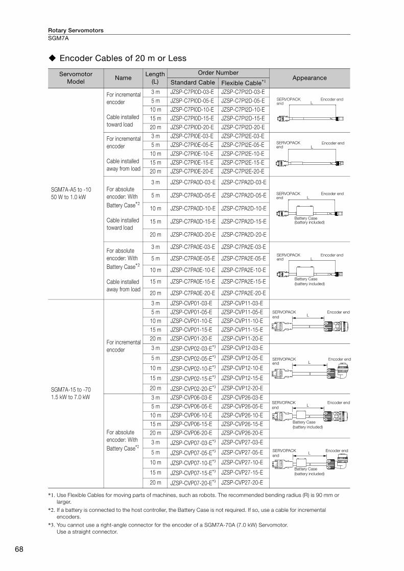
Rotary ServomotorsSGM7A
68
Encoder Cables of 20 m or Less
*1. Use Flexible Cables for moving parts of machines, such as robots. The recommended bending radius (R) is 90 mm or larger.
*2. If a battery is connected to the host controller, the Battery Case is not required. If so, use a cable for incremental encoders.
*3. You cannot use a right-angle connector for the encoder of a SGM7A-70A (7.0 kW) Servomotor.Use a straight connector.
Servomotor Model
NameLength
(L)
Order NumberAppearance
Standard Cable Flexible Cable*1
SGM7A-A5 to -1050 W to 1.0 kW
For incremental encoder
Cable installed toward load
3 m JZSP-C7PI0D-03-E JZSP-C7PI2D-03-E5 m JZSP-C7PI0D-05-E JZSP-C7PI2D-05-E
10 m JZSP-C7PI0D-10-E JZSP-C7PI2D-10-E15 m JZSP-C7PI0D-15-E JZSP-C7PI2D-15-E20 m JZSP-C7PI0D-20-E JZSP-C7PI2D-20-E
For incremental encoder
Cable installed away from load
3 m JZSP-C7PI0E-03-E JZSP-C7PI2E-03-E5 m JZSP-C7PI0E-05-E JZSP-C7PI2E-05-E
10 m JZSP-C7PI0E-10-E JZSP-C7PI2E-10-E15 m JZSP-C7PI0E-15-E JZSP-C7PI2E-15-E20 m JZSP-C7PI0E-20-E JZSP-C7PI2E-20-E
For absolute encoder: With Battery Case*2
Cable installed toward load
3 m JZSP-C7PA0D-03-E JZSP-C7PA2D-03-E
5 m JZSP-C7PA0D-05-E JZSP-C7PA2D-05-E
10 m JZSP-C7PA0D-10-E JZSP-C7PA2D-10-E
15 m JZSP-C7PA0D-15-E JZSP-C7PA2D-15-E
20 m JZSP-C7PA0D-20-E JZSP-C7PA2D-20-E
For absolute encoder: With Battery Case*2
Cable installed away from load
3 m JZSP-C7PA0E-03-E JZSP-C7PA2E-03-E
5 m JZSP-C7PA0E-05-E JZSP-C7PA2E-05-E
10 m JZSP-C7PA0E-10-E JZSP-C7PA2E-10-E
15 m JZSP-C7PA0E-15-E JZSP-C7PA2E-15-E
20 m JZSP-C7PA0E-20-E JZSP-C7PA2E-20-E
SGM7A-15 to -701.5 kW to 7.0 kW
For incremental encoder
3 m JZSP-CVP01-03-E JZSP-CVP11-03-E5 m JZSP-CVP01-05-E JZSP-CVP11-05-E
10 m JZSP-CVP01-10-E JZSP-CVP11-10-E15 m JZSP-CVP01-15-E JZSP-CVP11-15-E20 m JZSP-CVP01-20-E JZSP-CVP11-20-E
3 m JZSP-CVP02-03-E*3 JZSP-CVP12-03-E
5 m JZSP-CVP02-05-E*3 JZSP-CVP12-05-E
10 m JZSP-CVP02-10-E*3 JZSP-CVP12-10-E
15 m JZSP-CVP02-15-E*3 JZSP-CVP12-15-E
20 m JZSP-CVP02-20-E*3 JZSP-CVP12-20-E
For absolute encoder: With Battery Case*2
3 m JZSP-CVP06-03-E JZSP-CVP26-03-E5 m JZSP-CVP06-05-E JZSP-CVP26-05-E
10 m JZSP-CVP06-10-E JZSP-CVP26-10-E15 m JZSP-CVP06-15-E JZSP-CVP26-15-E20 m JZSP-CVP06-20-E JZSP-CVP26-20-E
3 m JZSP-CVP07-03-E*3 JZSP-CVP27-03-E
5 m JZSP-CVP07-05-E*3 JZSP-CVP27-05-E
10 m JZSP-CVP07-10-E*3 JZSP-CVP27-10-E
15 m JZSP-CVP07-15-E*3 JZSP-CVP27-15-E
20 m JZSP-CVP07-20-E*3 JZSP-CVP27-20-E
Encoder endSERVOPACK end L
SERVOPACK end
Encoder endL
SERVOPACK end
Encoder end
Battery Case (battery included)
L
LSERVOPACK end
Encoder end
Battery Case
(battery included)
L
mol
ex
SERVOPACK
end
Encoder end
L
mol
ex
SERVOPACK end
Encoder end
L
mol
ex
SERVOPACK
end
Encoder end
Battery Case
(battery included)
L
mol
ex
SERVOPACK
end
Encoder end
Battery Case
(battery included)
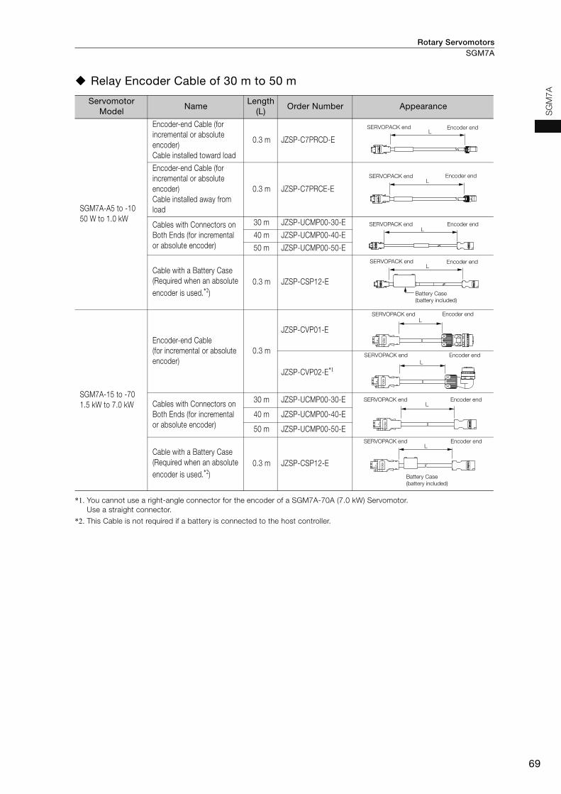
Rotary Servomotors SGM7A
69
SG
M7
A
Relay Encoder Cable of 30 m to 50 m
*1. You cannot use a right-angle connector for the encoder of a SGM7A-70A (7.0 kW) Servomotor. Use a straight connector.
*2. This Cable is not required if a battery is connected to the host controller.
Servomotor Model
NameLength
(L)Order Number Appearance
SGM7A-A5 to -1050 W to 1.0 kW
Encoder-end Cable (for incremental or absolute encoder)Cable installed toward load
0.3 m JZSP-C7PRCD-E
Encoder-end Cable (for incremental or absolute encoder)Cable installed away from load
0.3 m JZSP-C7PRCE-E
Cables with Connectors on Both Ends (for incremental or absolute encoder)
30 m JZSP-UCMP00-30-E
40 m JZSP-UCMP00-40-E
50 m JZSP-UCMP00-50-E
Cable with a Battery Case (Required when an absolute encoder is used.*2)
0.3 m JZSP-CSP12-E
SGM7A-15 to -701.5 kW to 7.0 kW
Encoder-end Cable (for incremental or absolute encoder)
0.3 m
JZSP-CVP01-E
JZSP-CVP02-E*1
Cables with Connectors on Both Ends (for incremental or absolute encoder)
30 m JZSP-UCMP00-30-E
40 m JZSP-UCMP00-40-E
50 m JZSP-UCMP00-50-E
Cable with a Battery Case (Required when an absolute encoder is used.*2)
0.3 m JZSP-CSP12-E
Encoder endSERVOPACK endL
SERVOPACK end Encoder endL
LSERVOPACK end Encoder end
SERVOPACK end Encoder end
Battery Case
(battery included)
L
SERVOPACK end Encoder endL
mol
ex
SERVOPACK end Encoder end
L
mol
ex
SERVOPACK end Encoder endL
mol
ex
SERVOPACK end Encoder end
Battery Case
(battery included)
L
mol
ex
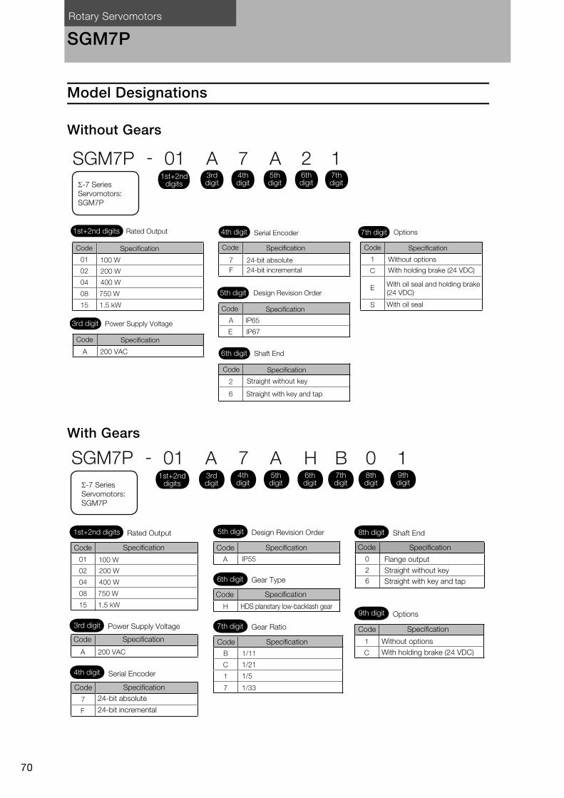
Rotary Servomotors
70
SGM7P
Model Designations
Without Gears
With Gears
1
C
E
S
A IP65
E IP67
2
6
SGM7P - 01 A 7 A 12
01
02
04
08 750 W
400 W
100 W
15 1.5 kW
200 W
7
F
A 200 VAC
1st+2nd digits
1st+2nd digits
3rd digit
Rated Output
Power Supply Voltage
4th digit Serial Encoder
5th digit Design Revision Order
7th digit Options
Without options
With holding brake (24 VDC)
With oil seal and holding brake
(24 VDC)
With oil seal
6th digit Shaft End
Straight without key
Straight with key and tap
24-bit absolute
24-bit incremental
3rd digit
4th digit
5th digit
6th digit
7th digitΣ-7 Series
Servomotors:
SGM7P
SpecificationCode SpecificationCode
SpecificationCode
SpecificationCode
SpecificationCode
SpecificationCode
01
02
04
08 750 W
400 W
100 W
15 1.5 kW
- 01 A 7 A 0BH
1
CB 1/11
C 1/21
1 1/5
7
H
A IP55
7
F
SGM7P
1/33
200 W
1
A 200 VAC
Specification
1st+2nd digits
1st+2nd digits
Σ-7 Series
Servomotors:
SGM7P
Rated Output 5th digit Design Revision Order 8th digit Shaft End
9th digit Options
Without options
With holding brake (24 VDC)
6th digit Gear Type
7th digit Gear Ratio
HDS planetary low-backlash gear
3rd digit Power Supply Voltage
4th digit Serial Encoder
24-bit absolute
24-bit incremental
Code
3rd digit
4th digit
5th digit
6th digit
7th digit
8th digit
9th digit
SpecificationCode
SpecificationCode
SpecificationCode
SpecificationCode
SpecificationCode
SpecificationCode
0
2
6
Code Specification
Flange output
Straight without key
Straight with key and tap

Rotary Servomotors SGM7P
71
SG
M7
P
Specifications and Ratings
Specifications
*1. A vibration class of V15 indicates a vibration amplitude of 15 μm maximum on the Servomotor without a load at the rated motor speed.
*2. The given values are for when the Servomotor shaft is mounted horizontally and shock or vibration is applied in the directions shown in the following figures.The strength of the vibration that the Servomotor can withstand depends on the application. Always check the vibration acceleration rate that is applied to the Servomotor with the actual equipment.
*3. Refer to the following section for the derating rates.Derating Rates (page 78)
*4. If you use a Servomotor together with a Σ-7W or Σ-7C SERVOPACK, the control gain may not increase as much as with a Σ-7S SERVOPACK and other performances may be lower than those achieved with a Σ-7S SERVOPACK.
Voltage 200 V
Model SGM7P- 01A 02A 04A 08A 15A
Time Rating Continuous
Thermal Class UL: B, CE: B
Insulation Resistance 500 VDC, 10 MΩ min.
Withstand Voltage 1,500 VAC for 1 minute
Excitation Permanent magnet
Mounting Flange-mounted
Drive Method Direct drive
Rotation Direction Counterclockwise (CCW) for forward reference when viewed from the load side
Vibration Class*1 V15
Environmental Conditions
Surrounding Air Temperature0°C to 40°C
(With derating, usage is possible between 40°C and 60°C.)*3
Surrounding Air Humidity 20% to 80% relative humidity (with no condensation)
Installation Site
• Must be indoors and free of corrosive and explosive gases.• Must be well-ventilated and free of dust and moisture.• Must facilitate inspection and cleaning.• Must have an altitude of 1,000 m or less. (With derating,
usage is possible between 1,000 m and 2,000 m.)*3
• Must be free of strong magnetic fields.
Storage Environment
Store the Servomotor in the following environment if you store it with the power cable disconnected.Storage Temperature: -20°C to 60°C (with no freezing)Storage Humidity: 20% to 80% relative humidity (with no condensation)
Shock Resistance*2
Impact Acceleration Rate at Flange 490 m/s2
Number of Impacts 2 times
Vibration Resistance*2 Vibration Acceleration Rate at Flange 49 m/s2
Applicable SERVOPACKs
SGD7S-R90A,R90F
2R8A, 2R1F
2R8A, 2R8F
5R5A 120A
SGD7W-SGD7C-
1R6A*4, 2R8A*4 2R8A, 5R5A*4, 7R6A*4 5R5A,
7R6A–
Vertical
Shock Applied to the Servomotor Vibration Applied to the Servomotor
Vertical
Horizontal directionSide to side
Front to back

Rotary ServomotorsSGM7P
72
Ratings of Servomotors without Gears
Note: The values in parentheses are for Servomotors with Holding Brakes.
*1. These values are for operation in combination with a SERVOPACK when the temperature of the armature wind-ing is 100°C. The values for other items are at 20°C. These are typical values.
*2. The rated torques are the continuous allowable torque values at a surrounding air temperature of 40°C with an aluminum heat sink of the dimensions given in the table.
*3. Refer to the following section for the relation between the heat sinks and derating rate.Servomotor Heat Dissipation Conditions (page 78)
*4. This does not apply to the shaft opening. Protective structure specifications apply only when the special cable is used.*5. Observe the following precautions if you use a Servomotor with a Holding Brake.
• The holding brake cannot be used to stop the Servomotor. • The time required to release the brake and the time required to brake depend on which discharge circuit is
used. Confirm that the operation delay time is appropriate for the actual equipment. • The 24-VDC power supply is not provided by Yaskawa.
*6. The motor moment of inertia scaling factor is the value for a standard Servomotor without a Holding Brake.*7. To externally connect dynamic brake resistor, select hardware option specification 020 for the SERVOPACK.
However, you cannot externally connect dynamic brake resistor if you use the following SERVOPACKs (maximum applicable motor capacity: 400 W).• SGD7S-R70A020 to -2R8A020• SGD7W-1R6A20A020 to -2R8A20A020• SGD7C-1R6AMAA020 to -2R8AMAA020
*8. Design the mechanical system so that the thrust and radial loads applied to the Servomotor shaft end during operation do not exceed the values given in the table.
Voltage 200 VModel SGM7P- 01A 02A 04A 08A 15A
Rated Output*1 W 100 200 400 750 1500
Rated Torque*1, *2 Nm 0.318 0.637 1.27 2.39 4.77
Instantaneous Maximum Torque*1 Nm 0.955 1.91 3.82 7.16 14.3
Rated Current*1 Arms 0.86 2.0 2.6 5.4 9.2
Instantaneous Maximum Current*1 Arms 2.8 6.4 8.4 16.5 28.0
Rated Motor Speed*1 min-1 3000
Maximum Motor Speed*1 min-1 6000Torque Constant Nm/Arms 0.401 0.355 0.524 0.476 0.559
Motor Moment of Inertia ×10-4 kgm2 0.0592(0.0892)
0.263(0.415)
0.409(0.561)
2.10 (2.98)
4.02(4.90)
Rated Power Rate*1 kW/s 17.1 (11.3)
15.4 (9.7)
39.6 (28.8)
27.2 (19.1)
56.6 (46.4)
Rated Angular Acceleration Rate*1 rad/s2 53700(35600)
24200(15300)
31100(22600)
11400(8020)
11900(9730)
Derating Rate for Servomotor with Oil Seal % 90 95
Heat Sink Size*3 mm 250 × 250 × 6 300 × 300 × 12
Protective Structure*4 Totally enclosed, self-cooled, IP65
Holding Brake Specifica-tions*5
Rated Voltage V 24 VDC ±10%
Capacity W 6 7.4 7.5
Holding Torque Nm 0.318 0.637 1.27 2.39 4.77
Coil Resistance Ω (at 20°C) 96 84.5 76.8Rated Current A (at 20°C) 0.25 0.31 0.31Time Required to Release Brake ms 80
Time Required to Brake ms 100Allowable Load Moment of Inertia (Motor Moment of Inertia Ratio)*6
25 times 15 times 10 times 5 timesWith External Regenerative Resistor and External Dynamic Brake Resistor*7
Allowable Shaft Loads*8
LF mm 20 25 35Allowable Radial Load N 78 245 392 490Allowable Thrust Load N 49 68 147
Radial load
Thrust Load
LF

Rotary Servomotors SGM7P
73
SG
M7
P
Torque-Motor Speed Characteristics
* A single-phase power input can be used in combination with the SGD7S-120AA008.
Note: 1. These values (typical values) are for operation in combination with a SERVOPACK when the temperature of the armature winding is 100°C.
2. The characteristics in the intermittent duty zone depend on the power supply voltage.
3. If the effective torque is within the allowable range for the rated torque, the Servomotor can be used within the intermittent duty zone.
4. If you use a Servomotor Main Circuit Cable that exceeds 20 m, the intermittent duty zone in the torque-motor speed characteristics will become smaller because the voltage drop increases.
A :
B :
Continuous duty zone (solid lines): With three-phase 200-V or single-phase 230-V input
(dotted lines): With single-phase 200-V input
(dashed-dotted lines): With single-phase 100-V inputIntermittent duty zone
SGM7P-01A
A B
0 0.25 0.5 0.75 10
1000
2000
3000
4000
5000
6000
SGM7P-02A
A B
0 0.5 1 1.5 20
1000
2000
3000
4000
5000
6000
7000SGM7P-04A
A B
0 1 2 3 40
1000
2000
3000
4000
5000
6000
7000
SGM7P-15A*
A B
0 4 8 12 160
1000
2000
3000
4000
5000
6000
7000SGM7P-08A
A B
0 2 4 6 80
1000
2000
3000
4000
5000
6000
7000
Torque (N�m)
Mo
tor
sp
eed
(m
in-1)
Torque (N�m)M
oto
r sp
eed
(m
in-1)
Torque (N�m)
Mo
tor
sp
eed
(m
in-1)
Torque (N�m)
Mo
tor
sp
eed
(m
in-1)
Torque (N�m)
Mo
tor
sp
eed
(m
in-1)

Rotary ServomotorsSGM7P
74
Ratings of Servomotors with Gears
*1. The gear output torque is expressed by the following formula.
The gear efficiency depends on operating conditions such as the output torque, motor speed, and temperature. The values in the table are typical values for the rated torque, rated motor speed, and a surrounding air tem-perature of 25°C. They are reference values only.
*2. Use the Servomotor at an effective load ratio of 85% or less. The values in the table take the effective load ratio into consideration.
*3. The maximum motor speed calculated at the motor shaft is 4,500 min-1 max.
Note: 1. The gears that are mounted to Yaskawa Servomotors have not been broken in.Break in the Servomotor if necessary. First, operate the Servomotor at low speed with no load. If no prob-lems occur, gradually increase the speed and load.
2. The no-load torque for a Servomotor with a Gear is high immediately after the Servomotor starts, and it then decreases and becomes stable after a few minutes. This is a common phenomenon caused by grease circulation in the gears and it does not indicate faulty gears.
3. Other specifications are the same as those for Servomotors without Gears.
All ModelsGear Mechanism Protective Structure Lost Motion [arc-min]
Planetary gear mechanismTotally enclosed, self-cooled,
IP55 (except for shaft opening)3 max.
Servomotor Model
SGM7P-
Servomotor Gear Output
Rated Output
[W]
Rated Motor Speed [min-1]
Maxi-mum Motor Speed [min-1]
Rated Torque[Nm]
Instanta-neous Maxi-mum Torque
[Nm]
Gear Ratio
Rated Torque/Efficiency*1
[Nm/%]
Instanta-neous Maxi-mum Torque
[Nm]
Rated Motor Speed[min-1]
Maxi-mum Motor Speed[min-1]
01AAH1
100 3000 6000 0.318 0.955
1/5 1.05/78*2 4.30 600 1200
01AAHB 1/11 2.52/72 9.30 273 545
01AAHC 1/21 5.34/80 18.2 143 286
01AAH7 1/33 6.82/65 27.0 91 182
02AAH1
200 3000 6000 0.637 1.91
1/5 2.39/75 8.60 600 1200
02AAHB 1/11 5.74/82 19.4 273 545
02AAHC 1/21 10.2/76 35.9 143 286
02AAH7 1/33 17.0/81 57.3 91 182
04AAH1
400 3000 6000 1.27 3.82
1/5 5.33/84 17.8 600 1200
04AAHB 1/11 11.5/82 38.3 273 545
04AAHC 1/21 22.9/86 74.4 143 286
04AAH7 1/33 34.0/81 114.6 91 182
08AAH1
750 3000 6000 2.39 7.16
1/5 10.0/84 32.8 600 1200
08AAHB 1/11 23.1/88 73.6 273 545
08AAHC 1/21 42.1/84 138.0 143 286
08AAH7 1/33 69.3/88 220 91 182
15AAH1
1500 3000 6000 4.77 14.3
1/5 19.1/80 64.8 600 1200
15AAHB 1/11 45.6/87 146 273 545
15AAHC 1/21 87.1/87 278 143 214*3
15AAH7 1/33 142/90 443 91 136*3
The SERVOPACK speed control range is 1:5,000. If you use Servomotors at extremely low speeds (0.02 min-1 or lower at the gear output shaft), if you use Servomotors with a one-pulse feed refer-ence for extended periods, or under some other operating conditions, the gear bearing lubrication may be insufficient. That may cause deterioration of the bearing or increase the load ratio. Contact your Yaskawa representative if you use a Servomotor under these conditions.
Gear output torque = Servomotor output torque × × Efficiency1
Gear ratio
Important

Rotary Servomotors SGM7P
75
SG
M7
P
* The moment of inertia for the Servomotor and gear is the value without a holding brake. You can calculate the moment of inertia for a Servomotor with a Gear and Holding Brake with the following formula.
Motor moment of inertia for a Servomotor with a Holding Brake from Ratings of Servomotors without Gears (page 72) + Moment of inertia for the gear from the above table.
Servomotor Model
SGM7P-
Moment of Inertia [×10-4 kgm2] With Low-Backlash Gears
Reference Diagram
Shaft Output Flange Output Allow-able
Radial Load[N]
Allow-able
Thrust Load [N]
LF [mm]Motor*
+ GearGear
Motor* + Gear
Gear
01AAH1 0.0642 0.005 0.0632 0.004 95 431 37
01AAHB 0.119 0.060 0.118 0.059 192 895 53
01AAHC 0.109 0.050 0.109 0.050 233 1087 53
01AAH7 0.509 0.450 0.508 0.449 605 2581 75
02AAH1 0.470 0.207 0.464 0.201 152 707 53
02AAHB 0.456 0.193 0.455 0.192 192 895 53
02AAHC 0.753 0.490 0.751 0.488 528 2254 75
02AAH7 0.713 0.450 0.712 0.449 605 2581 75
04AAH1 0.616 0.207 0.610 0.201 152 707 53
04AAHB 0.979 0.570 0.969 0.560 435 1856 75
04AAHC 0.899 0.490 0.897 0.488 528 2254 75
04AAH7 1.03 0.620 1.01 0.610 951 4992 128
08AAH1 3.20 1.10 3.16 1.06 343 1465 75
08AAHB 2.70 0.600 2.69 0.590 435 1856 75
08AAHC 5.10 3.00 5.08 2.98 830 4359 128
08AAH7 4.90 2.80 4.89 2.79 951 4992 128
15AAH1 7.82 3.80 7.55 3.53 540 2834 128
15AAHB 7.42 3.40 7.36 3.34 684 3590 128
15AAHC 9.82 5.80 9.72 5.70 2042 8840 151
15AAH7 8.82 4.80 8.79 4.77 2338 10120 151
During operation, the gear generates the loss at the gear mechanism and oil seal. The loss depends on the torque and motor speed conditions. The temperature rise depends on the loss and heat dissipation conditions. For the heat dissipation conditions, always refer to the following table and check the gear and motor temperatures with the actual equipment. If the temperature is too high, implement the following measures.• Decrease the load ratio.• Change the heat dissipation conditions.• Use forced-air cooling for the motor with a cooling fan or other means.
Radial load
Shaft Output
Thrust load
LF
LF
Radial load
Thrust load
Flange Output
Important
• A: 250 mm × 250 mm × 6 mm, aluminum plate• B: 300 mm × 300 mm × 12 mm, aluminum plate• C: 350 mm × 350 mm × 12 mm, aluminum plate
ModelHeat Sink Size
1/5 1/11 1/21 1/33
SGM7P-01 A
SGM7P-02
BSGM7P-04
CSGM7P-08
SGM7P-15
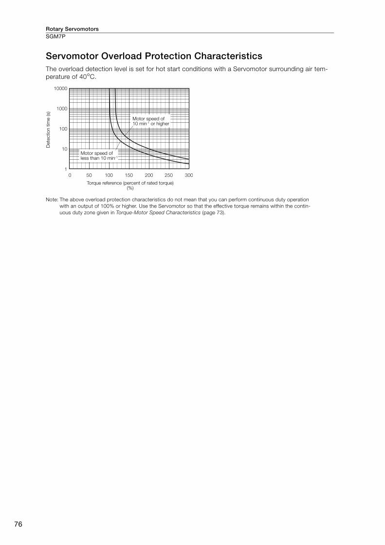
Rotary ServomotorsSGM7P
76
Servomotor Overload Protection CharacteristicsThe overload detection level is set for hot start conditions with a Servomotor surrounding air tem-perature of 40°C.
Note: The above overload protection characteristics do not mean that you can perform continuous duty operation with an output of 100% or higher. Use the Servomotor so that the effective torque remains within the contin-uous duty zone given in Torque-Motor Speed Characteristics (page 73).
0 50 100 150 200 250 300
10000
1000
100
10
1
Dete
ctio
n t
ime (s)
Motor speed of 10 min-1 or higher
Motor speed of less than 10 min-1
Torque reference (percent of rated torque) (%)
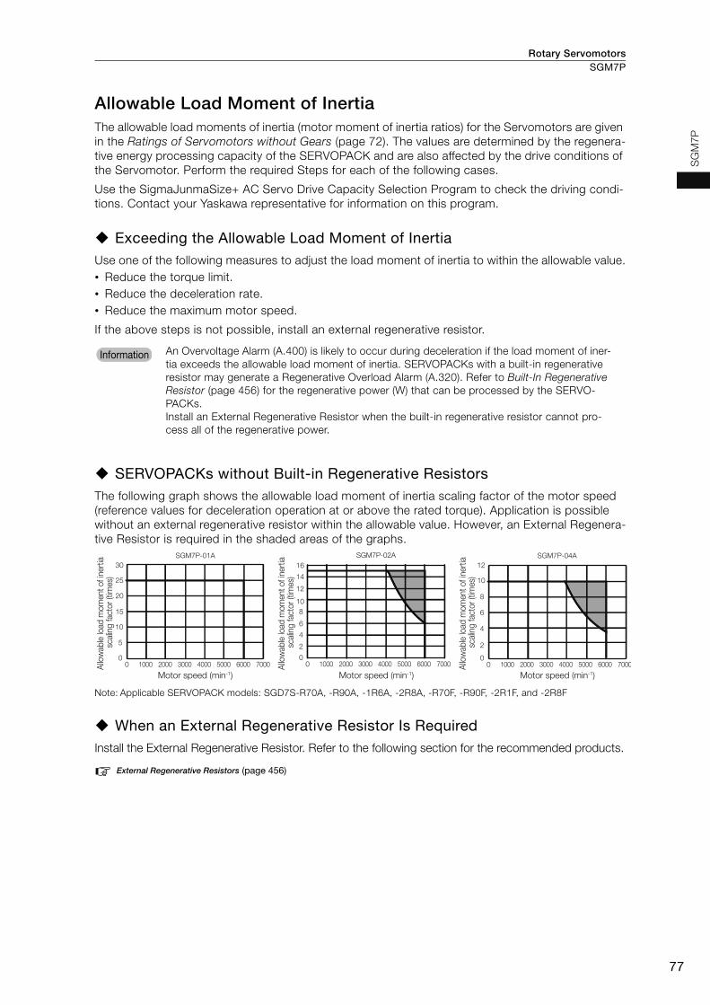
Rotary Servomotors SGM7P
77
SG
M7
P
Allowable Load Moment of InertiaThe allowable load moments of inertia (motor moment of inertia ratios) for the Servomotors are given in the Ratings of Servomotors without Gears (page 72). The values are determined by the regenera-tive energy processing capacity of the SERVOPACK and are also affected by the drive conditions of the Servomotor. Perform the required Steps for each of the following cases.
Use the SigmaJunmaSize+ AC Servo Drive Capacity Selection Program to check the driving condi-tions. Contact your Yaskawa representative for information on this program.
Exceeding the Allowable Load Moment of InertiaUse one of the following measures to adjust the load moment of inertia to within the allowable value.• Reduce the torque limit.• Reduce the deceleration rate.• Reduce the maximum motor speed.
If the above steps is not possible, install an external regenerative resistor.
SERVOPACKs without Built-in Regenerative ResistorsThe following graph shows the allowable load moment of inertia scaling factor of the motor speed (reference values for deceleration operation at or above the rated torque). Application is possible without an external regenerative resistor within the allowable value. However, an External Regenera-tive Resistor is required in the shaded areas of the graphs.
Note: Applicable SERVOPACK models: SGD7S-R70A, -R90A, -1R6A, -2R8A, -R70F, -R90F, -2R1F, and -2R8F
When an External Regenerative Resistor Is RequiredInstall the External Regenerative Resistor. Refer to the following section for the recommended products.
External Regenerative Resistors (page 456)
An Overvoltage Alarm (A.400) is likely to occur during deceleration if the load moment of iner-tia exceeds the allowable load moment of inertia. SERVOPACKs with a built-in regenerative resistor may generate a Regenerative Overload Alarm (A.320). Refer to Built-In Regenerative Resistor (page 456) for the regenerative power (W) that can be processed by the SERVO-PACKs. Install an External Regenerative Resistor when the built-in regenerative resistor cannot pro-cess all of the regenerative power.
Information
SGM7P-01A
0 1000 2000 3000 4000 5000 6000 70000
5
10
15
20
25
30
SGM7P-04A
0 1000 2000 3000 4000 5000 6000 70000
2
4
6
8
10
12
SGM7P-02A
0 1000 2000 3000 4000 5000 6000 70000
2
4
6
8
10
12
16
14
Motor speed (min-1)
Allo
wab
le lo
ad m
om
ent
of in
ertia
sc
alin
g fac
tor
(tim
es)
Motor speed (min-1)
Allo
wab
le lo
ad m
om
ent
of in
ertia
sc
alin
g fac
tor
(tim
es)
Motor speed (min-1)
Allo
wab
le lo
ad m
om
ent
of in
ertia
sc
alin
g fac
tor
(tim
es)

Rotary ServomotorsSGM7P
78
Derating Rates Servomotor Heat Dissipation ConditionsThe Servomotor ratings are the continuous allowable values at a surrounding air temperature of 40°C when a heat sink is installed on the Servomotor. If the Servomotor is mounted on a small device component, the Servomotor temperature may rise considerably because the surface for heat dissipation becomes smaller. Refer to the following graphs for the relation between the heat sink size and derating rate.
Applications Where the Surrounding Air Temperature Exceeds 40°CThe Servomotor ratings are the continuous allowable values at a surrounding air temperature of 40°C. If you use a Servomotor at a surrounding air temperature that exceeds 40°C (60°C max.), apply a suitable derating rate from the following graphs.
Applications Where the Altitude Exceeds 1,000 mThe Servomotor ratings are the continuous allowable values at an altitude of 1,000 m or less. If you use a Servomotor at an altitude that exceeds 1,000 m (2,000 m max.), the heat dissipation effect of the air is reduced. Apply the appropriate derating rate from the following graphs.
The actual temperature rise depends on how the heat sink (i.e., the Servomotor mounting sec-tion) is attached to the installation surface, what material is used for the Servomotor mounting section, and the motor speed. Always check the Servomotor temperature with the actual equip-ment.
When using Servomotors with derating, change the detection timing of overload warning and overload alarm based on the overload detection level of the motor given in Servomotor Overload Protection Characteristics (page 76).Note: 1. Use the combination of the SERVOPACK and Servomotor so that the derating conditions
are satisfied for both the SERVOPACK and Servomotor.2. The derating rates are applicable only when the average motor speed is less than or equal
to the rated motor speed. If the average motor speed exceeds the rated motor speed, consult with your Yaskawa representative.
120
0
100
80
60
40
20
0
120
100
80
60
40
20
0150 250 350300200100500150 250 30020010050
SGM7P-01, -02, and -04 SGM7P-15
SGM7P-08
Dera
ting
rate
(%
)
Heat sink size (mm)
Dera
ting
rate
(%
)
Heat sink size (mm)
Important
100
80
120
60
40
00
20
10 20 30 40 50 60 70 0 10 20 30 40 50 60
SGM7P-01
SGM7P-02
SGM7P-04
SGM7P-08
SGM7P-15
100
80
120
60
40
0
20
Der
atin
g ra
te (%
)
Surrounding air temperature (°C)
Der
atin
g ra
te (%
)
Surrounding air temperature (°C)
0 500 1000 1500 2000 2500 0 500 1000 1500 2000 2500
SGM7P-01, -02, and -04
SGM7P-08
SGM7P-15
100
80
120
60
40
0
20
100
80
120
60
40
0
20
Der
atin
g ra
te (%
)
Altitude (m)
Der
atin
g ra
te (%
)
Altitude (m)
InformationInformation
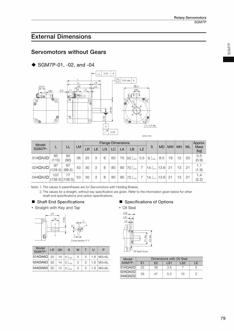
Rotary Servomotors SGM7P
79
SG
M7P
External Dimensions
Servomotors without Gears
SGM7P-01, -02, and -04
Note: 1. The values in parentheses are for Servomotors with Holding Brakes.
2. The values for a straight, without key specification are given. Refer to the information given below for other shaft end specifications and option specifications.
Model SGM7P- L LL LM
Flange DimensionsS MD MW MH ML
Approx. Mass [kg]LR LE LG LC LA LB LZ
01AA285
(115)60(90)
36 25 3 6 60 70 50 5.5 8 8.5 19 12 200.5(0.9)
02AA297
(128.5)67
(98.5)43 30 3 8 80 90 70 7 14 13.6 21 13 21
1.1(1.9)
04AA2107
(138.5)77
(108.5)53 30 3 8 80 90 70 7 14 13.6 21 13 21
1.4(2.2)
Shaft End Specifications• Straight with Key and Tap
Specifications of Options• Oil Seal
Unit: mm
(20.5)
MD 0.6 17 ML
LMLL LR
0.04 A
0.04 dia.
LA dia.
A
�LC
MW
4 × LZ dia.M
H
LE
L
LG
14
S d
ia.
LB d
ia.
A
0.02
0 -0.025
0 -0.009
0 -0.030
0 -0.011
0 -0.030
0 -0.011
QK
Y
Y
LR
W
T
U
P
S d
ia.
Cross section Y-Y
Model SGM7P- LR QK S W T U P
01AA6 25 14 8 3 3 1.8 M3×6L
02AA6 30 14 8 3 3 1.8 M3×6L
04AA6 30 14 8 3 3 1.8 M3×6L
0-0.009
0-0.009
0-0.009
LS2
LS1
LE
E1
dia.
E2
dia.
Oil Seal Cover
Model SGM7P-
Dimensions with Oil SealE1 E2 LS1 LS2 LE
01AA2 22 38 3.5 7 302AA2
35 47 5.2 10 304AA2

Rotary ServomotorsSGM7P
80
SGM7P-08 and -15
Note: 1. The values in parentheses are for Servomotors with Holding Brakes.
2. The values for a straight, without key specification are given. Refer to the information given below for other shaft end specifications and option specifications.
Model SGM7P- L LL LM LB LC SApprox.
Mass [kg]
08AA2126.5(160)
86.5(120)
67.6 110 120 194.2(5.9)
15AA2154.5(187.5)
114.5(147.5)
95.6 110 120 196.6(8.2)
Shaft End Specifications• Straight with Key and Tap
Specifications of Options • Oil Seal
Unit: mm
300±30Encoder CableUL20276, 6 dia.
Servomotor Main Circuit CableUL1828, 7 dia.
Encoder connector
Servomotor connector
�LC
38
4 × 10.2 dia.
280.04 dia.
S d
ia.
LB d
ia.
145 dia.
300±30
LL
L
40
0.04 A
A
A
0.02
LM
10.5
10
13 19(25.5)
3.5
7(40)
25
9
0-0.035
0-0.013
0-0.035
0-0.013
Cross section Y-Y
22
Y
Y
40
6
6
3.5
M6 × 10L 19
d
ia.
0
-0
.013
Oil Seal Cover
10
5
3.5
47 d
ia.
66 d
ia.

Rotary Servomotors SGM7P
81
SG
M7P
Servomotors with Gears SGM7P-01, -02, and -04
* The asterisk (*) is replaced by shaft end code 6 (straight with key and tap) for the 8th digit of the model designa-tion.If a key and tap are not necessary, specify shaft end code 2 (without key and tap).
Note: 1. The values in parentheses are for Servomotors with Holding Brakes.
2. Gear dimensions are different from those of the Σ, Σ-II, and Σ-III Series.
Model SGM7P-
Gear Ratio
L LL LMFlange Dimensions
LR LE LG B LD LB LC LA LZ
01AAH1 1/5141.5 (171.5)
99.5 (129.5)
75.5 42 2.2 5 29 39.5 40 40 46 3.4
01AAHB 1/11 182 (212)
124 (154)
100 58 2.5 8 40 55.5 56 60 70 5.501AAHC 1/21
01AAH7 1/33211 (241)
131 (161)
107 80 7.5 10 59 84 85 90 105 9
02AAH1 1/5 190 (221.5)
132 (163.5)
108 58 2.5 8 40 55.5 56 60 70 5.502AAHB 1/11
02AAHC 1/21 225 (256.5)
145 (176.5)
121 80 7.5 10 59 84 85 90 105 902AAH7 1/33
04AAH1 1/5200
(231.5)142
(173.5)118 58 2.5 8 40 55.5 56 60 70 5.5
04AAHB 1/11 235 (266.5)
155 (186.5)
131 80 7.5 10 59 84 85 90 105 904AAHC 1/21
04AAH7 1/33314
(345.5)181
(212.5)157 133 12.5 13 84 114 115 120 135 11
Model SGM7P-
Flange DimensionsQ C S
Tap Size × Depth
Key Dimensions Approx. Mass[kg]L1 L2 L3 QK U W T
01AAH1 22 20 14.6 − − 10 M3 × 6L 15 2.5 4 4 0.9 (1.3)
01AAHB 28 30 20 28 20 16 M4 × 8L 25 3 5 5 1.6 (2.0)
01AAHC
01AAH7 36 44 26 42 32 25 M6 × 12L 36 4 8 7 3.4 (3.8)
02AAH1 28 30 20 28 20 16 M4 × 8L 25 3 5 5
2.3 (2.9)
02AAHB 2.4 (3.0)
02AAHC 36 44 26 42 32 25 M6 × 12L 36 4 8 7 4.2 (5.0)
02AAH7
04AAH1 28 30 20 28 20 16 M4 × 8L 25 3 5 5 2.6 (3.2)
04AAHB 36 44 26 42 32 25 M6 × 12L 36 4 8 7 4.5 (5.3)
04AAHC
04AAH7 48 85 33 82 44 40 M10 × 20L 70 5 12 8 9.2 (10.0)
Unit: mm
L
0.6 17 ML LG LEL3 Q
QK
L1 L2LR
0.06
0.04
0.05 dia.
S di
a.
C d
ia.
B d
ia.
LD d
ia.
LB d
ia.
LA dia.
A
W
TU
A
AMH
LLLM
Details of Shaft End with Key and Tap
Rotating parts (shaded section)
Tap size × Depth4 × LZ dia.
�LC
�* 0-0.025
�* 0-0.030
�*
�* 0-0.035
�* 0-0.030
�*�* 0
-0.035�*
�* 0-0.030
�* 0-0.035
�*
�* 0-0.035
�* 0-0.015
�* 0-0.018
�*
�* 0-0.021
�* 0-0.018
�*�* 0
-0.021�*
�* 0-0.018
�* 0-0.021
�*
�* 0-0.025

Rotary ServomotorsSGM7P
82
Flange Output Face
Note: The geometric tolerance in parentheses is the value for LC = 40.
Note: 1. The values in parentheses are for Servomotors with Holding Brakes.
2. Dimensions not found in the above table are the same as those in the table on the previous page.
Model SGM7P-Gear Ratio
L LR LJ F G LKNo. of Taps ×
Tap Size × DepthApprox. Mass
[kg]
01AAH10 1/5114.5 (144.5)
15 18 5 24 3 3 × M4 × 6L 0.8 (1.2)
01AAHB0 1/11 145 (175)
21 30 14 40 5 6 × M4 × 7L 1.5 (1.9)01AAHC0 1/21
01AAH70 1/33158 (188)
27 45 24 59 5 6 × M6 × 10L 3.0 (3.4)
02AAH10 1/5 153 (184.5)
21 30 14 40 5 6 × M4 × 7L2.2 (2.8)
02AAHB0 1/11 2.3 (2.9)
02AAHC0 1/21 172 (203.5)
27 45 24 59 5 6 × M6 × 10L 3.8 (4.6)02AAH70 1/33
04AAH10 1/5163
(194.5)21 30 14 40 5 6 × M4 × 7L 2.5 (3.1)
04AAHB0 1/11 182 (213.5)
27 45 24 59 5 6 × M6 × 10L 4.1 (4.9)04AAHC0 1/21
04AAH70 1/33216
(247.5)35 60 32 84 5 6 × M8 × 12L 7.8 (8.6)
For a Servomotor with a flange output that has square gear flange dimensions (LC) of 40 mm, we recommend that you design the Servomotor with the dimensions shown in the following figure in order to secure a gap between the gear oil seal and the connecting parts on the load side.
oLC
LA dia.
LD d
ia.
LB d
ia.
G d
ia.
LJ dia.
LK
L3
LE
LR
L
4 × LZ dia. Tap size × Depth
A
0.04(0.03)
0.020.05 dia.(0.04 dia.)
A
A0.06(0.05)
Unit: mm
F di
a.
+0.012 0
+0.018 0
+0.021 0
+0.018 0
+0.021 0
+0.018 0
+0.021 0
+0.025 0
Important0.5 min.
Connecting parts on the load side
24 d
ia. m
ax.
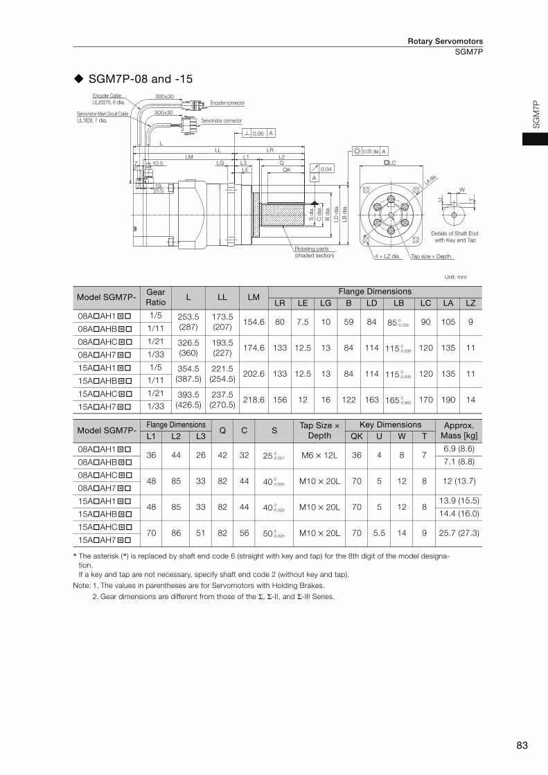
Rotary Servomotors SGM7P
83
SG
M7P
SGM7P-08 and -15
* The asterisk (*) is replaced by shaft end code 6 (straight with key and tap) for the 8th digit of the model designa-tion.If a key and tap are not necessary, specify shaft end code 2 (without key and tap).
Note: 1. The values in parentheses are for Servomotors with Holding Brakes.
2. Gear dimensions are different from those of the Σ, Σ-II, and Σ-III Series.
Model SGM7P-Gear Ratio
L LL LMFlange Dimensions
LR LE LG B LD LB LC LA LZ
08AAH1 1/5 253.5 (287)
173.5 (207)
154.6 80 7.5 10 59 84 85 90 105 908AAHB 1/11
08AAHC 1/21 326.5 (360)
193.5 (227)
174.6 133 12.5 13 84 114 115 120 135 1108AAH7 1/33
15AAH1 1/5 354.5 (387.5)
221.5 (254.5)
202.6 133 12.5 13 84 114 115 120 135 1115AAHB 1/11
15AAHC 1/21 393.5 (426.5)
237.5 (270.5)
218.6 156 12 16 122 163 165 170 190 1415AAH7 1/33
Model SGM7P-Flange Dimensions
Q C STap Size ×
DepthKey Dimensions Approx.
Mass [kg]L1 L2 L3 QK U W T
08AAH1 36 44 26 42 32 25 M6 × 12L 36 4 8 7
6.9 (8.6)
08AAHB 7.1 (8.8)
08AAHC 48 85 33 82 44 40 M10 × 20L 70 5 12 8 12 (13.7)
08AAH7
15AAH1 48 85 33 82 44 40 M10 × 20L 70 5 12 8
13.9 (15.5)
15AAHB 14.4 (16.0)
15AAHC 70 86 51 82 56 50 M10 × 20L 70 5.5 14 9 25.7 (27.3)
15AAH7
Unit: mm
Encoder CableUL20276, 6 dia. Encoder connector
Servomotor connectorServomotor Main Circuit CableUL1828, 7 dia.
300±30
300±30
(40)7 10.5
0.06
0.04
0.05 dia.
LB d
ia.
S d
ia.
LD d
ia.
B d
ia.
C d
ia.
LA dia.
4 × LZ dia. Tap size × DepthRotating parts (shaded section)
Details of Shaft End with Key and Tap
A
A
A
W
U T
LLL LR
LM L1 L2�LCLG L3
LE QKQ
19(25.5)
13
�* 0-0.035
�*
�* 0-0.035
�*
�* 0-0.035
�*
�* 0-0.063
�*
�* 0-0.021
�*
�* 0-0.025
�*
�* 0-0.025
�*
�* 0-0.025
�*

Rotary ServomotorsSGM7P
84
Flange Output Face
Note: 1. The values in parentheses are for Servomotors with Holding Brakes.
2. Dimensions not found in the above table are the same as those in the table on the previous page.
Model SGM7P-Gear Ratio
L LR LJ F G LKNo. of Taps ×
Tap Size × Depth
Approx. Mass[kg]
08AAH10 1/5 200.5 (234)
27 45 24 59 5 6 × M6 × 10L6.5 (8.2)
08AAHB0 1/11 6.7 (8.4)
08AAHC0 1/21 228.5 (262)
35 60 32 84 5 6 × M8 × 12L 10.6 (12.3)08AAH70 1/33
15AAH10 1/5 256.5 (289.5)
35 60 32 84 5 6 × M8 × 12L12.5 (14.1)
15AAHB0 1/11 13 (14.6)
15AAHC0 1/21 290.5 (323.5)
53 100 47 122 7 14 × M8 × 12L 22.7 (24.3)15AAH70 1/33
�LC
�LC
LA dia.
LJ dia.
LA dia.LD
dia
.LB
dia
.
LJ dia.
5
F di
a.
G d
ia.
LE
LR
L
L3
4 × LZ dia.
4 × LZ dia.
0.05 dia. A
0.06 A
Tap size × DepthTap size × Depth
A0.04
0.02
Unit: mm
45°
45°
SGM7P-15A�AHC0� and SGM7P-15A�AH70� Tap Locations
22.5° 22.5°
+0.021 0
+0.025 0
+0.025 0
+0.025 0

Rotary Servomotors SGM7P
85
SG
M7P
Selecting Cables
Cable ConfigurationsThe cables shown below are required to connect a Servomotor to a SERVOPACK.
Note: 1. If the Encoder Cable length exceeds 20 m, be sure to use a Relay Encoder Cable.
2. If you use a Servomotor Main Circuit Cable that exceeds 20 m, the intermittent duty zone in the torque-motor speed characteristics will become smaller because the voltage drop increases.
3. Refer to the following manual for the following information.• Cable dimensional drawings and cable connection specifications• Order numbers and specifications of individual connectors for cables• Order numbers and specifications for wiring materials
Σ-7-Series AC Servo Drive Peripheral Device Selection Manual (Manual No.: SIEP S800001 32)
Encoder Cable of 20 m or Less Encoder Cable of 30 m to 50 m (Relay Cable)
SERVOPACK
Encoder Cable
Servomotor Main Circuit Cable
Servomotor
Battery Case (Required when an absolute encoder is used.)
SERVOPACK
Cable with a Battery Case (Required when an absolute encoder is used.)
Cable with Connectors on Both Ends
Encoder-end CableServomotor Main Circuit Cable
Servomotor
Relay Encoder Cable
For SGM7P-08 or -15 (750 W or 1.5 kW) Servomotor
Servomotor Main Circuit Cable
Encoder CableRefer to page 88.
Refer to page 86.
� Cable with Connectors on Both Ends or� Cables without Connectors
For SGM7P-08 or -15 (750 W or 1.5 kW) Servomotor
� Cable with a Battery Case (Required when an absolute encoder is used.)
Relay Encoder Cable
Servomotor Main Circuit Cable
Refer to page 88.
Refer to page 86.

Rotary ServomotorsSGM7P
86
Servomotor Main Circuit Cables
Servomotor Model
Name Length
(L)Order Number
Appearance Standard Cable Flexible Cable*
SGM7P-01
100 W
For Servo-motors without Holding Brakes
3 m JZSP-CSM01-03-E JZSP-CSM21-03-E5 m JZSP-CSM01-05-E JZSP-CSM21-05-E
10 m JZSP-CSM01-10-E JZSP-CSM21-10-E15 m JZSP-CSM01-15-E JZSP-CSM21-15-E20 m JZSP-CSM01-20-E JZSP-CSM21-20-E30 m JZSP-CSM01-30-E JZSP-CSM21-30-E40 m JZSP-CSM01-40-E JZSP-CSM21-40-E50 m JZSP-CSM01-50-E JZSP-CSM21-50-E
SGM7P-02 and -04
200 W, 400 W
3 m JZSP-CSM02-03-E JZSP-CSM22-03-E5 m JZSP-CSM02-05-E JZSP-CSM22-05-E
10 m JZSP-CSM02-10-E JZSP-CSM22-10-E15 m JZSP-CSM02-15-E JZSP-CSM22-15-E20 m JZSP-CSM02-20-E JZSP-CSM22-20-E30 m JZSP-CSM02-30-E JZSP-CSM22-30-E40 m JZSP-CSM02-40-E JZSP-CSM22-40-E50 m JZSP-CSM02-50-E JZSP-CSM22-50-E
SGM7P-08
750 W
3 m JZSP-CMM00-03-E JZSP-CMM01-03-E5 m JZSP-CMM00-05-E JZSP-CMM01-05-E
10 m JZSP-CMM00-10-E JZSP-CMM01-10-E15 m JZSP-CMM00-15-E JZSP-CMM01-15-E20 m JZSP-CMM00-20-E JZSP-CMM01-20-E30 m JZSP-CMM00-30-E JZSP-CMM01-30-E40 m JZSP-CMM00-40-E JZSP-CMM01-40-E50 m JZSP-CMM00-50-E JZSP-CMM01-50-E
SGM7P-15
1.5 kW
3 m JZSP-CMM20-03-E −5 m JZSP-CMM20-05-E −
10 m JZSP-CMM20-10-E −15 m JZSP-CMM20-15-E −20 m JZSP-CMM20-20-E −
* Use Flexible Cables for moving parts of machines, such as robots. The recommended bending radius (R) is 90 mm or larger.
LSERVOPACK end
Motor end
LSERVOPACK end
Motor end
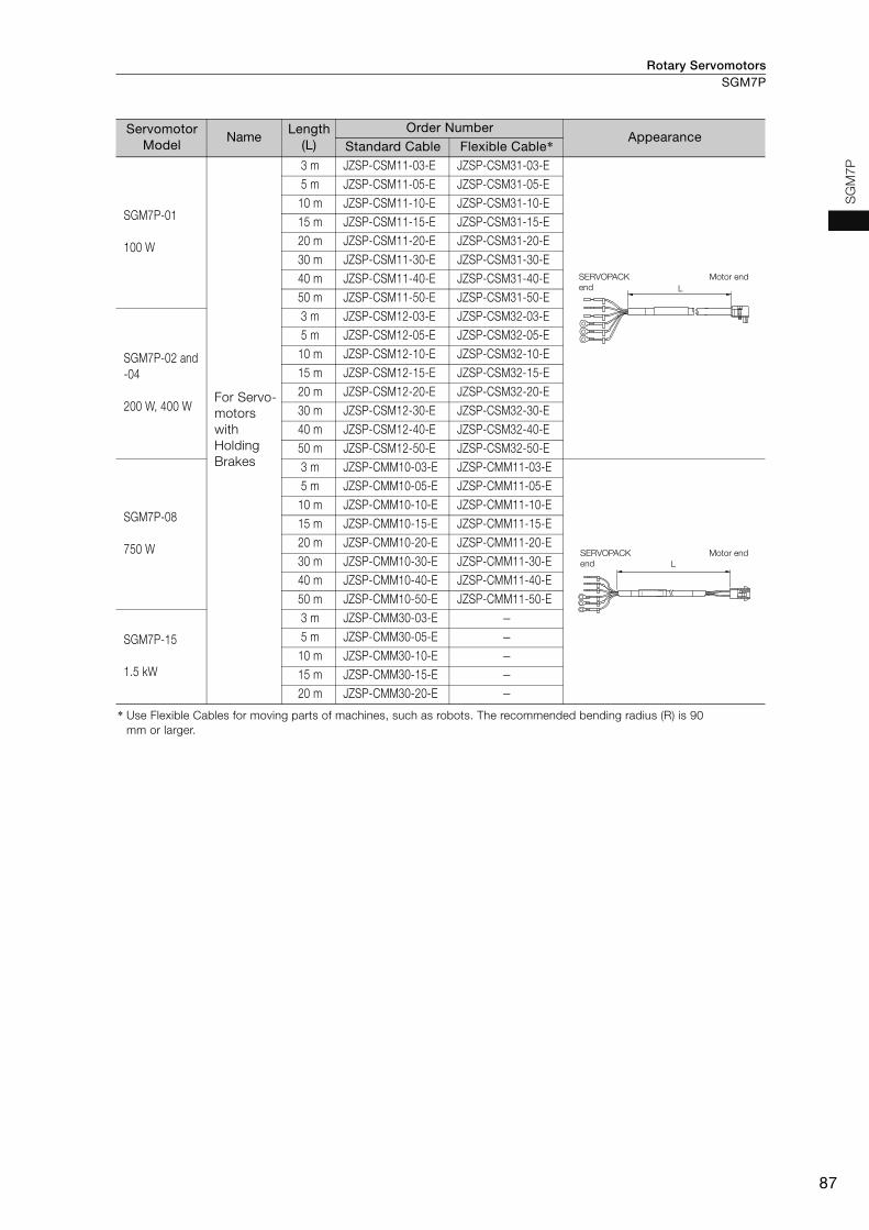
Rotary Servomotors SGM7P
87
SG
M7P
SGM7P-01
100 W
For Servo-motors with Holding Brakes
3 m JZSP-CSM11-03-E JZSP-CSM31-03-E5 m JZSP-CSM11-05-E JZSP-CSM31-05-E
10 m JZSP-CSM11-10-E JZSP-CSM31-10-E15 m JZSP-CSM11-15-E JZSP-CSM31-15-E20 m JZSP-CSM11-20-E JZSP-CSM31-20-E30 m JZSP-CSM11-30-E JZSP-CSM31-30-E40 m JZSP-CSM11-40-E JZSP-CSM31-40-E50 m JZSP-CSM11-50-E JZSP-CSM31-50-E
SGM7P-02 and -04
200 W, 400 W
3 m JZSP-CSM12-03-E JZSP-CSM32-03-E5 m JZSP-CSM12-05-E JZSP-CSM32-05-E
10 m JZSP-CSM12-10-E JZSP-CSM32-10-E15 m JZSP-CSM12-15-E JZSP-CSM32-15-E20 m JZSP-CSM12-20-E JZSP-CSM32-20-E30 m JZSP-CSM12-30-E JZSP-CSM32-30-E40 m JZSP-CSM12-40-E JZSP-CSM32-40-E50 m JZSP-CSM12-50-E JZSP-CSM32-50-E
SGM7P-08
750 W
3 m JZSP-CMM10-03-E JZSP-CMM11-03-E5 m JZSP-CMM10-05-E JZSP-CMM11-05-E
10 m JZSP-CMM10-10-E JZSP-CMM11-10-E15 m JZSP-CMM10-15-E JZSP-CMM11-15-E20 m JZSP-CMM10-20-E JZSP-CMM11-20-E30 m JZSP-CMM10-30-E JZSP-CMM11-30-E40 m JZSP-CMM10-40-E JZSP-CMM11-40-E50 m JZSP-CMM10-50-E JZSP-CMM11-50-E
SGM7P-15
1.5 kW
3 m JZSP-CMM30-03-E −5 m JZSP-CMM30-05-E −
10 m JZSP-CMM30-10-E −15 m JZSP-CMM30-15-E −20 m JZSP-CMM30-20-E −
* Use Flexible Cables for moving parts of machines, such as robots. The recommended bending radius (R) is 90 mm or larger.
Servomotor Model
Name Length
(L)Order Number
Appearance Standard Cable Flexible Cable*
LSERVOPACK end
Motor end
L
SERVOPACK
end
Motor end

Rotary ServomotorsSGM7P
88
Encoder Cables of 20 m or Less
*1. Use Flexible Cables for moving parts of machines, such as robots. The recommended bending radius (R) is 90 mm or larger.
*2. If a battery is connected to the host controller, the Battery Case is not required. If so, use a cable for incremental encoders.
Relay Encoder Cables of 30 m to 50 m
* This Cable is not required if a battery is connected to the host controller.
Servomotor Model
NameLength
(L)
Order Number Appearance
Standard Cable Flexible Cable*1
SGM7P-01, -02 and -04100 W, 200 W, 400 W For incremen-
tal encoder
Cable installed toward load
3 m JZSP-C7PI0D-03-E JZSP-C7PI2D-03-E
5 m JZSP-C7PI0D-05-E JZSP-C7PI2D-05-E
10 m JZSP-C7PI0D-10-E JZSP-C7PI2D-10-E
15 m JZSP-C7PI0D-15-E JZSP-C7PI2D-15-E
20 m JZSP-C7PI0D-20-E JZSP-C7PI2D-20-E
SGM7P-08 and -15750 W, 1500 W
3 m JZSP-CMP00-03-E JZSP-CMP10-03-E
5 m JZSP-CMP00-05-E JZSP-CMP10-05-E
10 m JZSP-CMP00-10-E JZSP-CMP10-10-E
15 m JZSP-CMP00-15-E JZSP-CMP10-15-E
20 m JZSP-CMP00-20-E JZSP-CMP10-20-E
SGM7P-01, -02 and -04100 W, 200 W, 400 W
For absolute encoder: With Battery Case*2
Cable installed toward load
3 m JZSP-C7PA0D-03-E JZSP-C7PA2D-03-E
5 m JZSP-C7PA0D-05-E JZSP-C7PA2D-05-E
10 m JZSP-C7PA0D-10-E JZSP-C7PA2D-10-E
15 m JZSP-C7PA0D-15-E JZSP-C7PA2D-15-E
20 m JZSP-C7PA0D-20-E JZSP-C7PA2D-20-E
SGM7P-08 and -15750 W, 1500 W
3 m JZSP-CSP19-03-E JZSP-CSP29-03-E
5 m JZSP-CSP19-05-E JZSP-CSP29-05-E
10 m JZSP-CSP19-10-E JZSP-CSP29-10-E
15 m JZSP-CSP19-15-E JZSP-CSP29-15-E
20 m JZSP-CSP19-20-E JZSP-CSP29-20-E
Servomotor Model
NameLength
(L)Order Number Appearance
All SGM7P models
Encoder-end Cable (for incremental or absolute encoder)Cable installed toward load
0.3 m JZSP-C7PRCD-E
Cables with Connectors on Both Ends (for incremental or absolute encoder)
30 m JZSP-UCMP00-30-E
40 m JZSP-UCMP00-40-E
50 m JZSP-UCMP00-50-E
Cable with a Battery Case (Required when an absolute encoder is used.*)
0.3 m JZSP-CSP12-E
Encoder endSERVOPACK end L
SERVOPACK end Encoder endL
SERVOPACK end
Encoder end
Battery Case (battery included)
L
SERVOPACK end Encoder endL
Encoder endSERVOPACK endL
LSERVOPACK end Encoder end
SERVOPACK end Encoder end
Battery Case
(battery included)
L

89
MEMO
SG
M7
P

Rotary Servomotors
90
SGM7G
Model Designations
* The rated output is 2.4 kW if you combine the SGM7G-30A with the SGD7S-200A.
1
7
F
2
6
A
3rd digit Power Supply Voltage
4th digit Serial Encoder
5th digit Design Revision Order
Code
24-bit absolute
24-bit incremental
Specification
Code Specification
6th digit Shaft End
7th digit Options
Without options
With holding brake (24 VDC)
With oil seal and holding
brake (24 VDC)
With oil seal
Straight without key
Code Specification
Straight with key and tap
Code SpecificationCode Specification
C
E
S
A 200 VAC
1st+2nd digits Rated Output
-7 Series
Servomotors:
SGM7G
SGM7G - 03 A 7 A 2 11st+2nd
digits3rd digit
4th digit
5th digit
6th digit
7th digit
03 300 W
05 450 W
09 850 W
13 1.3 kW
20 1.8 kW
1A 11 kW
1E 15 kW
30 2.9 kW*44 4.4 kW
55 5.5 kW
75 7.5 kW

Rotary Servomotors SGM7G
91
SG
M7
G
Specifications and Ratings
Specifications
*1. A vibration class of V15 indicates a vibration amplitude of 15 μm maximum on the Servomotor without a load at the rated motor speed.
*2. The given values are for when the Servomotor shaft is mounted horizontally and shock or vibration is applied in the directions shown in the following figures.The strength of the vibration that the Servomotor can withstand depends on the application. Always check the vibration acceleration rate that is applied to the Servomotor with the actual equipment.
*3. Refer to the following section for the derating rates.Derating Rates (page 98)
*4. If you use a Servomotor together with a Σ-7W or Σ-7C SERVOPACK, the control gain may not increase as much as with a Σ-7S SERVOPACK and other performances may be lower than those achieved with a Σ-7S SERVOPACK.
Voltage 200 V
Model SGM7G- 03A 05A 09A 13A 20A 30A 44A 55A 75A 1AA 1EA
Time Rating Continuous
Thermal Class UL: F, CE: F
Insulation Resistance 500 VDC, 10 MΩ min.
Withstand Voltage 1,500 VAC for 1 minute
Excitation Permanent magnet
Mounting Flange-mounted
Drive Method Direct drive
Rotation Direction Counterclockwise (CCW) for forward reference when viewed from the load side
Vibration Class*1 V15
Environmen-tal Condi-tions
Surrounding Air Temperature 0°C to 40°C (60°C max.)*3
Surrounding Air Humidity 20% to 80% relative humidity (with no condensation)
Installation Site
• Must be indoors and free of corrosive and explosive gases.• Must be well-ventilated and free of dust and moisture. • Must facilitate inspection and cleaning.• Must have an altitude of 1,000 m or less. (With derating, usage
is possible between 1,000 m and 2,000 m.)*3
• Must be free of strong magnetic fields.
Storage Environment Store the Servomotor in the following environment if you store it with the power cable disconnected.Storage Temperature: -20°C to 60°C (with no freezing) Storage Humidity: 20% to 80% relative humidity (with no condensation)
Shock Resistance*2
Impact Acceleration Rate at Flange 490 m/s2
Number of Impacts 2 times
Vibration Resistance*2
Vibration Acceleration Rate at Flange 49 m/s2 (24.5 m/s2 front to back) 24.5 m/s2
Applicable SERVOPACKs
SGD7S- 3R8A 7R6A 120A 180A 330A 470A 550A 590A 780A
SGD7W-SGD7C-
5R5A*4,7R6A*4 7A6A −
Vertical
Shock Applied to the Servomotor Vibration Applied to the Servomotor
Vertical
Horizontal directionSide to side
Front to back

Rotary ServomotorsSGM7G
92
Servomotor Ratings
Note: The values in parentheses are for Servomotors with Holding Brakes.
*1. These values are for operation in combination with a SERVOPACK when the temperature of the armature winding is 20°C. These are typical values.
*2. The rated torques are the continuous allowable torque values with an aluminum or steel heat sink of the dimensions given in the table.
*3. Refer to the following section for the relation between the heat sinks and derating rate.Servomotor Heat Dissipation Conditions (page 98)
*4. This does not apply to the shaft opening. Protective structure specifications apply only when the special cable is used.
*5. Observe the following precautions if you use a Servomotor with a Holding Brake.• The holding brake cannot be used to stop the Servomotor.• The time required to release the brake and the time required to brake depend on which discharge circuit is used.
Confirm that the operation delay time is appropriate for the actual equipment.• The 24-VDC power supply is not provided by Yaskawa.
*6. The motor moment of inertia scaling factor is the value for a standard Servomotor without a Holding Brake.*7. Design the mechanical system so that the thrust and radial loads applied to the Servomotor shaft end during
operation do not exceed the values given in the table.
Voltage 200 VModel SGM7G- 03A 05A 09A 13A 20A
Rated Output*1 kW 0.3 0.45 0.85 1.3 1.8
Rated Torque*1, *2 Nm 1.96 2.86 5.39 8.34 11.5
Instantaneous Maximum Torque*1 Nm 5.88 8.92 14.2 23.3 28.7
Rated Current*1 Arms 2.8 3.8 6.9 10.7 16.7
Instantaneous Maximum Current*1 Arms 8.0 11 17 28 42
Rated Motor Speed*1 min-1 1500
Maximum Motor Speed*1 min-1 3000
Torque Constant Nm/Arms 0.776 0.854 0.859 0.891 0.748
Motor Moment of Inertia ×10-4 kgm2 2.48 (2.73)
3.33 (3.58)
13.9 (16.0)
19.9 (22.0)
26.0 (28.1)
Rated Power Rate*1 kW/s 15.5 (14.1)
24.6 (22.8)
20.9 (18.2)
35.0 (31.6)
50.9 (47.1)
Rated Angular Acceleration Rate*1 rad/s2 7900(7180)
8590(7990)
3880(3370)
4190(3790)
4420(4090)
Heat Sink Size*3 mm 250 × 250 × 6(aluminum)
400 × 400 × 20(steel)
Protective Structure*4 Totally enclosed, self-cooled, IP67
Hol
din
g B
rake
S
pec
ifica
tions
*5
Rated Voltage V 24 VDCCapacity W 10
Holding Torque Nm 4.5 12.7 19.6
Coil Resistance Ω (at 20°C) 56 59
Rated Current A (at 20°C) 0.43 0.41
Time Required to Release Brake ms 100
Time Required to Brake ms 80
Allowable Load Moment of Inertia (Motor Moment of Inertia Ratio)*6 15 times 5 times
With External Regenerative Resistor and External Dynamic Brake Resistor 15 times 10 times
Allo
wab
le
Sha
ft
Load
s*7
LF mm 40 58
Allowable Radial Load N 490 686 980
Allowable Thrust Load N 98 343 392
+10% 0
LF
Radial load
Thrust load

Rotary Servomotors SGM7G
93
SG
M7
G
Torque-Motor Speed Characteristics
* A single-phase power input can be used in combination with the SGD7S-120AA008.
Note: 1. These values (typical values) are for operation in combination with a SERVOPACK when the temperature of the armature winding is 20°C.
2. The characteristics in the intermittent duty zone depend on the power supply voltage.
3. If the effective torque is within the allowable range for the rated torque, the Servomotor can be used within the intermittent duty zone.
4. If you use a Servomotor Main Circuit Cable that exceeds 20 m, the intermittent duty zone in the torque-motor speed characteristics will become smaller because the voltage drop increases.
SGM7G-03A
A B
0 1.2 2.4 3.6 4.8 6
0
500
1000
1500
2000
2500
3000
3500
500
1000
1500
2000
2500
3000
3500
500
1000
1500
2000
2500
3000
3500
500
1000
1500
2000
2500
3000
3500
SGM7G-05A
A B
0 2 4 6 8 10
0
500
1000
1500
2000
2500
3000
3500SGM7G-09A
A B
0 3 6 9 12 15
0
SGM7G-20A
A B
0 6 12 18 24 30
0
SGM7G-13A*
A B
0 5 10 15 20 25
0
(solid lines): With three-phase 200-V or single-phase 230-V input
(dotted lines): With single-phase 200-V input
:
:
Continuous duty zone
Intermittent duty zone
A :
B :
Torque (N�m)
Mo
tor
sp
eed
(m
in-1)
Torque (N�m)M
oto
r sp
eed
(m
in-1)
Torque (N�m)
Mo
tor
sp
eed
(m
in-1)
Torque (N�m)
Mo
tor
sp
eed
(m
in-1)
Torque (N�m)
Mo
tor
sp
eed
(m
in-1)

Rotary ServomotorsSGM7G
94
Servomotor Ratings
Note: The values in parentheses are for Servomotors with Holding Brakes.
*1. These values are for operation in combination with a SERVOPACK when the temperature of the armature winding is 20°C. These are typical values.
*2. The rated torques are the continuous allowable torque values with an aluminum or steel heat sink of the dimensions given in the table.
*3. Refer to the following section for the relation between the heat sinks and derating rate.Servomotor Heat Dissipation Conditions (page 98)
*4. This does not apply to the shaft opening. Protective structure specifications apply only when the special cable is used.*5. Observe the following precautions if you use a Servomotor with a Holding Brake.
• The holding brake cannot be used to stop the Servomotor.• The time required to release the brake and the time required to brake depend on which discharge circuit is used.
Confirm that the operation delay time is appropriate for the actual equipment.• The 24-VDC power supply is not provided by Yaskawa.
*6. The motor moment of inertia scaling factor is the value for a standard Servomotor without a Holding Brake.
*7. Design the mechanical system so that the thrust and radial loads applied to the Servomotor shaft end during opera-tion do not exceed the values given in the table.
*8. This is the value if you combine the SGM7G-30A with the SGD7S-200A.
Voltage 200 V
Model SGM7G- 30A 30A*6 44A 55A 75A 1AA 1EA
Rated Output*1 kW 2.9 2.4 4.4 5.5 7.5 11 15
Rated Torque*1, *2 Nm 18.6 15.1 28.4 35.0 48.0 70.0 95.4
Instantaneous Maximum Torque*1 Nm 54.0 45.1 71.6 102 119 175 224
Rated Current*1 Arms 23.8 19.6 32.8 37.2 54.7 58.6 78.0
Instantaneous Maximum Current*1 Arms 70 56 84 110 130 140 170
Rated Motor Speed*1 min-1 1500 1500 1500 1500 1500 1500 1500
Maximum Motor Speed*1 min-1 3000 3000 3000 3000 3000 2000 2000
Torque Constant Nm/Arms 0.848 0.848 0.934 1.00 0.957 1.38 1.44
Motor Moment of Inertia ×10-4 kgm2 46.0 (53.9)
46.0 (53.9)
67.5 (75.4)
89.0 (96.9)
125 (133)
242 (261)
303 (341)
Rated Power Rate*1 kW/s75.2 (64.2)
49.5 (42.2)
119 (107)
138 (126)
184 (173)
202 (188)
300 (267)
Rated Angular Acceleration Rate*1 rad/s2 4040(3450)
3280(2800)
4210(3770)
3930(3610)
3840(3610)
2890(2680)
3150(2800)
Heat Sink Size*3 mm 550 × 550 × 30 (steel)650 × 650 × 35
(steel)
Protective Structure*4 Totally enclosed, self-cooled, IP67
Hol
ding
Bra
ke
Spe
cific
atio
ns*5
Rated Voltage V 24 VDC
Capacity W 18.5 25 32 35
Holding Torque Nm 43.1 72.6 84.3 114.6
Coil Resistance Ω (at 20°C) 31 23 18 17
Rated Current A (at 20°C) 0.77 1.05 1.33 1.46
Time Required to Release Brake ms 170 250
Time Required to Brake ms 100 80
Allowable Load Moment of Inertia (Motor Moment of Inertia Ratio)*6
5 times
3 times
5 times
With External Regenerative Resistor and External Dynamic Brake Resistor
10 times
7 times
10 times
Allo
wab
le
Sha
ft Lo
ads*7 LF mm 79 113 116
Allowable Radial Load N 1470 1764 4998
Allowable Thrust Load N 490 588 2156
+10% 0
LF
Radial load
Thrust load

Rotary Servomotors SGM7G
95
SG
M7
G
Torque-Motor Speed Characteristics
* Use an SGM7G-75A Servomotor with a Holding Brake with an output torque of 14.4 N·m (30% of the rated torque) or lower when using the Servomotor in continuous operation at the maximum motor speed of 3,000 min-1.
Note: 1. These values (typical values) are for operation in combination with a SERVOPACK when the temperature of the armature winding is 20°C.
2. The characteristics in the intermittent duty zone depend on the power supply voltage.
3. If the effective torque is within the allowable range for the rated torque, the Servomotor can be used within the intermittent duty zone.
4. If you use a Servomotor Main Circuit Cable that exceeds 20 m, the intermittent duty zone in the torque-motor speed characteristics will become smaller because the voltage drop increases.
Continuous duty zone
Intermittent duty zone
(solid lines): With three-phase 200-V input
(dotted lines): When combined with the SGD7S-200A
A :
B :
SGM7G-30A
0 12 24 36 48 60
0
500
1000
1500
2000
2500
3000
3500SGM7G-44A
0 15 30 45 60 75
0
500
1000
1500
2000
2500
3000
3500SGM7G-55A
0 25 50 75 100 125
0
500
1000
1500
2000
2500
3000
3500
SGM7G-1AA
0 40 80 120 160 200
0
500
1000
1500
2000
2500SGM7G-1EA
0 50 100 150 200 250
0
500
1000
1500
2000
2500SGM7G-75A*
0 30 60 90 120 150
0
500
1000
1500
2000
2500
3000
3500
A B A B A B
A B
A B A B
Torque (N�m)
Mo
tor
sp
eed
(m
in-1)
Torque (N�m)M
oto
r sp
eed
(m
in-1)
Torque (N�m)
Mo
tor
sp
eed
(m
in-1)
Torque (N�m)
Mo
tor
sp
eed
(m
in-1)
Torque (N�m)
Mo
tor
sp
eed
(m
in-1)
Torque (N�m)
Mo
tor
sp
eed
(m
in-1)

Rotary ServomotorsSGM7G
96
Servomotor Overload Protection Characteristics The overload detection level is set for hot start conditions with a Servomotor surrounding air tem-perature of 40°C.
Note: The above overload protection characteristics do not mean that you can perform continuous duty operation with an output of 100% or higher. Use the Servomotor so that the effective torque remains within the contin-uous duty zone given in Torque-Motor Speed Characteristics on page 95.
Torque reference (percent of rated torque) (%)
Torque reference (percent of rated torque) (%)
Torque reference (percent of rated torque) (%)
Torque reference (percent of rated torque) (%)
Dete
ctio
n t
ime (s)
Dete
ctio
n t
ime (s)
Dete
ctio
n t
ime (s)
Dete
ctio
n t
ime (s)
SGM7G-03 and -05
0 50 100 150 200 250 300
10000
1000
100
10
1
SGM7G-30, -44, -55, and -75
0 50 100 150 200 250 300
10000
1000
100
10
1
SGM7G-1A and -1E
0 50 100 150 200 250 300
10000
1000
100
10
1
SGM7G-05
SGM7G-03
SGM7G-30 and -55
SGM7G-75
SGM7G-44
SGM7G-1A
SGM7G-1E
SGM7G-09, -13, and -20
0 50 100 150 200 250 300
10000
1000
100
10
1
SGM7G-13
SGM7G-09
SGM7G-20
Rotary Servomotors SGM7G
97
SG
M7
G
Allowable Load Moment of InertiaThe allowable load moments of inertia (motor moment of inertia ratios) for the Servomotors are given in the Servomotor Ratings (pages 92 and 94). The values are determined by the regenerative energy processing capacity of the SERVOPACK and are also affected by the drive conditions of the Servo-motor. Perform the required Steps for each of the following cases.
Use the SigmaJunmaSize+ AC Servo Drive Capacity Selection Program to check the driving condi-tions. Contact your Yaskawa representative for information on this program.
Exceeding the Allowable Load Moment of InertiaUse one of the following measures to adjust the load moment of inertia to within the allowable value.• Reduce the torque limit.• Reduce the deceleration rate.• Reduce the maximum motor speed.
If the above steps is not possible, install an external regenerative resistor.
When an External Regenerative Resistor Is RequiredInstall the External Regenerative Resistor. Refer to the following section for the recommended products.
External Regenerative Resistors (page 456)
An Overvoltage Alarm (A.400) is likely to occur during deceleration if the load moment of iner-tia exceeds the allowable load moment of inertia. SERVOPACKs with a built-in regenerative resistor may generate a Regenerative Overload Alarm (A.320). Refer to Built-In Regenerative Resistor (page 456) for the regenerative power (W) that can be processed by the SERVO-PACKs. Install an External Regenerative Resistor when the built-in regenerative resistor cannot pro-cess all of the regenerative power.
Information

Rotary ServomotorsSGM7G
98
Derating Rates
Servomotor Heat Dissipation Conditions The Servomotor ratings are the continuous allowable values when a heat sink is installed on the Ser-vomotor. If the Servomotor is mounted on a small device component, the Servomotor temperature may rise considerably because the surface for heat dissipation becomes smaller. Refer to the follow-ing graphs for the relation between the heat sink size and derating rate.
Servomotor Derating Rates for Surrounding Air TemperaturesApply a suitable derating rate from the following graphs according to the surrounding air tempera-ture of the Servomotor (60°C max.).
Applications Where the Altitude Exceeds 1,000 m The Servomotor ratings are the continuous allowable values at an altitude of 1,000 m or less. If you use a Servomotor at an altitude that exceeds 1,000 m (2,000 m max.), the heat dissipation effect of the air is reduced. Apply the appropriate derating rate from the following graphs.
The actual temperature rise depends on how the heat sink (i.e., the Servomotor mounting sec-tion) is attached to the installation surface, what material is used for the Servomotor mounting section, and the motor speed. Always check the Servomotor temperature with the actual equip-ment.
When using Servomotors with derating, change the detection timing of overload warning and overload alarm based on the overload detection level of the motor given in Servomotor Overload Protection Characteristics (page 96).Note: 1. Use the combination of the SERVOPACK and Servomotor so that the derating conditions
are satisfied for both the SERVOPACK and Servomotor.
2. The derating rates are applicable only when the average motor speed is less than or equal to the rated motor speed. If the average motor speed exceeds the rated motor speed, consult with your Yaskawa representative.
0 150 250 300200100500
20
40
60
80
100
120
0 100 200 300 4000
20
40
60
80
100
120
0 100 200 300 400 500 600 7000
20
40
60
80
100
120
0
20
40
60
80
100
120
0 100 200 300 400 500 600
Dera
ting
rate
(%
)
Heat sink size (mm) Heat sink size (mm)
Dera
ting
rate
(%
)
SGM7G-03 and -05 SGM7G-09, -13, and -20
SGM7G-30, -44, and -55
SGM7G-75
SGM7G-1A and -1E
Dera
ting
rate
(%
)
Heat sink size (mm) Heat sink size (mm)
Dera
ting
rate
(%
)
Important
0 10 20 30 40 50 60 700
20
40
60
80
100
120
0
20
40
60
80
100
120
0 10 20 30 40 50 60 700
20
40
60
80
100
120
0 10 20 30 40 50 60
SGM7G-75SGM7G-75
SGM7G-1ESGM7G-1E SGM7G-30 and -44SGM7G-30 and -44
SGM7G-55 and -1ASGM7G-55 and -1A
Dera
ting
rate
(%
)
Dera
ting
rate
(%
)
SGM7G-09, -13, and -20
Surrounding Air Temperature (°C)
Dera
ting
rate
(%
)
Surrounding Air Temperature (°C) Surrounding Air Temperature (°C)
SGM7G-03 and -05
0 500 1000 1500 2000 25000
20
40
60
80
100
120
0 500 1000 1500 2000 25000
20
40
60
80
100
120
0 500 1000 1500 2000 25000
20
40
60
80
100
120
SGM7G-55, -75, -1A, and -1E
SGM7G-30 and -44
Altitude (m)
Dera
ting r
ate
(%
)
Dera
ting r
ate
(%
)
SGM7G-03 and -05 SGM7G-09, -13, and -20
Altitude (m)
Dera
ting r
ate
(%
)
Altitude (m)
InformationInformation
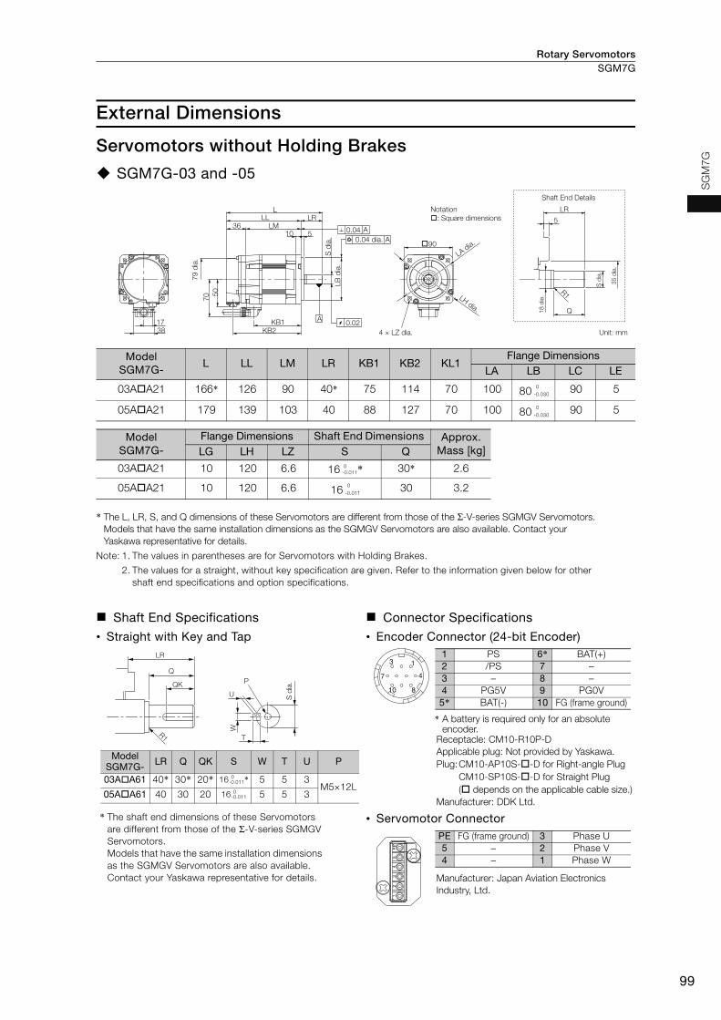
Rotary Servomotors SGM7G
99
SG
M7
G
External Dimensions
Servomotors without Holding Brakes
SGM7G-03 and -05
* The L, LR, S, and Q dimensions of these Servomotors are different from those of the Σ-V-series SGMGV Servomotors.Models that have the same installation dimensions as the SGMGV Servomotors are also available. Contact your Yaskawa representative for details.
Note: 1. The values in parentheses are for Servomotors with Holding Brakes.
2. The values for a straight, without key specification are given. Refer to the information given below for other shaft end specifications and option specifications.
Model SGM7G-
L LL LM LR KB1 KB2 KL1Flange Dimensions
LA LB LC LE
03AA21 166* 126 90 40* 75 114 70 100 80 90 5
05AA21 179 139 103 40 88 127 70 100 80 90 5
Model SGM7G-
Flange Dimensions Shaft End Dimensions Approx. Mass [kg]LG LH LZ S Q
03AA21 10 120 6.6 16 * 30* 2.6
05AA21 10 120 6.6 16 30 3.2
Shaft End Specifications Connector Specifications
• Straight with Key and Tap • Encoder Connector (24-bit Encoder)
* The shaft end dimensions of these Servomotors are different from those of the Σ-V-series SGMGV Servomotors. Models that have the same installation dimensions as the SGMGV Servomotors are also available. Contact your Yaskawa representative for details.
* A battery is required only for an absolute encoder.
Receptacle: CM10-R10P-DApplicable plug: Not provided by Yaskawa.Plug:CM10-AP10S--D for Right-angle Plug
CM10-SP10S--D for Straight Plug( depends on the applicable cable size.)
Manufacturer: DDK Ltd.
• Servomotor Connector
Manufacturer: Japan Aviation Electronics Industry, Ltd.
R1
Q
5
LR
90
50
1738
LLL
LM36LR
510
KB1KB2
70
A
A
A
0.02
0.04 dia.
79
dia
.
4 × LZ dia.
Shaft End Details
Unit: mm
0.04
S d
ia.
18
dia
.
S d
ia.
35
dia
.
LB
dia
.
LH dia.
LA dia.
Notation
: Square dimensions
0-0.030
0-0.030
0-0.011
0-0.011
LR
Q
QK
R1
U
T
W
S d
ia.P
Model SGM7G- LR Q QK S W T U P
03AA61 40* 30* 20* 16 * 5 5 3M5×12L
05AA61 40 30 20 16 5 5 3
0-0.011
0-0.011
3
7
10 8
4
11 PS 6* BAT(+)2 /PS 7 −3 − 8 −4 PG5V 9 PG0V5* BAT(-) 10 FG (frame ground)
12
34
5P
E
PE FG (frame ground) 3 Phase U5 − 2 Phase V4 − 1 Phase W

Rotary ServomotorsSGM7G
100
SGM7G-09 to -75
*1. This is 0.04 for the SGM7G-55 or SGM7G-75.
*2. The S dimensions of these Servomotors are different from those of the Σ-V-series SGMGV Servomotors. Models that have the same installation dimensions as the SGMGV Servomotors are also available. Contact your Yaskawa representative for details.
Note: 1. The values in parentheses are for Servomotors with Holding Brakes.
2. The values for a straight, without key specification are given. Refer to the information given below for other shaft end specifications and option specifications.
Model SGM7G-
L LL LM LR KB1 KB2 IE KL1Flange Dimensions
Shaft End Dimensions Approx.
Mass [kg]LA LB LC LE LG LH LZ S Q
09AA21 195 137 101 58 83 125 − 104 145 110 130 6 12 165 9 24 *2 40 5.5
13AA21 211 153 117 58 99 141 − 104 145 110 130 6 12 165 9 24 *2 40 7.1
20AA21 229 171 135 58 117 159 − 104 145 110 130 6 12 165 9 24 40 8.6
30AA21 239 160 124 79 108 148 − 134 200 114.3 180 3.2 18 230 13.5 35 76 13.5
44AA21 263 184 148 79 132 172 − 134 200 114.3 180 3.2 18 230 13.5 35 76 17.5
55AA21 334 221 185 113 163 209 123 144 200 114.3 180 3.2 18 230 13.5 42 110 21.5
75AA21 380 267 231 113 209 255 123 144 200 114.3 180 3.2 18 230 13.5 42 110 29.5
Shaft End Specifications Connector Specifications
• Straight with Key and Tap • Encoder Connector (24-bit Encoder)
* The shaft end dimensions of these Servomotors are different from those of the Σ-V-series SGMGV Servomotors. Models that have the same installation dimensions as the SGMGV Servomotors are also available. Contact your Yaskawa representative for details.
* A battery is required only for an absolute encoder.
Receptacle: CM10-R10P-DApplicable plug: Not provided by Yaskawa.Plug:CM10-AP10S--D for Right-angle Plug
CM10-SP10S--D for Straight Plug( depends on the applicable cable size.)
Manufacturer: DDK Ltd.
• Servomotor Connector
Manufacturer: DDK Ltd.
17
36
L
LL LR
LM
LG LE
S d
ia.
LB
dia
.
50K
L1
KB1
KB2
IE
LA dia.
LH dia.
0.04 A
0.04 dia. A
A
4 × LZ dia.
79 d
ia.
�LC
0.02*1
LE
LR
44 d
ia. R1
LE
LR
28 d
ia.
Q
R1
S d
ia.
45 d
ia.
S d
ia.
Q
Shaft End Details
SGM7G-30 to -75SGM7G-09 to -20
62 d
ia.
Unit: mm
0-0.035
0-0.013
0-0.035
0-0.013
0-0.035
0-0.013
0-0.025
+0.01 0
0-0.025
+0.01 0
0-0.025
0-0.016
0-0.025
0-0.016
LR
Q
QK
R1
U
T
W
S d
ia.P
Model SGM7G- LR Q QK S W T U P
09AA61 58 40 25 24 * 8* 7* 4*M5×12L13AA61 58 40 25 24 * 8* 7* 4*
20AA61 58 40 25 24 8 7 4
30AA61 79 76 60 35 10 8 5M12×25L
44AA61 79 76 60 35 10 8 5
55AA61 113 110 90 42 12 8 5M16×32L
75AA61 113 110 90 42 12 8 5
0-0.013
0-0.013
0-0.013
+0.010
+0.010
0-0.016
0-0.016
3
7
10 8
4
11 PS 6* BAT(+)2 /PS 7 −3 − 8 −4 PG5V 9 PG0V5* BAT(−) 10 FG (frame ground)
A
BC
D
A Phase U C Phase WB Phase V D FG (frame ground)

Rotary Servomotors SGM7G
101
SG
M7
G
SGM7G-1A and -1E
Note: 1. The values in parentheses are for Servomotors with Holding Brakes.
2. The values for a straight, without key specification are given. Refer to the information given below for other shaft end specifications and option specifications.
Model SGM7G-
L LL LM LR KB1 KB2 IE KL1Flange Dimensions
Shaft End Dimensions Approx.
Mass [kg]LA LB LC LE LG LH LZ S S1
1AAA21 447 331 295 116 247 319 150 168 235 200 220 4 20 270 13.5 42 50 57
1EAA21 509 393 357 116 309 381 150 168 235 200 220 4 20 270 13.5 55 60 67
Shaft End Specifications Connector Specifications
• Straight with Key and Tap • Encoder Connector (24-bit Encoder)
* A battery is required only for an absolute encoder.
Receptacle: CM10-R10P-DApplicable plug: Not provided by Yaskawa.Plug:CM10-AP10S--D for Right-angle Plug
CM10-SP10S--D for Straight Plug( depends on the applicable cable size.)
Manufacturer: DDK Ltd.
• Servomotor Connector
Manufacturer: DDK Ltd.
Shaft End Details
R1
LA dia.
LH dia.
IE
�LC
56 56
LR
LE
LM
LL
L
LR
36
LG LE
S d
ia.
LB
dia
.
KB2
KB1
50K
L1
17
S1 d
ia.
110
S d
ia.
0.04
0.06 A
0.04 dia. A
4 × LZ dia.A
79 d
ia.
Unit: mm
80
dia
.
0-0.046
0-0.016
0-0.046
+0.030+0.011
LR
Q
QK
R1
U
T
W
S d
ia.P
Model SGM7G- LR Q QK S W T U P
1AAA61 116 110 90 42 12 8 5 M16×32L
1EAA61 116 110 90 55 16 10 6 M20×40L
0-0.016
+0.030+0.011
3
7
10 8
4
11 PS 6* BAT(+)2 /PS 7 −3 − 8 −4 PG5V 9 PG0V5* BAT(−) 10 FG (frame ground)
A
BC
D
A Phase U C Phase WB Phase V D FG (frame ground)

Rotary ServomotorsSGM7G
102
Servomotors with Holding Brakes
SGM7G-03 and -05
* The L, LR, S, and Q dimensions of these Servomotors are different from those of the Σ-V-series SGMGV Servomotors.Models that have the same installation dimensions as the SGMGV Servomotors are also available. Contact your Yaskawa representative for details.
Note: 1. The values in parentheses are for Servomotors with Holding Brakes.
2. The values for a straight, without key specification are given. Refer to the information given below for other shaft end specifications and option specifications.
Model SGM7G-
L LL LM LR KB1 KB2 KL1Flange Dimensions
LA LB LC LE
03AA2C 199* 159 123 40* 75 147 70 100 80 90 5
05AA2C 212 172 136 40 88 160 70 100 80 90 5
Model SGM7G-
Flange DimensionsShaft End Dimen-
sions Approx.
Mass [kg]LG LH LZ S Q
03AA2C 10 120 6.6 16 * 30* 3.6
05AA2C 10 120 6.6 16 30 4.2
Shaft End Specifications Connector Specifications
• Straight with Key and Tap • Encoder Connector (24-bit Encoder)
* The shaft end dimensions of these Servomotors are different from those of the Σ-V-series SGMGV Servomotors. Models that have the same installation dimensions as the SGMGV Servomotors are also available. Contact your Yaskawa representative for details.
* A battery is required only for an absolute encoder.
Receptacle: CM10-R10P-DApplicable plug: Not provided by Yaskawa.Plug:CM10-AP10S--D for Right-angle Plug
CM10-SP10S--D for Straight Plug( depends on the applicable cable size.)
Manufacturer: DDK Ltd.
• Servomotor Connector
Manufacturer: Japan Aviation Electronics Industry, Ltd.
R1
S d
ia.
Q 18
dia
.
5
LR
90
KB1KB2
10 5LM
LL
LLR
36
70 5
0
1738
A
0.04 A
A
0.02
79
dia
.
0.04 dia.
4 × 6.6 dia.
Shaft End Details
Unit: mm
120 dia.
100 dia.
LB
dia
.
35
dia
.
S d
ia.
0-0.030
0
-0.030
0-0.011
0-0.011
LR
Q
QK
R1
U
T
W
S d
ia.P
Model SGM7G- LR Q QK S W T U P
03AA6C 40* 30* 20* 16 * 5 5 3M5×12L
05AA6C 40 30 20 16 5 5 3
0-0.011
0-0.011
3
7
10 8
4
11 PS 6* BAT(+)2 /PS 7 −3 − 8 −4 PG5V 9 PG0V5* BAT(-) 10 FG (frame ground)
12
34
5P
E
PE FG (frame ground) 3 Phase U5 − 2 Phase V4 − 1 Phase W
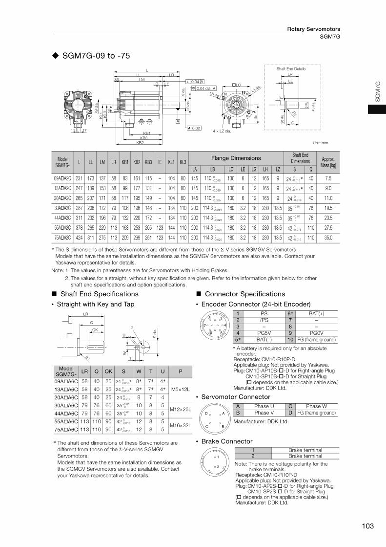
Rotary Servomotors SGM7G
103
SG
M7
G
SGM7G-09 to -75
* The S dimensions of these Servomotors are different from those of the Σ-V-series SGMGV Servomotors. Models that have the same installation dimensions as the SGMGV Servomotors are also available. Contact your Yaskawa representative for details.
Note: 1. The values in parentheses are for Servomotors with Holding Brakes.
2. The values for a straight, without key specification are given. Refer to the information given below for other shaft end specifications and option specifications.
Model SGM7G- L LL LM LR KB1 KB2 KB3 IE KL1 KL3
Flange Dimensions Shaft End Dimensions Approx.
Mass [kg]LA LB LC LE LG LH LZ S Q
09AA2C 231 173 137 58 83 161 115 − 104 80 145 110 130 6 12 165 9 24 * 40 7.5
13AA2C 247 189 153 58 99 177 131 − 104 80 145 110 130 6 12 165 9 24 * 40 9.0
20AA2C 265 207 171 58 117 195 149 − 104 80 145 110 130 6 12 165 9 24 40 11.0
30AA2C 287 208 172 79 108 196 148 − 134 110 200 114.3 180 3.2 18 230 13.5 35 76 19.5
44AA2C 311 232 196 79 132 220 172 − 134 110 200 114.3 180 3.2 18 230 13.5 35 76 23.5
55AA2C 378 265 229 113 163 253 205 123 144 110 200 114.3 180 3.2 18 230 13.5 42 110 27.5
75AA2C 424 311 275 113 209 299 251 123 144 110 200 114.3 180 3.2 18 230 13.5 42 110 35.0
Shaft End Specifications Connector Specifications
• Straight with Key and Tap • Encoder Connector (24-bit Encoder)
* The shaft end dimensions of these Servomotors are different from those of the Σ-V-series SGMGV Servomotors. Models that have the same installation dimensions as the SGMGV Servomotors are also available. Contact your Yaskawa representative for details.
* A battery is required only for an absolute encoder.
Receptacle: CM10-R10P-DApplicable plug: Not provided by Yaskawa.Plug:CM10-AP10S--D for Right-angle Plug
CM10-SP10S--D for Straight Plug( depends on the applicable cable size.)
Manufacturer: DDK Ltd.
• Servomotor Connector
Manufacturer: DDK Ltd.
• Brake Connector
Note: There is no voltage polarity for the brake terminals.
Receptacle: CM10-R10P-DApplicable plug: Not provided by Yaskawa.Plug:CM10-AP2S--D for Right-angle Plug
CM10-SP2S--D for Straight Plug( depends on the applicable cable size.)Manufacturer: DDK Ltd.
LE
LR
Q
R1
36
1711
IE
LELG
LLL
LRLM
KB1KB3
KB2
KL1
KL3 5
0
0.02
A
0.04 A
ALC
79
dia
.
S d
ia.
LB
dia
.
28
dia
.
S d
ia.
45
dia
.
0.04 dia.
4 × LZ dia.
Unit: mm
Shaft End Details
LH dia.
LA dia.
0-0.035
0-0.013
0-0.035
0-0.013
0-0.035
0-0.013
0-0.025
+0.01 0
0-0.025
+0.01 0
0-0.025
0-0.016
0-0.025
0-0.016
LR
Q
QK
R1
U
T
W
S d
ia.P
Model SGM7G- LR Q QK S W T U P
09AA6C 58 40 25 24 * 8* 7* 4*M5×12L13AA6C 58 40 25 24 * 8* 7* 4*
20AA6C 58 40 25 24 8 7 4
30AA6C 79 76 60 35 10 8 5M12×25L
44AA6C 79 76 60 35 10 8 5
55AA6C 113 110 90 42 12 8 5M16×32L
75AA6C 113 110 90 42 12 8 5
0-0.013
0-0.013
0-0.013
+0.010
+0.010
0-0.016
0-0.016
3
7
10 8
4
11 PS 6* BAT(+)2 /PS 7 −3 − 8 −4 PG5V 9 PG0V5* BAT(−) 10 FG (frame ground)
A
BC
D
A Phase U C Phase WB Phase V D FG (frame ground)
1
2
1 Brake terminal2 Brake terminal

Rotary ServomotorsSGM7G
104
SGM7G-1A, 1E
Note: 1. The values in parentheses are for Servomotors with Holding Brakes.
2. The values for a straight, without key specification are given. Refer to the information given below for other shaft end specifications and option specifications.
Model SGM7G-
L LL LM LR KB1 KB2 KB3 IE KL1 KL3Flange Dimensions Shaft End Dimensions Approx.
Mass [kg]LA LB LC LE LG LH LZ S S1
1AAA2C 498 382 346 116 247 370 315 150 168 125 235 200 220 4 20 270 13.5 42 50 65
1EAA2C 598 482 446 116 309 470 385 150 168 125 235 200 220 4 20 270 13.5 55 60 85
Shaft End Specifications Connector Specifications
• Straight with Key and Tap • Encoder Connector (24-bit Encoder)
* A battery is required only for an absolute encoder.
Receptacle: CM10-R10P-DApplicable plug: Not provided by Yaskawa.Plug:CM10-AP10S--D for Right-angle Plug
CM10-SP10S--D for Straight Plug( depends on the applicable cable size.)
Manufacturer: DDK Ltd.
• Servomotor Connector
Manufacturer: DDK Ltd.
• Brake Connector
Note: There is no voltage polarity for the brake terminals.
Receptacle: CM10-R10P-DApplicable plug: Not provided by Yaskawa.Plug:CM10-AP2S--D for Right-angle Plug
CM10-SP2S--D for Straight Plug( depends on the applicable cable size.)Manufacturer: DDK Ltd.
Shaft End Details
R1
LA dia.
LH dia.
IE
�LC
56 56
LRLE
S d
ia.
LB
dia
.
LL LR
LM
LG LE
36
KB1
KB3
KB2
50
KL3
KL1
11 17
L
S1
dia.
S d
ia.
110
0.04
0.04 dia.A
4 × LZ dia.A
0.06 A
79 d
ia.
80 d
ia.
Unit: mm
0-0.046
0-0.016
0-0.046
+0.030+0.011
LR
Q
QK
R1
U
T
W
S d
ia.P
Model SGM7G-
LR Q QK S W T U P
1AAA6C 116 110 90 42 12 8 5 M16×32L
1EAA6C 116 110 90 55 16 10 6 M20×40L
0-0.016
+0.030+0.011
3
7
10 8
4
11 PS 6* BAT(+)2 /PS 7 −3 − 8 −4 PG5V 9 PG0V5* BAT(−) 10 FG (frame ground)
A
BC
D
A Phase U C Phase WB Phase V D FG (frame ground)
1
2
1 Brake terminal2 Brake terminal
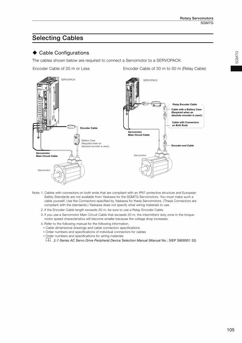
Rotary Servomotors SGM7G
105
SG
M7
G
Selecting Cables
Cable ConfigurationsThe cables shown below are required to connect a Servomotor to a SERVOPACK.
Note: 1. Cables with connectors on both ends that are compliant with an IP67 protective structure and European Safety Standards are not available from Yaskawa for the SGM7G Servomotors. You must make such a cable yourself. Use the Connectors specified by Yaskawa for these Servomotors. (These Connectors are compliant with the standards.) Yaskawa does not specify what wiring materials to use.
2. If the Encoder Cable length exceeds 20 m, be sure to use a Relay Encoder Cable.
3. If you use a Servomotor Main Circuit Cable that exceeds 20 m, the intermittent duty zone in the torque-motor speed characteristics will become smaller because the voltage drop increases.
4. Refer to the following manual for the following information.• Cable dimensional drawings and cable connection specifications• Order numbers and specifications of individual connectors for cables• Order numbers and specifications for wiring materials
Σ-7-Series AC Servo Drive Peripheral Device Selection Manual (Manual No.: SIEP S800001 32)
Encoder Cable of 20 m or Less Encoder Cable of 30 m to 50 m (Relay Cable)
SERVOPACK
Encoder Cable
Battery Case (Required when an absolute encoder is used.)
Servomotor Main Circuit Cable
Servomotor
SERVOPACK
Cable with a Battery Case (Required when an absolute encoder is used.)
Cable with Connectors on Both Ends
Encoder-end Cable
Servomotor Main Circuit Cable
Servomotor
Relay Encoder Cable

Rotary ServomotorsSGM7G
106
Servomotor Main Circuit Cables
Servomotor Model
NameLength
(L)Order Number* Appearance
SGM7G-03 and -05
300 W, 450 W
For Servomotors without Holding Brakes
3 m JZSP-CVM21-03-E5 m JZSP-CVM21-05-E
10 m JZSP-CVM21-10-E15 m JZSP-CVM21-15-E20 m JZSP-CVM21-20-E30 m JZSP-CVM21-30-E40 m JZSP-CVM21-40-E50 m JZSP-CVM21-50-E
For Servomotors with Holding Brakes
3 m JZSP-CVM41-03-E5 m JZSP-CVM41-05-E
10 m JZSP-CVM41-10-E15 m JZSP-CVM41-15-E20 m JZSP-CVM41-20-E30 m JZSP-CVM41-30-E40 m JZSP-CVM41-40-E50 m JZSP-CVM41-50-E
* Use Flexible Cables for moving parts of machines, such as robots. The recommended bending radius (R) is 90 mm or larger.
Servo-motor Model
Name Connec-tor Spec-ifications
Length (L)
Order NumberAppearance
Standard Cable Flexible Cable*1
SGM7G-09 and -13
850 W, 1.3 kW
For Servomotors without Holding Brakes
Straight
3 m JZSP-UVA101-03-E JZSP-UVA121-03-E
5 m JZSP-UVA101-05-E JZSP-UVA121-05-E
10 m JZSP-UVA101-10-E JZSP-UVA121-10-E
15 m JZSP-UVA101-15-E JZSP-UVA121-15-E
20 m JZSP-UVA101-20-E JZSP-UVA121-20-E
Right-angle
3 m JZSP-UVA102-03-E JZSP-UVA122-03-E
5 m JZSP-UVA102-05-E JZSP-UVA122-05-E
10 m JZSP-UVA102-10-E JZSP-UVA122-10-E
15 m JZSP-UVA102-15-E JZSP-UVA122-15-E
20 m JZSP-UVA102-20-E JZSP-UVA122-20-E
For Servomotors with Holding Brakes
(Set of Two Cables*2)
Straight
3 m JZSP-UVA131-03-E JZSP-UVA141-03-E5 m JZSP-UVA131-05-E JZSP-UVA141-05-E
10 m JZSP-UVA131-10-E JZSP-UVA141-10-E15 m JZSP-UVA131-15-E JZSP-UVA141-15-E20 m JZSP-UVA131-20-E JZSP-UVA141-20-E
Right-angle
3 m JZSP-UVA132-03-E JZSP-UVA142-03-E
5 m JZSP-UVA132-05-E JZSP-UVA142-05-E
10 m JZSP-UVA132-10-E JZSP-UVA142-10-E
15 m JZSP-UVA132-15-E JZSP-UVA142-15-E
20 m JZSP-UVA132-20-E JZSP-UVA142-20-E
*1. Use Flexible Cables for moving parts of machines, such as robots. The recommended bending radius (R) is 90 mm or larger.
*2. This order number is for a set of two cables (Main Power Supply Cable and Holding Brake Cable).When you purchase them separately, the order numbers for Main Power Supply Cables are the same as for a Servomotor without a Holding Brake. The following order numbers are for a Holding Brake Cable. These Standard Cables are Flexible Cables.• Cable with Straight Plug: JZSP-U7B23--E• Cable with Right-angle Plug: JZSP-U7B24--E
L
SERVOPACK end Motor end
L
SERVOPACK end Motor end
LSERVOPACK end
Motor end
LSERVOPACK end
Motor end
LSERVOPACK end Motor end
LSERVOPACK end Brake end
LSERVOPACK end
Motor end
LBrake end Motor end
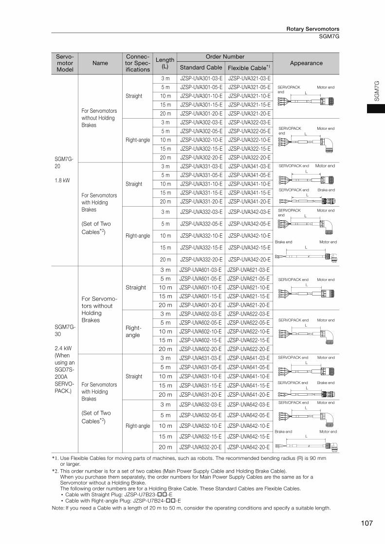
Rotary Servomotors SGM7G
107
SG
M7G
SGM7G-20
1.8 kW
For Servomotors without Holding Brakes
Straight
3 m JZSP-UVA301-03-E JZSP-UVA321-03-E
5 m JZSP-UVA301-05-E JZSP-UVA321-05-E
10 m JZSP-UVA301-10-E JZSP-UVA321-10-E
15 m JZSP-UVA301-15-E JZSP-UVA321-15-E
20 m JZSP-UVA301-20-E JZSP-UVA321-20-E
Right-angle
3 m JZSP-UVA302-03-E JZSP-UVA322-03-E
5 m JZSP-UVA302-05-E JZSP-UVA322-05-E
10 m JZSP-UVA302-10-E JZSP-UVA322-10-E
15 m JZSP-UVA302-15-E JZSP-UVA322-15-E
20 m JZSP-UVA302-20-E JZSP-UVA322-20-E
For Servomotors with Holding Brakes
(Set of Two Cables*2)
Straight
3 m JZSP-UVA331-03-E JZSP-UVA341-03-E
5 m JZSP-UVA331-05-E JZSP-UVA341-05-E
10 m JZSP-UVA331-10-E JZSP-UVA341-10-E
15 m JZSP-UVA331-15-E JZSP-UVA341-15-E
20 m JZSP-UVA331-20-E JZSP-UVA341-20-E
Right-angle
3 m JZSP-UVA332-03-E JZSP-UVA342-03-E
5 m JZSP-UVA332-05-E JZSP-UVA342-05-E
10 m JZSP-UVA332-10-E JZSP-UVA342-10-E
15 m JZSP-UVA332-15-E JZSP-UVA342-15-E
20 m JZSP-UVA332-20-E JZSP-UVA342-20-E
SGM7G-30
2.4 kW(When using an SGD7S-200A SERVO-PACK.)
For Servomo-tors without Holding Brakes
Straight
3 m JZSP-UVA601-03-E JZSP-UVA621-03-E
5 m JZSP-UVA601-05-E JZSP-UVA621-05-E
10 m JZSP-UVA601-10-E JZSP-UVA621-10-E
15 m JZSP-UVA601-15-E JZSP-UVA621-15-E
20 m JZSP-UVA601-20-E JZSP-UVA621-20-E
Right-angle
3 m JZSP-UVA602-03-E JZSP-UVA622-03-E
5 m JZSP-UVA602-05-E JZSP-UVA622-05-E
10 m JZSP-UVA602-10-E JZSP-UVA622-10-E
15 m JZSP-UVA602-15-E JZSP-UVA622-15-E
20 m JZSP-UVA602-20-E JZSP-UVA622-20-E
For Servomotors with Holding Brakes
(Set of Two Cables*2)
Straight
3 m JZSP-UVA631-03-E JZSP-UVA641-03-E
5 m JZSP-UVA631-05-E JZSP-UVA641-05-E
10 m JZSP-UVA631-10-E JZSP-UVA641-10-E
15 m JZSP-UVA631-15-E JZSP-UVA641-15-E
20 m JZSP-UVA631-20-E JZSP-UVA641-20-E
Right-angle
3 m JZSP-UVA632-03-E JZSP-UVA642-03-E
5 m JZSP-UVA632-05-E JZSP-UVA642-05-E
10 m JZSP-UVA632-10-E JZSP-UVA642-10-E
15 m JZSP-UVA632-15-E JZSP-UVA642-15-E
20 m JZSP-UVA632-20-E JZSP-UVA642-20-E
*1. Use Flexible Cables for moving parts of machines, such as robots. The recommended bending radius (R) is 90 mm or larger.
*2. This order number is for a set of two cables (Main Power Supply Cable and Holding Brake Cable).When you purchase them separately, the order numbers for Main Power Supply Cables are the same as for a Servomotor without a Holding Brake. The following order numbers are for a Holding Brake Cable. These Standard Cables are Flexible Cables.• Cable with Straight Plug: JZSP-U7B23--E• Cable with Right-angle Plug: JZSP-U7B24--E
Note: If you need a Cable with a length of 20 m to 50 m, consider the operating conditions and specify a suitable length.
Servo-motor Model
Name Connec-tor Spec-ifications
Length (L)
Order NumberAppearance
Standard Cable Flexible Cable*1
LSERVOPACK end
Motor end
LSERVOPACK end
Motor end
LSERVOPACK end Motor end
LSERVOPACK end Brake end
LSERVOPACK end
Motor end
LBrake end Motor end
LSERVOPACK end Motor end
LSERVOPACK end Motor end
LSERVOPACK end Motor end
LSERVOPACK end Brake end
LSERVOPACK end Motor end
LBrake end Motor end

Rotary ServomotorsSGM7G
108
Servo-motor Model
Name Connec-tor Spec-ifications
Length (L)
Order NumberAppearance
Standard Cable Flexible Cable*1
SGM7G-30 and -44
2.9 kW,4.4 kW
For Servomo-tors without Holding Brakes
Straight
3 m JZSP-UVA701-03-E JZSP-UVA721-03-E
5 m JZSP-UVA701-05-E JZSP-UVA721-05-E
10 m JZSP-UVA701-10-E JZSP-UVA721-10-E
15 m JZSP-UVA701-15-E JZSP-UVA721-15-E
20 m JZSP-UVA701-20-E JZSP-UVA721-20-E
Right-angle
3 m JZSP-UVA702-03-E JZSP-UVA722-03-E
5 m JZSP-UVA702-05-E JZSP-UVA722-05-E
10 m JZSP-UVA702-10-E JZSP-UVA722-10-E
15 m JZSP-UVA702-15-E JZSP-UVA722-15-E
20 m JZSP-UVA702-20-E JZSP-UVA722-20-E
For Servomotors with Holding Brakes
(Set of Two Cables*2)
Straight
3 m JZSP-UVA731-03-E JZSP-UVA741-03-E
5 m JZSP-UVA731-05-E JZSP-UVA741-05-E
10 m JZSP-UVA731-10-E JZSP-UVA741-10-E
15 m JZSP-UVA731-15-E JZSP-UVA741-15-E
20 m JZSP-UVA731-20-E JZSP-UVA741-20-E
Right-angle
3 m JZSP-UVA732-03-E JZSP-UVA742-03-E
5 m JZSP-UVA732-05-E JZSP-UVA742-05-E
10 m JZSP-UVA732-10-E JZSP-UVA742-10-E
15 m JZSP-UVA732-15-E JZSP-UVA742-15-E
20 m JZSP-UVA732-20-E JZSP-UVA742-20-E
SGM7G-55 and -75
5.5 kW, 7.5 kW
For Servomo-tors without Holding Brakes
Straight
3 m JZSP-UVAA01-03-E JZSP-UVAA21-03-E
5 m JZSP-UVAA01-05-E JZSP-UVAA21-05-E
10 m JZSP-UVAA01-10-E JZSP-UVAA21-10-E
15 m JZSP-UVAA01-15-E JZSP-UVAA21-15-E
20 m JZSP-UVAA01-20-E JZSP-UVAA21-20-E
Right-angle
3 m JZSP-UVAA02-03-E JZSP-UVAA22-03-E
5 m JZSP-UVAA02-05-E JZSP-UVAA22-05-E
10 m JZSP-UVAA02-10-E JZSP-UVAA22-10-E
15 m JZSP-UVAA02-15-E JZSP-UVAA22-15-E
20 m JZSP-UVAA02-20-E JZSP-UVAA22-20-E
For Servomotors with Holding Brakes
(Set of Two Cables*2)
Straight
3 m JZSP-UVAA31-03-E JZSP-UVAA41-03-E
5 m JZSP-UVAA31-05-E JZSP-UVAA41-05-E
10 m JZSP-UVAA31-10-E JZSP-UVAA41-10-E
15 m JZSP-UVAA31-15-E JZSP-UVAA41-15-E
20 m JZSP-UVAA31-20-E JZSP-UVAA41-20-E
Right-angle
3 m JZSP-UVAA32-03-E JZSP-UVAA42-03-E
5 m JZSP-UVAA32-05-E JZSP-UVAA42-05-E
10 m JZSP-UVAA32-10-E JZSP-UVAA42-10-E
15 m JZSP-UVAA32-15-E JZSP-UVAA42-15-E
20 m JZSP-UVAA32-20-E JZSP-UVAA42-20-E
*1. Use Flexible Cables for moving parts of machines, such as robots. The recommended bending radius (R) is 90 mm or larger.
*2. This order number is for a set of two cables (Main Power Supply Cable and Holding Brake Cable).When you purchase them separately, the order numbers for Main Power Supply Cables are the same as for a Servomotor without a Holding Brake. The following order numbers are for a Holding Brake Cable. These Standard Cables are Flexible Cables.• Cable with Straight Plug: JZSP-U7B23--E• Cable with Right-angle Plug: JZSP-U7B24--E
Note: If you need a Cable with a length of 20 m to 50 m, consider the operating conditions and specify a suitable length.
LSERVOPACK end
Motor end
LSERVOPACK end
Motor end
LSERVOPACK end
Motor end
LSERVOPACK end
Brake end
LSERVOPACK end
Motor end
LBrake end Motor end
LSERVOPACK end
Motor end
LSERVOPACK end
Motor end
LSERVOPACK end
Motor end
LSERVOPACK end
Brake end
LSERVOPACK end
Motor end
LBrake end Motor end
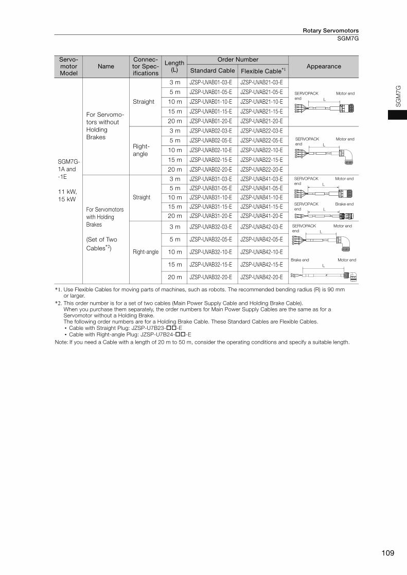
Rotary Servomotors SGM7G
109
SG
M7G
SGM7G-1A and -1E
11 kW, 15 kW
For Servomo-tors without Holding Brakes
Straight
3 m JZSP-UVAB01-03-E JZSP-UVAB21-03-E
5 m JZSP-UVAB01-05-E JZSP-UVAB21-05-E
10 m JZSP-UVAB01-10-E JZSP-UVAB21-10-E
15 m JZSP-UVAB01-15-E JZSP-UVAB21-15-E
20 m JZSP-UVAB01-20-E JZSP-UVAB21-20-E
Right-angle
3 m JZSP-UVAB02-03-E JZSP-UVAB22-03-E
5 m JZSP-UVAB02-05-E JZSP-UVAB22-05-E
10 m JZSP-UVAB02-10-E JZSP-UVAB22-10-E
15 m JZSP-UVAB02-15-E JZSP-UVAB22-15-E
20 m JZSP-UVAB02-20-E JZSP-UVAB22-20-E
For Servomotors with Holding Brakes
(Set of Two Cables*2)
Straight
3 m JZSP-UVAB31-03-E JZSP-UVAB41-03-E
5 m JZSP-UVAB31-05-E JZSP-UVAB41-05-E
10 m JZSP-UVAB31-10-E JZSP-UVAB41-10-E
15 m JZSP-UVAB31-15-E JZSP-UVAB41-15-E
20 m JZSP-UVAB31-20-E JZSP-UVAB41-20-E
Right-angle
3 m JZSP-UVAB32-03-E JZSP-UVAB42-03-E
5 m JZSP-UVAB32-05-E JZSP-UVAB42-05-E
10 m JZSP-UVAB32-10-E JZSP-UVAB42-10-E
15 m JZSP-UVAB32-15-E JZSP-UVAB42-15-E
20 m JZSP-UVAB32-20-E JZSP-UVAB42-20-E
*1. Use Flexible Cables for moving parts of machines, such as robots. The recommended bending radius (R) is 90 mm or larger.
*2. This order number is for a set of two cables (Main Power Supply Cable and Holding Brake Cable).When you purchase them separately, the order numbers for Main Power Supply Cables are the same as for a Servomotor without a Holding Brake. The following order numbers are for a Holding Brake Cable. These Standard Cables are Flexible Cables.• Cable with Straight Plug: JZSP-U7B23--E• Cable with Right-angle Plug: JZSP-U7B24--E
Note: If you need a Cable with a length of 20 m to 50 m, consider the operating conditions and specify a suitable length.
Servo-motor Model
Name Connec-tor Spec-ifications
Length (L)
Order NumberAppearance
Standard Cable Flexible Cable*1
LSERVOPACK end
Motor end
LSERVOPACK end
Motor end
LSERVOPACK end
Motor end
LSERVOPACK end
Brake end
LSERVOPACK end
Motor end
LBrake end Motor end

Rotary ServomotorsSGM7G
110
Encoder Cables of 20 m or Less
Relay Encoder Cables of 30 m to 50 m
* This Cable is not required if a battery is connected to the host controller.
Servomotor Model
NameLength
(L)Order Number
AppearanceStandard Cable Flexible Cable*
All SGM7G models
Cables with Connec-tors on Both Ends(for incre-mental encoder)
3 m JZSP-CVP01-03-E JZSP-CVP11-03-E
5 m JZSP-CVP01-05-E JZSP-CVP11-05-E
10 m JZSP-CVP01-10-E JZSP-CVP11-10-E
15 m JZSP-CVP01-15-E JZSP-CVP11-15-E
20 m JZSP-CVP01-20-E JZSP-CVP11-20-E
3 m JZSP-CVP02-03-E JZSP-CVP12-03-E
5 m JZSP-CVP02-05-E JZSP-CVP12-05-E
10 m JZSP-CVP02-10-E JZSP-CVP12-10-E
15 m JZSP-CVP02-15-E JZSP-CVP12-15-E
20 m JZSP-CVP02-20-E JZSP-CVP12-20-E
Cables with Connec-tors on Both Ends(for abso-lute encoder: With Bat-tery Case)
3 m JZSP-CVP06-03-E JZSP-CVP26-03-E
5 m JZSP-CVP06-05-E JZSP-CVP26-05-E
10 m JZSP-CVP06-10-E JZSP-CVP26-10-E
15 m JZSP-CVP06-15-E JZSP-CVP26-15-E
20 m JZSP-CVP06-20-E JZSP-CVP26-20-E
3 m JZSP-CVP07-03-E JZSP-CVP27-03-E
5 m JZSP-CVP07-05-E JZSP-CVP27-05-E
10 m JZSP-CVP07-10-E JZSP-CVP27-10-E
15 m JZSP-CVP07-15-E JZSP-CVP27-15-E
20 m JZSP-CVP07-20-E JZSP-CVP27-20-E
* Use Flexible Cables for moving parts of machines, such as robots. The recommended bending radius (R) is 90 mm or larger.
Servomotor Model
NameLength
(L)Order Number for Standard Cable
Appearance
All SGM7G models
Encoder-end Cable (for incremental or absolute encoder)
0.3 m
JZSP-CVP01-E
JZSP-CVP02-E
Cables with Connec-tors on Both Ends (for incremental or absolute encoder)
30 m JZSP-UCMP00-30-E
40 m JZSP-UCMP00-40-E
50 m JZSP-UCMP00-50-E
Cable with a Battery Case (Required when an absolute encoder is used.)*
0.3 m JZSP-CSP12-E
L
mol
ex
SERVOPACK end
Encoder end
SERVOPACK end L
mole
x
Encoder end
L
mole
x
SERVOPACK end
Encoder end
Battery Case (battery included)
L
mole
x
SERVOPACK end
Encoder end
Battery Case (battery included)
SERVOPACK end Encoder endL
molex
SERVOPACK end Encoder end
molex
L
SERVOPACK end
Encoder endL
molex
SERVOPACK end
Encoder end
Battery Case (battery included)
L
molex

SGM7D (With Core, Outer Rotor) ........................112
SGM7F (Small Capacity, with Core, Inner Rotor) ... 138
SGMCV (Small Capacity, with Core, Inner Rotor) ... 152
SGMCS (Small Capacity, Coreless, Inner Rotor or Medium Capacity, with Core, Inner Rotor) .....166
Direct Drive Servomotors

Direct Drive Servomotors
112
SGM7D (With Core, Outer Rotor)
Model Designations
Note: Direct Drive Servomotors are not available with holding brakes.
CCode Specification
F
G
H
I
J
L
Code Specification
724-bit multiturn absolute encoder
24-bit incremental encoder
F
SGM7D - 30 F 7 C 4 1
Code MountingServomotor Outer
Diameter Code (3rd Digit)
F
�
�
G
�
�*
H
�
-
I
-
�
J
-
�
K
-
�
4
5
With cable on side
With cable on bottom
1 Standard mechanical precision
�: Applicable models.
Code
264-mm dia.
224 mm × 224 mm
K 107-mm dia.
150-mm dia.
264-mm dia.
116-mm dia.
160-mm dia.
Specification
Specification
2 High mechanical precision
L
�
-Non
-load
si
de
Direct Drive Servomotors: SGM7D
4th digit
6th digit
3rd digit
7th digit Options
5th digit Design Revision OrderServomotor Outer Diameter
Serial Encoder
Flange
1st+2nd digits
1st+2nd digitsRated Torque
3rd digit
4th digit
5th digit
6th digit
7th digit
Code
1Z 100 N�m
1A 110 N�m
1C 130 N�m
2B 220 N�m
2D 240 N�m
* SGM7D-01G and -05G are not available with a cable extending from the bottom.
01 1.30 N�m
02 2.06 N�m
03 3.00 N�m
05 5.00 N�m
06 6.00 N�m
08 8.00 N�m
09 9.00 N�m
12 12.0 N�m
18 18.0 N�m
20 20.0 N�m
24 24.0 N�m
28 28.0 N�m
30 30.0 N�m
34 34.0 N�m
38 38.0 N�m
45 45.0 N�m
58 58.0 N�m
70 70.0 N�m
90 90.0 N�m
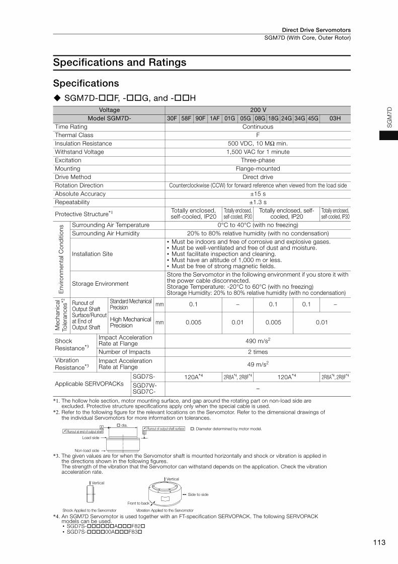
Direct Drive Servomotors SGM7D (With Core, Outer Rotor)
113
SG
M7D
Specifications and Ratings
Specifications
SGM7D-F, -G, and -H
*1. The hollow hole section, motor mounting surface, and gap around the rotating part on non-load side are excluded. Protective structure specifications apply only when the special cable is used.
*2. Refer to the following figure for the relevant locations on the Servomotor. Refer to the dimensional drawings of the individual Servomotors for more information on tolerances.
*3. The given values are for when the Servomotor shaft is mounted horizontally and shock or vibration is applied in the directions shown in the following figures.The strength of the vibration that the Servomotor can withstand depends on the application. Check the vibration acceleration rate.
*4. An SGM7D Servomotor is used together with an FT-specification SERVOPACK. The following SERVOPACK models can be used.• SGD7S-AF82• SGD7S-00AF83
Voltage 200 VModel SGM7D- 30F 58F 90F 1AF 01G 05G 08G 18G 24G 34G 45G 03H
Time Rating ContinuousThermal Class FInsulation Resistance 500 VDC, 10 MΩ min.Withstand Voltage 1,500 VAC for 1 minuteExcitation Three-phaseMounting Flange-mountedDrive Method Direct driveRotation Direction Counterclockwise (CCW) for forward reference when viewed from the load sideAbsolute Accuracy ±15 sRepeatability ±1.3 s
Protective Structure*1 Totally enclosed, self-cooled, IP20
Totally enclosed, self-cooled, IP30
Totally enclosed, self-cooled, IP20
Totally enclosed, self-cooled, IP30
Env
ironm
enta
l Con
diti
ons Surrounding Air Temperature 0°C to 40°C (with no freezing)
Surrounding Air Humidity 20% to 80% relative humidity (with no condensation)
Installation Site
• Must be indoors and free of corrosive and explosive gases.• Must be well-ventilated and free of dust and moisture.• Must facilitate inspection and cleaning.• Must have an altitude of 1,000 m or less.• Must be free of strong magnetic fields.
Storage Environment
Store the Servomotor in the following environment if you store it with the power cable disconnected.Storage Temperature: -20°C to 60°C (with no freezing)Storage Humidity: 20% to 80% relative humidity (with no condensation)
Mec
hani
cal
Tole
ranc
es*2 Runout of
Output Shaft Surface/Runout at End of Output Shaft
Standard Mechanical Precision mm 0.1 – 0.1 0.1 –
High Mechanical Precision mm 0.005 0.01 0.005 0.01
Shock Resistance*3
Impact Acceleration Rate at Flange 490 m/s2
Number of Impacts 2 timesVibration Resistance*3
Impact Acceleration Rate at Flange 49 m/s2
Applicable SERVOPACKsSGD7S- 120A*4 2R8A*4, 2R8F*4 120A*4 2R8A*4, 2R8F*4
SGD7W-SGD7C- –
AB
Load side
Non-load side
Runout of output shaft surfaceRunout at end of output shaft
� dia.�: Diameter determined by motor model.
Side to side
Front to back
Vertical
Shock Applied to the Servomotor Vibration Applied to the Servomotor
Vertical

Direct Drive ServomotorsSGM7D (With Core, Outer Rotor)
114
SGM7D-I and -J
*1. The hollow hole section, motor mounting surface, and gap around the rotating part on non-load side are excluded. Protective structure specifications apply only when the special cable is used.
*2. Refer to the following figure for the relevant locations on the Servomotor. Refer to the dimensional drawings of the individual Servomotors for more information on tolerances.
*3. The given values are for when the Servomotor shaft is mounted horizontally and shock or vibration is applied in the directions shown in the following figures.The strength of the vibration that the Servomotor can withstand depends on the application. Check the vibration acceleration rate.
*4. An SGM7D Servomotor is used together with an FT-specification SERVOPACK. The following SERVOPACK models can be used.• SGD7S-AF82• SGD7S-00AF83
Voltage 200 VModel SGM7D- 28I 70I 1ZI 1CI 2BI 2DI 06J 09J 18J 20J 38J
Time Rating ContinuousThermal Class FInsulation Resistance 500 VDC, 10 MΩ min.Withstand Voltage 1,500 VAC for 1 minuteExcitation Three-phaseMounting Flange-mountedDrive Method Direct driveRotation Direction Counterclockwise (CCW) for forward reference when viewed from the load sideAbsolute Accuracy ±15 sRepeatability ±1.3 s
Protective Structure*1 Totally enclosed, self-cooled, IP30
Env
ironm
enta
l Con
diti
ons Surrounding Air Temperature 0°C to 40°C (with no freezing)
Surrounding Air Humidity 20% to 80% relative humidity (with no condensation)
Installation Site
• Must be indoors and free of corrosive and explosive gases.• Must be well-ventilated and free of dust and moisture.• Must facilitate inspection and cleaning.• Must have an altitude of 1,000 m or less.• Must be free of strong magnetic fields.
Storage Environment
Store the Servomotor in the following environment if you store it with the power cable disconnected.Storage Temperature: -20°C to 60°C (with no freezing)Storage Humidity: 20% to 80% relative humidity (with no condensation)
Mec
hani
cal
Tole
ranc
es*2 Runout of
Output Shaft Surface/Runout at End of Out-put Shaft
Standard Mechanical Precision
mm 0.1
HighMechanical Precision
mm 0.005 0.02 0.005 0.01
Shock Resistance*3
Impact Acceleration Rate at Flange 490 m/s2
Number of Impacts 2 timesVibration Resistance*3
Impact Acceleration Rate at Flange 49 m/s2
Applicable SERVOPACKs
SGD7S- 120A*4
SGD7W-SGD7C- –
AB
Load side
Non-load side
Runout of output shaft surfaceRunout at end of output shaft
� dia.�: Diameter determined by motor model.
Side to side
Front to back
Vertical
Shock Applied to the Servomotor Vibration Applied to the Servomotor
Vertical

Direct Drive Servomotors SGM7D (With Core, Outer Rotor)
115
SG
M7D
SGM7D-K and -L
*1. The hollow hole section, motor mounting surface, and gap around the rotating part on non-load side are excluded. Protective structure specifications apply only when the special cable is used.
*2. Refer to the following figure for the relevant locations on the Servomotor. Refer to the dimensional drawings of the individual Servomotors for more information on tolerances.
*3. The given values are for when the Servomotor shaft is mounted horizontally and shock or vibration is applied in the directions shown in the following figures.The strength of the vibration that the Servomotor can withstand depends on the application. Check the vibration acceleration rate.
*4. An SGM7D Servomotor is used together with an FT-specification SERVOPACK. The following SERVOPACK models can be used.• SGD7S-AF82• SGD7S-00AF83
Voltage 200 VModel SGM7D- 02K 06K 08K 06L 12L 30L
Time Rating ContinuousThermal Class FInsulation Resistance 500 VDC, 10 MΩ min.Withstand Voltage 1,500 VAC for 1 minuteExcitation Three-phaseMounting Flange-mountedDrive Method Direct driveRotation Direction Counterclockwise (CCW) for forward reference when viewed from the load sideAbsolute Accuracy ±15 sRepeatability ±1.3 s
Protective Structure*1 Totally enclosed, self-cooled, IP30
Env
ironm
enta
l Con
diti
ons Surrounding Air Temperature 0°C to 40°C (with no freezing)
Surrounding Air Humidity 20% to 80% relative humidity (with no condensation)
Installation Site
• Must be indoors and free of corrosive and explosive gases.• Must be well-ventilated and free of dust and moisture.• Must facilitate inspection and cleaning.• Must have an altitude of 1,000 m or less.• Must be free of strong magnetic fields.
Storage Environment
Store the Servomotor in the following environment if you store it with the power cable disconnected.Storage Temperature: -20°C to 60°C (with no freezing)Storage Humidity: 20% to 80% relative humidity (with no condensation)
Mec
hani
cal
Tole
ranc
es*2 Runout of
Output Shaft Surface/Runout at End of Out-put Shaft
Standard Mechanical Precision
mm 0.1 0.05
HighMechanical Precision
mm 0.01 0.005
Shock Resistance*3
Impact Acceleration Rate at Flange 490 m/s2
Number of Impacts 2 timesVibration Resistance*3
Impact Acceleration Rate at Flange 49 m/s2
Applicable SERVOPACKs
SGD7S- 2R8A*4, 2R8F*4 120A*4
SGD7W-SGD7C- –
AB
Load side
Non-load side
Runout of output shaft surfaceRunout at end of output shaft
� dia.�: Diameter determined by motor model.
Side to side
Front to back
Vertical
Shock Applied to the Servomotor Vibration Applied to the Servomotor
Vertical
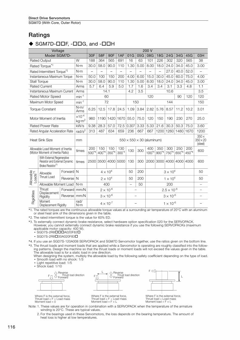
Direct Drive ServomotorsSGM7D (With Core, Outer Rotor)
116
Ratings
SGM7D-F, -G, and -H
*1. The rated torques are the continuous allowable torque values at a surrounding air temperature of 20°C with an aluminum or steel heat sink of the dimensions given in the table.
*2. The rated intermittent torque is the value for 60% ED.*3. To externally connect dynamic brake resistance, select hardware option specification 020 for the SERVOPACK.
However, you cannot externally connect dynamic brake resistance if you use the following SERVOPACKs (maximum applicable motor capacity: 400 W).• SGD7S-2R8A020F82• SGD7S-2R800A020F83
*4. If you use an SGD7S-120A008 SERVOPACK and SGM7D Servomotor together, use the ratios given on the bottom line.*5. The thrust loads and moment loads that are applied while a Servomotor is operating are roughly classified into the follow-
ing patterns. Design the machine so that the thrust loads or moment loads will not exceed the values given in the table. The allowable load is for a static load in one direction.When designing the system, multiply the allowable load by the following safety coefficient depending on the type of load.• Smooth load with no shock: 1/3• Light repetitive load: 1/5• Shock load: 1/10
Note: 1. These values are for operation in combination with a SERVOPACK when the temperature of the armature winding is 20°C. These are typical values.
2. For the bearings used in these Servomotors, the loss depends on the bearing temperature. The amount of heat loss is higher at low temperatures.
Voltage 200 VModel SGM7D- 30F 58F 90F 1AF 01G 05G 08G 18G 24G 34G 45G 03H
Rated Output W 188 364 565 691 16 63 101 226 302 320 565 38
Rated Torque*1 Nm 30.0 58.0 90.0 110 1.30 5.00 8.00 18.0 24.0 34.0 45.0 3.00
Rated Intermittent Torque*2 Nm – – – – – – – – 27.0 40.0 52.0 –Instantaneous Maximum Torque Nm 50.0 100 150 200 4.00 6.00 15.0 30.0 45.0 60.0 75.0 4.00Stall Torque Nm 30.0 58.0 90.0 110 1.30 5.00 8.00 18.0 24.0 34.0 45.0 3.00Rated Current Arms 5.7 6.4 5.9 5.0 1.7 1.6 3.4 3.4 3.1 3.3 4.8 1.1Instantaneous Maximum Current Arms 14.1 4.2 3.5 10.6 3.5Rated Motor Speed min-1 60 120 90 120 120
Maximum Motor Speed min-1 72 150 144 150
Torque Constant Nm/Arms 6.25 12.5 17.8 24.5 1.09 3.84 2.82 5.76 8.57 11.2 10.2 3.01
Motor Moment of Inertia ×10-4 kgm2 960 1190 1420 1670 55.0 75.0 120 150 190 230 270 25.0
Rated Power Rate kW/s 9.38 28.3 57.0 72.5 0.307 3.33 5.33 21.6 30.3 50.3 75.0 3.60Rated Angular Acceleration Rate rad/s2 313 487 634 659 236 667 667 1200 1260 1480 1670 1200
Heat Sink Size mm 550 × 550 × 30 (aluminum)350 ×
350 × 20 (steel)
Allowable Load Moment of Inertia(Motor Moment of Inertia Ratio) times
200500*4
150400*4
150350*4
130300*4 130 300
4001000*4
350900*4
300750*4
250650*4
200450*4 600
With External Regenerative Resistor and External Dynamic Brake Resistor*3
times 2500 3500 4000 5000 130 300 2000 3000 4000 4000 4000 600
Allo
wab
le L
oads
*5 Allowable Thrust Load
Forward N 4 × 10⁴ 50 200 3 × 10⁴ 50
Reverse N 2 × 10⁴ 50 200 1 × 10⁴ 50
Allowable Moment Load Nm 400 – 50 200 –
Rig
iditi
es
Thrust Displacement Rigidity
Forward mm/N 2 × 10⁻⁶ – 2.5 × 10⁻⁶ –
Reverse mm/N 3 × 10⁻⁶ – 3 × 10⁻⁶ –
Moment Displacement Rigidity
rad/Nm 4 × 10⁻⁷ – 1 × 10⁻⁶ –
F
Where F is the external force,Thrust load = F + Load massMoment load = F × L
Where F is the external force,Thrust load = F + Load massMoment load = 0
Where F is the external force,Thrust load = Load massMoment load = F × L
Reverse
ForwardThrust load direction
Reverse
ForwardThrust load direction
F
LF
L

Direct Drive Servomotors SGM7D (With Core, Outer Rotor)
117
SG
M7D
SGM7D-I and -J
*1. The rated torques are the continuous allowable torque values at a surrounding air temperature of 40°C with an aluminum heat sink of the dimensions given in the table.
*2. If you use an SGD7S-120A008 SERVOPACK and SGM7D Servomotor together, use the ratios given on the bot-tom line.
*3. The thrust loads and moment loads that are applied while a Servomotor is operating are roughly classified into the following patterns. Design the machine so that the thrust loads or moment loads will not exceed the values given in the table. The allowable load is for a static load in one direction.When designing the system, multiply the allowable load by the following safety coefficient depending on the type of load.• Smooth load with no shock: 1/3• Light repetitive load: 1/5• Shock load: 1/10
Note: 1. These values are for operation in combination with a SERVOPACK when the temperature of the armature winding is 20°C. These are typical values.
2. For the bearings used in these Servomotors, the loss depends on the bearing temperature. The amount of heat loss is higher at low temperatures.
Voltage 200 VModel SGM7D- 28I 70I 1ZI 1CI 2BI 2DI 06J 09J 18J 20J 38J
Rated Output W 264 440 628 817 691 754 75 113 226 251 358
Rated Torque*1 Nm 28.0 70.0 100 130 220 240 6.00 9.00 18.0 20.0 38.0Instantaneous Maximum Torque Nm 50.0 100 150 200 300 400 8.00 15.0 30.0 45.0 60.0
Stall Torque Nm 28.0 70.0 100 130 220 240 6.00 9.00 18.0 20.0 38.0Rated Current Arms 5.2 5.6 5.5 5.0 5.6 4.8 4.0 3.4 3.0 2.2 3.1Instantaneous Maximum Current Arms 14.1 10.6
Rated Motor Speed min-1 90 60 30 120 90
Maximum Motor Speed min-1 108 72 60 48 144
Torque Constant Nm/Arms 6.90 13.9 20.8 27.8 41.5 54.4 1.71 3.29 6.62 9.88 13.3
Motor Moment of Inertia ×10-4 kgm2 1800 2000 2300 2850 3400 4000 150 210 240 260 330
Rated Power Rate kW/s 4.36 24.5 43.5 59.3 142 144 2.40 3.86 13.5 15.4 43.8Rated Angular Acceleration Rate rad/s2 156 350 435 456 647 600 400 429 750 769 1150
Heat Sink Size mm 550 × 550 × 30Allowable Load Moment of Inertia(Motor Moment of Inertia Ratio) times
50125*2
100250*2
90230*2
80200*2 100 150
350700*2
250600*2
240550*2
220550*2
180450*2
With External Regenera-tive Resistor and External Dynamic Brake Resistor*3
times 800 2000 2500 3000 100 150 700 900 2500 2000 2000
Allo
wab
le L
oads
*3
Allow
able
Thru
st L
oad Forward N 4 × 10⁴ 3 × 10⁴
Reverse N 2 × 10⁴ 1 × 10⁴
Allowable Moment Load Nm 400 200
Rig
iditi
es
Thru
st D
isplac
emen
t R
igidi
ty Forward mm/N 2 × 10⁻⁶ 3 × 10⁻⁶
Reverse mm/N 3 × 10⁻⁶ 4 × 10⁻⁶
Moment Displacement Rigidity
rad/Nm 4 × 10⁻⁷ 2 × 10⁻⁶
F
Where F is the external force,Thrust load = F + Load massMoment load = F × L
Where F is the external force,Thrust load = F + Load massMoment load = 0
Where F is the external force,Thrust load = Load massMoment load = F × L
Reverse
ForwardThrust load direction
Reverse
ForwardThrust load direction
F
LF
L

Direct Drive ServomotorsSGM7D (With Core, Outer Rotor)
118
SGM7D-K and -L
*1. The rated torques are the continuous allowable torque values at a surrounding air temperature of 40°C with an aluminum heat sink of the dimensions given in the table.
*2. To externally connect dynamic brake resistance, select hardware option specification 020 for the SERVOPACK.However, you cannot externally connect dynamic brake resistance if you use the following SERVOPACKs (max-imum applicable motor capacity: 400 W).• SGD7S-2R8A020F82• SGD7S-2R800A020F83
*3. If you use an SGD7S-120A008 SERVOPACK and SGM7D Servomotor together, use the ratios given on the bot-tom line.
*4. The thrust loads and moment loads that are applied while a Servomotor is operating are roughly classified into the following patterns. Design the machine so that the thrust loads or moment loads will not exceed the values given in the table. The allowable load is for a static load in one direction.When designing the system, multiply the allowable load by the following safety coefficient depending on the type of load.• Smooth load with no shock: 1/3• Light repetitive load: 1/5• Shock load: 1/10
Note: 1. These values are for operation in combination with a SERVOPACK when the temperature of the armature winding is 20°C. These are typical values.
2. For the bearings used in these Servomotors, the loss depends on the bearing temperature. The amount of heat loss is higher at low temperatures.
Voltage 200 V
Model SGM7D- 02K 06K 08K 06L 12L 30L
Rated Output W 52 151 201 113 226 565
Rated Torque*1 Nm 2.06 6.00 8.00 6.00 12.0 30.0
Instantaneous Maximum Torque Nm 5.00 10.0 15.0 10.0 20.0 40.0
Stall Torque Nm 2.06 6.00 8.00 6.00 12.0 30.0
Rated Current Arms 1.6 1.8 1.6 1.7 2.1 8.1
Instantaneous Maximum Current Arms 4.2 4.2 4.2 14.1
Rated Motor Speed min-1 240 180
Maximum Motor Speed min-1 360 216
Torque ConstantNm/Arms
1.83 3.67 5.50 4.13 6.59 3.95
Motor Moment of Inertia×10-4 kgm2 60.0 70.0 80.0 220 220 370
Rated Power Rate kW/s 0.707 5.14 8.00 1.64 6.55 24.3
Rated Angular Acceleration Rate rad/s2 343 857 1000 273 545 811
Heat Sink Size mm 550 × 550 × 30 650 × 650 × 30
Allowable Load Moment of Inertia(Motor Moment of Inertia Ratio) times 200 350 25 450 20
60130*3
With External Regenerative Resistor and External Dynamic Brake Resistor*2 times 200 350 25 450 20 3500
Allo
wab
le L
oads
*4 Allowable Thrust Load
Forward N 5 × 10³ 2000
Reverse N 3 × 10³ 1000
Allowable Moment Load Nm 20 100
Rig
iditi
es
Thrust Displace-ment Rigidity
Forward mm/N 4 × 10⁻⁶ –
Reverse mm/N 8 × 10⁻⁶ –
Moment Displacement Rigidity
rad/Nm 8 × 10⁻⁶ –
F
Where F is the external force,Thrust load = F + Load massMoment load = F × L
Where F is the external force,Thrust load = F + Load massMoment load = 0
Where F is the external force,Thrust load = Load massMoment load = F × L
Reverse
ForwardThrust load direction
Reverse
ForwardThrust load direction
F
LF
L

Direct Drive Servomotors SGM7D (With Core, Outer Rotor)
119
SG
M7D
Torque-Motor Speed CharacteristicsA : Continuous duty zone (dotted lines): With 60%ED 10 min. duty factor
(solid lines): With three-phase 200-V, single-phase 230-V, and single-phase 200-V inputB : Intermittent duty zone*
A
0 20 40 60 80
0
B20
40
60
80
100
120
140
160
A
0 20 30 40 50 60 7010
0
B20
40
60
80
100
120
140
160
A
0 10 20 30 40 50
0
B20
40
60
80
100
120
140
160
A
0 8 16 24 32
0
B20
40
60
80
100
120
140
160
A
0 4 8 12 16
0
B20
40
60
80
100
120
140
160
A
0 2 4 6 8
0
B20
40
60
80
100
120
140
160
A
0 1 2 3 4 5
0
B20
40
60
80
100
120
140
160
A
0 1 2 3 4 5
0
B
40
80
120
160
A
0 20 40 60
0
10
A
0 8040 120 160 200 240
0
B10
20
30
40
50
60
70
80
A
0 40 80 120 160
0
B10
20
30
40
50
60
70
80
A
0 20 40 60 80 100 120
0
B10
20
30
40
50
60
70
80
20
30
40
50
60
70
80
B
A
0 20 40
0
B20
40
60
120
80
100
60
A
0 4020 8060
0
B20
40
60
120
80
100
120100
A
0 6030 12090
0
B20
40
60
120
80
100
180150
SGM7D-30F SGM7D-90FSGM7D-58F
SGM7D-05GSGM7D-01GSGM7D-1AF
Torque (N�m)
SGM7D-24GSGM7D-18GSGM7D-08G
SGM7D-45GSGM7D-34G SGM7D-03H
SGM7D-28I SGM7D-70I SGM7D-1ZI
Mot
or s
peed
(min
-1)
Torque (N�m)
Mot
or s
peed
(min
-1)
Torque (N�m)
Mot
or s
peed
(min
-1)
Torque (N�m)
Mot
or s
peed
(min
-1)
Torque (N�m)
Mot
or s
peed
(min
-1)
Torque (N�m)
Mot
or s
peed
(min
-1)
Torque (N�m)
Mot
or s
peed
(min
-1)
Torque (N�m)
Mot
or s
peed
(min
-1)
Torque (N�m)
Mot
or s
peed
(min
-1)
Torque (N�m)
Mot
or s
peed
(min
-1)
Torque (N�m)
Mot
or s
peed
(min
-1)
Torque (N�m)
Mot
or s
peed
(min
-1)
Torque (N�m)
Mot
or s
peed
(min
-1)
Torque (N�m)
Mot
or s
peed
(min
-1)
Torque (N�m)
Mot
or s
peed
(min
-1)
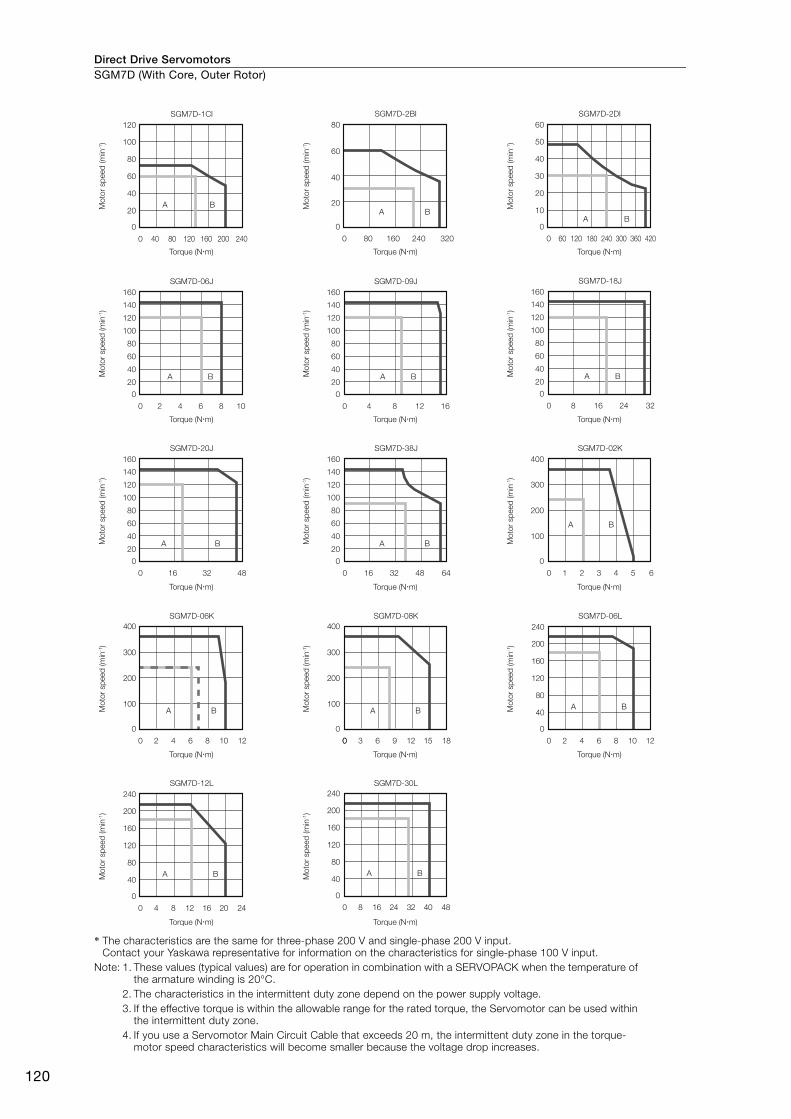
Direct Drive ServomotorsSGM7D (With Core, Outer Rotor)
120
* The characteristics are the same for three-phase 200 V and single-phase 200 V input.Contact your Yaskawa representative for information on the characteristics for single-phase 100 V input.
Note: 1. These values (typical values) are for operation in combination with a SERVOPACK when the temperature of the armature winding is 20°C.
2. The characteristics in the intermittent duty zone depend on the power supply voltage.3. If the effective torque is within the allowable range for the rated torque, the Servomotor can be used within
the intermittent duty zone.4. If you use a Servomotor Main Circuit Cable that exceeds 20 m, the intermittent duty zone in the torque-
motor speed characteristics will become smaller because the voltage drop increases.
A
0 4 62 108
B
SGM7D-06J
A
0 4 8 12 16
B
SGM7D-09J
A
8 16 24 32
B
SGM7D-18J
A
0 16 4832
B
SGM7D-20J
A
0 16 644832
B
SGM7D-38J SGM7D-02K
SGM7D-1CI SGM7D-2BI SGM7D-2DI
SGM7D-06LSGM7D-08KSGM7D-06K
0
A
0 8040 160120
0
B20
40
60
120
80
100
240200
A
0 16080 320240
0
B20
40
80
60
A
0 18060 120 420240 300 360
0B
10
20
30
60
40
50
A
0 1 2 3 4 5 6
0
B
400
300
200
100
A
0 2 4 6 8 10
0
B40
80
120
240
160
200
12
A
0 4 8 12 16 20
0
B40
80
120
240
160
200
24
A
0 8 16 24 32 40
0
B40
80
120
240
160
200
48
A
0
400
300
200
100BA
0 42 8 106 12
0
400
300
200
100B
00 63 12 159 18
0
20
40
60
160
140
120
80
100
0
20
40
60
160
140
120
80
100
0
20
40
60
160
140
120
80
100
0
20
40
60
160
140
120
80
100
0
20
40
60
160
140
120
80
100
SGM7D-12L SGM7D-30L
Torque (N�m)
Mot
or s
peed
(min
-1)
Torque (N�m)
Mot
or s
peed
(min
-1)
Torque (N�m)
Mot
or s
peed
(min
-1)
Torque (N�m)
Mot
or s
peed
(min
-1)
Torque (N�m)
Mot
or s
peed
(min
-1)
Torque (N�m)
Mot
or s
peed
(min
-1)
Torque (N�m)
Mot
or s
peed
(min
-1)
Torque (N�m)
Mot
or s
peed
(min
-1)
Torque (N�m)
Mot
or s
peed
(min
-1)
Torque (N�m)
Mot
or s
peed
(min
-1)
Torque (N�m)
Mot
or s
peed
(min
-1)
Torque (N�m)
Mot
or s
peed
(min
-1)
Torque (N�m)
Mot
or s
peed
(min
-1)
Torque (N�m)
Mot
or s
peed
(min
-1)
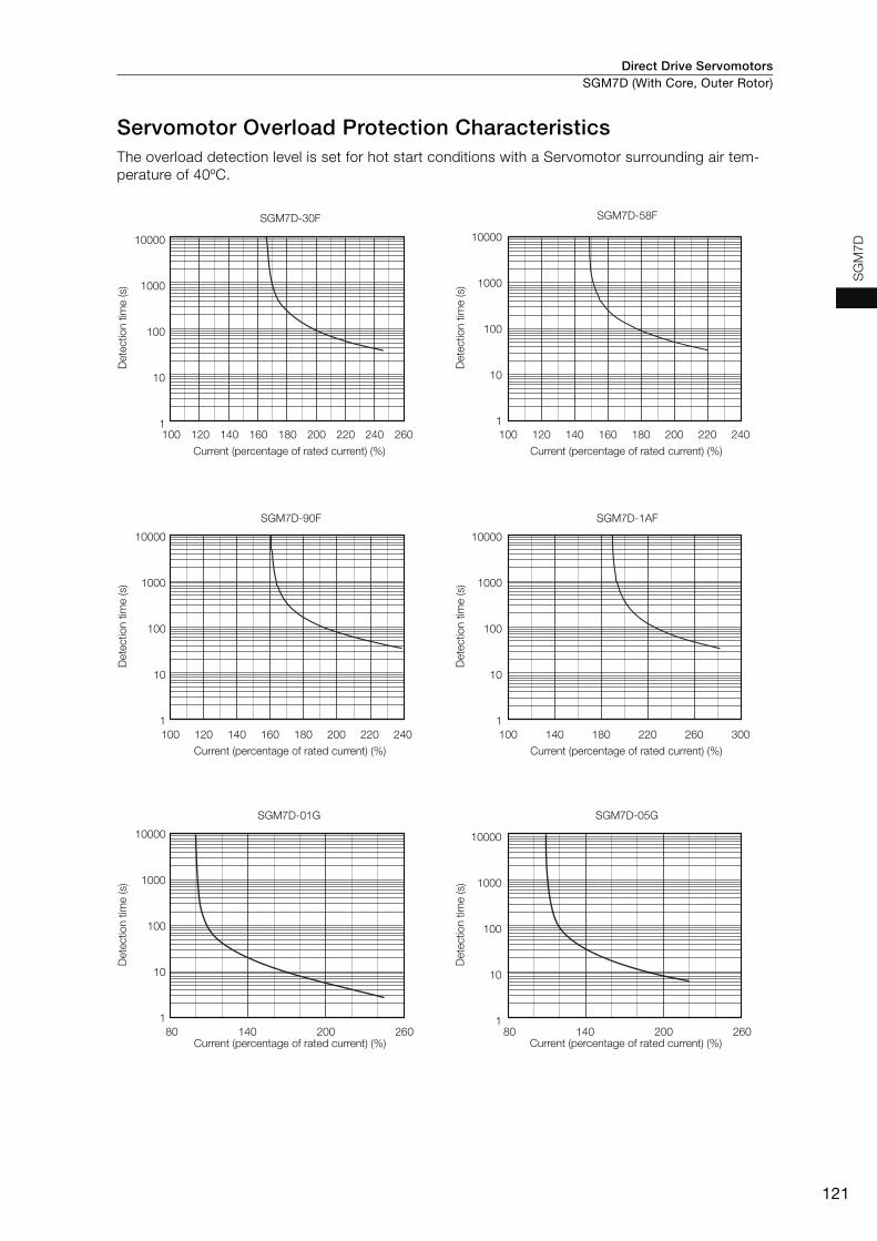
Direct Drive Servomotors SGM7D (With Core, Outer Rotor)
121
SG
M7D
Servomotor Overload Protection CharacteristicsThe overload detection level is set for hot start conditions with a Servomotor surrounding air tem-perature of 40ºC.
SGM7D-30F
100 120 260240220200160140 180
10000
1000
100
10
1
SGM7D-58F
100 120 140 240220200160 180
100 120 140 240220200160 180
10000
1000
100
10
1
SGM7D-90F
10000
1000
100
10
1
SGM7D-1AF
100 300180140 260220
10000
1000
100
10
1
SGM7D-01G
80 260140 200 80 260140 200
10000
1000
100
10
1
SGM7D-05G
10000
1000
100
10
1
Current (percentage of rated current) (%) Current (percentage of rated current) (%)
Current (percentage of rated current) (%) Current (percentage of rated current) (%)
Current (percentage of rated current) (%) Current (percentage of rated current) (%)
Det
ectio
n tim
e (s
)
Det
ectio
n tim
e (s
)
Det
ectio
n tim
e (s
)
Det
ectio
n tim
e (s
)
Det
ectio
n tim
e (s
)
Det
ectio
n tim
e (s
)
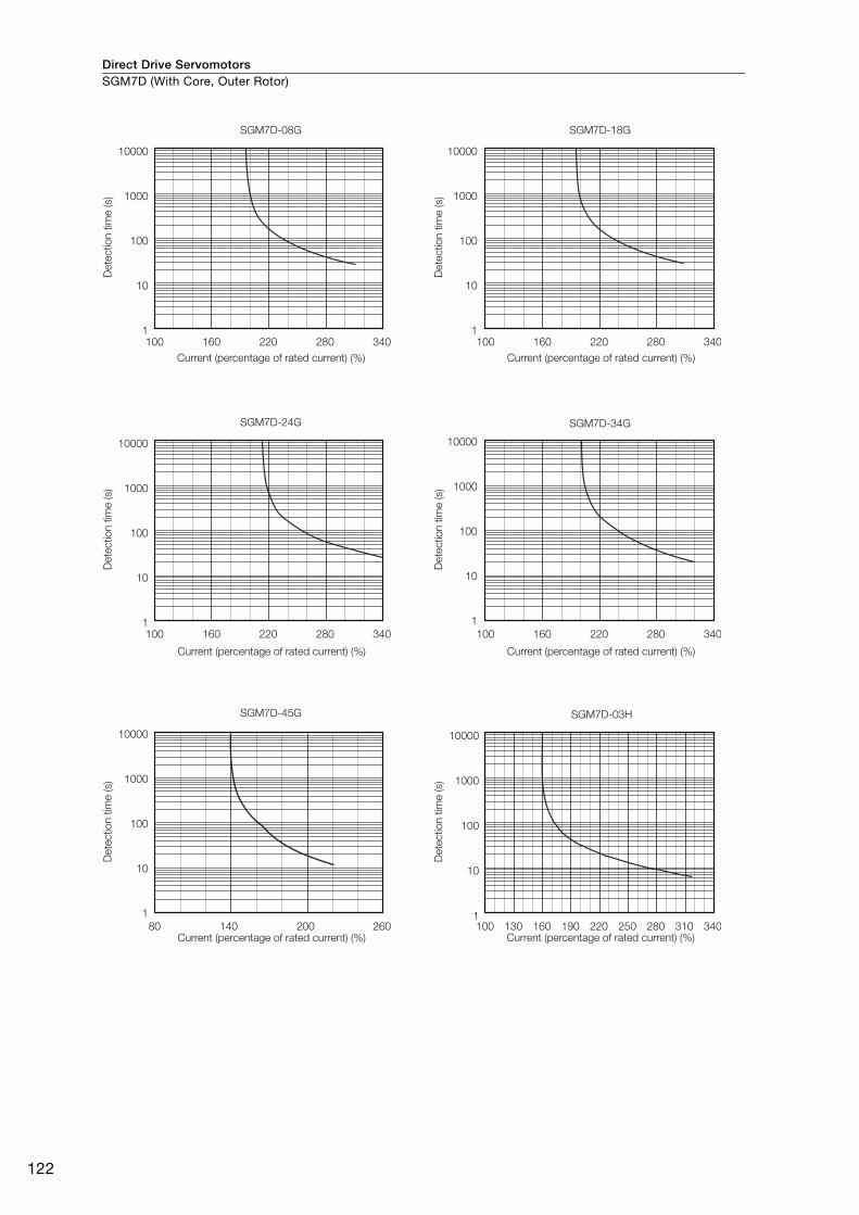
Direct Drive ServomotorsSGM7D (With Core, Outer Rotor)
122
SGM7D-08G
340
10000
1000
100
10
1
SGM7D-18G
10000
1000
100
10
1
SGM7D-34G
10000
1000
100
10
1
SGM7D-24G
SGM7D-45G
10000
1000
100
10
1
100 160 220 280 340100 160 220 280
340100 160 220 280 340100 160 220 280
10000
1000
100
10
1
26080 140 200
SGM7D-03H
100 130 340310280250220160 190
10000
1000
100
10
1
Current (percentage of rated current) (%) Current (percentage of rated current) (%)
Current (percentage of rated current) (%) Current (percentage of rated current) (%)
Current (percentage of rated current) (%) Current (percentage of rated current) (%)
Det
ectio
n tim
e (s
)
Det
ectio
n tim
e (s
)
Det
ectio
n tim
e (s
)
Det
ectio
n tim
e (s
)
Det
ectio
n tim
e (s
)
Det
ectio
n tim
e (s
)
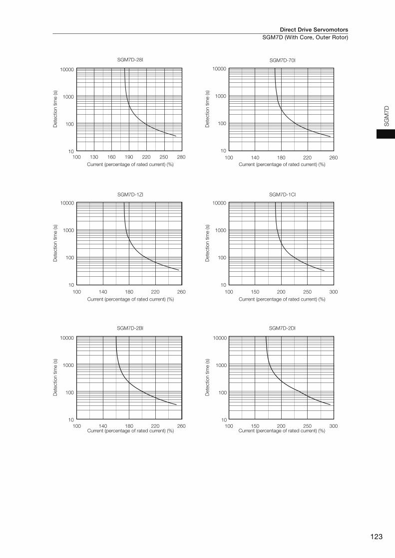
Direct Drive Servomotors SGM7D (With Core, Outer Rotor)
123
SG
M7D
SGM7D-28I
100 130 280250160 190 220
10000
1000
100
10
SGM7D-1CI
100 150 300250200
10000
1000
100
10
SGM7D-2BI
SGM7D-1ZI
100 140 260220180
100 150 300250200100 140 260220180
10000
1000
100
10
SGM7D-70I
100 140 260220180
10000
1000
100
10
SGM7D-2DI
10000
1000
100
10
10000
1000
100
10
Current (percentage of rated current) (%) Current (percentage of rated current) (%)
Current (percentage of rated current) (%) Current (percentage of rated current) (%)
Current (percentage of rated current) (%) Current (percentage of rated current) (%)
Det
ectio
n tim
e (s
)
Det
ectio
n tim
e (s
)
Det
ectio
n tim
e (s
)
Det
ectio
n tim
e (s
)
Det
ectio
n tim
e (s
)
Det
ectio
n tim
e (s
)
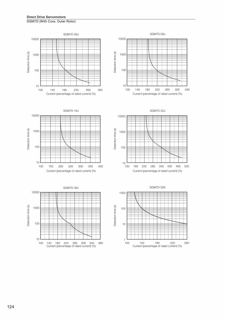
Direct Drive ServomotorsSGM7D (With Core, Outer Rotor)
124
SGM7D-06J
100 140 300260220180
10000
1000
100
10
SGM7D-20J
100 220160 520400 460280 340
10000
1000
100
10
SGM7D-09J
100 340220 260 300180140
10000
1000
100
10
SGM7D-18J
100 150 400350200 300250
10000
1000
100
10
SGM7D-38J
100 140 380340180 220 260 300
10000
1000
100
10
SGM7D-02K
100 260220180140
1000
100
10
1
Current (percentage of rated current) (%) Current (percentage of rated current) (%)
Current (percentage of rated current) (%) Current (percentage of rated current) (%)
Current (percentage of rated current) (%) Current (percentage of rated current) (%)
Det
ectio
n tim
e (s
)
Det
ectio
n tim
e (s
)
Det
ectio
n tim
e (s
)
Det
ectio
n tim
e (s
)
Det
ectio
n tim
e (s
)
Det
ectio
n tim
e (s
)
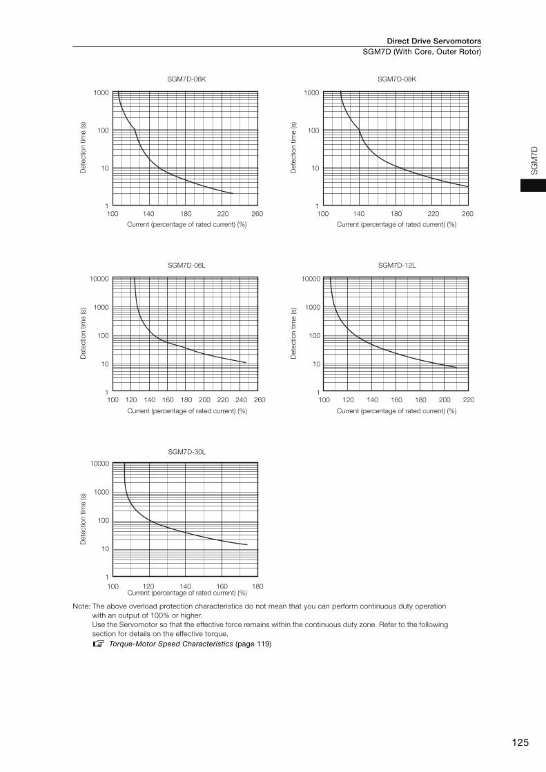
Direct Drive Servomotors SGM7D (With Core, Outer Rotor)
125
SG
M7D
Note: The above overload protection characteristics do not mean that you can perform continuous duty operation with an output of 100% or higher.Use the Servomotor so that the effective force remains within the continuous duty zone. Refer to the following section for details on the effective torque.
Torque-Motor Speed Characteristics (page 119)
SGM7D-06L
100 120 260240220200180160140
10000
1000
100
10
1
SGM7D-12L
100 120 140 160 180 200 220
10000
1000
100
10
1
SGM7D-30L
100 180160140120
10000
1000
100
10
1
SGM7D-08K
100 260220180140
1000
100
10
1
SGM7D-06K
100 260220180140
1000
100
10
1
Current (percentage of rated current) (%) Current (percentage of rated current) (%)
Current (percentage of rated current) (%) Current (percentage of rated current) (%)
Current (percentage of rated current) (%)
Det
ectio
n tim
e (s
)
Det
ectio
n tim
e (s
)
Det
ectio
n tim
e (s
)
Det
ectio
n tim
e (s
)
Det
ectio
n tim
e (s
)

Direct Drive ServomotorsSGM7D (With Core, Outer Rotor)
126
Allowable Load Moment of InertiaThe allowable load moments of inertia (motor moment of inertia ratios) for the Servomotors are given in the Ratings (pages 116 to 118). The values are determined by the regenerative energy processing capacity of the SERVOPACK and are also affected by the drive conditions of the Servomotor. Per-form the required Steps for each of the following cases.
Use the SigmaJunmaSize+ AC Servo Drive Capacity Selection Program to check the driving condi-tions. Contact your Yaskawa representative for information on this program.
Exceeding the Allowable Load Moment of InertiaUse one of the following measures to adjust the load moment of inertia to within the allowable value.• Reduce the torque limit.• Reduce the deceleration rate.• Reduce the maximum motor speed.
If the above steps is not possible, install an external regenerative resistor.
When an External Regenerative Resistor Is RequiredInstall the External Regenerative Resistor. Refer to the following section for the recommended products.
External Regenerative Resistors (page 456)
An Overvoltage Alarm (A.400) is likely to occur during deceleration if the load moment of iner-tia exceeds the allowable load moment of inertia. SERVOPACKs with a built-in regenerative resistor may generate a Regenerative Overload Alarm (A.320). Refer to Built-In Regenerative Resistor (page 456) for the regenerative power (W) that can be processed by the SERVO-PACKs.Install an External Regenerative Resistor when the built-in regenerative resistor cannot process all of the regenerative power.
Information
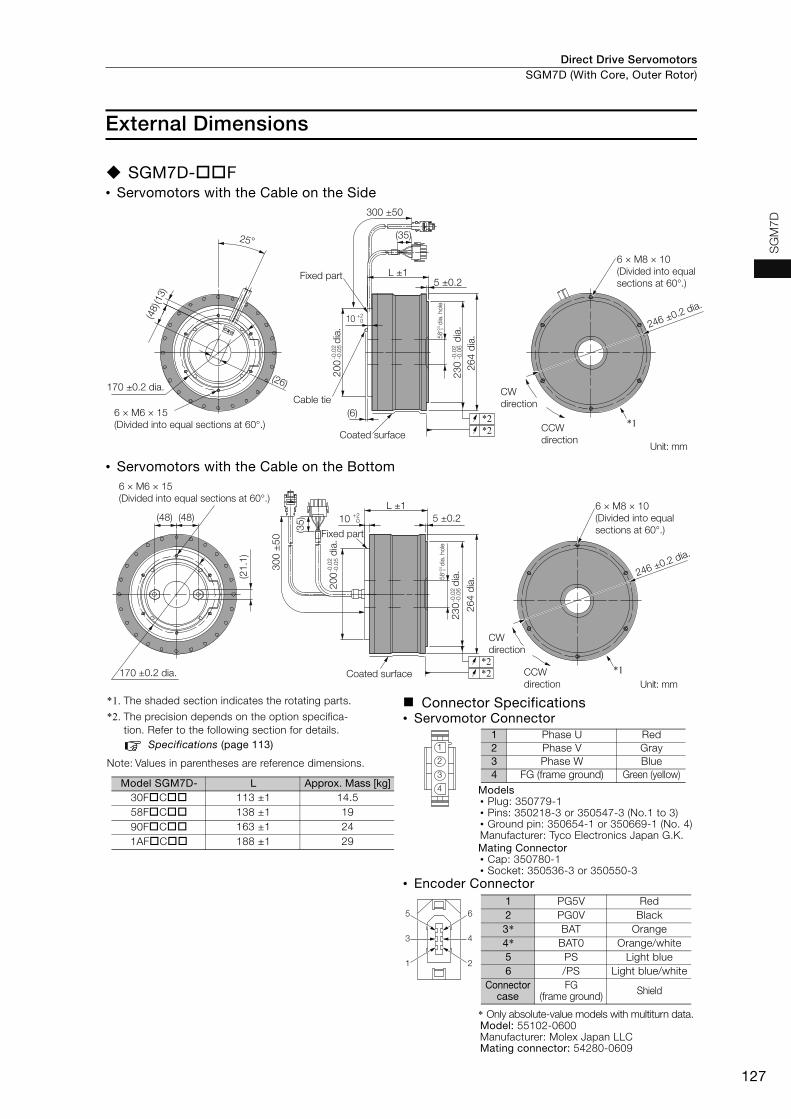
Direct Drive Servomotors SGM7D (With Core, Outer Rotor)
127
SG
M7D
External Dimensions
SGM7D-F• Servomotors with the Cable on the Side
• Servomotors with the Cable on the Bottom
*1. The shaded section indicates the rotating parts.
*2. The precision depends on the option specifica-tion. Refer to the following section for details.
Specifications (page 113)
Note: Values in parentheses are reference dimensions.
Connector Specifications• Servomotor Connector
Models• Plug: 350779-1• Pins: 350218-3 or 350547-3 (No.1 to 3)• Ground pin: 350654-1 or 350669-1 (No. 4)Manufacturer: Tyco Electronics Japan G.K.Mating Connector• Cap: 350780-1• Socket: 350536-3 or 350550-3
• Encoder Connector
* Only absolute-value models with multiturn data.Model: 55102-0600Manufacturer: Molex Japan LLCMating connector: 54280-0609
Unit: mm
CW direction
6 × M8 × 10(Divided into equal sections at 60°.)
CCW direction
246 ±0.2 dia.
*1
25°
(13)
(48)
6 × M6 × 15 (Divided into equal sections at 60°.)
Coated surface
5 ±0.2L ±1Fixed part
264
dia.
230
dia.
-0.0
2-0
.06
+0.5 0
(6)
200
d
ia.
-0.0
2-0
.05
*2*2
170 ±0.2 dia.
58
dia
. hol
e
300 ±50
(35)
Cable tie
(26)
10 +20
Unit: mm
CW direction
6 × M8 × 10(Divided into equal sections at 60°.)
CCW direction
246 ±0.2 dia.
*1
6 × M6 × 15(Divided into equal sections at 60°.)
170 ±0.2 dia.
(21.
1)
(48) (48) 5 ±0.210 +20
L ±1
Fixed part
230
d
ia.
-0.0
2-0
.06
Coated surface
200
d
ia.
-0.0
2-0
.05
*2*2
+0.5 0
58
dia
. hol
e
264
dia.
300
±50
(35)
Model SGM7D- L Approx. Mass [kg]30FC 113 ±1 14.558FC 138 ±1 1990FC 163 ±1 241AFC 188 ±1 29
1
2
3
4
1 Phase U Red2 Phase V Gray3 Phase W Blue4 FG (frame ground) Green (yellow)
4
2
6
3
1
51 PG5V Red2 PG0V Black3* BAT Orange4* BAT0 Orange/white5 PS Light blue6 /PS Light blue/white
Connector case
FG (frame ground) Shield
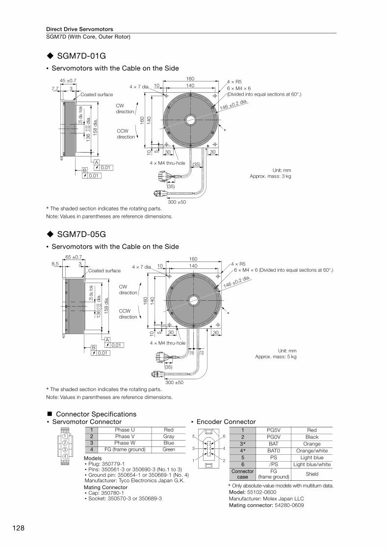
Direct Drive ServomotorsSGM7D (With Core, Outer Rotor)
128
SGM7D-01G• Servomotors with the Cable on the Side
* The shaded section indicates the rotating parts.
Note: Values in parentheses are reference dimensions.
SGM7D-05G• Servomotors with the Cable on the Side
* The shaded section indicates the rotating parts.
Note: Values in parentheses are reference dimensions.
Connector Specifications• Servomotor Connector • Encoder Connector
Models• Plug: 350779-1• Pins: 350561-3 or 350690-3 (No.1 to 3)• Ground pin: 350654-1 or 350669-1 (No. 4)Manufacturer: Tyco Electronics Japan G.K.Mating Connector• Cap: 350780-1• Socket: 350570-3 or 350689-3
* Only absolute-value models with multiturn data.Model: 55102-0600Manufacturer: Molex Japan LLCMating connector: 54280-0609
Unit: mmApprox. mass: 3 kg
*
158
dia.
136
dia.
-0.0
2-0
.06
Coated surface
45 ±0.7
37.7 6 × M4 × 6 (Divided into equal sections at 60°.)
4 × 7 dia.
CW direction
CCW direction
16014010
4 × R5
160
140
10 5 30 30
146 ±0.2 dia.
(35)4 × M4 thru-hole
0.01B
0.01A
25 d
ia. ho
le
300 ±50
(35)
Unit: mmApprox. mass: 5 kg
65 ±0.78.5
136
d
ia.
-0.0
2-0
.06
Coated surface3
6 × M4 × 6 (Divided into equal sections at 60°.)4 × R5
146 ±0.2 dia.
4 × 7 dia.
16014010
CW direction
CCW direction
160
140
10 5 30 30
(16) (12)
4 × M4 thru-hole
*
0.01A
0.01B
25 di
a. ho
le
158
dia.
300 ±50
(35)
1
2
3
4
1 Phase U Red2 Phase V Gray3 Phase W Blue4 FG (frame ground) Green 4
2
6
3
1
51 PG5V Red2 PG0V Black3* BAT Orange4* BAT0 Orange/white5 PS Light blue6 /PS Light blue/white
Connector case
FG (frame ground) Shield
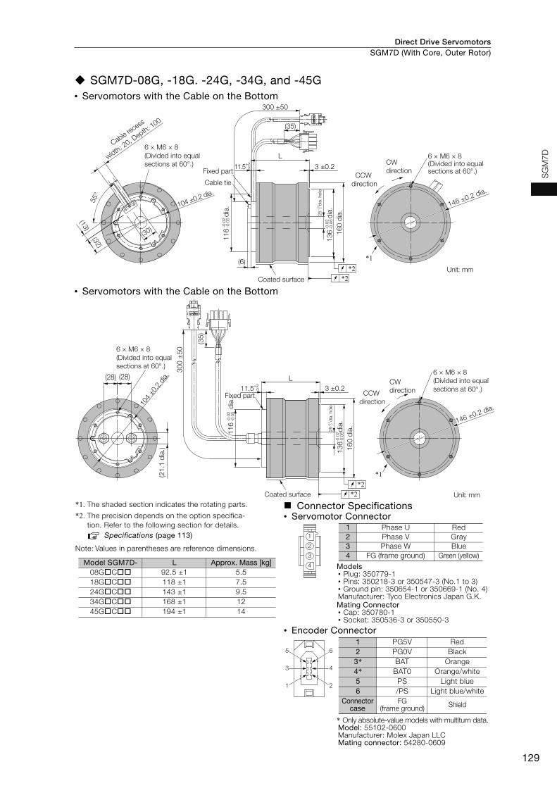
Direct Drive Servomotors SGM7D (With Core, Outer Rotor)
129
SG
M7D
SGM7D-08G, -18G. -24G, -34G, and -45G• Servomotors with the Cable on the Bottom
• Servomotors with the Cable on the Bottom
*1. The shaded section indicates the rotating parts.
*2. The precision depends on the option specifica-tion. Refer to the following section for details.
Specifications (page 113)
Note: Values in parentheses are reference dimensions.
Connector Specifications• Servomotor Connector
Models• Plug: 350779-1• Pins: 350218-3 or 350547-3 (No.1 to 3)• Ground pin: 350654-1 or 350669-1 (No. 4)Manufacturer: Tyco Electronics Japan G.K.Mating Connector• Cap: 350780-1• Socket: 350536-3 or 350550-3
• Encoder Connector
* Only absolute-value models with multiturn data.Model: 55102-0600Manufacturer: Molex Japan LLCMating connector: 54280-0609
Unit: mm
CW direction
CCW direction
*1
146 ±0.2 dia.
6 × M6 × 8 (Divided into equal sections at 60°.)
L
3 ±0.211.5+20
160
dia.
136
d
ia.
-0.0
2-0
.06
116
d
ia.
-0.0
2-0
.05
(6)
Coated surface
(13)(32)
55°
(30)
104 ±0.2 dia.
Cable recess
width: 20, D
epth: 100
6 × M6 × 8 (Divided into equal sections at 60°.)
Fixed part
Cable tie
*2*2
-0.0
20
25
dia
. hol
e
300 ±50
(35)
Unit: mm
(21.
1 di
a.)
104
±0.2
dia.
6 × M6 × 8(Divided into equal sections at 60°.)
(28) (28)
160
dia.
136
d
ia.
-0.0
2-0
.06
Coated surface
L3 ±0.211.5+2
0
Fixed part
116
dia.
-0.0
2-0
.05
*2*2
CCW direction
CW direction
6 × M6 × 8(Divided into equal sections at 60°.)
146 ±0.2 dia.
*1
+0.5 0
25
dia
. hol
e
300
±50
(35)
Model SGM7D- L Approx. Mass [kg]08GC 92.5 ±1 5.518GC 118 ±1 7.524GC 143 ±1 9.534GC 168 ±1 1245GC 194 ±1 14
1
2
3
4
1 Phase U Red2 Phase V Gray3 Phase W Blue4 FG (frame ground) Green (yellow)
4
2
6
3
1
51 PG5V Red2 PG0V Black3* BAT Orange4* BAT0 Orange/white5 PS Light blue6 /PS Light blue/white
Connector case
FG (frame ground) Shield
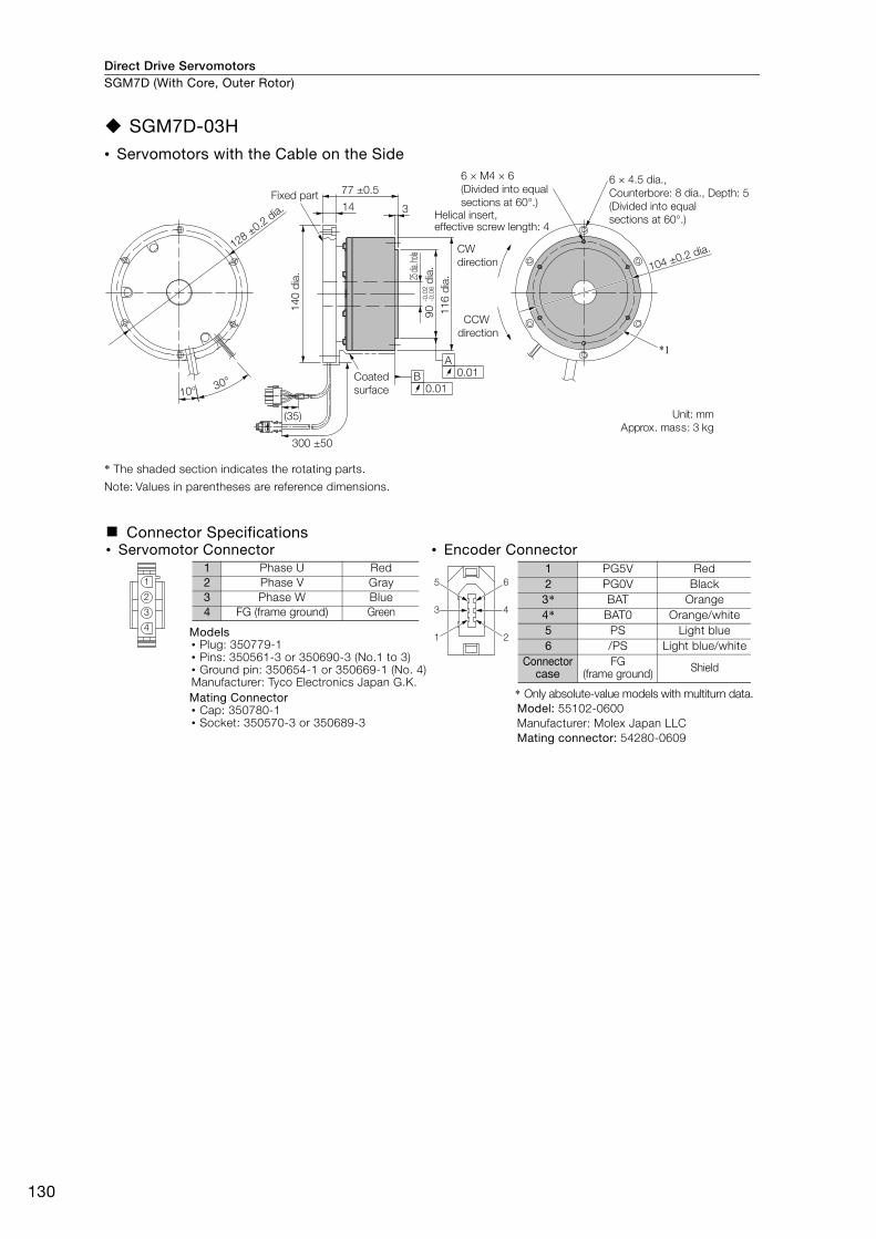
Direct Drive ServomotorsSGM7D (With Core, Outer Rotor)
130
SGM7D-03H• Servomotors with the Cable on the Side
* The shaded section indicates the rotating parts.
Note: Values in parentheses are reference dimensions.
Connector Specifications• Servomotor Connector • Encoder Connector
Models• Plug: 350779-1• Pins: 350561-3 or 350690-3 (No.1 to 3)• Ground pin: 350654-1 or 350669-1 (No. 4)Manufacturer: Tyco Electronics Japan G.K.Mating Connector• Cap: 350780-1• Socket: 350570-3 or 350689-3
* Only absolute-value models with multiturn data.Model: 55102-0600Manufacturer: Molex Japan LLCMating connector: 54280-0609
*1
10° 30°
77 ±0.5
14 3
0.01A
0.01B
300 ±50
(35) Unit: mmApprox. mass: 3 kg
Coated surface
CCW direction
CW direction
Fixed part
140
dia. 25
dia. ho
le-0
.02
-0.0
690
dia
.11
6 di
a.
6 × M4 × 6 (Divided into equal sections at 60°.)
6 × 4.5 dia., Counterbore: 8 dia., Depth: 5(Divided into equal sections at 60°.)
104 ±0.2 dia.
Helical insert, effective screw length: 4
128 ±0.2 dia.
1
2
3
4
1 Phase U Red2 Phase V Gray3 Phase W Blue4 FG (frame ground) Green 4
2
6
3
1
51 PG5V Red2 PG0V Black3* BAT Orange4* BAT0 Orange/white5 PS Light blue6 /PS Light blue/white
Connector case
FG (frame ground) Shield

Direct Drive Servomotors SGM7D (With Core, Outer Rotor)
131
SG
M7D
SGM7D-I
• Servomotors with the Cable on the Bottom
*1. The shaded section indicates the rotating parts.
*2. The precision depends on the option specifica-tion. Refer to the following section for details.
Specifications (page 113)
Note: Values in parentheses are reference dimensions.
Connector Specifications• Servomotor Connector
Models• Plug: 350779-1• Pins: 350218-3 or 350547-3 (No.1 to 3)• Ground pin: 350654-1 or 350669-1 (No. 4)Manufacturer: Tyco Electronics Japan G.K.Mating Connector• Cap: 350780-1• Socket: 350536-3 or 350550-3
• Encoder Connector
* Only absolute-value models with multiturn data.Model: 55102-0600Manufacturer: Molex Japan LLCMating connector: 54280-0609
*2*2
*1
(35)
300
±50
300 ±50
(88)
(88)
L
5 ±0.211.5+2
0
79
230 ±0.2 dia.
Rotating part
CW direction
CCW direction
170 ±0.2 dia.
215
dia.
-0.0
2-0
.06
(150
dia
.) ho
le
252
dia.
Coated surface
264
dia.
192
d
ia.
-0.0
2-0
.05
Fixed part
Unit: mm
6 × M8 × 12 (Divided into equal sections at 60°.)
6 × M8 × 12(Divided into equal sections at 60°.)
Model SGM7D- L Approx. Mass [kg]28IC5 158 ±1 2670IC5 185 ±1 311ZIC5 212 ±1 361CIC5 250 ±1 452BIC5 304 ±1 552DIC5 358 ±1 65
1
2
3
4
1 Phase U Red2 Phase V Gray3 Phase W Blue4 FG (frame ground) Green (yellow)
4
2
6
3
1
51 PG5V Red2 PG0V Black3* BAT Orange4* BAT0 Orange/white5 PS Light blue6 /PS Light blue/white
Connector case
FG (frame ground) Shield
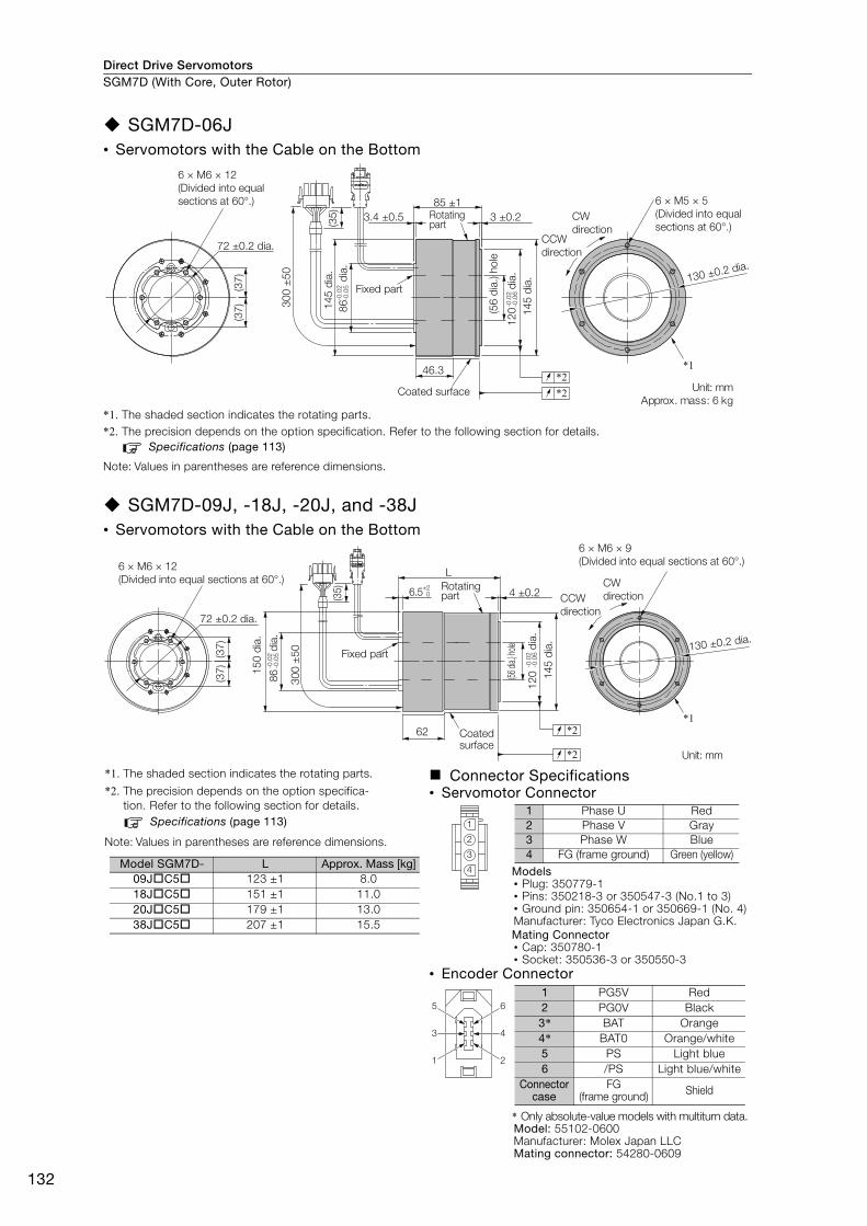
Direct Drive ServomotorsSGM7D (With Core, Outer Rotor)
132
SGM7D-06J• Servomotors with the Cable on the Bottom
*1. The shaded section indicates the rotating parts.*2. The precision depends on the option specification. Refer to the following section for details.
Specifications (page 113)
Note: Values in parentheses are reference dimensions.
SGM7D-09J, -18J, -20J, and -38J• Servomotors with the Cable on the Bottom
*1. The shaded section indicates the rotating parts.
*2. The precision depends on the option specifica-tion. Refer to the following section for details.
Specifications (page 113)
Note: Values in parentheses are reference dimensions.
Connector Specifications• Servomotor Connector
Models• Plug: 350779-1• Pins: 350218-3 or 350547-3 (No.1 to 3)• Ground pin: 350654-1 or 350669-1 (No. 4)Manufacturer: Tyco Electronics Japan G.K.Mating Connector• Cap: 350780-1• Socket: 350536-3 or 350550-3
• Encoder Connector
* Only absolute-value models with multiturn data.Model: 55102-0600Manufacturer: Molex Japan LLCMating connector: 54280-0609
*2*1
*2
(35)
300
±50
3 ±0.23.4 ±0.5
(37)
(37)
46.3
6 × M6 × 12 (Divided into equal sections at 60°.)
72 ±0.2 dia.
145
dia.
145
dia.
(56
dia.
) hol
e
120
d
ia.
-0.0
2-0
.06
86
di
a.-0
.02
-0.0
5
85 ±1
Fixed part
6 × M5 × 5 (Divided into equal sections at 60°.)
CW direction
CCW direction
Coated surface Unit: mmApprox. mass: 6 kg
130 ±0.2 dia.
Rotating part
*2
*2
300
±50
(35)
(37)
(37)
L
6.5+20 4 ±0.2
*162
6 × M6 × 9 (Divided into equal sections at 60°.)
72 ±0.2 dia.
86
di
a.-0
.02
-0.0
5
120
dia.
-0.0
2-0
.06
145
dia.
150
dia.
(56 di
a.) ho
le
Fixed part130 ±0.2 dia.
6 × M6 × 12 (Divided into equal sections at 60°.)
Coated surface
Unit: mm
CW directionCCW
direction
Rotating part
Model SGM7D- L Approx. Mass [kg]09JC5 123 ±1 8.018JC5 151 ±1 11.020JC5 179 ±1 13.038JC5 207 ±1 15.5
1
2
3
4
1 Phase U Red2 Phase V Gray3 Phase W Blue4 FG (frame ground) Green (yellow)
4
2
6
3
1
51 PG5V Red2 PG0V Black3* BAT Orange4* BAT0 Orange/white5 PS Light blue6 /PS Light blue/white
Connector case
FG (frame ground) Shield

Direct Drive Servomotors SGM7D (With Core, Outer Rotor)
133
SG
M7D
SGM7D-K
• Servomotors with the Cable on the Bottom
*1. The shaded section indicates the rotating parts.
*2. The precision depends on the option specification. Refer to the following section for details.Specifications (page 113)
Note: Values in parentheses are reference dimensions.
Model SGM7D- L Approx. Mass [kg]
02KC5 113 ±1 4.0
06KC5 140 ±1 5.0
08KC5 167 ±1 6.5
Connector Specifications• Servomotor Connector • Encoder Connector
Models• Plug: 350779-1• Pins: 350561-3 or 350690-3 (No.1 to 3)• Ground pin: 350654-1 or 350669-1 (No. 4)Manufacturer: Tyco Electronics Japan G.K.Mating Connector• Cap: 350780-1• Socket: 350570-3 or 350689-3
* Only absolute-value models with multiturn data.Model: 55102-0600Manufacturer: Molex Japan LLCMating connector: 54280-0609
*2*2
*1
(35)
300
±50
L3 ±0.2
45°
(24) (24)
5.5 +10
58
6 × M5 × 7 (Divided into equal sections at 60°.)
4 × M6 × 13 (Divided into equal sections at 60°.)
L
CW direction
84 ±0.2 dia.
CCW direction
50 ±0.2 dia.
Fixed part
Coated surface
100
dia.(26
dia.)
hole
74
di
a.-0
.02
-0.0
6
107
dia.
60
di
a.-0
.02
-0.0
6
Unit: mm
Rotating part
1
2
3
4
1 Phase U Red2 Phase V Gray3 Phase W Blue4 FG (frame ground) Green 4
2
6
3
1
51 PG5V Red2 PG0V Black3* BAT Orange4* BAT0 Orange/white5 PS Light blue6 /PS Light blue/white
Connector case
FG (frame ground) Shield

Direct Drive ServomotorsSGM7D (With Core, Outer Rotor)
134
SGM7D-06L and -12L• Servomotors with the Cable on the Side
*1. The shaded section indicates the rotating parts.
*2. The precision depends on the option specification. Refer to the following section for details.
Specifications (page 113)
*3. In the following cases, rigidity is required in the Servomotor. Therefore, secure the Servomotor with these holes.• There is a fluctuating vertical load on the Servomotor.• There is a moment load on the Servomotor.• The Servomotor is used hanging upside down.
Note: Values in parentheses are reference dimensions.
Connector Specifications• Servomotor Connector
Models• Plug: 350779-1• Pins: 350218-3 or 350547-3 (No.1 to 3)• Ground pin: 350654-1 or 350669-1 (No. 4)Manufacturer: Tyco Electronics Japan G.K.Mating Connector• Cap: 350780-1• Socket: 350536-3 or 350550-3
• Encoder Connector
* Only absolute-value models with multiturn data.Model: 55102-0600Manufacturer: Molex Japan LLCMating connector: 54280-0609
224180 ±0.2
180
±0.2 φ 121 121 ±0.20.2
224 × C20
37
0.5
7 7
0.5
0.5
A
2222
4
112
112
42 ±
1
2 ±0
.2
* 1
0
(32)
(70.
3)
(36)
*2*2
4 × 8.5 dia.
3 dia., depth: 5
224 dia.136 dia.
122 dia.140.5 dia.
6 × M5 × 8*3
(Divided into equal sections at 60°.)
4 × R115 A-0 Cross Section (Fixed Part)
6 × M4 × 6(Divided into equal sections at 60°.)
(122 dia.)(140.5 dia.)R115
D dia.
Unit: mmApprox. mass: 8.1 kg
131 ±0.2 dia.
122 dia.
140.5 dia.
50 dia.
300
±50
300
±50
(19) (37.
5)
(35)
φ 121 ±0.2
0 -0.2
0-0.2
+0.50
Model SGM7D- DLC41
(Standard mechanical precision) 112
LC42(High mechanical precision) 111.9
-0.02-0.06
-0.02-0.06
1
2
3
4
1 Phase U Red2 Phase V Gray3 Phase W Blue4 FG (frame ground) Green (yellow)
4
2
6
3
1
51 PG5V Red2 PG0V Black3* BAT Orange4* BAT0 Orange/white5 PS Light blue6 /PS Light blue/white
Connector case
FG (frame ground) Shield
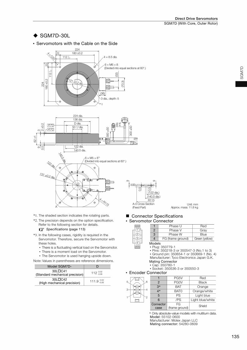
Direct Drive Servomotors SGM7D (With Core, Outer Rotor)
135
SG
M7D
SGM7D-30L• Servomotors with the Cable on the Side
*1. The shaded section indicates the rotating parts.
*2. The precision depends on the option specification. Refer to the following section for details.
Specifications (page 113)
*3. In the following cases, rigidity is required in the Servomotor. Therefore, secure the Servomotor with these holes.• There is a fluctuating vertical load on the Servomotor.• There is a moment load on the Servomotor.• The Servomotor is used hanging upside down.
Note: Values in parentheses are reference dimensions.
Connector Specifications• Servomotor Connector
Models• Plug: 350779-1• Pins: 350218-3 or 350547-3 (No.1 to 3)• Ground pin: 350654-1 or 350669-1 (No. 4)Manufacturer: Tyco Electronics Japan G.K.Mating Connector• Cap: 350780-1• Socket: 350536-3 or 350550-3
• Encoder Connector
* Only absolute-value models with multiturn data.Model: 55102-0600Manufacturer: Molex Japan LLCMating connector: 54280-0609
4 × 8.5 dia.
6 × M6 × 8(Divided into equal sections at 60°.)
121 121 ±0.2 dia.±0.2 dia.
3 dia., depth: 5
224 dia.136 dia.D dia.
50 dia.
122 dia.140.5 dia.
(Divided into equal sections at 60°.)
(122 dia.)(140.5 dia.)R115
A-0 Cross Section (Fixed Part)
6 × M5 × 8*3
Unit: mmApprox. mass: 11.8 kg
180 ±0.2224
224 × C20 112
180
±0.2
2222
4
112
* 1
39
0.5
62 ±
1
2 ±0
.2
4 × R115A
9 9
0.5
0.5
0
(32)
(70.
3)
(36)
*2*2
300
±50
300
±50
(19) (37.
5)
(35)
131 ±0.2 dia.
122 dia.
140.5 dia.
121 ±0.2 dia.
+0.50
0 -0.2
0-0.2
Model SGM7D- D30LC41
(Standard mechanical precision) 112
30LC42(High mechanical precision) 111.9
-0.02-0.06
-0.02-0.06
1
2
3
4
1 Phase U Red2 Phase V Gray3 Phase W Blue4 FG (frame ground) Green (yellow)
4
2
6
3
1
51 PG5V Red2 PG0V Black3* BAT Orange4* BAT0 Orange/white5 PS Light blue6 /PS Light blue/white
Connector case
FG (frame ground) Shield

Direct Drive ServomotorsSGM7D (With Core, Outer Rotor)
136
Selecting Cables
Cable ConfigurationsThe cables shown below are required to connect a Servomotor to a SERVOPACK.
Note: 1. If the Encoder Cable length exceeds 20 m, be sure to use a Relay Encoder Cable.
2. If you use a Servomotor Main Circuit Cable that exceeds 20 m, the intermittent duty zone in the torque-motor speed characteristics will become smaller because the voltage drop increases.
3. Refer to the following manual for the following information.• Cable dimensional drawings and cable connection specifications• Order numbers and specifications of individual connectors for cables• Order numbers and specifications for wiring materials
Σ-7-Series AC Servo Drive Peripheral Device Selection Manual (Manual No.: SIEP S800001 32)
Servomotor Main Circuit Cables
* Use Flexible Cables for moving parts of machines, such as robots. The recommended bending radius (R) is 90 mm or larger.
Note: Direct Drive Servomotors are not available with holding brakes.
Encoder Cable of 20 m or Less Encoder Cable of 30 m to 50 m (Relay Cable)
Servomotor ModelLength
(L)Order Number
AppearanceStandard Cable Flexible Cable*
SGM7D-FSGM7D-08G to -45GSGM7D-ISGM7D-JSGM7D-L
3 m JZSP-CMM00-03-E JZSP-C7DM21-03-E
5 m JZSP-CMM00-05-E JZSP-C7DM21-05-E
10 m JZSP-CMM00-10-E JZSP-C7DM21-10-E
15 m JZSP-CMM00-15-E JZSP-C7DM21-15-E
20 m JZSP-CMM00-20-E JZSP-C7DM21-20-E
SGM7D-01G or -05GSGM7D-HSGM7D-K
3 m JZSP-CMM00-03-E JZSP-CMM01-03-E
5 m JZSP-CMM00-05-E JZSP-CMM01-05-E
10 m JZSP-CMM00-10-E JZSP-CMM01-10-E
15 m JZSP-CMM00-15-E JZSP-CMM01-15-E
20 m JZSP-CMM00-20-E JZSP-CMM01-20-E
SERVOPACK
Encoder Cable
Encoder Cable
Servomotor
Servomotor Main Circuit Cable
Servomotor Main Circuit Cable
A A
Battery Case(Required to use a multiturn absolute encoder.)
SERVOPACK
Cable with a Battery Case(Required only if a multiturn absolute encoder is used.)
Cable with Connectors on Both Ends
Encoder-end CableServomotor
Servomotor Main Circuit Cable
A
Relay Encoder Cable
L
SERVOPACK end
Motor end
L
SERVOPACK end
Motor end

Direct Drive Servomotors SGM7D (With Core, Outer Rotor)
137
SG
M7D
Encoder Cables of 20 m or Less
*1. Use Flexible Cables for moving parts of machines, such as robots. The recommended bending radius (R) is 68 mm or larger.
*2. Use one of these Cables if a battery is connected to the host controller.
Relay Encoder Cables of 30 m to 50 m
*1. Flexible Cables are not available.*2. This Cable is not required if a battery is connected to the host controller.
Servomotor Model NameLength
(L)
Order NumberAppearance
Standard Cable Flexible Cable*1
All SGM7D models
For incre-mental encoder: Without Battery Case
3 m JZSP-CMP00-03-E JZSP-CMP10-03-E5 m JZSP-CMP00-05-E JZSP-CMP10-05-E
10 m JZSP-CMP00-10-E JZSP-CMP10-10-E15 m JZSP-CMP00-15-E JZSP-CMP10-15-E
20 m JZSP-CMP00-20-E JZSP-CMP10-20-E
For multi-turn abso-lute encoder: Without Battery Case*2
3 m JZSP-CMP00-03-E JZSP-CMP10-03-E5 m JZSP-CMP00-05-E JZSP-CMP10-05-E
10 m JZSP-CMP00-10-E JZSP-CMP10-10-E15 m JZSP-CMP00-15-E JZSP-CMP10-15-E
20 m JZSP-CMP00-20-E JZSP-CMP10-20-E
For multi-turn abso-lute encoder: With Battery Case
3 m JZSP-CSP19-03-E JZSP-CSP29-03-E5 m JZSP-CSP19-05-E JZSP-CSP29-05-E
10 m JZSP-CSP19-10-E JZSP-CSP29-10-E15 m JZSP-CSP19-15-E JZSP-CSP29-15-E
20 m JZSP-CSP19-20-E JZSP-CSP29-20-E
Servomotor Model
NameLength
(L) Order Number*1 Appearance
All SGM7D mod-els
Cables with Connec-tors on Both Ends (for incremental or multiturn absolute encoder)
30 m JZSP-UCMP00-30-E
40 m JZSP-UCMP00-40-E
50 m JZSP-UCMP00-50-E
Cable with a Battery Case (for multiturn absolute encoder)*2
0.3 m JZSP-CSP12-E
LSERVOPACK end Encoder end
LSERVOPACK end Encoder end
Encoder endSERVOPACK endL
Battery Case (battery included)
LSERVOPACK end
Encoder end
SERVOPACK end
Encoder end
Battery Case (battery included)

Direct Drive Servomotors
138
SGM7F (Small Capacity, with Core, Inner Rotor)
Model Designations
* A multiturn absolute encoder can be used as a single-turn absolute encoder.
Note: Direct Drive Servomotors are not available with holding brakes.
04 4.00 Nm
08 8.00 Nm
10 10.0 Nm
14 14.0 Nm
17 17.0 Nm25 25.0 Nm
16 16.0 Nm
35 35.0 Nm
4th digit 6th digit
3rd digit
7th digit
Mounting
Non-load side
Non-load side (with cable on side)
Options
Without optionsHigh machine precision (runout at end of shaft and runout of shaft surface: 0.01 mm)
24-bit multiturn absolute encoder*24-bit incremental encoder
A
5th digit Design Revision Order
Servomotor Outer Diameter
135-mm dia.
230-mm dia.
C 175-mm dia.
Serial Encoder Flange
SGM7F - 04 B 7 A 1 11st+2nd
digits
1st+2nd digits Rated Output
Code Specification
3rd digit
4th digit
5th digit
6th digit
7th digitDirect Drive
Servomotors: SGM7F
Code Code
Code
Code
Specification
Specification
Specification
B
D
7
F
1
2
1
4

Direct Drive Servomotors SGM7F (Small Capacity, with Core, Inner Rotor)
139
SG
M7F
Specifications and Ratings
Specifications
*1. A vibration class of V15 indicates a vibration amplitude of 15 μm maximum on the Servomotor without a load at the rated motor speed.*2. The hollow hole section, motor mounting surface, output shaft surface, and gap around the rotating part of the shaft are
excluded. Protective structure specifications apply only when the special cable is used. *3. The protective structure is IP40 for CE Marking.*4. Refer to the following figure for the relevant locations on the Servomotor. Refer to the dimensional drawings of the
individual Servomotors for more information on tolerances.
*5. The given values are for when the Servomotor shaft is mounted horizontally and shock or vibration is applied in the directions shown in the following figures.The strength of the vibration that the Servomotor can withstand depends on the application. Check the vibration acceleration rate.
*6. Use derated values for this combination. Refer to the following section for information on derating values.Ratings (page 140)
Voltage 200 VModel SGM7F- 04B 10B 14B 08C 17C 25C 16D 35D
Time Rating Continuous Thermal Class AInsulation Resistance 500 VDC, 10 MΩ min. Withstand Voltage 1,500 VAC for 1 minute Excitation Permanent magnet Mounting Flange-mounted Drive Method Direct drive Rotation Direction Counterclockwise (CCW) for forward reference when viewed from the load side
Vibration Class*1 V15Absolute Accuracy ±15 s Repeatability ±1.3 s
Protective Structure*2 Totally enclosed, self-cooled, IP42*3
Env
ironm
enta
l Con
diti
ons Surrounding Air Temperature 0°C to 40°C (with no freezing)
Surrounding Air Humidity 20% to 80% relative humidity (with no condensation)
Installation Site
• Must be indoors and free of corrosive and explosive gases. • Must be well-ventilated and free of dust and moisture. • Must facilitate inspection and cleaning. • Must have an altitude of 1,000 m or less.• Must be free of strong magnetic fields.
Storage Environment
Store the Servomotor in the following environment if you store it with the power cable disconnected. Storage Temperature: -20°C to 60°C (with no freezing)Storage Humidity: 20% to 80% relative humidity (with no condensation)
Mec
hani
cal
Tol
eran
ces*3
Runout of Output Shaft Surface mm 0.02 (0.01 for high machine precision option) Runout at End of Output Shaft mm 0.04 (0.01 for high machine precision option) Parallelism between Mounting Surface and Output Shaft Surface mm 0.07
Concentricity between Output Shaft and Flange Outer Diameter mm 0.07
Shock Resistance*5
Impact Acceleration Rate at Flange 490 m/s2
Number of Impacts 2 times Vibration Resistance*5
Vibration Acceleration Rate at Flange 49 m/s2
Applicable SERVOPACKsSGD7S- 2R8A, 2R8F
5R5A
2R8A, 2R8F
5R5A 7R6A 5R5A
7R6A*6, 120A
SGD7W-SGD7C- 2R8A 2R8A 7R6A*6
A
A B
B
Runout at end of output shaft
dia.
Load side
Non-load side
Concentricity between output shaft and flange outer diameter dia. Parallelism between mounting surface and output shaft surface
Runout of output shaft surface : Diameter determined by motor model.
Side to side
Front to back
Vertical
Shock Applied to the Servomotor Vibration Applied to the Servomotor
Vertical
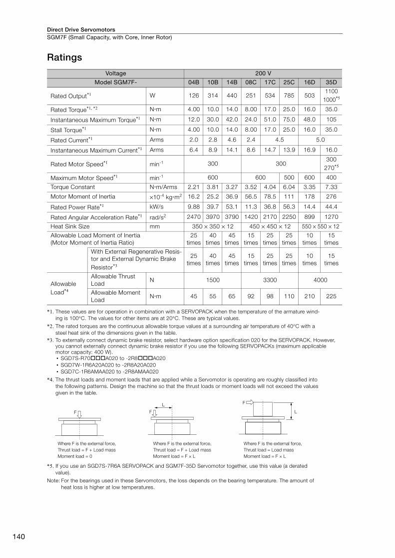
Direct Drive ServomotorsSGM7F (Small Capacity, with Core, Inner Rotor)
140
Ratings
*1. These values are for operation in combination with a SERVOPACK when the temperature of the armature wind-ing is 100°C. The values for other items are at 20°C. These are typical values.
*2. The rated torques are the continuous allowable torque values at a surrounding air temperature of 40°C with a steel heat sink of the dimensions given in the table.
*3. To externally connect dynamic brake resistor, select hardware option specification 020 for the SERVOPACK. However, you cannot externally connect dynamic brake resistor if you use the following SERVOPACKs (maximum applicable motor capacity: 400 W).• SGD7S-R70A020 to -2R8A020• SGD7W-1R6A20A020 to -2R8A20A020• SGD7C-1R6AMAA020 to -2R8AMAA020
*4. The thrust loads and moment loads that are applied while a Servomotor is operating are roughly classified into the following patterns. Design the machine so that the thrust loads or moment loads will not exceed the values given in the table.
*5. If you use an SGD7S-7R6A SERVOPACK and SGM7F-35D Servomotor together, use this value (a derated value).
Note: For the bearings used in these Servomotors, the loss depends on the bearing temperature. The amount of heat loss is higher at low temperatures.
Voltage 200 V
Model SGM7F- 04B 10B 14B 08C 17C 25C 16D 35D
Rated Output*1 W 126 314 440 251 534 785 5031100
1000*5
Rated Torque*1, *2 Nm 4.00 10.0 14.0 8.00 17.0 25.0 16.0 35.0
Instantaneous Maximum Torque*1 Nm 12.0 30.0 42.0 24.0 51.0 75.0 48.0 105
Stall Torque*1 Nm 4.00 10.0 14.0 8.00 17.0 25.0 16.0 35.0
Rated Current*1 Arms 2.0 2.8 4.6 2.4 4.5 5.0
Instantaneous Maximum Current*1 Arms 6.4 8.9 14.1 8.6 14.7 13.9 16.9 16.0
Rated Motor Speed*1 min-1 300 300300
270*5
Maximum Motor Speed*1 min-1 600 600 500 600 400
Torque Constant Nm/Arms 2.21 3.81 3.27 3.52 4.04 6.04 3.35 7.33
Motor Moment of Inertia ×10-4 kgm2 16.2 25.2 36.9 56.5 78.5 111 178 276
Rated Power Rate*1 kW/s 9.88 39.7 53.1 11.3 36.8 56.3 14.4 44.4
Rated Angular Acceleration Rate*1 rad/s2 2470 3970 3790 1420 2170 2250 899 1270
Heat Sink Size mm 350 × 350 × 12 450 × 450 × 12 550 × 550 × 12
Allowable Load Moment of Inertia (Motor Moment of Inertia Ratio)
25 times
40 times
45 times
15 times
25 times
25 times
10 times
15 times
With External Regenerative Resis-tor and External Dynamic Brake Resistor*3
25 times
40 times
45 times
15 times
25 times
25 times
10 times
15 times
Allowable Load*4
Allowable Thrust Load
N 1500 3300 4000
Allowable Moment Load
Nm 45 55 65 92 98 110 210 225
F
F
LF
L
Where F is the external force,Thrust load = F + Load mass Moment load = 0
Where F is the external force,Thrust load = F + Load massMoment load = F × L
Where F is the external force,Thrust load = Load massMoment load = F × L

Direct Drive Servomotors SGM7F (Small Capacity, with Core, Inner Rotor)
141
SG
M7F
Torque-Motor Speed Characteristics
*1. The characteristics are the same for three-phase 200 V, single-phase 200 V, and single-phase 100 V.
*2. Contact your Yaskawa representative for information on the SGM7F-25C.
Note: 1. These values (typical values) are for operation in combination with a SERVOPACK when the temperature of the armature winding is 100°C.
2. The characteristics in the intermittent duty zone depend on the power supply voltage.
3. If you use a Servomotor Main Circuit Cable that exceeds 20 m, the intermittent duty zone in the torque-motor speed characteristics will become smaller because the voltage drop increases.
SGM7F-08C
0 5 10 15 20 25 300
100
200
300
400
500
600
700
A B
SGM7F-17C
0 10 20 30 40 50 600
100
200
300
400
500
600
700
A B
SGM7F-04B*1
0
100
200
300
400
500
600
700
0 5 10 15
A B
SGM7F-25C*2
0 10 20 30 40 50 60 70 800
100
200
300
400
500
600
700
A B
SGM7F-10B
0 10 20 30 400
100
200
300
400
500
600
700
A B
SGM7F-14B*1
0 10 20 30 40 500
100
200
300
400
500
600
700
A B
SGM7F-16D
0 10 20 30 40 500
100
200
300
400
500
600
700
A B
0 20 40 60 80 100 120
SGM7F-35D
0
100
200
300
400
500
A B
A :
B :(dashed-dotted lines): With single-phase 100-V input
(solid lines): With three-phase 200-V or single-phase 230-V input(dotted lines): With single-phase 200-V inputIntermittent duty zone
Continuous duty zone
Torque (N�m)
Mot
or s
peed
(min
-1)
Torque (N�m)M
otor
spe
ed (m
in-1)
Torque (N�m)
Mot
or s
peed
(min
-1)
Torque (N�m)
Mot
or s
peed
(min
-1)
Torque (N�m)
Mot
or s
peed
(min
-1)
Torque (N�m)
Mot
or s
peed
(min
-1)
Torque (N�m)
Mot
or s
peed
(min
-1)
Torque (N�m)
Mot
or s
peed
(min
-1)

Direct Drive ServomotorsSGM7F (Small Capacity, with Core, Inner Rotor)
142
Servomotor Overload Protection Characteristics The overload detection level is set for hot start conditions with a Servomotor surrounding air tem-perature of 40°C.
Note: The above overload protection characteristics do not mean that you can perform continuous duty operation with an output of 100% or higher. Use the Servomotor so that the effective torque remains within the contin-uous duty zone given in Torque-Motor Speed Characteristics on page 141.
10000
1000
100
10
1
SGM7F-��B SGM7F-08C
0 50 100 150 200 250 300
10000
1000
100
10
1
SGM7F-17C and -25C
0 50 100 150 200 250 300
10000
1000
100
10
1
SGM7F-35D
0 50 100 150 200 250 300
10000
1000
100
10
10 50 100 150 200 250 300
SGM7F-16D10000
1000
100
10
10 50 100 150 200 250 300
Det
ectio
n tim
e (s
)
Torque reference (%)
Det
ectio
n tim
e (s
)
Torque reference (%)
Det
ectio
n tim
e (s
)
Torque reference (%)
Det
ectio
n tim
e (s
)
Torque reference (%)
Det
ectio
n tim
e (s
)
Torque reference (%)
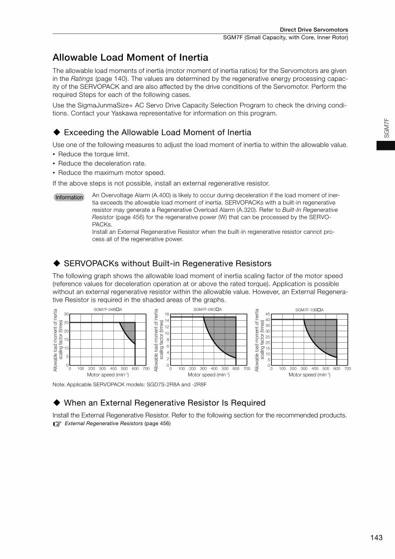
Direct Drive Servomotors SGM7F (Small Capacity, with Core, Inner Rotor)
143
SG
M7F
Allowable Load Moment of InertiaThe allowable load moments of inertia (motor moment of inertia ratios) for the Servomotors are given in the Ratings (page 140). The values are determined by the regenerative energy processing capac-ity of the SERVOPACK and are also affected by the drive conditions of the Servomotor. Perform the required Steps for each of the following cases.
Use the SigmaJunmaSize+ AC Servo Drive Capacity Selection Program to check the driving condi-tions. Contact your Yaskawa representative for information on this program.
Exceeding the Allowable Load Moment of InertiaUse one of the following measures to adjust the load moment of inertia to within the allowable value.• Reduce the torque limit.• Reduce the deceleration rate.• Reduce the maximum motor speed.
If the above steps is not possible, install an external regenerative resistor.
SERVOPACKs without Built-in Regenerative ResistorsThe following graph shows the allowable load moment of inertia scaling factor of the motor speed (reference values for deceleration operation at or above the rated torque). Application is possible without an external regenerative resistor within the allowable value. However, an External Regenera-tive Resistor is required in the shaded areas of the graphs.
Note: Applicable SERVOPACK models: SGD7S-2R8A and -2R8F
When an External Regenerative Resistor Is RequiredInstall the External Regenerative Resistor. Refer to the following section for the recommended products.
External Regenerative Resistors (page 456)
An Overvoltage Alarm (A.400) is likely to occur during deceleration if the load moment of iner-tia exceeds the allowable load moment of inertia. SERVOPACKs with a built-in regenerative resistor may generate a Regenerative Overload Alarm (A.320). Refer to Built-In Regenerative Resistor (page 456) for the regenerative power (W) that can be processed by the SERVO-PACKs. Install an External Regenerative Resistor when the built-in regenerative resistor cannot pro-cess all of the regenerative power.
Information
0
5
10
15
20
25
30
0 100 200 300 400 500 600 700 0 100 200 300 400 500 600 700 0 100 200 300 400 500 600 700
SGM7F-04B�A
0
2
4
6
8
10
12
14
16SGM7F-08C�A
05
1015202530354045
SGM7F-10B�A
Motor speed (min-1)
Allo
wab
le lo
ad m
omen
t of i
nerti
a sc
alin
g fa
ctor
(tim
es)
Motor speed (min-1)
Allo
wab
le lo
ad m
omen
t of i
nerti
a sc
alin
g fa
ctor
(tim
es)
Motor speed (min-1)
Allo
wab
le lo
ad m
omen
t of i
nerti
a sc
alin
g fa
ctor
(tim
es)
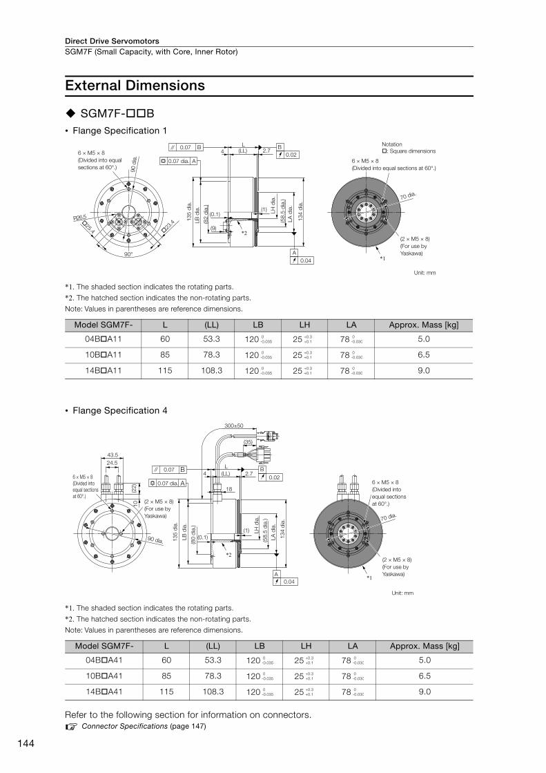
Direct Drive ServomotorsSGM7F (Small Capacity, with Core, Inner Rotor)
144
External Dimensions
SGM7F-B• Flange Specification 1
*1. The shaded section indicates the rotating parts.
*2. The hatched section indicates the non-rotating parts.
Note: Values in parentheses are reference dimensions.
• Flange Specification 4
*1. The shaded section indicates the rotating parts.
*2. The hatched section indicates the non-rotating parts.
Note: Values in parentheses are reference dimensions.
Refer to the following section for information on connectors. Connector Specifications (page 147)
Model SGM7F- L (LL) LB LH LA Approx. Mass [kg]
04BA11 60 53.3 120 25 78 5.0
10BA11 85 78.3 120 25 78 6.5
14BA11 115 108.3 120 25 78 9.0
Model SGM7F- L (LL) LB LH LA Approx. Mass [kg]
04BA41 60 53.3 120 25 78 5.0
10BA41 85 78.3 120 25 78 6.5
14BA41 115 108.3 120 25 78 9.0
23
.425.4
(1)
2.74
90°
R26.5
(LL)L
(9)
(0.1)
A0.04
B0.02
A
0.07 B
*1
*2
6 × M5 × 8 (Divided into equal sections at 60°.)
(82
dia.
)
134
dia.
(58.
5 di
a.)
LB d
ia.
135
dia.
0.07 dia. 6 × M5 × 8 (Divided into equal sections at 60°.)
(2 × M5 × 8) (For use by Yaskawa)
70 dia.
Unit: mm
90 d
ia.
LA d
ia.
LH d
ia.
Notation: Square dimensions
0-0.035
+0.3+0.1
0-0.030
0-0.035
+0.3+0.1
0-0.030
0-0.035
+0.3+0.1
0-0.030
(1)
2.7(LL)L
300±50
(35)
18
4
(0.1)
43.524.5
10(2
2)
A0.04
B
0.020.07 B
A
90 dia.
*1
*2
6 × M5 × 8 (Divided into equal sections at 60°.)
0.07 dia.
(2 × M5 × 8) (For use by Yaskawa)
134
dia.
(58.
5 di
a.)
LH d
ia.
(80
dia.
)
135
dia.
6 × M5 × 8 (Divided into equal sections at 60°.)
(2 × M5 × 8) (For use by Yaskawa)
Unit: mm
70 dia.
LB d
ia.
LA d
ia.
0-0.035
+0.3+0.1
0-0.030
0-0.035
+0.3+0.1
0-0.030
0-0.035
+0.3+0.1
0-0.030
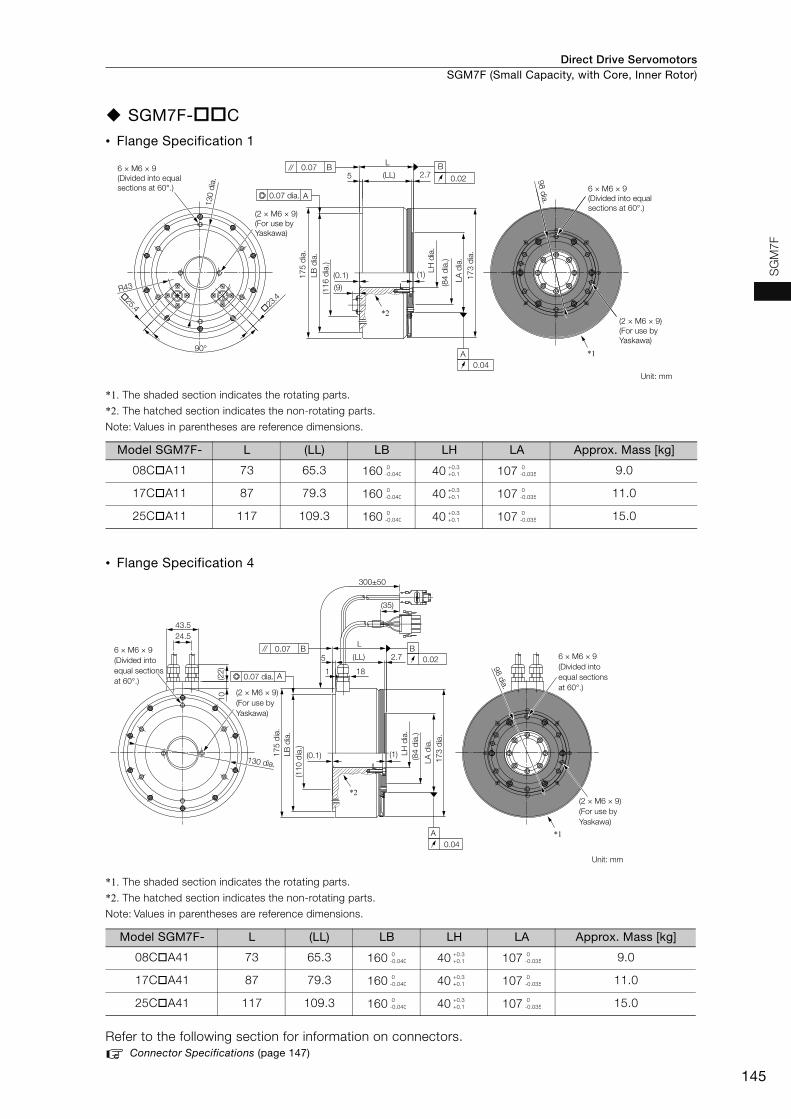
Direct Drive Servomotors SGM7F (Small Capacity, with Core, Inner Rotor)
145
SG
M7F
SGM7F-C
• Flange Specification 1
*1. The shaded section indicates the rotating parts.
*2. The hatched section indicates the non-rotating parts.
Note: Values in parentheses are reference dimensions.
• Flange Specification 4
*1. The shaded section indicates the rotating parts.
*2. The hatched section indicates the non-rotating parts.
Note: Values in parentheses are reference dimensions.
Refer to the following section for information on connectors.Connector Specifications (page 147)
Model SGM7F- L (LL) LB LH LA Approx. Mass [kg]
08CA11 73 65.3 160 40 107 9.0
17CA11 87 79.3 160 40 107 11.0
25CA11 117 109.3 160 40 107 15.0
Model SGM7F- L (LL) LB LH LA Approx. Mass [kg]
08CA41 73 65.3 160 40 107 9.0
17CA41 87 79.3 160 40 107 11.0
25CA41 117 109.3 160 40 107 15.0
23
.4
25.4
2.75
R43(0.1) (1)
90°
L
(LL)
(9)
B
0.02
A0.04
0.07 B
A
173
dia.
*1
*2
130
dia.
6 × M6 × 9 (Divided into equal sections at 60°.)
98 dia.
(2 × M6 × 9) (For use by Yaskawa)
Unit: mm
(2 × M6 × 9) (For use by Yaskawa)
LA d
ia.
(84
dia.
)
(116
dia
.)
175
dia.
0.07 dia.
LB d
ia.
LH d
ia.
6 × M6 × 9 (Divided into equal sections at 60°.)
0-0.040
+0.3+0.1
0-0.035
0-0.040
+0.3+0.1
0-0.035
0-0.040
+0.3+0.1
0-0.035
B0.022.75
1
(0.1) (1)
L
18
300±50
(LL)
24.5
(22)
43.5
10
(35)
0.07 B
A
A0.04
*1
*2
6 × M6 × 9 (Divided into equal sections at 60°.)
(2 × M6 × 9) (For use by Yaskawa)
173
dia.
(84
dia.
)
175
dia.
130 dia.
6 × M6 × 9 (Divided into equal sections at 60°.)
98 dia.
(2 × M6 × 9) (For use by Yaskawa)
Unit: mm
(110
dia
.)
0.07 dia.
LB d
ia.
LH d
ia.
LA d
ia.
0-0.040
+0.3+0.1
0-0.035
0-0.040
+0.3+0.1
0-0.035
0-0.040
+0.3+0.1
0-0.035
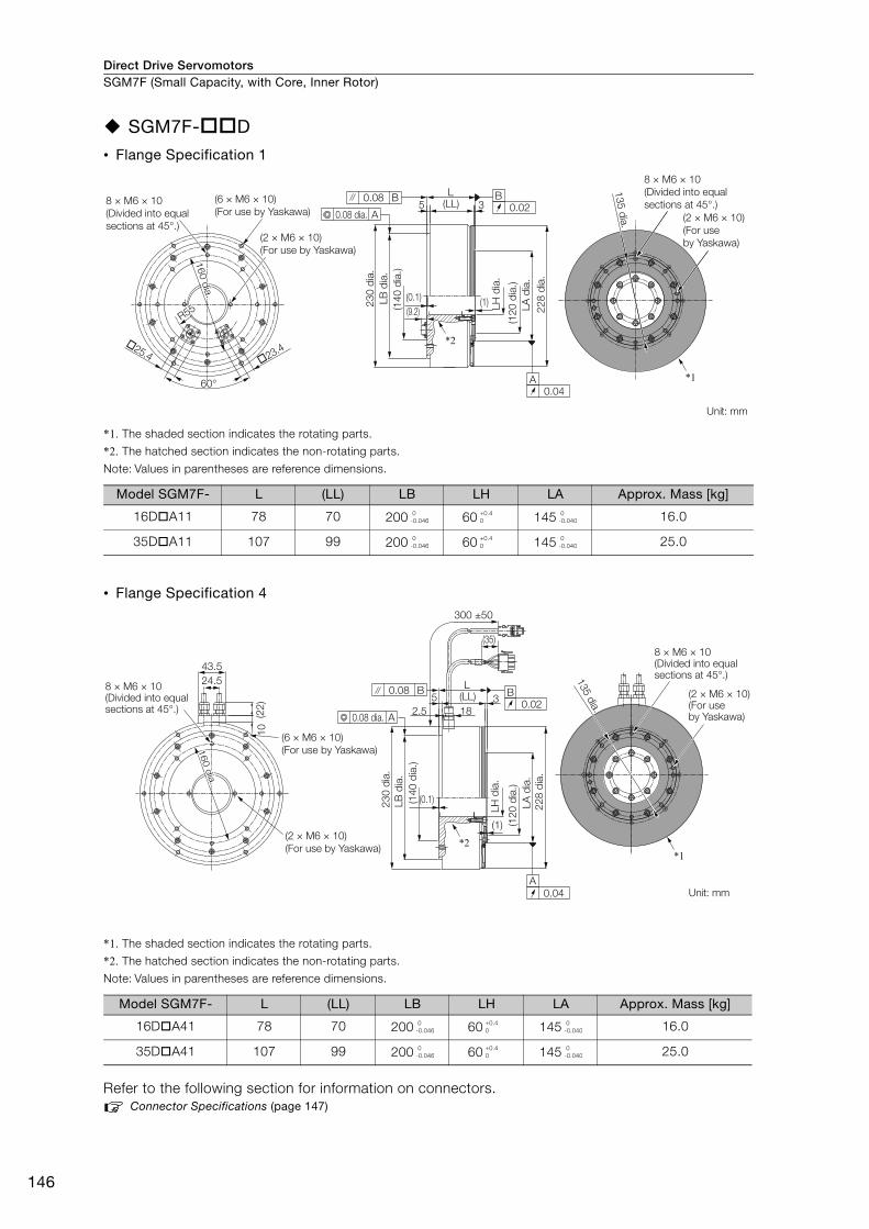
Direct Drive ServomotorsSGM7F (Small Capacity, with Core, Inner Rotor)
146
SGM7F-D
• Flange Specification 1
*1. The shaded section indicates the rotating parts.
*2. The hatched section indicates the non-rotating parts.
Note: Values in parentheses are reference dimensions.
• Flange Specification 4
*1. The shaded section indicates the rotating parts.
*2. The hatched section indicates the non-rotating parts.
Note: Values in parentheses are reference dimensions.
Refer to the following section for information on connectors.Connector Specifications (page 147)
Model SGM7F- L (LL) LB LH LA Approx. Mass [kg]
16DA11 78 70 200 60 145 16.0
35DA11 107 99 200 60 145 25.0
Model SGM7F- L (LL) LB LH LA Approx. Mass [kg]
16DA41 78 70 200 60 145 16.0
35DA41 107 99 200 60 145 25.0
Unit: mm
60°
�25.4 �23.4
8 × M6 × 10(Divided into equal sections at 45°.)
(2 × M6 × 10)(For use by Yaskawa)
(6 × M6 × 10)(For use by Yaskawa)
R55R55
160 dia.160 dia.160 dia.
R55
L(LL)5 3
B0.02
A0.04
230
dia.
LB d
ia.
(140
dia
.)
(0.1)(9.2) 22
8 di
a.LA
dia
.(1
20 d
ia.)
LH d
ia.
(1)
0.08 B
A0.08 dia.
*2
8 × M6 × 10(Divided into equal sections at 45°.)
(2 × M6 × 10)(For use by Yaskawa)
*1
135 dia.
0-0.046
+0.40
0-0.040
0-0.046
+0.40
0-0.040
Unit: mm
24.543.5
(6 × M6 × 10)(For use by Yaskawa)
(2 × M6 × 10)(For use by Yaskawa)
8 × M6 × 10(Divided into equal sections at 45°.) (2
2)10
(1)
228
dia.
LA d
ia.
(120
dia
.)
LH d
ia.
0.08 B
A0.08 dia.
(0.1)230
dia.
LB d
ia.
(140
dia
.)
300 ±50
(35)
(LL)L
318
52.5
A0.04
B0.02
*2
8 × M6 × 10(Divided into equal sections at 45°.)
(2 × M6 × 10)(For use by Yaskawa)
135 dia.
*1
160 d
ia.160 d
ia.160 d
ia.
0-0.046
+0.40
0-0.040
0-0.046
+0.40
0-0.040

Direct Drive Servomotors SGM7F (Small Capacity, with Core, Inner Rotor)
147
SG
M7F
Connector Specifications
Flange Specification 1
Flange Specification 4
• Servomotor Connector • Encoder Connector
Model: JN1AS04MK2RManufacturer: Japan Aviation Electronics Industry, Ltd.
Mating connector: JN1DS04FK1(Not provided by Yaskawa.)
* Only absolute-value models with multiturn data.
Model: JN1AS10ML1-R Manufacturer: Japan Aviation Electronics Industry, Ltd.
Mating connector: JN1DS10SL1 (Not provided by Yaskawa.)
• Servomotor Connector • Encoder Connector
Models • Plug: 350779-1 • Pins: 350561-3 or 350690-3 (No.1 to 3) • Ground pin: 350654-1 or 350669-1 (No. 4) Manufacturer: Tyco Electronics Japan G.K.
Mating Connector • Cap: 350780-1 • Socket: 350570-3 or 350689-3
* Only absolute-value models with multiturn data.
Model: 55102-0600Manufacturer: Molex Japan LLC
Mating connector: 54280-0609
1
3
2
4
1 Phase U Red2 Phase V White3 Phase W Blue4 FG (frame ground) Green (yellow)
1 3
4 7
8 10
1 PS Not used 6 − −
2 /PS Light blue/white 7 FG (frame
ground) Shield
3 − − 8* BAT Orange4 PG5V Red 9 PG0V Black
5* BAT0 Orange/white 10 − −
1
2
3
4
1 Phase U Red2 Phase V White3 Phase W Blue4 FG (frame ground) Green (yellow) 4
2
6
3
1
51 PG5V Red2 PG0V Black3* BAT Orange
4* BAT0 Orange/white
5 PS Light blue
6 /PS Light blue/white
Connector case FG (frame ground) Shield

Direct Drive ServomotorsSGM7F (Small Capacity, with Core, Inner Rotor)
148
Selecting Cables
Cable ConfigurationsThe cables shown below are required to connect a Servomotor to a SERVOPACK.
Note: 1. If the Encoder Cable length exceeds 20 m, be sure to use a Relay Encoder Cable.
2. If you use a Servomotor Main Circuit Cable that exceeds 20 m, the intermittent duty zone in the torque-motor speed characteristics will become smaller because the voltage drop increases.
3. Refer to the following manual for the following information.• Cable dimensional drawings and cable connection specifications• Order numbers and specifications of individual connectors for cables• Order numbers and specifications for wiring materials
Σ-7-Series AC Servo Drive Peripheral Device Selection Manual (Manual No.: SIEP S800001 32)
Servomotor Main Circuit Cables
*1. Use Flexible Cables for moving parts of machines, such as robots. The recommended bending radius (R) is 90 mm or larger.
*2. Refer to the following section for the flange specifications.Model Designations (page 138)
Note: Direct Drive Servomotors are not available with holding brakes.
Encoder Cable of 20 m or Less Encoder Cable of 30 m to 50 m (Relay Cable)
Servomotor ModelLength
(L)
Order NumberAppearance
Standard Cable Flexible Cable*1
SGM7F-BSGM7F-CSGM7F-D
Flange specification*2: 1Non-load side installation
3 m JZSP-CMM60-03-E JZSP-C7MDN23-03-E
5 m JZSP-CMM60-05-E JZSP-C7MDN23-05-E
10 m JZSP-CMM60-10-E JZSP-C7MDN23-10-E
15 m JZSP-CMM60-15-E JZSP-C7MDN23-15-E
20 m JZSP-CMM60-20-E JZSP-C7MDN23-20-E
SGM7F-BSGM7F-CSGM7F-D
Flange specification*2: 4Non-load side installation (with cable on side)
3 m JZSP-CMM00-03-E JZSP-C7MDS23-03-E
5 m JZSP-CMM00-05-E JZSP-C7MDS23-05-E
10 m JZSP-CMM00-10-E JZSP-C7MDS23-10-E
15 m JZSP-CMM00-15-E JZSP-C7MDS23-15-E
20 m JZSP-CMM00-20-E JZSP-C7MDS23-20-E
SERVOPACK
Encoder Cable
Encoder Cable
Servomotor
Servomotor Main Circuit Cable
Servomotor Main Circuit Cable
A A
Battery Case(Required to use a multiturn absolute encoder.)
SERVOPACK
Cable with a Battery Case(Required only if a multiturn absolute encoder is used.)
Cable with Connectors on Both Ends
Encoder-end CableServomotor
Servomotor Main Circuit Cable
A
Relay Encoder Cable
LSERVOPACK end
Motor end
L
SERVOPACK end
Motor end
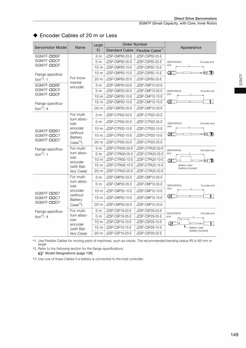
Direct Drive Servomotors SGM7F (Small Capacity, with Core, Inner Rotor)
149
SG
M7F
Encoder Cables of 20 m or Less
*1. Use Flexible Cables for moving parts of machines, such as robots. The recommended bending radius (R) is 68 mm or larger.
*2. Refer to the following section for the flange specifications.Model Designations (page 138)
*3. Use one of these Cables if a battery is connected to the host controller.
Servomotor Model NameLength
(L)
Order NumberAppearance
Standard Cable Flexible Cable*1
SGM7F-BFSGM7F-CFSGM7F-DF
Flange specifica-tion*2: 1 For incre-
mental encoder
3 m JZSP-CMP60-03-E JZSP-CSP60-03-E
5 m JZSP-CMP60-05-E JZSP-CSP60-05-E
10 m JZSP-CMP60-10-E JZSP-CSP60-10-E
15 m JZSP-CMP60-15-E JZSP-CSP60-15-E
20 m JZSP-CMP60-20-E JZSP-CSP60-20-E
SGM7F-BFSGM7F-CFSGM7F-DF
Flange specifica-tion*2: 4
3 m JZSP-CMP00-03-E JZSP-CMP10-03-E
5 m JZSP-CMP00-05-E JZSP-CMP10-05-E
10 m JZSP-CMP00-10-E JZSP-CMP10-10-E
15 m JZSP-CMP00-15-E JZSP-CMP10-15-E
20 m JZSP-CMP00-20-E JZSP-CMP10-20-E
SGM7F-B7SGM7F-C7SGM7F-D7
Flange specifica-tion*2: 1
For multi-turn abso-lute encoder (without Battery Case*3)
3 m JZSP-C7PI00-03-E JZSP-C7PI20-03-E
5 m JZSP-C7PI00-05-E JZSP-C7PI20-05-E
10 m JZSP-C7PI00-10-E JZSP-C7PI20-10-E
15 m JZSP-C7PI00-15-E JZSP-C7PI20-15-E
20 m JZSP-C7PI00-20-E JZSP-C7PI20-20-E
For multi-turn abso-lute encoder(with Bat-tery Case)
3 m JZSP-C7PA00-03-E JZSP-C7PA20-03-E
5 m JZSP-C7PA00-05-E JZSP-C7PA20-05-E
10 m JZSP-C7PA00-10-E JZSP-C7PA20-10-E
15 m JZSP-C7PA00-15-E JZSP-C7PA20-15-E
20 m JZSP-C7PA00-20-E JZSP-C7PA20-20-E
SGM7F-B7SGM7F-C7SGM7F-D7
Flange specifica-tion*2: 4
For multi-turn abso-lute encoder (without Battery Case*3)
3 m JZSP-CMP00-03-E JZSP-CMP10-03-E
5 m JZSP-CMP00-05-E JZSP-CMP10-05-E
10 m JZSP-CMP00-10-E JZSP-CMP10-10-E
15 m JZSP-CMP00-15-E JZSP-CMP10-15-E
20 m JZSP-CMP00-20-E JZSP-CMP10-20-E
For multi-turn abso-lute encoder(with Bat-tery Case)
3 m JZSP-CSP19-03-E JZSP-CSP29-03-E
5 m JZSP-CSP19-05-E JZSP-CSP29-05-E
10 m JZSP-CSP19-10-E JZSP-CSP29-10-E
15 m JZSP-CSP19-15-E JZSP-CSP29-15-E
20 m JZSP-CSP19-20-E JZSP-CSP29-20-E
L
SERVOPACK end
Encoder end
LSERVOPACK end
Encoder end
L
SERVOPACK end
Encoder end
SERVOPACK end
Encoder end
Battery Case (battery included)
L
LSERVOPACK end
Encoder end
SERVOPACK end
Encoder end
Battery Case (battery included)
L
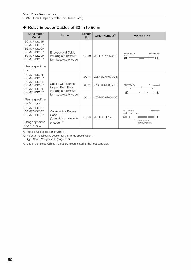
Direct Drive ServomotorsSGM7F (Small Capacity, with Core, Inner Rotor)
150
Relay Encoder Cables of 30 m to 50 m
*1. Flexible Cables are not available.
*2. Refer to the following section for the flange specifications.Model Designations (page 138)
*3. Use one of these Cables if a battery is connected to the host controller.
Servomotor Model
NameLength
(L) Order Number*1 Appearance
SGM7F-BFSGM7F-B7SGM7F-CFSGM7F-C7SGM7F-DFSGM7F-D7
Flange specifica-tion*2: 1
Encoder-end Cable (for single-turn/multi-turn absolute encoder)
0.3 m JZSP-C7PRC0-E
SGM7F-BFSGM7F-B7SGM7F-CFSGM7F-C7SGM7F-DFSGM7F-D7
Flange specifica-tion*2: 1 or 4
Cables with Connec-tors on Both Ends (for single-turn/multi-turn absolute encoder)
30 m JZSP-UCMP00-30-E
40 m JZSP-UCMP00-40-E
50 m JZSP-UCMP00-50-E
SGM7F-B7SGM7F-C7SGM7F-D7
Flange specifica-tion*2: 1 or 4
Cable with a Battery Case(for multiturn absolute encoder)*3
0.3 m JZSP-CSP12-E
SERVOPACK end
Encoder end
LSERVOPACK end
Encoder end
SERVOPACK end
Encoder end
Battery Case (battery included)

151
MEMO
SG
M7F

Direct Drive Servomotors
152
SGMCV (Small Capacity, with Core, Inner Rotor)
Model Designations
Note: Direct Drive Servomotors are not available with holding brakes.
B
D
E
I
1
5
1
4
4th digit 6th digit
3rd digit
7th digit
Mounting
Non-load side
Non-load side (with cable on side)
Options
Without optionsHigh machine precision (runout at end of shaft and runout of shaft surface: 0.01 mm)
22-bit single-turn absolute encoder
22-bit multiturn absolute encoder
A
5th digit Design Revision Order
Servomotor Outer Diameter
135-mm dia.
230-mm dia.
C 175-mm dia.
Serial Encoder Flange
SGMCV - 04 B E A 1 11st+2nd
digits
1st+2nd digits Rated Output
Code Specification
3rd digit
4th digit
5th digit
6th digit
7th digitDirect Drive
Servomotors: SGMCV
Code Code
Code
Code
Specification
Specification
Specification
04 4.00 Nm
08 8.00 Nm
10 10.0 Nm
14 14.0 Nm
17 17.0 Nm25 25.0 Nm
16 16.0 Nm
35 35.0 Nm
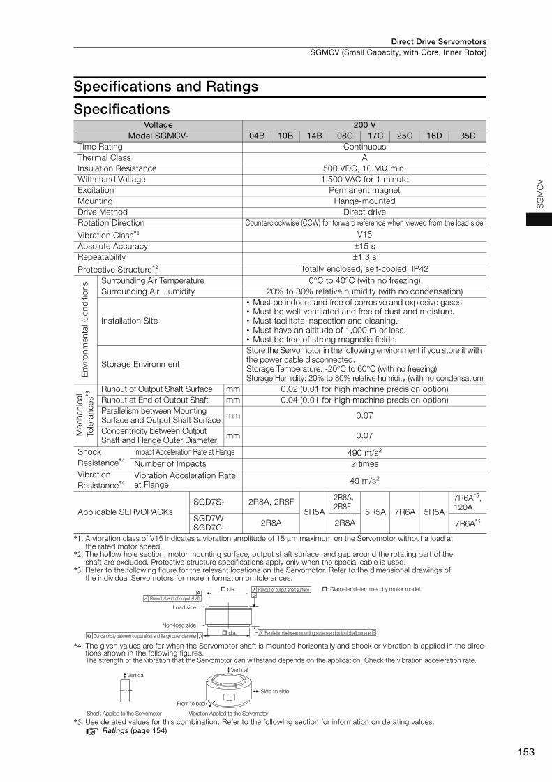
Direct Drive Servomotors SGMCV (Small Capacity, with Core, Inner Rotor)
153
SG
MC
V
Specifications and Ratings
Specifications
*1. A vibration class of V15 indicates a vibration amplitude of 15 μm maximum on the Servomotor without a load at the rated motor speed.
*2. The hollow hole section, motor mounting surface, output shaft surface, and gap around the rotating part of the shaft are excluded. Protective structure specifications apply only when the special cable is used.
*3. Refer to the following figure for the relevant locations on the Servomotor. Refer to the dimensional drawings of the individual Servomotors for more information on tolerances.
*4. The given values are for when the Servomotor shaft is mounted horizontally and shock or vibration is applied in the direc-tions shown in the following figures.The strength of the vibration that the Servomotor can withstand depends on the application. Check the vibration acceleration rate.
*5. Use derated values for this combination. Refer to the following section for information on derating values.Ratings (page 154)
Voltage 200 VModel SGMCV- 04B 10B 14B 08C 17C 25C 16D 35D
Time Rating Continuous Thermal Class AInsulation Resistance 500 VDC, 10 MΩ min. Withstand Voltage 1,500 VAC for 1 minute Excitation Permanent magnet Mounting Flange-mounted Drive Method Direct drive Rotation Direction Counterclockwise (CCW) for forward reference when viewed from the load side
Vibration Class*1 V15Absolute Accuracy ±15 s Repeatability ±1.3 s
Protective Structure*2 Totally enclosed, self-cooled, IP42
Env
ironm
enta
l Con
diti
ons Surrounding Air Temperature 0°C to 40°C (with no freezing)
Surrounding Air Humidity 20% to 80% relative humidity (with no condensation)
Installation Site
• Must be indoors and free of corrosive and explosive gases. • Must be well-ventilated and free of dust and moisture. • Must facilitate inspection and cleaning. • Must have an altitude of 1,000 m or less.• Must be free of strong magnetic fields.
Storage Environment
Store the Servomotor in the following environment if you store it with the power cable disconnected. Storage Temperature: -20°C to 60°C (with no freezing)Storage Humidity: 20% to 80% relative humidity (with no condensation)
Mec
hani
cal
Tol
eran
ces*3
Runout of Output Shaft Surface mm 0.02 (0.01 for high machine precision option) Runout at End of Output Shaft mm 0.04 (0.01 for high machine precision option) Parallelism between Mounting Surface and Output Shaft Surface mm 0.07
Concentricity between Output Shaft and Flange Outer Diameter mm 0.07
Shock Resistance*4
Impact Acceleration Rate at Flange 490 m/s2
Number of Impacts 2 times Vibration Resistance*4
Vibration Acceleration Rate at Flange 49 m/s2
Applicable SERVOPACKsSGD7S- 2R8A, 2R8F
5R5A
2R8A, 2R8F
5R5A 7R6A 5R5A
7R6A*5, 120A
SGD7W-SGD7C- 2R8A 2R8A 7R6A*5
A
A B
B
Runout at end of output shaft
dia.
Load side
Non-load side
Concentricity between output shaft and flange outer diameter dia. Parallelism between mounting surface and output shaft surface
Runout of output shaft surface : Diameter determined by motor model.
Side to side
Front to back
Vertical
Shock Applied to the Servomotor Vibration Applied to the Servomotor
Vertical

Direct Drive ServomotorsSGMCV (Small Capacity, with Core, Inner Rotor)
154
Ratings
*1. These values are for operation in combination with a SERVOPACK when the temperature of the armature wind-ing is 100°C. The values for other items are at 20°C. These are typical values.
*2. The rated torques are the continuous allowable torque values at a surrounding air temperature of 40°C with a steel heat sink of the dimensions given in the table.
*3. To externally connect dynamic brake resistor, select hardware option specification 020 for the SERVOPACK. However, you cannot externally connect dynamic brake resistor if you use the following SERVOPACKs (maximum applicable motor capacity: 400 W).• SGD7S-R70A020 to -2R8A020• SGD7W-1R6A20A020 to -2R8A20A020• SGD7C-1R6AMAA020 to -2R8AMAA020
*4. The thrust loads and moment loads that are applied while a Servomotor is operating are roughly classified into the following patterns. Design the machine so that the thrust loads or moment loads will not exceed the values given in the table.
*5. If you use an SGD7S-7R6A SERVOPACK and SGMCV-35D Servomotor together, use this value (a derated value).
Note: For the bearings used in these Servomotors, the loss depends on the bearing temperature. The amount of heat loss is higher at low temperatures.
Voltage 200 V
Model SGMCV- 04B 10B 14B 08C 17C 25C 16D 35D
Rated Output*1 W 126 314 440 251 534 785 5031100
1000*5
Rated Torque*1, *2 Nm 4.00 10.0 14.0 8.00 17.0 25.0 16.0 35.0
Instantaneous Maximum Torque*1 Nm 12.0 30.0 42.0 24.0 51.0 75.0 48.0 105
Stall Torque*1 Nm 4.00 10.0 14.0 8.00 17.0 25.0 16.0 35.0
Rated Current*1 Arms 2.0 2.8 4.6 2.4 4.5 5.0
Instantaneous Maximum Current*1 Arms 6.4 8.9 14.1 8.6 14.7 13.9 16.9 16.0
Rated Motor Speed*1 min-1 300 300300
270*5
Maximum Motor Speed*1 min-1 600 600 500 600 400
Torque Constant Nm/Arms 2.21 3.81 3.27 3.52 4.04 6.04 3.35 7.33
Motor Moment of Inertia ×10-4 kgm2 16.2 25.2 36.9 56.5 78.5 111 178 276
Rated Power Rate*1 kW/s 9.88 39.7 53.1 11.3 36.8 56.3 14.4 44.4
Rated Angular Acceleration Rate*1 rad/s2 2470 3970 3790 1420 2170 2250 899 1270
Heat Sink Size mm 350 × 350 × 12 450 × 450 × 12 550 × 550 × 12
Allowable Load Moment of Inertia (Motor Moment of Inertia Ratio)
25 times
40 times
45 times
15 times
25 times
25 times
10 times
15 times
With External Regenerative Resis-tor and External Dynamic Brake Resistor*3
25 times
40 times
45 times
15 times
25 times
25 times
10 times
15 times
Allowable Load*4
Allowable Thrust Load
N 1500 3300 4000
Allowable Moment Load
Nm 45 55 65 92 98 110 210 225
F
F
LF
L
Where F is the external force,Thrust load = F + Load mass Moment load = 0
Where F is the external force,Thrust load = F + Load massMoment load = F × L
Where F is the external force,Thrust load = Load massMoment load = F × L
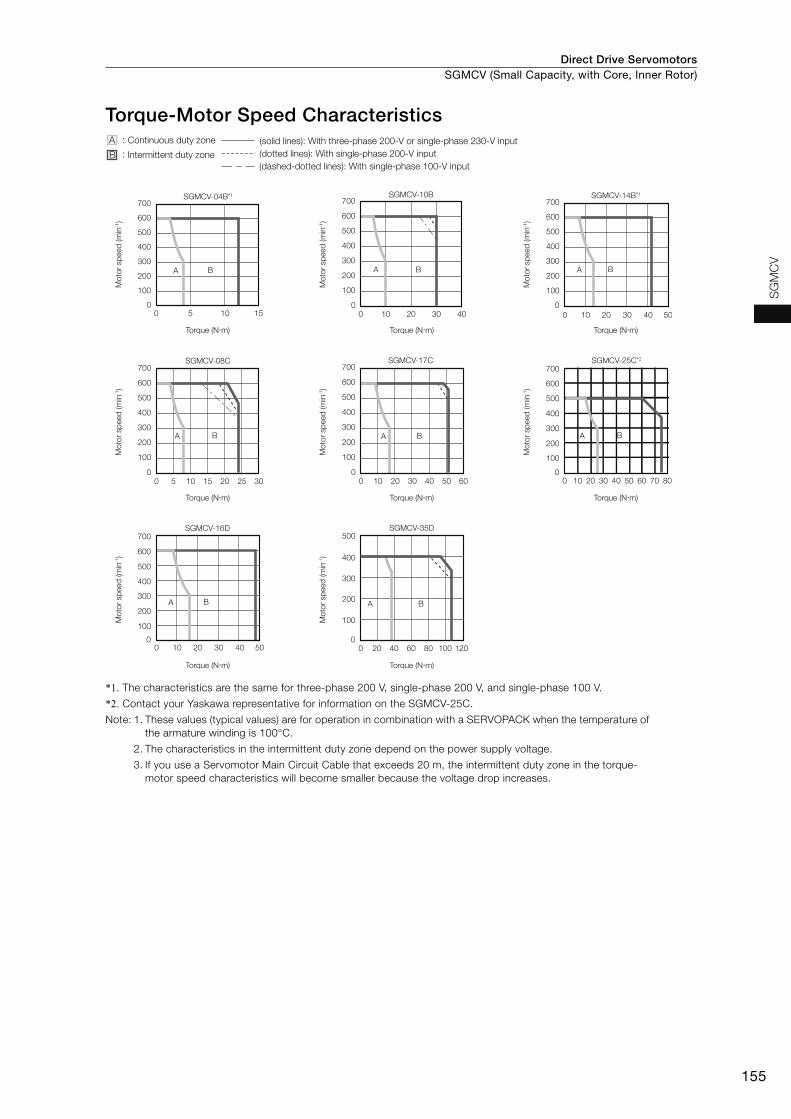
Direct Drive Servomotors SGMCV (Small Capacity, with Core, Inner Rotor)
155
SG
MC
V
Torque-Motor Speed Characteristics
*1. The characteristics are the same for three-phase 200 V, single-phase 200 V, and single-phase 100 V.
*2. Contact your Yaskawa representative for information on the SGMCV-25C.
Note: 1. These values (typical values) are for operation in combination with a SERVOPACK when the temperature of the armature winding is 100°C.
2. The characteristics in the intermittent duty zone depend on the power supply voltage.
3. If you use a Servomotor Main Circuit Cable that exceeds 20 m, the intermittent duty zone in the torque-motor speed characteristics will become smaller because the voltage drop increases.
SGMCV-08C
0 5 10 15 20 25 300
100
200
300
400
500
600
700
A B
SGMCV-17C
0 10 20 30 40 50 600
100
200
300
400
500
600
700
A B
SGMCV-04B*1
0
100
200
300
400
500
600
700
0 5 10 15
A B
SGMCV-25C*2
0 10 20 30 40 50 60 70 800
100
200
300
400
500
600
700
A B
SGMCV-10B
0 10 20 30 400
100
200
300
400
500
600
700
A B
SGMCV-14B*1
0 10 20 30 40 500
100
200
300
400
500
600
700
A B
SGMCV-16D
0 10 20 30 40 500
100
200
300
400
500
600
700SGMCV-35D
A B
0 20 40 60 80 100 1200
100
200
300
400
500
A B
A :
B :(dashed-dotted lines): With single-phase 100-V input
(solid lines): With three-phase 200-V or single-phase 230-V input(dotted lines): With single-phase 200-V inputIntermittent duty zone
Continuous duty zone
Torque (N�m)
Mot
or s
peed
(min
-1)
Torque (N�m)M
otor
spe
ed (m
in-1)
Torque (N�m)
Mot
or s
peed
(min
-1)
Torque (N�m)
Mot
or s
peed
(min
-1)
Torque (N�m)
Mot
or s
peed
(min
-1)
Torque (N�m)
Mot
or s
peed
(min
-1)
Torque (N�m)
Mot
or s
peed
(min
-1)
Torque (N�m)
Mot
or s
peed
(min
-1)
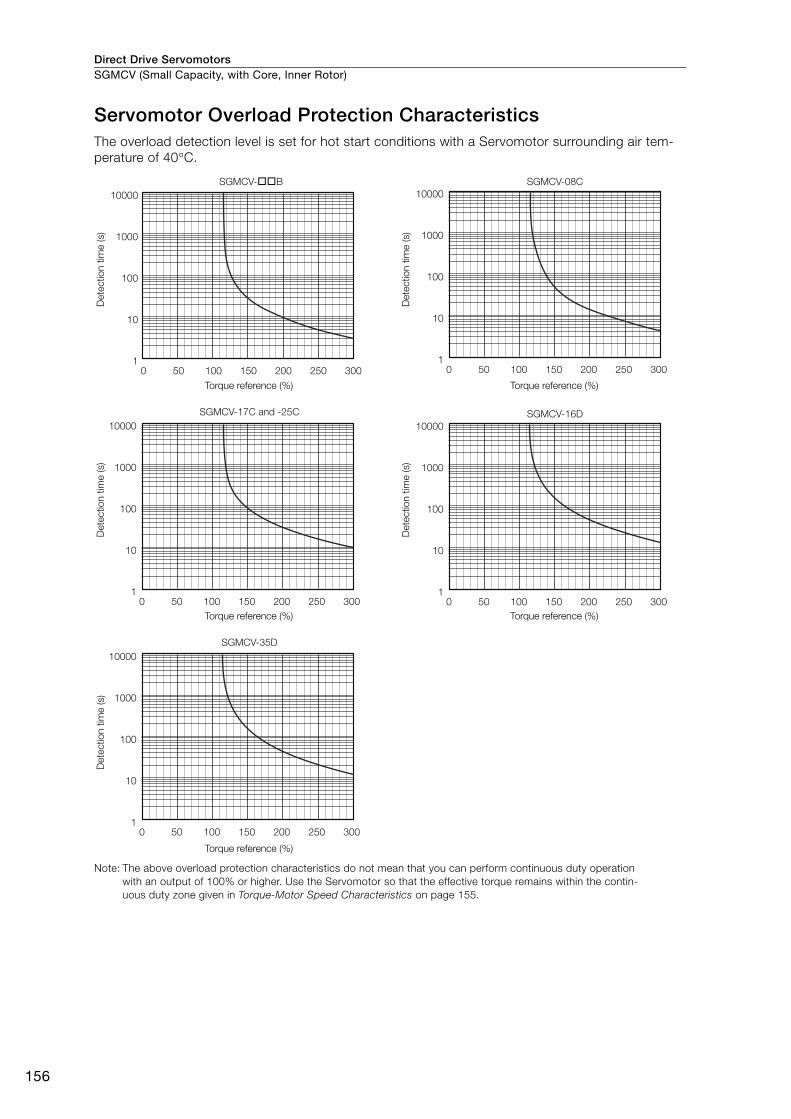
Direct Drive ServomotorsSGMCV (Small Capacity, with Core, Inner Rotor)
156
Servomotor Overload Protection Characteristics The overload detection level is set for hot start conditions with a Servomotor surrounding air tem-perature of 40°C.
Note: The above overload protection characteristics do not mean that you can perform continuous duty operation with an output of 100% or higher. Use the Servomotor so that the effective torque remains within the contin-uous duty zone given in Torque-Motor Speed Characteristics on page 155.
10000
1000
100
10
1
SGMCV-��B SGMCV-08C
0 50 100 150 200 250 300
10000
1000
100
10
1
SGMCV-17C and -25C
0 50 100 150 200 250 300
10000
1000
100
10
1
SGMCV-35D
0 50 100 150 200 250 300
10000
1000
100
10
10 50 100 150 200 250 300
SGMCV-16D10000
1000
100
10
10 50 100 150 200 250 300
Det
ectio
n tim
e (s
)
Torque reference (%)
Det
ectio
n tim
e (s
)
Torque reference (%)
Det
ectio
n tim
e (s
)
Torque reference (%)
Det
ectio
n tim
e (s
)
Torque reference (%)
Det
ectio
n tim
e (s
)
Torque reference (%)
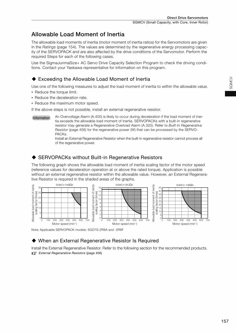
Direct Drive Servomotors SGMCV (Small Capacity, with Core, Inner Rotor)
157
SG
MC
V
Allowable Load Moment of InertiaThe allowable load moments of inertia (motor moment of inertia ratios) for the Servomotors are given in the Ratings (page 154). The values are determined by the regenerative energy processing capac-ity of the SERVOPACK and are also affected by the drive conditions of the Servomotor. Perform the required Steps for each of the following cases.
Use the SigmaJunmaSize+ AC Servo Drive Capacity Selection Program to check the driving condi-tions. Contact your Yaskawa representative for information on this program.
Exceeding the Allowable Load Moment of InertiaUse one of the following measures to adjust the load moment of inertia to within the allowable value.• Reduce the torque limit.• Reduce the deceleration rate.• Reduce the maximum motor speed.
If the above steps is not possible, install an external regenerative resistor.
SERVOPACKs without Built-in Regenerative Resistors The following graph shows the allowable load moment of inertia scaling factor of the motor speed (reference values for deceleration operation at or above the rated torque). Application is possible without an external regenerative resistor within the allowable value. However, an External Regenera-tive Resistor is required in the shaded areas of the graphs.
Note: Applicable SERVOPACK models: SGD7S-2R8A and -2R8F
When an External Regenerative Resistor Is RequiredInstall the External Regenerative Resistor. Refer to the following section for the recommended products.
External Regenerative Resistors (page 456)
An Overvoltage Alarm (A.400) is likely to occur during deceleration if the load moment of iner-tia exceeds the allowable load moment of inertia. SERVOPACKs with a built-in regenerative resistor may generate a Regenerative Overload Alarm (A.320). Refer to Built-In Regenerative Resistor (page 456) for the regenerative power (W) that can be processed by the SERVO-PACKs.Install an External Regenerative Resistor when the built-in regenerative resistor cannot process all of the regenerative power.
Information
0
5
10
15
20
25
30
0 100 200 300 400 500 600 700 0 100 200 300 400 500 600 700 0 100 200 300 400 500 600 700
SGMCV-04B�A
0
2
4
6
8
10
12
14
16SGMCV-08C�A
05
1015202530354045
SGMCV-10B�A
Motor speed (min-1)
Allo
wab
le lo
ad m
omen
t of i
nerti
a sc
alin
g fa
ctor
(tim
es)
Motor speed (min-1)
Allo
wab
le lo
ad m
omen
t of i
nerti
a sc
alin
g fa
ctor
(tim
es)
Motor speed (min-1)
Allo
wab
le lo
ad m
omen
t of i
nerti
a sc
alin
g fa
ctor
(tim
es)

Direct Drive ServomotorsSGMCV (Small Capacity, with Core, Inner Rotor)
158
External Dimensions
SGMCV-B• Flange Specification 1
*1. The shaded section indicates the rotating parts.
*2. The hatched section indicates the non-rotating parts.
Note: Values in parentheses are reference dimensions.
• Flange Specification 4
*1. The shaded section indicates the rotating parts.
*2. The hatched section indicates the non-rotating parts.
Note: Values in parentheses are reference dimensions.
Refer to the following section for information on connectors. Connector Specifications (page 161)
Model SGMCV- L (LL) LB LH LA Approx. Mass [kg]
04BA11 60 53.3 120 25 78 5.0
10BA11 85 78.3 120 25 78 6.5
14BA11 115 108.3 120 25 78 9.0
Model SGMCV- L (LL) LB LH LA Approx. Mass [kg]
04BA41 60 53.3 120 25 78 5.0
10BA41 85 78.3 120 25 78 6.5
14BA41 115 108.3 120 25 78 9.0
23
.425.4
(1)
2.74
90°
R26.5
(LL)L
(9)
(0.1)
A0.04
B0.02
A
0.07 B
*1
*2
6 × M5 × 8 (Divided into equal sections at 60°.)
(82
dia.
)
134
dia.
(58.
5 di
a.)
LB d
ia.
135
dia.
0.07 dia. 6 × M5 × 8 (Divided into equal sections at 60°.)
(2 × M5 × 8) (For use by Yaskawa)
70 dia.
Unit: mm
90 d
ia.
LA d
ia.
LH d
ia.
Notation: Square dimensions
0-0.035
+0.3+0.1
0-0.030
0-0.035
+0.3+0.1
0-0.030
0-0.035
+0.3+0.1
0-0.030
(1)
2.7(LL)L
300±50
(35)
18
4
(0.1)
43.524.5
10(2
2)
A0.04
B
0.020.07 B
A
90 dia.
*1
*2
6 × M5 × 8 (Divided into equal sections at 60°.)
0.07 dia.
(2 × M5 × 8) (For use by Yaskawa)
134
dia.
(58.
5 di
a.)
LH d
ia.
(80
dia.
)
135
dia.
6 × M5 × 8 (Divided into equal sections at 60°.)
(2 × M5 × 8) (For use by Yaskawa)
Unit: mm
70 dia.
LB d
ia.
LA d
ia.
0-0.035
+0.3+0.1
0-0.030
0-0.035
+0.3+0.1
0-0.030
0-0.035
+0.3+0.1
0-0.030

Direct Drive Servomotors SGMCV (Small Capacity, with Core, Inner Rotor)
159
SG
MC
V
SGMCV-C
• Flange Specification 1
*1. The shaded section indicates the rotating parts.
*2. The hatched section indicates the non-rotating parts.
Note: Values in parentheses are reference dimensions.
• Flange Specification 4
*1. The shaded section indicates the rotating parts.
*2. The hatched section indicates the non-rotating parts.
Note: Values in parentheses are reference dimensions.
Refer to the following section for information on connectors.Connector Specifications (page 161)
Model SGMCV- L (LL) LB LH LA Approx. Mass [kg]
08CA11 73 65.3 160 40 107 9.0
17CA11 87 79.3 160 40 107 11.0
25CA11 117 109.3 160 40 107 15.0
Model SGMCV- L (LL) LB LH LA Approx. Mass [kg]
08CA41 73 65.3 160 40 107 9.0
17CA41 87 79.3 160 40 107 11.0
25CA41 117 109.3 160 40 107 15.0
23
.4
25.4
2.75
R43(0.1) (1)
90°
L
(LL)
(9)
B
0.02
A0.04
0.07 B
A
173
dia.
*1
*2
130
dia.
6 × M6 × 9 (Divided into equal sections at 60°.)
98 dia.
(2 × M6 × 9) (For use by Yaskawa)
Unit: mm
(2 × M6 × 9) (For use by Yaskawa)
LA d
ia.
(84
dia.
)
(116
dia
.)
175
dia.
0.07 dia.
LB d
ia.
LH d
ia.
6 × M6 × 9 (Divided into equal sections at 60°.)
0-0.040
+0.3+0.1
0-0.035
0-0.040
+0.3+0.1
0-0.035
0-0.040
+0.3+0.1
0-0.035
B0.022.75
1
(0.1) (1)
L
18
300±50
(LL)
24.5
(22)
43.5
10
(35)
0.07 B
A
A0.04
*1
*2
6 × M6 × 9 (Divided into equal sections at 60°.)
(2 × M6 × 9) (For use by Yaskawa)
173
dia.
(84
dia.
)
175
dia.
130 dia.
6 × M6 × 9 (Divided into equal sections at 60°.)
98 dia.
(2 × M6 × 9) (For use by Yaskawa)
Unit: mm
(110
dia
.)
0.07 dia.
LB d
ia.
LH d
ia.
LA d
ia.
0-0.040
+0.3+0.1
0-0.035
0-0.040
+0.3+0.1
0-0.035
0-0.040
+0.3+0.1
0-0.035
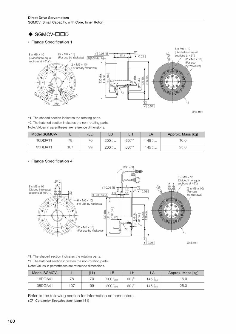
Direct Drive ServomotorsSGMCV (Small Capacity, with Core, Inner Rotor)
160
SGMCV-D
• Flange Specification 1
*1. The shaded section indicates the rotating parts.
*2. The hatched section indicates the non-rotating parts.
Note: Values in parentheses are reference dimensions.
• Flange Specification 4
*1. The shaded section indicates the rotating parts.
*2. The hatched section indicates the non-rotating parts.
Note: Values in parentheses are reference dimensions.
Refer to the following section for information on connectors.Connector Specifications (page 161)
Model SGMCV- L (LL) LB LH LA Approx. Mass [kg]
16DA11 78 70 200 60 145 16.0
35DA11 107 99 200 60 145 25.0
Model SGMCV- L (LL) LB LH LA Approx. Mass [kg]
16DA41 78 70 200 60 145 16.0
35DA41 107 99 200 60 145 25.0
Unit: mm
60°
�25.4 �23.4
8 × M6 × 10(Divided into equal sections at 45°.)
(2 × M6 × 10)(For use by Yaskawa)
(6 × M6 × 10)(For use by Yaskawa)
R55R55
160 dia.160 dia.160 dia.
R55
L(LL)5 3
B0.02
A0.04
230
dia.
LB d
ia.
(140
dia
.)
(0.1)(9.2) 22
8 di
a.LA
dia
.(1
20 d
ia.)
LH d
ia.
(1)
0.08 B
A0.08 dia.
*2
8 × M6 × 10(Divided into equal sections at 45°.)
(2 × M6 × 10)(For use by Yaskawa)
*1
135 dia.
0-0.046
+0.40
0-0.040
0-0.046
+0.40
0-0.040
Unit: mm
24.543.5
(6 × M6 × 10)(For use by Yaskawa)
(2 × M6 × 10)(For use by Yaskawa)
8 × M6 × 10(Divided into equal sections at 45°.) (2
2)10
(1)
228
dia.
LA d
ia.
(120
dia
.)
LH d
ia.
0.08 B
A0.08 dia.
(0.1)230
dia.
LB d
ia.
(140
dia
.)
300 ±50
(35)
(LL)L
318
52.5
A0.04
B0.02
*2
8 × M6 × 10(Divided into equal sections at 45°.)
(2 × M6 × 10)(For use by Yaskawa)
135 dia.
*1
160 d
ia.160 d
ia.160 d
ia.
0-0.046
+0.40
0-0.040
0-0.046
+0.40
0-0.040

Direct Drive Servomotors SGMCV (Small Capacity, with Core, Inner Rotor)
161
SG
MC
V
Connector Specifications
Flange Specification 1
Flange Specification 4
• Servomotor Connector • Encoder Connector
Model: JN1AS04MK2RManufacturer: Japan Aviation Electronics Industry, Ltd.
Mating connector: JN1DS04FK1 (Not provided by Yaskawa.)
* Only absolute-value models with multiturn data.
Model: JN1AS10ML1-R Manufacturer: Japan Aviation Electronics Industry, Ltd.
Mating connector: JN1DS10SL1 (Not provided by Yaskawa.)
• Servomotor Connector • Encoder Connector
Models • Plug: 350779-1 • Pins: 350561-3 or 350690-3 (No.1 to 3) • Ground pin: 350654-1 or 350669-1 (No. 4) Manufacturer: Tyco Electronics Japan G.K.
Mating Connector • Cap: 350780-1 • Socket: 350570-3 or 350689-3
* Only absolute-value models with multiturn data.
Model: 55102-0600Manufacturer: Molex Japan LLC
Mating connector: 54280-0609
1
3
2
4
1 Phase U Red2 Phase V White3 Phase W Blue4 FG (frame ground) Green (yellow)
1 3
4 7
8 10
1 PS Not used 6 − −
2 /PS Light blue/white 7 FG (frame
ground) Shield
3 − − 8* BAT Orange4 PG5V Red 9 PG0V Black
5* BAT0 Orange/white 10 − −
1
2
3
4
1 Phase U Red2 Phase V White3 Phase W Blue4 FG (frame ground) Green (yellow) 4
2
6
3
1
51 PG5V Red2 PG0V Black3* BAT Orange
4* BAT0 Orange/white
5 PS Light blue
6 /PS Light blue/white
Connector case FG (frame ground) Shield
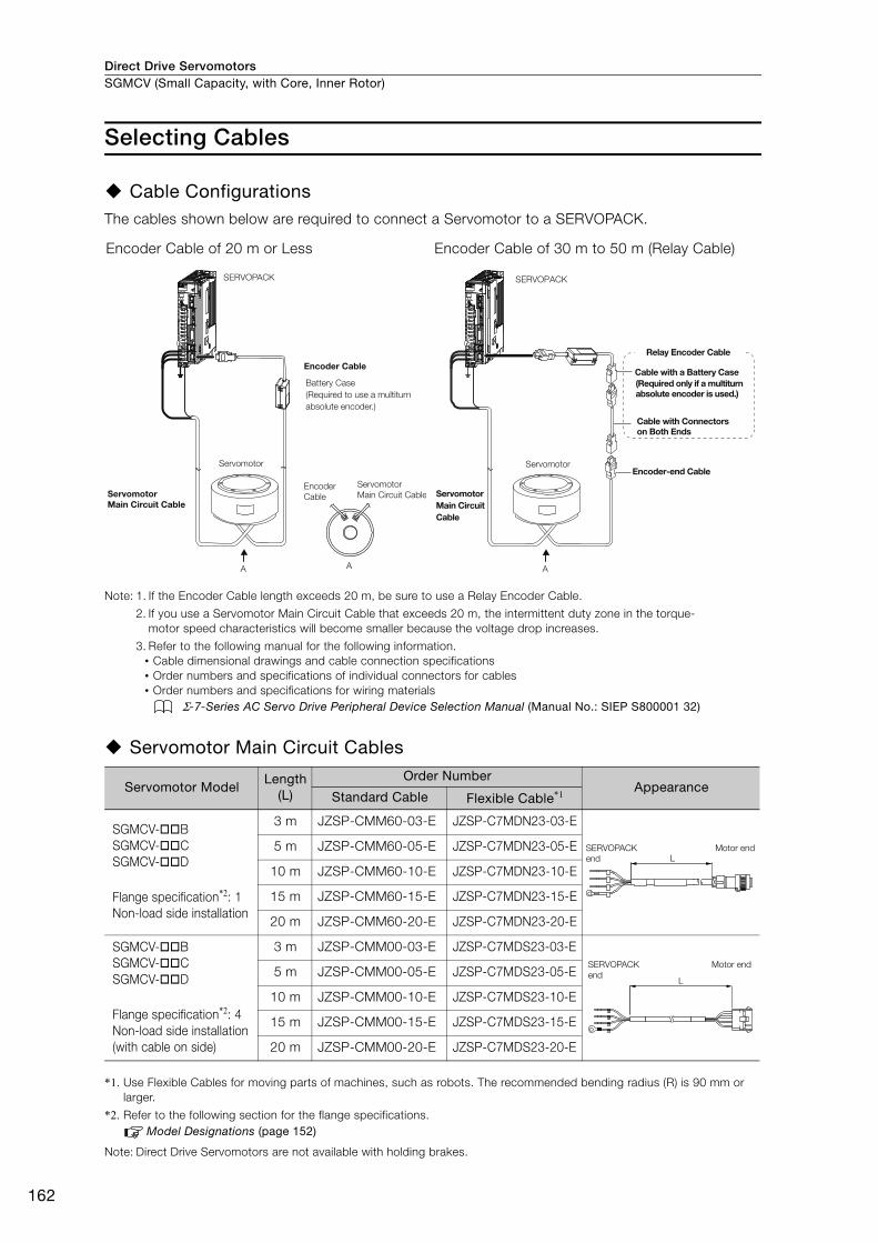
Direct Drive ServomotorsSGMCV (Small Capacity, with Core, Inner Rotor)
162
Selecting Cables
Cable ConfigurationsThe cables shown below are required to connect a Servomotor to a SERVOPACK.
Note: 1. If the Encoder Cable length exceeds 20 m, be sure to use a Relay Encoder Cable.
2. If you use a Servomotor Main Circuit Cable that exceeds 20 m, the intermittent duty zone in the torque-motor speed characteristics will become smaller because the voltage drop increases.
3. Refer to the following manual for the following information.• Cable dimensional drawings and cable connection specifications• Order numbers and specifications of individual connectors for cables• Order numbers and specifications for wiring materials
Σ-7-Series AC Servo Drive Peripheral Device Selection Manual (Manual No.: SIEP S800001 32)
Servomotor Main Circuit Cables
*1. Use Flexible Cables for moving parts of machines, such as robots. The recommended bending radius (R) is 90 mm or larger.
*2. Refer to the following section for the flange specifications.Model Designations (page 152)
Note: Direct Drive Servomotors are not available with holding brakes.
Encoder Cable of 20 m or Less Encoder Cable of 30 m to 50 m (Relay Cable)
Servomotor ModelLength
(L)
Order NumberAppearance
Standard Cable Flexible Cable*1
SGMCV-BSGMCV-CSGMCV-D
Flange specification*2: 1Non-load side installation
3 m JZSP-CMM60-03-E JZSP-C7MDN23-03-E
5 m JZSP-CMM60-05-E JZSP-C7MDN23-05-E
10 m JZSP-CMM60-10-E JZSP-C7MDN23-10-E
15 m JZSP-CMM60-15-E JZSP-C7MDN23-15-E
20 m JZSP-CMM60-20-E JZSP-C7MDN23-20-E
SGMCV-BSGMCV-CSGMCV-D
Flange specification*2: 4Non-load side installation (with cable on side)
3 m JZSP-CMM00-03-E JZSP-C7MDS23-03-E
5 m JZSP-CMM00-05-E JZSP-C7MDS23-05-E
10 m JZSP-CMM00-10-E JZSP-C7MDS23-10-E
15 m JZSP-CMM00-15-E JZSP-C7MDS23-15-E
20 m JZSP-CMM00-20-E JZSP-C7MDS23-20-E
SERVOPACK
Encoder Cable
Encoder Cable
Servomotor
Servomotor Main Circuit Cable
Servomotor Main Circuit Cable
A A
Battery Case(Required to use a multiturn absolute encoder.)
SERVOPACK
Cable with a Battery Case(Required only if a multiturn absolute encoder is used.)
Cable with Connectors on Both Ends
Encoder-end CableServomotor
Servomotor Main Circuit Cable
A
Relay Encoder Cable
LSERVOPACK end
Motor end
L
SERVOPACK end
Motor end

Direct Drive Servomotors SGMCV (Small Capacity, with Core, Inner Rotor)
163
SG
MC
V
Encoder Cables of 20 m or Less
*1. Use Flexible Cables for moving parts of machines, such as robots. The recommended bending radius (R) is 68 mm or larger.
*2. Refer to the following section for the flange specifications.Model Designations (page 152)
*3. Use one of these Cables if a battery is connected to the host controller.
Servomotor Model NameLength
(L)
Order NumberAppearance
Standard Cable Flexible Cable*1
SGMCV-BESGMCV-CESGMCV-DE
Flange specifica-tion*2: 1
For single-turn abso-lute encoder(without Battery Case)
3 m JZSP-CMP60-03-E JZSP-CSP60-03-E
5 m JZSP-CMP60-05-E JZSP-CSP60-05-E
10 m JZSP-CMP60-10-E JZSP-CSP60-10-E
15 m JZSP-CMP60-15-E JZSP-CSP60-15-E
20 m JZSP-CMP60-20-E JZSP-CSP60-20-E
SGMCV-BESGMCV-CESGMCV-DE
Flange specifica-tion*2: 4
3 m JZSP-CMP00-03-E JZSP-CMP10-03-E
5 m JZSP-CMP00-05-E JZSP-CMP10-05-E
10 m JZSP-CMP00-10-E JZSP-CMP10-10-E
15 m JZSP-CMP00-15-E JZSP-CMP10-15-E
20 m JZSP-CMP00-20-E JZSP-CMP10-20-E
SGMCV-BISGMCV-CISGMCV-DI
Flange specifica-tion*2: 1
For multi-turn abso-lute encoder (without Battery Case*3)
3 m JZSP-C7PI00-03-E JZSP-C7PI20-03-E
5 m JZSP-C7PI00-05-E JZSP-C7PI20-05-E
10 m JZSP-C7PI00-10-E JZSP-C7PI20-10-E
15 m JZSP-C7PI00-15-E JZSP-C7PI20-15-E
20 m JZSP-C7PI00-20-E JZSP-C7PI20-20-E
For multi-turn abso-lute encoder(with Bat-tery Case)
3 m JZSP-C7PA00-03-E JZSP-C7PA20-03-E
5 m JZSP-C7PA00-05-E JZSP-C7PA20-05-E
10 m JZSP-C7PA00-10-E JZSP-C7PA20-10-E
15 m JZSP-C7PA00-15-E JZSP-C7PA20-15-E
20 m JZSP-C7PA00-20-E JZSP-C7PA20-20-E
SGMCV-BISGMCV-CISGMCV-DI
Flange specifica-tion*2: 4
For multi-turn abso-lute encoder (without Battery Case*3)
3 m JZSP-CMP00-03-E JZSP-CMP10-03-E
5 m JZSP-CMP00-05-E JZSP-CMP10-05-E
10 m JZSP-CMP00-10-E JZSP-CMP10-10-E
15 m JZSP-CMP00-15-E JZSP-CMP10-15-E
20 m JZSP-CMP00-20-E JZSP-CMP10-20-E
For multi-turn abso-lute encoder(with Bat-tery Case)
3 m JZSP-CSP19-03-E JZSP-CSP29-03-E
5 m JZSP-CSP19-05-E JZSP-CSP29-05-E
10 m JZSP-CSP19-10-E JZSP-CSP29-10-E
15 m JZSP-CSP19-15-E JZSP-CSP29-15-E
20 m JZSP-CSP19-20-E JZSP-CSP29-20-E
L
SERVOPACK end
Encoder end
LSERVOPACK end
Encoder end
L
SERVOPACK end
Encoder end
SERVOPACK end
Encoder end
Battery Case (battery included)
L
LSERVOPACK end
Encoder end
SERVOPACK end
Encoder end
Battery Case (battery included)
L

Direct Drive ServomotorsSGMCV (Small Capacity, with Core, Inner Rotor)
164
Relay Encoder Cables of 30 m to 50 m
*1. Flexible Cables are not available.
*2. Refer to the following section for the flange specifications.Model Designations (page 152)
*3. Use one of these Cables if a battery is connected to the host controller.
Servomotor Model
NameLength
(L) Order Number*1 Appearance
SGMCV-BESGMCV-BISGMCV-CESGMCV-CISGMCV-DESGMCV-DI
Flange specifica-tion*2: 1
Encoder-end Cable (for single-turn/multi-turn absolute encoder)
0.3 m JZSP-C7PRC0-E
SGMCV-BESGMCV-BISGMCV-CESGMCV-CISGMCV-DESGMCV-DI
Flange specifica-tion*2: 1 or 4
Cables with Connec-tors on Both Ends (for single-turn/multi-turn absolute encoder)
30 m JZSP-UCMP00-30-E
40 m JZSP-UCMP00-40-E
50 m JZSP-UCMP00-50-E
SGMCV-BISGMCV-CISGMCV-DI
Flange specifica-tion*2: 1 or 4
Cable with a Battery Case(for multiturn absolute encoder)*3
0.3 m JZSP-CSP12-E
SERVOPACK end
Encoder end
LSERVOPACK end
Encoder end
SERVOPACK end
Encoder end
Battery Case (battery included)
165
MEMO
SG
MC
V
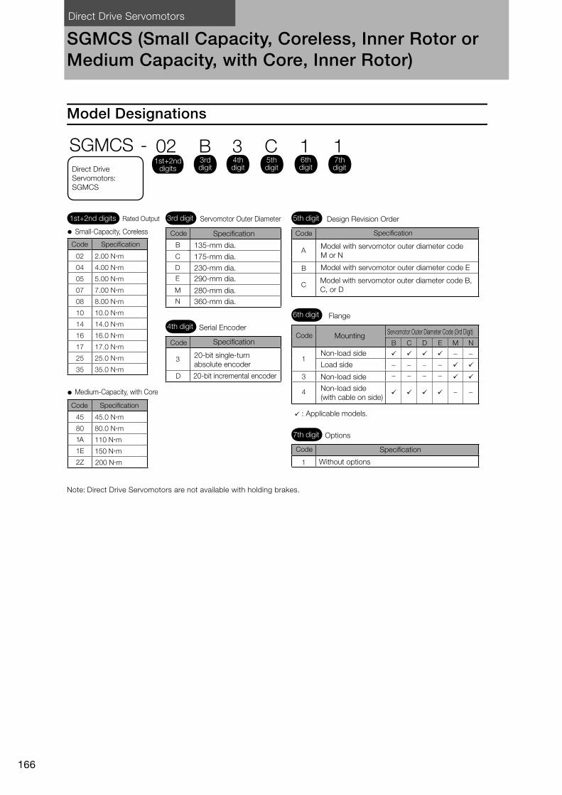
Direct Drive Servomotors
166
SGMCS (Small Capacity, Coreless, Inner Rotor or Medium Capacity, with Core, Inner Rotor)
Model Designations
Note: Direct Drive Servomotors are not available with holding brakes.
A
B
C
B
C
D
E
M
N
3
D
B
C
D
E
M
N
1
3
4
1
1A 110 Nm
1E 150 Nm
2Z 200 Nm
3rd digit 5th digit
6th digit
7th digit
Small-Capacity, Coreless
Medium-Capacity, with Core
Model with servomotor outer diameter code M or N
Model with servomotor outer diameter code E
Model with servomotor outer diameter code B, C, or D
135-mm dia.
Specification
175-mm dia.
230-mm dia.290-mm dia.
280-mm dia.360-mm dia.
Servomotor Outer Diameter
4th digit Serial Encoder
Specification
20-bit single-turn absolute encoder
20-bit incremental encoder
Design Revision Order
Flange
Mounting
Non-load side
Load side
Non-load side
Non-load side (with cable on side)
: Applicable models.
Options
Without options
Servomotor Outer Diameter Code (3rd Digit)
SGMCS - 02 B 3 C 1 11st+2nd
digits
1st+2nd digits Rated Output
Specification
Code Specification
3rd digit
4th digit
5th digit
6th digit
7th digitDirect Drive
Servomotors: SGMCS
Code
Code Specification
SpecificationCode
Code
Code
Code
02 2.00 Nm
04 4.00 Nm
05 5.00 Nm
07 7.00 Nm
08 8.00 Nm
10 10.0 Nm
14 14.0 Nm
16 16.0 Nm
17 17.0 Nm
25 25.0 Nm
35 35.0 Nm
45 45.0 Nm
80 80.0 Nm

Direct Drive Servomotors SGMCS (Small Capacity, Coreless, Inner Rotor or Medium Capacity, with Core, Inner Rotor)
167
SG
MC
S
Specifications and Ratings
Small-Capacity, Coreless Servomotors: Specifications
*1. A vibration class of V15 indicates a vibration amplitude of 15 μm maximum on the Servomotor without a load at the rated motor speed.
*2. The hollow hole section, motor mounting surface, output shaft surface, and gap around the rotating part of the shaft are excluded. Protective structure specifications apply only when the special cable is used.
*3. Refer to the following figure for the relevant locations on the Servomotor. Refer to the dimensional drawings of the individual Servomotors for more information on tolerances.
*4. The given values are for when the Servomotor shaft is mounted horizontally and shock or vibration is applied in the directions shown in the following figures.The strength of the vibration that the Servomotor can withstand depends on the application. Check the vibration acceleration rate.
Voltage 200 VModel SGMCS- 02B 05B 07B 04C 10C 14C 08D 17D 25D 16E 35E
Time Rating Continuous Thermal Class AInsulation Resistance 500 VDC, 10 MΩ min. Withstand Voltage 1,500 VAC for 1 minute Excitation Permanent magnet Mounting Flange-mounted Drive Method Direct drive Rotation Direction Counterclockwise (CCW) for forward reference when viewed from the load side
Vibration Class*1 V15
Absolute Accuracy ±15 s Repeatability ±1.3 s
Protective Structure*2 Totally enclosed, self-cooled, IP42
Env
ironm
enta
l Con
diti
ons
Surrounding Air Temperature 0°C to 40°C (with no freezing) Surrounding Air Humidity 20% to 80% relative humidity (with no condensation)
Installation Site
• Must be indoors and free of corrosive and explosive gases. • Must be well-ventilated and free of dust and moisture. • Must facilitate inspection and cleaning. • Must have an altitude of 1,000 m or less.• Must be free of strong magnetic fields.
Storage Environment
Store the Servomotor in the following environment if you store it with the power cable disconnected.Storage Temperature: -20°C to 60°C (with no freezing) Storage Humidity: 20% to 80% relative humidity (with no condensation)
Mec
hani
cal
Tol
eran
ces*3
Runout of Output Shaft Surface mm 0.02Runout at End of Output Shaft mm 0.04Parallelism between Mounting Surface and Output Shaft Surface
mm 0.07 0.08
Concentricity between Output Shaft and Flange Outer Diameter
mm 0.07 0.08
Shock Resistance*4
Impact Acceleration Rate at Flange 490 m/s2
Number of Impacts 2 times Vibration Resistance*4
Vibration Acceleration Rate at Flange 49 m/s2
Applicable SERVOPACKs
SGD7S- 2R8A, 2R1F 2R8A, 2R8F5R5ASGD7W-
SGD7C-2R8A
A
AB
B
dia.
dia.
Runout of output shaft surface
Parallelism between mounting surface and output shaft surface
Runout at end of output shaft
Load side
Non-load side
Concentricity between output shaft and flange outer diameter
: Diameter determined by motor model.
Side to side
Front to back
Vertical
Shock Applied to the Servomotor Vibration Applied to the Servomotor
Vertical
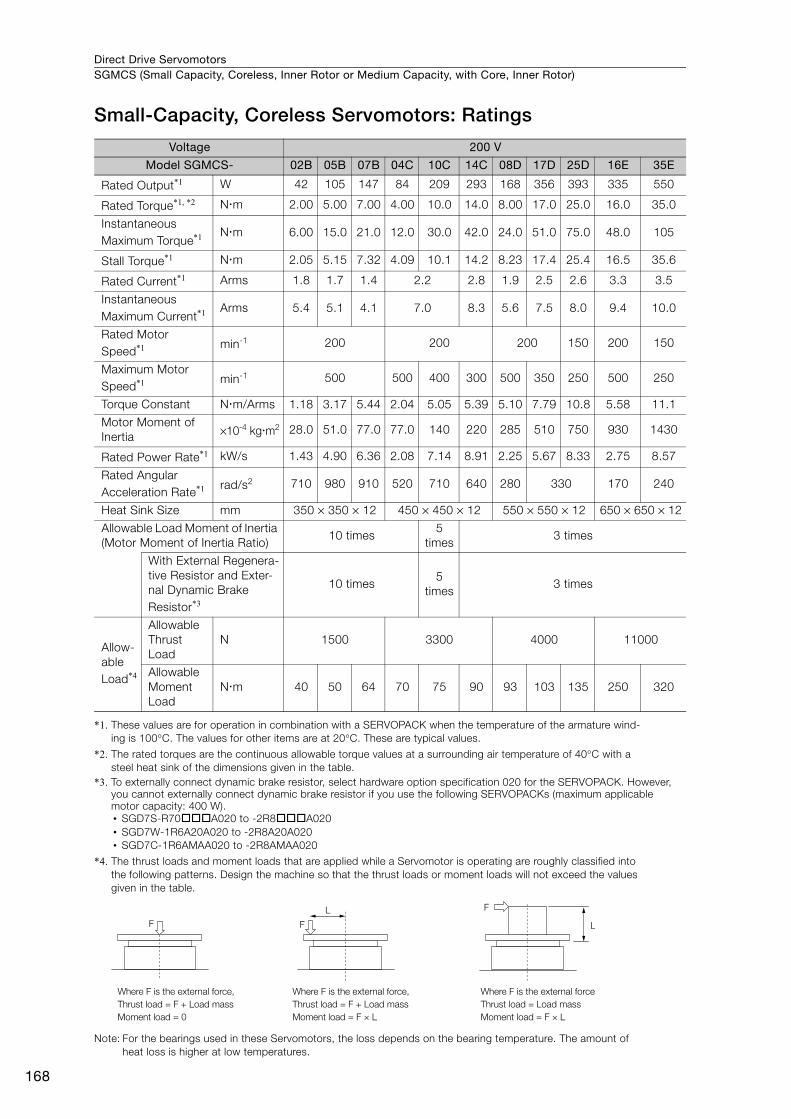
Direct Drive ServomotorsSGMCS (Small Capacity, Coreless, Inner Rotor or Medium Capacity, with Core, Inner Rotor)
168
Small-Capacity, Coreless Servomotors: Ratings
*1. These values are for operation in combination with a SERVOPACK when the temperature of the armature wind-ing is 100°C. The values for other items are at 20°C. These are typical values.
*2. The rated torques are the continuous allowable torque values at a surrounding air temperature of 40°C with a steel heat sink of the dimensions given in the table.
*3. To externally connect dynamic brake resistor, select hardware option specification 020 for the SERVOPACK. However, you cannot externally connect dynamic brake resistor if you use the following SERVOPACKs (maximum applicable motor capacity: 400 W).• SGD7S-R70A020 to -2R8A020• SGD7W-1R6A20A020 to -2R8A20A020• SGD7C-1R6AMAA020 to -2R8AMAA020
*4. The thrust loads and moment loads that are applied while a Servomotor is operating are roughly classified into the following patterns. Design the machine so that the thrust loads or moment loads will not exceed the values given in the table.
Note: For the bearings used in these Servomotors, the loss depends on the bearing temperature. The amount of heat loss is higher at low temperatures.
Voltage 200 V
Model SGMCS- 02B 05B 07B 04C 10C 14C 08D 17D 25D 16E 35E
Rated Output*1 W 42 105 147 84 209 293 168 356 393 335 550
Rated Torque*1, *2 Nm 2.00 5.00 7.00 4.00 10.0 14.0 8.00 17.0 25.0 16.0 35.0
Instantaneous Maximum Torque*1 Nm 6.00 15.0 21.0 12.0 30.0 42.0 24.0 51.0 75.0 48.0 105
Stall Torque*1 Nm 2.05 5.15 7.32 4.09 10.1 14.2 8.23 17.4 25.4 16.5 35.6
Rated Current*1 Arms 1.8 1.7 1.4 2.2 2.8 1.9 2.5 2.6 3.3 3.5
Instantaneous Maximum Current*1 Arms 5.4 5.1 4.1 7.0 8.3 5.6 7.5 8.0 9.4 10.0
Rated Motor Speed*1 min-1 200 200 200 150 200 150
Maximum Motor Speed*1 min-1 500 500 400 300 500 350 250 500 250
Torque Constant Nm/Arms 1.18 3.17 5.44 2.04 5.05 5.39 5.10 7.79 10.8 5.58 11.1
Motor Moment of Inertia ×10-4 kgm2 28.0 51.0 77.0 77.0 140 220 285 510 750 930 1430
Rated Power Rate*1 kW/s 1.43 4.90 6.36 2.08 7.14 8.91 2.25 5.67 8.33 2.75 8.57
Rated Angular Acceleration Rate*1 rad/s2 710 980 910 520 710 640 280 330 170 240
Heat Sink Size mm 350 × 350 × 12 450 × 450 × 12 550 × 550 × 12 650 × 650 × 12
Allowable Load Moment of Inertia (Motor Moment of Inertia Ratio)
10 times5
times3 times
With External Regenera-tive Resistor and Exter-nal Dynamic Brake Resistor*3
10 times5
times3 times
Allow-able Load*4
Allowable Thrust Load
N 1500 3300 4000 11000
Allowable Moment Load
Nm 40 50 64 70 75 90 93 103 135 250 320
F
F
LF
L
Where F is the external force,Thrust load = F + Load massMoment load = 0
Where F is the external forceThrust load = Load massMoment load = F × L
Where F is the external force,Thrust load = F + Load massMoment load = F × L
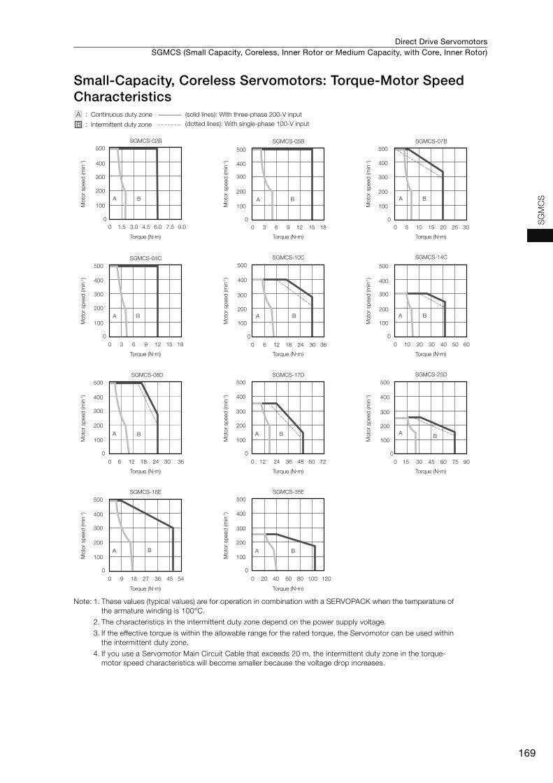
Direct Drive Servomotors SGMCS (Small Capacity, Coreless, Inner Rotor or Medium Capacity, with Core, Inner Rotor)
169
SG
MC
S
Small-Capacity, Coreless Servomotors: Torque-Motor Speed Characteristics
Note: 1. These values (typical values) are for operation in combination with a SERVOPACK when the temperature of the armature winding is 100°C.
2. The characteristics in the intermittent duty zone depend on the power supply voltage.
3. If the effective torque is within the allowable range for the rated torque, the Servomotor can be used within the intermittent duty zone.
4. If you use a Servomotor Main Circuit Cable that exceeds 20 m, the intermittent duty zone in the torque-motor speed characteristics will become smaller because the voltage drop increases.
SGMCS-02B
A
00
100
1.5 3.0 4.5 6.0 7.5 9.0
200
300
400
500
B
SGMCS-05B
A
00
100
3 6 9 12 15 18
200
300
400
500
B
SGMCS-07B
A
00
100
5 10 15 20 25 30
200
300
400
500
B
SGMCS-04C
A
00
100
3 6 9 12 15 18
200
300
400
500
B
SGMCS-10C
A
0
0
100
6 12 18 24 30 36
200
300
400
500
B
SGMCS-14C
A
00
100
10 20 30 40 50 60
200
300
400
500
B
100
200
300
400
500SGMCS-08D
0
0
100
6 12 18 24 30 36
200
300
400
500SGMCS-17D
A
0
0
12 24 36 48 60 72
B
100
200
300
400
500SGMCS-16E
A
0
0
100
9 18 27 36 45 54
200
300
400
500
B
SGMCS-35E
A
0
0
20 40 60 80 100 120
B
SGMCS-25D
A
0
0
100
15 30 45 60 75 90
200
300
400
500
BA B
A :
B :Continuous duty zone (solid lines): With three-phase 200-V input
(dotted lines): With single-phase 100-V inputIntermittent duty zone
Torque (N�m)
Mot
or s
peed
(min
-1)
Torque (N�m)
Mot
or s
peed
(min
-1)
Torque (N�m)
Mot
or s
peed
(min
-1)
Torque (N�m)
Mot
or s
peed
(min
-1)
Torque (N�m)
Mot
or s
peed
(min
-1)
Torque (N�m)
Mot
or s
peed
(min
-1)
Torque (N�m)
Mot
or s
peed
(min
-1)
Torque (N�m)
Mot
or s
peed
(min
-1)
Torque (N�m)
Mot
or s
peed
(min
-1)
Torque (N�m)
Mot
or s
peed
(min
-1)
Torque (N�m)
Mot
or s
peed
(min
-1)
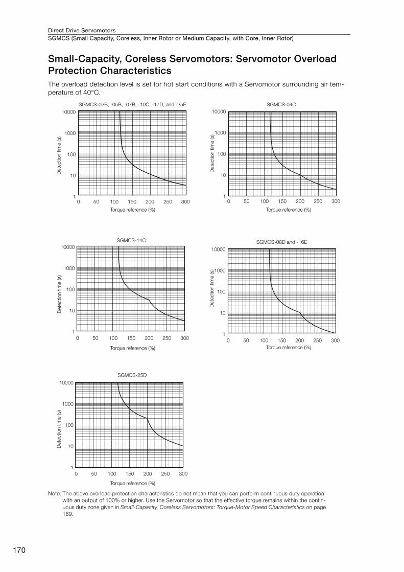
Direct Drive ServomotorsSGMCS (Small Capacity, Coreless, Inner Rotor or Medium Capacity, with Core, Inner Rotor)
170
Small-Capacity, Coreless Servomotors: Servomotor Overload Protection CharacteristicsThe overload detection level is set for hot start conditions with a Servomotor surrounding air tem-perature of 40°C.
Note: The above overload protection characteristics do not mean that you can perform continuous duty operation with an output of 100% or higher. Use the Servomotor so that the effective torque remains within the contin-uous duty zone given in Small-Capacity, Coreless Servomotors: Torque-Motor Speed Characteristics on page 169.
SGMCS-02B, -05B, -07B, -10C, -17D, and -35E SGMCS-04C
SGMCS-14C
SGMCS-25D
SGMCS-08D and -16E
Dete
ctio
n t
ime (s)
Torque reference (%)D
ete
ctio
n t
ime (s)
Dete
ctio
n t
ime (s)
Dete
ctio
n t
ime (s)
Dete
ctio
n t
ime (s)
Torque reference (%)
Torque reference (%) Torque reference (%)
Torque reference (%)
0 50 100 150 200 250 300
10000
1000
100
10
10 50 100 150 200 250 300
10000
1000
100
10
1
0 50 100 150 200 250 300
10000
1000
100
10
1
0 50 100 150 200 250 300
10000
1000
100
10
1
0 50 100 150 200 250 300
10000
1000
100
10
1
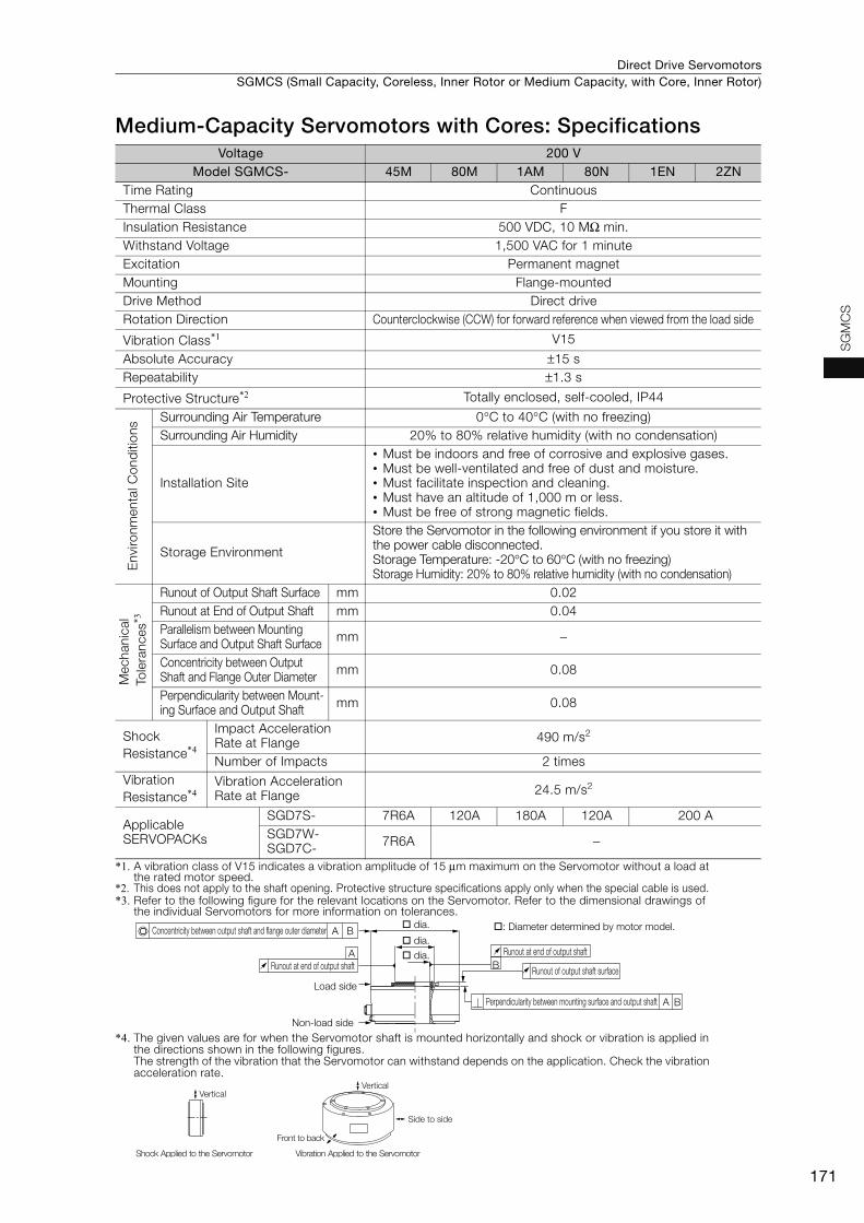
Direct Drive Servomotors SGMCS (Small Capacity, Coreless, Inner Rotor or Medium Capacity, with Core, Inner Rotor)
171
SG
MC
S
Medium-Capacity Servomotors with Cores: Specifications
*1. A vibration class of V15 indicates a vibration amplitude of 15 μm maximum on the Servomotor without a load at the rated motor speed.
*2. This does not apply to the shaft opening. Protective structure specifications apply only when the special cable is used. *3. Refer to the following figure for the relevant locations on the Servomotor. Refer to the dimensional drawings of
the individual Servomotors for more information on tolerances.
*4. The given values are for when the Servomotor shaft is mounted horizontally and shock or vibration is applied in the directions shown in the following figures.The strength of the vibration that the Servomotor can withstand depends on the application. Check the vibration acceleration rate.
Voltage 200 VModel SGMCS- 45M 80M 1AM 80N 1EN 2ZN
Time Rating Continuous Thermal Class FInsulation Resistance 500 VDC, 10 MΩ min. Withstand Voltage 1,500 VAC for 1 minute Excitation Permanent magnet Mounting Flange-mounted Drive Method Direct drive Rotation Direction Counterclockwise (CCW) for forward reference when viewed from the load side
Vibration Class*1 V15
Absolute Accuracy ±15 s Repeatability ±1.3 s
Protective Structure*2 Totally enclosed, self-cooled, IP44
Env
ironm
enta
l Con
diti
ons Surrounding Air Temperature 0°C to 40°C (with no freezing)
Surrounding Air Humidity 20% to 80% relative humidity (with no condensation)
Installation Site
• Must be indoors and free of corrosive and explosive gases.• Must be well-ventilated and free of dust and moisture.• Must facilitate inspection and cleaning.• Must have an altitude of 1,000 m or less.• Must be free of strong magnetic fields.
Storage Environment
Store the Servomotor in the following environment if you store it with the power cable disconnected.Storage Temperature: -20°C to 60°C (with no freezing) Storage Humidity: 20% to 80% relative humidity (with no condensation)
Mec
hani
cal
Tol
eran
ces*3
Runout of Output Shaft Surface mm 0.02Runout at End of Output Shaft mm 0.04Parallelism between Mounting Surface and Output Shaft Surface mm −
Concentricity between Output Shaft and Flange Outer Diameter mm 0.08
Perpendicularity between Mount-ing Surface and Output Shaft mm 0.08
Shock Resistance*4
Impact Acceleration Rate at Flange 490 m/s2
Number of Impacts 2 times Vibration Resistance*4
Vibration Acceleration Rate at Flange 24.5 m/s2
Applicable SERVOPACKs
SGD7S- 7R6A 120A 180A 120A 200 ASGD7W-SGD7C- 7R6A −
B
A
A
A B
B
Runout at end of output shaft
Runout of output shaft surface
Perpendicularity between mounting surface and output shaft
Concentricity between output shaft and flange outer diameter
Runout at end of output shaft
Load side
Non-load side
dia. : Diameter determined by motor model.
dia.
dia.
Side to side
Front to back
Vertical
Shock Applied to the Servomotor Vibration Applied to the Servomotor
Vertical
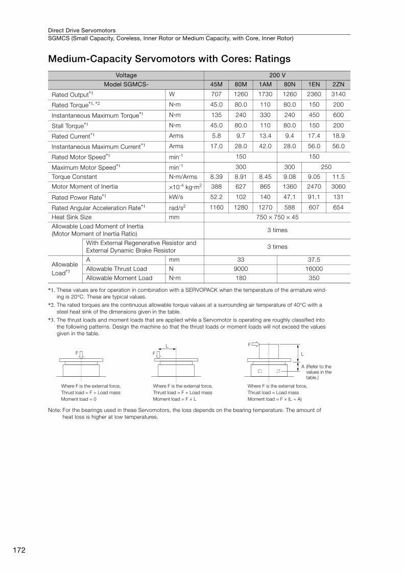
Direct Drive ServomotorsSGMCS (Small Capacity, Coreless, Inner Rotor or Medium Capacity, with Core, Inner Rotor)
172
Medium-Capacity Servomotors with Cores: Ratings
*1. These values are for operation in combination with a SERVOPACK when the temperature of the armature wind-ing is 20°C. These are typical values.
*2. The rated torques are the continuous allowable torque values at a surrounding air temperature of 40°C with a steel heat sink of the dimensions given in the table.
*3. The thrust loads and moment loads that are applied while a Servomotor is operating are roughly classified into the following patterns. Design the machine so that the thrust loads or moment loads will not exceed the values given in the table.
Note: For the bearings used in these Servomotors, the loss depends on the bearing temperature. The amount of heat loss is higher at low temperatures.
Voltage 200 V
Model SGMCS- 45M 80M 1AM 80N 1EN 2ZN
Rated Output*1 W 707 1260 1730 1260 2360 3140
Rated Torque*1, *2 Nm 45.0 80.0 110 80.0 150 200
Instantaneous Maximum Torque*1 Nm 135 240 330 240 450 600
Stall Torque*1 Nm 45.0 80.0 110 80.0 150 200
Rated Current*1 Arms 5.8 9.7 13.4 9.4 17.4 18.9
Instantaneous Maximum Current*1 Arms 17.0 28.0 42.0 28.0 56.0 56.0
Rated Motor Speed*1 min-1 150 150
Maximum Motor Speed*1 min-1 300 300 250
Torque Constant Nm/Arms 8.39 8.91 8.45 9.08 9.05 11.5
Motor Moment of Inertia ×10-4 kgm2 388 627 865 1360 2470 3060
Rated Power Rate*1 kW/s 52.2 102 140 47.1 91.1 131
Rated Angular Acceleration Rate*1 rad/s2 1160 1280 1270 588 607 654
Heat Sink Size mm 750 × 750 × 45
Allowable Load Moment of Inertia (Motor Moment of Inertia Ratio)
3 times
With External Regenerative Resistor and External Dynamic Brake Resistor
3 times
Allowable Load*3
A mm 33 37.5
Allowable Thrust Load N 9000 16000
Allowable Moment Load Nm 180 350
F F
L F
L
Where F is the external force,Thrust load = F + Load mass Moment load = 0
Where F is the external force,Thrust load = F + Load massMoment load = F × L
Where F is the external force,Thrust load = Load massMoment load = F × (L + A)
A (Refer to the values in the table.)
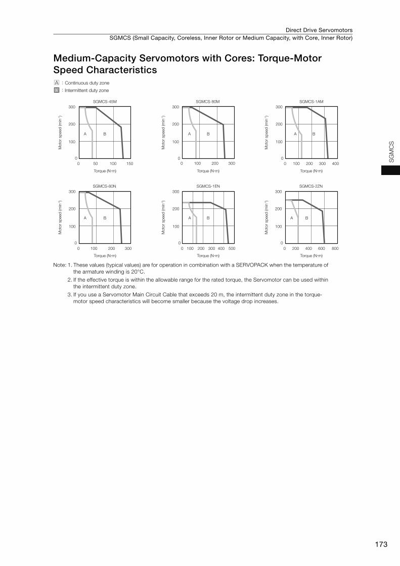
Direct Drive Servomotors SGMCS (Small Capacity, Coreless, Inner Rotor or Medium Capacity, with Core, Inner Rotor)
173
SG
MC
S
Medium-Capacity Servomotors with Cores: Torque-Motor Speed Characteristics
Note: 1. These values (typical values) are for operation in combination with a SERVOPACK when the temperature of the armature winding is 20°C.
2. If the effective torque is within the allowable range for the rated torque, the Servomotor can be used within the intermittent duty zone.
3. If you use a Servomotor Main Circuit Cable that exceeds 20 m, the intermittent duty zone in the torque-motor speed characteristics will become smaller because the voltage drop increases.
A
0 50 100 1500
100
200
300
B A
0 100 200 3000
100
200
300
B
SGMCS-45M SGMCS-80M
A
0 100 200 300 4000
100
200
300
B
A
0 100 200 3000
100
200
300
B
SGMCS-1AM
SGMCS-80N
A
0 100 200 300 400 5000
100
200
300
B A
0 200 400 600 8000
100
200
300
B
SGMCS-1EN SGMCS-2ZN
A :
B :Continuous duty zone
Intermittent duty zone
Torque (N�m)
Mot
or s
peed
(min
-1)
Torque (N�m)
Mot
or s
peed
(min
-1)
Torque (N�m)
Mot
or s
peed
(min
-1)
Torque (N�m)
Mot
or s
peed
(min
-1)
Torque (N�m)
Mot
or s
peed
(min
-1)
Torque (N�m)
Mot
or s
peed
(min
-1)

Direct Drive ServomotorsSGMCS (Small Capacity, Coreless, Inner Rotor or Medium Capacity, with Core, Inner Rotor)
174
Medium-Capacity Servomotors with Cores: Servomotor Overload Protection CharacteristicsThe overload detection level is set for hot start conditions with a Servomotor surrounding air tem-perature of 40°C.
Note: The above overload protection characteristics do not mean that you can perform continuous duty operation with an output of 100% or higher. Use the Servomotor so that the effective torque remains within the contin-uous duty zone given in Medium-Capacity Servomotors with Cores: Torque-Motor Speed Characteristics on page 173.
10000
1000
100
10
1
10000
1000
100
10
1
10000
1000
100
10
1
10000
1000
100
10
1
10000
1000
100
10
1
0 50 100 150 200 250 300 0 50 100 150 200 250 300
0 50 100 150 200 250 300
0 50 100 150 200 250 300
0 50 100 150 200 250 300 350
SGMCS-45MA SGMCS-80MA
SGMCS-1AMA and -80NA
SGMCS-2ZNA
SGMCS-1ENA
Det
ectio
n tim
e (s
)
Torque reference (%)D
etec
tion
time
(s)
Torque reference (%)
Det
ectio
n tim
e (s
)
Torque reference (%)
Det
ectio
n tim
e (s
)
Torque reference (%)
Det
ectio
n tim
e (s
)
Torque reference (%)
Direct Drive Servomotors SGMCS (Small Capacity, Coreless, Inner Rotor or Medium Capacity, with Core, Inner Rotor)
175
SG
MC
S
Allowable Load Moment of InertiaThe allowable load moments of inertia (motor moment of inertia ratios) for the Servomotors are given in the Small-Capacity, Coreless Servomotors: Ratings (page 168) and Medium-Capacity Servomo-tors with Cores: Ratings (page 172). The values are determined by the regenerative energy process-ing capacity of the SERVOPACK and are also affected by the drive conditions of the Servomotor. Perform the required Steps for each of the following cases.
Use the SigmaJunmaSize+ AC Servo Drive Capacity Selection Program to check the driving condi-tions. Contact your Yaskawa representative for information on this program.
Exceeding the Allowable Load Moment of InertiaUse one of the following measures to adjust the load moment of inertia to within the allowable value.• Reduce the torque limit.• Reduce the deceleration rate.• Reduce the maximum motor speed.
If the above steps is not possible, install an external regenerative resistor.
An Overvoltage Alarm (A.400) is likely to occur during deceleration if the load moment of iner-tia exceeds the allowable load moment of inertia. SERVOPACKs with a built-in regenerative resistor may generate a Regenerative Overload Alarm (A.320). Refer to Built-In Regenerative Resistor (page 456) for the regenerative power (W) that can be processed by the SERVO-PACKs.Install an External Regenerative Resistor when the built-in regenerative resistor cannot pro-cess all of the regenerative power.
Information
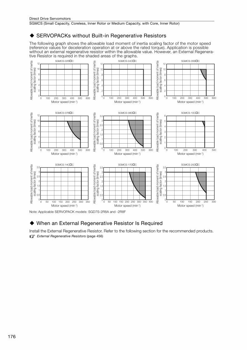
Direct Drive ServomotorsSGMCS (Small Capacity, Coreless, Inner Rotor or Medium Capacity, with Core, Inner Rotor)
176
SERVOPACKs without Built-in Regenerative ResistorsThe following graph shows the allowable load moment of inertia scaling factor of the motor speed (reference values for deceleration operation at or above the rated torque). Application is possible without an external regenerative resistor within the allowable value. However, an External Regenera-tive Resistor is required in the shaded areas of the graphs.
Note: Applicable SERVOPACK models: SGD7S-2R8A and -2R8F
When an External Regenerative Resistor Is RequiredInstall the External Regenerative Resistor. Refer to the following section for the recommended products.
External Regenerative Resistors (page 456)
0
2
4
6
8
10
12
0 100 200 300 400 500 600
SGMCS-02B�C
0
2
4
6
8
10
12
0 100 200 300 400 500 600
SGMCS-04C�C
0
2
4
6
8
10
12
0 100 200 300 400 500 600
SGMCS-07B�C
0
0.5
1
1.5
2
2.5
3
3.5
0 100 200 300 400 500 600
SGMCS-08D�C
0
1
2
3
4
5
6
0 100 200 300 400 500
SGMCS-10C�C
0
0.5
1
1.5
2
2.5
3
3.5
0 50 100 150 200 250 300 350
SGMCS-14C�C
0
0.5
1
1.5
2
2.5
3
3.5
0 50 100 150 200 250 300 350 400
SGMCS-17D�C
0
0.5
1
1.5
2
2.5
3
3.5
0 50 100 150 200 250 300
SGMCS-25D�C
0
2
4
6
8
10
12
0 100 200 300 400 500 600
SGMCS-05B�C
Motor speed (min-1)
Allo
wab
le lo
ad m
omen
t of i
nerti
a sc
alin
g fa
ctor
(tim
es)
Motor speed (min-1)
Allo
wab
le lo
ad m
omen
t of i
nerti
a sc
alin
g fa
ctor
(tim
es)
Motor speed (min-1)
Allo
wab
le lo
ad m
omen
t of i
nerti
a sc
alin
g fa
ctor
(tim
es)
Motor speed (min-1)
Allo
wab
le lo
ad m
omen
t of i
nerti
a sc
alin
g fa
ctor
(tim
es)
Motor speed (min-1)
Allo
wab
le lo
ad m
omen
t of i
nerti
a sc
alin
g fa
ctor
(tim
es)
Motor speed (min-1)Al
low
able
load
mom
ent o
f ine
rtia
scal
ing
fact
or (t
imes
)
Motor speed (min-1)
Allo
wab
le lo
ad m
omen
t of i
nerti
a sc
alin
g fa
ctor
(tim
es)
Motor speed (min-1)
Allo
wab
le lo
ad m
omen
t of i
nerti
a sc
alin
g fa
ctor
(tim
es)
Motor speed (min-1)
Allo
wab
le lo
ad m
omen
t of i
nerti
a sc
alin
g fa
ctor
(tim
es)

Direct Drive Servomotors SGMCS (Small Capacity, Coreless, Inner Rotor or Medium Capacity, with Core, Inner Rotor)
177
SG
MC
S
External Dimensions
Small-Capacity, Coreless Servomotors
SGMCS-B• Flange Specification 1
*1. The shaded section indicates the rotating parts.
*2. The hatched section indicates the non-rotating parts.
Note: Values in parentheses are reference dimensions.
• Flange Specification 4
*1. The shaded section indicates the rotating parts.
*2. The hatched section indicates the non-rotating parts.
Note: Values in parentheses are reference dimensions.
Refer to the following section for information on connectors. Connector Specifications (page 183)
Model SGMCS- L (LL) LB LH LA Approx. Mass [kg]
02BC11 59 51 120 20 100 4.8
05BC11 88 80 120 20 100 5.8
07BC11 128 120 120 20 100 8.2
Model SGMCS- L (LL) LB LH LA Approx. Mass [kg]
02BC41 59 51 120 20 100 4.8
05BC41 88 80 120 20 100 5.8
07BC41 128 120 120 20 100 8.2
LH d
ia.
0.04A
B0.02
A0.07 dia.
0.07 B4 (LL)
L
*1
*1
*2
4±0.9
135
dia.
LB d
ia.
(9)(1)
LA d
ia.
6 × M4 × 8(Divided into equal sections at 60°.)
Unit: mm
90 d
ia.
90°
R26
R40.5 max. connector area
6 × M4 × 8(Divided into equal sections at 60°.)
90 dia.
�25.4
�23.4
( 70
dia.
)
(0.5: bolt section)
0-0.035
+0.4 0
0-0.035
0-0.035
+0.4 0
0-0.035
0-0.035
+0.4 0
0-0.035
4
20
(LL)L
(1)0.1
(35)
300±50
4±0.93050
6 × M4 × 8(Divided into equal sections at 60°.)
0.07 B
A0.07 dia.
135
dia.
LB d
ia.
B0.02
LA d
ia.
A0.04
*1
90 dia.
6 × M4 × 8(Divided into equal sections at 60°.)
90 d
ia.
LH d
ia.
(70
dia.
)
(80
dia.
)
*1
*2
Unit: mm
(0.5: bolt section)
(22)
10
0-0.035
+0.4 0
0-0.035
0-0.035
+0.4 0
0-0.035
0-0.035
+0.4 0
0-0.035
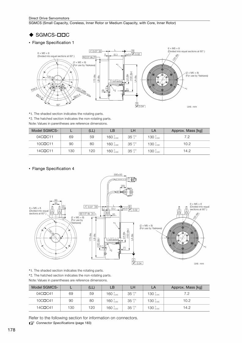
Direct Drive ServomotorsSGMCS (Small Capacity, Coreless, Inner Rotor or Medium Capacity, with Core, Inner Rotor)
178
SGMCS-C• Flange Specification 1
*1. The shaded section indicates the rotating parts.
*2. The hatched section indicates the non-rotating parts.
Note: Values in parentheses are reference dimensions.
• Flange Specification 4
*1. The shaded section indicates the rotating parts.
*2. The hatched section indicates the non-rotating parts.
Note: Values in parentheses are reference dimensions.
Refer to the following section for information on connectors. Connector Specifications (page 183)
Model SGMCS- L (LL) LB LH LA Approx. Mass [kg]
04CC11 69 59 160 35 130 7.2
10CC11 90 80 160 35 130 10.2
14CC11 130 120 160 35 130 14.2
Model SGMCS- L (LL) LB LH LA Approx. Mass [kg]
04CC41 69 59 160 35 130 7.2
10CC41 90 80 160 35 130 10.2
14CC41 130 120 160 35 130 14.2
R51 max. connector area
(2 × M5 × 8)(For use by Yaskawa)
60°
5 (LL)
L
5±0.9
175
dia.
LB d
ia.
(9)
(1: bolt section)
*1
*2 (1)
LH d
ia.
LA d
ia.
6 × M5 × 8(Divided into equal sections at 60°.)
120
dia.
(2 × M5 × 8)(For use by Yaskawa)
*1R36.5
�25.4 �23.4
B0.02
A0.07 dia.
0.07
0.04A
B
(100
dia
.)
6 × M5 × 8(Divided into equal sections at 60°.)
Unit: mm
130 dia.130 dia.130 dia.
0-0.040
+0.4 0
0-0.040
0-0.040
+0.4 0
0-0.040
0-0.040
+0.4 0
0-0.040
5
20
(LL)L
0.1
(35)
(1)
3050
6 × M5 × 8(Divided into equal sections at 60°.)
(2 × M5 × 8)(For use by Yaskawa)
0.07 B
A
B0.02
A0.04
(2 × M5 × 8)(For use by Yaskawa)
6 × M5 × 8(Divided into equal sections at 60°.)
300±50
5±0.9
0.07 dia.
120
dia.
175
dia.
LB d
ia.
LA d
ia.
(1: bolt section)
*1
*2
LH d
ia.
(100
dia
.)
(100
dia
.)
*1
Unit: mm
130130 dia.
dia.
130 dia.
(22)
10
0-0.040
+0.4 0
0-0.040
0-0.040
+0.4 0
0-0.040
0-0.040
+0.4 0
0-0.040
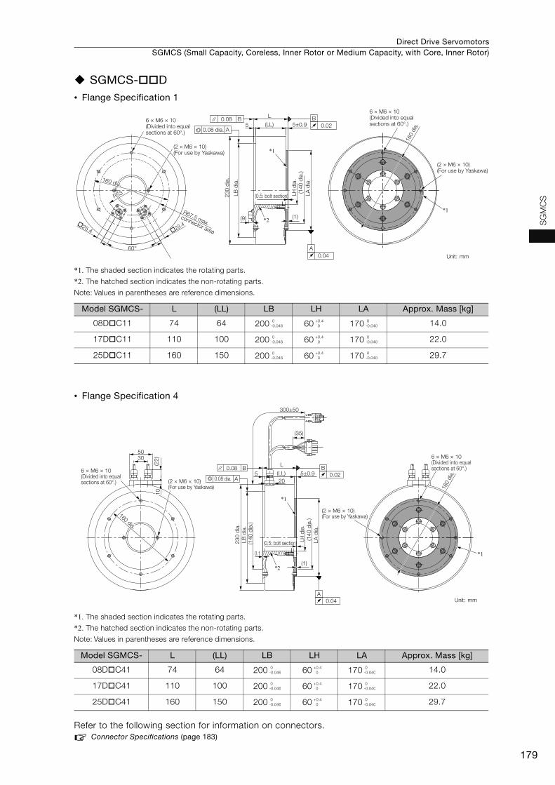
Direct Drive Servomotors SGMCS (Small Capacity, Coreless, Inner Rotor or Medium Capacity, with Core, Inner Rotor)
179
SG
MC
S
SGMCS-D• Flange Specification 1
*1. The shaded section indicates the rotating parts.
*2. The hatched section indicates the non-rotating parts.
Note: Values in parentheses are reference dimensions.
• Flange Specification 4
*1. The shaded section indicates the rotating parts.
*2. The hatched section indicates the non-rotating parts.
Note: Values in parentheses are reference dimensions.
Refer to the following section for information on connectors. Connector Specifications (page 183)
Model SGMCS- L (LL) LB LH LA Approx. Mass [kg]
08DC11 74 64 200 60 170 14.0
17DC11 110 100 200 60 170 22.0
25DC11 160 150 200 60 170 29.7
Model SGMCS- L (LL) LB LH LA Approx. Mass [kg]
08DC41 74 64 200 60 170 14.0
17DC41 110 100 200 60 170 22.0
25DC41 160 150 200 60 170 29.7
(LL)
L
5 5±0.9
(2 × M6 × 10)(For use by Yaskawa)
6 × M6 × 10(Divided into equal sections at 60°.)
60°
R67.5 max. connector area
(2 × M6 × 10)(For use by Yaskawa)
6 × M6 × 10(Divided into equal sections at 60°.)
*1
*2(9) (1)�25.4 �23.4
A0.08 dia.
0.08 B B0.02
230
dia.
LB d
ia.
0.04A
LH d
ia.
LA d
ia.
160
dia.
(0.5: bolt section)
(140
dia
.)
*1
Unit: mm
160 dia.160 dia.160 dia.
R53
0-0.046
+0.4 0
0-0.040
0-0.046
+0.4 0
0-0.040
0-0.046
+0.4 0
0-0.040
520
(LL)
L
(0.5: bolt section)
0.1
(1)
5±0.9
300±50
(35)
3050
6 × M6 × 10(Divided into equal sections at 60°.) (2 × M6 × 10)
(For use by Yaskawa)
*1
*1
*2
6 × M6 × 10(Divided into equal sections at 60°.)B
0.020.08 B
A0.08 dia.
230
dia.
LB d
ia.
LA d
ia.
LH d
ia.
A0.04
160
dia.
(140
dia
.)
(140
dia
.)
(2 × M6 × 10)(For use by Yaskawa)
Unit: mm
160160 dia.
dia.
160 dia.
(22)
10
0-0.046
+0.4 0
0-0.040
0-0.046
+0.4 0
0-0.040
0-0.046
+0.4 0
0-0.040
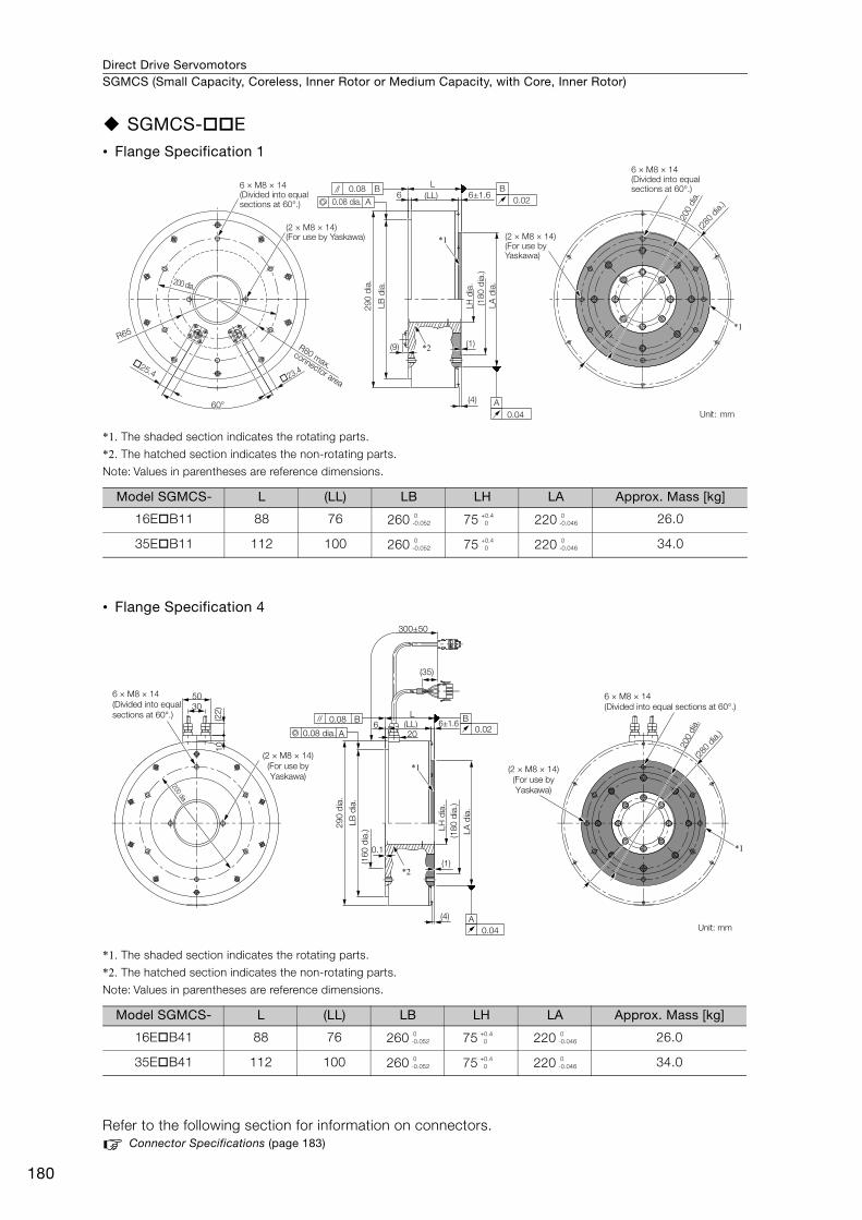
Direct Drive ServomotorsSGMCS (Small Capacity, Coreless, Inner Rotor or Medium Capacity, with Core, Inner Rotor)
180
SGMCS-E• Flange Specification 1
*1. The shaded section indicates the rotating parts.
*2. The hatched section indicates the non-rotating parts.
Note: Values in parentheses are reference dimensions.
• Flange Specification 4
*1. The shaded section indicates the rotating parts.
*2. The hatched section indicates the non-rotating parts.
Note: Values in parentheses are reference dimensions.
Refer to the following section for information on connectors. Connector Specifications (page 183)
Model SGMCS- L (LL) LB LH LA Approx. Mass [kg]
16EB11 88 76 260 75 220 26.0
35EB11 112 100 260 75 220 34.0
Model SGMCS- L (LL) LB LH LA Approx. Mass [kg]
16EB41 88 76 260 75 220 26.0
35EB41 112 100 260 75 220 34.0
60°
(2 × M8 × 14)(For use by Yaskawa)
R80 max. connector area
*2
*1
R65
(LL)L
6
(9) (1)
(4)
6 × M8 × 14(Divided into equal sections at 60°.)
(2 × M8 × 14)(For use by Yaskawa)
A0.08 dia.
0.08 B B0.02
0.04A
290
dia.
LB d
ia.
LH d
ia.
LA d
ia.
6 × M8 × 14(Divided into equal sections at 60°.)
�25.4�23.4
200 dia.
200
dia.6±1.6
(180
dia
.)
(280
dia.)
*1
Unit: mm
0-0.052
+0.4 0
0-0.046
0-0.052
+0.4 0
0-0.046
300±50
(35)
6 (LL)L
0.1
(1)
(4)
*1
*1
*2
3050
(22)
10
0.08 B
A
B0.02
A0.04
206±1.6
(2 × M8 × 14) (For use by Yaskawa)
(160
dia
.)
200
dia.
(280
dia.)
(180
dia
.)
290
dia.
0.08 dia.
(2 × M8 × 14) (For use by Yaskawa)
6 × M8 × 14 (Divided into equal sections at 60°.)
Unit: mm
200 dia.
6 × M8 × 14 (Divided into equal sections at 60°.)
LB d
ia.
LA d
ia.
LH d
ia.
0-0.052
+0.4 0
0-0.046
0-0.052
+0.4 0
0-0.046
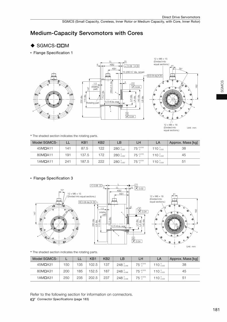
Direct Drive Servomotors SGMCS (Small Capacity, Coreless, Inner Rotor or Medium Capacity, with Core, Inner Rotor)
181
SG
MC
S
Medium-Capacity Servomotors with Cores
SGMCS-M• Flange Specification 1
* The shaded section indicates the rotating parts.
• Flange Specification 3
* The shaded section indicates the rotating parts.
Refer to the following section for information on connectors. Connector Specifications (page 183)
Model SGMCS- LL KB1 KB2 LB LH LA Approx. Mass [kg]
45MA11 141 87.5 122 280 75 110 38
80MA11 191 137.5 172 280 75 110 45
1AMA11 241 187.5 222 280 75 110 51
Model SGMCS- L LL KB1 KB2 LB LH LA Approx. Mass [kg]
45MA31 150 135 102.5 137 248 75 110 38
80MA31 200 185 152.5 187 248 75 110 45
1AMA31 250 235 202.5 237 248 75 110 51
A
15
147 18
2
264 d
ia.
41
0.04
0.04
B
0.08 dia.
15 (280 h7 dia. range)
15 (75 H6 dia. range)
A B
0.08 A B
12 × M6 × 15(Divided into equal sections.)
30°
KB2
KB1
LL6
51.5
Rotating part
*
*
*
LH d
ia.
75.2
dia
.
250
dia.
280±
0.5
dia.
115
dia.
LA d
ia.
140
dia.
LB d
ia.
(rotating part)
12 × M6 × 18(Divided into equal sections.)
Unit: mm
88 dia.88 dia.88 dia.
*
0-0.052
+0.019 0
0-0.035
0-0.052
+0.019 0
0-0.035
0-0.052
+0.019 0
0-0.035
5
182
15LL6
KB2KB1
L
41
1.5
0.08 C
*
*
A B0.08 dia.
LH d
ia.
115
dia.
75.2
dia
.
280
dia.
LA d
ia.
LB d
ia.
140
dia.
15 (75 H6 dia. range)
88 dia.88 dia.
10°
147
12 × M6 × 15(Divided into equal sections.)
264
dia.
C0.02
A0.04
B0.04
(rotating part)
*
Unit: mm
12 × M6 × 18(Divided into equal sections.)
88 dia.
*
0-0.046
+0.019 0
0-0.035
0-0.046
+0.019 0
0-0.035
0-0.046
+0.019 0
0-0.035
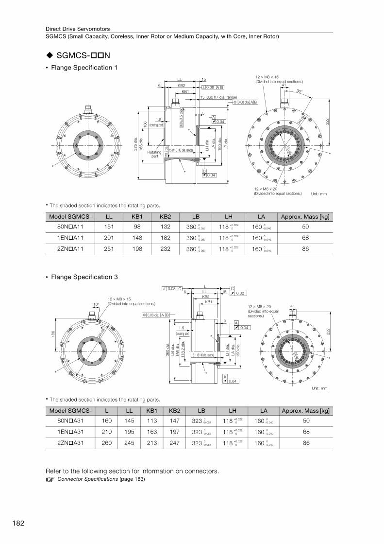
Direct Drive ServomotorsSGMCS (Small Capacity, Coreless, Inner Rotor or Medium Capacity, with Core, Inner Rotor)
182
SGMCS-N• Flange Specification 1
* The shaded section indicates the rotating parts.
• Flange Specification 3
* The shaded section indicates the rotating parts.
Refer to the following section for information on connectors. Connector Specifications (page 183)
Model SGMCS- LL KB1 KB2 LB LH LA Approx. Mass [kg]
80NA11 151 98 132 360 118 160 50
1ENA11 201 148 182 360 118 160 68
2ZNA11 251 198 232 360 118 160 86
Model SGMCS- L LL KB1 KB2 LB LH LA Approx. Mass [kg]
80NA31 160 145 113 147 323 118 160 50
1ENA31 210 195 163 197 323 118 160 68
2ZNA31 260 245 213 247 323 118 160 86
15 (360 h7 dia. range)
A
30°
344 d
ia.
15
LB d
ia.
166
dia.
12 × M8 × 20(Divided into equal sections.)
15 (118 H6 dia. range)
0.04
0.04
LH d
ia.
B
190
dia.
LA d
ia.
0.08 dia. A B
0.08 A B
222
41
186
KB2
KB1
118.2
dia.
5
360±
0.5
dia.
LL
325
dia.
6
12 × M8 × 15(Divided into equal sections.)
1.5
Rotating part
(rotating part)*
*
*
Unit: mm
135 dia.
*
0-0.057
+0.022 0
0-0.040
0-0.057
+0.022 0
0-0.040
0-0.057
+0.022 0
0-0.040
10°
222
41
1.5
5
LL 156KB2
KB1
L
186
12 × M8 × 15(Divided into equal sections.)
344 d
ia.
*
*
0.08 C C0.02
B0.04
A0.04
A B0.08 dia.
118.
2 di
a.16
6 di
a.LB
dia
.36
0 di
a.
LH d
ia.
190
dia.
LA d
ia.
15 (118 H6 dia. range)
135 dia.
12 × M8 × 20(Divided into equal sections.)
(rotating part)
*
Unit: mm
*
0-0.057
+0.022 0
0-0.040
0-0.057
+0.022 0
0-0.040
0-0.057
+0.022 0
0-0.040

Direct Drive Servomotors SGMCS (Small Capacity, Coreless, Inner Rotor or Medium Capacity, with Core, Inner Rotor)
183
SG
MC
S
Connector Specifications
SGMCS-B, -C, -D, or -E with Flange Specification 1
SGMCS-B, -C, -D, or -E with Flange Specification 4
SGMCS-M or -N with Flange Specification 1 or 3
• Servomotor Connector • Encoder Connector
Model: JN1AS04MK2RManufacturer: Japan Aviation Electronics Industry, Ltd.
Mating connector: JN1DS04FK1 (Not provided by Yaskawa.)
Model: JN1AS10ML1-R Manufacturer: Japan Aviation Electronics Industry, Ltd.
Mating connector: JN1DS10SL1 (Not provided by Yaskawa.)
• Servomotor Connector • Encoder Connector
Models • Plug: 350779-1 • Pins: 350561-3 or 350690-3 (No.1 to 3) • Ground pin: 350654-1 or 350669-1 (No. 4) Manufacturer: Tyco Electronics Japan G.K.
Mating Connector • Cap: 350780-1 • Socket: 350570-3 or 350689-3
Model: 55102-0600Manufacturer: Molex Japan LLC
Mating connector: 54280-0609
• Servomotor Connector • Encoder Connector
Model: CE05-2A18-10PDManufacturer: DDK Ltd.
Mating Connector Plug: CE05-6A18-10SD-B-BSSCable clamp: CE3057-10A-(D265)
Model: JN1AS10ML1Manufacturer: Japan Aviation Electronics Industry, Ltd.
Mating connector: JN1DS10SL1
1
3
2
4
1 Phase U Red2 Phase V White3 Phase W Blue4 FG (frame ground) Green (yellow)
1 3
4 7
8 10
1 PS Not used 6 − −
2 /PS Light blue/white 7 FG (frame
ground) Shield
3 − − 8 − −4 PG5V Red 9 PG0V Black5 − − 10 − −
1
2
3
4
1 Phase U Red2 Phase V White3 Phase W Blue4 FG (frame ground) Green (yellow) 4
2
6
3
1
51 PG5V Red2 PG0V Black3 – –4 – –5 PS Light blue
6 /PS Light blue/white
Connector case FG (frame ground) Shield
BA
CD
A Phase UB Phase VC Phase WD FG (frame ground)
1 3
4 7
8 10
1 PS2 /PS3 –4 PG5V5 –6 –7 FG (frame ground)8 –9 PG0V
10 –
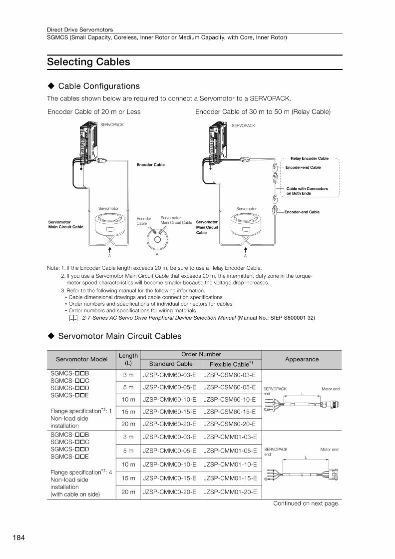
Direct Drive ServomotorsSGMCS (Small Capacity, Coreless, Inner Rotor or Medium Capacity, with Core, Inner Rotor)
184
Selecting Cables
Cable ConfigurationsThe cables shown below are required to connect a Servomotor to a SERVOPACK.
Note: 1. If the Encoder Cable length exceeds 20 m, be sure to use a Relay Encoder Cable.
2. If you use a Servomotor Main Circuit Cable that exceeds 20 m, the intermittent duty zone in the torque-motor speed characteristics will become smaller because the voltage drop increases.
3. Refer to the following manual for the following information.• Cable dimensional drawings and cable connection specifications• Order numbers and specifications of individual connectors for cables• Order numbers and specifications for wiring materials
Σ-7-Series AC Servo Drive Peripheral Device Selection Manual (Manual No.: SIEP S800001 32)
Servomotor Main Circuit Cables
Encoder Cable of 20 m or Less Encoder Cable of 30 m to 50 m (Relay Cable)
Servomotor ModelLength
(L)
Order NumberAppearance
Standard Cable Flexible Cable*1
SGMCS-BSGMCS-CSGMCS-DSGMCS-E
Flange specification*2: 1Non-load side installation
3 m JZSP-CMM60-03-E JZSP-CSM60-03-E
5 m JZSP-CMM60-05-E JZSP-CSM60-05-E
10 m JZSP-CMM60-10-E JZSP-CSM60-10-E
15 m JZSP-CMM60-15-E JZSP-CSM60-15-E
20 m JZSP-CMM60-20-E JZSP-CSM60-20-E
SGMCS-BSGMCS-CSGMCS-DSGMCS-E
Flange specification*2: 4Non-load side installation(with cable on side)
3 m JZSP-CMM00-03-E JZSP-CMM01-03-E
5 m JZSP-CMM00-05-E JZSP-CMM01-05-E
10 m JZSP-CMM00-10-E JZSP-CMM01-10-E
15 m JZSP-CMM00-15-E JZSP-CMM01-15-E
20 m JZSP-CMM00-20-E JZSP-CMM01-20-E
Continued on next page.
SERVOPACK
Encoder Cable
Encoder Cable
Servomotor
Servomotor Main Circuit Cable
Servomotor Main Circuit Cable
A A
SERVOPACK
Encoder-end Cable
Cable with Connectors on Both Ends
Encoder-end CableServomotor
Servomotor Main Circuit Cable
A
Relay Encoder Cable
LSERVOPACK
end
Motor end
L
SERVOPACK
end
Motor end
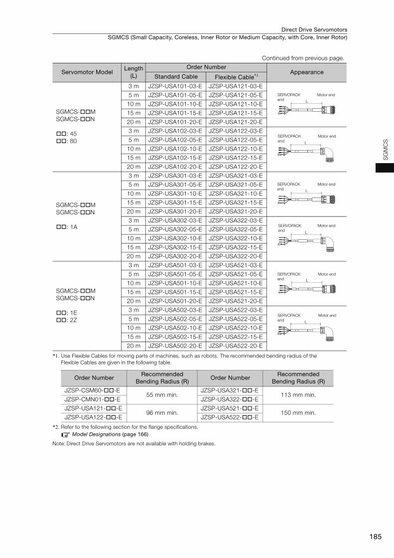
Direct Drive Servomotors SGMCS (Small Capacity, Coreless, Inner Rotor or Medium Capacity, with Core, Inner Rotor)
185
SG
MC
S
*1. Use Flexible Cables for moving parts of machines, such as robots. The recommended bending radius of the Flexible Cables are given in the following table.
*2. Refer to the following section for the flange specifications.Model Designations (page 166)
Note: Direct Drive Servomotors are not available with holding brakes.
SGMCS-MSGMCS-N
: 45: 80
3 m JZSP-USA101-03-E JZSP-USA121-03-E
5 m JZSP-USA101-05-E JZSP-USA121-05-E
10 m JZSP-USA101-10-E JZSP-USA121-10-E
15 m JZSP-USA101-15-E JZSP-USA121-15-E
20 m JZSP-USA101-20-E JZSP-USA121-20-E
3 m JZSP-USA102-03-E JZSP-USA122-03-E
5 m JZSP-USA102-05-E JZSP-USA122-05-E
10 m JZSP-USA102-10-E JZSP-USA122-10-E
15 m JZSP-USA102-15-E JZSP-USA122-15-E
20 m JZSP-USA102-20-E JZSP-USA122-20-E
SGMCS-MSGMCS-N
: 1A
3 m JZSP-USA301-03-E JZSP-USA321-03-E
5 m JZSP-USA301-05-E JZSP-USA321-05-E
10 m JZSP-USA301-10-E JZSP-USA321-10-E
15 m JZSP-USA301-15-E JZSP-USA321-15-E
20 m JZSP-USA301-20-E JZSP-USA321-20-E
3 m JZSP-USA302-03-E JZSP-USA322-03-E
5 m JZSP-USA302-05-E JZSP-USA322-05-E
10 m JZSP-USA302-10-E JZSP-USA322-10-E
15 m JZSP-USA302-15-E JZSP-USA322-15-E
20 m JZSP-USA302-20-E JZSP-USA322-20-E
SGMCS-MSGMCS-N
: 1E: 2Z
3 m JZSP-USA501-03-E JZSP-USA521-03-E
5 m JZSP-USA501-05-E JZSP-USA521-05-E
10 m JZSP-USA501-10-E JZSP-USA521-10-E
15 m JZSP-USA501-15-E JZSP-USA521-15-E
20 m JZSP-USA501-20-E JZSP-USA521-20-E
3 m JZSP-USA502-03-E JZSP-USA522-03-E
5 m JZSP-USA502-05-E JZSP-USA522-05-E
10 m JZSP-USA502-10-E JZSP-USA522-10-E
15 m JZSP-USA502-15-E JZSP-USA522-15-E
20 m JZSP-USA502-20-E JZSP-USA522-20-E
Order NumberRecommended
Bending Radius (R)Order Number
Recommended Bending Radius (R)
JZSP-CSM60--E55 mm min.
JZSP-USA321--E113 mm min.
JZSP-CMN01--E JZSP-USA322--E
JZSP-USA121--E96 mm min.
JZSP-USA521--E150 mm min.
JZSP-USA122--E JZSP-USA522--E
Continued from previous page.
Servomotor ModelLength
(L)
Order NumberAppearance
Standard Cable Flexible Cable*1
L
SERVOPACK
end
Motor end
L
SERVOPACK
end
Motor end
L
SERVOPACK
end
Motor end
L
SERVOPACK
end
Motor end
L
SERVOPACK
end
Motor end
L
SERVOPACK
end
Motor end
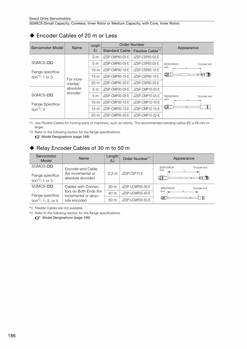
Direct Drive ServomotorsSGMCS (Small Capacity, Coreless, Inner Rotor or Medium Capacity, with Core, Inner Rotor)
186
Encoder Cables of 20 m or Less
*1. Use Flexible Cables for moving parts of machines, such as robots. The recommended bending radius (R) is 68 mm or larger.
*2. Refer to the following section for the flange specifications.Model Designations (page 166)
Relay Encoder Cables of 30 m to 50 m
*1. Flexible Cables are not available.
*2. Refer to the following section for the flange specifications.Model Designations (page 166)
Servomotor Model NameLength
(L)
Order NumberAppearance
Standard Cable Flexible Cable*1
SGMCS-
Flange specifica-tion*2: 1 or 3 For incre-
mental/absolute encoder
3 m JZSP-CMP60-03-E JZSP-CSP60-03-E
5 m JZSP-CMP60-05-E JZSP-CSP60-05-E
10 m JZSP-CMP60-10-E JZSP-CSP60-10-E
15 m JZSP-CMP60-15-E JZSP-CSP60-15-E
20 m JZSP-CMP60-20-E JZSP-CSP60-20-E
SGMCS-
Flange Specifica-tion*2: 4
3 m JZSP-CMP00-03-E JZSP-CMP10-03-E
5 m JZSP-CMP00-05-E JZSP-CMP10-05-E
10 m JZSP-CMP00-10-E JZSP-CMP10-10-E
15 m JZSP-CMP00-15-E JZSP-CMP10-15-E
20 m JZSP-CMP00-20-E JZSP-CMP10-20-E
Servomotor Model
NameLength
(L) Order Number*1 Appearance
SGMCS-
Flange specifica-tion*2: 1 or 3
Encoder-end Cable (for incremental or absolute encoder)
0.3 m JZSP-CSP15-E
SGMCS-
Flange specifica-tion*2: 1, 3, or 4
Cables with Connec-tors on Both Ends (for incremental or abso-lute encoder)
30 m JZSP-UCMP00-30-E
40 m JZSP-UCMP00-40-E
50 m JZSP-UCMP00-50-E
L
SERVOPACK
end
Encoder end
L
SERVOPACK
end
Encoder end
SERVOPACK end
Encoder endL
LSERVOPACK
end
Encoder end

SGLG (Coreless Models) .....................................188
SGLF (Models with F-type Iron Cores) ...............212
SGLT (Models with T-type Iron Cores) ................252
Recommended Linear Encoders and Cables .....278
Linear Servomotors
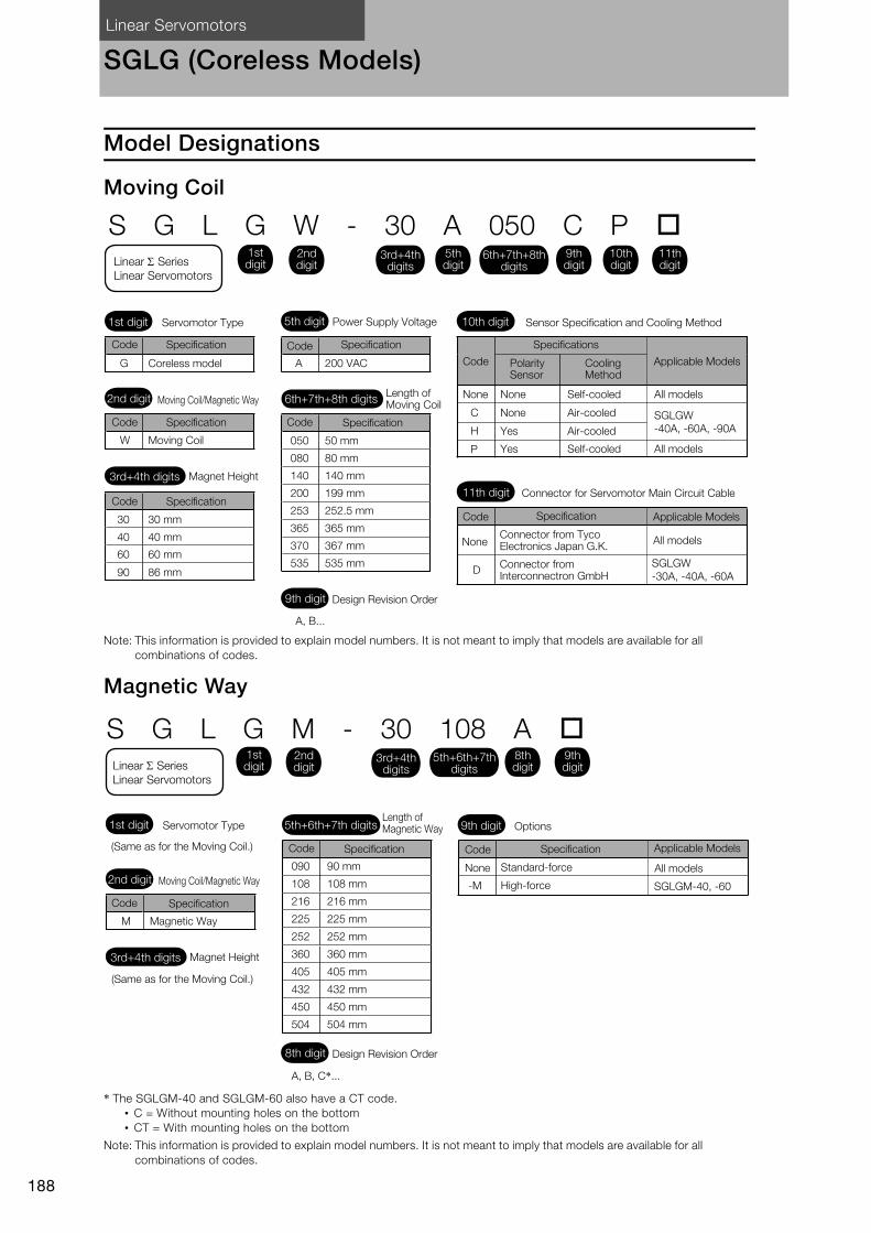
Linear Servomotors
188
SGLG (Coreless Models)
Model Designations
Moving Coil
Note: This information is provided to explain model numbers. It is not meant to imply that models are available for all combinations of codes.
Magnetic Way
* The SGLGM-40 and SGLGM-60 also have a CT code. • C = Without mounting holes on the bottom • CT = With mounting holes on the bottom
Note: This information is provided to explain model numbers. It is not meant to imply that models are available for all combinations of codes.
050
080
140
200
253
365
370
535
S G L G W - 30 A 050 C P
30 30 mm
40 40 mm
60 60 mm
90 86 mm
A 200 VAC
SGLGW
-40A, -60A, -90A
SGLGW
-30A, -40A, -60A
G
W 50 mm
80 mm
140 mm
199 mm
252.5 mm
365 mm
367 mm
535 mmD
C
H
P
Servomotor Type Power Supply Voltage Sensor Specification and Cooling Method
Connector for Servomotor Main Circuit Cable
NoneConnector from Tyco Electronics Japan G.K.
All models
Connector from Interconnectron GmbH
None None Self-cooled All models
All models
Air-cooled
Air-cooled
Self-cooled
None
Yes
Yes
Polarity Sensor
Cooling Method
Length of Moving Coil
Design Revision Order
Coreless model
Magnet Height
Moving Coil
Moving Coil/Magnetic Way
1st digit
3rd+4th digits
2nd digit
11th digit
9th digit
6th+7th+8th digits
5th digit 10th digit
3rd+4th digits
SpecificationCode
1st digitLinear Series
Linear Servomotors
2nd digit
5th digit
6th+7th+8th digits
9th digit
10th digit
11th digit
Code
Code
Code
Code
Code
Code
Specification Specifications
Specification
SpecificationSpecification
Specification
Applicable Models
Applicable Models
A, B...
090
108
216
225
252
360
405
432
450
504
S G L G M - 30 108 A
(Same as for the Moving Coil.)
Magnetic Way
(Same as for the Moving Coil.)
Length of Magnetic Way Options
Standard-force All models
High-force
9th digit
M
90 mm
108 mm
216 mm
225 mm
252 mm
360 mm
405 mm
432 mm
450 mm
504 mm
Servomotor Type
None
Design Revision Order
Magnet Height
Moving Coil/Magnetic Way
1st digit
3rd+4th digits
2nd digit
8th digit
3rd+4th digits
SpecificationCode
1st digitLinear Series
Linear Servomotors
2nd digit
9th digit
8th digit
Code CodeSpecification Specification Applicable Models
A, B, C*...
5th+6th+7th digits
-M
5th+6th+7th digits
SGLGM-40, -60
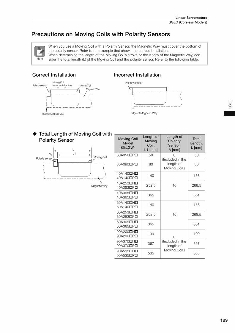
Linear Servomotors SGLG (Coreless Models)
189
SG
LG
Precautions on Moving Coils with Polarity Sensors
When you use a Moving Coil with a Polarity Sensor, the Magnetic Way must cover the bottom of the polarity sensor. Refer to the example that shows the correct installation. When determining the length of the Moving Coil’s stroke or the length of the Magnetic Way, con-sider the total length (L) of the Moving Coil and the polarity sensor. Refer to the following table.
Correct Installation Incorrect Installation
Total Length of Moving Coil with Polarity Sensor
Note
Polarity sensor
Edge of Magnetic Way
Magnetic Way
Moving Coil
Moving Coil movement direction
Polarity sensor
Edge of Magnetic Way
L1A
L
Polarity sensor
Magnetic Way
Moving Coil
Moving Coil Model
SGLGW-
Length of Moving
Coil, L1 [mm]
Length of Polarity Sensor, A [mm]
Total Length, L [mm]
30A050P 50 0(Included in the
length of Moving Coil.)
50
30A080P 80 80
40A140H40A140P
140
16
156
40A253H40A253P
252.5 268.5
40A365H40A365P
365 381
60A140H60A140P
140
16
156
60A253H60A253P
252.5 268.5
60A365H60A365P
365 381
90A200H90A200P
1990
(Included in the length of
Moving Coil.)
199
90A370H90A370P
367 367
90A535H90A535P
535 535

Linear ServomotorsSGLG (Coreless Models)
190
Specifications and Ratings
Specifications: With Standard-Force Magnetic Way Linear Servomotor Moving Coil Model
SGLGW-
30A 40A 60A 90A
050C 080C 140C 253C 365C 140C 253C 365C 200C 370C 535C
Time Rating Continuous
Thermal Class B
Insulation Resistance 500 VDC, 10 MΩ min.
Withstand Voltage 1,500 VAC for 1 minute
Excitation Permanent magnet
Cooling Method Self-cooled or air-cooled
(Only self-cooled models are available for the SGLGW-30A.)
Protective Structure IP00
Environ-mental Condi-tions
Surround-ing Air Tem-perature
0°C to 40°C (with no freezing)
Surround-ing Air Humidity
20% to 80% relative humidity (with no condensation)
Installation Site
• Must be indoors and free of corrosive and explosive gases.• Must be well-ventilated and free of dust and moisture. • Must facilitate inspection and cleaning. • Must have an altitude of 1,000 m or less.• Must be free of strong magnetic fields.
Shock Resis-tance
Impact Accelera-tion Rate
196 m/s2
Number of Impacts
2 times
Vibra-tion Resis-tance
Vibration Accelera-tion Rate
49 m/s2 (the vibration resistance in three directions, vertical, side-to-side, and front-to-back)
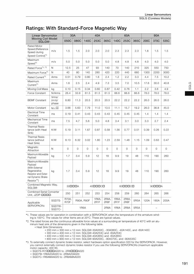
Linear Servomotors SGLG (Coreless Models)
191
SG
LG
Ratings: With Standard-Force Magnetic Way
*1. These values are for operation in combination with a SERVOPACK when the temperature of the armature wind-ing is 100°C. The values for other items are at 20°C. These are typical values.
*2. The rated forces are the continuous allowable force values at a surrounding air temperature of 40°C with an alu-minum heat sink of the dimensions given in the following table.
• Heat Sink Dimensions • 200 mm × 300 mm × 12 mm: SGLGW-30A050C, -30A080C, -40A140C, and -60A140C• 300 mm × 400 mm × 12 mm: SGLGW-40A253C and -60A253C• 400 mm × 500 mm × 12 mm: SGLGW-40A365C and -60A365C• 800 mm × 900 mm × 12 mm: SGLGW-90A200C, -90A370C, and -90A535C
*3. To externally connect dynamic brake resistor, select hardware option specification 020 for the SERVOPACK. However, you cannot externally connect dynamic brake resistor if you use the following SERVOPACKs (maximum applicable motor capacity: 400 W).• SGD7S-R70A020 to -2R8A020• SGD7W-1R6A20A020 to -2R8A20A020• SGD7C-1R6AMAA020 to -2R8AMAA020
Linear Servomotor Moving Coil Model
SGLGW-
30A 40A 60A 90A
050C 080C 140C 253C 365C 140C 253C 365C 200C 370C 535C
Rated Motor Speed (Reference Speed during Speed Control)*1
m/s 1.5 1.5 2.0 2.0 2.0 2.3 2.3 2.3 1.8 1.5 1.5
Maximum Speed*1 m/s 5.0 5.0 5.0 5.0 5.0 4.8 4.8 4.8 4.0 4.0 4.0
Rated Force*1, *2 N 12.5 25 47 93 140 70 140 210 325 550 750
Maximum Force*1 N 40 80 140 280 420 220 440 660 1300 2200 3000
Rated Current*1 Arms 0.51 0.79 0.80 1.6 2.4 1.2 2.2 3.3 4.4 7.5 10.2
Maximum Current*1 Arms 1.6 2.5 2.4 4.9 7.3 3.5 7.0 10.5 17.6 30.0 40.8
Moving Coil Mass kg 0.10 0.15 0.34 0.60 0.87 0.42 0.76 1.1 2.2 3.6 4.9
Force Constant N/Arms 26.4 33.9 61.5 61.5 61.5 66.6 66.6 66.6 78.0 78.0 78.0
BEMF ConstantVrms/(m/s)/phase
8.80 11.3 20.5 20.5 20.5 22.2 22.2 22.2 26.0 26.0 26.0
Motor Constant N/ 3.66 5.63 7.79 11.0 13.5 11.1 15.7 19.2 26.0 36.8 45.0
Electrical Time Constant
ms 0.19 0.41 0.43 0.43 0.43 0.45 0.45 0.45 1.4 1.4 1.4
Mechanical Time Constant
ms 7.5 4.7 5.6 5.0 4.8 3.4 3.1 3.0 3.3 2.7 2.4
Thermal Resis-tance (with Heat Sink)
K/W 5.19 3.11 1.67 0.87 0.58 1.56 0.77 0.51 0.39 0.26 0.22
Thermal Resis-tance (without Heat Sink)
K/W 8.13 6.32 3.02 1.80 1.23 2.59 1.48 1.15 1.09 0.63 0.47
Magnetic Attraction
N 0 0 0 0 0 0 0 0 0 0 0
Maximum Allowable Payload
kg 1.7 3.4 5.9 12 18 9.9 19 48 110 190 260
Maximum Allowable Payload(With External Regenerative Resistor and Exter-nal Dynamic Brake Resistor*3)
kg 1.7 3.4 5.9 12 18 9.9 19 48 110 190 260
Combined Magnetic Way, SGLGM- 30A 40C 60C 90A
Combined Serial Converter Unit, JZDP--
250 251 252 253 254 258 259 260 264 265 266
Applicable SERVOPACKs
SGD7S-R70A,R70F
R90A, R90F1R6A,2R1F
2R8A,2R8F
1R6A,2R1F
2R8A,2R8F
5R5A 120A 180A 200A
SGD7W-SGD7C-
1R6A 2R8A 1R6A 2R8A 5R5A −
W
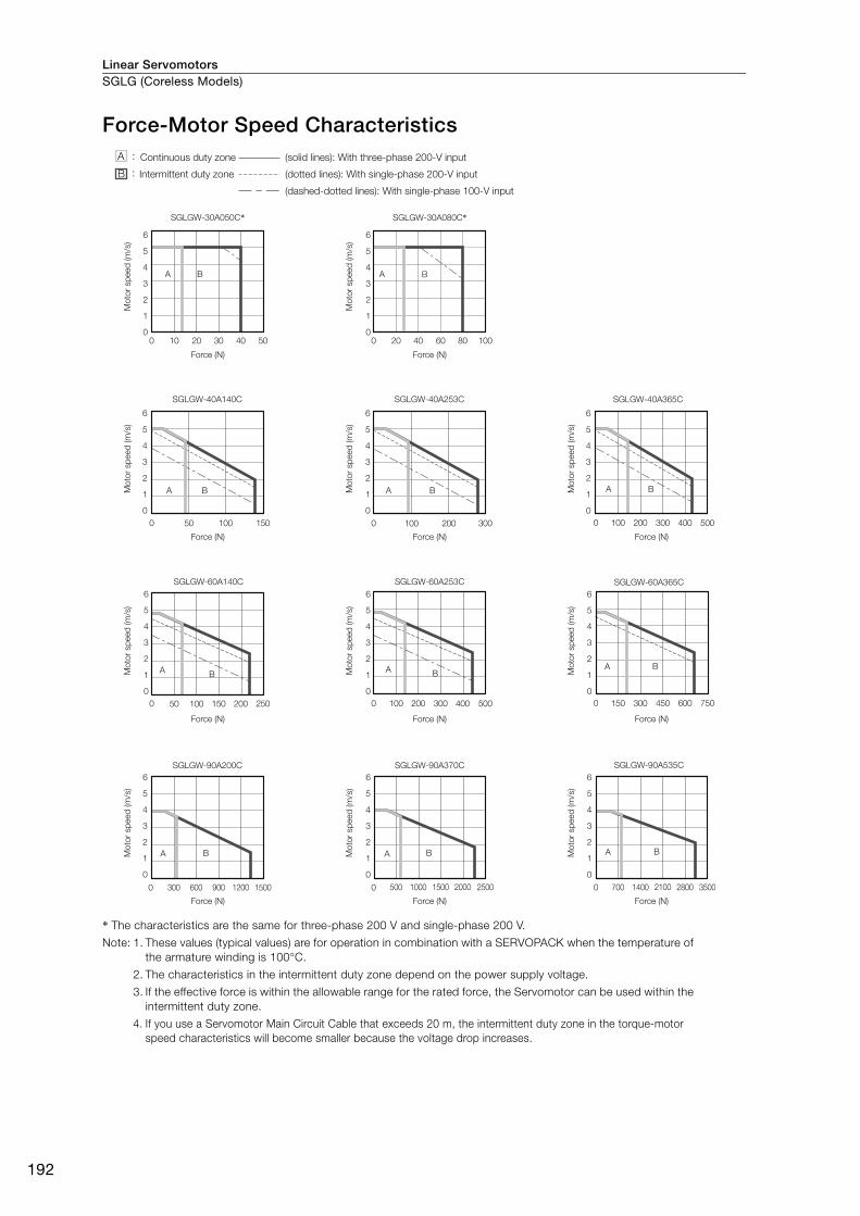
Linear ServomotorsSGLG (Coreless Models)
192
Force-Motor Speed Characteristics
* The characteristics are the same for three-phase 200 V and single-phase 200 V.
Note: 1. These values (typical values) are for operation in combination with a SERVOPACK when the temperature of the armature winding is 100°C.
2. The characteristics in the intermittent duty zone depend on the power supply voltage.
3. If the effective force is within the allowable range for the rated force, the Servomotor can be used within the intermittent duty zone.
4. If you use a Servomotor Main Circuit Cable that exceeds 20 m, the intermittent duty zone in the torque-motor speed characteristics will become smaller because the voltage drop increases.
SGLGW-40A365C
A B
SGLGW-40A140C
A B
SGLGW-40A253C
A B
SGLGW-30A050C*
6
5
4
3
2
1
0
6
5
4
3
2
1
0
6
5
4
3
2
1
0
6
5
4
3
2
1
0
6
5
4
3
2
1
0
6
5
4
3
2
1
0
6
5
4
3
2
1
0
6
5
4
3
2
1
0
6
5
4
3
2
1
0
6
5
4
3
2
1
0
6
5
4
3
2
1
0
A B
SGLGW-30A080C*
A B
SGLGW-60A365CSGLGW-60A140C SGLGW-60A253C
SGLGW-90A200C
A B
SGLGW-90A370C
A B
SGLGW-90A535C
A B BA BA
BA
0 10 20 30 40 50 20 40 60 80 1000
0 100 200 300 400 5000 15050 100 0 300200100
750600450150 3000250150 20050 1000 0 100 200 300 400 500
0 015001200900600300 2500200015001000500 0 3500280021001400700
(dashed-dotted lines): With single-phase 100-V input
Continuous duty zone
Intermittent duty zone
(solid lines): With three-phase 200-V input
(dotted lines): With single-phase 200-V input
A :
B :
Force (N)
Mo
tor
sp
eed
(m
/s)
Force (N)M
oto
r sp
eed
(m
/s)
Force (N)
Mo
tor
sp
eed
(m
/s)
Force (N)
Mo
tor
sp
eed
(m
/s)
Force (N)
Mo
tor
sp
eed
(m
/s)
Force (N)
Mo
tor
sp
eed
(m
/s)
Force (N)
Mo
tor
sp
eed
(m
/s)
Force (N)
Mo
tor
sp
eed
(m
/s)
Force (N)
Mo
tor
sp
eed
(m
/s)
Force (N)
Mo
tor
sp
eed
(m
/s)
Force (N)
Mo
tor
sp
eed
(m
/s)
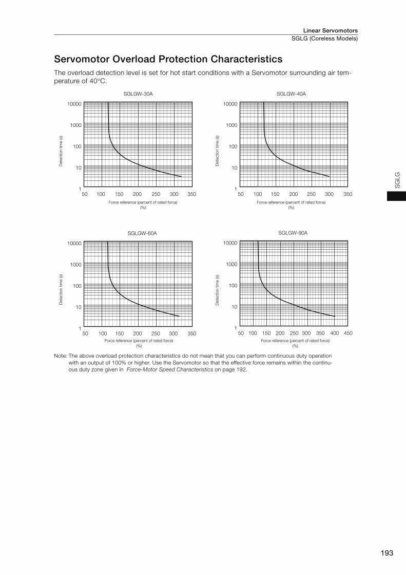
Linear Servomotors SGLG (Coreless Models)
193
SG
LG
Servomotor Overload Protection Characteristics The overload detection level is set for hot start conditions with a Servomotor surrounding air tem-perature of 40°C.
Note: The above overload protection characteristics do not mean that you can perform continuous duty operation with an output of 100% or higher. Use the Servomotor so that the effective force remains within the continu-ous duty zone given in Force-Motor Speed Characteristics on page 192.
SGLGW-30A
10000
1000
100
10
135050 100 150 200 250 300
SGLGW-40A
35050 100 150 200 250 300
10000
1000
100
10
1
35050 100 150 200 250 300 450350 40050 100 150 200 250 300
SGLGW-90A
10000
1000
100
10
1
SGLGW-60A
10000
1000
100
10
1
Dete
ctio
n t
ime (s)
Force reference (percent of rated force)
(%)
Dete
ctio
n t
ime (s)
Force reference (percent of rated force)
(%)
Dete
ctio
n t
ime (s)
Force reference (percent of rated force)
(%)
Dete
ctio
n t
ime (s)
Force reference (percent of rated force)
(%)
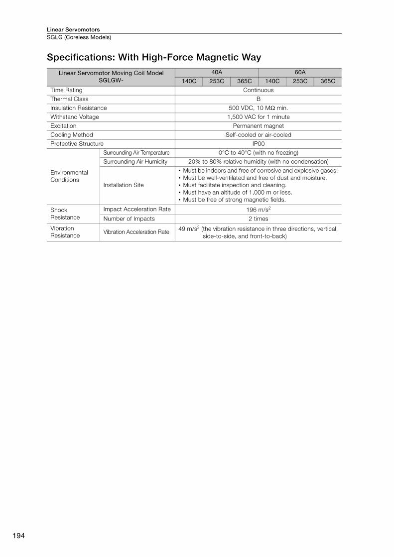
Linear ServomotorsSGLG (Coreless Models)
194
Specifications: With High-Force Magnetic Way
Linear Servomotor Moving Coil Model SGLGW-
40A 60A
140C 253C 365C 140C 253C 365C
Time Rating Continuous
Thermal Class B
Insulation Resistance 500 VDC, 10 MΩ min.
Withstand Voltage 1,500 VAC for 1 minute
Excitation Permanent magnet
Cooling Method Self-cooled or air-cooled
Protective Structure IP00
Environmental Conditions
Surrounding Air Temperature 0°C to 40°C (with no freezing)
Surrounding Air Humidity 20% to 80% relative humidity (with no condensation)
Installation Site
• Must be indoors and free of corrosive and explosive gases. • Must be well-ventilated and free of dust and moisture. • Must facilitate inspection and cleaning. • Must have an altitude of 1,000 m or less.• Must be free of strong magnetic fields.
Shock Resistance
Impact Acceleration Rate 196 m/s2
Number of Impacts 2 times
Vibration Resistance
Vibration Acceleration Rate 49 m/s2 (the vibration resistance in three directions, vertical, side-to-side, and front-to-back)
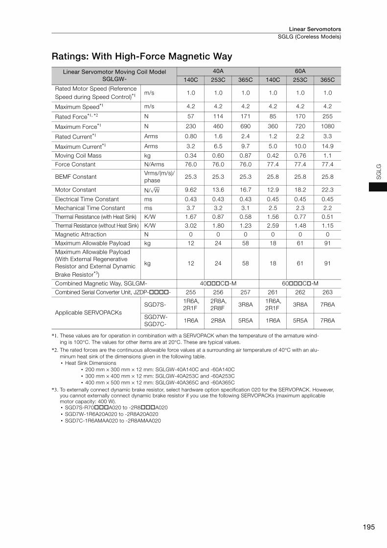
Linear Servomotors SGLG (Coreless Models)
195
SG
LG
Ratings: With High-Force Magnetic Way
*1. These values are for operation in combination with a SERVOPACK when the temperature of the armature wind-ing is 100°C. The values for other items are at 20°C. These are typical values.
*2. The rated forces are the continuous allowable force values at a surrounding air temperature of 40°C with an alu-minum heat sink of the dimensions given in the following table.• Heat Sink Dimensions
• 200 mm × 300 mm × 12 mm: SGLGW-40A140C and -60A140C• 300 mm × 400 mm × 12 mm: SGLGW-40A253C and -60A253C• 400 mm × 500 mm × 12 mm: SGLGW-40A365C and -60A365C
*3. To externally connect dynamic brake resistor, select hardware option specification 020 for the SERVOPACK. However, you cannot externally connect dynamic brake resistor if you use the following SERVOPACKs (maximum applicable motor capacity: 400 W).• SGD7S-R70A020 to -2R8A020• SGD7W-1R6A20A020 to -2R8A20A020• SGD7C-1R6AMAA020 to -2R8AMAA020
Linear Servomotor Moving Coil Model SGLGW-
40A 60A
140C 253C 365C 140C 253C 365C
Rated Motor Speed (Reference Speed during Speed Control)*1 m/s 1.0 1.0 1.0 1.0 1.0 1.0
Maximum Speed*1 m/s 4.2 4.2 4.2 4.2 4.2 4.2
Rated Force*1, *2 N 57 114 171 85 170 255
Maximum Force*1 N 230 460 690 360 720 1080
Rated Current*1 Arms 0.80 1.6 2.4 1.2 2.2 3.3
Maximum Current*1 Arms 3.2 6.5 9.7 5.0 10.0 14.9
Moving Coil Mass kg 0.34 0.60 0.87 0.42 0.76 1.1
Force Constant N/Arms 76.0 76.0 76.0 77.4 77.4 77.4
BEMF Constant Vrms/(m/s)/phase
25.3 25.3 25.3 25.8 25.8 25.8
Motor Constant N/ 9.62 13.6 16.7 12.9 18.2 22.3
Electrical Time Constant ms 0.43 0.43 0.43 0.45 0.45 0.45
Mechanical Time Constant ms 3.7 3.2 3.1 2.5 2.3 2.2
Thermal Resistance (with Heat Sink) K/W 1.67 0.87 0.58 1.56 0.77 0.51
Thermal Resistance (without Heat Sink) K/W 3.02 1.80 1.23 2.59 1.48 1.15
Magnetic Attraction N 0 0 0 0 0 0
Maximum Allowable Payload kg 12 24 58 18 61 91
Maximum Allowable Payload(With External Regenerative Resistor and External Dynamic Brake Resistor*3)
kg 12 24 58 18 61 91
Combined Magnetic Way, SGLGM- 40C-M 60C-M
Combined Serial Converter Unit, JZDP-- 255 256 257 261 262 263
Applicable SERVOPACKs SGD7S-
1R6A,2R1F
2R8A,2R8F
3R8A1R6A,2R1F
3R8A 7R6A
SGD7W-SGD7C-
1R6A 2R8A 5R5A 1R6A 5R5A 7R6A
W
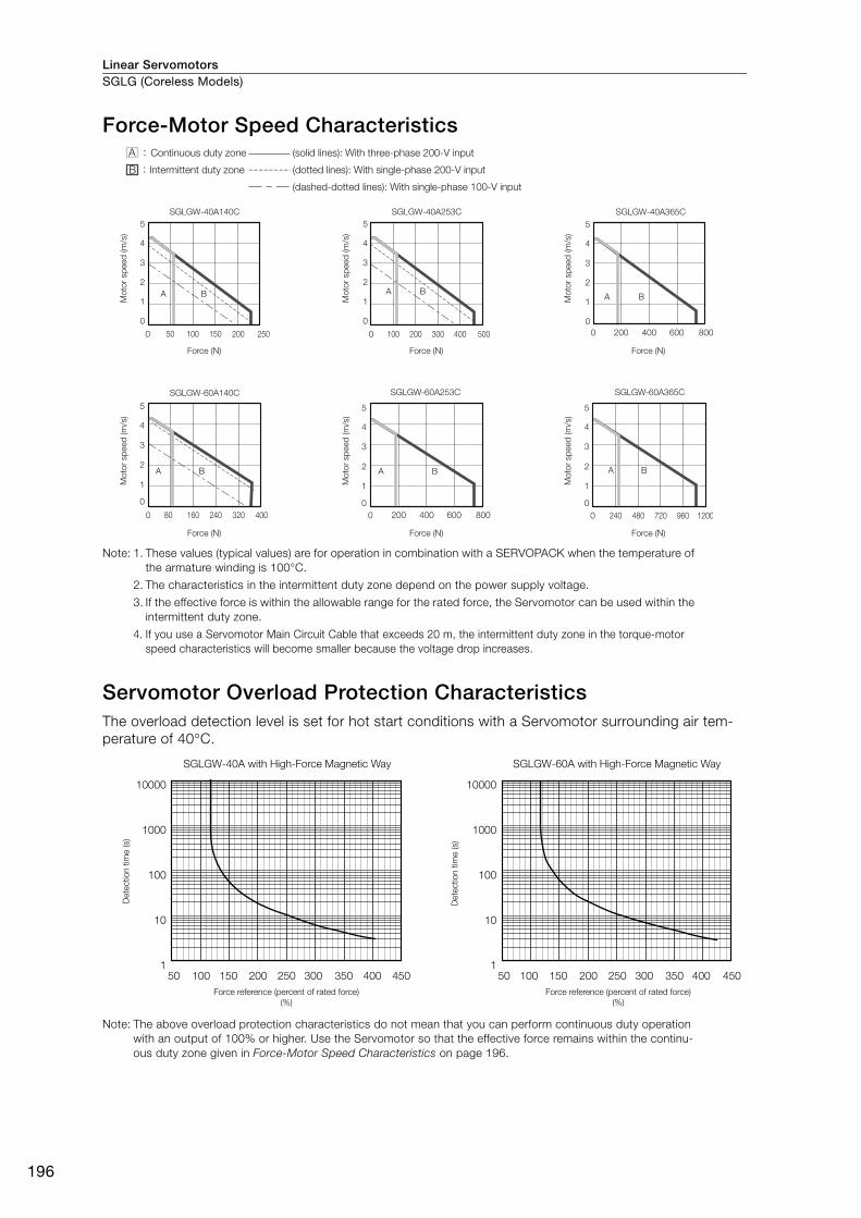
Linear ServomotorsSGLG (Coreless Models)
196
Force-Motor Speed Characteristics
Note: 1. These values (typical values) are for operation in combination with a SERVOPACK when the temperature of the armature winding is 100°C.
2. The characteristics in the intermittent duty zone depend on the power supply voltage.
3. If the effective force is within the allowable range for the rated force, the Servomotor can be used within the intermittent duty zone.
4. If you use a Servomotor Main Circuit Cable that exceeds 20 m, the intermittent duty zone in the torque-motor speed characteristics will become smaller because the voltage drop increases.
Servomotor Overload Protection Characteristics The overload detection level is set for hot start conditions with a Servomotor surrounding air tem-perature of 40°C.
Note: The above overload protection characteristics do not mean that you can perform continuous duty operation with an output of 100% or higher. Use the Servomotor so that the effective force remains within the continu-ous duty zone given in Force-Motor Speed Characteristics on page 196.
SGLGW-40A140C
0
1
2
3
4
5
A B A BA B
SGLGW-40A253C
0
1
2
3
4
5
SGLGW-40A365C
0
1
2
3
4
5
A B A B A B
SGLGW-60A253CSGLGW-60A140C
5
4
3
2
1
0
SGLGW-60A365C
5
4
3
2
1
0
5
4
3
2
1
0
0 200 400 600 8000 100 200 300 400 5000 250150 20050 100
200 400 600 8000 00400240 32080 160 240 480 720 960 1200
Force (N)
Mo
tor
sp
eed
(m
/s)
Force (N)M
oto
r sp
eed
(m
/s)
Force (N)
Mo
tor
sp
eed
(m
/s)
Force (N)
Mo
tor
sp
eed
(m
/s)
Force (N)
Mo
tor
sp
eed
(m
/s)
Force (N)
Mo
tor
sp
eed
(m
/s)
(dashed-dotted lines): With single-phase 100-V input
(dotted lines): With single-phase 200-V input
(solid lines): With three-phase 200-V input
Intermittent duty zone
Continuous duty zoneA :
B :
450350 40050 100 150 200 250 300
10000
1000
100
10
1450350 40050 100 150 200 250 300
10000
1000
100
10
1
SGLGW-40A with High-Force Magnetic Way SGLGW-60A with High-Force Magnetic Way
Dete
ctio
n t
ime (s)
Force reference (percent of rated force)
(%)
Force reference (percent of rated force)
(%)
Dete
ctio
n t
ime (s)

Linear Servomotors SGLG (Coreless Models)
197
SG
LG
External Dimensions
SGLGW-30
Moving Coils: SGLGW-30AC
* The mass is for a Moving Coil with a Polarity Sensor.
Moving Coil Model SGLGW-
L1 L2 L3 L4 L5 W G (Gap)Approx.
Mass* [kg]
30A050C 50 48 30 20 20 5.9 0.85 0.14
30A080C 80 72 50 30 25 5.7 0.95 0.19
Connector Specifications Polarity Sensor Output Signal
• Servomotor Connector The figure on the right shows the relationship between the Su, Sv, and Sw polarity sensor output signals and the inverse power of each motor phase Vu, Vv, and Vw when the Moving Coil moves in the direction indi-cated by the arrow in the dimensional drawings of the Moving Coil.
Plug: 350779-1 Pins: 350924-1 or 770672-1 From Tyco Electronics Japan G.K. Mating Connector Cap: 350780-1 Socket: 350925-1 or 770673-1
• Polarity Sensor Connector
Pin connector: 17JE-23090-02 (D8C)-CGFrom DDK Ltd. Mating Connector Socket connector: 17JE-13090-02 (D8C)A-CGStuds: 17L-002C or 17L-002C1
UL20276,AWG26
2 × #4-40 UNC screws
Cable
(5.3 dia.)
Cable UL2517, AWG25
The Moving Coil moves in the direction indicated by the arrow when current flows in the following phase sequence: U, V, W.
2 × 2 × M4 × 5 (both sides)
Unit: mm
(5 dia.)
3 1
17
4 × M4 × 5
L5 L4
500±
50
500±
50
22
5724
44
48.5
15L1L3
L2
G (Gap) G (Gap)
W
12
Vu
Vv
Vw
Su
Sv
Sw
0 180 360 540
Electrical angle (°)
Inve
rse
pow
er (V
)
1 2 3 41 Phase U Red2 Phase V White3 Phase W Blue4 FG Green
9 6
5 1
1 +5 V (power supply) 6
Not used2 Phase U 73 Phase V 84 Phase W 95 0 V (power supply) − −
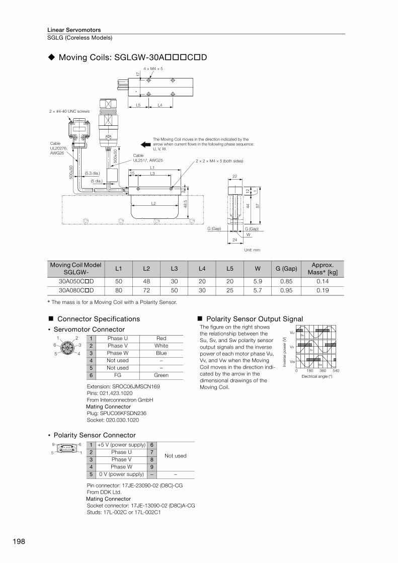
Linear ServomotorsSGLG (Coreless Models)
198
Moving Coils: SGLGW-30ACD
* The mass is for a Moving Coil with a Polarity Sensor.
Moving Coil Model SGLGW-
L1 L2 L3 L4 L5 W G (Gap)Approx.
Mass* [kg]
30A050CD 50 48 30 20 20 5.9 0.85 0.14
30A080CD 80 72 50 30 25 5.7 0.95 0.19
Connector Specifications Polarity Sensor Output Signal
• Servomotor Connector The figure on the right shows the relationship between the Su, Sv, and Sw polarity sensor output signals and the inverse power of each motor phase Vu, Vv, and Vw when the Moving Coil moves in the direction indi-cated by the arrow in the dimensional drawings of the Moving Coil.Extension: SROC06JMSCN169
Pins: 021.423.1020 From Interconnectron GmbH Mating Connector Plug: SPUC06KFSDN236 Socket: 020.030.1020
• Polarity Sensor Connector
Pin connector: 17JE-23090-02 (D8C)-CGFrom DDK Ltd. Mating Connector Socket connector: 17JE-13090-02 (D8C)A-CGStuds: 17L-002C or 17L-002C1
2 × #4-40 UNC screws
CableUL20276, AWG26
(5.3 dia.)
(5 dia.)
The Moving Coil moves in the direction indicated by the arrow when current flows in the following phase sequence: U, V, W.
Cable UL2517, AWG25 2 × 2 × M4 × 5 (both sides)
Unit: mm
3
22
24
48.5
15
500±
50
500±
50
L1L3
L2
G (Gap)G (Gap)
17
4 × M4 × 5
L5 L4
15744
W
12
Vu
Vv
Vw
Su
Sv
Sw
0 180 360 540
Electrical angle (°)
Inve
rse
pow
er (V
)
3
2
4
6
1
5
1 Phase U Red2 Phase V White3 Phase W Blue4 Not used −5 Not used −6 FG Green
9 6
5 1
1 +5 V (power supply) 6
Not used2 Phase U 73 Phase V 84 Phase W 95 0 V (power supply) − −
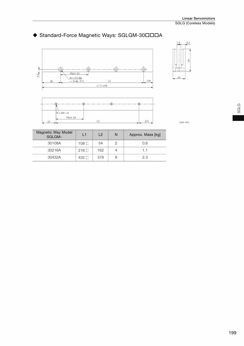
Linear Servomotors SGLG (Coreless Models)
199
SG
LG
Standard-Force Magnetic Ways: SGLGM-30A
Magnetic Way Model SGLGM-
L1 L2 N Approx. Mass [kg]
30108A 108 54 2 0.6
30216A 216 162 4 1.1
30432A 432 378 8 2.3
Pitch: 54
L1 (1 unit)
Pitch: 54
Unit: mm
8 dia. 5N × 4.5 dia.
27 (27)
44
7.6 8.2
N × M4 × 6
24
L2
4.5
36 (18)L2
-0.1-0.1
-0.1-0.1
-0.1-0.1

Linear ServomotorsSGLG (Coreless Models)
200
SGLGW-40
Moving Coils: SGLGW-40AC
* The mass is for a Moving Coil with a Polarity Sensor.
Moving Coil Model
SGLGW-L1 L2 L3 L4 L5 L6 N1 N2
Approx. Mass* [kg]
40A140C 140 125 90 30 52.5 45 3 4 0.40
40A253C 252.5 237.5 180 37.5 60 135 5 8 0.66
40A365C 365 350 315 30 52.5 270 8 14 0.93
Connector Specifications Polarity Sensor Output Signal
• Servomotor Connector The figure on the right shows the relationship between the Su, Sv, and Sw polarity sensor output signals and the inverse power of each motor phase Vu, Vv, and Vw when the Moving Coil moves in the direction indi-cated by the arrow in the dimensional drawings of the Moving Coil.
Plug: 350779-1 Pins: 350561-3 or 350690-3 (No.1 to 3)
350654-1 or 350669-1 (No. 4) From Tyco Electronics Japan G.K. Mating Connector Cap: 350780-1 Socket: 350570-3 or 350689-3
• Polarity Sensor Connector
Pin connector: 17JE-23090-02 (D8C)-CGFrom DDK Ltd. Mating Connector Socket connector: 17JE-13090-02 (D8C)A-CGStuds: 17L-002C or 17L-002C1
2 × #4-40 UNC screws
(5.3 dia.)(7 dia.)
Polarity sensor
The Moving Coil moves in the direction indicated by the arrow when current flows in the following phase sequence: U, V, W.
N1 × M4 × 6 (both sides)
Unit: mm
N2 × M4 × 6
15
63
30
4
(7.5)
17
L5 L645
L1L316 L4
45
L2
500±
50 500±
50
15 1
25.4
Gap 0.8Gap 0.8
25.4
78
62
5.8
Vu
Vv
Vw
Su
Sv
Sw
0 180 360 540
Electrical angle (°)
Inve
rse
pow
er (V
)
1 2 3 41 Phase U Red2 Phase V White3 Phase W Blue4 FG Green
9 6
5 1
1 +5 V (power supply) 6
Not used2 Phase U 73 Phase V 84 Phase W 95 0 V (power supply) − −

Linear Servomotors SGLG (Coreless Models)
201
SG
LG
Moving Coils: SGLGW-40ACD
* The mass is for a Moving Coil with a Polarity Sensor.
Moving Coil Model
SGLGW-L1 L2 L3 L4 L5 L6 N1 N2
Approx. Mass* [kg]
40A140CD 140 125 90 30 52.5 45 3 4 0.40
40A253CD 252.5 237.5 180 37.5 60 135 5 8 0.66
40A365CD 365 350 315 30 52.5 270 8 14 0.93
Connector Specifications Polarity Sensor Output Signal
• Servomotor Connector The figure on the right shows the relationship between the Su, Sv, and Sw polarity sensor output signals and the inverse power of each motor phase Vu, Vv, and Vw when the Moving Coil moves in the direction indi-cated by the arrow in the dimensional drawings of the Moving Coil.Extension: SROC06JMSCN169
Pins: 021.423.1020 From Interconnectron GmbH Mating Connector Plug: SPUC06KFSDN236 Socket: 020.030.1020
• Polarity Sensor Connector
Pin connector: 17JE-23090-02 (D8C)-CGFrom DDK Ltd. Mating Connector Socket connector: 17JE-13090-02 (D8C)A-CGStuds: 17L-002C or 17L-002C1
2 × #4-40 UNC screws
Polarity sensor
The Moving Coil moves in the direction indicated by the arrow when current flows in the following phase sequence: U, V, W.
N1 × M4 × 6 (both sides)
Unit: mm
(7 dia.)(5.3 dia.)
N2 × M4 × 6
15
63
30
4
(7.5)
17
L5 L645
L1L3
L2
16 L445
500±
50 500±
50
15 1
25.4
Gap 0.8Gap 0.8
25.4
78
62
5.8
Vu
Vv
Vw
Su
Sv
Sw
0 180 360 540
Electrical angle (°)
Inve
rse
pow
er (V
)
3
2
4
6
1
5
1 Phase U Red2 Phase V White3 Phase W Blue4 Not used −5 Not used −6 FG Green
9 6
5 1
1 +5 V (power supply) 6
Not used2 Phase U 73 Phase V 84 Phase W 95 0 V (power supply) − −

Linear ServomotorsSGLG (Coreless Models)
202
Standard-Force Magnetic Ways: SGLGM-40C (without Mounting Holes on the Bottom) SGLGM-40CT (with Mounting Holes on the Bottom)
Type Magnetic Way Model SGLGM- L1 L2 N Approx. Mass [kg]
Standard-Force
40090C or 40090CT 90 45 2 0.8
40225C or 40225CT 225 180 5 2.0
40360C or 40360CT 360 315 8 3.1
40405C or 40405CT 405 360 9 3.5
40450C or 40450CT 450 405 10 3.9
10 dia. 5.4
L1 (1 unit)
( SGLGM- CT only)Unit: mm
5.5
dia.
10 d
ia.
5.5
dia.
10 d
ia.
Pitch: 45
N × 5.5 dia.
Pitch: 45
7
L222.5
L222.5
N × M5 × 13
X
X
(22.5)
(22.5)
5.4
9
62
7.4
25.4
X-X
9
12.7
62
5.4
(13)
7.4
25.4
X-X
X
XSGLGM-40C
SGLGM-40CT
-0.1-0.3
-0.1-0.3
-0.1-0.3
-0.1-0.3
-0.1-0.3
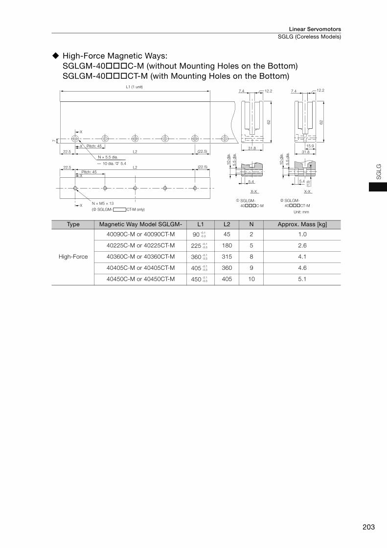
Linear Servomotors SGLG (Coreless Models)
203
SG
LG
High-Force Magnetic Ways: SGLGM-40C-M (without Mounting Holes on the Bottom) SGLGM-40CT-M (with Mounting Holes on the Bottom)
Type Magnetic Way Model SGLGM- L1 L2 N Approx. Mass [kg]
High-Force
40090C-M or 40090CT-M 90 45 2 1.0
40225C-M or 40225CT-M 225 180 5 2.6
40360C-M or 40360CT-M 360 315 8 4.1
40405C-M or 40405CT-M 405 360 9 4.6
40450C-M or 40450CT-M 450 405 10 5.1
Pitch: 45
L1 (1 unit)
( SGLGM- CT-M only)Unit: mm
5.5
dia.
10 d
ia.
5.5
dia.
10 d
ia.
10 dia. 5.4
N × 5.5 dia.
Pitch: 45L222.5
22.5 (22.5)
(22.5)
L2
7
62 62
12.27.4
31.815.9
12.2
31.8
7.4
X
X
X
X
5.4
(13)5.4
X-X X-X
N × M5 × 13SGLGM-40C-M
SGLGM-40CT-M
-0.1-0.3
-0.1-0.3
-0.1-0.3
-0.1-0.3
-0.1-0.3

Linear ServomotorsSGLG (Coreless Models)
204
SGLGW-60
Moving Coils: SGLGW-60AC
* The mass is for a Moving Coil with a Polarity Sensor.
Moving Coil ModelSGLGW-
L1 L2 L3 L4 L5 L6 N1 N2Approx.
Mass* [kg]
60A140C 140 125 90 30 52.5 45 3 4 0.48
60A253C 252.5 237.5 180 37.5 60 135 5 8 0.82
60A365C 365 350 315 30 52.5 270 8 14 1.16
Connector Specifications Polarity Sensor Output Signal
• Servomotor Connector The figure on the right shows the relationship between the Su, Sv, and Sw polarity sensor output signals and the inverse power of each motor phase Vu, Vv, and Vw when the Moving Coil moves in the direction indi-cated by the arrow in the dimensional drawings of the Moving Coil.
Plug: 350779-1 Pins: 350561-3 or 350690-3 (No.1 to 3)
350654-1 or 350669-1 (No. 4) From Tyco Electronics Japan G.K. Mating Connector Cap: 350780-1 Socket: 350570-3 or 350689-3
• Polarity Sensor Connector
Pin connector: 17JE-23090-02 (D8C)-CGFrom DDK Ltd. Mating Connector Socket connector: 17JE-13090-02 (D8C)A-CGStuds: 17L-002C or 17L-002C1
2 × #4-40 UNC screws
(5.3 dia.)(7 dia.)
Polarity sensor
The Moving Coil moves in the direction indicated by the arrow when current flows in the following phase sequence: U, V, W.
N1 × M4 × 6 (both sides)
Unit: mm
N2 × M4 × 6
15
83
L645
L5
30
500±
50
16 L4
45
L1
L3
(7.5)L2
500±
50
4
17
15 1
25.4
Gap 0.8Gap 0.8
25.4
98
82
5.8
Vu
Vv
Vw
Su
Sv
Sw
0 180 360 540
Electrical angle (°)
Inve
rse
pow
er (V
)
1 2 3 41 Phase U Red2 Phase V White3 Phase W Blue4 FG Green
9 6
5 1
1 +5 V (power supply) 6
Not used2 Phase U 73 Phase V 84 Phase W 95 0 V (power supply) − −

Linear Servomotors SGLG (Coreless Models)
205
SG
LG
Moving Coils: SGLGW-60ACD
* The mass is for a Moving Coil with a Polarity Sensor.
Moving Coil ModelSGLGW-
L1 L2 L3 L4 L5 L6 N1 N2Approx.
Mass* [kg]
60A140CD 140 125 90 30 52.5 45 3 4 0.48
60A253CD 252.5 237.5 180 37.5 60 135 5 8 0.82
60A365CD 365 350 315 30 52.5 270 8 14 1.16
Connector Specifications Polarity Sensor Output Signal
• Servomotor Connector The figure on the right shows the relationship between the Su, Sv, and Sw polarity sensor output signals and the inverse power of each motor phase Vu, Vv, and Vw when the Moving Coil moves in the direction indi-cated by the arrow in the dimensional drawings of the Moving Coil.Extension: SROC06JMSCN169
Pins: 021.423.1020 From Interconnectron GmbH Mating Connector Plug: SPUC06KFSDN236 Socket: 020.030.1020
• Polarity Sensor Connector
Pin connector: 17JE-23090-02 (D8C)-CGFrom DDK Ltd. Mating Connector Socket connector: 17JE-13090-02 (D8C)A-CGStuds: 17L-002C or 17L-002C1
The Moving Coil moves in the direction indicated by the arrow when current flows in the following phase sequence: U, V, W.
Polarity sensor
Unit: mm
N1 × M4 × 6 (both sides)(7 dia.)
(5.3 dia.)
2 × #4-40 UNC screws
N2 × M4 × 6
1583
L645
L5
3050
0±50
16 L445
L1L3
(7.5)L2
500±
50
4
17
15 1
25.4
Gap 0.8Gap 0.8
25.4
98
82
5.8
Vu
Vv
Vw
Su
Sv
Sw
0 180 360 540
Electrical angle (°)
Inve
rse
pow
er (V
)
3
2
4
6
1
5
1 Phase U Red2 Phase V White3 Phase W Blue4 Not used −5 Not used −6 FG Green
9 6
5 1
1 +5 V (power supply) 6
Not used2 Phase U 73 Phase V 84 Phase W 95 0 V (power supply) − −
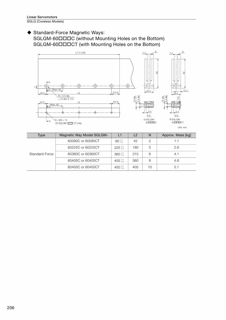
Linear ServomotorsSGLG (Coreless Models)
206
Standard-Force Magnetic Ways: SGLGM-60C (without Mounting Holes on the Bottom) SGLGM-60CT (with Mounting Holes on the Bottom)
Type Magnetic Way Model SGLGM- L1 L2 N Approx. Mass [kg]
Standard-Force
60090C or 60090CT 90 45 2 1.1
60225C or 60225CT 225 180 5 2.6
60360C or 60360CT 360 315 8 4.1
60405C or 60405CT 405 360 9 4.6
60450C or 60450CT 450 405 10 5.1
22.5
7
L2
L2
N M5 13
22.5
X
(22.5)
(22.5)X
X
X
5.4
9
82
7.4
25.4
X-X
12.7
82
5.4
(13)
7.4
25.4
9
X-X
SGLGM-60C
SGLGM-60CT
5.5
dia.
10 dia. 5.4N × 5.5 dia.
L1 (1 unit)
Unit: mm
10 d
ia.
5.5
dia.
10 d
ia.
Pitch: 45
( SGLGM- CT only)
Pitch: 45
-0.1-0.3
-0.1-0.3
-0.1-0.3
-0.1-0.3
-0.1-0.3

Linear Servomotors SGLG (Coreless Models)
207
SG
LG
High-Force Magnetic Ways: SGLGM-60C-M (without Mounting Holes on the Bottom) SGLGM-60CT-M (with Mounting Holes on the Bottom)
Type Magnetic Way Model SGLGM- L1 L2 N Approx. Mass [kg]
High-Force
60090C-M or 60090CT-M 90 45 2 1.3
60225C-M or 60225CT-M 225 180 5 3.3
60360C-M or 60360CT-M 360 315 8 5.2
60405C-M or 60405CT-M 405 360 9 5.9
60450C-M or 60450CT-M 450 405 10 6.6
10 dia. 5.4
( SGLGM- CT-M only)Unit: mm
Pitch: 45
N × 5.5 dia.
10 d
ia.
5.5
dia.
10 d
ia.
5.5
dia.
Pitch: 45
L1 (1 unit)
L222.5 (22.5)
(22.5)22.5 L2
N × M5 × 13
7
82 82
12.27.4
31.815.9
12.2
31.8
7.4
SGLGM-60C-M
SGLGM-60CT-M
X
X
X
X
5.4
(13)5.4
X-X X-X
-0.1-0.3
-0.1-0.3
-0.1-0.3
-0.1-0.3
-0.1-0.3
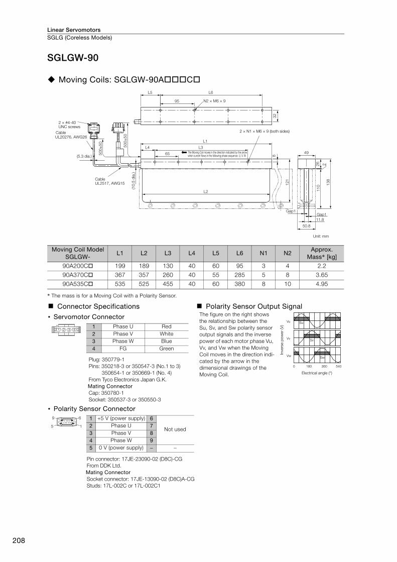
Linear ServomotorsSGLG (Coreless Models)
208
SGLGW-90
Moving Coils: SGLGW-90AC
* The mass is for a Moving Coil with a Polarity Sensor.
Moving Coil ModelSGLGW-
L1 L2 L3 L4 L5 L6 N1 N2Approx.
Mass* [kg]
90A200C 199 189 130 40 60 95 3 4 2.2
90A370C 367 357 260 40 55 285 5 8 3.65
90A535C 535 525 455 40 60 380 8 10 4.95
Connector Specifications Polarity Sensor Output Signal
• Servomotor Connector The figure on the right shows the relationship between the Su, Sv, and Sw polarity sensor output signals and the inverse power of each motor phase Vu, Vv, and Vw when the Moving Coil moves in the direction indi-cated by the arrow in the dimensional drawings of the Moving Coil.
Plug: 350779-1 Pins: 350218-3 or 350547-3 (No.1 to 3)
350654-1 or 350669-1 (No. 4) From Tyco Electronics Japan G.K. Mating Connector Cap: 350780-1 Socket: 350537-3 or 350550-3
• Polarity Sensor Connector
Pin connector: 17JE-23090-02 (D8C)-CGFrom DDK Ltd. Mating Connector Socket connector: 17JE-13090-02 (D8C)A-CGStuds: 17L-002C or 17L-002C1
UL20276, AWG26
2 × #4-40 UNC screws
The Moving Coil moves in the direction indicated by the arrow when current flows in the following phase sequence: U, V, W.
2 × N1 × M6 × 9 (both sides)
Unit: mm
Cable
(5.3 dia.)
(10.
5 di
a.)
Cable UL2517, AWG15
2
50.8
Gap1Gap1
11.8
26
49
138
110
32
500±
50
L2
95
8
121
500±
50
65
L3L4
L1
L6L5
N2 × M6 × 9
Vu
Vv
Vw
Su
Sv
Sw
0 180 360 540
Electrical angle (°)
Inve
rse
pow
er (V
)
1 2 3 41 Phase U Red2 Phase V White3 Phase W Blue4 FG Green
9 6
5 1
1 +5 V (power supply) 6
Not used2 Phase U 73 Phase V 84 Phase W 95 0 V (power supply) − −

Linear Servomotors SGLG (Coreless Models)
209
SG
LG
Standard-Force Magnetic Ways: SGLGM-90A
Magnetic Way ModelSGLGM-
L1 L2 N Approx. Mass [kg]
90252A 252 189 4 7.3
90504A 504 441 8 14.7
L1 (1 unit)
Pitch: 63
N × 6.6 dia.
Pitch: 63 12 d
ia.
6.6
dia.
Unit: mm
12 dia. 6.5
X-X
6.5
50.8
110
13.8 18.5
X
X
L2
L231.5 (31.5)
N × M6 × 14.5
8.5
19 (44)
-0.1-0.3
-0.1-0.3
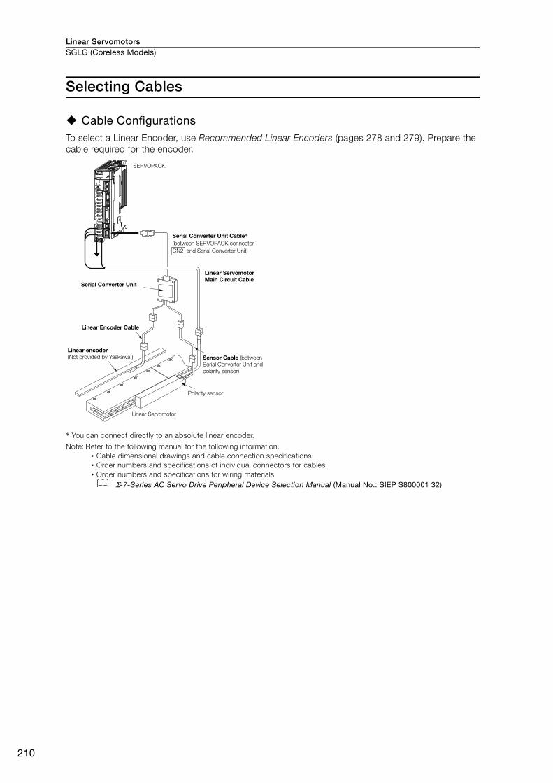
Linear ServomotorsSGLG (Coreless Models)
210
Selecting Cables
Cable ConfigurationsTo select a Linear Encoder, use Recommended Linear Encoders (pages 278 and 279). Prepare the cable required for the encoder.
* You can connect directly to an absolute linear encoder.
Note: Refer to the following manual for the following information.• Cable dimensional drawings and cable connection specifications• Order numbers and specifications of individual connectors for cables• Order numbers and specifications for wiring materials
Σ-7-Series AC Servo Drive Peripheral Device Selection Manual (Manual No.: SIEP S800001 32)
SERVOPACK
Serial Converter Unit Cable*
(between SERVOPACK connector
CN2 and Serial Converter Unit)
Linear Servomotor Main Circuit Cable
Sensor Cable (between
Serial Converter Unit and
polarity sensor)
Polarity sensor
Serial Converter Unit
Linear Encoder Cable
Linear encoder (Not provided by Yaskawa.)
Linear Servomotor

Linear Servomotors SGLG (Coreless Models)
211
SG
LG
Linear Servomotor Main Circuit Cables
*1. Connector from Tyco Electronics Japan G.K.
*2. Connector from Interconnectron GmbH
Linear Servomotor ModelLength
(L)Order Number Appearance
SGLGW-30A, -40A, -60A
1 m JZSP-CLN11-01-E
3 m JZSP-CLN11-03-E
5 m JZSP-CLN11-05-E
10 m JZSP-CLN11-10-E
15 m JZSP-CLN11-15-E
20 m JZSP-CLN11-20-E
SGLGW-90A
1 m JZSP-CLN21-01-E
3 m JZSP-CLN21-03-E
5 m JZSP-CLN21-05-E
10 m JZSP-CLN21-10-E
15 m JZSP-CLN21-15-E
20 m JZSP-CLN21-20-E
SGLGW-30AD-40AD-60AD
1 m JZSP-CLN14-01-E
3 m JZSP-CLN14-03-E
5 m JZSP-CLN14-05-E
10 m JZSP-CLN14-10-E
15 m JZSP-CLN14-15-E
20 m JZSP-CLN14-20-E
L
*1
SERVOPACK end Linear Servomotorend
L
*1
SERVOPACK end Linear Servomotor end
L
*2
SERVOPACK end Linear Servomotor end
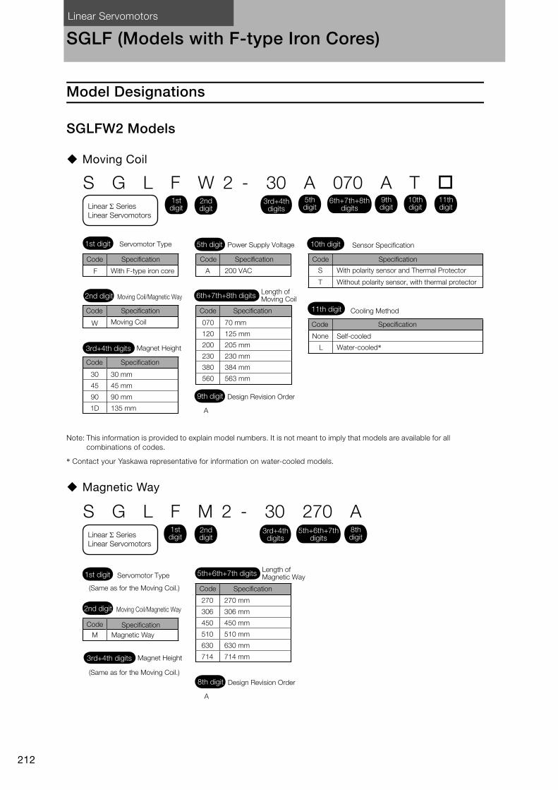
Linear Servomotors
212
SGLF (Models with F-type Iron Cores)
Model Designations
SGLFW2 Models
Moving Coil
Note: This information is provided to explain model numbers. It is not meant to imply that models are available for all combinations of codes.
* Contact your Yaskawa representative for information on water-cooled models.
Magnetic Way
S G L F W 2 - 30 A 070 A T
F A
W
30
45
90
1D
30 mm
45 mm
90 mm
135 mm
070
120
200
230
380
560
70 mm
125 mm
205 mm
230 mm
384 mm
563 mm
T
S
L
Sensor Specification
With F-type iron core
Without polarity sensor, with thermal protector
With polarity sensor and Thermal Protector
Cooling Method
Moving Coil
None Self-cooled
Water-cooled*
200 VAC
Servomotor Type Power Supply Voltage
Length of Moving Coil
Design Revision Order
Magnet Height
Moving Coil/Magnetic Way
1st digit
3rd+4th digits
2nd digit
11th digit
9th digit
6th+7th+8th digits
5th digit 10th digit
3rd+4th digits
1st digitLinear Series
Linear Servomotors
2nd digit
5th digit
6th+7th+8th digits
9th digit
10th digit
11th digit
Code Specification
A
Code Specification
Code Specification
Code Specification
Code Specification
Code Specification
Code Specification
270
306
450
510
630
714
M
S G L F M 2 - 30 270 A
(Same as for the Moving Coil.)
(Same as for the Moving Coil.)
Magnetic Way
270 mm
306 mm
450 mm
510 mm
630 mm
714 mm
Servomotor TypeLength of Magnetic Way
Design Revision Order
Magnet Height
Moving Coil/Magnetic Way
1st digit
3rd+4th digits
2nd digit
8th digit
5th+6th+7th digits
3rd+4th digits
1st digitLinear Series
Linear Servomotors
2nd digit
5th+6th+7th digits
8th digit
Code Specification
A
Code Specification

Linear Servomotors SGLF (Models with F-type Iron Cores)
213
SG
LF
SGLFW Models
Moving Coil
Note: This information is provided to explain model numbers. It is not meant to imply that models are available for all combinations of codes.
Magnetic Way
S G L F W - 20 A 090 A P
F A
W
20
35
50
1Z
20 mm
36 mm
47.5 mm
95 mm
090
120
200
230
380
91 mm
127 mm
215 mm
235 mm
395 mm
SGLFW-35, -50,
-1Z200B
Connector for Servomotor Main Circuit Cable
Connector from Tyco
Electronics Japan G.K.All models
Connector from
Interconnectron GmbH
Applicable Models
None
Moving Coil
With polarity sensor
Without polarity sensorNone
With F-type iron core
Voltage
P
D
Sensor Specification
200 VAC
Servomotor Type
Length of Moving Coil
Design Revision Order
Magnet Height
Moving Coil/Magnetic Way
1st digit
3rd+4th digits
2nd digit
11th digit
9th digit
6th+7th+8th digits
5th digit 10th digit
3rd+4th digits
1st digitLinear Series
Linear Servomotors
2nd digit
5th digit
6th+7th+8th digits
9th digit
10th digit
11th digit
Code Specification
A, B ...
Code Specification
Code SpecificationCode Specification
Code Specification Code Specification Code Specification
324
405
540
675
756
945
M
S G L F M - 20 324 A
Without options
With magnet cover
Options
(Same as for the Moving Coil.)
Magnetic Way
(Same as for the Moving Coil.)
324 mm
405 mm
540 mm
675 mm
756 mm
945 mm
None
C
Servomotor TypeLength of Magnetic Way
Design Revision Order
Magnet Height
Moving Coil/Magnetic Way
1st digit
3rd+4th digits
2nd digit
8th digit
5th+6th+7th digits 9th digit
3rd+4th digits
1st digitLinear Series
Linear Servomotors
2nd digit
8th digit
5th+6th+7th digits
9th digit
A, B ...
Code Specification
Code Specification
Code Specification
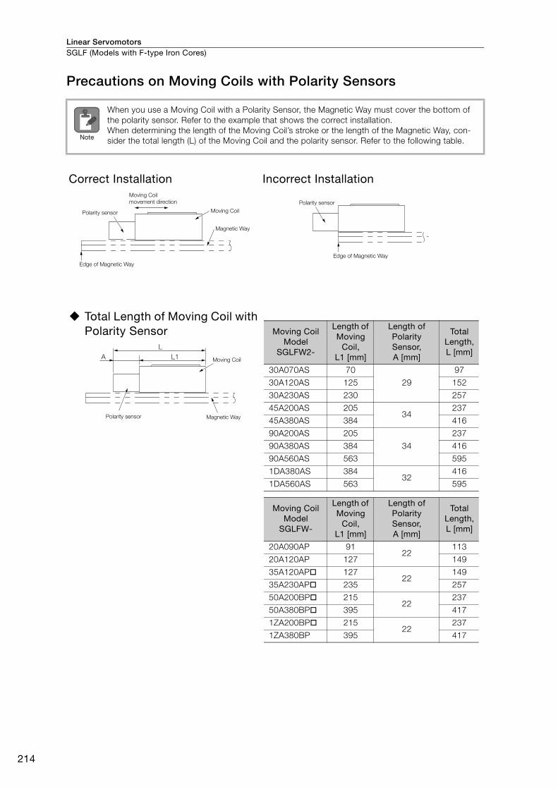
Linear ServomotorsSGLF (Models with F-type Iron Cores)
214
Precautions on Moving Coils with Polarity Sensors
When you use a Moving Coil with a Polarity Sensor, the Magnetic Way must cover the bottom of the polarity sensor. Refer to the example that shows the correct installation. When determining the length of the Moving Coil’s stroke or the length of the Magnetic Way, con-sider the total length (L) of the Moving Coil and the polarity sensor. Refer to the following table.
Correct Installation Incorrect Installation
Total Length of Moving Coil with Polarity Sensor
Note
Polarity sensor
Moving Coil
movement direction
Magnetic Way
Moving Coil
Edge of Magnetic Way
Polarity sensor
Edge of Magnetic Way
Moving Coil
Magnetic WayPolarity sensor
L
L1A
Moving Coil Model
SGLFW2-
Length of Moving
Coil, L1 [mm]
Length of Polarity Sensor, A [mm]
Total Length, L [mm]
30A070AS 70
29
97
30A120AS 125 152
30A230AS 230 257
45A200AS 20534
237
45A380AS 384 416
90A200AS 205
34
237
90A380AS 384 416
90A560AS 563 595
1DA380AS 38432
416
1DA560AS 563 595
Moving Coil Model
SGLFW-
Length of Moving
Coil, L1 [mm]
Length of Polarity Sensor, A [mm]
Total Length, L [mm]
20A090AP 9122
113
20A120AP 127 149
35A120AP 12722
149
35A230AP 235 257
50A200BP 21522
237
50A380BP 395 417
1ZA200BP 21522
237
1ZA380BP 395 417
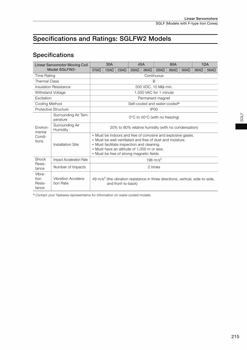
Linear Servomotors SGLF (Models with F-type Iron Cores)
215
SG
LF
Specifications and Ratings: SGLFW2 Models
Specifications
* Contact your Yaskawa representative for information on water-cooled models.
Linear Servomotor Moving Coil Model SGLFW2-
30A 45A 90A 1DA
070A 120A 230A 200A 380A 200A 380A 560A 380A 560A
Time Rating Continuous
Thermal Class B
Insulation Resistance 500 VDC, 10 MΩ min.
Withstand Voltage 1,500 VAC for 1 minute
Excitation Permanent magnet
Cooling Method Self-cooled and water-cooled*Protective Structure IP00
Environ-mental Condi-tions
Surrounding Air Tem-perature
0°C to 40°C (with no freezing)
Surrounding Air Humidity
20% to 80% relative humidity (with no condensation)
Installation Site
• Must be indoors and free of corrosive and explosive gases.• Must be well-ventilated and free of dust and moisture.• Must facilitate inspection and cleaning.• Must have an altitude of 1,000 m or less. • Must be free of strong magnetic fields.
Shock Resis-tance
Impact Acceleration Rate 196 m/s2
Number of Impacts 2 times
Vibra-tion Resis-tance
Vibration Accelera-tion Rate
49 m/s2 (the vibration resistance in three directions, vertical, side-to-side, and front-to-back)
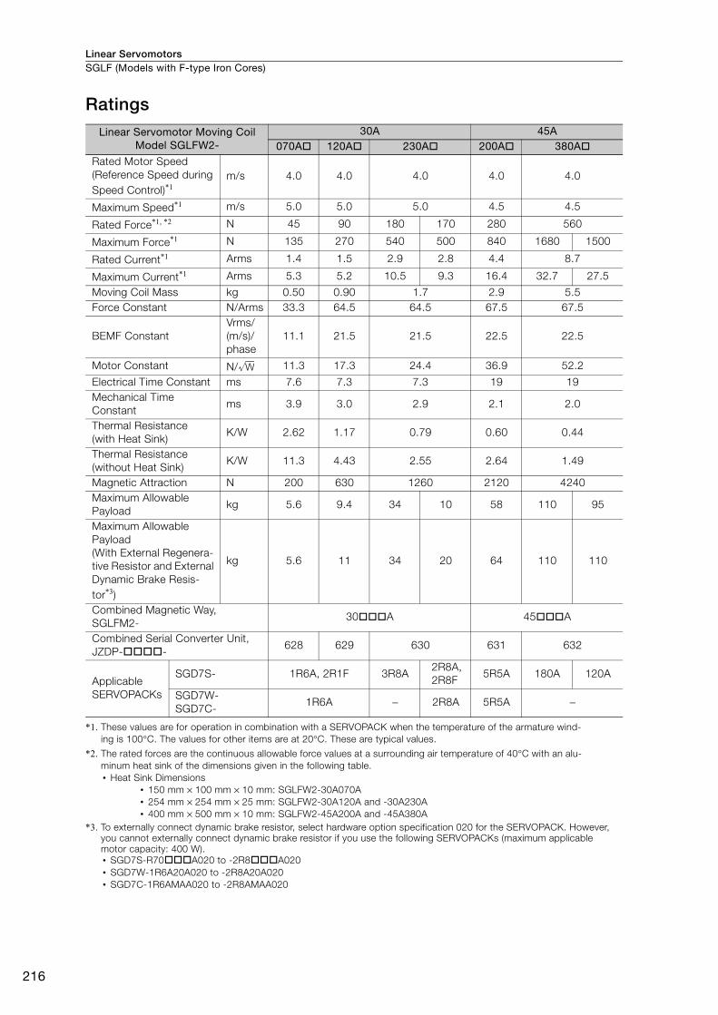
Linear ServomotorsSGLF (Models with F-type Iron Cores)
216
Ratings
*1. These values are for operation in combination with a SERVOPACK when the temperature of the armature wind-ing is 100°C. The values for other items are at 20°C. These are typical values.
*2. The rated forces are the continuous allowable force values at a surrounding air temperature of 40°C with an alu-minum heat sink of the dimensions given in the following table.• Heat Sink Dimensions
• 150 mm × 100 mm × 10 mm: SGLFW2-30A070A• 254 mm × 254 mm × 25 mm: SGLFW2-30A120A and -30A230A• 400 mm × 500 mm × 10 mm: SGLFW2-45A200A and -45A380A
*3. To externally connect dynamic brake resistor, select hardware option specification 020 for the SERVOPACK. However, you cannot externally connect dynamic brake resistor if you use the following SERVOPACKs (maximum applicable motor capacity: 400 W).• SGD7S-R70A020 to -2R8A020• SGD7W-1R6A20A020 to -2R8A20A020• SGD7C-1R6AMAA020 to -2R8AMAA020
Linear Servomotor Moving Coil Model SGLFW2-
30A 45A070A 120A 230A 200A 380A
Rated Motor Speed (Reference Speed during Speed Control)*1
m/s 4.0 4.0 4.0 4.0 4.0
Maximum Speed*1 m/s 5.0 5.0 5.0 4.5 4.5
Rated Force*1, *2 N 45 90 180 170 280 560
Maximum Force*1 N 135 270 540 500 840 1680 1500
Rated Current*1 Arms 1.4 1.5 2.9 2.8 4.4 8.7
Maximum Current*1 Arms 5.3 5.2 10.5 9.3 16.4 32.7 27.5
Moving Coil Mass kg 0.50 0.90 1.7 2.9 5.5 Force Constant N/Arms 33.3 64.5 64.5 67.5 67.5
BEMF Constant Vrms/(m/s)/phase
11.1 21.5 21.5 22.5 22.5
Motor Constant N/ 11.3 17.3 24.4 36.9 52.2
Electrical Time Constant ms 7.6 7.3 7.3 19 19 Mechanical TimeConstant
ms 3.9 3.0 2.9 2.1 2.0
Thermal Resistance(with Heat Sink)
K/W 2.62 1.17 0.79 0.60 0.44
Thermal Resistance (without Heat Sink)
K/W 11.3 4.43 2.55 2.64 1.49
Magnetic Attraction N 200 630 1260 2120 4240 Maximum AllowablePayload
kg 5.6 9.4 34 10 58 110 95
Maximum AllowablePayload(With External Regenera-tive Resistor and External Dynamic Brake Resis-tor*3)
kg 5.6 11 34 20 64 110 110
Combined Magnetic Way, SGLFM2-
30A 45A
Combined Serial Converter Unit, JZDP--
628 629 630 631 632
Applicable SERVOPACKs
SGD7S- 1R6A, 2R1F 3R8A2R8A,2R8F
5R5A 180A 120A
SGD7W-SGD7C-
1R6A − 2R8A 5R5A −
W
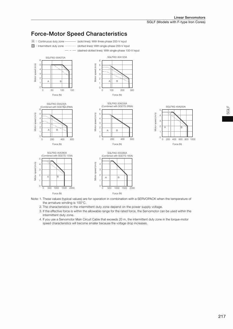
Linear Servomotors SGLF (Models with F-type Iron Cores)
217
SG
LF
Force-Motor Speed Characteristics
Note: 1. These values (typical values) are for operation in combination with a SERVOPACK when the temperature of the armature winding is 100°C.
2. The characteristics in the intermittent duty zone depend on the power supply voltage.3. If the effective force is within the allowable range for the rated force, the Servomotor can be used within the
intermittent duty zone.4. If you use a Servomotor Main Circuit Cable that exceeds 20 m, the intermittent duty zone in the torque-motor
speed characteristics will become smaller because the voltage drop increases.
SGLFW2-30A070A
SGLFW2-45A200A
SGLFW2-45A380A
(Combined with SGD7S-120A)SGLFW2-45A380A
(Combined with SGD7S-180A)
SGLFW2-30A230A
(Combined with SGD7�-2R8A)
SGLFW2-30A230A
(Combined with SGD7S-3R8A)
SGLFW2-30A120A
6
5
4
3
2
1
0
0 50 100 150
A B
6
5
4
3
2
1
00 100 200 300
A B
A B
6
5
4
3
2
1
0
A B
6
5
4
3
2
1
0
A B
5
4
3
2
1
0
5
4
3
2
1
00 200015001000500
A B
5
4
3
2
1
00 200015001000500
A B
0 10008006004002000 200 400 600 0 200 400 600
Force (N)
Mo
tor
sp
eed
(m
/s)
Force (N)M
oto
r sp
eed
(m
/s)
Force (N)
Mo
tor
sp
eed
(m
/s)
Force (N)
Mo
tor
sp
eed
(m
/s)
Force (N)
Mo
tor
sp
eed
(m
/s)
Force (N)
Mo
tor
sp
eed
(m
/s)
Force (N)
Mo
tor
sp
eed
(m
/s)
(dashed-dotted lines): With single-phase 100-V input
Continuous duty zone
Intermittent duty zone
(solid lines): With three-phase 200-V input
(dotted lines): With single-phase 200-V input
A :
B :
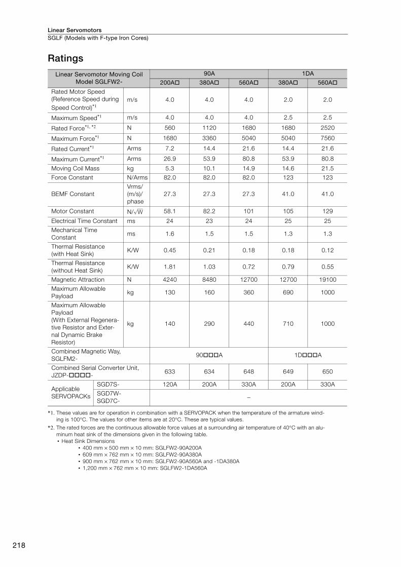
Linear ServomotorsSGLF (Models with F-type Iron Cores)
218
Ratings
*1. These values are for operation in combination with a SERVOPACK when the temperature of the armature wind-ing is 100°C. The values for other items are at 20°C. These are typical values.
*2. The rated forces are the continuous allowable force values at a surrounding air temperature of 40°C with an alu-minum heat sink of the dimensions given in the following table.• Heat Sink Dimensions
• 400 mm × 500 mm × 10 mm: SGLFW2-90A200A• 609 mm × 762 mm × 10 mm: SGLFW2-90A380A• 900 mm × 762 mm × 10 mm: SGLFW2-90A560A and -1DA380A• 1,200 mm × 762 mm × 10 mm: SGLFW2-1DA560A
Linear Servomotor Moving Coil Model SGLFW2-
90A 1DA
200A 380A 560A 380A 560A
Rated Motor Speed (Reference Speed during Speed Control)*1
m/s 4.0 4.0 4.0 2.0 2.0
Maximum Speed*1 m/s 4.0 4.0 4.0 2.5 2.5
Rated Force*1, *2 N 560 1120 1680 1680 2520
Maximum Force*1 N 1680 3360 5040 5040 7560
Rated Current*1 Arms 7.2 14.4 21.6 14.4 21.6
Maximum Current*1 Arms 26.9 53.9 80.8 53.9 80.8
Moving Coil Mass kg 5.3 10.1 14.9 14.6 21.5
Force Constant N/Arms 82.0 82.0 82.0 123 123
BEMF ConstantVrms/(m/s)/phase
27.3 27.3 27.3 41.0 41.0
Motor Constant N/ 58.1 82.2 101 105 129
Electrical Time Constant ms 24 23 24 25 25
Mechanical Time Constant
ms 1.6 1.5 1.5 1.3 1.3
Thermal Resistance(with Heat Sink)
K/W 0.45 0.21 0.18 0.18 0.12
Thermal Resistance(without Heat Sink)
K/W 1.81 1.03 0.72 0.79 0.55
Magnetic Attraction N 4240 8480 12700 12700 19100
Maximum AllowablePayload
kg 130 160 360 690 1000
Maximum AllowablePayload(With External Regenera-tive Resistor and Exter-nal Dynamic Brake Resistor)
kg 140 290 440 710 1000
Combined Magnetic Way, SGLFM2-
90A 1DA
Combined Serial Converter Unit, JZDP--
633 634 648 649 650
Applicable SERVOPACKs
SGD7S- 120A 200A 330A 200A 330A
SGD7W-SGD7C-
−
W
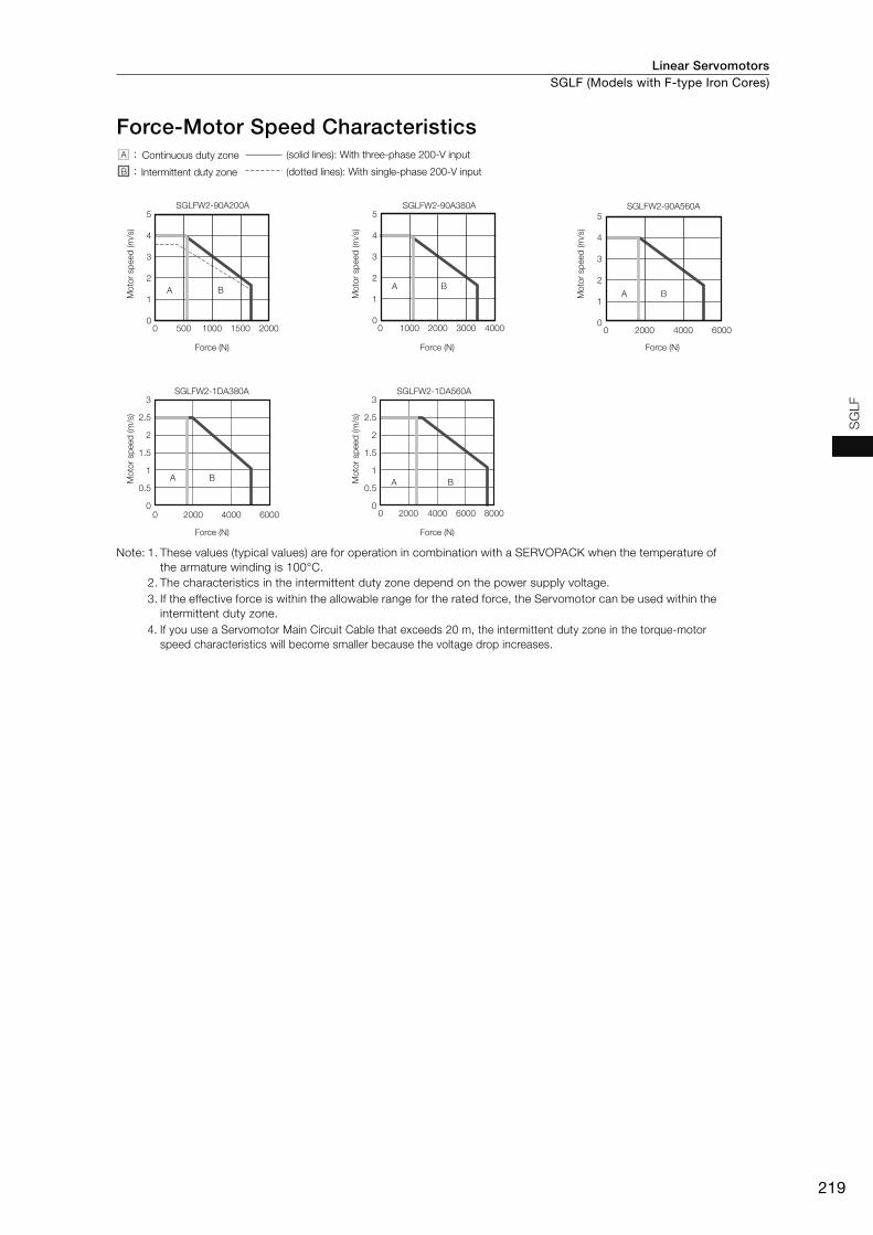
Linear Servomotors SGLF (Models with F-type Iron Cores)
219
SG
LF
Force-Motor Speed Characteristics
Note: 1. These values (typical values) are for operation in combination with a SERVOPACK when the temperature of the armature winding is 100°C.
2. The characteristics in the intermittent duty zone depend on the power supply voltage. 3. If the effective force is within the allowable range for the rated force, the Servomotor can be used within the
intermittent duty zone. 4. If you use a Servomotor Main Circuit Cable that exceeds 20 m, the intermittent duty zone in the torque-motor
speed characteristics will become smaller because the voltage drop increases.
SGLFW2-90A200A5
4
3
2
1
00 200015001000500
A B
SGLFW2-90A380A5
4
3
2
1
00 4000300020001000
A B
SGLFW2-1DA380A
A B
3
2.5
2
1.5
1
0.5
00 2000 4000 6000
SGLFW2-1DA560A
0 8000600040002000
A B
SGLFW2-90A560A
A B
0 2000 4000 6000
5
4
3
2
1
0
3
2.5
2
1.5
1
0.5
0
Force (N)
Mo
tor
sp
eed
(m
/s)
Force (N)M
oto
r sp
eed
(m
/s)
Force (N)
Mo
tor
sp
eed
(m
/s)
Mo
tor
sp
eed
(m
/s)
Mo
tor
sp
eed
(m
/s)
Force (N) Force (N)
Continuous duty zone
Intermittent duty zone
(solid lines): With three-phase 200-V input
(dotted lines): With single-phase 200-V input
:
:
A
B
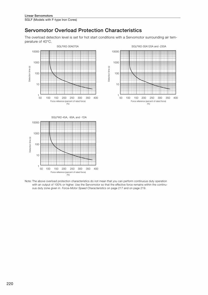
Linear ServomotorsSGLF (Models with F-type Iron Cores)
220
Servomotor Overload Protection CharacteristicsThe overload detection level is set for hot start conditions with a Servomotor surrounding air tem-perature of 40°C.
Note: The above overload protection characteristics do not mean that you can perform continuous duty operation with an output of 100% or higher. Use the Servomotor so that the effective force remains within the continu-ous duty zone given in Force-Motor Speed Characteristics on page 217 and on page 219.
40035050 100 150 200 250 300
SGLFW2-30A070A
10000
1000
100
10
1
40035050 100 150 200 250 300
10000
1000
100
10
1
40035050 100 150 200 250 300
SGLFW2-30A120A and -230A
10000
1000
100
10
1
SGLFW2-45A, -90A, and -1DA
Dete
ctio
n t
ime (s)
Force reference (percent of rated force)
(%)
Force reference (percent of rated force)
(%)
Force reference (percent of rated force)
(%)
Dete
ctio
n t
ime (s)
Dete
ctio
n t
ime (s)
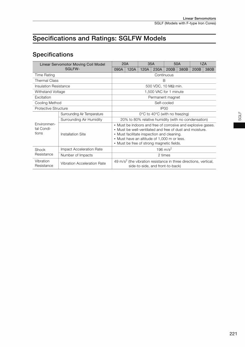
Linear Servomotors SGLF (Models with F-type Iron Cores)
221
SG
LF
Specifications and Ratings: SGLFW Models
Specifications
Linear Servomotor Moving Coil Model SGLFW-
20A 35A 50A 1ZA
090A 120A 120A 230A 200B 380B 200B 380B
Time Rating Continuous
Thermal Class B
Insulation Resistance 500 VDC, 10 MΩ min.
Withstand Voltage 1,500 VAC for 1 minute
Excitation Permanent magnet
Cooling Method Self-cooled
Protective Structure IP00
Environmen-tal Condi-tions
Surrounding Air Temperature 0°C to 40°C (with no freezing)
Surrounding Air Humidity 20% to 80% relative humidity (with no condensation)
Installation Site
• Must be indoors and free of corrosive and explosive gases.• Must be well-ventilated and free of dust and moisture.• Must facilitate inspection and cleaning.• Must have an altitude of 1,000 m or less. • Must be free of strong magnetic fields.
Shock Resistance
Impact Acceleration Rate 196 m/s2
Number of Impacts 2 times
Vibration Resistance
Vibration Acceleration Rate 49 m/s2 (the vibration resistance in three directions, vertical, side-to-side, and front-to-back)
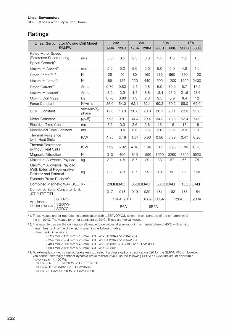
Linear ServomotorsSGLF (Models with F-type Iron Cores)
222
Ratings
*1. These values are for operation in combination with a SERVOPACK when the temperature of the armature wind-ing is 100°C. The values for other items are at 20°C. These are typical values.
*2. The rated forces are the continuous allowable force values at a surrounding air temperature of 40°C with an alu-minum heat sink of the dimensions given in the following table.• Heat Sink Dimensions
• 125 mm × 125 mm × 13 mm: SGLFW-20A090A and -20A120A• 254 mm × 254 mm × 25 mm: SGLFW-35A120A and -35A230A• 400 mm × 500 mm × 40 mm: SGLFW-50A200B, 50A380B, and -1ZA200B• 600 mm × 762 mm × 50 mm: SGLFW-1ZA380B
*3. To externally connect dynamic brake resistor, select hardware option specification 020 for the SERVOPACK. However, you cannot externally connect dynamic brake resistor if you use the following SERVOPACKs (maximum applicable motor capacity: 400 W).• SGD7S-R70A020 to -2R8A020• SGD7W-1R6A20A020 to -2R8A20A020• SGD7C-1R6AMAA020 to -2R8AMAA020
Linear Servomotor Moving Coil Model SGLFW-
20A 35A 50A 1ZA
090A 120A 120A 230A 200B 380B 200B 380B
Rated Motor Speed (Reference Speed during Speed Control)*1
m/s 5.0 3.5 2.5 3.0 1.5 1.5 1.5 1.5
Maximum Speed*1 m/s 5.0 5.0 5.0 5.0 5.0 5.0 4.9 4.9
Rated Force*1, *2 N 25 40 80 160 280 560 560 1120
Maximum Force*1 N 86 125 220 440 600 1200 1200 2400
Rated Current*1 Arms 0.70 0.80 1.4 2.8 5.0 10.0 8.7 17.5
Maximum Current*1 Arms 3.0 2.9 4.4 8.8 12.4 25.0 21.6 43.6
Moving Coil Mass kg 0.70 0.90 1.3 2.3 3.5 6.9 6.4 12
Force Constant N/Arms 36.0 54.0 62.4 62.4 60.2 60.2 69.0 69.0
BEMF ConstantVrms/(m/s)/phase
12.0 18.0 20.8 20.8 20.1 20.1 23.0 23.0
Motor Constant N/ 7.95 9.81 14.4 20.4 34.3 48.5 52.4 74.0
Electrical Time Constant ms 3.2 3.3 3.6 3.6 16 16 18 18
Mechanical Time Constant ms 11 9.4 6.3 5.5 3.0 2.9 2.3 2.1
Thermal Resistance (with Heat Sink)
K/W 4.35 3.19 1.57 0.96 0.56 0.38 0.47 0.20
Thermal Resistance (without Heat Sink)
K/W 7.69 5.02 4.10 1.94 1.65 0.95 1.30 0.73
Magnetic Attraction N 310 460 810 1590 1650 3260 3300 6520
Maximum Allowable Payload kg 3.2 4.8 8.7 29 33 67 66 78
Maximum Allowable Payload(With External Regenerative Resistor and External Dynamic Brake Resistor*3)
kg 3.2 4.8 8.7 29 40 80 82 160
Combined Magnetic Way, SGLFM- 20A 35A 50A 1ZA
Combined Serial Converter Unit, JZDP--
017 018 019 020 181 182 183 184
Applicable SERVOPACKs
SGD7S- 1R6A, 2R1F 3R8A 5R5A 120A 200A
SGD7W-SGD7C-
1R6A 5R5A −
W

Linear Servomotors SGLF (Models with F-type Iron Cores)
223
SG
LF
Force-Motor Speed Characteristics
Note: 1. These values (typical values) are for operation in combination with a SERVOPACK when the temperature of the armature winding is 100°C.
2. The characteristics in the intermittent duty zone depend on the power supply voltage.
3. If the effective force is within the allowable range for the rated force, the Servomotor can be used within the intermittent duty zone.
4. If you use a Servomotor Main Circuit Cable that exceeds 20 m, the intermittent duty zone in the torque-motor speed characteristics will become smaller because the voltage drop increases.
SGLFW-20A090A6
5
4
3
2
1
0
6
5
4
3
2
1
0
6
5
4
3
2
1
0
6
5
4
3
2
1
0
6
5
4
3
2
1
0
6
5
4
3
2
1
0
6
5
4
3
2
1
0
6
5
4
3
2
1
0
0 10080604020
A B
SGLFW-50A200B SGLFW-50A380B
0 200 400 600 800 0 500 1000 1500
SGLFW-1ZA200B SGLFW-1ZA380B
0 500 1000 1500 0 1000 2000 3000
A AB B
A B A B
SGLFW-35A120A
0 25020015010050
A B
SGLFW-35A230A
0 500400300200100
A B
SGLFW-20A120A
0 20 40 60 80 100 120 140
A B
Force (N)
Mo
tor
sp
eed
(m
/s)
Force (N)M
oto
r sp
eed
(m
/s)
Force (N)
Mo
tor
sp
eed
(m
/s)
Force (N)
Mo
tor
sp
eed
(m
/s)
Force (N)
Mo
tor
sp
eed
(m
/s)
Force (N)
Mo
tor
sp
eed
(m
/s)
Force (N)
Mo
tor
sp
eed
(m
/s)
Force (N)
Mo
tor
sp
eed
(m
/s)
Continuous duty zone
Intermittent duty zone
(solid lines): With three-phase 200-V input
(dashed-dotted lines): With single-phase 100-V input
(dotted lines): With single-phase 200-V input
A :
B :

Linear ServomotorsSGLF (Models with F-type Iron Cores)
224
Servomotor Overload Protection Characteristics The overload detection level is set for hot start conditions with a Servomotor surrounding air tem-perature of 40°C.
Note: The above overload protection characteristics do not mean that you can perform continuous duty operation with an output of 100% or higher. Use the Servomotor so that the effective force remains within the continu-ous duty zone given in Force-Motor Speed Characteristics on page 223.
SGLFW-50A and -1ZA
50 100 150 200 250 300
10000
1000
100
10
1
SGLFW-35A
35050 100 150 200 250 300
10000
1000
100
10
1450350 40050 100 150 200 250 300
SGLFW-20A
10000
1000
100
10
1
Force reference (percent of rated force)
(%)
Force reference (percent of rated force)
(%)
Force reference (percent of rated force)
(%)
Dete
ctio
n t
ime (s)
Dete
ctio
n t
ime (s)
Dete
ctio
n t
ime (s)
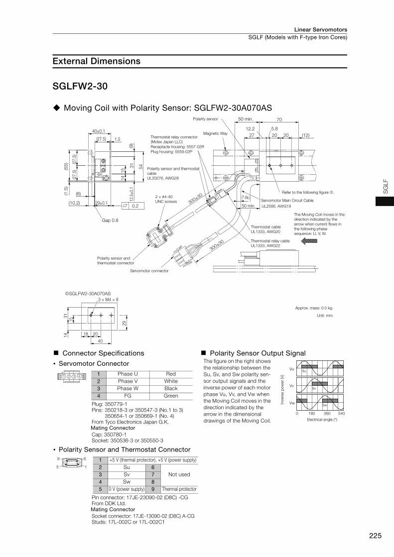
Linear Servomotors SGLF (Models with F-type Iron Cores)
225
SG
LF
External Dimensions
SGLFW2-30
Moving Coil with Polarity Sensor: SGLFW2-30A070AS
Connector Specifications Polarity Sensor Output Signal
• Servomotor Connector The figure on the right shows the relationship between the Su, Sv, and Sw polarity sen-sor output signals and the inverse power of each motor phase Vu, Vv, and Vw when the Moving Coil moves in the direction indicated by the arrow in the dimensional drawings of the Moving Coil.
Plug: 350779-1Pins: 350218-3 or 350547-3 (No.1 to 3)
350654-1 or 350669-1 (No. 4)From Tyco Electronics Japan G.K. Mating ConnectorCap: 350780-1Socket: 350536-3 or 350550-3
• Polarity Sensor and Thermostat Connector
Pin connector: 17JE-23090-02 (D8C) -CGFrom DDK Ltd. Mating ConnectorSocket connector: 17JE-13090-02 (D8C) A-CGStuds: 17L-002C or 17L-002C1
50 min.
(27.
5)(2
7.5)
(27.5) 1.5
(55
)
15
(6)
40±0.1
29±0.1
12.5
±0.
1
(10.2)
54
14
2020
70
(1.5
)
273
1(9
)(12)
(7 dia.)
50 min.0.2
Gap 0.8
5.812.2
300±30
UL2586, AWG19
Servomotor Main Circuit Cable
300±30
SGLFW2-30A070AS
31
15
14
29
40
18 20
3 × M4 × 8
Polarity sensor
Magnetic WayThermostat relay connector
(Molex Japan LLC)
Receptacle housing: 5557-02R
Plug housing: 5559-02P
Polarity sensor and thermostat
cable
UL20276, AWG28
2 × #4-40
UNC screws
Polarity sensor and
thermostat connector
Servomotor connector
Refer to the following figure .
The Moving Coil moves in the
direction indicated by the
arrow when current flows in
the following phase
sequence: U, V, W.
Thermostat cable
UL1333, AWG20
Thermostat relay cable
UL1333, AWG22
Approx. mass: 0.5 kg
Unit: mm
Vu
Vv
Vw
Su
Sv
Sw
0 180 360 540
Inve
rse p
ow
er
(V)
Electrical angle (°)
1 2 3 41 Phase U Red2 Phase V White3 Phase W Black4 FG Green
9 6
5 1
1 +5 V (thermal protector), +5 V (power supply)2 Su 6
Not used3 Sv 74 Sw 85 0 V (power supply) 9 Thermal protector

Linear ServomotorsSGLF (Models with F-type Iron Cores)
226
Moving Coils with Polarity Sensors: SGLFW2-30AAS
Moving Coil Model SGLFW2- L1 L2 L3 Approx. Mass [kg]
30A120AS 125 52.5 105.9 0.9
30A230AS 230 157.5 210.9 1.7
Connector Specifications Polarity Sensor Output Signal
• Servomotor Connector The figure on the right shows the relationship between the Su, Sv, and Sw polarity sen-sor output signals and the inverse power of each motor phase Vu, Vv, and Vw when the Moving Coil moves in the direction indicated by the arrow in the dimensional drawings of the Moving Coil.
Plug: 350779-1Pins: 350218-3 or 350547-3 (No.1 to 3)
350654-1 or 350669-1 (No. 4)From Tyco Electronics Japan G.K. Mating ConnectorCap: 350780-1Socket: 350536-3 or 350550-3
• Polarity Sensor and Thermostat Connector
Pin connector: 17JE-23090-02 (D8C) -CGFrom DDK Ltd. Mating ConnectorSocket connector: 17JE-13090-02 (D8C) A-CGStuds: 17L-002C or 17L-002C1
Unit: mm
SGLFW2-30A120AS SGLFW2-30A230AS
1531
12
7.5 39.3 52.5
27
1531
12
7.5 39.3 52.5
27
4 × M4 × 8 8 × M4 × 8
157.5 (52.5 × 3)
The Moving Coil moves in
the direction indicated by
the arrow when current flows in
the following phase sequence: U, V, W.
(27.
5)(2
7.5)
(27.5) 1.5
(55)
(0.5
)15 5
0
12
(6)
290.1
15
26.7 L2
L3
(33.2)
L1
12.50
.1
(10.2)
27400.1
31
(7)
50 min.
7.5
50 min.
(7 dia.)
12.6
0.2
Gap 0.8
Thermostat relay connector
(Molex Japan LLC)
Servomotor Main Circuit Cable
UL2586, AWG19
Servomotor connector
Polarity sensor and thermostat connector
2 #4-40 UNCscrews
Plug housing: 5559-02PReceptacle housing: 5557-02R
Polarity sensor
Thermostat cable
UL1333, AWG20
Refer to the following figures and .
30030
Thermostat relay cable
UL1333, AWG223003
0
Magnetic Way
Polarity sensor and thermostat
cable
UL20276, AWG28
Vu
Vv
Vw
Su
Sv
Sw
0 180 360 540
Electrical angle (°)
Inve
rse p
ow
er
(V)
1 2 3 41 Phase U Red2 Phase V White3 Phase W Black4 FG Green
9 6
5 1
1 +5 V (thermal protector), +5 V (power supply)2 Su 6
Not used3 Sv 74 Sw 85 0 V (power supply) 9 Thermal protector

Linear Servomotors SGLF (Models with F-type Iron Cores)
227
SG
LF
Moving Coil without Polarity Sensor: SGLFW2-30A070AT
Connector Specifications
• Servomotor Connector
Plug: 350779-1Pins: 350218-3 or 350547-3 (No.1 to 3)
350654-1 or 350669-1 (No. 4)From Tyco Electronics Japan G.K. Mating ConnectorCap: 350780-1Socket: 350536-3 or 350550-3
• Thermostat Connector
Receptacle housing: 5557-02RTerminals: 5556T or 5556TLFrom Molex Japan LLCMating ConnectorPlug housing: 5559-02PTerminals: 5558T or 5558TL
Magnetic Way
50 min.
Servomotor Main Circuit Cable
UL2586, AWG19
Refer to the following figure .
Thermostat cable
UL1333, AWG20
Thermostat connector
The Moving Coil moves in the
direction indicated by the arrow
when current flows in the following
phase sequence: U, V, W.
Approx. mass: 0.5 kg
Unit: mm
Servomotor connector(7 d
ia.)
(27
.5)
(27
.5)
(27.5) 1.5
(55
)
15
(6)
40±0.1
29±0.1
12.5
±0.
1
(10.2)
54
14
20
70
(1.5
)
31
(9)
20 (12)
0.2
100±20Gap 0.8
300±30
5.812.2
SGLFW2-30A070AT
31
15
14
29
40
18 20
3 × M4 × 8
1 2 3 41 Phase U Red2 Phase V White3 Phase W Black4 FG Green
1
2
1 Thermal protector2 Thermal protector
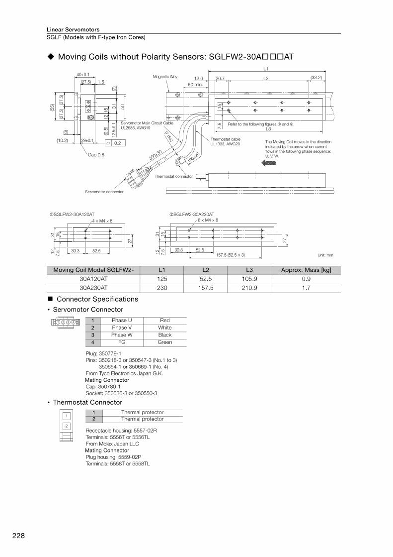
Linear ServomotorsSGLF (Models with F-type Iron Cores)
228
Moving Coils without Polarity Sensors: SGLFW2-30AAT
Moving Coil Model SGLFW2- L1 L2 L3 Approx. Mass [kg]
30A120AT 125 52.5 105.9 0.9
30A230AT 230 157.5 210.9 1.7
Connector Specifications
• Servomotor Connector
Plug: 350779-1Pins: 350218-3 or 350547-3 (No.1 to 3)
350654-1 or 350669-1 (No. 4)From Tyco Electronics Japan G.K. Mating ConnectorCap: 350780-1Socket: 350536-3 or 350550-3
• Thermostat Connector
Receptacle housing: 5557-02RTerminals: 5556T or 5556TLFrom Molex Japan LLC Mating ConnectorPlug housing: 5559-02PTerminals: 5558T or 5558TL
50 min.
Magnetic Way
Servomotor Main Circuit Cable
UL2586, AWG19
Thermostat cable
UL1333, AWG20
Thermostat connector
Servomotor connector
The Moving Coil moves in the direction
indicated by the arrow when current
flows in the following phase sequence:
U, V, W.
Refer to the following figures and .
(7 dia.)
(27.5
)(2
7.5
)
(27.5) 1.5
(55
)
(0.5
)1
5 50
12
(6)
29±0.1
15
7.5
26.7 L2
L3
(33.2)
L1
12.5
±0.
1
(10.2)
40±0.1
31
(7)
12.6
0.2
Gap 0.8
100±20300±30
Unit: mm
SGLFW2-30A120AT SGLFW2-30A230AT
1531
12
7.5 39.3 52.5
27
1531
12
7.5 39.3 52.5
27
4 × M4 × 8 8 × M4 × 8
157.5 (52.5 × 3)
1 2 3 4 1 Phase U Red2 Phase V White3 Phase W Black4 FG Green
1
2
1 Thermal protector2 Thermal protector

Linear Servomotors SGLF (Models with F-type Iron Cores)
229
SG
LF
Magnetic Ways: SGLFM2-30A
Note: More than one Magnetic Way can be connected. Connect the Magnetic Ways so that the reference marks on them are aligned in the same direction as shown in the figure.
Magnetic Way Model SGLFM2-
L1 ± 0.1 L2 N Approx. Mass [kg]
30270A 270 225 (45 × 5) 6 0.9
30450A 450 405 (45 × 9) 10 1.5
30630A 630 585 (45 × 13) 14 2.0
N S N SN S55
45
22.5±0.1 (22.5)
(45)
L2
(27
.5)
27
.5
45
(5)
5
6
L1±0.1
4.2
10.20.1
0.2
2 × N, 4.8-dia. mounting holes
Reference mark
Height of screw head: 4.2 max.
Mounting Section Details
(There are two, approx. 4-dia. indentations.)
(Reference mark)
Unit: mm
8.5 dia. 0.4
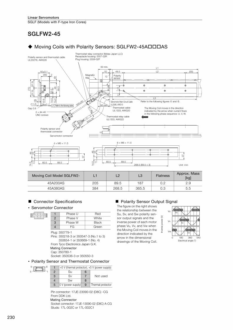
Linear ServomotorsSGLF (Models with F-type Iron Cores)
230
SGLFW2-45
Moving Coils with Polarity Sensors: SGLFW2-45AAS
Moving Coil Model SGLFW2- L1 L2 L3 Flatness Approx. Mass
[kg]
45A200AS 205 89.5 187 0.2 2.9
45A380AS 384 268.5 365.5 0.3 5.5
Connector Specifications Polarity Sensor Output Signal
• Servomotor Connector The figure on the right shows the relationship between the Su, Sv, and Sw polarity sen-sor output signals and the inverse power of each motor phase Vu, Vv, and Vw when the Moving Coil moves in the direction indicated by the arrow in the dimensional drawings of the Moving Coil.
Plug: 350779-1Pins: 350218-3 or 350547-3 (No.1 to 3)
350654-1 or 350669-1 (No. 4)From Tyco Electronics Japan G.K. Mating ConnectorCap: 350780-1Socket: 350536-3 or 350550-3
• Polarity Sensor and Thermostat Connector
Pin connector: 17JE-23090-02 (D8C) -CGFrom DDK Ltd. Mating ConnectorSocket connector: 17JE-13090-02 (D8C) A-CGStuds: 17L-002C or 17L-002C1
11
(36) 2
(6)
(37.5
)(3
7.5
)
48.5 (55)
L1
L3
L250±0.1
(75)
38±0.1(11.2)
32
(9)
46
15±0
.1
(0.5
)
69.5
14.5
22
.5
(9.1 dia.)
Gap 0.8
12
300±30
300±3023
Thermostat relay connector (Molex Japan LLC)
50 min.
Polarity sensor
Polarity sensor and thermostat cable
UL20276, AWG28
Magnetic
Way
Refer to the following table. 50 min.
Servomotor Main Circuit Cable
UL2586, AWG15
Thermostat cable
UL1333, AWG20
Thermostat relay cable
UL1333, AWG22
Refer to the following figures � and �.
The Moving Coil moves in the direction
indicated by the arrow when current flows
in the following phase sequence: U, V, W.2 × #4-40
UNC screws
Polarity sensor and
thermostat connector
Servomotor connector
Receptacle housing: 5557-02R
Plug housing: 5559-02P
Unit: mm
46
23
11
14.5 60.5 89.5
37
268.5 (89.5 × 3)
46
23
14.5 11 60.5 89.5
37
8 × M6 × 11.54 × M6 × 11.5
Vu
Vv
Vw
Su
Sv
Sw
0 180 360 540
Electrical angle (°)
Inve
rse p
ow
er
(V)1 2 3 4
1 Phase U Red2 Phase V White3 Phase W Black4 FG Green
9 6
5 1
1 +5 V (thermal protector), +5 V (power supply)2 Su 6
Not used3 Sv 74 Sw 85 0 V (power supply) 9 Thermal protector
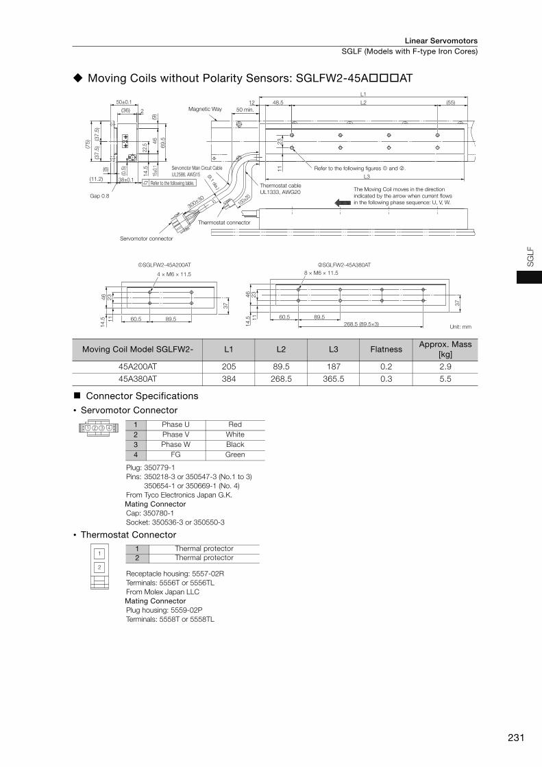
Linear Servomotors SGLF (Models with F-type Iron Cores)
231
SG
LF
Moving Coils without Polarity Sensors: SGLFW2-45AAT
Moving Coil Model SGLFW2- L1 L2 L3 FlatnessApprox. Mass
[kg]
45A200AT 205 89.5 187 0.2 2.9
45A380AT 384 268.5 365.5 0.3 5.5
Connector Specifications
• Servomotor Connector
Plug: 350779-1Pins: 350218-3 or 350547-3 (No.1 to 3)
350654-1 or 350669-1 (No. 4)From Tyco Electronics Japan G.K. Mating ConnectorCap: 350780-1Socket: 350536-3 or 350550-3
• Thermostat Connector
Receptacle housing: 5557-02RTerminals: 5556T or 5556TLFrom Molex Japan LLC Mating ConnectorPlug housing: 5559-02PTerminals: 5558T or 5558TL
Magnetic Way 50 min.
Servomotor Main Circuit Cable
UL2586, AWG15
Refer to the following table.
Servomotor connector
Thermostat connector
Thermostat cable
UL1333, AWG20
Refer to the following figures and .
The Moving Coil moves in the direction
indicated by the arrow when current flows
in the following phase sequence: U, V, W.
(9.1 dia.)
11
(36) 2
22.5 2
3
(6)
(37
.5)
(37
.5)
46
(9)
69
.5
48.5 (55)
L1
L2
L3
50±0.1
(75
)
14
.5
38±0.1
(0.5
)
15±0
.1
(11.2)
12
Gap 0.8
100±20
30030
Unit: mm
46
23
11
14
.5 60.5 89.5
37
268.5 (89.5×3)
46
23
14
.5 11 60.5 89.5
37
8 × M6 × 11.54 × M6 × 11.5
SGLFW2-45A200AT SGLFW2-45A380AT
1 2 3 41 Phase U Red2 Phase V White3 Phase W Black4 FG Green
1
2
1 Thermal protector2 Thermal protector

Linear ServomotorsSGLF (Models with F-type Iron Cores)
232
Magnetic Ways: SGLFM2-45A
Note: More than one Magnetic Way can be connected. Connect the Magnetic Ways so that the reference marks on them are aligned in the same direction as shown in the figure.
Magnetic Way Model SGLFM2-
L1 ± 0.1 L2 N Approx. Mass [kg]
45306A 306 204 (102 × 2) 3 1.5
45510A 510 408 (102 × 4) 5 2.5
45714A 714 612 (102 × 6) 7 3.4
N S N S N S
6102
(37
.5)
63
(6)
6
75
L2 (51)
L1±0.1
(102)5.2
11.2±0.1510.1
0.2
37
.5
2 × N, 5.8-dia. mounting holes
10 dia. 0.5
(Reference
mark)
Unit: mm
Reference mark(There are two, approx. 4-dia. indentations.)
Height of screw head: 5.2 max.
Mounting Section Details
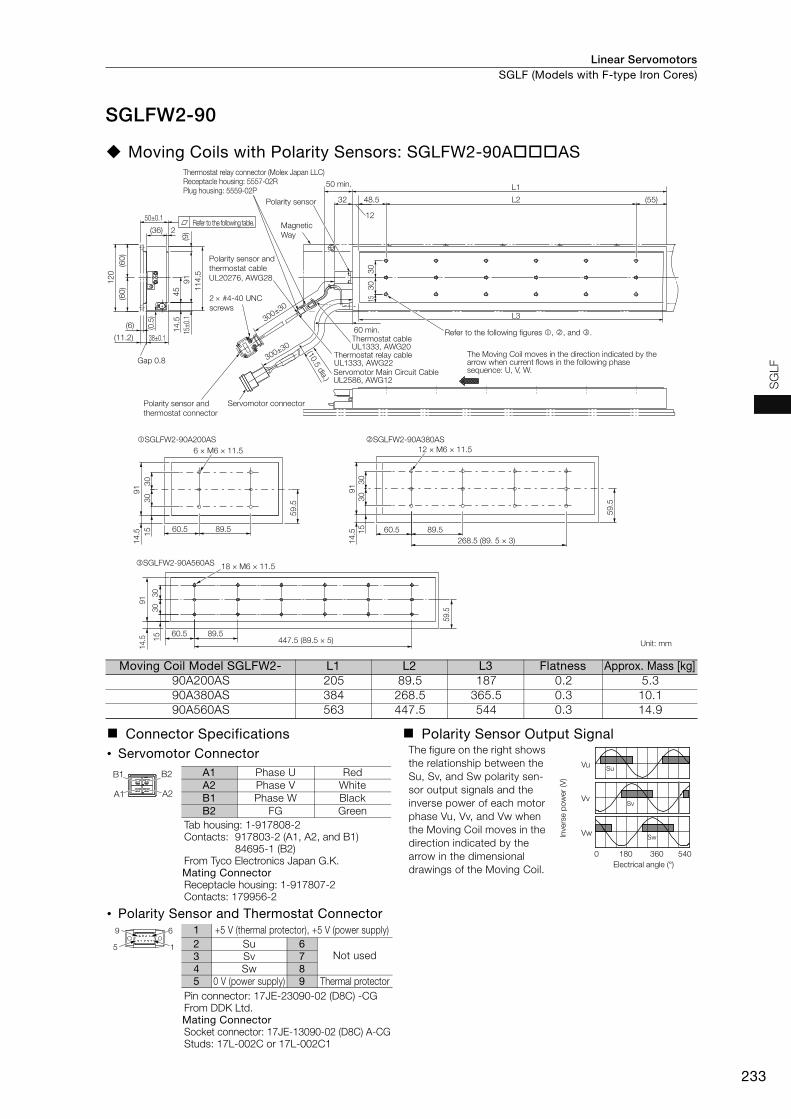
Linear Servomotors SGLF (Models with F-type Iron Cores)
233
SG
LF
SGLFW2-90
Moving Coils with Polarity Sensors: SGLFW2-90AAS
Moving Coil Model SGLFW2- L1 L2 L3 Flatness Approx. Mass [kg]90A200AS 205 89.5 187 0.2 5.390A380AS 384 268.5 365.5 0.3 10.190A560AS 563 447.5 544 0.3 14.9
Connector Specifications Polarity Sensor Output Signal• Servomotor Connector The figure on the right shows
the relationship between the Su, Sv, and Sw polarity sen-sor output signals and the inverse power of each motor phase Vu, Vv, and Vw when the Moving Coil moves in the direction indicated by the arrow in the dimensional drawings of the Moving Coil.
Tab housing: 1-917808-2Contacts: 917803-2 (A1, A2, and B1)
84695-1 (B2)From Tyco Electronics Japan G.K.Mating ConnectorReceptacle housing: 1-917807-2Contacts: 179956-2
• Polarity Sensor and Thermostat Connector
Pin connector: 17JE-23090-02 (D8C) -CGFrom DDK Ltd. Mating ConnectorSocket connector: 17JE-13090-02 (D8C) A-CGStuds: 17L-002C or 17L-002C1
Thermostat relay connector (Molex Japan LLC)Receptacle housing: 5557-02RPlug housing: 5559-02P
Polarity sensor and
thermostat cable
UL20276, AWG28
Refer to the following table.
50 min.
Polarity sensor
Magnetic
Way
2 #4-40 UNC
screws
60 min. Refer to the following figures , , and .
The Moving Coil moves in the direction indicated by the arrow when current flows in the following phase sequence: U, V, W.
Thermostat cableUL1333, AWG20
Thermostat relay cableUL1333, AWG22
Polarity sensor and
thermostat connector
Servomotor connector
Servomotor Main Circuit CableUL2586, AWG12
Unit: mm
(10.5 dia.)
SGLFW2-90A560AS
60.5 89.5447.5 (89.5 × 5)
59.5
91
14.5
30
30
15
18 × M6 × 11.5
SGLFW2-90A200AS SGLFW2-90A380AS
91
15
14
.5 60.5 89.5
59
.5
30
30
6 × M6 × 11.5
91
14
.5
59
.5
60.5 89.5
268.5 (89. 5 × 3)
30
30
15
12 × M6 × 11.5
(60
)(6
0)
12
0
(11.2)
45
15±0
.19
1
11
4.5
14
.5
50±0.1
2(36)
38±0.1
(6)
15
(0.5
)
30
30
(9)
300±30
Gap 0.8
300±30
48.5 (55)
L1
32
12
L2
L3
Vu
Vv
Vw
Su
Sv
Sw
0 180 360 540
Electrical angle (°)
Inve
rse p
ow
er
(V)
A1
B1 B2
A2
A1 Phase U RedA2 Phase V WhiteB1 Phase W BlackB2 FG Green
9 6
5 1
1 +5 V (thermal protector), +5 V (power supply)2 Su 6
Not used3 Sv 74 Sw 85 0 V (power supply) 9 Thermal protector
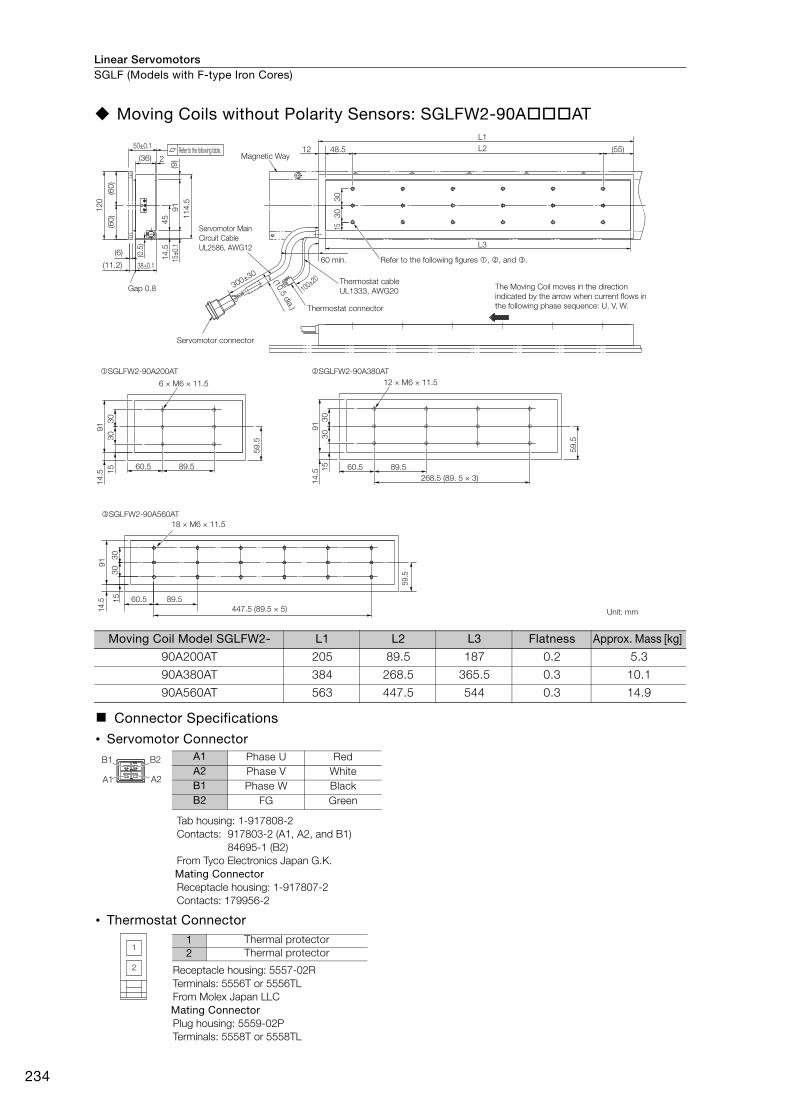
Linear ServomotorsSGLF (Models with F-type Iron Cores)
234
Moving Coils without Polarity Sensors: SGLFW2-90AAT
Moving Coil Model SGLFW2- L1 L2 L3 Flatness Approx. Mass [kg]
90A200AT 205 89.5 187 0.2 5.3
90A380AT 384 268.5 365.5 0.3 10.1
90A560AT 563 447.5 544 0.3 14.9
Connector Specifications
• Servomotor Connector
Tab housing: 1-917808-2Contacts: 917803-2 (A1, A2, and B1)
84695-1 (B2)From Tyco Electronics Japan G.K.Mating ConnectorReceptacle housing: 1-917807-2Contacts: 179956-2
• Thermostat Connector
Receptacle housing: 5557-02RTerminals: 5556T or 5556TLFrom Molex Japan LLC Mating ConnectorPlug housing: 5559-02PTerminals: 5558T or 5558TL
60 min.
Magnetic Way
Servomotor Main
Circuit Cable
UL2586, AWG12
Thermostat cable
UL1333, AWG20
(10.5 dia.)
The Moving Coil moves in the direction
indicated by the arrow when current flows in
the following phase sequence: U, V, W.
Unit: mm
Thermostat connector
Servomotor connector
SGLFW2-90A560AT
60.5 89.5
447.5 (89.5 × 5)
59.5
91
14.5
30
30
15
18 × M6 × 11.5
91
15
14
.5
60.5 89.5
59
.5
30
30
6 × M6 × 11.5
91
14
.5
59
.5
60.5 89.5
268.5 (89. 5 × 3)
30
30
15
12 × M6 × 11.5
SGLFW2-90A200AT SGLFW2-90A380AT
(60
)(6
0)
12
0
(11.2)
45
15±0
.19
1
11
4.5
14
.5
50±0.1
2(36)
38±0.1
(6)
15
(0.5
)
30
30
(9)
300±30
Gap 0.8
48.5 (55)
L1
L212
100±20
L3
Refer to the following figures , , and .
Refer to the following table.
A1
B1 B2
A2
A1 Phase U RedA2 Phase V WhiteB1 Phase W BlackB2 FG Green
1
2
1 Thermal protector2 Thermal protector

Linear Servomotors SGLF (Models with F-type Iron Cores)
235
SG
LF
Magnetic Ways: SGLFM2-90A
Note: More than one Magnetic Way can be connected. Connect the Magnetic Ways so that the reference marks on them are aligned in the same direction as shown in the figure.
Magnetic Way Model SGLFM2-
L1±0.1 L2 N Approx. Mass [kg]
90306A 306 204 (102 × 2) 3 2.6
90510A 510 408 (102 × 4) 5 4.2
90714A 714 612 (102 × 6) 7 5.9
L2
2 × N, 7-dia. mounting holes
11.5 dia. 2
Reference mark
(There are two, approx. 4-dia. indentations.)
Height of screw head: 6.7 max.
Mounting Section Details
(Reference mark)
Unit: mm
(51)
(102)
N N SSN S
102
510.1
L10.1
11.20.1
0.3
6 5.2
6.5
(6.5
)
(60)
(60)
10
7
12
0
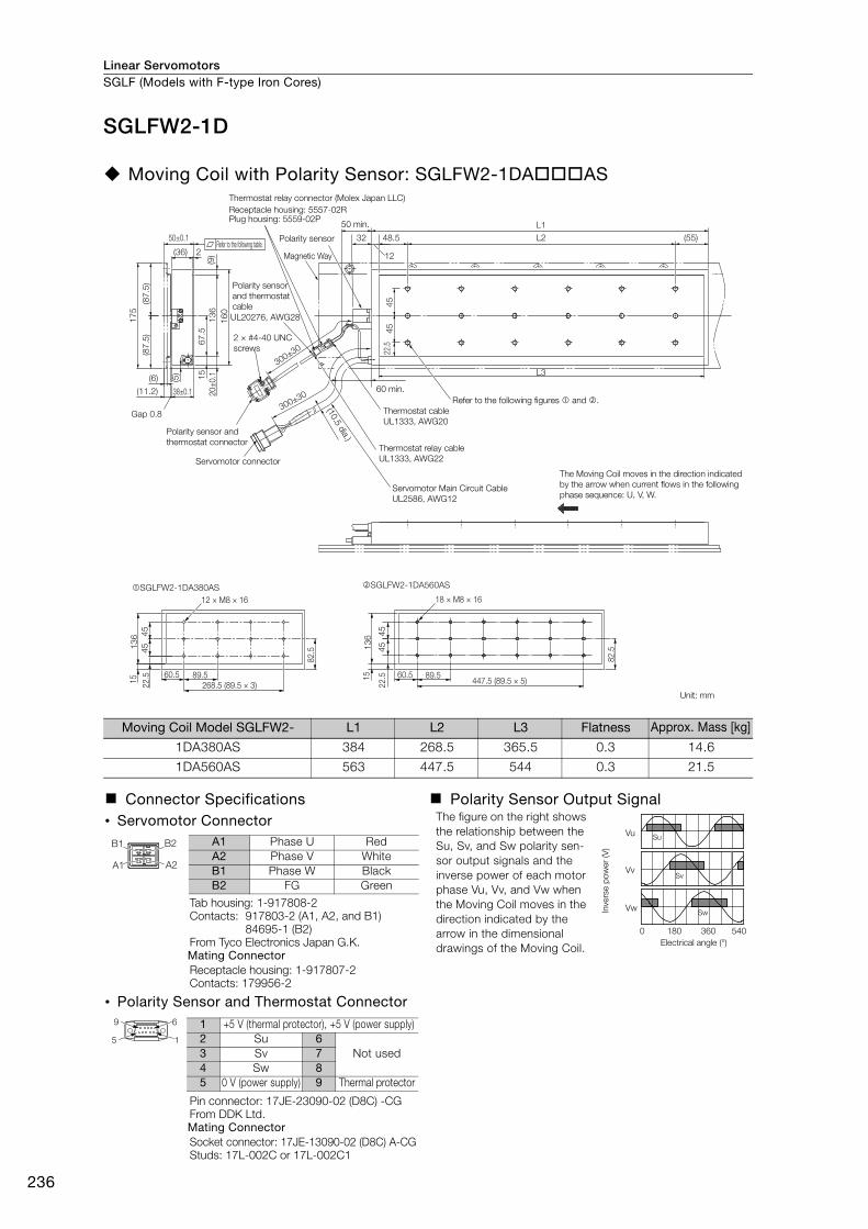
Linear ServomotorsSGLF (Models with F-type Iron Cores)
236
SGLFW2-1D
Moving Coil with Polarity Sensor: SGLFW2-1DAAS
Moving Coil Model SGLFW2- L1 L2 L3 Flatness Approx. Mass [kg]
1DA380AS 384 268.5 365.5 0.3 14.6
1DA560AS 563 447.5 544 0.3 21.5
Connector Specifications Polarity Sensor Output Signal• Servomotor Connector The figure on the right shows
the relationship between the Su, Sv, and Sw polarity sen-sor output signals and the inverse power of each motor phase Vu, Vv, and Vw when the Moving Coil moves in the direction indicated by the arrow in the dimensional drawings of the Moving Coil.
Tab housing: 1-917808-2Contacts: 917803-2 (A1, A2, and B1)
84695-1 (B2)From Tyco Electronics Japan G.K.Mating ConnectorReceptacle housing: 1-917807-2Contacts: 179956-2
• Polarity Sensor and Thermostat Connector
Pin connector: 17JE-23090-02 (D8C) -CGFrom DDK Ltd. Mating ConnectorSocket connector: 17JE-13090-02 (D8C) A-CGStuds: 17L-002C or 17L-002C1
UL20276, AWG28
Thermostat relay connector (Molex Japan LLC)
Receptacle housing: 5557-02RPlug housing: 5559-02P
50 min.
Polarity sensor
Magnetic Way
Polarity sensor
and thermostat
cable
2 × #4-40 UNC
screws
Polarity sensor and
thermostat connector
Servomotor connector
60 min.
Thermostat cable
UL1333, AWG20
Thermostat relay cable
UL1333, AWG22
Servomotor Main Circuit Cable
UL2586, AWG12
The Moving Coil moves in the direction indicated
by the arrow when current flows in the following
phase sequence: U, V, W.
Unit: mm
(10.5 dia.)
SGLFW2-1DA560AS
60.5 89.5447.5 (89.5 × 5)
82.5
18 × M8 × 16
13
615
45
45
22.5
SGLFW2-1DA380AS
(87
.5)
(87
.5)
17
5
(11.2)
67
.5
20±
0.1
13
6
16
0
15
50±0.1
2(36)
38±0.1
(6)
48.5
L3
L2 (55)
L1
22.5
32
(5)
45
45
(9) 12
Gap 0.8
300±30
300±30
60.5 89.5268.5 (89.5 × 3)
82.5
13
615
45
45
22.5
12 × M8 × 16
Refer to the following table.
Refer to the following figures and .
Vu
Vv
Vw
Su
Sv
Sw
0 180 360 540
Electrical angle (°)
Inve
rse p
ow
er
(V)
A1
B1 B2
A2
A1 Phase U RedA2 Phase V WhiteB1 Phase W BlackB2 FG Green
9 6
5 1
1 +5 V (thermal protector), +5 V (power supply)2 Su 6
Not used3 Sv 74 Sw 85 0 V (power supply) 9 Thermal protector
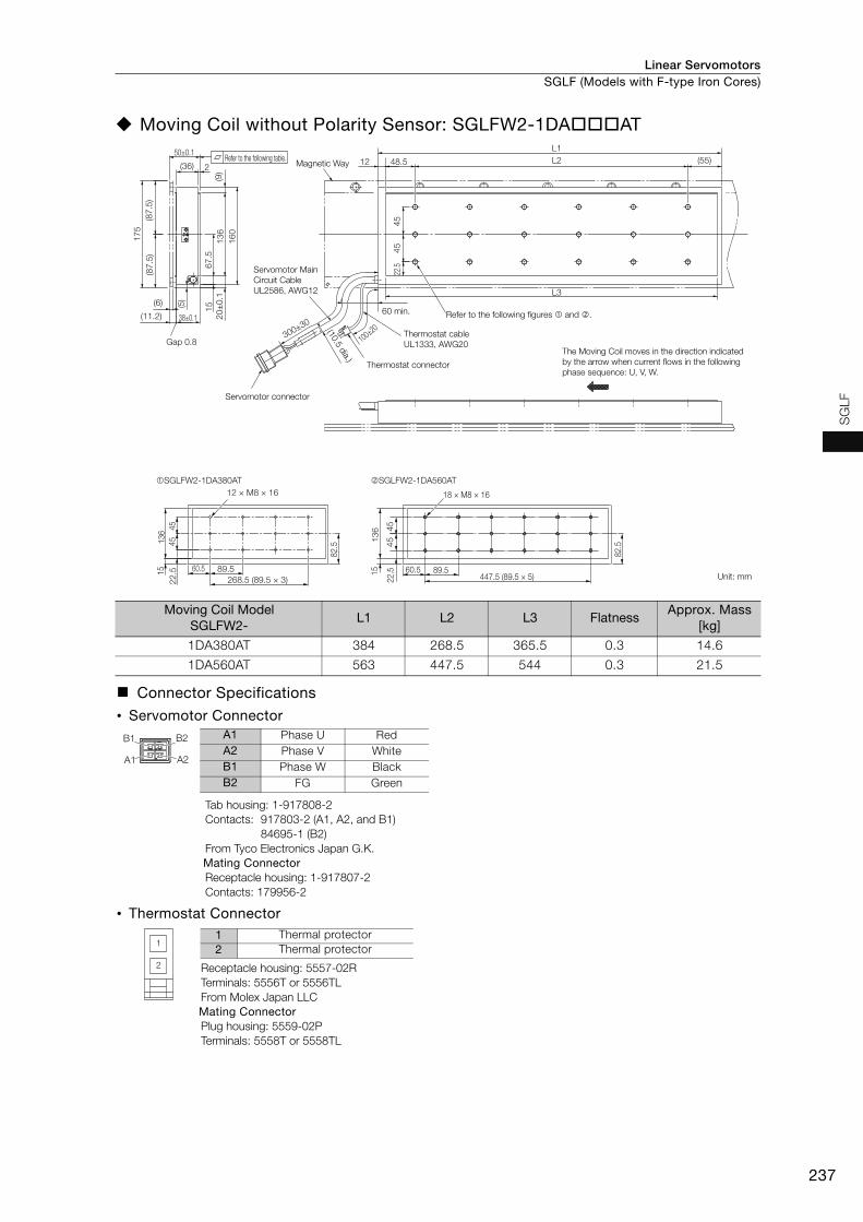
Linear Servomotors SGLF (Models with F-type Iron Cores)
237
SG
LF
Moving Coil without Polarity Sensor: SGLFW2-1DAAT
Moving Coil Model SGLFW2-
L1 L2 L3 FlatnessApprox. Mass
[kg]
1DA380AT 384 268.5 365.5 0.3 14.6
1DA560AT 563 447.5 544 0.3 21.5
Connector Specifications
• Servomotor Connector
Tab housing: 1-917808-2Contacts: 917803-2 (A1, A2, and B1)
84695-1 (B2)From Tyco Electronics Japan G.K.Mating ConnectorReceptacle housing: 1-917807-2Contacts: 179956-2
• Thermostat Connector
Receptacle housing: 5557-02RTerminals: 5556T or 5556TLFrom Molex Japan LLC Mating ConnectorPlug housing: 5559-02PTerminals: 5558T or 5558TL
Magnetic Way
Servomotor Main
Circuit Cable
UL2586, AWG12
Servomotor connector
60 min.
Thermostat cable
UL1333, AWG20
Thermostat connector
(10.5 dia.)
The Moving Coil moves in the direction indicated
by the arrow when current flows in the following
phase sequence: U, V, W.
Unit: mm
Refer to the following table.
Refer to the following figures and .
(87
.5)
(87
.5)
17
5
(11.2)
67
.5
20
±0
.11
36
16
0
15
50±0.1
2(36)
38±0.1
(6)
22.5
(5)
45
45
(9)
300±30
Gap 0.8
48.5 (55)
L1
L212
L3
100±20
SGLFW2-1DA560AT
60.5 89.5447.5 (89.5 × 5)
82.5
18 × M8 × 16
13
615
45
45
22.5
SGLFW2-1DA380AT
60.5 89.5
268.5 (89.5 × 3)
82.5
136
15
45
45
22
.5
12 × M8 × 16
A1
B1 B2
A2
A1 Phase U RedA2 Phase V WhiteB1 Phase W BlackB2 FG Green
1
2
1 Thermal protector2 Thermal protector

Linear ServomotorsSGLF (Models with F-type Iron Cores)
238
Magnetic Ways: SGLFM2-1DA
Note: More than one Magnetic Way can be connected. Connect the Magnetic Ways so that the reference marks on them are aligned in the same direction as shown in the figure.
Magnetic Way Model SGLFM2-
L1±0.1 L2 N Approx. Mass [kg]
1D306A 306 204 (102 × 2) 3 3.7
1D510A 510 408 (102 × 4) 5 6.2
1D714A 714 612 (102 × 6) 7 8.6
L2
175
(87.
5)9.
515
6(9
.5)
(87.
5)N S N SN S
10251±0.1 (51)
(102)6
L1±0.1
5.211.2±0.1
0.3
2 N, 10-dia. mounting holes15 dia. 3
(Reference mark)
Unit: mm
Reference mark
(There are two, approx. 4-dia. indentations.)
Height of screw head: 8.2 max.Mounting Section Details

Linear Servomotors SGLF (Models with F-type Iron Cores)
239
SG
LF
SGLFW-20
Moving Coils: SGLFW-20AA
Note: The above dimensional drawing gives the dimensions for both models with polarity sensors and models with-out polarity sensors.
Moving Coil Model SGLFW- L1 L2 L3 Approx. Mass [kg]
20A090A 91 36 72 0.7
20A120A 127 72 108 0.9
Connector Specifications Polarity Sensor Output Signal
• Servomotor Connector The figure on the right shows the relationship between the Su, Sv, and Sw polarity sen-sor output signals and the inverse power of each motor phase Vu, Vv, and Vw when the Moving Coil moves in the direction indicated by the arrow in the dimensional drawings of the Moving Coil.
Plug: 350779-1Pins: 350218-3 or 350547-3 (No.1 to 3)
350654-1 or 350669-1 (No. 4)From Tyco Electronics Japan G.K. Mating ConnectorCap: 350780-1Socket: 350536-3 or 350550-3
• Polarity Sensor Connector
Pin connector: 17JE-23090-02 (D8C) -CGFrom DDK Ltd. Mating ConnectorSocket connector: 17JE-13090-02 (D8C) A-CGStuds: 17L-002C or 17L-002C1
Unit: mm
2 × M4 × 8
2012
.5
22.5
30 36
�SGLFW-20A090A�3 × M4 × 8
2012
.5
22.5
30 36
72
�SGLFW-20A120A�
(Gap: 0.8 with magnet cover)(Gap: 1 without magnet cover)
(10.2 with magnet cover)(10 without magnet cover)
(4.2 with magnet cover)(4 without magnet cover)0.1
28
7.7
25.
522
.5
40
17.5
12.5
45±0.1
34
(32)
0.5(6)
(44)
(22)
(22)
Refer to the following figures � and �.
9.7
dia. 5
20
36
(25)L1L23030
(12) (7.5
)
(10)
(12.
5)
50 min.
Polarity sensorMagnetic Way
12
500±50
500±50 730 min.
L3
(6.1 dia.)
(4.2 dia.)
2 × #4-40 UNCscrews
The Moving Coil moves in the direction indicated by the arrow when current flows in the following phase sequence: U, V, W.
(20) 22
Vu
Vv
Vw
Su
Sv
Sw
0 180 360 540
Electrical angle (°)
Inve
rse
pow
er (V
)
1 2 3 41 Phase U Red2 Phase V White3 Phase W Black4 FG Green
9 6
5 1
1 +5 V (thermal protector), +5 V (power supply)2 Su 6
Not used3 Sv 74 Sw 85 0 V (power supply) 9 Thermal protector
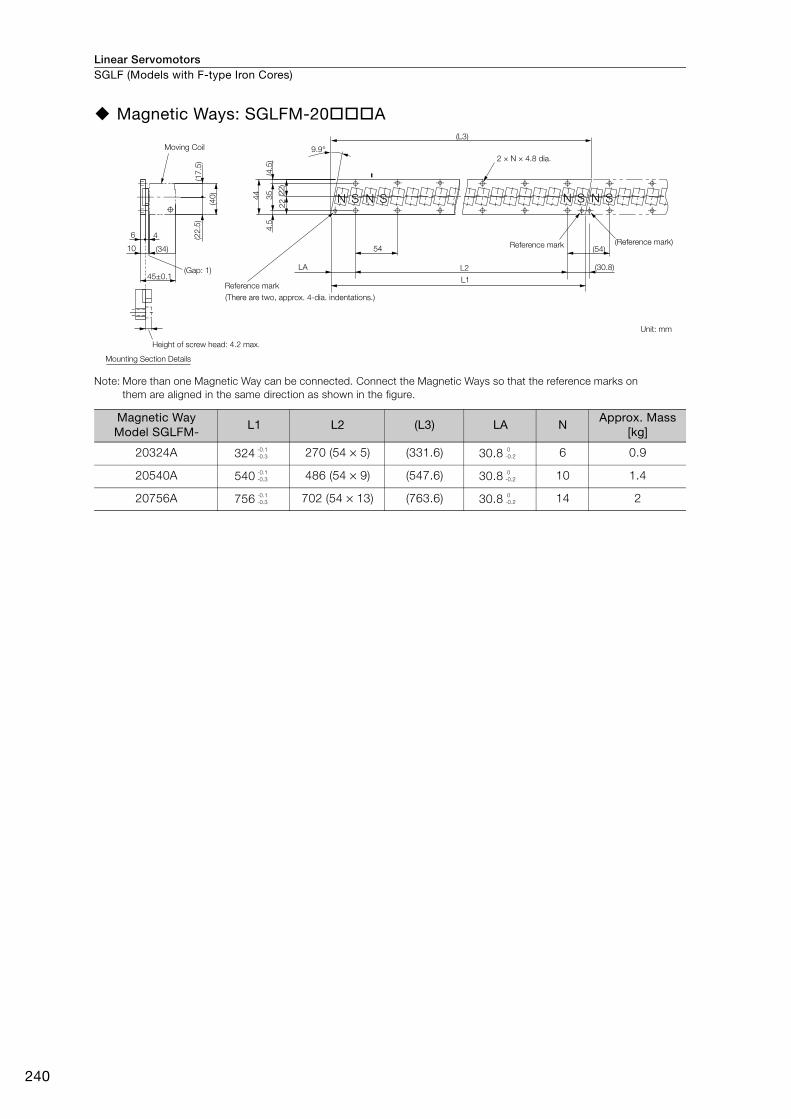
Linear ServomotorsSGLF (Models with F-type Iron Cores)
240
Magnetic Ways: SGLFM-20A
Note: More than one Magnetic Way can be connected. Connect the Magnetic Ways so that the reference marks on them are aligned in the same direction as shown in the figure.
Magnetic Way Model SGLFM-
L1 L2 (L3) LA NApprox. Mass
[kg]
20324A 324 270 (54 × 5) (331.6) 30.8 6 0.9
20540A 540 486 (54 × 9) (547.6) 30.8 10 1.4
20756A 756 702 (54 × 13) (763.6) 30.8 14 2
(Gap: 1)
SNSN
6
9.9°
10
4
(40)
(22.
5)(1
7.5)
(34)
4.5
3544
(4.5
)
(22)
22
54
LA
L1
L2
(L3)
(54)
(30.8)
SNSN
45±0.1
Moving Coil2 × N × 4.8 dia.
Reference mark(There are two, approx. 4-dia. indentations.)
Height of screw head: 4.2 max.
Mounting Section Details
Reference mark (Reference mark)
Unit: mm
-0.1-0.3
0-0.2
-0.1-0.3
0-0.2
-0.1-0.3
0-0.2
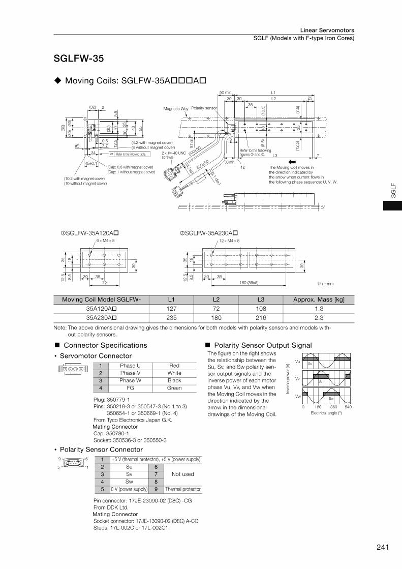
Linear Servomotors SGLF (Models with F-type Iron Cores)
241
SG
LF
SGLFW-35
Moving Coils: SGLFW-35AA
Note: The above dimensional drawing gives the dimensions for both models with polarity sensors and models with-out polarity sensors.
Moving Coil Model SGLFW- L1 L2 L3 Approx. Mass [kg]
35A120A 127 72 108 1.3
35A230A 235 180 216 2.3
Connector Specifications Polarity Sensor Output Signal
• Servomotor Connector The figure on the right shows the relationship between the Su, Sv, and Sw polarity sen-sor output signals and the inverse power of each motor phase Vu, Vv, and Vw when the Moving Coil moves in the direction indicated by the arrow in the dimensional drawings of the Moving Coil.
Plug: 350779-1Pins: 350218-3 or 350547-3 (No.1 to 3)
350654-1 or 350669-1 (No. 4)From Tyco Electronics Japan G.K. Mating ConnectorCap: 350780-1Socket: 350536-3 or 350550-3
• Polarity Sensor Connector
Pin connector: 17JE-23090-02 (D8C) -CGFrom DDK Ltd. Mating ConnectorSocket connector: 17JE-13090-02 (D8C) A-CGStuds: 17L-002C or 17L-002C1
6 M4 8
35 18
30
8.5
12.5
72
SGLFW-35A120A12 M4 8
35 188.
5
12.5 30 36
180 (365) Unit: mm
30
SGLFW-35A230A
Refer to the following table.
5.5
2
450.1
34
(32)
0.57.7(6)
5543
3025
12.5
(30)
(30)
(60)
(Gap: 0.8 with magnet cover)(Gap: 1 without magnet cover)
(10.2 with magnet cover)(10 without magnet cover)
(4.2 with magnet cover)(4 without magnet cover)
12
5
50050
50050
7
L1
30
(6.1 dia.)
(4.2 dia.)
(10.
5)
(12.
5)(7
.5)
L3
30 min.
L230 25
36
(8.5
)
50 min.
Polarity sensorMagnetic Way
2 #4-40 UNCscrews
The Moving Coil moves in the direction indicated by the arrow when current flows in the following phase sequence: U, V, W.
Refer to the following figures and .
3518(35) 37
9.7
dia.
30 36
Vu
Vv
Vw
Su
Sv
Sw
0 180 360 540
Electrical angle (°)
Inve
rse
pow
er (V
)
1 2 3 41 Phase U Red2 Phase V White3 Phase W Black4 FG Green
9 6
5 1
1 +5 V (thermal protector), +5 V (power supply)2 Su 6
Not used3 Sv 74 Sw 85 0 V (power supply) 9 Thermal protector
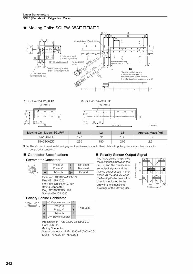
Linear ServomotorsSGLF (Models with F-type Iron Cores)
242
Moving Coils: SGLFW-35AAD
Note: The above dimensional drawing gives the dimensions for both models with polarity sensors and models with-out polarity sensors.
Moving Coil Model SGLFW- L1 L2 L3 Approx. Mass [kg]
35A120AD 127 72 108 1.3
35A230AD 235 180 216 2.3
Connector Specifications Polarity Sensor Output Signal
• Servomotor Connector The figure on the right shows the relationship between the Su, Sv, and Sw polarity sen-sor output signals and the inverse power of each motor phase Vu, Vv, and Vw when the Moving Coil moves in the direction indicated by the arrow in the dimensional drawings of the Moving Coil.
Extension: ARRA06AMRPN182Pins: 021.279.1020From Interconnectron GmbH Mating Connector Plug: APRA06BFRDN170Socket: 020.105.1020
• Polarity Sensor Connector
Pin connector: 17JE-23090-02 (D8C)-CGFrom DDK Ltd.Mating ConnectorSocket connector: 17JE-13090-02 (D8C)A-CGStuds: 17L-002C or 17L-002C1
6 M4 8
35 18
30
8.5
12.5 30 36
72
SGLFW-35A120AD12 M4 8
35 188.
5
12.5 30 36
180 (365)
30
SGLFW-35A230AD
Unit: mm
Refer to the following table.
5.5
2
450.1
34
(32)
0.57.7(6)
43 55
3025
12.5
(30)
(30)
(60)
(Gap: 0.8 with magnet cover)(Gap: 1 without magnet cover)
(10.2 with magnet cover)(10 without magnet cover)
(4.2 with magnet cover)(4 without magnet cover)
The Moving Coil moves in the direction indicated by the arrow when current flows in the following phase sequence: U, V, W.
12
50050
50050
7
L130
(6.1 dia.)
(4.2 dia.)
(10.
5)
(12.
5)(7
.5)
35
L3
30 min.
L230 25
36
(8.5
)
9.7
dia.
18
50 min.
Polarity sensorMagnetic Way
2 #4-40 UNCscrews
Refer to the following figures and .
(35) 37
Vu
Vv
Vw
Su
Sv
Sw
0 180 360 540
Electrical angle (°)
Inve
rse
pow
er (V
)
65
4
1
2
1 Phase U 5 Not used2 Phase V 6 Not used
4 Phase W Ground
9 6
5 1
1 +5 V (power supply) 6
Not used2 Phase U 73 Phase V 84 Phase W 95 0 V (power supply) − −

Linear Servomotors SGLF (Models with F-type Iron Cores)
243
SG
LF
Magnetic Ways: SGLFM-35A
Note: More than one Magnetic Way can be connected. Connect the Magnetic Ways so that the reference marks on them are aligned in the same direction as shown in the figure.
Magnetic Way Model SGLFM-
L1 L2 (L3) LA NApprox. Mass
[kg]
35324A 324 270 (54 × 5) (334.4) 32.2 6 1.2
35540A 540 486 (54 × 9) (550.4) 32.2 10 2
35756A 756 702 (54 × 13) (766.4) 32.2 14 2.9
L1
L2(Gap: 1)
(34)
S SNS SNNN
(L3)
6
10
4
45±0.1
60 51
30(3
0)
(4.5
)4.
5
(55)
(30)
(25)
9.9°
LA
54 (54)
(32.2)
2 × N × 4.8 dia.
Reference mark
Reference mark(There are two, approx. 4-dia. indentations.)
Height of screw head: 4.2 max.Mounting Section Details
(Reference mark)
Unit: mm
Moving Coil
-0.1-0.3
0-0.2
-0.1-0.3
0-0.2
-0.1-0.3
0-0.2

Linear ServomotorsSGLF (Models with F-type Iron Cores)
244
SGLFW-50
Moving Coils: SGLFW-50AB
Note: The above dimensional drawing gives the dimensions for both models with polarity sensors and models with-out polarity sensors.
Moving Coil ModelSGLFW-
L1 L2 L3 Approx. Mass [kg]
50A200B 215 120 180 3.5
50A380B 395 300 360 6.9
Connector Specifications Polarity Sensor Output Signal
• Servomotor Connector The figure on the right shows the relationship between the Su, Sv, and Sw polarity sen-sor output signals and the inverse power of each motor phase Vu, Vv, and Vw when the Moving Coil moves in the direction indicated by the arrow in the dimensional drawings of the Moving Coil.
Plug: 350779-1Pins: 350218-3 or 350547-3 (No.1 to 3)
350654-1 or 350669-1 (No. 4)From Tyco Electronics Japan G.K. Mating ConnectorCap: 350780-1Socket: 350536-3 or 350550-3
• Polarity Sensor Connector
Pin connector: 17JE-23090-02 (D8C) -CGFrom DDK Ltd. Mating ConnectorSocket connector: 17JE-13090-02 (D8C) A-CGStuds: 17L-002C or 17L-002C1
6 × M5 × 9.5
48 23.5
1214
55 60
120
SGLFW-50A200B
12 × M5 × 9.5
48 23.5
1214 55 60300 (60 × 5)
SGLFW-50A380B
Unit: mm
(7.4 dia.)
25
5
L3
L2 40
6055
L130
(4.2 dia.)
23.5
12 d
ia.
10
(15)
50050
50050
Polarity sensorMagnetic Way
50 min.
50 min.
2 #4-40 UNCscrews
The Moving Coil moves in the direction indicated by the arrow when current flows in the following phase sequence: U, V, W.
Refer to the following figures and .
7
(40)
(37.
5)
3
33.7
537
.75 71
.5
(37.
5)(75)
0.5(9)
43
580.1
(48)
(64.
5)
(10.2 with magnet cover)(10 without magnet cover)
(Gap: 0.8 with magnet cover)(Gap: 1 without magnet cover)
(4.2 with magnet cover)(4 without magnet cover)
Refer to the following table.
Vu
Vv
Vw
Su
Sv
Sw
0 180 360 540
Electrical angle (°)
Inve
rse
pow
er (V
)
1 2 3 41 Phase U Red2 Phase V White3 Phase W Black4 FG Green
9 6
5 1
1 +5 V (thermal protector), +5 V (power supply)2 Su 6
Not used3 Sv 74 Sw 85 0 V (power supply) 9 Thermal protector
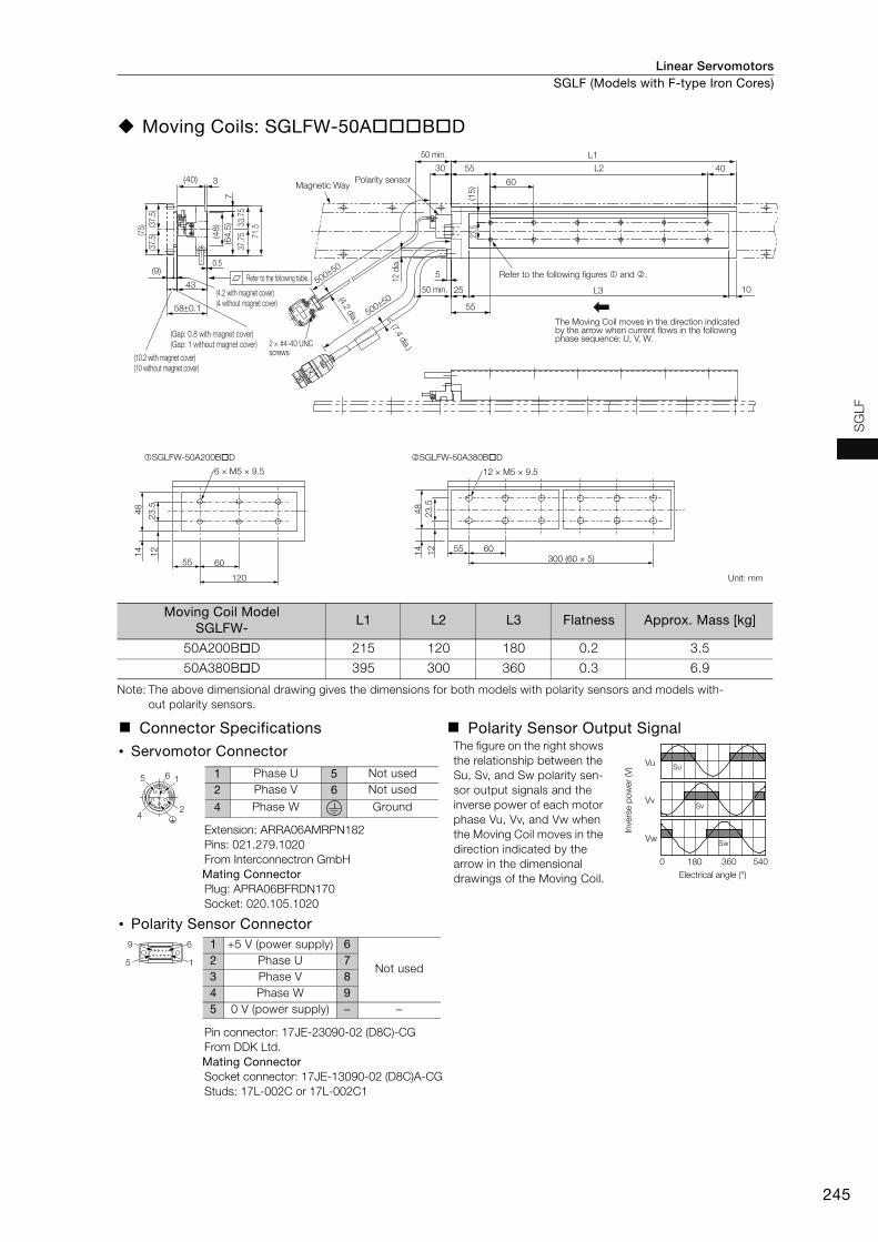
Linear Servomotors SGLF (Models with F-type Iron Cores)
245
SG
LF
Moving Coils: SGLFW-50ABD
Note: The above dimensional drawing gives the dimensions for both models with polarity sensors and models with-out polarity sensors.
Moving Coil ModelSGLFW-
L1 L2 L3 Flatness Approx. Mass [kg]
50A200BD 215 120 180 0.2 3.5
50A380BD 395 300 360 0.3 6.9
Connector Specifications Polarity Sensor Output Signal
• Servomotor Connector The figure on the right shows the relationship between the Su, Sv, and Sw polarity sen-sor output signals and the inverse power of each motor phase Vu, Vv, and Vw when the Moving Coil moves in the direction indicated by the arrow in the dimensional drawings of the Moving Coil.
Extension: ARRA06AMRPN182Pins: 021.279.1020From Interconnectron GmbH Mating Connector Plug: APRA06BFRDN170Socket: 020.105.1020
• Polarity Sensor Connector
Pin connector: 17JE-23090-02 (D8C)-CGFrom DDK Ltd.Mating ConnectorSocket connector: 17JE-13090-02 (D8C)A-CGStuds: 17L-002C or 17L-002C1
6 × M5 × 9.5
48 23.5
1214
55 60
120
SGLFW-50A200BD
12 × M5 × 9.5
48 23.5
1214 55 60300 (60 × 5)
SGLFW-50A380BD
Unit: mm
2 #4-40 UNCscrews
50050
50050
10
30
(7.4 dia.)
(4.2 dia.)
(15)
L3
L2
L1
25
55
5
55 40
60
23.5
12 d
ia.
50 min.
50 min.
Polarity sensorMagnetic Way
The Moving Coil moves in the direction indicated by the arrow when current flows in the following phase sequence: U, V, W.
Refer to the following figures and .
(64.
5) 33.7
537
.75
7
71.5
3
(37.
5)(75) (3
7.5)
(40)
43
580.1
0.5(9)
(Gap: 0.8 with magnet cover)(Gap: 1 without magnet cover)
(10.2 with magnet cover)(10 without magnet cover)
(4.2 with magnet cover)(4 without magnet cover)
(48)
Refer to the following table.
Vu
Vv
Vw
Su
Sv
Sw
0 180 360 540
Electrical angle (°)
Inve
rse p
ow
er
(V)
65
4
1
2
1 Phase U 5 Not used2 Phase V 6 Not used
4 Phase W Ground
9 6
5 1
1 +5 V (power supply) 6
Not used2 Phase U 73 Phase V 84 Phase W 95 0 V (power supply) − −
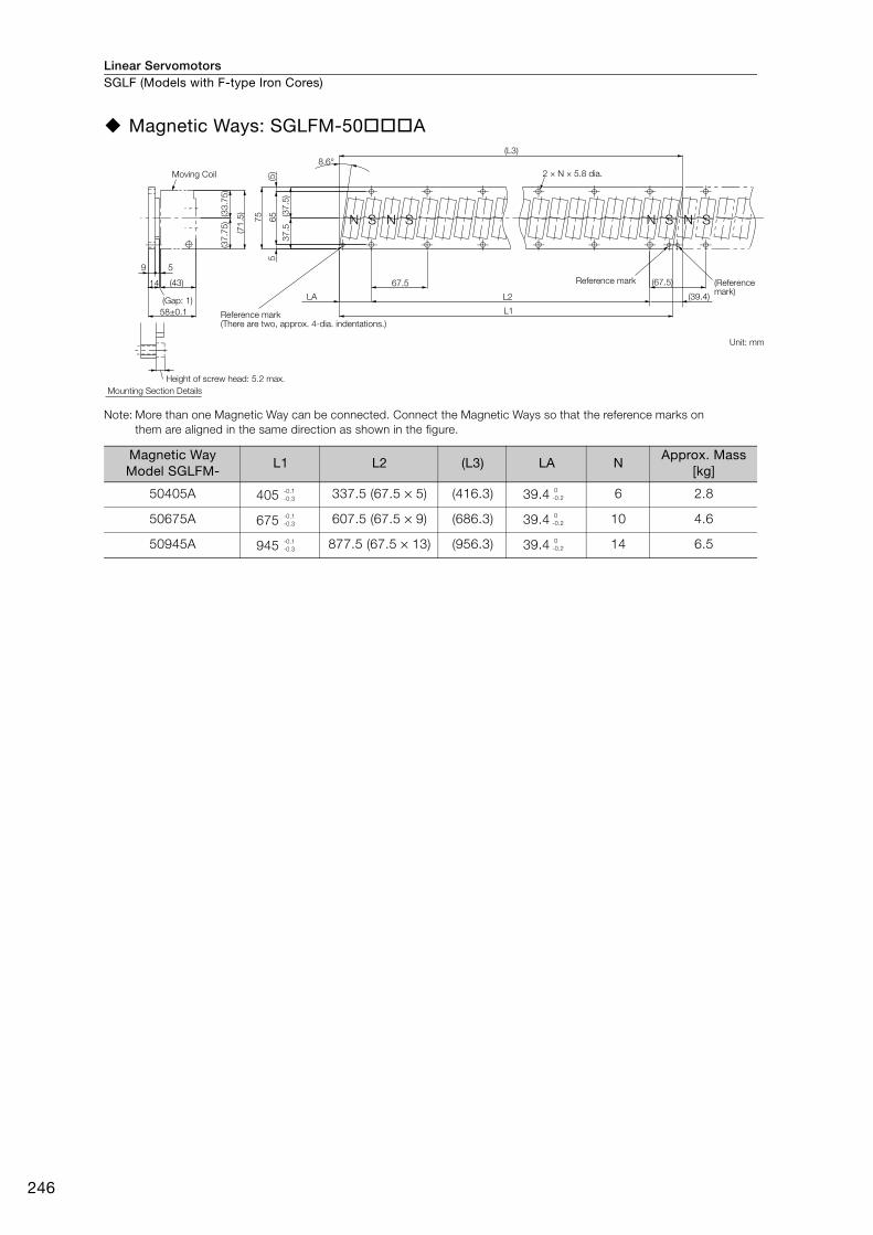
Linear ServomotorsSGLF (Models with F-type Iron Cores)
246
Magnetic Ways: SGLFM-50A
Note: More than one Magnetic Way can be connected. Connect the Magnetic Ways so that the reference marks on them are aligned in the same direction as shown in the figure.
Magnetic Way Model SGLFM-
L1 L2 (L3) LA NApprox. Mass
[kg]
50405A 405 337.5 (67.5 × 5) (416.3) 39.4 6 2.8
50675A 675 607.5 (67.5 × 9) (686.3) 39.4 10 4.6
50945A 945 877.5 (67.5 × 13) (956.3) 39.4 14 6.5
(Gap: 1)
2 × N × 5.8 dia.
S SSNS NNN
67.5
9 5
58±0.1
14 (43)
(5)
5
75
65
37
.5(3
7.5
)
(37
.75
)
(71
.5)(33
.75
)
8.6°
LA
L1
L2
(L3)
(67.5)
(39.4)
Moving Coil
Reference mark
Height of screw head: 5.2 max.
Mounting Section Details
(There are two, approx. 4-dia. indentations.)
Reference mark (Reference mark)
Unit: mm
-0.1-0.3
0-0.2
-0.1-0.3
0-0.2
-0.1-0.3
0-0.2
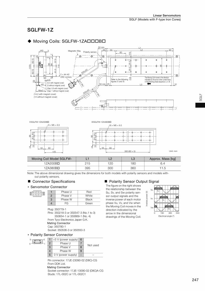
Linear Servomotors SGLF (Models with F-type Iron Cores)
247
SG
LF
SGLFW-1Z
Moving Coils: SGLFW-1ZAB
Note: The above dimensional drawing gives the dimensions for both models with polarity sensors and models with-out polarity sensors.
Moving Coil Model SGLFW- L1 L2 L3 Approx. Mass [kg]
1ZA200B 215 120 180 6.4
1ZA380B 395 300 360 11.5
Connector Specifications Polarity Sensor Output Signal
• Servomotor Connector The figure on the right shows the relationship between the Su, Sv, and Sw polarity sen-sor output signals and the inverse power of each motor phase Vu, Vv, and Vw when the Moving Coil moves in the direction indicated by the arrow in the dimensional drawings of the Moving Coil.
Plug: 350779-1Pins: 350218-3 or 350547-3 (No.1 to 3)
350654-1 or 350669-1 (No. 4)From Tyco Electronics Japan G.K. Mating ConnectorCap: 350780-1Socket: 350536-3 or 350550-3
• Polarity Sensor Connector
Pin connector: 17JE-23090-02 (D8C)-CGFrom DDK Ltd.Mating ConnectorSocket connector: 17JE-13090-02 (D8C)A-CGStuds: 17L-002C or 17L-002C1
9 M5 × 9.5
96 35
.535
.51
2
14
55 60
120
SGLFW-1ZA200B
500±50
500±50
60
(15
)
10L325
96
(12
)
L1L25530
96 35
.53
5.5
409
8
11
9
57
.56
1.5
(62
.5)
(62
.5)
(12
5)
3(40)7
14
43
58±0.1
0.5(9)
18 × M5 × 9.5
96 35
.535
.51
2
14
55 60
300 (60 × 5)
SGLFW-1ZA380B
Magnetic WayPolarity sensor
2 × #4-40
UNC screws
(5.2 with magnet cover)
(5 without magnet cover)
(Gap: 0.8 with magnet cover)
(Gap: 1 without magnet cover)
(14.2 with magnet cover)
(14 without magnet cover)
50 min.
The Moving Coil moves in the direction indicated by the arrow when current flows in the following phase sequence: U, V, W.
Unit: mm
Refer to the following figures and .
50 min.
(8.4 dia.)
(4.2 dia.)
Vu
Vv
Vw
Su
Sv
Sw
0 180 360 540
Electrical angle (°)
Inve
rse p
ow
er
(V)
1 2 3 41 Phase U Red2 Phase V White3 Phase W Black4 FG Green
9 6
5 1
1 +5 V (power supply) 6
Not used2 Phase U 73 Phase V 84 Phase W 95 0 V (power supply) − −
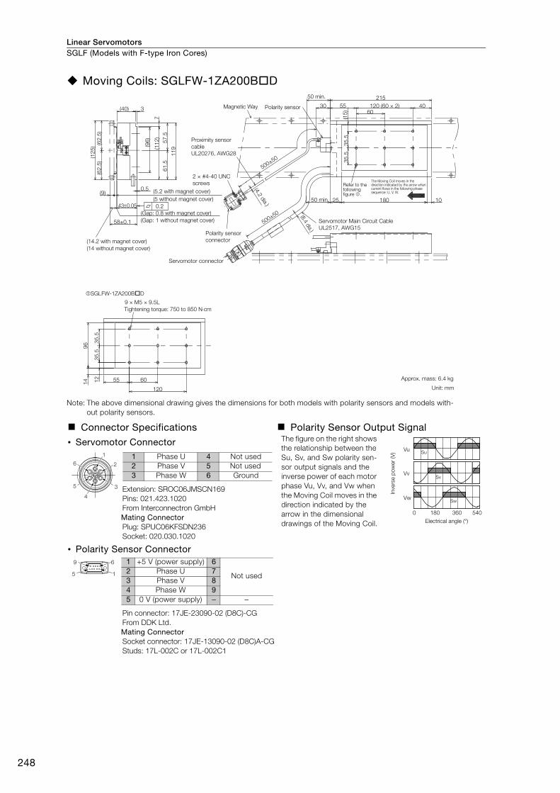
Linear ServomotorsSGLF (Models with F-type Iron Cores)
248
Moving Coils: SGLFW-1ZA200BD
Note: The above dimensional drawing gives the dimensions for both models with polarity sensors and models with-out polarity sensors.
Connector Specifications Polarity Sensor Output Signal
• Servomotor Connector The figure on the right shows the relationship between the Su, Sv, and Sw polarity sen-sor output signals and the inverse power of each motor phase Vu, Vv, and Vw when the Moving Coil moves in the direction indicated by the arrow in the dimensional drawings of the Moving Coil.
Extension: SROC06JMSCN169Pins: 021.423.1020From Interconnectron GmbH Mating ConnectorPlug: SPUC06KFSDN236Socket: 020.030.1020
• Polarity Sensor Connector
Pin connector: 17JE-23090-02 (D8C)-CGFrom DDK Ltd.Mating ConnectorSocket connector: 17JE-13090-02 (D8C)A-CGStuds: 17L-002C or 17L-002C1
430.05
(9)0.5
(62
.5)
(62
.5)
(12
5)
3(40)
11
9
61
.55
7.5
7
60
(96
)
(11
2)
4030
(15
)
215
120 (60 × 2)55
25 10180
35
.53
5.5
60
120
96 3
5.5
35
.5
14 12 55
58±0.1 500±50
500±50
0.2
9 × M5 × 9.5L
SGLFW-1ZA200BD
Magnetic Way
Proximity sensor
cable
UL20276, AWG28
Servomotor Main Circuit Cable
UL2517, AWG15
Refer to the following figure .
The Moving Coil moves in the direction indicated by the arrow when current flows in the following phase sequence: U, V, W.
2 × #4-40 UNC
screws
50 min.
(5.2 with magnet cover)
(Gap: 0.8 with magnet cover)
(14.2 with magnet cover)
(14 without magnet cover)
(Gap: 1 without magnet cover)
Polarity sensor
connector
(4.2 dia.)
(8.4 dia.)
Servomotor connector
Tightening torque: 750 to 850 Ncm
Approx. mass: 6.4 kg
Unit: mm
(5 without magnet cover)
Polarity sensor
50 min.
Vu
Vv
Vw
Su
Sv
Sw
0 180 360 540
Electrical angle (°)
Inve
rse p
ow
er
(V)
6
5
4
3
2
1 1 Phase U 4 Not used2 Phase V 5 Not used3 Phase W 6 Ground
9 6
5 1
1 +5 V (power supply) 6
Not used2 Phase U 73 Phase V 84 Phase W 95 0 V (power supply) − −
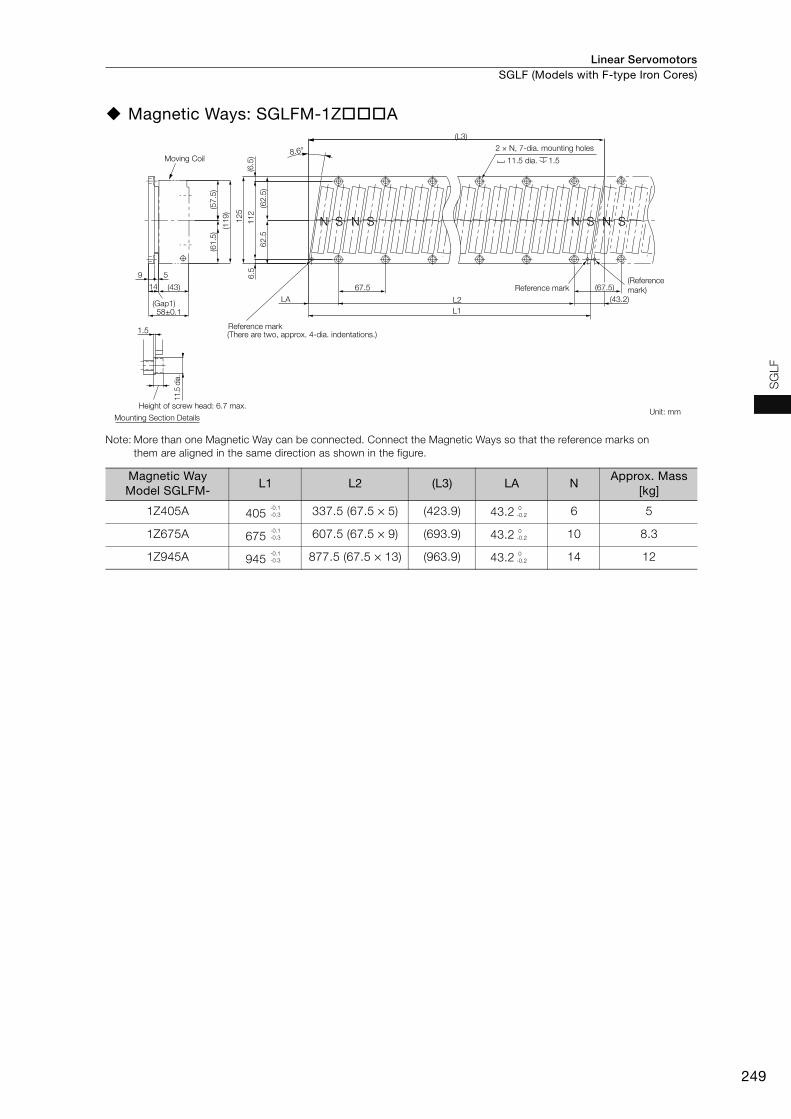
Linear Servomotors SGLF (Models with F-type Iron Cores)
249
SG
LF
Magnetic Ways: SGLFM-1ZA
Note: More than one Magnetic Way can be connected. Connect the Magnetic Ways so that the reference marks on them are aligned in the same direction as shown in the figure.
Magnetic Way Model SGLFM-
L1 L2 (L3) LA NApprox. Mass
[kg]
1Z405A 405 337.5 (67.5 × 5) (423.9) 43.2 6 5
1Z675A 675 607.5 (67.5 × 9) (693.9) 43.2 10 8.3
1Z945A 945 877.5 (67.5 × 13) (963.9) 43.2 14 12
12
5
11
26
.5(6
.5)
(62
.5)
62
.5
(61
.5)
(57
.5)
(11
9)
(43.2)
67.514
9 5
58±0.1
(43)
(Gap1)
S
(There are two, approx. 4-dia. indentations.)
S SS NNNN
8.6°
LA
L1
L2
(L3)
1.5
11.5
dia
.
(67.5)
Moving Coil
2 × N, 7-dia. mounting holes
11.5 dia. 1.5
Reference mark(Reference
mark)
Height of screw head: 6.7 max.
Mounting Section DetailsUnit: mm
Reference mark
-0.1-0.3
0-0.2
-0.1-0.3
0-0.2
-0.1-0.3
0-0.2

Linear ServomotorsSGLF (Models with F-type Iron Cores)
250
Selecting Cables
Cable ConfigurationsTo select a Linear Encoder, use Recommended Linear Encoders (pages 278 and 279). Prepare the cable required for the encoder.
* You can connect directly to an absolute linear encoder.
Note: Refer to the following manual for the following information.• Cable dimensional drawings and cable connection specifications• Order numbers and specifications of individual connectors for cables• Order numbers and specifications for wiring materials
Σ-7-Series AC Servo Drive Peripheral Device Selection Manual (Manual No.: SIEP S800001 32)
SERVOPACK
Serial Converter Unit Cable*
(between SERVOPACK connector
CN2 and Serial Converter Unit)
Linear Servomotor Main Circuit Cable
Sensor Cable
(between Serial Converter
Unit and polarity sensor)
Serial Converter Unit
Linear Encoder Cable
Linear Encoder (Not provided by Yaskawa.)
Polarity sensor
Linear Servomotor
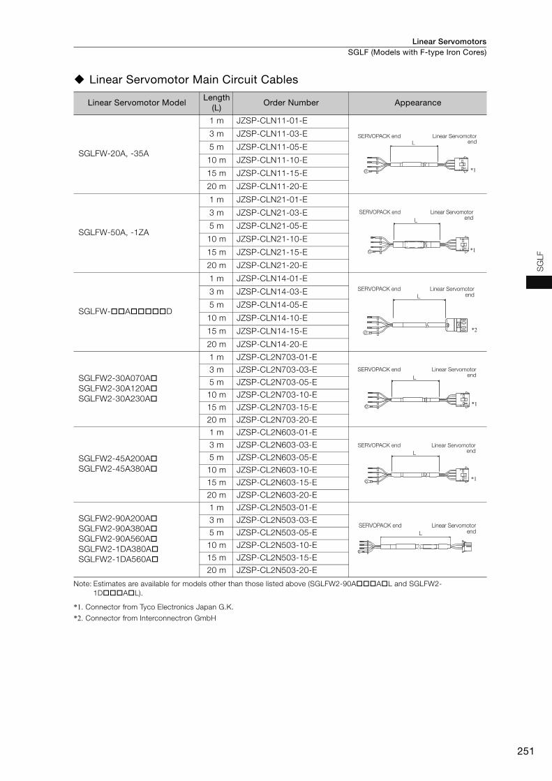
Linear Servomotors SGLF (Models with F-type Iron Cores)
251
SG
LF
Linear Servomotor Main Circuit Cables
Note: Estimates are available for models other than those listed above (SGLFW2-90AAL and SGLFW2-1DAL).
*1. Connector from Tyco Electronics Japan G.K.
*2. Connector from Interconnectron GmbH
Linear Servomotor ModelLength
(L)Order Number Appearance
SGLFW-20A, -35A
1 m JZSP-CLN11-01-E
3 m JZSP-CLN11-03-E
5 m JZSP-CLN11-05-E
10 m JZSP-CLN11-10-E
15 m JZSP-CLN11-15-E
20 m JZSP-CLN11-20-E
SGLFW-50A, -1ZA
1 m JZSP-CLN21-01-E
3 m JZSP-CLN21-03-E
5 m JZSP-CLN21-05-E
10 m JZSP-CLN21-10-E
15 m JZSP-CLN21-15-E
20 m JZSP-CLN21-20-E
SGLFW-AD
1 m JZSP-CLN14-01-E
3 m JZSP-CLN14-03-E
5 m JZSP-CLN14-05-E
10 m JZSP-CLN14-10-E
15 m JZSP-CLN14-15-E
20 m JZSP-CLN14-20-E
SGLFW2-30A070ASGLFW2-30A120ASGLFW2-30A230A
1 m JZSP-CL2N703-01-E
3 m JZSP-CL2N703-03-E
5 m JZSP-CL2N703-05-E
10 m JZSP-CL2N703-10-E
15 m JZSP-CL2N703-15-E
20 m JZSP-CL2N703-20-E
SGLFW2-45A200ASGLFW2-45A380A
1 m JZSP-CL2N603-01-E
3 m JZSP-CL2N603-03-E
5 m JZSP-CL2N603-05-E
10 m JZSP-CL2N603-10-E
15 m JZSP-CL2N603-15-E
20 m JZSP-CL2N603-20-E
SGLFW2-90A200ASGLFW2-90A380ASGLFW2-90A560ASGLFW2-1DA380ASGLFW2-1DA560A
1 m JZSP-CL2N503-01-E
3 m JZSP-CL2N503-03-E
5 m JZSP-CL2N503-05-E
10 m JZSP-CL2N503-10-E
15 m JZSP-CL2N503-15-E
20 m JZSP-CL2N503-20-E
L
*1
SERVOPACK end Linear Servomotorend
L
*1
SERVOPACK end Linear Servomotor end
L
*2
SERVOPACK end Linear Servomotor end
L
*1
SERVOPACK end Linear Servomotor end
L
*1
SERVOPACK end Linear Servomotor end
L
SERVOPACK end Linear Servomotor end
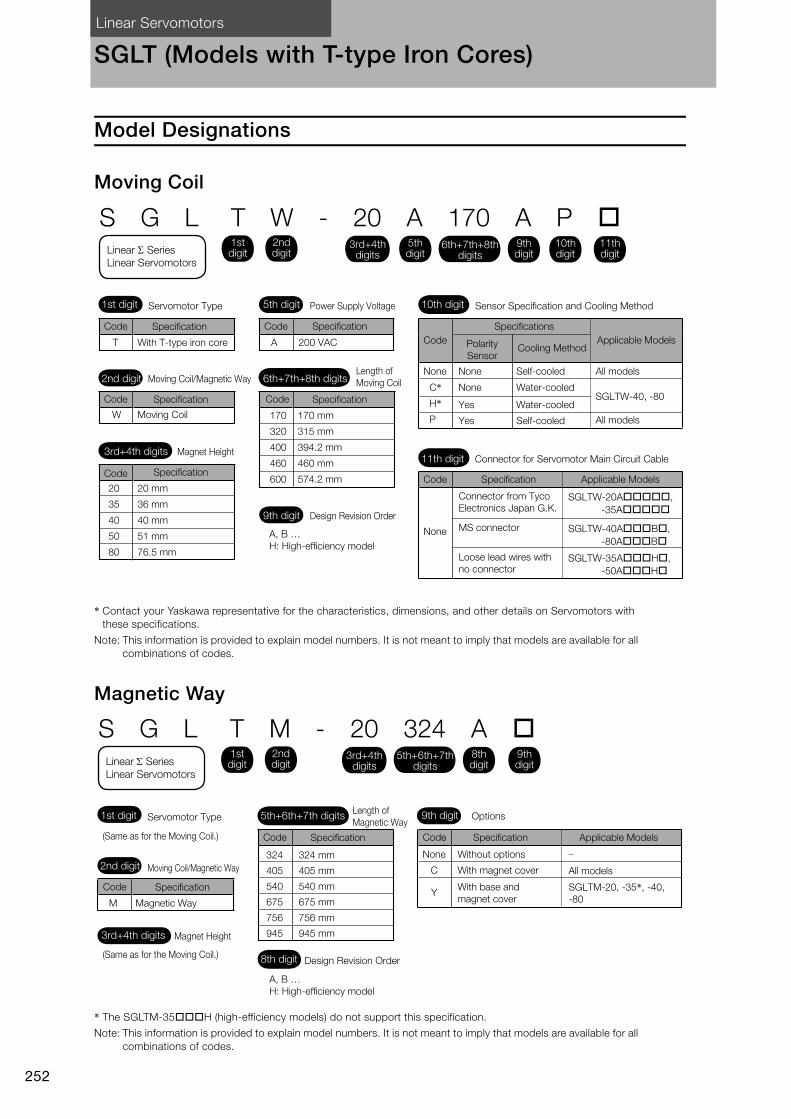
Linear Servomotors
252
SGLT (Models with T-type Iron Cores)
Model Designations
Moving Coil
* Contact your Yaskawa representative for the characteristics, dimensions, and other details on Servomotors with these specifications.
Note: This information is provided to explain model numbers. It is not meant to imply that models are available for all combinations of codes.
Magnetic Way
* The SGLTM-35H (high-efficiency models) do not support this specification.
Note: This information is provided to explain model numbers. It is not meant to imply that models are available for all combinations of codes.
10th digit Sensor Specification and Cooling Method
Code Specification
5th digit Power Supply Voltage1st digit Servomotor Type
6th+7th+8th digitsLength of
Moving Coil2nd digit Moving Coil/Magnetic Way
S G L T W - 20 A 170 A P
11th digit Connector for Servomotor Main Circuit Cable
Code
T With T-type iron core A 200 VAC
Specification
Code
W Moving Coil
Specification
3rd+4th digits Magnet Height
Code
20
35
40
50
80
20 mm
36 mm
40 mm
51 mm
76.5 mm
Specification
Code
170
320
400
460
600
170 mm
315 mm
394.2 mm
460 mm
574.2 mm
Specification
A, B …
H: High-efficiency model
9th digit Design Revision Order
Code
None Self-cooledNone
Specifications
Polarity
SensorCooling Method
Applicable Models
All models
Code
Connector from Tyco
Electronics Japan G.K.
MS connector
Loose lead wires with
no connector
Specification Applicable Models
SGLTW-20A,
-35A
SGLTW-40AB,
-80AB
SGLTW-35AH,
-50AH
3rd+4th digits
1st digit
2nd digit
5th digit
6th+7th+8th digits
9th digit
10th digit
11th digit
C*H*P
None
Yes
Yes
Water-cooled
Water-cooled
Self-cooled
SGLTW-40, -80
All models
None
Linear Series Linear Servomotors
9th digit
Code
324
405
540
675
756
945
1st digitLength of
Magnetic WayServomotor Type
8th digit Design Revision Order
S G L T M - 20 324 A
3rd+4th digits
5th+6th+7th digits
Specification
2nd digit Moving Coil/Magnetic Way
Magnet Height
Code
M Magnetic Way
Specification
A, B …
H: High-efficiency model
Code
Without options
With magnet cover
With base and
magnet cover
Specification Applicable Models
3rd+4th digits
1st digit
2nd digit
5th+6th+7th digits
8th digit
9th digit
(Same as for the Moving Coil.)
(Same as for the Moving Coil.)
324 mm
405 mm
540 mm
675 mm
756 mm
945 mm
Options
None
C
Y
All models
SGLTM-20, -35*, -40,
-80
Linear Series
Linear Servomotors

Linear Servomotors SGLT (Models with T-type Iron Cores)
253
SG
LT
Precautions on Moving Coils with Polarity Sensors
When you use a Moving Coil with a Polarity Sensor, the Magnetic Way must cover the bottom of the polarity sensor. Refer to the example that shows the correct installation.When determining the length of the Moving Coil’s stroke or the length of the Magnetic Way, con-sider the total length of the Moving Coil and the polarity sensor. Refer to the following table.
Correct Installation Incorrect Installation
Total Length of Moving Coil with Polarity Sensor
Note
Moving CoilPolarity sensor
Magnetic Way
Moving Coil movement direction
Edge of Magnetic Way
Polarity sensor
Edge of Magnetic Way
Magnetic Way
Polarity sensorMoving Coil
L
L1A
Moving Coil Model
SGLTW-
Length of Moving Coil,
L1 [mm]
Length of Polarity Sensor, A [mm]
Total Length, L [mm]
20A170AP 170
34
204
20A320AP 315 349
20A460AP 460 494
35A170AP 170
34
204
35A320AP 315 349
35A460AP 460 494
35A170HP 17034
204
35A320HP 315 349
50A170HP 17034
204
50A320HP 315 349
40A400BH40A400BP
394.2 26 420.2
40A600BH40A600BP
574.2 26 600.2
80A400BH80A400BP
394.2 26 420.2
80A600BH80A600BP
574.2 26 600.2
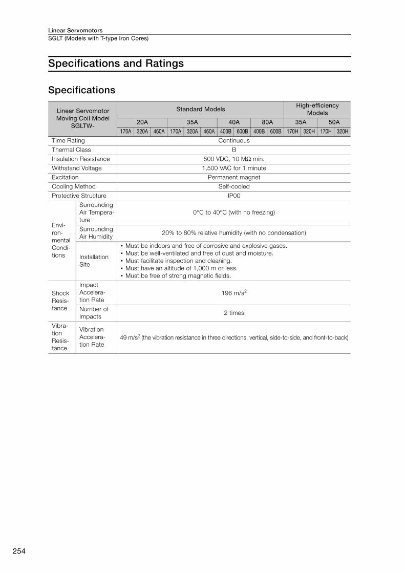
Linear ServomotorsSGLT (Models with T-type Iron Cores)
254
Specifications and Ratings
Specifications
Linear Servomotor Moving Coil Model
SGLTW-
Standard ModelsHigh-efficiency
Models
20A 35A 40A 80A 35A 50A
170A 320A 460A 170A 320A 460A 400B 600B 400B 600B 170H 320H 170H 320H
Time Rating Continuous
Thermal Class B
Insulation Resistance 500 VDC, 10 MΩ min.
Withstand Voltage 1,500 VAC for 1 minute
Excitation Permanent magnet
Cooling Method Self-cooled
Protective Structure IP00
Envi-ron-mental Condi-tions
Surrounding Air Tempera-ture
0°C to 40°C (with no freezing)
Surrounding Air Humidity
20% to 80% relative humidity (with no condensation)
Installation Site
• Must be indoors and free of corrosive and explosive gases.• Must be well-ventilated and free of dust and moisture.• Must facilitate inspection and cleaning.• Must have an altitude of 1,000 m or less. • Must be free of strong magnetic fields.
Shock Resis-tance
Impact Accelera-tion Rate
196 m/s2
Number of Impacts
2 times
Vibra-tion Resis-tance
Vibration Accelera-tion Rate
49 m/s2 (the vibration resistance in three directions, vertical, side-to-side, and front-to-back)
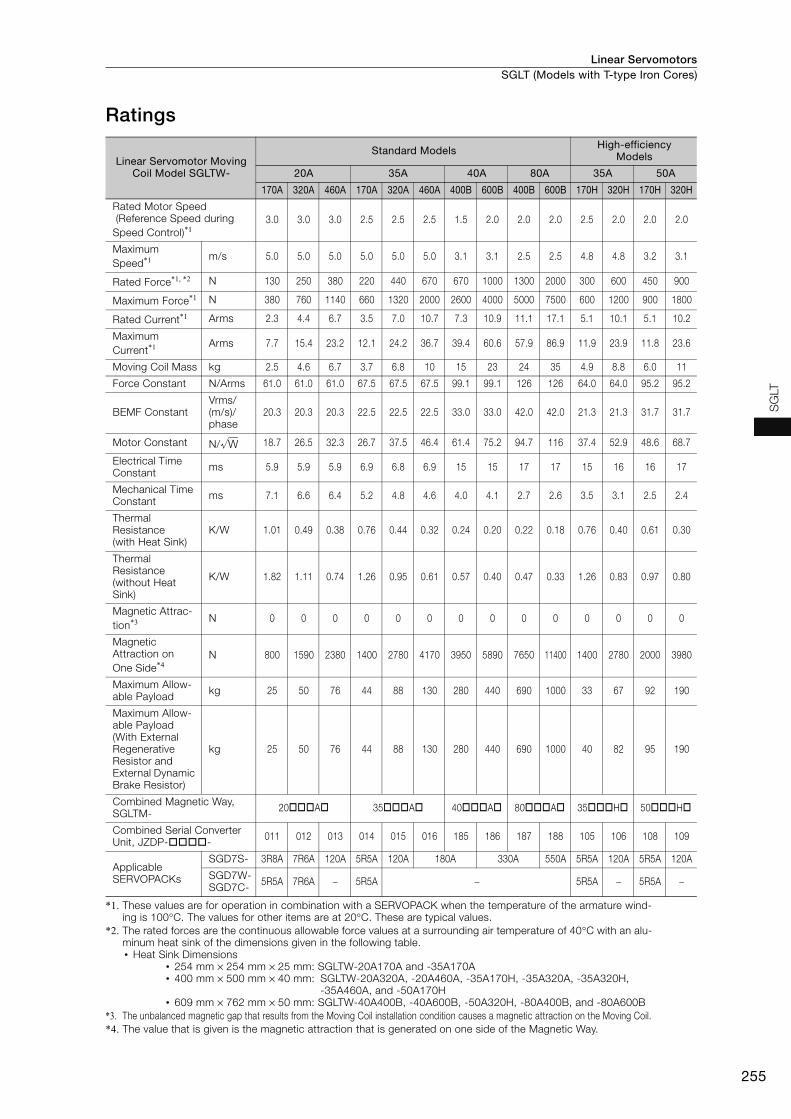
Linear Servomotors SGLT (Models with T-type Iron Cores)
255
SG
LT
Ratings
*1. These values are for operation in combination with a SERVOPACK when the temperature of the armature wind-ing is 100°C. The values for other items are at 20°C. These are typical values.
*2. The rated forces are the continuous allowable force values at a surrounding air temperature of 40°C with an alu-minum heat sink of the dimensions given in the following table.• Heat Sink Dimensions
• 254 mm × 254 mm × 25 mm: SGLTW-20A170A and -35A170A• 400 mm × 500 mm × 40 mm: SGLTW-20A320A, -20A460A, -35A170H, -35A320A, -35A320H,
-35A460A, and -50A170H• 609 mm × 762 mm × 50 mm: SGLTW-40A400B, -40A600B, -50A320H, -80A400B, and -80A600B
*3. The unbalanced magnetic gap that results from the Moving Coil installation condition causes a magnetic attraction on the Moving Coil.*4. The value that is given is the magnetic attraction that is generated on one side of the Magnetic Way.
Linear Servomotor Moving Coil Model SGLTW-
Standard Models High-efficiency Models
20A 35A 40A 80A 35A 50A
170A 320A 460A 170A 320A 460A 400B 600B 400B 600B 170H 320H 170H 320H
Rated Motor Speed (Reference Speed during Speed Control)*1
3.0 3.0 3.0 2.5 2.5 2.5 1.5 2.0 2.0 2.0 2.5 2.0 2.0 2.0
Maximum Speed*1 m/s 5.0 5.0 5.0 5.0 5.0 5.0 3.1 3.1 2.5 2.5 4.8 4.8 3.2 3.1
Rated Force*1, *2 N 130 250 380 220 440 670 670 1000 1300 2000 300 600 450 900
Maximum Force*1 N 380 760 1140 660 1320 2000 2600 4000 5000 7500 600 1200 900 1800
Rated Current*1 Arms 2.3 4.4 6.7 3.5 7.0 10.7 7.3 10.9 11.1 17.1 5.1 10.1 5.1 10.2
Maximum Current*1 Arms 7.7 15.4 23.2 12.1 24.2 36.7 39.4 60.6 57.9 86.9 11.9 23.9 11.8 23.6
Moving Coil Mass kg 2.5 4.6 6.7 3.7 6.8 10 15 23 24 35 4.9 8.8 6.0 11
Force Constant N/Arms 61.0 61.0 61.0 67.5 67.5 67.5 99.1 99.1 126 126 64.0 64.0 95.2 95.2
BEMF ConstantVrms/(m/s)/phase
20.3 20.3 20.3 22.5 22.5 22.5 33.0 33.0 42.0 42.0 21.3 21.3 31.7 31.7
Motor Constant N/ 18.7 26.5 32.3 26.7 37.5 46.4 61.4 75.2 94.7 116 37.4 52.9 48.6 68.7
Electrical Time Constant ms 5.9 5.9 5.9 6.9 6.8 6.9 15 15 17 17 15 16 16 17
Mechanical Time Constant ms 7.1 6.6 6.4 5.2 4.8 4.6 4.0 4.1 2.7 2.6 3.5 3.1 2.5 2.4
Thermal Resistance (with Heat Sink)
K/W 1.01 0.49 0.38 0.76 0.44 0.32 0.24 0.20 0.22 0.18 0.76 0.40 0.61 0.30
Thermal Resistance (without Heat Sink)
K/W 1.82 1.11 0.74 1.26 0.95 0.61 0.57 0.40 0.47 0.33 1.26 0.83 0.97 0.80
Magnetic Attrac-tion*3 N 0 0 0 0 0 0 0 0 0 0 0 0 0 0
Magnetic Attraction on One Side*4
N 800 1590 2380 1400 2780 4170 3950 5890 7650 11400 1400 2780 2000 3980
Maximum Allow-able Payload kg 25 50 76 44 88 130 280 440 690 1000 33 67 92 190
Maximum Allow-able Payload (With External Regenerative Resistor and External Dynamic Brake Resistor)
kg 25 50 76 44 88 130 280 440 690 1000 40 82 95 190
Combined Magnetic Way, SGLTM- 20A 35A 40A 80A 35H 50H
Combined Serial Converter Unit, JZDP-- 011 012 013 014 015 016 185 186 187 188 105 106 108 109
Applicable SERVOPACKs
SGD7S- 3R8A 7R6A 120A 5R5A 120A 180A 330A 550A 5R5A 120A 5R5A 120A
SGD7W-SGD7C- 5R5A 7R6A − 5R5A − 5R5A − 5R5A −
W

Linear ServomotorsSGLT (Models with T-type Iron Cores)
256
Force-Motor Speed Characteristics
Standard Models
High-efficiency Models
Note: 1. These values (typical values) are for operation in combination with a SERVOPACK when the temperature of the armature winding is 100°C.
2. The characteristics in the intermittent duty zone depend on the power supply voltage.3. If the effective force is within the allowable range for the rated force, the Servomotor can be used within the
intermittent duty zone.4. If you use a Servomotor Main Circuit Cable that exceeds 20 m, the intermittent duty zone in the torque-motor
speed characteristics will become smaller because the voltage drop increases.
Continuous duty zone
Intermittent duty zone
(solid lines): With three-phase 200-V input
(dotted lines): With single-phase 200-V input
A :
B :
A B
0 400 800 1200 1400
SGLTW-35A320A
A B
0 500 1000 1500 2000 2500
SGLTW-35A460A
A B
0 1000 2000 3000
SGLTW-40A400B
A B
0 200 400 600 800
SGLTW-20A320A
A B
0 200 400 600 800 1000 1200
SGLTW-20A460A
0 100 200 300 400
0 200 400 600 700
A B
A B
SGLTW-20A170A
SGLTW-35A170A
0 2000 4000 6000
SGLTW-80A400B
4
3
2
1
0
0 2000 4000
SGLTW-40A600B
A B
A B
4
3
2
1
00 2000 4000 80006000
SGLTW-80A600B
A B
6
5
4
3
2
1
0
6
5
4
3
2
1
0
6
5
4
3
2
1
0
6
5
4
3
2
1
0
4
3
2
1
0
4
3
2
1
0
6
5
4
3
2
1
0
6
5
4
3
2
1
0
Force (N)
Mo
tor
sp
eed
(m
/s)
Force (N)
Mo
tor
sp
eed
(m
/s)
Force (N)
Mo
tor
sp
eed
(m
/s)
Force (N)
Mo
tor
sp
eed
(m
/s)
Force (N)
Mo
tor
sp
eed
(m
/s)
Force (N)
Mo
tor
sp
eed
(m
/s)
Force (N)
Mo
tor
sp
eed
(m
/s)
Force (N)
Mo
tor
sp
eed
(m
/s)
Force (N)
Mo
tor
sp
eed
(m
/s)
Force (N)
Mo
tor
sp
eed
(m
/s)
6
5
4
3
2
1
0
4
3
2
1
0
0 400200 600
0 600300 900
BA
BA
4
3
2
1
0
0 1200600 1800
BA
SGLTW-35A170H
SGLTW-50A170H
A B
6
5
4
3
2
1
00 400 800 1200
SGLTW-35A320H
SGLTW-50A320H
Force (N)
Mo
tor
sp
eed
(m
/s)
Force (N)
Mo
tor
sp
eed
(m
/s)
Force (N)
Mo
tor
sp
eed
(m
/s)
Force (N)
Mo
tor
sp
eed
(m
/s)
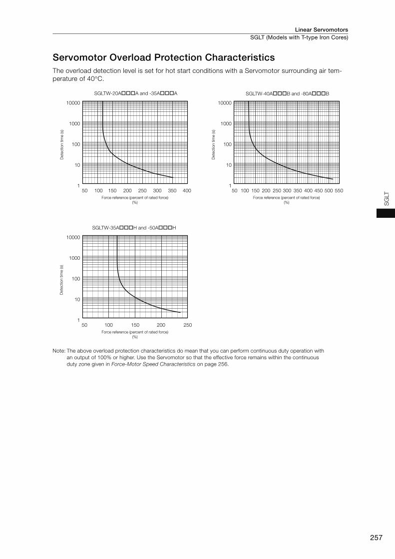
Linear Servomotors SGLT (Models with T-type Iron Cores)
257
SG
LT
Servomotor Overload Protection CharacteristicsThe overload detection level is set for hot start conditions with a Servomotor surrounding air tem-perature of 40°C.
Note: The above overload protection characteristics do mean that you can perform continuous duty operation with an output of 100% or higher. Use the Servomotor so that the effective force remains within the continuous duty zone given in Force-Motor Speed Characteristics on page 256.
SGLTW-40AB and -80AB
50 100 150 200 250 300 350 400 450 550500
10000
1000
100
10
1
SGLTW-35AH and -50AH
25050 100 150 200
10000
1000
100
10
1
40035050 100 150 200 250 300
SGLTW-20AA and -35AA
10000
1000
100
10
1
Dete
ctio
n t
ime (s)
Force reference (percent of rated force)
(%)
Dete
ctio
n t
ime (s)
Force reference (percent of rated force)
(%)
Dete
ctio
n t
ime (s)
Force reference (percent of rated force)
(%)
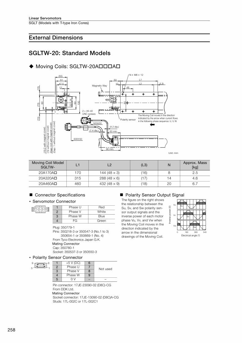
Linear ServomotorsSGLT (Models with T-type Iron Cores)
258
External Dimensions
SGLTW-20: Standard Models
Moving Coils: SGLTW-20AA
Moving Coil Model SGLTW-
L1 L2 (L3) NApprox. Mass
[kg]
20A170A 170 144 (48 × 3) (16) 8 2.5
20A320A 315 288 (48 × 6) (17) 14 4.6
20A460A 460 432 (48 × 9) (18) 20 6.7
Connector Specifications Polarity Sensor Output Signal
• Servomotor Connector The figure on the right shows the relationship between the Su, Sv, and Sw polarity sen-sor output signals and the inverse power of each motor phase Vu, Vv, and Vw when the Moving Coil moves in the direction indicated by the arrow in the dimensional drawings of the Moving Coil.
Plug: 350779-1 Pins: 350218-3 or 350547-3 (No.1 to 3)
350654-1 or 350669-1 (No. 4) From Tyco Electronics Japan G.K. Mating Connector Cap: 350780-1 Socket: 350537-3 or 350550-3
• Polarity Sensor Connector
Pin connector: 17JE-23090-02 (D8C)-CGFrom DDK Ltd.Mating ConnectorSocket connector: 17JE-13090-02 (D8C)A-CGStuds: 17L-002C or 17L-002C1
47.5
10
0
60
80
28
20
(15
)(1
5)
(70
)
(55)
50050
50050
12
51
(L3)
L1
1
L210
48
50
60
N M6 12
Magnetic Way
2 #4-40
UNC screws
(Gap
: 1 w
ithout
magnet
cove
r)
(Gap
: 0.8
with m
agnet
cove
r)(1
9 w
ithout
magnet
cove
r)
(19.2
with m
agnet
cove
r)
Polarity sensor
The Moving Coil moves in the direction
indicated by the arrow when current flows
in the following phase sequence: U, V, W.
(4.2 dia.)
63 min.(7.4 dia.)
90 min.
Unit: mm
Vu
Vv
Vw
Su
Sv
Sw
0 180 360 540
Inve
rse p
ow
er
(V)
Electrical angle (°)
1 2 3 41 Phase U Red2 Phase V White3 Phase W Blue4 FG Green
9 6
5 1
1 +5 V (DC) 6
Not used2 Phase U 73 Phase V 84 Phase W 95 0 V − −

Linear Servomotors SGLT (Models with T-type Iron Cores)
259
SG
LT
Magnetic Ways: SGLTM-20A
Note: 1. Two Magnetic Way tracks are used together as a set. For safety, when they are shipped, the two tracks are secured to a mounting spacer made from aluminum.
2. More than one Magnetic Way can be connected.
3. Dimensions with asterisks are the distances between the Magnetic Way tracks. Install the tracks according to the specified dimensions. Observe the dimensions given in Mounting Section Details after installation. Dimensions when the Magnetic Way is shipped from the factory are indicated by .
4. Use socket head screws of strength class 10.9 or higher for the Magnetic Way mounting screws. (Do not use stainless steel screws.)
Magnetic Way Model SGLTM-
L1 L2 LA LB LC LD NApprox.
Mass [kg]
20324A 324 270 (54 × 5) 31.7 13.7 40.3 62 6 3.4
20540A 540 486 (54 × 9) 31.7 13.7 40.3 62 10 5.7
20756A 756 702 (54 × 13) 31.7 13.7 40.3 62 14 7.9
2 N M6 8
C1
C1
(54)
L2
54
9.9
L2
54
(29.3)
(54)
R6
(54)
8
LC L2
54
(29.3)
L1
L1
LA
LB
(9.4)
9.9
*2.40.3
*2.40.3
32 (8)
(55)
40
27
87
27
(1)
(10
0)
19
Gap
: 10
.3
15
15
*700
.3
*700.3
LD
3
Moving Coil
2 N 7 dia. (Refer to Side-to-Side Cross Section for the depth.)
Spacers: Do not remove them
until the Moving Coil is mounted
on the machine.
Unit: mm
Mount the Magnetic
Way so that its edge
surfaces are flush
with the inner step.
Mount the Magnetic Way so that its edge surfaces are flush with the inner step.
R: 0.5 max.
R: 1 m
ax.
71.5
1
(at t
he fa
ctor
y)
103
max
.(at t
he fa
ctor
y)
Mounting Section Details
Side-to-Side Cross Section
-0.1-0.3
0-0.2
0-0.2
0-0.2
+0.6 0
-0.1-0.3
0-0.2
0-0.2
0-0.2
+0.6 0
-0.1-0.3
0-0.2
0-0.2
0-0.2
+0.6 0
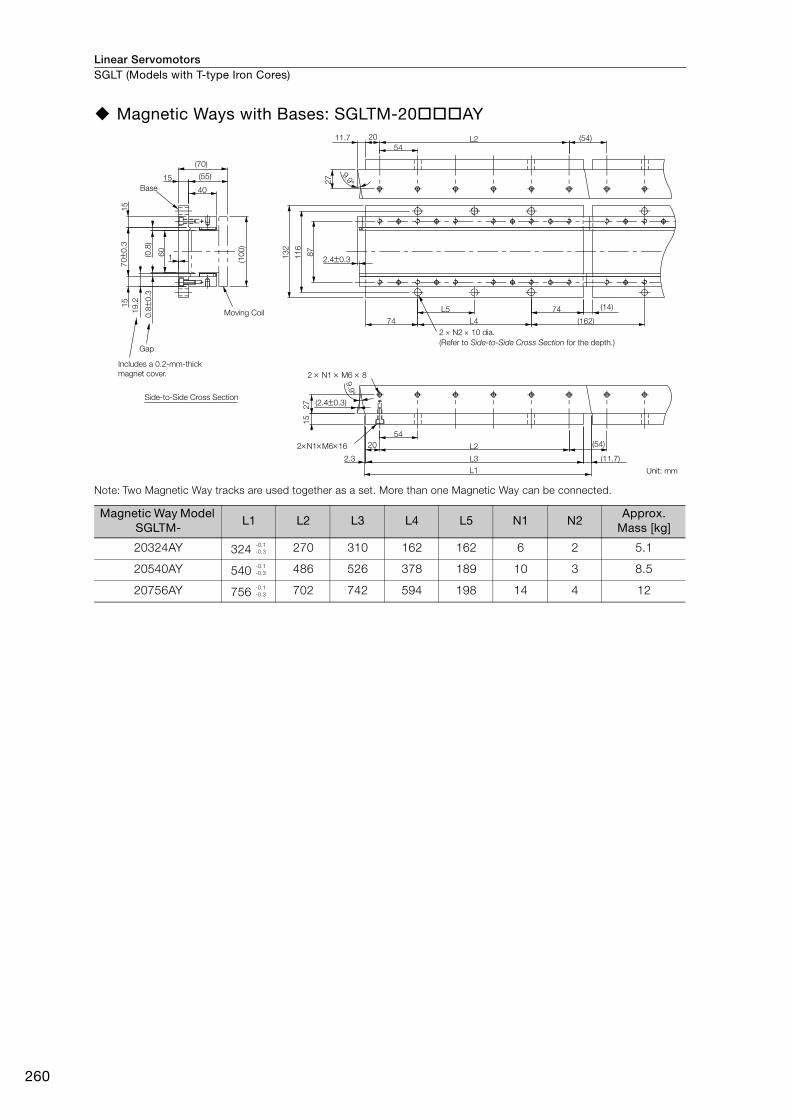
Linear ServomotorsSGLT (Models with T-type Iron Cores)
260
Magnetic Ways with Bases: SGLTM-20AY
Note: Two Magnetic Way tracks are used together as a set. More than one Magnetic Way can be connected.
Magnetic Way Model SGLTM-
L1 L2 L3 L4 L5 N1 N2Approx.
Mass [kg]
20324AY 324 270 310 162 162 6 2 5.1
20540AY 540 486 526 378 189 10 3 8.5
20756AY 756 702 742 594 198 14 4 12
Gap
27
15
(2.40.3)
13
2
11
6
87
2.40.3
L3
L4
L5
(0.8
)0
.80
.3
19
.2
700
.3
L1
(11.7)
(54)
2.3
20
54
L29.9
74 (14)
(162)74
(54)11.7 L254
20
27
9.9
160
15
15
(10
0)
(70)
(55)
40
15
DATE
2 N1 M6 8
2N1M616
Base
Moving Coil
2 N2 10 dia.
(Refer to Side-to-Side Cross Section for the depth.)
Unit: mm
Includes a 0.2-mm-thick
magnet cover.
Side-to-Side Cross Section
-0.1-0.3
-0.1-0.3
-0.1-0.3

Linear Servomotors SGLT (Models with T-type Iron Cores)
261
SG
LT
SGLTW-35: Standard Models
Moving Coils: SGLTW-35AA
Moving Coil Model SGLTW-
L1 L2 (L3) NApprox. Mass
[kg]
35A170A 170 144 (48 × 3) (16) 8 3.7
35A320A 315 288 (48 × 6) (17) 14 6.8
35A460A 460 432 (48 × 9) (18) 20 10
Connector Specifications Polarity Sensor Output Signal
• Servomotor Connector The figure on the right shows the relationship between the Su, Sv, and Sw polarity sen-sor output signals and the inverse power of each motor phase Vu, Vv, and Vw when the Moving Coil moves in the direction indicated by the arrow in the dimensional drawings of the Moving Coil.
Plug: 350779-1 Pins: 350218-3 or 350547-3 (No.1 to 3)
350654-1 or 350669-1 (No. 4) From Tyco Electronics Japan G.K. Mating Connector Cap: 350780-1 Socket: 350537-3 or 350550-3
• Polarity Sensor Connector
Pin connector: 17JE-23090-02 (D8C)-CGFrom DDK Ltd.Mating ConnectorSocket connector: 17JE-13090-02 (D8C)A-CGStuds: 17L-002C or 17L-002C1
55
10
0
60
28
20
(70)
66
12
50050
50050
50
60
(70
)(1
5)
(L3)
L1
80
1
10
48
L2
(15
)
N M6 12
Magnetic Way
2 #4-40
UNC screws
(8.4 dia.)(4.2 dia.)
Polarity sensor
63 min.
Unit: mm100 min.
The Moving Coil moves in the direction
indicated by the arrow when current flows
in the following phase sequence: U, V, W.
(Gap
: 1
witho
ut
mag
net
co
ver)
(Gap
: 0
.8 w
ith m
ag
net
co
ver)
(19
witho
ut
mag
net
co
ver)
(19
.2 w
ith m
ag
net
co
ver)
Vu
Vv
Vw
Su
Sv
Sw
0 180 360 540
Inve
rse p
ow
er
(V)
Electrical angle (°)
1 2 3 41 Phase U Red2 Phase V White3 Phase W Blue4 FG Green
9 6
5 1
1 +5 V (DC) 6
Not used2 Phase U 73 Phase V 84 Phase W 95 0 V − −
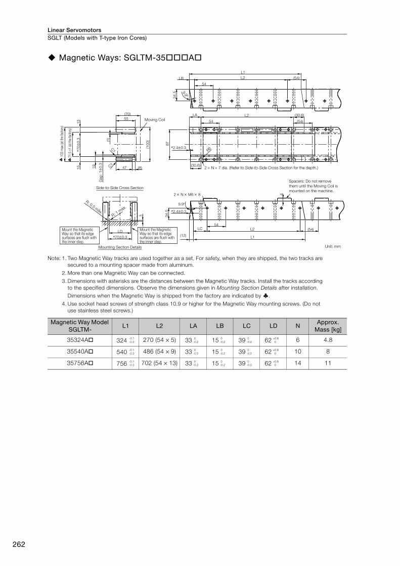
Linear ServomotorsSGLT (Models with T-type Iron Cores)
262
Magnetic Ways: SGLTM-35A
Note: 1. Two Magnetic Way tracks are used together as a set. For safety, when they are shipped, the two tracks are secured to a mounting spacer made from aluminum.
2. More than one Magnetic Way can be connected.
3. Dimensions with asterisks are the distances between the Magnetic Way tracks. Install the tracks according to the specified dimensions. Observe the dimensions given in Mounting Section Details after installation. Dimensions when the Magnetic Way is shipped from the factory are indicated by .
4. Use socket head screws of strength class 10.9 or higher for the Magnetic Way mounting screws. (Do not use stainless steel screws.)
Magnetic Way Model SGLTM-
L1 L2 LA LB LC LD NApprox.
Mass [kg]
35324A 324 270 (54 × 5) 33 15 39 62 6 4.8
35540A 540 486 (54 × 9) 33 15 39 62 10 8
35756A 756 702 (54 × 13) 33 15 39 62 14 11
(54)
L2
54
L1
LB
2 N M6 8
C1
C1
47 (8)
(70)
55
(1)
(10
0)
19
Gap
: 10
.3
15
15
*700
.3
*700.3
LD(54)LC L2
54
L1(12)
9.9
9.9
*2.40.3
34
.5
L2
54
(30.6)
(54)
R6
(30.6)
LA
87
34
.5
*2.40.3
3
4
Moving Coil
2 N 7 dia. (Refer to Side-to-Side Cross Section for the depth.)
Mount the Magnetic Way so that its edge surfaces are flush with the inner step.
Mount the Magnetic Way so that its edge surfaces are flush with the inner step.
Spacers: Do not remove
them until the Moving Coil is
mounted on the machine.
R: 0.5 max.
R: 1 m
ax.
Unit: mm
103
max
.(at t
he fa
ctor
y)
71.5
1
(at t
he fa
ctor
y)
Side-to-Side Cross Section
Mounting Section Details
-0.1-0.3
0-0.2
0-0.2
0-0.2
+0.6 0
-0.1-0.3
0-0.2
0-0.2
0-0.2
+0.6 0
-0.1-0.3
0-0.2
0-0.2
0-0.2
+0.6 0
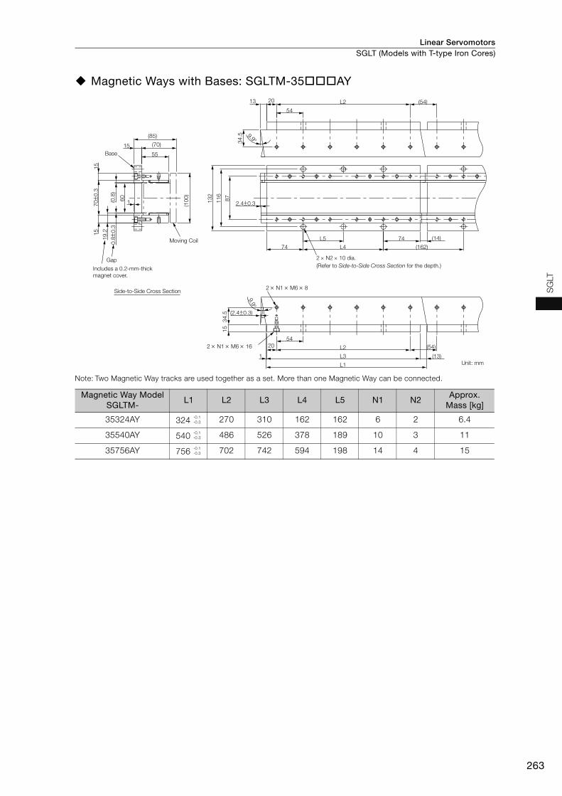
Linear Servomotors SGLT (Models with T-type Iron Cores)
263
SG
LT
Magnetic Ways with Bases: SGLTM-35AY
Note: Two Magnetic Way tracks are used together as a set. More than one Magnetic Way can be connected.
Magnetic Way Model SGLTM-
L1 L2 L3 L4 L5 N1 N2Approx.
Mass [kg]
35324AY 324 270 310 162 162 6 2 6.4
35540AY 540 486 526 378 189 10 3 11
35756AY 756 702 742 594 198 14 4 15
Gap
34
.51
5
(2.40.3)
(54)
9.9
2.40.3
L5
L4
L3
13
2
11
6
87
0.80
.3
19
.2
700
.3(54)
9.934
.5
13 L2
54
(162)74
74
1
54
L2
L1
60
(10
0)
15
55
(85)
(70)
1
15
15
2 N1 M6 8
2 N1 M6 16
(13)
20
(14)
20
(0.8
)
Base
Moving Coil
2 N2 10 dia.
(Refer to Side-to-Side Cross Section for the depth.)
Unit: mm
Includes a 0.2-mm-thick
magnet cover.
Side-to-Side Cross Section
-0.1-0.3
-0.1-0.3
-0.1-0.3
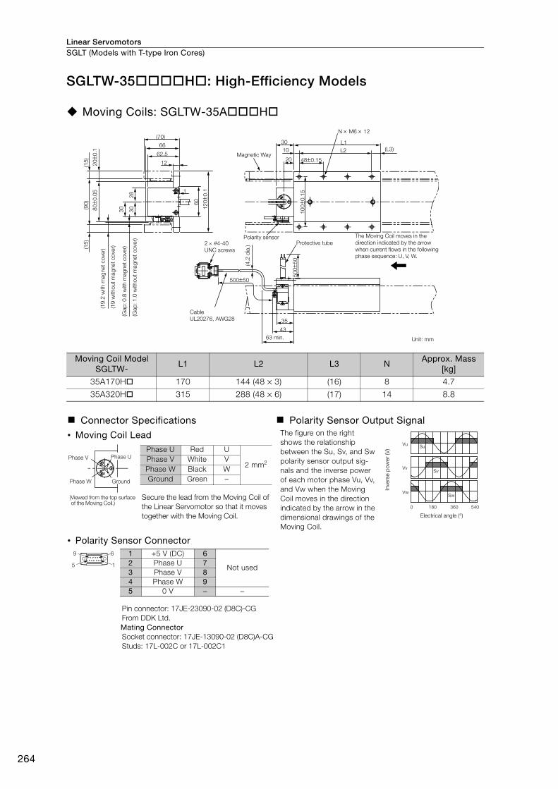
Linear ServomotorsSGLT (Models with T-type Iron Cores)
264
SGLTW-35H: High-Efficiency Models
Moving Coils: SGLTW-35AH
Moving Coil Model SGLTW-
L1 L2 L3 NApprox. Mass
[kg]
35A170H 170 144 (48 × 3) (16) 8 4.7
35A320H 315 288 (48 × 6) (17) 14 8.8
Connector Specifications Polarity Sensor Output Signal
• Moving Coil Lead The figure on the right shows the relationship between the Su, Sv, and Sw polarity sensor output sig-nals and the inverse power of each motor phase Vu, Vv, and Vw when the Moving Coil moves in the direction indicated by the arrow in the dimensional drawings of the Moving Coil.
Secure the lead from the Moving Coil of the Linear Servomotor so that it moves together with the Moving Coil.
• Polarity Sensor Connector
Pin connector: 17JE-23090-02 (D8C)-CGFrom DDK Ltd.Mating ConnectorSocket connector: 17JE-13090-02 (D8C)A-CGStuds: 17L-002C or 17L-002C1
12
16
0
28
30
62.5
66
(70)
(L3)
(90
)(1
5)
(15
)
30800
.05
12
00
.1
50050
35
43
50
05
0
200
.1
10
00
.15
480.1520
10
30 L1
N M6 12
L2Magnetic Way
2 #4-40
UNC screws
Polarity sensorProtective tube
The Moving Coil moves in the
direction indicated by the arrow
when current flows in the following
phase sequence: U, V, W.
Cable
UL20276, AWG28
63 min. Unit: mm
(4.2
dia
.)
(Gap
: 1
.0 w
itho
ut
mag
net
co
ver)
(Gap
: 0
.8 w
ith m
ag
net
co
ver)
(19
witho
ut
mag
net
co
ver)
(19
.2 w
ith m
ag
net
co
ver)
Vu
Vv
Vw
Su
Sv
Sw
0 180 360 540
Inve
rse p
ow
er
(V)
Electrical angle (°)
Phase V Phase U
GroundPhase W
(Viewed from the top surface of the Moving Coil.)
Phase U Red U
2 mm2Phase V White VPhase W Black WGround Green −
9 6
5 1
1 +5 V (DC) 6
Not used2 Phase U 73 Phase V 84 Phase W 95 0 V − −

Linear Servomotors SGLT (Models with T-type Iron Cores)
265
SG
LT
Magnetic Ways: SGLTM-35H
Note: 1. Two Magnetic Way tracks are used together as a set. For safety, when they are shipped, the two tracks are secured to a mounting spacer made from aluminum.
2. More than one Magnetic Way can be connected.
3. Dimensions with asterisks are the distances between the Magnetic Way tracks. Install the tracks according to the specified dimensions. Observe the dimensions given in Mounting Section Details after installation. Dimensions when the Magnetic Way is shipped from the factory are indicated by .
4. Use socket head screws of strength class 10.9 or higher for the Magnetic Way mounting screws. (Do not use stainless steel screws.)
Magnetic Way Model SGLTM-
L1 L2 LA LB LC LD NApprox.
Mass [kg]
35324H 324 270 (54 × 5) 33 15 39 82 6 4.8
35540H 540 486 (54 × 9) 33 15 39 82 10 8
35756H 756 702 (54 × 13) 33 15 39 82 14 11
Moving Coil
Includes a 0.2-mm-thick magnet cover.
2 N 7 dia. (Refer to Side-to-Side Cross Section for the depth.)
Unit: mm
Mount the Magnetic Way so that its edge surfaces are flush with the inner step.
Mount the Magnetic Way so that its edge surfaces are flush with the inner step.
R: 0.5 max. R: 1 m
ax.
91.5
1
(at th
e fac
tory)
123
max
.(at t
he fa
ctor
y)
Side-to-Side Cross Section
Mounting Section Details
3
LD
*900.3
(120
)
(70)(0
.8)
47
0.8
0.3
4.2
0.1
150
.1*9
00.
3150
.1
(8)
55
C1
C1
Gap
9.9
*2.40.3107
34.5
O/NS/NMADE IN JAPANDATE
YASKAWATYPE:
(30.6)
R6
(54)
(54)54
54
L2
L2LBL1
(30.6)LA
Spacers: Do not remove them until the Moving Coil is mounted on the machine.
9.9°
*2.4±0.3
34.5
2 × N × M6 × 8
(12)
L2LC
L1
(54)
(4)
54
-0.1-0.3
0-0.2
0-0.2
0-0.2
+0.6 0
-0.1-0.3
0-0.2
0-0.2
0-0.2
+0.6 0
-0.1-0.3
0-0.2
0-0.2
0-0.2
+0.6 0

Linear ServomotorsSGLT (Models with T-type Iron Cores)
266
SGLTW-40: Standard Models
Moving Coils: SGLTW-40AB
Moving Coil Model SGLTW-
L1 L2 (L3) NApprox. Mass
[kg]
40A400B 394.2 360 (60 × 6) (15) 14 15
40A600B 574.2 540 (60 × 9) (15) 20 22
Connector Specifications Polarity Sensor Output Signal
• Servomotor Connector The figure on the right shows the relationship between the Su, Sv, and Sw polarity sensor output sig-nals and the inverse power of each motor phase Vu, Vv, and Vw when the Moving Coil moves in the direction indicated by the arrow in the dimensional drawings of the Moving Coil.
Receptacle: MS3102A-22-22PFrom DDK Ltd.Mating ConnectorRight-angle plug: MS3108B22-22SStraight plug: MS3106B22-22SCable clamp: MS3057-12A
• Polarity Sensor Connector
Pin connector: 17JE-23090-02 (D8C)-CGFrom DDK Ltd.Mating ConnectorSocket connector: 17JE-13090-02 (D8C)A-CGStuds: 17L-002C or 17L-002C1
50050
75
(83)
78
16
(L3)20
63 L1L2
40 60(19.1
)(1
11.8
)
97
1
30
38
98
124
149.8
(19.1
)
N M8 16Polarity sensor
Receptacle
Magnetic Way
2 #4-40
UNC screws64 min.
The Moving Coil moves in the direction indicated by the arrow
when current flows in the following phase sequence: U, V, W.
Unit: mm
(4.2
dia
.)
(Gap
: 1.4
with
out m
agne
t cov
er)
(Gap: 1.2
with
magnet cove
r)(2
5.1
with
out m
agnet cove
r)(2
5.3
with m
ag
net
co
ver)
Vu
Vv
Vw
Su
Sv
Sw
0 180 360 540
Inve
rse p
ow
er
(V)
Electrical angle (°)
A
B
D
C
A Phase UB Phase VC Phase WD Ground
9 6
5 1
1 +5 V (power supply) 6
Not used2 Phase U 73 Phase V 84 Phase W 95 0 V (power supply) − −
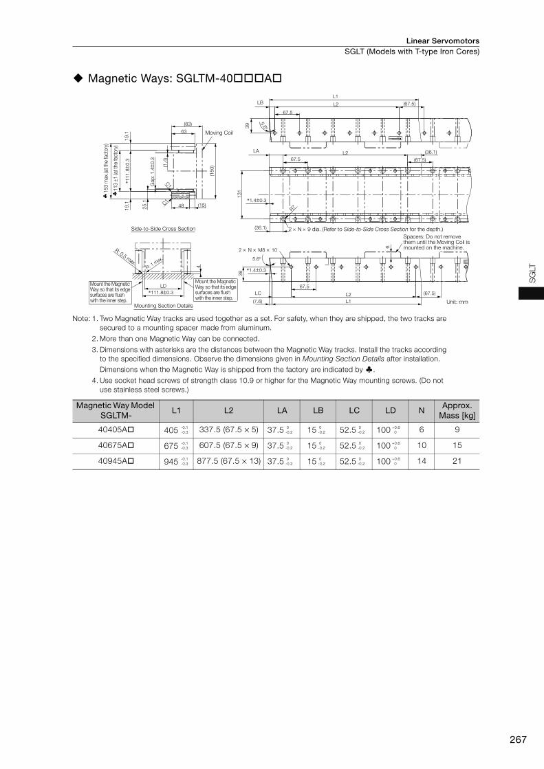
Linear Servomotors SGLT (Models with T-type Iron Cores)
267
SG
LT
Magnetic Ways: SGLTM-40A
Note: 1. Two Magnetic Way tracks are used together as a set. For safety, when they are shipped, the two tracks are secured to a mounting spacer made from aluminum.
2. More than one Magnetic Way can be connected.
3. Dimensions with asterisks are the distances between the Magnetic Way tracks. Install the tracks according to the specified dimensions. Observe the dimensions given in Mounting Section Details after installation. Dimensions when the Magnetic Way is shipped from the factory are indicated by .
4. Use socket head screws of strength class 10.9 or higher for the Magnetic Way mounting screws. (Do not use stainless steel screws.)
Magnetic Way Model SGLTM-
L1 L2 LA LB LC LD NApprox.
Mass [kg]
40405A 405 337.5 (67.5 × 5) 37.5 15 52.5 100 6 9
40675A 675 607.5 (67.5 × 9) 37.5 15 52.5 100 10 15
40945A 945 877.5 (67.5 × 13) 37.5 15 52.5 100 14 21
MADE IS/NO/N
TYPE:YASKAWA
2 N M8 10
C1
(67.5)LC L2
67.5
L1(7.6)
*1.40.3
39
*111.80.3
LD
48 (15)
(83)
63
(1.4
)
(150)
131
25.1 C1
Gap
: 1.40
.3
19.1
19.1
*111.80
.3
L2
67.5
(36.1)
(67.5)
(36.1)
LA
R7
*1.40.3
(67.5)L2
67.5
5.6
L1
LB
39
4
5.6
6
Moving Coil
Mount the Magnetic Way so that its edge surfaces are flush with the inner step.
Mount the Magnetic Way so that its edge surfaces are flush with the inner step.
Unit: mm
R: 0.5 max.R: 1
max.
2 N 9 dia. (Refer to Side-to-Side Cross Section for the depth.)
Spacers: Do not remove them until the Moving Coil is mounted on the machine.
113
1 (a
t th
e fa
ctory
)
153 m
ax.(a
t th
e fa
ctory
)
Side-to-Side Cross Section
Mounting Section Details
-0.1-0.3
0-0.2
0-0.2
0-0.2
+0.6 0
-0.1-0.3
0-0.2
0-0.2
0-0.2
+0.6 0
-0.1-0.3
0-0.2
0-0.2
0-0.2
+0.6 0
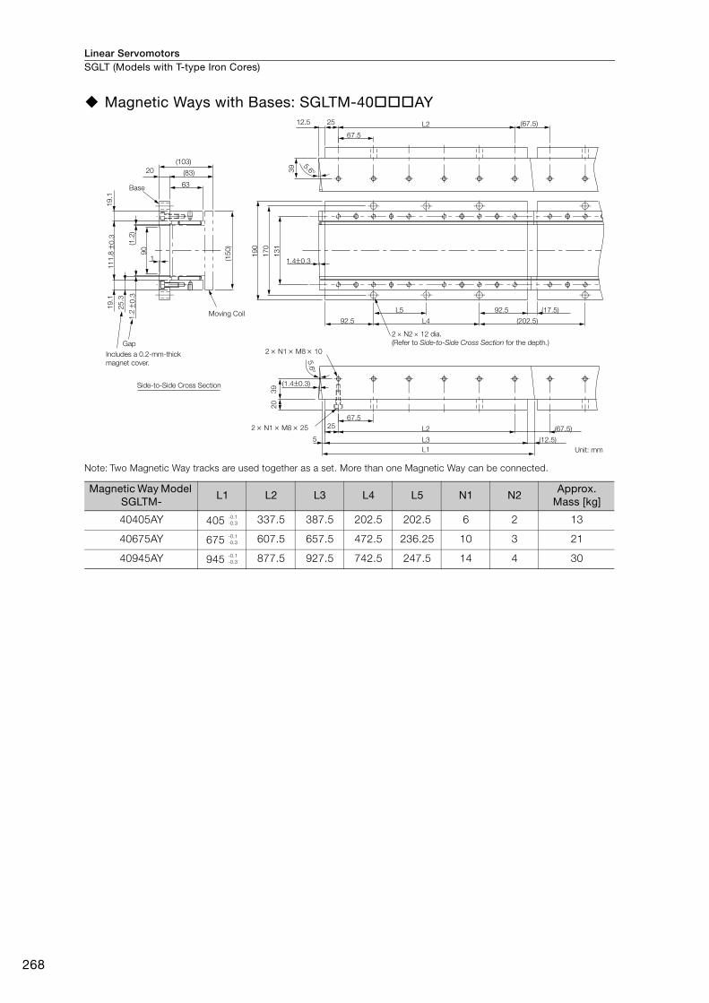
Linear ServomotorsSGLT (Models with T-type Iron Cores)
268
Magnetic Ways with Bases: SGLTM-40AY
Note: Two Magnetic Way tracks are used together as a set. More than one Magnetic Way can be connected.
Magnetic Way Model SGLTM-
L1 L2 L3 L4 L5 N1 N2Approx.
Mass [kg]
40405AY 405 337.5 387.5 202.5 202.5 6 2 13
40675AY 675 607.5 657.5 472.5 236.25 10 3 21
40945AY 945 877.5 927.5 742.5 247.5 14 4 30
Gap
Base
(1.40.3)
L1
(12.5)L35
25 L2 (67.5)
67.5
5.6
(202.5)92.5 L4
L5 92.5 (17.5)
17
0
19
0
13
12
03
9
1.40.3
(83)
(103)
1
(1.2
)
90
19
.1
25
.3
0.3
11
1.8
0.3
1.2
5.639
12.5 25 (67.5)
67.5
L2
63
20
19
.1
(15
0)
2 N1 M8 10
2 N1 M8 25
Moving Coil
2 N2 12 dia.
(Refer to Side-to-Side Cross Section for the depth.)
Unit: mm
Includes a 0.2-mm-thick
magnet cover.
Side-to-Side Cross Section
-0.1-0.3
-0.1-0.3
-0.1-0.3

Linear Servomotors SGLT (Models with T-type Iron Cores)
269
SG
LT
SGLTW-50: High-Efficiency Models
Moving Coils: SGLTW-50AH
Moving Coil Model SGLTW-
L1 L2 (L3) NApprox. Mass
[kg]
50A170H 170 144 (48 × 3) (16) 8 6
50A320H 315 288 (48 × 6) (17) 14 11
Connector Specifications Polarity Sensor Output Signal
• Moving Coil Lead The figure on the right shows the relationship between the Su, Sv, and Sw polarity sensor output sig-nals and the inverse power of each motor phase Vu, Vv, and Vw when the Moving Coil moves in the direction indicated by the arrow in the dimensional drawings of the Moving Coil.
Secure the lead from the Moving Coil of the Linear Servomotor so that it moves together with the Moving Coil.
• Polarity Sensor Connector
Pin connector: 17JE-23090-02 (D8C)-CGFrom DDK Ltd.Mating ConnectorSocket connector: 17JE-13090-02 (D8C)A-CGStuds: 17L-002C or 17L-002C1
28
30
1
(4.1
)
(90
)
(85)
(19
.1)
800
.05
12
00
.1
50050
35
43
200
.1
50
05
0
10
00
.15
(L3)
480.1520
10
30 L1
N M6 12
L2
(19
.1)
12
60
81
62.5 Magnetic Way
2 #4-40
UNC screws
Polarity sensor
connector
Cable
UL20276, AWG28
(4.2
dia
.)
Polarity sensorProtective tube
63 min. Unit: mm
The Moving Coil moves in the
direction indicated by the arrow
when current flows in the following
phase sequence: U, V, W.
(Gap
: 1
.0 w
itho
ut
mag
net
co
ver)
(Gap
: 0
.8 w
ith m
ag
net
co
ver)
(23
.1 w
itho
ut
mag
net
co
ver)
(23
.3 w
ith m
ag
net
co
ver)
Vu
Vv
Vw
Su
Sv
Sw
0 180 360 540
Inve
rse p
ow
er
(V)
Electrical angle (°)
Phase V Phase U
GroundPhase W
(Viewed from the top surface of the Moving Coil.)
Phase U Red U
2 mm2Phase V White VPhase W Black WGround Green −
9 6
5 1
1 +5 V (DC) 6
Not used2 Phase U 73 Phase V 84 Phase W 95 0 V − −
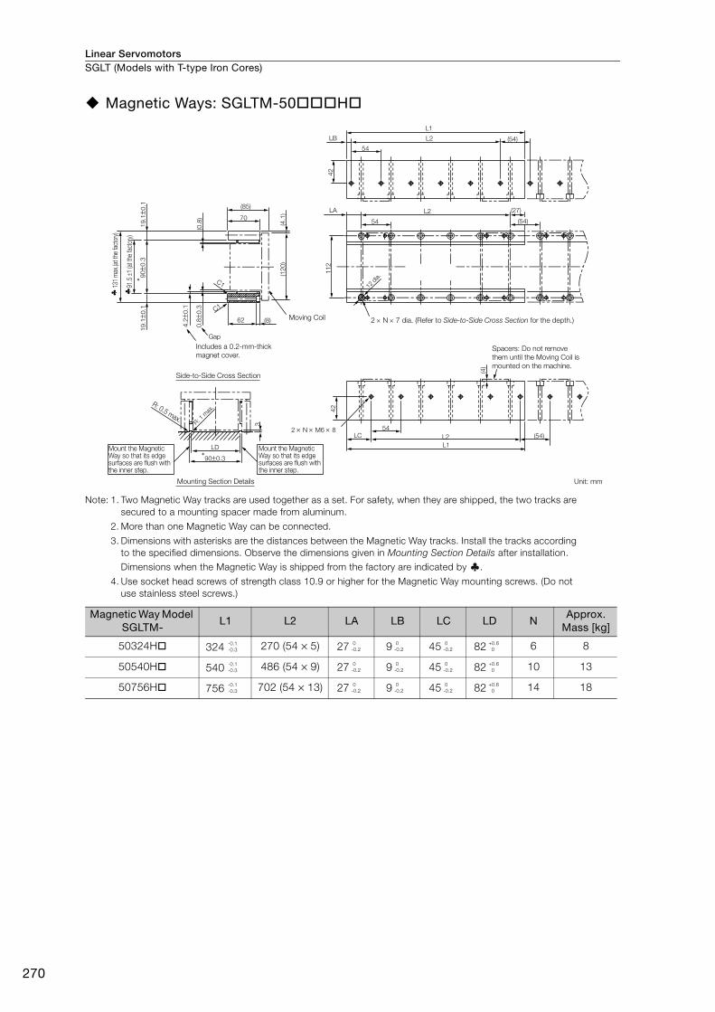
Linear ServomotorsSGLT (Models with T-type Iron Cores)
270
Magnetic Ways: SGLTM-50H
Note: 1. Two Magnetic Way tracks are used together as a set. For safety, when they are shipped, the two tracks are secured to a mounting spacer made from aluminum.
2. More than one Magnetic Way can be connected.
3. Dimensions with asterisks are the distances between the Magnetic Way tracks. Install the tracks according to the specified dimensions. Observe the dimensions given in Mounting Section Details after installation. Dimensions when the Magnetic Way is shipped from the factory are indicated by .
4. Use socket head screws of strength class 10.9 or higher for the Magnetic Way mounting screws. (Do not use stainless steel screws.)
Magnetic Way Model SGLTM-
L1 L2 LA LB LC LD NApprox.
Mass [kg]
50324H 324 270 (54 × 5) 27 9 45 82 6 8
50540H 540 486 (54 × 9) 27 9 45 82 10 13
50756H 756 702 (54 × 13) 27 9 45 82 14 18
3
LD*900.3
(120)
(4.1
)
(85)(0
.8)
62
0.80
.3
4.20
.1
19.10
.1* 9
00
.319.10
.1
(8)
70
C1
C1
Gap
2 N M6 8
(4)
(54)LC L2
L1
L1
54
112
42
42
(54)
(54)
54
L2LB
(27)
54
LA L2
91.5
1
(at t
he fa
ctor
y)
Moving Coil
R: 0.5 max.R: 1
max
.
2 N 7 dia. (Refer to Side-to-Side Cross Section for the depth.)
Spacers: Do not remove
them until the Moving Coil is
mounted on the machine.
Unit: mm
12 d
ia.
Includes a 0.2-mm-thick
magnet cover.
Mount the Magnetic Way so that its edge surfaces are flush with the inner step.
Mount the Magnetic Way so that its edge surfaces are flush with the inner step.
131
max
.(at t
he fa
ctor
y)
Side-to-Side Cross Section
Mounting Section Details
-0.1-0.3
0-0.2
0-0.2
0-0.2
+0.6 0
-0.1-0.3
0-0.2
0-0.2
0-0.2
+0.6 0
-0.1-0.3
0-0.2
0-0.2
0-0.2
+0.6 0
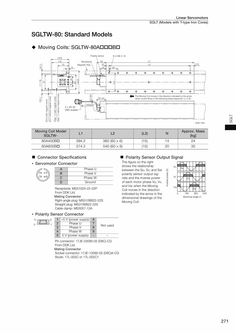
Linear Servomotors SGLT (Models with T-type Iron Cores)
271
SG
LT
SGLTW-80: Standard Models
Moving Coils: SGLTW-80AB
Moving Coil Model SGLTW-
L1 L2 (L3) NApprox. Mass
[kg]
80A400B 394.2 360 (60 × 6) (15) 14 24
80A600B 574.2 540 (60 × 9) (15) 20 35
Connector Specifications Polarity Sensor Output Signal
• Servomotor Connector The figure on the right shows the relationship between the Su, Sv, and Sw polarity sensor output sig-nals and the inverse power of each motor phase Vu, Vv, and Vw when the Moving Coil moves in the direction indicated by the arrow in the dimensional drawings of the Moving Coil.
Receptacle: MS3102A-22-22PFrom DDK Ltd.Mating ConnectorRight-angle plug: MS3108B22-22SStraight plug: MS3106B22-22SCable clamp: MS3057-12A
• Polarity Sensor Connector
Pin connector: 17JE-23090-02 (D8C)-CGFrom DDK Ltd.Mating ConnectorSocket connector: 17JE-13090-02 (D8C)A-CGStuds: 17L-002C or 17L-002C1
(25.3
with m
agnet
cove
r)
(25.1
without
magnet
cove
r)
(Gap
: 1
.2 w
ith m
ag
net
co
ver)
(Gap
: 1
.4 w
itho
ut
mag
net
co
ver)
Magnetic Way
Receptacle
Polarity sensor
500±50
75
(4.2
dia
.)
(L3)
L1
L2
63
20
6040
(120)
115
16
64 min.
30
38
98
124
149.8
97
(19.1
)(1
11.8
)(1
9.1
)
N × M8 × 16
The Moving Coil moves in the direction indicated by the arrow when current flows in the following phase sequence: U, V, W.
1
2 × #4-40
UNC screws
Unit: mm
Vu
Vv
Vw
Su
Sv
Sw
0 180 360 540
Inve
rse p
ow
er
(V)
Electrical angle (°)
A
B
D
C
A Phase UB Phase VC Phase WD Ground
9 6
5 1
1 +5 V (power supply) 6
Not used2 Phase U 73 Phase V 84 Phase W 95 0 V (power supply) − −
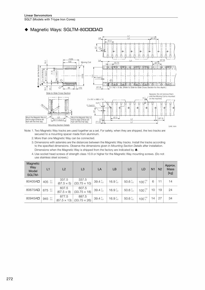
Linear ServomotorsSGLT (Models with T-type Iron Cores)
272
Magnetic Ways: SGLTM-80A
Note: 1. Two Magnetic Way tracks are used together as a set. For safety, when they are shipped, the two tracks are secured to a mounting spacer made from aluminum.
2. More than one Magnetic Way can be connected.
3. Dimensions with asterisks are the distances between the Magnetic Way tracks. Install the tracks according to the specified dimensions. Observe the dimensions given in Mounting Section Details after installation. Dimensions when the Magnetic Way is shipped from the factory are indicated by .
4. Use socket head screws of strength class 10.9 or higher for the Magnetic Way mounting screws. (Do not use stainless steel screws.)
Magnetic Way
Model SGLTM-
L1 L2 L3 LA LB LC LD N1 N2Approx.
Mass [kg]
80405A 405337.5
(67.5 × 5)337.5
(33.75 × 10) 39.4 16.9 50.6 100 6 11 14
80675A 675607.5
(67.5 × 9)607.5
(33.75 × 18) 39.4 16.9 50.6 100 10 19 24
80945A 945877.5
(67.5 × 13)887.5
(33.75 × 26) 39.4 16.9 50.6 100 14 27 34
2 × N1 × M8 × 10
2 × N2 × 9 dia. (Refer to Side-to-Side Cross Section for the depth.)
Mounting Section DetailsUnit: mm
C1
C1
Moving Coil
85 (15)
(120)
100
(1.4
)
(15
0)
25
.1
Gap
1.4
±0
.3
19
.11
9.1
♣1
53
max.
(at
the facto
ry)
*11
1.8
±0
.3
♣11
3 ±
1 (a
t the
fact
ory)
R0.5 max.
R: 1 m
ax.
*111.8±0.3
LD(67.5)LC L2
67.5
L1(11.3)
*1.5±0.3
57
L333.75
(37.9)
(37.9)
(67.5)
R7
LA
13
1
*1.5±0.3
(67.5)
L267.5
5.6°
L1LB
57
4
5.6°
6
Spacers: Do not remove them until the Moving Coil is mounted on the machine.
Side-to-Side Cross Section
Mount the Magnetic Way so that its edge surfaces are flush with the inner step.
Mount the Magnetic Way so that its edge surfaces are flush with the inner step.
-0.1-0.3
0-0.2
0-0.2
0-0.2
+0.6
0
-0.1-0.3
0-0.2
0-0.2
0-0.2
+0.6 0
-0.1-0.3
0-0.2
0-0.2
0-0.2
+0.6 0
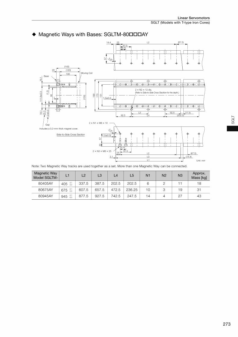
Linear Servomotors SGLT (Models with T-type Iron Cores)
273
SG
LT
Magnetic Ways with Bases: SGLTM-80AY
Note: Two Magnetic Way tracks are used together as a set. More than one Magnetic Way can be connected.
Magnetic Way Model SGLTM-
L1 L2 L3 L4 L5 N1 N2 N3Approx.
Mass [kg]
80405AY 405 337.5 387.5 202.5 202.5 6 2 11 18
80675AY 675 607.5 657.5 472.5 236.25 10 3 19 31
80945AY 945 877.5 927.5 742.5 247.5 14 4 27 43
Moving Coil
Gap
Base
67.533.75
(67.5)L22514.4
(17.5)
(202.5)L492.592.5L5
33.75
(67.5)
(14.4)
Unit: mmL1
3.1 L3
25 L267.5
20
57
(1.5±0.3)
5.6°
19
0
17
0
13
11.5±0.3
(120)
(140)
1.2
±0.3
(1.2
)
25
.3
11
1.8
±0
.3
57
90
1
5.6°
100
20
19
.11
9.1
(15
0)
Includes a 0.2-mm-thick magnet cover.
2 × N2 × 12 dia.
(Refer to Side-to-Side Cross Section for the depth.)
2 × N1 × M8 × 10
2 × N3 × M8 × 25
Side-to-Side Cross Section
-0.1-0.3
-0.1-0.3
-0.1-0.3

Linear ServomotorsSGLT (Models with T-type Iron Cores)
274
Selecting Cables
Cable ConfigurationsTo select a Linear Encoder, use Recommended Linear Encoders (pages 278 and 279). Prepare the cable required for the encoder.
* You can connect directly to an absolute linear encoder.
Note: Refer to the following manual for the following information.• Cable dimensional drawings and cable connection specifications• Order numbers and specifications of individual connectors for cables• Order numbers and specifications for wiring materials
Σ-7-Series AC Servo Drive Peripheral Device Selection Manual (Manual No.: SIEP S800001 32)
SERVOPACK
Serial Converter Unit Cable*
(between SERVOPACK connector
CN2 and Serial Converter Unit)
Linear Servomotor Main Circuit Cable
Sensor Cable (between
Serial Converter Unit and
polarity sensor)
Linear Servomotor
Serial Converter Unit
Linear Encoder Cable
Linear encoder (Not provided by Yaskawa.)
Polarity sensor

Linear Servomotors SGLT (Models with T-type Iron Cores)
275
SG
LT
Linear Servomotor Main Circuit Cables
*1. Connector from Tyco Electronics Japan G.K.
*2. Connector from Interconnectron GmbH
*3. A connector is not provided on the Linear Servomotor end. Obtain a connector according to your specifications. Refer to the next page for information on connectors.
JZSP-CLN39--E Cables
• Wiring Specifications
• JZSP-CLN39 Cable Connectors
Linear Servomotor ModelLength
(L)Order Number Appearance
SGLTW-20A, -35A
1 m JZSP-CLN21-01-E
3 m JZSP-CLN21-03-E
5 m JZSP-CLN21-05-E
10 m JZSP-CLN21-10-E
15 m JZSP-CLN21-15-E
20 m JZSP-CLN21-20-E
SGLTW-AD
1 m JZSP-CLN14-01-E
3 m JZSP-CLN14-03-E
5 m JZSP-CLN14-05-E
10 m JZSP-CLN14-10-E
15 m JZSP-CLN14-15-E
20 m JZSP-CLN14-20-E
SGLTW-40B-80B
1 m JZSP-CLN39-01-E
3 m JZSP-CLN39-03-E
5 m JZSP-CLN39-05-E
10 m JZSP-CLN39-10-E
15 m JZSP-CLN39-15-E
20 m JZSP-CLN39-20-E
Applicable Servomotor
Connector Provided with Servomotor
PlugCable Clamp
Straight Right-angle
SGLTW-40 and -80 MS3102A22-22PMS3106B22-22S
orMS3106A22-22S
MS3108B22-22S MS3057-12A
L
*1
SERVOPACK end Linear Servomotor end
L
*2
SERVOPACK end Linear Servomotor end
L
*3
SERVOPACK end Linear Servomotor end
L 35 mm 2 mm
8.5 mm
U
V
W
G
50 mm
M4 crimp terminal
Wire markers
Heat-shrinkable tube
Finished diameter: 15.8
Cable
(UL2570) AWG11/4C
A
B
C
DFGFG
SERVOPACK Leads
Wire Color
Red
White
Blue
Green/yellow
Signal Signal
Phase U
Phase V
Phase W
Pin
Phase U
Phase V
Phase W
Servomotor Connector

Linear ServomotorsSGLT (Models with T-type Iron Cores)
276
• MS3106B22-2S: Straight Plug with Two-piece Shell
• MS3106A22-2S: Straight Plug with Solid Shell
• MS3108B22-2S: Right-angle Plug with Two-piece Shell
• Dimensional Drawings: MS3057-12A Cable Clamp with Rubber Bushing
Unit: mm
Unit: mm
Unit: mm
Unit: mm
J W
A
Q
55.57 max.
Cable Clamp
mounting thread:
1-3/16-18UNEF
50
max. Shell Size
Joint ThreadA
Length of Joint
J ±0.12
Joint NutOuter
Diameter
Q
Effective Thread LengthW min.
22 1-3/8-18UNEF 18.26 40.48 9.53
+0-0.38
A
540.5
J
Q
W
Cable Clamp
mounting thread:
1-3/16-18UNEF
34.9
9
0.5
dia
.
Shell SizeJoint Thread
A
Length of Joint
J ±0.12
Joint Nut Outer
Diameter
Q
Effective Thread Length W min.
22 1-3/8-18UNEF 18.26 40.48 9.53
+0-0.38
24.10
.5W
J
A
Q
33.30
.5
76.98 max.
Cable Clamp
mounting thread:
1-3/16-18UNEF
Shell SizeJoint Thread
A
Length of Joint
J ± 0.12
Joint Nut Outer
Diameter
Q
Effective Thread LengthW min.
22 1-3/8-18UNEF 18.26 40.48 9.53
+0-0.38
37
.30
.7
23.80.7
V
1.6C
35
0.7
dia.
15.9 dia.
(bushing inner diameter)
19.0 dia.
(Cable Clamp
inner diameter)
4.0 (slide range)
Applicable Connector Shell Size
Effective Thread Length
C
Mounting Thread
V
Attached Bushing
20.22 10.31-3/16-18UNEF
AN3420-12

277
MEMO
SG
LT

Linear Servomotors
278
Recommended Linear Encoders and Cables
Recommended Linear Encoders
Incremental Linear Encoders
1 Vp-p Analog VoltageYou must also use a Yaskawa Serial Converter Unit. The output signal will be multiplied by 8 bits (256 divisions) or 12 bits (4,096 divisions) in the Serial Converter Unit.
: Applicable
*1. The maximum speeds given in the above table are the maximum applicable speeds of the encoders when combined with a Yaskawa SERVOPACK. The actual speed will be restricted by either the maximum speed of the Linear Servomotor or the maximum speed of the Linear Encoder (given above).
*2. If you use the origin signals with a Linear Encoder from Renishaw plc, the origin may sometimes be falsely detected. If that occurs, use the BID/DIR signal to output the origin signal only in one direction.
*3. These are the models of Serial Converter Units.*4. Contact your Yaskawa representative.
Note: Confirm detailed specifications, such as the tolerances, dimensions, and operating environment, with the manufacturer of the Linear Encoder before you use it.
Encoder for Yaskawa’s Serial InterfaceThe multiplier (number of divisions) depends on the Linear Encoder. Also, you must write the Servo-motor constant file to the Linear Encoder in advance.
: Applicable
*1. The maximum speeds given in the above table are the maximum applicable speeds of the encoders when combined with a Yaskawa SERVOPACK. The actual speed will be restricted by either the maximum speed of the Linear Servomotor or the maximum speed of the Linear Encoder (given above).
*2. This is the model of the Sensor Head with Interpolator.*3. This is the model of the Interpolator.*4. Contact your Yaskawa representative.
Note: Confirm detailed specifications, such as the tolerances, dimensions, and operating environment, with the manufacturer of the Linear Encoder before you use it.
Manufacturer Linear
Encoder Type
Model Linear
Encoder Pitch [μm]
Resolu-tion [nm]
Maxi-mum
Speed*1
[m/s]
Support for
Polarity Sensor Input
Applica-tion to Linear Servo-motors
Applica-tion to Fully-
Closed Loop
Control
ReferenceScale Sensor
Head
Relay Device between
SERVOPACK and Linear Encoder*3
Heidenhain Corporation Exposed
LIDA48JZDP-H003/-H006
2078.1 5 page 280
JZDP-J003/-J006 4.9 2 *4 page 281
LIF48JZDP-H003/-H006
415.6 1 page 280
JZDP-J003/-J006 1.0 0.4 *4 *4 page 281
Renishaw plc*2 Exposed RGS20 RGH22BJZDP-H005/-H008
2078.1 5 page 283
JZDP-J005/-J008 4.9 2 *4 page 284
Manufacturer Linear
Encoder Type
Model Linear
Encoder Pitch [μm]
Reso-lution [nm]
Maxi-mum
Speed*1
[m/s]
Sup-port for Polarity Sensor Input
Applica-tion to Linear Servo-motors
Applica-tion to Fully-
Closed Loop
Control
ReferenceScale Sensor
Head
Relay Device between
SERVOPACK and Linear Encoder
Magnescale Co., Ltd.
ExposedSL70
PL101-RY*2800 97.7 10
– page 285
PL101 MJ620-T13*3 *4 page 286
SQ10 PQ10MQ10-FLA
400 48.83 3–
page 288MQ10-GLA –
Sealed
SR75-LF – 80 9.8 3.33 –
page 290SR75-MF – 80 78.1 3.33 –
SR85-LF – 80 9.8 3.33 –
SR85-MF – 80 78.1 3.33 –

Linear Servomotors Recommended Linear Encoders and Cables
279
Reco
mm
end
ed
Lin
ear
Enco
ders
and
Cab
les
Absolute Linear Encoders
Encoder for Yaskawa’s Serial InterfaceThe multiplier (number of divisions) depends on the Linear Encoder. Also, you must write the Servo-motor constant file to the Linear Encoder in advance.
: Applicable
*1. The maximum speeds given in the above table are the maximum applicable speeds of the encoders when com-bined with a Yaskawa SERVOPACK. The actual speed will be restricted by either the maximum speed of the Linear Servomotor or the maximum speed of the Linear Encoder (given above).
*2. Contact Mitutoyo Corporation for details on the Linear Encoders.*3. The speed is restricted for some SERVOPACKs.*4. This is the model of the Interpolator.
Note: Confirm detailed specifications, such as the tolerances, dimensions, and operating environment, with the manufacturer of the Linear Encoder before you use it.
1.1
Manufacturer Linear
Encoder Type
Model Linear
Encoder Pitch [μm]
Reso-lution [nm]
Maxi-mum
Speed*1
[m/s]
Sup-port for Polarity Sensor Input
Applica-tion to Linear Servo-motors
Applica-tion to Fully-
Closed Loop
Control
ReferenceScale Sensor
Head
Relay Device between
SERVOPACK and Linear Encoder
Magnescale Co., Ltd. Sealed
SR77-LF – 80 9.8 3.33 –
page 290
SR77-MF – 80 78.1 3.33 –
SR87-LF – 80 9.8 3.33 –
SR87-MF – 80 78.1 3.33 –
Mitutoyo Corporation Exposed
ST781A – 256 500 5 –
page 291
ST782A – 256 500 5 –
ST783A – 51.2 100 5 –
ST784A – 51.2 100 5 –
ST788A – 51.2 100 5 –
ST789A*2 – 25.6 50 5 –
ST1381 – 5.12 10 8 –
ST1382 – 0.512 1 3.6*3 –
Heidenhain Corporation
Exposed LIC4100 Series EIB3391Y*4 20.48 5 10 – page
282Sealed LC115 40.96 10 3 –

Linear ServomotorsRecommended Linear Encoders and Cables
280
Connections to Linear Encoder from Heidenhain Corporation
Connections for a 1 Vp-p Analog Voltage Output SignalYou must make the connections through a Yaskawa Serial Converter Unit. The output signal will be multiplied by 8 bits (256 divisions) or 12 bits (4,096 divisions) in the Serial Converter Unit.
Connecting to a Linear Servomotor with a Polarity Sensor
*1. Only SGLFW2 Servomotors come equipped with Thermal Protector Relay Connectors. *2. When using a JZDP-J00- Serial Converter Unit, do not use a Yaskawa Linear Encoder Cable that is longer than 3 m. *3. Contact Heidenhain Corporation for details on cables (analog 1 Vp-p output, D-sub 15-pin, male) from Heidenhain Corporation.
SERVOPACK
Main circuit
connector
CN2
�Serial Converter Unit �Sensor Cable
Linear Encoder Cable*2�Serial Converter
Unit Cable
Moving
Coil
Magnetic Way
Polarity Sensor
Linear Encoder from
Heidenhain Corporation
Thermal Protector
Relay Connector *1
Sensor Cable
Cable from Heidenhain
Corporation*3
Linear Servomotor
Main Circuit Cable
�Linear Servomotor Main Circuit Cable

Linear Servomotors Recommended Linear Encoders and Cables
281
Reco
mm
end
ed
Lin
ear
Enco
ders
and
Cab
les
Connecting to a Linear Servomotor without a Polarity Sensor
Servomotors Other Than the SGLFW2
*1. When using a JZDP-J00- Serial Converter Unit, do not use a Yaskawa Linear Encoder Cable that is lon-ger than 3 m.
*2. Contact Heidenhain Corporation for details on cables (analog 1 Vp-p output, D-sub 15-pin, male) from Heiden-hain Corporation.
SGLFW2 Servomotors
*1. Only SGLFW2 Servomotors come equipped with Thermal Protector Relay Connectors.*2. When using a JZDP-J00- Serial Converter Unit, do not use a Yaskawa Linear Encoder Cable that is longer than 3 m. *3. Contact Heidenhain Corporation for details on cables (analog 1 Vp-p output, D-sub 15-pin, male) from Heidenhain Corporation.
No. Cable Type Reference
SGLG SGLF SGLT
Linear Servomotor Main Circuit Cable page 211 page 251 page 275
Serial Converter Unit Cable page 293
Serial Converter Unit page 292
Sensor Cable page 293
Linear Encoder Cable page 293
SERVOPACK
Main circuit
connector
CN2
Linear Encoder Cable*1
�Serial Converter Unit Cable
�Serial Converter Unit
Moving
Coil
Magnetic Way
Linear Encoder from
Heidenhain Corporation
Cable from
Heidenhain Corporation*2
Linear Servomotor
Main Circuit Cable
�Linear Servomotor Main Circuit Cable
�Sensor Cable
SERVOPACK
Main circuit
connector
CN2
Linear Encoder Cable*2
�Serial Converter Unit Cable
�Serial Converter Unit
Moving
Coil
Magnetic Way
Linear Encoder from
Heidenhain Corporation
Cable from
Heidenhain Corporation*3
Thermal Protector
Relay Connector*1
Linear Servomotor
Main Circuit Cable
�Linear Servomotor Main Circuit Cable

Linear ServomotorsRecommended Linear Encoders and Cables
282
LIC4100 and LC115 Linear Encoder with EIB3391Y Interpolator
*1. Cables to connect to the host controller are not provided by Yaskawa.Refer to the following manual for information on connector models.
Σ-7-Series AC Servo Drive Peripheral Device Selection Manual (Manual No.: SIEP S800001 32)
*2. Only SGLFW2 Servomotors come equipped with Thermal Protector Relay Connectors.
*3. Use an Encoder Cable from Heidenhain Corporation. Contact Heidenhain Corporation for detailed Encoder Cable specifications.
1. You cannot use an LIC4100 and LC115 Linear Encoder together with a Linear Servomotor with a Polarity Sensor.
2. If you use an SGLFW2 Servomotor, input the thermal protector signal from the Linear Servo-motor to the host controller. The thermal protector signal is closed when the temperature is normal and open when the thermal protector is activated. Do not exceed 3 A or 30 V.
No. Cable Type Reference
SGLG SGLF SGLT
Linear Servomotor Main Circuit Cable page 211 page 251 page 275
Important
SERVOPACK
Main circuit
connector
CN2
Moving
Coil
Magnetic Way
Linear Encoder from
Heidenhain Corporation
LIC4100
LC115
EIB3391Y
Interpolator
Encoder Cable from
Heidenhain Corporation*3
Products from Heidenhain Corp.
Thermal Protector
Relay Connector*2Input to host controller*1
Linear Servomotor
Main Circuit Cable
�Linear Servomotor Main Circuit Cable
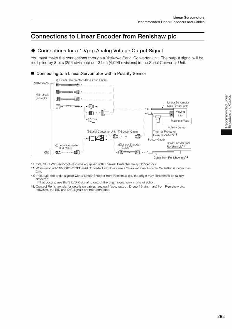
Linear Servomotors Recommended Linear Encoders and Cables
283
Reco
mm
end
ed
Lin
ear
Enco
ders
and
Cab
les
Connections to Linear Encoder from Renishaw plc
Connections for a 1 Vp-p Analog Voltage Output Signal You must make the connections through a Yaskawa Serial Converter Unit. The output signal will be multiplied by 8 bits (256 divisions) or 12 bits (4,096 divisions) in the Serial Converter Unit.
Connecting to a Linear Servomotor with a Polarity Sensor
*1. Only SGLFW2 Servomotors come equipped with Thermal Protector Relay Connectors.*2. When using a JZDP-J00- Serial Converter Unit, do not use a Yaskawa Linear Encoder Cable that is longer than
3 m. *3. If you use the origin signals with a Linear Encoder from Renishaw plc, the origin may sometimes be falsely
detected. If that occurs, use the BID/DIR signal to output the origin signal only in one direction.
*4. Contact Renishaw plc for details on cables (analog 1 Vp-p output, D-sub 15-pin, male) from Renishaw plc. However, the BID and DIR signals are not connected.
SERVOPACK
Main circuit
connector
CN2
�Serial Converter Unit
Linear Encoder Cable*2
Cable from Renishaw plc*4
�Serial Converter Unit Cable
Linear Encoder from
Renishaw plc*3
Moving
Coil
Magnetic Way
Polarity Sensor
Thermal Protector
Relay Connector*1
Sensor Cable
�Sensor Cable
Linear Servomotor
Main Circuit Cable
�Linear Servomotor Main Circuit Cable
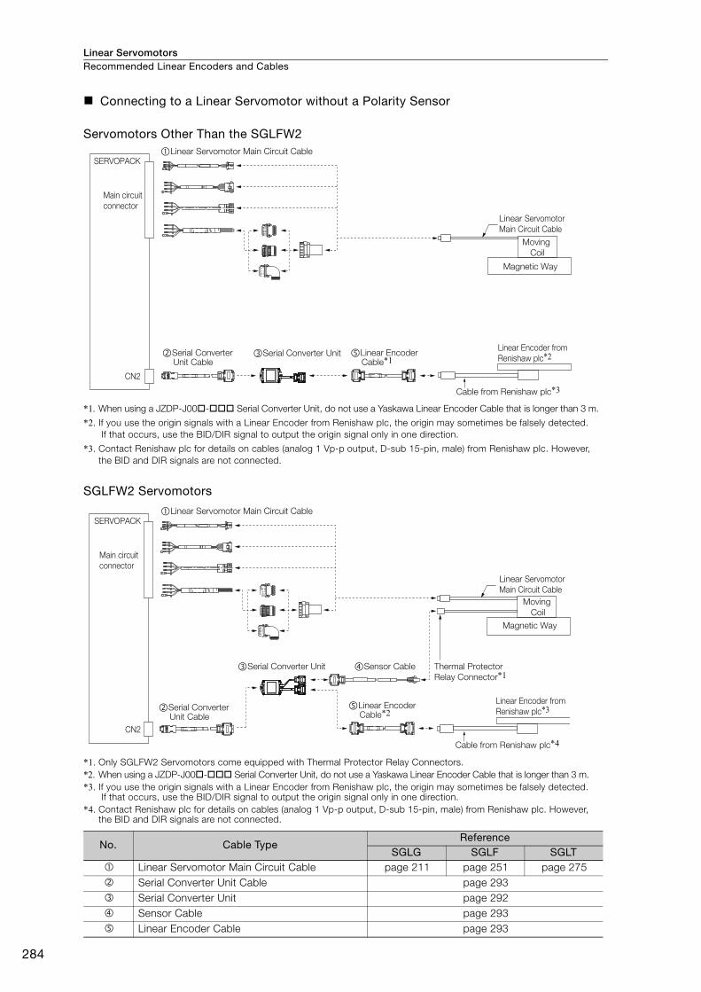
Linear ServomotorsRecommended Linear Encoders and Cables
284
Connecting to a Linear Servomotor without a Polarity Sensor
Servomotors Other Than the SGLFW2
*1. When using a JZDP-J00- Serial Converter Unit, do not use a Yaskawa Linear Encoder Cable that is longer than 3 m.
*2. If you use the origin signals with a Linear Encoder from Renishaw plc, the origin may sometimes be falsely detected. If that occurs, use the BID/DIR signal to output the origin signal only in one direction.
*3. Contact Renishaw plc for details on cables (analog 1 Vp-p output, D-sub 15-pin, male) from Renishaw plc. However, the BID and DIR signals are not connected.
SGLFW2 Servomotors
*1. Only SGLFW2 Servomotors come equipped with Thermal Protector Relay Connectors. *2. When using a JZDP-J00- Serial Converter Unit, do not use a Yaskawa Linear Encoder Cable that is longer than 3 m. *3. If you use the origin signals with a Linear Encoder from Renishaw plc, the origin may sometimes be falsely detected.
If that occurs, use the BID/DIR signal to output the origin signal only in one direction. *4. Contact Renishaw plc for details on cables (analog 1 Vp-p output, D-sub 15-pin, male) from Renishaw plc. However,
the BID and DIR signals are not connected.
No. Cable Type Reference
SGLG SGLF SGLT Linear Servomotor Main Circuit Cable page 211 page 251 page 275 Serial Converter Unit Cable page 293 Serial Converter Unit page 292 Sensor Cable page 293 Linear Encoder Cable page 293
SERVOPACK
Main circuit
connector
CN2
Linear Encoder Cable*1
Cable from Renishaw plc*3
�Serial Converter Unit Cable
�Serial Converter Unit
Moving
Coil
Magnetic Way
Linear Encoder from
Renishaw plc*2
Linear Servomotor
Main Circuit Cable
�Linear Servomotor Main Circuit Cable
SERVOPACK
Main circuit
connector
CN2
�Serial Converter Unit �Sensor Cable
Linear Encoder Cable*2
Cable from Renishaw plc*4
�Serial Converter Unit Cable
Moving
Coil
Magnetic Way
Linear Encoder from
Renishaw plc*3
Thermal Protector
Relay Connector*1
Linear Servomotor
Main Circuit Cable
�Linear Servomotor Main Circuit Cable

Linear Servomotors Recommended Linear Encoders and Cables
285
Reco
mm
end
ed
Lin
ear
Enco
ders
and
Cab
les
Connections to Linear Encoder from Magnescale Co., Ltd.
SL70 Linear Encoder and PL101-RY Sensor Head with Interpolator
*1. Cables to connect to the host controller are not provided by Yaskawa.Refer to the following manual for information on connector models.
Σ-7-Series AC Servo Drive Peripheral Device Selection Manual (Manual No.: SIEP S800001 32)
*2. Only SGLFW2 Servomotors come equipped with Thermal Protector Relay Connectors.
1. You cannot use a PL101-RY Sensor Head with an Interpolator together with a Linear Servo-motor with a Polarity Sensor.
2. If you use an SGLFW2 Servomotor, input the thermal protector signal from the Linear Servo-motor to the host controller. The thermal protector signal is closed when the temperature is normal and open when the thermal protector is activated. Do not exceed 3 A or 30 V.
No. Cable Type Reference
SGLG SGLF SGLT
Linear Servomotor Main Circuit Cable page 211 page 251 page 275
Serial Converter Unit Cable page 293
Important
SERVOPACK
Main circuit
connector
CN2
Moving
Coil
Magnetic Way
SL7�0 Linear Encoder from Magnescale Co., Ltd.
Thermal Protector
Relay Connector*2Sensor Cable
Products from
Magnescale Co., Ltd.
PL101-RY Head with
Interpolator
Input to host controller*1
Linear Servomotor
Main Circuit Cable
�Linear Servomotor Main Circuit Cable
�Serial Converter Unit Cable

Linear ServomotorsRecommended Linear Encoders and Cables
286
SL70 Linear Encoder, PL101 Sensor Head, and MJ620-T13 Interpolator
*1. Cables to connect to the host controller are not provided by Yaskawa.Refer to the following manual for information on connector models.
Σ-7-Series AC Servo Drive Peripheral Device Selection Manual (Manual No.: SIEP S800001 32)
*2. Only SGLFW2 Servomotors come equipped with Thermal Protector Relay Connectors.
1. A 5-VDC power supply is required for the MJ620-T13. (The 5-VDC power supply is not pro-vided by Yaskawa.)
2. Refer to the MJ620-T13 specifications from Magnescale Co., Ltd. for the current consumption of the MJ620-T13.
3. If you use an SGLFW2 Servomotor, remove the thermal protector relay connector and input the thermal protector signal from the Linear Servomotor to the host controller. The thermal protector signal is closed when the temperature is normal and open when the thermal protec-tor is activated. Do not exceed 3 A or 30 V.
No. Cable Type Reference
SGLG SGLF SGLT
Linear Servomotor Main Circuit Cable page 211 page 251 page 275
Encoder Cable These cables are not provided by Yaskawa.
page 287
External power supply cable
page 287
Sensor Cable page 293
Linear Encoder Cable
Use the cables that come with the MJ620-T13 Interpolator. For details, refer to the specifications for the MJ620-T13 Interpolator.
–
Important
SERVOPACK
Main circuit
connector
CN2
Moving
Coil
Magnetic Way
Polarity Sensor
Linear Encoder
Thermal Protector
Relay Connector*2
Sensor Cable
External power supply
�External power supply cable
�Encoder Cable
Linear Encoder Cable from Magnescale Co., Ltd.
(Included with the MJ620-T13 Interpolator.)
MJ620-T13
Interpolator
Input to host controller*1
Products from Magnescale Co., Ltd.
�Sensor Cable
Linear Servomotor
Main Circuit Cable
�Linear Servomotor Main Circuit Cable
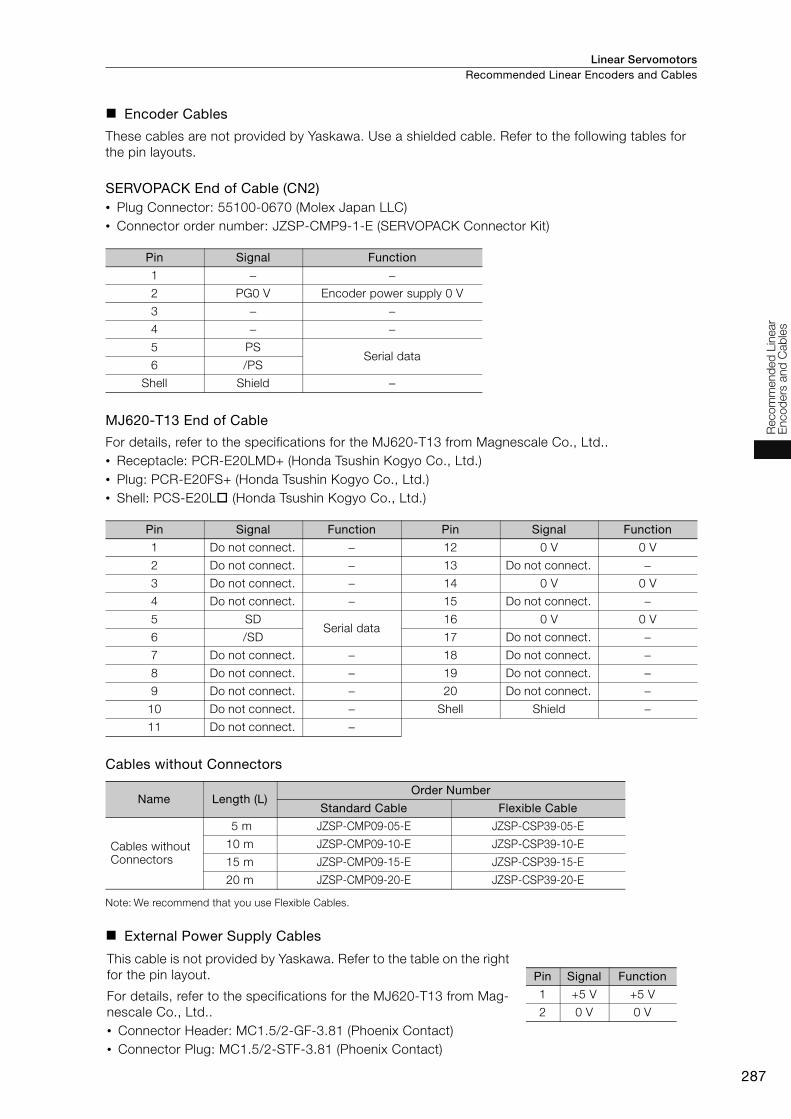
Linear Servomotors Recommended Linear Encoders and Cables
287
Reco
mm
end
ed
Lin
ear
Enco
ders
and
Cab
les
Encoder Cables
These cables are not provided by Yaskawa. Use a shielded cable. Refer to the following tables for the pin layouts.
SERVOPACK End of Cable (CN2)• Plug Connector: 55100-0670 (Molex Japan LLC) • Connector order number: JZSP-CMP9-1-E (SERVOPACK Connector Kit)
MJ620-T13 End of Cable
For details, refer to the specifications for the MJ620-T13 from Magnescale Co., Ltd.. • Receptacle: PCR-E20LMD+ (Honda Tsushin Kogyo Co., Ltd.) • Plug: PCR-E20FS+ (Honda Tsushin Kogyo Co., Ltd.) • Shell: PCS-E20L (Honda Tsushin Kogyo Co., Ltd.)
Cables without Connectors
Note: We recommend that you use Flexible Cables.
External Power Supply Cables
Pin Signal Function
1 − −2 PG0 V Encoder power supply 0 V
3 − −4 − −5 PS
Serial data 6 /PS
Shell Shield −
Pin Signal Function Pin Signal Function
1 Do not connect. − 12 0 V 0 V
2 Do not connect. − 13 Do not connect. −3 Do not connect. − 14 0 V 0 V
4 Do not connect. − 15 Do not connect. −5 SD
Serial data 16 0 V 0 V
6 /SD 17 Do not connect. −7 Do not connect. − 18 Do not connect. −8 Do not connect. − 19 Do not connect. −9 Do not connect. − 20 Do not connect. −
10 Do not connect. − Shell Shield −11 Do not connect. −
Name Length (L)Order Number
Standard Cable Flexible Cable
Cables without Connectors
5 m JZSP-CMP09-05-E JZSP-CSP39-05-E
10 m JZSP-CMP09-10-E JZSP-CSP39-10-E
15 m JZSP-CMP09-15-E JZSP-CSP39-15-E
20 m JZSP-CMP09-20-E JZSP-CSP39-20-E
This cable is not provided by Yaskawa. Refer to the table on the right for the pin layout.
For details, refer to the specifications for the MJ620-T13 from Mag-nescale Co., Ltd.. • Connector Header: MC1.5/2-GF-3.81 (Phoenix Contact) • Connector Plug: MC1.5/2-STF-3.81 (Phoenix Contact)
Pin Signal Function
1 +5 V +5 V
2 0 V 0 V

Linear ServomotorsRecommended Linear Encoders and Cables
288
SmartSCALE Linear Encoder (SQ10 Scale + MQ10-LA Interpolator)
*1. Cables to connect to the host controller are not provided by Yaskawa.Refer to the following manual for information on connector models.
Σ-7-Series AC Servo Drive Peripheral Device Selection Manual (Manual No.: SIEP S800001 32)
*2. Only SGLFW2 Servomotors come equipped with Thermal Protector Relay Connectors.
*3. This cable configurations shown above is the connection when you use the MQ10-GLA interpolator with polarity sensor.
*4. The maximum length of the Serial Converter Unit Cable is 15 m.
If you use an SGLFW2 Servomotor, remove the thermal protector relay connector and input the thermal protector signal from the Linear Servomotor to the host controller. The thermal protector signal is closed when the temperature is normal and open when the thermal protector is acti-vated. Do not exceed 3 A or 30 V.
No. Cable Type Reference
SGLG SGLF SGLT
Linear Servomotor Main Circuit Cable page 211 page 251 page 275
Encoder Cable page 289
Sensor Cable page 293
Linear Encoder Cable
Use the cables that come with the MQ10-LA Interpolator. For details, refer to the specifications for the MQ10-LA Interpolator.
–
Important
SERVOPACK
Main circuit
connector
CN2
Moving
Coil
Magnetic Way
Polarity Sensor
Linear Encoder
Thermal Protector
Relay Connector*2
Sensor Cable
�Encoder Cable*4
�Linear Encoder Cable from Magnescale Co., Ltd.
MQ10-GLA*3 Interpolator
Input to host controller*1
Products from Magnescale Co., Ltd.
Sensor Cable
Linear Servomotor
Main Circuit Cable
�Linear Servomotor Main Circuit Cable

Linear Servomotors Recommended Linear Encoders and Cables
289
Reco
mm
end
ed
Lin
ear
Enco
ders
and
Cab
les
Encoder Cables
These cables are not provided by Yaskawa. Use a shielded cable. Refer to the following tables for the pin layouts.
SERVOPACK End of Cable (CN2)• Plug Connector: 55100-0670 (Molex Japan LLC) • Connector order number: JZSP-CMP9-1-E (SERVOPACK Connector Kit)
MQ10-LA End of Cable
For details, refer to the specifications for the MQ10-LA from Magnescale Co., Ltd..
Cables without Connectors
Note: We recommend that you use Flexible Cables.
Pin Signal Function
1 − −2 PG0 V Encoder power supply 0 V
3 − −4 − −5 PS
Serial data 6 /PS
Shell Shield −
Name Length (L)Order Number
Standard Cable Flexible Cable
Cables without Connectors
5 m JZSP-CMP09-05-E JZSP-CSP39-05-E
10 m JZSP-CMP09-10-E JZSP-CSP39-10-E
15 m JZSP-CMP09-15-E JZSP-CSP39-15-E

Linear ServomotorsRecommended Linear Encoders and Cables
290
SR-75, SR-77, SR-85, and SR-87 Linear Encoders
*1. Cables to connect to the host controller are not provided by Yaskawa.Refer to the following manual for information on connector models.
Σ-7-Series AC Servo Drive Peripheral Device Selection Manual (Manual No.: SIEP S800001 32)
*2. Only SGLFW2 Servomotors come equipped with Thermal Protector Relay Connectors.
*3. To connect the SERVOPACK and Linear Encoder, use a CH33-xxG Cable from Magnescale Co., Ltd. (This cable has connectors designed for use with Yaskawa products.)
1. You cannot use an SR-75, SR-77, SR-85, or SR-87 Linear Encoder with a Linear Servomotor with a Polarity Sensor.
2. If you use an SGLFW2 Servomotor, input the thermal protector signal from the Linear Servo-motor to the host controller. The thermal protector signal is closed when the temperature is normal and open when the thermal protector is activated. Do not exceed 3 A or 30 V.
No. Cable Type Reference
SGLG SGLF SGLT
Linear Servomotor Main Circuit Cable page 211 page 251 page 275
Important
Input to host controller*1
SERVOPACK
Main circuit
connector
CN2
Moving
Coil
Magnetic Way
Linear Encoder from
Magnescale Co., Ltd.
SR75-�����LF
SR75-�����MF
SR77-�����LF
SR77-�����MF
SR85-�����LF
SR85-�����MF
SR87-�����LF
SR87-�����MF
Thermal Protector
Relay Connector*2
Encoder Cable from
Magnescale Co., Ltd.*3
Products from Magnescale Co., Ltd.
Linear Servomotor
Main Circuit Cable
�Linear Servomotor Main Circuit Cable

Linear Servomotors Recommended Linear Encoders and Cables
291
Reco
mm
end
ed
Lin
ear
Enco
ders
and
Cab
les
Connections to Linear Encoders from Mitutoyo Corporation
ST78A/ST13 Linear Encoders
*1. Cables to connect to the host controller are not provided by Yaskawa.Refer to the following manual for information on connector models.
Σ-7-Series AC Servo Drive Peripheral Device Selection Manual (Manual No.: SIEP S800001 32)
*2. Only SGLFW2 Servomotors come equipped with Thermal Protector Relay Connectors.
1. You cannot use a ST78A Linear Encoder together with a Linear Servomotor with a Polarity Sensor.
2. If you use an SGLFW2 Servomotor, input the thermal protector signal from the Linear Servo-motor to the host controller. The thermal protector signal is closed when the temperature is normal and open when the thermal protector is activated. Do not exceed 3 A or 30 V.
No. Cable Type Reference
SGLG SGLF SGLT
Linear Servomotor Main Circuit Cable page 211 page 251 page 275
Serial Converter Unit Cable page 293
Important
SERVOPACK
Main circuit
connector
CN2
�Serial Converter Unit Cable
Linear Servomotor Main Circuit Cable
Moving
Coil
Magnetic Way
Linear Encoders
from Mitutoyo Corporation
ST781A
ST782A
ST783A
ST784A
Thermal Protector
Relay Connector*2
Cable from Mitutoyo Corporation
Input to host controller*1
ST788A
ST789A
ST1381
ST1382
�Linear Servomotor Main Circuit Cable

Linear ServomotorsRecommended Linear Encoders and Cables
292
Serial Converter Units
Order NumberUse the following tables to select the Serial Converter Unit.
Note: 1. Refer to the following manual for detailed specifications of the Serial Converter Units.Σ-7-Series AC Servo Drive Peripheral Device Selection Manual (Manual No.: SIEP S800001 32)
2. Contact your Yaskawa representative for information on the water cooling specifications of the SGLFW2.
JZDP - �00� - ���
Serial Converter Unit Model
Code AppearanceApplicable
Linear Encoder P
olar
ity
Sen
sor
Ther
mal
P
rote
ctor
H003J003
From Heid-enhain Corp.
None None
H005J005
From Renishaw
PLCNone None
H006J006
From Heid-enhain Corp.
Yes Yes
H008J008
From Renishaw
PLCYes Yes
Applicable Linear Servomotor
Servomotor Model Code Servomotor Model Code
SGLGW -(coreless models)
For Stan-dard-force Magnetic
Way
30A050C 250
SGLFW2- (models
with F-type iron cores)
30A070A 628
30A080C 251 30A120A 629
40A140C 252 30A230A 630
40A253C 253 45A200A 631
40A365C 254 45A380A 632
60A140C 258 90A200A 633
60A253C 259 90A380A 634
60A365C 260 90A560A 648
90A200C 264 1DA380A 649
90A370C 265 1DA560A 650
90A535C 266
SGLTW- (models with T-
type iron cores)
20A170A 011
SGLGW -+
SGLGM --M
(coreless models)
For High-force Mag-netic Way
40A140C 255 20A320A 012
40A253C 256 20A460A 013
40A365C 257 35A170A 014
60A140C 261 35A320A 015
60A253C 262 35A460A 016
60A365C 263 35A170H 105
SGLFW- (models
with F-type iron cores)
20A090A 017 35A320H 106
20A120A 018 50A170H 108
35A120A 019 50A320H 109
35A230A 020 40A400B 185
50A200B 181 40A600B 186
50A380B 182 80A400B 187
1ZA200B 183 80A600B 188
1ZA380B 184
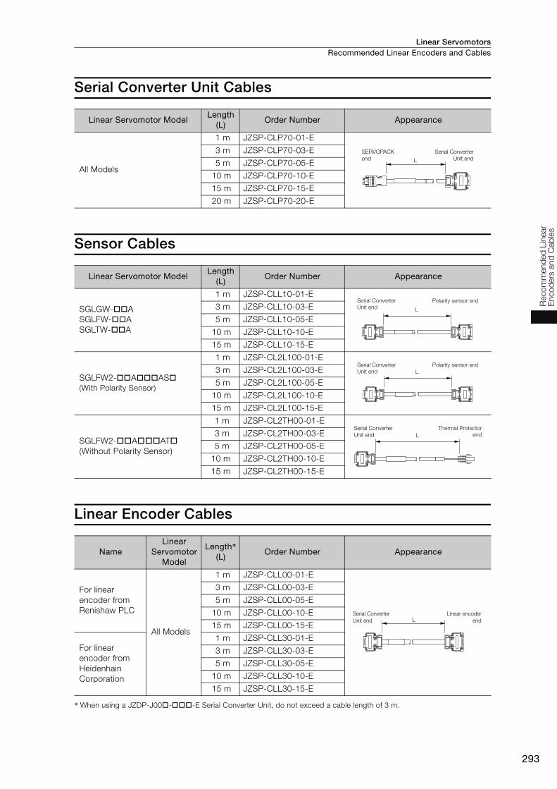
Linear Servomotors Recommended Linear Encoders and Cables
293
Reco
mm
end
ed
Lin
ear
Enco
ders
and
Cab
les
Serial Converter Unit Cables
Sensor Cables
Linear Encoder Cables
* When using a JZDP-J00--E Serial Converter Unit, do not exceed a cable length of 3 m.
Linear Servomotor ModelLength
(L)Order Number Appearance
All Models
1 m JZSP-CLP70-01-E
3 m JZSP-CLP70-03-E
5 m JZSP-CLP70-05-E
10 m JZSP-CLP70-10-E
15 m JZSP-CLP70-15-E
20 m JZSP-CLP70-20-E
Linear Servomotor ModelLength
(L)Order Number Appearance
SGLGW-ASGLFW-ASGLTW-A
1 m JZSP-CLL10-01-E
3 m JZSP-CLL10-03-E
5 m JZSP-CLL10-05-E
10 m JZSP-CLL10-10-E
15 m JZSP-CLL10-15-E
SGLFW2-AAS (With Polarity Sensor)
1 m JZSP-CL2L100-01-E
3 m JZSP-CL2L100-03-E
5 m JZSP-CL2L100-05-E
10 m JZSP-CL2L100-10-E
15 m JZSP-CL2L100-15-E
SGLFW2-AAT(Without Polarity Sensor)
1 m JZSP-CL2TH00-01-E
3 m JZSP-CL2TH00-03-E
5 m JZSP-CL2TH00-05-E
10 m JZSP-CL2TH00-10-E
15 m JZSP-CL2TH00-15-E
NameLinear
Servomotor Model
Length*(L)
Order Number Appearance
For linear encoder from Renishaw PLC
All Models
1 m JZSP-CLL00-01-E
3 m JZSP-CLL00-03-E
5 m JZSP-CLL00-05-E
10 m JZSP-CLL00-10-E
15 m JZSP-CLL00-15-E
For linear encoder from Heidenhain Corporation
1 m JZSP-CLL30-01-E
3 m JZSP-CLL30-03-E
5 m JZSP-CLL30-05-E
10 m JZSP-CLL30-10-E
15 m JZSP-CLL30-15-E
L
SERVOPACK end
Serial Converter Unit end
Serial Converter Unit end
Polarity sensor end
L
Polarity sensor endL
Serial Converter Unit end
Serial Converter Unit end
Thermal Protector endL
LSerial Converter Unit end
Linear encoder end

294
MEMO
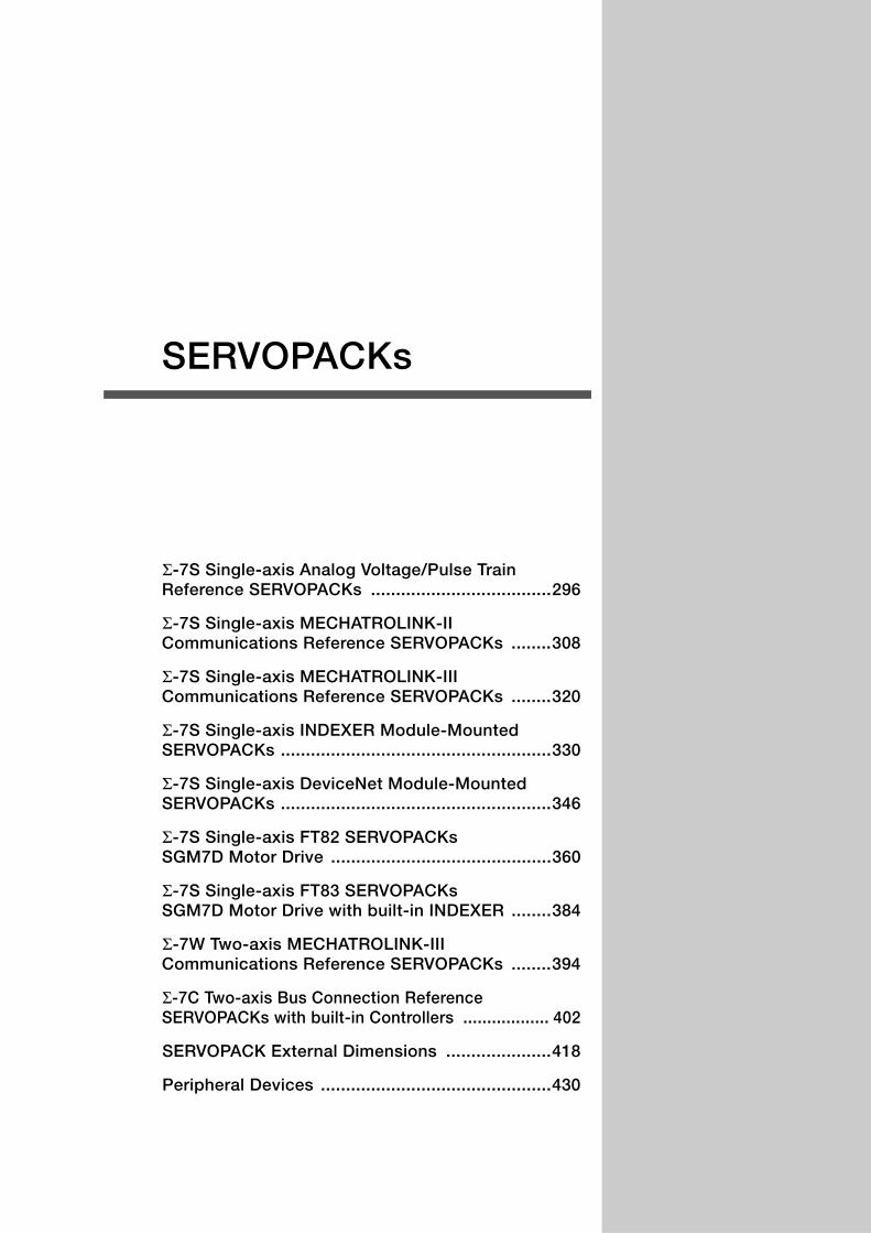
Σ-7S Single-axis Analog Voltage/Pulse Train Reference SERVOPACKs ....................................296
Σ-7S Single-axis MECHATROLINK-II Communications Reference SERVOPACKs ........308
Σ-7S Single-axis MECHATROLINK-III Communications Reference SERVOPACKs ........320
Σ-7S Single-axis INDEXER Module-Mounted SERVOPACKs ......................................................330
Σ-7S Single-axis DeviceNet Module-Mounted SERVOPACKs ......................................................346
Σ-7S Single-axis FT82 SERVOPACKs SGM7D Motor Drive ............................................360
Σ-7S Single-axis FT83 SERVOPACKs SGM7D Motor Drive with built-in INDEXER ........384
Σ-7W Two-axis MECHATROLINK-III Communications Reference SERVOPACKs ........394
Σ-7C Two-axis Bus Connection Reference SERVOPACKs with built-in Controllers .................. 402
SERVOPACK External Dimensions .....................418
Peripheral Devices ..............................................430
SERVOPACKs

SERVOPACKs
296
Σ-7S Single-axis Analog Voltage/Pulse Train Reference SERVOPACKs
Model Designations
*1. You can use these models with either a single-phase or three-phase power supply input.
*2. A model with a single-phase, 200-VAC power supply input is available as a hardware option (model: SGD7S-120A00A008).
*3. The rated output is 2.4 kW if you combine the SGM7G-30A with the SGD7S-200A.
*4. The same SERVOPACKs are used for both Rotary Servomotors and Linear Servomotors.
*5. Refer to the following manual for details. Σ-7-Series AC Servo Drive Σ-7S/Σ-7W SERVOPACK with Hardware Option Specifications Dynamic Brake Prod-
uct Manual (Manual No.: SIEP S800001 73)
*6. The BTO specification indicates if the SERVOPACK is customized by using the MechatroCloud BTO service.You need a BTO number to order SERVOPACKs with customized specifications.Refer to page M-15 for the details on the BTO service.
A 200 VAC
F 100 VAC
SGD7S - R70 A 00 A 001
A
R70*1
R90*1
1R6*1
2R8*1
3R8
5R5*1
7R6
120*2
180
200*3
330
470
550
590
780
R70
R90
2R1
2R8
0.05 kW
0.1 kW
0.2 kW
0.4 kW
0.5 kW
0.75 kW
1.0 kW
1.5 kW
2.0 kW
3.0 kW
5.0 kW
6.0 kW
7.5 kW
11 kW
15 kW
0.05 kW
0.1 kW
0.2 kW
0.4 kW
00
Maximum Applicable
Motor CapacityVoltage
Interface*4
Code
Code
Specification
Specification
Analog voltage/pulse
train reference
Design Revision Order
Hardware Options
Specification
Voltage Code Specification
Three-
phase,
200
VAC
Single-
phase,
100 VAC
1st+2nd+3rd digits 4th digit
5th+6th digits
7th digit
8th+9th+10th digits
-7 Series
-7S SERVOPACKs
4th digit
1st+2nd+3rd digits
5th+6th digits
8th+9th+10th digits
7th digit
00011th+12th+13th
digits
B14thdigit
NoneWithout options All models
All models
SGD7S-R70A to -330A
SGD7S-R70Fto -2R8F
SGD7S-470A to -780A
SGD7S-R70A to -2R8A
SGD7S-R70F to -2R8F
SGD7S-3R8A to -780A
SGD7S-120A
001
002
008
020*5
Duct-ventilated
Varnished
Single-phase, 200-VAC power supply input
No dynamic brake
External dynamic brake resistor
Code SpecificationApplicable
Models
000
Rack-mounted
FT/EX Specification11th+12th+13th digits
None
Code Specification
None000
BTO Specification*6
(Available in Japan only)14th digit
None
Code Specification
None
B BTO Specification
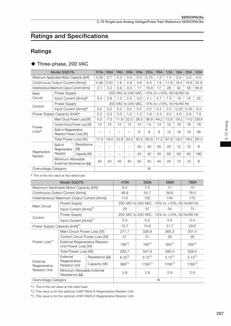
SERVOPACKs Σ-7S Single-axis Analog Voltage/Pulse Train Reference SERVOPACKs
297
Σ-7
S A
nalo
g
Ratings and Specifications
Ratings
Three-phase, 200 VAC
* This is the net value at the rated load.
*1. This is the net value at the rated load.
*2. This value is for the optional JUSP-RA04-E Regenerative Resistor Unit.
*3. This value is for the optional JUSP-RA05-E Regenerative Resistor Unit.
Model SGD7S- R70A R90A 1R6A 2R8A 3R8A 5R5A 7R6A 120A 180A 200A 330A
Maximum Applicable Motor Capacity [kW] 0.05 0.1 0.2 0.4 0.5 0.75 1.0 1.5 2.0 3.0 5.0
Continuous Output Current [Arms] 0.66 0.91 1.6 2.8 3.8 5.5 7.6 11.6 18.5 19.6 32.9
Instantaneous Maximum Output Current [Arms] 2.1 3.2 5.9 9.3 11 16.9 17 28 42 56 84.0
Main Circuit
Power Supply 200 VAC to 240 VAC, -15% to +10%, 50 Hz/60 Hz
Input Current [Arms]* 0.4 0.8 1.3 2.5 3.0 4.1 5.7 7.3 10 15 25
ControlPower Supply 200 VAC to 240 VAC, -15% to +10%, 50 Hz/60 Hz
Input Current [Arms]* 0.2 0.2 0.2 0.2 0.2 0.2 0.2 0.2 0.25 0.25 0.3Power Supply Capacity [kVA]* 0.2 0.3 0.5 1.0 1.3 1.6 2.3 3.2 4.0 5.9 7.5
Power Loss*
Main Circuit Power Loss [W] 5.0 7.0 11.9 22.5 28.5 38.9 49.2 72.6 104.2 114.2 226.6
Control Circuit Power Loss [W] 12 12 12 12 14 14 14 15 16 16 19
Built-in Regenerative Resistor Power Loss [W]
− − − − 8 8 8 10 16 16 36
Total Power Loss [W] 17.0 19.0 23.9 34.5 50.5 60.9 71.2 97.6 136.2 146.2 281.6
Regenerative Resistor
Built-In Regenerative Resistor
Resistance [Ω]
− − − − 40 40 40 20 12 12 8
Capacity [W] − − − − 40 40 40 60 60 60 180
Minimum Allowable External Resistance [Ω]
40 40 40 40 40 40 40 20 12 12 8
Overvoltage Category III
Model SGD7S- 470A 550A 590A 780A
Maximum Applicable Motor Capacity [kW] 6.0 7.5 11 15
Continuous Output Current [Arms] 46.9 54.7 58.6 78.0
Instantaneous Maximum Output Current [Arms] 110 130 140 170
Main CircuitPower Supply 200 VAC to 240 VAC, -15% to +10%, 50 Hz/60 Hz
Input Current [Arms]*1 29 37 54 73
ControlPower Supply 200 VAC to 240 VAC, -15% to +10%, 50 Hz/60 Hz
Input Current [Arms]*1 0.3 0.3 0.4 0.4
Power Supply Capacity [kVA]*1 10.7 14.6 21.7 29.6
Power Loss*1
Main Circuit Power Loss [W] 271.7 326.9 365.3 501.4
Control Circuit Power Loss [W] 21 21 28 28
External Regenerative Resistor Unit Power Loss [W] 180*2 180*3 350*3 350*3
Total Power Loss [W] 292.7 347.9 393.3 529.4
External Regenerative Resistor Unit
External Regenerative Resistor Unit
Resistance [Ω] 6.25*2 3.13*3 3.13*3 3.13*3
Capacity [W] 880*2 1760*3 1760*3 1760*3
Minimum Allowable External Resistance [Ω]
5.8 2.9 2.9 2.9
Overvoltage Category III

SERVOPACKsΣ-7S Single-axis Analog Voltage/Pulse Train Reference SERVOPACKs
298
Single-phase, 200 VAC
* This is the net value at the rated load.
270 VDC
*1. This is the net value at the rated load.*2. The value is 0.25 Arms for the SGD7S-120A00A008.
* This is the net value at the rated load.
Model SGD7S- R70A R90A 1R6A 2R8A 5R5A 120A
Maximum Applicable Motor Capacity [kW] 0.05 0.1 0.2 0.4 0.75 1.5
Continuous Output Current [Arms] 0.66 0.91 1.6 2.8 5.5 11.6Instantaneous Maximum Output Current [Arms] 2.1 3.2 5.9 9.3 16.9 28
Main CircuitPower Supply 200 VAC to 240 VAC, -15% to +10%, 50 Hz/60 Hz
Input Current [Arms]* 0.8 1.6 2.4 5.0 8.7 16
ControlPower Supply 200 VAC to 240 VAC, -15% to +10%, 50 Hz/60 Hz
Input Current [Arms]* 0.2 0.2 0.2 0.2 0.2 0.25Power Supply Capacity [kVA]* 0.2 0.3 0.6 1.2 1.9 4.0
Power Loss*
Main Circuit Power Loss [W] 5.0 7.1 12.1 23.7 39.2 71.8
Control Circuit Power Loss [W] 12 12 12 12 14 16Built-in Regenerative Resistor Power Loss [W] − − − − 8 16
Total Power Loss [W] 17.0 19.1 24.1 35.7 61.2 103.8
Regenerative Resistor
Built-In Regenerative Resistor
Resistance [Ω] − − − − 40 12
Capacity [W] − − − − 40 60
Minimum Allowable External Resistance [Ω] 40 40 40 40 40 12
Overvoltage Category III
Model SGD7S- R70A R90A 1R6A 2R8A 3R8A 5R5A 7R6A 120A
Maximum Applicable Motor Capacity [kW] 0.05 0.1 0.2 0.4 0.5 0.75 1.0 1.5
Continuous Output Current [Arms] 0.66 0.91 1.6 2.8 3.8 5.5 7.6 11.6
Instantaneous Maximum Output Current [Arms] 2.1 3.2 5.9 9.3 11.0 16.9 17.0 28.0
Main CircuitPower Supply 270 VDC to 324 VDC, -15% to +10%
Input Current [Arms]*1 0.5 1.0 1.5 3.0 3.8 4.9 6.9 11
ControlPower Supply 270 VDC to 324 VDC, -15% to +10%
Input Current [Arms]*1 0.2 0.2 0.2 0.2 0.2 0.2 0.2 0.2*2
Power Supply Capacity [kVA]*1 0.2 0.3 0.6 1 1.4 1.6 2.3 3.2
Power Loss*1
Main Circuit Power Loss [W] 4.4 5.9 9.8 17.5 23.0 30.7 38.7 55.8
Control Circuit Power Loss [W] 12 12 12 12 14 14 14 15
Total Power Loss [W] 16.4 17.9 21.8 29.5 37.0 44.7 52.7 70.8Overvoltage Category III
Model SGD7S- 180A 200A 330A 470A 550A 590A 780A
Maximum Applicable Motor Capacity [kW] 2.0 3.0 5.0 6.0 7.5 11.0 15.0 Continuous Output Current [Arms] 18.5 19.6 32.9 46.9 54.7 58.6 78.0
Instantaneous Maximum Output Current [Arms] 42.0 56.0 84.0 110 130 140 170
Main CircuitPower Supply 270 VDC to 324 VDC, -15% to +10%Input Current [Arms]* 14 20 34 36 48 68 92
ControlPower Supply 270 VDC to 324 VDC, -15% to +10%
Input Current [Arms]* 0.25 0.25 0.3 0.3 0.3 0.4 0.4Power Supply Capacity [kVA]* 4.0 5.9 7.5 10.7 14.6 21.7 29.6
Power Loss*Main Circuit Power Loss [W] 82.7 83.5 146.2 211.6 255.3 243.6 343.4Control Circuit Power Loss [W] 16 16 19 21 21 28 28
Total Power Loss [W] 98.7 99.5 165.2 232.6 276.3 271.6 371.4
Overvoltage Category III

SERVOPACKs Σ-7S Single-axis Analog Voltage/Pulse Train Reference SERVOPACKs
299
Σ-7
S A
nalo
g
Single-phase, 100 VAC
* This is the net value at the rated load.
SERVOPACK Overload Protection CharacteristicsThe overload detection level is set for hot start conditions with a SERVOPACK surrounding air tem-perature of 55°C.
An overload alarm (A.710 or A.720) will occur if overload operation that exceeds the overload pro-tection characteristics shown in the following diagram (i.e., operation on the right side of the appli-cable line) is performed.
The actual overload detection level will be the detection level of the connected SERVOPACK or Ser-vomotor that has the lower overload protection characteristics.
In most cases, that will be the overload protection characteristics of the Servomotor.
Note: The above overload protection characteristics do not mean that you can perform continuous duty operation with an output of 100% or higher.For a Yaskawa-specified combination of SERVOPACK and Servomotor, maintain the effective torque (or effective force) within the continuous duty zone of the torque-motor speed characteristic (or force-motor speed characteristics) of the Servomotor.
Model SGD7S- R70F R90F 2R1F 2R8F
Maximum Applicable Motor Capacity [kW] 0.05 0.1 0.2 0.4
Continuous Output Current [Arms] 0.66 0.91 2.1 2.8
Instantaneous Maximum Output Current [Arms] 2.1 3.2 6.5 9.3
Main CircuitPower Supply 100 VAC to 120 VAC, -15% to +10%, 50 Hz/60 Hz
Input Current [Arms]* 1.5 2.5 5 10
ControlPower Supply 100 VAC to 120 VAC, -15% to +10%, 50 Hz/60 Hz
Input Current [Arms]* 0.38 0.38 0.38 0.38Power Supply Capacity [kVA]* 0.2 0.3 0.6 1.4
Power Loss*Main Circuit Power Loss [W] 5.3 7.8 14.2 26.2
Control Circuit Power Loss [W] 12 12 12 12
Total Power Loss [W] 17.3 19.8 26.2 38.2
Regenerative Resistor
Minimum Allowable External Resistance [Ω]
40 40 40 40
Overvoltage Category III
SERVOPACK output current (continuous output current ratio) (%)
Continuous output current× 100%
SERVOPACK Model:
SGD7S-R70A, -R90A,
-1R6A, -2R8A, -R70F,
-R90F, -2R1F, and -2R8F
SERVOPACK Model:
SGD7S-3R8A, -5R5A, -7R6A,
-120A, -180A, -200A, -330A,
-470A, -550A, -590A,
and -780A
Instantaneous maximum output current
(Instantaneous maximum output current)
(Continuous output current)
SERVOPACK output current (continuous output current ratio) (%)
Continuous output current× 100%
Instantaneous maximum output current
(Instantaneous maximum output current)
(Continuous output current)
100 230
10000
1000
100
10
1100 200
10000
1000
100
10
1
Dete
ctio
n t
ime (s)
Dete
ctio
n t
ime (s)
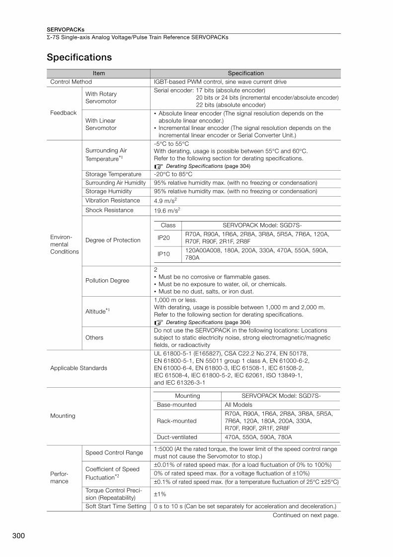
SERVOPACKsΣ-7S Single-axis Analog Voltage/Pulse Train Reference SERVOPACKs
300
Specifications
Item SpecificationControl Method IGBT-based PWM control, sine wave current drive
Feedback
With Rotary Servomotor
Serial encoder: 17 bits (absolute encoder)20 bits or 24 bits (incremental encoder/absolute encoder)22 bits (absolute encoder)
With Linear Servomotor
• Absolute linear encoder (The signal resolution depends on the absolute linear encoder.)
• Incremental linear encoder (The signal resolution depends on the incremental linear encoder or Serial Converter Unit.)
Environ-mental Conditions
Surrounding Air Temperature*1
-5°C to 55°C With derating, usage is possible between 55°C and 60°C. Refer to the following section for derating specifications.
Derating Specifications (page 304)
Storage Temperature -20°C to 85°CSurrounding Air Humidity 95% relative humidity max. (with no freezing or condensation)Storage Humidity 95% relative humidity max. (with no freezing or condensation)
Vibration Resistance 4.9 m/s2
Shock Resistance 19.6 m/s2
Degree of Protection
Pollution Degree
2• Must be no corrosive or flammable gases.• Must be no exposure to water, oil, or chemicals. • Must be no dust, salts, or iron dust.
Altitude*1
1,000 m or less. With derating, usage is possible between 1,000 m and 2,000 m.Refer to the following section for derating specifications.
Derating Specifications (page 304)
OthersDo not use the SERVOPACK in the following locations: Locations subject to static electricity noise, strong electromagnetic/magnetic fields, or radioactivity
Applicable Standards
UL 61800-5-1 (E165827), CSA C22.2 No.274, EN 50178, EN 61800-5-1, EN 55011 group 1 class A, EN 61000-6-2, EN 61000-6-4, EN 61800-3, IEC 61508-1, IEC 61508-2, IEC 61508-4, IEC 61800-5-2, IEC 62061, ISO 13849-1, and IEC 61326-3-1
Mounting
Perfor-mance
Speed Control Range 1:5000 (At the rated torque, the lower limit of the speed control range must not cause the Servomotor to stop.)
Coefficient of Speed Fluctuation*2
±0.01% of rated speed max. (for a load fluctuation of 0% to 100%)0% of rated speed max. (for a voltage fluctuation of ±10%)±0.1% of rated speed max. (for a temperature fluctuation of 25°C ±25°C)
Torque Control Preci-sion (Repeatability)
±1%
Soft Start Time Setting 0 s to 10 s (Can be set separately for acceleration and deceleration.)
Continued on next page.
Class SERVOPACK Model: SGD7S-
IP20R70A, R90A, 1R6A, 2R8A, 3R8A, 5R5A, 7R6A, 120A, R70F, R90F, 2R1F, 2R8F
IP10120A00A008, 180A, 200A, 330A, 470A, 550A, 590A, 780A
Mounting SERVOPACK Model: SGD7S-
Base-mounted All Models
Rack-mountedR70A, R90A, 1R6A, 2R8A, 3R8A, 5R5A, 7R6A, 120A, 180A, 200A, 330A, R70F, R90F, 2R1F, 2R8F
Duct-ventilated 470A, 550A, 590A, 780A

SERVOPACKs Σ-7S Single-axis Analog Voltage/Pulse Train Reference SERVOPACKs
301
Σ-7
S A
nalo
g
I/O Signals
Encoder Divided Pulse Output
Phase A, phase B, phase C: Line-driver outputNumber of divided output pulses: Any setting is allowed.
Linear Servomotor Overheat Protection Signal Input
Number of input points: 1Input voltage range: 0 V to +5 V
Sequence Input Signals
Fixed InputAllowable voltage range: 5 VDC ±5%Number of input points: 1Absolute Data Request (SEN)
Input Signals That Can Be Allocated
Allowable voltage range: 24 VDC ±20%Number of input points: 7
Input method: Sink inputs or source inputsInput Signals• /S-ON (Servo ON) signal• /P-CON (Proportional Control) Signal• P-OT (Forward Drive Prohibit) and N-OT (Reverse Drive Prohibit) sig-
nals• /ALM-RST (Alarm Reset) signal• /P-CL (Forward External Torque Limit) and /N-CL (Reverse External
Torque Limit) signals• /SPD-D (Motor Direction) signal• /SPD-A and /SPD-B (Internal Set Speed Selection) signals• /C-SEL (Control Selection) signal• /ZCLAMP (Zero Clamping) signal• /INHIBIT (Reference Pulse Inhibit) signal• /G-SEL (Gain Selection) signal• /P-DET (Polarity Detection) signal• SEN (Absolute Data Request) signal• /PSEL (Reference Pulse Input Multiplication Switch) Signal• FSTP (Forced Stop Input) signalA signal can be allocated and the positive and negative logic can be changed.
Sequence Output Signals
Fixed Output
Allowable voltage range: 5 VDC to 30 VDCNumber of output points: 1Output signal: Servo Alarm (ALM)
Output Signals That Can Be Allocated
Allowable voltage range: 5 VDC to 30 VDCNumber of output points: 6(A photocoupler output (isolated) is used for three of the outputs.)(An open-collector output (non-isolated) is used for the other three outputs.)
Output Signals• /COIN (Positioning Completion) Signal• /V-CMP (Speed Coincidence Detection) Signal• /TGON (Rotation Detection) Signal• /S-RDY (Servo Ready) signal• /CLT (Torque Limit Detection) Signal• /VLT (Speed Limit Detection) Signal• /BK (Brake) signal• /WARN (Warning) Signal• /NEAR (Near) signal• /PSELA (Reference Pulse Input Multiplication Switching Output) sig-
nal• ALO1, ALO2, and ALO3 (Alarm Code) signalsA signal can be allocated and the positive and negative logic can be changed.
Continued on next page.
Continued from previous page.
Item Specification
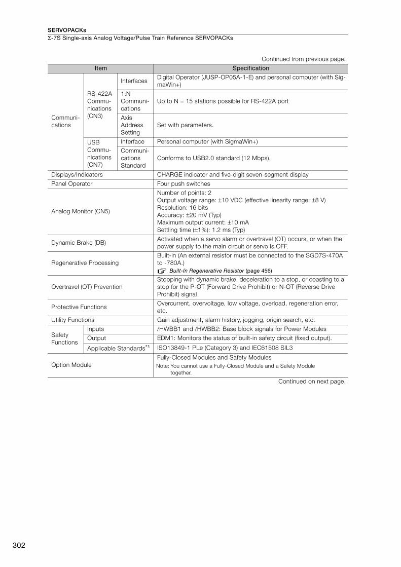
SERVOPACKsΣ-7S Single-axis Analog Voltage/Pulse Train Reference SERVOPACKs
302
Communi-cations
RS-422A Commu-nications (CN3)
InterfacesDigital Operator (JUSP-OP05A-1-E) and personal computer (with Sig-maWin+)
1:N Communi-cations
Up to N = 15 stations possible for RS-422A port
Axis Address Setting
Set with parameters.
USB Commu-nications (CN7)
Interface Personal computer (with SigmaWin+)
Communi-cations Standard
Conforms to USB2.0 standard (12 Mbps).
Displays/Indicators CHARGE indicator and five-digit seven-segment display
Panel Operator Four push switches
Analog Monitor (CN5)
Number of points: 2Output voltage range: ±10 VDC (effective linearity range: ±8 V)Resolution: 16 bitsAccuracy: ±20 mV (Typ)Maximum output current: ±10 mASettling time (±1%): 1.2 ms (Typ)
Dynamic Brake (DB)Activated when a servo alarm or overtravel (OT) occurs, or when the power supply to the main circuit or servo is OFF.
Regenerative ProcessingBuilt-in (An external resistor must be connected to the SGD7S-470A to -780A.)
Built-In Regenerative Resistor (page 456)
Overtravel (OT) PreventionStopping with dynamic brake, deceleration to a stop, or coasting to a stop for the P-OT (Forward Drive Prohibit) or N-OT (Reverse Drive Prohibit) signal
Protective FunctionsOvercurrent, overvoltage, low voltage, overload, regeneration error, etc.
Utility Functions Gain adjustment, alarm history, jogging, origin search, etc.
Safety Functions
Inputs /HWBB1 and /HWBB2: Base block signals for Power Modules
Output EDM1: Monitors the status of built-in safety circuit (fixed output).
Applicable Standards*3 ISO13849-1 PLe (Category 3) and IEC61508 SIL3
Option ModuleFully-Closed Modules and Safety ModulesNote: You cannot use a Fully-Closed Module and a Safety Module
together.
Continued on next page.
Continued from previous page.
Item Specification
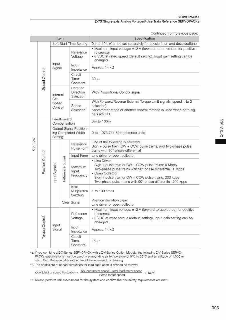
SERVOPACKs Σ-7S Single-axis Analog Voltage/Pulse Train Reference SERVOPACKs
303
Σ-7
S A
nalo
g
*1. If you combine a Σ-7-Series SERVOPACK with a Σ-V-Series Option Module, the following Σ-V-Series SERVO-PACKs specifications must be used: a surrounding air temperature of 0°C to 55°C and an altitude of 1,000 m max. Also, the applicable range cannot be increased by derating.
*2. The coefficient of speed fluctuation for load fluctuation is defined as follows:
*3. Always perform risk assessment for the system and confirm that the safety requirements are met.
Con
trol
s
Sp
eed
Con
trol
Soft Start Time Setting 0 s to 10 s (Can be set separately for acceleration and deceleration.)
Input Signal
Reference Voltage
• Maximum input voltage: ±12 V (forward motor rotation for positive reference).
• 6 VDC at rated speed (default setting). Input gain setting can be changed.
Input Impedance
Approx. 14 kΩ
Circuit Time Constant
30 μs
Internal Set Speed Control
Rotation Direction Selection
With Proportional Control signal
Speed Selection
With Forward/Reverse External Torque Limit signals (speed 1 to 3 selection).Servomotor stops or another control method is used when both sig-nals are OFF.
Pos
ition
Con
trol
Feedforward Compensation
0% to 100%
Output Signal Position-ing Completed Width Setting
0 to 1,073,741,824 reference units
Inp
ut S
igna
ls
Ref
eren
ce p
ulse
s
Reference Pulse Form
One of the following is selected:Sign + pulse train, CW + CCW pulse trains, and two-phase pulse trains with 90° phase differential
Input Form Line driver or open collector
Maximum Input Frequency
• Line DriverSign + pulse train or CW + CCW pulse trains: 4 MppsTwo-phase pulse trains with 90° phase differential: 1 Mpps
• Open CollectorSign + pulse train or CW + CCW pulse trains: 200 kppsTwo-phase pulse trains with 90° phase differential: 200 kpps
Input Multiplication Switching
1 to 100 times
Clear SignalPosition deviation clearLine driver or open collector
Torq
ue C
ontr
ol
Input Signal
Reference Voltage
• Maximum input voltage: ±12 V (forward torque output for positive reference).
• 3 VDC at rated torque (default setting). Input gain setting can be changed.
Input Impedance
Approx. 14 kΩ
Circuit Time Constant
16 μs
Continued from previous page.
Item Specification
× 100%Coefficient of speed fluctuation =No-load motor speed - Total-load motor speed
Rated motor speed
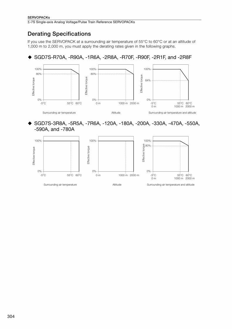
SERVOPACKsΣ-7S Single-axis Analog Voltage/Pulse Train Reference SERVOPACKs
304
Derating SpecificationsIf you use the SERVOPACK at a surrounding air temperature of 55°C to 60°C or at an altitude of 1,000 m to 2,000 m, you must apply the derating rates given in the following graphs.
SGD7S-R70A, -R90A, -1R6A, -2R8A, -R70F, -R90F, -2R1F, and -2R8F
SGD7S-3R8A, -5R5A, -7R6A, -120A, -180A, -200A, -330A, -470A, -550A, -590A, and -780A
100%
80%
2000 m
100%
1000 m
80%
0% 0%
0 m2000 m1000 m0 m
100%
0%
64%
-5°C 55°C 60°C -5°C 55°C 60°C
Effective
to
rque
Effective
to
rque
Surrounding air temperature Altitude
Effective
to
rque
Surrounding air temperature and altitude
80%
2000 m1000 m0 m2000 m1000 m0 m
-5°C 55°C 60°C -5°C 55°C 60°C
100% 100% 100%
0% 0% 0%
Effective
to
rque
Effective
to
rque
Surrounding air temperature Altitude
Effective
to
rque
Surrounding air temperature and altitude

SERVOPACKs Σ-7S Single-axis Analog Voltage/Pulse Train Reference SERVOPACKs
305
Σ-7
S A
nalo
g
Selecting Cables
System Configurations
I/O Signal Cable
Digital OperatorDigital Operator
Converter Cable
Analog Monitor Cable
Safety Function Device Cable
Computer Cable
Host controller
CN3VCMP
SVON COIN TGON REF CHARGE
ALARM
DATAJOGSVON
SCROLL MODE/SETRESET
SERVO
READ WRITESERVO
YASKAWA
DIGITAL OPERATOR JUSP−OP05A−1−E
CN7
CN1
CN8
CN5
JZSP-CVS06-02-E
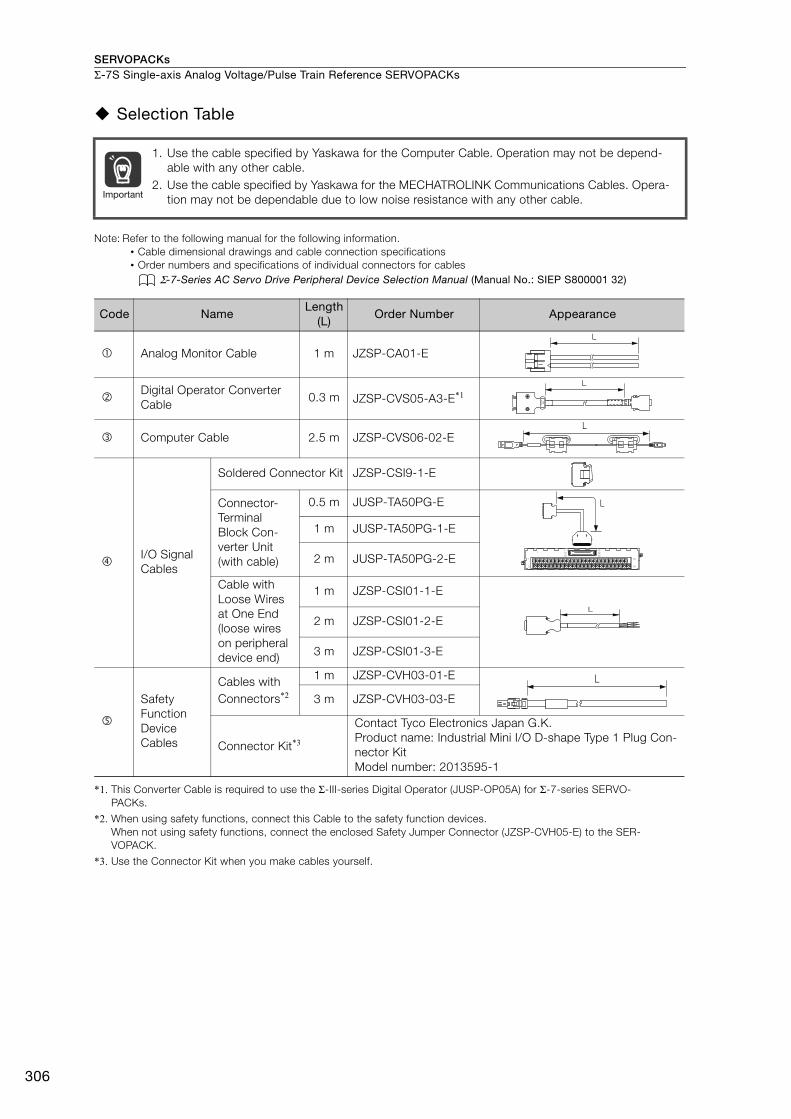
SERVOPACKsΣ-7S Single-axis Analog Voltage/Pulse Train Reference SERVOPACKs
306
Selection Table
Note: Refer to the following manual for the following information.• Cable dimensional drawings and cable connection specifications• Order numbers and specifications of individual connectors for cables
Σ-7-Series AC Servo Drive Peripheral Device Selection Manual (Manual No.: SIEP S800001 32)
*1. This Converter Cable is required to use the Σ-III-series Digital Operator (JUSP-OP05A) for Σ-7-series SERVO-PACKs.
*2. When using safety functions, connect this Cable to the safety function devices.When not using safety functions, connect the enclosed Safety Jumper Connector (JZSP-CVH05-E) to the SER-VOPACK.
*3. Use the Connector Kit when you make cables yourself.
1. Use the cable specified by Yaskawa for the Computer Cable. Operation may not be depend-able with any other cable.
2. Use the cable specified by Yaskawa for the MECHATROLINK Communications Cables. Opera-tion may not be dependable due to low noise resistance with any other cable.
Code NameLength
(L)Order Number Appearance
Analog Monitor Cable 1 m JZSP-CA01-E
Digital Operator Converter Cable
0.3 m JZSP-CVS05-A3-E*1
Computer Cable 2.5 m JZSP-CVS06-02-E
I/O Signal Cables
Soldered Connector Kit JZSP-CSI9-1-E
Connector-Terminal Block Con-verter Unit(with cable)
0.5 m JUSP-TA50PG-E
1 m JUSP-TA50PG-1-E
2 m JUSP-TA50PG-2-E
Cable with Loose Wires at One End(loose wires on peripheral device end)
1 m JZSP-CSI01-1-E
2 m JZSP-CSI01-2-E
3 m JZSP-CSI01-3-E
Safety Function Device Cables
Cables with Connectors*2
1 m JZSP-CVH03-01-E
3 m JZSP-CVH03-03-E
Connector Kit*3
Contact Tyco Electronics Japan G.K.Product name: Industrial Mini I/O D-shape Type 1 Plug Con-nector KitModel number: 2013595-1
Important
L
L
L
1
19
33
16
32
50
1
1
2
49
50
L
L
L
307
MEMO
Σ-7
S A
nalo
g
SERVOPACKs
308
Σ-7S Single-axis MECHATROLINK-II Communications Reference SERVOPACKs
Model Designations
*1. You can use these models with either a single-phase or three-phase power supply input.
*2. A model with a single-phase, 200-VAC power supply input is available as a hardware option (model: SGD7S-120A10A008).
*3. The rated output is 2.4 kW if you combine the SGM7G-30A with the SGD7S-200A.
*4. The same SERVOPACKs are used for both Rotary Servomotors and Linear Servomotors.
*5. Refer to the following manual for details. Σ-7-Series AC Servo Drive Σ-7S/Σ-7W SERVOPACK with Hardware Option Specifications Dynamic Brake Prod-
uct Manual (Manual No.: SIEP S800001 73)
*6. The BTO specification indicates if the SERVOPACK is customized by using the MechatroCloud BTO service.You need a BTO number to order SERVOPACKs with customized specifications.Refer to page M-15 for the details on the BTO service.
A
Interface*4
Design Revision Order
5th+6th digits
7th digit
SGD7S - R70 A 10 A 001
Maximum Applicable
Motor Capacity VoltageHardware Options
Specification1st+2nd+3rd digits 4th digit 8th+9th+10th digits
4th digit
1st+2nd+3rd digits
5th+6th digits
8th+9th+10th digits
7th digit
R70*1
R90*1
1R6*1
2R8*1
3R8
5R5*1
7R6
120*2
180
200*3
330
470
550
590
780
R70
R90
2R1
2R8
0.05 kW
0.1 kW
0.2 kW
0.4 kW
0.5 kW
0.75 kW
1.0 kW
1.5 kW
2.0 kW
3.0 kW
5.0 kW
6.0 kW
7.5 kW
11 kW
15 kW
0.05 kW
0.1 kW
0.2 kW
0.4 kW
10
Code Specification
MECHATROLINK-II
communications reference
A 200 VAC
Code SpecificationVoltage Code Specification
Three-
phase,
200
VAC
-7 Series
-7S SERVOPACKs
00011th+12th+13th
digits
B14thdigit
FT/EX Specification11th+12th+13th digits
None
Code Specification
None000
BTO Specification*6
(Available in Japan only)14th digit
None
Code Specification
None
B BTO Specification
Single-
phase,
100 VAC
F 100 VACNone
Without options All models
All models
SGD7S-R70A to -330A
SGD7S-R70Fto -2R8F
SGD7S-470A to -780A
SGD7S-R70A to -2R8A
SGD7S-R70F to -2R8F
SGD7S-3R8A to -780A
SGD7S-120A
001
002
008
020*5
Duct-ventilated
Varnished
Single-phase, 200-VAC power supply input
No dynamic brake
External dynamic brake resistor
Code SpecificationApplicable
Models
000
Rack-mounted

SERVOPACKs Σ-7S Single-axis MECHATROLINK-II Communications Reference SERVOPACKs
309
Σ-7
S M
-II
Ratings and Specifications
Ratings
Three-phase, 200 VAC
* This is the net value at the rated load.
*1. This is the net value at the rated load.
*2. This value is for the optional JUSP-RA04-E Regenerative Resistor Unit.
*3. This value is for the optional JUSP-RA05-E Regenerative Resistor Unit.
Model SGD7S- R70A R90A 1R6A 2R8A 3R8A 5R5A 7R6A 120A 180A 200A 330A
Maximum Applicable Motor Capacity [kW] 0.05 0.1 0.2 0.4 0.5 0.75 1.0 1.5 2.0 3.0 5.0
Continuous Output Current [Arms] 0.66 0.91 1.6 2.8 3.8 5.5 7.6 11.6 18.5 19.6 32.9
Instantaneous Maximum Output Current [Arms] 2.1 3.2 5.9 9.3 11 16.9 17 28 42 56 84.0
Main Circuit
Power Supply 200 VAC to 240 VAC, -15% to +10%, 50 Hz/60 Hz
Input Current [Arms]* 0.4 0.8 1.3 2.5 3.0 4.1 5.7 7.3 10 15 25
ControlPower Supply 200 VAC to 240 VAC, -15% to +10%, 50 Hz/60 Hz
Input Current [Arms]* 0.2 0.2 0.2 0.2 0.2 0.2 0.2 0.2 0.25 0.25 0.3Power Supply Capacity [kVA]* 0.2 0.3 0.5 1.0 1.3 1.6 2.3 3.2 4.0 5.9 7.5
Power Loss*
Main Circuit Power Loss [W] 5.0 7.0 11.9 22.5 28.5 38.9 49.2 72.6 104.2 114.2 226.6
Control Circuit Power Loss [W] 12 12 12 12 14 14 14 15 16 16 19
Built-in Regenerative Resistor Power Loss [W]
− − − − 8 8 8 10 16 16 36
Total Power Loss [W] 17.0 19.0 23.9 34.5 50.5 60.9 71.2 97.6 136.2 146.2 281.6
Regenerative Resistor
Built-In Regenerative Resistor
Resistance [Ω]
− − − − 40 40 40 20 12 12 8
Capacity [W] − − − − 40 40 40 60 60 60 180
Minimum Allowable External Resistance [Ω]
40 40 40 40 40 40 40 20 12 12 8
Overvoltage Category III
Model SGD7S- 470A 550A 590A 780A
Maximum Applicable Motor Capacity [kW] 6.0 7.5 11 15
Continuous Output Current [Arms] 46.9 54.7 58.6 78.0
Instantaneous Maximum Output Current [Arms] 110 130 140 170
Main CircuitPower Supply 200 VAC to 240 VAC, -15% to +10%, 50 Hz/60 Hz
Input Current [Arms]*1 29 37 54 73
ControlPower Supply 200 VAC to 240 VAC, -15% to +10%, 50 Hz/60 Hz
Input Current [Arms]*1 0.3 0.3 0.4 0.4
Power Supply Capacity [kVA]*1 10.7 14.6 21.7 29.6
Power Loss*1
Main Circuit Power Loss [W] 271.7 326.9 365.3 501.4
Control Circuit Power Loss [W] 21 21 28 28
External Regenerative Resistor Unit Power Loss [W] 180*2 180*3 350*3 350*3
Total Power Loss [W] 292.7 347.9 393.3 529.4
External Regenerative Resistor Unit
External Regenerative Resistor Unit
Resistance [Ω] 6.25*2 3.13*3 3.13*3 3.13*3
Capacity [W] 880*2 1760*3 1760*3 1760*3
Minimum Allowable External Resistance [Ω]
5.8 2.9 2.9 2.9
Overvoltage Category III

SERVOPACKsΣ-7S Single-axis MECHATROLINK-II Communications Reference SERVOPACKs
310
Single-phase, 200 VAC
* This is the net value at the rated load.
270 VDC
*1. This is the net value at the rated load.*2. The value is 0.25 Arms for the SGD7S-120A00A008.
* This is the net value at the rated load.
Model SGD7S- R70A R90A 1R6A 2R8A 5R5A 120A
Maximum Applicable Motor Capacity [kW] 0.05 0.1 0.2 0.4 0.75 1.5
Continuous Output Current [Arms] 0.66 0.91 1.6 2.8 5.5 11.6Instantaneous Maximum Output Current [Arms] 2.1 3.2 5.9 9.3 16.9 28
Main CircuitPower Supply 200 VAC to 240 VAC, -15% to +10%, 50 Hz/60 Hz
Input Current [Arms]* 0.8 1.6 2.4 5.0 8.7 16
ControlPower Supply 200 VAC to 240 VAC, -15% to +10%, 50 Hz/60 Hz
Input Current [Arms]* 0.2 0.2 0.2 0.2 0.2 0.25
Power Supply Capacity [kVA]* 0.2 0.3 0.6 1.2 1.9 4.0
Power Loss*
Main Circuit Power Loss [W] 5.0 7.1 12.1 23.7 39.2 71.8
Control Circuit Power Loss [W] 12 12 12 12 14 16
Built-in Regenerative Resistor Power Loss [W]
− − − − 8 16
Total Power Loss [W] 17.0 19.1 24.1 35.7 61.2 103.8
Regenerative Resistor
Built-In Regenerative Resistor
Resistance [Ω] − − − − 40 12
Capacity [W] − − − − 40 60
Minimum Allowable External Resistance [Ω]
40 40 40 40 40 12
Overvoltage Category III
Model SGD7S- R70A R90A 1R6A 2R8A 3R8A 5R5A 7R6A 120A
Maximum Applicable Motor Capacity [kW] 0.05 0.1 0.2 0.4 0.5 0.75 1.0 1.5
Continuous Output Current [Arms] 0.66 0.91 1.6 2.8 3.8 5.5 7.6 11.6
Instantaneous Maximum Output Current [Arms] 2.1 3.2 5.9 9.3 11.0 16.9 17.0 28.0
Main CircuitPower Supply 270 VDC to 324 VDC, -15% to +10%
Input Current [Arms]*1 0.5 1.0 1.5 3.0 3.8 4.9 6.9 11
ControlPower Supply 270 VDC to 324 VDC, -15% to +10%
Input Current [Arms]*1 0.2 0.2 0.2 0.2 0.2 0.2 0.2 0.2*2
Power Supply Capacity [kVA]*1 0.2 0.3 0.6 1 1.4 1.6 2.3 3.2
Power Loss*1
Main Circuit Power Loss [W] 4.4 5.9 9.8 17.5 23.0 30.7 38.7 55.8Control Circuit Power Loss [W] 12 12 12 12 14 14 14 15
Total Power Loss [W] 16.4 17.9 21.8 29.5 37.0 44.7 52.7 70.8
Overvoltage Category III
Model SGD7S- 180A 200A 330A 470A 550A 590A 780A
Maximum Applicable Motor Capacity [kW] 2.0 3.0 5.0 6.0 7.5 11.0 15.0 Continuous Output Current [Arms] 18.5 19.6 32.9 46.9 54.7 58.6 78.0
Instantaneous Maximum Output Current [Arms] 42.0 56.0 84.0 110 130 140 170
Main CircuitPower Supply 270 VDC to 324 VDC, -15% to +10%Input Current [Arms]* 14 20 34 36 48 68 92
ControlPower Supply 270 VDC to 324 VDC, -15% to +10%
Input Current [Arms]* 0.25 0.25 0.3 0.3 0.3 0.4 0.4Power Supply Capacity [kVA]* 4.0 5.9 7.5 10.7 14.6 21.7 29.6
Power Loss*Main Circuit Power Loss [W] 82.7 83.5 146.2 211.6 255.3 243.6 343.4
Control Circuit Power Loss [W] 16 16 19 21 21 28 28Total Power Loss [W] 98.7 99.5 165.2 232.6 276.3 271.6 371.4
Overvoltage Category III
SERVOPACKs Σ-7S Single-axis MECHATROLINK-II Communications Reference SERVOPACKs
311
Σ-7
S M
-II
Single-phase, 100 VAC
* This is the net value at the rated load.
SERVOPACK Overload Protection CharacteristicsThe overload detection level is set for hot start conditions with a SERVOPACK surrounding air tem-perature of 55°C.
An overload alarm (A.710 or A.720) will occur if overload operation that exceeds the overload pro-tection characteristics shown in the following diagram (i.e., operation on the right side of the appli-cable line) is performed.
The actual overload detection level will be the detection level of the connected SERVOPACK or Ser-vomotor that has the lower overload protection characteristics.
In most cases, that will be the overload protection characteristics of the Servomotor.
Note: The above overload protection characteristics do not mean that you can perform continuous duty operation with an output of 100% or higher.For a Yaskawa-specified combination of SERVOPACK and Servomotor, maintain the effective torque (or effective force) within the continuous duty zone of the torque-motor speed characteristic (or force-motor speed characteristics) of the Servomotor.
Model SGD7S- R70F R90F 2R1F 2R8F
Maximum Applicable Motor Capacity [kW] 0.05 0.1 0.2 0.4
Continuous Output Current [Arms] 0.66 0.91 2.1 2.8
Instantaneous Maximum Output Current [Arms] 2.1 3.2 6.5 9.3
Main CircuitPower Supply 100 VAC to 120 VAC, -15% to +10%, 50 Hz/60 Hz
Input Current [Arms]* 1.5 2.5 5 10
ControlPower Supply 100 VAC to 120 VAC, -15% to +10%, 50 Hz/60 Hz
Input Current [Arms]* 0.38 0.38 0.38 0.38Power Supply Capacity [kVA]* 0.2 0.3 0.6 1.4
Power Loss*Main Circuit Power Loss [W] 5.3 7.8 14.2 26.2
Control Circuit Power Loss [W] 12 12 12 12
Total Power Loss [W] 17.3 19.8 26.2 38.2
Regenerative Resistor
Minimum Allowable External Resistance [Ω]
40 40 40 40
Overvoltage Category III
SERVOPACK output current (continuous output current ratio) (%)
Continuous output current× 100%
SERVOPACK Model:
SGD7S-R70A, -R90A,
-1R6A, -2R8A, -R70F,
-R90F, -2R1F, and -2R8F
SERVOPACK Model:
SGD7S-3R8A, -5R5A, -7R6A,
-120A, -180A, -200A, -330A,
-470A, -550A, -590A,
and -780A
Instantaneous maximum output current
(Instantaneous maximum output current)
(Continuous output current)
SERVOPACK output current (continuous output current ratio) (%)
Continuous output current× 100%
Instantaneous maximum output current
(Instantaneous maximum output current)
(Continuous output current)
100 230
10000
1000
100
10
1100 200
10000
1000
100
10
1
Dete
ctio
n t
ime (s)
Dete
ctio
n t
ime (s)
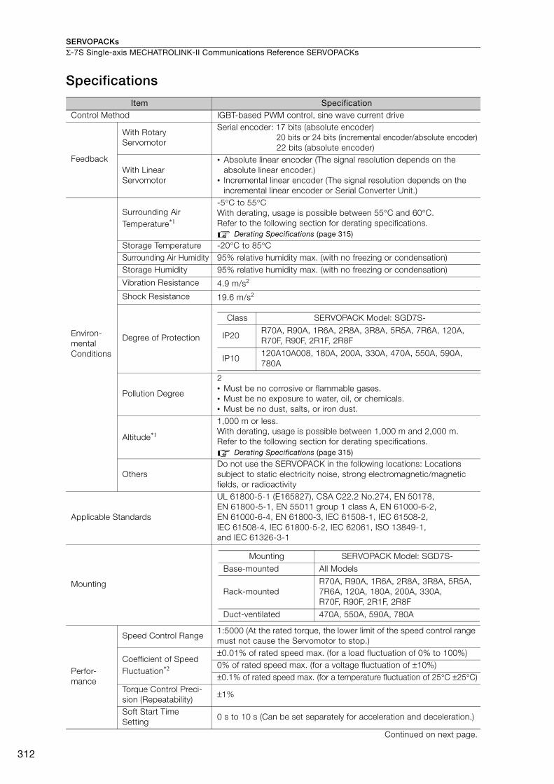
SERVOPACKsΣ-7S Single-axis MECHATROLINK-II Communications Reference SERVOPACKs
312
Specifications
Item SpecificationControl Method IGBT-based PWM control, sine wave current drive
Feedback
With Rotary Servomotor
Serial encoder: 17 bits (absolute encoder)20 bits or 24 bits (incremental encoder/absolute encoder)22 bits (absolute encoder)
With Linear Servomotor
• Absolute linear encoder (The signal resolution depends on the absolute linear encoder.)
• Incremental linear encoder (The signal resolution depends on the incremental linear encoder or Serial Converter Unit.)
Environ-mental Conditions
Surrounding Air Temperature*1
-5°C to 55°C With derating, usage is possible between 55°C and 60°C. Refer to the following section for derating specifications.
Derating Specifications (page 315)
Storage Temperature -20°C to 85°CSurrounding Air Humidity 95% relative humidity max. (with no freezing or condensation)Storage Humidity 95% relative humidity max. (with no freezing or condensation)
Vibration Resistance 4.9 m/s2
Shock Resistance 19.6 m/s2
Degree of Protection
Pollution Degree
2• Must be no corrosive or flammable gases.• Must be no exposure to water, oil, or chemicals.• Must be no dust, salts, or iron dust.
Altitude*1
1,000 m or less. With derating, usage is possible between 1,000 m and 2,000 m.Refer to the following section for derating specifications.
Derating Specifications (page 315)
OthersDo not use the SERVOPACK in the following locations: Locations subject to static electricity noise, strong electromagnetic/magnetic fields, or radioactivity
Applicable Standards
UL 61800-5-1 (E165827), CSA C22.2 No.274, EN 50178, EN 61800-5-1, EN 55011 group 1 class A, EN 61000-6-2, EN 61000-6-4, EN 61800-3, IEC 61508-1, IEC 61508-2, IEC 61508-4, IEC 61800-5-2, IEC 62061, ISO 13849-1, and IEC 61326-3-1
Mounting
Perfor-mance
Speed Control Range1:5000 (At the rated torque, the lower limit of the speed control range must not cause the Servomotor to stop.)
Coefficient of Speed Fluctuation*2
±0.01% of rated speed max. (for a load fluctuation of 0% to 100%)0% of rated speed max. (for a voltage fluctuation of ±10%)±0.1% of rated speed max. (for a temperature fluctuation of 25°C ±25°C)
Torque Control Preci-sion (Repeatability)
±1%
Soft Start Time Setting
0 s to 10 s (Can be set separately for acceleration and deceleration.)
Continued on next page.
Class SERVOPACK Model: SGD7S-
IP20R70A, R90A, 1R6A, 2R8A, 3R8A, 5R5A, 7R6A, 120A,R70F, R90F, 2R1F, 2R8F
IP10120A10A008, 180A, 200A, 330A, 470A, 550A, 590A, 780A
Mounting SERVOPACK Model: SGD7S-
Base-mounted All Models
Rack-mountedR70A, R90A, 1R6A, 2R8A, 3R8A, 5R5A, 7R6A, 120A, 180A, 200A, 330A, R70F, R90F, 2R1F, 2R8F
Duct-ventilated 470A, 550A, 590A, 780A
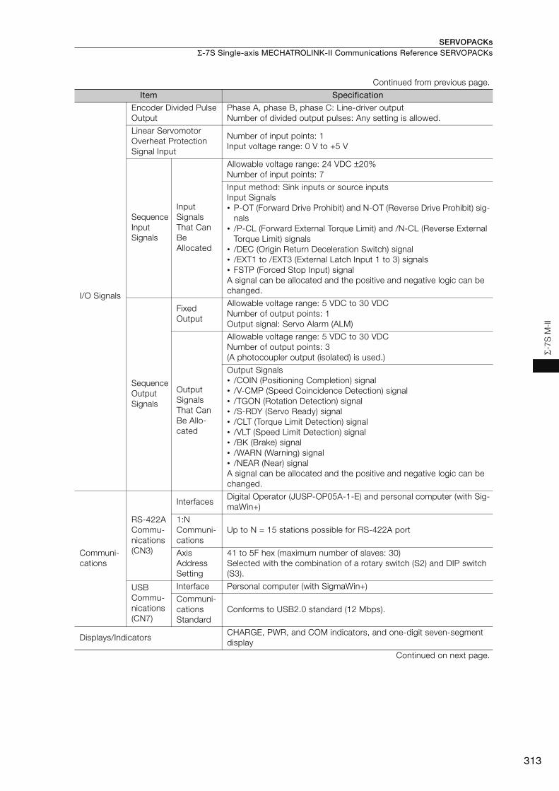
SERVOPACKs Σ-7S Single-axis MECHATROLINK-II Communications Reference SERVOPACKs
313
Σ-7
S M
-II
I/O Signals
Encoder Divided Pulse Output
Phase A, phase B, phase C: Line-driver output Number of divided output pulses: Any setting is allowed.
Linear Servomotor Overheat Protection Signal Input
Number of input points: 1Input voltage range: 0 V to +5 V
Sequence Input Signals
Input Signals That Can Be Allocated
Allowable voltage range: 24 VDC ±20%Number of input points: 7
Input method: Sink inputs or source inputsInput Signals• P-OT (Forward Drive Prohibit) and N-OT (Reverse Drive Prohibit) sig-
nals• /P-CL (Forward External Torque Limit) and /N-CL (Reverse External
Torque Limit) signals• /DEC (Origin Return Deceleration Switch) signal• /EXT1 to /EXT3 (External Latch Input 1 to 3) signals• FSTP (Forced Stop Input) signalA signal can be allocated and the positive and negative logic can be changed.
Sequence Output Signals
Fixed Output
Allowable voltage range: 5 VDC to 30 VDCNumber of output points: 1Output signal: Servo Alarm (ALM)
Output Signals That Can Be Allo-cated
Allowable voltage range: 5 VDC to 30 VDCNumber of output points: 3(A photocoupler output (isolated) is used.)
Output Signals• /COIN (Positioning Completion) signal• /V-CMP (Speed Coincidence Detection) signal• /TGON (Rotation Detection) signal• /S-RDY (Servo Ready) signal• /CLT (Torque Limit Detection) signal• /VLT (Speed Limit Detection) signal• /BK (Brake) signal• /WARN (Warning) signal• /NEAR (Near) signalA signal can be allocated and the positive and negative logic can be changed.
Communi-cations
RS-422A Commu-nications (CN3)
InterfacesDigital Operator (JUSP-OP05A-1-E) and personal computer (with Sig-maWin+)
1:N Communi-cations
Up to N = 15 stations possible for RS-422A port
Axis Address Setting
41 to 5F hex (maximum number of slaves: 30)Selected with the combination of a rotary switch (S2) and DIP switch (S3).
USB Commu-nications (CN7)
Interface Personal computer (with SigmaWin+)
Communi-cations Standard
Conforms to USB2.0 standard (12 Mbps).
Displays/IndicatorsCHARGE, PWR, and COM indicators, and one-digit seven-segment display
Continued on next page.
Continued from previous page.
Item Specification
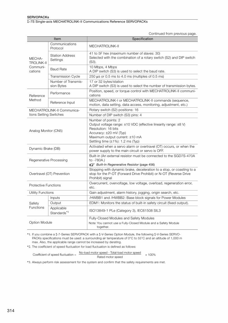
SERVOPACKsΣ-7S Single-axis MECHATROLINK-II Communications Reference SERVOPACKs
314
*1. If you combine a Σ-7-Series SERVOPACK with a Σ-V-Series Option Module, the following Σ-V-Series SERVO-PACKs specifications must be used: a surrounding air temperature of 0°C to 55°C and an altitude of 1,000 m max. Also, the applicable range cannot be increased by derating.
*2. The coefficient of speed fluctuation for load fluctuation is defined as follows:
*3. Always perform risk assessment for the system and confirm that the safety requirements are met.
MECHA-TROLINK-II Communi-cations
Communications Protocol
MECHATROLINK-II
Station Address Settings
41 to 5F hex (maximum number of slaves: 30)Selected with the combination of a rotary switch (S2) and DIP switch (S3).
Baud Rate 10 Mbps, 4 MbpsA DIP switch (S3) is used to select the baud rate.
Transmission Cycle 250 μs or 0.5 ms to 4.0 ms (multiples of 0.5 ms)
Number of Transmis-sion Bytes
17 or 32 bytes/station A DIP switch (S3) is used to select the number of transmission bytes.
Reference Method
PerformancePosition, speed, or torque control with MECHATROLINK-II communi-cations
Reference InputMECHATROLINK-I or MECHATROLINK-II commands (sequence, motion, data setting, data access, monitoring, adjustment, etc.)
MECHATROLINK-II Communica-tions Setting Switches
Rotary switch (S2) positions: 16
Number of DIP switch (S3) pins: 4
Analog Monitor (CN5)
Number of points: 2Output voltage range: ±10 VDC (effective linearity range: ±8 V)Resolution: 16 bitsAccuracy: ±20 mV (Typ)Maximum output current: ±10 mASettling time (±1%): 1.2 ms (Typ)
Dynamic Brake (DB)Activated when a servo alarm or overtravel (OT) occurs, or when the power supply to the main circuit or servo is OFF.
Regenerative ProcessingBuilt-in (An external resistor must be connected to the SGD7S-470A to -780A.)
Built-In Regenerative Resistor (page 456)
Overtravel (OT) PreventionStopping with dynamic brake, deceleration to a stop, or coasting to a stop for the P-OT (Forward Drive Prohibit) or N-OT (Reverse Drive Prohibit) signal
Protective FunctionsOvercurrent, overvoltage, low voltage, overload, regeneration error, etc.
Utility Functions Gain adjustment, alarm history, jogging, origin search, etc.
Safety Functions
Inputs /HWBB1 and /HWBB2: Base block signals for Power Modules
Output EDM1: Monitors the status of built-in safety circuit (fixed output).
Applicable Standards*3 ISO13849-1 PLe (Category 3), IEC61508 SIL3
Option ModuleFully-Closed Modules and Safety ModulesNote: You cannot use a Fully-Closed Module and a Safety Module
together.
Continued from previous page.
Item Specification
× 100%Coefficient of speed fluctuation =No-load motor speed - Total-load motor speed
Rated motor speed
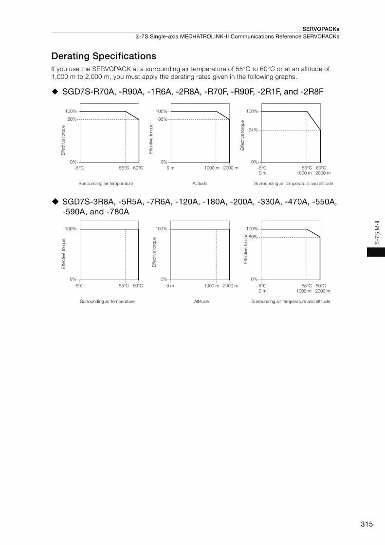
SERVOPACKs Σ-7S Single-axis MECHATROLINK-II Communications Reference SERVOPACKs
315
Σ-7
S M
-II
Derating SpecificationsIf you use the SERVOPACK at a surrounding air temperature of 55°C to 60°C or at an altitude of 1,000 m to 2,000 m, you must apply the derating rates given in the following graphs.
SGD7S-R70A, -R90A, -1R6A, -2R8A, -R70F, -R90F, -2R1F, and -2R8F
SGD7S-3R8A, -5R5A, -7R6A, -120A, -180A, -200A, -330A, -470A, -550A, -590A, and -780A
100%
80%
2000 m
100%
1000 m
80%
0% 0%
0 m2000 m1000 m0 m
100%
0%
64%
-5°C 55°C 60°C -5°C 55°C 60°C
Effective
to
rque
Effective
to
rque
Surrounding air temperature Altitude
Effective
to
rque
Surrounding air temperature and altitude
80%
2000 m1000 m0 m2000 m1000 m0 m
-5°C 55°C 60°C -5°C 55°C 60°C
100% 100% 100%
0% 0% 0%
Effective
to
rque
Effective
to
rque
Surrounding air temperature Altitude
Effective
to
rque
Surrounding air temperature and altitude

SERVOPACKsΣ-7S Single-axis MECHATROLINK-II Communications Reference SERVOPACKs
316
Selecting Cables
System Configurations
Digital Operator
Converter Cable
Safety Function Device Cable
Analog Monitor Cable
I/O Signal Cable
To next MECHATROLINK-II station
MECHATROLINK-II Communications Cable
To external devices,
such as LED indicators
CN1
CN5
CN6
CN3
CN7
CN8
Digital Operator
Computer CableJZSP-CVS06-02-E
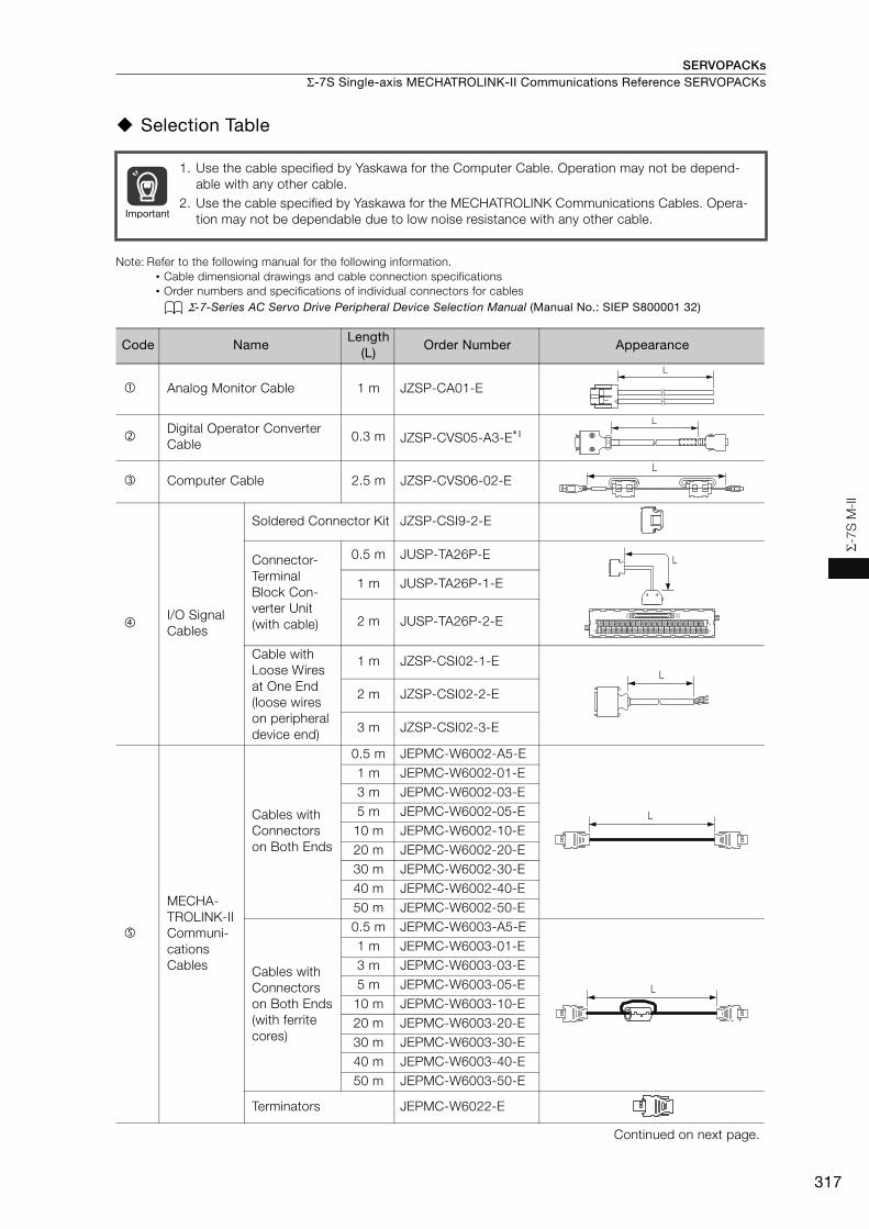
SERVOPACKs Σ-7S Single-axis MECHATROLINK-II Communications Reference SERVOPACKs
317
Σ-7
S M
-II
Selection Table
Note: Refer to the following manual for the following information.• Cable dimensional drawings and cable connection specifications• Order numbers and specifications of individual connectors for cables
Σ-7-Series AC Servo Drive Peripheral Device Selection Manual (Manual No.: SIEP S800001 32)
1. Use the cable specified by Yaskawa for the Computer Cable. Operation may not be depend-able with any other cable.
2. Use the cable specified by Yaskawa for the MECHATROLINK Communications Cables. Opera-tion may not be dependable due to low noise resistance with any other cable.
Code NameLength
(L)Order Number Appearance
Analog Monitor Cable 1 m JZSP-CA01-E
Digital Operator Converter Cable
0.3 m JZSP-CVS05-A3-E*1
Computer Cable 2.5 m JZSP-CVS06-02-E
I/O Signal Cables
Soldered Connector Kit JZSP-CSI9-2-E
Connector-Terminal Block Con-verter Unit(with cable)
0.5 m JUSP-TA26P-E
1 m JUSP-TA26P-1-E
2 m JUSP-TA26P-2-E
Cable with Loose Wires at One End (loose wires on peripheral device end)
1 m JZSP-CSI02-1-E
2 m JZSP-CSI02-2-E
3 m JZSP-CSI02-3-E
MECHA-TROLINK-II Communi-cations Cables
Cables with Connectors on Both Ends
0.5 m JEPMC-W6002-A5-E1 m JEPMC-W6002-01-E3 m JEPMC-W6002-03-E5 m JEPMC-W6002-05-E
10 m JEPMC-W6002-10-E20 m JEPMC-W6002-20-E30 m JEPMC-W6002-30-E40 m JEPMC-W6002-40-E50 m JEPMC-W6002-50-E
Cables with Connectors on Both Ends(with ferrite cores)
0.5 m JEPMC-W6003-A5-E1 m JEPMC-W6003-01-E3 m JEPMC-W6003-03-E5 m JEPMC-W6003-05-E
10 m JEPMC-W6003-10-E20 m JEPMC-W6003-20-E30 m JEPMC-W6003-30-E40 m JEPMC-W6003-40-E50 m JEPMC-W6003-50-E
Terminators JEPMC-W6022-E
Continued on next page.
Important
L
L
L
40
391
2
B20A20
B1A1
L
L
L
L
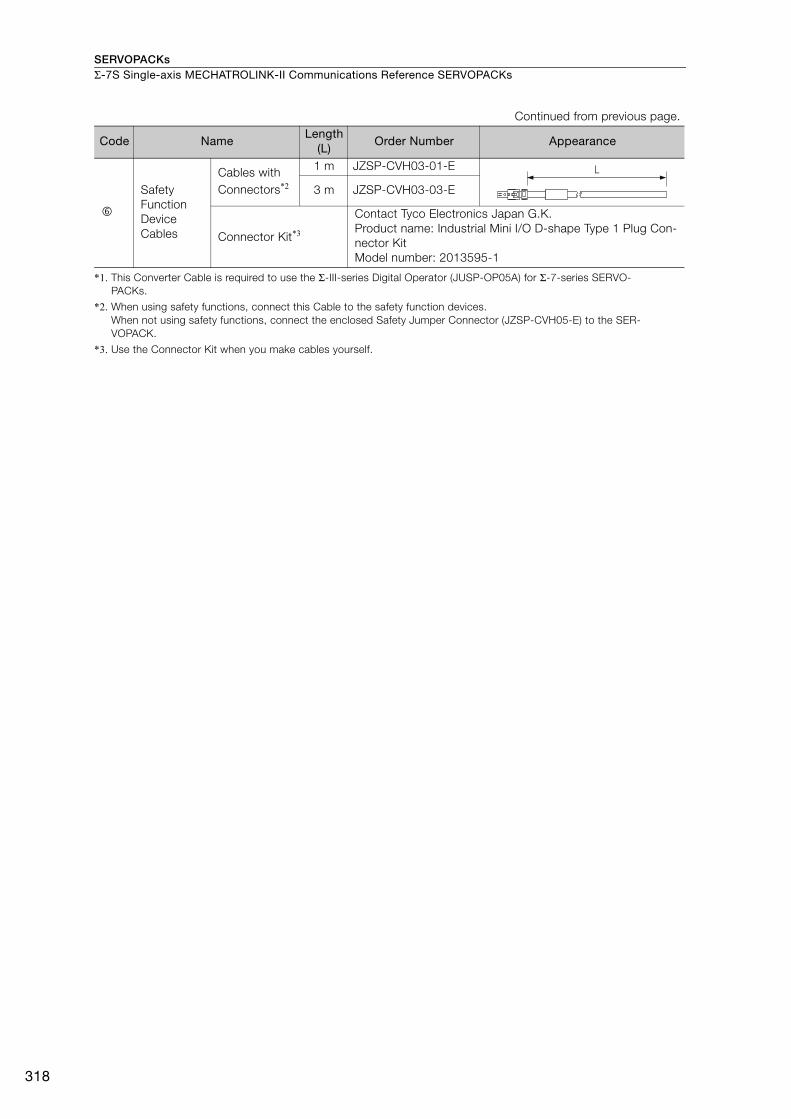
SERVOPACKsΣ-7S Single-axis MECHATROLINK-II Communications Reference SERVOPACKs
318
*1. This Converter Cable is required to use the Σ-III-series Digital Operator (JUSP-OP05A) for Σ-7-series SERVO-PACKs.
*2. When using safety functions, connect this Cable to the safety function devices.When not using safety functions, connect the enclosed Safety Jumper Connector (JZSP-CVH05-E) to the SER-VOPACK.
*3. Use the Connector Kit when you make cables yourself.
Safety Function Device Cables
Cables with Connectors*2
1 m JZSP-CVH03-01-E
3 m JZSP-CVH03-03-E
Connector Kit*3
Contact Tyco Electronics Japan G.K.Product name: Industrial Mini I/O D-shape Type 1 Plug Con-nector KitModel number: 2013595-1
Continued from previous page.
Code NameLength
(L)Order Number Appearance
L
319
MEMO
Σ-7
S M
-II
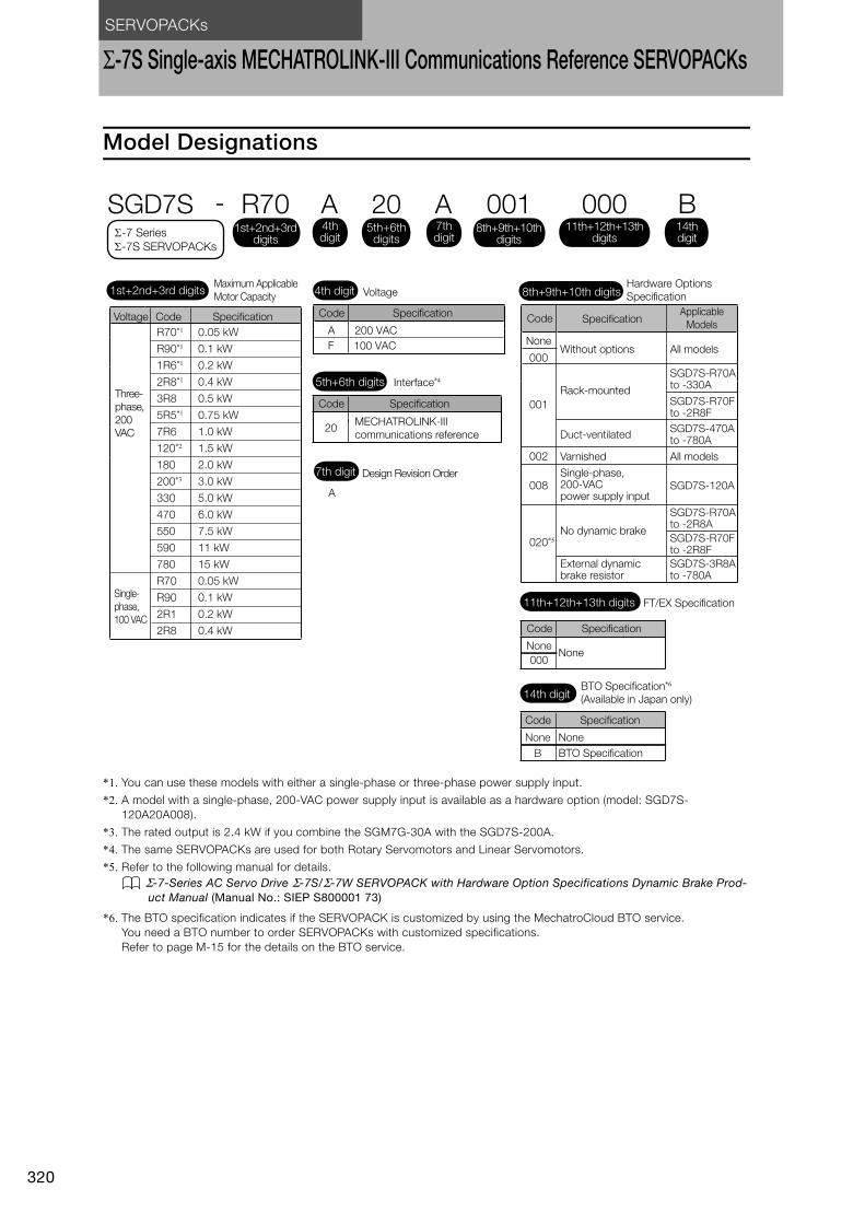
SERVOPACKs
320
Σ-7S Single-axis MECHATROLINK-III Communications Reference SERVOPACKs
Model Designations
*1. You can use these models with either a single-phase or three-phase power supply input.
*2. A model with a single-phase, 200-VAC power supply input is available as a hardware option (model: SGD7S-120A20A008).
*3. The rated output is 2.4 kW if you combine the SGM7G-30A with the SGD7S-200A.
*4. The same SERVOPACKs are used for both Rotary Servomotors and Linear Servomotors.
*5. Refer to the following manual for details. Σ-7-Series AC Servo Drive Σ-7S/Σ-7W SERVOPACK with Hardware Option Specifications Dynamic Brake Prod-
uct Manual (Manual No.: SIEP S800001 73)
*6. The BTO specification indicates if the SERVOPACK is customized by using the MechatroCloud BTO service.You need a BTO number to order SERVOPACKs with customized specifications.Refer to page M-15 for the details on the BTO service.
20
A
Interface*4
Code Specification
MECHATROLINK-III
communications reference
Design Revision Order
5th+6th digits
7th digit
A 200 VAC
F 100 VAC
SGD7S - R70 A 20 A 001
Maximum Applicable
Motor Capacity Voltage
Code Specification
Hardware Options
Specification1st+2nd+3rd digits 4th digit 8th+9th+10th digits
4th digit
1st+2nd+3rd digits
5th+6th digits
8th+9th+10th digits
7th digit
R70*1
R90*1
1R6*1
2R8*1
3R8
5R5*1
7R6
120*2
180
200*3
330
470
550
590
780
R70
R90
2R1
2R8
0.05 kW
0.1 kW
0.2 kW
0.4 kW
0.5 kW
0.75 kW
1.0 kW
1.5 kW
2.0 kW
3.0 kW
5.0 kW
6.0 kW
7.5 kW
11 kW
15 kW
0.05 kW
0.1 kW
0.2 kW
0.4 kW
Voltage Code Specification
Three-
phase,
200
VAC
-7 Series
-7S SERVOPACKs
00011th+12th+13th
digits
B14thdigit
FT/EX Specification11th+12th+13th digits
None
Code Specification
None000
BTO Specification*6
(Available in Japan only)14th digit
None
Code Specification
None
B BTO Specification
Single-
phase,
100 VAC
NoneWithout options All models
All models
SGD7S-R70A to -330A
SGD7S-R70Fto -2R8F
SGD7S-470A to -780A
SGD7S-R70A to -2R8A
SGD7S-R70F to -2R8F
SGD7S-3R8A to -780A
SGD7S-120A
001
002
008
020*5
Duct-ventilated
Varnished
Single-phase, 200-VAC power supply input
No dynamic brake
External dynamic brake resistor
Code SpecificationApplicable
Models
000
Rack-mounted

SERVOPACKs Σ-7S Single-axis MECHATROLINK-III Communications Reference SERVOPACKs
321
Σ-7
S M
-III
Ratings and Specifications
Ratings
Three-phase, 200 VAC
* This is the net value at the rated load.
*1. This is the net value at the rated load.
*2. This value is for the optional JUSP-RA04-E Regenerative Resistor Unit.
*3. This value is for the optional JUSP-RA05-E Regenerative Resistor Unit.
Model SGD7S- R70A R90A 1R6A 2R8A 3R8A 5R5A 7R6A 120A 180A 200A 330A
Maximum Applicable Motor Capacity [kW] 0.05 0.1 0.2 0.4 0.5 0.75 1.0 1.5 2.0 3.0 5.0
Continuous Output Current [Arms] 0.66 0.91 1.6 2.8 3.8 5.5 7.6 11.6 18.5 19.6 32.9
Instantaneous Maximum Output Current [Arms] 2.1 3.2 5.9 9.3 11 16.9 17 28 42 56 84.0
Main Circuit
Power Supply 200 VAC to 240 VAC, -15% to +10%, 50 Hz/60 Hz
Input Current [Arms]* 0.4 0.8 1.3 2.5 3.0 4.1 5.7 7.3 10 15 25
ControlPower Supply 200 VAC to 240 VAC, -15% to +10%, 50 Hz/60 Hz
Input Current [Arms]* 0.2 0.2 0.2 0.2 0.2 0.2 0.2 0.2 0.25 0.25 0.3Power Supply Capacity [kVA]* 0.2 0.3 0.5 1.0 1.3 1.6 2.3 3.2 4.0 5.9 7.5
Power Loss*
Main Circuit Power Loss [W] 5.0 7.0 11.9 22.5 28.5 38.9 49.2 72.6 104.2 114.2 226.6
Control Circuit Power Loss [W] 12 12 12 12 14 14 14 15 16 16 19
Built-in Regenerative Resistor Power Loss [W]
− − − − 8 8 8 10 16 16 36
Total Power Loss [W] 17.0 19.0 23.9 34.5 50.5 60.9 71.2 97.6 136.2 146.2 281.6
Regenerative Resistor
Built-In Regenerative Resistor
Resistance [Ω]
− − − − 40 40 40 20 12 12 8
Capacity [W] − − − − 40 40 40 60 60 60 180
Minimum Allowable External Resistance [Ω]
40 40 40 40 40 40 40 20 12 12 8
Overvoltage Category III
Model SGD7S- 470A 550A 590A 780A
Maximum Applicable Motor Capacity [kW] 6.0 7.5 11 15
Continuous Output Current [Arms] 46.9 54.7 58.6 78.0
Instantaneous Maximum Output Current [Arms] 110 130 140 170
Main CircuitPower Supply 200 VAC to 240 VAC, -15% to +10%, 50 Hz/60 Hz
Input Current [Arms]*1 29 37 54 73
ControlPower Supply 200 VAC to 240 VAC, -15% to +10%, 50 Hz/60 Hz
Input Current [Arms]*1 0.3 0.3 0.4 0.4
Power Supply Capacity [kVA]*1 10.7 14.6 21.7 29.6
Power Loss*1
Main Circuit Power Loss [W] 271.7 326.9 365.3 501.4
Control Circuit Power Loss [W] 21 21 28 28
External Regenerative Resistor Unit Power Loss [W] 180*2 180*3 350*3 350*3
Total Power Loss [W] 292.7 347.9 393.3 529.4
External Regenerative Resistor Unit
External Regenerative Resistor Unit
Resistance [Ω] 6.25*2 3.13*3 3.13*3 3.13*3
Capacity [W] 880*2 1760*3 1760*3 1760*3
Minimum Allowable External Resistance [Ω]
5.8 2.9 2.9 2.9
Overvoltage Category III
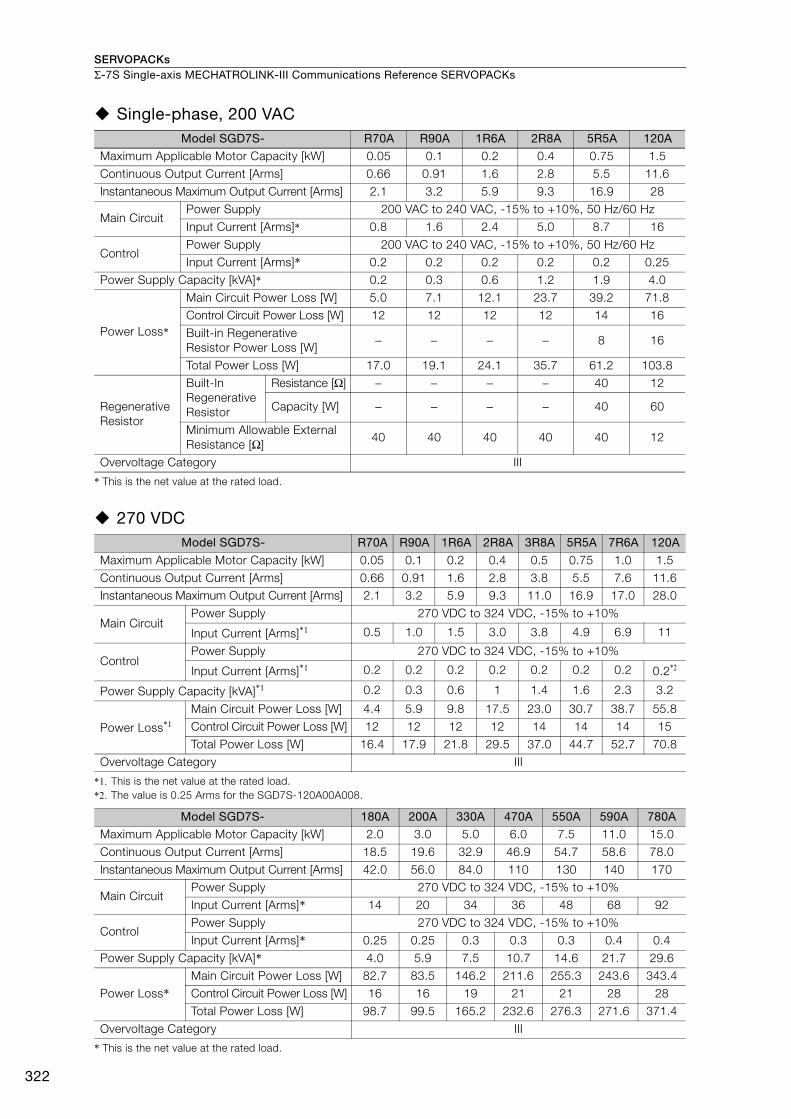
SERVOPACKsΣ-7S Single-axis MECHATROLINK-III Communications Reference SERVOPACKs
322
Single-phase, 200 VAC
* This is the net value at the rated load.
270 VDC
*1. This is the net value at the rated load.*2. The value is 0.25 Arms for the SGD7S-120A00A008.
* This is the net value at the rated load.
Model SGD7S- R70A R90A 1R6A 2R8A 5R5A 120A
Maximum Applicable Motor Capacity [kW] 0.05 0.1 0.2 0.4 0.75 1.5
Continuous Output Current [Arms] 0.66 0.91 1.6 2.8 5.5 11.6
Instantaneous Maximum Output Current [Arms] 2.1 3.2 5.9 9.3 16.9 28
Main CircuitPower Supply 200 VAC to 240 VAC, -15% to +10%, 50 Hz/60 Hz
Input Current [Arms]* 0.8 1.6 2.4 5.0 8.7 16
ControlPower Supply 200 VAC to 240 VAC, -15% to +10%, 50 Hz/60 HzInput Current [Arms]* 0.2 0.2 0.2 0.2 0.2 0.25
Power Supply Capacity [kVA]* 0.2 0.3 0.6 1.2 1.9 4.0
Power Loss*
Main Circuit Power Loss [W] 5.0 7.1 12.1 23.7 39.2 71.8Control Circuit Power Loss [W] 12 12 12 12 14 16
Built-in Regenerative Resistor Power Loss [W]
− − − − 8 16
Total Power Loss [W] 17.0 19.1 24.1 35.7 61.2 103.8
Regenerative Resistor
Built-In Regenerative Resistor
Resistance [Ω] − − − − 40 12
Capacity [W] − − − − 40 60
Minimum Allowable External Resistance [Ω]
40 40 40 40 40 12
Overvoltage Category III
Model SGD7S- R70A R90A 1R6A 2R8A 3R8A 5R5A 7R6A 120A
Maximum Applicable Motor Capacity [kW] 0.05 0.1 0.2 0.4 0.5 0.75 1.0 1.5
Continuous Output Current [Arms] 0.66 0.91 1.6 2.8 3.8 5.5 7.6 11.6 Instantaneous Maximum Output Current [Arms] 2.1 3.2 5.9 9.3 11.0 16.9 17.0 28.0
Main CircuitPower Supply 270 VDC to 324 VDC, -15% to +10%
Input Current [Arms]*1 0.5 1.0 1.5 3.0 3.8 4.9 6.9 11
ControlPower Supply 270 VDC to 324 VDC, -15% to +10%
Input Current [Arms]*1 0.2 0.2 0.2 0.2 0.2 0.2 0.2 0.2*2
Power Supply Capacity [kVA]*1 0.2 0.3 0.6 1 1.4 1.6 2.3 3.2
Power Loss*1
Main Circuit Power Loss [W] 4.4 5.9 9.8 17.5 23.0 30.7 38.7 55.8
Control Circuit Power Loss [W] 12 12 12 12 14 14 14 15
Total Power Loss [W] 16.4 17.9 21.8 29.5 37.0 44.7 52.7 70.8Overvoltage Category III
Model SGD7S- 180A 200A 330A 470A 550A 590A 780A
Maximum Applicable Motor Capacity [kW] 2.0 3.0 5.0 6.0 7.5 11.0 15.0
Continuous Output Current [Arms] 18.5 19.6 32.9 46.9 54.7 58.6 78.0
Instantaneous Maximum Output Current [Arms] 42.0 56.0 84.0 110 130 140 170
Main CircuitPower Supply 270 VDC to 324 VDC, -15% to +10%
Input Current [Arms]* 14 20 34 36 48 68 92
ControlPower Supply 270 VDC to 324 VDC, -15% to +10%Input Current [Arms]* 0.25 0.25 0.3 0.3 0.3 0.4 0.4
Power Supply Capacity [kVA]* 4.0 5.9 7.5 10.7 14.6 21.7 29.6
Power Loss*Main Circuit Power Loss [W] 82.7 83.5 146.2 211.6 255.3 243.6 343.4Control Circuit Power Loss [W] 16 16 19 21 21 28 28
Total Power Loss [W] 98.7 99.5 165.2 232.6 276.3 271.6 371.4
Overvoltage Category III

SERVOPACKs Σ-7S Single-axis MECHATROLINK-III Communications Reference SERVOPACKs
323
Σ-7
S M
-III
Single-phase, 100 VAC
* This is the net value at the rated load.
SERVOPACK Overload Protection CharacteristicsThe overload detection level is set for hot start conditions with a SERVOPACK surrounding air tem-perature of 55°C.
An overload alarm (A.710 or A.720) will occur if overload operation that exceeds the overload pro-tection characteristics shown in the following diagram (i.e., operation on the right side of the appli-cable line) is performed.
The actual overload detection level will be the detection level of the connected SERVOPACK or Ser-vomotor that has the lower overload protection characteristics.
In most cases, that will be the overload protection characteristics of the Servomotor.
Note: The above overload protection characteristics do not mean that you can perform continuous duty operation with an output of 100% or higher.For a Yaskawa-specified combination of SERVOPACK and Servomotor, maintain the effective torque (or effective force) within the continuous duty zone of the torque-motor speed characteristic (or force-motor speed characteristics) of the Servomotor.
Model SGD7S- R70F R90F 2R1F 2R8F
Maximum Applicable Motor Capacity [kW] 0.05 0.1 0.2 0.4
Continuous Output Current [Arms] 0.66 0.91 2.1 2.8
Instantaneous Maximum Output Current [Arms] 2.1 3.2 6.5 9.3
Main CircuitPower Supply 100 VAC to 120 VAC, -15% to +10%, 50 Hz/60 Hz
Input Current [Arms]* 1.5 2.5 5 10
ControlPower Supply 100 VAC to 120 VAC, -15% to +10%, 50 Hz/60 Hz
Input Current [Arms]* 0.38 0.38 0.38 0.38Power Supply Capacity [kVA]* 0.2 0.3 0.6 1.4
Power Loss*Main Circuit Power Loss [W] 5.3 7.8 14.2 26.2
Control Circuit Power Loss [W] 12 12 12 12
Total Power Loss [W] 17.3 19.8 26.2 38.2
Regenerative Resistor
Minimum Allowable External Resistance [Ω]
40 40 40 40
Overvoltage Category III
SERVOPACK output current (continuous output current ratio) (%)
Continuous output current× 100%
SERVOPACK Model:
SGD7S-R70A, -R90A,
-1R6A, -2R8A, -R70F,
-R90F, -2R1F, and -2R8F
SERVOPACK Model:
SGD7S-3R8A, -5R5A, -7R6A,
-120A, -180A, -200A, -330A,
-470A, -550A, -590A,
and -780A
Instantaneous maximum output current
(Instantaneous maximum output current)
(Continuous output current)
SERVOPACK output current (continuous output current ratio) (%)
Continuous output current× 100%
Instantaneous maximum output current
(Instantaneous maximum output current)
(Continuous output current)
100 230
10000
1000
100
10
1100 200
10000
1000
100
10
1
Dete
ctio
n t
ime (s)
Dete
ctio
n t
ime (s)

SERVOPACKsΣ-7S Single-axis MECHATROLINK-III Communications Reference SERVOPACKs
324
Specifications
Item Specification
Drive Method IGBT-based PWM control, sine wave current drive
Feedback
With Rotary Servomotor
Serial encoder: 17 bits (absolute encoder)20 bits or 24 bits (incremental encoder/absolute encoder)22 bits (absolute encoder)
With Linear Servomotor
• Absolute linear encoder (The signal resolution depends on the abso-lute linear encoder.)
• Incremental linear encoder (The signal resolution depends on the incremental linear encoder or Serial Converter Unit.)
Environ-mental Conditions
Surrounding Air Temperature*1
-5°C to 55°C With derating, usage is possible between 55°C and 60°C. Refer to the following section for derating specifications.
Derating Specifications (page 327)
Storage Temperature -20°C to 85°C
Surrounding Air Humidity 95% relative humidity max. (with no freezing or condensation)
Storage Humidity 95% relative humidity max. (with no freezing or condensation)
Vibration Resistance 4.9 m/s2
Shock Resistance 19.6 m/s2
Degree of Protection
Pollution Degree
2• Must be no corrosive or flammable gases.• Must be no exposure to water, oil, or chemicals. • Must be no dust, salts, or iron dust.
Altitude*1
1,000 m or less. With derating, usage is possible between 1,000 m and 2,000 m.Refer to the following section for derating specifications.
Derating Specifications (page 327)
Others Do not use the SERVOPACK in the following locations: Locations sub-ject to static electricity noise, strong electromagnetic/magnetic fields, or radioactivity
Applicable Standards
UL 61800-5-1 (E165827), CSA C22.2 No.274, EN 50178, EN 61800-5-1, EN 55011 group 1 class A, EN 61000-6-2, EN 61000-6-4, EN 61800-3, IEC 61508-1, IEC 61508-2, IEC 61508-4, IEC 61800-5-2, IEC 62061, ISO 13849-1, and IEC 61326-3-1
Mounting
Perfor-mance
Speed Control Range 1:5000 (At the rated torque, the lower limit of the speed control range must not cause the Servomotor to stop.)
Coefficient of Speed Fluctuation*2
±0.01% of rated speed max. (for a load fluctuation of 0% to 100%)
0% of rated speed max. (for a voltage fluctuation of ±10%)
±0.1% of rated speed max. (for a temperature fluctuation of 25°C ±25°C)
Torque Control Preci-sion (Repeatability)
±1%
Soft Start Time Setting
0 s to 10 s (Can be set separately for acceleration and deceleration.)
Continued on next page.
Class SERVOPACK Model: SGD7S-
IP20R70A, R90A, 1R6A, 2R8A, 3R8A, 5R5A, 7R6A, 120A, R70F, R90F, 2R1F, 2R8F
IP10120A20A008, 180A, 200A, 330A, 470A, 550A, 590A, 780A
Mounting SERVOPACK Model: SGD7S-
Base-mounted All Models
Rack-mounted R70A, R90A, 1R6A, 2R8A, 3R8A, 5R5A, 7R6A, 120A, 180A, 200A, 330A, R70F, R90F, 2R1F, 2R8F
Duct-ventilated 470A, 550A, 590A, 780A
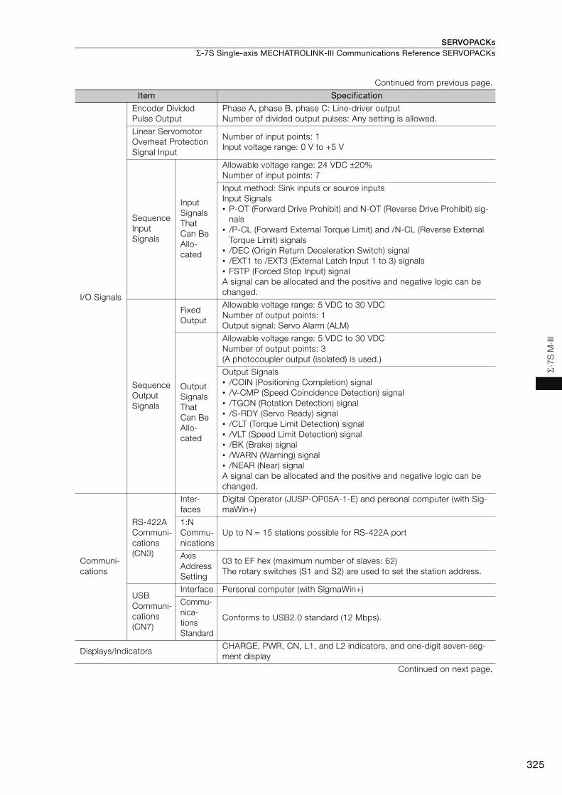
SERVOPACKs Σ-7S Single-axis MECHATROLINK-III Communications Reference SERVOPACKs
325
Σ-7
S M
-III
I/O Signals
Encoder Divided Pulse Output
Phase A, phase B, phase C: Line-driver output Number of divided output pulses: Any setting is allowed.
Linear Servomotor Overheat Protection Signal Input
Number of input points: 1 Input voltage range: 0 V to +5 V
Sequence Input Signals
Input Signals That Can Be Allo-cated
Allowable voltage range: 24 VDC ±20% Number of input points: 7
Input method: Sink inputs or source inputsInput Signals• P-OT (Forward Drive Prohibit) and N-OT (Reverse Drive Prohibit) sig-
nals• /P-CL (Forward External Torque Limit) and /N-CL (Reverse External
Torque Limit) signals• /DEC (Origin Return Deceleration Switch) signal• /EXT1 to /EXT3 (External Latch Input 1 to 3) signals• FSTP (Forced Stop Input) signalA signal can be allocated and the positive and negative logic can be changed.
Sequence Output Signals
Fixed Output
Allowable voltage range: 5 VDC to 30 VDC Number of output points: 1Output signal: Servo Alarm (ALM)
Output Signals That Can Be Allo-cated
Allowable voltage range: 5 VDC to 30 VDCNumber of output points: 3(A photocoupler output (isolated) is used.)
Output Signals• /COIN (Positioning Completion) signal• /V-CMP (Speed Coincidence Detection) signal• /TGON (Rotation Detection) signal• /S-RDY (Servo Ready) signal• /CLT (Torque Limit Detection) signal• /VLT (Speed Limit Detection) signal• /BK (Brake) signal• /WARN (Warning) signal• /NEAR (Near) signalA signal can be allocated and the positive and negative logic can be changed.
Communi-cations
RS-422A Communi-cations (CN3)
Inter-faces
Digital Operator (JUSP-OP05A-1-E) and personal computer (with Sig-maWin+)
1:N Commu-nications
Up to N = 15 stations possible for RS-422A port
Axis Address Setting
03 to EF hex (maximum number of slaves: 62) The rotary switches (S1 and S2) are used to set the station address.
USB Communi-cations (CN7)
Interface Personal computer (with SigmaWin+)
Commu-nica-tions Standard
Conforms to USB2.0 standard (12 Mbps).
Displays/Indicators CHARGE, PWR, CN, L1, and L2 indicators, and one-digit seven-seg-ment display
Continued on next page.
Continued from previous page.
Item Specification

SERVOPACKsΣ-7S Single-axis MECHATROLINK-III Communications Reference SERVOPACKs
326
*1. If you combine a Σ-7-Series SERVOPACK with a Σ-V-Series Option Module, the following Σ-V-Series SERVO-PACKs specifications must be used: a surrounding air temperature of 0°C to 55°C and an altitude of 1,000 m max. Also, the applicable range cannot be increased by derating.
*2. The coefficient of speed fluctuation for load fluctuation is defined as follows:
*3. Always perform risk assessment for the system and confirm that the safety requirements are met.
MECHATROLINK-III Communi-cations
Communications Protocol
MECHATROLINK-III
Station Address Settings
03 to EF hex (maximum number of slaves: 62) The rotary switches (S1 and S2) are used to set the station address.
Baud Rate 100 Mbps
Transmission Cycle 125 μs, 250 μs, 500 μs, 750 μs, 1.0 ms to 4.0 ms (multiples of 0.5 ms)
Number of Transmis-sion Bytes
32 or 48 bytes/stationA DIP switch (S3) is used to select the number of transmission bytes.
Reference Method
PerformancePosition, speed, or torque control with MECHATROLINK-III communi-cations
Reference Input MECHATROLINK-III commands (sequence, motion, data setting, data access, monitoring, adjustment, etc.)
Profile MECHATROLINK-III standard servo profile
MECHATROLINK-III Communica-tions Setting Switches
Rotary switch (S1 and S2) positions: 16
Number of DIP switch (S3) pins: 4
Analog Monitor (CN5)
Number of points: 2Output voltage range: ±10 VDC (effective linearity range: ±8 V)Resolution: 16 bitsAccuracy: ±20 mV (Typ)Maximum output current: ±10 mASettling time (±1%): 1.2 ms (Typ)
Dynamic Brake (DB)Activated when a servo alarm or overtravel (OT) occurs, or when the power supply to the main circuit or servo is OFF.
Regenerative Processing Built-in (An external resistor must be connected to the SGD7S-470A to -780A.)
Built-In Regenerative Resistor (page 456)
Overtravel (OT) Prevention Stopping with dynamic brake, deceleration to a stop, or coasting to a stop for the P-OT (Forward Drive Prohibit) or N-OT (Reverse Drive Pro-hibit) signal
Protective Functions Overcurrent, overvoltage, low voltage, overload, regeneration error, etc.
Utility Functions Gain adjustment, alarm history, jogging, origin search, etc.
Safety Functions
Inputs /HWBB1 and /HWBB2: Base block signals for Power Modules
Output EDM1: Monitors the status of built-in safety circuit (fixed output).
Applicable Standards*3 ISO13849-1 PLe (Category 3), IEC61508 SIL3
Option ModuleFully-Closed Modules and Safety ModulesNote: You cannot use a Fully-Closed Module and a Safety Module
together.
Continued from previous page.
Item Specification
× 100%Coefficient of speed fluctuation =No-load motor speed - Total-load motor speed
Rated motor speed

SERVOPACKs Σ-7S Single-axis MECHATROLINK-III Communications Reference SERVOPACKs
327
Σ-7
S M
-III
Derating SpecificationsIf you use the SERVOPACK at a surrounding air temperature of 55°C to 60°C or at an altitude of 1,000 m to 2,000 m, you must apply the derating rates given in the following graphs.
SGD7S-R70A, -R90A, -1R6A, -2R8A, -R70F, -R90F, -2R1F, and -2R8F
SGD7S-3R8A, -5R5A, -7R6A, -120A, -180A, -200A, -330A, -470A, -550A, -590A, and -780A
100%
80%
2000 m
100%
1000 m
80%
0% 0%
0 m2000 m1000 m0 m
100%
0%
64%
-5°C 55°C 60°C -5°C 55°C 60°C
Effective
to
rque
Effective
to
rque
Surrounding air temperature Altitude
Effective
to
rque
Surrounding air temperature and altitude
80%
2000 m1000 m0 m2000 m1000 m0 m
-5°C 55°C 60°C -5°C 55°C 60°C
100% 100% 100%
0% 0% 0%
Effective
to
rque
Effective
to
rque
Surrounding air temperature Altitude
Effective
to
rque
Surrounding air temperature and altitude

SERVOPACKsΣ-7S Single-axis MECHATROLINK-III Communications Reference SERVOPACKs
328
Selecting Cables
System Configurations
Selection Table
Note: Refer to the following manual for the following information.• Cable dimensional drawings and cable connection specifications• Order numbers and specifications of individual connectors for cables
Σ-7-Series AC Servo Drive Peripheral Device Selection Manual (Manual No.: SIEP S800001 32)
1. Use the cable specified by Yaskawa for the Computer Cable. Operation may not be depend-able with any other cable.
2. Use the cable specified by Yaskawa for the MECHATROLINK Communications Cables. Opera-tion may not be dependable due to low noise resistance with any other cable.
Code NameLength
(L)Order Number Appearance
Analog Monitor Cable 1 m JZSP-CA01-E
Digital Operator Converter Cable
0.3 m
JZSP-CVS05-A3-E*1
JZSP-CVS07-A3-E*2
Computer Cable 2.5 m JZSP-CVS06-02-E
Continued on next page.
Digital Operator
Converter Cable
Safety Function Device Cable
Analog Monitor Cable
I/O Signal Cable
To next MECHATROLINK-III station
MECHATROLINK-III Communications Cable
To external devices,
such as LED indicators
CN1
CN5
CN6
CN3
CN7
CN8
Digital Operator
Computer CableJZSP-CVS06-02-E
Important
L
L
L
L

SERVOPACKs Σ-7S Single-axis MECHATROLINK-III Communications Reference SERVOPACKs
329
Σ-7
S M
-III
*1. This Converter Cable is required to use the Σ-III-series Digital Operator (JUSP-OP05A) for Σ-7-series SERVO-PACKs.
*2. If you use a MECHATROLINK-III Communications Reference SERVOPACK, this Converter Cable is required to prevent the cable from disconnecting from the Digital Operator.
*3. When using safety functions, connect this Cable to the safety function devices.When not using safety functions, connect the enclosed Safety Jumper Connector (JZSP-CVH05-E) to the SER-VOPACK.
*4. Use the Connector Kit when you make cables yourself.
I/O Signal Cables
Soldered Connector Kit JZSP-CSI9-2-E
Connector-Terminal Block Con-verter Unit(with cable)
0.5 m JUSP-TA26P-E
1 m JUSP-TA26P-1-E
2 m JUSP-TA26P-2-E
Cable with Loose Wires at One End (loose wires on peripheral device end)
1 m JZSP-CSI02-1-E
2 m JZSP-CSI02-2-E
3 m JZSP-CSI02-3-E
MECHATROLINK-III Communi-cations Cables
Cables with Connectors on Both Ends
0.2 m JEPMC-W6012-A2-E0.5 m JEPMC-W6012-A5-E1 m JEPMC-W6012-01-E2 m JEPMC-W6012-02-E3 m JEPMC-W6012-03-E4 m JEPMC-W6012-04-E5 m JEPMC-W6012-05-E
10 m JEPMC-W6012-10-E20 m JEPMC-W6012-20-E30 m JEPMC-W6012-30-E50 m JEPMC-W6012-50-E
Cables with Connectors on Both Ends(with core)
10 m JEPMC-W6013-10-E20 m JEPMC-W6013-20-E30 m JEPMC-W6013-30-E50 m JEPMC-W6013-50-E
Cable with Loose Wires at One End
0.5 m JEPMC-W6014-A5-E1 m JEPMC-W6014-01-E3 m JEPMC-W6014-03-E5 m JEPMC-W6014-05-E
10 m JEPMC-W6014-10-E30 m JEPMC-W6014-30-E50 m JEPMC-W6014-50-E
Safety Function Device Cables
Cables with Connectors*3
1 m JZSP-CVH03-01-E
3 m JZSP-CVH03-03-E
Connector Kit*4
Contact Tyco Electronics Japan G.K.Product name: Industrial Mini I/O D-shape Type 1 Plug Con-nector KitModel number: 2013595-1
Continued from previous page.
Code NameLength
(L)Order Number Appearance
40
391
2
B20A20
B1A1
L
L
L
L
L
L
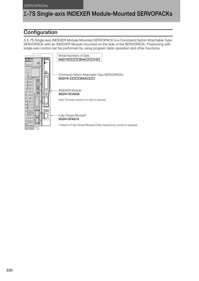
SERVOPACKs
330
Σ-7S Single-axis INDEXER Module-Mounted SERVOPACKs
ConfigurationA Σ-7S Single-axis INDEXER Module-Mounted SERVOPACK is a Command Option Attachable-Type SERVOPACK with an INDEXER Module mounted on the side of the SERVOPACK. Positioning with single-axis control can be performed by using program table operation and other functions.
Model Numbers of Sets
SGD7S����E0A���10�
Command Option Attachable-Type SERVOPACKs
SGD7S-����E0A���
INDEXER Module
SGDV-OCA03A
Fully-Closed Module*SGDV-OFA01A
Note: Firmware version 6 or later is required.
* Attach a Fully-Closed Module if fully-closed loop control is required.

SERVOPACKs
Σ-7S Single-axis INDEXER Module-Mounted SERVOPACKs
331
Σ-7
S IN
DE
XE
R
Purchase Order Number
Purchasing a Module in a Set with the SERVOPACKTo order SERVOPACKs with a INDEXER Module attached, use the following model numbers.
*1. The model number of a SERVOPACK with an Option Module is not hyphenated after SGD7S.
*2. You can use these models with either a single-phase or three-phase power supply input.
*3. A model with a single-phase, 200-VAC power supply input is available as a hardware option (model: SGD7S-120AE0A008).
*4. The rated output is 2.4 kW if you combine the SGM7G-30A with the SGD7S-200A.
*5. Refer to the following manual for details. Σ-7-Series AC Servo Drive Σ-7S/Σ-7W SERVOPACK with Hardware Option Specifications Dynamic Brake Prod-
uct Manual (Manual No.: SIEP S800001 73)
Note: Contact your Yaskawa representative for information on combining options.
*1 R70 A E0 A 000 100
R70*2
R90*2
1R6*2
2R8*2
3R8
5R5*2
7R6
120*3
180
200*4
330
470
550
590
780
R70
R90
2R1
2R8
SGD7S
0.05 kW
0.1 kW
0.2 kW
0.4 kW
0.5 kW
0.75 kW
1.0 kW
1.5 kW
2.0 kW
3.0 kW
5.0 kW
6.0 kW
7.5 kW
11 kW
15 kW
0.05 kW
0.1 kW
0.2 kW
0.4 kW 100 INDEXER Module
101INDEXER Module + Fully-Closed Module
Three-
phase,
200
VAC
A 200 VAC
F 100 VAC
Voltage
Code Specification
Interface5th+6th digits
Voltage Code Specification
4th digit
Single-
phase,
100 VAC
E0 Command Option Attachable Type
Σ-7 Series
Σ-7S SERVOPACKs
4th digit
1st+2nd+3rd digits
5th+6th digits
8th+9th+10th digits
7th digit
11th+12th+13th digits
Maximum Applicable
Motor Capacity1st+2nd+3rd digits
A
Design Revision Order7th digit
Hardware Options
Specification8th+9th+10th digits
Option Module11th+12th+13th digits
Code Specification
Code Specification
None Without options All models
All models
SGD7S-R70A to -330A
SGD7S-R70Fto -2R8F
SGD7S-470A to -780A
SGD7S-R70A to -2R8A
SGD7S-R70F to -2R8F
SGD7S-3R8A to -780A
SGD7S-120A
001
002
008
020*5
Duct-ventilated
Varnished
Single-phase, 200-VAC power supply input
No dynamic brake
External dynamic brake resistor
Code SpecificationApplicable
Models
Rack-mounted

SERVOPACKs
Σ-7S Single-axis INDEXER Module-Mounted SERVOPACKs
332
Purchasing a Module SeparatelyWhen ordering SERVOPACKs and Option Modules separately, use the following model numbers.
SERVOPACK
*1. You can use these models with either a single-phase or three-phase power supply input.*2. A model with a single-phase, 200-VAC power supply input is available as a hardware option (model: SGD7S-
120AE0A008).*3. The rated output is 2.4 kW if you combine the SGM7G-30A with the SGD7S-200A.*4. The same SERVOPACKs are used for both Rotary Servomotors and Linear Servomotors.*5. Refer to the following manual for details.
Σ-7-Series AC Servo Drive S-7S/S-7W SERVOPACK with Hardware Option Specifications Dynamic Brake Prod-uct Manual (Manual No.: SIEP S800001 73)
*6. The BTO specification indicates if the SERVOPACK is customized by using the MechatroCloud BTO service.You need a BTO number to order SERVOPACKs with customized specifications.Refer to page M-15 for the details on the BTO service.
INDEXER Module
Fully-Closed Module
One Option Case Kit is required for each SERVOPACK.Option Case Kit model: SGDV-OZA01A
A 200 VAC
F 100 VAC
SGD7S - R70 A E0 A 001
A
R70*1
R90*1
1R6*1
2R8*1
3R8
5R5*1
7R6
120*2
180
200*3
330
470
550
590
780
R70
R90
2R1
2R8
0.05 kW
0.1 kW
0.2 kW
0.4 kW
0.5 kW
0.75 kW
1.0 kW
1.5 kW
2.0 kW
3.0 kW
5.0 kW
6.0 kW
7.5 kW
11 kW
15 kW
0.05 kW
0.1 kW
0.2 kW
0.4 kW
E0
Maximum Applicable
Motor CapacityVoltage
Interface*4
Code
Code
Specification
Specification
Command Option
Attachable Type
Design Revision Order
Hardware Options
Specification
Voltage Code Specification
Three-
phase,
200
VAC
1st+2nd+3rd digits 4th digit
5th+6th digits
7th digit
8th+9th+10th digits
Σ-7 Series
Σ-7S SERVOPACKs
4th digit
1st+2nd+3rd digits
5th+6th digits
8th+9th+10th digits
7th digit
00011th+12th+13th
digits
B14thdigit
FT/EX Specification11th+12th+13th digits
None
Code Specification
None000
BTO Specification*614th digit
None
Code Specification
None
B BTO Specification
Single-
phase,
100 VAC
NoneWithout options All models
All models
SGD7S-R70A to -330A
SGD7S-R70Fto -2R8F
SGD7S-470A to -780A
SGD7S-R70A to -2R8A
SGD7S-R70F to -2R8F
SGD7S-3R8A to -780A
SGD7S-120A
001
002
008
020*5
Duct-ventilated
Varnished
Single-phase, 200-VAC power supply input
No dynamic brake
External dynamic brake resistor
Code SpecificationApplicable
Models
000
Rack-mounted
Important
SGDV-OCA03A
SGDV-OFA01A

SERVOPACKs
Σ-7S Single-axis INDEXER Module-Mounted SERVOPACKs
333
Σ-7S
IND
EXE
R
Ratings and Specifications
SERVOPACK Ratings
Three-Phase, 200 VAC
* This is the net value at the rated load.
*1. This is the net value at the rated load.*2. This value is for the optional JUSP-RA04-E Regenerative Resistor Unit.*3. This value is for the optional JUSP-RA05-E Regenerative Resistor Unit.
Model SGD7S- R70A R90A 1R6A 2R8A 3R8A 5R5A 7R6A 120A 180A 200A 330A
Maximum Applicable Motor Capacity [kW] 0.05 0.1 0.2 0.4 0.5 0.75 1.0 1.5 2.0 3.0 5.0
Continuous Output Current [Arms] 0.66 0.91 1.6 2.8 3.8 5.5 7.6 11.6 18.5 19.6 32.9
Instantaneous Maximum Output Current [Arms] 2.1 3.2 5.9 9.3 11 16.9 17 28 42 56 84.0
Main Circuit
Power Supply 200 VAC to 240 VAC, -15% to +10%, 50 Hz/60 Hz
Input Current [Arms]* 0.4 0.8 1.3 2.5 3.0 4.1 5.7 7.3 10 15 25
ControlPower Supply 200 VAC to 240 VAC, -15% to +10%, 50 Hz/60 Hz
Input Current [Arms]* 0.2 0.2 0.2 0.2 0.2 0.2 0.2 0.2 0.25 0.25 0.3Power Supply Capacity [kVA]* 0.2 0.3 0.5 1.0 1.3 1.6 2.3 3.2 4.0 5.9 7.5
Power Loss*
Main Circuit Power Loss [W] 5.0 7.0 11.9 22.5 28.5 38.9 49.2 72.6 104.2 114.2 226.6
Control Circuit Power Loss [W] 12 12 12 12 14 14 14 15 16 16 19
Built-in Regenerative Resistor Power Loss [W]
− − − − 8 8 8 10 16 16 36
Total Power Loss [W] 17.0 19.0 23.9 34.5 50.5 60.9 71.2 97.6 136.2 146.2 281.6
Regenerative Resistor
Built-In Regenerative Resistor
Resistance [Ω]
− − − − 40 40 40 20 12 12 8
Capacity [W] − − − − 40 40 40 60 60 60 180
Minimum Allowable External Resistance [Ω]
40 40 40 40 40 40 40 20 12 12 8
Overvoltage Category III
Model SGD7S- 470A 550A 590A 780A
Maximum Applicable Motor Capacity [kW] 6.0 7.5 11 15
Continuous Output Current [Arms] 46.9 54.7 58.6 78.0
Instantaneous Maximum Output Current [Arms] 110 130 140 170
Main CircuitPower Supply 200 VAC to 240 VAC, -15% to +10%, 50 Hz/60 Hz
Input Current [Arms]*1 29 37 54 73
ControlPower Supply 200 VAC to 240 VAC, -15% to +10%, 50 Hz/60 Hz
Input Current [Arms]*1 0.3 0.3 0.4 0.4
Power Supply Capacity [kVA]*1 10.7 14.6 21.7 29.6
Power Loss*1
Main Circuit Power Loss [W] 271.7 326.9 365.3 501.4
Control Circuit Power Loss [W] 21 21 28 28
External Regenerative Resistor Power Loss [W] 180*2 350*3 350*3 350*3
Total Power Loss [W] 292.7 347.9 393.3 529.4
Regenerative Resistor
External Regenerative Resistor
Resistance [Ω] 6.25*2 3.13*3 3.13*3 3.13*3
Capacity [W] 880*2 1760*3 1760*3 1760*3
Minimum Allowable External Resistance [Ω] 5.8 2.9 2.9 2.9
Overvoltage Category III
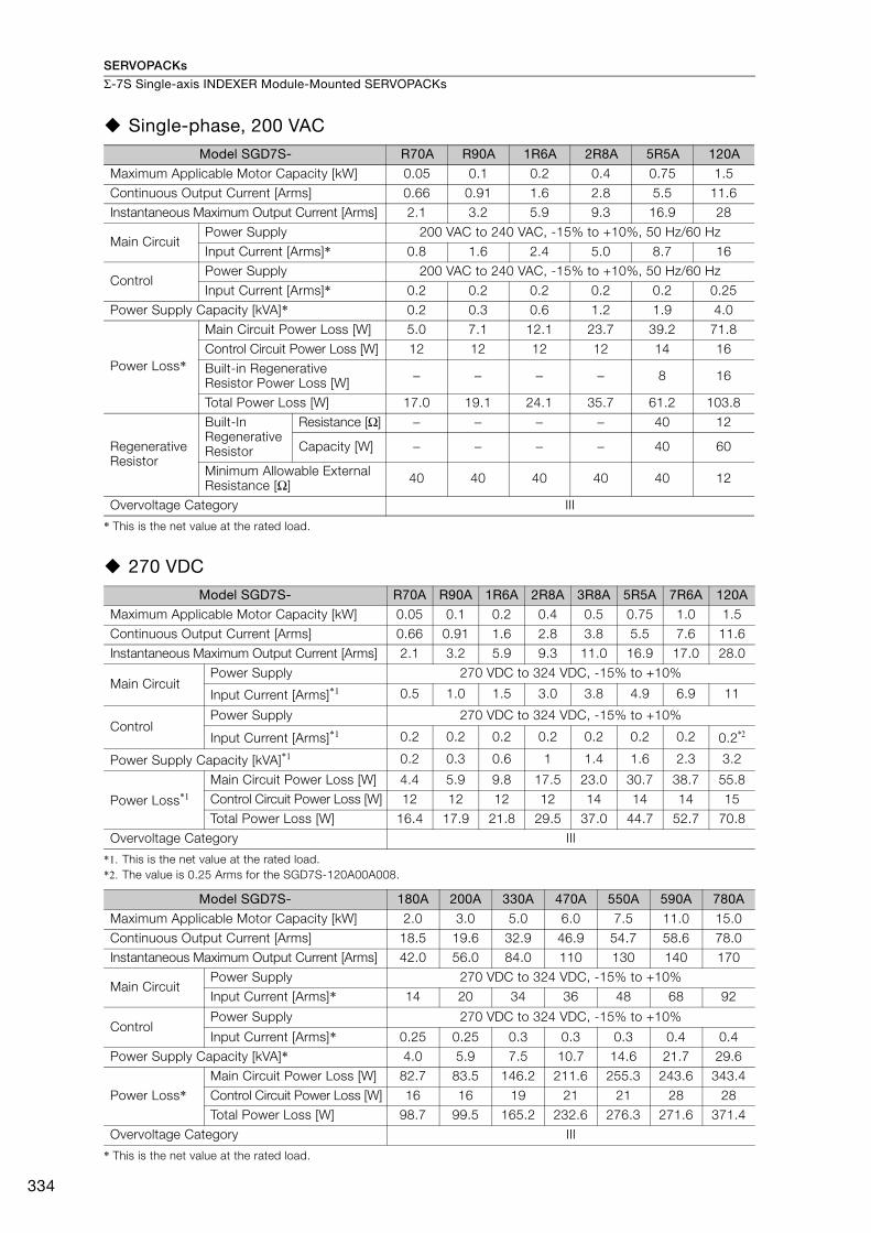
SERVOPACKs
Σ-7S Single-axis INDEXER Module-Mounted SERVOPACKs
334
Single-phase, 200 VAC
* This is the net value at the rated load.
270 VDC
*1. This is the net value at the rated load.*2. The value is 0.25 Arms for the SGD7S-120A00A008.
* This is the net value at the rated load.
Model SGD7S- R70A R90A 1R6A 2R8A 5R5A 120A
Maximum Applicable Motor Capacity [kW] 0.05 0.1 0.2 0.4 0.75 1.5
Continuous Output Current [Arms] 0.66 0.91 1.6 2.8 5.5 11.6Instantaneous Maximum Output Current [Arms] 2.1 3.2 5.9 9.3 16.9 28
Main CircuitPower Supply 200 VAC to 240 VAC, -15% to +10%, 50 Hz/60 Hz
Input Current [Arms]* 0.8 1.6 2.4 5.0 8.7 16
ControlPower Supply 200 VAC to 240 VAC, -15% to +10%, 50 Hz/60 Hz
Input Current [Arms]* 0.2 0.2 0.2 0.2 0.2 0.25
Power Supply Capacity [kVA]* 0.2 0.3 0.6 1.2 1.9 4.0
Power Loss*
Main Circuit Power Loss [W] 5.0 7.1 12.1 23.7 39.2 71.8
Control Circuit Power Loss [W] 12 12 12 12 14 16
Built-in Regenerative Resistor Power Loss [W] − − − − 8 16
Total Power Loss [W] 17.0 19.1 24.1 35.7 61.2 103.8
Regenerative Resistor
Built-In Regenerative Resistor
Resistance [Ω] − − − − 40 12
Capacity [W] − − − − 40 60
Minimum Allowable External Resistance [Ω] 40 40 40 40 40 12
Overvoltage Category III
Model SGD7S- R70A R90A 1R6A 2R8A 3R8A 5R5A 7R6A 120A
Maximum Applicable Motor Capacity [kW] 0.05 0.1 0.2 0.4 0.5 0.75 1.0 1.5
Continuous Output Current [Arms] 0.66 0.91 1.6 2.8 3.8 5.5 7.6 11.6
Instantaneous Maximum Output Current [Arms] 2.1 3.2 5.9 9.3 11.0 16.9 17.0 28.0
Main CircuitPower Supply 270 VDC to 324 VDC, -15% to +10%
Input Current [Arms]*1 0.5 1.0 1.5 3.0 3.8 4.9 6.9 11
ControlPower Supply 270 VDC to 324 VDC, -15% to +10%
Input Current [Arms]*1 0.2 0.2 0.2 0.2 0.2 0.2 0.2 0.2*2
Power Supply Capacity [kVA]*1 0.2 0.3 0.6 1 1.4 1.6 2.3 3.2
Power Loss*1
Main Circuit Power Loss [W] 4.4 5.9 9.8 17.5 23.0 30.7 38.7 55.8Control Circuit Power Loss [W] 12 12 12 12 14 14 14 15
Total Power Loss [W] 16.4 17.9 21.8 29.5 37.0 44.7 52.7 70.8
Overvoltage Category III
Model SGD7S- 180A 200A 330A 470A 550A 590A 780A
Maximum Applicable Motor Capacity [kW] 2.0 3.0 5.0 6.0 7.5 11.0 15.0
Continuous Output Current [Arms] 18.5 19.6 32.9 46.9 54.7 58.6 78.0 Instantaneous Maximum Output Current [Arms] 42.0 56.0 84.0 110 130 140 170
Main CircuitPower Supply 270 VDC to 324 VDC, -15% to +10%
Input Current [Arms]* 14 20 34 36 48 68 92
ControlPower Supply 270 VDC to 324 VDC, -15% to +10%
Input Current [Arms]* 0.25 0.25 0.3 0.3 0.3 0.4 0.4Power Supply Capacity [kVA]* 4.0 5.9 7.5 10.7 14.6 21.7 29.6
Power Loss*Main Circuit Power Loss [W] 82.7 83.5 146.2 211.6 255.3 243.6 343.4
Control Circuit Power Loss [W] 16 16 19 21 21 28 28Total Power Loss [W] 98.7 99.5 165.2 232.6 276.3 271.6 371.4
Overvoltage Category III
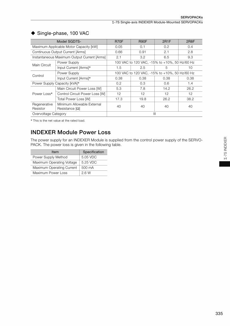
SERVOPACKs
Σ-7S Single-axis INDEXER Module-Mounted SERVOPACKs
335
Σ-7S
IND
EXE
R
Single-phase, 100 VAC
* This is the net value at the rated load.
INDEXER Module Power LossThe power supply for an INDEXER Module is supplied from the control power supply of the SERVO-PACK. The power loss is given in the following table.
Model SGD7S- R70F R90F 2R1F 2R8F
Maximum Applicable Motor Capacity [kW] 0.05 0.1 0.2 0.4
Continuous Output Current [Arms] 0.66 0.91 2.1 2.8
Instantaneous Maximum Output Current [Arms] 2.1 3.2 6.5 9.3
Main CircuitPower Supply 100 VAC to 120 VAC, -15% to +10%, 50 Hz/60 Hz
Input Current [Arms]* 1.5 2.5 5 10
ControlPower Supply 100 VAC to 120 VAC, -15% to +10%, 50 Hz/60 Hz
Input Current [Arms]* 0.38 0.38 0.38 0.38Power Supply Capacity [kVA]* 0.2 0.3 0.6 1.4
Power Loss*Main Circuit Power Loss [W] 5.3 7.8 14.2 26.2
Control Circuit Power Loss [W] 12 12 12 12
Total Power Loss [W] 17.3 19.8 26.2 38.2
Regenerative Resistor
Minimum Allowable External Resistance [Ω]
40 40 40 40
Overvoltage Category III
Item Specification
Power Supply Method 5.05 VDC
Maximum Operating Voltage 5.25 VDC
Maximum Operating Current 500 mA
Maximum Power Loss 2.6 W

SERVOPACKs
Σ-7S Single-axis INDEXER Module-Mounted SERVOPACKs
336
SERVOPACK Overload Protection CharacteristicsThe overload detection level is set for hot start conditions with a SERVOPACK surrounding air tem-perature of 55°C.
An overload alarm (A.710 or A.720) will occur if overload operation that exceeds the overload pro-tection characteristics shown in the following diagram (i.e., operation on the right side of the appli-cable line) is performed.
The actual overload detection level will be the detection level of the connected SERVOPACK or Ser-vomotor that has the lower overload protection characteristics.
In most cases, that will be the overload protection characteristics of the Servomotor.
Note: The above overload protection characteristics do not mean that you can perform continuous duty operation with an output of 100% or higher.For a Yaskawa-specified combination of SERVOPACK and Servomotor, maintain the effective torque (or effective force) within the continuous duty zone of the torque-motor speed characteristic (or force-motor speed characteristics) of the Servomotor.
SERVOPACK output current (continuous output current ratio) (%)
Continuous output current× 100%
SERVOPACK Model: SGD7S-R70A, -R90A, -1R6A, -2R8A, -R70F, -R90F, -2R1F, and -2R8F
SERVOPACK Model: SGD7S-3R8A, -5R5A, -7R6A, -120A, -180A, -200A, -330A,
-470A, -550A, -590A, and -780A
Instantaneous maximum output current
(Instantaneous maximum output current)
(Continuous output current)
SERVOPACK output current (continuous output current ratio) (%)
Continuous output current× 100%
Instantaneous maximum output current
(Instantaneous maximum output current)
(Continuous output current)
100 230
10000
1000
100
10
1100 200
10000
1000
100
10
1
Det
ectio
n tim
e (s
)
Det
ectio
n tim
e (s
)

SERVOPACKs
Σ-7S Single-axis INDEXER Module-Mounted SERVOPACKs
337
Σ-7S
IND
EXE
R
SpecificationsThe specifications when the INDEXER Module is combined with a Command Option Attachable-Type SERVOPACK are given in the following table.
Item SpecificationControl Method IGBT-based PWM control, sine wave current drive
Feedback
With Rotary Servomotor
Serial encoder: 17 bits (absolute encoder)20 bits or 24 bits (incremental encoder/absolute encoder)22 bits (absolute encoder)
With Linear Servomotor
• Absolute linear encoder (The signal resolution depends on the abso-lute linear encoder.)
• Incremental linear encoder (The signal resolution depends on the incremental linear encoder or Serial Converter Unit.)
Environ-mental Conditions
Surrounding Air Temperature 0°C to 55°CStorage Temperature -20°C to 85°CSurrounding Air Humidity 90% relative humidity max. (with no freezing or condensation)Storage Humidity 90% relative humidity max. (with no freezing or condensation)
Vibration Resistance 4.9 m/s2
Shock Resistance 19.6 m/s2
Degree of Protection
Pollution Degree
2• Must be no corrosive or flammable gases.• Must be no exposure to water, oil, or chemicals.• Must be no dust, salts, or iron dust.
Altitude 1,000 m max.
Others Do not use the SERVOPACK in the following locations: Locations subject to static electricity noise, strong electromagnetic/magnetic fields, or radioactivity
Applicable Standards
UL 61800-5-1 (E165827), CSA C22.2 No.274, EN 50178, EN 61800-5-1, EN 55011 group 1 class A, EN 61000-6-2, EN 61000-6-4, EN 61800-3, IEC 61508-1, IEC 61508-2, IEC 61508-4, IEC 61800-5-2, IEC 62061, ISO 13849-1, and IEC 61326-3-1
Mounting
Perfor-mance
Speed Control Range
1:5000 (At the rated torque, the lower limit of the speed control range must not cause the Servomotor to stop.)
Coefficient of Speed Fluctuation*1
±0.01% of rated speed max. (for a load fluctuation of 0% to 100%)0% of rated speed max. (for a voltage fluctuation of ±10%)±0.1% of rated speed max. (for a temperature fluctuation of 25°C ±25°C)
Torque Control Pre-cision (Repeatability) ±1%
Soft Start Time Setting 0 s to 10 s (Can be set separately for acceleration and deceleration.)
I/O Signals
Encoder Divided Pulse Output
Phase A, phase B, phase C: Line-driver output Number of divided output pulses: Any setting is allowed.
Linear Servomotor Overheat Protec-tion Signal Input
Number of input points: 1Input voltage range: 0 V to +5 V
Continued on next page.
Class SERVOPACK Model: SGD7S-
IP20R70A, R90A, 1R6A, 2R8A, 3R8A, 5R5A, 7R6A, 120A, R70F, R90F, 2R1F, 2R8F
IP10120AE0A008, 180A, 200A, 330A, 470A, 550A, 590A, 780A
Mounting SERVOPACK Model: SGD7S-
Base-mounted All Models
Rack-mountedR70A, R90A, 1R6A, 2R8A, 3R8A, 5R5A, 7R6A, 120A, 180A, 200A, 330A, R70F, R90F, 2R1F, 2R8F
Duct-ventilated 470A, 550A, 590A, 780A
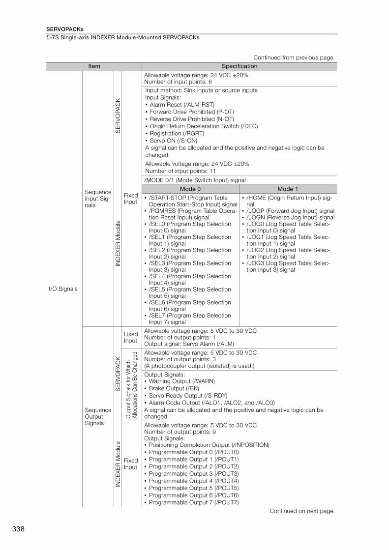
SERVOPACKs
Σ-7S Single-axis INDEXER Module-Mounted SERVOPACKs
338
I/O Signals
Sequence Input Sig-nals
SE
RV
OPA
CK
Fixed Input
Allowable voltage range: 24 VDC ±20%Number of input points: 6Input method: Sink inputs or source inputsInput Signals:• Alarm Reset (/ALM-RST)• Forward Drive Prohibited (P-OT)• Reverse Drive Prohibited (N-OT)• Origin Return Deceleration Switch (/DEC)• Registration (/RGRT)• Servo ON (/S-ON)A signal can be allocated and the positive and negative logic can be changed.
IND
EX
ER
Mod
ule
Allowable voltage range: 24 VDC ±20%Number of input points: 11
/MODE 0/1 (Mode Switch Input) signal
Mode 0 Mode 1
• /START-STOP (Program Table Operation Start-Stop Input) signal
• /PGMRES (Program Table Opera-tion Reset Input) signal
• /SEL0 (Program Step Selection Input 0) signal
• /SEL1 (Program Step Selection Input 1) signal
• /SEL2 (Program Step Selection Input 2) signal
• /SEL3 (Program Step Selection Input 3) signal
• /SEL4 (Program Step Selection Input 4) signal
• /SEL5 (Program Step Selection Input 5) signal
• /SEL6 (Program Step Selection Input 6) signal
• /SEL7 (Program Step Selection Input 7) signal
• /HOME (Origin Return Input) sig-nal
• /JOGP (Forward Jog Input) signal• /JOGN (Reverse Jog Input) signal• /JOG0 (Jog Speed Table Selec-
tion Input 0) signal• /JOG1 (Jog Speed Table Selec-
tion Input 1) signal• /JOG2 (Jog Speed Table Selec-
tion Input 2) signal• /JOG3 (Jog Speed Table Selec-
tion Input 3) signal
Sequence Output Signals
SE
RV
OPA
CK
Fixed Input
Allowable voltage range: 5 VDC to 30 VDCNumber of output points: 1Output signal: Servo Alarm (/ALM)
Out
put S
igna
ls fo
r Whi
ch
Allo
catio
ns C
an B
e C
hang
ed Allowable voltage range: 5 VDC to 30 VDCNumber of output points: 3(A photocoupler output (isolated) is used.)
Output Signals:• Warning Output (/WARN)• Brake Output (/BK)• Servo Ready Output (/S-RDY)• Alarm Code Output (/ALO1, /ALO2, and /ALO3)A signal can be allocated and the positive and negative logic can be changed.
IND
EX
ER
Mod
ule
Fixed Input
Allowable voltage range: 5 VDC to 30 VDCNumber of output points: 9Output Signals:• Positioning Completion Output (/INPOSITION)• Programmable Output 0 (/POUT0)• Programmable Output 1 (/POUT1)• Programmable Output 2 (/POUT2)• Programmable Output 3 (/POUT3)• Programmable Output 4 (/POUT4)• Programmable Output 5 (/POUT5)• Programmable Output 6 (/POUT6)• Programmable Output 7 (/POUT7)
Continued on next page.
Continued from previous page.Item Specification
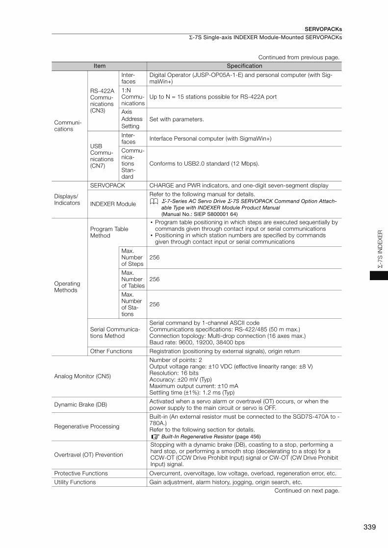
SERVOPACKs
Σ-7S Single-axis INDEXER Module-Mounted SERVOPACKs
339
Σ-7S
IND
EXE
R
Communi-cations
RS-422A Commu-nications (CN3)
Inter-faces
Digital Operator (JUSP-OP05A-1-E) and personal computer (with Sig-maWin+)
1:NCommu-nications
Up to N = 15 stations possible for RS-422A port
AxisAddressSetting
Set with parameters.
USB Commu-nications (CN7)
Inter-faces Interface Personal computer (with SigmaWin+)
Commu-nica-tions Stan-dard
Conforms to USB2.0 standard (12 Mbps).
Displays/Indicators
SERVOPACK CHARGE and PWR indicators, and one-digit seven-segment display
INDEXER Module
Refer to the following manual for details.Σ-7-Series AC Servo Drive Σ-7S SERVOPACK Command Option Attach-able Type with INDEXER Module Product Manual (Manual No.: SIEP S800001 64)
OperatingMethods
Program Table Method
• Program table positioning in which steps are executed sequentially by commands given through contact input or serial communications
• Positioning in which station numbers are specified by commands given through contact input or serial communications
Max. Number of Steps
256
Max. Number of Tables
256
Max. Number of Sta-tions
256
Serial Communica-tions Method
Serial command by 1-channel ASCII codeCommunications specifications: RS-422/485 (50 m max.)Connection topology: Multi-drop connection (16 axes max.)Baud rate: 9600, 19200, 38400 bps
Other Functions Registration (positioning by external signals), origin return
Analog Monitor (CN5)
Number of points: 2Output voltage range: ±10 VDC (effective linearity range: ±8 V)Resolution: 16 bitsAccuracy: ±20 mV (Typ)Maximum output current: ±10 mASettling time (±1%): 1.2 ms (Typ)
Dynamic Brake (DB) Activated when a servo alarm or overtravel (OT) occurs, or when the power supply to the main circuit or servo is OFF.
Regenerative Processing
Built-in (An external resistor must be connected to the SGD7S-470A to -780A.)Refer to the following section for details.
Built-In Regenerative Resistor (page 456)
Overtravel (OT) Prevention
Stopping with a dynamic brake (DB), coasting to a stop, performing a hard stop, or performing a smooth stop (decelerating to a stop) for a CCW-OT (CCW Drive Prohibit Input) signal or CW-OT (CW Drive Prohibit Input) signal.
Protective Functions Overcurrent, overvoltage, low voltage, overload, regeneration error, etc.
Utility Functions Gain adjustment, alarm history, jogging, origin search, etc.Continued on next page.
Continued from previous page.Item Specification

SERVOPACKs
Σ-7S Single-axis INDEXER Module-Mounted SERVOPACKs
340
*1. The coefficient of speed fluctuation for load fluctuation is defined as follows:
*2. Always perform risk assessment for the system and confirm that the safety requirements are met.
Reference MethodsThe INDEXER Module has two reference methods: digital I/O and serial commands. These command methods are described in the following sections.Digital I/O is used with a program table (mode 0) or a jog speed table (mode 1). You can use a program table (mode 0) to execute the program steps that you select with I/O signal patterns (binary format). If the jog speed table (mode 1) is being used, the jog speed selected with the input signal pattern (binary format) can be executed.
• Program Table
Safety Functions
Inputs /HWBB1 and /HWBB2: Base block signals for Power Modules
Output EDM1: Monitors the status of built-in safety circuit (fixed output).
Applicable Standards*2 ISO13849-1 PLe (Category 3), IEC61508 SIL3
Applicable Option Modules Fully-Closed ModuleNote: You cannot use a Safety Module if you are using an INDEXER Module.
PGMSTEP POS SPD RDST RSPD ACC* DEC* EVENT LOOP NEXT
0 I+400000 2000 500000 1000 200 100 T5000 1 1
1 I+100000 1000 200000 2000 100 50 IT0 1 END
...
...
...
...
...
...
...
...
...
...
n I+400000 2000 500000 1000 100 50 IT100 1 n+1
n+1 I+100000 1000 200000 2000 ...
... NT0 1 END
...
...
...
...
...
...
...
...
...
...
254 I+400000 2000 500000 1000 100 50 SEL3T200 1 127
255 I+100000 1000 200000 2000 100 50 DT0 1 END
Continued from previous page.Item Specification
× 100%Coefficient of speed fluctuation = No-load motor speed - Total-load motor speedRated motor speed
256 steps
Start signal
Positioning Completion signal
T=100 ms
Time
Speed
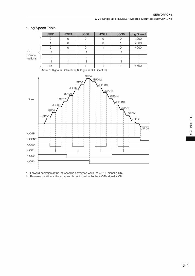
SERVOPACKs
Σ-7S Single-axis INDEXER Module-Mounted SERVOPACKs
341
Σ-7S
IND
EXE
R
• Jog Speed Table
*1. Forward operation at the jog speed is performed while the /JOGP signal is ON.*2. Reverse operation at the jog speed is performed while the /JOGN signal is ON.
JSPD JOG3 JOG2 JOG1 JOG0 Jog Speed
0 0 0 0 0 1000
1 0 0 0 1 2000
2 0 0 1 0 4000..
.
...
...
...
...
...
...
...
...
...
...
...
...
...
...
...
...
...
15 1 1 1 1 5500Note: 1: Signal is ON (active), 0: Signal is OFF (inactive).
16 combi-nations
/JOGP*1
/JOGN*2
/JOG0
/JOG1
/JOG2
/JOG3
JSPD0
JSPD1
JSPD3
JSPD2
JSPD6
JSPD7
JSPD5
JSPD4JSPD12
JSPD13
JSPD15
JSPD14
JSPD10
JSPD11
JSPD9
JSPD8
JSPD8
Speed

SERVOPACKs
Σ-7S Single-axis INDEXER Module-Mounted SERVOPACKs
342
With serial commands, ASCII command strings are sent to the INDEXER Module through RS-422 or RS-485 communications and these commands are interpreted and executed immedi-ately. You can use general-purpose serial communications (RS422/RS485) to perform indepen-dent control of up to 16 axes from one host controller (e.g., PC or HMI).
Computer
RS-422/RS-485, 16 axes max.
Positioning speed (SPD)
Path when an S-curve filter is set
Acceleration rate (ACC) Deceleration rate (DEC)
Target position (POS)
Speed
Time
1SVON # Servo turned ON.
1POSI=400000 # Set relative position to 400,000.
1SPD=2000 # Set speed to 2,000.
1ACC=200 # Set acceleration rate to 200.
1DEC=100 # Set deceleration rate to 100.
1ST # Start operation.
:
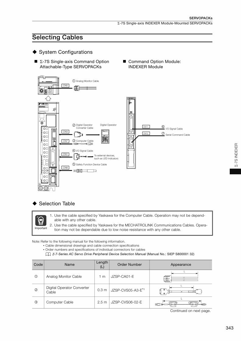
SERVOPACKs
Σ-7S Single-axis INDEXER Module-Mounted SERVOPACKs
343
Σ-7S
IND
EXE
R
Selecting Cables
System Configurations
Selection Table
Note: Refer to the following manual for the following information.• Cable dimensional drawings and cable connection specifications• Order numbers and specifications of individual connectors for cables
Σ-7-Series AC Servo Drive Peripheral Device Selection Manual (Manual No.: SIEP S800001 32)
Σ-7S Single-axis Command Option Attachable-Type SERVOPACKs
Command Option Module:INDEXER Module
1. Use the cable specified by Yaskawa for the Computer Cable. Operation may not be depend-able with any other cable.
2. Use the cable specified by Yaskawa for the MECHATROLINK Communications Cables. Opera-tion may not be dependable due to low noise resistance with any other cable.
Code NameLength
(L)Order Number Appearance
Analog Monitor Cable 1 m JZSP-CA01-E
Digital Operator Converter Cable
0.3 m JZSP-CVS05-A3-E*1
Computer Cable 2.5 m JZSP-CVS06-02-E
Continued on next page.
Digital Operator Converter Cable
Safety Function Device Cable
Analog Monitor Cable�
�
�
�
I/O Signal Cable
To external devices, such as LED indicators
CN1
CN5
CN3
CN7
CN8
Digital Operator
VCMPSVON COIN TGON REF CHARGE
ALARM
DATAJOGSVON
SCROLL MODE/SETRESET
SERVO
READ WRITESERVO
YASKAWA
DIGITAL OPERATOR JUSP−OP05A−1−E
Computer CableJZSP-CVS06-02-E
CN11
CN12
I/O Signal Cable
Serial Command Cable
Important
L
L
L

SERVOPACKs
Σ-7S Single-axis INDEXER Module-Mounted SERVOPACKs
344
*1. This Converter Cable is required to use the Σ-III-series Digital Operator (JUSP-OP05A) for Σ-7-series SERVO-PACKs.
*2. When using safety functions, connect this Cable to the safety function devices.When not using safety functions, connect the enclosed Safety Jumper Connector (JZSP-CVH05-E) to the SER-VOPACK.
*3. Use the Connector Kit when you make cables yourself.
I/O Signal Cables
Soldered Connector Kit JZSP-CSI9-2-E
Connector-Terminal Block Con-verter Unit(with cable)
0.5 m JUSP-TA26P-E
1 m JUSP-TA26P-1-E
2 m JUSP-TA26P-2-E
Cable with Loose Wires at One End (loose wires on peripheral device end)
1 m JZSP-CSI02-1-E
2 m JZSP-CSI02-2-E
3 m JZSP-CSI02-3-E
Safety Function Device Cables
Cables with Connectors*2
1 m JZSP-CVH03-01-E
3 m JZSP-CVH03-03-E
Connector Kit*3
Contact Tyco Electronics Japan G.K.Product name: Industrial Mini I/O D-shape Type 1 Plug Con-nector KitModel number: 2013595-1
I/O Signal Cables
Connector Kit DP9420007-E
Cables with Loose Wires at One End
1 m JZSP-CVI01-1-E2 m JZSP-CVI01-2-E3 m JZSP-CVI01-3-E
Cables with Terminal Block on One End
0.5 m JUSP-TA36V-E1 m JUSP-TA36V-1-E
2 m JUSP-TA36V-2-E
Serial Com-mand Cable Connector Kit*3 JZSP-CHI9-1
Contact Yaskawa Controls Co., Ltd. for the cable.
Continued from previous page.
Code NameLength
(L)Order Number Appearance
40
391
2
B20A20
B1A1
L
L
L

345
MEMO
Σ-7S
IND
EXE
R

SERVOPACKs
346
Σ-7S Single-axis DeviceNet Module-Mounted SERVOPACKs
ConfigurationA Σ-7S Single-axis DeviceNet Module-Mounted SERVOPACK is a Command Option Attachable-Type SERVOPACK with a DeviceNet Module mounted on the side of the SERVOPACK. Positioning and origin returns can be performed by sending commands from the host controller (DeviceNet master).
Model Numbers of SetsSGD7S����E0A���5�� (driven by control power supply)SGD7S����E0A���6�� (driven by external power supply)
Command Option Attachable-Type SERVOPACKsSGD7S-����E0A���
DeviceNet Modules with Option Case KitSGDV-OCA04A (driven by control power supply)SGDV-OCA05A (driven by external power supply)
Fully-Closed Module*SGDV-OFA01A
* Attach a Fully-Closed Module if fully-closed loop control is required.

SERVOPACKs
Σ-7S Single-axis DeviceNet Module-Mounted SERVOPACKs
347
Σ-7
S D
evi
ceN
et
Purchase Order Number
Purchasing a Module in a Set with the SERVOPACKTo order SERVOPACKs with a DeviceNet Module attached, use the following model numbers.
*1. The model number of a SERVOPACK with an Option Module is not hyphenated after SGD7S.
*2. You can use these models with either a single-phase or three-phase power supply input.
*3. A model with a single-phase, 200-VAC power supply input is available as a hardware option (model: SGD7S-120AE0A008).
*4. The rated output is 2.4 kW if you combine the SGM7G-30A with the SGD7S-200A.
*5. Refer to the following manual for details. Σ-7-Series AC Servo Drive Σ-7S/Σ-7W SERVOPACK with Hardware Option Specifications Dynamic Brake Prod-
uct Manual (Manual No.: SIEP S800001 73)
Note: Contact your Yaskawa representative for information on combining options.The DeviceNet Module is equipped with an Option Case Kit. (Option Case Kits do not need to be ordered separately.)
*1 R70 A E0 A 000 500SGD7S
500DeviceNet Module
driven by control power supply
DeviceNet Module
driven by external power supply
501
DeviceNet Module
driven by control power supply
+Fully-Closed Module
DeviceNet Module
driven by external power supply
+Fully-Closed Module
600
601
Option Module11th+12th+13th digits
Code Specification
Hardware Options
Specification8th+9th+10th digits
None Without options All models
All models
SGD7S-R70A to -330A
SGD7S-R70Fto -2R8F
SGD7S-470A to -780A
SGD7S-R70A to -2R8A
SGD7S-R70F to -2R8F
SGD7S-3R8A to -780A
SGD7S-120A
001
002
008
020*5
Duct-ventilated
Varnished
Single-phase, 200-VAC power supply input
No dynamic brake
External dynamic brake resistor
Code SpecificationApplicable
Models
Rack-mounted
Σ-7 Series
Σ-7S SERVOPACKs
4th digit
1st+2nd+3rd digits
5th+6th digits
8th+9th+10th digits
7th digit
11th+12th+13th digits
R70*2
R90*2
1R6*2
2R8*2
3R8
5R5*2
7R6
120*3
180
200*4
330
470
550
590
780
0.05 kW
0.1 kW
0.2 kW
0.4 kW
0.5 kW
0.75 kW
1.0 kW
1.5 kW
2.0 kW
3.0 kW
5.0 kW
6.0 kW
7.5 kW
11 kW
15 kW
R70
R90
2R1
2R8
0.05 kW
0.1 kW
0.2 kW
0.4 kW
Three-
phase,
200
VAC
Single-
phase,
100
VAC
A 200 VAC
F 100 VAC
Voltage
Code Specification
Interface5th+6th digits
Voltage Code Specification
4th digit
E0 Command Option Attachable Type
Maximum Applicable
Motor Capacity1st+2nd+3rd digits
A
Design Revision Order7th digit
Code Specification
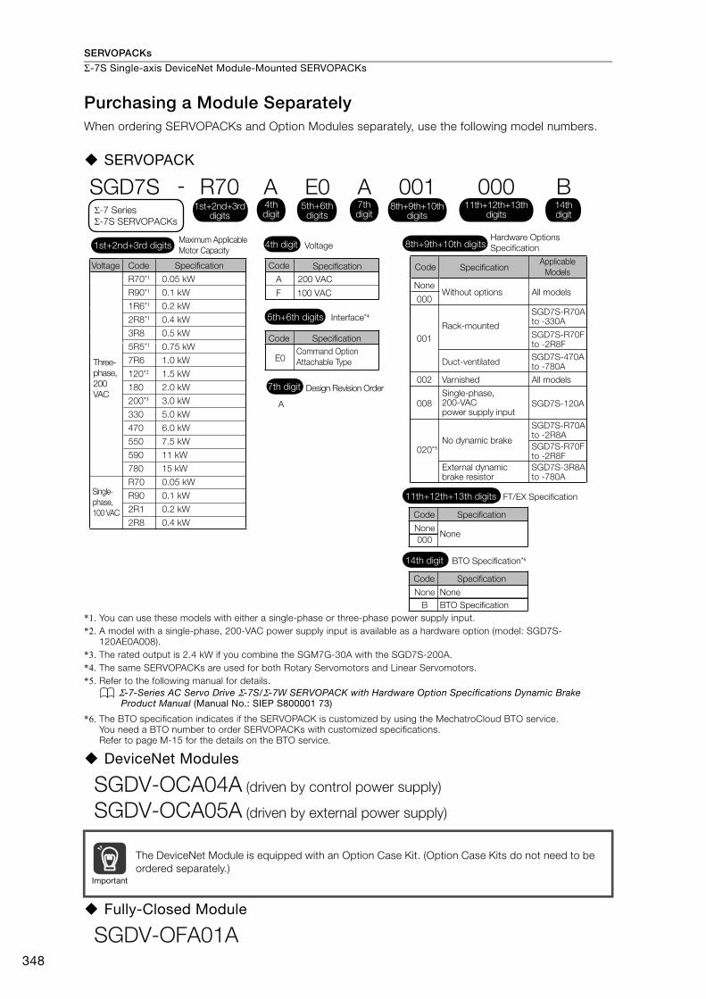
SERVOPACKs
Σ-7S Single-axis DeviceNet Module-Mounted SERVOPACKs
348
Purchasing a Module SeparatelyWhen ordering SERVOPACKs and Option Modules separately, use the following model numbers.
SERVOPACK
*1. You can use these models with either a single-phase or three-phase power supply input.*2. A model with a single-phase, 200-VAC power supply input is available as a hardware option (model: SGD7S-
120AE0A008).*3. The rated output is 2.4 kW if you combine the SGM7G-30A with the SGD7S-200A.*4. The same SERVOPACKs are used for both Rotary Servomotors and Linear Servomotors.*5. Refer to the following manual for details.
Σ-7-Series AC Servo Drive Σ-7S/Σ-7W SERVOPACK with Hardware Option Specifications Dynamic Brake Product Manual (Manual No.: SIEP S800001 73)
*6. The BTO specification indicates if the SERVOPACK is customized by using the MechatroCloud BTO service.You need a BTO number to order SERVOPACKs with customized specifications.Refer to page M-15 for the details on the BTO service.
DeviceNet Modules
Fully-Closed Module
The DeviceNet Module is equipped with an Option Case Kit. (Option Case Kits do not need to be ordered separately.)
A 200 VAC
F 100 VAC
SGD7S - R70 A E0 A 001
A
R70*1
R90*1
1R6*1
2R8*1
3R8
5R5*1
7R6
120*2
180
200*3
330
470
550
590
780
R70
R90
2R1
2R8
0.05 kW
0.1 kW
0.2 kW
0.4 kW
0.5 kW
0.75 kW
1.0 kW
1.5 kW
2.0 kW
3.0 kW
5.0 kW
6.0 kW
7.5 kW
11 kW
15 kW
0.05 kW
0.1 kW
0.2 kW
0.4 kW
E0
Maximum Applicable
Motor CapacityVoltage
Interface*4
Code
Code
Specification
Specification
Command Option
Attachable Type
Design Revision Order
Hardware Options
Specification
Voltage Code Specification
Three-
phase,
200
VAC
1st+2nd+3rd digits 4th digit
5th+6th digits
7th digit
8th+9th+10th digits
Σ-7 Series
Σ-7S SERVOPACKs
4th digit
1st+2nd+3rd digits
5th+6th digits
8th+9th+10th digits
7th digit
00011th+12th+13th
digits
B14thdigit
FT/EX Specification11th+12th+13th digits
None
Code Specification
None000
BTO Specification*614th digit
None
Code Specification
None
B BTO Specification
Single-
phase,
100 VAC
NoneWithout options All models
All models
SGD7S-R70A to -330A
SGD7S-R70Fto -2R8F
SGD7S-470A to -780A
SGD7S-R70A to -2R8A
SGD7S-R70F to -2R8F
SGD7S-3R8A to -780A
SGD7S-120A
001
002
008
020*5
Duct-ventilated
Varnished
Single-phase, 200-VAC power supply input
No dynamic brake
External dynamic brake resistor
Code SpecificationApplicable
Models
000
Rack-mounted
SGDV-OCA04A (driven by control power supply)
SGDV-OCA05A (driven by external power supply)
Important
SGDV-OFA01A
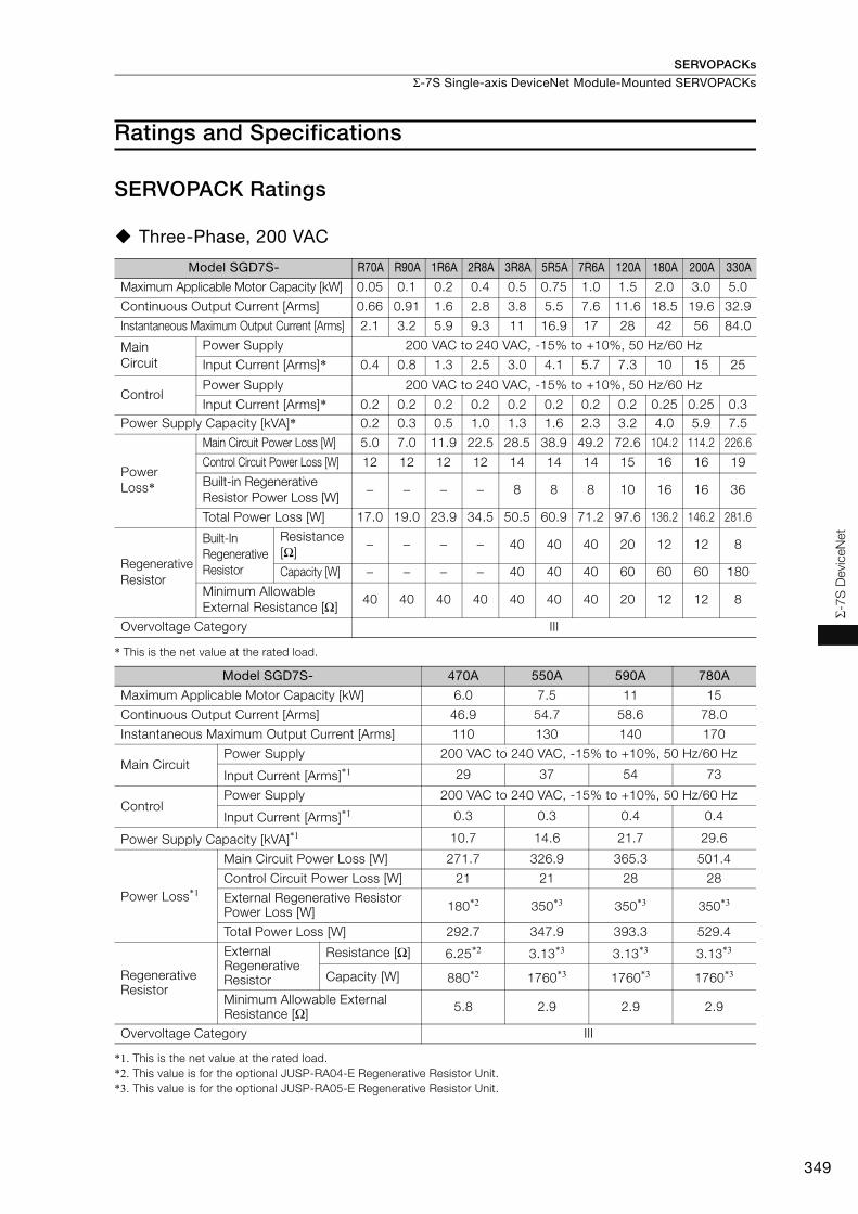
SERVOPACKs
Σ-7S Single-axis DeviceNet Module-Mounted SERVOPACKs
349
Σ-7S
Dev
iceN
et
Ratings and Specifications
SERVOPACK Ratings
Three-Phase, 200 VAC
* This is the net value at the rated load.
*1. This is the net value at the rated load.*2. This value is for the optional JUSP-RA04-E Regenerative Resistor Unit.*3. This value is for the optional JUSP-RA05-E Regenerative Resistor Unit.
Model SGD7S- R70A R90A 1R6A 2R8A 3R8A 5R5A 7R6A 120A 180A 200A 330A
Maximum Applicable Motor Capacity [kW] 0.05 0.1 0.2 0.4 0.5 0.75 1.0 1.5 2.0 3.0 5.0
Continuous Output Current [Arms] 0.66 0.91 1.6 2.8 3.8 5.5 7.6 11.6 18.5 19.6 32.9
Instantaneous Maximum Output Current [Arms] 2.1 3.2 5.9 9.3 11 16.9 17 28 42 56 84.0
Main Circuit
Power Supply 200 VAC to 240 VAC, -15% to +10%, 50 Hz/60 Hz
Input Current [Arms]* 0.4 0.8 1.3 2.5 3.0 4.1 5.7 7.3 10 15 25
ControlPower Supply 200 VAC to 240 VAC, -15% to +10%, 50 Hz/60 Hz
Input Current [Arms]* 0.2 0.2 0.2 0.2 0.2 0.2 0.2 0.2 0.25 0.25 0.3Power Supply Capacity [kVA]* 0.2 0.3 0.5 1.0 1.3 1.6 2.3 3.2 4.0 5.9 7.5
Power Loss*
Main Circuit Power Loss [W] 5.0 7.0 11.9 22.5 28.5 38.9 49.2 72.6 104.2 114.2 226.6
Control Circuit Power Loss [W] 12 12 12 12 14 14 14 15 16 16 19
Built-in Regenerative Resistor Power Loss [W]
− − − − 8 8 8 10 16 16 36
Total Power Loss [W] 17.0 19.0 23.9 34.5 50.5 60.9 71.2 97.6 136.2 146.2 281.6
Regenerative Resistor
Built-In Regenerative Resistor
Resistance [Ω]
− − − − 40 40 40 20 12 12 8
Capacity [W] − − − − 40 40 40 60 60 60 180
Minimum Allowable External Resistance [Ω]
40 40 40 40 40 40 40 20 12 12 8
Overvoltage Category III
Model SGD7S- 470A 550A 590A 780A
Maximum Applicable Motor Capacity [kW] 6.0 7.5 11 15
Continuous Output Current [Arms] 46.9 54.7 58.6 78.0
Instantaneous Maximum Output Current [Arms] 110 130 140 170
Main CircuitPower Supply 200 VAC to 240 VAC, -15% to +10%, 50 Hz/60 Hz
Input Current [Arms]*1 29 37 54 73
ControlPower Supply 200 VAC to 240 VAC, -15% to +10%, 50 Hz/60 Hz
Input Current [Arms]*1 0.3 0.3 0.4 0.4
Power Supply Capacity [kVA]*1 10.7 14.6 21.7 29.6
Power Loss*1
Main Circuit Power Loss [W] 271.7 326.9 365.3 501.4
Control Circuit Power Loss [W] 21 21 28 28
External Regenerative Resistor Power Loss [W] 180*2 350*3 350*3 350*3
Total Power Loss [W] 292.7 347.9 393.3 529.4
Regenerative Resistor
External Regenerative Resistor
Resistance [Ω] 6.25*2 3.13*3 3.13*3 3.13*3
Capacity [W] 880*2 1760*3 1760*3 1760*3
Minimum Allowable External Resistance [Ω] 5.8 2.9 2.9 2.9
Overvoltage Category III

SERVOPACKs
Σ-7S Single-axis DeviceNet Module-Mounted SERVOPACKs
350
Single-phase, 200 VAC
* This is the net value at the rated load.
270 VDC
*1. This is the net value at the rated load.*2. The value is 0.25 Arms for the SGD7S-120A00A008.
* This is the net value at the rated load.
Model SGD7S- R70A R90A 1R6A 2R8A 5R5A 120AMaximum Applicable Motor Capacity [kW] 0.05 0.1 0.2 0.4 0.75 1.5Continuous Output Current [Arms] 0.66 0.91 1.6 2.8 5.5 11.6Instantaneous Maximum Output Current [Arms] 2.1 3.2 5.9 9.3 16.9 28
Main CircuitPower Supply 200 VAC to 240 VAC, -15% to +10%, 50 Hz/60 HzInput Current [Arms]* 0.8 1.6 2.4 5.0 8.7 16
ControlPower Supply 200 VAC to 240 VAC, -15% to +10%, 50 Hz/60 HzInput Current [Arms]* 0.2 0.2 0.2 0.2 0.2 0.25
Power Supply Capacity [kVA]* 0.2 0.3 0.6 1.2 1.9 4.0
Power Loss*
Main Circuit Power Loss [W] 5.0 7.1 12.1 23.7 39.2 71.8Control Circuit Power Loss [W] 12 12 12 12 14 16Built-in Regenerative Resistor Power Loss [W]
− − − − 8 16
Total Power Loss [W] 17.0 19.1 24.1 35.7 61.2 103.8
Regenerative Resistor
Built-In Regenerative Resistor
Resistance [Ω] − − − − 40 12
Capacity [W] − − − − 40 60
Minimum Allowable External Resistance [Ω]
40 40 40 40 40 12
Overvoltage Category III
Model SGD7S- R70A R90A 1R6A 2R8A 3R8A 5R5A 7R6A 120AMaximum Applicable Motor Capacity [kW] 0.05 0.1 0.2 0.4 0.5 0.75 1.0 1.5 Continuous Output Current [Arms] 0.66 0.91 1.6 2.8 3.8 5.5 7.6 11.6 Instantaneous Maximum Output Current [Arms] 2.1 3.2 5.9 9.3 11.0 16.9 17.0 28.0
Main CircuitPower Supply 270 VDC to 324 VDC, -15% to +10%
Input Current [Arms]*1 0.5 1.0 1.5 3.0 3.8 4.9 6.9 11
ControlPower Supply 270 VDC to 324 VDC, -15% to +10%
Input Current [Arms]*1 0.2 0.2 0.2 0.2 0.2 0.2 0.2 0.2*2
Power Supply Capacity [kVA]*1 0.2 0.3 0.6 1 1.4 1.6 2.3 3.2
Power Loss*1Main Circuit Power Loss [W] 4.4 5.9 9.8 17.5 23.0 30.7 38.7 55.8Control Circuit Power Loss [W] 12 12 12 12 14 14 14 15Total Power Loss [W] 16.4 17.9 21.8 29.5 37.0 44.7 52.7 70.8
Overvoltage Category III
Model SGD7S- 180A 200A 330A 470A 550A 590A 780AMaximum Applicable Motor Capacity [kW] 2.0 3.0 5.0 6.0 7.5 11.0 15.0 Continuous Output Current [Arms] 18.5 19.6 32.9 46.9 54.7 58.6 78.0 Instantaneous Maximum Output Current [Arms] 42.0 56.0 84.0 110 130 140 170
Main CircuitPower Supply 270 VDC to 324 VDC, -15% to +10%Input Current [Arms]* 14 20 34 36 48 68 92
ControlPower Supply 270 VDC to 324 VDC, -15% to +10%Input Current [Arms]* 0.25 0.25 0.3 0.3 0.3 0.4 0.4
Power Supply Capacity [kVA]* 4.0 5.9 7.5 10.7 14.6 21.7 29.6
Power Loss*Main Circuit Power Loss [W] 82.7 83.5 146.2 211.6 255.3 243.6 343.4Control Circuit Power Loss [W] 16 16 19 21 21 28 28Total Power Loss [W] 98.7 99.5 165.2 232.6 276.3 271.6 371.4
Overvoltage Category III
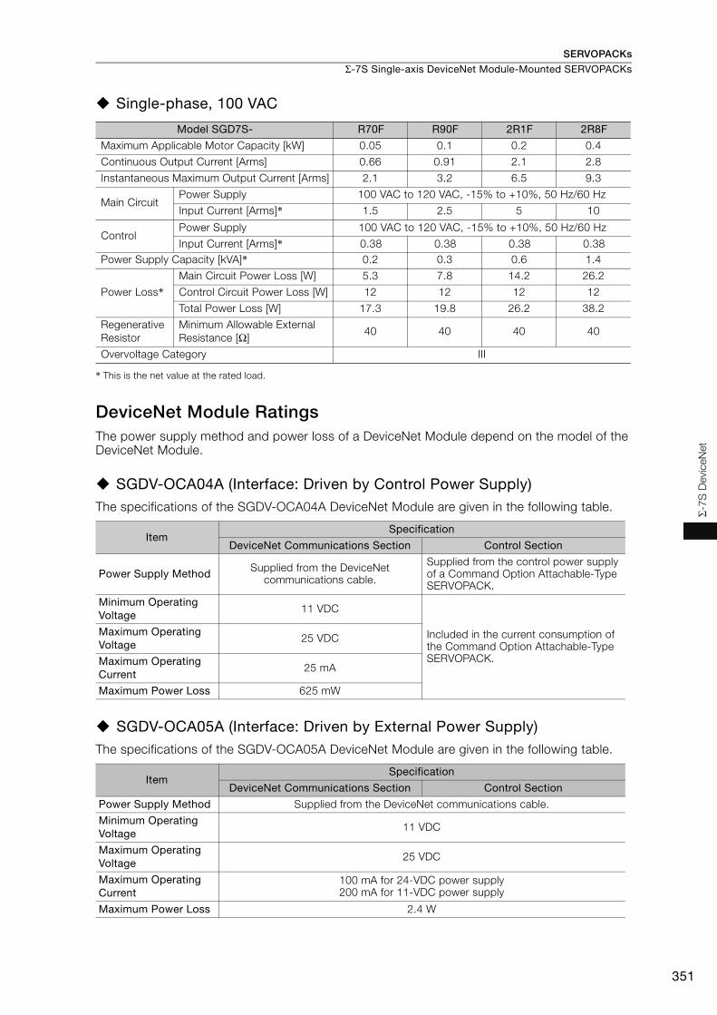
SERVOPACKs
Σ-7S Single-axis DeviceNet Module-Mounted SERVOPACKs
351
Σ-7S
Dev
iceN
et
Single-phase, 100 VAC
* This is the net value at the rated load.
DeviceNet Module RatingsThe power supply method and power loss of a DeviceNet Module depend on the model of the DeviceNet Module.
SGDV-OCA04A (Interface: Driven by Control Power Supply)The specifications of the SGDV-OCA04A DeviceNet Module are given in the following table.
SGDV-OCA05A (Interface: Driven by External Power Supply)The specifications of the SGDV-OCA05A DeviceNet Module are given in the following table.
Model SGD7S- R70F R90F 2R1F 2R8F
Maximum Applicable Motor Capacity [kW] 0.05 0.1 0.2 0.4
Continuous Output Current [Arms] 0.66 0.91 2.1 2.8
Instantaneous Maximum Output Current [Arms] 2.1 3.2 6.5 9.3
Main CircuitPower Supply 100 VAC to 120 VAC, -15% to +10%, 50 Hz/60 Hz
Input Current [Arms]* 1.5 2.5 5 10
ControlPower Supply 100 VAC to 120 VAC, -15% to +10%, 50 Hz/60 Hz
Input Current [Arms]* 0.38 0.38 0.38 0.38Power Supply Capacity [kVA]* 0.2 0.3 0.6 1.4
Power Loss*Main Circuit Power Loss [W] 5.3 7.8 14.2 26.2
Control Circuit Power Loss [W] 12 12 12 12
Total Power Loss [W] 17.3 19.8 26.2 38.2
Regenerative Resistor
Minimum Allowable External Resistance [Ω]
40 40 40 40
Overvoltage Category III
ItemSpecification
DeviceNet Communications Section Control Section
Power Supply Method Supplied from the DeviceNet communications cable.
Supplied from the control power supply of a Command Option Attachable-Type SERVOPACK.
Minimum Operating Voltage
11 VDC
Included in the current consumption of the Command Option Attachable-Type SERVOPACK.
Maximum Operating Voltage
25 VDC
Maximum Operating Current
25 mA
Maximum Power Loss 625 mW
ItemSpecification
DeviceNet Communications Section Control Section
Power Supply Method Supplied from the DeviceNet communications cable.
Minimum Operating Voltage
11 VDC
Maximum Operating Voltage
25 VDC
Maximum Operating Current
100 mA for 24-VDC power supply200 mA for 11-VDC power supply
Maximum Power Loss 2.4 W

SERVOPACKs
Σ-7S Single-axis DeviceNet Module-Mounted SERVOPACKs
352
SERVOPACK Overload Protection CharacteristicsThe overload detection level is set for hot start conditions with a SERVOPACK surrounding air tem-perature of 55°C.
An overload alarm (A.710 or A.720) will occur if overload operation that exceeds the overload pro-tection characteristics shown in the following diagram (i.e., operation on the right side of the appli-cable line) is performed.
The actual overload detection level will be the detection level of the connected SERVOPACK or Ser-vomotor that has the lower overload protection characteristics.
In most cases, that will be the overload protection characteristics of the Servomotor.
Note: The above overload protection characteristics do not mean that you can perform continuous duty operation with an output of 100% or higher.For a Yaskawa-specified combination of SERVOPACK and Servomotor, maintain the effective torque (or effective force) within the continuous duty zone of the torque-motor speed characteristic (or force-motor speed characteristics) of the Servomotor.
SERVOPACK output current (continuous output current ratio) (%)
Continuous output current× 100%
SERVOPACK Model: SGD7S-R70A, -R90A, -1R6A, -2R8A, -R70F, -R90F, -2R1F, and -2R8F
SERVOPACK Model: SGD7S-3R8A, -5R5A, -7R6A, -120A, -180A, -200A, -330A,
-470A, -550A, -590A, and -780A
Instantaneous maximum output current
(Instantaneous maximum output current)
(Continuous output current)
SERVOPACK output current (continuous output current ratio) (%)
Continuous output current× 100%
Instantaneous maximum output current
(Instantaneous maximum output current)
(Continuous output current)
100 230
10000
1000
100
10
1100 200
10000
1000
100
10
1
Det
ectio
n tim
e (s
)
Det
ectio
n tim
e (s
)
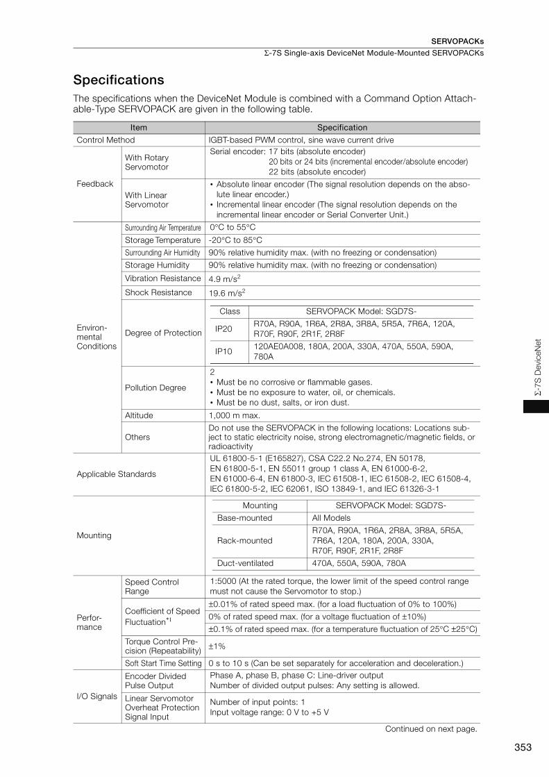
SERVOPACKs
Σ-7S Single-axis DeviceNet Module-Mounted SERVOPACKs
353
Σ-7S
Dev
iceN
et
SpecificationsThe specifications when the DeviceNet Module is combined with a Command Option Attach-able-Type SERVOPACK are given in the following table.
Item Specification
Control Method IGBT-based PWM control, sine wave current drive
Feedback
With Rotary Servomotor
Serial encoder: 17 bits (absolute encoder)20 bits or 24 bits (incremental encoder/absolute encoder)22 bits (absolute encoder)
With Linear Servomotor
• Absolute linear encoder (The signal resolution depends on the abso-lute linear encoder.)
• Incremental linear encoder (The signal resolution depends on the incremental linear encoder or Serial Converter Unit.)
Environ-mental Conditions
Surrounding Air Temperature 0°C to 55°C
Storage Temperature -20°C to 85°C
Surrounding Air Humidity 90% relative humidity max. (with no freezing or condensation)
Storage Humidity 90% relative humidity max. (with no freezing or condensation)
Vibration Resistance 4.9 m/s2
Shock Resistance 19.6 m/s2
Degree of Protection
Pollution Degree
2• Must be no corrosive or flammable gases.• Must be no exposure to water, oil, or chemicals.• Must be no dust, salts, or iron dust.
Altitude 1,000 m max.
Others Do not use the SERVOPACK in the following locations: Locations sub-ject to static electricity noise, strong electromagnetic/magnetic fields, or radioactivity
Applicable Standards
UL 61800-5-1 (E165827), CSA C22.2 No.274, EN 50178, EN 61800-5-1, EN 55011 group 1 class A, EN 61000-6-2, EN 61000-6-4, EN 61800-3, IEC 61508-1, IEC 61508-2, IEC 61508-4, IEC 61800-5-2, IEC 62061, ISO 13849-1, and IEC 61326-3-1
Mounting
Perfor-mance
Speed Control Range
1:5000 (At the rated torque, the lower limit of the speed control range must not cause the Servomotor to stop.)
Coefficient of Speed Fluctuation*1
±0.01% of rated speed max. (for a load fluctuation of 0% to 100%)
0% of rated speed max. (for a voltage fluctuation of ±10%)
±0.1% of rated speed max. (for a temperature fluctuation of 25°C ±25°C)
Torque Control Pre-cision (Repeatability) ±1%
Soft Start Time Setting 0 s to 10 s (Can be set separately for acceleration and deceleration.)
I/O Signals
Encoder Divided Pulse Output
Phase A, phase B, phase C: Line-driver output Number of divided output pulses: Any setting is allowed.
Linear Servomotor Overheat Protection Signal Input
Number of input points: 1Input voltage range: 0 V to +5 V
Continued on next page.
Class SERVOPACK Model: SGD7S-
IP20R70A, R90A, 1R6A, 2R8A, 3R8A, 5R5A, 7R6A, 120A, R70F, R90F, 2R1F, 2R8F
IP10120AE0A008, 180A, 200A, 330A, 470A, 550A, 590A, 780A
Mounting SERVOPACK Model: SGD7S-
Base-mounted All Models
Rack-mountedR70A, R90A, 1R6A, 2R8A, 3R8A, 5R5A, 7R6A, 120A, 180A, 200A, 330A, R70F, R90F, 2R1F, 2R8F
Duct-ventilated 470A, 550A, 590A, 780A

SERVOPACKs
Σ-7S Single-axis DeviceNet Module-Mounted SERVOPACKs
354
I/O Signals
Sequence Input Signals
Fixed Input
Allowable voltage range: 24 VDC ±20%Number of input points: 4
Input method: Sink inputs or source inputsInput Signals• CCW-OT (CCW Drive Prohibit Input) signal• CW-OT (CW Drive Prohibit Input) signal• /HOME (Origin Signal Input) signal• EXSTOP (External Stop Input) SignalPositive or negative logic can be changed in the parameters.
Sequence Output Signals
Fixed Output
Allowable voltage range: 5 VDC to 30 VDCNumber of output points: 4
Output Signals• ALM (Servo Alarm Output) signal• /WARN (Warning Signal Output) signal• /BK (Brake) signal• /S-RDY (Servo Ready Output) signal
Communi-cations
Digital Operator Commu-nications (CN3)
Inter-faces Digital Operator (JUSP-OP05A-1-E)
USB Commu-nications (CN7)
Inter-face Personal computer (with SigmaWin+)
Com-munica-tions Stan-dard
Conforms to USB2.0 standard (12 Mbps).
Displays/Indicators
SERVOPACK CHARGE and PWR indicators, and one-digit seven-segment display
DeviceNet Module
Refer to the following manual for details.Σ-7-Series AC Servo Drive Σ-7S SERVOPACK Command Option Attach-able Type with DeviceNet Module Product Manual (Manual No.: SIEP S800001 70)
Continued on next page.
Continued from previous page.
Item Specification

SERVOPACKs
Σ-7S Single-axis DeviceNet Module-Mounted SERVOPACKs
355
Σ-7S
Dev
iceN
et
Operating Methods
Refer-ence Method
Opera-tion Specifi-cations
Positioning via DeviceNet communications.
Refer-ence Inputs
DeviceNet communicationsCommands: Movement references (positioning or speed) and origin returns
Position Control Functions
Acceler-ation/Deceler-ation Meth-ods
Linear, asymmetrical, exponential, and S-curve acceleration/decelera-tion
Operat-ing Meth-ods
Simple positioning, origin returns, continuous operation, and switching to positioning
Fully-Closed Loop Control
Supported.
Built-in Functions
Position Data Latching
Position data can be latched on phase C, the origin signal, or an external signal.
Devi-ceNet Commu-nications
Com-munica-tions Meth-ods
DeviceNet I/O communications and explicit messages
Topol-ogy Multidrop or T-branching*2
Baud Rate 125 kbps, 250 kbps, or 500 kbps (Set on rotary switch (DR).)
Cables Special cables(OMRON DCA1-5CN02F1 Cable with Connectors or the equivalent.)
Maxi-mum Num-ber of Nodes
64 nodes (including the master, Maximum number of slaves: 63)
Node Address Setting
0 to 63 (Set on NA x10 and x1 rotary switches.)
Analog Monitor (CN5)
Number of points: 2Output voltage range: ±10 VDC (effective linearity range: ±8 V)Resolution: 16 bitsAccuracy: ±20 mV (Typ)Maximum output current: ±10 mASettling time (±1%): 1.2 ms (Typ)
Dynamic Brake (DB)Activated when a servo alarm or overtravel (OT) occurs, or when the power supply to the main circuit or servo is OFF.
Regenerative Processing
Built-in (An external resistor must be connected to the SGD7S-470A to -780A.)Refer to the following section for details.
Built-In Regenerative Resistor (page 456)
Overtravel (OT) PreventionStopping with a dynamic brake (DB), coasting to a stop, performing a hard stop, or smooth stop (decelerating to a stop) for a CCW-OT (CCW Drive Prohibit Input) signal or CW-OT (CW Drive Prohibit Input) signal.
Protective Functions Overcurrent, overvoltage, low voltage, overload, regeneration error, etc.
Utility Functions Gain adjustment, alarm history, jogging, origin search, etc.Continued on next page.
Continued from previous page.
Item Specification

SERVOPACKs
Σ-7S Single-axis DeviceNet Module-Mounted SERVOPACKs
356
*1. The coefficient of speed fluctuation for load fluctuation is defined as follows:
*2. Externally connected terminating resistance is required.*3. Always perform risk assessment for the system and confirm that the safety requirements are met.
The following table gives the specifications of the DeviceNet Module.
Safety Functions
Inputs /HWBB1 and /HWBB2: Base block signals for Power Modules
Output EDM1: Monitors the status of built-in safety circuit (fixed output).
Applicable Standards*3 ISO13849-1 PLe (Category 3), IEC61508 SIL3
Applicable Option Modules Fully-Closed ModuleNote: You cannot use a Safety Module if you are using a DeviceNet Module.
ItemSpecification
SGDV-OCA04A SGDV-OCA05A
Mounting Location Mounted to the side of a Command Option Attachable-Type SER-VOPACK.
Power Supply Method
Control SectionSupplied from the control power supply of a Command Option Attachable-Type SERVOPACK.
Supplied from the DeviceNet communications cable.
DeviceNet Communi-cations Section Supplied from the DeviceNet communications cable.
Current Consumption
Control SectionIncluded in the current consump-tion of the Command Option Attachable-Type SERVOPACK.
For 24-VDC power supply: 100 mA max., for 11-VDC power supply: 200 mA max.DeviceNet Communi-
cations Section 25 mA max.
Continued from previous page.
Item Specification
× 100%Coefficient of speed fluctuation = No-load motor speed - Total-load motor speedRated motor speed

SERVOPACKs
Σ-7S Single-axis DeviceNet Module-Mounted SERVOPACKs
357
Σ-7S
Dev
iceN
et
Selecting Cables
System Configurations
Σ-7S Single-axis Command Option Attachable-Type SERVOPACKs
Command Option Module:DeviceNet Module
Digital Operator Converter Cable
Safety Function Device Cable
Analog Monitor Cable�
�
�
�
I/O Signal Cable
To external devices, such as LED indicators
CN1
CN5
CN3
CN7
CN8
Digital Operator
VCMPSVON COIN TGON REF CHARGE
ALARM
DATAJOGSVON
SCROLL MODE/SETRESET
SERVO
READ WRITESERVO
YASKAWA
DIGITAL OPERATOR JUSP−OP05A−1−E
Computer CableJZSP-CVS06-02-E
Host controller (DeviceNet device)DeviceNet
Communications CableCN6
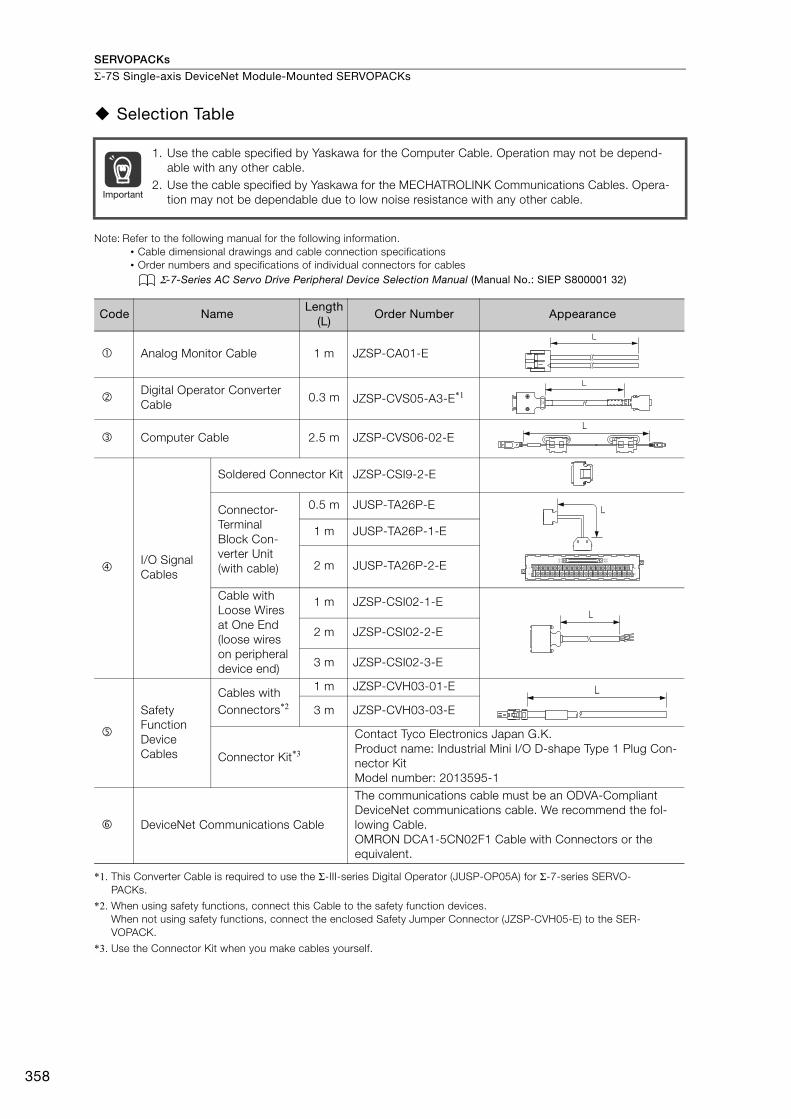
SERVOPACKs
Σ-7S Single-axis DeviceNet Module-Mounted SERVOPACKs
358
Selection Table
Note: Refer to the following manual for the following information.• Cable dimensional drawings and cable connection specifications• Order numbers and specifications of individual connectors for cables
Σ-7-Series AC Servo Drive Peripheral Device Selection Manual (Manual No.: SIEP S800001 32)
*1. This Converter Cable is required to use the Σ-III-series Digital Operator (JUSP-OP05A) for Σ-7-series SERVO-PACKs.
*2. When using safety functions, connect this Cable to the safety function devices.When not using safety functions, connect the enclosed Safety Jumper Connector (JZSP-CVH05-E) to the SER-VOPACK.
*3. Use the Connector Kit when you make cables yourself.
1. Use the cable specified by Yaskawa for the Computer Cable. Operation may not be depend-able with any other cable.
2. Use the cable specified by Yaskawa for the MECHATROLINK Communications Cables. Opera-tion may not be dependable due to low noise resistance with any other cable.
Code NameLength
(L)Order Number Appearance
Analog Monitor Cable 1 m JZSP-CA01-E
Digital Operator Converter Cable
0.3 m JZSP-CVS05-A3-E*1
Computer Cable 2.5 m JZSP-CVS06-02-E
I/O Signal Cables
Soldered Connector Kit JZSP-CSI9-2-E
Connector-Terminal Block Con-verter Unit(with cable)
0.5 m JUSP-TA26P-E
1 m JUSP-TA26P-1-E
2 m JUSP-TA26P-2-E
Cable with Loose Wires at One End (loose wires on peripheral device end)
1 m JZSP-CSI02-1-E
2 m JZSP-CSI02-2-E
3 m JZSP-CSI02-3-E
Safety Function Device Cables
Cables with Connectors*2
1 m JZSP-CVH03-01-E
3 m JZSP-CVH03-03-E
Connector Kit*3
Contact Tyco Electronics Japan G.K.Product name: Industrial Mini I/O D-shape Type 1 Plug Con-nector KitModel number: 2013595-1
DeviceNet Communications Cable
The communications cable must be an ODVA-Compliant DeviceNet communications cable. We recommend the fol-lowing Cable.OMRON DCA1-5CN02F1 Cable with Connectors or the equivalent.
Important
L
L
L
40
391
2
B20A20
B1A1
L
L
L

359
MEMO
Σ-7
S D
evi
ceN
et
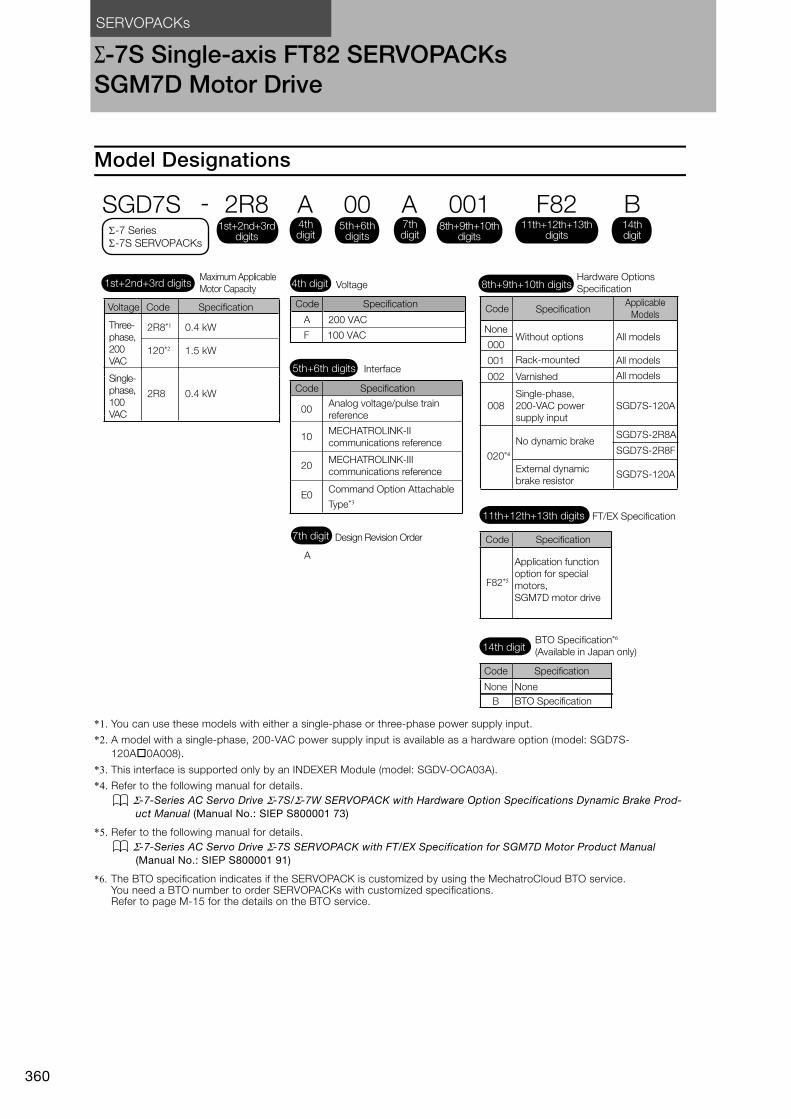
SERVOPACKs
360
Σ-7S Single-axis FT82 SERVOPACKsSGM7D Motor Drive
Model Designations
*1. You can use these models with either a single-phase or three-phase power supply input.
*2. A model with a single-phase, 200-VAC power supply input is available as a hardware option (model: SGD7S-120A0A008).
*3. This interface is supported only by an INDEXER Module (model: SGDV-OCA03A).
*4. Refer to the following manual for details. Σ-7-Series AC Servo Drive Σ-7S/Σ-7W SERVOPACK with Hardware Option Specifications Dynamic Brake Prod-
uct Manual (Manual No.: SIEP S800001 73)
*5. Refer to the following manual for details. Σ-7-Series AC Servo Drive Σ-7S SERVOPACK with FT/EX Specification for SGM7D Motor Product Manual
(Manual No.: SIEP S800001 91)
*6. The BTO specification indicates if the SERVOPACK is customized by using the MechatroCloud BTO service. You need a BTO number to order SERVOPACKs with customized specifications. Refer to page M-15 for the details on the BTO service.
A
Interface
Code Specification
Design Revision Order
5th+6th digits
7th digit
A 200 VAC
F 100 VAC
SGD7S - 2R8 A 00 A 001
Maximum Applicable
Motor Capacity Voltage
Code Specification
Hardware Options
Specification1st+2nd+3rd digits 4th digit 8th+9th+10th digits
4th digit
1st+2nd+3rd digits
5th+6th digits
8th+9th+10th digits
7th digit
2R8*1 0.4 kW
Voltage Code Specification
Three-
phase,
200
VAC
-7 Series
-7S SERVOPACKs
F8211th+12th+13th
digits
B14thdigit
FT/EX Specification11th+12th+13th digits
Code Specification
Application function
option for special
motors,
SGM7D motor drive
F82*5
BTO Specification*6
(Available in Japan only)14th digit
None
Code Specification
None
B BTO Specification
NoneWithout options All models
All models
All models001
002 Varnished
Code SpecificationApplicable
Models
000
Rack-mounted120*2 1.5 kW
00Analog voltage/pulse train
reference
10MECHATROLINK-II
communications reference
20MECHATROLINK-III
communications reference
E0Command Option Attachable
Type*3
2R8 0.4 kW
Single-
phase,
100
VACSGD7S-120A008
Single-phase,
200-VAC power
supply input
SGD7S-2R8A
020*4
No dynamic brakeSGD7S-2R8F
SGD7S-120AExternal dynamic
brake resistor

SERVOPACKs Σ-7S Single-axis FT82 SERVOPACKs SGM7D Motor Drive
361
Σ-7
S F
T8
2 S
pecifi
catio
n
Ratings and Specifications
Ratings
Three-Phase, 200 VAC
* This is the net value at the rated load.
Single-Phase, 200 VAC
* This is the net value at the rated load.
Model SGD7S- 2R8A 120A
Maximum Applicable Motor Capacity [kW] 0.4 1.5
Continuous Output Current [Arms] 2.8 11.6
Instantaneous Maximum Output Current [Arms] 9.3 28
Main CircuitPower Supply
200 VAC to 240 VAC, -15% to +10%, 50 Hz/60 Hz
Input Current [Arms]* 2.5 7.3
ControlPower Supply 200 VAC to 240 VAC, -15% to +10%,
50 Hz/60 Hz
Input Current [Arms]* 0.2 0.2Power Supply Capacity [kVA]* 1.0 3.2
Power Loss*
Main Circuit Power Loss [W] 22.5 72.6
Control Circuit Power Loss [W] 12 15
Built-in Regenerative Resistor Power Loss [W] − 10
Total Power Loss [W] 34.5 97.6
Regenerative Resistor
Built-In Regenerative Resistor
Resistance [Ω] − 20
Capacity [W] − 60
Minimum Allowable External Resistance [Ω] 40 20
Overvoltage Category III
Model SGD7S- 2R8A 120A
Maximum Applicable Motor Capacity [kW] 0.4 1.5
Continuous Output Current [Arms] 2.8 11.6
Instantaneous Maximum Output Current [Arms] 9.3 28
Main CircuitPower Supply
200 VAC to 240 VAC, -15% to +10%, 50 Hz/60 Hz
Input Current [Arms]* 5.0 16
ControlPower Supply 200 VAC to 240 VAC, -15% to +10%,
50 Hz/60 Hz
Input Current [Arms]* 0.2 0.25Power Supply Capacity [kVA]* 1.2 4.0
Power Loss*
Main Circuit Power Loss [W] 23.7 71.8
Control Circuit Power Loss [W] 12 16
Built-in Regenerative Resistor Power Loss [W] − 16
Total Power Loss [W] 35.7 103.8
Regenerative Resistor
Built-In Regenerative Resistor
Resistance [Ω] − 12
Capacity [W] − 60
Minimum Allowable External Resistance [Ω] 40 12
Overvoltage Category III

SERVOPACKsΣ-7S Single-axis FT82 SERVOPACKs SGM7D Motor Drive
362
Single-phase, 100 VAC
* This is the net value at the rated load.
SERVOPACK Overload Protection CharacteristicsThe overload detection level is set for hot start conditions with a SERVOPACK surrounding air tem-perature of 55°C.
An overload alarm (A.710 or A.720) will occur if overload operation that exceeds the overload pro-tection characteristics shown in the following diagram (i.e., operation on the right side of the appli-cable line) is performed.
The actual overload detection level will be the detection level of the connected SERVOPACK or Ser-vomotor that has the lower overload protection characteristics.
In most cases, that will be the overload protection characteristics of the Servomotor.
Note: The above overload protection characteristics do not mean that you can perform continuous duty operation with an output of 100% or higher.For a Yaskawa-specified combination of SERVOPACK and Servomotor, maintain the effective torque (or effective force) within the continuous duty zone of the torque-motor speed characteristic (or force-motor speed characteristics) of the Servomotor.
Model SGD7S- 2R8F
Maximum Applicable Motor Capacity [kW] 0.4
Continuous Output Current [Arms] 2.8
Instantaneous Maximum Output Current [Arms] 9.3
Main CircuitPower Supply
100 VAC to 120 VAC, -15% to +10%, 50 Hz/60 Hz
Input Current [Arms]* 10
ControlPower Supply 100 VAC to 120 VAC, -15% to +10%,
50 Hz/60 Hz
Input Current [Arms]* 0.38Power Supply Capacity [kVA]* 1.4
Power Loss*Main Circuit Power Loss [W] 26.2
Control Circuit Power Loss [W] 12
Total Power Loss [W] 38.2
Regenerative Resistor
Minimum Allowable External Resistance [Ω] 40
Overvoltage Category III
100 230
10000
1000
100
10
1100 200
10000
1000
100
10
1
SERVOPACK Model:
SGD7S-120A
SERVOPACK output current (continuous output current ratio) (%)
Continuous output current× 100%
Instantaneous maximum output current
(Instantaneous maximum output current)
(Continuous output current)
SERVOPACK Model:
SGD7S-2R8A and -2R8F
SERVOPACK output current (continuous output current ratio) (%)
Continuous output current× 100%
Instantaneous maximum output current
(Instantaneous maximum output current)
(Continuous output current)
Dete
ctio
n t
ime (s)
Dete
ctio
n t
ime (s)

SERVOPACKs Σ-7S Single-axis FT82 SERVOPACKs SGM7D Motor Drive
363
Σ-7
S F
T8
2 S
pecifi
catio
n
Specifications
FT82 SERVOPACKs with Analog Voltage/Pulse Train References
Item Specification
Control Method IGBT-based PWM control, sine wave current drive
Feedback Serial encoder: 24 bits (incremental encoder/absolute encoder)
Environ-mental Conditions
Surrounding Air Temperature*1
-5°C to 55°C With derating, usage is possible between 55°C and 60°C. Refer to the following section for derating specifications.
Derating Specifications (page 377)
Storage Temperature -20°C to 85°C
Surrounding Air Humidity
95% relative humidity max. (with no freezing or condensation)
Storage Humidity 95% relative humidity max. (with no freezing or condensation)
Vibration Resistance 4.9 m/s2
Shock Resistance 19.6 m/s2
Degree of Protection
Pollution Degree
2• Must be no corrosive or flammable gases.• Must be no exposure to water, oil, or chemicals. • Must be no dust, salts, or iron dust.
Altitude*1
1,000 m or less. With derating, usage is possible between 1,000 m and 2,000 m.Refer to the following section for derating specifications.
Derating Specifications (page 377)
OthersDo not use the SERVOPACK in the following locations: Locations sub-ject to static electricity noise, strong electromagnetic/magnetic fields, or radioactivity
Applicable Standards
UL 61800-5-1 (E165827), CSA C22.2 No.274, EN 50178, EN 61800-5-1, EN 55011 group 1 class A, EN 61000-6-2, EN 61000-6-4, EN 61800-3, IEC 61508-1, IEC 61508-2, IEC 61508-4, IEC 61800-5-2, IEC 62061, ISO 13849-1, and IEC 61326-3-1
Mounting Base-mounted or rack-mounted
Perfor-mance
Speed Control Range 1:5000 (At the rated torque, the lower limit of the speed control range must not cause the Servomotor to stop.)
Coefficient of Speed Fluctuation*2
±0.01% of rated speed max. (for a load fluctuation of 0% to 100%)
0% of rated speed max. (for a load fluctuation of ±10%)
±0.1% of rated speed max. (for a temperature fluctuation of 25°C ±25°C)
Torque Control Preci-sion (Repeatability)
±1%
Soft Start Time Set-ting
0 s to 10 s (Can be set separately for acceleration and deceleration.)
Continued on next page.
Degree SERVOPACK Models
IP20SGD7S-2R8A, -120A (three-phase, 200-VAC input), and -2R8F
IP10 SGD7S-120A00A008 (single-phase, 200-VAC input)

SERVOPACKsΣ-7S Single-axis FT82 SERVOPACKs SGM7D Motor Drive
364
I/O Signals
Encoder Divided Pulse Output
Phase A, phase B, phase C: Line-driver outputNumber of divided output pulses: Any setting is allowed.
Sequence Input Signals
Fixed Input
Allowable voltage range: 5 VDC ±5%Number of input points: 1SEN (Absolute Data Request) signal
Inp
ut S
igna
ls T
hat
Can
Be
Allo
cate
d
Allowable voltage range: 24 VDC ±20%Number of input points: 7
Input method: Sink inputs or source inputsInput Signals• /S-ON (Servo ON) signal• /P-CON (Proportional Control) Signal• P-OT (Forward Drive Prohibit) and N-OT (Reverse Drive Prohibit) sig-
nals• /ALM-RST (Alarm Reset) signal• /P-CL (Forward External Torque Limit) and /N-CL (Reverse External
Torque Limit) signals• /SPD-D (Motor Direction) signal• /SPD-A and /SPD-B (Internal Set Speed Selection) signals• /C-SEL (Control Selection) signal• /ZCLAMP (Zero Clamping) signal• /INHIBIT (Reference Pulse Inhibit) signal• /P-DET (Polarity Detection) signal• /G-SEL (Gain Selection) signal• /PSEL (Reference Pulse Input Multiplication Switch) Signal• SEN (Absolute Data Request) signalA signal can be allocated and the positive and negative logic can be changed.
Sequence Output Signals
Fixed Output
Allowable voltage range: 5 VDC to 30 VDCNumber of output points: 1Output signal: ALM (Servo Alarm) signal
Out
put
Sig
nals
Tha
t C
an B
e A
lloca
ted
Allowable voltage range: 5 VDC to 30 VDCNumber of output points: 6(A photocoupler output (isolated) is used for three of the outputs.)(An open-collector output (non-isolated) is used for the other three out-puts.)
Output Signals• /COIN (Positioning Completion) Signal• /V-CMP (Speed Coincidence Detection) Signal• /TGON (Rotation Detection) Signal• /S-RDY (Servo Ready) signal• /CLT (Torque Limit Detection) Signal• /VLT (Speed Limit Detection) Signal• /BK (Brake) signal• /WARN (Warning) Signal• /NEAR (Near) signal• /PSELA (Reference Pulse Input Multiplication Switching Output) sig-
nal• ALO1, ALO2, and ALO3 (Alarm Code) signalsA signal can be allocated and the positive and negative logic can be changed.
Continued on next page.
Continued from previous page.
Item Specification
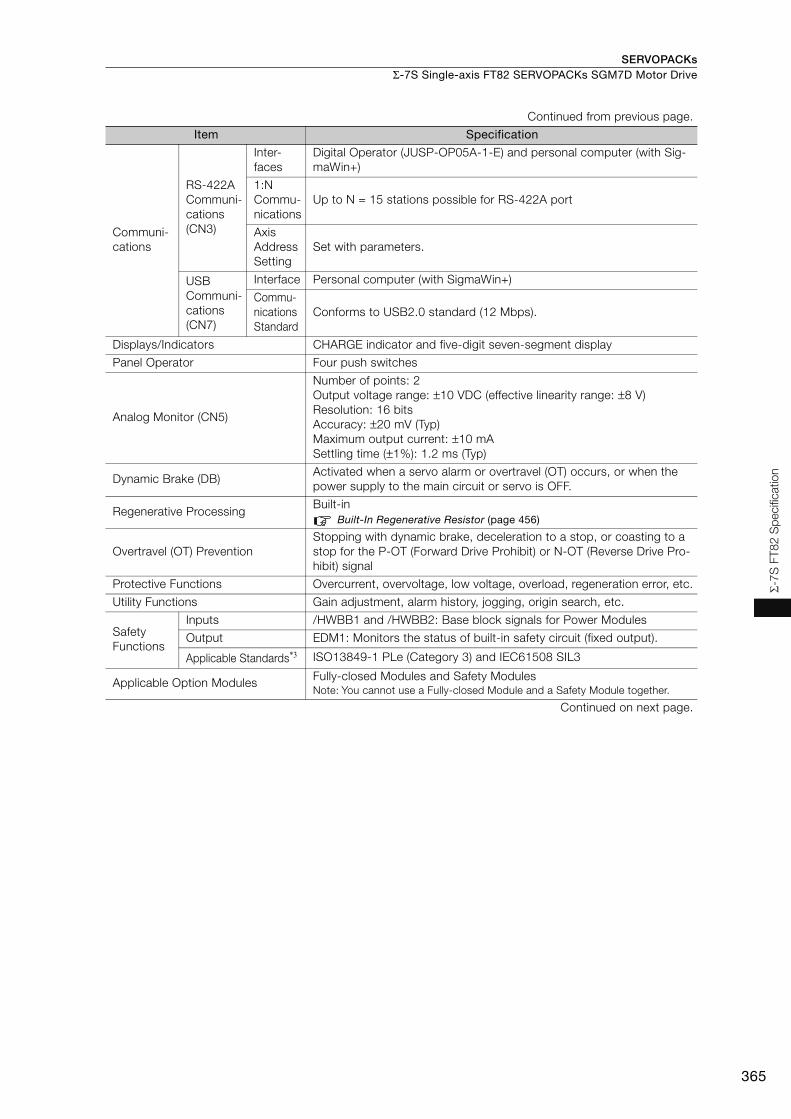
SERVOPACKs Σ-7S Single-axis FT82 SERVOPACKs SGM7D Motor Drive
365
Σ-7
S F
T8
2 S
pecifi
catio
n
Communi-cations
RS-422A Communi-cations (CN3)
Inter-faces
Digital Operator (JUSP-OP05A-1-E) and personal computer (with Sig-maWin+)
1:N Commu-nications
Up to N = 15 stations possible for RS-422A port
Axis Address Setting
Set with parameters.
USB Communi-cations (CN7)
Interface Personal computer (with SigmaWin+)
Commu-nications Standard
Conforms to USB2.0 standard (12 Mbps).
Displays/Indicators CHARGE indicator and five-digit seven-segment display
Panel Operator Four push switches
Analog Monitor (CN5)
Number of points: 2Output voltage range: ±10 VDC (effective linearity range: ±8 V)Resolution: 16 bitsAccuracy: ±20 mV (Typ)Maximum output current: ±10 mASettling time (±1%): 1.2 ms (Typ)
Dynamic Brake (DB)Activated when a servo alarm or overtravel (OT) occurs, or when the power supply to the main circuit or servo is OFF.
Regenerative ProcessingBuilt-in
Built-In Regenerative Resistor (page 456)
Overtravel (OT) PreventionStopping with dynamic brake, deceleration to a stop, or coasting to a stop for the P-OT (Forward Drive Prohibit) or N-OT (Reverse Drive Pro-hibit) signal
Protective Functions Overcurrent, overvoltage, low voltage, overload, regeneration error, etc.
Utility Functions Gain adjustment, alarm history, jogging, origin search, etc.
Safety Functions
Inputs /HWBB1 and /HWBB2: Base block signals for Power Modules
Output EDM1: Monitors the status of built-in safety circuit (fixed output).
Applicable Standards*3 ISO13849-1 PLe (Category 3) and IEC61508 SIL3
Applicable Option Modules Fully-closed Modules and Safety ModulesNote: You cannot use a Fully-closed Module and a Safety Module together.
Continued on next page.
Continued from previous page.
Item Specification
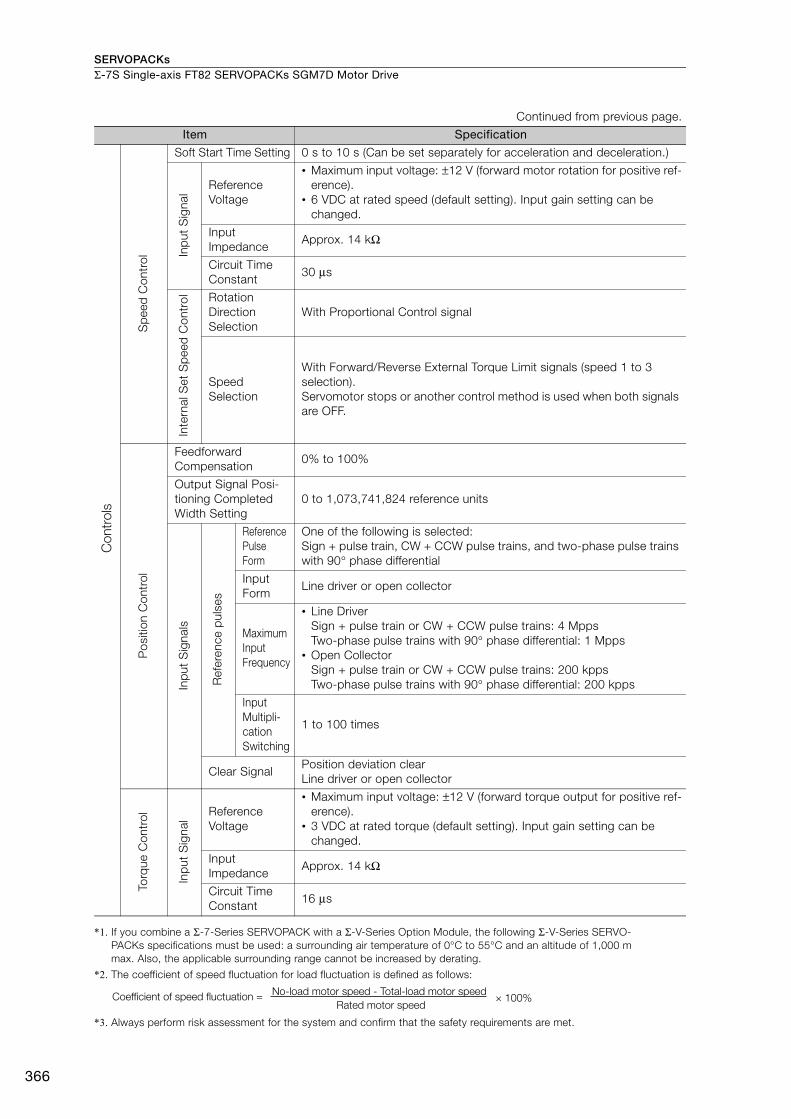
SERVOPACKsΣ-7S Single-axis FT82 SERVOPACKs SGM7D Motor Drive
366
*1. If you combine a Σ-7-Series SERVOPACK with a Σ-V-Series Option Module, the following Σ-V-Series SERVO-PACKs specifications must be used: a surrounding air temperature of 0°C to 55°C and an altitude of 1,000 m max. Also, the applicable surrounding range cannot be increased by derating.
*2. The coefficient of speed fluctuation for load fluctuation is defined as follows:
*3. Always perform risk assessment for the system and confirm that the safety requirements are met.
Sp
eed
Con
trol
Soft Start Time Setting 0 s to 10 s (Can be set separately for acceleration and deceleration.)
Inp
ut S
igna
l Reference Voltage
• Maximum input voltage: ±12 V (forward motor rotation for positive ref-erence).
• 6 VDC at rated speed (default setting). Input gain setting can be changed.
Input Impedance
Approx. 14 kΩ
Circuit Time Constant
30 μs
Inte
rnal
Set
Sp
eed
Con
trol Rotation
Direction Selection
With Proportional Control signal
Speed Selection
With Forward/Reverse External Torque Limit signals (speed 1 to 3 selection).Servomotor stops or another control method is used when both signals are OFF.
Pos
ition
Con
trol
Feedforward Compensation
0% to 100%
Output Signal Posi-tioning Completed Width Setting
0 to 1,073,741,824 reference units
Inp
ut S
igna
ls
Ref
eren
ce p
ulse
s
Reference Pulse Form
One of the following is selected:Sign + pulse train, CW + CCW pulse trains, and two-phase pulse trains with 90° phase differential
Input Form
Line driver or open collector
Maximum Input Frequency
• Line DriverSign + pulse train or CW + CCW pulse trains: 4 MppsTwo-phase pulse trains with 90° phase differential: 1 Mpps
• Open CollectorSign + pulse train or CW + CCW pulse trains: 200 kppsTwo-phase pulse trains with 90° phase differential: 200 kpps
Input Multipli-cation Switching
1 to 100 times
Clear SignalPosition deviation clearLine driver or open collector
Torq
ue C
ontr
ol
Inp
ut S
igna
l
Reference Voltage
• Maximum input voltage: ±12 V (forward torque output for positive ref-erence).
• 3 VDC at rated torque (default setting). Input gain setting can be changed.
Input Impedance
Approx. 14 kΩ
Circuit Time Constant
16 μs
Continued from previous page.
Item Specification
Con
trol
s
× 100%Coefficient of speed fluctuation =No-load motor speed - Total-load motor speed
Rated motor speed

SERVOPACKs Σ-7S Single-axis FT82 SERVOPACKs SGM7D Motor Drive
367
Σ-7
S F
T8
2 S
pecifi
catio
n
FT82 SERVOPACK with MECHATROLINK-II Communications References
Item Specification
Control Method IGBT-based PWM control, sine wave current drive
Feedback Serial encoder: 24 bits (incremental encoder/absolute encoder)
Environ-mental Conditions
Surrounding Air Temperature*1
-5°C to 55°C With derating, usage is possible between 55°C and 60°C. Refer to the following section for derating specifications.
Derating Specifications (page 377)
Storage Temperature -20°C to 85°C
Surrounding Air Humidity
95% relative humidity max. (with no freezing or condensation)
Storage Humidity 95% relative humidity max. (with no freezing or condensation)
Vibration Resistance 4.9 m/s2
Shock Resistance 19.6 m/s2
Degree of Protection
Pollution Degree
2• Must be no corrosive or flammable gases.• Must be no exposure to water, oil, or chemicals.• Must be no dust, salts, or iron dust.
Altitude*1
1,000 m or less. With derating, usage is possible between 1,000 m and 2,000 m.Refer to the following section for derating specifications.
Derating Specifications (page 377)
Others Do not use the SERVOPACK in the following locations: Locations sub-ject to static electricity noise, strong electromagnetic/magnetic fields, or radioactivity
Applicable Standards
UL 61800-5-1 (E165827), CSA C22.2 No.274, EN 50178, EN 61800-5-1, EN 55011 group 1 class A, EN 61000-6-2, EN 61000-6-4, EN 61800-3, IEC 61508-1, IEC 61508-2, IEC 61508-4, IEC 61800-5-2, IEC 62061, ISO 13849-1, and IEC 61326-3-1
Mounting Base-mounted or rack-mounted
Perfor-mance
Speed Control Range1:5000 (At the rated torque, the lower limit of the speed control range must not cause the Servomotor to stop.)
Coefficient of Speed Fluctuation*2
±0.01% of rated speed max. (for a load fluctuation of 0% to 100%)
0% of rated speed max. (for a voltage fluctuation of ±10%)
±0.1% of rated speed max. (for a temperature fluctuation of 25°C ±25°C)
Torque Control Preci-sion (Repeatability)
±1%
Soft Start Time Setting
0 s to 10 s (Can be set separately for acceleration and deceleration.)
Continued on next page.
Degree SERVOPACK Models
IP20SGD7S-2R8A, -120A (three-phase, 200-VAC input), and -2R8F
IP10 SGD7S-120A10A008 (single-phase, 200-VAC input)
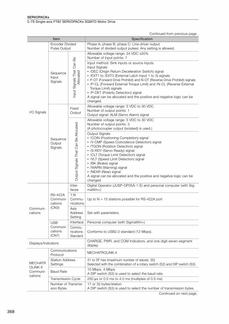
SERVOPACKsΣ-7S Single-axis FT82 SERVOPACKs SGM7D Motor Drive
368
I/O Signals
Encoder Divided Pulse Output
Phase A, phase B, phase C: Line-driver output Number of divided output pulses: Any setting is allowed.
Sequence Input Signals
Inp
ut S
igna
ls T
hat
Can
Be
Allo
cate
d
Allowable voltage range: 24 VDC ±20%Number of input points: 7
Input method: Sink inputs or source inputsInput Signals• /DEC (Origin Return Deceleration Switch) signal• /EXT1 to /EXT3 (External Latch Input 1 to 3) signals• P-OT (Forward Drive Prohibit) and N-OT (Reverse Drive Prohibit) signals• /P-CL (Forward External Torque Limit) and /N-CL (Reverse External
Torque Limit) signals• /P-DET (Polarity Detection) signalA signal can be allocated and the positive and negative logic can be changed.
Sequence Output Signals
Fixed Output
Allowable voltage range: 5 VDC to 30 VDCNumber of output points: 1Output signal: ALM (Servo Alarm) signal
Out
put
Sig
nals
Tha
t C
an B
e A
lloca
ted
Allowable voltage range: 5 VDC to 30 VDCNumber of output points: 3(A photocoupler output (isolated) is used.)
Output Signals• /COIN (Positioning Completion) signal• /V-CMP (Speed Coincidence Detection) signal• /TGON (Rotation Detection) signal• /S-RDY (Servo Ready) signal• /CLT (Torque Limit Detection) signal• /VLT (Speed Limit Detection) signal• /BK (Brake) signal• /WARN (Warning) signal• /NEAR (Near) signalA signal can be allocated and the positive and negative logic can be changed.
Communi-cations
RS-422A Communi-cations (CN3)
Inter-faces
Digital Operator (JUSP-OP05A-1-E) and personal computer (with Sig-maWin+)
1:N Commu-nications
Up to N = 15 stations possible for RS-422A port
Axis Address Setting
Set with parameters.
USB Communi-cations (CN7)
Interface Personal computer (with SigmaWin+)
Commu-nications Standard
Conforms to USB2.0 standard (12 Mbps).
Displays/IndicatorsCHARGE, PWR, and COM indicators, and one-digit seven-segment display
MECHATROLINK-II Communi-cations
Communications Protocol
MECHATROLINK-II
Station Address Settings
41 to 5F hex (maximum number of slaves: 30)Selected with the combination of a rotary switch (S2) and DIP switch (S3).
Baud Rate 10 Mbps, 4 MbpsA DIP switch (S3) is used to select the baud rate.
Transmission Cycle 250 μs or 0.5 ms to 4.0 ms (multiples of 0.5 ms)
Number of Transmis-sion Bytes
17 or 32 bytes/station A DIP switch (S3) is used to select the number of transmission bytes.
Continued on next page.
Continued from previous page.
Item Specification
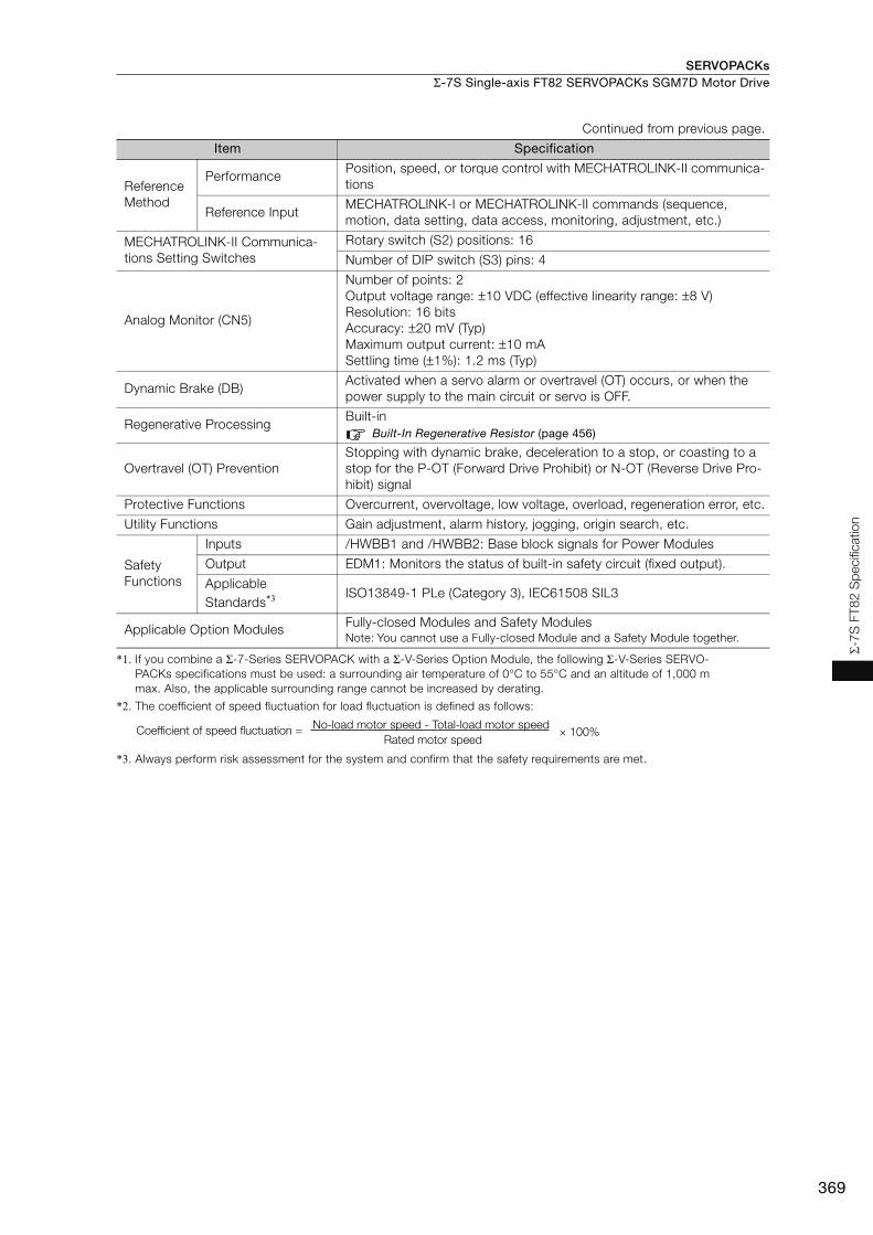
SERVOPACKs Σ-7S Single-axis FT82 SERVOPACKs SGM7D Motor Drive
369
Σ-7
S F
T8
2 S
pecifi
catio
n
*1. If you combine a Σ-7-Series SERVOPACK with a Σ-V-Series Option Module, the following Σ-V-Series SERVO-PACKs specifications must be used: a surrounding air temperature of 0°C to 55°C and an altitude of 1,000 m max. Also, the applicable surrounding range cannot be increased by derating.
*2. The coefficient of speed fluctuation for load fluctuation is defined as follows:
*3. Always perform risk assessment for the system and confirm that the safety requirements are met.
Reference Method
PerformancePosition, speed, or torque control with MECHATROLINK-II communica-tions
Reference InputMECHATROLINK-I or MECHATROLINK-II commands (sequence, motion, data setting, data access, monitoring, adjustment, etc.)
MECHATROLINK-II Communica-tions Setting Switches
Rotary switch (S2) positions: 16
Number of DIP switch (S3) pins: 4
Analog Monitor (CN5)
Number of points: 2Output voltage range: ±10 VDC (effective linearity range: ±8 V)Resolution: 16 bitsAccuracy: ±20 mV (Typ)Maximum output current: ±10 mASettling time (±1%): 1.2 ms (Typ)
Dynamic Brake (DB)Activated when a servo alarm or overtravel (OT) occurs, or when the power supply to the main circuit or servo is OFF.
Regenerative ProcessingBuilt-in
Built-In Regenerative Resistor (page 456)
Overtravel (OT) PreventionStopping with dynamic brake, deceleration to a stop, or coasting to a stop for the P-OT (Forward Drive Prohibit) or N-OT (Reverse Drive Pro-hibit) signal
Protective Functions Overcurrent, overvoltage, low voltage, overload, regeneration error, etc.
Utility Functions Gain adjustment, alarm history, jogging, origin search, etc.
Safety Functions
Inputs /HWBB1 and /HWBB2: Base block signals for Power Modules
Output EDM1: Monitors the status of built-in safety circuit (fixed output).
Applicable Standards*3 ISO13849-1 PLe (Category 3), IEC61508 SIL3
Applicable Option Modules Fully-closed Modules and Safety ModulesNote: You cannot use a Fully-closed Module and a Safety Module together.
Continued from previous page.
Item Specification
× 100%Coefficient of speed fluctuation =No-load motor speed - Total-load motor speed
Rated motor speed
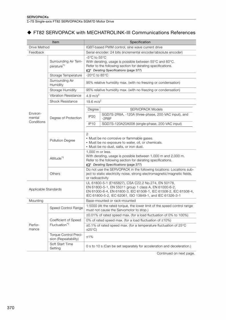
SERVOPACKsΣ-7S Single-axis FT82 SERVOPACKs SGM7D Motor Drive
370
FT82 SERVOPACK with MECHATROLINK-III Communications References
Item Specification
Drive Method IGBT-based PWM control, sine wave current drive
Feedback Serial encoder: 24 bits (incremental encoder/absolute encoder)
Environ-mental Conditions
Surrounding Air Tem-perature*1
-5°C to 55°C With derating, usage is possible between 55°C and 60°C. Refer to the following section for derating specifications.
Derating Specifications (page 377)
Storage Temperature -20°C to 85°C
Surrounding Air Humidity
95% relative humidity max. (with no freezing or condensation)
Storage Humidity 95% relative humidity max. (with no freezing or condensation)
Vibration Resistance 4.9 m/s2
Shock Resistance 19.6 m/s2
Degree of Protection
Pollution Degree
2• Must be no corrosive or flammable gases.• Must be no exposure to water, oil, or chemicals. • Must be no dust, salts, or iron dust.
Altitude*1
1,000 m or less. With derating, usage is possible between 1,000 m and 2,000 m.Refer to the following section for derating specifications.
Derating Specifications (page 377)
Others Do not use the SERVOPACK in the following locations: Locations sub-ject to static electricity noise, strong electromagnetic/magnetic fields, or radioactivity
Applicable Standards
UL 61800-5-1 (E165827), CSA C22.2 No.274, EN 50178, EN 61800-5-1, EN 55011 group 1 class A, EN 61000-6-2, EN 61000-6-4, EN 61800-3, IEC 61508-1, IEC 61508-2, IEC 61508-4, IEC 61800-5-2, IEC 62061, ISO 13849-1, and IEC 61326-3-1
Mounting Base-mounted or rack-mounted
Perfor-mance
Speed Control Range1:5000 (At the rated torque, the lower limit of the speed control range must not cause the Servomotor to stop.)
Coefficient of Speed Fluctuation*2
±0.01% of rated speed max. (for a load fluctuation of 0% to 100%)
0% of rated speed max. (for a load fluctuation of ±10%)
±0.1% of rated speed max. (for a temperature fluctuation of 25°C ±25°C)
Torque Control Preci-sion (Repeatability)
±1%
Soft Start Time Setting
0 s to 10 s (Can be set separately for acceleration and deceleration.)
Continued on next page.
Degree SERVOPACK Models
IP20SGD7S-2R8A, -120A (three-phase, 200-VAC input), and -2R8F
IP10 SGD7S-120A20A008 (single-phase, 200-VAC input)

SERVOPACKs Σ-7S Single-axis FT82 SERVOPACKs SGM7D Motor Drive
371
Σ-7
S F
T8
2 S
pecifi
catio
n
I/O Signals
Encoder Divided Pulse Output
Phase A, phase B, phase C: Line-driver output Number of divided output pulses: Any setting is allowed.
Sequence Input Signals
Inp
ut S
igna
ls T
hat
Can
Be
Allo
cate
d Allowable voltage range: 24 VDC ±20% Number of input points: 7
Input method: Sink inputs or source inputsInput Signals• /DEC (Origin Return Deceleration Switch) signal• /EXT1 to /EXT3 (External Latch Input 1 to 3) signals• P-OT (Forward Drive Prohibit) and N-OT (Reverse Drive Prohibit) sig-
nals• /P-CL (Forward External Torque Limit) and /N-CL (Reverse External
Torque Limit) signals• /P-DET (Polarity Detection) signalA signal can be allocated and the positive and negative logic can be changed.
Sequence Output Signals
Fixed Output
Allowable voltage range: 5 VDC to 30 VDC Number of output points: 1Output signal: ALM (Servo Alarm) signal
Out
put
Sig
nals
Tha
t C
an B
e A
lloca
ted
Allowable voltage range: 5 VDC to 30 VDCNumber of output points: 3(A photocoupler output (isolated) is used.)
Output Signals• /COIN (Positioning Completion) signal• /V-CMP (Speed Coincidence Detection) signal• /TGON (Rotation Detection) signal• /S-RDY (Servo Ready) signal• /CLT (Torque Limit Detection) signal• /VLT (Speed Limit Detection) signal• /BK (Brake) signal• /WARN (Warning) signal• /NEAR (Near) signalA signal can be allocated and the positive and negative logic can be changed.
Communi-cations
RS-422A Communi-cations (CN3)
Inter-faces
Digital Operator (JUSP-OP05A-1-E) and personal computer (with Sig-maWin+)
1:N Commu-nications
Up to N = 15 stations possible for RS-422A port
Axis Address Setting
Set with parameters.
USB Communi-cations(CN7)
Interface Personal computer (with SigmaWin+)
Commu-nications Standard
Conforms to USB2.0 standard (12 Mbps).
Displays/Indicators CHARGE, PWR, CN, L1, and L2 indicators, and one-digit seven-seg-ment display
Continued on next page.
Continued from previous page.
Item Specification
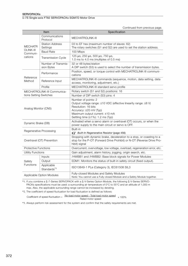
SERVOPACKsΣ-7S Single-axis FT82 SERVOPACKs SGM7D Motor Drive
372
*1. If you combine a Σ-7-Series SERVOPACK with a Σ-V-Series Option Module, the following Σ-V-Series SERVO-PACKs specifications must be used: a surrounding air temperature of 0°C to 55°C and an altitude of 1,000 m max. Also, the applicable surrounding range cannot be increased by derating.
*2. The coefficient of speed fluctuation for load fluctuation is defined as follows:
*3. Always perform risk assessment for the system and confirm that the safety requirements are met.
MECHATROLINK-III Communi-cations
Communications Protocol
MECHATROLINK-III
Station Address Settings
03 to EF hex (maximum number of slaves: 62) The rotary switches (S1 and S2) are used to set the station address.
Baud Rate 100 Mbps
Transmission Cycle 125 μs, 250 μs, 500 μs, 750 μs, 1.0 ms to 4.0 ms (multiples of 0.5 ms)
Number of Transmis-sion Bytes
32 or 48 bytes/stationA DIP switch (S3) is used to select the number of transmission bytes.
Reference Method
PerformancePosition, speed, or torque control with MECHATROLINK-III communi-cations
Reference Input MECHATROLINK-III commands (sequence, motion, data setting, data access, monitoring, adjustment, etc.)
Profile MECHATROLINK-III standard servo profile
MECHATROLINK-III Communica-tions Setting Switches
Rotary switch (S1 and S2) positions: 16
Number of DIP switch (S3) pins: 4
Analog Monitor (CN5)
Number of points: 2Output voltage range: ±10 VDC (effective linearity range: ±8 V)Resolution: 16 bitsAccuracy: ±20 mV (Typ)Maximum output current: ±10 mASettling time (±1%): 1.2 ms (Typ)
Dynamic Brake (DB)Activated when a servo alarm or overtravel (OT) occurs, or when the power supply to the main circuit or servo is OFF.
Regenerative Processing Built-in
Built-In Regenerative Resistor (page 456)
Overtravel (OT) Prevention Stopping with dynamic brake, deceleration to a stop, or coasting to a stop for the P-OT (Forward Drive Prohibit) or N-OT (Reverse Drive Pro-hibit) signal
Protective Functions Overcurrent, overvoltage, low voltage, overload, regeneration error, etc.
Utility Functions Gain adjustment, alarm history, jogging, origin search, etc.
Safety Functions
Inputs /HWBB1 and /HWBB2: Base block signals for Power Modules
Output EDM1: Monitors the status of built-in safety circuit (fixed output).
Applicable Standards*3 ISO13849-1 PLe (Category 3), IEC61508 SIL3
Applicable Option Modules Fully-closed Modules and Safety ModulesNote: You cannot use a Fully-closed Module and a Safety Module together.
Continued from previous page.
Item Specification
× 100%Coefficient of speed fluctuation =No-load motor speed - Total-load motor speed
Rated motor speed

SERVOPACKs Σ-7S Single-axis FT82 SERVOPACKs SGM7D Motor Drive
373
Σ-7
S F
T8
2 S
pecifi
catio
n
Command Option Attachable-type FT82 SERVOPACKs with INDEXER Modules
The specifications when the INDEXER Module is combined with a Command Option Attachable-type SERVOPACK are given in the following table.
Item Specification
Control Method IGBT-based PWM control, sine wave current drive
Feedback Serial encoder: 24 bits (incremental encoder/absolute encoder)
Environ-mental Conditions
Surrounding Air Temperature
0°C to 55°C
Storage Temperature -20°C to 85°C
Surrounding Air Humidity
90% relative humidity max. (with no freezing or condensation)
Storage Humidity 90% relative humidity max. (with no freezing or condensation)
Vibration Resistance 4.9 m/s2
Shock Resistance 19.6 m/s2
Degree of Protection IP10
Pollution Degree
2• Must be no corrosive or flammable gases.• Must be no exposure to water, oil, or chemicals.• Must be no dust, salts, or iron dust.
Altitude 1,000 m or less.
Others Do not use the SERVOPACK in the following locations: Locations sub-ject to static electricity noise, strong electromagnetic/magnetic fields, or radioactivity
Applicable Standards
UL 61800-5-1 (E165827), CSA C22.2 No.274, EN 50178, EN 61800-5-1, EN 55011 group 1 class A, EN 61000-6-2, EN 61000-6-4, EN 61800-3, IEC 61508-1, IEC 61508-2, IEC 61508-4, IEC 61800-5-2, IEC 62061, ISO 13849-1, and IEC 61326-3-1
Mounting Base-mounted or rack-mounted
Perfor-mance
Speed Control Range1:5000 (At the rated torque, the lower limit of the speed control range must not cause the Servomotor to stop.)
Coefficient of Speed Fluctuation*1
±0.01% of rated speed max. (for a load fluctuation of 0% to 100%)
0% of rated speed max. (for a voltage fluctuation of ±10%)
±0.1% of rated speed max. (for a temperature fluctuation of 25°C ±25°C)
Torque Control Preci-sion (Repeatability)
±1%
Soft Start Time Setting
0 s to 10 s (Can be set separately for acceleration and deceleration.)
Continued on next page.
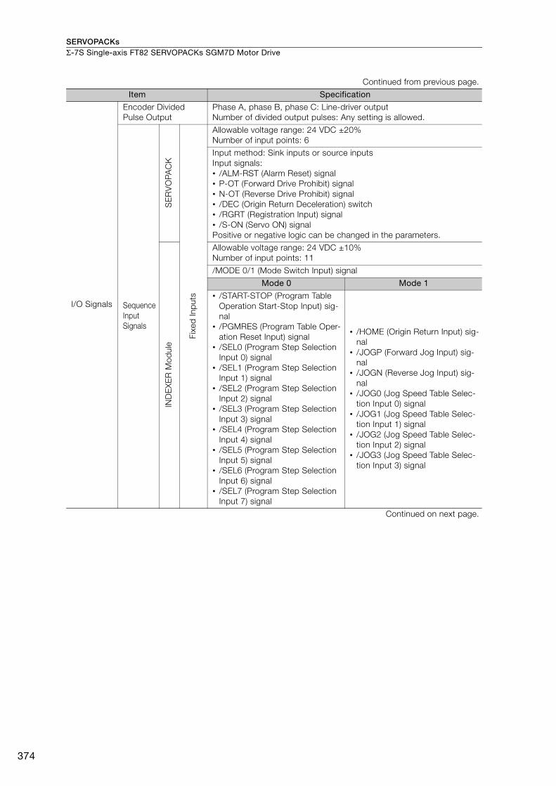
SERVOPACKsΣ-7S Single-axis FT82 SERVOPACKs SGM7D Motor Drive
374
I/O Signals
Encoder Divided Pulse Output
Phase A, phase B, phase C: Line-driver output Number of divided output pulses: Any setting is allowed.
Sequence Input Signals
SE
RV
OPA
CK
Fixe
d In
put
s
Allowable voltage range: 24 VDC ±20%Number of input points: 6
Input method: Sink inputs or source inputsInput signals:• /ALM-RST (Alarm Reset) signal• P-OT (Forward Drive Prohibit) signal• N-OT (Reverse Drive Prohibit) signal• /DEC (Origin Return Deceleration) switch• /RGRT (Registration Input) signal• /S-ON (Servo ON) signalPositive or negative logic can be changed in the parameters.
IND
EX
ER
Mod
ule
Allowable voltage range: 24 VDC ±10%Number of input points: 11
/MODE 0/1 (Mode Switch Input) signal
Mode 0 Mode 1
• /START-STOP (Program Table Operation Start-Stop Input) sig-nal
• /PGMRES (Program Table Oper-ation Reset Input) signal
• /SEL0 (Program Step Selection Input 0) signal
• /SEL1 (Program Step Selection Input 1) signal
• /SEL2 (Program Step Selection Input 2) signal
• /SEL3 (Program Step Selection Input 3) signal
• /SEL4 (Program Step Selection Input 4) signal
• /SEL5 (Program Step Selection Input 5) signal
• /SEL6 (Program Step Selection Input 6) signal
• /SEL7 (Program Step Selection Input 7) signal
• /HOME (Origin Return Input) sig-nal
• /JOGP (Forward Jog Input) sig-nal
• /JOGN (Reverse Jog Input) sig-nal
• /JOG0 (Jog Speed Table Selec-tion Input 0) signal
• /JOG1 (Jog Speed Table Selec-tion Input 1) signal
• /JOG2 (Jog Speed Table Selec-tion Input 2) signal
• /JOG3 (Jog Speed Table Selec-tion Input 3) signal
Continued on next page.
Continued from previous page.
Item Specification

SERVOPACKs Σ-7S Single-axis FT82 SERVOPACKs SGM7D Motor Drive
375
Σ-7
S F
T8
2 S
pecifi
catio
n
I/O SignalsSequence Output Signals
SE
RV
OPA
CK
Fixe
d
Out
put
s Allowable voltage range: 5 VDC to 30 VDCNumber of output points: 1Output signal: ALM (Servo Alarm Output) signal
Out
put
Sig
nals
for
Whi
ch
Allo
catio
ns C
an B
e C
hang
ed Allowable voltage range: 5 VDC to 30 VDCNumber of output points: 3(A photocoupler output (isolated) is used.)
Output signals:• /WARN (Warning Output) signal• /BK (Brake Output) signal• /S-RDY (Servo Ready Output) signal• /ALO1, /ALO2, and /ALO3 (Alarm Code Output) signalsSignal allocations and positive or negative logic can be changed in the parameters.
IND
EX
ER
Mod
ule
Fixe
d O
utp
uts
Allowable voltage range: 5 VDC to 30 VDCNumber of output points: 9Output signals:• /INPOSITION (Positioning Completion Output) signal• /POUT0 (Programmable Output 0) signal• /POUT1 (Programmable Output 1) signal• /POUT2 (Programmable Output 2) signal• /POUT3 (Programmable Output 3) signal• /POUT4 (Programmable Output 4) signal• /POUT5 (Programmable Output 5) signal• /POUT6 (Programmable Output 6) signal• /POUT7 (Programmable Output 7) signal
Communi-cations
RS-422A Commu-nications (CN3)
InterfacesDigital Operator (JUSP-OP05A-1-E), Personal computer (with Sig-maWin+)
1:N Communi-cations
Up to N = 15 stations possible for RS-422A port
Axis Address Setting
Set with parameters.
USB Commu-nications (CN7)
Interface Personal computer (with SigmaWin+)
Communi-cations Standard
Conforms to USB2.0 standard (12 Mbps).
Displays/Indicators
SERVOPACK CHARGE and PWR indicators, and one-digit seven-segment display
INDEXER ModuleRefer to the following manual for details.
Σ-7-Series Σ-7S Command Option Attachable-type SERVOPACK with INDEXER Module Product Manual (Manual No.: SIEP S800001 64)
Continued on next page.
Continued from previous page.
Item Specification
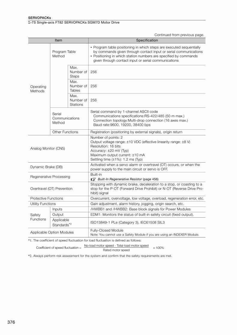
SERVOPACKsΣ-7S Single-axis FT82 SERVOPACKs SGM7D Motor Drive
376
*1. The coefficient of speed fluctuation for load fluctuation is defined as follows:
*2. Always perform risk assessment for the system and confirm that the safety requirements are met.
Operating Methods
Program Table Method
• Program table positioning in which steps are executed sequentially by commands given through contact input or serial communications
• Positioning in which station numbers are specified by commands given through contact input or serial communications
Max.Number ofSteps
256
Max.Number ofTables
256
Max.Number ofStations
256
Serial Communications Method
Serial command by 1-channel ASCII codeCommunications specifications:RS-422/485 (50 m max.)Connection topology:Multi-drop connection (16 axes max.)Baud rate:9600, 19200, 38400 bps
Other Functions Registration (positioning by external signals), origin return
Analog Monitor (CN5)
Number of points: 2Output voltage range: ±10 VDC (effective linearity range: ±8 V)Resolution: 16 bitsAccuracy: ±20 mV (Typ)Maximum output current: ±10 mASettling time (±1%): 1.2 ms (Typ)
Dynamic Brake (DB)Activated when a servo alarm or overtravel (OT) occurs, or when the power supply to the main circuit or servo is OFF.
Regenerative ProcessingBuilt-in
Built-In Regenerative Resistor (page 456)
Overtravel (OT) PreventionStopping with dynamic brake, deceleration to a stop, or coasting to a stop for the P-OT (Forward Drive Prohibit) or N-OT (Reverse Drive Pro-hibit) signal
Protective Functions Overcurrent, overvoltage, low voltage, overload, regeneration error, etc.
Utility Functions Gain adjustment, alarm history, jogging, origin search, etc.
Safety Functions
Inputs /HWBB1 and /HWBB2: Base block signals for Power Modules
Output EDM1: Monitors the status of built-in safety circuit (fixed output).
Applicable Standards*2 ISO13849-1 PLe (Category 3), IEC61508 SIL3
Applicable Option Modules Fully-Closed ModuleNote: You cannot use a Safety Module if you are using an INDEXER Module.
Continued from previous page.
Item Specification
× 100%Coefficient of speed fluctuation =No-load motor speed - Total-load motor speed
Rated motor speed
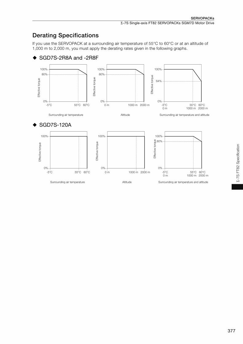
SERVOPACKs Σ-7S Single-axis FT82 SERVOPACKs SGM7D Motor Drive
377
Σ-7
S F
T8
2 S
pecifi
catio
n
Derating SpecificationsIf you use the SERVOPACK at a surrounding air temperature of 55°C to 60°C or at an altitude of 1,000 m to 2,000 m, you must apply the derating rates given in the following graphs.
SGD7S-2R8A and -2R8F
SGD7S-120A
100%
80%
2000 m
100%
1000 m
80%
0% 0%
0 m2000 m1000 m0 m
100%
0%
64%
-5°C 55°C 60°C -5°C 55°C 60°C
Effective
to
rque
Effective
to
rque
Surrounding air temperature Altitude
Effective
to
rque
Surrounding air temperature and altitude
80%
2000 m1000 m0 m2000 m1000 m0 m
-5°C 55°C 60°C -5°C 55°C 60°C
100% 100% 100%
0% 0% 0%
Effective
to
rque
Effective
to
rque
Surrounding air temperature Altitude
Effective
to
rque
Surrounding air temperature and altitude
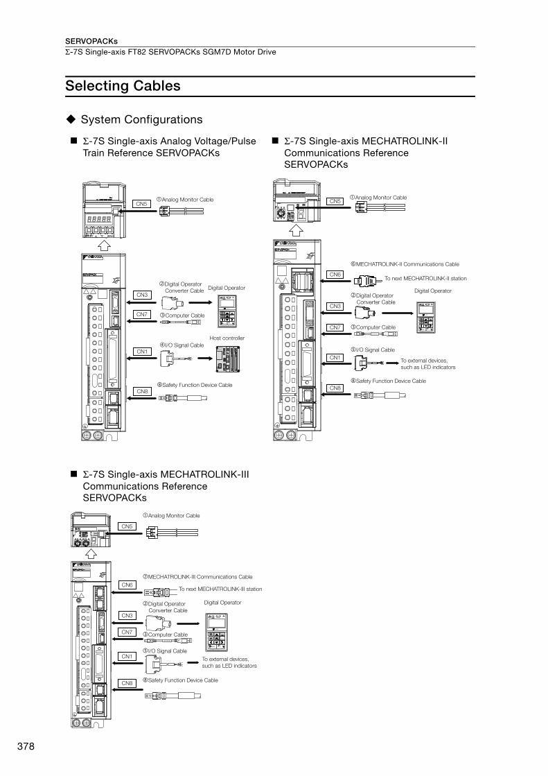
SERVOPACKsΣ-7S Single-axis FT82 SERVOPACKs SGM7D Motor Drive
378
Selecting Cables
System Configurations
Σ-7S Single-axis Analog Voltage/Pulse Train Reference SERVOPACKs
Σ-7S Single-axis MECHATROLINK-II Communications Reference SERVOPACKs
Σ-7S Single-axis MECHATROLINK-III Communications Reference SERVOPACKs
I/O Signal Cable
Digital OperatorDigital Operator
Converter Cable
Analog Monitor Cable
Safety Function Device Cable
Computer Cable
Host controller
CN3VCMP
SVON COIN TGON REF CHARGE
ALARM
DATAJOGSVON
SCROLL MODE/SETRESET
SERVO
READ WRITESERVO
YASKAWA
DIGITAL OPERATOR JUSP−OP05A−1−E
CN7
CN1
CN8
CN5
JZSP-CVS06-02-E
Digital Operator
Converter Cable
Safety Function Device Cable
Analog Monitor Cable
I/O Signal Cable
To next MECHATROLINK-II station
MECHATROLINK-II Communications Cable
To external devices,
such as LED indicators
CN1
CN5
CN6
CN3
CN7
CN8
Digital Operator
Computer CableJZSP-CVS06-02-E
Digital Operator
Converter Cable
Safety Function Device Cable
Analog Monitor Cable
I/O Signal Cable
To next MECHATROLINK-III station
MECHATROLINK-III Communications Cable
To external devices,
such as LED indicators
CN1
CN5
CN6
CN3
CN7
CN8
Digital Operator
Computer CableJZSP-CVS06-02-E

SERVOPACKs Σ-7S Single-axis FT82 SERVOPACKs SGM7D Motor Drive
379
Σ-7
S F
T8
2 S
pecifi
catio
n
Σ-7S Single-axis Command Option Attachable-Type SERVOPACKs
Command Option Module:INDEXER Module
Digital Operator
Converter Cable
Safety Function Device Cable
Analog Monitor Cable�
�
�
�
I/O Signal Cable
To external devices,
such as LED indicators
CN1
CN5
CN3
CN7
CN8
Digital Operator
VCMPSVON COIN TGON REF CHARGE
ALARM
DATAJOGSVON
SCROLL MODE/SETRESET
SERVO
READ WRITESERVO
YASKAWA
DIGITAL OPERATOR JUSP−OP05A−1−E
Computer CableJZSP-CVS06-02-E
CN11
CN12
I/O Signal Cable
Serial Command Cable

SERVOPACKsΣ-7S Single-axis FT82 SERVOPACKs SGM7D Motor Drive
380
Selection Table
Note: Refer to the following manual for the following information.• Cable dimensional drawings and cable connection specifications• Order numbers and specifications of individual connectors for cables
Σ-7-Series AC Servo Drive Peripheral Device Selection Manual (Manual No.: SIEP S800001 32)
1. Use the cable specified by Yaskawa for the Computer Cable. Operation may not be depend-able with any other cable.
2. Use the cable specified by Yaskawa for the MECHATROLINK Communications Cables. Opera-tion may not be dependable due to low noise resistance with any other cable.
Code NameLength
(L)Order Number Appearance
Analog Monitor Cable 1 m JZSP-CA01-E
Digital Operator Converter Cable
0.3 m
JZSP-CVS05-A3-E*1
JZSP-CVS07-A3-E*2
Computer Cable 2.5 m JZSP-CVS06-02-E
I/O Signal Cables
Soldered Connector Kit JZSP-CSI9-1-E
Connector-Terminal Block Con-verter Unit(with cable)
0.5 m JUSP-TA50PG-E
1 m JUSP-TA50PG-1-E
2 m JUSP-TA50PG-2-E
Cable with Loose Wires at One End(loose wires on peripheral device end)
1 m JZSP-CSI01-1-E
2 m JZSP-CSI01-2-E
3 m JZSP-CSI01-3-E
I/O Signal Cables
Soldered Connector Kit JZSP-CSI9-2-E
Connector-Terminal Block Con-verter Unit(with cable)
0.5 m JUSP-TA26P-E
1 m JUSP-TA26P-1-E
2 m JUSP-TA26P-2-E
Cable with Loose Wires at One End (loose wires on peripheral device end)
1 m JZSP-CSI02-1-E
2 m JZSP-CSI02-2-E
3 m JZSP-CSI02-3-E
Continued on next page.
Important
L
L
L
L
1
19
33
16
32
50
1
1
2
49
50
L
L
40
391
2
B20A20
B1A1
L
L
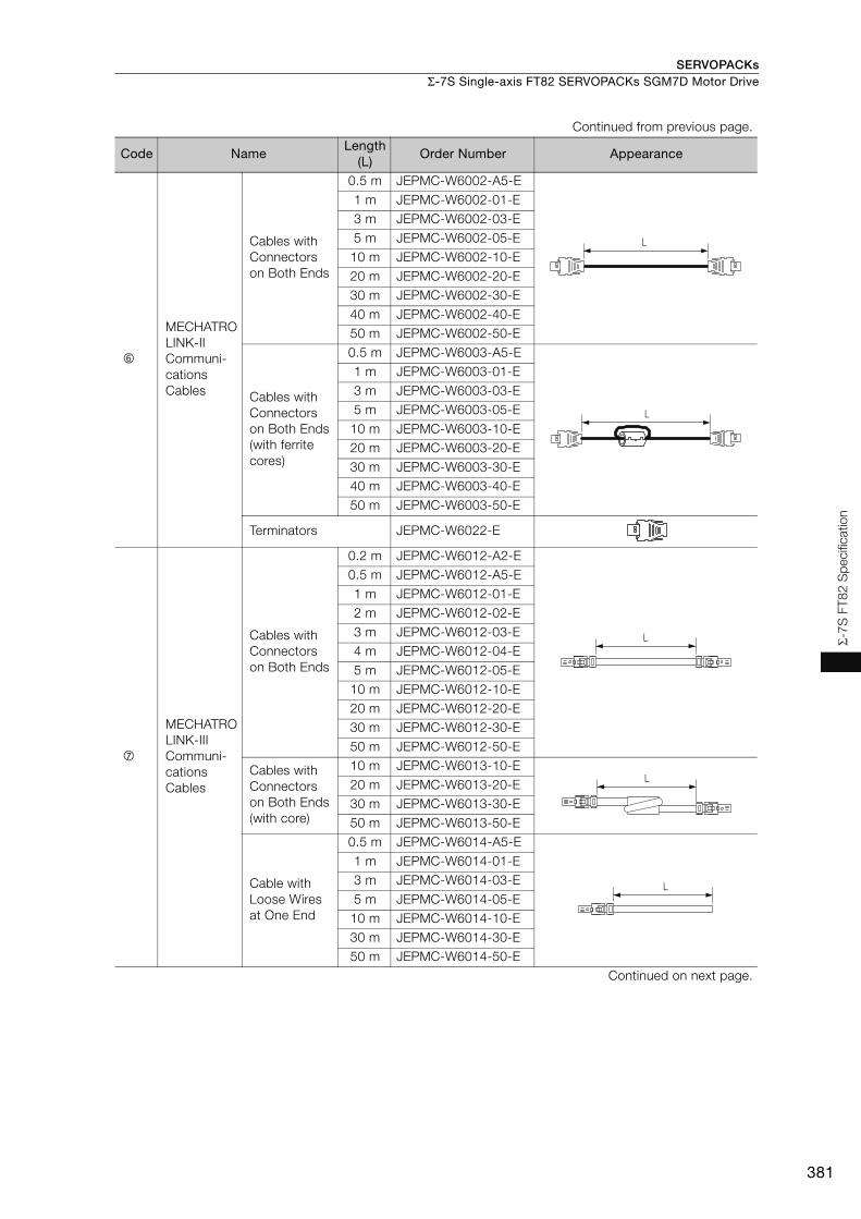
SERVOPACKs Σ-7S Single-axis FT82 SERVOPACKs SGM7D Motor Drive
381
Σ-7
S F
T8
2 S
pecifi
catio
n
MECHATROLINK-II Communi-cations Cables
Cables with Connectors on Both Ends
0.5 m JEPMC-W6002-A5-E1 m JEPMC-W6002-01-E3 m JEPMC-W6002-03-E5 m JEPMC-W6002-05-E
10 m JEPMC-W6002-10-E20 m JEPMC-W6002-20-E30 m JEPMC-W6002-30-E40 m JEPMC-W6002-40-E50 m JEPMC-W6002-50-E
Cables with Connectors on Both Ends(with ferrite cores)
0.5 m JEPMC-W6003-A5-E1 m JEPMC-W6003-01-E3 m JEPMC-W6003-03-E5 m JEPMC-W6003-05-E
10 m JEPMC-W6003-10-E20 m JEPMC-W6003-20-E30 m JEPMC-W6003-30-E40 m JEPMC-W6003-40-E50 m JEPMC-W6003-50-E
Terminators JEPMC-W6022-E
MECHATROLINK-III Communi-cations Cables
Cables with Connectors on Both Ends
0.2 m JEPMC-W6012-A2-E0.5 m JEPMC-W6012-A5-E1 m JEPMC-W6012-01-E2 m JEPMC-W6012-02-E3 m JEPMC-W6012-03-E4 m JEPMC-W6012-04-E5 m JEPMC-W6012-05-E
10 m JEPMC-W6012-10-E20 m JEPMC-W6012-20-E30 m JEPMC-W6012-30-E50 m JEPMC-W6012-50-E
Cables with Connectors on Both Ends(with core)
10 m JEPMC-W6013-10-E20 m JEPMC-W6013-20-E30 m JEPMC-W6013-30-E50 m JEPMC-W6013-50-E
Cable with Loose Wires at One End
0.5 m JEPMC-W6014-A5-E1 m JEPMC-W6014-01-E3 m JEPMC-W6014-03-E5 m JEPMC-W6014-05-E
10 m JEPMC-W6014-10-E30 m JEPMC-W6014-30-E50 m JEPMC-W6014-50-E
Continued on next page.
Continued from previous page.
Code NameLength
(L)Order Number Appearance
L
L
L
L
L

SERVOPACKsΣ-7S Single-axis FT82 SERVOPACKs SGM7D Motor Drive
382
*1. This Converter Cable is required to use the Σ-III-series Digital Operator (JUSP-OP05A) for Σ-7-series SERVO-PACKs.
*2. If you use a MECHATROLINK-III Communications Reference SERVOPACK, this Converter Cable is required to prevent the cable from disconnecting from the Digital Operator.
*3. When using safety functions, connect this Cable to the safety function devices.When not using safety functions, connect the enclosed Safety Jumper Connector (JZSP-CVH05-E) to the SER-VOPACK.
*4. Use the Connector Kit when you make cables yourself.
Safety Function Device Cables
Cables with Connectors*3
1 m JZSP-CVH03-01-E
3 m JZSP-CVH03-03-E
Connector Kit*4
Contact Tyco Electronics Japan G.K.Product name: Industrial Mini I/O D-shape Type 1 Plug Con-nector KitModel number: 2013595-1
I/O Signal Cables
Connector Kit DP9420007-E
Cables with Loose Wires at One End
1 m JZSP-CVI01-1-E2 m JZSP-CVI01-2-E3 m JZSP-CVI01-3-E
Cables with Terminal Block on One End
0.5 m JUSP-TA36V-E1 m JUSP-TA36V-1-E
2 m JUSP-TA36V-2-E
Serial Com-mand Cable Connector Kit*4 JZSP-CHI9-1
Contact Yaskawa Controls Co., Ltd. for the cable.
Continued from previous page.
Code NameLength
(L)Order Number Appearance
L

383
MEMO
Σ-7S
FT8
2 S
peci
ficat
ion
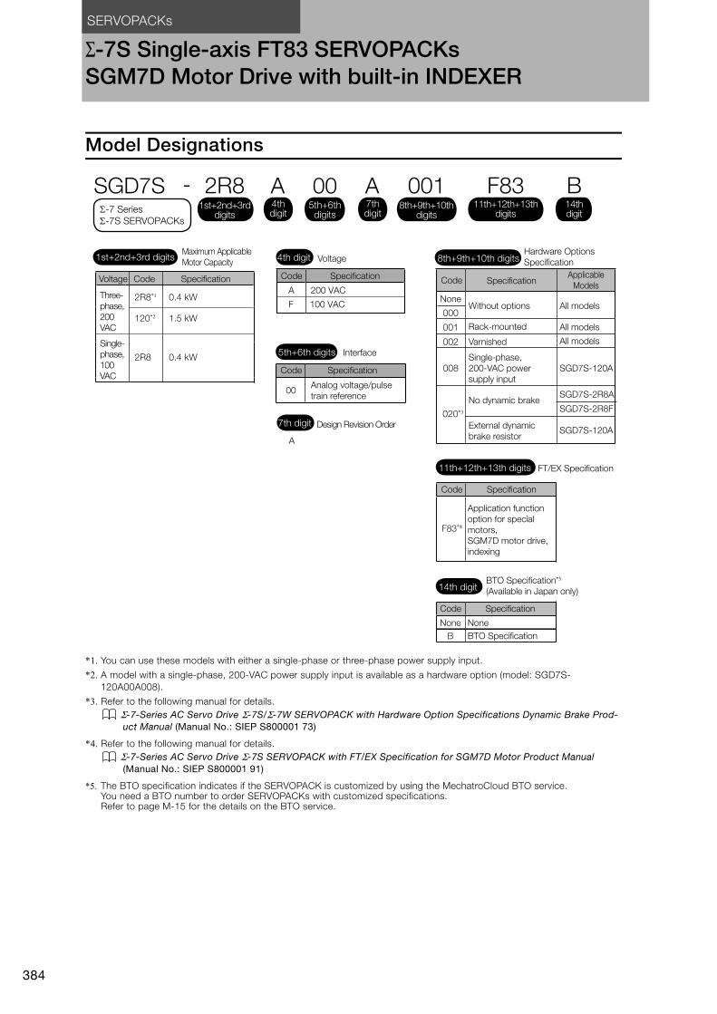
SERVOPACKs
384
Σ-7S Single-axis FT83 SERVOPACKsSGM7D Motor Drive with built-in INDEXER
Model Designations
*1. You can use these models with either a single-phase or three-phase power supply input.
*2. A model with a single-phase, 200-VAC power supply input is available as a hardware option (model: SGD7S-120A00A008).
*3. Refer to the following manual for details. Σ-7-Series AC Servo Drive Σ-7S/Σ-7W SERVOPACK with Hardware Option Specifications Dynamic Brake Prod-
uct Manual (Manual No.: SIEP S800001 73)
*4. Refer to the following manual for details. Σ-7-Series AC Servo Drive Σ-7S SERVOPACK with FT/EX Specification for SGM7D Motor Product Manual
(Manual No.: SIEP S800001 91)
*5. The BTO specification indicates if the SERVOPACK is customized by using the MechatroCloud BTO service. You need a BTO number to order SERVOPACKs with customized specifications. Refer to page M-15 for the details on the BTO service.
00
A
Interface
Code Specification
Analog voltage/pulse train reference
Design Revision Order
5th+6th digits
7th digit
A 200 VAC
SGD7S - 2R8 A 00 A 001
Maximum Applicable Motor Capacity Voltage
Code Specification
Hardware Options Specification1st+2nd+3rd digits 4th digit 8th+9th+10th digits
4th digit
1st+2nd+3rd digits
5th+6th digits
8th+9th+10th digits
7th digit
2R8*1 0.4 kW
Voltage Code Specification
Three-phase, 200 VAC
-7 Series -7S SERVOPACKs
F8311th+12th+13th
digits
B14thdigit
FT/EX Specification11th+12th+13th digits
Code Specification
Application function option for special motors,SGM7D motor drive, indexing
F83*4
BTO Specification*5
(Available in Japan only)14th digit
None
Code Specification
NoneB BTO Specification
NoneWithout options All models
All models
All models001
002 Varnished
Code SpecificationApplicable
Models
000
Rack-mounted120*2 1.5 kW
2R8 0.4 kW
Single-phase, 100 VAC
SGD7S-120A008Single-phase, 200-VAC power supply input
SGD7S-2R8A
020*3
No dynamic brakeSGD7S-2R8F
SGD7S-120AExternal dynamic brake resistor
F 100 VAC
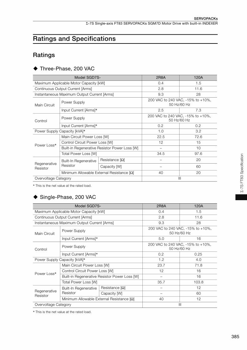
SERVOPACKs Σ-7S Single-axis FT83 SERVOPACKs SGM7D Motor Drive with built-in INDEXER
385
Σ-7
S F
T8
3 S
pecifi
catio
n
Ratings and Specifications
Ratings
Three-Phase, 200 VAC
* This is the net value at the rated load.
Single-Phase, 200 VAC
* This is the net value at the rated load.
Model SGD7S- 2R8A 120A
Maximum Applicable Motor Capacity [kW] 0.4 1.5
Continuous Output Current [Arms] 2.8 11.6
Instantaneous Maximum Output Current [Arms] 9.3 28
Main CircuitPower Supply
200 VAC to 240 VAC, -15% to +10%, 50 Hz/60 Hz
Input Current [Arms]* 2.5 7.3
ControlPower Supply 200 VAC to 240 VAC, -15% to +10%,
50 Hz/60 Hz
Input Current [Arms]* 0.2 0.2Power Supply Capacity [kVA]* 1.0 3.2
Power Loss*
Main Circuit Power Loss [W] 22.5 72.6
Control Circuit Power Loss [W] 12 15
Built-in Regenerative Resistor Power Loss [W] − 10
Total Power Loss [W] 34.5 97.6
Regenerative Resistor
Built-In Regenerative Resistor
Resistance [Ω] − 20
Capacity [W] − 60
Minimum Allowable External Resistance [Ω] 40 20
Overvoltage Category III
Model SGD7S- 2R8A 120A
Maximum Applicable Motor Capacity [kW] 0.4 1.5
Continuous Output Current [Arms] 2.8 11.6
Instantaneous Maximum Output Current [Arms] 9.3 28
Main CircuitPower Supply
200 VAC to 240 VAC, -15% to +10%, 50 Hz/60 Hz
Input Current [Arms]* 5.0 16
ControlPower Supply 200 VAC to 240 VAC, -15% to +10%,
50 Hz/60 Hz
Input Current [Arms]* 0.2 0.25Power Supply Capacity [kVA]* 1.2 4.0
Power Loss*
Main Circuit Power Loss [W] 23.7 71.8
Control Circuit Power Loss [W] 12 16
Built-in Regenerative Resistor Power Loss [W] − 16
Total Power Loss [W] 35.7 103.8
Regenerative Resistor
Built-In Regenerative Resistor
Resistance [Ω] − 12
Capacity [W] − 60
Minimum Allowable External Resistance [Ω] 40 12
Overvoltage Category III

SERVOPACKsΣ-7S Single-axis FT83 SERVOPACKs SGM7D Motor Drive with built-in INDEXER
386
Single-phase, 100 VAC
* This is the net value at the rated load.
SERVOPACK Overload Protection CharacteristicsThe overload detection level is set for hot start conditions with a SERVOPACK surrounding air tem-perature of 55°C.
An overload alarm (A.710 or A.720) will occur if overload operation that exceeds the overload pro-tection characteristics shown in the following diagram (i.e., operation on the right side of the appli-cable line) is performed.
The actual overload detection level will be the detection level of the connected SERVOPACK or Ser-vomotor that has the lower overload protection characteristics.
In most cases, that will be the overload protection characteristics of the Servomotor.
Note: The above overload protection characteristics do not mean that you can perform continuous duty operation with an output of 100% or higher.For a Yaskawa-specified combination of SERVOPACK and Servomotor, maintain the effective torque (or effective force) within the continuous duty zone of the torque-motor speed characteristic (or force-motor speed characteristics) of the Servomotor.
Model SGD7S- 2R8F
Maximum Applicable Motor Capacity [kW] 0.4
Continuous Output Current [Arms] 2.8
Instantaneous Maximum Output Current [Arms] 9.3
Main CircuitPower Supply 100 VAC to 120 VAC, -15% to +10%, 50 Hz/60 Hz
Input Current [Arms]* 10
ControlPower Supply 100 VAC to 120 VAC, -15% to +10%, 50 Hz/60 Hz
Input Current [Arms]* 0.38Power Supply Capacity [kVA]* 1.4
Power Loss*Main Circuit Power Loss [W] 26.2
Control Circuit Power Loss [W] 12
Total Power Loss [W] 38.2
RegenerativeResistor
Minimum Allowable External Resistance [Ω]
40
Overvoltage Category III
100 230
10000
1000
100
10
1100 200
10000
1000
100
10
1
SERVOPACK Model:
SGD7S-120A
SERVOPACK output current (continuous output current ratio) (%)
Continuous output current× 100%
Instantaneous maximum output current
(Instantaneous maximum output current)
(Continuous output current)
SERVOPACK Model:
SGD7S-2R8A and -2R8F
SERVOPACK output current (continuous output current ratio) (%)
Continuous output current× 100%
Instantaneous maximum output current
(Instantaneous maximum output current)
(Continuous output current)
Dete
ctio
n t
ime (s)
Dete
ctio
n t
ime (s)
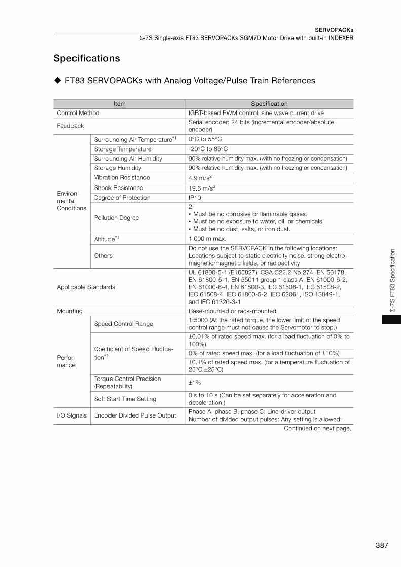
SERVOPACKs Σ-7S Single-axis FT83 SERVOPACKs SGM7D Motor Drive with built-in INDEXER
387
Σ-7
S F
T8
3 S
pecifi
catio
n
Specifications
FT83 SERVOPACKs with Analog Voltage/Pulse Train References
Item Specification
Control Method IGBT-based PWM control, sine wave current drive
FeedbackSerial encoder: 24 bits (incremental encoder/absolute encoder)
Environ-mental Conditions
Surrounding Air Temperature*1 0°C to 55°C
Storage Temperature -20°C to 85°C
Surrounding Air Humidity 90% relative humidity max. (with no freezing or condensation)
Storage Humidity 90% relative humidity max. (with no freezing or condensation)
Vibration Resistance 4.9 m/s2
Shock Resistance 19.6 m/s2
Degree of Protection IP10
Pollution Degree
2• Must be no corrosive or flammable gases.• Must be no exposure to water, oil, or chemicals. • Must be no dust, salts, or iron dust.
Altitude*1 1,000 m max.
OthersDo not use the SERVOPACK in the following locations: Locations subject to static electricity noise, strong electro-magnetic/magnetic fields, or radioactivity
Applicable Standards
UL 61800-5-1 (E165827), CSA C22.2 No.274, EN 50178, EN 61800-5-1, EN 55011 group 1 class A, EN 61000-6-2, EN 61000-6-4, EN 61800-3, IEC 61508-1, IEC 61508-2, IEC 61508-4, IEC 61800-5-2, IEC 62061, ISO 13849-1, and IEC 61326-3-1
Mounting Base-mounted or rack-mounted
Perfor-mance
Speed Control Range 1:5000 (At the rated torque, the lower limit of the speed control range must not cause the Servomotor to stop.)
Coefficient of Speed Fluctua-tion*2
±0.01% of rated speed max. (for a load fluctuation of 0% to 100%)
0% of rated speed max. (for a load fluctuation of ±10%)
±0.1% of rated speed max. (for a temperature fluctuation of 25°C ±25°C)
Torque Control Precision (Repeatability)
±1%
Soft Start Time Setting0 s to 10 s (Can be set separately for acceleration and deceleration.)
I/O Signals Encoder Divided Pulse OutputPhase A, phase B, phase C: Line-driver outputNumber of divided output pulses: Any setting is allowed.
Continued on next page.
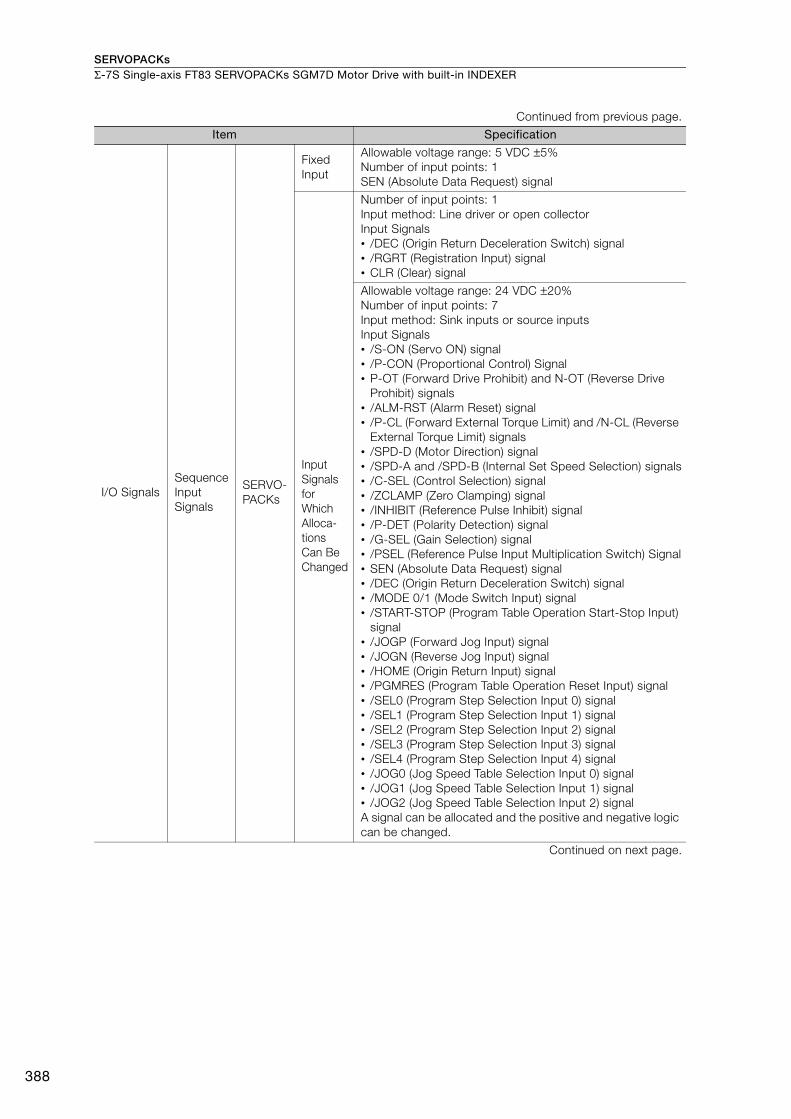
SERVOPACKsΣ-7S Single-axis FT83 SERVOPACKs SGM7D Motor Drive with built-in INDEXER
388
I/O SignalsSequence Input Signals
SERVO-PACKs
Fixed Input
Allowable voltage range: 5 VDC ±5%Number of input points: 1SEN (Absolute Data Request) signal
Input Signals for Which Alloca-tions Can Be Changed
Number of input points: 1Input method: Line driver or open collectorInput Signals• /DEC (Origin Return Deceleration Switch) signal• /RGRT (Registration Input) signal• CLR (Clear) signal
Allowable voltage range: 24 VDC ±20%Number of input points: 7Input method: Sink inputs or source inputsInput Signals• /S-ON (Servo ON) signal• /P-CON (Proportional Control) Signal• P-OT (Forward Drive Prohibit) and N-OT (Reverse Drive
Prohibit) signals• /ALM-RST (Alarm Reset) signal• /P-CL (Forward External Torque Limit) and /N-CL (Reverse
External Torque Limit) signals• /SPD-D (Motor Direction) signal• /SPD-A and /SPD-B (Internal Set Speed Selection) signals• /C-SEL (Control Selection) signal• /ZCLAMP (Zero Clamping) signal• /INHIBIT (Reference Pulse Inhibit) signal• /P-DET (Polarity Detection) signal• /G-SEL (Gain Selection) signal• /PSEL (Reference Pulse Input Multiplication Switch) Signal• SEN (Absolute Data Request) signal• /DEC (Origin Return Deceleration Switch) signal• /MODE 0/1 (Mode Switch Input) signal• /START-STOP (Program Table Operation Start-Stop Input)
signal• /JOGP (Forward Jog Input) signal• /JOGN (Reverse Jog Input) signal• /HOME (Origin Return Input) signal• /PGMRES (Program Table Operation Reset Input) signal• /SEL0 (Program Step Selection Input 0) signal• /SEL1 (Program Step Selection Input 1) signal• /SEL2 (Program Step Selection Input 2) signal• /SEL3 (Program Step Selection Input 3) signal• /SEL4 (Program Step Selection Input 4) signal• /JOG0 (Jog Speed Table Selection Input 0) signal• /JOG1 (Jog Speed Table Selection Input 1) signal• /JOG2 (Jog Speed Table Selection Input 2) signalA signal can be allocated and the positive and negative logic can be changed.
Continued on next page.
Continued from previous page.
Item Specification
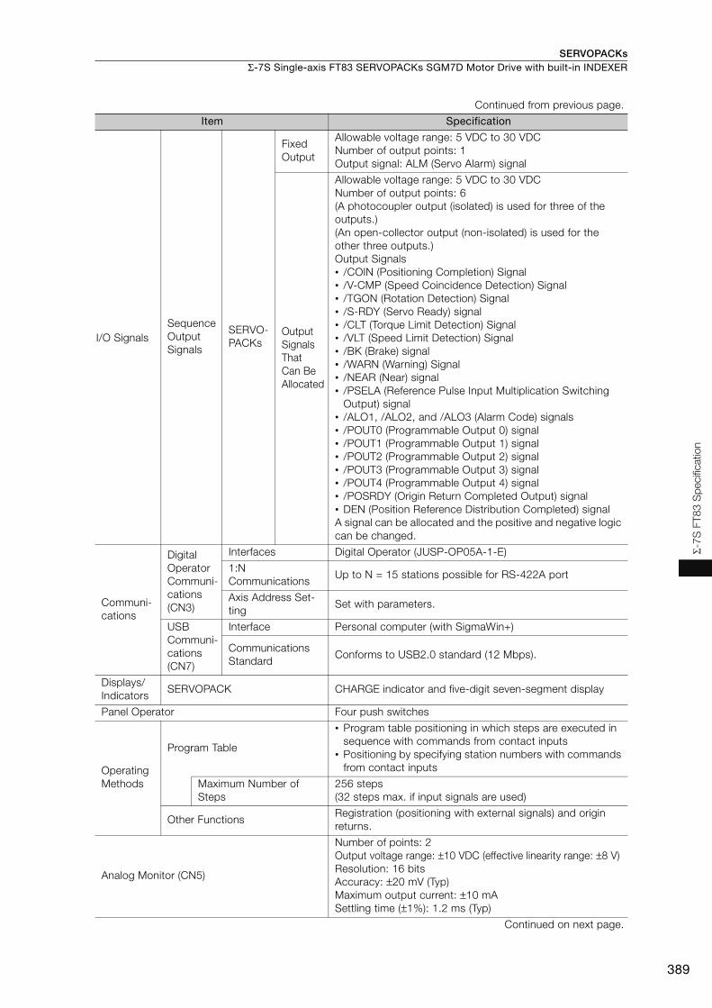
SERVOPACKs Σ-7S Single-axis FT83 SERVOPACKs SGM7D Motor Drive with built-in INDEXER
389
Σ-7
S F
T8
3 S
pecifi
catio
n
I/O SignalsSequence Output Signals
SERVO-PACKs
Fixed Output
Allowable voltage range: 5 VDC to 30 VDCNumber of output points: 1Output signal: ALM (Servo Alarm) signal
Output Signals That Can Be Allocated
Allowable voltage range: 5 VDC to 30 VDCNumber of output points: 6(A photocoupler output (isolated) is used for three of the outputs.)(An open-collector output (non-isolated) is used for the other three outputs.)Output Signals• /COIN (Positioning Completion) Signal• /V-CMP (Speed Coincidence Detection) Signal• /TGON (Rotation Detection) Signal• /S-RDY (Servo Ready) signal• /CLT (Torque Limit Detection) Signal• /VLT (Speed Limit Detection) Signal• /BK (Brake) signal• /WARN (Warning) Signal• /NEAR (Near) signal• /PSELA (Reference Pulse Input Multiplication Switching
Output) signal• /ALO1, /ALO2, and /ALO3 (Alarm Code) signals• /POUT0 (Programmable Output 0) signal• /POUT1 (Programmable Output 1) signal• /POUT2 (Programmable Output 2) signal• /POUT3 (Programmable Output 3) signal• /POUT4 (Programmable Output 4) signal• /POSRDY (Origin Return Completed Output) signal• DEN (Position Reference Distribution Completed) signalA signal can be allocated and the positive and negative logic can be changed.
Communi-cations
Digital Operator Communi-cations (CN3)
Interfaces Digital Operator (JUSP-OP05A-1-E)
1:N Communications
Up to N = 15 stations possible for RS-422A port
Axis Address Set-ting
Set with parameters.
USB Communi-cations (CN7)
Interface Personal computer (with SigmaWin+)
Communications Standard
Conforms to USB2.0 standard (12 Mbps).
Displays/Indicators
SERVOPACK CHARGE indicator and five-digit seven-segment display
Panel Operator Four push switches
Operating Methods
Program Table
• Program table positioning in which steps are executed in sequence with commands from contact inputs
• Positioning by specifying station numbers with commands from contact inputs
Maximum Number of Steps
256 steps(32 steps max. if input signals are used)
Other FunctionsRegistration (positioning with external signals) and origin returns.
Analog Monitor (CN5)
Number of points: 2Output voltage range: ±10 VDC (effective linearity range: ±8 V)Resolution: 16 bitsAccuracy: ±20 mV (Typ)Maximum output current: ±10 mASettling time (±1%): 1.2 ms (Typ)
Continued on next page.
Continued from previous page.
Item Specification
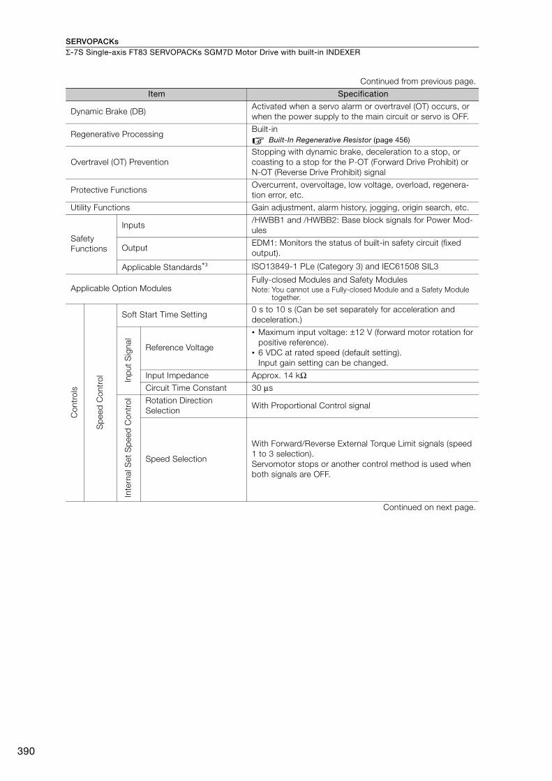
SERVOPACKsΣ-7S Single-axis FT83 SERVOPACKs SGM7D Motor Drive with built-in INDEXER
390
Dynamic Brake (DB)Activated when a servo alarm or overtravel (OT) occurs, or when the power supply to the main circuit or servo is OFF.
Regenerative ProcessingBuilt-in
Built-In Regenerative Resistor (page 456)
Overtravel (OT) PreventionStopping with dynamic brake, deceleration to a stop, or coasting to a stop for the P-OT (Forward Drive Prohibit) or N-OT (Reverse Drive Prohibit) signal
Protective FunctionsOvercurrent, overvoltage, low voltage, overload, regenera-tion error, etc.
Utility Functions Gain adjustment, alarm history, jogging, origin search, etc.
Safety Functions
Inputs/HWBB1 and /HWBB2: Base block signals for Power Mod-ules
OutputEDM1: Monitors the status of built-in safety circuit (fixed output).
Applicable Standards*3 ISO13849-1 PLe (Category 3) and IEC61508 SIL3
Applicable Option ModulesFully-closed Modules and Safety ModulesNote: You cannot use a Fully-closed Module and a Safety Module
together.
Con
trol
s
Sp
eed
Con
trol
Soft Start Time Setting0 s to 10 s (Can be set separately for acceleration and deceleration.)
Inp
ut S
igna
l
Reference Voltage
• Maximum input voltage: ±12 V (forward motor rotation for positive reference).
• 6 VDC at rated speed (default setting). Input gain setting can be changed.
Input Impedance Approx. 14 kΩCircuit Time Constant 30 μs
Inte
rnal
Set
Sp
eed
Con
trol Rotation Direction
SelectionWith Proportional Control signal
Speed Selection
With Forward/Reverse External Torque Limit signals (speed 1 to 3 selection).Servomotor stops or another control method is used when both signals are OFF.
Continued on next page.
Continued from previous page.
Item Specification
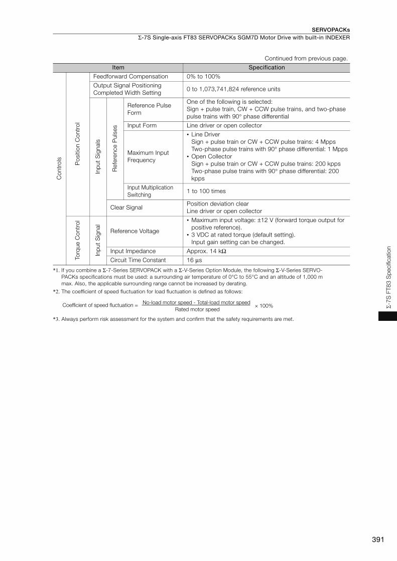
SERVOPACKs Σ-7S Single-axis FT83 SERVOPACKs SGM7D Motor Drive with built-in INDEXER
391
Σ-7
S F
T8
3 S
pecifi
catio
n
*1. If you combine a Σ-7-Series SERVOPACK with a Σ-V-Series Option Module, the following Σ-V-Series SERVO-PACKs specifications must be used: a surrounding air temperature of 0°C to 55°C and an altitude of 1,000 m max. Also, the applicable surrounding range cannot be increased by derating.
*2. The coefficient of speed fluctuation for load fluctuation is defined as follows:
*3. Always perform risk assessment for the system and confirm that the safety requirements are met.
Con
trol
s
Pos
ition
Con
trol
Feedforward Compensation 0% to 100%
Output Signal Positioning Completed Width Setting
0 to 1,073,741,824 reference unitsIn
put
Sig
nals
Ref
eren
ce P
ulse
sReference Pulse Form
One of the following is selected:Sign + pulse train, CW + CCW pulse trains, and two-phase pulse trains with 90° phase differential
Input Form Line driver or open collector
Maximum Input Frequency
• Line DriverSign + pulse train or CW + CCW pulse trains: 4 MppsTwo-phase pulse trains with 90° phase differential: 1 Mpps
• Open CollectorSign + pulse train or CW + CCW pulse trains: 200 kppsTwo-phase pulse trains with 90° phase differential: 200 kpps
Input Multiplication Switching
1 to 100 times
Clear SignalPosition deviation clearLine driver or open collector
Torq
ue C
ontr
ol
Inp
ut S
igna
l
Reference Voltage
• Maximum input voltage: ±12 V (forward torque output for positive reference).
• 3 VDC at rated torque (default setting). Input gain setting can be changed.
Input Impedance Approx. 14 kΩCircuit Time Constant 16 μs
Continued from previous page.
Item Specification
× 100%Coefficient of speed fluctuation =No-load motor speed - Total-load motor speed
Rated motor speed
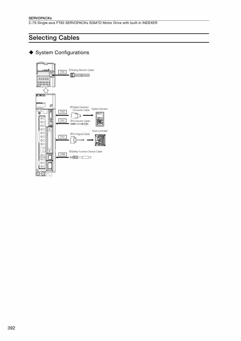
SERVOPACKsΣ-7S Single-axis FT83 SERVOPACKs SGM7D Motor Drive with built-in INDEXER
392
Selecting Cables
System Configurations
I/O Signal Cable
Digital OperatorDigital Operator
Converter Cable
Analog Monitor Cable
Safety Function Device Cable
Computer Cable
Host controller
CN3VCMP
SVON COIN TGON REF CHARGE
ALARM
DATAJOGSVON
SCROLL MODE/SETRESET
SERVO
READ WRITESERVO
YASKAWA
DIGITAL OPERATOR JUSP−OP05A−1−E
CN7
CN1
CN8
CN5
JZSP-CVS06-02-E
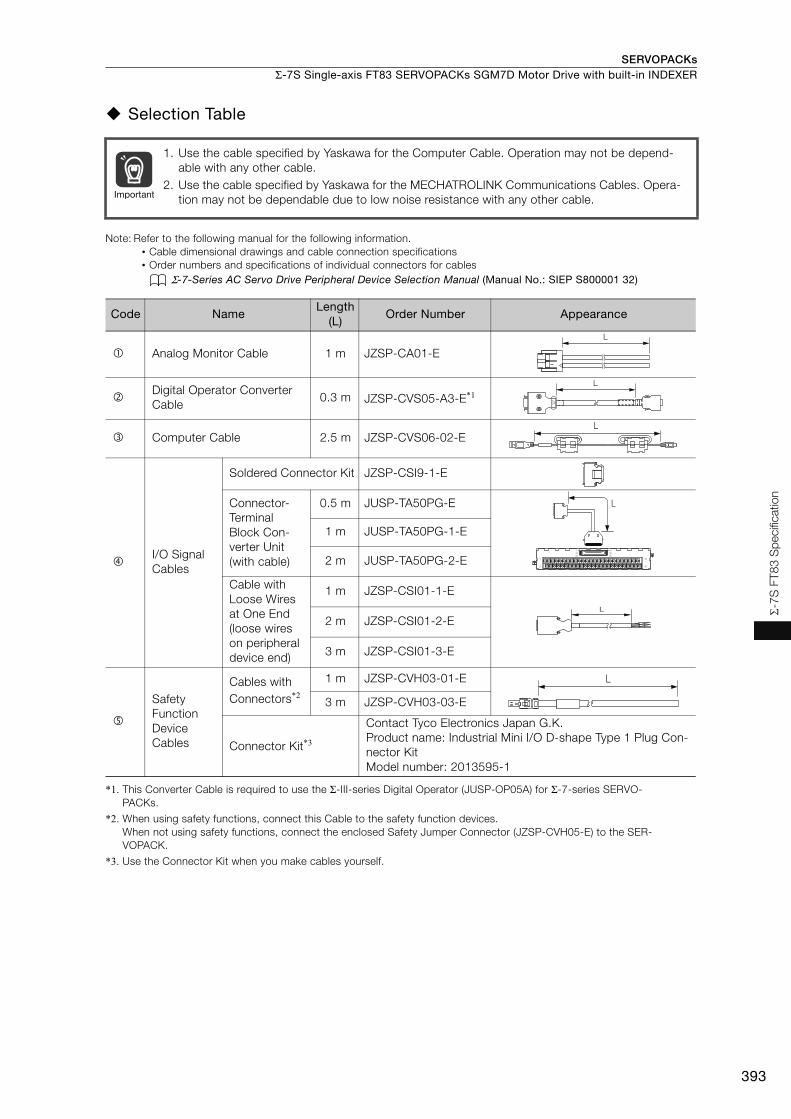
SERVOPACKs Σ-7S Single-axis FT83 SERVOPACKs SGM7D Motor Drive with built-in INDEXER
393
Σ-7
S F
T8
3 S
pecifi
catio
n
Selection Table
Note: Refer to the following manual for the following information.• Cable dimensional drawings and cable connection specifications• Order numbers and specifications of individual connectors for cables
Σ-7-Series AC Servo Drive Peripheral Device Selection Manual (Manual No.: SIEP S800001 32)
*1. This Converter Cable is required to use the Σ-III-series Digital Operator (JUSP-OP05A) for Σ-7-series SERVO-PACKs.
*2. When using safety functions, connect this Cable to the safety function devices.When not using safety functions, connect the enclosed Safety Jumper Connector (JZSP-CVH05-E) to the SER-VOPACK.
*3. Use the Connector Kit when you make cables yourself.
1. Use the cable specified by Yaskawa for the Computer Cable. Operation may not be depend-able with any other cable.
2. Use the cable specified by Yaskawa for the MECHATROLINK Communications Cables. Opera-tion may not be dependable due to low noise resistance with any other cable.
Code NameLength
(L)Order Number Appearance
Analog Monitor Cable 1 m JZSP-CA01-E
Digital Operator Converter Cable
0.3 m JZSP-CVS05-A3-E*1
Computer Cable 2.5 m JZSP-CVS06-02-E
I/O Signal Cables
Soldered Connector Kit JZSP-CSI9-1-E
Connector-Terminal Block Con-verter Unit(with cable)
0.5 m JUSP-TA50PG-E
1 m JUSP-TA50PG-1-E
2 m JUSP-TA50PG-2-E
Cable with Loose Wires at One End(loose wires on peripheral device end)
1 m JZSP-CSI01-1-E
2 m JZSP-CSI01-2-E
3 m JZSP-CSI01-3-E
Safety Function Device Cables
Cables with Connectors*2
1 m JZSP-CVH03-01-E
3 m JZSP-CVH03-03-E
Connector Kit*3
Contact Tyco Electronics Japan G.K.Product name: Industrial Mini I/O D-shape Type 1 Plug Con-nector KitModel number: 2013595-1
Important
L
L
L
1
19
33
16
32
50
1
1
2
49
50
L
L
L

SERVOPACKs
394
Σ-7W Two-axis MECHATROLINK-III Communications Reference SERVOPACKs
Model Designations
*1. You can use these models with either a single-phase or three-phase power supply input.
*2. If you use the Servomotor with a single-phase 200-VAC power supply input, derate the load ratio to 65%.An example is given below. If the load ratio of the first axis is 90%, use a load ratio of 40% for the second axis so that average load ratio for both axes is 65%.((90% + 40%)/2 = 65%)
*3. The same SERVOPACKs are used for both Rotary Servomotors and Linear Servomotors.
*4. Refer to the following manual for details. Σ-7-Series AC Servo Drive Σ-7S/Σ-7W SERVOPACK with Hardware Option Specifications Dynamic Brake Prod-
uct Manual (Manual No.: SIEP S800001 73)
*5. Refer to the following manual for details. Σ-7-Series AC Servo Drive Σ-7W SERVOPACK with Hardware Option Specifications HWBB Function Product
Manual (Manual No.: SIEP S800001 72)
*6. The BTO specification indicates if the SERVOPACK is customized by using the MechatroCloud BTO service.You need a BTO number to order SERVOPACKs with customized specifications.Refer to page M-15 for the details on the BTO service.
SGD7W - 1R6 A 20 A 0014th digit
1st+2nd+3rd digits
5th+6th digits
8th+9th+10th digits
7th digit
00011th+12th+13th
digits
B14thdigit
Maximum Applicable Motor Capacity per Axis
A 200 VAC
Voltage
Code Specification
1R6*1
2R8*1
5R5*1*2
7R6
0.2 kW
0.4 kW
0.75 kW
1.0 kW
Voltage Code Specification
Three-phase, 200VAC
1st+2nd+3rd digits 4th digitHardware Options Specification8th+9th+10th digits
20
A
Interface*3
Code Specification
MECHATROLINK-III communications reference
Design Revision Order
5th+6th digits
7th digit
-7 Series -7W SERVOPACKs
NoneWithout options
All models
SGD7W-1R6A to -2R8A
SGD7W-5R5A to -7R6A
All models
001002
700*5
020*4
Varnished
No dynamic brake
External dynamic brake resistor
HWBB option
Code SpecificationApplicable
Models
000Rack-mounted
FT/EX Specification11th+12th+13th digits
None
Code Specification
None000
BTO Specification*6
(Available in Japan only)14th digit
None
Code Specification
NoneB BTO Specification
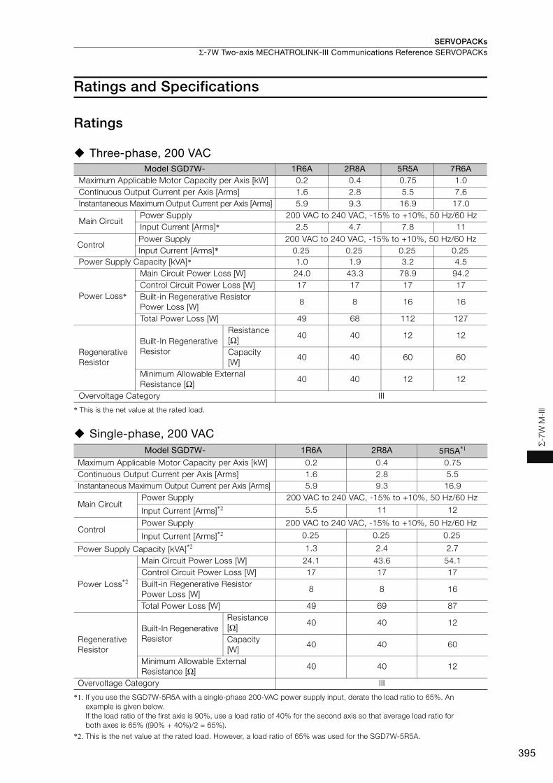
SERVOPACKs Σ-7W Two-axis MECHATROLINK-III Communications Reference SERVOPACKs
395
Σ-7
W M
-III
Ratings and Specifications
Ratings
Three-phase, 200 VAC
* This is the net value at the rated load.
Single-phase, 200 VAC
*1. If you use the SGD7W-5R5A with a single-phase 200-VAC power supply input, derate the load ratio to 65%. An example is given below.If the load ratio of the first axis is 90%, use a load ratio of 40% for the second axis so that average load ratio for both axes is 65% ((90% + 40%)/2 = 65%).
*2. This is the net value at the rated load. However, a load ratio of 65% was used for the SGD7W-5R5A.
Model SGD7W- 1R6A 2R8A 5R5A 7R6AMaximum Applicable Motor Capacity per Axis [kW] 0.2 0.4 0.75 1.0 Continuous Output Current per Axis [Arms] 1.6 2.8 5.5 7.6Instantaneous Maximum Output Current per Axis [Arms] 5.9 9.3 16.9 17.0
Main Circuit Power Supply 200 VAC to 240 VAC, -15% to +10%, 50 Hz/60 Hz Input Current [Arms]* 2.5 4.7 7.8 11
ControlPower Supply 200 VAC to 240 VAC, -15% to +10%, 50 Hz/60 HzInput Current [Arms]* 0.25 0.25 0.25 0.25
Power Supply Capacity [kVA]* 1.0 1.9 3.2 4.5
Power Loss*
Main Circuit Power Loss [W] 24.0 43.3 78.9 94.2Control Circuit Power Loss [W] 17 17 17 17Built-in Regenerative Resistor Power Loss [W]
8 8 16 16
Total Power Loss [W] 49 68 112 127
Regenerative Resistor
Built-In Regenerative Resistor
Resistance [Ω]
40 40 12 12
Capacity [W]
40 40 60 60
Minimum Allowable External Resistance [Ω]
40 40 12 12
Overvoltage Category III
Model SGD7W- 1R6A 2R8A 5R5A*1
Maximum Applicable Motor Capacity per Axis [kW] 0.2 0.4 0.75Continuous Output Current per Axis [Arms] 1.6 2.8 5.5Instantaneous Maximum Output Current per Axis [Arms] 5.9 9.3 16.9
Main Circuit Power Supply 200 VAC to 240 VAC, -15% to +10%, 50 Hz/60 Hz
Input Current [Arms]*2 5.5 11 12
ControlPower Supply 200 VAC to 240 VAC, -15% to +10%, 50 Hz/60 Hz
Input Current [Arms]*2 0.25 0.25 0.25
Power Supply Capacity [kVA]*2 1.3 2.4 2.7
Power Loss*2
Main Circuit Power Loss [W] 24.1 43.6 54.1Control Circuit Power Loss [W] 17 17 17Built-in Regenerative Resistor Power Loss [W]
8 8 16
Total Power Loss [W] 49 69 87
Regenerative Resistor
Built-In Regenerative Resistor
Resistance [Ω]
40 40 12
Capacity [W]
40 40 60
Minimum Allowable External Resistance [Ω]
40 40 12
Overvoltage Category III
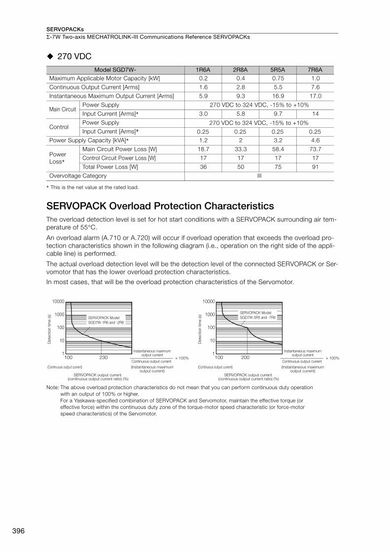
SERVOPACKsΣ-7W Two-axis MECHATROLINK-III Communications Reference SERVOPACKs
396
270 VDC
* This is the net value at the rated load.
SERVOPACK Overload Protection CharacteristicsThe overload detection level is set for hot start conditions with a SERVOPACK surrounding air tem-perature of 55°C.
An overload alarm (A.710 or A.720) will occur if overload operation that exceeds the overload pro-tection characteristics shown in the following diagram (i.e., operation on the right side of the appli-cable line) is performed.
The actual overload detection level will be the detection level of the connected SERVOPACK or Ser-vomotor that has the lower overload protection characteristics.
In most cases, that will be the overload protection characteristics of the Servomotor.
Note: The above overload protection characteristics do not mean that you can perform continuous duty operation with an output of 100% or higher.For a Yaskawa-specified combination of SERVOPACK and Servomotor, maintain the effective torque (or effective force) within the continuous duty zone of the torque-motor speed characteristic (or force-motor speed characteristics) of the Servomotor.
Model SGD7W- 1R6A 2R8A 5R5A 7R6AMaximum Applicable Motor Capacity [kW] 0.2 0.4 0.75 1.0
Continuous Output Current [Arms] 1.6 2.8 5.5 7.6
Instantaneous Maximum Output Current [Arms] 5.9 9.3 16.9 17.0
Main CircuitPower Supply 270 VDC to 324 VDC, -15% to +10%
Input Current [Arms]* 3.0 5.8 9.7 14
ControlPower Supply 270 VDC to 324 VDC, -15% to +10%Input Current [Arms]* 0.25 0.25 0.25 0.25
Power Supply Capacity [kVA]* 1.2 2 3.2 4.6
Power Loss*
Main Circuit Power Loss [W] 18.7 33.3 58.4 73.7
Control Circuit Power Loss [W] 17 17 17 17
Total Power Loss [W] 36 50 75 91
Overvoltage Category III
100 230
10000
1000
100
10
1100 200
10000
1000
100
10
1
SERVOPACK Model:
SGD7W-1R6 and -2R8
SERVOPACK Model:
SGD7W-5R5 and -7R6
SERVOPACK output current (continuous output current ratio) (%)
Continuous output current× 100%
Instantaneous maximum output current
(Instantaneous maximum output current)
(Continuous output current)
SERVOPACK output current (continuous output current ratio) (%)
Continuous output current× 100%
Instantaneous maximum output current
(Instantaneous maximum output current)
(Continuous output current)
Dete
ctio
n t
ime (s)
Dete
ctio
n t
ime (s)
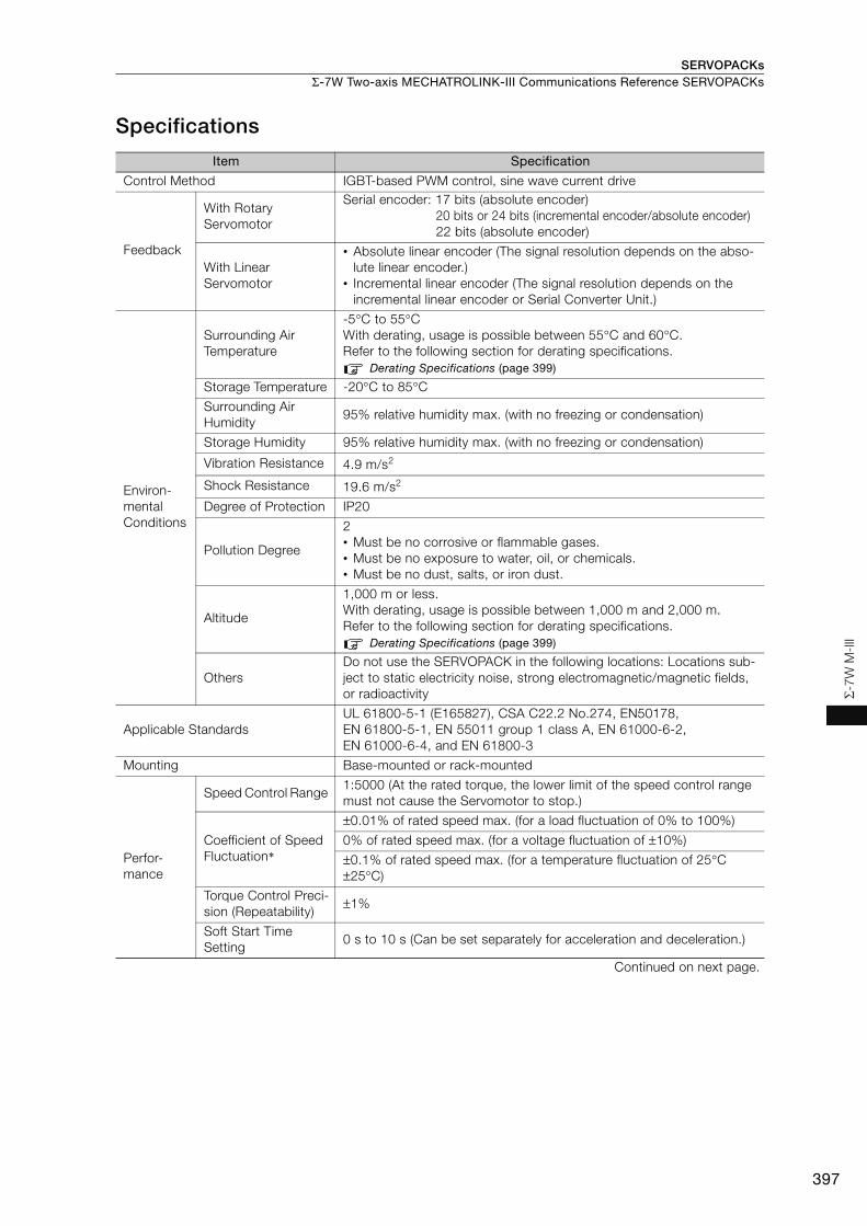
SERVOPACKs Σ-7W Two-axis MECHATROLINK-III Communications Reference SERVOPACKs
397
Σ-7
W M
-III
Specifications
Item Specification
Control Method IGBT-based PWM control, sine wave current drive
Feedback
With Rotary Servomotor
Serial encoder: 17 bits (absolute encoder)20 bits or 24 bits (incremental encoder/absolute encoder)22 bits (absolute encoder)
With Linear Servomotor
• Absolute linear encoder (The signal resolution depends on the abso-lute linear encoder.)
• Incremental linear encoder (The signal resolution depends on the incremental linear encoder or Serial Converter Unit.)
Environ-mental Conditions
Surrounding Air Temperature
-5°C to 55°C With derating, usage is possible between 55°C and 60°C. Refer to the following section for derating specifications.
Derating Specifications (page 399)
Storage Temperature -20°C to 85°C
Surrounding Air Humidity
95% relative humidity max. (with no freezing or condensation)
Storage Humidity 95% relative humidity max. (with no freezing or condensation)
Vibration Resistance 4.9 m/s2
Shock Resistance 19.6 m/s2
Degree of Protection IP20
Pollution Degree
2• Must be no corrosive or flammable gases.• Must be no exposure to water, oil, or chemicals. • Must be no dust, salts, or iron dust.
Altitude
1,000 m or less. With derating, usage is possible between 1,000 m and 2,000 m.Refer to the following section for derating specifications.
Derating Specifications (page 399)
Others Do not use the SERVOPACK in the following locations: Locations sub-ject to static electricity noise, strong electromagnetic/magnetic fields, or radioactivity
Applicable Standards UL 61800-5-1 (E165827), CSA C22.2 No.274, EN50178, EN 61800-5-1, EN 55011 group 1 class A, EN 61000-6-2, EN 61000-6-4, and EN 61800-3
Mounting Base-mounted or rack-mounted
Perfor-mance
Speed Control Range 1:5000 (At the rated torque, the lower limit of the speed control range must not cause the Servomotor to stop.)
Coefficient of Speed Fluctuation*
±0.01% of rated speed max. (for a load fluctuation of 0% to 100%)
0% of rated speed max. (for a voltage fluctuation of ±10%)
±0.1% of rated speed max. (for a temperature fluctuation of 25°C ±25°C)
Torque Control Preci-sion (Repeatability)
±1%
Soft Start Time Setting
0 s to 10 s (Can be set separately for acceleration and deceleration.)
Continued on next page.
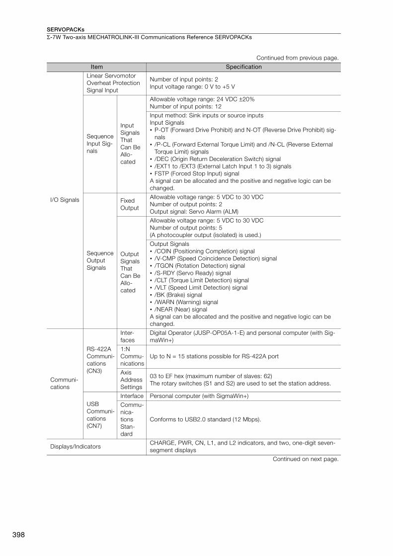
SERVOPACKsΣ-7W Two-axis MECHATROLINK-III Communications Reference SERVOPACKs
398
I/O Signals
Linear Servomotor Overheat Protection Signal Input
Number of input points: 2Input voltage range: 0 V to +5 V
Sequence Input Sig-nals
Input Signals That Can Be Allo-cated
Allowable voltage range: 24 VDC ±20% Number of input points: 12
Input method: Sink inputs or source inputsInput Signals• P-OT (Forward Drive Prohibit) and N-OT (Reverse Drive Prohibit) sig-
nals• /P-CL (Forward External Torque Limit) and /N-CL (Reverse External
Torque Limit) signals• /DEC (Origin Return Deceleration Switch) signal• /EXT1 to /EXT3 (External Latch Input 1 to 3) signals• FSTP (Forced Stop Input) signalA signal can be allocated and the positive and negative logic can be changed.
Sequence Output Signals
Fixed Output
Allowable voltage range: 5 VDC to 30 VDC Number of output points: 2 Output signal: Servo Alarm (ALM)
Output Signals That Can Be Allo-cated
Allowable voltage range: 5 VDC to 30 VDCNumber of output points: 5(A photocoupler output (isolated) is used.)
Output Signals• /COIN (Positioning Completion) signal• /V-CMP (Speed Coincidence Detection) signal• /TGON (Rotation Detection) signal• /S-RDY (Servo Ready) signal• /CLT (Torque Limit Detection) signal• /VLT (Speed Limit Detection) signal• /BK (Brake) signal• /WARN (Warning) signal• /NEAR (Near) signalA signal can be allocated and the positive and negative logic can be changed.
Communi-cations
RS-422A Communi-cations (CN3)
Inter-faces
Digital Operator (JUSP-OP05A-1-E) and personal computer (with Sig-maWin+)
1:N Commu-nications
Up to N = 15 stations possible for RS-422A port
Axis Address Settings
03 to EF hex (maximum number of slaves: 62) The rotary switches (S1 and S2) are used to set the station address.
USB Communi-cations (CN7)
Interface Personal computer (with SigmaWin+)
Commu-nica-tions Stan-dard
Conforms to USB2.0 standard (12 Mbps).
Displays/IndicatorsCHARGE, PWR, CN, L1, and L2 indicators, and two, one-digit seven-segment displays
Continued on next page.
Continued from previous page.
Item Specification
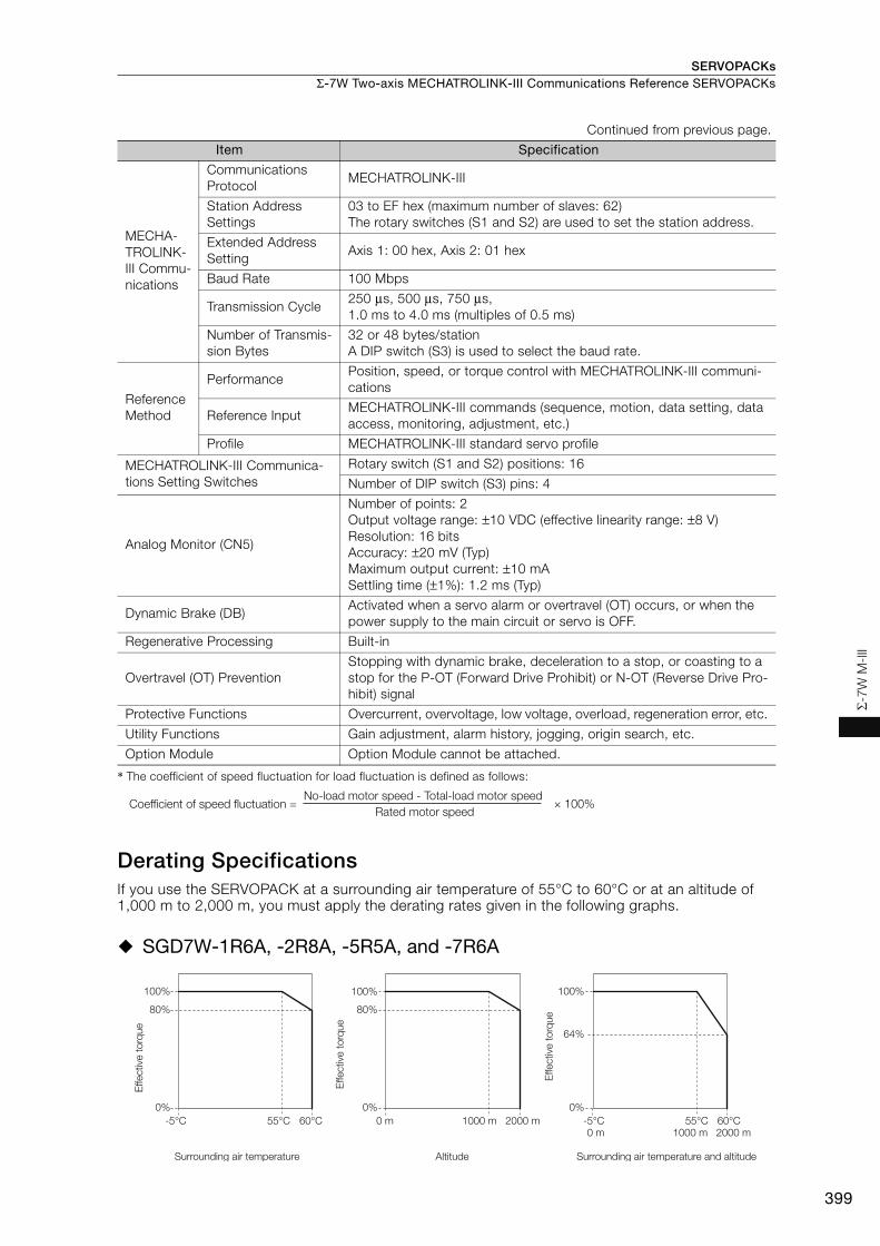
SERVOPACKs Σ-7W Two-axis MECHATROLINK-III Communications Reference SERVOPACKs
399
Σ-7
W M
-III
* The coefficient of speed fluctuation for load fluctuation is defined as follows:
Derating SpecificationsIf you use the SERVOPACK at a surrounding air temperature of 55°C to 60°C or at an altitude of 1,000 m to 2,000 m, you must apply the derating rates given in the following graphs.
SGD7W-1R6A, -2R8A, -5R5A, and -7R6A
MECHA-TROLINK-III Commu-nications
Communications Protocol
MECHATROLINK-III
Station Address Settings
03 to EF hex (maximum number of slaves: 62) The rotary switches (S1 and S2) are used to set the station address.
Extended Address Setting
Axis 1: 00 hex, Axis 2: 01 hex
Baud Rate 100 Mbps
Transmission Cycle 250 μs, 500 μs, 750 μs, 1.0 ms to 4.0 ms (multiples of 0.5 ms)
Number of Transmis-sion Bytes
32 or 48 bytes/stationA DIP switch (S3) is used to select the baud rate.
Reference Method
Performance Position, speed, or torque control with MECHATROLINK-III communi-cations
Reference Input MECHATROLINK-III commands (sequence, motion, data setting, data access, monitoring, adjustment, etc.)
Profile MECHATROLINK-III standard servo profile
MECHATROLINK-III Communica-tions Setting Switches
Rotary switch (S1 and S2) positions: 16
Number of DIP switch (S3) pins: 4
Analog Monitor (CN5)
Number of points: 2Output voltage range: ±10 VDC (effective linearity range: ±8 V)Resolution: 16 bits Accuracy: ±20 mV (Typ)Maximum output current: ±10 mASettling time (±1%): 1.2 ms (Typ)
Dynamic Brake (DB) Activated when a servo alarm or overtravel (OT) occurs, or when the power supply to the main circuit or servo is OFF.
Regenerative Processing Built-in
Overtravel (OT) Prevention Stopping with dynamic brake, deceleration to a stop, or coasting to a stop for the P-OT (Forward Drive Prohibit) or N-OT (Reverse Drive Pro-hibit) signal
Protective Functions Overcurrent, overvoltage, low voltage, overload, regeneration error, etc.
Utility Functions Gain adjustment, alarm history, jogging, origin search, etc.
Option Module Option Module cannot be attached.
Continued from previous page.
Item Specification
× 100%Coefficient of speed fluctuation =No-load motor speed - Total-load motor speed
Rated motor speed
100%
80%
2000 m
100%
1000 m
80%
0% 0%
0 m2000 m1000 m0 m
100%
0%
64%
-5°C 55°C 60°C -5°C 55°C 60°C
Effective
to
rque
Effective
to
rque
Surrounding air temperature Altitude
Effective
to
rque
Surrounding air temperature and altitude
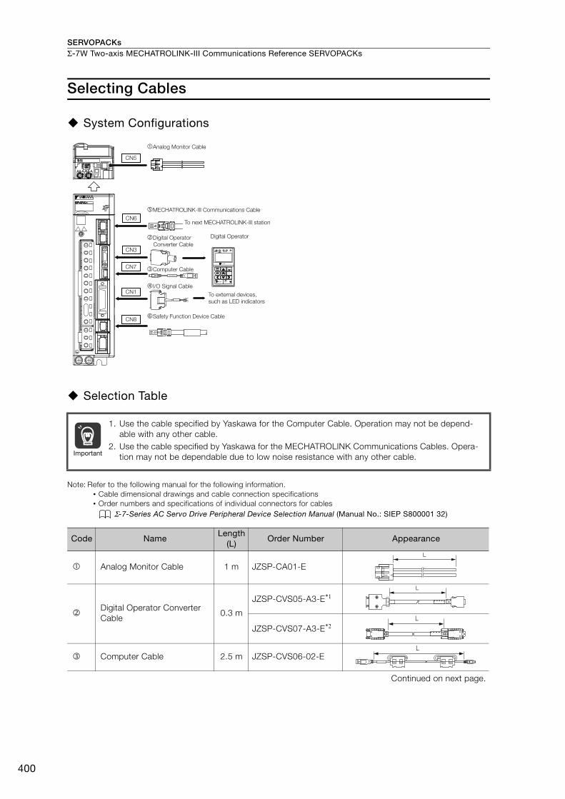
SERVOPACKsΣ-7W Two-axis MECHATROLINK-III Communications Reference SERVOPACKs
400
Selecting Cables
System Configurations
Selection Table
Note: Refer to the following manual for the following information.• Cable dimensional drawings and cable connection specifications• Order numbers and specifications of individual connectors for cables
Σ-7-Series AC Servo Drive Peripheral Device Selection Manual (Manual No.: SIEP S800001 32)
1. Use the cable specified by Yaskawa for the Computer Cable. Operation may not be depend-able with any other cable.
2. Use the cable specified by Yaskawa for the MECHATROLINK Communications Cables. Opera-tion may not be dependable due to low noise resistance with any other cable.
Code NameLength
(L)Order Number Appearance
Analog Monitor Cable 1 m JZSP-CA01-E
Digital Operator Converter Cable
0.3 m
JZSP-CVS05-A3-E*1
JZSP-CVS07-A3-E*2
Computer Cable 2.5 m JZSP-CVS06-02-E
Continued on next page.
Digital Operator
Converter Cable
Safety Function Device Cable
Analog Monitor Cable
I/O Signal Cable
To next MECHATROLINK-III station
MECHATROLINK-III Communications Cable
To external devices,
such as LED indicators
CN1
CN5
CN6
CN3
CN7
CN8
Digital Operator
Computer CableJZSP-CVS06-02-E
Important
L
L
L
L
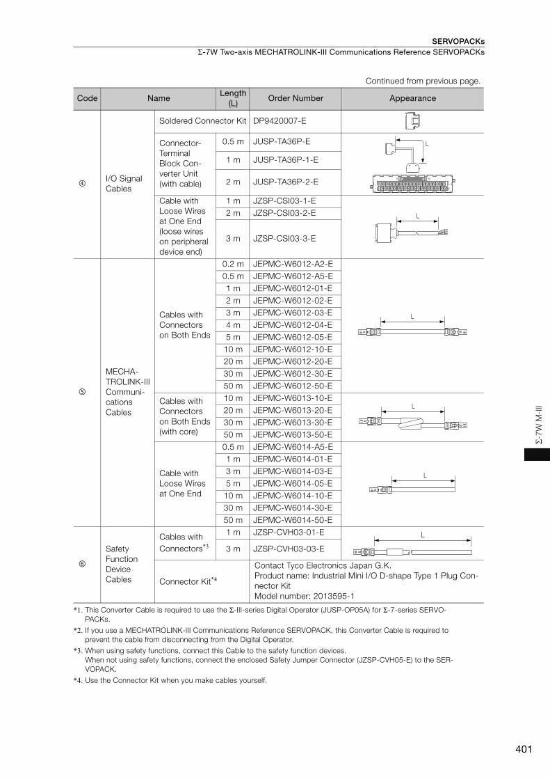
SERVOPACKs Σ-7W Two-axis MECHATROLINK-III Communications Reference SERVOPACKs
401
Σ-7
W M
-III
*1. This Converter Cable is required to use the Σ-III-series Digital Operator (JUSP-OP05A) for Σ-7-series SERVO-PACKs.
*2. If you use a MECHATROLINK-III Communications Reference SERVOPACK, this Converter Cable is required to prevent the cable from disconnecting from the Digital Operator.
*3. When using safety functions, connect this Cable to the safety function devices.When not using safety functions, connect the enclosed Safety Jumper Connector (JZSP-CVH05-E) to the SER-VOPACK.
*4. Use the Connector Kit when you make cables yourself.
I/O Signal Cables
Soldered Connector Kit DP9420007-E
Connector-Terminal Block Con-verter Unit(with cable)
0.5 m JUSP-TA36P-E
1 m JUSP-TA36P-1-E
2 m JUSP-TA36P-2-E
Cable with Loose Wires at One End (loose wires on peripheral device end)
1 m JZSP-CSI03-1-E2 m JZSP-CSI03-2-E
3 m JZSP-CSI03-3-E
MECHA-TROLINK-III Communi-cations Cables
Cables with Connectors on Both Ends
0.2 m JEPMC-W6012-A2-E0.5 m JEPMC-W6012-A5-E1 m JEPMC-W6012-01-E2 m JEPMC-W6012-02-E3 m JEPMC-W6012-03-E4 m JEPMC-W6012-04-E5 m JEPMC-W6012-05-E
10 m JEPMC-W6012-10-E20 m JEPMC-W6012-20-E30 m JEPMC-W6012-30-E50 m JEPMC-W6012-50-E
Cables with Connectors on Both Ends(with core)
10 m JEPMC-W6013-10-E20 m JEPMC-W6013-20-E30 m JEPMC-W6013-30-E50 m JEPMC-W6013-50-E
Cable with Loose Wires at One End
0.5 m JEPMC-W6014-A5-E1 m JEPMC-W6014-01-E3 m JEPMC-W6014-03-E5 m JEPMC-W6014-05-E
10 m JEPMC-W6014-10-E30 m JEPMC-W6014-30-E50 m JEPMC-W6014-50-E
Safety Function Device Cables
Cables with Connectors*3
1 m JZSP-CVH03-01-E
3 m JZSP-CVH03-03-E
Connector Kit*4
Contact Tyco Electronics Japan G.K.Product name: Industrial Mini I/O D-shape Type 1 Plug Con-nector KitModel number: 2013595-1
Continued from previous page.
Code NameLength
(L)Order Number Appearance
40
391
2
B20A20
B1A1
L
L
L
L
L
L

SERVOPACKs
402
Σ-7C Two-axis Bus Connection Reference SERVOPACKs with built-in Controllers
Model Designations
*1. You can use these models with either a single-phase or three-phase power supply input.
*2. If you use the Servomotor with a single-phase 200-VAC power supply input, derate the load ratio to 65%.An example is given below. If the load ratio of the first axis is 90%, use a load ratio of 40% for the second axis so that average load ratio for both axes is 65%.((90% + 40%)/2 = 65%)
*3. The same SERVOPACKs are used for both Rotary Servomotors and Linear Servomotors.
*4. Refer to the following manual for details. Σ-7-Series AC Servo Drive Σ-7S/Σ-7W SERVOPACK with Hardware Option Specifications Dynamic Brake Prod-
uct Manual (Manual No.: SIEP S800001 73)
*5. Refer to the following manual for details. Σ-7-Series AC Servo Drive Σ-7W SERVOPACK with Hardware Option Specifications HWBB Function Product
Manual (Manual No.: SIEP S800001 72)
Maximum Applicable
Motor Capacity per Axis
A 200 VAC
Voltage
Code Specification
1R6*1
2R8*1
5R5*1*2
7R6
0.2 kW
0.4 kW
0.75 kW
1.0 kW
Voltage Code Specification
Three-
phase,
200
VAC
1st+2nd+3rd digits 4th digitHardware Options
Specification8th+9th+10th digits
MA
A
Interface*3
Code Specification
Bus connection references
Design Revision Order
5th+6th digits
7th digit
-7 Series
-7C SERVOPACKs
NoneWithout options
All models
SGD7C-1R6A
to -2R8A
SGD7C-5R5A
to -7R6A
All models
001
002
700*5
020*4
Varnished
No dynamic brake
External dynamic
brake resistor
HWBB option
Code SpecificationApplicable
Models
000
Rack-mounted
SGD7C - 1R6 A AMA 0014th digit
1st+2nd+3rd digits
5th+6th digits
8th+9th+10th digits
7th digit

SERVOPACKs Σ-7C Two-axis Bus Connection Reference SERVOPACKs with built-in Controllers
403
Σ-7
C
Ratings and Specifications
Ratings
Three-phase, 200 VAC
* This is the net value at the rated load.
Single-phase, 200 VAC
*1. If you use the SGD7C-5R5A with a single-phase 200-VAC power supply input, derate the load ratio to 65%. An example is given below.If the load ratio of the first axis is 90%, use a load ratio of 40% for the second axis so that average load ratio for both axes is 65% ((90% + 40%)/2 = 65%).
*2. This is the net value at the rated load. However, a load ratio of 65% was used for the SGD7W-5R5A.
Model SGD7C- 1R6A 2R8A 5R5A 7R6AMaximum Applicable Motor Capacity per Axis [kW] 0.2 0.4 0.75 1.0 Continuous Output Current per Axis [Arms] 1.6 2.8 5.5 7.6Instantaneous Maximum Output Current per Axis [Arms] 5.9 9.3 16.9 17.0
Main Circuit Power Supply 200 VAC to 240 VAC, -15% to +10%, 50 Hz/60 Hz Input Current [Arms]* 2.5 4.7 7.8 11
ControlPower Supply 200 VAC to 240 VAC, -15% to +10%, 50 Hz/60 HzInput Current [Arms]* 0.25 0.25 0.25 0.25
Power Supply Capacity [kVA]* 1.0 1.9 3.2 4.5
Power Loss*
Main Circuit Power Loss [W] 24.0 43.3 78.9 94.2Control Circuit Power Loss [W] 17 17 17 17Built-in Regenerative Resistor Power Loss [W]
8 8 16 16
Total Power Loss [W] 49 68 112 127
Regenerative Resistor
Built-In Regenerative Resistor
Resistance [Ω]
40 40 12 12
Capacity [W]
40 40 60 60
Minimum Allowable External Resis-tance [Ω]
40 40 12 12
Overvoltage Category III
Model SGD7C- 1R6A 2R8A 5R5A*1
Maximum Applicable Motor Capacity per Axis [kW] 0.2 0.4 0.75Continuous Output Current per Axis [Arms] 1.6 2.8 5.5Instantaneous Maximum Output Current per Axis [Arms] 5.9 9.3 16.9
Main Circuit Power Supply 200 VAC to 240 VAC, -15% to +10%, 50 Hz/60 Hz
Input Current [Arms]*2 5.5 11 12
ControlPower Supply 200 VAC to 240 VAC, -15% to +10%, 50 Hz/60 Hz
Input Current [Arms]*2 0.25 0.25 0.25
Power Supply Capacity [kVA]*2 1.3 2.4 2.7
Power Loss*2
Main Circuit Power Loss [W] 24.1 43.6 54.1Control Circuit Power Loss [W] 17 17 17Built-in Regenerative Resistor Power Loss [W]
8 8 16
Total Power Loss [W] 49 69 87
Regenerative Resistor
Built-In Regenerative Resistor
Resistance [Ω]
40 40 12
Capacity [W]
40 40 60
Minimum Allowable External Resistance [Ω]
40 40 12
Overvoltage Category III
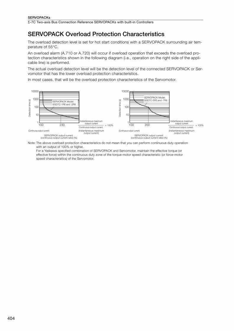
SERVOPACKsΣ-7C Two-axis Bus Connection Reference SERVOPACKs with built-in Controllers
404
SERVOPACK Overload Protection CharacteristicsThe overload detection level is set for hot start conditions with a SERVOPACK surrounding air tem-perature of 55°C.
An overload alarm (A.710 or A.720) will occur if overload operation that exceeds the overload pro-tection characteristics shown in the following diagram (i.e., operation on the right side of the appli-cable line) is performed.
The actual overload detection level will be the detection level of the connected SERVOPACK or Ser-vomotor that has the lower overload protection characteristics.
In most cases, that will be the overload protection characteristics of the Servomotor.
Note: The above overload protection characteristics do not mean that you can perform continuous duty operation with an output of 100% or higher.For a Yaskawa-specified combination of SERVOPACK and Servomotor, maintain the effective torque (or effective force) within the continuous duty zone of the torque-motor speed characteristic (or force-motor speed characteristics) of the Servomotor.
100 230
10000
1000
100
10
1100 200
10000
1000
100
10
1
SERVOPACK Model:
SGD7C-1R6 and -2R8
SERVOPACK Model:
SGD7C-5R5 and -7R6
SERVOPACK output current (continuous output current ratio) (%)
Continuous output current× 100%
Instantaneous maximum output current
(Instantaneous maximum output current)
(Continuous output current)
SERVOPACK output current (continuous output current ratio) (%)
Continuous output current× 100%
Instantaneous maximum output current
(Instantaneous maximum output current)
(Continuous output current)
Dete
ctio
n t
ime (s)
Dete
ctio
n t
ime (s)
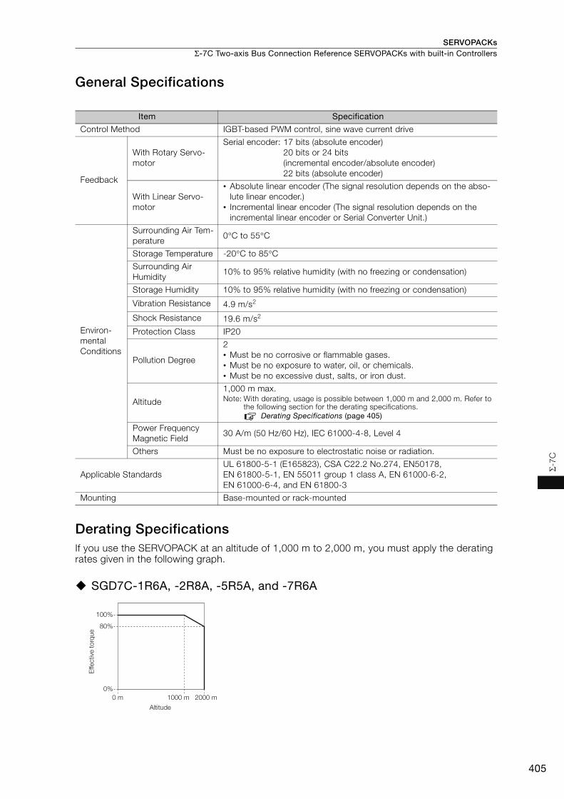
SERVOPACKs Σ-7C Two-axis Bus Connection Reference SERVOPACKs with built-in Controllers
405
Σ-7
C
General Specifications
Derating SpecificationsIf you use the SERVOPACK at an altitude of 1,000 m to 2,000 m, you must apply the derating rates given in the following graph.
SGD7C-1R6A, -2R8A, -5R5A, and -7R6A
Item Specification
Control Method IGBT-based PWM control, sine wave current drive
Feedback
With Rotary Servo-motor
Serial encoder: 17 bits (absolute encoder)20 bits or 24 bits(incremental encoder/absolute encoder)22 bits (absolute encoder)
With Linear Servo-motor
• Absolute linear encoder (The signal resolution depends on the abso-lute linear encoder.)
• Incremental linear encoder (The signal resolution depends on the incremental linear encoder or Serial Converter Unit.)
Environ-mental Conditions
Surrounding Air Tem-perature
0°C to 55°C
Storage Temperature -20°C to 85°C
Surrounding Air Humidity
10% to 95% relative humidity (with no freezing or condensation)
Storage Humidity 10% to 95% relative humidity (with no freezing or condensation)
Vibration Resistance 4.9 m/s2
Shock Resistance 19.6 m/s2
Protection Class IP20
Pollution Degree
2• Must be no corrosive or flammable gases.• Must be no exposure to water, oil, or chemicals.• Must be no excessive dust, salts, or iron dust.
Altitude
1,000 m max.Note: With derating, usage is possible between 1,000 m and 2,000 m. Refer to
the following section for the derating specifications.Derating Specifications (page 405)
Power Frequency Magnetic Field
30 A/m (50 Hz/60 Hz), IEC 61000-4-8, Level 4
Others Must be no exposure to electrostatic noise or radiation.
Applicable StandardsUL 61800-5-1 (E165823), CSA C22.2 No.274, EN50178, EN 61800-5-1, EN 55011 group 1 class A, EN 61000-6-2, EN 61000-6-4, and EN 61800-3
Mounting Base-mounted or rack-mounted
2000 m
100%
1000 m
80%
0%
0 m
Altitude
Effective
to
rque
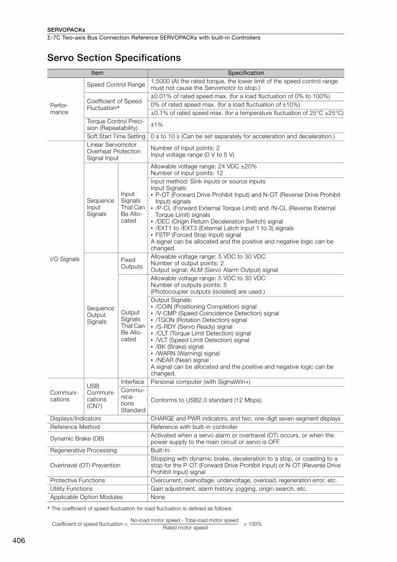
SERVOPACKsΣ-7C Two-axis Bus Connection Reference SERVOPACKs with built-in Controllers
406
Servo Section Specifications
* The coefficient of speed fluctuation for load fluctuation is defined as follows:
Item Specification
Perfor-mance
Speed Control Range 1:5000 (At the rated torque, the lower limit of the speed control range must not cause the Servomotor to stop.)
Coefficient of Speed Fluctuation*
±0.01% of rated speed max. (for a load fluctuation of 0% to 100%)0% of rated speed max. (for a load fluctuation of ±10%)±0.1% of rated speed max. (for a temperature fluctuation of 25°C ±25°C)
Torque Control Preci-sion (Repeatability) ±1%
Soft Start Time Setting 0 s to 10 s (Can be set separately for acceleration and deceleration.)
I/O Signals
Linear Servomotor Overheat Protection Signal Input
Number of input points: 2Input voltage range (0 V to 5 V)
Sequence Input Signals
Input Signals That Can Be Allo-cated
Allowable voltage range: 24 VDC ±20%Number of input points: 12Input method: Sink inputs or source inputsInput Signals:• P-OT (Forward Drive Prohibit Input) and N-OT (Reverse Drive Prohibit
Input) signals• /P-CL (Forward External Torque Limit) and /N-CL (Reverse External
Torque Limit) signals• /DEC (Origin Return Deceleration Switch) signal• /EXT1 to /EXT3 (External Latch Input 1 to 3) signals• FSTP (Forced Stop Input) signalA signal can be allocated and the positive and negative logic can be changed.
Sequence Output Signals
Fixed Outputs
Allowable voltage range: 5 VDC to 30 VDCNumber of output points: 2Output signal: ALM (Servo Alarm Output) signal
Output Signals That Can Be Allo-cated
Allowable voltage range: 5 VDC to 30 VDCNumber of outputs points: 5(Photocoupler outputs (isolated) are used.)Output Signals:• /COIN (Positioning Completion) signal• /V-CMP (Speed Coincidence Detection) signal• /TGON (Rotation Detection) signal• /S-RDY (Servo Ready) signal• /CLT (Torque Limit Detection) signal• /VLT (Speed Limit Detection) signal• /BK (Brake) signal• /WARN (Warning) signal• /NEAR (Near) signalA signal can be allocated and the positive and negative logic can be changed.
Communi-cations
USB Communi-cations (CN7)
Interface Personal computer (with SigmaWin+)Commu-nica-tions Standard
Conforms to USB2.0 standard (12 Mbps).
Displays/Indicators CHARGE and PWR indicators, and two, one-digit seven-segment displaysReference Method Reference with built-in controller
Dynamic Brake (DB) Activated when a servo alarm or overtravel (OT) occurs, or when the power supply to the main circuit or servo is OFF.
Regenerative Processing Built-in
Overtravel (OT) PreventionStopping with dynamic brake, deceleration to a stop, or coasting to a stop for the P-OT (Forward Drive Prohibit Input) or N-OT (Reverse Drive Prohibit Input) signal
Protective Functions Overcurrent, overvoltage, undervoltage, overload, regeneration error, etc.Utility Functions Gain adjustment, alarm history, jogging, origin search, etc.Applicable Option Modules None
× 100%Coefficient of speed fluctuation =No-load motor speed - Total-load motor speed
Rated motor speed

SERVOPACKs Σ-7C Two-axis Bus Connection Reference SERVOPACKs with built-in Controllers
407
Σ-7
C
Controller Section SpecificationsThis section provides the specifications of the Controller Section.
Hardware Specifications
Item Specification
Flash Memory Capacity: 24 MB (15 MB of user memory)
SDRAM Capacity: 256 MB
MRAM Capacity: 4 MB
CalendarSeconds, minutes, hour, day, week, month, year, day of week, and timing
Ethernet One port, 10Base-T or 100Base-TX
MECHA-TROLINK
• MECHATROLINK-III, 1 circuit with 1 port• Master
USB• USB 2.0, Type A host, 1 port• Compatible devices: USB storage
Indicators and Displays
• Seven-segment display• Status indicators• USB Status Indicator• Ethernet status indicators
Switches• DIP switches: Mode switches• STOP/SAVE switch
Connectors
• MECHATROLINK-III connector (CN6)• USB connector (CN10)• Ethernet connector (CN12)• Controller Section I/O connector (CN13)

SERVOPACKsΣ-7C Two-axis Bus Connection Reference SERVOPACKs with built-in Controllers
408
Performance Specifications
Item Specification Remarks
Num
ber
of
Con
trol
led
Axe
s SVC44 axes 1 circuit
Circuit number selected from 1 to 16.
SVD 2 axes Circuit number selected from 1 to 16.
SVR44 axes 1 circuit
Circuit number selected from 1 to 16.
Maximum Number of Controlled Axes
6 axes –
Sca
n T
ime
Set
tings
H Scan0.5 ms to 32.0 ms (in 0.25-ms increments)
Refer to the following manual for details.Σ-7-Series Σ-7C SERVOPACK Product Manual (Manual No.: SIEP S800002 04)
L Scan2.0 ms to 300 ms (in 0.5-ms increments)
−
H Scan Default 4 ms −L Scan Default 200 ms −
Per
iphe
ral
Dev
ices
Calendar Supported. −Communications Interface Ethernet −
USB Supported. −
Mem
ory
Cap
acity
DRAM 256 MB with ECC −
MRAM 4 MBUp to 1 MB can be used to back up table data.
Program Capacity 15 MBTotal capacity including definition data, ladder programs, table data, etc.
Lad
der
Pro
gram
s
Number of Startup Drawings (DWG.A)
64
Number of steps per drawing: 4,000
Number of Interrupt Drawings (DWG.I)
64
Number of High-Speed Scan Drawings (DWG.H)
1000
Number of Low-Speed Scan Drawings (DWG.L)
2000
Number of User Function Drawings
2000
Mot
ion
Pro
gram
s
Number of Programs 512
Total of all programs listed below:• Motion main programs• Motion subprograms• Sequence main programs• Sequence subprograms
Number of Groups 16 −Number of Tasks 32 −Number of Nesting Levels for IF Instructions
8 −
Number of Nesting Levels for MSEE Instructions
8 −
Number of Parallel Forks Per Task
8
Select from the following four options:• Main: 4 forks, Sub: 2 forks• Main: 8 forks• Main: 2 forks, Sub: 4 forks• Sub: 8 forks
Number of Simultaneously Controlled Axes Per Task
10 axes −
Continued on next page.

SERVOPACKs Σ-7C Two-axis Bus Connection Reference SERVOPACKs with built-in Controllers
409
Σ-7
C
Reg
iste
rs
S Registers 64 Kwords −M Registers 1 Mword −G Registers 2 Mwords −I/O Registers 64 Kwords −Motion Registers 32 Kwords −C Registers 16 Kwords −# Registers 16 Kwords −D Registers 16 Kwords −
Dat
a Ty
pes
Bit (B) Supported. 0 or 1Integer (W) Supported. −32,768 to 32,767Double-Length Integer (L) Supported. -2,147,483,648 to 2,147,483,647
Quadruple-Length Integer (Q) Supported.-9,223,372,036,854,775,808 to 9,223,372,036,854,775,807
Single-Precision Real Number (F) Supported. ± (1.175E-38 to 3.402E+38) or 0Double-Precision Real Num-ber (D)
Supported. ±(2.225E-308 to 1.798E+308) or 0
Addresses (A) Supported. 0 to 16,777,214
Ind
ex R
egis
ters Subscript i Supported. Special registers for offsetting addresses.
Subscripts i and j function identically.Subscript j Supported.
Array Registers Supported. Used to handle registers as arrays.
Dat
a Tr
acin
g
Number of Groups 4 −
Trace Memory256 Kwords total in 4 groups
−
Traceable Data Points 16 points per group −
Trigger Types
>, <, =, <>, >=, <= and differential detec-tion of the above con-ditions
−
Dat
a Lo
ggin
g
Number of Groups 4 −
Log Storage LocationBuilt-in RAM disk or USB memory device
−
Log File FormatsCSV file format or binary file format
−
Data Logging Points 64 points per group −
Number of Log Files
Built-in RAM Disk
1 to 4,000 −
USB Memory1 to 32,767 or unlim-ited
The ultimate upper limit is 10,000 files even if unlimited is selected.
Trigger Types >, <, =, <>, >=, <= −
Continued from previous page.
Item Specification Remarks
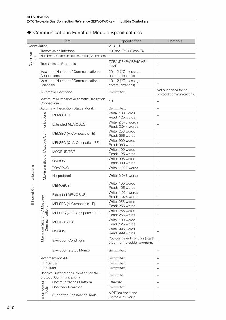
SERVOPACKsΣ-7C Two-axis Bus Connection Reference SERVOPACKs with built-in Controllers
410
Communications Function Module Specifications
Item Specification RemarksAbbreviation 218IFD
Com
mon
Ite
ms
Transmission Interface 10Base-T/100Base-TX −Number of Communications Ports (Connectors) 1 −
Transmission ProtocolsTCP/UDP/IP/ARP/ICMP/IGMP
−
Eth
erne
t C
omm
unic
atio
ns
Maximum Number of Communications Connections
20 + 2 (I/O message communications)
−
Maximum Number of Communications Channels
10 + 2 (I/O message communications)
−
Automatic Reception Supported.Not supported for no-protocol communications.
Maximum Number of Automatic Reception Connections
10 −
Automatic Reception Status Monitor Supported. −
Max
imum
Siz
e of
Mes
sage
Com
mun
icat
ions MEMOBUS
Write: 100 wordsRead: 125 words
−
Extended MEMOBUSWrite: 2,043 wordsRead: 2,044 words
−
MELSEC (A-Compatible 1E)Write: 256 wordsRead: 256 words
−
MELSEC (QnA-Compatible 3E)Write: 960 wordsRead: 960 words
−
MODBUS/TCPWrite: 100 wordsRead: 125 words
−
OMRONWrite: 996 wordsRead: 999 words
−
TOYOPUC Write: 1,022 words −
No-protocol Write: 2,046 words −
Max
imum
Siz
e of
I/O
Mes
sage
C
omm
unic
atio
ns
MEMOBUSWrite: 100 wordsRead: 125 words
−
Extended MEMOBUSWrite: 1,024 wordsRead: 1,024 words
−
MELSEC (A-Compatible 1E)Write: 256 wordsRead: 256 words
−
MELSEC (QnA-Compatible 3E)Write: 256 wordsRead: 256 words
−
MODBUS/TCPWrite: 100 wordsRead: 125 words
−
OMRONWrite: 996 wordsRead: 999 words
−
Execution ConditionsYou can select controls (start/stop) from a ladder program.
−
Execution Status Monitor Supported. −
MotomanSync-MP Supported. −FTP Server Supported. −FTP Client Supported. −Receive Buffer Mode Selection for No-protocol Communications
Supported. −
Eng
inee
ring
Tool
s
Communications Platform Ethernet −Controller Searches Supported. −
Supported Engineering ToolsMPE720 Ver.7 and SigmaWin+ Ver.7
−
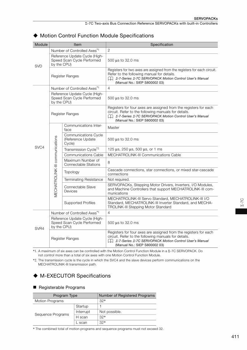
SERVOPACKs Σ-7C Two-axis Bus Connection Reference SERVOPACKs with built-in Controllers
411
Σ-7
C
Motion Control Function Module Specifications
*1. A maximum of six axes can be controlled with the Motion Control Function Module in a Σ-7C SERVOPACK. Do not control more than a total of six axes with one Motion Control Function Module.
*2. The transmission cycle is the cycle in which the SVC4 and the slave devices perform communications on the MECHATROLINIK-III transmission path.
M-EXECUTOR Specifications
Registerable Programs
* The combined total of motion programs and sequence programs must not exceed 32.
Module Item Specification
SVD
Number of Controlled Axes*1 2
Reference Update Cycle (High-Speed Scan Cycle Performed by the CPU)
500 μs to 32.0 ms
Register Ranges
Registers for two axes are assigned from the registers for each circuit. Refer to the following manual for details.
Σ-7-Series Σ-7C SERVOPACK Motion Control User’s Manual (Manual No.: SIEP S800002 03)
SVC4
Number of Controlled Axes*1 4
Reference Update Cycle (High-Speed Scan Cycle Performed by the CPU)
500 μs to 32.0 ms
Register Ranges
Registers for four axes are assigned from the registers for each circuit. Refer to the following manuals for details.
Σ-7-Series Σ-7C SERVOPACK Motion Control User’s Manual (Manual No.: SIEP S800002 03)
ME
CH
ATR
OLI
NK
-III
com
mun
icat
ions
Communications Inter-face Master
Communications Cycle (Reference Update Cycle)
500 μs to 32.0 ms
Transmission Cycle*2 125 μs, 250 μs, 500 μs, or 1 ms
Communications Cable MECHATROLINK-III Communications CableMaximum Number of Connectable Stations 8
Topology Cascade connections, star connections, or mixed star-cascade connections
Terminating Resistance Not required.
Connectable Slave Devices
SERVOPACKs, Stepping Motor Drivers, Inverters, I/O Modules, and Machine Controllers that support MECHATROLINK-III com-munications
Supported ProfilesMECHATROLINK-III Servo Standard, MECHATROLINK-III I/O Standard, MECHATROLINK-III Inverter Standard, and MECHA-TROLINK-III Stepping Motor Standard
SVR4
Number of Controlled Axes*1 4
Reference Update Cycle (High-Speed Scan Cycle Performed by the CPU)
500 μs to 32.0 ms
Register Ranges
Registers for four axes are assigned from the registers for each circuit. Refer to the following manuals for details.
Σ-7-Series Σ-7C SERVOPACK Motion Control User’s Manual (Manual No.: SIEP S800002 03)
Program Type Number of Registered ProgramsMotion Programs 32*
Sequence Programs
Startup 1Interrupt Not possible.H scan 32*L scan 32*
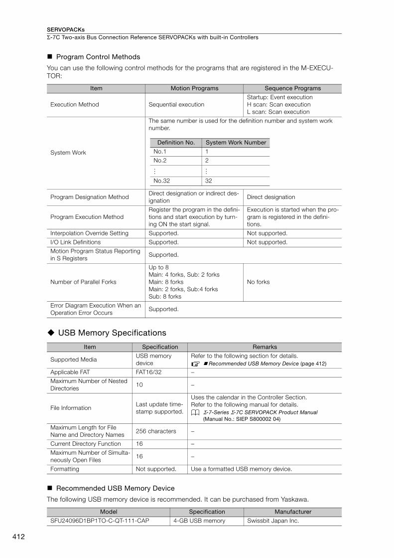
SERVOPACKsΣ-7C Two-axis Bus Connection Reference SERVOPACKs with built-in Controllers
412
Program Control Methods
You can use the following control methods for the programs that are registered in the M-EXECU-TOR:
USB Memory Specifications
Recommended USB Memory Device
The following USB memory device is recommended. It can be purchased from Yaskawa.
Item Motion Programs Sequence Programs
Execution Method Sequential executionStartup: Event executionH scan: Scan executionL scan: Scan execution
System Work
The same number is used for the definition number and system work number.
Program Designation MethodDirect designation or indirect des-ignation
Direct designation
Program Execution MethodRegister the program in the defini-tions and start execution by turn-ing ON the start signal.
Execution is started when the pro-gram is registered in the defini-tions.
Interpolation Override Setting Supported. Not supported.
I/O Link Definitions Supported. Not supported.
Motion Program Status Reporting in S Registers
Supported.
Number of Parallel Forks
Up to 8Main: 4 forks, Sub: 2 forksMain: 8 forksMain: 2 forks, Sub:4 forksSub: 8 forks
No forks
Error Diagram Execution When an Operation Error Occurs
Supported.
Item Specification Remarks
Supported MediaUSB memory device
Refer to the following section for details. Recommended USB Memory Device (page 412)
Applicable FAT FAT16/32 −Maximum Number of Nested Directories
10 −
File InformationLast update time-stamp supported.
Uses the calendar in the Controller Section.Refer to the following manual for details.
Σ-7-Series Σ-7C SERVOPACK Product Manual (Manual No.: SIEP S800002 04)
Maximum Length for File Name and Directory Names
256 characters −
Current Directory Function 16 −Maximum Number of Simulta-neously Open Files
16 −
Formatting Not supported. Use a formatted USB memory device.
Model Specification Manufacturer
SFU24096D1BP1TO-C-QT-111-CAP 4-GB USB memory Swissbit Japan Inc.
Definition No. System Work Number
No.1 1
No.2 2
No.32 32
… …

SERVOPACKs Σ-7C Two-axis Bus Connection Reference SERVOPACKs with built-in Controllers
413
Σ-7
C
IO16 Function Module SpecificationsThe following table gives the specifications of the IO16 Function Module. There are 16 digital inputs and 16 digital outputs in the IO16 Function Module.
Counter SpecificationsThe following table gives the specifications of counter. The counter uses a pulse input on one chan-nel.
Item Specification
Digital Inputs
Number of Inputs 16
Input Method Sink/source
Isolation Method Photocouplers
Input Voltage 24 VDC ±20%
Input Current 5 mA (typical)
ON Voltage/Current 15 V min./2 mA min.
OFF Voltage/Current 5 V max./1 mA max.
ON/OFF Time 0.01 ms + Digital filter setting
Digital Filter Setting 0 to 65,535 μs
Number of Commons 2 (8 points per common)
OthersDI_00 is also used for interrupt signals.DI_01 is also used as the pulse latch input.
Digital Outputs
Number of Outputs 16
Output Method Transistor open-collector sink outputs
Isolation Method Photocouplers
Output Voltage 24 VDC (20 V to 30 V)
Output Current 50 mA max.
Leakage Current When OFF
0.1 mA max.
ON/OFF Time 0.01 μs (for output current of 85 mA)
Number of Commons 2 (8 points per common)
Output Protection Thermistor (automatic recovery after blow out)
Others DO_00 is also used as the Match Output.
Item Specification
Pulse Input
Number of Inputs 1 (phase A, B, or Z input)
Input Circuits
Phases A and B: 5-V differential input, not isolated, maxi-mum frequency: 4 MHzPhase Z: 5-V, 12-V, or 24-V photocoupler input, maximum frequency: 500 kHz
Input Modes Phases A and B, sign, and incrementing/decrementing
Latch Input
Pulses are latched for phase Z or DI_01.Response Times for Phase-Z Input
ON: 1 μs max.OFF: 1 μs max.
Response Times for DI_01 InputON: 60 μs max.OFF: 0.5 ms max.
Other FunctionsMatch detection, counter preset and clear, electronic gear conversion, phase-C (phase-Z), and digital filter
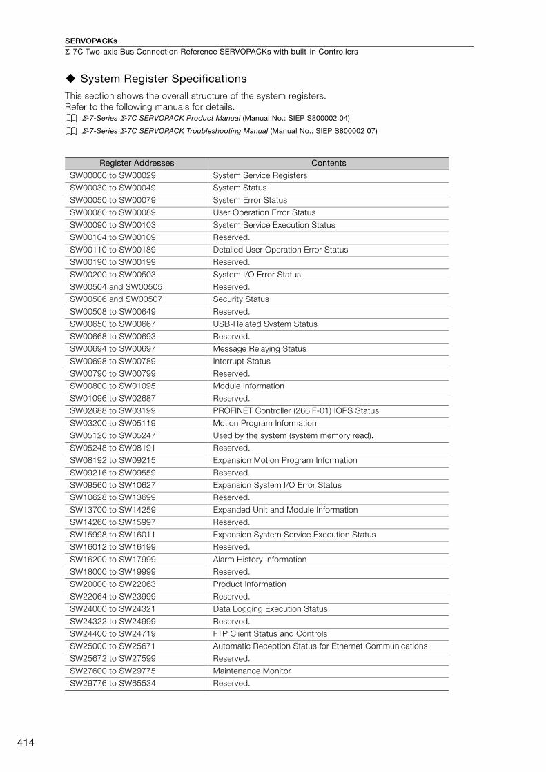
SERVOPACKsΣ-7C Two-axis Bus Connection Reference SERVOPACKs with built-in Controllers
414
System Register Specifications This section shows the overall structure of the system registers.Refer to the following manuals for details.
Σ-7-Series Σ-7C SERVOPACK Product Manual (Manual No.: SIEP S800002 04)
Σ-7-Series Σ-7C SERVOPACK Troubleshooting Manual (Manual No.: SIEP S800002 07)
Register Addresses Contents
SW00000 to SW00029 System Service Registers
SW00030 to SW00049 System Status
SW00050 to SW00079 System Error Status
SW00080 to SW00089 User Operation Error Status
SW00090 to SW00103 System Service Execution Status
SW00104 to SW00109 Reserved.
SW00110 to SW00189 Detailed User Operation Error Status
SW00190 to SW00199 Reserved.
SW00200 to SW00503 System I/O Error Status
SW00504 and SW00505 Reserved.
SW00506 and SW00507 Security Status
SW00508 to SW00649 Reserved.
SW00650 to SW00667 USB-Related System Status
SW00668 to SW00693 Reserved.
SW00694 to SW00697 Message Relaying Status
SW00698 to SW00789 Interrupt Status
SW00790 to SW00799 Reserved.
SW00800 to SW01095 Module Information
SW01096 to SW02687 Reserved.
SW02688 to SW03199 PROFINET Controller (266IF-01) IOPS Status
SW03200 to SW05119 Motion Program Information
SW05120 to SW05247 Used by the system (system memory read).
SW05248 to SW08191 Reserved.
SW08192 to SW09215 Expansion Motion Program Information
SW09216 to SW09559 Reserved.
SW09560 to SW10627 Expansion System I/O Error Status
SW10628 to SW13699 Reserved.
SW13700 to SW14259 Expanded Unit and Module Information
SW14260 to SW15997 Reserved.
SW15998 to SW16011 Expansion System Service Execution Status
SW16012 to SW16199 Reserved.
SW16200 to SW17999 Alarm History Information
SW18000 to SW19999 Reserved.
SW20000 to SW22063 Product Information
SW22064 to SW23999 Reserved.
SW24000 to SW24321 Data Logging Execution Status
SW24322 to SW24999 Reserved.
SW24400 to SW24719 FTP Client Status and Controls
SW25000 to SW25671 Automatic Reception Status for Ethernet Communications
SW25672 to SW27599 Reserved.
SW27600 to SW29775 Maintenance Monitor
SW29776 to SW65534 Reserved.
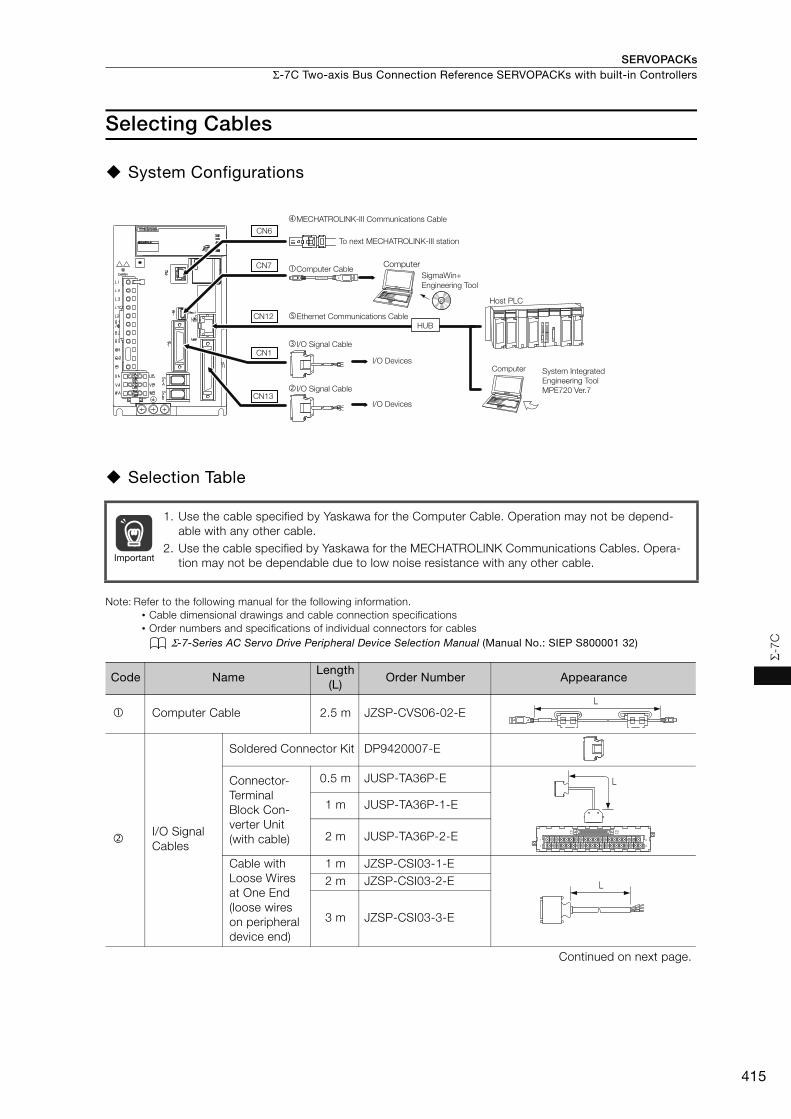
SERVOPACKs Σ-7C Two-axis Bus Connection Reference SERVOPACKs with built-in Controllers
415
Σ-7
C
Selecting Cables
System Configurations
Selection Table
Note: Refer to the following manual for the following information.• Cable dimensional drawings and cable connection specifications• Order numbers and specifications of individual connectors for cables
Σ-7-Series AC Servo Drive Peripheral Device Selection Manual (Manual No.: SIEP S800001 32)
1. Use the cable specified by Yaskawa for the Computer Cable. Operation may not be depend-able with any other cable.
2. Use the cable specified by Yaskawa for the MECHATROLINK Communications Cables. Opera-tion may not be dependable due to low noise resistance with any other cable.
Code NameLength
(L)Order Number Appearance
Computer Cable 2.5 m JZSP-CVS06-02-E
I/O Signal Cables
Soldered Connector Kit DP9420007-E
Connector-Terminal Block Con-verter Unit(with cable)
0.5 m JUSP-TA36P-E
1 m JUSP-TA36P-1-E
2 m JUSP-TA36P-2-E
Cable with Loose Wires at One End (loose wires on peripheral device end)
1 m JZSP-CSI03-1-E2 m JZSP-CSI03-2-E
3 m JZSP-CSI03-3-E
Continued on next page.
Computer
JZSP-CVS06-02-E
To next MECHATROLINK-III station
�MECHATROLINK-III Communications Cable
CN6
CN7
CN12
�Computer Cable
�I/O Signal Cable
I/O DevicesCN1
�I/O Signal Cable
I/O DevicesCN13
HUBEthernet Communications Cable
Computer
Host PLC
System Integrated
Engineering Tool
MPE720 Ver.7
SigmaWin+
Engineering Tool
Important
L
40
391
2
B20A20
B1A1
L
L

SERVOPACKsΣ-7C Two-axis Bus Connection Reference SERVOPACKs with built-in Controllers
416
I/O Signal Cables
Soldered Connector Kit JZSP-CSI9-1-E
Connector-Terminal Block Con-verter Unit(with cable)
0.5 m JUSP-TA50PG-E
1 m JUSP-TA50PG-1-E
2 m JUSP-TA50PG-2-E
Cable with Loose Wires at One End(loose wires on peripheral device end)
1 m JZSP-CSI01-1-E
2 m JZSP-CSI01-2-E
3 m JZSP-CSI01-3-E
MECHA-TROLINK-III Communi-cations Cables
Cables with Connectors on Both Ends
0.2 m JEPMC-W6012-A2-E0.5 m JEPMC-W6012-A5-E1 m JEPMC-W6012-01-E2 m JEPMC-W6012-02-E3 m JEPMC-W6012-03-E4 m JEPMC-W6012-04-E5 m JEPMC-W6012-05-E
10 m JEPMC-W6012-10-E20 m JEPMC-W6012-20-E30 m JEPMC-W6012-30-E50 m JEPMC-W6012-50-E
Cables with Connectors on Both Ends(with core)
10 m JEPMC-W6013-10-E20 m JEPMC-W6013-20-E30 m JEPMC-W6013-30-E50 m JEPMC-W6013-50-E
Cable with Loose Wires at One End
0.5 m JEPMC-W6014-A5-E1 m JEPMC-W6014-01-E3 m JEPMC-W6014-03-E5 m JEPMC-W6014-05-E
10 m JEPMC-W6014-10-E30 m JEPMC-W6014-30-E50 m JEPMC-W6014-50-E
Ethernet communications cables
Use a commercially available cable that meets the following conditions:• Ethernet specification: 100Base-TX• Category 5 or higher• Twisted-pair cable with RJ-45 connectors
Continued from previous page.
Code NameLength
(L)Order Number Appearance
1
19
33
16
32
50
1
1
2
49
50
L
L
L
L
L
417
MEMO
Σ-7
C
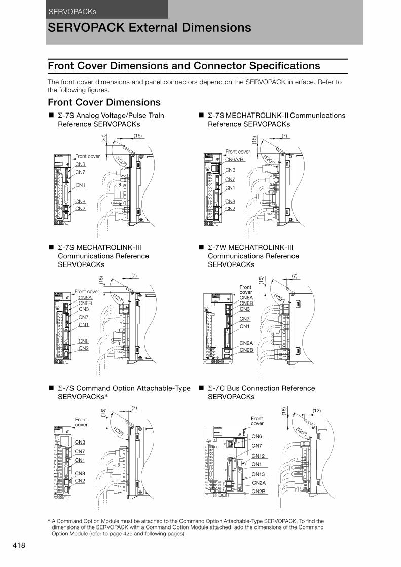
SERVOPACKs
418
SERVOPACK External Dimensions
Front Cover Dimensions and Connector SpecificationsThe front cover dimensions and panel connectors depend on the SERVOPACK interface. Refer to the following figures.
Front Cover Dimensions
* A Command Option Module must be attached to the Command Option Attachable-Type SERVOPACK. To find the dimensions of the SERVOPACK with a Command Option Module attached, add the dimensions of the Command Option Module (refer to page 429 and following pages).
Σ-7S Analog Voltage/Pulse Train Reference SERVOPACKs
Σ-7S MECHATROLINK-II Communications Reference SERVOPACKs
Σ-7S MECHATROLINK-III Communications Reference SERVOPACKs
Σ-7W MECHATROLINK-III Communications Reference SERVOPACKs
Σ-7S Command Option Attachable-Type SERVOPACKs*
Σ-7C Bus Connection Reference SERVOPACKs
Front cover
CN3
CN7
CN1
CN8
CN2
(16)
(120)
(20
)
Front cover
CN7
CN3
CN1
CN8
CN2
CN6A/B
(7)
(15
)
(120)
Front cover
CN3
CN7
CN1
CN8
CN2
CN6ACN6B
(7)
(15
)
(120)CN3
CN7
CN1
CN2A
CN2B
CN6ACN6B
Front cover
(7)
(15
)
(120°)
CN3
CN1
CN8
CN2
Front cover
CN7
(7)
(15
)
(120°)
CN1
CN7
CN6
CN13
CN12
CN2A
CN2B
Front cover
(12)
(18
)
(120°)

SERVOPACKs SERVOPACK External Dimensions
419
SE
RV
OP
AC
K E
xte
rnal D
imensio
ns
Connector Specifications
Note: The above connectors or their equivalents are used for the SERVOPACKs.
SERVOPACK Connector
No. Model
Number of Pins
Manufacturer
Σ-7SAnalog Voltage/Pulse Train Reference SERVOPACK
CN1 10250-59A3MB 50 3M Japan Ltd.
CN2 3E106-0220KV 6 3M Japan Ltd.
CN3HDR-EC14LFDTN-SLD-PLUS
14 Honda Tsushin Kogyo Co., Ltd.
CN7 2172034-1 5 Tyco Electronics Japan G.K.
CN8 1981080-1 8 Tyco Electronics Japan G.K.
Σ-7SMECHATROLINK-II Communications Reference SERVOPACK
CN1 10226-59A3MB 26 3M Japan Ltd.
CN2 3E106-0220KV 6 3M Japan Ltd.
CN3HDR-EC14LFDTN-SLD-PLUS
14 Honda Tsushin Kogyo Co., Ltd.
CN6A/B 1903815-1 8 Tyco Electronics Japan G.K.
CN7 2172034-1 5 Tyco Electronics Japan G.K.
CN8 1981080-1 8 Tyco Electronics Japan G.K.
Σ-7SMECHATROLINK-III Communications Reference SERVOPACK
CN1 10226-59A3MB 26 3M Japan Ltd.
CN2 3E106-0220KV 6 3M Japan Ltd.
CN3HDR-EC14LFDTN-SLD-PLUS
14 Honda Tsushin Kogyo Co., Ltd.
CN6A, CN6B
1981386-1 8 Tyco Electronics Japan G.K.
CN7 2172034-1 5 Tyco Electronics Japan G.K.
CN8 1981080-1 8 Tyco Electronics Japan G.K.
Σ-7S Command Option Attachable-Type SERVO-PACK
CN1 10226-59A3MB 26 3M Japan Ltd.
CN2 3E106-0220KV 6 3M Japan Ltd.
CN3HDR-EC14LFDTN-SLD-PLUS
14 Honda Tsushin Kogyo Co., Ltd.
CN7 2172034-1 5 Tyco Electronics Japan G.K.
CN8 1981080-1 8 Tyco Electronics Japan G.K.
Σ-7W MECHATROLINK-III Communications Reference SERVOPACK
CN1 10236-59A3MB 36 3M Japan Ltd.
CN2A, CN2B
3E106-2230KV 6 3M Japan Ltd.
CN3HDR-EC14LFDTN-SLD-PLUS
14 Honda Tsushin Kogyo Co., Ltd.
CN6A, CN6B
1981386-1 8 Tyco Electronics Japan G.K.
CN7 2172034-1 5 Tyco Electronics Japan G.K.
Σ-7C Bus Connection Reference SERVOPACK
CN1 10236-59A3MB 36 3M Japan Ltd.
CN2A, CN2B
3E106-2230KV 6 3M Japan Ltd.
CN6 1981386-1 8 Tyco Electronics Japan G.K.
CN7 2172034-1 5 Tyco Electronics Japan G.K.
CN12 26-51024KB13-1 8 UDE Corp.
CN13 10250-52A3PL 50 3M Japan Ltd.
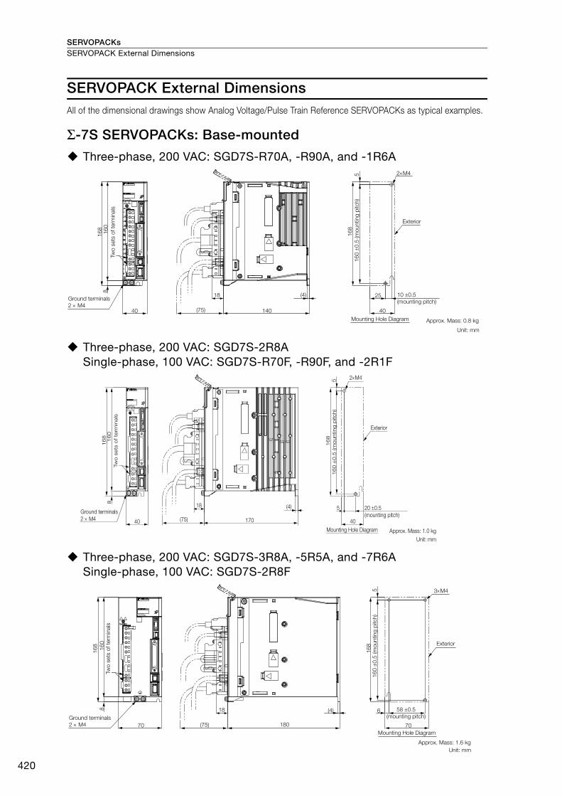
SERVOPACKsSERVOPACK External Dimensions
420
SERVOPACK External DimensionsAll of the dimensional drawings show Analog Voltage/Pulse Train Reference SERVOPACKs as typical examples.
Σ-7S SERVOPACKs: Base-mounted
Three-phase, 200 VAC: SGD7S-R70A, -R90A, and -1R6A
Three-phase, 200 VAC: SGD7S-2R8ASingle-phase, 100 VAC: SGD7S-R70F, -R90F, and -2R1F
Three-phase, 200 VAC: SGD7S-3R8A, -5R5A, and -7R6ASingle-phase, 100 VAC: SGD7S-2R8F
2M4
16
01
68
8
40 (75) 140
18 (4)
16
8
5
25
40
Two
sets
of te
rmin
als
Ground terminals
2 M4
16
0
0.5
(m
ounting
pitch)
Exterior
10 0.5
(mounting pitch)
Mounting Hole Diagram Approx. Mass: 0.8 kg
Unit: mm
160
168
8
40 170
18 (4)
(75)
168
5
2M4
40
5
Tw
o s
ets
of te
rmin
als
Ground terminals
2 M4
160
0.5
(m
ounting p
itch)
Exterior
20 0.5
(mounting pitch)
Mounting Hole Diagram Approx. Mass: 1.0 kg
Unit: mm
16
01
68
8
70 180(75)
18 (4)
70
6
16
8
3M45
Two
sets
of te
rmin
als
Ground terminals
2 M4
16
0
0.5
(m
ounting
pitch)
Exterior
58 0.5
(mounting pitch)
Mounting Hole Diagram
Approx. Mass: 1.6 kg
Unit: mm

SERVOPACKs SERVOPACK External Dimensions
421
SE
RV
OP
AC
K E
xte
rnal D
imensio
ns
Three-phase, 200 VAC: SGD7S-120A
Three-phase, 200 VAC: SGD7S-180A and -200ASingle-phase, 200 VAC: SGD7S-120AA008
Three-phase, 200 VAC: SGD7S-330A
16
01
68
8
90 180(75)
18(4)
16
8
5 3M4
90
12.5
5
Two
sets
of te
rmin
als
Ground terminals
2 M4
16
0
0.5
(m
ounting
pitch)
80 0.5
(mounting pitch)
Exterior
Mounting Hole Diagram
Approx. Mass: 2.2 kg
Unit: mm
180 10012.5
(4)
(75)
188
5
3M4
180 0
.5 (m
ount
ing
pitc
h)
Exterior
75 0.5 (mounting pitch)
82.5 0.5 (mounting pitch)
Mounting Hole Diagram
Approx. Mass: 2.7 kg
Unit: mm
180
8
100
188
Groundterminals2M4
Terminals14M4
Terminal Details
Unit: mmApprox. Mass: 4.4 kg
13×M4
258
258
250
± 0
.5 (m
ount
ing
pitc
h)
84 ± 0.5(mounting pitch)13
6
250
8
110 (75) 210110
Mounting Hole Diagram
4×M5Exterior
(5)Terminal Details
Ground terminals2 × M4
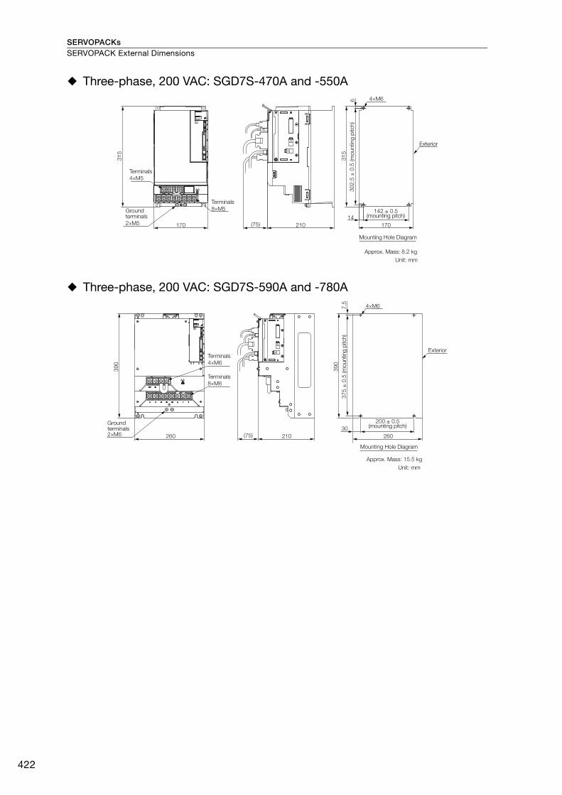
SERVOPACKsSERVOPACK External Dimensions
422
Three-phase, 200 VAC: SGD7S-470A and -550A
Three-phase, 200 VAC: SGD7S-590A and -780A
315
Terminals 4×M5
Ground terminals2×M5 170
Terminals 8×M5
(75) 210
315
14
6
170
Unit: mmApprox. Mass: 8.2 kg
302.
5 ±
0.5
(mou
ntin
g pi
tch)
142 ± 0.5(mounting pitch)
4×M6
Exterior
Mounting Hole Diagram
Ground terminals2×M6
Terminals 4×M6
Terminals 8×M6
Unit: mmApprox. Mass: 15.5 kg
375
± 0
.5 (m
ount
ing
pitc
h)
200 ± 0.5(mounting pitch)
4×M6
Exterior
Mounting Hole Diagram
390
260 (75) 210
390
30
7.5
260
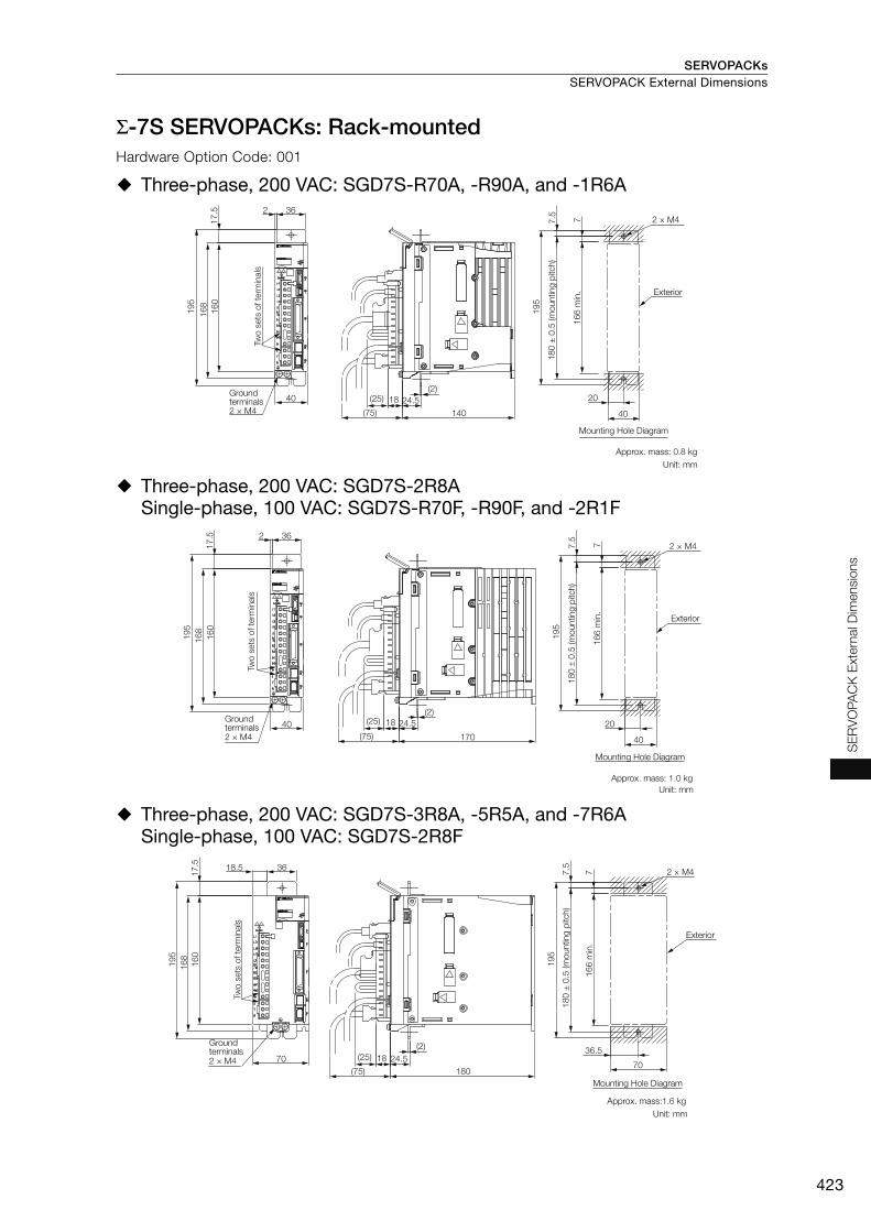
SERVOPACKs SERVOPACK External Dimensions
423
SE
RV
OPA
CK
Ext
erna
l Dim
ensi
ons
Σ-7S SERVOPACKs: Rack-mountedHardware Option Code: 001
Three-phase, 200 VAC: SGD7S-R70A, -R90A, and -1R6A
Three-phase, 200 VAC: SGD7S-2R8ASingle-phase, 100 VAC: SGD7S-R70F, -R90F, and -2R1F
Three-phase, 200 VAC: SGD7S-3R8A, -5R5A, and -7R6ASingle-phase, 100 VAC: SGD7S-2R8F
Unit: mmApprox. mass: 0.8 kg
2 × M4
Exterior
Mounting Hole Diagram
Ground terminals2 × M4
180
± 0
.5 (m
ount
ing
pitc
h)
166
min
.
140(75)
18(25)
168
40
2 36
195
17.5
24.5(2)
160
20
7.5
7
195
40
Two
sets
of t
erm
inal
s
Unit: mmApprox. mass: 1.0 kg
2 × M4
Exterior
Mounting Hole Diagram
Groundterminals2 × M4
180
± 0.
5 (m
ount
ing
pitc
h)
18(25)
(75)
160
168
40170
24.5(2)
2 36
17.5
195
20
7.5
166
min
.7
195
40
Two
sets
of t
erm
inal
s
Unit: mmApprox. mass:1.6 kg
Exterior
Mounting Hole Diagram
Ground terminals2 × M4
180
± 0
.5 (m
ount
ing
pitc
h)
2 × M4
18(25)
180(75)
160
70
168
195
17.5 18.5 36
24.5(2)
166
min
.
195
36.5
70
7.5
7
Two
sets
of t
erm
inal
s
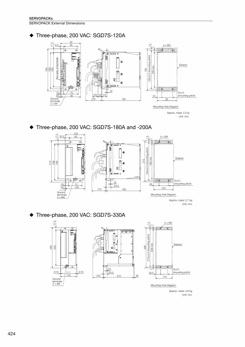
SERVOPACKsSERVOPACK External Dimensions
424
Three-phase, 200 VAC: SGD7S-120A
Three-phase, 200 VAC: SGD7S-180A and -200A
Three-phase, 200 VAC: SGD7S-330A
4 × M4
Exterior
180 ±
0.5
(mou
ntin
g pi
tch)
50±0.5 (mounting pitch)
Ground terminals2 × M4
Unit: mm
Approx. mass: 2.2 kg
Mounting Hole Diagram
9070
(3)13
(75) 180
160
17.5
15.5 6593
18(25)
(2)
24.5
168
195
195
77.5
23
166
min
.
93
Two
sets
of t
erm
inal
s
4 × M4
Exterior
200 ±
0.5
(mou
ntin
g pi
tch)
50±0.5 (mounting pitch)
Unit: mm
Approx. mass: 2.7 kg
Ground terminals2 × M4
Mounting Hole Diagram
10070
(3)18
(75) 180
180
17.5 20.5 65
103
(2)24.5
188
215 21
5
77.5
28
186
min
.
103
285
777.
5
30.5
256
min
.
116(75) 210
(2)
(6)24.5
116111(2.5) (2.5)
250
17.5
285
4 × M5
Exterior
270 ±
0.5
(mou
ntin
g pi
tch)
50±0.5 (mounting pitch)
Unit: mm
Approx. mass: 4.9 kg
Ground terminals2 × M4 Mounting Hole Diagram
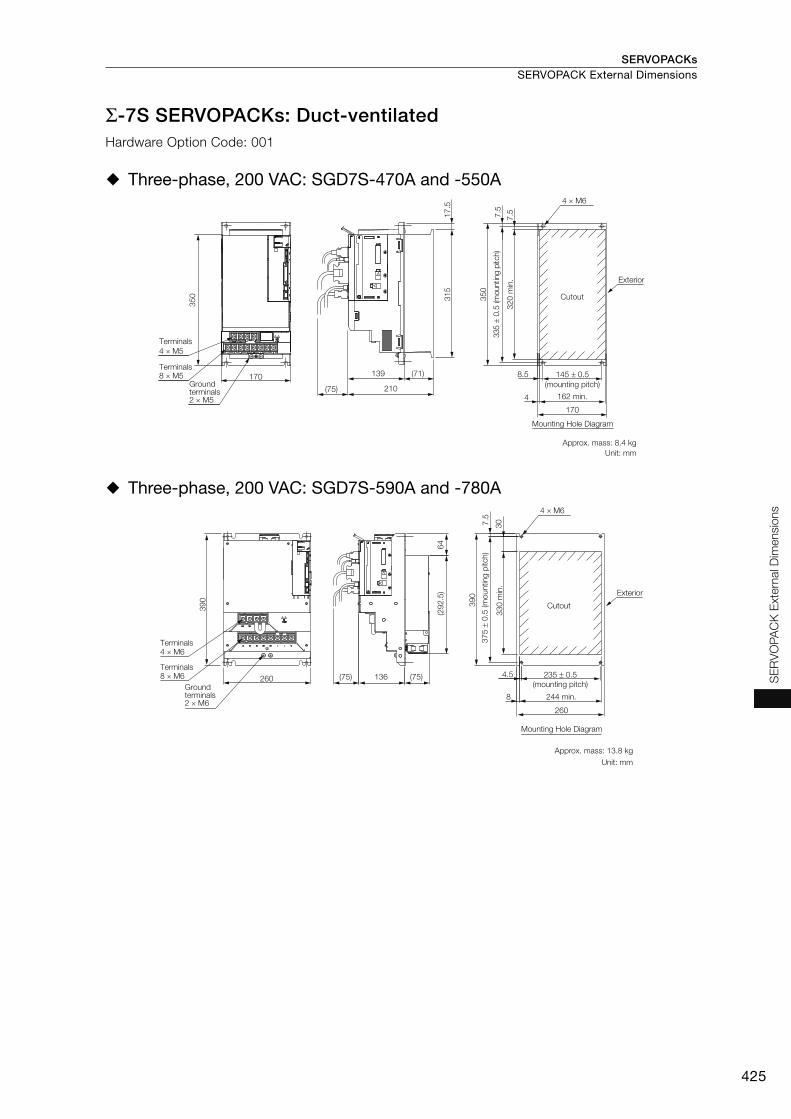
SERVOPACKs SERVOPACK External Dimensions
425
SE
RV
OPA
CK
Ext
erna
l Dim
ensi
ons
Σ-7S SERVOPACKs: Duct-ventilatedHardware Option Code: 001
Three-phase, 200 VAC: SGD7S-470A and -550A
Three-phase, 200 VAC: SGD7S-590A and -780A
Unit: mmApprox. mass: 8.4 kg
4 × M5Terminals
Terminals8 × M5
Ground terminals2 × M5
210
139 (71)
350
170
(75)
Exterior
Cutout
Mounting Hole Diagram
8.5
4
145 ± 0.5(mounting pitch)
320
min
.7.
5
350
315
7.5
17.5
162 min.
170
335
± 0.
5 (m
ount
ing
pitc
h)
4 × M6
Terminals4 × M6
Terminals8 × M6
Ground terminals2 × M6
260
390
(292
.5)
330
min
.
390
307.5
64
(75) (75)136
260
244 min.8
4.5
Unit: mmApprox. mass: 13.8 kg
Mounting Hole Diagram
Exterior
Cutout
375
± 0.
5 (m
ount
ing
pitc
h)
235 ± 0.5(mounting pitch)
4 × M6
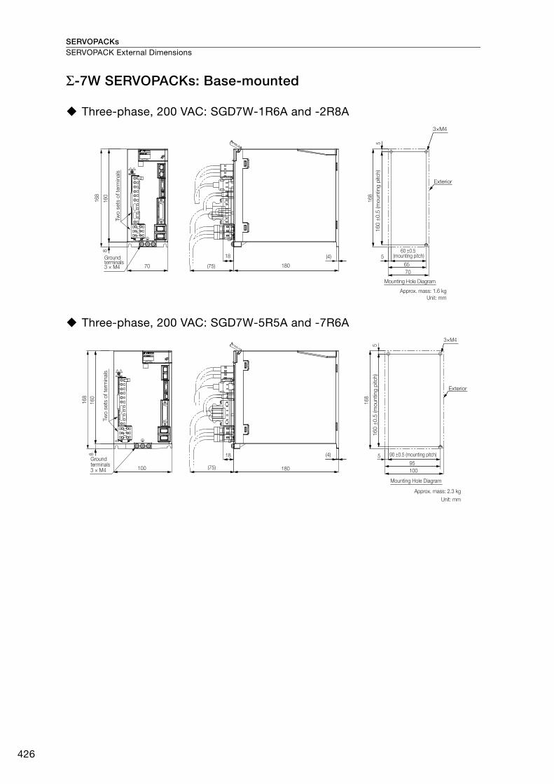
SERVOPACKsSERVOPACK External Dimensions
426
Σ-7W SERVOPACKs: Base-mounted
Three-phase, 200 VAC: SGD7W-1R6A and -2R8A
Three-phase, 200 VAC: SGD7W-5R5A and -7R6A
Exterior
160
±0.5
(mou
ntin
g pi
tch)
60 ±0.5 (mounting pitch)
Mounting Hole Diagram
Ground terminals3 × M4
Two
sets
of t
erm
inal
s
Unit: mmApprox. mass: 1.6 kg
3×M4
(4)
160
168
5
5
7065
8
18
70 (75) 180
168
Exterior
160
±0.5
(mou
ntin
g pi
tch)
90 ±0.5 (mounting pitch)
Mounting Hole Diagram
Ground terminals3 × M4
Unit: mmApprox. mass: 2.3 kg
Two
sets
of t
erm
inal
s
100 (75) 180
3×M4
(4)
160
168
5
5
10095
8 18
168

SERVOPACKs SERVOPACK External Dimensions
427
SE
RV
OPA
CK
Ext
erna
l Dim
ensi
ons
Σ-7W SERVOPACKs: Rack-mounted
Three-phase, 200 VAC: SGD7W-1R6A and -2R8A
Three-phase, 200 VAC: SGD7W-5R5A and -7R6A
Exterior
180 ±
0.5
(mou
ntin
g pi
tch)
Ground terminals3 × M4
Unit: mm
Approx. mass: 1.6 kg
Mounting Hole Diagram
Two
sets
of t
erm
inal
s
703618.5
(75) 180
2 × M416
017
.5 14.5 40
195
716
6 m
in.
36.57017(26)
(2)
24.5
168
195
Exterior
180 ±
0.5
(mou
ntin
g pi
tch)
50±0.5 (mounting pitch)
Ground terminals3 × M4
Unit: mmApprox. mass: 2.3 kg
Mounting Hole Diagram
Two
sets
of t
erm
inal
s
100
7018(3)
(75) 180
4 × M4
160
17.5
20.5 65103
195
7
28
103
166
min
.
17(26)
(2)
24.5
168
195
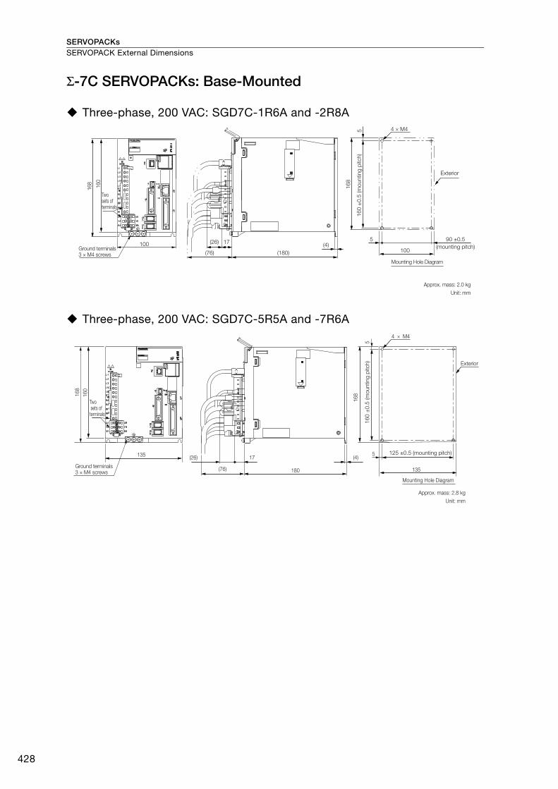
SERVOPACKsSERVOPACK External Dimensions
428
Σ-7C SERVOPACKs: Base-Mounted
Three-phase, 200 VAC: SGD7C-1R6A and -2R8A
Three-phase, 200 VAC: SGD7C-5R5A and -7R6A
(180)(76)
(26) 17100 (4)
160
5
5
100
168
168
Ground terminals 3 × M4 screws
Approx. mass: 2.0 kgUnit: mm
Two sets of terminals
Mounting Hole Diagram
160
±0.
5 (m
ount
ing
pitc
h)
Exterior
4 × M4
90 ±0.5(mounting pitch)
135
(76)
(26)
180
(4)17
160
168
5
5
135Ground terminals3 × M4 screws
168
Approx. mass: 2.8 kgUnit: mm
Two sets of terminals
125 ±0.5 (mounting pitch)
160
±0.
5 (m
ount
ing
pitc
h) Exterior
4 × M4
Mounting Hole Diagram

SERVOPACKs SERVOPACK External Dimensions
429
SE
RV
OPA
CK
Ext
erna
l Dim
ensi
ons
Σ-7C SERVOPACKs: Rack-MountedHardware Option Code: 001
Three-phase, 200 VAC: SGD7C-1R6A and -2R8A
Three-phase, 200 VAC: SGD7C-5R5A and -7R6A
Command Option Module External Dimensions
INDEXER Module DeviceNet Module
Ground terminals3 × M4 screws
100
160
168
195
17.5 5 80
(76) 180
(26) 17 24.5
(2)100
15 50 ±0.5
166
min
.7
195
180
±0.
5 (m
ount
ing
pitc
h)
4 x M4
(mounting pitch)
Exterior
Two sets of terminals
Mounting Hole Diagram
Approx. mass: 2.0 kgUnit: mm
Ground terminals3 × M4 screws
135
168
195 16
017
.5
11012.5
180(76)
17(26) 24.5
(2)
195
166
min
.
135
15
180
±0.
5 (m
ount
ing
pitc
h)
Exterior
4 x M4
Two sets of terminals
Mounting Hole Diagram
Approx. mass: 2.8 kg
Unit: mm
80 ±0.5(mounting pitch)
CN11
CN12
(10)
20
(60)
(100
)
160
(75) 97
Unit: mmApprox. Mass: 0.2 kg
Unit: mmApprox. Mass: 0.3 kg
CN6
(24)
20
(24)
(89)
97
(8)
160
(28)
(43)

SERVOPACKs
430
Peripheral Devices
*1. The peripheral devices are described using a MECHATROLINK-III Communications Reference, Three-phase 200 VAC SERVOPACK as an example. The shapes of the connectors may be different for other interfaces.
*2. The connected devices depend on the interface.For MECHATROLINK-II communications references: Other MECHATROLINK-II stations For analog voltage/pulse train references: There is no CN6 connector.
*3. A Holding Brake Power Supply Unit is required to use a Servomotor with a Holding Brake. Holding Brake Power Supply Units for 24 VDC are not provided by Yaskawa. Obtain these from other manufacturers.Never connect Holding Brake Power Supply Units with different output voltages to a SERVOPACK. Overcurrent may result in burning in the brake.
*4. If you use a Servomotor with a Holding Brake, select a brake relay according to the power supply voltage and current of the brake. Yaskawa does not recommend any particular brake relays. Select an appropriate brake relay using the selection method of the brake relay manufacturer.
*5. The power supply for the holding brake is not provided by Yaskawa. Select a power supply based on the hold-ing brake specifications. If you use a 24-V brake, install a separate power supply for the 24-VDC power supply from other power supplies, such as the one for the I/O signals of the CN1 connector. If the power supply is shared, the I/O signals may malfunction.
*6. For SERVOPACK cables, refer to the selection table for each type of SERVOPACK.
I/O Signal Cables*6
200 VAC
Power supply Three-phase, 200 VAC*1
Molded-case circuit breaker
Noise Filter
Magnetic Contactor
SERVOPACK*1
Analog Monitor Cable*6
MECHATROLINK Communications Cables
*1, 6
To other MECHATROLINK-III stations*2
Digital Operator cable
Computer Cable*6
Host controller
SERVOPACK Main Circuit Wires
Control Power Supply Cable
External Regenerative Resistor CableExternal Regenerative Resistor
Holding Brake Power Supply Unit*3, *4, *5
Magnetic Contactor Ground cable
Battery Case(Used for an absolute encoder.)
When not using a safety function, leave the Safety Jumper Connector connected to the SERVOPACK.
Encoder Cable
Servomotor
Servomotor Main Circuit Cable
Surge Absorbers
AC/DC Reactors for harmonic suppression
Surge Absorbers for Holding Brakes (Varistors) and Diodes
Safety function device
Safety Function Device Cable*6
ComputerEngineering Tool
Digital Operator
(Wires required for a Servomotor with a Brake)
R S T
(page 431)
(page 431)
(page 431)
(page 431)
(page 431)
(page 454)
(page 431)
(page 438)
(page 431)
(page 458)
(page 456)
(page 461)

SERVOPACKs Peripheral Devices
431
Per
iphe
ral D
evic
es
Peripheral Device Selection Table
Σ-7S SERVOPACKs
*1. Some Noise Filters have large leakage currents. The grounding conditions also affect the size of the leakage current. If necessary, select an appropriate leakage detector or leakage breaker taking into account the ground-ing conditions and the leakage current from the Noise Filter.
*2. The last digit of an RoHS-compliant serial number is R. Consult with Yaskawa Controls Co., Ltd. for RoHS-com-pliant reactors.
Note: 1. Consult the manufacturer for details on peripheral devices.
2. For Digital Operator Converter cables, refer to the selection table for each type of SERVOPACK.
3. Refer to the following manual for the following information.• Dimensional drawings, ratings, and specifications of peripheral devices
Σ-7-Series AC Servo Drive Peripheral Device Selection Manual (Manual No.: SIEP S800001 32)
Main Circuit Power Supply
Maximum Applicable
Motor Capacity [kW]
SERVO-PACK Model:
SGD7S-
Noise
Filter*1AC
Reactor*2DC
Reactor*2Magnetic Contactor
Surge Absorber
Digital Opera-
tor
Three-phase, 200 VAC
0.05 R70A
HF3010C-SZC
–
X5061
SC-03
LT-C32G801WS
JUSP-OP05A-1-E
0.1 R90A
0.2 1R6A
0.4 2R8A
0.5 3R8A
0.75 5R5A
HF3020C-SZCSC-4-11.0 7R6A
1.5 120AX5060
2.0 180ASC-5-1
3.0 200A HF3030C-SZC X5059
5.0 330A HF3050C-SZC-47EDD
X5068SC-N1
6.0 470A X008025
7.5 550A HF3060C-SZC X008026 SC-N2
11 590AHF3100C-SZC
X008027 SC-N2S
15 780A X008028 SC-N3
Single-phase, 200 VAC
0.05 R70A
HF2010A-UPF
X5071
SC-03
LT-C12G801WS
0.1 R90A
0.2 1R6A X5070
0.4 2R8A X5069
0.75 5R5AHF2020A-UPF-2BB
X5079 SC-4-1
1.5120A008
HF2030A-UPF-2BB
X5078 SC-5-1
Single-phase, 100 VAC
0.05 R70F
HF2010A-UPFX5053
–SC-030.1 R90F
0.2 2R1F X5054
0.4 2R8F HF2020A-UPF X5056 SC-4-1
Device Inquiries
Noise Filters
Yaskawa Controls Co., Ltd.Surge Absorbers
AC/DC Reactors for harmonic suppression
Magnetic Contactors Fuji Electric FA Components & Systems Co., Ltd.
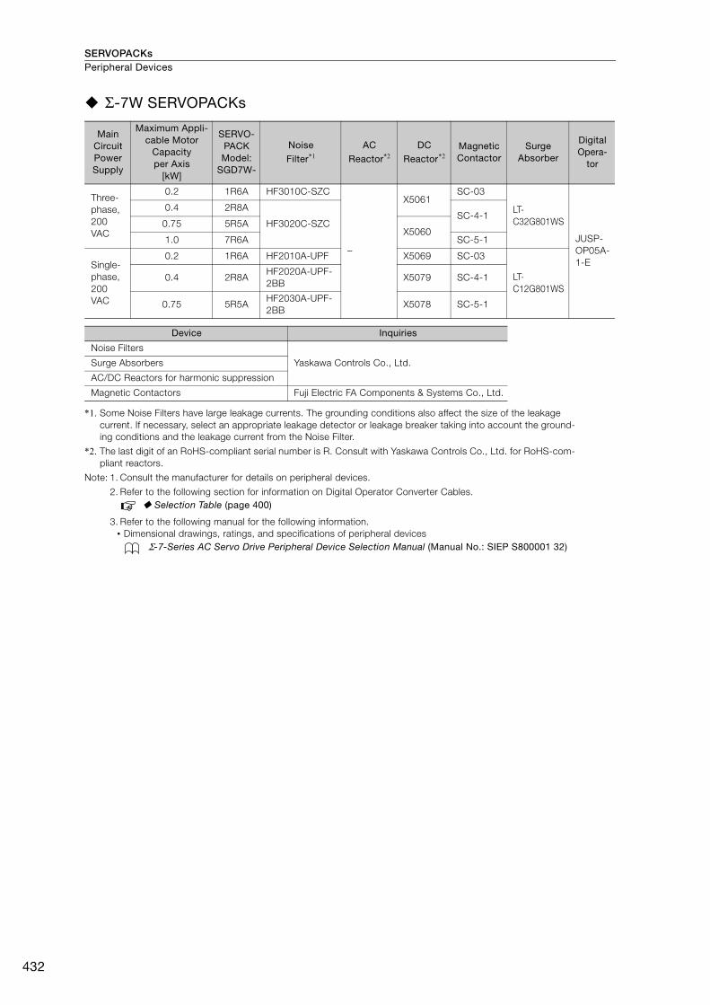
SERVOPACKsPeripheral Devices
432
Σ-7W SERVOPACKs
*1. Some Noise Filters have large leakage currents. The grounding conditions also affect the size of the leakage current. If necessary, select an appropriate leakage detector or leakage breaker taking into account the ground-ing conditions and the leakage current from the Noise Filter.
*2. The last digit of an RoHS-compliant serial number is R. Consult with Yaskawa Controls Co., Ltd. for RoHS-com-pliant reactors.
Note: 1. Consult the manufacturer for details on peripheral devices.
2. Refer to the following section for information on Digital Operator Converter Cables. Selection Table (page 400)
3. Refer to the following manual for the following information.• Dimensional drawings, ratings, and specifications of peripheral devices
Σ-7-Series AC Servo Drive Peripheral Device Selection Manual (Manual No.: SIEP S800001 32)
Main Circuit Power Supply
Maximum Appli-cable Motor
Capacityper Axis
[kW]
SERVO-PACK Model:
SGD7W-
Noise Filter*1
AC Reactor*2
DC Reactor*2
Magnetic Contactor
Surge Absorber
Digital Opera-
tor
Three-phase, 200 VAC
0.2 1R6A HF3010C-SZC
–
X5061SC-03
LT-C32G801WS
JUSP-OP05A-1-E
0.4 2R8A
HF3020C-SZCSC-4-1
0.75 5R5AX5060
1.0 7R6A SC-5-1
Single-phase, 200 VAC
0.2 1R6A HF2010A-UPF X5069 SC-03
LT-C12G801WS
0.4 2R8AHF2020A-UPF-2BB
X5079 SC-4-1
0.75 5R5AHF2030A-UPF-2BB
X5078 SC-5-1
Device Inquiries
Noise Filters
Yaskawa Controls Co., Ltd.Surge Absorbers
AC/DC Reactors for harmonic suppression
Magnetic Contactors Fuji Electric FA Components & Systems Co., Ltd.

SERVOPACKs Peripheral Devices
433
Per
iphe
ral D
evic
es
Σ-7C SERVOPACKs
*1. Some Noise Filters have large leakage currents. The grounding conditions also affect the size of the leakage current. If necessary, select an appropriate leakage detector or leakage breaker taking into account the ground-ing conditions and the leakage current from the Noise Filter.
*2. The last digit of an RoHS-compliant serial number is R. Consult with Yaskawa Controls Co., Ltd. for RoHS-com-pliant reactors.
Note: 1. Consult the manufacturer for details on peripheral devices.
2. Refer to the following manual for the following information.• Dimensional drawings, ratings, and specifications of peripheral devices
Σ-7-Series AC Servo Drive Peripheral Device Selection Manual (Manual No.: SIEP S800001 32)
Main Circuit Power Supply
Maximum Appli-cable Motor
Capacityper Axis
[kW]
SERVO-PACK Model:
SGM7C-
Noise Filter*1
AC Reactor*2
DC Reactor*2
Magnetic Contactor
Surge Absorber
Three-phase, 200 VAC
0.2 1R6A HF3010C-SZC
–
X5061SC-03
LT-C32G801WS
0.4 2R8A
HF3020C-SZCSC-4-1
0.75 5R5AX5060
1.0 7R6A SC-5-1
Single-phase, 200 VAC
0.2 1R6A HF2010A-UPF X5069 SC-03
LT-C12G801WS
0.4 2R8AHF2020A-UPF-2BB
X5079 SC-4-1
0.75 5R5AHF2030A-UPF-2BB
X5078 SC-5-1
Device Inquiries
Noise Filters
Yaskawa Controls Co., Ltd.Surge Absorbers
AC/DC Reactors for harmonic suppression
Magnetic Contactors Fuji Electric FA Components & Systems Co., Ltd.
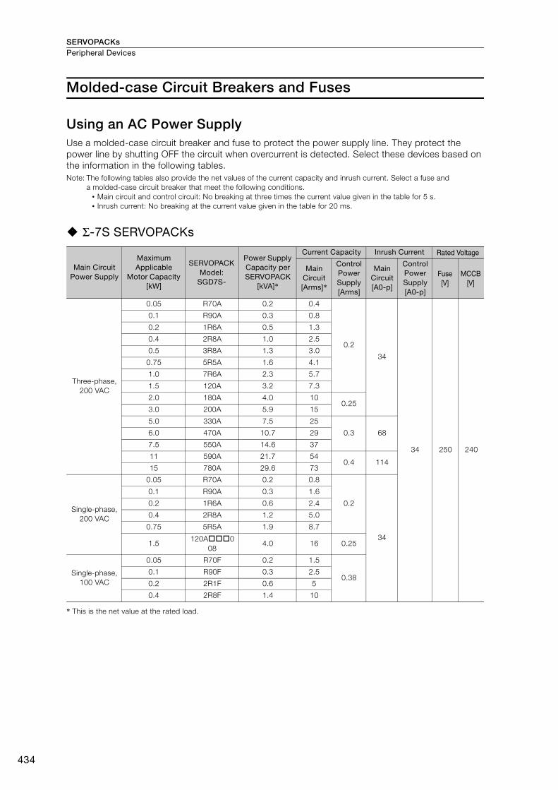
SERVOPACKsPeripheral Devices
434
Molded-case Circuit Breakers and Fuses
Using an AC Power SupplyUse a molded-case circuit breaker and fuse to protect the power supply line. They protect the power line by shutting OFF the circuit when overcurrent is detected. Select these devices based on the information in the following tables.Note: The following tables also provide the net values of the current capacity and inrush current. Select a fuse and
a molded-case circuit breaker that meet the following conditions.• Main circuit and control circuit: No breaking at three times the current value given in the table for 5 s. • Inrush current: No breaking at the current value given in the table for 20 ms.
Σ-7S SERVOPACKs
* This is the net value at the rated load.
Main Circuit Power Supply
Maximum Applicable
Motor Capacity [kW]
SERVOPACK Model:
SGD7S-
Power Supply Capacity per SERVOPACK
[kVA]*
Current Capacity Inrush Current Rated Voltage
Main Circuit [Arms]*
Control Power Supply [Arms]
Main Circuit [A0-p]
Control Power Supply [A0-p]
Fuse[V]
MCCB[V]
Three-phase, 200 VAC
0.05 R70A 0.2 0.4
0.2
34
34 250 240
0.1 R90A 0.3 0.8
0.2 1R6A 0.5 1.3
0.4 2R8A 1.0 2.5
0.5 3R8A 1.3 3.0
0.75 5R5A 1.6 4.1
1.0 7R6A 2.3 5.7
1.5 120A 3.2 7.3
2.0 180A 4.0 10 0.25
3.0 200A 5.9 15
5.0 330A 7.5 25
0.3 686.0 470A 10.7 29
7.5 550A 14.6 37
11 590A 21.7 540.4 114
15 780A 29.6 73
Single-phase, 200 VAC
0.05 R70A 0.2 0.8
0.2
34
0.1 R90A 0.3 1.6
0.2 1R6A 0.6 2.4
0.4 2R8A 1.2 5.0
0.75 5R5A 1.9 8.7
1.5120A0
084.0 16 0.25
Single-phase, 100 VAC
0.05 R70F 0.2 1.5
0.380.1 R90F 0.3 2.5
0.2 2R1F 0.6 5
0.4 2R8F 1.4 10
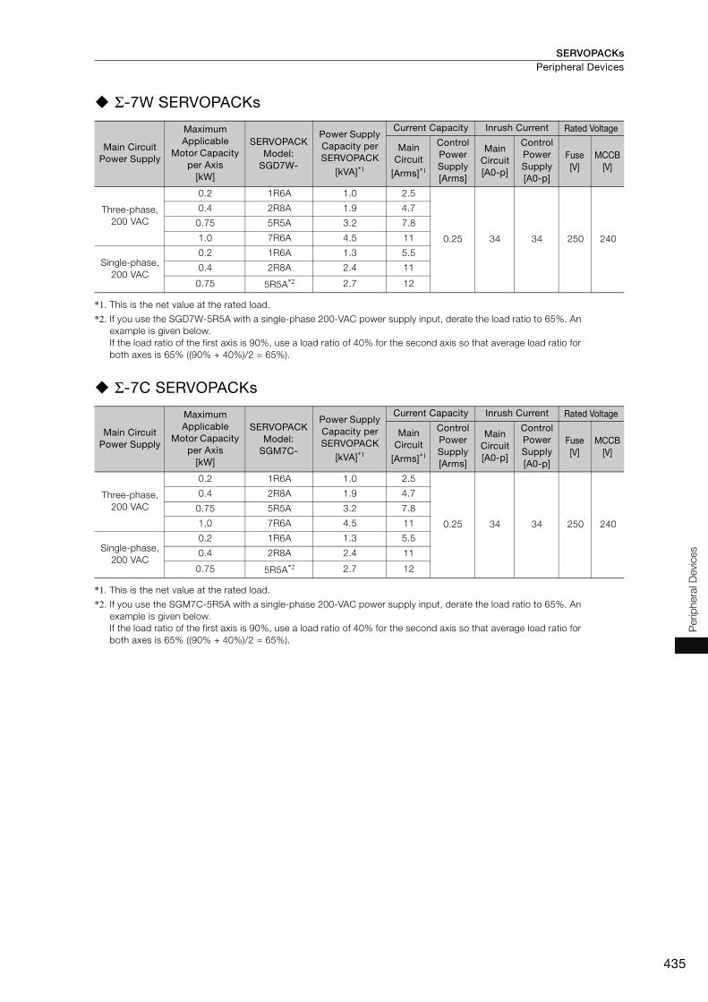
SERVOPACKs Peripheral Devices
435
Per
iphe
ral D
evic
es
Σ-7W SERVOPACKs
*1. This is the net value at the rated load.
*2. If you use the SGD7W-5R5A with a single-phase 200-VAC power supply input, derate the load ratio to 65%. An example is given below. If the load ratio of the first axis is 90%, use a load ratio of 40% for the second axis so that average load ratio for both axes is 65% ((90% + 40%)/2 = 65%).
Σ-7C SERVOPACKs
*1. This is the net value at the rated load.
*2. If you use the SGM7C-5R5A with a single-phase 200-VAC power supply input, derate the load ratio to 65%. An example is given below. If the load ratio of the first axis is 90%, use a load ratio of 40% for the second axis so that average load ratio for both axes is 65% ((90% + 40%)/2 = 65%).
Main Circuit Power Supply
Maximum Applicable
Motor Capacity per Axis
[kW]
SERVOPACK Model:
SGD7W-
Power Supply Capacity per SERVOPACK
[kVA]*1
Current Capacity Inrush Current Rated Voltage
Main Circuit
[Arms]*1
Control Power Supply [Arms]
Main Circuit [A0-p]
Control Power Supply [A0-p]
Fuse[V]
MCCB[V]
Three-phase, 200 VAC
0.2 1R6A 1.0 2.5
0.25 34 34 250 240
0.4 2R8A 1.9 4.7
0.75 5R5A 3.2 7.8
1.0 7R6A 4.5 11
Single-phase, 200 VAC
0.2 1R6A 1.3 5.5
0.4 2R8A 2.4 11
0.75 5R5A*2 2.7 12
Main Circuit Power Supply
Maximum Applicable
Motor Capacity per Axis
[kW]
SERVOPACK Model:
SGM7C-
Power Supply Capacity per SERVOPACK
[kVA]*1
Current Capacity Inrush Current Rated Voltage
Main Circuit
[Arms]*1
Control Power Supply [Arms]
Main Circuit [A0-p]
Control Power Supply [A0-p]
Fuse[V]
MCCB[V]
Three-phase, 200 VAC
0.2 1R6A 1.0 2.5
0.25 34 34 250 240
0.4 2R8A 1.9 4.7
0.75 5R5A 3.2 7.8
1.0 7R6A 4.5 11
Single-phase, 200 VAC
0.2 1R6A 1.3 5.5
0.4 2R8A 2.4 11
0.75 5R5A*2 2.7 12
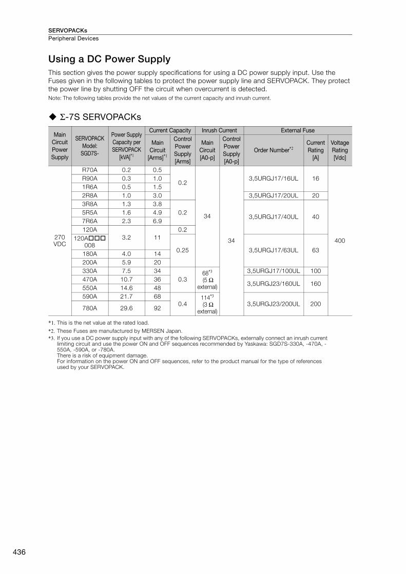
SERVOPACKsPeripheral Devices
436
Using a DC Power SupplyThis section gives the power supply specifications for using a DC power supply input. Use the Fuses given in the following tables to protect the power supply line and SERVOPACK. They protect the power line by shutting OFF the circuit when overcurrent is detected.Note: The following tables provide the net values of the current capacity and inrush current.
Σ-7S SERVOPACKs
*1. This is the net value at the rated load.
*2. These Fuses are manufactured by MERSEN Japan.*3. If you use a DC power supply input with any of the following SERVOPACKs, externally connect an inrush current
limiting circuit and use the power ON and OFF sequences recommended by Yaskawa: SGD7S-330A, -470A, -550A, -590A, or -780A.There is a risk of equipment damage.For information on the power ON and OFF sequences, refer to the product manual for the type of references used by your SERVOPACK.
Main Circuit Power Supply
SERVOPACK Model:
SGD7S-
Power Supply Capacity per SERVOPACK
[kVA]*1
Current Capacity Inrush Current External Fuse
Main Circuit
[Arms]*1
Control Power Supply [Arms]
Main Circuit [A0-p]
Control Power Supply [A0-p]
Order Number*2Current Rating
[A]
Voltage Rating [Vdc]
270 VDC
R70A 0.2 0.5
0.2
34
34
3,5URGJ17/16UL 16
400
R90A 0.3 1.01R6A 0.5 1.52R8A 1.0 3.0 3,5URGJ17/20UL 203R8A 1.3 3.8
0.23,5URGJ17/40UL 40
5R5A 1.6 4.97R6A 2.3 6.9120A
3.2 110.2
120A008
0.25 3,5URGJ17/63UL 63180A 4.0 14200A 5.9 20330A 7.5 34
0.368*3
(5 Ω external)
3,5URGJ17/100UL 100470A 10.7 36
3,5URGJ23/160UL 160550A 14.6 48 590A 21.7 68
0.4114*3
(3 Ω external)
3,5URGJ23/200UL 200780A 29.6 92
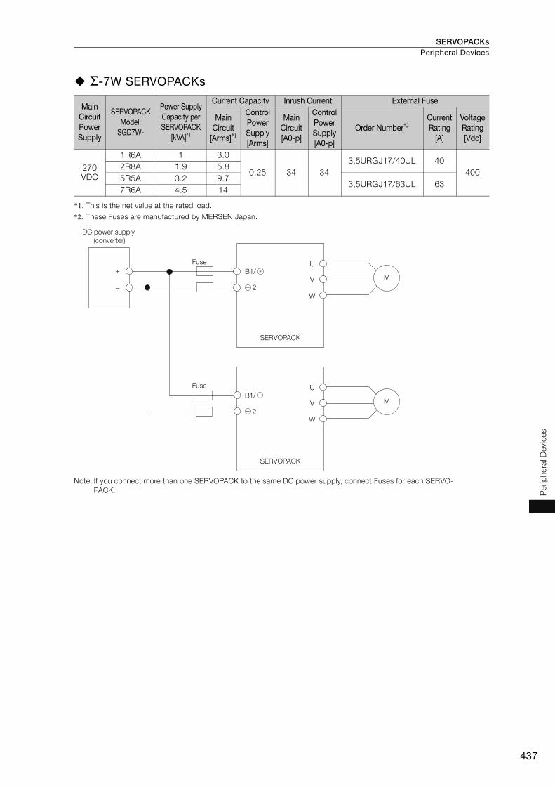
SERVOPACKs Peripheral Devices
437
Per
iphe
ral D
evic
es
Σ-7W SERVOPACKs
*1. This is the net value at the rated load.
*2. These Fuses are manufactured by MERSEN Japan.
Note: If you connect more than one SERVOPACK to the same DC power supply, connect Fuses for each SERVO-PACK.
Main Circuit Power Supply
SERVOPACK Model:
SGD7W-
Power Supply Capacity per SERVOPACK
[kVA]*1
Current Capacity Inrush Current External Fuse
Main Circuit
[Arms]*1
Control Power Supply [Arms]
Main Circuit [A0-p]
Control Power Supply [A0-p]
Order Number*2Current Rating
[A]
Voltage Rating [Vdc]
270 VDC
1R6A 1 3.0
0.25 34 343,5URGJ17/40UL 40
4002R8A 1.9 5.8 5R5A 3.2 9.7
3,5URGJ17/63UL 637R6A 4.5 14
Fuse
DC power supply (converter)
Fuse
M
M
+ B1/
2
+
−
U
V
W
U
V
W
SERVOPACK
SERVOPACK
B1/
2
+
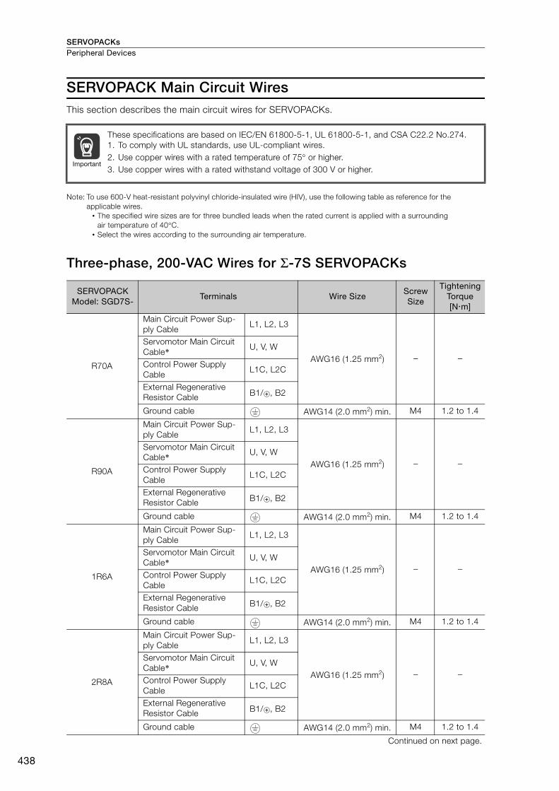
SERVOPACKsPeripheral Devices
438
SERVOPACK Main Circuit WiresThis section describes the main circuit wires for SERVOPACKs.
Note: To use 600-V heat-resistant polyvinyl chloride-insulated wire (HIV), use the following table as reference for the applicable wires.
• The specified wire sizes are for three bundled leads when the rated current is applied with a surrounding air temperature of 40°C.
• Select the wires according to the surrounding air temperature.
Three-phase, 200-VAC Wires for Σ-7S SERVOPACKs
These specifications are based on IEC/EN 61800-5-1, UL 61800-5-1, and CSA C22.2 No.274.1. To comply with UL standards, use UL-compliant wires.2. Use copper wires with a rated temperature of 75° or higher.3. Use copper wires with a rated withstand voltage of 300 V or higher.
SERVOPACK Model: SGD7S-
Terminals Wire SizeScrew Size
Tightening Torque[Nm]
R70A
Main Circuit Power Sup-ply Cable
L1, L2, L3
AWG16 (1.25 mm2) − −
Servomotor Main Circuit Cable* U, V, W
Control Power Supply Cable
L1C, L2C
External Regenerative Resistor Cable B1/ , B2
Ground cable AWG14 (2.0 mm2) min. M4 1.2 to 1.4
R90A
Main Circuit Power Sup-ply Cable
L1, L2, L3
AWG16 (1.25 mm2) − −
Servomotor Main Circuit Cable* U, V, W
Control Power Supply Cable
L1C, L2C
External Regenerative Resistor Cable B1/ , B2
Ground cable AWG14 (2.0 mm2) min. M4 1.2 to 1.4
1R6A
Main Circuit Power Sup-ply Cable
L1, L2, L3
AWG16 (1.25 mm2) − −
Servomotor Main Circuit Cable* U, V, W
Control Power Supply Cable
L1C, L2C
External Regenerative Resistor Cable B1/ , B2
Ground cable AWG14 (2.0 mm2) min. M4 1.2 to 1.4
2R8A
Main Circuit Power Sup-ply Cable
L1, L2, L3
AWG16 (1.25 mm2) − −
Servomotor Main Circuit Cable* U, V, W
Control Power Supply Cable
L1C, L2C
External Regenerative Resistor Cable B1/ , B2
Ground cable AWG14 (2.0 mm2) min. M4 1.2 to 1.4
Continued on next page.
Important
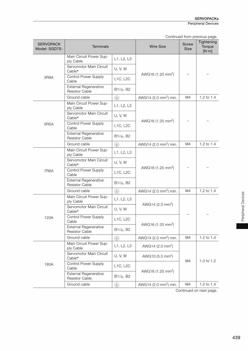
SERVOPACKs Peripheral Devices
439
Per
iphe
ral D
evic
es
3R8A
Main Circuit Power Sup-ply Cable
L1, L2, L3
AWG16 (1.25 mm2) − −
Servomotor Main Circuit Cable* U, V, W
Control Power Supply Cable
L1C, L2C
External Regenerative Resistor Cable B1/ , B2
Ground cable AWG14 (2.0 mm2) min. M4 1.2 to 1.4
5R5A
Main Circuit Power Sup-ply Cable
L1, L2, L3
AWG16 (1.25 mm2) − −
Servomotor Main Circuit Cable* U, V, W
Control Power Supply Cable
L1C, L2C
External Regenerative Resistor Cable B1/ , B2
Ground cable AWG14 (2.0 mm2) min. M4 1.2 to 1.4
7R6A
Main Circuit Power Sup-ply Cable
L1, L2, L3
AWG16 (1.25 mm2) − −
Servomotor Main Circuit Cable* U, V, W
Control Power Supply Cable
L1C, L2C
External Regenerative Resistor Cable B1/ , B2
Ground cable AWG14 (2.0 mm2) min. M4 1.2 to 1.4
120A
Main Circuit Power Sup-ply Cable
L1, L2, L3AWG14 (2.0 mm2)
− −
Servomotor Main Circuit Cable* U, V, W
Control Power Supply Cable
L1C, L2CAWG16 (1.25 mm2)
External Regenerative Resistor Cable B1/ , B2
Ground cable AWG14 (2.0 mm2) min. M4 1.2 to 1.4
180A
Main Circuit Power Sup-ply Cable
L1, L2, L3 AWG14 (2.0 mm2)
M4 1.0 to 1.2
Servomotor Main Circuit Cable* U, V, W AWG10 (5.5 mm2)
Control Power Supply Cable
L1C, L2CAWG16 (1.25 mm2)
External Regenerative Resistor Cable B1/ , B2
Ground cable AWG14 (2.0 mm2) min. M4 1.2 to 1.4
Continued on next page.
Continued from previous page.
SERVOPACK Model: SGD7S-
Terminals Wire SizeScrew Size
Tightening Torque[Nm]

SERVOPACKsPeripheral Devices
440
200A
Main Circuit Power Sup-ply Cable
L1, L2, L3 AWG12 (3.5 mm2)
M4 1.0 to 1.2
Servomotor Main Circuit Cable* U, V, W AWG10 (5.5 mm2)
Control Power Supply Cable
L1C, L2CAWG16 (1.25 mm2)
External Regenerative Resistor Cable B1/ , B2
Ground cable AWG14 (2.0 mm2) min. M4 1.2 to 1.4
330A
Main Circuit Power Sup-ply Cable
L1, L2, L3AWG8 (8.0 mm2)
M4 1.0 to 1.2
Servomotor Main Circuit Cable* U, V, W
Control Power Supply Cable
L1C, L2C AWG16 (1.25 mm2)
External Regenerative Resistor Cable B1/ , B2 AWG14 (2.0 mm2)
Ground cable AWG14 (2.0 mm2) min. M4 1.2 to 1.4
470A
Main Circuit Power Sup-ply Cable
L1, L2, L3 AWG8 (8.0 mm2)
M5 2.2 to 2.4
Servomotor Main Circuit Cable* U, V, W AWG6 (14 mm2)
Control Power Supply Cable
L1C, L2C AWG16 (1.25 mm2)
External Regenerative Resistor Cable B1/ , B2 AWG14 (2.0 mm2)
Ground cable AWG14 (2.0 mm2) min.
550A
Main Circuit Power Sup-ply Cable
L1, L2, L3 AWG8 (8.0 mm2)
Servomotor Main Circuit Cable* U, V, W AWG4 (22 mm2)
Control Power Supply Cable
L1C, L2C AWG16 (1.25 mm2)
External Regenerative Resistor Cable B1/ , B2 AWG10 (5.5 mm2)
Ground cable AWG14 (2.0 mm2) min.
Continued on next page.
Continued from previous page.
SERVOPACK Model: SGD7S-
Terminals Wire SizeScrew Size
Tightening Torque[Nm]
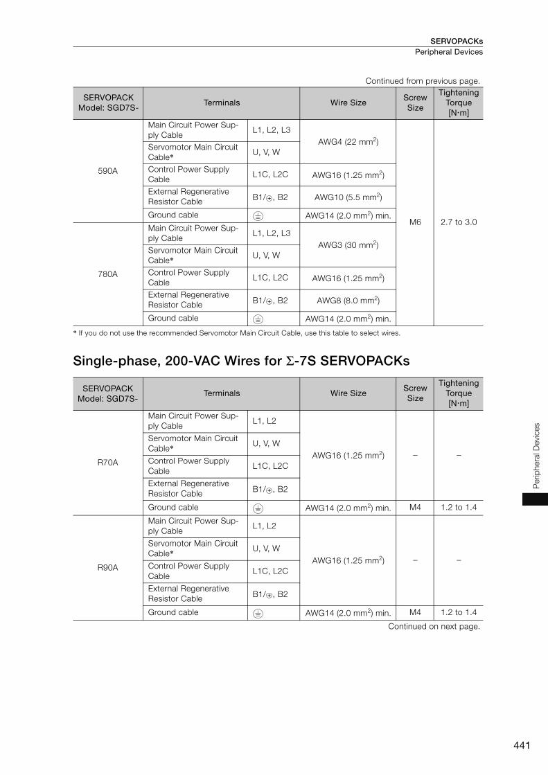
SERVOPACKs Peripheral Devices
441
Per
iphe
ral D
evic
es
* If you do not use the recommended Servomotor Main Circuit Cable, use this table to select wires.
Single-phase, 200-VAC Wires for Σ-7S SERVOPACKs
590A
Main Circuit Power Sup-ply Cable
L1, L2, L3AWG4 (22 mm2)
M6 2.7 to 3.0
Servomotor Main Circuit Cable* U, V, W
Control Power Supply Cable
L1C, L2C AWG16 (1.25 mm2)
External Regenerative Resistor Cable B1/ , B2 AWG10 (5.5 mm2)
Ground cable AWG14 (2.0 mm2) min.
780A
Main Circuit Power Sup-ply Cable
L1, L2, L3AWG3 (30 mm2)
Servomotor Main Circuit Cable* U, V, W
Control Power Supply Cable
L1C, L2C AWG16 (1.25 mm2)
External Regenerative Resistor Cable B1/ , B2 AWG8 (8.0 mm2)
Ground cable AWG14 (2.0 mm2) min.
SERVOPACK Model: SGD7S-
Terminals Wire SizeScrew Size
Tightening Torque[Nm]
R70A
Main Circuit Power Sup-ply Cable
L1, L2
AWG16 (1.25 mm2) − −
Servomotor Main Circuit Cable* U, V, W
Control Power Supply Cable
L1C, L2C
External Regenerative Resistor Cable B1/ , B2
Ground cable AWG14 (2.0 mm2) min. M4 1.2 to 1.4
R90A
Main Circuit Power Sup-ply Cable
L1, L2
AWG16 (1.25 mm2) − −
Servomotor Main Circuit Cable* U, V, W
Control Power Supply Cable
L1C, L2C
External Regenerative Resistor Cable B1/ , B2
Ground cable AWG14 (2.0 mm2) min. M4 1.2 to 1.4
Continued on next page.
Continued from previous page.
SERVOPACK Model: SGD7S-
Terminals Wire SizeScrew Size
Tightening Torque[Nm]
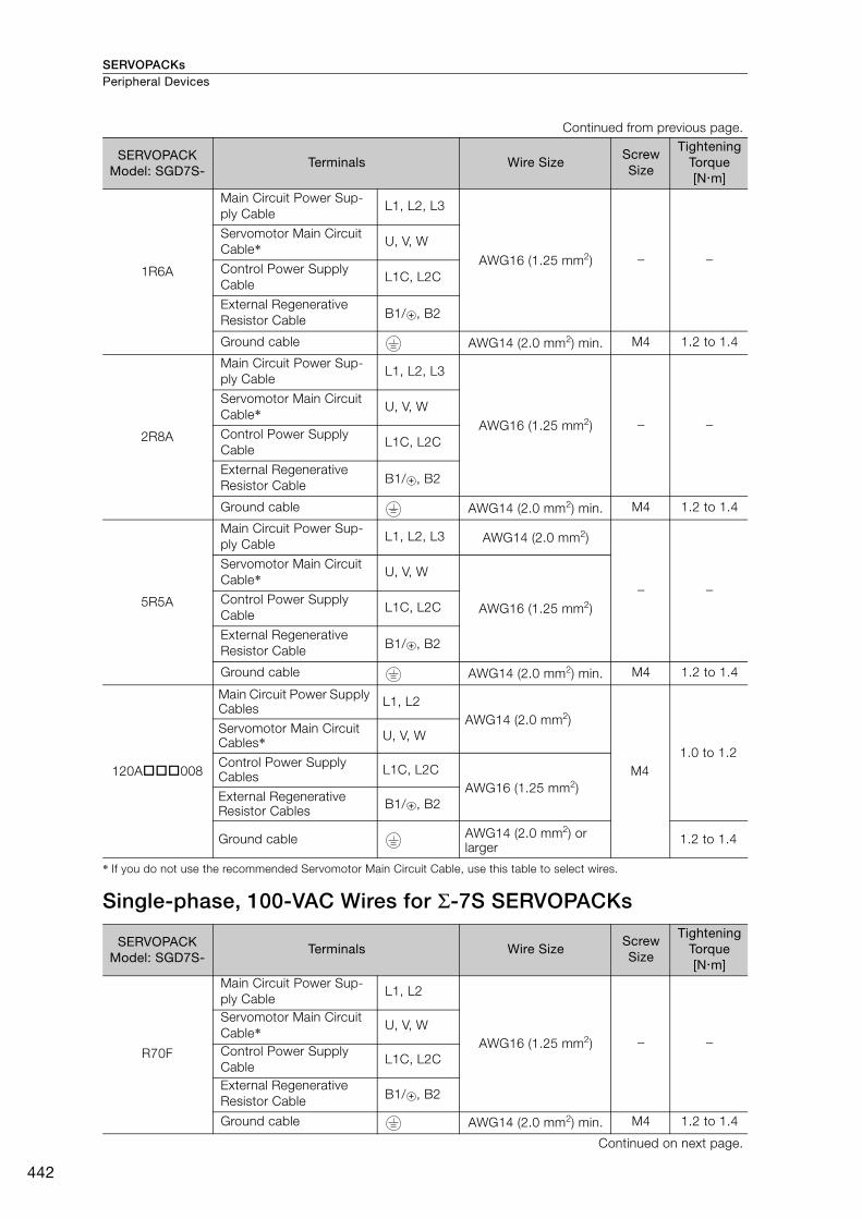
SERVOPACKsPeripheral Devices
442
* If you do not use the recommended Servomotor Main Circuit Cable, use this table to select wires.
Single-phase, 100-VAC Wires for Σ-7S SERVOPACKs
1R6A
Main Circuit Power Sup-ply Cable
L1, L2, L3
AWG16 (1.25 mm2) − −
Servomotor Main Circuit Cable* U, V, W
Control Power Supply Cable
L1C, L2C
External Regenerative Resistor Cable B1/ , B2
Ground cable AWG14 (2.0 mm2) min. M4 1.2 to 1.4
2R8A
Main Circuit Power Sup-ply Cable
L1, L2, L3
AWG16 (1.25 mm2) − −
Servomotor Main Circuit Cable* U, V, W
Control Power Supply Cable
L1C, L2C
External Regenerative Resistor Cable B1/ , B2
Ground cable AWG14 (2.0 mm2) min. M4 1.2 to 1.4
5R5A
Main Circuit Power Sup-ply Cable
L1, L2, L3 AWG14 (2.0 mm2)
− −
Servomotor Main Circuit Cable* U, V, W
AWG16 (1.25 mm2)Control Power Supply Cable
L1C, L2C
External Regenerative Resistor Cable B1/ , B2
Ground cable AWG14 (2.0 mm2) min. M4 1.2 to 1.4
120A008
Main Circuit Power Supply Cables L1, L2
AWG14 (2.0 mm2)
M41.0 to 1.2
Servomotor Main Circuit Cables* U, V, W
Control Power Supply Cables L1C, L2C
AWG16 (1.25 mm2)External Regenerative Resistor Cables B1/ , B2
Ground cable AWG14 (2.0 mm2) or larger
1.2 to 1.4
SERVOPACK Model: SGD7S-
Terminals Wire SizeScrew Size
Tightening Torque[Nm]
R70F
Main Circuit Power Sup-ply Cable
L1, L2
AWG16 (1.25 mm2) − −
Servomotor Main Circuit Cable* U, V, W
Control Power Supply Cable
L1C, L2C
External Regenerative Resistor Cable B1/ , B2
Ground cable AWG14 (2.0 mm2) min. M4 1.2 to 1.4
Continued on next page.
Continued from previous page.
SERVOPACK Model: SGD7S-
Terminals Wire SizeScrew Size
Tightening Torque[Nm]
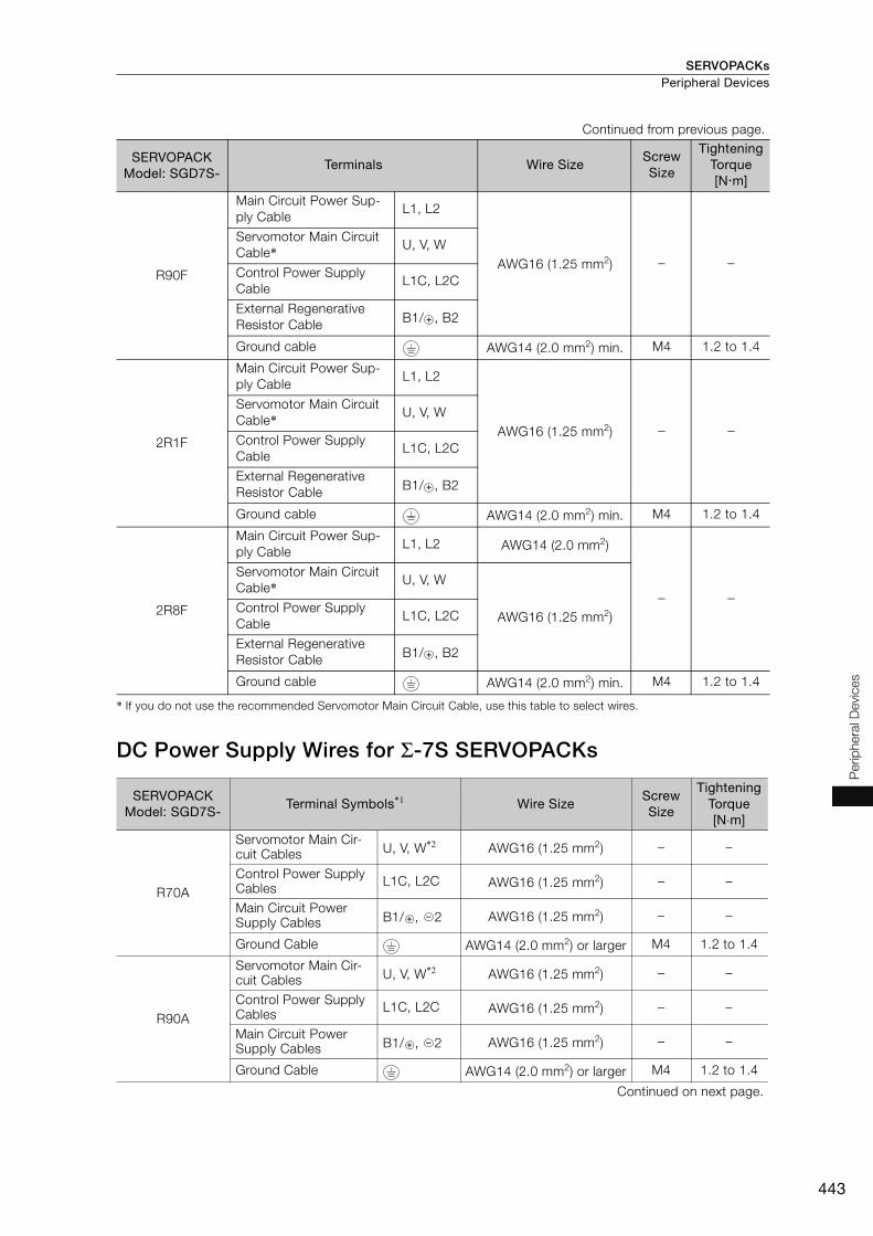
SERVOPACKs Peripheral Devices
443
Per
iphe
ral D
evic
es
* If you do not use the recommended Servomotor Main Circuit Cable, use this table to select wires.
DC Power Supply Wires for Σ-7S SERVOPACKs
R90F
Main Circuit Power Sup-ply Cable
L1, L2
AWG16 (1.25 mm2) − −
Servomotor Main Circuit Cable* U, V, W
Control Power Supply Cable
L1C, L2C
External Regenerative Resistor Cable B1/ , B2
Ground cable AWG14 (2.0 mm2) min. M4 1.2 to 1.4
2R1F
Main Circuit Power Sup-ply Cable
L1, L2
AWG16 (1.25 mm2) − −
Servomotor Main Circuit Cable* U, V, W
Control Power Supply Cable
L1C, L2C
External Regenerative Resistor Cable B1/ , B2
Ground cable AWG14 (2.0 mm2) min. M4 1.2 to 1.4
2R8F
Main Circuit Power Sup-ply Cable
L1, L2 AWG14 (2.0 mm2)
− −
Servomotor Main Circuit Cable* U, V, W
AWG16 (1.25 mm2)Control Power Supply Cable
L1C, L2C
External Regenerative Resistor Cable B1/ , B2
Ground cable AWG14 (2.0 mm2) min. M4 1.2 to 1.4
SERVOPACK Model: SGD7S-
Terminal Symbols*1 Wire SizeScrew Size
Tightening Torque[N⋅m]
R70A
Servomotor Main Cir-cuit Cables U, V, W*2 AWG16 (1.25 mm2) – –
Control Power Supply Cables L1C, L2C AWG16 (1.25 mm2) – –
Main Circuit Power Supply Cables B1/ , 2 AWG16 (1.25 mm2) – –
Ground Cable AWG14 (2.0 mm2) or larger M4 1.2 to 1.4
R90A
Servomotor Main Cir-cuit Cables U, V, W*2 AWG16 (1.25 mm2) – –
Control Power Supply Cables L1C, L2C AWG16 (1.25 mm2) – –
Main Circuit Power Supply Cables B1/ , 2 AWG16 (1.25 mm2) – –
Ground Cable AWG14 (2.0 mm2) or larger M4 1.2 to 1.4
Continued on next page.
Continued from previous page.
SERVOPACK Model: SGD7S-
Terminals Wire SizeScrew Size
Tightening Torque[Nm]
-
-
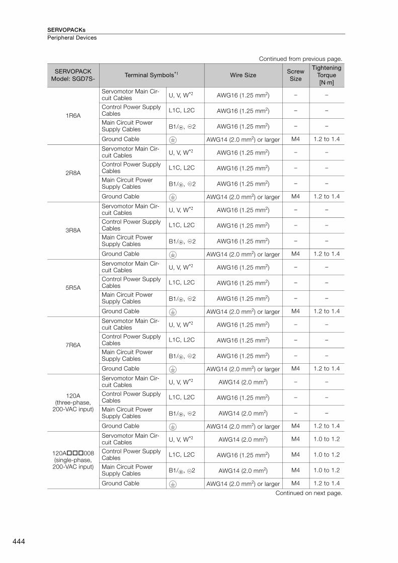
SERVOPACKsPeripheral Devices
444
1R6A
Servomotor Main Cir-cuit Cables U, V, W*2 AWG16 (1.25 mm2) – –
Control Power Supply Cables L1C, L2C AWG16 (1.25 mm2) – –
Main Circuit Power Supply Cables B1/ , 2 AWG16 (1.25 mm2) – –
Ground Cable AWG14 (2.0 mm2) or larger M4 1.2 to 1.4
2R8A
Servomotor Main Cir-cuit Cables U, V, W*2 AWG16 (1.25 mm2) – –
Control Power Supply Cables L1C, L2C AWG16 (1.25 mm2) – –
Main Circuit Power Supply Cables B1/ , 2 AWG16 (1.25 mm2) – –
Ground Cable AWG14 (2.0 mm2) or larger M4 1.2 to 1.4
3R8A
Servomotor Main Cir-cuit Cables U, V, W*2 AWG16 (1.25 mm2) – –
Control Power Supply Cables L1C, L2C AWG16 (1.25 mm2) – –
Main Circuit Power Supply Cables B1/ , 2 AWG16 (1.25 mm2) – –
Ground Cable AWG14 (2.0 mm2) or larger M4 1.2 to 1.4
5R5A
Servomotor Main Cir-cuit Cables U, V, W*2 AWG16 (1.25 mm2) – –
Control Power Supply Cables L1C, L2C AWG16 (1.25 mm2) – –
Main Circuit Power Supply Cables B1/ , 2 AWG16 (1.25 mm2) – –
Ground Cable AWG14 (2.0 mm2) or larger M4 1.2 to 1.4
7R6A
Servomotor Main Cir-cuit Cables U, V, W*2 AWG16 (1.25 mm2) – –
Control Power Supply Cables L1C, L2C AWG16 (1.25 mm2) – –
Main Circuit Power Supply Cables B1/ , 2 AWG16 (1.25 mm2) – –
Ground Cable AWG14 (2.0 mm2) or larger M4 1.2 to 1.4
120A(three-phase,
200-VAC input)
Servomotor Main Cir-cuit Cables U, V, W*2 AWG14 (2.0 mm2) – –
Control Power Supply Cables L1C, L2C AWG16 (1.25 mm2) – –
Main Circuit Power Supply Cables B1/ , 2 AWG14 (2.0 mm2) – –
Ground Cable AWG14 (2.0 mm2) or larger M4 1.2 to 1.4
120A008(single-phase,
200-VAC input)
Servomotor Main Cir-cuit Cables U, V, W*2 AWG14 (2.0 mm2) M4 1.0 to 1.2
Control Power Supply Cables L1C, L2C AWG16 (1.25 mm2) M4 1.0 to 1.2
Main Circuit Power Supply Cables B1/ , 2 AWG14 (2.0 mm2) M4 1.0 to 1.2
Ground Cable AWG14 (2.0 mm2) or larger M4 1.2 to 1.4
Continued on next page.
Continued from previous page.
SERVOPACK Model: SGD7S-
Terminal Symbols*1 Wire SizeScrew Size
Tightening Torque[N⋅m]
-
-
-
-
-
-
-
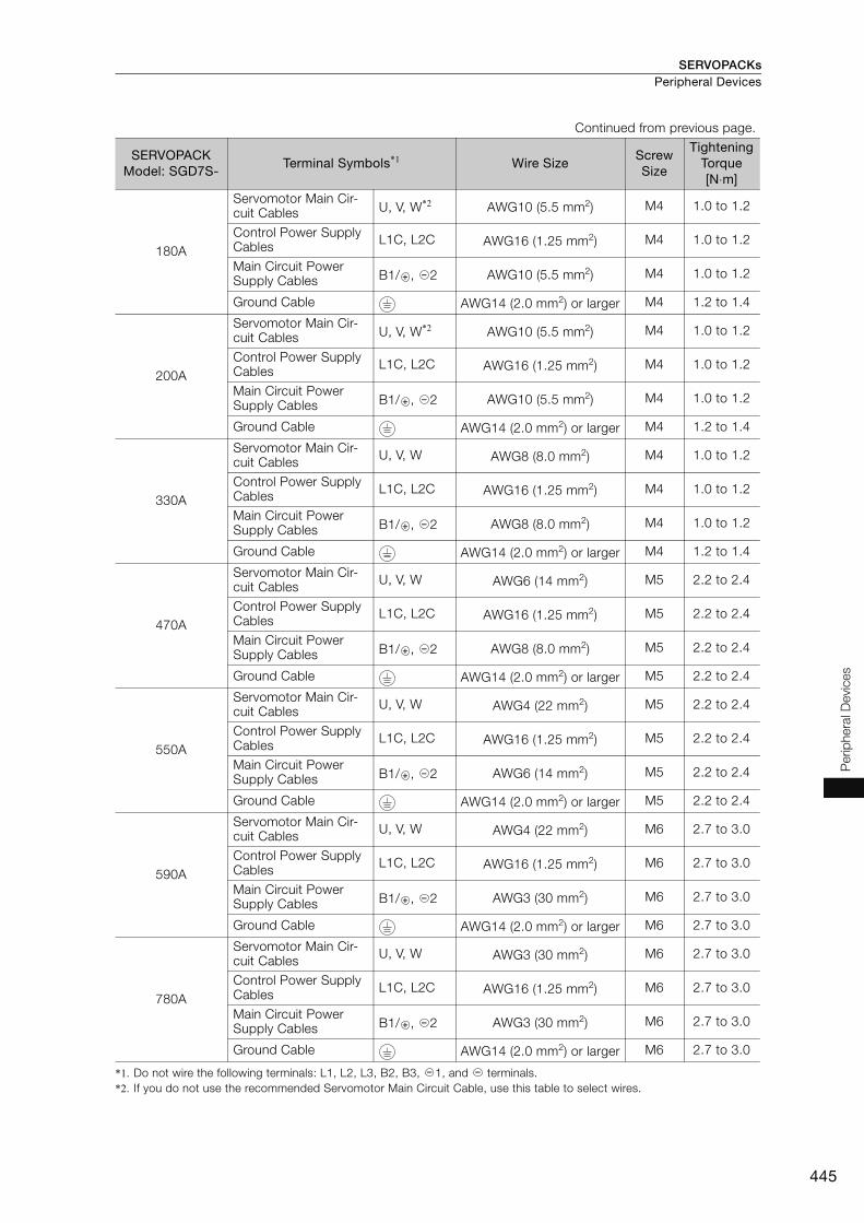
SERVOPACKs Peripheral Devices
445
Per
iphe
ral D
evic
es
*1. Do not wire the following terminals: L1, L2, L3, B2, B3, 1, and terminals.*2. If you do not use the recommended Servomotor Main Circuit Cable, use this table to select wires.
180A
Servomotor Main Cir-cuit Cables U, V, W*2 AWG10 (5.5 mm2) M4 1.0 to 1.2
Control Power Supply Cables L1C, L2C AWG16 (1.25 mm2) M4 1.0 to 1.2
Main Circuit Power Supply Cables B1/ , 2 AWG10 (5.5 mm2) M4 1.0 to 1.2
Ground Cable AWG14 (2.0 mm2) or larger M4 1.2 to 1.4
200A
Servomotor Main Cir-cuit Cables U, V, W*2 AWG10 (5.5 mm2) M4 1.0 to 1.2
Control Power Supply Cables L1C, L2C AWG16 (1.25 mm2) M4 1.0 to 1.2
Main Circuit Power Supply Cables B1/ , 2 AWG10 (5.5 mm2) M4 1.0 to 1.2
Ground Cable AWG14 (2.0 mm2) or larger M4 1.2 to 1.4
330A
Servomotor Main Cir-cuit Cables U, V, W AWG8 (8.0 mm2) M4 1.0 to 1.2
Control Power Supply Cables L1C, L2C AWG16 (1.25 mm2) M4 1.0 to 1.2
Main Circuit Power Supply Cables B1/ , 2 AWG8 (8.0 mm2) M4 1.0 to 1.2
Ground Cable AWG14 (2.0 mm2) or larger M4 1.2 to 1.4
470A
Servomotor Main Cir-cuit Cables U, V, W AWG6 (14 mm2) M5 2.2 to 2.4
Control Power Supply Cables L1C, L2C AWG16 (1.25 mm2) M5 2.2 to 2.4
Main Circuit Power Supply Cables B1/ , 2 AWG8 (8.0 mm2) M5 2.2 to 2.4
Ground Cable AWG14 (2.0 mm2) or larger M5 2.2 to 2.4
550A
Servomotor Main Cir-cuit Cables U, V, W AWG4 (22 mm2) M5 2.2 to 2.4
Control Power Supply Cables L1C, L2C AWG16 (1.25 mm2) M5 2.2 to 2.4
Main Circuit Power Supply Cables B1/ , 2 AWG6 (14 mm2) M5 2.2 to 2.4
Ground Cable AWG14 (2.0 mm2) or larger M5 2.2 to 2.4
590A
Servomotor Main Cir-cuit Cables U, V, W AWG4 (22 mm2) M6 2.7 to 3.0
Control Power Supply Cables L1C, L2C AWG16 (1.25 mm2) M6 2.7 to 3.0
Main Circuit Power Supply Cables B1/ , 2 AWG3 (30 mm2) M6 2.7 to 3.0
Ground Cable AWG14 (2.0 mm2) or larger M6 2.7 to 3.0
780A
Servomotor Main Cir-cuit Cables U, V, W AWG3 (30 mm2) M6 2.7 to 3.0
Control Power Supply Cables L1C, L2C AWG16 (1.25 mm2) M6 2.7 to 3.0
Main Circuit Power Supply Cables B1/ , 2 AWG3 (30 mm2) M6 2.7 to 3.0
Ground Cable AWG14 (2.0 mm2) or larger M6 2.7 to 3.0
Continued from previous page.
SERVOPACK Model: SGD7S-
Terminal Symbols*1 Wire SizeScrew Size
Tightening Torque[N⋅m]
-
-
-
-
-
-
-
- -

SERVOPACKsPeripheral Devices
446
Three-phase, 200-VAC Wires for Σ-7W SERVOPACKs
* If you do not use the recommended Servomotor Main Circuit Cable, use this table to select wires.
SERVOPACK Model: SGD7W-
Terminals Wire SizeScrew Size
Tightening Torque[Nm]
1R6A
Main Circuit Power Sup-ply Cable
L1, L2, L3
AWG16 (1.25 mm2) − −
Servomotor Main Circuit Cable*
UA, VA, WA, UB, VB, WB
Control Power Supply Cable
L1C, L2C
External Regenerative Resistor Cable B1/ , B2
Ground cable AWG14 (2.0 mm2) min. M4 1.2 to 1.4
2R8A
Main Circuit Power Sup-ply Cable
L1, L2, L3 AWG14 (2.0 mm2)
− −
Servomotor Main Circuit Cable*
UA, VA, WA, UB, VB, WB
AWG16 (1.25 mm2)Control Power Supply Cable
L1C, L2C
External Regenerative Resistor Cable B1/ , B2
Ground cable AWG14 (2.0 mm2) min. M4 1.2 to 1.4
5R5A
Main Circuit Power Sup-ply Cable
L1, L2, L3 AWG14 (2.0 mm2)
− −
Servomotor Main Circuit Cable*
UA, VA, WA, UB, VB, WB AWG16 (1.25 mm2)
Control Power Supply Cable
L1C, L2C
External Regenerative Resistor Cable B1/ , B2 AWG14 (2.0 mm2)
Ground cable AWG14 (2.0 mm2) min. M4 1.2 to 1.4
7R6A
Main Circuit Power Sup-ply Cable
L1, L2, L3 AWG14 (2.0 mm2)
− −
Servomotor Main Circuit Cable*
UA, VA, WA, UB, VB, WB AWG16 (1.25 mm2)
Control Power Supply Cable
L1C, L2C
External Regenerative Resistor Cable B1/ , B2 AWG14 (2.0 mm2)
Ground cable AWG14 (2.0 mm2) min. M4 1.2 to 1.4

SERVOPACKs Peripheral Devices
447
Per
iphe
ral D
evic
es
Single-phase, 200-VAC Wires for Σ-7W SERVOPACKs
* If you do not use the recommended Servomotor Main Circuit Cable, use this table to select wires.
DC Power Supply Wires for Σ-7W SERVOPACKs
SERVOPACK Model: SGD7W-
Terminals Wire SizeScrew Size
Tightening Torque[Nm]
1R6A
Main Circuit Power Sup-ply Cable
L1, L2, L3
AWG16 (1.25 mm2) − −
Servomotor Main Circuit Cable*
UA, VA, WA, UB, VB, WB
Control Power Supply Cable
L1C, L2C
External Regenerative Resistor Cable B1/ , B2
Ground cable AWG14 (2.0 mm2) min. M4 1.2 to 1.4
2R8A
Main Circuit Power Sup-ply Cable
L1, L2, L3 AWG14 (2.0 mm2)
− −
Servomotor Main Circuit Cable*
UA, VA, WA, UB, VB, WB
AWG16 (1.25 mm2)Control Power Supply Cable
L1C, L2C
External Regenerative Resistor Cable B1/ , B2
Ground cable AWG14 (2.0 mm2) min. M4 1.2 to 1.4
5R5A
Main Circuit Power Sup-ply Cable
L1, L2, L3 AWG14 (2.0 mm2)
− −
Servomotor Main Circuit Cable*
UA, VA, WA, UB, VB, WB AWG16 (1.25 mm2)
Control Power Supply Cable
L1C, L2C
External Regenerative Resistor Cable B1/ , B2 AWG14 (2.0 mm2)
Ground cable AWG14 (2.0 mm2) min. M4 1.2 to 1.4
SERVOPACK Model: SGD7W-
Terminal Symbols*1 Wire SizeScrew Size
Tightening Torque[N⋅m]
1R6A
Servomotor Main Cir-cuit Cables
UA, VA, WA, UB, VB, WB*2
AWG16 (1.25 mm2) – –
Control Power Supply Cables L1C, L2C AWG16 (1.25 mm2) – –
Main Circuit Power Supply Cables B1/ , 2 AWG16 (1.25 mm2) – –
Ground Cable AWG14 (2.0 mm2) or larger M4 1.2 to 1.4
Continued on next page.
-

SERVOPACKsPeripheral Devices
448
*1. Do not wire the following terminals: L1, L2, L3, B2, B3, 1, and terminals.*2. If you do not use the recommended Servomotor Main Circuit Cable, use this table to select wires.
2R8A
Servomotor Main Cir-cuit Cables
UA, VA, WA, UB, VB, WB*2
AWG16 (1.25 mm2) – –
Control Power Supply Cables L1C, L2C AWG16 (1.25 mm2) – –
Main Circuit Power Supply Cables B1/ , 2 AWG16 (1.25 mm2) – –
Ground Cable AWG14 (2.0 mm2) or larger M4 1.2 to 1.4
5R5A
Servomotor Main Cir-cuit Cables
UA, VA, WA, UB, VB, WB*2
AWG16 (1.25 mm2) – –
Control Power Supply Cables L1C, L2C AWG16 (1.25 mm2) – –
Main Circuit Power Supply Cables B1/ , 2 AWG14 (2.0 mm2) – –
Ground Cable AWG14 (2.0 mm2) or larger M4 1.2 to 1.4
7R6A
Servomotor Main Cir-cuit Cables
UA, VA, WA, UB, VB, WB*2
AWG16 (1.25 mm2) – –
Control Power Supply Cables L1C, L2C AWG16 (1.25 mm2) – –
Main Circuit Power Supply Cables B1/ , 2 AWG14 (2.0mm2) – –
Ground Cable AWG14 (2.0 mm2) or larger M4 1.2 to 1.4
Continued from previous page.
SERVOPACK Model: SGD7W-
Terminal Symbols*1 Wire SizeScrew Size
Tightening Torque[N⋅m]
-
-
-
- -
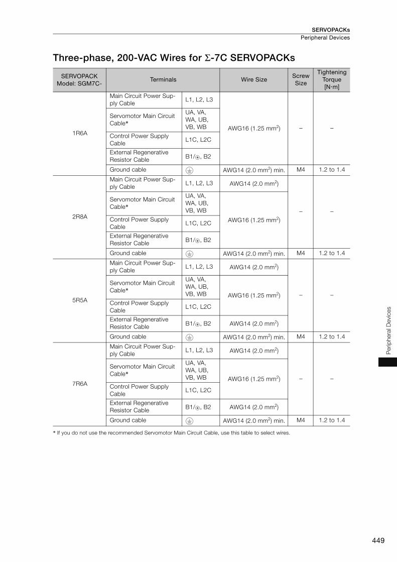
SERVOPACKs Peripheral Devices
449
Per
iphe
ral D
evic
es
Three-phase, 200-VAC Wires for Σ-7C SERVOPACKs
* If you do not use the recommended Servomotor Main Circuit Cable, use this table to select wires.
SERVOPACK Model: SGM7C-
Terminals Wire SizeScrew Size
Tightening Torque[Nm]
1R6A
Main Circuit Power Sup-ply Cable
L1, L2, L3
AWG16 (1.25 mm2) − −
Servomotor Main Circuit Cable*
UA, VA, WA, UB, VB, WB
Control Power Supply Cable
L1C, L2C
External Regenerative Resistor Cable B1/ , B2
Ground cable AWG14 (2.0 mm2) min. M4 1.2 to 1.4
2R8A
Main Circuit Power Sup-ply Cable
L1, L2, L3 AWG14 (2.0 mm2)
− −
Servomotor Main Circuit Cable*
UA, VA, WA, UB, VB, WB
AWG16 (1.25 mm2)Control Power Supply Cable
L1C, L2C
External Regenerative Resistor Cable B1/ , B2
Ground cable AWG14 (2.0 mm2) min. M4 1.2 to 1.4
5R5A
Main Circuit Power Sup-ply Cable
L1, L2, L3 AWG14 (2.0 mm2)
− −
Servomotor Main Circuit Cable*
UA, VA, WA, UB, VB, WB AWG16 (1.25 mm2)
Control Power Supply Cable
L1C, L2C
External Regenerative Resistor Cable B1/ , B2 AWG14 (2.0 mm2)
Ground cable AWG14 (2.0 mm2) min. M4 1.2 to 1.4
7R6A
Main Circuit Power Sup-ply Cable
L1, L2, L3 AWG14 (2.0 mm2)
− −
Servomotor Main Circuit Cable*
UA, VA, WA, UB, VB, WB AWG16 (1.25 mm2)
Control Power Supply Cable
L1C, L2C
External Regenerative Resistor Cable B1/ , B2 AWG14 (2.0 mm2)
Ground cable AWG14 (2.0 mm2) min. M4 1.2 to 1.4
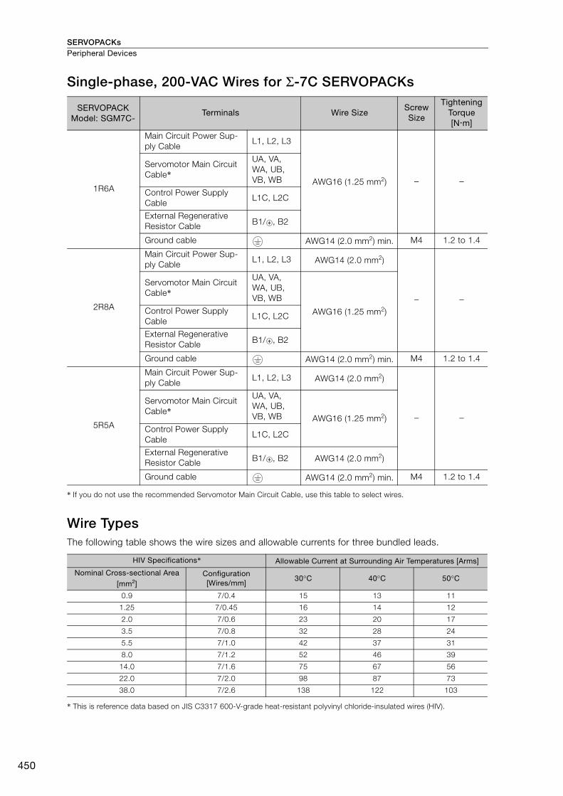
SERVOPACKsPeripheral Devices
450
Single-phase, 200-VAC Wires for Σ-7C SERVOPACKs
* If you do not use the recommended Servomotor Main Circuit Cable, use this table to select wires.
Wire Types The following table shows the wire sizes and allowable currents for three bundled leads.
* This is reference data based on JIS C3317 600-V-grade heat-resistant polyvinyl chloride-insulated wires (HIV).
SERVOPACK Model: SGM7C-
Terminals Wire SizeScrew Size
Tightening Torque[Nm]
1R6A
Main Circuit Power Sup-ply Cable
L1, L2, L3
AWG16 (1.25 mm2) − −
Servomotor Main Circuit Cable*
UA, VA, WA, UB, VB, WB
Control Power Supply Cable
L1C, L2C
External Regenerative Resistor Cable B1/ , B2
Ground cable AWG14 (2.0 mm2) min. M4 1.2 to 1.4
2R8A
Main Circuit Power Sup-ply Cable
L1, L2, L3 AWG14 (2.0 mm2)
− −
Servomotor Main Circuit Cable*
UA, VA, WA, UB, VB, WB
AWG16 (1.25 mm2)Control Power Supply Cable
L1C, L2C
External Regenerative Resistor Cable B1/ , B2
Ground cable AWG14 (2.0 mm2) min. M4 1.2 to 1.4
5R5A
Main Circuit Power Sup-ply Cable
L1, L2, L3 AWG14 (2.0 mm2)
− −
Servomotor Main Circuit Cable*
UA, VA, WA, UB, VB, WB AWG16 (1.25 mm2)
Control Power Supply Cable
L1C, L2C
External Regenerative Resistor Cable B1/ , B2 AWG14 (2.0 mm2)
Ground cable AWG14 (2.0 mm2) min. M4 1.2 to 1.4
HIV Specifications* Allowable Current at Surrounding Air Temperatures [Arms]
Nominal Cross-sectional Area [mm2]
Configuration [Wires/mm]
30°C 40°C 50°C
0.9 7/0.4 15 13 11
1.25 7/0.45 16 14 12
2.0 7/0.6 23 20 17
3.5 7/0.8 32 28 24
5.5 7/1.0 42 37 31
8.0 7/1.2 52 46 39
14.0 7/1.6 75 67 56
22.0 7/2.0 98 87 73
38.0 7/2.6 138 122 103
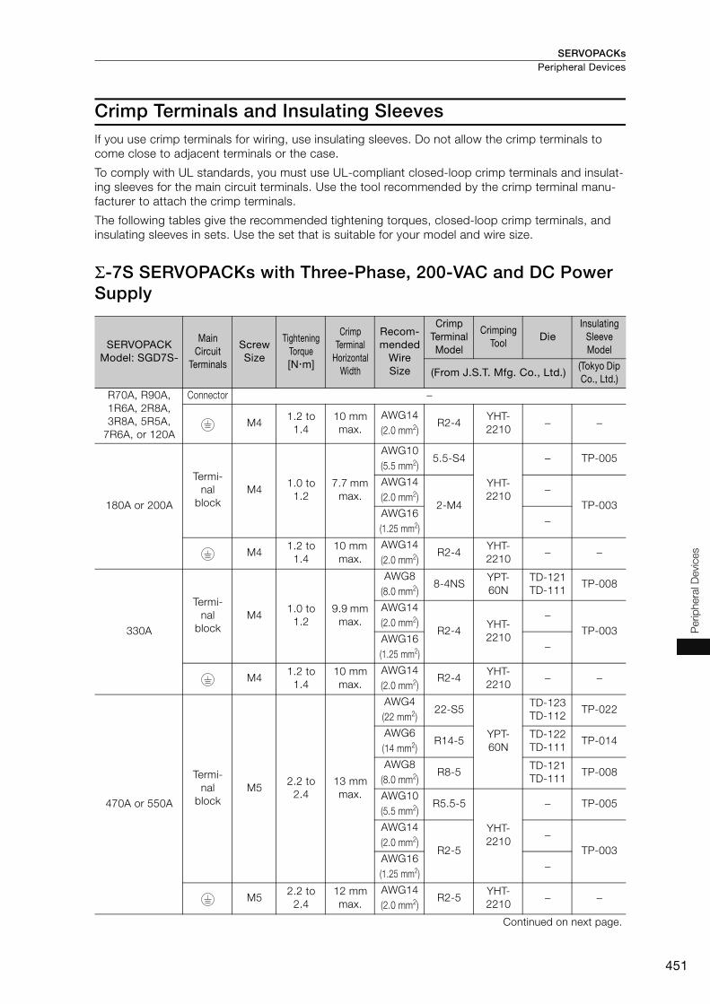
SERVOPACKs Peripheral Devices
451
Per
iphe
ral D
evic
es
Crimp Terminals and Insulating SleevesIf you use crimp terminals for wiring, use insulating sleeves. Do not allow the crimp terminals to come close to adjacent terminals or the case.
To comply with UL standards, you must use UL-compliant closed-loop crimp terminals and insulat-ing sleeves for the main circuit terminals. Use the tool recommended by the crimp terminal manu-facturer to attach the crimp terminals.
The following tables give the recommended tightening torques, closed-loop crimp terminals, and insulating sleeves in sets. Use the set that is suitable for your model and wire size.
Σ-7S SERVOPACKs with Three-Phase, 200-VAC and DC Power Supply
SERVOPACK Model: SGD7S-
Main Circuit
Terminals
Screw Size
Tightening Torque[Nm]
Crimp Terminal
Horizontal Width
Recom-mended
Wire Size
Crimp Terminal Model
Crimping Tool
DieInsulating
Sleeve Model
(From J.S.T. Mfg. Co., Ltd.)(Tokyo Dip Co., Ltd.)
R70A, R90A,1R6A, 2R8A, 3R8A, 5R5A,
7R6A, or 120A
Connector −
M41.2 to
1.410 mm max.
AWG14(2.0 mm2)
R2-4YHT-2210
− −
180A or 200A
Termi-nal
blockM4
1.0 to 1.2
7.7 mm max.
AWG10(5.5 mm2)
5.5-S4
YHT-2210
− TP-005
AWG14(2.0 mm2)
2-M4−
TP-003AWG16(1.25 mm2)
−
M41.2 to
1.410 mm max.
AWG14(2.0 mm2)
R2-4YHT-2210
− −
330A
Termi-nal
blockM4
1.0 to 1.2
9.9 mm max.
AWG8(8.0 mm2)
8-4NSYPT-60N
TD-121TD-111
TP-008
AWG14(2.0 mm2)
R2-4YHT-2210
−TP-003
AWG16(1.25 mm2)
−
M41.2 to
1.410 mm max.
AWG14(2.0 mm2)
R2-4YHT-2210
− −
470A or 550A
Termi-nal
blockM5
2.2 to 2.4
13 mm max.
AWG4(22 mm2)
22-S5
YPT-60N
TD-123TD-112
TP-022
AWG6(14 mm2)
R14-5TD-122TD-111
TP-014
AWG8(8.0 mm2)
R8-5TD-121TD-111
TP-008
AWG10(5.5 mm2)
R5.5-5
YHT-2210
− TP-005
AWG14(2.0 mm2)
R2-5−
TP-003AWG16(1.25 mm2)
−
M52.2 to
2.412 mm max.
AWG14(2.0 mm2)
R2-5YHT-2210
− −
Continued on next page.

SERVOPACKsPeripheral Devices
452
Σ-7S SERVOPACKs with Single-Phase, 200-VAC Power Supply
Σ-7S SERVOPACKs with Single-Phase, 100-VAC Power Supply
590A or 780A
Termi-nal
blockM6
2.7 to 3.0
18 mm max.
AWG3(30 mm2)
38-S6
YPT-60N
TD-124TD-112
TP-038
AWG4(22 mm2)
R22-6TD-123TD-112
TP-022
AWG8(8.0 mm2)
R8-6TD-121TD-111
TP-008
AWG10(5.5 mm2)
R5.5-6
YHT-2210
− TP-005
AWG14(2.0 mm2)
R2-6−
TP-003AWG16(1.25 mm2)
−
M62.7 to
3.012 mm max.
AWG14(2.0 mm2)
R2-6YHT-2210
− −
SERVOPACK Model: SGD7S-
Main Circuit
Terminals
Screw Size
Tightening Torque[Nm]
Crimp Terminal
Horizontal Width
Recom-mended
Wire Size
Crimp Terminal Model
Crimping Tool
DieInsulating
Sleeve Model
(From J.S.T. Mfg. Co., Ltd.)(Tokyo Dip Co., Ltd.)
R70A, R90A, 1R6A, 2R8A, or
5R5A
Connector −
M41.2 to
1.410 mm max.
AWG14(2.0 mm2)
R2-4YHT-2210
− −
120A008
Terminal block M4 1.0 to
1.27.7 mm
max.
AWG14(2.0 mm2)
2-M4 YHT-2210
−TP-003
AWG16(1.25 mm2)
−
M4 1.2 to 1.4
10 mm max.
AWG14(2.0 mm2)
R2-4 YHT-2210 − −
SERVOPACK Model: SGD7S-
Main Circuit
Terminals
Screw Size
Tightening Torque[Nm]
Crimp Terminal
Horizontal Width
Recom-mended
Wire Size
Crimp Terminal Model
Crimping Tool
DieInsulating
Sleeve Model
(From J.S.T. Mfg. Co., Ltd.)(Tokyo Dip Co., Ltd.)
R70F, R90F, 2R1F, or 2R8F
Connector −
M41.2 to
1.410 mm max.
AWG14(2.0 mm2)
R2-4YHT-2210
− −
Continued from previous page.
SERVOPACK Model: SGD7S-
Main Circuit
Terminals
Screw Size
Tightening Torque[Nm]
Crimp Terminal
Horizontal Width
Recom-mended
Wire Size
Crimp Terminal Model
Crimping Tool
DieInsulating
Sleeve Model
(From J.S.T. Mfg. Co., Ltd.)(Tokyo Dip Co., Ltd.)
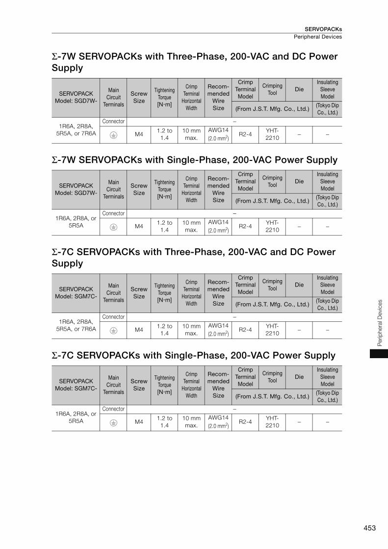
SERVOPACKs Peripheral Devices
453
Per
iphe
ral D
evic
es
Σ-7W SERVOPACKs with Three-Phase, 200-VAC and DC Power Supply
Σ-7W SERVOPACKs with Single-Phase, 200-VAC Power Supply
Σ-7C SERVOPACKs with Three-Phase, 200-VAC and DC Power Supply
Σ-7C SERVOPACKs with Single-Phase, 200-VAC Power Supply
SERVOPACK Model: SGD7W-
Main Circuit
Terminals
Screw Size
Tightening Torque[Nm]
Crimp Terminal
Horizontal Width
Recom-mended
Wire Size
Crimp Terminal Model
Crimping Tool
DieInsulating
Sleeve Model
(From J.S.T. Mfg. Co., Ltd.)(Tokyo Dip Co., Ltd.)
1R6A, 2R8A, 5R5A, or 7R6A
Connector −
M41.2 to
1.410 mm max.
AWG14(2.0 mm2)
R2-4YHT-2210
− −
SERVOPACK Model: SGD7W-
Main Circuit
Terminals
Screw Size
Tightening Torque[Nm]
Crimp Terminal
Horizontal Width
Recom-mended
Wire Size
Crimp Terminal Model
Crimping Tool
DieInsulating
Sleeve Model
(From J.S.T. Mfg. Co., Ltd.)(Tokyo Dip Co., Ltd.)
1R6A, 2R8A, or 5R5A
Connector −
M41.2 to
1.410 mm max.
AWG14(2.0 mm2)
R2-4YHT-2210
− −
SERVOPACK Model: SGM7C-
Main Circuit
Terminals
Screw Size
Tightening Torque[Nm]
Crimp Terminal
Horizontal Width
Recom-mended
Wire Size
Crimp Terminal Model
Crimping Tool
DieInsulating
Sleeve Model
(From J.S.T. Mfg. Co., Ltd.)(Tokyo Dip Co., Ltd.)
1R6A, 2R8A, 5R5A, or 7R6A
Connector −
M41.2 to
1.410 mm max.
AWG14(2.0 mm2)
R2-4YHT-2210
− −
SERVOPACK Model: SGM7C-
Main Circuit
Terminals
Screw Size
Tightening Torque[Nm]
Crimp Terminal
Horizontal Width
Recom-mended
Wire Size
Crimp Terminal Model
Crimping Tool
DieInsulating
Sleeve Model
(From J.S.T. Mfg. Co., Ltd.)(Tokyo Dip Co., Ltd.)
1R6A, 2R8A, or 5R5A
Connector −
M41.2 to
1.410 mm max.
AWG14(2.0 mm2)
R2-4YHT-2210
− −

SERVOPACKsPeripheral Devices
454
Surge Absorbers (Varistors) and Diodes for Holding Brake Power SuppliesSurge Absorbers (varistors) and Diodes for holding brake power supplies help prevent damage to brake coils caused by voltage surges.
If you use a Servomotor with a Holding Brake and switch the brake power supply circuit on the DC side, connect a Surge Absorber (varistor) or Diode that is suitable for the brake power supply volt-age and current.
Surge Absorbers (Varistors) for Holding Brake Power Supplies Use the following table as reference in selecting a Surge Absorber. Elements were selected for a Surge Absorber surrounding air temperature range of -20°C to 60°C and an ON/OFF switching fre-quency of 10 times or less per minute. The information in this table is for reference only, and does not ensure operation in combination with the holding brake.
Diodes for Holding Brake Power Supplies Select a Diode for the holding brake power supply with a rated current that is greater than that of the holding brake and with the recommended withstand voltage given in the following table.
Diodes are not provided by Yaskawa.
• When you select a Surge Absorber, varistor, or Diode for your application, consider the service life and test all operations, including the brake timing, before you use the Servomotor.
• If you connect an SSR (i.e., a semiconductor relay) to switch the brake circuit, use a Diode. • If you connect a Diode, more time is required to brake than with a Surge Absorber. (Refer to the
following figure.) If you use a diode, consider this in the application.
Holding Brake Power Supply Voltage
24 VDC
Manufacturer Nippon Chemi-Con Corporation Semitec Corporation
Order Number
Brake Rated Current
1 A max. TNR5V121K Z5D121
2 A max. TNR7V121K Z7D121
4 A max. TNR10V121K Z10D121
8 A max. TNR14V121K Z15D121
Holding Brake Power Supply Unit Specifications Withstand Voltage
Rated Output Voltage Input Voltage
24 VDC 200 V 100 V to 200 V
Note
00Time
Surge Absorber
Holding the brake (varistor)
Diode
Surge AbsorberTime
VoltageHolding the brake (Diode)
DiodeCurrent

SERVOPACKs Peripheral Devices
455
Perip
hera
l Devi
ces
Regenerative Resistors
Types of Regenerative ResistorsThe following regenerative resistors can be used.• Built-in regenerative resistors: Some models of SERVOPACKs have regenerative resistors built
into them. • External regenerative resistors: These resistors are used when the smoothing capacitor and built-
in regenerative resistor in the SERVOPACK cannot consume all of the regenerative power.Use Yaskawa’s SigmaJunmaSize+, an AC Servo drive capacity selection program, to determine if a regenerative resistor is required.
Note: If you use an External Regenerative Resistor, you must change the setting of the Pn600 (Regenerative Resis-tor Capacity) or Pn603 (Regenerative Resistance) parameters.
Selection Table
*1. Use Yaskawa’s SigmaJunmaSize+, an AC Servo drive capacity selection program, to select an external regener-ative resistor.
*2. Refer to the following section for the specifications of built-in regenerative resistors.Built-In Regenerative Resistor (page 456)
*3. Regenerative Resistor Units are available. Refer to the following sections for details.Regenerative Resistor Units (page 457)
SERVOPACK Model Built-In Regener-ative Resistor
External Regener-ative Resistor
Contents SGD7S- SGD7W- SGD7C-
R70A, R90A, 1R6A, 2R8A,R70F, R90F, 2R1F, 2R8F
− − None Basically not required
There is no built-in regenerative resistor, but nor-mally an external regenerative resistor is not required.Install an external regenerative resistor when the smoothing capacitor in the SERVOPACK cannot process all the regenerative power.*1
3R8A, 5R5A, 7R6A, 120A, 180A, 200A, 330A
1R6A, 2R8A, 5R5A, 7R6A
1R6A, 2R8A, 5R5A, 7R6A
Standard fea-ture*2
Basically not required
A built-in regenerative resistor is provided as a standard feature. Install an external regenerative resistor when the built-in regenerative resistor cannot process all the regenerative power.*1
470A, 550A, 590A, 780A
− − None Required.*3
A built-in regenerative resistor is not provided. An External Regenerative Resistor is required. If the External Regenerative Resistor is not con-nected to the SERVOPACK, a Regeneration Alarm (A.300) will occur.
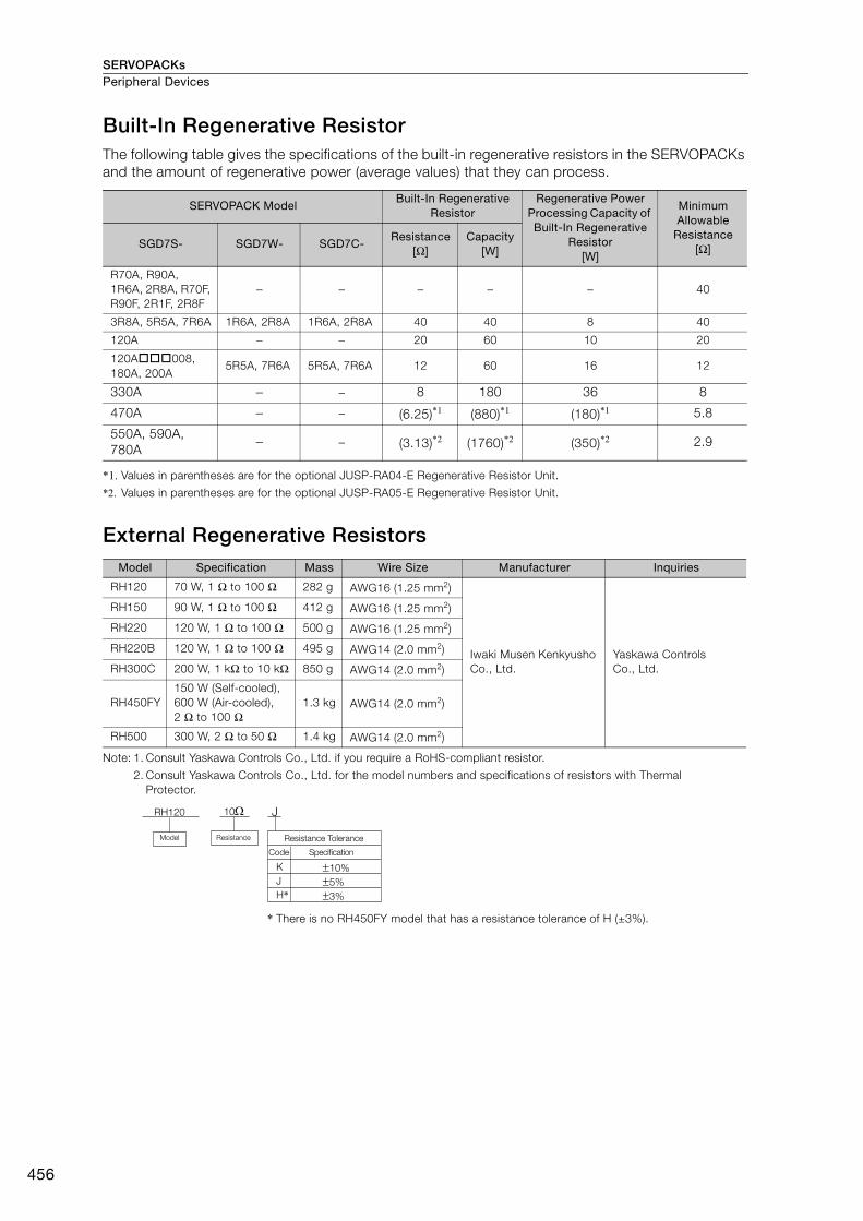
SERVOPACKsPeripheral Devices
456
Built-In Regenerative ResistorThe following table gives the specifications of the built-in regenerative resistors in the SERVOPACKs and the amount of regenerative power (average values) that they can process.
*1. Values in parentheses are for the optional JUSP-RA04-E Regenerative Resistor Unit.
*2. Values in parentheses are for the optional JUSP-RA05-E Regenerative Resistor Unit.
External Regenerative Resistors
Note: 1. Consult Yaskawa Controls Co., Ltd. if you require a RoHS-compliant resistor.
2. Consult Yaskawa Controls Co., Ltd. for the model numbers and specifications of resistors with Thermal Protector.
* There is no RH450FY model that has a resistance tolerance of H (±3%).
SERVOPACK Model Built-In Regenerative
Resistor Regenerative Power
Processing Capacity of Built-In Regenerative
Resistor[W]
Minimum Allowable
Resistance[Ω]SGD7S- SGD7W- SGD7C-
Resistance[Ω]
Capacity[W]
R70A, R90A, 1R6A, 2R8A, R70F, R90F, 2R1F, 2R8F
− − − − − 40
3R8A, 5R5A, 7R6A 1R6A, 2R8A 1R6A, 2R8A 40 40 8 40
120A − − 20 60 10 20
120A008, 180A, 200A
5R5A, 7R6A 5R5A, 7R6A 12 60 16 12
330A − − 8 180 36 8
470A − − (6.25)*1 (880)*1 (180)*1 5.8
550A, 590A, 780A
− − (3.13)*2 (1760)*2 (350)*2 2.9
Model Specification Mass Wire Size Manufacturer Inquiries
RH120 70 W, 1 Ω to 100 Ω 282 g AWG16 (1.25 mm2)
Iwaki Musen Kenkyusho Co., Ltd.
Yaskawa Controls Co., Ltd.
RH150 90 W, 1 Ω to 100 Ω 412 g AWG16 (1.25 mm2)
RH220 120 W, 1 Ω to 100 Ω 500 g AWG16 (1.25 mm2)
RH220B 120 W, 1 Ω to 100 Ω 495 g AWG14 (2.0 mm2)
RH300C 200 W, 1 kΩ to 10 kΩ 850 g AWG14 (2.0 mm2)
RH450FY150 W (Self-cooled), 600 W (Air-cooled), 2 Ω to 100 Ω
1.3 kg AWG14 (2.0 mm2)
RH500 300 W, 2 Ω to 50 Ω 1.4 kg AWG14 (2.0 mm2)
RH120 10
K
J
H*
10%
5%
3%
J
Model Resistance Resistance Tolerance
Code Specification
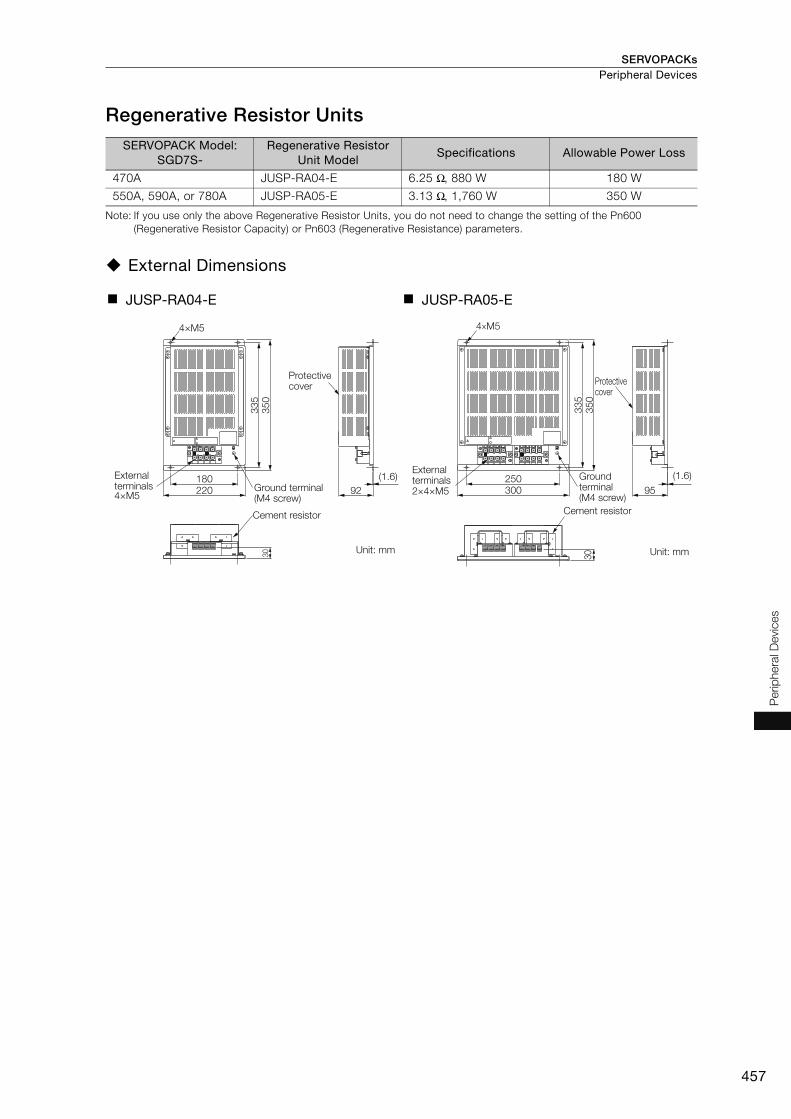
SERVOPACKs Peripheral Devices
457
Perip
hera
l Devi
ces
Regenerative Resistor Units
Note: If you use only the above Regenerative Resistor Units, you do not need to change the setting of the Pn600 (Regenerative Resistor Capacity) or Pn603 (Regenerative Resistance) parameters.
External Dimensions
SERVOPACK Model: SGD7S-
Regenerative Resistor Unit Model
Specifications Allowable Power Loss
470A JUSP-RA04-E 6.25 Ω, 880 W 180 W
550A, 590A, or 780A JUSP-RA05-E 3.13 Ω, 1,760 W 350 W
JUSP-RA04-E JUSP-RA05-E
4×M5
External terminals4×M5
Ground terminal (M4 screw)
Cement resistor
Protective cover
180220
33
53
50
30
92
(1.6)
Unit: mm
External terminals2×4×M5
Ground terminal (M4 screw)
Cement resistor
30
250
4×M5
300
33
53
50
Protective cover
95
(1.6)
Unit: mm

SERVOPACKsPeripheral Devices
458
Batteries for Servomotors with Absolute Encoders If you use an absolute encoder, you can use an Encoder Cable with a Battery Case connected to it to supply power and retain the absolute position data. You can also retain the absolute position data by supplying power from a battery on the host controller.
Using Encoder Cables with Battery CasesA Battery Case is attached to an Encoder Cable with a Battery Case. To replace the battery, obtain a Lithium Battery (JZSP-BA01) and mount it in the Battery Case.
Selection Table
Lithium Battery Dimensional Drawing
When Installing a Battery on the Host ControllerUse a battery that meets the specifications of the host controller. Use the recommended Battery given in the following table or the equivalent.
1. You cannot attach the Battery Case to an Incremental Encoder Cable. 2. Install the Battery Case where the surrounding air temperature is between -5°C and 60°C.
Name Order Number Remarks
Battery Case (case only) JUSP-BA01-E The Encoder Cable and Battery are not included. (This is a replacement part for a damaged Battery Case.)
Lithium Battery JZSP-BA01 This is a special battery that is mounted into the Battery Case.
Important
Lithium Battery (JZSP-BA01)Battery Case (JUSP-BA01-E)
Mount a Lithium Battery.
SERVOPACK
Connector
Encoder Cable with Battery CaseNote: The cable and connector to connect the Encoder
Cable and Battery Case are not included.
1
2
ER3V (3.6 V, 1,000 mAh, from Toshiba Battery Co., Ltd.)Battery
RedConnectors
Red
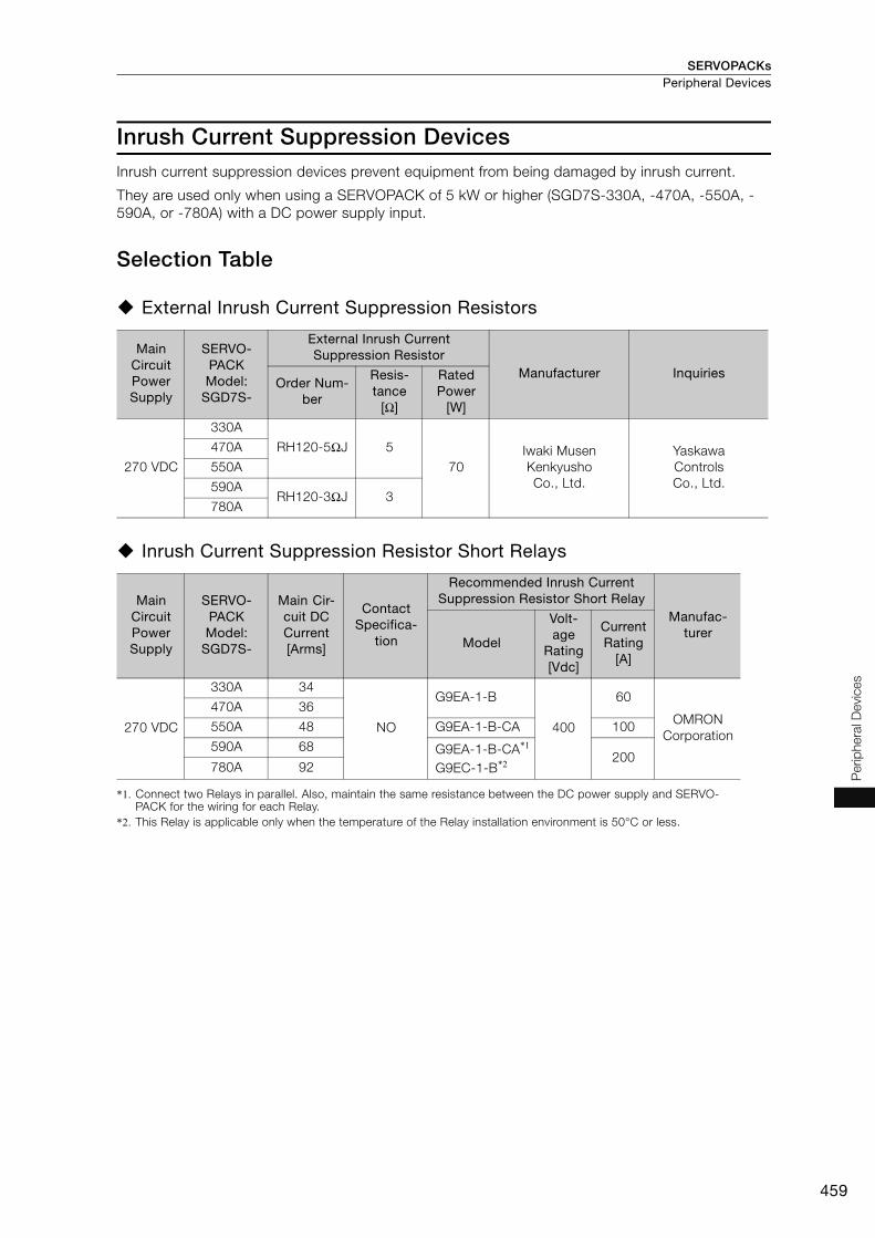
SERVOPACKs Peripheral Devices
459
Perip
hera
l Devi
ces
Inrush Current Suppression DevicesInrush current suppression devices prevent equipment from being damaged by inrush current.
They are used only when using a SERVOPACK of 5 kW or higher (SGD7S-330A, -470A, -550A, -590A, or -780A) with a DC power supply input.
Selection Table
External Inrush Current Suppression Resistors
Inrush Current Suppression Resistor Short Relays
*1. Connect two Relays in parallel. Also, maintain the same resistance between the DC power supply and SERVO-PACK for the wiring for each Relay.
*2. This Relay is applicable only when the temperature of the Relay installation environment is 50°C or less.
Main Circuit Power Supply
SERVO-PACK Model:
SGD7S-
External Inrush Current Suppression Resistor
Manufacturer InquiriesOrder Num-
ber
Resis-tance
[Ω]
Rated Power
[W]
270 VDC
330A
RH120-5ΩJ 5
70Iwaki Musen Kenkyusho Co., Ltd.
Yaskawa Controls Co., Ltd.
470A
550A
590ARH120-3ΩJ 3
780A
Main Circuit Power Supply
SERVO-PACK Model:
SGD7S-
Main Cir-cuit DC Current[Arms]
Contact Specifica-
tion
Recommended Inrush Current Suppression Resistor Short Relay
Manufac-turer
Model
Volt-age
Rating[Vdc]
Current Rating
[A]
270 VDC
330A 34
NO
G9EA-1-B
400
60
OMRON Corporation
470A 36
550A 48 G9EA-1-B-CA 100
590A 68 G9EA-1-B-CA*1
G9EC-1-B*2 200780A 92
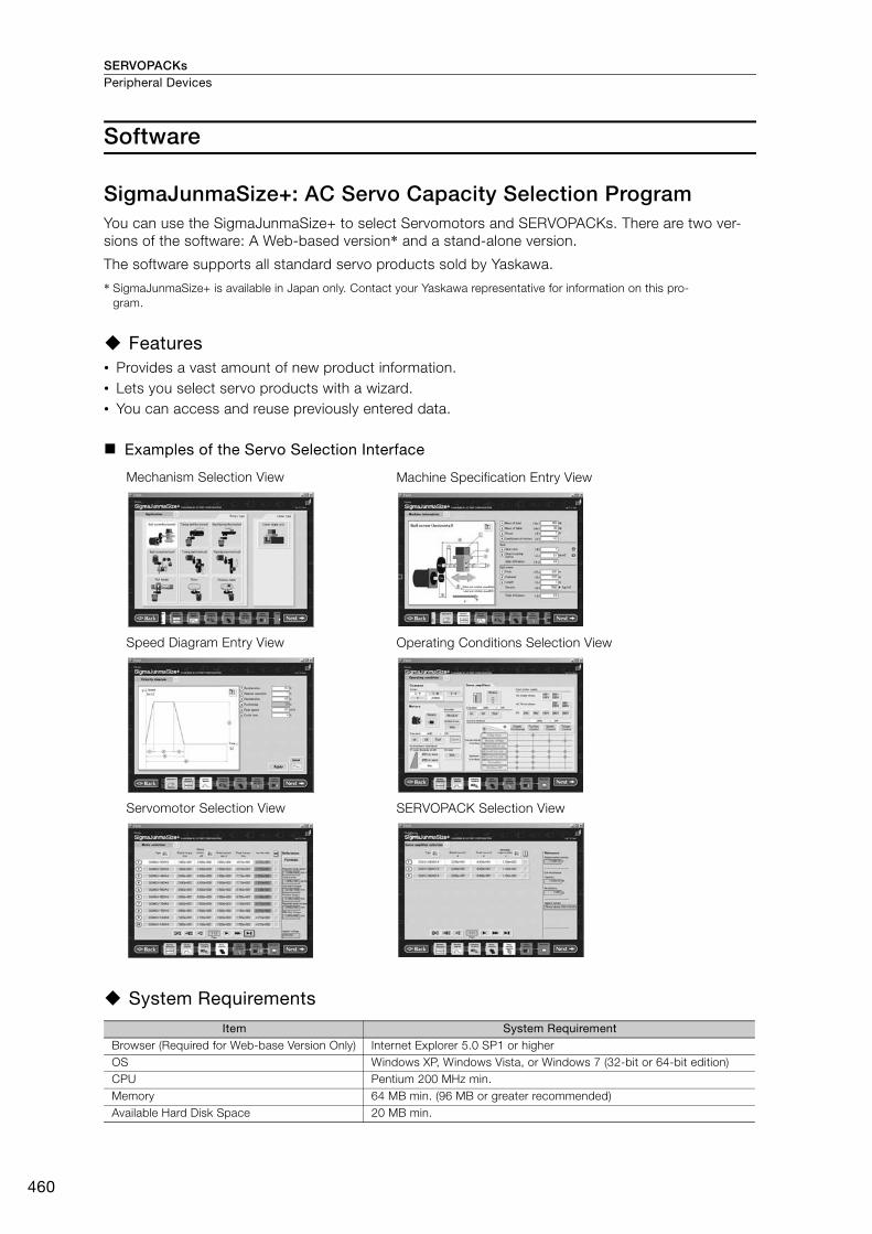
SERVOPACKsPeripheral Devices
460
Software
SigmaJunmaSize+: AC Servo Capacity Selection ProgramYou can use the SigmaJunmaSize+ to select Servomotors and SERVOPACKs. There are two ver-sions of the software: A Web-based version* and a stand-alone version.
The software supports all standard servo products sold by Yaskawa.
* SigmaJunmaSize+ is available in Japan only. Contact your Yaskawa representative for information on this pro-gram.
Features• Provides a vast amount of new product information. • Lets you select servo products with a wizard.• You can access and reuse previously entered data.
Examples of the Servo Selection Interface
System Requirements
Mechanism Selection View Machine Specification Entry View
Speed Diagram Entry View Operating Conditions Selection View
Servomotor Selection View SERVOPACK Selection View
Item System RequirementBrowser (Required for Web-base Version Only) Internet Explorer 5.0 SP1 or higherOS Windows XP, Windows Vista, or Windows 7 (32-bit or 64-bit edition)CPU Pentium 200 MHz min.Memory 64 MB min. (96 MB or greater recommended) Available Hard Disk Space 20 MB min.
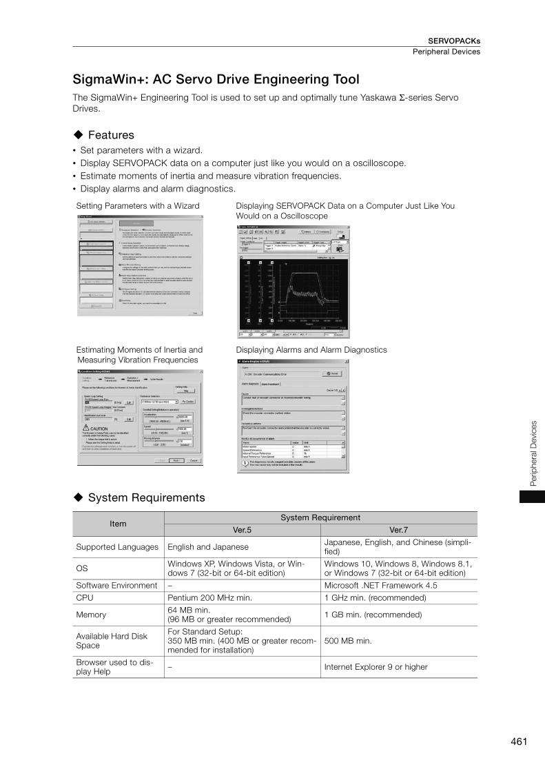
SERVOPACKs Peripheral Devices
461
Perip
hera
l Devi
ces
SigmaWin+: AC Servo Drive Engineering Tool The SigmaWin+ Engineering Tool is used to set up and optimally tune Yaskawa Σ-series Servo Drives.
Features • Set parameters with a wizard.• Display SERVOPACK data on a computer just like you would on a oscilloscope.• Estimate moments of inertia and measure vibration frequencies. • Display alarms and alarm diagnostics.
System Requirements
Setting Parameters with a Wizard Displaying SERVOPACK Data on a Computer Just Like You Would on a Oscilloscope
Estimating Moments of Inertia and Measuring Vibration Frequencies
Displaying Alarms and Alarm Diagnostics
ItemSystem Requirement
Ver.5 Ver.7
Supported Languages English and Japanese Japanese, English, and Chinese (simpli-fied)
OS Windows XP, Windows Vista, or Win-dows 7 (32-bit or 64-bit edition)
Windows 10, Windows 8, Windows 8.1, or Windows 7 (32-bit or 64-bit edition)
Software Environment – Microsoft .NET Framework 4.5
CPU Pentium 200 MHz min. 1 GHz min. (recommended)
Memory 64 MB min. (96 MB or greater recommended) 1 GB min. (recommended)
Available Hard Disk Space
For Standard Setup:350 MB min. (400 MB or greater recom-mended for installation)
500 MB min.
Browser used to dis-play Help – Internet Explorer 9 or higher

SERVOPACKsPeripheral Devices
462
MPE720 System Integrated Engineering ToolMPE720 Ver.7 is a system integrated Engineering Tool that provides the complete development functionality to set up, adjust, program, maintain, and inspect not only Controller programs but also all of the devices necessary to design machine installations, including Servo Drives, AC Drives, and Distributed I/O Devices.
It is installed in a PC and operated on a PC interface through a connection between the PC and Machine Controller.
Features
Complete Adjustment and Maintenance of Equipment Drive Devices
MPE720 Ver.7 connected to the MP3300 can be used to set up, adjust, and maintain Servo Drives, AC Drives, and I/O Devices connected to a network. There is no need to change connections, which increases efficiency.
Greater Efficiency with the Best Programming Method
System Requirements
Ladder Programming Motion Programming
• The new user interface lets just about anyone easily use the MPE720.
• An improved EXPRESSION instruction simpli-fies programming calculation in ladder dia-grams.
• Support is provided for all types of control, including position, speed, torque, and phase control.
• Positioning and interpolation can be pro-grammed with one instruction.
• Programs can be very easily edited using expressions in a text format.
• New variable programming can provide PC-like programming.
Item Specification
CPU Pentium 800 MHz min. or the equivalent (1 GHz or greater recommended)
Memory 512 MB min. (1 GB or greater recommended)
Available Hard Disk Space
700 MB min.
Display Resolution 1,024 × 768 min.
CD Drive 1 (only for installation)
Communications Ports RS-232C, Ethernet, MP2100 bus, and USB
OS Windows 10, Windows 8, Windows 8.1, or Windows 7 (32-bit or 64-bit)
.NET Environment .NET Framework 4.5
Supported Languages English and Japanese

Feedback Option Module ...................................464
Safety Option Module .........................................470
Option Modules

Option Modules
464
Feedback Option Module
Fully-Closed ModuleWith a Fully-Closed Module, an externally installed encoder is used to detect the position of the controlled machine and the machine’s position information is fed back to the SERVOPACK to imple-ment controls. High-precision positioning is possible because the actual machine position is fed back directly. To perform fully-closed loop control, a Fully-Closed Module and SERVOPACK are required.
Model Designations Purchasing a Module in a Set with the SERVOPACKTo order SERVOPACKs with a Fully-Closed Module attached, use the following model numbers.
*1. The model number of a SERVOPACK with an Option Module is not hyphenated after SGD7S.
*2. You can use these models with either a single-phase or three-phase power supply input.
*3. Refer to the following manual for details. Σ-7-Series AC Servo Drive Σ-7S/Σ-7W SERVOPACK with Hardware Option Specifications Dynamic Brake Prod-
uct Manual (Manual No.: SIEP S800001 73)
Note: Contact your Yaskawa representative for information on combining options.
Purchasing a Module SeparatelyWhen ordering a SERVOPACK and a Fully-Closed Module separately, use the following Fully-Closed Module model number.
1. One Option Case Kit is required for each SERVOPACK.Option Case Kit model: SGDV-OZA01A
2. Refer to the following pages when using these Command Option Modules with Fully-Closed Module.• INDEXER Module: Page 330• DeviceNet Module: Page 346
*1 R70 A 00 A 000 001
00
10
20
SGD7S
001
Option Module
Fully-Closed Module
A 200 VAC
A
R70*2
R90*2
1R6*2
2R8*2
3R8
5R5*2
7R6
120
180
200
330
470
550
590
780
R70
R90
2R1
2R8
0.05 kW
0.1 kW
0.2 kW
0.4 kW
0.5 kW
0.75 kW
1.0 kW
1.5 kW
2.0 kW
3.0 kW
5.0 kW
6.0 kW
7.5 kW
11 kW
15 kW
0.05 kW
0.1 kW
0.2 kW
0.4 kW
Maximum Applicable Motor Capacity Voltage
Interface
Code
Code
Specification Code
000
Specification
Without options
Rack-mounted
Varnished
All models
Applicable Models
Specification
Analog voltage/pulse train reference
Design Revision Order
Hardware Options Specification
Voltage Code Specification
Three-phase, 200 VAC
1st+2nd+3rd digits 4th digit
5th+6th digits
7th digit
8th+9th+10th digits
Σ-7 Series Σ-7S Models
4th digit
1st+2nd+3rd digits
5th+6th digits
8th+9th+10th digits
7th digit
001
002
11th+12th+13th digits
MECHATROLINK-II communications reference
MECHATROLINK-III communications reference
11th+12th+13th digits
Code Specification
SGD7S-R70A to -330A
SGD7S-470A to -780ADuct-ventilated
All models
Single-phase, 100 VAC
F 100 VAC
SGD7S-R70F to -2R8F
Single-phase, 200-VAC power supply input
008 SGD7S-120A
No dynamic brake
020*3
SGD7S-R70A to -2R8ASGD7S-R70F to -2R8F
External dynamic brake resistor
SGD7S-3R8A to -780A
SGDV-OFA01A
Important

Option Modules Feedback Option Module
465
Fully
-Clo
sed
Mod
ule
System ConfigurationRefer to the section for the relevant Servomotor for information on Servomotor Main Circuit Cables.
To select an External Linear Encoder, refer to Recommended Linear Encoders (page M-34). The connection devices and cables for each type of encoder are also given. Prepare the required items.
Note: 1. Refer to the following section for information on peripheral devices.Peripheral Devices (page 430)
2. If you purchase a Fully-Closed Module by itself, refer to the following manual for the method to mount it to the SERVOPACK.
Σ-V Series/Σ-V Series for Large-Capacity Models/Σ-7 Series Installation Guide Fully-Closed Module (Manual No.: TOBP C720829 03)
Servomotor Main Circuit Cable
SERVOPACKFully-Closed Module
Serial Converter Unit Cable
External Linear Encoder Cable
Serial Converter Unit
External Linear Encoder (Not provided by Yaskawa.)

Option ModulesFeedback Option Module
466
Connections to Linear Encoder from Heidenhain Corporation
Connections for a 1 Vp-p Analog Voltage Output Signal
You must make the connections through a Yaskawa Serial Converter Unit. The output signal will be multiplied by 8 bits (256 divisions) in the Serial Converter Unit.
*1. When using a JZDP-J00- Serial Converter Unit, do not use a Yaskawa Linear Encoder Cable that is lon-ger than 3 m.
*2. Contact Heidenhain Corporation for details on cables (analog 1 Vp-p output, D-sub 15-pin, male) from Heiden-hain Corporation.
*1. One Option Case Kit is required for each SERVOPACK.The set includes the module cover, PCB mounting plate, and two mounting screws.
*2. Refer to the following manual for the specifications of the Serial Converter Units. Σ-7-Series AC Servo Drive Peripheral Device Selection Manual (Manual No.: SIEP S800001 32)
*3. The boxes () in the model number are replaced with the cable length when ordering.(1 m = 01, 3 m = 03, 5 m = 05, 10 m = 10, 15 m = 15, and 20 m = 20)
Connections When Using a Yaskawa Serial Interface for the Output Signals
• LIC4100 Linear Encoder with EIB3391Y Interpolator
* Use an Encoder Cable from Heidenhain Corporation. Contact Heidenhain Corporation for detailed Encoder Cable specifications.
No. Item Model
Fully-Closed Module(Purchased as a set with the SERVOPACK)
Without options: SGD7S0A0001With options:SGD7S0A1Note: When a hardware option is mounted, is replaced with a
three-digit number that specifies the type of option.
Fully-Closed Module (Purchased alone)
Fully-Closed Module SGDV-OFA01A
Option Case Kit*1 SGDV-OZA01A
Serial Converter Unit Cable JZSP-CLP70--E*3
Serial Converter Unit*2 JZDP-H003-000
Linear Encoder Cable JZSP-CLL30--E*3
�Linear Encoder Cable*1
�Serial Converter Unit Cable
�Serial Converter UnitLinear Encoder from Heidenhain Corporation
Cable from Heidenhain Corporation*2
CN31
Connection to encoder in Rotary Servomotor
Encoder Cable
CN2
SERVO-PACK
Fully-Closed Module
�
EIB3391Y Interpolator
Encoder Cable from Heidenhain Corporation*
Products from Heidenhain Corporation
CN31
Connection to encoder in Rotary Servomotor
Encoder Cable
CN2
SERVO-PACK
Fully-Closed Module
LIC4100 Linear Encoder from Heidenhain Corporation

Option Modules Feedback Option Module
467
Fully
-Clo
sed
Mod
ule
Connections to Linear Encoder from Renishaw Plc
Connections for a 1 Vp-p Analog Voltage Output Signal
You must make the connections through a Yaskawa Serial Converter Unit. The output signal will be multiplied by 8 bits (256 divisions) in the Serial Converter Unit.
*1. Contact Renishaw plc for details on cables (analog 1 Vp-p output, D-sub 15-pin, male) from Renishaw plc. However, the BID and DIR signals are not connected.
*2. If you use the origin signals with a Linear Encoder from Renishaw plc, the origin may sometimes be falsely detected.If that occurs, use the BID/DIR signal to output the origin signal only in one direction.
*1. When ordering a SERVOPACK and a Fully-Closed Module separately, use this Fully-Closed Module model num-ber.
*2. Refer to the following manual for the specifications of the Serial Converter Units. Σ-7-Series AC Servo Drive Peripheral Device Selection Manual (Manual No.: SIEP S800001 32)
*3. The boxes () in the model number are replaced with the cable length when ordering.(1 m = 01, 3 m = 03, 5 m = 05, 10 m = 10, 15 m = 15, and 20 m = 20)
No. Item Model
Fully-Closed Module(Purchased as a set with the SERVOPACK)
Without options: SGD7S0A0001With options:SGD7S0A1Note: When a hardware option is mounted, is replaced
with a three-digit number that specifies the type of option.
Fully-Closed Module (Purchased alone)
Fully-Closed Module SGDV-OFA01A
Option Case Kit*1 SGDV-OZA01A
Serial Converter Unit Cable JZSP-CLP70--E*3
Serial Converter Unit*2 JZDP-H005-000
Linear Encoder Cable JZSP-CLL00--E*3
�Linear Encoder Cable
Cable from Renishaw plc*1
�Serial Converter Unit Cable
�Serial Converter UnitLinear Encoder from Renishaw plc*2
CN31
Connection to encoder in Rotary Servomotor
Encoder Cable
CN2
SERVO-PACK
Fully-Closed Module
�

Option ModulesFeedback Option Module
468
Connections to Linear Encoder from Magnescale Co., Ltd.
SL70 Linear Encoder and PL101-RY Sensor Head with Interpolator
* The boxes () in the model number are replaced with the cable length when ordering.(1 m = 01, 3 m = 03, 5 m = 05, 10 m = 10, 15 m = 15, and 20 m = 20)
SmartSCALE Linear Encoder (SQ10 Scale + MQ10-FLA Interpolator)
* The boxes () in the model number are replaced with the cable length when ordering.The maximum cable length in this case is 15 m.(1 m = 01, 3 m = 03, 5 m = 05, 10 m = 10, and 15 m = 15)
SR-75, SR-77, SR-85, and SR-87 Linear Encoders
* To connect the SERVOPACK and Linear Encoder, use a CH33-xxG Cable from Magnescale Co., Ltd. (This Cable has connectors designed for use with Yaskawa products.)
Serial Converter Unit Cable*JZSP-CLP70-��E
Products from Magnescale Co., Ltd.
PL101-RY Head with Interpolator
CN31CN2
Connection to encoder in Rotary Servomotor
Encoder CableSERVO-PACK
Fully-Closed Module
SL7�0 Linear Encoder from Magnescale Co., Ltd.
Serial Converter Unit Cable*JZSP-CLP70-��E
Products from Magnescale Co., Ltd.
MQ10-FLA Interpolator
CN31CN2
Connection to encoder in Rotary Servomotor
Encoder CableSERVO-PACK
Fully-Closed Module
SQ10 Linear Encoder from Magnescale Co., Ltd.
SR85-�����LFSR85-�����MFSR87-�����LFSR87-�����MFEncoder Cable from
Magnescale Co., Ltd.*
Products from Magnescale Co., Ltd.
Linear Encoder from Magnescale Co., Ltd.SR75-�����LFSR75-�����MFSR77-�����LFSR77-�����MF
CN31CN2
Connection to encoder in Rotary Servomotor
Encoder CableSERVO-PACK
Fully-Closed Module

Option Modules Feedback Option Module
469
Fully
-Clo
sed
Mod
ule
RU77-4096ADF/RU77-4096AFFT01 Absolute Rotary Encoders
* To connect the SERVOPACK and Rotary Encoder, use a CE28-Series Extension Cable for RU77 from Magnescale Co., Ltd.
Note: The RU77 is a single-turn absolute rotary encoder.
Connections to Linear Encoders from Mitutoyo Corporation
ST78A/ST13 Linear Encoders
* The boxes () in the model number are replaced with the cable length when ordering.(1 m = 01, 3 m = 03, 5 m = 05, 10 m = 10, 15 m = 15, and 20 m = 20)
External DimensionsRefer to pages 418 to 429 for the external dimensions of the individual SERVOPACKs.
Connectors
Note: The above connectors or their equivalents are used for the Fully-Closed Module.
Device Label Model Number of Pins Manufacturer
CN31 3E106-0220KV 6 3M Japan Ltd.
Products from Magnescale Co., Ltd.
CN31CN2
Rotary Encoder from Magnescale Co., Ltd.RU77-4096ADFRU77-4096AFFT01
Connection to encoder in Rotary Servomotor
Encoder CableSERVO-PACK
Fully-Closed Module
Encoder Cable from Magnescale Co., Ltd.*
ST788AST789AST1831ST1832
Linear Encoders from Mitutoyo CorporationST781AST782AST783AST784A
Cable from Mitutoyo Corporation
CN31CN2
Connection to encoder in Rotary Servomotor
Encoder CableSERVO-PACK
Fully-Closed Module
Serial Converter Unit Cable*JZSP-CLP70-��E
Unit: mmApprox. Mass: 0.1 kg(75) 97
CN31
20
(9.8)
160
(23)

Option Modules
470
Safety Option Module
Safety ModuleThis Safety Module implements safety functions that conform to EN ISO 13849-1 (the harmonized EU Machinery Directive) and are specified in the individual IEC 61800-5-2 standard. You can com-bine it with an SGD7S SERVOPACK to design optimum safety in a machine system according to industry needs.
Model Designations
Purchasing a Module in a Set with the SERVOPACKTo order SERVOPACKs with a Safety Module attached, use the following model numbers.
*1. The model number of a SERVOPACK with an Option Module is not hyphenated after SGD7S.
*2. You can use these models with either a single-phase or three-phase power supply input.
*3. Refer to the following manual for details. Σ-7-Series AC Servo Drive Σ-7S/Σ-7W SERVOPACK with Hardware Option Specifications Dynamic Brake Prod-
uct Manual (Manual No.: SIEP S800001 73)
Note: Contact your Yaskawa representative for information on combining options.
Purchasing a Module SeparatelyWhen ordering SERVOPACKs and Safety Modules separately, use the following Safety Module model number.
1. One Option Case Kit is required for each SERVOPACK.Option Case Kit model: SGDV-OZA01A
2. INDEXER Modules and DeviceNet Modules cannot be used with Safety Modules.
*1 R70 A 00 A 000 010
00
10
20
SGD7S
010
Option Module
Safety Module
A 200 VAC
A
R70*2
R90*2
1R6*2
2R8*2
3R8
5R5*2
7R6
120
180
200
330
470
550
590
780
R70
R90
2R1
2R8
0.05 kW
0.1 kW
0.2 kW
0.4 kW
0.5 kW
0.75 kW
1.0 kW
1.5 kW
2.0 kW
3.0 kW
5.0 kW
6.0 kW
7.5 kW
11 kW
15 kW
0.05 kW
0.1 kW
0.2 kW
0.4 kW
Maximum Applicable Motor Capacity Voltage
Interface
Code
Code
Specification Code
000
Specification
Without options
Rack-mounted
Varnished
All models
Applicable Models
Specification
Analog voltage/pulse train reference
Design Revision Order
Hardware Options Specification
Voltage Code Specification
Three-phase, 200 VAC
1st+2nd+3rd digits 4th digit
5th+6th digits
7th digit
8th+9th+10th digits
Σ-7 Series Σ-7S Models
4th digit
1st+2nd+3rd digits
5th+6th digits
8th+9th+10th digits
7th digit
001
002
11th+12th+13th digits
MECHATROLINK-II communications reference
MECHATROLINK-III communications reference
11th+12th+13th digits
Code Specification
SGD7S-R70A to -330A
SGD7S-470A to -780ADuct-ventilated
All models
Single-phase, 100 VAC
F 100 VAC
SGD7S-R70F to -2R8F
Single-phase, 200-VAC power supply input
008 SGD7S-120A
No dynamic brake020*3
SGD7S-R70A to -2R8A
SGD7S-R70F to -2R8F
External dynamic brake resistor
SGD7S-3R8A to -780A
SGDV-OSA01A
Important
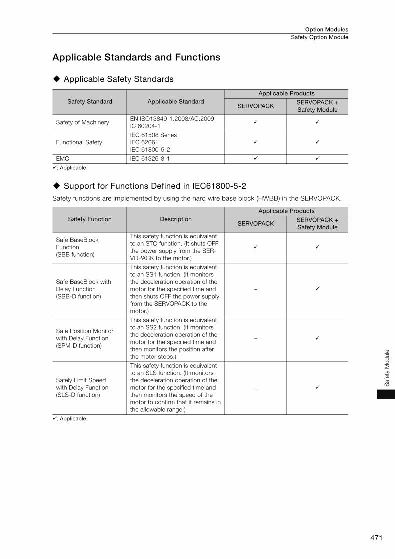
Option Modules Safety Option Module
471
Safe
ty M
od
ule
Applicable Standards and Functions
Applicable Safety Standards
: Applicable
Support for Functions Defined in IEC61800-5-2Safety functions are implemented by using the hard wire base block (HWBB) in the SERVOPACK.
: Applicable
Safety Standard Applicable StandardApplicable Products
SERVOPACKSERVOPACK + Safety Module
Safety of MachineryEN ISO13849-1:2008/AC:2009IC 60204-1
Functional SafetyIEC 61508 SeriesIEC 62061IEC 61800-5-2
EMC IEC 61326-3-1
Safety Function DescriptionApplicable Products
SERVOPACKSERVOPACK + Safety Module
Safe BaseBlockFunction(SBB function)
This safety function is equivalent to an STO function. (It shuts OFF the power supply from the SER-VOPACK to the motor.)
Safe BaseBlock withDelay Function(SBB-D function)
This safety function is equivalent to an SS1 function. (It monitors the deceleration operation of the motor for the specified time and then shuts OFF the power supply from the SERVOPACK to the motor.)
–
Safe Position Monitorwith Delay Function(SPM-D function)
This safety function is equivalent to an SS2 function. (It monitors the deceleration operation of the motor for the specified time and then monitors the position after the motor stops.)
–
Safely Limit Speedwith Delay Function(SLS-D function)
This safety function is equivalent to an SLS function. (It monitors the deceleration operation of the motor for the specified time and then monitors the speed of the motor to confirm that it remains in the allowable range.)
–
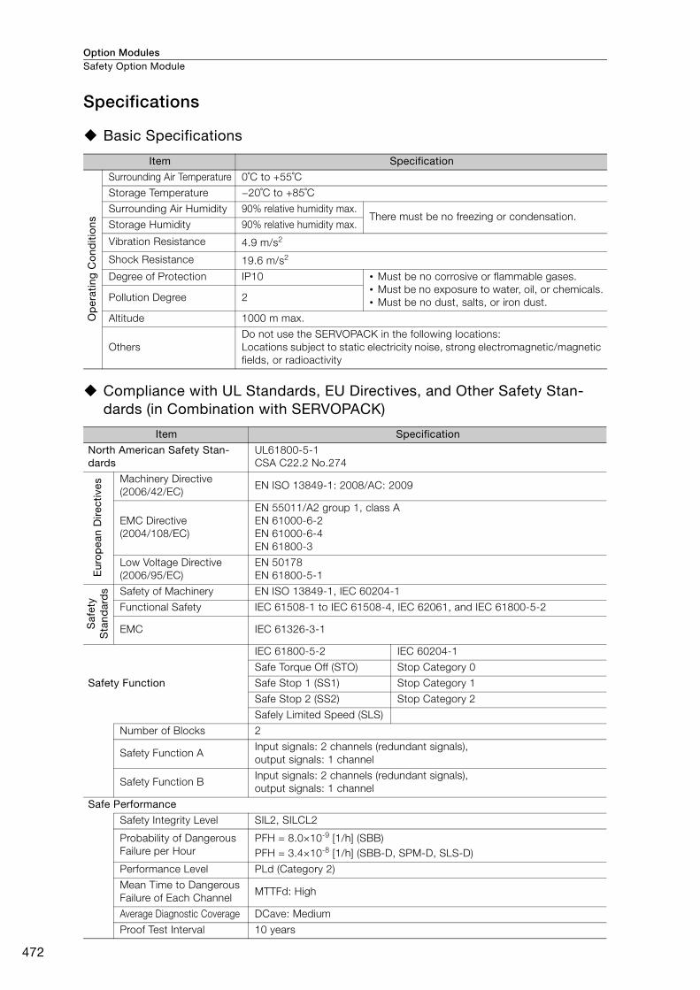
Option ModulesSafety Option Module
472
Specifications
Basic Specifications
Compliance with UL Standards, EU Directives, and Other Safety Stan-dards (in Combination with SERVOPACK)
Item Specification
Op
erat
ing
Co
nditi
ons
Surrounding Air Temperature 0˚C to +55˚C
Storage Temperature −20˚C to +85˚C
Surrounding Air Humidity 90% relative humidity max.There must be no freezing or condensation.
Storage Humidity 90% relative humidity max.
Vibration Resistance 4.9 m/s2
Shock Resistance 19.6 m/s2
Degree of Protection IP10 • Must be no corrosive or flammable gases.• Must be no exposure to water, oil, or chemicals.• Must be no dust, salts, or iron dust.Pollution Degree 2
Altitude 1000 m max.
OthersDo not use the SERVOPACK in the following locations:Locations subject to static electricity noise, strong electromagnetic/magnetic fields, or radioactivity
Item Specification
North American Safety Stan-dards
UL61800-5-1CSA C22.2 No.274
Eur
op
ean
Dire
ctiv
es
Machinery Directive(2006/42/EC)
EN ISO 13849-1: 2008/AC: 2009
EMC Directive(2004/108/EC)
EN 55011/A2 group 1, class AEN 61000-6-2EN 61000-6-4EN 61800-3
Low Voltage Directive(2006/95/EC)
EN 50178EN 61800-5-1
Saf
ety
Sta
ndar
ds Safety of Machinery EN ISO 13849-1, IEC 60204-1
Functional Safety IEC 61508-1 to IEC 61508-4, IEC 62061, and IEC 61800-5-2
EMC IEC 61326-3-1
Safety Function
IEC 61800-5-2 IEC 60204-1
Safe Torque Off (STO) Stop Category 0
Safe Stop 1 (SS1) Stop Category 1
Safe Stop 2 (SS2) Stop Category 2
Safely Limited Speed (SLS)
Number of Blocks 2
Safety Function AInput signals: 2 channels (redundant signals), output signals: 1 channel
Safety Function BInput signals: 2 channels (redundant signals), output signals: 1 channel
Safe Performance
Safety Integrity Level SIL2, SILCL2
Probability of Dangerous Failure per Hour
PFH = 8.0×10⁻⁹ [1/h] (SBB)PFH = 3.4×10⁻⁸ [1/h] (SBB-D, SPM-D, SLS-D)
Performance Level PLd (Category 2)
Mean Time to Dangerous Failure of Each Channel
MTTFd: High
Average Diagnostic Coverage DCave: Medium
Proof Test Interval 10 years

Option Modules Safety Option Module
473
Safe
ty M
od
ule
External DimensionsRefer to pages 418 to 429 for the external dimensions of the individual SERVOPACKs.
Connectors
Note: 1. The above connectors or their equivalents are used for SERVOPACKs.
2. Refer to the user’s manual of the Safety Module for installation standards.
Device Label Model Number of Pins Manufacturer
CN21 1981080-1 8 Tyco Electronics Japan G.K.
CN22 1981080-1 8 Tyco Electronics Japan G.K.
(75) 9720
(24)
(9.5)
(54
)(1
2)
16
0
Unit: mm
Approx. Mass: 0.1 kg
Safety function AI/O connector: CN21
Safety function BI/O connector: CN22

Option ModulesSafety Option Module
474
Cables for Safety Module
Safety Function Device Cable
Note: 1. When using safety functions, connect this Cable to the safety function devices. When not using safety functions, connect the enclosed Safety Jumper Connector (JZSP-CVH05-E) to the SERVOPACK.
2. If you make your own cable, use the following Connector Kit. Contact Tyco Electronics Japan G.K. for details.
Connector KitIf you make your own cable, use the Connector Kit.
Order Number Length (L) Inquires
JZSP-CVH03-01-E 1 mYaskawa Controls Co., Ltd.
JZSP-CVH03-03-E 3 m
Order Number Product Name Inquires
2013595-1INDUSTRIAL MINI I/O D-SHAPE TYPE1 PLUG
CONNECTOR KITTyco Electronics Japan G.K.
CN21Safety Function Device Cable
CN22

Capacity Selection for Servomotors ...................476
Capacity Selection for Regenerative Resistors ..484
International Standards ......................................500
Warranty ..............................................................502
Appendices
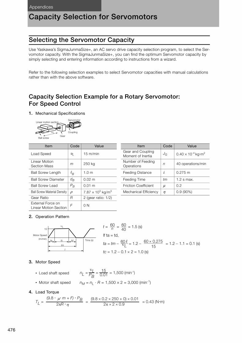
Appendices
476
Capacity Selection for Servomotors
Selecting the Servomotor CapacityUse Yaskawa’s SigmaJunmaSize+, an AC servo drive capacity selection program, to select the Ser-vomotor capacity. With the SigmaJunmaSize+, you can find the optimum Servomotor capacity by simply selecting and entering information according to instructions from a wizard.
Refer to the following selection examples to select Servomotor capacities with manual calculations rather than with the above software.
Capacity Selection Example for a Rotary Servomotor: For Speed Control
1. Mechanical Specifications
2. Operation Pattern
3. Motor Speed
4. Load Torque
Item Code Value Item Code Value
Load Speed υL 15 m/minGear and Coupling Moment of Inertia
JG 0.40 × 10⁻⁴ kgm2
Linear Motion Section Mass
m 250 kgNumber of Feeding Operations
n 40 operations/min
Ball Screw Length B 1.0 m Feeding Distance 0.275 m
Ball Screw Diameter dB 0.02 m Feeding Time tm 1.2 s max.
Ball Screw Lead PB 0.01 m Friction Coefficient μ 0.2
Ball Screw Material Density ρ 7.87 × 10³ kg/m3 Mechanical Efficiency η 0.9 (90%)
Gear Ratio R 2 (gear ratio: 1/2)
External Force on Linear Motion Section
F 0 N
• Load shaft speed
• Motor shaft speed nM = nL · R = 1,500 × 2 = 3,000 (min-1)
L
Linear motion sectionServomotor
Coupling
GearBall screw
tcta td(m/min)
tm
t
15
L
Motor Speed
Time (s)
t = = = 1.5 (s)
ta = tm = 1.2 = 1.2 1.1 = 0.1 (s)
tc = 1.2 0.1 2 = 1.0 (s)
60 6040
60 0.275
1560L
If ta = td,
nL = = = 1,500 (min-1)PB15
0.01
υL
TL = = = 0.43 (N�m)2πR �
(9.8 � � m + F) � PB2π × 2 × 0.9
(9.8 × 0.2 × 250 + 0) × 0.01
ημ
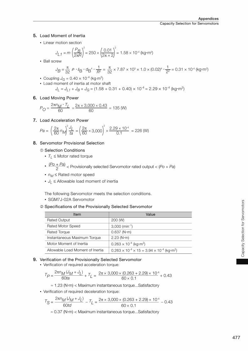
Appendices Capacity Selection for Servomotors
477
Cap
acity
Sele
ctio
n fo
r S
erv
om
oto
rs
5. Load Moment of Inertia
6. Load Moving Power
7. Load Acceleration Power
8. Servomotor Provisional Selection
Selection Conditions• TL ≤ Motor rated torque
•
• nM ≤ Rated motor speed
• JL ≤ Allowable load moment of inertia
The following Servomotor meets the selection conditions.• SGM7J-02A Servomotor
Specifications of the Provisionally Selected Servomotor
9. Verification of the Provisionally Selected Servomotor• Verification of required acceleration torque:
• Verification of required deceleration torque:
• Linear motion section
• Ball screw
• Coupling JG = 0.40 × 10⁻⁴ (kg⋅m2)• Load moment of inertia at motor shaft
JL = JL1 + JB + JG = (1.58 + 0.31 + 0.40) × 10-4 = 2.29 × 10⁻⁴ (kgm2)
Item Value
Rated Output 200 (W)
Rated Motor Speed 3,000 (min-1)
Rated Torque 0.637 (Nm)
Instantaneous Maximum Torque 2.23 (Nm)
Motor Moment of Inertia 0.263 × 10⁻⁴ (kgm2)
Allowable Load Moment of Inertia 0.263 × 10-4 × 15 = 3.94 × 10⁻⁴ (kgm2)
JL1 = m = 250 × = 1.58 × 10⁻⁴ (kg�m2)
2
2πRPB
2
2π × 2
0.01
JB = � B � dB4 � = × 7.87 × 103 × 1.0 × (0.02)4 � = 0.31 × 10⁻⁴ (kg�m2)
R2
132π
22
132πρ
PO = = = 135 (W)60
2πnM � TL60
2π × 3,000 × 0.43
Pa = = × × = 226 (W)nM
2
602π
taJL
3,000
2
602π
0.12.29 × 10-4
< Provisionally selected Servomotor rated output < (Po + Pa)2
(Po + Pa)
TP = + TL = + 0.4360ta 60 0.1
23,000 (0.263 +2.29) 10-4
≈ 1.23 (Nm) < Maximum instantaneous torque...Satisfactory
2nM (JM + JL)
TS = TL = 0.4360td 60 0.1
23,000 (0.263 + 2.29) 10-4
≈ 0.37 (Nm) < Maximum instantaneous torque...Satisfactory
2nM (JM + JL)

AppendicesCapacity Selection for Servomotors
478
• Verification of effective torque value:
10.Result It has been verified that the provisionally selected Servomotor is applicable.The torque diagram is shown below.
Capacity Selection Example for a Rotary Servomotor: For Position Control1. Mechanical Specifications
2. Speed Diagram
Item Code Value Item Code Value
Load Speed υL 15 m/min Coupling Outer Diameter dC 0.03 m
Linear Motion Section Mass
m 80 kgNumber of Feeding Operations
n 40 rotation/min
Ball Screw Length B 0.8 m Feeding Distance 0.25 m
Ball Screw Diameter dB 0.016 m Feeding Time tm 1.2 s max.
Ball Screw Lead PB 0.005 mElectrical Stopping Precision
δ ±0.01 mm
Ball Screw Material Density
ρ 7.87 × 10³ kg/m3 Friction Coefficient μ 0.2
External Force on Linear Motion Section
F 0 N Mechanical Efficiency η 0.9 (90%)
Coupling Mass mC 0.3 kg
Trms = =t 1.5
(1.23)2 0.1 + (0.43)2 1.0 + (0.37)2 0.1
≈ 0.483 (Nm) < Rated torque...Satisfactory
TP2 ta + TL
2 tc + Ts2 td
(Nm)
0.1
1.5
1.00.1
-0.37
0
0.43
1.23
TorqueMotor Speed
L
Linear motion section Servomotor
Ball screw
Coupling
(m/min)
tm
15
tcta td ts
t
L
Motor Speed
Reference pulses
Load speed
Time (s)
t = = = 1.5 (s)
ta = tm ts = 1.2 0.1 = 0.1 (s)
tc = 1.2 0.1 0.1 2 = 0.9 (s)
60 6040
60 0.2515
60
If ta = td and ts = 0.1 (s),
L

Appendices Capacity Selection for Servomotors
479
Cap
acity
Sele
ctio
n fo
r S
erv
om
oto
rs
3. Motor Speed
4. Load Torque
5. Load Moment of Inertia
6. Load Moving Power
7. Load Acceleration Power
8. Servomotor Provisional Selection
Selection Conditions• TL ≤ Motor rated torque
•
• nM ≤ Rated motor speed
• JL ≤ Allowable load moment of inertia
The following Servomotor meets the selection conditions.• SGM7J-01A Servomotor
Specifications of the Provisionally Selected Servomotor
• Load shaft speed
• Motor shaft speed Direct coupling gear ratio 1/R = 1/1Therefore, nM = nL ⋅ R = 3,000 × 1 = 3,000 (min-1)
• Linear motion section
• Ball screw
• Coupling
• Load moment of inertia at motor shaftJL = JL1 + JB + Jc = 1.25 × 10⁻⁴ (kgm2)
Item Value
Rated Output 100 (W)
Rated Motor Speed 3,000 (min-1)
Rated Torque 0.318 (Nm)
Instantaneous Maximum Torque 1.11 (Nm)
Motor Moment of Inertia 0.0659 × 10⁻⁴ (kgm2)
Allowable Load Moment of Inertia 0.0659 × 10-4 × 35 = 2.31 × 10⁻⁴ (kgm2)
Encoder Resolution 16,777,216 pulses/rev [24 bits]
nL = = = 3,000 (min-1)PB
150.005
υL
TL = = = 0.139 (N�m)2πR �
(9.8 � m + F ) � PB2π × 1 × 0.9
(9.8 × 0.2 × 80 + 0) × 0.005μη
JL1 = m = 80 × = 0.507 × 10⁻⁴ (kg�m2)
2
2πR
PB2
2π × 1
0.005
JB = � B � dB4 = × 7.87 × 103 × 0.8 × (0.016)4 = 0.405 × 10⁻⁴ (kg�m2)
32π
32πρ
Jc = mC � dC2 = × 0.3 × (0.03)2 = 0.338 × 10⁻⁴ (kg�m2)
81
81
PO = = = 43.7 (W)60
2πnM � TL60
2π × 3,000 × 0.139
Pa = = × × = 123.4 (W)nM
2
60
2πta
JL 3,000
2
60
2π0.1
1.25 × 10⁻⁴
< Provisionally selected Servomotor rated output < (Po + Pa)2
(Po + Pa)
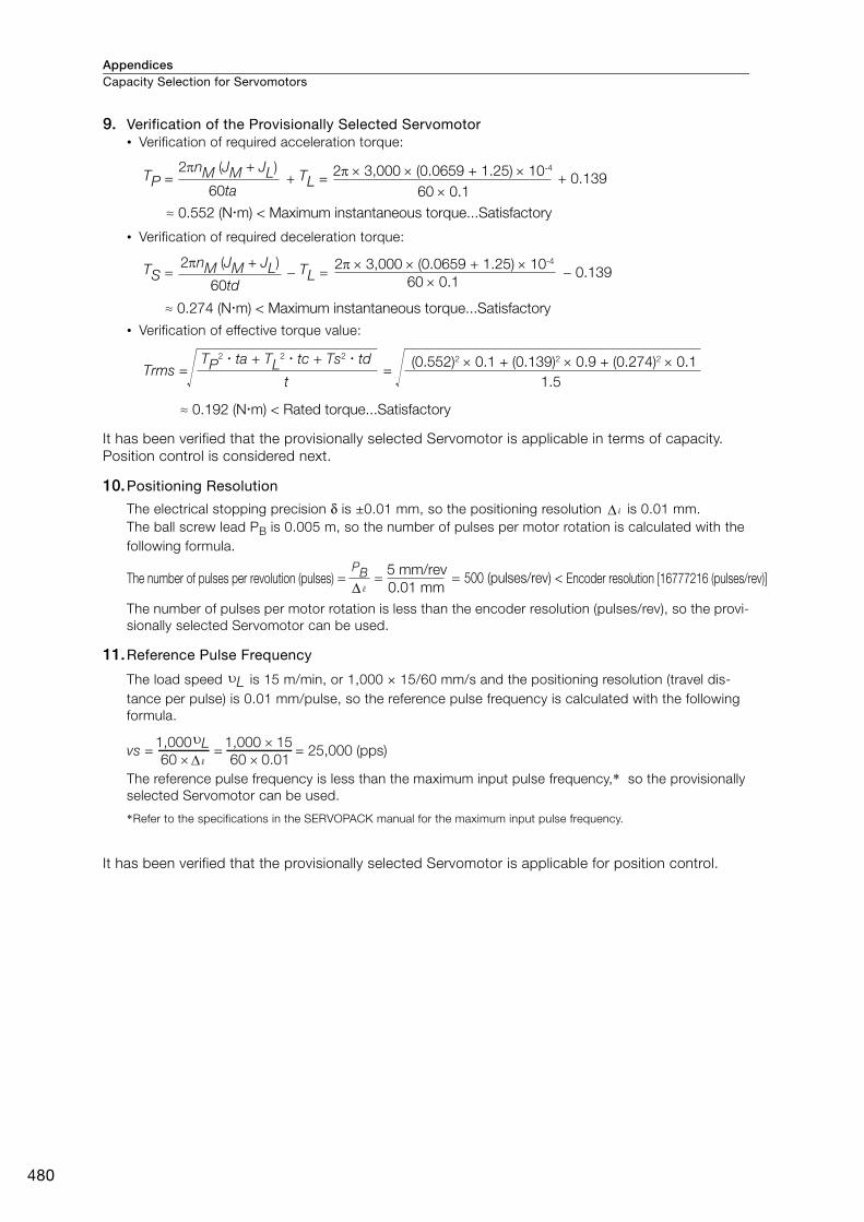
AppendicesCapacity Selection for Servomotors
480
9. Verification of the Provisionally Selected Servomotor• Verification of required acceleration torque:
• Verification of required deceleration torque:
• Verification of effective torque value:
It has been verified that the provisionally selected Servomotor is applicable in terms of capacity. Position control is considered next.
10.Positioning Resolution
The electrical stopping precision δ is ±0.01 mm, so the positioning resolution is 0.01 mm.The ball screw lead PB is 0.005 m, so the number of pulses per motor rotation is calculated with the following formula.
The number of pulses per motor rotation is less than the encoder resolution (pulses/rev), so the provi-sionally selected Servomotor can be used.
11.Reference Pulse Frequency
The load speed is 15 m/min, or 1,000 × 15/60 mm/s and the positioning resolution (travel dis-tance per pulse) is 0.01 mm/pulse, so the reference pulse frequency is calculated with the following formula.
The reference pulse frequency is less than the maximum input pulse frequency,* so the provisionally selected Servomotor can be used.
*Refer to the specifications in the SERVOPACK manual for the maximum input pulse frequency.
It has been verified that the provisionally selected Servomotor is applicable for position control.
TP = + TL = + 0.139
≈ 0.552 (Nm) < Maximum instantaneous torque...Satisfactory60ta 60 0.1
23,000 (0.0659 + 1.25) 10-42nM (JM + JL)
TS = TL = 0.13960td 60 0.1
23,000 (0.0659 + 1.25) 10-4
≈ 0.274 (Nm) < Maximum instantaneous torque...Satisfactory
2nM (JM + JL)
Trms = =t
TP2 ta + TL
2 tc + Ts2 td (0.552)2 0.1 + (0.139)2 0.9 + (0.274)2 0.1
1.5
≈ 0.192 (Nm) < Rated torque...Satisfactory
Δ
= = = 500 (pulses/rev) < 0.01 mm
5 mm/revPBThe number of pulses per revolution (pulses) Encoder resolution [16777216 (pulses/rev)]
υL
vs = = = 25,000 (pps)60 ×
1,000υL60 × 0.01
1,000 × 15
Δ
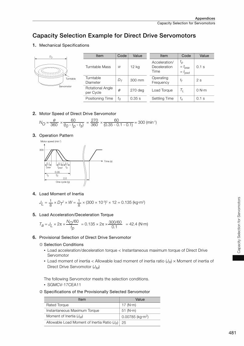
Appendices Capacity Selection for Servomotors
481
Cap
acity
Sele
ctio
n fo
r S
erv
om
oto
rs
Capacity Selection Example for Direct Drive Servomotors
1. Mechanical Specifications
2. Motor Speed of Direct Drive Servomotor
3. Operation Pattern
4. Load Moment of Inertia
5. Load Acceleration/Deceleration Torque
6. Provisional Selection of Direct Drive Servomotor
Selection Conditions• Load acceleration/deceleration torque < Instantaneous maximum torque of Direct Drive
Servomotor• Load moment of inertia < Allowable load moment of inertia ratio (JR) × Moment of inertia of
Direct Drive Servomotor (JM)
The following Servomotor meets the selection conditions.• SGMCV-17CEA11
Specifications of the Provisionally Selected Servomotor
Item Value
Rated Torque 17 (Nm)
Instantaneous Maximum Torque 51 (Nm)
Moment of Inertia (JM) 0.00785 (kgm2)
Allowable Load Moment of Inertia Ratio (JR) 25
Turntable
Servomotor
DTItem Code Value Item Code Value
Turntable Mass W 12 kgAcceleration/Deceleration Time
tp= tpsa= tpsd
0.1 s
Turntable Diameter
DT 300 mmOperating Frequency
tf 2 s
Rotational Angle per Cycle
θ 270 deg Load Torque TL 0 Nm
Positioning Time t0 0.35 s Settling Time ts 0.1 s
NO = × = × = 300 (min-1) 360 (t0 - tp - ts)
θ360 (0.35 - 0.1 - 0.1)270 6060
300
0.1 0.1 0.1
ts
2.0
0.35
Motor speed (min-1)
Time (s)
One cycle (tf)
t0ts
tpsdtpsa
8
1
8
1JL = × DT2 × W = × (300 × 10-3)2 × 12 = 0.135 (kg�m2)
Ta = JL × 2π × = 0.135 × 2π × = 42.4 (N�m) NO/60
tp300/60
0.1
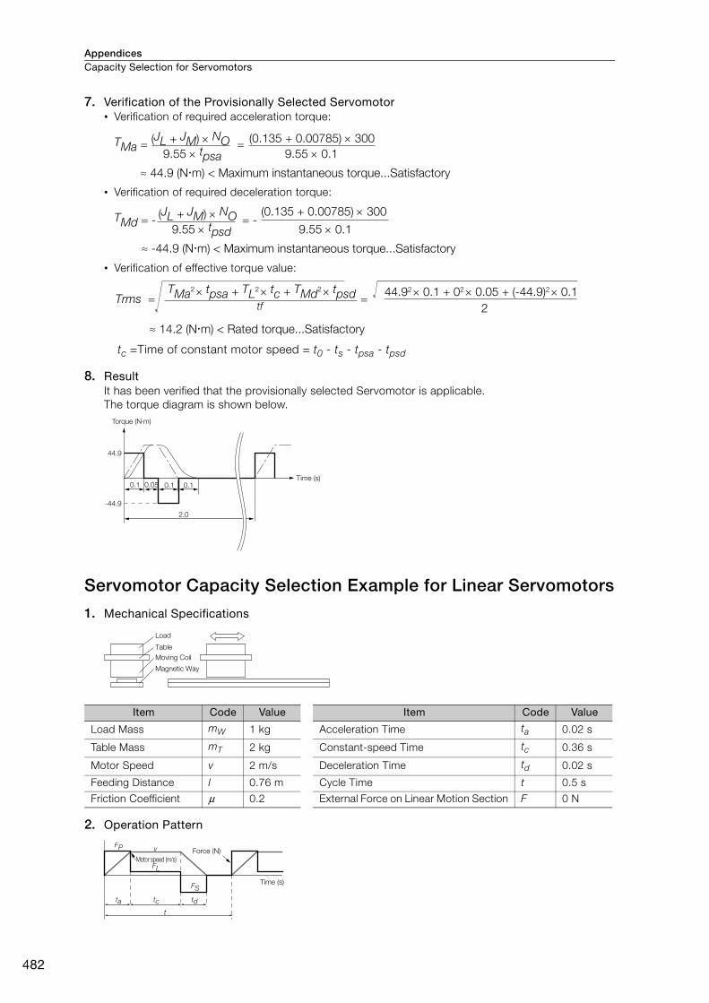
AppendicesCapacity Selection for Servomotors
482
7. Verification of the Provisionally Selected Servomotor• Verification of required acceleration torque:
• Verification of required deceleration torque:
• Verification of effective torque value:
tc =Time of constant motor speed = t0 - ts - tpsa - tpsd
8. Result It has been verified that the provisionally selected Servomotor is applicable.The torque diagram is shown below.
Servomotor Capacity Selection Example for Linear Servomotors
1. Mechanical Specifications
2. Operation Pattern
Item Code Value Item Code Value
Load Mass mW 1 kg Acceleration Time ta 0.02 s
Table Mass mT 2 kg Constant-speed Time tc 0.36 s
Motor Speed v 2 m/s Deceleration Time td 0.02 s
Feeding Distance l 0.76 m Cycle Time t 0.5 s
Friction Coefficient μ 0.2 External Force on Linear Motion Section F 0 N
TMa = =
≈ 44.9 (Nm) < Maximum instantaneous torque...Satisfactory
(JL + JM) NO9.55 tpsa
(0.135 + 0.00785) 300
9.55 0.1
TMd = - = -
≈ -44.9 (Nm) < Maximum instantaneous torque...Satisfactory
(JL + JM) NO9.55 tpsd
(0.135 + 0.00785) 300
9.55 0.1
Trms = =TMa2 tpsa + TL2 tc + TMd2 tpsd
2
44.92 0.1 + 02 0.05 + (-44.9)2 0.1
≈ 14.2 (Nm) < Rated torque...Satisfactory
tf
Torque (Nm)
Time (s)
-44.9
0.05
44.9
0.1 0.1 0.1
2.0
Load
Table
Moving Coil
Magnetic Way
v
t
Motor speed (m/s)Force (N)
Time (s)
ta
FP
FL
FS
tc td
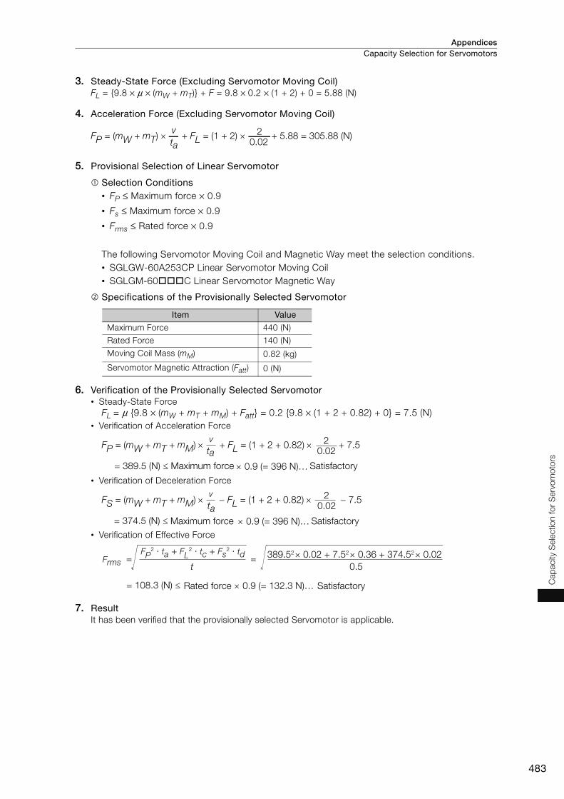
Appendices Capacity Selection for Servomotors
483
Cap
acity
Sele
ctio
n fo
r S
erv
om
oto
rs
3. Steady-State Force (Excluding Servomotor Moving Coil)FL = {9.8 × μ × (mW + mT)} + F = 9.8 × 0.2 × (1 + 2) + 0 = 5.88 (N)
4. Acceleration Force (Excluding Servomotor Moving Coil)
5. Provisional Selection of Linear Servomotor
Selection Conditions• FP ≤ Maximum force × 0.9
• Fs ≤ Maximum force × 0.9
• Frms ≤ Rated force × 0.9
The following Servomotor Moving Coil and Magnetic Way meet the selection conditions.• SGLGW-60A253CP Linear Servomotor Moving Coil• SGLGM-60C Linear Servomotor Magnetic Way
Specifications of the Provisionally Selected Servomotor
6. Verification of the Provisionally Selected Servomotor • Steady-State Force
FL = μ {9.8 × (mW + mT + mM) + Fatt} = 0.2 {9.8 × (1 + 2 + 0.82) + 0} = 7.5 (N)• Verification of Acceleration Force
• Verification of Deceleration Force
• Verification of Effective Force
7. ResultIt has been verified that the provisionally selected Servomotor is applicable.
Item Value
Maximum Force 440 (N)
Rated Force 140 (N)
Moving Coil Mass (mM) 0.82 (kg)
Servomotor Magnetic Attraction (Fatt) 0 (N)
vta
20.02
FP = (mW + mT) × + FL = (1 + 2) × + 5.88 = 305.88 (N)
taFP = (mW + mT + mM) + FL = (1 + 2 + 0.82) + 7.5
= 389.5 (N) ≤ 0.9 (= 396 N)…
20.02
Maximum force Satisfactory
taFS = (mW + mT + mM) FL = (1 + 2 + 0.82) 7.5
= 374.5 (N) ≤ 0.9 (= 396 N)…Maximum force Satisfactory
20.02
Frms = =t
FP2 ∙ ta + FL
2 ∙ tc + Fs2 ∙ td
0.5
389.52 0.02 + 7.52 0.36 + 374.52 0.02
= 108.3 (N) ≤ 0.9 (= 132.3 N)…Rated force Satisfactory
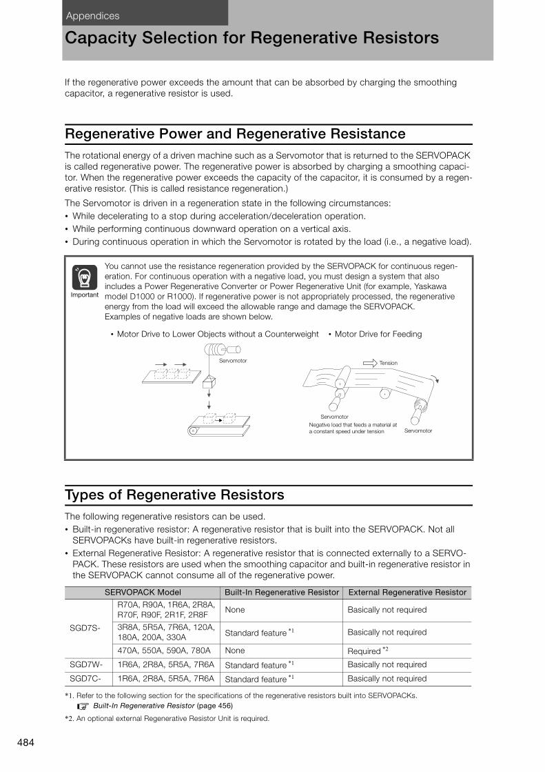
Appendices
484
Capacity Selection for Regenerative Resistors
If the regenerative power exceeds the amount that can be absorbed by charging the smoothing capacitor, a regenerative resistor is used.
Regenerative Power and Regenerative ResistanceThe rotational energy of a driven machine such as a Servomotor that is returned to the SERVOPACK is called regenerative power. The regenerative power is absorbed by charging a smoothing capaci-tor. When the regenerative power exceeds the capacity of the capacitor, it is consumed by a regen-erative resistor. (This is called resistance regeneration.)
The Servomotor is driven in a regeneration state in the following circumstances:• While decelerating to a stop during acceleration/deceleration operation.• While performing continuous downward operation on a vertical axis.• During continuous operation in which the Servomotor is rotated by the load (i.e., a negative load).
Types of Regenerative ResistorsThe following regenerative resistors can be used.• Built-in regenerative resistor: A regenerative resistor that is built into the SERVOPACK. Not all
SERVOPACKs have built-in regenerative resistors.• External Regenerative Resistor: A regenerative resistor that is connected externally to a SERVO-
PACK. These resistors are used when the smoothing capacitor and built-in regenerative resistor in the SERVOPACK cannot consume all of the regenerative power.
*1. Refer to the following section for the specifications of the regenerative resistors built into SERVOPACKs.Built-In Regenerative Resistor (page 456)
*2. An optional external Regenerative Resistor Unit is required.
You cannot use the resistance regeneration provided by the SERVOPACK for continuous regen-eration. For continuous operation with a negative load, you must design a system that also includes a Power Regenerative Converter or Power Regenerative Unit (for example, Yaskawa model D1000 or R1000). If regenerative power is not appropriately processed, the regenerative energy from the load will exceed the allowable range and damage the SERVOPACK.Examples of negative loads are shown below.
SERVOPACK Model Built-In Regenerative Resistor External Regenerative Resistor
SGD7S-
R70A, R90A, 1R6A, 2R8A, R70F, R90F, 2R1F, 2R8F
None Basically not required
3R8A, 5R5A, 7R6A, 120A, 180A, 200A, 330A Standard feature *1 Basically not required
470A, 550A, 590A, 780A None Required *2
SGD7W- 1R6A, 2R8A, 5R5A, 7R6A Standard feature *1 Basically not required
SGD7C- 1R6A, 2R8A, 5R5A, 7R6A Standard feature *1 Basically not required
Important
• Motor Drive to Lower Objects without a Counterweight • Motor Drive for Feeding
Tension
Servomotor
Servomotor
ServomotorNegative load that feeds a material at
a constant speed under tension

Appendices Capacity Selection for Regenerative Resistors
485
Cap
acity
Sele
ctio
n fo
r R
eg
enera
tive
Resis
tors
Selecting External Regenerative ResistorUse Yaskawa’s SigmaJunmaSize+, an AC servo drive capacity selection program, to determine if you need an External Regenerative Resistor.
You can use one of the following two methods to manually calculate whether an External Regenera-tive Resistor is required. Refer to the following information if you do not use the SigmaJunmaSize+.
Simple Calculation (page 485)
Calculating the Regenerative Energy (page 490)
Simple CalculationWhen driving a Servomotor with a horizontal shaft, check if an External Regenerative Resistor is required using the following calculation method.Note: If you use the SGD7S-470A, -550A, -590A, or -780A, always connect an External Regenerative Resistor.
SERVOPACKs without Built-in Regenerative Resistors: SGD7S-R70A, -R90A, -1R6A, -2R8A, -R70F, -R90F, -2R1F, and -2R8F
The total amount of energy that can be charged in the capacitors is given in the following table. If the rotational energy (ES) of the Servomotor and load exceeds the value in the following table, then connect an External Regenerative Resistor.
Calculate the rotational energy (ES) of the servo system with the following equation:
ES = J × (nM)2/182 (Joules)• J = JM + JL
• JM: Servomotor moment of inertia (kg⋅m2)
• JL: Load moment of inertia at motor shaft (kg⋅m2)
• nM: Servomotor operating motor speed (min-1)
Applicable SERVOPACKProcessable Regenerative Energy
(Joules)Remarks
SGD7S-
R70A, R90A, 1R6A 24.2 Value when main circuit input voltage is 200 VAC2R8A 31.7
R70F, R90F, 2R1F 28.6 Value when main circuit input voltage is 100 VAC2R8F 48.4

AppendicesCapacity Selection for Regenerative Resistors
486
SERVOPACKs with Built-in Regenerative Resistors:SGD7S-3R8A, -5R5A, -7R6A, -120A, -180A, -200A, and -330ASGD7W-1R6A, -2R8A, -5R5A, and -7R6ASGD7C-1R6A, -2R8A, -5R5A, and -7R6A
Use the following equation to calculate the allowable frequency for regenerative operation. The fol-lowing operating conditions were used: Operation cycle from a speed of 0 to the maximum motor speed to 0 (min-1) with acceleration and deceleration operation. If the frequency of the operation cycle (1/T) is lower than the allowable frequency in the calculation results, an External Regenerative Resistor is not necessary. Finally, do the calculation with the actual operating speed and load moment of inertia to determine if an External Regenerative Resistor is required.
• Operating Conditions for Calculating the Allowable Regenerative Frequency
• n = JL/JM
• JM: Servomotor moment of inertia (kg⋅m2)
• JL: Load moment of inertia at motor shaft (kg⋅m2)
* Assign the related value given in the table in Allowable Frequency for Regenerative Operation for Servomotor with-out Load (pages 487 to 489).
0
0
0
T
t
t
Load moment of inertia = 0 (Servomotor only)
Speed reference
Servomotor motor speed
Servomotor-generated torque
Maximum motor speed
Maximum torque
Maximum torque
(Operation cycle) Allowable frequency = 1/T (times/min)
Regenerative operation
(1+ n)× Allowable frequency
Allowable frequency for regenerative operation for Servomotor without load*Operating motor speed
Maximum motor speed 2
(time/min)

Appendices Capacity Selection for Regenerative Resistors
487
Cap
acity
Sele
ctio
n fo
r R
eg
enera
tive
Resis
tors
Allowable Frequency for Regenerative Operation for Servomotor without Load• Rotary Servomotors
Servomotor Model
Allowable Frequencies in Regenerative Operation
(Operations/Min)
Servomotor Model
Allowable Frequencies in Regenerative Operation
(Operations/Min)
SERVOPACK Model: SGD7S
SERVOPACK Model: SGD7W
and SGD7C (Simultaneous Operation of
Two Axes)
SERVOPACK Model: SGD7S
SERVOPACK Model: SGD7W
and SGD7C (Simultaneous Operation of Two Axes)
SGMMV-
A1A − −
SGM7P-
01A − 200
A2A − − C2A − 46
A3A − − 04A − 29
SGM7J-
A5A − 300 08A 11 11
01A − 180 15A 7.5 −C2A − 130
SGM7G-
03A 39 39
02A − 46 05A 29 29
04A − 25 09A 6.9 6.9
06A 30 30 13A 6.1 −08A 15 15 20A 7.4 −
SGM7A-
A5A − 560 30A 9.5 −01A − 360 44A 6.4 −C2A − 260 55A 24 −02A − 87 75A 34 −04A − 56 1AA 39 −06A 77 77 1EA 31 −
08A 31 31
10A 31 −
15A 15 −
20A 19 −
25A 15 −
30A 6.9 −
40A 11 −
50A 8.8 −
70A 86 −

AppendicesCapacity Selection for Regenerative Resistors
488
• Direct Drive Servomotors
Servomotor Model
Allowable Frequencies in Regenerative Operation
(Operations/Min)
Servomotor Model
Allowable Frequencies in Regenerative Operation
(Operations/Min)
SERVOPACK Model: SGD7S
SERVOPACK Model: SGD7W
and SGD7C (Simultaneous Operation of Two Axes)
SERVOPACK Model: SGD7S
SERVOPACK Model: SGD7W
and SGD7C (Simultaneous Operation of Two Axes)
SGM7D-
01G − −
SGM7F-
04B − 75
1AF 120 − 08C − 21
1CI 74 − 10B − 48
1ZI 91 − 14B 65 65
02K – − 16D 13 13
03H – − 17C 30 30
05G – − 25C 31 31
06J 350 − 35D 19 19
06L – −
SGMCV-
04B − 75
06K – − 08C − 21
08G 430 − 10B − 48
08K – − 14B 65 65
09J 250 − 16D 13 13
12L – − 17C 30 30
18G 350 − 25C 31 31
18J 210 − 35D 19 19
20J 200 −
SGMCS-
02B − 62
24G 270 − 05B − 34
28I 52 − 07B − 22
2BI 89 − 04C − 22
2DI 110 − 08D − 6.1
30F 210 − 10C − 19
30L 63 − 14C − 22
38J 150 − 17D − 7
34G 220 − 25D − 9.3
45G 190 − 16E 3.7 3.7
58F 170 − 35E 9.7 9.7
70I 100 − 45M 25 25
90F 140 − 80M 19 −80N 8.9 −1AM 22 −1EN 11 −2ZN 9.1 −

Appendices Capacity Selection for Regenerative Resistors
489
Cap
acity
Sele
ctio
n fo
r R
eg
enera
tive
Resis
tors
• Linear Servomotors
*1. This value is in combination with the SGD7S-120A.
*2. This value is in combination with the SGD7S-180A.
Servomotor Model
Allowable Frequencies in Regenerative Operation
(Operations/Min)
Servomotor Model
Allowable Frequencies in Regenerative Operation
(Operations/Min)
SERVOPACK Model: SGD7S
SERVOPACK Model: SGD7W
and SGD7C (Simultaneous Operation of Two Axes)
SERVOPACK Model: SGD7S
SERVOPACK Model: SGD7W
and SGD7C (Simultaneous Operation of Two Axes)
SGLGW- Using a Stan-dard-Force Mag-netic Way
30A050C − 190
SGLFW2-
30A070A − 38
30A080C − 120 30A120A − 21
40A140C − 56 30A230A 22 11
40A253C − 32 45A200A 16 16
40A365C − 2245A380A
10*1 −
60A140C − 49 17*2 −
60A253C − 27 90A200A 14 −60A365C 37 37 90A380A 11 −90A200C 34 − 90A560A 18 −90A370C 33 − 1DA380A 21 −90A535C 24 − 1DA560A 32 −
SGLGW- Using a High-Force Mag-netic Way
40A140C − 80
SGLTW-
20A170A 15 15
40A253C − 45 20A320A 8.3 8.3
40A365C 62 62 20A460A 7.1 −60A140C − 64 35A170A 10 10
60A253C 71 71 35A170H 8.5 8.5
60A365C 49 49 35A320A 7 −
SGLFW-
20A090A − 27 35A320H 5.9 −20A120A − 21 35A460A 7.6 −35A120A − 14 40A400B 13 −35A230A 16 16 40A600B 19 −50A200B 10 10 50A170H 15 15
50A380B 6.9 − 50A320H 11 −1ZA200B 7.8 − 80A400B 28 −1ZA380B 6.6 − 80A600B 180 −
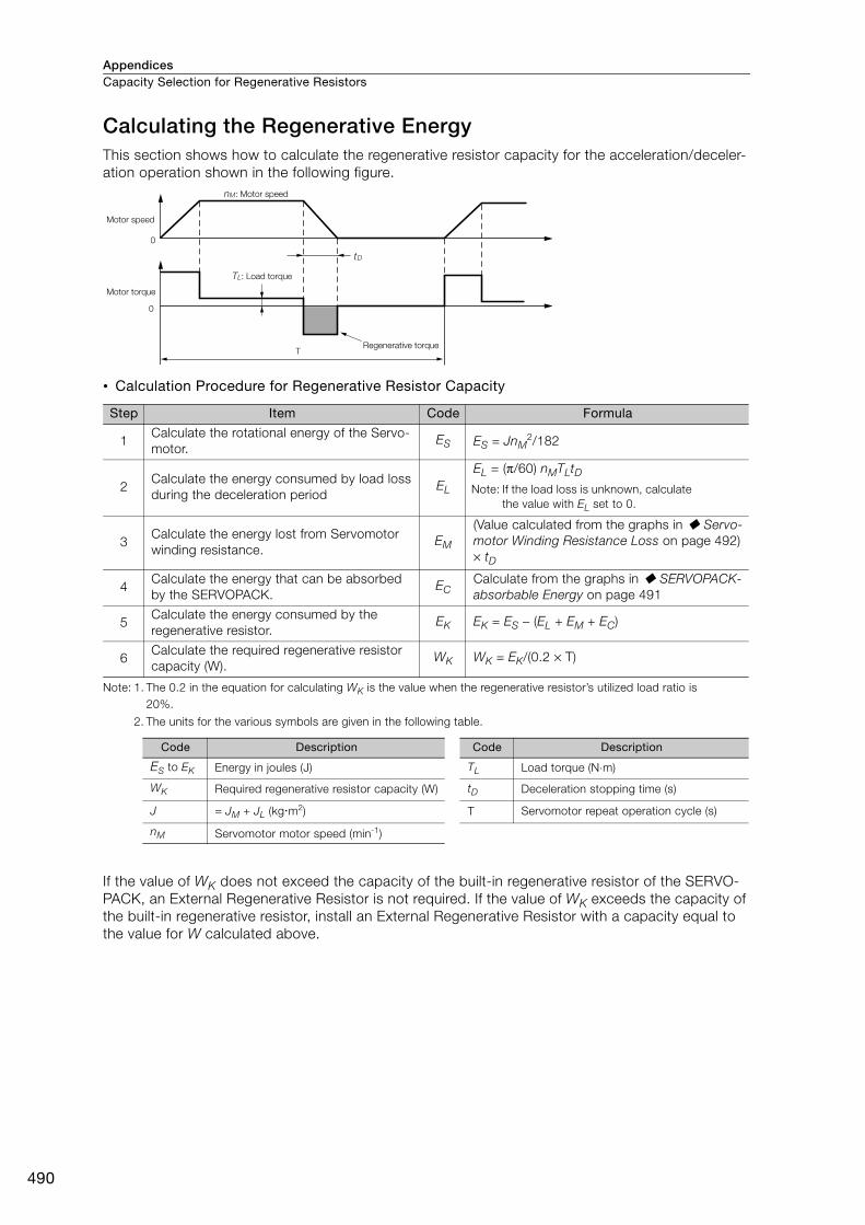
AppendicesCapacity Selection for Regenerative Resistors
490
Calculating the Regenerative EnergyThis section shows how to calculate the regenerative resistor capacity for the acceleration/deceler-ation operation shown in the following figure.
• Calculation Procedure for Regenerative Resistor Capacity
Note: 1. The 0.2 in the equation for calculating WK is the value when the regenerative resistor’s utilized load ratio is 20%.
2. The units for the various symbols are given in the following table.
If the value of WK does not exceed the capacity of the built-in regenerative resistor of the SERVO-PACK, an External Regenerative Resistor is not required. If the value of WK exceeds the capacity of the built-in regenerative resistor, install an External Regenerative Resistor with a capacity equal to the value for W calculated above.
Step Item Code Formula
1Calculate the rotational energy of the Servo-motor.
ES ES = JnM2/182
2Calculate the energy consumed by load loss during the deceleration period
EL
EL = (π/60) nMTLtDNote: If the load loss is unknown, calculate
the value with EL set to 0.
3Calculate the energy lost from Servomotor winding resistance.
EM
(Value calculated from the graphs in Servo-motor Winding Resistance Loss on page 492) × tD
4Calculate the energy that can be absorbed by the SERVOPACK.
ECCalculate from the graphs in SERVOPACK-absorbable Energy on page 491
5Calculate the energy consumed by the regenerative resistor.
EK EK = ES − (EL + EM + EC)
6Calculate the required regenerative resistor capacity (W).
WK WK = EK/(0.2 × T)
Code Description Code Description
ES to EK Energy in joules (J) TL Load torque (N⋅m)
WK Required regenerative resistor capacity (W) tD Deceleration stopping time (s)
J = JM + JL (kgm2) T Servomotor repeat operation cycle (s)
nM Servomotor motor speed (min-1)
T
0
0
tD
nM: Motor speed
Motor speed
Motor torque
TL: Load torque
Regenerative torque

Appendices Capacity Selection for Regenerative Resistors
491
Cap
acity
Sele
ctio
n fo
r R
eg
enera
tive
Resis
tors
SERVOPACK-absorbable EnergyThe following figures show the relationship between the SERVOPACK’s input power supply voltage and its absorbable energy.
Σ-7S SERVOPACKs
Σ-7W SERVOPACKs Σ-7C SERVOPACKs
Model: SGD7S- Model: SGD7S-
Ab
so
rbab
le e
nerg
y (J
)
Ab
so
rbab
le e
nerg
y (J
)
Input voltage (Vrms)
Ab
so
rbab
le e
nerg
y (J
)
Input voltage (Vrms)
Input voltage (Vrms)
R70A, R90A, and 1R6A
2R8A
3R8A
5R5A and 7R6A
170 180 190 200 210 220 230 240 250 260 270
0
10
20
30
40
50
60
70
80 120A (single-phase)
120A (three-phase),180A, and 200A
330A
170 180 190 200 210 220 230 240 250 260 270
0
470A
550A
590A
780A
170 180 190 200 210 220 230 240 250 260 270
0
100
200
300
400
500
600
20
40
60
80
100
120
140
160
180
Model: SGD7S-
R70F, R90F, and 2R1F
2R8F
80 90 100 110 120 130 140
0
10
20
30
40
50
70
60
Model: SGD7S-
Ab
so
rbab
le e
nerg
y (J
)
Input voltage (Vrms)
SGD7W-
1R6A
2R8A
5R5A and 7R6A
170 180 190 200 210 220 230 240 250 260 270
0
20
40
60
80
100
120
Ab
so
rbab
le e
nerg
y (J
)
Input voltage (Vrms)
SGD7C-
1R6A
2R8A
5R5A and 7R6A
170 180 190 200 210 220 230 240 250 260 270
0
20
40
60
80
100
120
Ab
so
rbab
le e
nerg
y (J
)
Input voltage (Vrms)
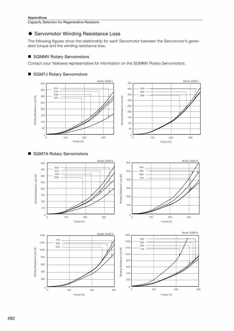
AppendicesCapacity Selection for Regenerative Resistors
492
Servomotor Winding Resistance LossThe following figures show the relationship for each Servomotor between the Servomotor’s gener-ated torque and the winding resistance loss.
SGMMV Rotary Servomotors
Contact your Yaskawa representative for information on the SGMMV Rotary Servomotors.
SGM7J Rotary Servomotors
SGM7A Rotary Servomotors
03002001000
03002001000
450
400
350
300
250
200
150
100
50
400
350
300
250
200
150
100
50
Model: SGM7J- Model: SGM7J-
Win
din
g R
esis
tance L
oss (W
)
Torque (%)
Win
din
g R
esis
tance L
oss (W
)
Torque (%)
04A
06A
08A
A5A
01A
C2A
02A
03002001000
03002001000
00
200 300100
600
500
400
300
200
100
1400
1200
1000
800
600
400
200
Model: SGM7A-
Win
din
g R
esis
tance L
oss (W
)
Torque (%)
Model: SGM7A-
Win
din
g R
esis
tance L
oss (W
)
Torque (%)
Model: SGM7A-
Win
din
g R
esis
tance L
oss (W
)
Torque (%)
Model: SGM7A-
Win
din
g R
esis
tance L
oss (W
)
Torque (%)
A5A
01A
C2A
02A
04A
06A
08A
10A
15A
20A
25A
400
350
300
250
200
150
100
50
00
300200100
200
400
600
800
1000
1200
1400
1600
30A
40A
50A
70A

Appendices Capacity Selection for Regenerative Resistors
493
Cap
acity
Sele
ctio
n fo
r R
eg
enera
tive
Resis
tors
SGM7P Rotary Servomotors
SGM7G Rotary Servomotors
00
200 300100
50
100
150
200
250
300
350
Model: SGM7P-
400
450
01A
02A
04A
08A
15A
Win
din
g R
esis
tance L
oss (W
)
Torque (%)
Model: SGM7G-
Win
din
g R
esis
tance L
oss (W
)
Torque (%)
Model: SGM7G-
Win
din
g R
esis
tance L
oss (W
)
Torque (%)
0
0
100
200
300
400
500
600
100 200 300 400
0
100 200500 150 250 300
100
200
300
400
500
600
700
800
0
0
200
400
600
800
1400
1000
1200
50 100 150 200 250 300 0
0
200
400
600
800
1400
1000
1200
50 100 150 200 250 300
05A
03A
13A
20A
09A
44
30
55
75
1E
1A
Model: SGM7G-
Win
din
g R
esis
tance L
oss (W
)
Torque (%)
Model: SGM7G-
Win
din
g R
esis
tance L
oss (W
)
Torque (%)

AppendicesCapacity Selection for Regenerative Resistors
494
SGM7D Direct Drive Servomotors
Contact your Yaskawa representative for information on the SGM7D Direct Drive Servomotors.
SGM7F Direct Drive Servomotors
Note: Contact your Yaskawa representative for information on the SGM7F-D Direct Drive Servomotors.
SGMCV Direct Drive Servomotors
Note: Contact your Yaskawa representative for information on the SGMCV-D Direct Drive Servomotors.
Model: SGM7F-
Win
din
g R
esis
tance L
oss (W
)
Torque (%)
Model: SGM7F-
Win
din
g R
esis
tance L
oss (W
)Torque (%)
700
600
500
400
300
200
100
600
500
400
300
200
100
0
0 100 200 300
0
0 100 200 300
08C
17C
25C
04B
10B
14B
Model: SGMCV-
Win
din
g R
esis
tance L
oss (W
)
Torque (%)
Model: SGMCV-
Win
din
g R
esis
tance L
oss (W
)
Torque (%)
700
600
500
400
300
200
100
600
500
400
300
200
100
0
0 100 200 300
0
0 100 200 300
08C
17C
25C
04B
10B
14B
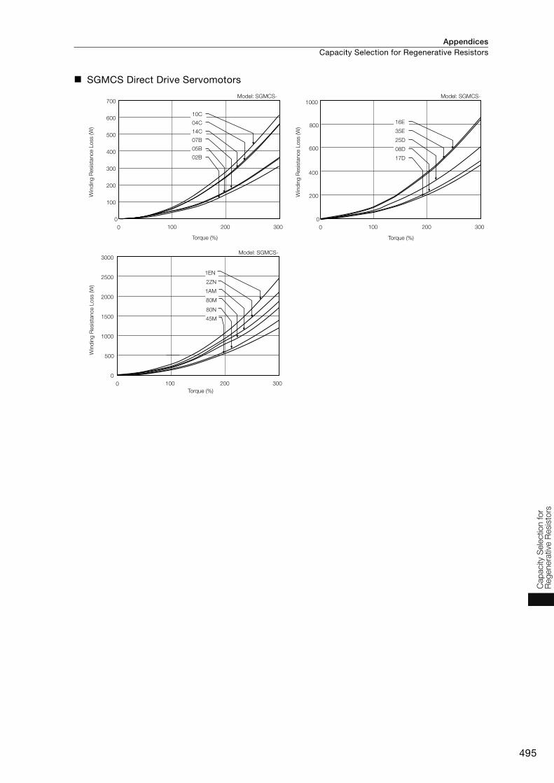
Appendices Capacity Selection for Regenerative Resistors
495
Cap
acity
Sele
ctio
n fo
r R
eg
enera
tive
Resis
tors
SGMCS Direct Drive Servomotors
0
0 100 200 300
100
300
200
400
500
600
700
10C
14C
04C
07B
05B
02B
0
0 100 200 300
200
600
400
800
1000
35E
16E
25D
17D
08D
Model: SGMCS- Model: SGMCS-
Torque (%)
Win
din
g R
esis
tance L
oss (W
)
Torque (%)
Win
din
g R
esis
tance L
oss (W
)
0
0 100 200 300
1000
500
1500
2000
2500
3000
2ZN
1EN
80N
45M
1AM
80M
Model: SGMCS-
Win
din
g R
esis
tance L
oss (W
)
Torque (%)
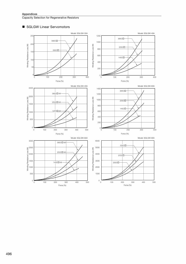
AppendicesCapacity Selection for Regenerative Resistors
496
SGLGW Linear Servomotors
Model: SGLGW-30A
Win
din
g R
esis
tance L
oss (W
)
Force (%)
Model: SGLGW-40A
Win
din
g R
esis
tance L
oss (W
)
Force (%)
Model: SGLGW-40A
Win
din
g R
esis
tance L
oss (W
)
Force (%)
Model: SGLGW-60A
Win
din
g R
esis
tance L
oss (W
)
Force (%)
Model: SGLGW-60A
Win
din
g R
esis
tance L
oss (W
)
Force (%)
Model: SGLGW-90A
Win
din
g R
esis
tance L
oss (W
)
Force (%)
0 100 200 300 4000
200
400
600
800
1000
1200
365C
253C
140C
0 100 200 300 400 500
0
500
1000
1500
2000
2500
0 100 200 300 4000
200
400
600
800
1000
1200
1400
365C
253C
140C
00
500
1000
1500
2000
2500
3000
100 200 300 400 500
365C-M
253C-M
00
1000
2000
3000
4000
5000
6000
100 200 300 400 500
200C
0 100 200 300 400
0
50
100
150
200
250
080C
050C
365C-M
253C-M
140C-M
140C-M
535C
370C

Appendices Capacity Selection for Regenerative Resistors
497
Cap
acity
Sele
ctio
n fo
r R
eg
enera
tive
Resis
tors
SGLFW2 Linear Servomotors
Model: SGLFW2-30AW
ind
ing
Resis
tance L
oss (W
)
Force (%)
Model: SGLFW2-45A
Win
din
g R
esis
tance L
oss (W
)
Model: SGLFW2-90A
Win
din
g R
esis
tance L
oss (W
)
Force (%)
Model: SGLFW2-1DA
Win
din
g R
esis
tance L
oss (W
)
Force (%)
100 200 300 4000
100 200 300 400100 200 300 400
0
0
0 0
0100 200 300 400
0
0
100
200
300
400
500
600
700
800
900
200
400
600
800
1000
1200
1400
1600
1800
2000
500
1000
1500
2000
2500
3000
3500
4000
4500
5000
1000
2000
3000
4000
5000
6000
7000
070A
120A
230A
200A
380A
560A
200A
380A
380A
560A
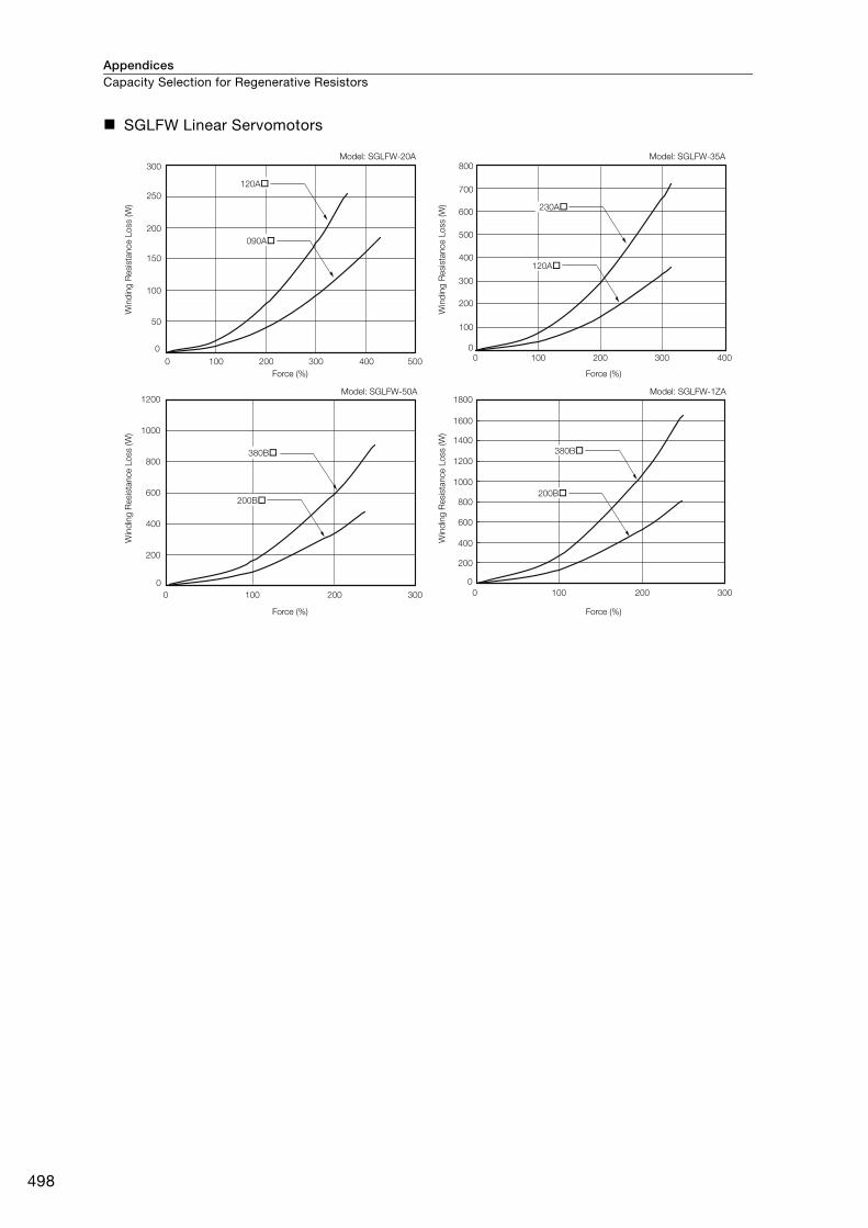
AppendicesCapacity Selection for Regenerative Resistors
498
SGLFW Linear Servomotors
Model: SGLFW-20A
Win
din
g R
esis
tance L
oss (W
)
Force (%)
Model: SGLFW-35A
Win
din
g R
esis
tance L
oss (W
)
Force (%)
Model: SGLFW-50A
Win
din
g R
esis
tance L
oss (W
)
Force (%)
Model: SGLFW-1ZA
Win
din
g R
esis
tance L
oss (W
)
Force (%)
0
0
100 200 300 400 500
50
100
150
200
250
300
00
100 200 300 400
100
200
300
400
500
600
700
800
0
0
200
400
600
800
1000
1200
100 200 300 0
0
100 200 300
200
400
600
800
1000
1200
1400
1600
1800
120A
090A
200B
380B 380B
200B
230A
120A

Appendices Capacity Selection for Regenerative Resistors
499
Cap
acity
Sele
ctio
n fo
r R
eg
enera
tive
Resis
tors
SGLTW Linear Servomotors
Model: SGLTW-20A
Win
din
g R
esis
tance L
oss (W
)
Force (%)
Model: SGLTW-35A
Force (%)
Model: SGLTW-35A
Win
din
g R
esis
tance L
oss (W
)
Win
din
g R
esis
tance L
oss (W
)
Force (%)
Model: SGLTW-50A
Win
din
g R
esis
tance L
oss (W
)
Force (%)
Model: SGLTW-40A
Force (%)
Win
din
g R
esis
tance L
oss (W
)
0 100 200 300 4000
500
1000
1500
2000
2500
460A
320A
0 100 200 300 4000
1000
500
1500
2000
2500
3000
3500
0 50 100 150 200 2500
400
300
200
100
500
600
700
800
900
0 200 400 600
400B
0
1000
2000
3000
4000
5000
7000
6000
0 50 100 150 200 2500
200
400
600
800
1000
1200
320H
0 200 400 600
400B
600B
0
1000
2000
3000
4000
5000
7000
8000
9000
10000
6000
600B
170H
320H
170H
170A170A
460A
320A
Model: SGLTW-80A
Win
din
g R
esis
tance L
oss (W
)
Force (%)
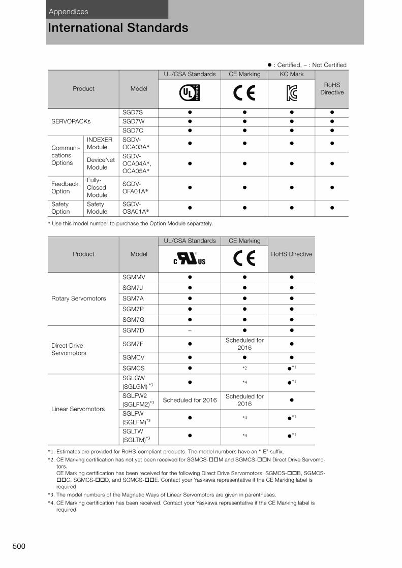
Appendices
500
International Standards
* Use this model number to purchase the Option Module separately.
*1. Estimates are provided for RoHS-compliant products. The model numbers have an “-E” suffix.
*2. CE Marking certification has not yet been received for SGMCS-M and SGMCS-N Direct Drive Servomo-tors.CE Marking certification has been received for the following Direct Drive Servomotors: SGMCS-B, SGMCS-C, SGMCS-D, and SGMCS-E. Contact your Yaskawa representative if the CE Marking label is required.
*3. The model numbers of the Magnetic Ways of Linear Servomotors are given in parentheses.
*4. CE Marking certification has been received. Contact your Yaskawa representative if the CE Marking label is required.
: Certified, – : Not Certified
Product Model
UL/CSA Standards CE Marking KC Mark
RoHS Directive
SERVOPACKs
SGD7S
SGD7W
SGD7C
Communi-cations Options
INDEXER Module
SGDV-OCA03A*
DeviceNet Module
SGDV-OCA04A*, OCA05A*
Feedback Option
Fully-Closed Module
SGDV-OFA01A*
Safety Option
Safety Module
SGDV-OSA01A*
Product Model
UL/CSA Standards CE Marking
RoHS Directive
Rotary Servomotors
SGMMV
SGM7J
SGM7A
SGM7P
SGM7G
Direct Drive Servomotors
SGM7D −
SGM7F Scheduled for
2016
SGMCV
SGMCS *2 *1
Linear Servomotors
SGLGW(SGLGM) *3 *4 *1
SGLFW2(SGLFM2)*3 Scheduled for 2016
Scheduled for 2016
SGLFW(SGLFM)*3 *4 *1
SGLTW(SGLTM)*3 *4 *1

501
MEMO
Inte
rnatio
nal S
tand
ard
s
Appendices
502
Warranty
Details of Warranty
Warranty Period
The warranty period for a product that was purchased (hereinafter called the “delivered product”) is one year from the time of delivery to the location specified by the customer or 18 months from the time of shipment from the Yaskawa factory, whichever is sooner.
Warranty Scope
Yaskawa shall replace or repair a defective product free of charge if a defect attributable to Yaskawa occurs during the above warranty period.
This warranty does not cover defects caused by the delivered product reaching the end of its ser-vice life and replacement of parts that require replacement or that have a limited service life.
This warranty does not cover failures that result from any of the following causes.• Improper handling, abuse, or use in unsuitable conditions or in environments not described in
product catalogs or manuals, or in any separately agreed-upon specifications • Causes not attributable to the delivered product itself • Modifications or repairs not performed by Yaskawa• Use of the delivered product in a manner in which it was not originally intended• Causes that were not foreseeable with the scientific and technological understanding at the time
of shipment from Yaskawa• Events for which Yaskawa is not responsible, such as natural or human-made disasters
Limitations of Liability• Yaskawa shall in no event be responsible for any damage or loss of opportunity to the customer
that arises due to failure of the delivered product.• Yaskawa shall not be responsible for any programs (including parameter settings) or the results of
program execution of the programs provided by the user or by a third party for use with program-mable Yaskawa products.
• The information described in product catalogs or manuals is provided for the purpose of the cus-tomer purchasing the appropriate product for the intended application. The use thereof does not guarantee that there are no infringements of intellectual property rights or other proprietary rights of Yaskawa or third parties, nor does it construe a license.
• Yaskawa shall not be responsible for any damage arising from infringements of intellectual prop-erty rights or other proprietary rights of third parties as a result of using the information described in catalogs or manuals.
Suitability for Use• It is the customer’s responsibility to confirm conformity with any standards, codes, or regulations
that apply if the Yaskawa product is used in combination with any other products.• The customer must confirm that the Yaskawa product is suitable for the systems, machines, and
equipment used by the customer.• Consult with Yaskawa to determine whether use in the following applications is acceptable. If use
in the application is acceptable, use the product with extra allowance in ratings and specifications, and provide safety measures to minimize hazards in the event of failure.• Outdoor use, use involving potential chemical contamination or electrical interference, or use in
conditions or environments not described in product catalogs or manuals• Nuclear energy control systems, combustion systems, railroad systems, aviation systems, vehi-
cle systems, medical equipment, amusement machines, and installations subject to separate industry or government regulations
• Systems, machines, and equipment that may present a risk to life or property• Systems that require a high degree of reliability, such as systems that supply gas, water, or
electricity, or systems that operate continuously 24 hours a day• Other systems that require a similar high degree of safety

Appendices Warranty
503
Warr
anty
• Never use the product for an application involving serious risk to life or property without first ensuring that the system is designed to secure the required level of safety with risk warnings and redundancy, and that the Yaskawa product is properly rated and installed.
• The circuit examples and other application examples described in product catalogs and manuals are for reference. Check the functionality and safety of the actual devices and equipment to be used before using the product.
• Read and understand all use prohibitions and precautions, and operate the Yaskawa product cor-rectly to prevent accidental harm to third parties.
Specifications ChangeThe names, specifications, appearance, and accessories of products in product catalogs and man-uals may be changed at any time based on improvements and other reasons. The next editions of the revised catalogs or manuals will be published with updated code numbers. Consult with your Yaskawa representative to confirm the actual specifications before purchasing a product.

504
MEMO


LITERATURE NO. KAEP S800001 23E <4>-0
15-7-15Published in Japan July 2016
In the event that the end user of this product is to be the military and said product is to be employed in any weapons systems or the manufacture thereof, the export will fall under the relevant regulations as stipulated in the Foreign Exchange and Foreign Trade Regulations. Therefore, be sure to follow all procedures and submit all relevant documentation according to any and all rules, regulations and laws that may apply.
Specifications are subject to change without notice for ongoing product modifications and improvements.
© 2014-2016 YASKAWA ELECTRIC CORPORATION
IRUMA BUSINESS CENTER (SOLUTION CENTER)480, Kamifujisawa, Iruma, Saitama, 358-8555, Japan
Phone 81-4-2962-5151 Fax 81-4-2962-6138
http://www.yaskawa.co.jp
YASKAWA AMERICA, INC.2121, Norman Drive South, Waukegan, IL 60085, U.S.A.
Phone 1-800-YASKAWA (927-5292) or 1-847-887-7000 Fax 1-847-887-7310
http://www.yaskawa.com
YASKAWA ELÉTRICO DO BRASIL LTDA.777, Avenida Piraporinha, Diadema, São Paulo, 09950-000, Brasil
Phone 55-11-3585-1100 Fax 55-11-3585-1187
http://www.yaskawa.com.br
YASKAWA EUROPE GmbH185, Hauptstraβe, Eschborn, 65760, Germany
Phone 49-6196-569-300 Fax 49-6196-569-398
http://www.yaskawa.eu.com
YASKAWA ELECTRIC KOREA CORPORATION9F, Kyobo Securities Bldg., 26-4, Yeouido-dong, Yeongdeungpo-gu, Seoul, 150-737, Korea
Phone 82-2-784-7844 Fax 82-2-784-8495
http://www.yaskawa.co.kr
YASKAWA ELECTRIC (SINGAPORE) PTE. LTD.151, Lorong Chuan, #04-02A, New Tech Park 556741, Singapore
Phone 65-6282-3003 Fax 65-6289-3003
http://www.yaskawa.com.sg
YASKAWA ELECTRIC (THAILAND) CO., LTD.59, 1st-5th Floor, Flourish Building, Soi Ratchadapisek 18, Ratchadapisek Road, Huaykwang, Bangkok 10310, Thailand
Phone: +66-2-017-0099 Fax: +66-2-017-0799
http://www.yaskawa.co.th
YASKAWA ELECTRIC (CHINA) CO., LTD.22F, One Corporate Avenue, No.222, Hubin Road, Shanghai, 200021, China
Phone 86-21-5385-2200 Fax 86-21-5385-3299
http://www.yaskawa.com.cn
YASKAWA ELECTRIC (CHINA) CO., LTD. BEIJING OFFICERoom 1011, Tower W3 Oriental Plaza, No.1, East Chang An Ave.,
Dong Cheng District, Beijing, 100738, China
Phone 86-10-8518-4086 Fax 86-10-8518-4082
YASKAWA ELECTRIC TAIWAN CORPORATION9F, 16, Nanking E. Rd., Sec. 3, Taipei, 104, Taiwan
Phone 886-2-2502-5003 Fax 886-2-2505-1280
http://www.yaskawa-taiwan.com.tw
SERIES