servo 25 - PÖTTINGER Landtechnik GmbH
50
����������������� GB Ihre / Your / Votre • Masch.Nr. • Fgst.Ident.Nr. ������������������������������������������������ �� �������������������������������������������� Ihre / Your / Votre • Masch.Nr. • Fgst.Ident.Nr. �� � SERVO 25 (MaschNr + . . 01001) SERVO 25 NOVA (MaschNr + . . 01001) Plough 99 987.GB.80H.1
-
Upload
khangminh22 -
Category
Documents
-
view
3 -
download
0
Transcript of servo 25 - PÖTTINGER Landtechnik GmbH

�����������������GB
Ihre / Your / Votre • Masch.Nr. • Fgst.Ident.Nr.
������������������������������������������������
����������������������������������������������
Ihre / Your / Votre • Masch.Nr. • Fgst.Ident.Nr.
���
SERVO 25(MaschNr + . . 01001)
SERVO 25 NOVA(MaschNr + . . 01001)
Plough
99 987.GB.80H.1

ALLG./BA SEITE 2 / 0000-GB
Important information concerning Product Liability.According to the laws governing product liability, the manufacturer and dealer are obliged to hand the operating manual to the customer at the time of sale, and to instruct them in the recommended operating, safety, and maintenance regulations. Confirmation is necessary to prove that the machine and operating manual have been handed over accordingly.
For this purpose,
- document A is to be signed and sent to Pöttinger,
- document B remains with the dealer supplying the machine,
- and the customer receives document C.
In accordance with the laws of product liability, every farmer is an entrepreneur.
According to the laws of product liability, property damage is damage caused by a machine and not to it. An excess of Euro 500 is provided for such a liabilioty.
In accordance with the laws of product liability, entrepreneurial property damages are excluded from the liability.
Attention! Should the customer resell the machine at a later date, the operating manual must be given to the new owner who must then be instructed in the recommended regulations referred to herein.
GB Dear FarmerYou have just made an excellent choice. Naturally we are very happy and wish to congratulate you for having chosen Pöttinger. As your agricultural partner, we offer you quality and efficiency combined with reliable servicing.
In order to assess the spare-parts demand for our agricultural machines and to take these demands into consideration when developing new machines, we would ask you to provide us with some details.
Furthermore, we will also be able to inform you of new developments.

Dokument D
GB-0600 Dokum D Servo - 3 -
ALOIS PÖTTINGER Maschinenfabrik GmbHA-4710 GrieskirchenTel. (07248) 600 -0Telefax (07248) 600-511GEBR. PÖTTINGER GMBHD-86899 Landsberg/Lech, Spöttinger-Straße 24Telefon (0 81 91) 92 99-111 / 112Telefax (0 81 91) 92 99-188
GEBR. PÖTTINGER GMBHServicezentrumD-86899 Landsberg/Lech, Spöttinger-Straße 24Telefon (0 81 91) 92 99-130 / 231Telefax (0 81 91) 59 656
❑ Check SERVO Turnover Plough as per the delivery docket. Check that delivery is complete. All safety equipment and operating devices at hand.
❑ Using the operating manual explain and go over the operation, initial start and maintenance of the machine or implement with the customer.
❑ Fitting to the tractor has been carried out.
❑ Check that hydraulic connections to the tractor have been made and that they are correct.
❑ Hydraulic functions (turnover, cutting width adjustment) have been demonstrated and explained.
❑ Plough is set correctly to the tractor (cutting width of 1st component, drawing point).
❑ Transport and working positions have been explained.
❑ Information about optional and additional equipment has been given.
❑ It has been pointed out that to read the operating manual is imperative.
Cross where applicable. X
In accordance with Product Liability obligations, we would ask you to please check the following points.
GB INSTRUCTIONS FOR PRODUCT DELIVERY
In order to prove that the machine and the operating manual have been properly delivered, a confirmation is necessary.For this purpose please do the following:- sign the document A and send it to the company Pöttinger (in case of Landsberg equipment: to the company Landsberg)- document B stays with the specialist factory delivering the machine. document C stays with the customer.

GBCONTENTS
- 4 -0700_GB-INHALT_987
Table of contentsMeaning of warning signs .............................................................................................................................................................................5Preparations on the tractor ............................................................................................................................................................................6Hydraulic control on the lifting gear ..............................................................................................................................................................6Hydraulic connection .....................................................................................................................................................................................7Preparations on the plough ...........................................................................................................................................................................7Attaching to the tractor ..................................................................................................................................................................................8Removal from tractor .....................................................................................................................................................................................8Garaging, cleaning and winter storage of the implement .............................................................................................................................8Before driving to the field ..............................................................................................................................................................................9Fine setting (measurement F) ......................................................................................................................................................................11Table for cat. II .............................................................................................................................................................................................11Setting the plough to the tractor using ........................................................................................................................................................12"Servomatic" ...............................................................................................................................................................................................12Turning the plough over ...............................................................................................................................................................................13Setting the plough gradient (11) ..................................................................................................................................................................13Ploughing with hydraulic control .................................................................................................................................................................14ON-LAND Ploughing ...................................................................................................................................................................................15Conventional ploughing ...............................................................................................................................................................................15Converting to conventional ploughing .........................................................................................................................................................15Converting to "ON-LAND" ploughing ..........................................................................................................................................................15Shear bolts ..................................................................................................................................................................................................16Fully automatic „Nonstop“ overload safety .................................................................................................................................................17Setting range ...............................................................................................................................................................................................17Table ............................................................................................................................................................................................................17Gas accumulator (43) ..................................................................................................................................................................................18Altering pressure in the gas accumulator ....................................................................................................................................................18General maintenance advice .......................................................................................................................................................................19Cleaning the machine parts .........................................................................................................................................................................19Hydraulic unit ...............................................................................................................................................................................................19Setting the ploughing component tilt ..........................................................................................................................................................20Basic setting of the ploughing component .................................................................................................................................................20Setting the disk coulter (* ............................................................................................................................................................................21Spring loaded disk coulter (* .......................................................................................................................................................................21Pre-ploughing implements ..........................................................................................................................................................................21Double feeler wheel .....................................................................................................................................................................................22Extension arm with hydraulic releasing device for packer and trailing implements ....................................................................................23Working with a trailing implement ...............................................................................................................................................................23Disconnect the arm .....................................................................................................................................................................................24Adjusting the amortisation effect .................................................................................................................................................................24Extension arm with hydraulic releasing device for packer and trailing implements ....................................................................................25Working with a trailing implement ...............................................................................................................................................................26Defined use of the plough according to the manufacturer’s instructions ....................................................................................................28Vehicle Identification Plate ...........................................................................................................................................................................28Technical data ..............................................................................................................................................................................................29Optional Equipment .....................................................................................................................................................................................30Plough body forms ......................................................................................................................................................................................31Supplement .................................................................................................................................................................................................32Recommendations for work safety .............................................................................................................................................................34Lubricants ....................................................................................................................................................................................................44Combination of tractor and mounted implement ........................................................................................................................................46Important! Additional Information ................................................................................................................................................................46

9501_GB-WARNBILDER_942
GBWARNING SIGNS
- 5 -
CE signThe CE sign, which is affixed by the manufacturer, indicates outwardly that this machine conforms to the engineering guideline regulations and the other relevant EU guidelines.
EU Declaration of Conformity (see supplement)By signing the EU Declaration of Conformity, the manufacturer declares that the machine being brought into service complies with all relevant safety and health requirements.
Meaning of warning signs
Stay c lear of swinging area of implements
Never reach into the crushing danger area as long as parts may move.

0600-GB ANBAU_987
GBATTACHING TO THE TRACTOR
- 6 -
Preparations on the tractor
General Please observe the power range limits of the tractor being used.
Wheels- Air pressure in the tractor’s rear tyres when ploughing should be 0.8
bar.
- Under difficult operating conditions additional wheel weights can be advantageous. See the tractor manufacturer’s operating manual also.
Ballast weight- Sufficient ballast weights are to be stacked on the front
of the tractor in order to guarantee steering and braking capabilities.
- At least 20% of the tractor’s tare weight on the front axle.
Lifting gear- Left and right lifting struts (4) must be of equal length.
Adjust using adjusting device (3).
- If the lifting struts on the lower link can be pinned variously, then select the back position (H). In so doing the tractor’s hydraulic unit will not be heavily loaded.
- Position (2) the upper link (1) according to the tractor manufacturer’s information.
Setting-up for transportation- Fix the lower link with the struts (5) so that the attached implement cannot
swing out during transportation.
- The hydraulic’s operating lever must be secured against lowering.
- Do not transport in the „ON-LAND“ position
Setting-up for ploughing- Set the struts (5) so that the greatest possible sideways swing range
exists.
Hydraulic control on the lifting gear
Control position:For mounting and dismounting the implement and for transportation.
The control position is the normal setting for the lifting gear hydraulics.
The mounted implement remains at the height (= position) set by the servo-valve (ST).
Pull control, mix control:Ploughing occurs with of one of the two operating modes. See chapter „OPERATION“ for description.
20%Kg
ST-24-11-2003

0600-GB ANBAU_987
GBATTACHING TO THE TRACTOR
- 7 -
Hydraulic connection
1 Double-action control unit
Preparations on the plough
Mounting axle 825 mm
• Carry out adaption to the tractor´s lifting gear
- both helical plates can be fitted in 4 different positions (P1, P2, P3, P4)
Upper link pins Position upper link pins (6) as per diagram
- secure with linch pin (K).
6
161-02-25
K

0600-GB ANBAU_987
GBATTACHING TO THE TRACTOR
- 8 -
TD65/92/27
1P1
P2
Parking stand- Using the control lever
(8), release parking stand, swing up and back and lay in the clamp (9).
Lighting and Warning equipment When travelling in fog, half-light or at night, protruding parts are to be
clearly indicated. Advice on the application of warning signs, reflective film or paint and lighting units can be found in the instructions for ancillary equipment in supplement C.
PôTTINGER can supply lighting units and warning signs upon request.
A lways observe the statutory regulations.
Removal from tractorHint: The shear points are hardened so when set down onto hard surface
(stone, concrete, etc.), risk of breaking exists. Therefore lower the shear points onto a suitable support (wooden board)!
- Turn plough frame to working position and park the implement on stable and even ground.
- Move the control lever (ST) back and forth several times to reduce pressure in the hydraulic lines.
- Switch tractor’s hydraulics to control position.
- Disconnect hydraulic hoses from tractor.
- Using the control lever (8), release parking stand, swing down and secure.
- Detach upper and lower links from implement.
Garaging, cleaning and winter storage of the implement
• Observe the points in the chapter „MAINTENANCE AND SERVICE“!
8
9TD65/92/31
Attaching to the tractorSafety advice:
See supplement A1, Pt. 8a-h
- Switch tractor’s hydraulics to control position.
- Attach implement to lower link and secure with linch pin.
Note The attaching frame can be positioned horizontally by turning the
tilt spindle (11).
Doing this enables an easier coupling to the lower link.
Then turn the tilt spindle (11) back. See chapter „OPERATION“ also.
Pin upper link (1)- Pin upper link (1) so that the attachment point (P1) on the plough
during operation is somewhat higher than the attachment point (P2) on the tractor.
Securing lower link If the tractor’s hydraulic control
is to be steered over the lower link, then the upper link should be positioned in the slot (LL) on the attaching frame.
Securing upper link If the tractor’s hydraulic control
is to be triggered over the upper link, then both the (RL) borings on the attaching frame are to be used.
- Couple hydraulic hoses to the tractor.
ST-24-11-2003

(981) 0000-GB VOREINSTELLUNG
GBPRESETTING THE PLOUGH
- 9 -
Before driving to the field
SERVOSERVO NOVA
see next page
SERVO PLUSSERVO NOVA PLUS
1. Carry out basic setting according to table B, with average cutting width position.
2. Carry out a more accurate setting when in use.
Setting both the spindles (ZP, VF) Drawing point (ZP)
Backfurrow (VF)
• Setting depends upon the inside distance between the tractor wheels (RA) and the set furrow width .
- Further Information on the drawing point and backfurrow in chapter "OPERATION".
RA
TD65/92/35
Table-B for
SERVO NOVA PLUS
Table-B for
SERVO PLUS
TD
126/
98/0
7
VF
ZP

(981) 0000-GB VOREINSTELLUNG
GBPRESETTING THE PLOUGH
- 10 -
Before driving to the field
SERVO1. Carry out basic setting according to table C.
2. Carry out a more accurate setting when in use.
SERVO NOVA1. Carry out basic setting according to table A.
2. Carry out a more accurate setting when in use.
Set furrow width- Loosen both hexagonal screw (SK).
- Remove rear hexagonal screw.
- Swivel anchoring console until the required furrow width is obtained and the hexagonal screw fits into one of the borings (1, 2, 3, 4, 5).
- Retighten hexagonal screws.
Setting both the spindles (ZP, VF) Drawing point (ZP)
Backfurrow (VF)
• Setting depends upon the inside distance between the tractor wheels (RA) and the set furrow width (1, 2, 3, 4, 5).
- Further Information on the drawing point and backfurrow in chapter "OPERATION". RA
TD65/92/35
Table-Cfor
SERVO
Table-Afor
SERVO NOVA
TD
82/
96/1
8
VF
ZP
2
1
3 4 5
SK

0700_GB-VOREINSTELLUNG_987
GBPRESETTING THE PLOUGH
- 11 -
Fine setting (measurement F) Fine setting adapts the plough to the tractor in use and therefore is to be
carried out only once.
With that the fine adjustment spindle is set at the etablished measurement (F)
- Make the measurements (A) and (B) and determine the intersecting point (F) for cat. II in accordance with the table.
The measurements (A, B) are each to be made from bolt centre to bolt centre.
- The position of the intersecting point between the diagonal lines on the graph is the setting (F).
Table for cat. IICat. II = 825 mm
W = 80 mm
Example: A = 416 mm
B = 931 mm
W = 80 mm
(W = 200 mm)
The intersecting point (F) lies between the lines "306" and "308".
Therefore the average is 307 mm.
F = 307 mm
Setting the adjustment spindle- Remove bolts (12).
- Set the adjustment spindle to the determined measurement (F).
- Replace bolts (12).
F
B
A W
165-02-11
12

0200-GB EINSATZ_987
GBOPERATION
- 12 -
Setting the plough to the tractor using"Servomatic"
„SERVOMATIC“ enables the optimum adaption of plough to tractor.
The following setting controls should be carried out in order.
1. Fine setting (F)- Check setting measurement for fine adjustment spindle (F).
See chapter "PRESETTING THE PLOUGH".
2. Furrow width setting of the first ploughing component (backfurrow)
The furrow width (S2) of the first ploughing component is set by turning the spindle (VF).
Furrow width (S1) to narrow- turn spindle (VF) longer
Furrow width (S2) to wide- turn spindle (VF) shorter
Furrow width (S2) correct- Spindle is correctly set according to table.
See chapter "PRESETTING THE PLOUGH“
ncorrect settingThe drawing line does not run through the mid-point of the tractor’s rear axle. Tractor is drawn into already ploughed area during ploughing. This can only be compensated by steering in the opposite direction.
- Turn spindle (ZP) longer
See chapter "PRESETTING THE PLOUGH“
3. Setting the drawing point (Z)
Correct settingThe drawing line (ZL) runs through the mid-point (M) of the tractor’s rear axle. No side pull arises from the tractor.The plough is easy to pull.- Spindle (ZP) is set according to the table.
See chapter "PRESETTING THE PLOUGH“
F
B
A W
165-02-11
123
1
4 2
SK
VFZP
165-02-12

0200-GB EINSATZ_987
GBOPERATION
- 13 -
Turning the plough overBeware!Nobody is to stand within the swinging range during turning.
Turning procedure is only to be actuated from the tractor cabin.
The plough must be completely raised to turn.
The automatic reversing gear enables the whole turning procedure to be carried out through only one single switch position on the control unit (ST).
Turning procedure with a double-action cylinder- Switch control unit (ST) to lift (h).
The plough is turned 180¯.
- Switch control unit (ST) to neutral (O).
After some 5 seconds another turning procedure can be effected.
Setting the plough gradient (11) The plough should sit as vertical (90°) as possible to the ground during
ploughing. This position is obtained by turning both spindles (11) as described below.
- Lift plough 5 - 10 cm
- Actuate control unit (ST) briefly.
The plough turns slightly away from the stop spindle (11).
- Set the gradient using the spindle (11).
- Turn plough back to stop again.
- Proceed with ploughing and check whether the plough sits more vertically (90°) to the ground through the new setting.
TD 65/92/48
s
h0
ST
TD 65/92/25
90° �

0200-GB EINSATZ_987
GBOPERATION
- 14 -
Ploughing with hydraulic control So that the hydraulic control functions properly, the following must
be observed.
- Position upper link (1) so that the attachment point (P1) on the plough during operation is somewhat higher than the attachment point (P2) on the tractor.
Pinning the upper link LL, RL = Pinning position for securing lower link
RL = Pinning position for securing upper link
Details see chapter „ATTACHING TO THE TRACTOR“.
- During operation the plough should lie lengthwise as parallel as possible to the ground surface.
- The working depth is set with the lifting gear via the servo-valve firstly.
Depending upon the hydraulic control model, varying ground resistance when ploughing is passed on to the control servo-valve via the upper link (1) or both the lower links. The relevant impulse is then converted causing the lifting gear to lift or lower.
An example: Securing upper link The plough penetrates deeper into the ground.
This causes the pressure on the control servo-valve via the upper link to become greater.
As a consequence, the control valve remains switched to lift until the set working depth is reached again.
Note: Follow the tractor manufacturer’s operating manual also.
TD65/92/27
1P1
P2
ST-24-11-2003

0300-GB ON LAND_981
GBOPERATION
- 15 -
ON-LAND Ploughing
What does "ON-LAND-Ploughing" mean?• No tractor wheels in the furrows
- All wheels travel on unploughed ground.
Advantages of an "ON-LAND-Plough"• Ground care with "ON-LAND" ploughing.
No tractor wheels in furrows to compress and knead the ground. Less tractor wheel slippage as with conventional ploughing in wet conditions.
• Greater swing range
This makes even travelling on unploughed ground with dual wheels possible.
• Boundary ploughing possibility
To swing the plough away from ground already ploughed (antiON-LAND position). This enables accurate ploughing right up to a boundary.
• Conventional Ploughing
The plough can be centred behind the tractor = conventional ploughing with wheels in the furrows.
Conventional ploughing
Ploughing with wheels in the furrows Swing plough to behind centre of tractor using hyraulics.
Converting to conventional ploughingSafety points
• Conversion to be carried on firm level ground only• Do not enter the area underneath a raised plough• When converting stay off the raised plough
1. Raise plough slightly- use tractor's lifting gear
2. Pin spindle in (KP) position- secure bolt with linch pin
3. Re-set drawing point (ZP)- see next page
Converting to "ON-LAND" ploughingSafety points
• Conversion to be carried on firm level ground only• Do not enter the area underneath a raised plough• When converting stay off the raised plough
1. Raise plough slightly- use tractor's lifting gear
2. Pin spindle in (OP) position- secure bolt with linch pin
3. Re-set drawing point (ZP)- see next page
KP = conventional ploughingOP = "ON-LAND" ploughing

(943) 9200 GB SICHERUNG
GBOVERLOAD SAFETY
- 16 -
Shear bolts
The ploughing components are fastened with shear bolts.
When overloaded the shear bolts break (30) and the ploughing component swings away and up.
- Remove the rest of the shear bolt.
- Loosen hexagonal bolt (31).
- Swing ploughing component back into the working position.
- Insert new shear screws and retighten both bolts.
Take note! Only use genuine shear bolts (see spare parts list) with the corresponding dimension and quality. Under no circumstances
use bolts with greater or lesser strength.

(984) 0500-GB NOVA
GBSERVO NOVA
- 17 -
Fully automatic „Nonstop“ overload safety
The fully automatic overload safety is recommended for soils which are difficult to plough e.g. soil with stones or other foreign bodies.
Every ploughing component is hydromechanically safeguarded against damage on the SERVO-NOVA plough.
When driving over an obstacle the ploughing body swings out to either side and then swings automatically back into the working position. There is no need to stop the tractor.
The plough body swings back into work position automatically.
Along with the fully automatic „Nonstop“ overload safety, all component carriers have a shear bolt as additional protection. See chapter "OVERLOAD SAFETY“ for a description.
Setting range• The overload safety release force can be adapted to the various
soil types.Normal setting
- Pressure in the hydraulic cylinders (40) must be approx. 10 bar greater than the nitrogen pressure in the gas accumulator (43).
Nitrogen pressure in the gas accumulator (43) (Factory set) 80 bar
Pressure adjustment area of the hydraulic cylinder (40) 90 to 160 bar Should practice show that the overload safety reacts too often,
the pressure(* in the hydraulic cylinders can be increased with the accompanying top-up device (42).
Table pressure(* release force ( bar ) ( kp ) 90 970 100 1060 110 1150 120 1240 130 1320 140 1410 150 1500 160 1590
Increasing the pressure in the hydraulic cylinders:- Shut-off valve in position A.
- Remove sealing cap (41) from shut-off valve and screw on top-up line.
- Depressurize servo-valve on the tractor.
- Connect plug-in coupling (42) to the tractor.
- Open shut-off valve (position E). The hydraulic pressure drops.
- Actuate servo-valve on tractor until the manometer shows the desired pressure. Then close the shut-off valve (position A).
Take note! The shut-off valve must always be closed (position A)
when ploughing.- Depressurize top-up line using servo-valve.
- Remove top-up line and screw sealing cap (41) back on.

(984) 0500-GB NOVA
GBSERVO NOVA
- 18 -
Gas accumulator (43) Pressure in the gas accumulator can also be altered.
A reduction or increase of gas pressure in the accumulator depends upon the various soil types.
• With very light soil the gas pressure can be somewhat reduced.
Important!
• No welding, soldering or mechanical work of any kind may be carried out on the accumulator.
Altering pressure in the gas accumulatorThis work must be carried out only by our Customer Service or by a specialist work shop.A special filling and testing device is required to reduce or increase the preload pressure in the gas accumulator.
1. Reduce pressure:a) Remove plastic cap.
Remove the lead mould plug (if it exists) in the gas filling plug (44) with a pointed tool.
b) Slightly loosen the gas filling plug (44).
c) Screw on filling and testing device.
d) Slightly open the outlet valve on the filling device.
Slowly let the nitrogen out (N) until the mamometer shows the desired pressure has been reached.
e) Close outlet valve, remove filling device, tighten gas filling plug and knock the lead mould plug (if it exists) back in.
2. Increase pressure:• Only use nitrogen (N) to fill the accumulator, do not use oxygen
(danger of explosion).
f) Connect filling device to nitrogen bottle.
g) Remove plastic cap.
Remove the lead mould plug (if it exists) in the gas filling plug (44) with a pointed tool.
Slightly loosen the gas filling plug (44).
Screw on filling and testing device.
h) Screw testing device onto nitrogen bottle.
i) Slightly open the outlet valve on the filling device and fill with nitrogen until the mamometer shows the required pressure has been reached.
k) Close outlet valve, remove filling device, tighten gas filling plug and knock the lead mould plug (if it exists) back in.
Take noteAll gas accumulators show a slight pressure drop after a certain period of time, according to "HYDAC" factory specifications.
The gas loss amounts to approx. 2-3 % pa.
It is recommended that the accumulator pressure be checked and, if necessary, regulated after 4-5 years.

(955) 9700-GB WARTUNG
GBMAINTENANCE AND SERVICE
- 19 -
General maintenance advice
In order to keep the implement in good condition even after a long service life, please observe the following points:
- After the first hours of operation retighten all screws.
During the operating season- Check all screws occasionally and retighten if necessary.- Grease the four greasing points on both of the swing bolts weekly.- Grease all other greasing points at least twice per season. At the same time oil joints and adjusting spindles also.
Expendable parts- Replace worn out expendable parts in time to prevent all stress-
bearing parts from becoming damaged.
Tyre pressure- Pay attention to the correct tyre pressure!
Check tyre pressure regularly!
• Danger of bursting exist when inflating or when tyre pressure is too great!
Cleaning the machine partsTake note! Do not use a high pressure cleaner to clean bearings or hydraulic
parts.
- Danger of rust formation!
- Lubricate the machine after cleaning and carry out a short trial run.
- Cleaning with too much pressure can damage the paintwork.
Parking in the open
When parking in the open for longer periods, clean plunger rods and then grease.
Winter storage- Thoroughly clean the machine
before storing.
- Store the machine where it is weather protected.
- Protect exposed parts against rusting.
- Grease all greasing points
Hydraulic unit- Check hydraulic hoses regularly for damage.
Immediately replace porous or damaged hydraulic hoses.
FETT
Beware: Danger of infection!• Where there are dfects in the
hydraulic unit, do not touch areas of leakage.
Before working on the hydraulic unit- lower implement to the ground.
- When carrying out maintenance work on a raised implement always make it secure with a suitable support.
- Depressurize the hydraulic unit and turn the motor off.

(955) 9700-GB WARTUNG
GBMAINTENANCE AND SERVICE
- 20 -
Basic setting of the ploughing component
Checks must be made in the following order after replacing worn out parts:
1. Stand the plough on even ground.
2. The gap (A) between plough and blade cutting edege must be the same for all ploughing components.
3. Check the gap (B1) on the last ploughing component.
B1 = 0 - 5 mm for ploughing components* of the type W, UWS
10 - 20 mm for ploughing components* of the type UW, UWS, WSS
4. Set the same measurement for gap (B) as for B1.
* The type of ploughing component is shown clearly on the manufacturer’s plate.
Setting the ploughing component tiltIf the plough is not penetrating the ground correctly, an improvement can be obtained by turning the eccentric bush.
• The blade point in the area „S“ is set either higher or lower depending upon the position of the eccentric bush (A or B).
• Retighten screws after resetting.
On some models a catch plate is fitted instead of an eccentric bush.
See "Basic setting of the ploughing component" also.

(943) 9500 GB ZUSÄTZE - 21 -
GBADDITIONAL DEVICES
(* Beware! Danger of injury on the cutting edges.
Setting the disk coulter (*
• Set the cutting depth of the disk coulter at a gap of 5 cm to the ploughing blade tip.
• The lengthwise fitting position is preselected by moving the carrier
on the console.
Further fitting positions arise by swivelling the eccentric (50) 180°.
• The lateral gap to the ploughing blade tip should be 2 - 3 cm. It is set by swiveling the eccentric (50).
Spring loaded disk coulter (*
- This disk coulter can be fitted to all SERVO NOVA ploughs with a frame height from 72 cm.
Pre-ploughing implementsMaize skimmer, Manure skimmerThese implements are designed to incorporate surface trash straw or manure in the soil.
• Set the working depth to 1/3 of the total working depth.
• The lengthwise fitting position should lie over or behind the ploughing blade tip. Where there is a lot of surface growth, or when ploughing in straw, the pre-ploughing implements should be set back as far as possible.
Leg deflector (60) Leg deflector, which are fitted to the ploughing component, serve
to bend the stalks less when ploughing in straw enabling them to slide off better.
Trashboards (61) For ploughing in manure or other fertilizers.
• Trashboards for ploughing components of the type UW, W, WSS.
These implements can be used instead of manure mulchers (see above) but are not very effective with shallow working depths.
Knife coulter (62) (*
This implement can be used instead of a disk coulter (see above) however it is not adjustable.

0200-GB TASTRÄDER_987
GBFEELER WHEELS
- 22 -
Double feeler wheel• The double feeler wheel is fitted to the last ploughing component.
• The working depth is set via the spindle (70) using the accompanying ratchet.
• When ploughing with a 4 blade plough the double feeler wheel can be fitted to the second last ploughing component. This has the advantage that when ploughing along the boundary the feeler wheel does not greatly project over the last ploughing component.
Double feeler wheel fitted to the second last ploughing component.

(983) 0000-GB AUSLEGER
GBPLOUGH-TRAILING IMPLEMENTS
- 23 -
Optional equipment
Extension arm with hydraulic releasing device for packer and trailing implements• A double-action control unit is necessary on the tractor.
• The extension arm is fitted to the main frame.
• A T screw fitting with a plug-in coupling sleeve is fitted to the return line (T) on the plough turning cylinder.
TD65/92/85
82
81v
81e
TD65/92/83
TD65/92/84
30cm
Working position• Pin strut (83) in the front boring
(A).
• The distance (40 - 50 cm) to the tractor wheel is also set with the strut (83).
Transport position• Pin strut (83) in the rear boring
(B).
With this the extension arm is swivelled in to the plough frame.
Working with a trailing implement For attachment a latching device is fitted to the trailing implement
which lies at right angles to the direction of travel.
Engaging the trailing implement• Bolts in the locking position (81v).
Switch the servo-valve briefly to „lift“ to lock the bolts.
• With the extension in the outer range (30 cm) hook on to the trailing implement’s latching device.
Releasing the trailing implement• Unlock the bolts hydraulically (81e).
Switch the servo-valve briefly to „lower“ to unlock the bolts.

(983) 0000-GB AUSLEGER
GBPLOUGH-TRAILING IMPLEMENTS
- 24 -
F1F2
018-01-11
Disconnect the arm
1. Disconnect the hydraulic pipe (Hyd)
2. Take away the two axles (B1, B2)
3. Take the arm from the bearings
Adjusting the amortisation effect
With the arm two springs are delivered (F1,F2)
They reduce shocks wenn the trailing implement is penetrating
Depending on the weight of the trailing implement it is necessary to chose the right spring
If the trailing implement is very heavy (up to 2000 Kg), attach the two springs to the arm.
F1 up to 500 kg
F2 up to 1200 kg
F1+F2 up to 2000 kg

0700_GB-SCHWENKAUSLEGER_983 - 25 -
GBPLOUGH-TRAILING IMPLEMENTS
Extension arm with hydraulic releasing device for packer and trailing implementsFrom 2006 model *)
Mounting:1. Fit bracket (K) to mainframe
2. Pin and secure extension arm (A) to bracket (K) with pin (B)
3. Pretension draw spring (Z) (max. 4 cm.)
4. Hydraulic connection to plough turning cylinder using the T screw fitting on the return line T or through a single action hydraulic control
115-07-01
K
AB
Z
Adjustment:The extension arm has 2 adjusting devices available:
1. Working settings (hole A)
(Trailing implement position next to the plough)
The trailing implement can be led at five different distances to the plough through hole pattern A
Setting positions:
A1 – smallest distance
A2 – distance approx. 30 cm > A1
A3 – distance approx. 60 cm > A1
A4 – distance approx. 90 cm > A1
A5 – greatest distance
2. Latching setting (hole A)
(Extension arm setting for latching position)
The extension arm can be set at five different latching positions to the trailing implement through hole pattern B
- The extension arm projection from the tractor tyres should be between 40 – 50 cm
- The overlap between extension arm and latching device on the trailing implement should be between 20 – 30 cm
Note!
The trailing implement should
run as close as possible next to
the plough but not collide with it.
Note!
If the latching arm length of the
trailing implement cannot be set appropriately, changing the
latching position can compensate
this.
115-07-02
A1234
5
B
115-07-04
40-5
0 cm
20-3
0 cm
*) Optional extra for SERVO 25 S, SERVO 35 S, SERVO 45 S

0700_GB-SCHWENKAUSLEGER_983 - 26 -
GBPLOUGH-TRAILING IMPLEMENTS
Engaging the trailing implement• Bolts in the locking position (81v).
Switch the servo-valve briefly to „lift“ to lock the bolts.
• With the extension in the outer range (30 cm) hook on to the trailing implement’s latching device.
Releasing the trailing implement• Unlock the bolts hydraulically (81e).
Switch the servo-valve briefly to „lower“ to unlock the bolts.
TD65/92/85
82
81v
81e
Working with a trailing implement For attachment a latching device is fitted to the trailing implement which lies at right angles to the direction of
travel.
Working position Latching position
Ploughs without trailing implements• For ploughs without Packer but with fitted extension
arm
- Insert pin (2) in hole (5)
Transport• Extension arm must be swung in fully when
transporting.
- Insert pin (3) in hole (T)
115-07-03
115-07-05
B5
2
115-07-06
T
115-07-07
3

0700_GB-SCHWENKAUSLEGER_983 - 27 -
GBPLOUGH-TRAILING IMPLEMENTS
Detaching:1. Disconnect hydraulic line
2. Detach draw spring (Z)
3. Remove bearing pin (B)
4. Remove extension arm (A)
Fitting to “PLUS” ploughs A control chain (S) is to be fitted on PLUS ploughs
The latching position of the extension arm (A) is set with this control chain, depending on the chain length.
Procedure:
1. Fit chain holder (H) and control chain (S)
2. Fit chain adjuster (L) to extension arm
3. Set plough to the narrowest working width
4. Hook control chain (S) onto chain adjuster (L) and secure with pins (chain length according to latching position)
Take note!
Fitting the control chain (S) must
only take place at the narrowest
working width otherwise
damage will occur to the plough and Packer arm if the
cutting width or frame inswing is
changed.
115-07-01
K
AB
Z
115-07-10
H
A
L
S
115-07-11
H
A
L
S
Fitting to “Servo – PLUS” Fitting to “Servo – PLUS NOVA”

0200-GB TECHN. DATEN_987
GBTECHNICAL DATA
- 28 -
Vehicle Identification Plate• The implement’s exact designation and its fittings (frame height,
component form, ...) are imprinted in the section „Type“.
• The factory number is imprinted on the vehicle identification plate (as shown opposite) and on the attachment frame.
Guarantee claims and queries cannot be processed without the serial number being supplied.
• Please enter the number onto the title page of this operating manual immediately after taking delivery of the implement.
Defined use of the plough according to the manufacturer’s instructions The plough (SERVO, SERVO NOVA) is intended solely for normal use in agricultural work.
* For the ploughing in of arable land, fields and other soils. Any other uses outside of these are regarded as not in accordance with the defined use. The manufacturer will not be held liable for any damages resulting from misuse. The risk is carried by the user alone. The keeping of operating, servicing and maintenance requirements as specified by the manufacturer also come under the heading of „defined use“.

0200-GB TECHN. DATEN_987
GBTECHNICAL DATA
- 29 -
Technical data
Permanent sound emmission level < 70 dB(A)
Power requirement max. 103 kW / 140 hp
SERVO 25 Standard Type Blades Component distance Frame height Cutting width Weight 1 Power requirement from (kW / PS)
SERVO 25-385 3 85 72 / 78 33-36-40-43 692 52/70 SERVO 25-485 4 (3+1) 85 72 / 78 33-36-40-43 842 66/90 SERVO 25-295 2 95 72 / 78 33-37-41-45 553 40/55 SERVO 25-395 3 95 72 / 78 33-37-41-45 708 52/70 SERVO 25-495 4 (3+1) 95 72 / 78 33-37-41-45 853 66/90 SERVO 25-202 2 102 72 / 78 35-40-44-48 556 40/55 SERVO 25-302 3 102 72 / 78 35-40-44-48 710 52/70 SERVO 25-402 4 (3+1) 102 72 / 78 35-40-44-48 861 66/90
SERVO 25 NOVA Type Blades Component distance Frame height Cutting width Weight 1 Power requirement from (kW / PS)
SERVO 25-N385 3 85 74 / 80 33-36-40-43 907 52/70 SERVO 25-N485 4 (3+1) 85 74 / 80 33-36-40-43 1109 66/90 SERVO 25-N295 2 95 74 / 80 33-37-41-45 689 44/60 SERVO 25-N395 3 95 74 / 80 33-37-41-45 913 52/70 SERVO 25-N495 4 (3+1) 95 74 / 80 33-37-41-45 1119 66/90 SERVO 25-N202 2 102 74 / 80 35-40-44-48 693 44/60 SERVO 25-N302 3 102 74 / 80 35-40-44-48 919 52/70
1 Applies to implements with standard fittings

0200-GB TECHN. DATEN_987
GBTECHNICAL DATA
- 30 -
Optional Equipment
Trashboard
UW, UWS, W, WSS.
Leg deflector
U, UW, UWS, W, WSS.
Guiding plate
U, UW, UWS.
Knife coulter
U, UW, W, WSS.
Landside saver
UW, UWS, W, WSS
Double depth wheel
Maize mulcher
M1 / M2
SubsoilerSmooth disk coulter Cutaway disk coulterManure mulcher - skim coulter DV 50-25
TD65/92/83
Warning sign, Yellow reflex reflector for side indication, Redreflex reflector for the lighting unit.
Extension arm for plough-trailing implements
turnover depth wheel (steel)

- 31 -
EQUIPMENTS GB
0000-GB AUSRÜSTUNGEN (981)
404045
35403545
45
303540
26253540
40
31 UW36 UW39 UW
35-26 W36 W35 W41 W
35 WSS
Plough body forms
Description
• Easy to pull
• Excellent clod breaking
• Suitable for all soils
• Especially for slopes/shallow plougling
• Easy to pull
• Very good characteristics for newly ploughed fields
The small slatted body
• Particularly suitable for heavy, sticky soils
• Very easy to pull
The large slatted body
• Particularly suitable for heavy, sticky soils
• Very easy to pull
• Factory fitted
◊ Possible variation to factory fittings (without additional charge)
- Not available
X Optional fitting for an additional charge
Wor
king
wid
th
Wor
king
dep
th
Des
igna
tion

GB-Anhang Titelblatt _BA-Allgemein
GB
SUPPLEMENT

GB-Anhang Titelblatt _BA-Allgemein
GB
The decision must be made, ”original” or ”imitation”? The decision is often governed by price and a ”cheap buy” can sometimes be very expensive.
Be sure you purchase the ”Original” with the cloverleaf symbol!
• Quality and precise fitting
- Operating safety.
• Reliable operation
• Longer lasting
- Economy
• Guaranteed availability through your
Pöttinger Sales Service.
Things will run better with genuine Pöttinger parts
The original cannot be copied ...

9400_GB-Anhang A_Sicherheit
SUPPLEMENT - ARecommendations for work safety
- A 1 -
20%Kg
Recommendations for work safety All points refering to safety in this manual are indicated by this sign.
1.) Defined usea. See "Technical Data".
b. The keeping of operating, service and maintenance requirements layed down by the manufacturer also come under the heading of "defined use".
2.) Spare partsa. The original components and accessories have been designed
especially for these machines and appliances.
b. We want to make it quite clear that components and accesories that have not been supplied by us have not been tested by us.
c. The installation and/or use of such products can, therefore, ne-gatively change or influence the construction characteristics of
the appliance. We are not liable for damages caused by the use of components and accessories that have not been supplied by us.
d. Alterations and the use of auxiliary parts that are not permitted by the manufacturer render all liability invalid.
3.) Protection devices All protection devices must remain on the machine and be
maintained in proper condition. Punctual replacement of worn and damaged covers is essential.
4.) Before starting worka. Before commencing work, the operator must be aware of all
operating devices and functions. The learning of these is too late after having already commenced operation!
b. The vehicle is to be tested for traffic and operating safety before each operation.
5.) Asbestos - Certain sub-supplied components of the
vehicle may contain asbestos due to technical reasons. Observe the warning on spare parts.
6.) Transport of persons prohibiteda. The transport of persons on the machine is not permitted.
b. The machine may only be driven on public roads when in the position stipulated for road transport.
7.) Driving ability with auxiliary equipment a. The towing vehicle is to be sufficiently equiped with weights at
the front or at the rear in order to guarantee the steering and braking capacity (a minimum of 20% of the vehicle’s tare weight on the front axle).
b. The driving ability is influenced by ground conditions and by the auxiliary equipment. The driving must be adapted to the cor-responding terrain and ground conditions.
c. When driving through curves with a connected appliance, observe the radius and swinging mass of the appliance.
d. When travelling in a curve with attached or semi-mounted implements, take into account the working range and swing mass of the implement!
8.) General a. Before attaching implement to three-point linkage, move system
lever into a position whereby unintentional raising or lowering is ruled out!
b. Danger of injury exists when coupling implement to tractor!
c. Danger of injury through crushing and cutting exists in the three-point linkage area!
d. Do not stand between tractor and implement when using three-point linkage external operation!
e. Attach and detach drive shaft only when motor has stopped.
f. When transporting with raised implement, secure operating lever against lowering!
g. Before leaving tractor, lower attached implement to the ground and remove ignition key!
h. Nobody is to stand between tractor and implement without tractor being secured against rolling using parking brake and/or wheel chocks!
i. For all maintenance, service and modification work, turn driving motor off and remove universal drive.
9.) Cleaning the machine Do not use high-pressure washers for the cleaning of bearing- and
hydraulic parts.

0300-GB TABELLE_987
GB
- 35 -
TABLE
3
1
4 2
SK
VFZP
165-02-12
3
1
4 2
SK
VFZP
165-02-12
Type: SERVO 25 NOVABlades: 2 Cutting width 35 cm 40 cm 44 cm 48 cm Position 1 2 3 4
RA VF ZP VF ZP VF ZP VF ZP[mm] [mm] [mm] [mm] [mm] [mm] [mm] [mm] [mm]900 407 493 402 511 398 525 1000 401 482 395 500 391 514 387 528 1100 395 470 389 488 384 502 379 516 1200 389 457 383 476 378 490 373 505 1300 384 445 377 464 372 478 366 493 1400 378 432 371 451 366 466 360 481 1500 373 419 366 438 360 454 354 468
102 cm
1234
165-02-02
Type: SERVO 25Blades: 2 Cutting width: 35 cm 40 cm 44 cm 48 cm Position 1 2 3 4
RA VF ZP VF ZP VF ZP VF ZP[mm] [mm] [mm] [mm] [mm] [mm] [mm] [mm] [mm]900 409 500 404 517 400 529 1000 403 490 397 506 393 519 389 5321100 397 479 391 496 386 509 382 5221200 391 469 385 485 380 499 375 5111300 386 458 379 475 374 488 368 5011400 380 446 373 464 368 477 362 4901500 374 435 367 452 362 466 356 479
102 cm
1234
165-02-02
RA
TD65/92/35
RA
TD65/92/35

0300-GB TABELLE_987
GB
- 36 -
TABLE
3
1
4 2
SK
VFZP
165-02-12
3
1
4 2
SK
VFZP
165-02-12
RA
TD65/92/35
Type: SERVO 25Blades: 3 Cutting width 35 cm 40 cm 44 cm 48 cm Position 1 2 3 4
RA VF ZP VF ZP VF ZP VF ZP[mm] [mm] [mm] [mm] [mm] [mm] [mm] [mm] [mm]900 408 471 402 486 397 498 392 510 1000 402 458 396 474 391 486 385 498 1100 397 445 390 461 385 473 379 486 1200 391 432 384 448 379 461 373 473 1300 386 419 379 435 373 448 367 460 1400 380 405 373 422 367 435 361 447 1500 375 391 368 408 362 421 355 434
102 cm102 cm
165-02-01
1234
Type: SERVO 25 NOVABlades: 3 (2+1) Cutting width 35 cm 40 cm 44 cm 48 cm Position 1 2 3 4
RA VF ZP VF ZP VF ZP VF ZP[mm] [mm] [mm] [mm] [mm] [mm] [mm] [mm] [mm]900 406 467 400 484 395 497 390 510 1000 401 453 394 470 389 484 384 497 1100 395 439 388 457 383 470 377 484 1200 390 425 383 443 377 457 371 470 1300 384 411 377 429 371 443 365 457 1400 379 396 371 414 365 429 359 443 1500 373 380 366 399 360 414 354 428
102 cm102 cm
165-02-09
1234
RA
TD65/92/35

0300-GB TABELLE_987
GB
- 37 -
TABLE
3
1
4 2
SK
VFZP
165-02-12
3
1
4 2
SK
VFZP
165-02-12
RA
TD65/92/35
Type: SERVO 25Blades: 4 (3+1) Cutting width 35 cm 40 cm 44 cm 48 cm Position 1 2 3 4
RA VF ZP VF ZP VF ZP VF ZP[mm] [mm] [mm] [mm] [mm] [mm] [mm] [mm] [mm]900 408 450 401 464 396 476 391 487 1000 402 435 396 450 390 462 384 473 1100 397 421 390 436 384 448 378 459 1200 392 405 385 421 379 433 373 445 1300 386 390 379 406 373 418 367 430 1400 381 374 374 390 368 403 361 415 1500 375 358 368 374 362 387 356 400
102 cm102 cm
165-02-01
1234
RA
TD65/92/35
Type: SERVO 25-NOVABlades: 3 Cutting width 35 cm 40 cm 44 cm 48 cm Position 1 2 3 4
RA VF ZP VF ZP VF ZP VF ZP[mm] [mm] [mm] [mm] [mm] [mm] [mm] [mm] [mm]900 422 515 418 531 1000 415 502 410 518 407 531 1100 409 489 404 505 399 518 395 531 1200 403 476 397 492 392 505 388 518 1300 397 462 391 479 386 492 381 505 1400 392 449 385 466 380 479 374 492 1500 386 435 379 452 374 466 368 479
102 cm 102 cm102 cm
165-02-13
1234

0300-GB TABELLE_987
GB
- 38 -
TABLE
3
1
4 2
SK
VFZP
165-02-12
3
1
4 2
SK
VFZP
165-02-12
RA
TD65/92/35
Type: SERVO 25Blades: 2 Cutting width 33 cm 37 cm 41 cm 45 cm Position 1 2 3 4
RA VF ZP VF ZP VF ZP VF ZP[mm] [mm] [mm] [mm] [mm] [mm] [mm] [mm] [mm]900 406 498 401 511 396 524 392 537 1000 400 488 394 501 389 514 384 527 1100 394 477 388 491 383 504 377 517 1200 388 466 382 480 376 494 370 507 1300 382 456 376 469 370 483 364 496 1400 377 444 370 458 364 472 357 486 1500 371 433 364 447 358 461 351 475
95 cm
165-02-05
1234
Type: SERVO 25 NOVABlades: 2 Cutting width 33 cm 37 cm 41 cm 45 cm Position 1 2 3 4
RA VF ZP VF ZP VF ZP VF ZP[mm] [mm] [mm] [mm] [mm] [mm] [mm] [mm] [mm]900 404 490 399 505 394 519 389 533 1000 398 478 392 493 387 508 382 522 1100 392 466 386 482 380 496 374 511 1200 386 454 380 470 374 484 368 499 1300 380 442 374 457 368 472 361 487 1400 375 429 368 445 362 460 355 475 1500 369 416 363 432 356 448 349 463
RA
TD65/92/35
95 cm
165-02-05
1234

0300-GB TABELLE_987
GB
- 39 -
TABLE
3
1
4 2
SK
VFZP
165-02-12
3
1
4 2
SK
VFZP
165-02-12
Type: SERVO 25Blades: 3 Cutting width 33 cm 37 cm 41 cm 45 cm Position 1 2 3 4
RA VF ZP VF ZP VF ZP VF ZP[mm] [mm] [mm] [mm] [mm] [mm] [mm] [mm] [mm]900 405 468 399 481 393 493 387 505 1000 399 456 393 468 387 481 381 493 1100 394 443 387 456 381 468 375 481 1200 388 430 382 443 375 456 368 468 1300 382 417 376 430 369 443 363 456 1400 377 403 370 417 364 430 357 443 1500 371 389 365 403 358 417 351 430
95 cm95 cm
165-02-04
1234
RA
TD65/92/35
Type: SERVO 25Blades: 3 (2 + 1)
95 cm95 cm
165-02-10
1234

0300-GB TABELLE_987
GB
- 40 -
TABLE
3
1
4 2
SK
VFZP
165-02-12
3
1
4 2
SK
VFZP
165-02-12
Type: SERVO 25 NOVABlades: 3 (2+1) Cutting width 33 cm 37 cm 41 cm 45 cm Position 1 2 3 4
RA VF ZP VF ZP VF ZP VF ZP[mm] [mm] [mm] [mm] [mm] [mm] [mm] [mm] [mm]900 403 464 397 478 391 491 386 504 1000 397 450 391 464 385 478 379 491 1100 392 437 386 451 379 465 373 478 1200 386 423 380 437 373 451 367 465 1300 381 408 374 423 368 437 361 451 1400 375 393 369 408 362 423 355 437 1500 370 378 363 394 356 409 349 423
Type: SERVO 25 NOVABlades: 3 Cutting width 33 cm 37 cm 41 cm 45 cm Position 1 2 3 4
RA VF ZP VF ZP VF ZP VF ZP[mm] [mm] [mm] [mm] [mm] [mm] [mm] [mm] [mm]900 418 512 414 525 410 537 1000 412 499 407 512 402 525 398 538 1100 406 486 400 500 395 513 390 525 1200 400 473 394 487 388 500 383 513 1300 394 460 388 474 382 487 376 500 1400 388 446 382 460 376 474 370 487 1500 383 432 377 447 370 461 363 474
95 cm95 cm
165-02-10
1234
RA
TD65/92/35
RA
TD65/92/35
95 cm95 cm
165-02-04
1234

0300-GB TABELLE_987
GB
- 41 -
TABLE
3
1
4 2
SK
VFZP
165-02-12
3
1
4 2
SK
VFZP
165-02-12
Type: SERVO 25 NOVABlades: 4 (3+1) Cutting width 33 cm 37 cm 41 cm 45 cm Position 1 2 3 4
RA VF ZP VF ZP VF ZP VF ZP[mm] [mm] [mm] [mm] [mm] [mm] [mm] [mm] [mm]900 417 493 412 506 407 518 402 529 1000 411 480 406 492 400 504 395 516 1100 405 465 399 478 394 490 388 502 1200 400 451 394 464 387 476 381 488 1300 394 436 388 449 381 462 375 474 1400 389 421 382 434 376 447 369 460 1500 383 405 377 419 370 432 363 445
95 cm 95 cm95 cm
165-02-06
1234
RA
TD65/92/35
RA
TD65/92/35
Type: SERVO 25Blades: 4 (3+1) Cutting width 33 cm 37 cm 41 cm 45 cm Position 1 2 3 4
RA VF ZP VF ZP VF ZP VF ZP[mm] [mm] [mm] [mm] [mm] [mm] [mm] [mm] [mm]900 405 447 399 459 393 470 386 481 1000 399 433 393 445 387 456 380 468 1100 394 418 387 430 381 442 374 454 1200 388 403 382 416 375 428 368 440 1300 383 388 376 401 370 413 363 425 1400 377 372 371 385 364 398 357 410 1500 371 356 365 369 358 383 351 395
95 cm 95 cm95 cm
165-02-06
1234

0300-GB TABELLE_987
GB
- 42 -
TABLE
3
1
4 2
SK
VFZP
165-02-12
3
1
4 2
SK
VFZP
165-02-12
RA
TD65/92/35
Type: SERVO 25Blades: 3 Cutting width 33 cm 36 cm 40 cm 43 cm Position 1 2 3 4
RA VF ZP VF ZP VF ZP VF ZP[mm] [mm] [mm] [mm] [mm] [mm] [mm] [mm] [mm]900 395 474 389 484 382 496 376 505 1000 389 462 383 472 376 485 370 494 1100 383 450 377 460 369 473 363 482 1200 378 438 372 448 363 460 357 470 1300 372 425 366 435 358 448 351 458 1400 366 412 360 422 352 435 345 445 1500 361 399 355 409 346 423 339 432
85 cm85 cm
165-02-07
1234
RA
TD65/92/35
Type: SERVO 25 NOVABlades: 3 Cutting width 33 cm 36 cm 40 cm 43 cm Position 1 2 3 4
RA VF ZP VF ZP VF ZP VF ZP[mm] [mm] [mm] [mm] [mm] [mm] [mm] [mm] [mm]900 409 518 405 528 1000 402 506 398 516 391 529 387 538 1100 396 493 391 503 384 516 379 526 1200 390 480 384 491 377 504 372 514 1300 384 467 378 478 371 491 365 501 1400 378 454 372 465 364 479 358 489 1500 372 441 366 451 358 466 352 476
85 cm85 cm
165-02-07
1234

0300-GB TABELLE_987
GB
- 43 -
TABLE
3
1
4 2
SK
VFZP
165-02-12
3
1
4 2
SK
VFZP
165-02-12
Type: SERVO 25Blades: 4 (3+1) Cutting width 33 cm 36 cm 40 cm 43 cm Position 1 2 3 4
RA VF ZP VF ZP VF ZP VF ZP[mm] [mm] [mm] [mm] [mm] [mm] [mm] [mm] [mm]900 394 452 389 461 381 472 375 481 1000 389 438 383 447 375 459 369 467 1100 383 424 377 433 369 445 363 454 1200 378 410 372 419 363 431 357 440 1300 372 395 366 405 358 417 351 426 1400 367 380 361 390 352 402 345 412 1500 361 365 355 375 346 388 340 397
RA
TD65/92/35
RA
TD65/92/35
Type: SERVO 25 NOVABlades: 4 (3+1) Cutting width 33 cm 36 cm 40 cm 43 cm Position 1 2 3 4
RA VF ZP VF ZP VF ZP VF ZP[mm] [mm] [mm] [mm] [mm] [mm] [mm] [mm] [mm]900 407 499 403 508 396 520 391 529 1000 401 485 396 494 389 507 384 515 1100 395 471 390 481 382 493 376 502 1200 389 457 384 467 376 479 370 488 1300 384 443 378 453 370 465 364 475 1400 378 428 372 438 364 451 357 461 1500 373 413 367 423 358 437 352 446
85 cm 85 cm85 cm
165-02-08
1234
85 cm 85 cm85 cm
165-02-08
1234

DG
BI
Leis
tung
und
Leb
ensd
auer
der
Mas
chin
e si
nd v
on s
orgf
ältig
er W
artu
ng u
nd d
er
Verw
endu
ng g
uter
Bet
riebs
stof
fe a
b -hä
ngig
. U
nser
e Be
trieb
ssto
ffauf
listu
ng
erle
icht
ert d
ie ri
chtig
e Au
swah
l gee
igne
ter
Betri
ebss
toffe
.Im
Sch
mie
rpla
n is
t de
r je
wei
ls e
inzu
set-
zend
e Be
trieb
ssto
ff du
rch
die
Betri
ebs-
stof
fken
nzah
l (z
.B.
“III”)
sym
bolis
iert.
An
hand
von
“Bet
riebs
stof
fken
nzah
l” ka
nn
das
gefo
rder
te Q
ualit
ätsm
erkm
al u
nd d
as
ents
prec
hend
e Pr
oduk
t de
r M
iner
alö-
lfirm
en fe
stge
stel
lt w
erde
n. D
ie L
iste
der
M
iner
alöl
firm
en e
rheb
t ke
inen
Ans
pruc
h au
f Vol
lstä
ndig
keit.
The
perfo
rman
ce a
nd th
e lif
etim
e of
the
farm
mac
hine
s are
hig
hly d
epen
ding
on
a ca
refu
l mai
nten
ance
and
app
licat
ion
of c
orre
ct l
ubric
ants
. O
ur s
ched
ule
enab
les
an e
asy
sele
ctio
n of
sel
ecte
d pr
oduc
ts.
The
appl
icab
le lu
bric
ants
are
sym
bo-
lized
(eg.
“III”
). Acc
ordi
ng to
this
lubr
icant
pr
oduc
t cod
e nu
mbe
r the
spe
cific
atio
n,
qual
ity an
d bra
ndna
me o
f oil c
ompa
nies
m
ay e
asily
be
dete
rmin
ed. T
he li
stin
g of
the
oil c
ompa
nies
is n
ot s
aid
to b
e co
mpl
ete.
Pres
tatie
s en
lev
ensd
uur
van
de
mac
hine
s zi
jn a
fhan
kelijk
van
een
zo
rgvu
ldig
onde
rhou
d en h
et ge
brui
k va
n go
ede
smee
rmid
dele
n.
Dit
sche
ma
verg
emak
kelij
kt d
e go
ede
keuz
e va
n de
juis
te s
mee
r -m
idde
len.
I
II III
IV
V
VI
VII
(II)
ÖL
Bet
riebs
stof
f-Ken
nzah
l Lu
bric
ant i
ndic
ator
C
ode
du lu
brifi
ant
Num
ero
cara
tteris
tico
del
lubr
ifica
nte
Smee
rmid
dele
n co
de
Olie
in a
andr
ijvin
gen
volg
ens
de g
e-br
uiks
aanw
ijzin
g ver
wiss
elen
- ech
ter
tenm
inst
e 1
x ja
arlijk
s.-
Afta
pplu
g er
uit
nem
en, d
e ol
ie
afta
ppen
en
milie
uvrie
ndel
ijk
verw
erke
n.
Get
riebe
öl g
emäß
Bet
riebs
anle
itung
- je
-do
ch m
inde
sten
s 1
x jä
hrlic
h w
echs
eln.
-
Öla
blaß
schr
aube
her
ausn
ehm
en, d
as
Altö
l aus
lauf
en la
ssen
und
ord
nung
s-ge
mäß
ent
sorg
en.
Gea
r oils
acco
rdin
g to o
pera
ting i
nstru
c-tio
ns -
how
ever
at l
east
onc
e a
year
. -
Take
out
oil d
rain
plu
g, le
t run
out
and
du
ly d
ispo
se w
aste
oil.
Mot
ori
a qu
attro
tem
pi:
biso
gna
effe
ttuar
e il
cam
bio
dell'o
lio o
gni 1
00 o
re d
i fun
zion
amen
to e
que
llo d
ell'o
lio
per c
ambi
com
e st
abilit
o ne
l man
uale
del
le is
truzi
oni p
er
l'uso
(tut
tavi
a, a
lmen
o 1
volta
all'a
nno)
. -
Togl
iere
il ta
ppo
di s
caric
o a
vite
del
l’olio
; far
sco
lare
l’o
lio e
elim
inar
e l’o
lio c
ome
prev
isto
dal
la le
gge
anti-
inqu
inam
ento
am
bien
tale
.
Voor
het
bui
ten
gebr
uik
stel
len
(win
-te
rper
iode
) de
olie
-wis
sel u
itvoe
ren
en a
lle v
etni
ppel
sm
eerp
unte
n do
orsm
eren
. Bl
anke
met
aald
elen
(k
oppe
linge
n en
z.) m
et e
en p
rodu
ct
uit g
roep
"IV"
van d
e nav
olge
nde t
abel
te
gen
corro
sie
besc
herm
en.
Befo
re g
arag
ing
(win
ter s
easo
n) a
n oi
l ch
ange
and
gre
asin
g of
all
lubr
icat
ing
poin
ts h
as t
o be
don
e. U
npro
tect
ed,
blan
c m
etal
par
ts o
utsi
de (j
oint
s, e
tc.)
have
to b
e pr
otec
ted
agai
nst c
orro
sion
w
ith a
gro
up "I
V" p
rodu
ct a
s in
dica
ted
on th
e re
vers
e of
this
pag
e.
NL
F
Le b
on fo
nctio
nnem
ent e
t la
long
évité
de
s m
achi
nes
dépe
nden
t d’u
n en
tre-
tien
soig
neux
et d
e l’u
tilis
atio
n de
bon
s lu
brifi
ants
. Not
re li
ste
faci
lite
le c
hoix
co
rrect
des
lubr
ifian
ts.
Sur l
e ta
blea
u de
gra
issa
ge, o
n tro
uve
un c
ode
(p.e
x."II
I") s
e ré
féra
nt à
un
lubr
ifian
t do
nné.
En
cons
ulta
nt c
e co
de o
n pe
ut fa
cile
men
t dét
erm
iner
la
spéc
ificat
ion d
eman
dée d
u lub
rifian
t. La
liste
des s
ocié
tés p
étro
lière
s ne p
réte
nd
pas
d’êt
re c
ompl
ète.
Pour
l’hu
ile t
rans
mis
sion
con
sulte
r le
ca
hier
d’e
ntre
tien
- au
moi
ns u
ne fo
is
par a
n.
- Re
tirer
le bo
ucho
n de v
idan
ge, la
isser
l'h
uile
s'éc
oule
r et l'
élim
iner
corre
cte -
men
t.
L'ef
ficie
nza
e la
dur
ata
della
mac
chin
a di
pend
ono
dall'a
ccur
atez
za d
ella
sua
man
uten
zion
e e
dall'i
mpi
ego
dei l
ubrifi
cant
i ada
tti. I
l nos
tro e
lenc
o de
i lub
rifica
nti V
i ag
evol
a ne
lla s
celta
del
lubr
ifica
nte
gius
to.
Il lu
brifi
cant
e da
util
izza
rsi d
i vol
ta in
vol
ta è
sim
boliz
zato
ne
llo s
chem
a di
lubr
ifica
zion
e da
un
num
ero
cara
tter-
istic
o (p
er e
s. "I
II").
In b
ase
al "n
umer
o ca
ratte
ristic
o de
l lu
brifi
cant
e" s
i pos
sono
sta
bilir
e si
a la
car
atte
ristic
a di
qu
alità
che
il p
roge
tto c
orris
pond
ente
del
le c
ompa
gnie
pe
trolif
ere.
L'e
lenc
o de
lle c
ompa
gnie
pet
rolif
ere
non
ha
pret
ese
di c
ompl
etez
za.
Vor S
tille
gung
(Win
terp
erio
de) Ö
lwec
hsel
du
rchf
ühre
n un
d al
le F
etts
chm
iers
telle
n ab
schm
iere
n. B
lank
e M
etal
lteile
auß
en
(Gel
enke
, usw
.) m
it ei
nem
Pro
dukt
gem
äß
“IV”
in d
er u
mse
itige
n Ta
belle
vor
Ros
t sc
hütz
en.
Avan
t l’a
rrêt e
t hiv
er: v
idan
ger e
t gra
is-
ser.
Mét
aux
nus
à l' e
xtér
ieur
pro
tége
r av
ec un
prod
uit ty
pe “I
V” co
ntre
la ro
uille
(c
onsu
lter t
able
au a
u ve
rso)
.
Effe
ttuar
e il c
ambi
o del
l'olio
ed in
gras
sare
tutte
le pa
rti ch
e ric
hied
ono
una
lubr
ifica
zion
e a
gras
so p
rima
del f
erm
o in
vern
ale d
ella
mac
chin
a. P
rote
gger
e dal
la ru
ggin
e tut
te le
pa
rti m
etal
liche
este
rne s
cope
rte co
n un p
rodo
tto a
norm
a di
"IV"
del
la ta
bella
ripo
rtata
sul
retro
del
la p
agin
a.
(IV)
FE
TT
- D 1
-
Smee
rmid
dele
nU
itgav
e 19
97Lu
brifi
cant
iEd
izio
ne 1
997
Lubr
ifian
tsÉd
ition
1997
Lubr
icant
sEd
ition
1997
Betri
ebss
toffe
Ausg
abe
1997
gefo
rder
tes
Qua
lität
smer
kmal
requ
ired
qual
ity le
vel n
ivea
u
de p
erfo
rman
ce d
eman
dé ca
ratte
ristic
a ric
hies
ta d
i qu
alità
verla
ngte
kw
alite
itske
nmer
ken
Get
riebe
öl S
AE 9
0 bz
w. 8
5 W
-140
gem
äß A
PI-G
L 5
gear
oil
SAE
90 re
sp. S
AE 8
5 W
-140
acc
ordi
ng to
API
-GL
5
huile
tran
smis
sion
SA
90 o
u SA
E 85
W-1
40, n
ivea
u AP
I G
L 5
oilio
per
cam
bi e
diff
eren
zial
i SA
E 90
o S
AE 8
5 W
-140
se-
cond
o sp
ecifi
che
API-G
L 5
Kom
plex
fett
(DIN
51
502:
KP
1R)
com
plex
gre
ase
grai
sse
com
plex
e
gras
so a
bas
e di
sap
oni
com
ples
si
Get
riebe
fließ
fett
(DIN
51
502:
GO
H
trans
mis
sion
gre
ase
grai
sse
trans
mis
sion
gras
so fl
uido
per
ridu
ttori
e m
otor
odut
tori
Li-F
ett (
DIN
51
502,
KP
2K)
lithi
um g
reas
e
grai
sse
au li
thiu
m
gras
so a
l liti
o
Get
riebe
öl S
AE 9
0 bz
w. S
AE 8
5 W
-140
ge
mäß
API
-GL
4 od
er A
PI-G
L 5
gear
oil,
SAE
90
resp
. SAE
85
W-1
40
acco
rdin
g to
API
-GL
4 or
API
-GL
5
huile
tran
smis
sion
SAE
90
ou
SAE
85 W
-140
, niv
eau
API-G
L 4
ou
API-G
L 5
olio
per
cam
bi e
diff
eren
zial
i SAE
90
o SA
E 85
W-1
40 s
econ
do s
peci
fiche
AP
I-GL
4 o
API-G
L 5
Mot
oren
öl S
AE 3
0 ge
mäß
AP
I CD
/SF
mot
or o
il SA
E 30
ac
cord
ing
to A
PI C
D/S
F
huile
mot
eur S
AE 3
0 ni
veau
AP
I CD
/SF
oilo
mot
ore
SAE
30 s
econ
do
spec
ifich
e AP
I CD
/SF
HYD
RAU
LIKö
L H
LP
DIN
515
24 T
eil 2
Sieh
e An
mer
kung
en* **
**
*

-OS
O 32
/46/68
AR
NICA
22/46
MO
TORO
IL HD
30
SIGM
A MU
LTI 1
5W-4
0 SU
PER
TRAC
TORO
IL UN
IVER
S.
15W
-30
ROTR
A HY
80W
-90/8
5W-1
40
ROTR
A MP
80W
-90/8
5W-1
40
GR M
U 2
GR S
LL
GR LF
O RO
TRA
MP 80
W-9
0 RO
TRA
MP 85
W-1
40
VITA
M GF
32/46
/68
VITA
M HF
32/46
SU
PER
KOW
AL 30
MUL
TI T
URBO
-RA
L SUP
ER T
RAKT
ORAL
15W
-30
GETR
IEBE
ÖL E
P 90
GET
RIEB
EÖL
HYP
85W
-90
ARAL
UB H
L 2
ARAL
UB F
DP 00
AR
ALUB
FK
2 GE
TRIE
BEÖL
HYP
90
AGIP
ARAL
IVAN
MER
KUN
GEN
III
VIV
VII
II I
Firm
a
Com
pany
So
ciét
é S
ocie
tá
(IV
)F
ET
T(I
I)Ö
L
* W
hen
work
ing in
co
njunc
tion
with
wet
-br
ake
tracto
rs, t
he in
ter-
natio
nal s
pecifi
catio
n J
20 A
is n
eces
sary.
** H
ydra
ulic o
il
HLP-
(D) +
HV.
***
Hyd
rauli
c oil w
ith ve
ge-
table
oil b
ase
HLP
+ HV
is
bio-d
egra
dable
and
is
ther
efor
e es
pecia
lly
safe
for t
he e
nviro
men
t.
HYDR
AULIK
ÖL H
LP 32
/46/68
SU
PER
2000
CD-
MC *
HYDR
A HY
DR. F
LUID
* HY
DRAU
-LIK
ÖL M
C 53
0 ** P
LANT
OHYD
40
N ***
SUPE
R 20
00 C
D-MC
SU
PER
2000
CD
HD S
UPER
IOR
20 W
-30
HD S
UPER
IOR
SAE
30
SUPE
R 80
90 M
C HY
POID
80W
-90
HYPO
ID 85
W-1
40
MULT
I FET
T 2
SPEZ
IALF
ETT
FLM
PLAN
TOGE
L 2 N
GETR
IEBE
FLIE
SSFE
TT N
LGI 0
RE
NOLIT
DUR
APLE
X EP
00
PLAN
TOGE
L 00N
RENO
PLEX
EP
1 HY
POID
85W
-140
BAYW
A
AVILU
B RL
32/46
AV
ILUB
VG 32
/46
MOTO
ROIL
HD 30
MU
LTIG
RADE
HDC
15W
-40 T
RAC-
TAVI
A HF
SUP
ER 10
W-3
0
GETR
IEBE
ÖL M
Z 90
M M
ULTI
HYP
85W
-140
AV
IA M
EHRZ
WEC
KFET
T AV
IA A
BSCH
MIER
FETT
AV
IA G
ETRI
EBEF
LIESS
FETT
AV
IALU
B SP
EZIA
LFET
T LD
GE
TRIE
BEÖL
HYP
90 E
P MU
LTIH
YP
85W
-140
EP
AVIA
ENER
GOL S
HF 32
/46/68
VI
SCO
2000
EN
ERGO
L HD
30VA
NELL
US M
30
GEAR
OIL
90 E
PHY
POGE
AR 90
EP
ENER
GREA
SE LS
-EP
2 FL
IESS
FETT
NO
ENER
GREA
SE H
TO
OLEX
PR
9142
HY
POGE
AR 90
EP
HYPO
GEAR
85W
-140
EP
BP
HYSP
IN A
WS
32/46
/68 H
YSPI
N AW
H 32
/46
RX S
UPER
DIE
SEL 1
5W-4
0 PO
WER
TRAN
S EP
X 80
W-9
0 HY
POY
C 80
W-1
40
IMPE
RVIA
MMO
CA
STRO
LGRE
ASE
LMX
EPX
80W
-90
HYPO
Y C
80W
-140
CAS
TRO
L
WIO
LAN
HS (H
G) 32
/46/68
WIO
LAN
HVG
46 **
WIO
LAN
HR 32
/46 **
*HY
DROL
FLUI
D *
MULT
I-REK
ORD
15W
-40
PRIM
ANOL
REKO
RD 30
HYPO
ID-G
ETRI
EBEÖ
L80
W-9
0, 85
W-1
40ME
HRZW
ECKG
ETRI
EBEÖ
L80
W-9
0
WIO
LUB
LFP
2W
IOLU
B GF
W
WIO
LUB
AFK
2 HY
POID
-GET
RIEB
EÖL
80W
-90,
85W
-140
ENAK
HLP
32/46
/68
ENAK
MUL
TI 46
/68
SUPE
R EV
VARO
L HD/
B SA
E 30
UN
IVER
SAL T
RACT
OROI
L SUP
ER
HYPO
ID G
A 90
HY
POID
GB
90
HOCH
DRUC
KFET
T LT
/SC
280
GETR
IEBE
FETT
MO
370
EVVA
CA
300
HYPO
ID G
B 90
HLP
32/46
/68HL
P-M
M32/M
46
MOTO
RÖL 1
00 M
S SA
E 30
MO
TORÖ
L 104
CM
15W
-40
AUST
ROTR
AC 15
W-3
0
GETR
IEBE
ÖL M
P 85
W-9
0 GE
TRIE
BEÖL
B 85
W-9
0 GE
TRIE
BEÖL
C 85
W-9
0
LORE
NA 46
LIT
ORA
27
RHEN
OX 34
-
GETR
IEBE
ÖL B
85W
-90
GETR
IEBE
ÖL C
85W
-140
OLNA
32/46
/68
HYDR
ELF
46/68
PE
RFOR
MANC
E 2 B
SAE
30 80
00
TOUR
S 20
W-3
0 TRA
CTOR
ELF
ST
15W
-30
TRAN
SELF
TYP
B 90
85W
-140
TR
ANSE
LF E
P 90
85W
-140
EP
EXA
2 RO
LEXA
2 MU
LTI 2
GA O
EP
POLY
G O
MU
LTIM
OTIV
E 1
TRAN
SELF
TYP
B 90
85W
-140
TR
ANSE
LF T
YP B
LS 80
W-9
0
NUTO
H 32
/46/68
NU
TO H
P 32
/46/68
PL
US M
OTOR
ÖL 20
W-3
0 UN
IFARM
15W
-30
GEAR
OIL G
P 80
W-9
0 GE
AROI
L GP
85W
-140
MU
LTI P
URPO
SE G
REAS
E H
FIBR
AX E
P 37
0 NE
BULA
EP
1 GP
GRE
ASE
GEAR
OIL
GX 80
W-9
0 GE
AR O
IL GX
85W
-140
ULTR
AMAX
HLP
32/46
/68
SUPE
R TR
AC F
E 10
W-3
0*
ULTR
AMAX
HVL
P 32
**
ULTR
APLA
NT 40
***
SUPE
R HP
O 30
ST
OU 15
W-3
0 SU
PER
TRAC
FE
10W
-30
ALL F
LEET
PLU
S 15
W-4
0
HP G
EAR
OIL 9
0 ode
r 85W
-140
TRAN
S GE
AR O
IL 80
W-9
0 MU
LTILU
BE E
P 2
VAL-
PLEX
EP
2PL
ANTO
GEL 2
N
RENO
LIT LZ
R 00
0 DE
GRAL
UB Z
SA 00
0 DU
RAPL
EX E
P 1
TELL
US S
32/S
46/S
68
TELL
US T
32/T
46
AGRO
MA 15
W-3
0 RO
TELL
A X
30
RIMU
LA X
15W
-40
SPIR
AX 90
EP
SPIR
AX H
D 90
SP
IRAX
HD
85/14
0
RETI
NAX
A AL
VANI
A EP
2 SP
EZ. G
ETRI
EBEF
ETT
H SI
MMNI
A GR
EASE
O
AERO
SHEL
L GRE
ASE
22 D
OLIU
M GR
EASE
R
SPIR
AX H
D 90
SP
IRAX
HD
85W
-140
AZOL
LA Z
S 32
, 46,
68
EQUI
VIS
ZS 32
, 46,
68
RUBI
A H
30
MULT
AGRI
TM
15W
-20
TOTA
L EP
85W
-90
TOTA
L EP
B 85
W-9
0 MU
LTIS
EP
2 MU
LTIS
EP
200
MULT
IS H
T 1
TOTA
L EP
B 85
W-9
0
DTE
22/24
/25
DTE
13/15
HD
20W
-20
DELV
AC 12
30
SUPE
R UN
IVER
SAL 1
5W-3
0
MOBI
LUBE
GX
90
MOBI
LUBE
HD
90
MOBI
LUBE
HD
85W
-140
MOBI
LGRE
ASE
MP
MOBI
LUX
EP 00
4MO
BILP
LEX
47
MOBI
LUBE
HD
90
MOBI
LUBE
HD
85W
-140
RENO
PLEX
EP
1 HY
POID
EW
90HY
POID
85W
-140
HY
DRAU
LIKÖL
HLP
/32/46
/68
HYDR
AMOT
1030
MC
* HY
DRAU
LIKÖL
520 *
* PL
ANTO
HYD
40N
***
MULT
I 203
0 20
00 T
C HY
DRAM
OT 15
W-3
0 HY
DRAM
OT 10
30 M
C
GETR
IEBE
ÖL M
P 90
HY
POID
EW
90HY
POID
85W
-140
MEHR
ZWEC
KFET
T SP
EZIA
LFET
T GL
MPL
ANTO
GEL 2
N
GETR
IEBE
FLIE
SSFE
TTPL
ANTO
GEL 0
0N
HYDR
AN 32
/46/68
DE
LTA
PLUS
SAE
30
SUPE
R UN
IVER
SAL O
IL PO
NTON
IC N
85W
-90 P
ONTO
NIC
MP 85
W-9
0 85W
-140
SU
PER
UNIV
ERSA
L OIL
MARS
ON E
P L 2
NA
TRAN
00
MARS
ON A
X 2
PONT
ONIC
MP
85W
-140
RENO
PLEX
EP
1 RE
NOGE
AR S
UPER
8090
MC
RE
NOGE
AR H
YPOI
D 85
W-1
40
RENO
GEAR
HYP
OID
90
TITA
N HY
DRAM
OT 1O
3O M
CTI
TAN
UNIV
ERSA
L HD
RENO
GEAR
SUP
ER 80
90 M
RE
NOGE
AR H
YPOI
D 85
W-1
4 RE
NOGE
AR H
YPOI
D 90
RENO
SOD
GFO
35DU
RAPL
EX E
P 00
PLAN
TOGE
L 00N
ELAN
FUC
HS
GEN
OL
MO
BIL
RH
G
SHEL
L
TOTA
L
ELF
ESSO
EVVA
FIN
A
VALV
OLI
NE
VEED
OL
RENO
LIN B
10/15
/20
RENO
LIN B
32 H
VI/46
HVI
EXTR
A HD
30
SUPE
R HD
20 W
-30
MEHR
ZWEC
KGET
RIEB
EÖl S
AE90
HY
POID
EW
90ME
HRZW
ECKF
ETT
RENO
LIT M
P DU
RAPL
EX E
P RE
NOSO
D GF
O 35
RE
NOPL
EX E
P 1
HYPO
ID E
W 90
--
ANDA
RIN
32/46
/68
HD P
LUS
SAE
30
MULT
IGRA
DE S
AE 80
/90
MULT
IGEA
R B
90
MULT
IGEA
R C
SAE
85W
-140
MULT
IPUR
POSE
MU
LTIG
EAR
B 90
MU
LTI C
SAE
85W
-140
WIN
TER
SHAL
L
HP G
EAR
OIL 9
0od
er 85
W-1
40
RENO
LIN 10
25 M
C ***
TITA
N HY
DRAM
OT 10
30 M
C **
RENO
GEAR
HYD
RA *
PLAN
TOHY
D 40
N ***
RENO
LIT M
P RE
NOLIT
FLM
2 RE
NOLIT
ADH
ESIV
2PL
ANTO
GEL 2
N
CAST
ROLG
REAS
E LM
- D 2
-
* Bi
j geb
ruik
op tr
ekke
rs me
t natt
e rem
men m
oet
de in
terna
tiona
le sp
e-cifi
catie
J 20
A wo
rden
toe
gepa
st**
Hy
drau
lieko
lie
HL
P-(D
) + H
V ***
Hyd
rauli
ekoli
e op p
lan-
tenoli
ebas
is HL
P +
HV is
bio
logisc
h afbr
eekb
aar,
daar
om m
ilieuv
riend
elijk
* Be
i Ver
bund
arbe
it mit
Naßb
rem
sen-
schle
p-pe
rn is
t die
inter
natio
-na
le Sp
ezifik
ation
J 20
A
erfo
rder
lich
** H
ydra
ulikö
le
HLP-
(D) +
HV
*** H
ydra
ulikö
le au
f Pfla
n -ze
nölba
sis H
LP +
HV
Biolo
gisch
abb
auba
r, de
shalb
bes
onde
rs
umwe
ltfreu
ndlic
h

0000-GB ZUSINFO / BA-EL ALLG.
GB
- Z.46 -
see instruction handbook of the tractor
see price list and/or instruction handbook of the implement
to be measured
Consideration of rear mounted implement and front/rear combinations1. CALCULATION OF MINIMUM BALLASTING AT THE FRONT GV minRecord the calculated minimum ballasting which is needed at the front of the tractor into the table.
Front mounted implement2. CALCULATION OF THE MINIMUM GH min
Record the calculated minimum ballasting which is needed at the rear of the tractor into the table.
For the calculation you need the following data:TL [kg]
TV [kg]
TH [kg]
GH [kg]
GV [kg]
unladen weight of tractor
front axle load of unladen tractor
rear axle load of unladen tractor
combined weight of rear mounted implement/rear ballast
combined weight of front mounted implement/front ballast
distance from centre of gravity for combined front mounted implement/front ballast to front axle centre
Tractor wheelbase
distance from rear axle centre to centre of lower link balls
distance from centre of lower link balls to centre of gravity for combined rear mounted implement/rear ballast
a [m]
b [m]
c [m]
d [m]
2
31
1
1
1
1
2
2
2
3
3
1
3
2
Combination of tractor and mounted implementThe mounting of implements on the front or rear three point linkage shall not result in exceeding the maximum permissible weight, the permissible axle loads and the tyre load carrying capacities ot the tractor. The front axle of the tractor must always to be loaded with at least 20 % of the unladen weight of the tractor.
Make sure before buying an implement that these conditions are fulfilled by carrying out the following calculations or by weighing the tractor/implement combination.
Determination of the total weight, the axle loads, the tyre load carrying capacity and the necessary minimum ballasting
Important! Additional Information
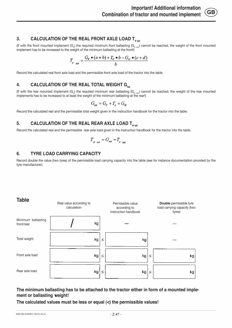
0000-GB ZUSINFO / BA-EL ALLG.
GB
- Z.47 -
3. CALCULATION OF THE REAL FRONT AXLE LOAD TV tat(If with the front mounted implement (GV) the required minimum front ballasting (GV min) cannot be reached, the weight of the front mounted implement has to be increased to the weight of the minimum ballasting at the front!)
Record the calculated real front axle load and the permissible front axle load of the tractor into the table.
4. CALCULATION OF THE REAL TOTAL WEIGHT Gtat(If with the rear mounted implement (GH) the required minimum rear ballasting (GH min) cannot be reached, the weight of the rear mounted implements has to be increased to at least the weight of the minimum ballasting at the rear!)
Record the calculated real and the permissible total weight given in the instruction handbook for the tractor into the table.
5. CALCULATION OF THE REAL REAR AXLE LOAD TH tat Record the calculated real and the permissible rear axle load given in the instruction handbook for the tractor into the table.
6. TYRE LOAD CARRYING CAPACITYRecord double the value (two tyres) of the permissible load carrying capacity into the table (see for instance documentation provided by the tyre manufacturer).
Minimum ballasting front/rear
Total weight
Front axle load
Rear axle load
Real value according to calculation
Permissible value according to
instruction handbook
Double permissible tyre load carrying capacity (two
tyres)
The minimum ballasting has to be attached to the tractor either in form of a mounted imple-ment or ballasting weight!The calculated values must be less or equal (<) the permissible values!
Table
Important! Additional informationCombination of tractor and mounted implement

Grieskirchen, 09.03.2006
Plough SERVO 25 SERVO 25 NOVA
pa. Ing. H. MenzlEntwicklungsleitung
ALOIS PÖTTINGER Maschinenfabrik Gesellschaft m.b.H.
A-4710 Grieskirchen; Industriegelände 1
0600
GB
-EG
Kon
form
itäts
erkl
ärun
g
EC Certificate of Conformityconforming to EEC Directions 98/37/EG
We ______________________________________________________________________������������������
__________________________________________________________________________________����������������������������������������������������������������������������������������������������������������������������������������
declare in sole responsibility, that the product
__________________________________________________________________________�������������
to which this certificate applies, conforms to the basic safety and health requirements of EEC Directions 98/37,���������������
and to the other relevant EEC Directions.
__________________________________________________________________________�������������������������������������������������������������������
���������������
To effect correct application of the safety and health requirements stated in the EEC Directions, the following standards and/or technical specifications were consulted:
__________________________________________________________________________�������������������������������������������������������������������������
Appendix 1
____________________________ ____________________________________ �������������������������� ��������������������������������������������
GB
EN ISO 12100-1 EN ISO 12100-2

Following the policy of the PÖTTINGER Ges.m.b.H to improve their products as tech-nical developments continue, PÖTTINGER
reserve the right to make alterations which must not necessarily correspond to text and illustrations contai-ned in this publication, and without incurring obligation to alter any machines previously delivered. Technical data, dimensions and weights are given as an indication only. Responsibility for errors or omissions not accepted. Reproduction or translation of this publication, in whole or part, is not permitted without the written consent of the ALOIS PÖTTINGER Maschinenfabrik Gesellschaft m.b.H. A-4710 Grieskirchen. All rights under the provision of the Copyright Act are reserved.
La société PÖTTINGER Ges.m.b.H améliore constamment ses produits grâce au progrès technique. C'est pourquoi nous nous réser-
vons le droit de modifier descriptions et illustrations de cette notice d'utilisation, sans qu'on en puisse faire découler un droit à modifications sur des machines déjà livrées. Caractéristiques techniques, dimensions et poids sont sans engagement. Des erreurs sont possibles. Copie ou traduction, même d'extraits, seulement avec la permission écrite deALOIS PÖTTINGER Maschinenfabrik Gesellschaft m.b.H. A-4710 Grieskirchen.Tous droits réservés selon la réglementation des droits d'auteurs.
La PÖTTINGER Ges.m.b.H è costantemente al lavoro per migliorare i suoi prodotti man-tenendoli aggiornati rispetto allo sviluppo
della tecnica.Per questo motivo siamo costretti a riservarci la facoltà di apportare eventuali modifiche alle illustrazioni e alle descrizioni di queste istruzioni per l’uso. Allo stesso tempo ciò non comporta il diritto di fare apportare modifiche a macchine già fornite.I dati tecnici, le misure e i pesi non sono impegnativi. Non rispondiamo di eventuali errori. Ristampa o tra-duzione, anche solo parziale, solo dietro consenso scritto dellaALOIS PÖTTINGER Maschinenfabrik Gesellschaft m.b.H.A-4710 Grieskirchen.Ci riserviamo tutti i diritti previsti dalla legge sul diritto d’autore.
Beroende på den tekniska utvecklingen arbe-tar PÖTTINGER Ges.m.b.H. på att förbättra sina produkter.
Vi måste därför förbehålla oss förändringar gentemot avbildningarna och beskrivningarna i denna bruksanvis-ning. Däremot består det inget anspråk på förändringar av produkter beroende av denna bruksanvisning.Tekniska uppgifter, mått och vikter är oförbindliga. Fel förbehållna.Ett eftertryck och översättningar, även utdrag, får endast genomföras med skriftlig tillåtelse avALOIS PÖTTINGERMaschinenfabrik Gesellschaft m.b.H.A – 4710 GrieskirchenAlla rättigheter enligt lagen om upphovsmannarätten förbehålls.
Im Zuge der technischen Weiterentwicklung arbeitet die PÖTTINGER Ges.m.b.H ständig an der Verbesserung ihrer Produkte.
Änderungen gegenüber den Abbildungen und Be-schreibungen dieser Betriebsanleitung müssen wir uns darum vorbehalten, ein Anspruch auf Änderungen an bereits ausgelieferten Maschinen kann daraus nicht abgeleitet werden. Technische Angaben, Maße und Gewichte sind unver-bindlich. Irrtümer vorbehalten. Nachdruck oder Übersetzung, auch auszugsweise, nur mit schriftlicher Genehmigung der ALOIS PÖTTINGER Maschinenfabrik Gesellschaft m.b.H. A-4710 Grieskirchen.Alle Rechte nach dem Gesetz des Urheberrecht vorbehalten.
PÖTTINGER Ges.m.b.H werkt permanent aan de verbetering van hun producten in het kader van hun technische ontwikkelingen.
Daarom moeten wij ons veranderingen van de afbeel-dingen en beschrijvingen van deze gebruiksaanwijzing voorbehouden, zonder dat daaruit een aanspraak op veranderingen van reeds geieverde machines kan worden afgeleid. Technische gegevens, maten en gewichten zijn niet bindend. Vergissingen voorbehouden. Nadruk of vertaling, ook gedeeltelijk, slechts met schriftelijke toestemming vanALOIS PÖTTINGER Maschinenfabrik Gesellschaft m.b.H. A-4710 Grieskirchen.Alle rechten naar de wet over het auteursrecht voor-behouden.
La empresa PÖTTINGER Ges.m.b.H se esfuerza contínuamente en la mejora con-stante de sus productos, adaptándolos a
la evolución técnica. Por ello nos vemos obligados a reservarnos todos los derechos de cualquier modifica-ción de los productos con relación a las ilustraciones y a los textos del presente manual, sin que por ello pueda ser deducido derecho alguno a la modificación de máquinas ya suministradas. Los datos técnicos, las medidas y los pesos se enti-enden sin compromiso alguno. La reproducción o la traducción del presente manual de instrucciones, aunque sea tan solo parcial, requiere de la autorización por escrito deALOIS PÖTTINGER Maschinenfabrik Gesellschaft m.b.H. A-4710 Grieskirchen.Todos los derechos están protegidos por la ley de la propiedad industrial.
D
NL
E
F
S
I
A empresa PÖTTINGER Ges.m.b.H esfor-ça-se continuamente por melhorar os seus produtos, adaptando-os à evolução técnica.
Por este motivo, reservamo-nos o direito de modificar as figuras e as descrições constantes no presente manual, sem incorrer na obrigação de modificar má-quinas já fornecidas.As características técnicas, as dimensões e os pesos não são vinculativos.A reprodução ou a tradução do presente manual de instruções, seja ela total ou parcial, requer a autori-zação por escrito daALOIS PÖTTINGERMaschinenfabrik Gesellschaft m.b.H.A-4710 GrieskirchenTodos os direitos estão protegidos pela lei da prop-riedade intelectual.
GB
P
Som led i den tekniske videreudvikling arbe-jder PÖTTINGER Ges.m.b.H hele tiden på at forbedre firmaets produkter.
Ret til ændringer i forhold til figurerne og beskrivelser-ne i denne driftsvejledning forbeholdes, krav om ændringer på allerede leverede maskinen kan ikke udledes deraf.Tekniske angivelser, mål og vægtangivelser er uforp-ligtende.Der tages forbehold for fejl.Kopiering eller oversættelse, også delvis, kun med skriftlig tilladelse fra ALOIS PÖTTINGERMaschinenfabrik Gesellschaft m.b.H.A-4710 Grieskirchen.Alle rettigheder forbeholdes iht. loven om ophavsret.
DK
Beroende på den tekniska utvecklingen arbetar PÖTTINGER Ges.m.b.H. på att förbättra sina produkter.
Vi måste därför förbehålla oss förändringar gentemot avbildningarna och beskrivningarna i denna bruk-sanvisning.Däremot består det inget anspråk på förändringar av produkter beroende av denna bruksanvisning.Tekniska uppgifter, mått och vikter är oförbindliga.Fel förbehållna.Ett eftertryck och översättningar, även utdrag, får endast genomföras med skriftlig tillåtelse avALOIS PÖTTINGERMaschinenfabrik Gesellschaft m.b.H.A – 4710 GrieskirchenAlla rättigheter enligt lagen om upphovsmannarätten förbehålls.
FIN NSom et ledd i den tekniske videreutviklingen arbeider PÖTTINGER Ges.m.b.H. stadig med forbedring av firmaets produkter.
Derfor tar vi forbehold om endringer i forhold til bilde-ne og beskrivelsene i denne bruksanvisningen, krav om endringer på allerede leverte maskiner kan ikke utledes fra dette. Tekniske angivelser, mål og vekt er veiledende. Med forbehold om feil.Kopiering eller oversetting, også i utdrag, utelukkende med skriftlig tillatelse fraALOIS PÖTTINGER Maschinenfabrik Gesellschaft m.b.H. A-4710 Grieskirchen.Med forbehold om alle rettigheter iht. loven om opp-havsrett.

GEBR. PÖTTINGER GMBHServicezentrumSpöttinger-Straße 24Postfach 1561D-86 899 LANDSBERG / LECHTelefon: Ersatzteildienst: 0 81 91 / 92 99 - 166 od. 169
Kundendienst: 0 81 91 / 92 99 - 130 od. 231
Telefax: 0 81 91 / 59 656
ALOIS PÖTTINGER Maschinenfabrik Gesellschaft m.b.HA-4710 GrieskirchenTelefon: 0043 (0) 72 48 600-0
Telefax: 0043 (0) 72 48 600-511
e-Mail: [email protected]: http://www.poettinger.co.at
GEBR. PÖTTINGER GMBHStützpunkt NordSteinbecker Strasse 15D-49509 ReckeTelefon: (0 54 53) 91 14 - 0Telefax: (0 54 53) 91 14 - 14
PÖTTINGER France129 b, la ChapelleF-68650 Le BonhommeTél.: 03.89.47.28.30
Fax: 03.89.47.28.39