ac servo drive - LS Electric
252
The Best Choice for the Most Benefit! LS ELECTRIC always tries its best to bring the greatest benefit to its customers. AC SERVO DRIVE Xmotion Read all safety precautions before using this product. After reading this manual, store it in a readily accessible location for future reference. Safety Precautions L7SB Series(400V) User Manual
-
Upload
khangminh22 -
Category
Documents
-
view
6 -
download
0
Transcript of ac servo drive - LS Electric

The Best Choice for the Most Benefit! LS ELECTRIC always tries its best to bring the greatest benefit to its customers.
AC SERVO DRIVE
Xmotion
Read all safety precautions before using this product.
After reading this manual, store it in a readily accessible location for future reference.
Safety Precautions
L7SB Series(400V) User Manual


Introduction
iii
Introduction
Hello. Thank you for choosing LS ELECTRIC L7 Series.
This user manual describes how to use this product safely and efficiently.
Failure to comply with the guidelines outlined in this manual may cause personal injury or damage to the product. Be sure to read this manual carefully before using this product and follow all guidelines contained therein.
The contents of this manual are subject to change without notice.
The reproduction of part or all of the contents of this manual in any form, by any means or for any purpose is strictly prohibited without the explicit written consent of LS ELECTRIC.
LS ELECTRIC retains all patents, trademarks, copyrights and other intellectual property rights to the material in this manual. The information contained in this manual is only intended for use with LS ELECTRIC products.
Safety precautions are categorized as either Warnings or Cautions, depending on the severity of the precaution.
Precautions Definition
Danger Failure to comply with these guidelines may cause serious injury or death.
Caution Failure to comply with these guidelines may cause personal injury or property damage.
Precautions listed as Cautions may also result in serious injury .
Electric Safety Precautions
Danger Before wiring or inspection tasks, turn off the power. Wait 15 minutes until the charge lamp
goes off, and then check the voltage. Ground both the servo drive and the servo motor. Only specially trained technicians may perform wiring on this product. Install both the servo drive and servo motor before performing any wiring. Do not operate the device with wet hands. Do not open the servo drive cover during operation. Do not operate the device with the servo drive cover removed. Even if the power is off, do not remove the servo drive cover.
Fire Safety Precautions
Caution Install the servo drive, the servo motor, and the regenerative resistor on non-combustible
materials. Disconnect the input power if the servo drive malfunctions.

Introduction
iv
Installation Precautions
Store and operate this product under the following environmental conditions.
Environment Conditions
Servo drive Servo motor Operating
temp. 0 ~ 50 0 ~ 40
Storage temp. -20 ~ 65 -10 ~ 60
Operating humidity
Below 90% RH (no condensation) 20~80% RH(no condensation)
Storage humidity 20~80% RH(no condensation)
Altitude 1000 m or lower
Spacing
When installing 1 unit: More than 40 mm at the top and
bottom of the control panel More than 10 mm on the left and right
sides of the control panel When installing 2 or more units: More than 100 mm at the top of the
control panel More than 40 mm at the bottom of the
control panel More than 30 mm on the left and right
sides of the control panel More than 2 mm between units Refer to Section 2.2.2, "Wiring the
Control Panel."
Other
Ensure the installation location is free from dust, iron, corrosive gas, and combustible gas.
Ensure the installation location is free from vibrations or the potential for hard impacts.
Caution Install the product with the correct orientation. Do not drop the product or expose it to hard impact. Install this product in a location that is free from water, corrosive gas, combustible gas, or
flammable materials. Install this product in a location capable of supporting the weight of this product. Do not stand on the product or place heavy objects on top of it. Always maintain the specified spacing when installing the servo drive. Ensure that there are no conductive or flammable debris inside the servo drive or the servo
motor. Firmly attach the servo motor to the machine. Install the servo motor with a correctly oriented decelerator. Do not touch the rotating unit of the servo motor during operation. Do not apply excessive force when connecting the couplings to the servo motor shaft. Do not place loads on the servo motor shaft that exceed the specified amount.

Introduction
v
Wiring Precautions
Caution Always use an AC 380-480 V power input for the servo drive. Always connect the servo drive to a ground terminal. Do not connect commercial power directly to the servo motor. Do not connect commercial power directly to the U, V, W output terminals of the servo drive. Connect the U, V, W output terminals of the servo drive directly to the U, V, W input terminals of
the servo motor, but do not install magnetic contactors between the wires. Always use pressurized terminals with insulation tubes when connecting the servo drive power
terminal. When wiring, be sure to separate the U, V, and W cables for the servo motor power and
encoder cable. Always use the robot cable if the motor moves. Before you perform power line wiring, turn off the input power of the servo drive, and then wait
until the charge lamp goes off completely. Be sure to use shielded twisted-pair wire for the pulse command signal (PF+, PF-, PR+, PR-),
speed command signal (SPDCOM), and torque command signal (TRQCOM). Use N terminals to connect the external capacitor. The product may burn if a commercial power
supply is connected to N terminals. Always contact the customer center or agency when it is necessary to connect the external capacitor.
Startup Precautions
Caution Check the input voltage (AC 380-480 V) and power unit wiring before supplying power to the
device. The servo must be in the OFF mode when you turn on the power. Before you turn on the power, check the motor's ID and the encoder pulse for L7 B . Set the motor ID ([P0-00]) and the encoder pulse ([P0-02]) for L7 B A first after you turn
on the power. After you complete the above settings, set the drive mode for the servo drive that is connected
to the upper level controller in [P0-03]. Refer to Chapter 1.2 "System Configuration" to perform CN1 wiring for the servo drive
according to each drive mode. You can check the ON/OFF state for each input terminal of CN1 at [St-14].
Handling and Operating Precautions
Caution Check and adjust each parameter before operation. Do not touch the rotating unit of the motor during operation. Do not touch the heat sink during operation. Be sure to attach or remove the CN1 and CN2 connectors when the power is off. Extreme change of parameters may cause system instability.

Introduction
vi
Usage Precautions
Caution Install an emergency cut-off switch which immediately stops operation in an emergency. Reset the alarm when the servo is off. Be warned that the system restarts immediately if the
alarm is reset while the servo is on. Use a noise filter or DC reactor to minimize electromagnetic interference. This prevents nearby
electrical devices from malfunctioning due to interference. Only use approved servo drive and servo motor combinations. The electric brake on the servo motor stops operation. Do not use it for ordinary braking. The electric brake may malfunction if the brake degrades or if the mechanical structure is
improper (for example, if the ball screw and servo motor are combined via the timing belt). Install an emergency stop device to ensure mechanical safety.
Malfunction Precautions
Caution Install a servo motor with an electric brake or separate the brake system for use during
emergencies or device malfunctions. If an alarm occurs, solve the underlying cause of the problem. After solving the problem and
ensuring safe operation, deactivate the alarm and resume operation. Do not approach the machine until the problem is solved.
Repair/Inspection Precautions
Caution Before performing servicing tasks, turn off the power. Wait 15 minutes until the charge lamp
goes off, and then check the voltage. Enough voltage may remain in the condenser after the power is off to cause an electric shock.
Only authorized personnel may repair and inspect the device or replace its parts. Do not modify this device in any way.
General Precautions
Caution This user manual is subject to change due to product modification or changes in standards. If
such changes occur, we issue a new user manual with a new product number.
Product Application
Caution This product is not designed or manufactured for machines or systems intended to sustain
human life. This product is manufactured under strict quality control conditions. Nevertheless, install safety
devices if installing the device in a facility where product malfunctions may result in a major accident or a significant loss.

Introduction
vii
EEPROM Lifespan
Caution The EEPROM is rewritable up to 1 million times for the purpose of recording parameter settings
and other information. The servo drive may malfunction if the total number of the following tasks exceeds 1 million, depending on the lifespan of the EEPROM. EEPROM recording as a result of parameter changes EEPROM recording as a result of an alarm

Table of Contents
viii
Table of Contents
Introduction .................................................................................................................... iii
Table of Contents ......................................................................................................... viii
1. Product Components and Signals .................................................................... 1-1
1.1 Product Components ..................................................................................................... 1-1 1.1.1 Product Verification ........................................................................................ 1-1 1.1.2 Part Names .................................................................................................... 1-3
1.2 System Configuration .................................................................................................... 1-9 1.2.1 Overview ........................................................................................................ 1-9 1.2.2 Wiring Diagram of the Entire CN1 Connector ................................................1-11 1.2.3 Example of Location Drive Mode Wiring ....................................................... 1-12 1.2.4 Example of Speed Drive Mode Wiring .......................................................... 1-13 1.2.5 Example of Torque Drive Mode Wiring ......................................................... 1-14 1.2.6 Example of Speed/Location Drive Mode Wiring ............................................ 1-15 1.2.7 Example of Speed/Torque Drive Mode Wiring .............................................. 1-16 1.2.8 Example of Location/Torque Drive Mode Wiring ........................................... 1-17
1.3 Signals ........................................................................................................................ 1-18 1.3.1 Digital Input Contact Signal .......................................................................... 1-18 1.3.2 Analog Input Contact Signal ......................................................................... 1-19 1.3.3 Digital Output Contact Signal........................................................................ 1-19 1.3.4 Monitor Output Signal and Output Power ..................................................... 1-20 1.3.5 Pulse Train Input Signal................................................................................ 1-20 1.3.6 Encoder Output Signal ................................................................................. 1-21
2. Installation ........................................................................................................... 2-1
2.1 Servo motor ................................................................................................................... 2-1 2.1.1 Operating Environment................................................................................... 2-1 2.1.2 Preventing Impact .......................................................................................... 2-1 2.1.3 Motor Connection ........................................................................................... 2-1 2.1.4 The Load Device Connection ......................................................................... 2-2 2.1.5 Cable Installation ............................................................................................ 2-2
2.2 Servo drive .................................................................................................................... 2-3 2.2.1 Operating Environment................................................................................... 2-3 2.2.2 Wiring the Control Panel................................................................................. 2-4 2.2.3 Power Supply Wiring ...................................................................................... 2-5
3. Wiring .................................................................................................................. 3-6
3.1 Internal Diagram ............................................................................................................ 3-6 3.1.1 L7 Drive Block Diagram [L7SB010 - L7SB035] .......................................... 3-6 3.1.2 L7 Drive Block Diagram [L7SB050 - L7SB075] .......................................... 3-7 3.1.3 L7 Drive Block Diagram [L7SB150] .............................................................. 3-8
3.2 Power Supply Wiring ..................................................................................................... 3-9 3.2.1 L7 Drive Wiring Diagram [L7SB010 - L7SB035] ......................................... 3-9 3.2.2 L7 Drive Wiring Diagram [L7SB050 - L7SB075] ....................................... 3-10 3.2.3 L7 Drive Wiring Diagram [L7SB150] ........................................................... 3-10

Table of Contents
ix
3.2.4 Power Circuit Electrical Components............................................................ 3-12
3.3 Example of wiring with PLC ......................................................................................... 3-18 3.3.1 XGT PLC ...................................................................................................... 3-18
3.4 Timing Diagram ........................................................................................................... 3-25 3.4.1 Timing Diagram During Power Input ............................................................. 3-25 3.4.2 Timing Diagram During an Alarm Trigger ...................................................... 3-26
3.5 Wiring the Control Signals ........................................................................................... 3-27 3.5.1 The Contact Input Signal .............................................................................. 3-27 3.5.2 The Contact Output Signal ........................................................................... 3-28 3.5.3 Analog Input/Output Signals ......................................................................... 3-29 3.5.4 Pulse Train Input Signal ................................................................................ 3-30 3.5.5 Encoder Output Signal ................................................................................. 3-31
3.6 Quadrature Encoder Signaling Unit (CN2) Wiring ........................................................ 3-32 3.6.1 APCS-EAS Cable ....................................................................................... 3-32 3.6.2 APCS-EBS Cable ....................................................................................... 3-32
3.7 Connecting the Serial Encoder Signals (CN2) ............................................................. 3-33 3.7.1 APCS-ECS Cable....................................................................................... 3-33 3.7.2 APCS-EDS Cable....................................................................................... 3-34 3.7.3 APCS-EES Cable ....................................................................................... 3-34
3.8 Multi-turn Encoder Signaling Unit (CN2) Wiring ........................................................... 3-35 3.8.1 APCS-ECS1 Cable..................................................................................... 3-35 3.8.2 APCS-EDS1 Cable..................................................................................... 3-36 3.8.3 APCS-EES1 Cable ..................................................................................... 3-36
3.9 Transmission of Absolute Value Encoder Data ............................................................ 3-37 3.9.1 Transmission of Absolute Value Encoder Data ............................................. 3-37
4. Parameters .......................................................................................................... 4-1
4.1 How to Use the Loader .................................................................................................. 4-1 4.1.1 Name and Function of Each Part .................................................................... 4-1 4.1.2 Status Summary Display ................................................................................ 4-2 4.1.3 Parameter Handling ....................................................................................... 4-4 4.1.4 Data Display ................................................................................................... 4-8 4.1.5 External Input Contact Signal Display [St-14] ............................................... 4-10 4.1.6 External Input Signal and Logic Definition .................................................... 4-11 4.1.7 External Output Contact Signal Display [St-15] ............................................. 4-21 4.1.8 External Output Signal and Logic Definition ................................................. 4-22
4.2 Parameters .................................................................................................................. 4-28 4.2.1 Parameter System ........................................................................................ 4-28 4.2.2 Operation Status Display Parameter............................................................. 4-29 4.2.3 System Parameters ...................................................................................... 4-32 4.2.4 Control Setting Parameter ............................................................................ 4-36 4.2.5 Input/Output Setting Parameter .................................................................... 4-39 4.2.6 Speed Operation Setting Parameter ............................................................. 4-42 4.2.7 Position Operation Setting Parameter .......................................................... 4-44 4.2.8 Operation Handling Parameter ..................................................................... 4-47
4.3 Operation Status Display ............................................................................................. 4-51 4.3.1 Status Display [St-00] ................................................................................... 4-51

Table of Contents
x
4.3.2 Speed Display .............................................................................................. 4-51 4.3.3 Position Display ............................................................................................ 4-51 4.3.4 Torque and Load Display .............................................................................. 4-51 4.3.5 I/O Status Display ......................................................................................... 4-52 4.3.6 Miscellaneous Status and Data Display ........................................................ 4-52 4.3.7 Version Display............................................................................................. 4-53
4.4 Parameter Setting ....................................................................................................... 4-54 4.4.1 Setting System Parameters .......................................................................... 4-54 4.4.2 Control Parameters ...................................................................................... 4-57 4.4.3 Analog Input/Output Parameter Setting ........................................................ 4-62 4.4.4 Setting the Input/Output Contact Point Parameters ...................................... 4-63 4.4.5 Setting Speed Operation Parameters ........................................................... 4-65 4.4.6 Position Operation Parameter Setting .......................................................... 4-66
4.5 Alarms and Warnings .................................................................................................. 4-68 4.5.1 Servo Alarm Status Summary Display List .................................................... 4-68 4.5.2 Servo Warning Status Summary Display List ................................................ 4-70
4.6 Motor Types and IDs ................................................................................................... 4-71
5. Handling and Operation ..................................................................................... 5-1
5.1 Operation Checklist ....................................................................................................... 5-1 5.1.1 Wiring Checklist.............................................................................................. 5-1 5.1.2 the Drive Signal (CN1) Wiring Checklist ......................................................... 5-1 5.1.3 Surrounding Environment Checklist ............................................................... 5-1 5.1.4 Machine Status Checklist ............................................................................... 5-1 5.1.5 System Parameter Checklist .......................................................................... 5-2
5.2 Handling ........................................................................................................................ 5-3 5.2.1 Manual JOG Operation [Cn-00] ...................................................................... 5-3 5.2.2 Program JOG Operation [Cn-01] .................................................................... 5-4 5.2.3 Alarm Reset [Cn-02] ....................................................................................... 5-5 5.2.4 Reading Alarm History [Cn-03] ....................................................................... 5-6 5.2.5 Alarm History Reset [Cn-04] ........................................................................... 5-7 5.2.6 Auto Gain Tuning [Cn-05] ............................................................................... 5-8 5.2.7 Phase Z Search Operation [Cn-06] ................................................................ 5-9 5.2.8 Input Contact Forced ON/OFF [Cn-07] ......................................................... 5-10 5.2.9 Output Contact Forced ON/OFF [Cn-08] ...................................................... 5-12 5.2.10 Parameter Reset [Cn-09] .............................................................................. 5-13 5.2.11 Automatic Speed Command Offset Correction [Cn-10]................................. 5-14 5.2.12 Automatic Torque Command Offset Correction [Cn-11] ................................ 5-15 5.2.13 Manual Speed Command Offset Correction [Cn-12] ..................................... 5-16 5.2.14 Manual Torque Command Offset Correction [Cn-13] .................................... 5-17 5.2.15 Absolute Encoder Value Reset [Cn-14] ........................................................ 5-18 5.2.16 Instantaneous Maximum Load Factor Initialization [Cn-15] .......................... 5-19 5.2.17 Parameter Lock [Cn-16] ............................................................................... 5-20 5.2.18 Current Offset [Cn-17] .................................................................................. 5-21
6. Communication Protocol ................................................................................... 6-1
6.1 Overview and Communication Specifications ................................................................ 6-1 6.1.1 Overview ........................................................................................................ 6-1 6.1.2 Communication Specifications and Cable Access Rate .................................. 6-2

Table of Contents
xi
6.2 Communication Protocol Base Structure ....................................................................... 6-3 6.2.1 Sending/Receiving Packet Structure .............................................................. 6-3 6.2.2 Protocol Command Codes ............................................................................. 6-5
6.3 L7 Servo Drive Communication Address Table ............................................................ 6-10 6.3.1 Operation Status Parameter Communication Address Table ........................ 6-10 6.3.2 System Parameter Communication Address Table ....................................... 6-12 6.3.3 Control Parameter Communication Address Table ....................................... 6-14 6.3.4 Input/Output Parameter Communication Address Table ............................... 6-16 6.3.5 Speed Operation Parameter Communication Address Table ........................ 6-17 6.3.6 Position Operation Parameter Communication Address Table ...................... 6-18
7. Product Specifications ...................................................................................... 7-1
7.1 Servo motor ................................................................................................................... 7-1 7.1.1 Product Features ............................................................................................ 7-1 7.1.2 Outline Diagram ........................................................................................... 7-22
7.2 Servo drive .................................................................................................................. 7-29 7.2.1 Product Features .......................................................................................... 7-29 7.2.2 Outline Diagram .................................................................................................. 7-31
7.3 Options and Peripheral Devices .................................................................................. 7-34
8. Maintenance and Inspection ............................................................................. 8-1
8.1 Maintenance and Inspection .......................................................................................... 8-1 8.1.1 Precautions .................................................................................................... 8-1 8.1.2 What to Inspect .............................................................................................. 8-1 8.1.3 Replacing Parts .............................................................................................. 8-3
8.2 Diagnosing and Troubleshooting Abnormalities ............................................................. 8-3 8.2.1 Servo motor .................................................................................................... 8-4 8.2.2 Servo Drive .................................................................................................... 8-5
9. Appendix ............................................................................................................. 9-1
9.1 Motor Types and IDs ..................................................................................................... 9-1
9.2 Test Drive Procedure ..................................................................................................... 9-3
User Manual Revision History ....................................................................................... A


1. Product Components and Signals
1-1
1. Product Components and Signals
1.1 Product Components
1.1.1 Product Verification
1. Check the name tag to verify that the product received matches the model ordered
Does the servo drive's name plate match?
Does the servo motor's name plate match?
2. Check the product components and options.
Are the type and length of cables correct?
Does the regenerative resistor conform to the required standard?
Is the shape of the shaft correct?
Are there any abnormalities after mounting the oil seal or brake?
Are the gearbox and the gear ratios correct?
Is the encoder format correct?
3. Check the exterior of the device.
Are there any foreign substances or humidity in the device?
Is there any discoloration, contaminant, damage or disconnected wire?
Are the bolts tightly fastened to the joints?
Is there any abnormal sound or excessive friction during operation?
The Servo Drive Product Format
Series Name Communication
Type Input voltage Capacity Encoder Type Option
L7 Series S: Standard I/O type
B: 400 VAC
010: 1.0kW 020: 2.0kW 035: 3.5kW 050: 5.0kW 075: 7.5kW 150: 15.0kW
B: Serial only (communication type)
Exclusive Option
L7 S B 010 B AA

1. Product Components and Signals
1-2
Servo Motor Product Format
APM – S E P 22 A E K 1
Servo Motor
Motor Shape
Classification
S : Solid axis
F : Flat Type
Flange Size
E : 130 Flange
F : 180 Flange
G : 220 Flange
H : 250 Flange
J : 280 Flange
Input voltage
P : 400 Vac
Motor capacity
03 : 300W
05 : 450W
06 : 600W
09 : 850/900W
11 : 1.1kW
12 : 1.2kW
.
.
.
110 : 11kW
150 : 15kW
220 : 22kW
300 : 30kW
370 : 37kW
Shaft cross-section
N: Straight
K: One-sided round
key (standard)
H: Hollow Shaft
Rated RPM
A: 3000 RPM
D: 2000 RPM
G: 1500 RPM
M: 1000 RPM
Encoder type
Serial BISS
(communication type)
N: 19bit S-Turn Abs.
M: 19-bit M-Turn Abs.
Oil Seal and Brake
Non-existent: Not attached
1: Oil Seal attached
2: Brake attached
3: Oil Seal and Brake attached

1. Product Components and Signals
1-3
1.1.2 Part Names
Servo motor
80 Flange or below
80 Flange or below (Flat type)
130 Flange or higher
Shaft
Flange Frame Mold Housing Encoder Cover
Power Connector Encoder Connector
Bearing Cap
Power Connector
Power Cable
Encoder Connector
Encoder Cable
Encoder Cover
Housing Frame Flange Shaft
Bearing Cap
Shaft
Flange Frame Housing
Encoder Cover
Power Connector
Encoder Connector
1. Product Components and Signals
1-4
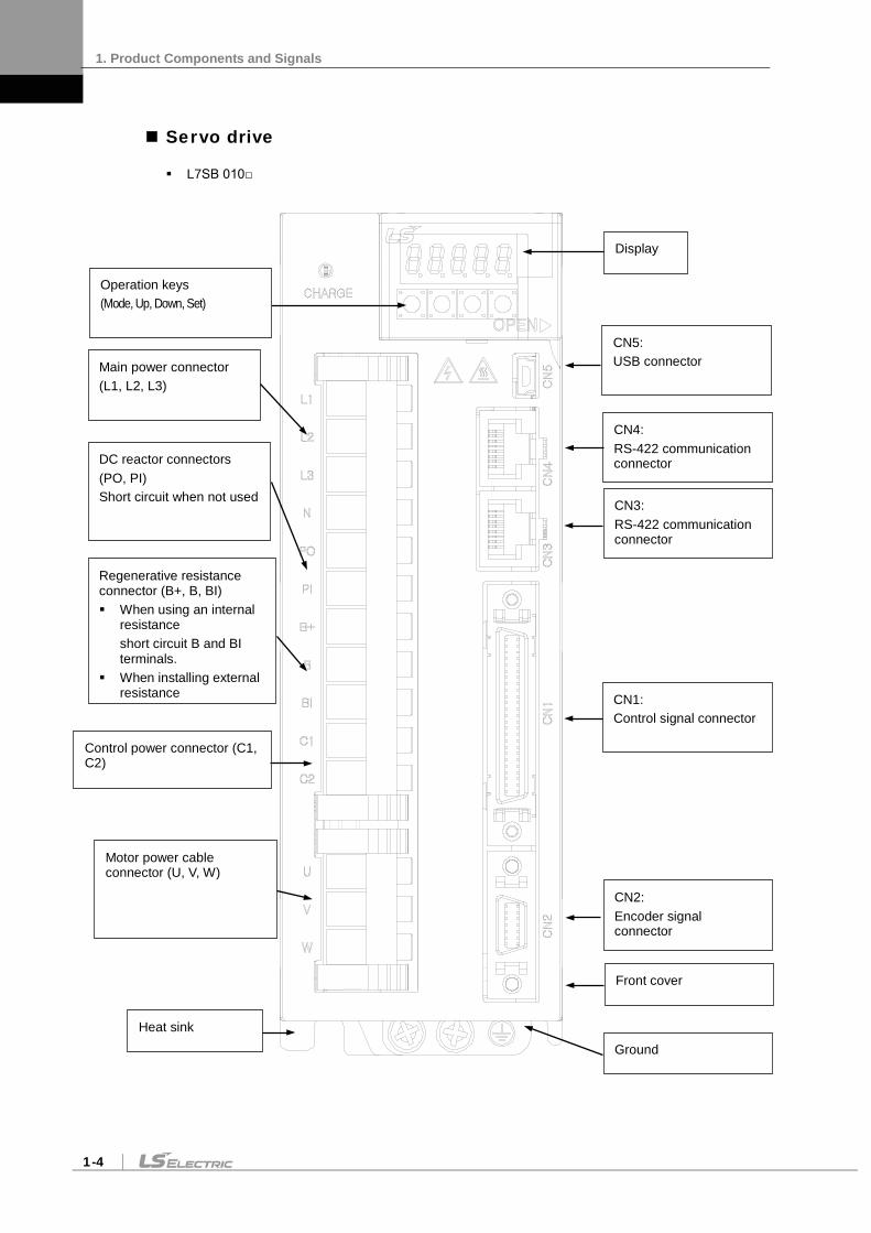
Servo drive
L7SB 010
CN3: RS-422 communication connector
CN2: Encoder signal connector
CN1: Control signal connector
Display
Front cover
CN5: USB connector
CN4: RS-422 communication connector
Main power connector (L1, L2, L3)
Motor power cable connector (U, V, W)
Heat sink
Control power connector (C1, C2)
Ground
Operation keys (Mode, Up, Down, Set)
DC reactor connectors (PO, PI) Short circuit when not used
Regenerative resistance connector (B+, B, BI) When using an internal
resistance short circuit B and BI terminals.
When installing external resistance

1. Product Components and Signals
1-5
L7SB 020 / L7SB 035
CN3: RS-422 communication connector
CN2: Encoder signal connector
CN1: Control signal connector
Display
Front cover
CN5: USB connector
CN4: RS-422 communication connector
Main power connector (L1, L2, L3)
Motor power cable connector (U, V, W)
Heat sink
Control power connector (C1, C2)
DC reactor connectors (PO, PI) Short circuit when not used
Regenerative resistance connector (B+, B, BI) When using an internal
resistance short circuit B and BI terminals.
When installing external resistance install in the B+ and B terminals.
Operation keys (Mode, Up, Down, Set)
Ground

1. Product Components and Signals
1-6
L7SB 050
CN2: Encoder signal connector
CN1: Control signal connector
Display
Front cover
CN5: USB connector
CN4: RS-422 communication connector
Main power connector (L1, L2, L3)
Control power connector (C1, C2)
DC reactor connector (PO, PI) Short circuit when not used
Operation keys (Mode, Up, Down, Set)
CN3: RS-422 communication connector
* DO NOT connect (N)
Motor power cable connector (U, V, W)
Regenerative resistance connector (B+, B) When using an internal resistance: short circuit B+
and B terminals. When installing external resistance, attach the wiring
of internal resistance to mounting hole "NC" for internal resistance of the case. Then, connect external resistance to B+ and B terminals.
Ground

1. Product Components and Signals
1-7
L7SB 075
CN2: Encoder signal connector
CN1: Control signal connector
Display
Front cover
CN5: USB connector
CN4: RS-422 communication connector
Main power connector (L1, L2, L3)
Motor power cable connector (U, V, W)
Heat sink
Control power connector (C1, C2)
DC reactor connector (PO, PI) Short circuit when not used
Regenerative resistance connector (B+, B) When using an internal resistance: short circuit B+
and B terminals. When installing external resistance, attach the wiring
of internal resistance to mounting hole "NC" for internal resistance of the case. Then, connect external resistance to B+ and B terminals.
Operation keys (Mode, Up, Down, Set)
Ground
CN3: RS-422 communication connector
NC
* DO NOT connect (N)

1. Product Components and Signals
1-8
L7SB 150
Control power connector (C1, C2)
CN2: Encoder signal connector
CN1: Control signal connector
Display
CN5: USB connector
CN4: RS-422 communication connector
CN3: RS-422 communication connector
Main power connector (L1, L2, L3) Motor power cable connector (U,
V, W)
Operation keys (Mode, Up, Down, Set)
Ground
DC reactor connector (PO, PI)
Regenerative resistance connector (B+, B) Install external regenerative
resistance
* DO NOT connect (N)

1. Product Components and Signals
1-9
1.2 System Configuration
1.2.1 Overview
The L7 servo system can be configured in various ways depending on its interface with the upper level controller.
(1) Position Operation System
The servo is run by pulse commands. You can change the location of the servo motor by changing command pulses based on a certain transfer unit.
Position Controller
Speed Controller
Position Command
Pulse Conversion
Position Controller
Speed Controller
Current Controller
Pulse CommandUpper Level Controller Servo Drive Servo Motor
Motor
EncoderPosition Feedback
Advantages: The structure of the upper level controller is simple because pulse input is linked to transfer units.
Disadvantage:
Fast rotation is compromised when a precise transfer unit is used.
Response is low because multiple levels of controllers are used.
(2) Speed Operation System
The servo is run by speed commands. There are two types of speed commands: analog voltage command and digital speed command.
Position Controller
Speed Controller
Speed Command Conversion
Speed Controller
Current Controller
Speed Command
Upper Level Controller Servo Drive Servo Motor
Motor
EncoderPosition Feedback
Advantages:
The servo responds quickly.
Precision control is easy.
Disadvantage: The upper level controller is complex.
1. Product Components and Signals
1-10
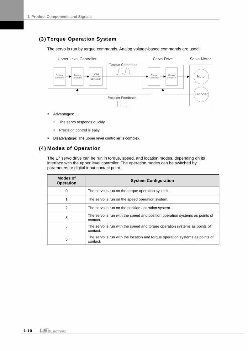
(3) Torque Operation System
The servo is run by torque commands. Analog voltage-based commands are used.
Position Controller
Torque Controller
Torque Command Conversion
Torque Controller
Current Controller
Torque Command
Upper Level Controller Servo Drive Servo Motor
Motor
EncoderPosition Feedback
Advantages:
The servo responds quickly.
Precision control is easy.
Disadvantage: The upper level controller is complex.
(4) Modes of Operation
The L7 servo drive can be run in torque, speed, and location modes, depending on its interface with the upper level controller. The operation modes can be switched by parameters or digital input contact point.
Modes of Operation System Configuration
0 The servo is run on the torque operation system.
1 The servo is run on the speed operation system.
2 The servo is run on the position operation system.
3 The servo is run with the speed and position operation systems as points of contact.
4 The servo is run with the speed and torque operation systems as points of contact.
5 The servo is run with the location and torque operation systems as points of contact.

1. Product Components and Signals
1-11
1.2.2 Wiring Diagram of the Entire CN1 Connector
STOP 48
EMG 18
CWLIM 19
CCWLIM 20
DIR 46
ALMRST 17
SPD3 21
SPD2 22
SPD1 23
SVON 47
ALARM+38
ALARM-39
READY+40
READY-41
ZSPD43
BRAKE44
INPOS45
50+24V IN
GND2424
ALO016
ALO115
ALO214
GND2425
SPDCOM 27
GND 8
TRQCOM 1
GND 8
Digital Input Digital Output
Command Pulse Input
Analog Input
DC 24V
3.3kΩ
Line Drive
Open Collector
CN1
-10V ~ +10V
Upper Level
Controller
-10V ~ +10V
Analog Speed Command/Limit
Analog Torque Command/Limit
Note 1)(DIA)
(DI9)
(DI8)
(DI7)
(DI6)
(DI5)
(DI4)
(DI3)
(DI2)
(DI1)
(DO1)
(DO2)
(DO3)
(DO4)
(DO5)
Note 1)
Note 1) The input signals (DI1 - DIA) and output signals (DO1 - DO5) are the factory default signals.Note 2) ** You can change the allocations for unallocated signals with the parameter settings.Refer to sections 4.1.6, "External Input Signals and Logic Definitions," and 4.1.8, "External Output Signals and Logic Definitions," for more information.
VLMT**
TLMT**
Note 2)
WARN**
INSPD**
EGEAR1 **
EGEAR2 **
PCON **
GAIN2 **
P_CLR **
T_LMT **
Note 2)
MODE **
ABS_RQ **
ZCLAMP ** MONIT128
MONIT229
GND37
AO32
/AO33
BO30
/BO31
ZO4
/ZO5
SG36
Analog Output
Encoder Pulse Output
Connect to the Connector Case
-10V ~ +10V
-10V ~ +10V
Upper Level
Controller
+12VA34
-12VA35
PULCOM 49
PF+ 9
PF- 10
PR+ 11
PR- 12

1. Product Components and Signals
1-12
1.2.3 Example of Location Drive Mode Wiring
STOP 48
EMG 18
CWLIM 19
CCWLIM 20
DIR 46
ALMRST 17
SPD3 21
SPD2 22
SPD1 23
SVON 47
ALARM+38
ALARM-39
READY+40
READY-41
ZSPD43
BRAKE44
INPOS45
50+24V IN
GND2424
MONIT128
MONIT229
GND37
AO32
/AO33
BO30
/BO31
ZO4
/ZO5
ALO016
ALO115
ALO214
GND2425
PULCOM 49
PF+ 9
PF- 10
PR+ 11
PR- 12
TRQCOM 1
GND 8
SG36
Digital Input Digital Output
Analog Output
Command Pulse Input
Encoder Pulse Output
Analog Input
Connect to the Connector Case
DC 24V
3.3kΩ
Line Drive
Open Collector
CN1
-10V ~ +10V
-10V ~ +10V
-10V ~ +10V
Upper Level
Controller
-10V ~ +10V
Analog Torque Limit
Upper Level
Controller
EGEAR1 **
EGEAR2 **
PCON **
GAIN2 **
P_CLR **
T_LMT **
VLMT**
TLMT**
주1)
Note 2)
Note 2)
(DIA)
(DI9)
(DI8)
(DI7)
(DI6)
(DI5)
(DI4)
(DI3)
(DI2)
(DI1)
(DO1)
(DO2)
(DO3)
(DO4)
(DO5)
Note 1)
Note 1) The input signals (DI1 - DIA) and output signals (DO1 - DO5) are the factory default signals.Note 2) ** You can change the allocations for unallocated signals with the parameter settings.Refer to sections 4.1.6, "External Input Signals and Logic Definitions," and 4.1.8, "External Output Signals and Logic Definitions," for more information.
MODE **
ABS_RQ **
ZCLAMP ** WARN**
INSPD**
+12VA34
-12VA35

1. Product Components and Signals
1-13
1.2.4 Example of Speed Drive Mode Wiring
STOP 48
EMG 18
CWLIM 19
CCWLIM 20
DIR 46
ALMRST 17
SPD3 21
SPD2 22
SPD1 23
SVON 47
ALARM+38
ALARM-39
READY+40
READY-41
ZSPD43
BRAKE44
INPOS45
50+24V IN
GND2424
ALO016
ALO115
ALO214
GND2425
SPDCOM 27
GND 8
TRQCOM 1
GND 8
Digital Input Digital Output
Command Pulse Input
Analog Input
DC 24V
3.3kΩ
Line Drive
Open Collector
CN1
-10V ~ +10V
-10V ~ +10V
Analog Speed Command
Analog Torque Limit
주1)(DIA)
(DI9)
(DI8)
(DI7)
(DI6)
(DI5)
(DI4)
(DI3)
(DI2)
(DI1)
(DO1)
(DO2)
(DO3)
(DO4)
(DO5)
Note 1)
Note 1) The input signals (DI1 - DIA) and output signals (DO1 - DO5) are the factory default signals.Note 2) ** You can change the allocations for unallocated signals with the parameter settings.Refer to sections 4.1.6, "External Input Signals and Logic Definitions," and 4.1.8, "External Output Signals and Logic Definitions," for more information.
VLMT**
TLMT**Note 2)
WARN**
INSPD**
EGEAR1 **
EGEAR2 **
PCON **
GAIN2 **
P_CLR **
T_LMT **
Note 2)
MODE **
ABS_RQ **
ZCLAMP ** MONIT128
MONIT229
GND37
AO32
/AO33
BO30
/BO31
ZO4
/ZO5
SG36
Analog Output
Encoder Pulse Output
Connect to the Connector Case
-10V ~ +10V
-10V ~ +10V
Upper Level
Controller
+12VA34
-12VA35

1. Product Components and Signals
1-14
1.2.5 Example of Torque Drive Mode Wiring
STOP 48
EMG 18
CWLIM 19
CCWLIM 20
DIR 46
ALMRST 17
SPD3 21
SPD2 22
SPD1 23
SVON 47
ALARM+38
ALARM-39
READY+40
READY-41
ZSPD43
BRAKE44
INPOS45
50+24V IN
GND2424
ALO016
ALO115
ALO214
GND2425
SPDCOM 27
GND 8
TRQCOM 1
GND 8
Digital Input Digital Output
Command Pulse Input
Analog Input
DC 24V
3.3kΩ
Line Drive
Open Collector
CN1
-10V ~ +10V
-10V ~ +10V
Analog Speed Limit
Analog Torque Command
주1)(DIA)
(DI9)
(DI8)
(DI7)
(DI6)
(DI5)
(DI4)
(DI3)
(DI2)
(DI1)
(DO1)
(DO2)
(DO3)
(DO4)
(DO5)
Note 1)
Note 1) The input signals (DI1 - DIA) and output signals (DO1 - DO5) are the factory default signals.Note 2) ** You can change the allocations for unallocated signals with the parameter settings.Refer to sections 4.1.6, "External Input Signals and Logic Definitions," and 4.1.8, "External Output Signals and Logic Definitions," for more information.
VLMT**
TLMT**
Note 2)
WARN**
INSPD**
EGEAR1 **
EGEAR2 **
PCON **
GAIN2 **
P_CLR **
T_LMT **
Note 2)
MODE **
ABS_RQ **
ZCLAMP **
MONIT128
MONIT229
GND37
AO32
/AO33
BO30
/BO31
ZO4
/ZO5
SG36
Analog Output
Encoder Pulse Output
Connect to the Connector Case
-10V ~ +10V
-10V ~ +10V
Upper Level
Controller
+12VA34
-12VA35

1. Product Components and Signals
1-15
1.2.6 Example of Speed/Location Drive Mode Wiring
STOP 48
EMG 18
CWLIM 19
CCWLIM 20
DIR 46
ALMRST 17
SPD3 21
SPD2 22
SPD1 23
SVON 47
ALARM+38
ALARM-39
READY+40
READY-41
ZSPD43
BRAKE44
INPOS45
50+24V IN
GND2424
ALO016
ALO115
ALO214
GND2425
PULCOM 49
PF+ 9
PF- 10
PR+ 11
PR- 12
SPDCOM 27
GND 8
TRQCOM 1
GND 8
Digital Input Digital Output
Command Pulse Input
Analog Input
DC 24V
3.3kΩ
Line Drive
Open Collector
CN1
-10V ~ +10V
Upper Level
Controller
-10V ~ +10V
Analog Speed Command
Analog Torque Limit
Note 1)(DIA)
(DI9)
(DI8)
(DI7)
(DI6)
(DI5)
(DI4)
(DI3)
(DI2)
(DI1)
(DO1)
(DO2)
(DO3)
(DO4)
(DO5)
Note 1)
Note 1) The input signals (DI1 - DIA) and output signals (DO1 - DO5) are the factory default signals.Note 2) ** You can change the allocations for unallocated signals with the parameter settings.Refer to sections 4.1.6, "External Input Signals and Logic Definitions," and 4.1.8, "External Output Signals and Logic Definitions," for more information.Note 3) Input Contact Mode = ON: Speed Control Mode, Mode = OFF: Position Operation Mode
VLMT**
TLMT**Note 2)
WARN**
INSPD**
EGEAR1 **
EGEAR2 **
PCON **
GAIN2 **
P_CLR **
T_LMT **
Note 2)
MODE **
ABS_RQ **
ZCLAMP **
MONIT128
MONIT229
GND37
AO32
/AO33
BO30
/BO31
ZO4
/ZO5
SG36
Analog Output
Encoder Pulse Output
Connect to the Connector Case
-10V ~ +10V
-10V ~ +10V
Upper Level
Controller
+12VA34
-12VA35
Note 3)

1. Product Components and Signals
1-16
1.2.7 Example of Speed/Torque Drive Mode Wiring
STOP 48
EMG 18
CWLIM 19
CCWLIM 20
DIR 46
ALMRST 17
SPD3 21
SPD2 22
SPD1 23
SVON 47
ALARM+38
ALARM-39
READY+40
READY-41
ZSPD43
BRAKE44
INPOS45
50+24V IN
GND2424
ALO016
ALO115
ALO214
GND2425
SPDCOM 27
GND 8
TRQCOM 1
GND 8
Digital Input Digital Output
Command Pulse Input
Analog Input
DC 24V
3.3kΩ
Line Drive
Open Collector
CN1
-10V ~ +10V
-10V ~ +10V
Analog Speed
Command/Limit
Analog Torque Limit/
Command
Note 1)(DIA)
(DI9)
(DI8)
(DI7)
(DI6)
(DI5)
(DI4)
(DI3)
(DI2)
(DI1)
(DO1)
(DO2)
(DO3)
(DO4)
(DO5)
Note 1)
Note 1) The input signals (DI1 - DIA) and output signals (DO1 - DO5) are the factory default signals.Note 2) ** You can change the allocations for unallocated signals with the parameter settings.Refer to sections 4.1.6, "External Input Signals and Logic Definitions," and 4.1.8, "External Output Signals and Logic Definitions," for more information.Note 3) Input Contact Mode = ON: Speed Control Mode, Mode = OFF: Torque Operation Mode
VLMT**
TLMT**
Note 2) WARN**
INSPD**
EGEAR1 **
EGEAR2 **
PCON **
GAIN2 **
P_CLR **
T_LMT **
Note 2)
MODE **
ABS_RQ **
ZCLAMP **
MONIT128
MONIT229
GND37
AO32
/AO33
BO30
/BO31
ZO4
/ZO5
SG36
Analog Output
Encoder Pulse Output
Connect to the Connector Case
-10V ~ +10V
-10V ~ +10V
Upper Level
Controller
+12VA34
-12VA35
Note 3)
1. Product Components and Signals
1-17
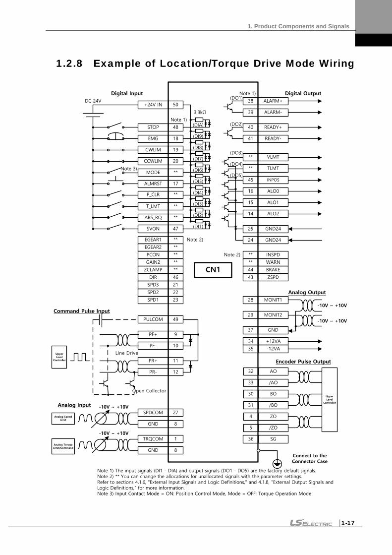
1.2.8 Example of Location/Torque Drive Mode Wiring
STOP 48
EMG 18
CWLIM 19
CCWLIM 20
DIR 46
ALMRST 17
SPD3 21
SPD2 22
SPD1 23
SVON 47
ALARM+38
ALARM-39
READY+40
READY-41
ZSPD43
BRAKE44
INPOS45
50+24V IN
GND2424
ALO016
ALO115
ALO214
GND2425
PULCOM 49
PF+ 9
PF- 10
PR+ 11
PR- 12
SPDCOM 27
GND 8
TRQCOM 1
GND 8
Digital Input Digital Output
Command Pulse Input
Analog Input
DC 24V
3.3kΩ
Line Drive
Open Collector
CN1
-10V ~ +10V
Upper Level
Controller
-10V ~ +10V
Analog Speed Limit
Analog Torque Limit/Command
Note 1)(DIA)
(DI9)
(DI8)
(DI7)
(DI6)
(DI5)
(DI4)
(DI3)
(DI2)
(DI1)
(DO1)
(DO2)
(DO3)
(DO4)
(DO5)
Note 1)
Note 1) The input signals (DI1 - DIA) and output signals (DO1 - DO5) are the factory default signals.Note 2) ** You can change the allocations for unallocated signals with the parameter settings.Refer to sections 4.1.6, "External Input Signals and Logic Definitions," and 4.1.8, "External Output Signals and Logic Definitions," for more information.Note 3) Input Contact Mode = ON: Position Control Mode, Mode = OFF: Torque Operation Mode
VLMT**
TLMT**
Note 2)
WARN**
INSPD**
EGEAR1 **
EGEAR2 **
PCON **
GAIN2 **
P_CLR **
T_LMT **
Note 2)
MODE **
ABS_RQ **
ZCLAMP **
MONIT128
MONIT229
GND37
AO32
/AO33
BO30
/BO31
ZO4
/ZO5
SG36
Analog Output
Encoder Pulse Output
Connect to the Connector Case
-10V ~ +10V
-10V ~ +10V
Upper Level
Controller
+12VA34
-12VA35
Note 3)

1. Product Components and Signals
1-18
1.3 Signals
1.3.1 Digital Input Contact Signal
Default pin
number name Details
Applicable Modes
Position Speed Torque Speed /Location
Speed /Torque
Position /Torque
50 +24 V IN Input contact +24 V power O O O O O O
47 SVON Servo ON O O O O O O
23 SPD1 Multi-speed 1 X O X O/X O/X X
22 SPD2 Multi-speed 2 X O X O/X O/X X
21 SPD3 Multi-speed 3 X O X O/X O/X X
17 ALMRST Reset upon alarm O O O O O O
46 DIR Select rotation direction O O O O O O
20 CCWLMT Counter-clockwise limit O O O O O O
19 CWLMT Clockwise limit O O O O O O
18 EMG Emergency stop O O O O O O
48 STOP Stop O O O O O O
assignment EGEAR1 Electronic gear ratio 1 O X X X/O X O/X
assignment EGEAR2 Electronic gear ratio 2 O X X X/O X O/X
assignment PCON P control action O O X O O/X O/X
assignment GAIN2 Select gain 2 O O X O O/X O/X
assignment P_CLR Input pulse clear O X X X/O X O/X
assignment T_LMT Control torque with TRQCOM O O O O O O
assignment MODE Change operation modes X X X O O O
assignment ABS_RQ Request absolute location data O O O O O O
assignment ZCLAMP Zero clamp X O X O/X O/X O

1. Product Components and Signals
1-19
1.3.2 Analog Input Contact Signal
Pin Number name Details
Applicable Modes
Position Speed Torque Speed /Location
Speed /Torque
Position /Torque
27 SPDCOM
Analog speed command (-10-+10 V)
X O X O/X O/X X
Analog Speed Limit (-10-+10 V)
X X O X X/O X/O
1 TRQCOM
Analog Torque Command (-10-+10 V)
X X O X X/O X/O
Analog torque limit (-10-+10 V) O O X O O/X O/X
8 37
GND Ground for analog signals O O O O O O
1.3.3 Digital Output Contact Signal
Default pin
number name Details
Applicable Modes
Position Speed Torque Speed
/Location Speed
/Torque Position /Torque
16 ALO0 Alarm group contact output 1 O O O O O O
15 ALO1 Alarm group contact output 2 O O O O O O
14 ALO2 Alarm group contact output 3 O O O O O O
38 / 39 ALARM +/- Alarm O O O O O O
40 / 41 READY +/- Ready for operation O O O O O O
43 ZSPD Zero speed reached O O O O O O
44 BRAKE Brake O O O O O O
45 INPOS Location reached O X X X/O X O/X
assignment TLMT Torque limit O O O O O O
assignment VLMT Speed limit O O O O O O
assignment INSPD Speed reached X O X O/X O/X X
assignment WARN Warning O O O O O O
24 25
GND24
Input/output contact Ground of drive power (24 V)
O O O O O O

1. Product Components and Signals
1-20
1.3.4 Monitor Output Signal and Output Power
Pin Number name Details
Applicable Modes
Position Speed Torque Speed /Location
Speed /Torque
Position /Torque
28 MONIT1 Analog monitor output 1 (-10-+10 V)
O O O O O O
29 MONIT2 Analog monitor output 2 (-10-+10 V)
O O O O O O
8 37
GND Ground for analog signals O O O O O O
34 +12V Terminal for +12 V power output O O O O O O
35 -12V Terminal for -12 V power output O O O O O O
1.3.5 Pulse Train Input Signal
Line Drive (5 V)
Pin Number name Details
Applicable Modes
Position Speed Torque Speed /Location
Speed /Torque
Position /Torque
9 PF+ F+ pulse input O X X X/O X O/X
10 PF- F- pulse input O X X X/O X O/X
11 PR+ R+ pulse input O X X X/O X O/X
12 PR- R- pulse input O X X X/O X O/X
49 PULCOM Not for use X X X X X X
Open Collector (24 V)
Pin Number name Details
Applicable Modes
Position Speed Torque Speed /Location
Speed /Torque
Position /Torque
9 PF+ Not for use X X X X X X
10 PF- F pulse input O X X X/O X O/X
11 PR+ Not for use X X X X X X
12 PR- R pulse input O X X X/O X O/X
49 PULCOM +24 V power input O X X X/O X O/X

1. Product Components and Signals
1-21
1.3.6 Encoder Output Signal
Pin Number name Details
Applicable Modes
Position Speed Torque Speed /Location
Speed /Torque
Position /Torque
32 33 30 31
AO /AO BO /BO
Outputs encoder signals received from the motor as signals pre-scaled according to the ratio defined by [P0-14]/[P0-15]. (5 V line drive method)
O O O O O O
4 5
ZO /ZO
Outputs encoder Z signals received from the motor. (5 V line drive method)
O O O O O O


2. Installation
2-1
2. Installation
2.1 Servo motor
2.1.1 Operating Environment
Item Requirements Notes
Ambient temperature 0 ∼ 40[]
Consult with our technical support team to customize the product if temperatures in the installation environment are outside this range.
Ambient humidity 80% RH or lower Do not operate this device in an environment with steam.
External vibration
Vibration acceleration 19.6 or below on
both the X and Y axis. Excessive vibrations reduce the lifespan of the bearings.
* Products in this manual have been passed the standards(EN 60034-1) for Industrial purpose(Class A), so they
are eligible to use in industrial environment.
2.1.2 Preventing Impact
Impact to the motor during installation or handling may damage the encoder.
2.1.3 Motor Connection
The motor might burn out if it is connected directly to commercial power. Always connect the motor via the specified drive.
Connect the ground terminals of the motor to either of the two ground terminals inside the drive, and attach the remaining terminal to the type-3 ground.
Connect the U, V, and W terminals of the motor in the same way as the U, V, and W terminals of the drive.
U – U V - V
W – W - F.G

2. Installation
2-2
Ensure that the pins on the motor connector are securely attached.
In order to protect against moisture or condensation in the motor, make sure that insulation resistance is 10 (500 V) or higher before installation.
2.1.4 The Load Device Connection
For coupling connections: Ensure that the motor shaft and load shaft are aligned within the tolerance range.
For pulley connections:
Flange Lateral Load Axial Load
Notes N kgf N kgf
40 148 15 39 4
60 206 21 69 7
80 255 26 98 10
130 725 74 362 37
180 1548 158 519 53
220 1850 189 781 90
2.1.5 Cable Installation
For vertical installations, make sure that no oil or water flows into the connecting parts.
Do not apply pressure to or damage the cables.
Use robot cables to prevent swaying when the motor moves.
Nr: 30 or below
Lateral load
Axial load
Load shaft
Motor shaft
0.03 or below (peak to peak)
0.03 or below (peak to peak)

2. Installation
2-3
2.2 Servo drive
2.2.1 Operating Environment
Item Environmental conditions Notes
Ambient temperature 0∼50[]
Caution Install a cooling fan on the control panel to maintain an appropriate temperature.
Ambient humidity 90% RH or lower
Caution Condensation or moisture may develop inside the drive during prolonged periods of inactivity and damage it. Remove all moisture before operating the drive after a prolonged period of inactivity.
External vibration
Vibration acceleration 4.9 or lower
Excessive vibration reduces the lifespan of the machine and may cause malfunctions.
Ambient conditions
Do not expose the device to direct sunlight. Do not expose the device to corrosive or combustible gases. Do not expose the device to oil or dust. Ensure that the device receives sufficient ventilation.

2. Installation
2-4
2.2.2 Wiring the Control Panel
Comply with the spacing specified in the following figures when installing the control panel.
Caution Ensure that during installation the heat from the external regenerative resistor does not affect
the drive. Ensure that the servo drive control panel is flat against the wall during installation. Ensure that the metal powder from drilling does not enter the drive when assembling the control
panel. Ensure that oil, water, and metal dust do not enter the drive through gaps in the casing. Protect the control panel by spraying compressed air in areas which accumulate harmful gases
or dust.
More than 20 mm
More than 100 mm
More than 10 mm
More than 10 mm
More than 40 mm More than
40 mm
More than 30 mm
More than
30 mm
More than 2 mm

2. Installation
2-5
2.2.3 Power Supply Wiring
Ensure that the input power voltage is within the acceptable range.
Caution Overvoltages can damage the drive.
Connecting commercial power to the U, V and W terminals of the drive may damage the drive. Always supply power via the L1, L2 and L3 terminals.
When using an internal regenerative resistor, connect short-circuit pins to the B and BI terminals. For external regenerative resistors, remove the short-circuit pins and use standard resistors for the B+ and B terminals.
Model Resistance value
Standard Capacity * Notes
L7SB010 100 Ω Built-in 100 W
Caution For information about resistance during regenerative capacity expansion, refer to Section 7.3, "Optional and Peripheral Devices.”
L7SB020 40 Ω Built-in 150 W
L7SB035 40 Ω Built-in 150 W
L7SB050 27Ω Built-in 120 W
L7SB075 27 Ω Built-in 240 W
L7SB150 13.4 Ω External 2000 W
Configure the system so that the main power (L1, L2, L3) is supplied after the control power (C1, C2). (Refer to Chapter 3, "Wiring.”)
High voltages may remain in the device for sometime even after the main power is disconnected.
Warning After disconnecting the main power, ensure that the charge lamp is off before you start wiring. Failure to do so may result in electric shock.
Always ground the device over the shortest possible distance. Long ground wires are susceptible to noise which may cause the device to malfunction.

3. Wiring
3-6
3. Wiring
3.1 Internal Diagram
3.1.1 L7 Drive Block Diagram [L7SB010 - L7SB035]
Note 1) If using a DC reactor, connect the PO and PI pins. Note 2) If using an external regenerative resistor, remove the B and BI short-circuit pins and connect the
B+ and B pins. Note 3) Models ranging from L7SB010 to L7SB035 are cooled by a DC 24 V cooling fan. Note 4) Use N terminals to connect the external capacitor. The product may burn if a commercial power
supply is connected to N terminals. Always contact the customer center or agency when it is necessary to connect the external capacitor.

3. Wiring
3-7
3.1.2 L7 Drive Block Diagram [L7SB050 - L7SB075]
Note 1) If using a DC reactor, connect the PO and PI pins. Note 2) If using an external regenerative resistor, attach the wiring of internal resistance to mounting hole
"NC" for internal resistance of the case. Then, connect external regenerative resistance to B+ and B terminals.
Note 3) Models ranging from L7SB050 to L7SB075 are cooled by a DC 24 V cooling fan. Note 4) Use N terminals to connect the external capacitor. The product may burn if a commercial power
supply is connected to N terminals. Always contact the customer center or agency when it is necessary to connect the external capacitor.

3. Wiring
3-8
3.1.3 L7 Drive Block Diagram [L7SB150]
Note 1) If using a DC reactor, connect the PO and PI pins. Note 2) L7SB150 model has no internal regenerative resistance. By default, use external regenerative
resistance. When attaching the resistance, connect it to B+, and B terminals. Note 3) L7SB150 Model is cooled by a DC 24 V cooling fan. Note 4) Use N terminals to connect the external capacitor. The product may burn if a commercial power
supply is connected to N terminals. Always contact the customer center or agency when it is necessary to connect the external capacitor.

3. Wiring
3-9
3.2 Power Supply Wiring
3.2.1 L7 Drive Wiring Diagram [L7SB010 - L7SB035]
UVW
L1L2L3
C1C2
B+BBI
17
18I/O
RA
M
E
Alarm-
Alarm+1Ry
RA
1SK1Ry1MC
+24V
NF 1MC
R S T 서보드라이브AC 380~480[V]
MainOFF
MainON
엔코더
외부
회생저항
주1)
주2)
PO
PI
DC 리액터
Note 1) It takes approximately one to two seconds until alarm signal is output after you turn on the main power. Accordingly, push and hold the main power ON switch for at least two seconds.
Note 2) Short-circuit B and BI terminals before use, because L7SB010 (100 W, 100 Ω) and L7SB035 (150 W, 40 Ω) have internal regenerative resistance. If the regenerative capacity is high because of frequent acceleration and deceleration, open the short-circuit pins (B , BI) and connect an external regenerative resistor to B and B+.
Note 3) Remove approximately 7-10 of the sheathing from the cables for the main circuit power and attach crimp terminals. (Refer to Section 3.2.2, "Power Circuit Electrical Components.”)
Note 4) Use a (-) flathead screwdriver to connect or remove the main circuit power unit wiring. Note 5) Use N terminals to connect the external capacitor. The product may burn if a commercial power
supply is connected to N terminals. Always contact the customer center or agency when it is necessary to connect the external capacitor.
Note 1) Servo Drive
DC reactor
Encoder
Note 2) External regenerative resistor

3. Wiring
3-10
3.2.2 L7 Drive Wiring Diagram [L7SB050 - L7SB075]
3.2.3 L7 Drive Wiring Diagram [L7SB150]
Note 1) Servo Drive
DC reactor
Encoder
Note 6) External regenerative resistor
Note 1) Servo Drive
DC reactor
Encoder
Note 7) External regenerative resistor

3. Wiring
3-11
Note 1) It takes approximately one to two seconds until alarm signal is output after you turn on the main power. Accordingly, push and hold the main power ON switch for at least two seconds.
Note 2) Short-circuit B and BI terminals before use, because L7SB075 (120 W, 27 Ω) has internal regenerative resistance. If the regenerative capacity is high because of frequent acceleration and deceleration, attach the short-circuit pins (B+, B) to NC terminal and connect an external regenerative resistor to B+ and B before use.
Note 3) By default, use external regenerative resistance for L7SB150 (2000 W, 13.4 Ω), and short-circuit B+ and B terminals before use.
Note 4) For the cables for the main circuit and control power unit, you must use crimp terminals compliant with electrical component standards (L7-075 : GP110028_KET, L7-150 : GP110732_KET). (Refer to Section 3.2.3, "Power Circuit Electrical Components.”)
Note 5) Both L7-075 and L7-150 use terminal block, so use (+) and (-) screwdriver to connect or remove the terminals.
Note 6) Use N terminals to connect the external capacitor. The product may burn if a commercial power supply is connected to N terminals. Always contact the customer center or agency when it is necessary to connect the external capacitor.

3. Wiring
3-12
3.2.4 Power Circuit Electrical Components
Name L7SB010 L7SB020 L7SB035 L7SB050 L7SB075 L7SB150
MCCB 30A Frame
10A (ABE33b/10)
30A Frame 20A
(ABE33b/20)
30A Frame 30A
(ABE33b/30)
30A Frame 30A
(ABE33b/30)
50A Frame 50A
(ABE53b/50)
Noise Filter (NF) TB6-
B010LBEI (10A)
TB6- B020NBDC
(20A)
TB6-
B030NBDC
(30A)
TB6- B040A (40A)
TB6- B060LA
(60A)
DC reactor 10 A 20 A 30A 30 A 50 A
MC 9A / 550V (GM-12)
18A / 550V (GM-22)
26A / 550V (GM-40)
26A / 550V (GM-40)
38A / 550V (GM-50)
Wire Note
1)
L1, L2 ,L3 PO, PI, N
B+, B U, V, W
AWG14
(2.08)
AWG10
(5.5)
AWG8
(8.0)
C1, C2 AWG14 (2.08)
Crimp terminal UA-F4010, SEOIL
(10 mm Strip & Twist) GP110028
KET GP110028
KET GP110732
KET
Regenerative resistor
(Default) 100 W 100 Ω 150 W 40 Ω 120 W 27 Ω 240 W 27 Ω
Connector (Default)
BLZ 7.62HP/3/180LR SN OR BX SO BLZ 7.62HP/11/180LR SN OR BX SO
Note 1) When you select a wire, please use 600V, PVC-insulated wire. To comply with UL(CSA) standards, use UL-certified wire (heat resistant temperature 75 or above). To comply with other standards, use proper wires that meet applicable standards. For other special specifications, use wires equivalent or superior to those in this section.

3. Wiring
3-13
L7B010
L7SB020 / L7SB035
BLZ7.62HP Series
BLZ7.62HP Series

3. Wiring
3-14
For information on wiring to BLZ7.62HP Series connector, refer to the above procedures.
1. Insert electric wire into insert hole with upper locking screw loosened, and use applicable flathead (-) driver for each model to fully tighten screw to 0.4-0.5 N·m.
2. Otherwise, insufficient torque of locking screw may cause vibration-induced disconnection, system malfunction and contact-induced fire accident.
3. After you connect a wire to connector, place the connector as closely to servo drive as possible and use both locking hooks to fully lock it.
4. Use FG locking screw of M4 size (shown in bottom of product) to tighten it to 1.2 N·m.
5. Insufficient torque of locking screw may cause FG contact failure and even malfunctioning drive.
6. Recommended (-) driver: Use Weidmuller flathead driver (SD 0.6×3.5×100).

3. Wiring
3-15
L7B050
TB1
L1 L2 L3 B+ B U V W FG FG
TB2
N PO P1
TB3
C1 C2
Terminal screw: M4
Tightening torque: 1.2 N·m
Terminal screw: M4
Tightening torque: 1.2 N·m
Terminal screw: M4
Tightening torque: 1.2 N·m
TB3
TB2
TB1 NC : Internal Regenerative Resistor
Screw for Fixing Lead Terminal
Terminal signal

3. Wiring
3-16
L7B075
Note 1) Otherwise, insufficient torque of locking screw may cause vibration-induced disconnection, system malfunction and contact-induced fire accident.
Note 2) Use FG locking screw of M4 size (shown in bottom of product) to tighten it to 1.2 N·m.
NC: Internal Regenerative Resistor
Screw for Fixing Lead Terminal
Terminal screw: M4 Tightening torque: 1.2 N•m
Terminal screw: M4 Tightening torque: 1.2 N•m
Terminal screw: M4 Tightening torque: 1.2 N•m
Layout of the Terminal Signals

3. Wiring
3-17
L7B150
Note 1) Otherwise, insufficient torque of locking screw may cause vibration-induced disconnection, system malfunction and contact-induced fire accident.
Note 2) Use FG locking screw of M4 size (shown in bottom of product) to tighten it to 1.2 N·m.
TB1
L1 L2 L3 N PO PI B+ B U V W
TB2
C1 C2
FG
Terminal screw: M5 Tightening torque: 3.24 N·m
Terminal screw: M4 Tightening torque: 1.2 N·m
Terminal screw: M5 Tightening torque: 3.24 N·m

3. Wiring
3-18
3.3 Example of wiring with PLC
3.3.1 XGT PLC
1. XGF-PO1/2/3A (Open Collector)
+24V
Power for I/O
XGF-PO1/2/3A (Open Collector)
GND24
+24V IN
F.G(CN1 Case)
F.G
Encoder z-phase output
Note 1, 2)
1.5K
1.5K
Twisted Pair
DR/INP COM 34
DR/INP 33
-10V ~ +10V
Analog torque limit
ALARM+38
ALARM-39
(DO1)Note1)
ZSPD43
BRAKE44
INPOS45
GND2424
ALO016
ALO115
ALO214
GND2425
VLMT**
TLMT** Note 2)
(DO3)
(DO4)
(DO5)
WARN**
INSPD**
(DIA)
MONIT128
MONIT229
GND37
Analog output
AO32
/AO33
BO30
/BO31
SG36
Encoder pulse output
CWLIM 19
EMG 18
STOP 48(DI9)
(DI8)
CCWLIM 20 (DI7)
DIR 46 (DI6)
ALMRST 17 (DI5)
EGEAR1 ** (DI4)
EGEAR2 ** (DI3)
P_CLR ** (DI2)
SVON 47 (DI1)
PCON **
GAIN2 **
T_LMT **
MODE **
ABS_RQ **
ZCLAMP **
SPD3 21
SPD2 22
SPD1 23
RDY+ 40
RDY- 41
(DO2)
TRQCOM 1
GND 8
COM 32
OV+ 25
OV- 26
STOP 27
DOG 28
VTP 29
ECMD 30
JOG- 31
FP- 22
FP+ 21
RP- 24
RP+ 23
3.3kΩDigital input
HOME +5V 37
HOME COM 38
DC 24V
/ZO 5
ZO 4
PR- 12
PF- 10
PULCOM 49
+24V IN 50
+24V IN
CN1
CON 7
EMG 8
COM 10
MPG A+ 1
MPG A- 2
MPG B+ 3
MPG B- 4
+24V
5V
A
B
0V
Manual pulse generator
P COM 40
24V 39
+12VA34
-12VA35
XDL-S(XGT Servo Drive)
※ This is the example of wiring for 1 axis. In case of 2,3 and 4 axes, refer to pin map of position module on PLC.
+24V

3. Wiring
3-19
2. XGF-PD1/2/3A (Line Driver)
+24V
Power for I/O
XGF-PD1/2/3A (Line Driver)
GND24
+24V IN
F.G(CN1 Case)
F.G
Encoder z-phase output
Note1, 2)
Twisted Pair
DR/INP COM 34
DR/INP 33
-10V ~ +10V
Analog torque limit
ALARM+38
ALARM-39
(DO1)Note 1)
ZSPD43
BRAKE44
INPOS45
GND2424
ALO016
ALO115
ALO214
GND2425
VLMT**
TLMT**Note 2)
(DO3)
(DO4)
(DO5)
WARN**
INSPD**
(DIA)
Analog output
AO32
/AO33
BO30
/BO31
SG36
Encoder pulse output
CWLIM 19
EMG 18
STOP 48(DI9)
(DI8)
CCWLIM 20 (DI7)
DIR 46 (DI6)
ALMRST 17 (DI5)
EGEAR1 ** (DI4)
EGEAR2 ** (DI3)
P_CLR ** (DI2)
SVON 47 (DI1)
PCON **
GAIN2 **
T_LMT **
MODE **
ABS_RQ **
ZCLAMP **
SPD3 21
SPD2 22
SPD1 23
RDY+ 40
RDY- 41
(DO2)
TRQCOM 1
GND 8
COM 32
OV+ 25
OV- 26
STOP 27
DOG 28
VTP 29
ECMD 30
JOG- 31
FP- 22
FP+ 21
RP- 24
RP+ 23
3.3kΩDigital input
HOME +5V 37
HOME COM 38
DC 24V
/ZO 5
ZO 4
PR+ 11
PF+ 9
+24V IN 50
+24V IN
CN1
PF- 10
PR- 12
Twisted Pair
Manual pulse generator
CON 7
EMG 8
COM 10
+24V
MPG A+ 1
MPG A- 2
MPG B+ 3
MPG B- 4
5V
A
B
0V
MONIT128
MONIT229
GND37
+12VA34
-12VA35
XDL-S(XGT Servo Drive)
※ This is the example of wiring for 1 axis. In case of 2,3 and 4 axes, refer to pin map of position module on PLC.
+24V

3. Wiring
3-20
3. XGF-PO1/2/3/4H (Open Collector)
+24V
Power for I/O
XGF-PO1/2/3/4H (Open Collector)
GND24
+24V IN
F.G(CN1 Case)
F.G
Encoder z-phase output
Note 1, 2)
1.5K
1.5K
Twisted Pair
DR/INP COM 6A
DR 8A
-10V ~ +10V
Analog torque limit
ALARM+38
ALARM-39
(DO1)Note 1)
ZSPD43
BRAKE44
ALO016
ALO115
ALO214
VLMT**
TLMT**Note 2)
(DO3)
(DO4)
WARN**
INSPD**(DIA)
Analog output
AO32
/AO33
BO30
/BO31
SG36
Encoder pulse output
CWLIM 19
EMG 18
STOP 48(DI9)
(DI8)
CCWLIM 20 (DI7)
DIR 46 (DI6)
ALMRST 17 (DI5)
EGEAR1 ** (DI4)
EGEAR2 ** (DI3)
P_CLR ** (DI2)
SVON 47 (DI1)
PCON **
GAIN2 **
T_LMT **
MODE **
ABS_RQ **
ZCLAMP **
SPD3 21
SPD2 22
SPD1 23
RDY+ 40
RDY- 41
(DO2)
TRQCOM 1
GND 8
COM 9A
OV+ 14A
OV- 13A
DOG 12A
EMG/STOP 11A
VTP 10A
FP- 17A
FP+ 18A
RP- 15A
RP+ 16A
3.3kΩDigital intput
HOME +5V 3A
HOME COM 2A
DC 24V
/ZO 5
ZO 4
PR- 12
PF- 10
PULCOM 49
+24V IN 50
+24V IN
CN1
MPG A+ 20A
MPG A- 20B
MPG B+ 19A
MPG B- 19B
5V
A
B
0V
Manual pulse generator
P COM 1B
24V 1C
24V 1A
P COM 1D
INPOS 45
GND 24
(DO5)INP 7A
GND2425
MONIT128
MONIT229
GND37
+12VA34
-12VA35
XDL-S(XGT Servo Drive)
※ This is the example of wiring for 1 axis. In case of 2,3 and 4 axes, refer to pin map of position module on PLC.
+24V
+24V

3. Wiring
3-21
4. XGF-PD1/2/3/4H (Line Driver)
+24V
Power forI/O XDL-S(XGT Servo Drive) XGF-PD1/2/3/4H
(Line Driver)GND24
+24V IN
F.G(CN1 Case)
F.G
Encoder z-phase output
Note 1, 2)
Twisted Pair
DR/INP COM 6A
DR 8A
-10V ~ +10V
Analog torque limit
ALARM+38
ALARM-39
(DO1)Note 1)
(DIA)
Analog output
AO32
/AO33
BO30
/BO31
SG36
Encoder pulse ouput
CWLIM 19
EMG 18
STOP 48(DI9)
(DI8)
CCWLIM 20 (DI7)
DIR 46 (DI6)
ALMRST 17 (DI5)
EGEAR1 ** (DI4)
EGEAR2 ** (DI3)
P_CLR ** (DI2)
SVON 47 (DI1)
PCON **
GAIN2 **
T_LMT **
MODE **
ABS_RQ **
ZCLAMP **
SPD3 21
SPD2 22
SPD1 23
RDY+ 40
RDY- 41
(DO2)
TRQCOM 1
GND 8
COM 9A
OV+ 14A
OV- 13A
DOG 12A
EMG/STOP 11A
VTP 10A
FP- 17A
FP+ 18A
RP- 15A
RP+ 16A
3.3kΩDigital input
HOME +5V 3A
HOME COM 2A
DC 24V
/ZO 5
ZO 4
PR+ 11
PF+ 9
+24V IN 50
+24V IN
CN1
PF- 10
PR- 12
Twisted Pair
Manual pulse generator
MPG A+ 20A
MPG A- 20B
MPG B+ 19A
MPG B- 19B
5V
A
B
0V
INPOS 45
GND24 24
(DO5)INP 7A
ZSPD43
BRAKE44
ALO016
ALO115
ALO214
VLMT**
TLMT**Note 2)
(DO3)
(DO4)
WARN**
INSPD**
GND2425
P COM 1B
24V 1C
24V 1A
P COM 1D
MONIT128
MONIT229
GND37
+12VA34
-12VA35
※ This is the example of wiring for 1 axis. In case of 2,3 and 4 axes, refer to pin map of position module on PLC.
+24V
+24V

3. Wiring
3-22
5. XBF-PD02A (Line Driver)
+24V
Power for I/O XDL-S(XGT Servo Drive) XBF-PD02A
(Line Driver)GND24
+24V IN
+24V
F.G(CN1 Case)
F.G
Encoder z-phase output
Note1, 2)
Twisted Pair
INP COM A6
-10V ~ +10V
Analog torque limit
ALARM+38
ALARM-39
(DO1)Note 1)
(DIA)
Analog output
AO32
/AO33
BO30
/BO31
SG36
Encoder pulse output
CWLIM 19
EMG 18
STOP 48(DI9)
(DI8)
CCWLIM 20 (DI7)
DIR 46 (DI6)
ALMRST 17 (DI5)
EGEAR1 ** (DI4)
EGEAR2 ** (DI3)
P_CLR ** (DI2)
SVON 47 (DI1)
PCON **
GAIN2 **
T_LMT **
MODE **
ABS_RQ **
ZCLAMP **
SPD3 21
SPD2 22
SPD1 23
RDY+ 40
RDY- 41
(DO2)
TRQCOM 1
GND 8
COM A9
OV+ A14
OV- A13
DOG A12
FP- A17
FP+ A18
RP- A15
RP+ A16
3.3kΩDigital input
HOME +5V A3
HOME COM A2
DC 24V
/ZO 5
ZO 4
PR+ 11
PF+ 9
+24V IN 50
+24V IN
CN1
PF- 10
PR- 12
Twisted Pair
Manual pulse generator
MPG A+ B20
MPG A- A20
MPG B+ B19
MPG B- A19
5V
A
B
0V
INPOS 45
GND24 24
(DO5)
INP A7
ZSPD43
BRAKE44
ALO016
ALO115
ALO214
VLMT**
TLMT**Note 2)
(DO3)
(DO4)
WARN**
INSPD**
GND2425
P COM 1B
24V 1C
24V 1A
P COM 1D
MONIT128
MONIT229
GND37
+12VA34
-12VA35
※ This is the example of wiring for 1 axis. In case of 2,3 and 4 axes, refer to pin map of position module on PLC.
+24V

3. Wiring
3-23
6. XBM-DN**S (Open Collector)
+24V
Power for I/O
XBM-DN**S (Open Collector)
GND24
+24V IN
F.G(CN1 Case)
F.G
Encoder z-phase output
Note 1, 2)
1.5K
1.5K
-10V ~ +10V
Analog torquelimit
ALARM+38
ALARM-39
(DO1)Note 1)
ZSPD43
BRAKE44
ALO016
ALO115
ALO214
VLMT**
TLMT**Note 2)
(DO3)
(DO4)
WARN**
INSPD**(DIA)
Analog output
AO32
/AO33
BO30
/BO31
SG36
Encoder pulse output
CWLIM 19
EMG 18
STOP 48(DI9)
(DI8)
CCWLIM 20 (DI7)
DIR 46 (DI6)
ALMRST 17 (DI5)
EGEAR1 ** (DI4)
EGEAR2 ** (DI3)
P_CLR ** (DI2)
SVON 47 (DI1)
PCON **
GAIN2 **
T_LMT **
MODE **
ABS_RQ **
ZCLAMP **
SPD3 21
SPD2 22
SPD1 23
RDY+ 40
RDY- 41
(DO2)
TRQCOM 1
GND 8
InputCommon
COM0
HOME P05
DOG P04
Limit L P01
P00
OutputCommon
COM
Pulse P20
COM
Direction P22
3.3kΩDigital input
DC 24V
/ZO 5
ZO 4
PR- 12
PF- 10
PULCOM 49
+24V IN 50
+24V IN
CN1
+24V DC24
INPOS 45
GND 24
(DO5)
GND2425
MONIT128
MONIT229
GND37
+12VA34
-12VA35
XDL-S(XGT Servo Drive)
※ This is the example of wiring for 1 axis. In case of 2,3 and 4 axes, refer to pin map of position module on PLC.
OutputCommon
Limit H

3. Wiring
3-24
7. XBC/XEC-DNxxH (Open Collector)
+24V
Power for I/O
XBC/XEC-DNxxH (Open Collector)
GND24
+24V IN
F.G(CN1 Case)
F.G
Encoder z-phase output
Note1, 2)
1.5K
1.5K
-10V ~ +10V
Analog torquelimit
ALARM+38
ALARM-39
(DO1)Note 1)
ZSPD43
BRAKE44
ALO016
ALO115
ALO214
VLMT**
TLMT**Note 2)
(DO3)
(DO4)
WARN**
INSPD**(DIA)
Analog output
AO32
/AO33
BO30
/BO31
SG36
Encoder pules output
CWLIM 19
EMG 18
STOP 48(DI9)
(DI8)
CCWLIM 20 (DI7)
DIR 46 (DI6)
ALMRST 17 (DI5)
EGEAR1 ** (DI4)
EGEAR2 ** (DI3)
P_CLR ** (DI2)
SVON 47 (DI1)
PCON **
GAIN2 **
T_LMT **
MODE **
ABS_RQ **
ZCLAMP **
SPD3 21
SPD2 22
SPD1 23
RDY+ 40
RDY- 41
(DO2)
TRQCOM 1
GND 8
InputCommon
COM0
HOME P0D%QX0.0.13
DOG P0C%QX0.0.12
Limit H P09%QX0.0.9
P08%QX0.0.8
OutputCommon
COM
Pulse P20%QX0.0.0
COM
Direction P22%QX0.0.2
3.3kΩDigital input
DC 24V
/ZO 5
ZO 4
PR- 12
PF- 10
PULCOM 49
+24V IN 50
+24V IN
CN1
+24V P
INPOS 45
GND 24
(DO5)
GND2425
MONIT128
MONIT229
GND37
+12VA34
-12VA35
XDL-S(XGT Servo Drive)
※ This is the example of wiring for 1 axis. In case of 2,3 and 4 axes, refer to pin map of position module on PLC.
OutputCommon
Limit L

3. Wiring
3-25
3.4 Timing Diagram
3.4.1 Timing Diagram during Power Input
For L7 Series, connect single-phase power to the C1 and C2 terminals to supply power to the control circuit, and three-phase power to L1, L2, and L3 to supply power to the main circuit.
The servo signal becomes ready after the maximum time of 120 ms that is required to reset the inside of the device. If you change the signal to ON, the servo starts operation in 40 ms.
Control power established 5 V
Control program reset
Main power established
Alarm (Normally On)
Servo Ready
Servo On
DB disengaged
PWM output (motor rotation)
150 ms 50 ms
120 ms
10 ms
10 ms
5 ms
40 ms
Main power, control power supply
200 ms
20 ms

3. Wiring
3-26
3.4.2 Timing Diagram during an Alarm Trigger
When an alarm is triggered in the servo drive, it blocks the PWM and stops the motor.
Caution Never reset the alarm before you solve the problem that triggered the alarm and change the
command signal (Servo ON) to OFF.
200 ms
Control power established
Control program Reset
Main power established
Alarm (Normally On)
Servo RDY
Servo On
DB disengaged
PWM (Motor
RESET
150 ms
40 ms
10 ms
5 ms
2 ms 30 ms
Alarm triggered by an anomaly
Remove the causes that triggered the l
Main power, control power supply

3. Wiring
3-27
3.5 Wiring the Control Signals
3.5.1 The Contact Input Signal
Caution 1. There are two input contacts based on the characteristics of individual signals: contact A and
contact B. They can be set by [P2-08] and [P2-09]. 2. It is possible to turn each contact on or off forcibly with [Cn-07]. Take extra caution, however,
because each contact is automatically turned off when power is off. 3. The signal definition of each contact can be modified by [P2-00], [P2-01], [P2-02], [P2-03], and
[P2-04].
R2Internal Circuit
COM
R1DC 24V
R1: 3.3 KΩ, R2: 680 Ω

3. Wiring
3-28
3.5.2 The Contact Output Signal
Caution 4. There are two output contacts based on the characteristics of individual signals: contact A and
contact B. They can be set by [P2-10]. 5. It is possible to turn each contact on or off forcibly with [Cn-08]. Take extra caution, however,
because each contact is automatically turned off when power is off. 6. The signal definition of each contact point can be modified by [P2-05], [P2-06], and [P2-07]. 7. Overvoltages or overcurrents may damage the device because it uses an internal transistor
switch. Rated voltage and current: DC 24 V ±10%, 120
Internal Circuit
DC 24V
L
LContact
Contact
Note 1)
Note 1) For alarm and ready output signals, the GND24 terminal is separated.

3. Wiring
3-29
3.5.3 Analog Input/Output Signals
1. Keep GND as 0 V of control power.
2. Keep the input signal command voltage within ±10 V, and input impedance at 22 .
3. Output signal voltage for Monitor 1 (No. 28) and Monitor 2 (No. 29) is ±10 V.
Configure wiring as shown in the following image when you adjust analog input with variable resistance by using power supplied by the drive.
Do not exceed the maximum output capacity of 30 .
Input/output signal
Servo drive
Input/output signal
AGND AGND
Twisted Pair Shield Wire
FG
330 Ω 1/4 W
330 Ω 1/4 W
5 kΩ
0.1 uF
+12 V (34)
-12 V (35)
Analog command (26), (27), (1)
AGND (8)

3. Wiring
3-30
3.5.4 Pulse Train Input Signal
(1) Line Drive (5 V) Pulse Input
(2) Open Collector (24 V) Pulse Input
(3) 12 V or 5 V NPN Open Collector Pulse Command
Note 1) When using 5 V power: Resistance R = 100-150 Ω, 1/2 W When using 12 V power: Resistance R = 560-680 Ω, 1/2 W When using 24 V power: Resistance R = 1.5 kΩ, 1/2 W
Servo drive Upper level controller
PF
PR
PF+ PF-
PR+ PR-
Line drive Line receiver
FG
Twisted Pair Shield Wire
Servo drive
Upper level controller
+24 V
GND24
GND24 Pulse COM
PR-
FG
Shield Wire PF-
Upper level controller Servo drive
PR+
PF+
PF-
PR-
GND12 Power note 1) NPN
R R
FG

3. Wiring
3-31
(4) PNP Open Collector Pulse Command
Note 2) When using 24 V power: Resistance R = 1.5 kΩ, 1/2 W When using 12 V power: Resistance R = 560-680 Ω, 1/2 W When using 5 V power: Resistance R = 100-150 Ω, 1/2 W
3.5.5 Encoder Output Signal
Connect the GND terminal of the upper level controller and the GND terminal of CN1 because encoder signals are output based on the GND of control power.
Encoder signals for the servo motor received from CN2 are pre-scaled according to the ratio defined by [P0-14] and output in line drive mode.
When you set Bit #3 of ‘P0-17 Function Select Bit’ to ‘1’, Open Collector Phase A, B and Z are output with existing AL0, AL1 and AL2 contact output.
(Output current less than 40 mA, max. frequency = 100 Khz)
Upper level controller Servo drive Power note 2)
FG
PNP PF+
PF-
GND24
PR+ GND24
GND24 PR-
R R
Servo drive Upper level controller
PA AO /AO GND
Line drive Line receiver
GND GND

3. Wiring
3-32
3.6 Quadrature Encoder Signaling Unit (CN2) Wiring
3.6.1 APCS-EAS Cable
Encoder
1 2 3 4 5 6 7 8 9 10 11 12 13 14 15
A /A B /B Z /Z U /U V /V W /W 5V
GND SHD
13 12 11 10 9 8 5 6 3 4 1 2 14 7 Frame
Servo Drive Servo Motor AWG24 7Pair TwistedShield Wire
Cable ConnectorMaker - AMP172163-1170361-1
CableConnector(CN2)Maker – 3M10314-52A0-00810114-3000VE
3.6.2 APCS-EBS Cable
Servo Drive Servo Motor
Encoder
A
B
C
D
E
F
K
L
M
N
P
R
H
G
J
A
/A
B
/B
Z
/Z
U
/U
V
/V
W
/W
5V
GND
SHD
13
12
11
10
9
8
5
6
3
4
1
2
7
Frame
AWG24 7Pair Twisted Shield Wire
CableConnector(CN2)Maker – 3M10314-52A0-00810114-3000VE
CableConnectorMS3108B20-29S
14

3. Wiring
3-33
3.7 Connecting the Serial Encoder Signals (CN2)
3.7.1 APCS-ECS Cable
Servo drive Servo motor
Encode
1 2 3 4
7 8
9
MA /MA SL /SL
+5V GND
SHD Cable Connector Maker-AMP 172161-1 170361-1
Encoder
3 4 5 6
14 7
Frame
Cable Connector (CN2) Maker-3M 10314-52A0-008 10114-3000VE
AWG24 4Pair Twist Shield Wire
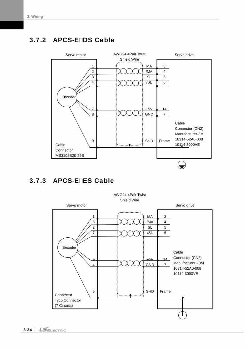
3. Wiring
3-34
3.7.2 APCS-EDS Cable
3.7.3 APCS-EES Cable
Servo drive Servo motor
Encoder
1 6 2 7
9 4
5
MA /MA SL /SL
+5V GND
SHD
Cable Connector (CN2) Manufacturer - 3M 10314-52A0-008 10114-3000VE
Connector Tyco Connector (7 Circuits)
Encoder
3 4 5 6
14 7
Frame
AWG24 4Pair Twist Shield Wire
Servo drive Servo motor
Encoder
1 2 3 4
7 8
9
MA /MA SL /SL
+5V GND
SHD
Encoder
3 4 5 6
14 7
Frame
Cable Connector (CN2) Manufacturer-3M 10314-52A0-008 10114-3000VE Cable
Connector MS3108B20-29S
AWG24 4Pair Twist Shield Wire

3. Wiring
3-35
3.8 Multi-turn Encoder Signaling Unit (CN2) Wiring
3.8.1 APCS-ECS1 Cable
Servo Drive Servo Motor
1 2 3 4
5 6
7 8
9
MA /MA SL /SL
BAT+ BAT-
5V
GND
SHD
Cable Connector (CN2) Manufacturer - 3M 10314-52A0-008 10114-3000VE
Cable Connector 172161-1 (AMP) 170361-1 (AMP)
Encoder
3 4 5 6
14 7
Frame
AWG24 4Pair Twist Shield Wire

3. Wiring
3-36
3.8.2 APCS-EDS1 Cable
3.8.3 APCS-EES1 Cable
Servo drive Servo motor
Encoder
1 6 2 7
8 3
9 4
5
MA /MA SL /SL
BAT+ BAT_
5V
GND
SHD
Cable Connector (CN2) Manufacturer - 3M 10314-52A0-008 10114-3000VE
Connector Tyco Connector (7 Circuits)
Encoder
3 4 5 6
14 7
Frame
Servo drive Servo motor
A B C D
E F
H G J
MA /MA SL /SL
BAT+ BAT-
5V
GND
SHD
AWG24 4Pair Twist Shield Wire
Cable Connector (CN2) Manufacturer - 3M 10314-52A0-008 10114-3000VE
Cable Connector MS3108S20-29S
Encoder
3 4 5 6
14 7
Frame

3. Wiring
3-37
3.9 Transmission of Absolute Value Encoder Data
3.9.1 Transmission of Absolute Value Encoder Data
Upon the absolute value encoder's request for absolute value data, the data of the absolute value encoder are transmitted to the upper level controller in the form of quadrature pulses through the output of the encoder output signals, AO and BO.
In this case, pulses are output at the speed of 500 Kbps.
Among absolute value data, multi-turn data are transmitted first, followed by single-turn data. (Refer to “4.1.6 External Input Signal and Logic Definition" for information on the allocation of the sequence input signal and ABS-RQ signal.)
Transmission Sequence of Absolute Value Data
1. When the servo is off, change the ABS_RQ signal on the upper level controller to ON.
2. The servo drive checks the ABS_RQ signal for 10 ms.
3. The servo drive prepares the transmission of multi-turn data for 100 ms.
4. The servo drive transmits multi-turn data for up to 140 ms (based on 16-bit multi-turn data).
5. The servo drive prepares the transmission of single-turn data for 100 ms.
6. The servo drive transmits single-turn data with the pre-scale ratio applied for up to 1100 ms (based on 19-bit single-turn data).
7. The servo drive operates with normal encoder output signals 100 ms after the single-turn data are completely transmitted.
Absolute value data transmission Pre-scale pulse output


4. Parameters
4-1
4. Parameters
4.1 How to Use the Loader
4.1.1 Name and Function of Each Part
Display 5-digit FND data.
DIGIT5 DIGIT4 DIGIT3 DIGIT2 DIGIT1
[MODE]: Change display mode. [/LEFT]: Move to another data digit. [UP]: Increase displayed data. [DOWN]: Decrease displayed data. [SET]: Confirm displayed data. [/RIGHT]: Move to another data digit.
Displays the decimal point.
E.g.) 123.4
In the case of 16 bits, the minus symbol is used.
In the case of 32 bits, a dot is used.
E.g.) -123.4

4. Parameters
4-2
4.1.2 Status Summary Display
(1) Status Summary Display in Speed Mode
① Example of the OFF status of the servo in speed control mode
② Example of the ON status of the servo in speed control mode
DIGIT 3-1: Displays the current status of the servo.
bb - Servo OFF run - Servo ON Pot - CCW Limit not - CW Limit
DIGIT 4_High: ZSPD
DIGIT 4_Medium: INSPD or INPOS
DIGIT 4_Low: Command (speed or torque)
DIGIT 4_DOT: Ready
DIGIT 5: Displays the current control mode.
P - Position control S - Speed control T - Torque control
DIGIT 5_DOT: Servo ON

4. Parameters
4-3
(2) Servo Operation Status Summary Display List
The following list explains the operation status summary display of different modes of the servo.
Operation Status Screen
Function Notes
Displays the servo's OFF status when in the position mode.
Displays the servo's ON status when in position mode.
Displays CCW status when in position mode.
Displays CW status when in position mode.
Displays the servo's OFF status when in speed mode.
Displays the servo's ON status when in speed mode.
Displays CCW status when in speed mode.
Displays CW status when in speed mode.
Displays the servo's OFF status when in torque mode.
Displays the servo's ON status when in torque mode.
Displays CCW status when in torque mode.
Displays CW status when in torque mode.
Current Operation Status and Servo Ready Status Display
TG_ON Signal Display (OFF: Stop, ON: Rotating)
For position control: Position command input in progress For speed control: Speed command input in progress For torque control: Torque command input in progress
For position control: INPOS1 signal indication For speed control: INSPD signal indication For torque control: OFF
TG_ON Signal DisplayServo Ready Status Display
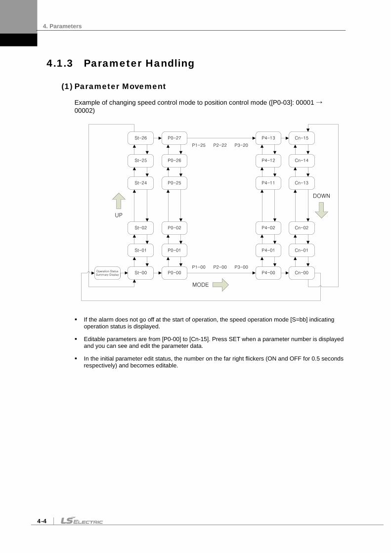
4. Parameters
4-4
4.1.3 Parameter Handling
(1) Parameter Movement
Example of changing speed control mode to position control mode ([P0-03]: 00001 → 00002)
St-00
St-01
St-02
St-24
St-25
St-26
P0-00
P0-01
P0-02
P0-25
P0-26
P0-27
Cn-00
Cn-01
Cn-02
Cn-13
Cn-14
Cn-15
UP
DOWN
MODE
P4-00
P4-01
P4-02
P4-11
P4-12
P4-13
Operation Status Summary Display
P1-00 P2-00 P3-00
P1-25 P2-22 P3-20
If the alarm does not go off at the start of operation, the speed operation mode [S=bb] indicating operation status is displayed.
Editable parameters are from [P0-00] to [Cn-15]. Press SET when a parameter number is displayed and you can see and edit the parameter data.
In the initial parameter edit status, the number on the far right flickers (ON and OFF for 0.5 seconds respectively) and becomes editable.

4. Parameters
4-5
(2) Example of changing speed control mode to position control mode ( [P0-03]: 00001 -> 00002 )
Order Loader Displays Keys to Use What to Do
1
Displays the speed control mode with main power and control power permitted.
2
Press MODE to move to [P0-00].
3
Press UP or DOWN to move to [P0-03].
4
Press SET to go to the parameter edit window. The parameter is displayed as 00001.
5
Press UP or DOWN at the blinking cursor to change the number to 00002.
6
Press and hold SET for approximately one second. After two flickers, the number will be saved as 00002 in the parameter.
7
Press and hold MODE for approximately one second to return to the P0-03 parameter.
8
Press MODE to change status to position operation [P= bb] status which is the summary display of the current status.
Note 1) “ ” indicates flickering. Note 2) If you hold down UP / DOWN at the current cursor in the parameter window, the number
continues to increase/decrease.

4. Parameters
4-6
(3) Example of changing speed proportional gain 2 ([P1-07]: 200 rad/s -> 500 rad/s)
Order Loader Displays Keys to Use What to Do
1
Displays the speed control mode with main power and control power permitted.
2
Press MODE to move to [P1-00].
3
Press UP or DOWN to move to [P1-07].
4
Press SET to enter parameter edit mode. The parameter is displayed as 00200.
5
Press /LEFT or /RIGHT at the blinking cursor to move to the desired digit, DIGIT 3.
6
Press UP or DOWN at the blinking DIGIT 3 position to change the number to 00500.
7
Press and hold SET for approximately one second. After two flickers, the number will be saved as 00500 in the parameter.
8
Press and hold MODE for approximately one second to return to [P1-07].
Note 1) “ ” indicates flickering. Note 2) If you hold down UP / DOWN at the current cursor in the parameter window, the number
continues to increase/decrease.

4. Parameters
4-7
(4) Example of changing DAC output offset 1 ([P0-19]: 0 Unit/V -> -500 Unit/V)
Order Loader Displays Keys to Use What to Do
1
Displays the speed control mode with main power and control power permitted.
2
Press MODE to move to [P0-00].
3
Press UP or DOWN to move to [P0-19].
4
Press SET to enter parameter edit mode. The parameter is displayed as 00000.
5
Press /LEFT or /RIGHT at the blinking cursor to move to the desired digit, DIGIT 3.
6
Press UP or DOWN at the blinking DIGIT 3 position to change the number to -0500.
7
Press and hold SET for approximately one second. After two flickers, the number will be saved as -0500 in the parameter.
8
Press and hold MODE for approximately one second to return to [P0-19].
Note 1) “ ” indicates flickering. Note 2) If you hold down UP / DOWN at the current cursor in the parameter window, the number
continues to increase/decrease.

4. Parameters
4-8
4.1.4 Data Display
(1) Binary
655 Minimum (0b00000) 655 Maximum (0b11111)
(2) Hex
655 Minimum (0x0000) 655 Maximum (0xFFFF)
(3) 16-bit Unsigned Integer
655 E.g.) 0 655 E.g.) +1234
(4) 16-bit Signed Integer
655 ex) -1234 ② ex) +5678
655 E.g.) -1234 655 E.g.) +5678
(5) 16-bit Decimal Point Display
655 ex) -123.4 ② ex) +123.4
655 E.g.) -123.4 655 E.g.) +123.4

4. Parameters
4-9
(6) 32-bit Signed Integer Data Display
Minimum (-2147483648)
Display upper two digits Display middle four digits Display lower four digits
Maximum (2147483647)
Display upper two digits Display middle four digits Display lower four digits
Example
[St-16]: Displayed as Upper = 0, Middle = 0012, and Lower = 2071
Order Loader Displays Keys to Use What to Do
1
Displays the speed control mode with main power and control power permitted.
2
Press MODE to move to [St-00].
3
Press UP or DOWN to move to [St-16].
4
Press SET to display lower digit data.
5
Each time you press /LEFT or /RIGHT lower, middle, and upper data is displayed.
6
Each time you press /LEFT or /RIGHT lower, middle, and upper data is displayed.
7
Press and hold MODE for approximately one second to return to [St-16].
Note 1) “ “ indicates flickering.

4. Parameters
4-10
4.1.5 External Input Contact Signal Display [St-14]
You can check whether the ON/OFF status of digital input/output signals that access the servo drive are on or off.
(1) External Input Signal Display
The positions of the seven segment LEDs and CN1 connector pins correspond as follows.
If an LED that corresponds to a pin is turned on/off, it indicates ON/OFF accordingly.
Input Contact Display
Number (A) (9) (8) (7) (6) (5) (4) (3) (2) (1) Contact
sign DIA DI9 DI8 DI7 DI6 DI5 DI4 DI3 DI2 DI1
CN1 Pin
Number 48 18 19 20 46 17 21 22 23 47
Initial Allocation
Signal Name
STOP EMG CWLIM CCW LIM
DIR ALM RST
SPD3 SPD2 SPD1 SVON

4. Parameters
4-11
4.1.6 External Input Signal and Logic Definition
The following describes how to allocate input signals and how to view them.
(1) Input Signal Allocation
In L7 drive, you can allocate a total of 19 input contact functions to 10 hardware-like contacts.
Each input contact function is positioned at certain DIGIT of parameter [P2-00], [P2-01], [P2-02], [P2-03] and [P2-04], and you can change the value of each DIGIT and allocate it to pin of DI1-DIA.
The default input signal allocation is shown in the figure below:
One number can be allocated to two input signals such as N (input signal): 1 (input allocation number).
E.g.) If SVON and SPD1 are allocated to DI #01, you can use both SVON and SPD1 signals when entering DI #01.
Caution If you change the input contact function, Since it is an immediate effect on the drive, you need to be careful for the operation. Before change, recommended to be set ‘EEPROM save no use’ in DIGIT 5 of [P0-17] parameter ..
Input Signal
Input Allocation Number

4. Parameters
4-12
Signal Name Input signal
Always
Allocated
CN1 Pin Default Allocation Number No Allocation
Input Signal
Definition
Default Value Parameter
Allocation 48 18 19 20 46 17 21 22 23 47
Servo ON [P2-00].DIGIT1 setting SVON F A 9 8 7 6 5 4 3 2 1 0
[P2-00] 0x4321
Multi-speed 1 [P2-00].DIGIT2 setting SPD1 F A 9 8 7 6 5 4 3 2 1 0
Multi-speed 2 [P2-00].DIGIT3 setting SPD2 F A 9 8 7 6 5 4 3 2 1 0
Multi-speed 3 [P2-00].DIGIT4 setting SPD3 F A 9 8 7 6 5 4 3 2 1 0
Alarm reset [P2-01].DIGIT1 setting ALMRST F A 9 8 7 6 5 4 3 2 1 0
[P2-01] 0x8765
Select rotation direction
[P2-01].DIGIT2 setting DIR F A 9 8 7 6 5 4 3 2 1 0
Forward rotation prohibited
[P2-01].DIGIT3 setting CCWLIM F A 9 8 7 6 5 4 3 2 1 0
Reverse rotation prohibited
[P2-01].DIGIT4 setting CWLIM F A 9 8 7 6 5 4 3 2 1 0
Emergency stop [P2-02].DIGIT1 setting EMG F A 9 8 7 6 5 4 3 2 1 0
[P2-02] 0x00A9
Stop [P2-02].DIGIT2 setting STOP F A 9 8 7 6 5 4 3 2 1 0
Electronic gear ratio 1
[P2-02].DIGIT3 setting EGEAR1 F A 9 8 7 6 5 4 3 2 1 0
Electronic gear ratio 2
[P2-02].DIGIT4 setting EGEAR2 F A 9 8 7 6 5 4 3 2 1 0
P control action [P2-03].DIGIT1 setting PCON F A 9 8 7 6 5 4 3 2 1 0
[P2-03] 0x0000
Select gain 2 [P2-03].DIGIT2 setting GAIN2 F A 9 8 7 6 5 4 3 2 1 0
Input pulse clear [P2-03].DIGIT3 setting P_CLR F A 9 8 7 6 5 4 3 2 1 0
Torque limit [P2-03].DIGIT4 setting T_LMT F A 9 8 7 6 5 4 3 2 1 0
Change operation modes
[P2-04].DIGIT1 setting MODE F A 9 8 7 6 5 4 3 2 1 0
[P2-04] 0x0000 Absolute encoder data request
[P2-04].DIGIT2 setting ABS_RQ F A 9 8 7 6 5 4 3 2 1 0
Zero clamp [P2-04].DIGIT3 setting ZCLAMP F A 9 8 7 6 5 4 3 2 1 0
Note 1) No CN1 connector pin is allocated when the default value is "0".

4. Parameters
4-13
(2) Example of Changing Input Signal Allocation
The input signal definition can be changed in [P2-00], [P2-01], [P2-02], [P2-03], and [P2-04].
The input signal logic definition can be changed in [P2-08] and [P2-09].
Allocate input signals as shown in the following table:
Input Signal
Input Allocation Number

4. Parameters
4-14
Signal Name Input
Signal
Always
Allocated
CN1 Pin Default Allocation Number No Allocation
Input Signal
Definition
Value After
Changing
Parameter Allocation
48 18 19 20 46 17 21 22 23 47
Servo ON [P2-00].DIGIT1 setting
SVON F A 9 8 7 6 5 4 3 2 1 0
[P2-00] 0x0321
Multi-speed 1 [P2-00].DIGIT2 setting
SPD1 F A 9 8 7 6 5 4 3 2 1 0
Multi-speed 2 [P2-00].DIGIT3 setting
SPD2 F A 9 8 7 6 5 4 3 2 1 0
Multi-speed 3 [P2-00].DIGIT4 setting
SPD3 F A 9 8 7 6 5 4 3 2 1 0
Alarm reset [P2-01].DIGIT1 setting
ALMRST F A 9 8 7 6 5 4 3 2 1 0
[P2-01] 0x0765
Select rotation direction
[P2-01].DIGIT2 setting DIR F A 9 8 7 6 5 4 3 2 1 0
Forward rotation prohibited
[P2-01].DIGIT3 setting CCWLIM F A 9 8 7 6 5 4 3 2 1 0
Reverse rotation prohibited
[P2-01].DIGIT4 setting CWLIM F A 9 8 7 6 5 4 3 2 1 0
Emergency stop [P2-02].DIGIT1 setting
EMG F A 9 8 7 6 5 4 3 2 1 0
[P2-02] 0x0080
Stop [P2-02].DIGIT2 setting
STOP F A 9 8 7 6 5 4 3 2 1 0
Electronic gear ratio 1 [P2-02].DIGIT3 setting
EGEAR1 F A 9 8 7 6 5 4 3 2 1 0
Electronic gear ratio 2 [P2-02].DIGIT4 setting
EGEAR2 F A 9 8 7 6 5 4 3 2 1 0
P control action [P2-03].DIGIT1 setting
PCON F A 9 8 7 6 5 4 3 2 1 0
[P2-03] 0x9000
Select gain 2 [P2-03].DIGIT2 setting
GAIN2 F A 9 8 7 6 5 4 3 2 1 0
Input pulse clear [P2-03].DIGIT3 setting
P_CLR F A 9 8 7 6 5 4 3 2 1 0
torque limit [P2-03].DIGIT4 setting
T_LMT F A 9 8 7 6 5 4 3 2 1 0
Change operation modes
[P2-04].DIGIT1 setting MODE F A 9 8 7 6 5 4 3 2 1 0
[P2-04] 0x000A Absolute encoder
data request [P2-04].DIGIT2 setting
ABS_RQ F A 9 8 7 6 5 4 3 2 1 0
Zero clamp [P2-04].DIGIT3 setting
ZCLAMP F A 9 8 7 6 5 4 3 2 1 0
Note 1) No CN1 connector pin is allocated when the default value is "0".

4. Parameters
4-15
Example of Changing Input Signal Allocation
The following is an example of changing input signal allocation.
The allocation signals of SVON (CN1-47) and STOP (CN1-48) can be switched in the following sequence:
Before Changing After Changing
[P2-00]:
[P2-02]:
Order Loader Displays Keys to Use What to Do
1
Press MODE to move to [P2-00].
2
Press SET to enter parameter edit mode. The parameter is displayed as 04321.
3
Press UP or DOWN at the blinking cursor to change the number to 0432A.
4
Hold down SET for approximately one second. After two flickers, the number is saved as 0432A for the parameter.
5
Hold down MODE for approximately one second to return to [P2-00].
6
Press UP or DOWN at the blinking cursor to change the number to P2-02.
7
Press SET to enter parameter edit mode. The parameter is displayed as 000A9.
8
Press /LEFT or /RIGHT at the blinking cursor to move to the desired digit, DIGIT 2.
9
Press UP or DOWN at the blinking cursor to change the number to 00019.
10
Hold down SET for approximately one second. After two flickers, the number is saved as 00019 for the parameter.
11
Hold down MODE for approximately one second to return to [P2-02].
12 ** Modification is not possible with the servo on. Reset the parameter.
※ In case of exiting
without saving the set value
Hold down MODE for approximately one second to return to the parameter.
Note 1) “ “ indicates flickering.

4. Parameters
4-16
(3) Input Signal Logic Definition
In L7 drive, you can define the logic of input signal through parameter [P2-08] and [P2-09], in terms of 10 hardware contacts ranging from DI1 to DIA.
The default logic state of input signal is as follows:
Input Signal Logic Definition
Input Signal Logic Definition Number
(Contact A/Contact B) (Contact A/Contact B) (Contact A/Contact B) (Contact A/Contact B) (Contact A/Contact B) (Contact A/Contact B) (Contact A/Contact B) (Contact A/Contact B) (Contact A/Contact B) (Contact A/Contact B)

4. Parameters
4-17
Signal Name Input Signal (Initial Name)
CN1 Pin Default Allocation Number Contact B
Input Signal Logic
Definition
Default Value Parameter
Allocation 48 18 19 20 46 17 21 22 23 47
Servo ON [P2-08].DIGIT1 setting
SVON 1 0
[P2-08] 0x11111
Multi-speed 1 [P2-08].DIGIT2 setting
SPD1 1 0
Multi-speed 2 [P2-08].DIGIT3 setting
SPD2 1 0
Multi-speed 3 [P2-08].DIGIT4 setting
SPD3 1 0
Alarm reset [P2-08].DIGIT5 setting
ALMRST 1 0
Select rotation direction
[P2-09].DIGIT1 setting DIR 1 0
[P2-09] 0x10001
Forward rotation prohibited
[P2-09].DIGIT2 setting CCWLIM 0
Reverse rotation prohibited
[P2-09].DIGIT3 setting CWLIM 0
Emergency stop [P2-09].DIGIT4 setting
EMG 0
Stop [P2-09].DIGIT5 setting
STOP 1 0
Note 1) According to the input signal logic definition, contact A is 1 and contact B is 0.

4. Parameters
4-18
(4) Example of Changing Input Signal Logic Definition
The input signal logic definition can be changed in [P2-08] and [P2-09].
Allocate input signals as shown in the following table:
Input Signal Logic Definition
Input Signal Logic Definition Number
(Contact A/Contact B) (Contact A/Contact B) (Contact A/Contact B) (Contact A/Contact B) (Contact A/Contact B) (Contact A/Contact B) (Contact A/Contact B) (Contact A/Contact B) (Contact A/Contact B) (Contact A/Contact B)

4. Parameters
4-19
Signal Name Input Signal
CN1 Pin Default Allocation Number Contact B
Input Signal Logic
Definition
Default Value Parameter
Allocation 48 18 19 20 46 17 21 22 23 47
Servo ON [P2-08].DIGIT 1
setting SVON 1 0
[P2-08] 0x11111
Multi-speed 1 [P2-08].DIGIT 2
setting SPD1 1 0
Multi-speed 2 [P2-08].DIGIT 3
setting SPD2 1 0
Multi-speed 3 [P2-08].DIGIT 4
setting EGEAR2 1 0
Alarm reset [P2-08].DIGIT 5
setting ALMRST 1 0
Select rotation direction
[P2-09].DIGIT 1 setting
DIR 1 0
[P2-09] 0x11101
Forward rotation prohibited
[P2-09].DIGIT 2 setting
CCWLIM 0
Reverse rotation prohibited
[P2-09].DIGIT 3 setting
STOP 1 0
Emergency stop [P2-09].DIGIT 4
setting T_LMT 1 0
Stop [P2-09].DIGIT 5
setting MODE 1 0
Note 1) According to the input signal logic definition, contact A is 1 and contact B is 0.

4. Parameters
4-20
Example of Changing Input Signal Logic Definition
The following is an example of changing input signal logic.
You can change logic signal contact A of SVON (CN1-47) to contact B, and
change logic signal contact B of CCWLIM (CN1-20) to contact A in the following sequence:
Before Changing After Changing
[P2-08]:
[P2-09]:
Order Loader Displays Keys to Use What to Do
1
Press UP or DOWN key at the blinking cursor to move to [P2-08].
2
Press SET to enter parameter edit mode. The parameter is displayed as 11111.
3
Press UP or DOWN key at the blinking cursor to change the number to 11110.
4
Hold down SET key for approximately one second. After two flickers, the number will be saved as 11110 for the parameter.
5
Hold down MODE key for approximately one second to return to [P2-08].
6
Press UP or DOWN key at the blinking cursor to change the number to P2-09.
7
Press SET to enter parameter edit mode. The parameter is displayed as 10001.
8
Press /LEFT or /RIGHT at the blinking cursor to move to the desired digit, DIGIT 2.
9
Press UP or DOWN key at the blinking cursor to change the number to 10011.
10
Press and hold the SET key for approximately one second. After two flickers, the number will be saved as 10011 in the parameter.
11
Hold down MODE key for approximately one second to return to [P2-09].
12 ** Modification is not possible with the servo on. Reset the parameter.
※ In case of exiting
without saving the set value
Hold down MODE for approximately one second to return to the parameter.
Note 1) “ “ indicates flickering.

4. Parameters
4-21
4.1.7 External Output Contact Signal Display [St-15]
You can check whether the ON/OFF status of digital input/output signals that access the servo drive are on or off.
(1) External Output Signal Display
The positions of the seven segment LEDs and CN1 connector pins correspond as follows.
If an LED that corresponds to a pin is turned on/off, it indicates ON/OFF accordingly.
Output Contact Display
Number (5) (4) (3) (2) (1) Contact
sign DO5 DO4 DO3 DO2 DO1
CN1 pin number 45 44 43 40/41 38/39
Initial allocation
signal name INPOS BRAKE ZSPD READY ALARM

4. Parameters
4-22
4.1.8 External Output Signal and Logic Definition
The following explains output signal allocation and the method of checking allocation status.
(1) Output Signal Allocation
Output signal definition: [P2-05], [P2-06], [P2-07]
Output signal logic definition: [P2-10]
The default output signal allocation is as follows:
Signal Name output signal
Always Allocated
CN1 Pin Default Allocation Number Not Allocated
Internal Parameter
Default Value Parameter Allocation 45 44 43 40/41 38/39
Alarm [P2-05].DIGIT1 setting ALARM F 5 4 3 2 1 0
[P2-05] 0x4321
Servo ready [P2-05].DIGIT2 setting READY F 5 4 3 2 1 0
Zero speed achieved [P2-05].DIGIT3 setting ZSPD F 5 4 3 2 1 0
Brake [P2-05].DIGIT4 setting BRAKE F 5 4 3 2 1 0
Position reached [P2-06].DIGIT1 setting INPOS F 5 4 3 2 1 0
[P2-06] 0x0005
Torque limit reached [P2-06].DIGIT2 setting TLMT F 5 4 3 2 1 0
Speed limit reached [P2-06].DIGIT3 setting VLMT F 5 4 3 2 1 0
Speed reached [P2-06].DIGIT4 setting INSPD F 5 4 3 2 1 0
Warning [P2-07].DIGIT1 setting WARN F 5 4 3 2 1 0 [P2-07] 0x0000
Note 1) No CN1 connector pin is allocated when the default value is "0".
Output Signal
Output Allocation Number

4. Parameters
4-23
(2) Example of Changing Output Signal Allocation
The output signal definition can be changed in [P2-05], [P2-06], and [P2-07].
The output signal logic definition can be changed in [P2-10].
Allocate output signals as in the following table:
Signal Name output signal
Always assignment
CN1 Pin Default Allocation Number Not Allocated
Internal Parameter
Value After
Changing Parameter Allocation 45 44 43 40/41 38/39
Alarm [P2-05].DIGIT1 setting ALARM F 5 4 3 2 1 0
[P2-05] 0x0301
Servo ready [P2-05].DIGIT2 setting READY F 5 4 3 2 1 0
Zero speed achieved [P2-05].DIGIT3 setting ZSPD F 5 4 3 2 1 0
Brake [P2-05].DIGIT4 setting BRAKE F 5 4 3 2 1 0
Position reached [P2-06].DIGIT1 setting INPOS F 5 4 3 2 1 0
[P2-06] 0x5400
Torque limit reached [P2-06].DIGIT2 setting TLMT F 5 4 3 2 1 0
Speed limit reached [P2-06].DIGIT3 setting VLMT F 5 4 3 2 1 0
Speed reached [P2-06].DIGIT4 setting INSPD F 5 4 3 2 1 0
Warning [P2-07].DIGIT1 setting WARN F 5 4 3 2 1 0 [P2-07] 0x0002
Note 1) No CN1 connector pin is allocated when the default value is "0".
Output Signal
Output Allocation Number

4. Parameters
4-24
Example of Changing Output Signal Allocation
The following is an example of output signal allocation change.
The allocation signals of ALARM (CN1-38/39) and ZSPD (CN1-43) can be switched in the following sequence:
Before Changing After Changing
[P2-05]:
Order Loader Window Display Result
Keys to Use What to Do
1
Press MODE to move to [P2-05].
2
Press SET to enter parameter edit mode. The parameter is displayed as 04321.
3
Press UP or DOWN at the blinking cursor to change the number to 04323.
4
Press /LEFT or /RIGHT at the blinking cursor to move to the desired digit, DIGIT 3.
5
Press UP or DOWN at the blinking cursor to change the number to 04123.
6
Hold down SET for approximately one second. After two flickers, the number will be saved as 04123 for the parameter.
7
Hold down MODE for approximately one second to return to [P2-05].
8 ** Modification is not possible with the servo on. Reset the parameter.
※ In case of exiting without saving the set value
Hold down MODE for approximately one second to return to the parameter.
Note 1) “ “ indicates flickering.
When two output signals are allocated to one number, the output contact setting error [AL-72] alarm triggers.

4. Parameters
4-25
(3) Output Signal Logic Definition
Output signal logic definition: [P2-10]
The default logic state of output signal is as follows:
Signal Name Input Signal (Initial Name)
CN1 Pin Default Allocation Number Contact
B
Output Signal Logic
Definition
Default Value Parameter
Allocation 45 44 43 40 /41
38 /39
Alarm [P2-10]. DIGIT1 setting ALARM 0
[P2-10] 0x10110
Servo ready [P2-10]. DIGIT2 setting READY 1 0
Zero speed achieved
[P2-10]. DIGIT3 setting ZSPD 1 0
Brake [P2-10]. DIGIT4 setting BRAKE 0
Position reached [P2-10]. DIGIT5 setting INPOS 1 0
Note 1) According to the input signal logic definition, contact A is 1 and contact B is 0.
Output Signal Logic Definition
Output Signal Logic Definition Number
(Contact A/Contact B) (Contact A/Contact B) (Contact A/Contact B) (Contact A/Contact B) (Contact A/Contact B)

4. Parameters
4-26
(4) Example of Changing Output Signal Logic Definition
The output signal logic definition can be changed in [P2-10].
Allocate output signals as in the following table:
Signal Name Input Signal (Initial Name)
CN1 Pin Default Allocation Number Contact
B
Output Signal Logic
Definition
Default Value Parameter
Allocation 45 44 43 40 /41
38 /39
Alarm [P2-10]. DIGIT1 setting ALARM 0
[P2-10] 0x11110
Servo ready [P2-10]. DIGIT2 setting READY 1 0
Zero speed achieved
[P2-10]. DIGIT3 setting ZSPD 1 0
Brake [P2-10]. DIGIT4 setting BRAKE 1 0
Position reached [P2-10]. DIGIT5 setting INPOS 1 0
Note 1) According to the input signal logic definition, contact A is 1 and contact B is 0.
Output Signal Logic Definition
Output Signal Logic Definition Number
(Contact A/Contact B) (Contact A/Contact B) (Contact A/Contact B) (Contact A/Contact B) (Contact A/Contact B)

4. Parameters
4-27
Example of Changing Output Signal Logic Definition
The following is an example of output signal allocation change.
The allocation signals of ALARM (CN1-38/39) and ZSPD (CN1-43) can be switched in the following sequence:
Before Changing After Changing
[P2-05]:
Order Loader Window
Display Result Keys to Use What to Do
1
Press MODE to move to [P2-05].
2
Press SET to enter parameter edit mode. The parameter is displayed as 04321.
3
Press UP or DOWN at the blinking cursor to change the number to 04323.
4
Press /LEFT or /RIGHT at the blinking cursor to move to the desired digit, DIGIT 3.
5
Press UP or DOWN at the blinking cursor to change the number to 04123.
6
Hold down SET for approximately one second. After two flickers, the number will be saved as 04123 for the parameter.
7
Hold down MODE for approximately one second to return to [P2-05].
8 ** Modification is not possible with the servo on. Reset the parameter.
※ In case of exiting without saving the set value
Hold down MODE for approximately one second to return to the parameter.
Note 1) “ “ indicates flickering.
When two output signals are allocated to one number, the output contact setting error [AL-72] alarm triggers.
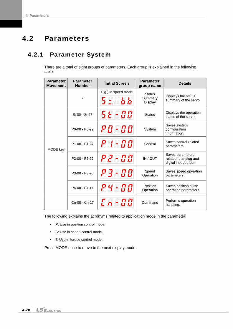
4. Parameters
4-28
4.2 Parameters
4.2.1 Parameter System
There are a total of eight groups of parameters. Each group is explained in the following table:
Parameter Movement
Parameter Number Initial Screen Parameter
group name Details
MODE key
-
E.g.) In speed mode
Status Summary Display
Displays the status summary of the servo.
St-00 - St-27
Status Displays the operation status of the servo.
P0-00 - P0-29
System Saves system configuration information.
P1-00 - P1-27
Control Saves control-related parameters.
P2-00 - P2-22
IN / OUT Saves parameters related to analog and digital input/output.
P3-00 - P3-20
Speed Operation
Saves speed operation parameters.
P4-00 - P4-14
Position Operation
Saves position pulse operation parameters.
Cn-00 - Cn-17
Command Performs operation handling.
The following explains the acronyms related to application mode in the parameter:
P: Use in position control mode.
S: Use in speed control mode.
T: Use in torque control mode.
Press MODE once to move to the next display mode.

4. Parameters
4-29
4.2.2 Operation Status Display Parameter
For detailed information, refer to "4.3 Operation Status Display
“**” Parameter that cannot be modified with the servo ON but can reset power
.“*” Parameter that cannot be modified with the servo ON
Parameter Unit Initial Details
Applicable Mode Code Name Minimum Maximum
St-00
Current Operation Status - - Displays the current operation status.
DIGIT 5: DIGIT 4: ZSPD, INPOS/INSPD, Command, READY DIGIT 3-1: Run Status (Details: Refer to "4.1.2 Status Summary Display.")
PST
0 0
St-01 Current Operation
Speed RPM 0 Displays the current operation speed. (Details: Refer to “4.3.2 Speed Display.”)
PST
-10000 10000
St-02 Current Command
Speed RPM 0 Displays the current command speed. (Details: Refer to “4.3.2 Speed Display.”)
ST
-10000 10000
St-03
Following Position Pulse Pulse 0 Displays the accumulated number of tracked position
command pulses. Displays the accumulated number of position
command pulses that followed as a result of rotation of the servo motor because the servo was turned on.
If a number is lower than the minimum or higher than the maximum, it is displayed as the minimum or maximum.
(Details: Refer to “4.3.3 Position Display.”)
P
-2^30 2^30
St-04
Position Command Pulse Pulse 0 Displays the accumulated number of position command
pulses. Displays the accumulated number of position
command pulses that have been entered since the servo turned on. (Details: Refer to “4.3.3 Position Display.”)
P
-2^30 2^30
St-05
Remaining Position Pulse Pulse 0 Displays the remaining position pulses that the servo has
to operate. This displays the difference between command pulses
and tracking pulses and the remaining position pulses for the servo to run.
The remaining position pulses, which are displayed when the servo is off, are ignored when the servo turns on. (Details: Refer to “4.3.3 Position Display.”)
P
-2^30 2^30
St-06 Input Pulse Frequency Kpps 0.0 Displays input pulse frequency. P
-1000.0 1000.0
St-07
Current Operation Torque [%] 0.0 Displays the current load factor against the rated load
factor. Displays the load currently output by the servo motor
as a percentage against the rated output.
T
-300.0 300.0
St-08
Current Command Torque [%] 0.0 Displays the command load factor against the rated load
factor. Displays the load currently output by the servo motor
as a percentage against the rated output. (Details: Refer to “4.3.4 Torque and Load Display.”)
T
-300.0 300.0

4. Parameters
4-30
Parameter Unit Initial Details
ApplicableMode Code Name Minimum Maximum
St-09
Accumulated Overload Rate [%] 0.0 Displays the currently accumulated load factor against
the maximum accumulated load factor as a percentage. (Details: Refer to “4.3.4 Torque and Load Display.”)
PST
-300.0 300.0
St-10
Instantaneous Maximum Load
Factor [%] 0.0
Displays the instantaneous maximum load factor against the rated load factor. Displays, as a percentage, the maximum overload
between the current time and the start of control set off when the servo turned on.
(Details: Refer to “4.3.4 Torque and Load Display.”)
PST
-300.0 300.0
St-11
Torque Limit [%] - Displays the torque limit value. Displays, as a percentage, the maximum torque
that the servo motor can output, against the rated torque. (T_LMT contact ON: Analog torque input. T_LMT contact OFF: [P1-13] and [P1-14] values)
PST
-300.0 300.0
St-12
DC Link Voltage V 0.0 Displays the current DC link voltage of the main power. The DC link voltage of the standard drive that
uses 380 V is approximately 537 V. The maximum DC link voltage allowed for the
standard drive that uses 380 V is 800 V. The excessive voltage alarm [AL-41] triggers
when the DC link voltage threshold is exceeded because there is either too much or too little regenerative resistance.
The normal DC link voltage in the regenerative section is 747 V or below.
(Details: Refer to “4.3.4 Torque and Load Display.”)
PST
0.0 900.0
St-13 Regenerative
Overload [%] 0.0 Displays the regenerative overload rate. PST
0.0 20.0
St-14
Input Contact Status - - Displays the input contact status that the servo
recognizes. (Details: Refer to “4.1.5 External Input Contact Signal Display.”)
PST
- -
St-15
Output Contact Status - - Displays the output contact status that the servo
outputs. (Details: Refer to “4.1.6 External Input Contact Signal Display.”)
PST
- -
St-16
SingleTurn Data (Single Turn
Data) Pulse 0
Displays the single-turn data of the encoder in pulses. PST
0 2^30
St-17 Single-turn data
(Degrees) [˚] 0.0 This displays the single-turn data of the encoder in degrees.
PST
0.0 360.0
St-18 Multi-Turn Data rev 0 This displays the multi-turn data for the encoder. PST
-32768 32767

4. Parameters
4-31
Parameter Unit Initial Details
ApplicableMode Code Name Minimum Maximum
St-19
Internal Temperature [] 0 Displays the internal temperature sensor value. PST
Room temperature 0 200
St-20 Rated Motor
Speed RPM 0 Displays the rated speed of the currently installed motor. PST
0 10000
St-21 Peak Motor
Speed RPM 0 Displays the maximum speed of the currently installed motor.
PST
0 10000
St-22 Rated Motor
Current A 0.00 Displays the rated current of the currently installed motor. PST
0.00 655.35
St-23
Phase U Current Offset mA 0 Displays the phase U current offset. PST
-200 200
St-24
Phase V Current Offset mA 0 Displays the phase V current offset. PST
-200 200
St-25 Program Version - - Displays the version of the currently installed program.
(Details: Refer to “4.3.7 Software Version Display.”) PST
- -
St-26 FPGA Version - -
This displays the version of the FPGA. PST
- -
St-27
Analog Command
Torque % 0
Displays current analog command torque.
T
-3000 3000

4. Parameters
4-32
4.2.3 System Parameters
For detailed information, refer to "4.4.1 System Parameter Setting."
“**” Parameter that cannot be modified with the servo ON but can reset power. “*” Parameter that cannot be modified with the servo ON
Parameter Unit Initial Details
ApplicableMode Code Name Minimum Maximum
**P0-00
Motor ID - 999 Serial Type Encoder: Reads the motor ID from the encoder and displays it.
Quadrature Type Encoder: Sets motor ID directly. If the attempt to read motor data fails, the initial value is
set to 999. (Details: Refer to “4.4.1 System Parameter Setting.")
PST
0 999
**P0-01
Encoder Type - 0 Serial Type Encoder: Reads and displays from the encoder.
Quadrature Type Encoder: Sets the value directly. 0: Quadrature type encoder 1: Serial encoder (-) 2: Serial encoder (12 bit) 3: Serial encoder (16 bit) 4: Serial encoder (20 bit) 5: Serial encoder (24 bit) (Details: Refer to “4.4.1 System Parameter Setting.")
PST
0 5
**P0-02
Encoder Pulse ppr 3000 Serial Type Encoder: Reads the number of bits per turn
from the encoder and displays it. Quadrature Type Encoder: Sets the number of encoder
pulses directly. (Details: Refer to “4.4.1 System Parameter Setting.")
PST
1 30000
*P0-03
Select operation mode
- 1 Sets operation mode. (0: Torque operation. 1: Speed operation. 2: Position operation. 3: Speed/position operation. 4: Torque/speed operation. 5: Torque/position operation.) (Details: Refer to “4.4.1 System Parameter Setting.")
PST
0 5
**P0-04
RS422 Communication Speed
bps 0 Sets communication speed for RS-422 communication. 0 : 9600 bps 1 : 19200 bps 2 : 38400 bps 3 : 57600 bps (Details: Refer to “4.4.1 System Parameter Setting.")
PST
0 3
**P0-05
System ID - 0 Sets drive ID for communication. An ID can be given to the servo if USB communication,
RS422 communication and BUS communication are used for communication with the servo.
A unique ID can be given to the servo and used for individual communication with it.
(Details: Refer to “4.4.1 System Parameter Setting.")
PST
0 99

4. Parameters
4-33
Parameter Unit Initial Details
ApplicableMode Code Name Minimum Maximum
P0-06
Main Power Input Mode - 0b00 Sets main power input.
DIGIT 1-> 0: Single-phase power 1: 3-phase power input
Caution: Using single-phase power may lower motor output.
DIGIT2 -> 0: Error in case of phase loss
1: Warning in case of phase loss
PST
0b00 0b11
P0-07 RST checking time ms 20 Sets the time to check main power phase loss. PST
0 5000
P0-08
Start-up Parameter
- 0 Sets the number for the operation status parameter that is displayed at the start. (Details: Refer to “4.4.1 System Parameter Setting.")
PST
0 25
*P0-09
Regenerative Overload Derating
[%] 100 This specifies the derating factor which checks for regenerative resistance overloads. The overload alarm triggers quickly when the derating value is set to 100% or below.
PST
1 200
**P0-10
Regenerative Resistance Value Ω 0 This specifies the resistance value for
regenerative braking resistance. If set to 0, the default resistance value of the drive is used.
PST
0 1000
**P0-11
Regenerative Resistance Capacity
W 0 This specifies the current capacity for regenerative resistance. If set to 0, a default resistance capacity embedded in the drive is used.
PST
0 30000
*P0-12
Overload Check Base Load Factor
[%] 100 This indicates the load factor which triggers a continuous overload check. If it is set to 100 or less, then the overload check starts early and the overload alarm triggers early.
PST
10 100
P0-13
Continuous Overload Warning Level
[%] 50 Indicates the level of continuous overload warning signal output. Outputs the warning signal when the percentage value against alarm trigger load factor is reached.
PST
10 100
*P0-14
Encoder Output Pre-scale - 12000 Sets the prescale for encoder output when the
servo outputs an encoder signal to the outside. (Details: Refer to “4.4.1 System Parameter Setting.")
PST
-2^21 2^21
*P0-15
PWM OFF Delay Time ms 10 Sets the time to delay until the PWM signal
actually goes off after the servo is turned off. (Details: Refer to “4.4.1 System Parameter Setting.")
PST
0 1000

4. Parameters
4-34
Parameter Unit Initial Details
ApplicableMode Code Name Minimum Maximum
*P0-16
DB Control Mode - 0x0 Specifies the DB control mode.
0: Hold after a DB stop 1: Release after a DB stop 2: Release after free run stop 3: Hold after a free run stop (Details: Refer to “4.4.1 System Parameter Setting.")
PST
0x0 0x3
*P0-17
Function Setting Bit - 0b00000 Sets drive function per digit.
DIGIT 1 -> Sets the operation direction of the servo. 0: Foward (CCW), Reverse (CW) 1: Forward (CW), Reverse (CCW)
DIGIT 2 -> Sets the Servo Lock. 0: Do not use 1: Interpolation
DIGIT 3 -> Sets Open Collector Output. 0: Do not use 1: Interpolation
DIGIT 4 -> Sets Monitor Output Voltage. 0: -10V - +10V 1: 0-10V
DIGIT 5 -> Sets saving EEPROM communication. 0: Do not use 1: Interpolation
(Details: Refer to “4.4.1 System Parameter Setting.")
PST
0b00000 0b11111
P0-18
DAC Output Mode - 0x3210 Sets output mode for 1-2 analog output channels.
Sets CH0-CH1 from the bottom, HEX Code, in order. Output CH0 and CH1 as MONIT1 and MONIT2. 0 : Speed feedback [RPM] 1 : Speed command [RPM] 2 : Torque feedback [%] 3 : Torque command [%] 4 : Position command frequency [0.1 Kpps] 5 : Following error [pulse] 6 : DC link voltage [V] D: Speed command (user) [RPM] E: Torque command (user) [%]
(Details: Refer to “4.4.1 System Parameter Setting.")
PST
0x0000 0xFFFF
P0-19 DAC Output Offset 1 Unit/V 0 Sets offset for 1-2 analog output channels.
Speed: RPM Torque: [%] Position command frequency: 0.1 Kpps Position: Pulse DC Link: V Offset
(Details: Refer to “4.4.1 System Parameter Setting.")
PST
-1000 1000
P0-20
DAC Output Offset 2 Unit/V 0
-1000 1000

4. Parameters
4-35
Parameter Unit Initial Details
ApplicableMode Code Name Minimum Maximum
P0-21 Reserv
ed - -
- -
P0-22 Reserv
ed Unit/V 0
-1000 1000
P0-23 DAC Output Scale 1 Unit/V 500 Sets magnification for 1-2 analog output channels.
Sets magnification as setting Unit/V. E.g.) Channel 1 scale 100 RPM: Output 100 RPM as 1 V. (Details: Refer to “4.4.1 System Parameter Setting.")
PST
1 10000
P0-24 DAC Output Scale 2 Unit/V 500
1 10000
P0-25 Reserved
P0-26 Encoder Function Bit
0 Multi turn encoder function setting *0: Using as Multi turn mode with multi turn encoder. *1: Using as Single turn mode with multi turn encoder.
PST
0 1
P0-27
Phase U Current Offset Value
mA 0 Saves phase U current offset value.
PST
-9999 9999
P0-28
Phase V Current Offset Value
mA 0 Saves phase V current offset value.
PST
-9999 9999
P0-29
Phase W Current Offset Value
mA 0 Saves phase W current offset value.
-9999 9999
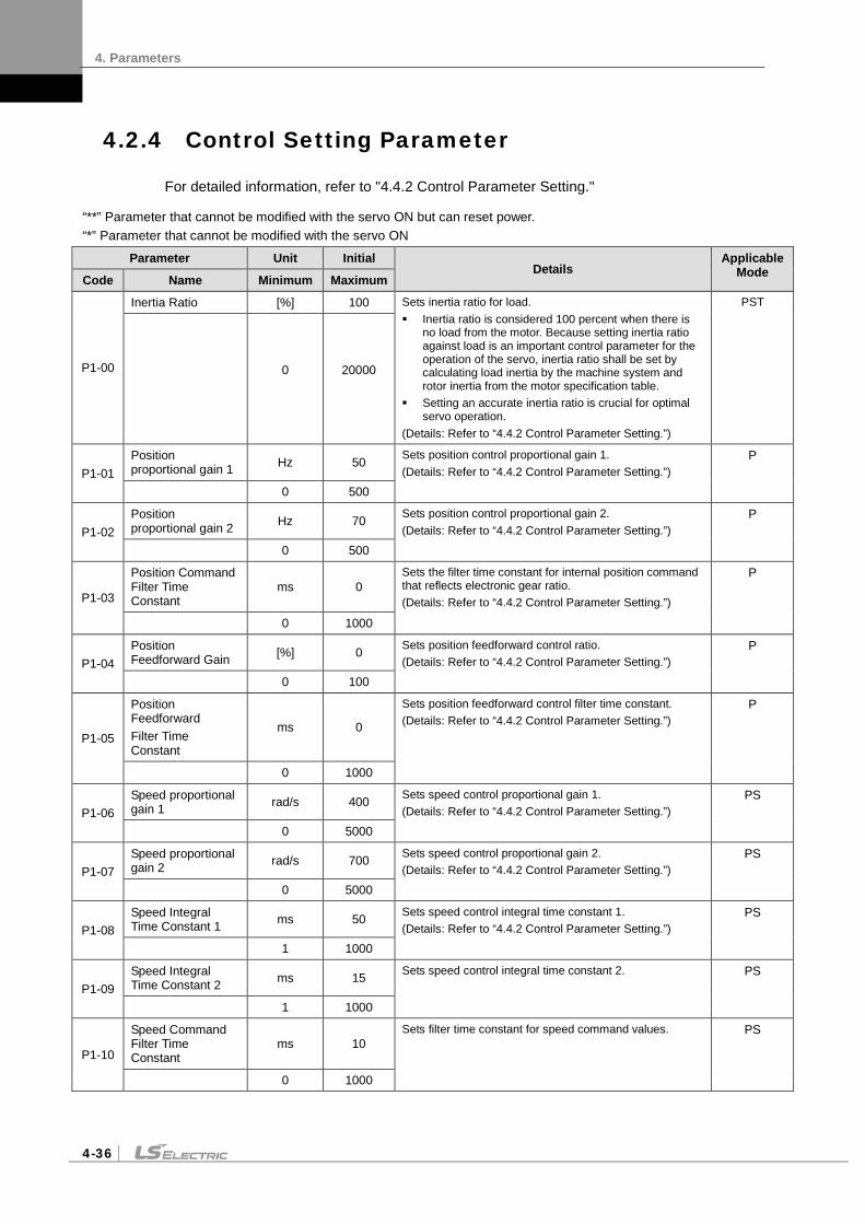
4. Parameters
4-36
4.2.4 Control Setting Parameter
For detailed information, refer to "4.4.2 Control Parameter Setting."
“**” Parameter that cannot be modified with the servo ON but can reset power. “*” Parameter that cannot be modified with the servo ON
Parameter Unit Initial Details
ApplicableMode Code Name Minimum Maximum
P1-00
Inertia Ratio [%] 100 Sets inertia ratio for load. Inertia ratio is considered 100 percent when there is
no load from the motor. Because setting inertia ratio against load is an important control parameter for the operation of the servo, inertia ratio shall be set by calculating load inertia by the machine system and rotor inertia from the motor specification table.
Setting an accurate inertia ratio is crucial for optimal servo operation.
(Details: Refer to “4.4.2 Control Parameter Setting.”)
PST
0
20000
P1-01 Position proportional gain 1 Hz 50 Sets position control proportional gain 1.
(Details: Refer to “4.4.2 Control Parameter Setting.”) P
0 500
P1-02 Position proportional gain 2 Hz 70 Sets position control proportional gain 2.
(Details: Refer to “4.4.2 Control Parameter Setting.”) P
0 500
P1-03
Position Command Filter Time Constant
ms 0 Sets the filter time constant for internal position command that reflects electronic gear ratio. (Details: Refer to “4.4.2 Control Parameter Setting.”)
P
0 1000
P1-04 Position Feedforward Gain [%] 0 Sets position feedforward control ratio.
(Details: Refer to “4.4.2 Control Parameter Setting.”) P
0 100
P1-05
Position Feedforward Filter Time Constant
ms 0
Sets position feedforward control filter time constant. (Details: Refer to “4.4.2 Control Parameter Setting.”)
P
0 1000
P1-06 Speed proportional gain 1 rad/s 400 Sets speed control proportional gain 1.
(Details: Refer to “4.4.2 Control Parameter Setting.”) PS
0 5000
P1-07 Speed proportional gain 2 rad/s 700 Sets speed control proportional gain 2.
(Details: Refer to “4.4.2 Control Parameter Setting.”) PS
0 5000
P1-08 Speed Integral Time Constant 1 ms 50 Sets speed control integral time constant 1.
(Details: Refer to “4.4.2 Control Parameter Setting.”) PS
1 1000
P1-09 Speed Integral Time Constant 2 ms 15 Sets speed control integral time constant 2. PS
1 1000
P1-10
Speed Command Filter Time Constant
ms 10 Sets filter time constant for speed command values. PS
0 1000

4. Parameters
4-37
Parameter Unit Initial Details
ApplicableMode Code Name Minimum Maximum
P1-11
Speed Feedback Filter Time Constant
0.1ms 5 Sets filter time constant for speed search values. (Details: Refer to “4.4.2 Control Parameter Setting.”)
PS
0 1000
P1-12
Torque Command Filter Time Constant
ms 10 Sets filter time constant for torque command values. (Details: Refer to “4.4.2 Control Parameter Setting.”)
PST
0 1000
P1-13 Positive Torque Limit [%] 300 Sets positive torque limit.
(Details: Refer to “4.4.2 Control Parameter Setting.”) PST
0 300
P1-14 Negative Torque Limit [%] 300 Sets negative torque limit.
(Details: Refer to “4.4.2 Control Parameter Setting.”) PST
0 300
P1-15
Switching Mode - 0x00 Sets gain switching mode. [0x0F (DIGIT 1)] 0: Only uses gain 1. 1: ZSPD automatic gain switching
In case of zero speed, switch from gain 1 to gain 2. In the opposite case, switch from gain 2 to gain 1.
2: INPOS automatic gain switching In case of IN position, switch from gain 1 to gain 2. In the opposite case, switch from gain 2 to gain 1.
3: Manual gain switching When the gain 2 contact is on, switch from gain 1 to gain 2. In the opposite case, switch from gain 2 to gain 1.
Sets P and PI control switching modes. [0xF0 (DIGIT 2)] 0: Only control PI. 1: Control P if the command torque is higher than
the set torque [P1-24]. 2: Control P if the command speed is higher than
the set speed [P1-25]. 3: Control P if the current acceleration is higher
than the set torque [P1-26]. 4: Control P if the current position error is higher
than the set position error [P1-27]. Control P if the PCON contact is on (highest
priority). (Details: Refer to “4.4.2 Control Parameter Setting.”) (Details: Refer to “4.4.4 Input/Output Contact Parameter Setting.”)
PS
0x00 0x43
P1-16
Gain Switching Time ms 1 Sets gain switching time during operation.
When switching from gain 1 to gain 2 and from gain 2 to gain 1, switching is scheduled according to the set time.
PS
1 100
P1-17
Resonance Aoidance Operation
- 0 Select whether to use the notch filter or not. 0: Do not use. 1: Interpolation (Details: Refer to “4.4.2 Control Parameter Setting.”)
PST
0 1

4. Parameters
4-38
Parameter Unit Initial Details
ApplicableMode Code Name Minimum Maximum
P1-18
Resonance Avoidance Frequency
Hz 300 Sets resonance avoidance frequency. (Details: Refer to “4.4.2 Control Parameter Setting.”)
PST
0 1000
P1-19
Resonance Avoidance Range
Hz 100 Sets the scope of resonance avoidance frequency. (Details: Refer to “4.4.2 Control Parameter Setting.”)
PST
0 1000
P1-20 Auto Gain Tuning Speed
100 RPM
8 Sets speed for automatic gain tuning run. PST
1 10
P1-21 Auto Gain Tuning Distance - 3 Sets round-trip distance for automatic gain tuning run. PST
1 5
P1-22
Torque Control Speed Limiting Mode
- 0 Sets speed limit mode during torque control. 0: Limit to [P1-23]. 1: Motor Maximum Speed 2: Analog speed command 3: Limited to the smaller value between the value
of [P1-23] and the analog speed command.
T
0 3
P1-23 Speed Limit RPM 2000 Sets speed limit when speed limit mode [P1-22] is 0
during torque control. T
0 10000
P1-24
P Control Switching Torque
% 200 When setting P and PI control switching mode [P1-15], sets [0x10 (DIGIT 2)] P control switching torque.
PS
0 300
P1-25
P Control Switching Speed rpm 50 When setting P and PI control switching mode [P1-
15], sets [0x20 (DIGIT 2)] P control switching speed.
PS
0 6000
P1-26
P Control Switching Acceleration
rpm/s 1000 When setting P and PI control switching mode [P1-15], sets [0x30 (DIGIT 2)] P control switching acceleration.
PS
0 5000
P1-27
P Control Switching Position Error
pulse 2000 When setting P and PI control switching mode [P1-15], sets [0x40 (DIGIT 2)] P control switching position error.
PS
0 10000

4. Parameters
4-39
4.2.5 Input/Output Setting Parameter
For detailed information, refer to "4.4.3 Analog Input/Output Parameter Setting" and "4.4.4 Input/Output Contact Parameter Setting."
“**” Parameter that cannot be modified with the servo ON but can reset power. “*” Parameter that cannot be modified with the servo ON
Parameter Unit Initial Details Applicable
Mode Code Name Minimum Maximum
**P2-00 Input signal definition 1 - 0x4321 Allocates a CN1 connector pin for a digital input signal.
State of initial input signal allocation [P2-00]DIGIT1 = SVON (DI1) [P2-00]DIGIT2 = SPD1 (DI2) [P2-00]DIGIT3 = SPD2 (DI3) [P2-00]DIGIT4 = SPD3 (DI4) [P2-01]DIGIT1 = ALMRST(DI5) [P2-01]DIGIT2 = DIR (DI6) [P2-01]DIGIT3 = CCWLIM (DI7) [P2-01]DIGIT4 = CWLIM (DI8) [P2-02]DIGIT1 = EMG (DI9) [P2-02]DIGIT2 = STOP (DIA) [P2-02]DIGIT3 = EGEAR1(**) [P2-02]DIGIT4 = EGEAR2(**) [P2-03]DIGIT1 = PCON(**) [P2-03]DIGIT2 = GAIN2(**) [P2-03]DIGIT3 = P_CLR(**) [P2-03]DIGIT4 = T_LMT(**) [P2-04]DIGIT1 = MODE(**) [P2-04]DIGIT2 = ABS_RQ(**) [P2-04]DIGIT3 = ZCLAMP(**)
(**) Unallocated signals (Details: Refer to “4.1.6 External Input Signal and Logic Definition.”)
PST
0 0xFFFF
**P2-01 Input signal definition 2 - 0x8765
0 0xFFFF
**P2-02 Input signal definition 3 - 0x00A9
0 0xFFFF
**P2-03 Input signal definition 4 - 0x0000
0 0xFFFF
**P2-04
Input signal definition 5 - 0x0F00
0 0xFFFF
**P2-05
Output signal definition 1
- 0x4321 Allocate a CN1 connector pin for a digital output signal. State of initial output signal allocation [P2-05]DIGIT1 = ALARM (DO1) [P2-05]DIGIT2 = READY(DO2) [P2-05]DIGIT3 = ZSPD(DO3) [P2-05]DIGIT4 = BRAKE(DO4) [P2-06]DIGIT1 = INPOS(DO5) [P2-06]DIGIT2 = TLMT(**) [P2-06]DIGIT3 = VLMT(**) [P2-06]DIGIT4 = INSPD(**) [P2-07]DIGIT1 = WARN(**)
(**) Unallocated signals (Details: Refer to “4.1.8 External Output Signal and Logic Definition.”) In case of dual allocation, the output contact setting error [AL-72] occurs.
PST
0 0xFFFF
**P2-06
Output signal definition 2
- 0x0005
0 0xFFFF
**P2-07
Output signal definition 3
- 0x0000
0 0xFFFF

4. Parameters
4-40
Parameter Unit Initial Details
ApplicableMode Code Name Minimum Maximum
**P2-08
Input signal logic definition 1
- 0b11111 Define CN1 connector logic for a digital input signal. ( 0: Contact B. 1: Contact A) Definition of initial input logic [P2-08]DIGIT1 = DI1(CN1 #47) (Contact A) [P2-08]DIGIT2 = DI2(CN1 #23) (Contact A) [P2-08]DIGIT3 = DI3(CN1 #22) (Contact A) [P2-08]DIGIT4 = DI4(CN1 #21) (Contact A) [P2-08]DIGIT5 = DI5(CN1 #17) (Contact A)
(Details: Refer to “4.1.6 External Input Signal and Logic Definition.”)
PST
0 0b11111
**P2-09
Input signal logic definition 2
- 0b10001 Define CN1 connector logic for a digital input signal. ( 0: Contact B. 1: Contact A) Definition of initial input logic [P2-09]DIGIT1 = DI6(CN1 #46) (Contact A) [P2-09]DIGIT2 = DI7(CN1 #20) (Contact A) [P2-09]DIGIT3 = DI8(CN1 #19) (Contact A) [P2-09]DIGIT4 = DI9(CN1 #18) (Contact A) [P2-09]DIGIT5 = DIA(CN1 #48) (Contact A)
(Details: Refer to “4.1.6 External Input Signal and Logic Definition.”)
PST
0 0b11111
**P2-10
Output Signal Logic Definition
- 0b10110 Define CN1 connector logic for a digital output signal. ( 0 : Contact B. 1: Contact A) [P2-10]DIGIT1 = DO1(CN1 #38/39) (Contact B) [P2-10]DIGIT2 = DO2(CN1 #40/41) (Contact A) [P2-10]DIGIT3 = DO3(CN1 #43) (Contact A) [P2-10]DIGIT4 = DO4(CN1 #44) (Contact B) [P2-10]DIGIT5 = DO5(CN1 #45) (Contact A)
(Details: Refer to “4.1.8 External Output Signal and Logic Definition.”) (Details: Refer to “4.4.4 Input/Output Parameter Setting.”)
PST
0
0b11111
P2-11
Range of Output for Position Reached
Pulse 10
Sets remaining pulse range for position reached output in position operation mode. (Details: Refer to “4.4.4 Input/Output Parameter Setting.”)
P
1 65535
P2-12 Zero Speed Output Range RPM 10 Sets speed range for zero speed output during a stop.
(Details: Refer to “4.4.4 Input/Output Parameter Setting.”)
PST
1 500
P2-13
Range of Output for Speed Reached
RPM 10
Sets speed range for command speed reached output. (Details: Refer to “4.4.4 Input/Output Parameter Setting.”)
S
1 500
P2-14 Brake Output Action Speed RPM 100 Sets speed for turning on the brake output contact.
(Details: Refer to “4.4.4 Input/Output Parameter Setting.”)
PST
0 6000

4. Parameters
4-41
Parameter Unit Initial Details
ApplicableMode Code Name Minimum Maximum
P2-15
Brake Output Delay Time ms 500 Sets how much time to delay until the brake output
contact turns on when the servo is off or stops. (Details: Refer to “4.4.4 Input/Output Parameter Setting.”)
PST
0 1000
P2-16
Position Pulse Clear Mode - 1 Select operation type for position pulse clear
(PCLR) mode. 0: Operate in edge mode. 1: Operate in level mode.
(Details: Refer to “4.4.4 Input/Output Parameter Setting.”)
P
0 1
*P2-17
Analog Speed Scale RPM 2000 Sets speed scale when the analog speed command
is 10 V. (Details: Refer to “4.4.3 Analog Input/Output Parameter Setting.”)
S
1 6000
P2-18
Analog Speed Offset mV 0 Sets offset for analog speed commands.
(Details: Refer to “4.4.3 Analog Input/Output Parameter Setting.”)
S
-1000 1000
P2-19
Zero Speed Clamp Speed RPM 0 Sets speed range for the clamp operation of the
analog zero speed command. (Details: Refer to “4.4.3 Analog Input/Output Parameter Setting.”)
S
Zero speed
0 1000
*P2-20
Analog Torque Scale [%] 100 Sets torque scale when the analog torque command
is 10 V. (Details: Refer to “4.4.3 Analog Input/Output Parameter Setting.”)
T
1 350
P2-21
Analog Torque Command Offset
mV 0 Sets offset for analog torque commands. (Details: Refer to “4.4.3 Analog Input/Output Parameter Setting.”)
T
-1000 1000
P2-22
Zero Torque Clamp Voltage mV 75 Sets voltage range for the clamp operation of the
analog zero torque command. (Details: Refer to “4.4.3 Analog Input/Output Parameter Setting.”)
T
0 1000
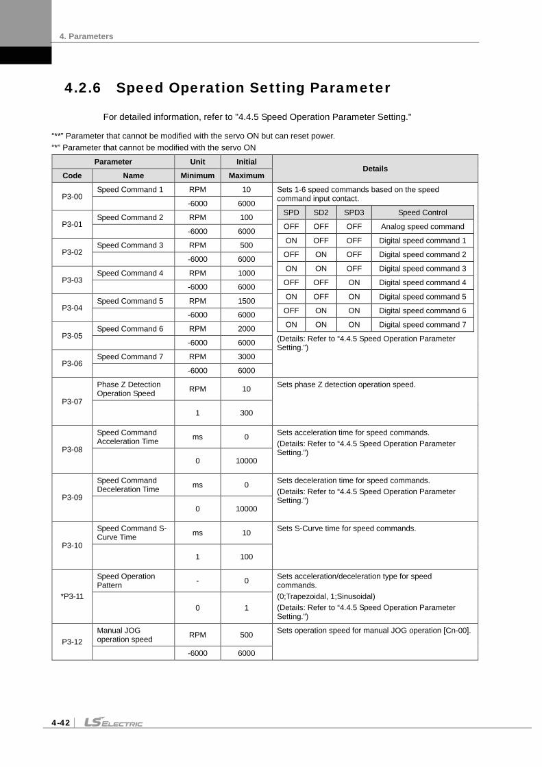
4. Parameters
4-42
4.2.6 Speed Operation Setting Parameter
For detailed information, refer to "4.4.5 Speed Operation Parameter Setting."
“**” Parameter that cannot be modified with the servo ON but can reset power. “*” Parameter that cannot be modified with the servo ON
Parameter Unit Initial Details
Code Name Minimum Maximum
P3-00 Speed Command 1 RPM 10 Sets 1-6 speed commands based on the speed
command input contact.
SPD SD2 SPD3 Speed Control
OFF OFF OFF Analog speed command
ON OFF OFF Digital speed command 1
OFF ON OFF Digital speed command 2
ON ON OFF Digital speed command 3
OFF OFF ON Digital speed command 4
ON OFF ON Digital speed command 5
OFF ON ON Digital speed command 6
ON ON ON Digital speed command 7
(Details: Refer to “4.4.5 Speed Operation Parameter Setting.”)
-6000 6000
P3-01 Speed Command 2 RPM 100
-6000 6000
P3-02 Speed Command 3 RPM 500
-6000 6000
P3-03 Speed Command 4 RPM 1000
-6000 6000
P3-04 Speed Command 5 RPM 1500
-6000 6000
P3-05 Speed Command 6 RPM 2000
-6000 6000
P3-06 Speed Command 7 RPM 3000
-6000 6000
P3-07
Phase Z Detection Operation Speed RPM 10 Sets phase Z detection operation speed.
1 300
P3-08
Speed Command Acceleration Time ms 0 Sets acceleration time for speed commands.
(Details: Refer to “4.4.5 Speed Operation Parameter Setting.”)
0 10000
P3-09
Speed Command Deceleration Time ms 0 Sets deceleration time for speed commands.
(Details: Refer to “4.4.5 Speed Operation Parameter Setting.”)
0 10000
P3-10
Speed Command S-Curve Time ms 10 Sets S-Curve time for speed commands.
1 100
*P3-11
Speed Operation Pattern - 0 Sets acceleration/deceleration type for speed
commands. (0;Trapezoidal, 1;Sinusoidal) (Details: Refer to “4.4.5 Speed Operation Parameter Setting.”)
0 1
P3-12 Manual JOG operation speed RPM 500 Sets operation speed for manual JOG operation [Cn-00].
-6000 6000

4. Parameters
4-43
Parameter Unit Initial Details
Code Name Minimum Maximum
P3-13
Program JOG operation speed 1
RPM 0 Sets operation speed/operation time for programs 1 to 4 during program JOG operation [Cn-01]. A test drive repeats step 1 to 4. Sets operation speed ([P3-13]-[P3-16]) and operation time ([P3-17]-[P3-20]) for each step. E.g.) Step 1 operation
SpeedCommand Speed
Time
-6000 6000
P3-14
Program JOG operation speed 2
RPM 3000
-6000 6000
P3-15
Program JOG operation speed 3
RPM 0
-6000 6000
P3-16
Program JOG operation speed 4
RPM -3000
-6000 6000
P3-17 Program JOG operation time 1 ms 500
0 65535
P3-18 Program JOG operation time 2 ms 5000
0 65535
P3-19 Program JOG operation time 3 ms 500
0 65535
P3-20 Program JOG operation time 4 ms 5000
0 65535

4. Parameters
4-44
4.2.7 Position Operation Setting Parameter
For detailed information, refer to "4.4.6 Position Operation Parameter Setting."
“**” Parameter that cannot be modified with the servo ON but can reset power. “*” Parameter that cannot be modified with the servo ON
Parameter Unit Initial Details
Code Name Minimum Maximum
**P4-00
Position Input Pulse Logic - 0 Sets logic for position operation input pulses.
- The type of position command input pulses and rotation direction per logic are as follows:
E.g.) Relation between direction signals and rotation directions when the position pulse input logic is set to 2. When the direction signal is low: Reverse rotation (CW/clockwise) When the direction signal is high: Forward rotation (CCW/counterclockwise) (Details: Refer to “4.4.6 Position Operation Parameter Setting.”)
0 5

4. Parameters
4-45
Parameter Unit Initial Details
Code Name Minimum Maximum
*P4-01
Electronic Gear Ratio Numerator 1
- 1000
Sets electronic gear ratio numerator/denominator 0, 1, 2, and 3.
EGEAR1 EGEAR 2 Electric Gear Ratio
Numerator / Denominator
Electric Gear Ratio
OFF OFF
Electronic gear ratio numerator 0 Electronic
gear ratio 1 Electronic Gear Ratio
Denominator 0
ON OFF
Electronic gear ratio numerator 1 Electronic
gear ratio 2 Electronic gear ratio
denominator 1
OFF ON
Electronic gear ratio numerator 2 Electronic
gear ratio 3 Electronic gear ratio
denominator 2
ON ON
Electronic gear ratio numerator 3 Electronic
gear ratio 4 Electronic gear ratio
denominator 3
The electronic gear ratio is the numerator/denominator form of the relation between the position command input pulse and the motor encoder pulse. It is important to set the ratio so that there is no error during position operation.
(Details: Refer to “4.4.6 Position Operation Parameter Setting.”)
1 2^21
*P4-02
Electronic Gear Ratio Numerator 2
- 1000
1 2^21
*P4-03
Electronic Gear Ratio Numerator 3
- 1000
1 2^21
*P4-04 Electronic gear ratio numerator 4 - 1000
1 2^21
*P4-05
Electronic Gear Ratio Denominator 1
- 1000
1 32767
*P4-06
Electronic Gear Ratio Denominator 2
- 2000
1 32767
*P4-07
Electronic Gear Ratio Denominator 3
3000
1 32767
*P4-08
Electronic Gear Ratio Denominator 4
- 4000
1 32767
P4-09
Electronic Gear Ratio Mode - 0 Select an electronic gear ratio mode.
0: Select electronic gear ratio 1-4. 1: Override offset [P4-10] on the electronic gear ratio
numerator 0. (Details: Refer to “4.4.6 Position Operation Parameter Setting.”)
0 1
P4-10
Electric Gear Ratio Numerator Offset
- 0 Sets the offset of the electronic gear ratio numerator 0. The offset will be set on the electronic gear ratio numerator 0. EGEAR1 contact LOW -> HIGH
: Increase the electronic gear ratio numerator by 1. EGEAR2 contact LOW -> HIGH
: Decrease the electronic gear ratio numerator by 1) (Details: Refer to “4.4.6 Position Operation Parameter Setting.”)
-32767 32767
P4-11 Position Error Pulse 90000 Sets range for triggering the position error alarm.
(Details: Refer to “4.4.4 Input/Output Contact Parameter Setting.”) 1 2^30
P4-12
Limit Contact Function - 0 Select the operation type of position command pulse clear for
CWLIM and CCWLIM contacts. 0: When the CCWLIM / CWLIM contact is on, receive an input
pulse and save it to buffer. 1: Ignore any input pulse when the CCWLIM / CWLIM contact
is on.
Function
0 1

4. Parameters
4-46
Parameter Unit Initial Details
Code Name Minimum Maximum
P4-13
Backlash Compensation - 0 Sets backlash compensation in position operation. Sets backlash compensation by converting the amount of backlashes to number of pulses if the position changes because of backlashes caused by position operation. Sets in the opposite direction according to the amount of backlashes. (Details: Refer to “4.4.6 Position Operation Parameter Setting.”)
0 10000
P4-14
Pulse Input Filter - 3 Sets filter frequency according to pulse input. 0: Do not use any filter. 1 : 500Khz (Min) 2 : 750Khz 3 : 1Mhz (Default) 4 : 1.25Mhz Determination of the above frequency bands is based on input pulse width in terms of digital filter's characteristics.
0 4

4. Parameters
4-47
4.2.8 Operation Handling Parameter
“**” Parameter that cannot be modified with the servo ON but can reset power. “*” Parameter that cannot be modified with the servo ON
Parameter Unit Initial Details
Code Name Minimum Maximum
Cn-00
Manual JOG Operation - - The drive performs manual JOG operation by itself. (Refer to “Chapter 5 Handling and Operation.”) [MODE]: Finish [UP]: Forward rotation (CCW) [DOWN]: Reverse rotation (CW) [SET]: Servo ON/OFF Related parameters are as follows. [P3-08]: Speed command acceleration time [P3-09]: Speed command deceleration time [P3-10]: Speed command S-curve [P3-11]: Speed operation pattern [P3-12]: JOG operation speed Operate regardless of the contact input status of CN1. (Details: Refer to “4.4.5 Speed Operation Parameter Setting.”) (Details: Refer to "5.2 Handling.")
- -
Cn-01
Program JOG Operation - - Continuously operates according to the program already set. [SET]: Program JOG run or stop Related parameters are as follows: [P3-08]: Speed command acceleration time [P3-09]: Speed command deceleration time [P3-10]: Speed command S-curve [P3-11]: Speed operation pattern [P3-13~16]: Program operation speed 1 to 4 [P3-17~20]: Program operation time 1 to 4 Operate regardless of the contact input status of CN1. (Details: Refer to “4.4.5 Speed Operation Parameter Setting.”) (Details: Refer to "5.2 Handling.")
- -
Cn-02 Alarm Reset - - Reset the alarm that went off.
(Details: Refer to "5.2 Handling.") - -

4. Parameters
4-48
Parameter Unit Initial Details
Code Name Minimum Maximum
Cn-03
Get Alarm History - - Check the saved alarm code history. [UP] or [DOWN]: Reads alarm codes. E.g.) Recent first history [AL-42]: RST_PFAIL
occurs. 01: Latest alarm 20: 20th previous alarm
(Details: Refer to "5.2 Handling.")
- -
Cn-04 Alarm History Reset - - Deletes the entire saved alarm code history.
(Details: Refer to "5.2 Handling.") - -
Cn-05
Auto Gain Tuning - - Performs automatic gain tuning operation. Related parameters are as follows. [P1-22]: Auto gain tuning speed [P1-23]: Auto gain tuning distance (Details: Refer to "5.2 Handling.")
- -
Cn-06
Phase Z Detection Operation - - Perform phase Z detection.
[SET]: Mode entering and servo ON status [UP]: Phase Z forward search [DOWN]: Phase Z reverse search Related parameters are as follows. [P3-07]: Sets Z-phase detection operation
speed [RPM]. (Details: Refer to "5.2 Handling.")
- -
Cn-07
Input Contact Forced ON/OFF - - Forcibly turns on/off the input contact temporarily.
[UP]: (A),(8),(6),(4), and (2) signals forced ON/OFF
[DOWN]: (9),(7),(5),(3), and (1) signals forced ON/OFF
[MODE]: Move to another digit. (Details: Refer to "5.2 Handling.")
- -
Cn-08
Output Contact Forced ON/OFF - - Forcibly turns on/off the output contact temporarily.
[UP]: (4) and (2) signals forced ON/OFF [DOWN]: (5),(3), and (1) signals forced
ON/OFF [MODE]: Move to another digit. (Details: Refer to "5.2 Handling.")
- -
Cn-09 Parameter Initialization - - Reset parameter data.
(Details: Refer to "5.2 Handling.") - -

4. Parameters
4-49
Parameter Unit Initial Details
Code Name Minimum Maximum
Cn-10
Auto Speed Command Offset Correction - - Calibrates the offset of analog speed commands
automatically. The possible voltage setting ranges from -1V to 1V. If offset voltage exceeds this range, oVrnG is displayed and there is no correction. You can check the calibrated offset in the analog speed command offset [P2-18]. (Details: Refer to "5.2 Handling.")
- -
Cn-11
Auto Torque Command Offset Correction - - Calibrates the offset of analog torque commands
automatically. The possible voltage setting ranges from -1V to 1V. If offset voltage exceeds this range, oVrnG is displayed and there is no correction. You can check the calibrated offset in the analog torque command offset [P2-21]. (Details: Refer to "5.2 Handling.")
- -
Cn-12
Manual Speed Command Offset Correction - - Calibrates the offset of analog speed commands
manually. The possible voltage setting ranges from -1V to 1V. If offset voltage exceeds this range, oVrnG is displayed and there is no correction. You can check the calibrated offset in the analog speed command offset [P2-18]. (Details: Refer to "5.2 Handling.")
- -
Cn-13
Manual Torque Command Offset
Correction - -
Calibrate the offset of analog torque commands manually. The possible voltage range is from +1 V to -1 V. If offset voltage exceeds this range, oVrnG is displayed and there is no correction. You can check the corrected offset in the analog torque command offset [P2-21]. (Details: Refer to "5.2 Handling.")
- -

4. Parameters
4-50
Parameter Unit Initial Details
Code Name Minimum Maximum
Cn-14 Absolute Encoder Reset - - Resets the absolute encoder.
(Details: Refer to "5.2 Handling.") - -
Cn-15
Instantaneous Maximum Load Factor Reset - - Reset the instantaneous maximum load factor to
0. [UP]: Displays the + forward maximum load
factor. [DOWN]: Displays the - direction maximum
load factor. [SET]: Initializes the maximum load factor. (Details: Refer to "5.2 Handling.")
- -
Cn-16
Parameter Lock - - Sets parameter lock. [UP]: UnLock [DOWN]: Lock (Details: Refer to "5.2 Handling.")
- -
Cn-17 Current Offset - - Saves current offset value to parameter P0-27 -
P0-28. (Details: Refer to "5.2 Handling.") - -

4. Parameters
4-51
4.3 Operation Status Display
4.3.1 Status Display [St-00]
Refer to "4.1.2 Status Summary Display."
4.3.2 Speed Display
1. Current operation speed [St-01]
This displays the current operation speed in RPM.
2. Current command speed [St-02]
Displays the current command speed in RPM.
4.3.3 Position Display
1. Tracking position pulse [St-03]
Displays the accumulated number of position command pulses that followed as a result of rotation of the servo motor because the servo was turned on.
2. Position command pulse [St-04]
Displays the accumulated number of position command pulses that have been entered since the servo turned on.
3. Remaining position pulse [St-05]
This displays the difference between command pulses and tracking pulses and the remaining position pulses for the servo to run.
The remaining position pulses delayed while the servo is off are ignored when it is turned on.
4. Input pulse frequency [St-06]
This displays the input pulse frequency.
4.3.4 Torque and Load Display
1. Current operation torque [St-07]
This displays the energy (load) output by the servo motor as a percentage of the rated output.
2. Current command torque [St-08]
This uses the servo's control algorithm to calculate the internal torque command and display it as a percentage of the rated torque.
3. Accumulated overload rate [St –09]
This displays the current energy (load) as a percentage of the rated energy (load) of the servo motor.

4. Parameters
4-52
4. Instantaneous maximum load factor [St–10]
Displays the maximum (peak) load between the current time and the start of control after the servo is turned on as a percentage of the rated output.
5. Torque limit [St –11]
This displays the maximum torque that the servo motor can output as a percentage of the rated torque.
6. DC link voltage [St–12]
The DC link voltage of the standard drive that uses 380 V is approximately 537 V.
The maximum DC link voltage allowed for the standard drive that uses 380 V is 800 V.
The overvoltage alarm [AL-41] triggers when the DC link voltage threshold is exceeded because there is either too much or too little regenerative resistance.
The normal DC link voltage in the regenerative section is 747 V or below.
7. Regenerative overload [St–13]
This displays the overload rate relative to the regenerative capacity of the servo drive.
4.3.5 I/O Status Display
1. CN1 I/O input contact point status [St-14]
Refer to "4.1.4 External Input Contact Point Signal Display [St-14]."
2. CN1 I/O output contact status [St-15]
Refer to "4.1.6 External Output Contact Signal Display [St-15]."
4.3.6 Miscellaneous Status and Data Display
1. Single-turn data (pulse) display [St-16]
Displays the single-turn data of the encoder in pulses.
2. Single-turn data (degree) display [St-17]
Displays the single-turn data of the encoder in degrees.
3. Multi-turn data display [St-18]
This displays the multi-turn data for the encoder.
4. Inside temperature display [St-19]
This displays the temperature sensor value of the servo drive in .
5. Rated motor speed display [St-20]
This displays the rated speed of the motor in RPM.
6. Peak motor speed display [St-21]
This displays the peak speed of the motor in RPM.
7. Rated motor current display [St-22]
This displays the rated current of the motor in A.

4. Parameters
4-53
8. U phase current offset display [St-23]
This displays the U phase current offset in mA.
9. V phase current offset display [St-24]
This displays the V phase current offset in mA.
4.3.7 Version Display
1. Software version display [St-25]
Displays the version of the currently installed software.
Encoder Type Rated Voltage Version Number Drive Capacity
Encoder Type Rated Voltage Type
Character Display Number Drive Capacity
Dot
None

4. Parameters
4-54
4.4 Parameter Setting
4.4.1 Setting System Parameters
1. Motor ID setting [P0-00]
Serial encoder: Reads the motor ID from the encoder and displays it.
Incremental encoder: Sets motor ID directly.
2. Encoder settings
Encoder type [P0-01]
Number Encoder Type Encoder Type
0 Quadrature type incremental encoder 1 Serial type encoder (-)
2 Serial type abs encoder (12 bit) 3 Serial type abs encoder (16 bit)
4 Serial type abs encoder (20 bit) 5 Serial type abs encoder (24 bit)
※ The bits in parentheses in the previous table indicate peak multi-turn data.
Encoder pulse [P0-02]
Set this pulse when using an incremental encoder. Set the number of pulses per turn for a signal. For a serial encoder, encoder data are set directly.
3. Operation mode setting [P0-03]: Sets operation mode of the servo.
Operation Modes Operation Method 0 Torque control operation
1 Speed control operation
2 Position control operation
3 Mode contact ON: Position control operation Mode contact OFF: Speed control operation
4 Mode contact ON: Speed control operation Mode contact OFF: Torque control operation
5 Mode contact ON: Position control operation Mode contact OFF: Torque control operation
4. System ID setting
An ID can be given to the servo if RS422 communication and BUS communication are used for communication with the servo. Communication-related options are required in this case.
Communication speed setting [P0-04]
You can select the baud rate, the communication speed of RS422.
0: 9600 bps
1: 19200 bps
2: 38400 bps
3: 57600 bps

4. Parameters
4-55
System ID [P0-05]
A unique ID can be given to the servo and used for individual communication with it.
5. Main power input mode setting [P0-06]
Specifies the main power input mode and the processing mode if phase loss occurs.
DIGIT 1: Sets the main power input type.
(0: Single-phase power input. 1: Three-phase power input.)
DIGIT 2: Sets how to handle errors and warnings in case of main power phase loss.
(0: Error in case of main power phase loss. 1: Warning in case of main power phase loss.)
6. RST checking time setting [P0-07]
Specifies the monitoring interval for main power phase losses.
7. Start-up display parameter setting [P0-08]
You can set the parameter applicable initially when the servo is turned on.
There are 26 values available for setting, from [St-00] to [St-25]. Choose one for a specific parameter.
8. Regenerative overload derating factor setting [P0-09]
This specifies the derating factor which checks for regenerative resistance overloads. If the derating value is 100% or less, then the overload alarm trigger time is proportional to the set value.
9. Regenerative resistance value setting [P0-10]
This specifies the resistance value for regenerative braking resistance. If it is set to 0, then it uses the default resistance capacity embedded in the drive.
10. Regenerative resistance capacity setting [P0-11]
This specifies the current capacity for regenerative resistance. If it is set to 0, then it uses the default resistance capacity embedded in the drive.
11. Overload check default load factor setting [P0-12]
This indicates the load factor which triggers a continuous overload check. If it is set to 100 or less, then the overload check starts early and the overload alarm triggers early.
12. Overload warning level setting [P0-13]
This specifies the level for the continuous overload warning signal output. The warning signal is issued when it reaches the setting of the percentage value relative to the alarm trigger value.
13. Encoder pulse pre-scale output (Encoder output pre-scale [P0-14])
When an encoder signal is output from the servo to the outside, its output pulse is pre-scaled as a pre-defined value
(encoder output prescale [P0-14]) before output.
E.g.) In a motor with encoder 3,000 ppr
Set pre-scale value (pulse output pre-scale [P0-14] = 12000)
=> Encoder pulse output: 3,000 ppr × 4 = 12,000 ppr
14. PWM OFF delay time setting [P0-15]
Sets the time span between servo OFF command and actual PWM OFF. This is to prevent the motor from slipping down the vertical axis until the motor brake comes into effect after receiving the

4. Parameters
4-56
servo off command and then the brake signal. Set a PWM off delay when operating the motor brake with the output contact point brake signal. (range: 0-1000 ms, initial value: 10).
15. DB control mode [P0-16]: Specifies the DB control mode.
0: Hold after DB stop
1: Release after a DB stop
2: Release after free run stop
3: Hold after a free run stop
16. Servo function setting bit [P0-17]
Sets drive function per digit.
DIGIT 1 -> Sets the operation direction of the servo.
0: CCW (Clockwise), CW (Counterclockwise)
1: CW (Clockwise), CCW (Counterclockwise)
DIGIT 2 -> Sets servo lock.
0: Do not use
1: Use (When analog speed command is 0 in speed operation mode, the operation mode switches to position operation mode temporarily to ensure that motor remains stopped firmly.)
DIGIT 3 -> Sets Open Collector Output
0: Do not use
1: Use (AL0, AL1, AL2 output contact -> Open Collector A, B, Z output)
DIGIT 4 -> Sets Monitor Output Voltage. (Applicable to both Monitor 1 and 2)
0 : -10-+10V
1: 0-+10V
DIGIT 5 -> Sets saving EEPROM communication.
0 : Do not use
1: Use (No parameter is saved to EEPROM when you write the parameter via communication.)
17. DAC Output Setting
There are four kinds of DAC output, each of which is made every 200 usec according to the condition of used data.
DAC output type [P0-18 DIGIT 1, DIGIT 2]
Type Data Content Type Data Content 0 Speed feedback [RPM] 5 Following error [pulse]
1 Speed command [RPM] 6 DC link voltage [V]
2 Torque feedback [%] D Speed command (user) [RPM]
3 Torque command [%] E Torque command (user) [%]
4 Position command frequency [0.1 Kpps]

4. Parameters
4-57
DAC output scale [P0-23], [P0-24]
If the output value is too low or too high, output ratio can be adjusted.
Sets magnification [Unit/V] for analog output channels 1 to 2.
(Speed [RPM], torque [%], position command frequency [0.1 Kpps], position [pulse], DC link [V])
Example: Channel 1 scale 100 =>100 RPM is output as 1 V.
DAC output offset [P0-19], [P0-20]
Sets offset [Unit/V] for 1-2 analog output channels.
(Speed [RPM], torque [%], position command frequency [0.1 Kpps], position [pulse], DC_Link [V])
4.4.2 Control Parameters
The control parameter setting sequence is as follows:
Load inertia ratio [P1-00] setting: Refer to “5.2.6 Auto Gain Tuning [Cn-05].”
Position proportional gain [P1-01] and [P1-02] adjustment:
Increase the gain so that the servo motor does not overshoot or lose control (do not use during speed operations or torque operations).
Speed proportional gain [P1-06] and [P1-07] adjustment:
Increase the gain so that the servo motor does not vibrate.
Speed integral time constant [P1-08] and [P1-09] adjustment:
Refer to the following table and set it according to the speed proportional gain.
(1) Inertia Ratio Setting [P1-00]
This sets the inertia ratio by calculating the load inertia from the machine system and rotor inertia listed on the motor specification table.
The inertia/load ratio is an important control parameter for the operation of the servo. It is crucial to set the correct inertia ratio for optimal servo operation.
The following table outlines the recommended control gain for different inertia ratios:
Motor Flange
Inertia Ratio Gain Range
Category Inertia (Multiple)
Position Proportional
Gain
Speed Proportional
Gain Speed Integral
Gain
40 ~ 80
Low inertia 1 ~ 5 40 ~ 90 400 ~ 1000 10 ~ 40
Medium inertia 5 ~ 20 20 ~ 70 200 ~ 500 20 ~ 60
High inertia 20 ~ 50 10 ~ 40 100 ~ 300 50 ~ 100
* You can tune the inertia ratio during a test drive if it is too hard to calculate the inertia ratio before operation.

4. Parameters
4-58
(2) Position Control Gain
Position command: Counts the position command pulses entering from outside and converts them into position command values. Next, it applies electronic gear ratio to those values and uses them as internal position commands by way of [P1-03] position command filter. In case the electronic gear ratio has a large numerator, change of external input position command pulse has increasing effects on change of internal position command, so you need to adjust [P1-03] position command filter time constant to reduce the effects.
Current position: Counts the pulse signals received from the encoder and uses the electronic gear ratio settings to convert them to the current position.
Position proportional gain [P1-01] and [P1-02]: Converts the difference between the position command and the current position into a speed command by multiplying it by the position proportional gain.
* Recommended value = Speed proportional gain [P1-06] / 10
Feedforward gain [P1-04]: Uses the differences in value to the position command to calculate the gradient. Adds the speed command to the gradient to reduce the time needed to reach the target position. If the value which results is too large, then the position controller may overshoot or become unstable. It is important to gradually increase the value from a small value while monitoring the test drive.
Feedforward filter [P1-05]: The feed-forward control filter vibrates if the position command changes too drastically. If this occurs, configure the filter value until the vibrations disappear.
Differentiation
FF filter time constant [P1-05]
Feedforward gain [P1-04]
Current position
Proportional gain [P1-01]
Position error +
-
+
+
Speed Command
Position command
Pulse output Division
[P0-14]/[P0-15]

4. Parameters
4-59
(3) The Speed Control Gain
Speed command: Use an analog speed signal entering from outside as a speed command after running it through the speed command filter [P1-10], or use a digital speed command and [RPM] set in the internal parameter.
Current speed: Calculates the speed by counting the number of encoder signals as time progresses. Filters the speed to calculate the current speed. The algorithm uses the current torque and inertia to project the speed and compensate for errors which occur when calculating the speed at very low speeds. Therefore, an accurate motor constant and inertia ratio are closely related to the stability of the motor speed control.
Speed integral time constant [P1-08]: Calculates the integral value of the speed error. The speed error is the difference between the command speed and the current speed. The speed integral time constant converts the speed error into a torque command by multiplying it by the integral time constant.
A decreased integral time constant solves transient response issues and improves speed tracking. If the integral time constant is too small, however, an overshoot occurs. On the other hand, if the integral time constant is too large, an excessive response drop occurs and proportional control takes over.
* Recommended value = 10000 / speed proportional gain [P1-06]
Speed proportional gain [P1-06]: Converts the speed error into a torque command by multiplying it by the proportional gain.
If the resulting value is large, then the speed response accelerates and speed tracking increases. However, vibrations occur if the value is too large. If the value is too small, then speed response slows down and speed tracking decreases. This may cause the servo to lose power.
Analog speed command Speed command
filter time constant [P1- 10]
Speed integral time constant [P1-08]
Speed Proportional Gain [P1-06]
Speed calculation Encoder signal
Torque command
Current
Digital speed command +
+
Current torque
-
Speed
Time
Command speed
Tracking speed
Low
High
Speed feedback filter time constant

4. Parameters
4-60
Speed feedback filter time constant [P1-11]: Filters the speed feedback to control vibrations when the speed of the motor changes due to drive system vibrations or vibrations due to gain and too much load inertia. If the value is too high, it reduces speed responsiveness and control power may be compromised.
* Recommended value = 0 - Speed integral time constant [P1-08]/10
(4) Torque Command Filter Time Constant Setting [P1-12]
Use a digital filter for the analog torque command voltage to improve the stability of command signals. If the filter value is set too high, responsiveness to torque commands will be reduced. It is important to set a value that is appropriate for your system.
(5) Torque Limit Setting [P1-13], [P1-14]
You can set maximum torque limits for forward rotation [P1-13] and for reverse rotation [P1-14] separately. The setting is displayed as a percentage of the rated torque and the standard is 300 %.
(6) Gain 1<->Gain 2 Switching Mode Setting [P1-15] 0x0F (DIGIT 1)
Set speed gain switching mode. [0x0F (DIGIT 1)]
0: Only uses gain 1.
1: ZSPD auto gain switching
In case of zero speed, switch from gain 1 to gain 2.
In the opposite case, switch from gain 2 to gain 1.
2: INPOS auto gain switching
In case of IN position, switch from gain 1 to gain 2.
In the opposite case, switch from gain 2 to gain 1.
3: Manual gain switching
When the gain 2 contact is on, switch from gain 1 to gain 2.
In the opposite case, switch from gain 2 to gain 1.
Time
Speed
Command speed
High
Low

4. Parameters
4-61
(7) Gain 1<->Gain 2 Switching Time Setting [P1-16]
Configure the gain switching time during operation.
When switching from gain 1 to gain 2 or gain 2 to gain 1, the switching occurs according to the set time.
(8) P / PI Switching Mode Setting [P1-15 DIGIT 2]
Set P and PI control switching modes. [0xF0 (DIGIT 2)]
0: Only control PI.
1: Control P if the command torque is higher than the set torque [P1-24].
2: Control P if the command speed is higher than the set speed [P1-25].
3: Control P if the current acceleration is higher than the set torque [P1-26].
4: Control P if the current position error is higher than the set position error [P1-27].
Control P if the PCON contact is on (highest priority).
These functions allow you to improve position operations by applying the P control operation stop function after PI control operation.
(9) Resonance Avoidance Operation Setting [P1-17], [P1-18], [P1-19]
Mechanical resonance causes vibrations to occur at certain frequencies in certain systems. You can control the vibrations by controlling the torque output for specific frequencies.
Resonance avoidance operation [P1-17]
0: Do not use
1: Interpolation
Resonance avoidance frequency [P1-18]
Torque output
Torque output frequency
Resonance avoidance range BW [P1-19]

4. Parameters
4-62
4.4.3 Analog Input/Output Parameter Setting
(1) Analog Speed Scale Setting
Analog speed scale [P2-17]: Set the analog speed command of 10 [V] in the unit of [RPM]. The maximum value is the maximum motor speed.
Analog speed command offset [P2-18]: There are cases where a certain level of voltage remains on the analog signal access circuit, even at the 0 speed command. In this case, you can compensate it by setting the voltage as offset. The unit is .
Zero speed command clamp setting
(2) Analog Torque Scale Setting
Analog torque command scale [P2-20]: Set the analog torque command of 10 [V] as a percentage of the rated torque. The setting should be within the torque limit [P1-13] and [P-14] of system parameter setting.
Torque command offset [P2-21]: There are cases in which a certain level of voltage remains on the analog circuit, even at the 0 torque command, because of problems with the circuit. You can compensate this by setting the voltage as offset. The unit is .
Zero torque command clamp
-10 V -10 V +10 V
Speed
Voltage
- +10 V
Zero speed command clamp voltage [P2-19]
+
Zero speed command clamp voltage [P2-19] = 0
Zero speed command clamp voltage [P2-19] = Not 0 mV
-10 V -10 V +10 V
Voltage
- +10 V
Zero torque command clamp voltage [P2-22]
+
Zero torque command clamp voltage [P2-22] = 0
Zero torque command clamp voltage [P2-22] = Not 0 mV
Torque

4. Parameters
4-63
4.4.4 Setting the Input/Output Contact Point Parameters
(1) Position Operation Parameter Setting
Position reached output range [P2-11]: If the error pulse, which is the difference between the command position pulse and the follow position pulse, reaches this range, a signal is output to indicate that the position has been decided.
If you set too great a value, the target position complete output signal might occur during operation depending on the position command pulse. Therefore, It is important to set an appropriate value.
Position operation follow error range [P4-11]
If the error pulse is greater than the position operation tracking error range, the position tracking error alarm [AL-51] triggers.
Pulse counter
Command pulse counter
Follow pulse counter Error pulse
Position decision Completed output
Position reached output range [P2-11] Time
Error pulse
Command pulse
Position follow error range
Follow pulse counter
Pulse counter
Position follow error alarm
Time

4. Parameters
4-64
(2) Speed Operation Parameter Setting
Zero speed output range [P2-12]: A zero speed signal is output if the current speed drops below the set speed.
Speed-reached output range [P2-13]: The speed-reached signal is output.
(3) Brake Signal Output Parameter Setting
Brake signal output operation speed [P2-14], brake signal output delay time [P2-15]
In the event that an alarm triggers when the servo’s built-in brake is applied to the vertical axis for the operation of the motor by the servo, this feature is activated to prevent the vertical axis from falling to the motor brake. This may occur as a result of the brake signal’s turning off, which is triggered by first of either the brake signal output operation speed [P2-14] or the brake signal output delay time [P2-15].
(4) Position Pulse Clear Mode [P2-16]
Set the operation of position pulse clear mode in position operation mode.
Setting Operation
0 Operate only on the edge where the contact point turns on. (Do not operate when it is off or on.)
1 Operate immediately at contact point on_ Level.
Speed
Command Range of output for speed
reached [P2-13]
Zero speed output range [P2-12]
Zero speed (ZSPD)
Speed reached (INSPD)
Time
Motor operation speed Speed
Servo ON input
Brake output signal Within 50 ms
Brake signal output Operation speed [P2-14]
Time
Brake signal output Delay time [P2-15]
Servo OFF or alarm trigger

4. Parameters
4-65
(5) Output Signal Logic Definition Setting [P2-10]
You can change the output condition of the current output contact point to initial status ON or initial status OFF.
4.4.5 Setting Speed Operation Parameters
(1) Speed Command [P3-00]-[P3-06]
You can adjust operation speed in [RPM]. Operation speed is determined by speed command input contact points.
SPD1 SPD2 SPD3 Speed Control OFF OFF OFF Analog speed command
ON OFF OFF Digital speed command 1
OFF ON OFF Digital speed command 2
ON ON OFF Digital speed command 3
OFF OFF ON Digital speed command 4
ON OFF ON Digital speed command 5
OFF ON ON Digital speed command 6
ON ON ON Digital speed command 7
(2) Acceleration/Deceleration Time
Acceleration time [P3-08]: Specifies the time required, in ms, for the motor to reach the rated motor speed from zero speed.
Deceleration time [P3-09]: Specifies the time, in ms, required for the motor to stop after running at the rated motor speed.
(3) S-Curve Operation [P3-11]
You can configure the acceleration/deceleration operation in an S-curve pattern for smooth acceleration/deceleration.
0: Trapezoidal -> Set acceleration/deceleration time [P3-08] and [P3-09].
1: Sinusoidal -> Set acceleration/deceleration time [P3-08] and [P3-09] + S-curve time [P3-10].
(4) Manual JOG Operation [Cn-00]
Press RIGHT for forward rotation at JOG operation speed [P3-12]. Press LEFT for reverse rotation at JOG operation speed [P3-12]. This ignores the CN1 contact point input status.
(5) Program JOG Operation [Cn-01]
A test drive repeats step 1 to 4. Set operation speed [P3-13]-[P3-16]) and operation time ([P3-17]-[P3-20]) for each step.
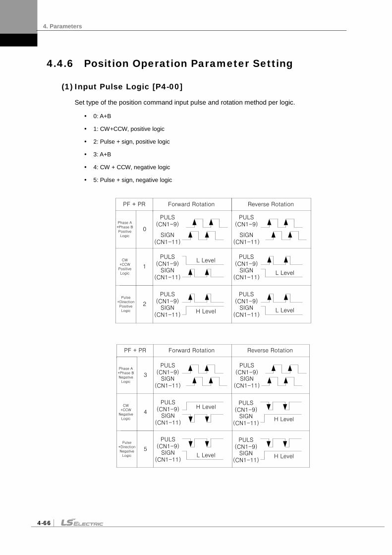
4. Parameters
4-66
4.4.6 Position Operation Parameter Setting
(1) Input Pulse Logic [P4-00]
Set type of the position command input pulse and rotation method per logic.
0: A+B
1: CW+CCW, positive logic
2: Pulse + sign, positive logic
3: A+B
4: CW + CCW, negative logic
5: Pulse + sign, negative logic
PULS(CN1-9)
SIGN(CN1-11)
PULS(CN1-9)
SIGN(CN1-11)
0
1
Phase A+Phase BPositive Logic
CW+CCWPositive Logic
PULS(CN1-9)
SIGN(CN1-11)
2Pulse
+DirectionPositive Logic
Forward Rotation Reverse Rotation
PULS(CN1-9)
SIGN(CN1-11)
PULS(CN1-9)
SIGN(CN1-11)
PULS(CN1-9)
SIGN(CN1-11)
PF + PR
L Level
L Level
L Level
H Level
PULS(CN1-9)
SIGN(CN1-11)
PULS(CN1-9)
SIGN(CN1-11)
3
4
PULS(CN1-9)
SIGN(CN1-11)
5
Forward Rotation
Phase A+Phase BNegative
Logic
CW+CCW
Negative Logic
Pulse+DirectionNegative
Logic
Reverse Rotation
PULS(CN1-9)
SIGN(CN1-11)
PULS(CN1-9)
SIGN(CN1-11)
PF + PR
PULS(CN1-9)
SIGN(CN1-11)
H Level
H Level
H Level
L Level

4. Parameters
4-67
(2) Electronic Gear Ratio [P4-01]-[P4-08]
The electronic gear ratio is the numerator/denominator form of the relation between the position command input pulse and the motor encoder pulse. It is important to set the ratio so that there is no error during position operation. The following describes how to set it:
* Electronic gear ratio = transmission per input pulse x number of pulses per motor rotation / transmission per motor rotation
e.g.) If deceleration ratio is 1/2, ball screw lead is 10 , and encoder pulse is 3000 in the unit of commands that control each pulse in 1 .
1. Transmission per input pulse = 1 × 10 - 3 = 0.001
2. Number of pulses per motor rotation = number of encoder pulses × 4 = 3000 × 4 = 12000
3. Transmission per motor rotation = 10 × 1/2 = 5
4. Electronic gear ratio = 12000×0.001/5 = 12/5
Therefore, the numerator and denominator of electronic gear ratio are 12 and 5 respectively.
Note 1) There are 12,000 pulses per rotation for a 3,000-pulse encoder because the servo drive controls pulses by multiplying them by four in quadrature type encoder signals.
Note 2) Here, motor speed can be calculated in the following equation:
Motor speed = 60 × electronic gear ratio × input pulse frequency / number of pulses per motor rotation
Note 3) Also, you can calculate error pulse [St-05], that is, the difference between command pulse and
following pulse during operation, in the following equation: Error pulse = command pulse frequency × electronic gear ratio × 1 - (0.01 × [P1-05]) / [P1-01]
Note 4) Series type encoder signal system applies 524288 pulses per revolution without a multiple of 4.
(3) Backlash Compensation [P4-13]
If the position operation causes backlashes which change the position, then this setting converts backlash amount into a number of pulses to compensate for the backlash.
(4) Electronic Gear Ratio Offset Adjustment [P4-09]
If the operation distance per rotation changes due to wear and tear on the machine during position pulse command operation, you can adjust the change caused by wear and tear with offset.
Electronic gear ratio setting mode [P4-09]
0: Use electronic gear ratio 0-3.
1: Use electronic gear ratio 0. Override the value on the electronic gear ratio numerator.
Electronic gear ratio numerator offset setting
In the above example, if you enter 12,000 for the numerator and 5,000 for the denominator and turn on the EGEAR1 contact point, the numerator increases by one. If you turn on the EGEAR2 contact, the numerator decreases by one. The change is saved in the [P4-10] parameter.
If the offset is two, the electronic gear ratio for operation changes from 12000/5000 to 12002/5000. Also, if the offset is -2, the electronic gear ratio for operation changes from 12000/5000 to 11998/5000.

4. Parameters
4-68
4.5 Alarms and Warnings
4.5.1 Servo Alarm Status Summary Display List
If an alarm triggers, the malfunction signal output contact point (ALARM) turns off and the dynamic brake stops the motor.
Alarm code Name Details What to check
IPM Fault Overcurrent (H/W)
Check for incorrect wiring in the drive output and encoder. Check the motor ID, drive ID, and encoder settings. Determine whether there is a conflict or binding in the equipment.
IPM temperature IPM overheat
Check for incorrect wiring in the drive output and encoder. Check the motor ID, drive ID, and encoder settings. Determine whether there is a conflict or binding in the equipment.
Over current Overcurrent (S/W)
Check for incorrect wiring in the drive output and encoder. Check the motor ID, drive ID, and encoder settings. Determine whether there is a conflict or binding in the equipment.
Current offset Abnormal current offset Replace the drive if [St-23] and [St-24] are 10% or higher of the rated current.
Overcurrent (/CL) Overcurrent (H/W)
Check for incorrect wiring in the drive output and encoder. Check the motor ID, drive ID, and encoder settings. Determine whether there is a conflict or binding in the equipment.
Continuous overload Continuous overload
Determine whether there is a conflict or binding in the equipment. Check the load and the condition of the brake. Check for incorrect wiring in the drive output and encoder. Check the motor ID, drive ID, and encoder settings.
Room temperature Drive overheat
Check the temperature inside the drive [St-19]. the cooling fan installation, and the load condition.
Regen. Overload Regenerative overload Check the input voltage, regenerative braking resistance, and wiring. Replace the drive.
Motor cable open Motor disconnection Check the wiring of the motor.
Encoder comm. Serial encoder communication error
Check for incorrect wiring of the serial encoder.
Encoder cable open Encoder cable disconnection
Check whether the encoder cable is disconnected.

4. Parameters
4-69
Alarm code Name Details What to check
Encoder data error Encoder data error Check the [P0-02] setting and encoder wiring.
Motor setting error Motor ID setting error Check the [P0-00] setting.
Encoder Z PHASE Open Encoder Z phase disconnected
Check whether the encoder cable is disconnected.
Low Battery Error Low voltage error
BackUp battery has not enough voltage, Change battery. ※After replacing battery, Power “ON” and Homing operation are absolutely needed (apply from S/W Ver 1.28)
Under voltage Low voltage Check input voltage and power unit wiring.
Overvoltage Overvoltage
Check the input voltage and wiring. Check the braking resistance for damage. Check for excessive regenerative operation. Check the regenerative resistance.
RST power fail Main power failure Check the power unit wiring and power supply.
Control power fail Control power failure Check the power unit wiring and power supply.
Over speed limit Overspeed
Check the encoder, encoder settings, encoder wiring, gain settings, motor wiring, motor ID, electric gear ratio, and speed command scale.
Position following Excessive positional error
Check the excessive position command pulse setting [P4-11], wiring, limit contact point, gain setting, encoder setting, and electric gear ratio. Check the load on the equipment and whether there is binding on the equipment.
Over pulse CMD Pulse command frequency error
Check the pulse command frequency on the upper level controller, and check the command pulse type.
Speed deviation Excessive speed error Check for incorrect wiring in the drive output and encoder. Also, check the connection and load status of the equipment.
Motor overrun Motor overrun Check for incorrect wiring in the drive output and encoder. Also, check the connection and load status of the equipment.
Parameter checksum Parameter error Factory reset [Cn-21].
Parameter range Parameter range error Factory reset [Cn-21].
Invalid factory setting Factory setting error Factory reset [Cn-21].
GPIO setting Output contact point setting error Factory reset [Cn-21].

4. Parameters
4-70
4.5.2 Servo Warning Status Summary Display List
If a warning code is displayed as the current operation status [St-00], the servo drive is operating abnormally. Check what needs to be inspected for the issue.
Warning State
(CODE) Name Details and causes What to check
RST_PFAIL Main power phase loss If the [P0-06] DIGIT 2 is set to 1, the main power fails.
LOW_BATT Battery low BackUp battery has not enough voltage
OV_TCMD Excessive Torque Command You have entered a command that exceeds the maximum set torque.
OV_VCMD Excessive speed command You have entered a command that exceeds the maximum set speed.
OV_LOAD Overload warning The maximum overload [P0-13] has been reached.
SETUP Capacity settings The electric current capacity of the motor is larger than that of the drive.
UD_VTG Low voltage warning When [P0-06] DIGIT 2 is set to 1, the DC link voltage is 190 V or below.
EMG EMG contact Check I/O wiring and [P2-09] value
Warning code is displayed in hexadecimal, but it is displayed as the sum of respective warning codes when two or more warnings occur at once. For example, warning code is displayed as [W-0C] when both [W-04] Excessive Torque Command and [W-08] Excessive Speed Command occur at once.
If [W-80] occurs, SVON turns from ON to OFF. And when you turn on I/O power or change contact logic, [W-80] code is automatically deactivated.

4. Parameters
4-71
4.6 Motor Types and IDs
Model Name ID Watt Notes Model Name ID Watt Notes
SEP09A 461 900 SGP35D 512 3500
SEP15A 462 1500 SGP55D 513 5500
SEP22A 463 2200 SGP75D 514 7500
SEP30A 464 3000 SGP110D 515 11000
SEP06D 465 600
SEP11D 466 1100 SGP12M 521 1200
SEP16D 467 1600 SGP20M 522 2000
SEP22D 468 2200 SGP30M 523 3000
SEP03M 469 300 SGP44M 524 4400
SGP60M 525 6000
SEP06M 470 600
SEP09M 471 900 SGP20G 531 1800
SEP12M 472 1200 SGP30G 532 2900
SEP05G 473 450 SGP44G 533 4400
SEP09G 474 850 SGP60G 534 6000
SEP13G 475 1300 SGP85G 535 8500
SEP17G 476 1700 SGP150G 537 15000
SFP30A 481 3000
SFP50A 482 5000
SFP22D 485 2200
SFP35D 486 3500
SFP55D 487 5500
SFP75D 488 7500
SFP12M 489 1200
SFP20M 490 2000
SFP30M 491 3000
SFP44M 492 4400
SFP20G 493 1800
SFP30G 494 2900
SFP44G 495 4400
SFP60G 496 6000
SFP75G 497 7500
SGP22D 511 2200

4. Parameters
4-72
Model Name ID Watt Notes Model Name ID Watt Notes
FEP09A 261 900 FFP60G 296 6000
FEP15A 262 1500 FFP75G 297 7500
FEP22A 263 2200
FEP30A 264 3000 FGP22D 311 2200
FGP35D 312 3500
FEP06D 265 600 FGP55D 313 5500
FEP11D 266 1100 FGP75D 314 7500
FEP16D 267 1600
FEP22D 268 2200 FGP12M 321 1200
FGP20M 322 2000
FEP03M 269 300 FGP30M 323 3000
FEP06M 270 600 FGP44M 324 4400
FEP09M 271 900
FEP12M 272 1200 FGP20G 331 1800
FGP30G 332 2900
FEP05G 273 450 FGP44G 333 4400
FEP09G 274 850 FGP60G 334 6000
FEP13G 275 1300
FEP17G 276 1700
FFP30A 281 3000
FFP50A 282 5000
FFP22D 285 2200
FFP35D 286 3500
FFP55D 287 5500
FFP75D 288 7500
FFP12M 289 1200
FFP20M 290 2000
FFP30M 291 3000
FFP44M 292 4400
FFP20G 293 1800
FFP30G 294 2900
FFP44G 295 4400

5. Handling and Operation
5-1
5. Handling and Operation
5.1 Operation Checklist
Thoroughly check the following items during the test drive to prevent injuries or damage to the servo motor.
5.1.1 Wiring Checklist
1. Is the voltage (AC 200 V) appropriate for the power input terminals?
2. Are the power cables (U, V, W, and FG) between the drive and the motor connected correctly?
3. Is the voltage (24 V) connected to the control signal correctly?
4. Is the regenerative resistance appropriate for the capacity and correctly connected?
5. Are the wiring cables free from bends or kinks?
6. Is the ground and wire insulation free from defects?
5.1.2 the Drive Signal (CN1) Wiring Checklist
Confirm that the wire and contacts for the drive signals are in the state listed on the following table.
Pin Number Pin Name State of
Contact Pin
Number Pin Name State of Contact
18 EMG ON 19 CWLIM ON
47 SVON OFF 20 CCWLIM ON
48 STOP OFF 17 ALMRST OFF
The above is factory-initialized status. Different functions may be allocated according to input signal allocations ([P2-00], [P2-01], [P2-02], [P2-03], and [P2-04]).
5.1.3 Surrounding Environment Checklist
Are there any metal filings or water around the wires?
5.1.4 Machine Status Checklist
1. Is the servo motor coupling in good condition?
2. Are the locking bolts fastened tightly?
3. Are there any obstacles that may prohibit operation of the machine?

5. Handling and Operation
5-2
5.1.5 System Parameter Checklist
1. Is the motor ID setting [P0-00] in good condition?
2. Are the encoder type [P0-01] and the encoder pulse [P0-02] in good condition?
3. Is control gain set to an appropriate value?
*Note: Refer to "Appendix 2 Test Drive Procedure."

5. Handling and Operation
5-3
5.2 Handling
5.2.1 Manual JOG Operation [Cn-00]
The drive performs manual JOG operation by itself.
1. Press SET in [Cn-00] and [JoG] is displayed.
2. Press SET and [SV-on] is displayed and the servo turns on for operation.
If an alarm triggers, check wiring and other possible causes before restarting.
3. Press and hold UP and the motor turns forward (CCW) at the JOG operation speed [P3-12].
4. Press and hold DOWN and the motor turns counterclockwise at the JOG operation speed [P3-12].
5. Press SET again and the manual JOG operation finishes and the servo turns off.
6. Press down [MODE] to return to the parameter screen [Cn-00].
Related Parameters
Speed Initial
[P3-08] Speed command acceleration time ms
0
[P3-09] Speed command deceleration time ms
0
[P3-10] Speed command S-curve time ms
10
*[P3-11] Speed operation pattern 0
[P3-12] JOG operation speed [RPM] 500
The parameter marked with “*” cannot be modified when the servo is on.
[Example of handling manual JOG operation]
Order Loader Displays Keys to Use What to Do
1
Displays the speed control mode with main power and control power permitted.
2
Press MODE to move to [Cn-00].
3
Press SET to enter manual JOG operation.
4
Press SET to turn on the servo.
5
Press and hold UP when the servo is on and the motor turns forward (CCW). Lift your hand off the key and the motor stops.
6
Press and hold DOWN when the servo is on and the motor turns counterclockwise. Lift your hand off the key and the motor stops.

5. Handling and Operation
5-4
Order Loader Displays Keys to Use What to Do
7
Press DOWN and the servo changes to OFF.
8
Press MODE for a second and you return to the menu screen [Cn-00].
※ “ ” indicates flickering.
5.2.2 Program JOG Operation [Cn-01]
Continuously operates according to the program already set.
1. Press the SET key in [Cn-01] parameter. Then, [P-JoG] is displayed.
2. Press SET and [run] is displayed. The program JOG operation starts after the servo is turned on.
(If an alarm triggers at this moment, check the wiring of the servo and other possible causes before restarting.)
3. Press SET again and the program JOG operation finishes and the servo is turned off.
4. Press down [MODE] to return to the parameter screen [Cn-00].
5. Four operation steps repeat continuously from 0 to 3. Operation speed and time can be set in the following parameters:
Related Parameters Speed Initial
[P3-08] Speed command acceleration time [ms]
100
[P3-09] Speed command deceleration time [ms]
100
[P3-10] Speed command S-curve time [ms]
10
[P3-11] Speed operation pattern 0
Step Program Operation Speed
Program Operation Time
0 [P3-13] [P3-17]
1 [P3-14] [P3-18]
2 [P3-15] [P3-19]
3 [P3-16] [P3-20]
[Example of handling program JOG operation]
Order Loader Displays Keys to Use What to Do
1
Displays the speed control mode with main power and control power permitted.
2
Press MODE to move to [Cn-00].

5. Handling and Operation
5-5
Order Loader Displays Keys to Use What to Do
3
Press UP or DOWN to move to [Cn-01].
4
Press SET to enter program Jog operation.
5
Press SET and the motor starts operating according to the predefined program.
6
Press the SET key again and the operation ends. [done] is displayed.
7
Hold down MODE for approximately one second to return to [Cn-01].
※ “ ” indicates flickering.
5.2.3 Alarm Reset [Cn-02]
Reset the alarm that went off.
1. Contact alarm reset: If you turn on ALMRST among input contacts, the alarm is reset and becomes normal.
2. Operation alarm reset: If you press SET in the alarm reset [Cn-02] parameter among operation handling parameters, [ALrst] is displayed. If you press SET again, the alarm is reset and becomes normal.
※ If the alarm keeps ring ing after the reset, check and remove possible causes and then repeat the process.
[Example of alarm reset]
Order Loader Displays Keys to Use What to Do
1
Displays the speed control mode with main power and control power permitted.
2
Press MODE to move to [Cn-00].
3
Press UP or [DOWN] to move to [Cn-02].
4
Press SET to enter alarm reset mode.
5
Press SET to reset the alarm. [done] is displayed.
6
Press MODE for a second to return to [Cn-02].
※ “ ” indicates flickering.

5. Handling and Operation
5-6
5.2.4 Reading Alarm History [Cn-03]
Check the saved alarm history.
[Example of getting alarm history]
Order Loader Displays Keys to Use What to Do
1
Displays the speed control mode with main power and control power permitted.
2
Press MODE to move to [Cn-00].
3
Press UP or DOWN to move to [Cn-03].
4
Press SET to start reading alarm history.
5
Press SET and the most recent alarm code is displayed. Example: Recent first history [AL-42]: Main power failure occurred. 01: Latest alarm 20: 20th previous alarm
6
Press UP or DOWN to read alarm history. Example: The second previous history [AL-10]: Overcurrent (HW) occurred. 01: Latest alarm 20: 20th previous alarm
7
Press SET to finish reading alarm history. [done] is displayed.
8
Press MODE for a second to return to [Cn-03].
※ “ ” indicates flickering.

5. Handling and Operation
5-7
5.2.5 Alarm History Reset [Cn-04]
Delete all currently stored alarm history.
[Example of alarm history reset]
Order Loader Displays Keys to Use What to Do
1
Displays the speed control mode with main power and control power permitted.
2
Press MODE to move to [Cn-00].
3
Press UP or DOWN to move to [Cn-04].
4
Press SET to enter alarm history reset.
5
Press SET to delete alarm history. [done] is displayed.
6
Press MODE for a second to return to [Cn-04].
※ “ ” indicates flickering.

5. Handling and Operation
5-8
5.2.6 Auto Gain Tuning [Cn-05]
Perform automatic tuning operation.
1. Press SET from the [Cn-05] parameter and [Auto] is displayed.
2. Press SET and [run] is displayed and automatic gain tuning starts.
If an alarm triggers at this moment, check the wiring of the servo and other possible causes before restarting.
3. When gain adjustment is completed, inertia ratio [%] is displayed, and [P1-00], [P1-06] and [P1-08] are automatically changed and saved.
Related Parameters
name Initial
[P1-20] Auto gain tuning speed [100 RPM] 8
[P1-21] Auto gain tuning distance 3
[Example of handling auto gain tuning]
Order Loader Displays Keys to Use What to Do
1
Displays the speed control mode with main power and control power permitted.
2
Press MODE to move to [Cn-00].
3
Press UP or DOWN to move to [Cn-05].
4
Press SET to enter automatic gain tuning.
5
Press SET to start three cycles of forward rotation and reverse rotation.
6
-
Upon completion of automatic tuning, the tuning result will be displayed on the loader. Press SET for retuning.
7
Press MODE for a second to return to [Cn-05].
※ “ ” indicates flickering.
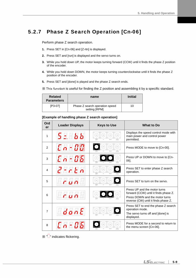
5. Handling and Operation
5-9
5.2.7 Phase Z Search Operation [Cn-06]
Perform phase Z search operation.
1. Press SET in [Cn-06] and [Z-rtn] is displayed.
2. Press SET and [run] is displayed and the servo turns on.
3. While you hold down UP, the motor keeps turning forward (CCW) until it finds the phase Z position of the encoder.
4. While you hold down DOWN, the motor keeps turning counterclockwise until it finds the phase Z position of the encoder.
5. Press SET and [done] is played and the phase Z search ends.
※ This function is useful for finding the Z position and assembling it by a specific standard.
Related Parameters
name Initial
[P3-07] Phase Z search operation speed setting [RPM]
10
[Example of handling phase Z search operation]
Order Loader Displays Keys to Use What to Do
1
Displays the speed control mode with main power and control power permitted.
2
Press MODE to move to [Cn-00].
3
Press UP or DOWN to move to [Cn-06].
4
Press SET to enter phase Z search operation.
5
Press SET to turn on the servo.
6
Press UP and the motor turns forward (CCW) until it finds phase Z. Press DOWN and the motor turns reverse (CW) until it finds phase Z.
7
Press SET to end the phase Z search operation mode. The servo turns off and [done] is displayed.
8
Press MODE for a second to return to the menu screen [Cn-06].
※ “ ” indicates flickering.

5. Handling and Operation
5-10
5.2.8 Input Contact Forced ON/OFF [Cn-07]
The drive forcibly turns on/off the input contact without an upper level controller or I/O jig.
(1) Input Contact Forced ON/OFF Setting
The positions of the seven segment LEDs and CN1 contacts correspond as follows.
If an LED that corresponds to a contact is turned on/off, it indicates ON/OFF accordingly.
[Input Contact Setting] Number (A) (9) (8) (7) (6) (5) (4) (3) (2) (1)
CN1 pin
number 48 18 19 20 46 17 21 22 23 47
Allocated default signal name
STOP EMG CWLIM CCWLIM DIR ALMRST SPD3 SPD2 SPD1 SVON
Press UP on each digit and the (A), (8), (6), (4), and (2) signals turn on or off forcibly.
Press DOWN on each digit and the (9), (7), (5), (3), and (1) signals turn on or off forcibly.
Press MODE to move to another digit.
(2) Example of Input Contact Forced ON/OFF
(SVON ON → EMG ON → EMG OFF → SVON OFF)
[Example of handling input contact forced ON/OFF]
Order Loader Displays Keys to Use What to Do
1
Press MODE to move to [Cn-00].
2
Press UP or DOWN to move to [Cn-07].
3
Press SET to enter input forced ON/OFF mode.
4
Press SET to enter forced input bit setting.

5. Handling and Operation
5-11
Order Loader Displays Keys to Use What to Do
5
Press DOWN to turn on the servo forcibly.
6
Press MODE at the blinking cursor to move to the desired digit, DIGIT 5.
7
Press DOWN to turn on EMG forcibly.
8
Press DOWN to turn off EMG forcibly.
9
Press MODE at the cursor to move to the desired digit, DIGIT 1.
10
Press DOWN to turn off the servo forcibly.
11
Press SET to end input forced ON/OFF mode. [done] is displayed.
12
Press MODE for a second to return to [Cn-07].
※ “ ” indicates flickering.

5. Handling and Operation
5-12
5.2.9 Output Contact Forced ON/OFF [Cn-08]
Without an upper level controller or I/O jig, the drive forcibly turns on/off the output contact.
(1) Output Contact Forced ON/OFF Setting
The positions of the seven segment LEDs and CN1 contacts correspond as follows.
If an LED that corresponds to a contact is turned on/off, it indicates ON/OFF accordingly.
[Output Contact Setting]
Number (5) (4) (3) (2) (1) CN1 - pin number 45 44 43 40 /41 38 / 39
Allocated default signal name INPOS BRAKE ZSPD READY ALARM
Press UP on each digit and the (4) and (2) signals are turned on or off for forced output.
Press DOWN on each digit and the (5), (3) and (1) signals are turned on or off for forced output.
Press MODE to move to another digit.
(2) Example of Output Contact Forced ON/OFF
(BRAKE OFF)
[Example of handling output contact forced ON/OFF]
Order Loader Displays Keys to Use What to Do
1
Press MODE to move to [Cn-00].
2
Press UP or DOWN to move to [Cn-08].
3
Press SET to enter input forced ON/OFF setting.
4
Press SET to enter forced output bit setting.

5. Handling and Operation
5-13
Order Loader Displays Keys to Use What to Do
5
Press MODE at the blinking cursor to move to the desired digit, DIGIT 2, and it rotates.
6
Press UP to turn off the brake signal.
7
Press SET to end input forced ON/OFF mode. [done] is displayed.
8
Press MODE for a second to return to [Cn-08].
※ “ ” indicates flickering.
5.2.10 Parameter Reset [Cn-09]
Reset parameter data.
[Example of initializing parameters]
Order Loader Displays Keys to Use What to Do
1
Displays the speed control mode with main power and control power permitted.
Press MODE to move to [Cn-00].
2
Press UP or DOWN to move to [Cn-09].
3
Press SET to enter parameter reset.
4
Press SET to reset data. [done] is displayed.
5
Press MODE for a second to return to [Cn-09].
※ “ ” indicates flickering.

5. Handling and Operation
5-14
5.2.11 Automatic Speed Command Offset Correction [Cn-10]
Correct the offset of analog speed commands automatically.
The range of adjustable speed command analog voltage is from +1 V to -1 V. If offset voltage exceeds this range, oVrnG is displayed and there is no correction.
You can check the corrected offset value in the analog speed offset [P2-18].
[Example of handling automatic speed command offset calibration]
Order Loader Displays Keys to Use What to Do
1
Press MODE to display [Cn-00].
2
Press UP or DOWN to move to [Cn-10].
3
Press SET to enter offset correction.
4
or
Press SET to compensate offset. [done] is displayed. If the value exceeds the allowed range, oVrnG is displayed.
5
Press MODE for a second to return to [Cn-10].
※ “ ” indicates flickering.

5. Handling and Operation
5-15
5.2.12 Automatic Torque Command Offset Correction [Cn-11]
Corrects the offset of analog torque commands automatically.
The range of adjustable torque command analog voltage is from +1 V to -1 V. If offset voltage exceeds this range, oVrnG is displayed and there is no correction.
You can check the corrected offset value in the analog torque offset [P2-21].
[Example of handling automatic torque command offset correction]
Order Loader Displays Keys to Use What to Do
1
Press MODE to display [Cn-00].
2
Press UP or DOWN to move to [Cn-11].
3
Press SET to enter offset correction.
4
or
Press SET to compensate offset. [done] is displayed. If the value exceeds the allowed range, oVrnG is displayed.
5
Press MODE for a second to return to [Cn-11].
※ “ ” indicates flickering.

5. Handling and Operation
5-16
5.2.13 Manual Speed Command Offset Correction [Cn-12]
Calibrates the offset value of analog speed commands manually. Example: -10
The range of adjustable speed command analog voltage is from +1 V to -1 V. If offset voltage exceeds this range, [oVrnG] Over Range is displayed and there is no compensation.
You can check the corrected offset value in the analog speed offset [P2-18].
[Example of handling manual speed command offset correction]
Order Loader Displays Keys to Use What to Do
1
Press MODE to display [Cn-00].
2
Press UP or DOWN to move to [Cn-12].
3
Press SET to enter offset correction.
4
Press SET to enter offset correction setting. The current offset value displayed.
5
Press UP or DOWN to adjust the value.
6
or
Press SET to save the adjusted offset value. [done] is displayed. Press MODE and it will not be saved.
7
Press MODE for a second to return to [Cn-12].
※ “ ” indicates flickering.

5. Handling and Operation
5-17
5.2.14 Manual Torque Command Offset Correction [Cn-13]
Correct the offset value of analog torque commands manually.
The range of adjustable torque command analog voltage is from +1 V to -1 V. If offset voltage exceeds this range, oVrnG is displayed and there is no correction.
You can check the corrected offset value in the analog torque command offset [P2-21].
[Example of handling manual torque command offset correction]
Order Loader Displays Keys to Use What to Do
1
Press MODE to display [Cn-00].
2
Press UP or DOWN to move to [Cn-13].
3
Press SET to enter offset correction.
4
Press SET to enter offset correction setting. The current offset value displayed.
5
Press UP or DOWN to adjust the value.
6
or
Press SET to save the adjusted offset value. [done] is displayed. Press MODE and it will not be saved.
7
Press MODE for a second to return to the menu screen [Cn-13].
※ “ ” indicates flickering.

5. Handling and Operation
5-18
5.2.15 Absolute Encoder Value Reset [Cn-14]
Resets encoder multi-turn data to zero (0).
[Example of absolute encoder reset]
Order Loader Displays Keys to Use What to Do
1
Press MODE to display [Cn-00].
2
Press UP or DOWN to move to [Cn-14].
3
Press the SET key to enter the state of encoder reset.
4
or
Press the SET key to reset the data value for absolute encoder multi-turn.
[done] is displayed. Press MODE and it is not reset.
7
Press MODE for a second to return to the menu screen [Cn-14].
※ “ ” indicates flickering.
※ After you reset absolute encoder value, you can see the reset value in [st-18].

5. Handling and Operation
5-19
5.2.16 Instantaneous Maximum Load Factor Initialization [Cn-15]
Reset the instantaneous maximum load factor to 0.
[Example of initializing the instantaneous maximum load factor]
Order Loader Displays Keys to Use What to Do
1
Press MODE to display [Cn-00].
2
Press UP or DOWN to move to [Cn-15].
3
Press SET to enter instantaneous maximum load factor initialization.
4
Press SET and the current maximum load factor is displayed.
5
or
Press UP and the clockwise maximum load factor is displayed. Press DOWN and the counterclockwise maximum load factor is displayed.
6
or
Press SET and the instantaneous maximum load factor is reset. [done] is displayed. Press MODE and it is not reset.
7
Press MODE for a second to return to [Cn-15].
※ “ ” indicates flickering.
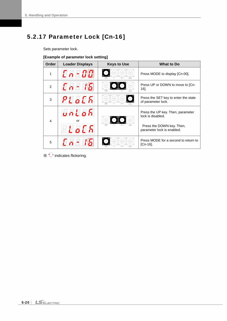
5. Handling and Operation
5-20
5.2.17 Parameter Lock [Cn-16]
Sets parameter lock.
[Example of parameter lock setting]
Order Loader Displays Keys to Use What to Do
1
Press MODE to display [Cn-00].
2
Press UP or DOWN to move to [Cn-16].
3
Press the SET key to enter the state of parameter lock.
4
or
Press the UP key. Then, parameter lock is disabled. Press the DOWN key. Then, parameter lock is enabled.
5
Press MODE for a second to return to [Cn-16].
※ “ ” indicates flickering.

5. Handling and Operation
5-21
5.2.18 Current Offset [Cn-17]
Saves current offset value to parameter [P0-28]-[P0-29].
[Example of handling current offset value]
Order Loader Displays Keys to Use What to Do
1
Press MODE to display [Cn-00].
2
Press UP or DOWN to move to [Cn-17].
3
Press the SET key to enter the state of current offset setting.
6
Press the SET key. Then, phase U current offset value is saved to [P0-28] and phase V current offset value is saved to [P0-29].
7
Press MODE for a second to return to [Cn-17].
※ “ ” indicates flickering.


6. Communication Protocol
6-1
6. Communication Protocol
6.1 Overview and Communication Specifications
6.1.1 Overview
The L7 servo drive is RS-422 serial communication. By connecting it to a PC or an upper level controller, you can test drive it or change gain tuning parameters.
You can also operate or handle communication of up to 32 axes by connecting multiple L7 servo drives via a multi-drop method.
(1) Serial Communication Access through RS422
CN4
CN3
Serial PortRS-232C/422
Communication Converter
Servo DrivePC
(2) Multi-Drop Access through RS422 (up to 32 machines)
CN4
CN3
Serial Port
RS-232C/422 Communication
Converter
Servo DrivePC
CN4
CN3
Servo Drive
CN4
CN3
Servo Drive
Note 1) When using a PC as the upper level controller, you have to use the RS232/RS485 communication
converter. Note 2) The CN3 and the CN4 connector pins of the servo drive are connected on an one-to-one basis
internally, making multi-drop wiring easy.

6. Communication Protocol
6-2
6.1.2 Communication Specifications and Cable Access Rate
(1) Communication Specifications
Item Specifications Communication standard ANSI/TIA/EIA-422 standard
Communication protocol MODBUS-RTU
Data Type
Data bit 8 bits
Stop bit 1 bits
Parity None
Synchronous method Asynchronous
Transmission speed 9600 /19200/38400/57600 [bps] [P0-04] can be selected.
Transmission distance Up to 200 m
Current consumption 100 or below
(2) Connection of CN3 and CN4 Connector Pins
18
18
CN 3 CN 4
Pin Number Pin Function
1 Not for use.
2 Terminating resistance connection note 1)
3 RXD+
4 TXD-
5 TXD+
6 RXD-
7 Not for use.
8 GND
Note 1) In case of multi access connection, apply terminating resistance by connecting Pin 2 of the last drive to Pin 6 (RXD-).
Note 2) Connect TXD+ and TXD-, and RXD+ and RXD- in twisted pairs. Note 3) The TXD and RXD in the above table are based on the servo drive.
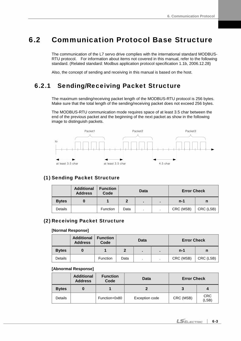
6. Communication Protocol
6-3
6.2 Communication Protocol Base Structure
The communication of the L7 servo drive complies with the international standard MODBUS-RTU protocol. For information about items not covered in this manual, refer to the following standard. (Related standard: Modbus application protocol specification 1.1b, 2006.12.28)
Also, the concept of sending and receiving in this manual is based on the host.
6.2.1 Sending/Receiving Packet Structure
The maximum sending/receiving packet length of the MODBUS-RTU protocol is 256 bytes. Make sure that the total length of the sending/receiving packet does not exceed 256 bytes.
The MODBUS-RTU communication mode requires space of at least 3.5 char between the end of the previous packet and the beginning of the next packet as show in the following image to distinguish packets.
to
Packet1 Packet2 Packet3
at least 3.5 char at least 3.5 char 4.5 char
(1) Sending Packet Structure
Additional Address
Function Code Data Error Check
Bytes 0 1 2 . . n-1 n
Details Function Data . . CRC (MSB) CRC (LSB)
(2) Receiving Packet Structure
[Normal Response]
Additional Address
Function Code Data Error Check
Bytes 0 1 2 . . n-1 n
Details Function Data . . CRC (MSB) CRC (LSB)
[Abnormal Response]
Additional Address
Function Code Data Error Check
Bytes 0 1 2 3 4
Details Function+0x80 Exception code CRC (MSB) CRC (LSB)

6. Communication Protocol
6-4
(3) Protocol Packet Code
Node ID
Indicates the exchange number of the servo drive to send.
Set the exchange number of the servo drive to [P0-05].
Function Code
The following are the Modbus-RTU standard function codes supported by the L7 servo drive.
Category Command code Details
Purpose Read Write
Public function code
0x03 Read single register
0x03 Read multi register
0x06 Write single register
0x10 Write multi register
User defined function code
0x6A Read each block register
Data
[Sending]: For read register commands, the Modbus address, the number of registers, and the number of bytes will be set. For write register commands, the Modbus address, the number of bytes, and other necessary values will be set.
[Receiving]: In the case of read register commands, normal responses are received with the same node ID and function code as they are sent. In terms of data, registers are received according to the order of sent registers.
In the case of write single register commands, the same data as those sent are received. In the case of write multi registers, the start address of the register, whose data were to be used with the write multi register command, and the number of registers are received.
Abnormal responses consist of node ID, error code, and exception code. The packet structure is the same for all abnormal responses regardless of their function codes.
(4) CRC
Enter the 16-bit CRC check sum. Send 1 byte of MSB and LSB each.
(5) Exception Code
The followings are the exception codes for all abnormal responses of all function codes supported in the L7 servo drive.
Exception Code Description 0x01 Unsupported function codes
0x02 Invalid register address
0x03 Non-matching node IDs or CRC check errors
0x04 Command handling failure
0x05 Waiting (Preparing data)
0x06 State of parameter lock

6. Communication Protocol
6-5
6.2.2 Protocol Command Codes
(1) Read Single Register (0x03)
Read the single register (16-bit data) value.
Sending Packet Normal Receiving Packet
Byte Content Value Byte Content Value
0 0x00 0 0x00
1 Function 0x03 1 Function 0x03
2 Starting Address Hi 0x00 2 Byte Count 0x02
3 Starting Address Lo 0x6B 3 Register Value Hi 0x02
4 Quantity of Register Hi 0x00 4 Register Value Lo 0x2B
5 Quantity of Register Lo 0x01 5 CRC Hi
6 CRC Hi 6 CRC Lo
7 CRC Lo
Error Receiving Packet
Byte Content Value
0 0x00
1 0x03 + 0x80
2 Exception Code 0x01 - 0x04
3 CRC Hi
4 CRC Lo
Ex)
Request
ResponseNode-ID
03
06
02
2B
CRC Hi
CRC Lo
Node-ID
03
00
6B
00
01
CRC Hi
CRC Lo
Slave Address(Node-ID)
Function Code
Staring Address Hi
Starting Address Lo
Quantity of Registers Hi
Quantity of Registers Lo
CRC Hi
CRC Lo
Slave Address(Node-ID)
Function Code
Byte Count
Register Value Hi (108)
Register Value Lo (108)
CRC Hi
CRC Lo

6. Communication Protocol
6-6
(2) Read Multi Register (0x03)
Read the continuous register block (16-bit data) value.
Sending Packet Normal Receiving Packet
Byte Content Value Byte Content Value
0 0x00 0 0x00
1 Function 0x03 1 Function 0x03
2 Starting Address Hi 0x00 2 Byte Count 0x06
3 Starting Address Lo 0x6B 3 Register Value Hi 0x02
4 Quantity of Register Hi 0x00 4 Register Value Lo 0x2B
5 Quantity of Register Lo 0x03 5 Register Value Hi 0x00
6 CRC Hi 6 Register Value Lo 0x00
7 CRC Lo 7 Register Value Hi 0x00
8 Register Value Lo 0x64
9 CRC Hi .
10 CRC Lo
Error Receiving Packet
Byte Content Value
0 0x00
1 0x03 + 0x80
2 Exception Code 0x01 - 0x04
3 CRC Hi
4 CRC Lo
Ex)
Request
ResponseNode-ID
03
06
02
2B
00
CRC Hi
CRC Lo
Node-ID
03
00
6B
00
03
CRC Hi
CRC Lo
Slave Address (Node-ID)
Function Code
Staring Address Hi
Starting Address Lo
Quantity of Registers Hi
Quantity of Registers Lo
CRC Hi
CRC Lo
00
00
64
Slave Address (Node-ID)
Function Code
Byte Count
Register Value Hi (First)
Register Value Lo
Register Value Hi (Second)
Register Value Lo
Register Value Hi (Third)
Register Value Lo
CRC Hi
CRC Lo

6. Communication Protocol
6-7
(3) Write Single Register (0x06)
Write values on the single register (16-bit data).
Sending Packet Normal Receiving Packet
Byte Content Value Byte Content Value
0 0x00 0 0x00
1 Function 0x06 1 Function 0x06
2 Register Address Hi 0x00 2 Register Address Hi 0x00
3 Register Address Lo 0x01 3 Register Address Lo 0x01
4 Register Value Hi 0x00 4 Register Value Hi 0x00
5 Register Value Lo 0x03 5 Register Value Lo 0x03
6 CRC Hi 6 CRC Hi
7 CRC Lo 7 CRC Lo
Error Receiving Packet
Byte Content Value
0 0x00
1 0x06 + 0x80
2 Exception Code 0x01 - 0x06
3 CRC Hi
4 CRC Lo
Ex)
Request
ResponseNode-ID
06
00
01
00
CRC Hi
CRC Lo
Node-ID
06
00
01
00
03
CRC Hi
CRC Lo
Slave Address (Node-ID)
Function Code
Register Address Hi
Register Address Lo
Register Value Hi (1)
Register Value Lo (1)
CRC Hi
CRC Lo
Slave Address (Node-ID)
Function Code
Register Address Hi
Register Address Lo
Register Value Hi (1)
Register Value Lo (1)
CRC Hi
CRC Lo
00

6. Communication Protocol
6-8
(4) Write Multi Register (0x10)
Writes values on the continuous register block (16-bit data).
Sending Packet Normal Receiving Packet
Byte Content Value Byte Content Value
0 0x00 0 0x00
1 Function 0x10 1 Function 0x10
2 Starting Address Hi 0x00 2 Starting Address Hi 0x00
3 Starting Address Lo 0x01 3 Starting Address Lo 0x01
4 Quantity of Registers Hi 0x00 4 Quantity of Registers Hi 0x00
5 Quantity of Registers Lo 0x02 5 Quantity of Registers Lo 0x02
6 Byte Count 0x04 6 CRC Hi
7 Register Value Hi 0x00 7 CRC Lo
8 Register Value Lo 0x0A
9 Register Value Hi 0x01 Error Receiving Packet
10 Register Value Lo 0x02 Byte Content Value
11 CRC Hi 0 0x00
12 CRC Lo 1 0x10 + 0x80
2 Exception Code 0x01 - 0x04
3 CRC Hi
4 CRC Lo
Ex)
Node-ID
10
00
01
00
02
CRC Hi
CRC Lo
Slave Address (Node-ID)
Function Code
Starting Address Hi
Starting Address Lo
Quantity of Registers Hi
Quantity of Registers Lo
Byte Count
Registers Values Hi
Registers Values Lo
Registers Values Hi
Registers Values Lo
CRC Hi
CRC Lo
04
00
0A
01
02
Node-ID
10
00
01
00
CRC Hi
CRC Lo
Slave Address (Node-ID)
Function Code
Starting Address Hi
Starting Address Lo
Quantity of Registers Hi
Quantity of Registers Lo
CRC Hi
CRC Lo
02
Request
Response

6. Communication Protocol
6-9
(5) Read Each Block Register (0x6A)
Read values on the discontinuous register block (16-bit data).
Sending Packet Normal Receiving Packet
Byte Content Value Byte Content Value
0 0x00 0 0x00
1 Function 0x6A 1 Function 0x6A
2 Byte Count 0x06 2 Byte Count 0x06
3 Address Hi 0x00 3 Register Value Hi 0x02
4 Address Lo 0x01 4 Register Value Lo 0x2B
5 Address Hi 0x00 5 Register Value Hi 0x00
6 Address Lo 0x04 6 Register Value Lo 0x00
7 Address Hi 0x00 7 Register Value Hi 0x00
8 Address Lo 0x08 8 Register Value Lo 0x64
9 CRC Hi 9 CRC Hi .
10 CRC Lo 10 CRC Lo
Error Receiving Packet
Byte Content Value
0 0x00
1 0x6A + 0x80
2 Exception Code 0x01 - 0x04
3 CRC Hi
4 CRC Lo
Ex)
Node-ID
6A
06
01
00
02
CRC Hi
CRC Lo
04
00
0A
Request
Response
Slave Address (Node-ID)
Function Code
Byte Count
Address Hi (First)
Address Lo
Address Hi (Second)
Address Lo
Address Hi (Third)
Address Lo
CRC Hi
CRC Lo
Node-ID
6A
06
02
2B
00
CRC Hi
CRC Lo
00
00
05
Slave Address (Node-ID)
Function Code
Byte Count
Address’s Value Hi (First)
Address’s Value Lo
Address’s Value Hi (Second)
Address’s Value Lo
Address’s Value Hi (Third)
Address’s Value Lo
CRC Hi
CRC Lo

6. Communication Protocol
6-10
6.3 L7 Servo Drive Communication Address Table
6.3.1 Operation Status Parameter Communication Address Table
Communication Address Parameter Name Parameter
Number Material Type
(Decimal Number) Operation Status Display Parameter
0 Current operation status St - 00
INT16 BIT0: Alarm BIT1: Servo on BIT2: Warning BIT3: CCW limit BIT4: CW limit BIT5: Zero speed BIT6: In speed BIT7: In position BIT8: Power ready BIT9: Analog command active BIT10 - BIT13: Control mode
(0: Trq, 1: Spd, 2: Pos, 3: Spd/Pos, 4: Trq/Spd, 5: Trq/Pos)
2 Current operation speed St - 01 INT16
4 Current command speed St - 02 INT16
6 Tracking position pulse - L St - 03 INT32
8 Tracking position pulse - H
10 Position command pulse - L St - 04 INT32
12 Position command pulse - H
14 Remaining position pulse - L St - 05 INT32
16 Remaining position pulse - H
18 Input pulse frequency – L St - 06 INT32
20 Input pulse frequency - H
22 Current operation torque St - 07 INT16
24 Current command torque St - 08 INT16
26 Accumulated overload rate St - 09 INT16
28 Instantaneous maximum load factor St - 10 INT16
30 Torque limit value St - 11 INT16
32 DC link voltage St - 12 UINT16
34 Regenerative overload St - 13 UINT16
36 Input contact status St - 14 UINT16

6. Communication Protocol
6-11
Communication Address Parameter Name Parameter
Number Material Type
(Decimal Number) Operation Status Display Parameter
38 Output contact status St - 15 UINT16
40 Single-turn data - L St - 16 INT32
42 Single-turn data - H
44 Single-turn data (degrees) St - 17 UINT16
46 Multi-turn data - L St - 18 INT32
48 Multi-turn data - H
50 Temperature in the servo drive St - 19 INT16
52 Rated motor speed St - 20 UINT16
54 Maximum motor speed St - 21 UINT16
56 Rated motor current St - 22 UINT16
58 Phase U current offset St - 23 INT16
60 Phase V current offset St - 24 INT16
62 Software Version St - 25
UINT16 BIT0 - BIT4: Drive capacity (1: 100w, 2: 200w, 3: 400w,
4: 750w, 5: 1Kw, 6: 3.5Kw) BIT5 - BIT14: Version number BIT15: Encoder type
(0: Quadrature, 1: Serial)
64 FPGA Version St - 26 UINT16
66 Analog torque command value St - 27 INT16
68 Reserved

6. Communication Protocol
6-12
6.3.2 System Parameter Communication Address Table
The following table lists Modbus communication addresses for the system parameter group [P0-xx]:
Communication Address Parameter Name Parameter
Number Material Type
(Decimal Number) System Parameter
70 Motor ID P0 - 00 UINT16
72 Encoder Type P0 - 01 UINT16
74 Encoder pulse P0 - 02 UINT16
76 Select operation mode P0 - 03 UINT16
78 RS-422 communication speed P0 - 04 UINT16
80 System ID P0 - 05 UINT16
82 Main power input mode P0 - 06 UINT16
84 RST checking time P0 - 07 UINT16
86 Start-up display parameter P0 - 08 UINT16
88 Regenerative overload derating P0 - 09 UINT16
90 Regenerative resistance value P0 - 10 UINT16
92 Regenerative resistance capacity P0 - 11 UINT16
94 Overload detection base load factor P0 - 12 UINT16
96 Continuous overload warning level P0 - 13 UINT16
98 Encoder output pre-scale - L P0 - 14 INT32
100 Encoder output pre-scale - H
102 PWM OFF delay time P0 - 15 UINT16
104 Dynamic brake control mode P0 - 16 UINT16
106 Function setting bit P0 - 17 UINT16
108 DAC output mode P0 - 18 UINT16
110 DAC output offset 1 P0 - 19 INT16
112 DAC output offset 2 P0 - 20 INT16
114 Reserved P0 - 21 INT16
116 Reserved P0 - 22 INT16
118 DAC output scale 1 P0 - 23 UINT16
120 DAC output scale 2 P0 - 24 UINT16
122 Reserved P0 - 25 UINT16
124 Reserved P0 - 26 UINT16

6. Communication Protocol
6-13
Communication Address Parameter Name Parameter
Number Material Type
(Decimal Number) System Parameter
126 P0 - 27 INT16
128 P0 - 28 INT16
130 P0 - 29 INT16
132 Reserved
134 Reserved
136 Reserved
138 Reserved

6. Communication Protocol
6-14
6.3.3 Control Parameter Communication Address Table
The following table lists Modbus communication addresses for the control parameter group [P1-xx]:
Communication Address Parameter Name Parameter
Number Material Type
(Decimal Number) Control parameter
140 Inertia ratio P1 - 00 UINT16
142 Position proportional gain 1 P1 - 01 UINT16
144 Position proportional gain 2 P1 - 02 UINT16
146 Position command filter time constant P1 - 03 UINT16
148 Position feedforward gain P1 - 04 UINT16
150 Position feedforward filter time constant P1 - 05 UINT16
152 Speed proportional gain 1 P1 - 06 UINT16
154 Speed proportional gain 2 P1 - 07 UINT16
156 Speed integral time constant 1 P1 - 08 UINT16
158 Speed integral time constant 2 P1 - 09 UINT16
160 Speed command filter time constant P1 - 10 UINT16
162 Speed feedback filter time constant P1 - 11 UINT16
164 Torque command filter time constant P1 - 12 UINT16
166 Forward rotation torque limit P1 - 13 UINT16
168 Counterclockwise rotation torque limit P1 - 14 UINT16
170 Gain switching mode P1 - 15 UINT16
172 Gain switching time P1 - 16 UINT16
174 Resonance avoidance operation P1 - 17 UINT16
176 Resonance avoidance frequency P1 - 18 UINT16
178 Resonance avoidance range P1 - 19 UINT16
180 Auto gain tuning speed P1 - 20 UINT16
182 Auto gain tuning distance P1 - 21 UINT16
184 Torque control speed limiting mode P1 - 22 UINT16
186 Speed limit P1 - 23 UINT16
188 Control P switching torque P1 - 24 UINT16

6. Communication Protocol
6-15
Communication Address Parameter Name Parameter
Number Material Type
(Decimal Number) Control parameter
190 Control P switching speed P1 - 25 UINT16
192 Control P switching acceleration P1 - 26 UINT16
194 Control P switching position error P1 - 27 UINT16
196 Reserved
198 Reserved
200 Reserved
202 Reserved
204 Reserved
206 Reserved
208 Reserved
210 Reserved
212 Reserved
214 Reserved
216 Reserved
218 Reserved

6. Communication Protocol
6-16
6.3.4 Input/Output Parameter Communication Address Table
The following table lists Modbus communication addresses for the input/output (analog and digital) parameter group [P2-xx]:
Communication Address Parameter Name Parameter
Number Material Type
(Decimal Number) Input/Output Parameter
220 Input signal definition 1 P2 - 00 UINT16
222 Input signal definition 2 P2 - 01 UINT16
224 Input signal definition 3 P2 - 02 UINT16
226 Input signal definition 4 P2 - 03 UINT16
228 Input signal definition 5 P2 - 04 UINT16
230 Output signal definition 1 P2 - 05 UINT16
232 Output signal definition 2 P2 - 06 UINT16
234 Output signal definition 3 P2 - 07 UINT16
236 Input signal logic definition 1 P2 - 08 UINT16
238 Input signal logic definition 2 P2 - 09 UINT16
240 Output signal logic definition P2 - 10 UINT16
242 Range of output for position reached P2 - 11 UINT16
244 Zero speed output range P2 - 12 UINT16
246 Range of output for speed reached P2 - 13 UINT16
248 Brake output operation speed P2 - 14 UINT16
250 Brake output delay time P2 - 15 UINT16
252 Position pulse clear mode P2 - 16 UINT16
254 Analog speed command scale P2 - 17 UINT16
256 Analog speed command offset P2 - 18 INT16
258 Zero speed clamp speed P2 - 19 UINT16
260 Analog torque command scale P2 - 20 UINT16
262 Analog torque command offset P2 - 21 INT16
264 Zero speed clamp voltage P2 - 22 UINT16
266 Reserved
268 Reserved
270 Reserved
272 Reserved
274 Reserved
276 Reserved
278 Reserved

6. Communication Protocol
6-17
6.3.5 Speed Operation Parameter Communication Address Table
The following table lists Modbus communication addresses for the speed operation parameter group [P3-xx]:
Communication Address Parameter Name Parameter
Number Material Type
(Decimal Number) Speed operation parameter
280 Digital speed command 1 P3 - 00 INT16
282 Digital speed command 2 P3 - 01 INT16
284 Digital speed command 3 P3 - 02 INT16
286 Digital speed command 4 P3 - 03 INT16
288 Digital speed command 5 P3 - 04 INT16
290 Digital speed command 6 P3 - 05 INT16
292 Digital speed command 7 P3 - 06 INT16
294 Z search operation speed setting P3 - 07 UINT16
296 Speed command acceleration time P3 - 08 UINT16
298 Speed command deceleration time P3 - 09 UINT16
300 Speed command S-Curve time P3 - 10 UINT16
302 Speed operation pattern P3 - 11 UINT16
304 Manual JOG operation speed P3 - 12 INT16
306 Program JOG operation speed 1 P3 - 13 INT16
308 Program JOG operation speed 2 P3 - 14 INT16
310 Program JOG operation speed 3 P3 - 15 INT16
312 Program JOG operation speed 4 P3 - 16 INT16
314 Program JOG operation time 1 P3 - 17 UINT16
316 Program JOG operation time 2 P3 - 18 UINT16
318 Program JOG operation time 3 P3 - 19 UINT16
320 Program JOG operation time 4 P3 - 20 UINT16
322 Reserved
324 Reserved
326 Reserved
328 Reserved

6. Communication Protocol
6-18
6.3.6 Position Operation Parameter Communication Address Table
The following table lists Modbus communication addresses for the position operation parameter group [P4-xx]:
Communication Address Parameter Name Parameter Number Material Type
(Decimal Number) Position operation parameter
330 Position input pulse logic P4 - 00 UINT16
332 Electronic gear ratio numerator 1 - L P4 - 01 INT32
334 Electronic gear ratio numerator 1 - H
336 Electronic gear ratio numerator 2 - L P4 - 02 INT32
338 Electronic gear ratio numerator 2 - H
340 Electronic gear ratio denominator 3 - L P4 - 03 INT32
342 Electronic gear ratio denominator 3 - H
344 Electronic gear ratio denominator 4 - H P4 - 04 INT32
346 Electronic gear ratio denominator 4 - L
348 Electronic gear ratio numerator 1 P4 - 05 UINT16
350 Electronic gear ratio numerator 2 P4 - 06 UINT16
352 Electronic gear ratio numerator 3 P4 – 07 UINT16
354 Electronic gear ratio numerator 4 P4 - 08 UINT16
356 Electronic gear ratio mode P4 – 09 UINT16
358 Electronic gear ratio numerator offset P4 - 10 UINT16
360 Position error range - L P4 - 11 INT32
362 Position error range - H
364 Limit contact function P4 – 12 UINT16
366 Backlash compensation P4 - 13 UINT16
368 Pulse input filter P4 – 14 UINT16

7. Product Specifications
7-1
7. Product Specifications
7.1 Servo motor
7.1.1 Product Features
Servo Motor Type (APM-) SEP09A SEP15A SEP22A SEP30A
Applicable Drive (L7B) L7B010 L7B020 L7B020 L7B035
Rated Output kW 0.9 1.5 2.2 3.0
Rated torque N⋅m 2.86 4.77 7.0 9.55
kgf⋅cm 29.23 48.72 71.46 97.44
Maximum instantaneous
torque
N⋅m 8.59 14.32 21.01 28.65
kgf⋅cm 87.7 146.16 214.37 292.33
Rated rotation speed r/min 3000
Maximum rotation speed r/min 5000
Inertia moment kg⋅m2x10-4 6.659 11.999 17.339 22.679
gf⋅cm⋅s2 6.795 12.244 17.693 23.142
Permitted load inertia Motor inertia x10
Rated power kW/s 12.32 19.00 28.28 40.21
Speed and position detector
Standard Serial Type 19 bits M-turn
Option Serial Type 19 bits S-turn(to be supported)
Specifications and
features
Protection method Fully enclosed⋅self-cooling IP65 (excluding axis penetration)
Time rating Continuous
Ambient temperature Operate : 0~40, Storage : -10~60
Ambient humidity 20-80% RH (no condensation)
Atmosphere No direct sunlight, corrosive gas, or combustible gas
Anti-vibration Vibration acceleration of 49 m/s2 (5G)
♦Speed-Torque characteristics♦
APM-SEP09A APM-SEP15A APM-SEP22A
APM-SEP30A

7. Product Specifications
7-2
Servo Motor Type (APM-) SEP06D SEP11D SEP16D SEP22D
Applicable Drive (L7B) L7B010 L7B010 L7B020 L7B020
Rated Output kW 0.6 1.1 1.6 2.2
Rated torque N⋅m 2.86 5.25 7.64 10.5
kgf⋅cm 29.23 53.59 77.95 107.19
Maximum instantaneous
torque
N⋅m 8.59 15.76 22.92 31.51
kgf⋅cm 87.7 160.78 233.86 321.56
Rated rotation speed r/min 2000
Maximum rotation speed r/min 3000
Inertia moment kg⋅m2x10-4 6.659 11.999 17.339 22.679
gf⋅cm⋅s2 6.795 12.244 17.693 23.142
Permitted load inertia Motor inertia x10
Rated power rate kW/s 12.32 22.99 48.64 91.96
Speed and position detector
Standard Serial Type 19 bits M-turn
Option Serial Type 19 bits S-turn(to be supported)
Specifications and
features
Protection method Fully enclosed⋅self-cooling IP65 (excluding axis penetration)
Time rating Continuous
Ambient temperature Operate : 0~40, Storage : -10~60
Ambient humidity 20-80% RH (no condensation)
Atmosphere No direct sunlight, corrosive gas, or combustible gas
Anti-vibration Vibration acceleration of 49 m/s2 (5G)
♦Speed-Torque characteristics♦
APM-SEP06D APM-SEP11D APM-SEP11D
APM-SEP22D

7. Product Specifications
7-3
Servo Motor Type (APM-) SEP05G SEP09G SEP13G SEP17G
Applicable Drive (L7B) L7B010 L7B010 L7B020 L7B020
Rated Output kW 0.45 0.85 1.3 1.7
Rated torque N⋅m 2.86 5.41 8.28 10.82
kgf⋅cm 29.23 55.22 84.45 110.43
Maximum instantaneous
torque
N⋅m 8.59 16.23 24.83 32.47
kgf⋅cm 87.70 165.65 253.35 331.30
Rated rotation speed r/min 1500
Maximum rotation speed r/min 3000
Inertia moment kg⋅m2x10-4 6.659 11.999 17.339 22.679
gf⋅cm⋅s2 6.795 12.244 17.693 23.142
Permitted load inertia Motor inertia x10
Rated power rate kW/s 12.32 24.4 57.08 97.61
Speed and position detector
Standard Serial Type 19 bits M-turn
Option Serial Type 19 bits S-turn(to be supported)
Specifications and
features
Protection method Fully enclosed⋅self-cooling IP65 (excluding axis penetration)
Time rating Continuous
Ambient temperature Operate : 0~40, Storage : -10~60
Ambient humidity 20-80% RH (no condensation)
Atmosphere No direct sunlight, corrosive gas, or combustible gas
Anti-vibration Vibration acceleration of 49 m/s2 (5G)
♦Speed-Torque characteristics♦
APM-SEP05G APM-SEP09G APM-SEP13G
APM-SEP17G

7. Product Specifications
7-4
Servo Motor Type (APM-) SEP03M SEP06M SEP09M SEP12M
Applicable Drive (L7B) L7B010 L7B010 L7B010 L7B020
Rated Output kW 0.3 0.6 0.9 1.2
Rated torque N⋅m 2.86 5.73 8.59 11.46
kgf⋅cm 29.23 58.47 87.70 116.93
Maximum instantaneous
torque
N⋅m 8.59 17.19 25.78 34.38
kgf⋅cm 87.70 175.40 263.09 350.79
Rated rotation speed r/min 1000
Maximum rotation speed r/min 2000
Inertia moment kg⋅m2x10-4 6.659 11.999 17.339 22.679
gf⋅cm⋅s2 6.795 12.244 17.693 23.142
Permitted load inertia Motor inertia x10
Rated power rate kW/s 12.32 27.36 42.60 57.90
Speed and position detector
Standard Serial Type 19 bits M-turn
Option Serial Type 19 bits S-turn(to be supported)
Specifications and
features
Protection method Fully enclosed⋅self-cooling IP65 (excluding axis penetration)
Time rating Continuous
Ambient temperature Operate : 0~40, Storage : -10~60
Ambient humidity 20-80% RH (no condensation)
Atmosphere No direct sunlight, corrosive gas, or combustible gas
Anti-vibration Vibration acceleration of 49 m/s2 (5G)
♦Speed-Torque characteristics♦
APM-SEP03M APM-SEP06M APM-SEP09M
APM-SEP12M

7. Product Specifications
7-5
Servo Motor Type (APM-) SFP30A SFP50A SFP22D SFP35D SFP55D SFP75D
Applicable Drive (L7B) L7B035 L7B075 L7B020 L7B035 L7B075 L7B075
Rated Output kW 3.0 5.0 2.2 3.5 5.5 7.5
Rated torque N⋅m 9.55 15.92 10.50 16.71 26.26 35.81
kgf⋅cm 97.44 162.40 107.19 170.52 267.96 365.41
Maximum instantaneous
torque
N⋅m 28.65 39.79 31.51 50.13 65.65 89.52
kgf⋅cm 292.33 406.01 321.56 511.57 669.91 913.52
Rated rotation speed r/min 3000 2000
Maximum rotation speed r/min 5000 3000
Inertia moment kg⋅m2x10-4 30.740 52.130 30.740 52.130 83.600 121.350
gf⋅cm⋅s2 31.367 53.194 31.367 53.194 85.306 123.827
Permitted load inertia Motor inertia x5
Rated power rate kW/s 29.66 48.59 35.89 53.57 82.49 105.67
Speed and position detector
Standard Serial Type 19 bits M-turn
Option Serial Type 19 bits S-turn(to be supported)
Specifications and
features
Protection method Fully enclosed⋅self-cooling IP65 (excluding axis penetration)
Time rating Continuous
Ambient temperature Operate : 0~40, Storage : -10~60
Ambient humidity 20-80% RH (no condensation)
Atmosphere No direct sunlight, corrosive gas, or combustible gas
Anti-vibration Vibration acceleration of 49 m/s2 (5G)
♦Speed-Torque characteristics♦
APM-SEP30A APM-SFP30A APM-SFP50A APM-SFP22D
APM-SFP35D APM-SFP55D APM-SFP75D

7. Product Specifications
7-6
Servo Motor Type (APM-) SFP20G SFP30G SFP44G SFP60G SFP75G
Applicable Drive (L7B) L7B020 L7B075 L7B075 L7B075 L7B0150
Rated Output kW 1.8 2.9 4.4 6.0 7.5
Rated torque N⋅m 11.46 18.46 28.01 38.20 47.75
kgf⋅cm 116.93 188.39 285.83 389.77 487.21
Maximum instantaneous
torque
N⋅m 34.38 55.39 70.03 95.49 119.37
kgf⋅cm 350.79 565.16 714.57 974.42 1,218.02
Rated rotation speed r/min 1500
Maximum rotation speed r/min 3000 2500
Inertia moment kg⋅m2x10-4 30.740 52.130 83.600 121.350 143.820
gf⋅cm⋅s2 31.367 53.194 85.306 123.827 146.755
Permitted load inertia Motor inertia x5
Rated power rate kW/s 42.72 65.38 93.86 120.23 158.51
Speed and position detector
Standard Serial Type 19 bits M-turn
Option Serial Type 19 bits S-turn(to be supported)
Specifications and
features
Protection method Fully enclosed⋅self-cooling IP65 (excluding axis penetration)
Time rating Continuous
Ambient temperature Operate : 0~40, Storage : -10~60
Ambient humidity 20-80% RH (no condensation)
Atmosphere No direct sunlight, corrosive gas, or combustible gas
Anti-vibration Vibration acceleration of 49 m/s2 (5G)
♦Speed-Torque characteristics♦
APM-SFP20G APM-SFP30G APM-SFP44G
APM-SFP60G APM-SFP75G

7. Product Specifications
7-7
Servo Motor Type (APM-) SFP12M SFP20M SFP30M SF44M
Applicable Drive (L7B) L7B020 L7B020 L7B075 L7B075
Rated Output kW 1.2 2.0 3.0 4.4
Rated torque N⋅m 11.46 19.10 28.65 42.02
kgf⋅cm 116.93 194.88 292.33 428.74
Maximum instantaneous
torque
N⋅m 34.38 57.30 71.62 105.04
kgf⋅cm 350.79 584.65 730.81 1,071.86
Rated rotation speed r/min 1000
Maximum rotation speed r/min 2000
Inertia moment kg⋅m2x10-4 30.740 52.130 83.600 121.350
gf⋅cm⋅s2 31.367 53.194 85.306 123.827
Permitted load inertia Motor inertia x5
Rated power rate kW/s 42.72 69.97 98.17 145.48
Speed and position detector
Standard Serial Type 19 bits M-turn
Option Serial Type 19 bits S-turn(to be supported)
Specifications and
features
Protection method Fully enclosed⋅self-cooling IP65 (excluding axis penetration)
Time rating Continuous
Ambient temperature Operate : 0~40, Storage : -10~60
Ambient humidity 20-80% RH (no condensation)
Atmosphere No direct sunlight, corrosive gas, or combustible gas
Anti-vibration Vibration acceleration of 49 m/s2 (5G)
♦Speed-Torque characteristics♦
APM-SFP12M APM-SFP20M APM-SFP30M
APM-SFP44M

7. Product Specifications
7-8
Servo Motor Type (APM-) SGP22D SGP35D SGP55D SGP75D SGP110D
Applicable Drive (L7B) L7B020 L7B035 L7B075 L7B075 L7B0150
Rated Output kW 2.2 3.5 5.5 7.5 11.0
Rated torque N⋅m 16.71 26.26 35.81 52.52 16.71
kgf⋅cm 170.52 267.96 365.41 535.93 170.52
Maximum instantaneous
torque
N⋅m 50.13 78.78 89.52 131.30 50.13
kgf⋅cm 511.57 803.89 913.52 1,339.82 511.57
Rated rotation speed r/min 2000
Maximum rotation speed r/min 3000 2500
Inertia moment kg⋅m2x10-4 51.42 80.35 132.41 172.91 291.36
gf⋅cm⋅s2 52.47 81.99 135.11 176.44 297.31
Permitted load inertia Motor inertia x5
Rated power rate kW/s 21.46 34.76 52.08 74.16 94.65
Speed and position detector
Standard Serial Type 19 bits M-turn
Option Serial Type 19 bits S-turn(to be supported)
Specifications and
features
Protection method Fully enclosed⋅self-cooling IP65 (excluding axis penetration)
Time rating Continuous
Ambient temperature Operate : 0~40, Storage : -10~60
Ambient humidity 20-80% RH (no condensation)
Atmosphere No direct sunlight, corrosive gas, or combustible gas
Anti-vibration Vibration acceleration of 49 m/s2 (5G)
♦Speed-Torque characteristics♦
APM-SGP22D APM-SGP35D APM-SGP55D
APM-SGP75D APM-SGP110D

7. Product Specifications
7-9
Servo Motor Type (APM-) SGP20G SGP30G SGP44G SGP60G SGP85G SGP110G
Applicable Drive (L7B) L7B020 L7B075 L7B075 L7B075 L7B150 L7B150
Rated Output kW 1.8 2.9 4.4 6.0 8.5 11.0
Rated torque N⋅m 11.46 18.46 28.01 38.20 54.11 70.03
kgf⋅cm 116.93 188.39 285.83 389.77 552.17 714.57
Maximum instantaneous
torque
N⋅m 34.38 55.39 70.03 95.49 135.28 175.07
kgf⋅cm 350.79 565.16 714.57 974.42 1,380.43 1,786.43
Rated rotation speed r/min 1500
Maximum rotation speed r/min 3000 2500 2000
Inertia moment kg⋅m2x10-4 51.42 80.35 132.41 172.91 291.36 51.42
gf⋅cm⋅s2 52.47 81.99 135.11 176.44 297.31 52.47
Permitted load inertia Motor inertia x5
Rated power rate kW/s 25.531 42.41 59.25 84.36 100.5 168.3
Speed and position detector
Standard Serial Type 19 bits M-turn
Option Serial Type 19 bits S-turn(to be supported)
Specifications and
features
Protection method Fully enclosed⋅self-cooling IP65 (excluding axis penetration)
Time rating Continuous
Ambient temperature Operate : 0~40, Storage : -10~60
Ambient humidity 20-80% RH (no condensation)
Atmosphere No direct sunlight, corrosive gas, or combustible gas
Anti-vibration Vibration acceleration of 49 m/s2 (5G)
♦Speed-Torque characteristics♦
APM-SGP20G APM-SGP30G APM-SGP44G
APM-SGP60G APM-SGP85G APM-SGP110G

7. Product Specifications
7-10
Servo Motor Type (APM-) SGP150G SGP12M SGP20M SGP30M SGP44M SGP60M
Applicable Drive (L7B) L7B150 L7B020 L7B020 L7B075 L7B075 L7B150
Rated Output kW 15.0 1.2 2.0 3.0 4.4 6.0
Rated torque N⋅m 95.49 11.46 19.10 28.65 42.02 57.30
kgf⋅cm 974.42 116.93 194.88 292.33 428.74 584.65
Maximum instantaneous
torque
N⋅m 238.73 34.38 57.30 85.94 105.04 143.24
kgf⋅cm 2,436.05 350.79 584.65 876.98 1,071.86 1,461.63
Rated rotation speed r/min 1500 1000
Maximum rotation speed r/min 2000 2000
Inertia moment kg⋅m2x10-4 424.5 51.42 80.35 132.41 172.91 291.36
gf⋅cm⋅s2 433.2 52.47 81.99 135.11 176.44 297.31
Permitted load inertia Motor inertia x5
Rated power rate kW/s 214.8 25.53 45.39 61.97 102.08 112.64
Speed and position detector
Standard Serial Type 19 bits M-turn
Option Serial Type 19 bits S-turn(to be supported)
Specifications and
features
Protection method Fully enclosed⋅self-cooling IP65 (excluding axis penetration)
Time rating Continuous
Ambient temperature Operate : 0~40, Storage : -10~60
Ambient humidity 20-80% RH (no condensation)
Atmosphere No direct sunlight, corrosive gas, or combustible gas
Anti-vibration Vibration acceleration of 49 m/s2 (5G)
♦Speed-Torque characteristics♦
APM-SGP150G APM-SGP12M APM-SGP20M
APM-SGP30M APM-SGP44M APM-SGP60M

7. Product Specifications
7-11
Servo Motor Type (APM-) FEP09A FEP15A FEP22A FEP30A
Applicable Drive (L7B) L7B010 L7B020 L7B030 L7B030
Rated Output kW 0.9 1.5 2.2 3.0
Rated torque N⋅m 2.86 4.77 7.0 9.55
kgf⋅cm 29.23 48.72 71.46 97.44
Maximum instantaneous
torque
N⋅m 8.59 14.32 21.01 28.65
kgf⋅cm 87.7 146.16 214.37 292.33
Rated rotation speed r/min 3000
Maximum rotation speed r/min 5000
Inertia moment kg⋅m2x10-4 5.659 10.179 14.619 19.040
gf⋅cm⋅s2 5.774 10.387 14.917 19.429
Permitted load inertia Motor inertia x10
Rated power rate kW/s 14.50 22.40 33.55 47.89
Speed and position detector
Standard Serial Type 19 bits M-turn
Option Serial Type 19 bits S-turn(to be supported)
Specifications and
features
Protection method Fully enclosed⋅self-cooling IP65 (excluding axis penetration)
Time rating Continuous
Ambient temperature Operate : 0~40, Storage : -10~60
Ambient humidity 20-80% RH (no condensation)
Atmosphere No direct sunlight, corrosive gas, or combustible gas
Anti-vibration Vibration acceleration of 49 m/s2 (5G)
♦Speed-Torque characteristics♦
APM-FEP09A APM-FEP15A APM-FEP22A
APM-FEP30A

7. Product Specifications
7-12
Servo Motor Type (APM-) FEP06D FEP11D FEP16D FEP22D
Applicable Drive (L7B) L7B010 L7B010 L7B020 L7B020
Rated Output kW 0.6 1.1 1.6 2.2
Rated torque N⋅m 2.86 5.25 7.64 10.5
kgf⋅cm 29.23 53.59 77.95 107.19
Maximum instantaneous
torque
N⋅m 8.59 15.76 22.92 31.51
kgf⋅cm 87.7 160.78 233.86 321.56
Rated rotation speed r/min 2000
Maximum rotation speed r/min 3000
Inertia moment kg⋅m2x10-4 5.659 10.179 14.619 19.040
gf⋅cm⋅s2 5.774 10.387 14.917 19.429
Permitted load inertia Motor inertia x10
Rated power rate kW/s 14.50 27.10 39.92 57.95
Speed and position detector
Standard Serial Type 19 bits M-turn
Option Serial Type 19 bits S-turn(to be supported)
Specifications and
features
Protection method Fully enclosed⋅self-cooling IP65 (excluding axis penetration)
Time rating Continuous
Ambient temperature Operate : 0~40, Storage : -10~60
Ambient humidity 20-80% RH (no condensation)
Atmosphere No direct sunlight, corrosive gas, or combustible gas
Anti-vibration Vibration acceleration of 49 m/s2 (5G)
♦Speed-Torque characteristics♦
APM-FEP06D APM-FEP11D APM-FEP16D
APM-FEP22D

7. Product Specifications
7-13
Servo Motor Type (APM-) FEP05G FEP09G FEP13G FEP17G
Applicable Drive (L7B) L7B010 L7B010 L7B020 L7B020
Rated Output kW 0.45 0.85 1.3 1.7
Rated torque N⋅m 2.86 5.41 8.28 10.82
kgf⋅cm 29.23 55.22 84.45 110.43
Maximum instantaneous
torque
N⋅m 8.59 16.23 24.83 32.47
kgf⋅cm 87.70 165.65 253.35 331.30
Rated rotation speed r/min 1500
Maximum rotation speed r/min 3000
Inertia moment kg⋅m2x10-4 5.659 10.179 14.619 19.040
gf⋅cm⋅s2 5.774 10.387 14.917 19.429
Permitted load inertia Motor inertia x10
Rated power rate kW/s 14.50 28.77 46.85 61.52
Speed and position detector
Standard Serial Type 19 bits M-turn
Option Serial Type 19 bits S-turn(to be supported)
Specifications and
features
Protection method Fully enclosed⋅self-cooling IP65 (excluding axis penetration)
Time rating Continuous
Ambient temperature Operate : 0~40, Storage : -10~60
Ambient humidity 20-80% RH (no condensation)
Atmosphere No direct sunlight, corrosive gas, or combustible gas
Anti-vibration Vibration acceleration of 49 m/s2 (5G)
♦Speed-Torque characteristics♦
APM-FEP09G APM-FEP13G
APM-FEP17G

7. Product Specifications
7-14
Servo Motor Type (APM-) FEP03M FEP06M FEP09M FEP12M
Applicable Drive (L7B) L7B010 L7B010 L7B010 L7B020
Rated Output kW 0.3 0.6 0.9 1.2
Rated torque N⋅m 2.86 5.73 8.59 11.46
kgf⋅cm 29.23 58.47 87.70 116.93
Maximum instantaneous
torque
N⋅m 8.59 17.19 25.78 34.38
kgf⋅cm 87.70 175.40 263.09 350.79
Rated rotation speed r/min 1000
Maximum rotation speed r/min 2000
Inertia moment kg⋅m2x10-4 5.659 10.179 14.619 19.040
gf⋅cm⋅s2 5.774 10.387 14.917 19.429
Permitted load inertia Motor inertia x10
Rated power rate kW/s 14.50 32.25 50.53 68.97
Speed and position detector
Standard Serial Type 19 bits M-turn
Option Serial Type 19 bits S-turn(to be supported)
Specifications and
features
Protection method Fully enclosed⋅self-cooling IP65 (excluding axis penetration)
Time rating Continuous
Ambient temperature Operate : 0~40, Storage : -10~60
Ambient humidity 20-80% RH (no condensation)
Atmosphere No direct sunlight, corrosive gas, or combustible gas
Anti-vibration Vibration acceleration of 49 m/s2 (5G)
♦Speed-Torque characteristics♦
APM-FEP03M APM-FEP06M APM-FEP09M
APM-FEP12M

7. Product Specifications
7-15
Servo Motor Type (APM-) FFP30A FFP50A FFP22D FFP35D FFP55D FFP75D
Applicable Drive (L7B) L7B035 L7B075 L7B020 L7B035 L7B075 L7B075
Rated Output kW 3.0 5.0 2.2 3.5 5.5 7.5
Rated torque N⋅m 9.55 15.92 10.50 16.71 26.26 35.81
kgf⋅cm 97.44 162.40 107.19 170.52 267.96 365.41
Maximum instantaneous
torque
N⋅m 28.65 39.79 31.51 50.13 65.65 89.52
kgf⋅cm 292.33 406.01 321.56 511.57 669.91 913.52
Rated rotation speed r/min 3000 2000
Maximum rotation speed r/min 5000 3000 2500
Inertia moment kg⋅m2x10-4 27.960 46.560 27.960 46.560 73.850 106.730
gf⋅cm⋅s2 28.531 47.510 28.531 47.510 75.357 108.908
Permitted load inertia Motor inertia x5
Rated power rate kW/s 32.61 54.40 39.46 59.98 93.38 120.15
Speed and position detector
Standard Serial Type 19 bits M-turn
Option Serial Type 19 bits S-turn(to be supported)
Specifications and
features
Protection method Fully enclosed⋅self-cooling IP65 (excluding axis penetration)
Time rating Continuous
Ambient temperature Operate : 0~40, Storage : -10~60
Ambient humidity 20-80% RH (no condensation)
Atmosphere No direct sunlight, corrosive gas, or combustible gas
Anti-vibration Vibration acceleration of 49 m/s2 (5G)
♦Speed-Torque characteristics♦
APM-FFP30A APM-FFP50A APM-FFP22D
APM-FFP35D APM-FFP55D APM-FFP75D

7. Product Specifications
7-16
Servo Motor Type (APM-) FFP20G FFP30G FFP44G FFP60G FFP75G
Applicable Drive (L7B) L7B020 L7B035 L7B075 L7B075 L7B075
Rated Output kW 1.8 2.9 4.4 6.0 7.5
Rated torque N⋅m 11.46 18.46 28.01 38.20 47.75
kgf⋅cm 116.93 188.39 285.83 389.77 487.21
Maximum instantaneous
torque
N⋅m 34.38 55.39 84.03 95.49 119.37
kgf⋅cm 350.79 565.16 857.49 974.42 1,218.02
Rated rotation speed r/min 1500
Maximum rotation speed r/min 3000 2700 3000 2500 2200
Inertia moment kg⋅m2x10-4 27.960 46.560 73.850 106.730 131.290
gf⋅cm⋅s2 28.531 47.510 75.357 108.908 133.969
Permitted load inertia Motor inertia x5
Rated power rate kW/s 46.96 73.21 106.25 136.70 173.64
Speed and position detector
Standard Serial Type 19 bits M-turn
Option Serial Type 19 bits S-turn(to be supported)
Specifications and
features
Protection method Fully enclosed⋅self-cooling IP65 (excluding axis penetration)
Time rating Continuous
Ambient temperature Operate : 0~40, Storage : -10~60
Ambient humidity 20-80% RH (no condensation)
Atmosphere No direct sunlight, corrosive gas, or combustible gas
Anti-vibration Vibration acceleration of 49 m/s2 (5G)
♦Speed-Torque characteristics♦
APM-FFP20G APM-FFP30G APM-FFP44G
APM-FFP60G APM-FFP75G

7. Product Specifications
7-17
Servo Motor Type (APM-) FFP12M FFP20M FFP30M FFP44M
Applicable Drive (L7B) L7B020 L7B020 L7B075 L7B075
Rated Output kW 1.2 2.0 3.0 4.4
Rated torque N⋅m 11.46 19.10 28.65 42.02
kgf⋅cm 116.93 194.88 292.33 428.74
Maximum instantaneous
torque
N⋅m 34.38 57.30 85.94 126.05
kgf⋅cm 350.79 584.65 876.98 1286.23
Rated rotation speed r/min 1000
Maximum rotation speed r/min 2000 1700 2000
Inertia moment kg⋅m2x10-4 27.960 46.560 73.850 106.730
gf⋅cm⋅s2 28.531 47.510 75.357 108.908
Permitted load inertia Motor inertia x5
Rated power rate kW/s 46.96 78.38 111.13 165.41
Speed and position detector
Standard Serial Type 19 bits M-turn
Option Serial Type 19 bits S-turn(to be supported)
Specifications and
features
Protection method Fully enclosed⋅self-cooling IP65 (excluding axis penetration)
Time rating Continuous
Ambient temperature Operate : 0~40, Storage : -10~60
Ambient humidity 20-80% RH (no condensation)
Atmosphere No direct sunlight, corrosive gas, or combustible gas
Anti-vibration Vibration acceleration of 49 m/s2 (5G)
♦Speed-Torque characteristics♦
APM-FFP12M APM-FFP20M APM-FFP30M
APM-FFP44M

7. Product Specifications
7-18
Servo Motor Type (APM-) FGP22D FGP35D FGP55D FGP75D
Applicable Drive (L7B) L7B020 L7B035 L7B075 L7B075
Rated Output kW 2.2 3.5 5.5 7.5
Rated torque N⋅m 10.50 16.71 26.26 35.81
kgf⋅cm 107.19 170.52 267.96 365.41
Maximum instantaneous
torque
N⋅m 31.51 50.13 78.78 89.52
kgf⋅cm 321.56 511.57 803.89 913.52
Rated rotation speed r/min 2000
Maximum rotation speed r/min 3000 2700 3000 2500
Inertia moment kg⋅m2x10-4 41.13 71.53 117.72 149.40
gf⋅cm⋅s2 41.67 72.99 120.12 152.45
Permitted load inertia Motor inertia x5
Rated power rate kW/s 26.83 39.04 58.58 85.83
Speed and position detector
Standard Serial Type 19 bits M-turn
Option Serial Type 19 bits S-turn(to be supported)
Specifications and
features
Protection method Fully enclosed⋅self-cooling IP65 (excluding axis penetration)
Time rating Continuous
Ambient temperature Operate : 0~40, Storage : -10~60
Ambient humidity 20-80% RH (no condensation)
Atmosphere No direct sunlight, corrosive gas, or combustible gas
Anti-vibration Vibration acceleration of 49 m/s2 (5G)
♦Speed-Torque characteristics♦
APM-FFP12M APM-FFP20M APM-FFP30M
APM-FFP44M

7. Product Specifications
7-19
Servo Motor Type (APM-) FGP20G FGP30G FGP44G FGP60G
Applicable Drive (L7B) L7B020 L7B035 L7B075 L7B075
Rated Output kW 1.8 2.9 4.4 6.0
Rated torque N⋅m 11.46 18.46 28.01 38.20
kgf⋅cm 116.93 188.39 285.83 389.77
Maximum instantaneous
torque
N⋅m 34.38 55.39 84.03 95.49
kgf⋅cm 350.79 565.16 857.49 974.42
Rated rotation speed r/min 1500
Maximum rotation speed r/min 3000 2700 3000 2500
Inertia moment kg⋅m2x10-4 51.42 80.35 132.41 172.91
gf⋅cm⋅s2 52.47 81.99 135.11 176.44
Permitted load inertia Motor inertia x5
Rated power rate kW/s 25.53 45.39 61.97 102.08
Speed and position detector
Standard Serial Type 19 bits M-turn
Option Serial Type 19 bits S-turn(to be supported)
Specifications and
features
Protection method Fully enclosed⋅self-cooling IP65 (excluding axis penetration)
Time rating Continuous
Ambient temperature Operate : 0~40, Storage : -10~60
Ambient humidity 20-80% RH (no condensation)
Atmosphere No direct sunlight, corrosive gas, or combustible gas
Anti-vibration Vibration acceleration of 49 m/s2 (5G)
♦Speed-Torque characteristics♦
APM-FGP20G APM-FGP30G APM-FGP44G
APM-FGP60G

7. Product Specifications
7-20
Servo Motor Type (APM-) FGP12M FGP20M FGP30M FGP44M
Applicable Drive (L7B) L7B020 L7B020 L7B075 L7B075
Rated Output kW 1.2 2.0 3.0 4.4
Rated torque N⋅m 11.46 19.10 28.65 42.02
kgf⋅cm 116.93 194.88 292.33 428.74
Maximum instantaneous
torque
N⋅m 34.38 57.30 85.94 126.05
kgf⋅cm 350.79 584.65 876.98 1,071.86
Rated rotation speed r/min 1000
Maximum rotation speed r/min 2000
Inertia moment kg⋅m2x10-4 51.42 80.35 132.41 172.91
gf⋅cm⋅s2 52.47 81.99 135.11 176.44
Permitted load inertia Motor inertia x5
Rated power rate kW/s 25.53 45.39 61.97 102.08
Speed and position detector
Standard Serial Type 19 bits M-turn
Option Serial Type 19 bits S-turn(to be supported)
Specifications and
features
Protection method Fully enclosed⋅self-cooling IP65 (excluding axis penetration)
Time rating Continuous
Ambient temperature Operate : 0~40, Storage : -10~60
Ambient humidity 20-80% RH (no condensation)
Atmosphere No direct sunlight, corrosive gas, or combustible gas
Anti-vibration Vibration acceleration of 49 m/s2 (5G)
♦Speed-Torque characteristics♦
APM-FGP20G APM-FGP30G APM-FGP44G
APM-FGP60G

7. Product Specifications
7-21
Heat Sink Specifications
Category Dimension (mm) Category AP13 350x350x20
Aluminum AP18 550x550x30
AP22 650x650x35
Note 1) Product specifications are the measurement data after Heat Sink is mounted.
Electronic Brake Specifications
Applicable Motor Series APM-SEP/FEP APM-SFP/FFP APM-SGP/FGP
Purpose Holding after stop. Holding after stop. Holding after stop.
Input voltage [V] DC 24V DC 24V DC 90 V
Static friction torque (N•m) 10.4 40 74
Capacity [W] 19.4 25 32
Coil resistance [Ω] 29.6 23 327
Rated current [A] 0.81 1.04 0.28
Braking method Spring brake Spring brake Spring brake
Insulation grade Grade F Grade F Grade F
Note 1) DO NOT apply DC24V power (for interface only) to electronic brake. You MUST use power source
only for electronic brake. Note 2) Electronic brake installed in our servo motor applies same specifications for each series. Note 3) Electric brakes are designed to maintain a stop. Never use them for absolute braking. Note 4) The characteristics of the electric brakes were measured at 20°C. Note 5) These brake specifications are subject to change. Check the voltage specifications on your
specific motor.

7. Product Specifications
7-22
7.1.2 Outline Diagram
SEP Series | APM-SEP09A, SEP06D, SEP05G, SEP03M APM-SEP15A, SEP11D, SEP09G, SEP06M APM-SEP22A, SEP16D, SEP13G, SEP09M APM-SEP30A, SEP22D, SEP17G, SEP12M
Model External Dimensions Shaft, Key Dimensions
L LM LC S T W U
SE09A,SE06D,SE05G,SE03M 201.3(239.3) 143.3(181.3) 93.8(93.6) 19 5 5 3
SE15A,SE11D,SE09G,SE06M 225.3(263.3) 167.3(205.3) 117.8(117.6) 19 5 5 3
SE22A,SE16D,SE13G,SE09M 249.3(287.3) 191.3(229.3) 141.8(141.6) 22 6 6 3.5
SE30A,SE22D,SE17G,SE12M 273.3(311.3) 215.3(253.3) 165.8(165.6) 22 6 6 3.5
Note 1) Use DC power (24 V) to operate the brake. Note 2) The sizes in parentheses apply when attached to the brakes.

7. Product Specifications
7-23
SFP Series | APM-SFP30A, SFP22D, SFP20G, SFP12M APM-SFP50A, SFP35D, SFP30G, SFP20M APM-SFP55D, SFP44G, SFP30M APM-SFP75D, SFP60G, SFP44M APM-SFP75G
Name External Dimensions Shaft, Key Dimensions Power
Connector L LM LC LR LQ LS S QK T W U
SFP30A, SFP22D, SFP20G, SFP12M
261.5 (312.9)
182.5 (233.9)
133 (132.7)
79 142 53.8
(106.5) Φ35
[0~+0.01] 60 8 10 5
MS3102A 22-22P
SFP50A, SFP35D, SFP30G, SFP20M
295.5 (346.9)
216.5 (267.9)
167 (166.7)
SFP55D, SFP44G, SFP30M
345.5 (396.9)
266.5 (317.9)
217 (216.7)
SFP75D, SFP60G, SFP44M
405.5 (456.9)
326.5 (377.9)
277 (276.7)
SF75G 457.5 344.5 295 113 152 60.2 Φ42 [-0.016~0]
96 8 12 5 MS3102A
32-17P
Note 1) SFP30M or higher-end models have eye bolts. Note 2) Use DC power (24 V) to operate the brake. Note 3) The sizes in parentheses apply when attached to the brakes.

7. Product Specifications
7-24
SGP Series | APM-SGP22D, SGP20G, SGP12M APM-SGP35D, SGP30G, SGP20M APM-SGP55D, SGP44G, SGP30M APM-SGP75D, SGP60G, SGP44M APM-SGP110D, SGP85G, SGP60M
Name External Dimensions Power
Connector L LM LC LF LQ LS S
SGP22D, SGP20G, SGP12M 236.5(302.7) 171.5(237.7) 122(121.2)
19 162 56.4(122.6) 35 MS3102A 22-22P
SGP35D, SGP30G, SGP20M 256.5(322.7) 191.5(257.7) 142(141.2)
SGP55D, SGP44G, SGP30M 292.5(358.7) 227.5(293.7) 178(177.2)
SGP75D, SGP60G, SGP44M 320.5(386.7) 255.5(321.7) 206(205.2)
SGP110D, SGP85G, SGP60M 418.5(484.7) 353.5(419.7) 304(303.2) 21 172 66(132.2) 45 MS3102A 32-17P Note 1) Use DC power (90 V) to operate the brake. Note 2) The sizes in parentheses apply when attached to the brakes.

7. Product Specifications
7-25
SG Series | APM-SGP110G, SGP150G
Name External Dimensions Shaft, Key Dimensions
L LM LC QK LR LF LS S T W U
SG110G 468.5 353.5 304 96 115 21 66 42
(-0.016~0) 8 12 5
SG150G 574.5 458.5 409 98 116 25 70 55
(+0.011~+0.030) 10 16 6

7. Product Specifications
7-26
FEP Series | APM-FEP09A, FEP06D, FEP05G, FEP03M, APM-FEP15A, FEP11D, FEP09G, FEP06M APM-FEP22A, FEP16D, FEP13G, FEP09M APM-FEP30A, FEP22D, FEP17G, FEP12M
Model External Dimensions Shaft, Key Dimensions
L LM LC S T W U
FE09A,FE06D,FE05G,FE03M 197.3(235.3) 139.3(177.3) 89.8(89.6) 19 5 5 3
FE15A,FE11D,FE09G,FE06M 217.3(255.3) 159.3(197.3) 109.8(109.6) 19 5 5 3
FE22A,FE16D,FE13G,FE09M 237.3(275.3) 179.3(217.3) 129.8(129.6) 22 6 6 3.5
FE30A,FE22D,FE17G,FE12M 255.3(293.3) 197.3(235.3) 147.8(147.6) 24 7 8 4
Note 1) Use DC power (24 V) to operate the brake. Note 2) The sizes in parentheses apply when attached to the brakes.

7. Product Specifications
7-27
FFP Series | APM-FFP30A, FFP22D, FFP20G, FFP12M APM-FFP50A, FFP35D, FFP30G, FFP20M APM-FFP55D, FFP44G, FFP30M APM-FFP75D, FFP60G, FFP44M APM-FFP75G
Name External Dimensions Shaft, Key Dimensions Power
Connector L LM LC LR LQ LS S QK T W U FFP30A,FFP22D, FFP20G,FFP12M
257.5 (308.9)
178.5 (229.9)
129 (128.7)
79 142 53.8
(106.5)
Φ35 [0~+0.01] 60
8
10
5
MS3102A 22-22P
FFP50A,FFP35D, FFP30G,FFP20M
287.5 (338.9)
208.5 (259.9)
159 (158.7)
FFP55D,FFP44G, FFP30M
331.5 (382.9)
252.5 (303.9)
203 (202.7)
FFP75D, FFP60G, FFP44M
384.5 (435.9)
305.5 (356.9)
256 (255.7) Φ42
[-0.016~0] 12
FFP75G 439.5 326.5 277 113 152 60.2 96 MS3102A
32-17P Note 1) SFP30M or higher-end models have eye bolts. Note 2) Use DC power (24 V) to operate the brake. Note 3) The sizes in parentheses apply when attached to the brakes.

7. Product Specifications
7-28
FGP Series | APM-FGP22D, FGP20G, FGP12M APM-FGP35D, FGP30G, FGP20M APM-FGP55D, FGP44G, FGP30M APM-FGP75D, FGP60G, FGP44M
Name External Dimensions
L LM LC S T W U
FGP22D, FGP20G, FGP12M 229.5(295.7) 164.5(230.7) 115(114.2)
35 (0~+0.01)
8 10 5 FGP35D, FGP30G, FGP20M 250.5(316.7) 185.5(251.7) 136(135.2)
FGP55D, FGP44G, FGP30M 282.5(348.7) 217.5(283.7) 168(167.2)
FGP75D, FGP60G, FGP44M 304.5(370.7) 239.5(305.7) 190(189.2) 42 (-0.016~0)
8 12 5
Note 1) Use DC power (90 V) to operate the brake. Note 2) The sizes in parentheses apply when attached to the brakes.

7. Product Specifications
7-29
7.2 Servo drive
7.2.1 Product Features
Name Item
L7SB010 L7SB020 L7SB035 L7SB050 L7SB075 L7SB150
Input power
Main power 3-phase AC 380-480 V (-15-10%), 50-60 Hz
Control power Single-phase AC 380-480 V (-15-10%), 50-60 Hz
Rated current (A) 3.7 8 10.1 17.5 22.8 39
Peak current (A) 11.1 24 30.3 52.5 57 97.5
Encoder Type Quad. Type incremental line drive 2000-10000 [P/R] Serial 17 / 19 bit / 21 bit
Control performance
Speed Control
Speed control range Maximum 1: 5000
Frequency response Maximum 1 kHz or above (when the 19-bit serial encoder is applied).
Speed command DC –10 V-+10 V (Reverse rotation in case of negative voltage)
Acceleration/deceleration time
Straight or S-curve acceleration/deceleration (0-10,000 ms, possible to be set by one ms unit)
Speed variation ±0.01% or lower (when the load changes between 0 and 100%) ±0.1% or less (temperature of 25 (±10))
Position Control
Input frequency 1 Mpps, line drive / 200 kbps, open collector
Input pulse Method
Symbol + pulse series, CW+CCW, A/B phase
Electric Gear Ratio Four digital gear ratios can be set, selected and tuned.
Torque Control
Torque command DC –10-+10 V (Reverse direction torque in case of negative voltage)
Speed limit DC 0-10 V, internal speed command within ±1%
repetition accuracy Within ±1%
Input/output signal
Analog Input
Input range DC 0-10 V
Angular resolution 12 bits*
Analog Output
Output range DC 0-10 V
Angular resolution 12 bits

7. Product Specifications
7-30
Name Item
L7SB010 L7SB020 L7SB035 L7SB050 L7SB075 L7SB150
Digital input
A total of 10 input channels (allocable) SVON, SPD1, SPD2, SPD3, ALMRST, DIR, CCWLIM, CWLIM, EMG, STOP, EGEAR1, EGEAR2, PCON, GAIN2, P_CLR, T_LMT, MODE, ABS_RQ, ZCLAMP You can selectively allocate a total of 19 functions. You can set the positive/negative logic of the selected signal.
Digital output
A total of 5 channels (allocable), 3 channels (fixed with alarm codes) ALARM, READY, ZSPD, BRAKE, INPOS, TLMT, VLMT, INSPD, WARN You can selectively allocate a total of 9 output types. You can set the positive/negative logic of the selected signal.
communication RS422 Accessible to PC software and the RS422 server
USB Status monitoring through PC software, JOG operation, and parameter uploading/downloading are possible.
Encoder Serial BiSS encoder and quadrature encoder supported
Encoder output method Random pre-scale output through FPGA (maximum 6.4 Mpps)
Built-in functions
Dynamic braking Standard built-in (activated when the servo alarm goes off or when the servo is off)
Regenerative braking Both the default built-in brake and an externally installed brake are possible.
Displaying Seven segments (5 DIGIT)
Self-setting Loader (SET, MODE, UP, and DOWN keys)
Add-on functions
Auto gain tuning, phase Z detection, manual JOG operation, program JOG operation, automatic analog input calibration
Protection functions
Overcurrent, overload, overvoltage, low voltage, main power input error, control power input error, overspeed, motor cable, heating error (power module heating, drive temperature error), encoder error, excessive regeneration, sensor error, communication error
Environment
Temperature 0 ~ 50[]
Humidity 90% RH or less (no condensation)
Environment Indoors in an area free from corrosive or combustible gases, liquids, or dust.
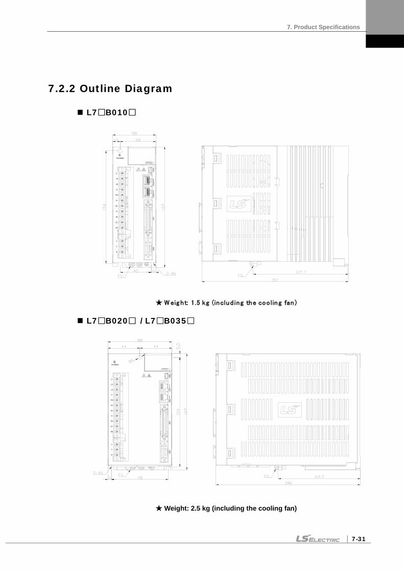
7. Product Specifications
7-31
7.2.2 Outline Diagram
L7B010
W eig ht: 1.5 kg (includ ing the coo ling fan )
L7B020 / L7B035
Weight: 2.5 kg (including the cooling fan)

7. Product Specifications
7-32
L7B050
Weight: 5.5 kg (including the cooling fan)
L7B075
W eig ht: 8.5 kg (includ ing the coo ling fan )

7. Product Specifications
7-33
L7B150
W eig ht: 15.5 kg (includ ing the coo ling fan )

7. Product Specifications
7-34
7.3 Options and Peripheral Devices
Option (Incremental/serial encoder cable)
Category Product Name
Name (Note 1)
Applicable Motors Specifications
For signaling
Medium capacity
Serial type encoder
cable (Single turn)
APCS-EDS
All models of FEP/ FFP/ FGP
SERIES
1. Motor connection (MS: Military Standard) a. Plug specifications : MS3108A 20-29S
2. Drive connection (CN2) a. Case : 10314-52A0-008 (3M) or SM-14J(Suntone) b. Connector : 10114-3000VE(3M) or SM-14J(Suntone)
3. Cable specifications : 3Px0.2SQ or 3PxAWG24
For signaling
Medium capacity
Serial type encoder
cable (Multi turn)
APCS-EDS1
All models of FEP/ FFP/ FGP
SERIES
1. Motor connection (MS: Military Standard) a. Plug specifications : MS3108A 20-29S
2. Drive connection (CN2) a. Case : 10314-52A0-008 (3M) or SM-14J(Suntone) b. Connector : 10114-3000VE(3M) or SM-14J(Suntone)
3. Cable specifications : 4Px0.2SQ or 4Px AWG24 4. Battery connection. a. Connector specifications : 5267-02A(Molex) b. Battery specification : ER6V
(TOSHIBA, AA, 3.6V, 2000mAh)
Note 3) The in the name indicates the type and length of each cable. Refer to the following table for this information.
Cable length (m) 3 5 10 20
Robot cable F03 F05 F10 F20
Regular cable N03 N05 N10 N20
Motor Side Connector Drive Side Connection
Motor Side Connector Drive Side Connection

7. Product Specifications
7-35
Optional power cable
Category Product Name
Name (Note 1)
Applicable Motors Specifications
For power
Middle capacity MS Type
Power cable (For 400V
130 Flange)
APCS- PHS
All models of SEP/ FEP
SERIES
1. Motor connection (MS: Military Standard) a. Plug specifications : MS3108A 20-4S
2. Drive connection (U,V, W, FG) a. U, V, W Ferrule specifications : 1512 b. FG PIN specifications: 1.5X4(Ring Terminal) 3. Power Cable specifications a. 4Cx1.5SQ or 4Cx15AWG
For power (Brake Type)
Middle capacity MS Type Power/
Brake cable (For 400V
130 Flange)
APCF- PNB
All models of SEP/ FEP
SERIES All model
1. Motor connection (MS: Military Standard) a. Plug specifications : MS3108A 20-15S(MS)
2. Drive connection (U,V, W, FG) a. U, V, W Ferrule specifications : 1512 b. FG PIN specification : 1.5X4(Ring Terminal) 3. Power Cable specifications a. 4Cx1.5SQ or 4Cx15AWG
4. Brake power connection a. Connection pin specification : 1.5 x 3(Ring Terminal)
5. Brake power cable specification a. 2Cx0.75SQ or 2Cx19AWG
Note 4) The in the name indicates the type and length of each cable. Refer to the following table for
this information. Cable length (m) 3 5 10 20
Robot cable F03 F05 F10 F20
Motor Side Connector Drive Side Connection
Motor Side Connector Drive Side Connection

7. Product Specifications
7-36
Category Product Name
Name (Note 1)
Applicable Motors Specifications
For power
Middle capacity MS Type Power cable
(400V 3.5kW Drive under
180/220 Flange)
APCS- PIS
SFP30A SFP22D SFP35D SFP20G SFP12M SFP20M SGP22D SGP35D SGP20G SGP12M SGP20M FFP30A FFP22D FFP35D FFP20G FFP30G FFP12M FFP20M FGP22D FGP35D FGP20G FGP30G FGP12M FGP20M
1. Motor connection (MS: Military Standard) a. Plug specifications: MS3108A 22-22S
2. Drive connection (U,V, W, FG) a. U, V, W Ferrule specifications : 1512 b. FG PIN specifications : 1.5X4(Ring Terminal) 3. Power Cable specifications : 4Cx1.5SQ or 4Cx15AWG
For power (Brake Type)
Middle capacity MS Type Power/
Brake cable (400V 3.5kW Drive under 180 Flange)
APCS- PPB
SFP30A SFP22D SFP35D SFP20G SFP12M SFP20M FFP30A FFP22D FFP35D FFP20G FFP30G FFP12M FFP20M
1. Motor connection (MS: Military Standard) a. Plug specifications : MS3108A 24-10S(MS)
2. Drive connection (U,V, W, FG) a. U, V, W Ferrule specifications : 1512 b. FG PIN specification : 1.5X4(Ring Terminal) 3. Power Cable specifications: 4Cx1.5SQ or 4Cx15AWG 4. Brake power connection a. Connection pin specification : 1.5 x 3(Ring
Terminal) 5. Brake power cable specification a. 2Cx0.75SQ or 2Cx19AWG
Note 5) The in the name indicates the type and length of each cable. Refer to the following table for
this information. Cable length (m) 3 5 10 20
Robot cable F03 F05 F10 F20
Motor Side Connector Drive Side Connection
Motor Side Connector Drive Side Connection

7. Product Specifications
7-37
Category Product Name
Name (Note 1)
Applicable Motors Specifications
For power
Middle capacity MS Type Power cable
(400V 7.5kW Drive under
180/220 Flange)
APCS- PJS
SFP50A, SFP55D, SFP75D, SFP30G SFP44G, SFP60G, SFP30M, SFP44M SGP55D, SGP75D, SGP30G, SGP44G, SGP60G, SGP30M, SGP44M FFP50A, FFP55D, FFP75D, FFP44G, FFP60G, FFP30M, FFP44M FGP55D, FGP75D, FGP44G, FGP60G, FGP30M, FGP44M
1. Motor connection (MS: Military Standard) a. Plug specifications: MS3108A 22-22S
2. Drive connection (U,V, W, FG) a. U, V, W, FG Pin specifications : 4.0x5(Ring Termianl) 3. Cable specifications : 4Cx4.0SQ or 4Cx11AWG
For power (Brake Type)
Middle capacity MS Type Power/
Brake cable (400V 7.5kW Drive under 180Flange)
APCS- PLB
SFP50A, SFP55D, SFP75D, SFP44G, SFP60G, SFP30M, SFP44M FFP50A, FFP55D, FFP75D, FFP44G, FFP60G, FFP75G FFP30M, FFP44M
1. Motor connection (MS: Military Standard) a. Plug specifications : MS3108A 24-10S(MS)
2. Drive connection (U,V, W, FG) a. U, V, W, FG Pin specifications : 4.0x5(Ring Termianl) 3. Power Cable specifications: 4Cx4.0SQ or 4Cx11AWG 4. Brake power connection a. Connection pin specification : 1.5 x 3(Ring Terminal)
5. Brake power cable specification a. 2Cx0.75SQ or 2Cx19AWG
Note 6) The in the name indicates the type and length of each cable. Refer to the following table for this information.
Cable length (m) 3 5 10 20
Robot cable F03 F05 F10 F20
Motor Side Connector Drive Side Connection
Motor Side Connector Drive Side Connector

7. Product Specifications
7-38
Category Product Name
Name (Note 1)
Applicable Motors Specifications
For power
Middle Capacity MS Type Power Cable
(400V 15kW Drive under
180/220 Flange)
APCS- PMS
SFP75G, SGP110D, SGP85G, SGP110G, SGP150G, SGP60M
1. Motor connection (MS: Military Standard) a. Plug specifications: MS3108A 32-17S
2. Drive connection (U,V, W, FG) a. U, V, W, FG Pin specifications : 10x5(Ring Termianl) 3. Cable specifications : 4Cx10.0SQ or 4Cx7AWG
For brake
Middle Capacity MS Type
Brake Cable
(200V/400V 220 Flange)
APCS- PMS
SGP22D SGP35D SGP55D SGP75D SGP12M SGP20M SGP30M SGP44M SGP20G SGP30G SGP44G SGP60G FGP22D FGP35D FGP55D FGP75D FGP20G FGP30G FGP30G FGP44G FGP60G FGP12M FGP20M FGP30M FGP44M
1. Motor connection (MS: Military Standard) a. Plug specifications: MS3108A 14-7S
2. Brake power connection : 1.5x3(Ring Terminal) 3. Brake power cable specification a. 2Cx0.75SQ or 2Cx19AWG
Note 7) The in the name indicates the type and length of each cable. Refer to the following table for this information.
Cable length (m) 3 5 10 20
Robot cable F03 F05 F10 F20
Motor Side Connector Drive Side Connection
Motor Side Connector

7. Product Specifications
7-39
Optional cables
Category Product Name
Name (Note 1)
Applicable Drive Specifications
For signaling CN1 Cable APC-
CN1A L7 SERIES
[Upper level controller]
[Drive connection CN1]
Pin number display
1. Drive connection (CN1)
a. Case specifications: 10350-52A0-008 (3M) b. Connector specifications: 10150-3000VE (3M) c. Cable specifications: ROW-SB0.1Cx50C
(AWG 28)
For signaling
Communication cable
APCS-CM5L7U L7 SERIES
[PC - USB port] [Servo drive – CN5]
1. PC connection: USB A plug 2. Drive connection (CN5): Mini USB 5P plug 3. Electrical requirements:
Double shielded, twisted pair, EMI filter installation (similar product: KU-AMB518 by SANWA)
Note 1) The in Type Name indicates the length of each cable. Refer to the table below for how to display
them. Cable length (m) 1 2 3 5
Written as 01 02 03 05

7. Product Specifications
7-40
Option (connector)
- Product Name Name Applicable
Drive Specifications
T/B CN1 T/B
APC-VSCN1T APC-VPCN1T
L7 SERIES
Cable Length
1. APC-VSCN1T: CN1 T/B expansion of APD-VS 2. APC-VPCN1T: CN1 T/B expansion of APD-VP 3. The cable length can be changed. 4. Standard cable length: 0.5 m
CN CN1
Connector APC-
CN1NNA L7 SERIES
1. Case specifications: 10350-52A0-008 (3M) 2. Connector specifications: 10150-3000VE (3M)
CN CN2
Connector APC-
CN3NNA L7 SERIES
1. Case specifications: 10314-52A0-008 (3M) 2. Connector specifications: 10114-3000VE (3M)
26
50
1
25
1
8
14
1
7

7. Product Specifications
7-41
Optional braking resistance
Category Product Name Name Applicable
Drive Specifications
Resistance Braking resistance
IRV300-82Ω
82[Ω (300W)
L7B010
Resistance Braking resistance
IRV600-140Ω
140Ω (600W)
- Making under review
L7B035
Resistance Braking resistance
IRV600-75Ω
25[Ω (600W *3P)
L7B050 L7B075
(3P)
Resistance Braking resistance
IRM2000-13.4Ω
13.4[Ω (2000W)
L7B150


8. Maintenance and Inspection
8-1
8. Maintenance and Inspection
8.1 Maintenance and Inspection
This chapter explains how to perform basic maintenance and inspection tasks as well as diagnose and troubleshoot the servo motor and drive.
8.1.1 Precautions
1. Measuring the motor voltage: The PWM controls the voltage output from the servo amp to the motor. Because of this, the waves take the form of pulses. Use a rectifier voltmeter for accurate measurements because different meters may produce different results.
2. Measuring the motor current: Use a moving iron ammeter and wait for the motor's reactance to smooth the pulse waveform into sine waves.
3. Measuring the electric power: Use an electrodynamometer based on the 3 power meter method.
4. Other gauges: When using an oscilloscope or digital voltmeter, do not allow them to touch the ground. Use a 1 mA or less input current gauge.
8.1.2 What to Inspect
Be sure to start inspection approximately 10 minutes after power is turned off because the charged voltage left in the internal smoothing condenser may cause an accident.
(1) Inspecting the Servo Motor
Caution Be sure to start inspection approximately 10 minutes after power is turned off because the charged voltage left in the internal smoothing condenser may cause an accident.
Inspection
Item Inspection Period Inspection and Handling Notes
Vibration and sound check Monthly Touch the motor and listen for
sounds. The feel and sounds should be the same as usual.
Inspect the exterior of the
motor
Depends on the amount of
contamination or damage.
Clean the motor with a cloth or air pressure. -
Measure the insulation resistance
At least once a year
Disconnect the motor from the drive and measure the insulation resistance. A normal resistance level is 10 or higher. Note 1)
Contact our service center if the resistance is lower than 10 .
Replace the oil seal
At least once every 5,000 hours
Remove the oil seal from the motor and replace it.
This only applies to motors with an oil seal.
General inspection
At least once every 20,000 hours or
after 5 years. Contact our service center. Do not disassemble the servo
motor yourself.
Note 1) Measure the resistance between the FG and one of the U, V, and W power lines on the servo motor.

8. Maintenance and Inspection
8-2
(2) Inspecting the Servo Drive
Inspection Item
Inspection Period Inspection process What to do if you find an
abnormality Clean the main body and control
board
At least once a year
Check if there is any dust or oil on the components.
Clean it with air pressure or a cloth.
Check for loose screws
At least once a year
Check whether the screws are loose on the terminals and connectors.
Tighten the screws.
Check for defective
parts on the main body or the control
board
At least once a year
Check for discoloration, damage, or disconnection caused by heat.
Contact our company.

8. Maintenance and Inspection
8-3
8.1.3 Replacing Parts
Mechanical friction and aging may deteriorate the following parts or even cause them to malfunction. This makes it important to conduct regular maintenance checks and replace worn parts.
1. The smoothing condenser: Ripple currents and other factors can cause this part to wear. The lifespan of this part depends on the operating temperature and environment. It normally lasts for 10 years if used continuously in a normal air-conditioned environment. Inspect the condenser at least once each year because it can rapidly age over a short period of time once it starts to deteriorate (inspect it more frequently as it approaches obsolescence).
※ Visual inspection criteria:
a. The condition of the case: Check for deformations on the sides and bottom.
b. The condition of the lid: Check for notable expansion, severe cracks, or broken parts.
c. The relief valve: Check for notable valve expansion and operation.
d. Also regularly check whether the exterior is cracked, discolored, or leaking and whether there are any broken parts. The condenser is obsolete when its capacity degrades to less than 85% of the rated capacity.
2. The relays: Check for bad connections and wear and tear on the contacts caused by switching currents. A relay is obsolete when its accumulated number of switches reaches 100,000, depending on the power capacity.
3. Motor bearings: Replace the bearings after 20,000 to 30,000 hours of operation at the rated speed under the rated load. Replace the bearings if abnormal sounds or vibrations are detected during inspection, depending on the operating conditions.
The Standard Part Replacement Cycle
Part Name Standard
Replacement Cycle
Method
Smoothing condenser 7-8 years Replace (determine after inspection).
Relays - Determine after inspection
Fuses 10 years Replace
Aluminum electrolytic condensers on printed
boards 5 years Replace with new boards (determined after
inspection)
Cooling fans 4-5 years Replace
Motor bearings - Determine after inspection
Motor oil seals 5,000 hours Replace
8.2 Diagnosing and Troubleshooting Abnormalities
AL- appears if a problem occurs during operation. If this happens, try to solve the problem by following the troubleshooting advice given in this section. If the problem persists, contact our service center.

8. Maintenance and Inspection
8-4
8.2.1 Servo motor
Cause of abnormalities, inspection procedure, and troubleshooting methods
Symptoms Cause Inspection process Remedies
The motor does not move.
The input of CCWLIM and CWLIM is off. Refer to "1.2 System Configuration." Turn on the input of CCWLIM and
CWLIM.
The parameters are set incorrectly
Check the parameters of the motor, encoder, and encoder type control mode.
Reset the parameters. (Refer to “Chapter 4 Parameters.”)
The motor has defects.
Use a resistance tester to measure the resistance to the motor lead terminal (resistance between phases: several ohms).
Replace the motor.
The locking screws are loose. Check the locking screws. Tighten any loose screws.
The external wiring is incorrect or the cables are disconnected.
Check the wires to the motor and the encoder.
Redo the wiring. Replace the cables.
The encoder has defects. Check the output waves. Replace the encoder. (Contact our service center.)
Motor rotation is unstable.
The connection is bad. Check the connection of the motor lead terminal. Fix any bad connections.
The input voltage is low. Check the input voltage of the drive. Change the power source.
Overloads occur. Check the condition of the machine. Remove any foreign substances from the rotating unit and grease or lubricate it.
The motor overheats.
The ambient temperature is too high.
Check the temperature around the motor. (40 or lower)
Change heat transfer structure. Install a cooling fan.
The surface of the motor is contaminated.
Check whether there are any foreign substances on the surface of the motor.
Clean the surface of the motor.
Overloads occur. Check the load on the drive. Check the acceleration/deceleration time.
Reduce the load. Increase the acceleration/deceleration time. Use a motor with a greater capacity.
The magnetic power of the magnets is reduced.
Check the counter voltage and voltage waveforms. Replace the motor.
The device is making a
strange sound.
Coupling is bad. Tighten the coupling screws and measure the concentricity of the connection.
Readjust the coupling.
The bearings are abnormal. Check the bearings for vibrations and sounds. Contact us.
The parameters are set incorrectly (the inertia, gain, and time constants).
Check the parameters. Refer to “Chapter 4 Parameters.”

8. Maintenance and Inspection
8-5
8.2.2 Servo Drive
If an alarm triggers, the malfunction signal output contact point (ALARM) turns off and the dynamic brake stops the motor.
Alarm code name Details What to check
IPM Fault Overcurrent (H/W)
Check for incorrect wiring in the drive output and encoder. Check the motor ID, drive ID, and encoder settings. Determine whether there is a conflict or binding in the equipment.
IPM temperature IPM overheat
Check for incorrect wiring in the drive output and encoder. Check the motor ID, drive ID, and encoder settings. Determine whether there is a conflict or binding in the equipment.
Over current Overcurrent (S/W)
Check for incorrect wiring in the drive output and encoder. Check the motor ID, drive ID, and encoder settings. Determine whether there is a conflict or binding in the equipment.
Current offset Abnormal current offset Replace the drive if [St-23] and [St-24] are 10% or higher of the rated current.
Overcurrent (/CL) Overcurrent (H/W)
Check for incorrect wiring in the drive output and encoder. Check the motor ID, drive ID, and encoder settings. Determine whether there is a conflict or binding in the equipment.
Continuous overload Continuous overload
Determine whether there is a conflict or binding in the equipment. Check the load and the condition of the brake. Check for incorrect wiring in the drive output and encoder. Check the motor ID, drive ID, and encoder settings.
Room temperature Drive overheat
Check the temperature inside the drive [St-19]. the cooling fan installation, and the load condition.
Regen. Overload Regenerative overload Check the input voltage, regenerative braking resistance, and wiring. Replace the drive.
Motor cable open Motor disconnection Check the wiring of the motor.
Encoder comm. Serial encoder communication error
Check for incorrect wiring of the serial encoder.
Encoder cable open Encoder cable disconnection
Check whether the encoder cable is disconnected.

8. Maintenance and Inspection
8-6
Alarm code name Details What to check
Encoder data error Encoder data error Check the [P0-02] setting and encoder wiring.
Motor setting error Motor ID setting error Check the [P0-00] setting.
Encoder Z PHASE Open Encoder Z phase disconnected
Check whether the encoder cable is disconnected.
Under voltage Low voltage Check input voltage and power unit wiring.
Overvoltage Overvoltage
Check the input voltage and wiring. Check the braking resistance for damage. Check for excessive regenerative operation. Check the regenerative resistance.
RST power fail Main power failure Check the power unit wiring and power supply.
Control power fail Control power failure Check the power unit wiring and power supply.
Over speed limit Overspeed
Check the encoder, encoder settings, encoder wiring, gain settings, motor wiring, motor ID, electric gear ratio, and speed command scale.
Position following Excessive positional error
Check the excessive position command pulse setting [P4-11], wiring, limit contact point, gain setting, encoder setting, and electric gear ratio. Check the load on the equipment and whether there is binding on the equipment.
Over pulse CMD Pulse command frequency error
Check the pulse command frequency on the upper level controller. Check the command pulse type.
Speed deviation Excessive speed error
Check for incorrect wiring in the drive output and encoder. Also, check the connection and load status of the equipment.
Motor overrun Motor overrun
Check for incorrect wiring in the drive output and encoder. Also, check the connection and load status of the equipment.
Parameter checksum Parameter error Factory reset [Cn-21].
Parameter range Parameter range error Factory reset [Cn-21].
Invalid factory setting Factory setting error Factory reset [Cn-21].
GPIO setting Output contact point setting error Factory reset [Cn-21].

8. Maintenance and Inspection
8-7
If a warning code is displayed as the current operation status [St-00], the servo drive is operating abnormally. Check what needs to be inspected for the issue.
Warning State
(CODE) name Details and causes What to check
RST_PFAIL Main power phase loss If the [P0-06] DIGIT 2 is set to 1, the main power fails.
LOW_BATT Battery low
OV_TCMD Excessive Torque Command You have entered a command that exceeds the maximum set torque.
OV_VCMD Excessive speed command You have entered a command that exceeds the maximum set speed.
OV_LOAD Overload warning The maximum overload [P0-13] has been reached.
SETUP Capacity settings The electric current capacity of the motor is larger than that of the drive.
UD_VTG Low voltage warning When [P0-06] DIGIT 2 is set to 1, the DC link voltage is 190 V or below.
EMG EMG contact Check I/O wiring and [P2-09] value
Warning code is displayed in hexadecimal, but it is displayed as the sum of respective warning codes when two or more warnings occur at once. For example, warning code is displayed as [W-0C] when both [W-04] Excessive Torque Command and [W-08] Excessive Speed Command occur at once.
If [W-80] occurs, SVON turns from ON to OFF. And when you turn on I/O power or change contact logic, [W-80] code is automatically deactivated.

8. Maintenance and Inspection
8-8
Servo Drive Overload Graphs (1.0KW)
(1) Rotation overload graph
Load (%)
AL-21 Occurring
Time (sec)
Max Min Load (%)
AL-21 Occurring
Time (sec)
Max Min
100% or lower Infinite
110 55776 89241.6 33465.6 210 100 160.0 60
120 13944 22310.4 8366.4 220 60 96.0 36
130 6197.3 9915.7 3718.38 230 40 64.0 24
140 3486 5577.6 2091.6 240 30.3 48.5 18.18
150 1183 1892.8 709.8 250 24.2 38.7 14.52
160 566 905.6 339.6 260 7 11.2 4.2
170 318 508.8 190.8 270 6.4 10.2 3.84
180 198 316.8 118.8 280 5.7 9.1 3.42
190 160 256.0 96 290 4 6.4 2.4
200 130 208.0 78 300 3 4.8 1.8
Load Curve During Rotation
Tim
e (s
ec.)
Load Rate (%)

8. Maintenance and Inspection
8-9
(2) Stoppage overload graph
Load (%)
AL-21 Occurring
Time (sec)
Max Min Load (%)
AL-21 Occurring
Time (sec)
Max Min
100% or
lower Infinite
110 37937.7 60700.3 22762.62 210 50.1 80.2 30.06
120 9483.9 15174.2 5690.34 220 38.5 61.6 23.1
130 4215.1 6744.2 2529.06 230 30.3 48.5 18.18
140 2371.0 3793.6 1422.6 240 9.7 15.5 5.82
150 926.0 1481.6 555.6 250 8.3 13.3 4.98
160 470.0 752.0 282 260 3.8 6.1 2.28
170 273.0 436.8 163.8 270 3.4 5.4 2.04
180 173.0 276.8 103.8 280 3.1 5.0 1.86
190 117.0 187.2 70.2 290 2.7 4.3 1.62
200 66.0 105.6 39.6 300 2.0 3.2 1.2
Load Curve When Stopped
Tim
e (s
ec.)
Load Rate (%)

8. Maintenance and Inspection
8-10
Servo Drive Overload Graphs (3.5KW)
(1) Rotation overload graph
Load (%)
AL-21 Occurring
Time (sec)
Max Min Load (%)
AL-21 Occurring
Time (sec)
Max Min
110% or
lower Infinite 210 85 136.0 51
120 1208 1932.8 724.8 220 54 86.4 32.4
130 500 800.0 300 230 33 52.8 19.8
140 323 516.8 193.8 240 25 40.0 15
150 250 400.0 150 250 20 32.0 12
160 231 369.6 138.6 260 18 28.8 10.8
170 180 288.0 108 270 15 24.0 9
180 164 262.4 98.4 280 12 19.2 7.2
190 120 192.0 72 290 3.5 5.6 2.1
200 100 160.0 60 300 85 4.0 1.5
Load Curve During Rotation
Tim
e (s
ec.)
Load Rate (%)

8. Maintenance and Inspection
8-11
(2) Stoppage overload graph
Load (%)
AL-21 Occurring
Time (sec)
Max Min Load (%)
AL-21 Occurring
Time (sec)
Max Min
100% or lower Infinite
110 4600 7360.0 2760 210 40 64.0 24
120 1208 1932.8 724.8 220 36 57.6 21.6
130 500 800.0 300 230 25 40.0 15
140 303 484.8 181.8 240 10 16.0 6
150 150 240.0 90 250 7.5 12.0 4.5
160 100 160.0 60 260 3.5 5.6 2.1
170 80 128.0 48 270 3.1 5.0 1.86
180 69 110.4 41.4 280 2.9 4.6 1.74
190 58 92.8 34.8 290 2.5 4.0 1.5
200 52 83.2 31.2 300 2.3 3.7 1.38
Load Curve When Stopped
Tim
e (s
ec.)
Load Rate (%)

8. Maintenance and Inspection
8-12
Servo Drive Overload Graphs (5KW)
(1) Rotation overload graph
Load (%)
AL-21 Occurring Time (sec)
Max Min Load (%)
AL-21 Occurring Time (sec)
Max Min
110%이하 무한대 210 66.8 93.52 40.08
120 4832 6764.8 2899.2 220 50.1 70.14 30.06
130 1208 1691.2 724.8 230 38.5 53.9 23.1
140 536.9 751.66 322.14 240 30.3 42.42 18.18
150 302 422.8 181.2 250 24.2 33.88 14.52
160 257 359.8 154.2 260 18 25.2 10.8
170 229 320.6 137.4 270 16 22.4 9.6
180 200 280 120 280 14 19.6 8.4
190 165 231 99 290 8 11.2 4.8
200 131 183.4 78.6 300 5 7 3

8. Maintenance and Inspection
8-13
(2) Stoppage overload graph
Load (%)
AL-21 Occurring Time (sec)
Max Min Load (%)
AL-21 Occurring Time (sec)
Max Min
100%이하 무한대
110 4832 6764.8 2899.2 210 61.6 26.4 44
120 1208 1691.2 724.8 220 50.4 21.6 36
130 536 750.4 321.6 230 42.42 18.18 30.3
140 302 422.8 181.2 240 13.58 5.82 9.7
150 154 215.6 92.4 250 11.62 4.98 8.3
160 100 140 60 260 5.32 2.28 3.8
170 85 119 51 270 4.76 2.04 3.4
180 70 98 42 280 4.34 1.86 3.1
190 61 85.4 36.6 290 3.78 1.62 2.7
200 52 72.8 31.2 300 3.5 1.5 2.5

8. Maintenance and Inspection
8-14
Servo Drive Overload Graphs (7.5KW)
(1) Rotation overload graph
Load (%)
AL-21 Occurring
Time (sec)
Max Min Load (%)
AL-21 Occurring
Time (sec)
Max Min
100% or lower Infinite
110 5760 9216.0 3456 210 120 192.0 72
120 550 880.0 330 220 60 96.0 36
130 440 704.0 264 230 40 64.0 24
140 360 576.0 216 240 30 48.0 18
150 300 480.0 180 250 20 32.0 12
160 270 432.0 162
170 240 384.0 144
180 210 336.0 126
190 180 288.0 108
200 150 240.0 90
Load Curve During Rotation
Tim
e (s
ec.)
Load Rate (%)

8. Maintenance and Inspection
8-15
(2) Stoppage overload graph
Load (%)
AL-21 Occurring
Time (sec)
Max Min Load (%)
AL-21 Occurring
Time (sec)
Max Min
100% or lower Infinite
110 420 672.0 252 210 20 32.0 12
120 300 480.0 180 220 12 19.2 7.2
130 250 400.0 150 230 7 11.2 4.2
140 200 320.0 120 240 2 3.2 1.2
150 150 240.0 90 250 1.5 2.4 0.9
160 120 192.0 72
170 100 160.0 60
180 60 96.0 36
190 45 72.0 27
200 35 56.0 21
Load Curve When Stopped
Tim
e (s
ec.)
Load Rate (%)

8. Maintenance and Inspection
8-16
Servo Drive Overload Graphs (15KW)
(1) Rotation overload graph
Load (%)
AL-21 Occurring
Time (sec)
Max Min Load (%)
AL-21 Occurring
Time (sec)
Max Min
100% or lower Infinite
110 Infinite Infinite Infinite 210 49 78.4 29.4
120 1998 3196.8 1198.8 220 42 67.2 25.2
130 630 1008.0 378 230 27.2 43.5 16.32
140 540 864.0 324 240 19.6 31.4 11.76
150 324 518.4 194.4 250 12 19.2 7.2
160 271.8 434.9 163.08
170 210.6 337.0 126.36
180 162.9 260.6 97.74
190 111 177.6 66.6
200 56 89.6 33.6
Load Curve During Rotation
Tim
e (s
ec.)
Load Rate (%)

8. Maintenance and Inspection
8-17
(2) Stoppage overload graph
Load (%)
AL-21 Occurring
Time (sec)
Max Min Load (%)
AL-21 Occurring
Time (sec)
Max Min
100% or lower Infinite
110 Infinite Infinite Infinite 210 16.4 26.2 9.84
120 698.4 1117.4 419.04 220 13.5 21.6 8.1
130 524.2 838.7 314.52 230 10.6 17.0 6.36
140 350.1 560.2 210.06 240 7.8 12.5 4.68
150 176 281.6 105.6 250 3 4.8 1.8
160 135 216.0 81
170 94 150.4 56.4
180 60 96.0 36
190 32.8 52.5 19.68
200 19.3 30.9 11.58
Load Curve When Stopped
Tim
e (s
ec.)
Load Rate (%)


9. Appendix
9-1
9. Appendix
9.1 Motor Types and IDs
Model Name ID Watt Notes Model Name ID Watt Notes
SEP09A 461 900 SGP35D 512 3500
SEP15A 462 1500 SGP55D 513 5500
SEP22A 463 2200 SGP75D 514 7500
SEP30A 464 3000 SGP110D 515 11000
SEP06D 465 600
SEP11D 466 1100 SGP12M 521 1200
SEP16D 467 1600 SGP20M 522 2000
SEP22D 468 2200 SGP30M 523 3000
SEP03M 469 300 SGP44M 524 4400
SGP60M 525 6000
SEP06M 470 600
SEP09M 471 900 SGP20G 531 1800
SEP12M 472 1200 SGP30G 532 2900
SEP05G 473 450 SGP44G 533 4400
SEP09G 474 850 SGP60G 534 6000
SEP13G 475 1300 SGP85G 535 8500
SEP17G 476 1700 SGP150G 537 15000
SFP30A 481 3000
SFP50A 482 5000
SFP22D 485 2200
SFP35D 486 3500
SFP55D 487 5500
SFP75D 488 7500
SFP12M 489 1200
SFP20M 490 2000
SFP30M 491 3000
SFP44M 492 4400
SFP20G 493 1800
SFP30G 494 2900
SFP44G 495 4400
SFP60G 496 6000
SFP75G 497 7500
SGP22D 511 2200
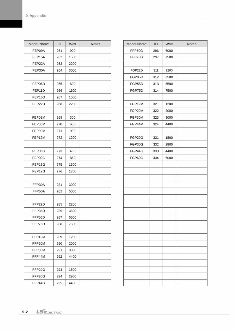
9. Appendix
9-2
Model Name ID Watt Notes Model Name ID Watt Notes
FEP09A 261 900 FFP60G 296 6000
FEP15A 262 1500 FFP75G 297 7500
FEP22A 263 2200
FEP30A 264 3000 FGP22D 311 2200
FGP35D 312 3500
FEP06D 265 600 FGP55D 313 5500
FEP11D 266 1100 FGP75D 314 7500
FEP16D 267 1600
FEP22D 268 2200 FGP12M 321 1200
FGP20M 322 2000
FEP03M 269 300 FGP30M 323 3000
FEP06M 270 600 FGP44M 324 4400
FEP09M 271 900
FEP12M 272 1200 FGP20G 331 1800
FGP30G 332 2900
FEP05G 273 450 FGP44G 333 4400
FEP09G 274 850 FGP60G 334 6000
FEP13G 275 1300
FEP17G 276 1700
FFP30A 281 3000
FFP50A 282 5000
FFP22D 285 2200
FFP35D 286 3500
FFP55D 287 5500
FFP75D 288 7500
FFP12M 289 1200
FFP20M 290 2000
FFP30M 291 3000
FFP44M 292 4400
FFP20G 293 1800
FFP30G 294 2900
FFP44G 295 4400

9. Appendix
9-3
9.2 Test Drive Procedure
Thank you for purchasing our product. Perform the following process to conduct the initial test drive:
Caution
In order to prevent accidents, conduct an operation test and test drive in manual JOG operation when there is no load (the motor exists without any coupling or belt) after attaching the servo motor to your equipment. Afterwards, connect the load and conduct the final test drive.
1. Product check: Check the name tag to verify that the product received matches the model ordered (refer to section 1.1). A name tag is attached to the right side of the product. (to the right side of the shaft on the
motor). Main check point: Product capacity and main options
2. Power connection: Wire a single-phase AC 380[V] power supply to control power input C1 and C2, and wire a three-phase AC 380 V-480V power supply to main power input L1, L2, and L3. (refer to section 3.2). Make sure that 3-phase AC 380 V-480 V power is input as main power before using our
product.
3. Signal cable wiring: Wire CN1 (I/O), CN3, CN4, CN5 (communication), CN2 encoder cable, and motor power cable per operation mode. (refer to section 1.2 and chapter 3). Be sure to use robot cables if the motor requires movement. Be sure to use twist shield cables as signal and encoder cables. Be sure to fasten bolts after locking the connector (drive direction) of the encoder cable. Be sure not to change the U, V, and W wiring of the motor power cable.

9. Appendix
9-4
4. Control power supply: Supply single-phase AC 380 V power to C1 and C2. Be sure to check external input voltage before turning on the servo drive. Check whether the display is normal. (There should be no break on the seven segments or
alarm output.)
5. Motor ID setting: Set motor ID in the parameter [P0-00] and encoder pulse in the parameter [P0-02] respectively. (Refer to "Appendix 1.") (※ The serial encoder is automatically set.) Easy check: Check the motor ID and encoder pulse on the product name tag attached on the
right side of the motor. Check whether the external control signal input is normal. For information on how to handle the keys of the servo drive loader, refer to "4.1 Loader
Handling."
6. Main power supply: Supply three-phase AC 380 V-480 V power to L1, L2 and L3. Be sure to check external input voltage before turning on the servo drive. When power is supplied, the red lamp on the charge LED at the bottom of the loader
window comes on. If an alarm appears, it indicates that there is an error in the power circuit, servo motor
wiring, or encoder wiring. Turn off power and fix the error using the information in "[Alarm Codes and Descriptions]."

9. Appendix
9-5
7. Test drive: Start [Cn-00] by pressing [SET] to conduct test drive manually. (JOG operation speed can be changed in [P3-12].) * [Up]: Motor forward rotation (CCW) → Only operate while you hold down the key. * [Down]: Reverse motor rotation (CW) → Only operate while you hold down the key. During normal operation, the power input of the servo drive and wiring among
motors are verified as normal. If the alarm is displayed, it indicates an error in the power circuit, wiring of the
servo motor, or encoder wiring. Turn off power and fix the error using the information in "[Alarm Codes and Descriptions]."
9. Operation mode setting: Set operation mode in [P0-03]. 0: Torque control operation 1: Speed control operation 2: Position control
operation 3: Speed/position control
operation 4: Speed/torque control
operation
Speed operation setting
Position operation setting
10. Perform speed operation with the upper level controller by adjusting the following parameter data.
a. Speed operation parameter: [P3-01]-[P3-20] b. Input/Output parameter: [P2-00]-[P2-22] c. Control parameter: [P1-00]-[P1-27]
(Refer to “Appendix 1.”)
11. Perform position operation with the upper level controller by adjusting the following parameter data.
d. Position operation parameter: [P4-00]-[P4-14]
e. Input/Output parameter: [P2-00]-[P2-22] f. Control parameter: [P1-00]-[P1-27]
(Refer to “Appendix 1.”)

9. Appendix
9-6
10-1 How to Set Control Parameters [Gain Tuning]
1) Auto gain tuning → Perform automatic gain tuning by pressing [SET] in [Cn-05]. → If the load condition of the equipment is not directly related to motor shaft, it is hard to perform accurate gain tuning because of characteristics of automatic gain tuning. Therefore, manual gain tuning is recommended.
2) Manual gain tuning → Set inertia ratio [P1-00], speed proportional gain [P1-06], and speed integral time constant [P1-08] as the standard gain. → Increase inertia ratio [P1-00] gradually until the motor starts vibrating. → For more stable control, increase speed proportional gain [P1-06] a little at a time until the motor vibrates slightly. If you increase speed integral time constant [P1-08], the motor stops vibrating. → Increase speed integral time constant [P1-08] in the last stage and the motor will stop vibrating. However, it takes as much time to reach normal state as the time constant set in responsiveness. If you set speed proportional gain [P1-06] too big in an effort to attain satisfying responsiveness, overshoot might occur. The allowed range of overshoot is generally 10 percent or below.
11-1 How to Set Electric Gear Ratio [P4-01]-[P4-05]
→ Electric gear ratio = transmission per input pulse X number of pulses per motor rotation / transmission per motor rotation

User Manual Revision History
Number Date issued Revised content Version Notes
1 2013.06.20 Modified miss printing and drawing 1.1
2 2014.03.13 Added functions and precautions 1.2
3 2014.08.06 Added wiring with PLC, New motor and cables. Indicated applicable mode on the parameter. 1.3
4 2014.11.06 Added New Model(L7NHB050U) 1.4
5 2020.05.15 Changed company name to ‘LS ELECTRIC’ 1.5
6 2021.07.15 Add N terminal caution 1.6
7
8
9
Green Management LS ELECTRIC considers protecting the environment a high priority. We work hard to protect the Earth.
Product Disposal The LS ELECTRIC servo drive is environmentally friendly. You can disassemble the drive and recycle the iron, aluminum, bronze and synthetic resin (cover) components.

www.ls-electric.com
Headquarter LS-ro 127(Hogye-dong) Dongan-gu, Anyang-si, Gyeonggi-Do, 14119, Korea
Seoul Office LS Yongsan Tower, 92, Hangang-daero, Yongsan-gu, Seoul, 04386, Korea Tel: 82-2-2034-4033, 4888, 4703 Fax: 82-2-2034-4588 E-mail: [email protected]
Overseas Subsidiaries • LS ELECTRIC Japan Co., Ltd. (Tokyo, Japan)
Tel: 81-3-6268-8241 E-Mail: [email protected] • LS ELECTRIC (Dalian) Co., Ltd. (Dalian, China)
Tel: 86-411-8730-6495 E-Mail: [email protected] • LS ELECTRIC (Wuxi) Co., Ltd. (Wuxi, China)
Tel: 86-510-6851-6666 E-Mail: [email protected] • LS ELECTRIC Middle East FZE (Dubai, U.A.E.)
Tel: 971-4-886-5360 E-Mail: [email protected] • LS ELECTRIC Europe B.V. (Hoofddorp, Netherlands)
Tel: 31-20-654-1424 E-Mail: [email protected] • LS ELECTRIC America Inc. (Chicago, USA)
Tel: 1-800-891-2941 E-Mail: [email protected] • LS ELECTRIC Turkey Co., Ltd.
Tel: 90-212-806-1225 E-Mail: [email protected]
Overseas Branches • LS ELECTRIC Tokyo Office (Japan)
Tel: 81-3-6268-8241 E-Mail: [email protected] • LS ELECTRIC Beijing Office (China)
Tel: 86-10-5095-1631 E-Mail: [email protected] • LS ELECTRIC Shanghai Office (China)
Tel: 86-21-5237-9977 E-Mail: [email protected] • LS ELECTRIC Guangzhou Office (China)
Tel: 86-20-3818-2883 E-Mail: [email protected] • LS ELECTRIC Chengdu Office (China)
Tel: 86-28-8670-3201 E-Mail: [email protected] • LS ELECTRIC Qingdao Office (China)
Tel: 86-532-8501-2065 E-Mail: [email protected] • LS ELECTRIC Nanjing Office (China)
Tel: 86-25-8467-0005 E-Mail: [email protected] • LS ELECTRIC Bangkok Office (Thailand)
Tel: 66-90-950-9683 E-Mail: [email protected] • LS ELECTRIC Jakarta Office (Indonesia)
Tel: 62-21-2933-7614 E-Mail: [email protected] • LS ELECTRIC Moscow Office (Russia)
Tel: 7-499-682-6130 E-Mail: [email protected] • LS ELECTRIC America Western Office (Irvine, USA)
Tel: 1-949-333-3140 E-Mail: [email protected]
Disclaimer of Liability LS ELECTRIC has reviewed the information in this publication to ensure consistency with the hardware and software described. However, LS ELECTRIC cannot guarantee full consistency, nor be responsible for any damages or compensation, since variance cannot be precluded entirely. Please check again the version of this publication before you use the product. LS ELECTRIC Co., Ltd 2013 All Right Reserved. 2021.07