HYPONIC Drive
206
HYPONIC Drive ® HYPONIC Drive ® No. N2201E-6 No. N2201E-6.0 Printed 2010.06 CW24
-
Upload
khangminh22 -
Category
Documents
-
view
0 -
download
0
Transcript of HYPONIC Drive

HYPONIC Drive®
HYPO
NIC D
rive®
No. N2201E-6No. N2201E-6.0Printed 2010.06
CW24

. Feature ‥‥‥‥‥‥‥‥‥‥‥‥‥‥‥‥‥‥‥‥‥‥‥‥‥ A2 . Product range ‥‥‥‥‥‥‥‥‥‥‥‥‥‥‥‥‥‥‥‥‥‥ A8 . Standard specification ‥‥‥‥‥‥‥‥‥‥‥‥‥‥‥‥‥‥ A14 . Nomenclature ‥‥‥‥‥‥‥‥‥‥‥‥‥‥‥‥‥‥‥‥‥‥ A15 . Hollow shaft Selection tables and dimensions (15W–5.5kW) ‥‥‥ B1 3-phase motor ‥‥‥‥‥‥‥‥‥‥‥‥‥‥‥‥‥‥‥ B2 Single-phase motor (Induction, Reversible) ‥‥‥‥‥‥ B46 3-phase motor for inverter ‥‥‥‥‥‥‥‥‥‥‥‥‥ B68 . Solid shaft Selection tables and dimensions (15W–90W) ‥‥ B87 3-phase motor ‥‥‥‥‥‥‥‥‥‥‥‥‥‥‥‥‥‥‥‥‥ B88 Single-phase motor (Induction, Reversible) ‥‥‥‥‥‥ B94 . Option ‥‥‥‥‥‥‥‥‥‥‥‥‥‥‥‥‥‥‥‥‥‥‥‥‥ B105 Solid shaft Flange Mount type (1) Dimension sheet ‥‥ B106 Solid shaft Flange Mount type (2) Dimension sheet ‥‥ B108 Solid shaft Foot Mount type Dimension sheet ‥‥‥‥‥ B110 IEC Flange type Dimension sheet ‥‥‥‥‥‥‥‥‥‥‥‥‥ B112
. Water proof type (IP65) ‥‥‥‥‥‥‥‥‥‥‥‥‥‥‥‥‥ B115 . Increased safety type (eG3) ‥‥‥‥‥‥‥‥‥‥‥‥‥‥‥ B125
CONTENTS

A1
. Technical data ‥‥‥‥‥‥‥‥‥‥‥‥‥‥‥‥‥‥‥‥‥‥ C1 Selection Procedure ‥‥‥‥‥‥‥‥‥‥‥‥‥‥‥‥‥‥ C2 Construction ‥‥‥‥‥‥‥‥‥‥‥‥‥‥‥‥‥‥‥‥‥ C8 Moment of inertia ‥‥‥‥‥‥‥‥‥‥‥‥‥‥‥‥‥‥‥ C9 GD2 ‥‥‥‥‥‥‥‥‥‥‥‥‥‥‥‥‥‥‥‥‥‥‥‥ C10 Moment of inertia and GD2 of gear motors ‥‥‥‥‥‥‥ C11 Rotating direction & Reduction ratio ‥‥‥‥‥‥‥‥‥‥ C12 Actual reduction ratio ‥‥‥‥‥‥‥‥‥‥‥‥‥‥‥‥ C15 Allowable axial load on output shaft ‥‥‥‥‥‥‥‥‥‥ C16 Lubrication ‥‥‥‥‥‥‥‥‥‥‥‥‥‥‥‥‥‥‥‥‥ C16 Detail dimensions ‥‥‥‥‥‥‥‥‥‥‥‥‥‥‥‥‥‥ C17 Hollow shaft type handling precautions ‥‥‥‥‥‥‥‥ C18 Torque arm (Option) ‥‥‥‥‥‥‥‥‥‥‥‥‥‥‥‥‥ C21 Torque arm designs ‥‥‥‥‥‥‥‥‥‥‥‥‥‥‥‥‥ C22 Detail dimensions of output shaft safety cover (separate shipment) C24 Detail dimensions of output shaft ‥‥‥‥‥‥‥‥‥‥‥ C25 Name plate ‥‥‥‥‥‥‥‥‥‥‥‥‥‥‥‥‥‥‥‥‥ C25 Motor characteristics ‥‥‥‥‥‥‥‥‥‥‥‥‥‥‥‥ C26 Dimensions of a terminal box ‥‥‥‥‥‥‥‥‥‥‥‥‥ C29 Mounting direction of a terminal box ‥‥‥‥‥‥‥‥‥ C30 Specifications and construction of built-in brake ‥‥‥‥ C31 Wiring diagram ‥‥‥‥‥‥‥‥‥‥‥‥‥‥‥‥‥‥‥ C35 Construction of terminal plate for brake motors (optional) C47 Connection of terminal plate for brake motors (optional) ‥ C47 Protection of motor ‥‥‥‥‥‥‥‥‥‥‥‥‥‥‥‥‥ C49 Cooling ‥‥‥‥‥‥‥‥‥‥‥‥‥‥‥‥‥‥‥‥‥‥ C49 International Standards and corresponding Sumitomo standards for a motor C50 Precautions for Inverter Driving ‥‥‥‥‥‥‥‥‥‥‥‥ C54 Constant Torque Operation of General-Purpose Motors ‥ C55 Painting specifications ‥‥‥‥‥‥‥‥‥‥‥‥‥‥‥‥ C56 Rust Proof Standards ‥‥‥‥‥‥‥‥‥‥‥‥‥‥‥‥ C58 Warranty ‥‥‥‥‥‥‥‥‥‥‥‥‥‥‥‥‥‥‥‥‥‥ C59
ISO 14001 CERTIFICATION
Okayama works has achieved ISO 14001 for environmental control . We are constantly striving to further enhance the quality of our environmental management.
Ho
llow
Sha
ftS
olid
Sha
ftO
pti
on
Wa
ter
pro
of
typ
e
IP65
Inc
rea
se
d s
afe
ty
typ
e e
G3
Tech
nica
l Dat
a

A2
Hollow shaft type has been changed fully as the New model
The all New Hyponic provide all three mounting configuration with a single housing design
(combinations of capacity and reduction ratio)
with addition of intermediate capacity motor (0.25,0.55,and 1.1kW) and reduction ratio (1/5,1/7,1/300,1/480,1/560,1/750,1/900,1/1200 and 1/1440), a wider range is made available to meet your requirements.
More compact gearhead for 0.1kW~2.2kW
Single Housing Design !
Ratio1/5
2.2kW
1.5kW
0.75kW
0.1kW
1/60 1/240
ex) Hollow shaft, 3-phase induction motor type
Details are shown on page 3.
More compactMore light weghtMore compactMore light weght
Mot
or c
apac
ity
New
New
Tripled the available combinations !New
Existing model
New model
RNYM SeriesHollow shaft type
RNFM SeriesFlange mount type (1)
RNFM SeriesFlange mount type (2)
RNHM SeriesFoot mount type

A3
Because the mounting bolts are on square pitch1. Mounting position can be changed without protrusion from existing envelope space.2. Mounting position can be changed without changing interface dimensions.
Patent Number 2628983 5,203,231
Obtained Japan and US patents
A
A
small
49
49 40
40
4940
49 40
A
A
large
RNYM05-1220-30 Mass 9.5kg
RNYM05-33-30 Mass 12kg
Example 1
Example 2New Series Example 0.4kW Ratio 1/30
Old Series
Horizontal mounting Vertical mounting
RNYM05-1220-30
RNYM05-1220-30
The output shaft is located as close to the corner as possible to shorten the distance (A dimensions) between the center of the shaft and the edge of the casing.Th i s a l l ows the Hypon ic to be installed within a very tight space.
Right angle New HYPONIC allows compact designs !New
A=49mm
A=60mm

A4
Are you sure that your parallel-shaft gear motors are best for your application?Hyponic Neo right-angle gear motors make motors installations more compact and less costly.
Substantial reduction in the number of mounting parts, man hours for mounting, and frequency of maintenance.
2.Advantages of Hyponic Drive®
1.Small sizes of Hyponic Drive®
Direct drive !
Space-saving design !
Twin shaft design !
Water-proof typeIP65 water-proof type Hyponic Drive can be used in various areas, including food processing machines.
Versatile Installation New style casing of Hyponic Neo allows installations from both sides.
Long
Deep
Inline
Right-angle
Shallow
Short
Torque arm(option)
Mounting base &alignment
Safety cover
Chain &sprocket

A5
High efficiencySumitomo Hyponic Dr ive provides h igher reduction ratio than bevel gears, allowing higher efficiency in all ranges of reduction ratios.
Low noiseWith larger contact intervals than bevel gears, Hyponic Dr ive has a greater t ransmission capacity, which results in extremely silent and vibrationless operation.
Robust and long-lifeHyponic gears are made of molybdenum steel and case hardened to provide reliable robust operation.
Lightweight and compactIntegration of the motor shaft and hypoid pinion and an aluminum alloy casing (for frame size #1531 or #56 and smaller) minimize weight in a strong compact package.
Maintenance-freeThe long-life grease allows operation without changing the grease for a long time and allows installation at any desired angle or incline.
World standardBrake motors, special voltages, international s t a n d a r d s f o r o u t d o o r u s e a n d o t h e r specifications are also available.
What if you could have right-angle gear motors with better efficiency and longer service life than general worm gears ? HYPONIC DRIVE® equipped with hypoid gears delivers high performance and high efficiency in a compact package.
3.Features of Hyponic Drive®
0 10
20
40
60
80
100
20 30 40 50 60
Effi
cien
cy (
%)
Reduction ratio
Input: 1500rpmInput capacity: 0.1-5.5kw
General-purpose worm gear
Sumitomo Hyponic Drive
Comparison of 0.4kw, 1/60 models
General-purpose worm gear motor
Hyponic Drive
Bevel
Hypoid
Worm

A6
To take full advantage of the features of Hypoid gear set.The patents include products of hollow shaft, using gear motors with Hypoid gear set.
Obtained Japan and US patents
Hypoid gear set
Hollow Shaft (RNYM Series)
Safety cover
Chain
Worm gear motor
Mounting Base
Cost by:Fewer mounting parts;Fewer man-hours for mounting; and Eliminating maintenance.
The exce l lent features of the ex is t ing models wi th ho l low shaf ts reduce
Safety
CoverCoupling
Chain
Mounting
Base Alignment
Maintenance
Using Hyponic Neo Hollow Shaft Series Space-saving designExcellent designGreater variety of mounting methods
Shaft mount(The mounting direction opposite to
the direction below is possible.)
Two more mounting methods(Flange mount and foot mount (option) shown below are possible.)
Example of flange mountingExample of foot mount (option)
(A plate should be furnished by the customer.)
The shaft serves also as a bearing for the driven shaft, so a bearing on one side can be eliminated.
This model can be used as a bearing unit with a driving section.
4.Features of Hyponic Drive®
Innovative Design
Hollow Shaft (RNYM Series)
Innovative Design
Mac
hine
sid
e
Bearing unit
Hollow shaft typeHYPONIC DRIVE
Bearing unit Hollow shaft typeHYPONIC DRIVE

A7
Auto-guided vehicle Wood shaving machine
DehydratorCrushers
Driving trucks
Direct installation using hollow shaft type (with torque arm).No requirement for sprockets, chains and other coupling equipment.
Easy installation by using through bolts directly into the casing.
Direct installation with solid shaft flanges.
Conveyor lines in breweries
Crushers Dehydrator
Auto-guided vehicle Wood shaving machine
Conveyor lines in breweries Driving trucks
5.Right angle HYPONIC Drive® allows compact designs

1120 ( 20)
1120 ( 20)
1320 ( 30)
1420 ( 35)
1520 ( 45)
1420 ( 35)
1522 ( 45)1634 ( 55)1634 ( 55)
1634 ( 55)
1521 ( 45)
1521 ( 45)
1632 ( 55)1522 ( 45) 1633 ( 55)
1632 ( 55)1522 ( 45) 1633 ( 55)
1633 ( 55)
1521 ( 45)1522 ( 45)
1634 ( 55)1634 ( 55)
1632 ( 55)1633 ( 55)
1120 ( 20)
A8
Reduction ratio 1/5 1/7 1/10 1/12 1/15 1/20 1/25 1/30 1/40 1/50 1/60
290 207 145 121 96.7 72.5 58.0 48.3 36.3 29.0 24.2
350 250 175 146 117 87.5 70.0 58.3 43.8 35.0 29.2
Output speed (r/min) 50Hz
60Hz
15W25W40W60W90W
0.1kW
0.2kW
0.25kW
0.4kW
0.55kW
0.75kW
1.1kW
1.5kW
2.2kW
3.0kW
3.7kW
5.5kW
7.5kW11kW
03 ( 15)03 ( 15)07 ( 15)07 ( 15)17 ( 15)
1120 ( 20)
1220 ( 25)
1320 ( 30)
1520 ( 45)
1220 ( 25)
1220 ( 25)
1320 ( 30)
1320 ( 30)
1420 ( 35)
1420 ( 35)
1520 ( 45)
110 ( 15)
110 ( 20)
1210 ( 25)
1210 ( 25)
1310 ( 30)
1310 ( 30)
1410 ( 35)
1410 ( 35)
1510 ( 45)
1220 ( 25)
1220 ( 25)
1320 ( 30)
1420 ( 35)
1531 ( 45)
1320 ( 30)
1320 ( 30)
1420 ( 35)
1420 ( 35)
1520 ( 45)
1520 ( 45)
1531 ( 45)
Power supply Motor spec.
Note 1
Note1 : Reduction ratio for 15W–90W is 1/7.5Note2 : Frame sizes marked with have a torque limitation. Refer to the selection table for the details.Note3 : Reduction ratio for 15W and 25W is 1/160.Note4 : Increased safety motors conform to eG3 of Japanese Industrial Standards (JIS).Note5 : Waterproof types of frame size 1120, 1220, 1320, 1420, and 1520 with reduction ratio 1/5 are not available.
15W25W40W60W90W
0.1kW
0.2kW
0.4kW
0.1kW
0.2kW
0.4kW
0.75kW
1.5kW
2.2kW3.7kW5.5kW7.5kW
03 ( 15)03 ( 15)07 ( 15)17 ( 15)17 ( 15)
1120 ( 20)
1220 ( 25)
1320 ( 30)
1520 ( 45)
1531 ( 45)
1220 ( 25)
1220 ( 25)
1320 ( 30)1220 ( 25)
1320 ( 30)
1220 ( 25)
1420 ( 35)
1420 ( 35)
1110 ( 20)
1110 ( 20)
1310 ( 30)
1410 ( 35)
1510 ( 45)
1210 ( 25)
1210 ( 25)
1310 ( 30)
Hollow shaft type
Note 4
Note 5
3-P
hase
Ind
oor
typ
e
Wat
er p
roof
type
Wat
er p
roof
typ
e IP
65 (W
ithou
t b
rake
)
Out
doo
r ty
pe
Incr
ease
d s
afet
y eG
3(W
ithou
t b
rake
, 0.2
5, 0
.55,
and
1.1
kW a
re e
xclu
ded
from
eG
3.)
For
inve
rter
s
Ind
oor
typ
e
Out
doo
r ty
pe
Wat
er p
roof
typ
eIP
65 (W
ithou
t bra
ke)
frame size ( bore diameter)
1520 ( 45)
Sin
gle
-P
hase
Wat
er
proo
f ty
pe
Out
door
ty
pe

1230 ( 25)
1631 ( 55)
1631 ( 55)
1631 ( 55)
1631 ( 55)
A9
Note 3
1/80 1/100 1/120 1/150 1/200 1/240 1/300 1/360 1/480 1/560 1/720 1/900 1/1200 1/1440
18.1 14.5 12.1 9.67 7.25 6.04 4.83 4.03 3.02 2.59 1.93 1.61 1.21 1.01
21.9 17.5 14.6 11.7 8.75 7.29 5.83 4.86 3.65 3.13 2.33 1.94 1.46 1.22
17 ( 15)17 ( 15)
1630 ( 55)
1630 ( 55)
1630 ( 55)
1531 ( 45)
1531 ( 45)
1330 ( 30)
1430 ( 35)
1530 ( 45)
1230 ( 25)
1330 ( 30)
1430 ( 35)
1430 ( 35)
1530 ( 45)
1530 ( 45)
1630 ( 55)
1630 ( 55)
17 ( 15)
1531 ( 45)
1531 ( 45)
1630 ( 55)
1640 ( 55)
1540 ( 45)
1440 ( 35)
1440 ( 35)
1340 ( 30)
1540 ( 45)
1440 ( 35)
1440 ( 35)
1340 ( 30)
1640 ( 55)
1540 ( 45) 1440 ( 35)
1440 ( 35) 1340 ( 30)
1540 ( 45) 1440 ( 35)
1440 ( 35) 1340 ( 30)
1240 ( 25) 1240 ( 25) 1240 ( 25)
1440 ( 35)
1631 ( 55)
1640 ( 55)
1640 ( 55)
1640 ( 55)
1540 ( 45)
1640 ( 55)
1540 ( 45)
1540 ( 45)
1540 ( 45)
1440 ( 35)
1540 ( 45)
1440 ( 35)
1440 ( 35)
1340 ( 30)
1440 ( 35)
1340 ( 30)
1240 ( 25) 1240 ( 25) 1240 ( 25)
1531 ( 45) 1630 ( 55) 1631 ( 55)
1330 ( 30)
1430 ( 35)
1530 ( 45)
1330 ( 30)
1330 ( 30)
1530 ( 45)
1430 ( 35)

A10
Reduction ratio 1/5 1/7 1/10 1/12 1/15 1/20 1/25 1/30 1/40 1/50 1/60
290 207 145 121 96.7 72.5 58.0 48.3 36.3 29.0 24.2
350 250 175 146 117 87.5 70.0 58.3 43.8 35.0 29.2
Output speed (r/min) 50Hz
60Hz
15W
25W
40W
60W
90W
0.1kW
0.2kW
0.25kW
0.4kW
0.55kW
0.75kW
1.1kW
1.5kW
2.2kW
01 ( 10)
01 ( 10)
05 ( 12)
07 ( 15)
15 ( 15)
1120 ( 18)
1120 ( 18)
1220 ( 22)
1320 ( 28)
1420 ( 32)
1520 ( 40)
1220 ( 22)
1220 ( 22)
1320 ( 28)
1320 ( 28)
1420 ( 32)
1420 ( 32)
1520 ( 40)
1220 ( 22)
1220 ( 22)
1320 ( 28)
1420 ( 32)
1520 ( 40)
1531 ( 40)
1320 ( 28)
1320 ( 28)
1420 ( 32)
1420 ( 32)
1520 ( 40)
1520 ( 40)
1531 ( 40)
Power supply Motor spec.
Note 1
Note1 : Reduction ratio for 15W–90W is 1/7.5Note2 : Frame sizes marked with have a torque limitation. Refer to the selection table for the details.Note3 : Reduction ratio for 15W and 25W is 1/160.Note4 : Consult us as to selection table and dimension of the ratio 300 or more.Note5 : Increased safety motors conform to eG3 of Japanese Industrial Standards (JIS).
1220bore diameter 25
15W
25W
40W
60W
90W
0.1kW
0.2kW
0.4kW
0.1kW
0.2kW
0.4kW
0.75kW
1.5kW
01 ( 10)
01 ( 10)
05 ( 12)
15 ( 15)
15 ( 15)
1120 ( 18)
1220 ( 22)
1320 ( 28)
1120 ( 18)
1220 ( 22)
1320 ( 28)
1420 ( 32)
1520 ( 40)
1220 ( 22)
1320 ( 28)
1420 ( 32)
1220 ( 22)
1320 ( 28)
1420 ( 32)
1520 ( 40)
1531 ( 40)
Solid shaft flange mount type3-
Pha
se
Ind
oor
typ
e
Wat
er p
roof
typ
e
Out
doo
r ty
pe
Incr
ease
d sa
fety
eG
3 (W
ithou
t bra
ke, 0
.25,
0.5
5, a
nd 1
.1kW
are
exc
lude
d fro
m e
G3.
)
Sin
gle
-Pha
seFo
rin
vert
ers
Ind
oor
typ
e
Out
door
ty
peO
utd
oor
typ
e
Water
proo
f typ
e
Note 5
frame size ( bore diameter)

A11
Note 3
1/80 1/100 1/120 1/150 1/200 1/240
18.1 14.5 12.1 9.67 7.25 6.04
21.9 17.5 14.6 11.7 8.75 7.29
07 ( 15)
17 ( 18)
17 ( 18)
17 ( 18)
03 ( 15)
03 ( 15)
1531 ( 40)
1531 ( 40)
1531 ( 40)
1330 ( 28)
1430 ( 32)
1530 ( 40)
1230 ( 22)
1330 ( 28)
1430 ( 32)
1430 ( 32)
1530 ( 40)
1530 ( 40)
1330 ( 28)
1430 ( 32)
1530 ( 40)
1330 ( 28)
1430 ( 32)
1530 ( 40)
17 ( 18)
03 ( 15)
17 ( 18)
17 ( 18)
07 ( 15)
03 ( 15)
1531 ( 40)

Note1 : Frame sizes marked with have a torque limitation. Refer to the selection table for the details.Note2 : Consult us as to selection table and dimension of the ratio 300 or more.Note3 : Increased safety motors conform to eG3 of Japanese Industrial Standards (JIS).
A12
Solid shaft foot mount typeReduction ratio 1/5 1/7 1/10 1/12 1/15 1/20 1/25 1/30 1/40 1/50 1/60
290 207 145 121 96.7 72.5 58.0 48.3 36.3 29.0 24.2
350 250 175 146 117 87.5 70.0 58.3 43.8 35.0 29.2
Output speed (r/min) 50Hz
60Hz
0.1kW
0.2kW
0.25kW
0.4kW
0.55kW
0.75kW
1.1kW
1.5kW
2.2kW
1120 ( 18)
1120 ( 18)
1220 ( 22)
1320 ( 28)
1420 ( 32)
1520 ( 40)
1220 ( 22)
1220 ( 22)
1320 ( 28)
1320 ( 28)
1420 ( 32)
1420 ( 32)
1520 ( 40)
1220 ( 22)
1220 ( 22)
1320 ( 28)
1420 ( 32)
1520 ( 40)
1531 ( 40)
1320 ( 28)
1320 ( 28)
1420 ( 32)
1420 ( 32)
1520 ( 40)
1520 ( 40)
1531 ( 40)
Power supply Motor spec.
0.1kW
0.2kW
0.4kW
0.1kW
0.2kW
0.4kW
0.75kW
1.5kW
1120 ( 18)
1220 ( 22)
1320 ( 28)
1120 ( 18)
1220 ( 22)
1320 ( 28)
1420 ( 32)
1520 ( 40)
1220 ( 22)
1320 ( 28)
1420 ( 32)
1220 ( 22)
1320 ( 28)
1420 ( 32)
1520 ( 40)
1531 ( 40)
3-P
hase
Out
doo
r ty
pe
Incr
ease
d sa
fety
eG
3 (W
ithou
t bra
ke,
0.25
, 0.5
5, a
nd 1
.1kW
are
exc
lude
d fro
m e
G3.
)
Fo
rin
vert
ers
Ind
oor
typ
e
Out
door
ty
pe
Out
doo
r ty
pe
Note 3
frame size ( bore diameter)S
ing
le-
Pha
se
A13
1/80 1/100 1/120 1/150 1/200 1/240
18.1 14.5 12.1 9.67 7.25 6.04
21.9 17.5 14.6 11.7 8.75 7.29
1531 ( 40)
1531 ( 40)
1531 ( 40)
1330 ( 28)
1430 ( 32)
1530 ( 40)
1230 ( 22)
1330 ( 28)
1430 ( 32)
1430 ( 32)
1530 ( 40)
1530 ( 40)
1330 ( 28)
1430 ( 32)
1530 ( 40)
1330 ( 28)
1430 ( 32)
1530 ( 40)
1531 ( 40)

Standard specification
A14
Notes : 1. Refer to page C30 for mounting direction of a terminal box. (No terminal box for standard 15-90W models) 2. Refer to page C12–C14 for output shaft rotation. 3. Refer to page C18–C19 and C19–C26 for the motor characteristics, brake specifications.
Mo
tor
Type Item Standard Specifications Specifications for motors with brake3-
pha
se
LubricationReductionMaterial
InstallationTemperature
HumidityAltitude
Atomosphere
Capacity range
Housingstructure
Power supply
Insulation
Time ratingStarting method
Lead wire(Lug type)Standard
Capacity range
Housingstructure
Power supplyInsulation
Time ratingStarting method
Lead wire(Lug type)Standard
Capacity range
Housingstructure
Power supplyInsulation
Time ratingLead wire(Lug type)Standard
Sin
gle
-pha
se
Reducer
3-p
hase
fo
r in
vert
ers
Ambient
conditions
Installation anglePainting
Grease lubrication: Filled with special high-grade grease prior to shipmentCombination of hypoid gear and involute gearCasing: Aluminum alloy (#60, #63 and #64: Cast iron), Gear: Chrome-molybdenum steelIndoor (Free from dust and water)–10-40˚C85%max. no dewing1000m max.Free from corrosive gas,explosive gas,or steam and well ventilated.
0.1-7.5kW 4-pole
IP44 (indoor or outdoor) Totally-enclosed fan-cooled type380V 60Hz, 400V 60Hz, 415V 60HzClass F
Continuous rating (6–60Hz Torque constant)
0.1-7.5kW 4-pole: 6-wire
IEC
0.1-7.5kW 4-poleFB Brake (Non-asbestos lining)IP44 (indoor or outdoor)Totally-enclosed fan-cooled type380V 60Hz, 400V 60Hz, 415V 60HzClass F (Brake insulation: Type F)
Continuous rating (6–60Hz Torque constant)
0.1-7.5kW 4-pole: 8-wire
IEC
No limitation
Refer to page C58–C59
15W-90W : IP44 (Indoor)Totally-enclosed non-ventilated type0.1kW and above : IP55Totally-enclosed fan-cooled type(0.1kW model : Totally-enclosed non ventilated type)15W-90W : 220V 50Hz, 220V 60Hz, 230V 50Hz0.1kW-3.7kW : 220V-240V 50Hz , 220V 60Hz 380V-420V 50Hz5.5kW-11kW : 380V-420V 50Hz 440V-480V 60Hz
15W-90W : IP44 (Indoor)Totally-enclosed non-ventilated type0.1kW and above : IP55Totally-enclosed fan-cooled type(0.1kW model : Totally-enclosed non ventilated type)15W-90W : 220V 50Hz, 220V 60Hz, 230V 50Hz0.1kW-3.7kW : 220V-240V 50Hz , 220V 60Hz 380V-420V 50Hz (Brake : 220VAC-240VAC)5.5kW-11kW : 380V-420V 50Hz 440V-480V 60Hz(Brake : 380VAC-480VAC)
15W-90W 4-pole : Class E0.1kW-11kW 4-pole : Class FContinuous15W-3.7kW : Direct5.5kW-11kW : - Starting15-90W : 3-wire0.1kW-11kW : 6-wire15W-90W : JIS0.1kW-11kW : IEC
15W-90W 4-pole : Class E (Brake insulation : Class B)0.1kW-11kW 4-pole : Class F (Brake insulation : Class F)Continuous15W-3.7kW : Direct5.5kW-11kW : - Starting15-90W : 5-wire0.1kW-11kW : 8-wire15W-90W : JIS0.1kW-11kW : IEC
15W-11kW 4-pole15W-11kW 4-poleSB, FB Brake (Non-asbestos lining)
Induction
15W-0.4kW 4-pole, Brake: non-asbestos lining
IP44 (indoor) Totally-enclosed fan-cooled type(40W for #17: Totally-enclosed non-ventilated type)
230V 50Hz 15W-90W 4-pole: Class E (Brake insulation: Class B)0.1-0.4kW 4-pole: Class B (Brake insulation: Class B)Continuous15W-90W 4-pole: capacitor-run type0.1-0.4kW 4-pole: capacitor-starting capacitor-run type
15W-90W 4-pole: 5-wire0.1-0.4kW 4-pole: 8-wireJIS
Induction Reversible
15W-0.4kW 4-pole 15W-90W 4-pole
IP44 (indoor) Totally-enclosed fan-cooled type IP44 (indoor) Totally-enclosed fan-cooled type (15W, 25W, and 40W for #17: (15W, 25W, and 40W for #17: Totally-enclosed non-ventilated type) Totally-enclosed non-ventilated type)
230V 50Hz 100V 50/60Hz 15W-90W 4-pole: Class E 15W-90W 4-pole: Class E 0.1-0.4kW 4-pole: Class B Continuous 30 minutes 15W-90W 4-pole: capacitor-run type capacitor-run type 0.1-0.4kW 4-pole: capacitor-starting capacitor-run type
15W-90W 4-pole: 3-wire0.1-0.4kW 4-pole: 6-wireJIS
YY
Y
YY
Y
Y Y

A15
Nomenclature
R
R Hyponic
Product Shaft Spec.
Metric Size
Inch Size
Symbol
Blank
Y
YA
YB
YC
Blank
B
Without brake
With brake
AGMA 1
AGMA 2
AGMA 3
N Universal
Output shaft direction
M Integral motor
Input Connection
0015
0025
004
006
009
01
02
03
05
08
1
1H
2
3
4
5
8
10
15
15W
25W
40W
60W
90W
0.1kW
0.2kW
0.25kW
0.4kW
0.55kW
0.75kW
1.1kW
1.5kW
2.2kW
3.0kW
3.7kW
5.5kW
7.5kW
11kW
Input Power
01
05
15
1010
1120
1220
1310
1330
1420
1510
1530
1630
1632
03
07
17
1110
1210
1230
1320
1340
1430
1520
1531
1631
1633
Hyponic frame size
CodeViewed
frommotor
Viewedfrom
above
Blank
L
R
T
–
Left
Right
Both
RNYM SeriesHollow shaft type
RNFM SeriesFlange mount type(1)
RNFM SeriesFlange mount type(2)
RNHM SeriesFoot mount type
Shaft direction
Y
F
H
Hollow
Flange
Foot
Mounting
N Y M 01 1010 B– ––– 5
Reduction ratio
Brake
X1
Plug-in shaft
With 3-phase motor
With Single-PhaseCapacitor Start Motor
With Single-PhaseCapacitor StartCapacitor-Run
With single-phasereversible motor
P1
Extended flange, Left(Viewed from motor)
Extended flange, Right(Viewed from motor)
Q1
J1
Blank
CA
CB
CC
AV
Bolt on feet
Motor for inverter
Suffix
Solid shaft options Motor spec.
Y F H
1240
1410
1440
1521
1640 1634
1522
1540

A16
Memo
http://www.sumitomodrive.com

B1
Hollow Shaft
Ho
llow
Sha
ft3-
pha
seS
ingl
e-p
hase
Mot
ors
for
Inve
rter
s

15
W
Designate model and voltage and frequency when ordering. Brackets contain dimension, model, or mass of type with brakes.
MotorSpeed n1
50Hz 1450r/min60Hz 1750r/min
15
W
Notes : 1. Motor slippage may affect n1 and n2. 2. Allowable radial load shows the value when the distance from hollow shaft end to the point of radial load is 20 mm.
Notes : 1. Output shaft diameter dimensions : Dimension tolerance in accordance with JIS B 0401-1976 "H8".
2. Output shaft keyway dimensions : Dimension tolerance in accordance with JIS B 1301-1996 parallel key (Normal Grade).
3. Dimensions and Masses in the drawings are subject to change without notice.
Fig. 1 RNYM0015–03–5~240 Mass 2.6kg(RNYM0015–03–B–5~240) (Mass 3.2kg)
15W 3-phase MotorRNYM Series Hollow Shaft Type
B2
Output speed n2
r/minOutput Torque Tout
Nm kgf m N kgfAllowable Pro
SF
4.004.004.004.004.004.004.004.004.004.004.004.004.003.342.502.001.67
Capacity – Frame
– Reduction
Symbol Size Ratio
OutlineDrawing
Fig.50Hz 60Hz 50Hz 60Hz 50Hz 60Hz 50Hz 60Hz 50Hz 60Hz 290 193 145 121 96.7 72.5 58.0 48.3 36.3 29.0 24.2 18.1 14.5 12.1 9.06 7.25 6.04
350 233 175 146 117 87.5 70.0 58.3 43.8 35.0 29.2 21.9 17.5 14.6 10.9 8.75 7.29
0.371 0.556 0.742 0.890 1.11 1.48 1.85 2.23 2.97 3.71 4.45 5.93 7.42 8.90 11.9 14.8 17.8
0.307 0.461 0.615 0.738 0.922 1.23 1.54 1.84 2.46 3.07 3.69 4.92 6.15 7.38 9.83 12.3 14.8
0.038 0.057 0.076 0.091 0.113 0.151 0.189 0.227 0.303 0.378 0.454 0.605 0.756 0.908 1.21 1.51 1.82
0.031 0.047 0.063 0.075 0.094 0.125 0.157 0.188 0.251 0.313 0.376 0.501 0.627 0.752 1.00 1.25 1.50
539 588 637 686 735 785 834 883 981 1080 1080 1080 1080 1080 1080 1080 1080
490 539 588 637 686 735 785 834 932 1030 1080 1080 1080 1080 1080 1080 1080
55 60 65 70 75 80 85 90 100 110 110 110 110 110 110 110 110
50 55 60 65 70 75 80 85 95 105 110 110 110 110 110 110 110
0015 — 03 — 5 0015 — 03 — 7.5 0015 — 03 — 10 0015 — 03 — 12 0015 — 03 — 15 0015 — 03 — 20 0015 — 03 — 25 0015 — 03 — 30 0015 — 03 — 40 0015 — 03 — 50 0015 — 03 — 60 0015 — 03 — 80 0015 — 03 — 100 0015 — 03 — 120 0015 — 03 — 160 0015 — 03 — 200 0015 — 03 — 240
1
A-A
5
17.3
82
28 28
R1
78
22 A
A
175 (214)
15
80 23.1
8
40 135 (174)
80
4- 5.5
94
15.6
15H8 76 (
8
0)
L=300

Ho
llow
Sha
ft3-
pha
se
Designate model and voltage and frequency when ordering. Brackets contain dimension, model, or mass of type with brakes.
B3
25
W25W 3-phase Motor
Notes : 1. Motor slippage may affect n1 and n2. 2. Allowable radial load shows the value when the distance from hollow shaft end to the point of radial load is 20 mm.
Notes : 1. Output shaft diameter dimensions : Dimension tolerance in accordance with JIS B 0401-1976 "H8".
2. Output shaft keyway dimensions : Dimension tolerance in accordance with JIS B 1301-1996 parallel key (Normal Grade).
3. Dimensions and Masses in the drawings are subject to change without notice.
Fig. 2 RNYM0025–03–5~240 Mass 2.7kg(RNYM0025–03–B–5~240) (Mass 3.3kg)
RNYM Series Hollow Shaft TypeOutput speed n2
r/minOutput Torque Tout
SF
2.402.402.402.402.402.402.402.402.402.402.402.402.402.001.501.201.00
Nm kgf m N kgfAllowable Pro
Capacity – Frame
– Reduction
Symbol Size Ratio
OutlineDrawing
Fig.50Hz 60Hz 50Hz 60Hz 50Hz 60Hz 50Hz 60Hz 50Hz 60Hz 290 193 145 121 96.7 72.5 58.0 48.3 36.3 29.0 24.2 18.1 14.5 12.1 9.06 7.25 6.04
350 233 175 146 117 87.5 70.0 58.3 43.8 35.0 29.2 21.9 17.5 14.6 10.9 8.75 7.29
0.618 0.927 1.24 1.48 1.85 2.47 3.09 3.71 4.95 6.18 7.42 9.89 12.4 14.8 19.8 24.7 29.7
0.512 0.768 1.02 1.23 1.54 2.05 2.56 3.07 4.10 5.12 6.15 8.20 10.2 12.3 16.4 20.5 24.6
0.063 0.095 0.126 0.151 0.189 0.252 0.315 0.378 0.504 0.630 0.756 1.01 1.26 1.51 2.02 2.52 3.03
0.052 0.078 0.104 0.125 0.157 0.209 0.261 0.313 0.418 0.522 0.627 0.836 1.04 1.25 1.67 2.09 2.51
539 588 637 686 735 785 834 883 981 1080 1080 1080 1080 1080 1080 1080 1080
490 539 588 637 686 735 785 834 932 1030 1080 1080 1080 1080 1080 1080 1080
55 60 65 70 75 80 85 90 100 110 110 110 110 110 110 110 110
50 55 60 65 70 75 80 85 95 105 110 110 110 110 110 110 110
0025 — 03 — 5 0025 — 03 — 7.5 0025 — 03 — 10 0025 — 03 — 12 0025 — 03 — 15 0025 — 03 — 20 0025 — 03 — 25 0025 — 03 — 30 0025 — 03 — 40 0025 — 03 — 50 0025 — 03 — 60 0025 — 03 — 80 0025 — 03 — 100 0025 — 03 — 120 0025 — 03 — 160 0025 — 03 — 200 0025 — 03 — 240
2
A-A
5
17.3
82
28 28
R1
78
22 A
A
175 (214)
15
80 23.1
8
40 135 (174)
80
4- 5.5
94
15.6
15H8 76 (
8
0)
L=300
MotorSpeed n1
50Hz 1450r/min60Hz 1750r/min

15
W
40
W40W 3-phase MotorRNYM Series Hollow Shaft Type
B4
MotorSpeed n1
50Hz 1450r/min60Hz 1750r/min
Designate model and voltage and frequency when ordering. Brackets contain dimension, model, or mass of type with brakes.
Notes : 1. Motor slippage may affect n1 and n2. 2. Allowable radial load shows the value when the distance from hollow shaft end to the point of radial load is 20 mm.
Notes : 1. Output shaft diameter dimensions : Dimension tolerance in accordance with JIS B 0401-1976 "H8".
2. Output shaft keyway dimensions : Dimension tolerance in accordance with JIS B 1301-1996 parallel key (Normal Grade).
3. Dimensions and Masses in the drawings are subject to change without notice.
Fig. 1 RNYM004–07–5~120 Mass 2.9kg(RNYM004–07–B–5~120) (Mass 3.5kg)
Fig. 2 RNYM004–17–150~240 Mass 3.7kg(RNYM004–17–B–150~240) (Mass 4.1kg)
Output speed n2
r/minOutput Torque Tout
SF
1.501.501.501.501.501.501.501.501.501.501.501.501.201.001.601.201.00
Nm kgf m N kgfAllowable Pro
Capacity – Frame
– Reduction
Symbol Size Ratio
OutlineDrawing
Fig.50Hz 60Hz 50Hz 60Hz 50Hz 60Hz 50Hz 60Hz 50Hz 60Hz 290 193 145 121 96.7 72.5 58.0 48.3 36.3 29.0 24.2 18.1 14.5 12.1 9.67 7.25 6.04
350 233 175 146 117 87.5 70.0 58.3 43.8 35.0 29.2 21.9 17.5 14.6 11.7 8.75 7.29
1.12 1.68 2.24 2.69 3.36 4.48 5.61 6.73 8.97 11.2 13.5 17.9 22.4 26.9 33.6 44.8 53.8
0.929 1.39 1.86 2.23 2.79 3.72 4.64 5.57 7.43 9.29 11.1 14.9 18.6 22.3 27.9 37.2 44.6
0.114 0.171 0.229 0.274 0.343 0.457 0.572 0.686 0.914 1.14 1.37 1.83 2.29 2.74 3.43 4.57 5.49
0.095 0.142 0.189 0.227 0.284 0.379 0.474 0.568 0.758 0.947 1.14 1.52 1.89 2.27 2.84 3.79 4.55
539 588 637 686 735 785 834 883 981 1080 1080 1080 1080 1080 1420 1420 1420
490 539 588 637 686 735 785 834 932 1030 1080 1080 1080 1080 1420 1420 1420
55 60 65 70 75 80 85 90 100 110 110 110 110 110 145 145 145
50 55 60 65 70 75 80 85 95 105 110 110 110 110 145 145 145
004 — 07 — 5 004 — 07 — 7.5 004 — 07 — 10 004 — 07 — 12 004 — 07 — 15 004 — 07 — 20 004 — 07 — 25 004 — 07 — 30 004 — 07 — 40 004 — 07 — 50 004 — 07 — 60 004 — 07 — 80 004 — 07 — 100 004 — 07 — 120 004 — 17 — 150 004 — 17 — 200 004 — 17 — 240
1
2
A-A
A
A
5
17.3
82
28 28
R1
906
18
45
90
78
22
23.1
180 (219)
135 (174)
4- 6.5
104
15.6
15H8 76 (
8
0)
L=300
A-A
A
23.1
5
17.3
28 28
R1
90
18
194 (253)
8
98 45 149 (208)
90
A
94
22
4- 6.5
104
15.6
15H8 90 (
9
6)
L=300

Ho
llow
Sha
ft3-
pha
se
B5
40
WRNYM Series Hollow Shaft Type MotorSpeed n1
50Hz 1450r/min60Hz 1750r/min
40W 3-phase Motor
Designate model, voltage, and frequency when ordering. Brackets contain dimension, model, or mass of type with brakes.
Notes : 1. Motor slippage may affect n1 and n2. 2. Allowable radial load shows the value when the distance from
hollow shaft end to the point of radial load is 20 mm.
3. Output torque is limited when SF is . It must be used within the value stipulated in the table as overload may occur if the motor is loaded to its full capacity.
A-A
10038 38
R1.5
φ25H8
Without brake
With brake
28.3
8
φ26.2
221.35
φ25.6 A
A
127
127
7651
6540
127
51 211262
9
4-φ9 40 65
A
B
~B
B
A
96
90
7651
6540
127
51
9
4-φ9 40 65
321270
41 41 55
φ78h7
φ78h7
9 82 9 φ1473
Notes : 1. Output shaft diameter dimensions : Dimension tolerance in accordance with JIS B 0401-1976 "H8".
2. Output shaft keyway dimensions : Dimension tolerance in accordance with JIS B 1301-1996 parallel key (Normal Grade).
3. Dimensions and masses in the drawings are subject to change without notice.
Fig. 3 RNYM004–1240–300~1440 Mass 6.5kg(RNYM004–1240–B–300~1440) (Mass 6.9kg)
Output speed n2
r/minOutput Torque Tout
SF
1.551.29
Nm kgf m N kgfAllowable Pro
Capacity – Frame
– Reduction
Symbol Size Ratio
OutlineDrawing
Fig.50Hz 60Hz 50Hz 60Hz 50Hz 60Hz 50Hz 60Hz 50Hz 60Hz4.834.033.022.422.011.611.211.01
5.834.863.652.922.431.941.461.22
63.376.098.198.198.198.198.198.1
52.562.983.998.198.198.198.198.1
6.467.7510.010.010.010.010.010.0
5.356.428.5610.010.010.010.010.0
18101810181018101810181018101810
18101810181018101810181018101810
185185185185185185185185
185185185185185185185185
004 — 1240 — 300 004 — 1240 — 360 004 — 1240 — 480 004 — 1240 — 600 004 — 1240 — 720 004 — 1240 — 900 004 — 1240 — 1200 004 — 1240 — 1440
3

15
W
B6
60W 3-phase MotorRNYM Series Hollow Shaft Type Motor
Speed n150Hz 1450r/min60Hz 1750r/min
Designate model and voltage and frequency when ordering. Brackets contain dimension, model, or mass of type with brakes.
Notes : 1. Motor slippage may affect n1 and n2. 2. Allowable radial load shows the value when the distance from
hollow shaft end to the point of radial load is 20 mm.
3. Output torque is limited when SF is . It must be used within the value stipulated in the table as overload may occur if the motor is loaded to its full capacity.
Notes : 1. Output shaft diameter dimensions : Dimension tolerance in accordance with JIS B 0401-1976 "H8".
2. Output shaft keyway dimensions : Dimension tolerance in accordance with JIS B 1301-1996 parallel key (Normal Grade).
3. Dimensions and Masses in the drawings are subject to change without notice.
Fig. 1 RNYM006–07–5~60 Mass 2.9kg(RNYM006–07–B–5~60) (Mass 3.5kg)
Fig. 2 RNYM006–17–80~240 Mass 3.9kg(RNYM006–17–B–80~240) (Mass 4.3kg)
Output speed n2
r/minOutput Torque Tout
SF
1.001.001.001.001.001.001.001.001.001.001.001.501.501.341.07
kgf m kgf m N kgfAllowable Pro
Capacity – Frame
– Reduction
Symbol Size Ratio
OutlineDrawing
Fig.50Hz 60Hz 50Hz 60Hz 50Hz 60Hz 50Hz 60Hz 50Hz 60Hz 290 193 145 121 96.7 72.5 58.0 48.3 36.3 29.0 24.2 18.1 14.5 12.1 9.67 7.25 6.04
350 233 175 146 117 87.5 70.0 58.3 43.8 35.0 29.2 21.9 17.5 14.6 11.7 8.75 7.29
1.68 2.52 3.36 4.04 5.04 6.73 8.41 10.1 13.5 16.8 20.2 26.9 33.6 40.4 50.4 53.9 53.9
1.39 2.09 2.79 3.34 4.18 5.57 6.97 8.36 11.1 13.9 16.7 22.3 27.9 33.4 41.8 53.9 53.9
0.171 0.257 0.343 0.412 0.514 0.686 0.857 1.03 1.37 1.71 2.06 2.74 3.43 4.12 5.14 5.50 5.50
0.142 0.213 0.284 0.341 0.426 0.568 0.710 0.852 1.14 1.42 1.70 2.27 2.84 3.41 4.26 5.50 5.50
539 588 637 686 735 785 834 883 981 1080 1080 1420 1420 1420 1420 1420 1420
490 539 588 637 686 735 785 834 932 1030 1080 1370 1420 1420 1420 1420 1420
55 60 65 70 75 80 85 90 100 110 110 145 145 145 145 145 145
50 55 60 65 70 75 80 85 95 105 110 140 145 145 145 145 145
006 — 07 — 5 006 — 07 — 7.5 006 — 07 — 10 006 — 07 — 12 006 — 07 — 15 006 — 07 — 20 006 — 07 — 25 006 — 07 — 30 006 — 07 — 40 006 — 07 — 50 006 — 07 — 60 006 — 17 — 80 006 — 17 — 100 006 — 17 — 120 006 — 17 — 150 006 — 17 — 200 006 — 17 — 240
1
2
A-A
A
A
5
17.3
82
28 28
R1
906
18
45
90
78
22
23.1
180 (219)
135 (174)
4- 6.5
104
15.6
15H8 76 (
8
0)
L=300
A-A
A
23.1
5
17.3
28 28
R1
90
18
194 (253)
8
98 45 149 (208)
90
A
94
22
4- 6.5
104
15.6
15H8 90 (
9
6)
L=300
60
W

B7
60
W60W 3-phase Motor
Ho
llow
Sha
ft3-
pha
se
RNYM Series Hollow Shaft Type MotorSpeed n1
50Hz 1450r/min60Hz 1750r/min
Notes : 1. Motor slippage may affect n1 and n2. 2. Allowable radial load shows the value when the distance from
hollow shaft end to the point of radial load is 20 mm.
3. Output torque is limited when SF is . It must be used within the value stipulated in the table as overload may occur if the motor is loaded to its full capacity.
Designate model, voltage, and frequency when ordering. Brackets contain dimension, model, or mass of type with brakes.
A-A
10038 38
R1.5
φ25H8
Without brake
With brake
28.3
8
φ26.2
221.35
φ25.6 A
A
127
127
7651
6540
127
51 211262
9
4-φ9 40 65
A
B
~B
B
A
96
90
7651
6540
127
51
9
4-φ9 40 65
321270
41 41 55
φ78h7
φ78h7
9 82 9 φ1473
Notes : 1. Output shaft diameter dimensions : Dimension tolerance in accordance with JIS B 0401-1976 "H8".
2. Output shaft keyway dimensions : Dimension tolerance in accordance with JIS B 1301-1996 parallel key (Normal Grade).
3. Dimensions and masses in the drawings are subject to change without notice.
Fig. 3 RNYM006–1240–300~1440 Mass 6.7kg(RNYM006–1240–B–300~1440) (Mass 7.1kg)
Output speed n2
r/minOutput Torque Tout
SF
1.03
Nm kgf m N kgfAllowable Pro
Capacity – Frame
– Reduction
Symbol Size Ratio
OutlineDrawing
Fig.50Hz 60Hz 50Hz 60Hz 50Hz 60Hz 50Hz 60Hz 50Hz 60Hz4.834.033.022.422.011.611.211.01
5.834.863.652.922.431.941.461.22
95.098.198.198.198.198.198.198.1
78.794.498.198.198.198.198.198.1
9.6810.010.010.010.010.010.010.0
8.029.6310.010.010.010.010.010.0
18101810181018101810181018101810
18101810181018101810181018101810
185185185185185185185185
185185185185185185185185
006 — 1240 — 300 006 — 1240 — 360 006 — 1240 — 480 006 — 1240 — 600 006 — 1240 — 720 006 — 1240 — 900 006 — 1240 — 1200 006 — 1240 — 1440
3

15
W
Designate model and voltage and frequency when ordering. Brackets contain dimension, model, or mass of type with brakes.
90
W
Notes : 1. Motor slippage may affect n1 and n2. 2. Allowable radial load shows the value when the distance from
hollow shaft end to the point of radial load is 20 mm.
3. Output torque is limited when SF is . It must be used within the value stipulated in the table as overload may occur if the motor is loaded to its full capacity.
Notes : 1. Output shaft diameter dimensions : Dimension tolerance in accordance with JIS B 0401-1976 "H8".
2. Output shaft keyway dimensions : Dimension tolerance in accordance with JIS B 1301-1996 parallel key (Normal Grade).
3. Dimensions and Masses in the drawings are subject to change without notice.
Fig. 1 RNYM009–17–5~240 Mass 4.2kg(RNYM009–17–B–5~240) (Mass 4.6kg)
90W 3-phase MotorRNYM Series Hollow Shaft Type
B8
Output speed n2
r/minOutput Torque Tout
SF
1.001.001.001.001.001.001.001.001.001.001.001.001.00
Nm kgf m N kgfAllowable Pro
Capacity – Frame
– Reduction
Symbol Size Ratio
OutlineDrawing
Fig.50Hz 60Hz 50Hz 60Hz 50Hz 60Hz 50Hz 60Hz 50Hz 60Hz 290 193 145 121 96.7 72.5 58.0 48.3 36.3 29.0 24.2 18.1 14.5 12.1 9.67 7.25 6.04
350 233 175 146 117 87.5 70.0 58.3 43.8 35.0 29.2 21.9 17.5 14.6 11.7 8.75 7.29
2.52 3.78 5.04 6.05 7.57 10.1 12.6 15.1 20.2 25.2 30.3 40.4 50.4 53.9 53.9 53.9 53.9
2.09 3.13 4.18 5.02 6.27 8.36 10.4 12.5 16.7 20.9 25.1 33.4 41.8 50.2 53.9 53.9 53.9
0.257 0.386 0.514 0.617 0.772 1.03 1.29 1.54 2.06 2.57 3.09 4.12 5.14 5.50 5.50 5.50 5.50
0.213 0.320 0.426 0.511 0.639 0.852 1.07 1.28 1.70 2.13 2.56 3.41 4.26 5.11 5.50 5.50 5.50
637 686 785 834 883 981 1030 1080 1180 1270 1320 1420 1420 1420 1420 1420 1420
588 637 735 785 834 932 981 1030 1130 1230 1270 1370 1420 1420 1420 1420 1420
65 70 80 85 90 100 105 110 120 130 135 145 145 145 145 145 145
60 65 75 80 85 95 100 105 115 125 130 140 145 145 145 145 145
009 — 17 — 5 009 — 17 — 7.5 009 — 17 — 10 009 — 17 — 12 009 — 17 — 15 009 — 17 — 20 009 — 17 — 25 009 — 17 — 30 009 — 17 — 40 009 — 17 — 50 009 — 17 — 60 009 — 17 — 80 009 — 17 — 100 009 — 17 — 120 009 — 17 — 150 009 — 17 — 200 009 — 17 — 240
1
A-A
A
23.1
5
17.3
28 28
R1
90
18
194 (253)
8
98 45 149 (208)
90
A
94
22
4- 6.5
104
15.6
15H8 90 (
9
6)
L=300
MotorSpeed n1
50Hz 1450r/min60Hz 1750r/min

Ho
llow
Sha
ft3-
pha
se
B9
90
W90W 3-phase Motor
Designate model and voltage and frequency when ordering. Brackets contain dimension, model, or mass of type with brakes.
Notes : 1. Motor slippage may affect n1 and n2. 2. Allowable radial load shows the value when the distance from
hollow shaft end to the point of radial load is 20 mm.
3. Output torque is limited when SF is . It must be used within the value stipulated in the table as overload may occur if the motor is loaded to its full capacity.
Output speed n2
r/minOutput Torque Tout
SFNm kgf m N kgfAllowable Pro
Capacity – Frame
– Reduction
Symbol Size Ratio
OutlineDrawing
Fig.50Hz 60Hz 50Hz 60Hz 50Hz 60Hz 50Hz 60Hz 50Hz 60Hz 4.83 4.03 3.02 2.42
2.01 1.61 1.21
1.01
5.83 4.86 3.65 2.92
2.43 1.94 1.46
1.22
98.198.198.198.198.198.198.198.1
98.198.198.198.198.198.198.198.1
10.010.010.010.010.010.010.010.0
10.010.010.010.010.010.010.010.0
1810 1810 1810 1810 1810 1810 1810 1810
1810 1810 1810 1810 1810 1810 1810 1810
185 185 185 185 185 185 185 185
185 185 185 185 185 185 185 185
009 — 1240 — 300 009 — 1240 — 360 009 — 1240 — 480 009 — 1240 — 600 009 — 1240 — 720 009 — 1240 — 900 009 — 1240 — 1200 009 — 1240 — 1440
A-A
10038 38
R1.5
φ25H8
Without brake
With brake
28.3
8
φ26.2
221.35
φ25.6 A
A
127
127
7651
6540
127
51 211262
9
4-φ9 40 65
A
B
~B
B
A
96
90
7651
6540
127
51
9
4-φ9 40 65
321270
41 41 55
φ78h7
φ78h7
9 82 9 φ1473
Notes : 1. Output shaft diameter dimensions : Dimension tolerance in accordance with JIS B 0401-1976 "H8".
2. Output shaft keyway dimensions : Dimension tolerance in accordance with JIS B 1301-1996 parallel key (Normal Grade).
3. Dimensions and masses in the drawings are subject to change without notice.
Fig. 2 RNYM009–1240–300~1440 Mass 7.0kg(RNYM009–1240–B–300~1440) (Mass 7.4kg)
RNYM Series Hollow Shaft Type MotorSpeed n1
50Hz 1450r/min60Hz 1750r/min
2

15
W
Designate model and voltage and frequency when ordering. Brackets contain dimension, model, or mass of type with brakes.
15.6
R 1
282882
5
17.3
223 (258)25
2532
3264
25 25
9 64 9
6 32 32 6
48h7
48h7
9032 45
64 1.5
9
A-A
A
A
4- 6.615H8
119(
12
4)
113
Fig. 1 RNYM01–1010–5~10 Mass 5.0kg(RNYM01–1010–B–5~10) (Mass 6.5kg)
0.1
kW
Notes : 1. Motor slippage may affect n1 and n2. 2. Allowable radial load shows the value when the distance from
hollow shaft end to the point of radial load is 20 mm.
Notes : 1. Output shaft diameter dimensions : Dimension tolerance in accordance with JIS B 0401-1976 "H8".
2. Output shaft keyway dimensions : Dimension tolerance in accordance with JIS B 1301-1996 parallel key (Normal Grade).
3. Dimensions and Masses in the drawings are subject to change without notice.
RNYM Series Hollow Shaft Type
B10
0.1kW 3-phase Motor
90
6 33 33 6
52h7
52h7
8 66 8
A-A
6
22.8
20H882
30 30
20.6
R1
16
1.15
21
A
A
268 (303)
40 82
90
4050
3242
32 42
20
4- 6.6
88 22
119
( 1
24)
113
Fig. 2 RNYM01–1120–5~60 Mass 6.0kg(RNYM01–1120–B–5~60) (Mass 7.5kg)
90
5 37 37
9 74 9
78h7
78h7
A-A
38 38
R1.5
25.6
92 25H8
28.3
822
1.35
26.2
A
A
49 96
115
6649 40
57
40 57
28
4- 9
291 (326)
119
( 1
24)
113 20
113
Fig. 3 RNYM01–1220–40~60 Mass 7.0kg(RNYM01–1220–B–40~60) (Mass 8.5kg)
Output speed n2
r/minOutput Torque Tout
SF
2.002.002.002.001.002.002.002.002.002.002.001.002.001.002.001.002.00
Nm kgf m N kgfAllowable Pro
Capacity – Frame
– Reduction
Symbol Size Ratio
OutlineDrawing
Fig.50Hz 60Hz 50Hz 60Hz 50Hz 60Hz 50Hz 60Hz 50Hz 60Hz 290
207
145
121 96.7 72.5 58.0 48.3 36.3
29.0
24.2
350
250
175
146 117 87.5 70.0 58.3 43.8
35.0
29.2
2.80
3.92
5.61
6.73 8.41 11.2 14.0 16.8 22.4
28.0
33.6
2.32
3.25
4.64
5.57 6.97 9.29 11.6 13.9 18.6
23.2
27.9
0.286
0.400
0.572
0.686 0.857 1.14 1.43 1.71 2.29
2.86
3.43
0.237
0.332
0.474
0.568 0.710 0.947 1.18 1.42 1.89
2.37
2.84
539 637 588 686 637 785 834 883 981 1030 1080 1180 1620 1270 1720 1320 1770
490 588 539 637 588 735 785 834 932 981 1030 1130 1570 1230 1670 1270 1720
55 65 60 70 65 80 85 90 100 105 110 120 165 130 175 135 180
50 60 55 65 60 75 80 85 95 100 105 115 160 125 170 130 175
01 — 1010 — 5 01 — 1120 — 5 01 — 1010 — 7 01 — 1120 — 7 01 — 1010 — 10 01 — 1120 — 10 01 — 1120 — 12 01 — 1120 — 15 01 — 1120 — 20 01 — 1120 — 25 01 — 1120 — 30 01 — 1120 — 40 01 — 1220 — 40 01 — 1120 — 50 01 — 1220 — 50 01 — 1120 — 60 01 — 1220 — 60
121212
32323
2
MotorSpeed n1
50Hz 1450r/min60Hz 1750r/min

Designate model and voltage and frequency when ordering. Brackets contain dimension, model, or mass of type with brakes.
B11
Notes : 1. Motor slippage may affect n1 and n2. 2. Allowable radial load shows the value when the distance from
hollow shaft end to the point of radial load is 20 mm.
3. Output torque is limited when SF is . It must be used within the value stipulated in the table as overload may occur if the motor is loaded to its full capacity.
Notes : 1. Output shaft diameter dimensions : Dimension tolerance in accordance with JIS B 0401-1976 "H8".
2. Output shaft keyway dimensions : Dimension tolerance in accordance with JIS B 1301-1996 parallel key (Normal Grade).
3. Dimensions and Masses in the drawings are subject to change without notice.
Fig. 4 RNYM01–1230–80~240 Mass 7.5kg(RNYM01–1230–B–80~840) (Mass 9.0kg)
5 41 41 5
9 82( 90)
9
78h7
78h7
73
14
A-A
8
28.3
1.35
1003838 25H8
R1.5
26.2
25.6
22A
A
292 (327)51 95
13
90
127 840 65
127
7651 40
65
4- 9
119
( 1
24)
113
Fig. 5 RNYM01–1330–80~240 Mass 9.0kg(RNYM01–1330–B–80~840) (Mass 10kg)
81
17.5
9 92 9
5 546 46
85h7
85h7
A-A
31.4
1.35
11046 46
8
33.3
30H8
30.6
R1.5
22 A
A
477992
6015
2
47 79
60 108
4- 11
314 (349)
119
( 1
24)
3.5152
11
113
Output speed n2
r/minOutput Torque Tout
SF
1.002.001.002.001.002.001.002.00
1.74
1.45
Nm kgf m N kgfAllowable Pro
Capacity – Frame
– Reduction
Symbol Size Ratio
OutlineDrawing
Fig.50Hz 60Hz 50Hz 60Hz 50Hz 60Hz 50Hz 60Hz 50Hz 60Hz 18.1
14.5
12.1
9.67
7.25
6.04
21.9
17.5
14.6
11.7
8.75
7.29
44.8
56.1
67.3
84.1
98.1 112 98.1 135
37.2
46.4
55.7
69.7
92.9 92.9 98.1 111
4.57
5.72
6.86
8.57
10.0 11.4 10.0 13.7
3.79
4.74
5.68
7.10
9.47 9.47 10.0 11.4
177030401810309018103090181030901810309018103090
177029401770304018103090181030901810309018103090
180310185315185315185315185315185315
180300180310185315185315185315185315
01 — 1230 — 80 01 — 1330 — 80 01 — 1230 — 100 01 — 1330 — 100 01 — 1230 — 120 01 — 1330 — 120 01 — 1230 — 150 01 — 1330 — 150 01 — 1230 — 200 01 — 1330 — 200 01 — 1230 — 240 01 — 1330 — 240
454545454545
Ho
llow
Sha
ft3-
pha
se
0.1
kW0.1kW 3-phase MotorRNYM Series Hollow Shaft Type Motor
Speed n150Hz 1450r/min60Hz 1750r/min

15
W
Designate model and voltage and frequency when ordering. Brackets contain dimension, model, or mass of type with brakes.
0.1
kW0.1kW 3-phase MotorRNYM Series Hollow Shaft Type
B12
Notes : 1. Motor slippage may affect n1 and n2. 2. Allowable radial load shows the value when the distance from
hollow shaft end to the point of radial load is 20 mm.
3. Output torque is limited when SF is . It must be used within the value stipulated in the table as overload may occur if the motor is loaded to its full capacity.
Output speed n2
r/minOutput Torque Tout
SF
1.002.001.002.00
1.54
1.23
1.03
Nm kgf m N kgfAllowable Pro
Capacity – Frame
– Reduction
Symbol Size Ratio
OutlineDrawing
Fig.50Hz 60Hz 50Hz 60Hz 50Hz 60Hz 50Hz 60Hz 50Hz 60Hz4.83
4.03
3.02
2.42
2.01
1.61
1.21
1.01
5.83
4.86
3.65
2.92
2.43
1.94
1.46
1.22
158
190
195253195317195380195390195390195390
131
157
195210195262195315195390195390195390
16.1
19.4
19.925.819.932.319.938.719.939.819.939.819.939.8
13.4
16.0
19.921.419.926.719.932.119.939.819.939.819.939.8
3090436030904360309043603090436030904360309043603090436030904360
3090436030904360309043603090436030904360309043603090436030904360
315445315445315445315445315445315445315445315445
315445315445315445315445315445315445315445315445
01 — 1340 — 300 01 — 1440 — 300 01 — 1340 — 360 01 — 1440 — 360 01 — 1340 — 480 01 — 1440 — 480 01 — 1340 — 600 01 — 1440 — 600 01 — 1340 — 720 01 — 1440 — 720 01 — 1340 — 900 01 — 1440 — 900 01 — 1340 — 1200 01 — 1440 — 1200 01 — 1340 — 1440 01 — 1440 — 1440
1212121212121212
MotorSpeed n1
50Hz 1450r/min60Hz 1750r/min
Notes : 1. Output shaft diameter dimensions : Dimension tolerance in accordance with JIS B 0401-1976 "H8".
2. Output shaft keyway dimensions : Dimension tolerance in accordance with JIS B 1301-1996 parallel key (Normal Grade).
3. Dimensions and masses in the drawings are subject to change without notice.
Fig. 1 RNYM01–1340–300~1440 Mass 10kg(RNYM01–1340–B–300~1440) (Mass 11kg)
Fig. 2 RNYM01–1440–300~1440 Mass 14.5kg(RNYM01–1440–B–300~1440) (Mass 16kg)
Without brake With brake125
4646
φ17
.5
819929
φ85
h7
φ85
h7
55
113
367
4-φ11
9□
90
13160
26.51527947
4779
6092
152
φ11
9
A
A
8
φ31
.4
1.35
φ30H8
22
φ30
.6
R1.5
4646
33.3
110A-A
113
372
φ12
4
4-φ11
9□
90
13160
26.51527947
4779
6092
152
A
A
113
409
4-φ14
11
□90
16370
44
9254
178
5492
7010
8
178 φ
119
A
A
125
φ95
h7
φ95
h7φ
20
105
1011810
5959 55
φ35
.6
φ37
R1.5
1.7526
5252138
38.3
10
φ35H8
A-A
113
414φ
124
4-φ14
11
□90
16370
44
9254
178
5492
7010
8
178
A
A
Without brake With brake

B13
Ho
llow
Sha
ft3-
pha
se
0.2
kW
Designate model and voltage and frequency when ordering. Brackets contain dimension, model, or mass of type with brakes.
Notes : 1. Motor slippage may affect n1 and n2. 2. Allowable radial load shows the value when the distance from
hollow shaft end to the point of radial load is 20 mm.
Notes : 1. Output shaft diameter dimensions : Dimension tolerance in accordance with JIS B 0401-1976 "H8".
2. Output shaft keyway dimensions : Dimension tolerance in accordance with JIS B 1301-1996 parallel key (Normal Grade).
3. Dimensions and Masses in the drawings are subject to change without notice.
Fig. 4 RNYM02–1120–5~10 Mass 7.0kg(RNYM02–1120–B–5~10) (Mass 8.5kg)
0.2kW 3-phase MotorRNYM Series Hollow Shaft Type
Fig. 5 RNYM02–1220–5~10 Mass 8.5kg(RNYM02–1220–B–5~10) (Mass 10kg)
90
5 537 37
9 74 9
78h7
78h7
A-A
38 38
R1.5
25.6
92 25H8
28.3
822
1.35
26.2
A
A
49 96
115
6649 40
57
40 57
113
28
4- 9
333 (365)
124
113 20
Fig. 3 RNYM02–1110–5~10 Mass 6.0kg(RNYM02–1110–B–5~10) (Mass 7.5kg)
30
82
30
20.6
21
16
1.15
R1
22.8
6
20H8
37 50
74
3737
2929
74 2
29 29
11
6 33 33 6
8 66 8
52h7
52h7
275 (307)
113
124
A-A
A
A
4- 6.6
90
90
6 33 33 6
52h7
52h7
8 66 8
A-A
6
22.8
20H882
30 30
20.6
R1
16
1.15
21
A
A
40 82
90
4050
3242
32 42
113
20
4- 6.6
124
310 (342)
88 22
Output speed n2
r/minOutput Torque Tout
SF
2.001.002.002.001.002.001.001.002.00
Nm kgf m N kgfAllowable Pro
Capacity – Frame
– Reduction
Symbol Size Ratio
OutlineDrawing
Fig.50Hz 60Hz 50Hz 60Hz 50Hz 60Hz 50Hz 60Hz 50Hz 60Hz290
207
145
350
250
175
5.61
7.85
11.2
4.64
6.50
9.29
0.572
0.800
1.14
0.474
0.663
0.947
637 637 883 686 686 981 785 785 1080
588 588 834 637 637 932 735 735 1030
65 65 90 70 70 100 80 80 110
60 60 85 65 65 95 75 75 105
02 — 1110 — 5 02 — 1120 — 5 02 — 1220 — 5 02 — 1110 — 7 02 — 1120 — 7 02 — 1220 — 7 02 — 1110 — 10 02 — 1120 — 10 02 — 1220 — 10
345345345
MotorSpeed n1
50Hz 1450r/min60Hz 1750r/min

15
W
Designate model and voltage and frequency when ordering. Brackets contain dimension, model, or mass of type with brakes.
0.2kW 3-phase Motor
Notes : 1. Motor slippage may affect n1 and n2. 2. Allowable radial load shows the value when the distance from
hollow shaft end to the point of radial load is 20 mm.
Notes : 1. Output shaft diameter dimensions : Dimension tolerance in accordance with JIS B 0401-1976 "H8".
2. Output shaft keyway dimensions : Dimension tolerance in accordance with JIS B 1301-1996 parallel key (Normal Grade).
3. Dimensions and Masses in the drawings are subject to change without notice.
RNYM Series Hollow Shaft Type0.2
kW
B14
Fig. 1 RNYM02–1120–12~30 Mass 7.0kg(RNYM02–1120–B–12~30) (Mass 8.5kg)
Fig. 2 RNYM02–1220–12~60 Mass 8.5kg(RNYM02–1220–B–12~60) (Mass 10kg)
90
5 537 37
9 74 9
78h7
78h7
A-A
38 38
R1.5
25.6
92 25H8
28.3
822
1.35
26.2
A
A
49 96
115
6649 40
57
40 57
113
28
4- 9
333 (365)12
4
113 20
Fig. 3 RNYM02–1320–40~60 Mass 10kg(RNYM02–1320–B–40~60) (Mass 11kg)
112
5 46 46 5
85h7
85h7
9 92 9
A-A
110
33.3
46 46
R1.5
30.6
22
30H8
1.35
31.4
8
A
A58 119
132
7458 46
62
46 62
27.5
124
113
4- 11
130 34
361 (393)
90
6 33 33 6
52h7
52h7
8 66 8
A-A
6
22.8
20H882
30 30
20.6
R1
16
1.15
21
A
A
40 82
90
4050
3242
32 42
113
20
4- 6.6
124
310 (342)
88 22
Output speed n2
r/minOutput Torque Tout
SF
1.002.001.002.001.002.001.002.001.002.001.002.001.002.001.002.00
Nm kgf m N kgfAllowable Pro
Capacity – Frame
– Reduction
Symbol Size Ratio
OutlineDrawing
Fig.50Hz 60Hz 50Hz 60Hz 50Hz 60Hz 50Hz 60Hz 50Hz 60Hz 121
96.7 72.5
58.0
48.3
36.3
29.0
24.2
146 117
87.5 70.0
58.3
43.8
35.0
29.2
13.5
16.8
22.4
28.0
33.6
44.8
56.1
67.3
11.1
13.9
18.6
23.2
27.9
37.2
46.4
55.7
1.37
1.71
2.29
2.86
3.43
4.57 5.72
6.86
1.14
1.42
1.89
2.37
2.84
3.79
4.74
5.68
834 1130 883 1230 981 1370 1030 1470 1080 1520 1620 2650 1720 2840 1770 2940
785 1080 834 1180 932 1320 981 1370 1030 1470 1570 2550 1670 2750 1720 2840
85 115 90 125 100 140 105 150 110 155 165 270 175 290 180 300
80 110 85 120 95 135 100 140 105 150 160 260 170 280 175 290
02 — 1120 — 12 02 — 1220 — 12 02 — 1120 — 15 02 — 1220 — 15 02 — 1120 — 20 02 — 1220 — 20 02 — 1120 — 25 02 — 1220 — 25 02 — 1120 — 30 02 — 1220 — 30 02 — 1220 — 40 02 — 1320 — 40 02 — 1220 — 50 02 — 1320 — 50 02 — 1220 — 60 02 — 1320 — 60
1212121212232323
MotorSpeed n1
50Hz 1450r/min60Hz 1750r/min

Ho
llow
Sha
ft3-
pha
se
B15
0.2
kW
Designate model and voltage and frequency when ordering. Brackets contain dimension, model, or mass of type with brakes.
Notes : 1. Motor slippage may affect n1 and n2. 2. Allowable radial load shows the value when the distance from
hollow shaft end to the point of radial load is 20 mm.
3. Output torque is limited when SF is . It must be used within the value stipulated in the table as overload may occur if the motor is loaded to its full capacity.
Notes : 1. Output shaft diameter dimensions : Dimension tolerance in accordance with JIS B 0401-1976 "H8".
2. Output shaft keyway dimensions : Dimension tolerance in accordance with JIS B 1301-1996 parallel key (Normal Grade).
3. Dimensions and Masses in the drawings are subject to change without notice.
0.2kW 3-phase MotorRNYM Series Hollow Shaft TypeOutput speed n2
r/minOutput Torque Tout
SF
1.002.001.002.001.002.001.002.00
1.74
1.45
Nm kgf m N kgfAllowable Pro
Capacity – Frame
– Reduction
Symbol Size Ratio
OutlineDrawing
Fig.50Hz 60Hz 50Hz 60Hz 50Hz 60Hz 50Hz 60Hz 50Hz 60Hz 18.1
14.5
12.1
9.67
7.25
6.04
21.9
17.5
14.6
11.7
8.75
7.29
89.7
112
135
168
195 224 195 269
74.3
92.9
111
139
186 186 195 223
9.14
11.4
13.7
17.1
19.9 22.9 19.9 27.4
7.58
9.47
11.4
14.2
18.9 18.9 19.9 22.7
304043603090436030904360309043603090436030904360
294042703040436030904360309043603090436030904360
310445315445315445315445315445315445
300435310445315445315445315445315445
02 — 1330 — 80 02 — 1430 — 80 02 — 1330 — 100 02 — 1430 — 100 02 — 1330 — 120 02 — 1430 — 120 02 — 1330 — 150 02 — 1430 — 150 02 — 1330 — 200 02 — 1430 — 200 02 — 1330 — 240 02 — 1430 — 240
454545454545
Fig. 4 RNYM02–1330–80~240 Mass 10kg(RNYM02–1330–B–80~240) (Mass 11kg)
81
17.5
9 92 9
5 546 46
85h7
85h7
A-A
31.4
1.35
11046 46
8
33.3
30H8
30.6
R1.5
22 A
A
477992
6015
2
47 79
60 108
4- 11
356 (388)
113
3.5152
11
124
Fig. 5 RNYM02–1430–80~240 Mass 15kg(RNYM02–1430–B–80~240) (Mass 16kg)
5 59 59 5105
95h7
10 118 10
20 A-A
1.75
35H8
26
52 52138
φ37
10
38.3
35.6
R1.5
A
A
70 130
178
7010
854
92
178 854 92
124
113
14
4- 14
384 (416)
95h7
MotorSpeed n1
50Hz 1450r/min60Hz 1750r/min

15
W
0.2
kW0.2kW 3-phase Motor
B16
Notes : 1. Motor slippage may affect n1 and n2. 2. Allowable radial load shows the value when the distance from
hollow shaft end to the point of radial load is 20 mm.
3. Output torque is limited when SF is . It must be used within the value stipulated in the table as overload may occur if the motor is loaded to its full capacity.
RNYM Series Hollow Shaft Type
Designate model and voltage and frequency when ordering. Brackets contain dimension, model, or mass of type with brakes.
Output speed n2
r/minOutput Torque Tout
SF
1.002.001.001.93
1.44
1.16
Nm kgf m N kgfAllowable Pro
Capacity – Frame
– Reduction
Symbol Size Ratio
OutlineDrawing
Fig.50Hz 60Hz 50Hz 60Hz 50Hz 60Hz 50Hz 60Hz 50Hz 60Hz4.83
4.03
3.02
2.42
2.01
1.61
1.21
1.01
5.83
4.86
3.65
2.92
2.43
1.94
1.46
1.22
317
380
390506390633390732390732390732390732
262
315
390420390525390629390732390732390732
32.3
38.7
39.851.639.864.639.874.639.874.639.874.639.874.6
26.7
32.1
39.842.839.853.539.864.239.874.639.874.639.874.6
4360623043606230436062304360623043606230436062304360623043606230
4360623043606230436062304360623043606230436062304360623043606230
445635445635445635445635445635445635445635445635
445635445635445635445635445635445635445635445635
02 — 1440 — 300 02 — 1540 — 300 02 — 1440 — 360 02 — 1540 — 360 02 — 1440 — 480 02 — 1540 — 480 02 — 1440 — 600 02 — 1540 — 600 02 — 1440 — 720 02 — 1540 — 720 02 — 1440 — 900 02 — 1540 — 900 02 — 1440 — 1200 02 — 1540 — 1200 02 — 1440 — 1440 02 — 1540 — 1440
1212121212121212
MotorSpeed n1
50Hz 1450r/min60Hz 1750r/min
RNYM02–1440–300~1440 Mass 15.5kg(RNYM02–1440–B–300~1440) (Mass 17kg)Fig. 1
125
φ95
h7
φ95
h7φ
20
1051011810
5959 55427
113
φ12
4
4-φ14
11
□90
16370
449254
178
5492
7010
817
8
A
A
φ35
.6
φ37
R1.5
1.7526
5252138
38.3
10
φ35H8
A-A
113
453
φ12
4
4-φ14
11
□90
16370
449254
178
5492
7010
817
8
A
A
Without brake With brake
Fig.2 RNYM02–1540–300~1440 Mass 24.5kg(RNYM02–1540–B–300~1440) (Mass 25.5kg)
1013610
6868 55
φ11
0h7
φ11
0h7
471
113
□11
2
19784
14
5421310964
6410
9213
8412
9
φ12
4
4-φ18
A
A
φ47
.5
φ45H8
48.8
14
R1.5
1.9530
φ45
.6
6767156A-A
113
497
□11
2
19784
14
5421310964
6410
9213
8412
9
φ12
4
4-φ18
A
A
Without brake With brake
Notes : 1. Output shaft diameter dimensions : Dimension tolerance in accordance with JIS B 0401-1976 "H8".
2. Output shaft keyway dimensions : Dimension tolerance in accordance with JIS B 1301-1996 parallel key (Normal Grade).
3. Dimensions and masses in the drawings are subject to change without notice.

Ho
llow
Sha
ft3-
pha
se
B17
0.25
kW
Designate model and voltage and frequency when ordering. Brackets contain dimension, model, or mass of type with brakes.
Notes : 1. Motor slippage may affect n1 and n2. 2. Allowable radial load shows the value when the distance from
hollow shaft end to the point of radial load is 20 mm.
Notes : 1. Output shaft diameter dimensions : Dimension tolerance in accordance with JIS B 0401-1976 "H8".
2. Output shaft keyway dimensions : Dimension tolerance in accordance with JIS B 1301-1996 parallel key (Normal Grade).
3. Dimensions and Masses in the drawings are subject to change without notice.
90
5 537 37
9 74 9
78h7
78h7
A-A
38 38
R1.5
25.6
92 25H8
28.3
822
1.35
26.2
A
A
49 96
115
6649 40
57
40 57
28
4- 9
353 (385)
124
113 20
113
Fig. 4 RNYM03–1220–5~30 Mass 9.5kg(RNYM03–1220–B–5~30) (Mass 11kg)
0.25kW 3-phase MotorRNYM Series Hollow Shaft TypeOutput speed n2
r/minOutput Torque Tout
Nm kgf m N kgfAllowable Pro
Capacity – Frame
– Reduction
Symbol Size Ratio
OutlineDrawing
Fig.50Hz 60Hz 50Hz 60Hz 50Hz 60Hz 50HzSF
3.201.603.201.601.601.601.601.601.601.601.601.601.601.60
60Hz 50Hz 60Hz 290
207
145
121 96.7 72.5 58.0 48.3 36.3 29.0 24.2
350
250
175
146 117 87.5 70.0 58.3 43.8 35.0 29.2
7.01
9.81
14.0
16.8 21.0 28.0 35.0 42.0 56.1 70.1 84.1
5.81
8.13
11.6
13.9 17.4 23.2 29.0 34.8 46.4 58.1 69.7
0.714
1.00
1.43
1.71 2.14 2.86 3.57 4.29 5.72 7.14 8.57
0.592
0.829
1.18
1.42 1.78 2.37 2.96 3.55 4.74 5.92 7.10
883
981
1080
1130 1230 1370 1470 1520 2650 2840 2940
834
932
1030
1080 1180 1320 1370 1470 2550 2750 2840
90
100
110
115 125 140 150 155 270 290 300
85
95
105
110 120 135 140
150 260 280 290
03 — 1210 — 5 03 — 1220 — 5 03 — 1210 — 7 03 — 1220 — 7 03 — 1210 — 10 03 — 1220 — 10 03 — 1220 — 12 03 — 1220 — 15 03 — 1220 — 20 03 — 1220 — 25 03 — 1220 — 30 03 — 1320 — 40 03 — 1320 — 50 03 — 1320 — 60
4
343434
5
112
5 46 46 5
85h7
85h7
9 92 9
A-A
110
33.3
46 46
R1.5
30.6
22
30H8
1.35
31.4
8
A
A58 119
132
7458 46
62
46 62
27.5
113
4- 11
130 34
381 (413)
124
Fig. 5 RNYM03–1320–40~60 Mass 11kg(RNYM03–1320–B–40~60) (Mass 13kg)
38 38
R1.5
25.6
92
25H8
28.3
8
22
1.35
26.278
h7
78h8
112
9 9
3737
4646
92
37 37
92 1.5
46 61
113
14
124
37 375 5
311 (343)
A-A
A
A
4- 9
Fig. 3 RNYM03–1210–5~10 Mass 9.0kg(RNYM03–1210–B–5~10) (Mass 10kg)
MotorSpeed n1
50Hz 1450r/min60Hz 1750r/min
15
W
Notes : 1. Output shaft diameter dimensions : Dimension tolerance in accordance with JIS B 0401-1976 "H8".
2. Output shaft keyway dimensions : Dimension tolerance in accordance with JIS B 1301-1996 parallel key (Normal Grade).
3. Dimensions and Masses in the drawings are subject to change without notice.
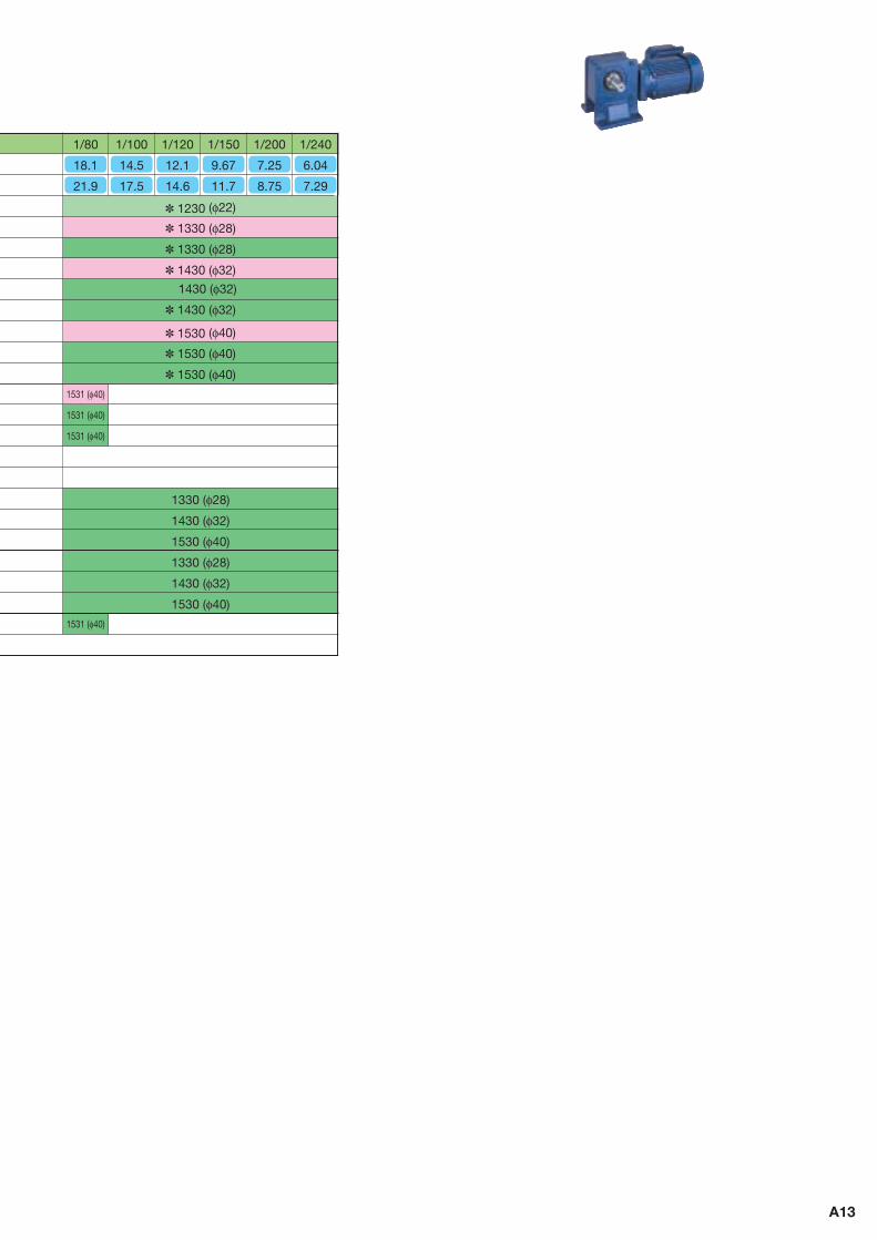
Fig. 2 RNYM03–1540–300~1440 Mass 26kg(RNYM03–1540–B–300~1440) (Mass 27.5kg)
Output speed n2
r/minOutput Torque Tout
Nm kgf m N kgfAllowable Pro
Capacity – Frame
– Reduction
Symbol Size Ratio
OutlineDrawing
Fig.50Hz 60Hz 50Hz 60Hz 50Hz 60HzSF
50Hz 60Hz 50Hz 60Hz 18.1 14.5 12.1 9.67 7.25 6.04 4.83
4.033.022.422.011.611.211.01
21.9 17.5 14.6 11.7 8.75 7.29 5.83
4.863.652.922.431.941.461.22
112140168210280336396475633732732732732732
92.9 116 139 174 232 279 328
393525656732732732732
11.414.317.121.428.634.340.348.464.674.674.674.674.674.6
9.47 11.8 14.2 17.8 23.7 28.4 33.4
40.153.566.974.674.674.674.6
1.601.601.601.601.391.161.601.541.16
43604360436043604360436062306230623062306230623062306230
42704360436043604360436062306230623062306230623062306230
445 445 445 445 445 445
635635635635635635635635
435 445 445 445 445 445
635635635635635635635635
03 — 1430 — 80 03 — 1430 — 100 03 — 1430 — 120 03 — 1430 — 150 03 — 1430 — 200 03 — 1430 — 240 03 — 1540 — 300 03 — 1540 — 360 03 — 1540 — 480 03 — 1540 — 600 03 — 1540 — 720 03 — 1540 — 900 03 — 1540 — 1200 03 — 1540 — 1440
2
0.25
kW0.25kW 3-phase Motor
B18
Notes : 1. Motor slippage may affect n1 and n2. 2. Allowable radial load shows the value when the distance from
hollow shaft end to the point of radial load is 20 mm.
3. Output torque is limited when SF is . It must be used within the value stipulated in the table as overload may occur if the motor is loaded to its full capacity.
RNYM Series Hollow Shaft Type
Designate model and voltage and frequency when ordering. Brackets contain dimension, model, or mass of type with brakes.
1
5 59 59 5105
95h7
95h7
10 118 10
20 A-A
1.75
35H8
26
52 52138
37
10
38.3
35.6
R1.5
A
A
70 130
178
7010
854
92
178 854 92
113
14
4- 14
404 (436)
124
Fig. 1 RNYM03–1430–80~240 Mass 16kg(RNYM03–1430–B–80~240) (Mass 17kg)
MotorSpeed n1
50Hz 1450r/min60Hz 1750r/min
1013610
6868 55
φ11
0h7
φ11
0h7
128
491
□12
2
19784
14
5421310964
6410
9213
8412
9
φ12
4
4-φ18
A
A
φ47
.5
φ45H8
48.8
14
R1.5
1.9530
φ45
.6
6767156A-A 11
3
517
□12
2
19784
14
5421310964
6410
9213
8412
9
φ12
4
4-φ18
A
A
Without brake With brake
Ho
llow
Sha
ft3-
pha
se
B19
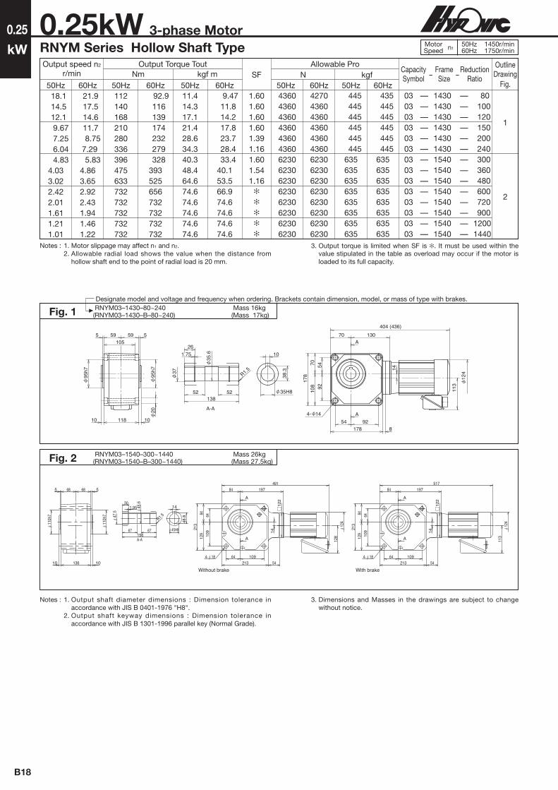
0.4
kW
Designate model and voltage and frequency when ordering. Brackets contain dimension, model, or mass of type with brakes.
Notes : 1. Output shaft diameter dimensions : Dimension tolerance in accordance with JIS B 0401-1976 "H8".
2. Output shaft keyway dimensions : Dimension tolerance in accordance with JIS B 1301-1996 parallel key (Normal Grade).
3. Dimensions and Masses in the drawings are subject to change without notice.
Fig. 4 RNYM05–1220–5~10 Mass 9.5kg(RNYM05–1220–B–5~10) (Mass 11kg)
0.4kW 3-phase MotorRNYM Series Hollow Shaft Type
Fig. 5 RNYM05–1320–5~10 Mass 11kg(RNYM05–1320–B–5~10) (Mass 13kg)
90
5 537 37
9 74 9
78h7
78h7
A-A
38 38
R1.5
25.6
92 25H8
28.3
822
1.35
26.2
A
A
49 96
115
6649 40
57
40 57
28
4- 9
353 (385)
124
113 20
113
112
5 46 46 5
85h7
85h7
9 92 9
A-A
110
33.3
46 46
R1.5
30.6
22
30H8
1.35
31.4
8
A
A58 119
132
7458 46
62
46 62
27.5
113
4- 11
130 34
381 (413)
124
38 38
R1.5
25.6
92
25H8
28.3
8
22
1.35
26.278
h7
78h8
112
9 9
3737
4646
92
37 37
92 1.5
46 61
113
14
124
37 375 5
311 (343)
A-A
A
A
4- 9
Fig. 3 RNYM05–1210–5~10 Mass 9kg(RNYM05–1210–B–5~10) (Mass 10kg)
Notes : 1. Motor slippage may affect n1 and n2. 2. Allowable radial load shows the value when the distance from
hollow shaft end to the point of radial load is 20 mm.
Output speed n2
r/minOutput Torque Tout
SF
2.001.002.002.001.002.001.001.002.00
Nm kgf m N kgfAllowable Pro
Capacity – Frame
– Reduction
Symbol Size Ratio
OutlineDrawing
Fig.50Hz 60Hz 50Hz 60Hz 50Hz 60Hz 50Hz 60Hz 50Hz 60Hz290
207
145
350
250
175
11.2
15.7
22.4
9.29
13.0
18.6
1.14
1.60
2.29
0.947
1.33
1.89
883 883 1470 981 981 1670 1080 1080 1810
834 834 1370 932 932 1570 1030 1030 1720
90 90 150 100 100 170 110 110 185
85 85 140 95 95 160 105 105 175
05 — 1210 — 5 05 — 1220 — 5 05 — 1320 — 5 05 — 1210 — 7 05 — 1220 — 7 05 — 1320 — 7 05 — 1210 — 10 05 — 1220 — 10 05 — 1320 — 10
345345345
MotorSpeed n1
50Hz 1450r/min60Hz 1750r/min

15
W
0.4
kW0.4kW 3-phase Motor
Notes : 1. Output shaft diameter dimensions : Dimension tolerance in accordance with JIS B 0401-1976 "H8".
2. Output shaft keyway dimensions : Dimension tolerance in accordance with JIS B 1301-1996 parallel key (Normal Grade).
3. Dimensions and Masses in the drawings are subject to change without notice.
B20
RNYM Series Hollow Shaft Type
Designate model and voltage and frequency when ordering. Brackets contain dimension, model, or mass of type with brakes.
Fig. 1 RNYM05–1220–12~30 Mass 9.5kg(RNYM05–1220–B–12~30) (Mass 11kg)
Fig. 2 RNYM05–1320–12~60 Mass 11kg(RNYM05–1320–B–12~60) (Mass 13kg)
90
5 537 37
9 74 9
78h7
78h7
A-A
38 38
R1.5
25.6
92 25H8
28.3
822
1.35
26.2
A
A
49 96
115
6649 40
57
40 57
28
4- 9
353 (385)
124
113 20
113
112
5 46 46 5
85h7
85h7
9 92 9
A-A
110
33.3
46 46
R1.5
30.6
22
30H8
1.35
31.4
8
A
A58 119
132
7458 46
62
46 62
27.5
113
4- 11
130 34
381 (413)12
4
Fig. 3 RNYM05–1420–40~60 Mass 15kg(RNYM05–1420–B–40~60) (Mass 16kg)
5 59 59 5
10 118 10
95h7
95h7
A-A
13852 52
26
1.75
R1.537
35.6
35H8
10
38.3
158
8870
7557
70
20
57 75155 43
4- 14
412 (444)146
A
A
113
124
Notes : 1. Motor slippage may affect n1 and n2. 2. Allowable radial load shows the value when the distance from
hollow shaft end to the point of radial load is 20 mm.
Output speed n2
r/minOutput Torque Tout
SF
1.002.001.002.001.002.001.002.001.002.001.002.001.002.001.002.00
Nm kgf m N kgfAllowable Pro
Capacity – Frame
– Reduction
Symbol Size Ratio
OutlineDrawing
Fig.50Hz 60Hz 50Hz 60Hz 50Hz 60Hz 50Hz 60Hz 50Hz 60Hz 121
96.7 72.5
58.0
48.3
36.3
29.0
24.2
146 117
87.5 70.0
58.3
43.8
35.0
29.2
26.9
33.6
44.8
56.1
67.3
89.7
112
135
22.3
27.9
37.2
46.4
55.7
74.3
92.9
111
2.74
3.43
4.57
5.72
6.86
9.14
11.4
13.7
2.27
2.84
3.79
4.74
5.68
7.58
9.47
11.4
1130191012302060137022601470235015202450265039702840417029404310
1080181011801960132021601370226014702350255038202750402028404170
115195125210140230150240155250270405290425300440
110185120200135220140230150240260390280410290425
05 — 1220 — 12 05 — 1320 — 12 05 — 1220 — 15 05 — 1320 — 15 05 — 1220 — 20 05 — 1320 — 20 05 — 1220 — 25 05 — 1320 — 25 05 — 1220 — 30 05 — 1320 — 30 05 — 1320 — 40 05 — 1420 — 40 05 — 1320 — 50 05 — 1420 — 50 05 — 1320 — 60 05 — 1420 — 60
1212121212232323
MotorSpeed n1
50Hz 1450r/min60Hz 1750r/min

Ho
llow
Sha
ft3-
pha
se
B21
0.4
kW
Designate model and voltage and frequency when ordering. Brackets contain dimension, model, or mass of type with brakes.
0.4kW 3-phase MotorRNYM Series Hollow Shaft Type
Notes : 1. Motor slippage may affect n1 and n2. 2. Allowable radial load shows the value when the distance from
hollow shaft end to the point of radial load is 20 mm.
3. Output torque is limited when SF is . It must be used within the value stipulated in the table as overload may occur if the motor is loaded to its full capacity.
Notes : 1. Output shaft diameter dimensions : Dimension tolerance in accordance with JIS B 0401-1976 "H8".
2. Output shaft keyway dimensions : Dimension tolerance in accordance with JIS B 1301-1996 parallel key (Normal Grade).
3. Dimensions and Masses in the drawings are subject to change without notice.
5 59 59 5105
95h7
95h7
10 118 10
20 A-A
1.75
35H8
26
52 52138
37
10
38.3
35.6
R1.5
A
A
70 130
178
7010
854
92
178 854 92
113
14
4- 14
404 (436)
124
Fig. 4 RNYM05–1430–80~240 Mass 16kg(RNYM05–1430–B–80~240) (Mass 17kg)
5 5
10 136 10
68 68
110h
7
A-A
15667 67
45.630
1.95
R1.5
14
48.8
45H8
47.5
A
A
84 157
64 109213 9.5
109
6412
984
213
4- 18
17
113
124
437 (469)
110h
7
Fig. 5 RNYM05–1530–80~240 Mass 23kg(RNYM05–1530–B–80~240) (Mass 24kg)
Output speed n2
r/minOutput Torque Tout
Nm kgf m N kgfAllowable Pro
Capacity – Frame
– Reduction
Symbol Size Ratio
OutlineDrawing
Fig.50Hz 60Hz 50Hz 60Hz 50Hz 60HzSF
50Hz 60Hz 50Hz 60Hz 18.1
14.5
12.1
9.67
7.25
6.04
21.9
17.5
14.6
11.7
8.75
7.29
179
224
269
336
390448390538
149
186
223
279
372372390446
18.3
22.9
27.4
34.3
39.845.739.854.9
15.2
18.9
22.7
28.4
37.937.939.845.5
1.002.001.002.001.002.001.002.00
1.63
1.36
436062304360623043606230436062304360623043606230
427061304360623043606230436062304360623043606230
445635445635445635445635445635445635
435625445635445635445635445635445635
05 — 1430 — 80 05 — 1530 — 80 05 — 1430 — 100 05 — 1530 — 100 05 — 1430 — 120 05 — 1530 — 120 05 — 1430 — 150 05 — 1530 — 150 05 — 1430 — 200 05 — 1530 — 200 05 — 1430 — 240 05 — 1530 — 240
454545454545
MotorSpeed n1
50Hz 1450r/min60Hz 1750r/min

15
WOutput speed n2
r/min
0.4
kW0.4kW 3-phase Motor
B22
3-phase Motor Indoor Type
Designate model and voltage and frequency when ordering. Brackets contain dimension, model, or mass of type with brakes.
Notes : 1. Motor slippage may affect n1 and n2. 2. Allowable radial load shows the value when the distance from
hollow shaft end to the point of radial load is 20 mm.
3. Output torque is limited when SF is . It must be used within the value stipulated in the table as overload may occur if the motor is loaded to its full capacity.
Output Torque ToutNm kgf m N kgf
Allowable Pro Capacity
– Frame
– Reduction
Symbol Size Ratio
OutlineDrawing
Fig.50Hz 60Hz 50Hz 60Hz 50Hz 60Hz 50HzSF
1.002.00
1.95
1.46
1.17
60Hz 50Hz 60Hz 4.83
4.03
3.02
2.42
2.01
1.61
1.21
1.01
5.83
4.86
3.65
2.92
2.43
1.94
1.46
1.22
633
732
732
732
732
732
732
732
525
629
732
732
732
732
732
732
64.6
74.6
74.6
74.6
74.6
74.6
74.6
74.6
53.5
64.2
74.6
74.6
74.6
74.6
74.6
74.6
6230981062309810623098106230981062309810623098106230981062309810
6230981062309810623098106230981062309810623098106230981062309810
63510006351000635100063510006351000635100063510006351000
63510006351000635100063510006351000635100063510006351000
05 — 1540 — 300 05 — 1640 — 300 05 — 1540 — 360 05 — 1640 — 360 05 — 1540 — 480 05 — 1640 — 480 05 — 1540 — 600 05 — 1640 — 600 05 — 1540 — 720 05 — 1640 — 720 05 — 1540 — 900 05 — 1640 — 900 05 — 1540 — 1200 05 — 1640 — 1200 05 — 1540 — 1440 05 — 1640 — 144 0
1212121212121212
MotorSpeed n1
50Hz 1450r/min60Hz 1750r/min
RNYM05–1540–300~1440 Mass 26kg(RNYM05–1540–B–300~1440) (Mass 27.5kg)
1013610
6868 55
φ11
0h7
φ11
0h7
113
491
□11
2
19784
14
5421310964
6410
9213
8412
9
φ12
4
4-φ18
A
A
φ47
.5
φ45H8
48.8
14
R1.5
1.9530
φ45
.6
6767156A-A 11
3
517
□11
2
19784
14
5421310964
6410
9213
8412
9
φ12
4
4-φ18
A
A
Without brake With brake
Fig. 1
Notes : 1. Output shaft diameter dimensions : Dimension tolerance in accordance with JIS B 0401-1976 "H8".
2. Output shaft keyway dimensions : Dimension tolerance in accordance with JIS B 1301-1996 parallel key (Normal Grade).
3. Dimensions and Masses in the drawings are subject to change without notice.
RNYM05–1640–300~1440 Mass 63kg(RNYM05–1640–B–300~1440) (Mass 64kg)
A
A
A-A
12
4
113
58
2.2
40
55
.6
R2.5
85 85
224
16
59.3
55H8
15
0h7
19 186 19
1212 93 93
8514
5
170
110
280
85 145
110 170
280
1716
0 1
16
4- 22
15
0h7
543(575)
Fig. 2

Ho
llow
Sha
ft3-
pha
se
B23
0.55
kW
Designate model and voltage and frequency when ordering. Brackets contain dimension, model, or mass of type with brakes.
Notes : 1. Motor slippage may affect n1 and n2. 2. Allowable radial load shows the value when the distance from
hollow shaft end to the point of radial load is 20 mm.
Notes : 1. Output shaft diameter dimensions : Dimension tolerance in accordance with JIS B 0401-1976 "H8".
2. Output shaft keyway dimensions : Dimension tolerance in accordance with JIS B 1301-1996 parallel key (Normal Grade).
3. Dimensions and Masses in the drawings are subject to change without notice.
112
5 46 46 5
85h7
9 92 9
A
58 119
132
7458 46
62
46 62
27.5
4- 11
423 (466)14
3
160
130 34
A
A-A
110
33.3
46 46
R1.5
30.6
22
30H8
1.35
31.4
8
85h7
112
Fig. 4 RNYM08–1320–5~30 Mass 13kg(RNYM08–1320–B–5~30) (Mass 16kg)
0.55kW 3-phase MotorRNYM Series Hollow Shaft Type
5 59 59 5
10 118 10
95h7
A-A
35H8
10
38.3
13852 52
261.75
R1.537
35.6
A
A
158
8870
7557
70
20
57 75155 43
4- 14
146
474 (517)
143
16095h7
112
Fig. 5 RNYM08–1420–40~60 Mass 17kg(RNYM08–1420–B–40~60) (Mass 19kg)
11046 46
221.35
31.4
30.6
R1.5
8
30H8
33.3
56
112
5656
4444
112 2
44 44
17
112
160
143
5 46 46 5
85h7
9 92 9
76
390 (433)116
A-A
A
A4- 11
85h7
Fig. 3 RNYM08–1310–5~10 Mass 12kg(RNYM08–1310–B–5~10) (Mass 14kg)
Output speed n2
r/minOutput Torque Tout
Nm kgf m NSF kgfAllowable Pro
Capacity – Frame
– Reduction
Symbol Size Ratio50Hz 60Hz 50Hz 60Hz 50Hz 60Hz 50Hz 60Hz 50Hz 60Hz
290
207
145
121 96.7 72.5 58.0 48.3 36.3 29.0 24.2
350
250
175
146 117 87.5 70.0 58.3 43.8 35.0 29.2
15.4
21.6
30.8
37.0 46.2 61.7 77.1 92.5 123 154 185
12.8
17.9
25.5
30.7 38.3 51.1 63.9 76.6 102 128 153
1.57
2.20
3.14
3.77 4.72 6.29 7.86 9.43 12.6 15.7 18.9
1.30
1.82
2.60
3.13 3.91 5.21 6.51 7.81 10.4 13.0 15.6
1470
1670
1810
19102060226023502450397041704310
2.801.452.801.451.451.451.451.451.451.451.451.451.451.45
1370
1570
1720
18101960216022602350382040204170
150
170
185
195210230240250405425440
140
160
175
185200220230240390410425
08 — 1310 — 5 08 — 1320 — 5 08 — 1310 — 7 08 — 1320 — 7 08 — 1310 — 10 08 — 1320 — 10 08 — 1320 — 12 08 — 1320 — 15 08 — 1320 — 20 08 — 1320 — 25 08 — 1320 — 30 08 — 1420 — 40 08 — 1420 — 50 08 — 1420 — 60
OutlineDrawing
Fig.
4
343434
5
MotorSpeed n1
50Hz 1450r/min60Hz 1750r/min

15
W
Fig. 2 RNYM08–1640–300~1440 Mass 68kg(RNYM08–1640–B–300~1440) (Mass 70kg)
Output speed n2
r/minOutput Torque Tout
Nm kgf m N kgfAllowable Pro
Capacity – Frame
– Reduction
Symbol Size Ratio
OutlineDrawing
Fig.50Hz 60Hz 50Hz 60Hz 50Hz 60Hz 50HzSF
1.451.451.451.451.19
1.451.421.06
60Hz 50Hz 60Hz 18.1 14.5 12.1 9.67 7.25 6.04 4.83 4.03 3.02 2.42 2.01 1.61 1.21 1.01
21.9 17.5 14.6 11.7 8.75 7.29 5.83
4.863.652.922.431.941.461.22
247308370462617732870
1040 1390 1480 1480 1480 1480 1480
204255307383511613721870
1150 1440 1480 1480 1480 1480
25.131.437.747.262.974.688.8
107 142 151 151 151 151 151
20.826.031.339.152.162.573.588.3
118 147 151 151 151 151
62306230623062306230623098109810981098109810981098109810
61306230623062306230623098109810981098109810981098109810
635635635635635635
1000 1000 1000 1000 1000 1000 1000 1000
625635635635635635
1000 1000 1000 1000 1000 1000 1000 1000
08 — 1530 — 80 08 — 1530 — 100 08 — 1530 — 120 08 — 1530 — 150 08 — 1530 — 200 08 — 1530 — 240 08 — 1640 — 300 08 — 1640 — 360 08 — 1640 — 480 08 — 1640 — 600 08 — 1640 — 720 08 — 1640 — 900 08 — 1640 — 1200 08 — 1640 — 1440
2
0.55
kW0.55kW 3-phase Motor
B24
Notes : 1. Motor slippage may affect n1 and n2. 2. Allowable radial load shows the value when the distance from
hollow shaft end to the point of radial load is 20 mm.
3. Output torque is limited when SF is . It must be used within the value stipulated in the table as overload may occur if the motor is loaded to its full capacity.
Notes : 1. Output shaft diameter dimensions : Dimension tolerance in accordance with JIS B 0401-1976 "H8".
2. Output shaft keyway dimensions : Dimension tolerance in accordance with JIS B 1301-1996 parallel key (Normal Grade).
3. Dimensions and Masses in the drawings are subject to change without notice.
3-phase Motor Indoor Type
Designate model and voltage and frequency when ordering. Brackets contain dimension, model, or mass of type with brakes.
5 5
10 136 10
68 68
110h
7
A-A156
67 67
45.630
1.95
R1.5
14
48.8
45H8
47.5
A
84 157
498 (541)
64 109213 9.5
109
6412
984
213
4- 18
17A 14
3
16011
0h7
112
Fig. 1 RNYM08–1530–80~240 Mass 24kg(RNYM08–1530–B–80~240) (Mass 26kg)
1
MotorSpeed n1
50Hz 1450r/min60Hz 1750r/min
A
A
A-A
16
0
143
58
2.2
40
55
.6
R2.5
85 85
224
16
59.3
55H8
15
0h7
19 186 19
1212 93 93
8514
5
170
110
280
85 145
110 170
280
1716
0 1
16
4- 22
604
15
0h7
112

Ho
llow
Sha
ft3-
pha
se
B25
0.75
kW
Designate model and voltage and frequency when ordering. Brackets contain dimension, model, or mass of type with brakes.
Notes : 1. Motor slippage may affect n1 and n2. 2. Allowable radial load shows the value when the distance from
hollow shaft end to the point of radial load is 20 mm.
Notes : 1. Output shaft diameter dimensions : Dimension tolerance in accordance with JIS B 0401-1976 "H8".
2. Output shaft keyway dimensions : Dimension tolerance in accordance with JIS B 1301-1996 parallel key (Normal Grade).
3. Dimensions and Masses in the drawings are subject to change without notice.
0.75kW 3-phase MotorRNYM Series Hollow Shaft Type
112
112
5 46 46 5
85h
7
9 92 9
A
58 119
132
7458 46
62
46 62
27.5
4- 11
423 (466)
143
160
130 34
A
A-A
110
33.3
46 46
R1.5
30.6
22
30H8
1.35
31.4
8
85h
7
Fig. 4 RNYM1–1320–5~10 Mass 15kg(RNYM1–1320–B–5~10) (Mass 17kg)
5 59 59 5
10 118 10
95h7
A-A
35H8
10
38.3
13852 52
261.75
R1.537
35.6
A
A
158
8870
7557
70
20
57 75155 43
4- 14
146
474 (517)
143
16095h7
112
Fig. 5 RNYM1–1420–5~10 Mass 18kg(RNYM1–1420–B–5~10) (Mass 20kg)
11046 46
221.35
31.4
30.6
R1.5
8
30H8
33.3
56
112
5656
4444
112 2
44 44
17
112
160
143
5 46 46 5
85h7
9 92 9
76
390 (433)116
A-A
A
A4- 11
85h7
Fig. 3 RNYM1–1310–5~10 Mass 13kg(RNYM1–1310–B–5~10) (Mass 16kg)
Output speed n2
r/minOutput Torque Tout
SF
2.051.072.052.051.072.051.071.072.05
Nm kgf m N kgfAllowable Pro
Capacity – Frame
– Reduction
Symbol Size Ratio
OutlineDrawing
Fig.50Hz 60Hz 50Hz 60Hz 50Hz 60Hz 50Hz 60Hz 50Hz 60Hz290
207
145
350
250
175
21.0
29.4
42.0
17.4
24.4
34.8
2.14
3.00
4.29
1.78
2.49
3.55
147014702160167016702450181018102750
137013702060157015702300172017202600
150150220170170250185185280
140140210160160235175175265
1 — 1310 — 5 1 — 1320 — 5 1 — 1420 — 5 1 — 1310 — 7 1 — 1320 — 7 1 — 1420 — 7 1 — 1310 — 10 1 — 1320 — 10 1 — 1420 — 10
345345345
MotorSpeed n1
50Hz 1450r/min60Hz 1750r/min

15
W
0.75
kW0.75kW 3-phase Motor
Notes : 1. Output shaft diameter dimensions : Dimension tolerance in accordance with JIS B 0401-1976 "H8".
2. Output shaft keyway dimensions : Dimension tolerance in accordance with JIS B 1301-1996 parallel key (Normal Grade).
3. Dimensions and Masses in the drawings are subject to change without notice.
B26
Notes : 1. Motor slippage may affect n1 and n2. 2. Allowable radial load shows the value when the distance from
hollow shaft end to the point of radial load is 20 mm.
3-phase Motor Indoor Type
Designate model and voltage and frequency when ordering. Brackets contain dimension, model, or mass of type with brakes.
112
112
5 46 46 5
85h
7
9 92 9
A
58 119
132
7458 46
62
46 62
27.5
4- 11
423 (466)
143
160
130 34
A
A-A
110
33.3
46 46
R1.5
30.6
22
30H8
1.35
31.4
8
85h
7
Fig. 1 RNYM1–1320–12~30 Mass 15kg(RNYM1–1320–B–12~30) (Mass 17kg)
5 59 59 5
10 118 10
95h7
A-A
35H8
10
38.3
13852 52
261.75
R1.537
35.6
A
A
158
8870
7557
70
20
57 75155 43
4- 14
146
474 (517)
143
16095h7
112
Fig. 2 RNYM1–1420–12~60 Mass 18kg(RNYM1–1420–B–12~60) (Mass 20kg)
150
68 68 5
110h
7
5
10 136 10
15667 67
45.6
30
1.95
R1.5
14
48.8
45H8
47.5
A-AA
A84 178
178
8494
7080
175 6870 80
28
498 (541)
4- 14
143
160
110h
7
112
Fig. 3 RNYM1–1520–40~60 Mass 26kg(RNYM1–1520–B–40~60) (Mass 28kg)
Output speed n2
r/minOutput Torque Tout
SF
1.072.051.072.051.072.051.072.051.072.051.072.051.072.051.072.05
Nm kgf m N kgfAllowable Pro
Capacity – Frame
– Reduction
Symbol Size Ratio
OutlineDrawing
Fig.50Hz 60Hz 50Hz 60Hz 50Hz 60Hz 50Hz 60Hz 50Hz 60Hz 121
96.7 72.5
58.0
48.3
36.3
29.0
24.2
146 117
87.5 70.0
58.3
43.8
35.0
29.2
50.4
63.1
84.1
105
126
168
210
252
41.8
52.2
69.7
87.1
104
139
174
209
5.14
6.43
8.57
10.7
12.9
17.1
21.4
25.7
4.26
5.33
7.10
8.88
10.7
14.2
17.8
21.3
1910284020603090226033302350353024503730397057404170603043106230
1810275019602940216031902260338023503580382055404020583041706030
195290210315230340240360250380405585425615440635
185280200300220325230345240365390565410595425615
1 — 1320 — 12 1 — 1420 — 12 1 — 1320 — 15 1 — 1420 — 15 1 — 1320 — 20 1 — 1420 — 20 1 — 1320 — 25 1 — 1420 — 25 1 — 1320 — 30 1 — 1420 — 30 1 — 1420 — 40 1 — 1520 — 40 1 — 1420 — 50 1 — 1520 — 50 1 — 1420 — 60 1 — 1520 — 60
1212121212232323
MotorSpeed n1
50Hz 1450r/min60Hz 1750r/min

Ho
llow
Sha
ft3-
pha
se
B27
0.75
kW
Designate model and voltage and frequency when ordering. Brackets contain dimension, model, or mass of type with brakes.
0.75kW 3-phase MotorRNYM Series Hollow Shaft Type
Notes : 1. Output shaft diameter dimensions : Dimension tolerance in accordance with JIS B 0401-1976 "H8".
2. Output shaft keyway dimensions : Dimension tolerance in accordance with JIS B 1301-1996 parallel key (Normal Grade).
3. Dimensions and Masses in the drawings are subject to change without notice.
5 5
10 136 10
68 68
110h
7
A-A156
67 67
45.630
1.95
R1.5
1448
.8
45H8
47.5
A
84 157
498 (541)
64 109213 9.5
109
6412
984
213
4- 18
17
A 143
16011
0h7
112
Fig. 4 RNYM1–1530–80~240 Mass 25kg(RNYM1–1530–B–80~240) (Mass 28kg)
5 5
10 136 10
68 68
110h
7
A-A156
67 67
45.630
1.95
R1.5
14
48.8
45H8
47.5
A
A
84 157
64 109213 9.5
109
6412
984
213
4- 18
17
498 (541)
160
143
110h
7
112
Fig. 5 RNYM1–1531–80 Mass 26kg(RNYM1–1531–B–80) (Mass 28kg)
MotorSpeed n1
50Hz 1450r/min60Hz 1750r/min
Output speed n2
r/minOutput Torque Tout
Nm kgf m N kgfAllowable Pro
Capacity – Frame
– Reduction
Symbol Size Ratio
OutlineDrawing
Fig.50Hz 60Hz 50Hz 60Hz 50Hz 60HzSF
1.072.051.072.931.072.93
50Hz 60Hz 50Hz 60Hz 18.1
14.5
12.1
21.9
17.5
14.6
336
420
504
279
348
418
34.3
42.9
51.4
28.4
35.5
42.6
623062306230981062309810
613061306230981062309810
63563563510006351000
62562563510006351000
1 — 1530 — 80 1 — 1531 — 80 1 — 1530 — 100 1 — 1630 — 100 1 — 1530 — 120 1 — 1630 — 120
454646
Notes : 1. Motor slippage may affect n1 and n2. 2. Allowable radial load shows the value when the distance from
hollow shaft end to the point of radial load is 20 mm.
3. Output torque is limited when SF is . It must be used within the value stipulated in the table as overload may occur if the motor is loaded to its full capacity.
A-A
A
A
15
0h7
93 93 1212
186 1919
8514
5
110
170
280
85 145
110 170
280
2716
0
1
64
16
0
143
558
58
2.2
40
55
.6
R2.5
85 85
224
16
59.3
55H8
4- 22
15
0h7
112
Fig. 6 RNYM1–1630–100~120 Mass 46kg(RNYM1–1630–B–100~120) (Mass 48kg)

15
W
0.75
kW
B28
0.75kW 3-phase MotorRNYM Series Hollow Shaft Type Motor
Speed n150Hz 1450r/min60Hz 1750r/min
Output speed n2
r/minOutput Torque Tout
Nm kgf m N kgfAllowable Pro
Capacity – Frame
– Reduction
Symbol Size Ratio
OutlineDrawing
Fig.50Hz 60Hz 50Hz 60Hz 50Hz 60HzSF
1.072.35
1.76
1.471.071.04
50Hz 60Hz 50Hz 60Hz9.67
7.25
6.04
4.834.033.022.422.011.611.211.01
11.7
8.75
7.29
5.834.863.652.922.431.941.461.22
631
732841732
101011901420148014801480148014801480
522
697697732836983
1180148014801480148014801480
64.3
74.685.774.6103121145151151151151151151
53.3
71.071.074.685.2100120151151151151151151
62309810623098106230981098109810981098109810981098109810
62309810623098106230981098109810981098109810981098109810
63510006351000635100010001000100010001000100010001000
63510006351000635100010001000100010001000100010001000
1 — 1530 — 150 1 — 1631 — 150 1 — 1530 — 200 1 — 1631 — 200 1 — 1530 — 240 1 — 1631 — 240 1 — 1640 — 300 1 — 1640 — 360 1 — 1640 — 480 1 — 1640 — 600 1 — 1640 — 720 1 — 1640 — 900 1 — 1640 — 1200 1 — 1640 — 1440
12
Notes : 1. Motor slippage may affect n1 and n2. 2. Allowable radial load shows the value when the distance from
hollow shaft end to the point of radial load is 20 mm.
3. Output torque is limited when SF is . It must be used within the value stipulated in the table as overload may occur if the motor is loaded to its full capacity.
1212
3
Designate model and voltage and frequency when ordering. Brackets contain dimension, model, or mass of type with brakes.
Notes : 1. Output shaft diameter dimensions : Dimension tolerance in accordance with JIS B 0401-1976 "H8".
2. Output shaft keyway dimensions : Dimension tolerance in accordance with JIS B 1301-1996 parallel key (Normal Grade).
3. Dimensions and Masses in the drawings are subject to change without notice.
5 5
10 136 10
68 68
110h
7
A-A156
67 67
45.630
1.95
R1.5
14
48.8
45H8
47.5
A
84 157
498 (541)
64 109213 9.5
109
6412
984
213
4- 1817
A 143
16011
0h7
112
Fig. 1 RNYM1–1530–150~240 Mass 25kg(RNYM1–1530–B–150~240) (Mass 28kg)
A-A
A
A
15
0h7
93 93 1212
186 1919
8514
5
110
170
280
85 145
110 170
280
2716
0
1
64
16
0
143
558
58
2.2
40
55
.6
R2.5
85 85
224
16
59.3
55H8
4- 22
15
0h7
112
Fig. 2 RNYM1–1631–150~240 Mass 46kg(RNYM1–1631–B–150~240) (Mass 48kg)
A
A
A-A
16
0
143
58
2.2
40
55
.6
R2.5
85 85
224
16
59.3
55H8
15
0h7
19 186 19
1212 93 93
8514
5
170
110
280
85 145
110 170
280
1716
0 1
16
4- 22
604
15
0h7
112
Fig. 3 RNYM1–1640–300~1440 Mass 68kg(RNYM1–1640–B–300~1440) (Mass 70kg)

Ho
llow
Sha
ft3-
pha
se
B29
1.1
kW
Designate model and voltage and frequency when ordering. Brackets contain dimension, model, or mass of type with brakes.
Notes : 1. Motor slippage may affect n1 and n2. 2. Allowable radial load shows the value when the distance from
hollow shaft end to the point of radial load is 20 mm.
Notes : 1. Output shaft diameter dimensions : Dimension tolerance in accordance with JIS B 0401-1976 "H8".
2. Output shaft keyway dimensions : Dimension tolerance in accordance with JIS B 1301-1996 parallel key (Normal Grade).
3. Dimensions and Masses in the drawings are subject to change without notice.
5 59 59 5
10 118 10
95h7
A-A
35H8
10
38.3
138
52 52
26
1.75
R1.537
35.6
A
A
158
8870
7557
70
20
57 75155 43
4- 14
146
504 (566)
148
16995
h7
117
Fig. 5 RNYM1H–1420–5~30 Mass 21kg(RNYM1H–1420–B–5~30) (Mass 25kg)
1.1kW 3-phase MotorRNYM Series Hollow Shaft TypeOutput speed n2
r/minOutput Torque Tout
Nm kgf m N kgfAllowable Pro
Capacity – Frame
– Reduction
Symbol Size Ratio
OutlineDrawing
Fig.50Hz 60Hz 50Hz 60Hz 50Hz 60HzSF
2.001.402.001.401.401.401.401.401.401.401.401.401.401.40
50Hz 60Hz 50Hz 60Hz 290
207
145
121 96.7 72.5 58.0 48.3 36.3 29.0 24.2
350
250
175
146 117 87.5 70.0 58.3 43.8 35.0 29.2
30.8
43.2
61.7
74.0 92.5 123 154 185 247 308 370
25.5
35.8
51.1
61.3 76.6 102 128 153 204 255 307
3.14
4.40
6.29
7.54 9.43 12.6 15.7 18.9 25.1 31.4 37.7
2.60
3.65
5.21
6.25 7.81 10.4 13.0 15.6 20.8 26.0 31.3
2160
2450
2750
28403090333035303730574060306230
2060
2300
2600
27502940319033803580554058306030
220
250
280
290315340360380585615635
210
235
265
280300325345365565595615
1H — 1410 — 5 1H — 1420 — 5 1H — 1410 — 7 1H — 1420 — 7 1H — 1410 — 10 1H — 1420 — 10 1H — 1420 — 12 1H — 1420 — 15 1H — 1420 — 20 1H — 1420 — 25 1H — 1420 — 30 1H — 1520 — 40 1H — 1520 — 50 1H — 1520 — 60
5
454545
6
150
68 68 5
110h
7
5
10 136 10
15667 67
45.6
30
1.95
R1.5
14
48.8
45H8
47.5
A-AA
A84 178
178
8494
7080
175 6870 80
28
534 (596)
4- 14
148
16911
0h7
117
Fig. 6 RNYM1H–1520–40~60 Mass 29kg(RNYM1H–1520–B–40~60) (Mass 33kg)
35H8
10
38.3
138
52 52
26
1.75
R1.537
35.6
10 118 10
95h7
5 59 59 5
15055
5566
66
132
66 90
2255 55
132 4
428 (490)
148
117
169
A-A
A
A
4- 11
95h7
Fig. 4 RNYM1H–1410–5~10 Mass 20kg(RNYM1H–1410–B–5~10) (Mass 24kg)
MotorSpeed n1
50Hz 1450r/min60Hz 1750r/min

15
W
Fig. 2 RNYM1H–1630–100~120 Mass 52kg(RNYM1H–1630–B–100~120) (Mass 56kg)
Output speed n2
r/minOutput Torque Tout
Nm kgf m SF
1.402.002.001.601.201.00
N kgfAllowable Pro
Capacity – Frame
– Reduction
Symbol Size Ratio
OutlineDrawing
Fig.50Hz 60Hz 50Hz 60Hz 50Hz 60Hz 50Hz 60Hz 50Hz 60Hz18.114.512.19.677.256.04
21.917.514.611.78.757.29
49361774092512301480
409511613766
10201230
50.362.975.494.3126151
41.752.162.578.1104125
623098109810981098109810
613098109810981098109810
63510001000100010001000
62510001000100010001000
1H — 1531 — 80 1H — 1630 — 100 1H — 1630 — 120 1H — 1631 — 150 1H — 1631 — 200 1H — 1631 — 240
2
3
1.1
kW1.1kW 3-phase Motor
B30
Notes : 1. Motor slippage may affect n1 and n2. 2. Allowable radial load shows the value when the distance from
hollow shaft end to the point of radial load is 20 mm.
Notes : 1. Output shaft diameter dimensions : Dimension tolerance in accordance with JIS B 0401-1976 "H8".
2. Output shaft keyway dimensions : Dimension tolerance in accordance with JIS B 1301-1996 parallel key (Normal Grade).
3. Dimensions and Masses in the drawings are subject to change without notice.
3-phase Motor Indoor Type
Designate model and voltage and frequency when ordering. Brackets contain dimension, model, or mass of type with brakes.
1
5 5
10 136 10
68 68
110h
7
A-A156
67 67
45.630
1.95
R1.5
14
48.8
45H8
47.5
A
A
84 157
64 109213 9.5
109
6412
984
213
4- 18
17
528 (590)
117
169
148
110h
7
Fig. 1 RNYM1H–1531–80 Mass 29kg(RNYM1H–1531–B–80) (Mass 33kg)
A
A
A-A
15
0h7
93 93 1212
186 1919
8514
5
110
170
280
85 145
110 170
280
2716
0
1
64
117
148
593
58
2.2
40
55
.6
R2.5
85 85
224
16
59.3
55H8
4- 22
16
9
15
0h7
Fig. 3 RNYM1H–1631–150~240 Mass 53kg(RNYM1H–1631–B–150~240) (Mass 57kg)
A
A
A-A
15
0h7
93 93 1212
186 1919
8514
5
110
170
280
85 145
110 170
280
2716
0
1
64
117
148
605
58
2.2
40
55
.6
R2.5
85 85
224
16
59.3
55H8
4- 22
16
9
15
0h7
MotorSpeed n1
50Hz 1450r/min60Hz 1750r/min

Ho
llow
Sha
ft3-
pha
se
B31
1.5
kW
Designate model and voltage and frequency when ordering. Brackets contain dimension, model, or mass of type with brakes.
Notes : 1. Motor slippage may affect n1 and n2. 2. Allowable radial load shows the value when the distance from
hollow shaft end to the point of radial load is 20 mm.
1.5kW 3-phase MotorRNYM Series Hollow Shaft Type
5 59 59 5
10 118 10
95h7
A-A
35H8
10
38.3
138
52 52
26
1.75
R1.537
35.6
A
A
158
8870
7557
70
20
57 75155 43
4- 14
146
504 (566)
148
16995
h7
117
Fig. 5 RNYM2–1420–5~10 Mass 22kg(RNYM2–1420–B–5~10) (Mass 26kg)
35H8
1038
.3
138
52 52
26
1.75
R1.537
35.6
10 118 10
95h7
5 59 59 5
150
5555
6666
132
66 90
22
55 55
132 4
428 (490)
148
117
169
A-A
A
A
4- 11
95h7
Fig. 4 RNYM2–1410–5~10 Mass 22kg(RNYM2–1410–B–5~10) (Mass 26kg)
Output speed n2
r/minOutput Torque Tout
SF
1.471.031.471.471.031.471.031.031.47
Nm kgf m N kgfAllowable Pro
Capacity – Frame
– Reduction
Symbol Size Ratio
OutlineDrawing
Fig.50Hz 60Hz 50Hz 60Hz 50Hz 60Hz 50Hz 60Hz 50Hz 60Hz290
207
145
350
250
175
42.0
58.9
84.1
34.8
48.8
69.7
4.29
6.00
8.57
3.55
4.97
7.10
216021603140245024503530275027503920
206020602940230023003330260026003730
220220320250250360280280400
210210300235235340265265380
2 — 1410 — 5 2 — 1420 — 5 2 — 1520 — 5 2 — 1410 — 7 2 — 1420 — 7 2 — 1520 — 7 2 — 1410 — 10 2 — 1420 — 10 2 — 1520 — 10
456456456
MotorSpeed n1
50Hz 1450r/min60Hz 1750r/min
Fig. 6 RNYM2–1520–80~120 Mass 31kg(RNYM2–1520–B–80~120) (Mass 35kg)
Notes : 1. Output shaft diameter dimensions : Dimension tolerance in accordance with JIS B 0401-1976 "H8".
2. Output shaft keyway dimensions : Dimension tolerance in accordance with JIS B 1301-1996 parallel key (Normal Grade).
3. Dimensions and Masses in the drawings are subject to change without notice.
150
68 68 5
110h
7
5
10 136 10
15667 67
45.6
30
1.95
R1.5
14
48.8
45H8
47.5
A-AA
A84 178
178
8494
7080
175 6870 80
28
534 (596)
4- 14
148
16911
0h7
117

15
W
1.5
kW1.5kW 3-phase Motor
B32
3-phase Motor Indoor Type
Designate model and voltage and frequency when ordering. Brackets contain dimension, model, or mass of type with brakes.
Notes : 1. Output shaft diameter dimensions : Dimension tolerance in accordance with JIS B 0401-1976 "H8".
2. Output shaft keyway dimensions : Dimension tolerance in accordance with JIS B 1301-1996 parallel key (Normal Grade).
3. Dimensions and Masses in the drawings are subject to change without notice.
5 59 59 5
10 118 10
95h7
A-A
35H8
10
38.3
138
52 52
26
1.75
R1.537
35.6
A
A
158
8870
7557
70
20
57 75155 43
4- 14
146
504 (566)
148
16995
h7
117
Fig. 1 RNYM2–1420–12~30 Mass 22kg(RNYM2–1420–B–12~30) (Mass 26kg)
150
68 68 5
110h
7
5
10 136 10
15667 67
45.6
30
1.95
R1.5
14
48.8
45H8
47.5
A-AA
A84 178
178
8494
7080
175 6870 80
28
534 (596)
4- 14
148
16911
0h7
117
Fig. 2 RNYM2–1520–12~30 Mass 31kg(RNYM2–1520–B–12~30) (Mass 35kg)
Notes : 1. Motor slippage may affect n1 and n2. 2. Allowable radial load shows the value when the distance from
hollow shaft end to the point of radial load is 20 mm.
Output speed n2
r/minOutput Torque Tout
SF
1.031.471.031.471.031.471.031.471.031.47
Nm kgf m N kgfAllowable Pro
Capacity – Frame
– Reduction
Symbol Size Ratio
OutlineDrawing
Fig.50Hz 60Hz 50Hz 60Hz 50Hz 60Hz 50Hz 60Hz 50Hz 60Hz 121
96.7 72.5
58.0
48.3
146 117
87.5 70.0
58.3
101
126
168
210
252
83.6
104
139
174
209
10.3
12.9
17.1 21.4
25.7
8.52
10.7
14.2
17.8
21.3
2840412030904410333048103530510037305340
2750397029404220319046103380490035805150
290420315450340490360520380545
280405300430325470345500365525
2 — 1420 — 12 2 — 1520 — 12 2 — 1420 — 15 2 — 1520 — 15 2 — 1420 — 20 2 — 1520 — 20 2 — 1420 — 25 2 — 1520 — 25 2 — 1420 — 30 2 — 1520 — 30
1212121212
MotorSpeed n1
50Hz 1450r/min60Hz 1750r/min

Ho
llow
Sha
ft3-
pha
se
B33
1.5
kW
Designate model and voltage and frequency when ordering. Brackets contain dimension, model, or mass of type with brakes.
1.5kW 3-phase MotorRNYM Series Hollow Shaft Type
5 5
10 136 10
68 68
110h
7
A-A156
67 67
45.630
1.95
R1.5
14
48.8
45H8
47.5
A
A
84 157
64 109213 9.5
109
6412
984
213
4- 18
17
528 (590)
117
169
148
110h
7
Fig. 4 RNYM2–1531–40~80 Mass 30kg(RNYM2–1531–B–40~80) (Mass 34kg)
Notes : 1. Output shaft diameter dimensions : Dimension tolerance in accordance with JIS B 0401-1976 "H8".
2. Output shaft keyway dimensions : Dimension tolerance in accordance with JIS B 1301-1996 parallel key (Normal Grade).
3. Dimensions and Masses in the drawings are subject to change without notice.
150
68 68 5
110h
7
5
10 136 10
15667 67
45.6
30
1.95
R1.5
14
48.8
45H8
47.5
A-AA
A84 178
178
8494
7080
175 6870 80
28
534 (596)
4- 14
148
16911
0h7
117
Fig. 3 RNYM2–1520–40~60 Mass 31kg(RNYM2–1520–B–40~60) (Mass 35kg)
Notes : 1. Motor slippage may affect n1 and n2. 2. Allowable radial load shows the value when the distance from
hollow shaft end to the point of radial load is 20 mm.
Output speed n2
r/minOutput Torque Tout
Nm kgf m N kgfAllowable Pro
Capacity – Frame
– Reduction
Symbol Size Ratio
OutlineDrawing
Fig.50Hz 60Hz 50Hz 60Hz 50Hz 60Hz 50HzSF
1.031.471.031.471.031.47
60Hz 50Hz 60Hz 36.3
29.0
24.2
43.8
35.0
29.2
336
420
504
279
348
418
34.3
42.9
51.4
28.4
35.5
42.6
574057406030603062306230
554055405830583060306030
585 585 615 615 635 635
565 565 595 595 615 615
2 — 1520 — 40 2 — 1531 — 40 2 — 1520 — 50 2 — 1531 — 50 2 — 1520 — 60 2 — 1531 — 60
343434
MotorSpeed n1
50Hz 1450r/min60Hz 1750r/min

15
W
1.5
kW
B34
Designate model and voltage and frequency when ordering. Brackets contain dimension, model, or mass of type with brakes.
1.5kW 3-phase Motor 3-phase Motor Indoor Type
Notes : 1. Output shaft diameter dimensions : Dimension tolerance in accordance with JIS B 0401-1976 "H8".
2. Output shaft keyway dimensions : Dimension tolerance in accordance with JIS B 1301-1996 parallel key (Normal Grade).
3. Dimensions and Masses in the drawings are subject to change without notice.
5 5
10 136 10
68 68
110h
7
A-A156
67 67
45.630
1.95
R1.5
1448
.8
45H8
47.5
A
A
84 157
64 109213 9.5
109
6412
984
213
4- 18
17
528 (590)
117
169
148
110h
7
Fig. 1 RNYM2–1531–80 Mass 30kg(RNYM2–1531–B–80) (Mass 34kg)
A
A
A-A
15
0h7
93 93 1212
186 1919
8514
5
110
170
280
85 145
110 170
280
2716
0
1
64
117
148
593
58
2.2
40
55
.6
R2.5
85 85
224
16
59.3
55H8
4- 22
169
15
0h7
Fig. 2 RNYM2–1630–80~120 Mass 52kg(RNYM2–1630–B–80~120) (Mass 56kg)
A
A
A-A
15
0h7
93 93 1212
186 1919
8514
5
110
170
280
85 145
110 170
280
2716
0
1
64
117
148
605
58
2.2
40
55
.6
R2.5
85 85
224
16
59.3
55H8
4- 22
16
9
15
0h7
Fig. 3 RNYM2–1631–150~240 Mass 53kg(RNYM2–1631–B–150~240) (Mass 57kg)
Notes : 1. Motor slippage may affect n1 and n2. 2. Allowable radial load shows the value when the distance from
hollow shaft end to the point of radial load is 20 mm.
Output speed n2
r/minOutput Torque Tout
SF
1.031.471.471.471.17
**
Nm kgf m N kgfAllowable Pro
Capacity – Frame
– Reduction
Symbol Size Ratio
OutlineDrawing
Fig.50Hz 60Hz 50Hz 60Hz 50Hz 60Hz 50Hz 60Hz 50Hz 60Hz 18.1
14.5 12.1 9.67 7.25 6.04
21.9
17.5 14.6 11.7 8.75 7.29
673
8411010126014801480
557
697836
104013901480
68.6
85.7 103 129 151 151
56.8
71.0 85.2 107 142 151
6230981098109810981098109810
6130966098109810981098109810
635100010001000100010001000
62598510001000100010001000
2 — 1531 — 80 2 — 1630 — 80 2 — 1630 — 100 2 — 1630 — 120 2 — 1631 — 150 2 — 1631 — 200 2 — 1631 — 240
12
2
3
MotorSpeed n1
50Hz 1450r/min60Hz 1750r/min

Ho
llow
Sha
ft3-
pha
se
B35
2.2
kW
Designate model and voltage and frequency when ordering. Brackets contain dimension, model, or mass of type with brakes.
Notes : 1. Motor slippage may affect n1 and n2. 2. Allowable radial load shows the value when the distance from hollow shaft end to the point of radial load is 20 mm.
Notes : 1. Output shaft diameter dimensions : Dimension tolerance in accordance with JIS B 0401-1976 "H8".
2. Output shaft keyway dimensions : Dimension tolerance in accordance with JIS B 1301-1996 parallel key (Normal Grade).
3. Dimensions and Masses in the drawings are subject to change without notice.
150
68 68 5
110h
7
5
10 136 10
15667 67
45.6
30
1.95
R1.5
14
48.8
45H8
47.5
A-AA
A84 178
178
8494
7080
175 6870 80
28
553 (616)
4- 14
123
155
18211
0h7
Fig. 5 RNYM3–1520–5~30 Mass 34kg(RNYM3–1520–B–5~30) (Mass 39kg)
2.2kW 3-phase MotorRNYM Series Hollow Shaft Type
150
68 68 5
110h
7
5
10 136 10
15667 67
45.6
30
1.95
R1.5
14
48.8
45H8
47.5
A-AA
A84 178
178
8494
7080
175 6870 80
28
553 (616)
4- 14
123
155
18211
0h7
Fig. 6 RNYM3–1521–5~25 Mass 34kg(RNYM3–1521–B–5~25 ) (Mass 39kg)
Output speed n2
r/minOutput Torque Tout
Nm kgf m N kgfAllowable Pro
Capacity – Frame
– Reduction
Symbol Size Ratio50Hz 60Hz 50Hz 60Hz 50Hz 60Hz
SF
2.501.001.681.681.001.681.001.001.681.001.681.001.681.001.681.001.68
50Hz 60Hz 50Hz 60Hz 290
207
145
121 96.7
72.5
58.0
350
250
175
146
117
87.5
70.0
61.7
86.3
123
148
185
247
308
51.1
71.5
102
123
153
204
255
6.29
8.80
12.6
15.1
18.9
25.1
31.4
5.21
7.29
10.4
12.5
15.6
20.8
26.0
3140
3530
3920
4120
4410
4810
5100
2940
3330
3730
3970
4220
4610
4900
320
360
400
420
450
490
520
300
340
380
405
430
470
500
3 — 1510 — 5 3 — 1520 — 5 3 — 1521 — 5 3 — 1510 — 7 3 — 1520 — 7 3 — 1521 — 7 3 — 1510 — 10 3 — 1520 — 10 3 — 1521 — 10 3 — 1520 — 12 3 — 1521 — 12 3 — 1520 — 15 3 — 1521 — 15 3 — 1520 — 20 3 — 1521 — 20 3 — 1520 — 25 3 — 1521 — 25
OutlineDrawing
Fig.
45645645656565656
Fig. 4 RNYM3–1510–5~10 Mass 29kg(RNYM3–1510–B–5~10) (Mass 35kg)
77 100
154 3
65 65
154
7777
6565
27
1645 68 68 5
10 136 10
110h
7
123
155
182
478 (541)
A
A
4- 11
15667 67
45.6
30
1.95
R1.5
14
48.8
45H8
47.5
A-A
110h
7
MotorSpeed n1
50Hz 1450r/min60Hz 1750r/min

15
W2.2kW 3-phase MotorRNYM Series Hollow Shaft Type
B36
MotorSpeed n1
50Hz 1450r/min60Hz 1750r/min
Designate model and voltage and frequency when ordering. Brackets contain dimension, model, or mass of type with brakes.
Notes : 1. Motor slippage may affect n1 and n2. 2. Allowable radial load shows the value when the distance from hollow shaft end to the point of radial load is 20 mm.
Notes : 1. Output shaft diameter dimensions : Dimension tolerance in accordance with JIS B 0401-1976 "H8".
2. Output shaft keyway dimensions : Dimension tolerance in accordance with JIS B 1301-1996 parallel key (Normal Grade).
3. Dimensions and Masses in the drawings are subject to change without notice.
150
68 68 5
110h
7
5
10 136 10
15667 67
45.6
30
1.95
R1.5
14
48.8
45H8
47.5
A-AA
A84 178
178
8494
7080
175 6870 80
28
553 (616)
4- 14
123
155
18211
0h7
Fig. 1 RNYM3–1520–5~30 Mass 34kg(RNYM3–1520–B–5~30) (Mass 39kg)
5 5
10 136 10
68 68
110h
7
A-A156
67 67
45.630
1.95
R1.5
14
48.8
45H8
47.5
A
A
84 157
64 109213 9.5
109
6412
984
213
4- 18
17
548 (611)
123
182
155
110h
7
Fig. 3 RNYM3–1531–40~60 Mass 34kg(RNYM3–1531–B–40~60 ) (Mass 39kg)
Output speed n2
r/minOutput Torque Tout
Nm kgf m N kgfAllowable Pro
Capacity – Frame
– Reduction
Symbol Size Ratio50Hz 60Hz 50Hz 60Hz 50Hz 60Hz
SF
1.001.681.001.681.001.681.001.00
50Hz 60Hz 50Hz 60Hz 48.3
36.3
29.0
121 96.7
58.3
43.8
35.0
146 117
370
493
617
148 185
307
409
511
123 153
37.7
50.3
62.9
15.1 18.9
31.3
41.7
52.1
12.5 15.6
53408380574088306030912041204410
51508090554084805830888039704220
545855585900615930420450
525825565865595905405430
3 — 1520 — 30 3 — 1632 — 30 3 — 1531 — 40 3 — 1632 — 40 3 — 1531 — 50 3 — 1632 — 50 3 — 1531 — 60 3 — 1632 — 60
OutlineDrawing
Fig.
121212
Fig. 2 RNYM3–1632–30~60 Mass 55kg(RNYM3–1632–B–30~60) (Mass 61kg)
A
A
A-A
15
0h7
93 93 1212
186 1919
8514
5
110
170
280
85 145
110 170
280
2716
0
1
64
123
155
624(687)
58
2.2
40
55
.6
R2.5
85 85
224
16
59.3
55H8
4- 22
182
15
0h7
3
2.2
kW

B37
2.2
kW2.2kW 3-phase MotorRNYM Series Hollow Shaft Type Motor
Speed n150Hz 1450r/min60Hz 1750r/min
Ho
llow
Sha
ft3-
pha
se
Designate model and voltage and frequency when ordering. Brackets contain dimension, model, or mass of type with brakes.
Notes : 1. Motor slippage may affect n1 and n2. 2. Allowable radial load shows the value when the distance from
hollow shaft end to the point of radial load is 20 mm.
Output speed n2
r/minOutput Torque Tout
Nm kgf m N kgfAllowable Pro
Capacity – Frame
– Reduction
Symbol Size Ratio50Hz 60Hz 50Hz 60Hz 50Hz 60Hz 50Hz
SF
1.001.001.00
***
60Hz 50Hz 60Hz 18.1 14.5 12.1 9.67 7.25 6.04
21.9 17.5 14.6 11.7 8.75 7.29
986 1230 1480 1480 1480 1480
817 1020 1230 1480 1480 1480
101 126 151 151 151 151
83.3 104 125 151 151 151
981098109810981098109810
966098109810981098109810
1000 1000 1000 1000 1000 1000
985 1000 1000 1000 1000 1000
3 — 1630 — 80 3 — 1630 — 100 3 — 1630 — 120 3 — 1631 — 150 3 — 1631 — 200 3 — 1631 — 240
OutlineDrawing
Fig.
Notes : 1. Output shaft diameter dimensions : Dimension tolerance in accordance with JIS B 0401-1976 "H8".
2. Output shaft keyway dimensions : Dimension tolerance in accordance with JIS B 1301-1996 parallel key (Normal Grade).
3. Dimensions and Masses in the drawings are subject to change without notice.
Fig. 4 RNYM3–1630–80~120 Mass 57kg(RNYM3–1630–B–80~120) (Mass 63kg)
A
A
A-A
15
0h7
93 93 1212
186 1919
8514
5
110
170
280
85 145
110 170
280
2716
0
1
64
123
155
624(687)
58
2.2
40
55
.6
R2.5
85 85
224
16
59.3
55H8
4- 22
18
2
15
0h7
Fig. 5 RNYM3–1631–150~240 Mass 57kg(RNYM3–1631–B–150~240) (Mass 63kg)
A
A
A-A
15
0h7
93 93 1212
186 1919
8514
5
110
170
280
85 145
110 170
280
2716
0
1
64
123
155
624(687)
58
2.2
40
55
.6
R2.5
85 85
224
16
59.3
55H8
4- 22
18
2
15
0h7
4
5

15
W
3.0
kW3.0kW 3-phase Motor
B38
RNYM Series Hollow Shaft Type MotorSpeed n1
50Hz 1450r/min60Hz 1750r/min
Notes : 1. Output shaft diameter dimensions : Dimension tolerance in accordance with JIS B 0401-1976 "H8".
2. Output shaft keyway dimensions : Dimension tolerance in accordance with JIS B 1301-1996 parallel key (Normal Grade).
3. Dimensions and Masses in the drawings are subject to change without notice.
A
A-A A
11
0h7
68 68 55
136 1010
150
7080
8494
178
84 178
612(684)
28
142
70 80
175 68
4- 14
47
.5
301.95
45
.6
R1.5
6767
156
14
48.8
45H8
1
50
166
22
2
11
0h7
Fig. 1 RNYM4–1521–5~25 Mass 47kg(RNYM4–1521–B–5~25) (Mass 58kg)
166
22
2
11
0h7
68 68 55
136 1010
150
7080
8494
178
84 178
28
142
70 80
175 68
4- 14
47
.5
301.95
45
.6
R1.5
6767
156
14
48.8
45H8
15
0
A
A-A A
11
0h7
612(684)
Fig. 2 RNYM4–1522–5~15 Mass 47kg(RNYM4–1522–B–5~15) (Mass 58kg)
A-A
A
A
15
0h7
93 93 1212
186 1919
8514
5
110
170
280
85 145
110 170
280
2716
0
1
64 58
2.2
40
55
.6
R2.5
85 85
224
16
59.3
55H8
4- 22
142
166
22
2
15
0h7
677(749)
Fig. 3 RNYM4–1633–20~25 Mass 67kg(RNYM4–1633–B–20~25) (Mass68kg)
Designate model and voltage and frequency when ordering. Brackets contain dimension, model, or mass of type with brakes.
Notes : 1. Motor slippage may affect n1 and n2. 2. Allowable radial load shows the value when the distance from
hollow shaft end to the point of radial load is 20 mm.
Output speed n2
r/minOutput Torque Tout
Nm kgf m N kgfAllowable Pro
Capacity – Frame
– Reduction
Symbol Size Ratio50Hz 60Hz 50Hz 60Hz 50Hz 60Hz 50Hz
SF
1.231.831.231.831.231.831.231.831.231.831.231.831.231.83
60Hz 50Hz 60Hz 290 207 145 121 96.7 72.5 58.0
350 250 175 146 117 87.5 70.0
84.1 118 168 202 252 336 420
69.7 97.5 139 167 209 279 348
8.57 12.0 17.1 20.6 25.7 34.3 42.9
7.10 9.95 14.2 17.0 21.3 28.4 35.5
3140
3530
3920
4120
4410
4810770051008090
2940
3330
3730
3970
4220
4610735049007750
320
360
400
420
450
490785520825
300
340
380
405
430
470750500790
4 — 1521 — 5 4 — 1522 — 5 4 — 1521 — 7 4 — 1522 — 7 4 — 1521 — 10 4 — 1522 — 10 4 — 1521 — 12 4 — 1522 — 12 4 — 1521 — 15 4 — 1522 — 15 4 — 1521 — 20 4 — 1633 — 20 4 — 1521 — 25 4 — 1633 — 25
OutlineDrawing
Fig.
12121212121313

Ho
llow
Sha
ft3-
pha
se
B39
3.0
kW3.0kW 3-phase MotorRNYM Series Hollow Shaft Type Motor
Speedn1
50Hz 1450r/min60Hz 1750r/min
Designate model and voltage and frequency when ordering. Brackets contain dimension, model, or mass of type with brakes.
Notes : 1. Motor slippage may affect n1 and n2. 2. Allowable radial load shows the value when the distance from
hollow shaft end to the point of radial load is 20 mm.
Notes : 1. Output shaft diameter dimensions : Dimension tolerance in accordance with JIS B 0401-1976 "H8".
2. Output shaft keyway dimensions : Dimension tolerance in accordance with JIS B 1301-1996 parallel key (Normal Grade).
3. Dimensions and Masses in the drawings are subject to change without notice.
Output speed n2
r/minOutput Torque Tout
Nm kgf m N kgfAllowable Pro
Capacity – Frame
– Reduction
Symbol Size Ratio50Hz 60Hz 50Hz 60Hz 50Hz 60Hz 50Hz
SF
1.231.831.231.831.231.23
60Hz 50Hz 60Hz 48.3 36.3 29.0 24.2
58.3 43.8 35.0 29.2
504 673 841 1010
418
557
697836
51.4 68.6 85.7 103
42.6
56.8
71.085.2
8380
8830
91209410
8090
8480
88809170
855
900
930960
825
865
905935
4 — 1632 — 30 4 — 1633 — 30 4 — 1632 — 40 4 — 1633 — 40 4 — 1632 — 50 4 — 1632 — 60
OutlineDrawing
Fig.
A
A
A-A
15
0h7
93 93 1212
186 1919
8514
5
110
170
280
85 145
110 170
280
2716
0
1
64
142
166
58
2.2
40
55
.6
R2.5
85 85
224
16
59.3
55H8
4- 22
677(749)
22
2
15
0h7
Fig. 4 RNYM4–1632–30~60 Mass 66kg(RNYM4–1632–B–30~60) (Mass 77kg)
4545
4
A-A
A
A
15
0h7
93 93 1212
186 1919
8514
5
110
170
280
85 145
110 170
280
2716
0
1
64 58
2.2
40
55
.6
R2.5
85 85
224
16
59.3
55H8
4- 22
142
166
22
2
15
0h7
677(749)
Fig. 5 RNYM4–1633–30~40 Mass 67kg(RNYM4–1633–B–30~40) (Mass 78kg)

15
W
3.7
kW
B40
3.7kW 3-phase MotorRNYM Series Hollow Shaft Type Motor
Speed n150Hz 1450r/min60Hz 1750r/min
Designate model and voltage and frequency when ordering. Brackets contain dimension, model, or mass of type with brakes.
Notes : 1. Motor slippage may affect n1 and n2. 2. Allowable radial load shows the value when the distance from
hollow shaft end to the point of radial load is 20 mm.
Notes : 1. Output shaft diameter dimensions : Dimension tolerance in accordance with JIS B 0401-1976 "H8".
2. Output shaft keyway dimensions : Dimension tolerance in accordance with JIS B 1301-1996 parallel key (Normal Grade).
3. Dimensions and Masses in the drawings are subject to change without notice.
Output speed n2
r/minOutput Torque Tout
Nm kgf m N kgfAllowable Pro
Capacity – Frame
– Reduction
Symbol Size Ratio50Hz 60Hz 50Hz 60Hz 50Hz 60Hz 50Hz 60Hz 50Hz 60Hz
290 207 145 121 96.7
350 250 175 146 117
104 145 207 249 311
85.9 120 172 206 258
10.6 14.8 21.1 25.4 31.7
8.76 12.3 17.5 21.0 26.3
3140
3530
3920
4120
4410
2940
3330
3730
3970
4220
320
360
400
420
450
300
340
380
405
430
5 — 1521 — 5 5 — 1522 — 5 5 — 1521 — 7 5 — 1522 — 7 5 — 1521 — 10 5 — 1522 — 10 5 — 1521 — 12 5 — 1522 — 12 5 — 1521 — 15 5 — 1522 — 15
OutlineDrawing
Fig.
1212121212
A
A-A A
11
0h7
68 68 55
136 1010
150
7080
8494
178
84 178
612(684)
28
142
70 80
175 68
4- 14
47
.5
301.95
45
.6
R1.5
6767
156
14
48.8
45H8
1
50
166
22
2
11
0h7
Fig. 1 RNYM5–1521–5~15 Mass 50kg(RNYM5–1521–B–5~15) (Mass 61kg)
SF
1.001.491.001.491.001.491.001.491.001.49
166
22
2
11
0h7
68 68 55
136 1010
150
7080
8494
178
84 178
28
142
70 80
175 68
4- 14
47
.5
301.95
45
.6
R1.5
6767
156
14
48.8
45H8
15
0
A
A-A A
11
0h7
612(684)
Fig. 2 RNYM5–1522–5~15 Mass 50kg(RNYM5–1522–B–5~15) (Mass 61kg)

Ho
llow
Sha
ft3-
pha
se
B41
3.7
kW3.7kW 3-phase MotorRNYM Series Hollow Shaft Type Motor
Speed n150Hz 1450r/min60Hz 1750r/min
A
A-A A
11
0h7
68 68 55
136 1010
150
7080
8494
178
84 178
612(684)
28
142
70 80
175 68
4- 14
47
.5
301.95
45
.6
R1.5
6767
156
14
48.8
45H8
1
50
166
22
2
11
0h7
Fig. 3 RNYM5–1521–20~25 Mass 50kg(RNYM5–1521–B–20~25) (Mass 61kg)
Designate model and voltage and frequency when ordering. Brackets contain dimension, model, or mass of type with brakes.
Notes : 1. Motor slippage may affect n1 and n2. 2. Allowable radial load shows the value when the distance from
hollow shaft end to the point of radial load is 20 mm.
Notes : 1. Output shaft diameter dimensions : Dimension tolerance in accordance with JIS B 0401-1976 "H8".
2. Output shaft keyway dimensions : Dimension tolerance in accordance with JIS B 1301-1996 parallel key (Normal Grade).
3. Dimensions and Masses in the drawings are subject to change without notice.
Output speed n2
r/minOutput Torque Tout
Nm kgf m N kgfAllowable Pro
Capacity – Frame
– Reduction
Symbol Size Ratio50Hz 60Hz 50Hz 60Hz 50Hz 60Hz 50Hz 60Hz 50Hz 60Hz
72.5
58.0
48.3 36.3 29.0 24.2
87.5
70.0
58.3
43.8
35.029.2
415
518
622 830 1040 1240
344
430
516 687 859 1030
42.3
52.9
63.4 84.6 106 127
35.0
43.8
52.6 70.1 87.6 105
48107700510080908380
8830
91209410
46107350490077508090
8480
88809170
490785520825855
900
930960
470750500790825
865
905935
5 — 1521 — 20 5 — 1633 — 20 5 — 1521 — 25 5 — 1633 — 25 5 — 1632 — 30 5 — 1633 — 30 5 — 1632 — 40 5 — 1633 — 40 5 — 1632 — 50 5 — 1632 — 60
OutlineDrawing
Fig.
A-A
A
A
15
0h7
93 93 1212
186 1919
8514
5
110
170
280
85 145
110 170
280
2716
0
1
64 58
2.2
40
55
.6
R2.5
85 85
224
16
59.3
55H8
4- 22
142
166
22
2
15
0h7
677(749)
Fig. 4 RNYM5–1633–20~40 Mass 70kg(RNYM5–1633–B–20~40) (Mass 81kg)
SF
1.001.491.001.491.001.491.001.491.001.00
34345454
5
A
A
A-A
15
0h7
93 93 1212
186 1919
8514
5
110
170
280
85 145
110 170
280
2716
0
1
64
142
166
58
2.2
40
55
.6
R2.5
85 85
224
16
59.3
55H8
4- 22
677(749)
22
2
15
0h7
Fig. 5 RNYM5–1632–30~60 Mass 69kg(RNYM5–1632–B–30~60) (Mass 80kg)

15
W5.5kW 3-phase Motor
B42
5.5
kW RNYM Series Hollow Shaft Type MotorSpeed n1
50Hz 1450r/min60Hz 1750r/min
Designate model and voltage and frequency when ordering. Brackets contain dimension, model, or mass of type with brakes.
Output speed n2
r/minOutput Torque Tout
Nm kgf m N kgfAllowable Pro
Capacity – Frame
– Reduction
Symbol Size Ratio50Hz 60Hz 50Hz 60Hz 50Hz 60Hz
SF
1.002.001.002.001.002.001.002.001.002.001.002.001.001.921.001.00
50Hz 60Hz 50Hz 60Hz 290
207
145
121
96.7
72.5
58.0
48.3 36.3
350
250
175
146
117
87.5
70.0
58.3 43.8
154
216
308
370
462
617
771
925 1230
128
179
255
307
383
511
639
766 1020
15.7
22.0
31.4
37.7
47.2
62.9
78.6
94.3 126
13.0
18.2
26.0
31.3
39.1
52.1
65.1
78.1 104
31405000353055903920623041206620441069607700
8090
83808830
29404760333052503730593039706330422066707350
7750
80908480
320510360570400635420675450710785
825
855900
300485340535380605405645430680750
790
825865
8 — 1522 — 5 8 — 1634 — 5 8 — 1522 — 7 8 — 1634 — 7 8 — 1522 — 10 8 — 1634 — 10 8 — 1522 — 12 8 — 1634 — 12 8 — 1522 — 15 8 — 1634 — 15 8 — 1633 — 20 8 — 1630 — 20 8 — 1633 — 25 8 — 1630 — 25 8 — 1633 — 30 8 — 1633 — 40
OutlineDrawing
Fig.
Notes : 1. Motor slippage may affect n1 and n2. 2. Allowable radial load shows the value when the distance from hollow shaft end to the point of radial load is 20 mm.
175
80
656(728)
178
150
10 10136
156
67
1.9530
47
.5
45H8
45
.6
67
R1.5
14
48.8
685 68
11
0h7
845
4- 14
178
9484
80
70
70
68
142
15
028
166A-A A
A
22
2
11
0h7
Fig. 1 RNYM8–1522–5~15 Mass 57kg(RNYM8–1522–B–5~15) (Mass 68kg)
A
A
A-A
15
0h7
93 93 1212
186 1919
8514
5
110
170
280
85 145
110 170
280
2716
0
1
64 58
2.240
55
.6
R2.5
85 85224
16
59.3
55H8
4- 22
142
721(793)
166
22
2
15
0h7
Fig. 2 RNYM8–1633–20~40 Mass 77kg(RNYM8–1633–B–20~40) (Mass 88kg)
Fig. 3 RNYM8–1634–5~25 Mass 95kg(RNYM8–1634–B–5~25) (Mass 105kg)
Notes : 1. Output shaft diameter dimensions : Dimension tolerance in accordance with JIS B 0401-1976 "H8".
2. Output shaft keyway dimensions : Dimension tolerance in accordance with JIS B 1301-1996 parallel key (Normal Grade).
3. Dimensions and Masses in the drawings are subject to change without notice.
1313131313232323

B43
7.5
kW
Ho
llow
Sha
ft3-
pha
se
7.5kW 3-phase MotorRNYM Series Hollow Shaft Type Motor
Speed n150Hz 1450r/min60Hz 1750r/min
Output speed n2
r/minOutput Torque Tout
Nm kgf m SF N kgfAllowable Pro
Capacity – Frame
– Reduction
Symbol Size Ratio
OutlineDrawing
Fig.50Hz 60Hz 50Hz 60Hz 50Hz 60Hz 50Hz 60Hz 50Hz 60Hz 290 207 145 121 96.7 72.5 58.0
350 250 175 146 117 87.5 70.0
2102944205046318411050
174244348418522697871
21.430.042.951.464.385.7107
17.824.935.542.653.371.088.8
1.471.471.471.471.471.471.41
5000559062306620696077008090
4760525059306330667073507750
510570635675710785825
485535605645680750790
10 – 1634(-B) – 5 10 – 1634(-B) – 7 10 – 1634(-B) – 10 10 – 1634(-B) – 12 10 – 1634(-B) – 15 10 – 1634(-B) – 20 10 – 1634(-B) – 25
1
Designate model and voltage and frequency when ordering. Brackets contain dimension, model, or mass of type with brakes.
Fig. 1 RNYM10–1634–5~25 Mass 111kg(RNYM10–1634–B–5~25) (Mass 129kg)

15
W11kW 3-phase MotorRNYM Series Hollow Shaft Type
B44
Output speed n2
r/minOutput Torque Tout
Nm kgf m SF N kgfAllowable Pro
Capacity – Frame
– Reduction
Symbol Size Ratio
OutlineDrawing
Fig.50Hz 60Hz 50Hz 60Hz 50Hz 60Hz 50Hz 60Hz 50Hz 60Hz 290 207 145 121 96.7 72.5
350 250 175 146 117 87.5
3084326177409251230
255358511613766
1020
31.444.062.975.494.3126
26.036.552.162.578.1104
1.001.001.001.001.001.00
500055906230662069607700
476052505930633066707350
510570635675710785
485535605645680750
15 – 1634(-B) – 5 15 – 1634(-B) – 7 15 – 1634(-B) – 10 15 – 1634(-B) – 12 15 – 1634(-B) – 15 15 – 1634(-B) – 20
1
MotorSpeed n1
50Hz 1450r/min60Hz 1750r/min
11
kW
Designate model and voltage and frequency when ordering. Brackets contain dimension, model, or mass of type with brakes.
Fig. 1 RNYM15–1634–5~20 Mass 125kg(RNYM15–1634–B–5~20) (Mass 143kg)

B45
M E M O

B46
15
W
Notes : 1. Motor slippage may affect n1 and n2. 2. Allowable radial load shows the value when the distance from
hollow shaft end to the point of radial load is 20 mm.
Notes : 1. Output shaft diameter dimensions : Dimension tolerance in accordance with JIS B 0401-1976 "H8".
2. Output shaft keyway dimensions : Dimension tolerance in accordance with JIS B 1301-1996 parallel key (Normal Grade).
3. Dimensions and Masses in the drawings are subject to change without notice.
Fig. 1 RNYM0015–03–CA–5~240 Mass 2.6kg(RNYM0015–03–CA–B–5~240) (Mass 3.2kg)
15W Single-phase MotorRNYM Series Hollow Shaft Type
A-A
5
17.3
82
28 28
R1
78
22 A
A
175 (214)
15
80 23.1
8
40 135 (174)
80
4- 5.5
94
15.6
15H8 76 (
8
0)
L=300
Output speed n2
r/minOutput Torque Tout
Nm kgf m N kgfAllowable Pro
SF
4.004.004.004.004.004.004.004.004.004.004.004.004.003.342.502.001.67
Capacity –
Frame – Suffix –
Reduction Symbol Size Ratio
OutlineDrawing
Fig.50Hz 60Hz 50Hz 60Hz 50Hz 60Hz 50Hz 60Hz 50Hz 60Hz 290 193 145 121 96.7 72.5 58.0 48.3 36.3 29.0 24.2 18.1 14.5 12.1 9.06 7.25 6.04
350 233 175 146 117 87.5 70.0 58.3 43.8 35.0 29.2 21.9 17.5 14.6 10.9 8.75 7.29
0.371 0.556 0.742 0.890 1.11 1.48 1.85 2.23 2.97 3.71 4.45 5.93 7.42 8.90 11.9 14.8 17.8
0.307 0.461 0.615 0.738 0.922 1.23 1.54 1.84 2.46 3.07 3.69 4.92 6.15 7.38 9.83 12.3 14.8
0.038 0.057 0.076 0.091 0.113 0.151 0.189 0.227 0.303 0.378 0.454 0.605 0.756 0.908 1.21 1.51 1.82
0.031 0.047 0.063 0.075 0.094 0.125 0.157 0.188 0.251 0.313 0.376 0.501 0.627 0.752 1.00 1.25 1.50
539 588 637 686 735 785 834 883 981
10801080108010801080108010801080
490 539 588 637 686 735 785 834 932
10301080108010801080108010801080
55 60 65 70 75 80 85 90 100 110 110 110 110 110 110 110 110
50 55 60 65 70 75 80 85 95 105 110 110 110 110 110 110 110
0015 – 03 – CA – 5 0015 – 03 – CA – 7.5 0015 – 03 – CA – 10 0015 – 03 – CA – 12 0015 – 03 – CA – 15 0015 – 03 – CA – 20 0015 – 03 – CA – 25 0015 – 03 – CA – 30 0015 – 03 – CA – 40 0015 – 03 – CA – 50 0015 – 03 – CA – 60 0015 – 03 – CA – 80 0015 – 03 – CA – 100 0015 – 03 – CA – 120 0015 – 03 – CA – 160 0015 – 03 – CA – 200 0015 – 03 – CA – 240
1
Designate model and voltage and frequency when ordering. Brackets contain dimension, model, or mass of type with brakes.
MotorSpeed n1
50Hz 1450r/min60Hz 1750r/min

Ho
llow
Sha
ftS
ingl
e-p
hase
B47
25
W
Notes : 1. Motor slippage may affect n1 and n2. 2. Allowable radial load shows the value when the distance from
hollow shaft end to the point of radial load is 20 mm.
Notes : 1. Output shaft diameter dimensions : Dimension tolerance in accordance with JIS B 0401-1976 "H8".
2. Output shaft keyway dimensions : Dimension tolerance in accordance with JIS B 1301-1996 parallel key (Normal Grade).
3. Dimensions and Masses in the drawings are subject to change without notice.
Fig. 2 RNYM0025–03–CA–5~240 Mass 2.7kg(RNYM0025–03–CA–B–5~240) (Mass 3.3kg)
25W Single-phase MotorRNYM Series Hollow Shaft Type
A-A
5
17.3
82
28 28
R1
78
22 A
A
175 (214)
15
80 23.1
8
40 135 (174)
80
4- 5.5
94
15.6
15H8 76 (
8
0)
L=300
Output speed n2
r/minOutput Torque Tout
SF
2.402.402.402.402.402.402.402.402.402.402.402.402.402.001.501.201.00
Nm kgf m N kgfAllowable Pro
Capacity –
Frame – Suffix –
Reduction Symbol Size Ratio
OutlineDrawing
Fig.50Hz 60Hz 50Hz 60Hz 50Hz 60Hz 50Hz 60Hz 50Hz 60Hz 290 193 145 121 96.7 72.5 58.0 48.3 36.3 29.0 24.2 18.1 14.5 12.1 9.06 7.25 6.04
350 233 175 146 117 87.5 70.0 58.3 43.8 35.0 29.2 21.9 17.5 14.6 10.9 8.75 7.29
0.618 0.927 1.24 1.48 1.85 2.47 3.09 3.71 4.95 6.18 7.42 9.89 12.4 14.8 19.8 24.7 29.7
0.512 0.768 1.02 1.23 1.54 2.05 2.56 3.07 4.10 5.12 6.15 8.20 10.2 12.3 16.4 20.5 24.6
0.063 0.095 0.126 0.151 0.189 0.252 0.315 0.378 0.504 0.630 0.756 1.01 1.26 1.51 2.02 2.52 3.03
0.052 0.078 0.104 0.125 0.157 0.209 0.261 0.313 0.418 0.522 0.627 0.836 1.04 1.25 1.67 2.09 2.51
539 588 637 686 735 785 834 883 981
10801080108010801080108010801080
490 539 588 637 686 735 785 834 932
10301080108010801080108010801080
55 60 65 70 75 80 85 90
100110110110110110110110110
50 55 60 65 70 75 80 85 95
105110110110110110110110
0025 – 03– CA – 5 0025 – 03 – CA – 7.5 0025 – 03 – CA – 10 0025 – 03 – CA – 12 0025 – 03 – CA – 15 0025 – 03 – CA – 20 0025 – 03 – CA – 25 0025 – 03 – CA – 30 0025 – 03 – CA – 40 0025 – 03 – CA – 50 0025 – 03 – CA – 60 0025 – 03– CA – 80 0025 – 03 – CA – 100 0025 – 03 – CA – 120 0025 – 03 – CA – 160 0025 – 03 – CA – 200 0025 – 03 – CA – 240
2
MotorSpeed n1
50Hz 1450r/min60Hz 1750r/min
Designate model and voltage and frequency when ordering. Brackets contain dimension, model, or mass of type with brakes.

B48
40
W
Notes : 1. Motor slippage may affect n1 and n2. 2. Allowable radial load shows the value when the distance from
hollow shaft end to the point of radial load is 20 mm.
Notes : 1. Output shaft diameter dimensions : Dimension tolerance in accordance with JIS B 0401-1976 "H8".
2. Output shaft keyway dimensions : Dimension tolerance in accordance with JIS B 1301-1996 parallel key (Normal Grade).
3. Dimensions and Masses in the drawings are subject to change without notice.
Fig. 1 RNYM004–07–CA–5~60 Mass 2.9kg(RNYM004–07–CA–B–5~60) (Mass 3.5kg)
40W Single-phase Motor RNYM Series Hollow Shaft Type
Fig. 2 RNYM004–17–CA–150~240 Mass 4.1kg(RNYM004–17–CA–B–150~240) (Mass 4.5kg)
A-A
5
17.3
82
28 28
R1
78
22
15.6
15H8
A
A
18
23.1
690
45
90
219174
4- 6.5
104
80
L=300
A-A
A
23.15
17.3
28 28
R1
9018
194 (253)
8
98 45 149 (208)
90
A
94
22
4- 6.5
104
15.6
15H8 90 (
9
6)
L=300
Output speed n2
r/minOutput Torque Tout
SF
1.501.501.501.501.501.501.501.501.501.501.501.501.201.001.601.201.00
Nm kgf m N kgfAllowable Pro
Capacity –
Frame – Suffix –
Reduction Symbol Size Ratio
OutlineDrawing
Fig.50Hz 60Hz 50Hz 60Hz 50Hz 60Hz 50Hz 60Hz 50Hz 60Hz 290 193 145 121 96.7 72.5 58.0 48.3 36.3 29.0 24.2 18.1 14.5 12.1 9.67 7.25 6.04
350 233 175 146 117 87.5 70.0 58.3 43.8 35.0 29.2 21.9 17.5 14.6 11.7 8.75 7.29
1.12 1.68 2.24 2.69 3.36 4.48 5.61 6.73 8.97 11.2 13.5 17.9 22.4 26.9 33.6 44.8 53.8
0.929 1.39 1.86 2.23 2.79 3.72 4.64 5.57 7.43 9.29 11.1 14.9 18.6 22.3 27.9 37.2 44.6
0.114 0.171 0.229 0.274 0.343 0.457 0.572 0.686 0.914 1.14 1.37 1.83 2.29 2.74 3.43 4.57 5.49
0.095 0.142 0.189 0.227 0.284 0.379 0.474 0.568 0.758 0.947 1.14 1.52 1.89 2.27 2.84 3.79 4.55
539 588 637 686 735 785 834 883 981
10801080108010801080142014201420
490 539 588 637 686 735 785 834 932
10301080108010801080142014201420
55 60 65 70 75 80 85 90
100110110110110110145145145
50 55 60 65 70 75 80 85 95
105110110110110145145145
004 – 07 – CA – 5 004 – 07 – CA – 7.5 004 – 07 – CA – 10 004 – 07 – CA – 12 004 – 07 – CA – 15 004 – 07 – CA – 20 004 – 07 – CA – 25 004 – 07 – CA – 30 004 – 07 – CA – 40 004 – 07 – CA – 50 004 – 07 – CA – 60 004 – 07 – CA – 80 004 – 07 – CA – 100 004 – 07 – CA – 120 004 – 17 – CA – 150 004 – 17 – CA – 200 004 – 17 – CA – 240
1
2
MotorSpeed n1
50Hz 1450r/min60Hz 1750r/min
Designate model and voltage and frequency when ordering. Brackets contain dimension, model, or mass of type with brakes.

Ho
llow
Sha
ftS
ingl
e-p
hase
B49
40
W40W Single-phase Motor
Notes : 1. Output shaft diameter dimensions : Dimension tolerance in accordance with JIS B 0401-1976 "H8".
2. Output shaft keyway dimensions : Dimension tolerance in accordance with JIS B 1301-1996 parallel key (Normal Grade).
3. Dimensions and masses in the drawings are subject to change without notice.
Fig. 3 RNYM004–1240–CA–300~1440 Mass 6.9kg(RNYM004–1240–CA–B–300~1440) (Mass 7.3kg)
RNYM Series Hollow Shaft Type MotorSpeed n1
50Hz 1450r/min60Hz 1750r/min
Designate model, voltage, and frequency when ordering. Brackets contain dimension, model, or mass of type with brakes.
Notes : 1. Motor slippage may affect n1 and n
2.
2. Allowable radial load shows the value when the distance from hollow shaft end to the point of radial load is 20 mm.
3. Output torque is limited when SF is . It must be used within the value stipulated in the table as overload may occur if the motor is loaded to its full capacity.
96
90
A-A
10038 38
R1.5
φ26.2
221.35
φ25.6
41 41 55
φ78h7
φ78h7
9 8 2 9 φ1473
φ25H8
28.3
8
A
A
127
7651
6540
127
51 211262
9
4-φ9 40 65
A
B
B
~B
A
127
7651
6540
127
51
9
4-φ940 65
321270
Without brake
With brake
Output speed n2
r/minOutput Torque Tout
SF
1.551.29
Nm kgf m N kgfAllowable Pro
Capacity –
Frame – Suffix –
Reduction Symbol Size Ratio
OutlineDrawing
Fig.50Hz 60Hz 50Hz 60Hz 50Hz 60Hz 50Hz 60Hz 50Hz 60Hz4.834.033.022.422.011.611.211.01
5.834.863.652.922.431.941.461.22
63.376.098.198.198.198.198.198.1
52.562.983.998.198.198.198.198.1
6.46 7.75 10.0 10.0 10.0 10.0 10.0 10.0
5.35 6.42 8.56 10.0 10.0 10.0 10.0 10.0
18101810181018101810181018101810
18101810181018101810181018101810
185185185185185185185185
185185185185185185185185
004 – 1240 – CA – 300 004 – 1240 – CA – 360 004 – 1240 – CA – 480 004 – 1240 – CA – 600 004 – 1240 – CA – 720 004 – 1240 – CA – 900 004 – 1240 – CA – 1200 004 – 1240 – CA – 1440
3
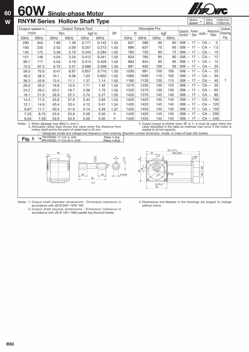
B50
60
W60W Single-phase Motor
Notes : 1. Motor slippage may affect n1 and n2. 2. Allowable radial load shows the value when the distance from
hollow shaft end to the point of radial load is 20 mm.
3. Output torque is limited when SF is . It must be used within the value stipulated in the table as overload may occur if the motor is loaded to its full capacity.
Notes : 1. Output shaft diameter dimensions : Dimension tolerance in accordance with JIS B 0401-1976 "H8".
2. Output shaft keyway dimensions : Dimension tolerance in accordance with JIS B 1301-1996 parallel key (Normal Grade).
3. Dimensions and Masses in the drawings are subject to change without notice.
Fig. 1 RNYM006–17–CA–5~240 Mass 4.4kg(RNYM006–17–CA–B–5~240) (Mass 4.8kg)
RNYM Series Hollow Shaft Type
A-A
A5
17.3
28 28
R1
90
23.1
818
231 (271)
2298
94
45 186 (226)
90
A
4- 6.5
104
15.6
15H8 96 (
9
6)
L=300
Output speed n2
r/minOutput Torque Tout
Nm kgf m N kgfAllowable Pro
SF
1.501.501.501.501.501.501.501.501.501.501.501.501.501.341.07
Capacity –
Frame – Suffix –
Reduction Symbol Size Ratio
OutlineDrawing
Fig.50Hz 60Hz 50Hz 60Hz 50Hz 60Hz 50Hz 60Hz 50Hz 60Hz 290 193 145 121 96.7 72.5 58.0 48.3 36.3 29.0 24.2 18.1 14.5 12.1 9.67 7.25 6.04
350 233 175 146 117 87.5 70.0 58.3 43.8 35.0 29.2 21.9 17.5 14.6 11.7 8.75 7.29
1.68 2.52 3.36 4.04 5.04 6.73 8.41 10.1 13.5 16.8 20.2 26.9 33.6 40.4 50.4 53.9 53.9
1.39 2.09 2.79 3.34 4.18 5.57 6.97 8.36 11.1 13.9 16.7 22.3 27.9 33.4 41.8 53.9 53.9
0.171 0.257 0.343 0.412 0.514 0.686 0.857 1.03 1.37 1.71 2.06 2.74 3.43 4.12 5.14 5.50 5.50
0.142 0.213 0.284 0.341 0.426 0.568 0.710 0.852 1.14 1.42 1.70 2.27 2.84 3.41 4.26 5.50 5.50
637 686 785 834 883 981 1030 1080 1180 1270 1320 1420 1420 1420 1420 1420 1420
588 637 735 785 834 932 981 1030 1130 1230 1270 1370 1420 1420 1420 1420 1420
65 70 80 85 90 100 105 110 120 130 135 145 145 145 145 145 145
60 65 75 80 85 95
100105115125130140145145145145145
006 – 17 – CA – 5 006 – 17 – CA – 7.5 006 – 17 – CA – 10 006 – 17 – CA – 12 006 – 17 – CA – 15 006 – 17 – CA – 20 006 – 17 – CA – 25 006 – 17 – CA – 30 006 – 17 – CA – 40 006 – 17 – CA – 50 006 – 17 – CA – 60 006 – 17 – CA – 80 006 – 17 – CA – 100 006 – 17 – CA – 120 006 – 17 – CA – 150 006 – 17 – CA – 200 006 – 17 – CA – 240
1
MotorSpeed n1
50Hz 1450r/min60Hz 1750r/min
Designate model and voltage and frequency when ordering. Brackets contain dimension, model, or mass of type with brakes.

Ho
llow
Sha
ftS
ingl
e-p
hase
B51
Notes : 1. Output shaft diameter dimensions : Dimension tolerance in accordance with JIS B 0401-1976 "H8".
2. Output shaft keyway dimensions : Dimension tolerance in accordance with JIS B 1301-1996 parallel key (Normal Grade).
3. Dimensions and masses in the drawings are subject to change without notice.
Fig. 2 RNYM006–1240–CA–300~1440 Mass 7.2kg(RNYM006–1240–CA–B–300~1440) (Mass 7.6kg)
RNYM Series Hollow Shaft Type MotorSpeed n1
50Hz 1450r/min60Hz 1750r/min
Designate model, voltage, and frequency when ordering. Brackets contain dimension, model, or mass of type with brakes.
Notes : 1. Motor slippage may affect n1 and n
2.
2. Allowable radial load shows the value when the distance from hollow shaft end to the point of radial load is 20 mm.
3. Output torque is limited when SF is . It must be used within the value stipulated in the table as overload may occur if the motor is loaded to its full capacity.
96
90
41 41 55
φ78h7
φ78h7
9 82 9
φ1473
A-A
10038 38
R1.5
φ25H8
28.3
8
φ26.2
221.35
φ25.6 A
B
B
~B
A
127
7651
6540
127
519
4-φ9 40 65
229280
A
A
127
7651
6540
127
51
9
4-φ9 40 65
288
339
Without brake
With brake
60
W60W Single-phase Motor
Output speed n2
r/minOutput Torque Tout
SF
1.03
Nm kgf m N kgfAllowable Pro
Capacity –
Frame – Suffix –
Reduction Symbol Size Ratio
OutlineDrawing
Fig.50Hz 60Hz 50Hz 60Hz 50Hz 60Hz 50Hz 60Hz 50Hz 60Hz4.834.033.022.422.011.611.211.01
5.834.863.652.922.431.941.461.22
95.098.198.198.198.198.198.198.1
78.794.498.198.198.198.198.198.1
9.68 10.0 10.0 10.0 10.0 10.0 10.0 10.0
8.02 9.63 10.0 10.0 10.0 10.0 10.0 10.0
18101810181018101810181018101810
18101810181018101810181018101810
185185185185185185185185
185185185185185185185185
006 – 1240 – CA – 300 006 – 1240 – CA – 360 006 – 1240 – CA – 480 006 – 1240 – CA – 600 006 – 1240 – CA – 720 006 – 1240 – CA – 900 006 – 1240 – CA – 1200 006 – 1240 – CA – 1440
2

B52
90
W
Notes : 1. Motor slippage may affect n1 and n2. 2. Allowable radial load shows the value when the distance from
hollow shaft end to the point of radial load is 20 mm.
3. Output torque is limited when SF is . It must be used within the value stipulated in the table as overload may occur if the motor is loaded to its full capacity.
Notes : 1. Output shaft diameter dimensions : Dimension tolerance in accordance with JIS B 0401-1976 "H8".
2. Output shaft keyway dimensions : Dimension tolerance in accordance with JIS B 1301-1996 parallel key (Normal Grade).
3. Dimensions and Masses in the drawings are subject to change without notice.
Fig. 1 RNYM009–17–CA–5~240 Mass 4.9kg(RNYM009–17–CA–B–5~240) (Mass 5.3kg)
90W Single-phase MotorRNYM Series Hollow Shaft Type
A-A
A5
17.3
28 28
R1
90
23.1
818
231 (271)
2298
94
45 186 (226)
90
A
4- 6.5
104
15.6
15H8 96 (
9
6)
L=300
Output speed n2
r/minOutput Torque Tout
SF
1.001.001.001.001.001.001.001.001.001.001.001.001.00
Nm kgf m N kgfAllowable Pro
Capacity –
Frame – Suffix –
Reduction Symbol Size Ratio
OutlineDrawing
Fig.50Hz 60Hz 50Hz 60Hz 50Hz 60Hz 50Hz 60Hz 50Hz 60Hz 290 193 145 121 96.7 72.5 58.0 48.3 36.3 29.0 24.2 18.1 14.5 12.1 9.67 7.25 6.04
350 233 175 146 117 87.5 70.0 58.3 43.8 35.0 29.2 21.9 17.5 14.6 11.7 8.75 7.29
2.52 3.78 5.04 6.05 7.57 10.1 12.6 15.1 20.2 25.2 30.3 40.4 50.4 53.9 53.9 53.9 53.9
2.09 3.13 4.18 5.02 6.27 8.36 10.4 12.5 16.7 20.9 25.1 33.4 41.8 50.2 53.9 53.9 53.9
0.257 0.386 0.514 0.617 0.772 1.03 1.29 1.54 2.06 2.57 3.09 4.12 5.14 5.50 5.50 5.50 5.50
0.213 0.320 0.426 0.511 0.639 0.852 1.07 1.28 1.70 2.13 2.56 3.41 4.26 5.11 5.50 5.50 5.50
637 686 785 834 883 981 1030 1080 1180 1270 1320 1420 1420 1420 1420 1420 1420
588 637 735 785 834 932 981 1030 1130 1230 1270 1370 1420 1420 1420 1420 1420
65 70 80 85 90 100 105 110 120 130 135 145 145 145 145 145 145
60 65 75 80 85 95 100 105 115 125 130 140 145 145 145 145 145
009 – 17 – CA – 5 009 – 17 – CA – 7.5 009 – 17 – CA – 10 009 – 17 – CA – 12 009 – 17 – CA – 15 009 – 17 – CA – 20 009 – 17 – CA – 25 009 – 17 – CA – 30 009 – 17 – CA – 40 009 – 17 – CA – 50 009 – 17 – CA – 60 009 – 17 – CA – 80 009 – 17 – CA – 100 009 – 17 – CA – 120 009 – 17 – CA – 150 009 – 17 – CA – 200 009 – 17 – CA – 240
1
MotorSpeed n1
50Hz 1450r/min60Hz 1750r/min
Designate model and voltage and frequency when ordering. Brackets contain dimension, model, or mass of type with brakes.

Ho
llow
Sha
ftS
ingl
e-p
hase
B53
90
W
Notes : 1. Motor slippage may affect n1 and n
2.
2. Allowable radial load shows the value when the distance from hollow shaft end to the point of radial load is 20 mm.
3. Output torque is limited when SF is . It must be used within the value stipulated in the table as overload may occur if the motor is loaded to its full capacity.
Notes : 1. Output shaft diameter dimensions : Dimension tolerance in accordance with JIS B 0401-1976 "H8".
2. Output shaft keyway dimensions : Dimension tolerance in accordance with JIS B 1301-1996 parallel key (Normal Grade).
3. Dimensions and masses in the drawings are subject to change without notice.
Fig. 2 RNYM009–1240–CA–300~1440 Mass 7.7kg(RNYM009–1240–CA–B–300~1440) (Mass 8.1kg)
RNYM Series Hollow Shaft Type
Designate model, voltage, and frequency when ordering. Brackets contain dimension, model, or mass of type with brakes.
96
90
41 41 55
φ78h7
φ78h7
9 82 9
φ1473
A-A
10038 38
R1.5
φ25H8
28.3
8
φ26.2
221.35
φ25.6 A
B
B
~B
A
127
7651
6540
127
519
4-φ9 40 65
229280
A
A
127
7651
6540
127
51
9
4-φ9 40 65
288
339
Without brake
With brake
40
W40W Single-phase Motor RNYM Series Hollow Shaft Type Motor
Speed n150Hz 1450r/min60Hz 1750r/min
Output speed n2
r/minOutput Torque Tout
SFNm kgf m N kgfAllowable Pro
Capacity –
Frame – Suffix –
Reduction Symbol Size Ratio
OutlineDrawing
Fig.50Hz 60Hz 50Hz 60Hz 50Hz 60Hz 50Hz 60Hz 50Hz 60Hz4.834.033.022.422.011.611.211.01
5.834.863.652.922.431.941.461.22
98.198.198.198.198.198.198.198.1
98.198.198.198.198.198.198.198.1
10.010.010.010.010.010.010.010.0
10.010.010.010.010.010.010.010.0
18101810181018101810181018101810
18101810181018101810181018101810
185185185185185185185185
185185185185185185185185
009 – 1240 – CA – 300 009 – 1240 – CA – 360 009 – 1240 – CA – 480 009 – 1240 – CA – 600 009 – 1240 – CA – 720 009 – 1240 – CA – 900 009 – 1240 – CA – 1200 009 – 1240 – CA – 1440
2

B54
0.1
kW0.1kW Single-phase MotorRNYM Series Hollow Shaft Type
Notes : 1. Motor slippage may affect n1 and n2. 2. Allowable radial load shows the value when the distance from
hollow shaft end to the point of radial load is 20 mm.
Notes : 1. Output shaft diameter dimensions : Dimension tolerance in accordance with JIS B 0401-1976 "H8".
2. Output shaft keyway dimensions : Dimension tolerance in accordance with JIS B 1301-1996 parallel key (Normal Grade).
3. Dimensions and Masses in the drawings are subject to change without notice.
Fig. 2 RNYM01–1120–CB–5~30 Mass 7.0kg(RNYM01–1120–CB–B–5~30) (Mass 8.5kg)
Fig. 3 RNYM01–1220–CB–40~60 Mass 8.5kg(RNYM01–1220–CB–B–40~60) (Mass 10kg)
Fig. 1 RNYM01–1110–CB–5~10 Mass 6.0kg(RNYM01–1110–CB–B–5~10) (Mass 7.5kg)
A
A4- 6.6
37 50
7437
3729
29
74 2
29 2911
906 33 33 6
8 66 8
52h7
275 (307)
124
( 1
24)
118
72 58
A-A
6
22.8
20H8
82
30 30
20.6
R1
16
1.15
21
52h7
Output speed n2
r/minOutput Torque Tout
Nm kgf m N kgfAllowable Pro
Capacity –
Frame – Suffix –
Reduction Symbol Size Ratio
50Hz 60Hz 50Hz 60Hz 50Hz 60Hz 50Hz 60Hz 50Hz 60Hz 290
207
145
121 96.7 72.5 58.0 48.3 36.3 29.0 24.2
350
250
175
146 117 87.5 70.0 58.3 43.8 35.0 29.2
2.80
3.92
5.61
6.73 8.41 11.2 14.0 16.8 22.4 28.0 33.6
2.32
3.25
4.64
5.57 6.97 9.29 11.6 13.9 18.6 23.2 27.9
0.286
0.400
0.572
0.686 0.857 1.14 1.43 1.71 2.29 2.86 3.43
0.237
0.332
0.474
0.568 0.710 0.947 1.18 1.42 1.89 2.37 2.84
637
686
785
834 883 981 1030 1080 1620 1720 1770
588
637
735
785 834 932 981 1030 1570 1670 1720
65
70
80
85 90 100 105 110 165 175 180
60
65
75
80 85 95 100 105 160 170 175
01 – 1110 – CB – 5 01 – 1120 – CB – 5 01 – 1110 – CB – 7 01 – 1120 – CB – 7 01 – 1110 – CB – 10 01 – 1120 – CB – 10 01 – 1120 – CB – 12 01 – 1120 – CB – 15 01 – 1120 – CB – 20 01 – 1120 – CB – 25 01 – 1120 – CB – 30 01 – 1220 – CB – 40 01 – 1220 – CB – 50 01 – 1220 – CB – 60
OutlineDrawing
Fig.121212
2
3
90
6 33 33 6
52h7
8 66 8116
5872
A
A
40 82
90
4050
3242
32 42
20
4- 6.6
124
( 1
24)
310 (342)
88 22
118
A-A
6
22.8
20H8
82
30 30
20.6
R1
16
1.15
52h7 21
905 537 37
9 74 9
78h7
116
A-A
38 38
R1.5
25.6
92
22
1.35
26.2
25H8
28.3
8
115
6649 40
57
4- 9
A
A
49 96
40 57
28
124
( 1
24)
333 (365)
113 20
118
5872
SF
4.002.004.002.002.002.002.002.002.002.002.002.002.002.00
MotorSpeed n1
50Hz 1450r/min60Hz 1750r/min
Designate model and voltage and frequency when ordering. Brackets contain dimension, model, or mass of type with brakes.

Ho
llow
Sha
ftS
ingl
e-p
hase
B55
0.1
kW0.1kW Single-phase MotorRNYM Series Hollow Shaft Type
Notes : 1. Motor slippage may affect n1 and n2. 2. Allowable radial load shows the value when the distance from
hollow shaft end to the point of radial load is 20 mm.
3. Output torque is limited when SF is . It must be used within the value stipulated in the table as overload may occur if the motor is loaded to its full capacity.
Notes : 1. Output shaft diameter dimensions : Dimension tolerance in accordance with JIS B 0401-1976 "H8".
2. Output shaft keyway dimensions : Dimension tolerance in accordance with JIS B 1301-1996 parallel key (Normal Grade).
3. Dimensions and Masses in the drawings are subject to change without notice.
Output speed n2
r/minOutput Torque Tout
Nm kgf m N kgfAllowable Pro
Capacity –
Frame – Suffix –
Reduction Symbol Size Ratio
50Hz 60Hz 50Hz 60Hz 50Hz 60Hz 50Hz 60Hz 50Hz 60Hz 18.1 14.5 12.1 9.67 7.25 6.04 4.83 4.03 3.02 2.42 2.01 1.61 1.21 1.01
21.9 17.5 14.6 11.7 8.75 7.29 5.83 4.86 3.65 2.92 2.43 1.94 1.46 1.22
44.8 56.1 67.3 84.1 112 135 158 190 253 317 380 475 630 732
37.2 46.4 55.7 69.7 92.9 111 131 157 210 262 315 393 520 630
4.57 5.72 6.86 8.57 11.4 13.7 16.1 19.4 25.8 32.3 38.7 48.4 64.6 74.6
3.79 4.74 5.68 7.10 9.47 11.4 13.4 16.0 21.4 26.7 32.1 40.1 53.5 64.2
30403090309030903090309062306230623062306230623062306230
29403040309030903090309062306230623062306230623062306230
310315315315315315635635635635635635635635
300310315315315315635635635635635635635635
01 – 1330 – CB – 80 01 – 1330 – CB – 100 01 – 1330 – CB – 120 01 – 1330 – CB – 150 01 – 1330 – CB – 200 01 – 1330 – CB – 240 01 – 1540 – CB – 300 01 – 1540 – CB – 360 01 – 1540 – CB – 480 01 – 1540 – CB – 600 01 – 1540 – CB – 720 01 – 1540 – CB – 900 01 – 1540 – CB – 1200 01 – 1540 – CB – 1440
OutlineDrawing
Fig.
4
5
Fig. 4 RNYM01–1330–CB–80~240 Mass 10kg(RNYM01–1330–CB–B–80~240) (Mass 11kg)
81
17.5
9 92 9
5 546 46
85h7
116
A-A
1.35
11046 46
30.6
R1.5
22 8
33.3
30H8
477992
6015
2
4- 11
A
A
47 79
60 108
11
356 (388)
3.5152
124
( 1
24)
118
5872
31.4
SF
2.002.002.002.001.741.454.003.852.892.311.931.541.16
MotorSpeed n1
50Hz 1450r/min60Hz 1750r/min
Designate model and voltage and frequency when ordering. Brackets contain dimension, model, or mass of type with brakes.
φ110h7
φ110h7
5 568 68
10 136 1072
A-A
15667 67
φ45.6
301.95
R1.5
14
48.8
φ45H8
φ47.5
A
A
4-φ18
129
84
213
109
64
64 109
213 54
14
84 197
112
465(497)
φ124(φ124)
118
Fig. 5 RNYM01–1540–300~1440 Mass 24.5kg(RNYM01–1540–B–300~1440) (Mass 25.5kg)

B56
0.2
kW
SF
4.002.004.002.002.002.002.002.002.002.002.002.002.002.00
0.2kW Single-phase MotorRNYM Series Hollow Shaft Type
Notes : 1. Motor slippage may affect n1 and n2. 2. Allowable radial load shows the value when the distance from
hollow shaft end to the point of radial load is 20 mm.
Notes : 1. Output shaft diameter dimensions : Dimension tolerance in accordance with JIS B 0401-1976 "H8".
2. Output shaft keyway dimensions : Dimension tolerance in accordance with JIS B 1301-1996 parallel key (Normal Grade).
3. Dimensions and Masses in the drawings are subject to change without notice.
Fig. 2 RNYM02–1220–CB–5~30 Mass 9.5kg(RNYM02–1220–CB–B–5~30) (Mass 11kg)
Fig. 3 RNYM02–1320–CB–40~60 Mass 11kg(RNYM02–1320–CB–B–40~60) (Mass 13kg)
Output speed n2
r/minOutput Torque Tout
Nm kgf m N kgfAllowable Pro
Capacity –
Frame – Suffix –
Reduction Symbol Size Ratio
50Hz 60Hz 50Hz 60Hz 50Hz 60Hz 50Hz 60Hz 50Hz 60Hz 290
207
145
121 96.7 72.5 58.0 48.3 36.3 29.0 24.2
350
250
175
146 117 87.5 70.0 58.3 43.8 35.0 29.2
5.61
7.85
11.2
13.5 16.8 22.4 28.0 33.6 44.8 56.1 67.3
4.64
6.50
9.29
11.1 13.9 18.6 23.2 27.9 37.2 46.4 55.7
0.572
0.800
1.14
1.37 1.71 2.29 2.86 3.43 4.57 5.72 6.86
0.474
0.66
0.947
1.14 1.42 1.89 2.37 2.84 3.79 4.74 5.68
883
981
1079
1130 1230 1370 1470 1520 2650 2840 2940
834
932
1030
1080 1180 1320 1370 1470 2550 2750 2840
90
100
110
115 125 140 150 155 270 290 300
85
95
105
110 120 135 140 150 260 280 290
02 – 1210 – CB – 5 02 – 1220 – CB – 5 02 – 1210 – CB – 7 02 – 1220 – CB – 7 02 – 1210 – CB – 10 02 – 1220 – CB – 10 02 – 1220 – CB – 12 02 – 1220 – CB – 15 02 – 1220 – CB – 20 02 – 1220 – CB – 25 02 – 1220 – CB – 30 02 – 1320 – CB – 40 02 – 1320 – CB – 50 02 – 1320 – CB – 60
OutlineDrawing
Fig.
2
12121 2
3
905 537 37
9 74 9
78h7
116
A-A
38 38
R1.5
25.6
92
22
1.35
26.2
25H8
28.3
8
115
6649 40
57
4- 9
A
A
49 96
40 57
28
124
( 1
24)
353 (385)
113 20
118
5872
78h7
112
5 46 46 5
85h7
9 92 9116
A-A
110
33.3
46 46
R1.5
30.6
22
30H8
1.35
31.4
8A
A
58 119
132
7458 46
62
46 62
27.5
4- 11
381 (413)
124
( 1
24)
130 34
118
5872
85h7
Fig. 1 RNYM02–1210–CB–5~10 Mass 9.0kg(RNYM02–1210–CB–B–5~10) (Mass 10kg)
78h7
112
9 74 9
3737
4646
92
37 37
92 1.5
46 61
14
124
(
124)
37 375 5311 (343)
72 58
118A
A
4- 9A-A
38 38
R1.5
25.6
92
22
1.35
26.2
25H8
28.3
8
78h7
MotorSpeed n1
50Hz 1450r/min60Hz 1750r/min
Designate model and voltage and frequency when ordering. Brackets contain dimension, model, or mass of type with brakes.

Ho
llow
Sha
ftS
ingl
e-p
hase
B57
SF
0.2kW Single-phase MotorRNYM Series Hollow Shaft Type
Notes : 1. Output shaft diameter dimensions : Dimension tolerance in accordance with JIS B 0401-1976 "H8".
2. Output shaft keyway dimensions : Dimension tolerance in accordance with JIS B 1301-1996 parallel key (Normal Grade).
3. Dimensions and Masses in the drawings are subject to change without notice.
Notes : 1. Motor slippage may affect n1 and n2. 2. Allowable radial load shows the value when the distance from
hollow shaft end to the point of radial load is 20 mm.
3. Output torque is limited when SF is . It must be used within the value stipulated in the table as overload may occur if the motor is loaded to its full capacity.
Output speed n2
r/minOutput Torque Tout
Nm kgf m N kgfAllowable Pro
Capacity –
Frame – Suffix –
Reduction Symbol Size Ratio
50Hz 60Hz 50Hz 60Hz 50Hz 60Hz 50Hz 60Hz 50Hz 60Hz 18.1 14.5 12.1 9.67 7.25 6.04 4.83 4.03 3.02 2.42 2.01 1.61 1.21 1.01
21.9 17.5 14.6 11.7 8.75 7.29 5.83 4.86 3.65 2.92 2.43 1.94 1.46 1.22
89.7 112 135 168 224 269
317380506633732732732732
74.3 92.9 111 139 186 223
262315420525629732732732
9.14 11.4 13.7 17.1 22.9 27.4 32.3 38.7 51.6 64.6 74.6 74.6 74.6 74.6
7.58 9.47 11.4 14.2 18.9 22.7 26.7 32.1 42.8 53.5 64.2 74.6 74.6 74.6
4360 4360 4360 4360 4360 4360
62306230623062306230623062306230
4270 4360 4360 4360 4360 4360
62306230623062306230623062306230
445 445 445 445 445 445
635635635635635635635635
435 445 445 445 445 445
635635635635635635635635
02 – 1430 – CB – 80 02 – 1430 – CB – 100 02 – 1430 – CB – 120 02 – 1430 – CB – 150 02 – 1430 – CB – 200 02 – 1430 – CB – 240 02 – 1540 – CB – 300 02 – 1540 – CB – 360 02 – 1540 – CB – 480 02 – 1540 – CB – 600 02 – 1540 – CB – 720 02 – 1540 – CB – 900 02 – 1540 – CB – 1200 02 – 1540 – CB – 1440
OutlineDrawing
Fig.
4
5
Fig. 4 RNYM02–1430–CB–80~240 Mass 16kg(RNYM02–1430–CB–B–80~240) (Mass 17kg)
5 59 59 5105
95h7
10 118 10
20
116
A-A
1.75
35H8
26
52 52138
37
10
38.3
35.6
R1.5
A
A
70 130
178
7010
854
92
178 854 92
124
( 1
24)14
4- 14
404 (436)
118
5872
95h7
MotorSpeed n1
50Hz 1450r/min60Hz 1750r/min
Designate model and voltage and frequency when ordering. Brackets contain dimension, model, or mass of type with brakes.
RNYM02–1540–CB–300~1440 Mass 26kg(RNYM02–1540–CB–B–300~1440) (Mass 27.5kg)Fig. 5
A-A
15667 67
φ45.6
301.95
R1.5
14
48.8
φ45H8
φ47.5
72
φ110h7
φ110h7
5 568 68
10 136 10
A
A
4-φ18
φ124(φ124)
118129
84
213
109
64
64 109213 54
14
84 197485(517)
112
2.002.002.002.001.741.452.001.931.441.16
0.2
kW

B58
SF
3.852.003.852.002.002.002.002.002.002.002.002.002.002.00
0.4
kW0.4kW Single-phase MotorRNYM Series Hollow Shaft Type
Notes : 1. Motor slippage may affect n1 and n2. 2. Allowable radial load shows the value when the distance from
hollow shaft end to the point of radial load is 20 mm.
Notes : 1. Output shaft diameter dimensions : Dimension tolerance in accordance with JIS B 0401-1976 "H8".
2. Output shaft keyway dimensions : Dimension tolerance in accordance with JIS B 1301-1996 parallel key (Normal Grade).
3. Dimensions and Masses in the drawings are subject to change without notice.
Fig. 2 RNYM05–1320–CB–5~30 Mass 15kg(RNYM05–1320–CB–B–5~30) (Mass 17kg)
Fig. 3 RNYM05–1420–CB–40~60 Mass 18kg(RNYM05–1420–CB–B–40~60) (Mass 20kg)
Output speed n2
r/minOutput Torque Tout
Nm kgf m N kgfAllowable Pro
Capacity –
Frame – Suffix –
Reduction Symbol Size Ratio
50Hz 60Hz 50Hz 60Hz 50Hz 60Hz 50Hz 60Hz 50Hz 60Hz 290
207
145
121 96.7 72.5 58.0 48.3 36.3 29.0 24.2
350
250
175
146 117 87.5 70.0 58.3 43.8 35.0 29.2
11.2
15.7
22.4
26.9 33.6 44.8 56.1 67.3 89.7 112 135
9.29
13.0
18.6
22.3 27.9 37.2 46.4 55.7 74.3 92.9 111
1.14
1.60
2.29
2.74 3.43 4.57 5.72 6.86 9.14 11.4 13.7
0.947
1.33
1.89
2.27 2.84 3.79 4.74 5.68 7.58 9.47 11.4
1470
1670
1810
1910 2060 2260 2350 2450 3970 4170 4310
1370
1570
1720
1810 1960 2160 2260 2350 3820 4020 4170
150
170
185
195210230240250405425440
140
160
175
185200220230240390410425
05 – 1310 – CB – 5 05 – 1320 – CB – 5 05 – 1310 – CB – 7 05 – 1320 – CB – 7 05 – 1310 – CB – 10 05 – 1320 – CB – 10 05 – 1320 – CB – 12 05 – 1320 – CB – 15 05 – 1320 – CB – 20 05 – 1320 – CB – 25 05 – 1320 – CB – 30 05 – 1420 – CB – 40 05 – 1420 – CB – 50 05 – 1420 – CB – 60
OutlineDrawing
Fig.
2
121212
3
112
5 46 46 5
85h7
9 92 9116
A-A
110
33.3
46 46
R1.5
30.6
22
30H8
1.35
31.4
8A
A
58 119
132
7458 46
62
46 62
27.5
4- 11
423 (466)15
5 (
155
)
85.5
130 34
128
5469
85h7
5 59 59 5
10 118 10
95h7
109
A-A
35H8
10
38.3
13852 52
261.75
R1.537
35.6
A
A
158
8870
7557
70
20
57 75155 43
4- 14
93
155
( 1
55)
146
474 (517)
128
5469
95h7
Fig. 1 RNYM05–1310–CB–5~10 Mass 13kg(RNYM05–1310–CB–B–5~10) (Mass 16kg)
56
112
5656
4444
112 244 44
17
113
155
( 1
55)
5 46 46 5
85h7
9 92 9
76
390 (433)116
69 54
128
A
A4- 11
A-A
110
33.3
46 46
R1.5
30.6
22
30H8
1.35
31.4
8
85h7
MotorSpeed n1
50Hz 1450r/min60Hz 1750r/min
Designate model and voltage and frequency when ordering. Brackets contain dimension, model, or mass of type with brakes.

Fig. 5 RNYM05–1640–CB–300~1440 Mass 68kg(RNYM05–1640–CB–B–300~1440) (Mass 70kg)
A
A
A-A
113
15
5
138
58
2.2
40
55
.6
R2.5
85 85
224
16
59.3
55H8
15
0h7
19 186 19
1212 93 93
8514
5
170
110
280
85 145
110 170
280
1716
0 1
16
4- 22
604
15
0h7
Ho
llow
Sha
ftS
ingl
e-p
hase
B59
SF
0.4
kW0.4kW Single-phase MotorRNYM Series Hollow Shaft Type
Notes : 1. Output shaft diameter dimensions : Dimension tolerance in accordance with JIS B 0401-1976 "H8".
2. Output shaft keyway dimensions : Dimension tolerance in accordance with JIS B 1301-1996 parallel key (Normal Grade).
3. Dimensions and Masses in the drawings are subject to change without notice.
Fig. 4 RNYM05–1530–CB–80~240 Mass 25kg(RNYM05–1530–CB–B–80~240) (Mass 28kg)
5 5
10 136 10
68 68
110h
7
109A-A156
67 67
45.6
301.95
R1.5
14
48.8
45H8
47.5
A
84 157498 (541)
64 109213 9.5
109
6412
984
213
4- 18
1796
155
( 1
55)
128
A
110h
7
Output speed n2
r/minOutput Torque Tout
Nm kgf m N kgfAllowable Pro
Capacity –
Frame – Suffix –
Reduction Symbol Size Ratio
50Hz 60Hz 50Hz 60Hz 50Hz 60Hz 50Hz 60Hz 50Hz 60Hz 18.1 14.5 12.1 9.67 7.25 6.04 4.83 4.03 3.02 2.42 2.01 1.61 1.21 1.01
21.9 17.5 14.6 11.7 8.75 7.29 5.83 4.86 3.65 2.92 2.43 1.94 1.46 1.22
179 224 269 336 448 538 630 760 1010 1270 1480 1480 1480 1480
149 186 223 279 372 446 525 630 840 1050 1260 1480 1480 1480
18.3 22.9 27.4 34.3 45.7 55 64.6 77.5 103 129 151 151 151 151
15.2 18.9 22.7 28.4 37.9 45.5 53.5 64.2 85.6 107 128 151 151 151
6230 6230 6230 6230 6230 6230 9810 9810 9810 9810 9810 9810 9810 9810
6130 6230 6230 6230 6230 6230
98109810981098109810981098109810
635635635635635635
10001000100010001000100010001000
62563563563563563510001000100010001000100010001000
05 – 1530 – CB – 80 05 – 1530 – CB – 100 05 – 1530 – CB – 120 05 – 1530 – CB – 150 05 – 1530 – CB – 200 05 – 1530 – CB – 240 05 – 1640 – CB – 300 05 – 1640 – CB – 360 05 – 1640 – CB – 480 05 – 1640 – CB – 600 05 – 1640 – CB – 720 05 – 1640 – CB – 900 05 – 1640 – CB – 1200 05 – 1640 – CB – 1440
OutlineDrawing
Fig.
4
5
MotorSpeed n1
50Hz 1450r/min60Hz 1750r/min
Designate model and voltage and frequency when ordering. Brackets contain dimension, model, or mass of type with brakes.
2.002.002.002.001.631.362.001.951.461.17
Notes : 1. Motor slippage may affect n1 and n2. 2. Allowable radial load shows the value when the distance from
hollow shaft end to the point of radial load is 20 mm.
3. Output torque is limited when SF is . It must be used within the value stipulated in the table as overload may occur if the motor is loaded to its full capacity.

B60
15W Single-phase Reversible MotorRNYM Series Hollow Shaft Type
15
W
Notes : 1. Motor slippage may affect n1 and n2. 2. Allowable radial load shows the value when the distance from
hollow shaft end to the point of radial load is 20 mm.
Notes : 1. Output shaft diameter dimensions : Dimension tolerance in accordance with JIS B 0401-1976 "H8".
2. Output shaft keyway dimensions : Dimension tolerance in accordance with JIS B 1301-1996 parallel key (Normal Grade).
3. Dimensions and Masses in the drawings are subject to change without notice.
Fig. 1 RNYM0015–03–CC–5~240 Mass 2.6kg
A-A
5
17.3
82
28 28
R1
78
22 A
A
175
15
80 23.1
8
40 135
80
4- 5.5
94
15.6
15H8
76
L=300
Output speed n2
r/minOutput Torque Tout
Nm kgf m N kgfAllowable Pro
SF
4.004.004.004.004.004.004.004.004.004.004.004.004.003.342.502.001.67
Capacity –
Frame – Suffix –
Reduction Symbol Size Ratio
OutlineDrawing
Fig.50Hz 60Hz 50Hz 60Hz 50Hz 60Hz 50Hz 60Hz 50Hz 60Hz 290 193 145 121 96.7 72.5 58.0 48.3 36.3 29.0 24.2 18.1 14.5 12.1 9.06 7.25 6.04
350 233 175 146 117 87.5 70.0 58.3 43.8 35.0 29.2 21.9 17.5 14.6 10.9 8.75 7.29
0.371 0.556 0.742 0.890 1.11 1.48 1.85 2.23 2.97 3.71 4.45 5.93 7.42 8.90 11.9 14.8 17.8
0.307 0.461 0.615 0.738 0.922 1.23 1.54 1.84 2.46 3.07 3.69 4.92 6.15 7.38 9.83 12.3 14.8
0.038 0.057 0.076 0.091 0.113 0.151 0.189 0.227 0.303 0.378 0.454 0.605 0.756 0.908 1.21 1.51 1.82
0.031 0.047 0.063 0.075 0.094 0.125 0.157 0.188 0.251 0.313 0.376 0.501 0.627 0.752 1.00 1.25 1.50
539 588 637 686 735 785 834 883 981
10801080108010801080108010801080
490 539 588 637 686 735 785 834 932
10301080108010801080108010801080
55 60 65 70 75 80 85 90
100110110110110110110110110
50 55 60 65 70 75 80 85 95
105110110110110110110110
0015 – 03 – CC – 5 0015 – 03 – CC – 7.5 0015 – 03 – CC – 10 0015 – 03 – CC – 12 0015 – 03 – CC – 15 0015 – 03 – CC – 20 0015 – 03 – CC – 25 0015 – 03 – CC – 30 0015 – 03 – CC – 40 0015 – 03 – CC – 50 0015 – 03 – CC – 60 0015 – 03 – CC – 80 0015 – 03 – CC – 100 0015 – 03 – CC – 120 0015 – 03 – CC – 160 0015 – 03 – CC – 200 0015 – 03 – CC – 240
1
MotorSpeed n1
50Hz 1450r/min60Hz 1750r/min
Designate model and voltage and frequency when ordering.

Ho
llow
Sha
ftS
ingl
e-p
hase
B61
25
W25W Single-phase Reversible MotorRNYM Series Hollow Shaft Type
Notes : 1. Motor slippage may affect n1 and n2. 2. Allowable radial load shows the value when the distance from
hollow shaft end to the point of radial load is 20 mm.
Notes : 1. Output shaft diameter dimensions : Dimension tolerance in accordance with JIS B 0401-1976 "H8".
2. Output shaft keyway dimensions : Dimension tolerance in accordance with JIS B 1301-1996 parallel key (Normal Grade).
3. Dimensions and Masses in the drawings are subject to change without notice.
Fig. 2 RNYM0025–03–CC–5~240 Mass 2.7kg
A-A
5
17.3
82
28 28
R1
78
22 A
A
175
15
80 23.1
8
40 135
80
4- 5.5
94
15.6
15H8
76
L=300
Output speed n2
r/minOutput Torque Tout
Nm kgf m N kgfAllowable Pro
SF
2.402.402.402.402.402.402.402.402.402.402.402.402.402.001.501.201.00
Capacity –
Frame – Suffix –
Reduction Symbol Size Ratio
OutlineDrawing
Fig.50Hz 60Hz 50Hz 60Hz 50Hz 60Hz 50Hz 60Hz 50Hz 60Hz 290 193 145 121 96.7 72.5 58.0 48.3 36.3 29.0 24.2 18.1 14.5 12.1 9.06 7.25 6.04
350 233 175 146 117 87.5 70.0 58.3 43.8 35.0 29.2 21.9 17.5 14.6 10.9 8.75 7.29
0.618 0.927 1.24 1.48 1.85 2.47 3.09 3.71 4.95 6.18 7.42 9.9 12.4 14.8 19.8 24.7 29.7
0.512 0.768 1.02 1.23 1.54 2.05 2.56 3.07 4.10 5.12 6.15 8.20 10.2 12.3 16.4 20.5 24.6
0.063 0.095 0.126 0.151 0.189 0.252 0.315 0.378 0.504 0.630 0.756 1.01 1.26 1.51 2.02 2.52 3.03
0.052 0.078 0.104 0.125 0.157 0.209 0.261 0.313 0.418 0.522 0.627 0.836 1.04 1.25 1.67 2.09 2.51
539 588 637 686 735 785 834 883 981
10801080108010801080108010801080
490 539 588 637 686 735 785 834 932
10301080108010801080108010801080
55 60 65 70 75 80 85 90
100110110110110110110110110
50 55 60 65 70 75 80 85 95
105110110110110110110110
0025 – 03 – CC – 5 0025 – 03 – CC – 7.5 0025 – 03 – CC – 10 0025 – 03 – CC – 12 0025 – 03 – CC – 15 0025 – 03 – CC – 20 0025 – 03 – CC – 25 0025 – 03 – CC – 30 0025 – 03 – CC – 40 0025 – 03 – CC – 50 0025 – 03 – CC – 60 0025 – 03 – CC – 80 0025 – 03 – CC – 100 0025 – 03 – CC – 120 0025 – 03 – CC – 160 0025 – 03 – CC – 200 0025 – 03 – CC – 240
2
MotorSpeed n1
50Hz 1450r/min60Hz 1750r/min
Designate model and voltage and frequency when ordering.

B62
40W Single-phase Reversible MotorRNYM Series Hollow Shaft Type
40
W
Notes : 1. Motor slippage may affect n1 and n2. 2. Allowable radial load shows the value when the distance from
hollow shaft end to the point of radial load is 20 mm.
Notes : 1. Output shaft diameter dimensions : Dimension tolerance in accordance with JIS B 0401-1976 "H8".
2. Output shaft keyway dimensions : Dimension tolerance in accordance with JIS B 1301-1996 parallel key (Normal Grade).
3. Dimensions and Masses in the drawings are subject to change without notice.
Fig. 1 RNYM004–07–CC–5~120 Mass 2.9kg
Fig. 2 RNYM004–17–CC–150~240 Mass 4.1kg
A-A
5
17.3
82
28 28
R1
78
22
15.6
15H8
A
A
18
23.1
690
45
90
219174
4- 6.5
104
80
L=300
A-A
A
23.15
17.3
28 28
R1
9018
194
8
98 45 149
90
A
94
22
4- 6.5
104
15.6
15H8
90
L=300
Output speed n2
r/minOutput Torque Tout
SF
1.501.501.501.501.501.501.501.501.501.501.501.501.201.001.601.201.00
Nm kgf m N kgfAllowable Pro
Capacity –
Frame – Suffix –
Reduction Symbol Size Ratio
OutlineDrawing
Fig.50Hz 60Hz 50Hz 60Hz 50Hz 60Hz 50Hz 60Hz 50Hz 60Hz 290 193 145 121 96.7 72.5 58.0 48.3 36.3 29.0 24.2 18.1 14.5 12.1 9.67 7.25 6.04
350 233 175 146 117 87.5 70.0 58.3 43.8 35.0 29.2 21.9 17.5 14.6 11.7 8.75 7.29
1.12 1.68 2.24 2.69 3.36 4.48 5.61 6.73 8.97 11.2 13.5 17.9 22.4 26.9 33.6 44.8 53.8
0.929 1.39 1.86 2.23 2.79 3.72 4.64 5.57 7.43 9.29 11.1 14.9 18.6 22.3 27.9 37.2 44.6
0.114 0.171 0.229 0.274 0.343 0.457 0.572 0.686 0.914 1.14 1.37 1.83 2.29 2.74 3.43 4.57 5.49
0.095 0.142 0.189 0.227 0.284 0.379 0.474 0.568 0.758 0.947 1.14 1.52 1.89 2.27 2.84 3.79 4.55
539 588 637 686 735 785 834 883 981
10801080108010801080142014201420
490 539 588 637 686 735 785 834 932
10301080108010801080142014201420
55 60 65 70 75 80 85 90
100110110110110110145145145
50 55 60 65 70 75 80 85 95
105110110110110145145145
004 – 07 – CC – 5 004 – 07 – CC – 7.5 004 – 07 – CC – 10 004 – 07 – CC – 12 004 – 07 – CC – 15 004 – 07 – CC – 20 004 – 07 – CC – 25 004 – 07 – CC – 30 004 – 07 – CC – 40 004 – 07 – CC – 50 004 – 07 – CC – 60 004 – 07 – CC – 80 004 – 07 – CC – 100 004 – 07 – CC – 120 004 – 17 – CC – 150 004 – 17 – CC – 200 004 – 17 – CC – 240
1
2
MotorSpeed n1
50Hz 1450r/min60Hz 1750r/min
Designate model and voltage and frequency when ordering.

Ho
llow
Sha
ftS
ingl
e-p
hase
B63
40
W
Notes : 1. Output shaft diameter dimensions : Dimension tolerance in accordance with JIS B 0401-1976 "H8".
2. Output shaft keyway dimensions : Dimension tolerance in accordance with JIS B 1301-1996 parallel key (Normal Grade).
3. Dimensions and masses in the drawings are subject to change without notice.
RNYM Series Hollow Shaft Type MotorSpeed n1
50Hz 1450r/min60Hz 1750r/min
Notes : 1. Motor slippage may affect n1 and n
2.
2. Allowable radial load shows the value when the distance from hollow shaft end to the point of radial load is 20 mm.
3. Output torque is limited when SF is . It must be used within the value stipulated in the table as overload may occur if the motor is loaded to its full capacity.
A-A
10038 38
R1.5
φ26.2
221.35
φ25.6
41 41 55
φ78h7
φ78h7
9 82 9 φ1473
φ25H8
28.3
8
A
A
127
7651
6540
127
51 211262
9
4-φ9 40 65
Without brake
90
40W Single-phase Reversible Motor
Output speed n2
r/minOutput Torque Tout
Nm kgf m N kgfAllowable Pro
Capacity –
Frame – Suffix –
Reduction Symbol Size Ratio
50Hz 60Hz 50Hz 60Hz 50Hz 60Hz 50Hz 60Hz 50Hz 60Hz4.834.033.022.422.011.611.211.01
5.834.863.652.922.431.941.461.22
63.376.098.198.198.198.198.198.1
52.562.983.998.198.198.198.198.1
6.467.7510.010.010.010.010.010.0
5.356.428.5610.010.010.010.010.0
18101810181018101810181018101810
18101810181018101810181018101810
185185185185185185185185
185185185185185185185185
004 – 1240 – CC – 300 004 – 1240 – CC – 360 004 – 1240 – CC – 480 004 – 1240 – CC – 600 004 – 1240 – CC – 720 004 – 1240 – CC – 900 004 – 1240 – CC – 1200 004 – 1240 – CC – 1440
OutlineDrawing
Fig.
3
SF
1.551.29
Fig. 3 RNYM004–1240–CC–300~1440 Mass 6.9kg
Designate model, voltage, and frequency when ordering.

B64
60W Single-phase Reversible MotorRNYM Series Hollow Shaft Type
Notes : 1. Motor slippage may affect n1 and n2. 2. Allowable radial load shows the value when the distance from
hollow shaft end to the point of radial load is 20 mm.
3. Output torque is limited when SF is . It must be used within the value stipulated in the table as overload may occur if the motor is loaded to its full capacity.
Notes : 1. Output shaft diameter dimensions : Dimension tolerance in accordance with JIS B 0401-1976 "H8".
2. Output shaft keyway dimensions : Dimension tolerance in accordance with JIS B 1301-1996 parallel key (Normal Grade).
3. Dimensions and Masses in the drawings are subject to change without notice.
Fig. 1 RNYM006–17–CC–5~240 Mass 4.4kg
A-A
A5
17.3
28 28
R1
90
23.1
818
231
2298
94
45 186
90
A
4- 6.5
104
15.6
15H8
96L=300
Output speed n2
r/minOutput Torque Tout
Nm kgf m N kgfAllowable Pro
SF
1.501.501.501.501.501.501.501.501.501.501.501.501.501.341.07
1.03
Capacity –
Frame – Suffix –
Reduction Symbol Size Ratio
OutlineDrawing
Fig.50Hz 60Hz 50Hz 60Hz 50Hz 60Hz 50Hz 60Hz 50Hz 60Hz 290 193 145 121 96.7 72.5 58.0 48.3 36.3 29.0 24.2 18.1 14.5 12.1 9.67 7.25 6.04 4.83 4.03 3.02 2.42 2.01 1.61 1.21 1.01
350 233 175 146 117 87.5 70.0 58.3 43.8 35.0 29.2 21.9 17.5 14.6 11.7 8.75 7.29 5.83 4.86 3.65 2.92 2.43 1.94 1.46 1.22
1.68 2.52 3.36 4.04 5.04 6.73 8.41 10.1 13.5 16.8 20.2 26.9 33.6 40.4 50.4 53.9 53.9 95.0 98.1 98.1 98.1 98.1 98.1 98.1 98.1
1.39 2.09 2.79 3.34 4.18 5.57 6.97 8.36 11.1 13.9 16.7 22.3 27.9 33.4 41.8 53.9 53.9 78.7 94.4 98.1 98.1 98.1 98.1 98.1 98.1
0.171 0.257 0.343 0.412 0.514 0.686 0.857 1.03 1.37 1.71 2.06 2.74 3.43 4.12 5.14 5.50 5.50 9.68 10.0 10.0 10.0 10.0 10.0 10.0 10.0
0.142 0.213 0.284 0.341 0.426 0.568 0.710 0.852 1.14 1.42 1.70 2.27 2.84 3.41 4.26 5.50 5.50 8.02 9.63 10.0 10.0 10.0 10.0 10.0 10.0
637 686 785 834 883 981
1030108011801270132014201420142014201420142018101810181018101810181018101810
588 637 735 785 834 932 981
103011301230127013701420142014201420142018101810181018101810181018101810
65 70 80 85 90
100105110120130135145145145145145145185185185185185185185185
60 65 75 80 85 95
100105115125130140145145145145145185185185185185185185185
006 – 17 – CC – 5 006 – 17 – CC – 7.5 006 – 17 – CC – 10 006 – 17 – CC – 12 006 – 17 – CC – 15 006 – 17 – CC – 20 006 – 17 – CC – 25 006 – 17 – CC – 30 006 – 17 – CC – 40 006 – 17 – CC – 50 006 – 17 – CC – 60 006 – 17 – CC – 80 006 – 17 – CC – 100 006 – 17 – CC – 120 006 – 17 – CC – 150 006 – 17 – CC – 200 006 – 17 – CC – 240 006 – 1240 – CC – 300 006 – 1240 – CC – 360 006 – 1240 – CC – 480 006 – 1240 – CC – 600 006 – 1240 – CC – 720 006 – 1240 – CC – 900 006 – 1240 – CC – 1200 006 – 1240 – CC – 1440
1
2
MotorSpeed n1
50Hz 1450r/min60Hz 1750r/min
Designate model and voltage and frequency when ordering.
60
W
RNYM006–1240–CC–300~1440 Mass 7.2kg
41 41 55
φ78h7
φ78h7
9 82 9 φ1473
A-A
10038 38
R1.5
φ25H8
28.3
8
φ26.2
221.35
φ25.6 A
A
127
7651
6540
127
51
9
4-φ9 40 65
229280
Without brake
90
Fig. 2

Ho
llow
Sha
ftS
ingl
e-p
hase
B65
90W Single-phase Reversible MotorRNYM Series Hollow Shaft Type
90
W
Notes : 1. Motor slippage may affect n1 and n2. 2. Allowable radial load shows the value when the distance from
hollow shaft end to the point of radial load is 20 mm.
3. Output torque is limited when SF is . It must be used within the value stipulated in the table as overload may occur if the motor is loaded to its full capacity.
Notes : 1. Output shaft diameter dimensions : Dimension tolerance in accordance with JIS B 0401-1976 "H8".
2. Output shaft keyway dimensions : Dimension tolerance in accordance with JIS B 1301-1996 parallel key (Normal Grade).
3. Dimensions and Masses in the drawings are subject to change without notice.
Fig. 1 RNYM009–17–CC–5~240 Mass 4.9kg
A-A
A5
17.3
28 28
R1
90
23.1
818
231
2298
94
45 186
90
A
4- 6.5
104
15.6
15H8
96L=300
Output speed n2
r/minOutput Torque Tout
Nm kgf m N kgfAllowable Pro
SF
1.001.001.001.001.001.001.001.001.001.001.001.001.00
Capacity –
Frame – Suffix –
Reduction Symbol Size Ratio
OutlineDrawing
Fig.50Hz 60Hz 50Hz 60Hz 50Hz 60Hz 50Hz 60Hz 50Hz 60Hz 290 193 145 121 96.7 72.5 58.0 48.3 36.3 29.0 24.2 18.1 14.5 12.1 9.67 7.25 6.04 4.83 4.03 3.02 2.42 2.01 1.61 1.21 1.01
350 233 175 146 117 87.5 70.0 58.3 43.8 35.0 29.2 21.9 17.5 14.6 11.7 8.75 7.29 5.83 4.86 3.65 2.92 2.43 1.94 1.46 1.22
2.52 3.78 5.04 6.05 7.57 10.1 12.6 15.1 20.2 25.2 30.3 40.4 50.4 53.9 53.9 53.9 53.9
98.198.198.198.198.198.198.198.1
2.09 3.13 4.18 5.02 6.27 8.36 10.4 12.5 16.7 20.9 25.1 33.4 41.8 50.2 53.9 53.9 53.9
98.198.198.198.198.198.198.198.1
0.257 0.386 0.514 0.617 0.772 1.03 1.29 1.54 2.06 2.57 3.09 4.12 5.14 5.50 5.50 5.50 5.50 10.0 10.0 10.0 10.0 10.0 10.0 10.0 10.0
0.213 0.320 0.426 0.511 0.639 0.852 1.07 1.28 1.70 2.13 2.56 3.41 4.26 5.11 5.50 5.50 5.50 10.0 10.0 10.0 10.0 10.0 10.0 10.0 10.0
637 686 785 834 883 981
1030108011801270132014201420142014201420142018101810181018101810181018101810
588 637 735 785 834 932 981
103011301230127013701420142014201420142018101810181018101810181018101810
65 70 80 85 90 100 105 110 120 130 135 145 145 145 145 145 145 185 185 185 185 185 185 185 185
60 65 75 80 85 95 100 105 115 125 130 140 145 145 145 145 145 185 185 185 185 185 185 185 185
009 – 17 – CC – 5 009 – 17 – CC – 7.5 009 – 17 – CC – 10 009 – 17 – CC – 12 009 – 17 – CC – 15 009 – 17 – CC – 20 009 – 17 – CC – 25 009 – 17 – CC – 30 009 – 17 – CC – 40 009 – 17 – CC – 50 009 – 17 – CC – 60 009 – 17 – CC – 80 009 – 17 – CC – 100 009 – 17 – CC – 120 009 – 17 – CC – 150 009 – 17 – CC – 200 009 – 17 – CC – 240 009 – 1240 – CC – 300 009 – 1240 – CC – 360 009 – 1240 – CC – 480 009 – 1240 – CC – 600 009 – 1240 – CC – 720 009 – 1240 – CC – 900 009 – 1240 – CC – 1200 009 – 1240 – CC – 1440
1
2
MotorSpeed n1
50Hz 1450r/min60Hz 1750r/min
Designate model and voltage and frequency when ordering.
RNYM009–1240–CC–300~1440 Mass 7.7kg
41 41 55
φ78h7
φ78h7
9 82 9 φ1473
A-A
10038 38
R1.5
φ25H8
28.3
8
φ26.2
221.35
φ25.6 A
A
127
7651
6540
127
51
9
4-φ9 40 65
229280
Without brake
90
Fig. 2

B66
0.1~0.4kW Single-phase Motor Outdoor Type Light Dust ProofRNYM Series Hollow Shaft Type
Dimension J, L and the shape of terminal box are as below.Please refer to page 62–67 for other dimensions and selection table.
L
J J
L
without brake, with brake
Terminal box (0.1, 0.2kW)(A rectifier is built-in for motors with brake)
U1
U2
V1
V2X
Y
36
36
78
116
91.5
63
33
73PF 1/2
�
U1
U2
V1
V2
XY
50
50109
129.566 35
.5 PF 1/2
93
75
Terminal box ( 0.4kW)(A rectifier is built-in for motors with brake)
Fig. 2 Fig. 3
Motor Power Model L J Mass (kg)
0.1kW
0.2kW
0.4kW
RNYM01-1110-CB(-B)-5~10 RNYM01-1120-CB(-B)-5~30 RNYM01-1220-CB(-B)-40~60 RNYM01-1330-CB(-B)-80~240 RNYM01-1440-CB(-B)-300~1440 RNYM01-1540-CB(-B)-300~1440 RNYM02-1210-CB(-B)-5~10 RNYM02-1220-CB(-B)-5~30 RNYM02-1320-CB(-B)-40~60 RNYM02-1430-CB(-B)-80~240 RNYM02-1540-CB(-B)-300~1440 RNYM05-1310-CB(-B)-5~10 RNYM05-1320-CB(-B)-5~30 RNYM05-1420-CB(-B)-40~60 RNYM05-1530-CB(-B)-80~240 RNYM05-1640-CB(-B)-300~1440
289(307)325(342)348(365)370(388)435(453)479(497)325(343)368(385)395(413)418(436)499(517)390(433)423(466)474(517)498(541)604(647)
120120120120120120120120120120120120130130130130
6.0(7.5) 8.0(9.5) 8.5(11) 11(12) 16(17) 25(26) 9.0(10) 10(12) 12(14) 17(18) 26(27.5) 13(16) 16(18) 19(21) 26(29) 68.5(70.5)
Fig. 2 2 2 3 3 3 2 2 2 3 3 2 2 2 3 3
Values in brackets ( ) are for motors with brake.
Out
door
Typ
e
Ligh
t Dus
t Pro
of

B67
M E M O

0.1kW Motor for inverterRNYM Series Hollow Shaft Type Motor
Speed n1 60Hz 1750r/min
B68
Designate model and voltage and frequency when ordering. Brackets contain dimension, model, or mass of type with brakes.
Notes : 1. Output shaft diameter dimensions : Dimension tolerance in accordance with JIS B 0401-1976 "H8".
2. Output shaft keyway dimensions : Dimension tolerance in accordance with JIS B 1301-1996 parallel key (Normal Grade).
3. Dimensions and Masses in the drawings are subject to change without notice.
Fig. 2 RNYM01–1120–AV–5~30 Mass 7.0kg(RNYM01–1120–AV–B–5~30) (Mass 8.5kg)
Output speed n2
r/minOutput Torque Tout
Nm kgf m N kgfAllowable Pro
Capacity –
Frame – Suffix –
Reduction Symbol Size Ratio
6Hz 60Hz Allowable max speed 60Hz 60HzSF
2.00
2.00
2.00
2.002.002.00
60Hz 60Hz 35.0
25.0
17.5
14.6 11.7 8.75
350
250
175
146 117 87.5
700 (120Hz)
500 (120Hz)
350 (120Hz)
292 (120Hz)234 (120Hz)175 (120Hz)
2.32
3.25
4.64
5.57 6.97 9.29
0.237
0.332
0.474
0.568 0.710 0.947
588
637
735
785 834 932
60
65
75
80 85 95
01 – 1110 – AV – 5 01 – 1120 – AV – 5 01 – 1110 – AV – 7 01 – 1120 – AV – 7 01 – 1110 – AV – 10 01 – 1120 – AV – 10 01 – 1120 – AV – 12 01 – 1120 – AV – 15 01 – 1120 – AV – 20
OutlineDrawing
Fig.
121212
2
90
6 33 33 6
52h7
8 66 8
A-A
6
22.8
20H882
30 30
20.6
R1
16
1.15
21
A
A
40 82
90
4050
3242
32 42
113
20
4- 6.6
124
310 (342)
88 22
52h7
Fig. 1 RNYM01–1110–AV–5~10 Mass 6.0kg(RNYM01–1110–AV–B–5~10) (Mass 7.5kg)
30
82
30
20.6
21
16
1.15
R1
22.8
6
20H8
37 50
74
3737
2929
74 2
29 29
11
6 33 33 6
8 66 8
52h7
275 (307)
113
124
A-A
A
A
4- 6.6
90
52h7
Notes : 1. Motor slippage may affect n1 and n2. 2. Allowable radial load shows the value when the distance from hollow shaft end to the point of radial load is 20 mm. 3. Usage of motor for inverters enables constant torque operation (continuous operation) within range of 6-60Hz. 4. Sensorless operation using our inverter (HF-320) enables constant torque operation using general-purpose motors. Refer to page A223 for details.
0.1
kW

0.1kW Motor for inverterRNYM Series Hollow Shaft Type
Ho
llow
Sha
ftM
otor
for
inve
rter
MotorSpeed n1 60Hz 1750r/min
B69
Designate model and voltage and frequency when ordering. Brackets contain dimension, model, or mass of type with brakes.
Notes : 1. Output shaft diameter dimensions : Dimension tolerance in accordance with JIS B 0401-1976 "H8".
2. Output shaft keyway dimensions : Dimension tolerance in accordance with JIS B 1301-1996 parallel key (Normal Grade).
3. Dimensions and Masses in the drawings are subject to change without notice.
Fig. 3 RNYM01–1120–AV–5~30 Mass 7.0kg(RNYM01–1120–AV–B–5~30) (Mass 8.5kg)
Output speed n2
r/minOutput Torque Tout
Nm kgf m N kgfAllowable Pro
Capacity –
Frame – Suffix –
Reduction Symbol Size Ratio
6Hz 60Hz Allowable max speed 60Hz 60HzSF
2.002.001.002.001.002.001.002.00
60Hz 60Hz7.005.834.38
3.50
2.92
70.058.343.8
35.0
29.2
140 (120Hz)117 (120Hz)87.6 (120Hz)
70.0 (120Hz)
58.4 (120Hz)
11.613.918.6
23.2
27.9
1.181.421.89
2.37
2.84
981 1030 1130 1570 1230 1670 1270 1720
100105115160125170130175
01 – 1120 – AV – 25 01 – 1120 – AV – 30 01 – 1120 – AV – 40 01 – 1220 – AV – 40 01 – 1120 – AV – 50 01 – 1220 – AV – 50 01 – 1120 – AV – 60 01 – 1220 – AV – 60
OutlineDrawing
Fig.
33343434
90
6 33 33 6
52h7
8 66 8
A-A
6
22.8
20H882
30 30
20.6
R1
16
1.15
21
A
A
40 82
90
4050
3242
32 42
113
20
4- 6.6
124
310 (342)
88 22
52h7
Notes : 1. Motor slippage may affect n1 and n2. 2. Allowable radial load shows the value when the distance from hollow shaft end to the point of radial load is 20 mm. 3. Usage of motor for inverters enables constant torque operation (continuous operation) within range of 6-60Hz. 4. Sensorless operation using our inverter (HF-320) enables constant torque operation using general-purpose motors. Refer to page A223 for details.
Fig. 4 RNYM01–1220–AV–40~60 Mass 8.5kg(RNYM01–1220–AV–B–40~60) (Mass 10kg)
905 537 37
9 74 9
78h7
A-A
38 38
R1.5
25.6
92 25H8
28.3
822
1.35
26.2
A
A
49 96
115
6649 40
57
40 57 113
28
4- 9
124
333 (365)
113 20
78h7
0.1
kW

Designate model and voltage and frequency when ordering. Brackets contain dimension, model, or mass of type with brakes.
Notes : 1. Output shaft diameter dimensions : Dimension tolerance in accordance with JIS B 0401-1976 "H8".
2. Output shaft keyway dimensions : Dimension tolerance in accordance with JIS B 1301-1996 parallel key (Normal Grade).
3. Dimensions and Masses in the drawings are subject to change without notice.
Fig. 1 RNYM02–1230–AV–80~240 Mass 8.5kg(RNYM02–1230–AV–B–80~240) (Mass 10kg)
SF
5 41 41 5
9 82( 90)
9
78h7
78h7
73
14
A-A
8
28.3
1.35
1003838 25H8
R1.5
26.2
25.6
22A
A
334 (366)51 95
13
90
127 840 65
127
7651 40
65
4- 9
113
124
Fig. 2 RNYM01–1330–AV–80~240 Mass 10kg(RNYM01–1330–AV–B–80~240) (Mass 11kg)
81
17.5
9 92 9
5 546 46
85h7
A-A
31.4
1.35
11046 46
33.3
30H8
30.6
R1.5
22 8A
A
477992
6015
2
47 79
60 108
11
4- 11
356 (388)
113
124
3.5152
85h7
Output speed n2
r/minOutput Torque Tout
Nm kgf m N kgfAllowable Pro
Capacity –
Frame – Suffix –
Reduction Symbol Size Ratio
6Hz 60Hz Allowable max speed 60Hz 60Hz 60Hz 60Hz 2.19
1.75
1.46
1.17
0.875
0.729
21.9
17.5
14.6
11.7
8.75
7.29
43.8 (120Hz)
35.0 (120Hz)
29.2 (120Hz)
23.4 (120Hz)
17.5 (120Hz)
14.6 (120Hz)
37.2
46.4
55.7
69.7
92.9
111
3.79
4.74
5.68
7.10
9.47
11.4
1770 2940 1770 3040 1810 3090 1810 3090 1810 3090 1810 3090
180 300 180 310 185 315 185 315 185 315 185 315
01 – 1230 – AV – 80 01 – 1330 – AV – 80 01 – 1230 – AV – 100 01 – 1330 – AV – 100 01 – 1230 – AV – 120 01 – 1330 – AV – 120 01 – 1230 – AV – 150 01 – 1330 – AV – 150 01 – 1230 – AV – 200 01 – 1330 – AV – 200 01 – 1230 – AV – 240 01 – 1330 – AV – 240
OutlineDrawing
Fig.
121212121212
Notes : 1. Motor slippage may affect n1 and n2. 2. Allowable radial load shows the value when the distance from hollow shaft end to the point of radial load is 20 mm. 3. Usage of motor for inverters enables constant torque operation (continuous operation) within range of 6-60Hz. 4. Sensorless operation using our inverter (HF-320) enables constant torque operation using general-purpose motors. Refer to page A223 for details.
1.002.001.002.001.002.001.002.001.002.00
1.80
0.1
kW0.1kW Motor for inverterRNYM Series Hollow Shaft Type Motor
Speed n1 60Hz 1750r/min
B70
MotorSpeed n1 60Hz 1750r/min

Ho
llow
Sha
ftM
otor
for
inve
rter
0.1
kW0.1kW Motor for inverterRNYM Series Hollow Shaft Type Motor
Speed n1 60Hz 1750r/minMotorSpeed n1 60Hz 1750r/min
B71
Notes : 1. Output shaft diameter dimensions : Dimension tolerance in accordance with JIS B 0401-1976 "H8".
2. Output shaft keyway dimensions : Dimension tolerance in accordance with JIS B 1301-1996 parallel key (Normal Grade).
3. Dimensions and masses in the drawings are subject to change without notice.
Designate model, voltage, and frequency when ordering. Brackets contain dimension, model, or mass of type with brakes.
Notes : 1. Motor slippage may affect n1 and n2. 2. Allowable radial load shows the value when the distance from
hollow shaft end to the point of radial load is 20 mm.
3. Output torque is limited when SF is . It must be used within the value stipulated in the table as overload may occur if the motor is loaded to its full capacity.
Output speed n2
r/minOutput Torque Tout
Nm kgf m N kgfAllowable Pro
Capacity –
Frame – Suffix –
Reduction Symbol Size Ratio
6Hz 60Hz Allowable max speed 60Hz 60HzSF
1.002.001.002.00
1.85
1.48
1.23
60Hz 60Hz0.58
0.49
0.36
0.29
0.24
0.19
0.15
0.12
5.83
4.86
3.65
2.92
2.43
1.94
1.46
1.22
11.7 (120Hz)
9.72 (120Hz)
7.29 (120Hz)
5.83 (120Hz)
4.86 (120Hz)
3.89 (120Hz)
2.92 (120Hz)
2.43 (120Hz)
131
157
210
262
315
390393390520390630
13.4
16.0
21.4
26.7
32.1
39.840.139.853.539.864.2
3090436030904360309043603090436030904360309043603090436030904360
315445315445315445315445315445315445315445315445
01 – 1340 – AV – 300 01 – 1440 – AV – 300 01 – 1340 – AV – 360 01 – 1440 – AV – 360 01 – 1340 – AV – 480 01 – 1440 – AV – 480 01 – 1340 – AV – 600 01 – 1440 – AV – 600 01 – 1340 – AV – 720 01 – 1440 – AV – 720 01 – 1340 – AV – 900 01 – 1440 – AV – 900 01 – 1340 – AV – 1200 01 – 1440 – AV – 1200 01 – 1340 – AV – 1440 01 – 1440 – AV – 1440
OutlineDrawing
Fig.
3434343434343434
RNYM01–1440–AV–300~1440 Mass 15.5kg(RNYM01–1440–AV–B–300~1440) (Mass 17kg)
427
128
φ12
4
4-φ14
11
□90
16370
449254
178
5492
7010
817
8
A
A
125
φ95
h7
φ95
h7φ
20
1051011810
5959 55
φ35
.6
φ37 R1.5
1.7526
5252138
38.3
10
φ35H8
A-A 113
453
φ12
4
4-φ14
11
□90
16370
449254
178
5492
7010
817
8
A
A
Without brake With brake
Fig. 4
RNYM02–1340–AV–300~1440 Mass 11kg(RNYM02–1340–AV–B–300~1440) (Mass 12kg)
With brakeWithout brake125
4646
φ17
.5
819929
φ85
h7
φ85
h7
55
8
φ31
.4
1.35
φ30H8
22
φ30
.6
R1.5
4646
33.3
110A-A
113
411
φ12
4
4-φ11
9□
90
13160
26.51527947
4779
6092
152
A
A11
3
379
φ12
4
4-φ11
9□
90
13160
26.51527947
4779
6092
152
A
A
Fig. 3

0.2
kW MotorSpeed n1 60Hz 1750r/min
B72
0.2kW Motor for inverterRNYM Series Hollow Shaft Type
Designate model and voltage and frequency when ordering. Brackets contain dimension, model, or mass of type with brakes.
Notes : 1. Output shaft diameter dimensions : Dimension tolerance in accordance with JIS B 0401-1976 "H8".
2. Output shaft keyway dimensions : Dimension tolerance in accordance with JIS B 1301-1996 parallel key (Normal Grade).
3. Dimensions and Masses in the drawings are subject to change without notice.
Fig. 2 RNYM02–1120–AV–5~15 Mass 8.0kg(RNYM02–1120–AV–B–5~15) (Mass 9.0kg)
Fig. 3 RNYM02–1220–AV–5~15 Mass 9.5kg(RNYM02–1220–AV–B–5~15) (Mass 11kg)
90
6 33 33 6
52h7
8 66 8
A-A
6
22.8
20H882
30 30
20.6
R1
16
1.15
21
A
A
40 82
90
4050
3242
32 42
113
20
4- 6.6
124
330 (362)
88 22
52h7
905 537 37
9 74 9
78h7
A-A
38 38
R1.5
25.6
92 25H8
28.3
822
1.35
26.2
A
A
49 96
115
6649 40
57
40 57 113
28
4- 9
124
353 (385)
113 20
78h7
Fig. 1 RNYM02–1210–AV–5~10 Mass 9.0kg(RNYM02–1210–AV–B–5~10) (Mass 10kg)
38 38
R1.5
25.6
92
25H8
28.3
8
22
1.35
26.278
h8
112
9 74 9
3737
4646
92
37 37
92 1.5
46 61
113
14
124
37 375 5
311 (343)
A-A
A
A
4- 9
78h8
Output speed n2
r/minOutput Torque Tout
Nm kgf m N kgfAllowable Pro
Capacity –
Frame – Suffix –
Reduction Symbol Size Ratio
6Hz 60Hz Allowable max speed 60Hz 60HzSF
4.001.002.004.001.002.001.002.002.001.002.001.002.00
60Hz 60Hz 35.0
25.0
17.5
14.6
11.7
350
250
175
146
117
700 (120Hz)
500 (120Hz)
350 (120Hz)
292 (120Hz)
234 (120Hz)
4.64
6.50
9.29
11.1
13.9
0.474
0.663
0.947
1.14
1.42
834 588 932 637
1030 735
785 1080 834 1180
85 60
95 65
105 75
80 110 85 120
02 – 1210 – AV – 5 02 – 1120 – AV – 5 02 – 1220 – AV – 5 02 – 1210 – AV – 7 02 – 1120 – AV – 7 02 – 1220 – AV – 7 02 – 1210 – AV – 10 02 – 1120 – AV – 10 02 – 1220 – AV – 10 02 – 1120 – AV – 12 02 – 1220 – AV – 12 02 – 1120 – AV – 15 02 – 1220 – AV – 15
OutlineDrawing
Fig.
1231231232323
Notes : 1. Motor slippage may affect n1 and n2. 2. Allowable radial load shows the value when the distance from hollow shaft end to the point of radial load is 20 mm. 3. Usage of motor for inverters enables constant torque operation (continuous operation) within range of 6-60Hz. 4. Sensorless operation using our inverter (HF-320) enables constant torque operation using general-purpose motors. Refer to page A223 for details.
Designate model and voltage and frequency when ordering. Brackets contain dimension, model, or mass of type with brakes.

0.2
kW
Ho
llow
Sha
ftM
otor
for
inve
rter
MotorSpeed n1 60Hz 1750r/min
B73
Designate model and voltage and frequency when ordering. Brackets contain dimension, model, or mass of type with brakes.
Notes : 1. Output shaft diameter dimensions : Dimension tolerance in accordance with JIS B 0401-1976 "H8".
2. Output shaft keyway dimensions : Dimension tolerance in accordance with JIS B 1301-1996 parallel key (Normal Grade).
3. Dimensions and Masses in the drawings are subject to change without notice.
Fig. 2 RNYM02–1220–AV–20~60 Mass 9.5kg(RNYM02–1220–AV–B–20~60) (Mass 11kg)
0.2kW Motor for inverterRNYM Series Hollow Shaft Type
Fig. 3 RNYM02–1320–AV–40~60 Mass 11kg(RNYM02–1320–AV–B–40~60) (Mass 13kg)
905 537 37
9 74 9
78h7
A-A
38 38
R1.5
25.6
92 25H8
28.3
822
1.35
26.2
A
A
49 96
115
6649 40
57
40 57 113
28
4- 9
124
353 (385)
113 20
78h7
112
5 46 46 5
85h7
9 92 9
A-A
110
46 46
R1.5
30.6
22
1.35
31.4
33.3
30H8
8
A
A58 119
132
7458 46
62
46 62
27.5
4- 11
130 34
381 (413)
124
113
85h7
Fig. 1 RNYM02–1120–AV–20~30 Mass 8.0kg(RNYM02–1120–AV–B–20~30) (Mass 9.0kg)
90
6 33 33 6
52h7
8 66 8
A-A
6
22.8
20H882
30 30
20.6
R1
16
1.15
21
A
A
40 82
90
4050
3242
32 42
113
20
4- 6.6
124
330 (362)
88 22
52h7
Output speed n2
r/minOutput Torque Tout
Nm kgf m N kgfAllowable Pro
Capacity –
Frame – Suffix –
Reduction Symbol Size Ratio
6Hz 60Hz Allowable max speed 60Hz 60HzSF
1.002.001.002.001.002.001.002.001.002.001.002.00
60Hz 60Hz 8.75
7.00
5.83
4.38
3.50
2.92
87.5
70.0
58.3
43.8
35.0
29.2
175 (120Hz)
140 (120Hz)
117 (120Hz)
87.6 (120Hz)
70.0 (120Hz)
58.4 (120Hz)
18.6
23.2
27.9
37.2
46.4
55.7
1.89
2.37
2.84
3.79
4.74
5.68
932 1320 981 1370 1030 1470 1570 2550 1670 2750 1720 2840
95135100140105150160260170280175290
02 – 1120 – AV – 20 02 – 1220 – AV – 20 02 – 1120 – AV – 25 02 – 1220 – AV – 25 02 – 1120 – AV – 30 02 – 1220 – AV – 30 02 – 1220 – AV – 40 02 – 1320 – AV – 40 02 – 1220 – AV – 50 02 – 1320 – AV – 50 02 – 1220 – AV – 60 02 – 1320 – AV – 60
OutlineDrawing
Fig.
121212232323
Notes : 1. Motor slippage may affect n1 and n2. 2. Allowable radial load shows the value when the distance from hollow shaft end to the point of radial load is 20 mm. 3. Usage of motor for inverters enables constant torque operation (continuous operation) within range of 6-60Hz. 4. Sensorless operation using our inverter (HF-320) enables constant torque operation using general-purpose motors. Refer to page A223 for details.
Designate model and voltage and frequency when ordering. Brackets contain dimension, model, or mass of type with brakes.
MotorSpeed n1 60Hz 1750r/min

121212121212
Designate model and voltage and frequency when ordering. Brackets contain dimension, model, or mass of type with brakes.
0.2
kW MotorSpeed n1 60Hz 1750r/min
B74
Notes : 1. Output shaft diameter dimensions : Dimension tolerance in accordance with JIS B 0401-1976 "H8".
2. Output shaft keyway dimensions : Dimension tolerance in accordance with JIS B 1301-1996 parallel key (Normal Grade).
3. Dimensions and Masses in the drawings are subject to change without notice.
0.2kW Motor for inverterRNYM Series Hollow Shaft Type
Fig. 1 RNYM02–1330–AV–80~240 Mass 11kg(RNYM02–1330–AV–B–80~240) (Mass 12kg)
81
17.5
9 92 9
5 546 46
85h7
85h7
A-A
31.4
1.35
11046 46
8
33.3
30H8
30.6
R1.5
22 A
A
477992
6015
2
47 79
60 108
4- 11
376 (408)
113
3.5152
11
124
Output speed n2
r/minOutput Torque Tout
Nm kgf m N kgfAllowable Pro
Capacity –
Frame – Suffix –
Reduction Symbol Size Ratio
6Hz 60Hz Allowable max speed 60Hz 60Hz 60Hz 60Hz 2.19
1.75
1.46
1.17
0.875
0.729
21.9
17.5
14.6
11.7
8.75
7.29
43.8 (120Hz)
35.0 (120Hz)
29.2 (120Hz)
23.4 (120Hz)
17.5 (120Hz)
14.6 (120Hz)
74.3
92.9
111
139
186
223
7.58
9.47
11.4
14.2
18.9
22.7
2940 4270 3040 4360 3090 4360 3090 4360 3090 4360 3090 4360
300 435 310 445 315 445 315 445 315 445 315 445
02 – 1330 – AV – 80 02 – 1430 – AV – 80 02 – 1330 – AV – 100 02 – 1430 – AV – 100 02 – 1330 – AV – 120 02 – 1430 – AV – 120 02 – 1330 – AV – 150 02 – 1430 – AV – 150 02 – 1330 – AV – 200 02 – 1430 – AV – 200 02 – 1330 – AV – 240 02 – 1430 – AV – 240
OutlineDrawing
Fig.SF
1.002.001.002.001.002.001.002.001.002.00*
1.80
Notes : 1. Motor slippage may affect n1 and n2. 2. Allowable radial load shows the value when the distance from hollow shaft end to the point of radial load is 20 mm. 3. Usage of motor for inverters enables constant torque operation (continuous operation) within range of 6-60Hz. 4. Sensorless operation using our inverter (HF-320) enables constant torque operation using general-purpose motors. Refer to page A223 for details.
MotorSpeed n1 60Hz 1750r/min
RNYM02–1430–AV–80~240 Mass 16kg(RNYM02–1430–AV–B–80~240) (Mass 17kg)
A-A
1.75
26
52 52138
37
35.6
R1.5
5 59 59 5105
95h7
10 118 10
20
35H8
10
38.3
A
A
70 130
178
7010
854
92
178 854 92
124
113
14
4- 14
404 (436)
95h7
Fig. 2

Ho
llow
Sha
ftM
otor
for
inve
rter
0.2
kWMotorSpeed n1 60Hz 1750r/min
B75
Designate model and voltage and frequency when ordering. Brackets contain dimension, model, or mass of type with brakes.
Notes : 1. Output shaft diameter dimensions : Dimension tolerance in accordance with JIS B 0401-1976 "H8".
2. Output shaft keyway dimensions : Dimension tolerance in accordance with JIS B 1301-1996 parallel key (Normal Grade).
3. Dimensions and Masses in the drawings are subject to change without notice.
Fig. 3 RNYM02–1440–AV–300~1440 Mass 17kg(RNYM02–1440–AV–B–300~1440) (Mass 18kg)
125
φ95
h7
φ95
h7φ
20
1051011810
5959 55441
113
φ12
4
4-φ14
11
□90
16370
449254
178
5492
7010
817
8
A
A
φ35
.6
φ37
R1.5
1.7526
5252138
38.3
10
φ35H8
A-A
113
473
φ12
4
4-φ1411
□90
16370
449254
178
5492
7010
817
8
A
A
Without brake With brake
Output speed n2
r/minOutput Torque Tout
Nm kgf m N kgfAllowable Pro
Capacity –
Frame – Suffix –
Reduction Symbol Size Ratio
6Hz 60Hz Allowable max speed 60Hz 60Hz 60Hz 60Hz0.58
0.49
0.36
0.29
0.24
0.19
0.15
0.12
5.83
4.86
3.65
2.92
2.43
1.94
1.46
1.22
11.7 (120Hz)
9.72 (120Hz)
7.29 (120Hz)
5.83 (120Hz)
4.86 (120Hz)
3.89 (120Hz)
2.92 (120Hz)
2.43 (120Hz)
262
315
420
525
629
732
732
732
26.7
32.1
42.8
53.5
64.2
74.6
74.6
74.6
4360623043606230436062304360623043606230436062304360623043606230
445635445635445635445635445635445635445635445635
02 – 1440 – AV – 300 02 – 1540 – AV – 300 02 – 1440 – AV – 360 02 – 1540 – AV – 360 02 – 1440 – AV – 480 02 – 1540 – AV – 480 02 – 1440 – AV – 600 02 – 1540 – AV – 600 02 – 1440 – AV – 720 02 – 1540 – AV – 720 02 – 1440 – AV – 900 02 – 1540 – AV – 900 02 – 1440 – AV – 1200 02 – 1540 – AV – 1200 02 – 1440 – AV – 1440 02 – 1540 – AV – 1440
OutlineDrawing
Fig.
3434343434343434
SF
1.002.001.002.00*
1.74*
1.39*
1.16******
Notes : 1. Motor slippage may affect n1 and n2. 2. Allowable radial load shows the value when the distance from hollow shaft end to the point of radial load is 20 mm. 3. Usage of motor for inverters enables constant torque operation (continuous operation) within range of 6-60Hz. 4. Sensorless operation using our inverter (HF-320) enables constant torque operation using general-purpose motors. Refer to page A223 for details.
RNYM02–1540–AV–300~1440 Mass 26kg(RNYM02–1540–AV–B–300~1440) (Mass 27.5kg)
1013610
6868 55
φ11
0h7
φ11
0h7
113
491
□11
2
19784
14
5421310964
6410
9213
8412
9
φ12
4
4-φ18
A
A
φ47
.5
φ45H8
48.8
14
R1.5
1.9530
φ45
.6
6767156A-A
113
517
□11
2
19784
14
5421310964
6410
9213
8412
9
φ12
4
4-φ18
A
A
Without brake With brake
Fig. 4
0.2kW Motor for inverterRNYM Series Hollow Shaft Type Motor
Speed n1 60Hz 1750r/min

0.4kW Motor for inverterRNYM Series Hollow Shaft Type
0.4
kW MotorSpeed n1 60Hz 1750r/min
B76
Designate model and voltage and frequency when ordering. Brackets contain dimension, model, or mass of type with brakes.
Notes : 1. Output shaft diameter dimensions : Dimension tolerance in accordance with JIS B 0401-1976 "H8".
2. Output shaft keyway dimensions : Dimension tolerance in accordance with JIS B 1301-1996 parallel key (Normal Grade).
3. Dimensions and Masses in the drawings are subject to change without notice.
Fig. 2 RNYM05–1320–AV–5~30 Mass 15kg(RNYM05–1320–AV–B–5~30) (Mass 17kg)
A-A
35H8
10
38.3
13852 52
261.75
R1.537
35.6
5 59 59 5
10 118 10
95h7
A
A
158
8870
7557
70
20
57 75155 43
4- 14
112
143
160
146
474 (517)
95h7
Fig. 3 RNYM05–1420–AV–40~60 Mass 18kg(RNYM05–1420–AV–B–40~60) (Mass 20kg)
112
112
5 46 46 5
85h7
9 92 9
A-A
110
33.3
46 46
R1.5
30.6
22
30H8
1.35
31.4
8A
A
58 119
132
7458 46
62
46 62
27.5
4- 11
423 (466)
143
160
130 34
85h7
Fig. 1 RNYM05–1310–AV–5~10 Mass 13kg(RNYM05–1310–AV–B–5~10) (Mass 16kg)
11046 46
221.35
31.4
30.6
R1.5
8
30H8
33.3
56
112
5656
4444
112 2
44 44
17
160
143
5 46 46 5
85h7
9 92 9
76
390 (433)116
A-A
A
A4- 11
85h7
112
Output speed n2
r/minOutput Torque Tout
Nm kgf m N kgfAllowable Pro
Capacity –
Frame – Suffix –
Reduction Symbol Size Ratio
6Hz 60Hz Allowable max speed 60Hz 60HzSF
1.88
1.88
1.88
1.881.881.881.881.881.881.881.88
60Hz 60Hz 35.0
25.0
17.5
14.6 11.7 8.75 7.00 5.83 4.38 3.50 2.92
350
250
175
146 117 87.5 70.0 58.3 43.8 35.0 29.2
700 (120Hz)
500 (120Hz)
350 (120Hz)
292 (120Hz)234 (120Hz)175 (120Hz)140 (120Hz)117 (120Hz)87.6 (120Hz)70.0 (120Hz)58.4 (120Hz)
9.29
13.0
18.6
22.3 27.9 37.2 46.4 55.7 74.3 92.9 111
0.947
1.33
1.89
2.27 2.84 3.79 4.74 5.68 7.58 9.47 11.4
1370
1570
1720
1810 1960 2160 2260 2350 3820 4020 4170
140
160
175
185 200 220 230 240 390 410 425
05 – 1310 – AV – 5 05 – 1320 – AV – 5 05 – 1310 – AV – 7 05 – 1320 – AV – 7 05 – 1310 – AV – 10 05 – 1320 – AV – 10 05 – 1320 – AV – 12 05 – 1320 – AV – 15 05 – 1320 – AV – 20 05 – 1320 – AV – 25 05 – 1320 – AV – 30 05 – 1420 – AV – 40 05 – 1420 – AV – 50 05 – 1420 – AV – 60
OutlineDrawing
Fig.
121212
2
3
Notes : 1. Motor slippage may affect n1 and n2. 2. Allowable radial load shows the value when the distance from hollow shaft end to the point of radial load is 20 mm. 3. Usage of motor for inverters enables constant torque operation (continuous operation) within range of 6-60Hz. 4. Sensorless operation using our inverter (HF-320) enables constant torque operation using general-purpose motors. Refer to page A223 for details.

0.4kW Motor for inverterRNYM Series Hollow Shaft Type
Ho
llow
Sha
ftM
otor
for
inve
rter
0.4
kWMotorSpeed n1 60Hz 1750r/min
B77
Designate model and voltage and frequency when ordering. Brackets contain dimension, model, or mass of type with brakes.
Fig. 4 RNYM05–1530–AV–80~240 Mass 25kg(RNYM05–1530–AV–B–80~240) (Mass 28kg)
5 5
10 136 10
68 68
110h
7
A-A
15667 67
45.630
1.95
R1.5
14
48.8
45H8
47.5
A
A
84 157498 (541)
64 109213 9.5
109
6412
984
213
4- 18
17
143
160
110h
7
112
Fig.5 RNYM05–1640–AV–300~1440 Mass 68kg(RNYM05–1640–AV–B–300~1440) (Mass 70kg)
A
A
A-A
112
16
0
143
58
2.2
40
55
.6
R2.5
85 85
224
16
59.3
55H8
15
0h7
19 186 19
1212 93 93
8514
5
170
110
280
85 145
110 170
280
1716
0 1
16
4- 22
604(647)
15
0h7
Output speed n2
r/minOutput Torque Tout
Nm kgf m N kgfAllowable Pro
Capacity –
Frame – Suffix –
Reduction Symbol Size Ratio
6Hz 60Hz Allowable max speed 60Hz 60Hz 60Hz 60Hz 2.19 1.75 1.46 1.17
0.8750.7290.5830.4860.3650.2920.2430.1940.1460.122
21.9 17.5 14.6 11.7 8.75 7.29 5.83 4.86 3.65 2.92 2.43 1.94 1.46 1.22
43.8 (120Hz)35.0 (120Hz)29.2 (120Hz)23.4 (120Hz)17.5 (120Hz)14.6 (120Hz)11.7 (120Hz)9.72 (120Hz)7.29 (120Hz)5.83 (120Hz)4.86 (120Hz)3.89 (120Hz)2.92 (120Hz)2.43 (120Hz)
149 186 223 279 372 446 525 630 840 1050 1260 1480 1480 1480
15.2 18.9 22.7 28.4 37.9 45.5 53.5 64.2 85.6 107 128 151 151 151
6130 6230 6230 6230 6230 6230 9810 9810 9810 9810 9810 9810 9810 9810
625 635 635 635 635 635 1000 1000 1000 1000 1000 1000 1000 1000
05 – 1530 – AV – 80 05 – 1530 – AV – 100 05 – 1530 – AV – 120 05 – 1530 – AV – 150 05 – 1530 – AV – 200 05 – 1530 – AV – 240 05 – 1640 – AV – 300 05 – 1640 – AV – 360 05 – 1640 – AV – 480 05 – 1640 – AV – 600 05 – 1640 – AV – 720 05 – 1640 – AV – 900 05 – 1640 – AV – 1200 05 – 1640 – AV – 1440
OutlineDrawing
Fig.
4
5
SF
1.881.881.881.881.881.692.002.001.761.411.18***
Notes : 1. Motor slippage may affect n1 and n2. 2. Allowable radial load shows the value when the distance from hollow shaft end to the point of radial load is 20 mm. 3. Usage of motor for inverters enables constant torque operation (continuous operation) within range of 6-60Hz. 4. Sensorless operation using our inverter (HF-320) enables constant torque operation using general-purpose motors. Refer to page A223 for details.
Notes : 1. Output shaft diameter dimensions : Dimension tolerance in accordance with JIS B 0401-1976 "H8".
2. Output shaft keyway dimensions : Dimension tolerance in accordance with JIS B 1301-1996 parallel key (Normal Grade).
3. Dimensions and Masses in the drawings are subject to change without notice.

0.75kW Motor for inverterRNYM Series Hollow Shaft Type
0.4
kW
0.75
kW MotorSpeed n1 60Hz 1750r/min
B78
MotorSpeed n1 60Hz 1750r/min
Designate model and voltage and frequency when ordering. Brackets contain dimension, model, or mass of type with brakes.
Notes : 1. Output shaft diameter dimensions : Dimension tolerance in accordance with JIS B 0401-1976 "H8".
2. Output shaft keyway dimensions : Dimension tolerance in accordance with JIS B 1301-1996 parallel key (Normal Grade).
3. Dimensions and Masses in the drawings are subject to change without notice.
A-A
35H8
10
38.3
13852 52
261.75
R1.537
35.6
5 59 59 5
10 118 10
95h7
A
A
158
8870
7557
70
20
57 75155 43
4- 14
117
148
169
146
504 (566)
95h7
Fig. 2 RNYM1–1420–AV–5~30 Mass 22kg(RNYM1–1420–AV–B–5~30) (Mass 26kg)
15068 68 5
110h
7
5
10 136 10
A-A
15667 67
45.6
301.95
R1.5
47.5
14
48.8
45H8
A
A
84 178
178
8494
7080
175 6870 80
28
534 (596)
117
148
169
4- 14
110h
7
Fig. 3 RNYM1–1520–AV–40~60 Mass 31kg(RNYM1–1520–AV–B–40~60) (Mass 35kg)
35H8
10
38.3
138
52 52
26
1.75
R1.537
35.6
10 118 10
95h7
5 59 59 5
15055
5566
66
132
66 90
22
55 55
132 4
428 (490)
148
117
169
A-A
A
A
4- 11
95h7
Fig. 1 RNYM1–1410–AV–5~10 Mass 22kg(RNYM1–1410–AV–B–5~10) (Mass 26kg)
Output speed n2
r/minOutput Torque Tout
Nm kgf m N kgfAllowable Pro
Capacity –
Frame – Suffix –
Reduction Symbol Size Ratio
6Hz 60Hz Allowable max speed 60Hz 60HzSF
2.00
2.00
2.00
2.002.002.002.002.002.002.002.00
60Hz 60Hz 35.0
25.0
17.5
14.6 11.7 8.75 7.00 5.83 4.38 3.50 2.92
350
250
175
146 117 87.5 70.0 58.3 43.8 35.0 29.2
700 (120Hz)
500 (120Hz)
350 (120Hz)
292 (120Hz)234 (120Hz)175 (120Hz)140 (120Hz)117 (120Hz)87.6 (120Hz)70.0 (120Hz)58.4 (120Hz)
17.4
24.4
34.8
41.8 52.2 69.7 87.1 104 139 174 209
1.78
2.49
3.55
4.26 5.33 7.10 8.88 10.7 14.2 17.8 21.3
2060
2300
2600
2750 2940 3190 3380 3580 5540 5830 6030
210
235
265
280 300 325 345 365 565 595 615
1 – 1410 – AV – 5 1 – 1420 – AV – 5 1 – 1410 – AV – 7 1 – 1420 – AV – 7 1 – 1410 – AV – 10 1 – 1420 – AV – 10 1 – 1420 – AV – 12 1 – 1420 – AV – 15 1 – 1420 – AV – 20 1 – 1420 – AV – 25 1 – 1420 – AV – 30 1 – 1520 – AV – 40 1 – 1520 – AV – 50 1 – 1520 – AV – 60
OutlineDrawing
Fig.
121212
2
3
Notes : 1. Motor slippage may affect n1 and n2. 2. Allowable radial load shows the value when the distance from hollow shaft end to the point of radial load is 20 mm. 3. Usage of motor for inverters enables constant torque operation (continuous operation) within range of 6-60Hz. 4. Sensorless operation using our inverter (HF-320) enables constant torque operation using general-purpose motors. Refer to page A223 for details.

Ho
llow
Sha
ftM
otor
for
inve
rter
0.75
kW
0.75
kWMotorSpeed n1 60Hz 1750r/min
B79
0.75kW Motor for inverterRNYM Series Hollow Shaft Type Motor
Speed n1 60Hz 1750r/min
Designate model and voltage and frequency when ordering. Brackets contain dimension, model, or mass of type with brakes.
Notes : 1. Output shaft diameter dimensions : Dimension tolerance in accordance with JIS B 0401-1976 "H8".
2. Output shaft keyway dimensions : Dimension tolerance in accordance with JIS B 1301-1996 parallel key (Normal Grade).
3. Dimensions and Masses in the drawings are subject to change without notice.
5 5
10 136 10
68 68
110h
7
A-A156
67 67
45.630
1.95
R1.5
14
48.8
45H8
47.5
A
84 157
64 109213 9.5
109
6412
984
213
4- 18
17
117
148
169
528 (590)
A
110h
7
Fig. 4 RNYM1–1531–AV–80 Mass 30kg(RNYM1–1531–AV–B–80) (Mass 34kg)
Output speed n2
r/minOutput Torque Tout
Nm kgf m N kgfAllowable Pro
Capacity –
Frame – Suffix –
Reduction Symbol Size Ratio
6Hz 60Hz Allowable max speed 60Hz 60Hz 60Hz 60Hz 2.19 1.75
1.461.17
0.875 0.729
21.9 17.5
14.611.7
8.75 7.29
43.8 (120Hz)35.0 (120Hz)29.2 (120Hz)23.3 (120Hz)17.5 (120Hz)14.6 (120Hz)
279348418522697836
28.435.542.653.371.085.2
6130 9810 9810 9810 9810 9810
625 1000 1000 1000 1000 1000
1 – 1531 – AV – 80 1 – 1630 – AV – 100 1 – 1630 – AV – 120 1 – 1631 – AV – 150 1 – 1631 – AV – 200 1 – 1631 – AV – 240
OutlineDrawing
Fig.
4
SF
2.002.932.932.832.131.77
A
A
A-A
15
0h7
93 93 1212
186 1919
8514
5
110
170
280
85 145
110 170
280
2716
0
1
64
117
148
593(655)
58
2.2
40
55
.6
R2.5
85 85
224
16
59.3
55H8
4- 22
16
9
15
0h7
Fig. 5 RNYM1–1630–AV–100~120 Mass 52kg(RNYM1–1630–AV–B–100~120) (Mass 56kg)
A
A
A-A
15
0h7
93 93 1212
186 1919
8514
5
110
170
280
85 145
110 170
280
2716
0
1
64
117
148
605(667)
58
2.2
40
55
.6
R2.5
85 85
224
16
59.3
55H8
4- 22
16
9
15
0h7
Fig. 6 RNYM1–1631–AV–150~240 Mass 53kg(RNYM1–1631–AV–B–150~240) (Mass 57kg)
5
6
Notes : 1. Motor slippage may affect n1 and n2. 2. Allowable radial load shows the value when the distance from hollow shaft end to the point of radial load is 20 mm. 3. Usage of motor for inverters enables constant torque operation (continuous operation) within range of 6-60Hz. 4. Sensorless operation using our inverter (HF-320) enables constant torque operation using general-purpose motors. Refer to page A223 for details.

1.5
kW MotorSpeed n1 60Hz 1750r/min
B80
1.5kW Motor for inverterRNYM Series Hollow Shaft Type Motor
Speed n1 60Hz 1750r/min
Designate model and voltage and frequency when ordering. Brackets contain dimension, model, or mass of type with brakes.
15068 68 5
110h
7
5
10 136 10
A-A
15667 67
45.6
301.95
R1.5
47.5
14
48.8
45H8
A
A
84 178
178
8494
7080
175 6870 80
28
553 (616)
123
155
182
4- 14
110h
7
Fig. 2 RNYM2–1520–AV–5~30 Mass 34kg(RNYM2–1520–AV–B–5~30) (Mass 39kg)
5 5
10 136 10
68 68
110h
7
A-A156
67 67
45.630
1.95
R1.5
14
48.8
45H8
47.5
A
84 157
64 109213 9.5
109
6412
984
213
4- 18
17
123
155
182
548 (611)
A
110h
7
Fig. 3 RNYM2–1531–AV–40~60 Mass 34kg(RNYM2–1531–AV–B–40~60) (Mass 39kg)
77 100
154 3
65 65
154
7777
6565
27
1645 68 68 5
10 136 10
110h
7
123
155
182
478 (541)
A
A
4- 11
15667 67
45.6
30
1.95
R1.5
14
48.8
45H8
47.5
A-A
110h
7
Fig. 1 RNYM2–1510–AV–5~10 Mass 29kg(RNYM2–1510–AV–B–5~10) (Mass 35kg)
Notes : 1. Output shaft diameter dimensions : Dimension tolerance in accordance with JIS B 0401-1976 "H8".
2. Output shaft keyway dimensions : Dimension tolerance in accordance with JIS B 1301-1996 parallel key (Normal Grade).
3. Dimensions and Masses in the drawings are subject to change without notice.
Output speed n2
r/minOutput Torque Tout
Nm kgf m N kgfAllowable Pro
Capacity –
Frame – Suffix –
Reduction Symbol Size Ratio
6Hz 60Hz Allowable max speed 60Hz 60HzSF
3.671.472.471.471.47
1.471.471.471.471.471.471.471.47
60Hz 60Hz 35.0
25.0
17.5
14.6 11.7 8.75 7.00 5.83 4.38 3.50 2.92
350
250
175
146 117 87.5 70.0 58.3 43.8 35.0 29.2
700 (120Hz)
500 (120Hz)
350 (120Hz)
292 (120Hz)234 (120Hz)175 (120Hz)140 (120Hz)117 (120Hz)87.6 (120Hz)70.0 (120Hz)58.4 (120Hz)
34.8
48.8
69.7
83.6 104 139 174 209 279 348 418
3.55
4.97
7.10
8.52 10.7 14.2 17.8 21.3 28.4 35.5 42.6
2940
3330
3730
3970 4220 4610 4900 5150 5540 5830 6030
300
340
380
405 430 470 500 525 565 595 615
2 – 1510 – AV – 5 2 – 1520 – AV – 5 2 – 1510 – AV – 7 2 – 1520 – AV – 7 2 – 1510 – AV – 10 2 – 1520 – AV – 10 2 – 1520 – AV – 12 2 – 1520 – AV – 15 2 – 1520 – AV – 20 2 – 1520 – AV – 25 2 – 1520 – AV – 30 2 – 1531 – AV – 40 2 – 1531 – AV – 50 2 – 1531 – AV – 60
OutlineDrawing
Fig.
121212
2
3
Notes : 1. Motor slippage may affect n1 and n2. 2. Allowable radial load shows the value when the distance from hollow shaft end to the point of radial load is 20 mm. 3. Usage of motor for inverters enables constant torque operation (continuous operation) within range of 6-60Hz. 4. Sensorless operation using our inverter (HF-320) enables constant torque operation using general-purpose motors. Refer to page A223 for details.

Ho
llow
Sha
ftM
otor
for
inve
rter
1.5
kWMotorSpeed n1 60Hz 1750r/min
B81
1.5kW Motor for inverterRNYM Series Hollow Shaft Type Motor
Speed n1 60Hz 1750r/min
SFOutput speed n2
r/minOutput Torque Tout
Nm kgf m N kgfAllowable Pro
Capacity –
Frame – Suffix –
Reduction Symbol Size Ratio
6Hz 60Hz Allowable max speed 60Hz 60Hz 60Hz 60Hz2.191.751.461.17
0.875 0.729
21.917.514.611.7
8.75 7.29
43.8 (120Hz)35.0 (120Hz)29.2 (120Hz)23.3 (120Hz)17.5 (120Hz)14.6 (120Hz)
557 697 836 1040 1390 1480
56.8 71.0 85.2 107 142 151
9660 9810 9810 9810 9810 9810
985 1000 1000
100010001000
2 – 1630 – AV – 80 2 – 1630 – AV – 100 2 – 1630 – AV – 120 2 – 1631 – AV – 150 2 – 1631 – AV – 200 2 – 1631 – AV – 240
OutlineDrawing
Fig.
444
5
Notes : 1. Motor slippage may affect n1 and n2. 2. Allowable radial load shows the value when the distance from hollow shaft end to the point of radial load is 20 mm. 3. Usage of motor for inverters enables constant torque operation (continuous operation) within range of 6-60Hz. 4. Sensorless operation using our inverter (HF-320) enables constant torque operation using general-purpose motors. Refer to page A223 for details.
1.471.471.471.421.06
*
A
A
A-A
15
0h7
93 93 1212
186 1919
8514
5
110
170
280
85 145
110 170
28027
160
1
64
123
155
624(687)
58
2.2
40
55
.6
R2.5
85 85
224
16
59.3
55H8
4- 22
18
2
15
0h7
Fig. 4 RNYM2–1630–AV–80~120 Mass 57kg(RNYM2–1630–AV–B–80~120) (Mass 63kg)
A
A
A-A
15
0h7
93 93 1212
186 1919
8514
5
110
170
280
85 145
110 170
280
2716
0
1
64
123
155
624(687)
58
2.2
40
55
.6
R2.5
85 85
224
16
59.3
55H8
4- 22
18
2
15
0h7
Fig. 5 RNYM2–1631–AV–150~240 Mass 57kg(RNYM2–1631–AV–B–150~240) (Mass 63kg)
Notes : 1. Output shaft diameter dimensions : Dimension tolerance in accordance with JIS B 0401-1976 "H8".
2. Output shaft keyway dimensions : Dimension tolerance in accordance with JIS B 1301-1996 parallel key (Normal Grade).
3. Dimensions and Masses in the drawings are subject to change without notice.
Designate model and voltage and frequency when ordering. Brackets contain dimension, model, or mass of type with brakes.

1
11
MotorSpeed n1 60Hz 1750r/min
2.2
kW2.2kW Motor for inverterRNYM Series Hollow Shaft Type Motor
Speed n1 60Hz 1750r/min
B82
Designate model and voltage and frequency when ordering. Brackets contain dimension, model, or mass of type with brakes.
Output speed n2
r/minOutput Torque Tout
Nm kgf m N kgfAllowable Pro
Capacity –
Frame – Suffix –
Reduction Symbol Size Ratio
6Hz 60Hz Allowable max speed 60Hz 60HzSF
1.681.681.681.681.681.681.68
60Hz 60Hz 35.0 25.0 17.5 14.6 11.7 8.75 7.00
350 250 175 146 117 87.5 70.0
350 (60Hz) 250 (60Hz) 175 (60Hz) 146 (60Hz) 117 (60Hz)
87.5 (60Hz)70.0 (60Hz)
51.1 71.5 102 123 153 204 255
5.21 7.29 10.4 12.5 15.6 20.8 26.0
2940 3330 3730 3970 4220 4610 4900
300340380405430470500
3 – 1521 – AV – 5 3 – 1521 – AV – 7 3 – 1521 – AV – 10 3 – 1521 – AV – 12 3 – 1521 – AV – 15 3 – 1521 – AV – 20 3 – 1521 – AV – 25
OutlineDrawing
Fig.
1
11
Fig. 1 RNYM3–1521–AV–5~25 Mass 50kg(RNYM3–1521–AV–B–5~25) (Mass 61kg)
A
A-A A
11
0h7
68 68 55
136 1010
150
7080
8494
178
84 178
612(684)
28
142
70 80
175 68
4- 14
47
.5
301.95
45
.6
R1.5
6767
156
14
48.8
45H8
1
50
166
22
2
11
0h7
Notes : 1. Motor slippage may affect n1 and n2. 2. Allowable radial load shows the value when the distance from hollow shaft end to the point of radial load is 20 mm. 3. Usage of motor for inverters enables constant torque operation (continuous operation) within range of 6-60Hz. 4. Sensorless operation using our inverter (HF-320) enables constant torque operation using general-purpose motors. Refer to page A223 for details.
Notes : 1. Output shaft diameter dimensions : Dimension tolerance in accordance with JIS B 0401-1976 "H8".
2. Output shaft keyway dimensions : Dimension tolerance in accordance with JIS B 1301-1996 parallel key (Normal Grade).
3. Dimensions and Masses in the drawings are subject to change without notice.
1.681.681.681.68
5.834.383.502.92
58.343.835.029.2
117 (120Hz)87.5 (120Hz)70.0 (120Hz)58.3 (120Hz)
307409511613
31.341.752.162.5
8090 8480 8880 9270
825865905945
3 – 1632 – AV – 30 3 – 1632 – AV – 40 3 – 1632 – AV – 50 3 – 1632 – AV – 60
2
Fig. 2 RNYM3–1632–AV–30~60 Mass 69kg(RNYM3–1632–AV–B–30~60) (Mass 80kg)
A
A
A-A
15
0h7
93 93 1212
186 1919
8514
5
110
170
280
85 145
110 170
280
2716
0
1
64
142
166
58
2.2
40
55
.6
R2.5
85 85
224
16
59.3
55H8
4- 22
677(749)
22
2
15
0h7

Ho
llow
Sha
ftM
otor
for
inve
rter
3.7
kWMotorSpeed n1 60Hz 1750r/min
B83
3.7kW Motor for inverterRNYM Series Hollow Shaft Type Motor
Speed n1 60Hz 1750r/min
Designate model and voltage and frequency when ordering. Brackets contain dimension, model, or mass of type with brakes.
Notes : 1. Output shaft diameter dimensions : Dimension tolerance in accordance with JIS B 0401-1976 "H8".
2. Output shaft keyway dimensions : Dimension tolerance in accordance with JIS B 1301-1996 parallel key (Normal Grade).
3. Dimensions and Masses in the drawings are subject to change without notice.
Fig. 3 RNYM5–1522–AV–5~15 Mass 57kg(RNYM5–1522–AV–B–5~15) (Mass 68kg)
SFOutput speed n2
r/minOutput Torque Tout
Nm kgf m N kgfAllowable Pro
Capacity –
Frame – Suffix –
Reduction Symbol Size Ratio
6Hz 60Hz Allowable max speed 60Hz 60Hz 60Hz 60Hz35.025.017.514.611.7
8.75 7.00 5.83 4.38
350250175146117
87.5 70.0 58.3 43.8
350 (60Hz)250 (60Hz)175 (60Hz)146 (60Hz)117 (60Hz)117 (80Hz)93.4 (80Hz)77.8 (80Hz)58.3 (80Hz)
85.9120172206258344430516687
8.7612.317.521.026.335.043.852.670.1
2940 3330 3730 3970 4220 7350 7750 8090 8480
300340380405430750790825865
5 – 1522 – AV – 5 5 – 1522 – AV – 7 5 – 1522 – AV – 10 5 – 1522 – AV – 12 5 – 1522 – AV – 15 5 – 1633 – AV – 20 5 – 1633 – AV – 25 5 – 1633 – AV – 30 5 – 1633 – AV – 40
OutlineDrawing
Fig.
3
4
175
80
656(728)
178
150
10 10136
156
67
1.9530
47
.5
45H8
45
.6
67
R1.5
14
48.8
685 68
11
0h7
845
4- 14
178
9484
80
70
70
68
142
15
028
166A-A A
A
22
2
11
0h7
Fig. 4 RNYM5–1633–AV–20~40 Mass 77kg(RNYM5–1633–AV–B–20~40) (Mass 88kg)
A
A
A-A
15
0h7
93 93 1212
186 1919
8514
5
110
170
280
85 145
110 170
280
2716
0
1
64 58
2.240
55
.6
R2.5
85 85224
16
59.3
55H8
4- 22
142
721(793)16
6
22
2
15
0h7
Notes : 1. Motor slippage may affect n1 and n2. 2. Allowable radial load shows the value when the distance from hollow shaft end to the point of radial load is 20 mm. 3. Usage of motor for inverters enables constant torque operation (continuous operation) within range of 6-60Hz. 4. Sensorless operation using our inverter (HF-320) enables constant torque operation using general-purpose motors. Refer to page A223 for details.
1.491.491.491.491.491.491.491.491.49

5.5
kW MotorSpeed n1 60Hz 1750r/min
B84
Designate model and voltage and frequency when ordering. Brackets contain dimension, model, or mass of type with brakes.
Notes : 1. Output shaft diameter dimensions : Dimension tolerance in accordance with JIS B 0401-1976 "H8".
2. Output shaft keyway dimensions : Dimension tolerance in accordance with JIS B 1301-1996 parallel key (Normal Grade).
3. Dimensions and Masses in the drawings are subject to change without notice.
Output speed n2
r/minOutput Torque Tout
Nm kgf m N kgfAllowable Pro
Capacity –
Frame – Suffix –
Reduction Symbol Size Ratio
6Hz 60Hz Allowable max speed 60Hz 60HzSF
2.002.002.002.002.002.002.00
60Hz 60Hz35.025.017.514.611.78.757.00
35025017514611787.570.0
350 (60Hz)250 (60Hz)175 (60Hz)146 (60Hz)117 (60Hz)87.5 (60Hz)70.0 (60Hz)
128179255307383511639
13.018.226.031.339.152.165.1
4760 5250 5930 6330 6670 7350 7750
485535605645680750790
8 – 1634 – AV – 5 8 – 1634 – AV – 7 8 – 1634 – AV – 10 8 – 1634 – AV – 12 8 – 1634 – AV – 15 8 – 1634 – AV – 20 8 – 1634 – AV – 25
OutlineDrawing
Fig.
1
Notes : 1. Motor slippage may affect n1 and n2. 2. Allowable radial load shows the value when the distance from hollow shaft end to the point of radial load is 20 mm. 3. Usage of motor for inverters enables constant torque operation (continuous operation) within range of 6-60Hz. 4. Sensorless operation using our inverter (HF-320) enables constant torque operation using general-purpose motors. Refer to page A223 for details.
5.5kW Motor for inverterRNYM Series Hollow Shaft Type Motor
Speed n1 60Hz 1750r/min
Fig. 1 RNYM8–1634–AV–5~25 Mass 111kg(RNYM8–1634–AV–B–5~25) (Mass 129kg)

Ho
llow
Sha
ftM
otor
for
inve
rter
7.5
kWMotorSpeed n1 60Hz 1750r/min
B85
7.5kW Motor for inverterRNYM Series Hollow Shaft Type Motor
Speed n1 60Hz 1750r/min
Designate model and voltage and frequency when ordering. Brackets contain dimension, model, or mass of type with brakes.
Notes : 1. Output shaft diameter dimensions : Dimension tolerance in accordance with JIS B 0401-1976 "H8".
2. Output shaft keyway dimensions : Dimension tolerance in accordance with JIS B 1301-1996 parallel key (Normal Grade).
3. Dimensions and Masses in the drawings are subject to change without notice.
Output speed n2
r/minOutput Torque Tout
Nm kgf m N kgfAllowable Pro
Capacity –
Frame – Suffix –
Reduction Symbol Size Ratio
6Hz 60Hz Allowable max speed 60Hz 60HzSF
1.471.471.471.471.471.47
60Hz 60Hz35.025.017.514.611.78.75
35025017514611787.5
350 (60Hz)250 (60Hz)175 (60Hz)146 (60Hz)117 (60Hz)87.5 (60Hz)
174244348418522697
17.824.935.542.653.371.0
4760 5250 5930 6330 6670 7350
485535605645680750
10 – 1634 – AV – 5 10 – 1634 – AV – 7 10 – 1634 – AV – 10 10 – 1634 – AV – 12 10 – 1634 – AV – 15 10 – 1634 – AV – 20
OutlineDrawing
Fig.
2
Notes : 1. Motor slippage may affect n1 and n2. 2. Allowable radial load shows the value when the distance from hollow shaft end to the point of radial load is 20 mm. 3. Usage of motor for inverters enables constant torque operation (continuous operation) within range of 6-60Hz. 4. Sensorless operation using our inverter (HF-320) enables constant torque operation using general-purpose motors. Refer to page A223 for details.
Fig. 2 RNYM10–1634–AV–5~20 Mass 125kg(RNYM10–1634–AV–B–5~20) (Mass 143kg)

B86

Solid ShaftS
olid
Sha
ft3-
pha
seS
ingl
e-p
hase
B87
15W-90W

RNFM0015–01 –5~100 Mass 2.7kg(RNFM0015–01 –B–5~100) (Mass 3.3kg)
LRLR
LRLR
15
W
Notes : 1. Motor slippage may affect n1 and n2. 2. Allowable radial load shows the value when the distance from
hollow shaft end to the point of radial load is 20 mm.
Notes : 1. Output shaft diameter dimensions : Dimension tolerance in accordance with JIS B 0401-1976 "H8".
2. Output shaft keyway dimensions : Dimension tolerance in accordance with JIS B 1301-1996 parallel key (Normal Grade).
3. Dimensions and Masses in the drawings are subject to change without notice.
Fig. 1
15W 3-phase MotorRNFM Series Solid shaft Flange mount type
B88
A
A
82
808
15
23.1
175 (214)
80
40 135 (174)
175 (214)
135 (174)
7
38
22
A-A
3 5
5
A
A
8
23.1
82
80
15
40
80
22
38
7
94
4- 5.5 4- 5.5
76 (
8
0)
76 (
8
0)
94
15h6
L=300 L=300
RL
Fig. 2 RNFM0015–03 –120~240 Mass 2.7kg(RNFM0015–03 –B–120~240) (Mass 3.3kg)
Output speed n2
r/minOutput Torque Tout
Nm kgf m N kgfAllowable Pro
Capacity – Frame
– Reduction
Symbol Size Ratio
OutlineDrawing
Fig.50Hz 60Hz 50Hz 60Hz 50Hz 60HzSF
4.004.004.004.004.004.004.003.532.642.121.761.321.063.342.502.001.67
50Hz 60Hz 50Hz 60Hz 290 193 145 121 96.7 72.5 58.0 48.3 36.3 29.0 24.2 18.1 14.5 12.1 9.06 7.25 6.04
350 233 175 146 117 87.5 70.0 58.3 43.8 35.0 29.2 21.9 17.5 14.6 10.9 8.75 7.29
0.371 0.556 0.742 0.890 1.11 1.48 1.85 2.23 2.97 3.71 4.45 5.93 7.42 8.90 11.9 14.8 17.8
0.307 0.461 0.615 0.738 0.922 1.23 1.54 1.84 2.46 3.07 3.69 4.92 6.15 7.38 9.83 12.3 14.8
0.038 0.057 0.076 0.091 0.113 0.151 0.189 0.227 0.303 0.378 0.454 0.605 0.756 0.908 1.21 1.51 1.82
0.031 0.047 0.063 0.075 0.094 0.125 0.157 0.188 0.251 0.313 0.376 0.501 0.627 0.752 1.00 1.25 1.50
343 343 343 343 343 343 343 343 343 343 343 343 343 1080 1080 1080 1080
343 343 343 343 343 343 343 343 343 343 343 343 343 1080 1080 1080 1080
35 35 35 35 35 35 35 35 35 35 35 35 35 110 110 110 110
35 35 35 35 35 35 35 35 35 35 35 35 35 110 110 110 110
0015 — 01 — 5 0015 — 01 — 7.5 0015 — 01 — 10 0015 — 01 — 12 0015 — 01 — 15 0015 — 01 — 20 0015 — 01 — 25 0015 — 01 — 30 0015 — 01 — 40 0015 — 01 — 50 0015 — 01 — 60 0015 — 01 — 80 0015 — 01 — 100 0015 — 03 — 120 0015 — 03 — 160 0015 — 03 — 200 0015 — 03 — 240
1
2
L=300
A
A
82 323
808
15
23.1
22
80
40
L=300
A-A
8
23.1
80
4
2.5
4
15
40
80
A
A
82323
22
RL
175 (214)
135 (174)
175 (214)
135 (174)
4- 5.54- 5.5
76 (
8
0)
76 (
8
0)
9494
10h6
MotorSpeed n1
50Hz 1450r/min60Hz 1750r/min
Designate model and voltage and frequency when ordering. Brackets contain dimension, model, or mass of type with brakes.

So
lid S
haft
3-p
hase
So
lid S
haft
LRLR
LRLR
B89
25
W
Notes : 1. Output shaft diameter dimensions : Dimension tolerance in accordance with JIS B 0401-1976 "H8".
2. Output shaft keyway dimensions : Dimension tolerance in accordance with JIS B 1301-1996 parallel key (Normal Grade).
3. Dimensions and Masses in the drawings are subject to change without notice.
Fig. 3 RNFM0025–01 –5~60 Mass 2.8kg(RNFM0025–01 –B–5~60) (Mass 3.4kg)
Fig. 4 RNFM0025–03 –80~240 Mass 2.9kg(RNFM0025–03 –B–80~240) (Mass 3.5kg)
Notes : 1. Motor slippage may affect n1 and n2. 2. Allowable radial load shows the value when the distance from
hollow shaft end to the point of radial load is 20 mm.
25W 3-phase MotorRNFM Series Solid shaft Flange mount type
A
A
82
808
15
23.1
175 (214)
80
40 135 (174)
175 (214)
135 (174)
7
38
22
A-A
3 5
5
A
A
8
23.1
82
80
15
40
80
22
38
7
94
4- 5.5 4- 5.5
76 (
8
0)
76 (
8
0)
94
15h6
L=300 L=300
RL
Output speed n2
r/minOutput Torque Tout
Nm kgf m N kgfAllowable Pro
Capacity – Frame
– Reduction
Symbol Size Ratio
OutlineDrawing
Fig.50Hz 60Hz 50Hz 60Hz 50Hz 60HzSF
2.402.402.402.402.402.402.402.121.591.271.062.402.402.001.501.201.00
50Hz 60Hz 50Hz 60Hz 290 193 145 121 96.7 72.5 58.0 48.3 36.3 29.0 24.2 18.1 14.5 12.1 9.06 7.25 6.04
350 233 175 146 117 87.5 70.0 58.3 43.8 35.0 29.2 21.9 17.5 14.6 10.9 8.75 7.29
0.618 0.927 1.24 1.48 1.85 2.47 3.09 3.71 4.95 6.18 7.42 9.9 12.4 14.8 19.8 24.7 29.7
0.512 0.768 1.02 1.23 1.54 2.05 2.56 3.07 4.10 5.12 6.15 8.20 10.2 12.3 16.4 20.5 24.6
0.063 0.095 0.126 0.151 0.189 0.252 0.315 0.378 0.504 0.630 0.756 1.01 1.26 1.51 2.02 2.52 3.03
0.052 0.078 0.104 0.125 0.157 0.209 0.261 0.313 0.418 0.522 0.627 0.836 1.04 1.25 1.67 2.09 2.51
343 343 343 343 343 343 343 343 343 343 343
108010801080108010801080
343 343 343 343 343 343 343 343 343 343 343
108010801080108010801080
35 35 35 35 35 35 35 35 35 35 35
110110110110110110
35 35 35 35 35 35 35 35 35 35 35
110110110110110110
0025 — 01 — 5 0025 — 01 — 7.5 0025 — 01 — 10 0025 — 01 — 12 0025 — 01 — 15 0025 — 01 — 20 0025 — 01 — 25 0025 — 01 — 30 0025 — 01 — 40 0025 — 01 — 50 0025 — 01 — 60 0025 — 03 — 80 0025 — 03 — 100 0025 — 03 — 120 0025 — 03 — 160 0025 — 03 — 200 0025 — 03 — 240
3
4
L=300
A
A
82 323
808
15
23.1
22
80
40
L=300
A-A
8
23.1
80
4
2.5
4
15
40
80
A
A
82323
22
RL
175 (214)
135 (174)
175 (214)
135 (174)
4- 5.54- 5.5
76 (
8
0)
76 (
8
0)
9494
10h6
MotorSpeed n1
50Hz 1450r/min60Hz 1750r/min
Designate model and voltage and frequency when ordering. Brackets contain dimension, model, or mass of type with brakes.

40
W
Notes : 1. Motor slippage may affect n1 and n2. 2. Allowable radial load shows the value when the distance from
hollow shaft end to the point of radial load is 20 mm.
Notes : 1. Output shaft diameter dimensions : Dimension tolerance in accordance with JIS B 0401-1976 "H8".
2. Output shaft keyway dimensions : Dimension tolerance in accordance with JIS B 1301-1996 parallel key (Normal Grade).
3. Dimensions and Masses in the drawings are subject to change without notice.
A
A
A-A
3
82 32
18
23.16
90
4
4
2.5
22 45
90
A
A
3
32 82
23.1
90
22
1890
6
45
L=300 L=300
RL
180 (219)
135 (174)
180 (219)
135 (174)
4- 6.54- 6.5
76 (
8
0)
76 (
8
0)
104104
12h6
Fig. 1 RNFM004–05 –5~50 Mass 3.0kg(RNFM004–05 –B–5~50) (Mass 3.6kg)
40W 3-phase MotorRNFM Series Solid shaft Flange mount type
B90
A
A
A-A
82
18
23.1
90
38
7
5
3 5
22 45
6
90
A
A
82
23.1
90
7
38
22
90
18
6
45
L=300 L=300
RL
180 (219)
135 (174)
180 (219)
135 (174)
4- 6.54- 6.5
76 (
8
0)
76 (
8
0)
104104
15h6
Fig. 2 RNFM004–07 –60~120 Mass 3.1kg(RNFM004–07 –B–60~120) (Mass 3.7kg)
A
A
38
7
98
23.1
90
18
8
22 45
90
3.5
6
A
A
A-A
7
38 98
890
22
18
90
45
6
23.1L=300 L=300
RL
194 (253)
149 (208)
194 (253)
149 (208)
4- 6.54- 6.5
90 (
9
6)
90 (
9
6)
104104
18h6
Fig. 3 RNFM004–17 –150~240 Mass 3.8kg(RNFM004–17 –B–150~240) (Mass 4.2kg)
LRLR
LRLR
LRLR
2
Output speed n2
r/minOutput Torque Tout
Nm kgf m N kgfAllowable Pro
Capacity – Frame
– Reduction
Symbol Size Ratio
OutlineDrawing
Fig.50Hz 60Hz 50Hz 60Hz 50Hz 60HzSF
1.501.501.501.501.501.501.501.501.311.051.501.501.201.001.501.201.00
50Hz 60Hz 50Hz 60Hz 290 193 145 121 96.7 72.5 58.0 48.3 36.3 29.0 24.2 18.1 14.5 12.1 9.67 7.25 6.04
350 233 175 146 117 87.5 70.0 58.3 43.8 35.0 29.2 21.9 17.5 14.6 11.7 8.75 7.29
1.12 1.68 2.24 2.69 3.36 4.48 5.61 6.73 8.97 11.2 13.5 17.9 22.4 26.9 33.6 44.8 53.8
0.929 1.39 1.86 2.23 2.79 3.72 4.64 5.57 7.43 9.29 11.1 14.9 18.6 22.3 27.9 37.2 44.6
0.114 0.171 0.229 0.274 0.343 0.457 0.572 0.686 0.914 1.14 1.37 1.83 2.29 2.74 3.43 4.57 5.49
0.095 0.142 0.189 0.227 0.284 0.379 0.474 0.568 0.758 0.947 1.14 1.52 1.89 2.27 2.84 3.79 4.55
441 490 539 588 588 588 588 588 588 588 1080 1080 1080 1080 1420 1420 1420
392 441 490 539 588 588 588 588 588 588 1080 1080 1080 1080 1420 1420 1420
45 50 55 60 60 60 60 60 60 60 110 110 110 110 145 145 145
40 45 50 55 60 60 60 60 60 60 110 110 110 110 145 145 145
004 — 05 — 5 004 — 05 — 7.5 004 — 05 — 10 004 — 05 — 12 004 — 05 — 15 004 — 05 — 20 004 — 05 — 25 004 — 05 — 30 004 — 05 — 40 004 — 05 — 50 004 — 07 — 60 004 — 07 — 80 004 — 07 — 100 004 — 07 — 120 004 — 17 — 150 004 — 17 — 200 004 — 17 — 240
1
3
MotorSpeed n1
50Hz 1450r/min60Hz 1750r/min
Designate model and voltage and frequency when ordering. Brackets contain dimension, model, or mass of type with brakes.

So
lid S
haft
3-p
hase
So
lid S
haft
B91
60
W
Notes : 1. Output shaft diameter dimensions : Dimension tolerance in accordance with JIS B 0401-1976 "H8".
2. Output shaft keyway dimensions : Dimension tolerance in accordance with JIS B 1301-1996 parallel key (Normal Grade).
3. Dimensions and Masses in the drawings are subject to change without notice.
Fig. 4 RNFM006–07 –5~60 Mass 3.1kg(RNFM006–07 –B–5~60) (Mass 3.6kg)
A
A
38
7
98
23.1
90
18
8
22 45
90
3.5
6
A
A
A-A
7
38 98
890
22
18
90
45
6
23.1L=300 L=300
RL
194 (253)
149 (208)
194 (253)
149 (208)
4- 6.54- 6.5
90 (
9
6)
90 (
9
6)
104104
18h6
Fig. 5 RNFM006–17 –80~240 Mass 4.0kg(RNFM006–17 –B–80~240) (Mass 4.4kg)
Notes : 1. Motor slippage may affect n1 and n2. 2. Allowable radial load shows the value when the distance from
hollow shaft end to the point of radial load is 20 mm.
3. Output torque is limited when SF is . It must be used within the value stipulated in the table as overload may occur if the motor is loaded to its full capacity.
60W 3-phase MotorRNFM Series Solid shaft Flange mount type
LRLR
LRLR
A
A
A-A
82
18
23.1
90
38
7
5
3 5
22 45
6
90
A
A
82
23.1
907
38
22
90
18
6
45
L=300 L=300
RL
180 (219)
135 (174)
180 (219)
135 (174)
4- 6.54- 6.5
76 (
8
0)
76 (
8
0)
104104
15h6
Output speed n2
r/minOutput Torque Tout
Nm kgf m N kgfAllowable Pro
Capacity – Frame
– Reduction
Symbol Size Ratio
OutlineDrawing
Fig.50Hz 60Hz 50Hz 60Hz 50Hz 60HzSF
1.001.001.001.001.001.001.001.001.001.001.001.501.501.341.07
50Hz 60Hz 50Hz 60Hz 290 193 145 121 96.7 72.5 58.0 48.3 36.3 29.0 24.2 18.1 14.5 12.1 9.67 7.25 6.04
350 233 175 146 117 87.5 70.0 58.3 43.8 35.0 29.2 21.9 17.5 14.6 11.7 8.75 7.29
1.68 2.52 3.36 4.04 5.04 6.73 8.41 10.1 13.5 16.8 20.2 26.9 33.6 40.4 50.4 53.9 53.9
1.39 2.09 2.79 3.34 4.18 5.57 6.97 8.36 11.1 13.9 16.7 22.3 27.9 33.4 41.8 53.9 53.9
0.171 0.257 0.343 0.412 0.514 0.686 0.857 1.03 1.37 1.71 2.06 2.74 3.43 4.12 5.14 5.50 5.50
0.142 0.213 0.284 0.341 0.426 0.568 0.710 0.852 1.14 1.42 1.70 2.27 2.84 3.41 4.26
5.505.50
539 588 637 686 735 785 834 883 981 1080 1080 1420 1420 1420 1420 1420 1420
490 539 588 637 686 735 785 834 932 1030 1080 1370 1420 1420 1420 1420 1420
55 60 65 70 75 80 85 90 100 110 110 145 145 145 145 145 145
50 55 60 65 70 75 80 85 95 105 110 140 145 145 145 145 145
006 — 07 — 5 006 — 07 — 7.5 006 — 07 — 10 006 — 07 — 12 006 — 07 — 15 006 — 07 — 20 006 — 07 — 25 006 — 07 — 30 006 — 07 — 40 006 — 07 — 50 006 — 07 — 60 006 — 17 — 80 006 — 17 — 100 006 — 17 — 120 006 — 17 — 150 006 — 17 — 200 006 — 17 — 240
4
5
MotorSpeed n1
50Hz 1450r/min60Hz 1750r/min
Designate model and voltage and frequency when ordering. Brackets contain dimension, model, or mass of type with brakes.

90
W
Notes : 1. Motor slippage may affect n1 and n2. 2. Allowable radial load shows the value when the distance from
hollow shaft end to the point of radial load is 20 mm.
3. Output torque is limited when SF is . It must be used within the value stipulated in the table as overload may occur if the motor is loaded to its full capacity.
Notes : 1. Output shaft diameter dimensions : Dimension tolerance in accordance with JIS B 0401-1976 "H8".
2. Output shaft keyway dimensions : Dimension tolerance in accordance with JIS B 1301-1996 parallel key (Normal Grade).
3. Dimensions and Masses in the drawings are subject to change without notice.
A
A
38
7
98
23.1
90
18
8
22 45
90
3
5
A
A
A-A
7
38 98
890
22
18
90
45
5
23.1L=300 L=300
RL
194 (253)
149 (208)
194 (253)
149 (208)
4- 6.54- 6.5
76 (
8
0)
76 (
8
0)
104104
15h6
Fig. 1 RNFM009–15 –5~60 Mass 4.3kg(RNFM009–15 –B–5~60) (Mass 4.7kg)
90W 3-phase MotorRNFM Series Solid shaft Flange mount type
B92
Fig. 2 RNFM009–17 –80~240 Mass 4.3kg(RNFM009–17 –B–80~240) (Mass 4.7kg)
LRLR
LRLR
2
Output speed n2
r/minOutput Torque Tout
Nm kgf m N kgfAllowable Pro
Capacity – Frame
– Reduction
Symbol Size Ratio
OutlineDrawing
Fig.50Hz 60Hz 50Hz 60Hz 50Hz 60HzSF
1.001.001.001.001.001.001.001.001.001.001.001.001.00
50Hz 60Hz 50Hz 60Hz 290 193 145 121 96.7 72.5 58.0 48.3 36.3 29.0 24.2 18.1 14.5 12.1 9.67 7.25 6.04
350 233 175 146 117 87.5 70.0 58.3 43.8 35.0 29.2 21.9 17.5 14.6 11.7 8.75 7.29
2.52 3.78 5.04 6.05 7.57 10.1 12.6 15.1 20.2 25.2 30.3 40.4 50.4 53.9 53.9 53.9 53.9
2.09 3.13 4.18 5.02 6.27 8.36 10.4 12.5 16.7 20.9 25.1 33.4 41.8 50.2 53.9 53.9 53.9
0.257 0.386 0.514 0.617 0.772 1.03 1.29 1.54 2.06 2.57 3.09 4.12 5.14 5.50 5.50 5.50 5.50
0.213 0.320 0.426 0.511 0.639 0.852 1.07 1.28 1.70 2.13 2.56 3.41 4.26 5.11 5.50 5.50 5.50
539 588 637 686 735 785 834 883 981 1270 1320 1420 1420 1420 1420 1420 1420
490 539 588 637 686 735 785 834 932 1230 1270 1370 1420 1420 1420 1420 1420
55 60 65 70 75 80 85 90 100 130 135 145 145 145 145 145 145
50 55 60 65 70 75 80 85 95 125 130 140 145 145 145 145 145
009 — 15 — 5 009 — 15 — 7.5 009 — 15 — 10 009 — 15 — 12 009 — 15 — 15 009 — 15 — 20 009 — 15 — 25 009 — 15 — 30 009 — 15 — 40 009 — 15 — 50 009 — 15 — 60 009 — 17 — 80 009 — 17 — 100 009 — 17 — 120 009 — 17 — 150 009 — 17 — 200 009 — 17 — 240
1
A
A
38
7
98
23.1
90
18
8
22 45
90
3.5
6
A
A
A-A
7
38 98
890
22
18
90
45
6
23.1L=300 L=300
RL
194 (253)
149 (208)
194 (253)
149 (208)
4- 6.54- 6.5
90 (
9
6)
90 (
9
6)
104104
18h6
MotorSpeed n1
50Hz 1450r/min60Hz 1750r/min
Designate model and voltage and frequency when ordering. Brackets contain dimension, model, or mass of type with brakes.

So
lid S
haft
3-p
hase
So
lid S
haft
B93
M E M O90
W

15
W
Notes : 1. Motor slippage may affect n1 and n2. 2. Allowable radial load shows the value when the distance from
hollow shaft end to the point of radial load is 20 mm.
Notes : 1. Output shaft diameter dimensions : Dimension tolerance in accordance with JIS B 0401-1976 "H8".
2. Output shaft keyway dimensions : Dimension tolerance in accordance with JIS B 1301-1996 parallel key (Normal Grade).
3. Dimensions and Masses in the drawings are subject to change without notice.
Fig. 1 RNFM0015–01 –CA–5~100 Mass 2.7kg(RNFM0015–01 –CA–B–5~100) (Mass 3.3kg)
15W Single-phase MotorRNFM Series Solid shaft Flange mount type
B94
A
A
82
808
15
23.1
80
40
7
38
22
A-A
RL
3 5
5
A
A
8
23.1
82
80
15
40
80
22
38
7
L=300 L=300
175 (214)
135 (174)
175 (214)
135 (174)
4- 5.54- 5.5
76 (
8
0)
76 (
8
0)
9494
15h6
Fig. 2 RNFM0015–03 –CA–120~240 Mass 2.7kg(RNFM0015–03 –CA–B–120~240) (Mass 3.3kg)
LRLR
LRLR
Output speed n2
r/minOutput Torque Tout
Nm kgf m N kgfAllowable Pro
Capacity –
Frame Reduction Symbol Size Ratio
OutlineDrawing
Fig.50Hz 60Hz 50Hz 60Hz 50Hz 60HzSF
4.004.004.004.004.004.004.003.532.642.121.761.321.063.342.502.001.67
50Hz 60Hz 50Hz 60Hz 290 193 145 121 96.7 72.5 58.0 48.3 36.3 29.0 24.2 18.1 14.5 12.1 9.06 7.25 6.04
350 233 175 146 117 87.5 70.0 58.3 43.8 35.0 29.2 21.9 17.5 14.6 10.9 8.75 7.29
0.371 0.556 0.742 0.890 1.11 1.48 1.85 2.23 2.97 3.71 4.45 5.93 7.42 8.90 11.9 14.8 17.8
0.307 0.461 0.615 0.738 0.922 1.23 1.54 1.84 2.46 3.07 3.69 4.92 6.15 7.38 9.83 12.3 14.8
0.038 0.057 0.076 0.091 0.113 0.151 0.189 0.227 0.303 0.378 0.454 0.605 0.756 0.908 1.21 1.51 1.82
0.031 0.047 0.063 0.075 0.094 0.125 0.157 0.188 0.251 0.313 0.376 0.501 0.627 0.752 1.00 1.25 1.50
343 343 343 343 343 343 343 343 343 343 343 343 343 1080 1080 1080 1080
343 343 343 343 343 343 343 343 343 343 343 343 343 1080 1080 1080 1080
35 35 35 35 35 35 35 35 35 35 35 35 35 110 110 110 110
35 35 35 35 35 35 35 35 35 35 35 35 35 110 110 110 110
0015 – 01 – CA – 5 0015 – 01 – CA – 7.5 0015 – 01 – CA – 10 0015 – 01 – CA – 12 0015 – 01 – CA – 15 0015 – 01 – CA – 20 0015 – 01 – CA – 25 0015 – 01 – CA – 30 0015 – 01 – CA – 40 0015 – 01 – CA – 50 0015 – 01 – CA – 60 0015 – 01 – CA – 80 0015 – 01 – CA – 100 0015 – 03 – CA – 120 0015 – 03 – CA – 160 0015 – 03 – CA – 200 0015 – 03 – CA – 240
1
2
L=300
A
A
82 32
3
808
15
23.1
4- 5.5
76 (
8
0)
76 (
8
0)
22
80
40
175 (214)
135 (174)
175 (214)
135 (174)
L=300
A-A
8
23.1
94
804
10h6
2.5
4
15
40
80
A
A
8232
3
22
RL
4- 5.5
94
MotorSpeed n1
50Hz 1450r/min60Hz 1750r/min
Designate model and voltage and frequency when ordering. Brackets contain dimension, model, or mass of type with brakes.

So
lid S
haft
So
lid S
haft
B95
25
W
Notes : 1. Output shaft diameter dimensions : Dimension tolerance in accordance with JIS B 0401-1976 "H8".
2. Output shaft keyway dimensions : Dimension tolerance in accordance with JIS B 1301-1996 parallel key (Normal Grade).
3. Dimensions and Masses in the drawings are subject to change without notice.
Fig. 3 RNFM0025–01 –CA–5~60 Mass 2.8kg(RNFM0025–01 –CA–B–5~60) (Mass 3.4kg)
A
A
82
808
15
23.1
80
40
7
38
22
A-A
RL
3 5
5
A
A
8
23.1
82
80
15
40
80
22
38
7
L=300 L=300
175 (214)
135 (174)
175 (214)
135 (174)
4- 5.54- 5.5
76 (
8
0)
76 (
8
0)
9494
15h6
Fig. 4 RNFM0025–03 –CA–80~240 Mass 2.9kg(RNFM0025–03 –CA–B–80~240) (Mass 3.5kg)
Notes : 1. Motor slippage may affect n1 and n2. 2. Allowable radial load shows the value when the distance from
hollow shaft end to the point of radial load is 20 mm.
25W Single-phase MotorRNFM Series Solid shaft Flange mount type
LRLR
LRLR
SF
2.402.402.402.402.402.402.402.121.591.271.062.402.402.001.501.201.00
Output Torque Tout Allowable ProOutput speed n2
r/min Nm kgf m N kgf Capacity –
Frame Reduction Symbol Size Ratio
OutlineDrawing
Fig.50Hz 60Hz 50Hz 60Hz 50Hz 60Hz 50Hz 60Hz 50Hz 60Hz 290 193 145 121 96.7 72.5 58.0 48.3 36.3 29.0 24.2 18.1 14.5 12.1 9.06 7.25 6.04
350 233 175 146 117 87.5 70.0 58.3 43.8 35.0
29.2 21.9 17.5 14.6 10.9 8.75 7.29
0.618 0.927 1.24 1.48 1.85 2.47 3.09 3.71 4.95 6.18 7.42 9.9 12.4 14.8 19.8 24.7 29.7
0.512 0.768 1.02 1.23 1.54 2.05 2.56 3.07 4.10 5.12 6.15 8.20 10.2 12.3 16.4 20.5 24.6
0.063 0.095 0.126 0.151 0.189 0.252 0.315 0.378 0.504 0.630 0.756 1.01 1.26 1.51 2.02 2.52 3.03
0.052 0.078 0.104 0.125 0.157 0.209 0.261 0.313 0.418 0.522 0.627 0.836 1.04 1.25 1.67 2.09 2.51
343 343 343 343 343 343 343 343 343 343 343 1080 1080 1080 1080 1080 1080
343 343 343 343 343 343 343 343 343 343 343 1080 1080 1080 1080 1080 1080
35 35 35 35 35 35 35 35 35 35 35 110 110 110 110 110 110
35 35 35 35 35 35 35 35 35 35 35 110 110 110 110 110 110
0025 – 01 – CA – 5 0025 – 01 – CA – 7.5 0025 – 01 – CA – 10 0025 – 01 – CA – 12 0025 – 01 – CA – 15 0025 – 01 – CA – 20 0025 – 01 – CA – 25 0025 – 01 – CA – 30 0025 – 01 – CA – 40 0025 – 01 – CA – 50 0025 – 01 – CA – 60 0025 – 03 – CA – 80 0025 – 03 – CA – 100 0025 – 03 – CA – 120 0025 – 03 – CA – 160 0025 – 03 – CA – 200 0025 – 03 – CA – 240
3
4
L=300
A
A
82 32
3
808
15
23.1
4- 5.5
76 (
8
0)
76 (
8
0)
22
80
40
175 (214)
135 (174)
175 (214)
135 (174)
L=300
A-A
8
23.1
94
804
10h6
2.5
4
15
40
80
A
A
8232
3
22
RL
4- 5.5
94
MotorSpeed n1
50Hz 1450r/min60Hz 1750r/min
Designate model and voltage and frequency when ordering. Brackets contain dimension, model, or mass of type with brakes.

40
W
Notes : 1. Motor slippage may affect n1 and n2. 2. Allowable radial load shows the value when the distance from
hollow shaft end to the point of radial load is 20 mm.
Notes : 1. Output shaft diameter dimensions : Dimension tolerance in accordance with JIS B 0401-1976 "H8".
2. Output shaft keyway dimensions : Dimension tolerance in accordance with JIS B 1301-1996 parallel key (Normal Grade).
3. Dimensions and Masses in the drawings are subject to change without notice.
A
A
A-A
3
3282
23.1
90
219(219) 219 (219)
4
4
2.5
22
18
90
6
45 174174
A
A
90
23.1
8232
3
22
18
45
90
6
4- 6.5
8080
104
12h6
L=300 L=300
RL
104
4- 6.5
Fig. 1 RNFM004–05 –CA–5~50 Mass 3.0kg(RNFM004–05 –CA–B–5~50) (Mass 3.6kg)
40W Single-phase Motor RNFM Series Solid shaft Flange mount type
B96
Fig. 2 RNFM004–07 –CA–60~120 Mass 3.1kg(RNFM004–07 –CA–B–60~120) (Mass 3.7kg)
Fig. 3 RNFM004–17 –CA–150~240 Mass 4.3kg(RNFM004–17 –CA–B–150~240) (Mass 4.7kg)
LRLR
LRLR
LRLR
Output Torque Tout Allowable ProOutput speed n2
r/min Nm kgf m N kgf Capacity –
Frame Reduction Symbol Size Ratio
OutlineDrawing
Fig.50Hz 60Hz 50Hz 60Hz 50Hz 60HzSF
1.501.501.501.501.501.501.501.501.311.051.501.501.201.001.601.201.00
50Hz 60Hz 50Hz 60Hz 290 193 145 121 96.7 72.5 58.0 48.3 36.3 29.0 24.2 18.1 14.5 12.1 9.67 7.25 6.04
350 233 175 146 117 87.5 70.0 58.3 43.8 35.0 29.2 21.9 17.5 14.6 11.7 8.75 7.29
1.12 1.68 2.24 2.69 3.36 4.48 5.61 6.73 8.97 11.2 13.5 17.9 22.4 26.9 33.6 44.8 53.8
0.929 1.39 1.86 2.23 2.79 3.72 4.64 5.57 7.43 9.29 11.1 14.9 18.6 22.3 27.9 37.2 44.6
0.114 0.171 0.229 0.274 0.343 0.457 0.572 0.686 0.914 1.14 1.37 1.83 2.29 2.74 3.43 4.57 5.49
0.095 0.142 0.189 0.227 0.284 0.379 0.474 0.568 0.758 0.947 1.14 1.52 1.89 2.27 2.84 3.79 4.55
441 490 539 588 588 588 588 588 588 588 1080 1080 1080 1080 1420 1420 1420
392 441 490 539 588 588 588 588 588 588 1080 1080 1080 1080 1420 1420 1420
45 50 55 60 60 60 60 60 60 60 110 110 110 110 145 145 145
40 45 50 55 60 60 60 60 60 60 110 110 110 110 145 145 145
004 – 05 – CA – 5 004 – 05 – CA – 7.5 004 – 05 – CA – 10 004 – 05 – CA – 12 004 – 05 – CA – 15 004 – 05 – CA – 20 004 – 05 – CA – 25 004 – 05 – CA – 30 004 – 05 – CA – 40 004 – 05 – CA – 50 004 – 07 – CA – 60 004 – 07 – CA – 80 004 – 07 – CA – 100 004 – 07 – CA – 120 004 – 17 – CA – 150 004 – 17 – CA – 200 004 – 17 – CA – 240
1
2
3
A
A
A-A
23.1
90
219 (219) 219 (219)
7
3882
5
3 5
22
90
18
6
45 174
A
A90
23.1
8238
7
22
90
18
6
45174
4- 6.5
80 80
104
15h6
L=300 L=300
RL
104
4- 6.5
A
A
38
7
98
23.1
90
18
8
22 45
90
194 (253)
149 (208)
194 (253)
149 (208)
3.5
6
A
A
A-A
7
38 98
890
22
18
90
45
6
23.1
4- 6.5
90 (
9
6)
90 (
9
6)
104
18h6
L=300 L=300
RL
4- 6.5
104
MotorSpeed n1
50Hz 1450r/min60Hz 1750r/min
Designate model and voltage and frequency when ordering. Brackets contain dimension, model, or mass of type with brakes.

So
lid S
haft
Sin
gle-
pha
seS
olid
Sha
ft
B97
60
W
Notes : 1. Output shaft diameter dimensions : Dimension tolerance in accordance with JIS B 0401-1976 "H8".
2. Output shaft keyway dimensions : Dimension tolerance in accordance with JIS B 1301-1996 parallel key (Normal Grade).
3. Dimensions and Masses in the drawings are subject to change without notice.
Fig. 4 RNFM006–15 –CA–5~60 Mass 4.3kg(RNFM006–15 –CA–B–5~60) (Mass 4.7kg)
A
A
A-A
38
7
98
22
8
18
90
23.1
45
90
6
6
3.5
A
A
7
38 98
22
23.1
90
18
8
90
45
L=300 L=300
RL
231 (271)
186 (226)
231 (271)
186 (226)
4- 6.54- 6.5
9696
104104
18h6
Fig. 5 RNFM006–17 –CA–80~240 Mass 4.5kg(RNFM006–17 –CA–B–80~240) (Mass 4.9kg)
Notes : 1. Motor slippage may affect n1 and n2. 2. Allowable radial load shows the value when the distance from
hollow shaft end to the point of radial load is 20 mm.
3. Output torque is limited when SF is . It must be used within the value stipulated in the table as overload may occur if the motor is loaded to its full capacity.
60W Single-phase MotorRNFM Series Solid shaft Flange mount type
LRLR
LRLR
SF
1.501.501.501.501.501.501.501.501.501.501.501.501.501.341.07
Output Torque Tout Allowable ProOutput speed n2
r/min Nm kgf m N kgf Capacity –
Frame Reduction Symbol Size Ratio
OutlineDrawing
Fig.50Hz 60Hz 50Hz 60Hz 50Hz 60Hz 50Hz 60Hz 50Hz 60Hz 290 193 145 121 96.7 72.5 58.0 48.3 36.3 29.0 24.2 18.1 14.5 12.1 9.67 7.25 6.04
350 233 175 146 117 87.5 70.0 58.3 43.8 35.0 29.2 21.9 17.5 14.6 11.7 8.75 7.29
1.68 2.52 3.36 4.04 5.04 6.73 8.41 10.1 13.5 16.8 20.2 26.9 33.6 40.4 50.4 53.9 53.9
1.39 2.09 2.79 3.34 4.18 5.57 6.97 8.36 11.1 13.9 16.7 22.3 27.9 33.4 41.8 53.9 53.9
0.171 0.257 0.343 0.412 0.514 0.686 0.857 1.03 1.37 1.71 2.06 2.74 3.43 4.12 5.14 5.50 5.50
0.142 0.213 0.284 0.341 0.426 0.568 0.710 0.852 1.14 1.42 1.70 2.27 2.84 3.41 4.26 5.50 5.50
539 588 637 686 735 785 834 883 981 1080
1080142014201420142014201420
490 539 588 637 686 735 785 834 932 1030
1080137014201420142014201420
55 60 65 70 75 80 85 90 100
110110145145145145145145
50 55 60 65 70 75 80 85 95 105
110140145145145145145
006 – 15 – CA – 5 006 – 15 – CA – 7.5 006 – 15 – CA – 10 006 – 15 – CA – 12 006 – 15 – CA – 15 006 – 15 – CA – 20 006 – 15 – CA – 25 006 – 15 – CA – 30 006 – 15 – CA – 40 006 – 15 – CA – 50 006 – 15 – CA – 60 006 – 17 – CA – 80 006 – 17 – CA – 100 006 – 17 – CA – 120 006 – 17 – CA – 150 006 – 17 – CA – 200 006 – 17 – CA – 240
4
5
A
A
A-A
38
7
98
5
3 5
22
8
18
90
23.1
45
90
231 (271)
186 (226)
231 (271)
186 (226)
A
A
7
38 98
22
23.1
90
18
90
45
8
4- 6.5
9696
104
15h6
L=300 L=300
RL
104
4- 6.5
MotorSpeed n1
50Hz 1450r/min60Hz 1750r/min
Designate model and voltage and frequency when ordering. Brackets contain dimension, model, or mass of type with brakes.

B98
90
W
Notes : 1. Motor slippage may affect n1 and n2. 2. Allowable radial load shows the value when the distance from
hollow shaft end to the point of radial load is 20 mm.
3. Output torque is limited when SF is . It must be used within the value stipulated in the table as overload may occur if the motor is loaded to its full capacity.
Notes : 1. Output shaft diameter dimensions : Dimension tolerance in accordance with JIS B 0401-1976 "H8".
2. Output shaft keyway dimensions : Dimension tolerance in accordance with JIS B 1301-1996 parallel key (Normal Grade).
3. Dimensions and Masses in the drawings are subject to change without notice.
Fig. 1 RNFM009–15 –CA–5~60 Mass 5.0kg(RNFM009–15 –CA–B–5~60) (Mass 5.4kg)
90W Single-phase MotorRNFM Series Solid shaft Flange mount type
LRLR
LRLR
Output Torque Tout Allowable ProOutput speed n2
r/min Nm kgf m N kgf Capacity –
Frame Reduction Symbol Size Ratio
OutlineDrawing
Fig.50Hz 60Hz 50Hz 60Hz 50Hz 60HzSF
1.001.001.001.001.001.001.001.001.001.001.001.001.00
50Hz 60Hz 50Hz 60Hz 290 193 145 121 96.7 72.5 58.0 48.3 36.3 29.0 24.2 18.1 14.5 12.1 9.67 7.25 6.04
350 233 175 146 117 87.5 70.0 58.3 43.8 35.0 29.2 21.9 17.5 14.6 11.7 8.75 7.29
2.52 3.78 5.04 6.05 7.57 10.1 12.6 15.1 20.2 25.2 30.3 40.4 50.4 53.9 53.9 53.9 53.9
2.09 3.13 4.18 5.02 6.27 8.36 10.4 12.5 16.7 20.9 25.1 33.4 41.8 50.2 53.9 53.9 53.9
0.257 0.386 0.514 0.617 0.772 1.03 1.29 1.54 2.06 2.57 3.09 4.12 5.14 5.50 5.50 5.50 5.50
0.213 0.320 0.426 0.511 0.639 0.852 1.07 1.28 1.70 2.13 2.56 3.41 4.26 5.11 5.50 5.50 5.50
539 588 637 686 735 785 834 883 981 1270 1320 1420 1420 1420 1420 1420 1420
490 539 588 637 686 735 785 834 932 1230 1270 1370 1420 1420 1420 1420 1420
55 60 65 70 75 80 85 90 100 130 135 145 145 145 145 145 145
50 55 60 65 70 75 80 85 95 125 130 140 145 145 145 145 145
009 – 15 – CA – 5 009 – 15 – CA – 7.5 009 – 15 – CA – 10 009 – 15 – CA – 12 009 – 15 – CA – 15 009 – 15 – CA – 20 009 – 15 – CA – 25 009 – 15 – CA – 30 009 – 15 – CA – 40 009 – 15 – CA – 50 009 – 15 – CA – 60 009 – 17 – CA – 80 009 – 17 – CA – 100 009 – 17 – CA – 120 009 – 17 – CA – 150 009 – 17 – CA – 200 009 – 17 – CA – 240
1
2
A
A
A-A
38
7
98
5
3 5
22
8
18
90
23.1
45
90
231 (271)
186 (226)
231 (271)
186 (226)
A
A
7
38 98
22
23.1
90
18
90
45
8
4- 6.5
9696
104
15h6
L=300 L=300
RL
104
4- 6.5
A
A
A-A
38
7
98
22
8
18
90
23.1
45
90
6
6
3.5
A
A
7
38 98
22
23.1
90
18
8
90
45
L=300 L=300
RL
231 (271)
186 (226)
231 (271)
186 (226)
4- 6.54- 6.5
9696
104104
18h6
Fig. 2 RNFM009–17 –CA–80~240 Mass 5.0kg(RNFM009–17 –CA–B–80~240) (Mass 5.4kg)
MotorSpeed n1
50Hz 1450r/min60Hz 1750r/min
Designate model and voltage and frequency when ordering. Brackets contain dimension, model, or mass of type with brakes.

So
lid S
haft
Sin
gle-
pha
seS
olid
Sha
ft
B99
M E M O90
W

15
W
Notes : 1. Motor slippage may affect n1 and n2. 2. Allowable radial load shows the value when the distance from
hollow shaft end to the point of radial load is 20 mm.
Notes : 1. Output shaft diameter dimensions : Dimension tolerance in accordance with JIS B 0401-1976 "H8".
2. Output shaft keyway dimensions : Dimension tolerance in accordance with JIS B 1301-1996 parallel key (Normal Grade).
3. Dimensions and Masses in the drawings are subject to change without notice.
Fig. 1 RNFM0015–01 –CC–5~100 Mass 2.7kg
15W Single-phase Reversible MotorRNFM Series Solid shaft Flange mount type
B100
A
A
82
808
15
23.1
175
80
40 135
7
38
22
A-A
3 5
5
A
A
8
23.1
82
80
175
15
40
80
135 22
38
7
L=300 L=300
RL
4- 5.54- 5.5
7676
9494
15h6
Fig. 2 RNFM0015–03 –CC–120~240 Mass 2.7kg
LR
LR
Output Torque Tout Allowable ProOutput speed n2
r/min Nm kgf m N kgf Capacity –
Frame Reduction Symbol Size Ratio
OutlineDrawing
Fig.50Hz 60Hz 50Hz 60Hz 50Hz 60HzSF
4.004.004.004.004.004.004.003.532.642.121.761.321.063.342.502.001.67
50Hz 60Hz 50Hz 60Hz 290 193 145 121 96.7 72.5 58.0 48.3 36.3 29.0 24.2 18.1 14.5 12.1 9.06 7.25 6.04
350 233 175 146 117 87.5 70.0 58.3 43.8 35.0 29.2 21.9 17.5 14.6 10.9 8.75 7.29
0.371 0.556 0.742 0.890 1.11 1.48 1.85 2.23 2.97 3.71 4.45 5.93 7.42 8.90 11.9 14.8 17.8
0.307 0.461 0.615 0.738 0.922 1.23 1.54 1.84 2.46 3.07 3.69 4.92 6.15 7.38 9.83 12.3 14.8
0.038 0.057 0.076 0.091 0.113 0.151 0.189 0.227 0.303 0.378 0.454 0.605 0.756 0.908 1.21 1.51 1.82
0.031 0.047 0.063 0.075 0.094 0.125 0.157 0.188 0.251 0.313 0.376 0.501 0.627 0.752 1.00 1.25 1.50
343 343 343 343 343 343 343 343 343 343 343 343 343 1080 1080 1080 1080
343 343 343 343 343 343 343 343 343 343 343 343 343 1080 1080 1080 1080
35 35 35 35 35 35 35 35 35 35 35 35 35 110 110 110 110
35 35 35 35 35 35 35 35 35 35 35 35 35 110 110 110 110
0015 – 01 – CC – 5 0015 – 01 – CC – 7.5 0015 – 01 – CC – 10 0015 – 01 – CC – 12 0015 – 01 – CC – 15 0015 – 01 – CC – 20 0015 – 01 – CC – 25 0015 – 01 – CC – 30 0015 – 01 – CC – 40 0015 – 01 – CC – 50 0015 – 01 – CC – 60 0015 – 01 – CC – 80 0015 – 01 – CC – 100 0015 – 03 – CC – 120 0015 – 03 – CC – 160 0015 – 03 – CC – 200 0015 – 03 – CC – 240
1
2
L=300
A
A
82 32
3
808
15
23.1
175
22
80
40 135
L=300
A-A
8
23.1
80
175
4
2.5
4
15
40
80
135
A
A
8232
3
22
RL
4- 5.5 4- 5.5
7676
10h6
9494
MotorSpeed n1
50Hz 1450r/min60Hz 1750r/min
Designate model and voltage and frequency when ordering.

So
lid S
haft
Sin
gle-
pha
seS
olid
Sha
ft
B101
25
W
Notes : 1. Output shaft diameter dimensions : Dimension tolerance in accordance with JIS B 0401-1976 "H8".
2. Output shaft keyway dimensions : Dimension tolerance in accordance with JIS B 1301-1996 parallel key (Normal Grade).
3. Dimensions and Masses in the drawings are subject to change without notice.
Fig. 3 RNFM0025–01 –CC–5~60 Mass 2.8kg
A
A
82
808
15
23.1
175
80
40 135
7
38
22
A-A
3 5
5
A
A
8
23.1
82
80
175
15
40
80
135 22
38
7
L=300 L=300
RL
4- 5.54- 5.5
7676
9494
15h6
Fig. 4 RNFM0025–03 –CC–80~240 Mass 2.9kg
Notes : 1. Motor slippage may affect n1 and n2. 2. Allowable radial load shows the value when the distance from
hollow shaft end to the point of radial load is 20 mm.
25W Single-phase Reversible MotorRNFM Series Solid shaft Flange mount type
LR
LR
SF
2.402.402.402.402.402.402.402.121.591.271.062.402.402.001.501.201.00
Output Torque Tout Allowable ProOutput speed n2
r/min Nm kgf m N kgf Capacity –
Frame Reduction Symbol Size Ratio
OutlineDrawing
Fig.50Hz 60Hz 50Hz 60Hz 50Hz 60Hz 50Hz 60Hz 50Hz 60Hz 290 193 145 121 96.7 72.5 58.0 48.3 36.3 29.0 24.2 18.1 14.5 12.1 9.06 7.25 6.04
350 233 175 146 117 87.5 70.0 58.3 43.8 35.0 29.2 21.9 17.5 14.6 10.9 8.75 7.29
0.618 0.927 1.24 1.48 1.85 2.47 3.09 3.71 4.95 6.18 7.42 9.89 12.4 14.8 19.8 24.7 29.7
0.512 0.768 1.02
1.23 1.54 2.05 2.56 3.07 4.10 5.12 6.15 8.20 10.2 12.3 16.4 20.5 24.6
0.063 0.095 0.126 0.151 0.189 0.252 0.315 0.378 0.504 0.630 0.756 1.01 1.26 1.51 2.02 2.52 3.03
0.052 0.078 0.104 0.125 0.157 0.209 0.261 0.313 0.418 0.522 0.627 0.836 1.04 1.25 1.67 2.09 2.51
343 343 343 343 343 343 343 343 343 343 343 1080 1080 1080 1080 1080 1080
343 343 343 343 343 343 343 343 343 343 343 1080 1080 1080 1080 1080 1080
35 35 35 35 35 35 35 35 35 35 35 110 110 110 110 110 110
35 35 35 35 35 35 35 35 35 35 35 110 110 110 110 110 110
0025 – 01 – CC – 5 0025 – 01 – CC – 7.5 0025 – 01 – CC – 10 0025 – 01 – CC – 12 0025 – 01 – CC – 15 0025 – 01 – CC – 20 0025 – 01 – CC – 25 0025 – 01 – CC – 30 0025 – 01 – CC – 40 0025 – 01 – CC – 50 0025 – 01 – CC – 60 0025 – 03 – CC – 80 0025 – 03 – CC – 100 0025 – 03 – CC – 120 0025 – 03 – CC – 160 0025 – 03 – CC – 200 0025 – 03 – CC – 240
3
4
L=300
A
A
82 32
3
808
15
23.1
175
22
80
40 135
L=300
A-A
8
23.1
80
175
4
2.5
4
15
40
80
135
A
A
8232
3
22
RL
4- 5.5 4- 5.5
7676
10h6
9494
MotorSpeed n1
50Hz 1450r/min60Hz 1750r/min
Designate model and voltage and frequency when ordering.

40
W
Notes : 1. Motor slippage may affect n1 and n2. 2. Allowable radial load shows the value when the distance from
hollow shaft end to the point of radial load is 20 mm.
Notes : 1. Output shaft diameter dimensions : Dimension tolerance in accordance with JIS B 0401-1976 "H8".
2. Output shaft keyway dimensions : Dimension tolerance in accordance with JIS B 1301-1996 parallel key (Normal Grade).
3. Dimensions and Masses in the drawings are subject to change without notice.
Fig. 1 RNFM004–05 –CC–5~50 Mass 3.0kg
40W Single-phase Reversible MotorRNFM Series Solid shaft Flange mount type
B102
A
A
A-A
23.1
90
219
7
3882
5
3 5
22
90
18
6
45 174
A
A90
23.1
82
219
38
7
22
90
18
6
45174
L=300 L=300
RL
4- 6.54- 6.5
8080
104104
15h6
Fig. 2 RNFM004–07 –CC–60~120 Mass 3.1kg
A
A
38
7
98
23.1
90
18
194
8
22 45
90
149
3.5
6
A
A
A-A
7
38 98
8
194
90
22
18
90
45149
6
23.1L=300 L=300
RL
4- 6.54- 6.5
9090
104104
18h6
Fig. 3 RNFM004–17 –CC–150~240 Mass 4.3kg
LR
LR
LR
3
Output Torque Tout Allowable ProOutput speed n2
r/min Nm kgf m N kgf Capacity –
Frame Reduction Symbol Size Ratio
OutlineDrawing
Fig.50Hz 60Hz 50Hz 60Hz 50Hz 60HzSF
1.501.501.501.501.501.501.501.501.311.051.501.501.201.001.601.201.00
50Hz 60Hz 50Hz 60Hz 290 193 145 121 96.7 72.5 58.0 48.3 36.3 29.0 24.2 18.1 14.5 12.1 9.67 7.25 6.04
350 233 175 146 117 87.5 70.0 58.3 43.8 35.0 29.2 21.9 17.5 14.6 11.7 8.75 7.29
1.12 1.68 2.24 2.69 3.36 4.48 5.61 6.73 8.97 11.2 13.5 17.9 22.4 26.9 33.6 44.8 53.8
0.929 1.39 1.86 2.23 2.79 3.72 4.64 5.57 7.43 9.29 11.1 14.9 18.6 22.3 27.9 37.2 44.6
0.114 0.171 0.229 0.274 0.343 0.457 0.572 0.686 0.914 1.14 1.37 1.83 2.29 2.74 3.43 4.57 5.49
0.095 0.142 0.189 0.227 0.284 0.379 0.474 0.568 0.758 0.947 1.14 1.52 1.89 2.27 2.84 3.79 4.55
441 490 539 588 588 588 588 588 588 588 1080 1080 1080 1080 1420 1420 1420
392 441 490 539 588 588 588 588 588 588 1080 1080 1080 1080 1420 1420 1420
45 50 55 60 60 60 60 60 60 60 110 110 110 110 145 145 145
40 45 50 55 60 60 60 60 60 60 110 110 110 110 145 145 145
004 – 05 – CC – 5 004 – 05 – CC – 7.5 004 – 05 – CC – 10 004 – 05 – CC – 12 004 – 05 – CC – 15 004 – 05 – CC – 20 004 – 05 – CC – 25 004 – 05 – CC – 30 004 – 05 – CC – 40 004 – 05 – CC – 50 004 – 07 – CC – 60 004 – 07 – CC – 80 004 – 07 – CC – 100 004 – 07 – CC – 120 004 – 17 – CC – 150 004 – 17 – CC – 200 004 – 17 – CC – 240
1
2
A
A
A-A
3
3282
23.1
90
219
4
4
2.5
22
18
90
6
45 174174
A
A
90
23.1
8232
3
219
22
18
45
90
6L=300 L=300
RL
4- 6.54- 6.5
8080
104104
12h6
MotorSpeed n1
50Hz 1450r/min60Hz 1750r/min
Designate model and voltage and frequency when ordering.

So
lid S
haft
Sin
gle-
pha
seS
olid
Sha
ft
B103
60
W
Notes : 1. Output shaft diameter dimensions : Dimension tolerance in accordance with JIS B 0401-1976 "H8".
2. Output shaft keyway dimensions : Dimension tolerance in accordance with JIS B 1301-1996 parallel key (Normal Grade).
3. Dimensions and Masses in the drawings are subject to change without notice.
A
A
A-A
38
7
98
5
3 5
22
8
18
90
23.1
231
45
90
186
A
A
7
38 98
22
23.1
90
18
231
90
45186
8
L=300 L=300
RL
4- 6.54- 6.5
9696
104104
15h6
Fig. 4 RNFM006–15 –CC–5~60 MassA 4.5kg
A
A
A-A
38
7
98
22
8
18
90
23.1
231
45
90
186
6
6
3.5
A
A
7
38 98
22
23.1
90
18
8
231
90
45186
L=300 L=300
RL
4- 6.54- 6.5
96 96
104104
18h6
Fig. 5 RNFM006–17 –CC–80~120 Mass 4.9kg
Notes : 1. Motor slippage may affect n1 and n2. 2. Allowable radial load shows the value when the distance from
hollow shaft end to the point of radial load is 20 mm.
3. Output torque is limited when SF is . It must be used within the value stipulated in the table as overload may occur if the motor is loaded to its full capacity.
60W Single-phase Reversible MotorRNFM Series Solid shaft Flange mount type
LR
LR
SF
1.501.501.501.501.501.501.501.501.501.501.501.501.501.341.07
Output Torque Tout Allowable ProOutput speed n2
r/min Nm kgf m N kgf Capacity –
Frame Reduction Symbol Size Ratio
OutlineDrawing
Fig.50Hz 60Hz 50Hz 60Hz 50Hz 60Hz 50Hz 60Hz 50Hz 60Hz 290 193 145 121 96.7 72.5 58.0 48.3 36.3 29.0 24.2 18.1 14.5 12.1 9.67 7.25 6.04
350 233 175 146 117 87.5 70.0 58.3 43.8 35.0 29.2 21.9 17.5 14.6 11.7 8.75 7.29
1.68 2.52 3.36 4.04 5.04 6.73 8.41 10.1 13.5 16.8 20.2 26.9 33.6 40.4 50.4 53.9 53.9
1.39 2.09 2.79 3.34 4.18 5.57 6.97 8.36 11.1 13.9 16.7 22.3 27.9 33.4 41.8 53.9 53.9
0.171 0.257 0.343 0.412 0.514 0.686 0.857 1.03 1.37 1.71 2.06 2.74 3.43 4.12 5.14 5.50 5.50
0.142 0.213 0.284 0.341 0.426 0.568 0.710 0.852 1.14 1.42 1.70 2.27 2.84 3.41 4.26 5.50 5.50
539 588 637 686 735 785 834 883 981 1080 1080 1420 1420 1420 1420 1420 1420
490 539 588 637 686 735 785 834 932 1030 1080 1370 1420 1420 1420 1420 1420
55 60 65 70 75 80 85 90 100 110 110 145 145 145 145 145 145
50 55 60 65 70 75 80 85 95 105 110 140 145 145 145 145 145
006 – 15 – CC – 5 006 – 15 – CC – 7.5 006 – 15 – CC – 10 006 – 15 – CC – 12 006 – 15 – CC – 15 006 – 15 – CC – 20 006 – 15 – CC – 25 006 – 15 – CC – 30 006 – 15 – CC – 40 006 – 15 – CC – 50 006 – 15 – CC – 60 006 – 17 – CC – 80 006 – 17 – CC – 100 006 – 17 – CC – 120 006 – 17 – CC – 150 006 – 17 – CC – 200 006 – 17 – CC – 240
4
5
MotorSpeed n1
50Hz 1450r/min60Hz 1750r/min
Designate model and voltage and frequency when ordering.

90
W
Notes : 1. Motor slippage may affect n1 and n2. 2. Allowable radial load shows the value when the distance from
hollow shaft end to the point of radial load is 20 mm.
3. Output torque is limited when SF is . It must be used within the value stipulated in the table as overload may occur if the motor is loaded to its full capacity.
Notes : 1. Output shaft diameter dimensions : Dimension tolerance in accordance with JIS B 0401-1976 "H8".
2. Output shaft keyway dimensions : Dimension tolerance in accordance with JIS B 1301-1996 parallel key (Normal Grade).
3. Dimensions and Masses in the drawings are subject to change without notice.
A
A
A-A
38
7
98
5
3 5
22
8
18
90
23.1
231
45
90
186
A
A
7
38 98
22
23.1
90
18
231
90
45186
8
L=300 L=300
RL
4- 6.54- 6.5
9696
104104
15h6
Fig. 1 RNFM009–15 –CC–5~60 Mass 5.0kg
90W Single-phase Reversible MotorRNFM Series Solid shaft Flange mount type
B104
A
A
A-A
38
7
98
22
8
18
90
23.1
231
45
90
186
6
6
3.5
A
A
7
38 98
22
23.1
90
18
8
231
90
45186
L=300 L=300
RL
4- 6.54- 6.5
96 96
104104
18h6
Fig. 2 RNFM009–17 –CC–80~120 Mass 5.4kg
LR
LR
Output Torque Tout Allowable ProOutput speed n2
r/min Nm kgf m N kgf Capacity –
Frame Reduction Symbol Size Ratio
OutlineDrawing
Fig.50Hz 60Hz 50Hz 60Hz 50Hz 60HzSF
1.001.001.001.001.001.001.001.001.001.001.001.001.00
50Hz 60Hz 50Hz 60Hz 290 193 145 121 96.7 72.5 58.0 48.3 36.3 29.0 24.2 18.1 14.5 12.1 9.67 7.25 6.04
350 233 175 146 117 87.5 70.0 58.3 43.8 35.0 29.2 21.9 17.5 14.6 11.7 8.75 7.29
2.52 3.78 5.04 6.05 7.57 10.1 12.6 15.1 20.2 25.2 30.3 40.4 50.4 53.9 53.9 53.9 53.9
2.09 3.13 4.18 5.02 6.27 8.36 10.4 12.5 16.7 20.9 25.1 33.4 41.8 50.2 53.9 53.9 53.9
0.257 0.386 0.514 0.617 0.772 1.03 1.29 1.54 2.06 2.57 3.09 4.12 5.14 5.50 5.50 5.50 5.50
0.213 0.320 0.426 0.511 0.639 0.852 1.07 1.28 1.70 2.13 2.56 3.41 4.26 5.11 5.50 5.50 5.50
539 588 637 686 735 785 834 883 981 1270 1320 1420 1420 1420 1420 1420 1420
490 539 588 637 686 735 785 834 932 1230 1270 1370 1420 1420 1420 1420 1420
55 60 65 70 75 80 85 90 100 130 135 145 145 145 145 145 145
50 55 60 65 70 75 80 85 95 125 130 140 145 145 145 145 145
009 – 15 – CC – 5 009 – 15 – CC – 7.5 009 – 15 – CC – 10 009 – 15 – CC – 12 009 – 15 – CC – 15 009 – 15 – CC – 20 009 – 15 – CC – 25 009 – 15 – CC – 30 009 – 15 – CC – 40 009 – 15 – CC – 50 009 – 15 – CC – 60 009 – 17 – CC – 80 009 – 17 – CC – 100 009 – 17 – CC – 120 009 – 17 – CC – 150 009 – 17 – CC – 200 009 – 17 – CC – 240
1
2
MotorSpeed n1
50Hz 1450r/min60Hz 1750r/min
Designate model and voltage and frequency when ordering.

B105
Option
Op
tio
n

OPTION Dimension sheetRNFM Series Solid Shaft Flange Mount Type (1) 3-phase Motor
Please refer to page 24-50 for selection table.
B106
15W
90W
~
0.1kW
2.2kW
AV
K
K
C
AC
BE
BE
S U
Dh7
DM
R R
T4 – M
dh6
A-A
A A
B B
C C
E E
L
L R
L
Q QO O
N NP PJ J
W W
V
4 – M
Dh7
DM
Fig.1
Power
0.1kW
0.2kW
0.25kW
0.4kW
0.55kW
0.75kW
1.1kW
1.5kW
2.2kW
A
324040473240464754404654404657546446576446577064645770645770647064
B
404951604049586070495870495870708458708458708484847084847084848484
C
4257657942576279925762925762759210962751096275801091097580109758010980109
E
5066769250667492108667410866728810812974881297488941291298894129889412994129
J
113113113113113113113113113113113113113113113113113143143143143143143143143148148148148148148155155
K
202813112028
27.5111428
27.51428
27.5201417
27.52017
27.5202817172028172028172817
M
6.699116.691111149111491114141811141811141418181414181414181418
D
52787885527885859578859578859595110859511085951101101109511011095110110110110
N
333742463337464659374659374659596846596846596868685968685968686868
O
655565555555555555555555555555555
V
565959675659676777596777596777779067779067779090907790907790909090
W
2032323220323232423232423232
42424232424232424242424242424242424242
ReductionRatio
5-6040-6080-24080-2405-305-6040-6080-24080-2405-3040-6080-2405-305-6040-6080-24080-2405-3040-6080-2405-305-6040-6080-240805-3040-60805-305-6040-805-3040-60
Model
RNFM01– 1120 –X1(–B)–RatioRNFM01– 1220 –X1(–B)–RatioRNFM01– 1230 –X1(–B)–RatioRNFM01– 1330 –X1(–B)–RatioRNFM02– 1120 –X1(–B)–RatioRNFM02– 1220 –X1(–B)–RatioRNFM02– 1320 –X1(–B)–RatioRNFM02– 1330 –X1(–B)–RatioRNFM02– 1430 –X1(–B)–RatioRNFM03– 1220 –X1(–B)–RatioRNFM03– 1320 –X1(–B)–RatioRNFM03– 1430 –X1(–B)–RatioRNFM05– 1220 –X1(–B)–RatioRNFM05– 1320 –X1(–B)–RatioRNFM05– 1420 –X1(–B)–RatioRNFM05– 1430 –X1(–B)–RatioRNFM05– 1530 –X1(–B)–RatioRNFM08– 1320 –X1(–B)–RatioRNFM08– 1420 –X1(–B)–RatioRNFM08– 1530 –X1(–B)–RatioRNFM1– 1320 –X1(–B)–RatioRNFM1– 1420 –X1(–B)–RatioRNFM1– 1520 –X1(–B)–RatioRNFM1– 1530 –X1(–B)–RatioRNFM1– 1531 –X1(–B)–RatioRNFM1H– 1420 –X1(–B)–RatioRNFM1H– 1520 –X1(–B)–RatioRNFM1H– 1531 –X1(–B)–RatioRNFM2– 1420 –X1(–B)–RatioRNFM2– 1520 –X1(–B)–RatioRNFM2– 1531 –X1(–B)–RatioRNFM3– 1520 –X1(–B)–RatioRNFM3– 1531 –X1(–B)–Ratio
Notes : 1. This type consisits of RNYM type and plug-in shaft. 2. The dimensions of right side shaft type are the same as left side shaft type except for the shaft and safety cover direction. 3. Values in brackets ( ) are for motors with brake.
LRLRLRLRLRLRLRLRLRLRLRLRLRLRLRLRLRLRLRLRLRLRLRLRLRLRLRLRLRLRLRLRLR

15W
90W
~0.1kW
2.2kW
B107
Op
tio
n
K K
AC
AC
BE
BE
Dh7
DM
R R
4 – M 4 – M
S U
T
A-A
dh6
L R
A A
B B
C C
E EL L
N NP PJ J
Dh7
Q QO OW W
V V
DM
Fig.2
Output Shaft Without braked P Q R S T U182222281822282832222832222832324028324028324040403240403240404040
5063.563.57150
63.5717191
63.57191
63.5719191120719112071911201201209112012091120120120120
283636422836424258364258364258588242588242588282825882825882828282
M6 12M6 12M6 12M8 16M6 12M6 12M8 16M8 16M8 16M6 12M8 16M8 16M6 12M8 16M8 16M8 16M10 18M8 16M8 16M10 18M8 16M8 16M10 18M10 18M10 18M8 16M10 18M10 18M8 16M10 18M10 18M10 18M10 18
666766778678678887887888888888888
66686688
1068
1068
1010128
10128
101212121012121012121212
3.53.53.54
3.53.5445
3.545
3.545554554555555555555
r111211222122122232232233323323333
L268291292314310333361356384353381404353381412404437423474498423474498498498504534528504534528553548
DM119119119119124124124124124124124124124124124124124160160160160160160160160169169169169169169182182
Mass L DM Mass6.5 kg7.5 kg8.0 kg10 kg7.5 kg9.0 kg11 kg11 kg16 kg10 kg12 kg17 kg10 kg12 kg16 kg17 kg25 kg14 kg19 kg27 kg14 kg19 kg28 kg27 kg28 kg23 kg33 kg32 kg23 kg33 kg32 kg36 kg36 kg
8.0 kg9.0 kg9.5 kg11 kg9.0 kg10.5 kg12 kg12 kg17 kg12 kg14 kg18 kg12 kg14 kg17 kg18 kg26 kg17 kg21 kg30 kg17 kg21 kg30 kg30 kg30 kg27 kg37 kg36 kg27 kg37 kg36 kg41 kg41 kg
With brakeFig.
303326327349342365393388416385413436385413444436469466517541466517541541541566596590566596590616611
124124124124124124124124124124124124124124124124124160160160160160160160160169169169169169169182182
112211122112111221121112211211212

OPTION Dimension sheetRNFM Series Solid Shaft Flange Mount Type (2) 3-phase Motor
B108
15W
90W
~
0.1kW
2.2kW
S U
T
dh6
O OQ Q W
R R
P PB BE E
L
L R
L
A AC C
N NJ J
W
Dh7
B K K
E
BEC
A
CA
DM
4 – M
V
Dh7 V
4 – M
DM
Fig.1
Notes : 1. This type consisits of RNYM type, plug-in shaft and bolt-on flange. 2. The dimensions of right side shaft type are the same as left side shaft type except for the shaft and safety cover direction.
Power
0.1kW
0.2kW
0.25kW
0.4kW
0.55kW
0.75kW
1.1kW
1.5kW
2.2kW
A
324040473240464754404654404657546446576446577064645770645770647064
B
404951604049586070495870495870708458708458708484847084847084848484
C
4257657942576279925762925762759210962751096275801091097580109758010980109
E
5066769250667492108667410866748810812974881297488941291298894129889412994129
J
113113113113113113113113113113113113113113113113113143143143143143143143143148148148148148148155155
K
202813112028
27.5111428
27.51428
27.5201417
27.52017
27.5202817172028172028172817
M
6.699116.691111149111491114141811141811141418181414181414181418
D
6085859460859494105859410585941051051209410512094105120120120105120120105120120120120
N
63.582.563.563.563.582.588.563.582.582.588.582.582.588.595
82.595
88.59595
88.5959595959595959595959595
O
333333333333333333333333333333333
V
565959675659676777596777596777779067779067779090907790907790909090
W
203232322032323242323242323242
424232424232424242424242424242424242
ReductionRatio
5-6040-6080-24080-2405-305-6040-6080-24080-2405-3040-6080-2405-305-6040-6080-24080-2405-3040-6080-2405-305-6040-6080-240805-3040-60805-305-6040-805-3040-60
Model
RNFM01– 1120 – (–B)–RatioRNFM01– 1220 – (–B)–RatioRNFM01– 1230 – (–B)–RatioRNFM01– 1330 – (–B)–RatioRNFM02– 1120 – (–B)–RatioRNFM02– 1220 – (–B)–RatioRNFM02– 1320 – (–B)–RatioRNFM02– 1330 – (–B)–RatioRNFM02– 1430 – (–B)–RatioRNFM03– 1220 – (–B)–RatioRNFM03– 1320 – (–B)–RatioRNFM03– 1430 – (–B)–RatioRNFM05– 1220 – (–B)–RatioRNFM05– 1320 – (–B)–RatioRNFM05– 1420 – (–B)–RatioRNFM05– 1430 – (–B)–RatioRNFM05– 1530 – (–B)–RatioRNFM08– 1320 – (–B)–RatioRNFM08– 1420 – (–B)–RatioRNFM08– 1530 – (–B)–RatioRNFM1– 1320 – (–B)–RatioRNFM1– 1420 – (–B)–RatioRNFM1– 1520 – (–B)–RatioRNFM1– 1530 – (–B)–RatioRNFM1– 1531 – (–B)–RatioRNFM1H– 1420 – (–B)–RatioRNFM1H– 1520 – (–B)–RatioRNFM1H– 1531 – (–B)–RatioRNFM2– 1420 – (–B)–RatioRNFM2– 1520 – (–B)–RatioRNFM2– 1531 – (–B)–RatioRNFM3– 1520 – (–B)–RatioRNFM3– 1531 – (–B)–Ratio
LR
P1Q1P1Q1P1Q1P1Q1P1Q1P1Q1P1Q1P1Q1P1Q1P1Q1P1Q1P1Q1P1Q1P1Q1P1Q1P1Q1P1Q1P1Q1P1Q1P1Q1P1Q1P1Q1P1Q1P1Q1P1Q1P1Q1P1Q1P1Q1P1Q1P1Q1P1Q1P1Q1P1Q1
LRLRLRLRLRLRLRLRLRLRLRLRLRLRLRLRLRLRLRLRLRLRLRLRLRLRLRLRLRLRLRLR
Please refer to page 24-50 for selection table.

15W
90W
~0.1kW
2.2kW
B109
Op
tio
n
S U
T
dh6
O OQ Q
R R
L R
L LB BE EA AC C
P PN NJ J
K K
BE
BEC
A
CA
W W
DM
4 – M
V V
4 – M
DM
Fig.2
Output Shaft Without braked P Q R S T U182222281822282832222832222832324028324028324040403240403240404040
334141473341474763414763414763638747638747638787876387876387878787
283636422836424258364258364258588242588242588282825882825882828282
M6 12M6 12M6 12M8 16M6 12M6 12M8 16M8 16M8 16M6 12M8 16M8 16M6 12M8 16M8 16M8 16M10 18M8 16M8 16M10 18M8 16M8 16M10 18M10 18M10 18M8 16M10 18M10 18M8 16M10 18M10 18M10 18M10 18
666766778678678887887888888888888
66686688
1068
1068
1010128
10128
101212121012121012121212
3.53.53.54
3.53.5445
3.545
3.545554554555555555555
L268291292314310333361356384353381404353381412404437423474498423474498498498504534528504534528553548
DM119119119119124124124124124124124124124124124124124160160160160160160160160169169169169169169182182
Mass L DM Mass7.0 kg9.0 kg9.0 kg11 kg8.0 kg10.5 kg12 kg12 kg18 kg12 kg14 kg19 kg12 kg14 kg18 kg19 kg29 kg16 kg21 kg31 kg16 kg21 kg30 kg31 kg32 kg25 kg35 kg36 kg25 kg35 kg36 kg38 kg40 kg
8.5 kg10.5 kg10.5 kg12 kg9.5 kg12 kg14 kg13 kg19 kg14 kg16 kg20 kg14 kg16 kg19 kg20 kg30 kg19 kg23 kg34 kg19 kg23 kg32 kg34 kg34 kg29 kg39 kg40 kg29 kg39 kg40 kg43 kg45 kg
With brakeFig.
303326327349342365393388416385413436385413444436469466517541466517541541541566596590566596590616611
124124124124124124124124124124124124124124124124124160160160160160160160160169169169169169169182182
112211122112111221121112211211212
r111211222122122232232233323323333

OPTION Dimension sheetRNHM Series Solid Shaft Foot Mount Type 3-phase Motor
B110
15W
90W
~
0.1kW
2.2kW
S U
T
dh6
N O
L
M MIH
EG K
F
4 – M
DMR
R
QCD
B B
P
A
L T R
A-A
J
V
R R
Q QQC CC
B B B B
P P
A A
J J
V
Fig.1
Power
0.1kW
0.2kW
0.25kW
0.4kW
0.55kW
0.75kW
1.1kW
1.5kW
2.2kW
A
120136144164120136164164204136164204136164204204244164204244164204244244244204244244204244244244244
B
101515151015151520151520151520202015202015202020202020202020202020
C
83100.5104.511783
100.5117117150
100.5117150
100.5117150150188117150188117150188188188150188188150188188188188
D
6669737866697878101697810169781011011107810111078101110110110101110110101110110110110
E
9011011011290110112112132110112132110112132132160112132160112132160160160132160160132160160160160
F
405151604051606070516070516070708460708460708484847084847084848484
G
101010121010121212101212101212121512121512121515151215151215151515
H
304040473040474751404751404751516447516447516464645164645164646464
I
7010510512670105126126140105126140105126140140173126140173126140173173173140173173140173173173173
J
113113113113113113113113113113113113113113113113113143143143143143143143143148148148148148148155155
K
708297
1017082
84.510111882
84.511882
84.511211814384.511214384.5112132143143112132143112132143132143
M
1011111310111313191113191113
19192013192013192020201920201920202020
ReductionRatio
5-6040-6080-24080-2405-305-6040-6080-24080-2405-3040-6080-2405-305-6040-6080-24080-2405-3040-6080-2405-305-6040-6080-240805-3040-60805-305-6040-805-3040-60
Model
RNHM01– 1120 –J1(–B)–RatioRNHM01– 1220 –J1(–B)–RatioRNHM01– 1230 –J1(–B)–RatioRNHM01– 1330 –J1(–B)–RatioRNHM02– 1120 –J1(–B)–RatioRNHM02– 1220 –J1(–B)–RatioRNHM02– 1320 –J1(–B)–RatioRNHM02– 1330 –J1(–B)–RatioRNHM02– 1430 –J1(–B)–RatioRNHM03– 1220 –J1(–B)–RatioRNHM03– 1320 –J1(–B)–RatioRNHM03– 1430 –J1(–B)–RatioRNHM05– 1220 –J1(–B)–RatioRNHM05– 1320 –J1(–B)–RatioRNHM05– 1420 –J1(–B)–RatioRNHM05– 1430 –J1(–B)–RatioRNHM05– 1530 –J1(–B)–RatioRNHM08– 1320 –J1(–B)–RatioRNHM08– 1420 –J1(–B)–RatioRNHM08– 1530 –J1(–B)–RatioRNHM1– 1320 –J1(–B)–RatioRNHM1– 1420 –J1(–B)–RatioRNHM1– 1520 –J1(–B)–RatioRNHM1– 1530 –J1(–B)–RatioRNHM1– 1531 –J1(–B)–RatioRNHM1H– 1420 –J1(–B)–RatioRNHM1H– 1520 –J1(–B)–RatioRNHM1H– 1531 –J1(–B)–RatioRNHM2– 1420 –J1(–B)–RatioRNHM2– 1520 –J1(–B)–RatioRNHM2– 1531 –J1(–B)–RatioRNHM3– 1520 –J1(–B)–RatioRNHM3– 1531 –J1(–B)–Ratio
Notes : 1. This type consisits of RNYM type, plug-in shaft and bolt-on foot. 2. The dimensions of right side shaft type are the same as left side shaft type except for the shaft and safety cover direction.
There is no safety cover on twin shaft type.
LRTLRTLRTLRTLRTLRTLRTLRTLRTLRTLRTLRTLRTLRTLRTLRTLRTLRTLRTLRTLRTLRTLRTLRTLRTLRTLRTLRTLRTLRTLRTLRTLRT
Please refer to page 24-50 for selection table.

15W
90W
~0.1kW
2.2kW
B111
Op
tio
n
S U
T
dh6
N O
L
R
P
L T RA-A
B BA
QC CD D
J J
M MIH 4 – M
E
KGF
DMV
R R
P P
B BB BA A
QQCC
J
V
R
Fig.2
N
405151604051606070516070516070708460708460708484847084847084848484
O
82969510882961141081309611413096114146130157114146157114146178157157146178157146178157178157
Output Shaft Without braked P Q R S T U
2332.532.53523
32.5353548
32.53548
32.53548486635486635486666664866664866666666
182222281822282832222832222832324028324028324040403240403240404040
283636422836424258364258364258588242588242588282825882825882828282
M6 12M6 12M6 12M8 16M6 12M6 12M8 16M8 16M8 16M6 12M8 16M8 16M6 12M8 16M8 16M8 16M10 18M8 16M8 16M10 18M8 16M8 16M10 18M10 18M10 18M8 16M10 18M10 18M8 16M10 18M10 18M10 18M10 18
666766778678678887887888888888888
6668668810681068101012810128101212121012121012121212
3.53.53.54
3.53.5445
3.545
3.545554554555555555555
L268293292314310335363356384355383404355383412404437425474498425474498498498504534528504534528553548
DM119119119119124124124124124124124124124124124124124160160160160160160160160169169169169169169182182
Mass L DM Mass6.5 kg7.5 kg8.0 kg10 kg7.5 kg9.0 kg11 kg11 kg16 kg10 kg12 kg17 kg10 kg12 kg16 kg17 kg25 kg14 kg19 kg27 kg14 kg19 kg28 kg27 kg28 kg23 kg33 kg32 kg23 kg33 kg32 kg36 kg36 kg
8.0 kg9.0 kg9.5 kg11 kg9.0 kg10.5 kg12 kg12 kg17 kg12 kg14 kg18 kg12 kg14 kg17 kg18 kg26 kg17 kg21 kg30 kg17 kg21 kg30 kg30 kg30 kg27 kg37 kg36 kg27 kg37 kg36 kg41 kg41 kg
With brakeFig.
303328327349342367395388416387415436387415444436469468517541468517541541541566596590566596590616611
124124124124124124124124124124124124124124124124124160160160160160160160160169169169169169169182182
112211122112111221121112211211212
V
595959675959676777596777596777779067779067779090907790907790909090
X
99911991111149111491114141811141811141818181418181418181818
r111211222122122232232233323323333

OPTION Dimension sheetIEC Flange Type
B112
15W
90W
~
0.1kW
2.2kW
F G
X
TQ B E A
K
L
I
U
d1k6
a-a
b–
b
V
FC
s
a
a
m
Z1– s1
Fig.1
Power
0.1kW
0.2kW
0.25kW
0.4kW
0.55kW
0.75kW
1.1kW
1.5kW
2.2kW
A
160160160160160160160160160160160160160200200200200200200200200200200200200200200250250
Motor Flange Size
71/A16071/A16071/A16071/A16071/A16071/A16071/A16071/A16071/A16071/A16071/A16071/A16071/A16080/A20080/A20080/A20080/A20080/A20080/A20080/A20080/A20090/A20080/A20090/A20090/A20080/A20090/A200100/A250100/A250
B Q E Z S C1 F1 I DReductionRatio
5~6080~2405~3040~6080~2405~3040~6080~120150~2405~3040~6080~120150~2405~3040~6080~120150~2405~3040~6080~120150~2405~3040~60805~3040~60805~3040~60
Model
RNYJ – 1120 – RatioRNYJ – 1230 – RatioRNYJ – 1120 – RatioRNYJ – 1220 – RatioRNYJ – 1330 – RatioRNYJ – 1220 – RatioRNYJ – 1320 – RatioRNYJ – 1430 – RatioRNYJ – 1430 – RatioRNYJ – 1220 – RatioRNYJ – 1320 – RatioRNYJ – 1430 – RatioRNYJ – 1430 – RatioRNYJ – 1320 – RatioRNYJ – 1420 – RatioRNYJ – 1530 – RatioRNYJ – 1530 – RatioRNYJ – 1320 – RatioRNYJ – 1420 – RatioRNYJ – 1530 – RatioRNYJ – 1530 – RatioRNYJ – 1420 – RatioRNYJ – 1520 – RatioRNYJ – 1531 – RatioRNYJ – 1420 – RatioRNYJ – 1520 – RatioRNYJ – 1531 – RatioRNYJ – 1520 – RatioRNYJ – 1531 – Ratio
110H8110H8110H8110H8110H8110H8110H8110H8110H8110H8110H8110H8110H8130H8130H8130H8130H8130H8130H8130H8130H8130H8130H8130H8130H8130H8130H8180H8180H8
6565656565659090906590909090909090909090909011011090110110150150
130130130130130130130130130130130130130165165165165165165165165165165165165165165215215
44444444444444444444444444444
999999999999912121212121212121211111211111414
11111111111110101011101010
12.512.512.512.512.512.512.512.512.51212
12.512121515
4.54.54.54.54.54.5555
4.55555555555555555566
3535353535353333333533333343434343434343434353534353536363
12k612k612k612k612k612k614k614k614k612k614k614k614k614k614k614k614k614k614k614k614k614k619k619k614k619k619k619k619k6
Please refer to page 24-50 for selection table and other dimensions.

15W
90W
~0.1kW
2.2kW
B113
Op
tio
n
L U
2525252525252525252525252525252525252525252535352535353535
44444455545555555555556656666
T
13.513.513.513.513.513.5161616
13.5161616161616161616161616
21.521.516
21.521.521.521.5
V
1818181818181616161816161616161616161616161625251625252525
s1
M4M4M4M4M4M4M5M5M5M4M5M5M5M5M5M5M5M5M5M5M5M5M6M6M5M6M6M6M6
m1
888888
1010108
10101010101010101010101012121012121212
G
110110110110110110150150150110150150150150150150150150150150150150200200150200200200200
F
909090909090
11211211290
112112112112116116116112116116116116150116116150116150116
X
––––––
115115115
–115115115115115115115115115115115115130130115130130130130
K
227251227260283260302325326260302325326302338363370302338363370347421388347421388421388
Mass
6.2 kg7.7 kg6.2 kg7.7 kg9.4 kg7.7 kg12.6 kg16.8 kg16.8 kg7.7 kg12.6 kg16.8 kg16.8 kg13.3 kg16.5 kg23.5 kg23.5 kg13.3 kg16.5 kg23.5 kg23.5 kg16.5 kg31.6 kg26.6 kg16.5 kg31.6 kg26.6 kg33.5 kg31.5 kg

B114
90W
M E M O

IP65
135B115
Water proof type IP65
Wa
ter
pro
of
typ
e
IP65

bolts
Cabtyre cable 7.7 2mStainless steel shaft
Stainless steel shaft
Stainless steel shaft
Stainless steel
(Shaft direction L)
(Shaft direction R)
Cabtyre cable 7.7 2m
Cabtyre cable 7.7 2m
IEC Standard IP65 Water proof/dust proof. It is ideal for places exposed to water splashes or places that are washed periodically.
IP65: The IP indication that represents dust-proofing and water-proofing grades is prescribed by IEC529 and IEC34-5. "6" of IP65 represents a "perfect dust-proofing structure" that is the highest-grade protection from contact or entry of solids, while "5" represents protection from water, ensuring protection from water jets in all directions. The motor has a structure that permits motor operation without any trouble even if it is exposed to water jets in all directions from a nozzle.
Test conditions: A nozzle of 6.3 mm in I.D. is placed at a distance of 3 m from the test piece and water jetted out of the nozzle under pressure of 30 kPa at the flow rate of 12.5 l/min is directed at the test piece in all directions for three minutes. After that, there should be no abnormality. The motor cannot be used underwater or in places exposed to high-pressure water jets.
Hollow shaft type
Solid shaft type
B116

IP65
15W
90W
~15W
90W
C
JZ
LN
X
B
K
E
M
F
B
4- d
A-A
W
R
D
t
b
W
D1
U
IP P
B
B
I
K
P P
G
4- d
AE
M
F
JZ
C
XLN
Cabtyre cable 7.7 2m
G
A
Cabtyre cable 7.7 2m
Without brake
With brake
Notes : 1. Output shaft diameter dimensions : Dimension tolerance in accordance with JIS B 0401-1976 "H8". 2. Output shaft keyway dimensions : Dimension tolerance in accordance with JIS B 1301-1996 parallel key (Normal Grade). 3. Dimensions and Masses in the drawings are subject to change without notice.
Motor Power ModelOutput Hollow Shaft Without Brake With Brake Mass
(kg)15W25W
40W
60W
90W
RNYM0015-03(-B)-5~240RNYM0025-03(-B)-5~240RNYM004-07(-B)-5~120RNYM004-17(-B)-150~240RNYM006-07(-B)-5~60RNYM006-17(-B)-80~240RNYM009-17(-B)-5~240
15H8 5 17.3 15.6 78 28 1 189 141 29 212 172 6 2.8(3.1) 15H8 5 17.3 15.6 78 28 1 189 141 29 212 172 6 2.9(3.2) 15H8 5 17.3 15.6 78 28 1 194 141 29 217 172 6 3.1(3.4) 15H8 5 17.3 15.6 94 28 1 229 176 29 255 210 3 4.7(5.1) 15H8 5 17.3 15.6 78 28 1 194 141 29 217 172 6 3.1(3.4) 15H8 5 17.3 15.6 94 28 1 229 176 29 255 210 3 4.7(5.1) 15H8 5 17.3 15.6 94 28 1 229 176 29 255 210 3 4.7(5.1)
D b t D1 U W R L N X L N X
Motor Power Model
15W25W
40W
60W
90W
RNYM0015-03(-B)-5~240RNYM0025-03(-B)-5~240RNYM004-07(-B)-5~120RNYM004-17(-B)-150~240RNYM006-07(-B)-5~60RNYM006-17(-B)-80~240RNYM009-17(-B)-5~240
A C E F G I J K M P Z d
80 76 8 15 94 82 78 23 40 2 38 5.5 80 76 8 15 94 82 78 23 40 2 38 5.5 90 76 6 18 104 82 78 23 45 2 38 6.5 90 90 8 18 104 98 86 23 45 2 45 6.5 90 76 6 18 104 82 78 23 45 2 38 6.5 90 90 8 18 104 98 86 23 45 2 45 6.5 90 90 8 18 104 98 86 23 45 2 45 6.5
3-phase motor
Values in bracket ( ) are for motors with brake.
Dimensions of waterproof types (IP65) are as below.Please refer to page B2–B8 for selection tables.Please let us know the nomenclature, voltage, frequency, and that it is waterproof (IP65) when ordering or inquiring.
15~90W 3-phase Motor Water Proof Type (IP65)RNYM Series Hollow Shaft Type
B117

C
JZ
LN
X
B
K
E
M
F
B
4- d
A-A
W
R
D
t
b
W
D1
U
IP P
B
B
I
K
P P
G
4- d
AE
M
F
JZ
C
XLN
Cabtyre cable 7.7 2m
G
A
Cabtyre cable 7.7 2m
Without brake
With brake
Notes : 1. Output shaft diameter dimensions : Dimension tolerance in accordance with JIS B 0401-1976 "H8". 2. Output shaft keyway dimensions : Dimension tolerance in accordance with JIS B 1301-1996 parallel key (Normal Grade). 3. Dimensions and Masses in the drawings are subject to change without notice.
Motor Power ModelOutput Hollow Shaft Without Brake With Brake Mass
(kg)15W25W40W
RNYM0015-03-CA(-B)-5~240RNYM0025-03-CA(-B)-5~240RNYM004-17-CA(-B)-5~240
15H8 5 17.3 15.6 78 28 1 189 141 29 212 172 6 2.8(3.1) 15H8 5 17.3 15.6 78 28 1 189 141 29 212 172 6 2.9(3.2) 15H8 5 17.3 15.6 94 28 1 229 176 29 255 210 3 4.7(5.1)
D b t D1 U W R L N X L N X
Motor Power Model
15W25W40W
RNYM0015-03-CA(-B)-5~240RNYM0025-03-CA(-B)-5~240RNYM004-17-CA(-B)-5~240
A C E F G I J K M P Z d
80 76 8 15 94 82 78 23 40 2 38 5.5 80 76 8 15 94 82 78 23 40 2 38 5.5 90 90 8 18 104 98 86 23 45 2 45 6.5
Single-phase motor
Values in bracket ( ) are for motors with brake.
Dimensions of waterproof types (IP65) are as below.Please refer to page B46–B48 for selection tables.Please let us know the nomenclature, voltage, frequency, and that it is waterproof (IP65) when ordering or inquiring.
~
15W
40W
15~40W Single-phase Motor Water Proof Type (IP65)RNYM Series Hollow Shaft Type
B118

IP65
15~90W 3-phase Motor Water Proof Type (IP65)RNFM Series Solid Shaft Flange Mount Type Shaft Direction L
B-B
b
t
h
D
X
F
E
K
M N
L
4- d
G
C
ZJ
B
B
IH
R
P
Q
L1
B-B
b
t
h
DB
B
IH
R
L2
QP
XN
KFAA
E
G
4- d
L
M
ZJ
C
L
L
Cabtyre cable 7.7 2m
Cabtyre cable 7.7 2m
Without brake
With brake
Motor Power ModelOutput Hollow Shaft Without Brake With Brake Mass
(kg)
15W
25W
40W
60W
90W
RNFM0015-01L(-B)-5~100RNFM0015-03L(-B)-120~240RNFM0025-01L(-B)-5~60RNFM0025-03L(-B)-80~240RNFM004-05L(-B)-5~50RNFM004-07L(-B)-60~120RNFM004-17L(-B)-150~240RNFM006-07L(-B)-5~60RNFM006-17L(-B)-80~240RNFM009-15L(-B)-5~60RNFM009-17L(-B)-80~240
10h6 4 2.5 4 0.4 22 189 141 29 212 172 6 2.9(3.2) 15h6 5 3 5 0.4 22 189 141 29 212 172 6 2.9(3.2) 10h6 4 2.5 4 0.4 22 189 141 29 212 172 6 3.0(3.3) 15h6 5 3 5 0.4 22 189 141 29 212 172 6 3.1(3.4) 12h6 4 2.5 4 0.4 22 194 141 29 217 172 6 3.2(3.5) 15h6 5 3 5 0.4 22 194 141 29 217 172 6 3.3(3.6) 18h6 6 3.5 6 0.4 22 229 176 29 255 210 3 4.8(5.2) 15h6 5 3 5 0.4 22 194 141 29 217 172 6 3.3(3.6) 18h6 6 3.5 6 0.4 22 229 176 29 255 210 3 4.8(5.2) 15h6 6 3.5 6 0.4 22 229 176 29 255 210 3 4.8(5.2) 18h6 6 3.5 6 0.4 22 229 176 29 255 210 3 4.8(5.2)
D b t h R L1 L N X L N X
Motor Power Model
15W
25W
40W
60W
90W
RNFM0015-01L(-B)-5~100RNFM0015-03L(-B)-120~240RNFM0025-01L(-B)-5~60RNFM0025-03L(-B)-80~240RNFM004-05L(-B)-5~50RNFM004-07L(-B)-60~120RNFM004-17L(-B)-150~240RNFM006-07L(-B)-5~60RNFM006-17L(-B)-80~240RNFM009-15L(-B)-5~60RNFM009-17L(-B)-80~240
A C E F G H I J K M P Q Z d
80 76 8 15 94 41 82 78 23 40 3 32 38 5.5 80 76 8 15 94 41 82 78 23 40 7 38 38 5.5 80 76 8 15 94 41 82 78 23 40 3 32 38 5.5 80 76 8 15 94 41 82 78 23 40 7 38 38 5.5 90 76 6 18 104 41 82 78 23 45 3 32 38 6.5 90 76 6 18 104 41 82 78 23 45 7 38 38 6.5 90 90 8 18 104 49 98 86 23 45 7 38 45 6.5 90 76 6 18 104 41 82 78 23 45 7 38 38 6.5 90 90 8 18 104 49 98 86 23 45 7 38 45 6.5 90 90 8 18 104 49 98 86 23 45 7 38 45 6.5 90 90 8 18 104 49 98 86 23 45 7 38 45 6.5
3-phase motor
Dimensions of waterproof types (IP65) are as below.Please refer to page B88–B92 for selection tables.Please let us know the nomenclature, voltage, frequency, and that it is waterproof (IP65) when ordering or inquiring.
Notes : 1. Output shaft diameter dimensions : Dimension tolerance in accordance with JIS B 0401-1976 "h6". 2. Output shaft keyway dimensions : Dimension tolerance in accordance with JIS B 1301-1996 parallel key (Normal Grade). 3. Dimensions and Masses in the drawings are subject to change without notice.
Values in bracket ( ) are for motors with brake.
15W
90W
~15W
90W
B119

15W
90W
~
15W
90W
15~90W 3-phase Motor Water Proof Type (IP65)RNFM Series Solid Shaft Flange Mount Type Shaft Direction R
B-B
bt
h
DZJ
C
K
NX
E
G
F
LM
B
B
R
L1
HIQ
P4- d
ZJ
C
K
XN
F
EA
G
4- d
ML
B
B
H
I
R
L1
Q
PB-B
b
t
h
D
R
R
Cabtyre cable 7.7 2m
Cabtyre cable 7.7 2m
A
Without brake
With brake
Motor Power ModelOutput Hollow Shaft Without Brake With Brake Mass
(kg)
15W
25W
40W
60W
90W
RNFM0015-01R(-B)-5~100RNFM0015-03R(-B)-120~240RNFM0025-01R(-B)-5~60RNFM0025-03R(-B)-80~240RNFM004-05R(-B)-5~50RNFM004-07R(-B)-60~120RNFM004-17R(-B)-150~240RNFM006-07R(-B)-5~60RNFM006-17R(-B)-80~240RNFM009-15R(-B)-5~60RNFM009-17R(-B)-80~240
10h6 4 2.5 4 0.4 22 189 141 29 212 172 6 2.9(3.2) 15h6 5 3 5 0.4 22 189 141 29 212 172 6 2.9(3.2) 10h6 4 2.5 4 0.4 22 189 141 29 212 172 6 3.0(3.3) 15h6 5 3 5 0.4 22 189 141 29 212 172 6 3.1(3.4) 12h6 4 2.5 4 0.4 22 194 141 29 217 172 6 3.2(3.5) 15h6 5 3 5 0.4 22 194 141 29 217 172 6 3.3(3.6) 18h6 6 3.5 6 0.4 22 229 176 29 255 210 3 4.8(5.2) 15h6 5 3 5 0.4 22 194 141 29 217 172 6 3.3(3.6) 18h6 6 3.5 6 0.4 22 229 176 29 255 210 3 4.8(5.2) 15h6 6 3.5 6 0.4 22 229 176 29 255 210 3 4.8(5.2) 18h6 6 3.5 6 0.4 22 229 176 29 255 210 3 4.8(5.2)
D b t h R L1 L N X L N X
Motor Power Model
15W
25W
40W
60W
90W
RNFM0015-01R(-B)-5~100RNFM0015-03R(-B)-120~240RNFM0025-01R(-B)-5~60RNFM0025-03R(-B)-80~240RNFM004-05R(-B)-5~50RNFM004-07R(-B)-60~120RNFM004-17R(-B)-150~240RNFM006-07R(-B)-5~60RNFM006-17R(-B)-80~240RNFM009-15R(-B)-5~60RNFM009-17R(-B)-80~240
A C E F G H I J K M P Q Z d
80 76 8 15 94 41 82 78 23 40 3 32 38 5.5 80 76 8 15 94 41 82 78 23 40 7 38 38 5.5 80 76 8 15 94 41 82 78 23 40 3 32 38 5.5 80 76 8 15 94 41 82 78 23 40 7 38 38 5.5 90 76 6 18 104 41 82 78 23 45 3 32 38 6.5 90 76 6 18 104 41 82 78 23 45 7 38 38 6.5 90 90 8 18 104 49 98 86 23 45 7 38 45 6.5 90 76 6 18 104 41 82 78 23 45 7 38 38 6.5 90 90 8 18 104 49 98 86 23 45 7 38 45 6.5 90 90 8 18 104 49 98 86 23 45 7 38 45 6.5 90 90 8 18 104 49 98 86 23 45 7 38 45 6.5
3-phase motor
Dimensions of waterproof types (IP65) are as below.Please refer to page B88–B92 for selection tables.Please let us know the nomenclature, voltage, frequency, and that it is waterproof (IP65) when ordering or inquiring.
Notes : 1. Output shaft diameter dimensions : Dimension tolerance in accordance with JIS B 0401-1976 "h6". 2. Output shaft keyway dimensions : Dimension tolerance in accordance with JIS B 1301-1996 parallel key (Normal Grade). 3. Dimensions and Masses in the drawings are subject to change without notice.
Values in bracket ( ) are for motors with brake.
B120

15W
90W
~15W
40W
B-B
b
t
h
D
X
F
E
K
M N
L
4- d
G
C
ZJ
B
B
IH
R
P
Q
L1
B-B
b
t
h
DB
B
IH
R
L2
QP
XN
KFAA
E
G
4- d
L
M
ZJ
C
L
L
Cabtyre cable 7.7 2m
Cabtyre cable 7.7 2m
Without brake
With brake
Dimensions of waterproof types (IP65) are as below.Please refer to page B94–B96 for selection tables.Please let us know the nomenclature, voltage, frequency, and that it is waterproof (IP65) when ordering or inquiring.
Motor Power ModelOutput Hollow Shaft Without Brake With Brake Mass
(kg)
15W
25W
40W
RNFM0015-01L-CA(-B)-5~100RNFM0015-03L-CA(-B)-120~240RNFM0025-01L-CA(-B)-5~60RNFM0025-03L-CA(-B)-80~240RNFM004-17L-CA(-B)-80~240
10h6 4 2.5 4 0.4 22 189 141 29 212 172 6 2.9(3.2) 15h6 4 2.5 4 0.4 22 189 141 29 212 172 6 2.9(3.2) 10h6 4 2.5 4 0.4 22 189 141 29 212 172 6 3.0(3.3) 15h6 4 2.5 4 0.4 22 189 141 29 212 172 6 3.1(3.4) 18h6 6 3.5 6 0.4 22 229 176 29 255 210 3 4.8(5.2)
D b t h R L1 L N X L N X
Motor Power Model
15W
25W
40W
RNFM0015-01L-CA(-B)-5~100RNFM0015-03L-CA(-B)-120~240RNFM0025-01L-CA(-B)-5~60RNFM0025-03L-CA(-B)-80~240RNFM004-17L-CA(-B)-80~240
A C E F G H I J K M P Q Z d
80 76 8 15 94 41 82 78 23 40 3 32 38 5.5 80 76 8 15 94 41 82 78 23 40 7 32 38 5.5 80 76 8 15 94 41 82 78 23 40 3 32 38 5.5 80 76 8 15 94 41 82 78 23 40 7 32 38 5.5 90 90 8 18 104 49 98 86 23 45 7 38 45 6.5
Single-phase motor
15~40W Single-phase Motor Water Proof Type (IP65)RNFM Series Solid Shaft Flange Mount Type Shaft Direction L
Notes : 1. Output shaft diameter dimensions : Dimension tolerance in accordance with JIS B 0401-1976 "h6". 2. Output shaft keyway dimensions : Dimension tolerance in accordance with JIS B 1301-1996 parallel key (Normal Grade). 3. Dimensions and Masses in the drawings are subject to change without notice.
Values in bracket ( ) are for motors with brake.
B121
IP65

90W
~
15W
40W
15~40W Single-phase Motor Water Proof Type (IP65)RNFM Series Solid Shaft Flange Mount Type Shaft Direction R
B-B
bt
h
DZJ
C
K
NX
E
G
F
LM
B
B
R
L1
HIQ
P4- d
ZJ
C
K
XN
F
EA
G
4- d
ML
B
B
H
I
R
L1
Q
PB-B
b
t
h
D
R
R
Cabtyre cable 7.7 2m
Cabtyre cable 7.7 2m
A
Without brake
With brake
Dimensions of waterproof types (IP65) are as below.Please refer to page B94–B96 for selection tables.Please let us know the nomenclature, voltage, frequency, and that it is waterproof (IP65) when ordering or inquiring.
Motor Power ModelOutput Hollow Shaft Without Brake With Brake Mass
(kg)
15W
25W
40W
RNFM0015-01R-CA(-B)-5~100RNFM0015-03R-CA(-B)-120~240RNFM0025-01R-CA(-B)-5~60RNFM0025-03R-CA(-B)-80~240RNFM004-17R-CA(-B)-80~240
10h6 4 2.5 4 0.4 22 189 141 29 212 172 6 2.9(3.2) 15h6 4 2.5 4 0.4 22 189 141 29 212 172 6 2.9(3.2) 10h6 4 2.5 4 0.4 22 189 141 29 212 172 6 3.0(3.3) 15h6 4 2.5 4 0.4 22 189 141 29 212 172 6 3.1(3.4) 18h6 6 3.5 6 0.4 22 229 176 29 255 210 3 4.8(5.2)
D b t h R L1 L N X L N X
Motor Power Model
15W
25W
40W
RNFM0015-01R-CA(-B)-5~100RNFM0015-03R-CA(-B)-120~240RNFM0025-01R-CA(-B)-5~60RNFM0025-03R-CA-(-B)-80~240RNFM004-17R-CA-(-B)-80~240
A C E F G H I J K M P Q Z d
80 76 8 15 94 41 82 78 23 40 3 32 38 5.5 80 76 8 15 94 41 82 78 23 40 7 32 38 5.5 80 76 8 15 94 41 82 78 23 40 3 32 38 5.5 80 76 8 15 94 41 82 78 23 40 7 32 38 5.5 90 90 8 18 104 49 98 86 23 45 7 38 45 6.5
Single-phase motor
B122
Notes : 1. Output shaft diameter dimensions : Dimension tolerance in accordance with JIS B 0401-1976 "h6". 2. Output shaft keyway dimensions : Dimension tolerance in accordance with JIS B 1301-1996 parallel key (Normal Grade). 3. Dimensions and Masses in the drawings are subject to change without notice.
Values in bracket ( ) are for motors with brake.

IP65
0.1~2.2kW 3-phase Motor Water Proof Type (IP65)RNYM Series Hollow Shaft TypeMotors without brake are available for the water proof type of 0.1kW or more. Dimensions of waterproof types (IP65) are as below.Please refer to page B10–B37 for selection tables.Please let us know the nomenclature, voltage, frequency, and that it is waterproof (IP65) when ordering or inquiring.
~0.1kW
2.2kW
0.55~2.2kW
0.1~0.4kWJ
J
Fig. 5 0.55~2.2kW Without brake
Fig. 6 0.55~2.2kW Without brake
Motor Power Model J RNYM08-1310-5~10 RNYM08-1320-7~30 RNYM08-1420-40~60 RNYM08-1530-80~240 RNYM08-1640-300~1440 RNYM1-1310-5~10 RNYM1-1320-7~30 RNYM1-1420-7~60 RNYM1-1520-40~60 RNYM1-1530-80~240 RNYM1-1531-80 RNYM1-1631-150~240 RNYM1-1640-300~1440 RNYM1H-1410-5~10 RNYM1H-1420-7~30 RNYM1H-1520-40~60 RNYM1H-1531-80 RNYM1H-1630-100~120 RNYM1H-1631-150~240 RNYM2-1410-5~10 RNYM2-1420-7~30 RNYM2-1520-7~60 RNYM2-1531-40~80 RNYM2-1630-80~120 RNYM2-1631-150~240 RNYM3-1510-5~10 RNYM3-1520-7~30 RNYM3-1531-40~60 RNYM3-1630-80~120 RNYM3-1631-150~240
153153153153152153153153153153153152152158158158158158158158158158158158158165165165165165
L390423474498604390423474498498498558604428504534528593605428504534528593605478553548624624
Mass(kg)12.514182568
13.514182726274769
20.52230305354
22.52232315354
29.535355858
Fig.555665555666655566655566655666
J
L
J
L
J
L
Fig. 1 0.1kW Without brake
Fig. 2 0.2~0.4kW Without brake
Fig. 3 0.1kW Without brake
Fig. 4 0.2~0.4kW Without brake
Motor Power Model J Mass(kg)
0.1kW
0.2kW
0.25kW
0.4kW
0.55kW
0.75kW
1.1kW
1.5kW
2.2kW
RNYM01-1010-5~10 RNYM01-1120-7~60 RNYM01-1220-40~60 RNYM01-1230-80~240 RNYM01-1330-80~240 RNYM01-1340-300~1440 RNYM01-1440-300~1440 RNYM02-1110-5~10 RNYM02-1120-7~30 RNYM02-1220-7~60 RNYM02-1320-40~60 RNYM02-1330-80~240 RNYM02-1430-80~240 RNYM02-1440-300~1440 RNYM02-1540-300~1440 RNYM03-1210-5~10 RNYM03-1220-7~30 RNYM03-1320-40~60 RNYM03-1430-80~240 RNYM03-1540-300~1440 RNYM05-1210-5~10 RNYM05-1220-7~30 RNYM05-1320-7~60 RNYM05-1420-40~60 RNYM05-1430-80~240 RNYM05-1530-80~240 RNYM05-1540-300~1440 RNYM05-1640-300~1440
149149149149149147147149149149149149149147147149149149149147149149149149149149147147
L258303326327349377419286321344372367395437481322364392415501322364392423415448501559
5.57.07.58.51011
15.56.58.09.5111016
16.524.59.5
10.51217279.5
10.5121617242764
Fig. 1 1 1 3 3 3 3 2 2 2 2 4 4 4 4 2 2 2 4 4 2 2 2 2 4 4 4 4
B123
J
L

Motors without brake are available for the water proof type of 0.1kW or more. Dimensions of waterproof types (IP65) are as below.Please refer to page B68–B81 for selection tables.Please let us know the nomenclature, voltage, frequency, and that it is waterproof (IP65) when ordering or inquiring.
90W
~
0.1kW
2.2kW
0.1~1.5kW Motor for inverter Water Proof Type (IP65)RNYM Series Hollow Shaft Type
0.4~1.5kW
0.1~0.2kW
J
J
Fig. 3 0.4~1.5kW Without brake Fig. 4 0.4~1.5kW Without brake
Motor Power Model J
0.4kW
0.75kW
1.5kW
RNYM05-1310-AV-5~10 RNYM05-1320-AV-7~30 RNYM05-1420-AV-7~60 RNYM05-1520-AV-40~60 RNYM05-1530-AV-80~240 RNYM05-1531-AV-80 RNYM1-1631-AV-150~240 RNYM1-1640-AV-300~1440 RNYM1-1410-AV-5~10 RNYM1-1420-AV-7~30 RNYM1-1520-AV-7~60 RNYM1-1531-AV-40~80 RNYM2-1630-AV-80~120 RNYM2-1631-AV-150~240 RNYM2-1510-AV-5~10 RNYM2-1520-AV-7~30 RNYM2-1531-AV-40~80 RNYM3-1630-AV-80~120 RNYM3-1631-AV-150~240
153153153153153153152152158158158158158158165165165164164
L390423474498498498558604428504534528593605478553548624624
Mass(kg)13.514182726274769
22.52232315354
29.535355858
Fig. 3 3 3 3 4 4 4 4 3 3 3 4 4 4 3 3 4 4 4
J
L
J
L
Fig. 1 0.1~0.2kW Without brake Fig. 2 0.1~0.2kW Without brake
Motor Power Model J Mass(kg)
0.1kW
0.2kW
RNYM01-1110-AV-5~10 RNYM01-1120-AV-7~30 RNYM01-1220-AV-5~60 RNYM01-1320-AV-40~60 RNYM01-1330-AV-80~240 RNYM01-1430-AV-80~240 RNYM02-1440-AV-300~1440 RNYM02-1540-AV-300~1440 RNYM02-1210-AV-5~10 RNYM02-1220-AV-7~30 RNYM02-1320-AV-5~60 RNYM02-1420-AV-40~60 RNYM02-1430-AV-80~240 RNYM02-1530-AV-80~240 RNYM05-1540-AV-300~1440 RNYM05-1640-AV-300~1440
149149149149149149147147149149149149149149147147
L286321344372367395437481322364392423415448501559
6.58.09.5111016
16.524.59.510.5121617242764
Fig. 1 1 1 1 2 2 2 2 1 1 1 1 2 2 2 2
B124

IP65
125B125
Increased safety type eG3
eG3

Motors without brake are available for the Increased safety type. Dimensions of Increased safety types (eG3) are as below.Please refer to page B10–B22 for selection tables.Please let us know the nomenclature, voltage, frequency, and that it is Increased safety (eG3) when ordering or inquiring.Increased safety motors conform to eG3 of Japanese Industrial Standards (JIS).
90W
~
0.1kW
0.4kW
0.1~0.4kW 3-phase Motor Increased Safety Type (eG3)RNYM Series Hollow Shaft Type
0.1~0.4kW
Terminal box
UVW
6048
24
52
PF 1/2
M4-earth bolt
33
L
J
L
JFig. 1 0.1kW Without brake Fig. 3 0.1kW Without brakeFig. 2 0.2~0.4kW Without brake Fig. 4 0.2~0.4kW Without brake
Motor Power Model L J Mass(kg)
0.1kW
0.2kW
0.4kW
RNYM01-1010-5~10 RNYM01-1120-5~60 RNYM01-1220-40~60 RNYM01-1230-80~240 RNYM01-1330-80~240 RNYM01-1340-300~1440 RNYM01-1440-300~1440 RNYM02-1110-5~10 RNYM02-1120-5~30 RNYM02-1220-5~60 RNYM02-1320-40~60 RNYM02-1330-80~240 RNYM02-1430-80~240 RNYM02-1440-300~1440 RNYM02-1540-300~1440 RNYM05-1210-5~10 RNYM05-1220-5~30 RNYM05-1320-5~60 RNYM05-1420-40~60 RNYM05-1430-80~240 RNYM05-1530-80~240 RNYM05-1540-300~1440 RNYM05-1640-300~1440
240285308309331354396275310333361356384421465311353381412404437485543
105105105105105105105105105105105105105105105105105105105105105105105
5.5 7.0 8.0 8.5 10 10.5 15 6.5 8.0 9.5 11 10 16 16 25 9.5 10.5 12 16 17 24 26.5 63.5
Fig. 1 1 1 3 3 3 3 2 2 2 2 4 4 4 4 2 2 2 2 4 4 4 4
J
L L
J
B126

0.75~5.5kW 3-phase Motor Increased Safety Type (eG3)RNYM Series Hollow Shaft Type
Motors without brake are available for the Increased safety type. Dimensions of Increased safety types (eG3) are as below.Please refer to page B25–B42 for selection tables.Please let us know the nomenclature, voltage, frequency, and that it is Increased safety (eG3) when ordering or inquiring.Increased safety motors conform to eG3 of Japanese Industrial Standards (JIS).
90W
~0.75kW
5.5kW
Terminal box
AW
S
PF 3/4(5.5kW : PF1)
M5 earth bolt
E
J
Motor Power Model J A
0.75kW
1.5kW
2.2kW
3.7kW
5.5kW
RNYM1-1310-5~10 RNYM1-1320-5~30 RNYM1-1420-5~60 RNYM1-1520-40~60 RNYM1-1530-80~240 RNYM1-1531-80 RNYM1-1631-150~240 RNYM1-1640-300~1440 RNYM2-1410-5~10 RNYM2-1420-5~30 RNYM2-1520-5~60 RNYM2-1531-40~80 RNYM2-1630-80~120 RNYM2-1631-150~240 RNYM3-1510-5~10 RNYM3-1520-5~30 RNYM3-1531-40~80 RNYM3-1630-80~120 RNYM3-1631-150~240 RNYM5-1521-5~25 RNYM5-1522-5~15 RNYM5-1632-30~60 RNYM5-1633-20~60 RNYM8-1522-5~15 RNYM8-1633-20~40
141141141141141141141141146146146146146146153153153153153183183183183183183
100 100 100 100 100 100 100 100 100 100 100 100 100 100 100 100 100 100 100 123 123 123 123 123 123
E 57 57 57 57 57 57 57 57 57 57 57 57 57 57 57 57 57 57 57 65 65 65 65 65 65
75 75 75 75 75 75 75 75 75 75 75 75 75 75 75 75 75 75 75 87 87 87 87 87 87
W 72 72 72 72 72 72 72 72 72 72 72 72 72 72 72 72 72 72 72 90 90 90 90 90 90
S 35.5 35.5 35.5 35.5 35.5 35.5 35.5 35.5 35.5 35.5 35.5 35.5 35.5 35.5 35.5 35.5 35.5 35.5 35.5 45 45 45 45 45 45
Mass(kg) 13.5 14 18 27 26 27 47 69 22.5 22 32 31 53 54 29.5 35 35 58 58 51 51 70 71 58 78
Fig. 5 5 5 5 6 6 6 6 5 5 5 6 6 6 5 5 6 6 6 6 6 6 6 6 6
Fig. 6 Without brake
J
Fig. 5 Without brake
B127
eG3

90W
M E M O
B128

C1
Technical Data
Tech
nica
l Dat
a

Selection procedure
C2
1. Hollow shaft type (RNYM series)
Selection
Example
Determine equivalent transmittedtorque [Te]
Te=T ✕load factor of gear motor [N·m](50=50✕1.0)
Reduction ratio and output speed
T (50 N .m)
SF (1.0)
Te(50N .m)
Reduction ratio (30)
Selectin tables
Page B2–B44Tout
Model (RNYM05-1220– – –30)
Table 9
AR
Output speed n2r/min
50Hz 60Hz29020714512196.772.558.048.3
35025017514611787.570.058.3
Page C6
Determine a modelRefer to A15 for nomenclature
T : Actual transmitted torque on slow speed shaft of a gear motor [N . m]
Tout : Allowable output torque of a gear motor [N . m]
Te : Equivalent transmitted torque [N . m]Pr : Actual radial load [N]
Pro : Allowable radial load [N]Lf : Location factorCf : Coupling factorFs : Shock factorAR : Torque arm length [mm]ARO : Standard torque arm length [mm]
Selectionprocedure
Output speed, Power supply frequency
Actual transmitted torque
Load conditions, Operation time
* Motor sl ippage is not accounted for output speed
* In case SF is ✽, select the model Tout >= TeDetermine Model (input power, frame size and reduction ratio)
Select model Tout✕SF Te(67.3✕1.00 50)
service factor of gear motor )(*
AR (200 )
Lf (1.0)
Fs (1.0)
ARO(100 )
Table 4
Table 3
Table 1
Standard torquearm length
Shock factor
Location factor
Torque arm length
Note 1
When the load is out of allowable range, use one bigger input power or frame size and check it again.
Flange mount /foot mount
Pr (1500N)
Lf (1.0)
Cf (1.0)
Fs (1.0)
Pro (1520N)
Pr Pro Lf5Cf5Fs
(1500 1520
1.051.051.0 )
Table 1
Table 2
Table 3 Shock factor
Location factor
Coupling factor
Actual radial loadNote 2
Check radial load
Selection tables Page B2–B44
Check driven shaft strength
Check st rength of driven shaft, bearings and to rque a rms . (Refer to page C20–C21)
AR ARO✕Lf✕Fs
(200 100✕1✕1)
Shaft top mount
Check torque arm length (AR)
T =50 [N-m]
Chain conveyor (uniform load)
10 hrs/day
50 [r/min]50 [Hz]3-phase motor
Indoor type Hollow shaft type
[Flange/foot mount]●Pr=1500 [N]● Load point : L=20 [mm]●Shock: negligible● Coupling: chain
coupling
[Shaft mount ]
●AR: 200 [mm]● Load point: 20 [mm]
away from output shaft end
●Shock: negligible
Confirm specifications and dimensions
●Confirm specifications: Refer to page A14. * Specify supply voltage and outdoor/indoor
usage when placing your order.● Confirm dimensions: Refer to page B2–B44.
Motor type
Brake
3-phase
Without brake
Model (RNYM05–1220–30) Note 1: Torque arm length is a distance between the center of driven shaft and the torque arm whirl stop.
Note 2: Refer to page C16 for the formula in case of axial load.
Model (RNYM05-1220– – –30)
>= >=
<=
<=
>=
>=
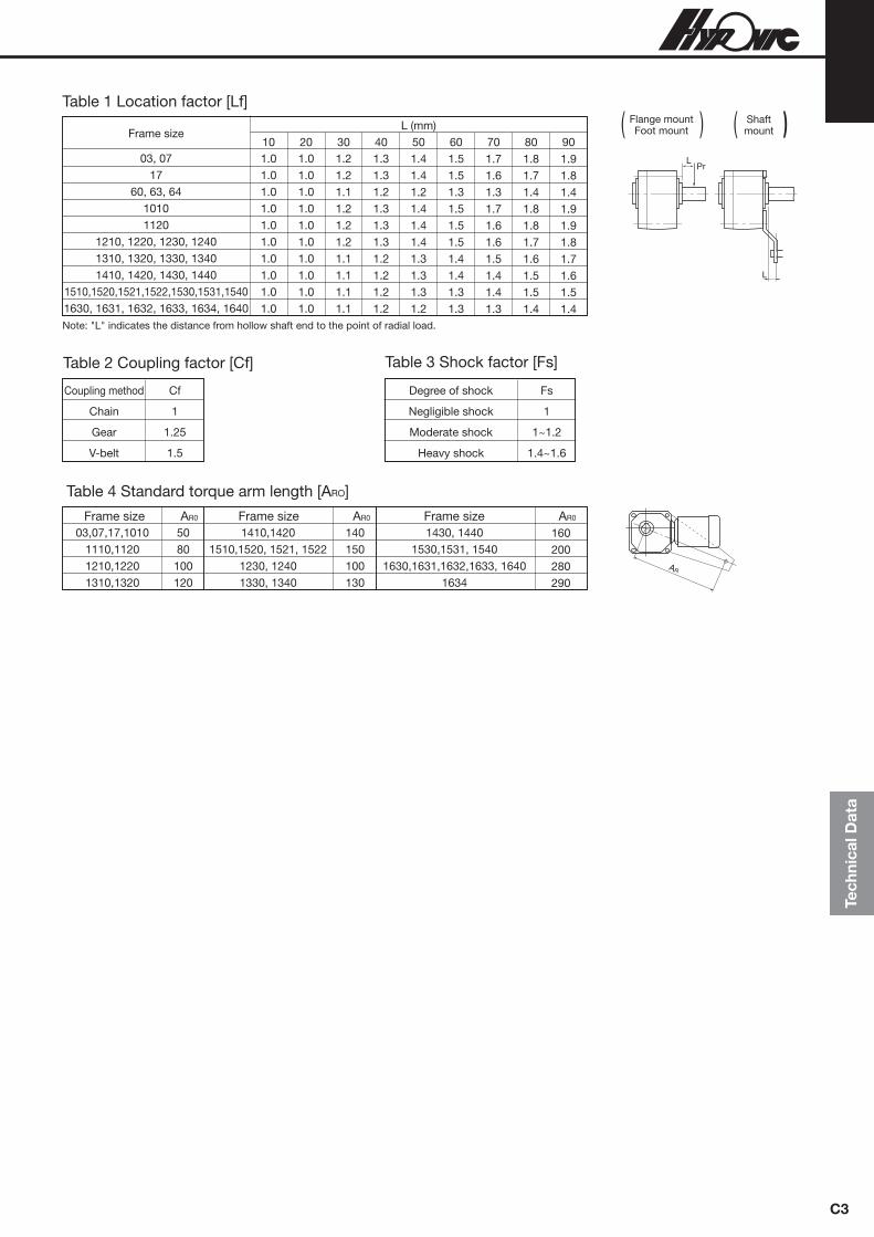
Tech
nica
l Dat
a
C3
AR
Table 1 Location factor [Lf]
Coupling method Cf
Chain 1
Gear 1.25
V-belt 1.5
Table 2 Coupling factor [Cf]
Degree of shock Fs
Negligible shock 1
Moderate shock 1~1.2
Heavy shock 1.4~1.6
Table 3 Shock factor [Fs]
03,07,17,10101110,11201210,12201310,1320
5080100120
Table 4 Standard torque arm length [ARO]
Note: "L" indicates the distance from hollow shaft end to the point of radial load.
Flange mount Foot mount
L
LPr
Shaftmount) ( ) (
Frame size AR0
1410,14201510,1520, 1521, 1522
1230, 12401330, 1340
140150100130
Frame size AR0
1430, 14401530,1531, 1540
1630,1631,1632,1633, 16401634
160200280290
Frame size AR0
Frame size
03, 0717
60, 63, 6410101120
1210, 1220, 1230, 12401310, 1320, 1330, 13401410, 1420, 1430, 1440
1510,1520,1521,1522,1530,1531,15401630, 1631, 1632, 1633, 1634, 1640
1.01.01.01.01.01.01.01.01.01.0
1.01.01.01.01.01.01.01.01.01.0
1.21.21.11.21.21.21.11.11.11.1
1.31.31.21.31.31.31.21.21.21.2
1.41.41.21.41.41.41.31.31.31.2
1.51.51.31.51.51.51.41.41.31.3
1.71.61.31.71.61.61.51.41.41.3
1.81.71.41.81.81.71.61.51.51.4
1.91.81.41.91.91.81.71.61.51.4
L (mm) 10 20 30 40 50 60 70 80 90

Selection procedure
C4
2. Solid shaft type
Selection
Example
T =50 [N·m]
Chain conveyor (uniform load)
10 hrs/day
50 [r/min]50 [Hz]3-phase motor
Indoor type Flange mount type
Check radial load
When the load is out of allowable range, use a bigger input power or frame size and check it again.
Pr (1110N)
Lf (1.0)
Cf (1.0)
Fs (1.0)
Pro(1520N)
Pr Pro Lf✕Cf✕Fs
(1110 1520
1.1✕1.0✕1.0
Note 1: Values and models in bracket ( ) for the selection example.Note 2: Refer to page C16 for the formula in case of axial load.
Table 5,6
Table 7
Table 8 Shock factor
Radial load location
Coupling
Actual radial load
●Sprocket pitch circle dia.90 [mm]Radius R=0.045 [m]
●Pr = TR = 50 R 0.045 =1110N
● Load point: L=20 [mm]
● Coupling: chain coupling
●Shock: negligible
●Flange mount
● Left (Viewed from motor)
Flange mount type (RNFM series)Foot mount type (RNHM series)
Model (05-1220 -30)
Refer to A15 and B10–B42 for nomenclature
Determine a model Mounting
Shaft direction
(RNFM-Flange mount)
(L-left)
Note.1
)
Selection tables
Page B88–B92
T : Actual transmitted torque on slow speed shaft of a gear motor [N.m]
Tout : Allowable output torque of a gear motor [N.m]
Te : Equivalent transmitted torque [N.m]Pr : Actual radial load [N]
Pro : Allowable radial load [N]Lf : Location factorCf : Coupling factorFs : Shock factor
Selectionprocedure
· ·
Confirm specifications and dimensions
●Confirm specifications: Refer to page A14. * Specify supply voltage and outdoor/indoor usage when placing your order.● Confirm dimensions: Refer to page B10–B42.
Motor type
Brake
3-phase
Without brake
Model (RNFM05-1220L–✕1– –30)
Model (RNFM05–1220L–✕1–30)
Determine equivalent transmittedtorque [Te]
Te=T ✕load factor of gear motor [N·m](50=50✕1.0)
Reduction ratio and output speed
T (50 N .m)
SF (1.0)
Te(50N .m)
Reduction ratio (30)
Table 9
Output speed n2r/min
50Hz 60Hz29020714512196.772.558.048.3
35025017514611787.570.058.3
Output speed, Power supply frequency
Actual transmitted torque
Load conditions, Operation time
* Motor sl ippage is not accounted for output speed
Selection tables
Page B88 –B92Tout
* In case SF is ✽, select the model Tout >= Te
Model (05-1220 -30)
Determine Model (input power, frame size and reduction ratio)
Select model Tout✕SF Te(67.3✕1.00 50)
service factor of gear motor )(*
>=
>=
<=
<=
Regarding selection of0.1kW–5.5kW please referto page B10–B42 for selection table

L
Pr
L
Pr
L
Pr
L
Pr
Tech
nica
l Dat
a
C5
Coupling method Cf
Chain 1
Gear 1.25
V-belt 1.5
Table 7 Coupling factor [Cf] Degree of shock Fs
Negligible shock 1
Moderate shock 1~1.2
Heavy shock 1.4~1.6
Table 8 Shock factor [Fs]
RNFM-X1 RNHM-J1
Frame Size
11201220132014201520123013301430
1530, 1531
L (mm)10
1.0 1.1 1.2 1.3 1.4 1.6 1.8 2.1 1.2 1.0 1.1 1.2 1.3 1.5 1.8 2.1 2.4 1.2 1.0 1.1 1.1 1.2 1.3 1.4 1.5 1.6 1.3 1.0 1.1 1.1 1.2 1.3 1.4 1.6 1.8 1.3 1.0 1.1 1.1 1.2 1.3 1.3 1.4 1.5 1.5 1.0 1.1 1.3 1.7 2.2 2.6 3.0 3.5 1.6 1.0 1.1 1.2 1.2 1.3 1.4 1.7 1.9 1.3 1.0 1.1 1.3 1.7 2.2 2.6 3.0 3.5 2.5 1.0 1.1 1.1 1.2 1.3 1.3 1.4 1.5 1.6
20 30 40 50 60 70 80 90
RNFM-P1, Q1
Frame Size
11201220132014201520123013301430
1530, 1531
L (mm)10
1.2 1.3 1.4 1.6 1.7 1.8 1.9 2.0 1.4 1.3 1.5 1.6 1.7 1.8 1.9 2.1 2.4 1.6 1.3 1.4 1.5 1.5 1.6 1.7 1.8 1.9 1.6 1.2 1.2 1.3 1.4 1.5 1.5 1.6 1.8 1.5 1.1 1.1 1.2 1.3 1.4 1.4 1.5 1.6 1.6 1.1 1.2 1.3 1.7 2.2 2.6 3.0 3.5 1.6 1.0 1.1 1.2 1.3 1.4 1.5 1.7 1.9 1.3 1.1 1.1 1.3 1.7 2.2 2.6 3.0 3.5 2.5 1.1 1.1 1.2 1.3 1.4 1.4 1.5 1.6 1.6
20 30 40 50 60 70 80 90
Table 6 Location factor [Lf]
(1) 15W–90W
Load location Lf
Shaft root 0.8
Shaft center 1.0
Shaft end 1.4
Table 5 Location factor [Lf]
(2) 0.1kW–2.2kW
RNFM–X1 RNHM–J1
RNFM–P1 RNFM–Q1

Selection procedure
C6
Uniform 1 1.25
Table 9 Service Factor [S.F.]
Operation time 10 hrs/ 10~24hrs/ Applications Load conditions day max. day max.
Conveyors (uniform load), Pumps (centrifugal), Food processing machine (rice polishers, canning machines), Elevators (uniform load), Plastic extruders, Agitators (pure liquid), Bar screens
Conveyors (variable speed and heavy duty), Food processing machine (peat slicer, dough mixer, meat grinder), Elevators (heavy duty), Agitators (liquid and solid, variable-density liquid), Feeders (belts, aprons, screws), Thickeners, Flocculators, Machine tools
Punching presses, Tapping machine, Crushers (crusher mills), Hoists (heavy duty), Drum barkers, Log hauls, Cutters, Platers
Moderate shock 1.25 1.5
Heavy shock 1.75 2.0
Note 1: The service factors and applications in the above table are only for your relerence. Actual applications and their characteristics may be variable.
3. Selection of load factorThe Load Factor is rated for the characteristics of the driven machine.
The tabulated ratings are based on a running time of 10 hours per day with uniform load.
For your reference, please see method and shown below.
Recommended Load Factor by the Driven Application.
Recommended Load Factor Modifications for Frequent Start-Stop Operation. Please select a model using Table 8 and check the motor thermal rating (Table 10).
Note : 1. The number of starts-stops includes brake or clutch operation times.
Note : 2. Consult us when starting under loaded conditions.
Table 10 Number of Starts-Stops and Load Factor.
I : Allowable ratio of Moment of Inertia (GD2) 0.3
II : Allowable ratio of Moment of Inertia (GD2) 3
III : Allowable ratio of Moment of Inertia (GD2) 10
The ratio of Moment of Inertia (The ratio of GD2) =Total Moment of Inertia (GD2) as seen from the motor shaft
Moment of Inertia (GD2) of motor
Number of starts-stops(Times/hour)
~10 1.00 1.15 1.50 1.20 1.30 1.65
1.10 1.35 1.65 1.30 1.50 1.85
1.15 1.50 1.80 1.40 1.65 2.00
~200
~500
I II III I II III
~10 hours/day 24 hours/day
<=
<=
<=

Tech
nica
l Dat
a
C7
Table 11 Motor thermal rating (C✕Z)
Output Motor
kW
0.1
0.2
0.25
0.4
0.55
0.75
1.1
1.5
2.2
3.0
3.7
5.5
3200
2200
2200
1800
1800
1400
1400
1200
1000
1000
800
300
3000
2800
2800
2200
2200
1400
1400
1200
900
900
800
300
2000
2800
2800
1500
1500
800
800
500
400
400
800
200
1200
2500
2500
1500
1500
500
500
400
200
200
700
150
0.00033
0.00050
0.00050
0.00065
0.00101
0.00120
0.00185
0.00213
0.00333
0.00700
0.00848
0.01143
0.00035
0.00055
0.00055
0.00068
0.00111
0.00130
0.00208
0.00235
0.00373
0.00810
0.00958
0.01253
0.0013
0.002
0.002
0.0026
0.00405
0.0048
0.0074
0.0085
0.0133
0.0281
0.0339
0.0457
0.0014
0.0022
0.0022
0.0027
0.00445
0.0052
0.0083
0.0094
0.0149
0.0325
0.0383
0.0501
Allowable C Z(35%ED)
Allowable C Z(35%ED~50ED%)
Allowable C Z(80%ED~100ED%)
Motor moment of inertia kgf . m2 Motor GD2 kgf.m2
Standard With brake Standard With brakeAllowable C Z(50%ED~80ED%)
Note : Contact us regarding a motor for inverters and a single-phase motor.
C✕Z calculated below to should be less than allowable C✕Z listed in Table 10.
(1) Obtain the C value.
(2) Obtain the Z value, number of starts per hour.
(3) Calculate C multiplied by Z.
C =GDM2 + GDL2
GDM2
GDM2 : Moment of inertia (kgf·m2) or GD2 (kg·m2) of motor.
GDL2 : Total moment of inertia (kgf·m2) or GD2 (kg·m2) of load as seen from the motor.
(a) Assume that one operating period consists of "on time" ta (sec), "off time" tb (sec)
and the motor is started nr (times/cycle)
(b) When inching, ni (times/cycle) is included in 1 cycle (ta+tb), the number of inching times per hour Zi,
and then included in the number of starts.
(c) Calculate Z (times/hr) by (a) and (b).
Use the C obtained in step and Z in step .
(4) Obtain the duty cycle %ED and check with table above.
%ED = ✕100t a
t a + t b
Z r = (times/hr)3600nrt a + t b
Z i = (times/hr)3600ni
t a + t b
Z =Z r+1/2 · Z i = (nr+ ni) (times/hr)3600 1
t a + t b 2

Construction
C8
Hollow shaft type example (RNYM1-1530-120)
DescriptionDescriptionDescriptionPart No. Part No. Part No. DescriptionPart No.
Casing (1)1 Gear4 Bearing7 Output shaft10
Gear2 Pinion shaft5 Bearing8 Oil seal11
Pinion shaft3 Hypoid pinion shaft6 Hypoid gear9 Casing (2)12

Tech
nica
l Dat
a
C9
Moment of inertia
(1) Moment of inertia of rotating motionRotating motion on the center of gravity Rotating motion off the center of gravity
General application
Horizontal motion
by conveyor
Vertical motion
by hoist
Horizontal motion
by lead screw
(2) Moment of inertia of rectilinear motion
(3) Calculation of moment of inertia at different rotating speeds
J= 18
MD2 [kg.m2]
J= 18 M (D2+d2) [kg.m2]
J= 112M (a2+b2) [kg.m2]
J= ( 12 D2+4R2 ) [kg.m2]
J= ( a2+b2
3 +4R2 ) [kg.m2]
J= 112M (4L2+C2) [kg.m2]
J= ( Vπ·Ns )
2
= D2 [kg.m2]
J= ( M1+M2
2 +M3+M4 ) 5D2 [kg.m2]
J= ( Vπ·Ns ) 2
= ( Pπ ) 2
[kg.m2]
J = ( Ns2
Ns1) 2
J
J=M1D2+ 1
8M2D2 [kg.m2]
JNs1(r/min)
Ns2 (r/min)Moment of inertia J
M4
M4
4
d [m]
D [m]
M [kg]
D [m]
M [kg]
M [kg]b [m]
a [m]
D dmfR dmf
M dkgf
R dmf
bdmfM dkgf
a dmf
L dmf M dkgf
c dmf
D [m]V [m/min]
Ns [r/min]
D [m]
D [m]
V [m/min]M3 [kg]
M4 [kgf]
M1 [kgf] M2 [kg]
Ns [r/min]
V [m/min]
M [kg] Ns [r/min]
Lead wire : P [m/rev]
D [m] V [m/min]
M1 [kgf
M2 [kg]
Ns [r/min]
M4
M4
M4
M4
M4

GD2
C10
(1) GD2 of rotating motionRotating motion on the center of gravity Rotating motion off the center of gravity
General application
Horizontal motion
by conveyor
Vertical motion by hoist
Horizontal motion
by lead screw
(2) GD2 of rectilinear motion
(3) Calculation of GD2 at different rotation speeds
GD2= 12 WD2 [kg.m2]
GD2= 12 W (D2+d2) [kg.m2]
GD2= 13 W (a2+b2) [kg.m2]
GD2=W ( 12 D2+4R2 ) [kg.m2]
GD2=W ( a2+b2
3 +4R2 ) [kg.m2]
GD2= 13 W (4L2+C2) [kg.m2]
GD2=W ( Vπ · N ) 2
=WD2 [kg.m2]
GD2= ( W1+W2
2+W3+W4 ) ✕D2 [kg.m2]
GD2=W ( Vπ · N ) 2
=W ( Pπ ) 2
[kg.m2]
GD 2= ( N2
N1) 2
GD2
GD2=W1D2+ 12 W2D2 [kg.m2]
GD 2N1(rpm)
N2(rpm)Load GD2
D [m]W [kgf]
d [m]
D [m]
W [kgf]
W [kgf]b [m]
a [m]
D [m] R [m]
W [kgf]
R [m]
b [m]
a [m]
W [kgf]
L [m]
c [m]
W [kgf]
D [m]V [m/min]
N [rpm]
D [m]
D [m]
V [m/min]W3 [kgf]
W4 [kgf]
W1 [kgf] W2 [kgf]
N [rpm]
V [m/min]
W [kgf] N [rpm]
Lead wire : P [m/rev]
D [m] V [m/min]W1〔kgf]
W2 [kgf]
N [rpm]

3.7kW 5.5kW
Tech
nica
l Dat
a
C11
Table 12
Note 1. Moment of inertia/GD2 on reducer and motor accounted for the value stipulated in the tables.Note 2. The values in the tables are subject to change without notice.
Motor type
Indoor
Indoor
Water proof
Water proof
Without brakeWith brake
Without brakeWith brake
Motor frame size
Motor frame size
Without brakeWith brake
Without brakeWith brake
3-phase
Single-phase Single-phase reversible
3-phase
Single-phase Single-phase reversible
3-phase
Single-phase Single-phase reversible
3-phase
Single-phase Single-phase reversible
15W 25W 40W
01#, 03# 01#, 03# 05#, 07# 17#
Moment of inertia
Moment of inertia
GD2
GD2
kg·m2
kg·m2
0.000050 0.00020 0.000070 0.00028 0.000050 0.00020 0.000070 0.00028 0.000050 0.00020 0.000070 0.00028 0.000050 0.00020 0.000070 0.00028
0.000058 0.00023 0.000078 0.00031 0.000058 0.00023 0.000078 0.00031 0.000058 0.00023 0.000078 0.00031 0.000058 0.00023 0.000078 0.00031
0.000070 0.00028 0.000090 0.00036 0.000070 0.00028 0.000090 0.00036 0.000070 0.00028 0.000090 0.00036 0.000070 0.00028 0.000090 0.00036
0.00011 0.00043 0.00012 0.00047 0.00015 0.00058 0.00015 0.00061 0.00011 0.00043 0.00012 0.00047 0.00015 0.00058 0.00015 0.00061
kgf·m2
kgf·m2
Moment of inertia
Moment of inertia
GD2
GD2
kg·m2
kg·m2
kgf·m2
kgf·m2
Moment of inertia
Moment of inertia
GD2
GD2
kg·m2
kg·m2
kgf·m2
kgf·m2
Moment of inertia GD2
kg·m2 kgf·m2
Motor type
Without brakeWith brake
Without brakeWith brake
Without brakeWith brake
Without brakeWith brake
60W 90W
07# 17# 15#,17# 36#, 361# 0.000070 0.00028 0.000090 0.00036 0.000070 0.00028 0.000090 0.00036 0.000070 0.00028 0.000090 0.00036 0.000070 0.00028 0.000090 0.00036
0.00012 0.00049 0.00013 0.00052 0.00016 0.00065 0.00017 0.00068 0.00012 0.00049 0.00013 0.00052 0.00016 0.00065 0.00017 0.00068
0.00015 0.00058 0.00016 0.00062 0.00021 0.00083 0.00022 0.00086 0.00015 0.00058 0.00016 0.00062 0.00021 0.00083 0.00022 0.00086
Moment of inertia GD2
kg·m2 kgf·m2
0.00033 0.0013 0.00035 0.0014 – – – – – – – – – – – –
Motor type
Indoor
OutdoorLight dust
proof
Protected explosion proof
Without brakeWith brake for FBWithout brakeWith brake for FBWithout brakeWith brake for FBWithout brakeWith brake forFBWithout brakeWith brake for FBWithout brakeWith brake for FBWithout brake
3-phase
Single-phase
For inverter
3-phase
Single-phase
For inverter
3-phase
0.1kW 0.2kW 0.25kW 0.4kW 0.55kW
Moment of inertia GD2
kg·m2
0.00033 0.0013 0.00035 0.0014 0.00050 0.0020 0.00055 0.0022 0.00050 0.0020 0.00055 0.0022 0.00033 0.0013 0.00035 0.0014 0.00050 0.0020 0.00055 0.0022 0.00050 0.0020 0.00055 0.0022 0.00033 0.0013
0.00050 0.0020 0.00055 0.0022 0.00065 0.0026 0.00068 0.0027 0.00065 0.0026 0.00068 0.0027 0.00050 0.0020 0.00055 0.0022 0.00065 0.0026 0.00068 0.0027 0.00065 0.0026 0.00068 0.0027 0.00050 0.0020
0.00065 0.0026 0.00068 0.0027 – – – – – – – – 0.00065 0.0026 0.00068 0.0027 – – – – – – – – – –
0.00065 0.0026 0.00068 0.0027 0.00120 0.0048 0.00130 0.0052 0.00120 0.0048 0.00130 0.0052 0.00065 0.0026 0.00068 0.0027 0.00120 0.0048 0.00130 0.0052 0.00120 0.0048 0.00130 0.0052 0.00065 0.0026
0.00101 0.00405 0.00111 0.00445 – – – – – – – – 0.00101 0.00405 0.00111 0.00445 – – – – – – – – – –
kgf·m2
Moment of inertia GD2
kg·m2 kgf·m2
Moment of inertia GD2
kg·m2 kgf·m2
Moment of inertia GD2
kg·m2 kgf·m2
Moment of inertia GD2
kg·m2 kgf·m2
Motor type
Indoor
OutdoorLight dust
proofProtected
explosion proof
Without brakeWith brake for FBWithout brakeWith brake for FBWithout brakeWith brake for FBWithout brakeWith brake for FBWithout brake
3-phase
For inverter
3-phase
For inverter
3-phase
0.75kW 1.1kW 1.5kW 2.2kW 3.0kW
Moment of inertia GD2
kg·m2
0.00120 0.0048 0.00130 0.0052 0.00213 0.0085 0.00235 0.0094 0.00120 0.0048 0.00130 0.0052 0.00213 0.0085 0.00235 0.0094 0.00120 0.0048
0.00185 0.0074 0.00208 0.0083 – – – – 0.00185 0.0074 0.00208 0.0083 – – – – – –
0.00213 0.0085 0.00235 0.0094 0.00333 0.0133 0.00373 0.0149 0.00213 0.0085 0.00235 0.0094 0.00333 0.0133 0.00373 0.0149 0.00213 0.0085
0.00333 0.0133 0.00373 0.0149 0.00848 0.0339 0.00958 0.0383 0.00333 0.0133 0.00373 0.0149 0.00848 0.0339 0.00958 0.0383 0.00333 0.0133
0.00703 0.0281 0.00813 0.0325 – – – – 0.00703 0.0281 0.00813 0.0325 – – – – – –
kgf·m2
Moment of inertia GD2
kg·m2 kgf·m2
Moment of inertia GD2
kg·m2 kgf·m2
Moment of inertia GD2
kg·m2 kgf·m2
Moment of inertia GD2
kg·m2 kgf·m2
Motor type
Indoor
OutdoorLight dust
proofProtected
explosion proof
Without brakeWith brake for FBWithout brakeWith brake for FBWithout brakeWith brake for FBWithout brakeWith brake for FBWithout brake
3-phase
For inverter
3-phase
For inverter
3-phase
Moment of inertia GD2
kg·m2
0.00848 0.0339 0.00958 0.0383 0.0114 0.0457 0.0125 0.0501 0.00848 0.0339 0.00958 0.0383 0.0114 0.0457 0.0125 0.0501 0.00848 0.0339
0.0114 0.0457 0.0125 0.0501 0.0268 0.107 0.0303 0.121 0.0114 0.0457 0.0125 0.0501 0.0268 0.107 0.0303 0.121 0.0114 0.0457
kgf·m2
Moment of inertia GD2
kg·m2 kgf·m2
7.5kW 11kW
Moment of inertia GD2
kg·m2
0.0268 0.107 0.0303 0.121 0.0375 0.150 0.0410 0.164 0.0268 0.107 0.0303 0.121 0.0375 0.150 0.0410 0.164 0.0268 0.107
0.0375 0.150 0.0410 0.164 – – – – 0.0375 0.150 0.0410 0.164 – – – – 0.0375 0.150
kgf·m2
Moment of inertia GD2
kg·m2 kgf·m2
Moment of inertia and GD2 of gear motors

Rotating direction & Reduction ratio
C12
RNYM series
Frame size
01,03,05,07 15,17 1240
Reduction ratio
Motor shaft will be rotating clockwise looking from the fan cover side when wire is connented as shown in connection figure in page
168–169.
The direction of output shaft rotation will be as in the arrows of diagrams below.
RNFM seriesRNFM series
a. 3-phase motor (15W–90W)
RNYM series
Reduction ratio
5, 80, 100, 120, 160, 200, 2405, 7.5, 10, 12, 80, 100, 120, 150, 200, 240300, 360, 480, 600, 720, 900, 1200, 1440
01,03,05,07 15,17 1240
Frame size
7.5, 10, 12, 15, 20, 25, 30, 40, 50, 6015, 20, 25, 30, 40, 50, 60
—

R type L type
T type
R type L type
T type
Tech
nica
l Dat
a
C13
Motor shaft will be rotating counterclockwise looking from the fan cover side when wire is connented as shown in connection figure in
page 168–173.
The direction of output shaft rotation will be as in the arrows of diagrams below.
b. 3-phase motor and motor for inverter (0.1kW–5.5kW)
RNYM seriesRNYM series
Frame size Reduction ratio
1010 1110 1120 1210 1220 1230 1240 1310 1320 1330 1340 1410 1420 1430 1440 1510 1520 1521 1522 1530 1531 1540 1630 1631 1632 1633 1634 1640
——
5, 7, 10, 12, 15, 20, 25, 30, 40, 50, 60—
5, 7, 10, 12, 15, 20, 25, 30, 40, 50, 60—
300, 360, 480, 600, 720, 900, 1200, 1440—
5, 7, 10, 12, 15, 20, 25, 30, 40, 50, 60—
300, 360, 480, 600, 720, 900, 1200, 1440—
5, 7, 10, 12, 15, 20, 25, 30, 40, 50, 60—
300, 360, 480, 600, 720, 900, 1200, 1440—
5, 7, 10, 12, 15, 20, 25, 30, 40, 50, 605, 7, 10, 12, 15, 20, 255, 7, 10, 12, 15
——
300, 360, 480, 600, 720, 900, 1200, 1440——
3020, 255, 7, 10, 12, 15300, 360, 480, 600, 720, 900, 1200, 1440
1010 1110 1120 1210 1220 1230
1310 1320 1330
1410 1420 1430
1510 1520
1530 1531
1630 1631 1632 1633 1634 1640
5, 7, 105, 7, 10
—5, 7, 10
—80, 100, 120, 150, 200, 240
5, 7, 10—
80, 100, 120, 150, 200, 240
5, 7, 10—
80, 100, 120, 150, 200, 240
5, 7, 10—
80, 100, 120, 150, 200, 24040, 50, 60, 80
80, 100, 120150, 200, 24040, 50, 6030, 4020, 25
—
Frame size Reduction ratio
RNFM seriesRNFM series
RNHM seriesRNHM series

R type L type
T type
R type L type
T type
C14
RNYM seriesRNYM series
Frame size Reduction ratio Frame size Reduction ratio
Motor shaft will be rotating clockwise looking from the fan cover side when wire is connented as shown in connection figure in page
163–167.
The direction of output shaft rotation will be as in the arrows of diagrams below.
RNFM seriesRNFM series
RNHM seriesRNHM series
c. Single-phase motor
01,03,05,07 15,17 1110 1120 1210 1220 1240 1310 1320 1330 1340 1420 1430 1440 1530 1540 1640
5, 80, 100, 120, 160, 200, 2405, 7.5, 10, 12, 80, 100, 120, 150, 200, 240
—5, 7, 10, 12, 15, 20, 25, 30, 40, 50, 60
—5, 7, 10, 12, 15, 20, 25, 30, 40, 50, 60300, 360, 480, 600, 720, 900, 1200, 1440
—5, 7, 10, 12, 15, 20, 25, 30, 40, 50, 60
—300, 360, 480, 600, 720, 900, 1200, 14405, 7, 10, 12, 15, 20, 25, 30, 40, 50, 60
—300, 360, 480, 600, 720, 900, 1200, 1440
—300, 360, 480, 600, 720, 900, 1200, 1440300, 360, 480, 600, 720, 900, 1200, 1440
01,03,05,07 15,17 1110 1120 1210 1220
1310 1320 1330
1420 1430
1530
1640
7.5, 10, 12, 15, 20, 25, 30, 40, 50, 6015, 20, 25, 30, 40, 50, 605, 7, 10
—5, 7, 10
—
5, 7, 10—
80, 100, 120, 150, 200, 240
—80, 100, 120, 150, 200, 240
80, 100, 120, 150, 200, 240
—

Tech
nica
l Dat
a
Actual reduction ratio
C15
Table 13 Actual reduction ratio RNYM, RNFM, RNHM series (Reduction raito: 5~240)
Frame sizeReduction ratio
55.015.005.005.005.005.005.005.005.005.005.005.005.005.005.06
4.90
7
7.007.007.007.007.007.007.037.037.036.977.037.037.00
7.13
7.57.507.50
1010.0010.1810.0010.0010.0010.0010.0010.009.819.819.81
10.009.819.81
10.00
10.02
1212.2712.00
11.7411.7411.7411.9611.7411.7412.21
11.97
1515.0015.00
15.2615.2615.2614.7515.2615.2615.25
15.09
2020.0020.36
20.6720.6720.6719.6920.6720.67
20.8820.07
2524.5525.42
24.6224.6224.6225.0024.6224.62
24.3325.29
3030.0030.48
30.0030.0030.0030.4530.00
29.2429.40
4040.0040.00
41.3341.3341.3339.3841.33
39.20
41.1640.25
5050.0050.71
49.2349.2349.2350.0049.23
49.88
49.0051.47
6060.9160.83
60.0060.0060.0060.9160.00
57.60
56.3559.50
8080.0080.00
81.4581.9480.3779.6377.4280.50
100100.00103.16
101.01102.27102.35101.32
102.94
120121.82120.00
120.15122.54122.64119.17
119.00
150
152.14
151.51153.40153.52149.65
154.41
160160.0
200200.00195.61
200.39199.13199.29188.57
195.42
240243.64234.64
231.27232.50240.00232.25
244.07
03 07 17 1010 1110 1210 1310 1410 1510 1120 1220 1320 1420 1520 1521 1522 1230 1330 1430 1530 1531 1630 1631 1632 1633 1634
Frame sizeReduction ratio
300297.57302.72301.12311.59297.68
360346.15360.10360.81373.36350.10
480485.71479.79498.18502.52475.66
600626.32595.00621.72602.13605.28
720728.57707.78744.97753.78711.87
900923.72892.50932.59903.20907.91
12001159.411180.451210.571194.571144.07
14401424.621382.221413.281403.081396.15
1240 1340 1440 1540 1640
Note: The values in the tables are subject to change without notice.
Table 14 Actual reduction ratio RNYM series (Reduction raito: 300~1440)

Allowable axial load on output shaft (Pao) [N/kgf]
Table 15 Allowable axial load on output shaft (3/single-phase)
C16
Frame size
01, 03, 05, 07
15, 17
1010, 1110, 1210, 1310, 1410, 1510
1120
1220, 1230
1320, 1330
1420, 1430
1520, 1521, 1522, 1530, 1531
1630, 1631, 1632, 1633, 1634, 1640
When radial and axial loads are posed simultaneously.
Note: Radial load on output shaft not accounted for in the calculation above.
( )Pr · LfPro Pao
Pa+ · Cf · Fs 1
Check your selection to be within the formula.
Lubrication
Pr : Actual radial loadPro : Allowable radial load (refer to selection tables)Pa : Actual axial loadPao : Allowable axial loadLf : Load location factor (refer to Table 1 of page 131, Table 5, 6 of page 133 )Cf : Coupling factor (refer to Table 2 of page 131, Table 7 of page 133)Fs : Shock factor (refer to Table 3 of page 131, Table 8 of page 133)
N/kgf
294N/30kgf
294N/30kgf
0N/0kgf
294N/30kgf
784N/80kgf
980N/100kgf
1470N/150kgf
2940N/300kgf
5390N/550kgf
20,000 hours or 3~5 years of operation will provide longer service life.
three years of operation under severe conditions.
<=

Tech
nica
l Dat
a
C17
Detail dimensions
Hollow shaft type (RNYM series) output shaft bore size
● Standard Semi-standard (Contact us for price and delivery.)
Bore (mm)
A-A
J
H
B B
A
F
G
E
C
D
L (Recommended length of driven shaft)
L (Recommended length of driven shaft)
Bore diameter
A
A
Frame size
03, 071710101110, 1120
1210, 1220
1230, 1240
1310, 1320, 1330,1340
1410, 1420, 1440
1430
1510, 1520, 1521, 1522, 1530, 1531, 1540
1630, 1631, 1632,1633, 1634, 1640
15 78 28 — — — 15.6 R1.0 5 17.3 55 20 15 94 28 — — — 15.6 R1.0 5 17.3 70 35 15 82 28 — — — 15.6 R1.0 5 17.3 60 20 20 82 30 21 16 1.15 20.6 R1.0 6 22.8 60 20 20 92 31 21 15 1.15 20.6 R1.5 6 22.8 65 55 25 92 38 26.2 22 1.35 25.6 R1.5 8 28.3 60 40 20 100 31 21 15 1.15 20.6 R1.5 6 22.8 75 55 25 100 38 26.2 22 1.35 25.6 R1.5 8 28.3 65 40 20 110 31 21 15 1.15 20.6 R1.5 6 22.8 85 75 25 110 38 26.2 22 1.35 25.6 R1.5 8 28.3 80 55 30 110 46 31.4 22 1.35 30.6 R1.5 8 33.3 70 45 25 138 38 26.2 22 1.35 25.6 R1.5 8 28.3 105 80 30 138 46 31.4 22 1.35 30.6 R1.5 8 33.3 95 65 35 138 52 37 26 1.75 35.6 R1.5 10 38.3 90 50 25 138 38 26.2 22 1.35 25.6 R1.5 8 28.3 105 80 30 138 46 31.4 22 1.35 30.6 R1.5 8 33.3 95 65 35 138 52 37 26 1.75 35.6 R1.5 10 38.3 90 50 38 138 58 40 26 1.75 38.6 R1.5 10 41.3 90 50 30 156 (160) 46 31.4 22 1.35 30.6 R1.5 8 33.3 130 (135) 115 35 156 (160) 52 37 26 1.75 35.6 R1.5 10 38.3 115 (120) 100 38 156 (160) 58 40 26 1.75 38.6 R1.5 10 41.3 110 (115) 90 40 156 (160) 60 42.5 30 1.95 40.6 R1.5 12 43.3 105 (110) 85 45 156 (160) 67 47.5 30 1.95 45.6 R1.5 14 48.8 100 (105) 70 40 224 60 42.5 30 1.95 40.6 R1.5 12 43.3 180 155 45 224 67 47.5 30 1.95 45.6 R1.5 14 48.8 175 120 50 224 76 53 30 2.2 50.6 R1.5 14 53.8 165 110 55 224 85 58 40 2.2 55.6 R2.5 16 59.3 155 90
Bore A B C D E F G H J LEffective length of
driven shaft
(mm)
Frame size
03, 07, 17, 1010
1110, 1120
1210, 1220, 1230, 1240
1310, 1320, 1330, 1340
1410, 1420, 1440
1430
1510, 1520, 1521, 1522, 1530, 1531, 1540
1630, 1631, 1632, 1633, 1634, 1640
15 20 25 30 35 38 40 45 50 55
●
●
●
●
●
●
●
●
Keyway dimensions in accordance with JIS B 1301-1996 parallel key (Normal Grade). Bore dimension tolerance in accordance with JIS B 0401-1976 "H8".
Output shaft dimensions

Hollow shaft type (RNYM series) handling precautions
C18
1. Mounting torque arm(1) Mounting on driven shaft ● Apply molybdenum disulfide to the
surface of the driven shaft and the inside of the hollow shaft, and insert Hyponic Drive onto the driven shaft.
● When engagement is too tight, lightly strike on the end of the hollow output shaft with a mallet. Never strike on the casing. It is recommended to make a jig shown on the right for smooth insertion.
● The hollow shaft dimension tolerance is in accordance with JIS "H8". The recommended tolerance for the driven shaft is :
uniform load without impact..............................JIS h6 or js6 shock load or large radial load..........................JIS js6 or k6 ● Snap ring size is in accordance with JIS B2804C.
(2) Hyponic Drive must be secured to driven shaft.
a) How to secure Hyponic Drive not to move to the machine side (Ex.: Figs.2~4)
e
cba
d
SpacerBearing unit Stopper ringSet screw
Mac
hine
sid
e
Mac
hine
sid
e
Mac
hine
sid
e
Fig. 2 secured by staged shaft Fig.3 secured by spacer (stageless driven shaft)
Fig. 1
......Retaining ring
......Spacer
......Thrust bearing
......Nut
......Double-end threaded bolt
Fig. 4 secured by a set screw and a stopper (stageless driven shaft)

Tech
nica
l Dat
a
C19
Frame size Bolt
03 M5
07, 17, 1010, 1110, 1120 M6
1210, 1220,1230, 1240 M8
1310, 1320, 1330, 1340, 1410, 1510 M10
1420, 1430, 1440, 1520, 1521, 1522, 1634 M12
1410, 1510, 1530,1531,1540 M16
1630, 1631, 1632, 1633, 1640 M20
(3) Torque arm whirl stop
Attach the torque arm to Hyponic Drive casing on the machine side with hex socket head cap screws. (Refer to the table below for sizes of the bolts.).
Leave some allowance in the section of torque arm whirl stop so that excessive force will not be applied between Hyponic Drive and the driven shaft. Don't secure the torque arm with the whirl stop bolt. Or it may damage the whirl stop bolt, the torque arm, Hyponic Drive, or the machine.
In case of frequent start/stop operations, or repeated normal/reverse operations, use a rubber bush between the torque arm and mounting bolt (or spacer) to absorb the shock.
Torque arm
Special bolt(or pin)
SpacerKeep someallowance
Rubber bushNo allowance between thetorque arm and the machine
Plain washer
A
Mac
hine
sid
e
Fig. 8 Example of whirl stop mounting (Section A)
Fig. 5 secured by a spacer and a snap ring Fig. 6 secured by an end plate Fig. 7 secured by a set screw and a stopper ring
b) How to secure Hyponic Drive not to move off from the machine side (Figs. C5-C7)
Stopper ring
Set screwEnd plateSpacerSnap ring
Mac
hine
sid
e
Mac
hine
sid
e
Mac
hine
sid
e
( Adjust the allowance according to the movement of the machine.)
( Excessive force on the whirl stop bolt, machine, and Hyponic Drive may cause damage.)
Good Bad

Good Bad Bad
Bearing unit
Hollow shaft typeHyponic Drive
Bearing unit
Hollow shaft typeHyponic Drive
(Poor concentricity of the driven shaft and mounting faucet)
(Excessive force on Hyponic and the bearing unit may cause damage on inner parts.)
(Poor perpendicularity of the driven shaft center and mounting flange surface)
Bearing unit
Hollow shaft typeHyponic Drive
Hollow shaft type (RNYM series) handling precautions
C20
(4) Removal from a driven shaft
Handle with care so that exces-sive force will not be applied between the casing and the hollow shaft. It is recommended to make a jig as shown on the right for easy removal.
Fig. 9
Fig. 10 Flange mounting surface
gh A A~
i
f
......Spacer
......Upper bolt
......Disc
......Snap ring
Note:Parts for mounting, securing, and removal should be provided by the customer.
Handle with care in order not to apply excessive force to driven shaft or hollow shaft by twisting the Hyponic casing.
2. Flange mounting and casing bottom mounting (optional)

03
07, 17
1010
1110
1210
1310
1410
1510
1120
1220
1320
1420
1520, 1521, 1522
1230, 1240
1330, 1340
1430, 1440
1530, 1531, 1540
1630, 1631, 1632, 1633, 1640
1634
Tech
nica
l Dat
a
Torque arm (Option)
C21
· There is an option for attaching torque arms. They can be used for continuous operations and cases where there are infrequent
startup and stops.
· Refer to "Hollow shaft type handling precautions (146–148)" when mounting.
· Torque arm cannot be attached between hollow shaft and motor.
· Refer to "Torque arm designs (150)" and "Examples of torque arm designs (151)" when designing for cases when customers are
preparing their own torque and, when startup and stop is frequent, or torque arm is going to be attached on the motor side. Mount
torque arm to reducer casing using 4 bolts.
2- d
ARD T
R3
R2
R2
R1
La
b
H
D
C
290
30
R45R110
165
30 40
445
220
30H9
140
ARD C
L
H
ba
C
L
H
ba
ARD
C
L
H
ba
Torque arm shape
Dimensions
Assenbly Example
Notes:· Use torque arm only for whirl stop function.· Fasten reducer at driven shaft for fixing in axial direction.
Frame size a b C D H L d1 d2 R1 R2 R3 T
33.2 33.2 46.8 – 61.8 78.4 6 6 – 6 9 3.2
36.8 36.8 53.2 18.8 70.7 87.6 7 7 26 7 10.5 3.2
25 25 25 25 45.5 64 7 9 26 7 13.5 3.2
29 29 51 29 72.5 74 7 9 28 8 13.5 3.2
37 37 63 37 88.5 92 9 11 41 9 16.5 4.5
44 44 76 44 108 110 11 14 44.5 11 21 4.5
55 55 85 55 123 132 11 18 49.5 11 27 6
65 65 85 65 130 154 11 22 57 12 33 9
42 32 48 32 69.5 90 7 9 28 8 13.5 3.2
57 40 60 40 85.5 115 9 11 41 9 16.5 4.5
62 46 74 46 107 132 11 14 44.5 12 21 4.5
75 57 83 57 123 158 14 18 49.5 13 27 6
80 70 80 – 127 178 14 22 – 14 33 9
65 40 60 40 82.5 123 9 9 41 9 13.5 3.2
79 47 83 47 110.5 148 11 11 45 11 21 6
92 54 106 54 141 174 14 14 50 14 21 6
109 64 136 64 181 209 18 18 60 18 27 9
145 85 195 85 250 274 22 22 80 22 33 12
(For 1634)
10゚
60°
See the above figure.
(For 1634)

G
G
R R
Y
m
YR
GARA
Sec. B
Brg1
Brg2Driven shaft
Torque arm
rotationrotation
3.2
3.2
4.5
3.2
3.2
3.2
3.2
4.5
6
4.5
4.5
9
6
6
9
9
9
9
12
16
80
90
90
50
80
80
100
100
100
120
120
130
140
140
160
150
150
200
280
290
6
7
7
7
7
7
9
9
9
11
11
11
11
14
14
11
14
18
22
14
48
55
55
—
—
—
—
—
—
—
—
—
—
—
—
—
—
—
—
60°
18
19
19
25
29
32
37
40
40
44
46
47
55
57
54
65
70
64
85
20°
33
37
37
25
29
42
37
57
65
44
62
79
55
75
92
65
80
109
145
165
6
7
7
9
9
9
11
11
9
14
14
11
18
18
14
18
22
18
22
33
37
37
37
50
54
54
80
80
80
87
87
87
97
97
97
112
112
112
152
142
03
07
17
1010
1110
1120
1210
1220
1230, 1240
1310
1320
1330, 1340
1410
1420
1430, 1440
1510
1520
1530, 1531, 1540
1630,1631,1632,1633,1640
1634
Torque arm designs
C22
Table. 16 Recommended dimensions of torque arm design
Mounting pitches
a b c
Length
AR
Bore
H
Whirl stop bore
D
Mounting bore
dThickness
(mm)
Frame size
Check the strength of torque arm and driven shaft and the life time of the bearing.
Frame size AG
03, 07, 17 0.05
1010, 1110, 1230, 1240 0.1
1120, 1210, 1220, 1310, 1330, 1340 ,1430, 1440 0.15
1320, 1410, 1430, 1510, 1540 0.2
1420, 1520, 1530, 1531, 1640 0.25
1630, 1631, 1632, 1633 0.30
approximate values
(m)
1. Torque arm load : R = T+AG·GAR
2. Brg.1 load : B1 = m (R–G) –YR·R
3. Brg.2 load : B2 = (R+m) (R–G) –YR·R
4. Sec. B of driven shaft
: M=YR·R–Y (R–G) 0<Y m
T : Output torque [N·m]G : Hyponic Drive gravity [N]R : Torque arm load [N]AG : Distance between the centers of the driven shaft and gravity [m]AR : Distance from driven shaft center to torque arm whirl stop [m]YR : Distance from the center of Hyponic Drive to torque arm whirl stop [m]m : Distance from the center of Hyponic Drive to Brg 2 [m]R : Distance between Brg.1 and Brg.2 [m]Y : Distance between the center of Hyponic Drive and Sec. B [m]
Note: Output torque is (+) on the shown rotation, and (-) on the opposite rotation. <=

D
D
D
d
d
dc
b
aa
cb
aa
A R
H
D
d
cb
aa
H
HH cb
a aA
R
AR
A R
aD
HAR
b
ab
d
a D
HAR
b
ab
d
Tech
nica
l Dat
a
C23
Fig. 11 Torque arm mountings and designs
Attach the torque arm to the casing on the machine side.
Machine side
Machine side
1 2 3 4
030717
Mou
ntin
g ex
amp
les
Dra
win
g ex
amp
les
11201220123013201331, 36114201430, 46115201530, 1531, 5660, 63, 64
1634
Dra
win
g ex
amp
les
Dra
win
g ex
amp
les
AR
D
H abc
d
AR
D
H a
bc
d
AR
D
Ha
bc
d
AR
D
Ha
bc
d

13
12
14
———
M3✕0.5✕6M3✕0.5✕6M3✕0.5✕6M3✕0.5✕6M5✕0.8✕10M5✕0.8✕10
252530404555659595
10 72 28 R5 2 — — 10 52 45 R3 2 — — 10 56 45 R3 2 — — 21 59 5 R5 2 70 2 21 67 5 R5 2 78 2 30 77 5 R5 2 88 2 30 90 5 R5 2 103 2 40 114 5 R5 2 135 2 40 114 5 R5 1.2 130 2
03, 07, 1710101110, 11201210, 1220, 1230, 12401310, 1320, 1330, 13401410, 1420, 1430, 14401510, 1520, 1521, 1522, 1530, 1531, 15401630, 1631, 1632, 1633, 16401634
Detail dimensions of output shaft safety cover (separate shipment)
C24
● It may be mounted on either the left or right side.● Made of plastics
φP
.C.D
Ct
A
D
C
t
A
D
t
A
D
E E EB B B
C
Fig. 12 Fig. 13 Fig. 14
M : Screw size P : Thread pitch L : Thread length P.C.D : Mounting pitch N : Q'tyNote 1: The values are subject to change without notice.Note 2: No screw is required for safety cover for frame size 03, 07, 17, 1010 and 1120.Note 3: Contact us when safety covers are required.
DimensionsFrame size A B C° D t P.C.D N
Safety coverM✕P✕L
Output shaft endE
Fig.
(mm)

Tech
nica
l Dat
a
C25
Tolerance(h6)
DimensionsFrame size
D1
10
15
12
15
15
18
18
22
28
32
40
D2
0 -0.009 0 -0.011 0 -0.011 0 -0.011 0 -0.011 0 -0.011 0 -0.011 0 -0.013 0 -0.013 0 -0.016 0 -0.016
S 1 t ToleranceTolerance2
(Key)3h
(Key)b (Key) Tolerance(h9)
Detail dimensions of output shaft (X1, J1)
Note: Keyway dimensions in accordance with JIS B 1301-1996 parallel keyway (Normal Grade).
b
t h
D1
D2
R1
R2
R3
S
Name plate
MODEL
JP
J APAN
RATIO
VOLTSkW P φ TYPE
FRAME
TIME RATINGM/B INS.CLASS
JISC4004B.TORQUE N m
HzM.AMPr/minB.AMPSERIAL NO.
AM446516
12
3
4 5
R
Model name of gear motor (refer to page A15)
Reduction ratio
· Input power
· Input features
Manufacturing serial No.
Motor type
Brake type
· Brake features
01
03
05
07
15
17
1120
1220, 1230
1320, 1330
1420, 1430
1520, 1530, 1531
29
31
29
31
31
31
28
36
42
58
82
25
25
25
25
25
25
25
30
35
45
55
—
—
—
—
—
—
M6
M6
M8
M8
M10
—
—
—
—
—
—
12
12
16
16
18
2.5
3
2.5
3
3
3.5
3.5
3.5
4
5
5
4
5
4
5
5
6
6
6
8
10
12
+0.1 0 +0.1 0 +0.1 0 +0.1 0 +0.1 0 +0.1 0 +0.1 0 +0.1 0 +0.2 0 +0.2 0 +0.2 0
0 -0.030 0 -0.030 0 -0.030 0 -0.030 0 -0.030 0 -0.030 0 -0.030 0 -0.030 0 -0.036 0 -0.036 0 -0.043
4
5
4
5
5
6
6
6
7
8
8
0 -0.030 0 -0.030 0 -0.030 0 -0.030 0 -0.030 0 -0.030 0 -0.030 0 -0.030 0 -0.090 0 -0.090 0 -0.090
22
22
22
22
22
22
22
32
35
50
70
25
25
25
25
25
25
25
35
39
55
76

0.1 0.34 235 230 1.3 1420 0.36 261 261 1.3 1430 0.37 281 286 1.4 1430
0.2 0.61 210 206 2.2 1410 0.62 233 236 2.3 1420 0.63 251 260 2.4 1420
0.25 0.95 332 334 4.2 1460 1.0 365 379 4.5 1460 1.1 389 413 4.7 1460
0.4 1.2 200 201 4.2 1410 1.2 221 229 4.5 1420 1.3 236 250 4.7 1420
0.55 1.4 182 206 5.3 1410 1.4 200 225 5.5 1420 1.4 218 248 5.8 1420
0.75 1.9 211 193 7.6 1420 1.9 219 215 8.0 1430 2.0 237 232 8.4 1440
1.1 2.7 215 200 12.5 1420 2.7 236 223 13.2 1420 2.7 256 243 14.3 1430
1.5 3.5 204 192 16.1 1420 3.5 228 224 17.1 1430 3.6 242 236 17.8 1430
2.2 5.0 203 213 24.3 1420 4.8 231 255 26.0 1430 5.0 240 263 26.8 1430
3.0 6.5 205 213 35.1 1420 6.4 224 237 37.0 1420 6.2 241 255 35.7 1420
3.7 7.8 219 218 45.9 1410 7.5 231 236 46.9 1420 7.7 259 269 51 1430
5.5 11.3 215 227 69.0 1410 11.1 237 256 73 1420 11.0 256 281 76 1430
7.5 15.0 228 232 93 1450 14.8 252 261 99 1450 14.8 270 284 103 1450
11 21.5 231 250 139 1450 21.0 256 282 147 1450 20.8 274 308 154 1450
F-132M
F-160M
C26
Motor characteristics
(1) Non-explosion Proof
1. 3-phase motor characteristics
Motor frame size
4 poles
200V-50Hz 220V-60Hz 230V-50Hz
Pole
PowerOutput power (kW)
Full load current
(A)
Largest torque
(%)
Starting torque
(%)
Starting current
(A)Speed(r/min)
F-50S 01#,03#
F-50M 01#,03#
F-50L 05#, 07#
F-50L 07#
F-56M 17#, 1240#
F-56L 15#, 17#, 1240#
F-56S 17#, 1240#
*The values shown in the above tables are subject to change without notice. Contact us for confirming values.
Reducerframe size
0.1 0.60 235 230 2.3 1420 0.62 261 261 2.3 1430 0.53 220 202 2.1 1700
0.2 1.0 210 206 3.8 1410 1.0 231 236 4.0 1420 0.95 186 191 3.5 1690
0.25 1.6 332 334 7.3 1460 1.8 365 379 7.8 1460 1.4 311 287 6.6 1750
0.4 2.0 200 201 7.3 1410 2.1 221 229 7.8 1420 1.8 188 185 6.6 1680
0.55 2.4 182 206 9.2 1410 2.4 200 225 9.6 1420 2.3 164 166 8.6 1680
0.75 3.3 211 193 13.1 1420 3.3 219 215 13.8 1430 3.1 189 180 12.3 1720
1.1 4.7 215 200 21.7 1420 4.6 236 223 22.8 1420 4.4 189 170 19.9 1690
1.5 6.1 204 192 27.9 1420 6.0 228 224 28.9 1430 5.7 196 175 25.5 1700
2.2 8.7 203 213 42.1 1420 8.3 231 255 45.0 1430 8.1 207 185 38.0 1690
3.0 11.2 205 213 61 1420 11.1 224 237 64 1420 10.8 189 155 54 1690
3.7 13.4 219 218 80 1410 13.0 231 236 81 1420 12.9 207 178 70 1700
Motor frame size
4 poles
220V-50Hz 230V-50Hz 220V-60Hz
Pole
PowerOutput power (kW)
Full load current
(A)
Largest torque
(%)
Starting torque
(%)
Starting current
(A)Speed(r/min)
Full load current
(A)
Largest torque
(%)
Starting torque
(%)
Starting current
(A)Speed(r/min)
Full load current
(A)
Largest torque
(%)
Starting torque
(%)
Starting current
(A)Speed(r/min)
V-63M
V-71M
V-71M
V-80S
V-80M
V-90S
V-90L
V-100L
V-112S
V-112M
V-63S
0.015 0.11 250 240 0.31 1350 0.11 319 319 0.37 1680 0.11 275 260 0.32 1360
0.025 0.16 232 221 0.41 1330 0.17 279 272 0.54 1670 0.16 259 248 0.51 1350
0.04 0.23 201 200 0.61 1260 0.24 248 248 0.74 1630 0.23 220 219 0.63 1290
0.04 0.26 217 215 0.80 1400 0.28 274 266 0.90 1710 0.27 239 242 0.80 1410
0.06 0.35 150 148 0.80 1200 0.35 197 197 0.92 1590 0.35 165 164 0.81 1230
0.06 0.37 208 211 1.1 1380 0.39 268 261 1.4 1690 0.38 229 236 1.2 1390
0.09 0.55 214 223 1.7 1370 0.57 269 271 2.1 1690 0.56 235 251 1.8 1380
Full load current
(A)
Largest torque
(%)
Starting torque
(%)
Starting current
(A)Speed(r/min)
Full load current
(A)
Largest torque
(%)
Starting torque
(%)
Starting current
(A)Speed(r/min)
Motor frame size
4 poles
380V-50Hz 400V-50Hz 415V-50Hz
Pole
PowerOutput power (kW)
Full load current
(A)
Largest torque
(%)
Starting torque
(%)
Starting current
(A)Speed(r/min)
Full load current
(A)
Largest torque
(%)
Starting torque
(%)
Starting current
(A)Speed(r/min)
Full load current
(A)
Largest torque
(%)
Starting torque
(%)
Starting current
(A)Speed(r/min)
V-63M
V-71M
V-71M
V-80S
V-80M
V-90S
V-90L
V-100L
V-112S
V-112M
V-132S
V-63S

0.1 0.32 300 289 1.4 1730
0.2 0.54 268 266 2.4 1720
0.25 0.87 420 429 4.6 1780
0.4 1.0 256 262 4.6 1730
0.55 1.2 224 240 5.9 1720
0.75 1.7 247 242 8.4 1740
1.1 2.3 257 246 13.6 1720
1.5 3.0 250 243 17.5 1740
2.2 4.2 248 260 26.2 1720
3.0 5.5 238 225 27.0 1720
3.7 6.6 246 238 46.4 1720
5.5 9.6 254 263 73 1720
7.5 12.8 267 271 98 1750
11 18.4 270 296 145 1750
V-132S
F-132M
F-160M
Tech
nica
l Dat
a
C27
5.5 11.4 233 286 79 1420 10.5 209 229 70 1700 9.9 254 291 78 1720
7.5 14.8 274 261 99 1450 13.7 240 224 88 1750 12.8 292 271 98 1760
11 21.0 305 297 151 1450 19.7 263 247 133 1740 18.3 322 309 148 1750
5.5 22.9 243 286 158 1420 21.1 209 229 139 1700 19.7 254 291 156 1720
7.5 29.5 274 261 198 1450 27.4 240 224 175 1750 25.6 292 271 195 1760
11 41.9 305 297 302 1450 39.5 263 247 265 1740 36.7 322 309 296 1750
0.1 0.36 261 261 1.3 1430 0.31 246 224 1.2 1710 0.32 300 289 1.4 1730
0.2 0.62 233 236 2.3 1420 0.54 219 202 2.1 1700 0.54 268 266 2.4 1720
0.4 1.2 221 229 4.5 1420 1.0 209 201 4.1 1700 1.0 256 262 4.6 1730
0.75 1.9 219 215 8.0 1430 1.7 203 190 7.6 1730 1.7 247 242 8.4 1740
1.5 3.5 228 224 17.1 1430 3.1 206 192 15.6 1720 3.0 250 243 17.5 1740
2.2 4.8 231 255 26.0 1430 4.4 204 204 23.5 1710 4.2 248 260 26.2 1720
3.7 7.5 231 236 46.9 1420 7.1 202 188 41.4 1700 6.6 246 238 46.4 1720
0.1 0.69 274 281 2.7 1430 0.60 255 245 2.5 1710 0.62 311 297 2.8 1730
0.2 1.2 238 233 4.6 1420 1.1 223 207 4.2 1700 1.1 273 250 4.8 1720
0.4 2.3 221 237 9.1 1410 2.0 203 210 8.3 1700 2.0 249 257 9.4 1730
0.75 3.9 219 215 16.0 1430 3.4 203 190 15.1 1730 3.3 247 242 16.8 1740
1.5 7.0 228 224 34.1 1430 6.3 206 192 31.2 1720 6.0 250 243 34.9 1740
2.2 9.6 231 255 52 1430 8.8 204 204 46.9 1710 8.3 248 260 52 1720
3.7 15.1 231 236 94 1420 14.2 202 188 83 1700 13.1 246 238 93 1720
(2) Increased safety motorsa. 200V class
b. 400V class
*The values shown in the above tables are subject to change without notice. Contact us for confirming values.
Motor frame size
4 poles
200V-50Hz 200V-60Hz 220V-60Hz
Pole
PowerOutput power (kW)
Full load current
(A)
Largest torque
(%)
Starting torque
(%)
Starting current
(A)Speed(r/min)
Full load current
(A)
Largest torque
(%)
Starting torque
(%)
Starting current
(A)Speed(r/min)
Full load current
(A)
Largest torque
(%)
Starting torque
(%)
Starting current
(A)Speed(r/min)
Motor frame size
4 poles
400V-50Hz 400V-60Hz 440V-60Hz
Pole
PowerOutput power (kW)
Full load current
(A)
Largest torque
(%)
Starting torque
(%)
Starting current
(A)Speed(r/min)
Full load current
(A)
Largest torque
(%)
Starting torque
(%)
Starting current
(A)Speed(r/min)
Full load current
(A)
Largest torque
(%)
Starting torque
(%)
Starting current
(A)Speed(r/min)
V-63S
V-63M
V-71M
V-80M
V-90L
V-100L
F-112M
F-132S F-132M F-160M
V-63SV-63M
V-71M
V-80M
V-90L
V-100L
F-112M
F-132S
F-132M
F-160M
Motor frame size
4 poles
440V-60Hz
Pole
PowerOutput power (kW)
Full load current
(A)
Largest torque
(%)
Starting torque
(%)
Starting current
(A)Speed(r/min)
V-63M
V-71M
V-71M
V-80S
V-80M
V-90S
V-90L
V-100L
V-112S
V-112M
V-63S
Increased safety motors conform to eG3 of Japanese Industrial Standards (JIS).

60 380 0.38 1755
6 68 0.37 125
60 380 0.69 1750
6 68 0.75 130
60 380 1.1 1725
6 70 1.1 115
60 380 1.9 1735
6 62 1.9 120
60 380 3.3 1705
6 66 3.2 110
60 380 4.7 1740
6 62 4.6 135
60 380 7.7 1730
6 60 7.4 120
60 380 11.2 1745
6 60 10.7 130
60 380 15.2 1750
6 60 14.1 145
60 415 0.40 1760
6 68 0.37 125
60 415 0.75 1760
6 68 0.75 130
60 415 1.1 1740
6 70 1.1 115
60 415 1.9 1745
6 62 1.9 120
60 415 3.1 1725
6 66 3.2 110
60 415 4.4 1750
6 62 4.6 135
60 415 7.2 1745
6 60 7.4 120
60 415 10.5 1755
6 60 10.7 130
60 415 14.2 1760
6 60 14.1 145
60 220 0.85 1765
6 34 0.75 120
60 220 1.6 1760
6 34 1.5 130
60 220 2.4 1745
6 35 2.2 115
60 220 4.0 1755
6 31 3.9 120
60 220 6.4 1735
6 33 6.5 105
60 220 9.1 1755
6 31 9.3 140
60 220 14.0 1750
6 30 14.8 125
60 220 20.2 1760
6 30 21.3 135
60 220 27.4 1765
6 30 28.2 145
C28
Motor characteristics
3. Characteristics of motors for inverters
*The values shown in the above tables are subject to change without notice. Contact us for confirming values.
* The values shown in the above tables are subject to change without notice.
Contact us for confirming values.
Motor frame size
Pole
Power
Output power (kW)
VA-63M
VA-63S 0.1
VA-71M
VA-80M
VA-90L
VA-100L
VA-112M
4 poles
220V-60Hz
0.2
0.4
0.75
1.5
2.2
3.7
FA-132S
5.5
FA-132M
7.5
a. Induction motors
Motorframesize
Reducerframe size
0.015 0.41 175 104 0.69 1290 0.38 158 103 0.67 1630
0.025 0.57 162 105 0.92 1310 0.66 190 133 0.93 1620
Pole 4 poles 4 poles
Power 100V-50Hz 100V-60Hz
FS-50S 01#, 03#01#, 03#05#, 07#
17#, 1240#15#,17#,1240#
FS-50MFS-50LFS-56SFS-56M
0.04 0.84 136 89 1.22 1270 0.97 145 106 1.24 1580
0.04 0.78 217 114 1.9 1370 0.92 240 150 1.8 1670
0.06 1.1 195 112 2.5 1370 1.4 220 140 2.4 1660
15#,17#,1240#FS-56L 0.09 1.6 185 104 3.5 1360 2.10 206 138 3.3 1660
b. Reversible motors
2. Single-phase motor characteristics
Output power (kW)
Full load
current (A)
Full load
current (A)
Largest
torque (%)
Largest
torque (%)
Starting
torque (%)
Starting
torque (%)
Starting
current (A)
Starting
current (A)
Speed
(r/min)
Speed
(r/min)
Frequency
(Hz)
Voltage
(V)
Full load current
(A)
Speed
(r/min)
4 poles
380V-60Hz
Frequency
(Hz)
Voltage
(V)
Full load current
(A)
Speed
(r/min)
4 poles
415V-60Hz
Frequency
(Hz)
Voltage
(V)
Full load current
(A)
Speed
(r/min)
Motorframesize
Reducerframe size
0.015 0.18 225 115 0.37 1390
0.025 0.23 145 82 0.38 1320
0.04 0.36 131 81 0.53 1300
0.04 0.32 206 105 0.85 1380
0.06 0.46 166 83 1.1 1330
0.09 0.70 172 96 1.5 1360
0.1 1.1 254 254 4.8 1450
0.2 1.6 201 224 6.9 1440
0.4 2.9 219 205 15.1 1450
Pole 4 poles
Power 230V-50Hz
FS-50SFS-50MFS-50LFS-56SFS-56MFS-56LVS-63MVS-71MFS-80M
01#, 03#01#, 03#05#, 07#
17#, 1240#15#,17#,1240#15#,17#,1240#
———
Output power (kW)
Full load
current (A)
Largest
torque (%)
Starting
torque (%)
Starting
current (A)
Speed
(r/min)

Tech
nica
l Dat
a
C29
Dimensions of a terminal box
3-phaseStandard motors 0.1kW~5.5kW and motors for inverters 0.1~3.7kW
3-phase, Single-phase15W~90W
Applicable motors
Indu
ctio
n m
otor
sRe
vers
ible
mot
ors
Without brake
With brake
Without brakeTerminal Plate
M3.5
3�W
�
Black
2�V
�
White
1�U
�
Red
BB
6213
.5
12.5
28
3832 49.5
81.5
|�
|�
|�
(mm)
(mm)
Single-phase0.1kW~0.4kW
A�
E� L�
Electronic governor switch
23
T
Terminal box with a terminal plate (option) Terminal boxes are optional for 15-90W.
RNFM and RNHM Series of solid shaft type do not come wi th e lect ron ic governor switch.
kWWith/without brake
0.10.20.4
A E L T 116 91.5 55.5 72 116 91.5 55.5 72 109 129.5 75.5 69
(mm)
125
6362
2-M25 P1.5

C30
Mounting direction of a terminal box
Solid shaft
Foot mount type
(RNHM series)
Solid shaft
Flange mount type
(RNFM series)
Solid shaft
Foot mount type
(RNHM series)
Solid shaft
Flange mount type
(RNFM series)
The directions indicated as above are viewed from the opposite side of motor fan cover. Arrows indicate lead wire opening direction.
The directions indicated as above are viewed from the opposite side of motor fan cover. Arrows indicate lead wire opening direction.
Mounting direction of a terminal box may be changed by 90˚. Specify a direction according to the Figs below. The direction must be changed by Sumitomo. (Terminal boxes are optional for 15-90W. Refer to the outline drawings for lead wire opening direction. The direction cannot be changed after shipment.)
Hollow shaft type
(RNYM series)
Hollow shaft type
(RNYM series)
(1) 3-phase (Standard motors and motors for inverters)
(2) Single-phase
Up
Down
Up
Down
L type R type
Right LeftStandard Standard(N33)(N34)
(N35)
(N36) (N36)
(N35)
Up
Down
StandardLeft
R type
(N37)
(N36)
(N35)Up
Down
RightStandard
L type(N36)
(N34)
(N35)
Up(N35)
(N34)(N33)Left Right
Standard
R type
Up
Down
Left Standard
(N35)
(N34)
(N36)
T type
Up
Down
RightStandard
(N35)
(N36)
(N34)
L type
Up (N35)
(N34)
Down
RightStandard
(N36)
L type R type
Up Up
Down Down
Right LeftStandard Standard
(N35) (N35)
(N36) (N36)
(N34)
(N33)
Right
Up
Down
T type
Standard
(N36)
(N34)
(N35)
Up
(N33) (N34)
(N35)
Left Right
Standard

FB-003 40W SB-004 60W
FB-005
60W 90W FB-01A1 90W
FB-01A 0.1kW
FB-02A1 0.2kW
0.25kW
FB-05A1
0.4kW
0.55kW
FB-1D
0.75kW
1.1kW
FB-2D
1.5kW
FB-3D 2.2kW
3.0kW
FB-5B
3.7kW
FB-8B 5.5kW
FB-10B 7.5kW
FB-15B 11kW
Tech
nica
l Dat
a
C31
Specifications and construction of built-in brake
(1) Specificationsa. Brake specifications of 3-phase motors (standard)
Brake type
Output power
(4 poles)
Standard torque
(Nm)Moment of inertia(1✕10-4kg·m2)
Total braking energy
(✕107J)Motion delay (Sec)
Standard control circuit
Quick braking circuit
Brake current (A)220V50Hz 230V50Hz 220V60Hz 380V50Hz 400V50Hz 415V50Hz 440V60Hz
c. Brake specifications of single-phase motors (standard)
b. Brake specifications of 3-phase motors (water-proof)
15W 01#, 03# 25W 01#, 03# 0.4 0.135 1.1 40W 05#, 07#
0.1~0.2 0.005~0.015
0.06
Reducer frame size
SB-004
17#07#17#
——
—
—
—
—
—
———
15#, 17#, 361#, 36#
0.30.4
0.5
1.01.0
2.0
4.0
7.5
15
22
37
5575
110
1.01.1
1.0
1212
12
12
33
38
45
235
235343343
0.1~0.120.1~0.2
0.1~0.12
0.15~0.2
0.15~0.2
0.1~0.15
0.2~0.3
0.3~0.4
0.4~0.5
0.3~0.40.7~0.80.5~0.6
0.05~0.060.005~0.015
0.05~0.06
0.015~0.02
0.015~0.02
0.01~0.015 0.1
0.1
0.3
0.3
0.6
———
0.01~0.02
0.030.06
0.03
0.080.08
0.1
— 0.05 — — — —
0.1 0.1
0.1 0.1
0.3 0.3
0.3 0.3
0.6 0.6
— — 0.3 0.3 0.3 0.3 — — 0.3 0.4 0.4 0.4 — — 0.4 0.4 0.4 0.4
— 0.04 — — — — — 0.05 — — — —
— 0.04 — — — —
0.08 0.08 0.08 0.08 0.03 0.04 0.04 0.04
0.1 0.1
1.10.135
1.21.5
3.63.6
5.6
6.9
13
24
38
98
128303410
0.01~0.02
0.03~0.04
Brake type
Output power
(4 poles)
Standard torque
(Nm)Moment of inertia(1✕10-4kg·m2)
Total braking energy
(✕107J)Motion delay (Sec)
Standard control circuit
Quick braking circuit
Quick braking circuit
230V50Hz
15W 01#, 03# 25W 01#, 03# 0.4 0.135 1.1 40W 05#, 07#
0.1~0.2 0.005~0.015 —
—
Reducer frame size
SB-004
FB-005
FB-003 17# 15#, 17# 15#, 17#
0.3
0.51.0 0.1~0.12 0.05~0.06
1.41.21.5
40W60W90W
0.2
0.2
FB-01A1 FB-02A1 FB-1B
———
1.02.04.0
121233
0.15~0.2
0.3~0.4
0.015~0.02
0.01~0.02
5.66.913
0.1kW
0.2kW
0.4kW
Brake type
Output power
(4 poles)
Standard torque
(Nm)Moment of inertia(1✕10-4kg·m2)
Total braking energy
(✕107J)Motion delay (Sec)
Standard control circuit
Quick braking circuit
Brake current (A)220V50Hz 220V60Hz 230V50Hz
FB-003 40W SB-004 60W
FB-005 60W
90W
15W 01#, 03# 25W 01#, 03# 0.4 0.135 1.1 40W 05#, 07#
0.1~0.2 0.005~0.015
0.05 0.05 —
Reducer frame size
SB-004
17#07#17#
15#, 17#,
0.30.4
0.5
1.01.1
1.0
0.1~0.120.1~0.2
0.1~0.12
0.05~0.060.005~0.015
0.05~0.06
0.040.05
0.04
0.040.05
0.04
——
—
1.10.135
1.21.5
Brakes are available only for
200V class.
Refer to the brake current at
200V classs

FB-02A2 0.1kW 2.0 5.6 12 FB-05A1 0.2kW 4.0 6.9 12 FB-1D 0.4kW 7.5 13 33 FB-2D 0.75kW 15 24 38 FB-3D 1.5kW 22 38 45 FB-5B 2.2kW 37 98 235 FB-8B 3.7kW 55 128 235 FB-10B 5.5kW 75 303 343 FB-15B 7.5kW 110 410 343
0.15~0.2 0.015~0.02 0.03~0.07 0.01~0.015
0.1~0.15
0.01~0.02 0.15~0.2 0.2~0.25
0.01~0.02
0.1~0.15 0.7~0.8
0.03~0.04
0.5~0.6
0.1
0.1
0.10.3
0.3
0.6———
Brakes are available
only for 200V class.
Refer to the brake
current at 200V class.
Specifications and construction of built-in brake
C32
e. Brake specifications of 3-phase motors for inverterBrake type
Output power
(4 poles)
Standard torque
(Nm)Moment of inertia(1✕10-4kg·m2)
Total braking energy
(✕107J)Motion delay (Sec)
Standard control circuit
Quick braking circuit
Brake Current (A)200V60Hz 380V60Hz 415V60Hz
. Continuous time rating for Motor as well as brake. . Non-asbestos lining is used for brake. . Mechanical life time of brake is as long as 2 million times under normal
usage conditions. . Rectifiers of FB brake is built in the brake for 40-90W and in the terminal
box for 0.1kW and above. Rectifiers of SB brake is supplied separately. . To improve the elevating device and stopping accuracy, use the quick
braking circuit.
. Low-noise type FB brake is available optionally. (FB-01A2-FB-8B) . FB brake is direct current and spring braking type (non-electrical braking). . The above standard torque indicates the value of
dynamic friction torque.
Brake type
Output power
(4 poles)
Standard torque
(Nm)Moment of inertia(1✕10-4kg·m2)
Total braking energy
(✕107J)Motion delay (Sec)
Standard control circuit
Quick braking circuit
Brake current (A)230V50Hz
15W 01#, 03# 25W 01#, 03# 40W 05#, 07#
0.1~0.2 0.005~0.015 —
Reducer frame size
SB-004 0.4 0.074 1.1
d. Brake specifications of single-phase motors (water-proof)
See Fig 15 and Fig 16 for differences between standard braking circuit and quick braking circuit.See Fig 17 and Fig 18 for current curves of standard braking circuit and quick braking circuit.
In the standard circuit as Fig 15, some current remains after the power is turned off due to the saved energy in the inductance L of brake coil. The current curve is shown in the Fig. 17.When it is connected to quick braking circuit as the Fig 16 and S is released at the same time, no current remains as there is no closed
circuit with the brake coil. (See the Fig. 18.)Therefore, it shortens the braking time by tb in the Fig 17. Quick braking circuit is to release all current by ON/OFF of brake coil at the same time with power ON/OFF. (VR varistor must be used to protect the rectifier and connection S.)
1
2 (3)
4
Remainingcurrent
U
V
W
2
(3)
41
N
M
U
V
W
SN
2
(3)
41 M
VR
tb
Holdingcurrent
Time TimeOFF OFF
Current Current
(Varistor)
Fig. 15 standard circuit Fig. 16 quick braking circuitFig. 17 current curve of Fig. 18 current curve
standard braking circuit of quick brakingcircuit
Circuit in the rectifier
Input voltage Output voltage
AC200V DC90V
AC220V DC99V
AC400V DC180V
AC440V DC198V
Output power of a rectifier in 3-phase brake
Why quick braking circuit shortens braking time.

Tech
nica
l Dat
a
C33
(2) Construction
Fig. 20 SB-004 (water-proof) (15W~90W 4 Poles)Fig. 19 SB-004 (Indoor) (15W~60W 4 Poles)
Part No. Description 1 Assembling bolt 2 Stationary core 3 Armature plate 4 Lining with fan
8 Set bolt 9 Retaining ring 10 Cover 11 Torque spring
Part No. Description 1 Assembling bolt 2 Stationary core 3 Armature plate 4 Lining with fan
8 Set bolt 9 Retaining ring 10 Cover 11 Torque spring
Fig. 22 FB-01A1,02A1,05A1 (0.1kW~0.4kW 4 Poles) (FB-01A1 Without Fan)
*Brake releasing unit is optionally available.
Fig. 21 FB-003,005 (40W~90W 4 Poles)
Part No. Description 1 Assembling bolt 2 Stationary core 3 Brake lining 4 Armature plate 5 Leaf spring 6 Rectifier 7 Stationary core
8 Cover 9 Fan (only for single-phase 60 and 90W)
10 Gap adjusting shim 11 Torque spring 12 Stud bolt 13 Supporting spring 14 Boss 15 Boss set bolt
G
G
G
Part No. Description 1 Stationary core 2 Spacer 3 Brake lining 4 Assembling bolt 5 Boss 6 Shaft retaining C-ring 7 Cove
8 Fan (except for 0.1kW 4 poles) 9 Leaf spring 10 Fixed plate 11 Armature plate 12 Spring 13 Electromagnetic coil 14 Ball bearing 15 Motor shaft

22 Bearing cover
Specifications and construction of built-in brake
C34
Fig.23 FB-1B,2B1,3B (0.75~2.2kW 4 poles) Fig. 24 FB-5B, 8B (3.0~5.5kW 4 poles)
12345678910
11121314151617181920
Part No. Description
Brake releasing bolt
Released In operation
Brake releasing bolt
Spacer
Stationary core Release fitting Manual release protection spacer Brake release bolt Spacer Gap adjusting shim Assembling bolt Brake lining Leaf spring Boss
Shaft retaining C-ring Cover Fan set bolt Fan Fixed plate Armature plate Spring Electromagnetic coil Ball bearing Motor shaft
Part No. Description 1 Stationary core 2 Release fitting 3 Stud bolt 4 Adjusting washer 5 Manual release protection spacer 6 Brake release bolt 7 Spring washer 8 Gap adjusting nut 9 Brake lining 10 Boss
11 Shaft retaining C-ring 12 Cover 13 Spring pin 14 Fan 15 Leaf spring 16 Fixed plate 17 Armature plate 18 Spring 19 Electromagnetic coil 20 Ball bearing 21 Motor shaft
GG
Manual releasing of FB brakeTo release the brake manually, follow the steps as below.
(1) Release two of the brake releasing bolts diagonally and remove the spacer. Then put back the bolts with a hexagon wrench until the brake will be released. Carefully screw the releasing bolts as the brake is being released.
(2) After the brake is released, put back the spacer in place for safety.
Note that brake releasing unit is optional for FB-01A1, FB-02A1 and FB-05A1 while it is supplied as standard specifications to FB-1B and above.
Fig. 25 FB-10B, 15B (7.5~11kW 4 poles)
Part No. Description 1 Stationary core 2 Release fitting 3 Stud bolt 4 Adjusting washer 5 Manual release protection spacer 6 Brake release bolt 7 Spring washer 8 Gap adjusting nut 9 Brake lining 10 Boss
12 Cover 13 Fan set bolt 14 Fan 15 Leaf spring 16 Fixed plate 17 Armature plate 18 Spring 19 Electromagnetic coil 20 Ball bearing 21 Motor shaft
11 Shaft retaining C-ring
12346 578
1312
11 10 9
14 15 16 17 18 19 20 21 22
G

Motor
R
C
MC
OLR
SW
S
Whi
te
Bla
ck
Bro
wn
Motor
R
C
MC
OLR
SW
S
Whi
te
Bla
ck
Bro
wn
Motor
U1
U2
X
R S
OLR
MC
V1
V2
YMotor
U1
XU2 V1
R S
OLR
MC
V2
Y
R
OLR
S
Motor
U1
U2Z1V1
V2Z2
Nor
mal
Rev
erse
MotorU1 Z2
U2
V1V2 Z1
R
OLR
S
Nor
mal
Rev
erse
Tech
nica
l Dat
a
C35
Wiring diagramO
per
atio
n in
one
dire
ctio
nO
per
atin
g in
bot
h d
irect
ions
Op
erat
ion
in o
ne d
irect
ion
1. Single-phase motor Wiring diagram for standard motors
Op
erat
ing
in b
oth
dire
ctio
ns
Note 1: Turn the switch SW to change the current to the opposite direction. When instant switching is required, use a reversible motor.
Note 2: Capacitor attached to the motor must be connected. (Refer to page 164 for a capacitor.)
15W~90W
100V Class 200V Class
0.1kW~0.4kW
Note 1: Turn the switch SW to change the current to the opposite direction. When instant switching is required, use reversible motor.
Note 2: Capacitor attached to the motor must be connected. (Refer to page 164 for a capacitor.)
Note 3: Single-phase 200V class motors for 15–90W are available by request.
100V Class 200V Class
Controlpanel
Terminalbox
Controlpanel
Terminalbox
Controlpanel
Terminalbox
Controlpanel
Terminalbox MC: Electromagnetic contactor, OLR: Overload relay (thermal
relay), SW: switch and C: capacitor are not supplied by Sumitomo.
Note: When operating in the reversed direction, exchange X and Y in the above diagrams .
Controlpanel
Terminalbox
Controlpanel
Terminalbox

Wiring diagram
C36
Specifications and dimensions of capacitors for 15-90W single-phase motor
Motorvoltage
Motortype
Input power (W)
Frame size ofreducer
Capacitorvoltage
100V 220V
Induction
Reversible
20
W D
E
4.3
Vinyl wire UL (1015)0.53mm2 (black)T
H
9510
4
200V 440V
Induction
Reversible
15 01#,03#01#,03#05#,07#
17#, 1240#17#, 1240#
15#,17#, 1240#01#,03#01#,03#05#,07#
17#, 1240#17#, 1240#
15#,17#, 1240#17#, 1240#17#, 1240#
15#,17#, 1240#17#, 1240#17#, 1240#
15#,17#
Capacitorcapacity
(μF)5712141825610141622323.54.56.54
5.58
Capacitor dimension (mm)
W H T D E
313748585858374858585858585858585858
272729313137272931313741353741353750
1718192121
23.518192121
23.52922
23.52922
23.535
2728293131
38.528293131
38.54432
38.54432
38.550
4.54.54.54.54.57
4.54.54.54.577
4.577
4.577
2540406090152540406090406090406090
Note: Contact us for 200V motors.

Motor Brake
Whi
te
Bla
ck
Blu
e
OLR
SW
MC
C
R S
1 2 4
Gre
y
Gre
y
Rectifier
Motor Brake
Whi
te
Blac
k
Brow
n
Yello
w
Yello
w
OLR
MC
C
R S
1 2 4
Rectifier
SW
Motor Brake
Whi
te
Bla
ck
Blu
e
OLR
SW
MCVR
C
R S
Gre
y
Gre
y
1 2 4
Rectifier
Motor Brake
Whit
e
Blac
k
Brow
n
OLR
MCVR
C
R SYe
llow
Yello
w1 2 4
Rectifier
SW
Motor Brake
Whi
te
Blac
k
Blue
OLR
SW
MC
C
R S
Yello
w
Yello
w
Motor Brake
Whi
te
Blac
k
Blue
OLR
SW
MC
C
R S
Yello
w
Yello
w
OLR
SW
MC
C
R S
Motor Brake
Whit
e
Blac
k
Brow
n
Yello
w
Yello
w
Motor Brake
Whi
te
Blac
k
Brow
n
OLR
SW
MC
C
R S
Yello
w
Yello
w
Tech
nica
l Dat
a
C37
2. Single-phase motor with brakea.Connections when operating in one direction
40~90W (FB-003~FB-005)For frame size #15 and 17
100V Class 200V Class
Sta
ndar
d b
raki
ng c
ircui
tQ
uick
bra
king
circ
uit
15W~40W (SB-004)For frame size #01, 03, 05 and 07
100V Class 200V Class
Sta
ndar
d b
raki
ng c
ircui
tQ
uick
bra
king
circ
uit
· For the elevating device or to improve stopping accuracy, use the quick braking circuit.
· Connection capacity for quick braking circuit is recommended to have more than five times of braking capacity (direct current coil load) of the brake current.
Controlpanel
Motor
Controlpanel
Motor
Controlpanel
Motor
Controlpanel
Motor
Controlpanel
Motor
Controlpanel
Motor
Controlpanel
Motor
Controlpanel
Motor
MC: Electromagnetic contactor, OLR: Overload relay (thermal relay), SW: switch, VR: varistor and C: capacitor are not supplied by Sumitomo.
Capacity of varistor (VR)Input power
Rated voltage of varistor
Voltage of varistor
AC100V, 200V
AC260V~300V
430V~470V0.2Watt or more Rated capacity of motor
Varistor is optionally available at Sumitomo.
Note 1: A rectifier is supplied separately for motors of 15~40W for frame size #01, 03, 05 and 07.
Note 2: A rectifier is built in the brake of motors of 40~90W for frame size #15 and 17. (FB-003~005)
Note 3: Turn the switch SW to change the current of 15~90W motors to the opposite direction. When instant switching is required, use a reversible motor.
Note 4: Contact us for motors of 40~90W 200V.
Note 5: Capacitor Use the capaci tor at tached to the
product.

Motor
U1
Z1U2 V1
R S
1 2 4 M N
OLR
MC
V2
Z2Rectifier Brake
VR
Motor
U1
Z1U2 V1
R S
1 2 4 M N
OLR
MC
V2
Z2Rectifier Brake
Motor
U1
Z1U2 V1
R S
1 2 3 4 M N
OLR
MC
V2
Z2Rectifier Brake
3
VR
Motor
U1
Z1U2 V1
R S
1 2 4 M N
OLR
MC
V2
Z2Rectifier Brake
Wiring diagram
C38
0.4kW (FB-1D)
200V Class
Sta
ndar
d b
raki
ng c
ircui
tQ
uick
bra
king
circ
uit
0.1kW~0.2kW (FB-01A1~FB-02A1)
200V Class
Sta
ndar
d b
raki
ng c
ircui
tQ
uick
bra
king
circ
uit
Capacity of varistor (VR)Input power
Rated voltage of varistor
Rated capacity of varistor
Voltage of varistor
AC100V, 200V
AC260V~300V
430V~470V0.2Watt or more
0.4Watt or more
FB-01A1, 02A1FB-1D
Varistor is optionally available at Sumitomo.
Note: When reversing 0.1~0.4kW motor, change X to Y (or Y to X) after the motor has stopped.
MC: Electromagnetic contactor, OLR: Overload relay (thermal relay), SW: switch and VR: varistor are not supplied by Sumitomo.
Controlpanel
Terminalbox
Controlpanel
Terminalbox
Controlpanel
Terminalbox
Controlpanel
Terminalbox

U1
OLRR S
V2 V1
U2
Z1 Z2 1 2 4 M N
Rev
erse
Sta
ndar
d
Motor Rectifier Brake
U1
OLRR S
V2 V1U2
Z1 Z2
R S
VR
1 2 4 M N
Rev
erse
Sta
ndar
d
Motor Rectifier Brake
U1
OLRR S
V2 V1
U2
Z1 Z2 1 2 3 4 M N
Rev
erse
Sta
ndar
d
Motor Rectifier Brake
VR
1 2 3 4 M NU1
OLRR S
V2 V1U2
Z1 Z2
Rev
erse
Sta
ndar
d
Motor Rectifier Brake
Tech
nica
l Dat
a
C39
b. Connections when operating in both directions (0.1~0.4kW single-motor)
0.1kW~0.2kW (FB-01A1~FB-02A1)
200V Class
0.4kW (FB-1D)
200V Class
Reversible electromagnetic contactor and OLR: Overload relay are not supplied by Sumitomo. VR: var is tor is opt ional ly available at Sumitomo.
Sta
ndar
d b
raki
ng c
ircui
tQ
uick
bra
king
circ
uit
Sta
ndar
d b
raki
ng c
ircui
tQ
uick
bra
king
circ
uit
Con
trol
pan
elTe
rmin
alb
oxC
ontr
olp
anel
Term
inal
box
Con
trol
pan
elTe
rmin
alb
oxC
ontr
olp
anel
Term
inal
box

MotorMotor
U1 V1 W1
W2 U2 V2
Motor
U1 V1 W1
W2 U2 V2
MC
OLR
U1 V1 W1
MC
OLR
MC
OLR
R S T
R S T
W2U2 V2
Motor
U1 V1 W1
W2U2 V2
Whit
eBla
ckRed
Motor
Whit
eBla
ckRed
Motor
L1 L2 L3
Forward Reverse
L1 L2 L3
Forward Reverse
L1 L2 L3 L1 L2 L3
Forward Reverse
Wiring diagram
C40
3. 3-phase motors
Wiring diagram for standard motors
Op
erat
ion
in o
ne d
irect
ion
Op
erat
ion
in b
oth
dire
ctio
ns
15–90W 0.1–3.7kW 400V Class 0.1–3.7kW 200V Class5.5kW 400V Class
Control panel
Terminal Box
Control panel
Terminal Box
Control panel
Terminal Box
Control panel
Terminal Box
Control panel
Motor
Control panel
Motor
Note:
MC: Electromagnetic contactorOLR: Overload relay or thermal relay
These should be furnished by the customer.
Example of wiring
0.1–3.7kW 400V Class 0.1–3.7kW 200V Class5.5kW 400V Class

Op
erat
ion
in o
ne d
irect
ion
L1 L2 L3
OLR
U1 V1 W1
U2 V2W2
Forward Reverse
Motor
(400V Class 3 Source)
L1 L2 L3
OLR
U1 U2V1 V2W1 W2
Forw
ard
Rev
erse
Motor
(400V Class 3 Source)
MCMC
YMCM
Op
erat
ion
in b
oth
dire
ctio
ns
Tech
nica
l Dat
a
C41
3. 3-phase motors
Wiring diagram for standard motors
7.5-11kW x 4P400V Class
Direct Starting
7.5-11kW x 4P400V Class- Starting
MC: Electromagnetic contactor and
OLR: Overload relay or thermal relay are not supplied by Sumitomo.
Motor
U1 V1 W1
MC
OLR
W2 U2 V2
L1 L2 L3
Control panel
Terminal box
Control panel
Terminal box
U1 V1 W1 W2 U2 V2
MC
L1 L2 L3
Control panel
Terminal box
Control panel
Terminal box
MCM ONMC OFF
MC ON
Start-up time
connection
After full
acceleration
connection
MCM ONMC OFF
MC ON
MCM ONMC OFFMC ON
Start-up time
connection
After full acceleration
connection
MCM ONMC OFFMC ON

R S T
MC
OLR
Whi
te
Red
Blac
k
1 2 4
Yello
w
Yello
w
Rectifier
BrakeMotor
R S T
MC
OLR
Whi
te
Red
Blac
k
Yello
w
Yello
w
BrakeMotor
R S T
MC
OLRVR
1 2 4
Whi
te
Red
Blac
k
Yello
w
Yello
w
Rectifier
BrakeMotor
R S T
MC
OLR
Whi
te
Red
Blac
k
Yello
w
Yello
w
BrakeMotor
Wiring diagram
C42
4. 3-phase motor with brake
a.Connections when operating in one direction
15~60W(SB-004) for frame size #01, 03, 05 and 07
40~90W (FB-003~FB-005) for frame size #15 and 17
Note 1: A rectifier is supplied separately for 15~40W motors for frame size #01, 03, 05 and 07.
Note 2: A rectif ier is built in the brake of 40~90W motors for frame size #15, 17 and 19.
(FB-003~005)
Sta
ndar
d b
raki
ng c
ircui
tQ
uick
bra
king
circ
uit
Controlpanel
Motor
Controlpanel
Motor
Controlpanel
Motor
Controlpanel
Motor

BrakeRectifierMotor Motor
M N1 2 3 4U1 V1 W1
W2 U2 V2
MC
OLR
1 M N2 3 4U1 V1 W1
MC
OLR
MC
L1 L2 L3 (200V Class 3 Source)
L1 L2 L3 (200V Class 3 Source) L1 L2 L3 (200V Class 3 Source)
OLR
VR
BrakeRectifierW2 U2 V2
MC
L1 L2 L3
OLR
VR
1
BrakeRectifierMotor
M N2 3 4U1 V1 W1
W2 U2 V2 V2U2W2
W1V1U1 432 NM
Motor
Rectifier Brake
1
(400V Class 3 Source)
Tech
nica
l Dat
aTe
chni
cal D
ata
43
200V Class 3 Source with 200V Class FB Brake
400V Class 3 Source with 200V Class FB Brake
Sta
ndar
d b
raki
ng c
ircui
tQ
uick
bra
king
circ
uit
Electromagnetic contactor and OLR: Overload relay are not supplied by Sumitomo.
VR: varistor is optionally available at Sumitomo.
Brake input power
Rated voltage of varistor
Varistor voltage
FB-01A1,02A1,05A1
FB-1B
FB-2B,3B,5B,8B
AC200V~230V
AC260~AC300V
430V~470V
0.2Watt and above
0.4Watt and above
0.6Watt and above
AC380V~460V
AC510V
820V
0.4Watt and above
0.6Watt and above
1.5Watt and above
Rat
ed
cap
acity
of v
aris
tor
To improve the e levat ing device and stopping accuracy, use the quick braking circuit.
Connection capacity of quick braking circuit is recommended to have more than five times of braking capacity (direct current coil load) of the brake current shown on the table in page 159.
Control panel
Terminal Box
3-Phase Motor with Brake : 0.1kW✕4P–3.7kW✕4P (FB-01A–FB-5B)
Control panel
Terminal Box
Control panel
Terminal Box
Control panel
Terminal Box
1
BrakeRectifierMotor
M N2 3 4U1 V1 W1
W2 U2 V2 V2U2W2
W1V1U1432 NM
MotorRectifier Brake
1
BrakeRectifierMotor
M N1 2 3 4U1 V1 W1
W2 U2 V2
MC
L1 L2 L3
OLR
VR
1
BrakeRectifier
Motor
M N2 3 4U1V1 W1
W2U2 V2
OLR
L3L2L1
MCM
VR
L1 L2 L3
MC
OLR
MCM
L1L2 L3
OLR
MC
MC
Y
MC
MC
Y
(400V Class 3 Source)
(400V Class 3 Source)
(400V Class 3 Source)
(400V Class 3 Source)
of Loading
(Star Connection)For Starting MC M ONMC M ON
(Delta Connection)MCMC
MC M ONONOFF
MCMC ON
OFF
After Completion
of Loading
(Star Connection)For Starting MC M ONMC M ON
(Delta Connection)MCMC
MC M ONONOFF
MCMC ON
OFF
After Completion
400V Class 3 Source with 400V Class FB Brake (Direct Starting Method)
400V Class 3 Source with 400V Class FB Brake ( Starting Method)
Sta
ndar
d b
raki
ng c
ircui
tQ
uick
bra
king
circ
uit
3-Phase Motor with Brake : 5.5–11kW✕4P (FB-8B–FB-15B)
Control panel
Terminal Box
Control panel
Terminal Box
Control panel
Terminal Box
Control panel
Terminal Box

Wiring diagram
C44
b. Connections when operating a brake motor by an inverter
· VR: varistor is optionally available at Sumitomo.
Note 1: Refer to instruction manuals and guide manual of inver ter for interlocking with inverter required in MC ON/OFF.
Note 2: Connection capacity for quick braking circuit is recommended to have more than f ive t imes of braking capacity (direct current coil load) of the brake current shown on the table in page 159.
Brake input power
Rated voltage of varistor
Varistor voltage
FB-01A1,02A1,05A1
FB-1B
FB-2B, 3B, 5B, 8B
AC200V~230V
AC260~AC300V
430V~470V
0.2Watt and above
0.4Watt and above
0.6Watt and above
AC380V~460V
AC510V
820V
0.4Watt and above
0.6Watt and above
1.5Watt and above
Rat
ed
capac
ity o
f va
risto
r
1
BrakeRectifier
Motor
M N2 3 4U1 V1 W1
W2 U2 V2
V2U2W2
W1V1U1 432 NM
Motor
Rectifier Brake
1
L1 L2 L3
VR
MCB
Inverter
L3L1
MC
MCB
L1 L2 L3
Inverter MC
L1 L3
(400V Class 3 Source)
(400V Class 3 Source)
(400V Class 3 Source)
(400V Class 3 Source)
400V Class 3 Source with 400V Class FB Brake
Sta
ndar
d b
raki
ng c
ircui
tQ
uick
bra
king
circ
uit
3-Phase Motor with Brake (Inverter Driven Connection) : 3.7–7.5kW✕4P (FB-8B–FB15B)
Control panelTerminal Box
Control panel
Terminal Box
1
BrakeRectifierMotor
2 3 4U1 V1 W1
W2 U2 V2
MCB
L1 L2 L3
Inverter MC
L1 N
1
BrakeRectifierMotor
M N2 3 4U1 V1 W1
W2 U2 V2
MCB
L1 L2 L3
Inverter MC
NL1
V2U2W2
W1V1U1 432 NM
MotorRectifier Brake
1
L1 L2 L3
MCB
Inverter
VR
NL1
MC
V2U2W2
W1V1U1 432 NM
MotorRectifier Brake
1
L1 L2 L3
VR
MCB
Inverter
NL1
MC
(400V Class 3 Source)
(200V Class 3 Source)
(200V Class 3 Source)
(200V Class 3 Source)
(200V Class 3 Source)
(200V Class 3 Source)
(400V Class 3 Source)
(200V Class 3 Source)
200V Class 3 Source with 200V Class FB Brake
400V Class 3 Source with 200V Class FB Brake
Sta
ndar
d b
raki
ng c
ircui
tQ
uick
bra
king
circ
uit
3-Phase Motor with Brake(Inverter Driven Connection) : 0.1kW✕4P–2.2kW✕4P (FB-01A–FB-5B)
Control panel
Terminal Box
Control panel
Terminal Box
Control panel
Terminal Box
Control panel
Terminal Box

R S T
Sta
ndar
d
Rev
erse
OLR
Whi
te
Blac
k
Red
Yello
w
Yello
w
BrakeMotor
1 2 4
Rectifier R S T
OLR
Sta
ndar
d
Rev
erse
Whi
te
Blac
k
Red
Yello
w
Yello
w
BrakeMotor
R
VR
S T
OLR
1 2 4
S R
Sta
ndar
d
Rev
erse
Whi
te
Blac
k
Red
Yello
w
Yello
w
BrakeMotor
RectifierR S T
S R
OLR
Sta
ndar
d
Rev
erse
Whi
te
Blac
k
Red
Yello
w
Yello
w
BrakeMotor
Tech
nica
l Dat
a
C45
c. Connections when operating in both directions
15W-60W (SB-004) for frame size #01, 03, 05 and 07
40W-90W(FB-003, FB-005) for frame size #15 and 17
Sta
ndar
d b
raki
ng c
ircui
tQ
uick
bra
king
circ
uit
Electromagnetic contactor and OLR: Overload relay are not supplied by Sumitomo.
VR: varistor is optionally available at Sumitomo.
Note 1: A rectifier is supplied separately for 15W-40W (SB-004) motors for frame size #01, 03, 05 and 07.
Note 2: A rectif ier is built in the brake of 40-90W motors for frame size #15 and 17 (FB-003-005)
Controlpanel
Motor
Controlpanel
Motor
Controlpanel
Motor
Controlpanel
Motor

of Loading
(Star Connection)For Starting MC M ONMC M ON
(Delta Connection)MCMC
MC M ONONOFF
MCMC ON
OFF
After Completion
of Loading
(Star Connection)For Starting MC M ONMC M ON
(Delta Connection)MCMC
MC M ONONOFF
MCMC ON
OFF
After Completion
L1 L2 L3
OLR
U1 V1 W1
U2 V2W2
1 2 3 4 M N
Forward
Forward
Reverse
BrakeMotor Rectifier
U1 V1 W1
U2 V2W2
1 2 3 4 M N
BrakeMotor Rectifier
(400V Class 3 Source) L1 L2 L3
OLR
U1 U2V1 V2W1 W2 1 2 3 4 M N
Forw
ard
Rev
erse
BrakeMotor Rectifier
(400V Class 3 Source)
L1 L2 L3 (400V Class 3 Source)
OLR
VR
FOR. REV. VR
Rev
erse
MCMC
Y
L1 L2 L3
OLR
U1 U2V1 V2W1 W2 1 2 3 4 M N
Forw
ard
Rev
erse
BrakeMotor Rectifier
(400V Class 3 Source)
MCMCM
MCM
MC
Y
FOR REV
L1 L2 L3
OLR
U1 V1 W1
U2 V2W2
1 2 3 4 M N
Forward
Forward
Reverse
BrakeMotor Rectifier
U1 V1 W1
U2 V2W2
1 2 3 4 M N
BrakeMotor Rectifier
(200V Class 3 Source) L1 L2 L3
OLR
U1 V1 W1
U2 V2W2
1 2 3 4 M N
Forward
Forward
Reverse
BrakeMotor Rectifier
(400V Class 3 Source)
L1 L2 L3 (200V Class 3 Source) L1 L2 L3 (400V Class 3 Source)
FOR REV
OLR
VRRev
erse
U1 V1 W1
U2 V2W2
1 2 3 4 M N
BrakeMotor Rectifier
OLR
VRRev
erse
FOR REV
C46
200V Class 3 Source with 200V Class FB Brake
400V Class 3 Source with 200V Class FB Brake
Sta
ndar
d b
raki
ng c
ircui
tQ
uick
bra
king
circ
uit
Control panel
Terminal Box
400V Class 3 Source with 400V Class FB Brake (Direct Starting Method)
400V Class 3 Source with 400V Class FB Brake ( Starting Method)
Sta
ndar
d b
raki
ng c
ircui
tQ
uick
bra
king
circ
uit
3-Phase Motor with Brake : 0.1kW✕4P–3.7kW✕4P (FB-01A–FB-5B)(Forward & Reverse Mode Connection)
3-Phase Motor with Brake : 5.5–11kW✕4P (FB-8B–FB-15B)(Forward & Reverse Mode Connection)
Control panel
Terminal Box
Control panel
Terminal Box
Control panel
Terminal Box
Control panel
Terminal Box
Control panel
Terminal Box
Control panelTerminal Box
Control panelTerminal Box
· VR: varistor is optionally available at Sumitomo.
Note 1: Refer to instruction manuals and guide manual of inver ter for interlocking with inverter required in MC ON/OFF.
Note 2: Connection capacity for quick braking circuit is recommended to have more than f ive t imes of braking capacity (direct current coil load) of the brake current shown on the table in page 159.
Brake input power
Rated voltage of varistor
Varistor voltage
FB-01A1,02A1,05A1
FB-1D
FB-2D, 3D, 5B, 8B
AC200V~230V
AC260~AC300V
430V~470V
0.2Watt and above
0.4Watt and above
0.6Watt and above
Rat
ed
capac
ity o
f va
risto
r
Brake input power
Rated voltage of varistor
Varistor voltage
FB-01A1,02A1,05A1
FB-1D
FB-2D, 3D, 5B, 8B
AC380V~460V
AC510V
820V
0.4Watt and above
0.6Watt and above
1.5Watt and above
Rat
ed
capac
ity o
f va
risto
r

1B
B2
3U
VW
WhiteYellowBlack
RedYellow Red
White
BlackWhiteYellowBlack
Blue
Yellow
1B
B2
3
UV
W
Red
White
Black
1B
B2
3U
VW
WhiteYellowBlack
RedYellow Red
White
Black
1B
B2
3U
VW
WhiteYellowBlack
Red
Yellow
Red
White
Black
1B
B2
3U
VW
WhiteYellowBlack
Red
Yellow
Red
White
Black
Tech
nica
l Dat
a
C47
Construction of terminal plate for brake motors (optional)
Frame size 01#,03#,05# and 07#
(Motor frame F-50S, F-50M, F-50L, FS-50S, FS-50M, FS-50L)
Single-phase motor 15~40W 100V Class 3-phase motor 15~60W 200V ClassStandard braking circuit Standard braking circuit
Quick braking circuit Quick braking circuit
Brake Motor
Grey
Grey
Rectifier
Connection bar
Blue
BlackWhite
12
S3W
2V
1U R
4
M CC
BB
S W
Brake Motor
Grey
Grey
Rectifier
Blue
BlackWhite
12
S3W
2V
1U R
4
M CC
B
B
S W
VR
Brake Motor
Yellow
Yellow
Rectifier
Black
WhiteRed
12
S
T3W
2V
1U R
4
M C
BB
Connection bar
VR
Brake Motor
Yellow
Yellow
Rectifier
Black
White
Red
12
T
S3W
2V
1U R
4
M C
BB
Connection of terminal plate for brake motors (optional)For frame size 15# and 17#
(Motor frame F-56S, F-56M, F-56L, FS-56S, FS-56M, FS-56L)
Standard braking (at shipment) Standard braking (at shipment)
Single-phase 40W~90W 100V Class 3-phase 40W~90W 200V Class
Single-phase 40W~90W 200V Class 3-phase 0.1kW~0.4kW 400V ClassStandard braking (at shipment)
Quick braking Quick braking
Quick braking Standard braking (at shipment) Quick braking
Note 1: Refer to page 163–173 for the connections shown above.Note 2: Connect brake to primary power supply of inverter when the motor is driven by an inverter.Note 3: Symbols and colors of lead wire are different when a motor is driven in the reversed direction (standard: clockwise rotation viewed from the fan cover.)
Same as shipmentChange connections of the motor side.
Release connection conductor.
Release connection conductor. Change connections of the motor side.
Release connection conductor. Change connections of the motor side.
WhiteYellowBlack
Blue
Yellow
1B
B2
3
UV
W
Red
White
Black
WhiteYellowBlack
Brown
Yellow
1B
B2
3
UV
W
Red
White
BlackWhite
YellowBlack
Brown
Yellow
1B
B2
3
UV
W
Red
White
Black

C48
Dimensions of separate rectifier
843429 5
25.565
5
2010
4
64
46
16 2.5
11.59.5 5
704
2
1
(15W~60W for frame size #01, 03, 05 and 07)

Tech
nica
l Dat
a
C49
Protection of motor
Cooling
0 2 3 4 5 6 7 8 Non-protected type Drip-proof type Spray-proof type Splash-proof type Water-jet-proof type Sea-wave-proof type Immersion-proof type Submersible type
Table 17 Protection Method of Motors
No.1 Symbol form of protection of humans and solid foreign substances Classified according to combination.No.2 Symbol form of protection against water permeation
Note 1: ✕ mark denotes difficulty in forming the combination.Note 2: Outlined columns denote the manufacturing range of Sumitomo.Note 3: Contact us for motors of JP45 and JP55.
Example: IP – 5 4
SM Form of protection against water permeation:
Splash-proof type Form of protection against bodily injury and solid
foreign substances penetration: Dust-proof type JEC Standards abbreviation (IP in case of IEC
Standards)
No.1 SymbolNo.1 Form
No.2 SymbolNo.2 Form
Type Symbol Description
Non-protected 0 Constructed without special protection against human contact and penetration of solid foreign substances.
Semi-protected 1 Constructed to prevent inadvertent contact with rotating and conductive parts inside the machine, by hand or other critical parts of human body. Constructed to prevent penetration of solid foreign substances over 50 mm in diameter.
Protected 2 Constructed to prevent contact with rotating and conductive parts inside the machine, by hand or other critical parts of the human body. Constructed to prevent penetration by solid substances over 12mm in diameter.
Totally enclosed 4 Constructed to prevent contact with the rotating and conductive parts inside the machine, by tools, electric wires, etc., with minimum width and thickness over 1mm. Constructed to prevent penetration of solid foreign substances over 1mm diameter. However, water drainage outlet and exhaust outlet may be of Symbol 2 construction.
Dust-proof type 5
Complete dust-proof type 6
Constructed to prevent contact with rotating and conductive parts inside the machine by any form of object. Constructed for maximum protection against dust particles penetration, but will not interfere with normal operation, despite of such penetration.
Constructed for complete protection against dust particles penetration.
Table 18 Class of No.1 Symbol
Type Symbol Description
Non-protected 0
Drip-proof 2
Spray-proof 3
Splash-proof 4
Water-jet-proof 5
Sea-wave-proof 6
Immersion-proof 7
Submersible 8
Constructed without special protection against water permeation.
Constructed to prevent harmful effect from dripping water falling from within 15° direction from vertical.
Constructed to prevent harmful effect from dripping water falling from within 60° direction from vertical.
Constructed to prevent harmful effect from dripping water falling from any direction.
Constructed to prevent harmful effect from spray from any direction.
Constructed to prevent harmful effect from strong spray from any direction.
Constructed for submersion into water of prescribed depth and time, but not having any harmful effect in spite of water permeation.
Constructed to assure normal operations under water.
Table 19 Class of No.2 Symbol
S································ Test of form of protection against water permeation, conducted when motor is stopped.
M································ Test of form of protection against water permeation, conducted while motor is operating.
When no S or M stipulated··· Test conducted when motor stopped and when operating
IP00 ✕ ✕ ✕ ✕
IP10 IP12S ✕ ✕ ✕
IP20 IP22S IP23S IP24 ✕ ✕ ✕
✕ IP44 IP45
✕
✕
IP54 IP55
IP65
IP56
Enclosure Construction
Totally enclosed, non-ventilated (TENV)
Totally enclosed, fan-cooled (TEFC)
IEC Standards
IC410
IC411
0 (Non-protected type)
1 (Semi-protected type)
2 (Protected type)
4 (Totally enclosed type)
5 (Dust-proof type)
6 (Complete dust-proof type)

C50
International Standards and Compliance of Sumitomo Products
CCC Standards (China Compulsory Certification)China had implemented the China Compulsory Certification (CCC) system since May 1, 2002 as becoming the full member of World Trade Organization (WTO). They have moved on to compulsory licensing on August 1, 2003.Motor capacity 1.1kW and below are subject to this certification, and requires CCC Mark for sales in China. Below table is our motor with CCC.
AF motor: 3 Phase Motor for inverter
Difference with standard items- CCC Mark as in the right is applied on the nameplate.- Aluminum terminal box is the standard for three phase motor (except indoor
specification for 40~90W).- Terminal block type (6 terminals, European system) is the standard for three
phase motor (for 0.1kW or more).- Rotational direction is the opposite from Japanese domestic specification
(in CCW direction looking from the anti-load side).- CCC correspondence motor coil is used.
Remarks· CCC Mark is necessary when exporting small size motor (or gear motor) units
of 1.1kW or below to China.· Subject service products and spare parts without certification may be
permitted for import to China by applying for exemption. Consult us for any clarification.
China Compulsory Certificate
Motor Single Phase Motor Three Phase Motor AF Motor AF Motor (Foot Mount)
Capacity 15~90W 0.1~0.75kW 40~90W 0.1~1.1kW 0.1~0.75kW 0.4~0.75kW
Voltage 220V 220 or 380V
Frequency 50Hz 50Hz
Thermal class Class E Class B Class E Class F
Usage Indoor (IP44), Outdoor (IP55) Indoor (IP44), Outdoor (IP55)
CCC Standards
Remarks
(Russian Gosstandard)GOST-R Standard is a national certification system determined by State Committee of Russian Federation for Standardization and Metrology. Any product distributed in the Russian Federation requires certification. Especially products subject to compulsory certification are not allowed to export to Russian Federation without this certification.Sumitomo offers motors conforming to GOST-R specification for export to Russia, because motors are subject to compulsory certification.Our Certified Motor Specification (Range other than the below is the same as CE Marking of Europe.)
AF motor: 3-Phase Motor for inverter
Difference Compared to Standard Japanese Product- Nameplate is marked with GOST-R Mark (as shown in the right).- Standard terminal box is made of Aluminum- The motor has terminal block (European type with 6 terminals).- Rotation direction is counterclockwise viewed from fan cover side (opposite from Japanese specification).- Motor coil is certified for GOST-R.
· Uncertified products cannot pass through customs when exported to Russia. (No specific certification is necessary when the unit is exported to Russia as a part of the machine.)
-A verified copy of the certification is necessary when exporting the individual unit for each case (each ship).
Let us know when ordering the units which are not included in an apparatus or not built into the exported aparatus.
GOST-R Mark
GOST-R Standard
Cautions
Motor
General motor Inverter motor (AF motor)
Without brake With brake Without brake With brake Without brake With brake Without brake With brake
Capacity x 4P 0.1~3.7kW 5.5kW 0.1~3.7kW 5.5kW 0.1~2.2kW 3.7kW 0.1~2.2kW 3.7kW
Motor voltage 220/380V 380V 220/380V 380V 220/380V 380V 220/380V 380V
Brake voltage - - 220V 380V - - 220V 380V
Frequency 50Hz 60Hz
Thermal class F F
Rating S1 (continuous) S1 (continuous)
Construction Indoor (IP44), Outdoor (IP55) Indoor (IP44), Outdoor (IP55)
Starting Dual voltage inline Dual voltage inline -

Among EC directives, the machinery directive (issued in January 1995) concerning induction motors and low voltage directive (issued in January 1997) are applicable.The EMC directive (issued in January 1996) does not apply to induction motors.
C51
Tech
nica
l Dat
a
International Standards and Compliance of Sumitomo Products
Standard Specifications of CE Marking Motors
Input power : 15W~90W 200V 50Hz Direct start-up 0.1kW~4kW 230/400V 50Hz Dual voltage direct starting 5.5kW or more 400V 50Hz StartInsulation : 15W~0.4kW Class E 0.75kW or more Class BRated time : ContinuousCharacteristics : IEC34-1 Protection : P54 (without brake), IP44 (with brake) 15W~90W : Aluminum (M20 bolts(P1.5)✕1pcs)Terminal box : (Material) 5.5kW or less : Aluminum (PG16 bolts✕2pcs or M25 bolts (P1.5)✕2pcs) 7.5kW or more : cast iron (PG21 bolts✕2pcs or M32 bolts (P1.5)✕2pcs) (specification) Terminal plate (six terminals European style) with grounding terminal Conduit tube in European size (*PG thread or M thread) *different from Japanese
standard of conduit tube PF thread. Models of 15W~90W contain M thread and cable ground (applicable lead diameter
P6.0~12)Shaft rotating direction : Rotating direction is reverse to Japanese standard direction.Insulation : Distances between insulated surfaces and spaces in accordance with IEC standards.External dimensions : Same as standard except for the terminal box Length might vary in some cases for models 90W or less.TUV test report : Acquired for a representative model 0.75kW✕4p, 230V/400V (Oct 1996) CE marking motors are manufactured in accordance with the model.Declaration of Conformity : Declaration of Conformity is available when necessary for CE marking
–Y
Manufacturing range of CE Marking motors
3-phase induction motor
· Motors of kWs without brackets ( ) in the above table are standard in Europe while motors of kWs with brackets ( ) are used only in Japan and other countries. · European standard kW motors are recommended. Motors of kWs with brackets ( ) are also available. 3-phase 200V/50Hz, 200V/60Hz, 220V/60Hz 3-phase 400V/50Hz, 400V/60Hz, 440V/60Hz 3-phase 380V/50Hz, 3P 415V/50Hz Contact us when motors of kW and voltage not shown in the above table are required. · Consult us when M bolt (Metric bolt) is needed for conduit tube.
Input power symbol
kW✕4PFrame
230/400V dual voltage
Input power symbol
kW✕4PFrame
230/400V dual voltage 400V 1H 2 3 4 5 6 8 1.1 1.5 2.2 3 (3.7) 4 5.5 V90S V90L V100L V112S V112M V132S
0015 0025 004 006 009 01 012 018 02 03 04 05 08 1
(0.015) (0.025) (0.04) (0.06) (0.09) (0.1) 0.12 0.18 (0.2) 0.25 0.37 (0.4) 0.55 0.75
F50S F50M F50L or F56S F50L or F56M F56L V63S V63M V71M V80S V80M
The CE mark is to be affixed to products that conform to EC directives, in order to certify the quality and safety of products and ensure free distribution of products across borders within the region of the EU (European Union).
Machinery directive
Low Voltage Directive
EMC Directives Electromagnetic Compatibility Directive
Details EC directives Objects
Aggregates of parts, which are movable (Industrial machines, primarily)
Products driven by power of 50-1,000 VAC or 75-15,000 VDC
All types of products that may cause jamming (electromagnetic radiation) or have their functions impeded by nearby radio waves
Details of directiveEssential matters related to safety of machines are stipulated. Machines that are electrically dangerous shall fulfill the requirements for low voltage.
Products not conforming to standards cannot be put on the market.
EMI : Not to cause external electromagnetic interference
EMS : To withstand external electromagnetic interference
CE marking logo shown on nameplates
EC directives applicable to machine products and implementation period
The following three directives apply to ordinary machine products.
CE MARKING
Measures to take for EC directives and CE marking related to gear motors

1 3
2��
C52
International Standards and corresponding Sumitomo standards for a motor
UL Standards (Underwriters Laboratories)
UL Standards are established for safety by a commercial testing institute in the US to prevent harmful effect to human life, fire and disaster based on a series of scientific study, research and experiment. It is not regulated to comply with the standards by Federal Government, but it is regulated by some states or cities. Approved products by UL standards are highly appreciated in the US to represent your reliability.
Differences from Sumitomo standard models· Terminal symbol: 1,2,3 · Name plate with UL mark and measurement in HP· Opposite rotating direction· Copper terminal box· UL standard motor coil and brake coil
HP P TYPEFRAMEVOLTS
AMPRPMCODESER. NO.
Hz INS. CLASSTIME RATINGSERVICE FACTORMAX AMB ˚C
SUMITOMO MACHINERY CORP. OF AMERICA�CHESAPEAKE, VIRGINIA
UL nameplate
UL mark
HP P TYPE
CSA Standards (Canadian Standard Association)
National standards established by a semi-governmental organization in Canada. Most states in Canada require electronic products to be approved by CSA. CSA is considered equivalent in some states in the US.
✻1: Contact us for manufacture of a single-phase motor or a high-efficiency motor with brake. ✻2: Outdoor type not supplied
✻3: Some 1/50 through 1/9HP¥4P are CUL approved products which are permitted for us in Canada.
Differences from Sumitomo standard models· Terminal symbol: 1,2,3 (with Brake type, T1, T2, T3)· The frame size of a high-efficiency motor is special.· Name plate with CSA mark and measurement in HP· Opposite rotating direction· Copper terminal box· CSA standard motor coil
Power 1/8~1HP✕4P 1/8~1HP✕4P 1.5~5HP✕4P 1.5~5HP✕4P
Voltage 208V, 230V, 460V, 575V 230V, 460V, 575V
Frequency 60Hz
Insulation Class B (and Class F)
Ambient conditions Indoor type ✻2
HP P TYPEFRAMEVOLTS
M.AMPRPMB.AMPB.TORQUEMANUF. No.
Hz M / B INS. CLASS / TIME RATINGSERVICE FACTOR
ENCLOSURE TEMAX.AMB ˚C
FT-LB
SM CYCLO OF CANADA, LTD TORONTO, MONTREAL, VANCOUVER
CSA nameplate
1 3
2��
3-Phase indoor terminal box
3-Phase indoor terminal box
Motor 3-phase induction motor3-phase induction motor
with brakeHigh efficiency 3-phase
induction motor ✻1
High efficiency 3-phase induction motor with brake
✻1
Remarks· Manufacturing and repair work may be conducted only at authorized factories.· Motor for inverter is excluded from UL approval. Sumitomo supplies UL compliant AF motor. (UL mark is not fixed on a nameplate of UL compliant products.)
Remarks· If exporting to Canada, it should be CSA approved motor and if above 1HP, High efficiency
motor is needed.· Manufacturing and repair work may be conducted only at authorized factories.· Motor for inverter is excluded from CSA approval. Sumitomo supplies CSA compliant AF motor. (CSA mark is not fixed on a nameplate of CSA compliant products.)
NRCan established the energy efficiency act (EEACT) in 1992 and the energy efficiency regulations (EER) in 1995, and additional regulations were applied to gear motors imported on November 27, 1999 or later. Import of gear motors that do not meet the efficiency standards has been banned. This rule applies to the following motors : 1-200HP, IEC frame 90 and larger, 600V or less, constant speed.
✻1. Single-phase motor or motor w/brake is manufactured in the range of 1/50 through 1/9 HP.✻2. Outdoor type is available. Please consult us.✻3. F-class insulation type is available. Please consult us.✻4. For other voltages or frequencies, please consult us.

C53
Tech
nica
l Dat
a
(Note): Dimensions of flanges and shafts a r e s u i t a b l e f o r S u m i t o m o p r o d u c t s o n l y . F o r o t h e r dimensions, consult factory.
● : Sumitomo standards
■ : Manufactured to special specification on customer's request
Japan ·
●
●
●
●
●
●
●
●
●
●
200V · 220V400V · 440V
50Hz · 60Hz
JISJEMJEC International·IEC
●
—
●
●
●
●
●
■
■
●
■
50Hz · 60Hz
UK · BS ■ : 4kWmax. ● : 5.5kWmin.
■
●
■
■
●
●
■
■
■
415V
50Hz
Germany· ■ : 4kWmax. ● : 5.5kWmin.
■
●
■
■
—
●
■
■
■
220V380V
50Hz
NEMA Standards (National Electrical Manufacturers Association)
Established by a manufacturers' association to provide standards of most
electrical products for both manufacturers and consumers.
Differences from Sumitomo standard models
· Terminal symbol: 1,2,3 · Name plate marked with NEMA DESIGN and measurement in HP· Opposite rotating direction· Copper terminal boxNEMA standard motor coil
IEC–International Electrotechnical Commission.
BS–British Standards.
Other standards
Application of International Standards (Example)
Major Japanese Standards
1 3
2��
HP P TYPEVOLTS FRAME
J A P A N
˚CFT LB
TIME RATING
MAX. AMB.B. TORQUENEMA DESIGN
SERVICE FACTOR
M B INS. CLASSM. AMPHz
RPMCODEB. AMPSERIAL NO.
NEMA nameplate
3-Phase indoor terminal box
Country/Standards
Standard outputApplicable output frame sizeMotor mounting dimension of corresponding frame size
Shaft end dimensionDimension tolerance of shaft end key and key groove
Insulation class
Lead wire codeStandard direction of rotation
Description on nameplate
Characteristic testing method
Standard voltage
Standard frequency
VDEDIN
(1) General rotating electrical machines JIS C 4004 (1992) : General rules for rotating electrical machines JEC-200 (1993) : Rotating machinery in general JEM 1188 (1969) : Rated output values of electric motors (2) General 3-phase induction motors JIS C 4210 (1983) : Low-voltage 3-phase squirrel cage induction motors
for general purpose JIS C4212 (2000) : High efficiency low-voltage 3-phase squirrel cage
induction motors. JEC-37 (1979) : Induction machines (3) Methods of testing and calculating characteristics JEC-37 (1979) : Induction machines JIS C 4207 (1995) : Calculating method of 3-phase induction motors
characteristics (4) Dimensions JEM 1400 (1991) : Dimension of low-voltage 3-phase squirrel cage
induction motors for general purpose JEM 1401 (1991) : Dimensions of flange-mounted low-voltage 3-phase
squirrel cage induction motors for general purposes(5) Explosion-proof construction JIS C 0903 (1983) : Electrical apparatus for explosive atmospheres in
general industries
JIS C 0904 (1983) : Test methods on electrical apparatus for explosive gas atmospheres in general industries
JIS C 0905 (1983) : Supplementary requirements for construction of electrical apparatus for explosive atmosphere in general industries
Recommended practices for explosion-protected electrical installations in general industries (1979)
Rules for authorization of explosion-proof construction of electrical machine tools (1981)
(6) Others JIS C 4003 (1977) : Classification of materials for insulation of electrical
machinery and apparatus JEC-147 (1960) : Classification of materials for insulation of electrical
machinery and apparatus JEM 1313 (1983) : Noise levels for low-voltage 3-phase squirrel-cage
induction motors for general purpose
Remarks: JEC Japanese Electrotechnical Committee Standards JIS Japanese Industrial Standard JEM Japan Electrical Manufacturers' Association
Remarks· No approval is required to state NEMA compliance.
· NEMA is also applicable for inverter motor, but limited to terminal symbols,
measurement in HP, rotating direction and terminal box.
International Standards and corresponding Sumitomo standards for a motor

C54
Precautions for Inverter Driving
1. Constant torque operation
2. Operation in frequency range exceeding the base frequency (60 Hz)
3. V/f mode operation of general-purpose inverter
4. Operation by sensorless vector inverter
5.Output torque characteristics of motor
Constant torque operation needs a special motor for the inverter. Contact us especially when operation is in the frequency range less than 6 Hz.The sensorless operation mode of our inverter HF-320 permits constant torque operation of general-purpose motors at 3.7 kW or less.
Rated output operation will be carried out in the frequency range exceeding the base frequency. Therefore, the torque will decrease as the speed increases. Select an appropriate motor capacity according to the machine load characteristics. (See Fig. 25.)The frequency exceeding 60 Hz is regarded as the base frequency. The output torque is lower than that at 60 Hz, which is the standard base frequency, also when V/f is set for constant torque operation.When such adjustment is made, insufficient torque may result at low frequency or during start-up.Do not change the base frequency figure for cases other than reduction load characteristics.
In the case of multiple operation of motors or V/f operation with an inverter that has no sensorless function, it is necessary to adjust the boost value in compensation for the start-up torque and slow-speed torque. Standard values are usually set before shipment from manufacturer's factory but overcurrent may result depending on the load condition and acceleration/deceleration. In such a case, change values appropriately as follows :
Some high-performance inverters of a newest type are equipped with a sensorless vector operation function. This function is basically valid only when a motor and an inverter are operated in one-to-one correspondence. The function does not apply to multiple operation or pole-change operation. Products to which the auto-tuning method is applied do not need adjustment as in the case of V/f operation due to automatic control of the motor characteristics. Vector operation is carried out on the basis of the motor data read by the inverter, and operation is controlled instantaneously in accordance with the load condition to continue optimal operation.When the wiring distance between the motor and inverter becomes long (20 m or more), compensation may be necessary according to the drop in the line impedance. Select sufficiently thick cables when the wiring distance is long.
a. In the case of a small capacity motor and a small load, a large boost setting may cause overexcitation of a motor, leading to overcurrent. In that case, lower the boost to return to a normal value.
b. In cases where a load is large and overcurrent during start-up and slow-speed operation easily causes tripping, increase the boost to lower the current value. If no improvement is observed after boost adjustment, it is necessary to examine the motor capacity.
Boost
Base frequency
Output frequency (Hz)
Base voltage
Output voltage (V)
Output frequency (Hz)Note: Constant torque operation is possible from 1 Hz when
an axial fan type is used.
6. Motor temperature rise
When a general-purpose motor is combined with an inverter for variable-speed operation, the motor temperature rise may be slightly greater than if the motor is operated by a commercial power supply.Possible causes are shown below :Influence of output waveform ・・・・ Unlike a commercial power supply, the output waveform of an inverter is not a complete sine
wave but includes harmonics; therefore, motor damage will increase, raising the temperature slightly higher.
Decrease in motor cooling effect during slow-speedoperation ・・・・・・・・・・・・・・ A motor is cooled by its own fan. Therefore, when the motor speed is decreased by an
inverter, the quantity of cooling air decreases, reducing the cooling effect.When a motor is to be operated at frequencies lower than the frequency of a commercial power supply, reduce the load torque to hold down the temperature rise or use a special motor designed for inverter operation.
Fig. 26
● Total output/torque characteristics curve when motor for inverter and SUMITOMO inverter are operated in combination
Output frequency (Hz)
● Continuous operation characteristics when a general-purpose motor is driven by an inverter
Torque curve
Output curveMotor for inverter
TorqueOutput
100
5020
60 60 120
50
80
100
(%) (%)
95~10080~90
40~6035~45
Torq
ue (%
)
6 20~30 60 120
200V (400V)
220V (440V)
General-purpose motor
When a general-purpose motor is driven by an inverter, the reduction torque operation characteristics shown below will appear.

Class F
C55
Tech
nica
l Dat
a
Constant Torque Operation of General-Purpose Motors
Operation with the following characteristics is possible when our inverter HF-320 series is used for sensorless control in combination with our general-purpose motors (3.7 kW or less).A combination with a motor of standard frame size can be used for constant torque operation where an inverter motor with a reducer of a larger frame size has conventionally been used.Notes : 1. Contact us for 400V class model because insulation selection is necessary for inverter operation. 2. When a motor with brakes is to be operated for a long time at slow speed, the cooling effect of the fan will decrease and the
brake temperature will rise substantially. Contact us for details. 3 Contact us for details when a general-purpose motor is to be operated under V/F control. (Contact us also when SF-320
series is to be used.)
kW
0.2 V63M
0.1 V63S
0.4 V71M
0.75 V80M
1.5 V90L
2.2 V100L
3.7 V112M
5.5 V132S
7.5 F132M
11 F160M
6~120Hz (Base frequency
60HZ)
HF-320
Series
HF-430Series
Motor frame size Insulation Frequency
rangeSeries of inverter
200 Short time maximum torque
Continuous operation torque
0.2~0.4kWFrequency (Hz)
Torq
ue (%
) 150
100
80
5040
0 6 20 40 60 120
200 Short time maximum torque
Continuous operation torque
0.75~11kWFrequency (Hz)
Torq
ue (%
) 150
100
80
5040
0 6 20 40 60 120
● The combination-output torque presupposes that the rating is 100% when the frequency of motor power is 60 Hz.● Consult us about motor with brake.
HF-320 & HF-430 Output Torque Characteristics during Operation in Sensorless Mode

C56
1. Painting Quality and color
1-1. Standard Painting Quality
Model
15W~90WIndoor type
Water-proof type3-phase, single-phase
0.1kW~5.5kWIndoor, Outdoor type
3-phase, single-phaseand for inverters
Applied paint
BrandTreatment
Cast iron : Near White blast cleaningSteel plate : Power tool cleaningCast iron : Near White blast cleaningSteel plate : Power tool cleaning
Standard
Standard
— 0
0
0
0
Undercoating
Finishcoating
Undercoating
Finishcoating
1(5~10)
1(15~25)
1(20~40)
1(15~30)
EtchingPrimer
Acrylic resin baking top coat
Modified alkyd resin
Acrylic modified phtalic
Shinto wash #20 100
✕ 100
✕ 100
100
Saglan 33
UNIGROUND PTC PRIMER
SUPIKA #3000
Acrylic resin
—
Acrylic modified phtalic
Ad
diti
onal
lead
tim
e(d
ays)
Wea
ther
re
sist
ance
Sub
mer
sib
le
Oil-
proo
f
Aci
d
resi
stan
ceA
lkal
i re
sist
ance
Heat
resi
stan
ce(C
)
ApplicationClassification
Kind of painting Painting specifications
Paint of finish coat Type Layers
(μm) Quality
: Appropriate : Caution in selection ✕ : Inappropriate
1-2. Standard Painting Color
Model Painting Color
15W~90WIndoor type
3-phase, single-phase
Gear case and motor : Warm silver
Terminal box, Safety cover, Brake cover : Warm beige
Equivalent to Muncell 6.5PB 3.6/8.2
0.1kW~5.5kWIndoor, Outdoor type
3-phase, single-phaseand for inverters
Standardunder coat
Standardfinish coat
Standardfinish coat
Standardunder coat
Painting specifications

C57
Tech
nica
l Dat
a
Painting specifications
1-3.Painting Specifications except Standard
Applied paint
Brand
✕ ✕ 100 ExportStandard export
painting
Treatment
Ad
diti
onal
lead
tim
e(d
ays)
Wea
ther
re
sist
ance
Sub
mer
sib
le
Oil-
proo
f
Aci
d
resi
stan
ceA
lkal
i re
sist
ance
Heat
resi
stan
ce(C
)
Acrylic modified phtalic
100
✕ ✕ ✕ 100
80
Special painting
(including rust-proof
and heat resisting
painting)
one layer of
Uniground PTC
Primer as the first
primer
Modified
3
epoxy
Long oil phtalic (synthetic resin
type)
Moderate corrosive atmosphere, sea
side, outdoor humid atmosphere,
chemical plant area, etc.
Ocean-going vessel & boat,
bridge, sea side, outdoor humid
atmosphere, etc.
Ocean-going vessel & boat,
bridge, sea side, outdoor humid
atmosphere, etc.
In-and-out door of acid treating
plant and chemical plant, etc.
Heating furnace (120°C), etc.
Chemical contact area, chemical
plant, anti-corrosion plant,
etc.
Nuclear power plant, etc.
Nuclear power plant, etc.
Submersible equipment, marine
structure, etc.
7
10Chloride rubber
Phenol
Heat-proof silver
Epoxy
Epoxy
Polyurethane
Thick film epoxy
Under coating
Finish coating
Under coating
Finish coating
Under coating
Second coating
Finish coating
Under coating
Finish coating
Under coating
Finish coating
Under coating
Finish coating
Under coating
Finish coating
Under coating
Finish coating
1
(20~40)
1
(30~60)
2
(40~70)
2
(30~60)
2
(40~70)
1
(20~40)
2
(40~70)
2
(40–70)
2
(30~60)
1
(20~40)
1
(15~30)
1
(50~60)
3
(30~90)
1
(50~60)
3
(120~240)
1
(50~60)
3
(45~90)
5
(250~350)
7
7
10
10
10
12
Vinyl modified epoxy paint
Acrylic modified alkyd resin
Lead rust preventive paint
Synthetics resin paint
Lead rust preventive paint
Phenol M.I.O. paint
Chloride rubber paint
Lead rust preventive paint
Phenol resin enamel
Lead rust preventive paint
Aluminum paint
Special permeability epoxy aluminum paint
Polyamide epoxy
Special permeability epoxy aluminum paint
Polyamide epoxy
Special permeability epoxy aluminum paint
Polyisocianate urethane resin paint
Thick film type modified epoxy resin paint
NEO-GOSE #500 Red lead primer
Under coating
1
(30~60)Modified alkyd resin UNIGROUND PTC PRIMER
Finish coating
1
(15~30)Acrylic modified
alkyd resinSUPIKA #3000
Acron #300
SSD MARINE PRIMER (rust)
PENFORTE #600
SD MARINE PRIMER (rust)
SHINTOH M10
RUBBER #100
SD MARINE PRIMER (rust)
NEW AKNON
SD MARINE PRIMER (rust)
SILVER TOP (heat resisting)
CARBOMASTIC #15
NEO-GOSE #200
CARBOMASTIC #15
NEO-GOSE #2300CW
CARBOMASTIC #15
NY POLIN K finish coat
NEO-GOSE #2300 NTHB
✕ 100
✕ ✕ ✕ ✕ 120
150
150
150
100
Cast iron : Near White
blast cleaning
Steel plate : Power tool cleaning
Application
: Appropriate : Caution in selection✕ : Inappropriate
✻
✻
Extra rust-preventive painting
(sand blast undercoating)
Extra rust-proof
painting
Classification
Kind of painting Painting specifications
Paint of finish coat Type Layers
(μm) Quality
2
Notes : 1. Additional lead time for coating refers to the number of days required for special coating compared to standard painting.
2. Coating may be substituted. 3. The coatings marked with ✻ may fade from the sun's ray. 4. Consult us when ambient temperature is above the heat resistance temperature. (The above heat resistance temperature is only for the painting and not for gear motor.) 5. Consult us when ambient temperature varies widely in a short period.

C58
Rust Proof Standards
2. Surface conditioning
1. Standard specifications of rust proof
2. Export specifications of rust-proof
(1) External treatment
(2) Internal treatment
Treatment
Class 1 Near white
blast cleaning
Class 2 Power tool cleaning
Class 3 Hand tool cleaning
Surface condition after treatment MethodsStandards
SSPC SIS
Surface to be completely free of mill scales, rust, corrosive substances, dirt and other foreign substances. However, solidly embedded residues (mill scales, rust, slight smears or discoloration of oxide substances) may be excepted, provided that a minimum of 95% of the surface area is visually free of any residues and the remaining area is limited to smears, stains and other minute loose particles.
SP-10
SP-6
(SP-3)
Sa-2
(St-3)
SP-2 St-2
Sa-2 1/2
Near White
Blast Cleaning
●Shot blast
●Sand blast, etc.
Commercial Blast Cleaning
Power Tool Cleaning
●Disk sander
●Wire wheel
●Grinder, etc.
Hand Tool Cleaning
●Wire brush
●Scrapper, etc.
Except for solidly embedded mill scales, the surface shall be completely free of loose mill scales, rust, corrosive substances, oil & grease, dirt and other foreign matters. However, solidly embedded residue (mill scales, rust, slight smears or stains of oxide substances) may be excepted. If there is any porous corrosion in the surface, residual rust and coating peelings may remain in such pores, but a minimum of two-thirds of the surface shall be visually free of such residues, with the remaining area being limited to minor smears, stains and other loose minute particles.
Remove the loose scale, rust, coating peelings, oil & grease and other foreign matters, with a wire brush, scrapper, etc. The surface shall have a slight metallic luster.
Ref. SSPC (U.S.A. Steel Structural Painting Councils) and SIS (Sweeden, Svensk Standard, S.I.S 055900)
Rust proof treatment is applied to all completely assembled models, prior to shipment.
Contact us for export rust-proof when special treatment is required or goods are exported.
Rust-proof oil is applied prior to shipment. Check the condition every six months and reapply the oil if necessary.
Rust-proofing period One year
To be stored inside the shop or warehouse, relatively free of humidity, dust, extreme variation of temperature, corrosive gas and similar atmosphere.Storage condition
Painting specifications & Rust proof

C59
Tech
nica
l Dat
a
Warranty
Warranty Period
WarrantyCondition
WarrantyExclusions
Not withstanding the above warranty, the warranty as set forth herein shall not apply to any problem or damage to the Product that is caused by :
1. installation, connection, combination or integration of the Product in or to the other equipment or machine that is rendered by any person or entity other than the Seller ;
2. insufficient maintenance or improper operation by the Buyer or its customers, such that the Product is not maintained in accordance with the maintenance manual provided or designated by the Seller ;
3. improper use or operation of the Product by the Buyer or its customers that is not informed to the Seller, including, without limitation, the Buyer's or its customers' operation of the Product not in conformity with the specifications, or use of lubricating oil in the Product that is not recommended by the Seller ;
4. any problem or damage to any equipment or machine to which the Product is installed, connected or combined, or on any specifications particular to the Buyer or its customers ;
5. any changes, modifications, improvements or alterations to the Product or those functions that are rendered on the Product by any person or entity other than the Seller ;
6. any parts in the Product that are supplied or designated by the Buyer or its customers ; 7. earthquake, fire, flood, sea-breeze, gas, thunder, acts of God or any other reasons beyond the control of the Seller ; 8. normal wear and tear, or deterioration of the Product's parts, such as bearings, oil-seals ; 9. any other troubles, problems or damage to the Product that are not attributable to the Seller.
The warranty period for the Products shall be 18 months after the commencement of delivery or 18 months after the shipment of the Products from the seller's works or 12 months from the Products coming into operation, whether comes first.
In the event that any problem or damage to the Product arises during the "Warranty Period" from defects in the Product whenever the Product is properly installed and combined with the Buyer's equipment or machines, maintained as specified in the maintenance manual, and properly operated under the conditions described in the catalog or as otherwise agree upon in writing between the Seller and the Buyer or its customers; the Seller will provide, at its sole discretion, appropriate repair or replacement of the Product, without charge, at a designated facility, except as stipulated in the "Warranty Exclusions" described below.
However, if the Product is installed or integrated into the Buyer's equipment or machines, the Seller shall not reimburse the cost of: removal or re-installation of the Product or other incidental costs related thereto, any lost opportunity, any profit loss or other incidental or consequential losses or damages incurred by the Buyer or its customers.

SAFETY PRECAUTIONS Strictly observe the safety rules for the installation place and the equipment to use. (Industrial Safety and Health Law,
Technical Standard for Electric Facilities, Extension Rules, Plant Explosion Guidelines, Building Standards Law, etc.)
Carefully read the maintenance manual before use. If the maintenance manual is not on hand, make a request for one to
the distributor from which you purchased the product or to our sales department. The maintenance manual should be sent
to the actual user.
Select an appropriate product that matches the operating environment and usage.
Install protective equipment on the machine side when the machine is used for transportation of passengers or for
elevators, escalators, and dumbwaiters.
Use an explosion-proof type motor in an explosive environment.
Select an explosion-proof type motor whose specifications is best suited to the danger zone.
When a 400V-class inverter is used for driving the motor, mount a control filter or reactor on the inverter side or use a
sufficiently insulated motor.
When the machine is used for food processing equipment and others that are susceptible to oil, install an oil pan or other
damage preventive devices in case of oil leakage or termination of service life.
Explosion-proof motors ... When driving an explosion-proof motor, an explosion-proof verification test is necessary for a
motor and an inverter in combination. The same applies to cases where existing explosion-proof motors are driven.
Inverters are of a non explosion-proof type. Install them in a safe place.
Pole change motors ... The rated current is different from that of general-purpose motors. Confirm the max. current of
the motor before selecting an inverter. Make sure to stop the motor when changing the number of poles, otherwise the
regenerative overvoltage protective circuit or overcurrent protective circuit will be activated, allowing the motor to run free.
Motors with brake ... Use an independent power supply for the brake. Be sure to connect the brake power supply to the
primary side of the inverter, and shut off the inverter output when the brake is activated (when the motor is stopped). Some
types of brakes may produce rattling sound during slow-speed running.
Single-phase motor ... A single-phase motor is not suitable for inverter driving. In the capacitor starting method, the
harmonic current flowing through the capacitor may break the capacitor. In motors of a split-phase-start type and
arepulsion-start type, the centrifugal switch inside will not be activated, possibly burning the starter coil.
Precautions for applications of special motors
Contact us in cases where a standard motor is driven by an inverter. The withstand voltage of the motor may have to be
taken into consideration when a high carrier frequency type (IGBT, for example) inverter that has high input voltage (400V
or more) is used or when the wiring distance is long.
When driving a 400V-class general-purpose motor by an inverter