YASKAWA AC Drive A1000
52
YASKAWA AC Drive A1000 1000Hz Software Quick Start Guide MANUAL NO. TOEP C710616 48A Type: CIMR-ACB Models: 200 V Class: 0.4 to 110 kW 400 V Class: 0.4 to 160 kW To properly use the product, read this manual thoroughly and retain for easy reference, inspection, and maintenance. Ensure the end user receives this manual.
-
Upload
khangminh22 -
Category
Documents
-
view
0 -
download
0
Transcript of YASKAWA AC Drive A1000
YASKAWA AC Drive A10001000Hz Software
Quick Start GuideType: CIMR-AC�BModels: 200 V Class: 0.4 to 110 kW
400 V Class: 0.4 to 160 kW
To properly use the product, read this manual thoroughly and retain for easy reference, inspection, and maintenance. Ensure the end user receives this manual.
MANUAL NO. TOEP C710616 48A

Copyright © 2011
YASKAWA ELECTRIC CORPORATION. All rights reserved.
No part of this publication may be reproduced, stored in a retrieval system, or transmitted, in any form, or by any means, mechanical, electronic, photocopying, recording, or otherwise, without the prior written permission of Yaskawa. No patent liability is assumed with respect to the use of the information contained herein. Moreover, because Yaskawa is constantly striving to improve its high-quality products, the information contained in this manual is subject to change without notice. Every precaution has been taken in the preparation of this manual. Nevertheless, Yaskawa assumes no responsibility for errors or omissions. Neither is any liability assumed for damages resulting from the use of the information contained in this publication.
EN 2 YASKAWA ELECTRIC TOEP C710606 48A - AC Drive A1000 1000Hz Software - Quick Start Guide

Table of Contents
1 SAFETY INSTRUCTIONS AND GENERAL WARNINGS . . . . . . . . . . . . . . . . . . . . . . . 42 MECHANICAL INSTALLATION . . . . . . . . . . . . . . . . . . . . . . . . . . . . . . . . . . . . . . . . . . . 93 ELECTRICAL INSTALLATION. . . . . . . . . . . . . . . . . . . . . . . . . . . . . . . . . . . . . . . . . . . 114 KEYPAD OPERATION . . . . . . . . . . . . . . . . . . . . . . . . . . . . . . . . . . . . . . . . . . . . . . . . . 185 MODIFICATION FROM STANDARD SOFTWARE . . . . . . . . . . . . . . . . . . . . . . . . . . . 206 START UP. . . . . . . . . . . . . . . . . . . . . . . . . . . . . . . . . . . . . . . . . . . . . . . . . . . . . . . . . . . 257 PARAMETER TABLE . . . . . . . . . . . . . . . . . . . . . . . . . . . . . . . . . . . . . . . . . . . . . . . . . . 298 TROUBLESHOOTING . . . . . . . . . . . . . . . . . . . . . . . . . . . . . . . . . . . . . . . . . . . . . . . . . 339 SAFE DISABLE INPUT FUNCTION . . . . . . . . . . . . . . . . . . . . . . . . . . . . . . . . . . . . . . . 3710 UL STANDARDS. . . . . . . . . . . . . . . . . . . . . . . . . . . . . . . . . . . . . . . . . . . . . . . . . . . . . 40
YASKAWA ELECTRIC TOEP C710606 48A - AC Drive A1000 1000Hz Software - Quick Start Guide

1 Safety Instructions and General Warnings
1 Safety Instructions and General WarningsYASKAWA Electric supplies component parts for use in a wide variety of industrial applications. The selection and application of YASKAWA products remain the responsibility of the equipment designer or end user. YASKAWA accepts no responsibility for the way its products are incorporated into the final system design. Under no circumstances should any YASKAWA product be incorporated into any product or design as the exclusive or sole safety control. Without exception, all controls should be designed to detect faults dynamically and fail safely under all circumstances. All products designed to incorporate a component part manufactured by YASKAWA must be supplied to the end user with appropriate warnings and instructions as to the safe use and operation of that part. Any warnings provided by YASKAWA must be promptly provided to the end user. YASKAWA offers an express warranty only as to the quality of its products in conforming to standards and specifications published in the manual. NO OTHER WARRANTY, EXPRESS OR IMPLIED, IS OFFERED. YASKAWA assumes no liability for any personal injury, property damage, losses, or claims arising from misapplication of its products.
Applicable DocumentationThe following manuals are available for A1000 series drives with 1000Hz software:
CIMR-AA2A0021FAA200V 3Phase 5.5kW/3.7kWS/N:
危 険据え付け、運転の前には必ず取扱説明書を読むこと。通電中および電源遮断後5分以内はフロントカバーを外さない事。400V級インバータの場合は、電源の中性点が接地されていることを確認すること。( 対応)保守・点検、配線を行う場合は、出力側開閉器を遮断後5分待って実施してください。
けが.感電のおそれがあります。
高温注意インバータ上部、両側面は高温になります。触らないでください。
●
●
●
●
●
AVERTISSMENT NPJT31470-1
Lire le manuel avant l'installation.Attendre 5 minutes après la coupurede l'alimentation, pour permettrela décharge des condensateurs. Pour répondre aux exigences , sassurer que le neutre soit relié à la terre, pour la série 400V.Après avoir déconnécte la protectionentre le driver et le moteur, veuillezpatienter 5 minutes avain d’effectuerune opération de montage ou decâblage du variateur.
Risque de décharge électrique.
Surfaces ChaudesDessus et cotés du boitier Peuventdevenir chaud. Ne Pas toucher.
WARNINGRead manual before installing.Wait 5 minutes for capacitordischarge after disconnectingpower supply.To conform to requirements,make sure to ground the supplyneutral for 400V class.After opening the manual switchbetween the drive and motor,please wait 5 minutes beforeinspecting, performingmaintenance or wiring the drive.
Risk of electric shock.
Hot surfaces Top and Side surfaces maybecome hot. Do not touch.
●
●
●
●
●
●
●
●
●
●
●
●
●
●
●
LORE
F2F1
ESC
RUN STOP
ENTERRESET
ALMDIGITAL OPERATOR JVOP-180
YASKAWA AC Drive A1000 Technical Manual
This manual provides detailed information on parameter settings, drive functions, and MEMOBUS/Modbus specifications. Use this manual to expand drive functionality and to take advantage of higher performance features.
YASKAWA AC Drive A1000 1000Hz Software Quick Start Guide (this book)Read this manual first. This guide is packaged together with the product. It contains basic information required to install and wire the drive, in addition to an overview of fault diagnostics, maintenance, and parameter settings. Use the information in this book to prepare the drive for a trial run with the application and for basic operation. Additionally parameter differences between 1000Hz software and standard software are notified.
ReceivingPlease perform the following tasks after receiving the drive:
• Inspect the drive for damage. If the drive appears damaged upon receipt, contact your supplier.• Verify receipt of all components.• Verify receipt of the correct model by checking the information on the nameplate. If you have received the wrong
model contact your supplier.
Drive Model IdentificationA1000 Series drives with 1000Hz Software have the same model code as standard A1000 drives.
C I M R - Drive A1000
Series
No. Region Code
No. Voltage Class2
Environmental Specification
Design Revision Order
No. CustomizedSpecifications
B High Frequency
4
A C 2 B 0 0 0 4 F A A
C Europe
No. EnclosureType
A IP00 TypeF IP20 /
NEMA Type 1
No.
A Standard3-phase, 200-240 Vac3-phase, 380-480 Vac
Model Number
NameplateA1000 Series drives with 1000Hz Software are labeled with a special VAJ code on the nameplate. Also, the software number shown on the nameplate must be “511”.
EN 4 YASKAWA ELECTRIC TOEP C710606 48A - AC Drive A1000 1000Hz Software - Quick Start Guide

1 Safety Instructions and General Warnings
PRG : 511�
IND.CONT.EQ.7J48 B
CIMR-AC2B0004FAA
YASKAWA ELECTRIC CORPORATION MADE IN JAPAN
:
: AC3PH 200-240V 50/60Hz 2.9A: AC3PH 0-240V 0-1000Hz 3.2A: 3.1kg : ������-�-��� : ���������������
: E131457 IP20 PASS
MODEL MAX APPLI. MOTOR : 0.55kW REV : AINPUTOUTPUTMASSO / NS / N
FILE NOTYPE 1 ENCLOSURE
VAJ920064 VAJ Code
2-1 Kurosaki-shiroishi, Yahatanishi-Ku, Kitakyushu 806-0004 Japan
Software Version
Enclosure Type
AC Drive Model
Input SpecificationsOutput Specifications
Lot NumberSerial Number
General Warnings
• Read and understand this manual before installing, operating or servicing this drive.• All warnings, cautions, and instructions must be followed.• All work must be performed by qualified personnel.• The drive must be installed according to this manual and local codes.
Heed the safety messages in this manual.The operating company is responsible for any injuries or equipment damage resulting from failure to heed the warnings in this manual.
The following conventions are used to indicate Safety messages in this manual:
Indicates a hazardous situation, which, if not avoided, could result in death or serious injury.
Indicates a hazardous situation, which, if not avoided, could result in minor or moderate injury.
Indicates a property damage message.
Safety Warnings
W ARNING
W ARNING
CAUTION
NOTICE
W ARNING
Electrical Shock HazardDo not attempt to modify or alter the drive in any way not explained in this manual.YASKAWA is not responsible for the damage caused by modification of the product made by the user. Failure to comply could result in death or serious injury from operation of damaged equipment.
Do not touch any terminals before the capacitors have fully discharged.Failure to comply could result in death or serious injury.Before wiring terminals, disconnect all power to the equipment. The internal capacitor remains charged even after the power supply is turned off. The charge indicator LED will extinguish when the DC bus voltage is below 50 VDC. To prevent electric shock, wait at least five minutes after all indicators are off and measure the DC bus voltage level to confirm safe level.
YASKAWA ELECTRIC TOEP C710606 48A - AC Drive A1000 1000Hz Software - Quick Start Guide EN 5

1 Safety Instructions and General Warnings
Do not allow unqualified personnel to use equipment. Failure to comply could result in death or serious injury.Maintenance, inspection, and replacement of parts must be performed only by authorized personnel familiar with installation, adjustment, and maintenance of AC drives.
Do not change wiring, remove covers, connectors or options cards, or attempt to service the drive with power applied to the drive. Failure to comply could result in death or serious injury. Disconnect all power to the drive and check for unsafe voltages before servicing.
Always ground the motor-side grounding terminal. Improper equipment grounding could result in death or serious injury by contacting the motor case.
Do not perform work on the drive while wearing loose clothing, jewelry or without eye protection.Failure to comply could result in death or serious injury.Remove all metal objects such as watches and rings, secure loose clothing, and wear eye protection before beginning work on the drive.
Never short the output circuits of the drive.Do not short the output circuits of the drive. Failure to comply could result in death or serious injury.
Make sure the protective earthing conductor complies with technical standards and local safety regulations.When an EMC filter is installed the leakage current exceeds 3.5 mA. Therefore according to IEC 61800-5-1 automatic power supply interruption in case of discontinuity of the protective earthing conductor must be provided or a protective earthing conductor with a cross section of at least 10 mm2 (Cu) or 16 mm2 (Al) must be used.
Use appropriate equipment for residual current monitoring/detection (RCM/RCD).This drive can cause a residual current with a DC component in the protective earthing conductor. Where a residual current operated protective or monitoring device is used for protection in case of direct or indirect contact, always use an RCM or RCD of type B according to IEC 60755.
Sudden Movement HazardThe motor may start operating suddenly.During automatic starting of equipment, the machine may start moving suddenly, which could result in death or serious injury.
System may start unexpectedly upon application of power, resulting in death or serious injury.Clear all personnel from the drive, motor, and machine area before applying power. Secure covers, couplings, shaft keys, and machine loads before applying power to the drive.
Fire HazardDo not use an improper voltage source. Failure to comply could result in death or serious injury by fire.Verify that the rated voltage of the drive matches the voltage of the incoming power supply before applying power.
W ARNING
EN 6 YASKAWA ELECTRIC TOEP C710606 48A - AC Drive A1000 1000Hz Software - Quick Start Guide

1 Safety Instructions and General Warnings
Do not use improper combustible materials in drive installation, repair or maintenance. Failure to comply could result in death or serious injury by fire. Attach the drive or braking resistors to metal or other noncombustible material.
Do not connect the AC power line to the output terminals of the drive.Failure to comply could result in death or serious injury by fire as a result of drive damage from line voltage application to output terminals.• Do not connect AC line power to output terminals U, V, and W.• Make sure that the power supply lines are connected to main circuit input terminals R/L1, S/L2, T/L3 (or R/L1 and S/
L2 for single-phase power).
Tighten all terminal screws to the specified tightening torque.Loose electrical connections could result in death or serious injury by fire due to overheating of electrical connections.
Crush HazardUse a dedicated lifter when transporting the drive by a lifter.Improper lifter may cause the drive to drop, resulting in serious injury.
Only allow qualified personnel to operate a crane or hoist to transport the drive.Failure to comply could result in death or serious injury from falling equipment.
Crush HazardDo not carry the drive by the front cover.Failure to comply may result in minor or moderate injury from the main body of the drive falling.
Burn HazardDo not touch the heatsink or braking resistor hardware until a powered-down cooling period has elapsed.
CAUTION
NOTICE
Equipment HazardObserve proper electrostatic discharge procedures (ESD) when handling the drive and circuit boards.Failure to comply may result in ESD damage to the drive circuitry.
Never connect or disconnect the motor from the drive while the drive is outputting voltage.Improper equipment sequencing could result in damage to the drive.
Do not perform a withstand voltage test on any part of the unit. Failure to comply could result in damage to the sensitive devices within the drive. Use power off resistance checks to determine shortcircuits.
Do not operate damaged equipment. Failure to comply could result in further damage to the equipment.Do not connect or operate any equipment with visible damage or missing parts.
If a fuse is blown or equipment for residual current monitoring/detection (RCM/RCD) is tripped, check the wiring and the selection of the peripheral devices. Contact your supplier if the cause cannot be identified after checking the above.
W ARNING
YASKAWA ELECTRIC TOEP C710606 48A - AC Drive A1000 1000Hz Software - Quick Start Guide EN 7

1 Safety Instructions and General Warnings
Precautions for CE Low Voltage Directive ComplianceThis drive has been tested according to European standard EN61800-5-1, and it fully complies with the Low Voltage Directive. The following conditions must be met to maintain compliance when combining this drive with other devices:
Do not use drives in areas with pollution higher than severity 2 and overvoltage category 3 in accordance with IEC664.
Ground the neutral point of the main power supply for 400 V Class drives.
Do not restart the drive until 5 minutes passes and CHARGE lamp is OFF or immediately operate the peripheral devices if a fuse is blown or equipment for residual current monitoring/detection (RCM/RCD) is tripped. Check the wiring and the selection of peripheral devices to identify the cause. Contact your supplier before restarting the drive or the peripheral devices if the cause cannot be identified.
Do not use unshielded cable for control wiring. Failure to comply may cause electrical interference resulting in poor system performance. Use shielded twisted-pair wires and ground the shield to the ground terminal of the drive.
Do not carelessly connect parts or devices to the drives braking transistor terminals. Failure to comply could result in damage to the drive or braking circuit. Carefully review instruction manual TOBP C720600 00 when connecting a braking option to the drive.
Do not modify the drive circuitry. Failure to comply could result in damage to the drive and will void warranty.YASKAWA is not responsible for modification of the product made by the user. This product must not be modified.
Check all the wiring to ensure that all connections are correct after installing the drive and connecting other devices.Failure to comply could result in damage to the drive.
Improper application of devices on drive output circuits can damage the driveDo not connect unapproved LC or RC interference suppression filters, capacitors, ground fault circuits, or overvoltage protection devices to the drive.
Fire HazardInstall adequate branch circuit short circuit protection per applicable codes.The drive is suitable for circuits capable of delivering not more than 100,000 RMS symmetrical Amperes, 240 Vac maximum (200 V Class) and 480 Vac maximum (400V Class). Inadequate branch short circuit protection damage or serious injury by fire.
NOTICE
EN 8 YASKAWA ELECTRIC TOEP C710606 48A - AC Drive A1000 1000Hz Software - Quick Start Guide

2 Mechanical Installation
2 Mechanical Installation
Upon ReceiptPerform the following tasks after receiving the drive:
• Inspect the drive for damage. If the drive appears damaged upon receipt, contact your supplier.• Verify receipt of the correct model by checking the information on the nameplate. If you have received the wrong
model, contact your supplier.
Installation EnvironmentFor optimum performance life of the drive, install the drive in an environment that meets the conditions listed below.
Environment ConditionsInstallation Area Indoors
Ambient Temperature
-10°C to +40°C (IP20/NEMA Type 1 Enclosure)-10°C to +50°C (IP00 Enclosure)Drive reliability improves in environments without wide temperature fluctuations.When using the drive in an enclosure panel, install a cooling fan or air conditioner in the area to ensure that the air temperature inside the enclosure does not exceed the specified levels.Do not allow ice to develop on the drive.
Humidity 95% RH or less and free of condensation
Storage Temperature -20°C to +60°C
Surrounding Area
Install the drive in an area free from:• oil mist and dust• metal shavings, oil, water or other foreign materials• radioactive materials• combustible materials (e.g., wood)• harmful gases and liquids• excessive vibration• chlorides• direct sunlight
Altitude 1000 m, up to 3000 m with derating (for details, refer to the Technical Manual)
Vibration10 to 20 Hz at 9.8 m/s2 20 to 55 Hz at 5.9 m/s2 (Models CIMR-AC2B0004 to 2B0211 and 4B0002 to 4B0165) or,2.0 m/s2 (Models CIMR-AC2B0250 to 2B0415 and 4B0208 to 4B0414)
Orientation Install the drive vertically to maintain maximum cooling effects.
Installation Orientation and Spacing
50 mm
50 mm30 mm 30 mm
120 mm
120 mm Air
Always install the drive in an upright position. Leave space around the unit for proper cooling as shown in the figure on the right.Note: Several units can be installed closer together than shown in the figure by using
“Side-by-Side” mounting. For details refer to the Technical Manual.
YASKAWA ELECTRIC TOEP C710606 48A - AC Drive A1000 1000Hz Software - Quick Start Guide EN 9

2 Mechanical Installation
Dimensions
IP20/NEMA Type 1 Enclosure DrivesNote: IP20/NEMA Type 1 Enclosure drives are equipped with a top protective cover. Removing this cover voids NEMA Type 1 protection
but still keeps IP20 conformity.
W1
1.5
HH1
H2W
DD1
t1
H2
W1 1.5
HH0
H1
W D1Dt1
H3
Figure 1
Figure 2
4-d
4-d ModelCIMR-AC
2B0004
1
140 260 147 122 – 248 6 – 38 5 – M5 3.12B0006 140 260 147 122 – 248 6 – 38 5 – M5 3.12B0010 140 260 147 122 – 248 6 – 38 5 – M5 3.22B0012 140 260 147 122 – 248 6 – 38 5 – M5 3.22B0021 140 260 164 122 – 248 6 – 55 5 – M5 3.52B0030 140 260 167 122 – 248 6 – 55 5 – M5 4.02B0040 140 260 167 122 – 248 6 – 55 5 – M5 4.02B0056 180 300 187 160 – 284 8 – 75 5 – M5 5.62B0069 220 350 197 192 – 335 8 – 78 5 – M6 8.72B0081 2 220 365 197 192 350 335 8 15 78 5 – M6 9.74B0002
1
140 260 147 122 – 248 6 – 38 5 – M5 3.24B0004 140 260 147 122 – 248 6 – 38 5 – M5 3.24B0005 140 260 147 122 – 248 6 – 38 5 – M5 3.24B0007 140 260 164 122 – 248 6 – 55 5 – M5 3.44B0009 140 260 164 122 – 248 6 – 55 5 – M5 3.54B0011 140 260 164 122 – 248 6 – 55 5 – M5 3.54B0018 140 260 167 122 – 248 6 – 55 5 – M5 3.94B0023 140 260 167 122 – 248 6 – 55 5 – M5 3.94B0031 180 300 167 160 – 284 8 – 55 5 – M5 5.44B0038 180 300 187 160 – 284 8 – 75 5 – M5 5.74B0044 220 350 197 192 – 335 8 – 78 5 – M6 8.3
IP00 Enclosure Drives
D1D
t2
H1
H2
H
4-d
W1
W Max 7.7Max 7.7
t1
W1 4-d
H1 H
H2
Max 10 Max 10W
t2
t1D1D
Figure 3
Figure 4
ModelCIMR-AC
Fig.Dimensions (mm) Weigh
t(kg)W H D W1 H1 H2 D1 t1 t2 d
2B0110
3
250 400 258 195 385 7.5 100 2.3 2.3 M6 212B0138 275 450 258 220 435 7.5 100 2.3 2.3 M6 252B0169 325 550 283 260 535 7.5 110 2.3 2.3 M6 372B0211 325 550 283 260 535 7.5 110 2.3 2.3 M6 382B0250 450 705 330 325 680 12.5 130 3.2 3.2 M10 762B0312 450 705 330 325 680 12.5 130 3.2 3.2 M10 802B0360 500 800 350 370 773 13 130 4.5 4.5 M12 982B0415 500 800 350 370 773 13 130 4.5 4.5 M12 994B0058 250 400 258 195 385 7.5 100 2.3 2.3 M6 214B0072 275 450 258 220 435 7.5 100 2.3 2.3 M6 254B0088 325 510 258 260 495 7.5 105 2.3 3.2 M6 364B0103 325 510 258 260 495 7.5 105 2.3 3.2 M6 364B0139 325 550 283 260 535 7.5 110 2.3 2.3 M6 414B0165 325 550 283 260 535 7.5 110 2.3 2.3 M6 424B0208 450 705 330 325 680 12.5 130 3.2 3.2 M10 794B0250 500 800 350 370 773 13 130 4.5 4.5 M12 964B0296 500 800 350 370 773 13 130 4.5 4.5 M12 1024B0362 500 800 350 370 773 13 130 4.5 4.5 M12 1074B0414 4 500 950 370 370 923 13 135 4.5 4.5 M12 125
Fig.Dimensions (mm) Weight
(kg)W H D W1 H0 H1 H2 H3 D1 t1 t2 d
EN 10 YASKAWA ELECTRIC TOEP C710606 48A - AC Drive A1000 1000Hz Software - Quick Start Guide

3 Electrical Installation
3 Electrical InstallationThe figure below shows the main and control circuit wiring.
Three-phase power supply200 to 400 V50/60 Hz
R/L1S/L2T/L3
MainSwitch Fuse
EMC Filter
+
-
+
+
++
MU/T1V/T2W/T
UVW3
Ground
Terminals -, +1, +2, B1, B2 are for connection options. Never connect power supply lines to these terminals
DC reactor(option)
U XThermal relay
(option)
+
-
+
+
++
+-
U X
S1
S2
S3
S4
S5
S6
S7
MP
DM
DM
RP
A1
A2
A3
0 VAC
RRSS
IG
H1H2
HC
Drive
B112 B2
2 kΩ
S8
SC
0 V
0 V
AC
FM
AMAC
E (G)
S1
S2
<1>
<3>
-
+24 V
+V
MA
M1M2
MBMC
Jumper Braking resistor(option)
Forward Run / Stop
Reverse Run / Stop
External fault
Fault reset
Multi-speed step 1
Multi-speed step 2
External Baseblock
Jog speed
Multi-function digtial inputs
(default setting)
Sink / Source mode selection wire link(default: Sink)
CN5-C
CN5-B
CN5-A
Option card connectors
Pulse Train Input (max 32 kHz)
Shield ground terminal
Multi-function analog/ pulse
train inputs
Power supply +10.5 Vdc, max. 20 mA
Analog Input 1 (Frequency Reference Bias)-10 to +10 Vdc (20 kΩ)
Analog Input 2 (Frequency Reference Bias)-10 to +10 Vdc (20 kΩ)0 or 4 to 20 mA (250 Ω)
Analog Input 3 / PTC Input (Aux. frequency reference)-10 to +10 Vdc (20 kΩ)
−V Power supply, -10.5 Vdc, max. 20 mA
Safety switch
MEMOBUS/Modbus comm. RS485/422
max. 115.2 kBps
Safe Disable inputs
Wire jumper
Open
Safety relay / controller
Termination resistor(120 Ω, 1/2 W)
DIP Switch S2
Fault relay output250 Vac, max. 1 A30 Vdc, max 1 A(min. 5 Vdc, 10 mA)
Multi-function relay output (During Run)250 Vac, max. 1 A30 Vdc, max 1 A(min. 5 Vdc, 10 mA)
Multi-function pulse train output(Output frequency)0 to 32 kHz (2.2 kΩ)
Multi-function analog output 1(Output frequency)-10 to +10 Vdc (2mA) or 4 to 20 mA
Multi-function analog output 2(Output current)-10 to +10 Vdc (2mA) or 4 to 20 mA
EDM (Safety Electronic Device Monitor)
Main Circuit
Control Circuit
shielded line
twisted-pair shielded line
main circuit terminal
control circuit terminal
R/L1S/L2T/L3
Motor
Shielded Cable
M3M4
Multi-function relay output (Zero Speed)250 Vac, max. 1 A30 Vdc, max 1 A(min. 5 Vdc, 10 mA)
M5M6
Multi-function relay output (Speed Agree 1)250 Vac, max. 1 A30 Vdc, max 1 A(min. 5 Vdc, 10 mA)
SP
SN
AMFM
V
I
V I DIP Switch S1A2 Volt/Curr. Sel
DIP Switch S4A3 Analog/PTC Input Sel
PTC
AI
Off On DIP Switch S2Term. Res. On/Off
Jumper S3H1, H2 Sink/Source Sel.
Jumper S5FM/AM Volt./Curr. Selection
Terminal board jumpers and switches
FM
+-AM
<2>
<1> Remove the jumper when installing a DC reactor. Models CIMR-AC2B0110 through 0415 and 4B0058 through 0414 come with a built-in DC reactor.
<2> Never short terminals SP and SN as doing so will damage the drive.<3> Disconnect the wire jumper between H1 - HC and H2 - HC when utilizing the Safe Disable input.
YASKAWA ELECTRIC TOEP C710606 48A - AC Drive A1000 1000Hz Software - Quick Start Guide EN 11

3 Electrical Installation
Wiring Specification
Main CircuitUse the fuses and line filters listed in the table below when wiring the main circuit. Make sure not to exceed the given tightening torque values.
ModelCIMR-AC
EMC Filter[Block]
Main Fuse [Bussmann]
Recom. Motor cable
(mm2)
Main Circuit Terminal SizesR/L1,S/L2,T/L3, U/T1,V/T2,W/T3,
– , +1, +2+3 B1, B2
2B0004FB-40008A
FWH-70B2.5
M4
–
M4M4
2B00062B0010
FB-40014A2B00122B0021 FB-40025A FWH-90B2B0030
FB-40060AFWH-100B 6
M52B0040
FWH-200B10
2B005616
M6M5 M62B0069 FB-40072A
M82B0081 FB-40105AFWH-300A
252B0110
FB-40170A35 M8
M82B0138 FWH-350A 50
M10M10
2B0169FWH-400A
70
M10 –
2B0211 FB-40250A 952B0250
FB-40414AFWH-600A
95 × 2PM12 M12
2B0312 FWH-700A2B0360 FWH-800A 2402B0415 FB-40675A FWH-1000A 3004B0002
FB-40008A
FWH-40B
2.5M4
–
M4M4
4B0004 FWH-50B4B0005
FWH-70B4B00074B0009
FB-40014A FWH-90B4B00114B0018
FB-40025AFWH-80B
M54B0023 FWH-100B 44B0031
FB-40044AFWH-125B
6 M5M5
M64B0038 FWH-200B4B0044
FB-40060A
FWH-250A
16M6
M84B0058
M8M8
4B0072 FB-40072A25
4B0088FB-40105A
M10–
4B0103 354B0139
FB-40170AFWH-350A 50
M10 M104B0165 FWH-400A 704B0208
FB-40250AFWH-500A 95
4B0250 FWH-600A 1204B0296
FB-40414AFWH-700A 185
M12 M124B0362FWH-800A
2404B0414 95 × 2P M12
EN 12 YASKAWA ELECTRIC TOEP C710606 48A - AC Drive A1000 1000Hz Software - Quick Start Guide

3 Electrical Installation
Tightening Torque ValuesTighten the main circuit terminals using the torque values provided by the table below.
Terminal Size M4 M5 M6 M8 M10 M12Tightening Torque (N•m) 1.2 to 1.5 2.0 to 2.5 4.0 to 6.0 9.0 to 11.0 18.0 to 23.0 32.0 to 40.0
Control CircuitThe control terminal board is equipped with screwless terminals. Always use wires within the specification listed below. For safe wiring it is recommended to use solid wires or flexible wires with ferrules. The stripping length respectively ferrule length should be 8 mm.
Wire Type Wire size (mm2)Solid 0.2 to 1.5
Flexible 0.2 to 1.0Flexible with ferrule 0.25 to 0.5
EMC Filter InstallationThis drive has been tested in accordance with European standards EN61800-3. In order to comply to the EMC standards, wire the main circuit as described below.
1. Install an appropriate EMC noise filter to the input side. See the table in Main Circuit on page 12 or refer to the Technical Manual for details.
2. Place the drive and EMC noise filter in the same enclosure.3. Use braided shield cable for the drive and motor wiring. 4. Remove any paint or dirt from ground connections for minimal ground impedance.5. Install an DC reactor at drives smaller than 1 kW for compliance with the EN61000-3-2. Refer to the Technical
Manual or contact your supplier for details.
L3L3 L2L2 L1L1L3 L2 L1
E
L3
L2
L1PE
Make sure the ground wire is grounded
Enclosure panel
Metal plateGrounding surface
(remove any paint or sealant)
Drive
Grounding surface (remove any paint or sealant)
Motor cable (braided shield cable)Cable clamp
Ground plate (scrape off any visible paint)
EMC noise filter
Motor
Ground the cable shield
YASKAWA ELECTRIC TOEP C710606 48A - AC Drive A1000 1000Hz Software - Quick Start Guide EN 13

3 Electrical Installation
Main and Control Circuit Wiring
Wiring the Main Circuit InputConsider the following precautions for the main circuit input.
• Use fuses recommended in Main Circuit on page 12 only.• If using a ground fault circuit breaker, make sure that it can detect both DC and high frequency current.• If using an input switch is used, make sure that the switch does not operate not more than once every 30 minutes.• Use insulation caps when wiring the drive with crimp terminals. Take particular care to ensure that wiring does not
touch neighboring terminals or the surrounding case.• Insulation barriers are packaged with drive model CIMR-AC4B0414 to provide added protection between terminals.
YASKAWA recommends using the insulation barriers provided to ensure proper wiring.• Use a DC reactor or AC reactor on the input side of the drive:
–To suppress harmonic current.–To improve the power factor on the power supply side.–When using an advancing capacitor switch.–With a large capacity power supply transformer (over 600 kVA).
Wiring the Main Circuit OutputConsider the following precautions for the output circuit wiring.
• Do not connect any other load than a 3 phase motor to the drives output.• Never connect a power source to the drives output. • Never short or ground the output terminals.• Do not use phase correction capacitors.• If using a contactor between the drive and motor, it should never be operated when the drive is outputting a voltage.
Operating while there is voltage output can cause large peak currents, thus tripping the over current detection or damage the drive.
Ground ConnectionTake the following precautions when grounding the drive.
• Never share the ground wire with other devices such as welding machines, etc.• Always use a ground wire, that complies with electrical equipment technical standards. Keep ground wires as short as
possible. Leakage current is caused by the drive. Therefore, if the distance between the ground electrode and the ground terminal is too long, potential on the ground terminal of the drive will become unstable.
• When using more than one drive, do not loop the ground wire.
Control Circuit Wiring PrecautionsConsider the following precautions for wiring the control circuits.
• Separate control circuit wiring from main circuit wiring and other high-power lines.• Separate wiring for control circuit terminals M1-M2, M3-M4, M5-M6, MA, MB, MC (contact output) from wiring to
other control circuit terminals.• For external control power supply use a UL Listed Class 2 power supply.• Use twisted-pair or shielded twisted-pair cables for control circuits to prevent operating faults. • Ground the cable shields with the maximum contact area of the shield and ground.• Cable shields should be grounded on both cable ends.• If flexible wires with ferrules are connected they might fit tightly into the terminals. To disconnect them, grasp the wire
end with a pair of pliers, release the terminal using a straight-edge screw driver, turn the wire for about 45°, and pull it gently out of the terminal. For details, refer to the Technical Manual. Use this procedure for removing the wire link between HC, H1 and H2 when the Safe Disable function is utilized.
EN 14 YASKAWA ELECTRIC TOEP C710606 48A - AC Drive A1000 1000Hz Software - Quick Start Guide

3 Electrical Installation
Main Circuit Terminals
Terminal TypeFunction200 V Class Model
CIMR-AC2B0004 to 2B0081 2B0110 to 2A0138 2B0169 to 2B0415
400 V Class 4B0002 to 4B0044 4B0058 to 4A0072 4B0088 to 4B0414
R/L1, S/L2, T/L3 Main circuit power supply input Connects line power to the drive
U/T1, V/T2, W/T3 Drive output Connects to the motor
B1, B2 Braking resistor not availableAvailable for connecting a braking resistor or a braking resistor unit option
+2 • DC reactor connection (+1, +2) (remove the shorting bar between +1 and +2)
• DC power supply input (+1, −)
not availableFor connection• of the drive to a DC power
supply (terminals +1 and – are not CE or UL approved)
• of braking options• connection of a DC reactor
+1, –• DC power supply input
(+1, −)
• DC power supply input (+1, −)
• Braking transistor connection (+3, −)
+3 not available − Grounding terminal
Control Circuit TerminalsThe figure below shows the control circuit terminal arrangement. The drive is equipped with screwless terminals.
MA MB MC
M1 M2 M5
M3 M6 M4
E(G) HC H1 H2 DM+ DM- IG R+ R- S+ S-
S1 S2 S3 S4 S5 S6 S7 S8 SN SC SP
V+ AC V- A1 A2 A3 FM AM AC MP RP AC
Use a straight-edge screwdriver with a blade width of max 2.5 mm and a thickness of max 0.6 mm to
release the terminals
S2
S3
S1
S4
S5
There are three DIP switches and two jumpers, S1 to S5, located on the terminal board.
S1 Terminal A2 Signal SelectionV I V I
Current Voltage
S2 RS422/485 Termination Resistor Off On
S3 Safe Disable Input Sink/Source/External Supply Selection
Source Sink External 24 Vdc Power Supply
S4 Terminal A3 Analog/PTC Input Selection
Analog Input PTC Input
PTC
AI
PTC
AI
S5 Terminal FM/AM Signal SelectionAMFM
V
I
V
I
AMFM
FM/AM: Voltage Output FM: Current OutputAM: Voltage Output
YASKAWA ELECTRIC TOEP C710606 48A - AC Drive A1000 1000Hz Software - Quick Start Guide EN 15
3 Electrical Installation
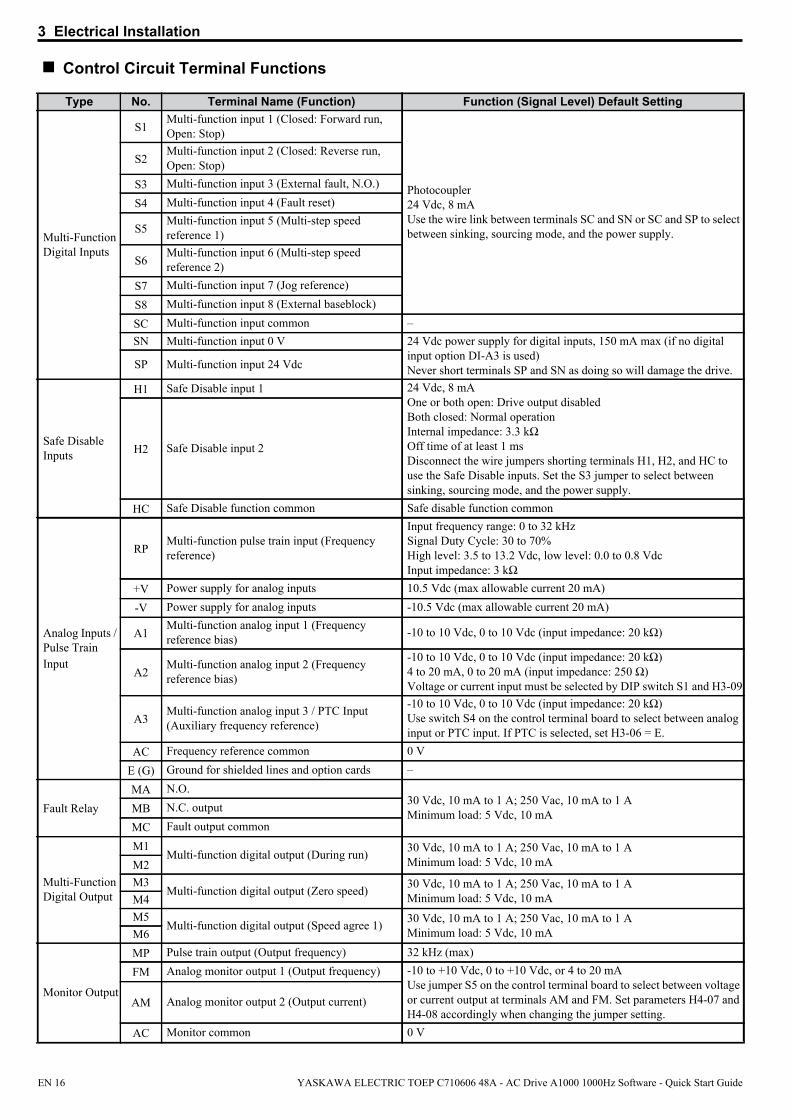
Control Circuit Terminal Functions
Type No. Terminal Name (Function) Function (Signal Level) Default Setting
Multi-Function Digital Inputs
S1Multi-function input 1 (Closed: Forward run, Open: Stop)
Photocoupler24 Vdc, 8 mAUse the wire link between terminals SC and SN or SC and SP to select between sinking, sourcing mode, and the power supply.
S2Multi-function input 2 (Closed: Reverse run, Open: Stop)
S3 Multi-function input 3 (External fault, N.O.)
S4 Multi-function input 4 (Fault reset)
S5Multi-function input 5 (Multi-step speed reference 1)
S6Multi-function input 6 (Multi-step speed reference 2)
S7 Multi-function input 7 (Jog reference)
S8 Multi-function input 8 (External baseblock)
SC Multi-function input common –SN Multi-function input 0 V 24 Vdc power supply for digital inputs, 150 mA max (if no digital
input option DI-A3 is used)Never short terminals SP and SN as doing so will damage the drive.SP Multi-function input 24 Vdc
Safe Disable Inputs
H1 Safe Disable input 1 24 Vdc, 8 mAOne or both open: Drive output disabledBoth closed: Normal operationInternal impedance: 3.3 kΩOff time of at least 1 msDisconnect the wire jumpers shorting terminals H1, H2, and HC to use the Safe Disable inputs. Set the S3 jumper to select between sinking, sourcing mode, and the power supply.
H2 Safe Disable input 2
HC Safe Disable function common Safe disable function common
Analog Inputs / Pulse Train Input
RPMulti-function pulse train input (Frequency reference)
Input frequency range: 0 to 32 kHzSignal Duty Cycle: 30 to 70%High level: 3.5 to 13.2 Vdc, low level: 0.0 to 0.8 VdcInput impedance: 3 kΩ
+V Power supply for analog inputs 10.5 Vdc (max allowable current 20 mA)
-V Power supply for analog inputs -10.5 Vdc (max allowable current 20 mA)
A1Multi-function analog input 1 (Frequency reference bias) -10 to 10 Vdc, 0 to 10 Vdc (input impedance: 20 kΩ)
A2Multi-function analog input 2 (Frequency reference bias)
-10 to 10 Vdc, 0 to 10 Vdc (input impedance: 20 kΩ)4 to 20 mA, 0 to 20 mA (input impedance: 250 Ω)Voltage or current input must be selected by DIP switch S1 and H3-09
A3Multi-function analog input 3 / PTC Input (Auxiliary frequency reference)
-10 to 10 Vdc, 0 to 10 Vdc (input impedance: 20 kΩ)Use switch S4 on the control terminal board to select between analog input or PTC input. If PTC is selected, set H3-06 = E.
AC Frequency reference common 0 V
E (G) Ground for shielded lines and option cards –
Fault RelayMA N.O.
30 Vdc, 10 mA to 1 A; 250 Vac, 10 mA to 1 AMinimum load: 5 Vdc, 10 mAMB N.C. output
MC Fault output common
Multi-Function Digital Output
M1Multi-function digital output (During run) 30 Vdc, 10 mA to 1 A; 250 Vac, 10 mA to 1 A
Minimum load: 5 Vdc, 10 mAM2M3
Multi-function digital output (Zero speed) 30 Vdc, 10 mA to 1 A; 250 Vac, 10 mA to 1 AMinimum load: 5 Vdc, 10 mAM4
M5Multi-function digital output (Speed agree 1) 30 Vdc, 10 mA to 1 A; 250 Vac, 10 mA to 1 A
Minimum load: 5 Vdc, 10 mAM6
Monitor Output
MP Pulse train output (Output frequency) 32 kHz (max)
FM Analog monitor output 1 (Output frequency) -10 to +10 Vdc, 0 to +10 Vdc, or 4 to 20 mAUse jumper S5 on the control terminal board to select between voltage or current output at terminals AM and FM. Set parameters H4-07 and H4-08 accordingly when changing the jumper setting.
AM Analog monitor output 2 (Output current)
AC Monitor common 0 V
EN 16 YASKAWA ELECTRIC TOEP C710606 48A - AC Drive A1000 1000Hz Software - Quick Start Guide

3 Electrical Installation
NOTICE: The terminals HC, H1, H2 are used for the Safe Disable function. Do not remove the wire link between HC, H1, or H2 unless the Safe Disable function is used. Refer to Safe Disable Input Function on page 37 when using this function.
NOTICE: The wiring length to the terminals HC, H1 and H2 should not exceed 30 m.
Safety Monitor Output
DM+ Safety monitor output Outputs status of Safe Disable function. Closed when both Safe Disable channels are closed. Up to +48 Vdc 50 mADM- Safety monitor output common
Type No. Terminal Name (Function) Function (Signal Level) Default Setting
YASKAWA ELECTRIC TOEP C710606 48A - AC Drive A1000 1000Hz Software - Quick Start Guide EN 17
4 Keypad Operation
4 Keypad Operation
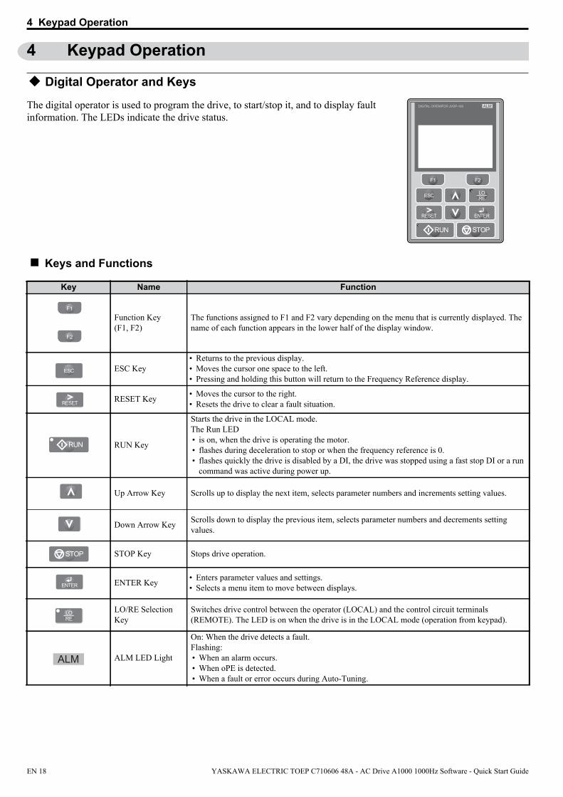
Digital Operator and Keys
LORE
F2F1
ESC
RUN STOP
ENTERRESET
ALMDIGITAL OPERATOR JVOP-180The digital operator is used to program the drive, to start/stop it, and to display fault information. The LEDs indicate the drive status.
Keys and Functions
Key Name Function
F1
F2
Function Key (F1, F2)
The functions assigned to F1 and F2 vary depending on the menu that is currently displayed. The name of each function appears in the lower half of the display window.
ESC ESC Key• Returns to the previous display.• Moves the cursor one space to the left.• Pressing and holding this button will return to the Frequency Reference display.
RESET RESET Key • Moves the cursor to the right.• Resets the drive to clear a fault situation.
RUN RUN Key
Starts the drive in the LOCAL mode.The Run LED• is on, when the drive is operating the motor.• flashes during deceleration to stop or when the frequency reference is 0.• flashes quickly the drive is disabled by a DI, the drive was stopped using a fast stop DI or a run
command was active during power up.
Up Arrow Key Scrolls up to display the next item, selects parameter numbers and increments setting values.
Down Arrow Key Scrolls down to display the previous item, selects parameter numbers and decrements setting values.
STOP STOP Key Stops drive operation.
ENTER ENTER Key • Enters parameter values and settings. • Selects a menu item to move between displays.
LORE
LO/RE Selection Key
Switches drive control between the operator (LOCAL) and the control circuit terminals (REMOTE). The LED is on when the drive is in the LOCAL mode (operation from keypad).
ALM ALM LED Light
On: When the drive detects a fault.Flashing: • When an alarm occurs.• When oPE is detected.• When a fault or error occurs during Auto-Tuning.
EN 18 YASKAWA ELECTRIC TOEP C710606 48A - AC Drive A1000 1000Hz Software - Quick Start Guide

4 Keypad Operation
Menu Structure and ModesThe following illustration explains the operator keypad menu structure.Figure 1.1
- MODE -
U1-01= 0.00HzU1-02= 0.00HzU1-03= 0.00A
DRVFREF (OPR)
Rdy -MONITR-FREF (d1-01)
U1-01= 000.00Hz
<3>
<4>
0.00 50.000.00Hz
DRV
← →FWD
Rdy
- MODE -
U1-01= 0.00HzU1-02= 0.00HzU1-03= 0.00A
DRVMonitor Menu
Rdy
- MODE - PRGModified Consts
HELP
HELP
DATA
- MODE - PRGQuick Setting
DATA
HELP
- MODE - PRG RdyAuto-Tuning
DATA
HELP
- MODE - PRG
DATA
Programming
AUTO
-MONITR-
U1 -01= 0.00HzU1-02= 0.00HzU1-03= 0.00A
DRVMonitor
JOG FWD FWD/REV
Rdy -MONITR-
U1- 01 = 0.00HzU1-02= 0.00HzU1-03= 0.00A
DRVFrequency Ref
JOG FWD FWD/REV
Rdy
-MONITR-
U1- 02 = 0.00HzU1-03= 0.00AU1-04= 0
DRVOutput Freq
JOG FWD FWD/REV
Rdy-MONITR-
U2 -01= oCU2-02= oPrU2-03= 0.00Hz
DRVFault Trace
JOG FWD FWD/REV
Rdy
JOG FWD FWD/REV
JOG FWD
FWD
FWD
FWD
FWD
FWD/REV
ModifiedX Parameters
LSEQLREF
LSEQLREF
LSEQLREF
LSEQLREF
LSEQLREF
LSEQLREF
YASKAWA
A1000
A1000XXXV X.X/X.XkW
XX.XX/XX.XXA<XXXXXXXXX>
Initial Display <5>
<6>
Pro
gram
min
g M
ode
<2>
Driv
e M
ode
<1>
<1> Pressing RUN will start the motor.<2> Drive cannot operate the motor.<3> Flashing characters are shown as 0 .<4> X characters are shown in this manual. The LCD Operator will display the actual setting values.<5> The Frequency Reference appears after the initial display which shows the product name.<6> The information that appears on the display will vary depending on the drive.
YASKAWA ELECTRIC TOEP C710606 48A - AC Drive A1000 1000Hz Software - Quick Start Guide EN 19
5 Modification from Standard Software
5 Modification from Standard Software
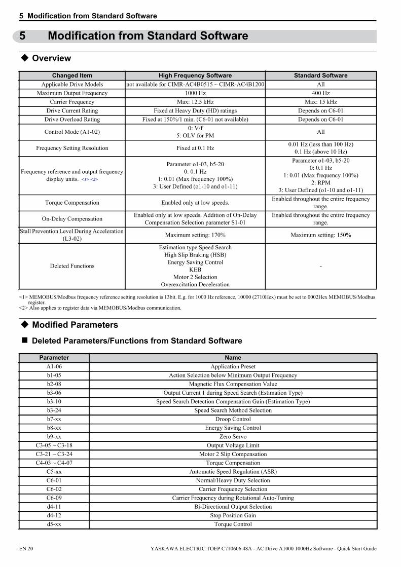
Overview
Changed ItemApplicable Drive Models not available for CIMR-AC4B0515 ~ CIMR-AC4B1200 All
Maximum Output Frequency 1000 Hz 400 HzCarrier Frequency Max: 12.5 kHz Max: 15 kHz
Drive Current Rating Fixed at Heavy Duty (HD) ratings Depends on C6-01Drive Overload Rating Fixed at 150%/1 min. (C6-01 not available) Depends on C6-01
Control Mode (A1-02) 0: V/f5: OLV for PM All
Frequency Setting Resolution Fixed at 0.1 Hz 0.01 Hz (less than 100 Hz)0.1 Hz (above 10 Hz)
Frequency reference and output frequency display units.
<1> MEMOBUS/Modbus frequency reference setting resolution is 13bit. E.g. for 1000 Hz reference, 10000 (2710Hex) must be set to 0002Hex MEMOBUS/Modbus register.
<2> Also applies to register data via MEMOBUS/Modbus communication.
<1> <2>
Parameter o1-03, b5-200: 0.1 Hz
1: 0.01 (Max frequency 100%)3: User Defined (o1-10 and o1-11)
Parameter o1-03, b5-200: 0.1 Hz
1: 0.01 (Max frequency 100%)2: RPM
3: User Defined (o1-10 and o1-11)
Torque Compensation Enabled only at low speeds. Enabled throughout the entire frequency range.
On-Delay Compensation Enabled only at low speeds. Addition of On-Delay Compensation Selection parameter S1-01
Enabled throughout the entire frequency range.
Stall Prevention Level During Acceleration (L3-02) Maximum setting: 170% Maximum setting: 150%
Deleted Functions
Estimation type Speed SearchHigh Slip Braking (HSB)Energy Saving Control
KEBMotor 2 Selection
Overexcitation Deceleration
-
Modified Parameters
Deleted Parameters/Functions from Standard Software
High Frequency Software Standard Software
Parameter NameA1-06 Application Presetb1-05 Action Selection below Minimum Output Frequencyb2-08 Magnetic Flux Compensation Valueb3-06 Output Current 1 during Speed Search (Estimation Type)b3-10 Speed Search Detection Compensation Gain (Estimation Type)b3-24 Speed Search Method Selectionb7-xx Droop Controlb8-xx Energy Saving Control b9-xx Zero Servo
C3-05 ~ C3-18 Output Voltage Limit C3-21 ~ C3-24 Motor 2 Slip Compensation C4-03 ~ C4-07 Torque Compensation
C5-xx Automatic Speed Regulation (ASR)C6-01 Normal/Heavy Duty SelectionC6-02 Carrier Frequency SelectionC6-09 Carrier Frequency during Rotational Auto-Tuningd4-11 Bi-Directional Output Selectiond4-12 Stop Position Gaind5-xx Torque Control
EN 20 YASKAWA ELECTRIC TOEP C710606 48A - AC Drive A1000 1000Hz Software - Quick Start Guide

5 Modification from Standard Software
Deleted Multi-function Digital Inputs (H1 Group)
Setting FunctionD PG Encoder DisableE ASR Integral Reset16 Motor 2 Select
65, 66 KEB Ride-thru 168 HSB (High Slip Braking)71 Speed / Torque Switch72 Zero Servo77 ASR Gain Switch78 External Torque Reference Polarity Inversion
7A, 7B KEB Ride-thru 2
Deleted Multi-function Digital Outputs (H2 Group)
Setting Function1D During Regeneration30 During Torque Limit31 During Speed Limit32 During Speed Limit in Torque Control33 Zero Servo Complete4A During KEB Ride-tru4B During Short Circuit Braking61 Rotor Position Detection Complete
Deleted Multi-function Analogue Outputs (H3 Group)
Setting Function10 ~ 15 Torque Limits
Modified Parameter Setting Ranges
d6-03, d6-06 Field Forcing E2-07, E2-08 Motor Iron-Core Saturation Coefficients
E2-09 Motor Mechanical LossE3-xx, E4-xx Motor 2 Setting
E5-11 Encoder Z-Pulse OffsetF1-xx PG Option
L2-06 ~ L2-29 KEB Function L3-11, L3-17, L3-19 ~ 22,
L3-24, L3-25 OV Suppression Function
L7-xx Torque Limit Functionn2-xx Automatic Frequency Regulation (AFR)n3-xx High Slip Braking / Overexcitation Deceleration n5-xx Feed Forward Controln6-xx Online Tuning
n8-02, n8-02, n8-35, n8-57, n8-69 PM Motor Control Tuning Parameters
T1-00, T1-05 ~ T1-11 Induction Motor Auto-Tuning ParametersT2-03, T2-09, T2-15 ~ T2-
17 PM Motor Auto-Tuning Parameter
T3-xx ASR and Inertia Tuning
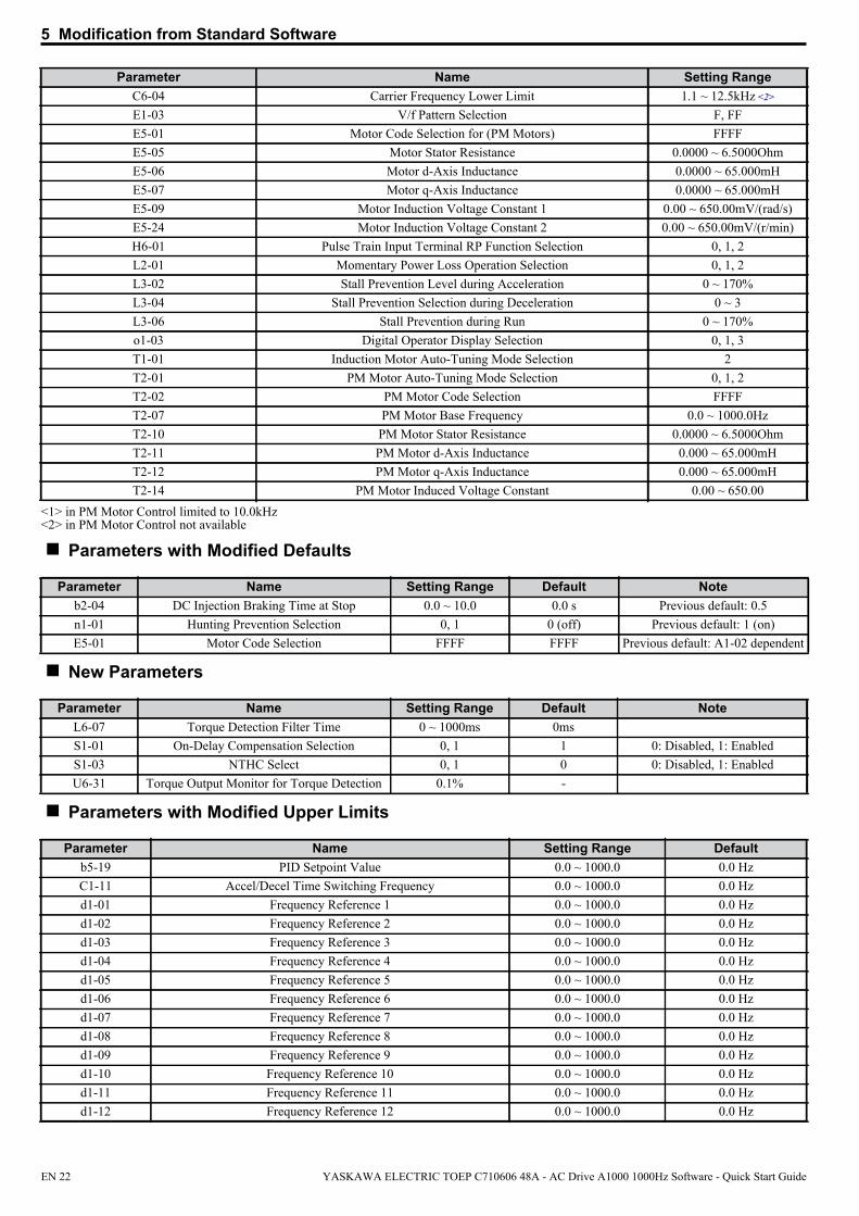
Parameter Name Setting RangeA1-02 Control Method Selection 0, 5b5-20 PID Setpoint Scaling 0, 1, 3C6-03 Carrier Frequency Upper Limit 1.1 ~ 12.5kHz <1>
Parameter Name
YASKAWA ELECTRIC TOEP C710606 48A - AC Drive A1000 1000Hz Software - Quick Start Guide EN 21
5 Modification from Standard Software
Parameters with Modified Defaults
Parameter Name Setting Range Default Noteb2-04 DC Injection Braking Time at Stop 0.0 ~ 10.0 0.0 s Previous default: 0.5n1-01 Hunting Prevention Selection 0, 1 0 (off) Previous default: 1 (on)E5-01 Motor Code Selection FFFF FFFF Previous default: A1-02 dependent
New Parameters
Parameter Name Setting Range Default NoteL6-07 Torque Detection Filter Time 0 ~ 1000ms 0msS1-01 On-Delay Compensation Selection 0, 1 1 0: Disabled, 1: EnabledS1-03 NTHC Select 0, 1 0 0: Disabled, 1: EnabledU6-31 Torque Output Monitor for Torque Detection 0.1% -
Parameters with Modified Upper Limits
C6-04 Carrier Frequency Lower Limit 1.1 ~ 12.5kHz <2>
E1-03 V/f Pattern Selection F, FFE5-01 Motor Code Selection for (PM Motors) FFFFE5-05 Motor Stator Resistance 0.0000 ~ 6.5000OhmE5-06 Motor d-Axis Inductance 0.0000 ~ 65.000mHE5-07 Motor q-Axis Inductance 0.0000 ~ 65.000mHE5-09 Motor Induction Voltage Constant 1 0.00 ~ 650.00mV/(rad/s)E5-24 Motor Induction Voltage Constant 2 0.00 ~ 650.00mV/(r/min)H6-01 Pulse Train Input Terminal RP Function Selection 0, 1, 2L2-01 Momentary Power Loss Operation Selection 0, 1, 2L3-02 Stall Prevention Level during Acceleration 0 ~ 170%L3-04 Stall Prevention Selection during Deceleration 0 ~ 3L3-06 Stall Prevention during Run 0 ~ 170%o1-03 Digital Operator Display Selection 0, 1, 3T1-01 Induction Motor Auto-Tuning Mode Selection 2T2-01 PM Motor Auto-Tuning Mode Selection 0, 1, 2T2-02 PM Motor Code Selection FFFFT2-07 PM Motor Base Frequency 0.0 ~ 1000.0HzT2-10 PM Motor Stator Resistance 0.0000 ~ 6.5000OhmT2-11 PM Motor d-Axis Inductance 0.000 ~ 65.000mHT2-12 PM Motor q-Axis Inductance 0.000 ~ 65.000mHT2-14 PM Motor Induced Voltage Constant 0.00 ~ 650.00
<1> in PM Motor Control limited to 10.0kHz<2> in PM Motor Control not available
Parameter Name Setting Range Defaultb5-19 PID Setpoint Value 0.0 ~ 1000.0 0.0 HzC1-11 Accel/Decel Time Switching Frequency 0.0 ~ 1000.0 0.0 Hzd1-01 Frequency Reference 1 0.0 ~ 1000.0 0.0 Hzd1-02 Frequency Reference 2 0.0 ~ 1000.0 0.0 Hzd1-03 Frequency Reference 3 0.0 ~ 1000.0 0.0 Hzd1-04 Frequency Reference 4 0.0 ~ 1000.0 0.0 Hzd1-05 Frequency Reference 5 0.0 ~ 1000.0 0.0 Hzd1-06 Frequency Reference 6 0.0 ~ 1000.0 0.0 Hzd1-07 Frequency Reference 7 0.0 ~ 1000.0 0.0 Hzd1-08 Frequency Reference 8 0.0 ~ 1000.0 0.0 Hzd1-09 Frequency Reference 9 0.0 ~ 1000.0 0.0 Hzd1-10 Frequency Reference 10 0.0 ~ 1000.0 0.0 Hzd1-11 Frequency Reference 11 0.0 ~ 1000.0 0.0 Hzd1-12 Frequency Reference 12 0.0 ~ 1000.0 0.0 Hz
Parameter Name Setting Range
EN 22 YASKAWA ELECTRIC TOEP C710606 48A - AC Drive A1000 1000Hz Software - Quick Start Guide

5 Modification from Standard Software
Modified Monitors
Parameter Name Setting RangeU1-01 Frequency Reference 0.0 ~ 1000.0 HzU1-02 Output Frequency 0.0 ~ 1000.0 HzU1-16 Output Frequency after Soft Start 0.0 ~ 1000.0 HzU2-03 Frequency Reference at Previous Fault 0.0 ~ 1000.0 HzU2-04 Output Frequency at Previous Fault 0.0 ~ 1000.0 HzU2-15 Softstarter Speed Reference at Previous Fault 0.0 ~ 1000.0 HzU4-14 Peak Hold Output Frequency 0.0 ~ 1000.0 Hz
Deleted Monitors
Parameter NameU1-05 Motor SpeedU1-09 Torque ReferenceU2-06 Motor Speed at Previous FaultU2-10 Torque reference at Previous FaultU2-19 Rotor Deviation at Previous FaultU6-03 ASR InputU6-04 ASR OutputU6-07 q-Axis ACR OutputU6-08 d-Axis ACR OutputU6-09 Advanced Phase CompensationU6-10 Control Axis DeviationU6-13 Flux Position DetectionU6-14 Flux Position EstimationU6-22 Zero Servo Pulse MovementU6-25 Feedback Control OutputU6-26 Feed Forward Control Output
MEMOBUS/Modbus Communication Data
Register Name Data02h Frequency Reference Setting upper limit 40000 to FFFFH3Eh Output Frequency RPM DeletedACh Motor Speed Monitor [rpm] DeletedB5h Softstarter Output Monitor [rpm] DeletedB7h Frequency Reference [rpm] Deleted
d1-13 Frequency Reference 13 0.0 ~ 1000.0 0.0 Hzd1-14 Frequency Reference 14 0.0 ~ 1000.0 0.0 Hzd1-15 Frequency Reference 15 0.0 ~ 1000.0 0.0 Hzd1-16 Frequency Reference 16 0.0 ~ 1000.0 0.0 Hzd1-17 Jog Frequency Reference 0.0 ~ 1000.0 0.0 Hzd3-01 Jump Frequency 1 0.0 ~ 1000.0 0.0 Hzd3-02 Jump Frequency 2 0.0 ~ 1000.0 0.0 Hzd3-03 Jump Frequency 3 0.0 ~ 1000.0 0.0 HzE1-04 Maximum Output Frequency 0.0 ~ 1000.0 50.0 HzE1-06 Base Frequency 0.0 ~ 1000.0 50.0 HzE1-07 Mid Output Frequency 0.0 ~ 1000.0 2.5 HzE1-09 Minimum Output Frequency 0.0 ~ 1000.0 1.3 HzE1-11 Mid Output Frequency 2 0.0 ~ 1000.0 0.0 HzL4-01 Speed Agreement Detection Level 0.0 ~ 1000.0 0.0 HzL4-03 Speed Agreement Detection Level (+/-) -999.9 ~ 999.9 0.0 Hz
Parameter Name Setting Range Default
YASKAWA ELECTRIC TOEP C710606 48A - AC Drive A1000 1000Hz Software - Quick Start Guide EN 23

5 Modification from Standard Software
New and modified Software Functions
Carrier Frequency• The carrier frequency upper limit changed from 15.0kHz to 12.5kHz (10.0kHz in PM control)• The carrier frequency selection parameter (C6-02) is not available.
A1-02Control Method
C6-02Carrier Frequency Selection
C6-03Carrier Frequency Upper
Limit
C6-04Carrier Frequency Lower
Limit
C6-05Carrier Frequency Proportional Gain
0not available
12.5 1.1 245 10.0 not available not available
Torque CompensationHigh speed motors typically have very low impedance compared to standard 60/120 Hz motors. These high speed/low impedance motors saturate easily and may cause hunting and oscillation when a high V/f pattern is applied, especially at high frequencies. Therefore, Torque Compensation Gain (C4-01) is modified to limit voltage boost above 120 Hz and eliminate voltage boost above 160 Hz as shown following diagram.
C4-01
120 Hz
OutputFrequency
(Fout)160 Hz0
On-Delay CompensationHigh speed motors typically operate at low V/f ratios compared to standard 60/120 Hz motors, and On-Delay Compensation settings may adversely affect the motor voltage and cause hunting and oscillation. Therefore, On-Delay Compensation Gain is modified to reduce its effectiveness above 120 Hz as shown in following diagram.
1.00
120 Hz 160 Hz0Output
Frequency(Fout)
The parameter S1-01 is added to enable/disable On-Delay Compensation manually.
EN 24 YASKAWA ELECTRIC TOEP C710606 48A - AC Drive A1000 1000Hz Software - Quick Start Guide
6 Start Up
6 Start Up
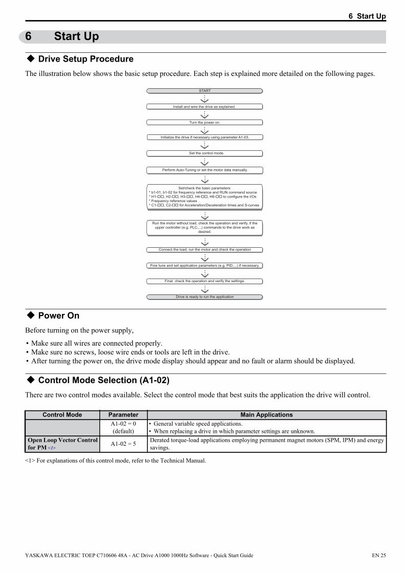
Drive Setup ProcedureThe illustration below shows the basic setup procedure. Each step is explained more detailed on the following pages.
Install and wire the drive as explained.
Turn the power on.
Set the control mode.
Set/check the basic parameters:* b1-01, b1-02 for frequency reference and RUN command source* H1-��, H2-��, H3-��, H4-��, H6-�� to configure the I/Os* Frequency reference values* C1-��, C2-�� for Acceleration/Deceleration times and S-curves
Run the motor without load, check the operation and verify, if the upper controller (e.g. PLC,...) commands to the drive work as
desired.
Connect the load, run the motor and check the operation
Fine tune and set application parameters (e.g. PID,...) if necessary.
Final check the operation and verify the settings.
Drive is ready to run the application
START
Perform Auto-Tuning or set the motor data manually.
Initialize the drive if necessary using parameter A1-03.
Power OnBefore turning on the power supply,
• Make sure all wires are connected properly.• Make sure no screws, loose wire ends or tools are left in the drive.• After turning the power on, the drive mode display should appear and no fault or alarm should be displayed.
Control Mode Selection (A1-02)There are two control modes available. Select the control mode that best suits the application the drive will control.
Control ModeV/f Control for Induction Motors
A1-02 = 0(default)
• General variable speed applications.• When replacing a drive in which parameter settings are unknown.
Open Loop Vector Control for PM <1>
A1-02 = 5 Derated torque-load applications employing permanent magnet motors (SPM, IPM) and energy savings.
<1> For explanations of this control mode, refer to the Technical Manual.
Parameter Main Applications
YASKAWA ELECTRIC TOEP C710606 48A - AC Drive A1000 1000Hz Software - Quick Start Guide EN 25

6 Start Up
Auto-Tuning (T1-)Auto-Tuning automatically sets up the motor data relevant drive parameters.
Type Setting Application Conditions and Benefits
Stationary Auto-Tuning for Line-to-Line Resistance
T1-01 = 2
• The drive is used in V/f Control and other Auto-Tuning selections not possible.• Drive and motor capacities differ.• Tunes the drive after the cable between the drive and motor has been replaced with a
cable over 50 m long. Assumes Auto-Tuning has already been performed.
Do not touch the motor until the Auto-Tuning is finished. Failure to comply may result in minor or moderate injury. Voltage is still applied to the motor during the tuning process, even thought the motor may not be rotating.
For Auto-Tuning enter the Auto-Tuning menu and perform the steps shown in the figure below. The number of name plate data to be entered depends on the selected type of Auto-Tuning. This example shows Terminal Resistance Auto-Tuning in V/f control.
- MODE -
EndTune Successful
DRV
FWD RESET
Enter the Auto-Tuning Mode
Select the tuning method
Set up all name plate data
The tuning start display appears
During the tuning the display flashes
After successful tuning “End” is displayed
Drive mode display
- A.TUNE -
T1-01= 2 ∗2∗Term Resistance
PRG
Entry Accepted
Tuning Mode Sel
FWD
- A.TUNE -
T1-01= 2 ∗2∗Term Resistance
PRGTuning Mode Sel
ESC FWD DATA
- MODE -
U1-01= 0.00HzU1-02= 0.00HzU1-03= 0.00A
DRVFREF (OPR)
Rdy
JOG FWD FWD/REV
LSEQLREF
HELP
- MODE - PRGAuto-Tuning
DATA
AUTO
FWD“2”
- A.TUNE -
T1-04= x.xxA(0.xx ~ x.xxA)
PRGRated Current
ESC FWD DATA“x.xxA”
- A.TUNE -
T1-02= X.XXkW(0.00 ~ 650.00)
PRGMtr Rated Power
ESC FWD DATA“X.XXkW”
- A.TUNE -
0.00 Hz/ 0.00ATuning Ready ?
DRVAuto-Tuning
ESC FWDPress RUN key
- A.TUNE -
X.XX Hz/ X.XXA
DRVTune Proceeding
FWDRUN
If Auto-Tuning can not be performed for some reason (no-load operation impossible etc.), then set up the maximum frequency and voltage in the E1- parameters and enter the motor data manually into the E2- parameters.
NOTICE: The Safe Disable inputs must be closed during Auto-Tuning.
External Reference Selection and Acceleration/ Deceleration Times
Frequency Reference Selection (b1-01)Set parameter b1-01 according to the frequency reference used.
b1-01 Reference source Frequency reference input
0 Operator keypad Set the frequency references in the d1- parameters and use digital inputs to switch over between different reference values.
1 Analog input Apply the frequency reference signal to terminal A1, A2, or A3.2 Serial Comm. Serial Communications using the RS422/485 port3 Option Card Communications option card4 Pulse input Set the frequency reference at terminal RP using a pulse train signal.
CAUTION
EN 26 YASKAWA ELECTRIC TOEP C710606 48A - AC Drive A1000 1000Hz Software - Quick Start Guide

6 Start Up
Run Command Selection (b1-02)Set parameter b1-02 according to the run command used.
b1-02 Reference source Run command input0 Operator keypad RUN and STOP keys on the operator1 Multi-Function digital input Multi-Function digital input2 Serial Comm. Serial Communications using the RS422/485 port3 Option Card Communications option card
Acceleration/ Deceleration Times and S-CurvesThere are four sets of acceleration and deceleration times which can be set in the C1- parameters. The default activated accel/decel times are C1-01/02. Adjust these times to the appropriate values required by the application. If necessary S-curves can be activated in the C2- parameters for softer accel/decel start and end.
Reference and Run SourceThe drive has a LOCAL and a REMOTE mode.
Status DescriptionLOCAL The Run/ Stop command and the frequency reference are entered at the operator keypad.
REMOTE The Run command source entered in parameter b1-02 and the frequency reference source entered in parameter b1-01 are used.
If the drive is operated in the REMOTE mode, make sure that the correct sources for the frequency reference and run command are set in parameters b1-01/02 and that the drive is in the REMOTE mode.
The LED in the LO/RE key indicates where the Run command is input from.
LO/RE LED DescriptionON Run command is issued from operator.OFF Run command is issued from a different source than the operator.
I/O SetupNote: The default setting functions can be seen in the connection diagram on page 11.
Multi-Function Digital Inputs (H1-)The function of each digital input can be assigned in the H1- parameters.
Multi-Function Digital Outputs (H2-)The function of each digital output can be assigned in the H2- parameters. The setting value of these parameters consist of 3 digits, where the middle and right digit set the function and the left digit sets the output characteristics (0: Output as selected; 1: Inverse output).
Multi-Function Analog Inputs (H3-)The function of each analog input can be assigned in the H3- parameters. Input A1 and A3 are set for -10 to +10 Vdc input. A2 is set for 4-20 mA input.
NOTICE: If the input signal level of input A2 is switched between voltage and current, make sure that DIP switch S1 is in the correct position and parameter H3-09 is set up correctly.
NOTICE: When using analog input A3 as PTC input, set DIP switch S4 to PTC and parameter H3-06 = E.
Multi-Function Analog Outputs (H4-)Use the H4- parameters to set up the output value of the analog monitor outputs and to adjust the output signal levels. When changing signal levels in parameter H4-07/08, make sure jumper S5 is set accordingly.
YASKAWA ELECTRIC TOEP C710606 48A - AC Drive A1000 1000Hz Software - Quick Start Guide EN 27

6 Start Up
Test RunPerform the following steps to start up the machine after all parameter settings have been done.
1. Run the motor without load and check if all input, outputs and the sequence work as desired.2. Connect the load to the motor.3. Run the motor with load and make sure that there is no vibrations, hunting or motor stalling occurs.
After taking the steps listed above, the drive should be ready to run the application and perform the basic functions. For special setups like PID control etc. refer to the Technical Manual.
EN 28 YASKAWA ELECTRIC TOEP C710606 48A - AC Drive A1000 1000Hz Software - Quick Start Guide
7 Parameter Table
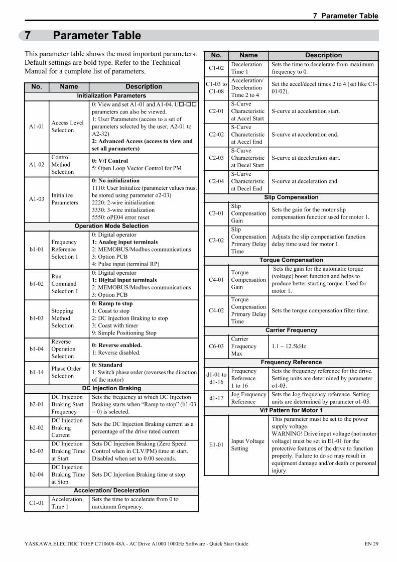
7 Parameter TableThis parameter table shows the most important parameters.
Default settings are bold type. Refer to the Technical Manual for a complete list of parameters.No. Name DescriptionInitialization Parameters
A1-01 Access Level Selection
0: View and set A1-01 and A1-04. U- parameters can also be viewed.1: User Parameters (access to a set of parameters selected by the user, A2-01 to A2-32)2: Advanced Access (access to view and set all parameters)
A1-02Control Method Selection
0: V/f Control5: Open Loop Vector Control for PM
A1-03 Initialize Parameters
0: No initialization1110: User Initialize (parameter values must be stored using parameter o2-03)2220: 2-wire initialization3330: 3-wire initialization5550: oPE04 error reset
Operation Mode Selection
b1-01Frequency Reference Selection 1
0: Digital operator1: Analog input terminals2: MEMOBUS/Modbus communications3: Option PCB4: Pulse input (terminal RP)
b1-02Run Command Selection 1
0: Digital operator1: Digital input terminals2: MEMOBUS/Modbus communications3: Option PCB
b1-03Stopping Method Selection
0: Ramp to stop1: Coast to stop2: DC Injection Braking to stop3: Coast with timer9: Simple Positioning Stop
b1-04Reverse Operation Selection
0: Reverse enabled.1: Reverse disabled.
b1-14 Phase Order Selection
0: Standard1: Switch phase order (reverses the direction of the motor)
DC Injection Braking
b2-01DC Injection Braking Start Frequency
Sets the frequency at which DC Injection Braking starts when “Ramp to stop” (b1-03 = 0) is selected.
b2-02DC Injection Braking Current
Sets the DC Injection Braking current as a percentage of the drive rated current.
b2-03DC Injection Braking Time at Start
Sets DC Injection Braking (Zero Speed Control when in CLV/PM) time at start. Disabled when set to 0.00 seconds.
b2-04DC Injection Braking Time at Stop
Sets DC Injection Braking time at stop.
Acceleration/ Deceleration
C1-01 Acceleration Time 1
Sets the time to accelerate from 0 to maximum frequency.
C1-02 Deceleration Time 1
Sets the time to decelerate from maximum frequency to 0.
C1-03 toC1-08
Acceleration/Deceleration Time 2 to 4
Set the accel/decel times 2 to 4 (set like C1-01/02).
C2-01S-Curve Characteristic at Accel Start
S-curve at acceleration start.
C2-02S-Curve Characteristic at Accel End
S-curve at acceleration end.
C2-03S-Curve Characteristic at Decel Start
S-curve at deceleration start.
C2-04S-Curve Characteristic at Decel End
S-curve at deceleration end.
Slip Compensation
C3-01Slip Compensation Gain
Sets the gain for the motor slip compensation function used for motor 1.
C3-02
Slip Compensation Primary Delay Time
Adjusts the slip compensation function delay time used for motor 1.
Torque Compensation
C4-01Torque Compensation Gain
Sets the gain for the automatic torque (voltage) boost function and helps to produce better starting torque. Used for motor 1.
C4-02
Torque Compensation Primary Delay Time
Sets the torque compensation filter time.
Carrier Frequency
C6-03Carrier Frequency Max
1.1 ~ 12.5kHz
Frequency Reference
d1-01 tod1-16
Frequency Reference 1 to 16
Sets the frequency reference for the drive. Setting units are determined by parameter o1-03.
d1-17 Jog Frequency Reference
Sets the Jog frequency reference. Setting units are determined by parameter o1-03.
V/f Pattern for Motor 1
E1-01 Input Voltage Setting
This parameter must be set to the power supply voltage.WARNING! Drive input voltage (not motor voltage) must be set in E1-01 for the protective features of the drive to function properly. Failure to do so may result in equipment damage and/or death or personal injury.
No. Name Description
YASKAWA ELECTRIC TOEP C710606 48A - AC Drive A1000 1000Hz Software - Quick Start Guide EN 29
7 Parameter Table
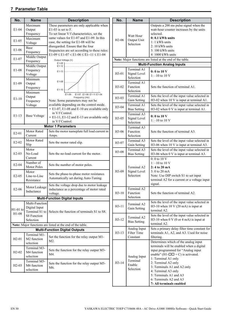
E1-04Maximum Output Frequency
These parameters are only applicable when E1-03 is set to F.To set linear V/f characteristics, set the same values for E1-07 and E1-09. In this case, the setting for E1-08 will be disregarded. Ensure that the four frequencies are set according to these rules:E1-09 ≤ E1-07 < E1-06 ≤ Ε1−11 ≤ E1-04
Output Voltage (V)
Frequency (Hz)
E1-05E1-12
E1-13
E1-08
E1-10
E1-09 E1-07 E1-06 E1-11 E1-04
Note: Some parameters may not be available depending on the control mode.• E1-07, E1-08 and E-10 are available only
in V/f Control.• E1-11, E1-12 and E-13 are available only
in V/f Control.
E1-05 Maximum Voltage
E1-06 Base Frequency
E1-07 Middle Output Frequency
E1-08Middle Output Frequency Voltage
E1-09Minimum Output Frequency
E1-10
Minimum Output Frequency Voltage
E1-13 Base Voltage
Motor 1 Parameters
E2-01 Motor Rated Current
Sets the motor nameplate full load current in Amps.
E2-02 Motor Rated Slip Sets the motor rated slip.
E2-03Motor No-Load Current
Sets the no-load current for the motor.
E2-04 Number of Motor Poles Sets the number of motor poles.
E2-05Motor Line-to-Line Resistance
Sets the phase-to-phase motor resistance. Automatically set during Auto-Tuning.
E2-06 Motor Leakage Inductance
Sets the voltage drop due to motor leakage inductance as a percentage of motor rated voltage.
Multi-Function Digital Inputs
H1-01 toH1-08
Multi-Function Digital Input Terminal S1 to S8 Function Selection
Selects the function of terminals S1 to S8.
Note: Major functions are listed at the end of the table.Multi-Function Digital Outputs
H2-01Terminal M1-M2 function selection
Set the function for the relay output M1-M2.
H2-02Terminal M3-M4 function selection
Sets the function for the relay output M3-M4.
H2-03Terminal M5-M6 function selection
Sets the function for the relay output M5-M6.
No. Name Description
H2-06Watt Hour Output Unit Selection
Outputs a 200 ms pulse signal when the watt-hour counter increases by the units selected.0: 0.1 kWh units1: 1 kWh units2: 10 kWh units3: 100 kWh units4: 1000 kWh units
Note: Major functions are listed at the end of the table.Multi-Function Analog Inputs
H3-01Terminal A1 Signal Level Selection
0: 0 to 10 V1: –10 to 10 V
H3-02Terminal A1 Function Selection
Sets the function of terminal A1.
H3-03 Terminal A1 Gain Setting
Sets the level of the input value selected in H3-02 when 10 V is input at terminal A1.
H3-04 Terminal A1 Bias Setting
Sets the level of the input value selected in H3-02 when 0 V is input at terminal A1.
H3-05Terminal A3 Signal Level Selection
0: 0 to 10 V 1: –10 to 10 V
H3-06Terminal A3 Function Selection
Sets the function of terminal A3.
H3-07 Terminal A3 Gain Setting
Sets the level of the input value selected in H3-06 when 10 V is input at terminal A3.
H3-08 Terminal A3 Bias Setting
Sets the level of the input value selected in H3-06 when 0 V is input at terminal A3.
H3-09Terminal A2 Signal Level Selection
0: 0 to 10 V1: –10 to 10 V2: 4 to 20 mA3: 0 to 20 mANote: Use DIP switch S1 to set input terminal A2 for a current or a voltage input signal.
H3-10Terminal A2 Function Selection
Sets the function of terminal A2.
H3-11 Terminal A2 Gain Setting
Sets the level of the input value selected in H3-10 when 10 V (20 mA) is input at terminal A2.
H3-12 Terminal A2 Bias Setting
Sets the level of the input value selected in H3-10 when 0 V (0 or 4 mA) is input at terminal A2.
H3-13Analog Input Filter Time Constant
Sets a primary delay filter time constant for terminals A1, A2, and A3. Used for noise filtering.
H3-14
Analog Input Terminal Enable Selection
Determines which of the analog input terminals will be enabled when a digital input programmed for “Analog input enable” (H1- = C) is activated.1: Terminal A1 only2: Terminal A2 only3: Terminals A1 and A2 only4: Terminal A3 only5: Terminals A1 and A36: Terminals A2 and A37: All terminals enabled
No. Name Description
EN 30 YASKAWA ELECTRIC TOEP C710606 48A - AC Drive A1000 1000Hz Software - Quick Start Guide

7 Parameter Table
Multi-Function Analog Inputs
H4-01
Multi-Function Analog Output Terminal FM Monitor Selection
Selects the data to be output through multi-function analog output terminal FM. Set the desired monitor parameter to the digits available in U-. For example, enter “103” for U1-03.
H4-02
Multi-Function Analog Output Terminal FM Gain
Sets the signal level at terminal FM that is equal to 100% of the selected monitor value.
H4-03
Multi-Function Analog Output Terminal FM Bias
Sets the signal level at terminal FM that is equal to 0% of the selected monitor value.
H4-04
Multi-Function Analog Output Terminal AM Monitor Selection
Selects the data to be output through multi-function analog output terminal AM. Set the desired monitor parameter to the digits available in U-. For example, enter “103” for U1-03.
H4-05
Multi-Function Analog Output Terminal AM Gain
Sets the signal level at terminal AM that is equal to 0% of the selected monitor value.
H4-06
Multi-Function Analog Output Terminal AM Bias
Sets the bias value added to the terminal AM output signal.
H4-07
Multi-Function Analog Output Terminal FM Signal Level Selection
0: 0 to 10 V1: -10 to 10 V2: 4 to 20 mA
H4-08
Multi-Function Analog Output Terminal AM Signal Level Selection
0: 0 to 10 V1: -10 to 10 V2: 4 to 20 mA
Pulse Input Setting (Freq.)
H6-02 Pulse Train Input Scaling
Sets the terminal RP input signal frequency that is equal to 100% of the value selected in H6-01.
H6-03 Pulse Train Input Gain
Sets the level of the value selected in H6-01 when a frequency with the value set in H6-02 is input.
H6-04 Pulse Train Input Bias
Sets the level of the value selected in H6-01 when 0 Hz is input.
Pulse Output Setting
H6-06Pulse Train Monitor Selection
Select the pulse train monitor output function (value of the - part of U-).Example: To select U5-01, set 501.
H6-07Pulse Train Monitor Scaling
Sets the terminal MP output signal frequency when the monitor value is 100%. To have the pulse train monitor output equal the output frequency, set H6-06 to 102 and H6-07 to 0.
No. Name DescriptionMotor Protection
L1-01
Motor Overload Protection Selection
0: Disabled1: General purpose motor (standard fan cooled)2: Drive dedicated motor with a speed range of 1:103: Vector motor with a speed range of 1:1004: PM motor with variable torque5: PM motor with constant torque control6: General purpose motor (50 Hz)The drive may not be able to provide protection when multiple motors are used, even if overload protection is enabled in L1-01. Set L1-01 to 0 and install separate thermal relay to each motor.
L1-02
Motor Overload Protection Time
Sets the motor thermal overload protection (oL1) time.
Stall Prevention
L3-01
Stall Prevention Selection during Acceleration
0: Disabled.1: General purpose. Acceleration is paused as long as the current is above the L3-02 setting. 2: Intelligent. Accelerate in the shortest possible time without exceeding the L3-02 level.Note: Setting 2 is not available when using OLV/PM.
L3-02
Stall Prevention Level during Acceleration
Used when L3-01 = 1 or 2. 100% is equal to the drive rated current.
L3-04
Stall Prevention Selection during Deceleration
0: Disabled. Deceleration at the active deceleration rate. An ov fault may occur.1: General purpose. Deceleration is paused when the DC bus voltage exceeds the Stall Prevention level.2: Intelligent. Decelerate as fast as possible while avoiding ov faults.3: Stall Prevention with braking resistor. Stall Prevention during deceleration is enabled in coordination with dynamic braking.
L3-05
Stall Prevention Selection during Run
0: Disabled. Drive runs at a set frequency. A heavy load may cause speed loss.1: Decel time 1. Uses the deceleration time set to C1-02 while Stall Prevention is performed.2: Decel time 2. Uses the deceleration time set to C1-04 while Stall Prevention is performed.
L3-06
Stall Prevention Level during Run
Enabled when L3-05 is set to 1 or 2. 100% is equal to the drive rated current.
Induction Motor Auto-Tuning
T1-01Auto-Tuning Mode Selection
2: Stationary Auto-Tuning for Line-to-Line Resistance
T1-02 Motor Rated Power
Sets the motor rated power as specified on the motor nameplate.
No. Name Description
YASKAWA ELECTRIC TOEP C710606 48A - AC Drive A1000 1000Hz Software - Quick Start Guide EN 31

7 Parameter Table
T1-04 Motor Rated Current
Sets the motor rated current as specified on the motor nameplate.
Monitor DescriptionU1-01 Frequency Reference (Hz)U1-02 Output Frequency (Hz)U1-03 Output Current (A)U1-06 Output Voltage Reference (Vac)U1-07 DC Bus Voltage (Vdc)U1-08 Output Power (kW)
U1-10
Displays the input terminal status.
U1 - 10=0 0 0 0 0 0 0 0Digital input 1 (terminal S1 enabled)Digital input 2 (terminal S2 enabled)Digital input 3 (terminal S3 enabled)Digital input 4 (terminal S4 enabled)Digital input 5 (terminal S5 enabled)Digital input 6 (terminal S6 enabled)Digital input 7 (terminal S7 enabled)Digital input 8 (terminal S8 enabled)
11111111
U1-11
Displays the output terminal status.
U1 - 11=0 0 0 0 0 0 0 0Multi-Function Digital Output (terminal M1-M2)
Digital Output (terminal M3-M4)
Digital Output (terminal M5-M6)
Multi-Function
Multi-Function
Not UsedFault Relay(terminal MA-MC closed
MA-MC open)
1
1
1
1
U1-12
Verifies the drive operation status.
U1 - 12=0 0 0 0 0 0 0 0During runDuring zero-speedDuring REVDuring fault reset signal inputDuring speed agreeDrive readyDuring alarm detectionDuring fault detection
11111111
U1-13 Terminal A1 Input LevelU1-14 Terminal A2 Input LevelU1-15 Terminal A3 Input LevelU1-16 Output Frequency after Soft StarterU1-18 oPE Fault ParameterU1-24 Input Pulse Monitor
Fault TraceU2-01 Current FaultU2-02 Previous FaultU2-03 Frequency Reference at Previous Fault
U2-04 Output Frequency at Previous FaultU2-05 Output Current at Previous FaultU2-07 Output Voltage at Previous FaultU2-08 DC Bus Voltage at Previous FaultU2-09 Output Power at Previous FaultU2-10 Torque Reference at Previous FaultU2-11 Input Terminal Status at Previous FaultU2-12 Output Terminal Status at Previous FaultU2-13 Drive Operation Status at Previous FaultU2-14 Cumulative Operation Time at Previous FaultU2-15 Soft Starter Speed Reference at Previous FaultU2-16 Motor q-Axis Current at Previous FaultU2-17 Motor d-Axis Current at Previous Fault <1>
U2-20 Heatsink Temperature at Previous FaultFault History
U3-01 to U3-04 First to 4th Most Recent Fault
U3-05 to U3-10 5th to 10th Most Recent Fault
U3-11 to U3-14
Cumulative Operation Time at 1st to 4th Most Recent Fault
U3-15 to U3-20
Cumulative Operation Time at 5th to 10th Most Recent Fault
NOTE: The following faults are not recorded in the error log. CPF00 to 03, Uv1, and Uv2
DI/DO Sel. DescriptionDigital Input Function Selections
3 Multi-step speed reference 14 Multi-step speed reference 25 Multi-step speed reference 3
6 Jog reference selection (higher priority than multi-step speed reference)
7 Accel/decel time selection 1F Through mode (Set when a terminal is not used)14 Fault reset (Reset when turned ON)
20 to 2F External fault; Input mode: N.O. contact / N.C. contact, Detection mode: Normal/during operation
Digital Output Function Selections
0 During Run (ON: run command is ON or voltage is being output)
1 Zero Speed2 Speed Agree 16 Drive ReadyE FaultF Through mode 10 Minor fault (Alarm) (ON: Alarm displayed)
No. Name Description
<1> Only available in OLV/PM (A1-02 = 5)
Monitor Description
EN 32 YASKAWA ELECTRIC TOEP C710606 48A - AC Drive A1000 1000Hz Software - Quick Start Guide

8 Troubleshooting
8 Troubleshooting
General Fault and AlarmsFaults and alarms indicate problems in the drive or in the machine.
An alarm is indicated by a code on the data display and the flashing ALM LED. The drive output is not necessarily switched off.
A fault is indicated by a code on the data display and the ALM LED is on. The drive output is always switched off immediately and the motor coast to stop.
To remove an alarm or reset a fault, trace the cause, remove it and reset the drive by pushing the Reset key on the operator or cycling the power supply.
This lists up the most important alarms and faults only. Please refer to the Technical Manual for a complete list.
Digital Operator AL FLT Cause Corrective Action
Base Blockbb
The software base block function is assigned to one of the digital inputs and the input is off. The drive does not accept Run commands.
• Check the digital inputs function selection.• Check the upper controller sequence.
Control Circuit Fault
CPF02 to CPF24
There is a problem in the drive’s control circuit.• Cycle the drive power supply.• Initialize the drive.• Replace the drive if the fault occurs again.
Control Circuit Fault
CPF25
There is no terminal board connected to the control board.
• Check if the terminal board is installed properly.• Uninstall and Reapply the terminal board.• Change the drive.
Cannot ResetCrST Fault reset was input when a Run command was active. Turn off the Run command and reset the drive.
Option External FaultEF0
An external fault was tripped by the upper controller via an option card.
• Remove the fault cause, reset the fault and restart the drive.
• Check the upper controller program.
External FaultEF
A forward and reverse command were input simultaneously for longer than 500 ms. This alarm stops a running motor.
• Check the sequence and make sure that the forward and reverse input are not set at the same time.
External FaultsEF1 to EF8
• An external fault was triggered by an external device via one of the digital inputs S1 to S8.
• The digital inputs are set up incorrectly.
• Find out why the device tripped the EF. Remove the cause and reset the fault.
• Check the functions assigned to the digital inputs.
Ground FaultGF
• Ground leakage current has exceeded 50% of the drives rated output current.
• Cable or motor insulation is broken.• Excessive stray capacitance at drive output.
• Check the output wiring and the motor for short circuits or broken insulation. Replace any broken parts.
• Reduce the carrier frequency.
Safe DisableHbb
Both Safe Disable inputs are open. The drive output is safely disabled and the motor can not be started.
• Check why the upper controller’s safety device disabled the drive. Remove the cause and restart.
• Check the wiring.• If the Safe Disable function is not utilized for the
ISO13849-1, Category 3 PLd, and IEC61508, SIL2 or for disabling the drive, the terminals HC, H1, H2 must be linked.
Safe Disable FaultHbbF
Drive output is disabled while only one of the Safe Disable inputs is open. (normally both input signals H1 and H2 should be open)• One channel is internally broken and does not switch
off, even if the external signal is removed.• Only one channel is switched off by the upper
controller.
• Check the wiring from the upper controller and make sure that both signals are set correctly by the controller.
• If the signals are set correctly and the alarm does not disappear, replace the drive.
Output Phase LossPF
Output cable is disconnected or the motor winding is damaged.Loose wires at the drive output.Motor is too small (less than 5% of drive current).
• Check the motor wiring.• Make sure all terminal screws in the drive and motor
are properly tightened.• Check the motor and drive capacity.
YASKAWA ELECTRIC TOEP C710606 48A - AC Drive A1000 1000Hz Software - Quick Start Guide EN 33
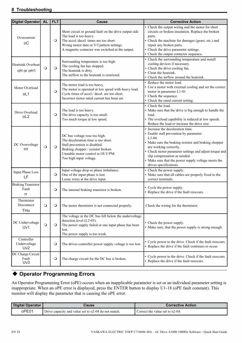
8 Troubleshooting
oC
Operator Programming ErrorsAn Operator Programming Error (oPE) occurs when an inapplicable parameter is set or an individual parameter setting is inappropriate. When an oPE error is displayed, press the ENTER button to display U1-18 (oPE fault constant). This monitor will display the parameter that is causing the oPE error.
Overcurrent
Short circuit or ground fault on the drive output sideThe load is too heavy.The accel./decel. times are too short.Wrong motor data or V/f pattern settings.A magnetic contactor was switched at the output.
• Check the output wiring and the motor for short circuits or broken insulation. Replace the broken parts.
• Check the machine for damages (gears, etc.) and repair any broken parts.
• Check the drive parameter settings.• Check the output contactor sequence.
Heatsink Overheat
oH or oH1
Surrounding temperature is too high.The cooling fan has stopped.The heatsink is dirty.The airflow to the heatsink is restricted.
• Check the surrounding temperature and install cooling devices if necessary.
• Check the drive cooling fan.• Clean the heatsink.• Check the airflow around the heatsink.
Motor Overload
oL1
The motor load is too heavy.The motor is operated at low speed with heavy load.Cycle times of accel./ decel. are too short.Incorrect motor rated current has been set.
• Reduce the motor load.• Use a motor with external cooling and set the correct
motor in parameter L1-01• Check the sequence.• Check the rated current setting.
Drive OverloadoL2
The load is too heavy.The drive capacity is too small.Too much torque at low speed.
• Check the load.• Make sure that the drive is big enough to handle the
load.• The overload capability is reduced at low speeds.
Reduce the load or increase the drive size.
DC Overvoltageov
DC bus voltage rose too high.The deceleration time is too short.Stall prevention is disabled.Braking chopper / resistor broken.Unstable motor control in OLV/PM.Too high input voltage.
• Increase the deceleration time.• Enable stall prevention by parameter
L3-04.• Make sure the braking resistor and braking chopper
are working correctly.• Check motor parameter settings and adjust torque and
slip compensation as needed.• Make sure that the power supply voltage meets the
drives specifications.
Input Phase LossLF
Input voltage drop or phase imbalance.One of the input phase is lost.Loose wires at the drive input.
• Check the power supply.• Make sure that all cables are properly fixed to the
correct terminals.Braking Transistor
Faultrr
The internal braking transistor is broken. • Cycle the power supply.• Replace the drive if the fault reoccurs.
Thermistor Disconnect
THo The motor thermistor is not connected properly. Check the wiring for the thermistor.
DC UndervoltageUv1
The voltage in the DC bus fell below the undervoltage detection level (L2-05).The power supply failed or one input phase has been lost.The power supply is too weak.
• Check the power supply.• Make sure, that the power supply is strong enough.
Controller Undervoltage
Uv2 The drives controller power supply voltage is too low. • Cycle power to the drive. Check if the fault reoccurs.
• Replace the drive if the fault continues to occur.
DC Charge Circuit FaultUv3
The charge circuit for the DC bus is broken. • Cycle power to the drive. Check if the fault reoccurs. • Replace the drive if the fault reoccurs.
Digital Operator Cause Corrective ActionoPE01 Drive capacity and value set to o2-04 do not match. Correct the value set to o2-04.
Digital Operator AL FLT Cause Corrective Action
EN 34 YASKAWA ELECTRIC TOEP C710606 48A - AC Drive A1000 1000Hz Software - Quick Start Guide

8 Troubleshooting
oPE02
Auto-Tuning Errors
Parameters were set outside the allowable setting range. Set parameters to the proper values.
oPE03
A contradictory setting is assigned to multi-function contact inputs H1-01 through to H1-08.• The same function is assigned to two inputs. (this excludes
“External fault” and “Not used”)• Input functions which require the setting of other input
functions were set alone.• Input functions that are not allowed to be used
simultaneously have been set.
• Fix any incorrect settings.• Refer to the Technical Manual for more details.
oPE05• The run command source (b1-02) or frequency reference
source (b1-01) is set to 3 but no option card is installed.• The frequency reference source is set to pulse input but
H6-01 is not 0.
• Install the required option card.• Correct the values set to b1-01 and b1-02.
oPE07
Settings to multi-function analog inputs H3-02 and H3-10 and PID functions conflict.• H3-02 and H3-10 are set to the same value. (this excludes
settings 0 and F)• PID functions have been assigned to both analog inputs and
the pulse input at the same time.
• Fix any incorrect setting.• Refer to the Technical Manual for more details.
oPE08 A function has been set that cannot be used in the control mode selected.(might appear after control mode change)
• Fix any incorrect setting.• Refer to the Technical Manual for more details.
oPE10 The V/f pattern setting is incorrect. • Check the V/f pattern settings.• Refer to the Technical Manual for more details.
Digital Operator Cause Corrective Action
Er-01Motor data faultThe input motor data are not valid. (e.g. the base frequency and base speed do not fit).
Re-enter the data and repeat Auto-Tuning.
Er-02 Minor Fault• The wiring is faulty. • Check the wiring.
Er-03 The STOP button was pressed and Auto-Tuning was canceled. Repeat the Auto-Tuning.
Er-04Resistance fault• Wrong input data.• Auto tuning exceeded the given time frame.• Calculated values out of range.
• Check the input data.• Check the wiring.• Re-enter the data and repeat the Auto-Tuning.
Er-05No-Load Current Error• Incorrect data was entered.• Auto tuning took too long.• Calculated values out of range.
Er-08
Rated Slip Error• Wrong data input.• Auto tuning exceeded the given time frame.• Calculated values out of range.
Er-12
Current detection error• One or all output phases are lost.• Current is either too low or exceeds the drives rating.• The current sensors are faulty.
• Check the wiring.• Make sure, that the drive rating fits to the motor.• Check the load. (Auto-Tuning should have been performed
without the load connected.)• Replace the drive.
End1
Excessive V/f Setting• The torque reference exceeded 20% during Auto-Tuning.• The calculated no-load current is above 80% of the motor
rated current.
• Check the V/f pattern setting.• Perform Auto-Tuning without the load connected.• Check the input data and repeat Auto-Tuning.
End3 Rated current alarm Check the input data and repeat tuning.
End4Adjusted Slip Calculation ErrorThe slip that was calculated is outside the allowable range. • Make sure the data entered for Auto-Tuning is correct.
End5Resistance Tuning ErrorThe resistance value that was calculated is outside the allowable range.
• Double check the data that was entered for the Auto-Tuning process.
• Check the motor and motor cable connection for faults.
Digital Operator Cause Corrective Action
YASKAWA ELECTRIC TOEP C710606 48A - AC Drive A1000 1000Hz Software - Quick Start Guide EN 35

8 Troubleshooting
End7
No-Load Current Alarm• The entered no-load current value was outside the
allowable range.• Auto-Tuning results were less than 5% of the motor rated
current.
• Check and correct faulty motor wiring.• Double check the data that was entered for the Auto-Tuning
process.
Digital Operator Cause Corrective Action
EN 36 YASKAWA ELECTRIC TOEP C710606 48A - AC Drive A1000 1000Hz Software - Quick Start Guide
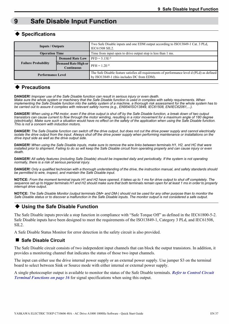
9 Safe Disable Input Function
9 Safe Disable Input Function
Specifications
Inputs / Outputs Two Safe Disable inputs and one EDM output according to ISO13849-1 Cat. 3 PLd, IEC61508 SIL2.
Operation Time Time from input open to drive output stop is less than 1 ms.
Failure ProbabilityDemand Rate Low PFD = 5.15E-5
Demand Rate High or Continuous PFH = 1.2E-9
Performance Level The Safe Disable feature satisfies all requirements of performance level d (PLd) as defined by ISO13849-1 (this includes DC from EDM).
PrecautionsDANGER! Improper use of the Safe Disable function can result in serious injury or even death. Make sure the whole system or machinery that the Safe Disable function is used in complies with safety requirements. When implementing the Safe Disable function into the safety system of a machine, a thorough risk assessment for the whole system has to be carried out to assure it complies with relevant safety norms (e.g., EN954/ISO13849, IEC61508, EN/IEC62061,...).
DANGER! When using a PM motor, even if the drive output is shut off by the Safe Disable function, a break down of two output transistors can cause current to flow through the motor winding, resulting in a rotor movement for a maximum angle of 180 degree (electrically). Make sure such a situation would have no effect on the safety of the application when using the Safe Disable function. This is not a concern with induction motors.
DANGER! The Safe Disable function can switch off the drive output, but does not cut the drive power supply and cannot electrically isolate the drive output from the input. Always shut off the drive power supply when performing maintenance or installations on the drive input side as well as the drive output side.
DANGER! When using the Safe Disable inputs, make sure to remove the wire links between terminals H1, H2, and HC that were installed prior to shipment. Failing to do so will keep the Safe Disable circuit from operating properly and can cause injury or even death.
DANGER! All safety features (including Safe Disable) should be inspected daily and periodically. If the system is not operating normally, there is a risk of serious personal injury.
DANGER! Only a qualified technician with a thorough understanding of the drive, the instruction manual, and safety standards should be permitted to wire, inspect, and maintain the Safe Disable input.
NOTICE: From the moment terminal inputs H1 and H2 have opened, it takes up to 1 ms for drive output to shut off completely. The sequence set up to trigger terminals H1 and H2 should make sure that both terminals remain open for at least 1 ms in order to properly interrupt drive output.
NOTICE: The Safe Disable Monitor (output terminals DM+ and DM-) should not be used for any other purpose than to monitor the Safe Disable status or to discover a malfunction in the Safe Disable inputs. The monitor output is not considered a safe output.
Using the Safe Disable FunctionThe Safe Disable inputs provide a stop function in compliance with “Safe Torque Off” as defined in the IEC61800-5-2. Safe Disable inputs have been designed to meet the requirements of the ISO13849-1, Category 3 PLd, and IEC61508, SIL2.
A Safe Disable Status Monitor for error detection in the safety circuit is also provided.
Safe Disable CircuitThe Safe Disable circuit consists of two independent input channels that can block the output transistors. In addition, it provides a monitoring channel that indicates the status of those two input channels.
The input can either use the drive internal power supply or an external power supply. Use jumper S3 on the terminal board to select between Sink or Source mode with either internal or external power supply.
A single photocoupler output is available to monitor the status of the Safe Disable terminals. Refer to Control Circuit Terminal Functions on page 16 for signal specifications when using this output.
YASKAWA ELECTRIC TOEP C710606 48A - AC Drive A1000 1000Hz Software - Quick Start Guide EN 37

9 Safe Disable Input Function
24V
Safety Outputs
Power Module PN
M
Gate Block 2
Gate Block 1
ControlCircuit
Main Power
H1
H2
HC
Drive
Jumper S3Setting:
SOURCE
>=1DM+
DM-
Feedback
Safety Relay or PLC with safety functionality
Disabling and Enabling the Drive Output (“Safe Torque Off”)The diagram below illustrates the Safe Disable input operation.
H1, H2 Input
Drive Output
ON (Safe Disable off)
Normal operation
OFF (Safe Disable activated)
Safe Torque-Off
Run Command Run Stop
Baseblock (Not Safe!)
Output Frequency
Motor coasts to stop
Run Command must be released to deactivate
Safe Disable Drive is ready for operation
Entering the “Safe Torque Off” StateWhenever either one Safe Disable input or both inputs open, the motor torque is shut off by switching off the drive output. If the motor was running before the Safe Disable inputs opened, then the motor will coast to stop, regardless of the stopping method set in parameter b1-03.
Notice that the “Safe Torque Off” state can only be achieved using the Safe Disable function. Removing the Run command stops the drive and shuts the output off (baseblock), but does not create a “Safe Torque Off” status.Note: To avoid an uncontrolled stop during normal operation, make sure that the Safe Disable inputs are opened first when the motor has
completely stopped.Returning to Normal Operation after Safe DisableThe Safe Disable function can only be deactivated when a Run command is not active.
When Safe Disable was activated during stop, normal operation can be resumed by simply turning on both Safe Disable inputs (i.e., by deactivating “Safe Torque Off”).
When Safe Disable was activated during run, first the Run command has to be removed and then the Safe Disable inputs have to be turned on before the drive can be restarted.
Safe Disable Monitor Output Function and Digital Operator DisplayThe table below explains the drive output and Safe Disable monitor state depending on the Safe Disable inputs.
Safe Disable Input Status Safe Disable Status Monitor,
DM+ - DM-Drive Output Status Digital Operator Display
Input 1, H1-HC Input 2, H2-HC
OFF OFF OFF Safely disabled, “Safe Torque Off” Hbb (flashes)
ON OFF ON Safely disabled, “Safe Torque Off” HbbF (flashes)
EN 38 YASKAWA ELECTRIC TOEP C710606 48A - AC Drive A1000 1000Hz Software - Quick Start Guide
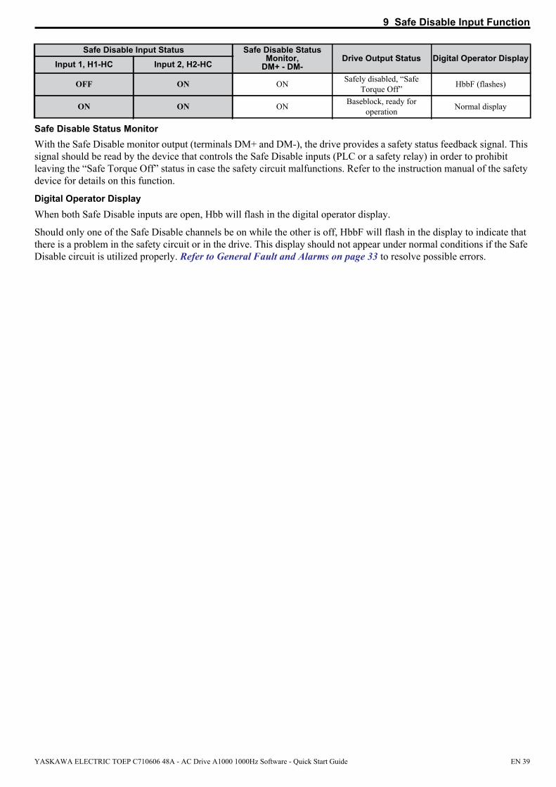
9 Safe Disable Input Function
Safe Disable Status MonitorWith the Safe Disable monitor output (terminals DM+ and DM-), the drive provides a safety status feedback signal. This signal should be read by the device that controls the Safe Disable inputs (PLC or a safety relay) in order to prohibit leaving the “Safe Torque Off” status in case the safety circuit malfunctions. Refer to the instruction manual of the safety device for details on this function.
Digital Operator DisplayWhen both Safe Disable inputs are open, Hbb will flash in the digital operator display.
Should only one of the Safe Disable channels be on while the other is off, HbbF will flash in the display to indicate that there is a problem in the safety circuit or in the drive. This display should not appear under normal conditions if the Safe Disable circuit is utilized properly. Refer to General Fault and Alarms on page 33 to resolve possible errors.
OFF ON ON Safely disabled, “Safe Torque Off” HbbF (flashes)
ON ON ON Baseblock, ready for operation Normal display
Safe Disable Input Status Safe Disable Status Monitor,
DM+ - DM-Drive Output Status Digital Operator Display
Input 1, H1-HC Input 2, H2-HC
YASKAWA ELECTRIC TOEP C710606 48A - AC Drive A1000 1000Hz Software - Quick Start Guide EN 39
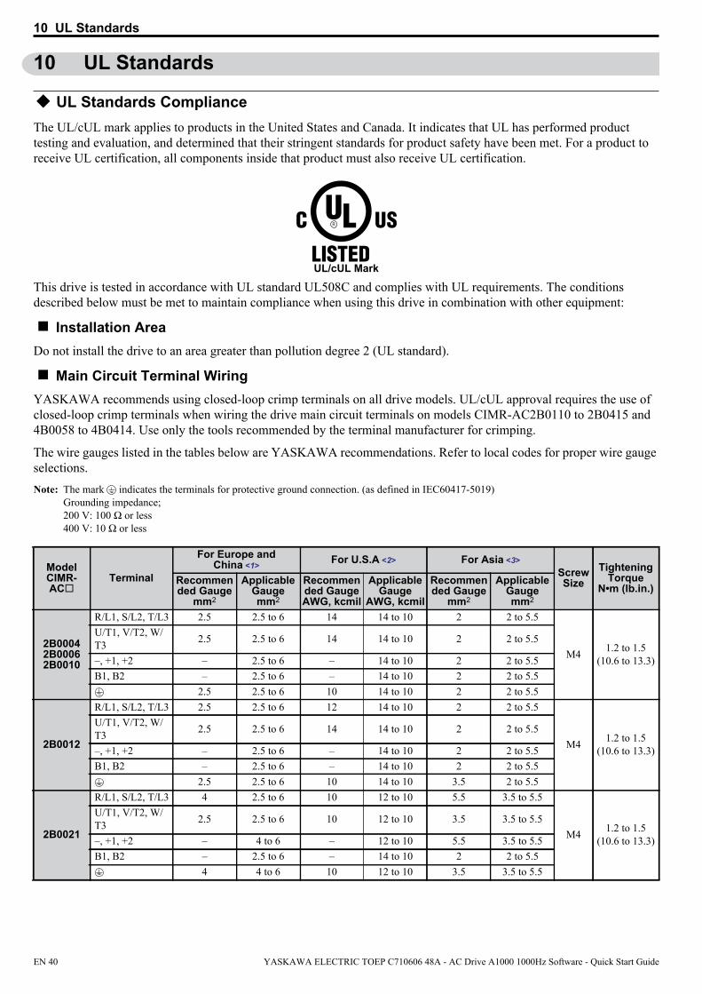
10 UL Standards
10 UL Standards
UL Standards ComplianceThe UL/cUL mark applies to products in the United States and Canada. It indicates that UL has performed product testing and evaluation, and determined that their stringent standards for product safety have been met. For a product to receive UL certification, all components inside that product must also receive UL certification.
UL/cUL Mark
This drive is tested in accordance with UL standard UL508C and complies with UL requirements. The conditions described below must be met to maintain compliance when using this drive in combination with other equipment:
Installation AreaDo not install the drive to an area greater than pollution degree 2 (UL standard).
Main Circuit Terminal Wiring YASKAWA recommends using closed-loop crimp terminals on all drive models. UL/cUL approval requires the use of closed-loop crimp terminals when wiring the drive main circuit terminals on models CIMR-AC2B0110 to 2B0415 and 4B0058 to 4B0414. Use only the tools recommended by the terminal manufacturer for crimping.
The wire gauges listed in the tables below are YASKAWA recommendations. Refer to local codes for proper wire gauge selections. Note: The mark indicates the terminals for protective ground connection. (as defined in IEC60417-5019)
Grounding impedance; 200 V: 100 Ω or less 400 V: 10 Ω or less
ModelCIMR-AC
Terminal
For Europe and China <1> For U.S.A <2> For Asia <3>
ScrewSize
TighteningTorque
N•m (lb.in.)Recommended Gauge
mm2
ApplicableGaugemm2
Recommended GaugeAWG, kcmil
ApplicableGauge
AWG, kcmil
Recommended Gauge
mm2
ApplicableGaugemm2
2B00042B00062B0010
R/L1, S/L2, T/L3 2.5 2.5 to 6 14 14 to 10 2 2 to 5.5
M4 1.2 to 1.5(10.6 to 13.3)
U/T1, V/T2, W/T3 2.5 2.5 to 6 14 14 to 10 2 2 to 5.5
–, +1, +2 – 2.5 to 6 – 14 to 10 2 2 to 5.5B1, B2 – 2.5 to 6 – 14 to 10 2 2 to 5.5
2.5 2.5 to 6 10 14 to 10 2 2 to 5.5
2B0012
R/L1, S/L2, T/L3 2.5 2.5 to 6 12 14 to 10 2 2 to 5.5
M4 1.2 to 1.5(10.6 to 13.3)
U/T1, V/T2, W/T3 2.5 2.5 to 6 14 14 to 10 2 2 to 5.5
–, +1, +2 – 2.5 to 6 – 14 to 10 2 2 to 5.5B1, B2 – 2.5 to 6 – 14 to 10 2 2 to 5.5
2.5 2.5 to 6 10 14 to 10 3.5 2 to 5.5
2B0021
R/L1, S/L2, T/L3 4 2.5 to 6 10 12 to 10 5.5 3.5 to 5.5
M4 1.2 to 1.5(10.6 to 13.3)
U/T1, V/T2, W/T3 2.5 2.5 to 6 10 12 to 10 3.5 3.5 to 5.5
–, +1, +2 – 4 to 6 – 12 to 10 5.5 3.5 to 5.5B1, B2 – 2.5 to 6 – 14 to 10 2 2 to 5.5
4 4 to 6 10 12 to 10 3.5 3.5 to 5.5
EN 40 YASKAWA ELECTRIC TOEP C710606 48A - AC Drive A1000 1000Hz Software - Quick Start Guide

10 UL Standards
2B0030
R/L1, S/L2, T/L3 6 4 to 16 8 10 to 6 14 5.5 to 14
M4 1.2 to 1.5(10.6 to 13.3)
U/T1, V/T2, W/T3 6 4 to 16 8 10 to 6 8 5.5 to 14
–, +1, +2 – 6 to 16 – 10 to 6 14 5.5 to 14B1, B2 – 4 to 6 – 14 to 10 3.5 2 to 5.5
6 6 to 10 8 10 to 8 5.5 5.5 to 8 M5 2 to 2.5(17.7 to 22.1)
2B0040
R/L1, S/L2, T/L3 10 6 to 16 6 8 to 6 14 14
M4 1.2 to 1.5(10.6 to 13.3)
U/T1, V/T2, W/T3 10 6 to 16 8 8 to 6 14 8 to 14
–, +1, +2 – 16 – 6 14 14B1, B2 – 4 to 6 – 12 to 10 5.5 3.5 to 5.5
10 6 to 10 8 10 to 8 5.5 5.5 to 8 M5 2 to 2.5(17.7 to 22.1)
2B0056
R/L1, S/L2, T/L3 16 16 to 25 4 6 to 4 22 14 to 22
M6 4 to 6(35.4 to 53.1)
U/T1, V/T2, W/T3 16 16 to 25 4 6 to 4 14 14 to 22
–, +1, +2 – 16 to 25 – 6 to 4 22 14 to 22
B1, B2 – 6 to 10 – 10 to 6 14 5.5 to 14 M5 2 to 2.5(17.7 to 22.1)
16 10 to 16 6 8 to 6 8 8 to 14 M6 4 to 6(35.4 to 53.1)
2B0069
R/L1, S/L2, T/L3 25 16 to 25 3 4 to 3 30 22 to 30
M8 9 to11(79.7 to 97.4)
U/T1, V/T2, W/T3 16 16 to 25 3 4 to 3 22 14 to 30
–, +1, +2 – 25 – 4 to 3 30 22 to 30
B1, B2 – 10 to 16 – 8 to 6 14 8 to 14 M5 2 to 2.5(17.7 to 22.1)
16 16 to 25 6 6 to 4 8 8 to 22 M6 4 to 6(35.4 to 53.1)
2B0081
R/L1, S/L2, T/L3 35 25 to 35 2 3 to 2 38 30 to 38
M8 9 to11(79.7 to 97.4)
U/T1, V/T2, W/T3 25 25 to 35 2 3 to 2 30 22 to 38
–, +1, +2 – 25 to 35 – 3 to 2 38 30 to 38
B1, B2 – 16 – 6 14 14 M5 2 to 2.5(17.7 to 22.1)
16 16 to 25 6 6 to 4 14 14 to 22 M6 4 to 6(35.4 to 53.1)
2B0110 <4>
R/L1, S/L2, T/L3 35 25 to 50 1/0 3 to 1/0 38 30 to 50
M8 9 to 11(79.7 to 97.4)
U/T1, V/T2, W/T3 35 25 to 50 1/0 3 to 1/0 38 30 to 50
–, +1 – 35 to 50 – 2 to 1/0 60 38 to 60B1, B2 – 16 to 50 – 6 to 1/0 22 14 to 50
16 16 to 25 6 6 to 4 14 14 to 38
2B0138 <4>
R/L1, S/L2, T/L3 50 35 to 70 2/0 1 to 2/0 60 50 to 60
M10 18 to 23(159 to 204)
U/T1, V/T2, W/T3 50 35 to 70 2/0 1 to 2/0 60 50 to 60
–, +1 – 50 to 70 – 1/0 to 3/0 80 60 to 80B1, B2 – 25 to 70 – 4 to 2/0 30 22 to 60
25 25 4 4 22 22 to 38 M8 9 to 11(79.7 to 97.4)
ModelCIMR-AC
Terminal
For Europe and China <1> For U.S.A <2> For Asia <3>
ScrewSize
TighteningTorque
N•m (lb.in.)Recommended Gauge
mm2
ApplicableGaugemm2
Recommended GaugeAWG, kcmil
ApplicableGauge
AWG, kcmil
Recommended Gauge
mm2
ApplicableGaugemm2
YASKAWA ELECTRIC TOEP C710606 48A - AC Drive A1000 1000Hz Software - Quick Start Guide EN 41

10 UL Standards
Note: Use crimp insulated terminals or insulated tubing for wiring these connections. Wires should have a continuous maximum allowable temperature of 75°C 600 V UL approved vinyl sheathed insulation. Ambient temperature should not exceed 40°C.
2B0169 <4>
R/L1, S/L2, T/L3 70 50 to 95 4/0 2/0 to 4/0 80 60 to 100
M10
18 to 23(159 to 204)
U/T1, V/T2, W/T3 70 50 to 95 4/0 3/0 to 4/0 80 60 to 100
–, +1 – 35 to 95 – 1 to 4/0 50 × 2P 50 to 100+3 – 50 to 95 – 1/0 to 4/0 60 50 to 100
35 25 to 35 4 4 to 2 22 22 to 60 9 to 11(79.7 to 97.4)
2B0211 <4>
R/L1, S/L2, T/L3 95 70 to 95 1/0 × 2P 1/0 to 2/0 100 80 to 100
M10
18 to 23(159 to 204)
U/T1, V/T2, W/T3 95 70 to 95 1/0 × 2P 1/0 to 2/0 50 × 2P 50 to 60
–, +1 – 35 to 95 – 1 to 4/0 50 × 2P 50 to 100+3 – 50 to 95 – 1/0 to 4/0 80 60 to 100
50 25 to 50 4 4 to 1/0 22 22 to 60 9 to 11(79.7 to 97.4)
2B0250 <4>
R/L1, S/L2, T/L3 95 × 2P 95 to 150 3/0 × 2P 3/0 to 300 80 × 2P 38 to 150
M12 32 to 40(283 to 354)
U/T1, V/T2, W/T3 95 × 2P 95 to 150 3/0 × 2P 3/0 to 300 80 × 2P 38 to 150
–, +1 – 70 to 150 – 3/0 to 300 80 × 2P 80 to 150
+3 – 35 to 150 – 2 to 300 80 × 2P 30 to 150 M10 18 to 23(159 to 204)
95 95 to 150 3 3 to 300 22 22 to 150 M12 32 to 40(283 to 354)
2B0312 <4>
R/L1, S/L2, T/L3 95 × 2P 95 to 150 4/0 × 2P 3/0 to 300 80 × 2P 70 to 150
M12 32 to 40(283 to 354)
U/T1, V/T2, W/T3 95 × 2P 95 to 150 3/0 × 2P 3/0 to 300 80 × 2P 70 to 200
–, +1 – 70 to 150 – 3/0 to 300 150 × 2P 80 to 150
+3 – 70 to 150 – 3/0 to 300 80 × 2P 80 to 150 M10 18 to 23(159 to 204)
95 95 to 150 2 2 to 300 38 38 to 150 M12 32 to 40(283 to 354)
2B0360 <4>
R/L1, S/L2, T/L3 240 95 to 300 250 × 2P 4/0 to 600 100 × 2P 80 to 325
M12 32 to 40(283 to 354)
U/T1, V/T2, W/T3 240 95 to 300 4/0 × 2P 4/0 to 600 100 × 2P 80 to 325
–, +1 – 125 to 300 – 250 to 600 150 × 2P 125 to 325
+3 – 70 to 300 – 3/0 to 600 80 × 2P 80 to 325 M10 18 to 23(159 to 204)
120 120 to 240 1 1 to 350 38 38 to 200 M12 32 to 40(283 to 354)
2B0415 <4>
R/L1, S/L2, T/L3 120 × 2P 95 to 300 350 × 2P 250 to 600 125 × 2P 100 to 325
M12 32 to 40(283 to 354)
U/T1, V/T2, W/T3 300 95 to 300 300 × 2P 300 to 600 125 × 2P 125 to 325
–, +1 – 150 to 300 – 300 to 600 200 × 2P 150 to 325
+3 – 70 to 300 – 3/0 to 600 100 × 2P 80 to 325 M10 18 to 23(159 to 204)
120 120 to 240 1 1 to 350 60 60 to 200 M12 32 to 40(283 to 354)
<1> Gauges listed here are for use in Europe and China.<2> Gauges listed here are for use in the United States.<3> Gauges listed here are for use in Asia except for China.<4> Drive models CIMR-AC2B0110 to 2B0415 require the use of closed-loop crimp terminals for UL/cUL compliance. Use only the tools
recommended by the terminal manufacturer for crimping.
ModelCIMR-AC
Terminal
For Europe and China <1> For U.S.A <2> For Asia <3>
ScrewSize
TighteningTorque
N•m (lb.in.)Recommended Gauge
mm2
ApplicableGaugemm2
Recommended GaugeAWG, kcmil
ApplicableGauge
AWG, kcmil
Recommended Gauge
mm2
ApplicableGaugemm2
EN 42 YASKAWA ELECTRIC TOEP C710606 48A - AC Drive A1000 1000Hz Software - Quick Start Guide

10 UL Standards
ModelCIMR-AC
Terminal
For Europe and China <1> For U.S.A <2> For Asia <3>
ScrewSize
TighteningTorque
N•m (lb.in.)Recommended Gauge
mm2
ApplicableGaugemm2
Recommended GaugeAWG, kcmil
ApplicableGauge
AWG, kcmil
Recommended Gauge
mm2
ApplicableGaugemm2
4B00024B0004
R/L1, S/L2, T/L3 2.5 2.5 to 6 14 14 to 10 2 2 to 5.5
M4 1.2 to 1.5(10.6 to 13.3)
U/T1, V/T2, W/T3 2.5 2.5 to 6 14 14 to 10 2 2 to 5.5
–, +1, +2 – 2.5 to 6 – 14 to 10 2 2 to 5.5B1, B2 – 2.5 to 6 – 14 to 10 2 2 to 5.5
2.5 2.5 to 4 12 14 to 12 2 2 to 5.5
4B00054B00074B0009
R/L1, S/L2, T/L3 2.5 2.5 to 6 14 14 to 10 2 2 to 5.5
M4 1.2 to 1.5(10.6 to 13.3)
U/T1, V/T2, W/T3 2.5 2.5 to 6 14 14 to 10 2 2 to 5.5
–, +1, +2 – 2.5 to 6 – 14 to 10 2 2 to 5.5B1, B2 – 2.5 to 6 – 14 to 10 2 2 to 5.5
2.5 2.5 to 6 10 14 to 10 3.5 2 to 5.5
4B0011
R/L1, S/L2, T/L3 2.5 2.5 to 6 12 14 to 10 2 2 to 5.5
M4 1.2 to 1.5(10.6 to 13.3)
U/T1, V/T2, W/T3 2.5 2.5 to 6 14 14 to 10 2 2 to 5.5
–, +1, +2 – 2.5 to 6 – 14 to 10 2 2 to 5.5B1, B2 – 2.5 to 6 – 14 to 10 2 2 to 5.5
2.5 2.5 to 6 10 14 to 10 3.5 2 to 5.5
4B0018
R/L1, S/L2, T/L3 2.5 2.5 to 16 10 12 to 6 3.5 2 to 14
M4 1.2 to 1.5(10.6 to 13.3)
U/T1, V/T2, W/T3 2.5 2.5 to 16 10 12 to 6 3.5 2 to 14
–, +1, +2 – 4 to 16 – 12 to 6 3.5 2 to 14B1, B2 – 4 to 6 – 12 to 10 2 2 to 5.5
2.5 2.5 to 6 10 14 to 10 3.5 2 to 5.5 M5 2 to 2.5(17.7 to 22.1)
4B0023
R/L1, S/L2, T/L3 4 2.5 to 16 10 10 to 6 5.5 3.5 to 14
M4 1.2 to 1.5(10.6 to 13.3)
U/T1, V/T2, W/T3 4 2.5 to 16 10 10 to 6 5.5 3.5 to 14
–, +1, +2 – 4 to 16 – 12 to 6 5.5 3.5 to 14B1, B2 – 4 to 6 – 12 to 10 2 2 to 5.5
4 4 to 6 10 12 to 10 3.5 3.5 to 5.5 M5 2 to 2.5(17.7 to 22.1)
4B0031
R/L1, S/L2, T/L3 6 6 to 16 8 8 to 6 14 5.5 to 14
M5 2 to 2.5(17.7 to 22.1)
U/T1, V/T2, W/T3 6 6 to 16 8 10 to 6 8 5.5 to 8
–, +1, +2 – 6 to 16 – 10 to 6 14 5.5 to 14
B1, B2 – 6 to 10 – 10 to 8 3.5 2 to 8 M5 2 to 2.5(17.7 to 22.1)
6 6 to 10 8 10 to 8 5.5 5.5 to 8 M6 4 to 6(35.4 to 53.1)
4B0038
R/L1, S/L2, T/L3 10 10 to 16 6 8 to 6 14 14
M5 2 to 2.5(17.7 to 22.1)
U/T1, V/T2, W/T3 6 6 to 16 8 8 to 6 14 8 to 14
–, +1, +2 – 6 to 16 – 6 14 14
B1, B2 – 6 to 10 – 10 to 8 5.5 3.5 to 8 M5 2 to 2.5(17.7 to 22.1)
10 6 to 16 6 10 to 6 8 5.5 to 14 M6 4 to 6(35.4 to 53.1)
YASKAWA ELECTRIC TOEP C710606 48A - AC Drive A1000 1000Hz Software - Quick Start Guide EN 43

10 UL Standards
4B0044
R/L1, S/L2, T/L3 16 16 to 25 6 6 to 4 14 14 to 22
M6 4 to 6(35.4 to 53.1)
U/T1, V/T2, W/T3 16 16 to 25 6 6 to 4 14 14 to 22
–, +1, +2 – 16 to 25 – 6 to 4 14 14 to 22
B1, B2 – 6 to 10 – 10 to 8 8 5.5 to 8 M5 2 to 2.5(17.7 to 22.1)
16 10 to 16 6 8 to 6 8 8 to 14 M6 4 to 6(35.4 to 53.1)
4B0058 <4>
R/L1, S/L2, T/L3 16 10 to 16 4 6 to 4 14 14
M8 9 to 11(79.7 to 97.4)
U/T1, V/T2, W/T3 16 10 to 16 4 6 to 4 14 14
–, +1 – 16 to 35 – 6 to 1 22 14 to 38B1, B2 – 10 to 16 – 8 to 4 14 8 to 14
16 10 to 16 6 8 to 6 8 8 to 14
4B0072 <4>
R/L1, S/L2, T/L3 16 16 to 25 3 4 to 3 22 14 to 22
M8 9 to 11(79.7 to 97.4)
U/T1, V/T2, W/T3 25 16 to 25 3 4 to 3 22 14 to 22
–, +1 – 25 to 35 – 4 to 1 30 22 to 38B1, B2 – 16 to 25 – 6 to 3 14 14 to 22
16 16 to 25 6 6 14 14 to 22
4B0088 <4>
R/L1, S/L2, T/L3 25 16 to 50 2 3 to 1/0 30 22 to 60
M8 9 to 11(79.7 to 97.4)
U/T1, V/T2, W/T3 25 25 to 50 2 3 to 1/0 30 22 to 60
–, +1 – 25 to 50 – 3 to 1/0 38 30 to 60+3 – 16 to 50 – 6 to 1/0 22 14 to 60
16 16 to 25 4 6 to 4 22 14 to 22
4B0103 <4>
R/L1, S/L2, T/L3 35 25 to 50 1/0 2 to 1/0 38 30 to 60
M8 9 to 11(79.7 to 97.4)
U/T1, V/T2, W/T3 35 25 to 50 1 2 to 1/0 38 30 to 60
–, +1 – 25 to 50 – 3 to 1/0 60 30 to 60+3 – 25 to 50 – 4 to 1/0 30 22 to 60
16 16 to 25 4 6 to 4 22 14 to 22
4B0139 <4>
R/L1, S/L2, T/L3 50 35 to 95 3/0 1/0 to 4/0 60 38 to 100
M10 18 to 23(159 to 204)
U/T1, V/T2, W/T3 50 35 to 95 2/0 1/0 to 4/0 60 50 to 100
–, +1 – 50 to 95 – 1/0 to 4/0 100 60 to 100+3 – 25 to 95 – 3 to 4/0 50 30 to 100
25 25 4 4 22 22
4B0165 <4>
R/L1, S/L2, T/L3 70 50 to 95 4/0 3/0 to 4/0 80 60 to 100
M10 18 to 23(159 to 204)
U/T1, V/T2, W/T3 70 70 to 95 4/0 3/0 to 4/0 80 80 to 100
–, +1 – 35 to 95 – 1 to 4/0 50 × 2P 50 to 100+3 – 50 to 95 – 1/0 to 4/0 60 50 to 100
35 25 to 35 4 4 to 2 22 22 to 30
4B0208 <4>
R/L1, S/L2, T/L3 95 35 to 95 300 2 to 300 150 30 to 150
M10 18 to 23(159 to 204)
U/T1, V/T2, W/T3 95 35 to 95 300 2 to 300 150 30 to 150
–, +1 – 35 to 150 – 1 to 250 80 × 2P 38 to 150+3 – 25 to 70 – 3 to 3/0 80 22 to 80
50 50 to 150 4 4 to 300 22 22 to 150
ModelCIMR-AC
Terminal
For Europe and China <1> For U.S.A <2> For Asia <3>
ScrewSize
TighteningTorque
N•m (lb.in.)Recommended Gauge
mm2
ApplicableGaugemm2
Recommended GaugeAWG, kcmil
ApplicableGauge
AWG, kcmil
Recommended Gauge
mm2
ApplicableGaugemm2
EN 44 YASKAWA ELECTRIC TOEP C710606 48A - AC Drive A1000 1000Hz Software - Quick Start Guide

10 UL Standards
Note: Use crimp insulated terminals or insulated tubing for wiring these connections. Wires should have a continuous maximum allowable temperature of 75°C 600 V UL approved vinyl sheathed insulation. Ambient temperature should not exceed 40°C.
Closed-Loop Crimp Terminal RecommendationsYASKAWA recommends using closed-loop crimp terminals on all drive models. UL approval requires the use of crimp terminals when wiring the drive main circuit terminals on models CIMR-AC2B0110 to 2B0415 and 4B0058 to 4B0414. Use only crimping tools as specified by the crimp terminal manufacturer. YASKAWA recommends crimp terminals made by JST and Tokyo DIP (or equivalent) for the insulation cap.
The table below matches the wire gauges and terminal screw sizes with YASKAWA - recommended crimp terminals, tools, and insulation caps. Refer to the appropriate Wire Gauge and Torque Specifications table for the wire gauge and screw size for your drive model. Place orders with a YASKAWA representatives the YASKAWA sales department.
4B0250 <4>
R/L1, S/L2, T/L3 120 95 to 300 400 1 to 600 150 38 to 325
M10 18 to 23(159 to 204)
U/T1, V/T2, W/T3 120 95 to 300 400 1/0 to 600 150 38 to 325
–, +1 – 70 to 300 – 3/0 to 600 200 80 to 325+3 – 35 to 300 – 1 to 325 125 38 to 325
70 70 to 240 2 2 to 350 22 22 to 200
4B0296 <4>
R/L1, S/L2, T/L3 185 95 to 300 500 2/0 to 600 200 80 to 325
M12 32 to 40(283 to 354)
U/T1, V/T2, W/T3 185 95 to 300 500 2/0 to 600 200 80 to 325
–, +1 – 70 to 300 – 3/0 to 600 325 80 to 325
+3 – 35 to 300 – 1 to 325 150 38 to 325 M10 18 to 23(159 to 204)
95 95 to 240 2 2 to 350 30 30 to 200 M12 32 to 40(283 to 354)
4B0362 <4>
R/L1, S/L2, T/L3 240 95 to 300 4/0 × 2P 3/0 to 600 250 80 to 325
M12 32 to 40(283 to 354)
U/T1, V/T2, W/T3 240 95 to 300 4/0 × 2P 3/0 to 600 250 80 to 325
–, +1 – 95 to 300 – 4/0 to 600 325 100 to 325
+3 – 70 to 300 – 3/0 to 600 200 80 to 325 M10 18 to 23(159 to 204)
120 120 to 240 1 1 to 350 30 30 to 200 M12 32 to 40(283 to 354)
4B0414 <4>
R/L1, S/L2, T/L3 95 × 2P 95 to 150 300 × 2P 4/0 to 300 100 × 2P 80 to 150
M12 32 to 40(283 to 354)
U/T1, V/T2, W/T3 95 × 2P 95 to 150 300 × 2P 4/0 to 300 125 × 2P 80 to 150
–, +1 – 70 to 150 – 3/0 to 300 150 × 2P 80 to 150+3 – 70 to 150 – 3/0 to 300 80 × 2P 80 to 150
95 35 to 95 1 1 to 3/0 38 38 to 100
<1> Gauges listed here are for use in Europe and China.<2> Gauges listed here are for use in the United States.<3> Gauges listed here are for use in Asia except for China.<4> Drive models CIMR-AC4B0058 to 4B0414 require the use of closed-loop crimp terminals for UL/cUL compliance. Use only the tools
recommended by the terminal manufacturer for crimping.
Wire Gauge Terminal Screws Crimp TerminalModel Number
Tool Insulation CapModel No.Machine No. Die Jaw
2 mm2
14 AWG M4 R2-4 YA-4 AD-900 TP-003
3.5 / 5.5 mm2
12 / 10 AWGM4 R5.5-4 YA-4 AD-900 TP-005M5 R5.5-5 YA-4 AD-900 TP-005
8 mm2
8 AWGM4 8-4 YA-4 AD-901 TP-008M5 R8-5 YA-4 AD-901 TP-008
ModelCIMR-AC
Terminal
For Europe and China <1> For U.S.A <2> For Asia <3>
ScrewSize
TighteningTorque
N•m (lb.in.)Recommended Gauge
mm2
ApplicableGaugemm2
Recommended GaugeAWG, kcmil
ApplicableGauge
AWG, kcmil
Recommended Gauge
mm2
ApplicableGaugemm2
YASKAWA ELECTRIC TOEP C710606 48A - AC Drive A1000 1000Hz Software - Quick Start Guide EN 45
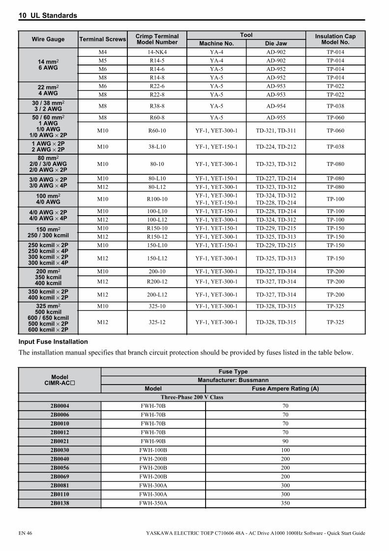
10 UL Standards
Input Fuse InstallationThe installation manual specifies that branch circuit protection should be provided by fuses listed in the table below.
14 mm2
6 AWG
M4 14-NK4 YA-4 AD-902 TP-014M5 R14-5 YA-4 AD-902 TP-014M6 R14-6 YA-5 AD-952 TP-014M8 R14-8 YA-5 AD-952 TP-014
22 mm2
4 AWGM6 R22-6 YA-5 AD-953 TP-022M8 R22-8 YA-5 AD-953 TP-022
30 / 38 mm2
3 / 2 AWG M8 R38-8 YA-5 AD-954 TP-038
50 / 60 mm2
1 AWG1/0 AWG
1/0 AWG × 2P
M8 R60-8 YA-5 AD-955 TP-060
M10 R60-10 YF-1, YET-300-1 TD-321, TD-311 TP-060
1 AWG × 2P2 AWG × 2P M10 38-L10 YF-1, YET-150-1 TD-224, TD-212 TP-038
80 mm2
2/0 / 3/0 AWG2/0 AWG × 2P
M10 80-10 YF-1, YET-300-1 TD-323, TD-312 TP-080
3/0 AWG × 2P3/0 AWG × 4P
M10 80-L10 YF-1, YET-150-1 TD-227, TD-214 TP-080M12 80-L12 YF-1, YET-300-1 TD-323, TD-312 TP-080
100 mm2
4/0 AWG M10 R100-10 YF-1, YET-300-1YF-1, YET-150-1
TD-324, TD-312TD-228, TD-214 TP-100
4/0 AWG × 2P4/0 AWG × 4P
M10 100-L10 YF-1, YET-150-1 TD-228, TD-214 TP-100M12 100-L12 YF-1, YET-300-1 TD-324, TD-312 TP-100
150 mm2
250 / 300 kcmilM10 R150-10 YF-1. YET-150-1 TD-229, TD-215 TP-150M12 R150-12 YF-1, YET-300-1 TD-325, TD-313 TP-150
250 kcmil × 2P250 kcmil × 4P300 kcmil × 2P300 kcmil × 4P
M10 150-L10 YF-1, YET-150-1 TD-229, TD-215 TP-150
M12 150-L12 YF-1, YET-300-1 TD-325, TD-313 TP-150
200 mm2
350 kcmil400 kcmil
M10 200-10 YF-1, YET-300-1 TD-327, TD-314 TP-200
M12 R200-12 YF-1, YET-300-1 TD-327, TD-314 TP-200
350 kcmil × 2P400 kcmil × 2P M12 200-L12 YF-1, YET-300-1 TD-327, TD-314 TP-200
325 mm2
500 kcmil600 / 650 kcmil500 kcmil × 2P600 kcmil × 2P
M10 325-10 YF-1, YET-300-1 TD-328, TD-315 TP-325
M12 325-12 YF-1, YET-300-1 TD-328, TD-315 TP-325
ModelCIMR-AC
Fuse TypeManufacturer: Bussmann
Model Fuse Ampere Rating (A)Three-Phase 200 V Class
2B0004 FWH-70B 702B0006 FWH-70B 702B0010 FWH-70B 702B0012 FWH-70B 702B0021 FWH-90B 902B0030 FWH-100B 1002B0040 FWH-200B 2002B0056 FWH-200B 2002B0069 FWH-200B 2002B0081 FWH-300A 3002B0110 FWH-300A 3002B0138 FWH-350A 350
Wire Gauge Terminal Screws Crimp TerminalModel Number
Tool Insulation CapModel No.Machine No. Die Jaw
EN 46 YASKAWA ELECTRIC TOEP C710606 48A - AC Drive A1000 1000Hz Software - Quick Start Guide

10 UL Standards
Low Voltage Wiring for Control Circuit TerminalsWire low voltage wires with NEC Class 1 circuit conductors. Refer to national state or local codes for wiring. Use a class 2 power supply for the control circuit terminal when not using the internal control power supply of the drive. Refer to NEC Article 725 Class 1, Class 2, and Class 3 Remote-Control, Signaling, and Power Limited Circuits for requirements concerning class 1 circuit conductors and class 2 power supplies.
Input / Output Terminal Signal Power Supply SpecificationsOpen Collector Outputs DM+, DM- Requires class 2 power supply.Digital inputs S1-S8, SN, SC, SP, HC, H1, H2 Use the internal LVLC power supply of the drive. Use class 2 for external power supply.Analog inputs / outputs +V, -V, A1, A2, A3, AC, AM, FM Use the internal LVLC power supply of the drive. Use class 2 for external power supply.
Drive Short-Circuit RatingThis drive is suitable for use on a circuit capable of delivering not more than 100,000 RMS symmetrical amperes, 600 Vac maximum (Up to 240 V in 200 V class drives , up to 480 V for 400 V class drives) when protected by Bussmann Type FWH fuses as specified in Input Fuse Installation on page 46.
Drive Motor Overload ProtectionSet parameter E2-01 (motor rated current) to the appropriate value to enable motor overload protection. The internal motor overload protection is UL listed and in accordance with the NEC and CEC.
E2-01 Motor Rated CurrentSetting Range: Model Dependent
2B0169 FWH-400A 4002B0211 FWH-400A 4002B0250 FWH-600A 6002B0312 FWH-700A 7002B0360 FWH-800A 8002B0415 FWH-1000A 1000
Three-Phase 400 V Class4B0002 FWH-40B 404B0004 FWH-50B 504B0005 FWH-70B 704B0007 FWH-70B 704B0009 FWH-90B 904B0011 FWH-90B 904B0018 FWH-80B 804B0023 FWH-100B 1004B0031 FWH-125B 1254B0038 FWH-200B 2004B0044 FWH-250A 2504B0058 FWH-250A 2504B0072 FWH-250A 2504B0088 FWH-250A 2504B0103 FWH-250A 2504B0139 FWH-350A 3504B0165 FWH-400A 4004B0208 FWH-500A 5004B0250 FWH-600A 6004B0296 FWH-700A 7004B0362 FWH-800A 8004B0414 FWH-800A 800
ModelCIMR-AC
Fuse TypeManufacturer: Bussmann
Model Fuse Ampere Rating (A)
YASKAWA ELECTRIC TOEP C710606 48A - AC Drive A1000 1000Hz Software - Quick Start Guide EN 47
10 UL Standards
Default Setting: Model Dependent
Parameter E2-01 (motor rated current) protects the motor if parameter L1-01 is not set to 0 (default is 1, enabling protection for standard induction motors).
If Auto-Tuning has been performed successfully, the motor data entered to T1-04 is automatically written into parameter E2-01. If Auto-Tuning has not been performed, manually enter the correct motor rated current to parameter E2-01.
L1-01 Motor Overload Protection SelectionThe drive has an electronic overload protection function (oL1) based on time, output current, and output frequency, which protects the motor from overheating. The electronic thermal overload function is UL-recognized, so it does not require an external thermal relay for single motor operation.
This parameter selects the motor overload curve used according to the type of motor applied.
Setting Description0 Disabled Disabled the drive’s internal motor overload protection.
1 Standard fan cooled motor (default)Selects protection characteristics for a standard self cooled motor with limited cooling capabilities when running below the rated speed. The motor overload detection level (oL1) is automatically reduces when running below the motor rated speed.
2 Drive duty motor with a speed range of 1:10
Selects protection characteristics for a motor with self-cooling capability within a speed range of 10:1. The motor overload detection level (oL1) is automatically reduced when running below 1/10 of the motor rated speed.
3 Vector motor with a speed range of 1:100Selects protection characteristics for a motor capable of cooling itself at any speed — including zero speed (externally cooled motor). The motor overload detection level (oL1) is constant over the entire speed range.
4 Permanent Magnet motor with variable torque
Selects protection characteristics for a variable torque PM motor. The motor overload detection level (oL1) is automatically reduces when running below the motor rated speed.
5 Permanent Magnet motor with constant torque
Selects protection characteristics for a constant torque PM motor. The motor overload detection level (oL1) is constant over the whole speed range.
6 Standard fan cooled motor (50 Hz)Selects protection characteristics for a standard self cooled motor with limited cooling capabilities when running below the rated speed. The motor overload detection level (oL1) is automatically reduces when running below the motor rated speed.
When connecting the drive to more than one motor for simultaneous operation, disable the electronic overload protection (L1-01 = 0) and wire each motor with its own motor thermal overload relay.
Enable the motor overload protection (L1-01 = 1 to 5) when connecting the drive to a single motor, unless another motor overload preventing device is installed. The drive electronic thermal overload function causes an oL1 fault, which shuts off the output of the drive and prevents additional overheating of the motor. The motor temperature is continually calculated as long as the drive is powered up.
L1-02 Motor Overload Protection TimeSetting Range: 0.1 to 5.0 min
Factory Default: 1.0 min
Parameter L1-02 determines how long the motor is allowed to operate before the oL1 fault occurs when the drive is running at 50 Hz and at 150% of the full load amp rating (E2-01) of the motor. Adjusting the value of L1-02 can shift the set of oL1 curves up the y axis of the diagram below, but will not change the shape of the curves.
EN 48 YASKAWA ELECTRIC TOEP C710606 48A - AC Drive A1000 1000Hz Software - Quick Start Guide

10 UL Standards
107
3
1
0.4
0.10 100 200150
Cold Start
Hot Start
Motor Current (%) (E2-01=100 %)
Time (min)
Precautionary Notes on External Heatsink (IP00 Enclosure)When using an external heatsink, UL compliance requires that exposed capacitors in the main circuit are covered to prevent injury to surrounding personnel.
The portion of the external heatsink that projects out can either be protected with the enclosure, or with the appropriate capacitor cover after drive installation is complete. Use the table below to match drive models and capacitor cover. Capacitor covers can be ordered from a YASKAWA representative or directly from the YASKAWA sales department. The table below lists available capacitor covers.
Drive ModelCIMR-AC Code Number Model Figure
2B0110 100-061-273 ECAT31875-11
7
2B0138 100-061-274 ECAT31876-112B0169
100-061-275 ECAT31877-112B02112B0250
100-061-277 ECAT31726-112B03122B0360
100-061-278 ECAT31698-112B04154B0058 100-061-273 ECAT31875-114B0072 100-061-274 ECAT31876-114B0088
100-061-276 ECAT31878-114B0103 4B0139
100-061-275 ECAT31877-114B0165 4B0208 100-061-277 ECAT31726-114B0250
100-061-278 ECAT31698-114B02964B03624B0414 100-061-279 ECAT31740-11
YASKAWA ELECTRIC TOEP C710606 48A - AC Drive A1000 1000Hz Software - Quick Start Guide EN 49
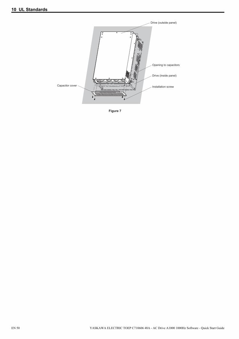
10 UL Standards
Drive (outside panel)
Opening to capacitors
Drive (inside panel)
Installation screw
Figure 7
Capacitor cover
EN 50 YASKAWA ELECTRIC TOEP C710606 48A - AC Drive A1000 1000Hz Software - Quick Start Guide
YASKAWA ELECTRIC TOEP C710606 48A - AC Drive A1000 1000Hz Software - Quick Start Guide EN 51
Revision History
The revision dates and the numbers of the revised manuals appear on the bottom of the back cover.
MANUAL NO. TOEP C710616 48APublished in Japan June 2011 11-06 1
Date of publication Date of original
publication
Revision number
Date of Publication Rev. No. Section Revised Content
June 2011 - - First edition
EUROPEN HEADQUATERSYASKAWA EUROPE GmbHHauptstraβe 185, 65760 Eschborn, GermanyPhone: +49 (0)6196 569 300 Fax: +49 (0)6196 569 398E-mail: [email protected] Internet: http://www.yaskawa.eu.com
U.S.A.YASKAWA AMERICA, INC.2121 Norman Drive South, Waukegan, IL 60085, U.S.A.Phone: +1 847 887 7000 Fax: +1 847 887 7370Internet: http://www.yaskawa.com
JAPANYASKAWA ELECTRIC CORPORATIONNew Pier Takeshiba South Tower, 1-16-1, Kaigan, Minatoku, Tokyo, 105-0022, Japan Phone: +81 (0)3 5402 4511 Fax: +81 (0)3 5402 4580Internet: http://www.yaskawa.co.jp
YASKAWA ELECTRIC CORPORATION
In the event that the end user of this product is to be the military and said product is to be employed in any weapons systems or the manufacture thereof, the export will fall under the relevant regulations as stipulated in the Foreign Exchange and Foreign Trade Regulations. Therefore, be sure to follow all procedures and submit all relevant documentation according to any and all rules, regulations and laws that may apply.
Specifications are subject to change without notice for ongoing product modifications and improvements.
© 2011 YASKAWA ELECTRIC CORPORATION. All rights reserved.
10-7-3_YECPublished in Japan June 2011 11-08
MANUAL NO. TOEP C710616 48A
YASKAWA AC Drive A10001000Hz Software
Quick Start Guide