
RPM AC Inverter Duty Motors L400 Frame Top Drive Application
28
— MN436_July 2020 July 2020 — RPM AC Inverter Duty Motors L400 Frame Top Drive Application (Specifically designed for operation with Adjustable Speed Controls) User’s guide
-
Upload
khangminh22 -
Category
Documents
-
view
0 -
download
0
Transcript of RPM AC Inverter Duty Motors L400 Frame Top Drive Application

—
MN
436_
July
20
20
July 2020
—RPM AC Inverter Duty MotorsL400 FrameTop Drive Application
(Specifically designed for operation with
Adjustable Speed Controls)
User’s guide

Any trademarks used in this manual are the property of their respective owners.
Note: Baldor Electric Company, became ABB Motors and Mechanical, Inc. on March 1, 2018. Nameplates, Declaration of Conformity and other collateral material may contain the company name of Baldor Electric Company and the brand names of Baldor-Dodge and Baldor-Reliance as well as the company name of ABB until such time as all materials have been updated to reflect our new corporate identity of ABB.
Important:Be sure to check www.baldor.com for the latest software, firmware and drivers for your EC Titanium product. Also, you can download the latest version of this manual in Adobe Acrobat PDF format.

iMN436
Section 1 General Information . . . . . . . . . . . . . . . . . . . . . . . . . . . . . . . . . . . . . . . . . . . . . . . . . . . . . . . . . . . . . . . . . 1−1
Overview . . . . . . . . . . . . . . . . . . . . . . . . . . . . . . . . . . . . . . . . . . . . . . . . . . . . . . . . . . . . . . . . . . . . . . . 1−1Safety Notice . . . . . . . . . . . . . . . . . . . . . . . . . . . . . . . . . . . . . . . . . . . . . . . . . . . . . . . . . . . . . . . . . . . . 1−1Receiving . . . . . . . . . . . . . . . . . . . . . . . . . . . . . . . . . . . . . . . . . . . . . . . . . . . . . . . . . . . . . . . . . . . . . . . 1−2Handling . . . . . . . . . . . . . . . . . . . . . . . . . . . . . . . . . . . . . . . . . . . . . . . . . . . . . . . . . . . . . . . . . . . . . . . 1−2Storage . . . . . . . . . . . . . . . . . . . . . . . . . . . . . . . . . . . . . . . . . . . . . . . . . . . . . . . . . . . . . . . . . . . . . . . . 1−2EMC Compliance Statement for European Union . . . . . . . . . . . . . . . . . . . . . . . . . . . . . . . . . . . . . . . 1−3Insulation Resistance Measurement . . . . . . . . . . . . . . . . . . . . . . . . . . . . . . . . . . . . . . . . . . . . . . . . . . 1−4
Section 2 Installation & Operation . . . . . . . . . . . . . . . . . . . . . . . . . . . . . . . . . . . . . . . . . . . . . . . . . . . . . . . . . . . . . . 2−1
Overview . . . . . . . . . . . . . . . . . . . . . . . . . . . . . . . . . . . . . . . . . . . . . . . . . . . . . . . . . . . . . . . . . . . . . . . 2−1Mechanical Installation . . . . . . . . . . . . . . . . . . . . . . . . . . . . . . . . . . . . . . . . . . . . . . . . . . . . . . . . . . . . 2−1Mounting Location . . . . . . . . . . . . . . . . . . . . . . . . . . . . . . . . . . . . . . . . . . . . . . . . . . . . . . . . . . . . . . . 2−1Alignment . . . . . . . . . . . . . . . . . . . . . . . . . . . . . . . . . . . . . . . . . . . . . . . . . . . . . . . . . . . . . . . . . . . . . . 2−2Guarding . . . . . . . . . . . . . . . . . . . . . . . . . . . . . . . . . . . . . . . . . . . . . . . . . . . . . . . . . . . . . . . . . . . . . . . 2−2Electrical Connection . . . . . . . . . . . . . . . . . . . . . . . . . . . . . . . . . . . . . . . . . . . . . . . . . . . . . . . . . . . . . 2−2Grounding . . . . . . . . . . . . . . . . . . . . . . . . . . . . . . . . . . . . . . . . . . . . . . . . . . . . . . . . . . . . . . . . . . . . . . 2−3Optional Accessories . . . . . . . . . . . . . . . . . . . . . . . . . . . . . . . . . . . . . . . . . . . . . . . . . . . . . . . . . . . . . . 2−4First Time Start Up . . . . . . . . . . . . . . . . . . . . . . . . . . . . . . . . . . . . . . . . . . . . . . . . . . . . . . . . . . . . . . . 2−4Air Flow Volume . . . . . . . . . . . . . . . . . . . . . . . . . . . . . . . . . . . . . . . . . . . . . . . . . . . . . . . . . . . . . . . . . 2−5Operation . . . . . . . . . . . . . . . . . . . . . . . . . . . . . . . . . . . . . . . . . . . . . . . . . . . . . . . . . . . . . . . . . . . . . . 2−5
Section 3 Maintenance & Troubleshooting . . . . . . . . . . . . . . . . . . . . . . . . . . . . . . . . . . . . . . . . . . . . . . . . . . . . . . . 3−1
General Inspection . . . . . . . . . . . . . . . . . . . . . . . . . . . . . . . . . . . . . . . . . . . . . . . . . . . . . . . . . . . . . . . . 3−1Relubrication & Bearings . . . . . . . . . . . . . . . . . . . . . . . . . . . . . . . . . . . . . . . . . . . . . . . . . . . . . . . . . . . 3−1Lubrication Procedure . . . . . . . . . . . . . . . . . . . . . . . . . . . . . . . . . . . . . . . . . . . . . . . . . . . . . . . . . . . . . 3−1Type of Grease . . . . . . . . . . . . . . . . . . . . . . . . . . . . . . . . . . . . . . . . . . . . . . . . . . . . . . . . . . . . . . . . . . 3−1Troubleshooting Chart . . . . . . . . . . . . . . . . . . . . . . . . . . . . . . . . . . . . . . . . . . . . . . . . . . . . . . . . . . . . 3−2Drawings . . . . . . . . . . . . . . . . . . . . . . . . . . . . . . . . . . . . . . . . . . . . . . . . . . . . . . . . . . . . . . . . . . . . . . . 3−3
Table of Contents

ii MN436

General Information 1-1MN438
Section 1General Information
Overview This manual contains general procedures that apply to Baldor-Reliance Motor products. Be sure to read andunderstand the Safety Notice statements in this manual. For your protection, do not install, operate orattempt to perform maintenance procedures until you understand the Warning and Caution statements.A Warning statement indicates a possible unsafe condition that can cause harm to personnel.A Caution statement indicates a condition that can cause damage to equipment.
Important: This instruction manual is not intended to include a comprehensive listing of all details for allprocedures required for installation, operation and maintenance. This manual describes generalguidelines that apply to most of the motor products shipped by ABB. If you have a questionabout a procedure or are uncertain about any detail, Do Not Proceed. Please contact your OEMfor more information or clarification. Before you install, operate or perform maintenance, become familiar with the following:
• IEC 34−1 Electrical and IEC72−1 Mechanical specifications.• NEMA Publication MG-2, Safety Standard for Construction and guide for Selection, Installation and Use of Electric Motors and Generators.• ANSI C51.5, the National Electrical Code (NEC) and local codes and practices.
Safety Notice: This equipment contains high voltage! Electrical shock can cause serious or fatal injury.Only qualified personnel should attempt installation, operation and maintenance of electrical equipment.Unsafe installation or use can cause conditions that lead to serious or fatal injury. Onlyqualified personnel should attempt the installation, operation and maintenance of this equipment.
WARNING: Do not touch electrical connections before you first ensure that power has been disconnected. Electrical shock can cause serious or fatal injury. Only qualified personnel should attempt the installation, operation and maintenance of this equipment.
WARNING: Disconnect all electrical power from the motor windings and accessory devices before disassembling of the motor. Electrical shock can cause serious or fatal injury.
WARNING: The Adjustable Speed Controller may apply hazardous voltages to the motor leads after power to the controller has been turned off. Verify that the controller is incapable of delivering hazardous voltages and that the voltage at the motor leads is zero before proceeding. Failure to observe this precaution may result in severe bodily injury or death.
WARNING: Be sure the system is properly grounded before applying power. Do not apply AC power before you ensure that all grounding instructions have been followed. Electrical shock can cause serious or fatal injury.
WARNING: Avoid extended exposure to machinery with high noise levels. Be sure to wear ear protective devices to reduce harmful effects to your hearing.
WARNING: Surface temperatures of motor enclosures may reach temperatures which can cause discomfort or injury to personnel accidentally coming into contact with hot surfaces. When installing, protection should be provided by the user to protect against accidental contact with hot surfaces. Failure to observe this precaution could result in bodily injury.
WARNING: Guards must be installed for rotating parts to prevent accidental contact by personnel. Accidental contact with body parts or clothing can cause serious or fatal injury.
WARNING: This equipment may be connected to other machinery that has rotating parts or parts that are driven by this equipment. Improper use can cause serious or fatal injury. Only qualified personnel should attempt to install operate or maintain this equipment.
WARNING: Do not by-pass or disable protective devices or safety guards. Safety features are designed to prevent damage to personnel or equipment. These devices can only provide protection if they remain operative.
WARNING: Avoid the use of automatic reset devices if the automatic restarting of equipment can be hazardous to personnel or equipment.
WARNING: Be sure the load is properly coupled to the motor shaft before applying power. The shaft key must be fully captive by the load device. Improper coupling can cause harm to personnel or equipment if the load decouples from the shaft during operation.
WARNING: Use proper care and procedures that are safe during handling, lifting, installing, operating and maintaining operations. Improper methods may cause muscle strain or other harm.
WARNING: Incorrect motor rotation direction can cause serious or fatal injury or equipment damage. Be sure to verify motor rotation direction before coupling the load to the motor shaft.
WARNING: Pacemaker danger − Magnetic and electromagnetic fields in the vicinity of current carrying carrying conductors and permanent magnet motors can result result in a serious health hazard to persons with cardiac pacemakers, metal implants, and hearing aids. To avoid risk, stay way from the area surrounding a permanent magnet motor.
WARNING: Thermostat contacts automatically reset when the motor has slightly cooled down. To prevent injury or damage, the control circuit should be designed so that automatic starting of the motor is not possible when the thermostat resets.
WARNING: Motors that are to be used in flammable and/or explosive atmospheres must display the CSA listed logo. Specific service conditions for these motors are defined in NFPA 70 (NEC) Article 500.

1-2 General Information MN438
Safety Notice Continued
WARNING: Before performing any motor maintenance procedure, be sure that the equipment connected to the motor shaft cannot cause shaft rotation. If the load can cause shaft rotation, disconnect the load from the motor shaft before maintenance is performed. Unexpected mechanical rotation of the motor parts can cause injury or motor damage.
WARNING: RPM AC permanent magnet motors can induce voltage and current in the motor leads by rotating the motor shaft. Electrical shock can cause serious or fatal injury. Therefore, do not couple the load to the motor shaft until all motor connections have been made. During any maintenance inspections, be sure the motor shaft will not rotate.
WARNING: Do not use non UL/CSA listed explosion proof motors in the presence of flammable or combustible vapors or dust. These motors are not designed for atmospheric conditions that require explosion proof operation.
WARNING: UL Listed motors must only be serviced by UL Approved Authorized ABB Service Centers if these motors are to be returned to a hazardous and/or explosive atmosphere.
Caution: Use only a shielded motor power cable with a complete circumferential braided or copper film/tape ground jacket around the power leads. This ground should be secured to the motor frame from within the motor terminal box and must return without interruption to the drive ground. In addition, if the motor and coupled equipment are not on a single common metal base plate, it is important to equalize the equipment ground potentials by bonding the motor frame to the coupled equipment using a high frequency conductor such as a braided strap.
Caution: To prevent premature equipment failure or damage, only qualified maintenance personnel should perform maintenance.
Caution: Do not over−lubricate motor as this may cause premature bearing failure. Caution: Do not lift the motor and its driven load by the motor lifting hardware. The motor lifting hardware is
adequate for lifting only the motor. Disconnect the load (gears, pumps, compressors, or other driven equipment) from the motor shaft before lifting the motor.
Caution: If eye bolts are used for lifting a motor, be sure they are securely tightened. Lifting direction should not exceed a 20 ° angle from the shank of the eye bolt or lifting lug. Excess lifting angles can cause damage.
Caution: To prevent equipment damage, be sure that the electrical service is not capable of delivering more than the maximum motor rated amps listed on the rating plate.
Caution: If a Motor Insulation test (High Potential Insulation test) must be performed, disconnect the motor from any Speed Control or drive to avoid damage to connected equipment.
Caution: Do not use an induction oven to heat noise tested bearings. Arcing between the balls and races may damage the bearing. Failure to observe this precaution may result in equipment damage.
Caution: Do not operate motors with a roller bearing unless a radial load is applied so that damage to the roller bearing does not occur.
Caution: RPM AC permanent magnet motors with an open enclosure, such as DP−FV, should not be used where ferrous dust or particles may may be present . Totally enclosed permanent magnet motors are recommended for these applications.
If you have any questions or are uncertain about any statement or procedure, or if you require additional information please contact your OEM.
Receiving Each Baldor-Reliance Electric Motor is thoroughly tested at the factory and carefully packaged for shipment. When you receive your motor, there are several things you should do immediately.1. Observe the condition of the shipping container and report any damage immediately to the commercial
carrier that delivered your motor.2. Verify that the part number of the motor you received is the same as the part number listed on your
purchase order.Caution: Do not lift the motor and its driven load by the motor lifting hardware. The motor lifting hardware is
adequate for lifting only the motor. Disconnect the load (gears, pumps, compressors, or other driven equipment) from the motor shaft before lifting the motor.
Handling The motor should be lifted using the lifting lugs or eye bolts provided.1. Use the lugs or eye bolts provided to lift the motor. Never attempt to lift the motor and additional
equipment connected to the motor by this method. The lugs or eye bolts provided are designed to lift only the motor. Never lift the motor by the motor shaft or the hood of a WPII motor. If eye bolts are used for lifting a motor, be sure they are securely tightened. The lifting direction should not exceed a 20° angle from the shank of the eye bolt. Excessive lifting angles can cause motor damage.
2. To avoid condensation inside the motor, do not unpack until the motor has reached room temperature. (Room temperature is the temperature of the room in which it will be installed). The packing provides insulation from temperature changes during transportation.
3. If the motor must be mounted to a plate with the driven equipment such as pump, compressor etc., it may not be possible to lift the motor alone. For this case, the assembly should be lifted by a sling around the mounting base. The entire assembly can be lifted as an assembly for installation. Do not lift the assembly

General Information 1-3MN438
using the motor lugs or eye bolts provided. Lugs or eye bolts are designed to lift motor only. If the load is unbalanced (as with couplings or additional attachments) additional slings or other means must be used to prevent tipping. In any event, the load must be secure before lifting.
Storage Storage requirements for motors and generators that will not be placed in service for at least six monthsfrom date of shipment.Improper motor storage will result in seriously reduced reliability and failure. An electric motor that doesnot experience regular usage while being exposed to normally humid atmospheric conditions is likely todevelop rust in the bearings or rust particles from surrounding surfaces may contaminate the bearings.The electrical insulation may absorb an excessive amount of moisture leading to the motor windingfailure.A wooden crate “shell” should be constructed to secure the motor during storage. This is similar to anexport box but the sides & top must be secured to the wooden base with lag bolts (not nailed as exportboxes are) to allow opening and closing many times without damage to the “shell”.Minimum resistance of motor winding insulation is 5 Meg ohms or the calculated minimum, which ever isgreater. Minimum resistance is calculated as follows: Rm = kV + 1where: (Rm is minimum resistance to ground in Meg−Ohms and kV is rated nameplate voltage defined as Kilo−Volts.)Example: For a 480VAC rated motor Rm =1.48 meg−ohms (use 5 MΩ). For a 4160VAC rated motor Rm = 5.16 meg−ohms.
More Information can be found at the end of this Section.
Preparation for Storage1. Some motors have a shipping brace attached to the shaft to prevent damage during transportation. The
shipping brace, if provided, must be removed and stored for future use. The brace must be reinstalled to hold the shaft firmly in place against the bearing before the motor is moved.
2. Store in a clean, dry, protected warehouse where control is maintained as follows: a. Shock or vibration must not exceed 2 mils maximum at 60 hertz, to prevent the bearings from
brinelling. If shock or vibration exceeds this limit vibration isolation pads must be used.b. Storage temperatures of 10 °C (50 °F) to 49 °C (120 °F) must be maintained.c. Relative humidity must not exceed 60%.d. Motor space heaters are to be connected and energized whenever there is a possibility that the
storage ambient conditions will reach the dew point. Space heaters are optional.Note: Remove motor from containers when heaters are energized, reprotect if necessary.
1. Measure and record the resistance of the winding insulation (dielectric withstand) every 30 days of storage.a. If motor insulation resistance decreases below the minimum resistance, contact your OEM.b. Place new desiccant inside the vapor bag and re−seal by taping it closed.c. If a zipper−closing type bag is used instead of the heat−sealed type bag, zip the bag closed instead
of taping it. Be sure to place new desiccant inside bag after each monthly inspection.a. Place the shell over the motor and secure with lag bolts.
2. Where motors are mounted to machinery, the mounting must be such that the drains and breathers are fully operable and are at the lowest point of the motor. Vertical motors must be stored in the vertical position. Storage environment must be maintained as stated in step 2.
3. Motors with anti−friction bearings are to be greased at the time of going into extended storage with periodic service. Ball and roller bearing (anti−friction) motor shafts are to be rotated manually every 3 months and greased every 6 months in accordance with the Maintenance section of this manual.
4. All breather drains are to be fully operable while in storage (drain plugs removed). The motors must be stored so that the drain is at the lowest point. All breathers and automatic “T” drains must be operable to allow breathing and draining at points other than through the bearings around the shaft. Vertical motors should be stored in a safe stable vertical position.
5. Coat all external machined surfaces with a rust preventing material. An acceptable product for this purpose is Exxon Rust Ban # 392.
All Other Motor Types Before storage, the following procedure must be performed.
1. Remove the grease drain plug, if supplied, (opposite the grease fitting) on the bottom of each bracket prior to lubricating the motor.
2. The motor with regreaseable bearing must be greased as instructed in Section 3 of this manual.3. Replace the grease drain plug after greasing.4. The motor shaft must be rotated a minimum of 15 times after greasing.5. Motor Shafts are to be rotated at least 15 revolutions manually every 3 months and additional grease
added every nine months (see Section 3) to each bearing.6. Bearings are to be greased at the time of removal from storage.

1-4 General Information MN438
Removal From Storage1. Remove all packing material.2. Measure and record the electrical resistance of the winding insulation resistance meter at the time
of removal from storage. The insulation resistance must not be less than 50% from the initial reading recorded when the motor was placed into storage. A decrease in resistance indicates moisture in the windings and necessitates electrical or mechanical drying before the motor can be placed into service. If resistance is low, contact your ABB District office.
3. Regrease the bearings as instructed in Section 3 of this manual.4. Reinstall the original shipping brace if motor is to be moved. This will hold the shaft firmly against the
bearing and prevent damage during movement.EMC Compliance Statement for European Union
The motors described in this instruction manual are designed to comply 2004/108/EC . These motors arecommercial in design and not intended for residential use. When used with converters, please consult converter manufacturers literature regarding recommendations on cable types, cable shielding, cable shielding termination, connection recommendations and any filters which may be recommended for EMC compliance. For additional information, consult ABB manual MN1383.
Insulation Resistance MeasurementThe motors insulation system must be kept in good condition to achieve proper motor life. A clean and dry insulation system maintained within the thermal limitations according to the insulation class will provide proper motor life. When motors are being used in harsh environments, moisture and contamination are being introduced into the motor winding, maintenance must be routinely performed to keep the inside of the motor clean and dry. Insulation resistance measurement evaluates the condition of the electrical insulation. Periodic measurements should be taken and test results should be kept to analyze trends to especially determine if a significant decrease in the insulation resistance has occurred. Testing should be performed according to the latest revision of IEEE 43. This document provides detailed guidelines for performing the test and how to analyze the results.
IEEE 43 Recommended Practice for Testing Insulation Resistance of Rotating Machinery. The insulation resistance measurement is performed by applying a DC voltage to the stator winding and measuring the resistance between the winding and ground. The test guidelines are:
Rated Motor Voltage Recommended DC Test Voltage
<1000 500
1001 - 2500 500 - 1000
For insulation in good condition and in a dry state, the insulation resistance will be essentially the same for a test voltage of 500 VDC or 1000 VDC. A significant decrease in the insulation resistance when an increased voltage is applied may be an indication of insulation problems.The measured insulation resistance of a motor winding will normally increase the longer the DC voltage is applied. The increase will usually be rapid when the potential is first applied, and the readings gradually approach a fairly constant value as time elapses. The measured insulation resistance of a dry winding in good condition may continue to increase for hours with constant test potential continuously applied; however, a fairly steady value is usually reached in 10 to 15 minutes. If the winding is wet or dirty, the steady value will usually be reached in one or two minutes after the test potential is applied. The slope of the curve is an indication of insulation condition. The polarization index is the ratio of the 10 minute resistance value to the 1 minute resistance value. The polarization index is indicative of the slope of the characteristic curve (resistance on the y axis versus time on the x axis using a y – log and x- log scale). The polarization index may be useful in the appraisal of the winding for dryness and for fitness for over-potential test. The 1 minute insulation resistance is useful for evaluating insulation condition where comparisons are to be made with earlier and later data, similarly obtained. Insulation resistance measurements are affected by several factors including surface condition, moisture, temperature, magnitude of test direct potential, duration of the application of test direct potential and residual charge in the winding. Insulation resistance of a winding is not directly related to its dielectric strength. It is impossible to specify the value of insulation resistance at which a winding will fail electrically. If the polarization index is reduced because of dirt or excessive moisture, it can be brought up to proper value by cleaning and drying to remove moisture. The IEEE recommended minimum value of polarization index for Class B, F and H motors is 2.0.

General Information 1-5MN438
Polarization Index Test Procedure1. Discharge the winding by grounding the motor power leads.2. It has been proven that the internal terminal block used for some of the NOV topdrive motors can have
a significant negative impact on the insulation resistance. Therefore, it is recommended that the motor power leads be removed from the terminal block before performing the insulation resistance test. In any case, the readings must be taken in the same manner each time to be able to compare results.
3. The winding temperature must be known.4. Apply voltage to the winding without interruption for 10 minutes.
Record the insulation resistance value after voltage has been applied for 1 minute and then at the 10 minute mark. Do not take a measurement at less than 1 minute.
5. Insulation test values should be corrected to a common base temperature of 40oC.
The correction may be made as follows:
where Rc is insulation resistance (in megohms) corrected to 40 °C, KT is insulation resistance temperature coefficient at temperature T°C RT is measured insulation resistance (in megohms) at temperature T°C.
For winding temperatures below the dew point, it is difficult to predict the effect of moisture condensation on the surface, therefore an attempt to correct to 40 °C for trend analysis would introduce an unacceptable error. In such cases, it is recommended that the history of the machine tested under similar conditions be the predominant factor in determining suitability for return to service. However, since moisture contamination normally reduces the insulation resistance and/or polarization index readings, it is possible to correct to 40 °C for comparison against the acceptance criteria.
KT can also be approximated for insulation resistance halving for a 10 °C rise in winding temperature by the following:
For example, if the winding temperature at test time was 35°C and the insulation was such that the resistance halved for every 10 °C, then the KT for correction to 40 °C would be derived as follows:
6. The polarization index is the 10 minute reading divided by the 1 minute reading.7. Discharge the power leads at the conclusion of the test.
Procedure for the Examination and Routine Maintenance of the Motor 1. Inspect the motor at regular intervals, approximately every 500 hours of operation or every 3 months.
If the environment is abnormally harsh with a potential for excessive contamination, the interval period may need to be less. Keep the motor clean and the ventilation openings clear. If the motor is not properly ventilated, overheating can occur and cause early motor failure.
2. Examine exterior of motor for defects, cracks, contamination and any other condition that is different from the condition of the motor as originally shipped. Pay particular attention to grease fittings, grease drains, end rings, and condensate drain holes. Record findings and take pictures.
3. Access motor leads and perform 500 VDC dielectric withstand test (insulation test). Record readings at 1 minute and 10 minutes to calculate polarization index.
4. Analyze the insulation resistance readings to determine if the motor needs to be removed from service for maintenance. It is recommended to remove the motor from service and perform maintenance on the motor if the 1 minute reading is less than 5 MΩ when corrected to 40 °C or if the polarization index is less than 2.0 or if there is a significant decrease in the values when compared to previous tests.
5. If the motor is removed from service for maintenance, measure the shaft extension for total indicator run out and record any damage to the shaft taper that may exist before disassembly of the motor. Record measurements. Take pictures if necessary.
6. Once the motor is disassembled, thoroughly examine all parts of the motor for obvious defects or damage. Examine bearings, bearing cavities, shaft bearing journals, seals, bracket drain holes, stator winding, rotor, shaft, motor leads, terminal strip, and stator core. Measure shaft bearing journals and bracket bearing cavities and record measurements. Compare to part drawings. Examine grease for contamination. Record findings and take pictures.
7. If the winding and/or core are contaminated, pressure cleaning may be required. Visual inspection and the insulation resistance test results will help determine if cleaning is required.
8. If the insulation resistance is low but a visual inspection does not reveal heavy contamination, moisture may be the problem. The stator core and winding may be dried in an oven at 250 °F - 275 °F for seven hours.
1-6 General Information MN438
9. When the stator is cleaned and dried, perform a thorough visual examination for cracks in the varnish and any possible scratches and nicks on wires. If the examination reveals any cracks, nicks or scratches, adding an overcoat of a thin varnish for repair is acceptable.
CAUTION: Excessive varnish build can cause motor overheating.
10. Perform an insulation resistance test on the cleaned, dried, and repaired stator to obtain the 1 minute and 10 minute values to validate the repairs. Record the values for future comparison with values obtained in the field.
11. Since the motor has been disassembled, the bearings and all seals should be replaced at this time. The brackets and bearing caps should be washed to remove all grease and contamination.
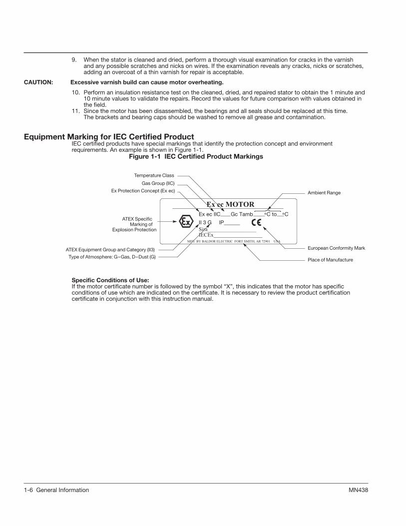
Equipment Marking for IEC Certified ProductIEC certified products have special markings that identify the protection concept and environment requirements. An example is shown in Figure 1-1.
Figure 1-1 IEC Certified Product Markings
Specific Conditions of Use:If the motor certificate number is followed by the symbol “X”, this indicates that the motor has specific conditions of use which are indicated on the certificate. It is necessary to review the product certification certificate in conjunction with this instruction manual.
Ex ec MOTOR
MFG. BY BALDOR ELECTRIC FORT SMITH, AR 72901 USA
Ex ec IIC Gc Tamb ºC to ºC
II 3 G IP______Sira__________________IECEx__________________
Ex Protection Concept (Ex ec)
Gas Group (IIC)
Temperature Class
ATEX SpecicMarking of
Explosion Protection
ATEX Equipment Group and Category (II3)
Type of Atmosphere: G--Gas, D--Dust (G)
Ambient Range
European Conformity Mark
Place of Manufacture

2-1MN436
Section 2Installation & Operation Overview
Installation should conform to the National Electrical Code as well as local codes and practices. Whenother devices are coupled to the motor shaft, be sure to install protective devices to prevent futureaccidents. Some protective devices include, coupling, belt guard, chain guard, shaft covers etc. Theseprotect against accidental contact with moving parts. Machinery that is accessible to personnel shouldprovide further protection in the form of guard rails, screening, warning signs etc.RPM AC motors are high performance motors specifically designed for use with adjustable frequencycontrollers. The basic design includes Class H insulation, 1.0 service factor, 40°C ambient, continuousduty. Standard enclosures are totally enclosed blower cooled, totally enclosed fan−cooled, totallyenclosed nonventilated, totally enclosed air over piggy back and drip−proof force ventilated. Manymodifications, and accessories are available. Motors are available as both induction and permanentmagnet construction. RPM AC motors are equipped with metric hardware.It is important that motors be installed in locations that are compatible with motor enclosure and ambientconditions. Improper selection of the motor enclosure and ambient conditions can lead to reducedoperating life of the motor. Proper ventilation for the motor must be provided. Obstructed airflow can lead to reduction of motor life.
Mechanical Installation WARNING: L400 must be supported by the feet and not by the D−Flange alone. Failure to observe these precautions
can result in bodily injury and equipment damage.Caution: Do not lift the motor and its driven load by the motor lifting hardware. The motor lifting hardware is
adequate for lifting only the motor. Disconnect the load (gears, pumps, compressors, or other driven equipment) from the motor shaft before lifting the motor.
Caution: If eye bolts are used for lifting a motor, be sure they are securely tightened. The lifting direction should not exceed a 20° angle from the shank of the eye bolt or lifting lug. Excessive lifting angles can cause damage.
Caution: RPM AC permanent magnet motors with an open enclosure, such as DP−FV (IP23/IC06), should not be used where ferrous dust or particles may may be present. Totally enclosed permanent magnet motors are recommended for these applications.After storage or after unpacking and inspection to see that all parts are in good condition, do the following:
1. Rotate the motor shaft by hand to be sure there are no obstructions to free rotation.2. A motor that has been in storage for some time should be tested for moisture (dielectric withstand insulation test) and
relubricated (regreaseable type) prior to being put into service.3. A motor with roller bearings is shipped with a shaft block. After removing the shaft block, be sure to replace any bolts
used to hold the shaft block in place during shipment that are required in service.Table 2-1 Tightening Torque
NEMA Frame
Hole Dia. (Inch)
"Bolt Size & Thread"
Torque lb−ft for Bolt Grade
IEC Frame Hole Dia. (mm)
"Bolt Size & Thread"
"Torque NM for Bolt Grade"
SAE 5 SAE 8 SAE 8.8 "SAE 12.9"
L400 1.06 7/8−9 434−486 616−689 DL250 24 M22−2.5 658 934
Mounting LocationAll RPM AC motors are designed to be mounted by the “Mounting Feet”.Use appropriate hardware (not furnished).The motor should be installed in a location compatible with the motor enclosure and specific ambient.Allow adequate air flow clearance between the motor and any obstruction. Locate the machine where the ambient temperature does not exceed 104°F (40°C) unless otherwise marked on the nameplate and where clean air has free access to ventilating intake and outlet openings. Except for machines with a suitable protective enclosure (IC06), the location should be clean and dry.
Note: The cooling system on (Non−Finned) frame RPM AC drip proof guarded force ventilated requires clean air to be forced through ducts which are integral to the frame. It is important that these air passages be kept clean and that sufficient clearance be provided on the blower motor air inlets and outlets for unrestricted flow of air. For Drip−Proof Force Ventilated Enclosures (IC06) sufficient clearance must be provided on all inlet and outlet openings to provide for unrestricted flow of air. Separately ventilated motors with exhaust to ambient (pipe−in only) must have at least 6 inches of clearance between the opening and adjacent walls or floor.
The motor must be securely installed to a rigid foundation or mounting surface to minimize vibration and maintain alignment between the motor and shaft load. Failure to provide a proper mounting surface may cause vibration, misalignment and bearing damage. All hold down bolts must be the correct grade for the type of mounting and must be torqued to their recommended value.Foundation caps and sole plates are designed to act as spacers for the equipment they support. If these devices are used, be sure that they are evenly supported by the foundation or mounting surface.When installation is complete and accurate alignment of the motor and load is accomplished, the base should be grouted to the foundation to maintain this alignment. The standard motor base is designed for horizontal or vertical mounting. Adjustable or sliding rails are designed for horizontal mounting only. Consult your ABB District Office for further information.

2-2 MN436
Coupled DriveStandard RPM AC Motors will operate successfully mounted on the floor, wall or ceiling, and with theshaft at any angle from horizontal to vertical. Special mountings may have duty or thrust demands thatmay require a different bearing system.
Alignment Accurate alignment of the motor with the driven equipment is extremely important.1. Direct Coupling
For direct drive, use flexible couplings if possible. Consult the drive or equipment manufacturer for more information. Mechanical vibration and roughness during operation may indicate poor alignment. Use dial indicators to check alignment. The space between coupling hubs should be maintained as recommended by the coupling manufacturer.
Note: Roller bearing motors are not suitable for coupled duty applications.2. End-Play Adjustment
The axial position of the motor frame with respect to its load is also extremely important. The motor bearings are not designed for excessive external axial thrust loads. Improper adjustment will cause failure.
Doweling & Bolting After proper alignment is verified, dowel pins should be inserted through the motor feet into the foundation. This will maintain the correct motor position should motor removal be required. (Baldor-Reliance motors are designed for doweling.)1. Drill dowel holes in diagonally opposite motor feet in the locations provided.2. Drill corresponding holes in the foundation.3. Ream all holes.4. Install proper fitting dowels.5. Mounting bolts must be carefully tightened to prevent changes in alignment.
Use a flat washer and lock washer under each nut or bolt head to hold the motor feet secure. Flanged nuts or bolts may be used as an alternative to washers.
WARNING: Guards must be installed for rotating parts such as couplings, pulleys, external fans, and unused shaft extensions, should be permanently guarded to prevent accidental contact by personnel. Accidental contact with body parts or clothing can cause serious or fatal injury.
Guarding Guards must be installed for rotating parts such as couplings, pulleys, external fans, and unused shaftextensions. This is particularly important where the parts have surface irregularities such as keys, keyways or set screws. Some satisfactory methods of guarding are:1. Covering the machine and associated rotating parts with structural or decorative parts of the driven
equipment.2. Providing covers for the rotating parts. Covers should be sufficiently rigid to maintain adequate guarding
during normal service.Electrical Installation
Bypass ModeAll RPM AC motors are inverter duty motors using optimum pole design. They are not intended to be usedin bypass mode (across the line). Consult your ABB District Office to determine suitability of motor forspecific applications in bypass mode. Permanent magnet motors cannot be run in bypass mode.
WARNING: Do not touch electrical connections before you first ensure that power has been disconnected. Electrical shock can cause serious or fatal injury. Only qualified personnel should attempt the installation, operation and maintenance of this equipment.
WARNING: The Adjustable Speed Controller may apply hazardous voltages to the motor leads after power to the controller has been turned off. Verify that the controller is incapable of delivering hazardous voltages and that the voltage at the motor leads is zero before proceeding. Failure to observe this precaution may result in severe bodily injury or death.
Caution: Use only a shielded motor power cable with a complete circumferential braided or copper film/tape ground jacket around the power leads. This ground should be secured to the motor frame from within the motor terminal box and must return without interruption to the drive ground. In addition, if the motor and coupled equipment are not on a single common metal base plate, it is important to equalize the equipment ground potentials by bonding the motor frame to the coupled equipment using a high frequency conductor such as a braided strap.
Note: Main power leads for CE Marked Motors may be marked U, V, W – for standard configurations, please consult connection diagrams.
Single Voltage/Three Lead Motors Connect leads marked U/T1, V/T2 and W/T3 to the appropriate control output terminals (refer to the Controller Instruction Manual). See Figure 2-1.
Leads P1 & P2 are thermostat leads. They are to be connected in series with the holding coil of the motor controller, which uses a manual momentary start switch.

2-3MN436
Figure 2-1 Connection Diagram
P1P2
U/T1T7
V/T2T8
W/T3T9T4T5T6
statL1
L2
L3
Low VoltageP1P2
U/T1
T7
V/T2
T5
W/T3
T8T6T9
T'StatL1L2L3
High Voltage
T4
3 Phase Dual Voltage
3 Phase Single VoltageP1P2
U/T1V/T2W/T3
T'StatL1L2L3
Connection Diagram 422927−1
H1H2 Space Heater
RTD or Thermistorsee Figure 2‐3.
Thermostat Leads ConnectionAs a standard feature, RPM AC motors have three (3) normally closed thermostats (one per phase) connected in series, with leads P1 through P6 terminated in the main conduit box.To protect against motor overheating, thermostats must be connected to the appropriate controller circuit (function loss). Failure to connect the thermostats will void the motor warranty. Follow the controller instruction manual for correct thermostat lead connections.
Grounding In Europe, the customer is responsible to ensure ground method conforms to IEC and applicable local codes.In the USA consult the National Electrical Code (NEC), Article 430 for information on grounding of motors and generators, and Article 250 for general information on grounding. In making the ground connection, the installer should make certain that there is a solid and permanent metallic connection between the ground point, the motor or generator terminal housing, and the motor or generator frame.Motors with resilient cushion rings usually must be provided with a bonding conductor across the resilient member. Some motors are supplied with the bonding conductor on the concealed side of the cushion ring to protect the bond from damage. Motors with bonded cushion rings should usually be grounded at the time of installation in accordance with the above recommendations for making ground connections. When motors with bonded cushion rings are used in multimotor installations employing group fusing or group protection, the bonding of the cushion ring should be checked to determine that it is adequate for the rating of the branch circuit over current protective device being used.There are applications where grounding the exterior parts of a motor or generator may result in greater hazard by increasing the possibility of a person in the area simultaneously contacting ground and some other nearby live electrical parts of other ungrounded electrical equipment. In portable equipment it is difficult to be sure that a positive ground connection is maintained as the equipment is moved, and providing a grounding conductor may lead to a false sense of security.Select a motor starter and over current protection suitable for this motor and its application. Consult motorstarter application data as well as the National Electric Code and/or other applicable local codes.
Caution: Use only a shielded motor power cable with a complete circumferential braided or copper film/tape ground jacket around the power leads. This ground should be secured to the motor frame from within the motor terminal box and must return without interruption to the drive ground. In addition, if the motor and coupled equipment are not on a single common metal base plate, it is important to equalize the equipment ground potentials by bonding the motor frame to the coupled equipment using a high frequency conductor such as a braided strap.Due to the high switching frequencies of inverter controls, the ground connection/path must be low impedance, not only low resistance. The NEC grounding instructions are intended to protect from low frequency, high current considerations and are not adequate for grounding of high frequency circuits.RPM AC induction motors are designed to operate with a high frequency adjustable speed drive. To avoid damage to the motor and driven equipment due to bearing currents, the motor must be grounded and bonded properly. A low impedance ground conductor should be used to ground all RPM AC motors.Failure to ground the motor properly for high frequency transients (1MHz to 10MHz) may result in electric discharge damage to the motor bearings and/or the driven equipment.The drive manufacturer should specify a shielded motor power cable that includes a complete circumferential braided or copper film/tape ground. This ground should be secured to the motor frame from within the motor terminal box and must return without interruption to the drive ground. In addition, if the motor and coupled equipment are not on a single common metal base plate, it is important to equalize the equipment ground potentials by bonding the motor frame to the coupled equipment using a high frequency conductor such as a braided strap.

2-4 MN436
Shipping BlocksMotors supplied with roller bearings at the drive end are shipped with wooden blocking to prevent axial movement of the shaft during shipment. Remove the blocking and bolts securing it and discard. Make sure motor shafts turn freely. If motor is to be reshipped, blocking of bearing is required.
Encoder ConnectionsDue to the wide variety of brands and types of feedback devices provided for RPM AC motors, please consult the encoder installation and instruction diagrams provided with the device.
Caution: Use of these radial load capacities requires the accurate calculation of the radial load. Radial loads for gears, sprockets, and flywheel are usually accurately determined but the radial loads due to V−belt drives are subject to miscalculations because they do not include all of the pre−tension load (belt tightening). The calculations of the radial load for a V−belt drive must include the pre−tension for transmitting the horsepower, pretension for centrifugal force on the belts, pre−tension for high start torques, rapid acceleration or deceleration, pre−tension for drives with short act−of−contact between the V−belt and sheave, and low coefficient of friction between belt and sheave caused by moisture, oil or dust. Over tension of the V−Belts may result in damage to the motor or driven equipment. Unless otherwise indicated, V−belt load must not exceed values given in Table 2−2.
Table 2-2 Radial load Capacities at the end of the shaft in lb (N) - Minimum 10,000 Hrs Bearing L-10 life - No axial load.
FrameL400
Radial Load Capacities at the End of the Shaft in lb(N)
2500 RPM 1750 RPM 1150 RPM 850 RPM
Lb 8900 9900 11250 12350
N 39587 44035 50040 54933
Data for motors with roller bearings at the drive end (back end).Motors with ball bearings at the drive end are for coupled duty only.
Table 2-3 Axial Thrust Capacities in lb (N) - Minimum 10,000 Hrs Bearing L-10 life - No external overhung load. FrameL400
Horizontal Mounting Vertical Mounting Thrust Down Vertical Mounting Thrust Up
2500RPM 1750RPM 1150RPM 850RPM 2500RPM 1750RPM 1150RPM 850RPM 2500RPM 1750RPM 1150RPM 850RPM
Lb 5900 6650 7600 8300 5300 6000 7000 7700 7050 7750 8700 9400
N 26243 29579 33805 36918 23574 26688 31136 34250 31358 34472 38698 41811
Optional AccessoriesFigure 2-2 Accessory Connections
One heater is installed in the drive end of motor. Leads for heater are labeled H1 & H2.
WARNING: Incorrect motor rotation direction can cause serious or fatal injury or equipment damage. Be sure to verify motor rotation direction before coupling the load to the motor shaft.
WARNING: Guards must be installed for rotating parts such as couplings, pulleys, external fans, and unused shaft extensions, should be permanently guarded to prevent accidental contact by personnel. Accidental contact with body parts or clothing can cause serious or fatal injury.
Caution: Do not operate motors with a roller bearing unless a radial load is applied so that damage to the roller bearing does not occur.

2-5MN436
Optional AccessoriesFigure 2-3 Accessory Connections
Space heaters are generally not required as the ACS880+5350 Cooling Tower Drive has a trickle current heating feature. For extreme applications that requirespace heaters, one heater is installed in each end of motor. Leads for eachheater are labeled H1 & H2. (Like numbers should be tied together).
Three thermistors are installed in windings. Leads are labeled TD1 −TD6 for shutdown and TD7 −TD12 for warning.
* One bearing RTD is installed in Drive end plate (PUEP), leads are labeled RTDDE. * One bearing RTD is installed in Opposite Drive end plate (FREP), leads labeled RTDODE.* Note RTD may have 2 −Red/1 −White leads; or 2 −White/1−Red Lead.
RTD CONNECTIONS
1TD11TD21TD3
418057 −549
Phase1 Phase2 Phase3One Per Phase
Two Per PhasePhase1 Phase2 Phase3
#1 #2 #3 #4 #5 #6
RedWhiteWhite
Leads(or Marked)
RedWhiteWhite
Leads(or Marked)
2TD12TD22TD3
3TD13TD23TD3
1TD11TD21TD3
2TD12TD22TD3
3TD13TD23TD3
4TD14TD24TD3
5TD15TD25TD3
6TD16TD26TD3
Heaters should be connected such that they are not energized when motor is operating
First Time Start Up1. Be sure that all power to motor and accessories is off.2. Be sure the motor shaft is disconnected from the load and will not cause mechanical rotation of the motor
shaft.3. Remove all unused shaft keys and loose rotating parts to prevent them from flying off.4. Verify the mechanical installation is secure. All bolts and nuts are tightened etc., covers and protective
devices are securely in their places.5. If motor has been in storage or idle for some time, check winding insulation integrity.6. Inspect all electrical connections for proper termination, clearance, mechanical strength and electrical
continuity.7. Be sure all shipping materials and braces (if used) are removed from motor shaft.8. Manually rotate the motor shaft to ensure that it rotates freely.9. Replace all panels and covers that were removed during installation.10. Momentarily apply power and check the direction of rotation of the motor shaft. If motor rotation is wrong be
sure power is off and change the motor lead connections as follows: RPM AC motors are designed to be capable of bi−directional shaft rotation. When voltages in an A−B−C
phase sequence are applied to leads U/T1, V/T2, W/T3 clockwise shaft rotation facing the opposite drive end will result. If shaft rotation is incorrect, change the direction of rotation as follows:
a. Turn off and lockout all power to the motor and verify that the voltage at the motor leads is zero. b. Reverse any two of three motor power leads. c. Restore power.11. Start the motor and ensure rotation is correct and operation is smooth without excessive vibration or noise. If
so, run the motor for 1 hour with no load connected.12. Momentarily apply power and check the direction of air flow is in agreement with the “direction of air flow”
arrows mounted on the motor. If directional flow is incorrect be sure power is off and interchange power leads to T1 and T2 or U1 and V1, Figure 2-2.
13. After 1 hour of operation, disconnect power and connect the load to the motor shaft. Verify all coupling guards and protective devices are installed. Ensure motor is properly ventilated.
14. If motor is totally enclosed fan−cooled or non−ventilated it is recommended that condensation drain plugs, if present, be removed. These are located in the lower portion of the end−shields. Totally enclosed fan−cooled “XT” motors are normally equipped with automatic drains which may be left in place as received.
While operating the motor, observe the performance. It should run smoothly with little noise. The bearings should not overheat and should reach a leveling off temperature. Any undue noise, overheating, or erratic performance should be investigated and necessary corrective action taken immediately to prevent serious damage. Please contact your Baldor District office. All RPM AC motors are lubricated before shipment and will operate for a long period before regreasing is required. The period will vary depending on environmental and service conditions. Refer to Maintenance section.

2-6 MN436
Air Flow VolumeSeparately ventilated motors DPSV, TESV (IP23 IC17 and IP44-IC37) must have the following volume of air to adequately cool the motor unless the nameplate specifies a different value. Cooling air temperature must not exceed the maximum ambient temperature indicated on the nameplate (standard is 40°C). This data applies to all base speeds for frame sizes in Table 2−4.
Table 2-4 Air FlowFrame Size DPSV OR TESV Data
Air Volume M3/sec Static Pressure psi (mm of water)
L400 / DL250 1100 (0.519) 6.5 (165.1)
WARNING: Do not touch electrical connections before you first ensure that power has been disconnected. Electrical shock can cause serious or fatal injury. Only qualified personnel should attempt the installation, operation and maintenance of this equipment.
WARNING: Surface temperatures of motor enclosures may reach temperatures which can cause discomfort or injury to personnel accidentally coming into contact with hot surfaces. When installing, protection should be provided by the user to protect against accidental contact with hot surfaces. Failure to observe this precaution could result in bodily injury.
WARNING: Incorrect motor rotation direction can cause serious or fatal injury or equipment damage. Be sure to verify motor rotation direction before coupling the load to the motor shaft.
WARNING: Guards must be installed for rotating parts such as couplings, pulleys, external fans, and unused shaft extensions, should be permanently guarded to prevent accidental contact by personnel. Accidental contact with body parts or clothing can cause serious or fatal injury.
Caution: Do not operate motors with a roller bearing unless a radial load is applied so that damage to the roller bearing does not occur.
Caution: RPM AC permanent magnet motors with an open enclosure, such as DP−FV (IP23/IC06), should not be used where ferrous dust or particles may may be present . Totally enclosed permanent magnet motors are recommended for these applications.
Operation During operation observe the motors’ performance. It should run smoothly with little noise. The bearings should not overheat and should reach a normal operating temperature. Any undue noise, overheating, or erratic performance should be investigated and corrective action taken immediately to prevent serious damage.All RPM AC motors are lubricated before shipment and will operate for a long period before regreasing is required. The period will vary depending on environmental and service conditions. Refer to Maintenance section of this manual.
Maximum Safe SpeedThe maximum safe operating speed of the motor is listed on the motor nameplate. Do not exceed this speed. When the maximum speed of the motor control can exceed the maximum safe motor speed (motor nameplate value), the speed characteristics of the control must be set so the speed is limited to this maximum.
Balance Motors are dynamically balanced to meet the dynamic balance limits of NEMA MG1 Part 7 second forpeak value of the unfiltered velocity in inches per second unless ordered differently. Balance is done witha full length 1/2 height shaft key. A full shaft key is shipped with motor. Sheave or coupling should bebalanced with a 1/2 height shaft key. Std. Dynamic Balance Limits.
Table 2-5 Dynamic BalanceRPM NEMA IEC
Velocity Peak (in/sec) Velocity (mm/sec RMS)
0-1200 0.15 2.7

3-1MN436
Section 3Maintenance & Troubleshooting WARNING: UL Listed motors must only be serviced by UL Approved Authorized ABB Service Centers if these motors
are to be returned to a hazardous and/or explosive atmosphere. WARNING: Pacemaker danger − Magnetic and electromagnetic fields in the vicinity of current carrying carrying
conductors and permanent magnet motors can result result in a serious health hazard to persons with cardiac pacemakers, metal implants, and hearing aids. To avoid risk, stay way from the area surrounding a permanent magnet motor.
WARNING: RPM AC permanent magnet motors can induce voltage and current in the motor leads by rotating the motor shaft. Electrical shock can cause serious or fatal injury. Therefore, do not couple the load to the motor shaft until all motor connections have been made. During any maintenance inspections, be sure the motor shaft will not rotate.
WARNING: Do not touch electrical connections before you first ensure that power has been disconnected. Electrical shock can cause serious or fatal injury. Only qualified personnel should attempt the installation, operation and maintenance of this equipment.
WARNING: The Adjustable Speed Controller may apply hazardous voltages to the motor leads after power to the controller has been turned off. Verify that the controller is incapable of delivering hazardous voltages and that the voltage at the motor leads is zero before proceeding. Failure to observe this precaution may result in severe bodily injury or death.
WARNING: Surface temperatures of motor enclosures may reach temperatures which can cause discomfort or injury to personnel accidentally coming into contact with hot surfaces. When installing, protection should be provided by the user to protect against accidental contact with hot surfaces. Failure to observe this precaution could result in bodily injury.
WARNING: Guards must be installed for rotating parts such as couplings, pulleys, external fans, and unused shaft extensions, should be permanently guarded to prevent accidental contact by personnel. Accidental contact with body parts or clothing can cause serious or fatal injury.
General Inspection Inspect the motor at regular intervals, approximately every month. Keep the motor clean and the ventilation openings clear.The following steps should be performed at each inspection:1. Check that the motor is clean. Check that the interior and exterior of the motor is free of dirt, oil, grease,
water, etc. Oily vapor, paper pulp, textile lint, etc. can accumulate and block motor ventilation. If the motor is not properly ventilated, overheating can occur and cause early motor failure.
2. Perform a dielectric with stand test periodically to ensure that the integrity of the winding insulation has been maintained. Record the readings. Immediately investigate any significant decrease in insulation resistance.
3. Check all electrical connectors to be sure that they are tight.Relubrication & Bearings
Bearing grease will lose its lubricating ability over time, not suddenly. The lubricating ability of a grease (over time) depends primarily on the type of grease, the size of the bearing, the speed at which the bearing operates and the severity of the operating conditions. Good results can be obtained if the following recommendations are used in your maintenance program. Relubrication with the shaft stationary and a warm motor is recommended.
Lubrication ProcedureWARNING: Disconnect all electrical power from the motor windings and accessory devices before disassembly of the
motor. Electrical shock can cause serious or fatal injury.1. Relubrication with the shaft stationary and a warm motor is recommended. If lubrication must be done with
motor running, stay clear of rotating parts and electrical circuits.2. Wipe all dirt from the outside of the grease fills and drains.3. Locate the grease inlet at the top of the bearing hub, clean the area and replace the 1/8−inch pipe plug with a
grease fitting if the motor is not equipped with grease fitting. 4. Remove grease drain plug located opposite the grease inlet.5. Using a manual grease gun, pump in the recommended grease in the amount shown. This amount of grease
will provide an ample supply of lubricant between lubrication periods for the service condition listed in Table 3-1, Table 3-2 and Table 3-3. Use only clean, fresh grease from clean containers and handle so as to keep it clean. In general, mixing of greases is not recommended. If an incompatible grease is used, the lube system must be repacked completely with the new grease.
6. Wipe away any excess grease at the grease drain or relief and replace drain plugs.
Type of GreaseSee the motor nameplate for replacement grease or oil recommendation. Use Chevron Black Pearl or equivalent grease unless motor nameplate specifies special grease. Amount of grease to be added and lubrication interval is given in Table 3-1.
Table 3-1 L400 Relubrication Amount and IntervalLocation Vol. in3 (cm3) Weight oz (gram) Interval
Bearings 2.5 (40) 1.25 (35) 3 Months
ODE (Inner Bearing Cap) 0.5 (8) 0.25 (7) 3 Months

3-2 MN436
Table 3-2 Troubleshooting Chart Symptom Possible Causes Possible Solutions
Motor will not start "Usually caused by line trouble, such as, single phasing at the starter." "Check source of power. Check overloads, fuses, controls, etc."
Excessive hummingHigh Voltage. Check input line connections.
Eccentric air gap. Have motor serviced at local ABB service center.
Motor Over Heating
"Overload. Compare actual amps (measured) with nameplate rating."
"Locate and remove source of excessive friction in motor or load. Reduce load or replace with motor of greater capacity."
Single Phasing. "Check current at all phases (should be approximately equal) to isolate and correct the problem."
Improper ventilation. "Check external cooling fan to be sure air is moving properly across cooling fins. Excessive dirt build-up on motor. Clean motor."
Unbalanced voltage. "Check voltage at all phases (should be approximately equal) to isolate and correct the problem."
Rotor rubbing on stator.Check air gap clearance and bearings.
Tighten “Thru Bolts”.
Over voltage or under voltage. Check input voltage at each phase to motor.
Open stator winding. "Check stator resistance at all three phases for balance."
Grounded winding. Perform dielectric test and repair as required.
Improper connections. "Inspect all electrical connections for proper termination, clearance, mechanical strength and electrical continuity. Refer to motor lead connection diagram."
Bearing Over Heating
Misalignment. Check and align motor and driven equipment.
Excessive belt tension. Reduce belt tension to proper point for load.
Excessive end thrust. Reduce the end thrust from driven machine.
Excessive grease in bearing. Remove grease until cavity is approximately 3/4 filled.
Insufficient grease in bearing. Add grease until cavity is approximately 3/4 filled.
Dirt in bearing. "Clean bearing cavity and bearing. Repack with correct grease until cavity is approximately 3/4 filled."
Vibration
Misalignment. Check and align motor and driven equipment.
"Rubbing between rotating parts and stationary parts." Isolate and eliminate cause of rubbing.
Rotor out of balance. "Have rotor balance checked are repaired at your ABB Service Center."
Resonance. "Tune system or contact your ABB Service Center for assistance."
Noise "Foreign material in air gap or ventilation openings."
"Remove rotor and foreign material. Reinstall rotor. Check insulation integrity. Clean ventilation openings."
Growling or whining Bad bearing. "Replace bearing. Clean all grease from cavity and new bearing. Repack with correct grease until cavity is approximately 3/4 filled."

3-3MN436

3-4 MN436

3-5MN436

3-6 MN436

4 - 1MN436
Section 4IEC 60079 Series
INFORMATION REQUIRED PER IEC 60079-0:2017 Ed7
All italicized information below is quoted from the standard, clause 30.
Clause 30 (instructions) – Instructions are provided with each motor, the most recent version of this manual can be download at baldor.com.
Instructions for purposes of this standard consists of the following that are shipped with your motor in the literature package:
• Instruction Manual MN406• Ex Certificates applicable for your motor• Nameplate marking photos for your motor
Clause 30.1 (general)
The instructions prepared by the manufacturer shall include the following particulars as a minimum.Marking
A recapitulation of the information with which the equipment is marked, except for the serial number (see Clause 29), together with any appropriate additional information to facilitate maintenance (for example, address of the importer, repairer, etc.)
A copy of the nameplates is included in the literature package and is shipped with each motor. These instructions are used for a range of motors. An example of typical certification marking is shown in Section 1. For motor specific information, please refer to the certification nameplate photos, electrical rating information and any specific conditions conveyed in the motor marking such as but not limited to ambient range, water flow, converter set up parameters and refer to the data package shipped with the product.
on-site assembling:
Not typically required.
adjustment and parameter setting
If operated on a converter, refer to nameplate marking for set-up parameters.
Use and setting-up;
Ratings such as electrical values, ambient temperatures and pressures, maximum surface temperatures and other limit values related to a designated use are included on the product nameplate photos and in the product data package..
- putting into service- of the equipment / of the whole installation:
ii) Information about verifications / tests prior to first use
Refer to Section 2, Installation and Operation
ii) detailed information about any special installation requirements for the Type of Protection(s)employed
i) information about verifications / tests prior to (first) useRefer to Section 2, Installation and Operationii) detailed information about any special installation requirements for the Type of Protection(s)employed

4 - 2 MN436
- maintenance;
ii) Information such as cleaning, oil level check or recalibration requirements;
Cleaning- The enclosure is non-conducting and may generate an ignition capable level of electrostatic charge under extreme conditions. The user should ensure that the equipment is not installed in a location in a location where it might be subjected to external conditions which might cause a build-up of electrostatic charges on non-conducting surfaces. Additionally, cleaning of the equipment should be done only with a damp cloth.’
Additional information on maintenance such as Information on bearing inspection is in the Maintenance Section 3
iii) Requirements for the maintenance of the explosion protection.
For Ex e machines, consult manufacturer for winding details
For permanent magnet motors, the voltage that may be present at the motor terminals, when the supply is disconnected, when the motor is rotating. Open circuit vs. speed data is normally supplied.
For motors using permanent magnet rotors, consult warning marking, which is provided with the Instructions.
Information on any maintenance required to ensure continued compliance with the rubbing seal requirements of 5.2.12
Inspect Seal during the bearing lubrication process to ensure the integrity of the seal.
- repairi) Repair should be conducted in accordance with the requirements given in IEC 60079-19
Refer to Repair of Motors used in Hazardous Locations
Information related to the fitting or removal of parts / components; As each motor design is unique, it is necessary to Contact the manufacture for additional repair details. Use only original manufacturer’s parts.
ii) information related to the fitting or removal of parts / components
Contact ABB regarding any spare parts.
iii) Information about spare parts
Contact ABB regarding any spare parts.
iv) Requirements for a documentation of such repairs.
As any repair is undertaken after consultation with IEC60079-19, the documentation requirements for the repair in this standard apply.
- taking out of service and dismantling
i) Use appropriate lock out tag out procedures to prevent restart and prior to making or breaking any electrical connection.
• where applicable, Specific Conditions of Use according to 29.3 e)
As Specific Conditions of Use may vary with each certificate, if Specific Conditions are applied, the certificate is shipped with each motor forming part of the Instructions. Refer to Marking and Acceptance section for an explanation of the “X” suffix to certificate numbers.

4 - 3MN436
Clause 30.3 (electrical machines)
In addition to the information required according to 30.1, the following additional information shall be prepared for electrical machines, as applicable:
machines intended to be supplied by a converter
For speed torque information on motors intended to be supplied by converter, consult motor nameplate.
bearing lubrication requirements for both commissioning and maintaining;
Instructions for lubrication are included in the Bearing Maintenance Section. Only use ABB recommended grease or contact ABB Motors and Mechanical Inc., product support team for guidance on equivalents suitable for hazardous locations.
the permitted axial and radial loading of the shaft;
Please refer to Table 2-2 and Table 2-3 in this manual for information.
• the thermal expansion of the shaft and housing under rated conditions
Maintain minimum clearances necessary to accommodate thermal growth of up to 3mm of the frame and up to 5mm (8mm for Furnace Fan Motor Designs) of the shaft during design operating conditions. Consult engineering for application specific solutions where these minimum clearances are not permissible.
• any necessary maintenance of the protection provided by the manufacturer against stray circulating currents in the bearings or shafts.
Ensure that the motor is properly earthed and bonded. For motors operated by converter, consult converter manufacturers instructions relative to cable recommendations.
• any necessary protection of the bearings from vibration, including during transportation, storage, or standby service; Protection of bearings from vibration during storage and transportation are addressed in General. Bearings requiring blocking are blocked during shipment.
• guidance on maintenance and replacement intervals for bearings based on the operating conditions.
Instructions for lubrication are included in the Bearing Maintenance Section

4 - 4 MN436


*436-0720*
MN
44
6 Ju
ly 2
020
© Copyright 2020 ABB. All rights reserved. Specifications subject to change without notice.
Additional informationWe reserve the right to make technical changes or modify the contents of this document without prior notice. With regard to purchase orders, the agreed particulars shall prevail. ABB does not accept any responsibility whatsoever for potential errors or possible lack of infor-mation in this document.
We reserve all rights in this document and in the subject matter and illustra-tions contained therein. Any reproduc-tion, disclosure to third parties or utilization of its contents – in whole or in parts – is forbidden without prior written consent of ABB.
—ABB Motors and Mechanical Inc.5711 R.S. Boreham, Jr. StreetFort Smith, AR 72901Ph: 1.479.646.4711
Mechanical Power Transmission Support Ph: 1.864.297.4800
new.abb.com/mechanical-power-transmission