Bendability Analysis for Bending of C-Mn Steel Plates on Heavy Duty 3Roller Bending Machine
Upload
khangminh22Category
view
1download
0
196
NATIONAL COOPERATIVE HIGHWAY RESEARCH PROGRAM 196 REPORT
RECONDITIONING HEAVY-DUTY FREEWAYS IN URBAN AREAS
TRANSPORTATION RESEARCH BOARD NATIONAL RESEARCH COUNCIL
TRANSPORTATION RESEARCH BOARD 1978
Officers
SCHEFFER LANG, Chairman PETER G. KOLTNOW, Vice Chairman W. N. CAREY, JR., Executive Director
Executive Committee
HENRIK E. STAFSETH, Executive Director, American Assn. of State Highway and Transportation Officials (ex officio) KARL S. BOWERS, Federal Highway Administrator, U.S. Department of Transportation (ex officio) RICHARD S. PAGE, Urban Mass Transportation Administrator, U.S. Department of Transportation (ex officio) JOHN M. SULLIVAN, Federal Railroad Administrator, U.S. Department of Transportation (ex officio) HARVEY BROOKS, Chairman, Commission on Sociotechnical Systems, National Research Council (ex officio) HAROLD L. MICHAEL, Professor of Civil Engineering, Purdue University (ex officio, Past Chairman 1976) ROBERT N. HUNTER, Chief Engineer, Missouri State Highway Department (ex officio, Past Chairman 1977) HOWARD L. GAUTHIER, Professor of Geography, Ohio State University (ex officio, MTRB liaison) KURT W. BAUER, Executive Director, Southeastern Wisconsin Regional Planning Commission LAWRENCE D. DAHMS, Executive Director, Metropolitan Transportation Commission, San Francisco Bay Area
L. DEBERRY, Engineer-Director, Texas State Department of Highways and Public Transportation ARTHUR C. FORD, Assistant Vice President (Long-Range Planning), Delta Air Lines FRANK C. HERRINGER, General Manager, San Francisco Bay Area Rapid Transit District ARTHUR J. HOLLAND, Mayor, City of Trenton, N.J. ANNE R. HULL, Speaker Pro Tern, Maryland House of Delegates ROBERT R. KILEY, Chairman, Massachusetts Bay Transportation Authority PETER G. KOLTNOW, President, Highway Users Federation for Safety and Mobility THOMAS J. LAMPHIER, President, Transportation Division, Burlington Northern, Inc. A. SCHEFFER LANG, Assistant to the President, Association of American Railroads ROGER L. MALLAR, Commissioner, Maine Department of Transportation MARVIN L. MANHEIM, Professor of Civil Engineering, Massachusetts Institute of Technology DARRELL V MANNING, Director, Idaho Transportation Department ROBERT S. MICHAEL, Director of Aviation, City and County of Denver, Colorado THOMAS D. MORELAND, Commissioner and State Highway Engineer, Georgia Department of Transportation GEORGE E. PAKE, Vice President, Xerox Corp.; Manager, Xerox Palo Alto Research Center DOUGLAS N. SCHNEIDER, JR., Director, District of Columbia Department of Transportation WILLIAM K. SMITH, Vice President (Transportation), General Mills JOHN R. TABB, Director, Mississippi State Highway Department JOHN P. WOODWARD, Director, Michigan Department of State Highways and Transportation
NATIONAL COOPERATIVE HIGHWAY RESEARCH PROGRAM
Transportation Research Board Executive Committee Subcommittee for the NCHRP
A. SCHEFFER LANG, Association of American Railroads (Chairman) KARL S. BOWERS, U.S. Department of Transportation PETER G. KOLTNOW, Highway Users Federation HARVEY BROOKS, National Research Council HENRIK E. STAFSETH, Amer. Assn. of State Hwy. and Transp. Officials ROBERT N. HUNTER, Missouri State Highway Department
W. N. CAREY, JR., Transportation Research Board
Field of Maintenance Area of Maintenance of Way and Structures Project Panel F14-4
LEO D. SANDVIG, Pennsylvania Dept. of Transp. (Chairman) J. C. OBERMULLER, California Dept. of Transp. DONALD R. ANDERSON, Washington Dept. of Transportation L. T. OEHLER, Michigan Dept. of St. Hwys. & Transp. GEORGE M. BRIGGS, New York State Dept. of Transp. GERALD B. PECK, Texas St. Dept. of Hwys. & Pub. Transp. GEORGE C. HOFF, USAE Waterways Exper. Station ROBERT T. TIERNEY, Massachusetts Dept. of Pub. Wks. THOMAS T. MORIMOTO, Illinois Dept. of Transp. RICHARD A. McCOMB, Federal Highway Administration W. G. MULLEN, North Carolina State University ADRIAN CLARY, Transportation Research Board
Program Stall
KRIEGER W. HENDERSON, JR., Program Director HARRY A. SMITH, Projects Engineer DAVID K. WITHEFORD, Assistant Program Director ROBERT E. SPICHER, Projects Engineer LOUIS M. MACGREGOR, Administrative Engineer HERBERT P. ORLAND, Editor R. IAN KINGHAM, Projects Engineer HELEN MACK, Associate Editor ROBERT J. REILLY, Projects Engineer EDYTHE T. CRUMP, Assistant Editor
NATIONAL COOPERATIVE HIGHWAY RESEARCH PROGRAM 196 - REPORT
RECONDITIONING HEAVY-DUTY FREEWAYS IN URBAN AREAS
A. H. MEYER, W. B. LEDBETTER,
A. H. LAYMAN AND DONALD SAYLAK
TEXAS A&M UNIVERSITY
COLLEGE STATION, TEXAS
RESEARCH SPONSORED BY THE AMERICAN ASSOCIATION OF STATE HIGHWAY AND TRANSPORTATION OFFICIALS IN COOPERATION WITH THE FEDERAL HIGHWAY ADMINISTRATION
AREAS OF INTEREST:
PAVEMENT DESIGN
PAVEMENT PERFORMANCE
BITUMINOUS MATERIALS AND MIXES
CEMENT AND CONCRETE
CONSTRUCTION
GENERAL MATERIALS
MAINTENANCE, GENERAL
TRANSPORTATION RESEARCH BOARD NATIONAL RESEARCH COUNCIL
WASHINGTON, D.C. 1978

NATIONAL COOPERATIVE HIGHWAY RESEARCH PROGRAM
Systematic, well-designed research provides the most - ef-fective approach to the solution of many problems facing highway administrators and engineers. Often, highway problems are of local interest and can best be studied by highway departments individually or in cooperation with their state universities and others. However, the accelerat-ing growth of highway transportation develops increasingly complex problems of wide interest to highway authorities. These problems are best studied through a coordinated-program of cooperative research. In recognition of these needs, the highway administrators of the American Association of State Highway and Trans-portation Officials, initiated in 1962 an objective national highway research program employing modern scientific techniques. This program is supported on a continuing basis by funds from participating member states of the Association and it receives the full cooperation and support of the Federal Highway Administration, United States Department of Transportation. The Transportation Research Board of the National Re-search Council was requested by the Association to admin-ister the research program because of the Board's recog-nized objectivity and understanding of modern research practices. The Board is uniquely suited for this purpose as: it maintains an extensive committee structure from which authorities on any highway transportation subject may be drawn; it possesses avenues of communications and cooperation with federal, state, and local governmental agencies, universities, and industry; its relationship to its parent organization, the National Academy of Sciences, a private, nonprofit institution, is an insurance of objectivity; it maintains a full-time research correlation staff of special-ists in highway transportation matters to bring the findings of research directly to those who are in a position to use them.
The program is developed on the basis of research needs identified by chief administrators of the highway and trans-portation departments and by committees of AASHTO. Each year, specific areas of research needs to be included in the program are proposed to the Academy and the Board by the American Association of State Highway and Trans-portation Officials. Research projects to fulfill these needs are defined by the Board, and qualified research agencies are selected from those that have submitted proposals. Ad-ministration and surveillance of research contracts are responsibilities of the Academy and its Transportation Research Board.
The needs for highway research are many, and the National Cooperative Highway Research Program can make signifi-cant contributions to the solution of highway transportation problems of mutual concern to many responsible groups. The program, however, is intended to complement rather than to substitute for or duplicate other highway research programs.
NCHRP Report 196
Project 14-4 FY '74 ISSN 0077-5614 ISBN 0-309-02856-6
L. C. Catalog Card No. 78-65953
Price: $6.40
Notice
The project that is the subject of this report was a part of the National Cooperative Highway Research Program conducted by the Transportation Research Board with the approval of the Governing Board of the National Research Council, acting in behalf of the National Academy of Sciences. Such approval reflects the Governing Board's judgment that the program concerned is of national ixnpor-tance and appropriate with respect to both the purposes and re-sources of the National Research Council. The members of the technical committee selected to monitor this project and to review this report were chosen for recognized scholarly competence and with due consideration for the balance of disciplines appropriate to the project. The opinions and con-clusions expressed or implied are those of the research agency that performed the research, and, while they have been accepted as appropriate by the technical committee, they are not necessarily those of the Transportation Research Board, the National Research Coun-cil, the National Academy of Sciences, or the program sponsors. Each report is reviewed and processed according to procedures established and monitored by the Report Review Committee of the National Academy of Sciences. Distribution of the report is ap-proved by the President of the Academy upon satisfactory comple- tion of the review process. - The National Research Council is the principal operating agency of the National Academy of Sciences and the National Academy of Engineering, serving government and other organizations. The Transportation Research Board evolved from the 54-year-old High-way Research Board. The TRB incorporates all former HRB activities but also performs additional functions under a broader scope involving all modes of transportation and the interactions of transportation with society.
Special Notice
The Transportation Research Board, the National Academy of Sci-ences, the Federal Highway Administration, the American Associa-tion of State Highway and Transportation Officials, and the individual states participating in the National Cooperative Highway Research Program do not endorse products or manufacturers. Trade or manufacturers' names appear herein solely because they are con-sidered essential to the object of this report.
Published reports of the
NATIONAL COOPERATIVE HIGHWAY RESEARCH PROGRAM
are available from:
Transportation Research Board National Academy of Sciences 2101 Constitution Avenue, N.W. Washington, D.C. 20418
Printed in the United States of America.
FOREWORD This report is recommended to design, construction, materials, and mainte-nance engineers, and others who become involved in the reconditioning of heavily
By Staff traveled urban freeway pavements. The research included an extensive literature
Transportation searh and discussions with contractors, material suppliers, equipment manufac-
Research Board turers, representatives of state highway and transportation agencies, and others having information that could help in solving the many problems involved in recon-ditioning busy urban freeways. The end product of the study is a series of detailed rehabilitation schemes for several specific structural conditions. All of the schemes are designed to permit completion of construction activity on 1/4 -mile single-lane segments in 48 hr or less without total closure of the freeway to traffic and without significantly raising the elevation of the pavement surface.
As the original life cycles of the substantial mileage of freeway pavements constructed during the unprecedented roadbuilding surge of the 1960's draw to a close, highway and transportation agencies are faced with an equally unprecedented task of pavement rehabilitation. Nowhere are the problems of rehabilitation more severe and more trying than on urban freeways that must be kept open to traffic during the construction process. The interference of construction operations with the flow of traffic on already crowded pavements, the interference of traffic with con-struction operations, the ever-present need for concern about the safety of both the highway users and workers in such situations of conflict, and the loss of the most viable of rehabilitation alternatives, the overlay, because of overhead clearance requirements in the typical urban environment, present problems of imposing magnitude.
In the study reported herein, the researchers made a careful analysis of the capabilities of existing construction equipment and normally available construction materials, and concluded that, through some unconventional application of both equipment and materials, a significant improvement and speedup of urban freeway rehabilitation operations is within reach. Some well-defined guidelines are offered for several specific rehabilitation situations. Agencies that have situations similar to those for which solutions are proposed may want to test the proposed solutions in limited areas to evaluate their effectiveness.
Several revolutionary concepts for urban freeway rehabilitation that were iden-tified during the course of the investigation are also briefly described in the report. The researchers concluded that major expenditures for development would be re-quired before any of the concepts could be brought to an application stage.
CONTENTS
1 SUMMARY
PART I
3 CHAPTER ONE Introduction and Research Approach Introduction Objective Constraints Research Approach
6 CHAPTER TWO Findings General Lane-Closure System Proposed Solutions for All Layers Structurally Unsound Proposed Solutions for Surface Layer Structurally Un-
sound—Sublayers Structurally Sound Proposed Solutions—All Layers Structurally Sound Futuristic Systems
21 CHAPTER THREE Appraisal and Applications of Findings
23 CHAPTER FOUR Conclusions and Recommendations Conclusions Recommendations
25 REFERENCES
PART II
26 APPENDIX A Literature Search
27 APPENDIX B Site Visits
37 APPENDIX C Asphaltic Concrete Pavements
55 APPENDIX D Stress Analysis of the Pavement Sections
58 APPENDIX E Partial Depth Precast Panels
59 APPENDIX F Subgrade Treatments

ACKNOWLEDGMENTS
The research reported herein was performed under NCHRP Project 14-4 by the Texas Transportation Institute, Texas A&M University. The Texas A&M Research Foundation was the con-tractor for the study.
Dr. William B. Ledbetter, Professor of Civil Engineering, and Dr. Alvin H. Meyer, Associate Professor of Civil Engineering, Texas A&M University, were the co-principal investigators. The other authors of this report are Dr. Andrew H. Layman, Pro-fessor of Civil Engineering, and Dr. Donald Saylak, Associate Professor of Civil Engineering, Texas A&M University.
The work was done under the general supervision of Dr. Meyer with assistance from Dr. Ledbetter. In addition to Drs. Lay-man and Saylak, assistance was received from Debbie Fisher, Research Assistant, and Sidney Greer and Edward Ellis, Technicians.
The following served as advisory consultants to the project:
Bruce Cloud, Executive Vice President, H. B. Zachary Com-pany, San Antonio, Tex.; Ralph W. Coho, Jr., Vice President, Irl Daffin. Associates, Inc., Lancaster, Pa.; Charles Foster, Di-rector, Engineering and Research, National Asphalt Paving As-sociation, Riverdale, Md.; Professor B. M. Gallaway, Research Engineer, Texas Transportation Institute, Texas A&M Univer-sity, College Station, Tex.; Harold Haim, Executive Director, American Concrete Paving Association, Oak Brook, Ill.; Alan Kus, Vice President, Brighton-Krug Construction Company, Chicago, Ill.; R. W. Beaty, General Marketing Manager, Asphalt Construction Products, Barber-Greene Company, Aurora, Ill.
Thanks also are extended to the many equipment manufac-turers, contractors, engineers, and government agencies who re-sponded to inquiries and provided the project with the detailed information necessary for completion.
RECONDITIONING HEAVY-DUTY FREEWAYS IN URBAN AREAS
SUMMARY A significant portion of urban freeway pavement is more than 10 years old and many of the designed traffic volumes and loads have been exceeded. In the next few years an important mileage of these pavements will require structural rehabilitation to remain in operation.
The objective of this project was to develop new technology by which all or part of the pavement structure on a heavily traveled urban freeway could be rapidly reconstituted or replaced (or both) so that the finished product would have a design service life equal to, if not greater than, that of the original pavement. Included in the objective was the restoration of the riding quality and nonskid characteristics of the pavement structure.
The major constraints in developing solutions to this rehabilitation problem included a time constraint that the rehabilitation must be completed in less than 48 hr, a facilities constraint which involved closing only one lane of the travel-way during most of the construction, and a quantity constraint in that significant lengths of trayel-way were to be rehabilitated. An additional constraint was that vertical clearances at overpass structures could not be reduced, therefore overlays of any type could not be used.
At the initiation of this project a comprehensive literature search was con-ducted, which resulted in the preparation of an annotated bibliography containing more than 500 references. Following the literature search, a number of sites were visited and discussions were held with contractors, suppliers, manufacturers, re-searchers, and highway transportation agency representatives. At each site, the problem was presented and discussed for possible solutions. Using the information gathered from the literature and the site visits, a rehabilitation strategy was devel-oped to focus on the various aspects of the problem.
It was obvious from the beginning of the study that a universally acceptable solution to the problem presented would require the development of totally new and innovative technology. However, in view of the applied nature of the National Cooperative Highway Research Program, effort was concentrated on the develop-ment of practical advances within the realm of current engineering technology. No single, best, unique solution was found to the problem; rather a number of solutions were developed which appear promising for certain preexisting conditions. In this strategy three pavement structure conditions were considered: (1) all layers are structurally unsound; (2) the surface layer is structurally unsound whereas the sublayers are structurally sound; and (3) surface layer and all sublayers are struc-turally sound.
The major findings of the study are:
Because of the vastly different situations existing throughout the United States, no single solution to the problem could be developed. Therefore, a number of realistic solutions were developed to cover the expected range of situations which might be encountered.
The solutions involving the least amount of new technology were those in

2
which an adjacent lane could be closed during the rehabilitation of a significant length of a freeway lane.
3. Because of the time constraint (48 hours), improvement of the subgrade, or natural soil, could not be accomplished and had to be left "as is." Thus, the rehabilitated pavement structural layers had to be designed to prevent overstressing the unimproved subgrade.
4. The construction management techniques of precedence diagraming and analysis bar charting indicated the critical aspects of each rehabilitation strategy and provided the information necessary to schedule rehabilitation within the time constraint.
5. For the "worst probable" case [a 10 in. (0.25 m) portland cement concrete pavement exceeding 14 in. (0.35 m) of sublayers, all of which are deteriorated], solutions were developed for removing all materials in a quarter mile long (400 m) lane and replacing such material with materials equal to or better than the original pavement structure—in 43 hr from the time the barriers are erected. Using new and innovative technology the potential exists to reduce this time to 35 hr.
6. When only the surface layer is structurally unsound, solutions were devel-oped whereby a quarter mile long (400 m) lane could be rehabilitated in 26 hr.
7. When all pavement layers are structurally sound (requiring only the restoration of riding quality and/or skid resistance), solutions were developed whereby a quarter mile long (400 m) lane could be rehabilitated in from 4 to 24 hr, depending on existing conditions.
8. Promising innovative materials/systems to accomplish rapid rehabilitation of significant portions of an urban freeway include:
Deep-lift asphaltic concrete. Rapid-hardening, high early-strength concrete. Sulphur systems for pavements. Precast portland cement concrete panels.
9. Futuristic systems offer potential for rehabilitating significant sections of a freeway lane by closing only one lane of traffic throughout the rehabilitation periods.
10. One futuristic system has the potential for keeping all lanes open during rehabilitation.
11. Development of the futuristic systems will require the expenditure of large sums of money, and thus are unlikely to be undertaken without significant Federal support.
12. A large number of special matcrials/systems techniques exists that offer potential for rapid spot rehabilitation.
The solutions developed in this report call for close control of materials and close construction scheduling of the rehabilitation. To test the validity of the solu-tions, one or more solutions should be tried on a full-scale rehabilitation project in which a quarter mile long (400 m) lane is selected, a rehabilitation strategy is selected within the specified time limit, and a construction technique is employed to accomplish the rehabilitation. Materials selection should be made in cooperation with the materials supplier and the constructor. Construction management tech-niques, to include precedence diagraming and analysis bar charting, should be employed to insure proper execution of the rehabilitation.
In addition to the aforementioned materials/systems for replacement, several other popular and seemingly promising techniques were considered and rejected. These materials/systems are discussed in Appendix C and include polymer con-cretes, polymer modified concretes, polymer impregnated concretes, fiber concretes, epoxy injections, ultrasonic vibrations, and fabric layers.
CHAPTER ONE
INTRODUCTION AND RESEARCH APPROACH
INTRODUCTION
In 1972 the Federal-Aid Primary Highway System in urban areas included 35,350 miles (56,900 km) of the nations highways (1). In this urban system there are some 23,300 miles (37,500 km) which have 4 or more lanes of traffic and of those, 17,000 miles (27,400 km) are divided highways. Of these divided highways, 1,800 miles (2,900 km) have partial access control and 9,700 miles (15,600 km) have full access control. Approximately 62 percent of the urban highways carry more than 10,000 vehicles per day (vpd) and more than 3,800 miles (6,100 km) of these highways carry more than 40,000 vpd.
The Interstate Highway System comprises about 8,800 miles (14,200 km) of this urban system. Of these, 5,400 miles (8,700 km) are portland cement concrete and 3,400 miles (5,500 km) are asphaltic concrete surfaces. Some 5,400 miles (8,700 km) of this system carries more than 20,000 vpd of traffic.
A significant portion of the urban freeway pavement is more than 10 years old, and many of the design traffic volumes and loads have been exceeded. In the next few years, a substantial mileage of these pavements will require structural rehabilitation to remain in operation. In several areas, especially where volume capacities have been in-creased by adding traffic lanes, the entire pavement will not need rehabilitation. Other pavements may exhibit distress only in relatively short segments along their lengths, due to loss of subgrade support by erosion, pump-ing, saturation, or other causes.
The types and causes of distress must be identified before realistic decisions regarding rehabilitation can be made. Three distress modes (fracture, distortion, disinte-gration) and the associated mechanisms have been sug-gested (2). These distress modes would lead to a need for rehabilitation to improve one or more of the following (2):
Level of service. Riding quality. Safety. Structural adequacy. Surface condition. Cost of maintenance.
Structural adequacy is probably the most difficult to improve because removal and replacement of part of the existing pavement or expensive in-place subgrade treat-ment or relatively thick structural overlays may be re-quired. Often, these types of rehabilitation treatments are difficult to perform on limited portions of the roadway width.
Defining the problem of needs for pavement rehabilita-tion can be an 'infinite task; however, there are several
rational approaches to evaluating pavements. One such systematic approach has been proposed by Hudson and Finn (3). In this approach, a number of inputs are'used to predict the need for rehabilitation, and rational methods for establishing priorities are presented.
The probable causes of distress which require removal and replacement can be categorized in four general areas:
1. Inadequate design. Estimate of traffic and/or percent of trucks too low. Change in allowable loads using roadway. Excessively severe environment. Other.
2. Inadequate materials. 3. Inadequate construction procedures.
Improper consolidation. Inadequate quality control. Other.
4. Inadequate subgrade support. Inadequate drainage. Inadequate maintenance. Swelling soils. Other.
The first of these areas, inadequate design, shortens the expected life of the pavement. For example an 8-mi (13 km) portion of the Dan Ryan Expressway in Chicago, Illinois, was removed and replaced after being in service for only 9 years (4). One of the principal factors respon-sible for its early failure was that it carried greater than 35 percent more traffic than could have been anticipated from the information available when the pavement was designed. The distress due to inadequate design does not "per Se" require removal and replacement. In many cases, overlay procedures are adequate for rehabilitation to ex-tend the life of the pavement. However, when inadequate design is coupled with other modes of pavement distress, removal and replacement may then be required.
The remaining three of these general areas tend to be localized and seldom, if ever, exist for the entire length of a given roadway section.
An example of area 2, inadequate materials, might 'be improper reinforcement causing inadequate performance of the pavement' structure which usually results in localized failures.
In area 3, inadequate construction procedures, a number of possibilities exist, such as periodic improper, batch quantities causing lean mixes with inadequate strength. This could be true for either asphaltic concrete (AC) or portland cement concrete (PCC) pavements. Sometimes starting and stopping the paver can result in a weak spot. In either condition the weak spots will eventually result in localized failures.
Area 4 is probably the type of distress that will most often exist if the pavement rehabilitation is to require removal and replacement. Inadequate drainage has been identified as a cause of pavement distress in almost all parts of the country. California, Illinois, and Florida, among others, have reported this type of distress (4, 5, 6). As reported by Ring (7), inadequate drainage can result in significantly weakened subgrades and/or untreated (and in some cases treated) base courses. Ring points out that overlays per se will not solve problems caused by poor drainage.
When the pavement distress is sufficiently localized, a number of patching repair techniques have been used with adequate performance. Some of these can be performed in less than the 6-hr time frame usually existing for off-peak hours on urban freeways. These include precast slabs such as used in California, Florida, and Michigan (8, 9, 10), or special concrete patching materials such as those evaluated by Pike and Baker (11).
All cases of rehabilitation require advance planning and cooperation among the several agencies involved in the management of an urban system. As pointed out in NCHRP Synthesis 25 (12), every available means should be exercised to insure the safety of the workmen and the driving public. In addition, the problems of noise and dust must be controlled and the disposal of waste products (such as old pavement) must be considered. Even under the best of conditions, urban highway rehabilitation is expensive in terms of both direct costs and user costs. The longer a rehabilitated segment remains serviceable, the lower will be the cost per unit time. This forces con-sideration of high quality materials, unusual subgrade treatments, and even ultra conservatism in strength design to extend the service life of the rehabilitation.
This project sought to synthesize the current technology available to accomplish rapid removal and replacement of distressed segments of urban highways. In addition, some futuristic systems were considered.
OBJECTIVE
The objective of this project was to develop new tech-nology by which all or part of the pavement structure on a heavily traveled urban freeway could be reconstituted or replaced (or both) so that the finished product would have a design service life equal to, if not greater than, that of the original pavement. It includes restoration of riding quality and nonskid characteristics of the pavement struc-ture.
CONSTRAI NTS
In proposing a solution to any problem some constraints must be recognized or assumed. The following constraints are imposed in order to present a feasible case for con-sideration:
1. The facility has a minimum of three lanes in each direction or two lanes with a shoulder capable of carrying traffic through a construction site at reduced speed.
The rehabilitation must be completed in less than 48 hr, closing only one lane during peak-traffic periods and closing an adjacent lane during off-peak traffic periods. For the purpose of this study the peak traffic periods are defined as 6 to 9 AM and 3 to 8 PM.
Significant lengths of a single-lane are to be rehabili-tated; that is, deteriorated sections exceeding 200 ft (60 m) in length.
The original pavement structure has deteriorated to the point where partial to complete removal for depths up to 24 in. (0.6 m) are required.
The natural subgrade has a California bearing ratio (CBR) of 2 to 5, or a modulus of subgrade reaction (k) of less than 100.
No weather delays will be encountered. Vertical clearances at overpass structures cannot be
reduced, so that overlays of any type cannot be used. Traffic barriers to include visual screens are to be
erected to prevent motorists in adjacent lanes from becom-ing distracted by the construction.
The rehabilitation systems developed will be flexible and "open-ended" to permit rapid adaptation to particular conditions on a given project.
RESEARCH APPROACH
Literature Search
At the initiation of this project a four-phase literature search was conducted. First a Highway Research Infor-mation Service (HRIS) search was made using selected key words (see Appendix A). This search generated 720 abstracts for review.
A second search using the same key words was made through the National Technical Information Service (NTIS). An additional 1,322 abstracts were secured for review. From the articles used' in the bibliography it was observed that only about 15 percent overlap of articles existed between the HRIS and NTIS searches.
The research librarian for the Texas Transportation In-stitute (TTI) then made a search using similar key words for references not identified by either of the previous searches. This search produced 180 more reference ab-stracts for review. Additionally, each of the researchers involved in the project secured references for his particu-lar area of concern. An-annotated bibliography, containing more than 500 references was prepared from these searches.
Site Visits
A number of sites were visited and discussions were held with contractors, suppliers, manufacturers, researchers, and agency representatives. Locations included Alabama, California, Florida, Georgia, Illinois, Massachusetts, Michi-gan, Mississippi, Missouri, Ohio, Oklahoma, Texas, Utah, and Washington. These are more fully described in Ap-pendix B. At each site the problem was presented and discussed for possible solutions.

DETERMINE SURFACE UNSOUND DETERIORATED
NATURE AND B ASE(S) REMOVE PAVEMENT
EXTENT OF SOUND - - - - SURFACE STRUCTURE PROBLEM
AVER I - DESIGN
I REHABIL-
SURFACE BASE(S) ITATION
I UNSOUND UNSOUND FOR
CAN THE
BASE LAYER(S) YES - - - BE IMPROVED RFACE INPLACEP I PAVEMENT AVER
STRUCTURE I
NO' REMOVE
SURFACE LAYER
REPLACE SURFACE
LAYER
IN PLACE IMPROVEMENT OF BASE(S)
REHABIL- IT AT ION
COMPLETE
REMOVE
REPLACE
BASE(S)
BASE(S)
5
General Approach
Based on the established constraints, the information gathered from the literature search and site work was analyzed in the context of meeting the objective of the project. A rehabilitation strategy was developed, as shown in Figure 1 to focus on the various aspects of the problem. In this strategy three pavement structure conditions were considered: (1) all layers are structurally unsound; (2) the surface layer is structurally unsound, whereas the sub-layers are structurally sound; and (3) the surface layer and all sublayers are structurally sound.
Because of the construction time constraint (48 hr) the researchers concluded that improvement of the under-lying subgrade could not be accomplished rapidly enough to allow time to rehabilitate, the pavement structure layer (see Appendix F for details). Thus, the subgrade was considered "as is" and the upper layers of the pavement structure were designed to prevent overstressing the sub-grade materials.
Early in the study a basic premise established was that the research should concentrate on solutions within the realm of current engineering technology. Although it was recognized that the problem almost certainly demanded revolutionary developments for a completely satisfying solution, practical considerations of project funding, time,
and the applied nature of the National Cooperative High-way Research Program provided persuasive reasons for not engaging in research that would be highly dependent' on the uncertainties of future development before practical application of the results could be achieved.
The research led to a number of solutions which appear to be promising for certain preexisting conditions.
These solutions use various candidate materials/ systems, some of which are new and innovative (see Appendix C for details). These systems were first analyzed for struc-tural adequacy in either an elastic-layered analysis system or a finite-element system (Appendix D). Those solutions found structurally sound were then presented to a panel of researchers from the Texas Transportation Institute. Subsequently, this panel's suggestions were incorporated into the proposed solutions and presented to two panels; one being primarily rigid- (portland cement concrete) systems oriented and the other flexible- (bituminous con-crete) systems oriented. The panels consisted of repre-sentatives from paving associations, equipment manufac-turers, and contractors. Using their input, the proposed solutions were further refined and the most promising approaches to the problem were selected. These promising, approaches are presented in Chapter Two of this report. Other materials/systems which may be applicable in some cases are described in Appendix C.
I SURFACE AND
HABILITATE I SURFACE
BASE LAYER(S) LAYER SOUND
Figure 1. Rehabilitation strategy.
CHAPTER TWO
FINDINGS
GENERAL
In this chapter solutions are presented for three rehabili-tation problems enumerated in Chapter One (see Fig. 1); to wit:
All layers are structurally unsound. The surface layer is structurally unsound whereas
the sublayers are structurally sound. The surface layer and all sublayers are structurally
sound.
Solutions to these problems involve two aspects—con-struction techniques and materials. To meet the project objective, innovative concepts had to be employed in both aspects, and solutions had to be formulated in sufficient detail to demonstrate feasibility. Accordingly, innovative construction techniques are described using (whenever possible) currently available equipment with proven per-formance records. This equipment is often mentioned by name—for illustrative and documentation purposes only. Such mention should not be construed to imply endorse-ment of one brand of equipment over another. Some innovative material concepts are also described by name. Again, this should not be construed to imply endorsement of a particular product, but rather as an illustration of a type of material suitable for a particular situation. Suffi-cient detail is given to demonstrate feasibility. However, specific sequencing and details for routing of equipment and materials flow are not included because each situation is different and may require special routing considerations which cannot be enumerated in this report.
In addition to presenting innovative solutions to the three problems, a section is included discussing futuristic systems for solution to the problem. These futuristic sys-tems are conceptual, and indicate the types of materials/ systems that might be employed—should sufficient need develop.
Of the two pavement systems—flexible and rigid—the rigid system requires more effort to remove, because break-ing portland cement concrete is an expensive, time- and energy-consuming operation. Solutions are proposed for rehabilitating ,a rigid system within the constraints enume-rated in Chapter One. These solutions can then be used, with only minor modification, for flexible pavement sys-tems.
All three problems have in common the requirement of at least a one-lane closure (the one being repaired) to effect the rehabilitation. The methods and procedures for lane closure are extremely important as well as time-consuming. A number of reports exist on this subject and the reader is referred to references 12, 13, and 14 for detailed information. For completeness of the solution, one system for lane closure(s) is presented in this report.
This system is not to be considered as the optimum one, but rather as .a system which offers some advantages under - the stringent time constraint imposed for the rehabilitation. Following the section on lane-closure system, solutions to the three problems are presented.
LANE-CLOSURE SYSTEM
Lane closure on a high-volume roadway is hazardous at all times and costly. Quoting from NCHRP Synthesis 25 (12):
The development of traffic handling plans must be given as much comprehensive professional attention
'as is re-
quired for the physical repairs themselves. Agencies must be prepared in some instances to spend as many dollars on the traffic handling requirements of the project as on its basic construction features.
The problems of lane closure(s) are intensified when work is accelerated, constricted, and proceeding on a 24-hr day basis (all of which are required to meet the objective of this project). One notable problem is the so-called "motorist gawking syndrone" (12, 14) where motorists become distracted by the construction activity and thus are more accident prone than when their entire attention is focused on driving their vehicle.
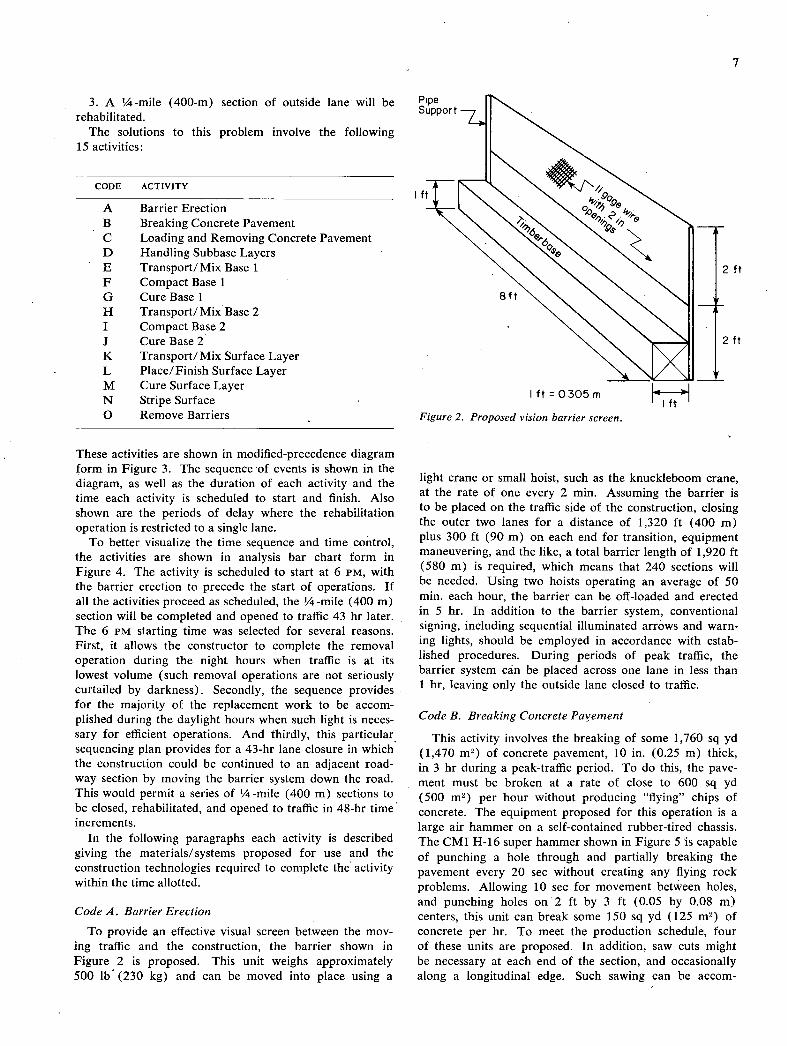
The proposed closure system employs standard warning signs, flashing lights, overhead illumination for nighttime construction, traffic cones, and reduced speed limits through the construction site. In addition, a "vision barrier screen," as shown in Figure 2, is proposed. This screen, made by attaching standard chain-link fence units to a 12 by 12 in. (0.30 by 0.30 m) timber base, can be quickly deployed and removed. It offers an effective, stable screen in winds gusting'to 50 mph (80 kmh). This screen is a modification of a barrier system presently being used in Massachusetts (see Appendix B) and reported to give excellent results.
PROPOSED SOLUTIONS FOR ALL LAYERS STRUCTURALLY,
UNSOUND
General
Additional assumptions made for this particular prob-lem are:
The pavement to be rehabilitated has a minimum of three 12-ft (3.7-m) wide lanes in each direction and con-sists of a 10-in. (0.25-m) thick unreinforced concrete pavement resting on a 6-in. (0.15-rn) granular base and an 8-in. (0.20-m) lime-stabilized subgrade.
The vertical alignment of the rehabilitated surface will conform to the average elevation of the adjacent lane.
3. A ¼-mile (400-rn) section of outside lane will be rehabilitated.
The solutions to this problem involve the following 15 activities:
Pipe Support
CODE ACTIVITY
A Barrier Erection B Breaking Concrete Pavement C Loading and Removing Concrete Pavement D Handling Subbase Layers E Transport/Mix Base 1 F Compact Base 1 G Cure Base 1 H Transport/ Mix Base 2 I Compact Base 2 J Cure Base 2 K Transport/Mix Surface Layer L Place/Finish Surface Layer M Cure Surface Layer N Stripe Surface 0 Remove Barriers
These activities are shown in modified-precedence diagram form in Figure 3. The sequence of events is shown in the diagram, as well as the duration of each activity and the time each activity is scheduled to start and finish. Also shown are the periods of delay where the rehabilitation operation is restricted to a single lane.
To better visualize the time sequence and time control, the activities are shown in analysis bar chart form in Figure 4. The activity is scheduled to start at 6 PM, with the barrier erection to precede the start of operations. If all the activities proceed as scheduled, the ¼-mile (400 m) section will be completed and opened to traffic 43 hr later. The 6 PM starting time was selected for several reasons. First, it allows the constructor to complete the removal operation during the night hours when traffic is at its lowest volume (such removal operations are not seriously curtailed by darkness). Secondly, the sequence provides for the majority of the replacement work to be accom-plished during the daylight hours when such light is neces-sary for efficient operations. And thirdly, this particular sequencing plan provides for a 43-hr lane closure in which the construction could be continued to an adjacent road-way section by moving the barrier system down the road. This would permit a series of 1/4 -mile (400 m) sections to be closed, rehabilitated, and opened to traffic in 48-hr time increments.
In the following paragraphs each activity is described giving the materials/systems proposed for use and the construction technologies required to complete the activity within the time allotted.
Code A. Barrier Erection
To provide an effective visual screen between the mov-ing traffic and the construction, the barrier shown in Figure 2 is proposed. This unit weighs approximately 500 lb (230 kg) and can be moved into place using a
Iftj fog, o ...
NN NN N NNNN4 II
NNNNN 2ff
8ff IL
2 ft
IftO.305m I ft
Figure 2. Proposed vision barrier screen.
light crane or small hoist, such as the knuckleboom crane, at the rate of one every 2 mm. Assuming the barrier is to be placed on the traffic side of the construction, closing the outer two lanes for a distance of 1,320 ft (400 m) plus 300 ft (90 m) on each end for transition, equipment maneuvering, and the like, a total barrier length of 1,920 ft (580 m) is required, which means that 240 sections will be needed. Using two hoists operating an average of 50 mm. each hour, the barrier can be off-loaded and erected in 5 hr. In addition to the barrier system, conventional signing, including sequential illuminated arrows and warn-ing lights, should be employed in accordance with estab-lished procedures. During periods of peak traffic, the barrier system can be placed across one lane in less than 1 hr, leaving only the outside lane closed to traffic.
Code B. Breaking Concrete Pavement
This activity involves the breaking of some 1,760 sq yd (1,470 m2 ) of concrete pavement, 10 in. (0.25 m) thick, in 3 hr during a peak-traffic period. To do this, the pave-ment must be broken at a rate of close to 600 sq yd (500 m2 ) per hour without producing "flying" chips of concrete. The equipment proposed for this operation is a large air hammer on a self-contained rubber-tired chassis. The CMI H-16 super hammer shown in Figure 5 is capable of punching a hole through and partially breaking the pavement every 20 sec without creating any flying rock problems. Allowing 10 sec for movement between holes, and punching holes on2 ft by 3 ft (0.05 by 0.08 rn) centers, this unit can break some 150 sq yd (125 m2 ) of concrete per hr. To meet the production schedule, four of these units are proposed. In addition, saw cuts might be necessary at each end of the section, and occasionally along a longitudinal edge. Such sawing can be accom-

8
C I Loadand
Barrier
Break 1 Remove
Delay
12 15
15
1212
Cu er Transport
2 Place
3 Base I iL i5Ba iIiJ1hITh+ 14
Transport / Mix Base 2
7
2 Load and Remove
2ndSec Concrete
9
D2 Handle U1 JiiJ ±
2nd Sec
Dl Handle iI 2 1st Sec Sublayer
15 19 19 23
3 Bose2 H 4 1 Base 2
3 Delay
25 31
K Transport / Mix 6 Surface Layer
26 31
L Place 5 Surface
Layer
31 41
M Cure 12 Surface
36 39
Delay
38 39
I Stripping
38 43
T50 Remove i I Barriers
Start Ti77 Fish Time
Activity Code Activity
Time Required
hrs
LEGEND
Figure 3. Modified precedence diagram for highway rehabilitation—all layers structurally unsound.
TIME (24 HR CLOCK)
A BARRIER ERECTION
B BREAK PAVEMENT
C1 LOAD/REMOVE PAVEMENT
C 2 LOAD/REMOVE PAVEMENT
D HANDLING SUBLAVERS I
Op HANDLING SUBLAYERS I
TRANSPORT/MIX BASE I
F COMPACT BASE I I
G CURE BASEI
H TRANSPORT/ MIX BASE 2 I
I COMPACT BASE 2
CURE BASE 2 i
K TRANSPORT / MIX SURFACE
PLACE / FINISH SURFACE I I
M CURE SURFACE I
N STRIPE/SAW SURFACE I
OREVE BARRIER
LEI b----
0 12 24 36 48
TIME (882)
Figure 4. Analysis bar chart for highway rehabilitation—all layers structurally unsound.
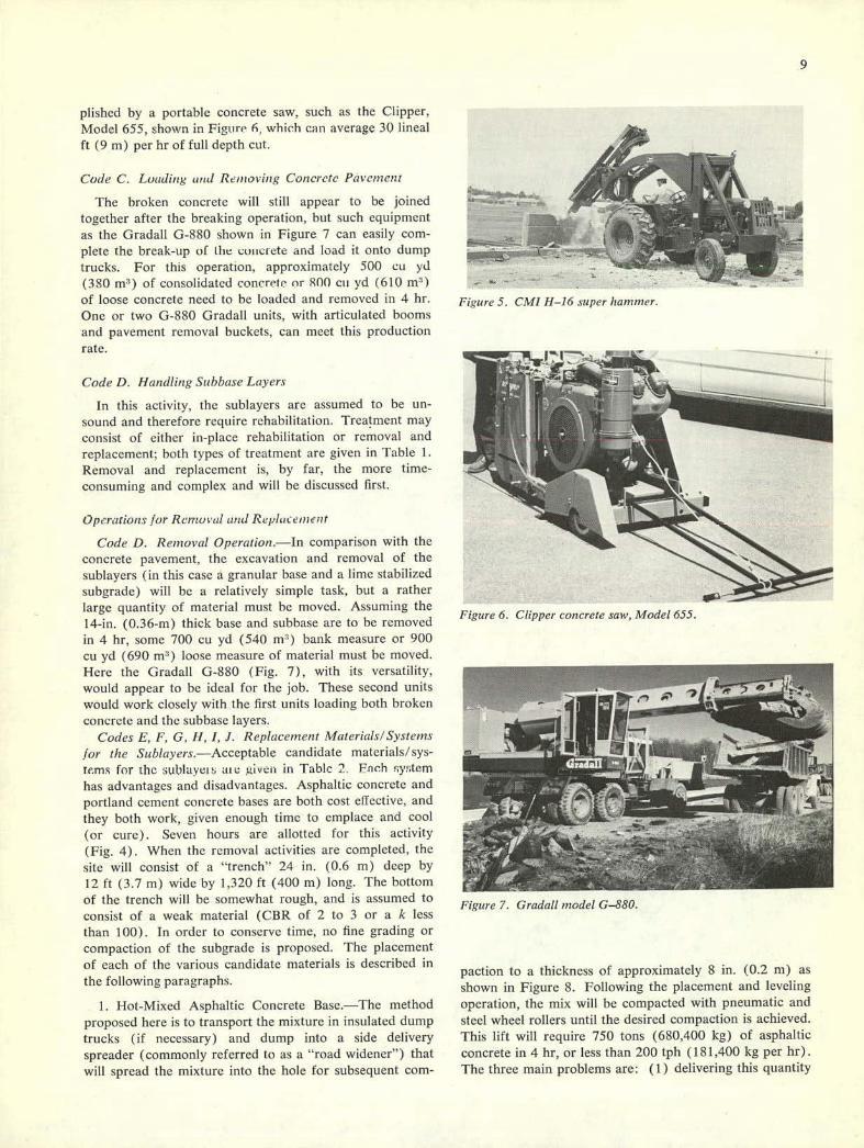
Figure 6. Clipper concrete saw, Model 655.
Figure 7. Gradall model G-880.
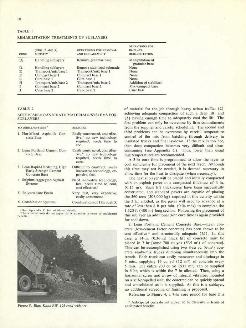
pushed by a portable concrete saw, such as the Clipper, Model 655, shown in Figuri' 6, which can average 30 lineal ft (9 m) per hr of full depth cut.
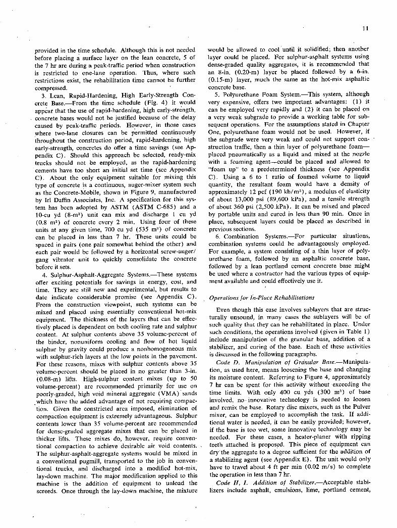
Code C. Lutzdi,,' and Rtmovi,zg Concrete Pavement
The broken concrete will still appear to be joined together after the breaking operation, but such equipment as the Gradall G-880 shown in Figure 7 can easily com-plete the break-up of [lie cuiiei'ete and load it onto dump trucks. For this operation, approximately 500 cii yd (380 m3 ) of consolidated concrc'tc or 800 cii yd (610 1113)
of loose concrete need to be loaded and removed in 4 hr. One or two G-880 Gradall units, with articulated booms and pavement removal buckets, can meet this production rate.
Code D. 1-landling Subbase Layers
in this activity, the sublayers are assumed to be un-sound and therefore require rehabilitation. Treatment may consist of either in-place rehabilitation or removal and replacement; both types of treatment are given in Table 1. Removal and replacement is, by far, the more time-consuming and complex and will be discussed first.
Operations for Removal and Rep! et,mle't
Code D. Removal Operation.—In comparison with the concrete pavement, the excavation and removal of the sublayers (in this case a granular base and a lime stabilized subgradc) will be a relatively simple task, but a rather large quantity of material must be moved. Assuming the 14-in. (0.36-rn) thick base and subbase are to be removed in 4 hr, some 700 cu yd (540 m) bank measure or 900 cu yd (690 m3) loose measure of material must be moved. Here the Gradall G-880 (Fig. 7), with its versatility, would appear to be ideal for the job. These second units would work closely with the first units loading both broken concrete and the subbase layers.
Codes E, F, G, H, I, J. Replacement Iv!aterials/Svstemns
for the Sublayers.—Acceptable candidate materials/ sys-Tems for the sublavei; ai c giveo in Table 2. Fach ;y;tem has advantages and disadvantages. Asphaltic concrete and portland cement concrete bases are both cost effective, and they both work, given enough time to emplace and cool (or cure). Seven hours are allotted for this activity (Fig. 4). When the removal activities are completed, the site will consist of a "treneh' 24 in. (0.6 m) deep by 12 ft (3.7 in) wide by 1,320 ft (400 m) long. The bottom of the trench will be somewhat rough, and is assumed to consist of a weak material (CBR of 2 to 3 or a k less than 100). In order to conserve time, no fine grading or compaction of the subgrade is proposed. The placement of each of the various candidate materials is described in the following paragraphs.
I. Hot-Mixed Asphaltic Concrete Base.—The method proposed here is to transport the mixture in insulated dump trucks (if necessary) and dump into a side delivery spreader (commonly referred to as a "road widener") that will spread the mixture into the hole for subsequent corn-
Figure 5. C?'I1 H-16 super hammer.
paction to a thickness of approximately 8 in. (0.2 rn) as shown in Figure 8. Following the placement and leveling operation, the mix will be compacted with pneumatic and steel wheel rollers until the desired compaction is achieved. This lift will require 750 tons (680,400 kg) of asphaltic concrete in 4 hr, or less than 200 tph (181,400 kg per hr). The three main problems are: (1) delivering this quantity
EI
TABLE I
REHABILITATION TREATMENTS OF SUBLAYERS
CODE
(Ems. 2 AND 3) ACTIVITY
OPERATIONS FOR REMOVAL AND REPLACEMENT
OPERATIONS FOR
IN-PLACE
REHABILITATION
Handling sublayers Remove granular base Manipulation of granular base
D2 Handling sublayers Remove stabilized subgrade None E Transport/mix base I Transport/mix base 1 None F Compact base 1 Compact base I None G Cure base I Cure base I None H Transport/mix base 2 Transport/mix base 2 Addition of stabilizer I Compact base 2 Compact base 2 Mix/compact base J Cure base 2 Cure base 2 Cure base
TABLE 2
ACCEPTA BLE CANDIDATE MATERIALS/SYSTEMS FOR SUI3LAYERS
MATERIAL/SYSTEM REMARES
Hot-Mixed Asphaltic Con- Easily constructed, cost effec- crete Base tive,' no new technology
required, needs time to cool.
Lean Portland Cement Con- Easily constructed, cost effec- crete Base tive," no new technology
required, needs time to cure.
Lean Rapid-Hardening, High
Difficult to construct, needs Early-Strength Cement
innovative technology, ex- Concrete Base pensive, fast.
Sulphur-Aggregate-Asphalt
Need innovative technology, Systems
fast, needs time to cool, cost effective."
S. Polyurethane Foam Very fast, very expensive, easily constructed.
6. Combination Systems Combinations of I through 5.
See Appendix C for additional details. Anticipated costs do not appear to be excessive in terms of anticipated
benefits.
Figure 8. Blatt'-Knox RI'V-195 road t'idencr.
of material for the job through heavy urban traffic; (2) achieving adequate compaction of such a deep lift; and (3) having enough time to adequately cool the lift. The first problem can only be overcome by firm commitments from the supplier and careful scheduling. The second and third problems can be overcome by careful temperature control of the mix from batching through delivery in insulated trucks and final laydown. If the mix is too hot, then deep compaction becomes very difficult and time-consuming (see Appendix C). Thus, lower than usual mix tcmperaturcs are recommended.
A 3-hr cure time is programmed to allow the layer to cool sufficiently for placement of the next layer. Although this time may not be needed, it is deemed necessary to allow time for the heat to dissipate (when necessary).
The next sublaycr will be placed and initially compacted with an asphalt paver to a euiiipaeted Iltickitess of 6 in. (0.15 rn). Such lift thicknesses have been successfully constructed, and standard payers are capable of placing the 560 tons (508,000 kg) required in this activity within the 3 hr allotted, as the paver will need to advance at a rate of less than 8 ft per mm. (0.04 m/s) to complete the 1,320 ft (400 m) long section. Following the placement of this sublayer an additional 3-hr cure time is again provided for cool-down.
2. Lean Portland Cement Concrete Base.—Lean con-crete (low-cement factor concrete) has been shown to be cost effective * and structurally adequate (15). In this case, a 14-in. (0.36-rn) thick lift of concrete must be placed in 7 hr [sonic 700 cii yds (535 rn') of concrete]. This can be accomplished using two S-eu yd (6-rn1) con-crete ready-mix trucks dumping simultaneously into the trench. Each truck can easily maneuver and discharge in 5 mm., supplying 16 cu yd (12 rn3) of concrete every 5 nun. The entire 700 cu yd (535 rn') can be supplied in 6 hr, which is within the 7 hr allotted. Then, using a horizontal screw and a row of internal vibrators mounted on a self-propelled unit, the concrete can be quickly spread and consolidated as it is supplied. As this is a sublayer, no additional sereeding or finishing is proposed.
Referring to Figure 4, a 7-hr cure period for base 2 is
Anticipated costs do not appear to be excessive in terms of anticipated benefits.
11
provided in the time schedule. Although this is not needed before placing a surface layer on the lean concrete, 5 of the 7 hr are during a peak-traffic period when construction is restricted to one-lane operation. Thus, where such restrictions exist, the rehabilitation time cannot be further compressed.
Lean, Rapid-Hardening, High Early-Strength Con-crete Base.—From the time schedule (Fig. 4) it would appear that the use of rapid-hardening, high early-strength, concrete bases would not be justified because of the delay caused by peak-traffic periods. However, in those cases where two-lane closures can be permitted continuously throughout the construction period, rapid-hardening, high early-strength, concretes do offer a time savings (see Ap-pendix Q. Should this approach be selected, ready-mix trucks should not be employed, as the rapid-hardening cements have too short an initial set time (see Appendix Q. About the only equipment suitable for mixing this type of concrete is a continuous, auger-mixer system such as the Concrete-Mobile, shown in Figure 9, manufactured by Irl Daffin Associates, Inc. A specification for this sys-tem has been adopted by ASTM (ASTM C-685) and a 10-cu yd (8-m3) unit can mix and discharge 1 cu yd (0.8 m3) of concrete every 2 mm. Using four of these units at any given time, 700 cu yd (535 m3) of concrete can be placed in less than 7 hr. These units could be spaced in pairs (one pair somewhat behind the other) and each pair would be followed by a horizontal screw-auger/ gang vibrator unit to quickly consolidate the concrete before it sets.
Sulphur-Asphalt-Aggregate Systems.—These systems offer exciting potentials for savings in energy, cost, and time. They are still new and experimental, but results to date indicate considerable promise (see Appendix C). From the construction viewpoint, such systems can be mixed and placed using essentially conventional hot-mix equipment. The thickness of the layers that can be effec-tively placed is dependent on both cooling rate and sulphur content. At sulphur contents above 35 volume-percent of the binder, nonuniform cooling and flow of hot liquid sulphur by gravity could produce a nonhomogeneous mix with sulphur-rich layers at the low points in the pavement. For these reasons, mixes with sulphur contents above 35 volume-percent should be placed in no greater than 3-in. (0.08-m) lifts, content mixes (up to 50 volume-percent) are recommended primarily for use on poorly-graded, high void mineral aggregate (VMA) sands which have the added advantage of not requiring compac-tion. Given the constricted area imposed, elimination of compaction equipment is extremely advantageous. Sulphur contents lower than 35 volume-percent are recommended for dense-graded aggregate mixes that can be placed in thicker lifts. These mixes do, however, require conven-tional compaction to achieve desirable air void contents. The sulphur-asphalt-aggregate systems would be mixed in a conventional pugmill, transported to the job in conven-tional trucks, and discharged into a modified hot-mix, lay-down machine. The major modification applied to this machine is the addition of equipment to unload the screeds. Once through the lay-down machine, the mixture
would be allowed to cool until it solidified; then another layer could be placed. For sulphur-asphalt systems using dense-graded quality aggregates, it is recommended that an 8-in. (0.20-m) layer be placed followed by a 6-in. (0.15-m) layer, much the same as the hot-mix asphaltic concrete base.
Polyurethane Foam System.—This system, although very expensive, offers two important advantages: (1) it can be employed very rapidly and (2) it can be placed on a very weak subgrade to provide a working table for sub-sequent operations. For the assumptions stated in Chapter One, polyurethane foam would not be used. However, if the subgrade were very weak and could not support con-struction traffic, then a thin layer of polyurethane foam—placed pneumatically as a liquid and mixed at the nozzle with a foaming agent—could be placed and allowed to "foam up" to a predetermined thickness (see Appendix Q. Using a 6 to 1 ratio of foamed volume to liquid quantity, the resultant foam would have a density of approximately 12 pcf (190 kb!m3), a modulus of elasticity of about 13,000 psi (89,600 kPa), and a tensile strength of about 360 psi (2,500 .kPa). It can be mixed and placed by portable units and cured in less than 90 mm. Once in place, subsequent layers could be placed as described in previous sections.
Combination Systems.—For particular situations, combination systems could be advantageously employed. For example, a system consisting of a thin layer of poly-urethane foam, followed by an asphaltic concrete base, followed by a lean portland cement concrete base might be used where a contractor had the various types of equip-ment available and could effectively use it.
Operations for In-Place Rehabilitations
Even though this case involves sublayers that are struc-turally unsound, in many cases the sublayers will be of such quality that they can be rehabilitated in place. Under such conditions, the operations involved (given in Table 1) include manipulation of the granular base, addition of a stabilizer, and curing of the base. Each of these activities is discussed in the following paragraphs.
Code D. Manipulation of Granular Base.—Manipula-tion, as used here, means loosening the base and changing its moisture content. Referring to Figure 4, approximately 7 hr can be spent for this activity without exceeding the time limits. With only 400 cu yds (300 m3) of base involved, no - innovative technology is needed to loosen and remix the base. Rotary disc mixers, such as the Pulver mixer, can be employed to accomplish the task. If addi-tional water is needed, it can be easily provided; however, if the base is too wet, some innovative technology may be needed. For these cases, a heater-planer with ripping teeth attached is proposed. This piece of equipment can dry the aggregate to a degree sufficient for the addition of a stabilizing agent (see Appendix E). The unit would only have to travel about 4 ft per mm (0.02 m/s) to complete the operation in less than 7 hr.
Code H, I. Addition of Stabilizer.—Acceptable stabi-lizers include asphalt, emulsions, lime, portland cement,

12
and sulphur—the first three of which are widely used and accepted. It is sometimes difficult to obtain desired uni-formity with field mixing of emulsions and aggregates. It is, however, both cost and energy effective, and the resulting layer has improved strength and durability once the emulsion "breaks."
Lime stabilization is inexpensive and easy to construct. The strength improvement to the base normally is much less than with the other stabilizing agents, and relatively long time periods are required for the lime reactions to be completed (16). In those cases where only limited im-provements (within the time constraints) in base quality are required, lime stabilization should be strongly con-sidered. Where the base is quite wet, quicklime (CaO) might well serve to both dry up the base and stabilize it.
Stabilization of granular materials with portland cement is an accepted practice (16). It is cost effective and can be completed fairly rapidly. The cement can be placed on the surface, water added, and then mixed with the base using a rotary disc mixer. Acceptable uniformity of mix-ing can easily be achieved. Once mixed, the base is com-pacted with standard compaction equipment and allowed to cure. Although this curing takes time, the granular mass can usually take construction traffic immediately without damage so rapid hardening cements would not generally be needed. Where significant strength gains are required in the base layer, portland cement stabilization offers some significant advantages.
Sulphur is a new, promising- and innovative stabilizer for granular materials (see Appendix Q. One innovative idea, if the base is in fairly good shape and relatively porous (such as that used in the so-called free-draining subbases), is to pour molten sulphur on the surface of such a base that has been heated and dried. The molten sulphur should infiltrate the base until the sulphur cools. In most conditions, the base will be wet and relatively cool. If molten sulphur is poured on such a surface it will immedi-ately solidify and prevent infiltration of any additional sulphur that might be added. To prevent this, the porous base must first be heated and dried. This heat can be applied with the traveling heater-scarifier, shown in Fig-ure 10, which should drive off the water. Probably rela-tively long heating times will be required to heat the aggregate sufficiently. Once heated, the molten sulphur, added quickly, should infiltrate the base approximately 3 in. (0.03 m). If the base is dense and relatively non-porous, then it needs to be loosened in place before heating and the addition of any sulphur. Using a rotary disc, the material can be rapidly loosened, then heated with the heater-scarifier. Following immediately, the molten sul-phur can be applied, allowed to impregnate the base, and cooled (although relatively long cool-down times may be-necessary). The stabilized base, though not as strong as a portland cement stabilized base, might be made signifi-cantly stronger than the original granular base, and the treatment should be quite cost effective. New technology is needed to verify this idea and evaluate its potential.
One other innovative approach would be to use cement slurries—made with rapid-hardening, high-strength ce-ments—in the same manner as proposed for the sulphur
in that the slurry would infiltrate the base and rapidly stabilize it in place. The base would need to be porous enough and the- voids dry enough to accept the slurry. The U.S. Air Force is reported to be pursuing this idea for runway repair.
Code J. Curing of the Base.—In this operation, enough time must be provided for the stabilized base to cure (or cool) sufficiently to withstand the loads imposed upon it during placement of the surface layer. Fo1 asphalt, lime, or portland cement stabilizing agents, the aggregate inter-lock will usually be sufficient to prevent damage to the stabilization process. Sulphur, however, must crystallize before any loads are imposed, or the structure may become fractured. Thus, sulphur-impregnated systems should be allowed to cool to at least 200 F (93 C) before subsequent layers are' placed. Within the time limits imposed for this activity, sufficient cool-down time is provided for the sulphur system, should it be selected.
Code K, L, M, N. Rehabilitation Materials/Systems for the Surface Layer
Once the sublayers have been rehabilitated, either in-place or by removal and replacement, then the last major activity is rehabilitation of the surface layer. Referring to Figure 4, 5 hr are allocated for the placing and finishing operation, and 12 additional hr are allotted for curing (or cooling) this surface layer. Promising candidate mate-rials/ systems are listed in Table 3 and discussed in the following paragraphs.
Hot-Mixed Asphaltic Concrete.—Hot-mixed asphaltic concrete (HMAC) surfaces can be placed and compacted in much the same manner as HMAC bases except that closer vertical tolerances must be maintained. For the assumed condition, a 10-in. (0.25-m) thick surface layer is needed. Standard practice calls for this surface layer to be placed in three lifts of 51/2 in. (0.14 m), 3 in. (0.08 m), and 11/2 in. (0.04 m) (17). One asphalt paver can place all three lifts in the 17-hr placement cool-down time allotted, even though there is a 3-hr period during which the construction operation is restricted to a single lane. The only problems envisioned would be the steady supply of HMAC through heavy urban traffic, and the provision of enough time for the mix to cool sufficiently to support traffic (see Appendix C). By overcoming these problems, this material/system offers one solution to the problem.
Portland Cement Concrete, Cast-In-Place.—Use of port-land cement concrete, cast-in-place, offers many advan-tages; namely, it is the same material that was removed, which makes the rehabilitation aesthetically acceptable, it requires no new technology, and it is cost effective. The one major disadvantage is the cure time necessary before the section can be opened to traffic. In order to cut this cure time to 12 hr, Type III cement with a strength ac-celerating admixture (see Appendix C) is proposed. Transportation of the concrete can be achieved in concrete ready-mix trucks, but the water and admixture should not be added until the truck reaches the construction site. This precaution will provide maximum time for placement and finishing of the concrete. An 8-cu yd (6-rn3) mixer can
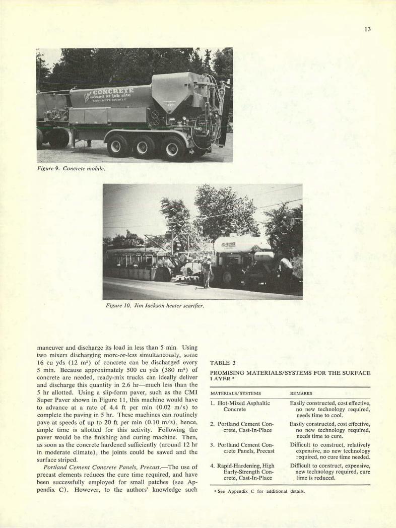
Figure 9. Concrete mobile.
Figure 10. Jim Jackson heater scarifier.
13
maneuver and discharge its load in less than 5 mm. Using two mixers discharging morc-or-less simultaricously, suffic 16 cu yds (12 m) of concrete can be discharged every 5 mm. Because approximately 500 cu yds (380 m3) of concrete are needed, ready-mix trucks can ideally deliver and discharge this quantity in 2.6 hr—much less than the 5 hr allotted. Using a slip-form paver, such as the CMI Super Paver shown in Figure 11, this machine would have to advance at a rate of 4.4 ft per mm (0.02 m/s) to complete the paving in 5 hr. These machines can routinely pave at speeds of up to 20 ft per mm (0.10 m/s), hence, ample time is allotted for this activity. Following the paver would be the finishing and curing machine. Then, as soon as the concrete hardened sufficiently (around 12 hr in moderate climate), the joints could be sawed and the surface striped.
Portland Cement Concrete Panels, Precast—The use of precast elements reduces the cure time required, and have been successfully employed for small patches (see Ap-pendix C). However, to the authors' knowledge such
TABLE 3
PROMISING MATERIALS/SYSTEMS FOR THE SURFACE I AYF.R
MATERIALS/SYSTEMS
REMARKS
Hot-Mixed Asphaltic
Easily constructed, cost effective, Concrete no new technology required,
needs time to cool.
Portland Cement Con- Easily constructed, cost effective, crete, Cast-In-Place no new technology required,
needs time to cure.
Portland Cement Con- Difficult to construct, relatively crete Panels, Precast expensive, no new technology
required, no cure time needed.
Rapid-Hardening, High
Difficult to construct, expensive, Early-Strength Con- new technology required, cure crete, Cast-In-Place time is reduced.
See Appendix C for additional details.

14
Figure ii. CMI 3Iip-/ornm j)aver.
elements have not been used in an extensive replacement system such as the 1.320-ft (400-rn) system proposed here. Innovative technology is needed to more rapidly place and set the panels in the grout bed to the correct grade. The system proposed here is to provide sublayers to within 7 in. (0.18 m) of the surface. This would then be followed by pump placement of a 1-in. (0.03-rn) thick portland cement grout bed on which the concrete panels would be placed. These panels, 21 ft by 12 ft by 0.5 ft (6.4 x 3.7 X 0.15 m) in size, constructed with reinforced, structural lightweight concrete, would each weigh approxi-mately 15,000 lb (6,800 kg). Three such panels could be carried on a flatbed truck, and a total of 63 slabs would be required for the section. Using a 35-ton (32.000-kg) capacity crane, each panel could be secured, lifted, and placed in approximately 10 mm., assuming a tolerance of -1/4 in. (0.02) on both ends and one side. For a 10-mm placement time per panel, the entire 1,320-ft (400-rn) section can be placed in less than 11 hr, which is 8 hr less than the 19-hr placement and cure time allotted. Imniedi-ately following placement of each panel, a crew would check alignment, correct as necessary, and place a flexible sealing compound around each panel. This material/ system can cut approximately 8 hr off the rehabilitation time—provided no delays are encountered. The major disadvantages are the relatively high probability that delays will occur, the need for an expensive joint-sealing com-pound around each panel, the lack of load transfer between each panel (which must be accounted for in the design), and the fact that the joint spacing in adjacent lanes will not match the joint spacing in the rehabilitated sections. Rapid-IIardenin, High Ear!y-Strengtlz Concrete, Cast-in-Place—This material/system offers the major advantage of reducing the required cure time by 8 hr, as adequate strengths are achieved in 4 hr in moderate climates (see Appendix C). The problems and construction techniques have been discussed previously in the section on replace-ment materials/systems for sublayers. As soon as the surface is strong enough to support the equipment (in approximately 2 hr), transverse joints can be sawed and
Lode 0. Renove Barrier
This final activity can be performed in the same manner as the barrier erection, and 5 hr are again allotted for the operation. The barrier system can be removed completely or moved down the roadway to another section to be rehabilitated, depending on the situation.
PROPOSLL) SULU lIONS FOR SURFACE LAYER STRUCTUR-
ALLY UNSOUND—SUBLAYERS STRUCTURALLY SOUND
General
Additional assumptions made for this particular prob-lem are;
I. The pavement to be rehabilitated consists of either 8 in. (0.20 m) of hot-mixed asphaltic concrete or a 10-in. (0.25-m) thick unreinforced concrete pavement, both resting on a structurally sound sublayer.
The vertical alignment of the rehabilitated surface will conform to the adjacent lane.
A ¼-mile (400-rn) section of outside lane will be rehabilitated.
The solution to this problem involves the following eight activities (the coding follows that given in Fig. 4):
CODE ACTIVITY
A
Barrier Erection B
Breaking Pavement C
Loading and Removing Pavement K
Transport/Mix Surface Layer L
Place/Finish Surface Layer M
Cure Surface Layer N
Stripe Surface 0
Remove Barriers
These eight activities are shown in analysis bar chart form in Figure 12. The activities are scheduled to begin at S PM with the erection of the barrier system. This time was selected because, generally, the peak-traffic period will have ended, and the construction activity can commence with minimum interruption to trafllc flow. The ¼-mile (800-rn) section is scheduled to be completed and re-opened to traffic in about 26 hr.
In the following paragraphs, each activity is described giving the materials/systems proposed for use and the construction technologies required to complete the activity within the time allotted. Where the activities for this prob-lem coincide with the activities of the previous problem (all layers structurally unsound), the reader is referred to the preceding applicable discussion.
Code A. Barrier Erection
the surface striped. (See previous discussion.)

15
Code B. Breaking Pavement
This activity involves the breaking of .1,760 sq yd (1,470 m2 ) of pavement in 3 hr. To do this the pavement must be broken at a rate of close to 600 sq yd per hr (500 m2 ). For portland cement concrete pavement, re-moval methodology is given in the previous section under "Proposed Solutions for all Layers Structurally Unsound." For hot-mixed asphaltic concrete pavement, removal methodology is similar, yet somewhat simplified as this type pavement is fairly easily broken. An excellent ma-chine for breaking pavement is the Gradall, Model 880 (Fig. 7) which can tear and pick up the pavement without the need for prior break up. At each end of the sectionS a saw cut might be necessary, and a portable concrete saw, such as the Clipper,. Model 655 (Fig. 6), is recommended for this operation.
Code C. Loading and Removing Pavement
For concrete or bituminous pavements, the Gradall, Model 880, is recommended to pick up the material and load it onto trucks for removal. Machines of this size are needed because only 4 hr are allocated to remove some 500 cu yd (400 m3) of consolidated concrete or some 400 cu yd (300 rn3) of consolidated hot-mixed asphaltic concrete.
liME (24 HR CLOCK) Lluut ACTIVITY 6 PM 6AM .I 6 AM
A BARRIER ERECTION I
B BREAK PAVEMENT
C1 LOAD/REMOVE PAVEMENT El
C2 LOAD/REMOVE PAVEMENT
1< TRANSPORT / MIX SURFACE
L PLACE/FINISH SURFACE E1i
M CURE SURFACE I I
N STRIPE/SAW SURFACE -
0 REMOVE BARRIER - I
DELAYS (ONE LANE) I.
I I
0 12 24 30 TIME (HRS)
Figure 12. Analysis bar chart for highway rehabilitation—surface layer structurally unsound, sublayers structurally sound.
Portland Cement Concrete
For portland cement concrete surfaces, the solution involves the following eight activities (the coding follows that given in Fig. 4):
CODE ACTIVITY
Code K, L, M, N. Rehabilitation Materials/Systems for the Surface Layer
These activities have been fully discussed previously, and, therefore, will not be reiterated here. However, it should be pointed out that should a rapid-hardening, high early-strength concrete pavement (cast-in-place or precast portland cement concrete panels) be used, the total re-habilitation time can be cut approximately 8 hr. This results in a total lane closule of 18 hr for rehabilitating a. ¼-mile (400-rn) section of the outside lane of a highway.
Code 0. Remove Barrier
(See previous discussion.)
PROPOSED SOLUTIONS—ALL LAYERS STRUCTURALLY SOUND
When the pavement structure is sound and only the surface requires treatment to restore riding quality or skid resistance, the usual practice is to overlay the pavement. If overhead restrictions prevent the use of an overlay, then partial-depth rehabilitation must be considered.
Additional assumptions made for this particular prob-lem are:
The pavement surface is either wavy with the waves and sags not exceeding 2 in. (0.05 m) above or below the average pavement height, or the surface is deteriorated (spalled, ravelled, rutted, etc.). In either case, all pave-ment layers are structurally sound.
A ¼-mile (400-m) section will be rehabilitated.
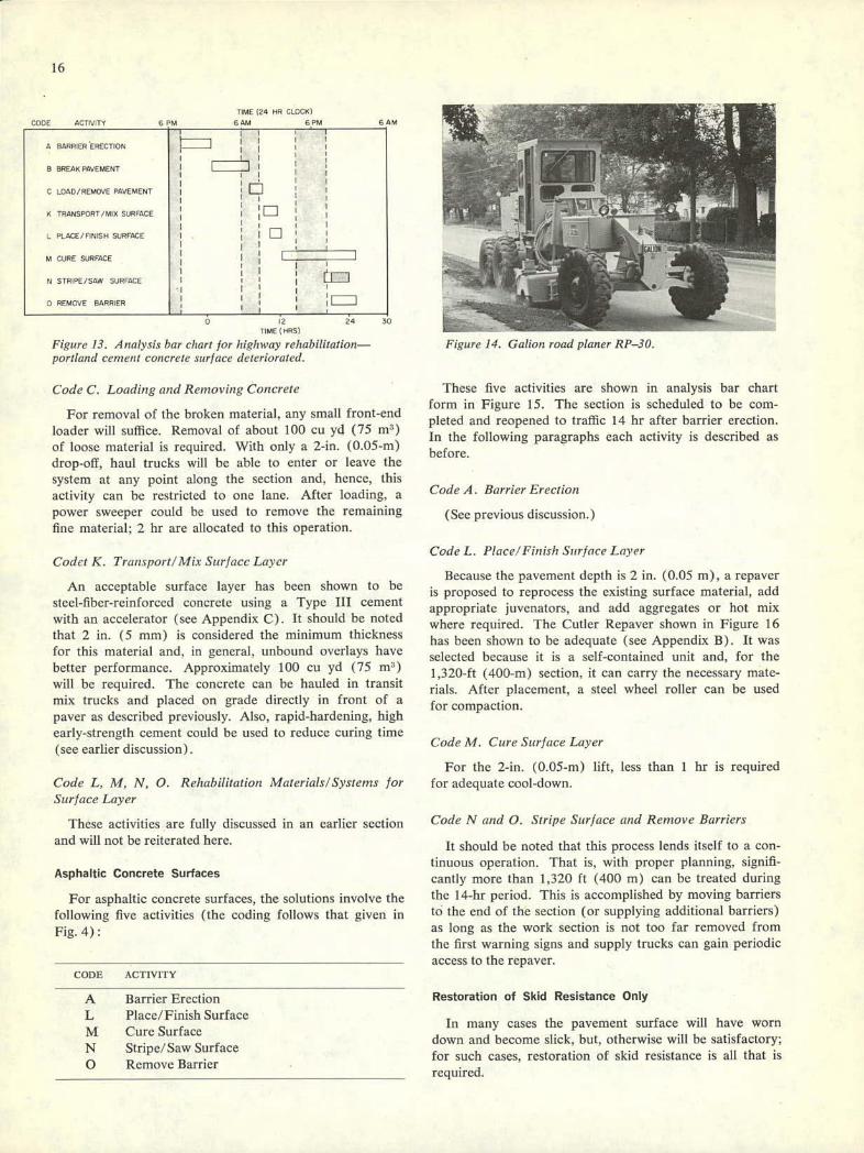
A Barrier Erection B Break Pavement (Grind) C Load/Remove Pavement K Transport/Mix Surface L Place/Finish Surface M Cure Surface N Stripe/Saw Surface 0 Remove Barrier
These activities are portrayed in analysis bar chart form in Figure 13. The section is scheduled to be completed and reopened to traffic 24 hr after barrier erection.
In the following paragraphs, each activity is described giving the material/systems proposed for use and the construction technologies required to complete the ac-tivity within the time allotted. Where the activities coin-cide with activities described earlier, the reader is referred to the previous discussion.
Code A. Barrier Erection
(See previous discussion.)
Code B. Break Pavement (Grind)
This activity involves grinding 1,760 sq yd (1,470 m2 )
of the pavement surface to an average depth of 2 in. (0.05 m) below grade line. Grinding can be accomplished in approximately 6 hr by using four Galion RP 30 road planers shown in Figure 14. As before, a portable con-crete saw may be required for vertical cuts at each end of the section.
16
TIME (24 HR CLOCK)
A BAWRIER ERECTION I I
B BREAK PAVEMENT
C LOAD/REMOVE PAVEMENT
K TRANSPORT/MIX SURFACE cTl
L PLACE/FINISH SURFACE
MCURESURFACE I
N STRIPE/SAW SURFACE
0 REMOVE BARRIER
1 2 24 2
TIME (HRS(
Figure 13. Analvsi.c bar chart for highway rehabilitation—portland ce,ne,,( concrete surface deteriorated.
Code C. Loading and Removing Concrete
For removal of the broken material, any small front-end loader will suffice. Removal of about 100 cu yd (75 rnT) of loose material is required. With only a 2-in. (0.05-rn) drop-off, haul trucks will be able to enter or leave the system at any point along the section and, hence, this activity can be restricted to one lane. After loading, a power sweeper could be used to remove the remaining fine material; 2 hr are allocated to this operation.
Codct K. Transport! Mix Surf ace Laycr
An acceptable surface layer has been shown to be steel-fiber-reinforced concrete using a Type III cement with an accelerator (see Appendix C). It should be noted that 2 in. (5 mm) is considered the minimum thickness for this material and, in general, unbound overlays have better performance. Approximately 100 cu yd (75 mT) will be required. The concrete can be hauled in transit mix trucks and placed on grade directly in front of a paver as described previously. Also, rapid-hardening, high early-strength cement could be used to reduce curing time (see earlier discussion).
Code L, M, N, 0. Rehabilitation Materials!Syste,ns for Surface Layer
These activities are fully discussed in an earlier section and will not be reiterated here.
Asphaltic Concrete Surfaces
For asphaltic concrete surfaces, the solutions involve the following five activities (the coding follows that given in Fig. 4):
CODE ACTIVITY
A Barrier Erection L Place/Finish Surface M Cure Surface N Stripe/Saw Surface 0 Remove Barrier
141111IM; -,%—,
Figure 14. Ga/ion road planer RP-30.
These five activities are shown in analysis bar chart form in Figure 15. The section is scheduled to be com-pleted and reopened to traffic 14 hr after barrier erection. In the following paragraphs each activity is described as before.
Code A. Barrier Erection
(See previous discussion.)
Code L. Place/Finish Surface Layer
Because the pavement depth is 2 in. (0.05 m), a repaver is proposed to reprocess the existing surface material, add appropriate juvenators, and add aggregates or hot mix where required. The Cutler Repaver shown in Figure 16 has been shown to be adequate (see Appendix B). It was selected because it is a self-contained unit and, for the 1,320-ft (400-rn) section, it can carry the necessary mate-rials. After placement, a steel wheel roller can be used for compaction.
Code M. Cure Surface Layer
For the 2-in. (0.05-rn) lift, less than 1 hr is required for adequate cool-down.
Code N and 0. Stripe Surface and Remove Barriers
It should be noted that this process lends itself to a con-tinuous operation. That is, with proper planning, signifi-cantly more than 1,320 ft (400 rn) can be treated during the 14-hr period. This is accomplished by moving barriers to the end of the section (or supplying additional harriers) as long as the work section is not too far removed from the first warning signs and supply trucks can gain periodic access to the repaver.
Restoration of Skid Resistance Only
In many eases the pavement surface will have worn down and become slick, but, otherwise will be satisfactory; for such cases, restoration of skid resistance is all that is required.
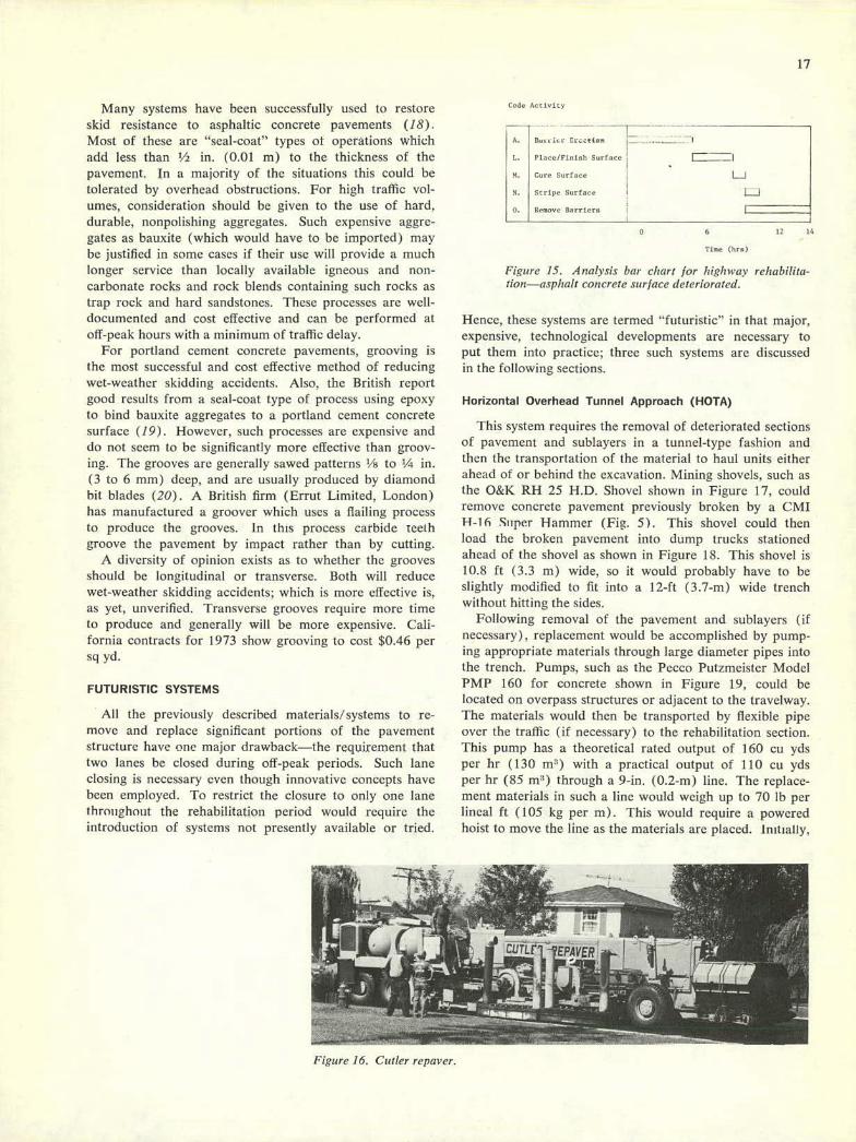
17
Many systems have been successfully used to restore skid resistance to asphaltic concrete pavements (18). Most of these are "seal-coat" types of operations which add less than ½ in. (0.01 m) to the thickness of the pavement. In a majority of the situations this could be tolerated by overhead obstructions. For high traffic vol-umes, consideration should be given to the use of hard, durable, nonpolishing aggregates. Such expensive aggre-gates as bauxite (which would have to be imported) may be justified in some cases if their use will provide a much longer service than locally available igneous and non-carbonate rocks and rock blends containing such rocks as trap rock and hard sandstones. These processes are well-documented and cost effective and can be performed at off-peak hours with a minimum of traffic delay.
For portland cement concrete pavements, grooving is the most successful and cost effective method of reducing vet-weather skidding accidents. Also, the British report good results from a seal-coat type of process using epoxy to bind bauxite aggregates to a portland cement concrete surface (19). However, such processes are expensive and do not seem to be significantly more effective than groov-ing. The grooves are generally sawed patterns ½ to ¼ in. (3 to 6 mm) deep, and are usually produced by diamond hit blades (20). A British firm (Errut Limited, London) has manufactured a groover which uses a flailing process to produce the grooves, in this process carbide teeth groove the pavement by impact rather than by cutting.
A diversity of opinion exists as to whether the grooves should be longitudinal or transverse. l3oth will reduce wet-weather skidding accidents; which is more effective is, as yet, unverified. Transverse grooves require more time to produce and generally will be more expensive. Cali-fornia contracts for 1973 show grooving to cost $0.46 per sc yd.
FUTURISTIC SYSTEMS
All the previously described materials/systems to re-move and replace significant portions of the pavement structure have one major drawback—the requirement that two lanes be closed during off-peak periods. Such lane closing is necessary even though innovative concepts have been employed. To restrict the closure to only one lane throiihoiit the rehabilitation period would require the introduction of systems not presently available or tried.
Code Activity
A. Ba, • ic Crctio,, ---------
1. Piaco/Finiuh Surface _________
H. Cure Surface L_J N. Stripe Surface I L..J 0. Re,uove Barriers I
A 6 12 16
live (net)
Figure 15. A nairsis bar chart for high hay rehabilita-tion—asphalt concrete surf ace deteriorated.
Hence, these systems are termed "futuristic" in that major, expensive, technological developments are necessary to put them into practice; three such systems are discussed in the following sections.
Horizontal Overhead Tunnel Approach (HOTA)
This system requires the removal of deteriorated sections of pavement and sublayers in a tunnel-type fashion and then the transportation of the material to haul units either ahead of or behind the excavation. Mining shovels, such as the O&K RH 25 H.D. Shovel shown in Figure 17, could remove concrete pavement previously broken by a CMI H-16 Super Hanimer (Fig. 5). This shovel could then load the broken pavement into dump trucks stationed ahead of the shovel as shown in Figure 18. This shovel is 10.8 ft (3.3 m) wide, so it would probably have to be slightly modified to fit into a 12-ft (3.7-rn) wide trench without hitting the sides.
Following removal of the pavement and sublayers (if necessary), replacement would be accomplished by pump-ing appropriate materials through large diameter pipes into the trench. Pumps, such as the Pecco Putzmeister Model PMP 160 for concrete shown in Figure 19, could be located on overpass structures or adjacent to the travclway. The materials would then be transported by flexible pipe over the traffic (if necessary) to the rehabilitation section. This pump has a theoretical rated output of 160 cu yds per hr (130 mi) with a practical output of 110 cu yds per hr (85 rn 1 ) through a 9-in. (0.2-rn) line. The replace-ment materials in such a line would weigh up to 70 lb per lineal ft (105 kg per m). This would require a powered hoist to move the line as the materials are placed. Initially,
!izgure 16, Cutler rcpavcr.

18
could be completely removed and replaced in 44 hr as shown by the analysis bar chart in Figure 20. The cost of such an approach would depend on equipment avail-ability, inasmuch as this equipment is not commonly used by most highway contractors. New technology needed includes:
Modified mining shovel. Means to rapidly assemble and disassemble pipe for
the pump. Pumping lean concrete.
Moving Barrier Support Systems (MBSS)
Figure 17. Mining shovel, O&K RI! 25 II D.
the entire line would be laid out and then sections would be removed as replacement proceeded. Materials specifi-cally suited for this type of delivery include the lean con-crete base and the portland cement concrete pavement. By placing the pump off the traveiway, potential bottleneck conditions resulting from material deliveries are reduced, and rehabilitation can proceed with only a one-lane closure. Conceptually. a ¼-mile (400-m) section of pavement
This system requires the development of a moving barrier system inside of which the necessary rehabilitation operations are carried out. Such a system is schematically shown in Figure 21 and Figure 22, and is an amplification of a system first conceived by a group of graduate civil engineering students at Texas A&M University. The sys-tem consists of a moving barrier support frame 150 ft (45 m) long, attached to the chassis of an H-16 Super Hammer. This frame has the following three functions: ( I ) to provide a visual screen between the rehabilitation work and the adjacent traffic; (2) to support the two conveyor systems; and (3) to support the loading clam-shell. This frame would come to the job in five, 30-ft (9-rn), sections and, after assembled, would move in a
Figure 18. Loading arrangement using a ,nining shovel.
013cre" - -
Figure 19. Pecco Putzmeister concrete pump, Model PMP 160.
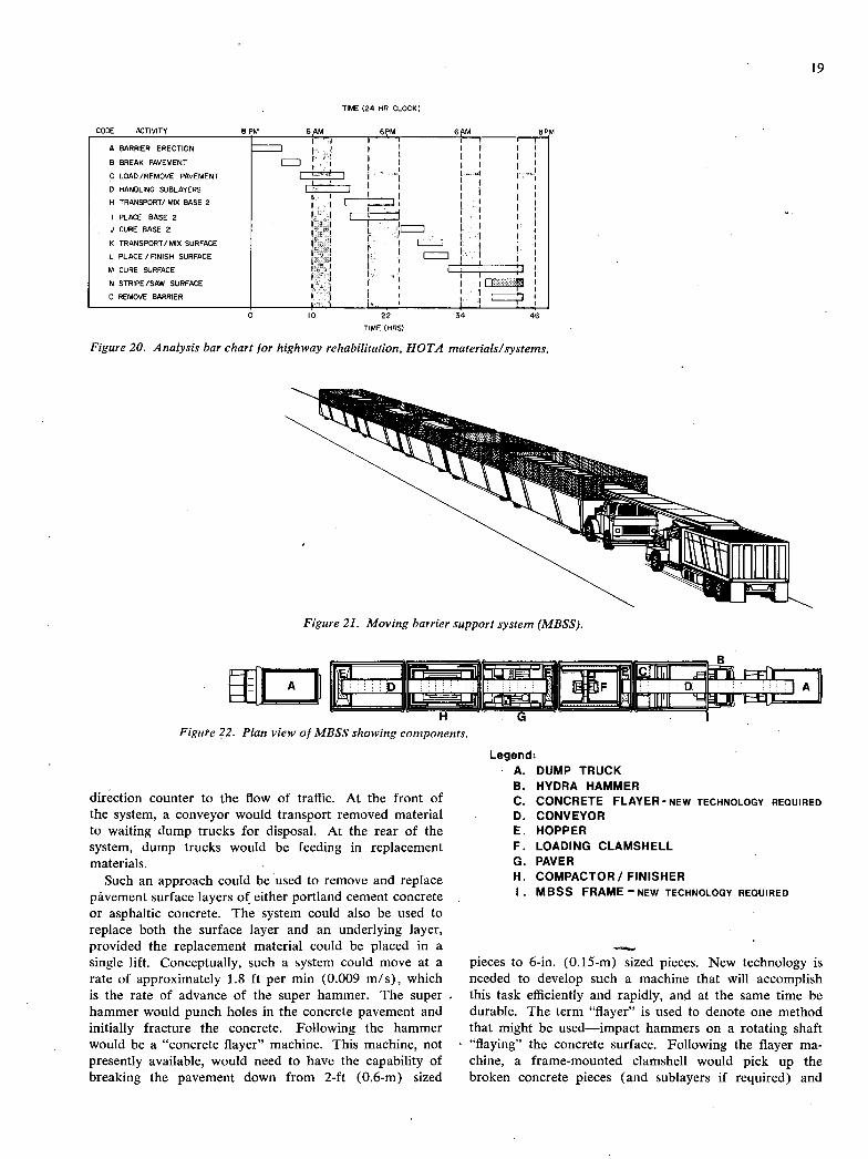
I _
1 ___
19
TIME (24 HR CLOCK)
A BARRIER ERECTION -'-
B BREAK PAVEMENT E:J C LOAD/REMOVE PAVEMENT I I
D HANDLING SUBLAYERS I I
H TRANSPORT! MIX BASE 2 I I
I PLACE BASE 2
CURE BASE 2 I. K TRANSPORT/MIX SURFACE I LJ L PLACE / FINISH SURFACE
M CURE SURFACE I I
N STRIPE/SAW SURFACE I i rr 0 REMOVE BARRIER LJ
IC)
TIME (HRS)
Figure 20. Analysis bar chart for highway rehabilitation, HOTA materials/systems.
Figure 21. Moving barrier support system (MBSS).
H
G Figure 22. Plan view of MBSS showing components.
direction counter to the flow of traffic. At the front of the system, a conveyor would transport removed material to waiting dump trucks for disposal. At the rear of the system, dump trucks would be feeding in replacement materials.
Such an approach could be used to remove and replace pavement surface layers of either portland cement concrete or asphaltic concrete. The system could also be used to replace both the surface layer and an underlying layer, provided the replacement material could be placed in a single lift. Conceptually, such a system could move at a rate of approximately 1.8 ft per mm (0.009 m/s), which is the rate of advance of the super hammer. The super hammer would punch holes in the concrete pavement and initially fracture the concrete. Following the hammer would be a "concrete flayer" machine. This machine, not presently available, would need to have the capability of breaking the pavement down from 2-ft (0.6-m) sized
Legend: A. DUMP TRUCK
HYDRA HAMMER CONCRETE FLAYER-NEW TECHNOLOGY REQUIRED CONVEYOR HOPPER LOADING CLAMSHELL PAVER COMPACTOR! FINISHER MBSS FRAME NEW TECHNOLOGY REQUIRED
pieces to 6-in. (0.15-rn) sized pieces. New technology is needed to develop such a machine that will accomplish this task efficiently and rapidly, and at the same time be durable. The term "flayer" is used to denote one method that might be used—impact hammers on a rotating shaft "flaying" the concrete surface. Following the flayer ma-chine, a frame-mounted clamshell would pick up the broken concrete pieces (and sublayers if required) and

20
deposit them into a hopper. The clamshell, hopper, and conveyor subsystems are connected to the MBSS frame in order that the forward motion of the frame will not cause a clamshell load to miss the hopper. The clamshell will move back and forth on tracks and from side to side. Thus, almost all deteriorated pavement material can be readily removed. The small amount of material remaining can be left without harming the replacement material or the pavement structure.
Following the clamshell is an automatic, grade-leveling, slip-form paving machine. Concrete is supplied to the paver by conveyor belt from hopper E which is supplied by dump trucks or ready-mix trucks. What is envisione1 here is similar to that shown in Figure 11. The size of the machine would need to be reduced to make it fit into the 12-ft (3.7-m) width. It should be able to handle all the materials proposed for use in the rehabilitated pavement.
Following the paver is a final compaction machine (for asphaltic concrete) or a finishing/curing machine (for rapid-hardening, high early-strength concrete).
At the rear of the MBSS is a receiving hopper and conveyor subsystem for the receipt of replacement mate-rials and the conveyance of these materials to the paving machine.
Such a system as the MBSS would be approximately 150 ft (45 m) in length. It must be capable of maintaining proper alignment as it moves along either tangent sections or curved sections.
To facilitate hauling unit egress and ingress, the MBSS will move in a direction counter to the flow of traffic. As the construction operations are all enclosed in the system, traffic handling ahead of and behind the MBSS could be accomplished by using mobile sequential arrow units;
One major drawback to this concept is that if the machine moves at approximately 1.5 ft per mm (0.008 m/s), the new pavement will be exposed to the stress of haul units bringing in new material at an age of approxi-mately 1 hr. If asphaltic concrete is used, then a tandem wheel roller, following the MBSS, could be employed to smooth out any irregularities that were introduced in the pavement surface by the haul units. On the other hand, if a rigid type of pavement were required, rapid-hardening, high early-strength concrete, mixed through a continuous type of mixer, such as the Concrete Mobile (Fig. 9), would appear to be the only potential material to use.
New technology needed for the moving barrier support includes:
A frame subsystem that will support the conveyors and moveable clamshell.
A frame subsystem that will track properly as it moves along the roadway.
A concrete "flayer" machine that will efficiently break down concrete pavement from 2-ft (0.6-m) sized pieces to 6-in. (0.15-m) sized pieces.
A modified slip-form paver, capable of placing hot-mix asphaltic concrete (HMAC) and rapid-hardening, high early-strength concrete materials.
Mobile Roadway Repair Unit
This concept consists of a self-propelled reconditioning factory which, by use of a bridge over the repair site, provides pavement rehabilitation with minimal disturbance to through traffic. This concept was developed by Professor Rollin C. Dix of the Illinois Institute of Technology, and has been patented (U.S. Patent 3.811, 147 titled "Mobile Roadway Repair Unit") (21). The vehicle is essentially a 41/4 -ft (1.4-m) high by 160-ft (50-m) long bridge which is moved into place in four sections and remains stationary while work is proceeding. Following completion of the work, the unit will move down the roadway at a speed of approximately 2 mph (0.9 m/s). Traffic movement over the bridge can continue whether the unit is stationary or moving. The artist's conception of the unit is shown in Figure 23.
The concept offers several advantages. One, no lanes are completely closed at any time (except when assembling the system and resupplying the system with paving mate-rial). A second advantage is that repair can proceed without interruption or undue hazard using conventional material/systems to effect the rehabilitation. A third ad-vantage is the mobility of the system and enclosure of all equipment, operators, and material within the unit. Con-cerning the first advantage, any system that can keep all lanes open is certainly a desirable goal, especially when considering the very high traffiC volumes in many urban areas. The second advantage means that the most cost, effective materials can be used even if they require the unit to remain stationary an extra few hours for these materials to attain sufficient strength to be subjected to traffic. The third advantage means that minimum traffic disturbance will result.
The mobile roadway repair unit concept has two major disadvantages. First, the cost involved in developing it to the point where it can be put into commercial use, and second, the restrictive working height [41/2 ft (1.4 m) for workmen in the unit (this height might be raised to 51/2 ft (1.7 m) without decreasing traffic flow]. The first dis-advantage (which is the same for any new concept) can be overcome only by the desire of some agency or industry to underwrite the development cost'. The second disad-vantage only means that work inside the unit will be uncomfortable, and hence, labor cost will be higher than normal.
Discussion of Futuristic Systems
The development of new and advanced materials/ sys-tems is an expensive, time-consuming process. The re-search team discussed concepts, such as the three proposed previously, with numerous contractors, equipment manu-facturers, and highway engineers. One contractor inter-viewed discussed his concept of a system to continuously remove, upgrade, and replace asphaltic concrete pavement (22). In his opinion, the development cost for such a system could easily escalate to $1,000,000. An equipment manufacturer indicated that his company seriously con-sidered developing rapid pavement rehabilitation systems, using its knowledge of mining equipment (23). However,
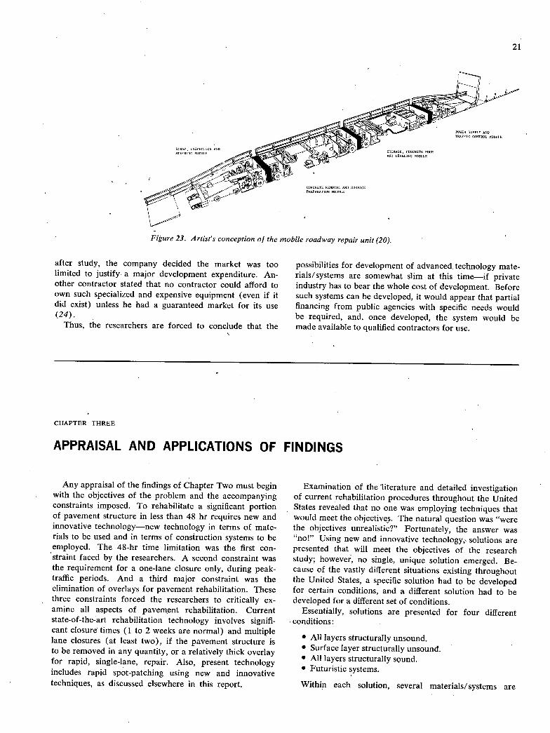
21
Figure 23. Artist's conception of the mobile roadway repair unit (20). '
after study, the company decided the market was too limited to justify a major development expenditure. An-other contractor stated that no contractor could afford to own such specialized and expensive equipment (even if it did exist) unless he had a guaranteed market for its use (24).
Thus, the researchers are forced to conclude that the
possibilities for development of advanced, technology mate-rials/systems are somewhat slim at this time—if private industry has to bear the whole cost of development. Before such systems can be developed, it would appear that partial financing from public agencies with specific needs would be required, and, once developed, the system would be made available to qualified contractors for use.
CHAPTER THREE
APPRAISAL AND APPLICATIONS OF FINDINGS
Any appraisal of the findings of Chapter Two must begin with the objectives of the problem and the accompanying constraints imposed. To rehabilitate a significant portion of pavement structure in less than 48 hr requires new and innovative technology—new technology in terms of mate-rials to be used and in terms of construction systems to be employed. The 48-hr time limitation was the first con-straint faced by the researchers. A second constraint was the requirement for a one-lane closure only, during peak-traffic periods. And a third major constraint was the elimination of overlays for pavement rehabilitation. These three constraints forced the researchers to critically ex-amine all aspects of pavement rehabilitation. Current state-of-the-art rehabilitation technology involves signifi-cant closure times (1 to 2 weeks are normal) and multiple lane closures (at least two), if the pavement structure is to be removed in any quantity, or a relatively thick overlay for rapid, single-lane, repair. Also, present technology includes rapid spot-patching using new and innovative techniques, as discussed elsewhere in this report.
Examination of the literature and detailed investigation of current rehabilitation procedures throughout the United States revealed that no one was employing techniques that would meet the objectives. The natural question was "were the objectives unrealistic?" Fortunately, the answer was "no!" Using new and innovative technology, solutions are presented that will meet the objectives of the research study; however, no single, unique solution emerged. Be-cause of the vastly different situations existing throughout the United States, a specific solution had to be developed for certain conditions, and a different solution had to be developed for a different set of conditions.
Essentially, solutions are presented for four different conditions:
All layers structurally unsound. Surface layer structurally unsound. All layers structurally sound. Futuristic systems.
Within each solution, several materials/ systems are
22
presented and discussed. Each materials/ system presented is recommended for a particular case and, as such, may not apply for other than the stated case.
Such an approach seems consistent with the reality that vastly differing situations will be encountered in different sections of the country.
The solutions presented are not meant to be inclusive of all possible solutions to the stated problem. As the research progressed, ideas and concepts were developed through systematic appraisals of the problem by various members of the research team working with the literature and by knowledgeable people contacted on this project. Many ideas, materials, and construction systems were discussed, and quite a few were discarded. For example, in the many materials or additives or modifications to existing materials reviewed, most dealt with improving strength which, in a full-depth repair, is not generally needed. The ones that dealt with rapid-strength gains were, in general, too fast for large-scale work but worked well for patches—some as large as 100 sq yd (80 m2 ). However, with replacements on the order of 1,000 sq yd (800 m2 ), an agency could ill afford the handwork usually associated with the rapid-hardening materials used in patches. Another example involved equipment that had performed well in certain applications but had never been restricted to a one-lane width.
Each process, material, equipment, or procedure was reviewed by the research team. The available literature was reviewed and people who used a particular system were interviewed. Where possible, an onsite evaluation, considering project objectives, was made. Most of these ideas are presented in the appendixes and, as might be expected, more were found that did not have application to this problem than were found that had application.
The solutions offered in Chapter Two were reviewed by the research team, and knowledgeable consultants were drawn from highway transportation departments, manu-facturers, and highway contractors. The proposed solu-tions appear to be technically feasible and conceptually sound for the applicable conditions imposed.
Appraisal of the cost effectiveness of the proposed solu-tions is a difficult task. Obviously, under the constraints imposed by the problem to be solved, any solution will be costly to the agency paying the bill for the rehabilitation. On the other hand, reducing the out-of-service time for the rehabilitation of a major freeway carrying in excess
of 100,000 vehicles per day will significantly reduce the delays, annoyance, automobile fuel consumption, accident potential, and thus cost, to the users of the facility. For each situation encountered, the following factors should be determined:
Estimated cost to the owner for various rehabilitation strategies.
Estimated extra fuel and delay costs to the users for various rehabilitation strategies.
Available funds for the rehabilitation. Estimated costs to the users if the rehabilitation is
postponed. Estimated future costs for rehabilitation if postponed. Estimated level of traffic service required (the public
simply may not permit the facility to be closed down for any appreciable length of time).
These factors should be analyzed for their interactive effect and a solution generated that offers the greatest over-all cost and energy effectiveness to both the owner and the users—within the available funds for the rehabili-tation. In Chapter Two, all the solutions presented, except the futuristic systems, contained materials/ systems that were judged to be cost effective. The basis for this judg-ment was largely logic, stemming from the fact that cur-rently existing materials were used with innovative, but plausible construction techniques; or new and innovative materials were used with currently existing construction techniques. Occasionally, both new materials and new construction technology were proposed. In these cases cost effectiveness cannot be assessed without field trials.
The cost effectiveness of the futuristic systems cannot be assessed at this time because of the large costs of develop-ing such systems to the point where they can be success-fully employed. Costs of one million dollars, or more, might be needed to develop any one of the systems. Com-plicating the cost problem is the reality that, in order to recover the developmental costs, the system would have to be transported throughout the country and made avail-able to contractors bidding on specific jobs. The logistics and administration of such an undertaking would be difficult, to say the least. Therefore, the researchers are of the opinion that the futuristic systems proposed in Chapter Two will probably not be developed within the private sector of the economy; such development would have to come from public funds.
CHAPTER FOUR
CONCLUSIONS AND RECOMMENDATIONS
23
CONCLUSIONS
To rapidly rehabilitate heavy-duty freeways in urban areas requires innovative technology in two areas—mate-rials/systems to be used and construction procedures to be followed. Based on the results of this study the follow-ing conclusions are made:
1. B.ecause of the vastly different situations existing throughout the United States, no single solution to the problem is likely to be developed.
2. Solutions involving the least amount of new tech-nology are those in which an adjacent lane can be closed during the rehabilitation of a significant length of a free-way lane.
3. Because of the time constraint (48 hr), improvement of the subgrade, or natural soil, cannot be accomplished by known technology and must be left "as is." Thus, the rehabilitated pavement structure layers must be designed to prevent overstressing the unimproved subgrade.
4. The construction management techniques of prece-dence diagramming and analysis bar charting will indicate the critical aspects of any rehabilitation strategy and pro-vide the information necessary to schedule the rehabilita-tion within the time constraint.
5. The capability exists for the removal of ¼-mi (400 m), single-lane sections of the heaviest of unsound pavements and sublayers in existence today and replace-ment with equal or better pavement structures in 48 hr. Lighter structures can be removed and replaced in even less time. Using new and innovative technology, the poten-tial exists for reducing the 43-hr time period to 35 hr.
6. When only the surface layer is structurally unsound, solutions are available whereby a ¼-mi (400 m) long lane could be rehabilitated in 26 hr.
7. When all pavement layers are structurally sound (requiring only the restoration of riding quality and/or skid resistance), solutions are available whereby a ¼-mi long (400 m) lane could be rehabilitated in from 14 to 24 hr, depending on existing conditions.
8. Promising innovative materials/.systems to accom-plish rapid rehabilitation of significant portions of an urban freeway include:
Deep-life asphaltic concrete. Rapid-hardening, high early-strength concrete.. Sulphur systems for pavements. Precast portland cement concrete panels.
9. Futuristic systems are discussed which offer the potential for rehabilitation of significant sections of a freeway lane by closing only one lane of traffic throughout the rehabilitation period.
10. One possible futuristic system has the potential for keeping all lanes open during rehabilitation.
11. Development of futuristic systems to the state of readiness for practical application is likely to require the expenditure of large sums of money, and thus are not likely to be undertaken without significant public financial support.
12: A large number of special materials! systems tech-niques exist that offer potential for very rapid spot reha-bilitation.
RECOMMENDATIONS
The solutions developed in this report call for close control of materials and close construction scheduling of the rehabilitation. To test the validity of the solutions, one or more solutions should be tried on a full-scale rehabilitation project in which a ¼-mi long (400 m) lane is selected, a rehabilitation strategy is designed to accom-plish the rehabilitation within the specified time limit, and a construction technique is employed to accomplish the rehabilitation. Materials selection should be made in co-operation with the materials supplier and the constructor. Construction management techniques, which include prec-edence diagramming and analysis bar charting, should be employed to insure proper execution of the rehabilitation. A suggested research plan is shown in Figure 24 for the field demonstration of a rapid rehabilitation strategy.
Preconstruction Evaluation
Once the administration has made the decision that rehabilitation must be done on an urban freeway, certain procedures are necessary to insure that time and money are not wasted. Any motorist can determihe with reason-able certainty whether a pavement is in need of repair. However, more definitive evaluations are required if re-sources are to be best utilized. Such an evaluation should include the following items:
The pavement design (both thickness and geometric) and the construction records should be examined to iden-tify potential problem areas, such as sag curves and low areas, where drainage may be inadequate and base and subgrade problems may be anticipated.
Traffic histories should be examined; such histories may give probable cause for pavement failure and better predictive traffic to promote adequate strength design for the rehabilitation.
Maintenance records should be examined for areas that might affect removal of the existing structure such as overlays, base repairs, or extra-depth patches with dis-similar materials.
The actual physical condition of the existing pave-ment should be determined. A number of states are now keeping condition survey records which may supply much
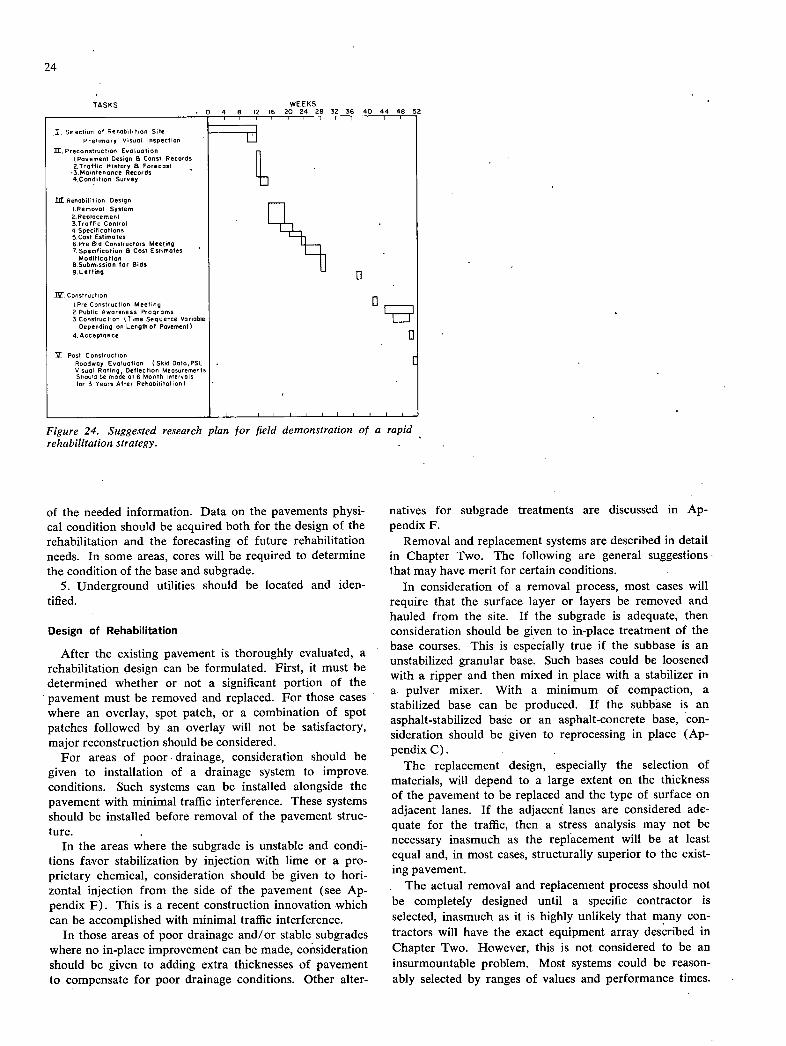
24
TASKS WEEKS
I. Selection of Rehabilition Site
Prelimary Visual Inspection
U. Preconstructian Evaluation I,Pavernent Design & Const. Records 2.Traffic History & Forecast
'3 Maintenance Records 4,Condition Survey
I.Rehabilitian Design l.Remaual System 2. Replace men, 3.Tnatfic Control 4 Specifications S.Cost Estimates 6 Pro Bid Constructars Mee!ing 7. Specification B Cost Estimates
Modification B.Submissian for Bids 9.LettinB
iV. Construction I Pre Construction Meeting 2 Public Awareness Pragrams 3 Construction (Time Sequence Variable
Depending or Length of Pavement)
4. Acceptance
Post Construction Roadway Evaluative ) Skid Data,PSI, Visual Rating, Deflection Measurements Stivuid be made at 6 Month Intervals for 3 Years After Rehabilitation)
Figure 24. Suggested research plan for field demonstration of a rapid rehabilitation strategy. -
of the needed information. Data on the pavements physi-cal condition should be acquired both for the design of the rehabilitation and the forecasting of future rehabilitation needs. In some areas, cores will be required to determine the condition of the base and subgrade.
5. Underground utilities should be located and iden-tified.
Design of Rehabilitation
After the existing pavement is thoroughly evaluated, a rehabilitation design can be formulated. First, it must be determined whether or not a significant portion of the pavement must be removed and replaced. For those cases where an overlay, spot patch, or a combination of spot patches followed by an overlay will not be satisfactory, major reconstruction should be considered.
For areas of poor. drainage, consideration should be given to installation of a drainage system to improve. conditions. Such systems can be installed alongside the pavement with minimal traffic interference. These systems should be installed before removal of the pavement struc-ture.
In the areas where the subgrade is unstable and condi-tions favor stabilization by injection with lime or a pro-prietary chemical, consideration should be given to hori-zontal injection from the side of the pavement (see Ap-pendix F). This is a recent construction innovation which can be accomplished with minimal traffic interference.
In those areas of poor drainage and/or stable subgrades where no in-place improvement can be made, consideration should be given to adding extra thicknesses of pavement to compensate for poor drainage conditions. Other alter-
natives for subgrade treatments are discussed in Ap-pendix F.
Removal and replacement systems are described in detail in Chapter Two. The following are general suggestions that may have merit for certain conditions.
In consideration of a removal process, most cases will require that the surface layer or layers be removed and hauled from the site. If the subgrade is adequate, then consideration should be given to in-place treatment of the base courses. This is especially true if the subbase is an unstabilized granular base. Such bases could be loosened with a ripper and then mixed in place with a stabilizer in a pulver mixer. With a minimum of compaction, a stabilized base can be produced. If the subbase is an asphalt-stabilized base or an asphalt-concrete base, con-sideration should be given to reprocessing in place (Ap-pendix C).
The replacement design, especially the selection of materials, will depend to a large extent on the thickness of the pavement to be replaced and the type of surface on adjacent lanes. If the adjacent lanes are considered ade-quate for the traffic, then a stress analysis may not be necessary inasmuch as the replacement will be at least equal and, in most cases, structurally superior to the exist-ing pavement.
The actual removal and replacement process should not be completely designed until a specific contractor is selected, inasmuch as it is highly unlikely that many con-tractors will have the exact equipment array described in Chapter Two. However, this is not considered to be an insurmountable problem. Most systems could be reason-ably selected by ranges of values and performance times.

25
Construction. Control
As pointed out in NCHRP Synthesis 25 (12), any con-struction in urban areas requires a sizeable effort in coor-dination and cooperation between several agencies. Public awareness of the project will tend to maximize acceptance of traffic delays. Coordination of operations with police can maximize traffic safety during construction. Strict adhereiice to predetermined schedules by both the agencies and the contractor will minimize delays and thus minimize contractor occupancy of the roadway.
In terms of quality control and acceptance procedures, this type of rapid rehabilitation construction lends itself to end-product specification and acceptance, which should be
used whenever possible. The construction sequence should be closely controlled, monitored, and documented for evaluation.
Post Construction Evaluation
After construction is completed, certain data should be gathered periodically to evaluate the project. As a mini-mum, skid data, pavement serviceability, and a visual rat-ing should be performed initially and at 6-month intervals for at least 3 years. Deflection data are desirable and should be obtained. Depending on the state agency's poli-cies, the aforementioned data could be obtained as a part of a regular inventory of state highways.
REFERENCES
FEDERAL HIGHWAY ADMINISTRATION. "Highway Sta-tistics 1972." U.S. Dept. of Transp., Washington, D.C. (1972). "Pavement Rehabilitation-Materials and Tech-niques." NCHRP Synthesis 9 (1972) 41 pp. HUDSON, W. R., and FINN, F. N., "A General Frame-work for Pavement Rehabilitation." Proceedings of TRB Workshop (Sept. 19-22, 1975) pp. 44-5. MORIMOTO, T. T. "Rehabilitating Chicago's Express-ways." Civil Eng., Vol. 42 (Dec. 1972) pp. 59-62. Private communication to A. H. Layman. Private communication to A. H. Layman. RING, G. H. "Drainage and Pavement Rehabilita-tion." Proceedings of TRB Workshop (Sept. 19-22, 1975) pp. 171-6. FooR, B. C. "An Operational Report on Prefabri-cated Pavement Sections for PCC Pavement Re-pairs." (Feb. 1974) pp. 1-3. GRIMSLEY, R. F., and MORRIS, B. G., "An-Approach to Concrete Pavement Replacement Which Mini-mizes Disruption of Traffic." Florida Dept. of Transp. "Concrete Pavement Replaced in 11/2 Hours." Civil Eng., Vol. 44 (Apr. 1974) pp. 62-4. PIKE, R. - G., and BAKER, W. N., "Concrete Patching Materials." Final Report, Federal Highway Admin., (Apr. 1974). "Reconditioning High-Volume Freeways in Urban Areas." NCHRP Synthesis 25 (1974) pp. 56. "Traffic Control for Freeway Maintenance." NCHRP Synthesisi (1969) 47pp.
KERM0DE, R. H., and MAGRA, W. A., "Freeway Lane Closures." Traffic Eng. (Feb. 1970) pp. 14-18. HALM, H. J., and EISENHOWER, J. E., JR., "Econo-crete-What it is and How it's Used." AC! Journal, Vol. 71, No. 4 (Dec. 1974) pp. 644-51. KREBS, R. D., and WALKER, R. D., Highway Mate-rials, McGraw-Hill (1971). Private communication, Charles Foster, National As-phalt Paving Assn., July 30, 1975. "Skid Resistance." TRB Res. Rec. 523 (1974) 152 pp. MURPHY, W. E., and MAYNARD, D. P., "Skid-Resistant Textures on Concrete Pavements-Research and Practice in the United Kingdom." Pending publica-tion by the Transportation Division of ASCE. RASMUSSEN, R. J., "Pavement Surface Texturing and Restoration for Highway Safety." Presented at 53rd meeting of the Transportation ResearGh Board, Janu-ary 1974. Private communication, Rollin C. Dix, Illinois Insti-tute of Technology, October 7, 1975. Personal communication from R. S. Mendenhall, President of the Las Vegas Paving Corp., Las Vegas,
- Nev. Personal communication from Ralph Coho, Vice President of Irl Daffin Assn. Inc., Lancaster, Pa., July 17, 1975. Personal communication from Samuel L. Carmen, In-diana Area Manager, Denton Construction Co., Grosse Point Woods, Mich., May, 1975.

APPENDIX A
LITERATURE SEARCH
The total abstracts described in the literature search
were reviewed and a number were eliminated from fur-
ther consideration as not being germane to the project. A
second review was made and salient articles were secured
for reference in the final report, and additional articles
were eliminated from consideration.
The remaining abstracts assembled by topic areas are given in Table A-2. Where possible, the abstracts within each topic area were arranged in alphabetical order by au-thor. More than 500 abstracts were assembled in an an-notated bibliography as a separate document from this report. The annotated bibliography is available from NCHRP staff.
TABLE A—i
KEY WORDS LIST
I. PAVEMENT II. RECONDITIONING
pavements highways asphalts concretes portland cements concrete pavements freeways roadways roads aggregates aggregate seal coats reinforced concrete; cements bituminous cements bituminous concretes bituminous coatings flexible pavements paving
creep rupture strength resilience skid resistance reconditioning renovating fracture strength surface finishing reinforcement (structures) binders (materials) stresses tensile strength tensile impact strength impact tests impact strength stress relieving flexural strength stress relaxation tests durability fiber composites
metal particle composites composite structures compressive strength compression tests compressibility epoxy resins epoxy coatings crack propagation reinforcing steels sulphur glass fibers cement additives admixtures glass particle composites weatherproofing density measurement fiber reinforcing waterproofing structural reliability
TABLE A-2
TOPIC AREA LIST
General Pavement Repair Techniques Precast Panel Construction Fiber Reinforced Concrete Polymer-Strengthened
Concretes Sulphur Repair Techniques Rapid-Setting Cements Structural Foams
Recycled Pavements Pavement Surface Treatments Portland Cement Concrete
Pavements Asphalt Cement Concrete
Pavements Subbases Pavement Design Pavement Evaluation
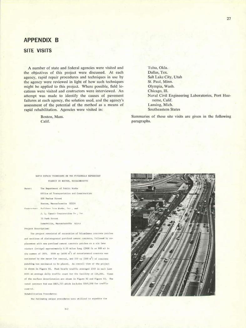
-Ic-
APPENDIX B
27
SITE VISITS
A number of state and federal agencies were visited and the objectives of this project were discussed. At each agency, rapid repair procedures and techniques in use by the agency were reviewed in light of how such techniques might be applicd to this project. Where possible, field lo-cations were visited and contractors were interviewed. An attempt was made to identify the causes of pavement failures at each agency, the solution used, and the agency's assessment of the potential of the method as a means of rapid rehabilitation. Agencies were visited in:
Boston, Mass. Calif.
HAVID SEFAl K 1fF Ma F:FUFS ON in ri FE:;ERAED EXPRESSEVi
VIADUCT IN BOSTON. fSASSAV1IFISFTTO
Owner: The Oeparteent of Public Works
Office of Transportation and Construction
100 Nashua Street
Boston, Massachusetts 02114
Ir.., W,.rku Inc aol
J. L. Capote C:'nute,,:tion Cu
33 Pork Street
Soorruille. MausaciurSetts tilt,,
Project Description:
The project consisted of curavation of bituminous cue rrtr pitch..
and sections of disintegrated purr land cement concrete, followed by re-
placement with new portland eemeut concrete patches on a sin lane
ciadact (bridge) approuinuteiy 0.55 nilcu long (2900 it or 900 c) in
CIte sunnier of 1974. 5500 us (4600 m) of deteriorated concrete cc:
estinoted by the owner for removal, and 550 cy (460 2) of concrete
patuhing was estimated to he placed. An overall view of the project
is shown in Figure 11. Peak hourly traffic averagsd 1560 in each ianr
with an average daily tratfic count for the laclitty of 135,000. Views
of the surface deterioration are shown in Figure 12 and Figure 03. The
total contract hid was $825,725 which includes $140,000 for rrtu(te
Kehabllltatiori Procedures:
The following unique procedures were utilized toenprdite the
lulsa, OkIa. Dallas, Tcx. Salt Lake City, Utah St. Paul, Minn. Olympia, Wash. Chicago, Ill. Naval Civil Engineering Laboratories, Port Hue-
neme, Calif. Lansing, Mich. Southeastern States
Summaries of these site visits are given in the following paragraphs.
1-2
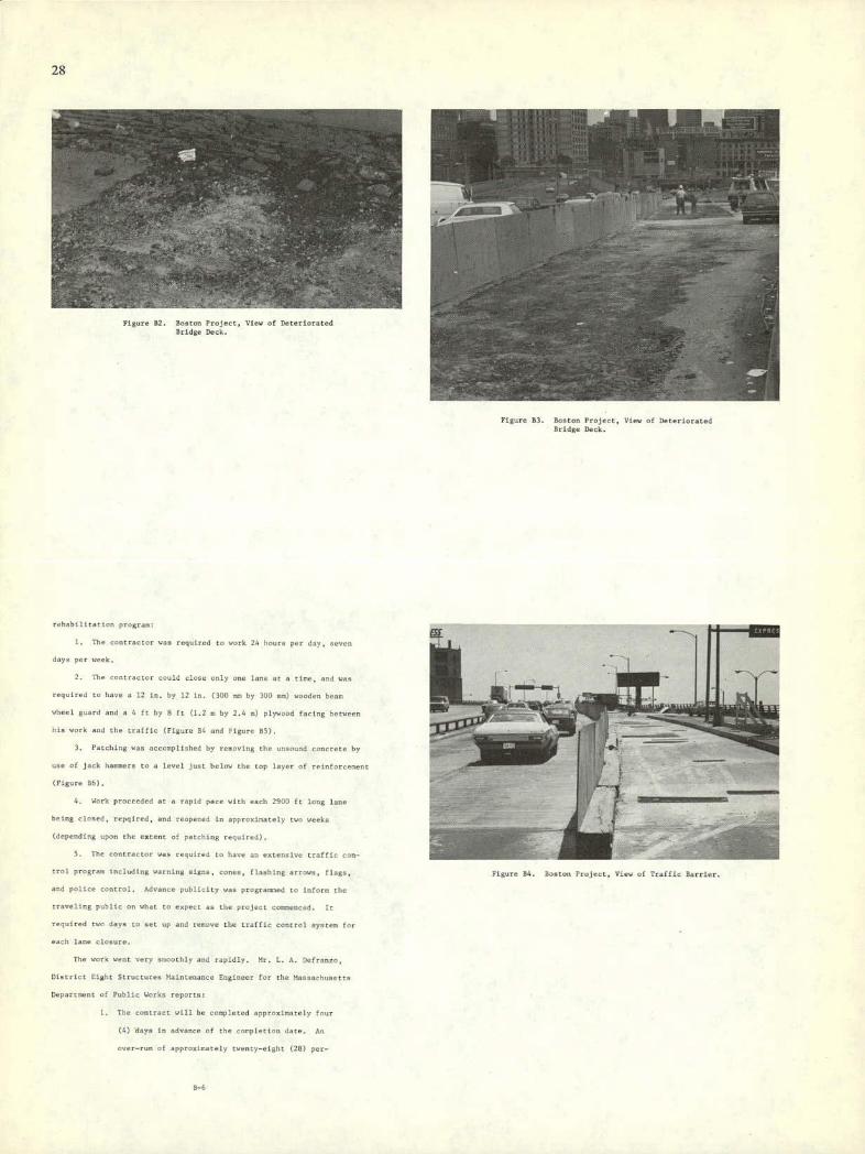
28
-a — .--
• 0
-061
—1v1tf I
—;
Figure 82. BOston Project. View of Deteriorated Bridge Dock.
Figure 83. Boston Project, View of Deterioratnd Bridge Deck.
rehabilitation progr.r
ifit:rt r.rcrcr r..r.. r.qir; rd r noel. •., Jr-pr C 0-cC
days per :cck.
7h, ci ac --ccl vvu- :.-. rt c tiC, ccl
required to h.tve a cccx by 12 cn. 31w -n- by moc; cc—c) c.-.y -C
wheel guard and a 4 It by 8 It (1.2 mc by 2.4 v) pin-arc-!
his work and the traffic (Figure 86 and Figure R).
Patching was accomplished by removing tin-
use of jack haremers to a level just below the top layer of reifliorecrent
(Figure fIb).
Work proceeded at a ropid pace with each 2900 it long lone
being closed, repqired, and roopened in approximately two weeks
(depending upon the extent of patching required).
S. The ever ractnr was required to have an extensive traffic con-
trol program including warning signs, cones, flushing arrows, flags,
and police control. Advance publicity was prograrosed to Inform the
traveling public On what to expect as the project Corenced, it
required two days to set up and renove the traffic contrel systrv for
each lane closure.
The work went vcry n-soothly and rapidly. Mr. L. A. Dofruneo,
l)istrict Eight Structures Maioteoancc Engineer for the Mannnchusetts
Departrsont of Public Works reports:
1. The contract will be completed approxir.ateiy four
(4) days is advance of the corpietion date. As
over-ron of apprnuircaiely twenty-eight (28) pnr-
Figure 84. la-aLec reject, Vcoc. of Traffic Barrier.
8-6
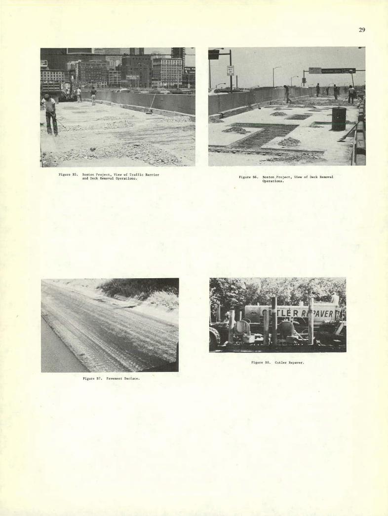
29
Wis ---.- - ____
t
11- - -
--
L - .:•- — - r ,.
Figure 55. Boston Project, Vies, of Traffic Barrier and Dock Ronovat Operations. Figure 56. Boston Project, View of Deck Reoovai
Operations.
'-.00L41LEP RP'AVER
F gore (b (:o tIe

30
cent in the dcc k excavation and concrete delayed
conpiction of the project well in advance of the
completion date. This in accredited to the co-
operation of the Contractor with regards to his
work force remaining Constant while work
progressed.
Use of police details to control the flow of
traffic on the viaduct and surface roads re-
sulted in a minimum delay to the truveling
poblic. The contractor benefited fran the
use of police detuiln by allowing minimum
delays in moving eqoipsent on the viaduct
structure.
On a project of this nice the use of patchisi
compounds would have been ec000nically onseijed.
Any time saved by use of these cvmpoands vu:,!]
have been ninionl because of the length of the
project.
The method of replacing those sections of dech
found nnnound, either by visual inspection or by
sounding, leaves the question of how long the
remainder of the dccc will last. Taking the
problem of decb repoirs from a maintenance
standpoint it in only a tenporary neanore to
Insure a rldeable roadway for the traveling
public.
1-10
FREEWAY iEPOIRS ID CALIFORNIA
Two of the most vivid esaspiec of the problems confronting the
highway engineer in rapidly rehabilitating major freeways are in the
Los Angeles and lam Francisco areas of California. ilrre traffic novas
at volumes in the neighborhood of 200000 vehicles per day pant a
given point, with pith volumes in excess of 15,000 vehicles per hour.
A detailed ooanioation of the expressways in these two areas
revealed that the major rehabilitation efforts seen to be concerned
with portland cement concrete (FCC). This is true lirnt. because
virtually all of the major, high-volume facilities are fCC and secondly,
hecacse flexible panenents hunt (to date) usually been rehabilitated by
relativoly conventional motes. The ea(or pavenent problems roquiriog
rehabilitation are,
I) joInts at strsctoren
2) Jol,tt filler materials
31 Edge curling of FCC slabs and slab rocking
Salt, ch.,in and studded tire damage to rcc pavementn in ice
aod snow areas
Sect leetent at bridge ends
hI Structural cracking of PCC clubs in the outer lanes which carry
the majority of the truck traffic. It has been vbserved that
some of the cosent treated hose courses (aRC) with relatively
low cement centents 0 to 5 percont) lose their slab action
after a number of yearu and degenerate into a 'granular' etass
of individual larger pactieles and c000retioss of smaller
The major problems with the job seencd to be the occasional delay
of ready mined concrete doe to traffic tieops and weather. Otheruine
the job wcnt about as rapidly as possible under the conditions imposed
by the owner. About the only procedures which could have been
meployed in speed the job any faster were:
I. Allow the contractor to cocoon the full thickness of the con-
crete in the deck at each deteriorated site rather than only 2 to 4 in.
(50 to 100 nm). By so doing, larger jack hammers could have been used
and than it is evtinated that appronlmately 15 percent less time would
have been required. however, thin untold have been much more expensive.
Use a more rapid hardening concrete in the lant foe patches
in each lane, on they had to keep the lane cloned for 22 lirs beyond the
l.tct pour in order to provide nufficient enre time for the concrete.
Thin could save as estimated ii peroent in the time each lane was
(loved, flowerer, these more rapid hardening concretes would have to be
shown to be sufficiently strong and durable for the intended use.
Combining 1 and 2 above, it would appear possible to remove
and repair patches in one lane of a 2000 It (600 n) long section of
concrete highway or bridge in approximately 10 days, which would
inclsde 2 days of traffic control setup and romoval and 5 days for
fairly extensive repair work using readily accepted techniques and
materials. Reducing the length: of repair in each lane closure would
reduce the lane closure time. but not the two days required to set up
the traffic control myntets as it would be almost independent of the
length of lane closure.
particles. It should be noted that there is no steel in
thrsr FCC pavements.
/1 certIcal laoltsng or the uoreivtorced pavement slabs. Theve
pavements were constructed over :,neeinforced CT0, and the
magnitode of vertical faulting eohibited has node necessary
on enteonlve grinding program which is followed, ultimately,
by cenplete slab replacement.
It should be emphasized that only a small pertien of the eopresc-
way system In in need of repair, with freeway failures no more than one
or two lanes wide and gener.slly lo,ndreds of met (or leon) in length.
Out, these repair s are eutrwmnly diffIcult to eoecute due to the
traffic. Row can rehabilitation be accospllnhed without serious dis-
ruption to traffic? The ansv,'rv lie in speed and closure of as few
lanes as possible for any deco period of tine.
Conpetindlsg the problem of rapid rehabilitation are several
factors, I tic huh log:
11 Some ycarn before the creation of OSHA. a series of traffic
induced fatalities among the Maintenance workers of the Los
Angelns District produced a concerted drsand from the unions
for better protection of the workers. The California Depart-
ment of hudostrial Safety required the District t&'cvtahllnh
a Lane Closure Policy shuereby "When work is periorneci on a
freeway or romp, any traffic lane of the freeway of the camp
whouc nearest edge in within b it (2 s) of the verb shall be
cloned and a traffic control system shall be luvialled."
2) The nast nojnrity of detours required to permit freeway
1-12 0-13

31
rohahi I Itarion are confined with in the freeway R.O.W.
3) Rerouting freeway traffic at night demands coordination with
utility and transportation companleu, fire, pollen and county
jurisdiction. Othnrwise freeway traffic may unknowingly be
routed over streetu that are blocked by utility work.
4) Requirements enforced by FR/I, restrictions resulting from the
Porter-Cologne Warer Quality Control Act. Flub and Cane
Cotnulssion Controls and the County Air Control Board all Com-
bine to mshe the maintenance and recooutrsctinn of freeways
increasingly difficult. ConstructIon operations particularly
affected Include: pavement grooving, night construction from
the standpoint of noise, production of hot mix - omissions.
placcinent of hot mio - blue smoke.
California has incorporated a number of Innovative techniques in
order to cope with rehabilitation problems.
Frecw.sy reconstructIon plans include traffic control pro-
cedurea and sequencing of construction operations. The con-
trader is controlled with rogard to when he can work, hew
sony bouts he can occupy, and whot type of traffic control
devices and what method traffic control he ount employ.
All lane closures are logged with the Cn,msunications Division
and information on closart' locations and duratluss is trans-
mitted to all interests affected.
5) The resident engineer no a freeway recenotrudtius project
notifies all lecal intereuts affected by a construction
closure. Digits are pouted in acivoncc and the public is also
alorted through the radio. T.V. Ind newspaper farilitfes.
Shouidrrn and flush-poved medians are sometimes converted to
entra pos500ger car lanes by proper utriping and signing and
shifting vi the vvstrr .t,,dt,n (...,rd ruSt
for the PCC pavement over 4 in. (100 on) CTI1C. the recon-
struction is usually as a 12 in. (300 mm) PCC pavement to
achieve greater speed of construction.
On the highest traffic volume freeways, emergency repairu
are made to PCC pavements at night by removing the PCC pave-
ments and oodcrlying CTBC to the subgradm. The r.'pnir Is
made by filling the curavaced area with a 564 to 618 iks per to yd
(192 to 213 hg/s ) Typo TI eeriest concrete to which 2 percent CaCl2
is added on-site. The patch is opesed to traffic at 6 All.
the following morning at an age of S hours.
When the outer truck lanes ofa rural PCC freeway become too
rough, truck traffic moves toward the inner lanes. To fore-
stall this unwanted shift of heavy axle loads into the
passenger ear lanes, truck lanes have been rt.habilltoted by
a combiination of:
leiodlng of step-faulted nicks
Hu:hjocking Individual slabs
Ovoriaying with 4 to 6 in. (100 to 150 mo) of hot 010
asphaltic concrete where vertical clearances permit.
2 is
,\SPIIALr PAVEMEST RflhAilI.iTATIOU. TULSA. OKI.AROSIA
Project Description: A na(oc arterial Street in Vulva, Ohiaheva,
was cracked and had lost riding quality (Figure 87).
Rehabilitation Procedure: may. 1974. A Cutler tvpaver can used
10 h:eoc and scarify a surface iayrr approximately 3/4 in. (29 ret) in
thickness. Additional hot-ely asphalt he concrete was added to the
removed material, mined with an auger-type miser and laid down in
A single pass. The layer was then coopactod in a conventiov.ul n.seller
(ruinrec 05 uhiongh: 112).
The machine was able to prcgreso it an average spcod of abouc 3d
fpn (9 n/isis) on this project. The cont of the Unpaver was
about 50v/o' (35/n) and rho addhr(cnal nat,gr(ul added about Shic/sy
(35cm 8 ) for a total ccvi of about Sl/sv (8lim 2) in place (1974
prices).
Analysis: The Caller Reyaoer performed well and the rehabili-
tation was satisfactory with a nininunit of traffic delay.
1•
Figure 89. Heater Portius.
8-46

9;
32
- •d -.t- . -
al '
I1l. • I
Figure RIO $carlfier Teeth.
- p
.. --•';e. . -,
'Oi5l.Ail) CENR7iT CONCRETE PAVEMENT REPAIRS - DALLAS. TEXAS. AREA
Project Description: Full depth patching of Forniond Cement Con-
' -Ic (FCC) pavesent. Generally the sections are less than 20 it
-) in .s siog1e lone.
Rehabilitation Procedure: 05w rut partial depth around area to
Sore): I.nrd. Unsound material was broken up with jack humoers and removed
Sack hoe or gradali. SDHFT District IS (Dallas Area) has used among others
CaRton Crete- (previously known an Fast Fin by Western
/. Ihiracal.
hUH hot): materials they use an epocy around the patch to promote
'ad:np.. Generally the cement content is 7 to U sb/cy (S to b nh/n3)
.ivd costs about $57 per cy ($00/a'). They vlcw the repair
as temporary and eupect it to last 5 years or less. The patches can
be accomplished and opened to traffic in less than sin hours.
Analysis: These products seen to loch the durability for enten-
sloe long tern rehabilitation.
PAVEMENT REPAIRS - SALT LAKE CITY. UTAH, AREA
Projects Description:
I. Pot hole repairs, primarily on bridge decks. Distress due
in part to the use of delving salts.
Overlay to restore riding quality.
Overlay on bridge.
:i-hshiliiotio:: rrccnd,:.-.
1.dr.- : :r-.: Stop ui:; lvii,':::: an,! ;!,. i- ic): pot hole and remove
Figure Ru. Additional Hot-Mix.
- - -_-
Figure 312. Compactors.
covcre to. Pat::!:08 were sad ins Ing several c-peas adnivt:: cc..'.
photsp.raph). After only a short time cracks usually developed at
Is:- edge of the patch indicating bond(ng probiemu. The engineer in-
specting the jobs stated that the additional cost of the new materIals
did not seem justified on the b.isis of performance to date.
As asphalt concrete overlay using a product called "Cruobme
rubber (a ground lateu furnished by Atlas Rubber Co., Los Angeles.
California) was placed to restore riding qualIty (see photograph).
The overlay required the use of a special asphalt. The conbinatlon
of asphalt and rubber was intended to reduce reflection craching.
The Overlay was relatively new (less than Vi months aid) and exhibited
no cracking.
A latex modliled PC v000r:.te overlay I in. thick (25 ma) was
placed on a bridge deck to su.al it and restore riding quaiitv. The
-ncr lay cost approninately $19 per sy (u6/n2 ) and developed craning
-rio 5:; in less than sin unesthu.
Auaiysiu: Honeof these materials/systems reiuted directly to
li;c pro':l.-o s:z.!-l;- (vi -'u-p.S

33
SISEL ASS CLASS-FIBER REISFORCED FCC OVERLAY ON
11151 III KAnSAS CoSIIIT'1, !I1SSCYOTA
Owner: State of Minnesota
Department of Highways
SE. Paul, Minnesota 55155
Contractor: Area:, Construction Company, Inc.
Project description: Experimental Sections of plain. uteel-fiber
reinforced and glass fiber reinforced, each three in. (76 em) thick
were placed on the four lane facility. The work was completed in June,
1974. Two traffic lanes were closed during construction.
Rcitabilitatioo Procedures: The existing surfaces were first
cleaned either with a power hroom or sasdblasting. then fleshed with
water. Epoxy or cement slurry was used in those areas requiring
special bonding. The overlays were hatched, piaccd, consolidated and
finished using normal procedures.
The plain concrete was 649 lb of cement per cy (226 kg/n3) batch
using 3/4 in. (19 on) naoinsrn slecd aggregates. Roth fiber mixes were
of 800 lb of ernest per cy (272 kg/n3) wit!: 3/4 in. (19 em) maximum
sioed aggregates, and contained 1.2 percent fibers by volume. Higher
than normal water to cement ratios had to be used with the glusn fibers
in order to maintain workability, and the glass-fiber strength was IS
to 40 percent lower than the plain or steel fiber strength at all ages.
Analysis of Project: The steel fiber concrete worked essentially
the same as other reported steel fibe: cot, Iu,o (Iowa, Mi-c: plc
Illinois). A. E. Pulk, Resident Engineer with the Minnesota Depart-
i-20
— 5
), Ii
r .5. . ...., .... 1. . ..
Figore 814. Surface Deterioratloo.
S i 5 5
r y;
gg1t:.
fa
cc::c( !Iigha.,ys .c,I in ::harge of the Pro(eet, ctated the b!5geot
prohlee with the play,, fibers yeesed tq be that occaslonallc ti:r
fibers would ball up and create a pop-out in the, concrete (Figures
1113, ill, xl)). Part of the glass-fiber section was cosstrscted
dsring a rain. Mr. Puib t):osght that this was the primary cease
for the poor prrfonnance of the surface, lie stated that this would
not he a good field test for the giasn-fiber reinforced concrete.
/ L..k-- Figure 813. View of Fiber Class Con-
crete Overlay.
11-21
PAVE.MEIIT REPAIRS - OLYMPIA. WASIiINOTOS, AREA
Project DescriptIon:
I. Partland Cement Concrete (FCC)
2. Asphalt Cement Concrete (iCC)
Rehabilitation Procedure:
1. Remove unsound concrete and replace with one of Ll,n fallow
lug materials/systems.
Quick Set-H. This in a shrinkage compensating cement.
It has a high purchaae coat but performance has been reasonable.
This ageocy would not use it for large repairs.
High Alumina Cement. Has been used and opened to traffic
in 24 i,rn. This agency does not see much advantage of this
cement over Type Ill cement with an accelerator.
2. a. A Csttler Repaner was used about 1972 to resurface an
experimental section of concrete pavement. Perternance Ices seen
satisfactory tho:,gh the proceso has not been used on other projects.
b. Petromat has been used to prevent reflection cracking
in an asphalt concrete resurfacing project. Perform.ucee to date
has been satisfactory.
An., iysiu:
The above materials are evaluated in Appendix C of this report.
hfanhingtos has tried the technique of closing a major structure
(bridge) over a week end for resurfacing. Be using the news media
extensively to secure public cooperation the project was deemed
successful.
Figure 1115. Pop Out Due to Bailed Up Fibers. 8-22
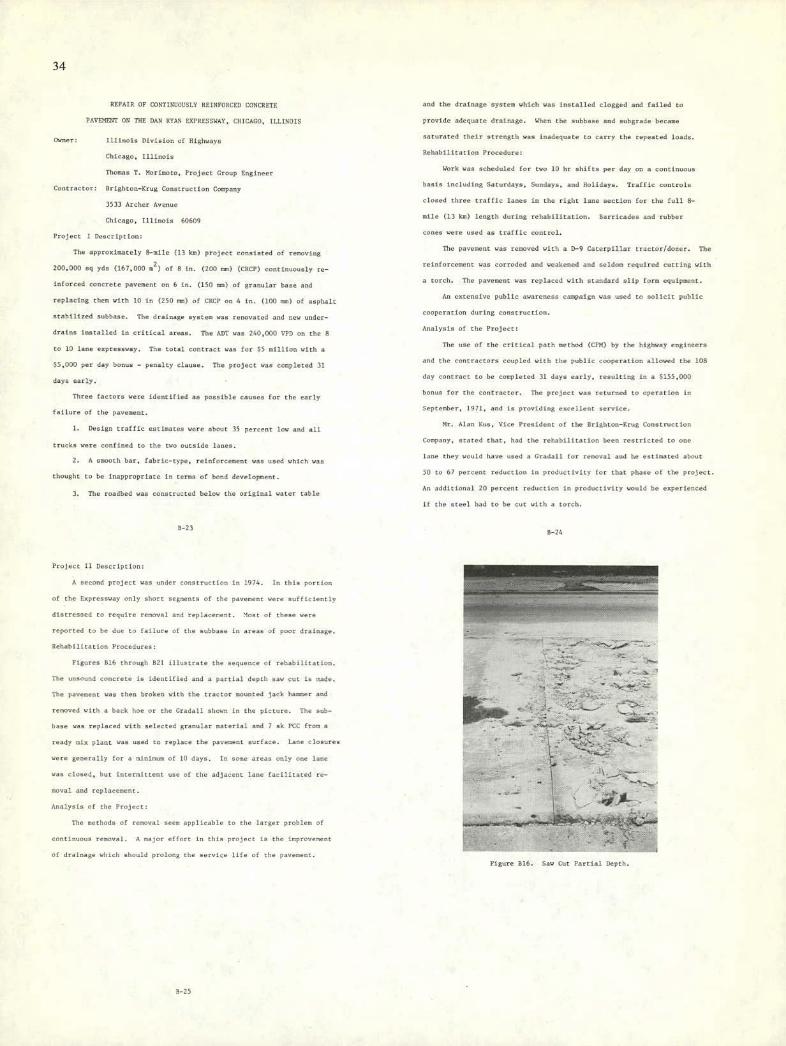
34
REPATR OF cORTINCOUSLY REINFORCP.S CONCRETE
PAVNT ON THE DAN RYAN EXPRESSWAY, CIIICAGO, ILLINOIS
Owner: Illinois Division of Highways
Chicago, Illinois
Thomas T. Mnrinoto, Project Group Engineer
Contractor: Brighton-frog Construction Company
3533 Archer Avenue
Chicago, Illinois 60609
Project I Description:
The approximately 8-nile (13 km) project rennieted of removing
200.000 sq ydn (167.000 2) of B in. (200 mm) (CRCF) continuously re-
inforced concrete pavement on 6 in. (150 me) of granular bone and
replacing then with 15 in (250 ens) of CRCP on A in. (100 ret) of asphalt
stabilized subbase. The drainage System was renovated and new under-
drains installed in critical areas. The AlIT was 210,000 VEX on the 8
to 10 lane eopressway. The total contract was for $N million with a
$5,000 per day bonus - penalty clause. The project was cospletod 31
days early.
Three factory were identified an ponnible causes for the early
failure of the pavement.
I. Design traffic enrimatev were about 35 percent low and all
trucks were confined to the two outsldn lanes.
A snooth bar, fabric-type, reinforcement was used which was
thought to be inappropriate in terms of bond development.
The roadbed was constructed below the original water table
8-23
and the drainage system which was inntallcd clogged and failed to
provide adequate drainage. When the subbase and suhgrade became
snturated their ntresgth was inadequate to carey the repeated loads.
Behabilicition Procedure:
Work was scheduled for two 10 hr shifts per day on a continuous
basis incl::ding Saturdays, Sundays, and Holidays. Traffic controls
cizued three traffic ianos in the right lane section for the full 8-
mile (13 kn) length during rehabilitation. Barricades and rubber
cones were used as traffic control.
The pavement was removed with a D-9 Caterpillar tractor/dozer. The
reinforcement was corroded and weahened and seldon reqaired cutting with
a torch. The pavement was replaced with utaudard nlip form equipment.
An ostensive public awareness campaign was used to solicit public
cooperation during construction.
Analysis of the Project:
The use of the critical path method (CPu) by the highway engineers
and the oostractors coupled with the public cooperation allowed the lOB
day contract to be completed 31 days early, resulting in a $155,001
bonus for the contractor. The project was returned to operation in
Septenker, 1971, and is providing excellent nervier.
Mr. Alan fun, Vice President of the Brighton-frog Construct Ion
Company, stated that, had the rehabilitation been restricted to one
lane they would have used a Gradall for r,'noval and he eat tooted about
50 to 67 percent reduction in productivity for that phase of the project.
An additional 20 percent reduction in prod::ctivlty would be experienced
if the stee) i:ad to be cut with a torch.
8-24
Project 11 Description:
A second project was tinder construe tiov in 1974. In this portion
of the Expressway only short segnootu of the pavcrcvr were sufficiently
distresued to require renoval and replacerent. Most of these were
reported to be due to failure of the subbase in areas of poor drainage.
Rehabilitation Procedures:
Figures D16 through R21 iilnntrate the sequence of rehabilitation.
The unsound concrete is identified and a partial depth saw cut is trade.
The pavement was then broken with the tractor mounted jack hamer and
removed with a back hoe or the Gradall shuwv in the picture. The sub-
base was replaced with selected granular material and 7 yk FCC from a
ready nix plant was used to replace the pavement surface. Lane closures
were generally for a mlninum of 10 days. In some areas only one lane
was closed, but intermittent use of the adjacoot lane facilitated re-
moval and replacenent.
Analysis of the Prajrct:
The methods of renoval sec-n applicable to the larger problev of
contInuous removal. A major etfurt in this project is the ivprovrvent
of drainage which should prolong the service life of the pavement.
--
-
- L I
a- •, -- t
L -
- -
*
- , ,• . ar-
Figure Rib. Saw Cut PartIal Depth.
8-25
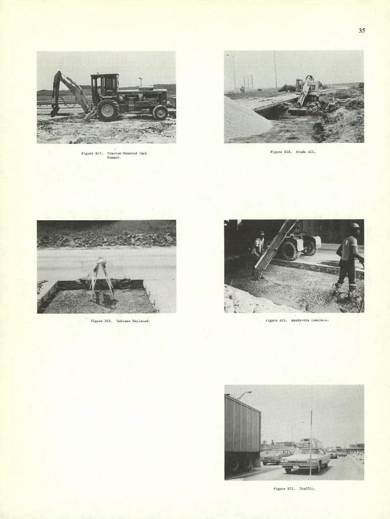
-
Fire B17. Tractor-Mo,ntcd Jk )Iam.
35
•;' . .. . .. .. -
4Z
iv .-
, ;:•
L tigure u2O. Ready-i-fix iuncrctx.
si —.
Figure B21. Traffic.

36
NAVAL CIVIL ENGINEERING LABORATORIES (NCEL)
PORTLAND CEMENT CONCRETE PAVEMENT REPAIRS, MICRIGAN
Projects:
Use of rigid foam systems for temporary or expedient runways
for light aircraft.
Polymer strengthened concrete.
Procedure: (see Appeodix C for more detailed information)
The NCEL has developed a pavement system suing fiber glass
filled with epoxy as a skis for a layer of 20 pcf (320 kg/rn3) poly-
urethane foam. They report difficulty in generating large quantities
of the 20 pcf (320 kg/n3) foam, but that lower densities of 12 pcf
(190 kg/m3) and less can be produced readily. They have used the
system in several experimental tests on poor subgrades and as as
eopediest work table. The system is expensive but it will work.
The polymer strengthened concrete tests included an ostensive
list of polymers with various curing agents. They were able to
develop some compressive strength.s of 10.000 psi (69 MPa) in one
day. gowever, most required the one of steam heat for 16 hours.
Those tests performed without steam or heat offered little advantage
over control specimens without the polymers. At best a 20 percent
increase in strength was observed and in most cases studied, the air
cured polynnr concretes had lower strengths than control specimens.
Analysis:
The rigid foams offers potential as a subbase material.
B-28
ing ecpresnways in and around Atlanta under the guidance of the
Enecutive Secretary, Georgia Asphalt Pavement Association, Inc. and
timelapse films and color slides were taken of those enprensways and
of the bypass loops around Atlanta.
PORTLAND CEMENT CONCRETE PAVEMENT REPAIRS, FLORIDA
Conferences were held in Florida with the Tampa Maintenance
District and with the Orlando Maintenance office. The subjoct of
these conferences was the maintenance of 15 4 from Tampa to its
jet ersection with IN 95 sear Daytona Bosch. Typical sections, mud-
jacking information and a technical paper on the use of precast slabs
for rigid pavement repair in the Tampa area were provided. A tour of
IN 4 from Tampa to Lakelasd, Florida was made during which several
precast slab repairs were inspected and photographed. III 4 was also
inspected in the Orlando area as was the new Orlando tell road facility.
A conference was arranged with the Director of Planning and
Development, Rilluhorough Cnusty Aviation Authority, Tampa Inter-
notional Airport, and his assistant. Two fibrous concrete overlays on
a tasiway at the Tampa airport were discussed and inspected.
The eopresnways and bridges of. the Jacksonville, Florida area
were inspected with the old of the Maintenance logineer of that
disnrict. Typical sections and valued information concerning the
crack pouring schedule in the Jacksonville area were provided.
Types of Pavement listress Observed
Pavement distress observed on high volume enpressways and Inter-
state highways inspected to date varied to some degree with location
A conference was held in the office of the Research Engineer,
Michigan Department of Otate Highways. He and the Physical Research
Engineer discussed maintenasce problems on Michigan enpressways and
presented a slide lecture on precast slab repairs conducted usder
their direction. Typical sections of CRC and PC pavenests constructed
in Michigan as well as specifications for precast slabs and slides
and script of precast slab repairs have been made available to this
research team. (See Appendix C.)
SITE VISITS TO THE SOUTHEASTERN STATER
Pibrous Concrete Waterways Eoperiment Station, Vickshurg, Mississippi:
A conference was held with the Chief, Materials Properties Branch,
Coscrete Laborotory, Waterways Esperiment Station, Vicknburg, Miss-
issippi. The subject of this conference was fibrous concrete and its
suitability for the repair of distressed eopressways. The work
conducted on fibrous concrete at the Waterways Experiment Station was
discussed. The research team was also provided a technical paper
dealing with the development of fiber-reinforced concrete in North
America. (See Appesdin C.)
MUD JACKINI OP PORTLAND CEMENT CONCRETE PAVEMENTS, GEORGIA
A conference was held in Atlanta, Georgia, with the Maintenance
Eng050er, Department of Transportation, State of Georgia. Information
was provided on the mud-jacking program in Georgia as well as
specifications and typical roadway sections employed in Atlanta
expressways and Georgia Interstate highways. Time was spent in tour-
5-29
throughout the United Staten. Soil type, weather, traffic count and
percentage of trucks were also factors which contributed in large
measure to the total damage suffered by any given facility. Certain
modes of incipient failure were present in all eopressways esunined
thus far. Other types of failure were more localiced in nature. With
the eoception of vertical faulting of rigid pavement slabs, failnres
were generally 50 ft (15 m) or less in leogth. An occauioncl distressed
area, however, extended a hundred ft (30 s) or more. Failure nodes
identified at this point in the research progran include but are not
limited to the following:
Settlesent and general evidence of sobgrade mutability in
high fills, particularly at bridge ends and at other large structures -
wiHespread.
Vortical faulting of rigid pavement slabs - widespread.
Edge pumping of rigid pavement slabs with associated slab
cracking and joint spalling - localioed.
oisiotegrutiuo from dc-icing salts at the joints and con-
tractios cracks of unreinforced and continuously reisforced concrete
paveneets - localioed. -
Oubgrade and shoulder subuidonce loading to settlement and
structural failure of both rigid and fleoible pavements- localioed.
Craching and associated reveling in flexible pavements -
locolized and limited.
8-30 5-31

APPENDIX C
ASPHALTIC CONCRETE PAVEMENTS
The design and construction of bituninous base and surface courses
,.nIi dvrcmcrtsd (Cl-05). DurinG the pact ten yearn, nignifinuot
changes have taken place in the industry (C16). New mixing eqoipnent
has been developed, new mix dnsigns introduced, environmental and
health standards enforced, and costs of materials, labor and eqsipmest
have increased. Additionally, new design procedures incorpo-
rating fatigue concepts have been introduced (Cu). Even with all the
changes asphaltic concrete remains one of the most economical paving
materials.
Pavements can be placed in thick lifts to increase speed of place-
ment. Single lifts in excess of lf inches (460 ens) thick have been
successfully placed and still achieved the desired density (Cl). new-
ever, caution mast.he exercised when using thick lifts to allow suf-
ficient curing time for heat to dissipate prioc to loud application.
To treat this question, a heat-transfer model developed by Oenpney
(Cli) was used to produce Pigure Cl. The following asnunptinns
were made to predict the time for a certain lift thickness to cool
to 1750P (790C) for any point in the layer.
Air temperature at a constant 90'F (32'C).
A 10 in. (250 sos) thick base at a constant fO'P (27'C).
A 131 in. (3300 mm) thick sibbase at a constant 75'F (24'C).
S. Zero cloud cover
C-1
Zero wind velocity.
Solar radiation maximum.
Granted that these are entrene values seldom in combination in the
field. However, it does demonstrate that for a 12 in. (300 non) lift
thickness placed at 220"P (104'C), as much as four hnsrs may be re-
quired before other operatinns can begin. The New York ltate Thraway
Authority has used full depth asphalt concrete patches for rigid
pavementn, and they report that some patches require as muck on 24
hours for heat to escape (Cl9). Charles Pouter (Director, Esgineering
and Research. National Asphalt Paving Assoniatimn) states that this
cure time can be reduced by balancing the lift thickness with the
desired reduction in temperature, previding a finished product that
can be immediately opened to traffic (C20). Examples of early traffic
are given in referescen Cl and Cli. In one recent application up to
625 cy (480 m3) of asphalt concrete pavement were removed and replaced
in one 9-hr shift (C20). This is the equivalent of 1400 lineal ft
(425 m) of a 12 ft (3.7 m) wide by 12 is. (300 not) deep pavement.
The asphaltic concretes have elastic moduli ranging. from 40 ksi
(275 MPa) up to 4000 psi (28 MPa) with 300 mi (2,000 MPa) to
450 kni (3,000 MPa) considered to be the general range. Dantncci
(reporting as the work Moniunith, McLean, Epps, van Dijk and others),
states that if tennile strains are bun than 100 p in/in, then a
fatigue life, for 18 hip (8.000 kg) equivalent axle load in excess of
10 cycles, can b expected (Cl?. C21). Also, he reports that if the
vertical nsbgrade strain is held below 250 i in/in, a similar life can
be expected without overstresning the subgrade. These design criteria
37
C-2
C
lend themselves to conpster analyses (CS). Some of these computer
programs contain optimization techniques which include user delay
costs as ad inpat (0).
In some circumstances, the existing material can be reprocessed
to form base courses (C22, C23) (see cecycling Existing Pavenents).
Also, a recent ntudy'indicaten certain so-called lower qnality or
marginal aggregates can be economically utilized in bituminous treated
base courses (ClS). This could reduce replacement costs under certain
- Care must be exercised when asphaltic concrete and purtland nenerit
concrete are interfaced in the pavement surface. Per example, re-
placing a PCC slab with an mISC surface or vice seems. Dxx to the
dissimilarities in the physical properties of the two materials,
there seems alnost certain to be a "bunp" at the interface of the
two materials. Good construction practices (st?rike-off, cunnolidatioo,
shrinkage compensation, etc.) ouut be used to nixixize the "bump".
An asphaltic concrete pavement can be designed to satisfy
most doostraints. Its recommended use will be a function
of the lucaticu and conditins of. the pavement to be re-
habilitated.
E
: \N;;J,iTs\\\.. snO00
:N\ ca A 0
(d3Hfl1v3diN3i XIV 1VIIINI
RAPII HARDENING, HIGH EARLY STRENGTH CONCRETES FOR PAVEMENTO
Hydracal, a product of the U. I. Gypsum Conpany, was introduced in 1931
(C24). Interest has continued to be high is the devxlnpment of cements which
C-3
C-i
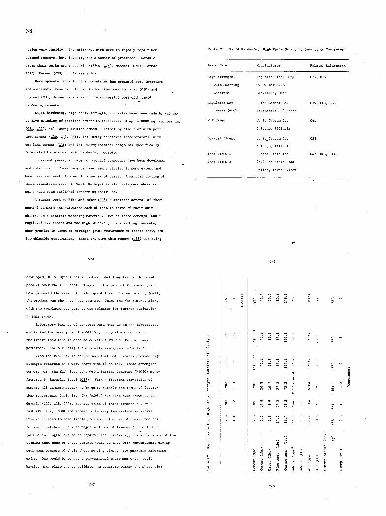
H
A
C.,.
38
harden very rapidly. The military, with need to rapidly repair hnmb
damaged runways, have investigated a number of processes. Notable
among their wnrks are those of Griffin (C25), Mosseir (C26), Larman
(C27), Setser (C28) and Pruitt (C29).
Developmental work In other coontries has produced some inortant
and successful results. In particular, the work in Japan (CII) and
England (Cii) demonstrate some of the successfol work with rapid
hardening cements.
Rapid hardening, high early strength, concretes have been made by (a) ex-
tensive grinding of partlaud cement to finenesses of up to HIll sq. cm. per gm.
(C32, CII), (h) using alumina cement - either by itself or with port-
land cement (dO, C34, CII), (c) using additives (accelerators) with
portland cement (C36) and (d) using chemical compounds specifically
formulated to produce rapid hardening concrete. -
In recent yearn, a number of special compounds have been developed
and'istroduced. These cements have been evaluated to some eutent and
have been successfully used in a number of cases. A partial listing of
these cements; is given in Table Cl together with reference where re-
sults have been published concerning their use.
A recent work by Pike and Raker (C38) summarizes several of these
special cements and evaluates each of them in terms of their suit-
ability as a concrete patching material. Two of these cements (the
regulated sat cement and the high strength, quick netting concrete)
show promise in terms of strength gain, rmalstaoue to freeze thaw, and
low chloride penetration. Since the time this report (C38) was being
Table Cl. Rapid Hardening, High Early Strength, Cements or Concretes
Brand Name Manufacturer Related References
High Strength, Republic Steel Corp. C37, C38
Quick Setting P. o. Bun 6778
Concrete Cleveland, Ohm
Regulated let Huron Cement Co. C39, GAO, C38
Cement (RSC) Snutkfield, Illinois
VHE Cement R. S. Gypsum Cu. C41
Chicago, Illinois
Duracol CEment R. i.5Gypsum Co. C38
Chicago, Illinois
Fast Fin C-1 Custuo-Crete Inc. C42, C43, C44
Post Fin C-2 2624 Joe Field Ruad
Dallas, Tenas 75229
C-s C-6
developed, U. S. Gypsum has introduced what they term an Improved
product over their Duracal. They call the product VHE cement, and
have prudoced the cement in pilot qoantitien. In one report, (C41),
the product was uhown to have promise. Thus, the VHE cement, alnmg
with the regulated net cement, was selected for further evaluation
in this study.
Laboratory batches of concrete were made up in the laboratory,
and tented for strength. In-addition, one performance test -
the freeze thaw tent in accordance with AIIM C666-Part A - was
performed. The mix designs and results are given to Table 2.
From the results, it can be seem that both cements provide high
strength concrete isaverv short time (4 hours). These strengths
compare with the High Strength, Quick Getting Concrete (HSQSC) manu-
factured by Republic -lteel (C38). With sufficient quantities of
cement, all cements appear to be quite durable (in terms of freeze-
thaw resistance, Table 2). The (O1QIC) has also been shuns to be
durable (CI?, dO, Cii), but all three of these cements set very
fast (Table 2) (CIH) and appear to be very temperature sensitive.
This could seen to pose little problem in the use of these products
for small patches, but when majur sections of freeway (up to 1510 It,
(460 u) in length) are to berepai'red (see criteria), the authors are of the
npioion that note of these cements could be used with conventional paving
equipment because of their short setting times. Two possible solutions
enist. One wnuld be to use cuconventmonal equipment which could
handle, mm, placo and consolidate the concrete within the short time
C-7 C-H
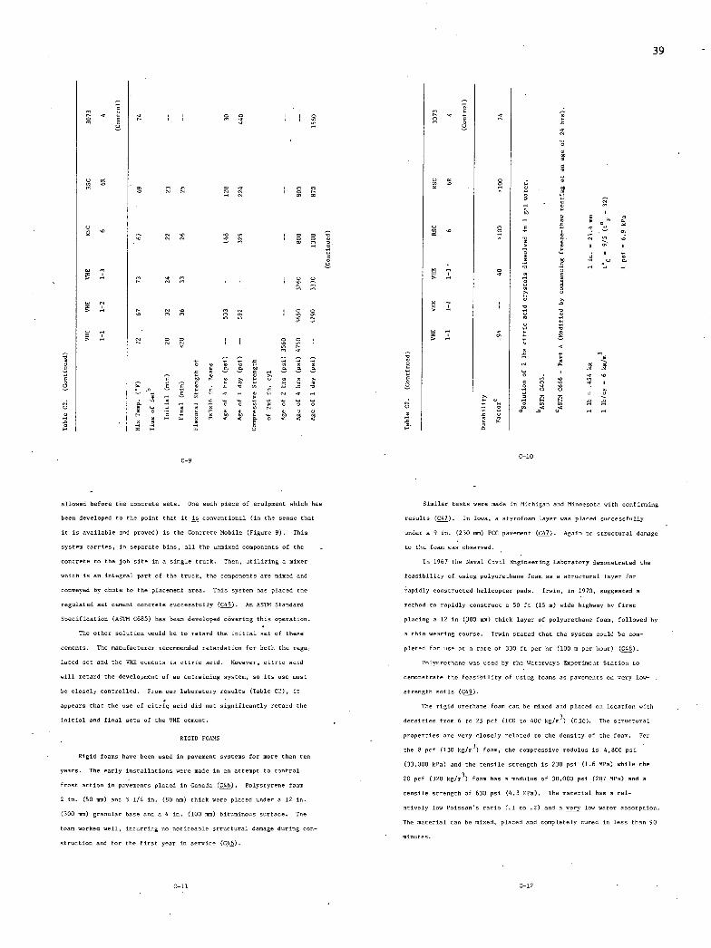
39
(5 . • 5 . .0 0 d .0 .0 5
o
C-9 C-b
allowed before the concrete sets. One such piece of equipment which has
been developed to the point that it is conventional (in the sense that
it is available and proved) is the Concrete Mobile (Figure 9). This
system carries, in separate bins, all the unmined components of the
concrete to the job site in a single truck. Then, utilizing a miser
which is an integral part of the truck, the conpusentn are mined and
conveyed by chute to the placement area. This system has placed the
regulated set cement concrete successfully (CII). As ASTh Itandard
Specification (ASTM C685) has been developed covering this operation.
The other solution would be to retard the initial set of these
cements. The manufacturer recommended retardation for both the regur
lated set and the VIE cements is citric acid. However • citric acid
will retard the development of as entraining system, so its use must
be closely controlled. From out laboratory results (Table C2), it
appears that the use of citric acid did net significantly retard the
initial and final nets of the ONE cemont.
RIGID FlAWS
Rigid foams have been used in pavement systems for more than ten
years. The early installationn were made in as attempt to control
frost action in pavements placed in Canada (C46). Polystyrene foam
2 in. (Ii mm) and 3 1/4 is. (91mm) thick were placed under a 12 in.
(310 mm) granular base and a 4 in. (lii mm) bituminous surface. The
foam worked well, incurring no noticeable structural damage during con-
struction and for the first year in service (C46).
Similar tents were made in Michigan and Minnesota with confirming
results (C47). In Iowa, a styrofoam layer was placed successfully
under a 9 in. (230 mm) PCC pavement (C47). Ag ais no structural damage
to the foam was observed. -
Is 1967 the Naval Civil Engineering Laboratory demonstrated the
feasibility of using polyurethane foam as a structural layer for
apid1y coontructed helicopter pads. Irwin, in 1970, suggested a
method to rapidly construct a 50 ft (15 n) wide highway by first
placing a 12 in (300 000) thick layer of polyurethane foam, followed by
a thin wearing course. Irwin stated that the system could be com-
pleted for one at a rate of 331 ft per hr (100 m per hour) (CII).
Polyurethane was used by the Waterways Enperinent Station to
demonstrate the feasibility of using foams as pavements on very low-
strength toils (C49).
The rigid urethane foam can be mined and placed on location with
densities from 6 to 21 pcf (lii to 400 kg/n3) (Cli). The structural
properties are very closely relatod to the density of the foam. For
the 8 pci (130 hg/n3) foam, the compressive modulus is 4,800 psi
(33,000 kPa) and the tensile strength is 230 psi (1.6 MPa) while the
20 pci (320 kg/rn3) foam has a modulus of 30.000 psi (207 MPa) and a
tensile strength of 630 psi (4,3 MPa). The material has o rel-
atively low Poinsonu ratio (.1 to .2) and a ivery low watnr absorption.
The material can be mixed, placed and completely cored in lens than 90
C-lb C-12
40
PRECAST SLABS
Precast PCC slabs, asame Shod of rapid repair of highway pave-
ments, have been used in Michigan (ç), California (C52) and Florida
(C53). Michigan began in 1969 with an experimental precast slab repair
system that, through 1973, has been used in the placement of more than
900 precast units (C51).
The typical Michigan procedure is as follows:
Traffic control is established.
A full-depth longitodimal saw cut is made (to prevent damage
to adjacent lame).
Boles are drilled and lift pins installed in as large a slab
as can be lifted to minimiee damage to subbase.
The slab is then lifted out by a crane (if slab is broken up
it is removed with' a front loader or bach hoe).
Final clean up is accomplished with hand tools.
fobbase is then leveled and new material added and compacted
if required.
A one in. (25 mm) layer of high-slump, nob, namd-cement
mortar is placed and leveled with a screed.
The precast slab is then lowered slowly into the hole and
leveled by beam guides with adjachnt slabs.
The joints are filled with mortar.
The pavement is then opened to traffic.
This whole procedure, 050epc for the saw cuts which are usually
performed separately, requires less than 1 1/2 hours for umdoweled
joints, and less than 2 1/2 hours for doweled joints. These slabs are
C-13
precast usits in one eight-hour work night at a 1972 cost of $35 per
sq yd ($42 per m2) (which projects to a December, 1975, prise of
about $47 per sq yd or $56 per
Florida used the "Manual of Uniform Traffic Control Devices for
Streets and Highways" and reported that it required about 2 hours to
set up signs and demur barricades.
ROCYCLINI EXISTING PAVEMENT MATERIALS
The reuse of road-bed materials for paving has gained increasing
attemtiom. Increased costs of new materials, availability of accept-
able quality aggregates, and the consideration of the disposal of materials
removed from the road-bed are cited as fartors contributing to this
increased attention (cia).
Many projects in recent years have reusod noisting road-bed
materials. These range from stabilizing a previonsly usstabiliend
base nourse to reproressing and replacing a surface morse (C22).
Much of the worh has used asphalt as the binding agent. However,
portland cement has been used in several projects including a recnnt
project is the Redosdo Beach Freeway near Los Angeles, California
(C54). is this project, beth auphaltic and portland cement concrete
were crushed and processed together, and used as aggregates for a
lean concrete (econocrete) base.
Mos t current recycling prncensen require that the material be
broken in place, then hauled to a resote site for crushing, nizing,
mining, and finally returned to the location for conventional placing
operations (C22, C54, C55). In some cirmumstasceu, in-place cr:,shing
and processing were accomplished (C56). Ouwever, in-place nioing
usually 15 In 20 ft (5 to 6 n) in length.
Michigan reportu the cost is 1972-73 to nary from $39 to $75 per
sq yd ($47 to $90 per n2) in-place, as compared to more conventional
cast-in-place repairs of $45 to $78 per sq yd ($32 to $54 per m2).
Using the Engineering News Record Cost Sodec, this projects to about
$100 maninom per sq yd ($120 masinsm per m2) in Deneeber, 1974, for
precast, and $87 naninum per sq yd ($104 per m2) for nast-in-plece.
The California procedure (152) is similar with the following
encerti005:
An Arrow Hydraihaneser was used to break the concrete and
it was removed by a rubber tired leader. Final clean up of the hole
was accomplished with hand tools.
The precast slab was placed on a cement-rich mortar and held
at grade by I beam guides for approsimacely one hour.
Tutal time required was about 5 1/2 hours and the cost in 1974 was
about $80 per sq yd ($67 per n2).
The Florida procedure (C53) had some other variatiess. Namely:
The saw cuts were made through the dowel bars and then the
concrete was broken with a typical headache ball.
A plate compactor was then used to densify the subgrade.
A crane was used to ponicioo the precast slab.
The slab was then jached to final elesation by pumping grout
through preformed epenings in the slab.
The joints were then sealed and the repaired section opened to traf-
fic. Florida's typical precast slab in 12 ft (4 m) wide by 20 ft (6 n) long
and weighs about 12 ten (11,000 kg). They have placed as many as foot
C-14
process es norm ally do not lend thenseives to high quality surface
courses whether the binder used is asphalt or portland cement. Hence,
with in-place recycling, a quality surface course usually nssc be placed as
an overlay in order to provide the kind of service usually required
on high volune highways.
The coocraitors and agoscies that have used recycled materials
generally report satisfactory results. Though in many cases 4 he long
tern effects have yet to be evaluated, the early results give no
rea000 to suggest that recycled materials will not perforo as well as
new materials. Some research has indicated that for portland cement
niotureu, some reduction in cempressisa strength may be expected
(155). gowever, adequate strengths chn be easily obtained for most
paveneot designs.
The recycling of highway materials will continue to nerit atten-
tion for economic considerations, if nothing else. Most recycling
projects have reported redound costs over new censtructien. This will
be especially moe if the cost of disposal of rubble is included in
economic evaluacions.
ULTRASONIC VIBRATION CONCRETE
A sosically assisted cement miner was invented at Ohio State University
(C57). The process uses a lead-ziruonace-cicanote piezoelectric
uryscal driven by electricity to produce high frequency sound waven
which can be trausmittod to various mechanical devices. Our of these
is an experimental auger type concrete miser. The vibrations are
crassnitted to the housing of the niser.
The researchers theorize that the vibrations reduce the internal
C-iS C-l6
41
friction of the botch, thus promoting more ceoplete mixing and eeatieg POLYMER CONCRETE
of the particles. This type of mixing reduces the requirements for The typeo of concretes under this heading can be broadly care-
water and cement to produce a specified strength. The process rednceu gorioed by the following:
the required water content so that a very stiff concrete is produced Polymer-concrete (PC) which is a concrete with a polymer as the
oI,il: l:ad Lu be esiiuded ii: tf::al for:::. No attemprn'were made to matrix or cementing agent. the polymeric material in polymerieed
modify the process to produce more convex tional mines with encess after placement during curing.
mortar for finishing processes. Likewise, no attempts were made to Polymer portland cement concrete (PPCC) is a premimed material in
determinn the effects of various cements or additives such as Type which either a polymer or monomer is added to the fresh concrete mixture in
III, Reg let, retarders, plasticieers, polymers or epoxies. either a powder or dispersed phase, uubseqsently cured, and, if seeded,
Ultrasonic vibration was a sod to produce a high density, high . pO15'O5iZd in place. -
strength concrete using normal portland cement and normal aggregates Polymer-impregnated concrete (PlC) which consists of a dry hardened
(C57). Concretes with a compressive strength of 3300 psi (23 MPa) portland cement concrete impregnated either partially or folly with a
were produced from a mix using 330 lb of cement per cy (200 kg/n3). monomer which is than polymerined inuito.
This coop ares with 100 psi (.7 MPa) produced by control batches with Polymer-Concrete (PC)
the same cement content 2.). A 1972 state-of-the-art publication (COg) lists the following
The dry materials are introduced into an auger which mines and advantages and disadvantages for resin concrmteu.
moves the material to a wetting point and thee to a discharge port. 'a. The advantages are:
The hossing is vibrated at both low and high frequencies. The re- High strength (both compressive and tensile)
search sonic miner required 3000 volts of power to drive the vibration High static and dynamic resistance
mechacism at 10.000 hertz. . High bonding strength
In 1969 the Ohio State Snimernity gesearch Team made the decision - Moisture tolerance uf bond
that the feosibility of this concept had been demonstrated and that Impermeability
iodsstry should provide the development work for practical application ' Durability
of the technique. To the writeru' knowledge, no further effort has High early strength (adjustable time of set)
been made to develop the process. It would seem to offer some proniue, . Impact resistance
provided the necessary developmental work were performed. Low shrinkage
C-17 C-18
Creep resistance .
Cracking resistance
Adjustable fleolbility
Adjsutability of composition to suit particular needs
Eesls taste to wear, chenicalu, abrasives, oils, salts,
cauuticu, and frost penetration
b. The disadvantageu are:
High cost of materials (resins)
High cost of handling (special equipment, etc.)
Short pot life (requires small hatches)
geduction in strength with temperature increase
Shrinkage is large foam
Difficult handling and placement (doe to tosio effectu
and bonding characteristics)."
The authors found that epoxy resin cnncrnten generally exhibit
higher strength, better bonding, higher moisture tolerance and better
chemical resistance than other resin concretnu (COO). The polyester,
and ceramic resins cost less, can be cared at lower temperatareu,
posseus similar strengths at low concentrations, but are less mniutare
tolerant and have lower adhesive and durability values. The silicone
resins are s inilar the polyester and ceramic resins encept they
seem to be more durable than the nponien.
Anether type of polymer-concrete cues portland cement as a mineral
filler is the concrete system. No water is used is this concrete and
the strengths are greater than other types of polymer concrete (c!) A
typical niotarecantalss 11 wt percent polymer (50/50 methyl methalcrylate
and utyrene) and 89 wt percent cement, sand and coarse aggregate with a
proportioned ration of 1:2.14:2.72. It is niond and placed with non-
ventional concrete equipment.. The best results were obtained with a
cure time of 6 hours P 70'C (l)H'f). The polymer-concrete developed
compressive strengths in excess of 11,000 psi (76,000 hfa) and modulus
of rnpturo strengths in encesu of 3,500 psi (24,000 kPa).
Most of these systems were developnd as rapid patches. Repair of
the Major Deegan Espressway in New York City was performed in 1974
sning polymer concrete (C60). i patch 3 n 10 It (1 o 3m) n 15 in.
(385 non) deep was made. The removal of the deteriorated pavement was
dose during the day and the hole cevered with steel plate to carry traffgs
during the night. On the day of placement the material was placed and
opened to. traffic is 3 1/2 hours.
There has been very little large-ncale tenting of these materials,
hence, little is hnown of their characteristics under fall-scale pave-
ment conditions. Such properties as shrinkage or thermal crackisg of
large slabs, cure time for full depth ulahu, caring under field con-
ditions, and wear resistance to tire scrubbing action must be given
connideration prior to use in najor pavement facilities.
The major drawback for the polymer-concretes is cost. Estimates
for materials alone range from $170 per on yd ($130/) to over $300
per cx yd ($230/n3) (C61). These costs, plan the additional con-
struction difficulties, would precludn the use of polymer-concrete in
full-scale, fsll-depth pave000ts at this time. This does not imply
that its use in short, partial-depth patches should not be enamised as
viable alternative.
C-19 : C-20
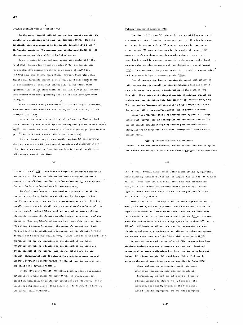
42
Polymer Portland Cement Concrete (PPCC)
In the early research with polymer Portland cement concrete, the
results were cunsidered to be less than desirable (C62). This was
especially true when compared to the results obtained with polymer-
impregnated concrete. The monomers used as additives tended to coat
the aggregates and thus Inhibited bond development.
Research using latexes and epoxy resins were cunducted by the
Naval Civil Engineering Laboratory during 1973. The results were
encouraging with compressive strengths in eon ens of 10,000 psi
(69 MPa) developed in some cones (163). However, those mines show-
ing the most favorable properties were those cured with steam or heat
or a combination of these with ashiest air. In all cases, those
specimens cured in air alone euhibited less than a 20 percent increase
over control (untreated specimens) and is many eases developed lower
strengths.
Other research seems ;te confirm that if early strength is desired,
then some mechanism other than moist curing or air dry curing must be
employed (164, C65).
An inutaiiutidn of a 1 in. (25 mm) thick latex modified Portland
cement concrete placed as a bridge deck overlay cost $19 per sq yd ($23/n2)
(C66). This would indicate a cost of $150 to $190 per sq yd ($180 to $230
per n2) for dull depth pavement (10 in. or 25 mm thick).
The additional strength is not really required for most pavement
designs, hence, the additional cost of materials and construction dif-
ficulties do not appear to favor its use in a full depth, rapid reha-
bilitation system at this time.
C-2l
discrete fibers (C71), have been the subject of eutessive research is
recent years. The state-of-the-art has been clearly and cuscisely
summarized by ACE Csmeirtee 544, sith 101 references (C71) and by the
Concrete Society in Esgland with 80 references (172).
Portland cement concrete, when used as a pavement material, is
generally regarded as having one signi ficant disadvantage - a low
tensile strength in cusparisos to its compressive strength. This low
tensile capacity can be nlgmificantly increaned by the addition of dis-
crete, rasdomly-nrdered fibers which act as crack arrentsrs and sig-
nigicantly increase the ultinate tensile load-currying capacity of the
concrete. When the fiber's volumes are kept reasonably low - say less
than around 4 percent by volume- the concrete's proportional limit
does not seem to be nigni ficontly increased, but its ultinate flenural
strength can be more than dnubled (C73). There seems to be no quantitative
expression yet for the prediction of the strength of the fiber-
reinforced concrete as a function of the strength of the plain con-
crete, strength of the fibers, fiber volume, fiber geometry, rtc.
However, euperinentzl data do indicate the signi firann improvement of
ulitna in strength in either fleoure no indirect tension, which is very
inpvrtant f orapavemeut material. -
Fibers have been produced from steel, plastic, glass, and natural
materials in various shapes and niens (171). Of these, steel and
glass have been found to be the most useful and cost effective. In the
following paragraphn each of these fibers will be discussed is terms of
the current s tate-of-the-art.
g/,y1gy-Inpreinuted Concrete (PlC)
The idea in PlC in to fill the voids in a normal PC concrete with
a monomer and then polymeriee the mu000er in-situ. This has been done
with dramatic success such as 285 percent increases in compressive
strengths and 250 percent increases in the modulus of rupture (162).
However, to obtain these properties requires that the spenimen be
oven dried,, placed in a vacuum, submergrd in the onsener and ulluwed
to soak under punitive pressure, and then drained while still heated
(C67). In ether words, the process would limit itself to precast units
such as precast bridge or pavement panels (C68).
Partial impregnation does not require the vacuum-noah methods of
full impregnation, but usually partial impregnation does not signifi-
cantly increase the strength characteristics of the concrete (C69).
Generally, the process does reduce abssrptios of moisture through the
surface and improves freeze-thaw durability of the surface (169, 170).
This surface impregnation has been used on a new bridge dnch in the
Denver area (C68). It required ueveral days of special nreatmenr.
Since the properties that were improved most by partial impreg-
nation with polymer (moisture absorption and freeze-thaw durability)
are not usually censidered the most serious problems with pavement
ulabs, its use in rapid repair of urban freeways would seen to be of
limited value.
FIBER REINFORCED CONCRETE FOR PAVEMENTS
General. Fiber rnioforced concrete, defined as "concrete made of hydrau-
ho cements unetaining fine or fine and uxarne aggregate and discuntinuxus
C-22
Steel Fibers. Typical aspect runs (fiber length divided by equivalent
fiber diameter) range from 30 to 150 for lengths 0.25 to 3 in. (6.35 mm to
76.2 m). Both round and flat steel fibers have been prndwned and
used, as well as crimped and deformed steel fibers (171). Various
types of steels have been used with tensile strengths from 40 to 600
kni (275 MPa to 4,100 MPa).
Steel fibers have a tendency to ball or clump together in the
miner, thus mining has been a prublen. Due to these difficulties the
aspect ratin should be limited in less than abuat 100 and fiber con-
tents shsuld be limited to less than around 2 percent (171). Further-
nure, the maximum reronneuded coarse aggregate nice is about 3/8 in.
(10 mm). ACT Cnnnittee 544 has made specific reconnendations abnut
the mining and planing procedures to be followed to reduce segregation
and prnmnte preper coating of the fibers with cement paste (171).
Several different apphiratinen of steel fiber concrete have been
uniliend, inuluding a number of pavement applicatinus. Eucelient
summaries of pavement applicatinus have been repurted by Lankard and
Walker (C74), Gray, et. al (C75), and Puskn (176). Problems do
euist in the use of steel fiber concrete ancsrdimg to Paskx (C76).
These problems can be crudely greuped into three
majur areas; ernunmies, materials and structural.
Ernmomically, the cost per cabin yard of fiber re-
iofnrced concrete is high primarily becaune of the
steel cost and secondly because of the high cement
context, smaller aggregates, and the extra materials
C-23 C-2i
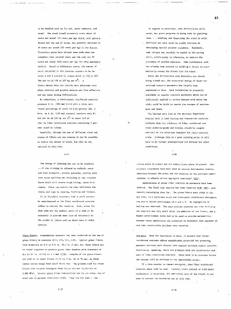
to be handled such as fly ash, water reducers, and
steel. The steel itself presently costs about lB
cents per pound (40 cents per kg) which, with grouter
demand and the use of scrap, may possibly decrease to
10 cents per pound (22 cents per kg) in the future.
Tremendous gains have already been made when one
remembers that several years ago the cost was 65
cents per pound (143 cents per kg) for this specialty
product. Based no laboratory tests, the amount of
steel necessary in the concrete appears to be be-
tween 1 and 2 percent by volume which is 133 to 265
lbs per to yd (78 to 157 kg per m3). A
lesser amount does not provide much advantage over
plain concrete and greater amounts are less effective
and may cause mining difficulties.
By comparison, a comtinuously reinforced concrete
pavement 8 in. (201 nun) thick with a cross see-
tinoal percentage of steel of 0.64 percent (fIn. 5
bars on b in. (150 mm) centers) contains only 85
lbs per cu yd (50 kg per m 3 ) or about 1/3 of
that in fiber reinforced concrete containing 2 per-
cent steel by volume.
Bopefully, through the use of different sines and
shapes of fibers and new cemeutu it may be possible
to rednce the amount of steel, but this is not
isesioent at this time.
C-25
The design of jointing has yet to be resolved.
If the cracking is allowed to rnridomly occnr
and fnrm irregular, erratic pitteren, traffic will
soon cause spalling and ravelling of the concrete
faces which will create rough riding, unsealable
cracks. Water and debris can then infiltrate the
cracks and lead to pumpiug, faulting and blowups.
It in therefore necessary that a joint pattero
be superimposed on the fiber reinforced concrete
ribbnn to control the cracking. Also, since the
slab ends are the weakest poiot of a slab it is
necessary to provide some type of continuity at
the cracks or joints such an dowel bars or other
devices.
ilans Fibers. Considerable research has been conducted on the use of
glass fibers in concrete (C72, C75, C77, C78). Typical glass fibers
have diameters of 0,2 to lb in, (0.5 to 15 mm), but these fibers may
be bonded together to produce glass fiber bundles with diameters of
5.5 to 50 is. (0.013 to 1.3 mm) (C70). Lengths of the glass fibers
are similar to steel fibers (0.25 to 3 in. (0 to 76 sos), su their
aspect ratios range from about 30 to 150. The glasses used for these
fibers have tensile strengths from 150 to 550 mi (1,000 Ml's to
3,800 SPa). Several glass fiber comsouitioos are in use today, two of
which are in general production (C72). They are the soda - lime -
43
In regards to materials, some difficulties still
esist, but great progress is being made in resolving
them. . . Saodliog and dispersing the steel in still
difficult but this ceuld be easily overcome by
developing special purpose eqnipnent. Similarly,
some chomges may possibly be mended in the paving
- traim, particularly in vibration, to improve the
placement of stiffer mintures. Some development work
has already been started on building a device to auto-
matically convey the fibers into the miner.
While the difficulties with materials are slowly
being ironed out, the ntracturnl design of fiber re-
inforced concrete pavements has largely been
neglected to date. Much infor'motion in presently
available on regular concrete pavements which can be
judiciously applied to evolve designs with which the
slabs could be built to resist the ravages of environ-
ment and loads.
The limited work done at the Waterway Esperiment
itation both in load tenting and theoretical asalysis
indicate that the thickness of fiber reinforced con-
crete slabs-on-grade and overlay should be roughly
one-half of the thickness required for plain concrete
slabs. Although this in a good starting point it will
have to be further substantiated and defined for other
conditions.
C-26
silica glass (A glass) and the borosilicate glass (E glass). Pro-
prietary treatments have been used to prevent detrimental chemical
reactions between the glass and the alkalies in the portland cement
(similar to alkalie-silica aggregate reactions) (C71).
Applications of glass fiber concrete in pavements have been
limited. One field tent section has been reported (COB, CBS), with
results encouraging thus far. The glass fibers were added at the
job site, in a ready-mis track and thoroughly distributed throughout
the mis in volume percentages nfl and 1.5. No segregation or
balling was observed. The only problem reported was that isitially
the concrete was very stiff after the addition of the fibers, and a
higher water/cement ratio had to be used to provide workability.
Aoother field application was conducted in Minnesota (see Appendin B)
and some construction problems were reported.
Analysis. From the emperience to date, it appears that fiber-
reinforced concrete offers csoniderable potential for prsdscing
pavement sections such thinner than regular portland cement concrete.
Practically speoking, there are problems with the constructiom and
cost of fiber-reinforced concrete. These need to be overcome before
the concept will be utilized to any appreciable estest.
If a thin overlay is deemed necessary, then fiber reinforced
concrete might well be used. inwever, where partial or full-depth
replacement is necessary, the additional cost of the fiber4 do not
seem tewarran t its coressive use at this time.
C-27 C-2f
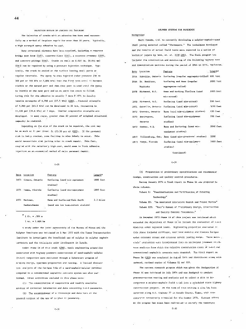
44
INJECTION REPAIR OF CRACKED FCC PAVEMENT
The injection of cracks with an adhesive has been used success-
fully as a method of in-place repair for more than 10 years. Typically,
a high strength epoxy adhesive in used.
Man y utractural elements have been repaired, including a concrete
bridge seat beam (C81), concrete floor (C82), a concrete craneway (C83),
and concrete pilings (C84). Cranky as small as 0.002 in. (0.051 mv)
(C83) can be repaired by using a pressure injection technique. Typ-
ically, the crack is sealed at the surface leaving small ports at
regular intervals. The epoxy is then injected under pressure (50 to
300 psi or 345 kfa to 2,000 kPa) into the first port until it becomes
visible at the second port and then that port is used until the epoxy
is visible at the sent port and so on until the crack in filled.
Curing time for the adhesive is usually 7 days 8 25uC to develop
tensile strengths of 6,890 psi (47.5 MPa) (C84). . Flexurol strengths
of 9,890 psi (68.2 MPa) can be developed in 24 hrs, increasing to
11,400 psi (76.6 MPa) at 7 days. Similar compressive stresgnhs are
developed. In most cases, greater than 80 percent of original structural
capacity in restored.
Depending on the size of the crack to be repaired, the cost may
be as much as $1 per lineal ft ($0.30 per m) (C85). If the pavement
slab is badly reached, some faulting is also likely to occur. This
would necessitate slab jacking prior to crack repair. This fact,
coupled with the relatively high cost, would seem to limit adhesive
injection as an economical method of major pavement repair.
C-29
Date Location Feature Length
1973 Sinaco, Ontario Surfacing (sand mix-equipment 1550 feet
studies) -.
1974 Tampa, Florida Surfacing (sand nm-equipment 1000 feet
studies)
1974 MacLean, Base and Surfacing-full depth 2.3 miles
Saskatchewan (sand mix-low temperature studies)
1 ft. = .305 m
1 xi. = 1.609 k.
A study under the joint npomsorship of the Bureau of Mines and the
Dalphnr Institute was initiated on 1 May 1973 with the Texas Transportation
Institute to investigate the boneficial use of sulphur in sulphur anphalt
pavements and the techniques under developnnmt in Canada.
Under Phase lA of this study (C90), basic engineering properties
ansociated with highway pavement construction of sand-anphalt-sulphur
(S-A-S) cumponites were evaluated through a labxratory program of
mixture design, specimen preparation and testing. A limited theoret-
ical analysis of the fatigue life of a sand-auphalt-sulphur pavement
compared to a conventional auphaltic concrete nyxtem was also per-
formed. Other activities included in this phase were:
The consolidation of responsible and readily available
sources of technical information and data concemmlng S-A-S pavements.
The establishment of a literature and data bank on the
general nabjeot of the use of sulphur in pavements.
SULPHUR SYSTEMS FOR PAVEMENTS
Background
Shell Canaaa, Ltd. is currently developing a sulphur-nspkalt-sand
(SAD) paving material called nmermopave. The techniques developed
and the renultu of actnal field tests were repnrted in a series of
technical papers by Deem, et. al. (C86-C89). The Shell program has
included the construction and monitoring of the following highway tent
and demonxtration sections during the period of 1964 to 1974, inclusive.
Date Location Feature -Length
1964 Oakville, Ontario Surfacing (regular aggregate-rolled) 600 feet
1964 St. Boniiace, Surfacing and Base (regular 1000 feet
Manitxha aggregates-rolled)
1970 Richmond, B.C. Base and Working Platform (sand lOIS feet
niu-xcreed)
1970 Richmond, B.C. Surfacing (sand min-ncreed) 200 feet
1971 Oakville, Ontario Surfacing (sand mix-screed) 3250 feet
1972 Toronto, intatio Base (sand min-equipmeut studies) 400 feet
1972 Burlington, Surfacing (sand mix-mquipmext 150 feet
Ontario studies)
1972 Quebec, F.Q. Base and Surfacing (sand mix- 2640 feet
equipnent studies)
1972 Tillnonburg, lnt. Base (sand nix-structural studies) 5280
1973 Tampa, Florida Surfacing (sand nm-equipment 1000 feet
studies)
(continued)
C-3D
Preparation of preliminary xpecifioanionx and recoumemded
design, construction and quality control procedures.
During January 1974 a final report on Phase SA was prepared in
three volumes.
Volume 0: npamiliarieation and Verification of Emisting
Technology
Volume IS: "An Annotated Literature Search and Patent Review
Volume III: Suer's Manual of Preliminary Design, Coos tructiox
and Quality Control Frocedurex."
Is Deceeber 1973 Phase lB of this project was initiated which
extended the objectives of Phase lAte include the evalnation of S-A-S
mixtures under repeated loads. Engineering properties evaluated in
this phase included stiffness, resilient modulus and fleouro fatigue
under coextant stress and constant strain loading modex. These mate-
rials' properties were inonrporated into an equivalent pavement thirk-
mess analysis from which the relative construction costs of S-A-S and
conventional auphaltir concrete were compared. The final report on
Phase OR (C90) was conpleted in August 1974 and distributed along with
updated, revised copien of Volumen II and III.
The rurrent research program which was given the denigsation of
Phase SC was initiated in July 1974 and was designed to oosduct
preconscructiun testixg and analysis and to select a site to in-
corporate a sulphur-asphalt field trial into a ucheduled state highway
construction project. At the time of this writing a site has been
selected along U.S. Highway 77 in fenedy County. Texas, with con-
struction tentatively scheduled for the Sumner 1976. Current effort
on the program has sisce been redirected to satisfy the immediate
C-3S C-32
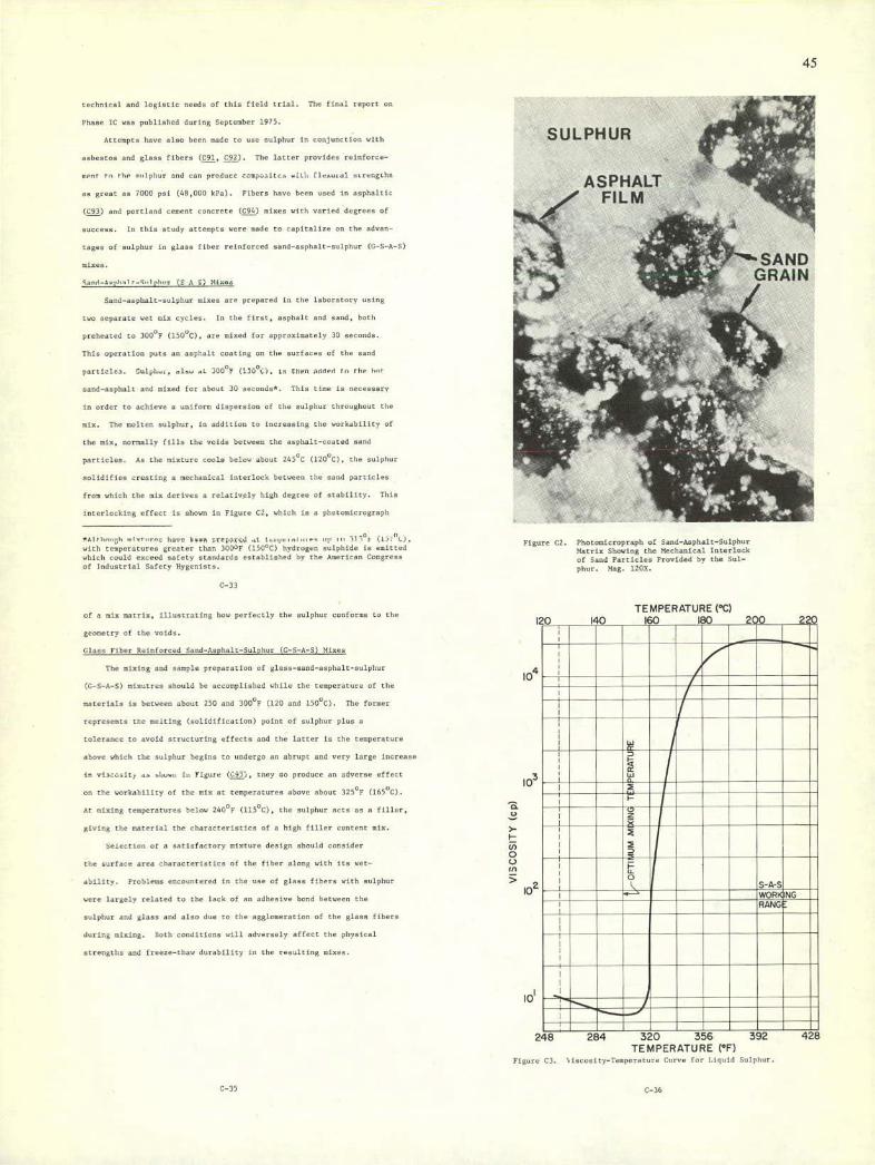
ASP HALT FILM
45
no
see hnicai and iogisile needs of this field trial. The ttnei report on
Phase IC cam published during September 1971.
Attempts have also been made to use sulphur in conjunction with
asbestnn and glass fibers (591, 592). The latter provides reinforce-
vent to the eviphor and can product zampe...itcexiti; fleaural ssrnngtho
as great an 7000 psi (48,000 kpa). Fibers have been used in asphaltic
(C93) and portland cement concrete (594) mixes with varied degrees of
success. In this study atteopts were made to capitalize on the adnan-
tacos of sulphur in glass fibor reinforced sand-asphalt-sulphur (G-S-A-S)
Savd-Sephsl c_S,,l ph.. (0 .1 i) Macau
Sand-asphalt-sulphur mixes are prepared in the luharatory using
two separate wet mix cycles. In the first, asphalt and sand, huth
preheated to 300°F (1500C), are mixed for appeanlnately 30 necundn.
This operation puts an asphalt coating on the surfaces of the sand
partiolca. Ssl.l,e • nine ,,L 300°F (13004), in torn annest tv the ho'
sand-asphalt and mixed for about 30 seconds0 . This time is necessary
In arder to achieve a uniform dispersion of the sulphur throughout the
mix. The molten nsipbst, In addition to increasing the workability of
the mix. nnntally tills the voids between the asphalt-coated nnsd
particles. As the nixtxre coals below about 2450C (1200C). Elie sulphur
solidifies creating a ,sechaxical interlock between the sand particles
Iron which the mix deciven a relatively high degrrn of stability. This
interlocking effect is shown in Figure C2, which in a phatomlorograph
l,avv burn creleyss..j al eS \i If with tespecatxrrs greater than 300°F (1550C) hydrogen sslphide in eittd which could encecd safety ntandardn established by the American Congeece of Industrial Safety Hygenists.
C-33
of a mix matrix, illustrating hew perfectly the sulphur conforms to the
geometry of the vuids.
Glass Fiber Reinforced Oaod-Aspholt-Sslphor (5-0-4-0) Mixes
The mining and nample preparation of glass-sand-asphalt-sulphur
(C-S-A-I) mixutrea should be axcxnplished while the teuperunsro of the
materials is between about 250 and 300°F (120 and 150°C). The former
repreuents tne melting (solidlficatinn) point of sulphur plus a
tolerance to avoid strsctsring oifncts and the latter Is the tenperature
above which the sulphur begins to undergo an abrupt and very large increase
In niSCc..lty et—o In Figure (493), tney no produce an adverse effect
on the workability of the mix at temperatures above about 325°F (165°C).
At mixing temperatures belaw 240°F (1150C), the sulphur acts as a fillee.
giving the material the characteristics of a high filler contest mix.
Seicctiou of a satiufactxry mixture design uhould consider
the surface area characteristics of the fiber along with its set-
ability. Froblenu encountered in the use of glass fibers with sulphur
were largely related to the lack of an adhesive bond between the
sulphur and glass and also due to the aggboxeration of the glass fibers
during mixing, both conditions will adversely aftoct the physical
strengths and freeze-thaw dsrabiilty Is the resulting mixes.
Fliure C2. Phutosic ropraphof Sacd-Aephait-Sulphar Matrix Showing the Mechanical lutorluch of Saud Farticlen Feuvided by the Sul-phsr. Mug. 1200.
TEMPERATURE (cC)
TEMPERATURE (0F) Fifuro C3. b is,-csl r y-Teuperaturc Curve for liquid Sulphur.
C-35 C-36
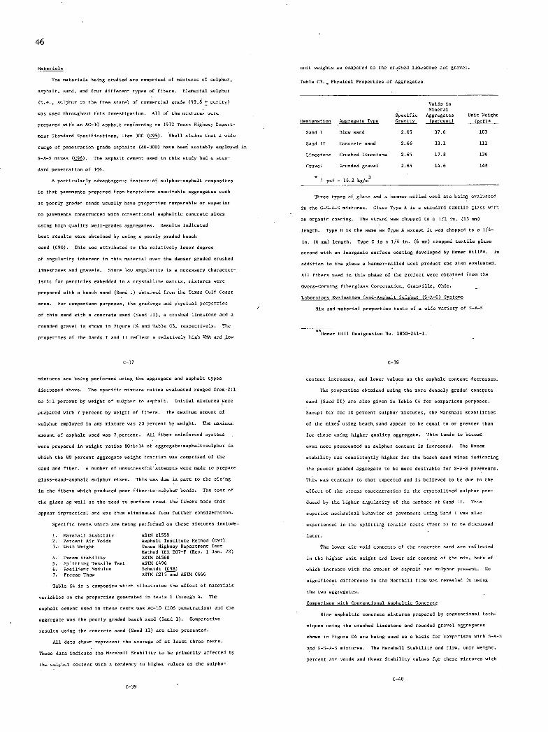
46
Materials
The materials being studied are cnmprised of mixtures of sulphur,
asphalt, sand, and four different types of fibers. Elemental sulphur
(i.e., sulphur in the free state) of commercial grade (99.8 + purity.)
was used throughout this investigation. All of the mixtures were
prepared with as Ac-li asphalt conforming to 1972 Tenon Highway Depart-
ment Standard Specifications, Item 311 (C95). Shell claims that a wide
range of penetration grade asphalts (40-300) have bees suitably employed in
S-A-S mixes (C96). The asphalt cement used in this study had a stan-
dard penetration of 106.
A particularly advantageous featureof sulphur-asphalt cnmpusites
is that pavements prepared from heretofore unsuitable aggregates such
as poorly graded sands usually have properties comparable or superior
to pavements constructed with convestional asphaltic concrete mixes
using high quality well-graded aggregates. Results indicated
best results were obtained by using a poorly graded beach
sand (C90). This was attributed to the relatively lower degree
of angularity inherest is this material over the denser graded crushed
linestoses and gravels. Since low angularity is a seen suary character-
istic for particles embedded in a crystalline matrin, mixtures were
prepared with a beach sand (Sand 5) obtained from the Tenon Gulf Coast
area. For comparison purposes, the gradings and physical properties
of this sand with a concrete sand (Sand II), a crushed limestone and a
rounded gravel is shown in Figure C4 and Table C3, respectively. The
properties of the lands I and II reflect a relatively high VMA and low
unit weights an compared to the crushed limestone and gravel
Table CI. - Physical Properties of Aggregates
Voids is Mineral
Specific Aggregates Omit Weight Designation Aggregate Type Gravity (percent) (ncf)5
land I Blow sand 2.65 37.6 103
Sand II Concrete sand 2.66 33.1 111
Lisestuse Crushed limestone 2.65 17.8 136
Gravel Rounded gravel 2.65 14.6 148
a 1 pcf - 16.2 kg/n3
Three types of glass and a hammer-milled wool are being evaluated
in the 0-S-A-S mixtures. Glans Type A is a standard textile glass with
an organic coating. The strand was chopped to a 1/2 in. (13 xx)
length. Type B is the same as Type A except it was chopped to a 1/4-
in. (6 sea) length. Type C is a 1/4 in. (6 mm) chopped textile glass
strand with an inorganic surface coating developed by goner Hillu*. In
addition to thE glass a haenser-nllled wool product was also evaluated.
All fibers used in this phase of the project were obtained from the
Owens-Corning Fiberglass Corporation, Grauville, Ohio.
Laberatory Evaluation Sand-Asphalt-Sulphur (S-A-S) Syntems
Mix and material properties tests of a wide variety of S-A-S
Honor gill Designation No. 1850-241-1.
C-37
mixtures are being performed using the aggregate and asphalt types
discussed above. The specific mixture ration evaluated ranged fron2:1
to 5:1 percent by weight of sulphur to asphalt. Initial mixtures were
prepared with 7 percent by weight of fibers. The maximum amount of
sulphur employed in any mixture was 20 percent by weight. The maximum
amount of asphalt used was 7 percent. All fiber reinforced systems
were prepared in weight ratios 80:6:14 of aggregate:axphalt:sulphur in
which the BO percent aggregate weight fraction was comprised of the
sand and fiber. A masher of unsuccessful attempts were made to prepare
glass-sand-asphalt sulphur mixes. This was due is part to the sizing
in the fibers which produced poor fiber-to-sulphur bonds. The cost of
the glass as well as the need to surface treat the fibers made this
appear impractical and was thus eliminated from further consideration.
Specific tests which are being performed on these mixtures include:
Marshall Stability ASTM D1559 Percent Air Voids Auphalt Institute Method (C97)
3.. Usit Weight Texas Uighway Department Test Method TEX 207-p (Rev. 1 Jas. 72)
Sveem Stability ASTM D1560 Splitting Tessile Test AITh C496 fesilient Modulus Schmidt (C9B) Freeae Thaw ASTM c215 and ASTM C666
Table C4 in a composite which Illustrates the effect of materials
variables on the properties geserated is tests 1 through 4. The
asphalt cement used in these tests was AC-IS (106 penetration) and the
aggregate was the poorly graded beach sand (Sand I). Comparative
results using the concrete sand (Sand II) are also presented.
All data shown repreneot the average of at least three tests.
These data indicate the Marshall Stability to be primarily affected by
the sulphur content with a tendency to higher values as the sulphur
C-38
content increases, and lower values an the asphalt content decreases.
The properties obtained using the more deusely graded concrete
sand (Sand II) are also given is Table C4 for comparison purposes.
Eucept for the 10 percent sulphur mixtures, the Marshall stabilities
of the mixes using beach sand appear Cu be equal to or greater than
for those using higher quality aggregate. This tends to become
even more pronounced as sulphur content is increased. The 8vees
stability was consistently higher for the beach sand mixes indicating
the poorer graded aggregate to be more desirable for S-A-S pavements.
This was contrary to that enpected and is believed to be due to the
effect of the stress concentration in the cryutallioed sulphur pro-
duced by the higher angularity of the surface of Sand 00. This
superior mechanical behavior of pavements using Sand I was also
experienced in the splitting tensile tests (Test 5) to be discussed
later.
The lower air void contests of the concrete sand are reflected
in the higher unit weight and lower air content of the nix, both of
which increase with the amount of asphalt and sulphur present. No
nigsificaxt differeucv in the Marshall flow was revvaled in using
the two aggregates.
Comparison with Ceuventional Asphaltic Concrete
Nine asphaltmc concrete mixtures prepared by conventional tech-
niques using the crushed limestone and rounded gravel aggregates
shown in Figure C4 are being used as a basis for comparison with S-A-S
and C-I-A-S mixtures. The Marshall Stability and flow, unit weight,
percent air voids and Oveem Stability values for these mixtures with
C-iS
C-39

A
I I'I
5 .e• O c 0 O• rj 0
0
S B t0
5? Z 0 0 0 0 0 0 0 0 0 0
o
mm 2228 82222
'5
MINN iiiiiMEMEMEMEEN
igr uu!!::iiiiuuI IIIIIuIIUIIIi!iIIU uuuIIu!!i.Prauln uii:iuuiivainn' IIIiU!iIUIIV4I!1IIIlI III [iIIIIIIII 'MW
imom iui iuiuiuuiu•iuiui' !iiIP1IItiIIIIIUII
lIIUII 19I00IIIIiII1 .UUU••U••U•UU••U•
I i.rnuuuiUuIIUuuIIuIU OD
NO 9NISSVd
C-43
1-41
(%) 03NIV13 0 0 0 0 0 o
CA IT W OD 2 £00'O
900C L00'C
b .c
LI O'C
— L0'C Ui N
6L0'( LU 60( > LU U)
Cl I
47
::
o
::
I
• so - 0 0-srI-S Ifl,-Im .5
o
• ,-s,u,ua,-I,u,u-IrI
C-42
75 compaction blows are shown in Table CS. These data reflect the
superior properties isherent in the mixes using the
crushed limestone. The data represented by Table C4 would indicate
that, with the exceptios of unit weight and air voids, the properties
of S-A-S mixtures can be tailored to provide the name ranie of values
as thuse given in Table CS. At higher sulphur contents, the stabil-
itieu of S-A-S mixtureu exceed those of the A/i with the crushed
limestone. Because of the much higher VMA in Sands I and II, the air
voids and unit weights of the A/C mixture could not be achieved by the
S-A-S mixes. Unless otherwise noted, comparisons with other test
results discussed in this report were made with the 6.5 percent asphalt
nix whose design sununary is also gives in Table CS.
Splitting Tensile Tent
Uesolts of the splitting tensile tents (test 5) for various S-A-S
mix designs are nhnwn in Table C6. Comparisons are also made with the
conventional asphalticcuncrete niu design shown in Table CS.
In general, the splitting tensile strength of a miu increases
with sulphur content and decreases with increaning asphalt content. It
was interesting to note that beach sand (Sand I) gave higher utrehgths
than the concrete sand (Sand II). One reason suggested for this effect
was that the higher degree of particle angularity is the cnscrete sand
particles created otress concentrations in the sulphur crystals which
produced prenabure failure in the specimen when the load was applied.
This is also consistent with the results of the Marshall and ilveem
testsdiscussed earlier. The degree of superiority of Sand I over
Sand II varies from test to test, but the consistently higher strengths
C-44

48
Table C5. Asphaltic Concrete Mix Properties.
Asphalt Marshall Unit Air Hveem Content Stability Flow Weight Voids Stability (Percent) (lbs)n (0.01 ln.)° (pcf)n (Percent)
Gravel Asphalt Concrete - 75 Blows Compoctios
2.5 1628 7 144 9.4 41
3.0 1855 8 146 7.4 38
3.5 1793 8 148 5.2 36
4.1 1692 9 . 151 3.1 32
4.5 1610 12 152 1.6 20
5.0 1283 15 151 1.2 3
Crushed Limestone Asphaltic Concrete - 75 Blnws Conpactlon
6.0 5287 11 142 6.0 48
6.5 4983 18 145 3.7 49
7.0 5140 15 145 2.9 49
6.5% Asphalt Mix Benign Suonnary
% Asphalt by weight of mb
Maximum Density 6.7
Maximum Marshall Stability 5.9
4% Air Voids 6.0
iv. 6.2
Design Asphalt Content
6.2% by weight of mix
6.5% by weight of aggregate
*1 lb = 0.454 kg 1 in. = 25.4 mm 1 pet = 16.018 hg/n3
C-45
of the beach sand provide an added measure of confidence in the use of
this aggregate.
The results tabulated in Table C6 also give a first indication of
the temperature and rate dependence of S-A-S materials.
The effect of specimen temperature on strength was determined by
conducting the tent at three temperatures 20, 73 and 135'P (-7, 23
and 570C). It is shown that the strengths decreased with temperature
with the greatest change occurring between 20 and 73'F (-7 and 23'C).
The strength changed by a factor of 6 for S-A-S mines and 12 for anphaltic
concrete at the lower deformation rates over this temperature range. The
strengths of the anphaltic concrete samples were nearly the same an
thone for the S-A-S mixes with 20 percent sulphur at 73 and 135'F (23
and 57'0 but peahed at 690 psi (4800 hPa) at 20'F (-70C).
The effect of deformation rate on splitting tensile strengths was
determined using three speeds (2, 0.2 and 0.02 in./min or 51, 5.1 and
0.51 mm/nm). The results shown in Table C6 indicAte the strength to
be directly related to the loading rates reaching a manimum of around
300 psi (2000 kPa) at 20'F (-70C) with each rate. The 0.2 in/mis
(0.51 mn/sin) deformation rate showed the greatest change in strength
with the 20 percent S-A-S mmutare and the A/C mis increasing by 20 and
40 percent, respectively.
The inability to obtain reliable strain data prevented the cal-
culatinn of the stiffnenses in these nines. A cursory enaoination of
the data would indicate the stiffness of S-A-S to be higher than anphaltic
concrete at very low rates. As the loading rates increase, the difference in
C-46
Table C6. Effect of Temperature and Deformation Rate no Splitting
Tensile Stregth of Varioun S-A-S Mix Satios
Test Defor- Splitting Tensile Strength
Temp. tien Sate Asphalt Sulphur (psi)
Weight ()u Percent percWe,gent Sand 0 land 00 Anph. Cone.
6.0 13.5 309 303
6.0 16.0 312 306 20
6.0 20.0 312 305
6.2 --- --- --- 690
6.0 13.5 116 87
6.0 16.0 127 79
73 2 6.0 20.0 123 87
6.2 --- --- --- 156
6.0 13.5 28 17
6.0 16.0 37 18 135
6.0 20.0 43 23
6.2 --- --- --- 54
6.0 13.5 302 267
- 6.0 16.0 327 267 20
6.0 20.0 315 270
6.2 --- --- --- 685
Table C6. Continued
Test Sefor- Splitting Tensile Strength
Temp. tion Rote Asphalt Sulphur (psi) Percent Percent
('F) . Weight Weight lund I Sand ID Aspb. Cane.
6.0 13.5 62 42
6.0 16.0 79 42 73 0.2
6.0 20.0 80 51
6.2 --- --- --- 84
6.0 13.5 13 8
6.0 - 16.0 18 8 135
6.0 20.0 26 11
6.2 --- --- 21
5 6.0 13.5 307 277
6.0 16.0 292 283 20 -
6.0 20.0 323 287
6.2 --- --- 685
6.0 13.5 38 23
6.0 16.0 50 21 73 0.02
6.0 20.0 54 26
6.2 --- --- --- 56
6.0 13.5 7 3
6.0 16.0 9 4 135
6.0 20.0 14 7
6.2 --- --- --- 17
t'C = (t'F - 32)/1.8
C-47 0*1 psi = 6.89 hPa C-48

rate dependence of the two materials produce comparatively higher
changes in stiffness in the A/C than in the S-A-S system.
Reuwltu of tents conducted by Shell indicate the stiffness of S-A-S
to he about 20 times greater than asphaltic concrete under constant load
creep tests at 70°F (21°C) (C96). Other data (C86) shown the dysamic
stiffness of S-A-S and A/c to he 660,000 and 900,000 psi (4500 and 6200
MPa), respectively, at 50 Hz. It would appear that at light to moderate
loading rates the higher stiffness would esist with the S-A-S mixtures.
Resilient Modulus
The results of the resilient modulus tests (test 6) are shows in
Tables c7 and C8. Table C7 shows a comparisos of the stiffness
measurements at 70F (21C) obtained using the Schmidt device with
those gemerated in the direct tension tests at a deformation rate of
20 is/sin (508 rn/mm). Resilient and direct teosioo modsli for the
asphaltic cemcrete mixtures were 385,000 and 415,000 psi (2700 and
2900 MPa), respectively, and were slightly lower than any of those
obtained for S-A-S mixtures using Sand I. These data along with those
gives in Table CS are consistent with constant strain rate direct
tessien test results which indicate as increase in stiffness with
sulphur contest and red uctiom in temperature. Ixcept for an appureet
ieconsistency at the 68F (20C) test temperature, the mixtures using
Sand I produce higher stiffneusen than those for Sand II. The range
of eoduli for the S-A-S mixtures extends from 240,000 to 1,851.000
psi (1,700 to 13,000 MPa) and reemphasizes the ability to nigoificuntly
tailor the eechanicxl properties of these mixtures by altering the
49
8
C-49 c-so
Table C8.. Resilient Modulus Versus Mixture Design and Tent
Temperature.
Percent Percent - Resilient Modulus
Asphalt Sulphur (by weight) (by weight) psi I 10
405 F (45c) 68P (20c) 90F (32nC)
0 10 1086 1 1102 1082
13.5 1929 1649 1171
20 ---- 4431 2061
2 10 ---- 610 571
13.5 1321 854 594
20 1704 lRSl 966
4 10 ---- 575 462
13.5 1051 1194 449
20 1403 1382 653
6 10 696 . 481 311
13.5 (Sand 0) 885 441 294
13.5 (Sand SI) 805 513 240
20 864 542 413
*1 psi - 6.89 bRa
C-52

50
sulphur and asphalt contents. Nodali for sulphur-sand systems (i.e.
percent asphalt) ranged from 1.08 x 10⁶ to 4.4 X 10⁶ psi (7,000 to 30,100
MPa).
Freeze-Thaw Test
A limited number of mines were subjected to a series of freeze-
thaw cycles (test 7) in a chest-type freezer at a rate of 6 to 10
cycles per day. The fundamental transverse frequency at aero cycles,
q, was measured at the beginning of that test. Additional values were
also measured at 50. 70, 110 and 150 cycles. The tests results
plotted in terms of the fundamental transverse frequency-squared
versos the number of freeze-thaw cycles are uhowsi in Figure 15 and
indicate a rapid drup of n values after 50 cycles of freezing and
thawisg. Since (u)2 is directly related to the chasge is dynamic
modulus, t, in accordasce with:
ii 2 - Xl0S%,
this sudden drop indicates as adverse change in structural integrity
of the mixtures after 50 cycles. Shortly after these initial tents
were run, the freeze-thaw equipmnmt began to malfunction. Therefore,
it is not possible to make any definite statements at this writing
regarding the effect of other sin variables on the freeze-thaw dur-
ability. It should be meted that improved resistance to freezing and
thawing was achieved from cises with higher sulphur contents. This
was attributed to the lower air void s contents associated with these mines
which in torn decreases their moisture susceptibility. In contrast to con-
crete, water has an adverse effect on the quality of the aggregate-asphalt
bond. The high VMA (36-39%) associated with beach sands produce eioen with
high air voids content which made them estremely vulnerable to freeze-thaw
cycling.
C-53
Glaso Fiber Reinforced land-Asphalt-Sulphur (C-S-A-I) Systems
During the preparation of the C-i-A-S mixtures it became difficult
to obtain samples without incurring regions of dry (nnwetted).agglom-
erated glass-fibers. Part of this effect was due to the poor bond
quality between the sulphur and the glans which were influenced by the
surface coatings on the glass. These coatings are applied during
manufacture as a lubricant and to alter the surface tension within
fiber bundles. Both the org anic and imorgaeic surface coatings pro-
duced the sane effect. This is consistent with the results of Dale
and Ludwig (C91) who investigated a number of additives to improve the
wetting and strengths of the sulphur-glass bond. One clans of
additives which was found to improve both wetting and strength were
terpese polymers and includes Alpha-Pinene, Beta-Pinene and Dipentene.
Since the use of additives could add significantly to the cost of
producing a structurally adequate C-S-A-S composite, no further con-
sideration was given to these systems.
Conclusious — Sand-Asphalt-Sulphur .Systems
- A series of standard pavement evaluation tests have been per-
formed on a large number of mixtures comprised of different percent1
by-weight ratins of sand, asphalt and sulphur. The testing Proirar
performed in this tank was designed to qualitatively evaluate the in-
fluence of both material and process variables on esgineering
properties. The following represent some of the conclusions reached:
Sand-asphalt-sulphur pavement made with inexpensive, poorly-
graded sands have been shown to have properties at least equal to or
better than conventional asphaltic concrete.
For bent workability and strength, processing should be
Ifl
0 - — N
CS)
- a, ciJ
I . w Co nO
0 8- -o
• 4 U
.8)
0 It)
to Cd
I I I
0 .Ifl o It) 0 Cd —' - 0
( 90Ix)lL. 'avnos-A3N3n0td 3S3ASNV1 1V1N3INcINflJ
C-54
accomplished at 250°F < T 300°F (120°C < T < 150°C).
No adverse trends in properties were indicated after 28 days
of post-cure.
The design properties of a xis can be tailored to a pre-
determined stability, percent air void or unit weSght through adjust-
umut of sulphur contest.
Preparation of S-A-S materials should be accomplished with a
minimum of compaction or densificatios effort. This could result in a
significant economic advantage of S-A-S over asphal tic nounrete
during construction.
Eeonoxicu of using S-A-S an a pavement material depends to a
large entant on availability of low cost aggregate, and the cost and
accessibility of sulphur to suer.
Conclusions- Class Fiber Seinforced Sand-Asphalt-Sulphur Systems
Problems were consistently encountered in trying to produce
acceptable C-S-A-S mixtures. Primary source of the problem was the
coatings on the fibers which produced a poor fiber to sulphur bond.
The need to utilize special fiber surface treatnextu or additives to
improve wetability eliminated this concept for further consideration
in this project.
This does not ixply that glaus fibers if nuitably treated will
not enhance the physical strength of a sulphur-asphalt composite.
When the surface coatings of the glasu are removed eithor through
burning or the use of additives they produced a significant inpreve-
nest in the flexural strength of sulphur. This area is suggested for
future study.
C-Sb
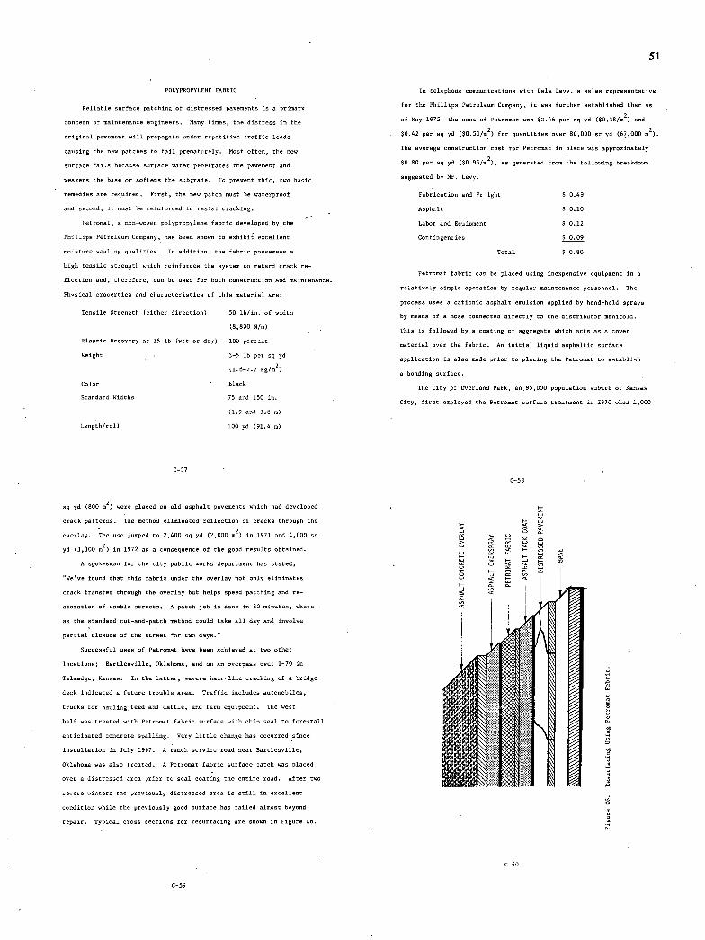
51
POLYPROPYLENE PABRIC
Reliable surface patching of distressed pavements is a primary
concern of maintenance engineers. Many times, the dintress is the
original pavement will propagate under repetitive traffic loads
causlog the new patches to fail prematurely. Most often, the new
surface fails because surface water penetrates the pavement and
weakens the base or softens the subgrade. To prevent this, two basic
remedies are required. First, the new patch oust be waterproof
and second, it must be reinforced to resist cracking.
Petromat, a non-woven polypropylene fabric developed by the
Phillips Petroleum Company, has been shown to eobibit eocellest
moisture sealing qualities. Is addition, the fabric possesses a
high tensile stresgth which reinforces the system to retard crack re-
flection and, therefore, can be used for both construction and maintenance.
Physical properties and characteristics of this material are:
Tensile Otrength (either direction) 50 lb/is, of width
(8,800 8/n)
Elastic Recovery at 15 lb (wet or dry) lii percent
Weight 3-5 lb per sq yd
(1.6-2.7 hg/rn2)
Color Black
Standard Widths 75 and 150 in.
(1.9 and 3.8 n)
Length/roll 100 yd (91.4 m)
In telephone communications with Dale Levy, a sale s representative
for the Phillips Petroleum Company, it was further established that an
of May 1975, the cost of Petromat was $0.46 per sq yd ($0.38/n2) and
$0.42 per sq yd ($050102) for quantities over 80,000 sq yd (67,000 m2).
The average construction cost for Petromat in place was approximately
$0.80 per sq yd ($0.95/n2), as generated from the follswing breakdown
usggested by Mr. Levy
Fabrication and Fr Ight $ 0.49
Asphalt $ 0.10
Labor and Dquipmest $ 0.12
Contingencies .LQa.Q
Total $ 1.80
Petromat fabric can be placed using inexpensive equipment in a
relatively simple operation by regular maintenance personnel. The
process uses a cationic asphalt emulsion applied by hand-held sprays
by means of a hose connected directly to the distributor manifold.
This is follewed by a coating of aggregate which acts ass cover
material over the fabric. An initial liquid asphaltic surface
applicetion is also made prior to plating the Petromat to estoblis4
a bonding surface.
The City of Overland Park, as85,000-popslation suburb of Kansas
City, first employed the Petromat surface treatment is 1970 when 1,000
C-Si
C-SB
sq yd (800 02) were placed on old asphalt pavements which had developed
crack pattersu. The method eliminated reflection of cracks through the
overlay. The use jumped to 2,400 sq yd (2,000 m2) in 1971 and 4,000 sq
yd (3,300 m2) in 1972 as a consequence of the good renultu obtained.
A spokesmae for the city public works department has stated.
uWeve 80usd that this fabric under the overlay not only eliminates
crack transfer throsgh the overlay but helps speed patching and re-
storatios of unable streets. A patch job is done in 30 minstes, where-
as the standard cut-and-patch method could take all day and involve
partial closure of the street for two days.
Successful uses of Petromat have been achieved at two other
locations; Bartlesville. Oklahoma. and on an overpass over 1-70 in
Talnadge, Kansas. Is the latter, severe hsir-line cracking of a bridge
deck indicated a future trouble area. Traffic includes automabiles,
trucks for hauling feed and cattle, and farm eqsipnent. The West
half was treated with Petromat fabric surface with chip seal to forestall
anticipated concrete spalling. Very little change has occurred since
installation is July 1967. A ranch service road near Bartlesville.
Oklahoma was also treated. A Petromat fabric surface patch was placed
over a distressed area prior to seal coating the estire road. After two
severe cistern the previously distressed area is still is excellent
condition while the previeusly good surface has failed almost beyond
repair. Typical cross sections for resurfacing are shown in Figure C6.
C-6O
C-59

52
In September 1973 a high quality asphaltic concrete pavement was
constructed by the Texas Transportation Institute on a section of the
portland cement concrete airport runway system of the Texas AiM
Research Annex. This pavement was constructed in partial fulfillment
of the requirements of the Federal Highway Administration project
entitled "Field Test and Evaluatiso Center for Central and Southern
States. Part of the resurfacing utilized the Petromat techtiqae.
The renultn of these tests show that whereas nearly 90 percent of
the untreated joists transmitted reflective cracks after nine months,
only 18 percest were transmitted through the Petromat. The rate at
which the distress was generated was significantly lower in the treated
nurfacn. These results would indicate the effectiveness of Petromat
as a nurfoce treatment for retarding the initiation and propagation
of reflective cracks.
C-6l
BEPtRENCES APPENDIX C
Cl. Weagle, C. E. "leo Yearn With fuii-Septh Asphalt." Favinjk
Forum, Winter, pp. 16-18, 1974. -
Cl. Gotolshl, H. H., Smith, B. 8., and Roberts, J. M. "A Study of
Physical Factors Affecting the Durability of Asphaltic Pavement."
Pennsylvania State Univ., University Park, Dept. of Civil Engineer-
log, Rept. No: RR-SR-9, 161 pp., Sept. 1968.
Lu, Danny, Shih, Chia Shun, and Scrivoer, Frank W. "The Optimi-
zation of a Flexible Pavement System Using Linear Elasticity,"
Texas Transportation Sent. • College Station, Rept. No: TTS-1-8-
69-123-17, 100 pp., Mar. 1973.
I Majidadeh, K. "Durability Characteristics of Auphaitic Materials."
Ohio State University, Rept. No. EES 300, 214 pp., Apr. 1970.
CS. Monismith, C. L. and tpps, J. A. "Asphalt Mixture Behavior In
Repented Flexure." California Univ., Rerheley, Soil Mechanics
and Bituminous Materials Research Lab, Rept. No: Tl-69-6, 105
pp., Dec. 1969. -
C6. Monismith, C. L., Hicks, R. C., and Salarn, Y. M. "Bauic Properties
of Pavement Components." California Univ., Berkeley, Rept. No:
- Tt-71-4, 202 pp., Sept. 1971.
C?. Fell, P. S. "Fatigue of Bituminous Materials in Flexible Pave-
ments." Oust. Hwy. Ingineeru Journal, London fOil,- Vol. lB.
No. H, pp. 1723, Aug. 1971.
CB. Fuhrnann, H. "Bituminous Courses or Priners Bnder Concrete
Roadways." ltrassen Dud Tiefbau/Cermany, Vol. 19, No. 1,
C-62
pp. 13-17, Jan. 1965.
C9. Kennedy, Thomas H. and Hudson, W. R. "Tensile Properties of
lubbases for Use in Rigid Pavement Design." Texas Univ., Austin.
Center for Highway Research, Rept. No: CFHR-3-8-66-98-14F,
86 pp., Feb. 1973.
ClO. Layman, A. H. and Phillippi,S. W. "A Study of the Flenoral
Properties of Certain Black Base Mixtures." Assoc. Asphalt
Paving Technol, Proc. Vol. 38, pp. 684-705, Feb. 1969.
Cll. McKenson, C. L. "Emulsified Asphalt Treated Subbase Snder
Ceneut Concrete Pavement." Highway Research Hoard, Proc.
Vol. 24, pp. 466-477. 1944.
Nair, K., Smith, W. S., and Chang, C. Y. "Character-
ization of Asphalt Concrete and Cement-Treated Cranular Base
Course." Materials Research and Developmest, Inc., Oakland,
Calif., 320 pp., Feb. 1972.
Scrimnher, T., Mann, G. W., Sherman, G. 8., and Johnson, N.
"Selection of Optimum Binder Content for Bituminous Treated
Bases." California State liv. of Highways, Sacramento,
Materials and Research Dept., Rept. No: CA-HY-MR-3378-1-73-03,
32 pp., Jan. 1973.
Terrell, B. L. "Fatigue Behavior: Field Observations and
Anaiytical." ASTM Spec. Tech. Publ. No. 508, pp. 117-143,
July 1972.
Eppn, J. A. and Gallaway, Bob M. "Design and Economics of
Bituminous Treated Bases in Texas." Texas Transportation
Institute, Research Report No. 14-lP, 96 pp., July 1974.
C-63
Eppn, Jon A. and lallaway, Bob N. "The Changing Picture in the
Hot Mis Asphalt Concrete Industry." Texas Rot Mix Asphalt Pave-
ment Association Annnai Meeting. 30 pp., April 1975.
"Fatigue of Conpacted Bituminous Aggregate Mixtures." ASTM
Spec. Tech. Fuki. No. 508, 173 pp., 1972.
CDH. Dempsey, Barry J. "A Heat-Transfer Model for Evaluating Frost
Action and Temperature Related Effects in Multilayered Pavement
Systems." University of Illinois, Appendix C, 1969.
"Reuonditiouing High-Volume Freewayu in Srban Areas." Trans-
portation Research Board, NCHRF Synthesis of Highway Practice
No. 25, 56 pp., 1974.
Anderson, Crane S. and OGles, Kenneth T. "Runway Rebuilding
With Daily Sue." Civil Exgixeerisg, ASCR, pp. 78-80, March 1975.
500tocci, L. E. "Thickoess Design Procedure for Asphalt and
imuluified Asphalt Mixes." Chevron Research Company, Richmond,
California, 31 pp., 1975.
"Asphalt Recycled in Place Focus Base for New Pavement." Roads
and Streets, p. 122, Nov. 1974.
"Nevada Becycles A Highway." Paving Forum, Wider, pp. 4-7.
1974.
Asnouxcemeot in the "industrial Bulletin," No. 52 of Arthur B.
Little Inc., Cambridge, Massachusetts, April 1931.
Griffin, D. F. "Mis Denignx for Faut Pin C-1 Cemext Concrete."
Technical Report R651, Naval Civil Engineering Laboratory, Fort
Hueneme, California, Nov. 19691.
C-64
53
Nosseir, S. B. and Katona, .M. C. Structural Behavior of Rein-
forced Concrete Beans made with Fast Fio 1 Concrete." Technical
Report R614, Naval Civil Engioeerivg Laboratory, Port Hueneme,
California, Feb. 19691.
Lormao, N. H. "Rapid-gardening Concrete for Repairing Navy Con-
crete ltrcctores in Any Ceographic Region. Technical Note
9-1300, Naval Civil ingiseering Laboratory, Port Beaneme,
California, August 1973.
Setser, W. 1., et. al. vgapid Repair of Bomb Damaged Runways.
Technical Report AFAPL-TR-67-165, Vol. I, Air Force Acm
Propulsion Laboratory, Air Force System Command, Wright-
Fatternoo Air Force Base, Ohio, March 1968.
Pruitt, C. T., et. al. "Rapid Repair of Homb-lamaged Runways."
Technical Report APAFL-TR-67-165, Air Force hero Propuluion
Vol. Il, Laboratory, Air Force Systems Conssand, Wright-
Patteruon Air Force Base, Ohio, April 1968.
Halley, W. "Runway Repairs Using Alaminvus Cement Concrete."
Unpublished paper as the Yokota Air Base repairs in Japan.
Laocaster, I. R. "Early Traffiokiog of Thin Concrete Patches."
RRL Report 1126, Road Research Laboratory, Crowthoroe, Berk-
shire, Englasd, 1969.
Hruevauor, I., et. al "Hardevod Cement Pastes of Low Poronity -
Exploratory Studies." Research Report 68-9, Bureac of Physical
Research, New York lthte Department of Transportation, Jose 1968.
Bennett, U. W. and Collins, S. C. 'High Early ltrength by Means
of Very Five Portlaud Cement." The Inrtitation of Civil
togineern (England), Proceedisgs, Vol. 43, pp. 443-552, July 1969.
Robnev, T. S. "The Charaoterinticn and Applications of Mioturen
of Portland and High-Alumina Cements,' Cement and Industry,
January 5, 1952.
Taylor, H. F. W. The Chemintry of Cements. Vol. 2, Academic
Press, New York, New York, pp. 17-26, 1964.
136. "Pour-Boar Concrete Patching with Low-Shrinkage Admioturn."
Roads and Streets, Vol. 106, pp. 96-97, 100-101, June 1963.
Russell, Robert S. "A New Sigh Early Strength Concrete."
Roadways and Airport Pavements, ACE PshlicationSP-51-15,
pp. 269-278, 1975.
Pike, R. I. and Baker, W. M. "Concrete Patching Materials."
Report No. FHWA-RS-74-55, Federal Highway Administration,
April 1974.
Halvvmsen, Crane F. "Concrete for Tunnel Liners: Evaluation
of Fiber Reinforced Quick letting Cement Concrete." Report
FRA-SRDD-75-3, Dept. of Civil Rngineering, University of
Illinois, 73 pp.' Aug. 1974.
Houston, B. J. and Hoff, I. C. "Regulated-Sot Cement for Cold
Weather Concreting." U. S. Army Engineer Waterways Experiment
Station, Corps of Engineers, iH PP. • Sept. 1974.
U. S. Gypsum Cu. "Properties of Concrete Containing VBE Cement."
Research Laboratories, 10 pp., 1974.
an C-66
ri
Custom Crete Inc. "Fast Fis C-2 Cement." Dallas, Texas,
Technical Bulletin, No. 5, 13 pp., October 1, 1971.
Carntensen, J. B. and Nakorn, N. "Fast Fin Pavement Repair."
Military Engineer, Vol. 61, No. 403, pp. 352-353, Sept. 1969.
144. Campbell, J. "Fast-Set Concrete Tested at Port Huenome Trials."
Navy Civil Engineer, Vol. 9, No. 1, p. 18, Jan. 1968.
Pcronehio, N. "Regulated-Set Cements Applications and Field
Problems." Prepared for the New Materials in Concrete Con-
struction Conference, Chicagn Circle Campus of the University
of Illinois, December 1971. R&D Ocr. 1491, 5 pp., Jan. 1972.
Young F. I. "Experimental Foamed Plastic Base Course." figj-
way Research Record No. 101, pp. 1-10, 1965. -
Oosterbaan, M. D. and Leonards, G. A. "Use of Insulating Layer
to Attenuate Frost Actioo in Highway Pavements." JilA)z
Research Record No. 151, pp. 11-27, 1965.
Irwin, Lynne, H. "Application of Polyurethane Foams to Pavement
Construction," A Conceptual Presentation to the Air Force
Weapons Laboratory, Texas AiM University, 9 pp., Sept. 1970.
Joseph, Alfred H., Jackson, Ralph S. and Resser, Thomas B, DDE.
"Evaluation of Foamed Plastics for Use as Strdctural Rupporting
Layers in Pavements and Foundations." Army Engineer Waterways
Experiment Station, Vickshurg, Miss. • Rept. No: AEWES-Misc-
Paper-S-71-24, 84 pp., Nov. 1971.
The Upjohn Cempany. "Inonate System." Technical Information,
CPR 740, May 1973.
"Concrete Pavement Replaced in N 1/2 Boors." cjlR0gneeyi0 ,
ASCE, Vol. 44. pp. 62-64, April 1974.
Poor, B. C. "As, Operational Report on Prefabricated Pavement
Sections for PCC Pavement Repairs." Caltrans, 3 pp., Feb. 1974.
Orimnley, N. F. and Morris, B. I. "An Approach to Concrete
Pavement Replacement Which Minimines DiDrsption of Traffic."
Florida Dept. of Transportation, 5 pp.
Bmscn, Alan M. "New Life for Old Asphalt." Constructor,
pp. 18-21, May 1975.
CII. Suck, A. I. "Reevr:ed ivvree me." U. S. Arms Eceineerive Water-
ways Experiment Station, Vicksburg, Minnisuippi, Misceilasenus Paper
C-72-14, 35 pp., May 1972.
"Recycled Concrete Used in California Subbase." Americas Con-
crete Paving Associanion Newsletter, Vol. 11, No. 5, p. 2,
May 1975.
Blank, L. H. "Ionic Mixer Strengthens Concrete by 300%."
Ohio Contractor, December 1969.
Dennard, J. U., Jr. "Resin Concretes: A Literature Review.'
Waterways Experiment Station, Siuceilaseoun Paper 1-72-21,
26 pp.. Sept. 1972.
Chang, T. V., Stephens, H. L. and Yen, R. C. "Pxiymer Concrete
Prepared from MMA - Stymene Copoiy:ver System." August 1974.
Prepared for presentation at the 54th Annual Meeting of the
Transportation Research Hoard, Washington, I. C., January 1975.
Ialler, Sol and Steinberg, Meyer. "Polymer Concrete ihown
Promise an Patching Material." Public Works, Vol. 105, No. 5,
pp. 92-93, May 1974.
C-67
C-6H

54
C61. Kukacka, L. E., Fontana, J. and Steinberg. M. "Polymer-Concrete
for Use in the Repair of Deteriorated Bridge Decks. Dept. of
Applied Science, Brookhaven National Laboratory, Upton, New York,
26 pp., Asgant 1974.
C62. "Concrete-Polymer Materials, First Topical." Dept. of Applied
Science, Brookhaven National Laboratories, Upton, New York,
December 1968.
C63. "Polymer-Strengthened Concrete for Military Facilities."
Technical Note N-1319, Naval Civil Engineering Laboratory, Port
Hueneme, California. December 1973. -
C64. Eash, R. D. and Shafer, H. H. "Reoctinen of Polymeric Latoues
with Portland Cement Concrete." 54th Annual Meeting Trans-
portation Research Board, Wanhingtnn, D. C., 25 pp., January 14,
1974.
C65. "Epoxy Portland Cement Concretes." Celanese Coatings Co., Los
Angeles, California, Technical Bulletin, 19 ''.' March 1, 1972.
C66. Private connusication from Vi/tor Sorhe, Utah Highway Depart-
ment, Salt Lake City, Utah.
C67. "Development of Polyner-Impregmoted Concrete an a Construction
Material for Engineering Projects." Presented at the American
Concrete Institute Canadian Capital Chapter Ueeioar, Sttowa,
Ontario, October 9-10, 1973.
C68. "Highway Applications of Concrete-Polyner Materials." Prepored
for Transportation Research Board Annual Meeting, Washington,
S. C., January 1975.
C-69
Majamthar, A. J. and Ryder, J. F. "Reinforcement of Cements and
Gypsum Planter by Glass Fibres." Science of Ceramics, Vol. 5,
pp. 539-764, 1970.
Nawy, E. G. • Neuwerth, G. E. and Phillips, C. J. "Behavior of
Fiber Glass Reinforced Concrete Beams." ASCE, it ructural Div.,
Vol. 97, No. iT 9, Proo. Paper 8353, pp. 2253-2215, Sept. 1971.
Buckley, Ernest L. "Alternativd Fiber Reinforcements for Port-
land Cement Mortar and Concrete." Construction Research Center,
University of Texas at Arlington. 10 Pp, Apr. 1973.
CR0. Buckley, Ernest L. "Accelerated Trials of Glass Fiber Rein-
forced Rigid Pavements." Construction Research Center,
University of Texas at Arlington, Report TR-3-74, Apr. 1974.
"Highway Bridge Seat Dean itructurally Restored by Epoxy Crack
Sojection." New Hampshire Highways, Feb. 1968.
"Epoxy Adhesive Injection Technique Fills Crackn Upgradep Con-
crete Floor Slab." Plant Engineering, Sept. 1967.
"Epoxy Crack Repair." Sesterm Manafacturing, Oct. 1964.
"Cracked Concrete Pilings Repaired with Epoxy Adhesive for
Large ianiogs." World Construction, March 1971.
CRY. Private tRemusica tine with William C. Hodges, Adhesive Engineer-
ing Company, Sen Carlos, California.
Some, I., Hammond, S. and McMamon, S. "The Use of Sand-Asphalt-
Sulphnr Mimen for Rood Base and Snrfoce Applications."
Canadian Technical Asphalt Association, Proc. Vol. SVI, Nov.
1971.
Demo, S. "Basic Properties of Sand-Asphalt-Sulphur Mixes."
Presented to the VII International Road Federation World Meet-
ing, Munich, Oct. 1973.
C69. Meyer, A. H. "A Polymer as a Surface Treatment for Concrete."
Journal of the Strsctsral Division, ASCE, pp. 1205-1215, Jone
1974.
C75. Powler, B. H. • et. ul. "Polyner-Inpregnated Concrete for High-
way Applications." Research Report No. 114-1, Center for High-
way Research, University of Texas at Austin, Austin, Texas,
Feb. 1973.
"State-of-the-Art Report on Fiber Reinforced Concrete."
Journal of the ACG, Proc. Vol. 70, No. 11, pp. 729-744, Nov. 1973.
"Fiber-Reinforced Cement Composites.' Report produned by the
Materials Technology Division of the Concrete Society, 52 Gron
Venor Gardens, London, England, 77 pp., July 1973.
Haynes, A. H. "Investigation of Fiber Reinforcement Methods for
Thin Shell Concrete." Technical Report No. 979, Naval Civil
Engineering Laboratory, Port Macnone, Calif. • 47 pp., 1968.
Lankard, David R. and Walker, Alvin J. "Pavement Applications
for Steel Fibrous Concrete." Transportation Engineering Journal,
ASCE, Vol. 101, No. TEl, pp. 137-153, Feb. 1975.
Gray, B. H., Williamson, G. R. and Batsom, U. B. "Fibrous Con-
crete Construction Material for the Seventies." Dept. of the
Army, Construction Engineering Research Laboratory, 246 pp.,
Dec. 1972.
Pasko, Thomas J., Jr. "Pavement Applicatidom of Steel Fiber
Reinforced Concrete." Highway Focan, Vol. 4, No. 5, pp. 71-91,
Oct. 1972.
C-7I
$0. Deer, I. "The Use of Sulphur in Asphalt Paving Mines."
Presented to the Fourth Joint Chemical Engineering Conference,
Vancouver, Sept. 1973.
Deme, I. "Processing of Sand-Asphalt-Sulphur Mines." Pre-
sented at the Annual Meeting of AAPT, Williamnbsrg, Virginia,
Feb. 1974.
Gollaway, B. M. and Saylak, S. "Beneficial Use of Sulphur in
Sslp'bur-Asphalt Pavements." Texas AiM Research Foundation,
Report RP 983-1A, Volunes lA, 18, SC, II and 151, Aug. 1974.
Dale, J. N. and Ludwig, A. C. "Reinforcement of Elemental
Sulphur." Sulphur Institute Journal, Vol. 5, No. 2., Summer
1969.
Dale, J. M."Sulphur-Fiber Coatings." Sulphur Institute
Journal, pp. 11-13. Sept. 1965.
Gallaway, S. M. and Jirnenee. R. A. "A Study of the Effect of
Short Anbextos Pibee's on the Phynical Charocteristicu of Hot-Mix
Anphaltic Concrete." A Texas Transportation Institute Report for
The Johns-Manville Co. of New Jersey, 1962.
Majundar, A. J. "The Sole of the Interface in Glass Fiber Rein-
forced Cement." Cement and Concrete Research, Vol. 4, pp. 247-
266, 1974.
Texas Highway Department. "Standard Specificatinex of Con-
struction of Highways, ltreotn and Rridgex," 1972.
96. U. S. Patent No. 3,738,953, June 12, 1973.
Asphalt Institute Handbook, Manual Series No. 4 (MS-4), p. 71,
March 1970.
Schmidt, R. J. "A Practical liethod for Determining the Resilient
Modulus of Asphalt Treated Nines." Highway Research Board, 1972.
C-72
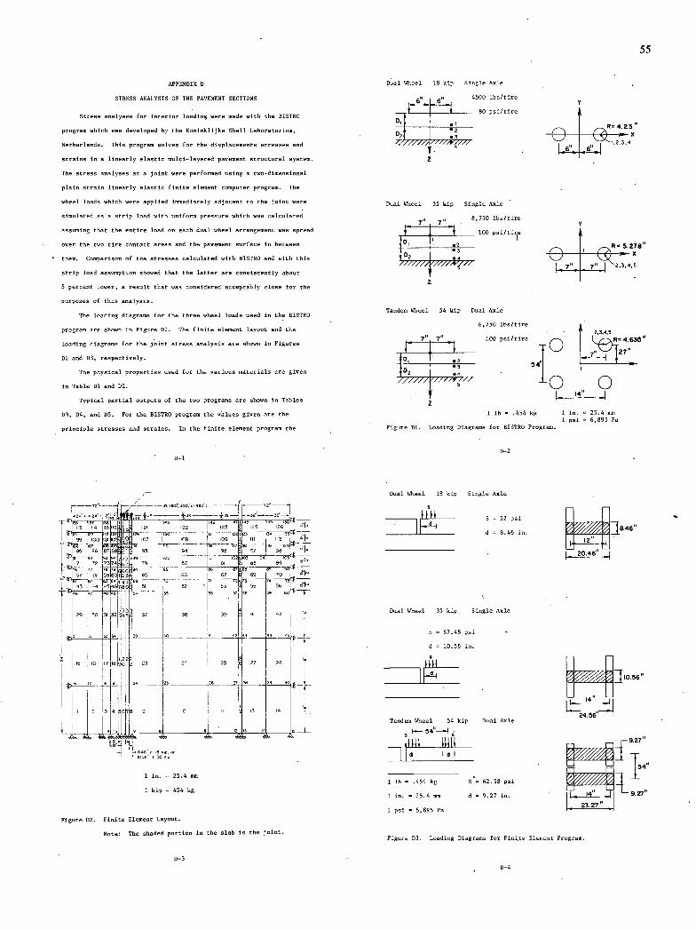
55
APPENDIX I
STRESS ANALYSIS OF THE PAVEMENT SECTIONS
Stress analyses for interior loading were made with the BISTRO
program which was developed by the Konisklijke Shell Laboretorism,
Netherlands. This program solves for the displacememts stresses and
strains in a linearly elantic mslti-layered pavement structural system.
The stress analyses at a joint were performed suing a two-dimensional
plain strais linearly elastic finite element computer program. The
wheel loads which were applied immediately adjacent to the joint were
simulated as a strip load with smiforn pressure which was calculated
assumimg that the estire load on each dual wheel arrangement was spread
over the two tire contact areas and the pavement surface in betweem
them. Csmparinom of the stresses calculated with BISTRO and with this
strip load assumption showed that the latter are consistently about
5 percent lower, a result that was considered acceptably clone for the
purposes of this amalynis.
The loading diagrams for the three wheel loads used in the BISTRO
program are shows in Figure Dl. The finite element layout and the
loading diagrams for the joint stress analysis are shown in Figures
D2 and 13, respectively.
The physical properties used for the various materials are given
in Table Dl and Dl.
Typical partial outputs of the two programs are shows in Tables
03, 04, and D5. For the BISTRO program the values given are the
prisciple stresses and strains. In the finite element program the
D-1
suoo 4s4I- —12 -
--si—r—Ss
Is
Ii
85 06 8 7 00 93 94 93 97 52 9S 94
: L:i . -'----
flii 01 - I02103 - rc4
j -
29 3l
, 99 451 44?
IS IS Ii 10 O 23 24 23 21721
1 74I7i52T
L
IS
eui7 use. 4,
1 in. = 25.4 san
1 kip = 454 kg
Figure Dl. Finite Element Layout.
Note, The nhadmd portion in the slab in the joint.
Dual Wheel 18 kip Single Axle
6 _6" 4500 lbs/tire
80 psi/tire
Do
Ru423
u s 0,3
Dual Wheel 35 kip Single Axle
8,750 lbs/tire
105 psi/tiee
_ 0
I 5.28
/77777 /7-" 2,3,4,5
z
Tandem Wheel 54 kip Dual Asle
6,750 lbu/tire 2,3,4,5
100 Psi/tire
' ED
0 0
I- 'k"
z
1 lb .454 kg 1 in. 25.4 so, 1 psi = 6,895 P.
Figure Dl. Loading Diagrams for BISTRO Program.
1-2
Dual Wheel 18 kip Single Axle
S = 52 psi flfl I F-i d = 8.46 in.
7J8.46"
20.46"
Dual Wheel 35 kip Single Axle
5 = 67.48 psi
d = 10.56 in.
JI056"
Tandem Wheel 54 kip Soul Axle 24.56
I— 54--I
__
dII dl
9.27
1 lb = .454 kg S'= 62.58 psi
1 in. = 25.4 mm d = 9.27 in.
1 psi = 6,895 Pa
Figure S3. Leading liagrams for Finite Element Program.
98 I 10S
3244 433
37 30
~40
39 41 42
11 L ss
0-3
1-4
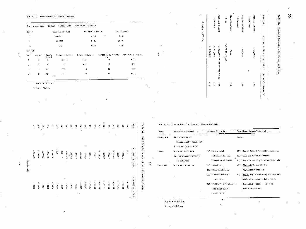
Cu H.
5 0 5 Cnes-, 5 5 5 H. 5 OC to 5 o s -s s B
B 0 s m
Table D3. Streamlined Dsal-6S,eel BISTRO.
Dual-Wheel Load 18 kip Single Axle - Number of Layers 3
Layer Ilastic Modulus Poisson's Ratio Thickness
1 4000000 0.15 8.5
2 465000 0.35 16.0
3 5000 0.45 0.0
Output
No. Layer Depth Sigma 1 (psi) Sigma 3 (psi) Epsim S (p in/in) Epsin 3 (p in/in) in
1 1 8 57- -12 13 -7
2 2 8 2 -12 13 -29
3 2 24 15 5 21 -22
4 3 24 -1 0 21 -51
1 psi = 6,095 Pa
1 in. = 25.4 sec
A
Table 02. Assumptions for Pavement Stress Analysis.
Iten Condition Asssmed Minimum Criteria Candidate Synten/Moterial
Hubgrode Periodically or Nose
Continuously Saturated -
l5000 psi p.45
Base 4 to 20 in. thick (1) Struttnral Dense Graded Aspholtio Concrete
May be planed directly Adequacy in the Sulphur Asphalt Systems
on Subgrade - Presence of Water Rigid FaCe if placed on lubgrade
Surface 4 to 10 in. thick (1) Durable (1) Flexible Demne Sraded
5, (2) Wear Reniutant Asphaltic Concrete
(3) Smooth Ridiug (2) Rigid Rapid Hardening Concretes;
PSI P 4 with or withuat reinfnrcemes
(4) SufficIent Texture including fibers; Cast in
for gogh Shod place or precast
ReuS stance
1 psi = 6,895 Pa
S in. = 25.4 mm

57
Table 14. Continued
Node S = X-Disp. (in.) V = i-lisp. (in.)
82 -.00046 -.0146
83 -.00047 - .0144
84 -.00047 - .0140
85 -.00041 - .0071
86 -.00035 - .0005
87 -.00029 .0022
88 -.00016 .0421
89 -.00006 .0020
90 0.0 .0019
1 in. 25.4 mm
0-9
Table 05. Stresses at Element Centroids - Finite Element Analysis.
Element X I Sigma 1 (psi) Sigma 2 (psi)
29 12.05 20.00 -1 -3
30 36.00 20.00 -1 -3
31 54.00 20.00 -1 -3
32 66.00 20.00 -1 -4
33 72.50 20.00 -1 -4
34 74.25 20.00 -1 -4
35 76.75 20.00 -1 -4
36 79.73 20.00 -1 -4
37 113.23 20.00 -1 -3
38 181.00 20.09 0 -1
39 235.00 20.40 0 0
40 253.50 20.00 0 0
41 272.00 20.00 1 S
42 308.00 20.00 1 0
57 02.00 33.00 -2 -6
58 36.00 33.00 5 -6
59 54.00 33.00 6 '-7
60 66.00 33.00 12 -13
61 72.50 33.00 9 -58
62 74.25 33.00 -1 -26
63 76.75 33.00 4 -13
(Continued)
0-10
Table 05. Continued
Element S S Sigma 1 (psi) Sigma 2 (psi)
64 . 79.63 33.00 7 -8
65 113.23 33.00 3 -,
66 181.00 33.04 -1 -1
67 235.00 33.00 2 -2
68 253.50 33.00 34 12
69 272.00 33.00 3 -2
70 308.00 33.00 S S
1 psi = 6.895 Pa
displacenest values are for the modes and the Ste ens values are for the
certroid of the elements.
The two programs indicated reasonable feasibility of using the
rigid foams or similar materials as bane and sub-base coarsen under
heavy loads. However, some caution should be emercined because the
fatigue characteristics are not available for these materials.
Esieg a fatigue criteria for the asphalt, vulphur asphalt and
portland cement concretes indicates that almost all combinations of
these materials could be used.
When the joint filler material was assumed an E value the sane
as the portland cement concrete the finite element program generated
very similar stresses to the BIITRO system for the name wheel load.
Thus giving reasonable confidence in the results of the finite element
system.
I-il 0-12
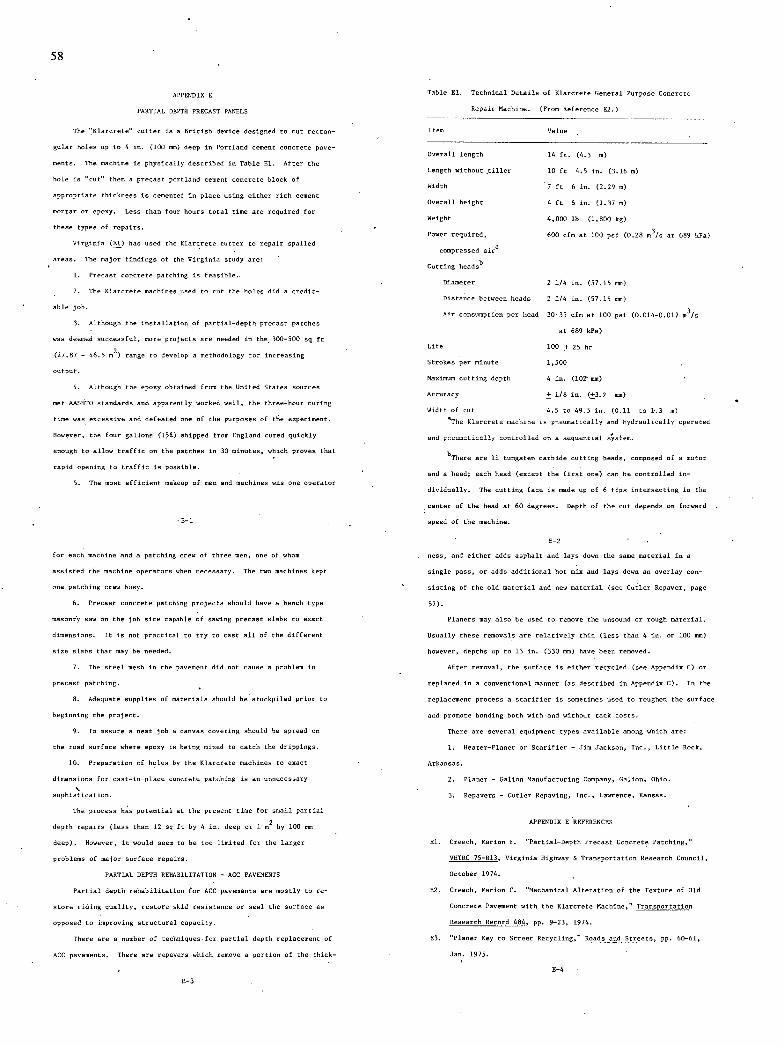
58
APPENDIX
PARTIAL DEPTH PRECAST PANELS
The "Klarcrete" cutter is a British device designed to cut rectan-
gular holes up to 4 in. (ill sos) deep in Portland cement concrete pave-
ments. The machine is physically described in Table El. After the
hole is "cut" then a precast portland cement concrete block of
appropriate thickness is cemented in place using either rich cement
mortar or eposy. Less than four hours total time are required for
these types of repairs.
Virginia (El) has used the Klarcrete cutter to repair spalled
areas. The major tisdings of the Virginia study are,
Precast concrete patching is feasible.
The Klarcrete machines used to cut the holes did a credit-
able job.
Although the installation of partial-depth precast patches
was deemed successful, more projects are needed is the 300-500 sq ft
(27.87 - 46.5 m2) range to develop a methodology for increasing
output.
Although the eposy obtained from the United States sources
met AASHTO standards and apparently worked well, the three-hour curing
time was escensive and defeated one of the purposes of the enperimest.
However, the four gallons (lsi) shipped from England cored quickly
enough to allow traffir on the patches in 30 minutes, which proves that
rapid opening to traffic is possible.
The most efficient mabeup of men and machines was one operator
1-1
Table El. Technical Details of Klarcrete General Purpose Concrete
Repair Machine. (From Reference E2.)
lien Value
Overall length 14 ft. (4.3 n)
Length without tiller 10 ft 4.5 is. (3.16 n)
Width 7 ft 6 in. (2.29 m)
Overall height 4 ft h in. (1.37 n)
Weight 4,000 lb (1,800 kg)
Power required, 600 cfm at 100 pui (0.28 m3/n at 689 kPa)
cnnpressed alra
Cutting headu'
Dianeter 2 1/4 in. (57.15 mm)
listanco between heads 2 1/4 is. (57.15 mm)
Air consumption per head 30-35 rfn at 111 psi (0.014-0.017 m3/s
at 689 kPa)
Life 100 + 25 hr
Itrokes per minute 1,500
Maninum cutting depth 4 is. (102 ens)
Accsracy ± 1/8 is. (±3.2 mm)
Width of cut 4.5 to 49.5 in. (0.11 to 1-3 m)
aThe Klarcrete machine is pneumatically and hydraulically operated
and pacunatically conralled on a sequential s,stem.
hmere are 11 tungsten carbide cutting heads, composed of a color
and a head; each head (encept the first one) can be controlled in-
dividually. The cutting face in made up of 6 tips intersecting in the
center of the head at 60 degrees. Hepth of the cut depends on forward
speed of the machine.
for each machine and a patching crew of three men, one of wham
asuisted the machine operators when necessary. The two machines kept
one patching crew busy.
Precast concrete patching proj ects should have a bench type
masonfy saw on the job site capable of sawing precast slabu to enact
dimensions. It in not practical to try to cast all of the different
size slabs that may be needed.
The steel mesk in the pavement did not cause o problem in
precast patching.
Adequate supplies of naterials should be stockpiled prior to
beginning the project.
To assure a neat job a canvas cnvering should be spread on
the road surface where epoxy is being mined to catch the drippings.
Preparation of holes by the Klarcrete machines to enact
dimensions for cast-is-placn concrete patihing is an snsecessary
sophistication.
The process has potential at the present time for small partial
depth repairs (less than 12 sq ft by 4 in. deep or 1 m2 by 100 eon
deep). Hawever, it would seen to be too limited for the larger
problems of major surface repairs.
PARTIAL DEPTH REHABILITATION - ACC PAVEMENTS
Partial depth rehabilitation for ACC pavements are mostly to re-
store riding quality, restore skid resistance or seal the surface as
opposed to improving structural capacity.
There are a number of teehniqses-for partial depth replacement of
ACC pavements. There are repaveru which remove a portion of the thick-
ness, and either adds asphalt and lays down the same material in a
mingle pass, or adds additinnal kot nix and lays down an overlay con-
sisting of the old material and new material (see Cutler Repuver, page
57).
Planers may also be used to remnve the unsound or rough material.
Usually these removals are relatively thin (less than 4 in. or 100 mm)
however, depths up to 13 in. (330 mm) have been removed.
After removal, the surface is either recycled (see Appendix C) or
replaced in a conventional manner (an described in Appendin C). In the
replacement process a scarifier in sometimes used to roughen the surface
and promote bending both with and withost tack casts.
There are several equipment types available among which are:
Heater-Planer or Scarifier - Jim Jackson, Inc., Little Reek,
Arkansas.
Planer - Golion Mansfacturing Company, Galion, Ohio.
Repaveru - Cutler Repaving, Inc. • Lawrence, Kansas.
APPENDIX I REFERENCES
El. Creech, Marion F. "Partial-Depth Precast Concrete Patching,"
V8TRC 75-R13, Virginia Highway h Transportation Hexearch Cosncil,
October 1974.
12. Creech, Marion P. "Mechanical Alteration of the Teoture of Old
Concrete Pavenent with the Klarcrete Machine." Transportation
Research Record 484. pp. 9-23, 1974.
E3. "Planer Key to Itreet Recycling," Roads and Streets, pp. 60-61,
Jan. 1975. -
I-i
E-3
59
APPENDIX F
SUBCRADE TREATMENTS
LIME STABILIZATION
Lime is the oldest stabilizing agent in use, today. it has been
used to strengthen structural systems, to provide serviceable worhing
tables for construotiom equipment, and to reduce the swelling potential
of certain clay soils. The most con000nly used form is hydrated lime
(calciun hydroxide) which, when mixed with plastic soil, cusses two
rncogsizable stages of reaction.
The first stage, called "soil modification, occurs within a few
minutes to an hour after intimate contact with the soil. This stage
is marked by a flocculation, agglomeration, and granulation of the soil
particles, a reductios in plasticity and swelling potential, and con-
siderable improvement in workability (Fl). In the subsequent stage,
referred to as "soil cementation", a compacted miuture slowly develops
strength an a result of pozeolanic reaction and the formaticm of new
compounds over a long period of time, sometinen yeorn (Fl).
In most applications, adequate stabilization can be accomplished
with 6 to B in. (151 to 200 son) of treated material. Typically, the
lime in distributed over the soil and mined with the soft, wet sub-
grade soil (AASTO groups A-b and A-7) using light equipment. Then,
it is intimately mined and compacted with normal compaction equip-
ment. If the soil is very soft, it may be allowed to "mellow" for a
day or two after the preliminary mixing, is order to allow for the
F-1
development of the drying action.
The effectiveness of lime stabilization has been conclusively
demonstrated. gowever, to provide effective swell control, it has been
suggested that eopamnioe soils should be treated to a depth of 5 ft
(1.5 m) (P2). To accomplish this depth of treatment conventional
methods are usually inadeqcate or too eopossive, hence, other tech-
niques have been devised.
Drill-time s/abilioation was developed as a maintenance measure
to treat pavement failures due to a lack of stability in wet, plastic
nubgradeu (P1). The procedure required 6 to 9 in. (150 to 230 nun)
diameter holes drilled through the existing pavement and 30 to 50 in.
(760 to 1270 mm) into the subgrade. These holes, spaced on 5 ft.
(1.5 m) centers, are then partially filled with lime and water to form
a slurry. The holes are then backfilled, tanped and patched. It is
claimed that the lime migrates through the subgrade to cause sufficient
stabilization, thus prevecting additional movement. The results have
been erratic. The major limitation seems to be the inability of the
lime to distribute throughout the soil mass (PS).
In order to obtain a better distribution of the lime, a prensore
injection lime (PIL) procedure was developed (P3). In the PIL pro-
cedure, a lime-water slurry (typically 3 lbs lime per gal of water
or 360 hg/n3) in pumped through injection rods into the soil.. The
injection reds are spaced 3 to 5 ft (1 to 1.5 m) apart and the slurry
in usually pomped under 50-200 psi (345-1400 kPa) pressure.
It is apparemt that openings must be present in the soil mass if
adequate slurry distribution is to be obtained. Field test reports
F-2
isclude about an many successes as they do failures to achieve desired
results .(P3).
An 'excellent state of the art report (PS), citing 36 referescns
(many le'es than 3 yearn old), suns up PIL as follows:
There are conflicting report s concerning the effective-
lens of PIL treatment of empannive soils. The proposed
treatment mechanisms ("prewetting", the development of soil-
lime moisture barriers, effective swell restraint with the
fnrnaticn of limited quantities of soil-lime reaction
products) have validity. It therefore seems logical to
conclude the P01. may be an effective swell contrOl pro-
cedure under certain circumstances. The condition most
favoring the achievement of successful PIL treatment of
espassive soils is the presence of an extensive fissure
and crack network into which the lime slurry can be
successfully injected. The relative significance of the
"prewetting" and "soil-lime pozzolanic reaction" aspects
of PIL treatment have not been established. If soil-
lime poenolanic reactions are essential to achieving an
effective application perhaps that fact can be used to
bvaivate the potential success of an anticipated treat-
ment and ecplain the apparent cnmflicting PIL experience
reports.
Due to the necessity of drilling a network of holes at 5 ft
(1.5 m) intervals and the limited suitability of PIL in saturated
fine grained soils, it would appear to have limited applicability to
the solution of rapid repair of urban freeways.
ELECTRO-OSMOTIC STABILIZATION
In the mid 30's Casagrande patented in Germany (and later the
U. I.) a method of hardening clayey soils (P4, P5). He and many others
worked on the process of electro-chemical soil stabilization during the
nest 50 years. More recently, O'nannos (F6, P7) has reported the
results of field tests is Arizona on stabilization of Chinle Clay by
electro-onmotic treatment.
The process causes a bane enchange of ions to reduce the swelling
characteristics of clays. Among the advantages of electro-onmotic
stabilization are:
The stabilization of esisting highways can be accomplished
without the necessity of removing and mewnrbing the in-place material.
Once the treatment and stabilization of enpansive clays had
been accomplished, the results would irreversible over the engineering
life of the highway.
After treatment and stabilization of the expansive clay,
radical changes is moisture content of the subgrade would not cause
escensive changes in volume.
Basically, the system consists of an anode capable of dispersing
a satorated solutios of a water soluble salt (K Cl, Ca C12, Mg Cl,
Al C13) and a cathode placed up to lB ft (5.5 n) away. The two are
coupled with a DC power source capable of producing a voltage gradient
of at least .5 volt/in. (.02 volt/mm).
O'Banson found that about 0.5 percent KC1 by weight of soil was
required to stabilize the Chenie clays. His work also revealed that a
F-S F-i
60
horizontal arrangement if anodes and cathodes were the most effective.
Stabilization to a depth greater than 3 ft(l m) below subgrade
is nsually not necessary. In 1969 in a field test by O'Bassnn,
Chenle clay was treated to a depth of 3 It (1 m) at an estimated cost
of 05.432 per lineal foot ($17.82 per m) of treated section. (Cost
based on a section of 200 it (60 m) long by 40 ft (12 m) wide and is
the non-recoverable items.) The treatment required about one week. At
todays prices the treatment would cost considerably more.
The process does work and can be installed with aminimsm of
interrupted to traffic flow. I t is envisioned that this process could
be used to treat soft spots' along a pavement section to stabilize
the subgrade prior to remuval and replacement of the pavement. Also,
this technique could probably be used to stabilize expansive soils under
pavements where the only rehabilita tins woek to be done is to restore
riding quality as described in Chapter Two. -
FIBER MATS
A number of fiber filled membranes are currently nanofactsred
for various construction uses. Polypropylene is the basic cnnpnment
is most of the fabrics. (lee Appendix C)
The marketing brochures for some of these fabrics prnmnte the
following uses:
Mnisture barriers for comet eto cosstrnctinn.
Construction covers.
Road support membrane. -
Strengthening membrane is layered pavements.
Pond and ditch liners.
Some published results include:
(1) The prevention of refiectinn cracking in asphalt patches
F-5
REFERENCES APPENDIX P
Krebs, Robert D. and Walker, Richard D. Righway Materials,
McGraw-Hill Dxvi Company, New Turk, 1971.
Roltz, W. C. "Volume Change in Expansive Clay Soils and Control
by Lime Treatment." Secnnd International Research and Engineer-
ing Conference on Expansive Clay Soils, Proceedings, Texas AhM
Iniversity, College Satins, Texas, 1969.
Thompson, Marshall R. and Robnett, Quentin L. "Pressure In-
jection Lime Treatment of Swelling Soils." Presented at the 54th
Annual Meeting of the Transportation Research Board, 17 pp.
January 1975.
Casagrande, Lea. "Verfabren ear Verfestigung tnniger laden
(Method of gardening of Clayey Soils)." German Patent No.
621694, 1935 (Application 1934).
Casagrasde, Leo. "Method of Hardening Soils." U. S. Patent No.
2,099,328, 1937 (Application January 7, 1935). -
O'BanmOn, C. E. "Research on Stabilization of Expansive Clays
Using Eleetro-Onmotic Treatment." 15th Arizone Conference on
Roads and itreets, Proceedings, pp. 76-86, April 1966.
O'Basnon, C. E. "Stabilization of Expansive Clays Ssing Electro-
Osmotic Treatment and Dane Exchange of Inns." Pifth Paving
Conference, Albuquerque, New Mexico, Pp. 60-82, December 1967.
PB. "Reflective Cracks in Asphalt Patches Stemmed with Plastic Mats."
Rural and Urban Roads, Dec. 1972.
P9. Webster, S. L. "Plantic Wrapped Roads." Military Engineer,
May-June 1972.
(PH). In this installation a fabric mat was placed over an asphalt
pavement enhibitiog alligator cracking. The mat was bedded in liquid
asphalt and covered with a sprayed-on catiosic emulsion. A con-
ventional, hot-mix overlay was then placed on top of the eat. Gxod
renults were nbtained.
(2) The military has encapsulated a soil layer in a plastic
fabric for use as a roadbed over very soft soils (P9). The process,
termed membrane enveloped soil layer (MESAL), consists of a nubgrade
upom which a foundation layer of compacted soil lien between waterproof
membranes fnrmixg a waterproof encapsulated soil system. A 12 in.
(300 mm) lift of soil compacted to 95 percent of AASTO T-180 will
support 5 ton (4,5I0 kg) 6 x 6 military cargo truck loaded to its
maoixum weight for highway travel.
In relation to rapid rehabilitation of arbhn freeways, there are
two prnposed uses. One would be to use the fabric directly on a soft
subgrade an a load distribution membrane to reduce the thickness re-
quirement for, base or subbase courses. The membranes could be a
cuntinuoun strip or it could be .used intermittently if the subgrade
were only soft in spots. The second application would be to use the
fabric as a reinforcing layer between laymen of asphalt concrete to
assist load distributiox and reduce thickness requirements.
The products discussed here are commercially produced by several
maxufactarers including Phillips Petcoleam Cunpamy under the trade
mane of Petrxmat, DuPont under the trade naxe nf Typar and Celanese
Fibers under the trade name of Micafi.
P-6
P-7

THE TRANSPORTATION RESEARCH BOARD is an agency of the National Research Council, which serves the National Academy of Sciences and the National Academy of Engineering. The Board's purpose is to stimulate research concerning the nature and performance of transportation systems, to disseminate information that the research produces, and to encourage the application of appropriate research findings. The Board's program is carried out by more than 150 committees and task forces composed of more than 1,800 administrators, engineers, social scientists, and educators who serve without compensation. The program is supported by state transportation and highway departments, the U.S. Department of Transportation, and other organizations interested in the development of transportation.
The Transportation Research Board operates within the Commission on Sociotech-nical Systems of the National Research Council. The Council was organized in 1916 at the request of President Woodrow Wilson as an agency of the National Academy of Sciences to enable the broad community of scientists and engineers to associate their efforts with those of the Academy membership. Members of the Council are appointed by the president of the Academy and are drawn from academic, industrial, and govern-mental organizations throughout the United States.
The National Academy of Sciences was established by a congressional act of incorpo-ration signed by President Abraham Lincoln on March 3, 1863, to further science and its use for the general welfare by bringing together the most qualified individuals to deal with scientific and technological problems of broad significance. It is a private, honorary organization of more than 1,000 scientists elected on the basis of outstanding contribu-tions to knowledge and is supported by private and public funds. Under the terms of its congressional charter, the Academy is called upon to act as an official—yet indepen-dent—advisor to the federal government in any matter of science and technology, although it is not a government agency and its activities are not limited to those on behalf of the government.
To share in the tasks of furthering science and engineering and of advising the federal government, the National Academy of Engineering was established on December 5, 1964, under the authority of the act of incorporation of the National Academy of Sciences. Its advisory activities are closely coordinated with those of the National Academy of Sciences, but it is independent and autonomous in its organization and election of members.

NON-PROFIT ORG. US. POSTAGE
P A I D
WASHINGTON, D.C.
PERMIT NO. 42970
0
>-m I
C
> '-I
C
0 w
.4 z_ )
0 I v 0 0
TRANSPORTATION RESEARCH BOARD National Research Council
2101 Constitution Avenue, N.W.
Washington, D.C. 20418
ADDRESS CORRECTION REQUESTED
Copyright © 2022 FDOKUMEN