Electrical Interconnection Systems for Heavy-Duty Applications
204
MaxGard ® J-Line ™ DuraGard ® FS/FD ™ UniGard ® DuraTite ® Ever-Lok ® Control Circuit Industrial Interlock Electrical Interconnection Systems for Heavy-Duty Applications United States Tel: 901.252.8000 800.326.5282 Fax: 800.888.0690 www.tnb.com
-
Upload
khangminh22 -
Category
Documents
-
view
0 -
download
0
Transcript of Electrical Interconnection Systems for Heavy-Duty Applications

MaxGard ®
J-Line™
DuraGard ®
FS/FD™
UniGard ®
DuraTite ®
Ever-Lok ®
Control Circuit
IndustrialInterlock
Electrical InterconnectionSystems for Heavy-DutyApplications
United StatesTel: 901.252.8000
800.326.5282Fax: 800.888.0690
www.tnb.com

At T&B, we’re committed to:
• Convenience of single-order, single-shipment to your site for thousands of stocking items
• Expert local point of contact for clear, consistent information regarding training, codes and standards
• Quality brands that have proven themselves over time
• Inventive design and manufacture of problem-solving products
• Offering a best-of-class warranty and returns policy
• Uniform carton labeling with additional bar-coding for convenient inventory management
• Nationwide network of stocking electrical distributors
• Outstanding customer service capability
• Supplying you with the right products, convenient packaging, on-time delivery and competitive pricing
We deliver the solutions that make your job easier and offer the power tobring it all together in one package. Call us today and let us help you profitfrom sourcing your electrical products from the leader, Thomas & Betts.
Washdown and Light MarineApplications
Industrial and CommercialApplications
Control Circuit and Industrial/Interlock Applications
Hazardous LocationApplications
Russellstoll® Interconnection Systems Stand Up to Your Toughest Environments.
When you’re dealing with electrical connections in wet, corrosive or hazardous environments, performance, safety and durabilityare of paramount importance. Russellstoll® MaxGard® and DuraGard® interconnection systems provide superior waterproof
connections in rugged, corrosion-resistant, waterproof, UL 94-V0 rated housings. You can rely on Russellstoll® plugs, connectorsand receptacles to safely provide power where you need it — even under the harshest indoor and outdoor conditions.
Heavy Industrial/MarineApplications

United StatesTel: 901.252.8000Fax: 901.252.1354
CanadaTel: 450.347.5318Fax: 450.347.1976
Technical ServicesTel: 888.862.3289 1
Call 1-800-326-5282 for Immediate,Knowledgeable Assistance.Every Thomas & Betts Customer Service Representative is right where the action is — surrounded by all the support and information they need to answer your questions and fill your orders faster than ever. Your calls and faxes are automatically routed to account specialists who personally serve your region and can answerin-depth questions about products, provide pricing information andprocess orders accurately and efficiently.
For Customer Service and Order Inquiries, call: 1-800-326-5282or fax 1-800-888-0690.
T&B Access® for Online 24/7 Information at Your Fingertips.
T&B Access is an online tool that provides distributorswith a “real-time” solution for the most frequentinquiries and order requests. Now distributors can obtain a faster answer without having to make
a phone call to T&B. Through T&B Access, you cancheck order status, price and availability, retrieve an
electronic copy of an invoice and packing slip and use our onlinecompetitor cross reference. You also take advantage of our Express OrderService, verify delivery service options, arrange for returns and send anautomated expedite e-mail directly to your CSR — no phone call required.
In a real hurry? Go to www.tnb.com today and discover the advantagesT&B Access provides for T&B Distributor partners, day or night.
Call 1-800-858-6022 for our toll-free, 24-hour Fax-On-Demand service, technical documentation, brochures and product literature, or visit our website at www.tnb.com.
Russellstoll ®Electrical Interconnection Systems
Heavy Industrial/Marine ..............................5–66MaxGard® Interconnection Systems..........6–53J-Line™ Interconnection Systems............54–65
Washdown Industrial/Light Marine ........67–118DuraGard® Waterproof Connections ........68–85FS/FD™ Metallic Connections ..................86–98UniGard® Pin & Sleeve IEC Connections ....99–118
Industrial and Commercial....................119–142DuraTite® and Ever-Lok®
Locking Connections ..........................120–142
Control Circuit and Industrial Interlock Applications ..........................143–162
Control Circuit Connectors ....................144–153Industrial Interlocked Receptacles ........154–162
Hazardous Locations ............................163–174
Computer Systems ................................175–185
Index ......................................................186–200
United StatesTel: 901.252.8000
800.326.5282Fax: 800.888.0690
www.tnb.com

2
United StatesTel: 901.252.8000
800.326.5282Fax: 800.888.0690
www.tnb.com
Appl
icat
ion
Guid
e
Russellstoll Application Guide
This catalog has been divided into sections based on standard application groups. Below is a description of each of the six general categories in which Russellstoll products appear. Applications are not limited to those listed below.
Heavy Industrial/Marine Applications: Outdoor, Severe or High Abuse Environments• Industrial hook-ups
• Shore-to-ship power connections stations
• Portable generator sets
• Mills and process plants
• Agriculture
• Portable power connections
• Aerospace manufacturing and airports
• Lift stations
• Irrigation and wastewater equipment
• Industrial and shipyard welding
• Power distribution centers
• Job site power: For telephone power and communications equipment
• Food processing plants
• Pharmaceutical manufacturing
• Bottling and beverage plants
• Barge and workboat applications
• Pulp and paper factories
• Outdoor construction sites
Automotive/Industrial Interlock systemswere designed for the needs of themanufacturing industry. These devicesare used where safety requirementsmandate a mechanically interlockedsystem for connection and removal of plugs under full load.
• Automatic press
• Heavy-duty portable welding
• Portable systems
• Machine tool control or Servo systems
• Shipyard maintenance power
• Battery chargers
• Automated welder applications
• Food processing
• Temporary power connections
Hazardous Location Applications: Class I, Div. 1/Class II, Div. 1• Aerospace
• Steel mills and mining
• Petroleum
• Chemical
• Food processing
• Waste treatment
Computer Systems: Data Center and OEM Products
Industrial and Commercial Applications
Washdown and Light Marine Applications: Watertight/Waterproof
• Entertainment (lighting and sound systems)
• Machinery
• Computer-related equipment
• Welding installations
• Construction sites
• Facilities’ electrical power
Control Circuit and Industrial Interlock Applications
• Raised floor applications • Main power connections • Critical power for test, instrumentation,telephone and medical equipment
3
United StatesTel: 901.252.8000
800.326.5282Fax: 800.888.0690
www.tnb.com
Application Guide
Russellstoll Application Guide
Heavy Industrial/Marine (pages 5–66)
MaxGard® ✔ — ✔ ✔ ✔ ✔
J-Line™ ✔ — ✔ ✔ ✔ —
Washdown and Light Marine (pages 67–118)
DuraGard® ✔ ✔ ✔ ✔ — — —
FS/FD™ ✔ ✔ — — — — —
Mechanically Interlocked Receptacles ✔ ✔ ✔ — — — —
UniGard® (IEC 309) IP67 ✔ ✔ — ✔ ✔ — —
Industrial and Commercial (pages 119–142)
DuraTite™ ✔ ✔ — — — — —
Standard Ever-Lok® (+Midget) ✔ ✔ ✔ — — — —
Heavy Service Ever-Lok® — ✔ — ✔ ✔ — —
UniGard® (IEC 309) IP44 ✔ ✔ — ✔ ✔ — —
Control Circuit and Industrial Interlock (pages 143–162)
Control Circuit Connectors ✔ — — — — — —
Industrial Interlock Systems (Custom Products) ✔ ✔ — ✔ ✔ ✔ ✔
Hazardous Location (pages 163–174)MaxGard® — ✔ — ✔ ✔ — —
Interlocked Switch Receptacles ✔ ✔ — — — — —
Delayed Action Circuit Breaking Receptacles ✔ ✔ — — — — —
Safe Ground Indicator System — — — — — — —
Computer Systems (pages 175–185)
FS/FD and Angle Type DP ✔ ✔ ✔ ✔ — — —
Spec Grade ✔ ✔ ✔ — — — —
DuraGard® ✔ ✔ ✔ ✔ — — —
UniGard® (IEC) ✔ ✔ — ✔ — — —
AMPERAGE
20 30 50 60 100 200 400
4
United StatesTel: 901.252.8000
800.326.5282Fax: 800.888.0690
www.tnb.com
Fax
Quot
e Re
ques
t For
m
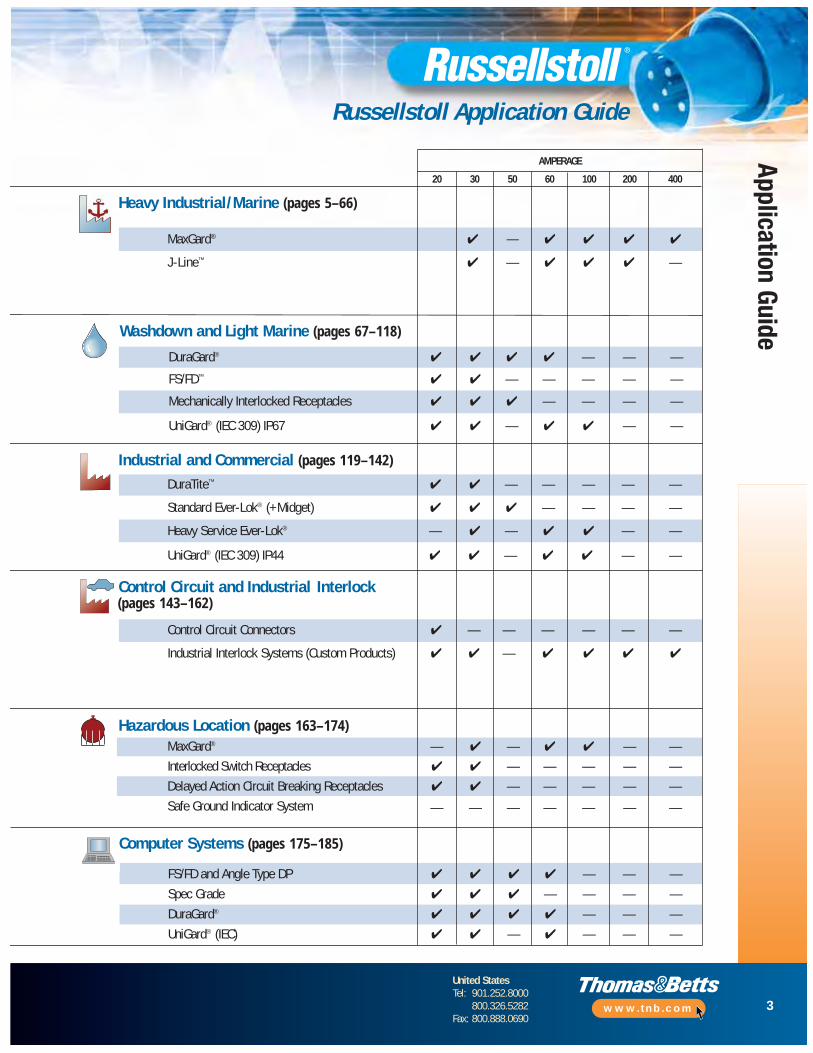
Russellstoll Fax Quote Request FormT&B Russellstoll Specification Project Information: RFQ
Fax QuoteRequest Form
(Copy and Fax)
Regional Office: ______________________________________________ Inquiry Date: __________________________________________
File or Quote (T&B): ______________________________________________ Response Date: __________________________________________
Customer Name: ______________________________________________ Project Contact: __________________________________________
Installation Site: ______________________________________________ Position/Company: __________________________________________
Customer Contact: ______________________________________________ Contact Phone: __________________________________________
Position: ______________________________________________ Contact Fax/Email: __________________________________________
Customer Phone: ______________________________________________ Other: __________________________________________
T&B Rep. and Phone: ______________________________________________ __________________________________________
T&B Rep. Fax/Email: ______________________________________________ __________________________________________
Please fill out as much information as possible; better information makes a better bid!Project Type: (circle) [New/Expanded Facility] [New Equipment] [Competitive Replacement]
Other/Note: ________________________________________________________________________________________________
Specification Definition Information1. Application/Usage or System How used, connectors for…
What is needed or requested?Heavy-duty or standard service?
2. Environment and Operational Indoor or outdoor; Washdown?Chemical, XP or other needsTemperature range service issues
3. Amperage and Voltage Full load motor amps (3 phase?)System amperage or requestNote any DC apps./specials
4. Poles/Wires and Cable XpYw and cable type and O.D.and Control Contacts? Control contacts? And why needed?
Conductor stranding — Superflex?
5. Enclosure Specs and Switched, fused, circuit breakerMounting (Interlocks) NEMA style and cast aluminum/brass
Environmental/usage issues
6. Competitive Issues Competitor ratings or specsList Cat. #’s, quantities, pricesDirect mate or crossover OK?
7. Response Type and Timing Quantities, pricing issuesBudget info or formal quoteProject schedule for bids
8. Other Requirements: Specs or drawings neededIssues or Drawings Other competitive/channel issues
Special colors, coatings, specsAdded device features requests
Fax this form to: 800-888-0690Thanks for specifying Russellstoll: The Maximum in Safety, Durability and Performance!

5
United StatesTel: 901.252.8000
800.326.5282Fax: 800.888.0690
www.tnb.com
Heavy Industrial/Marine
Heavy Industrial/Marine Applications: Outdoor, Severe or High-Abuse Environments
MaxGard® Interconnection Systems
Overview .................................................................................6–11
Competitive Checklist ..................................................................12
Catalog Numbering System .........................................................13
Load-Breaking Plugs, Receptacles and Connectors — 30 Amp ...................................................14–19
Load-Breaking Plugs, Receptacles and Connectors — 60 Amp ...................................................20–25
Load-Breaking Plugs, Receptacles and Connectors — 100 Amp .................................................26–31
Load-Breaking Plugs, Receptacles and Connectors — 200 Amp .................................................32–37
Load-Breaking Plugs, Receptacles and Connectors — 400 Amp .................................................38–43
Accessories ...........................................................................44–47
Engineering Specifications.....................................................48–49
Voltage Selection .........................................................................50
Dimensions............................................................................51–52
Circuit Breakers ...........................................................................53
J-Line™ Interconnection Systems
Overview ...............................................................................54–57
Plugs, Connectors and Receptacles .......................................58–59
Construction ................................................................................60
Dimensions............................................................................61–62
Accessories ...........................................................................63–65

6
United StatesTel: 901.252.8000
800.326.5282Fax: 800.888.0690
www.tnb.com
Heav
y In
dust
rial/M
arin
e —
Max
Gard
®
MaxGard® Interconnection Systems Overview
Defined• Any application where electrical connections need protection from
water and/or dust ingress to contacts or wiring compartment• Cable-to-connector sealing and watertight device locking
designs are critical
• Metal connectors are usually preferred for long service life
Russellstoll Line Selections for Outdoor(and Indoor) Applications
The widest range and toughest construction. Safety, durability and performanceby design in copper-free, cast aluminum, epoxy powder-coated housings.Built to last, from 30 through 400 amp application, with a full interlock line,too. Optional 2-control contacts and more than 200 individual voltagepolarization options through 600VAC/250VDC, 4P5W. O-ringed sealed pins, sleeves and interiors.
MaxGard®
4P5W + 2 Opt.30 through 400A
MarineLighting SystemsShore-to-Ship PowerWelding StationsPower Distribution CentersShipboard Power OutletsBarge Power Connection
Construction and AgriculturalGenerator Sets and SystemsPortable Tools and EquipmentIrrigation Systems PanelsPortable Lighting and Equipment
Government Municipal and UtilitiesPortable Building PowerArmy Corps of EngineersUtilities PanelsEmergency Power SystemsSewage Pumping StationsLight and ControlsTelephone Vault SystemsCellular Telephone Masts
OEMsGenSet and Welding SystemsTransportable Equipment
Typical Application Groups
7
United StatesTel: 901.252.8000
800.326.5282Fax: 800.888.0690
www.tnb.com
Heavy Industrial/Marine —
MaxGard
®
MaxGard® Interconnection Systems Overview
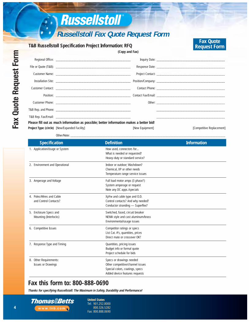
30A–400A (30–200A Load Breaking), Maximum 600VAC/250VDCReceptacles, Inlets, Plugs, Connectors, Interlocked Receptacles, Explosion-Proof Interlocked Receptacles
BenefitsRussellstoll builds a variety of benefits into one plug, receptacle and interlocksystem for your application. The MaxGard system: Maximum Safety,Durability and Performance in electrical interconnections .
Safety• Waterproof construction: Standard Neoprene O-ringed interior
components provide environ mental separation at the front of each device; they don’t have to be connected together just to be called “watertight”
• Different power supply ratings can’t mix: 24 single-ratedevice polarizations ensure exact voltage, frequency and phasedifferentiation plus a few specials, too. In every current range
• Plugs stay in: Standard delayed action pull and turn withdrawaloffers all plugs an XP rating (30–100 amps). All system componentsuse mating screw collars
• Foreign objects stay out: All receptacles and connectors have a gated rotating disk on the face of the interior, engaged on insertion
Durability• At last — durability: Rugged cast aluminum housings with two
layers of electrostatic epoxy coating are standard, along with stainlesssteel hardware. Available with flap or screw covers. Interiors aremolded from a tough reinforced UL94-V0 thermoset polyester
• The best connections for life: Pins and sleeves are made from CDA 360 and Marine-grade CDA 485 brass; 200 and 400 amp linesare silver-plated as well.
• The most power available in the most pack ages : 30, 60, 100, 200- and 400-amp lines in one system with cast aluminum NEMA 4Xinterlocks; steel 30, 60 and 100 amp NEMA 12 interlocks or castaluminum XP interlocks in 30, 60 and 100 amp ranges
Performance• Any configuration you need: Through 4-pole 5-wire configurations,
all have a safety center earth ground pin design that makes first andbreaks last. This applies to all of our plugs, connectors, receptacles,male inlets and interlock systems
• More control available: Two optional pilot/control pins for contactors,load monitor circuits, shunt trip or any other communication functionsyou need
• Ease of assembly: Solderless pressure-type screw terminals with hex socket heads and rear-access, take-apart housings provide quickwiring access. No interior removal required for wiring receptacles and connectors
• More power: 150% non-UL ratings allow extending MaxGardinstallations to 600 amp custom loads, with separate disconnect service
8
United StatesTel: 901.252.8000
800.326.5282Fax: 800.888.0690
www.tnb.com
Heav
y In
dust
rial/M
arin
e —
Max
Gard
®
MaxGard® Interconnection Systems Overview
30A–400A (30–200A Load Breaking), Maximum 600VAC/250VDC Receptacles, Inlets, Plugs, Connectors, Interlocked Receptacles, Explosion-Proof Interlocked Receptacles
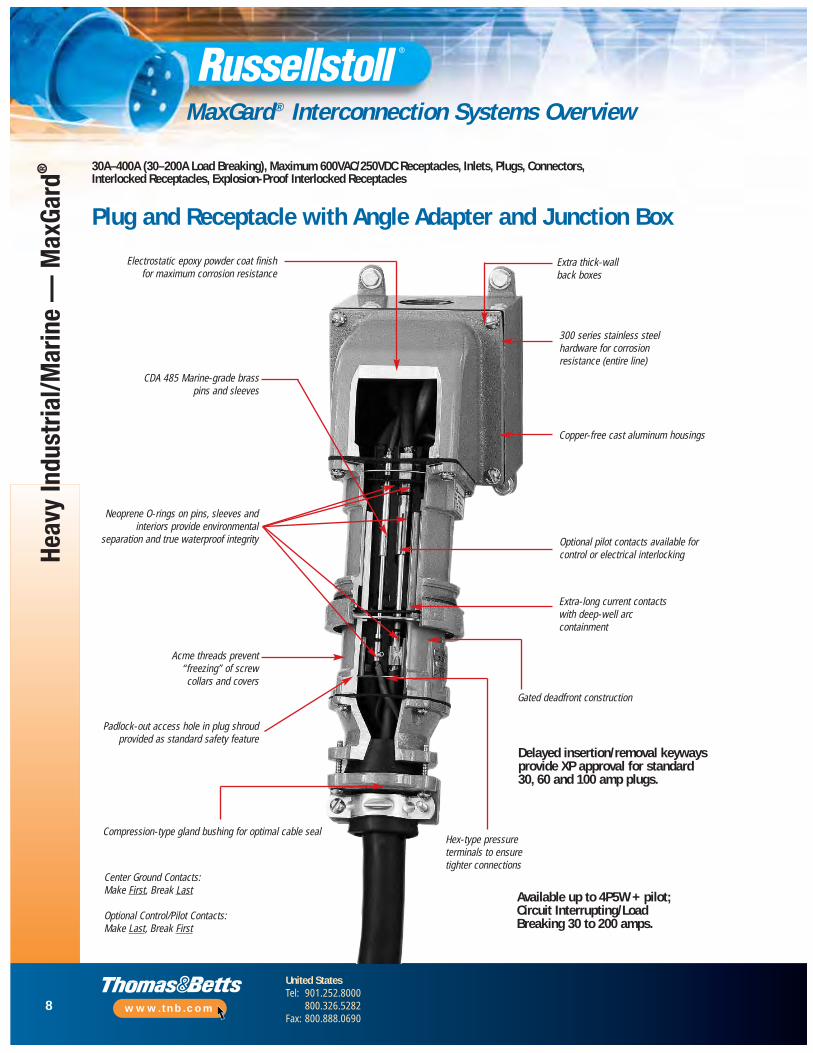
Plug and Receptacle with Angle Adapter and Junction Box
Electrostatic epoxy powder coat finishfor maximum corrosion resistance
CDA 485 Marine-grade brass pins and sleeves
Neoprene O-rings on pins, sleeves andinteriors provide environmental
separation and true waterproof integrity
Acme threads prevent“freezing ” of screw collars and covers
Padlock-out access hole in plug shroudprovided as standard safety feature
Compression-type gland bushing for optimal cable seal
Center Ground Contacts:Make First, Break Last
Optional Control/Pilot Contacts:Make Last, Break First
Extra thick-wallback boxes
300 series stainless steelhardware for corrosion resistance (entire line)
Copper-free cast aluminum housings
Optional pilot contacts available forcontrol or electrical interlocking
Extra-long current contacts with deep-well arccontainment
Gated deadfront construction
Delayed insertion/removal keywaysprovide XP approval for standard 30, 60 and 100 amp plugs.
Hex-type pressureterminals to ensuretighter connections
Available up to 4P5W + pilot;Circuit Interrupting/LoadBreaking 30 to 200 amps.

9
United StatesTel: 901.252.8000
800.326.5282Fax: 800.888.0690
www.tnb.com
Heavy Industrial/Marine —
MaxGard
®
MaxGard® Interconnection Systems Overview
30A–400A (30–200A Load Breaking), Maximum 600VAC/250VDC Receptacles, Inlets, Plugs, Connectors, Interlocked Receptacles, Explosion-Proof Interlocked Receptacles
Cast Aluminum Circuit Breaker Interlocked Receptacle (Cutaway View)
Thick-wall cast copper-freealuminum housing with
epoxy powder coat finish
NEMA 4X interlocks avail able in 30–400 amp ranges through4P5W, with 2 optional pilot/control contacts.
Heavy On/Off handle adds mechanical-to-electrical interlock function
(External lockoutoption kit available)
Gated, rotating deadfront receptacle
Watertight = Screw cap coverSplashproof = Flap cover
Standard conduit openings through topor side (cutaway shown), optional sizesand locations
Standard, high A/C or NA breaker switch (cutaway shown)
Options include:• Shunt Trip• Auxiliary Switch• Trip Ratings
Heavy-duty sliding bar interlockmechanism (mates with plugpadlock-out access hole)
Protective screw cap (flap cap also available)
10
United StatesTel: 901.252.8000
800.326.5282Fax: 800.888.0690
www.tnb.com
Heav
y In
dust
rial/M
arin
e —
Max
Gard
®
MaxGard® Interconnection Systems Overview
30A–400A (30–200A Load Breaking), Maximum 600VAC/250VDCReceptacles, Inlets, Plugs, Connectors, Interlocked Receptacles, Explosion-Proof Interlocked Receptacles
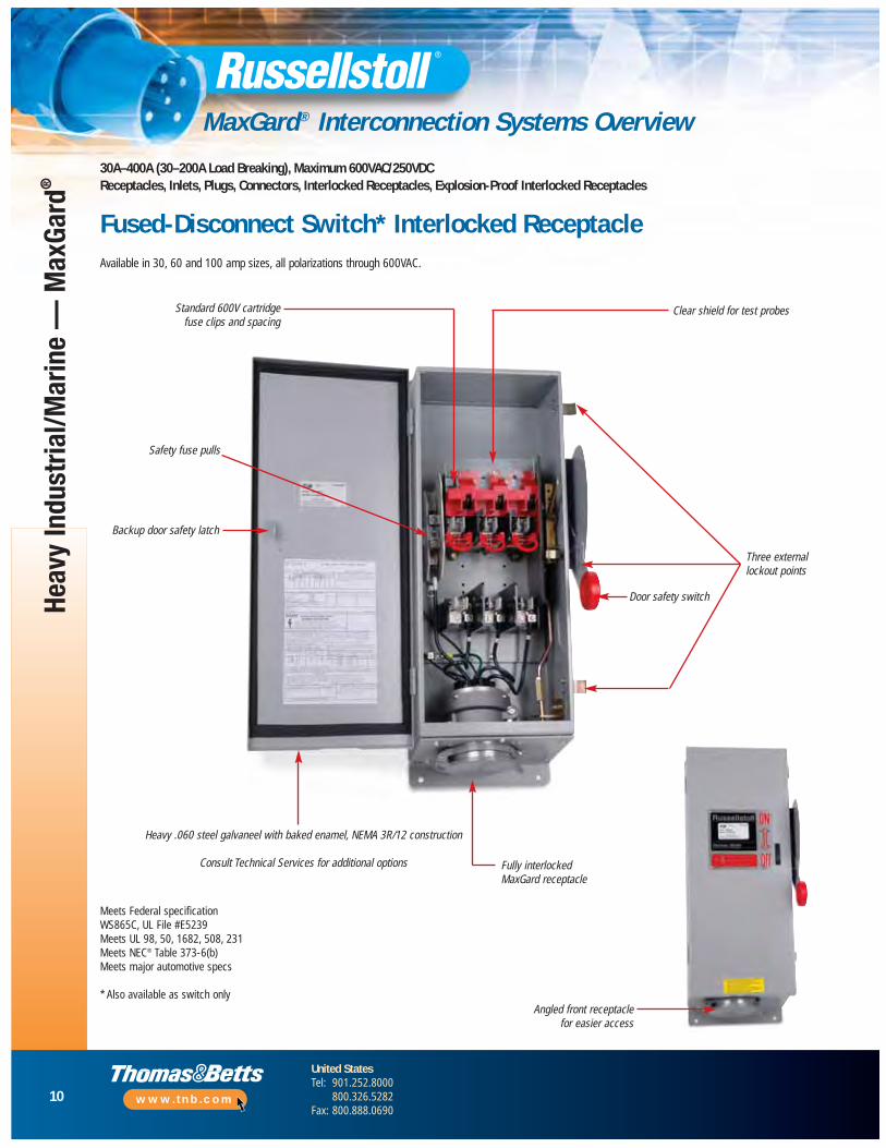
Fused-Disconnect Switch* Interlocked ReceptacleAvailable in 30, 60 and 100 amp sizes, all polarizations through 600VAC.
Standard 600V cartridge fuse clips and spacing
Clear shield for test probes
Three externallockout points
Door safety switch
Backup door safety latch
Heavy .060 steel galvaneel with baked enamel, NEMA 3R/12 construction
Consult Technical Services for additional options Fully interlockedMaxGard receptacle
Safety fuse pulls
Angled front receptacle for easier access
Meets Federal specificationWS865C, UL File #E5239Meets UL 98, 50, 1682, 508, 231Meets NEC® Table 373-6(b)Meets major automotive specs
* Also available as switch only
11
United StatesTel: 901.252.8000
800.326.5282Fax: 800.888.0690
www.tnb.com
Heavy Industrial/Marine —
MaxGard
®
MaxGard® Interconnection Systems Overview
30A–400A (30–200A Load Breaking), Maximum 600VAC/250VDCReceptacles, Inlets, Plugs, Connectors, Interlocked Receptacles, Explosion-Proof Interlocked Receptacles
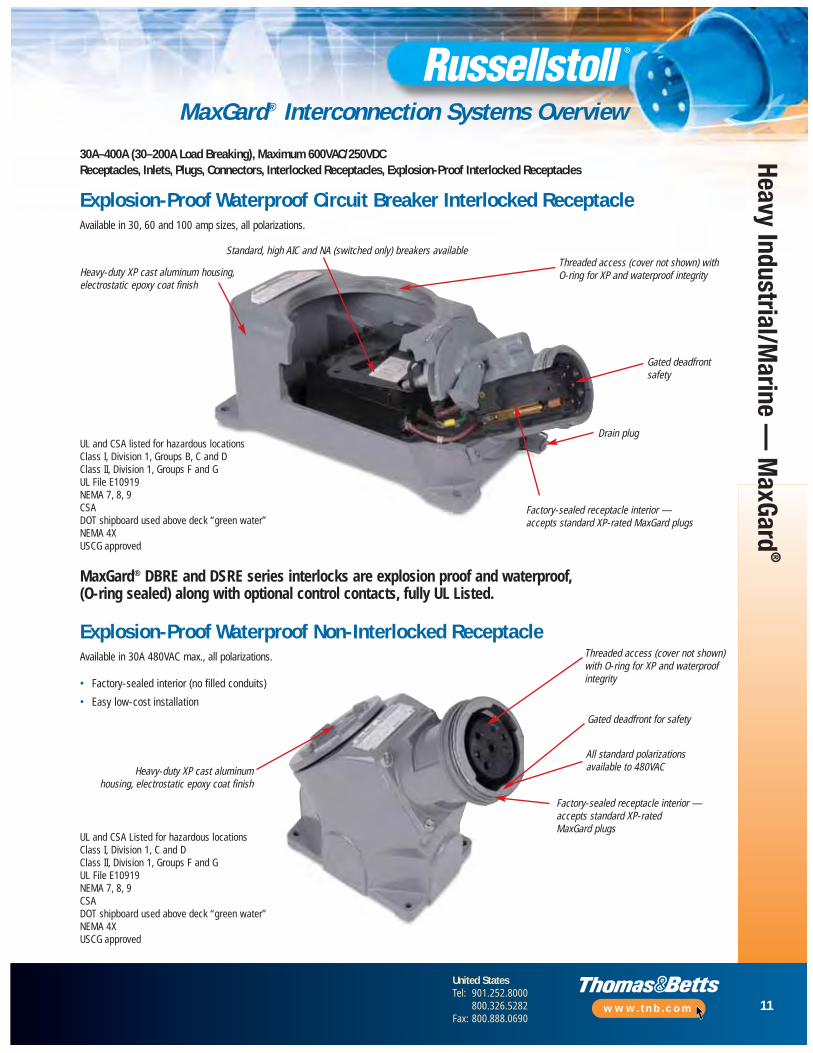
Explosion-Proof Waterproof Circuit Breaker Interlocked ReceptacleAvailable in 30, 60 and 100 amp sizes, all polarizations.
MaxGard® DBRE and DSRE series interlocks are explosion proof and waterproof, (O-ring sealed) along with optional control contacts, fully UL Listed.
Heavy-duty XP cast aluminum housing,electrostatic epoxy coat finish
Standard, high AIC and NA (switched only) breakers availableThreaded access (cover not shown) withO-ring for XP and waterproof integrity
Gated deadfrontsafety
Drain plug
Explosion-Proof Waterproof Non-Interlocked ReceptacleAvailable in 30A 480VAC max., all polarizations.
Heavy-duty XP cast aluminum housing, electrostatic epoxy coat finish
Threaded access (cover not shown)with O-ring for XP and waterproofintegrity
Gated deadfront for safety
All standard polarizations available to 480VAC
Factory-sealed receptacle interior —accepts standard XP-rated MaxGard plugs
UL and CSA Listed for hazardous locationsClass I, Division 1, C and DClass II, Division 1, Groups F and GUL File E10919NEMA 7, 8, 9CSADOT shipboard used above deck “green water”NEMA 4XUSCG approved
• Factory-sealed interior (no filled conduits)
• Easy low-cost installation
Factory-sealed receptacle interior — accepts standard XP-rated MaxGard plugs
UL and CSA listed for hazardous locationsClass I, Division 1, Groups B, C and DClass II, Division 1, Groups F and GUL File E10919NEMA 7, 8, 9CSADOT shipboard used above deck “green water”NEMA 4XUSCG approved
12
United StatesTel: 901.252.8000
800.326.5282Fax: 800.888.0690
www.tnb.com
Heav
y In
dust
rial/M
arin
e —
Max
Gard
®
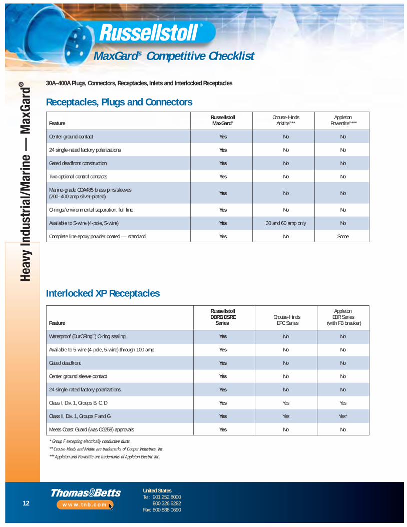
MaxGard® Competitive Checklist
30A–400A Plugs, Connectors, Receptacles, Inlets and Interlocked Receptacles
Receptacles, Plugs and ConnectorsRussellstoll Crouse-Hinds Appleton
Feature MaxGard® Arktite®** Powertite®***
Center ground contact Yes No No
24 single-rated factory polarizations Yes No No
Gated deadfront construction Yes No No
Two optional control contacts Yes No No
Marine-grade CDA485 brass pins/sleevesYes No No
(200–400 amp silver-plated)
O-rings/environmental separation, full line Yes No No
Available to 5-wire (4-pole, 5-wire) Yes 30 and 60 amp only No
Complete line epoxy powder coated — standard Yes No Some
Interlocked XP Receptacles
Russellstoll AppletonDBRE/DSRE Crouse-Hinds EBR Series
Feature Series EPC Series (with FB breaker)
Waterproof (DurORing™) O-ring sealing Yes No No
Available to 5-wire (4-pole, 5-wire) through 100 amp Yes No No
Gated deadfront Yes No No
Center ground sleeve contact Yes No No
24 single-rated factory polarizations Yes No No
Class I, Div. 1, Groups B, C, D Yes Yes Yes
Class II, Div. 1, Groups F and G Yes Yes Yes*
Meets Coast Guard (was CG259) approvals Yes No No
* Group F excepting electrically conductive dusts
** Crouse-Hinds and Arktite are trademarks of Cooper Industries, Inc.
*** Appleton and Powertite are trademarks of Appleton Electric Inc.
13
United StatesTel: 901.252.8000
800.326.5282Fax: 800.888.0690
www.tnb.com
Heavy Industrial/Marine —
MaxGard
®
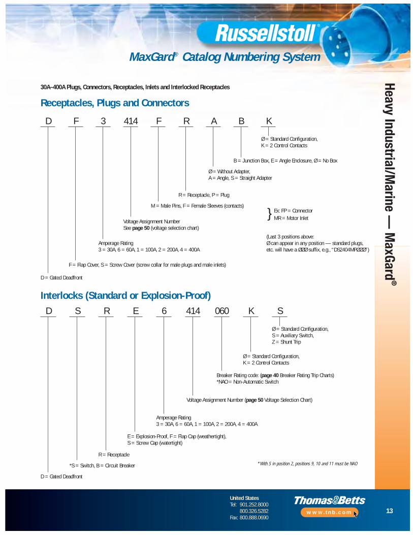
MaxGard® Catalog Numbering System
30A–400A Plugs, Connectors, Receptacles, Inlets and Interlocked Receptacles
Receptacles, Plugs and Connectors
D F 3 414 F R A B K
Ø = Standard Configuration,K = 2 Control Contacts
B = Junction Box, E = Angle Enclosure, Ø = No Box
Ø = Without Adapter,A = Angle, S = Straight Adapter
R = Receptacle, P = Plug
M = Male Pins, F = Female Sleeves (contacts)
Voltage Assignment NumberSee page 50 (voltage selection chart)
Amperage Rating3 = 30A, 6 = 60A, 1 = 100A, 2 = 200A, 4 = 400A
F = Flap Cover, S = Screw Cover (screw collar for male plugs and male inlets)
D = Gated Deadfront
} Ex: FP = Connector MR = Motor Inlet
(Last 3 positions above: Ø can appear in any position — standard plugs,etc. will have a ØØØ suffix, e.g., “DS2404MPØØØ”)
Interlocks (Standard or Explosion-Proof)D S R E 6 414 060 K S
Ø = Standard Configuration,S = Auxiliary Switch,Z = Shunt Trip
Ø = Standard Configuration,K = 2 Control Contacts
Breaker Rating code: (page 40 Breaker Rating Trip Charts)*NAO = Non-Automatic Switch
Voltage Assignment Number (page 50 Voltage Selection Chart)
Amperage Rating3 = 30A, 6 = 60A, 1 = 100A, 2 = 200A, 4 = 400A
E = Explosion-Proof, F = Flap Cap (weathertight),S = Screw Cap (watertight)
R = Receptacle
*S = Switch, B = Circuit Breaker
D = Gated Deadfront
* With S in position 2, positions 9, 10 and 11 must be NAO
14
United StatesTel: 901.252.8000
800.326.5282Fax: 800.888.0690
www.tnb.com
Heav
y In
dust
rial/M
arin
e —
Max
Gard
®
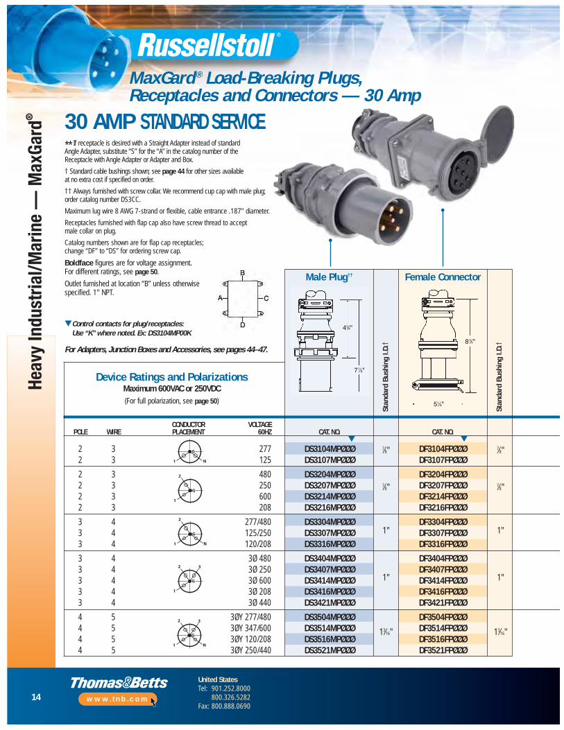
MaxGard ® Load-Breaking Plugs, Receptacles and Connectors — 30 Amp
** If receptacle is desired with a Straight Adapter instead of standard Angle Adapter, substitute “S” for the “A” in the catalog number of the Receptacle with Angle Adapter or Adapter and Box.
† Standard cable bushings shown; see page 44 for other sizes available at no extra cost if specified on order.
†† Always furnished with screw collar. We recommend cup cap with male plug;order catalog number DS3CC.
Maximum lug wire 8 AWG 7-strand or flexible, cable entrance .187" diameter.
Receptacles furnished with flap cap also have screw thread to accept male collar on plug.
Catalog numbers shown are for flap cap receptacles; change “DF” to “DS” for ordering screw cap.
Boldface figures are for voltage assignment. For different ratings, see page 50.
Outlet furnished at location “B” unless otherwisespecified. 1" NPT.
▼Control contacts for plug/receptacles: Use “K” where noted. Ex: DS3104MP00K
For Adapters, Junction Boxes and Accessories, see pages 44–47.
CONDUCTOR VOLTAGEPOLE WIRE PLACEMENT 60HZ CAT. NO. CAT. NO.
2 3 277 DS3104MPØØØ DF3104FPØØØ2 3 125 DS3107MPØØØ DF3107FPØØØ
2 3 480 DS3204MPØØØ DF3204FPØØØ2 3 250 DS3207MPØØØ DF3207FPØØØ2 3 600 DS3214MPØØØ DF3214FPØØØ2 3 208 DS3216MPØØØ DF3216FPØØØ
3 4 277/480 DS3304MPØØØ DF3304FPØØØ3 4 125/250 DS3307MPØØØ DF3307FPØØØ3 4 120/208 DS3316MPØØØ DF3316FPØØØ
3 4 3Ø 480 DS3404MPØØØ DF3404FPØØØ3 4 3Ø 250 DS3407MPØØØ DF3407FPØØØ3 4 3Ø 600 DS3414MPØØØ DF3414FPØØØ3 4 3Ø 208 DS3416MPØØØ DF3416FPØØØ3 4 3Ø 440 DS3421MPØØØ DF3421FPØØØ
4 5 3ØY 277/480 DS3504MPØØØ DF3504FPØØØ4 5 3ØY 347/600 DS3514MPØØØ DF3514FPØØØ4 5 3ØY 120/208 DS3516MPØØØ DF3516FPØØØ4 5 3ØY 250/440 DS3521MPØØØ DF3521FPØØØ
Male Plug††
Stan
dard
Bus
hing
I.D.
†
Stan
dard
Bus
hing
I.D.
†Device Ratings and Polarizations
Maximum 600VAC or 250VDC(For full polarization, see page 50)
G
N1
G
1
2
G
N1
2
G
1
2 3
G
N1
2 3
▼ ▼7⁄8"
7⁄8"
1"
1"
13⁄16"
Female Connector
43⁄4"
77⁄8"
83⁄4"
51⁄8"
30 AMP STANDARD SERVICE
7⁄8"
7⁄8"
1"
1"
13⁄16"
15
United StatesTel: 901.252.8000
800.326.5282Fax: 800.888.0690
www.tnb.com
Heavy Industrial/Marine —
MaxGard
®
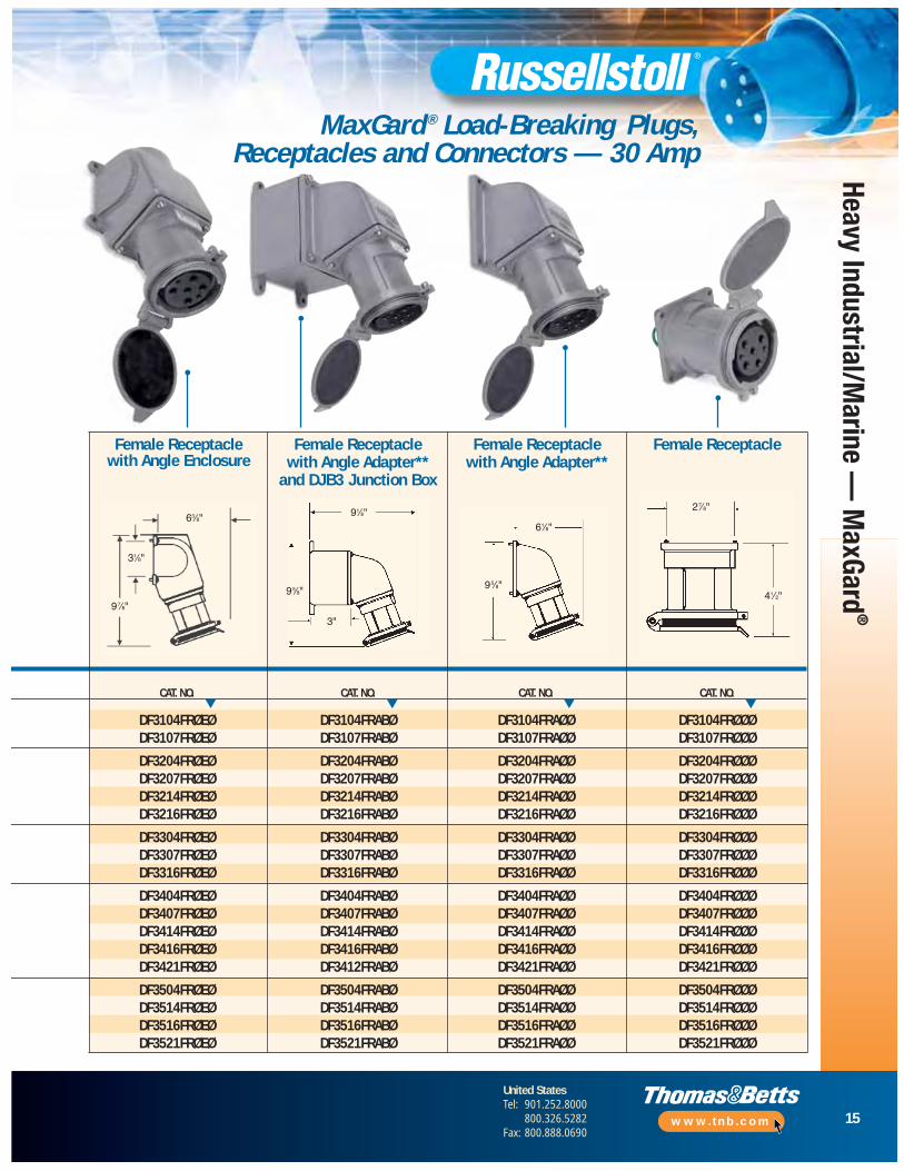
MaxGard ® Load-Breaking Plugs, Receptacles and Connectors — 30 Amp
CAT. NO. CAT. NO. CAT. NO. CAT. NO.
DF3104FRØEØ DF3104FRABØ DF3104FRAØØ DF3104FRØØØDF3107FRØEØ DF3107FRABØ DF3107FRAØØ DF3107FRØØØ
DF3204FRØEØ DF3204FRABØ DF3204FRAØØ DF3204FRØØØDF3207FRØEØ DF3207FRABØ DF3207FRAØØ DF3207FRØØØDF3214FRØEØ DF3214FRABØ DF3214FRAØØ DF3214FRØØØDF3216FRØEØ DF3216FRABØ DF3216FRAØØ DF3216FRØØØ
DF3304FRØEØ DF3304FRABØ DF3304FRAØØ DF3304FRØØØDF3307FRØEØ DF3307FRABØ DF3307FRAØØ DF3307FRØØØDF3316FRØEØ DF3316FRABØ DF3316FRAØØ DF3316FRØØØ
DF3404FRØEØ DF3404FRABØ DF3404FRAØØ DF3404FRØØØDF3407FRØEØ DF3407FRABØ DF3407FRAØØ DF3407FRØØØDF3414FRØEØ DF3414FRABØ DF3414FRAØØ DF3414FRØØØDF3416FRØEØ DF3416FRABØ DF3416FRAØØ DF3416FRØØØDF3421FRØEØ DF3412FRABØ DF3421FRAØØ DF3421FRØØØ
DF3504FRØEØ DF3504FRABØ DF3504FRAØØ DF3504FRØØØDF3514FRØEØ DF3514FRABØ DF3514FRAØØ DF3514FRØØØDF3516FRØEØ DF3516FRABØ DF3516FRAØØ DF3516FRØØØDF3521FRØEØ DF3521FRABØ DF3521FRAØØ DF3521FRØØØ
Female ReceptacleFemale Receptacle with Angle Enclosure
Female Receptacle with Angle Adapter**
and DJB3 Junction Box
Female Receptacle with Angle Adapter**
▼ ▼ ▼ ▼
63⁄8"
31⁄8"
91⁄8"61⁄8"
27⁄8"
41⁄2"95⁄8"
95⁄8"
3"
97⁄8"
16
United StatesTel: 901.252.8000
800.326.5282Fax: 800.888.0690
www.tnb.com
Heav
y In
dust
rial/M
arin
e —
Max
Gard
®
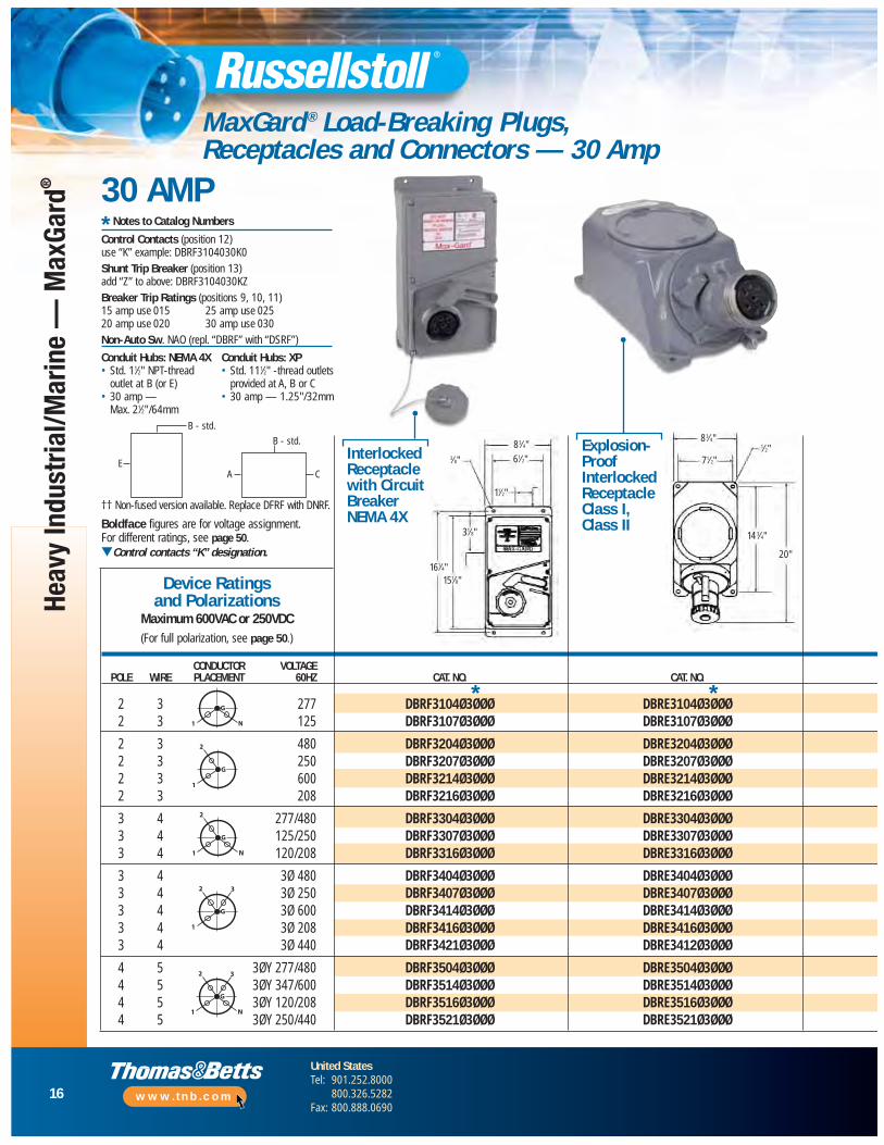
MaxGard ® Load-Breaking Plugs, Receptacles and Connectors — 30 Amp
†† Non-fused version available. Replace DFRF with DNRF.
Boldface figures are for voltage assignment. For different ratings, see page 50.▼Control contacts “K” designation.
CONDUCTOR VOLTAGEPOLE WIRE PLACEMENT 60HZ CAT. NO. CAT. NO.
2 3 277 DBRF3104Ø3ØØØ DBRE3104Ø3ØØØ2 3 125 DBRF3107Ø3ØØØ DBRE3107Ø3ØØØ
2 3 480 DBRF3204Ø3ØØØ DBRE3204Ø3ØØØ2 3 250 DBRF3207Ø3ØØØ DBRE3207Ø3ØØØ2 3 600 DBRF3214Ø3ØØØ DBRE3214Ø3ØØØ2 3 208 DBRF3216Ø3ØØØ DBRE3216Ø3ØØØ
3 4 277/480 DBRF3304Ø3ØØØ DBRE3304Ø3ØØØ3 4 125/250 DBRF3307Ø3ØØØ DBRE3307Ø3ØØØ3 4 120/208 DBRF3316Ø3ØØØ DBRE3316Ø3ØØØ
3 4 3Ø 480 DBRF3404Ø3ØØØ DBRE3404Ø3ØØØ3 4 3Ø 250 DBRF3407Ø3ØØØ DBRE3407Ø3ØØØ3 4 3Ø 600 DBRF3414Ø3ØØØ DBRE3414Ø3ØØØ3 4 3Ø 208 DBRF3416Ø3ØØØ DBRE3416Ø3ØØØ3 4 3Ø 440 DBRF3421Ø3ØØØ DBRE3412Ø3ØØØ
4 5 3ØY 277/480 DBRF3504Ø3ØØØ DBRE3504Ø3ØØØ4 5 3ØY 347/600 DBRF3514Ø3ØØØ DBRE3514Ø3ØØØ4 5 3ØY 120/208 DBRF3516Ø3ØØØ DBRE3516Ø3ØØØ4 5 3ØY 250/440 DBRF3521Ø3ØØØ DBRE3521Ø3ØØØ
Device Ratings and Polarizations
Maximum 600VAC or 250VDC(For full polarization, see page 50.)
InterlockedReceptaclewith CircuitBreakerNEMA 4X
Explosion-ProofInterlockedReceptacle Class I, Class II
G
N1
G
1
2
G
N1
2
G
1
2 3
G
N1
2 3
Conduit Hubs: NEMA 4X• Std. 11⁄2" NPT-thread
outlet at B (or E)• 30 amp —
Max. 21⁄2"/64mm
Conduit Hubs: XP• Std. 111⁄2" -thread outlets
provided at A, B or C• 30 amp — 1.25"/32mm
* Notes to Catalog Numbers
Control Contacts (position 12) use “K” example: DBRF3104030K0Shunt Trip Breaker (position 13) add “Z” to above: DBRF3104030KZBreaker Trip Ratings (positions 9, 10, 11) 15 amp use 015 25 amp use 02520 amp use 020 30 amp use 030Non-Auto Sw. NAO (repl. “DBRF” with “DSRF”)
B - std.
E
B - std.
A C
30 AMP
83⁄4"83⁄4"
14 3⁄4"
20"
71⁄2"
1⁄2"61⁄2"
11⁄2"
31⁄8"
151⁄8"161⁄4"
3⁄8"
* *

17
United StatesTel: 901.252.8000
800.326.5282Fax: 800.888.0690
www.tnb.com
Heavy Industrial/Marine —
MaxGard
®
MaxGard ® Load-Breaking Plugs, Receptacles and Connectors — 30 Amp
CAT. NO. CAT. NO.
DFRF3104Ø DSE3104FRØDFRF3107Ø DSE3107FRØ
DFRF3204Ø DSE3204FRØDFRF3207Ø DSE3207FRØDFRF3214Ø DSE3214FRØDFRF3216Ø DSE3216FRØ
DFRF3304Ø DSE3304FRØDFRF3307Ø DSE3307FRØDFRF3316Ø DSE3316FRØ
DFRF3404Ø DSE3404FRØDFRF3407Ø DSE3407FRØDFRF3414Ø DSE3414FRØDFRF3416Ø DSE3416FRØDFRF3421Ø DSE3421FRØ
DFRF3504Ø DSE3504FRØDFRF3514Ø DSE3514FRØDFRF3516Ø DSE3516FRØDFRF3521Ø DSE3521FRØ
Fused††
DisconnectInterlockedReceptacle NEMA 12/3R
▼ ▼
Application:Dulles International Airport “People Mover.”“People Movers” are used at Dulles for shuttlingpassengers from check-in to mid-field terminalsto board their flight. These vehicles require airconditioning and heater unit power when dockedat either location for maintenance and overhaul.
Installation:Vehicle-mounted 30 amp male inlet with mating connector and two control contacts.MaxGard® receptacles, plugs and connectorswere specified for their safety, constructiondurability needed to withstand frequentreconnections. The single-rated factorypolarization also ensured built-in protectionagainst unsafe hookups. The control contactsoffer monitoring capabilities for the vehicle while being overhauled. Deep insulatingchambers confine and snuff out arcing whenremoving devices under load. Maintenance costs are minimal due to self-cleaning pin and sleeve contact design, rear-loaded interiorwiring access and quick pressure-screw typewiring terminals.
solution30 AMP11.35"
10.16"
1.50"
Conduit Location “B”
ConduitLocation “A”
Conduit Location “D”ConduitLocation “C”
7.26"
7.03"
4.00 Mtg.
Ø.284 PLS
91⁄2"
253⁄4" 25"
Fasteners Screws(2 places)
Access Cover to Pigtails for Wiring
Holes for Padlock(2 places)
71⁄2"
23⁄16"
30"
223⁄4"
3⁄4"
Explosion-Proof Non-InterlockedReceptacle
Male Plug††

18
United StatesTel: 901.252.8000
800.326.5282Fax: 800.888.0690
www.tnb.com
Heav
y In
dust
rial/M
arin
e —
Max
Gard
®
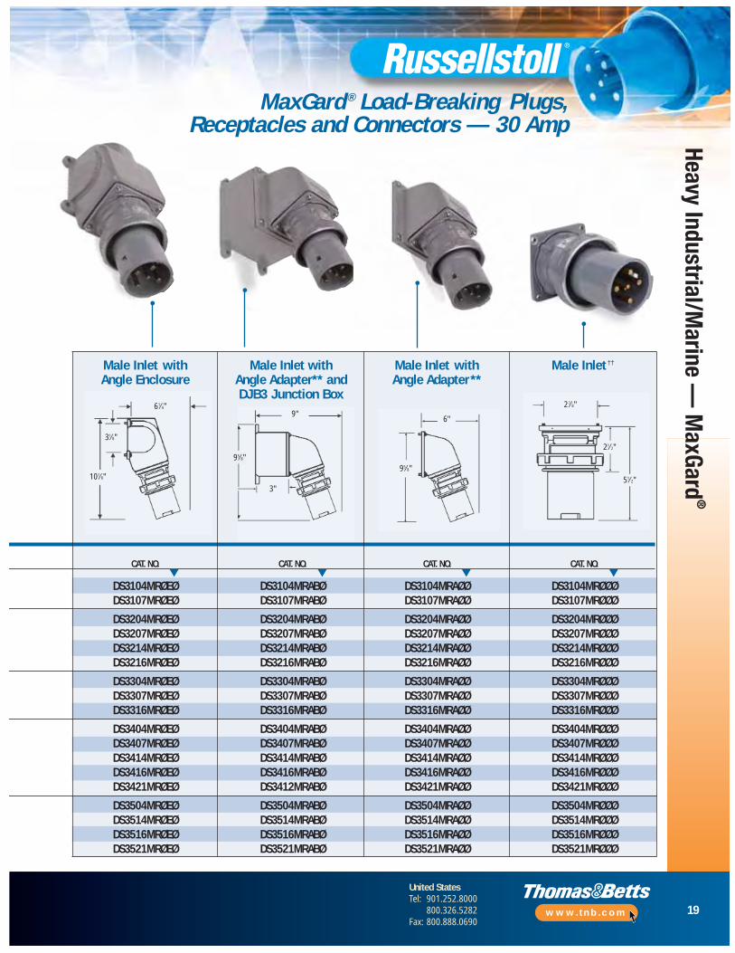
MaxGard ® Load-Breaking Plugs, Receptacles and Connectors — 30 Amp
83⁄4"
51⁄8"
▼Control contacts for plug/receptacles: Use “K” where noted. Ex: DS3104MR00K
For Adapters, Junction Boxes and Accessories, see pages 44–47.
CONDUCTOR VOLTAGEPOLE WIRE PLACEMENT 60HZ CAT. NO. CAT. NO.
2 3 277 DF3104FPØØØ DS3104MPØØØ2 3 125 DF3107FPØØØ DS3107MPØØØ
2 3 480 DF3204FPØØØ DS3204MPØØØ2 3 250 DF3207FPØØØ DS3207MPØØØ2 3 600 DF3214FPØØØ DS3214MPØØØ2 3 208 DF3216FPØØØ DS3216MPØØØ
3 4 277/480 DF3304FPØØØ DS3304MPØØØ3 4 125/250 DF3307FPØØØ DS3307MPØØØ3 4 120/208 DF3316FPØØØ DS3316MPØØØ
3 4 3Ø 480 DF3404FPØØØ DS3404MPØØØ3 4 3Ø 250 DF3407FPØØØ DS3407MPØØØ3 4 3Ø 600 DF3414FPØØØ DS3414MPØØØ3 4 3Ø 208 DF3416FPØØØ DS3416MPØØØ3 4 3Ø 440 DF3421FPØØØ DS3421MPØØØ
4 5 3ØY 277/480 DF3504FPØØØ DS3504MPØØØ4 5 3ØY 347/600 DF3514FPØØØ DS3514MPØØØ4 5 3ØY 120/208 DF3516FPØØØ DS3516MPØØØ4 5 3ØY 250/440 DF3521FPØØØ DS3521MPØØØ
Stan
dard
Bus
hing
I.D.
†
Stan
dard
Bus
hing
I.D.
†Device Ratings and Polarizations
Maximum 600VAC or 250VDC(For full polarization, see page 50)
G
N1
G
1
2
G
N1
2
G
1
2 3
G
N1
2 3
▼ ▼
7⁄8"
7⁄8"
1"
1"
13⁄16"
30 AMP REVERSE SERVICE
Male Plug††Female Connector
43⁄4"
** If receptacle is desired with a Straight Adapter instead of standard Angle Adapter, substitute “S” for the “A” in the catalog number of the Receptacle with Angle Adapter or Adapter and Box.
† Standard cable bushings shown; see page 44 for other sizes available at no extra cost if specified on order.
†† Always furnished with screw collar. We recommend cup cap with male plug; order catalog number DS3CC.
Maximum lug wire 4 AWG 7-strand or flexible, cable entrance .187" diameter.
Receptacles furnished with flap cap also have screw thread to accept male collar on plug.
Catalog numbers shown are for flap cap receptacles; change “DF” to “DS” for ordering screw cap.
Boldface figures are for voltage assignment. For different ratings, see page 50.
Outlet furnished at location “B” unless otherwise specified. 1" NPT.
7⁄8"
7⁄8"
1"
1"
13⁄16"
19
United StatesTel: 901.252.8000
800.326.5282Fax: 800.888.0690
www.tnb.com
Heavy Industrial/Marine —
MaxGard
®
MaxGard ® Load-Breaking Plugs, Receptacles and Connectors — 30 Amp
CAT. NO. CAT. NO. CAT. NO. CAT. NO.
DS3104MRØEØ DS3104MRABØ DS3104MRAØØ DS3104MRØØØDS3107MRØEØ DS3107MRABØ DS3107MRAØØ DS3107MRØØØ
DS3204MRØEØ DS3204MRABØ DS3204MRAØØ DS3204MRØØØDS3207MRØEØ DS3207MRABØ DS3207MRAØØ DS3207MRØØØDS3214MRØEØ DS3214MRABØ DS3214MRAØØ DS3214MRØØØDS3216MRØEØ DS3216MRABØ DS3216MRAØØ DS3216MRØØØ
DS3304MRØEØ DS3304MRABØ DS3304MRAØØ DS3304MRØØØDS3307MRØEØ DS3307MRABØ DS3307MRAØØ DS3307MRØØØDS3316MRØEØ DS3316MRABØ DS3316MRAØØ DS3316MRØØØ
DS3404MRØEØ DS3404MRABØ DS3404MRAØØ DS3404MRØØØDS3407MRØEØ DS3407MRABØ DS3407MRAØØ DS3407MRØØØDS3414MRØEØ DS3414MRABØ DS3414MRAØØ DS3414MRØØØDS3416MRØEØ DS3416MRABØ DS3416MRAØØ DS3416MRØØØDS3421MRØEØ DS3412MRABØ DS3421MRAØØ DS3421MRØØØ
DS3504MRØEØ DS3504MRABØ DS3504MRAØØ DS3504MRØØØDS3514MRØEØ DS3514MRABØ DS3514MRAØØ DS3514MRØØØDS3516MRØEØ DS3516MRABØ DS3516MRAØØ DS3516MRØØØDS3521MRØEØ DS3521MRABØ DS3521MRAØØ DS3521MRØØØ
▼ ▼ ▼ ▼
Male Inlet ††Male Inlet with Angle Enclosure
Male Inlet with Angle Adapter** andDJB3 Junction Box
Male Inlet with Angle Adapter**
31⁄8"
9"6"
27⁄8"
51⁄2"
21⁄2"
95⁄8"
3"
107⁄8"
61⁄4"
95⁄8"
20
United StatesTel: 901.252.8000
800.326.5282Fax: 800.888.0690
www.tnb.com
Heav
y In
dust
rial/M
arin
e —
Max
Gard
®
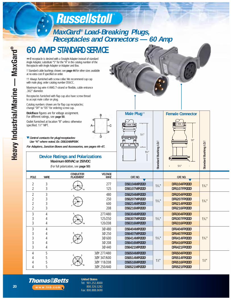
MaxGard ® Load-Breaking Plugs, Receptacles and Connectors — 60 Amp
** If receptacle is desired with a Straight Adapter instead of standard Angle Adapter, substitute “S” for the “A” in the catalog number of the Receptacle with Angle Adapter or Adapter and Box.
† Standard cable bushings shown; see page 44 for other sizes available at no extra cost if specified on order.
†† Always furnished with screw collar. We recommend cup cap with male plug; order catalog number DS6CC.
Maximum lug wire 4 AWG 7-strand or flexible, cable entrance .302" diameter.
Receptacles furnished with flap cap also have screw thread to accept male collar on plug.
Catalog numbers shown are for flap cap receptacles; change “DF” to “DS” for ordering screw cap.
Boldface figures are for voltage assignment. For different ratings, see page 50.
Outlet furnished at location “B” unless otherwisespecified. 11⁄2" NPT.
▼Control contacts for plug/receptacles: Use “K” where noted. Ex: DS6104MP00K
For Adapters, Junction Boxes and Accessories, see pages 44–47.
CONDUCTOR VOLTAGEPOLE WIRE PLACEMENT 60HZ CAT. NO. CAT. NO.
2 3 277 DS6104MPØØØ DF6104FPØØØ2 3 125 DS6107MPØØØ DF6107FPØØØ
2 3 480 DS6204MPØØØ DF6204FPØØØ2 3 250 DS6207MPØØØ DF6207FPØØØ2 3 600 DS6214MPØØØ DF6214FPØØØ2 3 208 DS6216MPØØØ DF6216FPØØØ
3 4 277/480 DS6304MPØØØ DF6304FPØØØ3 4 125/250 DS6307MPØØØ DF6307FPØØØ3 4 120/208 DS6316MPØØØ DF6316FPØØØ
3 4 3Ø 480 DS6404MPØØØ DF6404FPØØØ3 4 3Ø 250 DS6407MPØØØ DF6407FPØØØ3 4 3Ø 600 DS6414MPØØØ DF6414FPØØØ3 4 3Ø 208 DS6416MPØØØ DF6416FPØØØ3 4 3Ø 440 DS6421MPØØØ DF6421FPØØØ
4 5 3ØY 277/480 DS6504MPØØØ DF6504FPØØØ4 5 3ØY 347/600 DS6514MPØØØ DF6514FPØØØ4 5 3ØY 118/208 DS6516MPØØØ DF6516FPØØØ4 5 3ØY 250/440 DS6521MPØØØ DF6521FPØØØ
Male Plug ††
Stan
dard
Bus
hing
I.D.
†
Stan
dard
Bus
hing
I.D.
†Device Ratings and Polarizations
Maximum 600VAC or 250VDC(For full polarization, see page 50)
G
N1
G
1
2
G
N1
2
G
1
2 3
G
N1
2 3
▼ ▼
13⁄16"
13⁄16"
15⁄16"
15⁄16"
11⁄2"
13⁄16"
13⁄16"
15⁄16"
15⁄16"
11⁄2"
Female Connector
51⁄2"
91⁄8"
10"
53⁄8"
60 AMP STANDARD SERVICE
21
United StatesTel: 901.252.8000
800.326.5282Fax: 800.888.0690
www.tnb.com
Heavy Industrial/Marine —
MaxGard
®
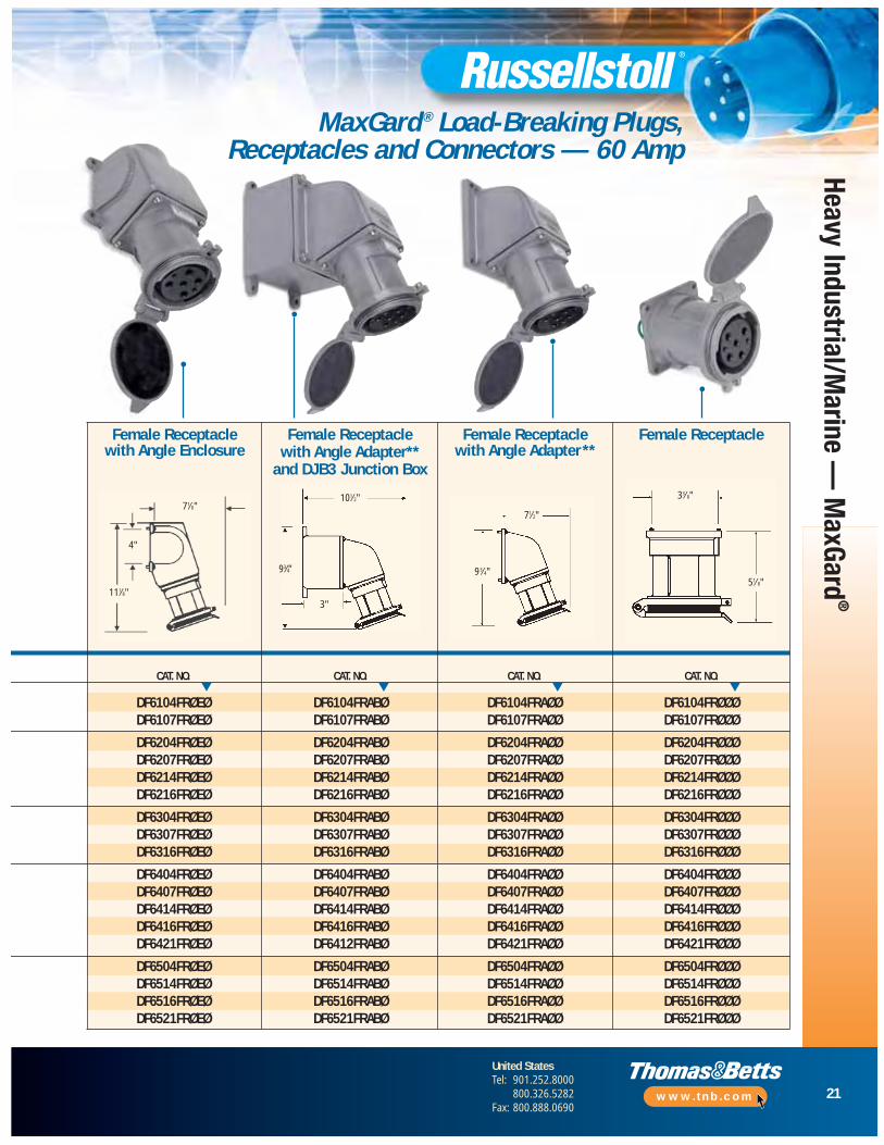
MaxGard ® Load-Breaking Plugs, Receptacles and Connectors — 60 Amp
CAT. NO. CAT. NO. CAT. NO. CAT. NO.
DF6104FRØEØ DF6104FRABØ DF6104FRAØØ DF6104FRØØØDF6107FRØEØ DF6107FRABØ DF6107FRAØØ DF6107FRØØØ
DF6204FRØEØ DF6204FRABØ DF6204FRAØØ DF6204FRØØØDF6207FRØEØ DF6207FRABØ DF6207FRAØØ DF6207FRØØØDF6214FRØEØ DF6214FRABØ DF6214FRAØØ DF6214FRØØØDF6216FRØEØ DF6216FRABØ DF6216FRAØØ DF6216FRØØØ
DF6304FRØEØ DF6304FRABØ DF6304FRAØØ DF6304FRØØØDF6307FRØEØ DF6307FRABØ DF6307FRAØØ DF6307FRØØØDF6316FRØEØ DF6316FRABØ DF6316FRAØØ DF6316FRØØØ
DF6404FRØEØ DF6404FRABØ DF6404FRAØØ DF6404FRØØØDF6407FRØEØ DF6407FRABØ DF6407FRAØØ DF6407FRØØØDF6414FRØEØ DF6414FRABØ DF6414FRAØØ DF6414FRØØØDF6416FRØEØ DF6416FRABØ DF6416FRAØØ DF6416FRØØØDF6421FRØEØ DF6412FRABØ DF6421FRAØØ DF6421FRØØØ
DF6504FRØEØ DF6504FRABØ DF6504FRAØØ DF6504FRØØØDF6514FRØEØ DF6514FRABØ DF6514FRAØØ DF6514FRØØØDF6516FRØEØ DF6516FRABØ DF6516FRAØØ DF6516FRØØØDF6521FRØEØ DF6521FRABØ DF6521FRAØØ DF6521FRØØØ
Female ReceptacleFemale Receptacle with Angle Enclosure
Female Receptacle with Angle Adapter**
and DJB3 Junction Box
Female Receptacle with Angle Adapter**
▼ ▼ ▼ ▼
71⁄8"
4"
101⁄2"
71⁄2"
33⁄8"
51⁄8"93⁄4"93⁄4"
3"111⁄8"
22
United StatesTel: 901.252.8000
800.326.5282Fax: 800.888.0690
www.tnb.com
Heav
y In
dust
rial/M
arin
e —
Max
Gard
®
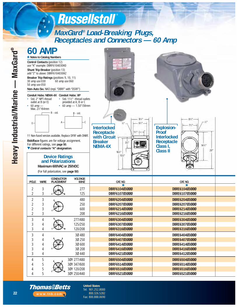
MaxGard ® Load-Breaking Plugs, Receptacles and Connectors — 60 Amp
60 AMP
†† Non-fused version available. Replace DFRF with DNRF.
Boldface figures are for voltage assignment. For different ratings, see page 50.▼Control contacts “K” designation.
Device Ratings and Polarizations
Maximum 600VAC or 250VDC(For full polarization, see page 50)
InterlockedReceptaclewith CircuitBreakerNEMA 4X
Explosion-ProofInterlockedReceptacle Class I, Class II
G
N1
G
1
2
G
N1
2
G
1
2 3
G
N1
2 3
Conduit Hubs: NEMA 4X• Std. 2" NPT-thread
outlet at B (or E)• 60 amp —
Max. 21⁄2"/64mm
Conduit Hubs: XP• Std. 111⁄2" -thread outlets
provided at A, B or C• 60 amp — 1.50"/38mm
* Notes to Catalog Numbers
Control Contacts (position 12) use “K” example: DBRF6104030K0Shunt Trip Breaker (position 13) add “Z” to above: DBRF6104030KZBreaker Trip Ratings (positions 9, 10, 11) 30 amp use 030 60 amp use 06050 amp use 050Non-Auto Sw. NAO (repl. “DBRF” with “DSRF”)
B - std.
E
B - std.
A C83⁄4"
14 3⁄4"
20"
71⁄2"
1⁄2"
G
N1
G
1
2
G
N1
2
G
1
2 3
G
N1
2 3
*
83⁄4"
61⁄2"
11⁄2"
31⁄8"
151⁄8"161⁄4"
3⁄8"
CONDUCTOR VOLTAGEPOLE WIRE PLACEMENT 60HZ CAT. NO. CAT. NO.
2 3 277 DBRF6104Ø3ØØØ DBRE6104Ø3ØØØ2 3 125 DBRF6107Ø3ØØØ DBRE6107Ø3ØØØ
2 3 480 DBRF6204Ø3ØØØ DBRE6204Ø3ØØØ2 3 250 DBRF6207Ø3ØØØ DBRE6207Ø3ØØØ2 3 600 DBRF6214Ø3ØØØ DBRE6214Ø3ØØØ2 3 208 DBRF6216Ø3ØØØ DBRE6216Ø3ØØØ
3 4 277/480 DBRF6304Ø3ØØØ DBRE6304Ø3ØØØ3 4 125/250 DBRF6307Ø3ØØØ DBRE6307Ø3ØØØ3 4 120/208 DBRF6316Ø3ØØØ DBRE6316Ø3ØØØ
3 4 3Ø 480 DBRF6404Ø3ØØØ DBRE6404Ø3ØØØ3 4 3Ø 250 DBRF6407Ø3ØØØ DBRE6407Ø3ØØØ3 4 3Ø 600 DBRF6414Ø3ØØØ DBRE6414Ø3ØØØ3 4 3Ø 208 DBRF6416Ø3ØØØ DBRE6416Ø3ØØØ3 4 3Ø 440 DBRF6421Ø3ØØØ DBRE6412Ø3ØØØ
4 5 3ØY 277/480 DBRF6504Ø3ØØØ DBRE6504Ø3ØØØ4 5 3ØY 347/600 DBRF6514Ø3ØØØ DBRE6514Ø3ØØØ4 5 3ØY 120/208 DBRF6516Ø3ØØØ DBRE6516Ø3ØØØ4 5 3ØY 250/440 DBRF6521Ø3ØØØ DBRE6521Ø3ØØØ
*
23
United StatesTel: 901.252.8000
800.326.5282Fax: 800.888.0690
www.tnb.com
Heavy Industrial/Marine —
MaxGard
®
▼
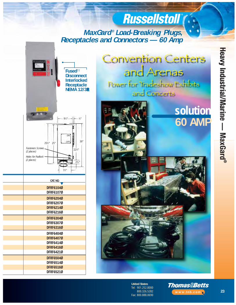
91⁄2"
254⁄5" 25"
Holes for Padlock(2 places)
71⁄2"
23⁄16"
30"
223⁄4"
3⁄4"
Fasteners Screws(2 places)
Fused††
DisconnectInterlockedReceptacle NEMA 12/3R
MaxGard ® Load-Breaking Plugs, Receptacles and Connectors — 60 Amp
CAT. NO.
DFRF6104ØDFRF6107Ø
DFRF6204ØDFRF6207ØDFRF6214ØDFRF6216Ø
DFRF6304ØDFRF6307ØDFRF6316Ø
DFRF6404ØDFRF6407ØDFRF6414ØDFRF6416ØDFRF6421Ø
DFRF6504ØDFRF6514ØDFRF6516ØDFRF6521Ø
Convention Centersand Arenas
Power for Tradeshow Exhibits and Concerts
solution60 AMP
24
United StatesTel: 901.252.8000
800.326.5282Fax: 800.888.0690
www.tnb.com
Heav
y In
dust
rial/M
arin
e —
Max
Gard
®
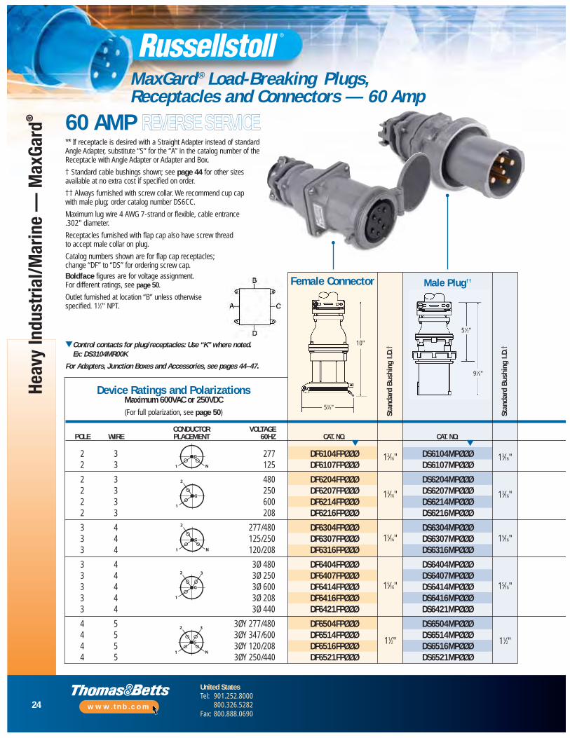
MaxGard ® Load-Breaking Plugs, Receptacles and Connectors — 60 Amp
60 AMP REVERSE SERVICE
10"
53⁄8"
** If receptacle is desired with a Straight Adapter instead of standard Angle Adapter, substitute “S” for the “A” in the catalog number of the Receptacle with Angle Adapter or Adapter and Box.
† Standard cable bushings shown; see page 44 for other sizes available at no extra cost if specified on order.
†† Always furnished with screw collar. We recommend cup cap with male plug; order catalog number DS6CC.
Maximum lug wire 4 AWG 7-strand or flexible, cable entrance .302" diameter.
Receptacles furnished with flap cap also have screw thread to accept male collar on plug.
Catalog numbers shown are for flap cap receptacles; change “DF” to “DS” for ordering screw cap. Boldface figures are for voltage assignment. For different ratings, see page 50.
Outlet furnished at location “B” unless otherwisespecified. 11⁄2" NPT.
▼Control contacts for plug/receptacles: Use “K” where noted. Ex: DS3104MR00K
For Adapters, Junction Boxes and Accessories, see pages 44–47.
CONDUCTOR VOLTAGEPOLE WIRE PLACEMENT 60HZ CAT. NO. CAT. NO.
2 3 277 DF6104FPØØØ DS6104MPØØØ2 3 125 DF6107FPØØØ DS6107MPØØØ
2 3 480 DF6204FPØØØ DS6204MPØØØ2 3 250 DF6207FPØØØ DS6207MPØØØ2 3 600 DF6214FPØØØ DS6214MPØØØ2 3 208 DF6216FPØØØ DS6216MPØØØ
3 4 277/480 DF6304FPØØØ DS6304MPØØØ3 4 125/250 DF6307FPØØØ DS6307MPØØØ3 4 120/208 DF6316FPØØØ DS6316MPØØØ
3 4 3Ø 480 DF6404FPØØØ DS6404MPØØØ3 4 3Ø 250 DF6407FPØØØ DS6407MPØØØ3 4 3Ø 600 DF6414FPØØØ DS6414MPØØØ3 4 3Ø 208 DF6416FPØØØ DS6416MPØØØ3 4 3Ø 440 DF6421FPØØØ DS6421MPØØØ
4 5 3ØY 277/480 DF6504FPØØØ DS6504MPØØØ4 5 3ØY 347/600 DF6514FPØØØ DS6514MPØØØ4 5 3ØY 120/208 DF6516FPØØØ DS6516MPØØØ4 5 3ØY 250/440 DF6521FPØØØ DS6521MPØØØ
Stan
dard
Bus
hing
I.D.
†
Stan
dard
Bus
hing
I.D.
†Device Ratings and Polarizations
Maximum 600VAC or 250VDC(For full polarization, see page 50)
G
N1
G
1
2
G
N1
2
G
1
2 3
G
N1
2 3
▼ ▼
13⁄16"
13⁄16"
15⁄16"
15⁄16"
11⁄2"
13⁄16"
13⁄16"
15⁄16"
15⁄16"
11⁄2"
Male Plug††Female Connector
51⁄2"
91⁄8"
25
United StatesTel: 901.252.8000
800.326.5282Fax: 800.888.0690
www.tnb.com
Heavy Industrial/Marine —
MaxGard
®
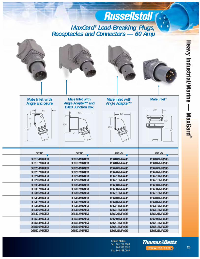
MaxGard ® Load-Breaking Plugs, Receptacles and Connectors — 60 Amp
CAT. NO. CAT. NO. CAT. NO. CAT. NO.
DS6104MRØEØ DS6104MRABØ DS6104MRAØØ DS6104MRØØØDS6107MRØEØ DS6107MRABØ DS6107MRAØØ DS6107MRØØØ
DS6204MRØEØ DS6204MRABØ DS6204MRAØØ DS6204MRØØØDS6207MRØEØ DS6207MRABØ DS6207MRAØØ DS6207MRØØØDS6214MRØEØ DS6214MRABØ DS6214MRAØØ DS6214MRØØØDS6216MRØEØ DS6216MRABØ DS6216MRAØØ DS6216MRØØØ
DS6304MRØEØ DS6304MRABØ DS6304MRAØØ DS6304MRØØØDS6307MRØEØ DS6307MRABØ DS6307MRAØØ DS6307MRØØØDS6316MRØEØ DS6316MRABØ DS6316MRAØØ DS6316MRØØØ
DS6404MRØEØ DS6404MRABØ DS6404MRAØØ DS6404MRØØØDS6407MRØEØ DS6407MRABØ DS6407MRAØØ DS6407MRØØØDS6414MRØEØ DS6414MRABØ DS6414MRAØØ DS6414MRØØØDS6416MRØEØ DS6416MRABØ DS6416MRAØØ DS6416MRØØØDS6421MRØEØ DS6412MRABØ DS6421MRAØØ DS6421MRØØØ
DS6504MRØEØ DS6504MRABØ DS6504MRAØØ DS6504MRØØØDS6514MRØEØ DS6514MRABØ DS6514MRAØØ DS6514MRØØØDS6516MRØEØ DS6516MRABØ DS6516MRAØØ DS6516MRØØØDS6521MRØEØ DS6521MRABØ DS6521MRAØØ DS6521MRØØØ
▼ ▼ ▼ ▼
Male Inlet††Male Inlet with Angle Enclosure
Male Inlet with Angle Adapter** andDJB3 Junction Box
Male Inlet with Angle Adapter**
4"
101⁄4"71⁄4"
33⁄8"
51⁄2"
21⁄2"
101⁄8"101⁄8"
3"111⁄2"
67⁄8"
26
United StatesTel: 901.252.8000
800.326.5282Fax: 800.888.0690
www.tnb.com
Heav
y In
dust
rial/M
arin
e —
Max
Gard
®
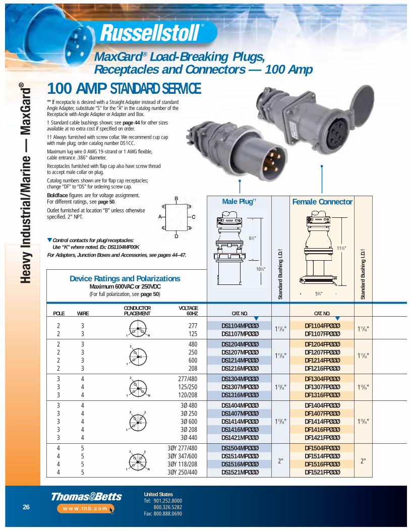
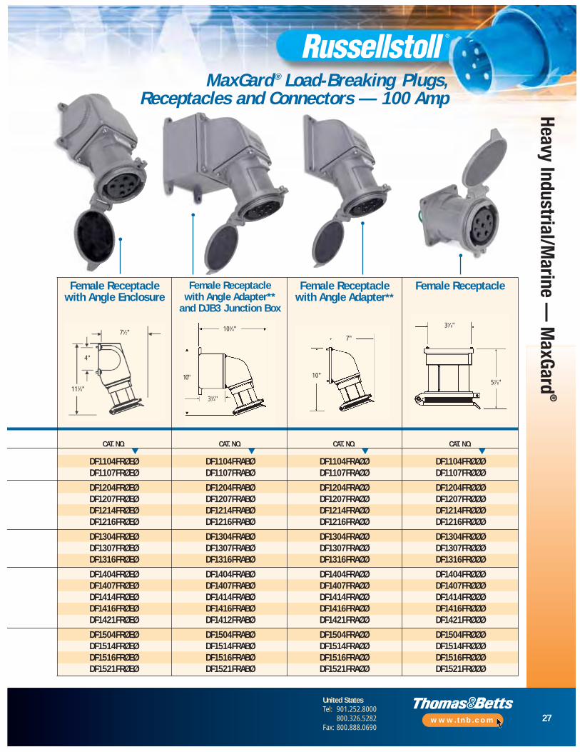
MaxGard ® Load-Breaking Plugs, Receptacles and Connectors — 100 Amp
** If receptacle is desired with a Straight Adapter instead of standard Angle Adapter, substitute “S” for the “A” in the catalog number of the Receptacle with Angle Adapter or Adapter and Box.
† Standard cable bushings shown; see page 44 for other sizes available at no extra cost if specified on order.
†† Always furnished with screw collar. We recommend cup cap with male plug; order catalog number DS1CC.
Maximum lug wire 0 AWG 19-strand or 1 AWG flexible, cable entrance .386" diameter.
Receptacles furnished with flap cap also have screw thread to accept male collar on plug.
Catalog numbers shown are for flap cap receptacles; change “DF” to “DS” for ordering screw cap.
Boldface figures are for voltage assignment. For different ratings, see page 50.
Outlet furnished at location “B” unless otherwisespecified. 2" NPT.
▼Control contacts for plug/receptacles: Use “K” where noted. Ex: DS1104MP00K
For Adapters, Junction Boxes and Accessories, see pages 44–47.
CONDUCTOR VOLTAGEPOLE WIRE PLACEMENT 60HZ CAT. NO. CAT. NO.
2 3 277 DS1104MPØØØ DF1104FPØØØ2 3 125 DS1107MPØØØ DF1107FPØØØ
2 3 480 DS1204MPØØØ DF1204FPØØØ2 3 250 DS1207MPØØØ DF1207FPØØØ2 3 600 DS1214MPØØØ DF1214FPØØØ2 3 208 DS1216MPØØØ DF1216FPØØØ
3 4 277/480 DS1304MPØØØ DF1304FPØØØ3 4 125/250 DS1307MPØØØ DF1307FPØØØ3 4 120/208 DS1316MPØØØ DF1316FPØØØ
3 4 3Ø 480 DS1404MPØØØ DF1404FPØØØ3 4 3Ø 250 DS1407MPØØØ DF1407FPØØØ3 4 3Ø 600 DS1414MPØØØ DF1414FPØØØ3 4 3Ø 208 DS1416MPØØØ DF1416FPØØØ3 4 3Ø 440 DS1421MPØØØ DF1421FPØØØ
4 5 3ØY 277/480 DS1504MPØØØ DF1504FPØØØ4 5 3ØY 347/600 DS1514MPØØØ DF1514FPØØØ4 5 3ØY 118/208 DS1516MPØØØ DF1516FPØØØ4 5 3ØY 250/440 DS1521MPØØØ DF1521FPØØØ
Male Plug††
Stan
dard
Bus
hing
I.D.
†
Stan
dard
Bus
hing
I.D.
†Device Ratings and Polarizations
Maximum 600VAC or 250VDC(For full polarization, see page 50)
G
N1
G
1
2
G
N1
2
G
1
2 3
G
N1
2 3
▼ ▼
111⁄16"
111⁄16"
113⁄16"
113⁄16"
2"
111⁄16"
111⁄16"
113⁄16"
113⁄16"
2"
Female Connector
61⁄2"
101⁄8"
111⁄8"
53⁄8"
100 AMP STANDARD SERVICE
27
United StatesTel: 901.252.8000
800.326.5282Fax: 800.888.0690
www.tnb.com
Heavy Industrial/Marine —
MaxGard
®
MaxGard ® Load-Breaking Plugs, Receptacles and Connectors — 100 Amp
CAT. NO. CAT. NO. CAT. NO. CAT. NO.
DF1104FRØEØ DF1104FRABØ DF1104FRAØØ DF1104FRØØØDF1107FRØEØ DF1107FRABØ DF1107FRAØØ DF1107FRØØØ
DF1204FRØEØ DF1204FRABØ DF1204FRAØØ DF1204FRØØØDF1207FRØEØ DF1207FRABØ DF1207FRAØØ DF1207FRØØØDF1214FRØEØ DF1214FRABØ DF1214FRAØØ DF1214FRØØØDF1216FRØEØ DF1216FRABØ DF1216FRAØØ DF1216FRØØØ
DF1304FRØEØ DF1304FRABØ DF1304FRAØØ DF1304FRØØØDF1307FRØEØ DF1307FRABØ DF1307FRAØØ DF1307FRØØØDF1316FRØEØ DF1316FRABØ DF1316FRAØØ DF1316FRØØØ
DF1404FRØEØ DF1404FRABØ DF1404FRAØØ DF1404FRØØØDF1407FRØEØ DF1407FRABØ DF1407FRAØØ DF1407FRØØØDF1414FRØEØ DF1414FRABØ DF1414FRAØØ DF1414FRØØØDF1416FRØEØ DF1416FRABØ DF1416FRAØØ DF1416FRØØØDF1421FRØEØ DF1412FRABØ DF1421FRAØØ DF1421FRØØØ
DF1504FRØEØ DF1504FRABØ DF1504FRAØØ DF1504FRØØØDF1514FRØEØ DF1514FRABØ DF1514FRAØØ DF1514FRØØØDF1516FRØEØ DF1516FRABØ DF1516FRAØØ DF1516FRØØØDF1521FRØEØ DF1521FRABØ DF1521FRAØØ DF1521FRØØØ
Female ReceptacleFemale Receptacle with Angle Enclosure
Female Receptacle with Angle Adapter**
and DJB3 Junction Box
Female Receptacle with Angle Adapter**
▼ ▼ ▼ ▼
71⁄2"
4"
103⁄4"7"
35⁄8"
53⁄8"10"10"
33⁄4"
113⁄8"
28
United StatesTel: 901.252.8000
800.326.5282Fax: 800.888.0690
www.tnb.com
Heav
y In
dust
rial/M
arin
e —
Max
Gard
®
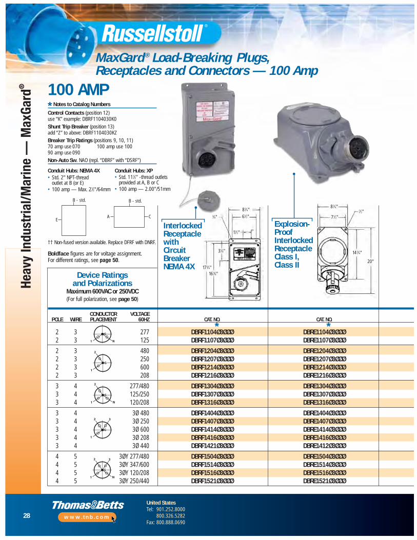
MaxGard ® Load-Breaking Plugs, Receptacles and Connectors — 100 Amp
100 AMP
†† Non-fused version available. Replace DFRF with DNRF.
Boldface figures are for voltage assignment. For different ratings, see page 50.
CONDUCTOR VOLTAGEPOLE WIRE PLACEMENT 60HZ CAT. NO. CAT. NO.
2 3 277 DBRF1104Ø3ØØØ DBRE1104Ø3ØØØ2 3 125 DBRF1107Ø3ØØØ DBRE1107Ø3ØØØ
2 3 480 DBRF1204Ø3ØØØ DBRE1204Ø3ØØØ2 3 250 DBRF1207Ø3ØØØ DBRE1207Ø3ØØØ2 3 600 DBRF1214Ø3ØØØ DBRE1214Ø3ØØØ2 3 208 DBRF1216Ø3ØØØ DBRE1216Ø3ØØØ
3 4 277/480 DBRF1304Ø3ØØØ DBRE1304Ø3ØØØ3 4 125/250 DBRF1307Ø3ØØØ DBRE1307Ø3ØØØ3 4 120/208 DBRF1316Ø3ØØØ DBRE1316Ø3ØØØ
3 4 3Ø 480 DBRF1404Ø3ØØØ DBRE1404Ø3ØØØ3 4 3Ø 250 DBRF1407Ø3ØØØ DBRE1407Ø3ØØØ3 4 3Ø 600 DBRF1414Ø3ØØØ DBRE1414Ø3ØØØ3 4 3Ø 208 DBRF1416Ø3ØØØ DBRE1416Ø3ØØØ3 4 3Ø 440 DBRF1421Ø3ØØØ DBRE1412Ø3ØØØ
4 5 3ØY 277/480 DBRF1504Ø3ØØØ DBRE1504Ø3ØØØ4 5 3ØY 347/600 DBRF1514Ø3ØØØ DBRE1514Ø3ØØØ4 5 3ØY 120/208 DBRF1516Ø3ØØØ DBRE1516Ø3ØØØ4 5 3ØY 250/440 DBRF1521Ø3ØØØ DBRE1521Ø3ØØØ
Device Ratings and Polarizations
Maximum 600VAC or 250VDC(For full polarization, see page 50)
InterlockedReceptaclewithCircuitBreakerNEMA 4X
Explosion-ProofInterlockedReceptacle Class I, Class II
G
N1
G
1
2
G
N1
2
G
1
2 3
G
N1
2 3
**
Conduit Hubs: NEMA 4X• Std. 2" NPT-thread
outlet at B (or E)• 100 amp — Max. 21⁄2"/64mm
Conduit Hubs: XP• Std. 111⁄2" -thread outlets
provided at A, B or C• 100 amp — 2.00"/51mm
* Notes to Catalog Numbers
Control Contacts (position 12) use “K” example: DBRF1104030K0Shunt Trip Breaker (position 13) add “Z” to above: DBRF1104030KZBreaker Trip Ratings (positions 9, 10, 11) 70 amp use 070 100 amp use 10090 amp use 090Non-Auto Sw. NAO (repl. “DBRF” with “DSRF”)
B - std.
E
B - std.
A C
83⁄4"
14 3⁄4"
20"
71⁄2"
1⁄2"83⁄4"
61⁄2"
11⁄2"
31⁄8"
165⁄8"173⁄4"
3⁄8"
29
United StatesTel: 901.252.8000
800.326.5282Fax: 800.888.0690
www.tnb.com
Heavy Industrial/Marine —
MaxGard
®
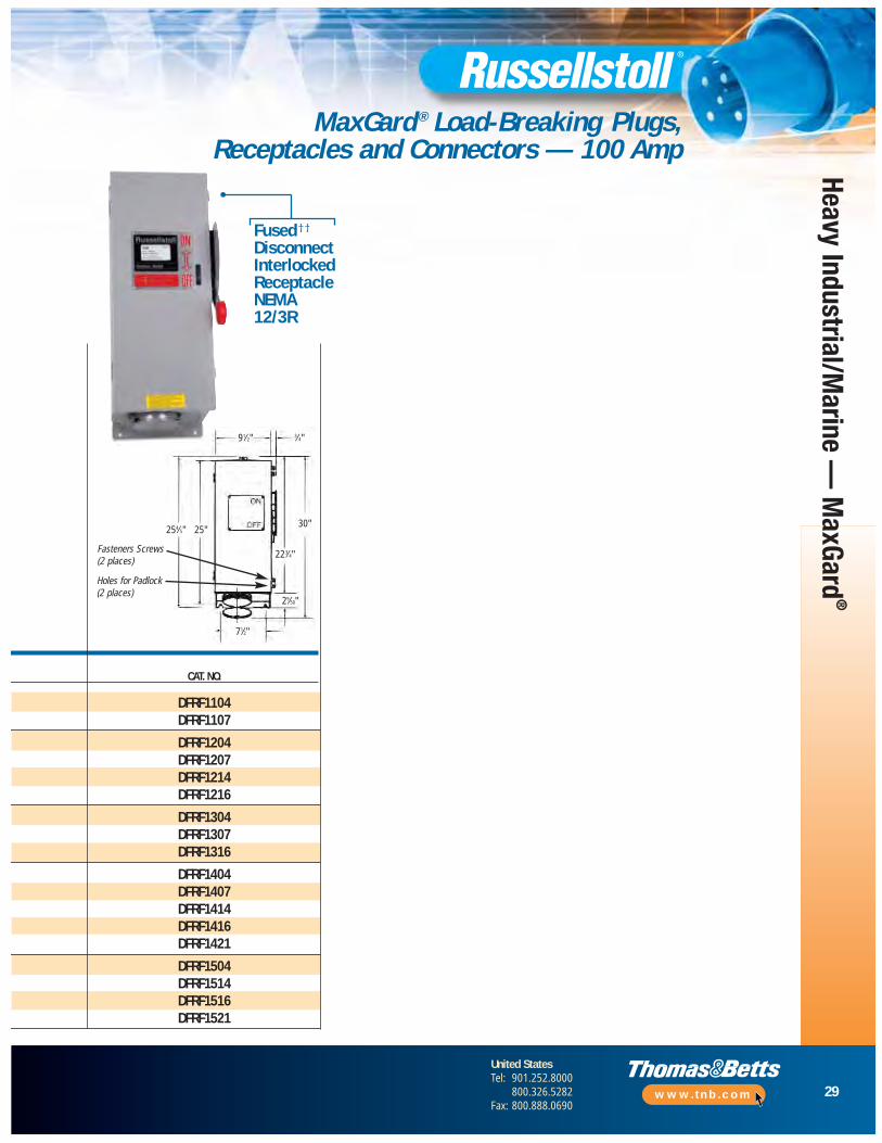
MaxGard ® Load-Breaking Plugs, Receptacles and Connectors — 100 Amp
CAT. NO.
DFRF1104DFRF1107
DFRF1204DFRF1207DFRF1214DFRF1216
DFRF1304DFRF1307DFRF1316
DFRF1404DFRF1407DFRF1414DFRF1416DFRF1421
DFRF1504DFRF1514DFRF1516DFRF1521
Fused††
DisconnectInterlockedReceptacle NEMA12/3R
91⁄2"
254⁄5" 25"
Fasteners Screws(2 places)
Holes for Padlock(2 places)
71⁄2"
29⁄50"
30"
223⁄4"
3⁄4"

30
United StatesTel: 901.252.8000
800.326.5282Fax: 800.888.0690
www.tnb.com
Heav
y In
dust
rial/M
arin
e —
Max
Gard
®
MaxGard ® Load-Breaking Plugs, Receptacles and Connectors — 100 Amp
100 AMP REVERSE SERVICE
111⁄8"
53⁄8"
** If receptacle is desired with a Straight Adapter instead of standard Angle Adapter, substitute “S” for the “A” in the catalog number of the Receptacle with Angle Adapter or Adapter and Box.
† Standard cable bushings shown; see page 44 for other sizes available at no extra cost if specified on order.
†† Always furnished with screw collar. We recommend cup cap with male plug; order catalog number DS1CC.
Maximum lug wire 0 AWG 19-strand or 1 AWG flexible, cable entrance .386" diameter.
Receptacles furnished with flap cap also have screw thread to accept male collar on plug.
Catalog numbers shown are for flap cap receptacles; change “DF” to “DS” for ordering screw cap.
Boldface figures are for voltage assignment. For different ratings, see page 50.Outlet furnished at location “B” unless otherwisespecified. 2" NPT.
▼Control contacts for plug/receptacles: Use “K” where noted. Ex: DS1104MR00K
For Adapters, Junction Boxes and Accessories, see pages 44–47.
Stan
dard
Bus
hing
I.D.
†
Stan
dard
Bus
hing
I.D.
†Device Ratings and Polarizations
Maximum 600VAC or 250VDC(For full polarization, see page 50)
G
N1
G
1
2
G
N1
2
G
1
2 3
G
N1
2 3
▼ ▼
111⁄16"
111⁄16"
113⁄16"
113⁄16"
2"
Male Plug††Female Connector
61⁄2"
101⁄8"
111⁄16"
111⁄16"
113⁄16"
113⁄16"
2"
CONDUCTOR VOLTAGEPOLE WIRE PLACEMENT 60HZ CAT. NO. CAT. NO.
2 3 277 DF1104FPØØØ DS1104MPØØØ2 3 125 DF1107FPØØØ DS1107MPØØØ
2 3 480 DF1204FPØØØ DS1204MPØØØ2 3 250 DF1207FPØØØ DS1207MPØØØ2 3 600 DF1214FPØØØ DS1214MPØØØ2 3 208 DF1216FPØØØ DS1216MPØØØ
3 4 277/480 DF1304FPØØØ DS1304MPØØØ3 4 125/250 DF1307FPØØØ DS1307MPØØØ3 4 120/208 DF1316FPØØØ DS1316MPØØØ
3 4 3Ø 480 DF1404FPØØØ DS1404MPØØØ3 4 3Ø 250 DF1407FPØØØ DS1407MPØØØ3 4 3Ø 600 DF1414FPØØØ DS1414MPØØØ3 4 3Ø 208 DF1416FPØØØ DS1416MPØØØ3 4 3Ø 440 DF1421FPØØØ DS1421MPØØØ
4 5 3ØY 277/480 DF1504FPØØØ DS1504MPØØØ4 5 3ØY 347/600 DF1514FPØØØ DS1514MPØØØ4 5 3ØY 120/208 DF1516FPØØØ DS1516MPØØØ4 5 3ØY 250/440 DF1521FPØØØ DS1521MPØØØ
31
United StatesTel: 901.252.8000
800.326.5282Fax: 800.888.0690
www.tnb.com
Heavy Industrial/Marine —
MaxGard
®
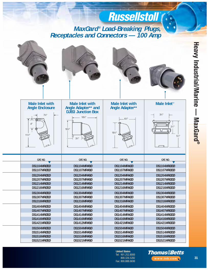
MaxGard ® Load-Breaking Plugs, Receptacles and Connectors — 100 Amp
▼ ▼ ▼ ▼
Male Inlet††Male Inlet with Angle Enclosure
Male Inlet with Angle Adapter** andDJB3 Junction Box
Male Inlet with Angle Adapter**
4"
105⁄8"67⁄8"
33⁄8"
51⁄2"
21⁄2"
101⁄8"
101⁄8"
33⁄4"
111⁄2"
73⁄8"
CAT. NO. CAT. NO. CAT. NO. CAT. NO.
DS1104MRØEØ DS1104MRABØ DS1104MRAØØ DS1104MRØØØDS1107MRØEØ DS1107MRABØ DS1107MRAØØ DS1107MRØØØ
DS1204MRØEØ DS1204MRABØ DS1204MRAØØ DS1204MRØØØDS1207MRØEØ DS1207MRABØ DS1207MRAØØ DS1207MRØØØDS1214MRØEØ DS1214MRABØ DS1214MRAØØ DS1214MRØØØDS1216MRØEØ DS1216MRABØ DS1216MRAØØ DS1216MRØØØ
DS1304MRØEØ DS1304MRABØ DS1304MRAØØ DS1304MRØØØDS1307MRØEØ DS1307MRABØ DS1307MRAØØ DS1307MRØØØDS1316MRØEØ DS1316MRABØ DS1316MRAØØ DS1316MRØØØ
DS1404MRØEØ DS1404MRABØ DS1404MRAØØ DS1404MRØØØDS1407MRØEØ DS1407MRABØ DS1407MRAØØ DS1407MRØØØDS1414MRØEØ DS1414MRABØ DS1414MRAØØ DS1414MRØØØDS1416MRØEØ DS1416MRABØ DS1416MRAØØ DS1416MRØØØDS1421MRØEØ DS1412MRABØ DS1421MRAØØ DS1421MRØØØ
DS1504MRØEØ DS1504MRABØ DS1504MRAØØ DS1504MRØØØDS1514MRØEØ DS1514MRABØ DS1514MRAØØ DS1514MRØØØDS1516MRØEØ DS1516MRABØ DS1516MRAØØ DS1516MRØØØDS1521MRØEØ DS1521MRABØ DS1521MRAØØ DS1521MRØØØ

32
United StatesTel: 901.252.8000
800.326.5282Fax: 800.888.0690
www.tnb.com
Heav
y In
dust
rial/M
arin
e —
Max
Gard
®
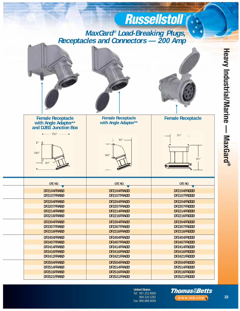
MaxGard ® Load-Breaking Plugs, Receptacles and Connectors — 200 Amp
** If receptacle is desired with a Straight Adapter instead of standard Angle Adapter, substitute “S” for the “A” in the catalog number of the Receptacle with Angle Adapter or Adapter and Box.
† Standard cable bushings shown; see page 44 for other sizes available at no extra cost if specified on order.
†† Always furnished with screw collar. We recommend cup cap with male plug; order catalog number DS2CC.
Maximum lug wire 4/0 AWG 19-strand or flexible, cable entrance .625" diameter.
Receptacles furnished with flap cap also have screw thread to accept male collar on plug.
Catalog numbers shown are for flap cap receptacles; change “DF” to “DS” for ordering screw cap. Boldface figures are for voltage assignment. For different ratings, see page 50.Outlet furnished at location “B” unless otherwisespecified. 3" NPT.
▼Control contacts for plug/receptacles: Use “K” where noted. Ex: DS2104MP00K
For Adapters, Junction Boxes and Accessories, see pages 44–47.
CONDUCTOR VOLTAGEPOLE WIRE PLACEMENT 60HZ CAT. NO. CAT. NO.
2 3 277 DS2104MPØØØ DF2104FPØØØ2 3 125 DS2107MPØØØ DF2107FPØØØ
2 3 480 DS2204MPØØØ DF2204FPØØØ2 3 250 DS2207MPØØØ DF2207FPØØØ2 3 600 DS2214MPØØØ DF2214FPØØØ2 3 208 DS2216MPØØØ DF2216FPØØØ
3 4 277/480 DS2304MPØØØ DF2304FPØØØ3 4 125/250 DS2307MPØØØ DF2307FPØØØ3 4 120/208 DS2316MPØØØ DF2316FPØØØ
3 4 3Ø 480 DS2404MPØØØ DF2404FPØØØ3 4 3Ø 250 DS2407MPØØØ DF2407FPØØØ3 4 3Ø 600 DS2414MPØØØ DF2414FPØØØ3 4 3Ø 208 DS2416MPØØØ DF2416FPØØØ3 4 3Ø 440 DS2421MPØØØ DF2421FPØØØ
4 5 3ØY 277/480 DS2504MPØØØ DF2504FPØØØ4 5 3ØY 347/600 DS2514MPØØØ DF2514FPØØØ4 5 3ØY 118/208 DS2516MPØØØ DF2516FPØØØ4 5 3ØY 250/440 DS2521MPØØØ DF2521FPØØØ
Male Plug††
Stan
dard
Bus
hing
I.D.
†
Stan
dard
Bus
hing
I.D.
†Device Ratings and Polarizations
Maximum 600VAC or 250VDC(For full polarization, see page 50)
G
N1
G
1
2
G
N1
2
G
1
2 3
G
N1
2 3
▼ ▼
21⁄8"
21⁄8"
21⁄4"
21⁄4"
21⁄2"
21⁄8"
21⁄8"
21⁄4"
21⁄4"
21⁄2"
Female Connector
9"
133⁄4"
15"
91⁄2"
200 AMP STANDARD SERVICE
33
United StatesTel: 901.252.8000
800.326.5282Fax: 800.888.0690
www.tnb.com
Heavy Industrial/Marine —
MaxGard
®
MaxGard ® Load-Breaking Plugs, Receptacles and Connectors — 200 Amp
CAT. NO. CAT. NO. CAT. NO.
DF2104FRABØ DF2104FRAØØ DF2104FRØØØDF2107FRABØ DF2107FRAØØ DF2107FRØØØ
DF2204FRABØ DF2204FRAØØ DF2204FRØØØDF2207FRABØ DF2207FRAØØ DF2207FRØØØDF2214FRABØ DF2214FRAØØ DF2214FRØØØDF2216FRABØ DF2216FRAØØ DF2216FRØØØ
DF2304FRABØ DF2304FRAØØ DF2304FRØØØDF2307FRABØ DF2307FRAØØ DF2307FRØØØDF2316FRABØ DF2316FRAØØ DF2316FRØØØ
DF2404FRABØ DF2404FRAØØ DF2404FRØØØDF2407FRABØ DF2407FRAØØ DF2407FRØØØDF2414FRABØ DF2414FRAØØ DF2414FRØØØDF2416FRABØ DF2416FRAØØ DF2416FRØØØDF2412FRABØ DF2421FRAØØ DF2421FRØØØ
DF2504FRABØ DF2504FRAØØ DF2504FRØØØDF2514FRABØ DF2514FRAØØ DF2514FRØØØDF2516FRABØ DF2516FRAØØ DF2516FRØØØDF2521FRABØ DF2521FRAØØ DF2521FRØØØ
Female ReceptacleFemale Receptacle with Angle Adapter**
and DJB3 Junction Box
Female Receptacle with Angle Adapter**
▼ ▼▼
153⁄4"
91⁄2"
51⁄4"
65⁄8"143⁄4"
145⁄8"
65⁄8"
34
United StatesTel: 901.252.8000
800.326.5282Fax: 800.888.0690
www.tnb.com
Heav
y In
dust
rial/M
arin
e —
Max
Gard
®
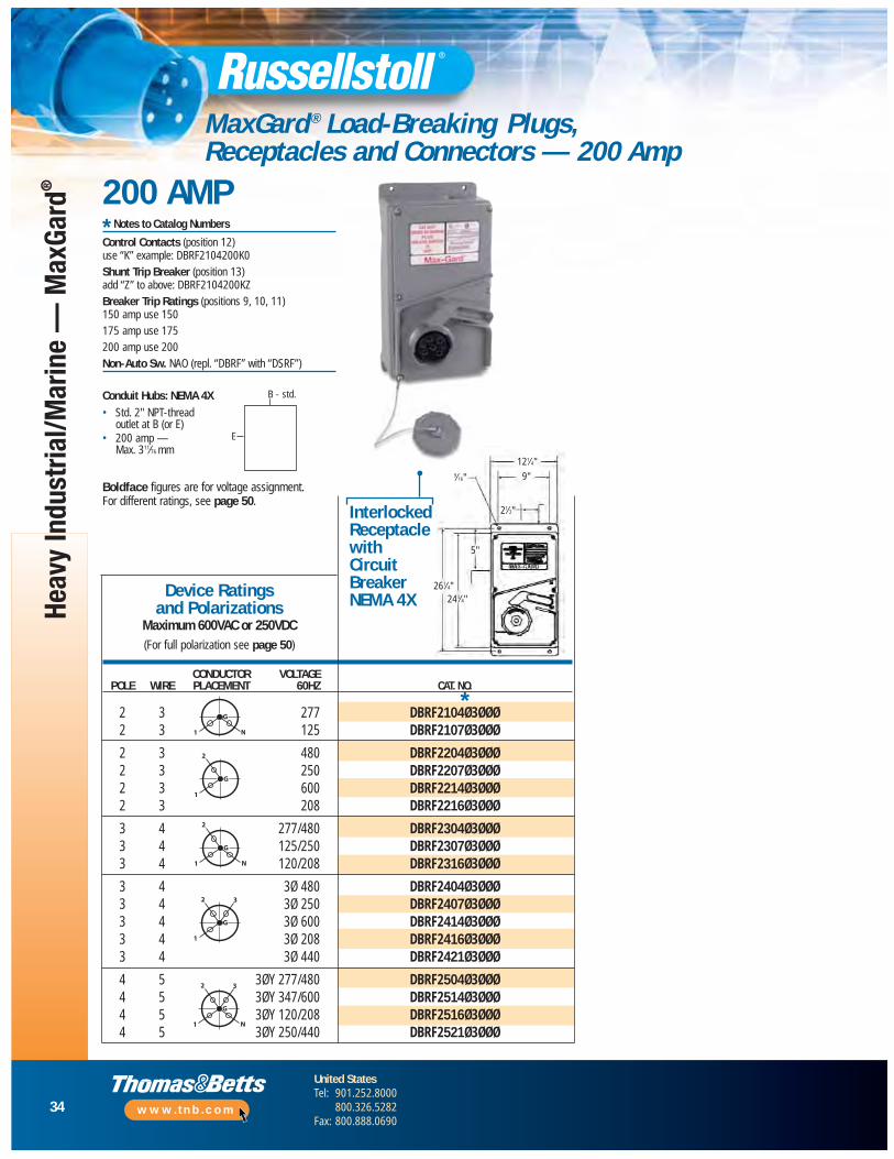
MaxGard ® Load-Breaking Plugs, Receptacles and Connectors — 200 Amp
200 AMP
Boldface figures are for voltage assignment. For different ratings, see page 50.
CONDUCTOR VOLTAGEPOLE WIRE PLACEMENT 60HZ CAT. NO.
2 3 277 DBRF2104Ø3ØØØ2 3 125 DBRF2107Ø3ØØØ
2 3 480 DBRF2204Ø3ØØØ2 3 250 DBRF2207Ø3ØØØ2 3 600 DBRF2214Ø3ØØØ2 3 208 DBRF2216Ø3ØØØ
3 4 277/480 DBRF2304Ø3ØØØ3 4 125/250 DBRF2307Ø3ØØØ3 4 120/208 DBRF2316Ø3ØØØ
3 4 3Ø 480 DBRF2404Ø3ØØØ3 4 3Ø 250 DBRF2407Ø3ØØØ3 4 3Ø 600 DBRF2414Ø3ØØØ3 4 3Ø 208 DBRF2416Ø3ØØØ3 4 3Ø 440 DBRF2421Ø3ØØØ
4 5 3ØY 277/480 DBRF2504Ø3ØØØ4 5 3ØY 347/600 DBRF2514Ø3ØØØ4 5 3ØY 120/208 DBRF2516Ø3ØØØ4 5 3ØY 250/440 DBRF2521Ø3ØØØ
Device Ratings and Polarizations
Maximum 600VAC or 250VDC(For full polarization see page 50)
InterlockedReceptaclewithCircuitBreakerNEMA 4X
G
N1
G
1
2
G
N1
2
G
1
2 3
G
N1
2 3
*
Conduit Hubs: NEMA 4X• Std. 2" NPT-thread
outlet at B (or E)• 200 amp —
Max. 311⁄76 mm
* Notes to Catalog Numbers
Control Contacts (position 12) use “K” example: DBRF2104200K0Shunt Trip Breaker (position 13) add “Z” to above: DBRF2104200KZBreaker Trip Ratings (positions 9, 10, 11) 150 amp use 150175 amp use 175200 amp use 200Non-Auto Sw. NAO (repl. “DBRF” with “DSRF”)
B - std.
E
121⁄4"
9"
21⁄2"
5"
243⁄4"261⁄4"
9⁄16"

35
United StatesTel: 901.252.8000
800.326.5282Fax: 800.888.0690
www.tnb.com
MaxGard ® Load-Breaking Plugs, Receptacles and Connectors — 200 Amp
solution200 AMP
200A MaxGard interlocks in parallel
200A MaxGard connected on ferry deck
200A MaxGard inlets with disconnects
30A and 200AMaxGard Interlocks
200A MaxGard inlets with disconnects
Staten Island Ferry
Heavy Industrial/Marine —
MaxGard
®
36
United StatesTel: 901.252.8000
800.326.5282Fax: 800.888.0690
www.tnb.com
Heav
y In
dust
rial/M
arin
e —
Max
Gard
®
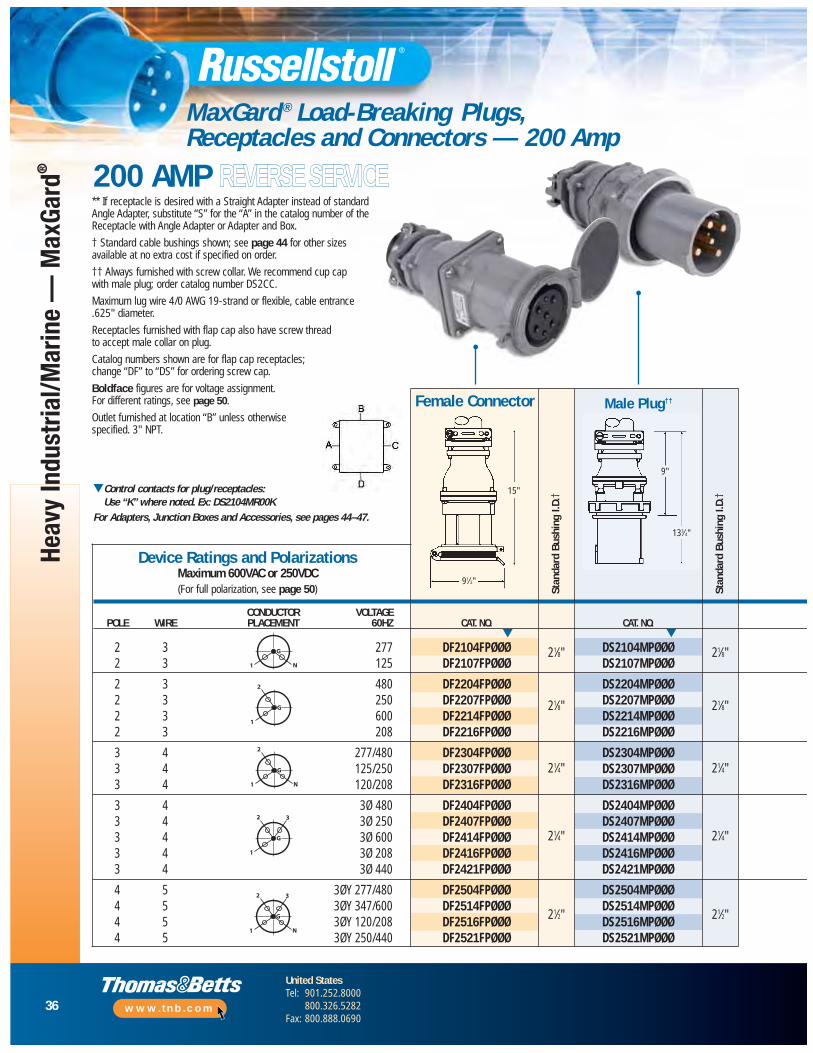
MaxGard ® Load-Breaking Plugs, Receptacles and Connectors — 200 Amp
200 AMP REVERSE SERVICE
15"
91⁄2"
** If receptacle is desired with a Straight Adapter instead of standard Angle Adapter, substitute “S” for the “A” in the catalog number of the Receptacle with Angle Adapter or Adapter and Box.
† Standard cable bushings shown; see page 44 for other sizes available at no extra cost if specified on order.
†† Always furnished with screw collar. We recommend cup cap with male plug; order catalog number DS2CC.
Maximum lug wire 4/0 AWG 19-strand or flexible, cable entrance .625" diameter.
Receptacles furnished with flap cap also have screw thread to accept male collar on plug.
Catalog numbers shown are for flap cap receptacles; change “DF” to “DS” for ordering screw cap.
Boldface figures are for voltage assignment. For different ratings, see page 50.
Outlet furnished at location “B” unless otherwisespecified. 3" NPT.
▼Control contacts for plug/receptacles: Use “K” where noted. Ex: DS2104MR00K
For Adapters, Junction Boxes and Accessories, see pages 44–47.
CONDUCTOR VOLTAGEPOLE WIRE PLACEMENT 60HZ CAT. NO. CAT. NO.
2 3 277 DF2104FPØØØ DS2104MPØØØ2 3 125 DF2107FPØØØ DS2107MPØØØ
2 3 480 DF2204FPØØØ DS2204MPØØØ2 3 250 DF2207FPØØØ DS2207MPØØØ2 3 600 DF2214FPØØØ DS2214MPØØØ2 3 208 DF2216FPØØØ DS2216MPØØØ
3 4 277/480 DF2304FPØØØ DS2304MPØØØ3 4 125/250 DF2307FPØØØ DS2307MPØØØ3 4 120/208 DF2316FPØØØ DS2316MPØØØ
3 4 3Ø 480 DF2404FPØØØ DS2404MPØØØ3 4 3Ø 250 DF2407FPØØØ DS2407MPØØØ3 4 3Ø 600 DF2414FPØØØ DS2414MPØØØ3 4 3Ø 208 DF2416FPØØØ DS2416MPØØØ3 4 3Ø 440 DF2421FPØØØ DS2421MPØØØ
4 5 3ØY 277/480 DF2504FPØØØ DS2504MPØØØ4 5 3ØY 347/600 DF2514FPØØØ DS2514MPØØØ4 5 3ØY 120/208 DF2516FPØØØ DS2516MPØØØ4 5 3ØY 250/440 DF2521FPØØØ DS2521MPØØØ
Stan
dard
Bus
hing
I.D.
†
Stan
dard
Bus
hing
I.D.
†Device Ratings and Polarizations
Maximum 600VAC or 250VDC(For full polarization, see page 50)
G
N1
G
1
2
G
N1
2
G
1
2 3
G
N1
2 3
▼ ▼
21⁄8"
21⁄8"
21⁄4"
21⁄4"
21⁄2"
Male Plug††Female Connector
9"
133⁄4"
21⁄8"
21⁄8"
21⁄4"
21⁄4"
21⁄2"

37
United StatesTel: 901.252.8000
800.326.5282Fax: 800.888.0690
www.tnb.com
Heavy Industrial/Marine —
MaxGard
®
MaxGard ® Load-Breaking Plugs, Receptacles and Connectors — 200 Amp
CAT. NO. CAT. NO. CAT. NO.
DS2104MRABØ DS2104MRAØØ DS2104MRØØØDS2107MRABØ DS2107MRAØØ DS2107MRØØØ
DS2204MRABØ DS2204MRAØØ DS2204MRØØØDS2207MRABØ DS2207MRAØØ DS2207MRØØØDS2214MRABØ DS2214MRAØØ DS2214MRØØØDS2216MRABØ DS2216MRAØØ DS2216MRØØØ
DS2304MRABØ DS2304MRAØØ DS2304MRØØØDS2307MRABØ DS2307MRAØØ DS2307MRØØØDS2316MRABØ DS2316MRAØØ DS2316MRØØØ
DS2404MRABØ DS2404MRAØØ DS2404MRØØØDS2407MRABØ DS2407MRAØØ DS2407MRØØØDS2414MRABØ DS2414MRAØØ DS2414MRØØØDS2416MRABØ DS2416MRAØØ DS2416MRØØØDS2412MRABØ DS2421MRAØØ DS2421MRØØØ
DS2504MRABØ DS2504MRAØØ DS2504MRØØØDS2514MRABØ DS2514MRAØØ DS2514MRØØØDS2516MRABØ DS2516MRAØØ DS2516MRØØØDS2521MRABØ DS2521MRAØØ DS2521MRØØØ
▼ ▼ ▼
Male Inlet††Male Inlet with Angle Adapter** andDJB3 Junction Box
Male Inlet with Angle Adapter**
151⁄2"91⁄4"
4"
91⁄4"
31⁄2"
15"
147⁄8"
65⁄8"
solution200 AMP
Application:Electrical hook-up of mobile medical imaging (MMI) trailers Mobile medical units provide trailer-transportable blood banks, dental clinics,magnetic resonance imaging (MRI), X-ray andother diagnostic equipment to many hospitalsand clinics throughout the country on a regularleased basis. Safe outdoor usage connectionsare required for up to 200 amp power suppliesat each facility. Major specialized customtrailer manufacturers rely on the MaxGard®
200 amp interface.
Installation:Site-mounted 200 amp receptacles with trailer-mounted plugs and connectorsWhen a mobile medical unit trailer is at thedesired location, a heavy-duty MaxGard® 200amp cable assembly connects the trailer with acorresponding receptacle or connector at eachsite, usually mounted on an outside wall. Aprimary safety feature is the receptacle’s gateddead-front construction that ensures noexterior access to live receptacle contacts.With so many different hands involved on adaily basis, the MaxGard epoxy powder-coatfinish and rugged waterproof constructionprovides hospital-safe long service life.
MMITrailer
38
United StatesTel: 901.252.8000
800.326.5282Fax: 800.888.0690
www.tnb.com
Heav
y In
dust
rial/
Mar
ine
— M
axGa
rd®
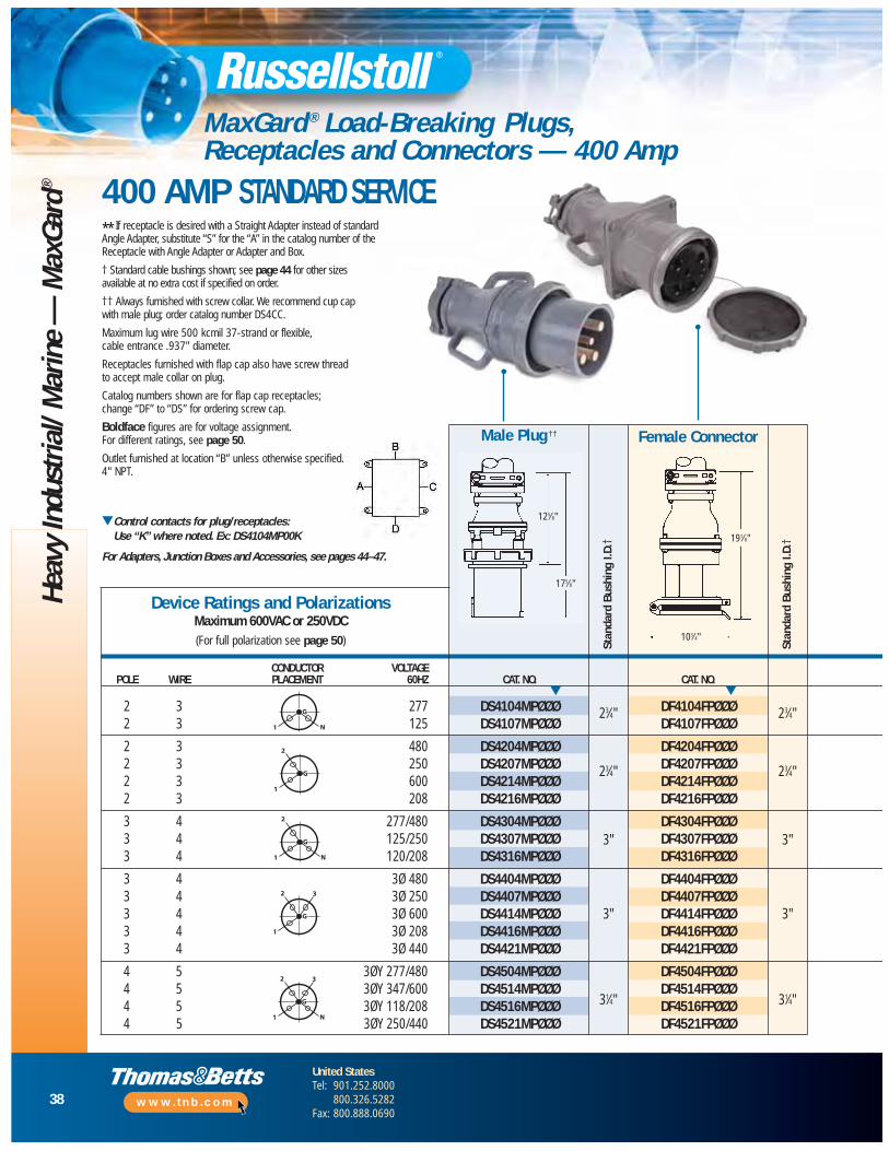
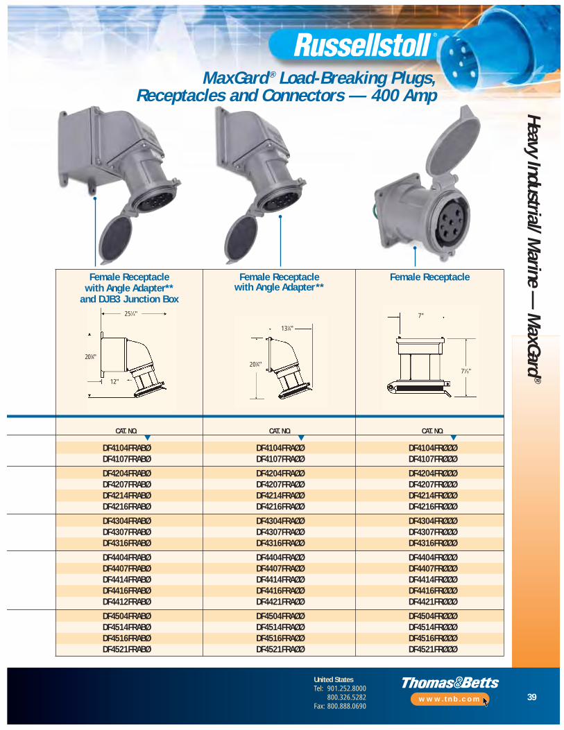
MaxGard ® Load-Breaking Plugs, Receptacles and Connectors — 400 Amp
** If receptacle is desired with a Straight Adapter instead of standard Angle Adapter, substitute “S” for the “A” in the catalog number of the Receptacle with Angle Adapter or Adapter and Box.
† Standard cable bushings shown; see page 44 for other sizes available at no extra cost if specified on order.
†† Always furnished with screw collar. We recommend cup cap with male plug; order catalog number DS4CC.
Maximum lug wire 500 kcmil 37-strand or flexible, cable entrance .937" diameter.
Receptacles furnished with flap cap also have screw thread to accept male collar on plug.
Catalog numbers shown are for flap cap receptacles; change “DF” to “DS” for ordering screw cap.
Boldface figures are for voltage assignment. For different ratings, see page 50.
Outlet furnished at location “B” unless otherwise specified.4" NPT.
▼Control contacts for plug/receptacles: Use “K” where noted. Ex: DS4104MP00K
For Adapters, Junction Boxes and Accessories, see pages 44–47.
CONDUCTOR VOLTAGEPOLE WIRE PLACEMENT 60HZ CAT. NO. CAT. NO.
2 3 277 DS4104MPØØØ DF4104FPØØØ2 3 125 DS4107MPØØØ DF4107FPØØØ
2 3 480 DS4204MPØØØ DF4204FPØØØ2 3 250 DS4207MPØØØ DF4207FPØØØ2 3 600 DS4214MPØØØ DF4214FPØØØ2 3 208 DS4216MPØØØ DF4216FPØØØ
3 4 277/480 DS4304MPØØØ DF4304FPØØØ3 4 125/250 DS4307MPØØØ DF4307FPØØØ3 4 120/208 DS4316MPØØØ DF4316FPØØØ
3 4 3Ø 480 DS4404MPØØØ DF4404FPØØØ3 4 3Ø 250 DS4407MPØØØ DF4407FPØØØ3 4 3Ø 600 DS4414MPØØØ DF4414FPØØØ3 4 3Ø 208 DS4416MPØØØ DF4416FPØØØ3 4 3Ø 440 DS4421MPØØØ DF4421FPØØØ
4 5 3ØY 277/480 DS4504MPØØØ DF4504FPØØØ4 5 3ØY 347/600 DS4514MPØØØ DF4514FPØØØ4 5 3ØY 118/208 DS4516MPØØØ DF4516FPØØØ4 5 3ØY 250/440 DS4521MPØØØ DF4521FPØØØ
Male Plug ††
Stan
dard
Bus
hing
I.D.
†
Stan
dard
Bus
hing
I.D.
†Device Ratings and Polarizations
Maximum 600VAC or 250VDC(For full polarization see page 50)
G
N1
G
1
2
G
N1
2
G
1
2 3
G
N1
2 3
▼ ▼
23⁄4"
23⁄4"
3"
3"
31⁄4"
23⁄4"
23⁄4"
3"
3"
31⁄4"
Female Connector
125⁄8"
175⁄8"
191⁄8"
103⁄4"
400 AMP STANDARD SERVICE
39
United StatesTel: 901.252.8000
800.326.5282Fax: 800.888.0690
www.tnb.com
Heavy Industrial/ Marine —
MaxGard
®
MaxGard ® Load-Breaking Plugs, Receptacles and Connectors — 400 Amp
CAT. NO. CAT. NO. CAT. NO.
DF4104FRABØ DF4104FRAØØ DF4104FRØØØDF4107FRABØ DF4107FRAØØ DF4107FRØØØ
DF4204FRABØ DF4204FRAØØ DF4204FRØØØDF4207FRABØ DF4207FRAØØ DF4207FRØØØDF4214FRABØ DF4214FRAØØ DF4214FRØØØDF4216FRABØ DF4216FRAØØ DF4216FRØØØ
DF4304FRABØ DF4304FRAØØ DF4304FRØØØDF4307FRABØ DF4307FRAØØ DF4307FRØØØDF4316FRABØ DF4316FRAØØ DF4316FRØØØ
DF4404FRABØ DF4404FRAØØ DF4404FRØØØDF4407FRABØ DF4407FRAØØ DF4407FRØØØDF4414FRABØ DF4414FRAØØ DF4414FRØØØDF4416FRABØ DF4416FRAØØ DF4416FRØØØDF4412FRABØ DF4421FRAØØ DF4421FRØØØ
DF4504FRABØ DF4504FRAØØ DF4504FRØØØDF4514FRABØ DF4514FRAØØ DF4514FRØØØDF4516FRABØ DF4516FRAØØ DF4516FRØØØDF4521FRABØ DF4521FRAØØ DF4521FRØØØ
▼ ▼▼
251⁄4"
131⁄4"
7"
71⁄8"203⁄4"
203⁄4"
12"
Female ReceptacleFemale Receptacle with Angle Adapter**
and DJB3 Junction Box
Female Receptacle with Angle Adapter**
40
United StatesTel: 901.252.8000
800.326.5282Fax: 800.888.0690
www.tnb.com
Heav
y In
dust
rial/M
arin
e —
Max
Gard
®
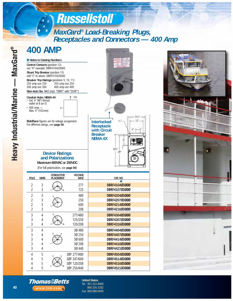
MaxGard ® Load-Breaking Plugs, Receptacles and Connectors — 400 Amp
Boldface figures are for voltage assignment. For different ratings, see page 50.
CONDUCTOR VOLTAGEPOLE WIRE PLACEMENT 60HZ CAT. NO.
2 3 277 DBRF4104Ø3ØØØ2 3 125 DBRF4107Ø3ØØØ
2 3 480 DBRF4204Ø3ØØØ2 3 250 DBRF4207Ø3ØØØ2 3 600 DBRF4214Ø3ØØØ2 3 208 DBRF4216Ø3ØØØ
3 4 277/480 DBRF4304Ø3ØØØ3 4 125/250 DBRF4307Ø3ØØØ3 4 120/208 DBRF4316Ø3ØØØ
3 4 3Ø 480 DBRF4404Ø3ØØØ3 4 3Ø 250 DBRF4407Ø3ØØØ3 4 3Ø 600 DBRF4414Ø3ØØØ3 4 3Ø 208 DBRF4416Ø3ØØØ3 4 3Ø 440 DBRF4421Ø3ØØØ
4 5 3ØY 277/480 DBRF4504Ø3ØØØ4 5 3ØY 347/600 DBRF4514Ø3ØØØ4 5 3ØY 120/208 DBRF4516Ø3ØØØ4 5 3ØY 250/440 DBRF4521Ø3ØØØ
Device Ratings and Polarizations
Maximum 600VAC or 250VDC(For full polarization, see page 50)
InterlockedReceptaclewith CircuitBreakerNEMA 4X
G
N1
G
1
2
G
N1
2
G
1
2 3
G
N1
2 3
*
Conduit Hubs: NEMA 4X• Std. 4" NPT-thread
outlet at B (or E)• 400 amp —
Max. 4" (102mm)
* Notes to Catalog Numbers
Control Contacts (position 12) use “K” example: DBRF4104200K0Shunt Trip Breaker (position 13) add “Z” to above: DBRF4104200KZBreaker Trip Ratings (positions 9, 10, 11) 250 amp use 250 350 amp use 350300 amp use 300 400 amp use 400Non-Auto Sw. NAO (repl. “DBRF” with “DSRF”)
B - std.
E
400 AMP
151⁄2"
12"
3"
6"
29"301⁄2"
9⁄16"
41
United StatesTel: 901.252.8000
800.326.5282Fax: 800.888.0690
www.tnb.com
Heavy Industrial/Marine —
MaxGard
®
MaxGard ® Load-Breaking Plugs, Receptacles and Connectors — 400 Amp
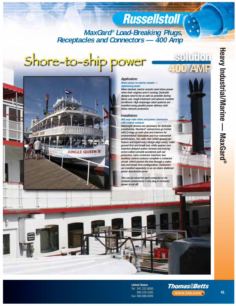
solution400 AMP
Application:Shore power to marine vessels — sightseeing boatsWhen docked, marine vessels need shore powerwhen their engines aren’t running. Docksidedesigns need to be as safe as possible duringheavy use, rough treatment and adverse weatherconditions. High amperage-rated systems areinstalled using parallel power delivery with cross-network protection.
Installation:400 amp male inlets and power connectors with control contactsWatertight devices are necessary for docksideinstallations. MaxGard® connections go furtherwith O-rings on both pins and interiors forenvironmental separation and true waterproofperformance. The male inlet center ground pinfeature and keyed entry design align easily, makeground first and break last, while quarter-turninsertion delayed-action removal and lockingscrew collars provide accidental pull-outprotection. Upon connector insertion, twoauxiliary control contacts complete a contactorcircuit, which powers the line through a make-last-and-break-first configuration. Contactors are installed separately in an on-shore shelteredpower distribution panel.
This can be wired for each contactor or formultiple connections; if one plug is removed,power is cut off.
Shore-to-ship power
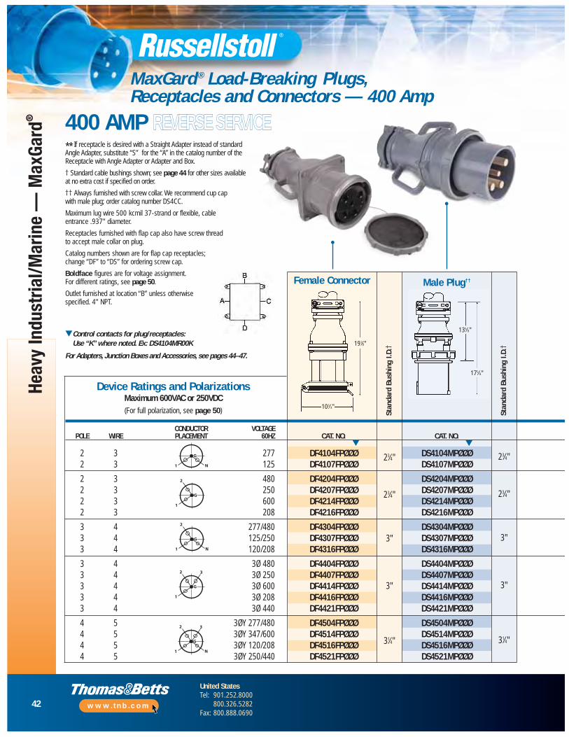
42
United StatesTel: 901.252.8000
800.326.5282Fax: 800.888.0690
www.tnb.com
Heav
y In
dust
rial/M
arin
e —
Max
Gard
®
MaxGard ® Load-Breaking Plugs, Receptacles and Connectors — 400 Amp
191⁄8"
103⁄4"
** If receptacle is desired with a Straight Adapter instead of standard Angle Adapter, substitute “S” for the “A” in the catalog number of the Receptacle with Angle Adapter or Adapter and Box.
† Standard cable bushings shown; see page 44 for other sizes available at no extra cost if specified on order.
†† Always furnished with screw collar. We recommend cup cap with male plug; order catalog number DS4CC.
Maximum lug wire 500 kcmil 37-strand or flexible, cable entrance .937" diameter.
Receptacles furnished with flap cap also have screw thread to accept male collar on plug.
Catalog numbers shown are for flap cap receptacles; change “DF” to “DS” for ordering screw cap.
Boldface figures are for voltage assignment. For different ratings, see page 50.
Outlet furnished at location “B” unless otherwisespecified. 4" NPT.
▼Control contacts for plug/receptacles: Use “K” where noted. Ex: DS4104MR00K
For Adapters, Junction Boxes and Accessories, see pages 44–47.
CONDUCTOR VOLTAGEPOLE WIRE PLACEMENT 60HZ CAT. NO. CAT. NO.
2 3 277 DF4104FPØØØ DS4104MPØØØ2 3 125 DF4107FPØØØ DS4107MPØØØ
2 3 480 DF4204FPØØØ DS4204MPØØØ2 3 250 DF4207FPØØØ DS4207MPØØØ2 3 600 DF4214FPØØØ DS4214MPØØØ2 3 208 DF4216FPØØØ DS4216MPØØØ
3 4 277/480 DF4304FPØØØ DS4304MPØØØ3 4 125/250 DF4307FPØØØ DS4307MPØØØ3 4 120/208 DF4316FPØØØ DS4316MPØØØ
3 4 3Ø 480 DF4404FPØØØ DS4404MPØØØ3 4 3Ø 250 DF4407FPØØØ DS4407MPØØØ3 4 3Ø 600 DF4414FPØØØ DS4414MPØØØ3 4 3Ø 208 DF4416FPØØØ DS4416MPØØØ3 4 3Ø 440 DF4421FPØØØ DS4421MPØØØ
4 5 3ØY 277/480 DF4504FPØØØ DS4504MPØØØ4 5 3ØY 347/600 DF4514FPØØØ DS4514MPØØØ4 5 3ØY 120/208 DF4516FPØØØ DS4516MPØØØ4 5 3ØY 250/440 DF4521FPØØØ DS4521MPØØØ
Stan
dard
Bus
hing
I.D.
†
Stan
dard
Bus
hing
I.D.
†Device Ratings and Polarizations
Maximum 600VAC or 250VDC(For full polarization, see page 50)
G
N1
G
1
2
G
N1
2
G
1
2 3
G
N1
2 3
▼ ▼
23⁄4"
23⁄4"
3"
3"
31⁄4"
23⁄4"
23⁄4"
3"
3"
31⁄4"
400 AMP REVERSE SERVICE
Male Plug††Female Connector
135⁄8"
175⁄8"

43
United StatesTel: 901.252.8000
800.326.5282Fax: 800.888.0690
www.tnb.com
Heavy Industrial/Marine —
MaxGard
®
MaxGard ® Load-Breaking Plugs, Receptacles and Connectors — 400 Amp
CAT. NO. CAT. NO. CAT. NO.
DS4104MRABØ DS4104MRAØØ DS4104MRØØØDS4107MRABØ DS4107MRAØØ DS4107MRØØØ
DS4204MRABØ DS4204MRAØØ DS4204MRØØØDS4207MRABØ DS4207MRAØØ DS4207MRØØØDS4214MRABØ DS4214MRAØØ DS4214MRØØØDS4216MRABØ DS4216MRAØØ DS4216MRØØØ
DS4304MRABØ DS4304MRAØØ DS4304MRØØØDS4307MRABØ DS4307MRAØØ DS4307MRØØØDS4316MRABØ DS4316MRAØØ DS4316MRØØØ
DS4404MRABØ DS4404MRAØØ DS4404MRØØØDS4407MRABØ DS4407MRAØØ DS4407MRØØØDS4414MRABØ DS4414MRAØØ DS4414MRØØØDS4416MRABØ DS4416MRAØØ DS4416MRØØØDS4412MRABØ DS4421MRAØØ DS4421MRØØØ
DS4504MRABØ DS4504MRAØØ DS4504MRØØØDS4514MRABØ DS4514MRAØØ DS4514MRØØØDS4516MRABØ DS4516MRAØØ DS4516MRØØØDS4521MRABØ DS4521MRAØØ DS4521MRØØØ
▼ ▼ ▼
Male Inlet††Male Inlet with Angle Adapter** andDJB3 Junction Box
Male Inlet with Angle Adapter**
251⁄2"131⁄2"
4"
91⁄4"
31⁄2"
223⁄4"223⁄4"
65⁄8"
R E V E R S E S E R V I C E
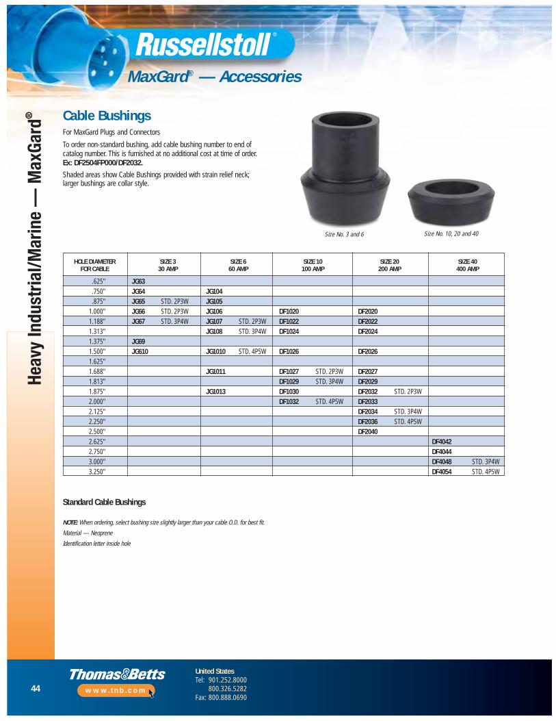
44
United StatesTel: 901.252.8000
800.326.5282Fax: 800.888.0690
www.tnb.com
Heav
y In
dust
rial/M
arin
e —
Max
Gard
®
MaxGard® — Accessories
Cable BushingsFor MaxGard Plugs and Connectors
To order non-standard bushing, add cable bushing number to end of catalog number. This is furnished at no additional cost at time of order. Ex: DF2504FP000/DF2032.
Shaded areas show Cable Bushings provided with strain relief neck; larger bushings are collar style.
Standard Cable Bushings
NOTE: When ordering, select bushing size slightly larger than your cable O.D. for best fit.
Material — Neoprene
Identification letter inside hole
Size No. 3 and 6
HOLE DIAMETER SIZE 3 SIZE 6 SIZE 10 SIZE 20 SIZE 40FOR CABLE 30 AMP 60 AMP 100 AMP 200 AMP 400 AMP
.625" JG63
.750" JG64 JG104
.875" JG65 STD. 2P3W JG1051.000" JG66 STD. 2P3W JG106 DF1020 DF20201.188" JG67 STD. 3P4W JG107 STD. 2P3W DF1022 DF20221.313" JG108 STD. 3P4W DF1024 DF20241.375" JG691.500" JG610 JG1010 STD. 4P5W DF1026 DF20261.625"1.688" JG1011 DF1027 STD. 2P3W DF20271.813" DF1029 STD. 3P4W DF20291.875" JG1013 DF1030 DF2032 STD. 2P3W2.000" DF1032 STD. 4P5W DF20332.125" DF2034 STD. 3P4W2.250" DF2036 STD. 4P5W2.500" DF20402.625" DF40422.750" DF40443.000" DF4048 STD. 3P4W3.250" DF4054 STD. 4P5W
Size No. 10, 20 and 40
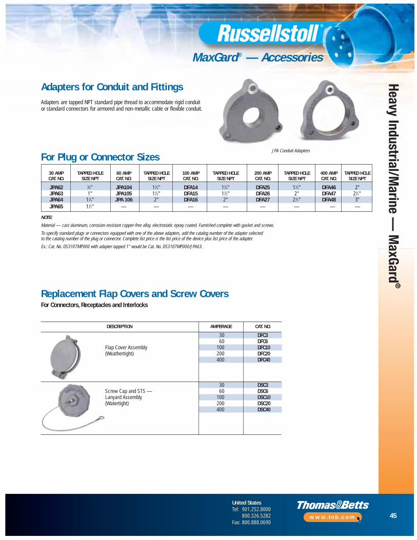
45
United StatesTel: 901.252.8000
800.326.5282Fax: 800.888.0690
www.tnb.com
Heavy Industrial/Marine —
MaxGard
®
MaxGard® — Accessories
Adapters for Conduit and FittingsAdapters are tapped NPT standard pipe thread to accommodate rigid conduit or standard connectors for armored and non-metallic cable or flexible conduit.
Replacement Flap Covers and Screw CoversFor Connectors, Receptacles and Interlocks
For Plug or Connector Sizes30 AMP TAPPED HOLE 60 AMP TAPPED HOLE 100 AMP TAPPED HOLE 200 AMP TAPPED HOLE 400 AMP TAPPED HOLECAT. NO. SIZE NPT CAT. NO. SIZE NPT CAT. NO. SIZE NPT CAT. NO. SIZE NPT CAT. NO. SIZE NPT
JPA62 3⁄4" JPA104 11⁄4" DFA14 11⁄4" DFA25 11⁄2" DFA46 2"JPA63 1" JPA105 11⁄2" DFA15 11⁄2" DFA26 2" DFA47 21⁄2"JPA64 11⁄4" JPA 106 2" DFA16 2" DFA27 21⁄2" DFA48 3"JPA65 11⁄2" — — — — — — — —
NOTE:
Material — cast aluminum, corrosion-resistant copper-free alloy, electrostatic epoxy coated. Furnished complete with gasket and screws.
To specify standard plugs or connectors equipped with one of the above adapters, add the catalog number of the adapter selected to the catalog number of the plug or connector. Complete list price is the list price of the device plus list price of the adapter.
Ex.: Cat. No. DS3107MP000 with adapter tapped 1" would be Cat. No. DS3107MP000/JPA63.
JPA Conduit Adapters
DESCRIPTION AMPERAGE CAT. NO.
30 DFC360 DFC6
Flap Cover Assembly 100 DFC10(Weathertight) 200 DFC20
400 DFC40
30 DSC3Screw Cap and STS — 60 DSC6Lanyard Assembly 100 DSC10(Watertight) 200 DSC20
400 DSC40
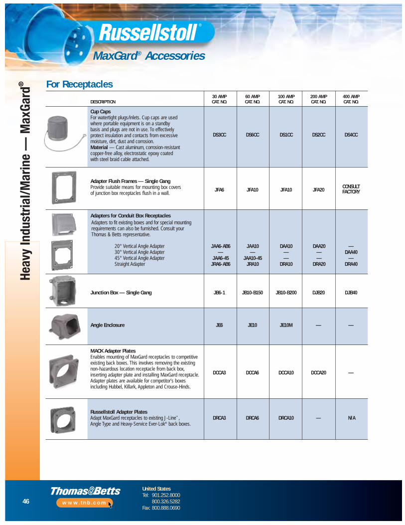
46
United StatesTel: 901.252.8000
800.326.5282Fax: 800.888.0690
www.tnb.com
MaxGard® Accessories
Heav
y In
dust
rial/M
arin
e —
Max
Gard
®
30 AMP 60 AMP 100 AMP 200 AMP 400 AMPDESCRIPTION CAT. NO. CAT. NO. CAT. NO. CAT. NO. CAT. NO.
Cup CapsFor watertight plugs/inlets. Cup caps are usedwhere portable equipment is on a standby basis and plugs are not in use. To effectively
DS3CC DS6CC DS1CC DS2CC DS4CCprotect insulation and contacts from excessive moisture, dirt, dust and corrosion. Material — Cast aluminum, corrosion-resistantcopper-free alloy, electrostatic epoxy coatedwith steel braid cable attached.
Adapter Flush Frames — Single Gang
JFA6 JFA10 JFA10 JFA20CONSULTProvide suitable means for mounting box covers FACTORYof junction box receptacles flush in a wall.
Adapters for Conduit Box Receptacles
Junction Box — Single Gang JB6-1 JB10-B150 JB10-B200 DJB20 DJB40
Angle Enclosure JE6 JE10 JE10M — —
MACK Adapter PlatesEnables mounting of MaxGard receptacles to competitiveexisting back boxes. This involves removing the existing non-hazardous location receptacle from back box,
DCCA3 DCCA6 DCCA10 DCCA20 —inserting adapter plate and installing MaxGard receptacle.Adapter plates are available for competitor’s boxes including Hubbel, Killark, Appleton and Crouse-Hinds.
Russellstoll Adapter PlatesAdapt MaxGard receptacles to existing J-Line™, DRCA3 DRCA6 DRCA10 — N/AAngle Type and Heavy-Service Ever-Lok® back boxes.
For Receptacles
Adapters to fit existing boxes and for special mountingrequirements can also be furnished. Consult your Thomas & Betts representative.
20° Vertical Angle Adapter JAA6-AB6 JAA10 DAA10 DAA20 —30° Vertical Angle Adapter — — — — DAA4045° Vertical Angle Adapter JAA6-45 JAA10-45 — — —Straight Adapter JRA6-AB6 JRA10 DRA10 DRA20 DRA40
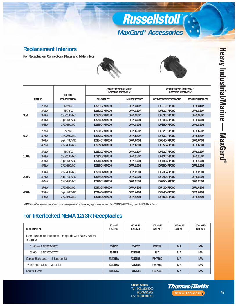
47
United StatesTel: 901.252.8000
800.326.5282Fax: 800.888.0690
www.tnb.com
Heavy Industrial/Marine —
MaxGard
®
MaxGard® Accessories
Replacement InteriorsFor Receptacles, Connectors, Plugs and Male Inlets
CORRESPONDING MALE CORRESPONDING FEMALE
VOLTAGEINTERIOR ASSEMBLY INTERIOR ASSEMBLY
RATING POLARIZATION PLUG/INLET MALE INTERIOR CONNECTOR/RECEPTACLE FEMALE INTERIOR
2P3W 125VAC DS3107MP000 DFPU3107 DF3107FP000 DFRU3107
2P3W 250VAC DS3207MP000 DFPU3207 DF3207FP000 DFRU3207
30A 3P4W 125/250VAC DS3307MP000 DFPU3307 DF3307FP000 DFRU3307
3P4W 3-ph 480VAC DS3404MP000 DFPU3404 DF3404FP000 DFRU3404
4P5W 277/480VAC DS3504MP000 DFPU3504 DF3504FP000 DFRU3504
2P3W 250VAC DS6207MP000 DFPU6207 DF6207FP000 DFRU6207
60A 3P4W 125/250VAC DS6307MP000 DFPU6307 DF6307FP000 DFRU6307
3P4W 3-ph 480VAC DS6404MP000 DFPU6404 DF6404FP000 DFRU6404
4P5W 277/480VAC DS6504MP000 DFPU6504 DF6504FP000 DFRU6504
2P3W 250VAC DS1207MP000 DFPU1207 DF1207FP000 DFRU1207
100A 3P4W 125/250VAC DS1307MP000 DFPU1307 DF1307FP000 DFRU1307
3P4W 3-ph 480VAC DS1404MP000 DFPU1404 DF1404FP000 DFRU1404
4P5W 277/480VAC DS1504MP000 DFPU1504 DF1504FP000 DFRU1504
3P4W 277/480VAC DS2304MP000 DFPU2304 DF2304FP000 DFRU2304
200A 3P4W 3-ph 480VAC DS2404MP000 DFPU2404 DF2404FP000 DFRU2404
4P5W 277/480VAC DS2504MP000 DFPU2504 DF2504FP000 DFRU2504
3P4W 277/480VAC DS4304MP000 DFPU4304 DF4304FP000 DFRU4304
400A 3P4W 3-ph 480VAC DS4404MP000 DFPU4404 DF4404FP000 DFRU4404
4P5W 277/480VAC DS4504MP000 DFPU4504 DF4504FP000 DFRU4504
NOTE: For other interiors not shown, use same polarization index as plug, connector, etc. Ex: DS6416MP000 plug uses DFPU6416 interior.
30 AMP 60 AMP 100 AMP 200 AMP 400 AMPDESCRIPTION CAT. NO. CAT. NO. CAT. NO. CAT. NO. CAT. NO.
Fused Disconnect Interlocked Receptacle with Safety Switch30–100A
1 NO — 1 NC CONTACT F34757 F34757 F34757 N/A N/A
2 NO — 2 NC CONTACT F34758 F34756B N/A N/A N/A
Copper Body Lugs — 6 lugs per kit F34756A F34756B F34756C N/A N/A
Type R Fuse Clips — 3 per kit F34755A F34755B F34755C N/A N/A
Neutral Block F34754A F34754B F34754B N/A N/A
For Interlocked NEMA 12/3R Receptacles

48
United StatesTel: 901.252.8000
800.326.5282Fax: 800.888.0690
www.tnb.com
Heav
y In
dust
rial/M
arin
e —
Max
Gard
®
MaxGard ® Engineering Specifications
Rating for Pilot/Control ContactsContact Rating Code Designation A-600, Table 119.1 — UL 508 Heavy Pilot Duty Load (720 VA/600VAC) Maximum
THERMALCONTINUOUS
MAXIMUM CURRENT, AMPERE
CURRENT AMPS 120V 240V 480V 600V MAX VOLT AMPERE
Make Break Make Break Make Break Make Break Make Break10 (#12 AWG) 60 6 30 3 15 1.5 12 1.2 7200 720
Pin and Sleeve Plugs, Receptacles and Systems
1.0 Scope
1.1 This document covers multi-contact pin and sleeve, industrial grade,arc-quenching, circuit interrupting-rated electrical plugs, motorplugs, connectors, receptacles, mechanically inter locked receptaclesand assorted accessories. Usable in dry, damp, wet, marine and/orhazardous locations for electrical power circuits. Devices are to berated 30, 60, 100, 200 and/or 400 amperes at 600VAC, 50–400Hzand 250VDC maximum. Devices are also rated for continuous usein temperatures from -40˚ C to +130˚ C. These devices mustprovide internal environmental seals for marine and extreme wetapplications and can be electrically interlocked.
1.2 The devices described shall be Thomas & Betts/RussellstollMaxGard® catalog numbers as specified.
2.0 Product Classifications (Features)
2.1 Gated Deadfront — All receptacles and connectors must have a rotating disk on the face of the interior, which provides live contactisolation and environmental separation.
2.2 Delayed Action Arc Containment — All devices upon disconnectunder load shall have provision so the arc is contained andextinguished within the insulation cavity, making it impossible to withdraw a live plug.
2.3 Flap Cover or Screw Cover Option — Flap cover option must provide weathertight capability by utilizing a spring actuatedself-closing flap. Watertight capability shall be obtained by using a gasketed screw cap.
2.4 Polarization — All devices shall be factory polarized foramperage, voltage, frequency and phase; thus providing a single voltage rating, single interface system.
2.5 Grounding — The grounding of the device shall be accomplishedthrough a separate center ground (earth) make-first and break-lastpole on all devices for complete system grounding.
2.6 Pole Capabilities — All devices shall accom modate up to four power pins plus a separate center ground pin and they shall be integral with the connector bodies (5 pins total).
2.7 Interior Type — Interiors must be male (pin type) or female (sleeve type). Pins and sleeves shall also be self-aligning and self-wiping/self-cleaning.
2.8 Control Contacts — All devices must have an option for two control contacts, which shall be make-last and break-first for use in electrical interlocks and/or control circuits. See table below.
2.9 Conductor Terminals — Pin and sleeve connections shall employsolderless pressure type screw terminals and be sized to acceptstranded or solid copper conductors in AWG sizes (max. O.D.s asnoted). The screw terminals shall also have socket heads to ensureproper torquing of wires.
2.10 Environmental Seals — Each device must have an environmentalseal or O-ring around all interiors and around each pin and sleeveto prevent water and contaminants from entering the wiringcompartment. This provides waterproof capability, even when not mated.
2.11 Hazardous Location — All standard plugs 30, 60 and 100 ampshall be UL and CSA listed for hazardous location Class I Division 1,Groups C and D; Class II Division 1, Groups F and G. A hazardouslocation circuit breaker-pro tected interlock shall also be applicableto the same environments and possess all the same productfeatures as outlined above. Enclosures shall meet NEMA 8hazardous outdoor-duty classifications and shall meet shipboard use above deck in accordance with the Department ofTransportation (USCG “Green Water”).
2.12 Lockout Devices — Plug connection lockout is achieved by a padlock through plug sleeve housing hole provided for thispurpose. On Hazardous Location/Explosion Proof InterlockReceptacles, lockout shall additionally be achieved by separate lockout accessory available from the factory. On standard Interlocks,lockout accessory/construction is available from the factory.
MAXIMUM CURRENT AMPRERE
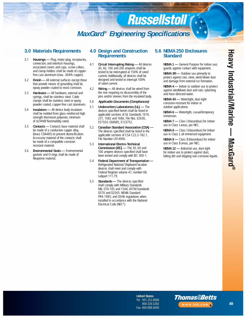
49
United StatesTel: 901.252.8000
800.326.5282Fax: 800.888.0690
www.tnb.com
Heavy Industrial/Marine —
MaxGard
®
MaxGard ® Engineering Specifications
3.0 Materials Requirements
3.1 Housings — Plug, motor plug, receptacles,connectors and interlock housings,associated covers and caps, screw collars, and clamp holders shall be made of copper-free cast aluminum (max. .004% copper).
3.2 Finish — All external surfaces except thosethat provide means of grounding shall beepoxy powder coated to resist corrosion.
3.3 Hardware — All hardware, external andsprings, shall be stainless steel. Cableclamps shall be stainless steel or epoxypowder coated, copper-free cast aluminum.
3.4 Insulators — All device body insulatorsshall be molded from glass-reinforced highstrength thermoset polyester, minimum of UL94VØ flammability rated.
3.5 Contacts — Contacts base material shall be made of a conductive copper alloy, (brass CDA485) to prevent dezincification.Accessory material of the contacts shall be made of a compatible corrosion resistant material.
3.6 Environmental Seals — Environmentalgaskets and O-rings shall be made ofNeoprene material.
4.0 Design and ConstructionRequirements
4.1 Circuit Interrupting Rating — All devices30, 60, 100 and 200 amperes shall betested to be interrupted at 150% of ratedcurrent. Additionally, all devices shall bedesigned and tested to interrupt 100% of rated current.
4.2 Wiring — All devices shall be wired fromthe rear requiring no disassembly of the pins and/or sleeves from the insulated body.
5.0 Applicable Documents (Compliances)
5.1 Underwriters Laboratories (UL) — Thedevices specified herein shall be listed inapplicable sections of UL Standards 1010,231, 1682 and 1686, File Nos. E2630,E57324, E68085, E123752.
5.2 Canadian Standard Association (CSA) —The devices specified shall be listed in theapplicable sections of CSA C22.2-182.1, File Number LR14096.
5.3 International Electro-TechnicalCommission (IEC) — The 30, 60 and 100 ampere devices specified shall havebeen tested and comply with IEC 309-1.
5.4 Federal Department of Transportation —Refrigerated National Shipboard locationdevices shall meet and comply with Federal Register volume 47, number 68,subpart 111.79.
5.5 Standards — The devices specified shall comply with Military Standards MIL-STD-105 and 1344; ASTM StandardsD570 and D2565: NEMA Standard PR4-1983; and OSHA regulations wheninstalled in accordance with the NationalElectrical Code (NEC®).
5.6 NEMA 250 EnclosuresStandard
NEMA 1 — General Purpose for indoor use;guards against contact with equipment.
NEMA 3R — Outdoor use primarily toprotect against rain, sleet, wind-blown dustand damage from external ice formation.
NEMA 4 — Indoor or outdoor use to protectagainst windblown dust and rain; splashingand hose-directed water.
NEMA 4X — Watertight, dust-tightcorrosion-resistant for indoor or outdoor applications.
NEMA 6 — Watertight, casual/temporaryimmersion.
NEMA 7 — Class I (Hazardous) for indooruse in Class I areas, per NEC.
NEMA 8 — Class I (Hazardous) for indooruse in Class I, oil-immersed equipment.
NEMA 9 — Class II (Hazardous) for indooruse in Class II areas, per NEC.
NEMA 12 — Industrial use, dust-tight for indoor use to protect against dust, falling dirt and dripping non-corrosive liquids.

50
United StatesTel: 901.252.8000
800.326.5282Fax: 800.888.0690
www.tnb.com
Heav
y In
dust
rial/M
arin
e —
Max
Gard
®
MaxGard® Voltage Selection
Single Polarization/Multiple Service* Assigned Voltages and Wiring Systems
N-R1-G R1-S2-G N-R1-S2-G R1-S2-T3-G N-R1-S2-T3-G 2P+G(DC)
VOLTAGE VOLTAGE VOLTAGE VOLTAGE VOLTAGE VOLTAGEASSIGN. ASSIGN. ASSIGN. ASSIGN. ASSIGN. ASSIGN.NO. VOLTAGE NO. VOLTAGE NO. VOLTAGE NO. VOLTAGE NO. VOLTAGE NO. VOLTAGE INDEX
101 220V–50Hz 201 380V–50Hz 301 220/380V–50Hz 401 380V–50Hz 501 220/380V–50Hz 01103 127V–50Hz 203 220V–50Hz 303 220/127V–50Hz 403 220V–50Hz 503 220/127V–50Hz 03104 277V–60Hz 204 480V–60Hz 304 277/480V–60Hz 404 3Ø 480V–60Hz 504 3ØY 277/480V–60Hz 04105 250V–50Hz 205 440V–50Hz 305 250/440V–50Hz 405 3Ø 440V–50Hz 505 3Ø 250/440V–50Hz 05107 125V–60Hz 207 250V–60Hz 307 125/250V–60Hz 407 3Ø 250V–60Hz 507 3ØY 125/250V–60Hz 07108 220V–60Hz 208 380V–60Hz 308 220/380V–60Hz 408 3Ø 380V–60Hz 508 3Ø 220/380V–60Hz 08109 100V–60Hz 209 220V–60Hz 309 100/220V–60Hz 409 3Ø 220V–60Hz 509 3Ø 100/220V–60Hz 09111 115V–400Hz 211 220V–400Hz 311 220/115V–400Hz 411 220V–400Hz 511 220/115V–400Hz 11
— — — — 513 230V DC 613 250 VDC 13114 347V–60Hz 214 600V–60Hz 314 347/600V–60Hz 414 3Ø 600V–60Hz 514 3ØY 347/600V–60Hz 14115 100V–50Hz 215 220V–50Hz 315 100/220V–50Hz 415 3Ø 220V–50Hz 515 3Ø 100/220V–50Hz 15116 120V–60Hz 216 208V–60Hz 316 120/208V–60Hz 416 3Ø 208V–60Hz 516 3ØY 120/208V–60Hz 16117 120V–400Hz 217 208V–400Hz 317 120/208V–400Hz 417 3Ø 208V–400Hz 517 3Ø 120/208V–400Hz 17
— — — 208V — 618 28 VDC 1820
— 221 440V–60Hz 321 250/440V–60Hz 421 3Ø 440V–60Hz 521 3ØY 250/440V–60Hz 21250V Reserved 22480V Reserved 23600V Reserved 24
G
1 N
G
1
2
G
1
2
G
3
N
G
1 N
G
1 N
2 3 32
MaxGard receptacles and plugs may be furnished in any of the above voltageand phasing systems.
To order any device in a voltage and phasing not shown in the precedingcatalog pages, substitute the Voltage Assignment Number in the above chartfor that portion of the listed catalog number appearing in boldface type.
Example: 200 Amp Weathertight Receptacle with Flap Cover, Angle Adapterand Junction Box for 3Ø 480 volt (3-pole and ground) is DF2404FRAB0.
To change to 3Ø 208 volt, the catalog number becomes DF2416FRAB0.NOTE: All devices may be furnished with two control contacts. Add “K” to the end of thecatalog number, in place of last position Ø.
* Dual-Voltage or Multiple-Service Applications (for any givenpolarization number) — Example: A factory installation may consist of all receptacles specified and wired at polarization “507.” This is a3ph.Y–125/250V–60Hz supply. However, all circuit requirements “below”(507) can also be met; for instance a “207” plug will draw phasing for250V–60Hz operation of equipment as well, while another “.507” receptaclesupplies power for a 3-phase motor installation. See chart above.
For non-interrupting polarizations at 45, 90, 150, 300, 600A ratings, consultTechnical Services.

51
United StatesTel: 901.252.8000
800.326.5282Fax: 800.888.0690
www.tnb.com
Heavy Industrial/Marine —
MaxGard
®
MaxGard® Dimensions
Connector Male Inlet
Receptacle withAngle Enclosure
Receptacle with AngleAdapter and DJB
Junction Box
Receptacle with Angle Adapter
(Flap covers shown — screw covers available. On all, screw covers have nominal effect on outside dimensions.)
Male Plug
A AA
A
A
A
B
C
C
B
B
B
CB
B
Amp A B
30 43⁄4" 77⁄8"60 51⁄2" 91⁄8"100 61⁄2" 101⁄8"200 9" 133⁄4"400 125⁄8" 175⁄8"
Amp A B
30 83⁄4" 51⁄8"60 10" 53⁄8"
100 111⁄8" 53⁄8"200 15" 91⁄2"400 191⁄8" 103⁄4"
Amp A B C
30 27⁄8" 21⁄2" 51⁄2"60 33⁄8" 21⁄2" 51⁄2"100 33⁄8" 21⁄2" 51⁄2"200 51⁄4" 31⁄2" 91⁄4"400 35⁄8" 43⁄8" 91⁄4"
Amp A B C
30 63⁄8" 31⁄8" 97⁄8"60 71⁄8" 4" 111⁄8"100 71⁄2" 4" 113⁄8"200 — — —400 — — —
Amp A B C
30 91⁄8" 3" 95⁄8"60 101⁄2" 3" 93⁄4"100 103⁄4" 33⁄4" 10"200 153⁄4" 65⁄8" 145⁄8"400 251⁄4" 12" 203⁄4"
Amp A B
30 61⁄8" 95⁄8"60 71⁄2" 93⁄4"100 7" 10"200 91⁄2" 143⁄4"400 131⁄4" 203⁄4"
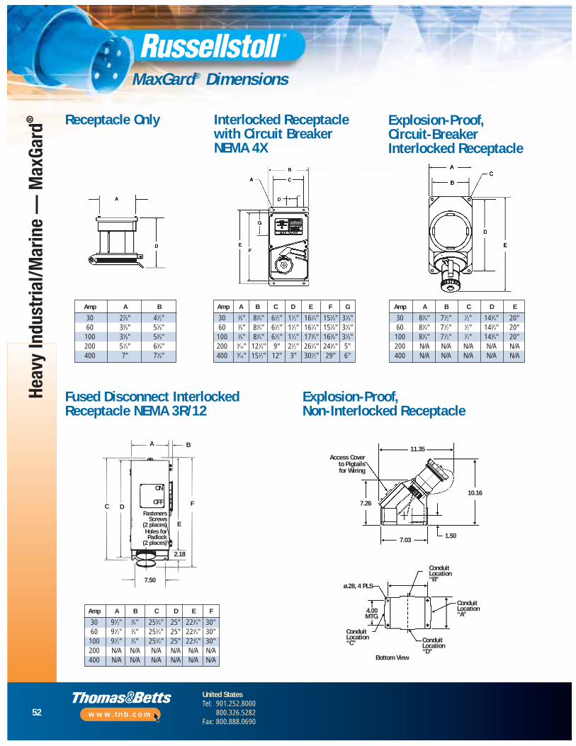
52
United StatesTel: 901.252.8000
800.326.5282Fax: 800.888.0690
www.tnb.com
Heav
y In
dust
rial/M
arin
e —
Max
Gard
®
MaxGard® Dimensions
Receptacle Only Interlocked Receptaclewith Circuit Breaker NEMA 4X
Explosion-Proof, Circuit-Breaker Interlocked Receptacle
Fused Disconnect Interlocked Receptacle NEMA 3R/12
Explosion-Proof, Non-Interlocked Receptacle
Fasteners Screws2 PlacesHoles for Padlock2 Places
C D
BA
F
E
7.50
2.18
ON
OFF
FastenersScrews
(2 places)
Access Cover to Pigtails for Wiring
ON
A B
C D
E
F
2.18
7.50
7.03
ø.28, 4 PLS
4.00MTG.
ConduitLocation“B’’
ConduitLocation“B’’
ConduitLocation“A’’
ConduitLocation“D’’
ConduitLocation“C’’
Bottom View
1.50
10.16
11.35
7.26OFF
Holes forPadlock
(2 places)
Amp A B
30 27⁄8" 41⁄2"60 33⁄8" 51⁄8"100 35⁄8" 53⁄8"200 51⁄4" 65⁄8"400 7" 71⁄8"
Amp A B C D E F G
30 3⁄8" 83⁄4" 61⁄2" 11⁄2" 161⁄4" 151⁄8" 31⁄8"60 3⁄8" 83⁄4" 61⁄2" 11⁄2" 161⁄4" 151⁄8" 31⁄8"100 3⁄8" 83⁄4" 61⁄2" 11⁄2" 173⁄4" 165⁄8" 31⁄8"200 9⁄16" 121⁄4" 9" 21⁄2" 261⁄4" 243⁄4" 5"400 9⁄16" 151⁄2" 12" 3" 301⁄2" 29" 6"
Amp A B C D E
30 83⁄4" 71⁄2" 1⁄2" 143⁄4" 20"60 83⁄4" 71⁄2" 1⁄2" 143⁄4" 20"
100 83⁄4" 71⁄2" 1⁄2" 143⁄4" 20"200 N/A N/A N/A N/A N/A400 N/A N/A N/A N/A N/A
Amp A B C D E F
30 91⁄2" 3⁄4" 253⁄4" 25" 223⁄4" 30"60 91⁄2" 3⁄4" 253⁄4" 25" 223⁄4" 30"100 91⁄2" 3⁄4" 253⁄4" 25" 223⁄4" 30"200 N/A N/A N/A N/A N/A N/A400 N/A N/A N/A N/A N/A N/A
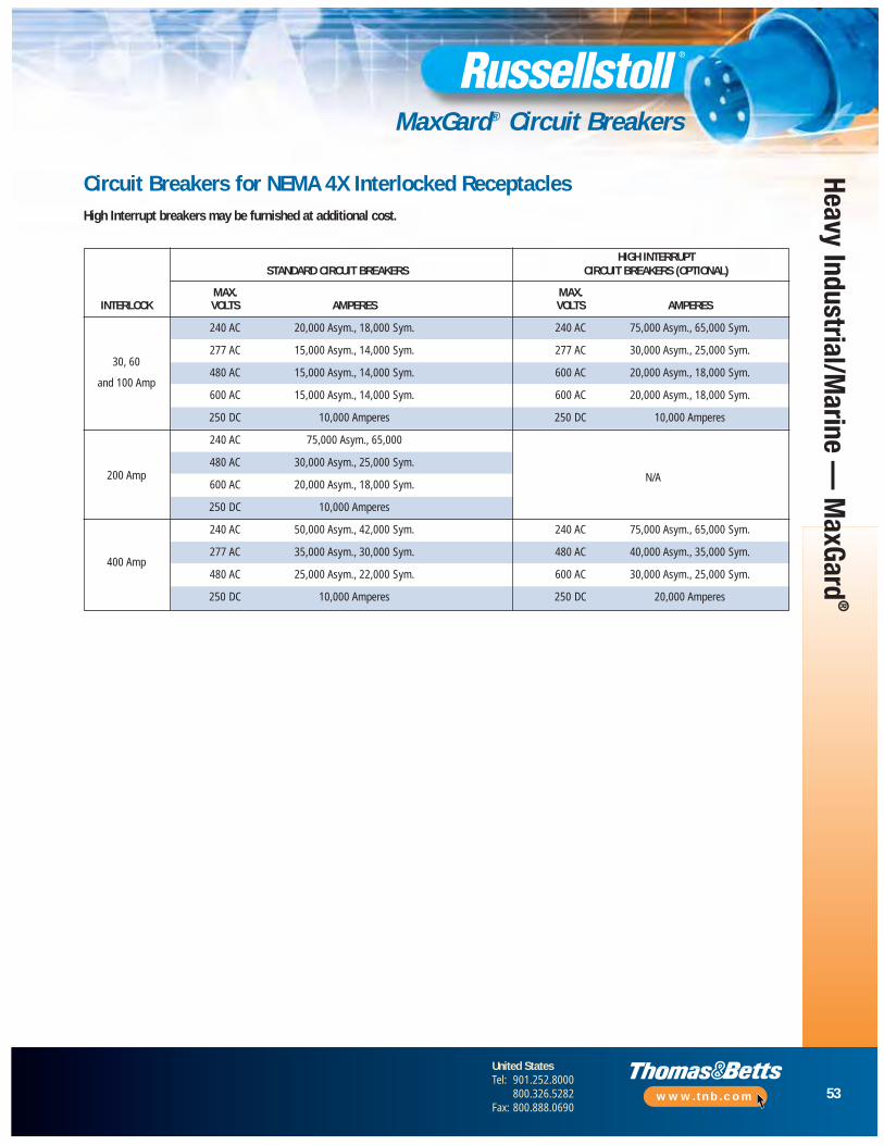
53
United StatesTel: 901.252.8000
800.326.5282Fax: 800.888.0690
www.tnb.com
Heavy Industrial/Marine —
MaxGard
®
MaxGard® Circuit Breakers
Circuit Breakers for NEMA 4X Interlocked ReceptaclesHigh Interrupt breakers may be furnished at additional cost.
HIGH INTERRUPTSTANDARD CIRCUIT BREAKERS CIRCUIT BREAKERS (OPTIONAL)
MAX. MAX.INTERLOCK VOLTS AMPERES VOLTS AMPERES
240 AC 20,000 Asym., 18,000 Sym. 240 AC 75,000 Asym., 65,000 Sym.
30, 60277 AC 15,000 Asym., 14,000 Sym. 277 AC 30,000 Asym., 25,000 Sym.
and 100 Amp480 AC 15,000 Asym., 14,000 Sym. 600 AC 20,000 Asym., 18,000 Sym.
600 AC 15,000 Asym., 14,000 Sym. 600 AC 20,000 Asym., 18,000 Sym.
250 DC 10,000 Amperes 250 DC 10,000 Amperes
240 AC 75,000 Asym., 65,000
200 Amp480 AC 30,000 Asym., 25,000 Sym.
600 AC 20,000 Asym., 18,000 Sym.N/A
250 DC 10,000 Amperes
240 AC 50,000 Asym., 42,000 Sym. 240 AC 75,000 Asym., 65,000 Sym.
400 Amp277 AC 35,000 Asym., 30,000 Sym. 480 AC 40,000 Asym., 35,000 Sym.
480 AC 25,000 Asym., 22,000 Sym. 600 AC 30,000 Asym., 25,000 Sym.
250 DC 10,000 Amperes 250 DC 20,000 Amperes
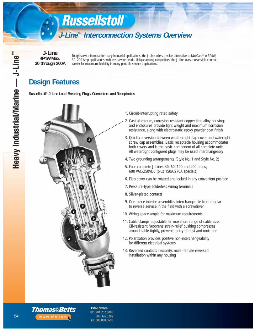
54
United StatesTel: 901.252.8000
800.326.5282Fax: 800.888.0690
www.tnb.com
Heav
y In
dust
rial/M
arin
e —
J-L
ine™
J-Line™ Interconnection Systems Overview
J-Line4P4W Max.
30 through 200A
Tough service in metal for many industrial applications, the J-Line offers a value alternative to MaxGard® in 3P4W, 30–200 Amp applications with less severe needs. Unique among competitors, the J-Line uses a reversible contract carrier for maximum flexibility in many portable service applications.
Design FeaturesRussellstoll® J-Line Load-Breaking Plugs, Connectors and Receptacles
1. Circuit-interrupting rated safety
2. Cast aluminum, corrosion-resistant copper-free alloy housingsand enclosures provide light weight and maximum corrosionresistance, along with electrostatic epoxy powder coat finish
3. Quick conversion between weathertight flap cover and watertightscrew cap assemblies. Basic receptacle housing accommodatesboth covers and is the basic component of all complete units. All watertight configured plugs may be used interchangeably
4. Two grounding arrangements (Style No. 1 and Style No. 2)
5. Four complete J-Lines 30, 60, 100 and 200 amps; 600 VAC/250VDC (plus 150A/270A specials)
6. Flap cover can be rotated and locked in any convenient position
7. Pressure-type solderless wiring terminals
8. Silver-plated contacts
9. One-piece interior assemblies interchangeable from regular to reverse service in the field with a screwdriver
10. Wiring space ample for maximum requirements
11. Cable clamps adjustable for maximum range of cable size. Oil-resistant Neoprene strain-relief bushing compresses around cable tightly, prevents entry of dust and moisture
12. Polarization provides positive non-interchangeability for different electrical systems
13. Reversed contacts flexibility: male–female reversedinstallation within any housing
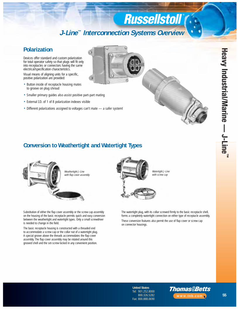
55
United StatesTel: 901.252.8000
800.326.5282Fax: 800.888.0690
www.tnb.com
Conversion to Weathertight and Watertight Types
Weathertight J-Linewith flap cover assembly
Watertight J-Linewith screw cap
Substitution of either the flap cover assembly or the screw cap assembly on the housing of the basic receptacle permits quick and easy conversionbetween the weathertight and watertight types. Only a small screwdriveris needed to change in the field.
The basic receptacle housing is constructed with a threaded end to accommodate a screw cap or the collar nut of a watertight plug. A special groove above the threads accommodates the flap cover assembly. The flap cover assembly may be rotated around this grooved shell and the set-screw locked in any convenient position.
The watertight plug, with its collar screwed firmly to the basic receptacle shell,forms a completely watertight connection on either type of receptacle assembly.
These conversion features also permit the use of flap cover or screw cap on connector housings.
Devices offer standard and custom polarizationfor total operator safety so that plugs will fit onlyinto receptacles or connectors having the sameelectrical/specification characteristics.
Visual means of aligning units for a specific,positive polarization are provided:
• Button inside of receptacle housing mates to groove on plug shroud
• Smaller primary guides also assist positive part-part mating
• External I.D. of 1 of 8 polarization indexes visible
• Different polarizations assigned to voltages can’t mate — a safer system!
Polarization
Heavy Industrial/Marine —
J-Line™
J-Line™ Interconnection Systems Overview
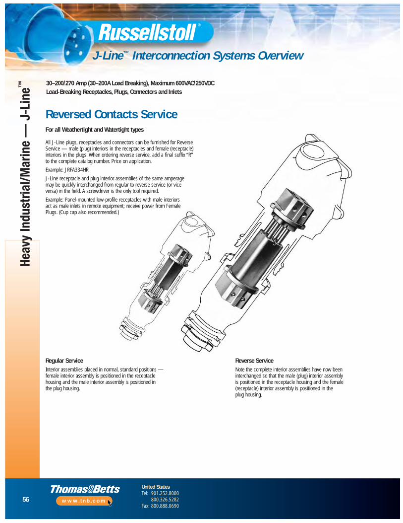
56
United StatesTel: 901.252.8000
800.326.5282Fax: 800.888.0690
www.tnb.com
Heav
y In
dust
rial/M
arin
e —
J-L
ine™
J-Line™ Interconnection Systems Overview
30–200/270 Amp (30–200A Load Breaking), Maximum 600VAC/250VDCLoad-Breaking Receptacles, Plugs, Connectors and Inlets
All J-Line plugs, receptacles and connectors can be furnished for ReverseService — male (plug) interiors in the receptacles and female (receptacle)interiors in the plugs. When ordering reverse service, add a final suffix “R” to the complete catalog number. Price on application.
Example: JRFA334HR
J-Line receptacle and plug interior assemblies of the same amperage may be quickly interchanged from regular to reverse service (or vice versa) in the field. A screwdriver is the only tool required.
Example: Panel-mounted low-profile receptacles with male interiors act as male inlets in remote equipment; receive power from FemalePlugs. (Cup cap also recommended.)
Reverse ServiceNote the complete interior assemblies have now beeninterchanged so that the male (plug) interior assembly is positioned in the receptacle housing and the female(receptacle) interior assembly is positioned in the plug housing.
Regular ServiceInterior assemblies placed in normal, standard positions —female interior assembly is positioned in the receptaclehousing and the male interior assembly is positioned in the plug housing.
Reversed Contacts ServiceFor all Weathertight and Watertight types
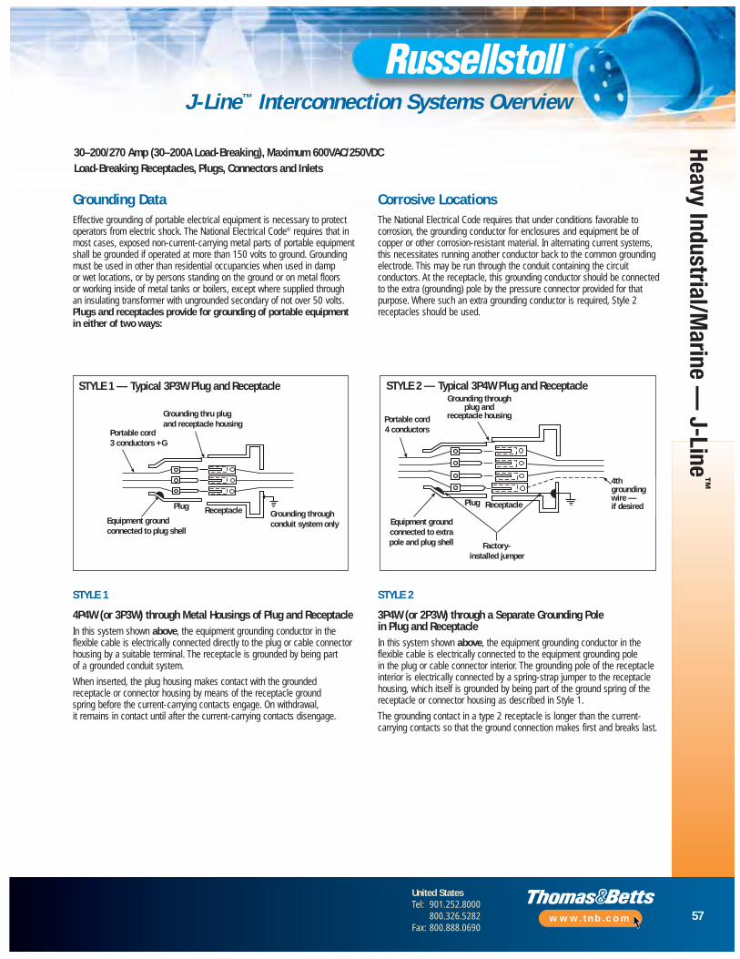
57
United StatesTel: 901.252.8000
800.326.5282Fax: 800.888.0690
www.tnb.com
Heavy Industrial/Marine —
J-Line™
J-Line™ Interconnection Systems Overview
30–200/270 Amp (30–200A Load-Breaking), Maximum 600VAC/250VDCLoad-Breaking Receptacles, Plugs, Connectors and Inlets
Grounding Data
Portable cord3 conductors + G
Grounding thruplug & receptaclehousing
Groundingthru conduitsystem onlyEquipment ground
connected toplug shell
PlugReceptacle
Portable cord4 conductors
Grounding thruplug & receptaclehousing
Equipment groundconnected to extrapole and plug shell
Plug Receptacle
Factory installedjumper
4th groundingwire – if desired
STYLE 1 — Typical 3P3W Plug and Receptacle STYLE 2 — Typical 3P4W Plug and Receptacle
STYLE 1
4P4W (or 3P3W) through Metal Housings of Plug and ReceptacleIn this system shown above, the equipment grounding conductor in theflexible cable is electrically connected directly to the plug or cable connectorhousing by a suitable terminal. The receptacle is grounded by being part of a grounded conduit system.
When inserted, the plug housing makes contact with the groundedreceptacle or connector housing by means of the receptacle ground spring before the current-carrying contacts engage. On withdrawal, it remains in contact until after the current-carrying contacts disengage.
STYLE 2
3P4W (or 2P3W) through a Separate Grounding Pole in Plug and ReceptacleIn this system shown above, the equipment grounding conductor in theflexible cable is elec trically connected to the equipment grounding pole in the plug or cable connector interior. The grounding pole of the receptacleinterior is elec trically connected by a spring-strap jumper to the receptaclehousing, which itself is grounded by being part of the ground spring of thereceptacle or con nector housing as described in Style 1.
The grounding contact in a type 2 receptacle is longer than the current-carrying contacts so that the ground connection makes first and breaks last.
Effective grounding of portable electrical equipment is necessary to protectoperators from electric shock. The National Electrical Code® requires that inmost cases, exposed non-current-carrying metal parts of portable equipmentshall be grounded if operated at more than 150 volts to ground. Groundingmust be used in other than residential occupancies when used in damp or wet locations, or by persons standing on the ground or on metal floors or working inside of metal tanks or boilers, except where supplied throughan insulating transformer with ungrounded secondary of not over 50 volts. Plugs and receptacles provide for grounding of portable equipmentin either of two ways:
Portable cord3 conductors +G
Grounding thru plugand receptacle housing
Receptacle
Factory- installed jumper
Equipment groundconnected to extrapole and plug shell
Portable cord4 conductors
Grounding throughplug and
receptacle housing
4thgroundingwire — if desiredPlug Plug
Equipment groundconnected to plug shell
Grounding throughconduit system only
Receptacle
The National Electrical Code requires that under conditions favorable tocorrosion, the grounding conductor for enclosures and equipment be ofcopper or other corrosion-resistant material. In alternating current systems,this necessitates running another conductor back to the common groundingelectrode. This may be run through the conduit containing the circuitconductors. At the receptacle, this grounding conductor should be connectedto the extra (grounding) pole by the pressure connector provided for thatpurpose. Where such an extra grounding conductor is required, Style 2receptacles should be used.
Corrosive Locations

58
United StatesTel: 901.252.8000
800.326.5282Fax: 800.888.0690
www.tnb.com
Heav
y In
dust
rial/M
arin
e —
J-L
ine™
J-Line™ Plugs, Connectors and Receptacles
30–270 Amp (30, 60, 100 and 200 Amp Load-Breaking, 150 and 270 Amp Special Service),Maximum 600VAC/250VDC Receptacles, Plugs, Connectors and Inlets Plugs
Current Rating Weathertight/Watertight Configuration
❒ ▼
2P3W JPS323H __Weathertight 3P3W* JPS333F
(Spring Hinged Flap Cover) 3P4W JPS334H30 Amp 4P4W* JPS344F
2P3W JPS323HWatertight 3P3W* JPS333F
(Screw Cover) 3P4W JPS334H4P4W* JPS344F
2P3W JPS623HWeathertight 3P3W* JPS633F
(Spring Hinged Flap Cover) 3P4W JPS634H60 Amp 4P4W* JPS644F
2P3W JPS623HWatertight 3P3W* JPS633F
(Screw Cover) 3P4W JPS634H4P4W* JPS644F
2P3W JPS1023HWeathertight 3P3W* JPS1033F
(Spring Hinged Flap Cover) 3P4W JPS1034H100 Amp 4P4W* JPS1044F
(150 Amp)** 2P3W JPS1023HWatertight 3P3W* JPS1033F
(Screw Cover) 3P4W JPS1034H4P4W* JPS1044F
2P3W JPS2023HWeathertight 3P3W* JPS2033F
(Spring Hinged Flap Cover) 3P4W JPS2034H200 Amp 4P4W* JPS2044F
(270 Amp)** 2P3W JPS2023HWatertight 3P3W* JPS2033F
(Screw Cover) 3P4W JPS2034H4P4W* JPS2044F
For any J-Line catalog numbers not shown here, check page 60 for “Series” information.For special polarizations (suffixes), contact Technical Services.
(All plugs come with watertight screw collar)
Max. 600VAC/250VDC
* Housing Ground Only (Style 1 Grounding), see page 57.
+ Shown with 20° angle adapter. Can be furnished with 45° angle at same price. When ordering, add suffix -45 to catalog number.
** Special rated devices (not shown). Consult Customer Service for details.
NOTE: To order Reverse Service, add a final suffix “R” to catalog number. Example: JRFA334HR — a receptacle housing with male interior.
❒ Polarization index (std. shown); consult Technical Services for more information.
♦ Flap Cover “F” noted. Screw Cover “S” also available.
▼ For Reversed Contacts, use “R” suffix to any catalog number.
Std. Cable Bushing
Current Rating Bushing I.D. Max. AWG Size
30 7⁄8" #6 7-strand or #8 flexible60 13⁄16" #4 7-strand or flexible
100 11⁄2" #10 19-strand or #1 flexible200 2" #4/0 19-strand or flexible
(See page 64 for other bushings.)
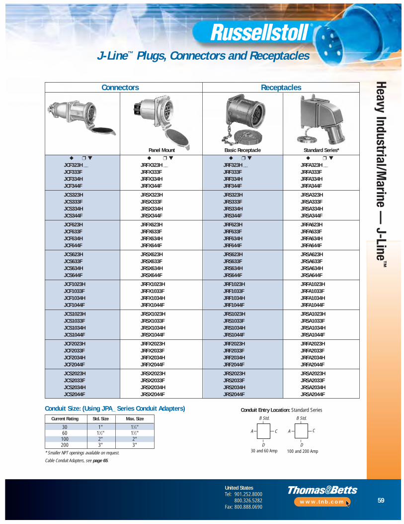
59
United StatesTel: 901.252.8000
800.326.5282Fax: 800.888.0690
www.tnb.com
Heavy Industrial/Marine —
J-Line™
J-Line™ Plugs, Connectors and Receptacles
Connectors Receptacles
Conduit Entry Location: Standard Series
30 and 60 Amp 100 and 200 Amp
B Std.
A C
D
B Std.
A C
D
Panel Mount Basic Receptacle Standard Series*
◆ ❒ ▼ ◆ ❒ ▼ ◆ ❒ ▼ ◆ ❒ ▼
JCF323H __ JRFX323H __ JRF323H __ JRFA323H __JCF333F JRFX333F JRF333F JRFA333FJCF334H JRFX334H JRF334H JRFA334HJCF344F JRFX344F JRF344F JRFA344F
JCS323H JRSX323H JRS323H JRSA323HJCS333F JRSX333F JRS333F JRSA333FJCS334H JRSX334H JRS334H JRSA334HJCS344F JRSX344F JRS344F JRSA344F
JCF623H JRFX623H JRF623H JRFA623HJCF633F JRFX633F JRF633F JRFA633FJCF634H JRFX634H JRF634H JRFA634HJCF644F JRFX644F JRF644F JRFA644F
JCS623H JRSX623H JRS623H JRSA623HJCS633F JRSX633F JRS633F JRSA633FJCS634H JRSX634H JRS634H JRSA634HJCS644F JRSX644F JRS644F JRSA644F
JCF1023H JRFX1023H JRF1023H JRFA1023HJCF1033F JRFX1033F JRF1033F JRFA1033FJCF1034H JRFX1034H JRF1034H JRFA1034HJCF1044F JRFX1044F JRF1044F JRFA1044F
JCS1023H JRSX1023H JRS1023H JRSA1023HJCS1033F JRSX1033F JRS1033F JRSA1033FJCS1034H JRSX1034H JRS1034H JRSA1034HJCS1044F JRSX1044F JRS1044F JRSA1044F
JCF2023H JRFX2023H JRF2023H JRFA2023HJCF2033F JRFX2033F JRF2033F JRFA2033FJCF2034H JRFX2034H JRF2034H JRFA2034HJCF2044F JRFX2044F JRF2044F JRFA2044F
JCS2023H JRSX2023H JRS2023H JRSA2023HJCS2033F JRSX2033F JRS2033F JRSA2033FJCS2034H JRSX2034H JRS2034H JRSA2034HJCS2044F JRSX2044F JRS2044F JRSA2044F
Current Rating Std. Size Max. Size
30 1" 11⁄4"60 11⁄2" 11⁄2"
100 2" 2"200 3" 3"
* Smaller NPT openings available on request.
Cable Conduit Adapters, see page 65.
Conduit Size: (Using JPA_ Series Conduit Adapters)

60
United StatesTel: 901.252.8000
800.326.5282Fax: 800.888.0690
www.tnb.com
Heav
y In
dust
rial/M
arin
e —
J-L
ine™
J-Line™ Construction
30–200/270 Amp (30–200A Load Breaking), Maximum 600VAC/250VDCLoad-Breaking Receptacles, Plugs, Connectors and Inlets
MountingCurrent Rating
Style To Order Use: 30 Amp 60 Amp 100/150 Amp 200/270 Amp
Standard Receptacle Basic Receptacle* Basic Receptacle* Basic Receptacle* Basic Receptacle*
Series+ + + + +
JRFA/JRSA ❒
Vertical or Square JB3-B100 JB6-B150 JB10-B200 JB20
Mount Box 1" Std. Conduit Size 1d" Std. Conduit Size 2" Std. Conduit Size 3" Std. Conduit Size
+ + + + +
AngleJAA3 (20°) JAA6-AB6 (20°) JAA10 (20°) JAA20 (20°)
Adapteror or or or
JAA3-45 (45°) JAA6-45 (45°) JAA10-45 (45°) JAA20-45 (45°)
Series Receptacle Basic Receptacle* Basic Receptacle* Basic Receptacle* Basic Receptacle*
JRFR/JRSR ❒+ + + + +
Straight
Vertical Mount JB3-B100 JB6-B150 JB10-B200 JB20
Box 1" Std. Conduit Size 11⁄2" Std. Conduit Size 2" Std. Conduit Size 3" Std. Conduit Size
+ + + + +
StraightJRA3 JRA6-AB6 JRA10 JRA20
Adapter
Series Receptacle Basic Receptacle* Basic Receptacle* Basic Receptacle* Basic Receptacle*
JRFB/JRSB ❒+ + + + +
30° AngleJAAB3 JAAB6 JAAB10 JAAB20
Adapter
Series Receptacle Basic Receptacle* Basic Receptacle* Basic Receptacle*JRFE/JRSE ❒
+ + + + N/A
Angle EnclosureJE3 JE6 JE10
1" Std. Conduit Size 11⁄2" Std. Conduit Size 2" Std. Conduit Size
Series Receptacle Basic Receptacle*
JRFH/JRSH ❒+ +
Horizontal
Horizontal JB3-B100 N/A N/A N/A
Mount Box 1" Std. Conduit Size
+ +
Angle Adapter JHA3 (20°)
* Select appropriate receptacle by rating, configuration and voltage on page 59. ❒ NOTE: JRXX 3rd letter denotes Flap (F) or Screw (S) Cover.Ex: JRSA — Screw CoverJRFA — Flap CoverJRF — Flap Cover, Basic ReceptacleJRS — Screw Cover, Basic Receptacle
Receptacle Mounting Options — J-Line ConstructionProgressive Assembly
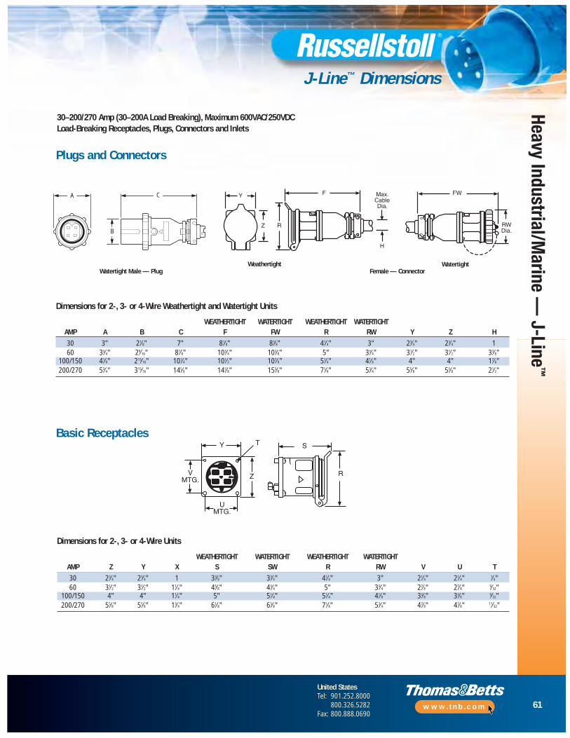
61
United StatesTel: 901.252.8000
800.326.5282Fax: 800.888.0690
www.tnb.com
Heavy Industrial/Marine —
J-Line™
J-Line™ Dimensions
30–200/270 Amp (30–200A Load Breaking), Maximum 600VAC/250VDCLoad-Breaking Receptacles, Plugs, Connectors and Inlets
Dimensions for 2-, 3- or 4-Wire Units
WEATHERTIGHT WATERTIGHT WEATHERTIGHT WATERTIGHTAMP Z Y X S SW R RW V U T
30 23⁄4" 23⁄4" 1 33⁄8" 33⁄4" 41⁄4" 3" 21⁄4" 21⁄4" 1⁄4"60 31⁄2" 31⁄2" 11⁄4" 45⁄8" 43⁄4" 5" 33⁄4" 27⁄8" 27⁄8" 9⁄32"
100/150 4" 4" 11⁄4" 5" 51⁄4" 51⁄4" 41⁄8" 33⁄8" 33⁄8" 9⁄32"200/270 55⁄8" 55⁄8" 13⁄4" 61⁄8" 63⁄8" 71⁄8" 53⁄4" 47⁄8" 47⁄8" 11⁄32"
Plugs and Connectors
Dimensions for 2-, 3- or 4-Wire Weathertight and Watertight Units
WEATHERTIGHT WATERTIGHT WEATHERTIGHT WATERTIGHTAMP A B C F FW R RW Y Z H
30 3" 21⁄8" 7" 81⁄8" 83⁄8" 41⁄4" 3" 23⁄4" 23⁄4" 160 33⁄4" 29⁄16" 87⁄8" 103⁄4" 103⁄8" 5" 33⁄4" 31⁄2" 31⁄2" 33⁄8"
100/150 41⁄8" 213⁄16" 101⁄4" 101⁄2" 107⁄8" 51⁄4" 41⁄8" 4" 4" 17⁄8"200/270 53⁄4" 315⁄16" 145⁄8" 147⁄8" 153⁄8" 71⁄8" 53⁄4" 55⁄8" 55⁄8" 21⁄2"
WeathertightFemale — Connector
WatertightWatertight Male — Plug
Basic Receptacles
A C
B
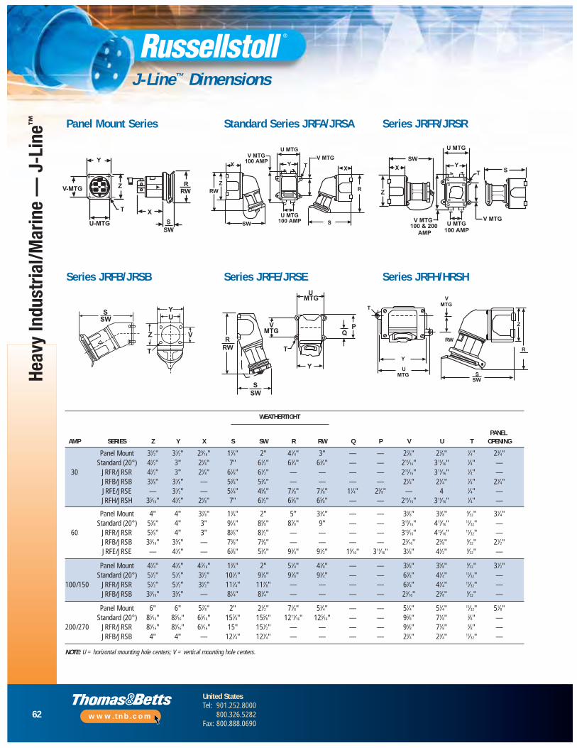
Heav
y In
dust
rial/M
arin
e —
J-L
ine™
J-Line™ Dimensions
Panel Mount Series Standard Series JRFA/JRSA Series JRFR/JRSR
Series JRFB/JRSB Series JRFE/JRSE Series JRFH/HRSH
NOTE: U = horizontal mounting hole centers; V = vertical mounting hole centers.
WEATHERTIGHT
PANELAMP SERIES Z Y X S SW R RW Q P V U T OPENING
Panel Mount 31⁄2" 31⁄2" 29⁄16" 13⁄4" 2" 41⁄4" 3" — — 27⁄8" 27⁄8" 1⁄4" 23⁄4"Standard (20°) 41⁄2" 3" 21⁄8" 7" 61⁄2" 63⁄4" 63⁄4" — — 211⁄16" 311⁄16" 1⁄4" —
30 JRFR/JRSR 41⁄2" 3" 21⁄8" 61⁄8" 61⁄2" — — — — 211⁄16" 311⁄16" 1⁄4" —JRFB/JRSB 31⁄8" 31⁄8" — 53⁄4" 53⁄4" — — — — 21⁄4" 21⁄4" 1⁄4" 21⁄4"JRFE/JRSE — 31⁄2" — 51⁄4" 45⁄8" 71⁄8" 71⁄8" 11⁄4" 23⁄8" — 4 1⁄4" —JRFH/JRSH 35⁄16" 41⁄2" 21⁄8" 7" 61⁄2" 65⁄8" 65⁄8" — — 211⁄16" 311⁄16" 1⁄4" —
Panel Mount 4" 4" 37⁄8" 13⁄4" 2" 5" 33⁄4" — — 33⁄8" 33⁄8" 9⁄32" 31⁄4"Standard (20°) 55⁄8" 4" 3" 91⁄4" 85⁄8" 87⁄8" 9" — — 313⁄16" 413⁄16" 11⁄32" —
60 JRFR/JRSR 55⁄8" 4" 3" 83⁄8" 81⁄2" — — — — 313⁄16" 415⁄16" 11⁄32" —JRFB/JRSB 33⁄16" 35⁄8" — 73⁄8" 73⁄8" — — — — 23⁄16" 25⁄8" 9⁄32" 21⁄2"JRFE/JRSE — 41⁄4" — 63⁄8" 53⁄4" 93⁄4" 91⁄2" 19⁄16" 311⁄16" 31⁄8" 41⁄2" 9⁄32" —
Panel Mount 41⁄4" 41⁄4" 47⁄16" 13⁄4" 2" 51⁄4" 41⁄8" — — 35⁄8" 35⁄8" 9⁄32" 31⁄2"Standard (20°) 51⁄2" 51⁄2" 31⁄2" 101⁄2" 97⁄8" 97⁄8" 93⁄4" — — 63⁄4" 41⁄4" 11⁄32" —
100/150 JRFR/JRSR 51⁄2" 51⁄2" 31⁄2" 111⁄4" 117⁄8" — — — — 63⁄4" 41⁄4" 11⁄32" —JRFB/JRSB 33⁄16" 35⁄8" — 81⁄4" 81⁄4" — — — — 23⁄16" 25⁄8" 9⁄32" —
Panel Mount 6" 6" 57⁄8" 2" 21⁄2" 71⁄8" 53⁄4" — — 51⁄4" 51⁄4" 11⁄32" 51⁄8"Standard (20°) 85⁄16" 85⁄16" 65⁄16" 157⁄8" 155⁄8" 1211⁄16" 125⁄16" — — 95⁄8" 71⁄8" 3⁄8" —
200/270 JRFR/JRSR 85⁄16" 85⁄16" 65⁄16" 15" 151⁄2" — — — — 95⁄8" 71⁄8" 3⁄8" —JRFB/JRSB 4" 4" — 121⁄4" 121⁄4" — — — — 23⁄4" 23⁄4" 11⁄32" —
62
United StatesTel: 901.252.8000
800.326.5282Fax: 800.888.0690
www.tnb.com
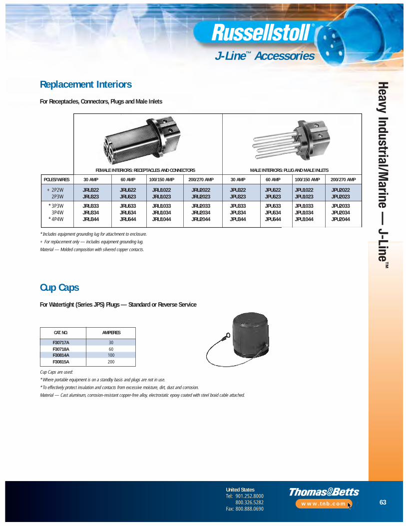
63
United StatesTel: 901.252.8000
800.326.5282Fax: 800.888.0690
www.tnb.com
Heavy Industrial/Marine —
J-Line™
J-Line™ Accessories
CAT. NO. AMPERES
F30717A 30
F30718A 60F30814A 100
F30815A 200
Replacement Interiors
For Receptacles, Connectors, Plugs and Male Inlets
FEMALE INTERIORS: RECEPTACLES AND CONNECTORS MALE INTERIORS: PLUG AND MALE INLETS
POLES/WIRES 30 AMP 60 AMP 100/150 AMP 200/270 AMP 30 AMP 60 AMP 100/150 AMP 200/270 AMP
+ 2P2W JRU322 JRU622 JRU1022 JRU2022 JPU322 JPU622 JPU1022 JPU20222P3W JRU323 JRU623 JRU1023 JRU2023 JPU323 JPU623 JPU1023 JPU2023
* 3P3W JRU333 JRU633 JRU1033 JRU2033 JPU333 JPU633 JPU1033 JPU20333P4W JRU334 JRU634 JRU1034 JRU2034 JPU334 JPU634 JPU1034 JPU2034
* 4P4W JRU344 JRU644 JRU1044 JRU2044 JPU344 JPU644 JPU1044 JPU2044
* Includes equipment grounding lug for attachment to enclosure.
+ For replacement only — includes equipment grounding lug.
Material — Molded composition with silvered copper contacts.
Cup Caps
For Watertight (Series JPS) Plugs — Standard or Reverse Service
Cup Caps are used:
* Where portable equipment is on a standby basis and plugs are not in use.
* To effectively protect insulation and contacts from excessive moisture, dirt, dust and corrosion.
Material — Cast aluminum, corrosion-resistant copper-free alloy, electrostatic epoxy coated with steel braid cable attached.
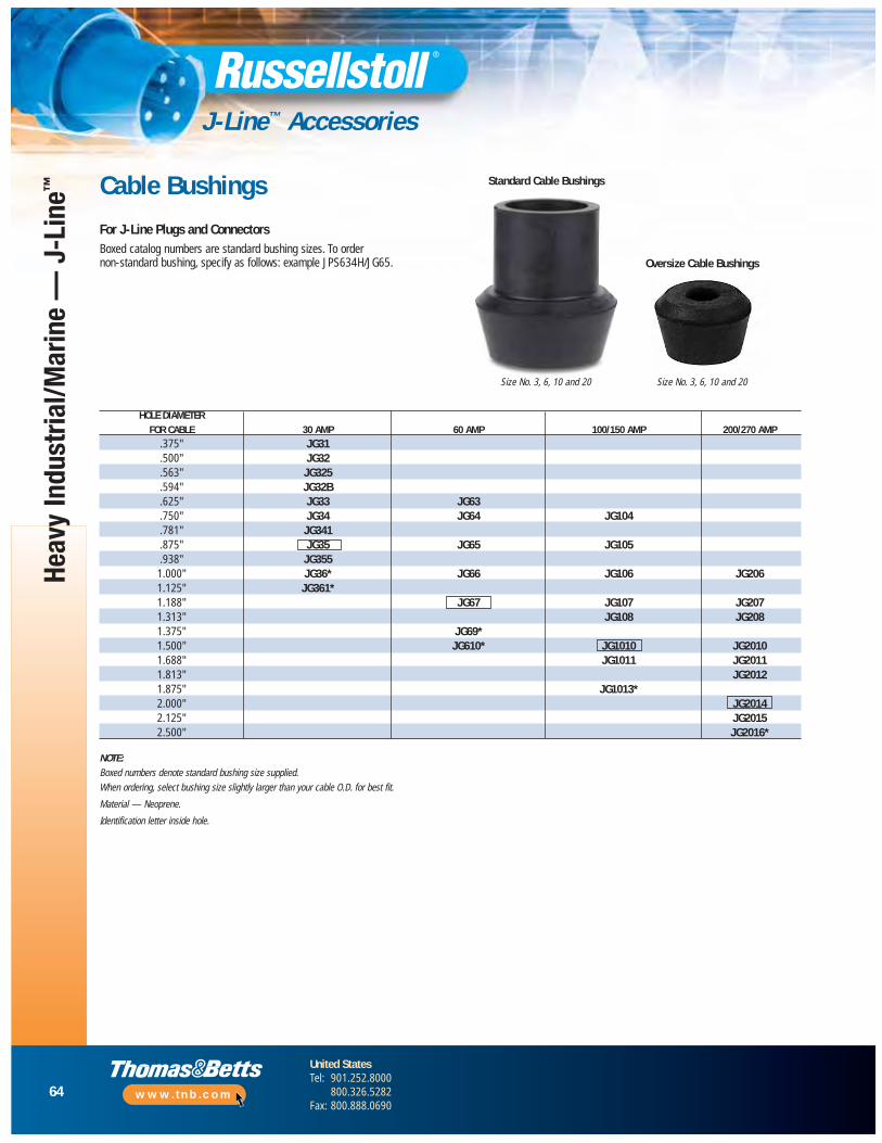
64
United StatesTel: 901.252.8000
800.326.5282Fax: 800.888.0690
www.tnb.com
Heav
y In
dust
rial/M
arin
e —
J-L
ine™
J-Line™ Accessories
Cable Bushings
For J-Line Plugs and ConnectorsBoxed catalog numbers are standard bushing sizes. To order non-standard bushing, specify as follows: example JPS634H/JG65.
HOLE DIAMETERFOR CABLE 30 AMP 60 AMP 100/150 AMP 200/270 AMP
.375" JG31
.500" JG32
.563" JG325
.594" JG32B
.625" JG33 JG63
.750" JG34 JG64 JG104
.781" JG341
.875" JG35 JG65 JG105
.938" JG3551.000" JG36* JG66 JG106 JG2061.125" JG361*1.188" JG67 JG107 JG2071.313" JG108 JG2081.375" JG69*1.500" JG610* JG1010 JG20101.688" JG1011 JG20111.813" JG20121.875" JG1013*2.000" JG20142.125" JG20152.500" JG2016*
NOTE:Boxed numbers denote standard bushing size supplied.
When ordering, select bushing size slightly larger than your cable O.D. for best fit.
Material — Neoprene.
Identification letter inside hole.
Standard Cable Bushings
Oversize Cable Bushings
Size No. 3, 6, 10 and 20 Size No. 3, 6, 10 and 20

65
United StatesTel: 901.252.8000
800.326.5282Fax: 800.888.0690
www.tnb.com
Heavy Industrial/Marine —
J-Line™
J-Line™ Accessories
Adapters for Conduit and Fittings
For use on J-Line Plugs and ConnectorsAdapters are tapped NPT standard pipe thread to accommodate rigid conduit or standard connectors for armored and non-metallic cable or flexible conduit.
* JPA65 @ 11⁄2" also available.
NOTE:Material — Cast aluminum, corrosion-resistant copper-free alloy, electrostatic epoxy coated.Furnished complete with gasket and screws.
To specify standard plugs or connectors equipped with one of the above adapters, add thecatalog number of the adapter selected to the catalog number of the plug or connector.Complete list price is the list price of the device plus list price of the adapter.
Example: Cat. No. JPS634H with adapter tapped 1" would be Cat. No. JPS634H/JPA63.
JPA62 Conduit Adapter(replaces cable gland assembly)
CoversFor Connectors and Receptacles ®
Plug or Connector Sizes
30 AMP TAPPED HOLE 60 AMP TAPPED HOLE 100/150 AMP TAPPED HOLE 200/270 AMP TAPPED HOLECAT. NO. SIZE NPT CAT. NO. SIZE NPT CAT. NO. SIZE NPT CAT. NO. SIZE NPT
JPA31 1⁄2" JPA62 3⁄4" JPA104 11⁄4" JPA205 11⁄2"JPA32 3⁄4" JPA63 1" JPA105 11⁄2" JPA206 2"JPA33 1" JPA64 11⁄4"* JPA106 2" JPA207 21⁄2"
JPA106 Conduit Adapter
DESCRIPTION AMPERAGE CAT. NO.
30 JFC3Flap Cover Assembly 60 JFC6
(Weathertight) 100/150 JFC10200/270 JFC20
Screw Cap and 30 JSC3Braid Cable 60 JSC6Assembly 100/150 JSC10
(Watertight) 200/270 JSC20
For Plugs
30 JSN3
Plug Collar 60 JSN6100/150 JSN10200/270 JSN20

66
United StatesTel: 901.252.8000
800.326.5282Fax: 800.888.0690
www.tnb.com
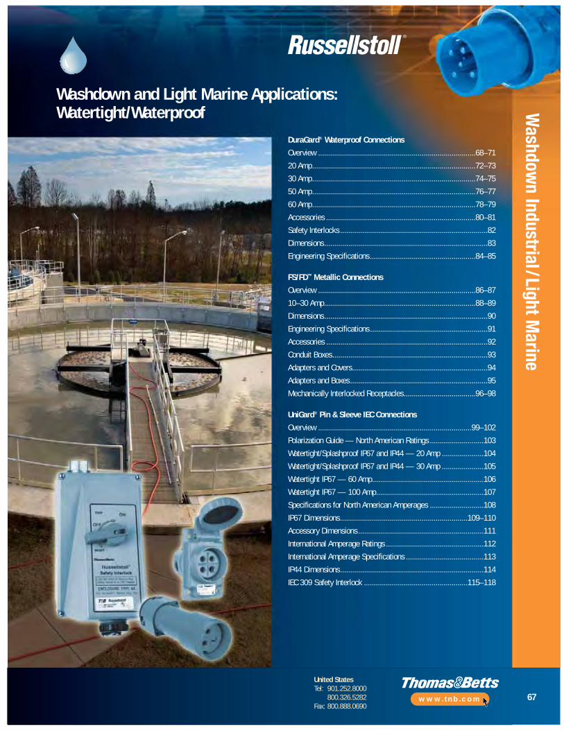
67
United StatesTel: 901.252.8000
800.326.5282Fax: 800.888.0690
www.tnb.com
Washdow
n Industrial/Light Marine
Washdown and Light Marine Applications:Watertight/Waterproof
DuraGard® Waterproof Connections
Overview ...............................................................................68–71
20 Amp..................................................................................72–73
30 Amp..................................................................................74–75
50 Amp..................................................................................76–77
60 Amp..................................................................................78–79
Accessories ...........................................................................80–81
Safety Interlocks ..........................................................................82
Dimensions..................................................................................83
Engineering Specifications.....................................................84–85
FS/FD™ Metallic Connections
Overview ...............................................................................86–87
10–30 Amp............................................................................88–89
Dimensions..................................................................................90
Engineering Specifications...........................................................91
Accessories .................................................................................92
Conduit Boxes..............................................................................93
Adapters and Covers....................................................................94
Adapters and Boxes.....................................................................95
Mechanically Interlocked Receptacles....................................96–98
UniGard® Pin & Sleeve IEC Connections
Overview .............................................................................99–102
Polarization Guide — North American Ratings ...........................103
Watertight/Splashproof IP67 and IP44 — 20 Amp .....................104
Watertight/Splashproof IP67 and IP44 — 30 Amp .....................105
Watertight IP67 — 60 Amp........................................................106
Watertight IP67 — 100 Amp......................................................107
Specifications for North American Amperages ...........................108
IP67 Dimensions................................................................109–110
Accessory Dimensions...............................................................111
International Amperage Ratings .................................................112
International Amperage Specifications .......................................113
IP44 Dimensions........................................................................114
IEC 309 Safety Interlock ....................................................115–118

68
United StatesTel: 901.252.8000
800.326.5282Fax: 800.888.0690
www.tnb.com
Was
hdow
n In
dust
rial/
Ligh
t Mar
ine
— D
uraG
ard®
DuraGard® Waterproof Connections Overview
The toughest design and construction in thermoplastic safety, durability and performance in UL 94-V0 flame-rated DuraV® material. WithDurOring™ sealed pins, sleeves and interiors arewatertight even unmated. A 30A and 50A CircuitBreaker Interlock line in DuraV are the bestchoices for standard voltage polarization optionsthrough 600VAC (Interlock to 480VAC).
USCG Accepted 20–50A convenience InterlockedReceptacles accept DuraGard plugs. Built fromaluminum or brass for rough-service installations,in Switched or Circuit Breaker formats, theirextremely heavy-duty designs provide maximumdurability.
DuraGardto 3P4W
20 through 60A
IEC (IP67)to 4P5W
20 to 100A
InterlockedOutlets
20 through 60A
Defined
MarineLighting Connectors
Shore-to-Ship Power
Low-Power Welding
Power Distribution Panels
Shipboard Power Outlets
Barge Power Connection
Construction and AgriculturalGenerator Set Panels
Portable Tools and Equipment
Irrigation Systems Panels
Portable Lighting and Equipment
Food Processing, Brewery/Beverage, Pulp and Paper, PharmaceuticalsPortable Building PowerWelding Outlets
Motor Power Connections
Lighting Systems
Machinery Interconnections
Process Control Power Systems
OEMsExport Machinery
Critical Power Connections and Welding Systems
Transportable Equipment
Typical Application Groups
Russellstoll Line Selections for Outdoor (and Indoor) Applications
• Any application where electrical connections need protection from water and/or dust entrance to the contacts or the wiring compartment
• Cable-to-connector sealing and device locking designs are critical
Thermoplastic international standard IEC 309-2 or CEE-17 connector usage is growing especiallyin OEM, export and standard performanceapplications. The IP67 style is watertight whenmated and directly interchangeable with othermanufacturers. International designations shadowU.S. amperage ratings: 20/(16), 30/(32), 60/(63)and 100/(125) Amps. IP67 devices have screwcollars or flap/screw covers, with catalog number“W” suffixes.

69
United StatesTel: 901.252.8000
800.326.5282Fax: 800.888.0690
www.tnb.com
Washdow
n Industrial/Light Marine —
DuraGard®
DuraGard® Waterproof Connections Overview
Not just “watertight”; Waterproof for Washdown Duty: DurORing™ Sealing• Specifically designed for wet environments with our unique DurORing™
sealing system. Unit is watertight mated or unmated
• Eliminates need for costly “weather boots” or “adapters”
• Compact size
• “Lockout Ready” plugs have padlock access hole in front (30A/50A)
Durable, Tough and Flame Safety Rated Housings• DuraV® housing material specially selected for hot or cold washdown duty
• Flame safe UL94-V0 rated housings
• Superior performance in corrosive environments
• High-visibility yellow housings
Safe and Reliable Power Connections: Pin and Sleeve, Voltage Polarized• Long life: round, self-cleaning, constant pressure pin and sleeve contacts
of solid CDA 360 brass for long, reliable electrical life
• More power, operates cooler: large circular electrical contact area enables more current flow with lower temperature rise
• Ground pin keyed for voltage polarization (O-ring seal)
Easy to Wire• No twist-off “Locking Plugs”: integral threaded screw collars
and compression-type bushings make wiring a snap
• Fast assembly and wiring: “Drop-In” rear-loaded interiors use no assemblyscrews versus 3–5 or more with other connectors, 30A/50A/60A connectors use unique E-Z Tite™ external gland lock screw, also
Washdown Duty, Chemical, Outdoor, Industrial and Marine Use Non-Metallic Plugs, Connectors, Receptacles and Inlets — 20, 30, 50 and 60 Amp, Maximum 600VAC/250VDC
The Next Generation: DuraGard® Waterproof ConnectorsSevere environments and high-pressure washdown duty applications require durable, waterproofand safe connection s. Russellstoll takes design reliability to new heights with Safety Grade™
standards for truly waterproof connectors. Many watertight specifications cover mated connectionsonly. DuraGard connectors are designed to be watertight mated or unmated, thus offering theultimate waterproof connection. DuraGard connectors are also UL94-V0 flame rated for safety andutilize a durable, efficient pin and sleeve contact design that is voltage polarized to meet NEC®
210-7 and OSHA standards. DuraGard... designed for maximum safety, durability and performance.
DuraGard® Features Make the Performance Difference.

70
United StatesTel: 901.252.8000
800.326.5282Fax: 800.888.0690
www.tnb.com
DuraGard® Waterproof Connections Overview
DuraGard® Pin and Sleeve Connections
Spring blade contact designs offer point contact only, with minimalmechanical support in receptacles. Higher heat is generated in use as contacts loosen with age and dirt accumulation, resulting in failures.Exposed blade contacts can easily be damaged. Contacts are both theelectrical and mechanical locking method.
Pin and Sleeve design enables higher current flow at cooler temperatures due to large circular contact area. Sleeves act as retainers for the pins, makinga reliable connection. Shrouded pins and sleeves are protected from damageand inadvertent access. Locking housing screw collars provide for a reliable,long-lasting connection with electrical contacts separate.
The Water Spray Test1000-PSI water spray was directly applied at the faceof DuraGard receptacles. No damage occurred, and nowater penetrated the housing or cord seal. DuraGardplugs, connectors and receptacles are designed towithstand water spray test at 1000 PSI. No extraboots or adapters required.
DuraGard: Designed for the Toughest Washdown Applications
Pulp and Paper Pharmaceutical ManufacturingFood Processing Beverage and Bottling
Washdown Duty, Chemical, Outdoor, Industrial and Marine Use Non-Metallic Plugs, Connectors Receptacles and Inlets — 20, 30, 50 and 60 Amp, Maximum 600VAC/250VDC
Pin and Sleeve
Bladed Plug and Receptacle Pin and Sleeve Connector and Plug
Spring Contacts
Blades
Shrouds
Sleeve Pin
Locking Screw Collar
Pin and Sleeve contact devices consist of round male pins that are insertedinto tubular female sleeves. Current flows through a large pin-to-sleevecircular contact area. Because current is not restricted through point contactonly, higher current flow and cooler operating temperatures are achieved in a compact connection. Wiping action during insertion or withdrawal providespositive self cleaning. Shrouded pins and sleeves are protected from physical
damage or casual access and aid in polarization features of the line. The shroud and screw collar completely lock plugs to receptacles orconnectors for a reliable connection. Step on the cord, kick or drop a plug — your connection will remain tight. Pin and Sleeve devices are the safety standard for high-current applications worldwide.
Was
hdow
n In
dust
rial/
Ligh
t Mar
ine
— D
uraG
ard®
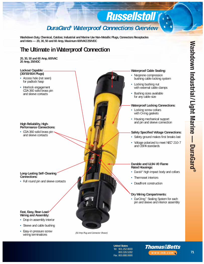
71
United StatesTel: 901.252.8000
800.326.5282Fax: 800.888.0690
www.tnb.com
Washdow
n Industrial/Light Marine —
DuraGard®
DuraGard® Waterproof Connections Overview
20, 30, 50 and 60 Amp, 600VAC20 Amp, 250VDC
Safety Specified Voltage Connections:• Safety ground makes first breaks last
• Voltage polarized to meet NEC® 210-7and OSHA standards
High Reliability, High-Performance Connections:• CDA 360 solid brass pin
and sleeve contacts
Long-Lasting Self-CleaningConnections: • Full round pin and sleeve contacts
Fast, Easy, Rear-LoadWiring and Assembly:• Drop-in assembly interior
• Sleeve and cable bushing
• Easy-in pressure screw wiring terminations
Waterproof Cable Sealing:• Neoprene compression
bushing cable locking system
• Locking bushing nut with external cable clamps
• Bushing sizes available for any cable size
Durable and UL94-V0 Flame Rated Housings:• DuraV® high impact body and collars
• Thermoset interiors
• Deadfront construction
Waterproof Locking Connections: • Locking screw collars
with O-ring gaskets
• Housing mechanical support and pin and sleeve connection
Dry Wiring Compartments:• DurOring™ Sealing System for each
pin and sleeve and interior assembly
(50 Amp Plug and Connector Shown)
Lockout Capable: (30/50/60A Plugs)• Access hole (not seen)
for padlock hasp
• Interlock engagementCDA 360 solid brass pin and sleeve contacts
Washdown Duty, Chemical, Outdoor, Industrial and Marine Use Non-Metallic Plugs, Connectors Receptacles and Inlets — 20, 30, 50 and 60 Amp, Maximum 600VAC/250VDC
The Ultimate in Waterproof Connection

72
United StatesTel: 901.252.8000
800.326.5282Fax: 800.888.0690
www.tnb.com
Was
hdow
n In
dust
rial/
Ligh
t Mar
ine
— D
uraG
ard®
Male Plug††
Device Ratings and PolarizationsMaximum 600VAC or 250VDC
Female Connector
DuraGard® Waterproof Connections — 20 Amp
❑ Add suffix — / xxxx for bushing I.D. (page 80) or conduit adapter assembled.
♦ “W” suffix is watertight; “F” suffix for splash-proof spring flap cover.* Consult Technical Services.
SAFETY ❑ ❑POLE WIRE POLARIZATION (RECEPTACLE) VOLTAGE CAT. NO. CAT. NO.
2 3 125VAC 9P23U1_ 9C23U1_2 3 250VAC 9P23U2 9C23U22 3 277VAC 9P23U3 9C23U32 3 480VAC 9P23U4 9C23U42 3 600VAC 9P23U5 9C23U52 3 through 600VAC/250VDC 9P23U0 9C23U0
3 4 125/250VAC 9P24U1 9C24U13 4 3Ø 250VAC 9P24U2 9C24U23 4 3Ø 480VAC 9P24U4 9C24U43 4 3Ø 600VAC 9P24U5 9C24U53 4 through 600VAC/250VDC 9P24U0 9C24U0
▼▼
20 AMP STANDARD SERVICE
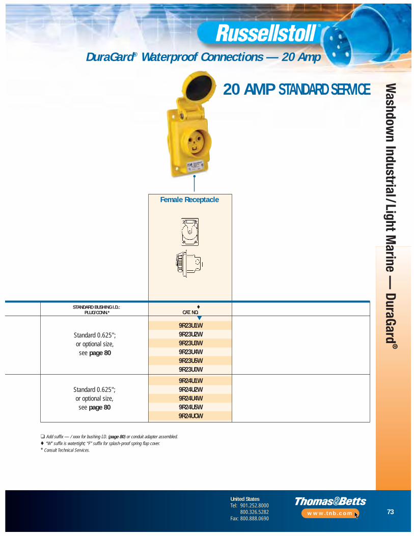
73
United StatesTel: 901.252.8000
800.326.5282Fax: 800.888.0690
www.tnb.com
Washdow
n Industrial/Light Marine —
DuraGard®
DuraGard® Waterproof Connections — 20 Amp
Female Receptacle
❑ Add suffix — / xxxx for bushing I.D. (page 80) or conduit adapter assembled.♦ “W” suffix is watertight; “F” suffix for splash-proof spring flap cover.* Consult Technical Services.
Standard 0.625"; or optional size,see page 80
Standard 0.625"; or optional size,see page 80
STANDARD BUSHING I.D.: ♦PLUG/CONN.* CAT. NO.
9R23U1W9R23U2W9R23U3W9R23U4W9R23U5W9R23U0W
9R24U1W9R24U2W9R24U4W9R24U5W9R24UOW
▼
20 AMP STANDARD SERVICE
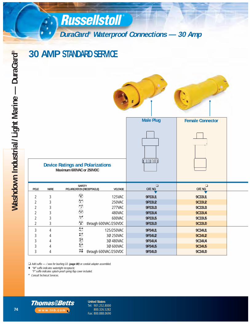
74
United StatesTel: 901.252.8000
800.326.5282Fax: 800.888.0690
www.tnb.com
Was
hdow
n In
dust
rial/
Ligh
t Mar
ine
— D
uraG
ard®
SAFETY ❑ ❑POLE WIRE POLARIZATION (RECEPTACLE) VOLTAGE CAT. NO. CAT. NO.
2 3 125VAC 9P33U1 9C33U12 3 250VAC 9P33U2 9C33U22 3 277VAC 9P33U3 9C33U32 3 480VAC 9P33U4 9C33U42 3 600VAC 9P33U5 9C33U52 3 through 600VAC/250VDC 9P33U0 9C33U0
3 4 125/250VAC 9P34U1 9C34U13 4 3Ø 250VAC 9P34U2 9C34U23 4 3Ø 480VAC 9P34U4 9C34U43 4 3Ø 600VAC 9P34U5 9C34U53 4 through 600VAC/250VDC 9P34U0 9C34U0
Male Plug
Device Ratings and PolarizationsMaximum 600VAC or 250VDC
▼ ▼
Female Connector
DuraGard® Waterproof Connections — 30 Amp
❑ Add suffix — / xxxx for bushing I.D. (page 80) or conduit adapter assembled.♦ “W” suffix indicates watertight receptacle;
“F” suffix indicates splash-proof spring flap cover included.* Consult Technical Services.
30 AMP STANDARD SERVICE

75
United StatesTel: 901.252.8000
800.326.5282Fax: 800.888.0690
www.tnb.com
Washdow
n Industrial/Light Marine —
DuraGard®
DuraGard® Waterproof Connections — 30 Amp
STANDARD BUSHING I.D.: ♦ ❑ ♦PLUG/CONN.* CAT. NO. CAT. NO. CAT. NO.
9R33U1W 9F33U1_ 9B33U1F9R33U2W 9F33U2 9B33U2F9R33U3W 9F33U3 9B33U3F9R33U4W 9F33U4 9B33U4F9R33U5W 9F33U5 9B33U5F9R33U0W 9F33UØ 9B33UØF
9R34U1W 9F34U1 9B34U1F9R34U2W 9F34U2 9B34U2F9R34U4W 9F34U4 9B34U4F9R34U5W 9F34U5 9B34U5F9R34UOW 9F34UØ 9B34UØF
▼ ▼▼
Female Receptacle Female Plug Male Receptacle
❑ Add suffix — / xxxx for bushing I.D. (page 80) or conduit adapter assembled.♦ “W” suffix indicates watertight receptacle;
“F” suffix indicates splash-proof spring flap cover included.* Consult Technical Services.
Standard 0.700"; for optional size,
see page 80
Standard 0.750"; for optional size,
see page 80
30 AMP REVERSE SERVICE
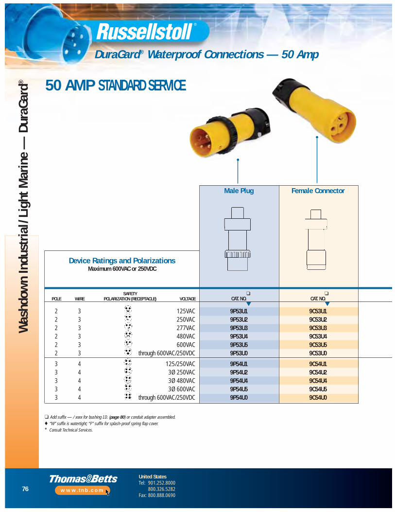
76
United StatesTel: 901.252.8000
800.326.5282Fax: 800.888.0690
www.tnb.com
Was
hdow
n In
dust
rial/
Ligh
t Mar
ine
— D
uraG
ard®
Male Plug
Device Ratings and PolarizationsMaximum 600VAC or 250VDC
▼ ▼
Female Connector
DuraGard® Waterproof Connections — 50 Amp
❑ Add suffix — / xxxx for bushing I.D. (page 80) or conduit adapter assembled.♦ “W” suffix is watertight; “F” suffix for splash-proof spring flap cover.* Consult Technical Services.
SAFETY ❑ ❑POLE WIRE POLARIZATION (RECEPTACLE) VOLTAGE CAT. NO. CAT. NO.
2 3 125VAC 9P53U1 9C53U12 3 250VAC 9P53U2 9C53U22 3 277VAC 9P53U3 9C53U32 3 480VAC 9P53U4 9C53U42 3 600VAC 9P53U5 9C53U52 3 through 600VAC/250VDC 9P53U0 9C53U0
3 4 125/250VAC 9P54U1 9C54U13 4 3Ø 250VAC 9P54U2 9C54U23 4 3Ø 480VAC 9P54U4 9C54U43 4 3Ø 600VAC 9P54U5 9C54U53 4 through 600VAC/250VDC 9P54U0 9C54U0
50 AMP STANDARD SERVICE
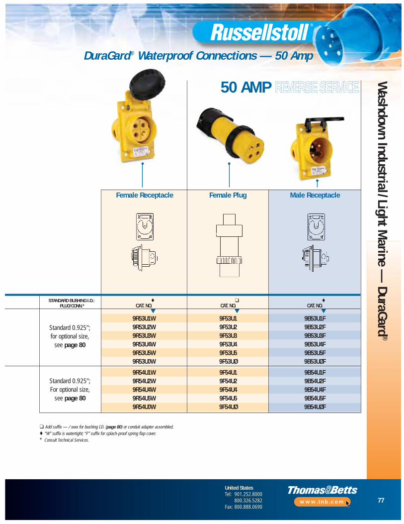
77
United StatesTel: 901.252.8000
800.326.5282Fax: 800.888.0690
www.tnb.com
Washdow
n Industrial/Light Marine —
DuraGard®
DuraGard® Waterproof Connections — 50 Amp
▼▼
Female Receptacle Female Plug Male Receptacle
❑ Add suffix — / xxxx for bushing I.D. (page 80) or conduit adapter assembled.♦ “W” suffix is watertight; “F” suffix for splash-proof spring flap cover.* Consult Technical Services.
STANDARD BUSHING I.D.: ♦ ❑ ♦PLUG/CONN.* CAT. NO. CAT. NO. CAT. NO.
9R53U1W 9F53U1 9B53U1F9R53U2W 9F53U2 9B53U2F9R53U3W 9F53U3 9B53U3F9R53U4W 9F53U4 9B53U4F9R53U5W 9F53U5 9B53U5F9R53U0W 9F53UØ 9B53UØF
9R54U1W 9F54U1 9B54U1F9R54U2W 9F54U2 9B54U2F9R54U4W 9F54U4 9B54U4F9R54U5W 9F54U5 9B54U5F9R54U0W 9F54UØ 9B54UØF
▼
50 AMP REVERSE SERVICE
Standard 0.925"; for optional size,
see page 80
Standard 0.925"; For optional size,
see page 80
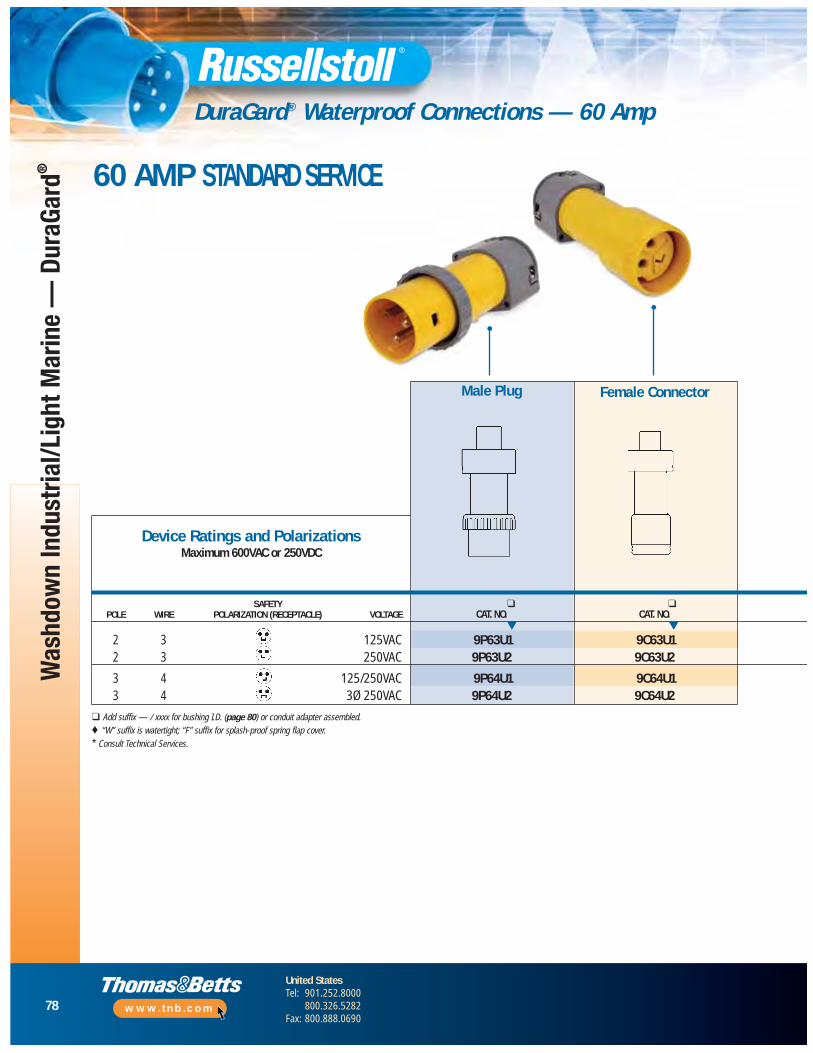
78
United StatesTel: 901.252.8000
800.326.5282Fax: 800.888.0690
www.tnb.com
Was
hdow
n In
dust
rial/L
ight
Mar
ine
— D
uraG
ard®
Male Plug
Device Ratings and PolarizationsMaximum 600VAC or 250VDC
Female Connector
DuraGard® Waterproof Connections — 60 Amp
❑ Add suffix — / xxxx for bushing I.D. (page 80) or conduit adapter assembled.♦ “W” suffix is watertight; “F” suffix for splash-proof spring flap cover.* Consult Technical Services.
SAFETY ❑ ❑POLE WIRE POLARIZATION (RECEPTACLE) VOLTAGE CAT. NO. CAT. NO.
2 3 125VAC 9P63U1 9C63U12 3 250VAC 9P63U2 9C63U2
3 4 125/250VAC 9P64U1 9C64U13 4 3Ø 250VAC 9P64U2 9C64U2
▼ ▼
60 AMP STANDARD SERVICE
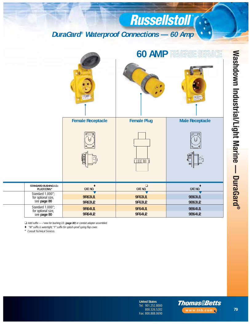
79
United StatesTel: 901.252.8000
800.326.5282Fax: 800.888.0690
www.tnb.com
Washdow
n Industrial/Light Marine —
DuraGard®
DuraGard® Waterproof Connections — 60 Amp
Female Receptacle Female Plug Male Receptacle
❑ Add suffix — / xxxx for bushing I.D. (page 80) or conduit adapter assembled.♦ “W” suffix is watertight; “F” suffix for splash-proof spring flap cover.* Consult Technical Services.
STANDARD BUSHING I.D.: ♦ ❑ ♦PLUG/CONN.* CAT. NO. CAT. NO. CAT. NO.
9R63U1 9F63U1 9B63U19R63U2 9F63U2 9B63U2
9R64U1 9F64U1 9B64U19R64U2 9F64U2 9B64U2
▼ ▼ ▼
60 AMP REVERSE SERVICE
Standard 1.000"; for optional size,
see page 80
Standard 1.000"; for optional size,
see page 80

80
United StatesTel: 901.252.8000
800.326.5282Fax: 800.888.0690
www.tnb.com
Was
hdow
n In
dust
rial/
Ligh
t Mar
ine
— D
uraG
ard®
DuraGard® Accessories
Conduit Boxes (For Surface Mounting)
NOTE: 3⁄4" NPT Hole Std. Additional accessories are available. Please consult yourThomas & Betts representative.
Replacement Caps
(Minimum limit 85% of O.D. size for sealing.)Material — oil-resistant Neoprene.State catalog number followed by slash ( / ) and bushing code; example: 9P33U1/1000.
20 Amp Cable Bushing
4.12".31"4.12"
2"
2.62"3.62"
3.18"MTG.
.31"
(2) MTG. Holes
4.37"MTG.
Catalog Number 3781A
Catalog Number 3712A
Catalog Number 3711A
Catalog Number 3678A
NOTE: _ suffix to plugs/connectors for assembly from factory.Cable Bushings
Conduit Adapter Kits (Plugs or Connectors)
SIZE 20 AMP 30 AMP 50 AMP 60 AMP1⁄2" 9X2C50 9X3C50 — —3⁄4" 9X2C75 9X3C75 9X5C75 9X6C75
1" — 9X3C10 9X5C10 9X6C10
MAX. CABLE O.D. (INCHES) 20 AMP 30 AND 50 AMP
0.375 C16984A —
0.437 C16984B —
0.500 C16984C —
0.545 — 2000-11
0.562 C16984D —
0.606 B16506 —
0.620 — 2000-03
0.625 B16524
0.700 — 2000-04
0.750 — 2000-01
0.800 — 2000-06
0.870 — 2000-02
0.925 — 2000-12
1.000 — 2000-05
20 AMP 30 AMP 50 AMP 60 AMP
Screw Cap (Connector) 9X2PSC 9X3PSC 9X5PSC 9X6PSC
Cup Cap (Plug) — F26874C F26874C F26874C
Screw Cap (Receptacle) — 7X3RCW 7X5RCW 7X6RCW
Flap Cap (Receptacle) — 7X3RCF 7X5RCF 7X6RCF
CAST ALUMINUM CAST BRASS USE WITH
Single 3711A 3731 20A
Double 3712A 3732 30A
DSFD 3781A 3782 50A
CAST ALUMINUM CAST BRASS
3678A 3678B
9X2PSC
7X6RCW
45° Angle Adapter
F28674C
7X3RCF
Type FD

81
United StatesTel: 901.252.8000
800.326.5282Fax: 800.888.0690
www.tnb.com
Washdow
n Industrial/Light Marine —
DuraGard®
DuraGard® Accessories
Replacement InteriorsCATALOG NUMBERS
AMPS VOLTAGE POLARIZATION MALE INTERIOR ASSEMBLY FEMALE INTERIOR ASSEMBLY
125VAC 9XM23U1 9XF23U1
250VAC 9XM23U2 9XF23U2
2P3W 277VAC 9XM23U3 9XF23U3
20A 480VAC 9XM23U4 9XF23U4
600VAC 9XM23U5 9XF23U5
through 600VAC/250VDC 9XM23U0 9XF23U0
125VAC 9XM33U1 9XF33U1
250VAC 9XM33U2 9XF33U2
2P3W 277VAC 9XM33U3 9XF33U3
30A 480VAC 9XM33U4 9XF33U4
600VAC 9XM33U5 9XF33U5
through 600VAC/250VDC 9XM33U0 9XF33U0
125VAC 9XM53U1 9XF53U1
2P3W250VAC 9XM53U2 9XF53U2
50A480VAC 9XM53U4 9XF53U4
600VAC 9XM53U5 9XF53U5
through 600VAC/250VDC 9XM53U0 9XF53U0
125/250VAC 9XM24U1 9XF24U1
3P4W3Ø 250VAC 9XM24U2 9XF24U2
20A3Ø 480VAC 9XM24U4 9XF24U4
3Ø 600VAC 9XM24U5 9XF24U5
through 600VAC/250VDC 9XM24U0 9XF24U0
125/250VAC 9XM34U1 9XF34U1
3P4W3Ø 250VAC 9XM34U2 9XF34U2
30A3Ø 480VAC 9XM34U4 9XF34U4
3Ø 600VAC 9XM34U5 9XF34U5
through 600VAC/250VDC 9XM34U0 9XF34U0
125/250VAC 9XM54U1 9XF54U1
3P4W3Ø 250VAC 9XM54U2 9XF54U2
50A3Ø 480VAC 9XM54U4 9XF54U4
3Ø 600VAC 9XM54U5 9XF54U5
through 600VAC/250VDC 9XM54U0 9XF54U0
2P3W 125VAC 9XM63U1 9XF63U1
60A 250VAC 9XM63U2 9XF63U2
3P4W 125/250VAC 9XM64U1 9XF64U1
60A 3Ø 250VAC 9XM64U2 9XF64U2

82
United StatesTel: 901.252.8000
800.326.5282Fax: 800.888.0690
www.tnb.com
Was
hdow
n In
dust
rial/
Ligh
t Mar
ine
— D
uraG
ard®
DuraGard® Safety Interlocks
3P4W50A
Features and BenefitsCircuit Breaker Interlocked Outlet:
• 30A and 50A ranges and polarizations to 480VAC
• 22kA interrupt capacity breaker
• Easy handle reset after trip
• Auxiliary switch or other options
User Friendly — Flexible Mounting:
• Variable footprint mounting tabs
• Compact size fits 8" standard I-beam webs
• Conduit entry from top, bottom or side (3⁄4", 1" or 11⁄4" NPT)
• Large red handle with lockout access
Flame Rated and DuraV™ Tough Housing:
• UL 94-V0 housing and interior with stainless steel components
• High-impact thermoplastic housing
• NEMA 4X construction
7.00
5.25-MTG
13.47-MTG13.46
12.00
8.13
“A”-side-entry
“B” conduit-entry standard
3P4W30A
Safety Interlocks
CAT. NO.3P4W EXAMPLES SHOWN: SAFETY INTERLOCK CIRCUIT BREAKER MATING ROTARY REPLACEMENT
AMPS VOLTAGE POLARIZATION WITH CIRCUIT BREAKER TRIP RATING PLUG CONTROLLER INTERIOR♦ 1
125/250VAC 9MT34U1W30B 30A 9P34U1 9MI34U1WNAB 9XL34U13Ø 250VAC 9MT34U2W30B 30A 9P34U2 9MI34U2WNAB 9XL34U23Ø 480VAC 9MT34U4W30B 30A 9P34U4 9MI34U4WNAB 9XL34U43Ø 600VAC 9MT34U5W30B 30A 9P34U5 9MI34U5WNAB 9XL34U5
through 600VAC/3P4W 9MT34U0W30B 30A 9P34U0 9MI34U0WNAB 9XL34U0
125/250VAC 9MT54U1W50B 50A 9P54U1 9MI54U1WNAB 9XL54U13Ø 250VAC 9MT54U2W50B 50A 9P54U2 9MI54U2WNAB 9XL54U23Ø 480VAC 9MT54U4W50B 50A 9P54U4 9MI54U4WNAB 9XL54U43Ø 600VAC 9MT54U5W50B 50A 9P54U5 9MI54U5WNAB 9XL54U5
through 600VAC/3P4W 9MT54U0W50B 50A 9P54U0 9MI54U0WNAB 9XL54U0
8.13
13.47MTG
5.25MTG
7.00
13.4612.00
“A”SideEntry
“B” ConduitEntry Standard
The only non-metallic, 22KAIC, 30A and 50A series circuit breaker interlocked receptacle available today!
Dimensions
NOTE: 1. Change suffix for alternate trip ratings. Example: 9MT54U2W30B — 50 amp, 3P4W, safety interlock with 30 amp circuit breaker, conduit top entry.♦ Change “W” to “F” for flap cap access. Example: 9MI34U2F30B — 30 amp, 3P4W, safety interlock with rotary controller and flap cap.(Minimum limit 85% of O.D. size for sealing.)
Foot and Hardware Replacement Kit: Cat. No. 9XLMF (non-metallic) and Cat. No. 9XLMF-SS (stainless steel).
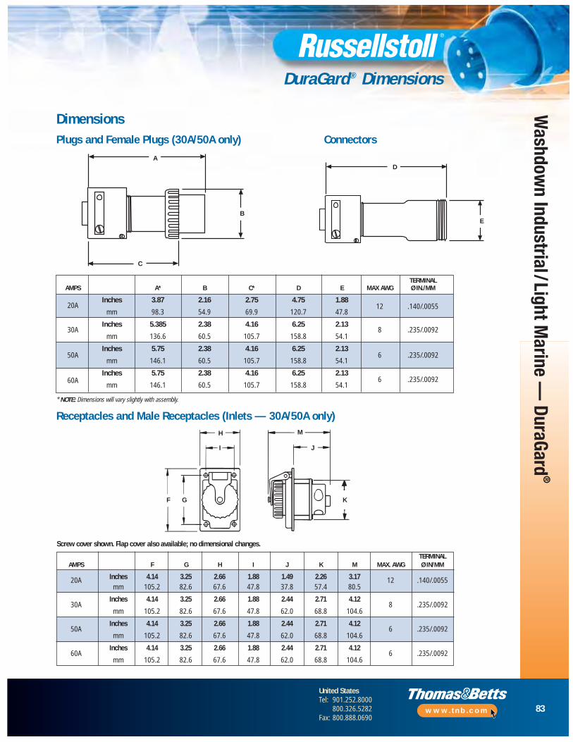
83
United StatesTel: 901.252.8000
800.326.5282Fax: 800.888.0690
www.tnb.com
Washdow
n Industrial/Light Marine —
DuraGard®
DuraGard® Dimensions
TERMINALAMPS A* B C* D E MAX AWG Ø IN./MM
20AInches 3.87 2.16 2.75 4.75 1.88
12 .140/.0055mm 98.3 54.9 69.9 120.7 47.8
30AInches 5.385 2.38 4.16 6.25 2.13
8 .235/.0092mm 136.6 60.5 105.7 158.8 54.1
50AInches 5.75 2.38 4.16 6.25 2.13
6 .235/.0092mm 146.1 60.5 105.7 158.8 54.1
60AInches 5.75 2.38 4.16 6.25 2.13
6 .235/.0092mm 146.1 60.5 105.7 158.8 54.1
A
B
C
D
E
Plugs and Female Plugs (30A/50A only) Connectors
Receptacles and Male Receptacles (Inlets — 30A/50A only)
TERMINALAMPS F G H I J K M MAX. AWG Ø IN/MM
20A Inches 4.14 3.25 2.66 1.88 1.49 2.26 3.17 12 .140/.0055mm 105.2 82.6 67.6 47.8 37.8 57.4 80.5
30AInches 4.14 3.25 2.66 1.88 2.44 2.71 4.12
8 .235/.0092mm 105.2 82.6 67.6 47.8 62.0 68.8 104.6
50AInches 4.14 3.25 2.66 1.88 2.44 2.71 4.12
6 .235/.0092mm 105.2 82.6 67.6 47.8 62.0 68.8 104.6
60AInches 4.14 3.25 2.66 1.88 2.44 2.71 4.12
6 .235/.0092mm 105.2 82.6 67.6 47.8 62.0 68.8 104.6
Screw cover shown. Flap cover also available; no dimensional changes.
Dimensions
A
B
C
H
I J
KF G
M
D
E
* NOTE: Dimensions will vary slightly with assembly.

84
United StatesTel: 901.252.8000
800.326.5282Fax: 800.888.0690
www.tnb.com
Was
hdow
n In
dust
rial/
Ligh
t Mar
ine
— D
uraG
ard®
DuraGard® Engineering Specifications
Performance — ElectricalDielectric Voltage 3000 voltsWithstand
Max. Working 6000 volts RMS (minimum creepageVoltage and minimum clearance per UL 840)
Circuit Interrupting/ UL listed and CSA certified for circuit Load Breaking interrupting at full rated current
Temperature Rise Max. 30° C/86° F temperature rise at fullrated current after 50 cycles of overload at 150% rated current at .75-pf
Performance — MechanicalImpact Resistance Per UL 1682 Paragraph 34
Cord Round portable service cords. Accommodation 10 standard diameters from
.405" to 1.00", custom sizes to spec
Terminal In accordance with UL 1682Identification
Cable Pull Out Force In accordance with UL 1682
Product Identification label and moldedIdentification in name
Lockout/Tagout Lockout/tagout hole on plug complies with OSHA Reg. 29 CFR 1910.147
Performance — EnvironmentalMoisture Per UL 1682 Paragraph 49 Resistance Watertight/flap screw cover on receptacle,
O-rings on all pins and sleeves, interiors and plug shell. Watertight even when not engaged
Flammability V0 or better per UL 94
Operating Maximum continuous: 95° C/203° F
Temperatures Minimum: -40° C/-40° F without impact
Chemicals Resists standard industrial hydrocarbons,acids, bases and solvents
MaterialContact Carrier Molded arc-resistant UL 94-V0Interior phenolic thermoset
Housing, Gland Nuts, DuraV® UL 94-V0, high-impact Screw Collar Rings Thermoplastic
O-Rings Buna-N (Nitrile)
Contacts: Pins Brass CDA 360and Sleeves
Hinge Pins Stainless steel(Receptacle)
Terminals Brass CDA 360
Terminal Screws, Stainless steelFlap Springs,Assembly Screws,Nuts, Hardware
Gland Friction 20 amp — NylonWasher 30, 50 and 60 amp — Aluminum
Cable Clamp Bushing Neoprene
Approvals*
630/E47956
LL14096
* TUV & PSE listed product also available; contact Technical Services
Engineering Specifications — Plugs, Connectors and Receptacles

85
United StatesTel: 901.252.8000
800.326.5282Fax: 800.888.0690
www.tnb.com
Washdow
n Industrial/Light Marine —
DuraGard®
DuraGard® Engineering Specifications
Engineering Specifications — Safety Interlocks Performance — ElectricalDielectric Voltage 3000 voltsWithstand
Max. Working 480 volts RMS (minimum creepageVoltage distance and minimum clearance
per UL 840) (using circuit breaker)
Circuit Interrupting/ UL Listed and CSA certified for Load Breaking circuit interrupting at full rated current
Temperature Rise Max. 30° C/86° F temperature rise at fullrated current after 50 cycles of overload at 150% rated current at .75-pf
Shrouded Contacts Complies with California Code Title 8, Art. 51,S2510.7(b) for devices exceeding 300VAC
Performance — MechanicalImpact Resistance Per UL 1682 Paragraph 34
Wiring Conduit entries at top, Accommodation side and bottom, .750"
NPT top entrystandard
Terminal In accordance with UL 1682Identification
Plug Pull Out Force In accordance with UL 1682
Product Identification label Identification
Lockout/Tagout Lockout/tagout access on switch complieswith OSHA Reg. 29 CFR 1910.147
Performance — EnvironmentalMoisture Per UL 1682 Paragraph 49. Watertight/flap Resistance screw cover on receptacle, O-rings on all
pins and sleeves, interiors and plug shell. Watertight even when not engaged (screw cover closed/locked)
Flammability V0 or better per UL 94
Operating Maximum Continuous: 95° C/203° F
Temperatures Minimum: -40° C /-40° F without impact (NOTE: per C/B trip at elevated temps.)
Chemicals Resists standard industrial hydrocarbons,acids, bases and solvents
UV Resistance UV-stabilized material
MaterialContact Carrier Molded arc-resistant UL 94-V0Interior thermoset material
Housing, Gland Nuts, DuraV® UL 94-V0, high-impact Screw Collar Rings Thermoplastic
O-Rings Buna-N (Nitrile)
Contacts: Pins Brass CDA 360and Sleeves
Hinge Pins Stainless steel(Receptacle)
Terminals Brass CDA 360
Terminal Screws, Stainless steelFlap Springs,Assembly Screws,Nuts, Hardware
Approvals
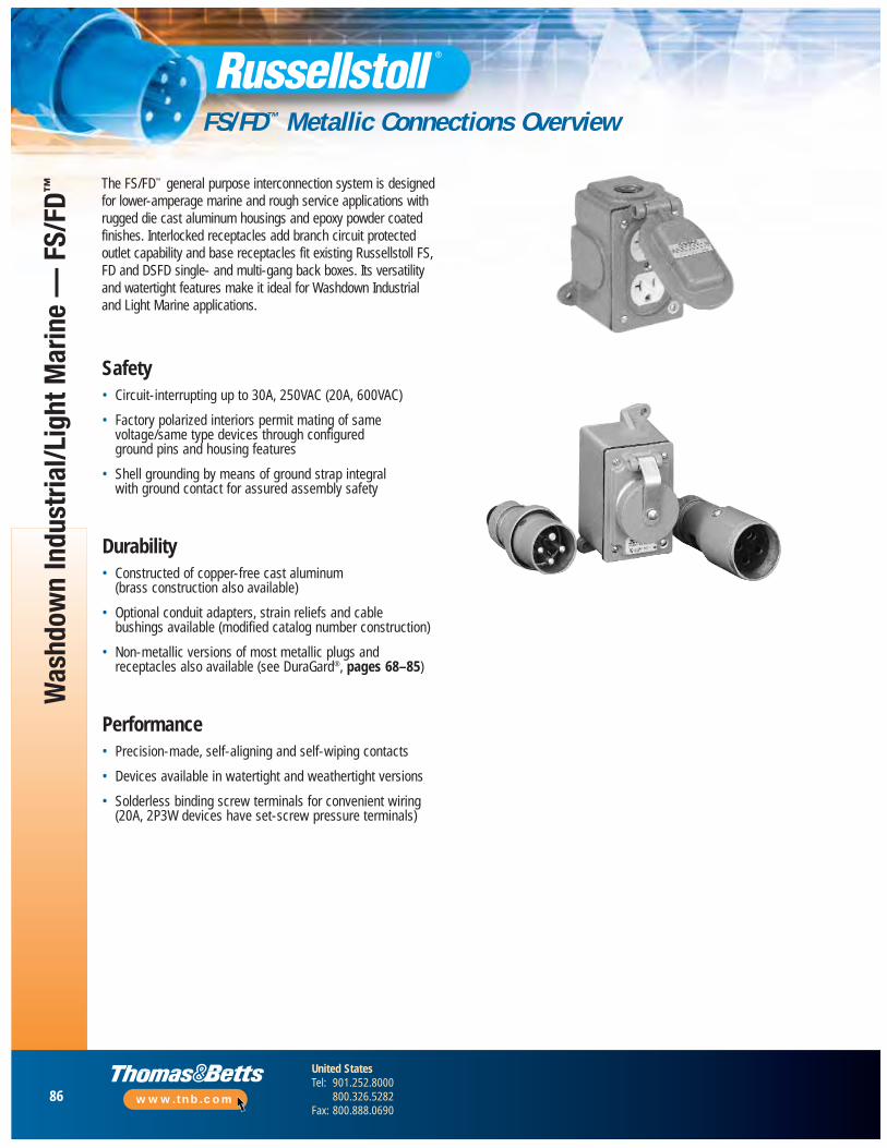
86
United StatesTel: 901.252.8000
800.326.5282Fax: 800.888.0690
www.tnb.com
Was
hdow
n In
dust
rial/L
ight
Mar
ine
— F
S/FD
™
FS/FD™ Metallic Connections Overview
Safety• Circuit-interrupting up to 30A, 250VAC (20A, 600VAC)
• Factory polarized interiors permit mating of samevoltage/same type devices through configured ground pins and housing features
• Shell grounding by means of ground strap integral with ground contact for assured assembly safety
Durability• Constructed of copper-free cast aluminum
(brass construction also available)
• Optional conduit adapters, strain reliefs and cable bushings available (modified catalog number construction)
• Non-metallic versions of most metallic plugs andreceptacles also available (see DuraGard®, pages 68–85)
Performance• Precision-made, self-aligning and self-wiping contacts
• Devices available in watertight and weathertight versions
• Solderless binding screw terminals for convenient wiring (20A, 2P3W devices have set-screw pressure terminals)
The FS/FD™ general purpose interconnection system is designedfor lower-amperage marine and rough service applications withrugged die cast aluminum housings and epoxy powder coatedfinishes. Interlocked receptacles add branch circuit protectedoutlet capability and base receptacles fit existing Russellstoll FS,FD and DSFD single- and multi-gang back boxes. Its versatilityand watertight features make it ideal for Washdown Industrialand Light Marine applications.
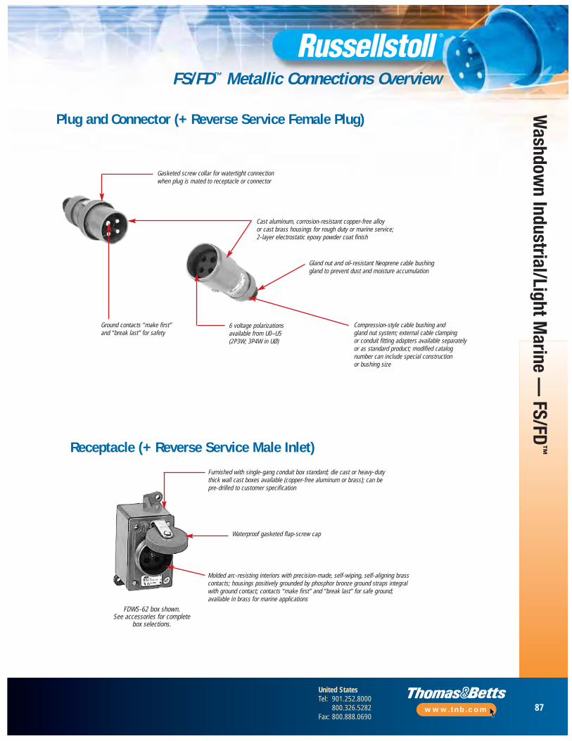
87
United StatesTel: 901.252.8000
800.326.5282Fax: 800.888.0690
www.tnb.com
Washdow
n Industrial/Light Marine —
FS/FD™
FS/FD™ Metallic Connections Overview
Plug and Connector (+ Reverse Service Female Plug)
Receptacle (+ Reverse Service Male Inlet)
Gasketed screw collar for watertight connection when plug is mated to receptacle or connector
Cast aluminum, corrosion-resistant copper-free alloy or cast brass housings for rough duty or marine service;2-layer electrostatic epoxy powder coat finish
Gland nut and oil-resistant Neoprene cable bushing gland to prevent dust and moisture accumulation
Compression-style cable bushing and gland nut system; external cable clamping or conduit fitting adapters available separately or as standard product; modified catalog number can include special construction or bushing size
6 voltage polarizations available from U0–U5(2P3W; 3P4W in UØ)
Ground contacts “make first” and “break last” for safety
Furnished with single-gang conduit box standard; die cast or heavy-duty thick wall cast boxes available (copper-free aluminum or brass); can be pre-drilled to customer specification
Waterproof gasketed flap-screw cap
Molded arc-resisting interiors with precision-made, self-wiping, self-aligning brasscontacts; housings positively grounded by phosphor bronze ground straps integral with ground contact; contacts “make first” and “break last” for safe ground;available in brass for marine applications
FDWS-62 box shown.See accessories for complete
box selections.
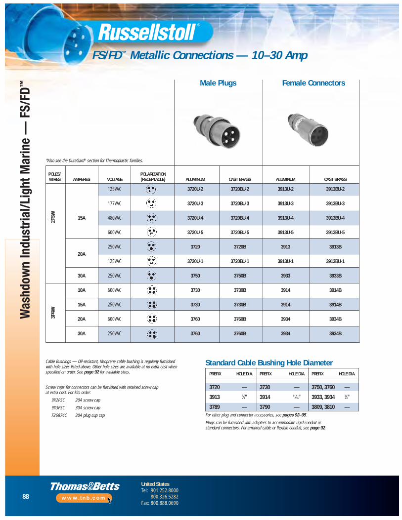
88
United StatesTel: 901.252.8000
800.326.5282Fax: 800.888.0690
www.tnb.com
Was
hdow
n In
dust
rial/L
ight
Mar
ine
— F
S/FD
™
FS/FD™ Metallic Connections — 10–30 Amp2P
3W3P
4W
Cable Bushings — Oil-resistant, Neoprene cable bushing is regularly furnishedwith hole sizes listed above. Other hole sizes are available at no extra cost whenspecified on order. See page 92 for available sizes.
Screw caps for connectors can be furnished with retained screw cap at extra cost. For kits order:
9X2PSC 20A screw cap
9X3PSC 30A screw cap
F26874C 30A plug cup cap
*Also see the DuraGard® section for Thermoplastic families.
Male Plugs Female Connectors
Standard Cable Bushing Hole DiameterPREFIX HOLE DIA. PREFIX HOLE DIA. PREFIX HOLE DIA.
3720 — 3730 — 3750, 3760 —
3913 5⁄8" 3914 11⁄16" 3933, 3934 3⁄4"
3789 — 3790 — 3809, 3810 —For other plug and connector accessories, see pages 92–95.
Plugs can be furnished with adapters to accommodate rigid conduit orstandard connectors. For armored cable or flexible conduit, see page 92.
POLES/ POLARIZATIONWIRES AMPERES VOLTAGE (RECEPTACLE) ALUMINUM CAST BRASS ALUMINUM CAST BRASS
125VAC 3720U-2 3720BU-2 3913U-2 3913BU-2
177VAC 3720U-3 3720BU-3 3913U-3 3913BU-3
15A 480VAC 3720U-4 3720BU-4 3913U-4 3913BU-4
600VAC 3720U-5 3720BU-5 3913U-5 3913BU-5
250VAC 3720 3720B 3913 3913B20A
125VAC 3720U-1 3720BU-1 3913U-1 3913BU-1
30A 250VAC 3750 3750B 3933 3933B
10A 600VAC 3730 3730B 3914 3914B
15A 250VAC 3730 3730B 3914 3914B
20A 600VAC 3760 3760B 3934 3934B
30A 250VAC 3760 3760B 3934 3934B
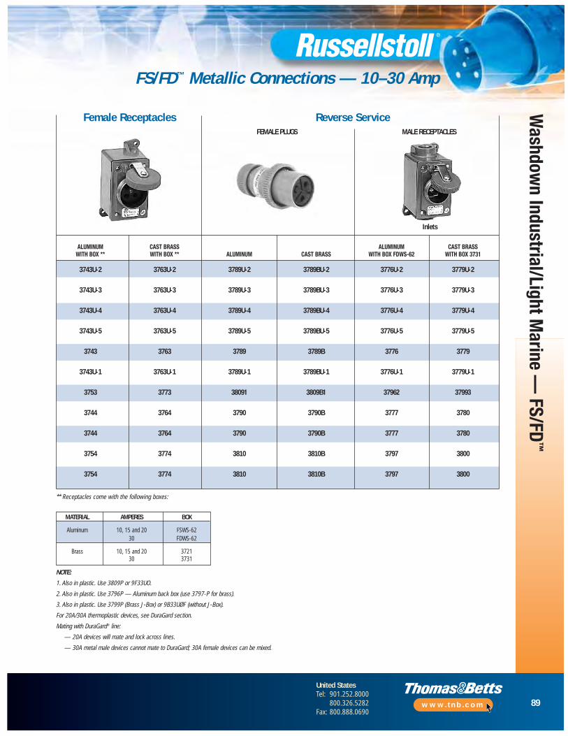
89
United StatesTel: 901.252.8000
800.326.5282Fax: 800.888.0690
www.tnb.com
Washdow
n Industrial/Light Marine —
FS/FD™
FS/FD™ Metallic Connections — 10–30 Amp
NOTE:
1. Also in plastic. Use 3809P or 9F33UO.
2. Also in plastic. Use 3796P — Aluminum back box (use 3797-P for brass).
3. Also in plastic. Use 3799P (Brass J-Box) or 9B33UØF (without J-Box).
For 20A/30A thermoplastic devices, see DuraGard section.
Mating with DuraGard® line:
— 20A devices will mate and lock across lines.
— 30A metal male devices cannot mate to DuraGard; 30A female devices can be mixed.
** Receptacles come with the following boxes:
FEMALE PLUGS MALE RECEPTACLES
Female Receptacles Reverse Service
Inlets
ALUMINUM CAST BRASS ALUMINUM CAST BRASSWITH BOX ** WITH BOX ** ALUMINUM CAST BRASS WITH BOX FDWS-62 WITH BOX 3731
3743U-2 3763U-2 3789U-2 3789BU-2 3776U-2 3779U-2
3743U-3 3763U-3 3789U-3 3789BU-3 3776U-3 3779U-3
3743U-4 3763U-4 3789U-4 3789BU-4 3776U-4 3779U-4
3743U-5 3763U-5 3789U-5 3789BU-5 3776U-5 3779U-5
3743 3763 3789 3789B 3776 3779
3743U-1 3763U-1 3789U-1 3789BU-1 3776U-1 3779U-1
3753 3773 38091 3809B1 37962 37993
3744 3764 3790 3790B 3777 3780
3744 3764 3790 3790B 3777 3780
3754 3774 3810 3810B 3797 3800
3754 3774 3810 3810B 3797 3800
MATERIAL AMPERES BOX
Aluminum 10, 15 and 20 FSWS-6230 FDWS-62
Brass 10, 15 and 20 372130 3731
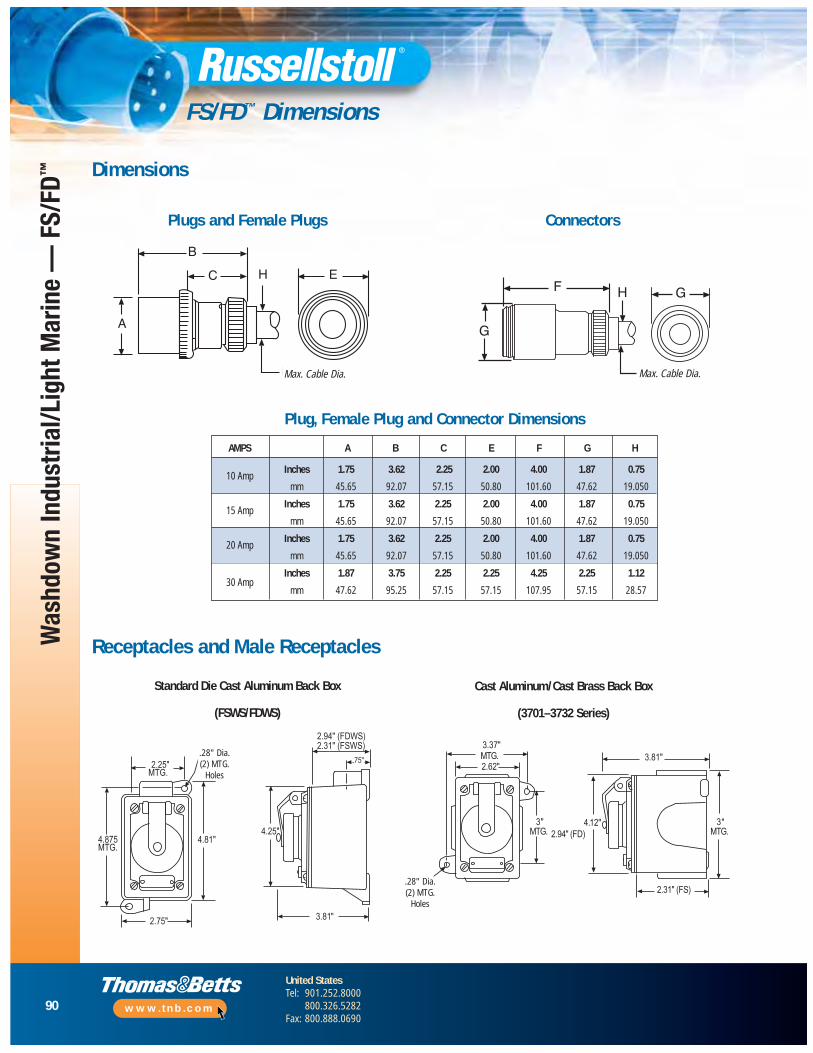
90
United StatesTel: 901.252.8000
800.326.5282Fax: 800.888.0690
www.tnb.com
Was
hdow
n In
dust
rial/L
ight
Mar
ine
— F
S/FD
™
FS/FD™ Dimensions
B
C H E
Max. CableDia.
A
GF H
G
Max. CableDia.
Plugs and Female Plugs Connectors
Receptacles and Male Receptacles
Plug, Female Plug and Connector Dimensions
Standard Die Cast Aluminum Back Box
(FSWS/FDWS)
Cast Aluminum/Cast Brass Back Box
(3701–3732 Series)
Dimensions
Max. Cable Dia. Max. Cable Dia.
.28" Dia.(2) MTG.
Holes
.28" Dia.(2) MTG.
Holes
AMPS A B C E F G H
10 AmpInches 1.75 3.62 2.25 2.00 4.00 1.87 0.75
mm 45.65 92.07 57.15 50.80 101.60 47.62 19.050
15 Amp Inches 1.75 3.62 2.25 2.00 4.00 1.87 0.75
mm 45.65 92.07 57.15 50.80 101.60 47.62 19.050
20 Amp Inches 1.75 3.62 2.25 2.00 4.00 1.87 0.75
mm 45.65 92.07 57.15 50.80 101.60 47.62 19.050
30 Amp Inches 1.87 3.75 2.25 2.25 4.25 2.25 1.12
mm 47.62 95.25 57.15 57.15 107.95 57.15 28.57
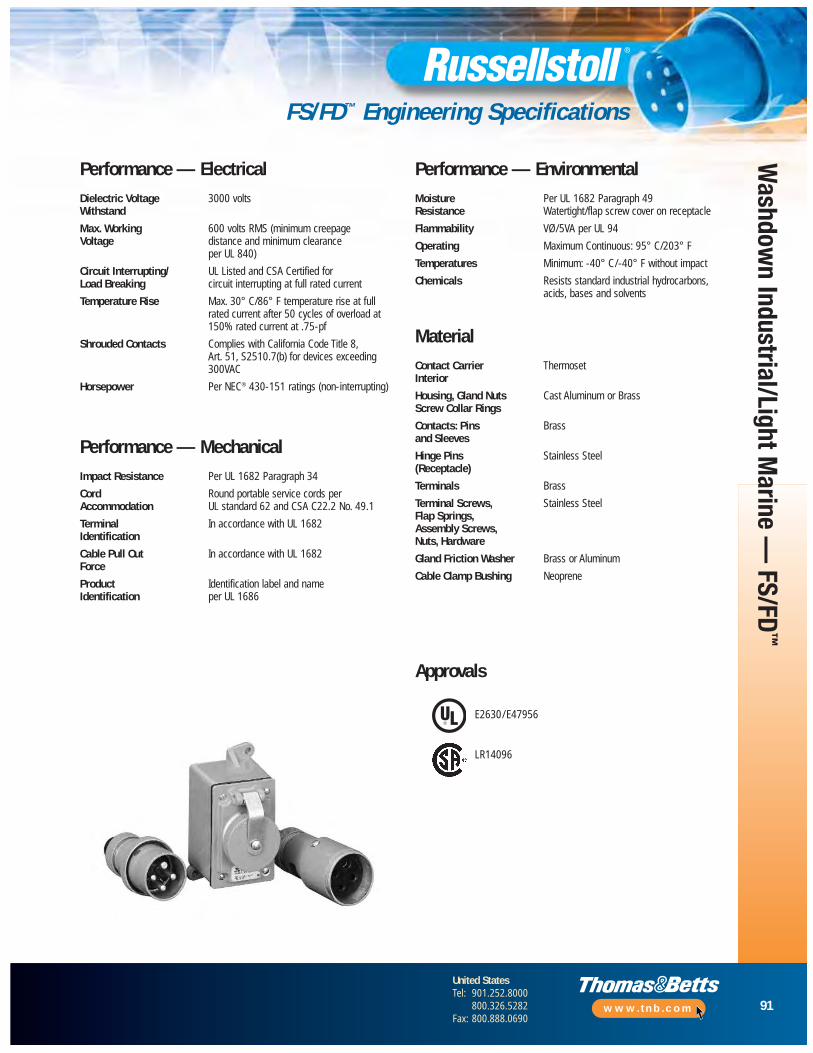
91
United StatesTel: 901.252.8000
800.326.5282Fax: 800.888.0690
www.tnb.com
Washdow
n Industrial/Light Marine —
FS/FD™
FS/FD™ Engineering Specifications
Performance — ElectricalDielectric Voltage 3000 voltsWithstand
Max. Working 600 volts RMS (minimum creepageVoltage distance and minimum clearance
per UL 840)
Circuit Interrupting/ UL Listed and CSA Certified for Load Breaking circuit interrupting at full rated current
Temperature Rise Max. 30° C/86° F temperature rise at fullrated current after 50 cycles of overload at150% rated current at .75-pf
Shrouded Contacts Complies with California Code Title 8, Art. 51, S2510.7(b) for devices exceeding 300VAC
Horsepower Per NEC® 430-151 ratings (non- interrupting)
Performance — MechanicalImpact Resistance Per UL 1682 Paragraph 34
Cord Round portable service cords perAccommodation UL standard 62 and CSA C22.2 No. 49.1
Terminal In accordance with UL 1682Identification
Cable Pull Out In accordance with UL 1682Force
Product Identification label and nameIdentification per UL 1686
Performance — EnvironmentalMoisture Per UL 1682 Paragraph 49Resistance Watertight/flap screw cover on receptacle
Flammability VØ/5VA per UL 94
Operating Maximum Continuous: 95° C/203° F
Temperatures Minimum: -40° C/-40° F without impact
Chemicals Resists standard industrial hydrocarbons, acids, bases and solvents
MaterialContact Carrier ThermosetInterior
Housing, Gland Nuts Cast Aluminum or BrassScrew Collar Rings
Contacts: Pins Brass and Sleeves
Hinge Pins Stainless Steel(Receptacle)
Terminals Brass
Terminal Screws, Stainless SteelFlap Springs,Assembly Screws,Nuts, Hardware
Gland Friction Washer Brass or Aluminum
Cable Clamp Bushing Neoprene
Approvals
E2630/E47956
LR14096
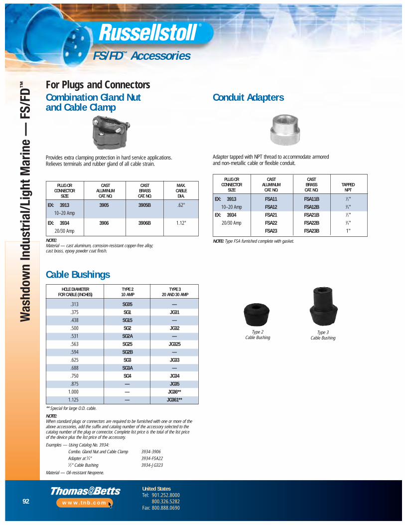
92
United StatesTel: 901.252.8000
800.326.5282Fax: 800.888.0690
www.tnb.com
Was
hdow
n In
dust
rial/L
ight
Mar
ine
— F
S/FD
™
FS/FD™ Accessories
Combination Gland Nut and Cable Clamp
Conduit Adapters
Cable Bushings
Material — Oil-resistant Neoprene.
Type 2Cable Bushing
Type 3Cable Bushing
For Plugs and Connectors
** Special for large O.D. cable.
NOTE:When standard plugs or connectors are required to be furnished with one or more of theabove accessories, add the suffix and catalog number of the accessory selected to thecatalog number of the plug or connector. Complete list price is the total of the list price of the device plus the list price of the accessory.
Examples — Using Catalog No. 3934:
Combo. Gland Nut and Cable Clamp 3934-3906
Adapter at 3⁄4" 3934-FSA221⁄2" Cable Bushing 3934-JG323
HOLE DIAMETER TYPE 2 TYPE 3FOR CABLE (INCHES) 10 AMP 20 AND 30 AMP
.313 SG05 —
.375 SG1 JG31
.438 SG15 —
.500 SG2 JG32
.531 SG2A —
.563 SG25 JG325
.594 SG2B —
.625 SG3 JG33
.688 SG3A —
.750 SG4 JG34
.875 — JG35
1.000 — JG36**
1.125 — JG361**
Provides extra clamping protection in hard service applications. Relieves terminals and rubber gland of all cable strain.
PLUG OR CAST CAST MAX.CONNECTOR ALUMINUM BRASS CABLE
SIZE CAT. NO. CAT. NO. DIA.
EX: 3913 3905 3905B .62"
10–20 Amp
EX: 3934 3906 3906B 1.12"
20/30 Amp
NOTE: Material — cast aluminum, corrosion-resistant copper-free alloy; cast brass, epoxy powder coat finish.
Adapter tapped with NPT thread to accommodate armored and non-metallic cable or flexible conduit.
PLUG OR CAST CASTCONNECTOR ALUMINUM BRASS TAPPED
SIZE CAT. NO. CAT. NO. NPT
EX: 3913 FSA11 FSA11B 1⁄2"
10–20 Amp FSA12 FSA12B 3⁄4"
EX: 3934 FSA21 FSA21B 1⁄2"
20/30 Amp FSA22 FSA22B 3⁄4"
FSA23 FSA23B 1"
NOTE: Type FSA furnished complete with gasket.
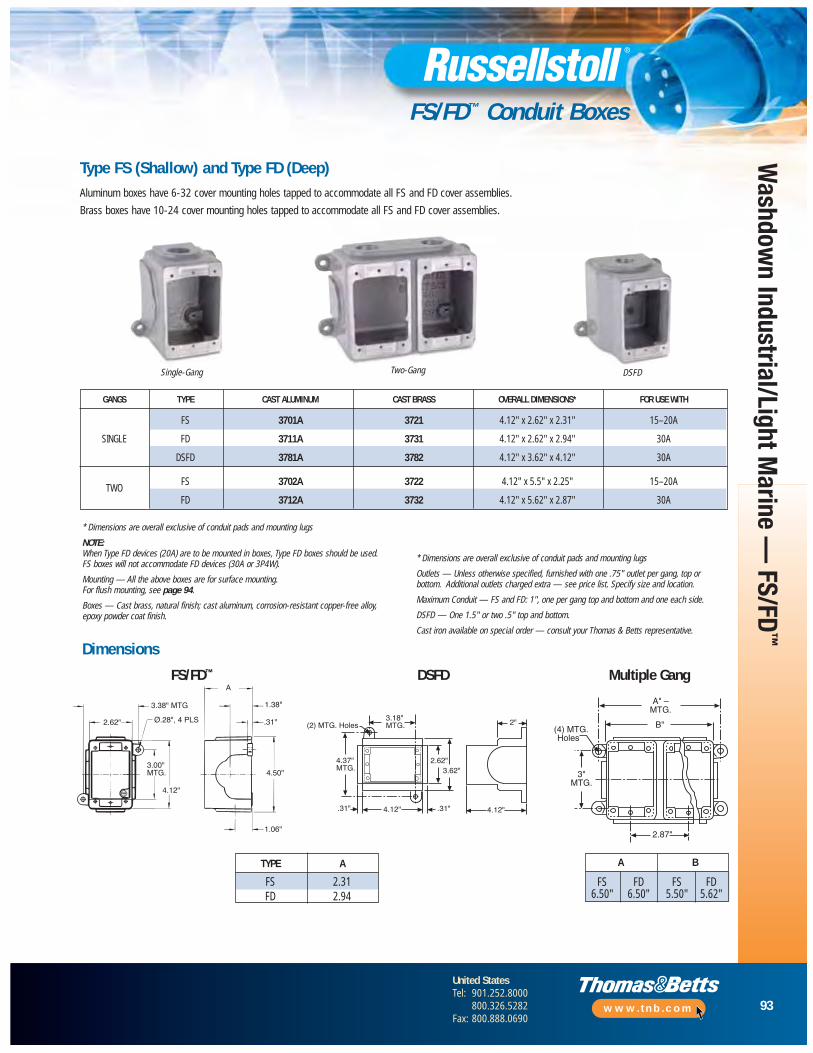
93
United StatesTel: 901.252.8000
800.326.5282Fax: 800.888.0690
www.tnb.com
Washdow
n Industrial/Light Marine —
FS/FD™
FS/FD™ Conduit Boxes
Type FS (Shallow) and Type FD (Deep)
GANGS TYPE CAST ALUMINUM CAST BRASS OVERALL DIMENSIONS* FOR USE WITH
FS 3701A 3721 4.12" x 2.62" x 2.31" 15–20A
SINGLE FD 3711A 3731 4.12" x 2.62" x 2.94" 30A
DSFD 3781A 3782 4.12" x 3.62" x 4.12" 30A
TWOFS 3702A 3722 4.12" x 5.5" x 2.25" 15–20A
FD 3712A 3732 4.12" x 5.62" x 2.87" 30A
Single-Gang Two-Gang DSFD
* Dimensions are overall exclusive of conduit pads and mounting lugs
NOTE:When Type FD devices (20A) are to be mounted in boxes, Type FD boxes should be used. FS boxes will not accommodate FD devices (30A or 3P4W).
Mounting — All the above boxes are for surface mounting. For flush mounting, see page 94.
Boxes — Cast brass, natural finish; cast aluminum, corrosion-resistant copper-free alloy,epoxy powder coat finish.
* Dimensions are overall exclusive of conduit pads and mounting lugs
Outlets — Unless otherwise specified, furnished with one .75" outlet per gang, top orbottom. Additional outlets charged extra — see price list. Specify size and location.
Maximum Conduit — FS and FD: 1", one per gang top and bottom and one each side.
DSFD — One 1.5" or two .5" top and bottom.
Cast iron available on special order — consult your Thomas & Betts representative.
A
1.38"
.31"
4.50"
1.06"
4.12"
3.00"MTG.
2.62" Ø.28", 4 PLS
3.38" MTG
Aluminum boxes have 6-32 cover mounting holes tapped to accommodate all FS and FD cover assemblies.
Brass boxes have 10-24 cover mounting holes tapped to accommodate all FS and FD cover assemblies.
4.12".31"4.12"
2"
2.62"3.62"
3.18"MTG.
.31"
(2) MTG. Holes
4.37"MTG.
B"
A" –MTG.
(4) MTG.Holes
3"MTG.
2.87"
Dimensions
FS/FD™ DSFD Multiple Gang
TYPE A
FS 2.31FD 2.94
A B
FS FD FS FD6.50" 6.50" 5.50" 5.62"
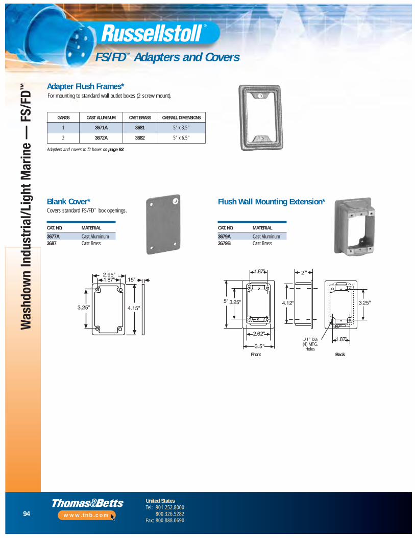
94
United StatesTel: 901.252.8000
800.326.5282Fax: 800.888.0690
www.tnb.com
Was
hdow
n In
dust
rial/L
ight
Mar
ine
— F
S/FD
™
FS/FD™ Adapters and Covers
Adapter Flush Frames*
Adapters and covers to fit boxes on page 93.
Blank Cover* Flush Wall Mounting Extension*
CAT. NO. MATERIAL
3677A Cast Aluminum3687 Cast Brass
CAT. NO. MATERIAL
3679A Cast Aluminum3679B Cast Brass
Covers standard FS/FD™ box openings.
GANGS CAST ALUMINUM CAST BRASS OVERALL DIMENSIONS
1 3671A 3681 5" x 3.5"
2 3672A 3682 5" x 6.5"
2.95"1.87"
3.25" 4.15"
.15"
1.87"
5" 3.25"
2.62"
3.5"
4.12"
2 "
3.25"
1.87"
1.87"
.21" DIA.4 MTG.Holes
Front BackFront Back
.21" Dia(4) MTG.
Holes
For mounting to standard wall outlet boxes (2 screw mount).
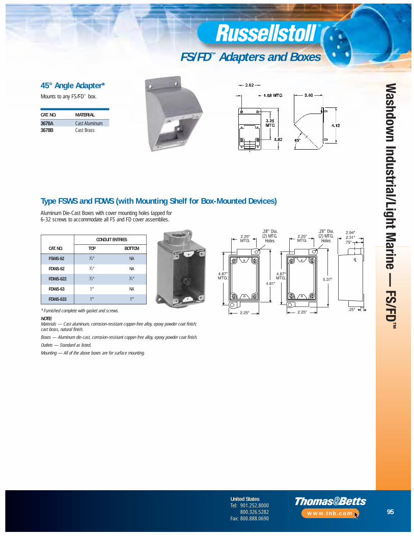
95
United StatesTel: 901.252.8000
800.326.5282Fax: 800.888.0690
www.tnb.com
Washdow
n Industrial/Light Marine —
FS/FD™
FS/FD™ Adapters and Boxes
CAT. NO. MATERIAL
3678A Cast Aluminum3678B Cast Brass
45° Angle Adapter*Mounts to any FS/FD™ box.
* Furnished complete with gasket and screws.
NOTE: Materials — Cast aluminum, corrosion-resistant copper-free alloy, epoxy powder coat finish;cast brass, natural finish.
Boxes — Aluminum die-cast, corrosion-resistant copper-free alloy, epoxy powder coat finish.
Outlets — Standard as listed.
Mounting — All of the above boxes are for surface mounting.
2.25"MTG.
4.87"MTG.
2.25"
4.81"
.28" Dia.(2) MTG.
Holes
4.87"MTG.
2.25"MTG.
.28" Dia.(2) MTG.
Holes
2.25"
5.37"
.75"
.25"
2.94"2.31"
Type FSWS and FDWS (with Mounting Shelf for Box-Mounted Devices)Aluminum Die-Cast Boxes with cover mounting holes tapped for 6-32 screws to accommodate all FS and FD cover assemblies.
.28" Dia.(2) MTG.
Holes
.28" Dia.(2) MTG.
HolesCONDUIT ENTRIES
CAT. NO. TOP BOTTOM
FSWS-62 3⁄4" NA
FDWS-62 3⁄4" NA
FDWS-622 3⁄4" 3⁄4"
FDWS-63 1" NA
FDWS-633 1" 1"

96
United StatesTel: 901.252.8000
800.326.5282Fax: 800.888.0690
www.tnb.com
Was
hdow
n In
dust
rial/L
ight
Mar
ine
— F
S/FD
™
FS/FD™ Mechanically Interlocked Receptacles
Marine/Series Industrial — 20 and 30 Amp, 250VAC
Mechanically interlocked FS/FD™ Interface receptacle outlets, availablethrough 30 amp 250VAC, provide added electrical safety in branch circuits.
By design, the plug must be fully inserted into the interlocked receptaclebefore the switch or circuit breaker can be turned to the “ON” position, and the switch or circuit breaker must be in the “OFF” position before theplug can be withdrawn. This design ensures that when properly installed and operated, the circuit is made and broken by the switch or circuit breaker, not by the connectors.
As with all Russellstoll products, mechanically interlocked receptacles were designed with safety, durability and performance in mind.
Safety• Mechanical linkage prevents plug insertion or withdrawal
unless switch is in “OFF” position
• Circuit breaker protection available on many models
• Ground contacts “make first,” “break last”
Durability• Constructed of copper-free cast aluminum
(some types available in brass)
• Sturdy die-cast and sand-cast housings
Performance• Precision-made, self-aligning and self-wiping contacts
• Receptacles provided with spring-actuated, self-closing flaps
• Devices available in watertight and weathertight versions
• Solderless screw terminals for convenient wiring
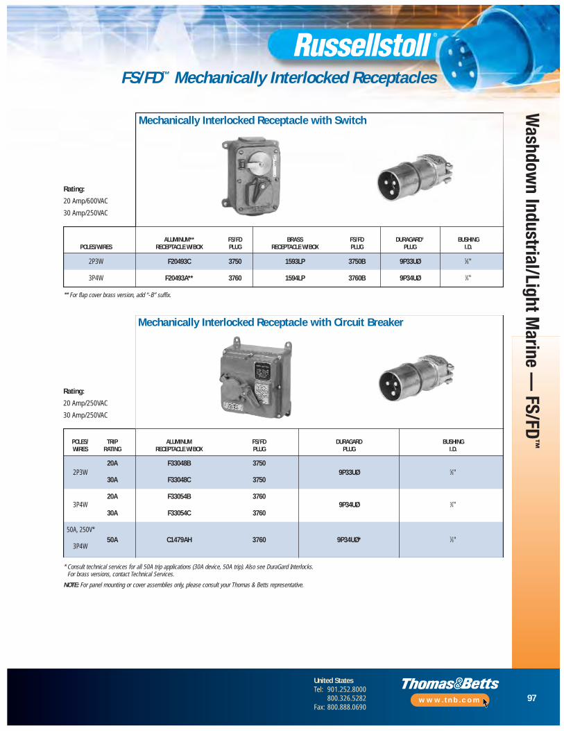
97
United StatesTel: 901.252.8000
800.326.5282Fax: 800.888.0690
www.tnb.com
Washdow
n Industrial/Light Marine —
FS/FD™
FS/FD™ Mechanically Interlocked Receptacles
Mechanically Interlocked Receptacle with Circuit Breaker
Mechanically Interlocked Receptacle with Switch
ALUMINUM** FS/FD BRASS FS/FD DURAGARD® BUSHINGPOLES/WIRES RECEPTACLE W/BOX PLUG RECEPTACLE W/BOX PLUG PLUG I.D.
2P3W F20493C 3750 1593LP 3750B 9P33UØ 5⁄8"
3P4W F20493A** 3760 1594LP 3760B 9P34UØ 3⁄4"
Rating:
20 Amp/600VAC
30 Amp/250VAC
** For flap cover brass version, add “-B” suffix.
Rating:
20 Amp/250VAC
30 Amp/250VAC
* Consult technical services for all 50A trip applications (30A device, 50A trip). Also see DuraGard Interlocks.For brass versions, contact Technical Services.
NOTE: For panel mounting or cover assemblies only, please consult your Thomas & Betts representative.
POLES/ TRIP ALUMINUM FS/FD DURAGARD BUSHINGWIRES RATING RECEPTACLE W/BOX PLUG PLUG I.D.
2P3W20A F33048B 3750
9P33UØ 5⁄8"30A F33048C 3750
3P4W20A F33054B 3760
9P34UØ 3⁄4"30A F33054C 3760
50A, 250V*
3P4W50A C1479AH 3760 9P34UØ* 7⁄8"

98
United StatesTel: 901.252.8000
800.326.5282Fax: 800.888.0690
www.tnb.com
Was
hdow
n In
dust
rial/L
ight
Mar
ine
— F
S/FD
™
FS/FD™ Mechanically Interlocked Receptacles
Interlocked with Switch, Surface Mount
DimensionsInterlocked with Circuit Breaker
4.5"
6.75"
4.81"
2.93" 1.87"
1.25" Max. ConduitTop & Bottom only
5.06"
5.87"MTG
5.43"
.34" Dia.(4) MTG.Holes
7.50"6.75"
8.50"
.34"
5.25"
PluggedDrain Hole1/8" 27 NPT
Machine Panel Mount Floor Extension Mount4.5"
6.75"
2.5"
3.37"
6.37"
5.46"
3.12"
3.68"
.37" .87".75"
12-24 NC28 Tap6 Req’d
.43"
45ϒ3.37"
Standard Plug
A
B
C
30/50 Amp DuraGard20/30 Amp FS/FD
(also as replacement cover assembly)
CAT. NO. F18196B&C and F20493A&B
• Housings: Cast brass, natural finish. Cast aluminum, corrosion-resistantcopper-free alloy, epoxy powder coat finish
• Cable Bushings: Oil-resistant, Neoprene strain-relief cable bushings regularlyfurnished with hole size as listed for plug; other hole sizes available if specifiedon order; see Accessory Reference Section, Bushing sizes on page 92
• Outlets: Unless otherwise specified, boxes are furnished blank
• Receptacle interlocked with switch: Maximum conduit outlets 13⁄4" top and bottom. Specify outlets required
• Receptacle Interlocked with Circuit Breaker: Maximum conduit outlet 13⁄4" atlocations V, W, X, Y and Z as per diagram; specify outlets required, use symbols
A
B
D
C
PluggedDrain Hole3/8" 18 NPT
SwitchCircuit Breaker
4.88"
2.13"
. . . . . . . . . . . . . . . . . . . . . . . . . . . . . . . . . . . . . . . . . . . . . . Specifications . . . . . . . . . . . . . . . . . . . . . . . . . . . . . . . . . . . . . . . . . .
Amps A B C
30 AmpInches 5.38 2.38 4.16
mm 136.6 60.5 105.7
50 AmpInches 5.75 2.38 4.16
mm 146.1 60.5 105.7

Washdow
n Industrial/Light Marine —
UniGuard®
UniGard® Pin and Sleeve IEC Connections Overview
ConstructionSites
FoodProcessing
Marine and Shipboard
Pulp andPaper Mills
Chemical Plants
BeveragePlants
E2630E47956
E205590
99
United StatesTel: 901.252.8000
800.326.5282Fax: 800.888.0690
www.tnb.com
Safety, Performance and Durability… in a Snap!
Extensive Product Family• Safe and reliable, portable electrical connections
• Wide variety of plugs, connectors, receptacles, inlets and mounting boxes
• Watertight (IP67) and splashproof (IP44) versions available
• 20, 30, 60 and 100 Amp ratings for small, medium or large current loads
• cULus Listed for North American ratings
• UL classified to IEC 309-1 and IEC 309-2 for North American and International ratings
• Complete interchangeability with all manufacturers’ IEC309-1 and IEC 309-2 devices
• Meets IEC 309 global configurations for safety in industrial applications
• 16, 32, 63 and 125A international ratings available
Watertight• Watertight design and construction meet stringent IP67 internal
protection standards
• Rugged thermoplastic housings resist impact or abuse and provideexcellent corrosion resistance
• Unique Thomas & Betts strain relief grip and sealing system ensures superior cable retention and watertight conductor termination
• Ideal for outdoor, wet, marine and washdown applications
• Unique 75% faster assembly with EZ Clik® handle locking, and EZ Tite™ cable grip system
Splashproof• Suitable for indoor use where splashing liquids and other
contaminants may interfere with electrical connections
• Ideal for most heavy commercial applications and light industrial applications
• Available in 20 and 30 Amp ratings
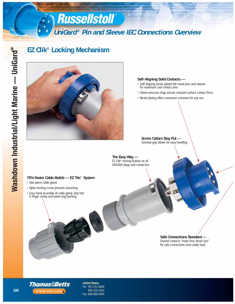
100
United StatesTel: 901.252.8000
800.326.5282Fax: 800.888.0690
www.tnb.com
Was
hdow
n In
dust
rial/L
ight
Mar
ine
— U
niGa
rd®
UniGard ® Pin and Sleeve IEC Connections Overview
EZ Clik® Locking Mechanism
Safe Connections Standard —Ground contacts “make first, break last”for safe connections even under load
The Easy Way —EZ Clik® locking feature on all 20A/30A plugs and connectors
Self-Aligning Solid Contacts —• Self-aligning nickel-plated full-round pins and sleeves
for maximum cool contact area
• Sleeve pressure rings ensure constant surface contact force
• Nickel plating offers maximum corrosion for any use
75% Faster Cable Builds — EZ Tite™ System• One-piece cable gland
• Nylon locking screw prevents loosening
• Easy hand assembly of cable gland, Grip Tite™
6-finger clamp and onion-ring bushing
Screw Collars Stay Put —Turreted grip allows for easy handling
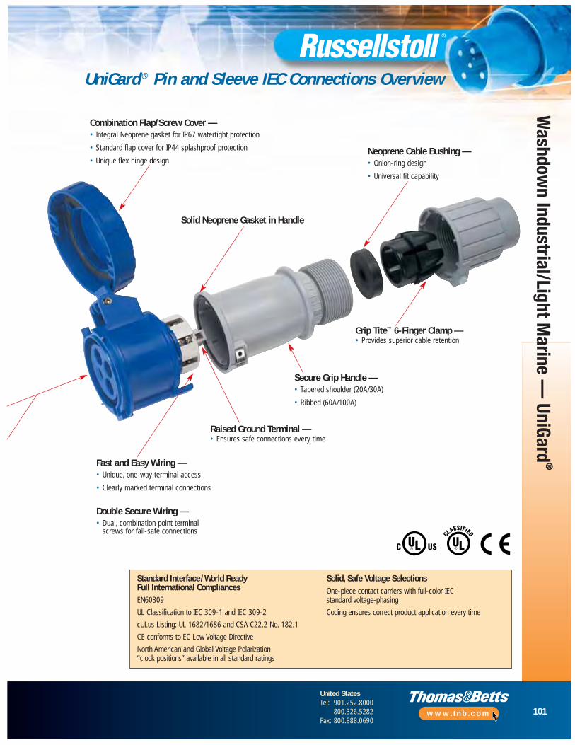
101
United StatesTel: 901.252.8000
800.326.5282Fax: 800.888.0690
www.tnb.com
Washdow
n Industrial/Light Marine —
UniGard®
UniGard ® Pin and Sleeve IEC Connections Overview
Standard Interface/World Ready Full International Compliances EN60309
UL Classification to IEC 309-1 and IEC 309-2
cULus Listing: UL 1682/1686 and CSA C22.2 No. 182.1
CE conforms to EC Low Voltage Directive
North American and Global Voltage Polarization “clock positions” available in all standard ratings
Solid, Safe Voltage SelectionsOne-piece contact carriers with full-color IEC standard voltage-phasing
Coding ensures correct product application every time
Combination Flap/Screw Cover —• Integral Neoprene gasket for IP67 watertight protection
• Standard flap cover for IP44 splashproof protection
• Unique flex hinge design
Solid Neoprene Gasket in Handle
Neoprene Cable Bushing —• Onion-ring design
• Universal fit capability
Fast and Easy Wiring —• Unique, one-way terminal access
• Clearly marked terminal connections
Double Secure Wiring —• Dual, combination point terminal
screws for fail-safe connections
Grip Tite™ 6-Finger Clamp —• Provides superior cable retention
Raised Ground Terminal —• Ensures safe connections every time
Secure Grip Handle —• Tapered shoulder (20A/30A)
• Ribbed (60A/100A)

102
United StatesTel: 901.252.8000
800.326.5282Fax: 800.888.0690
www.tnb.com
Was
hdow
n In
dust
rial/L
ight
Mar
ine
— U
niGa
rd®
UniGard ® Pin and Sleeve IEC Connections Overview
FeaturesNo Tools, No Screws Necessary
• EZ Clik® locking handle saves 75% on assembly time
• Unique EZ Clik® assembly feature on 20 and 30 Amp plugs and connectors makes installation and inspection fast and reliable
• Captured gaskets in handles seal out water, chemicals and dust
Simple Cable Clamping
• Threaded EZ Tite™ cable gland on 20 and 30 Amp devices makes assembly fast and easy
• One-piece lock screw verifies clamp locking hold, with no external metal contact possible(20 and 30 Amp devices)
The Performance Connection
• Watertight spring-loaded covers with high-strength flex-hinge screw covers on IP67 devices
• Flap covers on IP44 splashproof styles
• Safety, performance and durability for all IEC 309 applications worldwide
Unique Fast Assembly
• One-piece EZ Tite™ cable gland with locking screw loads to cable followed by Grip Tite™ 6-finger cable clamp/grip piece
• Watertight onion-ring bushing fits a wide variety of outside diameters
Easy Action Single-Wiring Point Access Saves Time Wiring
• All terminal screws face in same direction allowing installer to make safe and secureconductor terminations in 30% less time than other devices
• Rugged, corrosion-free thermoplastic housings are color-coded for safe and reliableconnections to all other mating type/polarizations, with raised ground terminal standard
Watertight and Grip Tite™ Safety
• Grip Tite™ flexible 6-finger clamp teeth holds well beyond all agency test pullout forces
• No internal clamps required
• Available in all amperages
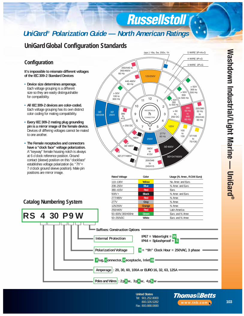
103
United StatesTel: 901.252.8000
800.326.5282Fax: 800.888.0690
www.tnb.com
Washdow
n Industrial/Light Marine —
UniGard®
UniGard® Polarization Guide — North American Ratings
250/440 to265/460V
60 Hz
440-460V60 Hz
> 50V100 to300 Hz
3Ø120/208
3Ø250V
277V60 Hz
3Ø 600V
3ØY347/600V
125V
100to
130 57/100to
75/130
> 50to
250 DC
38050 Hz
to440
60 Hz
220/38050 Hz
to250/44060 Hz
> 50V300
to 500 Hz
> 50V300
to 500 Hz
> 50V300 to500 Hz
125/250V
5 WIRE 3P+N+G
4 WIRE 3P+G
3 WIRE 2P+G
h
121
2
3
4
56
7
8
9
10
11
380to
415
> 250 DC
480V
3Ø 480V
3Ø 277/480V
250V
380Vto
415V
200/346to
240/415
US
US
US
EU
R
EU
R
EU
R
(spc.) 16a, 5w, 250v, 1h
RECEPTACLE
CONNECTOR
Catalog Numbering System
Configuration
It’s impossible to mismate different voltagesof the IEC 309-2 Standard Devices
• Device size determines amperage.Each voltage grouping is a different size so they are easily distinguishable for compatibility.
• All IEC 309-2 devices are color-coded.Each voltage grouping has its own distinctcolor coding for mating compatibility.
• Every IEC 309-2 mating plug grounding pin is a mirror image of the female device.Devices of differing voltages cannot be matedto one another.
• The Female receptacles and connectorshave a “clock face” voltage polarization.A “keyway” female housing notch is always at 6 o’clock reference position. Ground contact (sleeve) position on this “clockface”establishes voltage polarization (ie. “7h”= 7 o’clock ground sleeve position). Male pinpositions are mirror image.
Suffixes: Construction Options
Internal Protection IP67 = Watertight = WIP44 = Splashproof = S
Polarization/Voltage 9 = “9h” Clock Hour = 250VAC, 3 phase
Amperage : 20, 30, 60, 100A or EURO 16, 32, 63, 125A
R S 4 30 P 9 W
Plug, Connector, R eceptacle, Inlet B
Poles and Wires : 2 p 3 w, 3 p 4 w, 4 p 5 w
Rated Voltage Color Usage (N. Amer., R.O.W. Euro)
110–130V Yellow No. Amer. and Euro.208–250V Blue N. Amer. and Euro.380–415V Red Euro.500V + Black N. Amer. and Euro.277/480V Red N. Amer.277V Gray N. Amer.125/250V Orange N. Amer.250/440V Red Latin America50–600V, 300/400Hz Green Euro. and N. Amer.50–250VDC White Euro. and N. Amer.
UniGard Global Configuration Standards
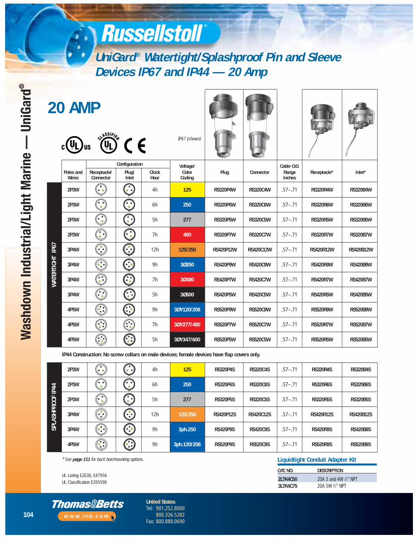
104
United StatesTel: 901.252.8000
800.326.5282Fax: 800.888.0690
www.tnb.com
Was
hdow
n In
dust
rial/L
ight
Mar
ine
— U
niGa
rd®
UniGard® Watertight/Splashproof Pin and Sleeve Devices IP67 and IP44 — 20 Amp
WAT
ERTI
GHT
IP67
Configuration Voltage/ Cable O.D.Poles and Receptacle/ Plug/ Clock Color Plug Connector Range Receptacle* Inlet*
Wires Connector Inlet Hour Coding Inches
2P3W 4h 125 RS320P4W RS320C4W .57–.71 RS320R4W RS320B4W
2P3W 6h 250 RS320P6W RS320C6W .57–.71 RS320R6W RS320B6W
2P3W 5h 277 RS320P5W RS320C5W .57–.71 RS320R5W RS320B5W
2P3W 7h 480 RS320P7W RS320C7W .57–.71 RS320R7W RS320B7W
3P4W 12h 125/250 RS420P12W RS420C12W .57–.71 RS420R12W RS420B12W
3P4W 9h 3Ø250 RS420P9W RS420C9W .57–.71 RS420R9W RS420B9W
3P4W 7h 3Ø480 RS420P7W RS420C7W .57–.71 RS420R7W RS420B7W
3P4W 5h 3Ø600 RS420P5W RS420C5W .57–.71 RS420R5W RS420B5W
4P5W 9h 3ØY120/208 RS520P9W RS520C9W .57–.71 RS520R9W RS520B9W
4P5W 7h 3ØY277/480 RS520P7W RS520C7W .57–.71 RS520R7W RS520B7W
4P5W 5h 3ØY347/600 RS520P5W RS520C5W .57–.71 RS520R5W RS520B5W
IP44 Construction: No screw collars on male devices; female devices have flap covers only.
2P3W 4h 125 RS320P4S RS320C4S .57–.71 RS320R4S RS320B4S
2P3W 6h 250 RS320P6S RS320C6S .57–.71 RS320R6S RS320B6S
2P3W 5h 277 RS320P5S RS320C5S .57–.71 RS320R5S RS320B5S
3P4W 12h 125/250 RS420P12S RS420C12S .57–.71 RS420R12S RS420B12S
3P4W 9h 3ph.250 RS420P9S RS420C9S .57–.71 RS420R9S RS420B9S
4P5W 9h 3ph.120/208 RS520P9S RS520C9S .57–.71 RS520R9S RS520B9S
* See page 111 for back box/mounting options.
SPLA
SHPR
OOF
IP44
20 AMP
Liquidtight Conduit Adapter Kit
CAT. NO. DESCRIPTION
2LTK4C50 20A 3 and 4W 1⁄2" NPT3LTK4C75 20A 5W 3⁄4" NPT
UL Listing E2630, E47956
UL Classification E205590
IP67 (shown)

105
United StatesTel: 901.252.8000
800.326.5282Fax: 800.888.0690
www.tnb.com
Washdow
n Industrial/Light Marine —
UniGard®
UniGard® Watertight/Splashproof Pin and Sleeve Devices IP67 and IP44 — 30 Amp
Configuration Voltage/ Cable O.D.Poles and Receptacle/ Plug/ Clock Color Plug Connector Range Receptacle* Inlet*
Wires Connector Inlet Hour Coding Inches
2P3W 4h 125 RS330P4W RS330C4W .675–.91 RS330R4W RS330B4W
2P3W 6h 250 RS330P6W RS330C6W .675–.91 RS330R6W RS330B6W
2P3W 7h 480 RS330P7W RS330C7W .675–.91 RS330R7W RS330B7W
3P4W 12h 125/250 RS430P12W RS430C12W .675–.91 RS430R12W RS430B12W
3P4W 9h 3Ø250 RS430P9W RS430C9W .675–.91 RS430R9W RS430B9W
3P4W 7h 3Ø480 RS430P7W RS430C7W .675–.91 RS430R7W RS430B7W
3P4W 5h 3Ø600 RS430P5W RS430C5W .675–.91 RS430R5W RS430B5W
4P5W 9h 3ØY120/208 RS530P9W RS530C9W .675–.91 RS530R9W RS530B9W
4P5W 7h 3ØY277/480 RS530P7W RS530C7W .675–.91 RS530R7W RS530B7W
4P5W 5h 3ØY347/600 RS530P5W RS530C5W .675–.91 RS530R5W RS530B5W
IP44 Construction: No screw collars on male devices; female devices have flap covers only.
2P3W 4h 125 RS330P4S RS330C4S .675–.91 RS330R4S RS330B4S
2P3W 6h 250 RS330P6S RS330C6S .675–.91 RS330R6S RS330B6S
2P3W 5h 277 RS330P5S RS330C5S .675–.91 RS330R5S RS330B5S
3P4W 12h 125/250 RS430P12S RS430C12S .675–.91 RS430R12S RS430B12S
3P4W 9h 3ph.250 RS430P9S RS430C9S .675–.91 RS430R9S RS430B9S
4P5W 9h 3ph.120/208 RS530P9S RS530C9S .675–.91 RS530R9S RS530B9S
* See page 111 for back box/mounting options.
WAT
ERTI
GHT
IP67
SPLA
SHPR
OOF
IP44
Liquidtight Conduit Adapter Kit
CAT. NO DESCRIPTION
3LTK4C50 30A 3 and 4W 1⁄2" NPT3LTK4C10 30A 3 and 4W 1" NPT3LTK4C75 30A 3 and 4W 3⁄4" NPT3LTK5C75 30A 5W 3⁄4" NPT3LTK5C10 30A 5W 1" NPT
30 AMP
UL Listing E2630, E47956
UL Classification E205590
IP67 (shown)
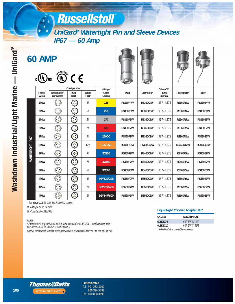
106
United StatesTel: 901.252.8000
800.326.5282Fax: 800.888.0690
www.tnb.com
Was
hdow
n In
dust
rial/L
ight
Mar
ine
— U
niGa
rd®
UniGard® Watertight Pin and Sleeve Devices IP67 — 60 Amp
Configuration Voltage/ Cable O.D.Poles/ Receptacle/ Plug/ Clock Color Plug Connector Range Receptacle* Inlet*Wires Connector Inlet Hour Coding Inches
2P3W 4h 125 RS360P4W RS360C4W .937–1.375 RS360R4W RS360B4W
2P3W 6h 250 RS360P6W RS360C6W .937–1.375 RS360R6W RS360B6W
2P3W 5h 277 RS360P5W RS360C5W .937–1.375 RS360R5W RS360B5W
2P3W 7h 480 RS360P7W RS360C7W .937–1.375 RS360R7W RS360B7W
2P3W 3h 250DC RS360P3W RS360C3W .937–1.375 RS360R3W RS360B3W
3P4W 12h 125/250 RS460P12W RS460C12W .937–1.375 RS460R12W RS460B12W
3P4W 9h 3Ø250 RS460P9W RS460C9W .937–1.375 RS460R9W RS460B9W
3P4W 7h 3Ø480 RS460P7W RS460C7W .937–1.375 RS460R7W RS460B7W
3P4W 5h 3Ø600 RS460P5W RS460C5W .937–1.375 RS460R5W RS460B5W
4P5W 9h 3ØY120/208 RS560P9W RS560C9W .937–1.375 RS560R9W RS560B9W
4P5W 7h 3ØY277/480 RS560P7W RS560C7W .937–1.375 RS560R7W RS560B7W
4P5W 5h 3ØY347/600 RS560P5W RS560C5W .937–1.375 RS560R5W RS560B5W
WAT
ERTI
GHT
IP67
60 AMP
* See page 111 for back box/mounting options.
UL Listing E2630, E47956
UL Classification E205590
NOTE: All UniGard 60 and 100 Amp devices ship standard with IEC 309-1 configuration “pilot”pin/sleeves used for auxillary contact service.
Special construction without these pilot contacts is available. Add “XC” to end of Cat. No.
CAT. NO. DESCRIPTION
6LTK5C75 60A 5W 3⁄4" NPT6LTK5C10 60A 5W 1" NPT* Additional sizes available on request.
Liquidtight Conduit Adapter Kit*

107
United StatesTel: 901.252.8000
800.326.5282Fax: 800.888.0690
www.tnb.com
Washdow
n Industrial/Light Marine —
UniGard®
UniGard® Watertight Pin and Sleeve Devices IP67 — 100 Amp
Configuration Voltage/ Cable O.D.Poles/ Receptacle/ Plug/ Clock Color Plug Connector Range Receptacle* Inlet*Wires Connector Inlet Hour Coding Inches
2P3W** 6h 250 RS3100P6W RS3100C6W RS3100R6W RS3100B6W
2P3W** 7h 480 RS3100P7W RS3100C7W RS3100R7W RS3100B7W
3P4W 12h 125/250 RS4100P12W RS4100C12W RS4100R12W RS4100B12W
3P4W 9h 3Ø250 RS4100P9W RS4100C9W RS4100R9W RS4100B9W
3P4W 7h 3Ø480 RS4100P7W RS4100C7W RS4100R7W RS4100B7W
3P4W 5h 3Ø600 RS4100P5W RS4100C5W RS4100R5W RS4100B5W
4P5W 9h 3ØY120/208 RS5100P9W RS5100C9W RS5100R9W RS5100B9W
4P5W 7h 3ØY277/480 RS5100P7W RS5100C7W RS5100R7W RS5100B7W
4P5W 5h 3ØY347/600 RS5100P5W RS5100C5W RS5100R5W RS5100B5W
WAT
ERTI
GHT
IP67
100 AMP
1.2650–1.790
1.2650–1.790
1.2650–1.790
1.2650–1.790
1.2650–1.790
1.2650–1.790
1.2650–1.790
1.2650–1.790
1.2650–1.790
UL Listing E2630, E47956
UL Classification E205590
NOTE: All UniGard 60 and 100 Amp devices ship standard with IEC 309-1 configuration “pilot”pin/sleeves used for auxillary contact service.
Special construction without these pilot contacts is available. (Add “XC” to end of Cat. No.)
▼ For 4-wire and 5-wire plugs and connectors only.Contact Technical Services for 3-wire plug andconnector conduit adapters. 100A 3-wire plugs andconnectors use PG48 backhandle thread.
CAT. NO. DESCRIPTION
10LTK5C10▼ 100A 4W, 5W 1" NPT10LTK5C125▼ 100A 4W, 5W 11⁄4" NPT10LTK5C150▼ 100A 4W, 5W 11⁄2" NPT
Liquidtight Conduit Adapter Kit* See page 111 for back box/mounting options.
** Alternate vendor-supplied item; construction features will vary from specs in this catalog. Full IECapproval and mating guaranteed. Contact Technical Services for inlet/receptacle mounting components.
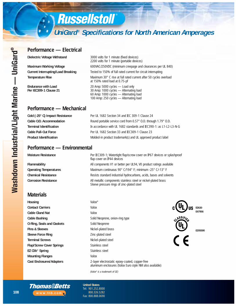
108
United StatesTel: 901.252.8000
800.326.5282Fax: 800.888.0690
www.tnb.com
Was
hdow
n In
dust
rial/L
ight
Mar
ine
— U
niGa
rd®
UniGard® Specifications for North American Amperages
Performance — ElectricalDielectric Voltage Withstand 3000 volts for 1 minute (fixed devices)
2200 volts for 1 minute (portable devices)
Maximum Working Voltage 600VAC/250VDC (minimum creepage and clearances per UL 840)
Current Interrupting/Load Breaking Tested to 150% of full rated current for circuit interrupting
Temperature Rise Maximum 30° C rise at full rated current after 50 cycles overload at 150% rated load at 0.75-pf
Endurance with Load 20 Amp: 5000 cycles — Load onlyPer IEC309-1 Clause 21 30 Amp: 1000 cycles — Alternating load
60 Amp: 1000 cycles — Alternating load100 Amp: 250 cycles — Alternating load
Performance — MechanicalCold (-25° C) Impact Resistance Per UL 1682 Section 34 and IEC 309-1 Clause 24
Cable O.D. Accommodation Round portable service cord from 0.57" O.D. through 1.79" O.D.
Terminal Identification In accordance with UL 1682 standards and IEC390-1: as L1-L2-L3-N-G
Cable Pull-Out Force Per UL 1682 Section 33 and IEC309-1 Clause 23
Product Identification Molded-in product trademark(s) and UL approved product label
Performance — EnvironmentalMoisture Resistance Per IEC309-1; Watertight flap/screw cover on IP67 devices or splashproof
flap cover on IP44 devices
Flammability All components V1 or better per UL94, V0 product ratings available
Operating Temperatures Maximum continuous 90° C/194° F; minimum -25° C/-13° F
Chemical Resistance Resists standard industrial hydrocarbons, acids, bases and solvents
Corrosion Resistance All metallic components stainless steel or nickel-plated brass Sleeve pressure rings of zinc-plated steel
MaterialsHousing Valox®
Contact Carriers Valox
Cable Gland Nut Valox
Cable Bushing Solid Neoprene, onion-ring type
O-Ring, Seals and Gaskets Solid Neoprene
Pins & Sleeves Nickel-plated brass
Sleeve Force Ring Zinc-plated steel
Terminal Screws Nickel-plated steel
Flap/Screw Cover Springs Stainless steel
EZ Clik® Spring Stainless steel
Mounting Flanges Valox
Cast Enclosures/Adapters 2-layer electrostatic epoxy-coated, copper-free aluminum enclosures (Valox Euro style NM also available)
(Valox® is a trademark of GE)
E2630E47956
E205590
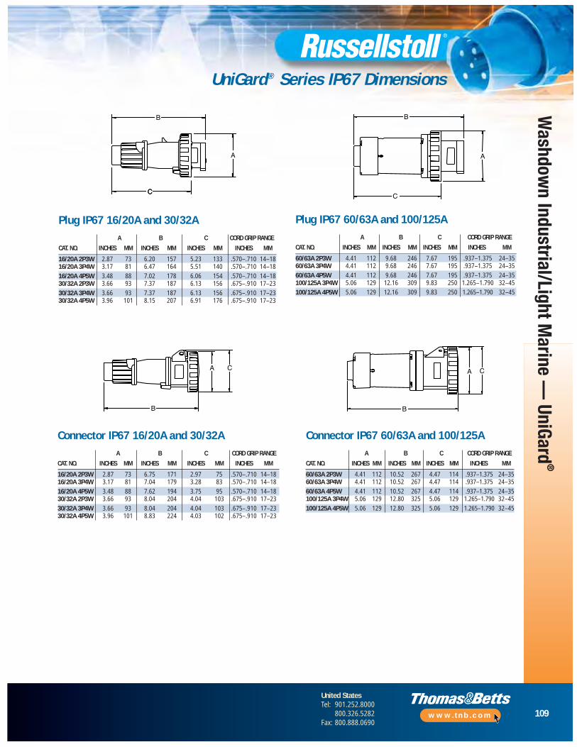
109
United StatesTel: 901.252.8000
800.326.5282Fax: 800.888.0690
www.tnb.com
Washdow
n Industrial/Light Marine —
UniGard®
UniGard® Series IP67 Dimensions
C
B
C
A
B
C
A
B
CA
B
CA
Plug IP67 16/20A and 30/32AA B C CORD GRIP RANGE
CAT. NO. INCHES MM INCHES MM INCHES MM INCHES MM
16/20A 2P3W 2.87 73 6.20 157 5.23 133 .570–.710 14–1816/20A 3P4W 3.17 81 6.47 164 5.51 140 .570–.710 14–18
16/20A 4P5W 3.48 88 7.02 178 6.06 154 .570–.710 14–1830/32A 2P3W 3.66 93 7.37 187 6.13 156 .675–.910 17–23
30/32A 3P4W 3.66 93 7.37 187 6.13 156 .675–.910 17–2330/32A 4P5W 3.96 101 8.15 207 6.91 176 .675–.910 17–23
Plug IP67 60/63A and 100/125AA B C CORD GRIP RANGE
CAT. NO. INCHES MM INCHES MM INCHES MM INCHES MM
60/63A 2P3W 4.41 112 9.68 246 7.67 195 .937–1.375 24–3560/63A 3P4W 4.41 112 9.68 246 7.67 195 .937–1.375 24–35
60/63A 4P5W 4.41 112 9.68 246 7.67 195 .937–1.375 24–35100/125A 3P4W 5.06 129 12.16 309 9.83 250 1.265–1.790 32–45
100/125A 4P5W 5.06 129 12.16 309 9.83 250 1.265–1.790 32–45
Connector IP67 16/20A and 30/32AA B C CORD GRIP RANGE
CAT. NO. INCHES MM INCHES MM INCHES MM INCHES MM
16/20A 2P3W 2.87 73 6.75 171 2.97 75 .570–.710 14–1816/20A 3P4W 3.17 81 7.04 179 3.28 83 .570–.710 14–18
16/20A 4P5W 3.48 88 7.62 194 3.75 95 .570–.710 14–1830/32A 2P3W 3.66 93 8.04 204 4.04 103 .675–.910 17–23
30/32A 3P4W 3.66 93 8.04 204 4.04 103 .675–.910 17–2330/32A 4P5W 3.96 101 8.83 224 4.03 102 .675–.910 17–23
Connector IP67 60/63A and 100/125AA B C CORD GRIP RANGE
CAT. NO. INCHES MM INCHES MM INCHES MM INCHES MM
60/63A 2P3W 4.41 112 10.52 267 4.47 114 .937–1.375 24–3560/63A 3P4W 4.41 112 10.52 267 4.47 114 .937–1.375 24–35
60/63A 4P5W 4.41 112 10.52 267 4.47 114 .937–1.375 24–35100/125A 3P4W 5.06 129 12.80 325 5.06 129 1.265–1.790 32–45
100/125A 4P5W 5.06 129 12.80 325 5.06 129 1.265–1.790 32–45
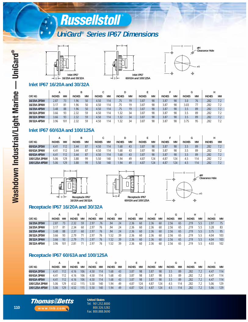
110
United StatesTel: 901.252.8000
800.326.5282Fax: 800.888.0690
www.tnb.com
Was
hdow
n In
dust
rial/L
ight
Mar
ine
— U
niGa
rd®
UniGard ® Series IP67 Dimensions
B
IAC
D
B
C
D
A I
B
D
C A
B
D
C A F
E
øG
øH-CLEARANCE-HOLE
Inlet IP67 16/20A and 30/32A
Inlet IP67 60/63A and 100/125A
F
E
øG
øH-CLEARANCE-HOLE
Receptacle IP67 16/20A and 30/32A
Receptacle IP67 60/63A and 100/125A
øHClearance Hole
øHClearanceHole
Inlet IP67 16/20A and 30/32AA B C D E F G H
CAT. NO. INCHES MM INCHES MM INCHES MM INCHES MM INCHES MM INCHES MM INCHES MM INCHES MM
16/20A 2P3W 2.87 73 1.96 50 4.50 114 .75 19 3.87 98 3.87 98 3.0 76 .282 7.216/20A 3P4W 3.17 81 1.96 50 4.50 114 .75 19 3.87 98 3.87 98 3.03 77 .282 7.216/20A 4P5W 3.48 88 1.96 50 4.50 114 .75 19 3.87 98 3.87 98 3.5 89 .282 7.230/32A 2P3W 3.66 93 2.32 59 4.50 114 1.32 34 3.87 98 3.87 98 3.5 89 .282 7.230/32A 3P4W 3.66 93 2.32 59 4.50 114 1.32 34 3.87 98 3.87 98 3.5 89 .282 7.230/32A 4P5W 3.96 101 2.32 59 4.50 114 1.32 34 3.87 98 3.87 98 3.75 95 .282 7.2
Inlet IP67 60/63A and 100/125AA B C D E F G H
CAT. NO. INCHES MM INCHES MM INCHES MM INCHES MM INCHES MM INCHES MM INCHES MM INCHES MM
60/63A 2P3W 4.41 112 3.44 87 4.50 114 1.68 43 3.87 98 3.87 98 3.5 89 .282 7.260/63A 3P4W 4.41 112 3.44 87 4.50 114 1.68 43 3.87 98 3.87 98 3.5 89 .282 7.260/63A 4P5W 4.41 112 3.44 87 4.50 114 1.68 43 3.87 98 3.87 98 3.5 89 .282 7.2100/125A 3P4W 5.06 129 3.88 99 5.50 140 1.94 49 4.87 124 4.87 124 4.5 114 .282 7.2100/125A 4P5W 5.06 129 3.88 99 5.50 140 1.94 49 4.87 124 4.87 124 4.5 114 .282 7.2
Receptacle IP67 16/20A and 30/32AA B C D E F G H I
CAT. NO. INCHES MM INCHES MM INCHES MM INCHES MM INCHES MM INCHES MM INCHES MM INCHES MM INCHES MM
16/20A 2P3W 2.87 73 2.32 59 2.97 .76 .94 24 2.36 60 2.36 60 2.56 65 .219 5.5 2.97 7516/20A 3P4W 3.17 81 2.34 60 2.97 76 .94 24 2.36 60 2.36 60 2.56 65 .219 5.5 3.28 8316/20A 4P5W 3.48 88 2.37 60 2.97 76 .94 24 2.36 60 2.36 60 2.56 65 .219 5.5 3.75 9530/32A 2P3W 3.66 93 2.79 71 2.97 76 1.52 39 2.36 60 2.36 60 2.56 65 .219 5.5 4.04 10330/32A 3P4W 3.66 93 2.79 71 2.97 76 1.52 39 2.36 60 2.36 60 2.56 65 .219 5.5 4.04 10330/32A 4P5W 3.96 101 2.81 71 2.97 76 1.52 39 2.36 60 2.36 60 2.56 65 .219 5.5 4.03 102
Receptacle IP67 60/63A and 100/125AA B C D E F G H I
CAT. NO. INCHES MM INCHES MM INCHES MM INCHES MM INCHES MM INCHES MM INCHES MM INCHES MM INCHES MM
60/63A 2P3W 4.41 112 4.16 106 4.50 114 1.68 43 3.87 98 3.87 98 3.5 89 .282 7.2 4.47 11460/63A 3P4W 4.41 112 4.16 106 4.50 114 1.68 43 3.87 98 3.87 98 3.5 89 .282 7.2 4.47 11460/63A 4P5W 4.41 112 4.16 106 4.50 114 1.68 43 3.87 98 3.87 98 3.5 89 .282 7.2 4.47 114100/125A 3P4W 5.06 129 4.52 115 5.50 140 1.94 49 4.87 124 4.87 124 4.5 114 .282 7.2 5.06 129100/125A 4P5W 5.06 129 4.52 115 5.50 140 1.94 49 4.87 124 4.87 124 4.5 114 .282 7.2 5.06 129
øHClearance Hole
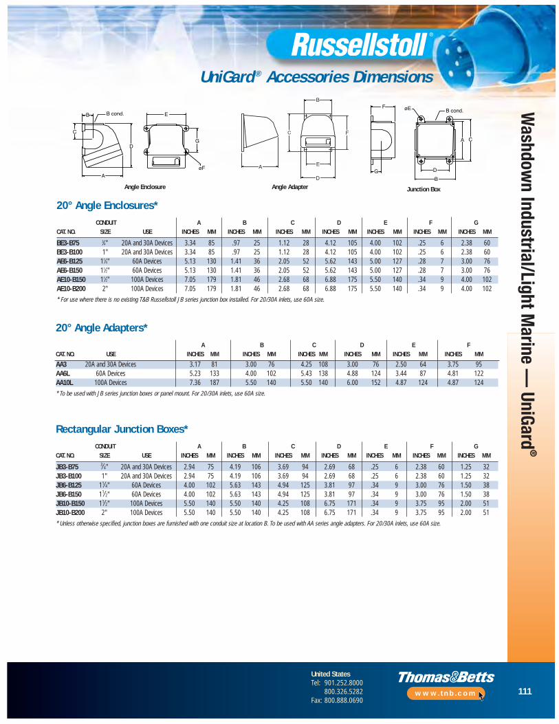
111
United StatesTel: 901.252.8000
800.326.5282Fax: 800.888.0690
www.tnb.com
Washdow
n Industrial/Light Marine —
UniGard®
UniGard ® Accessories Dimensions
B
C
A
E
D
øF
G
-
B cond.
B
C
A E
D
F
B
CA
øE
D
F
G
B cond.
Junction BoxAngle AdapterAngle Enclosure
20° Angle Enclosures*CONDUIT A B C D E F G
CAT. NO. SIZE USE INCHES MM INCHES MM INCHES MM INCHES MM INCHES MM INCHES MM INCHES MM
BE3-B75 3⁄4" 20A and 30A Devices 3.34 85 .97 25 1.12 28 4.12 105 4.00 102 .25 6 2.38 60BE3-B100 1" 20A and 30A Devices 3.34 85 .97 25 1.12 28 4.12 105 4.00 102 .25 6 2.38 60AE6-B125 11⁄4" 60A Devices 5.13 130 1.41 36 2.05 52 5.62 143 5.00 127 .28 7 3.00 76AE6-B150 11⁄2" 60A Devices 5.13 130 1.41 36 2.05 52 5.62 143 5.00 127 .28 7 3.00 76AE10-B150 11⁄2" 100A Devices 7.05 179 1.81 46 2.68 68 6.88 175 5.50 140 .34 9 4.00 102AE10-B200 2" 100A Devices 7.05 179 1.81 46 2.68 68 6.88 175 5.50 140 .34 9 4.00 102
* For use where there is no existing T&B Russellstoll JB series junction box installed. For 20/30A inlets, use 60A size.
Rectangular Junction Boxes*CONDUIT A B C D E F G
CAT. NO. SIZE USE INCHES MM INCHES MM INCHES MM INCHES MM INCHES MM INCHES MM INCHES MM
JB3-B75 3⁄4" 20A and 30A Devices 2.94 75 4.19 106 3.69 94 2.69 68 .25 6 2.38 60 1.25 32JB3-B100 1" 20A and 30A Devices 2.94 75 4.19 106 3.69 94 2.69 68 .25 6 2.38 60 1.25 32JB6-B125 11⁄4" 60A Devices 4.00 102 5.63 143 4.94 125 3.81 97 .34 9 3.00 76 1.50 38JB6-B150 11⁄2" 60A Devices 4.00 102 5.63 143 4.94 125 3.81 97 .34 9 3.00 76 1.50 38JB10-B150 11⁄2" 100A Devices 5.50 140 5.50 140 4.25 108 6.75 171 .34 9 3.75 95 2.00 51JB10-B200 2" 100A Devices 5.50 140 5.50 140 4.25 108 6.75 171 .34 9 3.75 95 2.00 51
* Unless otherwise specified, junction boxes are furnished with one conduit size at location B. To be used with AA series angle adapters. For 20/30A inlets, use 60A size.
20° Angle Adapters*A B C D E F
CAT. NO. USE INCHES MM INCHES MM INCHES MM INCHES MM INCHES MM INCHES MM
AA3 20A and 30A Devices 3.17 81 3.00 76 4.25 108 3.00 76 2.50 64 3.75 95AA6L 60A Devices 5.23 133 4.00 102 5.43 138 4.88 124 3.44 87 4.81 122AA10L 100A Devices 7.36 187 5.50 140 5.50 140 6.00 152 4.87 124 4.87 124
* To be used with JB series junction boxes or panel mount. For 20/30A inlets, use 60A size.
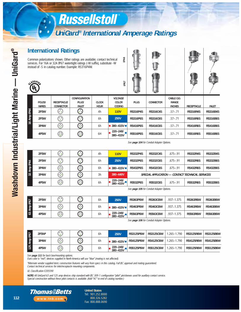
112
United StatesTel: 901.252.8000
800.326.5282Fax: 800.888.0690
www.tnb.com
Was
hdow
n In
dust
rial/L
ight
Mar
ine
— U
niGa
rd®
UniGard ® International Amperage Ratings
International RatingsCommon polarizations shown. Other ratings are available; contact technicalservices. For 16A or 32A IP67 watertight ratings (-W suffix), substitute -Winstead of -S in catalog number. Example: RS316P4W.
CONFIGURATION VOLTAGE/ CABLE O.D.POLES/ RECEPTACLE/ PLUG/ CLOCK COLOR PLUG CONNECTOR RANGEWIRES CONNECTOR INLET HOUR CODING INCHES RECEPTACLE INLET
2P3W 4h RS316P4S RS316C4S .57–.71 RS316R4S RS316B4S
2P3W 6h RS316P6S RS316C6S .57–.71 RS316R6S RS316B6S
3P4W 6h RS416P6S RS416C6S .57–.71 RS416R6S RS416B6S
4P5W 6H RS516P6S RS516C6S .57–.71 RS516R6S RS516B6S
16 A
mp
IP44 110V
250V
380–415V
220–240/380–415V
IP67
IP44
See page 104 for Conduit Adapter Options.
2P3W 4h RS332P4S RS332C4S .675–.91 RS332R4S RS332B4S
2P3W 6h RS332P6S RS332C6S .675–.91 RS332R6S RS332B6S
3P4W 6h RS432P6S RS432C6S .675–.91 RS432R6S RS432B6S
3P4W 3h
4P5W 6h RS532P6S RS532C6S .675–.91 RS532R6S RS532B6S
32 A
mp
IP44
SPECIAL APPLICATION — CONTACT TECHNICAL SERVICES
110V
250V
380–415V
380–440V
220–240/380–415V
2P3W 6h RS363P6W RS363C6W .937–1.375 RS363R6W RS363B6W
3P4W 6h RS463P6W RS463C6W .937–1.375 RS463R6W RS463B6W
4P5W 6h RS563P6W RS563C6W .937–1.375 RS563R6W RS563B6W63 A
mp
IP67 250V
380–415V
220–240/380–415V
See page 105 for Conduit Adapter Options.
See page 106 for Conduit Adapter Options.
2P3W* 6h RS3125P6W RS3125C6W 1.265–1.790 RS3125R6W RS3125B6W
3P4W 6h RS4125P6W RS4125C6W 1.265–1.790 RS4125R6W RS4125B6W
4P5W 6h RS5125P6W RS5125C6W 1.265–1.790 RS5125R6W RS5125B6W125
Amp
IP67 250V
380–415V
220–240/380–415V
See page 111 for back box/mounting options.Euro color is “red”; devices supplied in North America will use “blue” (mating is not affected).
*Alternate vendor supplied item; construction features will vary from specs in this catalog. Full IEC approval and mating guaranteed. Contact technical services for inlet/receptacle mounting components.
UL Classification E205590
NOTE: All UniGard 63 and 125 amp devices ship standard with IEC 309-1 configuration “pilot” pin/sleeves used for auxillary contact service.Special construction without these pilot contacts is available. (Add “XC” to end of catalog number.)
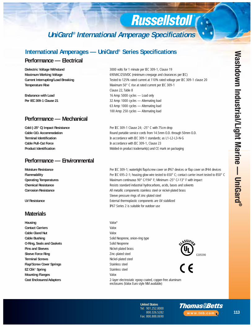
113
United StatesTel: 901.252.8000
800.326.5282Fax: 800.888.0690
www.tnb.com
Washdow
n Industrial/Light Marine —
UniGard®
UniGard ® International Amperage Specifications
International Amperages — UniGard® Series SpecificationsPerformance — ElectricalDielectric Voltage Withstand 3000 volts for 1 minute per IEC 309-1, Clause 19
Maximum Working Voltage 690VAC/250VDC (minimum creepage and clearances per IEC)
Current Interrupting/Load Breaking Tested to 125% rated current at 110% rated voltage per IEC 309-1 clause 20
Temperature Rise Maximum 50° C rise at rated current per IEC 309-1
Clause 22, Table 8
Endurance with Load 16 Amp: 5000 cycles — Load only
Per IEC 309-1 Clause 21 32 Amp: 1000 cycles — Alternating load
63 Amp: 1000 cycles — Alternating load
100 Amp: 250 cycles — Alternating load
Performance — MechanicalCold (-25° C) Impact Resistance Per IEC 309-1 Clause 24; -25° C with 75cm drop
Cable O.D. Accommodation Round portable service cords from 14.5mm O.D. through 50mm O.D.
Terminal Identification In accordance with IEC 309-1 standards; as L1-L2-L3-N-G
Cable Pull-Out Force In accordance with IEC 309-1, Clause 23
Product Identification Molded-in product trademark(s) and CE mark on packaging
Performance — EnvironmentalMoisture Resistance Per IEC 309-1; watertight flap/screw cover on IP67 devices or flap cover on IP44 devices
Flammability Per IEC 695-2-1; housing glow wire tested to 650° C; contact carrier insert tested to 850° C
Operating Temperatures Maximum continuous 90° C/194° F; Minimum -25° C/-13° F with impact
Chemical Resistance Resists standard industrial hydrocarbons, acids, bases and solvents
Corrosion Resistance All metallic components stainless steel or nickel-plated brass
Sleeve pressure rings of zinc-plated steel
UV Resistance External thermoplastic components are UV stabilized
IP67 Series 2 is suitable for outdoor use
MaterialsHousing Valox®
Contact Carriers Valox
Cable Gland Nut Valox
Cable Bushing Solid Neoprene, onion-ring type
O-Ring, Seals and Gaskets Solid Neoprene
Pins and Sleeves Nickel-plated brass
Sleeve Force Ring Zinc-plated steel
Terminal Screws Nickel-plated steel
Flap/Screw Cover Springs Stainless steel
EZ Clik® Spring Stainless steel
Mounting Flanges Valox
Cast Enclosures/Adapters 2-layer electrostatic epoxy-coated, copper-free aluminum enclosures (Valox Euro style NM available)
E205590
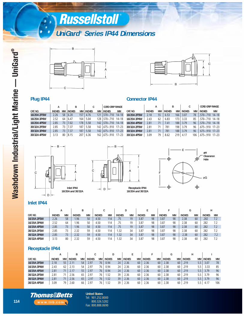
114
United StatesTel: 901.252.8000
800.326.5282Fax: 800.888.0690
www.tnb.com
Was
hdow
n In
dust
rial/L
ight
Mar
ine
— U
niGa
rd®
UniGard® Series IP44 Dimensions
B
A
CB-
CA
B
C A
D
B
CI
A
D
F
E
øG
øH-CLEARANCE-HOLE
Inlet IP44 16/20A and 30/32A
Receptacle IP44 16/20A and 30/32A
øHClearanceHole
Connector IP44A B C CORD GRIP RANGE
CAT. NO. INCHES MM INCHES MM INCHES MM INCHES MM16/20A 2P3W 2.18 55 6.53 166 3.07 78 .570–.710 14–1816/20A 3P4W 2.43 62 6.83 173 3.33 85 .570–.710 14–1816/20A 4P5W 2.81 71 7.41 188 3.79 96 .570–.710 14–1830/32A 2P3W 2.81 71 781 198 3.79 96 .675–.910 17–2330/32A 3P4W 2.81 71 781 188 3.79 96 675–.910 17–2330/32A 4P5W 3.09 79 8.62 219 4.17 106 .675–.910 17–23
Inlet IP44A B C D E F G H
CAT. NO. INCHES MM INCHES MM INCHES MM INCHES MM INCHES MM INCHES MM INCHES MM INCHES MM16/20A 2P3W 2.26 58 1.96 50 4.50 114 .75 19 3.87 98 3.87 98 2.38 60 .282 7.216/20A 3P4W 2.52 64 1.96 50 4.50 114 .75 19 3.87 98 3.87 98 2.38 60 282 7.216/20A 4P5W 2.85 73 1.96 50 4.50 114 .75 19 3.87 98 3.87 98 2.38 60 282 7.230/32A 2P3W 2.85 73 2.32 59 4.50 114 1.32 34 3.87 98 3.87 98 2.38 60 282 7.230/32A 3P4W 2.85 73 2.32 59 4.50 114 1.32 34 3.87 98 3.87 98 2.38 60 282 7.230/32A 4P5W 3.13 80 2.32 59 4.50 114 1.32 34 3.87 98 3.87 98 2.38 60 282 7.2
Receptacle IP44A B C D E F G H I
CAT. NO. INCHES MM INCHES MM INCHES MM INCHES MM INCHES MM INCHES MM INCHES MM INCHES MM INCHES MM16/20A 2P3W 2.18 55 2.11 54 2.97 76 0.94 24 2.36 60 2.36 60 2.38 60 .219 5.5 3.07 7816/20A 3P4W 2.43 62 2.13 54 2.97 76 0.94 24 2.36 60 2.36 60 2.38 60 .219 5.5 3.33 8516/20A 4P5W 2.81 71 2.17 55 2.97 76 0.94 24 2.36 60 2.36 60 2.38 60 .219 5.5 3.79 9630/32A 2P3W 2.81 71 2.56 65 2.97 76 1.52 39 2.36 60 2.36 60 2.38 60 .219 5.5 3.79 9630/32A 3P4W 2.81 71 2.56 65 2.97 76 1.52 39 2.36 60 2.36 60 2.38 60 .219 5.5 3.79 9630/32A 4P5W 3.09 79 2.60 66 2.97 76 1.52 39 2.36 60 2.36 60 2.38 60 .219 5.5 4.17 106
Plug IP44
A B C CORD GRIP RANGE
CAT. NO. INCHES MM INCHES MM INCHES MM INCHES MM16/20A 2P3W 2.26 58 6.20 157 4.76 121 .570–.710 14–1816/20A 3P4W 2.52 64 6.47 164 5.04 128 .570–.710 14–1816/20A 4P5W 2.85 73 7.02 178 5.58 142 .570–.710 14–1830/32A 2P3W 2.85 73 7.37 187 5.58 142 .675–.910 17–2330/32A 3P4W 2.85 73 7.37 187 5.58 142 .675–.910 17–2330/32A 4P5W 3.13 80 8.15 207 6.36 162 .675–.910 17–23
B

115
United StatesTel: 901.252.8000
800.326.5282Fax: 800.888.0690
www.tnb.com
Washdow
n Industrial/Light Marine —
UniGard®
UniGard® IEC 309 Safety Interlock
Watertight — IP67• “W” suffixes (UL Type 4X construction)
• Rugged thermoplastic housings resist impact or abuse and provide excellentcorrosion resistance
• Rugged V0-5VA flameproof housings
• Ideal for outdoor, wet, marine and washdown applications
• Unique industry-first circuit breaker interlock
• US: 20, 30, 60 and 100 amp sizes
• International: 16, 32, 63 and 125 amp sizes
Splashproof — IP44• “S” suffixes (NEMA 3R construction)
• Suitable for indoor use where splashing liquidsand other contaminants may interfere withelectrical connections
• Ideal for most heavy commercial applicationsand light industrial applications
• US 20, 30 and 60 amp ratings
• International 16, 32 and 63 amp ratings
Protection and Safety in Power Delivery• Red vertical “ON’’ indication
• Lock on and Lock “OFF” positions
• Branch circuit load and operation pro tec tionor switched-only version (shown)
Mount It Anywhere• Swivel 3- or 4-point feet variable footprint
for flexible mounting
• Fits in web of 8" I-beams
The Only True Circuit Breaker Interlocked IEC 309 Receptacle (Outlet)• Circuit breaker integrated interlock mechanism
• UL 489 Listed 22KAIC protection
• Alternate trip ratings available
• Auxiliary switch option
E211951
E47955
Wire It Up, Sideways or Down• Top, side and bottom entry
• Industry standard entry sizes
ORSwitched-Only Version• Rugged UL Listed switch
• Proven performance components
• Through 600VAC 4P5W plus auxiliary contacts capable
IEC 309 Safety Interlock — The UniGard® Difference
TOP AND BOTTOM TOP SIDE ENTRY
20/30 Amp 60/100 Amp All
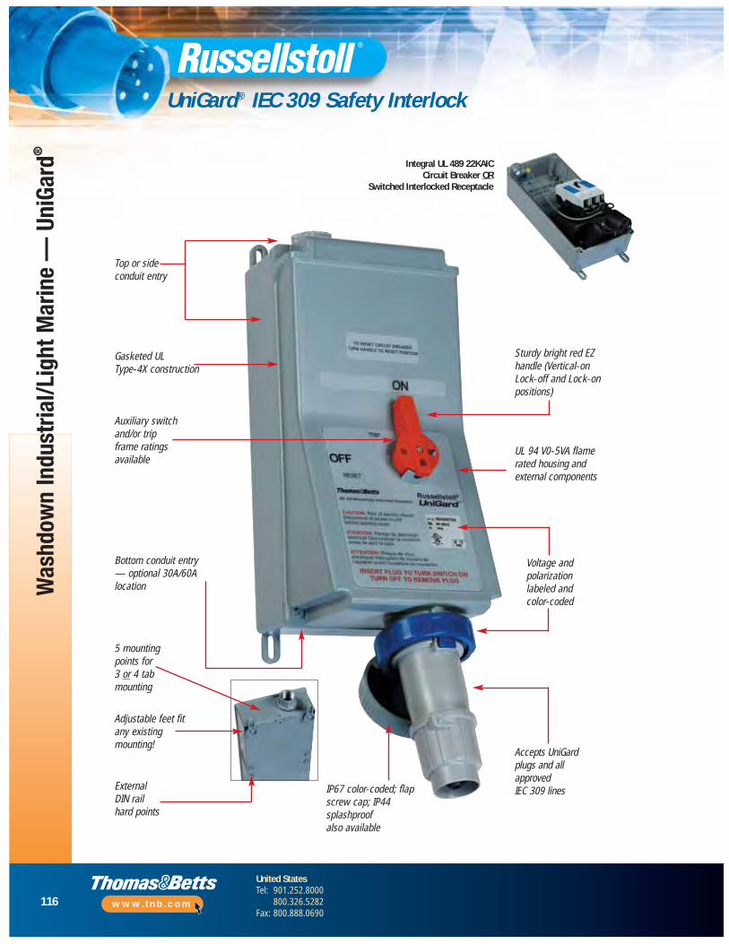
116
United StatesTel: 901.252.8000
800.326.5282Fax: 800.888.0690
www.tnb.com
Was
hdow
n In
dust
rial/L
ight
Mar
ine
— U
niGa
rd®
UniGard® IEC 309 Safety Interlock
Bottom conduit entry — optional 30A/60Alocation
5 mountingpoints for 3 or 4 tabmounting
UL 94 V0-5VA flamerated housing andexternal components
Auxiliary switchand/or tripframe ratingsavailable
Sturdy bright red EZhandle (Vertical-onLock-off and Lock-onpositions)
IP67 color-coded; flapscrew cap; IP44splashproof also available
Voltage andpolarization labeled and color-coded
Accepts UniGardplugs and all approved IEC 309 lines
Adjustable feet fitany existingmounting!
Gasketed UL Type-4X construction
Top or side conduit entry
ExternalDIN railhard points
Integral UL 489 22KAIC Circuit Breaker OR
Switched Interlocked Receptacle
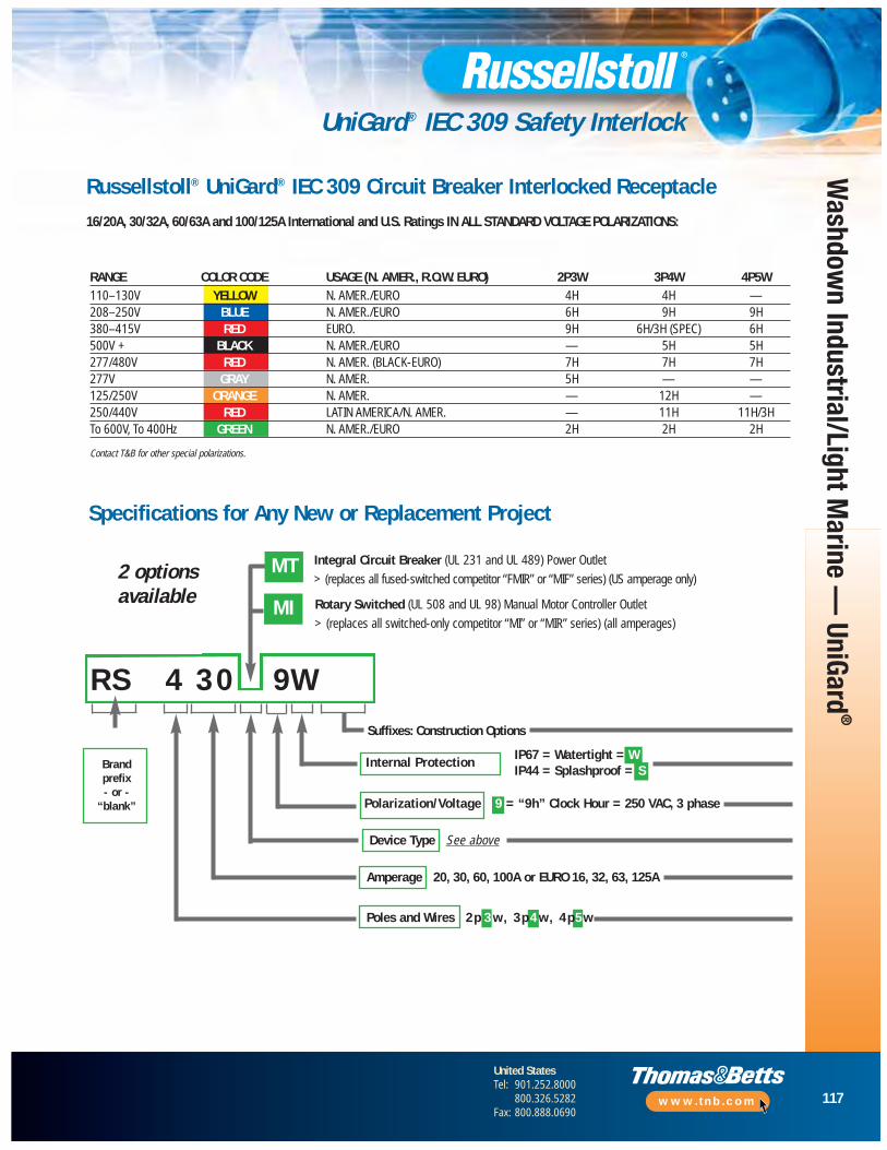
117
United StatesTel: 901.252.8000
800.326.5282Fax: 800.888.0690
www.tnb.com
UniGard® IEC 309 Safety Interlock
Internal Protection
Amperage 20, 30, 60, 100A or EURO 16, 32, 63, 125A
R S 4 3 0 9W
RANGE COLOR CODE USAGE (N. AMER., R.O.W. EURO) 2P3W 3P4W 4P5W110–130V YELLOW N. AMER./EURO 4H 4H —208–250V BLUE N. AMER./EURO 6H 9H 9H380–415V RED EURO. 9H 6H/3H (SPEC) 6H500V + BLACK N. AMER./EURO — 5H 5H277/480V RED N. AMER. (BLACK-EURO) 7H 7H 7H277V GRAY N. AMER. 5H — —125/250V ORANGE N. AMER. — 12H —250/440V RED LATIN AMERICA/N. AMER. — 11H 11H/3HTo 600V, To 400Hz GREEN N. AMER./EURO 2H 2H 2H
Contact T&B for other special polarizations.
Russellstoll® UniGard® IEC 309 Circuit Breaker Interlocked Receptacle16/20A, 30/32A, 60/63A and 100/125A International and U.S. Ratings IN ALL STANDARD VOLTAGE POLARIZATIONS:
Specifications for Any New or Replacement Project
2 optionsavailable MI
Integral Circuit Breaker (UL 231 and UL 489) Power Outlet
> (replaces all fused-switched competitor “FMIR” or “MIF” series) (US amperage only)
Rotary Switched (UL 508 and UL 98) Manual Motor Controller Outlet
> (replaces all switched-only competitor “MI” or “MIR” series) (all amperages)
Brandprefix- or -
“blank”
Device Type See above
MT
Suffixes: Construction Options
Poles and Wires 2 p 3 w, 3 p 4 w, 4 p5 w
IP67 = Watertight = WIP44 = Splashproof = S
Polarization/Voltage 9 = “9h” Clock Hour = 250 VAC, 3 phase
Washdow
n Industrial/Light Marine —
UniGard®
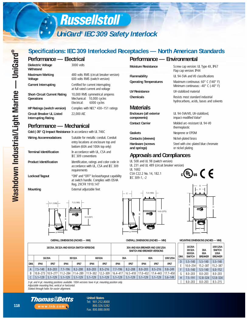
118
United StatesTel: 901.252.8000
800.326.5282Fax: 800.888.0690
www.tnb.com
Was
hdow
n In
dust
rial/L
ight
Mar
ine
— U
niGa
rd®
UniGard® IEC 309 Safety Interlock
Specifications: IEC 309 Interlocked Receptacles — North American Standards
5.1 (129) 7.2 (183)
A
B9.3 (237)
C
A
B
7.2 (183)
14.6 (370)
H-
G
D
E
F
I
Performance — ElectricalDielectric Voltage 3000 voltsWithstand
Maximum Working 480 volts RMS (circuit breaker version)Voltage 600 volts RMS (switch version)
Current Interrupting Certified for current interrupting at full rated current and voltage
Short-Circuit Current Rating 10,000 RMS symmetrical amperesOperations Mechanical: 10,000 cycles
Electrical: 6000 cycles
HP Ratings (switch version) Complies with NEC® 430–151 ratings
Circuit Breaker UL Listed 22,000 AICInterrupting Rating
Performance — MechanicalCold (-35° C) Impact Resistance In accordance with UL 746C
Wiring Accommodations Suitable for metallic conduit. Conduit entry locations at enclosure top and bottom (60A and 100A top only)
Terminal Identification In accordance with UL, CSA and IEC 309 conventions
Product Identification Identification, ratings and color code in accordance with UL, CSA and IEC 309 requirements
Lockout/Tagout “ON” and “OFF” lockout/tagout capabilityat switch handle. Complies with OSHA Reg. 29CFR 1910.147
Mounting External adjustable feet
Performance — EnvironmentalMoisture Resistance Screw cap version: UL Type 4X, IP67
Flap cap version: IP44
Flammability UL 94-5VA and V0 classifications
Operating Temperatures Maximum continuous: 60° C (140° F)Minimum continuous: -40° C (-40° F)
UV Resistance UV-stabilized material
Chemicals Resists most standard industrial hydrocarbons, acids, bases and solvents
MaterialsEnclosure (all exterior UL 94-5VA/V0, UV-stabilized, components) impact-modified Valox®
Contact Carrier Molded arc-resistant UL 94-V0 thermoplastic
Gaskets Neoprene or EPDM
Contacts (sleeves) Nickel-plated brass
Hardware (screws Steel with zinc-plated blue chromate and springs) or nickel plating
Approvals and CompliancesUL 508 and UL 98 (switch version)UL 231 and UL 489 (circuit breaker version) UL 1682CSA C22.2 No. 14, 182.1IEC 309-1, -2
MOUNTING DIMENSIONS (INCHES — MM)
16/20A 100/125A30/32A 30A SWITCH60/63A 60A 100A
DIM. SWITCH BREAKER BREAKER
D 5.5–140 5.5–140 5.5–140E 10.0–254 15.2–387 15.2–387F 5.5–140 5.5–140 6.0–152G 8.0–203 8.0–203 8.0–203H 7.5–191 12.8–324 12.8–324I 8.0–203 8.0–203 8.5–215
OVERALL DIMENSIONS (INCHES — MM) OVERALL DIMENSIONS (INCHES — MM)
16/20A, 30/32A AND 60/63A SWITCH VERSIONS 30A AND 60A BREAKER AND 100/125ASWITCH AND BREAKER VERSIONS
16/20A 30/32A 60/63A 30A 60A 100/125A
DIM. IP44 IP67 IP44 IP67 IP44 IP67 IP44 IP67 IP44 IP67 IP67
A 7.5–140 8.0–203 7.7–196 8.2–208 8.0–203 8.5–216 7.7–196 8.2–208 8.0–203 8.5–216 9.8–249B 10.8–273 10.9–277 11.2–284 11.4–289 11.9–302 12.2–309 16.4–417 16.5–418 17.0–432 17.4–443 17.7–450C 5.1–129 5.1–129 5.1–129 5.1–129 5.1–129 5.1–129 5.1–129 5.1–129 5.1–129 5.1–129 5.6–149
3-pt. and 4-pt. mounting positions available. 100A versions have 4-pt. mounting position only.Adjustable mounting feet, vertical or horizontal.Slotted through holes for easier alignment.

119
United StatesTel: 901.252.8000
800.326.5282Fax: 800.888.0690
www.tnb.com
Industrial and Comm
ercial
Industrial and Commercial Applications
DuraTite® and Ever-Lok® Locking Connections
Overview and Comparison .........................................................120
DuraTite® Non-Metallic Self-Locking Connections Overview ...............................................................121
DuraTite® and Ever-Lok® Plugs, Connectors and Receptacles ........................................................................122
DuraTite® Specifications ............................................................123
DuraTite® Dimensions ................................................................124
Ever-Lok® Locking Connections Overview..................................125
Ever-Lok® Plugs, Connectors and Receptacles ...................126–129
Ever-Lok® Midget Plugs, Connectors and Receptacles .......130–131
Ever-Lok® Dimensions ...............................................................132
Ever-Lok® Accessories .......................................................133–135
Heavy-Service Ever-Lok® Connections Overview........................136
Heavy-Service Ever-Lok® Plugs, Connectors and Receptacles ........................................................................137
Heavy-Service Ever-Lok® Receptacle Assembly .........................138
Heavy-Service Ever-Lok® Dimensions ................................139–140
Heavy-Service Ever-Lok® Accessories................................141–142

120
United StatesTel: 901.252.8000
800.326.5282Fax: 800.888.0690
www.tnb.com
Overview and Comparison
A new thermoplastic option to 20/30AStandard Ever-Lok plugs and connectors. 20A and 30A plugs will mate directly toStandard Ever-Lok receptacles, with a newEZTab locking feature. For new installations,specify Ever-Lok receptacles with DuraTiteplugs and connectors. Clamp or conduitoptions complete a flexible value option for new and existing installations.
Steel self-locking housings make Standardand Midget Ever-Lok connections famous for their endurance in punishing factoryinstallations. Clamp, bushing or hub fittingcable entries are offered for both withStandard Ever-Lok available at 20A, 30A and50A over the 15A Midget Ever-Lok. Standardvoltage polarizations are maintained in theselines through 480VAC.
The standard in portable weldinginstallations, from 30A to 100A. Ruggedaluminum housings and self-locking uponinsertion, HSE series products are ideal for indoor factory use. With unique handledesigns, a simple 1⁄8 turn counter-clockwisereleases plug for withdrawal. Switched /fusedor circuit breaker interlocks in severalconfigurations are also offered. SeeAutomotive/Industrial Interlock section.
Thermoplastic International Standard 309-2 or CEE-17 type connector lines usage isgrowing in OEM, export and standardperformance applications. The IP44 indooruse style is splashproof when mated anddirectly interchangeable with othermanufacturers. Inter national designationsshadow U.S. ratings: 20/16A, 30/32A,60/63A and 100/125A. IP44 devices haveNO locking features except flap covers,with catalog numbers “S” or “SW” suffixes.
DuraTite®
to 3P4W20A and 30A
Ever-Lok® Standardand Midget Series
to 3P4W15A through 50A
Heavy Service Ever-Lokto 4P4W
30A through 100A
Defined
General IndustrialLighting ConnectionsIndoor Welding StationsMachinery/Tool ConnectionsPower Distribution PanelsConvenience PowerBattery Charging Equipment
ConstructionGenerator Set PanelsPortable Tools and EquipmentLimited-Life InstallationsPortable Lighting Equipment
Typical Application Groups
Russellstoll Line Selections for Indoor Applications
• Any application where electrical connections needprotection from water and/or dust entering the contacts or the wiring compartment
• Less credit cable sealing but easier to use device locking designs are employed
• Metal connectors are usually preferred with thermoplasticoptions increasing. Thermoplastic devices must withstandnormal industrial handling
InstrumentationPortable EquipmentCritical Power ConnectionsMotor Power ConnectionsCritical Robotics PowerTest EquipmentLaboratory/Test Stations
OEMsExport MachineryCritical Power ConnectionsInternational Indoor UsageTransportable Equipment
Indu
stria
l and
Com
mer
cial
— D
uraT
ite®
and
Ever
-Lok
®
IEC (IP44)to 4P5W
20A through 100A

121
United StatesTel: 901.252.8000
800.326.5282Fax: 800.888.0690
www.tnb.com
Industrial and Comm
ercial — DuraTite
®and Ever-Lok
®
DuraTite® Non-Metallic Self-Locking Connections Overview
Industrial Specification Grade Redefined
From our industry standard Ever-Lok series of plugs, connectors and receptacles,Russellstoll has developed DuraTite — the first non-metallic, self-locking pin and sleeve power interconnection system. In 20 and 30 amp ranges, DuraTite mates with existing 15–30A Ever-Lok receptacles already in use.
Industrial “Safety Grade” Construction• 20 and 30 Amp plugs and connectors (600VAC max.)
• Indoor industrial and heavy-duty use
• Durable, tough and flame safety rated housings
• DuraV® housing material specially selected for hot or cold washdown duty
• Flame safe UL94-V0 rated housings
• Superior performance in corrosive environments
• High-visibility yellow housings
Safe and Reliable Power Connections: Pin and Sleeve, Voltage Polarized• Long life: Round, self cleaning, constant pressure pin and sleeve contacts,
of solid CDA 360 brass for long reliable electrical life
• More power, operates cooler: Large circular electrical contact area allows more current flow with lower temperature rise
• Ground pin keyed for voltage polarization (O-ring seal)
• Voltage polarized for safe connection (U-ground) (pins shown with optional O-ring seals)
Easy To Wire• “No Twist-Off” locking plugs: Integral threaded screw collars
and compression type bushings make wiring a snap
• Fast assembly and wiring: “Drop-In” rear loaded interiors use no assembly screws, versus 3–5 or more with other connectors. 30/50A connectors use unique E-Z Tite™ external gland lock screw
• Set screw terminals: Are quick and easy to wire, with complete wire capture in deep pin/sleeve barrels
Non-Metallic Self-Locking Plugs, Connectors and Receptacles

122
United StatesTel: 901.252.8000
800.326.5282Fax: 800.888.0690
www.tnb.com
Indu
stria
l and
Com
mer
cial
— D
uraT
ite®
and
Ever
-Lok
®
DuraTite® and Ever-Lok® Plugs, Connectors and Receptacles
CAT. NOS.
PLUG CONNECTOR RECEPTACLE — EVER-LOK
FACE@ 250V RECEP./AMPS VOLTAGE CONN. DURATITE EVER-LOK DURATITE EVER-LOK
8013U1 8023U1125VAC 5P23U1LD 8153U1 5C23U1LD 8093U1 .625 8003U1 8083U1
8593U1 8683U15P23U2LD 8013U2 5C23U2LD 8023U2 .625 8003U2 8083U2
250VAC 8153U2 8093U28593U2 8683U2
5P23U3LD 8013U3 5C23U3LD 8023U3 .625 8003U3 8083U3277 8153U3 8093U3
8593U3 8683U35P23U4LD 8013U4 5C23U4LD 8023U4 .625 8003U4 8083U4
480 8153U4 8093U48593U4 8683U4
5P23U5LD 801345 5C23U5LD 8023U5 .625 8003U5 8083U5600 8153U5 8093U5
8593U5 8683U55P23U0LD 8013 5C23U0LD 8023 .625 8003N 8083N
through 600 (all) 8153 8093 8593 8683
125VAC 5P33U1LD –– 5C33U1LD –– .700 NA NA
250VAC 5P33U2LD –– 5C33U2LD –– .700 NA NA
277VAC 5P33U3LD –– 5C33U3LD –– .700 NA NA
480VAC 5P33U4LD –– 5C33U4LD –– .700 NA NA
600VAC 5P33U5LD –– 5C33U5LD –– .700 NA NA
5P33U0LD 8015 5C33U0LD 8025 .700 8030N 8005Nthrough 600 (all) 8155 8095
8656 8646
125/250VAC 5P24U1LD –– 5C24U1LD –– .625 NA NA
3Ø 250VAC 5P24U2LD –– 5C24U2LD –– .625 NA NA
3Ø 480VAC 5P24U4LD –– 5C24U4LD –– .625 NA NA
347/600VAC 5P24U5LD –– 5C24U5LD –– .625 NA NA
5P24U0LD 8018 5C24U0LD 8028 .625 8008 8084through 600 (all) 8158 8098
8594 8684
125/250VAC 5P34U1LD –– 5C34U1LD –– .750 NA NA
3Ø 250VAC 5P34U2LD –– 5C34U2LD –– .750 NA NA
3Ø 480VAC 5P34U4LD –– 5C34U4LD –– .750 NA NA
347/600V 5P34U5LD –– 5C34U5LD –– .750 NA NA
5P34U0LD 8014 5C34U0LD 8024 .750 8031 8004through 600 (all) 8154 8094
8597 86878657 8647
3P4W20A
(10A,600V)
STD. I.D.BUSHING:
PLUG/CONN.*
2P3W20A
2P3W30A
3P4W30A
(20A,600V)
NOTE: DuraTite plugs and connectors will mate but not lock to metal plugs and connectors referenced above. DuraTite will lock to existing metal receptacles, from standard Ever-Lok line.
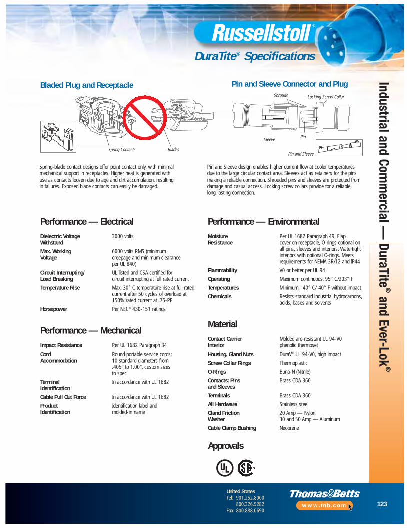
123
United StatesTel: 901.252.8000
800.326.5282Fax: 800.888.0690
www.tnb.com
Industrial and Comm
ercial — DuraTite
®and Ever-Lok
®
DuraTite® Specifications
Spring-blade contact designs offer point contact only, with minimalmechanical support in receptacles. Higher heat is generated with use as contacts loosen due to age and dirt accumulation, resulting in failures. Exposed blade contacts can easily be damaged.
Pin and Sleeve design enables higher current flow at cooler temperatures due to the large circular contact area. Sleeves act as retainers for the pinsmaking a reliable connection. Shrouded pins and sleeves are protected fromdamage and casual access. Locking screw collars provide for a reliable, long-lasting connection.
Pin and Sleeve
Bladed Plug and Receptacle Pin and Sleeve Connector and Plug
Spring Contacts Blades
Shrouds
SleevePin
Locking Screw Collar
Performance — ElectricalDielectric Voltage 3000 voltsWithstand
Max. Working 6000 volts RMS (minimum Voltage creepage and minimum clearance
per UL 840)
Circuit Interrupting/ UL listed and CSA certified for Load Breaking circuit interrupting at full rated current
Temperature Rise Max. 30° C temperature rise at full ratedcurrent after 50 cycles of overload at150% rated current at .75-PF
Horsepower Per NEC® 430-151 ratings
Performance — MechanicalImpact Resistance Per UL 1682 Paragraph 34
Cord Round portable service cords; Accommodation 10 standard diameters from
.405" to 1.00", custom sizesto spec
Terminal In accordance with UL 1682Identification
Cable Pull Out Force In accordance with UL 1682
Product Identification label and Identification molded-in name
Performance — EnvironmentalMoisture Per UL 1682 Paragraph 49. FlapResistance cover on receptacle, O-rings optional on
all pins, sleeves and interiors. Watertightinteriors with optional O-rings. Meetsrequire ments for NEMA 3R/12 and IP44
Flammability V0 or better per UL 94
Operating Maximum continuous: 95° C/203° F
Temperatures Minimum: -40° C/-40° F without impact
Chemicals Resists standard industrial hydro carbons,acids, bases and solvents
MaterialContact Carrier Molded arc-resistant UL 94-V0Interior phenolic thermoset
Housing, Gland Nuts DuraV® UL 94-V0, high impact
Screw Collar Rings Thermoplastic
O-Rings Buna-N (Nitrile)
Contacts: Pins Brass CDA 360and Sleeves
Terminals Brass CDA 360
All Hardware Stainless steel
Gland Friction 20 Amp — NylonWasher 30 and 50 Amp — Aluminum
Cable Clamp Bushing Neoprene
Approvals
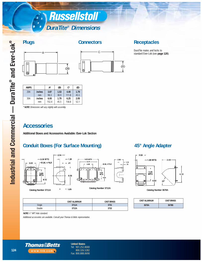
124
United StatesTel: 901.252.8000
800.326.5282Fax: 800.888.0690
www.tnb.com
Indu
stria
l and
Com
mer
cial
— D
uraT
ite®
and
Ever
-Lok
®
DuraTite® Dimensions
A
ØB
C
ØD
Plugs Connectors
* NOTE: Dimensions will vary slightly with assembly.
Receptacles
DuraTite mates and locks tostandard Ever-Lok (see page 120).
Conduit Boxes (For Surface Mounting) 45° Angle Adapter
NOTE: 3⁄4" NPT Hole standard.
Additional accessories are available. Consult your Thomas & Betts representative.
AccessoriesAdditional Boxes and Accessories Available: Ever-Lok Section
Catalog Number 3712ACatalog Number 3678A
AMPS A* ØB C* ØD
20A inches 3.87 1.53 4.40 1.79mm 98.3 38.9 111.8 45.5
30A inches 6.00 1.79 6.25 2.05mm 152.4 45.5 158.8 52.1
CAST ALUMINUM CAST BRASSSingle 3711A 3731Double 3712A 3732
CAST ALUMINUM CAST BRASS
3678A 3678B
Catalog Number 3711A

125
United StatesTel: 901.252.8000
800.326.5282Fax: 800.888.0690
www.tnb.com
Industrial and Comm
ercial — DuraTite
®and Ever-Lok
®
Ever-Lok® Locking Connections Overview
Standard: 10–50 Amp, Maximum 600VAC or 250VDC
Heavy Service: 30–100 Amp, Maximum 480VAC or 250VDC
Midget: 10–20 Amp, Maximum 250VAC or 250VDC
When an Ever-Lok connection is made, it is a mechanical attachmentthat will not pull apart unless it is unlocked by hand.
To install, line up the tabs and plug it straight in. External buttons or ribslock with the mating internal housing automatically. When an Ever-Lokconnector plugs in, it stays in. Locked housings do the work so Ever-Lokcontacts can carry the load! A firm grip and a counter-clockwise reversetwist release locking for easy removal.
1. Automatic Locking — Automatic locking feature mechanically attachesthe plug casing to the receptacle or connector and eliminates strain on electrical contacts.
2. Positive Grounding — Casings are positively grounded by means ofphosphor-bronze ground straps integral with ground contacts. Equipmentgrounding is secured by separate set of contacts which “make first” and “break last” as required by UL.
3. Dust-Proof — On clamp-type plugs and connectors, a washer isprovided in each cap to be forced over the cord. This serves as a shield to prevent metal particles, dust, etc., from entering the interiors of plugs and connectors.
Bushing-type plugs and connectors are furnished with a gland nut andNeoprene cable bushing gland to exclude dust and moisture. A formedglide washer is also provided to facilitate tightening of the gland nut.
Receptacle covers are sealed to boxes by gaskets and have hinged flapswhich are gasket-lined and equipped with strong springs to keep themclosed and dust out.
4. Steel-Clad — Plugs and connectors are plated steel. Plugs haveencased locking spring in machine assembled non-separable housings.
5. Cord Grip — Plugs and connectors are provided with adjustable cordgrips, preventing strains on connections.
6. Contacts — Contacts are precision-made, self-wiping and self-aligningbrass and nickel-plated brass.
7. Unit Assembly — Contacts and terminals are permanently assembledin an arc-resisting composition body, permitting removal of interior as aunit for wiring. All connections are entirely enclosed, thus avoidingaccidental short circuits and tampering by inexperienced personnel.
8. Handles Lined — Shell handles have a HDPE liner to contain stray wire ends.
9. Interiors — All interiors are molded arc-resisting composition.
Design Features
Automatic Locking Feature
Contacts
MoldedArc-Resisting
Interiors
Steel-CladHousings
Cord Grip
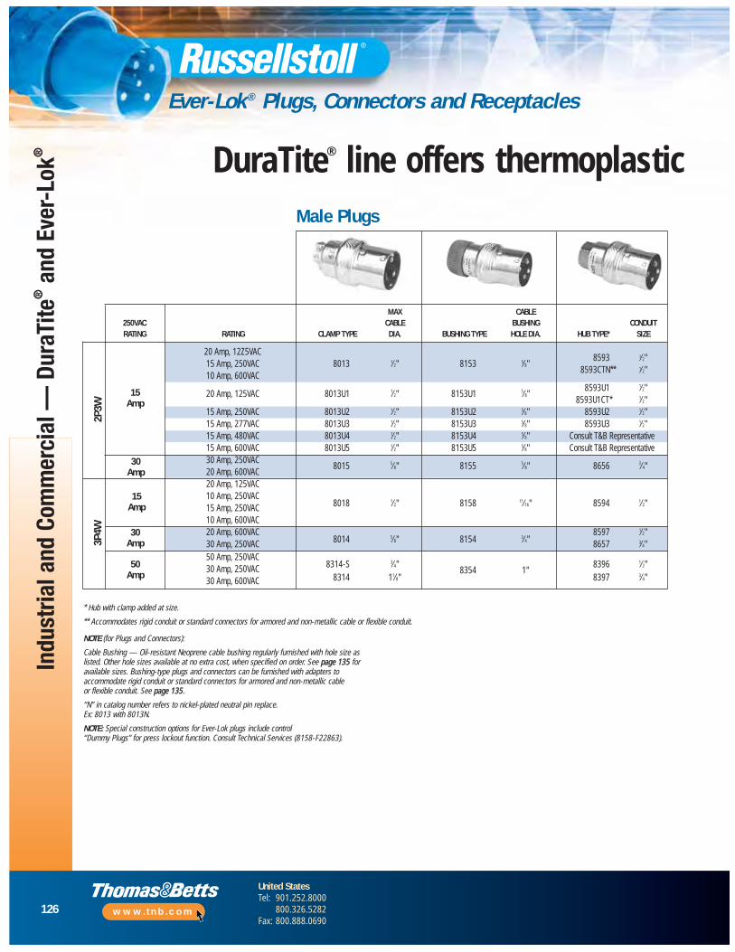
126
United StatesTel: 901.252.8000
800.326.5282Fax: 800.888.0690
www.tnb.com
Indu
stria
l and
Com
mer
cial
— D
uraT
ite®
and
Ever
-Lok
®
Ever-Lok® Plugs, Connectors and Receptacles
DuraTite® line offers thermoplastic
2P3W
3P4W
NOTE (for Plugs and Connectors):
Cable Bushing — Oil-resistant Neoprene cable bushing regularly furnished with hole size aslisted. Other hole sizes available at no extra cost, when specified on order. See page 135 foravailable sizes. Bushing-type plugs and connectors can be furnished with adapters toaccommodate rigid conduit or standard connectors for armored and non-metallic cable or flexible conduit. See page 135.
“N” in catalog number refers to nickel-plated neutral pin replace. Ex: 8013 with 8013N.
NOTE: Special construction options for Ever-Lok plugs include control “Dummy Plugs” for press lockout function. Consult Technical Services (8158-F22863).
* Hub with clamp added at size.
** Accommodates rigid conduit or standard connectors for armored and non-metallic cable or flexible conduit.
15Amp
30Amp
15Amp
Male Plugs
MAX CABLE250VAC CABLE BUSHING CONDUITRATING RATING CLAMP TYPE DIA. BUSHING TYPE HOLE DIA. HUB TYPE* SIZE
20 Amp, 12Z5VAC15 Amp, 250VAC 8013 1⁄2" 8153 5⁄8"
8593 1⁄2"
10 Amp, 600VAC8593CTN** 1⁄2"
20 Amp, 125VAC 8013U1 1⁄2" 8153U1 5⁄8"8593U1 1⁄2"
8593U1CT* 1⁄2"15 Amp, 250VAC 8013U2 1⁄2" 8153U2 5⁄8" 8593U2 1⁄2"15 Amp, 277VAC 8013U3 1⁄2" 8153U3 5⁄8" 8593U3 1⁄2"15 Amp, 480VAC 8013U4 1⁄2" 8153U4 5⁄8" Consult T&B Representative15 Amp, 600VAC 8013U5 1⁄2" 8153U5 5⁄8" Consult T&B Representative30 Amp, 250VAC
8015 5⁄8" 8155 5⁄8" 8656 3⁄4"20 Amp, 600VAC20 Amp, 125VAC10 Amp, 250VAC
8018 1⁄2" 8158 11⁄16" 8594 1⁄2"15 Amp, 250VAC10 Amp, 600VAC20 Amp, 600VAC
8014 5⁄8" 8154 3⁄4"8597 1⁄2"
30 Amp, 250VAC 8657 3⁄4"50 Amp, 250VAC
8314-S 3⁄4"8354 1"
8396 1⁄2"30 Amp, 250VAC8314 11⁄8" 8397 3⁄4"30 Amp, 600VAC
30Amp
50Amp
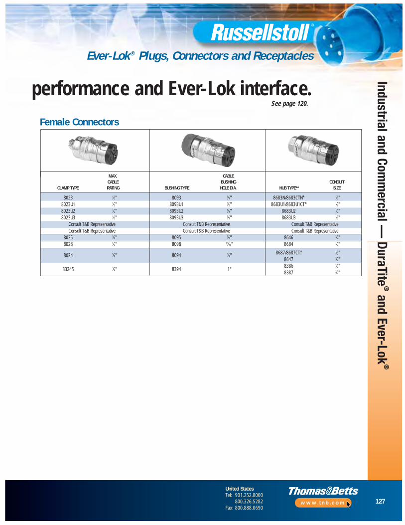
127
United StatesTel: 901.252.8000
800.326.5282Fax: 800.888.0690
www.tnb.com
Industrial and Comm
ercial — DuraTite
®and Ever-Lok
®
Ever-Lok® Plugs, Connectors and Receptacles
MAX. CABLECABLE BUSHING CONDUIT
CLAMP TYPE RATING BUSHING TYPE HOLE DIA. HUB TYPE** SIZE
8023 1⁄2" 8093 5⁄8" 8683N/8683CTN* 1⁄2"8023U1 1⁄2" 8093U1 5⁄8" 8683U1/8683U1CT* 1⁄2"8023U2 1⁄2" 8093U2 5⁄8" 8683U2 1⁄2"8023U3 1⁄2" 8093U3 5⁄8" 8683U3 1⁄2"
Consult T&B Representative Consult T&B Representative Consult T&B RepresentativeConsult T&B Representative Consult T&B Representative Consult T&B Representative
8025 5⁄8" 8095 5⁄8" 8646 3⁄4"8028 1⁄2" 8098 11⁄16" 8684 1⁄2"
8024 5⁄8" 8094 3⁄4" 8687/8687CT* 1⁄2"8647 3⁄4"
8324S 3⁄4" 8394 1"8386 1⁄2"8387 3⁄4"
Female Connectors
performance and Ever-Lok interface.See page 120.
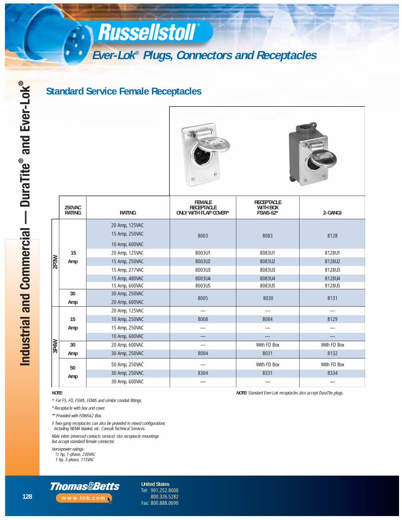
128
United StatesTel: 901.252.8000
800.326.5282Fax: 800.888.0690
www.tnb.com
Indu
stria
l and
Com
mer
cial
— D
uraT
ite®
and
Ever
-Lok
®
Ever-Lok® Plugs, Connectors and Receptacles
Standard Service Female Receptacles
NOTE:
^ For FS, FD, FSWS, FDWS and similar conduit fittings.
* Receptacle with box and cover.
** Provided with FDWS62 Box.
‡ Two-gang receptacles can also be provided in mixed configurationsincluding NEMA bladed, etc. Consult Technical Services.
Male inlets (reversed contacts service): Use receptacle mountings but accept standard female connector.
Horsepower ratings:1⁄2 hp, 1-phase, 230VAC 1 hp, 3-phase, 115VAC
NOTE: Standard Ever-Lok receptacles also accept DuraTite plugs.
3P4W
2P3W
FEMALE RECEPTACLE250VAC RECEPTACLE WITH BOXRATING RATING ONLY WITH FLAP COVER^ FSWS-62* 2-GANG‡
20 Amp, 125VAC
15 Amp, 250VAC 8003 8083 8128
10 Amp, 600VAC
15 20 Amp, 125VAC 8003U1 8083U1 8128U1
Amp 15 Amp, 250VAC 8003U2 8083U2 8128U2
15 Amp, 277VAC 8003U3 8083U3 8128U3
15 Amp, 480VAC 8003U4 8083U4 8128U415 Amp, 600VAC 8003U5 8083U5 8128U5
30 30 Amp, 250VAC
Amp 20 Amp, 600VAC8005 8030 8131
20 Amp, 125VAC — — —
15 10 Amp, 250VAC 8008 8084 8129
Amp 15 Amp, 250VAC — — —
10 Amp, 600VAC — — —
30 20 Amp, 600VAC — With FD Box With FD Box
Amp 30 Amp, 250VAC 8004 8031 8132
5050 Amp, 250VAC — With FD Box With FD Box
Amp30 Amp, 250VAC 8304 8331 8334
30 Amp, 600VAC — — —
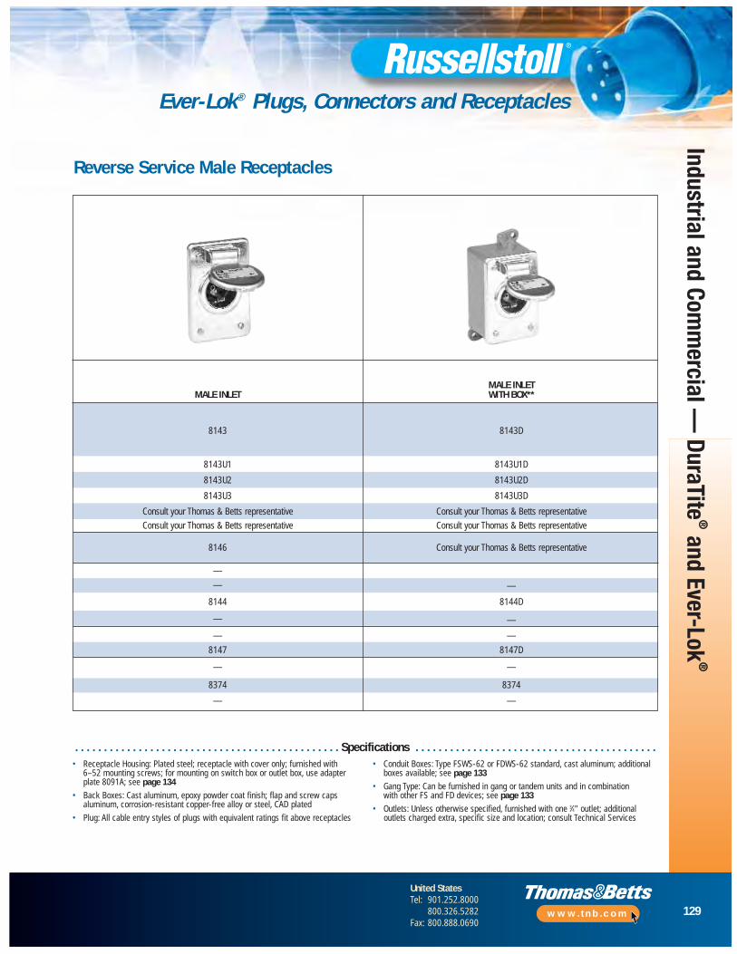
129
United StatesTel: 901.252.8000
800.326.5282Fax: 800.888.0690
www.tnb.com
Industrial and Comm
ercial — DuraTite
®and Ever-Lok
®
Ever-Lok® Plugs, Connectors and Receptacles
Reverse Service Male Receptacles
MALE INLETMALE INLET WITH BOX**
8143 8143D
8143U1 8143U1D
8143U2 8143U2D
8143U3 8143U3D
Consult your Thomas & Betts representative Consult your Thomas & Betts representative
Consult your Thomas & Betts representative Consult your Thomas & Betts representative
8146 Consult your Thomas & Betts representative
—
— —
8144 8144D
— —
— —
8147 8147D
— —
8374 8374
— —
• Receptacle Housing: Plated steel; receptacle with cover only; furnished with 6–52 mounting screws; for mounting on switch box or outlet box, use adapterplate 8091A; see page 134
• Back Boxes: Cast aluminum, epoxy powder coat finish; flap and screw capsaluminum, corrosion-resistant copper-free alloy or steel, CAD plated
• Plug: All cable entry styles of plugs with equivalent ratings fit above receptacles
• Conduit Boxes: Type FSWS-62 or FDWS-62 standard, cast aluminum; additionalboxes available; see page 133
• Gang Type: Can be furnished in gang or tandem units and in combination with other FS and FD devices; see page 133
• Outlets: Unless otherwise specified, furnished with one 3⁄4" outlet; additionaloutlets charged extra, specific size and location; consult Technical Services
. . . . . . . . . . . . . . . . . . . . . . . . . . . . . . . . . . . . . . . . . . . . . . Specifications . . . . . . . . . . . . . . . . . . . . . . . . . . . . . . . . . . . . . . . . . .
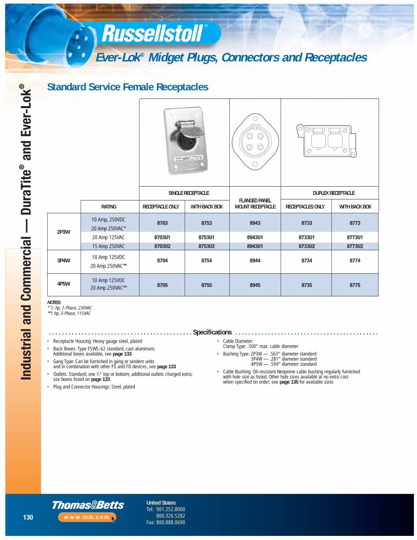
130
United StatesTel: 901.252.8000
800.326.5282Fax: 800.888.0690
www.tnb.com
Indu
stria
l and
Com
mer
cial
— D
uraT
ite®
and
Ever
-Lok
®
Ever-Lok® Midget Plugs, Connectors and Receptacles
SINGLE RECEPTACLE DUPLEX RECEPTACLEFLANGED PANEL
RATING RECEPTACLE ONLY WITH BACK BOX MOUNT RECEPTACLE RECEPTACLES ONLY WITH BACK BOX
10 Amp, 250VDC8703 8753 8943 8733 8773
2P3W20 Amp 250VAC*
20 Amp 125VAC 8703U1 8753U1 8943U1 8733U1 8773U1
15 Amp 250VAC 8703U2 8753U2 8943U1 8733U2 8773U2
3P4W10 Amp 125VDC
8704 8754 8944 8734 877420 Amp 250VAC**
4P5W10 Amp 125VDC
8705 8755 8945 8735 877520 Amp 250VAC**
NOTES:* 1⁄2 hp, 1-Phase, 230VAC**1 hp, 3-Phase, 115VAC
Standard Service Female Receptacles
• Receptacle Housing: Heavy gauge steel, plated
• Back Boxes: Type FSWS-62 standard, cast aluminum;Additional boxes available, see page 133
• Gang Type: Can be furnished in gang or tandem units and in combination with other FS and FD devices, see page 133
• Outlets: Standard, one 3⁄4" top or bottom; additional outlets charged extra; see boxes listed on page 133
• Plug and Connector Housings: Steel, plated
• Cable Diameter: Clamp Type: .500" max. cable diameter
• Bushing Type: 2P3W — .563" diameter standard3P4W — .281" diameter standard4P5W — .594" diameter standard
• Cable Bushing: Oil-resistant Neoprene cable bushing regularly furnished with hole size as listed. Other hole sizes available at no extra costwhen specified on order; see page 135 for available sizes
. . . . . . . . . . . . . . . . . . . . . . . . . . . . . . . . . . . . . . . . . . . . Specifications . . . . . . . . . . . . . . . . . . . . . . . . . . . . . . . . . . . . . . . . . . . .

131
United StatesTel: 901.252.8000
800.326.5282Fax: 800.888.0690
www.tnb.com
Industrial and Comm
ercial — DuraTite
®and Ever-Lok
®
Ever-Lok® Midget Plugs, Connectors and Receptacles
^ Plugs and connectors are also available as bushing or hub type similar to those in standard Ever-Lok. Please consult your Thomas & Betts representative.
CLAMP TYPE^ CLAMP TYPE^ MALE FLANGED CLAMP TYPE^ CLAMP TYPE^MALE PLUG FEMALE CONNECTOR PANEL MOUNT FEMALE PLUG MALE CONNECTOR
8713 8723 8943R 8713R 8723R
8713U1 8723U1 8943U1R 8713U1R 8723U1R
8713U2 8723U2 8943U2R 8713U2R 8723U2R
8714 8724 8944R 8714R 8724R
8715 8725 8945R 8715R 8725R
Standard Service Plugs and Connectors Reverse Service
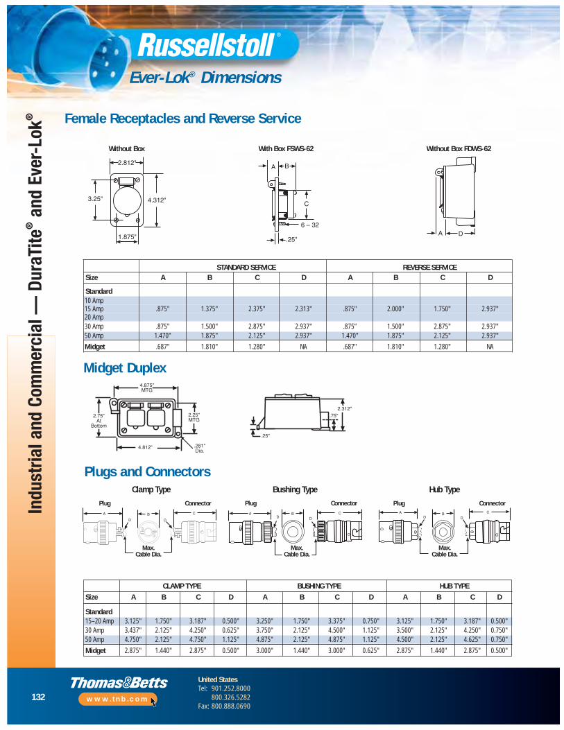
132
United StatesTel: 901.252.8000
800.326.5282Fax: 800.888.0690
www.tnb.com
Ever-Lok® Dimensions
Female Receptacles and Reverse Service
2.812"
4.312"
1.875"
3.25"
A
C
B
6 – 32
.25"A D
Without Box With Box FSWS-62 Without Box FDWS-62
Midget Duplex
STANDARD SERVICE REVERSE SERVICESize A B C D A B C D
Standard10 Amp15 Amp .875" 1.375" 2.375" 2.313" .875" 2.000" 1.750" 2.937"20 Amp30 Amp .875" 1.500" 2.875" 2.937" .875” 1.500" 2.875" 2.937"50 Amp 1.470" 1.875" 2.125" 2.937" 1.470" 1.875" 2.125" 2.937"
Midget .687" 1.810" 1.280" NA .687" 1.810" 1.280" NA
Plugs and ConnectorsClamp Type Bushing Type Hub Type
Plug Connector
CLAMP TYPE BUSHING TYPE HUB TYPE
Size A B C D A B C D A B C D
Standard15–20 Amp 3.125" 1.750" 3.187" 0.500" 3.250" 1.750" 3.375" 0.750" 3.125" 1.750" 3.187" 0.500"30 Amp 3.437" 2.125" 4.250" 0.625" 3.750" 2.125" 4.500" 1.125" 3.500" 2.125" 4.250" 0.750"50 Amp 4.750" 2.125" 4.750" 1.125" 4.875" 2.125" 4.875" 1.125" 4.500" 2.125" 4.625" 0.750"
Midget 2.875" 1.440" 2.875" 0.500" 3.000" 1.440" 3.000" 0.625" 2.875" 1.440" 2.875" 0.500"
Indu
stria
l and
Com
mer
cial
— D
uraT
ite®
and
Ever
-Lok
®
Plug Connector Plug Connector
Max.Cable Dia.
Max.Cable Dia.
Max.Cable Dia.

133
United StatesTel: 901.252.8000
800.326.5282Fax: 800.888.0690
www.tnb.com
Ever-Lok® Accessories
Type FS (Shallow) and Type FD (Deep)Aluminum boxes have 6-32 cover mounting holes tapped to accommodate all FS and FD cover assemblies.Brass boxes have 10-24 cover mounting holes tapped to accommodate all FS and FD cover assemblies.
Mounting Options for Midget and Standard Ever-Lok
Single-Gang Two-Gang DSFD
Type FSWS and FDWS (with Mounting Shelf for Box-Mounted Devices)Aluminum Die-Cast Boxes with cover mounting holes tapped for 6-32 screws to accommodate all FS and FD cover assemblies.
NOTE:
When Type FD devices are to be mounted in boxes, Type FD boxes should be used. FS boxes will not accommodate FD devices.
Mounting — All the above boxes are for surface mounting. For flush mounting, see page 134.
Boxes — Cast brass, natural finish; cast aluminum, corrosion-resistant copper-free alloy,epoxy powder coat finish.
Conduit Entries — Unless otherwise specified, furnished with one .75" outlet per gang, top or bottom. Additional conduit entries available — see price list. Specify size and location.
Maximum Conduit — FS and FD: 1", one per gang top and bottom and one each side.
DSFD — One 1.5" or two .5" top and bottom. Cast iron available on special order — consult your Thomas & Betts representative.
NOTE:
Boxes — Aluminum die-cast, corrosion-resistant copper-free alloy, epoxy powder coat finish.
Conduit Entries — Standard as listed.
Mounting — All of the above boxes are for surface mounting.
Multiple-GangSingle-Gang
DSFD Multiple-Gang Dimensions
4.12".31"4.12"
2"
2.62"3.62"
3.18"MTG
.31"
2 MTG. Holes
4.37"MTG
Industrial and Comm
ercial — DuraTite
®and Ever-Lok
®
* Dimensions are overall exclusive of conduit pads and mounting lugs.
A B
GANGS FS FD FS FD
2-Gang 6.50" 6.50" 5.50" 5.62"3-Gang 11.25" 9.37" 10.37" 8.50"4-Gang 14.12" 12.25" 13.25" 11.37"
CONDUIT ENTRIES
CAT. NO. TOP BOTTOM
FSWS-62 3⁄4" NAFDWS-62 3⁄4" NAFDWS-622 3⁄4" 3⁄4"FDWS-63 1" NAFDWS-633 1" 1"
GANGS TYPE CAST ALUMINUM CAST BRASS OVERALL DIMENSIONS*
FS 3701A 3721 4.12" x 2.62" x 2.31"Single FD 3711A 3731 4.12" x 2.62" x 2.94"
DSFD 3781A 3782 4.12" x 3.62" x 4.12"
TwoFS 3702A 3722 4.12" x 5.5" x 2.25"FD 3712A 3732 4.12" x 5.62" x 2.87"

134
United StatesTel: 901.252.8000
800.326.5282Fax: 800.888.0690
www.tnb.com
Indu
stria
l and
Com
mer
cial
— D
uraT
ite®
and
Ever
-Lok
®
Ever-Lok® Accessories
Adapter Flush Frames*
Blank Cover*Covers Standard FS/FD™ box openings.
CAT. NO. MATERIAL
3677A Cast Aluminum3687 Cast Brass
CAT. NO. MATERIAL
3678A Cast Aluminum3678B Cast Brass
CAT. NO. MATERIAL
8091A Cast Aluminum
CAT. NO. MATERIAL
3679A Cast Aluminum3679B Cast Brass
Flush Wall-Mounting Extension*
45° Angle Adapter*Mounts to any FS/FD™ box.
* Furnished complete with gasket and screws.
Material — Cast aluminum, corrosion-resistant copper-free alloy, epoxy powder coat finish. Cast brass, natural finish.
Adapter Sub-PlateThe addition of this adapter sub-plate will permitthe use of Ever-Lok conduit box-type receptaclesin switch boxes or outlet boxes with raised covers,as listed. Used on standard (deep) stamped metalconduit boxes. Adapts two-hole to four-holepatterns.
GANGS CAST ALUMINUM CAST BRASS OVERALL DIMENSIONS
1 3671A 3681 5" x 3.5"2 3672A 3682 5" x 6.5"
Catalog Number 3678A
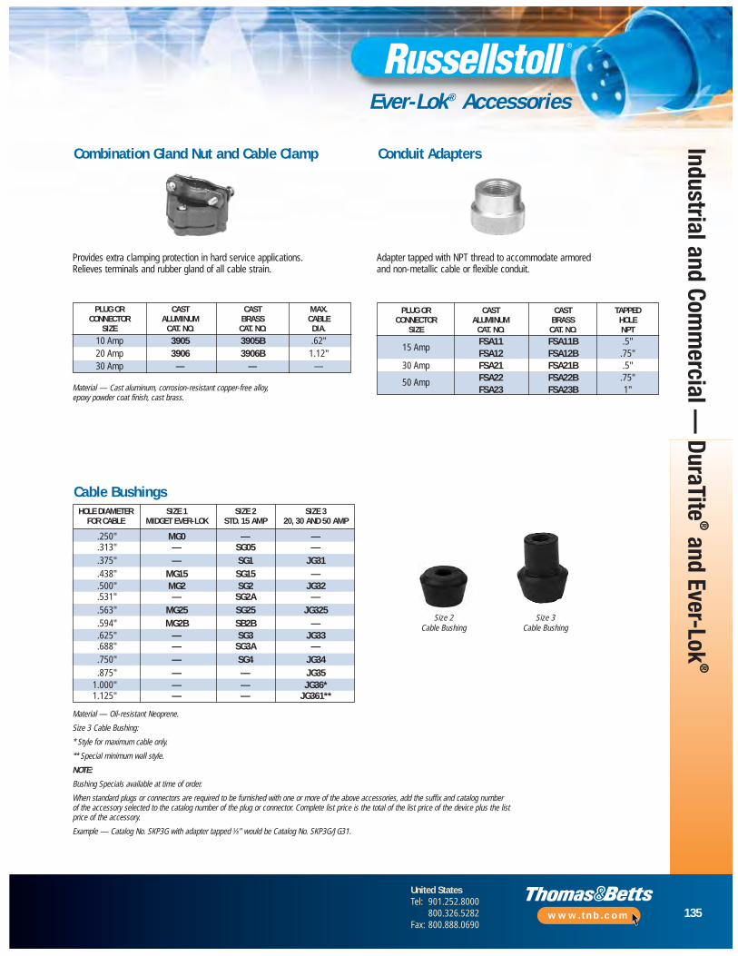
135
United StatesTel: 901.252.8000
800.326.5282Fax: 800.888.0690
www.tnb.com
Industrial and Comm
ercial — DuraTite
®and Ever-Lok
®
Ever-Lok® Accessories
Combination Gland Nut and Cable Clamp
Provides extra clamping protection in hard service applications. Relieves terminals and rubber gland of all cable strain.
Adapter tapped with NPT thread to accommodate armored and non-metallic cable or flexible conduit.
Conduit Adapters
Cable Bushings
Size 2Cable Bushing
Size 3Cable Bushing
Material — Cast aluminum, corrosion-resistant copper-free alloy, epoxy powder coat finish, cast brass.
Material — Oil-resistant Neoprene.
Size 3 Cable Bushing:
* Style for maximum cable only.
** Special minimum wall style.
NOTE:
Bushing Specials available at time of order.
When standard plugs or connectors are required to be furnished with one or more of the above accessories, add the suffix and catalog number of the accessory selected to the catalog number of the plug or connector. Complete list price is the total of the list price of the device plus the list price of the accessory.
Example — Catalog No. SKP3G with adapter tapped 3⁄8" would be Catalog No. SKP3G/JG31.
HOLE DIAMETER SIZE 1 SIZE 2 SIZE 3FOR CABLE MIDGET EVER-LOK STD. 15 AMP 20, 30 AND 50 AMP
.250" MG0 — —
.313" — SG05 —
.375" — SG1 JG31
.438" MG15 SG15 —
.500" MG2 SG2 JG32
.531" — SG2A —
.563" MG25 SG25 JG325
.594" MG2B SB2B —
.625" — SG3 JG33
.688" — SG3A —
.750" — SG4 JG34
.875" — — JG351.000" — — JG36*1.125" — — JG361**
PLUG OR CAST CAST MAX.CONNECTOR ALUMINUM BRASS CABLE
SIZE CAT. NO. CAT. NO. DIA.
10 Amp 3905 3905B .62"20 Amp 3906 3906B 1.12"30 Amp — — —
PLUG OR CAST CAST TAPPEDCONNECTOR ALUMINUM BRASS HOLE
SIZE CAT. NO. CAT. NO. NPT
15 AmpFSA11 FSA11B .5"FSA12 FSA12B .75"
30 Amp FSA21 FSA21B .5"
50 Amp FSA22 FSA22B .75"FSA23 FSA23B 1"
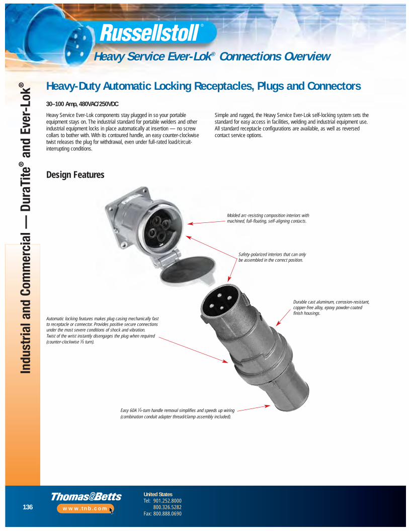
136
United StatesTel: 901.252.8000
800.326.5282Fax: 800.888.0690
www.tnb.com
Indu
stria
l and
Com
mer
cial
— D
uraT
ite®
and
Ever
-Lok
®
Heavy Service Ever-Lok® Connections Overview
Heavy-Duty Automatic Locking Receptacles, Plugs and Connectors30–100 Amp, 480VAC/250VDC
Design Features
Durable cast aluminum, corrosion-resistant,copper-free alloy, epoxy powder-coatedfinish housings.
Easy 60A 1⁄4-turn handle removal simplifies and speeds up wiring(combination conduit adapter thread/clamp assembly included).
Safety-polarized interiors that can onlybe assembled in the correct position.
Molded arc-resisting composition interiors withmachined, full-floating, self-aligning contacts.
Heavy Service Ever-Lok components stay plugged in so your portableequipment stays on. The industrial standard for portable welders and otherindustrial equipment locks in place automatically at insertion — no screwcollars to bother with. With its contoured handle, an easy counter-clockwisetwist releases the plug for withdrawal, even under full-rated load/circuit-interrupting conditions.
Simple and rugged, the Heavy Service Ever-Lok self-locking system sets thestandard for easy access in facilities, welding and industrial equipment use.All standard receptacle configurations are available, as well as reversed contact service options.
Automatic locking features makes plug casing mechanically fastto receptacle or connector. Provides positive secure connectionsunder the most severe conditions of shock and vibration.Twist of the wrist instantly disengages the plug when required(counter-clockwise 1⁄8 turn).
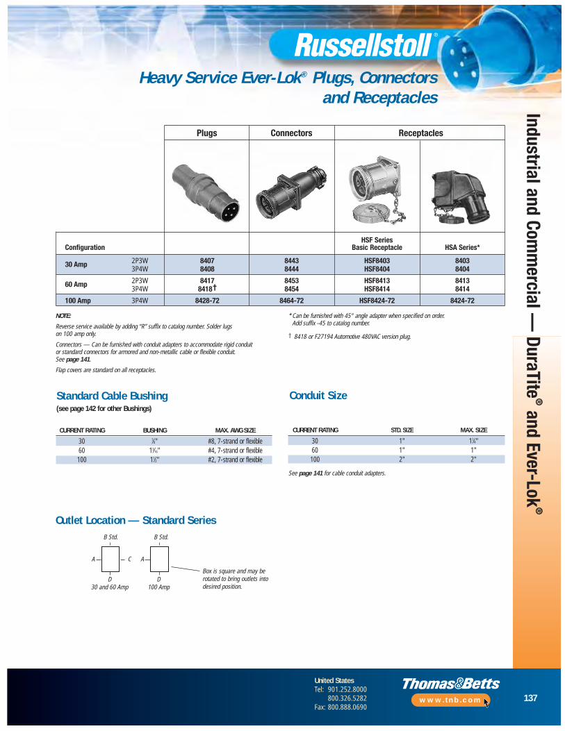
137
United StatesTel: 901.252.8000
800.326.5282Fax: 800.888.0690
www.tnb.com
Heavy Service Ever-Lok® Plugs, Connectors and Receptacles
CURRENT RATING BUSHING MAX. AWG SIZE
30 7⁄8" #8, 7-strand or flexible60 13⁄16" #4, 7-strand or flexible
100 11⁄2" #2, 7-strand or flexible
CURRENT RATING STD. SIZE MAX. SIZE
30 1" 11⁄4"60 1" 1"
100 2" 2"
See page 141 for cable conduit adapters.
Outlet Location — Standard Series
D100 Amp
Box is square and may berotated to bring outlets intodesired position.
NOTE:
Reverse service available by adding “R” suffix to catalog number. Solder lugson 100 amp only.
Connectors — Can be furnished with conduit adapters to accommodate rigid conduitor standard connectors for armored and non-metallic cable or flexible conduit.See page 141.
Flap covers are standard on all receptacles.
* Can be furnished with 45° angle adapter when specified on order.Add suffix -45 to catalog number.
† 8418 or F27194 Automotive 480VAC version plug.
A C
D30 and 60 Amp
B Std.B Std.
A
Plugs Connectors Receptacles
HSF SeriesConfiguration Basic Receptacle HSA Series*
30 Amp 2P3W 8407 8443 HSF8403 84033P4W 8408 8444 HSF8404 8404
60 Amp 2P3W 8417 8453 HSF8413 84133P4W 8418† 8454 HSF8414 8414
100 Amp 3P4W 8428-72 8464-72 HSF8424-72 8424-72
Standard Cable Bushing (see page 142 for other Bushings)
Conduit Size
Industrial and Comm
ercial — DuraTite
®and Ever-Lok
®
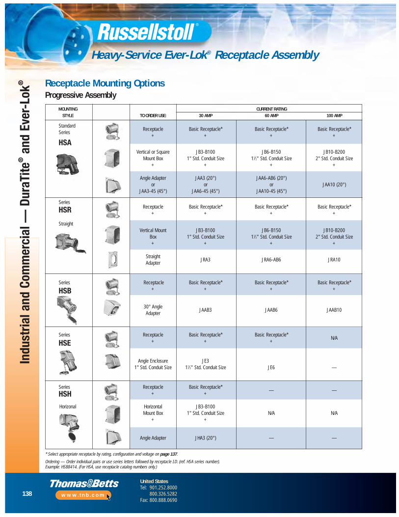
138
United StatesTel: 901.252.8000
800.326.5282Fax: 800.888.0690
www.tnb.com
Indu
stria
l and
Com
mer
cial
— D
uraT
ite®
and
Ever
-Lok
®
Heavy-Service Ever-Lok® Receptacle Assembly
* Select appropriate receptacle by rating, configuration and voltage on page 137.
Ordering — Order individual pairs or use series letters followed by receptacle I.D. (ref. HSA series number). Example: HSB8414. (For HSA, use receptacle catalog numbers only.)
MOUNTING CURRENT RATINGSTYLE TO ORDER USE: 30 AMP 60 AMP 100 AMP
StandardReceptacle Basic Receptacle* Basic Receptacle* Basic Receptacle*
Series+ + + +
HSAVertical or Square JB3-B100 JB6-B150 JB10-B200
Mount Box 1" Std. Conduit Size 11⁄2" Std. Conduit Size 2" Std. Conduit Size+ + + +
Angle Adapter JAA3 (20°) JAA6-AB6 (20°)or or or JAA10 (20°)
JAA3-45 (45°) JAA6-45 (45°) JAA10-45 (45°)
SeriesReceptacle Basic Receptacle* Basic Receptacle* Basic Receptacle*HSR + + + +
StraightVertical Mount JB3-B100 JB6-B150 JB10-B200
Box 1" Std. Conduit Size 11⁄2" Std. Conduit Size 2" Std. Conduit Size+ + + +
StraightJRA3 JRA6-AB6 JRA10
Adapter
Series Receptacle Basic Receptacle* Basic Receptacle* Basic Receptacle*
HSB + + + +
30° AngleJAAB3 JAAB6 JAAB10
Adapter
Series Receptacle Basic Receptacle* Basic Receptacle*N/A
HSE + + +
Angle Enclosure JE31" Std. Conduit Size 11⁄2" Std. Conduit Size JE6 —
Series Receptacle Basic Receptacle*— —HSH + +
Horizonal Horizontal JB3-B100Mount Box 1" Std. Conduit Size N/A N/A
+ +
Angle Adapter JHA3 (20°) — —
Receptacle Mounting OptionsProgressive Assembly
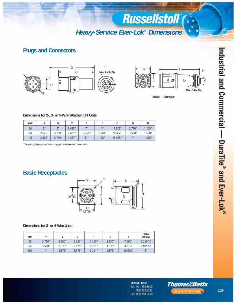
139
United StatesTel: 901.252.8000
800.326.5282Fax: 800.888.0690
www.tnb.com
Industrial and Comm
ercial — DuraTite
®and Ever-Lok
®
Heavy-Service Ever-Lok® Dimensions
PANELAMP Y V U T S R OPENING
30 2.750" 2.250" 2.250" 0.213" 3.250" 7.000" 2.250" D
60 3.500" 2.875" 2.875" 0.281" 4.625" 8.875" 2.875" D
100 4" 3.375" 3.375" 0.281" 5.875" 10.500" 3"
Plugs and Connectors
Dimensions for 2-, 3- or 4-Wire Weathertight Units
Female — Connector
Basic Receptacles
Dimensions for 3- or 4-Wire Units
* Length of plug exposed when engaged in receptacle or connector.
AMP A B C* D E F G H
30 2" 3" 5.625" 7" 1" 7.625" 2.750" 1.125"
60 2.625" 3.750" 7.687" 9.750" 1.500" 9.625" 3.500" 1.500"
100 2.625" 3.750" 7.687" 11" 1.50" 10.875" 4" 1.875"
Max. Cable Dia.
Max. Cable Dia.
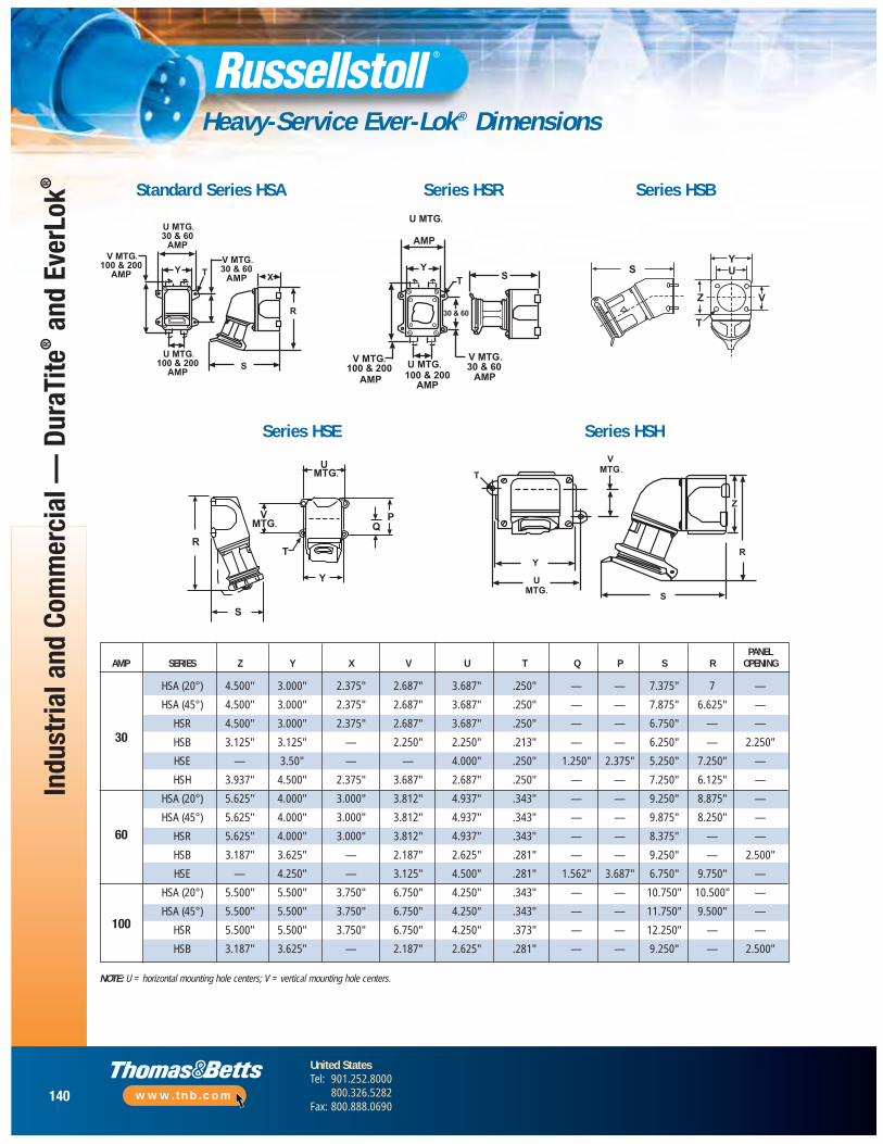
140
United StatesTel: 901.252.8000
800.326.5282Fax: 800.888.0690
www.tnb.com
Indu
stria
l and
Com
mer
cial
— D
uraT
ite®
and
Ever
Lok®
Heavy-Service Ever-Lok® Dimensions
PANELAMP SERIES Z Y X V U T Q P S R OPENING
HSA (20°) 4.500" 3.000" 2.375" 2.687" 3.687" .250" — — 7.375" 7 —
HSA (45°) 4.500" 3.000" 2.375" 2.687" 3.687" .250" — — 7.875" 6.625" —
HSR 4.500" 3.000" 2.375" 2.687" 3.687" .250" — — 6.750" — —
HSB 3.125" 3.125" — 2.250" 2.250" .213" — — 6.250" — 2.250"
HSE — 3.50" — — 4.000" .250" 1.250" 2.375" 5.250" 7.250" —
HSH 3.937" 4.500" 2.375" 3.687" 2.687" .250" — — 7.250" 6.125" —
HSA (20°) 5.625" 4.000" 3.000" 3.812" 4.937" .343" — — 9.250" 8.875" —
HSA (45°) 5.625" 4.000" 3.000" 3.812" 4.937" .343" — — 9.875" 8.250" —
HSR 5.625" 4.000" 3.000" 3.812" 4.937" .343" — — 8.375" — —
HSB 3.187" 3.625" — 2.187" 2.625" .281" — — 9.250" — 2.500"
HSE — 4.250" — 3.125" 4.500" .281" 1.562" 3.687" 6.750" 9.750" —
HSA (20°) 5.500" 5.500" 3.750" 6.750" 4.250" .343" — — 10.750" 10.500" —
HSA (45°) 5.500" 5.500" 3.750" 6.750" 4.250" .343" — — 11.750" 9.500" —
HSR 5.500" 5.500" 3.750" 6.750" 4.250" .373" — — 12.250" — —
HSB 3.187" 3.625" — 2.187" 2.625" .281" — — 9.250" — 2.500"
Standard Series HSA Series HSR Series HSB
Series HSE Series HSH
NOTE: U = horizontal mounting hole centers; V = vertical mounting hole centers.
30
60
100
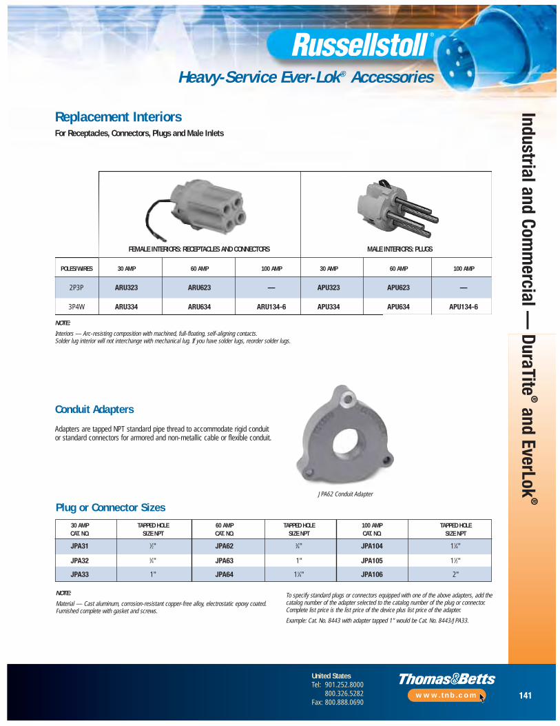
141
United StatesTel: 901.252.8000
800.326.5282Fax: 800.888.0690
www.tnb.com
Industrial and Comm
ercial — DuraTite
®and EverLok
®
Heavy-Service Ever-Lok® Accessories
Replacement InteriorsFor Receptacles, Connectors, Plugs and Male Inlets
NOTE:
Interiors — Arc-resisting composition with machined, full-floating, self-aligning contacts.Solder lug interior will not interchange with mechanical lug. If you have solder lugs, reorder solder lugs.
Conduit Adapters
Adapters are tapped NPT standard pipe thread to accommodate rigid conduit or standard connectors for armored and non-metallic cable or flexible conduit.
Plug or Connector Sizes
NOTE:
Material — Cast aluminum, corrosion-resistant copper-free alloy, electrostatic epoxy coated.Furnished complete with gasket and screws.
To specify standard plugs or connectors equipped with one of the above adapters, add thecatalog number of the adapter selected to the catalog number of the plug or connector.Complete list price is the list price of the device plus list price of the adapter.
Example: Cat. No. 8443 with adapter tapped 1" would be Cat. No. 8443/JPA33.
JPA62 Conduit Adapter
FEMALE INTERIORS: RECEPTACLES AND CONNECTORS MALE INTERIORS: PLUGS
POLES/WIRES 30 AMP 60 AMP 100 AMP 30 AMP 60 AMP 100 AMP
2P3P ARU323 ARU623 — APU323 APU623 —
3P4W ARU334 ARU634 ARU134-6 APU334 APU634 APU134-6
30 AMP TAPPED HOLE 60 AMP TAPPED HOLE 100 AMP TAPPED HOLECAT. NO. SIZE NPT CAT. NO. SIZE NPT CAT. NO. SIZE NPT
JPA31 1⁄2" JPA62 3⁄4" JPA104 11⁄4"
JPA32 3⁄4" JPA63 1" JPA105 11⁄2"
JPA33 1" JPA64 11⁄4" JPA106 2"
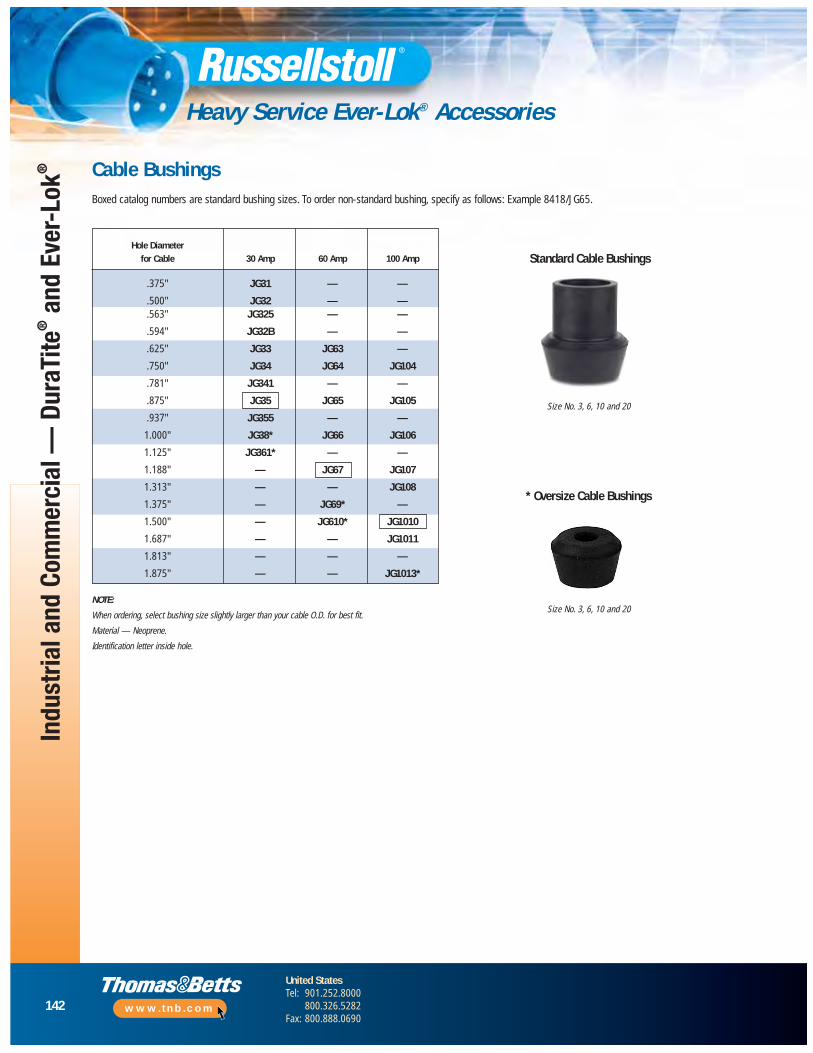
142
United StatesTel: 901.252.8000
800.326.5282Fax: 800.888.0690
www.tnb.com
Indu
stria
l and
Com
mer
cial
— D
uraT
ite®
and
Ever
-Lok
®
Heavy Service Ever-Lok® Accessories
Hole Diameterfor Cable 30 Amp 60 Amp 100 Amp
.375" JG31 — —
.500" JG32 — —
.563" JG325 — —
.594" JG32B — —
.625" JG33 JG63 —
.750" JG34 JG64 JG104
.781" JG341 — —
.875" JG35 JG65 JG105
.937" JG355 — —
1.000" JG38* JG66 JG106
1.125" JG361* — —
1.188" — JG67 JG107
1.313" — — JG108
1.375" — JG69* —
1.500" — JG610* JG1010
1.687" — — JG1011
1.813" — — —
1.875" — — JG1013*
Cable BushingsBoxed catalog numbers are standard bushing sizes. To order non-standard bushing, specify as follows: Example 8418/JG65.
NOTE:
When ordering, select bushing size slightly larger than your cable O.D. for best fit.
Material — Neoprene.
Identification letter inside hole.
Size No. 3, 6, 10 and 20
Size No. 3, 6, 10 and 20
Standard Cable Bushings
* Oversize Cable Bushings

143
United StatesTel: 901.252.8000
800.326.5282Fax: 800.888.0690
www.tnb.com
Control Circuit and Industrial Interlock
Control Circuit and Industrial Interlock Applications
Control Circuit Connectors
Control Circuit Connectors Overview..........................................144
Types SK and SKW Overview .....................................................145
Type SK .............................................................................146–147
Type SKW ..........................................................................148–149
Control Circuit Connector Accessories................................150–153
Industrial Interlocked Receptacles
Industrial Interlocked Receptacles......................................154–162
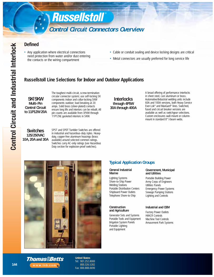
144
United StatesTel: 901.252.8000
800.326.5282Fax: 800.888.0690
www.tnb.com
Cont
rol C
ircui
t and
Indu
stria
l Int
erlo
ck
Control Circuit Connectors Overview
SK/SKWMulti-Pin
Control Circuitto 11P12W 20A
Switches125/250VAC
10A, 20A and 30A
Interlocksthrough 4P5W
30A through 400A
The toughest multi-circuit, screw-terminationcircular connector system; use self-locking SKcomponents indoor and collar-locking SKWcomponents outdoor; load breaking at 20amps. Solid brass (silver-plated) contactsensure long life and interiors can be rebuilt. Allpin counts are available from 3P4W through11P12W, gasketed interiors in SKW.
SPST and SPDT Tumbler Switches are offeredin industrial and hazardous-duty styles. Heavy-duty, copper-free aluminum housings (brassavailable) around selected common ratings.Switches carry AC-only ratings (see HazardousDuty section for explosion-proof switches).
Defined
General Industrial MarineLighting SystemsShore-to-Ship PowerWelding StationsPortable Distribution CentersShipboard Power OutletsTelephone Shore-to-Ship
Construction and AgricultureGenerator Sets and SystemsPortable Tools and EquipmentIrrigation System PanelsPortable Lighting and Equipment
Typical Application Groups
Russellstoll Line Selections for Indoor and Outdoor Applications
• Any application where electrical connections need protection from water and/or dust entering the contacts or the wiring compartment
• Cable or conduit sealing and device locking designs are critical
• Metal connectors are usually preferred for long service life
A broad offering of performance interlocks in sheet steel, cast aluminum or brass.Automotive/Industrial welding units include 60A and 100A versions, both Heavy ServiceEver-Lok® and MaxGard® lines. Switched,fused and circuit breaker versions areavailable as well as switchgear selections.Custom enclosures wall-mount or column-mount in standard 8" I-beam webs.
Government, Municipal and UtilitiesPortable Building PowerArmy Corps of EngineersUtilities PanelsEmergency Power SystemsSewage Pumping StationsLighting and Controls
Industrial and OEMFactory Power OutletsHVACR ControlsMachine Tool ControlsAmusement Park Systems
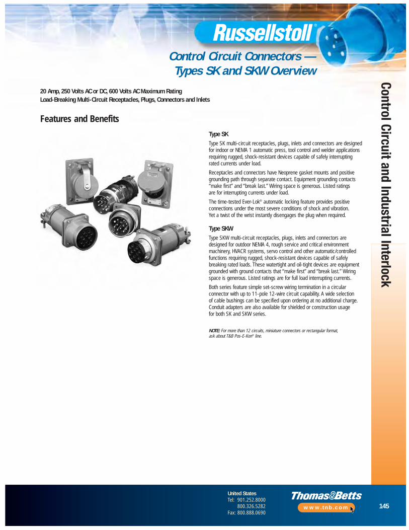
145
United StatesTel: 901.252.8000
800.326.5282Fax: 800.888.0690
www.tnb.com
Control Circuit and Industrial Interlock
Control Circuit Connectors — Types SK and SKW Overview
Features and Benefits
20 Amp, 250 Volts AC or DC, 600 Volts AC Maximum RatingLoad-Breaking Multi-Circuit Receptacles, Plugs, Connectors and Inlets
Type SK Type SK multi-circuit receptacles, plugs, inlets and connectors are designedfor indoor or NEMA 1 automatic press, tool control and welder applicationsrequiring rugged, shock-resistant devices capable of safely interrupting rated currents under load.
Receptacles and connectors have Neoprene gasket mounts and positivegrounding path through separate contact. Equipment grounding contacts“make first” and “break last.” Wiring space is generous. Listed ratings are for interrupting currents under load.
The time-tested Ever-Lok® automatic locking feature provides positiveconnections under the most severe conditions of shock and vibration. Yet a twist of the wrist instantly disengages the plug when required.
Type SKW Type SKW multi-circuit receptacles, plugs, inlets and connectors aredesigned for outdoor NEMA 4, rough service and critical environmentmachinery, HVACR systems, servo control and other automatic/controlledfunctions requiring rugged, shock-resistant devices capable of safelybreaking rated loads. These watertight and oil-tight devices are equipmentgrounded with ground contacts that “make first” and “break last.” Wiringspace is generous. Listed ratings are for full load interrupting currents.
Both series feature simple set-screw wiring termination in a circularconnector with up to 11-pole 12-wire circuit capability. A wide selection of cable bushings can be specified upon ordering at no additional charge.Conduit adapters are also available for shielded or construction usage for both SK and SKW series.
NOTE: For more than 12 circuits, miniature connectors or rectangular format, ask about T&B Pos-E-Kon® line.
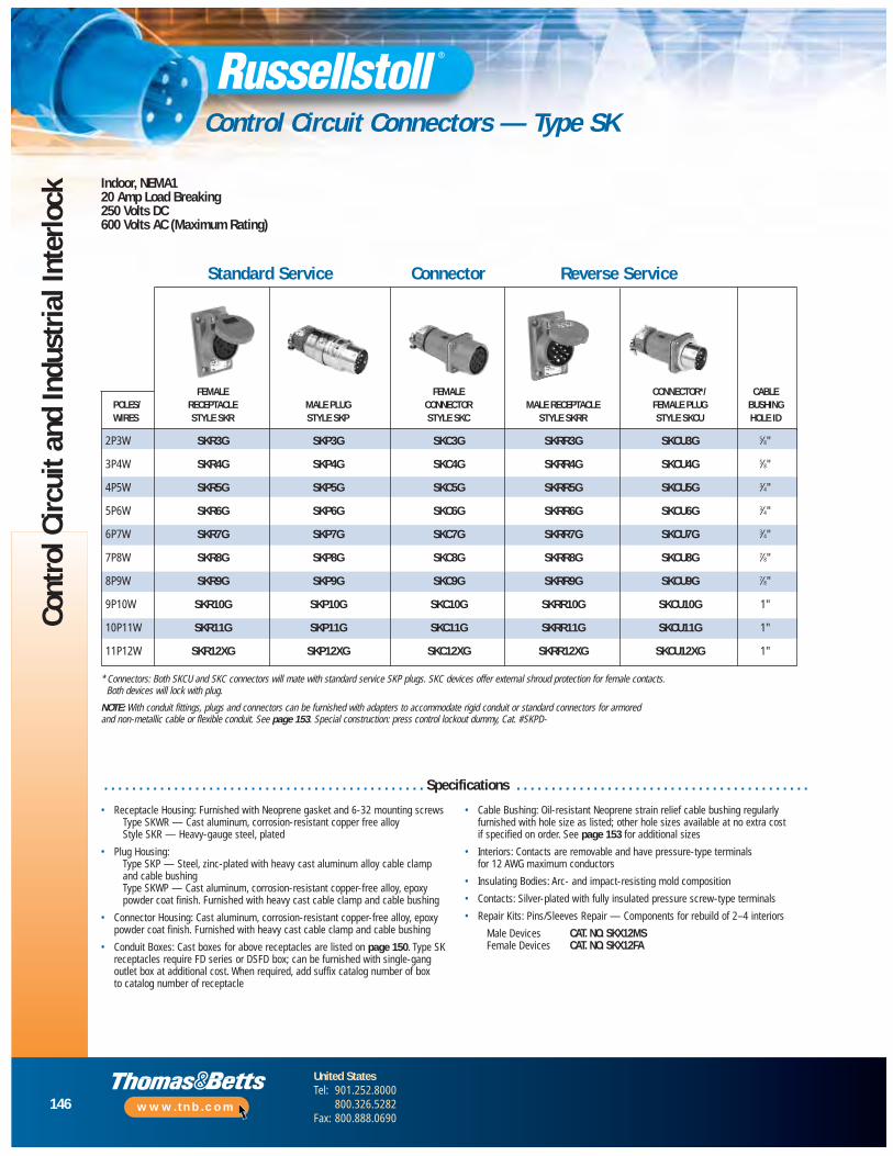
146
United StatesTel: 901.252.8000
800.326.5282Fax: 800.888.0690
www.tnb.com
Cont
rol C
ircui
t and
Indu
stria
l Int
erlo
ck
Control Circuit Connectors — Type SK
Indoor, NEMA120 Amp Load Breaking250 Volts DC600 Volts AC (Maximum Rating)
* Connectors: Both SKCU and SKC connectors will mate with standard service SKP plugs. SKC devices offer external shroud protection for female contacts. Both devices will lock with plug.
NOTE: With conduit fittings, plugs and connectors can be furnished with adapters to accommodate rigid conduit or standard connectors for armored and non-metallic cable or flexible conduit. See page 153. Special construction: press control lockout dummy, Cat. #SKPD-
FEMALE FEMALE CONNECTOR*/ CABLEPOLES/ RECEPTACLE MALE PLUG CONNECTOR MALE RECEPTACLE FEMALE PLUG BUSHING WIRES STYLE SKR STYLE SKP STYLE SKC STYLE SKRR STYLE SKCU HOLE ID
2P3W SKR3G SKP3G SKC3G SKRR3G SKCU3G 5⁄8"
3P4W SKR4G SKP4G SKC4G SKRR4G SKCU4G 5⁄8"
4P5W SKR5G SKP5G SKC5G SKRR5G SKCU5G 3⁄4"
5P6W SKR6G SKP6G SKC6G SKRR6G SKCU6G 3⁄4"
6P7W SKR7G SKP7G SKC7G SKRR7G SKCU7G 3⁄4"
7P8W SKR8G SKP8G SKC8G SKRR8G SKCU8G 7⁄8"
8P9W SKR9G SKP9G SKC9G SKRR9G SKCU9G 7⁄8"
9P10W SKR10G SKP10G SKC10G SKRR10G SKCU10G 1"
10P11W SKR11G SKP11G SKC11G SKRR11G SKCU11G 1"
11P12W SKR12XG SKP12XG SKC12XG SKRR12XG SKCU12XG 1"
Standard Service Connector Reverse Service
. . . . . . . . . . . . . . . . . . . . . . . . . . . . . . . . . . . . . . . . . . . . . . Specifications . . . . . . . . . . . . . . . . . . . . . . . . . . . . . . . . . . . . . . . . . .
• Receptacle Housing: Furnished with Neoprene gasket and 6-32 mounting screwsType SKWR — Cast aluminum, corrosion-resistant copper free alloyStyle SKR — Heavy-gauge steel, plated
• Plug Housing:Type SKP — Steel, zinc-plated with heavy cast aluminum alloy cable clampand cable bushingType SKWP — Cast aluminum, corrosion-resistant copper-free alloy, epoxypowder coat finish. Furnished with heavy cast cable clamp and cable bushing
• Connector Housing: Cast aluminum, corrosion-resistant copper-free alloy, epoxypowder coat finish. Furnished with heavy cast cable clamp and cable bushing
• Conduit Boxes: Cast boxes for above receptacles are listed on page 150. Type SKreceptacles require FD series or DSFD box; can be furnished with single-gangoutlet box at additional cost. When required, add suffix catalog number of box to catalog number of receptacle
• Cable Bushing: Oil-resistant Neoprene strain relief cable bushing regularlyfurnished with hole size as listed; other hole sizes available at no extra cost if specified on order. See page 153 for additional sizes
• Interiors: Contacts are removable and have pressure-type terminals for 12 AWG maximum conductors
• Insulating Bodies: Arc- and impact-resisting mold composition
• Contacts: Silver-plated with fully insulated pressure screw-type terminals
• Repair Kits: Pins/Sleeves Repair — Components for rebuild of 2–4 interiors
Male Devices CAT. NO. SKX12MSFemale Devices CAT. NO. SKX12FA
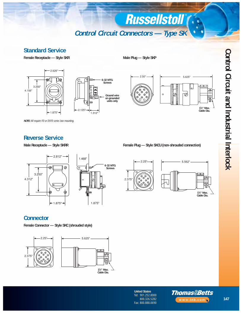
147
United StatesTel: 901.252.8000
800.326.5282Fax: 800.888.0690
www.tnb.com
Control Circuit and Industrial Interlock
Control Circuit Connectors — Type SK
Standard ServiceFemale Receptacle — Style SKR Male Plug — Style SKP
NOTE: All require FD or DSFD series box mounting.
Reverse ServiceMale Receptacle — Style SKRR Female Plug — Style SKCU (non-shrouded connection)
ConnectorFemale Connector — Style SKC (shrouded style)
6-32 MTG.Screws
6-32 MTG.Screws
Ground wire on grounded
units only
11⁄8" Max.Cable Dia.
11⁄8" Max.Cable Dia.
11⁄8" Max.Cable Dia.
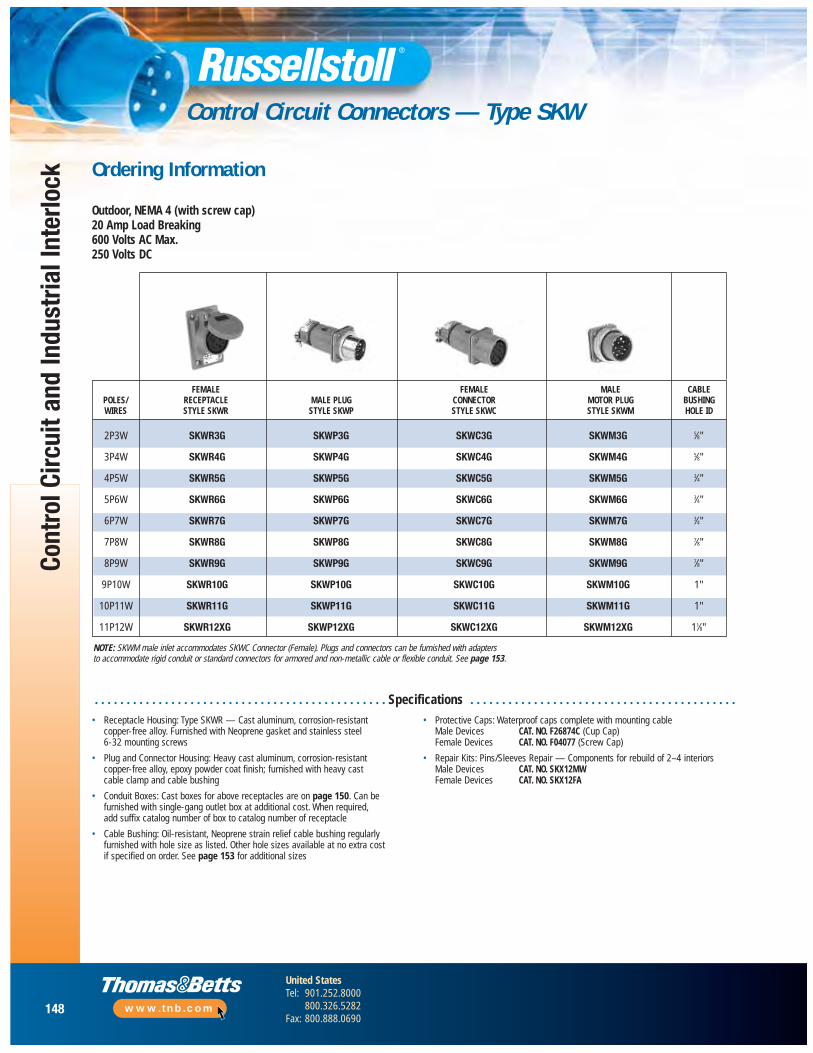
148
United StatesTel: 901.252.8000
800.326.5282Fax: 800.888.0690
www.tnb.com
Cont
rol C
ircui
t and
Indu
stria
l Int
erlo
ck
Control Circuit Connectors — Type SKW
Ordering Information
Outdoor, NEMA 4 (with screw cap)20 Amp Load Breaking600 Volts AC Max.250 Volts DC
• Receptacle Housing: Type SKWR — Cast aluminum, corrosion-resistant copper-free alloy. Furnished with Neoprene gasket and stainless steel 6-32 mounting screws
• Plug and Connector Housing: Heavy cast aluminum, corrosion-resistant copper-free alloy, epoxy powder coat finish; furnished with heavy cast cable clamp and cable bushing
• Conduit Boxes: Cast boxes for above receptacles are on page 150. Can befurnished with single-gang outlet box at additional cost. When required, add suffix catalog number of box to catalog number of receptacle
• Cable Bushing: Oil-resistant, Neoprene strain relief cable bushing regularlyfurnished with hole size as listed. Other hole sizes available at no extra cost if specified on order. See page 153 for additional sizes
• Protective Caps: Waterproof caps complete with mounting cableMale Devices CAT. NO. F26874C (Cup Cap)Female Devices CAT. NO. F04077 (Screw Cap)
• Repair Kits: Pins/Sleeves Repair — Components for rebuild of 2–4 interiorsMale Devices CAT. NO. SKX12MWFemale Devices CAT. NO. SKX12FA
NOTE: SKWM male inlet accommodates SKWC Connector (Female). Plugs and connectors can be furnished with adapters to accommodate rigid conduit or standard connectors for armored and non-metallic cable or flexible conduit. See page 153.
. . . . . . . . . . . . . . . . . . . . . . . . . . . . . . . . . . . . . . . . . . . . . . Specifications . . . . . . . . . . . . . . . . . . . . . . . . . . . . . . . . . . . . . . . . . .
FEMALE FEMALE MALE CABLEPOLES/ RECEPTACLE MALE PLUG CONNECTOR MOTOR PLUG BUSHING WIRES STYLE SKWR STYLE SKWP STYLE SKWC STYLE SKWM HOLE ID
2P3W SKWR3G SKWP3G SKWC3G SKWM3G 5⁄8"
3P4W SKWR4G SKWP4G SKWC4G SKWM4G 5⁄8"
4P5W SKWR5G SKWP5G SKWC5G SKWM5G 3⁄4"
5P6W SKWR6G SKWP6G SKWC6G SKWM6G 3⁄4"
6P7W SKWR7G SKWP7G SKWC7G SKWM7G 3⁄4"
7P8W SKWR8G SKWP8G SKWC8G SKWM8G 7⁄8"
8P9W SKWR9G SKWP9G SKWC9G SKWM9G 7⁄8"
9P10W SKWR10G SKWP10G SKWC10G SKWM10G 1"
10P11W SKWR11G SKWP11G SKWC11G SKWM11G 1"
11P12W SKWR12XG SKWP12XG SKWC12XG SKWM12XG 11⁄8"
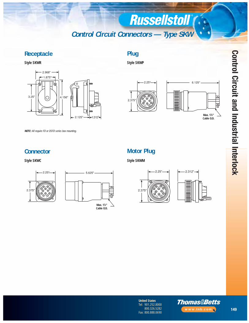
149
United StatesTel: 901.252.8000
800.326.5282Fax: 800.888.0690
www.tnb.com
Control Circuit and Industrial Interlock
Control Circuit Connectors — Type SKW
ReceptacleStyle SKWR Style SKWP
NOTE: All require FD or DSFD series box mounting.
ConnectorStyle SKWC Style SKWM
Plug
Motor Plug
Max. 11⁄8"Cable O.D.
Max. 11⁄8"Cable O.D.
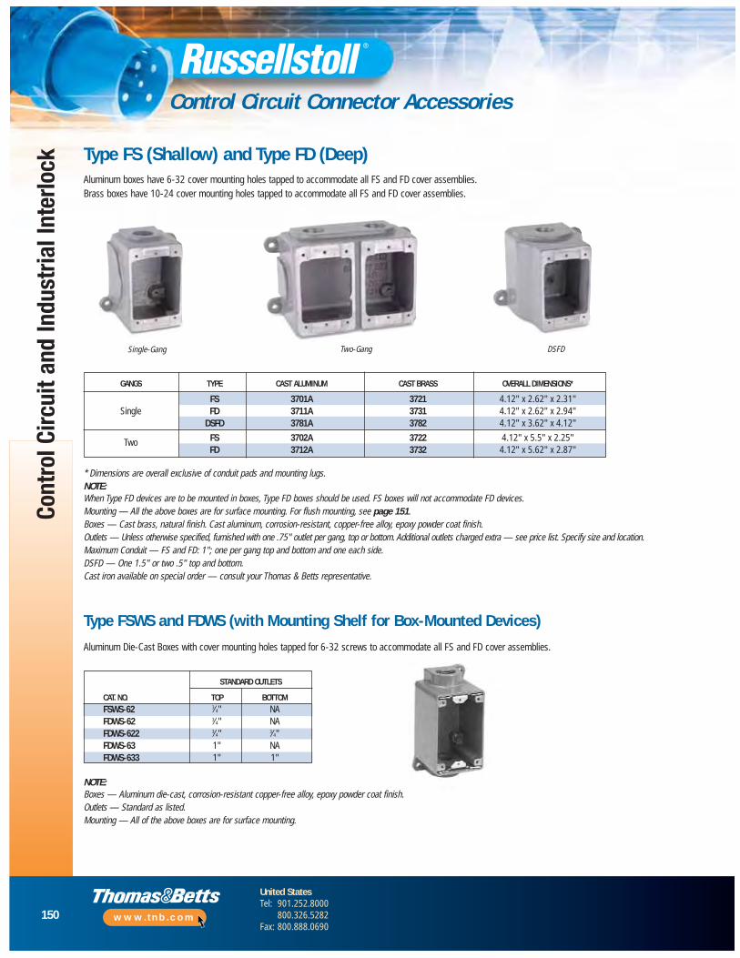
150
United StatesTel: 901.252.8000
800.326.5282Fax: 800.888.0690
www.tnb.com
Cont
rol C
ircui
t and
Indu
stria
l Int
erlo
ck
Control Circuit Connector Accessories
STANDARD OUTLETS
CAT. NO. TOP BOTTOMFSWS-62 3⁄4" NAFDWS-62 3⁄4" NAFDWS-622 3⁄4" 3⁄4"FDWS-63 1" NAFDWS-633 1" 1"
Type FS (Shallow) and Type FD (Deep)Aluminum boxes have 6-32 cover mounting holes tapped to accommodate all FS and FD cover assemblies.Brass boxes have 10-24 cover mounting holes tapped to accommodate all FS and FD cover assemblies.
Single-Gang Two-Gang DSFD
* Dimensions are overall exclusive of conduit pads and mounting lugs.NOTE:When Type FD devices are to be mounted in boxes, Type FD boxes should be used. FS boxes will not accommodate FD devices.Mounting — All the above boxes are for surface mounting. For flush mounting, see page 151.Boxes — Cast brass, natural finish. Cast aluminum, corrosion-resistant, copper-free alloy, epoxy powder coat finish.Outlets — Unless otherwise specified, furnished with one .75" outlet per gang, top or bottom. Additional outlets charged extra — see price list. Specify size and location.Maximum Conduit — FS and FD: 1"; one per gang top and bottom and one each side.DSFD — One 1.5" or two .5" top and bottom.Cast iron available on special order — consult your Thomas & Betts representative.
Type FSWS and FDWS (with Mounting Shelf for Box-Mounted Devices)
Aluminum Die-Cast Boxes with cover mounting holes tapped for 6-32 screws to accommodate all FS and FD cover assemblies.
NOTE:Boxes — Aluminum die-cast, corrosion-resistant copper-free alloy, epoxy powder coat finish.Outlets — Standard as listed.Mounting — All of the above boxes are for surface mounting.
GANGS TYPE CAST ALUMINUM CAST BRASS OVERALL DIMENSIONS*
FS 3701A 3721 4.12" x 2.62" x 2.31"Single FD 3711A 3731 4.12" x 2.62" x 2.94"
DSFD 3781A 3782 4.12" x 3.62" x 4.12"
Two FS 3702A 3722 4.12" x 5.5" x 2.25"FD 3712A 3732 4.12" x 5.62" x 2.87"
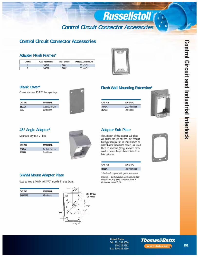
151
United StatesTel: 901.252.8000
800.326.5282Fax: 800.888.0690
www.tnb.com
Control Circuit and Industrial Interlock
Control Circuit Connector Accessories
Covers standard FS/FD™ box openings.
Control Circuit Connector Accessories
GANGS CAST ALUMINUM CAST BRASS OVERALL DIMENSIONS
1 3671A 3681 5" x 3.5"2 3672A 3682 5" x 6.5"
Adapter Flush Frames*
Blank Cover*
45° Angle Adapter*Mounts to any FS/FD™ box.
* Furnished complete with gasket and screws.
Material — Cast aluminum, corrosion-resistant copper-free alloy, epoxy powder coat finish. Cast brass, natural finish.
Adapter Sub-Plate
SKWM Mount Adapter Plate
Used to mount SKWM to FS/FD™ standard series boxes.
The addition of this adapter sub-plate will permit the use of Ever-Lok® conduit box-type receptacles in switch boxes oroutlet boxes with raised covers, as listed.Used on standard (deep) stamped metalconduit boxes. Adapts two-hole to four- hole patterns.
CAT. NO. MATERIAL
SKWMFS Aluminum
CAT. NO. MATERIAL
3678A Cast Aluminum3678B Cast Brass
CAT. NO. MATERIAL
3677A Cast Aluminum3687 Cast Brass
CAT. NO. MATERIAL
3679A Cast Aluminum3679B Cast Brass
CAT. NO. MATERIAL
8091A Cast Aluminum
Flush Wall Mounting Extension*
#8–32 Tap(4) Holes
113 ⁄16"
Dia.
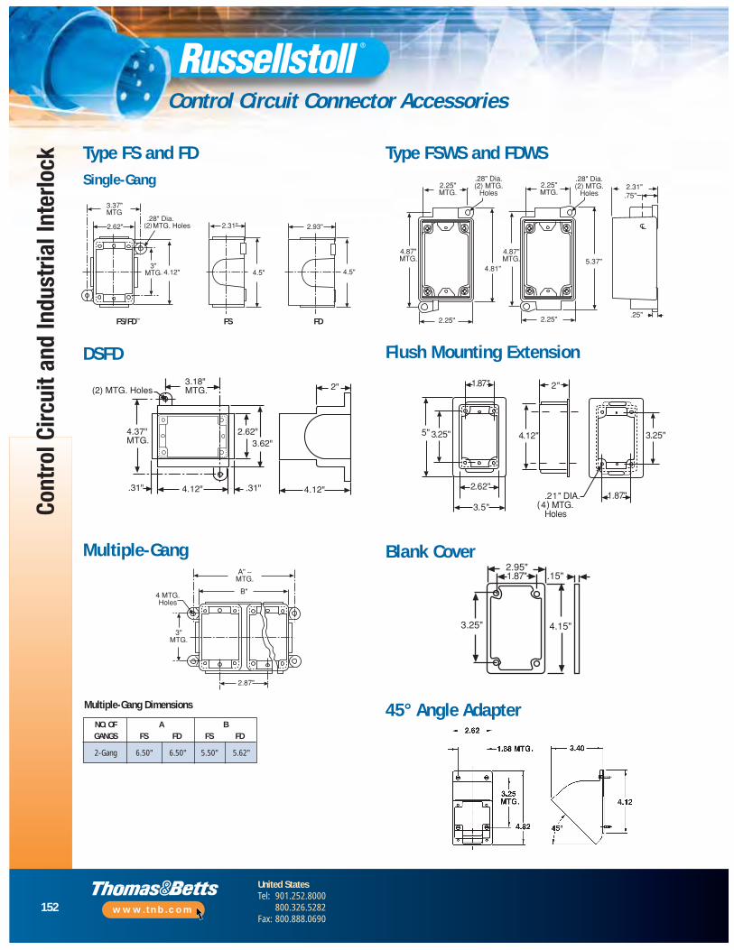
152
United StatesTel: 901.252.8000
800.326.5282Fax: 800.888.0690
www.tnb.com
Cont
rol C
ircui
t and
Indu
stria
l Int
erlo
ck
Control Circuit Connector Accessories
Type FS and FDSingle-Gang
4.12".31"4.12"
2"
2.62"3.62"
3.18"MTG.
.31"
(2) MTG. Holes
4.37"MTG.
DSFD
FS/FD™ FS FD
Multiple-Gang
Type FSWS and FDWS
Flush Mounting Extension
Blank Cover
45° Angle AdapterNO. OF A BGANGS FS FD FS FD
2-Gang 6.50" 6.50" 5.50" 5.62"
Multiple-Gang Dimensions
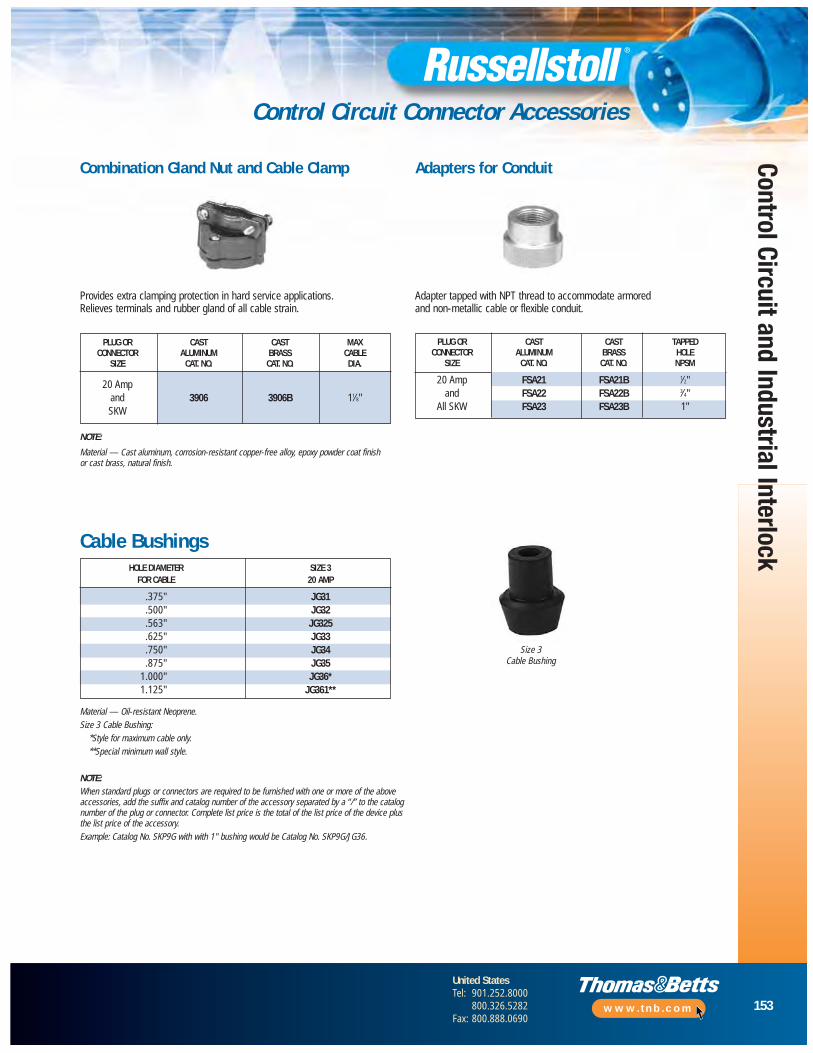
153
United StatesTel: 901.252.8000
800.326.5282Fax: 800.888.0690
www.tnb.com
Control Circuit and Industrial Interlock
Control Circuit Connector Accessories
Adapter tapped with NPT thread to accommodate armored and non-metallic cable or flexible conduit.
HOLE DIAMETER SIZE 3FOR CABLE 20 AMP
.375" JG31
.500" JG32
.563" JG325
.625" JG33
.750" JG34
.875" JG351.000" JG36*1.125" JG361**
Combination Gland Nut and Cable Clamp Adapters for Conduit
Cable Bushings
Size 3Cable Bushing
Provides extra clamping protection in hard service applications. Relieves terminals and rubber gland of all cable strain.
NOTE:
Material — Cast aluminum, corrosion-resistant copper-free alloy, epoxy powder coat finishor cast brass, natural finish.
Material — Oil-resistant Neoprene.Size 3 Cable Bushing:
*Style for maximum cable only.**Special minimum wall style.
NOTE:When standard plugs or connectors are required to be furnished with one or more of the aboveaccessories, add the suffix and catalog number of the accessory separated by a “/” to the catalognumber of the plug or connector. Complete list price is the total of the list price of the device plusthe list price of the accessory.Example: Catalog No. SKP9G with with 1" bushing would be Catalog No. SKP9G/JG36.
PLUG OR CAST CAST MAXCONNECTOR ALUMINUM BRASS CABLE
SIZE CAT. NO. CAT. NO. DIA.
20 Ampand 3906 3906B 11⁄8"SKW
PLUG OR CAST CAST TAPPEDCONNECTOR ALUMINUM BRASS HOLE
SIZE CAT. NO. CAT. NO. NPSM
20 Amp FSA21 FSA21B 1⁄2"and FSA22 FSA22B 3⁄4"
All SKW FSA23 FSA23B 1"

154
United StatesTel: 901.252.8000
800.326.5282Fax: 800.888.0690
www.tnb.com
Cont
rol C
ircui
t and
Indu
stria
l Int
erlo
ck
Industrial Interlocked Receptacles Overview
Industrial interlocked receptacles are available in 30 through 400 Amp. Switched receptacles have mechanical linkages for added safety. Safety features include:
• Plugs cannot be inserted unless power is safely turned off
• Plugs cannot be removed until power is safely turned off
• Specialty designs may also automatically disengage powerif plug is removed while power is on, either mechanically or electrically
Applications
Applications where these units are most commonly used are:
• Welding stations in automotive and heavy industry
• Temporary and portable power distribution for construction
• Marine shore-to-ship power
• Industrial machinery installation
• Portable power distribution, vehicle and gen-set power for aerospace
• Custom systems in all industries
Sample Installation: Fixed Power Source (Wall) To Remote/Portable Location
1. Receptacle (wall-mounted female)
2. Receptacle (panel-mounted female)
3. Plug (attachment)
4. Female connector
5. Male Inlet with angle adapter
6. Male inlet with straight adapter
Other installations: generator power sources, custom control circuits, multiple voltage service — contact Technical Services.
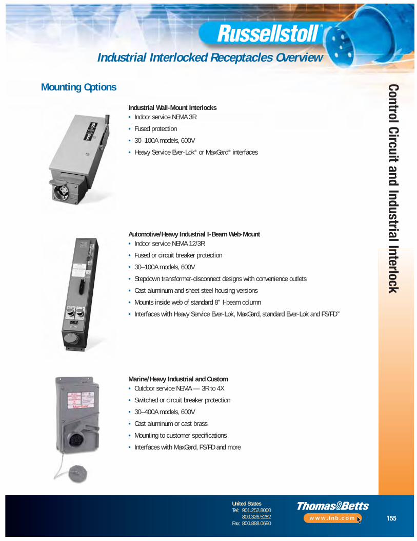
155
United StatesTel: 901.252.8000
800.326.5282Fax: 800.888.0690
www.tnb.com
Control Circuit and Industrial Interlock
Industrial Interlocked Receptacles Overview
Mounting Options
Industrial Wall-Mount Interlocks• Indoor service NEMA 3R
• Fused protection
• 30–100A models, 600V
• Heavy Service Ever-Lok® or MaxGard® interfaces
Automotive/Heavy Industrial I-Beam Web-Mount• Indoor service NEMA 12/3R
• Fused or circuit breaker protection
• 30–100A models, 600V
• Stepdown transformer-disconnect designs with convenience outlets
• Cast aluminum and sheet steel housing versions
• Mounts inside web of standard 8" I-beam column
• Interfaces with Heavy Service Ever-Lok, MaxGard, standard Ever-Lok and FS/FD™
Marine/Heavy Industrial and Custom• Outdoor service NEMA — 3R to 4X
• Switched or circuit breaker protection
• 30–400A models, 600V
• Cast aluminum or cast brass
• Mounting to customer specifications
• Interfaces with MaxGard, FS/FD and more
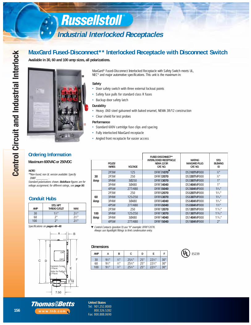
156
United StatesTel: 901.252.8000
800.326.5282Fax: 800.888.0690
www.tnb.com
Cont
rol C
ircui
t and
Indu
stria
l Int
erlo
ck
Industrial Interlocked Receptacles
FUSED DISCONNECT**INTERLOCKED RECEPTACLE MATING STD.
POLES/ NEMA 12/3R MAXGARD PLUG BUSHINGWIRES VOLTAGE CAT. NO. CAT. NO. ID
2P3W 125 DFRF31070 DS3107MP000 7⁄8"30 2P3W 250 DFRF32070 DS3207MP000 7⁄8"
Amp 3P4W 3Ø250 DFRF33070 DS3307MP000 1"3P4W 3Ø480 DFRF34040 DS3404MP000 1"4P5W 277/480 DFRF35040 DS3504MP000 13⁄16"2P3W 250 DFRF62070 DS6207MP000 13⁄16"
60 3P4W 125/250 DFRF63070 DS6307MP000 15⁄16"Amp 3P4W 3Ø480 DFRF64040 DS6404MP000 15⁄16"
4P5W 277/480 DFRF65040 DS6504MP000 11⁄2"2P3W 250 DFRF12070 DS1207MP000 111⁄16"
100 3P4W 125/250 DFRF13070 DS1307MP000 113⁄16"Amp 3P4W 3Ø480 DFRF14040 DS1404MP000 113⁄16"
4P5W 277/480 DFRF15040 DS1504MP000 2"
Fasteners Screws2 PlacesHoles for Padlock2 Places
C D
BA
F
E
7.50
2.18
ON
OFF
MaxGard® Fused-Disconnect Interlocked Receptacle with Safety Switch meets UL, NEC® and major automotive specifications. This unit is the maximum in:
Safety • Door safety switch with three external lockout points
• Safety fuse pulls for standard class R fuses
• Backup door safety latch
Durability• Heavy .060 steel galvaneel with baked enamel, NEMA 3R/12 construction
• Clear shield for test probes
Performance• Standard 600V cartridge fuse clips and spacing
• Fully interlocked MaxGard receptacle
• Angled front receptacle for easier access
NOTE:**Non-fused, non UL version available: Specify
DNRF ________ .Standard polarizations shown. Boldface figures are forvoltage assignment; for different ratings, see page 50.
▼ Control Contacts (position 9) use “K” example: DFRF1207K.Always use liquidtight fittings to limit condensation entry.
E5239
▼
Specifications on pages 48–49.
MaxGard Fused-Disconnect** Interlocked Receptacle with Disconnect SwitchAvailable in 30, 60 and 100 amp sizes, all polarizations.
Ordering InformationMaximum 600VAC or 250VDC
Dimensions
STD. NPTAMP THREAD OUTLET MAX
30 11⁄2" 21⁄2"60 2" 21⁄2"
100 2" 21⁄2"
AMP A B C D E F
30 91⁄2" 3⁄4" 253⁄4" 25" 223⁄4" 30"60 91⁄2" 3⁄4" 253⁄4" 25" 223⁄4" 30"100 91⁄2" 3⁄4" 253⁄4" 25" 223⁄4" 30"
Conduit Hubs
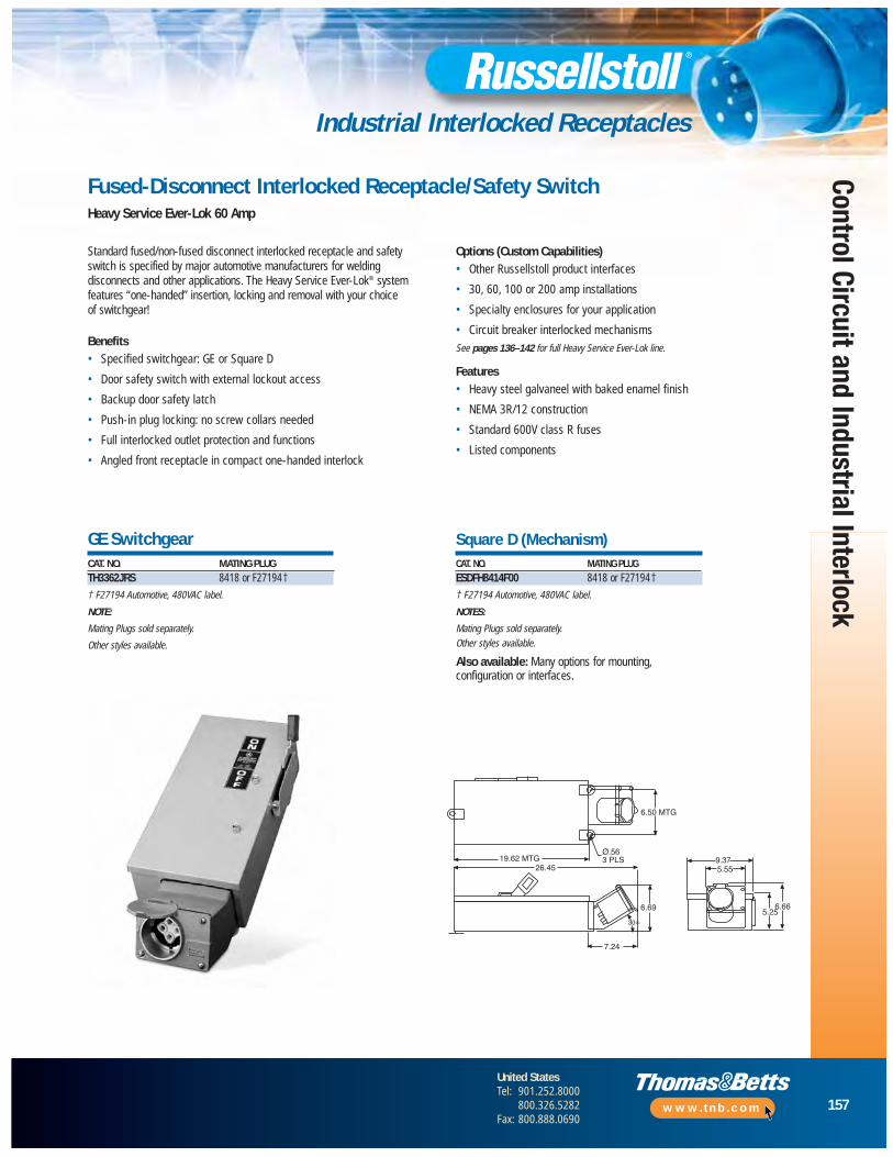
157
United StatesTel: 901.252.8000
800.326.5282Fax: 800.888.0690
www.tnb.com
Control Circuit and Industrial Interlock
Industrial Interlocked Receptacles
Fused-Disconnect Interlocked Receptacle/Safety SwitchHeavy Service Ever-Lok 60 Amp
Standard fused/non-fused disconnect interlocked receptacle and safetyswitch is specified by major automotive manufacturers for weldingdisconnects and other applications. The Heavy Service Ever-Lok® systemfeatures “one-handed” insertion, locking and removal with your choice of switchgear!
Benefits• Specified switchgear: GE or Square D
• Door safety switch with external lockout access
• Backup door safety latch
• Push-in plug locking: no screw collars needed
• Full interlocked outlet protection and functions
• Angled front receptacle in compact one-handed interlock
Options (Custom Capabilities)• Other Russellstoll product interfaces
• 30, 60, 100 or 200 amp installations
• Specialty enclosures for your application
• Circuit breaker interlocked mechanismsSee pages 136–142 for full Heavy Service Ever-Lok line.
Features• Heavy steel galvaneel with baked enamel finish
• NEMA 3R/12 construction
• Standard 600V class R fuses
• Listed components
GE SwitchgearCAT. NO. MATING PLUGTH3362JRS 8418 or F27194†
† F27194 Automotive, 480VAC label.
NOTE:
Mating Plugs sold separately.
Other styles available.
Square D (Mechanism)CAT. NO. MATING PLUGESDFH8414F00 8418 or F27194†
† F27194 Automotive, 480VAC label.
NOTES:
Mating Plugs sold separately.Other styles available.
Also available: Many options for mounting,configuration or interfaces.
19.62 MTG26.45
6.50 MTG
Ø.563 PLS
6.69
7.24
30∞
6.665.25
5.559.37
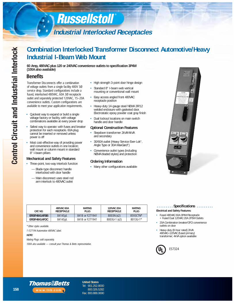
158
United StatesTel: 901.252.8000
800.326.5282Fax: 800.888.0690
www.tnb.com
Cont
rol C
ircui
t and
Indu
stria
l Int
erlo
ck
Industrial Interlocked Receptacles
Combination Interlocked Transformer Disconnect Automotive/HeavyIndustrial I-Beam Web Mount60 Amp, 480VAC plus 120 or 240VAC convenience outlets to specification 3P4W (100A also available)
BenefitsTransformer Disconnects offer a combination of voltage outlets from a single facility 480V 3Øservice drop. Standard configurations include afused, interlocked 480VAC, 60A 3Ø receptacleoutlet and separately protected 120VAC, 15–20Aconvenience outlets. Custom configurations areavailable to meet your application requirements.
• Quickest way to expand or build a singlevoltage factory or facility, with voltagecombinations available at every power drop
• Safest way to operate: with fuses and breakerprotection for each recep tacle. 60A plugcannot be inserted or removed unless power is off
• Most cost-effective way of providing powerand convenience outlets in one location; wall mount or column mount in standard 8" I-beam pillars
Mechanical and Safety Features• Three-point, two-way interlock function
— Blade-type disconnect handle interlocked with door handle
— Main disconnect uses steel rod arm interlock to 480VAC outlet
• High strength 3-point door hinge design
• Standard 8" I-beam web vertical mounting or conventional wall mount
• Easy access angled front 480VAC receptacle position
• Heavy-duty 14-gauge steel NEMA 3R/12 welded enclosure with gasketed door. Electrostatic epoxy powder coat gray finish
• Dual lockout locations on main switch handle and door handle
Optional Construction Features• Stepdown transformer 2kVA/4kVA
and secondary
• 30/60A outlet (Heavy Service Ever-Lok®, Angle Type or 30A MaxGard®)
• Convenience outlet types (including NEMA bladed styles) and protection
Ordering Information• Many other configurations available
480VAC 60A MATING 120VAC 20A MATINGCAT. NO. RECEPTACLE PLUG RECEPTACLE PLUG
ERSFH8414FBB 8414Spl. 8418 or F27194† 8003N (x2) 8593CTN*ERSFH8414FDC 8414Spl. 8418 or F27194† 8003U-1 (x2) 8013U-1*
* Other styles available.
† F27194 Automotive 480VAC label.
NOTE:
Mating Plugs sold separately.
100A also available — consult your Thomas & Betts representative.
. . . . . . . . . Specifications . . . . . . . . .Electrical and Safety Features:
• Fused 480VAC 60A 3P4W Receptacle + Fused Dual 120VAC 20A 2P3W Outlets
• 20A Combination breaker/GFCI convenienceoutlets on door
• Heavy-duty (8-hour rated) 2kVA 480VAC–120VAC (fused primary) transformer; 4kVA option available
E57324

RECEPTACLE480 VOLT
CIRCUIT BREAKER GFCI
TWO RECEPTACLES120 VOLT
TRANSFORMER
FUSE HOLDER
FUSEDSWITCH
159
United StatesTel: 901.252.8000
800.326.5282Fax: 800.888.0690
www.tnb.com
Control Circuit and Industrial Interlock
Industrial Interlocked Receptacles
6.75
4.00MTG.
Mains Disconnect
Door Handle
Convenience Outletsto spec
Breaker/GFCIProtection to spec
60A Outlet
11.75
7.00
36.37MTG.
37.37
35.37
ø .414 PLS
Wiring Diagram
Dimensions
Mains Disconnect
Door Handle
Convenience Outlets to Spec
Breaker/GFCI Protection to Spec
60A Outlet
Circuit Breaker GFCI
Two Receptacles120 Volt Transformer
Fused Switch
Fuse Holder
Receptacle480 Volt

160
United StatesTel: 901.252.8000
800.326.5282Fax: 800.888.0690
www.tnb.com
Cont
rol C
ircui
t and
Indu
stria
l Int
erlo
ck
Industrial Interlocked Receptacles
ON
OFF12.25"
14.88"
6.12"
20°
480VReceptacle
7.12"Approx.
4.00"MTG.
10.00"MTG.
Ø .284 PlsMTG.
10.00"Ø 3.62"
Ever-Lok® Mechanically Interlocked Receptacle and SwitchAutomotive/Heavy Industrial I-Beam Web MountHeavy Service Ever-Lok® Mechanically Interlocked Receptacles and Switch60 Amp, 480VAC/250VDC, 3P4WCircuit Breaker Interlocked Receptacle Option
Features and Benefits
Mechanically Interlocked Switch
DimensionsMating Plug
11⁄4" NPT Top Entry Std./Other Sizes Available 60A, 3P4W, 8418 or F27194
*17" dim. for F32753 unit
Mechanically interlocked between the receptacleand the switch. Designed so that when the plug isfully inserted, the switch interlock is automaticallyreleased, permitting the switch to be turned on. The plug cannot be removed from the receptacleuntil the switch is manually turned off.
• Switch: 60 amp, 480VAC, 3-pole, quick “make”and quick “break”
• Housings: heavy cast aluminum corrosion-resistant copper-free alloy with grayelectrostatic epoxy powder coat finish.Furnished with oil-resistant gaskets
• Handle lock-out feature
• Circuit-breaker interlocked version available in standard and high AIC models
• One-handed insertion or removal: unique auto-locking collar engages upon insertion, 1⁄8counter-clockwise turn disengages for removal
• Simple and rugged full interlock safety. Plug cannot be inserted or withdrawn while power is on
• Fits in standard 8" I-beam web or wall mounting
† Automotive 480VAC.
‡ 70A Trip version F26313 and other variations alsoavailable.
NOTE:
CFCSRA13-60 replaces previous Cat. #FCSRA13-60.
Mating Plugs sold separately.
INTERLOCK MATINGCAT. NO. TYPE PLUG
CFCSRA13-60 Switched only 8418 or F27194†F32753 ‡ Circuit breaker 8418 or F27194†
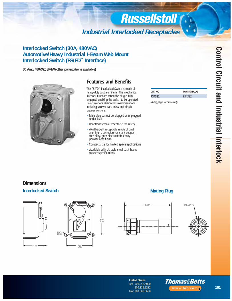
161
United StatesTel: 901.252.8000
800.326.5282Fax: 800.888.0690
www.tnb.com
Control Circuit and Industrial Interlock
Industrial Interlocked Receptacles
Mating plugs sold separately.
OFF ON0.34"4 PLS
5.06"MTG.
5.88"MTG.
4.62"
5.62" Ø 2.25"
Interlocked Switch (30A, 480VAC)Automotive/Heavy Industrial I-Beam Web MountInterlocked Switch (FS/FD™ Interface)
30 Amp, 480VAC, 3P4W (other polarizations available)
Features and Benefits
Interlocked Switch
DimensionsMating Plug
The FS/FD™ Interlocked Switch is made of heavy-duty cast aluminum. The mechanicalinterlock functions when the plug is fullyengaged, enabling the switch to be operated.Basic interlock design has many variationsincluding screw cover, brass and circuit breaker versions.
• Male plug cannot be plugged or unpluggedunder load
• Deadfront female receptacle for safety
• Weathertight receptacle made of castaluminum, corrosion-resistant copper-free alloy, gray electrostatic epoxy powder coat finish
• Compact size for limited space applications
• Available with UL style steel back boxes to user specifications
CAT. NO. MATING PLUG
F34331 F34332

162
United StatesTel: 901.252.8000
800.326.5282Fax: 800.888.0690
www.tnb.com
Cont
rol C
ircui
t and
Indu
stria
l Int
erlo
ck
Industrial Interlocked Receptacles
Conduit Hubs: (at B or E)
Boldface figures are for voltage assignment; for different ratings, see page 50.
B-Std.
E
Dimensions
▼
MaxGard® NEMA 4X interlocks are ideal for demanding non-hazardousareas where dust, dirt, moisture andcorrosion might be a problem — such as shipyards, food processingfacilities, manufacturing operations or similar areas.
Safety • Gated deadfront waterproof
receptacle
• Standard, high AIC or NA/switch circuit breaker
• Protective screw cap forwatertight protection
Durability• Thick-wall cast copper-free
aluminum housing with epoxypowder coat finish
• Heavy-duty sliding bar interlock mechanism
Performance• Heavy ON/OFF handle adds
mechanical ability to electricalinterlock function
• Standard conduit openingsthrough top or side
▼ Control Contacts (position 12) use “K” example:DBRF6104060K0
Shunt Trip Breaker (position 13) add “Z” to above: DBRF6104060KZ
Breaker Trip Ratings (positions 9, 10, 11) 30 amp use 030; 50 amp use 050; 60 amp use 060
Non-Auto Sw. NA0 (repl.” DBRF” with “DSRF”)
For additional full line and polarization options, see MaxGard sectionon pages 6–53.
▼
Maximum 600VAC/250VDC
STD. NPTAMP THREAD OUTLET MAX
30 11⁄2" 21⁄2"60 11⁄2" 21⁄2"100 2" 21⁄2"
MECHANICALLY STD.INTERLOCKED RECEPTACLE MATING BUSHING
POLES/ NEMA 4X MAXGARD PLUG ID
WIRES VOLTAGE CAT. NO. CAT. NO.
2P3W 125 DBRF310703000 DS3107MP000 7⁄8"30 2P3W 250 DBRF320703000 DS3207MP000 7⁄8"
AMP 3P4W 3Ø250 DBRF330703000 DS3307MP000 1"3P4W 3Ø480 DBRF340403000 DS3404MP000 1"4P5W 277/480 DBRF350403000 DS3504MP000 13⁄16"
2P3W 250 DBRF620706000 DS6207MP000 13⁄16"60 3P4W 125/250 DBRF630706000 DS6307MP000 15⁄16"
AMP 3P4W 3Ø480 DBRF640406000 DS6404MP000 15⁄16"4P5W 277/480 DBRF650406000 DS6504MP000 11⁄2"
2P3W 250 DBRF120710000 DS1207MP000 111⁄16"100 3P4W 125/250 DBRF130710000 DS1307MP000 113⁄16"AMP 3P4W 3Ø480 DBRF140410000 DS1404MP000 113⁄16"
4P5W 277/480 DBRF150410000 DS1504MP000 2"
3P4W 277/480 DBRF230720000 DS2307MP000 11⁄4"200 3P4W 3Ø480 DBRF240420000 DS2404MP000 21⁄4"AMP 4P5W 277/480 DBRF250420000 DS2504MP000 21⁄2"
400 3P4W 277/480 DBRF430740000 DS4307MP000 3"
AMP 3P4W 3Ø480 DBRF440440000 DS4404MP000 3"4P5W 277/480 DBRF450440000 DS4504MP000 31⁄4"
Amp A B C D E F G
30 3⁄8" 83⁄4" 61⁄2" 11⁄2" 161⁄4" 151⁄8" 31⁄8"60 3⁄8" 83⁄4" 61⁄2" 11⁄2" 161⁄4" 151⁄8" 31⁄8"
100 3⁄8" 83⁄4" 61⁄2" 11⁄2" 161⁄4" 151⁄8" 31⁄8"200 9⁄16" 121⁄4" 9" 21⁄2" 261⁄4" 243⁄4" 5"400 9⁄16" 151⁄2" 12" 3" 301⁄2" 29" 6"

Hazardous Locations
Hazardous Location Applications:Class I, Div. 1/Class II, Div. 1
Hazardous-Duty Plugs, Receptacles and Interlocks ............164–170
Static-Ground Receptacles.........................................................171
Safe Ground Indicator System............................................172–174
163
United StatesTel: 901.252.8000
800.326.5282Fax: 800.888.0690
www.tnb.com
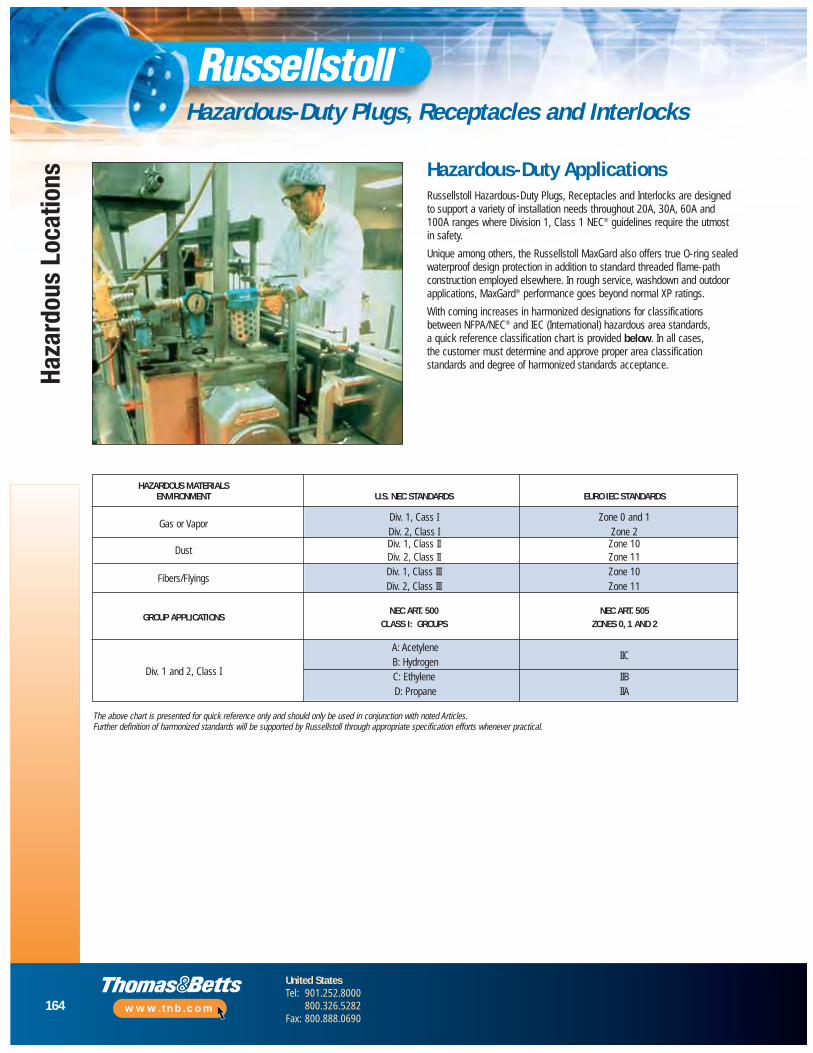
164
United StatesTel: 901.252.8000
800.326.5282Fax: 800.888.0690
www.tnb.com
Haza
rdou
s Lo
catio
ns
Hazardous-Duty Plugs, Receptacles and Interlocks
Russellstoll Hazardous-Duty Plugs, Receptacles and Interlocks are designed to support a variety of installation needs throughout 20A, 30A, 60A and100A ranges where Division 1, Class 1 NEC® guidelines require the utmostin safety.
Unique among others, the Russellstoll MaxGard also offers true O-ring sealedwaterproof design protection in addition to standard threaded flame-pathconstruction employed elsewhere. In rough service, washdown and outdoor applications, MaxGard® performance goes beyond normal XP ratings.
With coming increases in harmonized designations for classifications between NFPA/NEC® and IEC (International) hazardous area standards, a quick reference classification chart is provided below. In all cases, the customer must determine and approve proper area classificationstandards and degree of harmonized standards acceptance.
Hazardous-Duty Applications
HAZARDOUS MATERIALSENVIRONMENT U.S. NEC STANDARDS EURO IEC STANDARDS
Gas or VaporDiv. 1, Cass I Zone 0 and 1Div. 2, Class I Zone 2
DustDiv. 1, Class II Zone 10Div. 2, Class II Zone 11
Fibers/FlyingsDiv. 1, Class III Zone 10Div. 2, Class III Zone 11
NEC ART. 500 NEC ART. 505GROUP APPLICATIONS
CLASS I: GROUPS ZONES 0, 1 AND 2
A: AcetyleneIIC
Div. 1 and 2, Class IB: HydrogenC: Ethylene IIBD: Propane IIA
The above chart is presented for quick reference only and should only be used in conjunction with noted Articles. Further definition of harmonized standards will be supported by Russellstoll through appropriate specification efforts whenever practical.
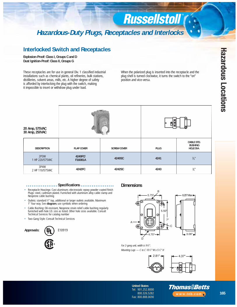
165
United StatesTel: 901.252.8000
800.326.5282Fax: 800.888.0690
www.tnb.com
Hazardous Locations
Hazardous-Duty Plugs, Receptacles and Interlocks
5.75"B
5.50"
7"
CA
D
4.75" 3.06"
6.25" Max
2.81" 4.37"
Interlocked Switch and ReceptaclesExplosion-Proof: Class I, Groups C and DDust Ignition-Proof: Class II, Groups G
These receptacles are for use in general Div. 1 classified industrialinstallations such as chemical plants, oil refineries, bulk stations,distilleries, solvent areas, mills, etc. A higher degree of safety is afforded by interlocking the plug with the switch, making it impossible to insert or withdraw plug under load.
When the polarized plug is inserted into the receptacle and the plug shell is turned clockwise, it turns the switch to the “on” position and vice-versa.
. . . . . . . . . . . . . . . . . Specifications . . . . . . . . . . . . . . . . . .• Receptacle Housings: Cast aluminum; electrostatic epoxy powder coated finish
Plugs: steel, cadmium plated. Furnished with aluminum alloy cable clamp andNeoprene cable bushing
• Outlets: standard 3⁄4" top, additional or larger outlets available. Maximum 1" four way. See diagram, use symbols when ordering
• Cable Bushing: Oil-resistant, Neoprene strain relief cable bushing regularlyfurnished with hole I.D. size as listed. Other hole sizes available. ConsultTechnical Services for catalog number
• Two-Gang Style: Consult Technical Services
Approvals: E10919
Dimensions
For 2-gang unit, width is 9 3⁄8".Mounting Lugs — C to C 10 1⁄2" W x 5 1⁄2" H
20 Amp, 575VAC30 Amp, 250VAC
CABLE STD. BUSHING
DESCRIPTION FLAP COVER SCREW COVER PLUG HOLE DIA.
2P3W 4240FC/4240SC 4241 5⁄8"1 HP 220/575VAC F16081A
3P4W4242FC 4242SC 4243 3⁄4"2 HP 110/575VAC
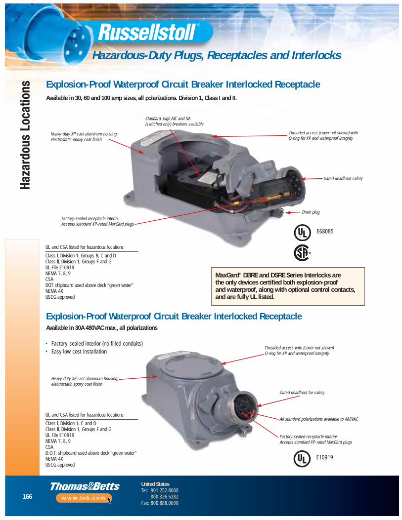
166
United StatesTel: 901.252.8000
800.326.5282Fax: 800.888.0690
www.tnb.com
Haza
rdou
s Lo
catio
ns
Hazardous-Duty Plugs, Receptacles and Interlocks
Explosion-Proof Waterproof Circuit Breaker Interlocked ReceptacleAvailable in 30, 60 and 100 amp sizes, all polarizations. Division 1, Class I and II.
Heavy-duty XP cast aluminum housing,electrostatic epoxy coat finish
Standard, high AIC and NA(switched only) breakers available
Threaded access (cover not shown) with O-ring for XP and waterproof integrity
Gated deadfront safety
Drain plugFactory-sealed receptacle interior. Accepts standard XP-rated MaxGard plugs
UL and CSA listed for hazardous locations
Class I, Division 1, Groups B, C and DClass II, Division 1, Groups F and GUL File E10919NEMA 7, 8, 9CSADOT shipboard used above deck “green water”NEMA 4XUSCG approved
MaxGard® DBRE and DSRE Series Interlocks are the only devices certified both explosion-proof and waterproof, along with optional control contacts,and are fully UL listed.
Explosion-Proof Waterproof Circuit Breaker Interlocked ReceptacleAvailable in 30A 480VAC max., all polarizations
Heavy-duty XP cast aluminum housing,electrostatic epoxy coat finish
• Factory-sealed interior (no filled conduits)• Easy low cost installation
Threaded access with (cover not shown) O-ring for XP and waterproof integrity
Gated deadfront for safety
All standard polarizations available to 480VAC
Factory-sealed receptacle interiorAccepts standard XP-rated MaxGard plugs
UL and CSA listed for hazardous locations
Class I, Division 1, C and DClass II, Division 1, Groups F and GUL File E10919NEMA 7, 8, 9CSAD.O.T. shipboard used above deck “green water”NEMA 4XUSCG approved
E68085
E10919
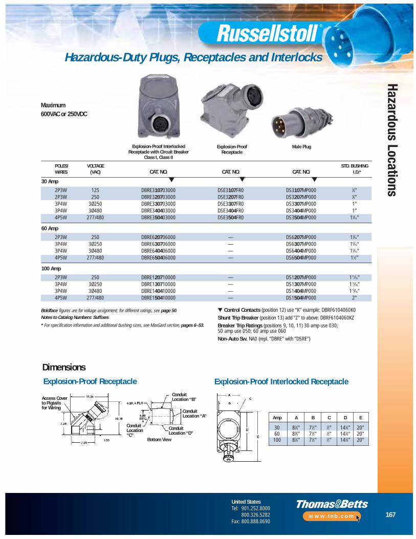
167
United StatesTel: 901.252.8000
800.326.5282Fax: 800.888.0690
www.tnb.com
Hazardous Locations
Hazardous-Duty Plugs, Receptacles and Interlocks
Explosion-Proof InterlockedReceptacle with Circuit Breaker
Class I, Class II
Maximum600VAC or 250VDC
Boldface figures are for voltage assignment; for different ratings, see page 50.Notes to Catalog Numbers: Suffixes
* For specification information and additional bushing sizes, see MaxGard section, pages 6–53.
▼ Control Contacts (position 12) use “K” example: DBRF6104060K0
Shunt Trip Breaker (position 13) add “Z” to above: DBRF6104060KZ
Breaker Trip Ratings (positions 9, 10, 11) 30 amp use 030; 50 amp use 050; 60 amp use 060
Non-Auto Sw. NA0 (repl. “DBRE” with “DSRE”)
DimensionsExplosion-Proof Interlocked ReceptacleExplosion-Proof Receptacle
▼ ▼
POLES/ VOLTAGE STD. BUSHINGWIRES (VAC) CAT. NO. CAT. NO. CAT. NO. I.D.*
30 Amp
2P3W 125 DBRE310703000 DSE3107FR0 DS3107MP000 7⁄8"2P3W 250 DBRE320703000 DSE3207FR0 DS3207MP000 7⁄8"3P4W 3Ø250 DBRE330703000 DSE3307FR0 DS3307MP000 1"3P4W 3Ø480 DBRE340403000 DSE3404FR0 DS3404MP000 1"4P5W 277/480 DBRE350403000 DSE3504FR0 DS3504MP000 13⁄16"
60 Amp
2P3W 250 DBRE620706000 — DS6207MP000 13⁄16"3P4W 3Ø250 DBRE630706000 — DS6307MP000 15⁄16"3P4W 3Ø480 DBRE640406000 — DS6404MP000 15⁄16"4P5W 277/480 DBRE650406000 — DS6504MP000 11⁄2"
100 Amp
2P3W 250 DBRE120710000 — DS1207MP000 111⁄16"3P4W 3Ø250 DBRE130710000 — DS1307MP000 113⁄16"3P4W 3Ø480 DBRE140410000 — DS1404MP000 113⁄16"4P5W 277/480 DBRE150410000 — DS1504MP000 2"
Explosion-ProofReceptacle
Male Plug
Amp A B C D E
30 83⁄4" 71⁄2" 1⁄2" 143⁄4" 20"60 83⁄4" 71⁄2" 1⁄2" 143⁄4" 20"
100 83⁄4" 71⁄2" 1⁄2" 143⁄4" 20"
Access Coverto Pigtails for Wiring
ConduitLocation “C”
ConduitLocation “D”
ConduitLocation “B”
ConduitLocation “A”
Bottom View
▼
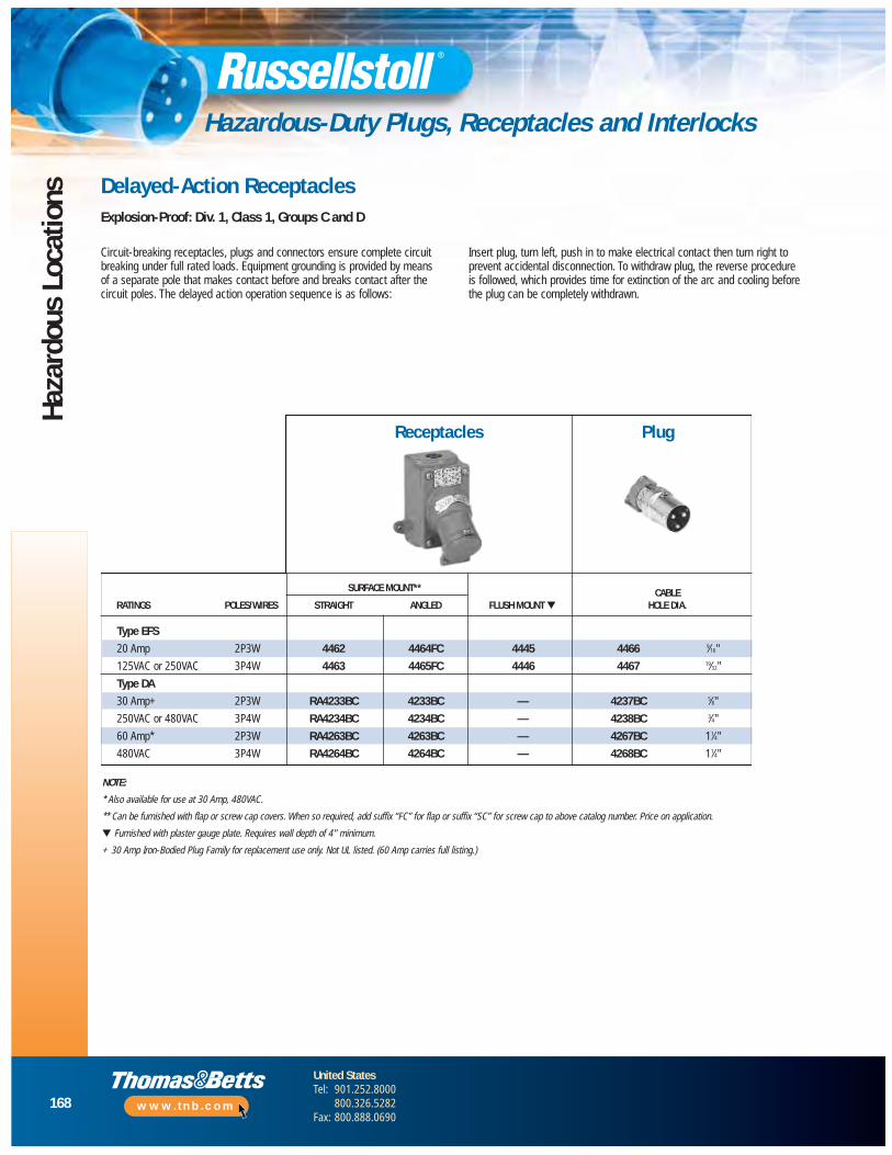
168
United StatesTel: 901.252.8000
800.326.5282Fax: 800.888.0690
www.tnb.com
Haza
rdou
s Lo
catio
ns
Hazardous-Duty Plugs, Receptacles and Interlocks
Receptacles Plug
Circuit-breaking receptacles, plugs and connectors ensure complete circuitbreaking under full rated loads. Equipment grounding is provided by meansof a separate pole that makes contact before and breaks contact after thecircuit poles. The delayed action operation sequence is as follows:
Insert plug, turn left, push in to make electrical contact then turn right toprevent accidental disconnection. To withdraw plug, the reverse procedure is followed, which provides time for extinction of the arc and cooling before the plug can be completely withdrawn.
Delayed-Action ReceptaclesExplosion-Proof: Div. 1, Class 1, Groups C and D
NOTE:
* Also available for use at 30 Amp, 480VAC.
** Can be furnished with flap or screw cap covers. When so required, add suffix “FC” for flap or suffix “SC” for screw cap to above catalog number. Price on application.
▼ Furnished with plaster gauge plate. Requires wall depth of 4" minimum.
+ 30 Amp Iron-Bodied Plug Family for replacement use only. Not UL listed. (60 Amp carries full listing.)
SURFACE MOUNT** CABLERATINGS POLES/WIRES STRAIGHT ANGLED FLUSH MOUNT ▼ HOLE DIA.
Type EFS
20 Amp 2P3W 4462 4464FC 4445 4466 9⁄16"
125VAC or 250VAC 3P4W 4463 4465FC 4446 4467 19⁄32"
Type DA
30 Amp+ 2P3W RA4233BC 4233BC — 4237BC 5⁄8"
250VAC or 480VAC 3P4W RA4234BC 4234BC — 4238BC 3⁄4"
60 Amp* 2P3W RA4263BC 4263BC — 4267BC 11⁄4"
480VAC 3P4W RA4264BC 4264BC — 4268BC 11⁄4"
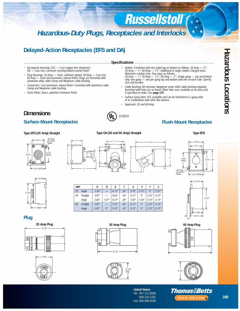
169
United StatesTel: 901.252.8000
800.326.5282Fax: 800.888.0690
www.tnb.com
Hazardous Locations
Hazardous-Duty Plugs, Receptacles and Interlocks
AMP D R S T U V Y Z
20 Angle 2.56" — 6.12" .28" 3.75" 3.75" 3" 5.37"
30 Straight 3.87" –– 8.62" .34" 6.12" 5" 5.25" 6.75"
Angle 3.06" 7.37" 8.37" .28" 3.50" 5.50" 4.75" 4.75"
60 Straight 3.87" –– 9.25" .34" 6.12" 5" 5.25" 6.75"
Angle 3.87" 9" 9.25" .34" 6.12" 5" 5.25" 6.75"
Delayed-Action Receptacles (EFS and DA)
D
Z
S
V
U
Y
T
S
R Z
3.75"
3"
4.75" 5.5"3.75"MTG.
3.75" MTG.
.28" Dia.(2) MTG.Holes
3.12"
5.37"
3.31"
2.56"
.81"
1.75"
2.12"Dia. 3.12"
• Receptacle Housings: EFS — Cast copper-free aluminum; DA — Cast iron, corrosion-resisting baked enamel finish
• Plug Housings: 20 Amp — Steel, cadmium plated; 30 Amp — Cast iron; 60 Amp — Steel and aluminum, natural finish. Plugs are furnished withaluminum alloy cable clamp and Neoprene cable bushing
• Connectors: Cast aluminum, natural finish. Furnished with aluminum cable clamp and Neoprene cable bushing
• Flush Plates: Brass, polished chromium finish
• Outlets: Furnished with one outlet top or bottom as follows. 20 Amp — 3⁄4"; 30 Amp — 1"; 60 Amp — 11⁄2". Additional or larger outlets charged extra.Maximum conduit sizes, four ways as follows: 20 Amp — 1"; 30 Amp — 11⁄2"; 60 Amp — 2". Single gang — top and bottomonly; two gang — one per gang top and bottom and one on each side. Specifysize and location
• Cable Bushing: Oil-resistant, Neoprene strain relief cable bushing regularlyfurnished with hole size as listed. Other hole sizes available at no extra cost if specified on order. See page 170
• Surface Gang Units: EFS available and can be furnished in 2-gang units or in combination with other like devices
• Approvals: 20 and 60 Amp
DimensionsSurface-Mount Receptacles Flush-Mount Receptacles
Plug
Type EFS (20 Amp) Straight Type DA (30 and 60 Amp) Straight Type EFS
20 Amp Plug
3.62"
4.75"
2.56"a.G.
4
3"
5.37"3.75"MTG.
3.75" MTG
.28" Dia.(2) MTG.Holes
4.12"
5.12" 7"
E10919
. . . . . . . . . . . . . . . . . . . . . . . . . . . . . . . . . . . . . . . . . . . . . . Specifications . . . . . . . . . . . . . . . . . . . . . . . . . . . . . . . . . . . . . . . . . .
5.12"
60 Amp Plug30 Amp Plug
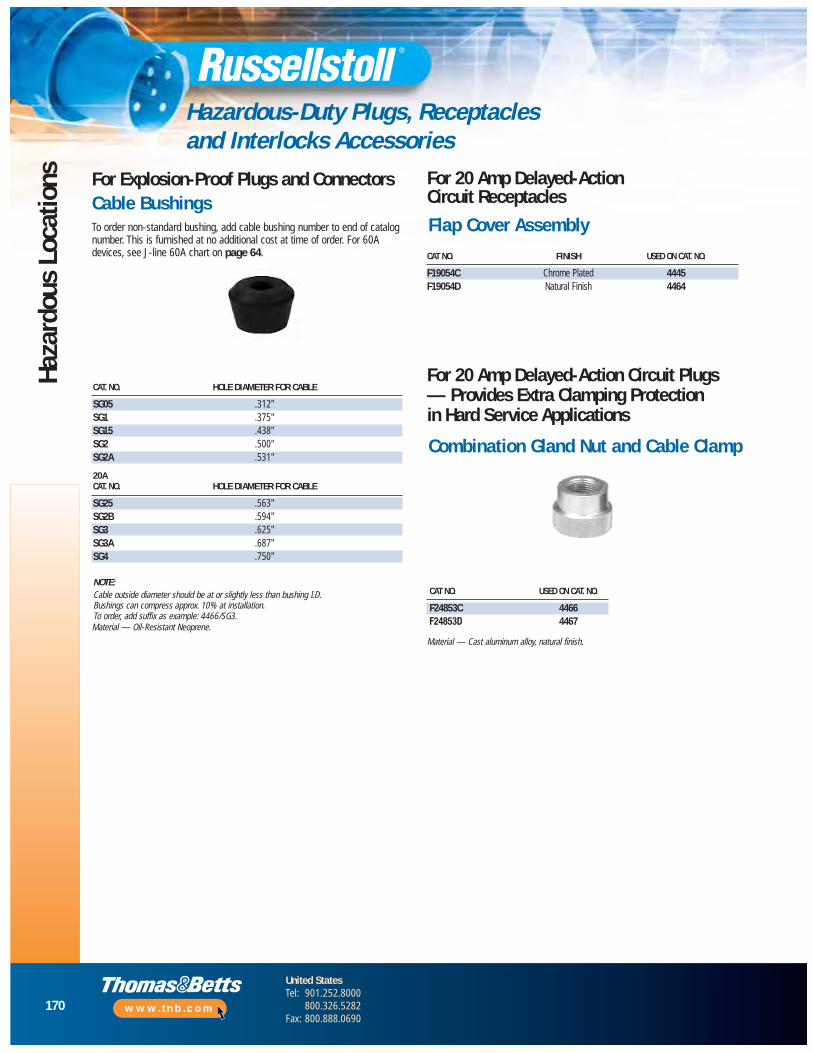
170
United StatesTel: 901.252.8000
800.326.5282Fax: 800.888.0690
www.tnb.com
Haza
rdou
s Lo
catio
ns
Hazardous-Duty Plugs, Receptaclesand Interlocks Accessories
CAT. NO. HOLE DIAMETER FOR CABLE
SG05 .312"SG1 .375"SG15 .438"SG2 .500"SG2A .531"
20ACAT. NO. HOLE DIAMETER FOR CABLE
SG25 .563"SG2B .594"SG3 .625"SG3A .687"SG4 .750"
Material — Oil-Resistant Neoprene.
CAT NO. FINISH USED ON CAT. NO.
F19054C Chrome Plated 4445F19054D Natural Finish 4464
For 20 Amp Delayed-ActionCircuit Receptacles
CAT NO. USED ON CAT. NO.
F24853C 4466F24853D 4467
For 20 Amp Delayed-Action Circuit Plugs— Provides Extra Clamping Protection in Hard Service Applications
Material — Cast aluminum alloy, natural finish.
For Explosion-Proof Plugs and ConnectorsCable BushingsTo order non-standard bushing, add cable bushing number to end of catalognumber. This is furnished at no additional cost at time of order. For 60Adevices, see J-line 60A chart on page 64.
Flap Cover Assembly
Combination Gland Nut and Cable Clamp
NOTE:Cable outside diameter should be at or slightly less than bushing I.D.Bushings can compress approx. 10% at installation.To order, add suffix as example: 4466/SG3.
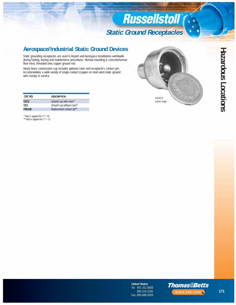
171
United StatesTel: 901.252.8000
800.326.5282Fax: 800.888.0690
www.tnb.com
Hazardous Locations
Static Ground Receptacles
CAT. NO. DESCRIPTION
GCC1 Ground cup with cover*GC1 Ground cup without cover*F06146 Replacement contact tip**
* Hub is tapped for 3⁄4"–10.** Hub is tapped for 1⁄2"–13.
Aerospace/Industrial Static Ground DevicesStatic grounding receptacles are used in Airport and Aerospace installations worldwideduring fueling, testing and maintenance procedures. Normal mounting is concrete/tarmacfloor inset, threaded onto copper ground rod.
Heavy brass construction cup includes optional cover and receptacle’s contact pin.Accommodates a wide variety of single-contact (copper on steel wire) static groundwire clamps in service.
F07073(cover only)
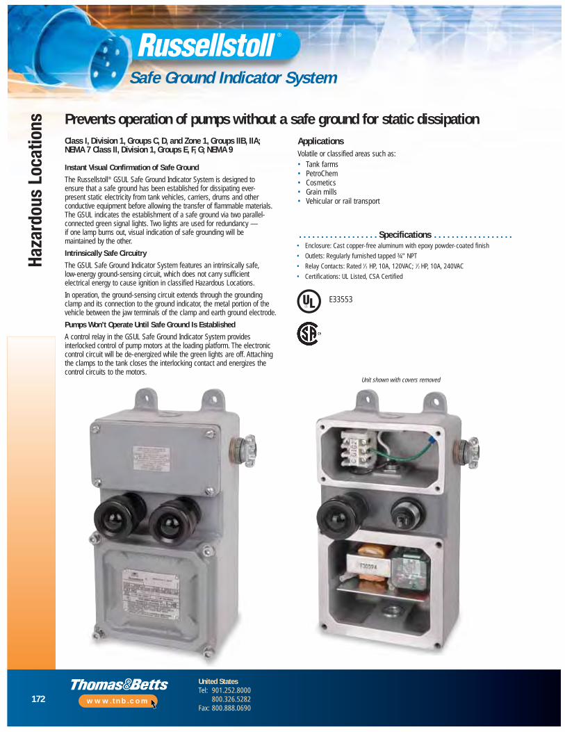
172
United StatesTel: 901.252.8000
800.326.5282Fax: 800.888.0690
www.tnb.com
Haza
rdou
s Lo
catio
ns
Safe Ground Indicator System
Prevents operation of pumps without a safe ground for static dissipationClass I, Division 1, Groups C, D, and Zone 1, Groups IIB, IIA;NEMA 7 Class II, Division 1, Groups E, F, G; NEMA 9
Instant Visual Confirmation of Safe Ground
The Russellstoll® GSUL Safe Ground Indicator System is designed to ensure that a safe ground has been established for dissipating ever-present static electricity from tank vehicles, carriers, drums and otherconductive equipment before allowing the transfer of flammable materials.The GSUL indicates the establishment of a safe ground via two parallel-connected green signal lights. Two lights are used for redundancy — if one lamp burns out, visual indication of safe grounding will be maintained by the other.
Intrinsically Safe Circuitry
The GSUL Safe Ground Indicator System features an intrinsically safe, low-energy ground-sensing circuit, which does not carry sufficient electrical energy to cause ignition in classified Hazardous Locations.
In operation, the ground-sensing circuit extends through the groundingclamp and its connection to the ground indicator, the metal portion of thevehicle between the jaw terminals of the clamp and earth ground electrode.
Pumps Won’t Operate Until Safe Ground Is Established
A control relay in the GSUL Safe Ground Indicator System providesinterlocked control of pump motors at the loading platform. The electroniccontrol circuit will be de-energized while the green lights are off. Attachingthe clamps to the tank closes the interlocking contact and energizes thecontrol circuits to the motors.
ApplicationsVolatile or classified areas such as:• Tank farms • PetroChem• Cosmetics • Grain mills• Vehicular or rail transport
. . . . . . . . . . . . . . . . . . Specifications . . . . . . . . . . . . . . . . . .• Enclosure: Cast copper-free aluminum with epoxy powder-coated finish
• Outlets: Regularly furnished tapped ¾" NPT
• Relay Contacts: Rated 1⁄3 HP, 10A, 120VAC; 1⁄2 HP, 10A, 240VAC
• Certifications: UL Listed, CSA Certified
Unit shown with covers removed
E33553

TB1L1 G L2 C N.O. N.C.1 2 3 4 5 6 G
G
G2
G1
C
TB3
Ground Electrode Connection (1 electrode required) not provided by Russellstoll
Two-Conductor Cable
Weathertight Reel
Grounding ClampCat. No. SGC2
Remote Indicator Pilot Light(Optional)Mounting
Feet
N.O. - N.C. Relay Contacts1/3 H.P. 10 Amp 120 VAC1/2 H.P. 10 Amp 240VAC
To 115 Volts,60 Hz
Ground in explosion-proofportion provided by conduitsystem
173
United StatesTel: 901.252.8000
800.326.5282Fax: 800.888.0690
www.tnb.com
Hazardous Locations
Safe Ground Indicator System
GSUL Safe Operating Features• Two redundant, parallel green indicator lights
glow when safe ground is established
• Lamps offer approximately 20,000 hours of operating life
• Unit may be ordered without lights whereremote visual indication is desired
• Intrinsically safe, simplified circuitry
• Integral, intrinsically safe wiring compartmentwith approved strain-relief fitting for connectionof cable from grounding clamp
• Solid-state actuating and control circuitsmounted on removable printed circuit board
• Enclosure protects components against moisture
• Control relay provided for interlocked control of pump motor at loading rack
• Grounding clamp (ordered separately) providesdual isolated tip contacts in a heavy-duty cast-aluminum handle design
Weathertight Reel
Mounting Feet
Ground in explosion-proof portionprovided by conduit system
To 115 Volts, 60Hz or 240VAC, 50/60Hz
Loading rack illustration suggests a typical installation, which includes an Explosion-Proof Switch, Explosion-Proof Sealing Fittings, Weathertight Reel and the GSUL-2-SS Safe Ground indicator with 2-wire grounding clamp.
Wiring Diagram
Ground Electrode Connection (1 electrode required not provided by Russellstoll)
Two-Conductor Cable
N.O. – N.C. Relay Contacts1⁄3 HP 10 Amp 120VAC1⁄2 HP 10 Amp 240VAC
Remote Indicator Pilot Light (Optional)
Grounding ClampCAT. NO. SGC2
Weatherproof ReelCat. No. SGR25
Grounding Clampto Fuel CarrierCat. No. SGC2
Explosion-proofSealing Fittings
Explosion ProofTumbler SwitchCat. No. 4411S7
Explosion ProofSafe Ground IndicatorCat No. GSUL-2-SS
To Ground Electrode
Typical Installation
Weatherproof ReelCAT. NO. SGR25
Grounding Clamp toFuel Carrier
CAT. NO. SGC2
Explosion-Proof Safe Ground IndicatorCAT. NO. GSUL-2-SSCAT. NO. GSUL-2-SS-240
Explosion-Proof Sealing Fittings
To Ground Electrode

174
United StatesTel: 901.252.8000
800.326.5282Fax: 800.888.0690
www.tnb.com
Haza
rdou
s Lo
catio
ns
Safe Ground Indicator System
CAT. NO. DESCRIPTIONGSUL2SS Safe Ground Indicator with Indicator Lights, 120V, UL/CSAGSUL2SS-240 Safe Ground Indicator with Indicator Lights, 240V, CSASGC2 Safe Ground Static ClampSGR25 Weathertight Retracing Reel with 25 ft. of 12/2 SJO-W CableSGR50 Weathertight Retracing Reel with 50 ft. of 12/2 SJO-W CableSGR75 Weathertight Retracing Reel with 75 ft. of 12/2 SJO-W CableReplacement Parts for GSULC13662 Printed Circuit Board, 120 Volts (includes relay)6X24RCB Printed Circuit Board, 240 Volts (includes relay)F30674 Control RelayF30602 Lamp Socket AssemblyELAG Pilot Light Globe Assembly (green)310993 Lamp for GSUL2SSReplacement Parts for SGC2GX2TK Ground Clamp Repair Kit
Russellstoll® GSUL Safe Ground Indicator System
5.25"3" MTG .75" NPT
Conduit
.75" NPT
10.25"MTG
9.25"
.75"
.3" Dia.Hole
.75" NPTConduit
.75"
Max
. Con
duit
4.5" Approx..44"
.84"3.88"
IndicatingLights (Green)
SGR25SGR50SGR75
SGC2
2X Conductor Termination Set Screws
.146 PLS
Cable Entry Clamp and Screw
13" Dia.
7.5"
3.37"
1.25"
3" Sq.
8.5"Rad.
1.56"
.56" Dia. MTG Holes.75" Female Thread
Line Entrance
14.75"
8.25"
2.5"
9.75"3.37" 6.37"
.37"3"2"
4 Holes Pivot MTG (optional)2 Holes Rigid MTG
.37"6.87"
4 Sq
13" Dia.7.5" Dia.
9.75"3.37" 6.37"
2" 3" .37"
14.75"
8.25"
2.5"
4 Sq.4 Holes Pivot MTG. (optional)
.37"
3.37"
1.25"
3" Sq.
8.5"Rad.
6.87"2 Holes Rigid MTG.
.56" Dia. MTG. Holes .75" Female Thread
Line Entrance1.56"
2X “Rue Pin” Pivot Pin Locking
GSUL-2-SS
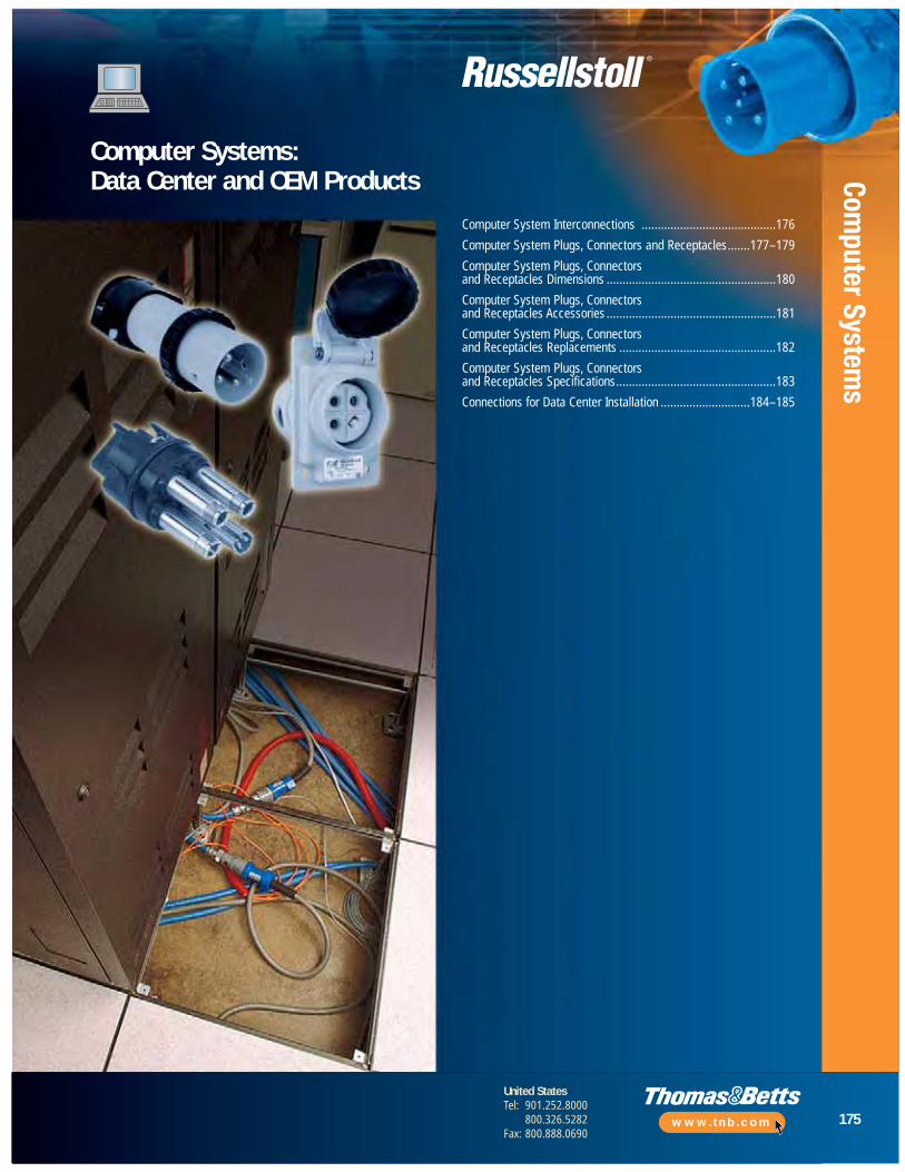
175
United StatesTel: 901.252.8000
800.326.5282Fax: 800.888.0690
www.tnb.com
Computer System
s
Computer Systems:Data Center and OEM Products
Computer System Interconnections ..........................................176
Computer System Plugs, Connectors and Receptacles.......177 –179
Computer System Plugs, Connectors and Receptacles Dimensions .....................................................180
Computer System Plugs, Connectors and Receptacles Accessories .....................................................181
Computer System Plugs, Connectors and Receptacles Replacements .................................................182
Computer System Plugs, Connectors and Receptacles Specifications..................................................183
Connections for Data Center Installation ............................184 –185

176
United StatesTel: 901.252.8000
800.326.5282Fax: 800.888.0690
www.tnb.com
Com
pute
r Sy
stem
s
Computer System Interconnections
The toughest construction in thermoplasticsafety, durability and performance by design, in UL 94-VO flame-rated DuraV® material. WithDurOring sealed pins, sleeves and interiors arewatertight even unmated. 30A and 50A uniquecircuit breaker interlock line in DuraV are thebest choices in all standard voltage polarizationoptions through 600VAC (Interlock to 480VAC).
Otherwise similar to the DuraGard®, SpecGrade refers to blue Lexan plugs only made tothe same original FS/FD design standards asDuraGard, in UL 94-5VA flame-rated material.Spec Grade features DurOring sealed pins,sleeves and interiors are watertight evenunmated. Spec Grade devices have beensuperceded by DuraGard ratings for OEM use.
The original 15/20/30A computer systemconnectors, the FS/FD line in aluminumcontinues in MRO usage. Many installationscan also mate directly or convert to DuraGardunits. Our large installed base can besupported with any construction and productoptions. Convert to DuraGard when possible.
DuraGard®
to 4P4W20A through 60A
Spec Gradeto 4P4W
20A and 30A
FS/FD™
to 3P4W15A through 30A
Angle Typeto 3P4W60A use
MaxGard®
30A to 4P5W
UniGard®
to 4P5W20A to 100A
Defined
Telephony EquipmentSwitching Rack SystemsPower Distribution UnitsTest and Laboratory EquipmentMainframes from 30–270APeripheralsData Storage DevicesMilitary or Critical Power Supplies
Typical Application Groups
Russellstoll Line Selections for Outdoor and Indoor Applications
• Any application where electrical connections must be protected from humidity, water, condensation and/or dust entering the wiring compartment and contacts
• Cable-to-connector sealing and device locking designs are critical
• Thermoplastic connectors preferred: some with aluminum conduit grounded shell
• Connection integrity needs are absolute; data center systems cannot go down
• Underfloor data center applications and wall-mount installations
The original 60A main power computer systemconnector, Angle Type plugs are also available inspecialty UL 94-V0 material (Aluminum Connectors).As part of the MRO usage 30–200A Angle TypeLine, the 60A connector is still commonly usedtoday. Other lines such as MaxGard should be used for changeout when possible.
For DP/Computer System Applications, a specialMaxGard polarization reflects DP installations.Special thermoplastic housing and back handle are supplied for these applications. Use wherever4P5W installations are required.
Thermoplastic International standard 309-2 or CEE-17 type connector lines usage is growing,especially in OEM, export and standard performanceapplications. The IP67 style is watertight whenmated and directly interchangeable with othermanufacturers. International designations shadowU.S. ratings: 20/16A, 30/32A, 60/63A and100/125A. IP67 devices have screw collars orflap/screw covers, with catalog number “W”suffixes.
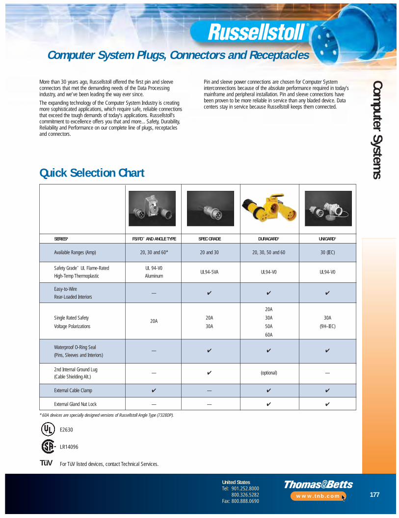
177
United StatesTel: 901.252.8000
800.326.5282Fax: 800.888.0690
www.tnb.com
Computer System
s
Computer System Plugs, Connectors and Receptacles
SERIES* FS/FD™ AND ANGLE TYPE SPEC GRADE DURAGARD® UNIGARD®
Available Ranges (Amp) 20, 30 and 60* 20 and 30 20, 30, 50 and 60 30 (IEC)
Safety Grade™ UL Flame-Rated UL 94-V0
High-Temp Thermoplastic AluminumUL94-5VA UL94-V0 UL94-V0
Easy-to-Wire— ✔ ✔ ✔
Rear-Loaded Interiors
20A
Single Rated Safety20A
20A 30A 30A
Voltage Polarizations 30A 50A (9H–IEC)
60A
Waterproof O-Ring Seal— ✔ ✔ ✔
(Pins, Sleeves and Interiors)
2nd Internal Ground Lug— ✔ (optional) —
(Cable Shielding Alt.)
External Cable Clamp ✔ — ✔ ✔
External Gland Nut Lock — — ✔ ✔
More than 30 years ago, Russellstoll offered the first pin and sleeveconnectors that met the demanding needs of the Data Processing industry, and we’ve been leading the way ever since.
The expanding technology of the Computer System Industry is creating more sophisticated applications, which require safe, reliable connections that exceed the tough demands of today’s applications. Russellstoll’scommitment to excellence offers you that and more... Safety, Durability,Reliability and Performance on our complete line of plugs, receptacles and connectors.
Pin and sleeve power connections are chosen for Computer Systeminterconnections because of the absolute performance required in today’smainframe and peripheral installation. Pin and sleeve connections have been proven to be more reliable in service than any bladed device. Datacenters stay in service because Russellstoll keeps them connected.
E2630
LR14096
For TüV listed devices, contact Technical Services.TüV
Quick Selection Chart
* 60A devices are specially designed versions of Russellstoll Angle Type (7328DP).

178
United StatesTel: 901.252.8000
800.326.5282Fax: 800.888.0690
www.tnb.com
Com
pute
r Sy
stem
s
Computer System Plugs, Connectors and Receptacles
15/20Amp
2P/3W
3P/4W
30 Amp
20 Amp
50 Amp
Plugs
60 Amp
60 Amp
30 Amp
50 Amp
60 Amp
PLUG STD. SEE BUSHINGSAFETY CABLE** FS/FD™• SPEC GRADE CHART DURAGARD®
VOLTAGE POLARIZATION BUSHING ALUMINUM UL 94-5VA UL 94-VO*
Up to 0.625" 3720DP (0.375)600VAC/ 0.455" 3720 3720DP/0455 9P23U0250VDC 0.405" 3720DP/0405
0.625" 3720DPU1 (0.375)125VAC 0.455" 3720U1 3720DPU1/0455 9P23U1
0.405" 3720DPU1/0405
0.625" 3720DPU2 (0.375)250VAC 0.455" 3720U2 3720DPU2/0455 9P23U2
0.405" 3720DPU2/0405
Up to 0.760"
600VAC0.700" 3750 3750DP 9P33U00.625"
Up to 1.000"
600VAC 0.925" — — 9P53U00.750"
125VAC 1.000" — — 9P63U1
250VAC 1.000" — — 9P63U2
Up to 0.688" — —600VAC/ 0.625" 3730 3730DP/0625 9P24U0250VDC 0.606" 3730DP —
1.100" 3760DPG/1100 —Up to 1.000" 3760 3760PDG/1000 9P34U0◆
600VAC 0.875" 3760PDG/0875 — 0.760" 3760DPG0760 —
Up to 1.000"600VAC 0.925" — — 9P54U0250VDC 0.750"
125/250VAC 1.000" — — 9P64U1
250 3Ø VAC 1.000" — — 9P64U2
1.375" — 7328DP/1375Up to 1.188" 7328-78^ — —
600VAC 1.020" — 7328DP†0.750" — 7328DP/0750
3øY120/208 0.775" — — DS3516MPDP+
VAC
NOTE: All 20A devices are compatible. 30A FS/FD™ receptacles and connectors will accept all styles of mating plugs.* For a more complete listing of UL 94-V0 rated devices, consult DuraGard information on pages 68–85.
** Consult your Thomas & Betts representative for additional cable bushing sizes not listed.† 7328 DP series thermoplastic can replace 7328 metallic.● 30A FS/FD™ aluminum plugs may not directly exchange with DuraGard plugs.
Special Angle Type
Angle Type
30 Amp4P/5WMaxGard
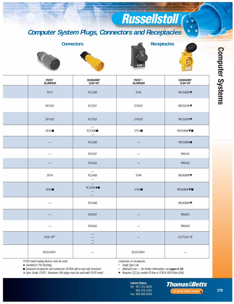
179
United StatesTel: 901.252.8000
800.326.5282Fax: 800.888.0690
www.tnb.com
Computer System
s
Computer System Plugs, Connectors and Receptacles
Connectors Receptacles
FS/FD™ DURAGARD® FS/FD™• DURAGARD®
ALUMINUM UL94-VO* ALUMINUM UL94-VO*
3913 9C23U0 3743 9R23U0W▼
3913U1 9C23U1 3743U1 9R23U1W▼
3913U2 9C23U2 3743U2 9R23U2W▼
—3933■ 9C33U0■ 3753■ 9R33U0W▼■
—
— 9C53U0 — 9R53U0W●
— 9C63U1 — 9R63U1
— 9C63U2 — 9R63U2
—3914 9C24U0 3744 9R24U0W▼
—
—
3934■9C34U0◆■
3754■ 9R34U0W▼■——
— 9C54U0 9R54U0W▼
— 9C64U1 — 9R64U1
— 9C64U2 — 9R64U2
—7428-78^ — — SCF7324-78
——
DS3516FP+ — DS3516FR+ —
FS/FD metal mating devices must be used.◆ Standard 0.750 Bushing.■ DuraGard receptacles and connectors 30/50A will accept only DuraGard or Spec Grade. FS/FD™ Aluminum 30A plugs must be used with FS/FD metal
connectors or receptacles.^ Angle Type Line+ MaxGard Line — for further information, see pages 6–53.▼ Requires 3711A conduit FD box or 3781A DSFD Box (50A).
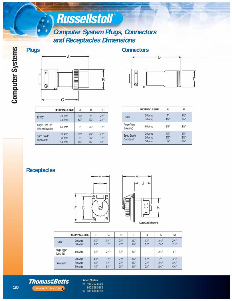
180
United StatesTel: 901.252.8000
800.326.5282Fax: 800.888.0690
www.tnb.com
Com
pute
r Sy
stem
s
Computer System Plugs, Connectors and Receptacles Dimensions
RECEPTACLE SIZE F G H I J K M
20 Amp 41⁄8" 31⁄4" 25⁄8" 17⁄8" 11⁄8" 21⁄4" 21⁄2"FS/FD™
30 Amp 41⁄8" 31⁄4" 25⁄8" 17⁄8" 13⁄8" 23⁄4" 25⁄8"
Angle Type60 Amp 31⁄2" 27⁄8" 31⁄2" 27⁄8" — 21⁄2" 6"
(Metallic)
20 Amp 41⁄8" 31⁄4" 25⁄8" 17⁄8" 11⁄2" 2" 31⁄8"DuraGard® 30 Amp 41⁄8" 31⁄4" 25⁄8" 17⁄8" 21⁄2" 23⁄4" 41⁄8"
50 Amp 41⁄8" 31⁄4" 25⁄8" 17⁄8" 21⁄2" 23⁄4" 41⁄8"
RECEPTACLE SIZE A B C
20 Amp 35⁄8" 2" 21⁄4"FS/FD™
30 Amp 33⁄4" 21⁄4" 23⁄8"
Angle Type DP60 Amp 8" 21⁄2" 33⁄4"
(Thermoplastic)
20 Amp 31⁄4" 21⁄8" 21⁄8"Spec Grade
30 Amp 5" 23⁄8" 35⁄8"DuraGard®
50 Amp 51⁄4" 23⁄8" 35⁄8"
A
B
C
D
E
Plugs Connectors
Receptacles
(DuraGard shown)
RECEPTACLE SIZE D E
20 Amp 4" 17⁄8"FS/FD™
30 Amp 45⁄8" 21⁄8"
Angle Type60 Amp 91⁄8" 31⁄2"
(Metallic)
20 Amp 41⁄8" 17⁄8"Spec Grade
30 Amp 55⁄8" 21⁄8"DuraGard®
50 Amp 55⁄8" 21⁄8"

181
United StatesTel: 901.252.8000
800.326.5282Fax: 800.888.0690
www.tnb.com
Computer System
s
Computer System Plugs, Connectors and Receptacles Accessories
CAT. NO.
RECEPTACLE SIZE SINGLE GANG DOUBLE GANG
20, 30 and 50 Amp 3711A 3712A
60 Amp* JB6-1 —
50 Amp 3781A 3782
Conduit Boxes (for Surface Mounting)
Angle Adapter
* Various mounting options available.4" deep (not shown)
Conduit Adapter
Catalog No. 3711A Catalog No. 3712A
All Conduit Boxes/Angle Adapters are Copper-Free, Cast Aluminum, Epoxy Powder Coat Finish.
CAT. NO.
RECEPTACLE SIZE 45º 20º
20, 30 and 50 Amp 3678A —
60 Amp* JAA6-45 JAA6-AB6
Mounts to conduit boxes to angle receptacle downward for easier access, no moistureretention on surfaces and better plug-cable drop bend relief.
* Various mounting options available.
Catalog No. 3678A
PLUG/ CAT. NO.CONNECTOR TAPPED
SIZE HOLE SIZE FS/FD SPEC GRADE DURAGARD®
20 Amp
1⁄2" FSA11 — 9X2C503⁄4" FSA12 — 9X2C75
30 Amp
1⁄2" FSA21 — 9X3C503⁄4" FSA22 — 9X3C751" FSA23 — —
50 Amp
3⁄4" — — 9X5C751" — — 9X5C10
60 Amp
3⁄4" JPA62 — —
Angle Type
1" JPA63 — —11⁄4" JPA64 — —11⁄2" JPA65 — —
Kit includes gland nuts for plugs or connectors.

182
United StatesTel: 901.252.8000
800.326.5282Fax: 800.888.0690
www.tnb.com
Com
pute
r Sy
stem
s
Computer System Plugs, Connectors and Receptacles Replacements
Plug/Connector Replacement Items
Replacement Interiors
CAT. NO.
MALE INTERIOR ASSEMBLY FEMALE INTERIOR ASSEMBLY
AMPERAGE VOLTAGE POLARIZATION
— — 125VAC 9XM23U1 9XF23U12P3W 20 250VAC 9XM23U2 9XF23U2
— — Through 600VAC/250 VDC 9XM23U0 9XF23U02P3W 30 Through 600VAC/250 VDC 9XM33U0 9XF33U02P3W 50 Through 600VAC/250 VDC 9XM53U0 9XF53U03P4W 20 Through 600VAC/250 VDC 9XM24U0 9XF24U03P4W 30 Through 600VAC/250 VDC 9XM34U0 9XF34U03P4W 50 Through 600VAC/250 VDC 9XM54U0 9XF54U0
Interiors with ground straps are specials.
NOTE: For replacement bushings, see DuraGard section, page 81.
SPEC GRADE DURAGARD® SPEC GRADE DURAGARD
Item Color Blue Yellow Blue Yellow Black
Plug/Connector Amperage 20A 20A 30A 30A 50A
Gland Nut C17077C C17077A C17076CX C17076AX C17076BX
Nylon Locking Screw N/A NA B16983 B16983 B16983
Bushing, Clamp, Nut and Screw KitB17019CPR B17019APR B17018CPR B17018APR B17018BPR(Inc. Nylon Locking Screw — 30/50A)
Bushings To Spec To Spec To Spec To Spec To Spec
Glide Washer 863-8 863-8 500RS 500RS 500RS
Gland Nut Assembly B17019CR B17019AR B17018CR B17018AR B17018BR
NOTE: Minimum purchase quantities apply.
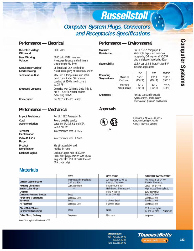
183
United StatesTel: 901.252.8000
800.326.5282Fax: 800.888.0690
www.tnb.com
Computer System
s
Computer System Plugs, Connectors and Receptacles Specifications
Performance — ElectricalDielectric Voltage 3000 voltsWithstandMax. Working 6000 volts RMS minimumVoltage (creepage distance and minimum
clearance per UL 840)
Circuit Interrupting/ UL listed and CSA certified forLoad Breaking circuit interrupting at full rated current
Temperature Rise Max. 30° C temperature rise at fullrated current after 50 cycles of overload at 150% rated current at .75-PF
Shrouded Contacts Complies with California Code Title 8,Art. 51, S2510.7(b) for devicesexceeding 300VAC
Horsepower Per NEC® 430–151 ratings
Performance — MechanicalImpact Resistance Per UL 1682 Paragraph 34
Cord Round portable serviceAccommodation cords per UL Std. 62 and CSA
C22.2 No. 49.1
Terminal In accordance with UL 1682IdentificationCable Pull Out In accordance with UL 1682ForceProduct Identification label andIdentification molded-in name
Lockout/Tagout Lockout/Tagout hole in 30/50ADuraGard® plug complies with OSHAReg. 29 CFR 1910.147 (V0 30A and50A plugs only)
Performance — EnvironmentalMoisture Per UL 1682 Paragraph 49.Resistance Watertight flap screw cover on
receptacle, O-Rings on all V0/5VA pins and sleeves (excludes 60A)
Flammability V0/5A per UL 94 (DuraV® also 5VA in some applications)
OperatingTemperatures
Chemicals Resists standard industrial hydrocarbons, acids, bases and solvents (DuraV® and Metal)
Approvals
Conforms to NEMA 4, 4X and 6(DuraGard and Spec Grade)Contact Technical Services
VO* 5VA METAL*
Maximum 95° C 130° C 130° CContinuous (230° F) (266° F) (266° F)
Minimum -40° C -29° C -40° Cwithout Impact (-40° F) (-20° F) (-40° F)
Materials
®
TüV
FS/FD SPEC GRADE DURAGARD® SAFETY GRADE™
Contact Carrier InteriorThermoset/Thermoplastic) Arc-resistant UL 94-V0 Arc-resistant UL 94-V0(20A and 30A) Phenolic Thermoset Phenolic Thermoset
Housing, Gland Nuts Cast Aluminum Lexan® UL 94-5VA DuraV™ UL 94-V0Screw Collar Rings — High-Impact Thermoplastic High-Impact ThermoplasticO-Rings — Buna-N (Nitrile) Buna-N (Nitrile)Contacts: Pins and Sleeves Brass Brass CDA 360 Brass CDA 360Hinge Pins (Receptacle) Stainless Steel — Stainless SteelTerminals Brass Stainless Steel Stainless SteelAll Hardware Stainless Steel Stainless Steel Stainless Steel
Gland Glide Washer Brass
20 Amp — Nylon(or Internal Cable Grip) 30 and 50 Amp — AluminumNylon
Cable Clamp Bushing Neoprene Neoprene Neoprene
Lexan® is a registered trademark of GE.

184
United StatesTel: 901.252.8000
800.326.5282Fax: 800.888.0690
www.tnb.com
Com
pute
r Sy
stem
s
Connections for Data Center Installation
Custom ProductsInterlocked Branch Distribution CentersUtilize an existing higher amperage service and split it into multiple lowercurrent service outlets. The outlets are individually interlocked with circuitbreaker protection. Branch Distribution Centers are UL and CSA Listed and can be configured for many inlet/outlet combinations.
Standard Dual Configuration• 60A male inlet
• 2–30A individually interlocked female outlets, each circuit breaker protected
• Heavy-duty NEMA 4 welded, gasketed enclosure
Benefits• Saves rewiring costs in a facility when installing
small-sized, lower-current machines using existingelectrical service
• Quickest and most cost-effective way to expand or reconfigure a single service with multiple service outlet combinations possible at every power drop
• Safest way to operate: UL Listed 22kA interrupt capacity interlocked circuit breaker protection for each branch outlet receptacle, in a NEMA 4 enclosure
Applications• Data Processing: CPU/disk arrays/peripherals
new, smaller multiple units
• Industrial/Manufacturing Lines: Reorganization, process reconfiguration
• Portable Power: Machinery, tools, test and diagnostic equipment
Electrical and Safety Features• One: 250VAC, 3P4W, 60 amps, male inlet feeding;
Two: 250VAC, 3P4W, 30 amps, IEC 309-2 (9h Blue) female receptacle outlets, each protected by 22kA IC circuit breaker; each mechanically interlocked
• Power is manually energized only after plug is inserted;externally visible trip indicator handles on each interlock
• Automatic Shut Off when plug is removed before contactsdisengage; ground sleeves “Make First, Break Last”
• Patented “Trip-Free” Safety Mechanism where outlets are not powered unless plug is inserted
• Full NEMA rated UL 489 listed 22kA Circuit Breakers,available to 480V at 30 amps. 60 amp and other options available
Mechanical and Safety Features• All internal wiring is complete: a Drop-In, Plug-In
specified device
• DP Underfloor (Horizontal) installation standard; vertical or other mounting conventions optional
• Electrostatic epoxy powder coat gray finish over 14-gaugesteel, NEMA 4 welded enclosure with gasketed accesscover
• Screw cover protects outlet receptacles (flap cap option)
• Long-life stainless steel and nylon external hardware, copper-free aluminum castings, O-ring seals (to devicespec) and brass electrical contacts
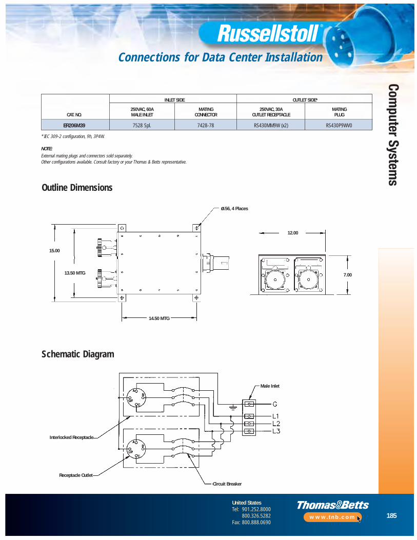
185
United StatesTel: 901.252.8000
800.326.5282Fax: 800.888.0690
www.tnb.com
Computer System
s
Connections for Data Center Installation
INLET SIDE OUTLET SIDE*
250VAC, 60A MATING 250VAC, 30A MATINGCAT. NO. MALE INLET CONNECTOR OUTLET RECEPTACLE PLUG
ER206M39 7528 Spl. 7428-78 RS430MM9W (x2) RS430P9WV0
Outline Dimensions
Schematic Diagram
* IEC 309-2 configuration, 9h, 3P4W.
NOTE: External mating plugs and connectors sold separately.Other configurations available. Consult factory or your Thomas & Betts representative.
Male Inlet
Circuit Breaker
ø.56, 4 Places
12.00
7.00
14.50 MTG
13.50 MTG
15.00
Receptacle Outlet
Interlocked Receptacle
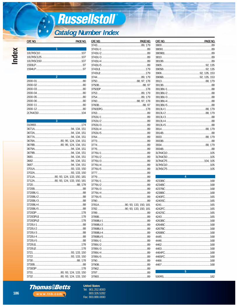
186
United StatesTel: 901.252.8000
800.816.7809Fax: 901.252.1354
Technical ServicesTel: 888.862.3289
www.tnb.com
Index
Catalog Number Index
186
United StatesTel: 901.252.8000
800.326.5282Fax: 800.888.0690
www.tnb.com
Index
Catalog Number IndexCAT. NO. PAGE NO.
10LTK5C10 .......................................................10710LTK5C125 .....................................................10710LTK5C150 .....................................................1071593LP...............................................................971594LP...............................................................97
2000-01 .............................................................802000-02 .............................................................802000-03 .............................................................802000-04 .............................................................802000-05 .............................................................802000-06 .............................................................802000-11 .............................................................802000-12 .............................................................802LTK4C50 .........................................................104
310993.............................................................1743671A.................................................94, 134, 1513672A.................................................94, 134, 1513677A.................................................94, 134, 1513678A...................................80, 95, 124, 134, 1513678B...................................80, 95, 124, 134, 1513679A.................................................94, 134, 1513679B.................................................94, 134, 1513681...................................................94, 134, 1513682...................................................94, 134, 1513687...................................................94, 134, 1513701A.................................................93, 133, 1503702A.................................................93, 133, 1503711A...........................80, 93, 124, 133, 150, 1813712A...........................80, 93, 124, 133, 150, 1813720...........................................................88, 1783720B.................................................................883720BU-1 ...........................................................883720BU-2 ...........................................................883720BU-3 ...........................................................883720BU-4 ...........................................................883720BU-5 ...........................................................883720DP ............................................................1783720DPU1 ........................................................1783720DPU2 ........................................................1783720U-1 .............................................................883720U-2 .............................................................883720U-3 .............................................................883720U-4 .............................................................883720U-5 .............................................................883720U1.............................................................1783720U2.............................................................1783721...................................................93, 133, 1503722...................................................93, 133, 1503730...........................................................88, 1783730B.................................................................883730DP ............................................................1783731 .....................................80, 93, 124, 133, 1503732 .....................................80, 93, 124, 133, 150
CAT. NO. PAGE NO.3743...........................................................89, 1793743U-1 .............................................................893743U-2 .............................................................893743U-3 .............................................................893743U-4 .............................................................893743U-5 .............................................................893743U1.............................................................1793743U2.............................................................1793744...........................................................89, 1793750.....................................................88, 97, 1783750B...........................................................88, 973750DP ............................................................1783753...........................................................89, 1793754...........................................................89, 1793760.....................................................88, 97, 1783760B...........................................................88, 973760DPG ..........................................................1783763...................................................................893763U-1 .............................................................893763U-2 .............................................................893763U-3 .............................................................893763U-4 .............................................................893763U-5 .............................................................893764...................................................................893773...................................................................893774...................................................................893776...................................................................893776U-1 .............................................................893776U-2 .............................................................893776U-3 .............................................................893776U-4 .............................................................893776U-5 .............................................................893777...................................................................893779...................................................................893779U-1 .............................................................893779U-2 .............................................................893779U-3 .............................................................893779U-4 .............................................................893779U-5 .............................................................893780...................................................................893781A...................................80, 93, 133, 150, 1813782 .....................................80, 93, 133, 150, 1813789...................................................................893789B.................................................................893789BU-1 ...........................................................893789BU-2 ...........................................................893789BU-3 ...........................................................893789BU-4 ...........................................................893789BU-5 ...........................................................893789U-1 .............................................................893789U-2 .............................................................893789U-3 .............................................................893789U-4 .............................................................893789U-5 .............................................................893790...................................................................893790B.................................................................8937962.................................................................893797...................................................................8937993.................................................................89
CAT. NO. PAGE NO.3800...................................................................8938091.................................................................893809B1...............................................................893810...................................................................893810B.................................................................893905...........................................................92, 1353905B.........................................................92, 1353906...................................................92, 135, 1533906B.................................................92, 135, 1533913...........................................................88, 1793913B.................................................................883913BU-1 ...........................................................883913BU-2 ...........................................................883913BU-3 ...........................................................883913BU-4 ...........................................................883913BU-5 ...........................................................883913U-1 .....................................................88, 1793913U-2 .....................................................88, 1793913U-3 .............................................................883913U-4 .............................................................883913U-5 .............................................................883914...........................................................88, 1793914B.................................................................883933...........................................................88, 1793933B.................................................................883934...........................................................88, 1793934B.................................................................883LTK4C10 .........................................................1053LTK4C50 .........................................................1053LTK4C75 .................................................104, 1053LTK5C10 .........................................................1053LTK5C75 .........................................................105
4233BC ............................................................1684234BC ............................................................1684237BC ............................................................1684238BC ............................................................1684240FC.............................................................1654240SC.............................................................1654241.................................................................1654242FC.............................................................1654242SC.............................................................1654243.................................................................1654263BC ............................................................1684264BC ............................................................1684267BC ............................................................1684268BC ............................................................1684445.................................................................1684446.................................................................1684462.................................................................1684463.................................................................1684464FC.............................................................1684465FC.............................................................1684466.................................................................1684467.................................................................168
500RS...............................................................182
1
2
3
4
5
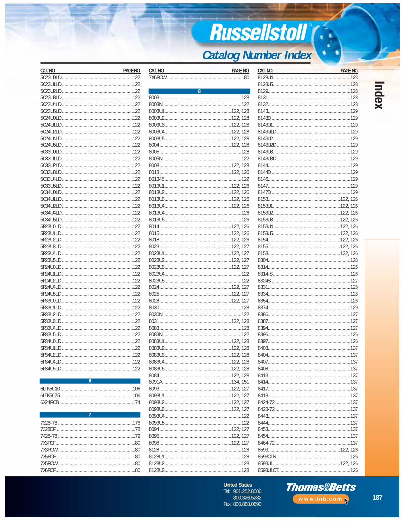
187
United StatesTel: 901.252.8000
800.816.7809Fax: 901.252.1354
Technical ServicesTel: 888.862.3289
www.tnb.com
Index
Catalog Number Index
187
United StatesTel: 901.252.8000
800.326.5282Fax: 800.888.0690
www.tnb.com
Index
Catalog Number IndexCAT. NO. PAGE NO.5C23U0LD ........................................................1225C23U1LD ........................................................1225C23U2LD ........................................................1225C23U3LD ........................................................1225C23U4LD ........................................................1225C23U5LD ........................................................1225C24U0LD ........................................................1225C24U1LD ........................................................1225C24U2LD ........................................................1225C24U4LD ........................................................1225C24U5LD ........................................................1225C33U0LD ........................................................1225C33U1LD ........................................................1225C33U2LD ........................................................1225C33U3LD ........................................................1225C33U4LD ........................................................1225C33U5LD ........................................................1225C34U0LD ........................................................1225C34U1LD ........................................................1225C34U2LD ........................................................1225C34U4LD ........................................................1225C34U5LD ........................................................1225P23U0LD ........................................................1225P23U1LD ........................................................1225P23U2LD ........................................................1225P23U3LD ........................................................1225P23U4LD ........................................................1225P23U5LD ........................................................1225P24U0LD ........................................................1225P24U1LD ........................................................1225P24U2LD ........................................................1225P24U4LD ........................................................1225P24U5LD ........................................................1225P33U0LD ........................................................1225P33U1LD ........................................................1225P33U2LD ........................................................1225P33U3LD ........................................................1225P33U4LD ........................................................1225P33U5LD ........................................................1225P34U0LD ........................................................1225P34U1LD ........................................................1225P34U2LD ........................................................1225P34U4LD ........................................................1225P34U5LD ........................................................122
6LTK5C10 .........................................................1066LTK5C75 .........................................................1066X24RCB ..........................................................174
7328-78 ...........................................................1787328DP ............................................................1787428-78 ...........................................................1797X3RCF...............................................................807X3RCW .............................................................807X5RCF...............................................................807X5RCW .............................................................807X6RCF...............................................................80
CAT. NO. PAGE NO.7X6RCW .............................................................80
8003.................................................................1288003N ..............................................................1228003U1.....................................................122, 1288003U2.....................................................122, 1288003U3.....................................................122, 1288003U4.....................................................122, 1288003U5.....................................................122, 1288004.........................................................122, 1288005.................................................................1288005N ..............................................................1228008.........................................................122, 1288013.........................................................122, 126801345.............................................................1228013U1.....................................................122, 1268013U2.....................................................122, 1268013U3.....................................................122, 1268013U4.....................................................122, 1268013U4.............................................................1268013U5.............................................................1268014.........................................................122, 1268015.........................................................122, 1268018.........................................................122, 1268023.........................................................122, 1278023U1.....................................................122, 1278023U2.....................................................122, 1278023U3.....................................................122, 1278023U4.............................................................1228023U5.............................................................1228024.........................................................122, 1278025.........................................................122, 1278028.........................................................122, 1278030.................................................................1288030N ..............................................................1228031.........................................................122, 1288083.................................................................1288083N ..............................................................1228083U1.....................................................122, 1288083U2.....................................................122, 1288083U3.....................................................122, 1288083U4.....................................................122, 1288083U5.....................................................122, 1288084.........................................................122, 1288091A.......................................................134, 1518093.........................................................122, 1278093U1.....................................................122, 1278093U2.....................................................122, 1278093U3.....................................................122, 1278093U4.............................................................1228093U5.............................................................1228094.........................................................122, 1278095.........................................................122, 1278098.........................................................122, 1278128.................................................................1288128U1.............................................................1288128U2.............................................................1288128U3.............................................................128
CAT. NO. PAGE NO.8128U4.............................................................1288128U5.............................................................1288129.................................................................1288131.................................................................1288132.................................................................1288143.................................................................1298143D ..............................................................1298143U1.............................................................1298143U1D ..........................................................1298143U2.............................................................1298143U2D ..........................................................1298143U3.............................................................1298143U3D ..........................................................1298144.................................................................1298144D ..............................................................1298146.................................................................1298147.................................................................1298147D ..............................................................1298153.........................................................122, 1268153U1.....................................................122, 1268153U2.....................................................122, 1268153U3.....................................................122, 1268153U4.....................................................122, 1268153U5.....................................................122, 1268154.........................................................122, 1268155.........................................................122, 1268158.........................................................122, 1268304.................................................................1288314.................................................................1268314-S .............................................................1268324S...............................................................1278331.................................................................1288334.................................................................1288354.................................................................1268374.................................................................1298386.................................................................1278387.................................................................1278394.................................................................1278396.................................................................1268397.................................................................1268403.................................................................1378404.................................................................1378407.................................................................1378408.................................................................1378413.................................................................1378414.................................................................1378417.................................................................1378418.................................................................1378424-72 ...........................................................1378428-72 ...........................................................1378443.................................................................1378444.................................................................1378453.................................................................1378454.................................................................1378464-72 ...........................................................1378593.........................................................122, 1268593CTN ..........................................................1268593U1.....................................................122, 1268593U1CT.........................................................126
6
7
8
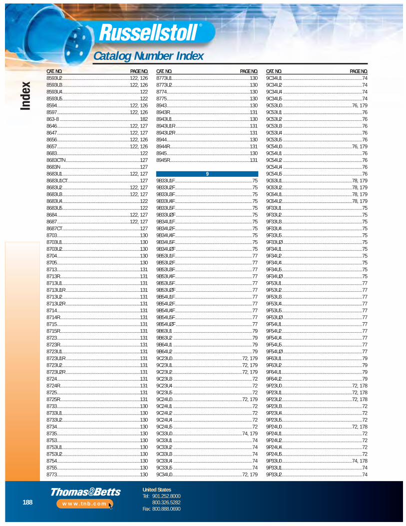
188
United StatesTel: 901.252.8000
800.326.5282Fax: 800.888.0690
www.tnb.com
Index
Catalog Number IndexCAT. NO. PAGE NO.8593U2.....................................................122, 1268593U3.....................................................122, 1268593U4.............................................................1228593U5.............................................................1228594.........................................................122, 1268597.........................................................122, 126863-8 ...............................................................1828646.........................................................122, 1278647.........................................................122, 1278656.........................................................122, 1268657.........................................................122, 1268683.................................................................1228683CTN ..........................................................1278683N ..............................................................1278683U1.....................................................122, 1278683U1CT.........................................................1278683U2.....................................................122, 1278683U3.....................................................122, 1278683U4.............................................................1228683U5.............................................................1228684.........................................................122, 1278687.........................................................122, 1278687CT.............................................................1278703.................................................................1308703U1.............................................................1308703U2.............................................................1308704.................................................................1308705.................................................................1308713.................................................................1318713R...............................................................1318713U1.............................................................1318713U1R ..........................................................1318713U2.............................................................1318713U2R ..........................................................1318714.................................................................1318714R...............................................................1318715.................................................................1318715R...............................................................1318723.................................................................1318723R...............................................................1318723U1.............................................................1318723U1R ..........................................................1318723U2.............................................................1318723U2R ..........................................................1318724.................................................................1318724R...............................................................1318725.................................................................1318725R...............................................................1318733.................................................................1308733U1.............................................................1308733U2.............................................................1308734.................................................................1308735.................................................................1308753.................................................................1308753U1.............................................................1308753U2.............................................................1308754.................................................................1308755.................................................................1308773.................................................................130
CAT. NO. PAGE NO.8773U1.............................................................1308773U2.............................................................1308774.................................................................1308775.................................................................1308943.................................................................1308943R...............................................................1318943U1.............................................................1308943U1R ..........................................................1318943U2R ..........................................................1318944.................................................................1308944R...............................................................1318945.................................................................1308945R...............................................................131
9B33U1F.............................................................759B33U2F.............................................................759B33U3F.............................................................759B33U4F.............................................................759B33U5F.............................................................759B33UØF ............................................................759B34U1F.............................................................759B34U2F.............................................................759B34U4F.............................................................759B34U5F.............................................................759B34UØF ............................................................759B53U1F.............................................................779B53U2F.............................................................779B53U3F.............................................................779B53U4F.............................................................779B53U5F.............................................................779B53UØF ............................................................779B54U1F.............................................................779B54U2F.............................................................779B54U4F.............................................................779B54U5F.............................................................779B54UØF ............................................................779B63U1 ..............................................................799B63U2 ..............................................................799B64U1 ..............................................................799B64U2 ..............................................................799C23U0.......................................................72, 1799C23U1.......................................................72, 1799C23U2.......................................................72, 1799C23U3 ..............................................................729C23U4 ..............................................................729C23U5 ..............................................................729C24U0.......................................................72, 1799C24U1 ..............................................................729C24U2 ..............................................................729C24U4 ..............................................................729C24U5 ..............................................................729C33U0.......................................................74, 1799C33U1 ..............................................................749C33U2 ..............................................................749C33U3 ..............................................................749C33U4 ..............................................................749C33U5 ..............................................................749C34U0.......................................................72, 179
CAT. NO. PAGE NO.9C34U1 ..............................................................749C34U2 ..............................................................749C34U4 ..............................................................749C34U5 ..............................................................749C53U0.......................................................76, 1799C53U1 ..............................................................769C53U2 ..............................................................769C53U3 ..............................................................769C53U4 ..............................................................769C53U5 ..............................................................769C54U0.......................................................76, 1799C54U1 ..............................................................769C54U2 ..............................................................769C54U4 ..............................................................769C54U5 ..............................................................769C63U1.......................................................78, 1799C63U2.......................................................78, 1799C64U1.......................................................78, 1799C64U2.......................................................78, 1799F33U1...............................................................759F33U2...............................................................759F33U3...............................................................759F33U4...............................................................759F33U5...............................................................759F33UØ ..............................................................759F34U1...............................................................759F34U2...............................................................759F34U4...............................................................759F34U5...............................................................759F34UØ ..............................................................759F53U1...............................................................779F53U2...............................................................779F53U3...............................................................779F53U4...............................................................779F53U5...............................................................779F53UØ ..............................................................779F54U1...............................................................779F54U2...............................................................779F54U4...............................................................779F54U5...............................................................779F54UØ ..............................................................779F63U1...............................................................799F63U2...............................................................799F64U1...............................................................799F64U2...............................................................799P23U0.......................................................72, 1789P23U1.......................................................72, 1789P23U2.......................................................72, 1789P23U3...............................................................729P23U4...............................................................729P23U5...............................................................729P24U0.......................................................72, 1789P24U1...............................................................729P24U2...............................................................729P24U4...............................................................729P24U5...............................................................729P33U0.......................................................74, 1789P33U1...............................................................749P33U2...............................................................74
9

189
United StatesTel: 901.252.8000
800.326.5282Fax: 800.888.0690
www.tnb.com
Index
Catalog Number IndexCAT. NO. PAGE NO.9P33U3...............................................................749P33U4...............................................................749P33U5...............................................................749P33UØ ..............................................................979P34U0.......................................................74, 1789P34U1...............................................................749P34U2...............................................................749P34U4...............................................................749P34U5...............................................................749P34UØ ..............................................................979P53U0.......................................................76, 1789P53U1...............................................................769P53U2...............................................................769P53U3...............................................................769P53U4...............................................................769P53U5...............................................................769P54U0.......................................................76, 1789P54U1...............................................................769P54U2...............................................................769P54U4...............................................................769P54U5...............................................................769P63U1.......................................................78, 1789P63U2.......................................................78, 1789P64U1.......................................................78, 1789P64U2.......................................................78, 1789R23U0W ...................................................73, 1799R23U1W ...................................................73, 1799R23U2W ...................................................73, 1799R23U3W ...........................................................739R23U4W ...........................................................739R23U5W ...........................................................739R24U0W ...................................................73, 1799R24U1W ...........................................................739R24U2W ...........................................................739R24U4W ...........................................................739R24U5W ...........................................................739R33U0W ...................................................75, 1799R33U1W ...........................................................759R33U2W ...........................................................759R33U3W ...........................................................759R33U4W ...........................................................759R33U5W ...........................................................759R34U0W ...................................................75, 1799R34U1W ...........................................................759R34U2W ...........................................................759R34U4W ...........................................................759R34U5W ...........................................................759R53U0W ...................................................77, 1799R53U1W ...........................................................779R53U2W ...........................................................779R53U3W ...........................................................779R53U4W ...........................................................779R53U5W ...........................................................779R54U0W ...................................................77, 1799R54U1W ...........................................................779R54U2W ...........................................................779R54U4W ...........................................................779R54U5W ...........................................................779R63U1.......................................................79, 179
CAT. NO. PAGE NO.9R63U2.......................................................79, 1799R64U1.......................................................79, 1799R64U2.......................................................79, 1799X2C50.......................................................80, 1819X2C75.......................................................80, 1819X2PSC...............................................................809X3C10...............................................................809X3C50.......................................................80, 1819X3C75.......................................................80, 1819X3PSC...............................................................809X5C10.......................................................80, 1819X5C75.......................................................80, 1819X5PSC...............................................................809X6C10...............................................................809X6C75...............................................................809X6PSC...............................................................809XF23U0.....................................................81, 1829XF23U1.....................................................81, 1829XF23U2.....................................................81, 1829XF23U3.............................................................819XF23U4.............................................................819XF23U5.............................................................819XF24U0.....................................................81, 1829XF24U1.............................................................819XF24U2.............................................................819XF24U4.............................................................819XF24U5.............................................................819XF33U0.....................................................81, 1829XF33U1.............................................................819XF33U2.............................................................819XF33U3.............................................................819XF33U4.............................................................819XF33U5.............................................................819XF34U0.....................................................81, 1829XF34U1.............................................................819XF34U2.............................................................819XF34U4.............................................................819XF34U5.............................................................819XF53U0.....................................................81, 1829XF53U1.............................................................819XF53U2.............................................................819XF53U4.............................................................819XF53U5.............................................................819XF54U0.....................................................81, 1829XF54U1.............................................................819XF54U2.............................................................819XF54U4.............................................................819XF54U5.............................................................819XF63U1.............................................................819XF63U2.............................................................819XF64U1.............................................................819XF64U2.............................................................819XM23U0....................................................81, 1829XM23U1....................................................81, 1829XM23U2....................................................81, 1829XM23U3............................................................819XM23U4............................................................819XM23U5............................................................819XM24U0....................................................81, 182
CAT. NO. PAGE NO.9XM24U1............................................................819XM24U2............................................................819XM24U4............................................................819XM24U5............................................................819XM33U0....................................................81, 1829XM33U1............................................................819XM33U2............................................................819XM33U3............................................................819XM33U4............................................................819XM33U5............................................................819XM34U0....................................................81, 1829XM34U1............................................................819XM34U2............................................................819XM34U4............................................................819XM34U5............................................................819XM53U0....................................................81, 1829XM53U1............................................................819XM53U2............................................................819XM53U4............................................................819XM53U5............................................................819XM54U0....................................................81, 1829XM54U1............................................................819XM54U2............................................................819XM54U4............................................................819XM54U5............................................................819XM63U1............................................................819XM63U2............................................................819XM64U1............................................................819XM64U2............................................................81
AA10L...............................................................111AA3...................................................................111AA6L.................................................................111AE10-B150 .......................................................111AE10-B200 .......................................................111AE6-B125 .........................................................111AE6-B150 .........................................................111APU134-6 .........................................................141APU323.............................................................141APU334.............................................................141APU623.............................................................141APU634.............................................................141ARU134-6.........................................................141ARU323 ............................................................141ARU334 ............................................................141ARU623 ............................................................141ARU634 ............................................................141
B16506...............................................................80B16524...............................................................80B17018APR ......................................................182B17018AR ........................................................182B17018BPR ......................................................182B17018BR ........................................................182B17018CPR ......................................................182B17018CR ........................................................182B17019APR ......................................................182
A
B
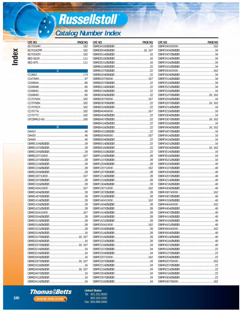
190
United StatesTel: 901.252.8000
800.326.5282Fax: 800.888.0690
www.tnb.com
Index
Catalog Number IndexCAT. NO. PAGE NO.B17019AR ........................................................182B17019CPR ......................................................182B17019CR ........................................................182BE3-B100 .........................................................111BE3-B75 ...........................................................111
C13662.............................................................174C1479AH ............................................................97C16984A.............................................................80C16984B ............................................................80C16984C ............................................................80C16984D ............................................................80C17076AX.........................................................182C17076BX ........................................................182C17076CX ........................................................182C17077A...........................................................182C17077C ..........................................................182CFCSRA13-60...................................................160
DAA10 ................................................................46DAA20 ................................................................46DAA40 ................................................................46DBRE1104Ø3ØØØ...............................................28DBRE1107Ø3ØØØ...............................................28DBRE1204Ø3ØØØ...............................................28DBRE120710000 ..............................................167DBRE1207Ø3ØØØ...............................................28DBRE1214Ø3ØØØ...............................................28DBRE1216Ø3ØØØ...............................................28DBRE1304Ø3ØØØ...............................................28DBRE130710000 ..............................................167DBRE1307Ø3ØØØ...............................................28DBRE1316Ø3ØØØ...............................................28DBRE140410000 ..............................................167DBRE1404Ø3ØØØ...............................................28DBRE1407Ø3ØØØ...............................................28DBRE1414Ø3ØØØ...............................................28DBRE1416Ø3ØØØ...............................................28DBRE1421Ø3ØØØ...............................................28DBRE150410000 ..............................................167DBRE1504Ø3ØØØ...............................................28DBRE1514Ø3ØØØ...............................................28DBRE1516Ø3ØØØ...............................................28DBRE1521Ø3ØØØ...............................................28DBRE3104Ø3ØØØ...............................................16DBRE3107Ø3ØØØ.......................................16, 167DBRE3204Ø3ØØØ...............................................16DBRE3207Ø3ØØØ.......................................16, 167DBRE3214Ø3ØØØ...............................................16DBRE3216Ø3ØØØ...............................................16DBRE3304Ø3ØØØ...............................................16DBRE3307Ø3ØØØ.......................................16, 167DBRE3316Ø3ØØØ...............................................16DBRE3404Ø3ØØØ.......................................16, 167DBRE3407Ø3ØØØ...............................................16DBRE3412Ø3ØØØ...............................................16DBRE3414Ø3ØØØ...............................................16
CAT. NO. PAGE NO.DBRE3416Ø3ØØØ...............................................16DBRE3504Ø3ØØØ.......................................16, 167DBRE3514Ø3ØØØ...............................................16DBRE3516Ø3ØØØ...............................................16DBRE3521Ø3ØØØ...............................................16DBRE6104Ø3ØØØ...............................................22DBRE6107Ø3ØØØ...............................................22DBRE6204Ø3ØØØ...............................................22DBRE620706000 ..............................................167DBRE6207Ø3ØØØ...............................................22DBRE6214Ø3ØØØ...............................................22DBRE6216Ø3ØØØ...............................................22DBRE6304Ø3ØØØ...............................................22DBRE630706000 ..............................................167DBRE6307Ø3ØØØ...............................................22DBRE6316Ø3ØØØ...............................................22DBRE640406000 ..............................................167DBRE6404Ø3ØØØ...............................................22DBRE6407Ø3ØØØ...............................................22DBRE6414Ø3ØØØ...............................................22DBRE6416Ø3ØØØ...............................................22DBRE6421Ø3ØØØ...............................................22DBRE650406000 ..............................................167DBRE6504Ø3ØØØ...............................................22DBRE6514Ø3ØØØ...............................................22DBRE6516Ø3ØØØ...............................................22DBRE6521Ø3ØØØ...............................................22DBRF1104Ø3ØØØ ...............................................28DBRF1107Ø3ØØØ ...............................................28DBRF1204Ø3ØØØ ...............................................28DBRF120710000 ..............................................162DBRF1207Ø3ØØØ ...............................................28DBRF1214Ø3ØØØ ...............................................28DBRF1216Ø3ØØØ ...............................................28DBRF1304Ø3ØØØ ...............................................28DBRF130710000 ..............................................162DBRF1307Ø3ØØØ ...............................................28DBRF1316Ø3ØØØ ...............................................28DBRF140410000 ..............................................162DBRF1404Ø3ØØØ ...............................................28DBRF1407Ø3ØØØ ...............................................28DBRF1414Ø3ØØØ ...............................................28DBRF1416Ø3ØØØ ...............................................28DBRF1421Ø3ØØØ ...............................................28DBRF150410000 ..............................................162DBRF1504Ø3ØØØ ...............................................28DBRF1514Ø3ØØØ ...............................................28DBRF1516Ø3ØØØ ...............................................28DBRF1521Ø3ØØØ ...............................................28DBRF2104Ø3ØØØ ...............................................34DBRF2107Ø3ØØØ ...............................................34DBRF2204Ø3ØØØ ...............................................34DBRF220720000 ..............................................162DBRF2207Ø3ØØØ ...............................................34DBRF2214Ø3ØØØ ...............................................34DBRF2216Ø3ØØØ ...............................................34DBRF2304Ø3ØØØ ...............................................34DBRF2307Ø3ØØØ ...............................................34DBRF2316Ø3ØØØ ...............................................34
CAT. NO. PAGE NO.DBRF240420000 ..............................................162DBRF2404Ø3ØØØ ...............................................34DBRF2407Ø3ØØØ ...............................................34DBRF2414Ø3ØØØ ...............................................34DBRF2416Ø3ØØØ ...............................................34DBRF2421Ø3ØØØ ...............................................34DBRF250420000 ..............................................162DBRF2504Ø3ØØØ ...............................................34DBRF2514Ø3ØØØ ...............................................34DBRF2516Ø3ØØØ ...............................................34DBRF2521Ø3ØØØ ...............................................34DBRF3104Ø3ØØØ ...............................................16DBRF3107Ø3ØØØ .......................................16, 162DBRF3204Ø3ØØØ ...............................................16DBRF3207Ø3ØØØ .......................................16, 162DBRF3214Ø3ØØØ ...............................................16DBRF3216Ø3ØØØ ...............................................16DBRF3304Ø3ØØØ ...............................................16DBRF3307Ø3ØØØ .......................................16, 162DBRF3316Ø3ØØØ ...............................................16DBRF3404Ø3ØØØ .......................................16, 162DBRF3407Ø3ØØØ ...............................................16DBRF3414Ø3ØØØ ...............................................16DBRF3416Ø3ØØØ ...............................................16DBRF3421Ø3ØØØ ...............................................16DBRF3504Ø3ØØØ .......................................16, 162DBRF3514Ø3ØØØ ...............................................16DBRF3516Ø3ØØØ ...............................................16DBRF3521Ø3ØØØ ...............................................16DBRF4104Ø3ØØØ ...............................................40DBRF4107Ø3ØØØ ...............................................40DBRF4204Ø3ØØØ ...............................................40DBRF4207Ø3ØØØ ...............................................40DBRF4214Ø3ØØØ ...............................................40DBRF4216Ø3ØØØ ...............................................40DBRF4304Ø3ØØØ ...............................................40DBRF430740000 ..............................................162DBRF4307Ø3ØØØ ...............................................40DBRF4316Ø3ØØØ ...............................................40DBRF440440000 ..............................................162DBRF4404Ø3ØØØ ...............................................40DBRF4407Ø3ØØØ ...............................................40DBRF4414Ø3ØØØ ...............................................40DBRF4416Ø3ØØØ ...............................................40DBRF4421Ø3ØØØ ...............................................40DBRF450440000 ..............................................162DBRF4504Ø3ØØØ ...............................................40DBRF4514Ø3ØØØ ...............................................40DBRF4516Ø3ØØØ ...............................................40DBRF4521Ø3ØØØ ...............................................40DBRF6104Ø3ØØØ ...............................................22DBRF6107Ø3ØØØ ...............................................22DBRF6204Ø3ØØØ ...............................................22DBRF620706000 ..............................................162DBRF6207Ø3ØØØ ...............................................22DBRF6214Ø3ØØØ ...............................................22DBRF6216Ø3ØØØ ...............................................22DBRF6304Ø3ØØØ ...............................................22DBRF630706000 ..............................................162
D
C
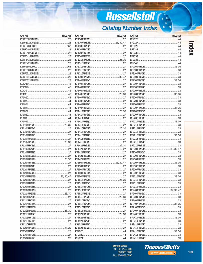
191
United StatesTel: 901.252.8000
800.326.5282Fax: 800.888.0690
www.tnb.com
Index
Catalog Number IndexCAT. NO. PAGE NO.DBRF6307Ø3ØØØ ...............................................22DBRF6316Ø3ØØØ ...............................................22DBRF640406000 ..............................................162DBRF6404Ø3ØØØ ...............................................22DBRF6407Ø3ØØØ ...............................................22DBRF6414Ø3ØØØ ...............................................22DBRF6416Ø3ØØØ ...............................................22DBRF6421Ø3ØØØ ...............................................22DBRF650406000 ..............................................162DBRF6504Ø3ØØØ ...............................................22DBRF6514Ø3ØØØ ...............................................22DBRF6516Ø3ØØØ ...............................................22DBRF6521Ø3ØØØ ...............................................22DCCA10 ..............................................................46DCCA20 ..............................................................46DCCA3 ................................................................46DCCA6 ................................................................46DF1020...............................................................44DF1022...............................................................44DF1024...............................................................44DF1026...............................................................44DF1027...............................................................44DF1029...............................................................44DF1030...............................................................44DF1032...............................................................44DF1104FPØØØ..............................................26, 30DF1104FRABØ ....................................................27DF1104FRAØØ....................................................27DF1104FRØEØ ....................................................27DF1104FRØØØ....................................................27DF1107FPØØØ..............................................26, 30DF1107FRABØ ....................................................27DF1107FRAØØ....................................................27DF1107FRØEØ ....................................................27DF1107FRØØØ....................................................27DF1204FPØØØ..............................................26, 30DF1204FRABØ ....................................................27DF1204FRAØØ....................................................27DF1204FRØEØ ....................................................27DF1204FRØØØ....................................................27DF1207FPØØØ........................................26, 30, 47DF1207FRABØ ....................................................27DF1207FRAØØ....................................................27DF1207FRØEØ ....................................................27DF1207FRØØØ....................................................27DF1214FPØØØ..............................................26, 30DF1214FRABØ ....................................................27DF1214FRAØØ....................................................27DF1214FRØEØ ....................................................27DF1214FRØØØ....................................................27DF1216FPØØØ..............................................26, 30DF1216FRABØ ....................................................27DF1216FRAØØ....................................................27DF1216FRØEØ ....................................................27DF1216FRØØØ....................................................27DF1304FPØØØ..............................................26, 30DF1304FRABØ ....................................................27DF1304FRAØØ....................................................27DF1304FRØEØ ....................................................27
CAT. NO. PAGE NO.DF1304FRØØØ....................................................27DF1307FPØØØ........................................26, 30, 47DF1307FRABØ ....................................................27DF1307FRAØØ....................................................27DF1307FRØEØ ....................................................27DF1307FRØØØ....................................................27DF1316FPØØØ..............................................26, 30DF1316FRABØ ....................................................27DF1316FRAØØ....................................................27DF1316FRØEØ ....................................................27DF1316FRØØØ....................................................27DF1404FPØØØ........................................26, 30, 47DF1404FRABØ ....................................................27DF1404FRAØØ....................................................27DF1404FRØEØ ....................................................27DF1404FRØØØ....................................................27DF1407FPØØØ..............................................26, 30DF1407FRABØ ....................................................27DF1407FRAØØ....................................................27DF1407FRØEØ ....................................................27DF1407FRØØØ....................................................27DF1414FPØØØ..............................................26, 30DF1414FRABØ ....................................................27DF1414FRAØØ....................................................27DF1414FRØEØ ....................................................27DF1414FRØØØ....................................................27DF1416FPØØØ..............................................26, 30DF1416FRABØ ....................................................27DF1416FRAØØ....................................................27DF1416FRØEØ ....................................................27DF1416FRØØØ....................................................27DF1421FPØØØ..............................................26, 30DF1421FRABØ ....................................................27DF1421FRAØØ....................................................27DF1421FRØEØ ....................................................27DF1421FRØØØ....................................................27DF1504FPØØØ........................................26, 30, 47DF1504FRABØ ....................................................27DF1504FRAØØ....................................................27DF1504FRØEØ ....................................................27DF1504FRØØØ....................................................27DF1514FPØØØ..............................................26, 30DF1514FRABØ ....................................................27DF1514FRAØØ....................................................27DF1514FRØEØ ....................................................27DF1514FRØØØ....................................................27DF1516FPØØØ..............................................26, 30DF1516FRABØ ....................................................27DF1516FRAØØ....................................................27DF1516FRØEØ ....................................................27DF1516FRØØØ....................................................27DF1521FPØØØ..............................................26, 30DF1521FRABØ ....................................................27DF1521FRAØØ....................................................27DF1521FRØEØ ....................................................27DF1521FRØØØ....................................................27DF2020...............................................................44DF2022...............................................................44DF2024...............................................................44
CAT. NO. PAGE NO.DF2026...............................................................44DF2027...............................................................44DF2029...............................................................44DF2032...............................................................44DF2033...............................................................44DF2034...............................................................44DF2036...............................................................44DF2040...............................................................44DF2104FPØØØ..............................................32, 36DF2104FRABØ ....................................................33DF2104FRAØØ....................................................33DF2104FRØØØ....................................................33DF2107FPØØØ..............................................32, 36DF2107FRABØ ....................................................33DF2107FRAØØ....................................................33DF2107FRØØØ....................................................33DF2204FPØØØ..............................................32, 36DF2204FRABØ ....................................................33DF2204FRAØØ....................................................33DF2204FRØØØ....................................................33DF2207FPØØØ..............................................32, 36DF2207FRABØ ....................................................33DF2207FRAØØ....................................................33DF2207FRØØØ....................................................33DF2214FPØØØ..............................................32, 36DF2214FRABØ ....................................................33DF2214FRAØØ....................................................33DF2214FRØØØ....................................................33DF2216FPØØØ..............................................32, 36DF2216FRABØ ....................................................33DF2216FRAØØ....................................................33DF2216FRØØØ....................................................33DF2304FPØØØ........................................32, 36, 47DF2304FRABØ ....................................................33DF2304FRAØØ....................................................33DF2304FRØØØ....................................................33DF2307FPØØØ..............................................32, 36DF2307FRABØ ....................................................33DF2307FRAØØ....................................................33DF2307FRØØØ....................................................33DF2316FPØØØ..............................................32, 36DF2316FRABØ ....................................................33DF2316FRAØØ....................................................33DF2316FRØØØ....................................................33DF2404FPØØØ........................................32, 36, 47DF2404FRABØ ....................................................33DF2404FRAØØ....................................................33DF2404FRØØØ....................................................33DF2407FPØØØ..............................................32, 36DF2407FRABØ ....................................................33DF2407FRAØØ....................................................33DF2407FRØØØ....................................................33DF2414FPØØØ..............................................32, 36DF2414FRABØ ....................................................33DF2414FRAØØ....................................................33DF2414FRØØØ....................................................33DF2416FPØØØ..............................................32, 36DF2416FRABØ ....................................................33DF2416FRAØØ....................................................33
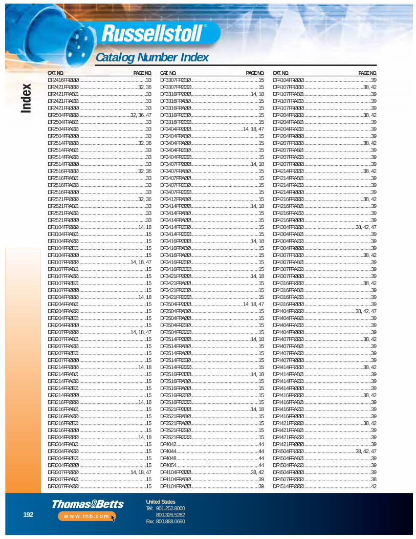
192
United StatesTel: 901.252.8000
800.326.5282Fax: 800.888.0690
www.tnb.com
Index
Catalog Number IndexCAT. NO. PAGE NO.DF2416FRØØØ....................................................33DF2421FPØØØ..............................................32, 36DF2421FRABØ ....................................................33DF2421FRAØØ....................................................33DF2421FRØØØ....................................................33DF2504FPØØØ........................................32, 36, 47DF2504FRABØ ....................................................33DF2504FRAØØ....................................................33DF2504FRØØØ....................................................33DF2514FPØØØ..............................................32, 36DF2514FRABØ ....................................................33DF2514FRAØØ....................................................33DF2514FRØØØ....................................................33DF2516FPØØØ..............................................32, 36DF2516FRABØ ....................................................33DF2516FRAØØ....................................................33DF2516FRØØØ....................................................33DF2521FPØØØ..............................................32, 36DF2521FRABØ ....................................................33DF2521FRAØØ....................................................33DF2521FRØØØ....................................................33DF3104FPØØØ..............................................14, 18DF3104FRABØ ....................................................15DF3104FRAØØ....................................................15DF3104FRØEØ ....................................................15DF3104FRØØØ....................................................15DF3107FPØØØ........................................14, 18, 47DF3107FRABØ ....................................................15DF3107FRAØØ....................................................15DF3107FRØEØ ....................................................15DF3107FRØØØ....................................................15DF3204FPØØØ..............................................14, 18DF3204FRABØ ....................................................15DF3204FRAØØ....................................................15DF3204FRØEØ ....................................................15DF3204FRØØØ....................................................15DF3207FPØØØ........................................14, 18, 47DF3207FRABØ ....................................................15DF3207FRAØØ....................................................15DF3207FRØEØ ....................................................15DF3207FRØØØ....................................................15DF3214FPØØØ..............................................14, 18DF3214FRABØ ....................................................15DF3214FRAØØ....................................................15DF3214FRØEØ ....................................................15DF3214FRØØØ....................................................15DF3216FPØØØ..............................................14, 18DF3216FRABØ ....................................................15DF3216FRAØØ....................................................15DF3216FRØEØ ....................................................15DF3216FRØØØ....................................................15DF3304FPØØØ..............................................14, 18DF3304FRABØ ....................................................15DF3304FRAØØ....................................................15DF3304FRØEØ ....................................................15DF3304FRØØØ....................................................15DF3307FPØØØ........................................14, 18, 47DF3307FRABØ ....................................................15DF3307FRAØØ....................................................15
CAT. NO. PAGE NO.DF3307FRØEØ ....................................................15DF3307FRØØØ....................................................15DF3316FPØØØ..............................................14, 18DF3316FRABØ ....................................................15DF3316FRAØØ....................................................15DF3316FRØEØ ....................................................15DF3316FRØØØ....................................................15DF3404FPØØØ........................................14, 18, 47DF3404FRABØ ....................................................15DF3404FRAØØ....................................................15DF3404FRØEØ ....................................................15DF3404FRØØØ....................................................15DF3407FPØØØ..............................................14, 18DF3407FRABØ ....................................................15DF3407FRAØØ....................................................15DF3407FRØEØ ....................................................15DF3407FRØØØ....................................................15DF3412FRABØ ....................................................15DF3414FPØØØ..............................................14, 18DF3414FRABØ ....................................................15DF3414FRAØØ....................................................15DF3414FRØEØ ....................................................15DF3414FRØØØ....................................................15DF3416FPØØØ..............................................14, 18DF3416FRABØ ....................................................15DF3416FRAØØ....................................................15DF3416FRØEØ ....................................................15DF3416FRØØØ....................................................15DF3421FPØØØ..............................................14, 18DF3421FRAØØ....................................................15DF3421FRØEØ ....................................................15DF3421FRØØØ....................................................15DF3504FPØØØ........................................14, 18, 47DF3504FRABØ ....................................................15DF3504FRAØØ....................................................15DF3504FRØEØ ....................................................15DF3504FRØØØ....................................................15DF3514FPØØØ..............................................14, 18DF3514FRABØ ....................................................15DF3514FRAØØ....................................................15DF3514FRØEØ ....................................................15DF3514FRØØØ....................................................15DF3516FPØØØ..............................................14, 18DF3516FRABØ ....................................................15DF3516FRAØØ....................................................15DF3516FRØEØ ....................................................15DF3516FRØØØ....................................................15DF3521FPØØØ..............................................14, 18DF3521FRABØ ....................................................15DF3521FRAØØ....................................................15DF3521FRØEØ ....................................................15DF3521FRØØØ....................................................15DF4042...............................................................44DF4044...............................................................44DF4048...............................................................44DF4054...............................................................44DF4104FPØØØ..............................................38, 42DF4104FRABØ ....................................................39DF4104FRAØØ....................................................39
CAT. NO. PAGE NO.DF4104FRØØØ....................................................39DF4107FPØØØ..............................................38, 42DF4107FRABØ ....................................................39DF4107FRAØØ....................................................39DF4107FRØØØ....................................................39DF4204FPØØØ..............................................38, 42DF4204FRABØ ....................................................39DF4204FRAØØ....................................................39DF4204FRØØØ....................................................39DF4207FPØØØ..............................................38, 42DF4207FRABØ ....................................................39DF4207FRAØØ....................................................39DF4207FRØØØ....................................................39DF4214FPØØØ..............................................38, 42DF4214FRABØ ....................................................39DF4214FRAØØ....................................................39DF4214FRØØØ....................................................39DF4216FPØØØ..............................................38, 42DF4216FRABØ ....................................................39DF4216FRAØØ....................................................39DF4216FRØØØ....................................................39DF4304FPØØØ........................................38, 42, 47DF4304FRABØ ....................................................39DF4304FRAØØ....................................................39DF4304FRØØØ....................................................39DF4307FPØØØ..............................................38, 42DF4307FRABØ ....................................................39DF4307FRAØØ....................................................39DF4307FRØØØ....................................................39DF4316FPØØØ..............................................38, 42DF4316FRABØ ....................................................39DF4316FRAØØ....................................................39DF4316FRØØØ....................................................39DF4404FPØØØ........................................38, 42, 47DF4404FRABØ ....................................................39DF4404FRAØØ....................................................39DF4404FRØØØ....................................................39DF4407FPØØØ..............................................38, 42DF4407FRABØ ....................................................39DF4407FRAØØ....................................................39DF4407FRØØØ....................................................39DF4414FPØØØ..............................................38, 42DF4414FRABØ ....................................................39DF4414FRAØØ....................................................39DF4414FRØØØ....................................................39DF4416FPØØØ..............................................38, 42DF4416FRABØ ....................................................39DF4416FRAØØ....................................................39DF4416FRØØØ....................................................39DF4421FPØØØ..............................................38, 42DF4421FRABØ ....................................................39DF4421FRAØØ....................................................39DF4421FRØØØ....................................................39DF4504FPØØØ........................................38, 42, 47DF4504FRABØ ....................................................39DF4504FRAØØ....................................................39DF4504FRØØØ....................................................39DF4507FPØØØ....................................................38DF4514FPØØØ....................................................42

193
United StatesTel: 901.252.8000
800.326.5282Fax: 800.888.0690
www.tnb.com
Index
Catalog Number IndexCAT. NO. PAGE NO.DF4514FRABØ ....................................................39DF4514FRAØØ....................................................39DF4514FRØØØ....................................................39DF4516FPØØØ..............................................38, 42DF4516FRABØ ....................................................39DF4516FRAØØ....................................................39DF4516FRØØØ....................................................39DF4521FPØØØ..............................................38, 42DF4521FRABØ ....................................................39DF4521FRAØØ....................................................39DF4521FRØØØ....................................................39DF6104FPØØØ..............................................20, 24DF6104FRABØ ....................................................21DF6104FRAØØ....................................................21DF6104FRØEØ ....................................................21DF6104FRØØØ....................................................21DF6107FPØØØ..............................................20, 24DF6107FRABØ ....................................................21DF6107FRAØØ....................................................21DF6107FRØEØ ....................................................21DF6107FRØØØ....................................................21DF6204FPØØØ..............................................20, 24DF6204FRABØ ....................................................21DF6204FRAØØ....................................................21DF6204FRØEØ ....................................................21DF6204FRØØØ....................................................21DF6207FPØØØ........................................20, 24, 47DF6207FRABØ ....................................................21DF6207FRAØØ....................................................21DF6207FRØEØ ....................................................21DF6207FRØØØ....................................................21DF6214FPØØØ..............................................20, 24DF6214FRABØ ....................................................21DF6214FRAØØ....................................................21DF6214FRØEØ ....................................................21DF6214FRØØØ....................................................21DF6216FPØØØ..............................................20, 24DF6216FRABØ ....................................................21DF6216FRAØØ....................................................21DF6216FRØEØ ....................................................21DF6216FRØØØ....................................................21DF6304FPØØØ..............................................20, 24DF6304FRABØ ....................................................21DF6304FRAØØ....................................................21DF6304FRØEØ ....................................................21DF6304FRØØØ....................................................21DF6307FPØØØ........................................20, 24, 47DF6307FRABØ ....................................................21DF6307FRAØØ....................................................21DF6307FRØEØ ....................................................21DF6307FRØØØ....................................................21DF6316FPØØØ..............................................20, 24DF6316FRABØ ....................................................21DF6316FRAØØ....................................................21DF6316FRØEØ ....................................................21DF6316FRØØØ....................................................21DF6404FPØØØ........................................20, 24, 47DF6404FRABØ ....................................................21DF6404FRAØØ....................................................21
CAT. NO. PAGE NO.DF6404FRØEØ ....................................................21DF6404FRØØØ....................................................21DF6407FPØØØ..............................................20, 24DF6407FRABØ ....................................................21DF6407FRAØØ....................................................21DF6407FRØEØ ....................................................21DF6407FRØØØ....................................................21DF6412FRABØ ....................................................21DF6414FPØØØ..............................................20, 24DF6414FRABØ ....................................................21DF6414FRAØØ....................................................21DF6414FRØEØ ....................................................21DF6414FRØØØ....................................................21DF6416FPØØØ..............................................20, 24DF6416FRABØ ....................................................21DF6416FRAØØ....................................................21DF6416FRØEØ ....................................................21DF6416FRØØØ....................................................21DF6421FPØØØ..............................................20, 24DF6421FRAØØ....................................................21DF6421FRØEØ ....................................................21DF6421FRØØØ....................................................21DF6504FPØØØ........................................20, 24, 47DF6504FRABØ ....................................................21DF6504FRAØØ....................................................21DF6504FRØEØ ....................................................21DF6504FRØØØ....................................................21DF6514FPØØØ..............................................20, 24DF6514FRABØ ....................................................21DF6514FRAØØ....................................................21DF6514FRØEØ ....................................................21DF6514FRØØØ....................................................21DF6516FPØØØ..............................................20, 24DF6516FRABØ ....................................................21DF6516FRAØØ....................................................21DF6516FRØEØ ....................................................21DF6516FRØØØ....................................................21DF6521FPØØØ..............................................20, 24DF6521FRABØ ....................................................21DF6521FRAØØ....................................................21DF6521FRØEØ ....................................................21DF6521FRØØØ....................................................21DFA14.................................................................45DFA15.................................................................45DFA16.................................................................45DFA25.................................................................45DFA26.................................................................45DFA27.................................................................45DFA46.................................................................45DFA47.................................................................45DFA48.................................................................45DFC10 ................................................................45DFC20 ................................................................45DFC3 ..................................................................45DFC40 ................................................................45DFC6 ..................................................................45DFPU1207 ..........................................................47DFPU1307 ..........................................................47DFPU1404 ..........................................................47
CAT. NO. PAGE NO.DFPU1504 ..........................................................47DFPU2304 ..........................................................47DFPU2404 ..........................................................47DFPU2504 ..........................................................47DFPU3107 ..........................................................47DFPU3207 ..........................................................47DFPU3307 ..........................................................47DFPU3404 ..........................................................47DFPU3504 ..........................................................47DFPU4304 ..........................................................47DFPU4404 ..........................................................47DFPU4504 ..........................................................47DFPU6207 ..........................................................47DFPU6307 ..........................................................47DFPU6404 ..........................................................47DFPU6504 ..........................................................47DFRF1104...........................................................29DFRF1107...........................................................29DFRF1204...........................................................29DFRF1207...........................................................29DFRF12070.......................................................156DFRF1214...........................................................29DFRF1216...........................................................29DFRF1304...........................................................29DFRF1307...........................................................29DFRF13070.......................................................156DFRF1316...........................................................29DFRF1404...........................................................29DFRF14040.......................................................156DFRF1407...........................................................29DFRF1414...........................................................29DFRF1416...........................................................29DFRF1421...........................................................29DFRF1504...........................................................29DFRF15040.......................................................156DFRF1514...........................................................29DFRF1516...........................................................29DFRF1521...........................................................29DFRF3104Ø ........................................................17DFRF3107Ø ................................................17, 156DFRF3204Ø ........................................................17DFRF3207Ø ................................................17, 156DFRF3214Ø ........................................................17DFRF3216Ø ........................................................17DFRF3304Ø ........................................................17DFRF3307Ø ................................................17, 156DFRF3316Ø ........................................................17DFRF3404Ø ................................................17, 156DFRF3407Ø ........................................................17DFRF3414Ø ........................................................17DFRF3416Ø ........................................................17DFRF3421Ø ........................................................17DFRF3504Ø ................................................17, 156DFRF3514Ø ........................................................17DFRF3516Ø ........................................................17DFRF3521Ø ........................................................17DFRF6104Ø ........................................................23DFRF6107Ø ........................................................23DFRF6204Ø ........................................................23
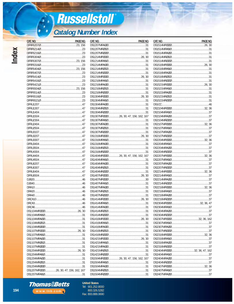
194
United StatesTel: 901.252.8000
800.326.5282Fax: 800.888.0690
www.tnb.com
Index
Catalog Number IndexCAT. NO. PAGE NO.DFRF6207Ø ................................................23, 156DFRF6214Ø ........................................................23DFRF6216Ø ........................................................23DFRF6304Ø ........................................................23DFRF6307Ø ................................................23, 156DFRF6316Ø ........................................................23DFRF6404Ø ................................................23, 156DFRF6407Ø ........................................................23DFRF6414Ø ........................................................23DFRF6416Ø ........................................................23DFRF6421Ø ........................................................23DFRF6504Ø ................................................23, 156DFRF6514Ø ........................................................23DFRF6516Ø ........................................................23DFRF6521Ø ........................................................23DFRU1207 ..........................................................47DFRU1307 ..........................................................47DFRU1404 ..........................................................47DFRU1504 ..........................................................47DFRU2304 ..........................................................47DFRU2404 ..........................................................47DFRU2504 ..........................................................47DFRU3107 ..........................................................47DFRU3207 ..........................................................47DFRU3307 ..........................................................47DFRU3404 ..........................................................47DFRU3504 ..........................................................47DFRU4304 ..........................................................47DFRU4404 ..........................................................47DFRU4504 ..........................................................47DFRU6207 ..........................................................47DFRU6307 ..........................................................47DFRU6404 ..........................................................47DFRU6504 ..........................................................47DJB20.................................................................46DJB40.................................................................46DRA10 ................................................................46DRA20 ................................................................46DRA40 ................................................................46DRCA10 ..............................................................46DRCA3 ................................................................46DRCA6 ................................................................46DS1104MPØØØ.............................................26, 30DS1104MRABØ...................................................31DS1104MRAØØ...................................................31DS1104MRØEØ...................................................31DS1104MRØØØ ..................................................31DS1107MPØØØ.............................................26, 30DS1107MRABØ...................................................31DS1107MRAØØ...................................................31DS1107MRØEØ...................................................31DS1107MRØØØ ..................................................31DS1204MPØØØ.............................................26, 30DS1204MRABØ...................................................31DS1204MRAØØ...................................................31DS1204MRØEØ...................................................31DS1204MRØØØ ..................................................31DS1207MPØØØ...............26, 30, 47, 156, 162, 167DS1207MRABØ...................................................31
CAT. NO. PAGE NO.DS1207MRAØØ...................................................31DS1207MRØEØ...................................................31DS1207MRØØØ ..................................................31DS1214MPØØØ.............................................26, 30DS1214MRABØ...................................................31DS1214MRAØØ...................................................31DS1214MRØEØ...................................................31DS1214MRØØØ ..................................................31DS1216MPØØØ.............................................26, 30DS1216MRABØ...................................................31DS1216MRAØØ...................................................31DS1216MRØEØ...................................................31DS1216MRØØØ ..................................................31DS1304MPØØØ.............................................26, 30DS1304MRABØ...................................................31DS1304MRAØØ...................................................31DS1304MRØEØ...................................................31DS1304MRØØØ ..................................................31DS1307MPØØØ...............26, 30, 47, 156, 162, 167DS1307MRABØ...................................................31DS1307MRAØØ...................................................31DS1307MRØEØ...................................................31DS1307MRØØØ ..................................................31DS1316MPØØØ.............................................26, 30DS1316MRABØ...................................................31DS1316MRAØØ...................................................31DS1316MRØEØ...................................................31DS1316MRØØØ ..................................................31DS1404MPØØØ...............26, 30, 47, 156, 162, 167DS1404MRABØ...................................................31DS1404MRAØØ...................................................31DS1404MRØEØ...................................................31DS1404MRØØØ ..................................................31DS1407MPØØØ.............................................26, 30DS1407MPØØØ ..................................................30DS1407MRABØ...................................................31DS1407MRAØØ...................................................31DS1407MRØEØ...................................................31DS1407MRØØØ ..................................................31DS1414MPØØØ.............................................26, 30DS1414MRABØ...................................................31DS1414MRAØØ...................................................31DS1414MRØEØ...................................................31DS1414MRØØØ ..................................................31DS1416MPØØØ.............................................26, 30DS1416MRABØ...................................................31DS1416MRAØØ...................................................31DS1416MRØEØ...................................................31DS1416MRØØØ ..................................................31DS1421MPØØØ.............................................26, 30DS1421MRABØ...................................................31DS1421MRAØØ...................................................31DS1421MRØEØ...................................................31DS1421MRØØØ ..................................................31DS1504MPØØØ...............26, 30, 47, 156, 162, 167DS1504MRABØ...................................................31DS1504MRAØØ...................................................31DS1504MRØEØ...................................................31DS1504MRØØØ ..................................................31
CAT. NO. PAGE NO.DS1514MPØØØ.............................................26, 30DS1514MRABØ...................................................31DS1514MRAØØ...................................................31DS1514MRØEØ...................................................31DS1514MRØØØ ..................................................31DS1516MPØØØ.............................................26, 30DS1516MRABØ...................................................31DS1516MRAØØ...................................................31DS1516MRØEØ...................................................31DS1516MRØØØ ..................................................31DS1521MPØØØ.............................................26, 30DS1521MRABØ...................................................31DS1521MRAØØ...................................................31DS1521MRØEØ...................................................31DS1521MRØØØ ..................................................31DS1CC ................................................................46DS2104MPØØØ.............................................32, 36DS2104MRABØ...................................................37DS2104MRAØØ...................................................37DS2104MRØØØ ..................................................37DS2107MPØØØ.............................................32, 36DS2107MRABØ...................................................37DS2107MRAØØ...................................................37DS2107MRØØØ ..................................................37DS2204MPØØØ.............................................32, 36DS2204MRABØ...................................................37DS2204MRAØØ...................................................37DS2204MRØØØ ..................................................37DS2207MPØØØ.............................................32, 36DS2207MRABØ...................................................37DS2207MRAØØ...................................................37DS2207MRØØØ ..................................................37DS2214MPØØØ.............................................32, 36DS2214MRABØ...................................................37DS2214MRAØØ...................................................37DS2214MRØØØ ..................................................37DS2216MPØØØ.............................................32, 36DS2216MRABØ...................................................37DS2216MRAØØ...................................................37DS2216MRØØØ ..................................................37DS2304MPØØØ.......................................32, 36, 47DS2304MRABØ...................................................37DS2304MRAØØ...................................................37DS2304MRØØØ ..................................................37DS2307MPØØØ.....................................32, 36, 162DS2307MRABØ...................................................37DS2307MRAØØ...................................................37DS2307MRØØØ ..................................................37DS2316MPØØØ.............................................32, 36DS2316MRABØ...................................................37DS2316MRAØØ...................................................37DS2316MRØØØ ..................................................37DS2404MPØØØ...............................32, 36, 47, 162DS2404MRABØ...................................................37DS2404MRAØØ...................................................37DS2404MRØØØ ..................................................37DS2407MPØØØ.............................................32, 36DS2407MRABØ...................................................37DS2407MRAØØ...................................................37

195
United StatesTel: 901.252.8000
800.326.5282Fax: 800.888.0690
www.tnb.com
Index
Catalog Number IndexCAT. NO. PAGE NO.DS2407MRØØØ ..................................................37DS2414MPØØØ.............................................32, 36DS2414MRABØ...................................................37DS2414MRAØØ...................................................37DS2414MRØØØ ..................................................37DS2416MPØØØ.............................................32, 36DS2416MRABØ...................................................37DS2416MRAØØ...................................................37DS2416MRØØØ ..................................................37DS2421MPØØØ.............................................32, 36DS2421MRABØ...................................................37DS2421MRAØØ...................................................37DS2421MRØØØ ..................................................37DS2504MPØØØ...............................32, 36, 47, 162DS2504MRABØ...................................................37DS2504MRAØØ...................................................37DS2504MRØØØ ..................................................37DS2514MPØØØ.............................................32, 36DS2514MRABØ...................................................37DS2514MRAØØ...................................................37DS2514MRØØØ ..................................................37DS2516MPØØØ.............................................32, 36DS2516MRABØ...................................................37DS2516MRAØØ...................................................37DS2516MRØØØ ..................................................37DS2521MPØØØ.............................................32, 36DS2521MRABØ...................................................37DS2521MRAØØ...................................................37DS2521MRØØØ ..................................................37DS2CC ................................................................46DS3104MPØØØ.............................................14, 18DS3104MRABØ...................................................19DS3104MRAØØ...................................................19DS3104MRØEØ...................................................19DS3104MRØØØ ..................................................19DS3107MPØØØ...............14, 18, 47, 156, 162, 167DS3107MRABØ...................................................19DS3107MRAØØ...................................................19DS3107MRØEØ...................................................19DS3107MRØØØ ..................................................19DS3204MPØØØ.............................................14, 18DS3204MRABØ...................................................19DS3204MRAØØ...................................................19DS3204MRØEØ...................................................19DS3204MRØØØ ..................................................19DS3207MPØØØ...............14, 18, 47, 156, 162, 167DS3207MRABØ...................................................19DS3207MRAØØ...................................................19DS3207MRØEØ...................................................19DS3207MRØØØ ..................................................19DS3214MPØØØ.............................................14, 18DS3214MRABØ...................................................19DS3214MRAØØ...................................................19DS3214MRØEØ...................................................19DS3214MRØØØ ..................................................19DS3216MPØØØ.............................................14, 18DS3216MRABØ...................................................19DS3216MRAØØ...................................................19DS3216MRØEØ...................................................19
CAT. NO. PAGE NO.DS3216MRØØØ ..................................................19DS3304MPØØØ.............................................14, 18DS3304MRABØ...................................................19DS3304MRAØØ...................................................19DS3304MRØEØ...................................................19DS3304MRØØØ ..................................................19DS3307MPØØØ...............14, 18, 47, 156, 162, 167DS3307MRABØ...................................................19DS3307MRAØØ...................................................19DS3307MRØEØ...................................................19DS3307MRØØØ ..................................................19DS3316MPØØØ.............................................14, 18DS3316MRABØ...................................................19DS3316MRAØØ...................................................19DS3316MRØEØ...................................................19DS3316MRØØØ ..................................................19DS3404MPØØØ...............14, 18, 47, 156, 162, 167DS3404MRABØ...................................................19DS3404MRAØØ...................................................19DS3404MRØEØ...................................................19DS3404MRØØØ ..................................................19DS3407MPØØØ.............................................14, 18DS3407MRABØ...................................................19DS3407MRAØØ...................................................19DS3407MRØEØ...................................................19DS3407MRØØØ ..................................................19DS3412MRABØ...................................................19DS3414MPØØØ.............................................14, 18DS3414MRABØ...................................................19DS3414MRAØØ...................................................19DS3414MRØEØ...................................................19DS3414MRØØØ ..................................................19DS3416MPØØØ ..................................................14DS3416MRABØ...................................................19DS3416MRAØØ...................................................19DS3416MRØEØ...................................................19DS3416MRØØØ ..................................................19DS3421MPØØØ.............................................14, 18DS3421MRAØØ...................................................19DS3421MRØEØ...................................................19DS3421MRØØØ ..................................................19DS3504MPØØØ...............14, 18, 47, 156, 162, 167DS3504MRABØ...................................................19DS3504MRAØØ...................................................19DS3504MRØEØ...................................................19DS3504MRØØØ ..................................................19DS3514MPØØØ ..................................................14DS3514MRABØ...................................................19DS3514MRAØØ...................................................19DS3514MRØEØ...................................................19DS3514MRØØØ ..................................................19DS3516FP.........................................................179DS3516FR ........................................................179DS3516MPDP ...................................................178DS3516MPØØØ.............................................14, 18DS3516MRABØ...................................................19DS3516MRAØØ...................................................19DS3516MRØEØ...................................................19DS3516MRØØØ ..................................................19
CAT. NO. PAGE NO.DS3521MPØØØ.............................................14, 18DS3521MRABØ...................................................19DS3521MRAØØ...................................................19DS3521MRØEØ...................................................19DS3521MRØØØ ..................................................19DS3CC ................................................................46DS4104MPØØØ.............................................38, 42DS4104MRABØ...................................................43DS4104MRAØØ...................................................43DS4104MRØØØ ..................................................43DS4107MPØØØ.............................................38, 42DS4107MRABØ...................................................43DS4107MRAØØ...................................................43DS4107MRØØØ ..................................................43DS4204MPØØØ.............................................38, 42DS4204MRABØ...................................................43DS4204MRAØØ...................................................43DS4204MRØØØ ..................................................43DS4207MPØØØ.............................................38, 42DS4207MRABØ...................................................43DS4207MRAØØ...................................................43DS4207MRØØØ ..................................................43DS4214MPØØØ.............................................38, 42DS4214MRABØ...................................................43DS4214MRAØØ...................................................43DS4214MRØØØ ..................................................43DS4216MPØØØ.............................................38, 42DS4216MRABØ...................................................43DS4216MRAØØ...................................................43DS4216MRØØØ ..................................................43DS4304MPØØØ.......................................38, 42, 47DS4304MRABØ...................................................43DS4304MRAØØ...................................................43DS4304MRØØØ ..................................................43DS4307MPØØØ.....................................38, 42, 162DS4307MRABØ...................................................43DS4307MRAØØ...................................................43DS4307MRØØØ ..................................................43DS4316MPØØØ.............................................38, 42DS4316MRABØ...................................................43DS4316MRAØØ...................................................43DS4316MRØØØ ..................................................43DS4404MPØØØ...............................38, 42, 47, 162DS4404MRABØ...................................................43DS4404MRAØØ...................................................43DS4404MRØØØ ..................................................43DS4407MPØØØ.............................................38, 42DS4407MRABØ...................................................43DS4407MRAØØ...................................................43DS4407MRØØØ ..................................................43DS4414MPØØØ.............................................38, 42DS4414MRABØ...................................................43DS4414MRAØØ...................................................43DS4414MRØØØ ..................................................43DS4416MPØØØ.............................................38, 42DS4416MRABØ...................................................43DS4416MRAØØ...................................................43DS4416MRØØØ ..................................................43DS4421MPØØØ.............................................38, 42
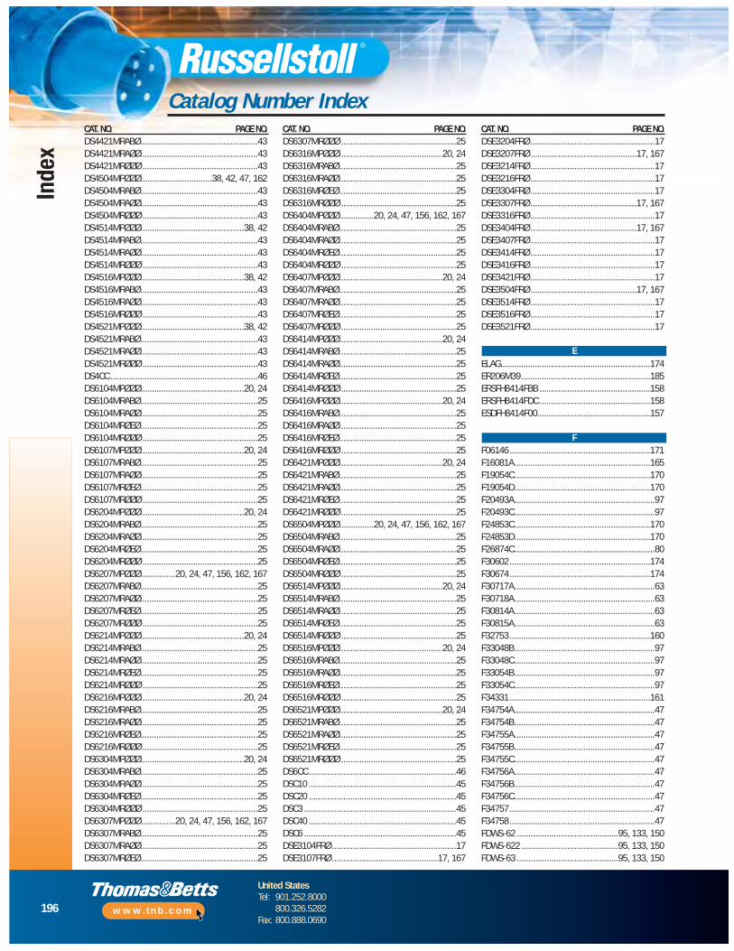
196
United StatesTel: 901.252.8000
800.326.5282Fax: 800.888.0690
www.tnb.com
Index
Catalog Number IndexCAT. NO. PAGE NO.DS4421MRABØ...................................................43DS4421MRAØØ...................................................43DS4421MRØØØ ..................................................43DS4504MPØØØ...............................38, 42, 47, 162DS4504MRABØ...................................................43DS4504MRAØØ...................................................43DS4504MRØØØ ..................................................43DS4514MPØØØ.............................................38, 42DS4514MRABØ...................................................43DS4514MRAØØ...................................................43DS4514MRØØØ ..................................................43DS4516MPØØØ.............................................38, 42DS4516MRABØ...................................................43DS4516MRAØØ...................................................43DS4516MRØØØ ..................................................43DS4521MPØØØ.............................................38, 42DS4521MRABØ...................................................43DS4521MRAØØ...................................................43DS4521MRØØØ ..................................................43DS4CC ................................................................46DS6104MPØØØ.............................................20, 24DS6104MRABØ...................................................25DS6104MRAØØ...................................................25DS6104MRØEØ...................................................25DS6104MRØØØ ..................................................25DS6107MPØØØ.............................................20, 24DS6107MRABØ...................................................25DS6107MRAØØ...................................................25DS6107MRØEØ...................................................25DS6107MRØØØ ..................................................25DS6204MPØØØ.............................................20, 24DS6204MRABØ...................................................25DS6204MRAØØ...................................................25DS6204MRØEØ...................................................25DS6204MRØØØ ..................................................25DS6207MPØØØ...............20, 24, 47, 156, 162, 167DS6207MRABØ...................................................25DS6207MRAØØ...................................................25DS6207MRØEØ...................................................25DS6207MRØØØ ..................................................25DS6214MPØØØ.............................................20, 24DS6214MRABØ...................................................25DS6214MRAØØ...................................................25DS6214MRØEØ...................................................25DS6214MRØØØ ..................................................25DS6216MPØØØ.............................................20, 24DS6216MRABØ...................................................25DS6216MRAØØ...................................................25DS6216MRØEØ...................................................25DS6216MRØØØ ..................................................25DS6304MPØØØ.............................................20, 24DS6304MRABØ...................................................25DS6304MRAØØ...................................................25DS6304MRØEØ...................................................25DS6304MRØØØ ..................................................25DS6307MPØØØ...............20, 24, 47, 156, 162, 167DS6307MRABØ...................................................25DS6307MRAØØ...................................................25DS6307MRØEØ...................................................25
CAT. NO. PAGE NO.DS6307MRØØØ ..................................................25DS6316MPØØØ.............................................20, 24DS6316MRABØ...................................................25DS6316MRAØØ...................................................25DS6316MRØEØ...................................................25DS6316MRØØØ ..................................................25DS6404MPØØØ...............20, 24, 47, 156, 162, 167DS6404MRABØ...................................................25DS6404MRAØØ...................................................25DS6404MRØEØ...................................................25DS6404MRØØØ ..................................................25DS6407MPØØØ.............................................20, 24DS6407MRABØ...................................................25DS6407MRAØØ...................................................25DS6407MRØEØ...................................................25DS6407MRØØØ ..................................................25DS6414MPØØØ.............................................20, 24DS6414MRABØ...................................................25DS6414MRAØØ...................................................25DS6414MRØEØ...................................................25DS6414MRØØØ ..................................................25DS6416MPØØØ.............................................20, 24DS6416MRABØ...................................................25DS6416MRAØØ...................................................25DS6416MRØEØ...................................................25DS6416MRØØØ ..................................................25DS6421MPØØØ.............................................20, 24DS6421MRABØ...................................................25DS6421MRAØØ...................................................25DS6421MRØEØ...................................................25DS6421MRØØØ ..................................................25DS6504MPØØØ...............20, 24, 47, 156, 162, 167DS6504MRABØ...................................................25DS6504MRAØØ...................................................25DS6504MRØEØ...................................................25DS6504MRØØØ ..................................................25DS6514MPØØØ.............................................20, 24DS6514MRABØ...................................................25DS6514MRAØØ...................................................25DS6514MRØEØ...................................................25DS6514MRØØØ ..................................................25DS6516MPØØØ.............................................20, 24DS6516MRABØ...................................................25DS6516MRAØØ...................................................25DS6516MRØEØ...................................................25DS6516MRØØØ ..................................................25DS6521MPØØØ.............................................20, 24DS6521MRABØ...................................................25DS6521MRAØØ...................................................25DS6521MRØEØ...................................................25DS6521MRØØØ ..................................................25DS6CC ................................................................46DSC10 ................................................................45DSC20 ................................................................45DSC3 ..................................................................45DSC40 ................................................................45DSC6 ..................................................................45DSE3104FRØ ......................................................17DSE3107FRØ ..............................................17, 167
CAT. NO. PAGE NO.DSE3204FRØ ......................................................17DSE3207FRØ ..............................................17, 167DSE3214FRØ ......................................................17DSE3216FRØ ......................................................17DSE3304FRØ ......................................................17DSE3307FRØ ..............................................17, 167DSE3316FRØ ......................................................17DSE3404FRØ ..............................................17, 167DSE3407FRØ ......................................................17DSE3414FRØ ......................................................17DSE3416FRØ ......................................................17DSE3421FRØ ......................................................17DSE3504FRØ ..............................................17, 167DSE3514FRØ ......................................................17DSE3516FRØ ......................................................17DSE3521FRØ ......................................................17
ELAG.................................................................174ER206M39........................................................185ERSFH8414FBB ................................................158ERSFH8414FDC ................................................158ESDFH8414F00.................................................157
F06146.............................................................171F16081A...........................................................165F19054C...........................................................170F19054D...........................................................170F20493A.............................................................97F20493C.............................................................97F24853C...........................................................170F24853D...........................................................170F26874C.............................................................80F30602.............................................................174F30674.............................................................174F30717A.............................................................63F30718A.............................................................63F30814A.............................................................63F30815A.............................................................63F32753.............................................................160F33048B.............................................................97F33048C.............................................................97F33054B.............................................................97F33054C.............................................................97F34331.............................................................161F34754A.............................................................47F34754B.............................................................47F34755A.............................................................47F34755B.............................................................47F34755C.............................................................47F34756A.............................................................47F34756B.............................................................47F34756C.............................................................47F34757...............................................................47F34758...............................................................47FDWS-62 ............................................95, 133, 150FDWS-622 ..........................................95, 133, 150FDWS-63 ............................................95, 133, 150
E
F
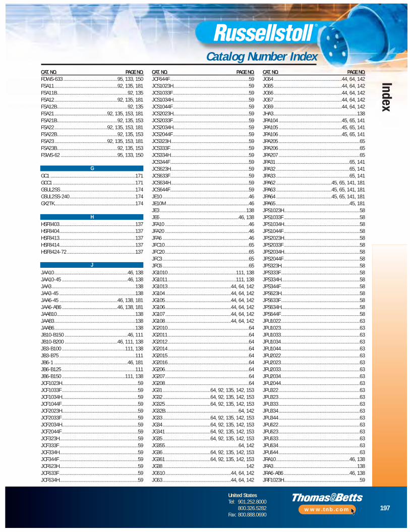
197
United StatesTel: 901.252.8000
800.326.5282Fax: 800.888.0690
www.tnb.com
Index
Catalog Number IndexCAT. NO. PAGE NO.FDWS-633 ..........................................95, 133, 150FSA11.................................................92, 135, 181FSA11B.......................................................92, 135FSA12.................................................92, 135, 181FSA12B.......................................................92, 135FSA21.........................................92, 135, 153, 181FSA21B...............................................92, 135, 153FSA22.........................................92, 135, 153, 181FSA22B...............................................92, 135, 153FSA23.........................................92, 135, 153, 181FSA23B...............................................92, 135, 153FSWS-62 ............................................95, 133, 150
GC1 ..................................................................171GCC1 ................................................................171GSUL2SS ..........................................................174GSUL2SS-240...................................................174GX2TK...............................................................174
HSF8403...........................................................137HSF8404...........................................................137HSF8413...........................................................137HSF8414...........................................................137HSF8424-72 .....................................................137
JAA10.........................................................46, 138JAA10-45 ...................................................46, 138JAA3.................................................................138JAA3-45 ...........................................................138JAA6-45 .............................................46, 138, 181JAA6-AB6 ...........................................46, 138, 181JAAB10.............................................................138JAAB3...............................................................138JAAB6...............................................................138JB10-B150 .................................................46, 111JB10-B200 .........................................46, 111, 138JB3-B100 .................................................111, 138JB3-B75 ...........................................................111JB6-1 .........................................................46, 181JB6-B125 .........................................................111JB6-B150 .................................................111, 138JCF1023H...........................................................59JCF1033F ...........................................................59JCF1034H...........................................................59JCF1044F ...........................................................59JCF2023H...........................................................59JCF2033F ...........................................................59JCF2034H...........................................................59JCF2044F ...........................................................59JCF323H.............................................................59JCF333F .............................................................59JCF334H.............................................................59JCF344F .............................................................59JCF623H.............................................................59JCF633F .............................................................59JCF634H.............................................................59
CAT. NO. PAGE NO.JCF644F .............................................................59JCS1023H...........................................................59JCS1033F...........................................................59JCS1034H...........................................................59JCS1044F...........................................................59JCS2023H...........................................................59JCS2033F...........................................................59JCS2034H...........................................................59JCS2044F...........................................................59JCS323H.............................................................59JCS333F.............................................................59JCS334H.............................................................59JCS344F.............................................................59JCS623H.............................................................59JCS633F.............................................................59JCS634H.............................................................59JCS644F.............................................................59JE10 ...................................................................46JE10M ................................................................46JE3 ...................................................................138JE6 .............................................................46, 138JFA10 .................................................................46JFA20 .................................................................46JFA6 ...................................................................46JFC10 .................................................................65JFC20 .................................................................65JFC3 ...................................................................65JFC6 ...................................................................65JG1010.....................................................111, 138JG1011.....................................................111, 138JG1013.................................................44, 64, 142JG104...................................................44, 64, 142JG105...................................................44, 64, 142JG106...................................................44, 64, 142JG107...................................................44, 64, 142JG108...................................................44, 64, 142JG2010...............................................................64JG2011...............................................................64JG2012...............................................................64JG2014...............................................................64JG2015...............................................................64JG2016...............................................................64JG206.................................................................64JG207.................................................................64JG208.................................................................64JG31 .....................................64, 92, 135, 142, 153JG32 .....................................64, 92, 135, 142, 153JG325 ...................................64, 92, 135, 142, 153JG32B.........................................................64, 142JG33 .....................................64, 92, 135, 142, 153JG34 .....................................64, 92, 135, 142, 153JG341 ...................................64, 92, 135, 142, 153JG35 .....................................64, 92, 135, 142, 153JG355.........................................................64, 142JG36 .....................................64, 92, 135, 142, 153JG361 ...................................64, 92, 135, 142, 153JG38.................................................................142JG610...................................................44, 64, 142JG63.....................................................44, 64, 142
CAT. NO. PAGE NO.JG64.....................................................44, 64, 142JG65.....................................................44, 64, 142JG66.....................................................44, 64, 142JG67.....................................................44, 64, 142JG69.....................................................44, 64, 142JHA3.................................................................138JPA104 .................................................45, 65, 141JPA105 .................................................45, 65, 141JPA106 .................................................45, 65, 141JPA205 ...............................................................65JPA206 ...............................................................65JPA207 ...............................................................65JPA31 .........................................................65, 141JPA32 .........................................................65, 141JPA33 .........................................................65, 141JPA62 ...........................................45, 65, 141, 181JPA63 ...........................................45, 65, 141, 181JPA64 ...........................................45, 65, 141, 181JPA65 .........................................................45, 181JPS1023H...........................................................58JPS1033F ...........................................................58JPS1034H...........................................................58JPS1044F ...........................................................58JPS2023H...........................................................58JPS2033F ...........................................................58JPS2034H...........................................................58JPS2044F ...........................................................58JPS323H.............................................................58JPS333F .............................................................58JPS334H.............................................................58JPS344F .............................................................58JPS623H.............................................................58JPS633F .............................................................58JPS634H.............................................................58JPS644F .............................................................58JPU1022.............................................................63JPU1023.............................................................63JPU1033.............................................................63JPU1034.............................................................63JPU1044.............................................................63JPU2022.............................................................63JPU2023.............................................................63JPU2033.............................................................63JPU2034.............................................................63JPU2044.............................................................63JPU322...............................................................63JPU323...............................................................63JPU333...............................................................63JPU334...............................................................63JPU344...............................................................63JPU622...............................................................63JPU623...............................................................63JPU633...............................................................63JPU634...............................................................63JPU644...............................................................63JRA10.........................................................46, 138JRA3.................................................................138JRA6-AB6 ...................................................46, 138JRF1023H...........................................................59
G
H
J
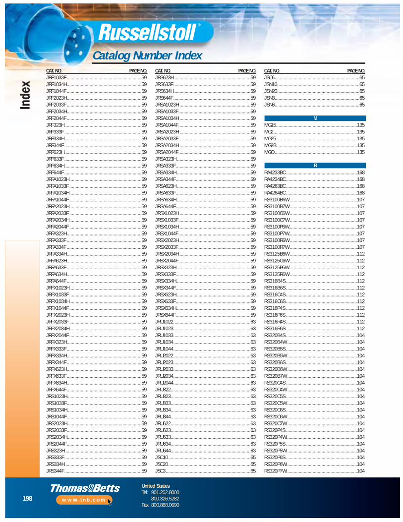
198
United StatesTel: 901.252.8000
800.326.5282Fax: 800.888.0690
www.tnb.com
Index
Catalog Number IndexCAT. NO. PAGE NO.JRF1033F ...........................................................59JRF1034H...........................................................59JRF1044F ...........................................................59JRF2023H...........................................................59JRF2033F ...........................................................59JRF2034H...........................................................59JRF2044F ...........................................................59JRF323H.............................................................59JRF333F .............................................................59JRF334H.............................................................59JRF344F .............................................................59JRF623H.............................................................59JRF633F .............................................................59JRF634H.............................................................59JRF644F .............................................................59JRFA1023H.........................................................59JRFA1033F .........................................................59JRFA1034H.........................................................59JRFA1044F .........................................................59JRFA2023H.........................................................59JRFA2033F .........................................................59JRFA2034H.........................................................59JRFA2044F .........................................................59JRFA323H...........................................................59JRFA333F ...........................................................59JRFA334F ...........................................................59JRFA334H...........................................................59JRFA623H...........................................................59JRFA633F ...........................................................59JRFA634H...........................................................59JRFA644F ...........................................................59JRFX1023H.........................................................59JRFX1033F .........................................................59JRFX1034H.........................................................59JRFX1044F .........................................................59JRFX2023H.........................................................59JRFX2033F .........................................................59JRFX2034H.........................................................59JRFX2044F .........................................................59JRFX323H...........................................................59JRFX333F ...........................................................59JRFX334H...........................................................59JRFX344F ...........................................................59JRFX623H...........................................................59JRFX633F ...........................................................59JRFX634H...........................................................59JRFX644F ...........................................................59JRS1023H...........................................................59JRS1033F...........................................................59JRS1034H...........................................................59JRS1044F...........................................................59JRS2023H...........................................................59JRS2033F...........................................................59JRS2034H...........................................................59JRS2044F...........................................................59JRS323H.............................................................59JRS333F.............................................................59JRS334H.............................................................59JRS344F.............................................................59
CAT. NO. PAGE NO.JRS623H.............................................................59JRS633F.............................................................59JRS634H.............................................................59JRS644F.............................................................59JRSA1023H ........................................................59JRSA1033F.........................................................59JRSA1034H ........................................................59JRSA1044F.........................................................59JRSA2023H ........................................................59JRSA2033F.........................................................59JRSA2034H ........................................................59JRSA2044F.........................................................59JRSA323H ..........................................................59JRSA333F...........................................................59JRSA334H ..........................................................59JRSA344F...........................................................59JRSA623H ..........................................................59JRSA633F...........................................................59JRSA634H ..........................................................59JRSA644F...........................................................59JRSX1023H.........................................................59JRSX1033F.........................................................59JRSX1034H.........................................................59JRSX1044F.........................................................59JRSX2023H.........................................................59JRSX2033F.........................................................59JRSX2034H.........................................................59JRSX2044F.........................................................59JRSX323H...........................................................59JRSX333F...........................................................59JRSX334H...........................................................59JRSX344F...........................................................59JRSX623H...........................................................59JRSX633F...........................................................59JRSX634H...........................................................59JRSX644F...........................................................59JRU1022.............................................................63JRU1023.............................................................63JRU1033.............................................................63JRU1034.............................................................63JRU1044.............................................................63JRU2022.............................................................63JRU2023.............................................................63JRU2033.............................................................63JRU2034.............................................................63JRU2044.............................................................63JRU322...............................................................63JRU323...............................................................63JRU333...............................................................63JRU334...............................................................63JRU344...............................................................63JRU622...............................................................63JRU623...............................................................63JRU633...............................................................63JRU634...............................................................63JRU644...............................................................63JSC10.................................................................65JSC20.................................................................65JSC3...................................................................65
CAT. NO. PAGE NO.JSC6...................................................................65JSN10.................................................................65JSN20.................................................................65JSN3...................................................................65JSN6...................................................................65
MG15................................................................135MG2..................................................................135MG25................................................................135MG2B ...............................................................135MGO .................................................................135
RA4233BC ........................................................168RA4234BC ........................................................168RA4263BC ........................................................168RA4264BC ........................................................168RS3100B6W .....................................................107RS3100B7W .....................................................107RS3100C6W .....................................................107RS3100C7W .....................................................107RS3100P6W......................................................107RS3100P7W......................................................107RS3100R6W .....................................................107RS3100R7W .....................................................107RS3125B6W .....................................................112RS3125C6W .....................................................112RS3125P6W......................................................112RS3125R6W .....................................................112RS316B4S ........................................................112RS316B6S ........................................................112RS316C4S ........................................................112RS316C6S ........................................................112RS316P4S ........................................................112RS316P6S ........................................................112RS316R4S ........................................................112RS316R6S ........................................................112RS320B4S ........................................................104RS320B4W .......................................................104RS320B5S ........................................................104RS320B5W .......................................................104RS320B6S ........................................................104RS320B6W .......................................................104RS320B7W .......................................................104RS320C4S ........................................................104RS320C4W .......................................................104RS320C5S ........................................................104RS320C5W .......................................................104RS320C6S ........................................................104RS320C6W .......................................................104RS320C7W .......................................................104RS320P4S ........................................................104RS320P4W........................................................104RS320P5S ........................................................104RS320P5W........................................................104RS320P6S ........................................................104RS320P6W........................................................104RS320P7W........................................................104
M
R

199
United StatesTel: 901.252.8000
800.326.5282Fax: 800.888.0690
www.tnb.com
Index
Catalog Number IndexCAT. NO. PAGE NO.RS320R4S ........................................................104RS320R4W .......................................................104RS320R5S ........................................................104RS320R5W .......................................................104RS320R6S ........................................................104RS320R6W .......................................................104RS320R7W .......................................................104RS330B4S ........................................................105RS330B4W .......................................................105RS330B5S ........................................................105RS330B6S ........................................................105RS330B6W .......................................................105RS330B7W .......................................................105RS330C4S ........................................................105RS330C4W .......................................................105RS330C5S ........................................................105RS330C6S ........................................................105RS330C6W .......................................................105RS330C7W .......................................................105RS330P4S ........................................................105RS330P4W........................................................105RS330P5S ........................................................105RS330P6S ........................................................105RS330P6W........................................................105RS330P7W........................................................105RS330R4S ........................................................105RS330R4W .......................................................105RS330R5S ........................................................105RS330R6S ........................................................105RS330R6W .......................................................105RS330R7W .......................................................105RS332B4S ........................................................112RS332B6S ........................................................112RS332C4S ........................................................112RS332C6S ........................................................112RS332P4S ........................................................112RS332P6S ........................................................112RS332R4S ........................................................112RS332R6S ........................................................112RS360B3W .......................................................106RS360B4W .......................................................106RS360B5W .......................................................106RS360B6W .......................................................106RS360B7W .......................................................106RS360C3W .......................................................106RS360C4W .......................................................106RS360C5W .......................................................106RS360C6W .......................................................106RS360C7W .......................................................106RS360P3W........................................................106RS360P4W........................................................106RS360P5W........................................................106RS360P6W........................................................106RS360P7W........................................................106RS360R3W .......................................................106RS360R4W .......................................................106RS360R5W .......................................................106RS360R6W .......................................................106RS360R7W .......................................................106
CAT. NO. PAGE NO.RS363B6W .......................................................112RS363C6W .......................................................112RS363P6W........................................................112RS363R6W .......................................................112RS4100B12W ...................................................107RS4100B5W .....................................................107RS4100B7W .....................................................107RS4100B9W .....................................................107RS4100C12W ...................................................107RS4100C5W .....................................................107RS4100C9W .....................................................107RS4100P12W....................................................107RS4100P5W......................................................107RS4100P7W......................................................107RS4100P9W......................................................107RS4100R12W ...................................................107RS4100R5W .....................................................107RS4100R7W .....................................................107RS4100R9W .....................................................107RS4125B6W .....................................................112RS4125C6W .....................................................112RS4125P6W......................................................112RS4125R6W .....................................................112RS416B6S ........................................................112RS416C6S ........................................................112RS416P6S ........................................................112RS416R6S ........................................................112RS4209C9W .....................................................104RS420B12S ......................................................104RS420B12W .....................................................104RS420B5W .......................................................104RS420B7W .......................................................104RS420B9S ........................................................104RS420B9W .......................................................104RS420C12S ......................................................104RS420C12W .....................................................104RS420C5W .......................................................104RS420C7W .......................................................104RS420C9S ........................................................104RS420P12S ......................................................104RS420P12W......................................................104RS420P5W........................................................104RS420P7W........................................................104RS420P9S ........................................................104RS420P9W........................................................104RS420R12S ......................................................104RS420R12W .....................................................104RS420R5W .......................................................104RS420R7W .......................................................104RS420R9S ........................................................104RS420R9W .......................................................104RS430B12S ......................................................105RS430B12W .....................................................105RS430B5W .......................................................105RS430B7W .......................................................105RS430B9S ........................................................105RS430B9W .......................................................105RS430C12S ......................................................105RS430C12W .....................................................105
CAT. NO. PAGE NO.RS430C5W .......................................................105RS430C7W .......................................................105RS430C9S ........................................................105RS430C9W .......................................................105RS430P12S ......................................................105RS430P12W......................................................105RS430P5W........................................................105RS430P7W........................................................105RS430P9S ........................................................105RS430P9W........................................................105RS430R12S ......................................................105RS430R12W .....................................................105RS430R5W .......................................................105RS430R7W .......................................................105RS430R9S ........................................................105RS430R9W .......................................................105RS432B6S ........................................................112RS432C6S ........................................................112RS432P6S ........................................................112RS432R6S ........................................................112RS460B12W .....................................................106RS460B5W .......................................................106RS460B7W .......................................................106RS460B9W .......................................................106RS460C12W .....................................................106RS460C5W .......................................................106RS460C7W .......................................................106RS460C9W .......................................................106RS460P12W......................................................106RS460P5W........................................................106RS460P7W........................................................106RS460P9W........................................................106RS460R12W .....................................................106RS460R5W .......................................................106RS460R7W .......................................................106RS460R9W .......................................................106RS463B6W .......................................................112RS463C6W .......................................................112RS463P6W........................................................112RS463R6W .......................................................112RS5100B5W .....................................................107RS5100B7W .....................................................107RS5100B9W .....................................................107RS5100C5W .....................................................107RS5100C7W .....................................................107RS5100C9W .....................................................107RS5100P5W......................................................107RS5100P7W......................................................107RS5100P9W......................................................107RS5100R5W .....................................................107RS5100R7W .....................................................107RS5100R9W .....................................................107RS5125B6W .....................................................112RS5125C6W .....................................................112RS5125P6W......................................................112RS5125R6W .....................................................112RS516B6S ........................................................112RS516C6S ........................................................112RS516P6S ........................................................112
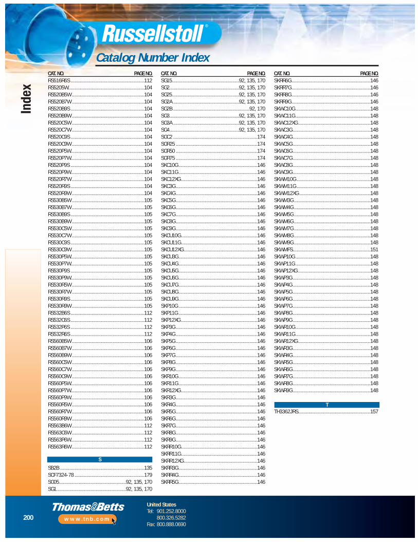
200
United StatesTel: 901.252.8000
800.326.5282Fax: 800.888.0690
www.tnb.com
Index
Catalog Number IndexCAT. NO. PAGE NO.RS516R6S ........................................................112RS5205W..........................................................104RS520B5W .......................................................104RS520B7W .......................................................104RS520B9S ........................................................104RS520B9W .......................................................104RS520C5W .......................................................104RS520C7W .......................................................104RS520C9S ........................................................104RS520C9W .......................................................104RS520P5W........................................................104RS520P7W........................................................104RS520P9S ........................................................104RS520P9W........................................................104RS520R7W .......................................................104RS520R9S ........................................................104RS520R9W .......................................................104RS530B5W .......................................................105RS530B7W .......................................................105RS530B9S ........................................................105RS530B9W .......................................................105RS530C5W .......................................................105RS530C7W .......................................................105RS530C9S ........................................................105RS530C9W .......................................................105RS530P5W........................................................105RS530P7W........................................................105RS530P9S ........................................................105RS530P9W........................................................105RS530R5W .......................................................105RS530R7W .......................................................105RS530R9S ........................................................105RS530R9W .......................................................105RS532B6S ........................................................112RS532C6S ........................................................112RS532P6S ........................................................112RS532R6S ........................................................112RS560B5W .......................................................106RS560B7W .......................................................106RS560B9W .......................................................106RS560C5W .......................................................106RS560C7W .......................................................106RS560C9W .......................................................106RS560P5W........................................................106RS560P7W........................................................106RS560P9W........................................................106RS560R5W .......................................................106RS560R7W .......................................................106RS560R9W .......................................................106RS563B6W .......................................................112RS563C6W .......................................................112RS563P6W........................................................112RS563R6W .......................................................112
SB2B ................................................................135SCF7324-78 .....................................................179SG05...................................................92, 135, 170SG1.....................................................92, 135, 170
CAT. NO. PAGE NO.SG15...................................................92, 135, 170SG2.....................................................92, 135, 170SG25...................................................92, 135, 170SG2A ..................................................92, 135, 170SG2B ..........................................................92, 170SG3.....................................................92, 135, 170SG3A ..................................................92, 135, 170SG4.....................................................92, 135, 170SGC2 ................................................................174SGR25 ..............................................................174SGR50 ..............................................................174SGR75 ..............................................................174SKC10G ............................................................146SKC11G ............................................................146SKC12XG ..........................................................146SKC3G ..............................................................146SKC4G ..............................................................146SKC5G ..............................................................146SKC6G ..............................................................146SKC7G ..............................................................146SKC8G ..............................................................146SKC9G ..............................................................146SKCU10G ..........................................................146SKCU11G ..........................................................146SKCU12XG ........................................................146SKCU3G ............................................................146SKCU4G ............................................................146SKCU5G ............................................................146SKCU6G ............................................................146SKCU7G ............................................................146SKCU8G ............................................................146SKCU9G ............................................................146SKP10G ............................................................146SKP11G ............................................................146SKP12XG ..........................................................146SKP3G ..............................................................146SKP4G ..............................................................146SKP5G ..............................................................146SKP6G ..............................................................146SKP7G ..............................................................146SKP8G ..............................................................146SKP9G ..............................................................146SKR10G ............................................................146SKR11G ............................................................146SKR12XG ..........................................................146SKR3G ..............................................................146SKR4G ..............................................................146SKR5G ..............................................................146SKR6G ..............................................................146SKR7G ..............................................................146SKR8G ..............................................................146SKR9G ..............................................................146SKRR10G ..........................................................146SKRR11G ..........................................................146SKRR12XG ........................................................146SKRR3G ............................................................146SKRR4G ............................................................146SKRR5G ............................................................146
CAT. NO. PAGE NO.SKRR6G ............................................................146SKRR7G ............................................................146SKRR8G ............................................................146SKRR9G ............................................................146SKWC10G .........................................................148SKWC11G .........................................................148SKWC12XG .......................................................148SKWC3G ...........................................................148SKWC4G ...........................................................148SKWC5G ...........................................................148SKWC6G ...........................................................148SKWC7G ...........................................................148SKWC8G ...........................................................148SKWC9G ...........................................................148SKWM10G ........................................................148SKWM11G ........................................................148SKWM12XG ......................................................148SKWM3G ..........................................................148SKWM4G ..........................................................148SKWM5G ..........................................................148SKWM6G ..........................................................148SKWM7G ..........................................................148SKWM8G ..........................................................148SKWM9G ..........................................................148SKWMFS...........................................................151SKWP10G .........................................................148SKWP11G .........................................................148SKWP12XG .......................................................148SKWP3G ...........................................................148SKWP4G ...........................................................148SKWP5G ...........................................................148SKWP6G ...........................................................148SKWP7G ...........................................................148SKWP8G ...........................................................148SKWP9G ...........................................................148SKWR10G .........................................................148SKWR11G .........................................................148SKWR12XG .......................................................148SKWR3G ...........................................................148SKWR4G ...........................................................148SKWR5G ...........................................................148SKWR6G ...........................................................148SKWR7G ...........................................................148SKWR8G ...........................................................148SKWR9G ...........................................................148
TH3362JRS.......................................................157
S
T

Your source for these and other industry-leading Thomas & Betts brands.
www.tnb.com
CustomerService
1-800-326-5282
Fax on Demand 1-800-858-6022
Tool Service 1-800-284-TOOL(1-800-284-8665)

United StatesTel: 901.252.8000
800.326.5282Fax: 800.888.0690
www.tnb.com
For U.S. Customer Service and Order Inquiries, Call 1-800-326-5282 or Fax 1-800-888-0690.
For International Service and Order Inquiries, Call (U.S.) 901-252-5400 or Fax 901-252-1330.
For Canadian Customer Service and Order Inquiries, Call 450-347-5318 or Fax 450-347-1976.
For Tool Service and Repair, Call 1-800-284-TOOL (8665).
Thomas & Betts CorporationElectrical Division8155 T&B BoulevardMemphis, Tennessee 38125
© 2009 Thomas & Betts Corporation. All rights reserved.Specifications are subject to change without notice. Printed in U.S.A. 10/09/15M Order No. GM-397