
Heavy-Duty Spark-Ignited Single Cylinder Engine Fueling ...
69
Heavy-Duty Spark-Ignited Single Cylinder Engine Fueling System Rohan Sharad Kittur Master of Science Thesis MMK TRITA-ITM-EX 2018:512 KTH Industrial Engineering and Management Machine Design SE-100 44 STOCKHOLM
-
Upload
khangminh22 -
Category
Documents
-
view
1 -
download
0
Transcript of Heavy-Duty Spark-Ignited Single Cylinder Engine Fueling ...
Heavy-Duty Spark-Ignited Single Cylinder Engine
Fueling System
Rohan Sharad Kittur
Master of Science Thesis MMK TRITA-ITM-EX 2018:512
KTH Industrial Engineering and Management
Machine Design
SE-100 44 STOCKHOLM


i
Examensarbete MMK TRITA-ITM-EX 2018:512
Bränslesystem för encylindrig motor
Rohan Sharad Kittur
Godkänt
2018-06-26
Examinator
Dr. Andreas Cronhjort
Handledare
Dr. Ola Stenlåås
Uppdragsgivare
Scania CV AB, Södertälje
Kontaktperson
Dr. Ola Stenlåås
Sammanfattning
Forskning inom motorutveckling bedrivs för att möta kommande emissionskrav och samtidigt
minska bränsleförbrukningen. Kommande förbud mot dieseldrivna fordon planeras i flera städer
runt om i världen. Alternativa bränsle som exempelvis naturgas ses som en lovande ersättning
även för tunga fordon. Metan som är huvudkomponenten av naturgas har en fördelaktigt
förhållande mellan väte och kol vilket gör den attraktiv för CO2-reducering. Hur som helst,
bränslets låga cetantal och den höga aktiveringsenergin som krävs för att tända naturgas förutsätter
tändstiftsantändning.
En fördel av att använda en encylindrig motor inom forskning är möjligheten att studera fenomen
utan negativa gasväxlingsinteraktioner från intilliggande cylindrar. Jämfört med en fullmotor
möjliggörs även ett snabbare utbyte av motordelar samt lägre bränsleförbrukning.
Fokus för detta examensarbete var genomförandet av ett flexibelt bränslesystem för en
tändstiftsantänd encylindrig motor. Motorn är en tändstiftsantänd Scania 9 liters som modifieras
för encylinder körning. Flexibilitet som t.ex. laddningshomogenitet, selektiv fyllning av
inloppsporter och förberedelser för direktinsprutning av flytande bränsle realiserades. För enkel
användning är motorn styrd av en eftermarknadsmotorstyrenhet som använder ett användarvänligt
grafiskt gränssnitt för ändring av driftsparametrar. Säkerhetshänsyn vid blandning av gasformiga
bränsle och luft långt innan inloppsporterna har implementerats.
Nyckelord: bränslesystem, tunga fordon, tändstiftsantändning, encylinder motor,
eftermarknadsmotorstyrenhet, bränsle-luft blandningssäkerhet

ii
iii
Master of Science Thesis MMK TRITA-ITM-EX 2018:512
Heavy-Duty Spark-Ignited Single Cylinder Engine
Fueling System
Rohan Sharad Kittur
Approved
2018-06-26
Examiner
Dr. Andreas Cronhjort
Supervisor
Dr. Ola Stenlåås
Commissioner
Scania CV AB, Södertälje
Contact person
Dr. Ola Stenlåås
Abstract
Most of the fundamental research in internal combustion engines is driven by the ever-increasing
stringency of emissions regulations along with the need for increased fuel economy. The proposed
ban on diesel vehicles in several cities around the world combined with extensive availability, has
made natural gas a promising substitute even for heavy-duty applications. The high
hydrogen-to-carbon ratio of methane, the major component of natural gas, makes it attractive from
an emissions reduction perspective. CO2 emissions from natural gas combustion are particularly
low. However, the low cetane number and high activation energy required to ignite natural gas,
requires spark-ignition.
In a research setting, it is often advantageous to have a single cylinder engine. The main benefit is
the ability to study phenomena without adverse interactions which multi-cylinder operation may
cause. This is especially important for gas-exchange studies. Quicker replacement of parts and
lower fuel consumption are secondary benefits.
The focus of this thesis was the implementation of a flexible fueling system for a single cylinder
spark-ignited engine. The engine is a Scania 9-liter spark-ignited engine modified for single
cylinder operation. Flexibility in terms of charge homogeneity, selective intake port filling and
provisions for liquid fuel direct injection have been provided. For ease of use, the engine is
controlled by an aftermarket engine control unit with a graphical user interface for configuration.
Safety considerations when mixing gaseous fuels and air well upstream of the intake ports have
been implemented.
Keywords: Fueling system, heavy-duty, spark-ignited, single cylinder engine, aftermarket engine
control unit, fuel-air mixture safety.

iv

v
FOREWORD
I would like to express my gratitude to all the people who have offered their time and support to
help me see this project to the end.
Foremost, I thank Dr. Ola Stenlåås (Scania CV AB, Södertälje) for motivating me to step outside
my comfort zone so that I could learn something. I also thank him for helping improve my
technical writing skills. My thanks to Dr. Andreas Cronhjort as well for being a constant source of
support.
It has been a pleasure working with Richard Adolfsson (NMEG). I am extremely grateful to him
for sharing his vast practical knowledge of engines. For being accommodating of my lack of
experience and patiently teaching me practical techniques to gain the required experience, I thank
him very much.
I would like to thank the entire Otto engine pre-development and optimization teams for accepting
me as their colleague and for tirelessly answering each of my questions. My particular gratitude
goes to Arne Burger and Mats Janzon (NMEG) for their kind nature, encouragement and
enlightening discussions over lunch.
I extend my special thanks to Tomas Karlberg (NLRD) for patiently answering all my questions
related to the single cylinder test cells. Pål Axelsson and Björn Lind (KETE) have been extremely
helpful with the flame arrestor for which I thank them. I also thank Ludvig Adlercreutz
(AVL, Södertälje) for his support.
My heartfelt thanks go to Philip Thörhammar (KETL), Peter Olsson (KETL) and Timo Lohilahti
(NLWM) for sharing their practical knowledge and tools. I am also grateful to all the other
workshop personnel for their patience and assistance.
My fellow students of the IC engines program at KTH deserve special mention as well, for all the
fun times we had over the course of two years. Particular thanks to Andreas Lius for allowing me
to learn more about engines by assisting him with his thesis.
Lastly, I thank my parents for believing in me and being my pillars during all of life’s highs and
lows.
Rohan Sharad Kittur
Stockholm, June 2018

vi
vii
NOMENCLATURE
The notations and abbreviations used in this report are as follows.
Notations
Symbol Description
bar(a) Absolute pressure
bar(g) Gauge pressure
Abbreviations
BDC Bottom Dead Center
CFD Computational Fluid Dynamics
CI Compression-ignition/ignited
CNG Compressed Natural Gas
ECU Electronic Engine Control Unit
FAME Fatty Acid Methyl Ester
HVO Hydrogenated Vegetable Oil
Hythane Hydrogen-methane blends (% composition may vary)
ICE Internal Combustion Engine
LNG Liquefied Natural Gas
PWM Pulse Width Modulation
RON Research Octane Number
SI Spark-ignition/ignited
TDC Top Dead Center

viii
ix
TABLE OF CONTENTS
Sammanfattning ............................................................................................................................... i
Abstract .......................................................................................................................................... iii
Foreword ......................................................................................................................................... v
Nomenclature ................................................................................................................................ vii
Table of contents ............................................................................................................................ ix
List of figures ............................................................................................................................... xiii
List of tables .................................................................................................................................. xv
1 INTRODUCTION ....................................................................................................................... 1
1.1 Internal Combustion Engines – A Brief Overview ............................................................... 1
1.1.1 Commonly used fueling methods: .................................................................................. 1
1.1.2 CNG as a fuel .................................................................................................................. 3
1.2 Purpose .................................................................................................................................. 3
1.3 Task Definition ...................................................................................................................... 4
1.3.1 Research objectives ......................................................................................................... 4
1.3.2 Project outline ................................................................................................................. 4
1.4 Deliverables and delimitations .............................................................................................. 5
1.4.1 Deliverables .................................................................................................................... 5
1.4.2 Delimitations ................................................................................................................... 5
2 ENGINE SELECTION ............................................................................................................... 7
2.1 Single cylinder research engine ............................................................................................. 7
2.2 Requirement specification and alternatives ........................................................................... 7
2.3 Implementation ...................................................................................................................... 7
3 FUELING SYSTEM ................................................................................................................... 9
3.1 Fuel-air mixture formation .................................................................................................... 9
3.1.1 Gaseous fuel-air mixture ................................................................................................. 9
3.1.2 Effects of fuel injector location and injection timing ..................................................... 9
x
3.2 Charge homogeneity variation ............................................................................................. 10
3.3 Laboratory fueling setup ...................................................................................................... 11
3.3.1 Gas panel ....................................................................................................................... 12
3.4 Installation assembly ........................................................................................................... 14
3.5 Liquid fuel direct injection .................................................................................................. 15
3.5.1 Assignment ................................................................................................................... 15
3.5.2 Implementation ............................................................................................................. 16
3.5.3 Modifications ................................................................................................................ 16
4 ELECTRONIC ENGINE CONTROL ...................................................................................... 19
4.1 Engine control unit .............................................................................................................. 19
4.1.1 Assignment ................................................................................................................... 19
4.1.2 ECU selection criteria ................................................................................................... 19
4.1.3 ECU selection and installation ...................................................................................... 20
4.2 Fueling control ..................................................................................................................... 20
4.2.1 Types of CNG injectors ................................................................................................ 21
4.2.2 Installation ..................................................................................................................... 22
4.2.3 Verification ................................................................................................................... 22
4.3 Lambda control .................................................................................................................... 22
4.3.1 Stoichiometric combustion and the three-way catalyst ................................................ 22
4.3.2 Exhaust gas oxygen sensors/Lambda sensors ............................................................... 23
4.3.3 Implementation ............................................................................................................. 25
5 GAS EXCHANGE SYSTEM ................................................................................................... 27
5.1 Intake damping/mixing tank ................................................................................................ 27
5.1.1 Purpose .......................................................................................................................... 27
5.1.2 Alternative designs ........................................................................................................ 27
5.1.3 Design choice and implementation ................................................................................... 28
5.2 Throttle valve ....................................................................................................................... 29
5.2.1 Purpose ............................................................................................................................. 29
xi
5.2.2 Throttle sizing ................................................................................................................... 29
5.2.3 Implementation and verification ....................................................................................... 29
5.3 Intake manifold modifications and implementation ............................................................ 29
5.4 Variable intake port filling .................................................................................................. 30
5.4.1 Assignment ................................................................................................................... 30
5.4.2 Alternative solutions ..................................................................................................... 31
5.4.3 Implementation ............................................................................................................. 32
5.5 Exhaust side damping tank .................................................................................................. 32
5.5.1 Purpose .......................................................................................................................... 32
5.5.2 Implementation ............................................................................................................. 32
6 SAFETY DEVICES .................................................................................................................. 35
6.1 Flame arrestor ...................................................................................................................... 35
6.1.1 Working principle ......................................................................................................... 35
6.1.2 Motivation ..................................................................................................................... 36
6.1.3 Implementation ............................................................................................................. 36
6.2 Damping/mixing tank overpressure safety .......................................................................... 37
6.2.1 Motivation ..................................................................................................................... 37
6.2.2 Implementation ............................................................................................................. 38
7 CONCLUSION ......................................................................................................................... 41
7.1 Summary .............................................................................................................................. 41
7.1.1 Fueling system .............................................................................................................. 41
7.1.2 Electronic engine control unit ....................................................................................... 41
7.1.3 Safety devices ............................................................................................................... 41
7.2 Conclusions ......................................................................................................................... 42
8 RECOMMENDATIONS AND FUTURE WORK ................................................................... 43
8.1 Recommendations ............................................................................................................... 43
8.2 Future work.......................................................................................................................... 43
9 REFERENCES .......................................................................................................................... 45

xii
APPENDIX A: DRAWINGS .......................................................................................................... 1
xiii
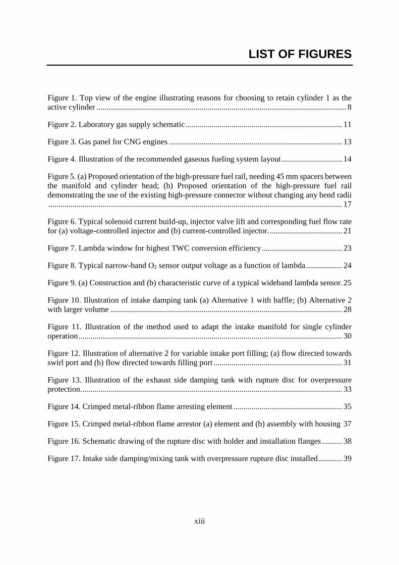
LIST OF FIGURES
Figure 1. Top view of the engine illustrating reasons for choosing to retain cylinder 1 as the
active cylinder ............................................................................................................................ 8
Figure 2. Laboratory gas supply schematic .............................................................................. 11
Figure 3. Gas panel for CNG engines ...................................................................................... 13
Figure 4. Illustration of the recommended gaseous fueling system layout .............................. 14
Figure 5. (a) Proposed orientation of the high-pressure fuel rail, needing 45 mm spacers between
the manifold and cylinder head; (b) Proposed orientation of the high-pressure fuel rail
demonstrating the use of the existing high-pressure connector without changing any bend radii
.................................................................................................................................................. 17
Figure 6. Typical solenoid current build-up, injector valve lift and corresponding fuel flow rate
for (a) voltage-controlled injector and (b) current-controlled injector. .................................... 21
Figure 7. Lambda window for highest TWC conversion efficiency ........................................ 23
Figure 8. Typical narrow-band O2 sensor output voltage as a function of lambda .................. 24
Figure 9. (a) Construction and (b) characteristic curve of a typical wideband lambda sensor. 25
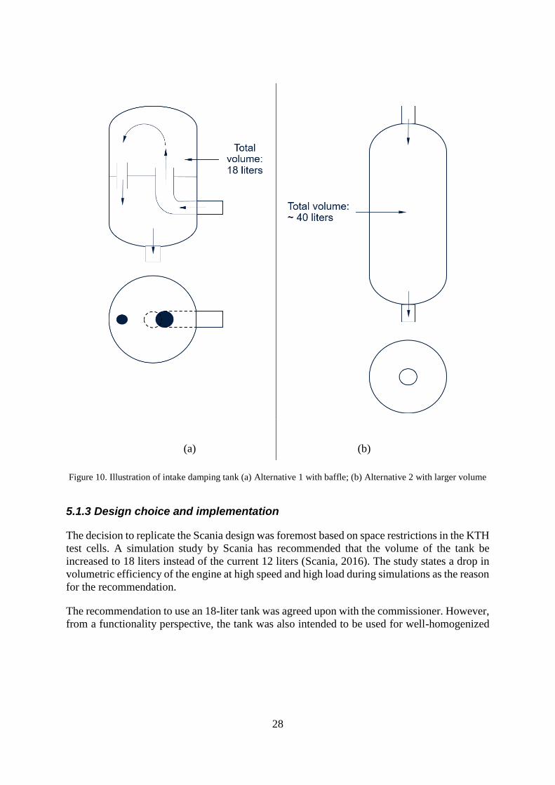
Figure 10. Illustration of intake damping tank (a) Alternative 1 with baffle; (b) Alternative 2
with larger volume ................................................................................................................... 28
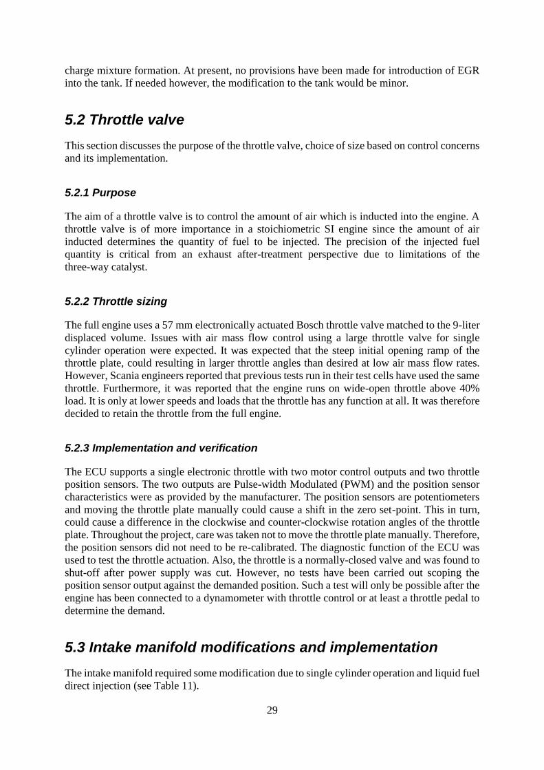
Figure 11. Illustration of the method used to adapt the intake manifold for single cylinder
operation ................................................................................................................................... 30
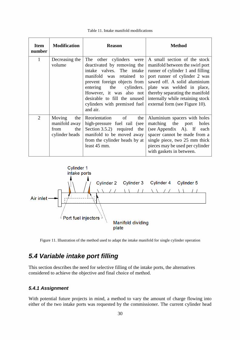
Figure 12. Illustration of alternative 2 for variable intake port filling; (a) flow directed towards
swirl port and (b) flow directed towards filling port ................................................................ 31
Figure 13. Illustration of the exhaust side damping tank with rupture disc for overpressure
protection. ................................................................................................................................. 33
Figure 14. Crimped metal-ribbon flame arresting element ...................................................... 35
Figure 15. Crimped metal-ribbon flame arrestor (a) element and (b) assembly with housing 37
Figure 16. Schematic drawing of the rupture disc with holder and installation flanges .......... 38
Figure 17. Intake side damping/mixing tank with overpressure rupture disc installed ............ 39

xiv
Figure A-1. Spacer between the intake manifold and cylinder head with half the stock filling
port area .................................................................................................................................. A-1
Figure A-2. Spacer between the intake manifold and cylinder head with half the stock swirl port
area ......................................................................................................................................... A-2
Figure A-3. Spacer between the intake manifold and cylinder head with blocked filling port
................................................................................................................................................ A-3
Figure A-4. Spacer between the intake manifold and cylinder head with blocked swirl port A-4
Figure A-5. Spacers with stock port areas for unused cylinders ............................................ A-5
xv
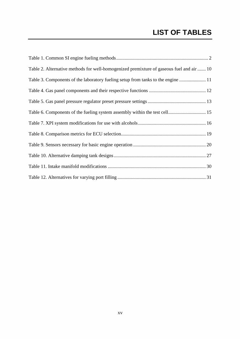
LIST OF TABLES
Table 1. Common SI engine fueling methods ............................................................................ 2
Table 2. Alternative methods for well-homogenized premixture of gaseous fuel and air ....... 10
Table 3. Components of the laboratory fueling setup from tanks to the engine ...................... 11
Table 4. Gas panel components and their respective functions ............................................... 12
Table 5. Gas panel pressure regulator preset pressure settings ................................................ 13
Table 6. Components of the fueling system assembly within the test cell ............................... 15
Table 7. XPI system modifications for use with alcohols ........................................................ 16
Table 8. Comparison metrics for ECU selection ...................................................................... 19
Table 9. Sensors necessary for basic engine operation ............................................................ 20
Table 10. Alternative damping tank designs ............................................................................ 27
Table 11. Intake manifold modifications ................................................................................. 30
Table 12. Alternatives for varying port filling ......................................................................... 31

xvi
1
1 INTRODUCTION
This chapter gives a brief introduction to internal combustion engines, the purpose of this
project followed by the deliverables and delimitations.
1.1 Internal Combustion Engines – A Brief Overview
Internal combustion engines (ICEs) date back to the late 19th century when Nikolaus Otto
developed the spark-ignition (SI) engine and Rudolf Diesel invented the compression-ignition
(CI) engine. ICEs have played a dominant role in the fields of energy and propulsion. However,
the last three or so decades have seen vast developments in engine research and development
to tackle the issues of pollution, fuel cost and market competitiveness (Heywood, 1988).
Engines can be classified in a variety of different ways, but for the purposes of this report, they
shall only be classified as being either of the SI type or the CI type. This classification is based
on the method used to provide the activation energy required to initiate the combustion process.
Both methods are applicable to fuels possessing different qualities. Spark ignition is used for
fuels that have high auto-ignition temperatures. As the name suggests, the ignition is initiated
by a spark plug which provides a high voltage electric arc. On the other hand, certain fuels can
be ignited by simply compressing them in a quasi-adiabatic process (Heywood, 1988).
A majority of ICEs operate on what is known as the four-stroke cycle. Each of the four strokes
takes place during half a rotation of the crank or 180°. Thus, one complete cycle requires that
the crank rotate through a total of 720°. The four strokes that make up the cycle are as follows
(Heywood, 1988):
1. The intake stroke which starts at Top Dead Center (TDC) and ends at Bottom Dead Center
(BDC) during which the charge is inducted into the engine via the intake valves. The
exhaust valves remain closed.
2. The compression stroke during which both the exhaust and intake valves are closed. The
charge is compressed to a fraction of its initial volume by the upward motion of the piston
form BDC to TDC. Combustion is initiated toward the end of this stroke and there is a
further increase in the cylinder pressure.
3. The expansion stroke results from the expanding high-temperature gases which are
products of the combustion. This is the only stroke during which work is extracted from
the fuel. The expansion causes the piston to move from TDC to BDC. The exhaust valves
open toward the end of this stroke.
4. The exhaust stroke during which the exhaust valve is fully open and the upward motion
of the piston from BDC to TDC driven by inertia, causes the exhaust gases to be evacuated
from the cylinder. The intake valves open toward the end of this stroke to allow fresh
charge to be inducted for the next cycle.
1.1.1 Commonly used fueling methods:
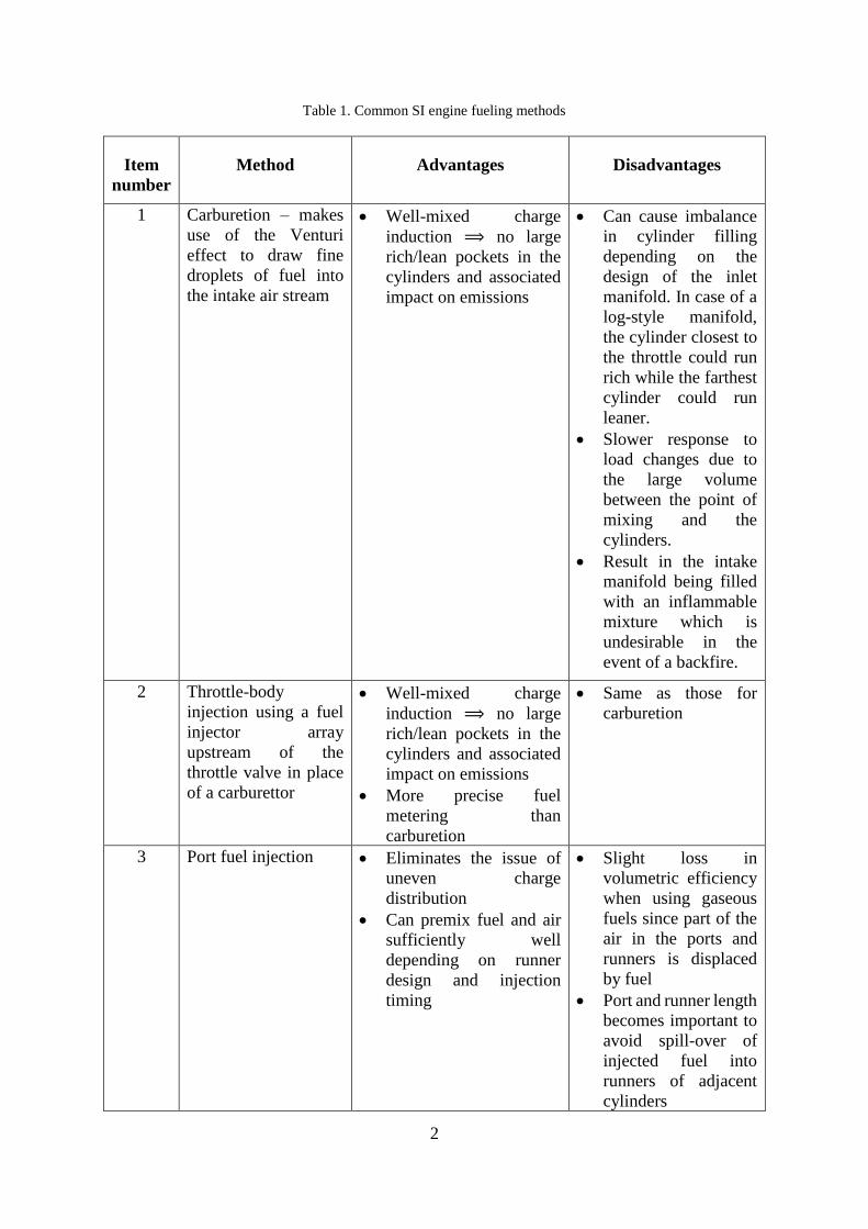
SI engines employ four main fueling methods (see Table 1) (Heywood, 1988):
2
Table 1. Common SI engine fueling methods
Item
number
Method Advantages Disadvantages
1 Carburetion – makes
use of the Venturi
effect to draw fine
droplets of fuel into
the intake air stream
• Well-mixed charge
induction ⟹ no large
rich/lean pockets in the
cylinders and associated
impact on emissions
• Can cause imbalance
in cylinder filling
depending on the
design of the inlet
manifold. In case of a
log-style manifold,
the cylinder closest to
the throttle could run
rich while the farthest
cylinder could run
leaner.
• Slower response to
load changes due to
the large volume
between the point of
mixing and the
cylinders.
• Result in the intake
manifold being filled
with an inflammable
mixture which is
undesirable in the
event of a backfire.
2 Throttle-body
injection using a fuel
injector array
upstream of the
throttle valve in place
of a carburettor
• Well-mixed charge
induction ⟹ no large
rich/lean pockets in the
cylinders and associated
impact on emissions
• More precise fuel
metering than
carburetion
• Same as those for
carburetion
3 Port fuel injection • Eliminates the issue of
uneven charge
distribution
• Can premix fuel and air
sufficiently well
depending on runner
design and injection
timing
• Slight loss in
volumetric efficiency
when using gaseous
fuels since part of the
air in the ports and
runners is displaced
by fuel
• Port and runner length
becomes important to
avoid spill-over of
injected fuel into
runners of adjacent
cylinders
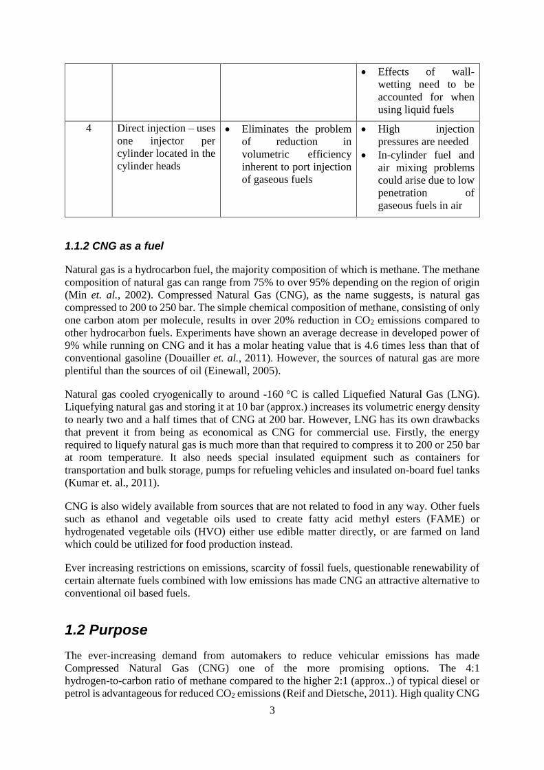
3
• Effects of wall-
wetting need to be
accounted for when
using liquid fuels
4 Direct injection – uses
one injector per
cylinder located in the
cylinder heads
• Eliminates the problem
of reduction in
volumetric efficiency
inherent to port injection
of gaseous fuels
• High injection
pressures are needed
• In-cylinder fuel and
air mixing problems
could arise due to low
penetration of
gaseous fuels in air
1.1.2 CNG as a fuel
Natural gas is a hydrocarbon fuel, the majority composition of which is methane. The methane
composition of natural gas can range from 75% to over 95% depending on the region of origin
(Min et. al., 2002). Compressed Natural Gas (CNG), as the name suggests, is natural gas
compressed to 200 to 250 bar. The simple chemical composition of methane, consisting of only
one carbon atom per molecule, results in over 20% reduction in CO2 emissions compared to
other hydrocarbon fuels. Experiments have shown an average decrease in developed power of
9% while running on CNG and it has a molar heating value that is 4.6 times less than that of
conventional gasoline (Douailler et. al., 2011). However, the sources of natural gas are more
plentiful than the sources of oil (Einewall, 2005).
Natural gas cooled cryogenically to around -160 °C is called Liquefied Natural Gas (LNG).
Liquefying natural gas and storing it at 10 bar (approx.) increases its volumetric energy density
to nearly two and a half times that of CNG at 200 bar. However, LNG has its own drawbacks
that prevent it from being as economical as CNG for commercial use. Firstly, the energy
required to liquefy natural gas is much more than that required to compress it to 200 or 250 bar
at room temperature. It also needs special insulated equipment such as containers for
transportation and bulk storage, pumps for refueling vehicles and insulated on-board fuel tanks
(Kumar et. al., 2011).
CNG is also widely available from sources that are not related to food in any way. Other fuels
such as ethanol and vegetable oils used to create fatty acid methyl esters (FAME) or
hydrogenated vegetable oils (HVO) either use edible matter directly, or are farmed on land
which could be utilized for food production instead.
Ever increasing restrictions on emissions, scarcity of fossil fuels, questionable renewability of
certain alternate fuels combined with low emissions has made CNG an attractive alternative to
conventional oil based fuels.
1.2 Purpose
The ever-increasing demand from automakers to reduce vehicular emissions has made
Compressed Natural Gas (CNG) one of the more promising options. The 4:1
hydrogen-to-carbon ratio of methane compared to the higher 2:1 (approx..) of typical diesel or
petrol is advantageous for reduced CO2 emissions (Reif and Dietsche, 2011). High quality CNG
4
with a high percentage of methane also provides a virtually soot-free operation (Reif and
Dietsche, 2011). Moreover, CNG has an Research Octane Number (RON) of approximately
130 which makes it more knock-resistant (Reif and Dietsche, 2011). This makes it possible to
use higher compression ratios compared to typical gasoline engines. The higher
knock-resistance of CNG also means that the engines running on CNG can be turbocharged to
higher pressures for improved indicated efficiency. The decrease in volumetric efficiency due
to displacement of air by fuel can also be addressed through forced induction.
In a research setting where one intends to study various phenomena concerning engine
operation, it is often desirable to eliminate or isolate as many variables as possible in a
controlled manner. In a multi-cylinder engine, flow and/or electrical phenomena occurring in
one cylinder could possibly affect those in another cylinder. This makes it difficult to perform
a controlled study of the phenomena of interest. Nevertheless, a single cylinder engine permits
the study of these phenomena of interest without disturbances due to adjacent cylinders.
1.3 Task definition
The project aims at implementing flexible fueling of a series production multi-cylinder
heavy-duty CNG fueled engine modified for single cylinder operation using an aftermarket
electronic engine control unit (ECU). The modified engine is intended for further research and
will be installed in one of the test cells at the Internal Combustion Engines laboratory at KTH
Royal Institute of Technology, Stockholm. This thesis is part of the bigger Project CLOCK
(Closed Loop Otto Combustion and Knock control). The participating partners are Scania CV
AB, KTH Royal Institute of Technology, Sweden, and the Swedish Energy Agency. Although
the first customer of the engine once installed at KTH will be Project CLOCK, future projects
could potentially involve research on different fuels and fueling methods.
1.3.1 Research objectives
The main research objectives intended to be fulfilled through this project are:
1. Evaluating the best aftermarket ECU taking the extent of controllability offered into
account while remaining easy to use in an academic setting
2. Making provisions for variable homogeneity of gaseous fuel-air mixture with due
consideration to safety
3. Making provisions for selective intake port usage for future studies on its effect on
in-cylinder flows
4. Making hardware provisions for implementation of liquid fuel direct injection
1.3.2 Project outline
The project involves the following steps/stages:
1. Selection of a suitable engine for modification
2. Selection of a suitable aftermarket ECU to control the fuel system
5
3. Selection of required sensors and actuators needed to implement the control
4. Making required mechanical modifications on the engine from a fueling system
perspective
5. Installing the control hardware and configuring the control system as required
6. Delivering a working engine
The engine uses a port-injected CNG fueling system. The parameters of the fueling system that
are expected to be controlled are: Mass flow rate of fuel, injection pressure and start of injection.
1.4 Deliverables and delimitations
This thesis project spanned over a duration of 20 weeks, was limited in the deliverables. The
following deliverables and delimitations were formulated after mutual agreement between the
author and the project commissioner.
1.4.1 Deliverables
1. The fuel injectors will be controlled with respect to start/end of injection and mass flow
rate of CNG.
2. A conventional speed-density based open loop and lambda sensor-based closed loop
control of the injectors will be implemented.
3. Additional injector(s) (capable of injecting a different gaseous fuel) will be installed in
the intake air path thus varying homogeneity (and composition) of the resulting charge.
4. Provisions will be made for higher or lower flow rate through either intake port.
5. The selected aftermarket ECU should be capable of liquid fuel direct injection, if possible.
6. The ECU should be able to control Exhaust Gas Recirculation (EGR).
7. Safety devices such as flame arrestors and vent valves will be installed at appropriate
locations
8. Documentation for future users will be created for all the non-standard auxiliaries
mounted on the engine.
1.4.2 Delimitations
1. Mechanical modifications for conversion to single cylinder if using a multi-cylinder
engine will not be the main focus although assistance for the same will be provided.
2. Cycle-to-cycle injector control will not be carried out.
3. The ECU will not be programmed at machine level but only via the bundled software
GUI.

6
4. Ignition control remains outside the scope of this project. It shall be the focus of a
concurrent thesis project carried out by a fellow student.
5. Controlling the liquid fuel direct injection fueling will be excluded.
6. Further components in the intake air path upstream of the damping tanks were considered
to belong to the test cell and were excluded from the scope of this project.
Mechanical modifications to the engine for single cylinder operation were carried out as part of
a separate thesis project concurrent to this one. The author has assisted in this work.
7
2 ENGINE SELECTION
The first section of this chapter presents the rationale behind using a single cylinder engine for
research. The final choice of engine based on certain requirements has also been discussed.
2.1 Single cylinder research engine
Internal combustion engines used for research can be either single cylinder or multi-cylinder
based on the phenomenon of interest being studied. When the phenomena of interest are
combustion, combustion chamber designs, in-cylinder flows, flows across valves etc., it is
prudent to use a single cylinder engine.
A single cylinder engine has the inherent advantage of not being affected by the adverse flow
interactions due to other cylinders. It is also logical to use a single cylinder engine to reduce
fuel consumption. The ability to facilitate easy replacement of internal components suitable for
the type of tests intended to be run is another advantage.
2.2 Requirement specification and alternatives
The most important requirement regarding the engine was the availability of spare parts in the
future. The engine was a contribution from Scania CV AB towards Project CLOCK. At the
beginning of the project, there were three tentative engine options to choose from:
1. A custom-built single cylinder engine based on the 13-liter Scania DC13 engine
2. A 5-cylinder Scania OC09 9-liter Otto engine
3. A 6-cylinder Scania OC13 13-liter Otto engine
Unlike options 2 and 3, the custom-built single cylinder engine would not require mechanical
modifications to run it as single cylinder. However, most of the parts for such an engine were
custom-made. From the perspective of ready availability of spare parts, it was decided that the
series-produced multi-cylinder engines would be a more practical choice. Additionally, the
multi-cylinder engines were already balanced and would not vibrate as much even when only
one cylinder was fired.
2.3 Implementation
The availability of a run-in and tested 5-cylinder, 9-liter engine, made it the default choice. All
requisite modifications for conversion to single cylinder operation were done by another
student, assisted by the author. The details of these modifications can be found in a separate
report (Lius, 2018).
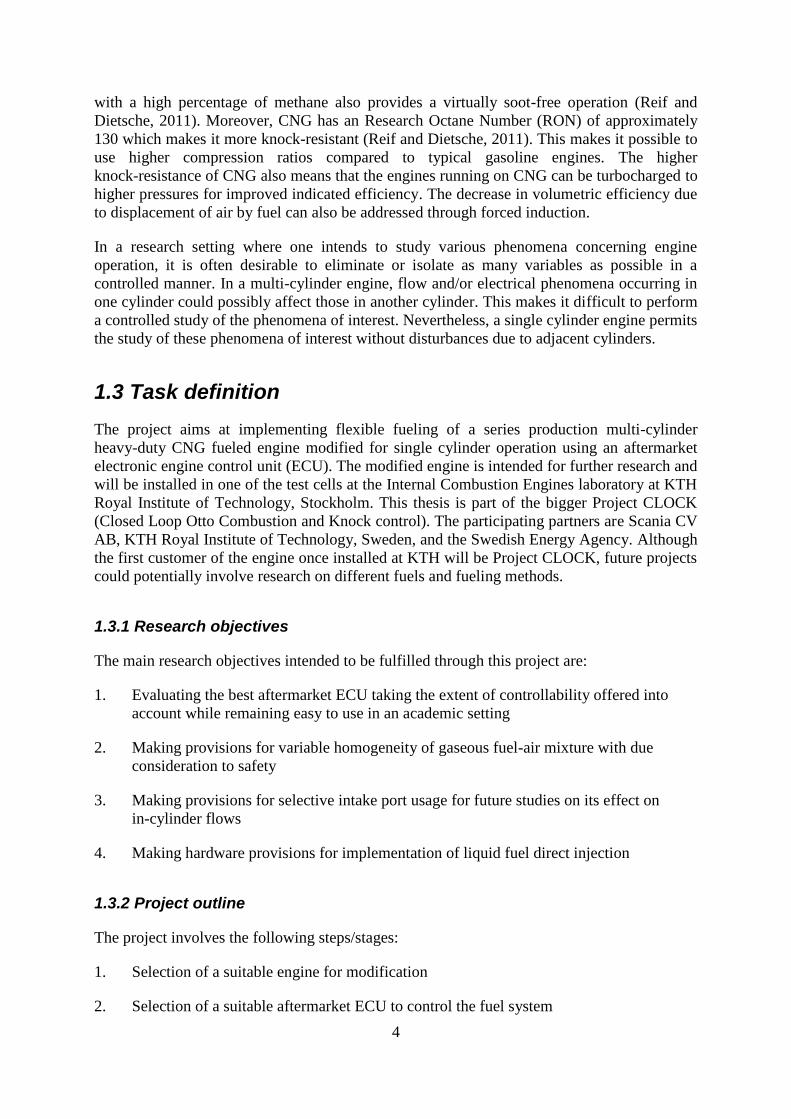
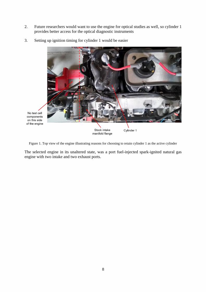
It was decided to use cylinder 1 (first cylinder from the front of the engine) as the active cylinder
because of the following considerations:
1. The open end of the intake manifold lies adjacent to cylinder 1, meaning that the existing
flange on the manifold could be used without subjecting the manifold to machining
8
2. Future researchers would want to use the engine for optical studies as well, so cylinder 1
provides better access for the optical diagnostic instruments
3. Setting up ignition timing for cylinder 1 would be easier
Figure 1. Top view of the engine illustrating reasons for choosing to retain cylinder 1 as the active cylinder
The selected engine in its unaltered state, was a port fuel-injected spark-ignited natural gas
engine with two intake and two exhaust ports.
9
3 FUELING SYSTEM
The following chapter is a discussion on the fueling of the engine, the challenges associated
with gaseous fueling and final implementation.
3.1 Fuel-air mixture formation
This section discusses the main challenge involved in mixing two fluids of comparable
densities. The fluids of interest to this project are CNG and air. Researchers have reported
turbulence, volume and residence time available for mixing affect the homogeneity of the
mixture. Methods to promote the turbulence intensity and to vary the residence time to achieve
varying mixture homogeneity were implemented.
3.1.1 Gaseous fuel-air mixture
Turbulence caused by the transfer of momentum from the periphery of a jet to the surrounding
fluid provides the necessary shear forces to generate eddies and vortices that promote mixing.
The appreciable difference in the densities of liquid fuel droplets and air, create significant
turbulence at the jet-air interface. Vaporization of the droplets creates a vapor trail behind them
which, combined with the momentum induced small-scale vortices, accelerates the diffusion
rate. This process helps create a more uniformly distributed mixture (Khan et. al., 2009).
However, the shear forces between a gas jet injected into another quiescent gas, are low and
mixture formation may become diffusion dominated, which is a relatively slow process. The
comparable densities of gaseous fuels and air, do not allow the utilization of jet penetration for
large scale mixing throughout the volume. Low penetration is characteristic of gas jets
irrespective of injection pressure. Research has shown that mixing can be improved by inducing
large-scale turbulence (Herrera et. al., 2012; Khan et. al., 2009).
3.1.2 Effects of fuel injector location and injection timing
The location of the fuel injectors determines the residence time available for the fuel to form a
homogeneous mixture. Researchers have reported that injecting fuel just downstream of the
throttle body provides a greater time for homogeneous mixture formation owing to the length
of the intake pipe from the injector(s) to the cylinders. The turbulence prevalent after the throttle
valve also serves to promote mixing (Soanes and Koopmans, 2012; Puzinauskas et. al., 2000).
In the case of port fuel injection, variation in mixture homogeneity was reported to be sensitive
to the injection timing. The decrease in mixing length makes the mixing dependent on the inlet
valve opening and pulsations in the manifold (Soanes and Koopmans, 2012). It is believed that
injecting against a closed inlet valve can provide enough residence time for mixture formation.
However, port injection into an open inlet valve was reported to aid turbulence effects and
promote in cylinder mixing. Residual mixture in the port from the previous injection cycle was
observed to reduce the effect of any stratification in the cylinder. However, this strategy was
not found to produce any prominent effects at high loads (Czerwinski et. al., 1999).
10
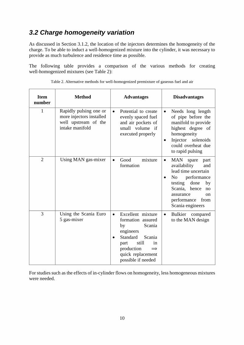
3.2 Charge homogeneity variation
As discussed in Section 3.1.2, the location of the injectors determines the homogeneity of the
charge. To be able to induct a well-homogenized mixture into the cylinder, it was necessary to
provide as much turbulence and residence time as possible.
The following table provides a comparison of the various methods for creating
well-homogenized mixtures (see Table 2):
Table 2. Alternative methods for well-homogenized premixture of gaseous fuel and air
Item
number
Method Advantages Disadvantages
1 Rapidly pulsing one or
more injectors installed
well upstream of the
intake manifold
• Potential to create
evenly spaced fuel
and air pockets of
small volume if
executed properly
• Needs long length
of pipe before the
manifold to provide
highest degree of
homogeneity
• Injector solenoids
could overheat due
to rapid pulsing
2 Using MAN gas-mixer • Good mixture
formation
• MAN spare part
availability and
lead time uncertain
• No performance
testing done by
Scania, hence no
assurance on
performance from
Scania engineers
3 Using the Scania Euro
5 gas-mixer • Excellent mixture
formation assured
by Scania
engineers
• Standard Scania
part still in
production ⟹
quick replacement
possible if needed
• Bulkier compared
to the MAN design
For studies such as the effects of in-cylinder flows on homogeneity, less homogeneous mixtures
were needed.
11
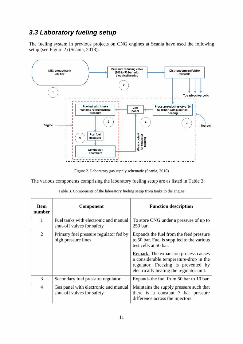
3.3 Laboratory fueling setup
The fueling system in previous projects on CNG engines at Scania have used the following
setup (see Figure 2) (Scania, 2018):
Figure 2. Laboratory gas supply schematic (Scania, 2018)
The various components comprising the laboratory fueling setup are as listed in Table 3:
Table 3. Components of the laboratory fueling setup from tanks to the engine
Item
number
Component Function description
1 Fuel tanks with electronic and manual
shut-off valves for safety
To store CNG under a pressure of up to
250 bar.
2 Primary fuel pressure regulator fed by
high pressure lines
Expands the fuel from the feed pressure
to 50 bar. Fuel is supplied to the various
test cells at 50 bar.
Remark: The expansion process causes
a considerable temperature-drop in the
regulator. Freezing is prevented by
electrically heating the regulator unit.
3 Secondary fuel pressure regulator Expands the fuel from 50 bar to 10 bar.
4 Gas panel with electronic and manual
shut-off valves for safety
Maintains the supply pressure such that
there is a constant 7 bar pressure
difference across the injectors.
12
5 Fuel rail Temporary fuel storage before
injection.
Remark: Another function of the fuel
rail especially in a multi-cylinder setup,
is to ensure that each injector receives
fuel at the same pressure and that none
of the injectors are starved.
6 Fuel injectors connected to the fuel
rail
Injecting fuel in the intake ports to
induct a premixed charge into the
cylinders
Safety devices such as flame traps and shut-off valves (both manual and automatic) are located
at various points in the circuit
3.3.1 Gas panel
Installed within the test cell between the secondary pressure regulator and the fuel rail, is a gas
panel which consists of the following components (see Table 4 and Figure 3):
Table 4. Gas panel components and their respective functions
Item
number
Component Function
1 Reference pressure line to
intake manifold
To maintain a constant pressure difference of 7 bar
across the injector irrespective of intake manifold
pressure
2 Pressure limiting valve To prevent fuel overpressure which could impact
injector opening time and current
3 Pressure regulator To reduce the gas from tank pressure (~ 200 bar) to
injection pressure (~ 7.3 bar)
4 Pressure sensor For diagnostics
5 Solenoid valve For automatic gas supply switching on/off on the
low-pressure side when the power is switched
on/off
6 Manometer For manual inspection of supply pressure from the
tank
7 Fuel filter To remove oil droplets possibly introduced during
compression, and other impurities from the gas
8 Manual shut-off valve To manually turn on/off low-pressure gas supply
13
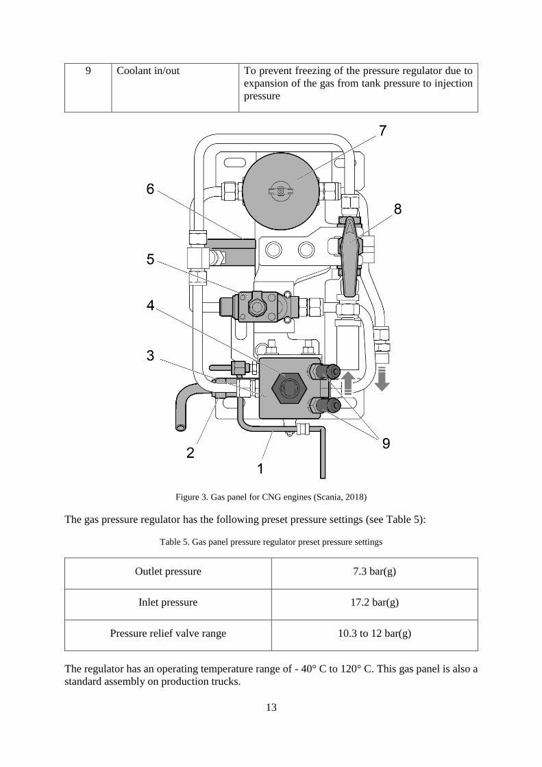
9 Coolant in/out To prevent freezing of the pressure regulator due to
expansion of the gas from tank pressure to injection
pressure
Figure 3. Gas panel for CNG engines (Scania, 2018)
The gas pressure regulator has the following preset pressure settings (see Table 5):
Table 5. Gas panel pressure regulator preset pressure settings
Outlet pressure 7.3 bar(g)
Inlet pressure 17.2 bar(g)
Pressure relief valve range 10.3 to 12 bar(g)
The regulator has an operating temperature range of - 40° C to 120° C. This gas panel is also a
standard assembly on production trucks.
14
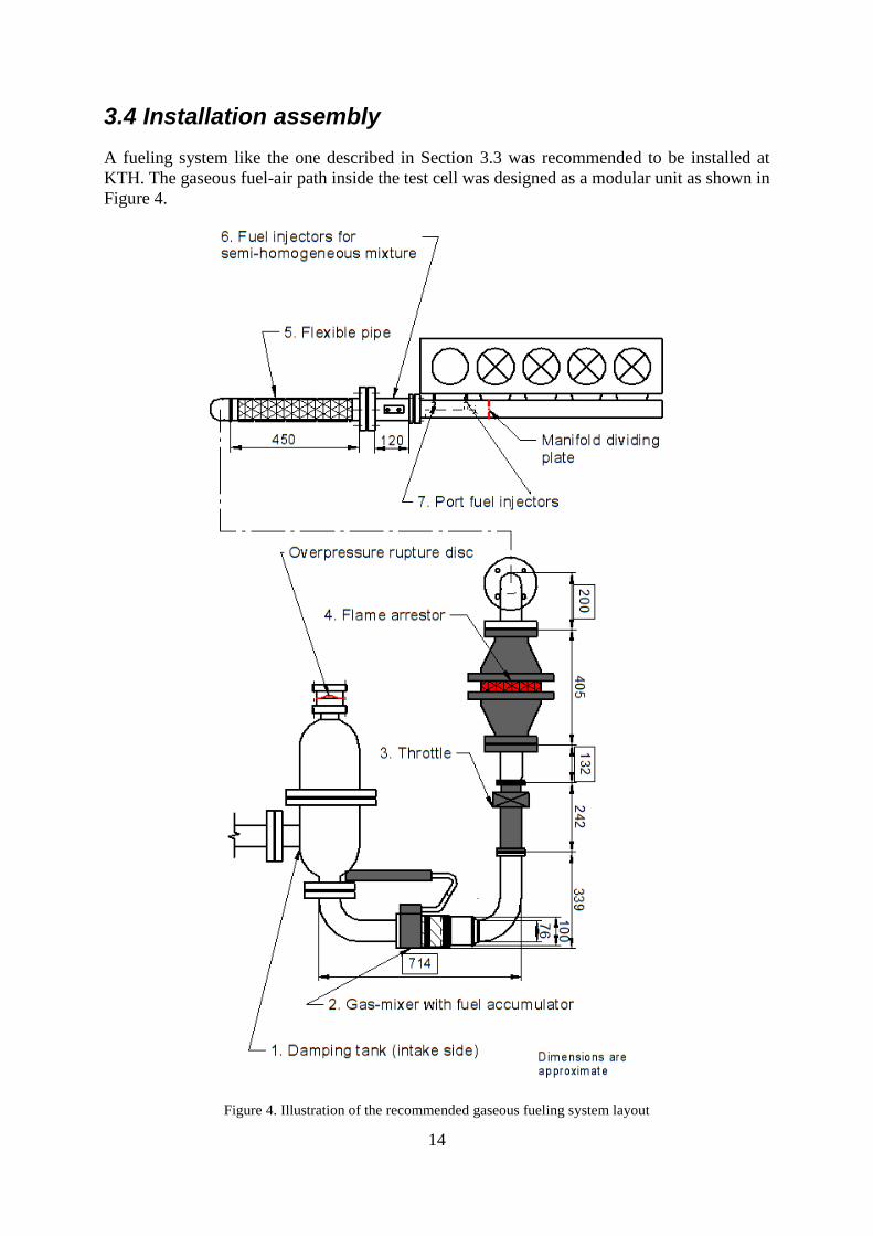
3.4 Installation assembly
A fueling system like the one described in Section 3.3 was recommended to be installed at
KTH. The gaseous fuel-air path inside the test cell was designed as a modular unit as shown in
Figure 4.
Figure 4. Illustration of the recommended gaseous fueling system layout
15
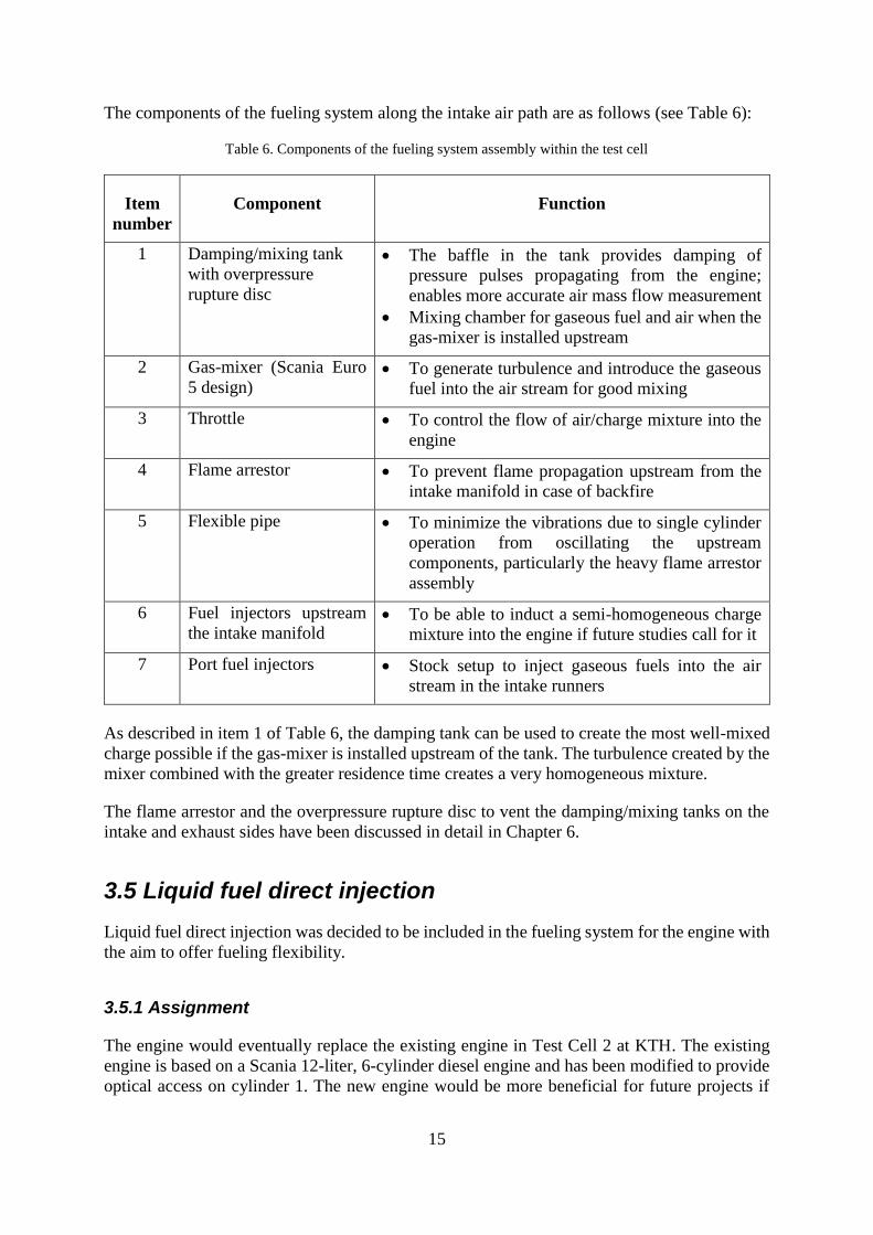
The components of the fueling system along the intake air path are as follows (see Table 6):
Table 6. Components of the fueling system assembly within the test cell
Item
number
Component Function
1 Damping/mixing tank
with overpressure
rupture disc
• The baffle in the tank provides damping of
pressure pulses propagating from the engine;
enables more accurate air mass flow measurement
• Mixing chamber for gaseous fuel and air when the
gas-mixer is installed upstream
2 Gas-mixer (Scania Euro
5 design) • To generate turbulence and introduce the gaseous
fuel into the air stream for good mixing
3 Throttle • To control the flow of air/charge mixture into the
engine
4 Flame arrestor • To prevent flame propagation upstream from the
intake manifold in case of backfire
5 Flexible pipe • To minimize the vibrations due to single cylinder
operation from oscillating the upstream
components, particularly the heavy flame arrestor
assembly
6 Fuel injectors upstream
the intake manifold • To be able to induct a semi-homogeneous charge
mixture into the engine if future studies call for it
7 Port fuel injectors • Stock setup to inject gaseous fuels into the air
stream in the intake runners
As described in item 1 of Table 6, the damping tank can be used to create the most well-mixed
charge possible if the gas-mixer is installed upstream of the tank. The turbulence created by the
mixer combined with the greater residence time creates a very homogeneous mixture.
The flame arrestor and the overpressure rupture disc to vent the damping/mixing tanks on the
intake and exhaust sides have been discussed in detail in Chapter 6.
3.5 Liquid fuel direct injection
Liquid fuel direct injection was decided to be included in the fueling system for the engine with
the aim to offer fueling flexibility.
3.5.1 Assignment
The engine would eventually replace the existing engine in Test Cell 2 at KTH. The existing
engine is based on a Scania 12-liter, 6-cylinder diesel engine and has been modified to provide
optical access on cylinder 1. The new engine would be more beneficial for future projects if
16
provisions are made for flexible fueling. A requirement from the commissioner was to be able
to directly inject liquid fuels such as diesel and alcohols.
3.5.2 Implementation
To fulfill this requirement, it was decided to use the Scania XPI direct injection fueling system.
Apart from the extremely high pressure (~ 1500 bar) fuel injection capability of the system, the
cylinder heads are designed to accommodate the XPI injectors. The engine also had the
gear-train to drive the high-pressure fuel pump pre-installed. These features necessitate no
extensive machining to be able to implement liquid fuel direct injection.
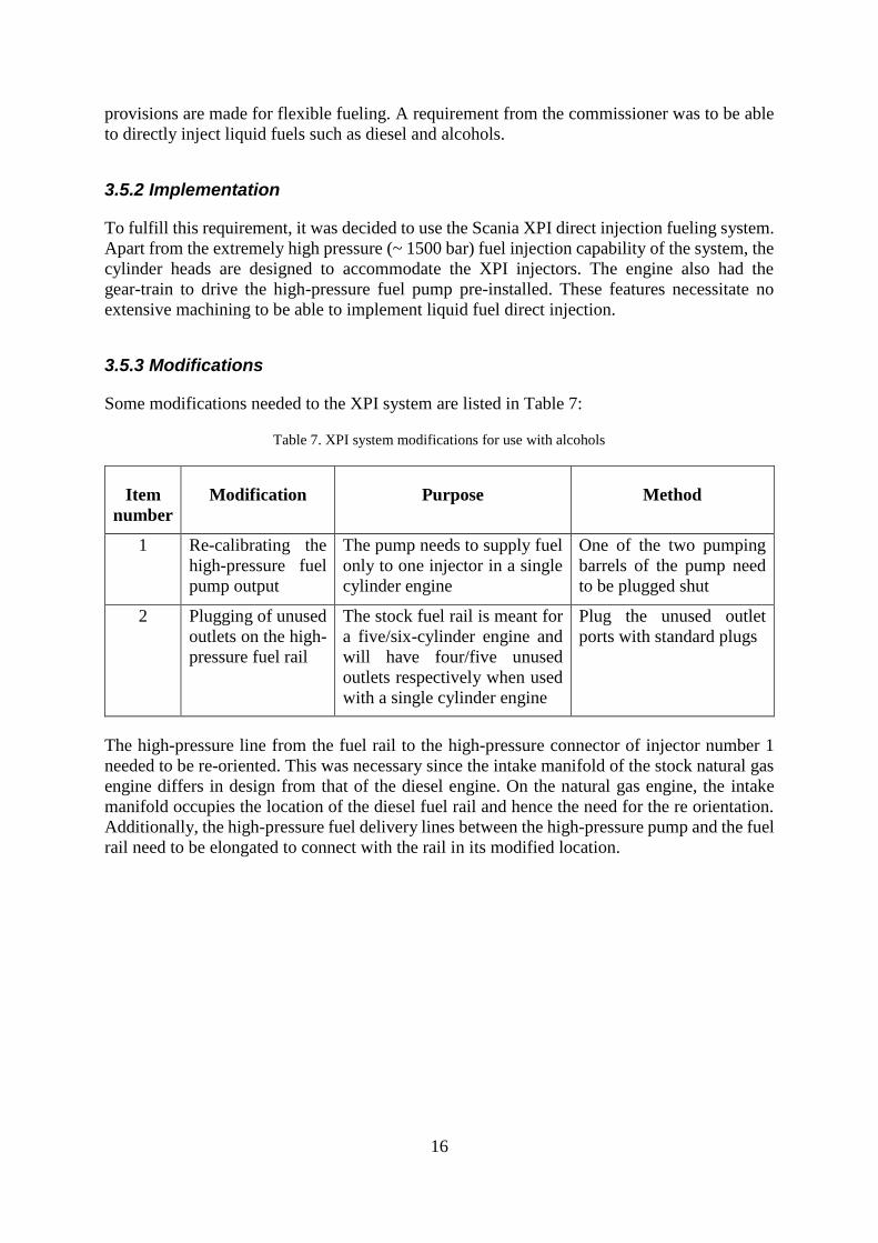
3.5.3 Modifications
Some modifications needed to the XPI system are listed in Table 7:
Table 7. XPI system modifications for use with alcohols
Item
number
Modification Purpose Method
1 Re-calibrating the
high-pressure fuel
pump output
The pump needs to supply fuel
only to one injector in a single
cylinder engine
One of the two pumping
barrels of the pump need
to be plugged shut
2 Plugging of unused
outlets on the high-
pressure fuel rail
The stock fuel rail is meant for
a five/six-cylinder engine and
will have four/five unused
outlets respectively when used
with a single cylinder engine
Plug the unused outlet
ports with standard plugs
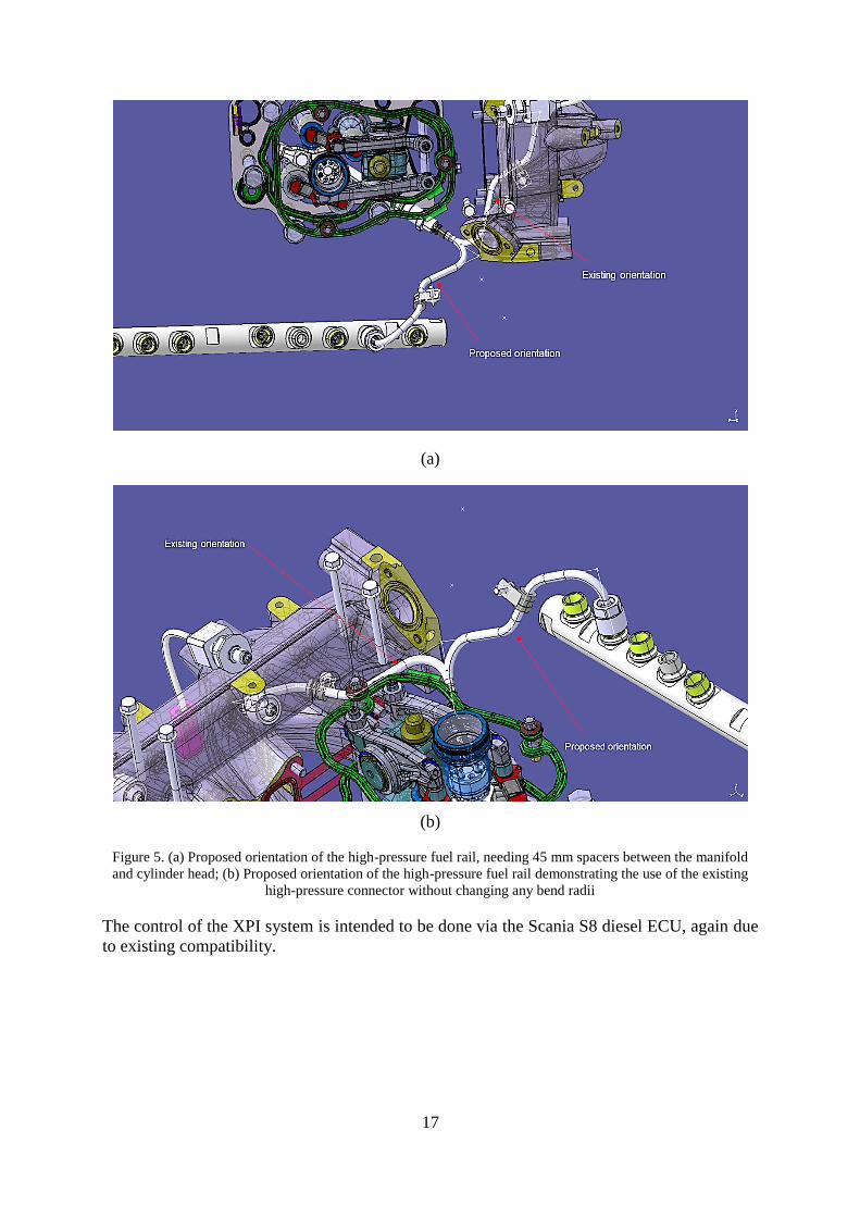
The high-pressure line from the fuel rail to the high-pressure connector of injector number 1
needed to be re-oriented. This was necessary since the intake manifold of the stock natural gas
engine differs in design from that of the diesel engine. On the natural gas engine, the intake
manifold occupies the location of the diesel fuel rail and hence the need for the re orientation.
Additionally, the high-pressure fuel delivery lines between the high-pressure pump and the fuel
rail need to be elongated to connect with the rail in its modified location.
17
(a)
(b)
Figure 5. (a) Proposed orientation of the high-pressure fuel rail, needing 45 mm spacers between the manifold
and cylinder head; (b) Proposed orientation of the high-pressure fuel rail demonstrating the use of the existing
high-pressure connector without changing any bend radii
The control of the XPI system is intended to be done via the Scania S8 diesel ECU, again due
to existing compatibility.

18
19
4 ELECTRONIC ENGINE CONTROL
In this chapter, a discussion of the electronic engine control unit used for this project has been
presented. Also included, are the most important electronic fueling system components – the
injectors and the lambda control.
4.1 Engine control unit
This section provides a brief description of the requirements set on the engine control unit in
terms of controllability, followed by selection and implementation of the control unit.
4.1.1 Assignment
The production version of the original engine is controlled by a Bosch EGC 4 engine
management system specific to natural gas engines. However, this control unit contains
proprietary programming from Bosch and is not open for modification. In order to set up the
engine for the intended tests, a user-configurable ECU was found necessary. Aftermarket ECUs
which usually have a Graphical User Interface (GUI) were found suitable. These ECUs, while
not programmable at the code level, still offered more flexible configurability compared to the
Bosch system. Deciding the most important comparison metrics for selection of the ECU was
undertaken as part of this project.
4.1.2 ECU selection criteria
The main criteria for choice of aftermarket ECU for the project were as follows (see Table 8):
Table 8. Comparison metrics for ECU selection
Item
number
Criterion Description
1 Configurability and ease of use The chosen unit should be easy to
configure, preferably on-the-fly through a
Graphical User Interface (GUI). A Swedish
manufacturer is preferred so that requests
for feature addition/modification can be
done quickly.
2 Cost The cost should be as low as possible since
it is possible that the new Scania Otto ECU
being developed by NESI could replace the
unit eventually.
3 Number of inputs and outputs The ECU should be able to read and control
as many parameters as possible.
Inputs: Crank and cam position, intake air
temperature and pressure, oil pressure,
coolant temperature, exhaust temperature
20
shall be the bare minimum parameters to be
read.
Outputs: Electronic throttle control, drive
for at least six low impedance injectors,
EGR valve control (if possible) shall be the
bare minimum outputs.
4.1.3 ECU selection and installation
The criteria mentioned in the previous section resulted in a choice between either the MaxxECU
Race or the NIRA i7x. Recommendations from Scania engineers with previous positive
experience with MaxxECU were strongly influential in the decision. The NIRA i7x was also
found to lack driver circuits for low impedance injectors. Thus, the MaxxECU Race was opted
for and installed.
The main sensors needed for engine operations (see Table 9) were connected to the ECU via
the accompanying wiring harness.
Table 9. Sensors necessary for basic engine operation
Item
number
Sensor Description
1 Engine speed sensor Senses rotational speed and position of the
crankshaft to determine injection and
ignition timing.
2 Camshaft position sensor Used in conjunction with the engine speed
sensor to determine which of the pistons is
towards the end of the compression stroke.
3 Intake manifold combined pressure
and temperature sensor
Determines the air mass flow rate into the
engine via the Speed-Density algorithm.
4 Wideband lambda sensor Determines the stoichiometry of the
previous combustion event and used for
feedback control.
5 Knock sensor Senses the occurrence of engine knock so
that ignition timing can be retarded.
4.2 Fueling control
The following section describes the hardware and considerations that need to be accounted for
to control the fueling system.
21
4.2.1 Types of CNG injectors
There exist two types of injectors which are suitable for CNG applications namely, the
voltage-controlled and the current-controlled types. Both types of injectors have been used in
all kinds of injection methods such as throttle-body injection, multi-point injection (sequential
and continuous) as well as direct injection. Both types of injectors have electromagnetic
solenoids which can be opened and closed by energizing and de-energizing the coils
(Reif, 2015).
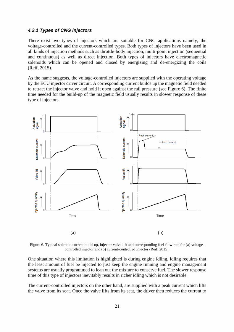
As the name suggests, the voltage-controlled injectors are supplied with the operating voltage
by the ECU injector driver circuit. A corresponding current builds up the magnetic field needed
to retract the injector valve and hold it open against the rail pressure (see Figure 6). The finite
time needed for the build-up of the magnetic field usually results in slower response of these
type of injectors.
(a) (b)
Figure 6. Typical solenoid current build-up, injector valve lift and corresponding fuel flow rate for (a) voltage-
controlled injector and (b) current-controlled injector (Reif, 2015).
One situation where this limitation is highlighted is during engine idling. Idling requires that
the least amount of fuel be injected to just keep the engine running and engine management
systems are usually programmed to lean out the mixture to conserve fuel. The slower response
time of this type of injectors inevitably results in richer idling which is not desirable.
The current-controlled injectors on the other hand, are supplied with a peak current which lifts
the valve from its seat. Once the valve lifts from its seat, the driver then reduces the current to
22
the amount needed to hold the valve open. This current reduction is done to prevent the higher
peak current from potentially burning the coils (Reif, 2015).
4.2.2 Installation
The injectors used for this application are the standard Bosch NGI2 gas injectors with a nominal
impedance of 8.5 Ω. The ECU has eight injector driver outputs. It can supply 8 A of peak
current and 4 A of hold current at 12 V per driver output (MaxxECU, 2018). The injectors
require 1.3 A of peak current and 0.35 A of hold current. At normal operating conditions, the
injectors are restricted to 30 mins at 100% duty cycle. It was therefore decided to install two
injectors in parallel per driver output. Reducing the on-time per injector for a given quantity of
fuel was the rationale behind this decision.
4.2.3 Verification
The ECU was set up for sequential injection every 720° CAD. However, it was not possible to
test the synchronization. Recommendations for testing the injectors and injection timing have
been made in Chapter 8. These tests will be carried out once the engine has been installed in
the test cell where it can at least be cranked using the dynamometer if not under its own power.
4.3 Lambda control
This section discusses the motivation behind maintaining unit lambda, associated hardware
namely the lambda sensor and implementation of lambda control.
4.3.1 Stoichiometric combustion and the three-way catalyst
Lean pre-mixed combustion can reduce the combustion temperature, but prolonged operation
in this mode results in an increase in NOx emissions. Extremely lean mixtures beyond the
flammability limit result in flame extinction and misfire. Experiments have found that lean burn
engines produce very low emissions and lower fuel consumption under low loads. However, at
higher loads, the high temperatures and excess air lead to an increase especially in the NOx
component of the emissions (Saanum et. al., 2007; Verhelst et. al., 2006). Stoichiometric
combustion on the other hand, produce higher NOx, CO and HC emissions and have slightly
higher fuel consumption at low loads. The three-way catalytic converter however, can treat
these emissions as long as the combustion is stoichiometric (Saanum et. al., 2007;
Verhelst et. al., 2006).
Einewall et. al. (2005) also report a decrease in NOx emissions by over 99% and hydrocarbon
emissions by over 90% by operating stoichiometrically compared to lean burn. However, it was
found that EGR inclusion resulted in significantly higher CO emissions along with a slight drop
in efficiency. It must also be noted that the trade-off window between NOx reduction and CO
oxidation in the catalyst is of the order of 0.01 in terms of lambda (see Figure 7) which requires
the lambda control to be very accurate.
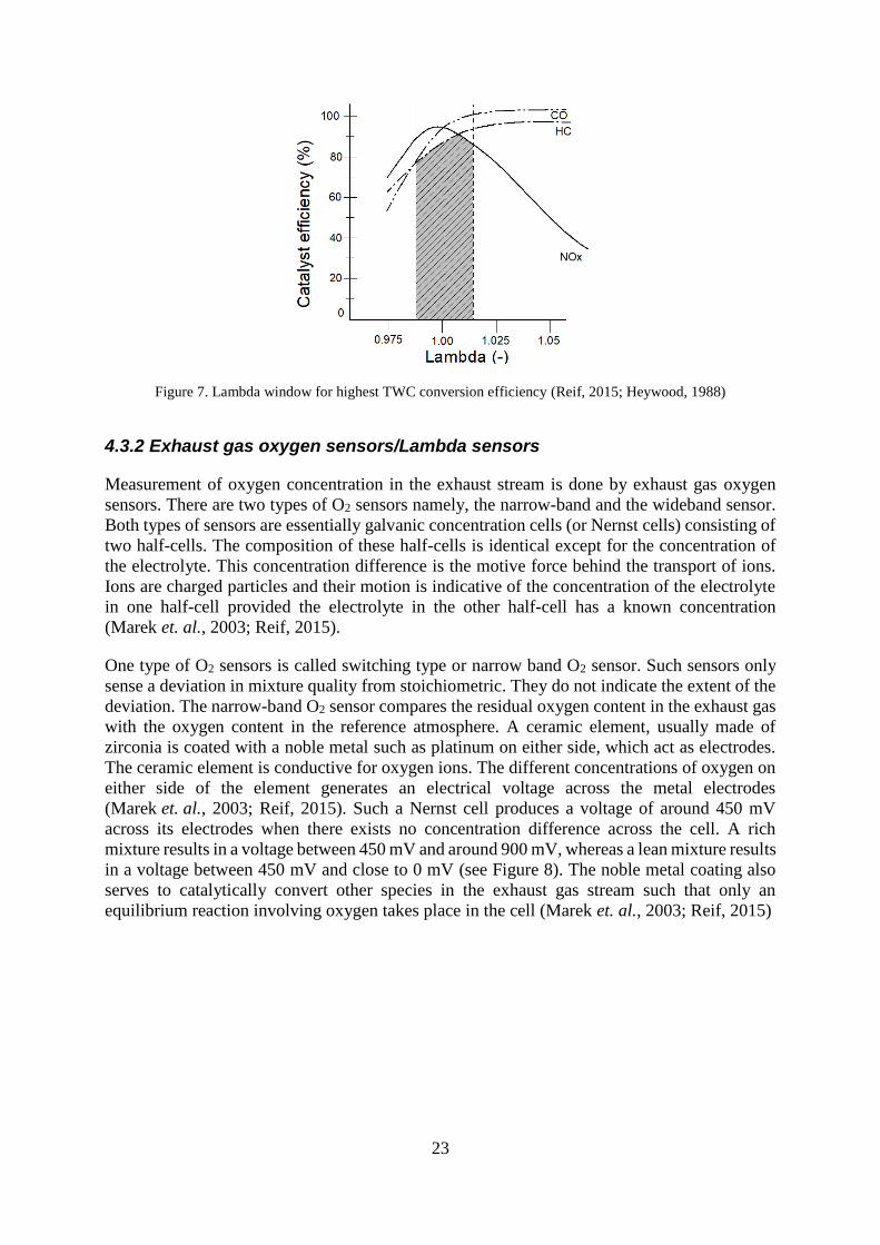
23
Figure 7. Lambda window for highest TWC conversion efficiency (Reif, 2015; Heywood, 1988)
4.3.2 Exhaust gas oxygen sensors/Lambda sensors
Measurement of oxygen concentration in the exhaust stream is done by exhaust gas oxygen
sensors. There are two types of O2 sensors namely, the narrow-band and the wideband sensor.
Both types of sensors are essentially galvanic concentration cells (or Nernst cells) consisting of
two half-cells. The composition of these half-cells is identical except for the concentration of
the electrolyte. This concentration difference is the motive force behind the transport of ions.
Ions are charged particles and their motion is indicative of the concentration of the electrolyte
in one half-cell provided the electrolyte in the other half-cell has a known concentration
(Marek et. al., 2003; Reif, 2015).
One type of O2 sensors is called switching type or narrow band O2 sensor. Such sensors only
sense a deviation in mixture quality from stoichiometric. They do not indicate the extent of the
deviation. The narrow-band O2 sensor compares the residual oxygen content in the exhaust gas
with the oxygen content in the reference atmosphere. A ceramic element, usually made of
zirconia is coated with a noble metal such as platinum on either side, which act as electrodes.
The ceramic element is conductive for oxygen ions. The different concentrations of oxygen on
either side of the element generates an electrical voltage across the metal electrodes
(Marek et. al., 2003; Reif, 2015). Such a Nernst cell produces a voltage of around 450 mV
across its electrodes when there exists no concentration difference across the cell. A rich
mixture results in a voltage between 450 mV and around 900 mV, whereas a lean mixture results
in a voltage between 450 mV and close to 0 mV (see Figure 8). The noble metal coating also
serves to catalytically convert other species in the exhaust gas stream such that only an
equilibrium reaction involving oxygen takes place in the cell (Marek et. al., 2003; Reif, 2015)
24
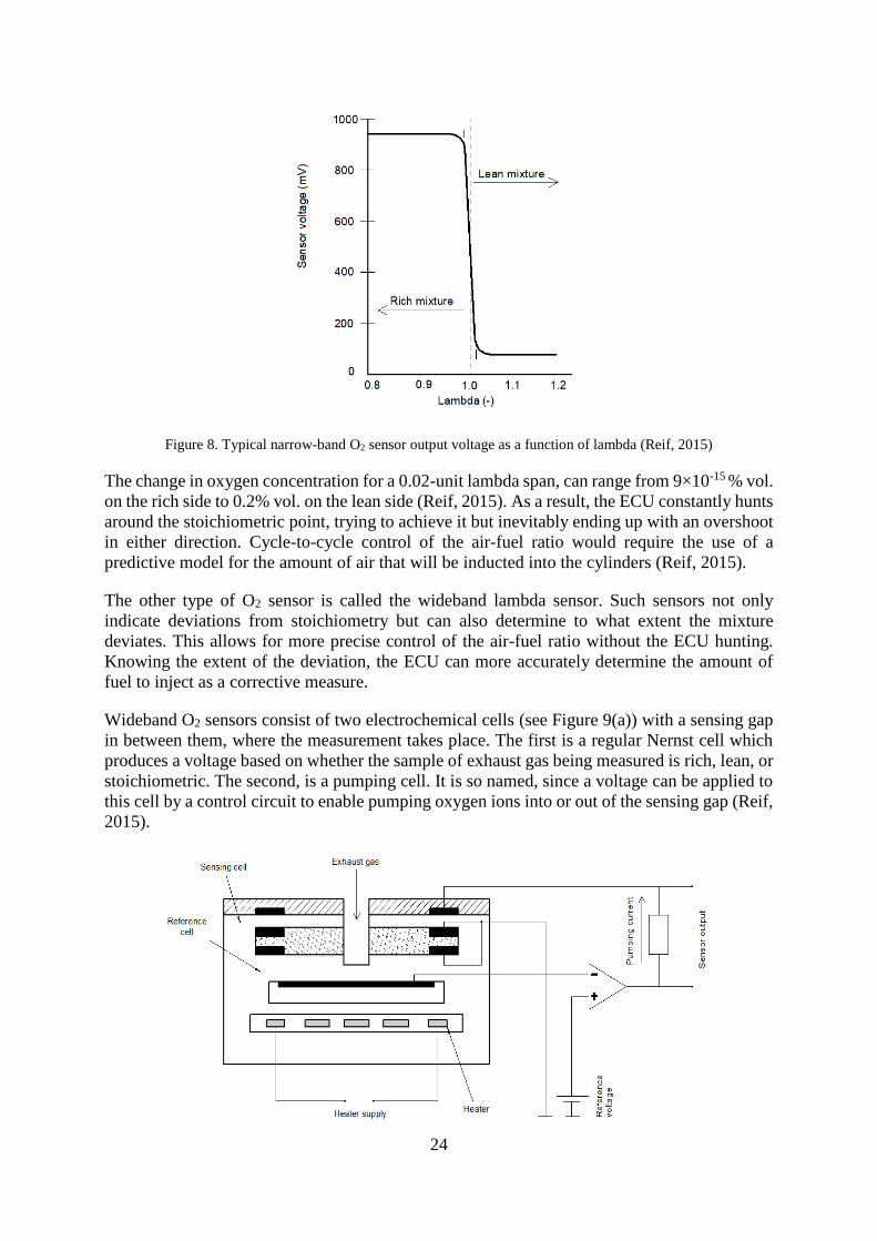
Figure 8. Typical narrow-band O2 sensor output voltage as a function of lambda (Reif, 2015)
The change in oxygen concentration for a 0.02-unit lambda span, can range from 9×10-15 % vol.
on the rich side to 0.2% vol. on the lean side (Reif, 2015). As a result, the ECU constantly hunts
around the stoichiometric point, trying to achieve it but inevitably ending up with an overshoot
in either direction. Cycle-to-cycle control of the air-fuel ratio would require the use of a
predictive model for the amount of air that will be inducted into the cylinders (Reif, 2015).
The other type of O2 sensor is called the wideband lambda sensor. Such sensors not only
indicate deviations from stoichiometry but can also determine to what extent the mixture
deviates. This allows for more precise control of the air-fuel ratio without the ECU hunting.
Knowing the extent of the deviation, the ECU can more accurately determine the amount of
fuel to inject as a corrective measure.
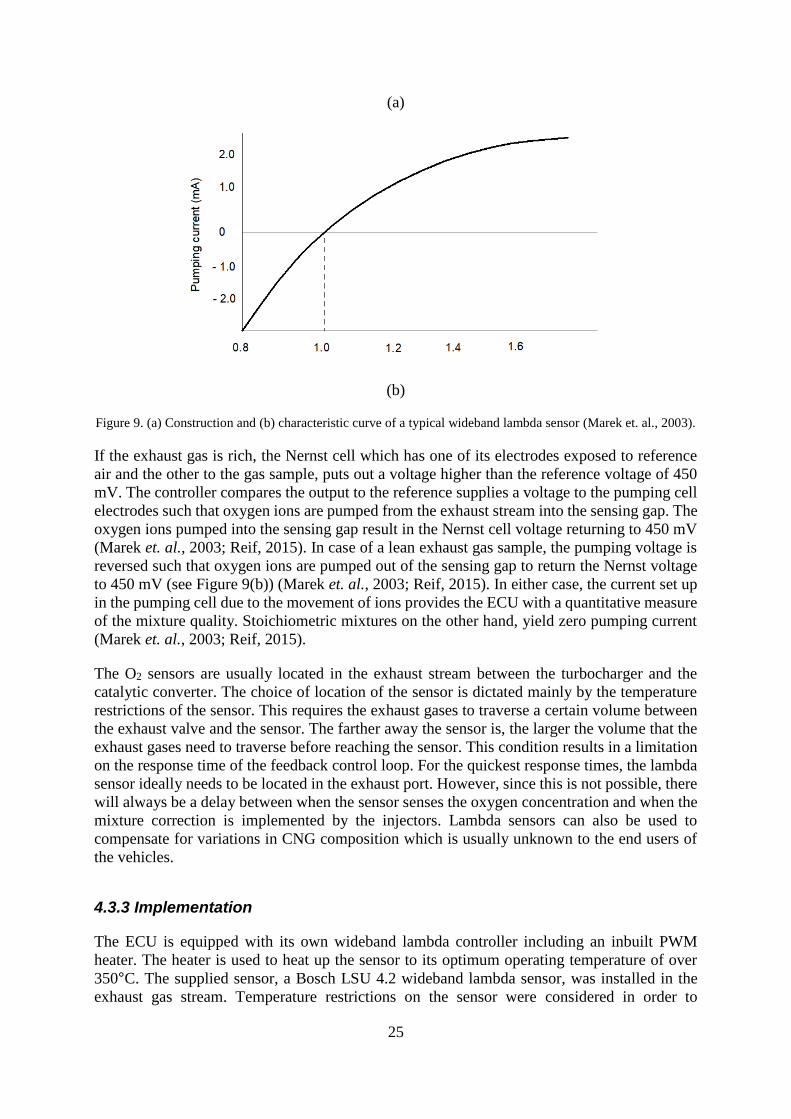
Wideband O2 sensors consist of two electrochemical cells (see Figure 9(a)) with a sensing gap
in between them, where the measurement takes place. The first is a regular Nernst cell which
produces a voltage based on whether the sample of exhaust gas being measured is rich, lean, or
stoichiometric. The second, is a pumping cell. It is so named, since a voltage can be applied to
this cell by a control circuit to enable pumping oxygen ions into or out of the sensing gap (Reif,
2015).
25
(a)
(b)
Figure 9. (a) Construction and (b) characteristic curve of a typical wideband lambda sensor (Marek et. al., 2003).
If the exhaust gas is rich, the Nernst cell which has one of its electrodes exposed to reference
air and the other to the gas sample, puts out a voltage higher than the reference voltage of 450
mV. The controller compares the output to the reference supplies a voltage to the pumping cell
electrodes such that oxygen ions are pumped from the exhaust stream into the sensing gap. The
oxygen ions pumped into the sensing gap result in the Nernst cell voltage returning to 450 mV
(Marek et. al., 2003; Reif, 2015). In case of a lean exhaust gas sample, the pumping voltage is
reversed such that oxygen ions are pumped out of the sensing gap to return the Nernst voltage
to 450 mV (see Figure 9(b)) (Marek et. al., 2003; Reif, 2015). In either case, the current set up
in the pumping cell due to the movement of ions provides the ECU with a quantitative measure
of the mixture quality. Stoichiometric mixtures on the other hand, yield zero pumping current
(Marek et. al., 2003; Reif, 2015).
The O2 sensors are usually located in the exhaust stream between the turbocharger and the
catalytic converter. The choice of location of the sensor is dictated mainly by the temperature
restrictions of the sensor. This requires the exhaust gases to traverse a certain volume between
the exhaust valve and the sensor. The farther away the sensor is, the larger the volume that the
exhaust gases need to traverse before reaching the sensor. This condition results in a limitation
on the response time of the feedback control loop. For the quickest response times, the lambda
sensor ideally needs to be located in the exhaust port. However, since this is not possible, there
will always be a delay between when the sensor senses the oxygen concentration and when the
mixture correction is implemented by the injectors. Lambda sensors can also be used to
compensate for variations in CNG composition which is usually unknown to the end users of
the vehicles.
4.3.3 Implementation
The ECU is equipped with its own wideband lambda controller including an inbuilt PWM
heater. The heater is used to heat up the sensor to its optimum operating temperature of over
350°C. The supplied sensor, a Bosch LSU 4.2 wideband lambda sensor, was installed in the
exhaust gas stream. Temperature restrictions on the sensor were considered in order to

26
determine the installation location. The sensor was delivered pre-calibrated. However, the
closed-loop lambda control could not be tested as the sensor would remain exposed to ambient
air until installed in the test cell with the associated piping in place.
The ECU also features a proprietary Speed-Density algorithm for feed-forward lambda control.
The ECU consists of an inbuilt reference pressure port to which a pressure line was connected.
The other end of this line was connected to the intake manifold. Nevertheless, the ECU does
not contain pre-programmed fuel maps for CNG. Therefore, for the open loop control to
function, a manual fuel map needs to be programmed into the ECU. For initial engine startup
and idle running, it was decided to use a modified gasoline fuel map. The gasoline equivalent
CNG mass flow rate was determined assuming an average calorific value of gasoline and CNG.
This fuel mass flow rate has been used to set the injection duration but if this method results in
unit lambda, has not been tested.
27
5 GAS EXCHANGE SYSTEM
A majority of the discussion presented in this chapter pertains to the intake air handling system.
A short discussion has also been presented on the exhaust side damping tank.
5.1 Intake damping/mixing tank
The layout of the air intake system has been illustrated in Section 3.4 (see Figure 4). The engine
will be supplied with boosted charge-air from an external compressor belonging to the
laboratory. The first component in the air flow path is the damping tank which can also be used
for premixing a gaseous fuel and air.
5.1.1 Purpose
The tank has multiple purposes, namely:
1. Dampen pulsations in the air path enabling more accurate air mass flow measurement
2. Preparing well homogenized mixtures of air and gaseous fuels before induction into the
engine
3. For mixing EGR into the intake air stream
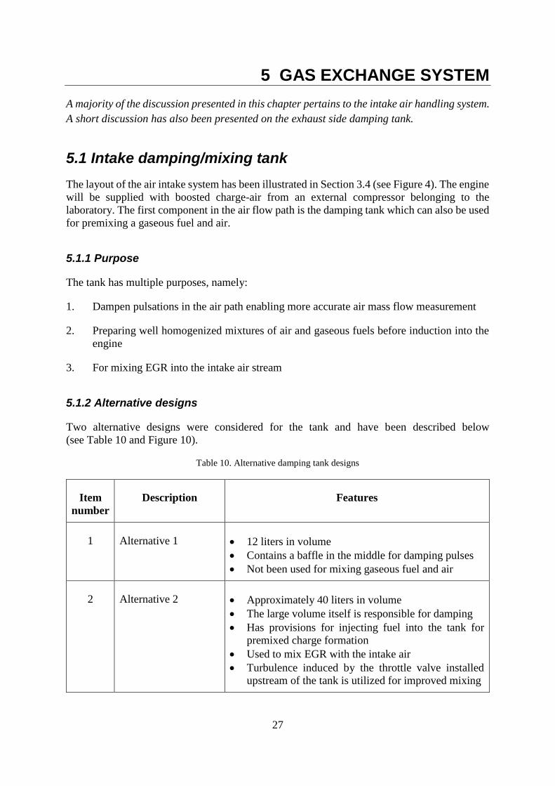
5.1.2 Alternative designs
Two alternative designs were considered for the tank and have been described below
(see Table 10 and Figure 10).
Table 10. Alternative damping tank designs
Item
number
Description Features
1 Alternative 1 • 12 liters in volume
• Contains a baffle in the middle for damping pulses
• Not been used for mixing gaseous fuel and air
2 Alternative 2 • Approximately 40 liters in volume
• The large volume itself is responsible for damping
• Has provisions for injecting fuel into the tank for
premixed charge formation
• Used to mix EGR with the intake air
• Turbulence induced by the throttle valve installed
upstream of the tank is utilized for improved mixing
28
(a) (b)
Figure 10. Illustration of intake damping tank (a) Alternative 1 with baffle; (b) Alternative 2 with larger volume
5.1.3 Design choice and implementation
The decision to replicate the Scania design was foremost based on space restrictions in the KTH
test cells. A simulation study by Scania has recommended that the volume of the tank be
increased to 18 liters instead of the current 12 liters (Scania, 2016). The study states a drop in
volumetric efficiency of the engine at high speed and high load during simulations as the reason
for the recommendation.
The recommendation to use an 18-liter tank was agreed upon with the commissioner. However,
from a functionality perspective, the tank was also intended to be used for well-homogenized
29
charge mixture formation. At present, no provisions have been made for introduction of EGR
into the tank. If needed however, the modification to the tank would be minor.
5.2 Throttle valve
This section discusses the purpose of the throttle valve, choice of size based on control concerns
and its implementation.
5.2.1 Purpose
The aim of a throttle valve is to control the amount of air which is inducted into the engine. A
throttle valve is of more importance in a stoichiometric SI engine since the amount of air
inducted determines the quantity of fuel to be injected. The precision of the injected fuel
quantity is critical from an exhaust after-treatment perspective due to limitations of the
three-way catalyst.
5.2.2 Throttle sizing
The full engine uses a 57 mm electronically actuated Bosch throttle valve matched to the 9-liter
displaced volume. Issues with air mass flow control using a large throttle valve for single
cylinder operation were expected. It was expected that the steep initial opening ramp of the
throttle plate, could resulting in larger throttle angles than desired at low air mass flow rates.
However, Scania engineers reported that previous tests run in their test cells have used the same
throttle. Furthermore, it was reported that the engine runs on wide-open throttle above 40%
load. It is only at lower speeds and loads that the throttle has any function at all. It was therefore
decided to retain the throttle from the full engine.
5.2.3 Implementation and verification
The ECU supports a single electronic throttle with two motor control outputs and two throttle
position sensors. The two outputs are Pulse-width Modulated (PWM) and the position sensor
characteristics were as provided by the manufacturer. The position sensors are potentiometers
and moving the throttle plate manually could cause a shift in the zero set-point. This in turn,
could cause a difference in the clockwise and counter-clockwise rotation angles of the throttle
plate. Throughout the project, care was taken not to move the throttle plate manually. Therefore,
the position sensors did not need to be re-calibrated. The diagnostic function of the ECU was
used to test the throttle actuation. Also, the throttle is a normally-closed valve and was found to
shut-off after power supply was cut. However, no tests have been carried out scoping the
position sensor output against the demanded position. Such a test will only be possible after the
engine has been connected to a dynamometer with throttle control or at least a throttle pedal to
determine the demand.
5.3 Intake manifold modifications and implementation
The intake manifold required some modification due to single cylinder operation and liquid fuel
direct injection (see Table 11).
30
Table 11. Intake manifold modifications
Item
number
Modification Reason Method
1 Decreasing the
volume
The other cylinders were
deactivated by removing the
intake valves. The intake
manifold was retained to
prevent foreign objects from
entering the cylinders.
However, it was also not
desirable to fill the unused
cylinders with premixed fuel
and air.
A small section of the stock
manifold between the swirl port
runner of cylinder 1 and filling
port runner of cylinder 2 was
sawed off. A solid aluminium
plate was welded in place,
thereby separating the manifold
internally while retaining stock
external form (see Figure 10).
2 Moving the
manifold away
from the
cylinder heads
Reorientation of the
high-pressure fuel rail (see
Section 3.5.2) required the
manifold to be moved away
from the cylinder heads by at
least 45 mm.
Aluminium spacers with holes
matching the port holes
(see Appendix A). If each
spacer cannot be made from a
single piece, two 25 mm thick
pieces may be used per cylinder
with gaskets in between.
Figure 11. Illustration of the method used to adapt the intake manifold for single cylinder operation
5.4 Variable intake port filling
This section describes the need for selective filling of the intake ports, the alternatives
considered to achieve the objective and final choice of method.
5.4.1 Assignment
With potential future projects in mind, a method to vary the amount of charge flowing into
either of the two intake ports was requested by the commissioner. The current cylinder head
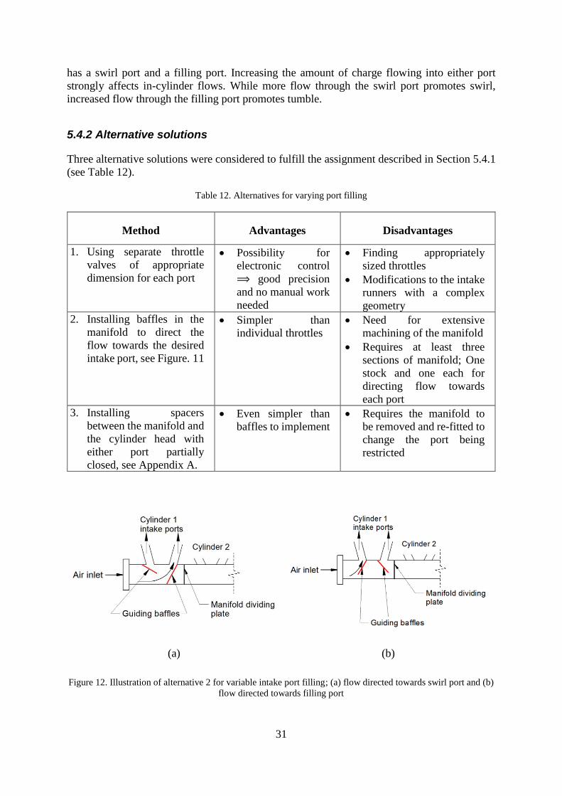
31
has a swirl port and a filling port. Increasing the amount of charge flowing into either port
strongly affects in-cylinder flows. While more flow through the swirl port promotes swirl,
increased flow through the filling port promotes tumble.
5.4.2 Alternative solutions
Three alternative solutions were considered to fulfill the assignment described in Section 5.4.1
(see Table 12).
Table 12. Alternatives for varying port filling
Method Advantages Disadvantages
1. Using separate throttle
valves of appropriate
dimension for each port
• Possibility for
electronic control
⟹ good precision
and no manual work
needed
• Finding appropriately
sized throttles
• Modifications to the intake
runners with a complex
geometry
2. Installing baffles in the
manifold to direct the
flow towards the desired
intake port, see Figure. 11
• Simpler than
individual throttles
• Need for extensive
machining of the manifold
• Requires at least three
sections of manifold; One
stock and one each for
directing flow towards
each port
3. Installing spacers
between the manifold and
the cylinder head with
either port partially
closed, see Appendix A.
• Even simpler than
baffles to implement
• Requires the manifold to
be removed and re-fitted to
change the port being
restricted
(a) (b)
Figure 12. Illustration of alternative 2 for variable intake port filling; (a) flow directed towards swirl port and (b)
flow directed towards filling port
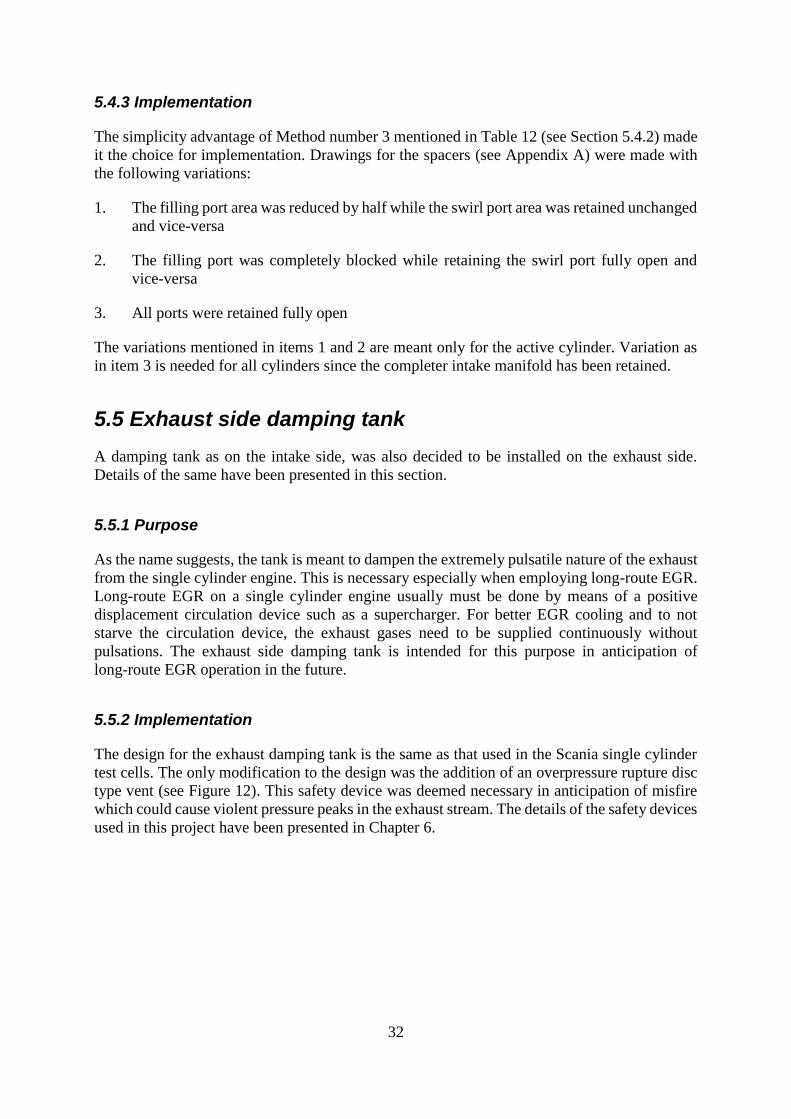
32
5.4.3 Implementation
The simplicity advantage of Method number 3 mentioned in Table 12 (see Section 5.4.2) made
it the choice for implementation. Drawings for the spacers (see Appendix A) were made with
the following variations:
1. The filling port area was reduced by half while the swirl port area was retained unchanged
and vice-versa
2. The filling port was completely blocked while retaining the swirl port fully open and
vice-versa
3. All ports were retained fully open
The variations mentioned in items 1 and 2 are meant only for the active cylinder. Variation as
in item 3 is needed for all cylinders since the completer intake manifold has been retained.
5.5 Exhaust side damping tank
A damping tank as on the intake side, was also decided to be installed on the exhaust side.
Details of the same have been presented in this section.
5.5.1 Purpose
As the name suggests, the tank is meant to dampen the extremely pulsatile nature of the exhaust
from the single cylinder engine. This is necessary especially when employing long-route EGR.
Long-route EGR on a single cylinder engine usually must be done by means of a positive
displacement circulation device such as a supercharger. For better EGR cooling and to not
starve the circulation device, the exhaust gases need to be supplied continuously without
pulsations. The exhaust side damping tank is intended for this purpose in anticipation of
long-route EGR operation in the future.
5.5.2 Implementation
The design for the exhaust damping tank is the same as that used in the Scania single cylinder
test cells. The only modification to the design was the addition of an overpressure rupture disc
type vent (see Figure 12). This safety device was deemed necessary in anticipation of misfire
which could cause violent pressure peaks in the exhaust stream. The details of the safety devices
used in this project have been presented in Chapter 6.
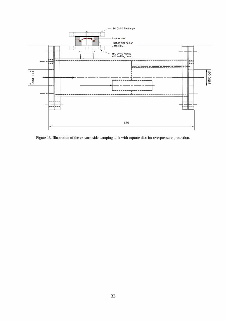
33
Figure 13. Illustration of the exhaust side damping tank with rupture disc for overpressure protection.

34
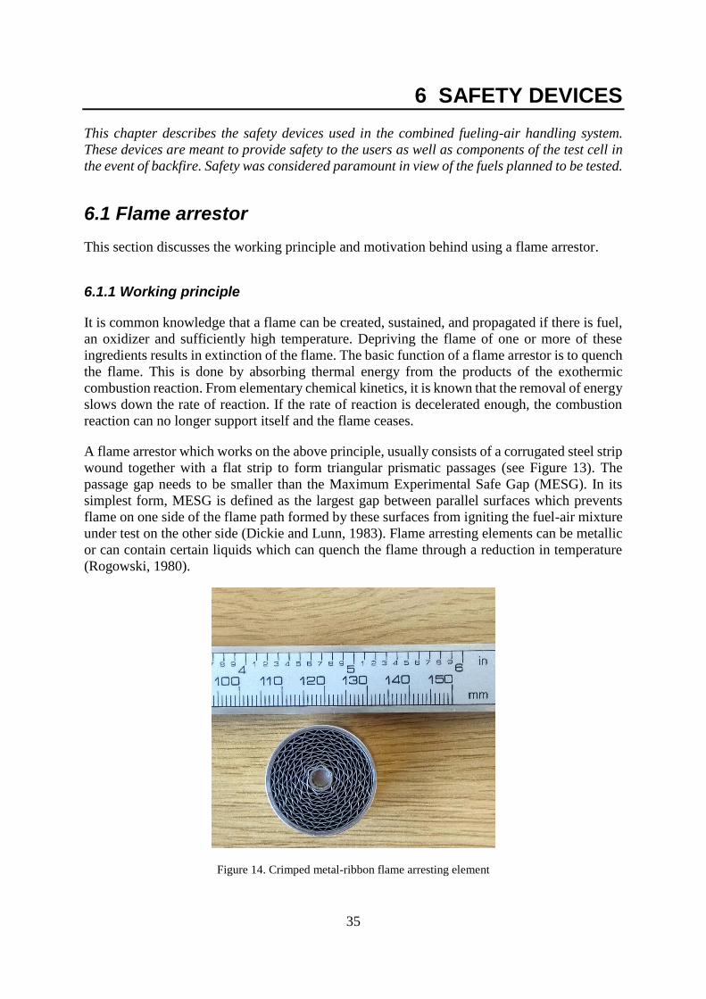
35
6 SAFETY DEVICES
This chapter describes the safety devices used in the combined fueling-air handling system.
These devices are meant to provide safety to the users as well as components of the test cell in
the event of backfire. Safety was considered paramount in view of the fuels planned to be tested.
6.1 Flame arrestor
This section discusses the working principle and motivation behind using a flame arrestor.
6.1.1 Working principle
It is common knowledge that a flame can be created, sustained, and propagated if there is fuel,
an oxidizer and sufficiently high temperature. Depriving the flame of one or more of these
ingredients results in extinction of the flame. The basic function of a flame arrestor is to quench
the flame. This is done by absorbing thermal energy from the products of the exothermic
combustion reaction. From elementary chemical kinetics, it is known that the removal of energy
slows down the rate of reaction. If the rate of reaction is decelerated enough, the combustion
reaction can no longer support itself and the flame ceases.
A flame arrestor which works on the above principle, usually consists of a corrugated steel strip
wound together with a flat strip to form triangular prismatic passages (see Figure 13). The
passage gap needs to be smaller than the Maximum Experimental Safe Gap (MESG). In its
simplest form, MESG is defined as the largest gap between parallel surfaces which prevents
flame on one side of the flame path formed by these surfaces from igniting the fuel-air mixture
under test on the other side (Dickie and Lunn, 1983). Flame arresting elements can be metallic
or can contain certain liquids which can quench the flame through a reduction in temperature
(Rogowski, 1980).
Figure 14. Crimped metal-ribbon flame arresting element
36
6.1.2 Motivation
Using a gas-mixer upstream of the intake ports causes the piping between the intake port and
the mixer to be filled with well-mixed fuel and air. In the event of a backfire, it is highly
probable that this volume of mixture could ignite and cause an explosion. Such an occurrence
is not desirable from a safety perspective. Flame arrestors like the ones shown in figures
14 and 15(a) are usually used to stop the flame from propagating.
6.1.3 Implementation
The Technical Development department for electrical and performance systems at Scania
Engines recommended KITO Armaturen GmbH for supply of the flame arrestor. The high boost
pressures (2 to 3 bar(g)) intended for the engine, and the need to keep the pressure loss across
the arresting element as low as possible, resulted in the selection of a crimped stainless-steel
ribbon arresting element. However, since it was also mentioned to KITO during correspondence
that hythane and pure hydrogen would also be used as fuels in the future, it was suggested to
use multiple elements in series as there were no dedicated arrestors for hydrogen flames.
Furthermore, all standard flame arrestors manufactured by KITO included cast-steel housings.
This the entire assembly weighed approximately 40 kg. The anticipated vibrations due to single
cylinder operation made the heavy assembly undesirable. A custom-made aluminium housing
used by Scania Engines reduced the assembly weight to approximately 10 kg (see Figure 15(b)).
(a)

37
(b)
Figure 15. Crimped metal-ribbon flame arrestor (a) element and (b) assembly with housing
The gap size of the arresting element used by Scania Engines is 0.7 mm and is meant for CNG,
while the theoretical MESG for hydrogen is around 0.08 mm (Grossel, 2002). However,
preliminary communication with KITO revealed that there exist no exclusive arresting elements
for hydrogen flames especially at the boost pressures intended to be run on the engine. Further
study needs to be done on this claim as it is possible that sintered metal flame arrestors could
be used for hydrogen flames.
6.2 Damping/mixing tank overpressure safety
The following section pertains to the safety consideration accorded to the intake
damping/mixing tank as well as the exhaust side damping tank. These tanks are basically
pressure vessels and needed to be protected against explosion due to backfire or misfire
6.2.1 Motivation
The damping tank on the intake side also serves for fuel-air mixing if the gas-mixer is installed
upstream. The same hazard as described in Section 4.1.2 holds true for this tank as well. The
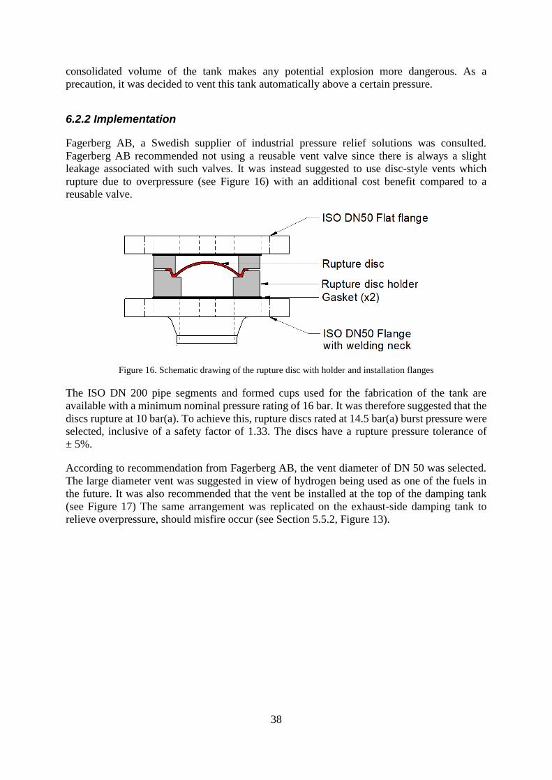
38
consolidated volume of the tank makes any potential explosion more dangerous. As a
precaution, it was decided to vent this tank automatically above a certain pressure.
6.2.2 Implementation
Fagerberg AB, a Swedish supplier of industrial pressure relief solutions was consulted.
Fagerberg AB recommended not using a reusable vent valve since there is always a slight
leakage associated with such valves. It was instead suggested to use disc-style vents which
rupture due to overpressure (see Figure 16) with an additional cost benefit compared to a
reusable valve.
Figure 16. Schematic drawing of the rupture disc with holder and installation flanges
The ISO DN 200 pipe segments and formed cups used for the fabrication of the tank are
available with a minimum nominal pressure rating of 16 bar. It was therefore suggested that the
discs rupture at 10 bar(a). To achieve this, rupture discs rated at 14.5 bar(a) burst pressure were
selected, inclusive of a safety factor of 1.33. The discs have a rupture pressure tolerance of
± 5%.
According to recommendation from Fagerberg AB, the vent diameter of DN 50 was selected.
The large diameter vent was suggested in view of hydrogen being used as one of the fuels in
the future. It was also recommended that the vent be installed at the top of the damping tank
(see Figure 17) The same arrangement was replicated on the exhaust-side damping tank to
relieve overpressure, should misfire occur (see Section 5.5.2, Figure 13).
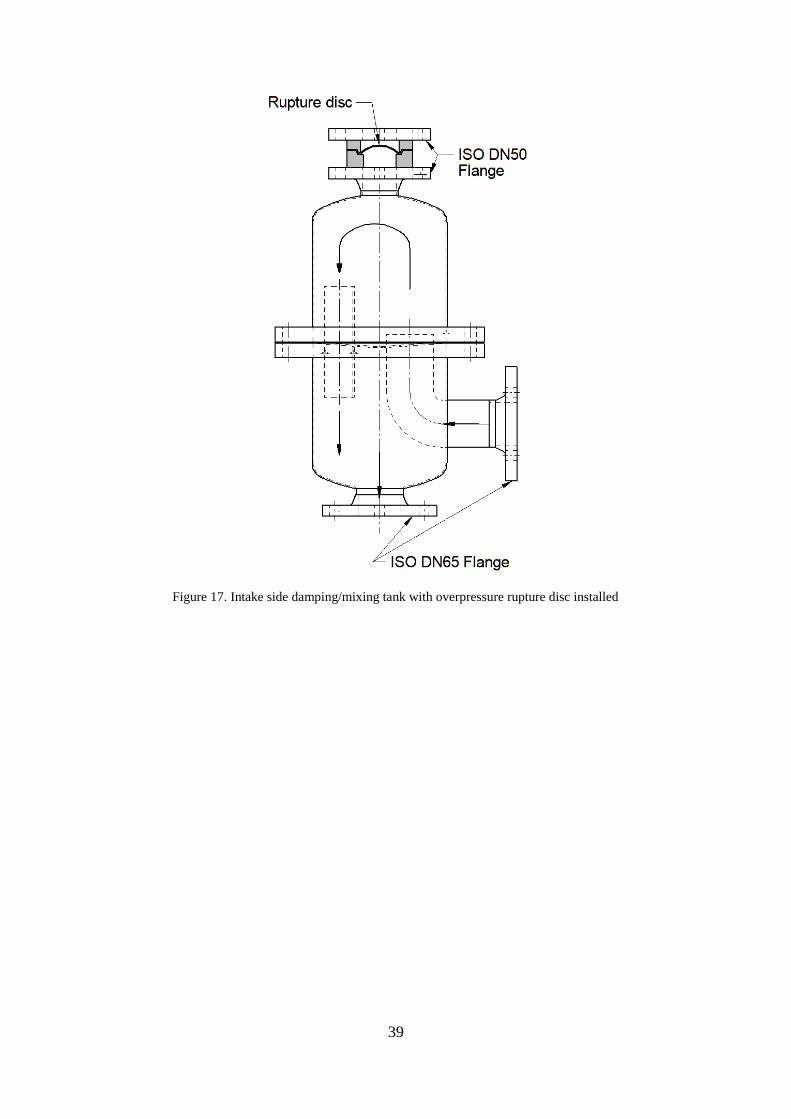
39
Figure 17. Intake side damping/mixing tank with overpressure rupture disc installed

40
41
7 CONCLUSION
This chapter provides a summary of the entire thesis work.
7.1 Summary
This thesis project was carried out concurrently with the work of another student. The focus of
this project was a heavy-duty single cylinder SI engine.
7.1.1 Fueling system
Three requirements set on the fueling system were implemented:
1. Variation in the premixed charge homogeneity was implemented. Turbulence induced by
the gas-mixer was utilized for well-mixed charge formation. The residence time offered
for diffusive mixing by the damping/mixing tank and the length of pipe between the gas-
mixer and the intake ports is believed to be sufficient for good mixture uniformity.
2. Injectors installed further upstream of the intake ports are expected to create
inhomogeneous mixtures. However, no quantification of the mixture uniformity was done
numerically or experimentally.
3. The ability to influence in-cylinder flow through selective intake port usage was
implemented via spacers as described in Section 5.4.3.
4. The Scania XPI common-rail direct injection fuel system was chosen for direct injection
of liquid fuels. Necessary modifications as enumerated in Section 3.5.3 have been agreed
to after consulting Scania engineers.
7.1.2 Electronic engine control unit
Selection of a suitable engine control unit was carried out. The main comparison metrics were
ease of use, cost and the number of inputs and outputs provided.
7.1.3 Safety devices
1. A flame arrestor with MESG corresponding to CNG was decided to be installed close to
the intake manifold as described in Section 6.1. The pressure of the boosted charge-air
meant that no exclusive arresting elements were available for hydrogen and hythane fuels.
Arresting elements are available with a MESG of 0.5 mm which is claimed to be
applicable to hydrogen and hythane as well.
2. Rupture disc type overpressure vents were decided to be installed on the intake and
exhaust damping tanks as described in Section 6.2. The supplier, Fagerberg AB has stated
that test pieces are destructively tested, and a certificate provided for the burst pressure.

42
7.2 Conclusions
Through this project, a flexible fueling system for a single cylinder heavy-duty, spark-ignited
engine has been implemented in theory, pending physical fabrication and installation. No
simulation studies or experimental investigations have been done on the charge mixture
uniformity resulting from the various points of mixing. Selective port filling to influence
in-cylinder flows was carried out using spacers with cut-outs of different areas. Safety was
given high importance especially since gaseous fuels are involved. Hardware for liquid fuel
direct injection and corresponding modifications have been agreed to by the Scania high-
pressure fuel systems department with agreed delivery during Autumn, 2018.
43
8 RECOMMENDATIONS AND FUTURE WORK
In this chapter, recommendations on more detailed solutions and future work in this field are
presented.
8.1 Recommendations
The uniformity of the premixed charge may be determined through CFD studies or appropriate
experimental methods, if quantification of homogeneity is required.
Once the engine is installed in the test cell, the injectors of the gas-mixer, the ones for
semi-homogeneous mixture formation as well as the port injectors need to be configured for
injection timing and duration.
The injector manufacturer limits the boost pressure at which the injectors can operate. The
current value is set to 2.5 bar(a). The constant 7 bar pressure difference across the injector needs
to be maintained such that there is sonic flow at the injector nozzle. Increasing the boost
pressure above 2.5 bar(a) will cause the pressure difference to drop. This in turn, will result in
sub-critical flow. The author speculates that this effect can be negated to some extent by
increasing the outlet pressure of the gas pressure regulator to a suitable value. It is recommended
that detailed calculations for these values be made before increasing the boost pressure.
The flame arresting method for hydrogen and hythane using multiple arresting elements as
recommended by KITO, should be tested on an appropriate test rig before installation in the
test cell. However, the single arresting element with a gap size of 0.7 mm has been tested for
CNG operation by Scania Engines and deemed safe.
To ensure that the intake air path is evacuated of gas-air mixture, it is recommended to
switch-off gas supply and motor the engine for a few minutes before turning it off.
The Scania service manual ought to be referred to when re-fastening the intake manifold bolts
after installing/removing the spacers meant to distribute the charge to the desired intake port.
The same applies to all high-tension bolts such as those for the cylinder heads. The number of
times such bolts can be used needs to be followed as per the service manual to avoid catastrophic
failures. It is also important to follow the tightening torques and order for all bolts and screwed
fasteners.
8.2 Future work
Prior to commissioning the engine for research, the damping/mixing on the intake and exhaust
side need to be fabricated with the inclusion of the rupture disc style overpressure vents during
welding.
The high-pressure gas supply system needs to be installed and connected to the gas-panel. The
pressure relief outlet of the gas regulator on the panel needs to be vented via a suitable method
such as a flexible hose. Care should be taken not to accidentally block the relief outlet.
44
The stainless-steel rupture discs need to be shielded by a metallic umbrella which permits visual
inspection before each experimental run while containing any shrapnel during rupture.
A study on sintered-metal flame arrestor may be undertaken for use with hydrogen and hythane.
This type of flame arrestor could prove to be an alternative to the crimped metal-ribbon arresting
element.
Installation of piping for charge-air and exhaust gases within the test cell needs to be carried
out with the engine installed in the cell. This would aid precise measurement of pipe lengths.
From the fueling system perspective, the modified XPI system for liquid fuel direct injection
needs to be ordered and installed on the engine. The system also needs to be equipped with the
Scania S8 ECU for control.
The throttle valve position sensor outputs need to be tested against demands created by the
dynamometer throttle control or using a pre-calibrated throttle pedal.
The prototype cylinder head with provision for installing a flush-mounted cylinder pressure
sensor needs to be ordered and machined as required. If tests are intended to be run using liquid
fuel direct injection along with spark ignition, another such prototype head needs to be ordered.
The cylinder pressure sensor needs to be installed via a hole through the cooling water jacket
and the spark plug needs to be installed through the hole meant for the flush-mounted cylinder
pressure sensor.
Laboratory grade sensors may be installed where needed. These additional sensors need to be
connected to a separate data acquisition system since all inputs on the ECU have been occupied
by sensors needed for engine operation.
45
9 REFERENCES
Douailler B., Ravet F., Delpech V., Soleri D., Reveille B., Kumar R., "Direct Injection of CNG
on High Compression Ratio Spark Ignition Engine: Numerical and Experimental
Investigation", SAE Technical Paper 2011-01-0923, 2011
Herrera J., Toohey J., Jin B., Rogers T. and Koopmans L., “Effects of Different Port Injection
CNG System Configurations on a 3.8L V6 Engine”, Sustainable Automotive Technologies
2012, Springer-Verlag Berlin Heidelberg, pp. 103-110.
Heywood J., “Internal combustion engine fundamentals”, McGraw-Hill, New York, 1988.
Khan M., Watson H. and Baker P., “Mixture Preparation Effects on Gaseous Fuel Combustion
in SI Engines”, SAE International. Journal of Engines, Vol. 2, Issue 1, 2009, pp.230-245.
Kumar S., Kwon H-T., Choi K-H., Lim W., Cho J.H., Tak K., Moon I., “LNG: An eco-friendly
cryogenic fuel for sustainable development”, Applied Energy, Vol. 88, Issue 12, 2011,
pp. 4264-4273
Lius A., “Single cylinder research engine multi-spark ignition system”, M.Sc. Thesis, KTH
Royal Institute of Techonology, 2018.
MaxxECU, “MaxxECU RACE Quick-start Guide”
Min B.H., Chung J.T., Kim H.Y., Park S., “Effects of gas composition on the performance and
emissions of compressed natural gas engines”, KSME International Journal, Vol. 16, Issue 2,
2002, pp. 219-226.
Puzinauskas P., Willson B., and Evans K., “Optimization of Natural Gas Combustion in Spark-
Ignited Engines Through Manipulation of Intake-Flow Configuration”, SAE Technical Paper
2000-01-1948, 2000.
Reif K. and Dietsche K., “Automotive Handbook (8th ed.)”, Robert Bosch GmbH, Plochingen:
Robert Bosch, 2011.
Reif K., “Automotive Mechatronics: Automotive Networking, Driving Stability System,
Electronics (1st ed.)”, Bosch Professional Automotive Information, 2015.
Reif K., “Gasoline engine management: Systems and components”, Bosch Professional
Automotive Information, 2015.
Saanum I., Bysveen M., Tunestål P., Johansson B., “Lean burn versus stoichiometric operation
with EGR and 3-way catalyst of an engine fueled with natural gas and hydrogen enriched
natural gas”, SAE Transactions Journal of Engines, Vol. 116, 3rd ed. Society of Automotive
Engineers, 2007.
Soanes C. and Koopmans L., “On the Application of Compressed Natural Gas for an SI Internal
Combustion Engine and Two Different Injector Positions”, Sustainable Automotive
Technologies 2012, Springer-Verlag Berlin Heidelberg, pp. 111-118.
Verhelst S., Verstraetenb S., Sierensa R., “A Comparison Between Lean Burn Operation and
Stoichiometric Operation with EGR for a Hydrogen Fuelled IC Engine”, 16th World Hydrogen
Energy Conference Proceedings, Lyon, 2006.

46
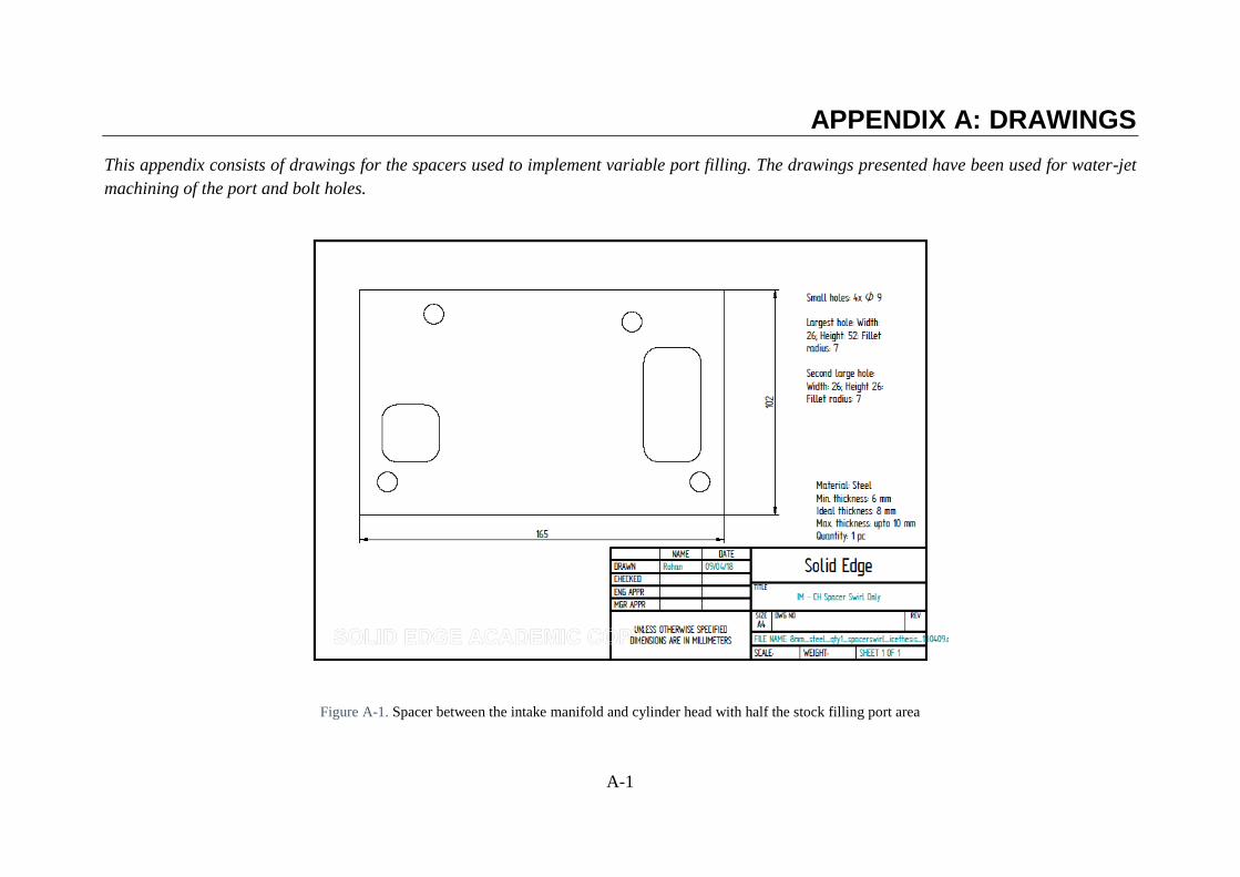
A-1
APPENDIX A: DRAWINGS
This appendix consists of drawings for the spacers used to implement variable port filling. The drawings presented have been used for water-jet
machining of the port and bolt holes.
Figure A-1. Spacer between the intake manifold and cylinder head with half the stock filling port area
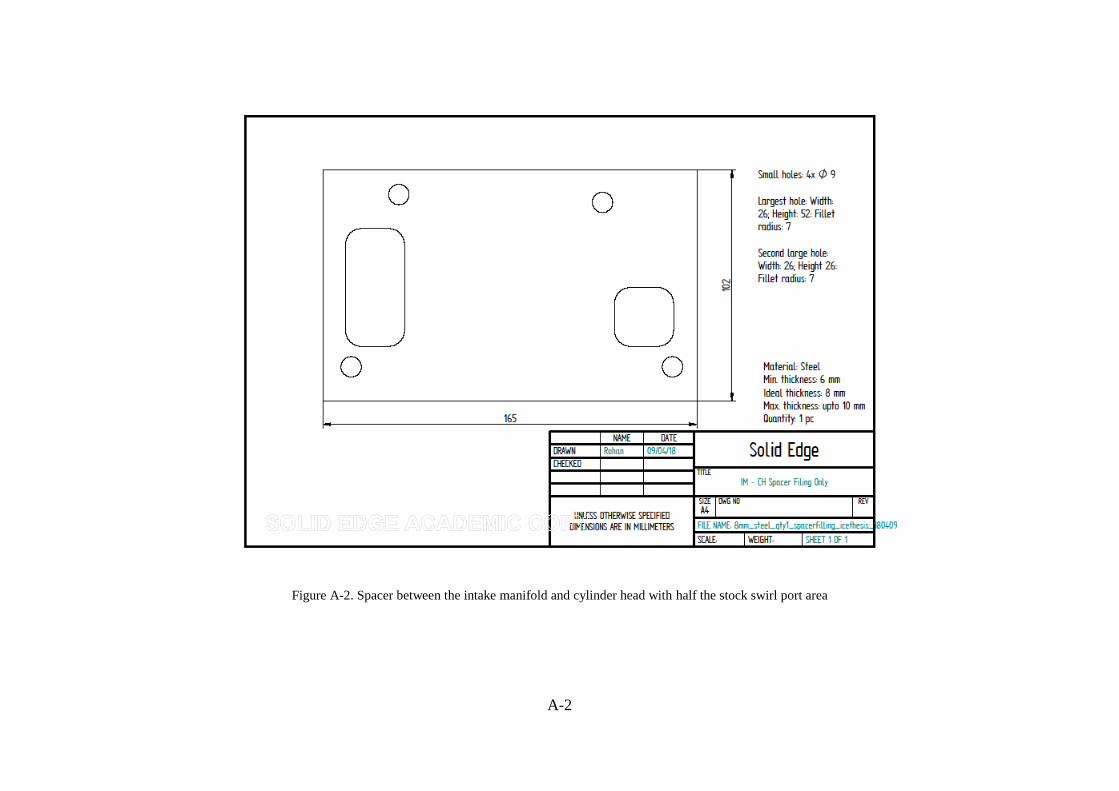
A-2
Figure A-2. Spacer between the intake manifold and cylinder head with half the stock swirl port area
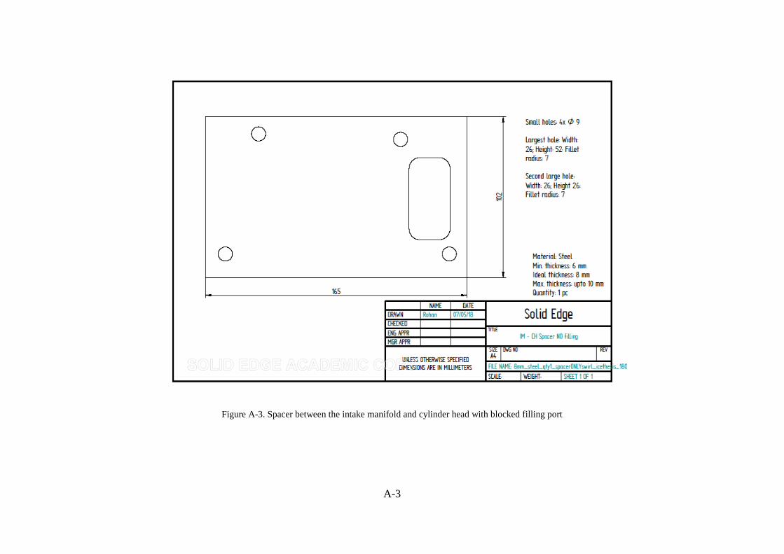
A-3
Figure A-3. Spacer between the intake manifold and cylinder head with blocked filling port
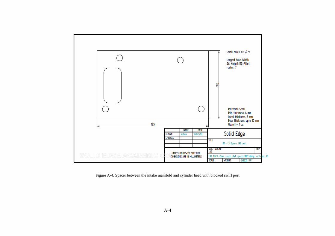
A-4
Figure A-4. Spacer between the intake manifold and cylinder head with blocked swirl port
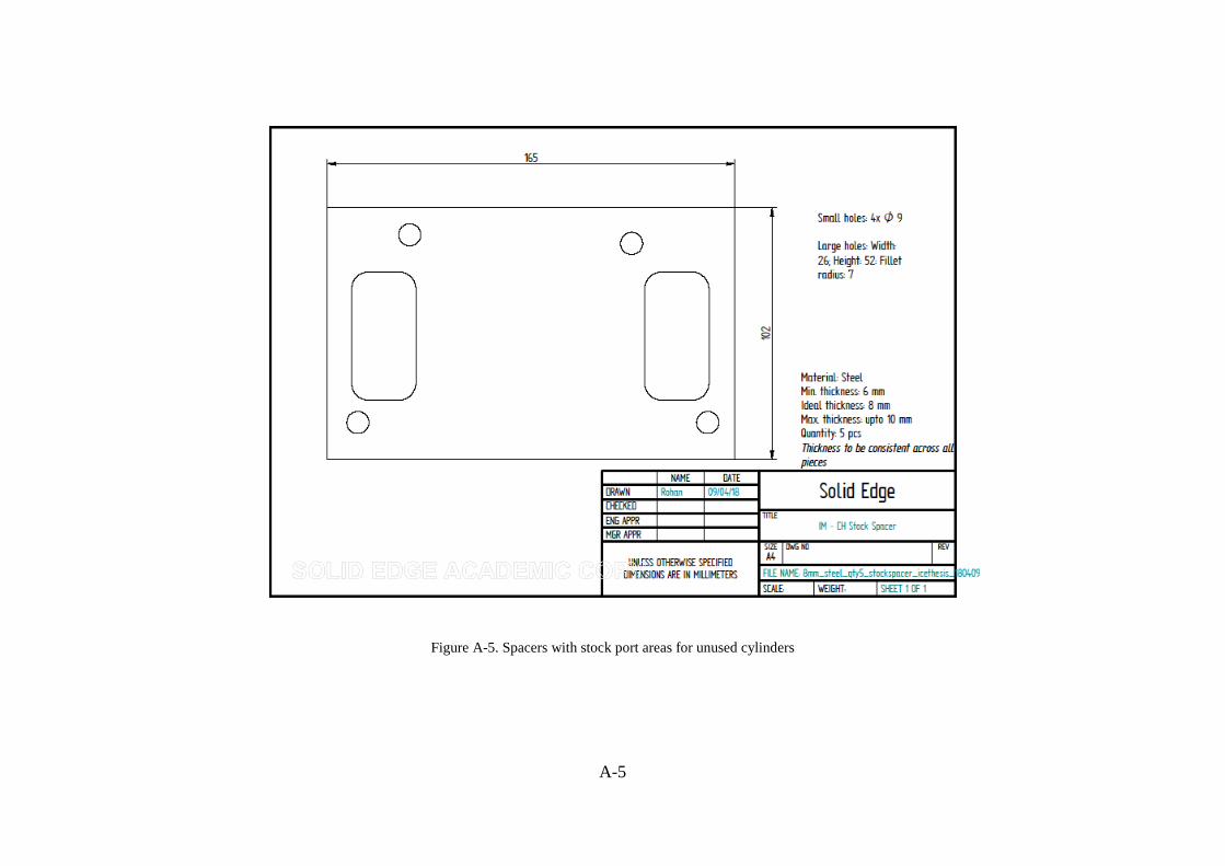
A-5
Figure A-5. Spacers with stock port areas for unused cylinders