Compressor Surge Mitigation in Turbocharged Spark-Ignition ...
15
Citation: Galindo, J.; Climent, H.; de la Morena, J.; González-Domínguez, D.; Guilain, S.; Besançon, T. Compressor Surge Mitigation in Turbocharged Spark-Ignition Engines without an Anti-Surge Control System during Load-Decrease Operation. Appl. Sci. 2022, 12, 1751. https://doi.org/10.3390/ app12031751 Academic Editor: Talal Yusaf Received: 13 January 2022 Accepted: 4 February 2022 Published: 8 February 2022 Publisher’s Note: MDPI stays neutral with regard to jurisdictional claims in published maps and institutional affil- iations. Copyright: © 2022 by the authors. Licensee MDPI, Basel, Switzerland. This article is an open access article distributed under the terms and conditions of the Creative Commons Attribution (CC BY) license (https:// creativecommons.org/licenses/by/ 4.0/). applied sciences Article Compressor Surge Mitigation in Turbocharged Spark-Ignition Engines without an Anti-Surge Control System during Load-Decrease Operation José Galindo 1 ,Héctor Climent 1 , Joaquín de la Morena 1 , David González-Domínguez 1, * , Stéphane Guilain 2 and Thomas Besançon 2 1 CMT Motores Térmicos, Universitat Politècnica de València, 46022 Valencia, Spain; [email protected] (J.G.); [email protected] (H.C.); [email protected] (J.d.l.M.) 2 Renault SAS, 91510 Lardy, France; [email protected] (S.G.); [email protected] (T.B.) * Correspondence: [email protected]; Tel.: +34-96-387-76-50 Abstract: Automotive manufacturers are showing an increasing preference for hybrid powertrains based on advanced gasoline engines. The most extended solution to improve fuel economy in these engines consists in downsizing with direct injection, while turbocharging is required to compensate the consequent power loss. However, turbocharging is associated with different issues, such as compressor surge. It can appear during fast throttle closings (tip-outs), when the engine air flow is abruptly reduced. A usual strategy to manage this kind of maneuver is the installation of an anti- surge valve (ASV) that connects the compressor inlet and outlet when approaching the surge limit. In pursuit of cost reduction, the removal of the ASV system was assessed in this research. To this end, tip-outs without ASV were tested in a turbocharged gasoline engine equipped with a low-pressure EGR loop, and two strategies were analyzed: throttle closure optimization and reduction of the compressor inlet pressure through the intake flap (located upstream of the compressor to increase the EGR rate). The instantaneous compressor outlet pressure and its time derivative were used for surge detection. Experimental tip-outs without ASV revealed that applying a certain intake flap closing combined with an optimized throttle actuation led to a fast torque decrease, similar to that observed for the reference case with ASV, without compressor instabilities. Keywords: spark-ignition engines; turbocharging; transient operation; compressor surge; valve control strategies; cost reduction 1. Introduction In search of greener transport solutions, hybrid powertrains based on advanced spark- ignition (SI) engines, usually fueled with gasoline, have become one of the most common propulsion systems in new passenger cars. This solution is successful due to the reduction of SI engine operation at low load conditions [1,2], and to the lower complexity of the three-way catalyst compared to diesel aftertreatment devices [3]. Regarding the state of the art in SI engines, an extended strategy to enhance fuel economy in this kind of engines is the combination of downsizing and direct fuel injection, while turbocharging is used to compensate the consequent power loss. Lumsden et al. [4] and Shaded et al. [5] demonstrated that downsizing with direct injection allows decreasing the pumping losses and increasing the compression ratio, thus reducing fuel consumption by around 25%. Besides, other interesting strategies are being applied to gasoline engines to improve fuel economy, such as exhaust gas recirculation (EGR), variable valve timing [6], deactivation of cylinders [7], and water injection in the intake ports [8]. Focusing on turbocharging, it is key to apply downsizing in SI engines, so to optimize fuel efficiency, as mentioned above. However, the use of turbochargers in SI engines is also subject to different issues: higher pumping losses and knocking tendency, gas temperature Appl. Sci. 2022, 12, 1751. https://doi.org/10.3390/app12031751 https://www.mdpi.com/journal/applsci
-
Upload
khangminh22 -
Category
Documents
-
view
6 -
download
0
Transcript of Compressor Surge Mitigation in Turbocharged Spark-Ignition ...
�����������������
Citation: Galindo, J.; Climent, H.; de
la Morena, J.; González-Domínguez,
D.; Guilain, S.; Besançon, T.
Compressor Surge Mitigation in
Turbocharged Spark-Ignition Engines
without an Anti-Surge Control
System during Load-Decrease
Operation. Appl. Sci. 2022, 12, 1751.
https://doi.org/10.3390/
app12031751
Academic Editor: Talal Yusaf
Received: 13 January 2022
Accepted: 4 February 2022
Published: 8 February 2022
Publisher’s Note: MDPI stays neutral
with regard to jurisdictional claims in
published maps and institutional affil-
iations.
Copyright: © 2022 by the authors.
Licensee MDPI, Basel, Switzerland.
This article is an open access article
distributed under the terms and
conditions of the Creative Commons
Attribution (CC BY) license (https://
creativecommons.org/licenses/by/
4.0/).
applied sciences
Article
Compressor Surge Mitigation in Turbocharged Spark-IgnitionEngines without an Anti-Surge Control System duringLoad-Decrease OperationJosé Galindo 1 , Héctor Climent 1, Joaquín de la Morena 1 , David González-Domínguez 1,* ,Stéphane Guilain 2 and Thomas Besançon 2
1 CMT Motores Térmicos, Universitat Politècnica de València, 46022 Valencia, Spain; [email protected] (J.G.);[email protected] (H.C.); [email protected] (J.d.l.M.)
2 Renault SAS, 91510 Lardy, France; [email protected] (S.G.); [email protected] (T.B.)* Correspondence: [email protected]; Tel.: +34-96-387-76-50
Abstract: Automotive manufacturers are showing an increasing preference for hybrid powertrainsbased on advanced gasoline engines. The most extended solution to improve fuel economy in theseengines consists in downsizing with direct injection, while turbocharging is required to compensatethe consequent power loss. However, turbocharging is associated with different issues, such ascompressor surge. It can appear during fast throttle closings (tip-outs), when the engine air flow isabruptly reduced. A usual strategy to manage this kind of maneuver is the installation of an anti-surge valve (ASV) that connects the compressor inlet and outlet when approaching the surge limit. Inpursuit of cost reduction, the removal of the ASV system was assessed in this research. To this end,tip-outs without ASV were tested in a turbocharged gasoline engine equipped with a low-pressureEGR loop, and two strategies were analyzed: throttle closure optimization and reduction of thecompressor inlet pressure through the intake flap (located upstream of the compressor to increase theEGR rate). The instantaneous compressor outlet pressure and its time derivative were used for surgedetection. Experimental tip-outs without ASV revealed that applying a certain intake flap closingcombined with an optimized throttle actuation led to a fast torque decrease, similar to that observedfor the reference case with ASV, without compressor instabilities.
Keywords: spark-ignition engines; turbocharging; transient operation; compressor surge; valvecontrol strategies; cost reduction
1. Introduction
In search of greener transport solutions, hybrid powertrains based on advanced spark-ignition (SI) engines, usually fueled with gasoline, have become one of the most commonpropulsion systems in new passenger cars. This solution is successful due to the reductionof SI engine operation at low load conditions [1,2], and to the lower complexity of thethree-way catalyst compared to diesel aftertreatment devices [3]. Regarding the stateof the art in SI engines, an extended strategy to enhance fuel economy in this kind ofengines is the combination of downsizing and direct fuel injection, while turbocharging isused to compensate the consequent power loss. Lumsden et al. [4] and Shaded et al. [5]demonstrated that downsizing with direct injection allows decreasing the pumping lossesand increasing the compression ratio, thus reducing fuel consumption by around 25%.Besides, other interesting strategies are being applied to gasoline engines to improve fueleconomy, such as exhaust gas recirculation (EGR), variable valve timing [6], deactivation ofcylinders [7], and water injection in the intake ports [8].
Focusing on turbocharging, it is key to apply downsizing in SI engines, so to optimizefuel efficiency, as mentioned above. However, the use of turbochargers in SI engines is alsosubject to different issues: higher pumping losses and knocking tendency, gas temperature
Appl. Sci. 2022, 12, 1751. https://doi.org/10.3390/app12031751 https://www.mdpi.com/journal/applsci
Appl. Sci. 2022, 12, 1751 2 of 15
limit at the turbine inlet, slower engine transient response due to turbocharger lag, andcompressor surge limit. Luján et al. [9] and Siokos et al. [10] demonstrated that introducingcooled EGR leads to a lower knock tendency and allows removing fuel enrichment tocontrol the turbine inlet temperature. Moreover, some improvements have been studied tocompensate the turbocharger lag, such as the application of low-viscosity oils [11], advancedbearing technologies [12], mechanically driven superchargers [13], electric boosters [14],and VGT control strategy optimization [15,16].
Regarding the compressor surge, it is an air stalling phenomenon that results in flowreversal and recirculation within the compressor, which can cause from local instabilities andnoise to large flow oscillations and severe damage to bearings, seals, and impellers [17,18]. Surgeappearance is dependent on the compressor design and the upstream and downstream ductgeometry [19,20]. Galindo et al. [21,22] reported that using a tapered duct at the compressorinlet improves the surge margin, while reducing the downstream volume may changethe surge dynamics from a low-frequency deep to a high-frequency mild surge [23,24].In addition, Galindo et al. [25,26] found by experiments that the surge margin can alsobe increased under pulsating flow conditions at the compressor outlet, and when usingcompressor inlet vanes to generate a swirling flow.
Despite all these improvements to reduce surge area, this undesirable phenomenon canusually appear in turbocharged SI engines during gear shifts and fast throttle closings, whenthe engine air flow is abruptly reduced. Under such circumstances, the most widespreadsolution for surge avoidance is the installation of a recirculation loop in which an anti-surge valve (ASV) is opened when the compressor is getting close to the surge limit, thusconnecting its inlet and outlet [27]. Besides, the ASV can be employed to mitigate boostspikes during load increase maneuvers at iso-engine speed, better known as tip-ins [28].Nevertheless, it must be remarked that the use of this anti-surge control system is alsoassociated with higher turbocharger production costs and additional calibration tasks toproperly manage the ASV.
In this research, the potential removal of the compressor ASV was assessed in theinterest of cost reduction. Hence, the paper is focused on the evaluation of two strategiesto manage throttle tip-outs with no anti-surge control system in a turbocharged SI engineequipped with a low-pressure EGR loop. Throttle tip-outs are referred to the engineload reduction at quasi-constant speed when lifting the accelerator sharply. The mainobjective is to guarantee the compressor stable operation and fast torque decrease duringthis type of maneuvers, despite not using the ASV. The following two strategies werestudied: the optimization of throttle closure and the application of different closings on theintake flap, located upstream of the compressor, to increase EGR rate. Podevin et al. [29]already demonstrated, via experiments in a turbocharger test rig, that the surge area canbe decreased by up to 60% by applying a certain closing on an electric throttle at thecompressor inlet. In order to evaluate both strategies, a series of tip-outs under the mostcritical surge conditions was tested, and the filtered crank-angle resolved pressure signal atthe compressor outlet and its time derivative were analyzed for surge detection. The paperis structured as follows: the experimental setup, engine tests, and surge limit criterion aredetailed in Section 2, the results and discussion are presented in Section 3, and finally themain conclusions are given in Section 4.
2. Materials and Methods2.1. Engine Test Cell
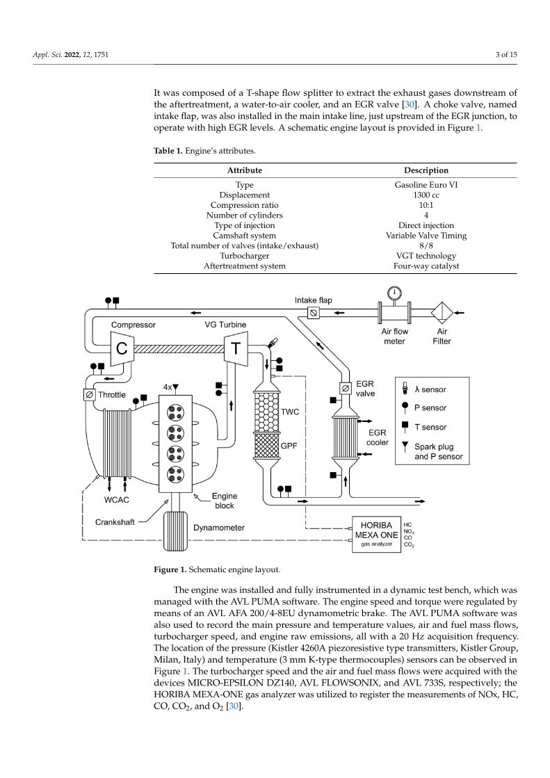
A EURO VI 1.3L 4-stroke 4-cylinder turbocharged direct-injection SI engine wasemployed in this study, and its principal attributes are shown in Table 1. The engine alsoincluded the VGT, variable valve timing (VVT), and four-way catalyst (FWC) technologies.The latter is the combination of a conventional three-way catalyst with a gasoline particulatefilter. Regarding the VVT system, the camshaft timing can be advanced or delayed in arange of 40◦ for both intake and exhaust sides, while the valve lift and opening durationsare kept constant. In addition, a low-pressure EGR loop was appended to the base engine.
Appl. Sci. 2022, 12, 1751 3 of 15
It was composed of a T-shape flow splitter to extract the exhaust gases downstream ofthe aftertreatment, a water-to-air cooler, and an EGR valve [30]. A choke valve, namedintake flap, was also installed in the main intake line, just upstream of the EGR junction, tooperate with high EGR levels. A schematic engine layout is provided in Figure 1.
Table 1. Engine’s attributes.
Attribute Description
Type Gasoline Euro VIDisplacement 1300 cc
Compression ratio 10:1Number of cylinders 4
Type of injection Direct injectionCamshaft system Variable Valve Timing
Total number of valves (intake/exhaust) 8/8Turbocharger VGT technology
Aftertreatment system Four-way catalyst
Figure 1. Schematic engine layout.
The engine was installed and fully instrumented in a dynamic test bench, which wasmanaged with the AVL PUMA software. The engine speed and torque were regulated bymeans of an AVL AFA 200/4-8EU dynamometric brake. The AVL PUMA software wasalso used to record the main pressure and temperature values, air and fuel mass flows,turbocharger speed, and engine raw emissions, all with a 20 Hz acquisition frequency.The location of the pressure (Kistler 4260A piezoresistive type transmitters, Kistler Group,Milan, Italy) and temperature (3 mm K-type thermocouples) sensors can be observed inFigure 1. The turbocharger speed and the air and fuel mass flows were acquired with thedevices MICRO-EPSILON DZ140, AVL FLOWSONIX, and AVL 733S, respectively; theHORIBA MEXA-ONE gas analyzer was utilized to register the measurements of NOx, HC,CO, CO2, and O2 [30].

Appl. Sci. 2022, 12, 1751 4 of 15
Moreover, three Kistler 601CAA piezoelectric type sensors (Kistler Group, Milan,Italy) were installed to measure the instantaneous pressure traces at the compressor outletand both manifolds, while four AVL Z133 spark plugs with integrated pressure sensorswere utilized to register the in-cylinder pressure traces. All these signals were recordedwith a sampling of 0.2 crank-angle degrees (CAD) by means of the PXI 6123 and PXI 6251acquisition modules, both programmed with Labview by National InstrumentsTM (Austin,TX, USA) [31,32]. The original engine control unit (ECU), designed for the base enginewithout EGR, was partially bypassed with the ETAS ES910 prototyping and interfacemodule to enable any variations on the VVT system, throttle position, spark timing, andinjected fuel. The EGR valve, intake flap, and VGT position were directly controlled inopen-loop configuration, independently of the ECU, through the PXI 7813R and NI 9759control modules [31,32]. Finally, the ECU was also equipped with an air flowmeter at theair-filter outlet to ensure proper lambda control when operating with EGR.
2.2. Experimental Campaign
The objective of this research was to analyze the technical viability of dispensing withthe compressor anti-surge valve in a turbocharged SI engine equipped with a low-pressureEGR loop. To this end, a series of tip-outs at 1500 rpm from full to zero load (the mostcritical surge conditions) was tested. Two strategies were studied in these tip-outs. First,the throttle closure was optimized to avoid instabilities in the compressor while ensuringa fast load decrease. Second, different closings on the intake flap were applied, and thethrottle closure was re-optimized for each of them in order to evaluate the reduction of thecompressor inlet pressure as a potential strategy to accelerate the maneuver. It must beremarked that the use of the intake flap does not involve an additional cost, given it is notan ad hoc solution to enhance the engine transient response without the ASV. As mentionedabove, the installation of the intake flap is required to increase EGR rate and, consequently,fuel efficiency. Indeed, notable improvements in fuel consumption were achieved withhigh EGR operation in the same engine, as shown in a previous study [33]. In pursuit ofsimplicity, however, no EGR was used in the tests to reduce the degrees of freedom.
To optimize throttle closure, its actuation was divided into five transitions in whichthe time to reach five different openings was varied to find the surge limit. The throttleactuation of the 20 tip-outs tested for its optimization is shown in Figure 2. For all cases,the throttle position was automatically moved from 60 (fully open) to 40◦ in just one enginecycle (0.08 s), given that the air mass flow (AMF) was marginally modified in this openingrange. For closer positions, the four transitions between openings equal to 40, 30, 20, 10, and3◦ (minimum value to compensate friction losses) were optimized by testing five transitiondurations (1, 3, 5, 7, and 9 cycles), as seen in Figure 2. In descending order of duration, theoptimum case was the one before the first in which compressor surge was detected.
Later, the effect of the intake flap on the surge limit was studied. Inducing a reductionin the compressor inlet pressure (p1) through the intake flap led to an increase in thecorrected mass flow, thus moving to the right the operating point on the compressor map.In this research, three p1 levels were evaluated if considering its minimum value during thetip-out maneuver: 0.33, 0.65, and 0.87 bar. Likewise, the throttle actuation was re-optimizedfor each p1 level by following a similar procedure to the one described above.

Appl. Sci. 2022, 12, 1751 5 of 15
Figure 2. Optimization of throttle closure.
2.3. Surge Detection
The turbocharger was formerly characterized in a gas test stand according to theprocedure explained by Serrano et al. [34], and the surge line was determined. However,this limit is not reliable once the turbocharger is coupled to the engine, because surgeappearance is affected by the piping geometry around the compressor [19–24] and enginepulsation [25,26], as stated before. Besides, the surge margin may be modified undertransient flow conditions [29]. Instead, the compressor outlet pressure (p2) signal, acquiredwith a sampling of 0.2 crank-angle degrees, and its first derivative were used for surgedetection. The surge characteristic frequency is generally below 30 Hz [35], while theengine firing frequency with four cylinders at 1500 rpm is 50 Hz. Hence, the signals ofp2 were processed by means of a 5th order low-pass Butterworth filter [36] with a cut-offfrequency ( fC) of 30 Hz, to identify surge with no interference from engine pulses. Themoving average of p2 was also calculated by applying the same low-pass filter, but withan fC of 10 Hz to eliminate the oscillations due to the surge. The time derivative of thedifference between the filtered pressure signal with a fC of 30 Hz (p̃2) and the movingaverage pressure signal (p2) was chosen as the main surge indicator, and an amplitudethreshold of 1 bar/s was considered. In this way, an oscillation in that time derivative wasregarded as surge if its amplitude was higher than 1 bar/s.
3. Results and Discussion
The experimental results of the tip-out maneuvers at 1500 rpm from full to zero loadwithout ASV were arranged into two subsections: (i) optimization of throttle actuation tooperate as close as possible to the surge limit and (ii) assessment of the effect of differentintake flap closings on the surge margin to reduce maneuver duration.
3.1. Optimization of Throttle Actuation
The throttle closure was optimized by varying the duration of the four transitionsbetween the openings equal to 40, 30, 20, 10, and 3◦, as stated in Section 2.2 (Figure 2). Theobjective was to find the fastest throttle closure which did not induce the appearance ofcompressor surge, without the aid of the anti-surge control system. Regarding the restof the actuations, the VVT system was configured to provide a constant valve overlap of40 CAD during the whole tip-out, and the VGT was fully open in 2 cycles from its fullload position at the same timing as the throttle (that is, no delay between the start of the2 actuations considered). Besides, the time profile of spark timing was defined to avoidknocking and misfires for all cases. As explained in Section 2.3, the compressor outletpressure signal and its time derivative were processed and utilized to identify the surge.
Appl. Sci. 2022, 12, 1751 6 of 15
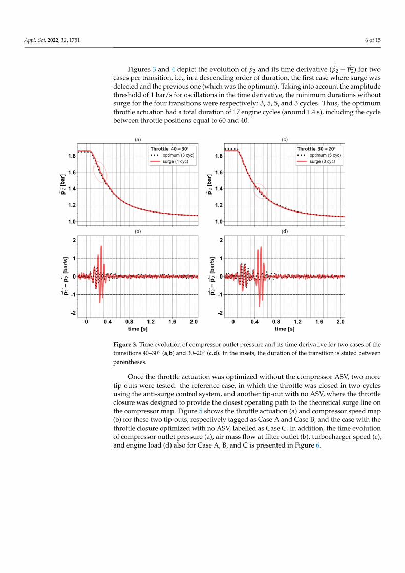
Figures 3 and 4 depict the evolution of p̃2 and its time derivative (.
p̃2 −.
p2) for twocases per transition, i.e., in a descending order of duration, the first case where surge wasdetected and the previous one (which was the optimum). Taking into account the amplitudethreshold of 1 bar/s for oscillations in the time derivative, the minimum durations withoutsurge for the four transitions were respectively: 3, 5, 5, and 3 cycles. Thus, the optimumthrottle actuation had a total duration of 17 engine cycles (around 1.4 s), including the cyclebetween throttle positions equal to 60 and 40.
Figure 3. Time evolution of compressor outlet pressure and its time derivative for two cases of thetransitions 40–30◦ (a,b) and 30–20◦ (c,d). In the insets, the duration of the transition is stated betweenparentheses.
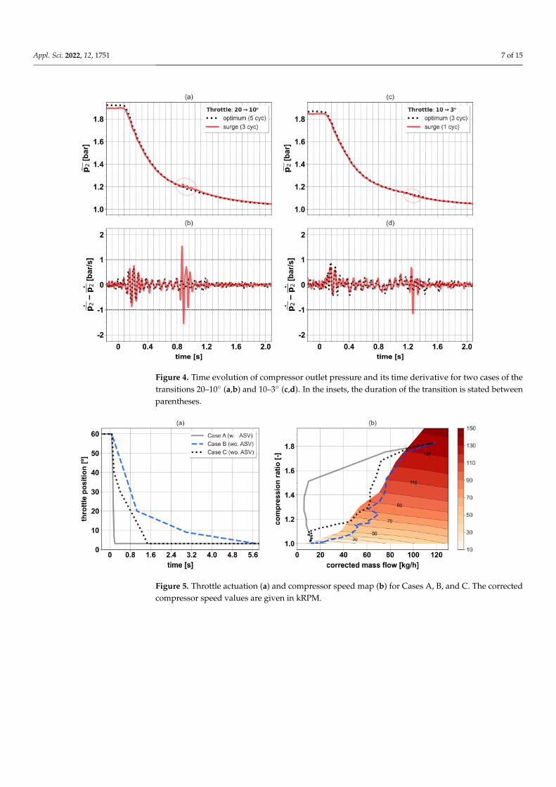
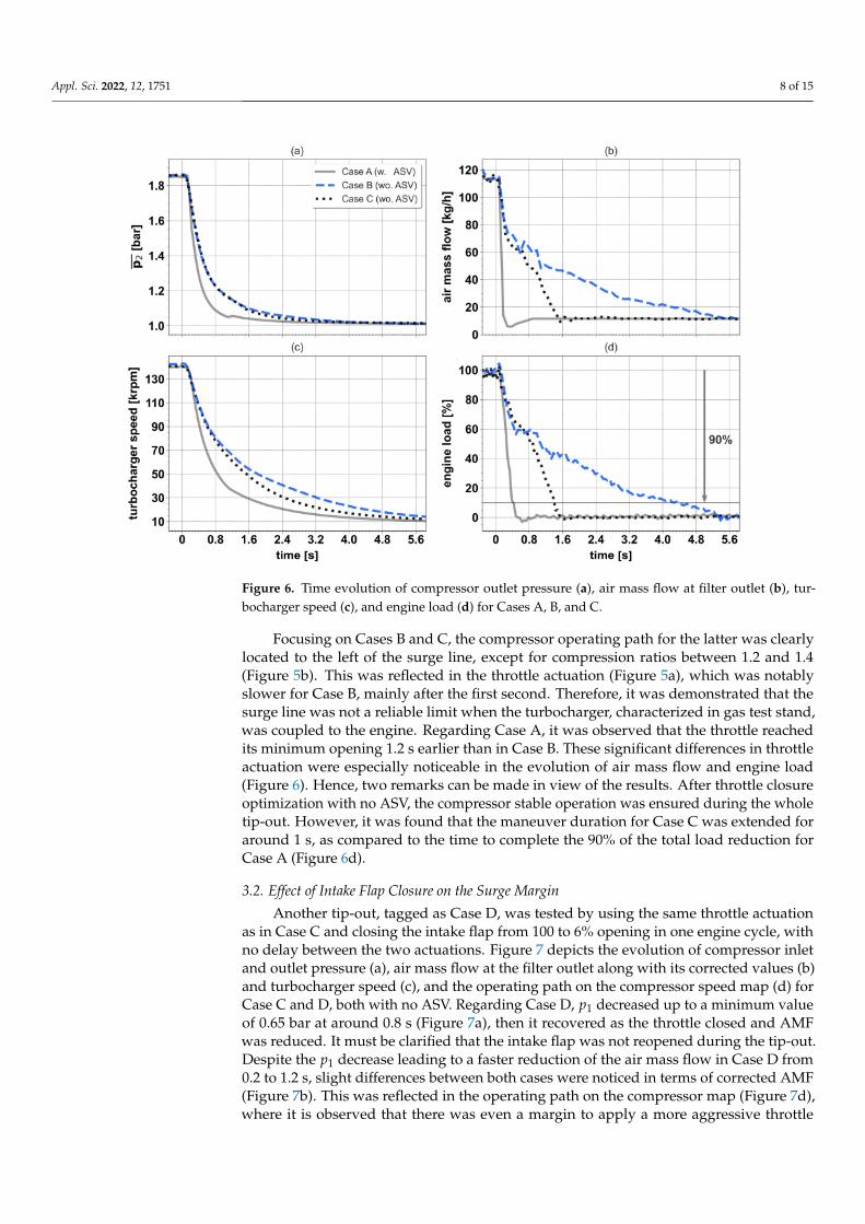
Once the throttle actuation was optimized without the compressor ASV, two moretip-outs were tested: the reference case, in which the throttle was closed in two cyclesusing the anti-surge control system, and another tip-out with no ASV, where the throttleclosure was designed to provide the closest operating path to the theoretical surge line onthe compressor map. Figure 5 shows the throttle actuation (a) and compressor speed map(b) for these two tip-outs, respectively tagged as Case A and Case B, and the case with thethrottle closure optimized with no ASV, labelled as Case C. In addition, the time evolutionof compressor outlet pressure (a), air mass flow at filter outlet (b), turbocharger speed (c),and engine load (d) also for Case A, B, and C is presented in Figure 6.
Appl. Sci. 2022, 12, 1751 7 of 15
Figure 4. Time evolution of compressor outlet pressure and its time derivative for two cases of thetransitions 20–10◦ (a,b) and 10–3◦ (c,d). In the insets, the duration of the transition is stated betweenparentheses.
Figure 5. Throttle actuation (a) and compressor speed map (b) for Cases A, B, and C. The correctedcompressor speed values are given in kRPM.
Appl. Sci. 2022, 12, 1751 8 of 15
Figure 6. Time evolution of compressor outlet pressure (a), air mass flow at filter outlet (b), tur-bocharger speed (c), and engine load (d) for Cases A, B, and C.
Focusing on Cases B and C, the compressor operating path for the latter was clearlylocated to the left of the surge line, except for compression ratios between 1.2 and 1.4(Figure 5b). This was reflected in the throttle actuation (Figure 5a), which was notablyslower for Case B, mainly after the first second. Therefore, it was demonstrated that thesurge line was not a reliable limit when the turbocharger, characterized in gas test stand,was coupled to the engine. Regarding Case A, it was observed that the throttle reachedits minimum opening 1.2 s earlier than in Case B. These significant differences in throttleactuation were especially noticeable in the evolution of air mass flow and engine load(Figure 6). Hence, two remarks can be made in view of the results. After throttle closureoptimization with no ASV, the compressor stable operation was ensured during the wholetip-out. However, it was found that the maneuver duration for Case C was extended foraround 1 s, as compared to the time to complete the 90% of the total load reduction forCase A (Figure 6d).
3.2. Effect of Intake Flap Closure on the Surge Margin
Another tip-out, tagged as Case D, was tested by using the same throttle actuationas in Case C and closing the intake flap from 100 to 6% opening in one engine cycle, withno delay between the two actuations. Figure 7 depicts the evolution of compressor inletand outlet pressure (a), air mass flow at the filter outlet along with its corrected values (b)and turbocharger speed (c), and the operating path on the compressor speed map (d) forCase C and D, both with no ASV. Regarding Case D, p1 decreased up to a minimum valueof 0.65 bar at around 0.8 s (Figure 7a), then it recovered as the throttle closed and AMFwas reduced. It must be clarified that the intake flap was not reopened during the tip-out.Despite the p1 decrease leading to a faster reduction of the air mass flow in Case D from0.2 to 1.2 s, slight differences between both cases were noticed in terms of corrected AMF(Figure 7b). This was reflected in the operating path on the compressor map (Figure 7d),where it is observed that there was even a margin to apply a more aggressive throttle

Appl. Sci. 2022, 12, 1751 9 of 15
closure in Case D at the start and at the end of the maneuver, given that the operating pathof Case C set the surge limit a priori.
Figure 7. Time evolution of compressor inlet and outlet pressure (a), air mass flow at filter outletalong with its corrected values (b) and turbocharger speed (c), and operating path on the compressorspeed map (d) for Cases C and D.
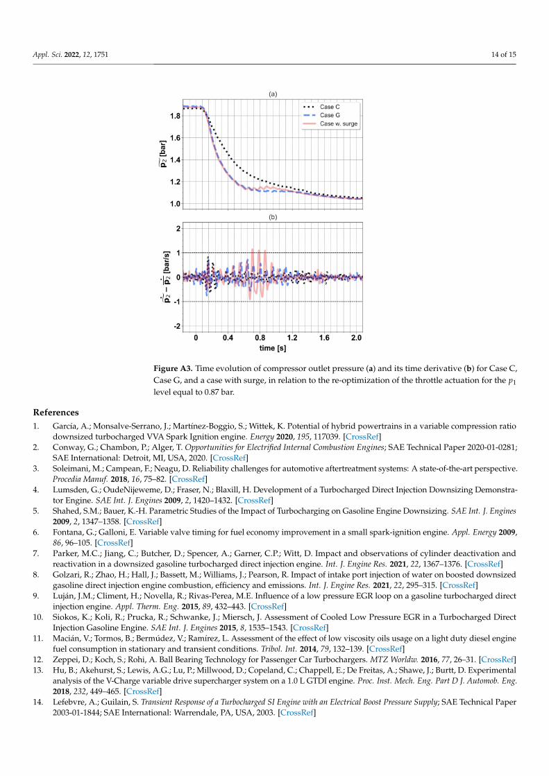
Once the capability of intake flap closure to accelerate the maneuver was confirmed,three p1 levels were analyzed (considering its minimum value): 0.33, 0.65, and 0.87 bar. Inthe first case, load reduction was only achieved through the intake flap, while the throttlewas kept open during the whole maneuver. For the other two p1 levels, throttle actuationwas re-optimized by following a similar procedure to the one described in Figure 2. Itshould be stated that intake flap closing was demanded in one cycle, from full openingto its corresponding final position (2, 6, and 12%, in ascending order of p1), and that nodelay between the start of throttle and intake flap actuations was applied. Figures A1–A3(Appendix A) show the evolution of the compressor outlet pressure and its time derivativefor three cases per each p1 level: the best tip-out for each intake flap closing, labelled asCase E (p1 = 0.33), F (p1 = 0.65) or G (p1 = 0.87), a tip-out with a more aggressive throttleactuation for the two highest p1 levels, in which surge was detected, and the best casewith throttle only (Case C). It must be emphasized that no surge was found for the tip-outmanaged only with the intake flap (Case E), despite its closing in one cycle. For the sake ofreadability, a summary of the different cases analyzed is provided in Table 2, where throttleand intake flap actuations, p1 level, and the use of ASV in each case are specified.

Appl. Sci. 2022, 12, 1751 10 of 15
Table 2. Summary of the main features of Case A, B, C, D, E, F and G.
Case Throttle Actuation Intake Flap p1 Level ASV
A closed in two cycles fully open ambient YesB defined to follow surge line fully open ambient NoC optimized fully open ambient NoD same as C closed until 6% in one cycle 0.65 bar NoE fully open closed until 2% in one cycle 0.33 bar NoF re-optimized closed until 6% in one cycle 0.65 bar NoG re-optimized closed until 12% in one cycle 0.87 bar No
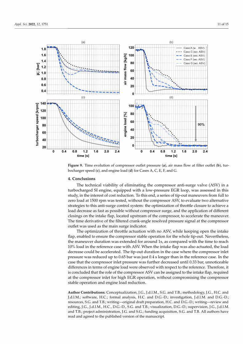
Figures 8 and 9 depict throttle actuation and time evolution of the compressor inletand outlet pressure, air mass flow at filter outlet, turbocharger speed, and engine loadfor five tip-outs: Cases A, C, E, F, and G. It should be reminded that the first one wastested with the anti-surge valve, while the remaining ones were performed without it. Asobserved in Figure 8a, the throttle could be closed two and six cycles faster in Cases F andG, as compared to Case C, due to p1 decrease up to 0.65 and 0.87 bar, respectively. Thereduction of air mass flow and engine load is consequently accelerated. In particular, themaneuver duration in Case F was just 0.4 s longer than in the reference tip-out (Case A),considering, again, the time to complete the 90% of the total load reduction (Figure 9d).After that, it can be concluded that the use of intake flap to perform the tip-out with noASV allowed ensuring the compressor stable operation, without compromising the enginetransient response in excess. Indeed, the reduction of engine load in Case A and Case E wasquite similar (Figure 9d). By contrast, it would be necessary to analyze if such momentarylow p1 levels can cause oil leakages in the turbocharger, but this falls beyond the scope ofthis research.
Figure 8. Throttle actuation (a) and time evolution of compressor inlet pressure (b) for Cases A, C, E,F, and G.
Appl. Sci. 2022, 12, 1751 11 of 15
Figure 9. Time evolution of compressor outlet pressure (a), air mass flow at filter outlet (b), tur-bocharger speed (c), and engine load (d) for Cases A, C, E, F, and G.
4. Conclusions
The technical viability of eliminating the compressor anti-surge valve (ASV) in aturbocharged SI engine, equipped with a low-pressure EGR loop, was assessed in thisstudy, in the interest of cost reduction. To this end, a series of tip-out maneuvers from full tozero load at 1500 rpm was tested, without the compressor ASV, to evaluate two alternativestrategies to this anti-surge control system: the optimization of throttle closure to achieve aload decrease as fast as possible without compressor surge, and the application of differentclosings on the intake flap, located upstream of the compressor, to accelerate the maneuver.The time derivative of the filtered crank-angle resolved pressure signal at the compressoroutlet was used as the main surge indicator.
The optimization of throttle actuation with no ASV, while keeping open the intakeflap, enabled to ensure the compressor stable operation for the whole tip-out. Nevertheless,the maneuver duration was extended for around 1s, as compared with the time to reach10% load in the reference case with ASV. When the intake flap was also actuated, the loaddecrease could be accelerated. The tip-out duration in the case where the compressor inletpressure was reduced up to 0.65 bar was just 0.4 s longer than in the reference case. In thecase that the compressor inlet pressure was further decreased until 0.33 bar, unnoticeabledifferences in terms of engine load were observed with respect to the reference. Therefore, itis concluded that the role of the compressor ASV can be assigned to the intake flap, requiredat the compressor inlet for high EGR operation, without compromising the compressorstable operation and engine load reduction.
Author Contributions: Conceptualization, J.G., J.d.l.M., S.G. and T.B.; methodology, J.G., H.C. andJ.d.l.M.; software, H.C.; formal analysis, H.C. and D.G.-D.; investigation, J.d.l.M. and D.G.-D.;resources, S.G. and T.B.; writing—original draft preparation, H.C. and D.G.-D.; writing—review andediting, J.G., J.d.l.M., H.C., D.G.-D., S.G. and T.B.; visualization, D.G.-D.; supervision, J.G., J.d.l.M.and T.B.; project administration, J.G. and S.G.; funding acquisition, S.G. and T.B. All authors haveread and agreed to the published version of the manuscript.

Appl. Sci. 2022, 12, 1751 12 of 15
Funding: This research received no external funding.
Data Availability Statement: The data that support the findings of this study are not available dueto privacy restrictions.
Acknowledgments: The authors would like to thank Vicente Esteve, Rafael Pitarch, and Irina Jimenezfor their invaluable work during the experimental campaign.
Conflicts of Interest: The authors declare no conflict of interest. The funders had no role in the designof the study; in the collection, analyses, or interpretation of data; in the writing of the manuscript, orin the decision to publish the results.
NomenclatureAcronyms and abbreviationsAMF air mass flowASV anti-surge valveCAD crank-angle degreescyc. cycleECU engine control unitEGR exhaust gas recirculationSI spark ignitionVGT variable geometry turbineVVT variable valve timingw. withwo. withoutSymbolsf frequencyp pressure signalp̃ filtered pressure signal ( fC = 30 Hz)p moving average pressure signal ( fC = 10 Hz).p̃ time derivative of p̃.p time derivative of pSubscripts1 compressor inlet2 compressor outletc cut-offcorr corrected
Appendix A
The time evolution of the compressor outlet pressure and its time derivative for threecases per each p1 level (0.33, 0.65 and 0.87 bar) is presented in Figures A1–A3, in relation tothe re-optimization of throttle actuation.

Appl. Sci. 2022, 12, 1751 13 of 15
Figure A1. Time evolution of compressor outlet pressure (a) and its time derivative (b) for Case Cand Case E.
Figure A2. Time evolution of compressor outlet pressure (a) and its time derivative (b) for Case C,Case F, and a case with surge, in relation to the re-optimization of the throttle actuation for the p1
level equal to 0.65 bar.
Appl. Sci. 2022, 12, 1751 14 of 15
Figure A3. Time evolution of compressor outlet pressure (a) and its time derivative (b) for Case C,Case G, and a case with surge, in relation to the re-optimization of the throttle actuation for the p1
level equal to 0.87 bar.
References1. García, A.; Monsalve-Serrano, J.; Martínez-Boggio, S.; Wittek, K. Potential of hybrid powertrains in a variable compression ratio
downsized turbocharged VVA Spark Ignition engine. Energy 2020, 195, 117039. [CrossRef]2. Conway, G.; Chambon, P.; Alger, T. Opportunities for Electrified Internal Combustion Engines; SAE Technical Paper 2020-01-0281;
SAE International: Detroit, MI, USA, 2020. [CrossRef]3. Soleimani, M.; Campean, F.; Neagu, D. Reliability challenges for automotive aftertreatment systems: A state-of-the-art perspective.
Procedia Manuf. 2018, 16, 75–82. [CrossRef]4. Lumsden, G.; OudeNijeweme, D.; Fraser, N.; Blaxill, H. Development of a Turbocharged Direct Injection Downsizing Demonstra-
tor Engine. SAE Int. J. Engines 2009, 2, 1420–1432. [CrossRef]5. Shahed, S.M.; Bauer, K.-H. Parametric Studies of the Impact of Turbocharging on Gasoline Engine Downsizing. SAE Int. J. Engines
2009, 2, 1347–1358. [CrossRef]6. Fontana, G.; Galloni, E. Variable valve timing for fuel economy improvement in a small spark-ignition engine. Appl. Energy 2009,
86, 96–105. [CrossRef]7. Parker, M.C.; Jiang, C.; Butcher, D.; Spencer, A.; Garner, C.P.; Witt, D. Impact and observations of cylinder deactivation and
reactivation in a downsized gasoline turbocharged direct injection engine. Int. J. Engine Res. 2021, 22, 1367–1376. [CrossRef]8. Golzari, R.; Zhao, H.; Hall, J.; Bassett, M.; Williams, J.; Pearson, R. Impact of intake port injection of water on boosted downsized
gasoline direct injection engine combustion, efficiency and emissions. Int. J. Engine Res. 2021, 22, 295–315. [CrossRef]9. Luján, J.M.; Climent, H.; Novella, R.; Rivas-Perea, M.E. Influence of a low pressure EGR loop on a gasoline turbocharged direct
injection engine. Appl. Therm. Eng. 2015, 89, 432–443. [CrossRef]10. Siokos, K.; Koli, R.; Prucka, R.; Schwanke, J.; Miersch, J. Assessment of Cooled Low Pressure EGR in a Turbocharged Direct
Injection Gasoline Engine. SAE Int. J. Engines 2015, 8, 1535–1543. [CrossRef]11. Macián, V.; Tormos, B.; Bermúdez, V.; Ramírez, L. Assessment of the effect of low viscosity oils usage on a light duty diesel engine
fuel consumption in stationary and transient conditions. Tribol. Int. 2014, 79, 132–139. [CrossRef]12. Zeppei, D.; Koch, S.; Rohi, A. Ball Bearing Technology for Passenger Car Turbochargers. MTZ Worldw. 2016, 77, 26–31. [CrossRef]13. Hu, B.; Akehurst, S.; Lewis, A.G.; Lu, P.; Millwood, D.; Copeland, C.; Chappell, E.; De Freitas, A.; Shawe, J.; Burtt, D. Experimental
analysis of the V-Charge variable drive supercharger system on a 1.0 L GTDI engine. Proc. Inst. Mech. Eng. Part D J. Automob. Eng.2018, 232, 449–465. [CrossRef]
14. Lefebvre, A.; Guilain, S. Transient Response of a Turbocharged SI Engine with an Electrical Boost Pressure Supply; SAE Technical Paper2003-01-1844; SAE International: Warrendale, PA, USA, 2003. [CrossRef]
Appl. Sci. 2022, 12, 1751 15 of 15
15. Hu, B.; Yang, J.; Li, J.; Li, S.; Bai, H. Intelligent control strategy for transient response of a variable geometry turbocharger systembased on deep reinforcement learning. Processes 2019, 7, 601. [CrossRef]
16. Tang, H.; Akehurst, S.; Brace, C.J.; Garrett, S.; Smith, L. Optimisation of transient response of a gasoline engine with variablegeometry turbine turbocharger. In Proceedings of the Institution of Mechanical Engineers: 11th International Conference onTurbochargers and Turbocharging, London, UK, 13–14 May 2014; pp. 163–175. [CrossRef]
17. Andersen, J.; Lindström, F.; Westin, F. Surge Definitions for Radial Compressors in Automotive Turbochargers. SAE Int. J. Engines2009, 1, 218–231. [CrossRef]
18. Kurz, R.; White, R.C. Surge Avoidance in Gas Compression Systems. ASME. J. Turbomach. 2004, 126, 501–506. [CrossRef]19. Oakes, W.C.; Lawless, P.B.; Fagan, J.R.; Fleeter, S. High-speed centrifugal compressor surge initiation characterization. J. Propuls.
Power 2002, 18, 1012–1018. [CrossRef]20. Engeda, A.; Kim, Y.; Aungier, R.; Direnzi, G. The inlet flow structure of a centrifugal compressor stage and its influence on the
compressor performance. J. Fluids Eng. 2003, 125, 779–785. [CrossRef]21. Galindo, J.; Arnau, F.; Tiseira, A.; Lang, R.; Lahjaily, H.; Gimenes, T. Measurement and Modeling of Compressor Surge on Engine Test
Bench for Different Intake Line Configurations; SAE Technical Paper 2011-01-0370; SAE International: Warrendale, PA, USA, 2011.[CrossRef]
22. Galindo, J.; Tiseira, A.; Navarro, R.; Tarí, D.; Meano, C.M. Effect of the inlet geometry on performance, surge margin and noiseemission of an automotive turbocharger compressor. Appl. Therm. Eng. 2017, 110, 875–882. [CrossRef]
23. Fink, D.A.; Cumpsty, N.A.; Greitzer, E.M. Surge Dynamics in a Free-Spool Centrifugal Compressor System. ASME. J. Turbomach.1992, 114, 321–332. [CrossRef]
24. Galindo, J.; Serrano, J.R.; Climent, H.; Tiseira, A. Experiments and modelling of surge in small centrifugal compressor forautomotive engines. Exp. Therm. Fluid Sci. 2008, 32, 818–826. [CrossRef]
25. Galindo, J.; Serrano, J.R.; Margot, X.; Tiseira, A.; Schorn, N.; Kindl, H. Potential of flow pre-whirl at the compressor inlet ofautomotive engine turbochargers to enlarge surge margin and overcome packaging limitations. Int. J. Heat Fluid Flow 2007, 28,374–387. [CrossRef]
26. Galindo, J.; Climent, H.; Guardiola, C.; Tiseira, A. On the effect of pulsating flow on surge margin of small centrifugal compressorsfor automotive engines. Exp. Therm. Fluid Sci. 2009, 33, 1163–1171. [CrossRef]
27. Lujan, J.; Pastor, J.; Climent, H.; Rivas, M. Experimental Characterization and Modelling of a Turbocharger Gasoline Engine CompressorBy-Pass Valve in Transient Operation; SAE Technical Paper 2015-24-2524; SAE International: Warrendale, PA, USA, 2015. [CrossRef]
28. Ossareh, H.R.; Buckland, J.; Jankovic, M. Continuous compressor recirculation to improve boost response and mitigate compressorsurge in turbocharged gasoline engines. In Proceedings of the 2016 American Control Conference (ACC), Boston, MA, USA, 6–8July 2016; pp. 5093–5098. [CrossRef]
29. Podevin, P.; Danlos, A.; Deligant, M.; Punov, P.; Clenci, A.; de La Bourdonnaye, G. Automotive compressor: Effect of an electricthrottle in the upstream circuit on the surge limit. MATEC Web Conf. 2018, 234, 03006. [CrossRef]
30. Galindo, J.; Climent, H.; de la Morena, J.; González-Domínguez, D.; Guilain, S.; Besançon, T. Assessment of air-managementstrategies to improve the transient performance of a gasoline engine under high EGR conditions during load-decrease operation.Int. J. Engine Res. 2021. [CrossRef]
31. Pla, B.; De La Morena, J.; Bares, P.; Jiménez, I. Knock Analysis in the Crank Angle Domain for Low-Knocking Cycles Detection; SAETechnical Paper 2020-01-0549; SAE International: Warrendale, PA, USA, 2020. [CrossRef]
32. Pla, B.; De la Morena, J.; Bares, P.; Jiménez, I. Cycle-to-cycle combustion variability modelling in spark ignited engines for controlpurposes. Int. J. Engine Res. 2020, 21, 1398–1411. [CrossRef]
33. Galindo, J.; Climent, H.; De la Morena, J.; González-Domínguez, D.; Guilain, S.; Besançon, T. Experimental and modeling analysison the optimization of combined VVT and EGR strategies in turbocharged direct-injection gasoline engines with VNT. Proc. Inst.Mech. Eng. Part D J. Automob. Eng. 2021, 235, 2843–2856. [CrossRef]
34. Serrano, J.R.; Arnau, F.J.; García-Cuevas, L.M.; Gómez-Vilanova, A.; Guilain, S.; Batard, S. A Methodology for MeasuringTurbocharger Adiabatic Maps in a Gas-Stand and Its Usage for Calibrating Control Oriented and One-Dimensional Models atEarly ICE Design Stages. ASME. J. Energy Resour. Technol. 2021, 143, 042303. [CrossRef]
35. Galindo, J.; Serrano, J.R.; Guardiola, C.; Cervelló, C. Surge limit definition in a specific test bench for the characterization ofautomotive turbochargers. Exp. Therm. Fluid Sci. 2006, 30, 449–462. [CrossRef]
36. Ellis, G. Chapter 9—Filters in Control Systems. In Control Systems Design Guide, 4th ed.; Ellis, G., Ed.; Butterworth-Heinemann:Oxford, UK, 2012; pp. 165–183. [CrossRef]