Testing Ignition Timing
34
Testing Ignition Timing Using Pico Scope & WPS500X Pressure Transducer and kV Pickup Use PgUp and PgDn keys or Mouse Scroll Wheel to navigate tutorial
-
Upload
khangminh22 -
Category
Documents
-
view
1 -
download
0
Transcript of Testing Ignition Timing

Testing Ignition Timing
Using Pico Scope & WPS500X
Pressure Transducer and kV Pickup
Use PgUp and PgDn keys or Mouse Scroll Wheel to navigate tutorial

Setting up the Pico Scope

Plug USB for Pico into Computer and Start Pico Software

Use the Red ‘Stop’ Button (or the Space Bar) to pause the Scope
before adjusting the settings
Select the ‘Collection Time’ Box to adjust the time setting

Use the drop down menu to select 10 s(This is a good time setting for most captures – adjust if needed)

Select ‘CH A’ to set up this channel to measure pressure(Pressure Transducer connected to ‘CH A’)

Select the ‘Probes’ drop down menu by clicking on the arrow next to ‘Probe’(Do not select the pop up menu – Button with ‘3 dots’)

In the ‘Probes’ drop down menu scroll down to ‘Library’(Do not choose from the ‘Standard’ nor the ‘Automotive’ Menus)

Under the ‘Library’ Menu Select ‘WPS500X 500 psi (Range 1)’

Make sure the filter is turned on the pressure transducer (1 kHz filter)

Use the probe library to set CH D to ‘Secondary kV (Inverted) +/- 50 kV(If secondary pattern is upside dwon switch to ‘Secondary kV (Pos) +/- 50 kV)

Set CH D to the +/-50 kV Scale

Turn off the channels that you are not using (CH B and CH C)

To adjust the zero position – select the scale and move down as needed

Setting Up the WPS500X
Pressure Transducer
&
Secondary kV Pickup

Turn Power on
Press power button to turn on (Press & Hold Briefly to Turn Off)
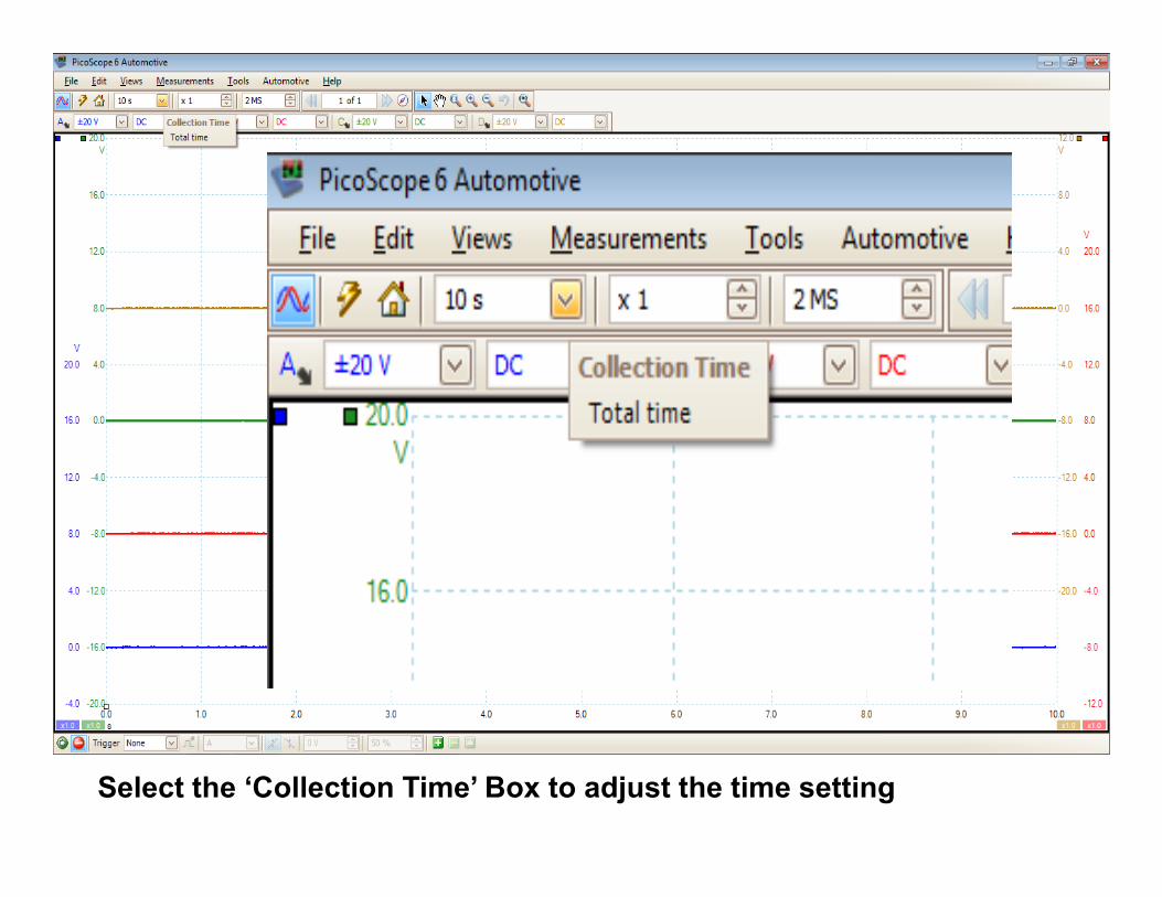
WPS500X Pressure Transducer

Lights will flash as the unit
Self calibrates Don’t Touch!
WPS500X Pressure Transducer
Unit will run a self calibration
Range 1 should be lit
When calibration is complete
WPS500X Pressure Transducer
Make sure ‘Range 1’ (500 psi) is selected and that none of the ‘Zoom’ lights are lit

Secondary Capacitive Pickup Clip to Spark Plug wire
Always ground to an Engine Ground (Not Chassis or Battery)
Danger: Never connect scope directly to
secondary with back pins or alligator clips. Only
use Secondary kV pickup on the secondary side

Remove Spark Plug from cylinder to be tested
Connect Spark tester to plug wire (if adjustable set a ‘S|E’ Gap)
Clip Secondary kV Probe to plug wire (Ground to Engine Ground)
Thread compression hose into cylinder
Connect Pressure transducer to compression hose
Connect Pressure transducer to scope (CH A – Blue)


Use the Green Start Button to start the scope. Crank (or Run) Engine for at
least 5 seconds and use the Red Stop Button to pause

Select the ‘Windowed Zoom’ Tool to take a closer look

Zoom in on one complete cycle of the engine (2 revolutions of the crankshaft – compression to compression)
Sp
ark
TD
C C
om
p
Sp
ark
Wa
ste
Sp
ark
TD
C C
om
p
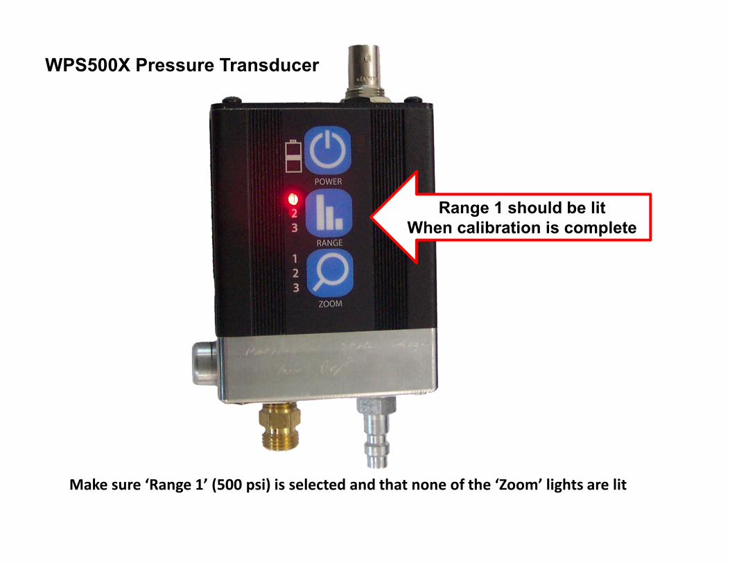
Typical Cranking waveform for a DIS – Waste System with good ignition timing(Note: COP and DI will not have the Waste Spark Event on the Exhaust Stroke)

Use Degree Cursors to mark off 2 revolutions of the crankshaft (720o)
Degree Cursors

Use Degree Cursors to mark off 2 revolutions of the crankshaft (720o)
Degree Cursors
0o Top Dead Center Compression
2 Revolutions of Crankshaft (720o)

Use measurement Cursor to measure when spark occurs(Note: Spark typically occurs 0o to 30o Before Top Dead Center Compression 0o to 10o cranking)
Measurement Cursors

Use measurement Cursor to measure when spark occurs(Note: Spark typically occurs 0o to 30o Before Top Dead Center Compression 0o to 10o cranking)
Measurement
Cursor

Use Rulers Menu to mark off 4 divisions (Rotation Partitions)
Rulers Menu

TDC BDC TDC BDC TDC
Intake
Comp.Power
ExhaustComp.
Typical Cranking waveform for a DIS – Waste System with good ignition timing
With 4 strokes marked off

1 3 2 4 1
Use the engine firing order and rulers to mark off when each cylinder is at top
dead center compression (Example above: 4 Cylinder with firing order 1-3-2-4)

2 1 8 4 3 6 5 7 2
Use the engine firing order and rulers to mark off when each cylinder is at top
dead center compression (Example above: 8 Cylinder with firing order 1,8,4,3,6,5,7,2)
#2 Cylinder
8
Rulers Menu