Closed loop ignition timing control using ionization current ...
12
416 IEEE TRANSACTIONS ON CONTROL SYSTEMS TECHNOLOGY, VOL. 15, NO. 3, MAY 2007 Closed-Loop Ignition Timing Control for SI Engines Using Ionization Current Feedback Guoming G. Zhu, Ibrahim Haskara, and Jim Winkelman, Fellow, IEEE Abstract—Minimal advance for best torque (MBT) timing for an internal combustion (IC) spark ignition (SI) engine is the minimum advance of spark timing for the best torque or, in other words, for the best fuel economy. But MBT timing is often limited by engine knock in the advanced direction and spark timing is also constrained by partial burn and misfire in the retard direction. It is preferred to operate IC engines at MBT timing when it is not knock limited and at borderline knock limit when it is knock lim- ited. During cold start conditions it is desired to operate IC engines at its maximum retard limit subject to combustion stability con- straints to reduce catalyst light-off time. Traditionally, both MBT timing and retard spark limit are open-loop feedforward controls whose values are experimentally determined by conducting spark sweeps at different speed and load points, and at different envi- ronmental conditions. The borderline knock limit is controlled by a dual-rate count-up/count-down closed-loop control utilizing in- formation from engine knock sensor signals. A closed-loop con- trol architecture for spark timing is proposed in this paper. Using in-cylinder ionization signals both borderline knock and retard spark limits are regulated using closed-loop stochastic limit con- trols. MBT timing is also controlled closed-loop using an MBT cri- terion derived from in-cylinder ionization signals. The proposed control strategy and architecture was experimentally validated on a 3.0-L V6 engine for steady state and slow transient conditions. Index Terms—Automotive controls, closed-loop systems, en- gines, ionization, microcontrollers, stochastic systems. I. INTRODUCTION I NTERNAL combustion (IC) engines are optimized to meet exhaust emission requirements with the best fuel economy. Spark timing is used as one of the optimization parameters for best fuel economy within given emission constraints. For normal operation, engine spark timing is often optimized to provide minimal advance for the best torque (MBT). On the other hand, engine combustion stability and knock avoidance requirements also constrain engine spark timing within a certain region, called the feasible spark timing region. For certain operational conditions, it is desirable to operate the engine at the borderline of the feasible region continuously. For instance, under certain operational conditions engine MBT timing is located outside of the feasible spark-timing region Manuscript received October 30, 2006; revised January 18, 2007. Manuscript received in final form January 31, 2007. Recommended by Associate Editor I. Kolmanovsky. G. G. Zhu and J. Winkelman are with the Advanced Powertrain Systems, Visteon Corporation, Van Buren TWP, MI 48111 USA (e-mail: gzhu1@visteon. com; [email protected]). I. Haskara is with General Motors, Warren, MI 48090 USA (e-mail: ibrahim. [email protected]). Color versions of Figs. 1, 2, 10, 14, and 15 are available online at http://iee- explore.ieee.org. Digital Object Identifier 10.1109/TCST.2007.894634 Fig. 1. Feasible region of spark timing. due to the requirement to avoid engine knock. In order to obtain maximum brake torque it is required to operate the engine at the knock limit (borderline knock limit) of the feasible region. Under different operating conditions, in order to reduce cold start hydrocarbon (HC) emissions it is desired to locate the spark timing at the retard limit of the feasible region for fast catalyst light-off. This is due to the desire to maintain a certain level of combustion stability. Fig. 1 shows a typical spark timing feasible region as a func- tion of exhaust gas recirculation (EGR) for a desired level of combustion stability with coefficient of variation (COV) of in- dicated mean effective pressure (IMEP) less than 3%, where the thick dash line represents the engine MBT spark timing, thick dash-dotted line represents the engine advanced (knock) spark limit, and the thick solid line represents the retard spark limit. It can be observed that knock, MBT, and retard limits vary as a function of EGR rate, which makes it difficult to control the op- timal spark timing in an open-loop fashion. Further, this feasible region varies in shape with different engine operational and en- vironmental conditions. In current production applications, MBT timing is an open- loop feedforward control whose values are experimentally de- termined by conducting spark sweeps at different speed and load points, and at different environmental operating conditions. Al- most every calibration point needs a spark sweep to see if the engine can be operated at the MBT timing condition. If not, a certain degree of safety margin is needed to avoid preignition or knock during engine operation. Open-loop spark mapping usu- ally requires a tremendous amount of effort and time to achieve a satisfactory calibration. 1063-6536/$25.00 © 2007 IEEE
-
Upload
khangminh22 -
Category
Documents
-
view
3 -
download
0
Transcript of Closed loop ignition timing control using ionization current ...

416 IEEE TRANSACTIONS ON CONTROL SYSTEMS TECHNOLOGY, VOL. 15, NO. 3, MAY 2007
Closed-Loop Ignition Timing Control for SI EnginesUsing Ionization Current Feedback
Guoming G. Zhu, Ibrahim Haskara, and Jim Winkelman, Fellow, IEEE
Abstract—Minimal advance for best torque (MBT) timing for aninternal combustion (IC) spark ignition (SI) engine is the minimumadvance of spark timing for the best torque or, in other words,for the best fuel economy. But MBT timing is often limited byengine knock in the advanced direction and spark timing is alsoconstrained by partial burn and misfire in the retard direction. Itis preferred to operate IC engines at MBT timing when it is notknock limited and at borderline knock limit when it is knock lim-ited. During cold start conditions it is desired to operate IC enginesat its maximum retard limit subject to combustion stability con-straints to reduce catalyst light-off time. Traditionally, both MBTtiming and retard spark limit are open-loop feedforward controlswhose values are experimentally determined by conducting sparksweeps at different speed and load points, and at different envi-ronmental conditions. The borderline knock limit is controlled bya dual-rate count-up/count-down closed-loop control utilizing in-formation from engine knock sensor signals. A closed-loop con-trol architecture for spark timing is proposed in this paper. Usingin-cylinder ionization signals both borderline knock and retardspark limits are regulated using closed-loop stochastic limit con-trols. MBT timing is also controlled closed-loop using an MBT cri-terion derived from in-cylinder ionization signals. The proposedcontrol strategy and architecture was experimentally validated ona 3.0-L V6 engine for steady state and slow transient conditions.
Index Terms—Automotive controls, closed-loop systems, en-gines, ionization, microcontrollers, stochastic systems.
I. INTRODUCTION
I NTERNAL combustion (IC) engines are optimized to meetexhaust emission requirements with the best fuel economy.
Spark timing is used as one of the optimization parametersfor best fuel economy within given emission constraints. Fornormal operation, engine spark timing is often optimized toprovide minimal advance for the best torque (MBT). On theother hand, engine combustion stability and knock avoidancerequirements also constrain engine spark timing within acertain region, called the feasible spark timing region. Forcertain operational conditions, it is desirable to operate theengine at the borderline of the feasible region continuously.For instance, under certain operational conditions engine MBTtiming is located outside of the feasible spark-timing region
Manuscript received October 30, 2006; revised January 18, 2007. Manuscriptreceived in final form January 31, 2007. Recommended by Associate Editor I.Kolmanovsky.
G. G. Zhu and J. Winkelman are with the Advanced Powertrain Systems,Visteon Corporation, Van Buren TWP, MI 48111 USA (e-mail: [email protected]; [email protected]).
I. Haskara is with General Motors, Warren, MI 48090 USA (e-mail: [email protected]).
Color versions of Figs. 1, 2, 10, 14, and 15 are available online at http://iee-explore.ieee.org.
Digital Object Identifier 10.1109/TCST.2007.894634
Fig. 1. Feasible region of spark timing.
due to the requirement to avoid engine knock. In order to obtainmaximum brake torque it is required to operate the engine atthe knock limit (borderline knock limit) of the feasible region.Under different operating conditions, in order to reduce coldstart hydrocarbon (HC) emissions it is desired to locate thespark timing at the retard limit of the feasible region for fastcatalyst light-off. This is due to the desire to maintain a certainlevel of combustion stability.
Fig. 1 shows a typical spark timing feasible region as a func-tion of exhaust gas recirculation (EGR) for a desired level ofcombustion stability with coefficient of variation (COV) of in-dicated mean effective pressure (IMEP) less than 3%, where thethick dash line represents the engine MBT spark timing, thickdash-dotted line represents the engine advanced (knock) sparklimit, and the thick solid line represents the retard spark limit.It can be observed that knock, MBT, and retard limits vary as afunction of EGR rate, which makes it difficult to control the op-timal spark timing in an open-loop fashion. Further, this feasibleregion varies in shape with different engine operational and en-vironmental conditions.
In current production applications, MBT timing is an open-loop feedforward control whose values are experimentally de-termined by conducting spark sweeps at different speed and loadpoints, and at different environmental operating conditions. Al-most every calibration point needs a spark sweep to see if theengine can be operated at the MBT timing condition. If not, acertain degree of safety margin is needed to avoid preignition orknock during engine operation. Open-loop spark mapping usu-ally requires a tremendous amount of effort and time to achievea satisfactory calibration.
1063-6536/$25.00 © 2007 IEEE

ZHU et al.: CLOSED-LOOP IGNITION TIMING CONTROL FOR SI ENGINES USING IONIZATION CURRENT FEEDBACK 417
Fig. 2. Closed-loop ignition timing control system.
Existing knock spark limit control utilizes an accelerom-eter-based knock sensor for feedback control. Due to the lowsignal-to-noise ratio (SNR), conventional approaches are basedon the use of a knock flag signal obtained by comparing theknock intensity signal of a knock sensor to a given threshold.The knock intensity signal is defined as the integrated value,over a given knock window, of the absolute value signal ob-tained by filtering the raw knock sensor signal using a band-passfilter. This knock flag signal is the input to a dual-rate (slowand fast correction) count-up/count-down engine knock limitcontroller. The disadvantage of this control scheme is that itcontinually takes the engine in and out of knock, rather thanoperating continually at the desired borderline knock limit. Inaddition, at certain operating points knock observability canbe severely compromised by engine mechanical noises suchas valve closures and piston slap which may be picked up bythe accelerometer. Such issues result in conservative ignitiontiming that leads to reduced engine performance.
As discussed before, during a cold start, it is desirable to op-erate the engine at its retard spark-timing limit for minimal HCemissions. The retard spark-timing limit is often constrained byengine combustion stability metrics such as COV of IMEP. Dueto unavailability of production ready in-cylinder pressure sen-sors, the retard spark-timing limit is obtained through an offlineengine mapping process, leading to conservative calibrations. Inaddition, to accommodate the range of fuels used throughout amarket, this calibration is made even more conservative.
In recent years, various closed-loop spark timing controlschemes have been proposed based upon in-cylinder pressuremeasurements ([1]–[8]) or spark ionization current sensing([9]–[11], and [16]). Based upon test data, it has been foundthat the peak cylinder pressure (PCP) usually occurs around15 after top dead center (TDC) at MBT timing (see [9]).The 50% mass fraction burned (MFB) point generally occursbetween 8 and 10 after TDC when MBT timing is achieved.The algorithm published in [3], controls PR(10) (normalizedpressure ratio of in-cylinder and motoring pressures at 10 afterTDC) around 0.55 to obtain the MBT timing.
Due to the recent advance of electronics technology, ioniza-tion current can be detected at 15 A with very low backgroundnoise. The high quality of an in-cylinder ionization signal makesit possible to derive a linear knock intensity that is proportional
to the knock level (see [4], [13], and [14]). It can also be pro-cessed to derive a metric for combustion quality similar to COVof IMEP and closeness of combustion to partial burn and mis-fire limit (see [16]), which can be used as a feedback signal forretard limit control. Engine MBT timing can also be derivedfrom in-cylinder ionization signals similar to the pressure sig-nals (see [3] and [9]). Since MBT criteria derived from pres-sure and ionization signals are solely based upon observationsand may change at different operating conditions, the associ-ated control algorithms still require some dynamometer-basedcalibration effort. It is clear that the combustion process has tobe matched with the engine cylinder volume change to attainthe best torque. The major advantage for the ionization-basedclosed-loop MBT timing control is no additional sensing ele-ment or assembly steps are required since it uses the spark plugas an ignition actuator and a combustion sensor.
This paper proposes a closed-loop ignition control architec-ture (see Fig. 2) that combines MBT timing control, knock, andretard timing limit control strategies into an integrated one. Theintegrated ignition control architecture allows the engine to op-erate at its true MBT timing when it is not limited by borderlineknock limit and operate at its borderline knock limit when it islimited by knock. Alternatively, it allows the engine to be oper-ated at its borderline retard limit when it is limited by combus-tion stability.
This paper is organized as follows. Section II describesclosed-loop MBT timing control strategy. Section III proposesthe stochastic limit controller architecture, which is used forboth knock and retard spark timing control. The application ofthe proposed MBT timing, borderline knock limit and retardspark limit closed-loop ignition control on a 3.0-L V6 engine isdescribed in Section IV. Section V adds some conclusions.
II. MBT TIMING CONTROL STRATEGY
Closed-loop MBT timing control using in-cylinder pressurefeedback was described in [5] and [8], and closed-loop igni-tion timing control using ionization feedback was presented in[10]. This section describes closed-loop MBT timing control,using a composite MBT criterion derived from an ionizationsignal as a feedback signal. For the closed-loop MBT timingcontrol strategy, an individual cylinder ionization current wassampled at every crank degree and processed every combustion
418 IEEE TRANSACTIONS ON CONTROL SYSTEMS TECHNOLOGY, VOL. 15, NO. 3, MAY 2007
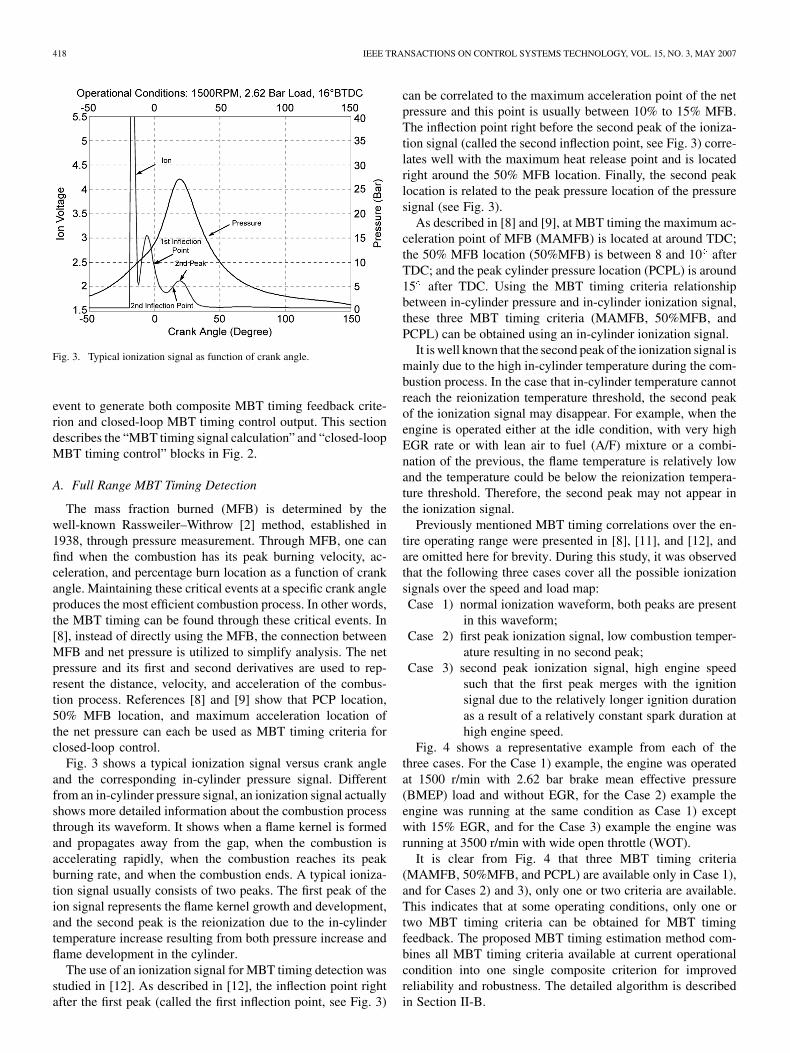
Fig. 3. Typical ionization signal as function of crank angle.
event to generate both composite MBT timing feedback crite-rion and closed-loop MBT timing control output. This sectiondescribes the “MBT timing signal calculation” and “closed-loopMBT timing control” blocks in Fig. 2.
A. Full Range MBT Timing Detection
The mass fraction burned (MFB) is determined by thewell-known Rassweiler–Withrow [2] method, established in1938, through pressure measurement. Through MFB, one canfind when the combustion has its peak burning velocity, ac-celeration, and percentage burn location as a function of crankangle. Maintaining these critical events at a specific crank angleproduces the most efficient combustion process. In other words,the MBT timing can be found through these critical events. In[8], instead of directly using the MFB, the connection betweenMFB and net pressure is utilized to simplify analysis. The netpressure and its first and second derivatives are used to rep-resent the distance, velocity, and acceleration of the combus-tion process. References [8] and [9] show that PCP location,50% MFB location, and maximum acceleration location ofthe net pressure can each be used as MBT timing criteria forclosed-loop control.
Fig. 3 shows a typical ionization signal versus crank angleand the corresponding in-cylinder pressure signal. Differentfrom an in-cylinder pressure signal, an ionization signal actuallyshows more detailed information about the combustion processthrough its waveform. It shows when a flame kernel is formedand propagates away from the gap, when the combustion isaccelerating rapidly, when the combustion reaches its peakburning rate, and when the combustion ends. A typical ioniza-tion signal usually consists of two peaks. The first peak of theion signal represents the flame kernel growth and development,and the second peak is the reionization due to the in-cylindertemperature increase resulting from both pressure increase andflame development in the cylinder.
The use of an ionization signal for MBT timing detection wasstudied in [12]. As described in [12], the inflection point rightafter the first peak (called the first inflection point, see Fig. 3)
can be correlated to the maximum acceleration point of the netpressure and this point is usually between 10% to 15% MFB.The inflection point right before the second peak of the ioniza-tion signal (called the second inflection point, see Fig. 3) corre-lates well with the maximum heat release point and is locatedright around the 50% MFB location. Finally, the second peaklocation is related to the peak pressure location of the pressuresignal (see Fig. 3).
As described in [8] and [9], at MBT timing the maximum ac-celeration point of MFB (MAMFB) is located at around TDC;the 50% MFB location (50%MFB) is between 8 and 10 afterTDC; and the peak cylinder pressure location (PCPL) is around15 after TDC. Using the MBT timing criteria relationshipbetween in-cylinder pressure and in-cylinder ionization signal,these three MBT timing criteria (MAMFB, 50%MFB, andPCPL) can be obtained using an in-cylinder ionization signal.
It is well known that the second peak of the ionization signal ismainly due to the high in-cylinder temperature during the com-bustion process. In the case that in-cylinder temperature cannotreach the reionization temperature threshold, the second peakof the ionization signal may disappear. For example, when theengine is operated either at the idle condition, with very highEGR rate or with lean air to fuel (A/F) mixture or a combi-nation of the previous, the flame temperature is relatively lowand the temperature could be below the reionization tempera-ture threshold. Therefore, the second peak may not appear inthe ionization signal.
Previously mentioned MBT timing correlations over the en-tire operating range were presented in [8], [11], and [12], andare omitted here for brevity. During this study, it was observedthat the following three cases cover all the possible ionizationsignals over the speed and load map:Case 1) normal ionization waveform, both peaks are present
in this waveform;Case 2) first peak ionization signal, low combustion temper-
ature resulting in no second peak;Case 3) second peak ionization signal, high engine speed
such that the first peak merges with the ignitionsignal due to the relatively longer ignition durationas a result of a relatively constant spark duration athigh engine speed.
Fig. 4 shows a representative example from each of thethree cases. For the Case 1) example, the engine was operatedat 1500 r/min with 2.62 bar brake mean effective pressure(BMEP) load and without EGR, for the Case 2) example theengine was running at the same condition as Case 1) exceptwith 15% EGR, and for the Case 3) example the engine wasrunning at 3500 r/min with wide open throttle (WOT).
It is clear from Fig. 4 that three MBT timing criteria(MAMFB, 50%MFB, and PCPL) are available only in Case 1),and for Cases 2) and 3), only one or two criteria are available.This indicates that at some operating conditions, only one ortwo MBT timing criteria can be obtained for MBT timingfeedback. The proposed MBT timing estimation method com-bines all MBT timing criteria available at current operationalcondition into one single composite criterion for improvedreliability and robustness. The detailed algorithm is describedin Section II-B.

ZHU et al.: CLOSED-LOOP IGNITION TIMING CONTROL FOR SI ENGINES USING IONIZATION CURRENT FEEDBACK 419
Fig. 4. Three cases of ionization waveforms.
B. MBT Timing Detection Algorithm
In order to implement the MBT timing estimation strategyusing an in-cylinder ionization signal, a detection algorithm wasdeveloped. The MBT timing detection algorithm can be dividedinto the following four steps.
Step 1: Ionization Signal Conditioning: For each givencylinder, the ionization signal is sampled at every crank degreeafter the ignition coil dwell event for 120 , as the ionizationsignal disappears after 120 crank angle degrees. The sampledionization signal is conditioned by a low-pass filteringto improve the accuracy of detecting the first and second peaksand inflection points. In order to minimize the phase shifteffects due to low-pass filtering for improved MBT timingestimation, a two-way low-pass filtering technique is used, see[8] for details. Note that the complete ionization signal array isavailable for computing the spark timing control for the nextcombustion event, so it is possible to perform this noncausalcalculation. The ionization vector is filtered by the first-orderforward filter defined as follows:
(2.1)
where is the digital filter parameter associated with the low-pass filter bandwidth; and then the index of the ionization vectoris reversed and filtered by again. The combined filteringtransfer function has zero phase delay, see [8].
Step 2: Operational Condition Identification: In this step,the engine operational condition is identified, and the resultingoutput of this step is the determination of which case the sam-pled ionization signal belongs to, that is Cases 1), 2), or 3). Apattern recognition algorithm is used for the case identificationby using the calculated number of peaks, inflection points, andtheir distances from end of ignition.
Step 3: MBT Timing Criteria Calculation: After the ioniza-tion signal case is identified, MBT timing criteria can be calcu-lated using a peak location detection algorithm. The inflectionlocation detection logic is implemented by applying a peak lo-cation detection algorithm to the derivative of the filtered ion-ization signal.
TABLE ICOEFFICIENT SELECTION MATRIX
Step 4: Composite MBT Timing Criterion Generation: Thecomposite MBT timing criterion is calculated basedupon the case number identified from Step 2. For all threecases, the composite MBT timing criterion can be calculatedusing the following equation:
where
(2.2)
By definition, the composite MBT timing criterion is equalto zero when the engine is running at its MBT timing conditionsince the MBT timing criteria MAMFB is zero and the MBTcriteria 50%MFB and PCPL are shifted from their nominallocations defined by and ,respectively. At MBT timing, both and
vary slightly (a few degrees) as a function ofengine operational conditions and they are a function of enginespeed and load. They can be obtained through an existingcalibration process (no extra calibration needed). Coefficients
, , and are selected based uponTable I for a given case number.
C. Closed-Loop Control Strategy
The purpose of closed-loop MBT timing control is two-fold:keeping the engine operating at its MBT spark timing if it is notknock limited and reducing the cycle-to-cycle combustion vari-ation through closed-loop spark timing control [8]. The controlstrategy associated with the “MBT timing signal calculation”and “closed-loop MBT timing control” blocks, shown in Fig. 2,is discussed as follows.
Inputs to the “MBT timing signal calculation” block (seeFig. 2) are the individual in-cylinder ionization signals synchro-nized with engine crank angle and the current engine operationalinformation such as the engine speed, load, etc. Speed and loadinformation are lookup table inputs for calculating MBT timingoffsets ( and ) as well as theMBT feedforward ignition timing. The output of the “MBTtiming signal calculation” block are the composite MBT timingcriterion for the current cylinder using the proposed al-gorithm from Section II-B.
The closed-loop spark MBT timing control is realized usinga proportional–integral (PI) controller whose output is used tocorrect the feedforward MBT ignition timing. The error betweenMBT criterion reference and the composite MBT timing crite-rion is used as an input to the PI controller. Under the study

420 IEEE TRANSACTIONS ON CONTROL SYSTEMS TECHNOLOGY, VOL. 15, NO. 3, MAY 2007
Fig. 5. Ionization signal and integration location.
conditions used in this work, the MBT criteria reference signalwas set to zero. However, this is not necessary. For example,under certain conditions, to meet emission requirements it maybe desired to retard spark timing from its MBT timing by a fewdegrees. Under these conditions, the reference signal can be setto a negative value.
III. STOCHASTIC IGNITION LIMIT CONTROL
This section describes a stochastic ignition limit control algo-rithm that is used for both advanced and retard ignition timinglimit controls.
A. Combustion Stability Criterion
This subsection discusses how to generate a feedback mea-sure for the retard limit control, which is the functionality of the“Combustion stability calculation” block shown in Fig. 2. A typ-ical ionization signal with its integration window is displayed inFig. 5. Before defining the combustion stability criterion, let usdefine an integral ratio function as follows:
(3.1)
where is a 120 element ionization vector sampled at thestart of ignition with one crank degree resolution (same vectorfor the MBT timing estimation), is the crank angle index atthe start of integration window (see Fig. 5), and is the crankdegrees representing the integration window width. The inte-gration location (IL) of a given percentage is an integer
that satisfies the following equation:
(3.2)
Fig. 5 shows a 90% integration location . Note that,100% integration location is ideally reached at theend of the integration window.
Fig. 6 shows the stochastic properties of with sparktiming at 21 before TDC. 300 cycles (number of consecutive
Fig. 6. Ion integration location PDF.
Fig. 7. Mean and standard deviation of integration locations.
firing events at the same spark timing) of data are used to createthe probability density function (PDF) or histogram of the inte-gration location, where the solid line is a Gaussian distributionfit of PDF data.
Based on the PDF shown in Fig. 6, the statistics of the ioniza-tion integration locations seem to be close to a Gaussian randomprocess. As the spark timing becomes more retarded, the PDF ofintegration location starts skewing towards the retard direction(see [16] for details). But more importantly, at the spark timingwith a desired combustion stability level, the PDFs are close toa Gaussian random process.
The mean and standard deviation of the ionization integra-tion locations (90%) during a spark sweep at 1500 r/min with2.62 bar BMEP are shown in Fig. 7, where stars represent thetest data and the solid lines are fitted curves using polynomials.It can be observed that both mean and standard deviation of in-tegration location increases as the spark timing retards.
B. Knock Intensity Calculation
This subsection is associated with the “Knock intensitycalculation” block in Fig. 2. Under engine operational condi-

ZHU et al.: CLOSED-LOOP IGNITION TIMING CONTROL FOR SI ENGINES USING IONIZATION CURRENT FEEDBACK 421
Fig. 8. Knock intensity PDF.
tions that result in knock, knock intensity can be calculatedusing in-cylinder ionization signals in a similar way to usingan in-cylinder pressure sensor signal (see [4], [13], and [15]).Knock intensity calculation utilizes the high frequency com-ponent (between 3 and 15 kHz corresponding to the knockfrequency range) of ionization signal over a given knockwindow defined in Fig. 5. An analog circuit was used tocalculate knock intensity. Define as the analogionization signal and the band-pass filteredionization knock signal that is obtained by filteringusing a fourth-order Butterworth band-pass filter with cornerfrequencies of 3 and 15 kHz, respectively. The knock intensity
can be calculated using the following formula:
(3.3)
where is the time corresponding to the beginning of the knockwindow defined in Fig. 5 and is the time associated with theend of the knock window. Fig. 8 shows a PDF of knock inten-sity signal obtained from the ionization signal, where an analogcircuit was used for calculating knock intensity . The en-gine was operated at 1000 r/min with WOT. The spark timing isat 18 before TDC. Comparing the PDF drawings of Figs. 6 and8, the knock intensity PDF histogram is not symmetric and it isobvious that a Gaussian random process cannot approximate it.In fact, [20] shows that the knock intensity is a log-normalrandom process.
The mean and standard deviation of knock intensityduring a spark sweep at 1500 r/min with 2.62 bar BMEP areshown in Fig. 9, where stars represent the test data and the solidlines are fitted curves using polynomials. It can be observedthat both mean and standard deviation of integration locationdecreases as the spark timing retards. For stochastic limit con-trol, we use the mean of knock intensity and the informationcontained in PDF such as percentage of knock intensity belowa given threshold as the feedback signals.
Fig. 9. Mean and standard deviation of knock intensity.
C. Stochastic Limit Control
The objective of the stochastic limit controller is to providedynamic ignition-timing limits for the overall spark controllerto avoid engine knock in advanced direction or to assure com-bustion stability in retard direction. This subsection describesthe strategies of both the “Stochastic knock limit control” andthe “Stochastic retard limit control” blocks in Fig. 2. Since thestochastic knock limit controller structure is the same as the re-tard limit control, it will not be discussed in detail.
Fig. 10 shows the architecture of the closed-loop stochasticlimit controller for the retard limit application. Inputs to thiscontroller block are user specified confidence level targets, madeup of two parts (reference confidence number and level
), and the stochastic limit feedback signal .The control objective is to maintain a reference confidencenumber (percentage) of the controlled feedback signal
below the reference confidence level .There are three main feedback actions of the proposed control
scheme shown in Fig. 10. Their functionalities are discussed asfollows.
Adaptive Seeking Feedback (Thin Black Lines): The purposeof this loop is two-fold: reducing the calibration conservative-ness by providing the regulation set point with its “TRUE” meantarget value and improving robustness of stochastic limit con-troller when the engine operates under different conditions. Thiscontrol loop is associated with two blocks in Fig. 10. Theyare the “stochastic analyzer” and the “adaptive seeking algo-rithm” blocks. The “nominal mean target” block consists ofa multi-dimensional lookup table using reference confidencenumber , engine speed, and load as input, and the outputis the estimated mean target from a calibration table.is the desired value for the mean of the feedback signal. The“stochastic analyzer” block forms a buffer ofwith a calibratable length (number of consecutive combus-tion events). At each event, the oldest date is replaced by thenew one in the buffer. The mean of is calculated by
(3.4)

422 IEEE TRANSACTIONS ON CONTROL SYSTEMS TECHNOLOGY, VOL. 15, NO. 3, MAY 2007
Fig. 10. Stochastic closed-loop retard limit controller.
and actual confidence number can be calculated by
(3.5)where if , otherwise, .
The actual confidence level of a given confidencenumber is another parameter of interest. Defineas a reordered vector of with its elements arranged in anincreased order. Then the actual confidence level can be definedas follows:
(3.6)
where is the closest integer of . The “adaptiveseeking algorithm” utilizes adaptation erroras input, and the output is mean target correction (MTC) ob-tained by integrating the adaptation error with a calibratablegain. This control loop is used to reduce the conservativenessof the mean target for the regulation controller discussednext.
Regulation Stochastic Feedback (Thick Black Line): The reg-ulation loop is used to regulate the mean value of the stochasticlimit feedback signal to a mean target value. The regulation con-troller is structured as a PI controller and a feed-forward termbased on engine operating conditions. The error input to the PIcontroller is
(3.7)
Despite the variability of the stochastic retard limit feedbacksignal its mean value is a well-behaved signal forregulation purposes. The regulation controller is tuned to pro-vide the desired settling time and steady-state accuracy for theresponse.
Instant Correction Feedback (Thick Grey Line): This blockcalculates an instant correction signal to be fed into the inte-gration portion of the PI controller. The instant correction is
generated by a lookup table using the error signalas input. When the error is greater than zero, the
output is zero, and when the error is less than zero, the outputis positive and increases as the input becomes more negative.Feeding the instant correction to integral term is equivalent tothe role of counter up/down logic. Instant correction refers to aspark retard action at the next combustion event; the gain de-termines how much spark retard is generated for the excessiveknock intensity value over the threshold.
For knock limit control, the same controller structure wasused. The stochastic limit feedback signal is re-placed by calculated , and the details can be found in [15].
The interaction of the stochastic limit controllers with theMBT controller is managed by the “spark timing limit man-agement” block in Fig. 2. This interaction may be illustratedusing the retard limit control as an example. If the baseline sparktiming is more advanced than the current retard limit, then thebaseline spark is used as it is. In that case, the retard limit con-troller pushes the limit in the maximum retard direction by itself.This is due to the fact that the limit controller integrator has anegative input and keeps integrating until the maximum retardallowed is reached (an anti-windup scheme is used). If the base-line spark controller pushes the spark timing to a level at whichthe feedback signals generate corrections, then the retard sparklimit moves from its maximum retard spark limit to a less retardlevel as a variable saturation limit on the baseline spark. On theother hand, if the baseline spark continues pushing the spark inthe retard direction even when baseline spark is saturated, theseeking and instant correction actions of the retard controllerwill adjust the retard limit online.
IV. EXPERIMENTAL STUDY
The experimental study of the proposed spark timing controlstrategy consists of three subsections. These subsections presentthe experimental results for closed-loop MBT timing, advanced,and retard limit controllers. At the end of this section, the resultsof an integrated ignition control system that combines the MBT

ZHU et al.: CLOSED-LOOP IGNITION TIMING CONTROL FOR SI ENGINES USING IONIZATION CURRENT FEEDBACK 423
Fig. 11. MBT criterion C from ionization signal.
timing controller, along with both advanced and retard limit con-trollers are also shown.
The proposed control system was validated in an enginedynamometer. The engine was controlled by the enginedynamometer except for engine spark timing. The enginedynamometer controlled the engine throttle position, EGR rate,and fuel injection. It also controlled the engine speed and load.A rapid prototype controller was used for prototyping bothopen-loop and closed-loop spark timing control. Laboratorygrade pressure sensors were installed in every cylinder forcomparing with in-cylinder ionization signals.
The digital waveform capture card inside the rapid prototypecontroller generates the interrupt based upon the crankshaft en-coder pulses that triggers the data sampling process. A calcu-lated crank angle also generates a software interrupt to initiatethe combustion event-based closed-loop ignition control calcu-lation. The spark timing is calculated during exhaust stroke ofthe corresponding cylinder to make the spark control commandsavailable before intake stroke. The closed-loop control algo-rithms, shown in Fig. 2, run every combustion event.
A. Closed-Loop MBT Timing Control
Before the results of closed-loop MBT timing control are dis-cussed, results demonstrating the validity of the composite MBTtiming criterion are presented on an example operating point.Fig. 11 shows the estimated MBT timing criterion whenthe engine was running at 1500 r/min with 7.0 bar BMEP load,and the ignition timing is at its MBT timing (21 before TDC).The data shown in Fig. 11 is 100 cycles of data for cylinderthree only. It can be observed that the MBT criterion confirmsthat the engine is operated close to its MBT timing since the av-erage of the calculated is close to zero. This ionizationMBT timing detection algorithm was validated over the entireengine operational map using offline test data.
Fig. 12 shows the relationship between estimated ionizationMBT criterion and in-cylinder pressure MBT criteriaMAMFB, 50%MFB, and PCPL, where MAMFB is the max-imum acceleration point of MFB calculated from in-cylinderpressure signal (see [8]), which is defined as the peak locationof the second derivative of MFB. The data shown in Fig. 12 is
Fig. 12. MBT timing criteria versus timing sweep.
Fig. 13. CL MBT timing control with ionization feedback.
a result of spark-timing sweep when the engine was operated at1500 r/min with 7.0 bar BMEP load. The spark timing variesfrom 13 to 25 before TDC. The top graph of Fig. 12 shows theMBT timing criteria for cylinder number three, and the bottomone shows the average MBT timing criteria over all the cylin-ders. It is clear that the ionization MBT timing criterionis very close to the MAMFB.
From the average MBT timing criteria plot, it can be con-cluded that the engine MBT timing is around 21 before TDCsince both and MAMFB are close to zero at that timing.An important observation of both top and bottom graphs is thatall four MBT timing criteria are almost linear against the sparktiming sweep, that provides for good closed-loop control char-acteristics. Test data for the other cylinders is also similar tocylinder three.
Fig. 13 shows the response of PCP location, 50%MFBlocation, and under closed-loop MBT timing controlat 1500 r/min with 7.0 bar BMEP load. It is clear that all

424 IEEE TRANSACTIONS ON CONTROL SYSTEMS TECHNOLOGY, VOL. 15, NO. 3, MAY 2007
Fig. 14. Open-/closed-loop variance comparison.
Fig. 15. CL control for transient temperature.
three MBT timing criteria on average remain at their MBTlocations, respectively. That is, the PCP location is around 14to 16 after TDC, 50%MFB location is around 8 to 10 afterTDC, and is close to TDC. The closed-loop controllerdemonstrated in this paper, utilizes ionization signals fromall the cylinders continuously to generate a global ignitiontiming control signal. Constant timing offsets are then used tocompensate for individual cylinder unbalance. The PI gains aretuned to have sufficient stability margin.
Another aspect of analyzing closed-loop control of en-gine MBT timing is from a stochastic perspective. It is wellknown that for a linear dynamic system with a stationarystochastic process input, closed-loop controllers, such as alinear quadratic Gaussian (LQG) controller, are able to reduceclosed-loop system output variances. Fig. 14 shows outputvariances of MBT timing criteria (PCP and 50%MFB loca-tions) for both open-loop and closed-loop control. The engineoperating condition is the same as the open-loop control caseshown in Fig. 11. It is clear that closed-loop control usingionization-based MBT timing feedback reduces cycle-to-cyclevariances shown in Fig. 14 by about 5%–10% resulting in asmoother running engine.
Finally, Fig. 15 shows the results of closed-loop ionizationMBT timing control during engine warm-up process. The en-gine was operating at 1500 r/min with 64 Nm load. The whole
process lasted for about 10 min and resulted in almost 10 000engine cycles. The starting engine coolant temperature is about34 C and the ending temperature is about 93 C. The top graphof Fig. 15 shows the relationship between engine coolant tem-perature and engine MBT timing. In order to keep the com-posite ionization MBT timing criterion at or around TDC lo-cation, the ignition timing has to be advanced to compensatefor relatively slow combustion when engine is cold. It is clearthat during the 10-min warm-up process, the closed-loop MBTtiming controller moves the spark timing in a retard directionfrom around 28 before TDC to 21 before TDC. During thiswarm-up process, the burn-rate increases and the correspondingMBT spark timing moves back in a retard direction.
The second graph from the top in Fig. 15 shows the averagePCP location of all cylinders and the bottom graph showsthe average 50%MFB locations for all cylinders. It can beobserved that the mean PCP location is between 15 and 16after TDC during the engine warm-up process, and that theaverage 50%MFB location for all four cylinders is between 8and 10 after TDC. This validates that engine operates at itsMBT timing during the engine warm-up process, and it alsoshows that closed-loop MBT timing control using ionizationfeedback is able to operate the engine at its MBT timing duringthe temperature transition.
B. Closed-Loop Retard Limit Control
During an engine cold start process, the stochastic retard limitmanager seeks the maximum retard possible while assuringthat misfire and partial-burn are avoided with the objective ofincreasing the catalyst temperature rapidly to minimize tailpipeemissions. Delaying the combustion through high values ofignition retard can shorten the time that it takes the catalystto reach its light-off temperature. Therefore, the conventionalthree-way catalyst becomes effective much sooner in reducingtailpipe emissions ([17]–[19]). However, if the ignition retardis too much, engine-out HC emissions become excessive dueto incomplete combustion (partial-burn) as well as misfire. Anopen-loop retard calibration needs to provide enough marginsto avoid misfire under all conditions and with all fuels. It,therefore, is inherently conservative.
The calibration of the stochastic retard limit controller (seeFig. 10) for cold start retard limit control can be explained asfollows. Suppose that we want to make sure that a given per-centage of the integration locations will not go beyonda certain crank angle (say, 110 after TDC). Since the integra-tion location practically represents the end of the combustion,this is equivalent to saying that for a percentage of theconsecutive combustion events the combustion will be over be-fore the desired crank angle (110 after TDC in this example).This location is then the desired confidence level targetfor the feedback control. In this sense, represents theacceptable combustion retard in crank degrees, which will becontinuously monitored from the ion current processing. Usingthe standard deviation of the measured data, a nominal targetmean for the regulation controller is calculated by subtracting acertain multiple of the standard deviation of the measured data inthe buffer. That initial mean target is then increased by the adap-tive seeking loop slowly if the actual confidence level (say with

ZHU et al.: CLOSED-LOOP IGNITION TIMING CONTROL FOR SI ENGINES USING IONIZATION CURRENT FEEDBACK 425
Fig. 16. Control for cold start run-up.
Fig. 17. Temperature versus controlled ignition retard.
90% confidence number) computed from themeasured data is less than desired confidence level of 110 afterTDC.
Figs. 16 and 17 show responses from a cold-start run usingintegration location as feedback signal. The 90% confidencelevel is also included in Fig. 16 as a performancemeasure. Note that it was kept around 110 after TDC atthe steady state and did not exceed 124 after TDC duringthe transient operation, which was the exhaust valve openingtiming for the particular engine tested. Therefore, combustionwas completed before the exhaust valves were opened, whichis critical for engine HC emissions. Fig. 17 demonstrates thecorresponding exhaust temperature rise during the run. Anopen-loop temperature profile was also included in Fig. 17to show the improved temperature rise-time with the proposedcontrol. For the open-loop case, the ignition timing was held atTDC, which was the initial ignition timing for the closed-loopcontroller. Based on Fig. 17, the time it takes the exhausttemperature to reach 500 C was reduced from 18 to 12 s usingthe closed-loop controller.
Fig. 18. Knock intensity statistics.
Fig. 19. Knock intensity actual confidence levels.
C. Application to Knock Limit Control
Before applying stochastic limit control to knock limit man-agement, knock controllability was studied using ionizationknock intensity feedback. Due to the high-resolution knockintensity signal obtained from in-cylinder ionization signals,both mean and standard deviation of the knock intensity signalshow high correlation to engine spark timing (see Fig. 18).
Both mean and standard deviation of knock intensity increasewhen the engine spark timing varies from 10 before TDC to26 before TDC. This demonstrates good controllability usingthe knock intensity obtained from ionization signals. The meanand standard deviation data is processed using 300 cycle ioniza-tion data. Similar results are obtained over the whole speed andload range of the engine.
The knock intensity actual confidence levels ,, and are shown in Fig. 19. The
actual confidence levels of 90%, 95%, and 100% increase as thespark timing advances. The criterion used for adaptive seeking

426 IEEE TRANSACTIONS ON CONTROL SYSTEMS TECHNOLOGY, VOL. 15, NO. 3, MAY 2007
Fig. 20. CL knock limit control.
is the actual confidence level with referenceconfidence number for stochastic limit control. This adaptiveseeking control loop adjusts the reference signal for meancontrol loop such that the given confidence number percentage
of the actual knock intensity signal stays below thetarget confidence level .
The closed-loop control results of the knock intensity confi-dence number and level, using the proposed stochastic limit con-trol of Fig. 10, are shown in Fig. 20, where the top plot showsboth actual mean knock intensity and actual confidence levelof knock intensity with reference confidence number 90%. Thesecond plot from the top shows spark advance limit and actualspark timing, the third shows the instantaneous knock intensity(KI) signal, and the reference confidence level knock intensityat 0.1 V. The bottom plot shows the percentage of KI over the0.1-V threshold V . Note that, the con-trol calibrations ( is 90% and for KI is 0.1 V) setthe knock limit control objective as keeping 90% of the consec-utive knock intensity levels below 0.1 V. During the first 18 s,the closed-loop knock limit control is not active, baseline sparktiming starts at around 13 before TDC, the advanced limit is atits maximum of 20 before TDC, and the knock intensity meanis relatively low (less than 0.1 V). At the 16th second, the base-line spark timing is manually advanced to 20 before TDC andmean and actual confidence level knock intensity increases toover 0.40 and 1.4 V, respectively right before the closed-loopknock limit control is activated. After the mean knock limit con-trol is enabled at the 18th second, knock intensity is reducedto desired knock intensity level and the advanced limit, gen-erated by the closed-loop knock limit controller, moves to the
range before TDC. Note that the advanced spark isdigitized from the advanced limit with 1 resolution due to thecontrol hardware limitations. Between the 18th and 60th second,the bottom plot shows that there is about 5% of the actual knock
Fig. 21. CL advanced and retard limit control.
intensity staying beyond 0.1 V reference confidence level. Atthe 60th second, the adaptive seeking algorithm is enabled witha 90% reference confidence number, and the KI percentage over0.1 V target increases to around 10% (or equivalent to 90% ac-tual confidence level). The spark timing is further advanced tobetween 14 and 13 before TDC.
Fig. 21 shows the test results of the combined advance(knock) and retard limit control. The thin dark line is the enginebaseline spark timing starting at 15 before TDC. Since theengine is neither knock limited nor retard limited, both advance(thick gray) and retard (thin gray) limit stay at their maximumlevels (40 before TDC for advanced limit and 5 before TDCfor retard limit). When the baseline spark timing moves in theadvanced direction and causes engine knocking, the advancedlimit reduces due to the closed-loop knock limit control, thebaseline spark timing is limited to about 23 before TDC andthe retard spark limit still stays at its maximum retard limit (5before TDC). At the 30th second, the baseline spark timingis manually moved in the retard direction. At about the 38thsecond, the retard limit control moves the retard limit in theadvanced direction due to the reduced combustion stability andthe retard spark timing stabilizes at about 12 before TDC whilethe knock limit controller independently returns the advancedlimit to its maximum at 40 before TDC due to its integralaction since knock is below the target. This plot demonstratesboth steady state and transitional control utilizing both knockadvanced limit control and combustion stability retard limitcontrol. It also shows how each limit control interacts withthe baseline (or MBT) ignition timing control as independenttiming limits in both directions.
V. CONCLUSION
A closed-loop ignition control architecture is proposed tocombine three closed-loop ignition control strategies into asingle one. They are closed-loop MBT timing control, border-line knock limit control, and retard limit control. The integratedignition control architecture allows the engine to operate at itstrue MBT timing when it is not limited by borderline knock

ZHU et al.: CLOSED-LOOP IGNITION TIMING CONTROL FOR SI ENGINES USING IONIZATION CURRENT FEEDBACK 427
limit and operate at its borderline knock limit when it is knocklimited. During a cold start, the closed-loop controller operatesthe engine at its maximum retard limit for fast catalyst light-offwhile maintaining combustion stability at desired level. Thecontrol strategy has been validated under steady state and slowtransient operations and the fast transient tests (such as FTP)have not been completed yet. Combining this quasi-steady-stateoriented ignition timing control strategy with a feedforwardcontroller for improved transient performance remains a workin progress.
REFERENCES
[1] J. D. Powell, M. Hubbard, and R. R. Clappier, “Ignition timing controlsmethod and apparatus,” U.S. Patent 4 063 538, Dec. 20, 1977.
[2] G. M. Rassweiler and L. Withrow, “Motion picture of engine flamescorrelated with pressure cards,” SAE Trans., vol. 42, pp. 185–204, May1938.
[3] M. C. Sellnau, F. A. Matekunas, P. A. Battiston, C.-F. Chang, andD. R. Lancaster, “Cylinder-pressure-based engine control using pres-sure-ratio-management and low-cost non-intrusive cylinder pressuresensor,” SAE, Warrendale, PA, Tech. Rep. 2000-01-0932, 2000.
[4] R. J. Hosey and J. D. Powell, “Closed loop, knock adaptive spark timingcontrol based on cylinder pressure,” Trans. ASME, vol. 101, pp. 64–70,Mar. 1979.
[5] K. Sawamoto, Y. Kawamura, T. Kita, and K. Matsushita, “Individualcylinder knock control by detecting cylinder pressure,” SAE, Warren-dale, PA, Tech. Rep. 871911, 1987.
[6] Y. Kawamura, M. Shinshi, H. Sato, N. Takahshi, and M. Iriyama,“MBT control through individual cylinder pressure detection,” SAE,Warrendale, PA, Tech. Rep. 881779, 1988.
[7] R. Muller, M. Hart, G. Krotz, M. Eickhoff, A. Truscott, A. Nobel, C.Cavalloni, and M. Gnielka, “Combustion pressure based engine man-agement system,” SAE, Warrendale, PA, Tech. Rep. 2000-01-0928,2000.
[8] G. G. Zhu, C. F. Daniels, and J. Winkelman, “MBT timing detectionand its closed-loop control using in-cylinder pressure signal,” SAE Int.,Warrendale, PA, 2003-01-3266, 2003.
[9] L. Eriksson, “Spark advance modeling and control,” Ph.D. dissertation,Dept. Elect. Eng., Linkoping Univ., Linkoping, Sweden, 1999.
[10] L. Eriksson and L. Nielsen, “Closed loop ignition control by ioniza-tion current interpretation,” SAE, Warrendale, PA, Tech. Rep. 970854,1997.
[11] G. G. Zhu, C. F. Daniels, and J. Winkelman, “MBT timing detectionand its closed-loop control using in-cylinder ionization signal,” SAE,Warrendale, PA, Tech. Rep. 2004-01-2976, 2004.
[12] C. F. Daniels, “The comparison of mass fraction burned obtained fromcylinder pressure signal and spark plug ion signal,” SAE, Warrendale,PA, Tech. Rep. 980140, 1998.
[13] K. Sawamoto, Y. Kawamura, T. Kita, and K. Matsushita, “Individualcylinder knock control by detecting cylinder pressure,” SAE, Warren-dale, PA, Tech. Rep. 871911, 1987.
[14] C. F. Daniels, G. G. Zhu, and J. Winkelman, “Inaudible knock andpartial burn detection using in-cylinder ionization signal,” SAE, War-rendale, PA, Tech. Rep. 2003-01-3149, 2003.
[15] G. G. Zhu, I. Haskara, and J. Winkelman, “Stochastic limit control andits application to knock limit control using ionization feedback,” SAE,Warrendale, PA, Tech. Rep. 2005-01-0018, 2005.
[16] I. Haskara, G. Zhu, and J. Winkelman, “IC engine retard ignition timinglimit detection and control using in-cylinder ionization signal,” SAE,Warrendale, PA, Tech. Rep. 2004-01-2977, 2004.
[17] N. A. Henein and M. K. Tagomari, “Cold-start hydrocarbon emissionsin port-injected gasoline engines,” Progr. Energy Combustion Sci., vol.25, pp. 563–593, 1999.
[18] J. Zhu and S. C. Chan, “An approach for rapid automotive catalystlight off by high values of ignition retard,” J. Inst. Energy, vol. 69, pp.167–173, 1996.
[19] P. Tunestal, M. Wilcutts, A. T. Lee, and J. K. Hedrick, “In-cylindermeasurement for engine cold-start control,” in Proc. IEEE Int. Conf.Control Appl., 1999, pp. 460–464.
[20] J. D. Naber, J. R. Blough, D. Frankowski, M. Goble, and J. E.Szpytman, “Analysis of combustion knock metrics in spark-ignitedengines,” SAE, Warrendale, PA, Tech. Rep. 2006-01-0400, 2006.
[21] I. Haskara, G. Zhu, and J. Winkelman, “Multivariable EGR/sparktiming control for IC engines via extremum seeking,” in Proc. Amer.Control Conf., 2006, pp. 1173–1178.
Guoming G. (George) Zhu received the B.S. degreein mechanical engineering and the M.S. degree inelectrical engineering from Beijing University ofAeronautics and Astronautics, Beijing, China, in1982 and 1984, respectively, and the Ph.D. degreein aerospace engineering from Purdue University,Lafayette, IN, in 1992.
Currently, he is a Technical Fellow at VisteonCorporation, Van Buren TWP, MI, in engine com-bustion controls. From 1994 to 2000, he worked asa Technical Advisor at Cummins Engine Company,
Columbus, IN, where he developed diesel combustion, charge handling, andafter treatment control systems. Over the last six years, he has led variouscombustion feedback projects using in-cylinder pressure and ionization currentfeedback signals for minimal advance for best torque (MBT) timing control,stochastic knock control, and combustion stability control. He has authoredor co-authored more than 50 refereed technical papers and received 28 U.S.patents.
Ibrahim Haskara received the B.S. degree in elec-trical engineering and electronics and physics fromBogazici University, Istanbul, Turkey, in 1995, andthe M.S. and Ph.D. degrees in electrical engineeringfrom the Ohio State University, Columbus, OH, in1996 and 1999, respectively.
Since 2005, he has been with General Motors,Warren, MI, where he is currently a Senior Re-searcher in the area of engine/powertrain controlsystems at GM Research and Development andStrategic Planning. He worked as a Control Research
Scientist at Visteon Corporation, Van Buren TWP, MI, from 1999 to 2005. Hiscurrent research interests include control of automotive systems, particularlyin the area of advanced powertrain systems and engines as well as control ofnonlinear systems. He holds eight U.S. patents.
Jim Winkelman (F’01) received the B.S.E.E.,M.S.E.E., and Ph.D. degrees from the Universityof Wisconsin, Madison, in 1971, 1972, and 1976,respectively.
Since 1997, he has been with Visteon, Van BurenTWP, MI, where he is a Manager of AdvancedPowertrain Systems. His group is currently workingto reduce CO emissions through development ofbase internal combustion engine and hybrid pow-ertrain technologies. He spent the next ten years atGeneral Electric, Schenectady, NY, working on the
application of singular perturbation methods and adaptive control techniquesto the area of power systems. From 1987 to 1997, he was with the FordMotor Company, Dearborn, MI, where he was involved in the developmentof electronic vehicle controls ranging from vehicle speed control to activesuspension systems. He managed the Motorsports Electronics Department atFord from 1993 to 1997, where they developed electronic controls for bothchassis and powertrain systems.