Ignition Inductive Automation Ethernet IP Driver connecting to ...
8
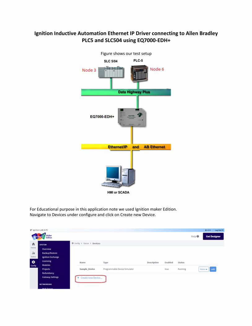
Ignition Inductive Automation Ethernet IP Driver connecting to Allen Bradley PLC5 and SLC504 using EQ7000-EDH+ Figure shows our test setup For Educational purpose in this application note we used Ignition maker Edition. Navigate to Devices under configure and click on Create new Device.
-
Upload
khangminh22 -
Category
Documents
-
view
6 -
download
0
Transcript of Ignition Inductive Automation Ethernet IP Driver connecting to ...
Ignition Inductive Automation Ethernet IP Driver connecting to Allen Bradley PLC5 and SLC504 using EQ7000-EDH+
Figure shows our test setup
For Educational purpose in this application note we used Ignition maker Edition. Navigate to Devices under configure and click on Create new Device.

Select Allen-Bradley PLC5 (Connect to PLC5s via Ethernet)
Then scroll down and click on Next.

Under General: Type a name for the PLC here we typed PLC5 then type the Description, in ours here we typed PLC5-80. Under Connectivity: Hostname: is the IP address of our EQ7000-EDH+ Connection Path: Since here EQ7000 is emulating a Control Logix 1756 DHRIO, Details of the path according to Ignition Inductive Automation manual The Connection Path format contains 4 numbers separated by commas. The first number is always 1 and tells the 1756-ENET module to route through the backplane. The second number is the slot number of the 1756-DHRIO module of the DH+ network the PLC-5 processor is connected to. The third number is the channel of the 1756-DHRIO module that the PLC-5 processor is connected to. Use 2 for channel A and 3 for channel B. The final and fourth number is the DH+ node number. This number is in octal and is the same as configured in the PLC-5 processor. See the ControlLogix Ethernet Communication interface Module User Manual for more information. Connection Path Format: 1,<1756-DHRIO slot number>,<1756-DHRIO channel>,<DH+ node number> The valid range for the 1756-DHRIO slot number is between 0 and 16 but depends on the chassis size. The 1756-DHRIO channel is either 2 for channel A or 3 for channel B. The DH+ node number range is from 00 to 77 octal. Reference Inductive Automation manual https://docs.inductiveautomation.com/display/DOC80/Connecting+to+PLC5 1 : for Backplane , 0 for the slot number, 2 is for Channel A, 6 is for our PLC5 octal node address number
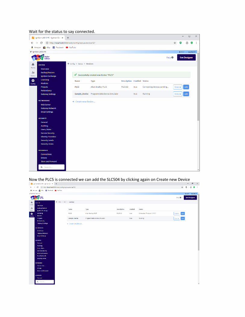
Wait for the status to say connected.
Now the PLC5 is connected we can add the SLC504 by clicking again on Create new Device
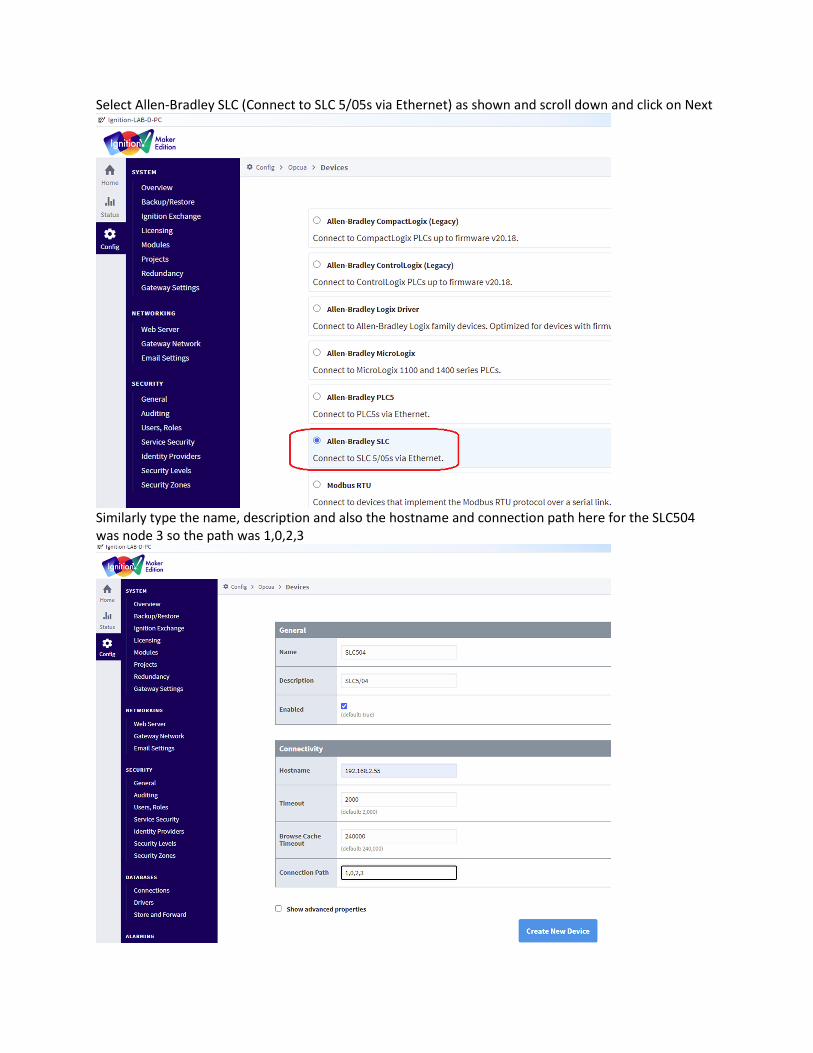
Select Allen-Bradley SLC (Connect to SLC 5/05s via Ethernet) as shown and scroll down and click on Next
Similarly type the name, description and also the hostname and connection path here for the SLC504 was node 3 so the path was 1,0,2,3

Here we have both the SLC 5/04 and the PLC5 both connected.
Now to confirm our connections we were able to read some tags form both the PLC5 and the SLC 504 To do that click on OPC Quick client, then click on the plus sign beside the Ignition OPC UA Server
To see connected devices click on the plus sign of the Devices that will show both PLC5 & SLC-504 those we added before, now to open the folders and see the tags of each device, 1st to check the SLC 5/04 tags click on the plus sign of the SLC504

Here we can see SLC504 tags, open N7 then click on N7:0 then to read that word 0 of Integer file 7 just click on r
Here we can see the word 0 value of integer file N7 for SLC5/04

We can repeat for PLC5
Here we can see the word 0 value of integer file N7 for PLC5