VRF inverter multi-system Air-Conditioners - Heavy Duty Split ...
90
2013 Mitsubishi Heavy Industries VRF inverter multi-system Air-Conditioners 50Hz 14KX02E R410A VRF inverter multi-system Air-Conditioners 2013
-
Upload
khangminh22 -
Category
Documents
-
view
0 -
download
0
Transcript of VRF inverter multi-system Air-Conditioners - Heavy Duty Split ...

Safety Precautions
Before starting use
HB91-14KX02E
Our factories are ISO9001 and ISO14001 certified.
BIWAJIMA PLANT Mitsubishi Heavy Industries, Ltd.
Air-conditioning & Refrigeration Systems Headquarters
MITSUBISHI HEAVY INDUSTRIES-MAHAJAK AIR CONDITIONERS CO., LTD.
Mitsubishi HeavyIndustries-Haier (Quingdao)
Air-conditioners Co.,Ltd.
MITSUBISHI HEAVY INDUSTRIES-MAHAJAK AIR CONDITIONERS CO.,LTD.
ISO 14001Certificate 04104 1998 0813 E5
Mitsubishi HeavyIndustries-Haier (Quingdao)
Air-conditioners Co.,Ltd.
Certified ISO 9001
BIWAJIMA PLANT Mitsubishi Heavy Industries, Ltd.
Air-conditioning & Refrigeration Systems Headquarters
Certified ISO 14001
Because of our policy of continuous improvement, we reserve right to make changes in all specifications without notice.
Printed in JapanNovember 2013 (2B)R
Mitsubishi Heavy Industries, Ltd.Air-Conditioning & Refrigeration Systems16-5, Konan 2-chome, Minato-ku, Tokyo, 108-8215 Japanhttp://www.mhi.co.jp
2013
Mitsubishi Heavy Industries VRF inverter m
ulti-system Air-Conditioners
50Hz14KX02E
R410A
VRF inverter multi-system Air-Conditioners
InstallationAlways commission the installation to a dealer or specialist. Improper installation will lead to water leakage, electric shocks and fires. Make sure that the outdoor unit is stable in installation. Fix the unit to stable base.
Usage placeDo not install in places where combustible gas could leak or where there are sparks. Installation in a place where combustible gas could be generated, flow or accumulate, or places containing carbon fibers could lead to fires.
Air-conditioner usage targetThe air-conditioner described in this catalog is a dedicated cooling/heating device for human use. Do not use it for special applications such as the storage of foodstuffs, animals or plants, precision devices or valuable art, etc. This could cause the quality of the items to drop, etc. Do not use this for cooling vehicles or ships. Water leakage or current leaks could occur.
Before useAlways read the "User,s Manual" thoroughly before starting use.
Heating performanceThe heating performance values (kW) described in catalog are the values obtained by operating at an outdoor temperature of 7 C and indoor temperature of 20 C as set forth in the ISO Standards. As the heating performance decreases as the outdoor temperature drops, if the outdoor temperature is too low and the heating performance is insufficient, use other heating appliances as well.
Indication of sound valuesThe sound values are the values (A scale) measured in a chamber such as an anechoic chamber following the ISO Standards. In the actual installation state, the value is normally larger than the values given in the catalog due to the effect of surrounding noise and echo. Take this into consideration when installing.
Use in oil atmosphereAvoid installing this unit in as atmosphere where oil scatters or builds up, such as in a kitchen or machine factory. If the oil adheres to the heat exchanger, the heat exchanging performance will drop, mist may be generated, and the synthetic resin parts may deform and break.
Use in acidic or alkaline atmosphereIf this unit is used in acidic atmosphere such as hot spring areas having high level of sulfuric gases or in alkaline atmosphere including ammonia or calcium chloride, places where the exhaust of the heat exchanger is sucked in, or at coastal areas where the unit is subject to salt breezes, the outer plate or heat exchanger, etc., will corrode. Please ask a dealer or specialist when you use an air conditioner in places differing from a general atmosphere. Use in places with high ceilingsIf the ceiling is high, install a circulator to improve the heat and air flow distribution when heating.
Refrigerant leakageThe refrigerant (R410A) used for Air conditioner is non-toxic and inflammable in its original state. However, in consideration of a state where the refrigerant leaks into the room, measures against refrigerant leaks must be taken in small rooms where the tolerable level could be exceeded. Take measures by installing ventilation devices, etc.
Use in snowy areasTake the following measures when installing the outdoor unit in snowy areas.
·Snow preventionInstall a snow-prevention hood so that the snow does not obstruct the air intake port or enter and freeze in the outdoor unit.
·Snow pilingIn areas with heavy snow fall, the piled snow could block the air intake port. In this case, a frame that is 50cm or higher than the estimated snow fall must be installed underneath the outdoor unit.
Automatic defrosting deviceIf the temperature is low, and the humidity is high, frost will stick to the heat exchanger of the outdoor unit. If use is continued, the heating performance will drop. The "Automatic defrosting device" will function to remove this frost. After heating for approx, three to ten minutes, it will stop, and the frost will be removed. After defrosting, hot air will be blown again.
Servicing the air-conditionerAfter the air-conditioner is used for several seasons, dirt will build up in the air-conditioner causing the performance to drop. In addition to regular servicing, we recommend the maintenance contract (charged for) by a specialist.
2013

2 3
R410A
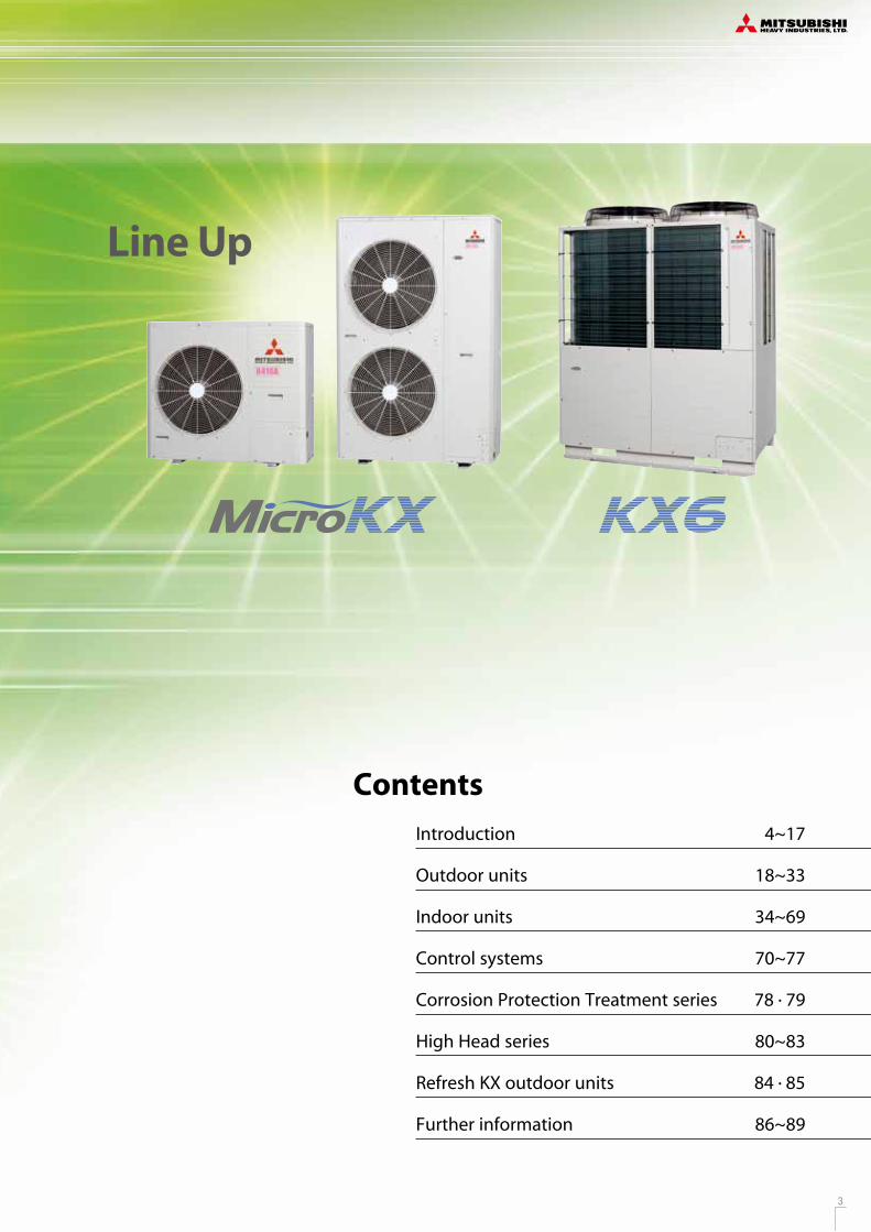
Contents
Outdoor units 18~33
Indoor units
Control systems
Refresh KX outdoor units
34~69
70~77
High Head series 80~83
84 . 85
Corrosion Protection Treatment series 78 . 79
Further information 86~89
Introduction 4~17
more efficient , more sophisticated
History of Technologies
Line Up
KX2 KX4 KX6(8~12HP)
2 3
R410A
Contents
Outdoor units 18~33
Indoor units
Control systems
Refresh KX outdoor units
34~69
70~77
High Head series 80~83
84 . 85
Corrosion Protection Treatment series 78 . 79
Further information 86~89
Introduction 4~17
more efficient , more sophisticated
History of Technologies
Line Up
KX2 KX4 KX6(8~12HP)
4 5
R410A
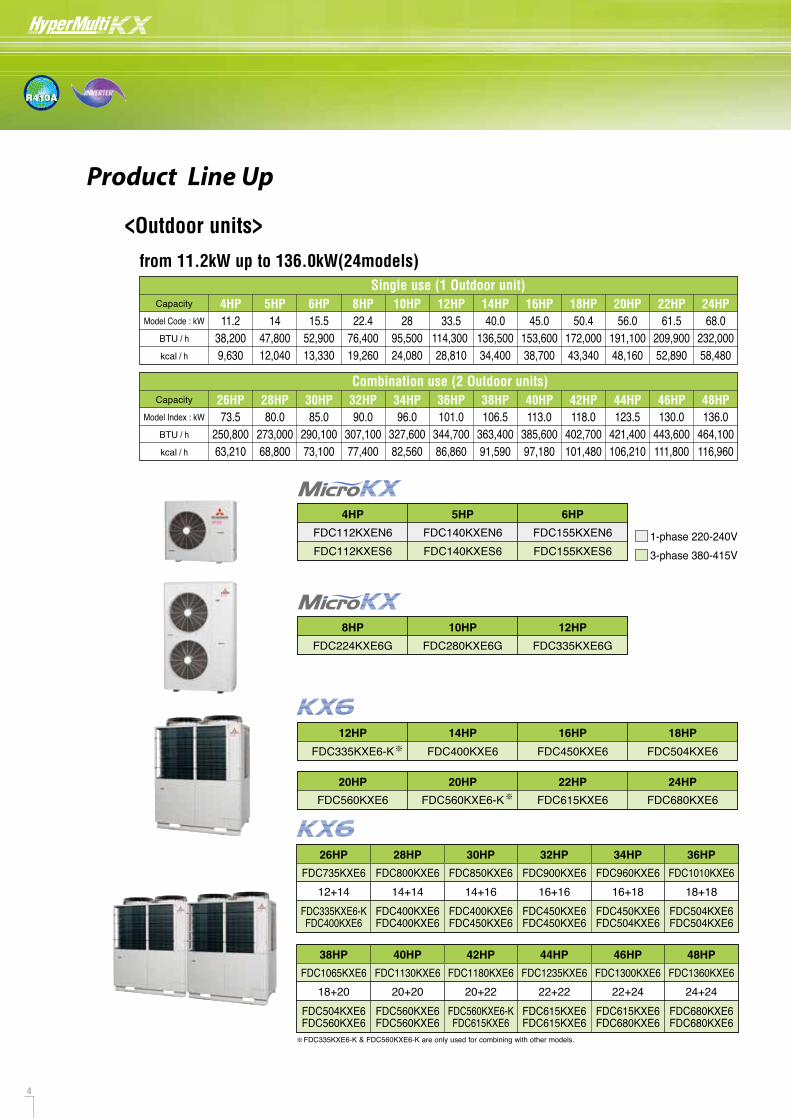
<Outdoor units>
Product Line Up
from 11.2kW up to 136.0kW(24models)
5HP14
47,80012,040
6HP15.5
52,90013,330
4HP11.2
38,2009,630
8HP22.4
76,40019,260
10HP28
95,50024,080
12HP33.5
114,300 28,810
14HP40.0
136,50034,400
16HP45.0
153,60038,700
18HP50.4
172,00043,340
20HP56.0
191,10048,160
22HP61.5
209,90052,890
24HP68.0
232,00058,480
Single use (1 Outdoor unit)Capacity
Model Code : kW
28HP80.0
273,00068,800
30HP85.0
290,10073,100
26HP73.5
250,80063,210
32HP90.0
307,10077,400
34HP96.0
327,60082,560
36HP101.0
344,70086,860
38HP106.5
363,40091,590
40HP113.0
385,60097,180
42HP118.0
402,700101,480
44HP123.5
421,400106,210
46HP130.0
443,600111,800
48HP136.0
464,100116,960
Combination use (2 Outdoor units)Capacity
Model Index : kW
BTU / h
BTU / h
kcal / h
kcal / h
4HP 5HP 6HP
FDC140KXEN6FDC140KXES6
FDC155KXEN6FDC155KXES6
FDC112KXEN6FDC112KXES6
8HP 10HP 12HP
FDC224KXE6G FDC280KXE6G FDC335KXE6G
26HP
FDC735KXE628HP
FDC800KXE630HP
FDC850KXE632HP
FDC900KXE634HP
FDC960KXE636HP
FDC1010KXE612+14 14+14 14+16 16+16 16+18 18+18
FDC335KXE6-KFDC400KXE6
FDC400KXE6FDC400KXE6
FDC400KXE6FDC450KXE6
FDC450KXE6FDC450KXE6
FDC450KXE6FDC504KXE6
FDC504KXE6FDC504KXE6
38HP
FDC1065KXE640HP
FDC1130KXE642HP
FDC1180KXE644HP
FDC1235KXE646HP
FDC1300KXE648HP
FDC1360KXE618+20 20+20 20+22 22+22 22+24 24+24
FDC504KXE6FDC560KXE6
FDC560KXE6FDC560KXE6
FDC560KXE6-KFDC615KXE6
FDC615KXE6FDC615KXE6
FDC615KXE6FDC680KXE6
FDC680KXE6FDC680KXE6
1-phase 220-240V3-phase 380-415V
12HP 14HP 16HP 18HP
FDC335KXE6-K FDC400KXE6 FDC450KXE6 FDC504KXE6
20HP 20HP 24HP
FDC560KXE6 FDC560KXE6-K22HP
FDC615KXE6 FDC680KXE6
FDC335KXE6-K & FDC560KXE6-K are only used for combining with other models.
Wide variety of 17 types 92 models
<Indoor units>
Indoor units lineup
A range of 17 types of exposed or concealed indoor units, in wide capacities, 92 indoor models. The best selection of indoor units for many kinds of rooms and preference can be available from our full lineup.
22Capacity
Model Code : kWType
28 36 45 56 71 90 112 140 160 224 2800.8HP 1HP 1.25HP 1.6HP 2HP 2.5HP 3.2HP 4HP 5HP 6HP 8HP 10HP
150 250Air flow M3/hType 350 500 650 800 850 1000 1300 1800
4way FDT
4way Compact (600 x 600) FDTC
2way FDTW
1way Compact FDTQ
1way
Wall Mounted FDK
Ceiling Suspended FDE
FDFW
Low Static Pressure(thin)
Compact & Flexible
FDUT
150.5HP
FDUH
High Static Pressure FDU
Low/Middle Static Pressure FDUM
with casing
2way
FDFL
without casing FDFU
SAF
FDTS
CeilingCassette
Floor Standing
Duct Connected
Fresh Air DX Assembly SAF-DX
OA Processing unit FDU-F
Fresh Air Ventilation and Heat Exchange unit
Not available in EU/EEA area.
NEW
NEW NEW
NEW
NEW
NEW
NEW
NEW

4 5
R410A
<Outdoor units>
Product Line Up
from 11.2kW up to 136.0kW(24models)
5HP14
47,80012,040
6HP15.5
52,90013,330
4HP11.2
38,2009,630
8HP22.4
76,40019,260
10HP28
95,50024,080
12HP33.5
114,300 28,810
14HP40.0
136,50034,400
16HP45.0
153,60038,700
18HP50.4
172,00043,340
20HP56.0
191,10048,160
22HP61.5
209,90052,890
24HP68.0
232,00058,480
Single use (1 Outdoor unit)Capacity
Model Code : kW
28HP80.0
273,00068,800
30HP85.0
290,10073,100
26HP73.5
250,80063,210
32HP90.0
307,10077,400
34HP96.0
327,60082,560
36HP101.0
344,70086,860
38HP106.5
363,40091,590
40HP113.0
385,60097,180
42HP118.0
402,700101,480
44HP123.5
421,400106,210
46HP130.0
443,600111,800
48HP136.0
464,100116,960
Combination use (2 Outdoor units)Capacity
Model Index : kW
BTU / h
BTU / h
kcal / h
kcal / h
4HP 5HP 6HP
FDC140KXEN6FDC140KXES6
FDC155KXEN6FDC155KXES6
FDC112KXEN6FDC112KXES6
8HP 10HP 12HP
FDC224KXE6G FDC280KXE6G FDC335KXE6G
26HP
FDC735KXE628HP
FDC800KXE630HP
FDC850KXE632HP
FDC900KXE634HP
FDC960KXE636HP
FDC1010KXE612+14 14+14 14+16 16+16 16+18 18+18
FDC335KXE6-KFDC400KXE6
FDC400KXE6FDC400KXE6
FDC400KXE6FDC450KXE6
FDC450KXE6FDC450KXE6
FDC450KXE6FDC504KXE6
FDC504KXE6FDC504KXE6
38HP
FDC1065KXE640HP
FDC1130KXE642HP
FDC1180KXE644HP
FDC1235KXE646HP
FDC1300KXE648HP
FDC1360KXE618+20 20+20 20+22 22+22 22+24 24+24
FDC504KXE6FDC560KXE6
FDC560KXE6FDC560KXE6
FDC560KXE6-KFDC615KXE6
FDC615KXE6FDC615KXE6
FDC615KXE6FDC680KXE6
FDC680KXE6FDC680KXE6
1-phase 220-240V3-phase 380-415V
12HP 14HP 16HP 18HP
FDC335KXE6-K FDC400KXE6 FDC450KXE6 FDC504KXE6
20HP 20HP 24HP
FDC560KXE6 FDC560KXE6-K22HP
FDC615KXE6 FDC680KXE6
FDC335KXE6-K & FDC560KXE6-K are only used for combining with other models.
Wide variety of 17 types 92 models
<Indoor units>
Indoor units lineup
A range of 17 types of exposed or concealed indoor units, in wide capacities, 92 indoor models. The best selection of indoor units for many kinds of rooms and preference can be available from our full lineup.
22Capacity
Model Code : kWType
28 36 45 56 71 90 112 140 160 224 2800.8HP 1HP 1.25HP 1.6HP 2HP 2.5HP 3.2HP 4HP 5HP 6HP 8HP 10HP
150 250Air flow M3/hType 350 500 650 800 850 1000 1300 1800
4way FDT
4way Compact (600 x 600) FDTC
2way FDTW
1way Compact FDTQ
1way
Wall Mounted FDK
Ceiling Suspended FDE
FDFW
Low Static Pressure(thin)
Compact & Flexible
FDUT
150.5HP
FDUH
High Static Pressure FDU
Low/Middle Static Pressure FDUM
with casing
2way
FDFL
without casing FDFU
SAF
FDTS
CeilingCassette
Floor Standing
Duct Connected
Fresh Air DX Assembly SAF-DX
OA Processing unit FDU-F
Fresh Air Ventilation and Heat Exchange unit
Not available in EU/EEA area.
NEW
NEW NEW
NEW
NEW
NEW
NEW
NEW

6 7
R410A
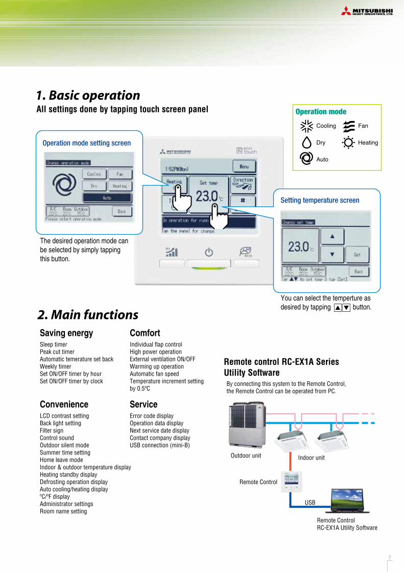
2. Main functions
Simple setting REMOTE CONTROLAdvanced touch screen panel with full dot Liquid Crystal display All settings done by tapping touch screen panel
Simple setting by tapping button only
RC-EX1A
Operation mode setting screen
The desired operation mode can be selected by simply tapping this button.
Setting temperature screen
You can select the temperture as desired by tapping button.
User friendly
Sleep timerPeak cut timerAutomatic temerature set backWeekly timerSet ON/OFF timer by hourSet ON/OFF timer by clock
Saving energyIndividual flap controlHigh power operationExternal ventilation ON/OFFWarming up operationAutomatic fan speed Temperature increment setting by 0.5ºC
Comfort
By connecting this system to the Remote Control, the Remote Control can be operated from PC.
Remote control RC-EX1A Series Utility Software
LCD contrast settingBack light settingFilter signControl soundOutdoor silent modeSummer time settingHome leave modeIndoor & outdoor temperature displayHeating standby displayDefrosting operation displayAuto cooling/heating displayºC/ºF displayAdministrator settingsRoom name setting
ConvenienceError code displayOperation data displayNext service date displayContact company displayUSB connection (mini-B)
Service
•LCD panel with light tap operation introduced as the industry's first•Simple interface with only three buttons
High level of visibility•Big LCD with 3.8 inch full dot display•Back light function•Multi language display (9 languages)
Operation mode
Cooling
Dry
Auto
Fan
Heating
1. Basic operation
The highest capacity operation (Max 15 minutes)•Increasing compressor� speed •Increasing air flow volume
High power operation
Run / Stop
•Changes set temperature. At 28ºC in cooling mode and 22ºC in heating mode, 25ºC in auto mode. •Operation correction by outdoor temperature
Energy-saving operationOutdoor unit
Remote Control
Indoor unit
USB
Remote Control RC-EX1A Utility Software
6 7
R410A
2. Main functions
Simple setting REMOTE CONTROLAdvanced touch screen panel with full dot Liquid Crystal display All settings done by tapping touch screen panel
Simple setting by tapping button only
RC-EX1A
Operation mode setting screen
The desired operation mode can be selected by simply tapping this button.
Setting temperature screen
You can select the temperture as desired by tapping button.
User friendly
Sleep timerPeak cut timerAutomatic temerature set backWeekly timerSet ON/OFF timer by hourSet ON/OFF timer by clock
Saving energyIndividual flap controlHigh power operationExternal ventilation ON/OFFWarming up operationAutomatic fan speed Temperature increment setting by 0.5ºC
Comfort
By connecting this system to the Remote Control, the Remote Control can be operated from PC.
Remote control RC-EX1A Series Utility Software
LCD contrast settingBack light settingFilter signControl soundOutdoor silent modeSummer time settingHome leave modeIndoor & outdoor temperature displayHeating standby displayDefrosting operation displayAuto cooling/heating displayºC/ºF displayAdministrator settingsRoom name setting
ConvenienceError code displayOperation data displayNext service date displayContact company displayUSB connection (mini-B)
Service
•LCD panel with light tap operation introduced as the industry's first•Simple interface with only three buttons
High level of visibility•Big LCD with 3.8 inch full dot display•Back light function•Multi language display (9 languages)
Operation mode
Cooling
Dry
Auto
Fan
Heating
1. Basic operation
The highest capacity operation (Max 15 minutes)•Increasing compressor� speed •Increasing air flow volume
High power operation
Run / Stop
•Changes set temperature. At 28ºC in cooling mode and 22ºC in heating mode, 25ºC in auto mode. •Operation correction by outdoor temperature
Energy-saving operationOutdoor unit
Remote Control
Indoor unit
USB
Remote Control RC-EX1A Utility Software
8 9
R410A
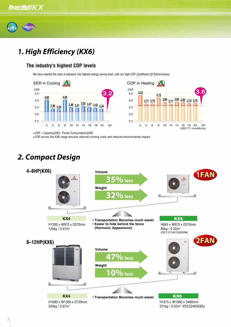
1. High Efficiency (KX6)
The industry's highest COP levels
2. Compact Design
4~6HP(KX6)
8~12HP(KX6)
*COP = Capacity[kW] / Power Consumption[kW]
*COP across the KX6 range ensures reduced running costs and reduced environmental impact.
1FAN1FAN
2FAN2FAN
Volume
35% lessWeight
32% less
Volume
47% lessWeight
10% less
H1300 x W970 x D370mm125kg / 0.47m3
H845 x W970 x D370mm85kg / 0.30m3
• Transportation Becomes much easier• Easier to hide behind the fence (Harmonic Appearance)
KX4 KX6
H1690 x W1350 x D720mm245kg / 0.97m3
H1675 x W1080 x D480mm221kg / 0.52m3 (FDC224KXE6G)
• Transportation Becomes much easierKX4 KX6
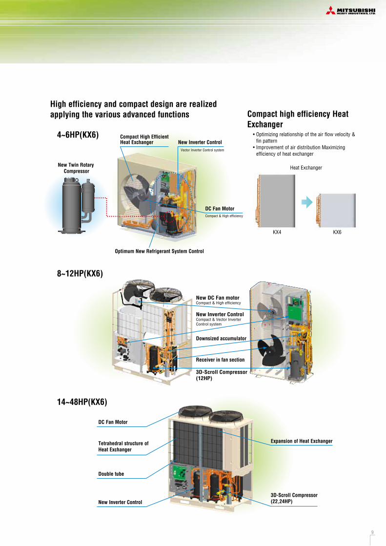
Compact High Efficient Heat Exchanger
4~6HP(KX6)
8~12HP(KX6)
14~48HP(KX6)
New Twin Rotary Compressor
Optimum New Refrigerant System Control
Compact & High efficiency
Vector Inverter Control system
DC Fan Motor
New Inverter Control
High efficiency and compact design are realized applying the various advanced functions Compact high efficiency Heat
Exchanger
KX4 KX6
Heat Exchanger
• Optimizing relationship of the air flow velocity & fin pattern
• Improvement of air distribution Maximizing efficiency of heat exchanger
Expansion of Heat Exchanger
DC Fan Motor
Tetrahedral structure of Heat Exchanger
Double tube
New Inverter Control3D-Scroll Compressor(22,24HP)
Receiver in fan section
New DC Fan motorCompact & High efficiency
New Inverter ControlCompact & Vector InverterControl system
3D-Scroll Compressor(12HP)
Downsized accumulator
8
3.41 3.55
4.00
3.46
10 124 5 6 14
3.293.36
3.2
3.42 3.343.47
16 18 20 HP
COP
2.5
3.0
3.5
4.0
4.5
4.00
EER in CoolingCLASSAA COP in Heating
CLASSAA
12 142.5
3.0
3.5
4.0
4.5
8
3.844.15
10
3.84
3.6
18 20 HP
3.74 3.75
16
3.82
4 5 6
3.72
4.33
3.71 3.71
(ISO-T1 conditions)
COP
We have cleared the class A standard, the highest energy saving level, with our high COP (Coefficient Of Performance).
(FDC112/140/155KXEN6)
8 9
R410A
1. High Efficiency (KX6)
The industry's highest COP levels
2. Compact Design
4~6HP(KX6)
8~12HP(KX6)
*COP = Capacity[kW] / Power Consumption[kW]
*COP across the KX6 range ensures reduced running costs and reduced environmental impact.
1FAN1FAN
2FAN2FAN
Volume
35% lessWeight
32% less
Volume
47% lessWeight
10% less
H1300 x W970 x D370mm125kg / 0.47m3
H845 x W970 x D370mm85kg / 0.30m3
• Transportation Becomes much easier• Easier to hide behind the fence (Harmonic Appearance)
KX4 KX6
H1690 x W1350 x D720mm245kg / 0.97m3
H1675 x W1080 x D480mm221kg / 0.52m3 (FDC224KXE6G)
• Transportation Becomes much easierKX4 KX6
Compact High Efficient Heat Exchanger
4~6HP(KX6)
8~12HP(KX6)
14~48HP(KX6)
New Twin Rotary Compressor
Optimum New Refrigerant System Control
Compact & High efficiency
Vector Inverter Control system
DC Fan Motor
New Inverter Control
High efficiency and compact design are realized applying the various advanced functions Compact high efficiency Heat
Exchanger
KX4 KX6
Heat Exchanger
• Optimizing relationship of the air flow velocity & fin pattern
• Improvement of air distribution Maximizing efficiency of heat exchanger
Expansion of Heat Exchanger
DC Fan Motor
Tetrahedral structure of Heat Exchanger
Double tube
New Inverter Control3D-Scroll Compressor(22,24HP)
Receiver in fan section
New DC Fan motorCompact & High efficiency
New Inverter ControlCompact & Vector InverterControl system
3D-Scroll Compressor(12HP)
Downsized accumulator
8
3.41 3.55
4.00
3.46
10 124 5 6 14
3.293.36
3.2
3.42 3.343.47
16 18 20 HP
COP
2.5
3.0
3.5
4.0
4.5
4.00
EER in CoolingCLASSAA COP in Heating
CLASSAA
12 142.5
3.0
3.5
4.0
4.5
8
3.844.15
10
3.84
3.6
18 20 HP
3.74 3.75
16
3.82
4 5 6
3.72
4.33
3.71 3.71
(ISO-T1 conditions)
COP
We have cleared the class A standard, the highest energy saving level, with our high COP (Coefficient Of Performance).
(FDC112/140/155KXEN6)
10 11
R410A
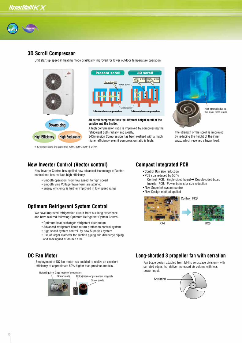
Optimum Refrigerant System Control
• Smooth operation from low speed to high speed• Smooth Sine Voltage Wave form are attained • Energy efficiency is further improved in low speed range
New Inverter Control (Vector control)
• Optimum heat exchanger refrigerant distribution• Advanced refrigerant liquid return protection control system• High speed system control by new Superlink system• Use of larger diameter for suction piping and discharge piping and redesigned of double tube
Employment of DC fan motor has enabled to realize an excellent efficiency of approximate 60% higher than previous models.
DC Fan Motor
Rotor(Squirrel Cage made of conductor)Rotor(made of permanent magnet)Stator (coil)
Stator (coil)
New Inverter Control has applied new advanced technology of Vector control and has realized high efficiency.
We have improved refrigeration circuit from our long experience and have realized following Optimum Refrigerant System Control.
Compact Integrated PCB• Control Box size reduction• PCB size reduced by 50 % Control PCB: Single-sided board Double-sided board Inverter PCB: Power transistor size reduction• New Superlink system control• New Design method applied
Control PCB
KX4 KX6
Fan blade design adapted from MHI's aerospace division - with serrated edges that deliver increased air volume with less power input.
Long-chorded 3 propeller fan with serration
Serration
High EfficiencyHigh Efficiency High EnduranceHigh Endurance
DownsizingDownsizing
Orbital scroll2-Dimension compression 3-Dimension compression
Present scroll 3D scroll
Fixed scroll
Lower at theinsideSame height
Higher at theoutside
3D scroll compressor has the different height scroll at the outside and the inside.A high compression ratio is improved by compressing the refrigerant both radially and axially.3-Dimension Compression has been realized with a much higher efficiency even if compression ratio is high.
The strength of the scroll is improved by reducing the height of the inner wrap, which receives a heavy load.
High strength due tothe lower teeth inside
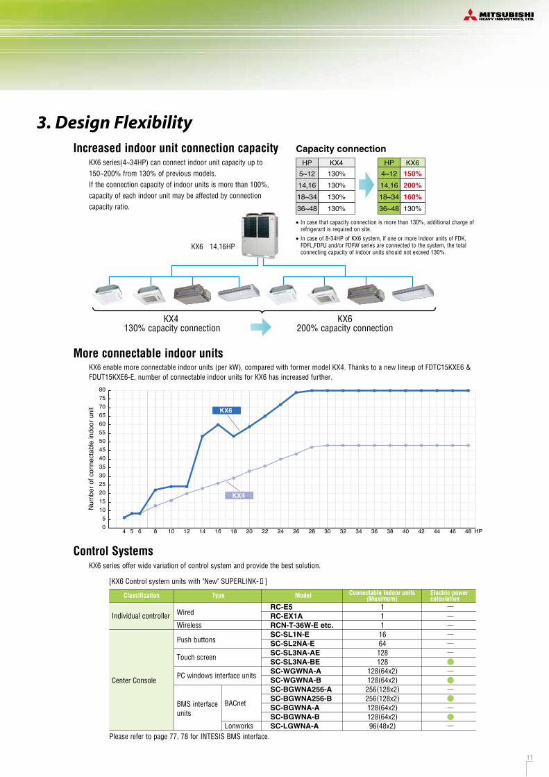
Increased indoor unit connection capacity
3. Design Flexibility
KX6 series(4~34HP) can connect indoor unit capacity up to 150~200% from 130% of previous models. If the connection capacity of indoor units is more than 100%, capacity of each indoor unit may be affected by connection capacity ratio.
HP5~1214,1618~3436~48
KX4130%130%130%130%
HP4~1214,1618~3436~48
KX6150%
200%
160%
130%
Capacity connection
• In case that capacity connection is more than 130%, additional charge of refrigerant is required on site.
• In case of 8-34HP of KX6 system, if one or more indoor units of FDK, FDFL,FDFU and/or FDFW series are connected to the system, the total connecting capacity of indoor units should not exceed 130%.
3D Scroll CompressorUnit start up speed in heating mode drastically improved for lower outdoor temperature operation.
KX6 series offer wide variation of control system and provide the best solution.
Individual controller
Center Console
Wired
Wireless
Push buttons
Touch screen
PC windows interface units
Model
RC-E5RC-EX1ARCN-T-36W-E etc.SC-SL1N-ESC-SL2NA-ESC-SL3NA-AESC-SL3NA-BESC-WGWNA-ASC-WGWNA-BSC-BGWNA256-ASC-BGWNA256-BSC-BGWNA-ASC-BGWNA-BSC-LGWNA-A
1111664128128
128(64x2)128(64x2)256(128x2)256(128x2)128(64x2)128(64x2)96(48x2)
Connectable Indoor units(Maximum)
Electric powercalculation
Control Systems
BACnet
Lonworks
TypeClassification
BMS interface units
[KX6 Control system units with "New" SUPERLINK- ]
KX4 130% capacity connection
KX6 200% capacity connection
KX6 14,16HP
3D compressors are applied for 12HP, 20HP, 22HP & 24HP.
More connectable indoor unitsKX6 enable more connectable indoor units (per kW), compared with former model KX4. Thanks to a new lineup of FDTC15KXE6 & FDUT15KXE6-E, number of connectable indoor units for KX6 has increased further.
Num
ber o
f con
nect
able
indo
or u
nit
HP
KX4
KX6
05
85 64
101520253035404550556065707580
10 12 14 16 18 20 22 24 26 28 30 32 34 36 38 40 42 44 46 48
Please refer to page 77, 78 for INTESIS BMS interface.
10 11
R410A
Optimum Refrigerant System Control
• Smooth operation from low speed to high speed• Smooth Sine Voltage Wave form are attained • Energy efficiency is further improved in low speed range
New Inverter Control (Vector control)
• Optimum heat exchanger refrigerant distribution• Advanced refrigerant liquid return protection control system• High speed system control by new Superlink system• Use of larger diameter for suction piping and discharge piping and redesigned of double tube
Employment of DC fan motor has enabled to realize an excellent efficiency of approximate 60% higher than previous models.
DC Fan Motor
Rotor(Squirrel Cage made of conductor)Rotor(made of permanent magnet)Stator (coil)
Stator (coil)
New Inverter Control has applied new advanced technology of Vector control and has realized high efficiency.
We have improved refrigeration circuit from our long experience and have realized following Optimum Refrigerant System Control.
Compact Integrated PCB• Control Box size reduction• PCB size reduced by 50 % Control PCB: Single-sided board Double-sided board Inverter PCB: Power transistor size reduction• New Superlink system control• New Design method applied
Control PCB
KX4 KX6
Fan blade design adapted from MHI's aerospace division - with serrated edges that deliver increased air volume with less power input.
Long-chorded 3 propeller fan with serration
Serration
High EfficiencyHigh Efficiency High EnduranceHigh Endurance
DownsizingDownsizing
Orbital scroll2-Dimension compression 3-Dimension compression
Present scroll 3D scroll
Fixed scroll
Lower at theinsideSame height
Higher at theoutside
3D scroll compressor has the different height scroll at the outside and the inside.A high compression ratio is improved by compressing the refrigerant both radially and axially.3-Dimension Compression has been realized with a much higher efficiency even if compression ratio is high.
The strength of the scroll is improved by reducing the height of the inner wrap, which receives a heavy load.
High strength due tothe lower teeth inside
Increased indoor unit connection capacity
3. Design Flexibility
KX6 series(4~34HP) can connect indoor unit capacity up to 150~200% from 130% of previous models. If the connection capacity of indoor units is more than 100%, capacity of each indoor unit may be affected by connection capacity ratio.
HP5~1214,1618~3436~48
KX4130%130%130%130%
HP4~1214,1618~3436~48
KX6150%
200%
160%
130%
Capacity connection
• In case that capacity connection is more than 130%, additional charge of refrigerant is required on site.
• In case of 8-34HP of KX6 system, if one or more indoor units of FDK, FDFL,FDFU and/or FDFW series are connected to the system, the total connecting capacity of indoor units should not exceed 130%.
3D Scroll CompressorUnit start up speed in heating mode drastically improved for lower outdoor temperature operation.
KX6 series offer wide variation of control system and provide the best solution.
Individual controller
Center Console
Wired
Wireless
Push buttons
Touch screen
PC windows interface units
Model
RC-E5RC-EX1ARCN-T-36W-E etc.SC-SL1N-ESC-SL2NA-ESC-SL3NA-AESC-SL3NA-BESC-WGWNA-ASC-WGWNA-BSC-BGWNA256-ASC-BGWNA256-BSC-BGWNA-ASC-BGWNA-BSC-LGWNA-A
1111664128128
128(64x2)128(64x2)256(128x2)256(128x2)128(64x2)128(64x2)96(48x2)
Connectable Indoor units(Maximum)
Electric powercalculation
Control Systems
BACnet
Lonworks
TypeClassification
BMS interface units
[KX6 Control system units with "New" SUPERLINK- ]
KX4 130% capacity connection
KX6 200% capacity connection
KX6 14,16HP
3D compressors are applied for 12HP, 20HP, 22HP & 24HP.
More connectable indoor unitsKX6 enable more connectable indoor units (per kW), compared with former model KX4. Thanks to a new lineup of FDTC15KXE6 & FDUT15KXE6-E, number of connectable indoor units for KX6 has increased further.
Num
ber o
f con
nect
able
indo
or u
nit
HP
KX4
KX6
05
85 64
101520253035404550556065707580
10 12 14 16 18 20 22 24 26 28 30 32 34 36 38 40 42 44 46 48
Please refer to page 77, 78 for INTESIS BMS interface.
12 13
R410A
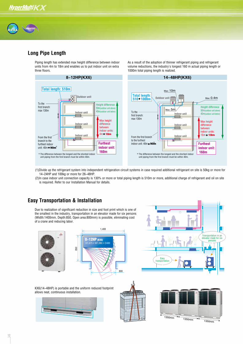
Long Pipe Length
Piping length has extended max height difference between indoor units from 4m to 18m and enables us to put indoor unit on extra three floors.
8~12HP(KX6) 14~48HP(KX6)
As a result of the adoption of thinner refrigerant piping and refrigerant volume reductions, the industry's longest 160 m actual piping length or 1000m total piping length is realized.
Outdoor unit
Height difference50m(outdoor unit above)40m(outdoor unit below)
Max height differencebetween indoor units: 15m 18m
Indoor unit
Indoor unit
Indoor unit
Max: 0.4m
Max: 10m
Max: 5mTo the first branch:max 130m
From the first branch to the furthest indoor unit: 40m 90m
Total length:510 1000m
*
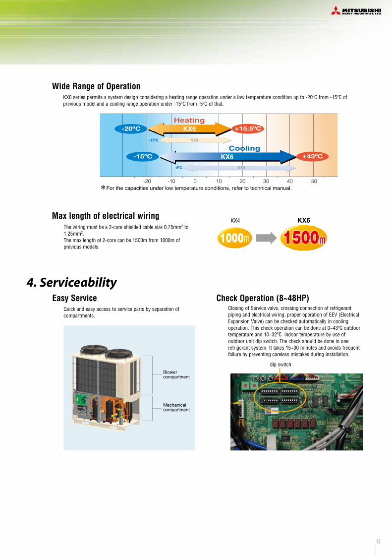
Easy Service
Blower compartment
Mechanical compartment
Quick and easy access to service parts by separation of compartments.
Check Operation (8~48HP)Closing of Service valve, crossing connection of refrigerant piping and electrical wiring, proper operation of EEV (Electrical Expansion Valve) can be checked automatically in cooling operation. This check operation can be done at 0~43ºC outdoor temperature and 10~32ºC indoor temperature by use of outdoor unit dip switch. The check should be done in one refrigerant system. It takes 15~30 minutes and avoids frequent failure by preventing careless mistakes during installation.
The wiring must be a 2-core shielded cable size 0.75mm2 to 1.25mm2. The max length of 2-core can be 1500m from 1000m of previous models.
Max length of electrical wiring
1350mm 1350mm 1350mm
KX4 KX6
1000m 1500m1500m
(1)Divide up the refrigerant system into independent refrigeration circuit systems in case required additional refrigerant on site is 50kg or more for 14~24HP and 100kg or more for 26~48HP.
(2)In case indoor unit connection capacity is 130% or more or total piping length is 510m or more, additional charge of refrigerant and oil on site is required. Refer to our Installation Manual for details.
Wide Range of Operation
For the capacities under low temperature conditions, refer to technical manual.
Heating
KX4
KX6
KX6
KX4
Cooling+43ºC
+15.5ºC
-15ºC
-20ºC
50403020100-10-20
KX6 series permits a system design considering a heating range operation under a low temperature condition up to -20ºC from -15ºC of previous model and a cooling range operation under -15ºC from -5ºC of that.
-15ºC
-5ºC
4. Serviceability
KX6(14~48HP) is portable and the uniform reduced footprint allows neat, continuous installation.
Easy Transportation & Installation
Due to realization of significant reduction in size and foot print which is one of the smallest in the industry, transportation in an elevator made for six persons (Width:1400mm, Depth:850, Open area:800mm) is possible, eliminating cost of a crane and reducing labor.
dip switch1,400
850
800
H1,675 x W1,080 x D4808~12HP (KX6)
Transportation in an elevator made for six
persons
Easy transportation
*
*
Outdoor unit
Total length: 510m
To the first branch:max 130m
From the first branch to the furthest indoor unit: 40m 90m
Height difference50m(outdoor unit above)40m(outdoor unit below)
Furthest indoor unit: 160m
Max height differencebetween indoor units: 4m 18m
Indoor unit
Indoor unit
Indoor unit
Furthest indoor unit: 160m
The difference between the longest and the shortest indoor unit piping from the first branch must be within 40m.
* The difference between the longest and the shortest indoor unit piping from the first branch must be within 40m.
12 13
R410A
Long Pipe Length
Piping length has extended max height difference between indoor units from 4m to 18m and enables us to put indoor unit on extra three floors.
8~12HP(KX6) 14~48HP(KX6)
As a result of the adoption of thinner refrigerant piping and refrigerant volume reductions, the industry's longest 160 m actual piping length or 1000m total piping length is realized.
Outdoor unit
Height difference50m(outdoor unit above)40m(outdoor unit below)
Max height differencebetween indoor units: 15m 18m
Indoor unit
Indoor unit
Indoor unit
Max: 0.4m
Max: 10m
Max: 5mTo the first branch:max 130m
From the first branch to the furthest indoor unit: 40m 90m
Total length:510 1000m
*
Easy Service
Blower compartment
Mechanical compartment
Quick and easy access to service parts by separation of compartments.
Check Operation (8~48HP)Closing of Service valve, crossing connection of refrigerant piping and electrical wiring, proper operation of EEV (Electrical Expansion Valve) can be checked automatically in cooling operation. This check operation can be done at 0~43ºC outdoor temperature and 10~32ºC indoor temperature by use of outdoor unit dip switch. The check should be done in one refrigerant system. It takes 15~30 minutes and avoids frequent failure by preventing careless mistakes during installation.
The wiring must be a 2-core shielded cable size 0.75mm2 to 1.25mm2. The max length of 2-core can be 1500m from 1000m of previous models.
Max length of electrical wiring
1350mm 1350mm 1350mm
KX4 KX6
1000m 1500m1500m
(1)Divide up the refrigerant system into independent refrigeration circuit systems in case required additional refrigerant on site is 50kg or more for 14~24HP and 100kg or more for 26~48HP.
(2)In case indoor unit connection capacity is 130% or more or total piping length is 510m or more, additional charge of refrigerant and oil on site is required. Refer to our Installation Manual for details.
Wide Range of Operation
For the capacities under low temperature conditions, refer to technical manual.
Heating
KX4
KX6
KX6
KX4
Cooling+43ºC
+15.5ºC
-15ºC
-20ºC
50403020100-10-20
KX6 series permits a system design considering a heating range operation under a low temperature condition up to -20ºC from -15ºC of previous model and a cooling range operation under -15ºC from -5ºC of that.
-15ºC
-5ºC
4. Serviceability
KX6(14~48HP) is portable and the uniform reduced footprint allows neat, continuous installation.
Easy Transportation & Installation
Due to realization of significant reduction in size and foot print which is one of the smallest in the industry, transportation in an elevator made for six persons (Width:1400mm, Depth:850, Open area:800mm) is possible, eliminating cost of a crane and reducing labor.
dip switch1,400
850
800
H1,675 x W1,080 x D4808~12HP (KX6)
Transportation in an elevator made for six
persons
Easy transportation
*
*
Outdoor unit
Total length: 510m
To the first branch:max 130m
From the first branch to the furthest indoor unit: 40m 90m
Height difference50m(outdoor unit above)40m(outdoor unit below)
Furthest indoor unit: 160m
Max height differencebetween indoor units: 4m 18m
Indoor unit
Indoor unit
Indoor unit
Furthest indoor unit: 160m
The difference between the longest and the shortest indoor unit piping from the first branch must be within 40m.
* The difference between the longest and the shortest indoor unit piping from the first branch must be within 40m.

14 15
R410A
KX6
ex.10HP
R410A
9.52 22.22
Liquidpiping Gas piping
Reduced Refrigerant VolumeTo use the new refrigerant R410A, KX6 series have adopted thinner diameter refrigerant pipes, which will help reduce piping work cost.
Outdoor unit
8654
1012141618 20 22 242628303234 36 38 40 42 44 46 48
ø9.52
ø12.7
ø15.88
ø19.05
ø19.05
ø15.88
ø22.22
ø25.4[ø28.58]
ø28.58
ø31.8[ø34.92]
ø38.1[ø34.92]
Liquid piping Gas pipingKX6
HP
ø9.52
3/8"
mm
inch
ø12.7
1/2"
ø15.88
5/8"
ø19.05
3/4"
ø22.22
7/8"
ø25.4
1"
ø28.58
11/8"
ø31.8
11/4"
ø34.92
13/8"
ø38.1
11/2"
ø44.5
13/4"
ø50.8
2"
[ ]: Pipe sizes applicable to European installations are shown in parentheses.
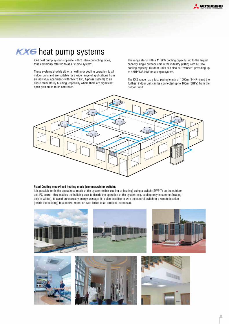
heat pump systemsKX6 heat pump systems operate with 2 inter-connecting pipes, thus commonly referred to as a '2-pipe system'.
These systems provide either a heating or cooling operation to all indoor units and are suitable for a wide range of applications from an individual apartment (with "Micro KX", 1/phase system) to an entire multi storey building, especially where there are significant open plan areas to be controlled.
The range starts with a 11.2kW cooling capacity, up to the largest capacity single outdoor unit in the industry (24hp) with 68.0kW cooling capacity. Outdoor units can also be “twinned” providing up to 48HP/136.0kW on a single system.
The KX6 range has a total piping length of 1000m (14HP+) and the furthest indoor unit can be connected up to 160m (8HP+) from the outdoor unit.
Fixed Cooling mode/fixed heating mode (summer/winter switch):It is possible to fix the operational mode of the system (either cooling or heating) using a switch (SW3-7) on the outdoor unit PC board - this enables the building user to decide the operation of the system (e.g. cooling only in summer/heating only in winter), to avoid unnecessary energy wastage. It is also possible to wire the control switch to a remote location (inside the building) to a control room, or even linked to an ambient thermostat.
3 Layer Construction (KX6 <14~48HP>)
Thanks to improvement of control box structure from 4 to 3 layer construction and by use of hinged lays, service and maintenance has been made much easier for inverter components.
Equipped with RS232C for connection directly to your PC monitoring and service tasks made simple with our service software (“Mente PC”).
Monitoring FunctionKX6 series includes new feature to assist with servicing and trouble shooting. Various data can be monitored through 3-digit or 6-digit display on the outdoor unit PCB.
8~48HP4~6HP
Detailed fault diagnosis and operation history memory via 7-segment display.
all KX6 series
Blue FinDue to application of blue coated fins for the heat exchanger of new outdoor unit, corrosion resistance has been improved compared to current models.
BlueFin
BlueFin
Back-up Operation <14~48HP>
Inverter
Compressorfailed
Keeping operation
In, 2-compressor module, in the event of the compressor failure, the system will keep operating with good compressor.In combined module, in the event that one unit has a failure, the system will keep operating with another unit.Should compressor be damaged, compressor replacement should be done as soon as possible. However as emergency measure for a limited time, in 2 compressor module, the system can be kept operating with the good compressor. In combined module, the system can be kept operating with the other unit.
14 15
R410A
KX6
ex.10HP
R410A
9.52 22.22
Liquidpiping Gas piping
Reduced Refrigerant VolumeTo use the new refrigerant R410A, KX6 series have adopted thinner diameter refrigerant pipes, which will help reduce piping work cost.
Outdoor unit
8654
1012141618 20 22 242628303234 36 38 40 42 44 46 48
ø9.52
ø12.7
ø15.88
ø19.05
ø19.05
ø15.88
ø22.22
ø25.4[ø28.58]
ø28.58
ø31.8[ø34.92]
ø38.1[ø34.92]
Liquid piping Gas pipingKX6
HP
ø9.52
3/8"
mm
inch
ø12.7
1/2"
ø15.88
5/8"
ø19.05
3/4"
ø22.22
7/8"
ø25.4
1"
ø28.58
11/8"
ø31.8
11/4"
ø34.92
13/8"
ø38.1
11/2"
ø44.5
13/4"
ø50.8
2"
[ ]: Pipe sizes applicable to European installations are shown in parentheses.
heat pump systemsKX6 heat pump systems operate with 2 inter-connecting pipes, thus commonly referred to as a '2-pipe system'.
These systems provide either a heating or cooling operation to all indoor units and are suitable for a wide range of applications from an individual apartment (with "Micro KX", 1/phase system) to an entire multi storey building, especially where there are significant open plan areas to be controlled.
The range starts with a 11.2kW cooling capacity, up to the largest capacity single outdoor unit in the industry (24hp) with 68.0kW cooling capacity. Outdoor units can also be “twinned” providing up to 48HP/136.0kW on a single system.
The KX6 range has a total piping length of 1000m (14HP+) and the furthest indoor unit can be connected up to 160m (8HP+) from the outdoor unit.
Fixed Cooling mode/fixed heating mode (summer/winter switch):It is possible to fix the operational mode of the system (either cooling or heating) using a switch (SW3-7) on the outdoor unit PC board - this enables the building user to decide the operation of the system (e.g. cooling only in summer/heating only in winter), to avoid unnecessary energy wastage. It is also possible to wire the control switch to a remote location (inside the building) to a control room, or even linked to an ambient thermostat.
3 Layer Construction (KX6 <14~48HP>)
Thanks to improvement of control box structure from 4 to 3 layer construction and by use of hinged lays, service and maintenance has been made much easier for inverter components.
Equipped with RS232C for connection directly to your PC monitoring and service tasks made simple with our service software (“Mente PC”).
Monitoring FunctionKX6 series includes new feature to assist with servicing and trouble shooting. Various data can be monitored through 3-digit or 6-digit display on the outdoor unit PCB.
8~48HP4~6HP
Detailed fault diagnosis and operation history memory via 7-segment display.
all KX6 series
Blue FinDue to application of blue coated fins for the heat exchanger of new outdoor unit, corrosion resistance has been improved compared to current models.
BlueFin
BlueFin
Back-up Operation <14~48HP>
Inverter
Compressorfailed
Keeping operation
In, 2-compressor module, in the event of the compressor failure, the system will keep operating with good compressor.In combined module, in the event that one unit has a failure, the system will keep operating with another unit.Should compressor be damaged, compressor replacement should be done as soon as possible. However as emergency measure for a limited time, in 2 compressor module, the system can be kept operating with the good compressor. In combined module, the system can be kept operating with the other unit.
16
R410A
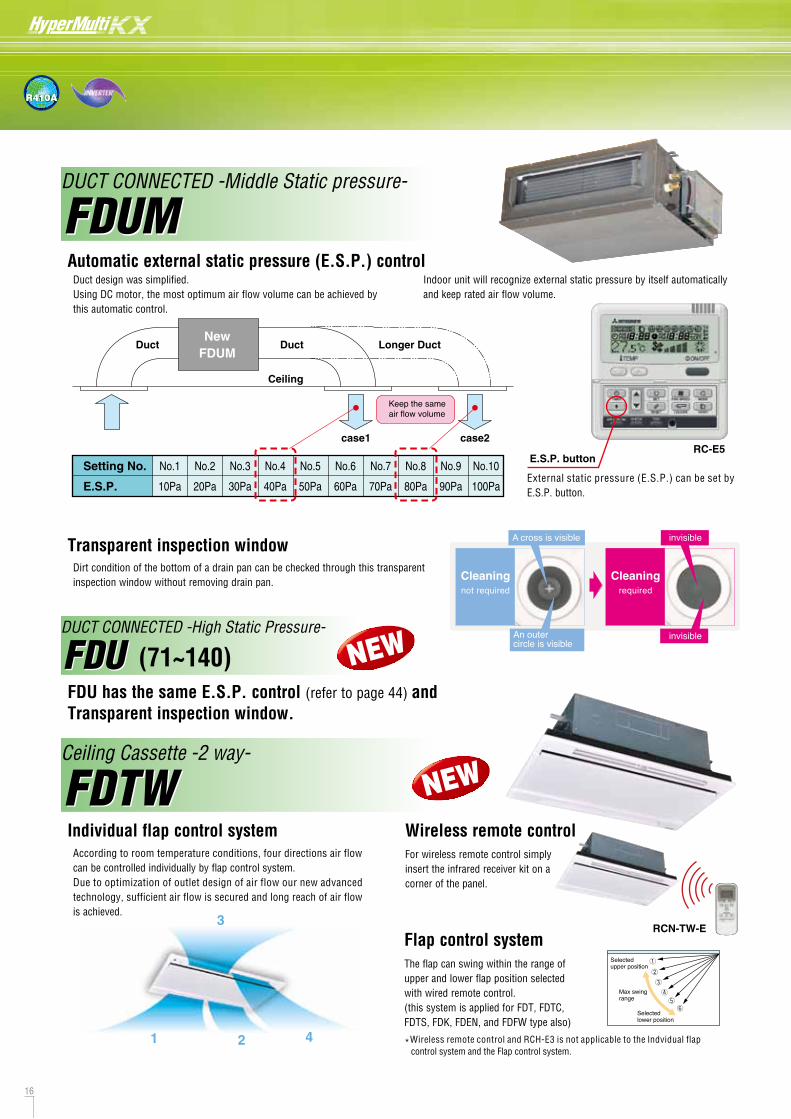
Duct design was simplified.Using DC motor, the most optimum air flow volume can be achieved by this automatic control.
Keep the same air flow volume
Longer DuctDuct
Ceiling
NewFDUM
Duct
Indoor unit will recognize external static pressure by itself automatically and keep rated air flow volume.
Automatic external static pressure (E.S.P.) control
According to room temperature conditions, four directions air flow can be controlled individually by flap control system.Due to optimization of outlet design of air flow our new advanced technology, sufficient air flow is secured and long reach of air flow is achieved.
Individual flap control systemFor wireless remote control simply attach an additional panel with infrared receiver on the right side of the main decorative panel.
Wireless remote controlFor wireless remote control simply insert the infrared receiver kit on a corner of the panel.
Wireless remote controlTwo directions of air flow can be controlled individually by flap control system.
Individual flap control system
FDUMDUCT CONNECTED -Middle Static pressure-
FDTWCeiling Cassette -2 way-
Compact design <FDUT15~56KXE6F-E> Lower noise <FDUT28KXE6F-E>
Serviceability
FDUTDUCT CONNECTED (thin) -Low Static pressure-
FDTS
FDUM
FDTW
FDUT
FDTSCeiling Cassette -1 way-
External static pressure (E.S.P.) can be set by E.S.P. button.
E.S.P. buttonRC-E5
Setting No.
E.S.P.
No.1
10Pa
No.2
20Pa
No.3
30Pa
No.4
40Pa
No.5
50Pa
No.6
60Pa
No.7
70Pa
No.8
80Pa
No.9
90Pa
No.10
100Pa
20mm less!!Height: 220 200mm
Depth: 520 500mm
Larger outlet for connecting ductL700 x 70mm L860 x 99 (45/56) Measured based on JIS B 8616
Access to control Access to fan motor Access to fan motor
Access to control
2m 1m1.5m
1m
1mUnit
1 2
3
4
0
10
20
30
0
10
20
30
405dB(A)Down
4dB(A)Down
2dB(A)Down
1dB(A)Down
Fan speed
Fan speed
CurrentNew
CurrentNew
Hi Lo
Hi Lo
[dB(A)]
[dB(A)]
2924
28
22
373032
26
case1 case2
RCN-TW-E
RCN-TS-E
Transparent inspection windowDirt condition of the bottom of a drain pan can be checked through this transparent inspection window without removing drain pan. Cleaning
not required
A cross is visible
An outercircle is visible
Cleaningrequired
invisible
invisible
FDU has the same E.S.P. control (refer to page 44) and Transparent inspection window.
FDUDUCT CONNECTED -High Static Pressure-
FDU (71~140)
17
Current Model New Model
Current Model New Model
The flap can swing within the range of upper and lower flap position selected with wired remote control.(this system is applied for FDT, FDTC, FDTS, FDK, FDEN, and FDFW type also)
Selected upper position
Max swingrange
Selected lower position
*Wireless remote control and RCH-E3 is not applicable to the lndvidual flap control system and the Flap control system.
Flap control system
NEW
NEW
NEW
NEW

16
R410A
Duct design was simplified.Using DC motor, the most optimum air flow volume can be achieved by this automatic control.
Keep the same air flow volume
Longer DuctDuct
Ceiling
NewFDUM
Duct
Indoor unit will recognize external static pressure by itself automatically and keep rated air flow volume.
Automatic external static pressure (E.S.P.) control
According to room temperature conditions, four directions air flow can be controlled individually by flap control system.Due to optimization of outlet design of air flow our new advanced technology, sufficient air flow is secured and long reach of air flow is achieved.
Individual flap control systemFor wireless remote control simply attach an additional panel with infrared receiver on the right side of the main decorative panel.
Wireless remote controlFor wireless remote control simply insert the infrared receiver kit on a corner of the panel.
Wireless remote controlTwo directions of air flow can be controlled individually by flap control system.
Individual flap control system
FDUMDUCT CONNECTED -Middle Static pressure-
FDTWCeiling Cassette -2 way-
Compact design <FDUT15~56KXE6F-E> Lower noise <FDUT28KXE6F-E>
Serviceability
FDUTDUCT CONNECTED (thin) -Low Static pressure-
FDTS
FDUM
FDTW
FDUT
FDTSCeiling Cassette -1 way-
External static pressure (E.S.P.) can be set by E.S.P. button.
E.S.P. buttonRC-E5
Setting No.
E.S.P.
No.1
10Pa
No.2
20Pa
No.3
30Pa
No.4
40Pa
No.5
50Pa
No.6
60Pa
No.7
70Pa
No.8
80Pa
No.9
90Pa
No.10
100Pa
20mm less!!Height: 220 200mm
Depth: 520 500mm
Larger outlet for connecting ductL700 x 70mm L860 x 99 (45/56) Measured based on JIS B 8616
Access to control Access to fan motor Access to fan motor
Access to control
2m 1m1.5m
1m
1mUnit
1 2
3
4
0
10
20
30
0
10
20
30
405dB(A)Down
4dB(A)Down
2dB(A)Down
1dB(A)Down
Fan speed
Fan speed
CurrentNew
CurrentNew
Hi Lo
Hi Lo
[dB(A)]
[dB(A)]
2924
28
22
373032
26
case1 case2
RCN-TW-E
RCN-TS-E
Transparent inspection windowDirt condition of the bottom of a drain pan can be checked through this transparent inspection window without removing drain pan. Cleaning
not required
A cross is visible
An outercircle is visible
Cleaningrequired
invisible
invisible
FDU has the same E.S.P. control (refer to page 44) and Transparent inspection window.
FDUDUCT CONNECTED -High Static Pressure-
FDU (71~140)
17
Current Model New Model
Current Model New Model
The flap can swing within the range of upper and lower flap position selected with wired remote control.(this system is applied for FDT, FDTC, FDTS, FDK, FDEN, and FDFW type also)
Selected upper position
Max swingrange
Selected lower position
*Wireless remote control and RCH-E3 is not applicable to the lndvidual flap control system and the Flap control system.
Flap control system
NEW
NEW
NEW
NEW
18 19
R410A
Minimum installation space
Intake
outlet
Intake
Servicespace
L1
L2L3
L4
5140 36
100B
A
A
845
10
110
50
195 242
279
97050 15
55
502752
110
50
195
B
A
Terminal block
F
CC
VIEW AC 5015
7050
150
40
F
E
370
4040
410
2020
55
60
388262
38
60
190 580 200
60 15
103
15
C
D
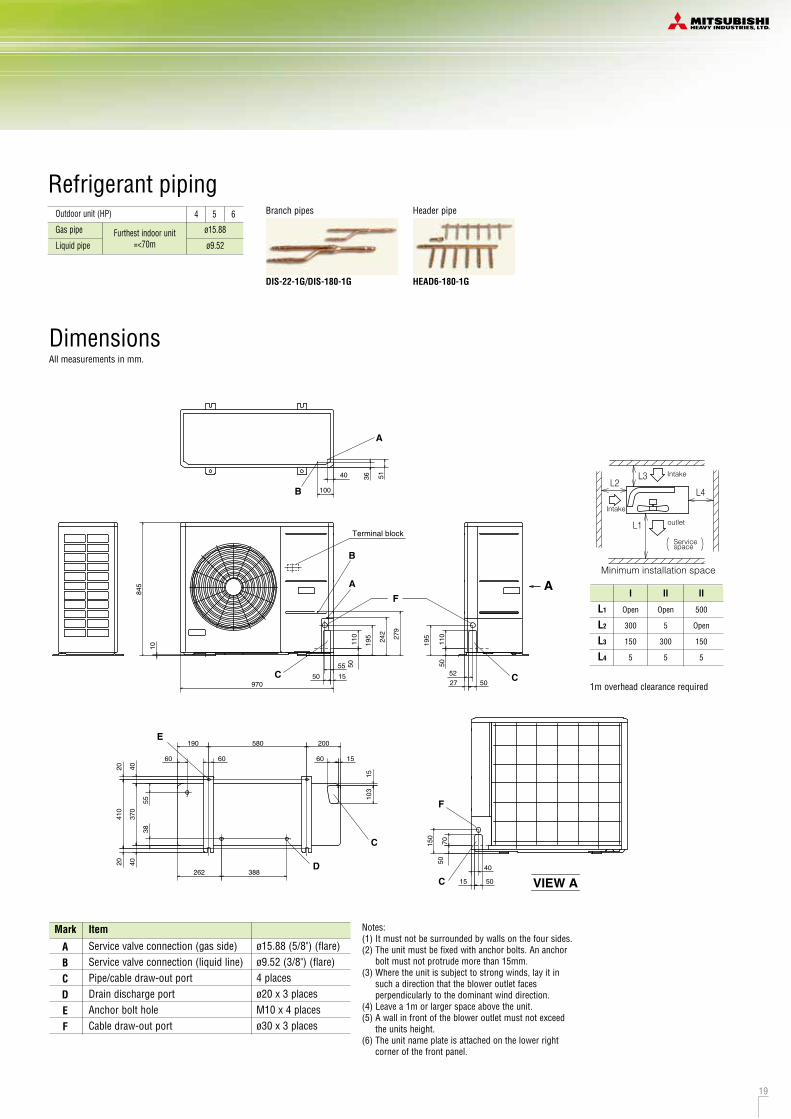
DimensionsAll measurements in mm.
Model No. FDC112KXEN6 FDC140KXEN6 FDC155KXEN6
FDC112KXES6 FDC140KXES6 FDC155KXES6
Nominal Cooling Capacity 11.2kW (1phase) 14.0kW (1phase) 15.5kW (1phase)
11.2kW (3phase) 14.0kW (3phase) 15.5kW (3phase)
Notes:(1) It must not be surrounded by walls on the four sides.(2) The unit must be fixed with anchor bolts. An anchor
bolt must not protrude more than 15mm.(3) Where the unit is subject to strong winds, lay it in
such a direction that the blower outlet faces perpendicularly to the dominant wind direction.
(4) Leave a 1m or larger space above the unit.(5) A wall in front of the blower outlet must not exceed
the units height.(6) The unit name plate is attached on the lower right
corner of the front panel.
Mark Item
Service valve connection (gas side)Service valve connection (liquid line)Pipe/cable draw-out portDrain discharge portAnchor bolt holeCable draw-out port
ABCDEF
ø15.88 (5/8") (flare)ø9.52 (3/8") (flare)4 placesø20 x 3 placesM10 x 4 placesø30 x 3 places
1m overhead clearance required
I
Open
300
150
5
II
Open
5
300
5
II
500
Open
150
5
L1
L2
L3
L4
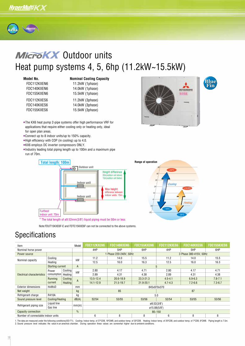
•The KX6 heat pump 2-pipe systems offer high performance VRF for applications that require either cooling only or heating only, ideal for open plan areas.
•Connect up to 8 indoor units/up to 150% capacity.
•High efficiency with COP (in cooling) up to 4.0.
•KX6 employs DC inverter compressors ONLY.
•Industry leading total piping length up to 100m and a maximum pipe run of 70m.
Range of operation
50
40
30
20
10
0
-10
-20
Heating
Cooling
+43ºC
-15ºC
+15.5ºC
-20ºC
Specifications
1. The data are measured under the following conditions(ISO-T1). Cooling: Indoor temp. of 27ºCDB, 19ºCWB, and outdoor temp. of 35ºCDB. Heating: Indoor temp. of 20ºCDB, and outdoor temp. of 7ºCDB, 6ºCWB. Piping length is 7.5m.2. Sound pressure level indicates the value in an anechoic chamber. During operation these values are somewhat higher due to ambient conditions.
ItemNominal horse powerPower source
Nominal capacity
Electrical characteristics
Exterior dimensionsNet weightRefrigerant chargeSound pressure level
Refrigerant piping size
Capacity connectionNumber of connectable indoor units
CoolingHeatingStarting current
Powerconsumption
Runningcurrent
HxWxD
R410ACooling/HeatingLiquid lineGas line
CoolingHeatingCoolingHeating
kW
A
kW
A
mmkgkg
dB(A)
mm(in)
%
4HP
11.212.5
2.802.89
13.5-12.414.1-12.9
52/54
6
FDC112KXEN6 FDC140KXEN6 FDC155KXEN6 FDC112KXES65HP
14.016.0
4.174.31
20.6-18.921.5-19.7
85
53/55
8
6HP
15.516.3
4.714.38
23.3-21.321.9-20.1
53/56
8
4HP
11.212.5
2.802.89
4.5-4.14.7-4.3
52/54
6
FDC140KXES65HP
14.016.0
4.174.31
6.9-6.37.2-6.6
87
53/55
8
FDC155KXES66HP
15.516.3
4.714.38
7.8-7.17.3-6.7
53/56
8
1 Phase 220-240V, 50Hz
5
845x970x370
5.0
ø9.52(3/8")ø15.88(5/8")
80~150
3 Phase 380-415V, 50Hz
Outdoor unitTotal length: 100m
Height difference30m(outdoor unit above)15m(outdoor unit below)
Furthest indoor unit: 70m
Max height difference between indoor units: 15m
Indoor unit
Indoor unit
The total length of ø9.52mm(3/8") liquid piping must be 50m or less*
Outdoor units Heat pump systems 4, 5, 6hp (11.2kW~15.5kW)
Model
BlueFin
BlueFin
Header pipe
HEAD6-180-1G
Branch pipes
DIS-22-1G/DIS-180-1G
Outdoor unit (HP) 4 5 6
Liquid pipe ø9.52
Gas pipe ø15.88Furthest indoor unit=<70m
Refrigerant piping
Note:FDUT15KXE6F-E and FDTC15KXE6F can not be connected to the above systems.
18 19
R410A
Minimum installation space
Intake
outlet
Intake
Servicespace
L1
L2L3
L4
5140 36
100B
A
A
845
10
110
50
195 242
279
97050 15
55
502752
110
50
195
B
A
Terminal block
F
CC
VIEW AC 5015
7050
150
40
F
E
370
4040
410
2020
55
60
388262
38
60
190 580 200
60 15
103
15
C
D
DimensionsAll measurements in mm.
Model No. FDC112KXEN6 FDC140KXEN6 FDC155KXEN6
FDC112KXES6 FDC140KXES6 FDC155KXES6
Nominal Cooling Capacity 11.2kW (1phase) 14.0kW (1phase) 15.5kW (1phase)
11.2kW (3phase) 14.0kW (3phase) 15.5kW (3phase)
Notes:(1) It must not be surrounded by walls on the four sides.(2) The unit must be fixed with anchor bolts. An anchor
bolt must not protrude more than 15mm.(3) Where the unit is subject to strong winds, lay it in
such a direction that the blower outlet faces perpendicularly to the dominant wind direction.
(4) Leave a 1m or larger space above the unit.(5) A wall in front of the blower outlet must not exceed
the units height.(6) The unit name plate is attached on the lower right
corner of the front panel.
Mark Item
Service valve connection (gas side)Service valve connection (liquid line)Pipe/cable draw-out portDrain discharge portAnchor bolt holeCable draw-out port
ABCDEF
ø15.88 (5/8") (flare)ø9.52 (3/8") (flare)4 placesø20 x 3 placesM10 x 4 placesø30 x 3 places
1m overhead clearance required
I
Open
300
150
5
II
Open
5
300
5
II
500
Open
150
5
L1
L2
L3
L4
•The KX6 heat pump 2-pipe systems offer high performance VRF for applications that require either cooling only or heating only, ideal for open plan areas.
•Connect up to 8 indoor units/up to 150% capacity.
•High efficiency with COP (in cooling) up to 4.0.
•KX6 employs DC inverter compressors ONLY.
•Industry leading total piping length up to 100m and a maximum pipe run of 70m.
Range of operation
50
40
30
20
10
0
-10
-20
Heating
Cooling
+43ºC
-15ºC
+15.5ºC
-20ºC
Specifications
1. The data are measured under the following conditions(ISO-T1). Cooling: Indoor temp. of 27ºCDB, 19ºCWB, and outdoor temp. of 35ºCDB. Heating: Indoor temp. of 20ºCDB, and outdoor temp. of 7ºCDB, 6ºCWB. Piping length is 7.5m.2. Sound pressure level indicates the value in an anechoic chamber. During operation these values are somewhat higher due to ambient conditions.
ItemNominal horse powerPower source
Nominal capacity
Electrical characteristics
Exterior dimensionsNet weightRefrigerant chargeSound pressure level
Refrigerant piping size
Capacity connectionNumber of connectable indoor units
CoolingHeatingStarting current
Powerconsumption
Runningcurrent
HxWxD
R410ACooling/HeatingLiquid lineGas line
CoolingHeatingCoolingHeating
kW
A
kW
A
mmkgkg
dB(A)
mm(in)
%
4HP
11.212.5
2.802.89
13.5-12.414.1-12.9
52/54
6
FDC112KXEN6 FDC140KXEN6 FDC155KXEN6 FDC112KXES65HP
14.016.0
4.174.31
20.6-18.921.5-19.7
85
53/55
8
6HP
15.516.3
4.714.38
23.3-21.321.9-20.1
53/56
8
4HP
11.212.5
2.802.89
4.5-4.14.7-4.3
52/54
6
FDC140KXES65HP
14.016.0
4.174.31
6.9-6.37.2-6.6
87
53/55
8
FDC155KXES66HP
15.516.3
4.714.38
7.8-7.17.3-6.7
53/56
8
1 Phase 220-240V, 50Hz
5
845x970x370
5.0
ø9.52(3/8")ø15.88(5/8")
80~150
3 Phase 380-415V, 50Hz
Outdoor unitTotal length: 100m
Height difference30m(outdoor unit above)15m(outdoor unit below)
Furthest indoor unit: 70m
Max height difference between indoor units: 15m
Indoor unit
Indoor unit
The total length of ø9.52mm(3/8") liquid piping must be 50m or less*
Outdoor units Heat pump systems 4, 5, 6hp (11.2kW~15.5kW)
Model
BlueFin
BlueFin
Header pipe
HEAD6-180-1G
Branch pipes
DIS-22-1G/DIS-180-1G
Outdoor unit (HP) 4 5 6
Liquid pipe ø9.52
Gas pipe ø15.88Furthest indoor unit=<70m
Refrigerant piping
Note:FDUT15KXE6F-E and FDTC15KXE6F can not be connected to the above systems.

20 21
R410A
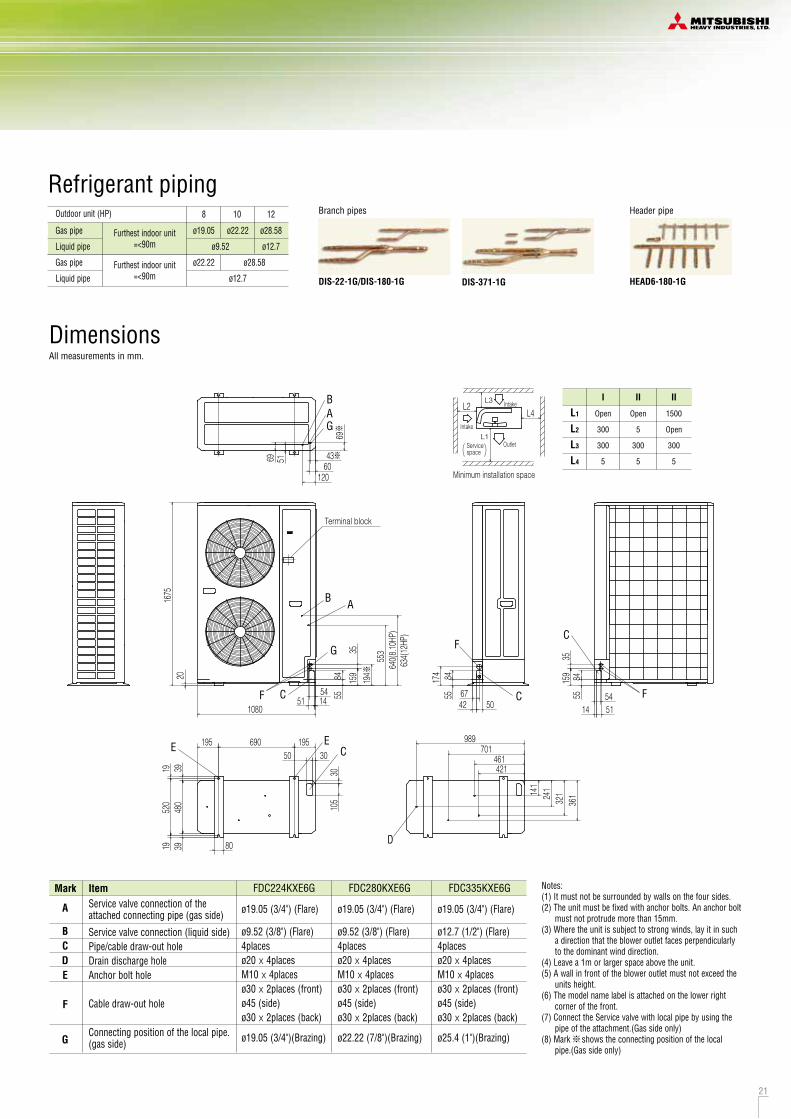
DimensionsAll measurements in mm.
Model No. FDC224KXE6G FDC280KXE6G FDC335KXE6G
Nominal Cooling Capacity 22.4kW 28.0kW 33.5kW
Heat pump systems 8, 10, 12hp (22.4kW~33.5kW)
•The KX6 heat pump 2-pipe systems offer high performance VRF for applications that require either cooling only or heating only, ideal
for open plan areas.
•Connect up to 24 indoor units/up to 150% capacity.
•High efficiency with COP (in cooling) up to 4.0.
•KX6 employs DC inverter compressors ONLY.
•Industry leading total piping length up to 510m and a maximum pipe run of 160m.
50
40
30
20
10
0
-10
-20
Heating
Cooling
+43ºC
-15ºC
+15.5ºC
-20ºC
Range of operation
Specifications
1. The data are measured under the following conditions(ISO-T1). Cooling: Indoor temp. of 27ºCDB, 19ºCWB, and outdoor temp. of 35ºCDB. Heating: Indoor temp. of 20ºCDB, and outdoor temp. of 7ºCDB, 6ºCWB. Piping length is 7.5m.2. Sound pressure level indicates the value in an anechoic chamber. During operation these values are somewhat higher due to ambient conditions.3. [ ] : Pipe sizes applicable to European installations are shown in parentheses.
ItemNominal horse powerPower source
Nominal capacity
Electrical characteristics
Exterior dimensionsNet weightRefrigerant chargeSound pressure level
Refrigerant piping size
Capacity connectionNumber of connectable indoor units
CoolingHeatingStarting current
Powerconsumption
Runningcurrent
HxWxD
R410ACooling/HeatingLiquid lineGas line
CoolingHeatingCoolingHeating
kW
A
kW
A
mmkgkg
dB(A)
mm(in)
%
8HP
22.425.0
5.606.03
9.25-8.479.85-9.02
58/58
ø19.05(3/4")
22
FDC224KXE6G10HP
3 Phase 380-415V, 50Hz28.031.5
58.098.21
13.22-12.1013.41-12.28
1675x1080x480
11.559/60
ø22.22(7/8")50~150
24
FDC280KXE6G FDC335KXE6G12HP
33.537.5
9.8210.12
15.87-14.5316.36-14.98
224
61/61ø12.7(1/2")
ø25.4(1") [ø22.22(7/8")]
24
ø9.52(3/8")
I
Open
300
300
5
II
Open
5
300
5
II
1500
Open
300
5
L1
L2
L3
L4
Notes:(1) It must not be surrounded by walls on the four sides.(2) The unit must be fixed with anchor bolts. An anchor bolt
must not protrude more than 15mm.(3) Where the unit is subject to strong winds, lay it in such
a direction that the blower outlet faces perpendicularly to the dominant wind direction.
(4) Leave a 1m or larger space above the unit.(5) A wall in front of the blower outlet must not exceed the
units height.(6) The model name label is attached on the lower right
corner of the front.(7) Connect the Service valve with local pipe by using the
pipe of the attachment.(Gas side only)(8) Mark shows the connecting position of the local
pipe.(Gas side only)
Mark ItemService valve connection of the attached connecting pipe (gas side)
Service valve connection (liquid side)Pipe/cable draw-out holeDrain discharge holeAnchor bolt hole
Cable draw-out hole
Connecting position of the local pipe. (gas side)
A
BCDE
F
G
ø19.05 (3/4") (Flare)
ø9.52 (3/8") (Flare)4placesø20 x 4placesM10 x 4placesø30 x 2places (front)ø45 (side)ø30 x 2places (back)
ø19.05 (3/4")(Brazing)
ø19.05 (3/4") (Flare)
ø9.52 (3/8") (Flare)4placesø20 x 4placesM10 x 4placesø30 x 2places (front)ø45 (side)ø30 x 2places (back)
ø22.22 (7/8")(Brazing)
ø19.05 (3/4") (Flare)
ø12.7 (1/2") (Flare)4placesø20 x 4placesM10 x 4placesø30 x 2places (front)ø45 (side)ø30 x 2places (back)
ø25.4 (1")(Brazing)
FDC280KXE6GFDC224KXE6G FDC335KXE6G
L1
L3
Intake
Outlet
Intake
Service
Minimum installation space
space
L2 L4
43
69
60
BAG
51
120
69
8455
159
35
545114
F
C
675042
F
C
174 84
55
1675
20
1080
8455F C 1451
54
G
B
194
640(8
.10HP
)63
4(12H
P)
553
A
159
35
Terminal block
Model
221
BlueFin
BlueFin
Outdoor units
141
241
321
361
421461
701989
D
1956901953050
3010
5
C
3948
039
1952
019
EE
80
DIS-371-1G
Header pipe
HEAD6-180-1G
Branch pipes
DIS-22-1G/DIS-180-1G
Outdoor unit (HP) 8 10 12
Liquid pipe ø9.52 ø12.7
Gas pipe ø22.22ø19.05 ø28.58Furthest indoor unit=<90m
Liquid pipe ø12.7
Gas pipe ø22.22 ø28.58Furthest indoor unit=<90m
Refrigerant piping
Outdoor unitTotal length: 510m
To the first branch:max 130m
From the first branch to the furthest indoor unit: 90m
Height difference50m(outdoor unit above)40m(outdoor unit below)
Max height differencebetween indoor units: 18m
Indoor unit
Indoor unit
Indoor unit
Furthest indoor unit: 160m
*
*
The difference between the longest and the shortest indoor unit piping from the first branch must be within 40m.
20 21
R410A
DimensionsAll measurements in mm.
Model No. FDC224KXE6G FDC280KXE6G FDC335KXE6G
Nominal Cooling Capacity 22.4kW 28.0kW 33.5kW
Heat pump systems 8, 10, 12hp (22.4kW~33.5kW)
•The KX6 heat pump 2-pipe systems offer high performance VRF for applications that require either cooling only or heating only, ideal
for open plan areas.
•Connect up to 24 indoor units/up to 150% capacity.
•High efficiency with COP (in cooling) up to 4.0.
•KX6 employs DC inverter compressors ONLY.
•Industry leading total piping length up to 510m and a maximum pipe run of 160m.
50
40
30
20
10
0
-10
-20
Heating
Cooling
+43ºC
-15ºC
+15.5ºC
-20ºC
Range of operation
Specifications
1. The data are measured under the following conditions(ISO-T1). Cooling: Indoor temp. of 27ºCDB, 19ºCWB, and outdoor temp. of 35ºCDB. Heating: Indoor temp. of 20ºCDB, and outdoor temp. of 7ºCDB, 6ºCWB. Piping length is 7.5m.2. Sound pressure level indicates the value in an anechoic chamber. During operation these values are somewhat higher due to ambient conditions.3. [ ] : Pipe sizes applicable to European installations are shown in parentheses.
ItemNominal horse powerPower source
Nominal capacity
Electrical characteristics
Exterior dimensionsNet weightRefrigerant chargeSound pressure level
Refrigerant piping size
Capacity connectionNumber of connectable indoor units
CoolingHeatingStarting current
Powerconsumption
Runningcurrent
HxWxD
R410ACooling/HeatingLiquid lineGas line
CoolingHeatingCoolingHeating
kW
A
kW
A
mmkgkg
dB(A)
mm(in)
%
8HP
22.425.0
5.606.03
9.25-8.479.85-9.02
58/58
ø19.05(3/4")
22
FDC224KXE6G10HP
3 Phase 380-415V, 50Hz28.031.5
58.098.21
13.22-12.1013.41-12.28
1675x1080x480
11.559/60
ø22.22(7/8")50~150
24
FDC280KXE6G FDC335KXE6G12HP
33.537.5
9.8210.12
15.87-14.5316.36-14.98
224
61/61ø12.7(1/2")
ø25.4(1") [ø22.22(7/8")]
24
ø9.52(3/8")
I
Open
300
300
5
II
Open
5
300
5
II
1500
Open
300
5
L1
L2
L3
L4
Notes:(1) It must not be surrounded by walls on the four sides.(2) The unit must be fixed with anchor bolts. An anchor bolt
must not protrude more than 15mm.(3) Where the unit is subject to strong winds, lay it in such
a direction that the blower outlet faces perpendicularly to the dominant wind direction.
(4) Leave a 1m or larger space above the unit.(5) A wall in front of the blower outlet must not exceed the
units height.(6) The model name label is attached on the lower right
corner of the front.(7) Connect the Service valve with local pipe by using the
pipe of the attachment.(Gas side only)(8) Mark shows the connecting position of the local
pipe.(Gas side only)
Mark ItemService valve connection of the attached connecting pipe (gas side)
Service valve connection (liquid side)Pipe/cable draw-out holeDrain discharge holeAnchor bolt hole
Cable draw-out hole
Connecting position of the local pipe. (gas side)
A
BCDE
F
G
ø19.05 (3/4") (Flare)
ø9.52 (3/8") (Flare)4placesø20 x 4placesM10 x 4placesø30 x 2places (front)ø45 (side)ø30 x 2places (back)
ø19.05 (3/4")(Brazing)
ø19.05 (3/4") (Flare)
ø9.52 (3/8") (Flare)4placesø20 x 4placesM10 x 4placesø30 x 2places (front)ø45 (side)ø30 x 2places (back)
ø22.22 (7/8")(Brazing)
ø19.05 (3/4") (Flare)
ø12.7 (1/2") (Flare)4placesø20 x 4placesM10 x 4placesø30 x 2places (front)ø45 (side)ø30 x 2places (back)
ø25.4 (1")(Brazing)
FDC280KXE6GFDC224KXE6G FDC335KXE6G
L1
L3
Intake
Outlet
Intake
Service
Minimum installation space
space
L2 L4
43
69
60
BAG
51
120
69
8455
159
35
545114
F
C
675042
F
C
174 84
55
1675
20
1080
8455F C 1451
54
G
B
194
640(8
.10HP
)63
4(12H
P)
553
A
159
35
Terminal block
Model
221
BlueFin
BlueFin
Outdoor units
141
241
321
361
421461
701989
D
1956901953050
3010
5
C
3948
039
1952
019
EE
80
DIS-371-1G
Header pipe
HEAD6-180-1G
Branch pipes
DIS-22-1G/DIS-180-1G
Outdoor unit (HP) 8 10 12
Liquid pipe ø9.52 ø12.7
Gas pipe ø22.22ø19.05 ø28.58Furthest indoor unit=<90m
Liquid pipe ø12.7
Gas pipe ø22.22 ø28.58Furthest indoor unit=<90m
Refrigerant piping
Outdoor unitTotal length: 510m
To the first branch:max 130m
From the first branch to the furthest indoor unit: 90m
Height difference50m(outdoor unit above)40m(outdoor unit below)
Max height differencebetween indoor units: 18m
Indoor unit
Indoor unit
Indoor unit
Furthest indoor unit: 160m
*
*
The difference between the longest and the shortest indoor unit piping from the first branch must be within 40m.
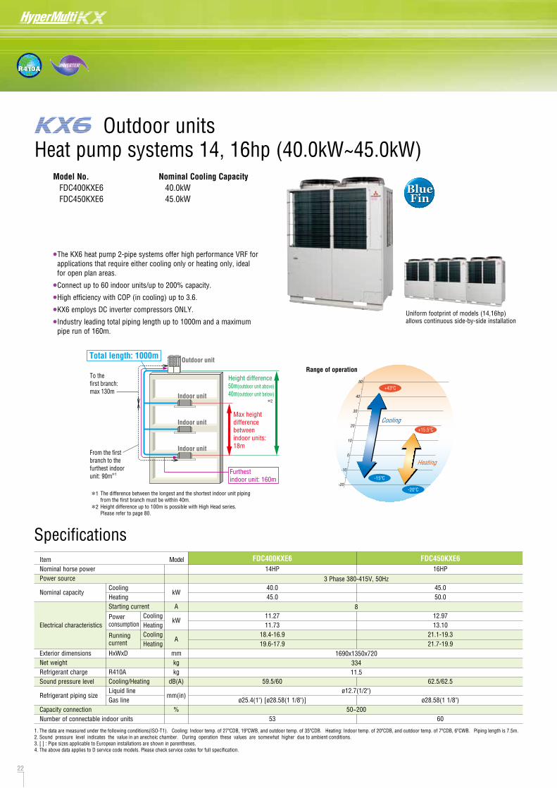
22 23
R410A
Heat pump systems 14, 16hp (40.0kW~45.0kW)
50
40
30
20
10
0
-10
-20
Heating
Cooling
+43ºC
-15ºC
+15.5ºC
-20ºC
Range of operation
SpecificationsItemNominal horse powerPower source
Nominal capacity
Electrical characteristics
Exterior dimensionsNet weightRefrigerant chargeSound pressure level
Refrigerant piping size
Capacity connectionNumber of connectable indoor units
CoolingHeatingStarting current
Powerconsumption
Runningcurrent
HxWxD
R410ACooling/HeatingLiquid lineGas line
CoolingHeatingCoolingHeating
kW
A
kW
A
mmkgkg
dB(A)
mm(in)
%
14HP
40.045.0
11.2711.73
18.4-16.919.6-17.9
59.5/60
ø25.4(1") [ø28.58(1 1/8")]
53
FDC400KXE616HP
45.050.0
12.9713.10
21.1-19.321.7-19.9
62.5/62.5
ø28.58(1 1/8")
60
FDC450KXE6
ø12.7(1/2")
50~200
1690x1350x72033411.5
8
3 Phase 380-415V, 50Hz
Model No. FDC400KXE6 FDC450KXE6
Nominal Cooling Capacity 40.0kW 45.0kW
•The KX6 heat pump 2-pipe systems offer high performance VRF for applications that require either cooling only or heating only, ideal
for open plan areas.
•Connect up to 60 indoor units/up to 200% capacity.
•High efficiency with COP (in cooling) up to 3.6.
•KX6 employs DC inverter compressors ONLY.
•Industry leading total piping length up to 1000m and a maximum pipe run of 160m.
Uniform footprint of models (14,16hp)allows continuous side-by-side installation
Model
1. The data are measured under the following conditions(ISO-T1). Cooling: Indoor temp. of 27ºCDB, 19ºCWB, and outdoor temp. of 35ºCDB. Heating: Indoor temp. of 20ºCDB, and outdoor temp. of 7ºCDB, 6ºCWB. Piping length is 7.5m.2. Sound pressure level indicates the value in an anechoic chamber. During operation these values are somewhat higher due to ambient conditions.3. [ ] : Pipe sizes applicable to European installations are shown in parentheses.4. The above data applies to D service code models. Please check service codes for full specification.
BlueFin
BlueFin
Outdoor units
Outdoor unitTotal length: 1000m
To the first branch:max 130m
From the first branch to the furthest indoor unit: 90m
Height difference50m(outdoor unit above)40m(outdoor unit below)
Max height differencebetween indoor units: 18m
Indoor unit
Indoor unit
Indoor unit
Furthest indoor unit: 160m
*1
*1
*2
The difference between the longest and the shortest indoor unit piping from the first branch must be within 40m.
*2 Height difference up to 100m is possible with High Head series.Please refer to page 80.
When more than one unit is installed
L3
L2 L5 L6 L4
Wal
l hei
ght
H2
Wall height
H4
Wall heightH2
Wall heightH3
L1 (Unit front side)
DimensionsAll measurements in mm.
A
500
10
100
10
0
0
1500
No restrictions
1000
No restrictions
B
Open
200
300
Open
400
400
No restrictions
No restrictions
No restrictions
No restrictions
Dimensions
L1
L2
L3
L4
L5
L6
H1
H2
H3
H4
Installation exampleNotes:(1) The unit must be fixed with anchor bolts.(2) Leave a 2m or larger space above the unit.(3) The unit name plate is attached on the lower right corner of
the front panel.(4) The ports for refrigerant pipe and power cable penetrations
are covered with half-blanks. Please cut off a half-blank with nippers in using these ports.
(5) Use a ø88 port for refrigerant pipe connection.(6) Anchor holes marked “L J” (four holes for M10) are for a
renewal installation.(7) The oil-equalising pipe K should be used when outdoor units
are used in combination. (For 14,16Hp only)
Mark Content 335-K 400 450 Installation example
ABCDFGHKL
Refrigerant gas piping connection pipeRefrigerant liquid piping connection pipeRefrigerant piping exit holePower supply entry holeAnchor bolt holeDrain waste water hose holeDrain holeRefrigerant oil equalization piping connection pipeCarrying in or hole for hanging
ø12.7(Flare)ø88(or ø100)
M10 x 4 placesø45 x 3 placesø20 x 10 places
ø9.52(Flare)230 x 60
1
500
10
100
10
1500
No limited
1000
No limited
2
Open
10
100
Open
–
No limited
No limited
–
Dimensions
L1
L2
L3
L4
H1
H2
H3
H4
ø50 (right . left . front), long hole 40 x 80 (under side)
ø25.4(Brazing) ø28.58(Brazing)
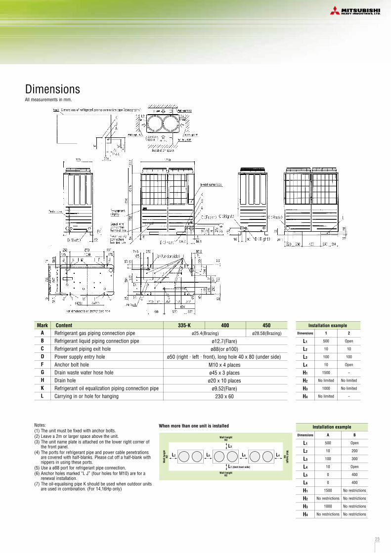
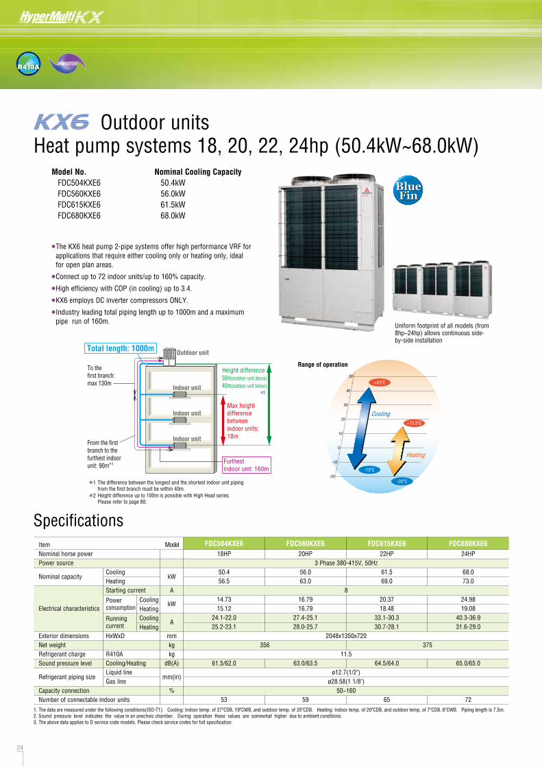
24 25
R410A
SpecificationsItemNominal horse powerPower source
Nominal capacity
Electrical characteristics
Exterior dimensionsNet weightRefrigerant chargeSound pressure level
Refrigerant piping size
Capacity connectionNumber of connectable indoor units
CoolingHeatingStarting current
Powerconsumption
Runningcurrent
HxWxD
R410ACooling/HeatingLiquid lineGas line
CoolingHeatingCoolingHeating
kW
A
kW
A
mmkgkg
dB(A)
mm(in)
%
18HP
50.456.5
14.7315.12
24.1-22.025.2-23.1
61.5/62.0
53
FDC504KXE6 FDC560KXE6 FDC615KXE6 FDC680KXE620HP
56.063.0
16.7916.79
27.4-25.128.0-25.7
63.0/63.5
59
22HP
61.569.0
20.3718.48
33.1-30.330.7-28.1
64.5/64.0
65
24HP
68.073.0
24.9819.08
40.3-36.931.6-29.0
65.0/65.0
72
Range of operation
•The KX6 heat pump 2-pipe systems offer high performance VRF for applications that require either cooling only or heating only, ideal for open plan areas.
•Connect up to 72 indoor units/up to 160% capacity.
•High efficiency with COP (in cooling) up to 3.4.
•KX6 employs DC inverter compressors ONLY.
•Industry leading total piping length up to 1000m and a maximum pipe run of 160m.
Uniform footprint of all models (from8hp~24hp) allows continuous side-by-side installation
3 Phase 380-415V, 50Hz
8
2048x1350x720
11.5
ø12.7(1/2")ø28.58(1 1/8")
50~160
356 375
50
40
30
20
10
0
-10
-20
Heating
Cooling
+43ºC
-15ºC
+15.5ºC
-20ºC
Model
BlueFin
BlueFin
1. The data are measured under the following conditions(ISO-T1). Cooling: Indoor temp. of 27ºCDB, 19ºCWB, and outdoor temp. of 35ºCDB. Heating: Indoor temp. of 20ºCDB, and outdoor temp. of 7ºCDB, 6ºCWB. Piping length is 7.5m.2. Sound pressure level indicates the value in an anechoic chamber. During operation these values are somewhat higher due to ambient conditions.3. The above data applies to D service code models. Please check service codes for full specification.
Heat pump systems 18, 20, 22, 24hp (50.4kW~68.0kW)Model No. FDC504KXE6 FDC560KXE6 FDC615KXE6 FDC680KXE6
Nominal Cooling Capacity 50.4kW 56.0kW 61.5kW 68.0kW
Outdoor units
Outdoor unitTotal length: 1000m
To the first branch:max 130m
From the first branch to the furthest indoor unit: 90m
Height difference50m(outdoor unit above)40m(outdoor unit below)
Max height differencebetween indoor units: 18m
Indoor unit
Indoor unit
Indoor unit
Furthest indoor unit: 160m
*1
*1
*2
The difference between the longest and the shortest indoor unit piping from the first branch must be within 40m.
*2 Height difference up to 100m is possible with High Head series.Please refer to page 80.
DimensionsAll measurements in mm.
Notes:(1) The unit must be fixed with anchor bolts.(2) Leave a 2m or larger space above the unit.(3) The unit name plate is attached on the lower right corner of
the front panel.(4) The ports for refrigerant pipe and power cable penetrations
are covered with half-blanks. Please cut off a half-blank with nippers in using these ports.
(5) Use a ø88 port for refrigerant pipe connection.(6) Anchor holes marked “L J” (four holes for M10) are for a
renewal installation.(7) The oil-equalising pipe K should be used when outdoor units
are used in combination.
Mark Content Installation example
ABCDFGHKL
Refrigerant gas piping connection pipeRefrigerant liquid piping connection pipeRefrigerant piping exit holePower supply entry holeAnchor bolt holeDrain waste water hose holeDrain holeRefrigerant oil equalization piping connection pipeCarrying in or hole for hanging
ø28.58(Brazing)ø12.7(Flare)ø88(or ø100)
ø50 (right . left . front), long hole 40 x 80 (under side)M10 x 4 placesø45 x 3 placesø20 x 10 places
ø9.52(Flare)230 x 60
1
500
10
100
10
1500
No limited
1000
No limited
2
Open
10
100
Open
–
No limited
No limited
–
Dimensions
L1
L2
L3
L4
H1
H2
H3
H4
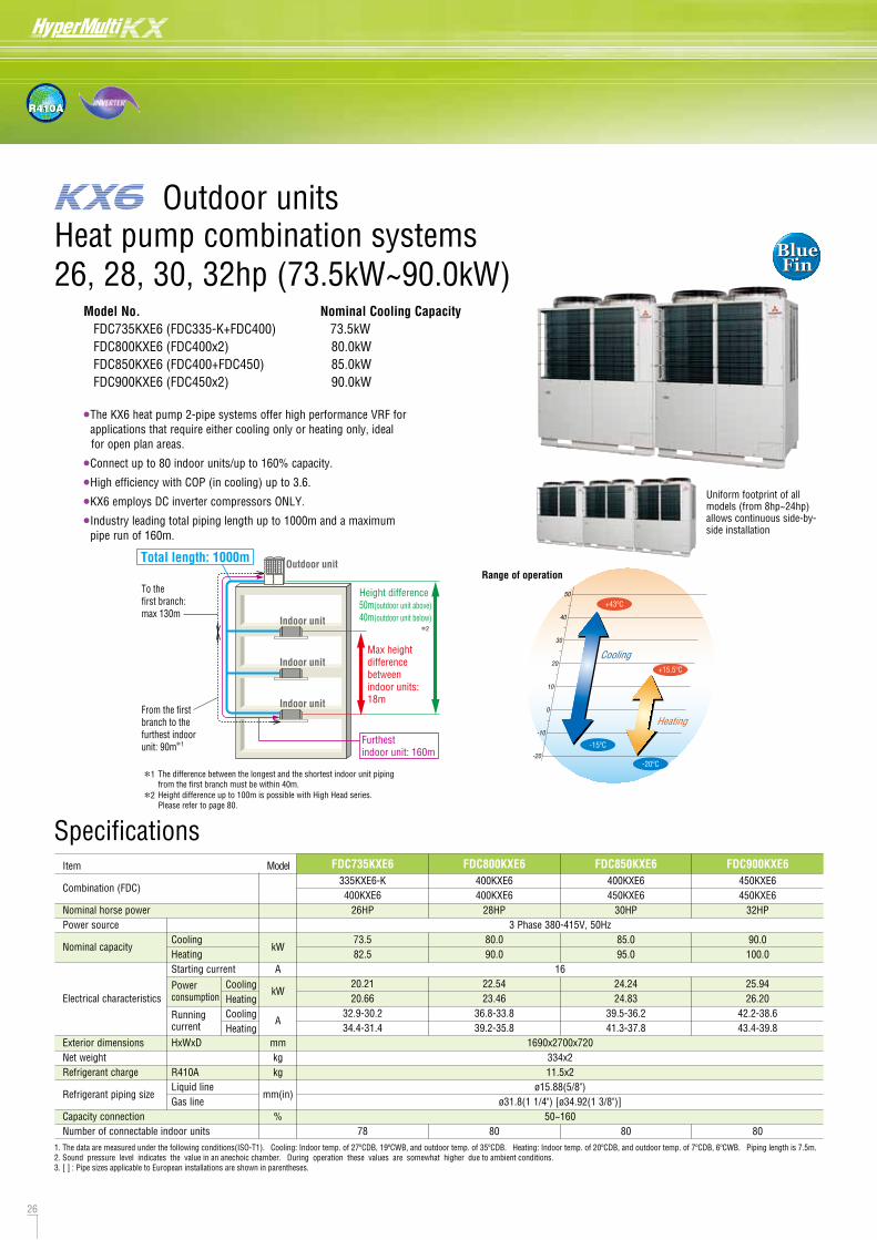
26 27
R410A
Specifications
Nominal Cooling Capacity 73.5kW 80.0kW 85.0kW 90.0kW
Heat pump combination systems26, 28, 30, 32hp (73.5kW~90.0kW)
Item
Combination (FDC)
Nominal horse powerPower source
Nominal capacity
Electrical characteristics
Exterior dimensionsNet weightRefrigerant charge
Refrigerant piping size
Capacity connectionNumber of connectable indoor units
CoolingHeatingStarting current
Powerconsumption
Runningcurrent
HxWxD
R410ALiquid lineGas line
CoolingHeatingCoolingHeating
kW
A
kW
A
mmkgkg
mm(in)
%
FDC735KXE6 FDC800KXE6 FDC850KXE6 FDC900KXE6
Range of operation
Uniform footprint of all models (from 8hp~24hp) allows continuous side-by-side installation
3 Phase 380-415V, 50Hz
16
1690x2700x720334x211.5x2
ø15.88(5/8")ø31.8(1 1/4") [ø34.92(1 3/8")]
50~160
•The KX6 heat pump 2-pipe systems offer high performance VRF for applications that require either cooling only or heating only, ideal
for open plan areas.
•Connect up to 80 indoor units/up to 160% capacity.
•High efficiency with COP (in cooling) up to 3.6.
•KX6 employs DC inverter compressors ONLY.
•Industry leading total piping length up to 1000m and a maximum pipe run of 160m.
335KXE6-K400KXE6
26HP
73.582.5
20.2120.66
32.9-30.234.4-31.4
78
400KXE6400KXE6
28HP
80.090.0
22.5423.46
36.8-33.839.2-35.8
80
400KXE6450KXE6
30HP
85.095.0
24.2424.83
39.5-36.241.3-37.8
80
450KXE6450KXE6
32HP
90.0100.0
25.9426.20
42.2-38.643.4-39.8
80
50
40
30
20
10
0
-10
-20
Heating
Cooling
+43ºC
-15ºC
+15.5ºC
-20ºC
Model
Model No. FDC735KXE6 (FDC335-K+FDC400) FDC800KXE6 (FDC400x2) FDC850KXE6 (FDC400+FDC450) FDC900KXE6 (FDC450x2)
BlueFin
BlueFin
1. The data are measured under the following conditions(ISO-T1). Cooling: Indoor temp. of 27ºCDB, 19ºCWB, and outdoor temp. of 35ºCDB. Heating: Indoor temp. of 20ºCDB, and outdoor temp. of 7ºCDB, 6ºCWB. Piping length is 7.5m.2. Sound pressure level indicates the value in an anechoic chamber. During operation these values are somewhat higher due to ambient conditions.3. [ ] : Pipe sizes applicable to European installations are shown in parentheses.
Outdoor units
Outdoor unitTotal length: 1000m
To the first branch:max 130m
From the first branch to the furthest indoor unit: 90m
Height difference50m(outdoor unit above)40m(outdoor unit below)
Max height differencebetween indoor units: 18m
Indoor unit
Indoor unit
Indoor unit
Furthest indoor unit: 160m
*1
*1
*2
The difference between the longest and the shortest indoor unit piping from the first branch must be within 40m.
*2 Height difference up to 100m is possible with High Head series.Please refer to page 80.
DimensionsAll measurements in mm.
Notes:(1) The unit must be fixed with anchor bolts.(2) Leave a 2m or larger space above the unit.(3) The unit name plate is attached on the lower right corner of the front panel.(4) The ports for refrigerant pipe and power cable penetrations are covered with half-blanks. Please cut off a half-blank with nippers in using these ports.(5) Use a ø88 port for refrigerant pipe connection.(6) Anchor holes marked “L J” (four holes for M10) are for a renewal installation.(7) The oil-equalising pipe K should be used when outdoor units are used in combination.
Mark Content 335-K 400 450 Installation example
ABCDFGHKL
Refrigerant gas piping connection pipeRefrigerant liquid piping connection pipeRefrigerant piping exit holePower supply entry holeAnchor bolt holeDrain waste water hose holeDrain holeRefrigerant oil equalization piping connection pipeCarrying in or hole for hanging
ø12.7(Flare)ø88(or ø100)
M10 x 4 placesø45 x 3 placesø20 x 10 places
ø9.52(Flare)230 x 60
1
500
10
100
10
1500
No limited
1000
No limited
2
Open
10
100
Open
–
No limited
No limited
–
Dimensions
L1
L2
L3
L4
H1
H2
H3
H4
ø50 (right . left . front), long hole 40 x 80 (under side)
ø25.4(Brazing) ø28.58(Brazing)
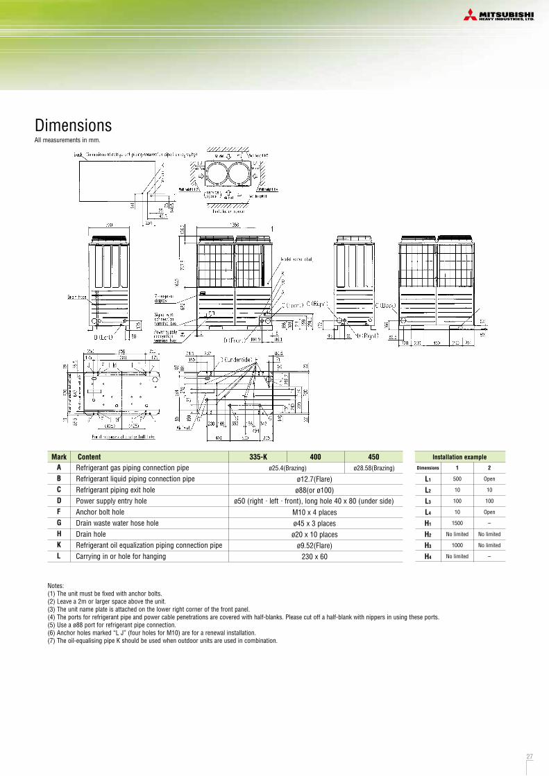
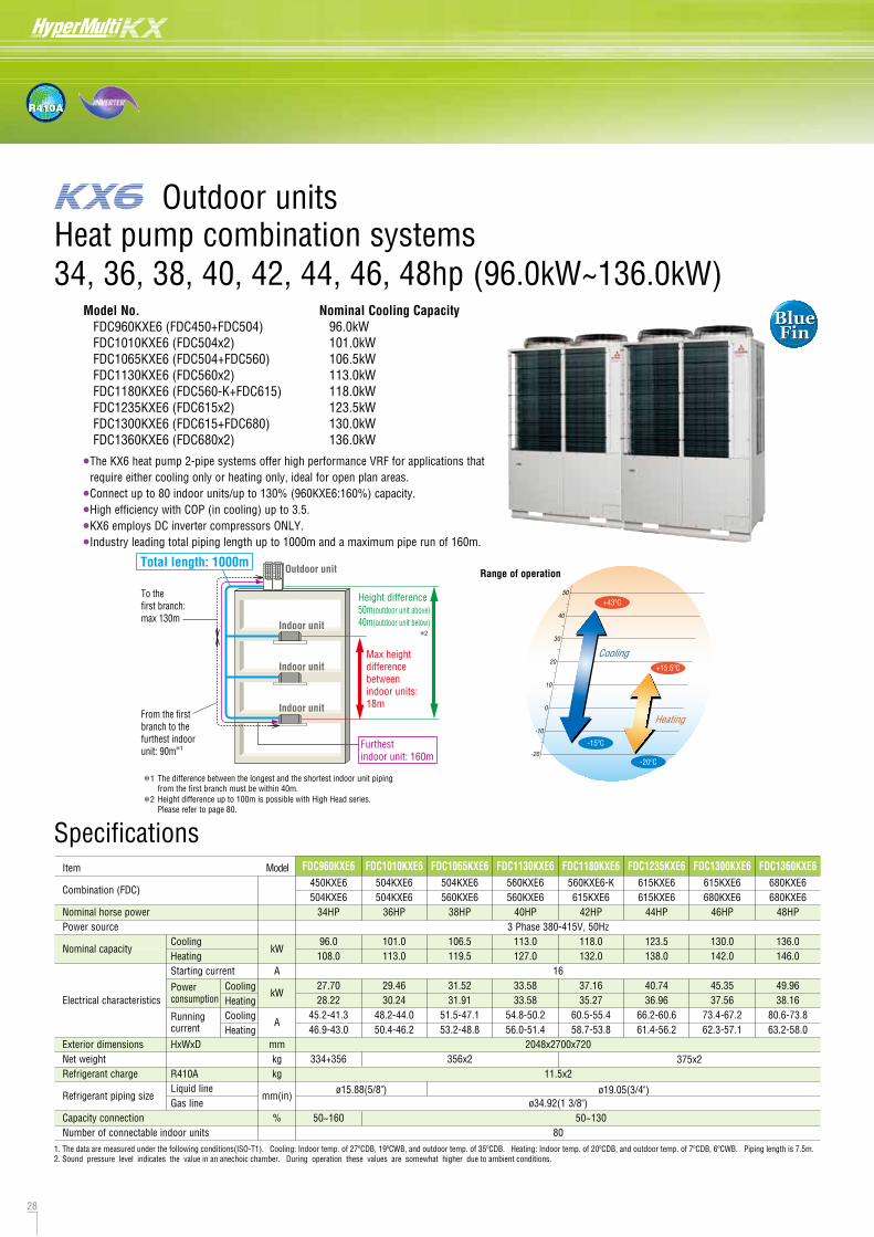
28 29
R410A
BlueFin
BlueFin
Specifications
Model No. FDC960KXE6 (FDC450+FDC504) FDC1010KXE6 (FDC504x2) FDC1065KXE6 (FDC504+FDC560) FDC1130KXE6 (FDC560x2) FDC1180KXE6 (FDC560-K+FDC615) FDC1235KXE6 (FDC615x2) FDC1300KXE6 (FDC615+FDC680) FDC1360KXE6 (FDC680x2)
Nominal Cooling Capacity 96.0kW 101.0kW 106.5kW 113.0kW 118.0kW 123.5kW 130.0kW 136.0kW
Heat pump combination systems 34, 36, 38, 40, 42, 44, 46, 48hp (96.0kW~136.0kW)
Item
Combination (FDC)
Nominal horse powerPower source
Nominal capacity
Electrical characteristics
Exterior dimensionsNet weightRefrigerant charge
Refrigerant piping size
Capacity connectionNumber of connectable indoor units
CoolingHeatingStarting current
Powerconsumption
Runningcurrent
HxWxD
R410ALiquid lineGas line
CoolingHeatingCoolingHeating
kW
A
kW
A
mmkgkg
mm(in)
%
FDC960KXE6
Range of operation
3 Phase 380-415V, 50Hz
16
2048x2700x720
11.5x2
ø34.92(1 3/8")
80
•The KX6 heat pump 2-pipe systems offer high performance VRF for applications that require either cooling only or heating only, ideal for open plan areas.
•Connect up to 80 indoor units/up to 130% (960KXE6:160%) capacity.
•High efficiency with COP (in cooling) up to 3.5.
•KX6 employs DC inverter compressors ONLY.
•Industry leading total piping length up to 1000m and a maximum pipe run of 160m.
450KXE6504KXE6
34HP
96.0108.0
27.7028.22
45.2-41.346.9-43.0
334+356
50~160
FDC1010KXE6504KXE6504KXE6
36HP
101.0113.0
29.4630.24
48.2-44.050.4-46.2
FDC1065KXE6504KXE6560KXE6
38HP
106.5119.5
31.5231.91
51.5-47.153.2-48.8
356x2
FDC1130KXE6560KXE6560KXE6
40HP
113.0127.0
33.5833.58
54.8-50.256.0-51.4
FDC1180KXE6560KXE6-K615KXE6
42HP
118.0132.0
37.1635.27
60.5-55.458.7-53.8
50~130
FDC1235KXE6615KXE6615KXE6
44HP
123.5138.0
40.7436.96
66.2-60.661.4-56.2
FDC1300KXE6615KXE6680KXE6
46HP
130.0142.0
45.3537.56
73.4-67.262.3-57.1
FDC1360KXE6680KXE6680KXE6
48HP
136.0146.0
49.9638.16
80.6-73.863.2-58.0
ø15.88(5/8") ø19.05(3/4")
50
40
30
20
10
0
-10
-20
Heating
Cooling
+43ºC
-15ºC
+15.5ºC
-20ºC
Model
1. The data are measured under the following conditions(ISO-T1). Cooling: Indoor temp. of 27ºCDB, 19ºCWB, and outdoor temp. of 35ºCDB. Heating: Indoor temp. of 20ºCDB, and outdoor temp. of 7ºCDB, 6ºCWB. Piping length is 7.5m.2. Sound pressure level indicates the value in an anechoic chamber. During operation these values are somewhat higher due to ambient conditions.
Outdoor units
375x2
Outdoor unitTotal length: 1000m
To the first branch:max 130m
From the first branch to the furthest indoor unit: 90m
Height difference50m(outdoor unit above)40m(outdoor unit below)
Max height differencebetween indoor units: 18m
Indoor unit
Indoor unit
Indoor unit
Furthest indoor unit: 160m
*1
*1
*2
The difference between the longest and the shortest indoor unit piping from the first branch must be within 40m.
*2 Height difference up to 100m is possible with High Head series.Please refer to page 80.
DimensionsAll measurements in mm.
Notes:(1) The unit must be fixed with anchor bolts.(2) Leave a 2m or larger space above the unit.(3) The unit name plate is attached on the lower right corner of the front panel.(4) The ports for refrigerant pipe and power cable penetrations are covered with half-blanks. Please cut off a half-blank with nippers in using these ports.(5) Use a ø88 port for refrigerant pipe connection.(6) Anchor holes marked “L J” (four holes for M10) are for a renewal installation.(7) The oil-equalising pipe K should be used when outdoor units are used in combination.
Mark Content Installation example
ABCDFGHKL
Refrigerant gas piping connection pipeRefrigerant liquid piping connection pipeRefrigerant piping exit holePower supply entry holeAnchor bolt holeDrain waste water hose holeDrain holeRefrigerant oil equalization piping connection pipeCarrying in or hole for hanging
ø28.58(Brazing)ø12.7(Flare)ø88(or ø100)
ø50 (right . left . front), long hole 40 x 80 (under side)M10 x 4 placesø45 x 3 placesø20 x 10 places
ø9.52(Flare)230 x 60
1
500
10
100
10
1500
No limited
1000
No limited
2
Open
10
100
Open
–
No limited
No limited
–
Dimensions
L1
L2
L3
L4
H1
H2
H3
H4
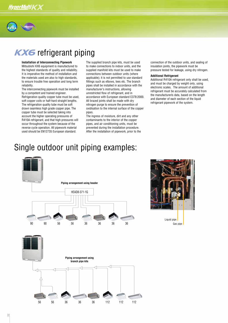
30 31
R410A
Installation of Interconnecting PipeworkMitsubishi KX6 equipment is manufactured to the highest standards of quality and reliability. It is imperative the method of installation and the materials used are also to high standards, to ensure trouble free operation and long term reliability.The interconnecting pipework must be installed by a competent and trained engineer. Refrigeration quality copper tube must be used, soft copper coils or half-hard straight lengths. The refrigeration quality tube must be soft drawn seamless high grade copper pipe. The copper tube must be selected taking into account the higher operating pressures of R410A refrigerant, and that high pressures will occur throughout the system because of the reverse cycle operation. All pipework material used should be EN12735 European standard.
The supplied branch pipe kits, must be used to make connections to indoor units, and the supplied manifold kits must be used to make connections between outdoor units (where applicable); it is not permitted to use standard fittings such as elbows, tees etc. The branch pipes shall be installed in accordance with the manufacturer’s instructions, allowing unrestricted flow of refrigerant, and in accordance with European standard E378:2000. All brazed joints shall be made with dry nitrogen purge to ensure the prevention of oxidisation to the internal surface of the copper pipes. The ingress of moisture, dirt and any other contaminants to the interior of the copper pipes, and air conditioning units, must be prevented during the installation procedure. After the installation of pipework, prior to the
connection of the outdoor units, and sealing of insulation joints, the pipework must be pressure tested for leakage, using dry nitrogen.
Additional Refrigerant Additional R410A refrigerant only shall be used, and must be charged by weight only, using electronic scales. The amount of additional refrigerant must be accurately calculated from the manufacturerís data, based on the length and diameter of each section of the liquid refrigerant pipework of the system.
Single outdoor unit piping examples:
HEAD8-371-1G
90 90 56 56 36 36 36 36
56 56 36 36 36 112 112 112
Piping arrangement using header
Piping arrangement usingbranch pipe kits
Combination outdoor unit piping examples:
Branch pipes Header pipe
Combination outdoor unit manifold
Outdoor unit (HP) 8 10 12 14 16 18 20 22 24 26 28 30 32 34 36 38 40 42 44 46 48
Liquid pipe ø9.52 ø12.7 ø15.88 ø19.05
Gas pipe ø19.05 ø22.22 ø28.58 ø34.92
Liquid pipe ø12.7 ø15.88 ø19.05 ø22.22
Gas pipe ø22.22 ø28.58 ø34.92
DIS-22-1G/DIS-180-1G
DIS-371-1G/DIS-540-2G
HEAD6-180-1G
DOS-2A-1G
Oil equalisationpipe
Outdoor unit branchpipe set (DOS-2A-1G)
112 112 90 90 90 140 140 140
HEAD8-540-2G
112 112 90 90 140 140
Oil equalisationpipe
Outdoor unit branchpipe set (DOS-2A-1G)
90 140
Indoor unit's first branching piping
Total capacity of indoor units~179180~370371~539540~
Branch piping set
DIS-22-1GDIS-180-1GDIS-371-1GDIS-540-2G
Header setModelHEAD4-22-1GHEAD6-180-1GHEAD8-371-1GHEAD8-540-2G
BranchesMax 4 branchesMax 6 branchesMax 8 branchesMax 8 branches
Piping arrangement using header
Piping arrangement usingbranch pipe kits
Floor
Floor
FloorGood
GoodNo
No Floor
Vertically
Horizontally
Outdoor unit's branching piping
Outdoor unit2 units (for 735~1360)
Branch piping setDOS-2A-1G
mm inchmm inch
ø9.52 3/8"
ø12.7 1/2"
ø15.88 5/8"
ø19.05 3/4"
ø22.22 7/8"
ø25.4 1"
ø28.58 11/8"
ø31.8 11/4"
ø34.92 13/8"
ø38.1 11/2"
ø44.5 13/4"
ø50.8 2"
Furthest indoor unit=<90m
Furthest indoor unit=>90m
Gas pipe
Liquid pipe
Pipe sizes applicable to European installations. refrigerant piping refrigerant piping
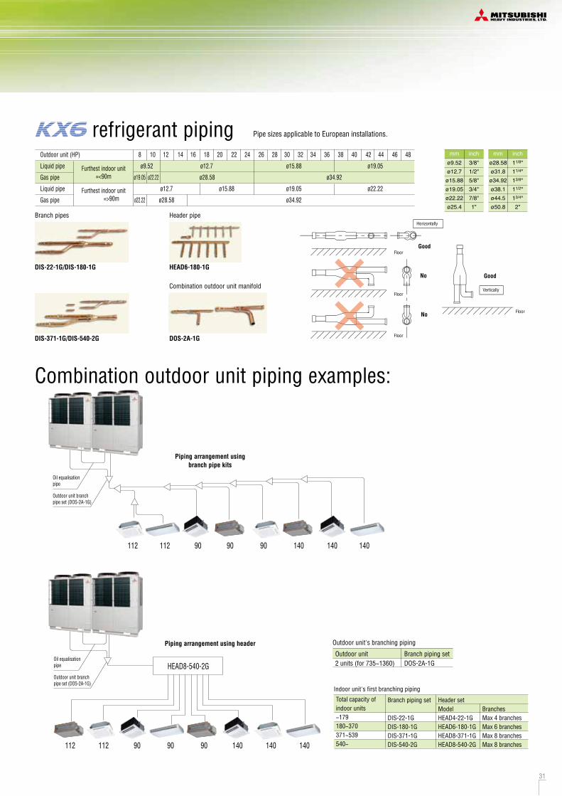

32 33
R410A
KX6 new design includes greatly simplified wiring requirements utilising a ‘polarity-free’ two wire control loop connecting the indoor units.
Power wiringCables can be laid through the front, right, left or bottom of the outdoor unit casing.Separate power supplies should be used for the outdoor unit (3/phase) and the indoor units (1/phase). Only control wiring is connected from outdoor to indoor unit.
Length (m) Wire size100 to 200 0.5mm2 x 2 core
To 300 0.75mm2 x 2 coreTo 400 1.25mm2 x 2 coreTo 600 2.0mm2 x 2 core
(1) When one outdoor unit is used
(3) The signal lines can also be connected using the method shown below.
(2) When plural outdoor units are used
A1 B1
A B A B A B
Outdoor signal lineterminal block
Indoor signal lineterminal block
Indoor unit Indoor unit Indoor unit Indoor unit
Outdoor unit Outdoor unit Outdoor unit Outdoor unit
Loop wiring prohibited
Wires can be connectedacross different refrigerant systems when wired within1 Superlink system
A B
Indoor unit
A B
Indoor unit
A B
Indoor unit
A B
Indoor unit
A B
Outdoor unit
Remote control
(a) The maximum number of indoor units that can be connected in a system is 128 and it is possible to configure outdoor units and/or indoor units as an outdoor or indoor unit group connected with each other with two wires.
(b)
Remote control wiring specifications
Indoor and outdoor signal line do not have a polarity. Any of the connections in the following illustration can be made.
The signal lines cannot form a loop, so the wirings shown as in the diagram are prohibited.
The control wiring is 5 Volt DC, non-polarised, two wire connection notated as ‘A1’ and ‘B1’. This ‘AB’ wiring connects outdoor unit to indoor unit and indoor unit to indoor unit.
This wiring must be a 2-core shielded cable size 0.75mm2 or 1.25mm2.
We recommend the both ends of the shield of the cable are connected to ground (earth) at all the indoor units and outdoor units.
When plural outdoor units are used,.Connect the signal cable between indoor and outdoor units and the signal cable between outdoor units belonging to the same refrigerant line to A1 and B1.
.Connect the signal line between outdoor units on different refrigerant lines to A2 and B2.
For current specification of 2-core (AB) wiring, please consult your MHI dealer.
For interconnecting wiring between the remote control and indoor units (XY wiring) use 2-core cable size 0.3mm2. The maximum length of 2-core cable is 600 metres. Where the 2-core wiring exceeds 100m, use the wire size detailed on the table opposite.
The signal wires can also be connected using the method shown below.
A1
B1
A
B
A1
B1
A
B
Indoor unit
Indoor unit
Indoor unit
Indoor unit
AB
AB
A1·B1 A2·B2
AB
AB
Outdoor unit
A1·B1 A2·B2
Outdoor unit
A1·B1 A2·B2
Outdoor unit
A1·B1 A2·B2
Outdoor unit
Signal line
Refrigerant pipe
Network connector
Outdoor unit
Indoor unit
Indoor unit
Outdoor unit
Indoor unit
Indoor unit
Outdoor unit
Indoor unit
Indoor unit
Important
Outdoor unit power supply: 3 phase 4 wiring 380-415V
Power cable (Main Power cable)[4 cores]Signal wire (Super Link wire)[2 cores]Power cable (Indoor unit power cable)[2 cores]Remote control cord[2 cores]
Indoor unit power supply: Single phase 220-240V
Outdoor unit
Indoor unit
Remote control unit
Distributed, separate power supply system
Groundingwire
A
C
D
R
Earth leakage breaker(Impulse withstanding type)
Earth leakage breaker
Circuit breakerfor cabling
Circuit breakerfor cabling
A
BB
R R R RR
CAUTION
ABC
D
If the earth leakage breaker is exclusively for ground fault protection, then you will need to install a circuit breaker for wiring work.
1.
2.
3.
4.
5.
~1000m1000~1500m
YESYES
YESNO
0.75mm2 1.25mm2
KX6 outdoor unit mechanical compartment
Electrical component box
Outdoor unit power supply terminal block
electrical wiring – power supply electrical wiring – control wiring
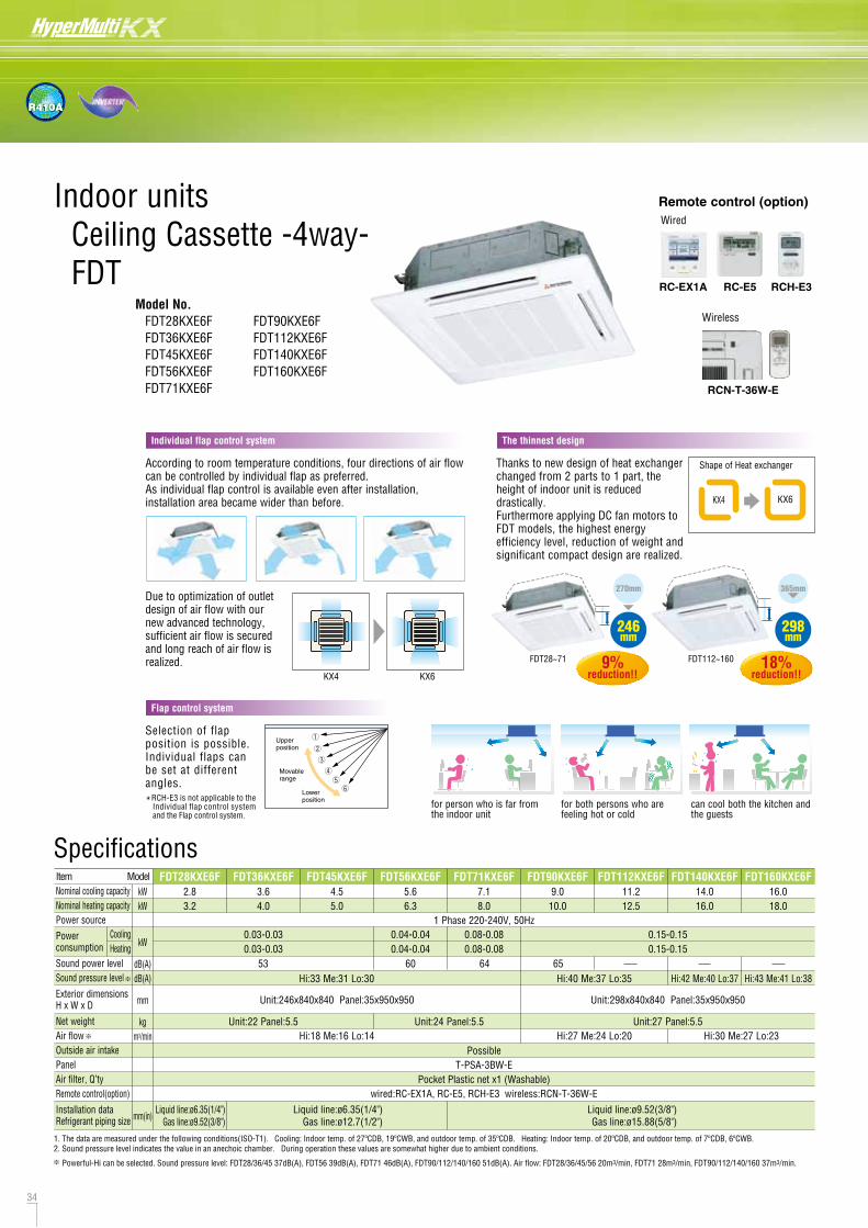
34 35
R410A
According to room temperature conditions, four directions of air flow can be controlled by individual flap as preferred. As individual flap control is available even after installation, installation area became wider than before.
Due to optimization of outlet design of air flow with our new advanced technology, sufficient air flow is secured and long reach of air flow is realized.
KX4 KX6
Thanks to new design of heat exchanger changed from 2 parts to 1 part, the height of indoor unit is reduced drastically. Furthermore applying DC fan motors to FDT models, the highest energy efficiency level, reduction of weight and significant compact design are realized.
KX4 KX6
Shape of Heat exchanger
270mm
246mm
FDT28~71 9%reduction!!
365mm
298mm
FDT112~160 18%reduction!!
Indoor units Ceiling Cassette -4way- FDT
Model No. FDT28KXE6F FDT36KXE6F FDT45KXE6F FDT56KXE6F FDT71KXE6F
FDT90KXE6F FDT112KXE6F FDT140KXE6F FDT160KXE6F
Individual flap control system The thinnest design
DimensionsAll measurements in mm.
FDT28KXE6F, 36KXE6F, 45KXE6F, 56KXE6F, 71KXE6F
FDT90KXE6F, 112KXE6F, 140KXE6F, 160KXE6F
Wireless
RCN-T-36W-E
RC-E5
Wired
RCH-E3RC-EX1A
Selection of flap position is possible. Individual flaps can be set at different angles.
Upperposition
Movablerange
Lowerposition
Flap control system
for person who is far from the indoor unit
for both persons who are feeling hot or cold
can cool both the kitchen and the guests
*RCH-E3 is not applicable to the Individual flap control system and the Flap control system.
Remote control (option)
Hi:43 Me:41 Lo:38Hi:42 Me:40 Lo:37Hi:40 Me:37 Lo:35Hi:33 Me:31 Lo:30
Hi:18 Me:16 Lo:14 Hi:30 Me:27 Lo:23Hi:27 Me:24 Lo:20Unit:22 Panel:5.5 Unit:24 Panel:5.5 Unit:27 Panel:5.5
FDT28KXE6F2.83.2
FDT36KXE6F3.64.0
FDT45KXE6F4.55.0
FDT56KXE6F5.66.3
FDT71KXE6F7.18.0
FDT90KXE6F9.010.0
FDT112KXE6F11.212.5
FDT140KXE6F14.016.0
FDT160KXE6F16.018.0
1 Phase 220-240V, 50Hz
kWkW
kW
dB(A)dB(A)
mm
kgm3/min
mm(in)
ItemNominal cooling capacityNominal heating capacityPower source
Power consumption
Sound power levelSound pressure level
Exterior dimensionsH x W x D
Net weightAir flowOutside air intakePanelAir filter, Q’tyRemote control(option)
Installation dataRefrigerant piping size
Unit:246x840x840 Panel:35x950x950 Unit:298x840x840 Panel:35x950x950
PossibleT-PSA-3BW-E
Pocket Plastic net x1 (Washable)wired:RC-EX1A, RC-E5, RCH-E3 wireless:RCN-T-36W-E
Liquid line:ø6.35(1/4")Gas line:ø12.7(1/2")
Liquid line:ø9.52(3/8")Gas line:ø15.88(5/8")
Liquid line:ø6.35(1/4")Gas line:ø9.52(3/8")
Model
CoolingHeating
0.03-0.030.03-0.03
0.08-0.080.08-0.08
0.04-0.040.04-0.04
0.15-0.150.15-0.15
Specifications
1. The data are measured under the following conditions(ISO-T1). Cooling: Indoor temp. of 27ºCDB, 19ºCWB, and outdoor temp. of 35ºCDB. Heating: Indoor temp. of 20ºCDB, and outdoor temp. of 7ºCDB, 6ºCWB.2. Sound pressure level indicates the value in an anechoic chamber. During operation these values are somewhat higher due to ambient conditions.
Powerful-Hi can be selected. Sound pressure level: FDT28/36/45 37dB(A), FDT56 39dB(A), FDT71 46dB(A), FDT90/112/140/160 51dB(A). Air flow: FDT28/36/45/56 20m3/min, FDT71 28m3/min, FDT90/112/140/160 37m3/min.
53 60 64 65
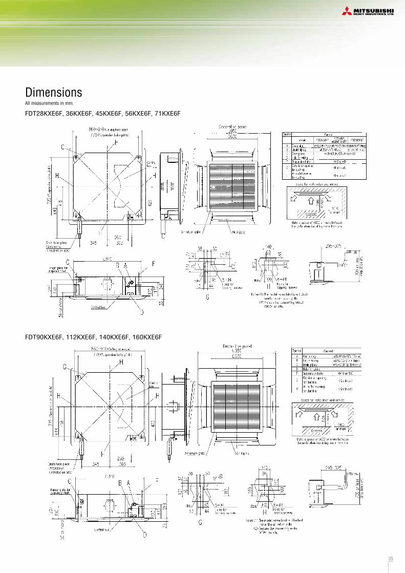

36 37
R410A
FDTC15KXE6F,22KXE6F,28KXE6F
Connectable with VP20(Standard)or VP25(used with attached socket)
DimensionsAll measurements in mm.
Ceiling Cassette -4way Compact (600x600mm)- FDTC
Model No. FDTC15KXE6F※
FDTC22KXE6F FDTC28KXE6F FDTC36KXE6F FDTC45KXE6F FDTC56KXE6F
Hi:35 Me:33 Lo:30Hi:35 Me:33 Lo:32
Hi:32 Me:28 Lo:25Hi:32 Me:28 Lo:25
Hi:9.5 Me:8.5 Lo:7Hi:9.5 Me:8.5 Lo:8
Hi:7 Me:5.5 Lo:4.5Hi:7 Me:5.5 Lo:4.5
Hi:10 Me:9 Lo:7Hi:10 Me:9 Lo:8
Unit:14 Panel:3.5 Unit:15 Panel:3.5
FDTC22KXE6F2.22.5
FDTC15KXE6F1.51.7
FDTC28KXE6F2.83.2
FDTC36KXE6F3.64.0
Hi:38 Me:36 Lo:31Hi:38 Me:36 Lo:34
FDTC45KXE6F4.55.0
Hi:40 Me:37 Lo:31Hi:40 Me:37 Lo:34
Hi:11 Me:9 Lo:7Hi:11 Me:9 Lo:8
FDTC56KXE6F5.66.3
Hi:45 Me:39 Lo:31Hi:45 Me:39 Lo:34
Hi:13 Me:10 Lo:7Hi:13 Me:10 Lo:8
1 Phase 220-240V, 50Hz
kWkW
kW
dB(A)
dB(A)
mm
kg
m3/min
mm(in)
ItemNominal cooling capacityNominal heating capacityPower source
Power consumption
Sound power level
Sound pressure level
Exterior dimensionsH x W x D
Net weight
Air flow
Outside air intakePanelAir filter, Q’tyRemote control(option)
Installation dataRefrigerant piping size
Unit:248x570x570 Panel:35x700x700
Possible with OA Spacer TC-OAS-E & Joint Duct TC-OAD-ETC-PSA-25W-E
Pocket Plastic net x1 (Washable)wired:RC-EX1A, RC-E5, RCH-E3 wireless:RCN-TC-24W-ER
Liquid line:ø6.35(1/4")Gas line:ø9.52(3/8")
Liquid line:ø6.35(1/4")Gas line:ø12.7(1/2")
Model
CoolingHeating
CoolingHeating
CoolingHeating
0.03-0.030.03-0.03
0.02-0.020.02-0.02
0.05-0.050.05-0.05
Specifications
1. The data are measured under the following conditions(ISO-T1). Cooling: Indoor temp. of 27ºCDB, 19ºCWB, and outdoor temp. of 35ºCDB. Heating: Indoor temp. of 20ºCDB, and outdoor temp. of 7ºCDB, 6ºCWB.2. Sound pressure level indicates the value in an anechoic chamber. During operation these values are somewhat higher due to ambient conditions.
Fits into standard 600 x 600 ceiling
Condensate drain pump included as standardUltra slim design at just 248mm above the ceiling
Wireless
RCN-TC-24W-ERRC-E5
Wired
RCH-E3
Powerful-Hi can be selected. Sound pressure level: FDTC15 34dB(A), FDTC22/28 44dB(A), FDTC36 46dB(A), FDTC45 48dB(A), FDTC56 49dB(A). Air flow: FDTC15 8m3/min, FDTC22/28 12m3/min, FDTC36 13m3/min, FDTC45 15m3/min, FDTC56 16m3/min.
Quiet operation (Sound pressure level in the Lo mode.)
KX4(Cooling/Heating)
KX6(Cooling)
KX6(Heating)
32dB
34dB34dB2dB
Down
40
35
30
25
20
(dB)
KX6(Cooling)
KX6(Heating)
40
35
30
25
20
(dB)
KX4(Cooling/Heating)
KX6(Cooling)
KX6(Heating)
39dB
34dB
31dB
34dB
3~8dBDown
40
35
30
25
20
(dB)
OA Spacer TC-OAS-E (option)Joint Duct TC-OAD-E (option)
Utilizing OA spacer which comes as optional equipment, outside air can be taken inside.
Taking OA (Outside Air) into inside
According to room temperature conditions, four directions of air flow can be controlled by individual flap as preferred. As individual flap control is available even after installation, installation area became wider than before.
Individual flap control system
Selection of flap position is possible. Individual flaps can be set at different angles.
Upperposition
Movablerange
Lowerposition
Flap control system
*RCH-E3 is not applicable to the Individual flap control system and the Flap control system.
OA OAPanel
300mm
Ceiling surface
Indoor Unit FDTC
OA Spacer
Joint Duct
Using 1 joint duct: OA up to 1.3m3/min.
Using 2 joint ducts: OA from 1.3 to 2.6m3/min.
RC-EX1A
Remote control (option)
※(1) Can not be connected to some KX outdoor units. Please consult your dealer for further details. (2) Regarding pipe length (150m or more is required) and temperature condition (lowest 10ºC) in the cooling operation etc. , please refer to our technical manual.
NEW
FDTC22/28 FDTC36/45/56FDTC15
The industry's lowest sound pressure level:25dB(A) of FDTC15KXE6F wasachieved by Optimizing fan speed and distributor size.
36dB
34dB
25dB
25dB
32dB
30dB
32dB
NEW
56 58 60
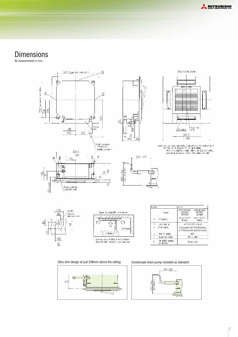
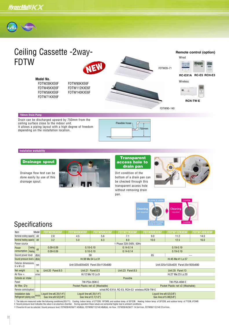
38 39
R410A
Ceiling Cassette -2way-FDTW FDTW28KXE6F, 45KXE6F, 56KXE6F, 71KXE6F
FDTW90KXE6F, 112KXE6F, 140KXE6F
DimensionsAll measurements in mm.
Model No. FDTW28KXE6F FDTW45KXE6F FDTW56KXE6F FDTW71KXE6F
FDTW90KXE6F FDTW112KXE6F FDTW140KXE6F
RC-E5
Wired
RCH-E3
Wireless
RCN-TW-E
FDTW90~140
FDTW28~71
RC-EX1A
Remote control (option)
Drainage spoutTransparent
access hole to drain pan
Dirt condition of the bottom of a drain pan can be checked through this transparent access hole without removing drain pan.
Drainage flow test can be done easily by use of this drainage spout.
Installation workability
NEW
Drain can be discharged upward by 750mm from the ceiling surface close to the indoor unit.It allows a piping layout with a high degree of freedom depending on the installation location.
Flexible hose
750mm
750mm Drain Pump
Cleaningnot required
A cross is visible
A circumscribescircle is visible
Cleaningrequired
invisible
invisible
Hi:38 Me:34 Lo:31
Hi:12 Me:10 Lo:9Unit:23 Panel:8.5 Unit:35 Panel:13
FDTW28KXE6F2.83.2
FDTW45KXE6F4.55.0
FDTW56KXE6F5.66.3
FDTW71KXE6F7.18.0
FDTW90KXE6F9.010.0
FDTW112KXE6F11.212.5
FDTW140KXE6F14.016.0
Hi:45 Me:41 Lo:37
Hi:27 Me:23 Lo:20
1 Phase 220-240V, 50Hz
kWkW
kW
dB(A)dB(A)
mm
kgm3/min
mm(in)
ItemNominal cooling capacityNominal heating capacityPower source
Power consumption
Sound power levelSound pressure level
Exterior dimensionsH x W x D
Net weightAir flowOutside air intakePanelAir filter, Q’tyRemote control(option)
Installation dataRefrigerant piping size
Unit:325x820x620 Panel:20x1120x680 Unit:325x1535x620 Panel:20x1835x680
Possible
wired:RC-EX1A, RC-E5, RCH-E3 wireless:RCN-TW-ELiquid line:ø6.35(1/4")
Gas line:ø12.7(1/2")Liquid line:ø9.52(3/8")Gas line:ø15.88(5/8")
Liquid line:ø6.35(1/4")Gas line:ø9.52(3/8")
Model
TW-PSA-26W-E TW-PSA-46W-EPocket Plastic net x2 (Washable) Pocket Plastic net x3 (Washable)
Unit:21 Panel:8.5Unit:20 Panel:8.5
CoolingHeating
0.09-0.090.09-0.09
0.10-0.100.10-0.10
0.14-0.140.14-0.14
0.19-0.190.19-0.19
Specifications
1. The data are measured under the following conditions(ISO-T1). Cooling: Indoor temp. of 27ºCDB, 19ºCWB, and outdoor temp. of 35ºCDB. Heating: Indoor temp. of 20ºCDB, and outdoor temp. of 7ºCDB, 6ºCWB.2. Sound pressure level indicates the value in an anechoic chamber. During operation these values are somewhat higher due to ambient conditions. Powerful-Hi can be selected. Sound pressure level: FDTW28/45/56/71 42dB(A), FDTW90/112/140 48dB(A). Air flow: FDTW28/45/56/71 14.5m3/min, FDTW90/112/140 31m3/min.
58 65
VP25 (I.D. 25, O.D. 32) Note(2)
650
102
102
VP25 (I.D. 25, O.D. 32) Note(2)
650
102
102
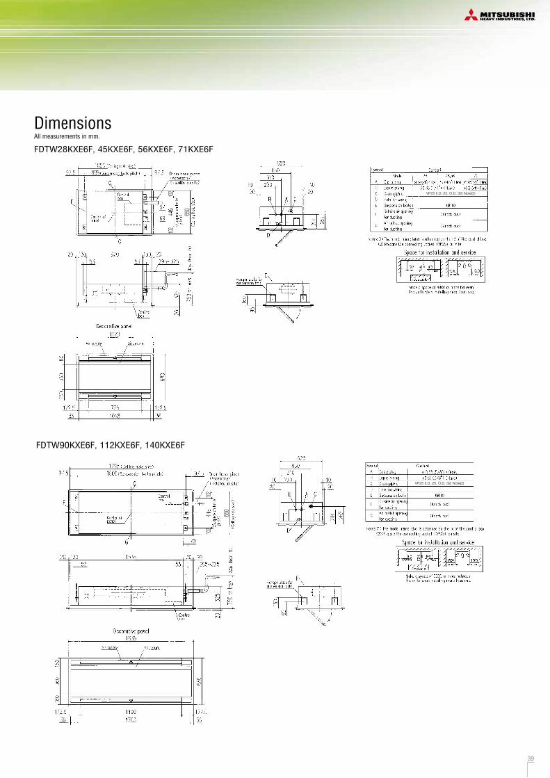
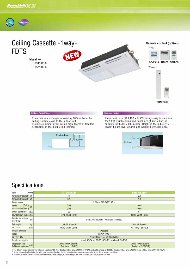
40 41
R410A
Ceiling Cassette -1way-FDTS
DimensionsAll measurements in mm.
Model No. FDTS45KXE6F FDTS71KXE6F
RC-E5
Wired
RCH-E3
Wireless
RCN-TS-E
RC-EX1A
Remote control (option)
600mm Drain Pump Compact design
Drain can be discharged upward by 600mm from the ceiling surface close to the indoor unit.It allows a piping layout with a high degree of freedom depending on the installation location.
Indoor unit size (W:1,150 x D:565) brings easy installation for 1,200 x 600 ceiling and Panel size (1,250 x 650) is suitable for 1,200 x 600 ceiling. Height is the industry's lowest height level 220mm and weight is 27/28kg only.
Flexible hose
600mm
NEW
220mm
FDTS45KXE6F4.55.0
0.040.0460
Hi:40 Me:38 Lo:35
Unit:27 Panel:5Hi:12 Me:11 Lo:9.5
Unit:28 Panel:5Hi:15 Me:12 Lo:9.5
FDTS71KXE6F7.18.0
0.090.0961
Hi:46 Me:41 Lo:36
1 Phase 220-240V, 50Hz
kWkW
kW
dB(A)dB(A)
mm
kgm3/min
mm(in)
ItemNominal cooling capacityNominal heating capacityPower source
Power consumption
Sound power levelSound pressure level
Exterior dimensionsH x W x D
Net weightAir flowOutside air intakePanelAir filter, Q’tyRemote control(option)
Installation dataRefrigerant piping size
Model
CoolingHeating
Specifications
1. The data are measured under the following conditions(ISO-T1). Cooling: Indoor temp. of 27ºCDB, 19ºCWB, and outdoor temp. of 35ºCDB. Heating: Indoor temp. of 20ºCDB, and outdoor temp. of 7ºCDB, 6ºCWB.2. Sound pressure level indicates the value in an anechoic chamber. During operation these values are somewhat higher due to ambient conditions.
Unit:220x1150x565 Panel:35x1250x650
PossibleTS-PSA-3AW-E
Pocket Plastic net x2 (Washable)wired:RC-EX1A, RC-E5, RCH-E3 wireless:RCN-TS-E
Liquid line:ø6.35(1/4")Gas line:ø12.7(1/2")
Liquid line:ø9.52(3/8")Gas line:ø15.88(5/8")
Powerful-Hi can be selected. Sound pressure level: FDTS45 42dB(A), FDTS71 49dB(A). Air flow: FDTS45 13m3/min, FDTS71 17m3/min.
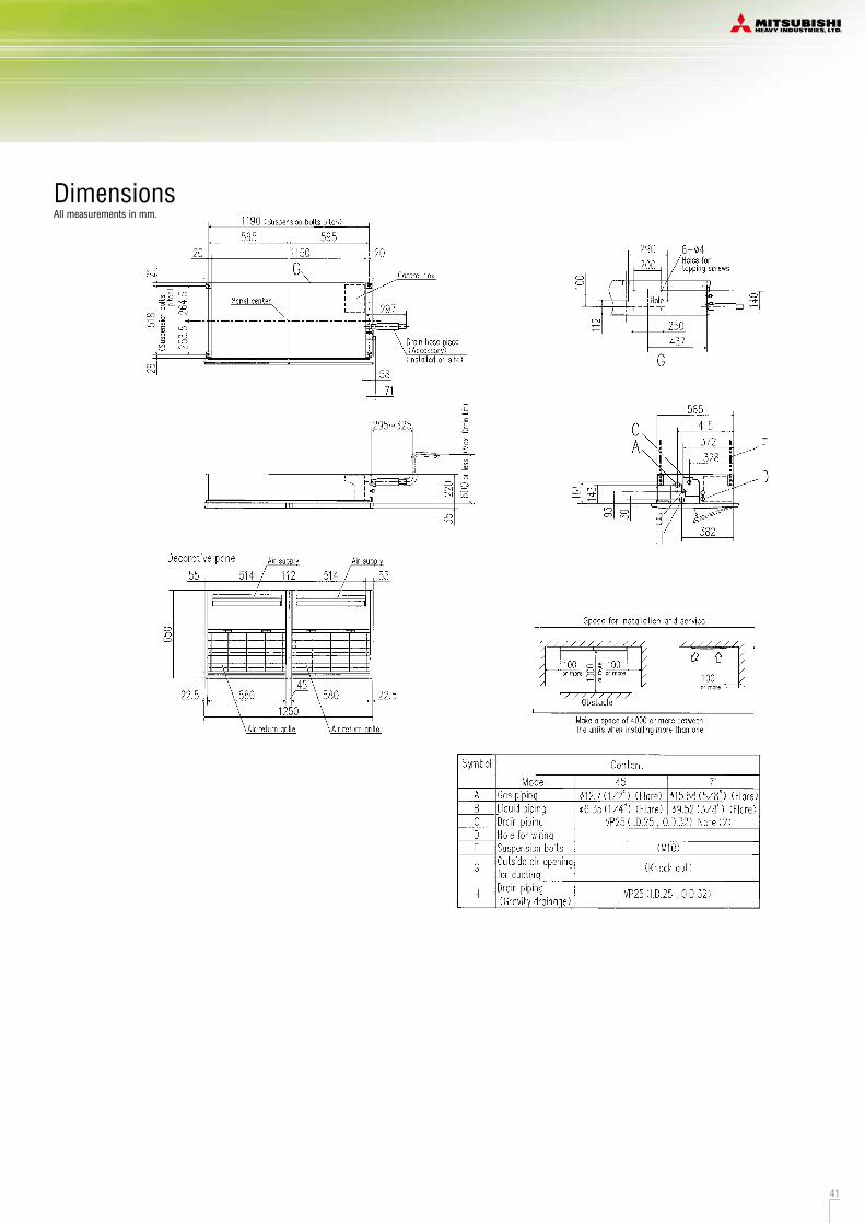
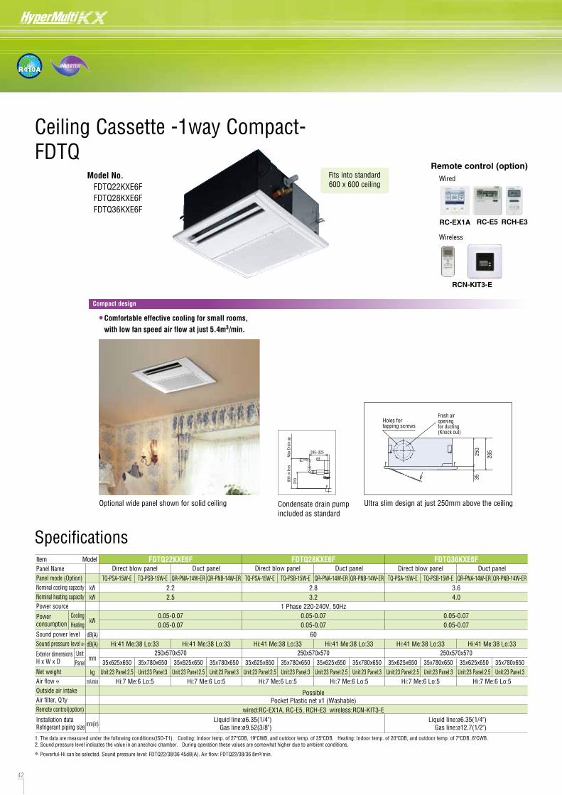
42 43
R410A
Ceiling Cassette -1way Compact- FDTQ
Model No. FDTQ22KXE6F FDTQ28KXE6F FDTQ36KXE6F
DimensionsAll measurements in mm.
Duct panel (QR-PNA-14W-ER) Duct panel (QR-PNB-14W-ER)
Direct blow panel (TQ-PSA-15W-E) Direct blow panel (TQ-PSB-15W-E)
Condensate drain pumpincluded as standard
or le
ssM
ax.D
rain
up
295~325
63
600
210
Optional wide panel shown for solid ceiling Ultra slim design at just 250mm above the ceiling
Fresh airopeningfor ducting(Knock out)
3525
0
285
Holes fortapping screws
Fits into standard 600 x 600 ceiling
*
* In case of Direct blow panel
• Comfortable effective cooling for small rooms, with low fan speed air flow at just 5.4m3/min.
Dimension Tablemodel
TQ-PSA-15W-E
TQ-PSB-15W-E
a
625
b
514
c
650
d
580
780 514 650 580
Unit:mm Dimension Tablemodel
QR-PNA-14W-ER
QR-PNB-14W-ER
a
625
b
650
c
580
780 650 580
Unit:mm
Specifications
RC-E5
Wired
RCH-E3
Wireless
RCN-KIT3-E
RC-EX1A
Remote control (option)
Compact design
Direct blow panel Duct panel Direct blow panel Duct panel Direct blow panel Duct panel
Hi:41 Me:38 Lo:33
Hi:7 Me:6 Lo:5
2.22.5
2.83.2
3.64.0
1 Phase 220-240V, 50Hz
kWkW
kW
dB(A)dB(A)
mm
kgm3/min
mm(in)
ItemPanel NamePanel mode (Option)Nominal cooling capacityNominal heating capacityPower source
Power consumption
Sound power levelSound pressure level
Exterior dimensionsH x W x D
Net weightAir flowOutside air intakeAir filter, Q’tyRemote control(option)
Installation dataRefrigerant piping size
35x625x650 35x780x650
PossiblePocket Plastic net x1 (Washable)
wired:RC-EX1A, RC-E5, RCH-E3 wireless:RCN-KIT3-ELiquid line:ø6.35(1/4")
Gas line:ø12.7(1/2")Liquid line:ø6.35(1/4")
Gas line:ø9.52(3/8")
Model FDTQ22KXE6F FDTQ28KXE6F FDTQ36KXE6F
TQ-PSA-15W-E TQ-PSB-15W-E QR-PNA-14W-ER QR-PNB-14W-ER TQ-PSA-15W-E TQ-PSB-15W-E QR-PNA-14W-ER QR-PNB-14W-ER TQ-PSA-15W-E TQ-PSB-15W-E QR-PNA-14W-ER QR-PNB-14W-ER
Unit:23 Panel:2.5 Unit:23 Panel:3
Hi:41 Me:38 Lo:33
Hi:7 Me:6 Lo:5
35x625x650 35x780x650Unit:23 Panel:2.5 Unit:23 Panel:3
Hi:41 Me:38 Lo:33
Hi:7 Me:6 Lo:5
35x625x650 35x780x650Unit:23 Panel:2.5 Unit:23 Panel:3
Hi:41 Me:38 Lo:33
Hi:7 Me:6 Lo:5
35x625x650 35x780x650Unit:23 Panel:2.5 Unit:23 Panel:3
Hi:41 Me:38 Lo:33
Hi:7 Me:6 Lo:5
35x625x650 35x780x650Unit:23 Panel:2.5 Unit:23 Panel:3
Hi:41 Me:38 Lo:33
Hi:7 Me:6 Lo:5
35x625x650 35x780x650Unit:23 Panel:2.5 Unit:23 Panel:3
UnitPanel
CoolingHeating
0.05-0.070.05-0.07
0.05-0.070.05-0.07
60
0.05-0.070.05-0.07
250x570x570 250x570x570 250x570x570
1. The data are measured under the following conditions(ISO-T1). Cooling: Indoor temp. of 27ºCDB, 19ºCWB, and outdoor temp. of 35ºCDB. Heating: Indoor temp. of 20ºCDB, and outdoor temp. of 7ºCDB, 6ºCWB.2. Sound pressure level indicates the value in an anechoic chamber. During operation these values are somewhat higher due to ambient conditions.
Powerful-Hi can be selected. Sound pressure level: FDTQ22/38/36 45dB(A). Air flow: FDTQ22/38/36 8m3/min.
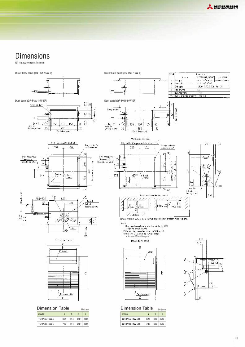
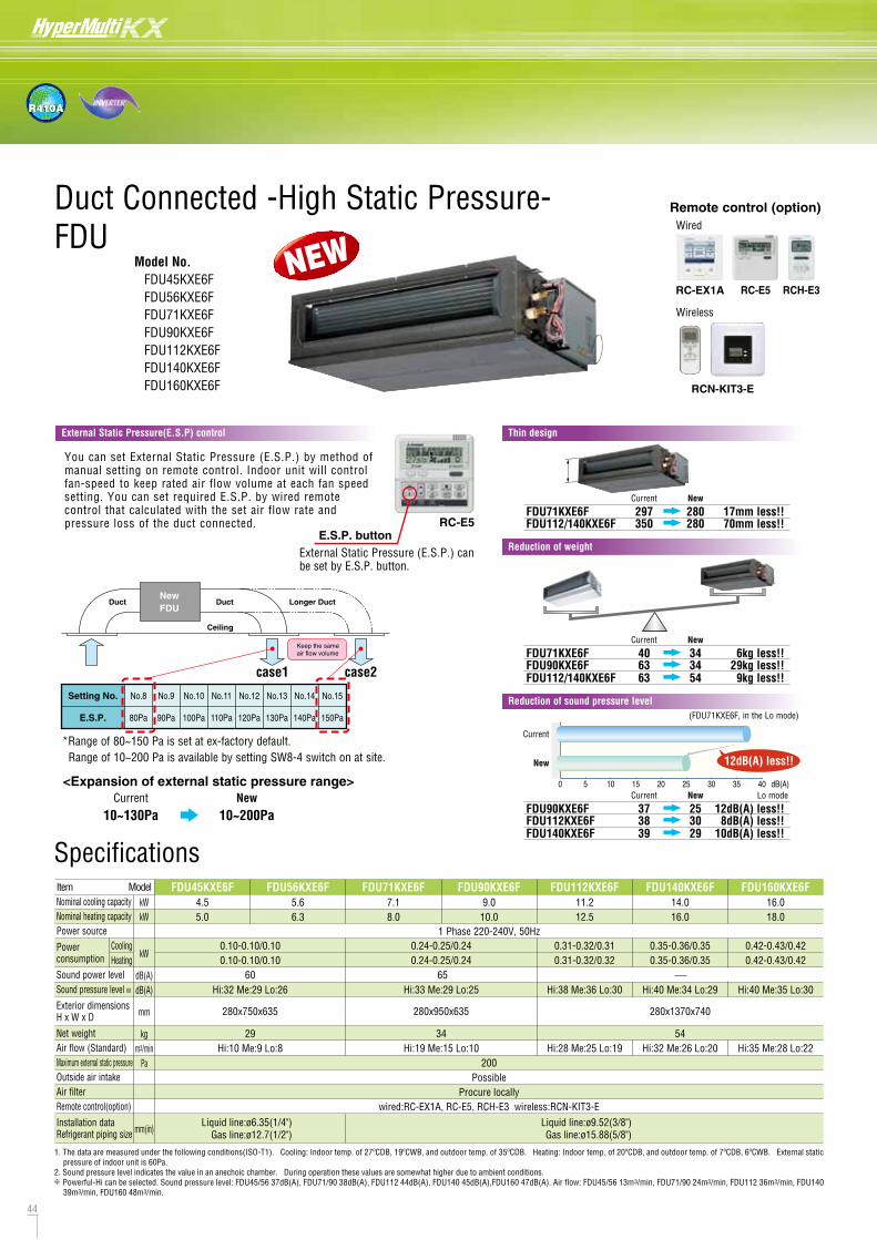
44 45
R410A
Duct Connected -High Static Pressure-FDU
Model No. FDU45KXE6F FDU56KXE6F FDU71KXE6F FDU90KXE6F FDU112KXE6F FDU140KXE6F FDU160KXE6F
DimensionsAll measurements in mm.
FDU45KXE6F, 56KXE6F
FDU71KXE6F, 90KXE6F
FDU112KXE6F, 140KXE6F, 160KXE6FSpecifications
Remote control (option)
Keep the same air flow volume
Longer DuctDuct
Ceiling
NewFDU
Duct
External Static Pressure (E.S.P.) can be set by E.S.P. button.
*Range of 80~150 Pa is set at ex-factory default. Range of 10~200 Pa is available by setting SW8-4 switch on at site.
E.S.P. buttonRC-E5
Setting No.
E.S.P.
No.8
80Pa
No.9
90Pa
No.10
100Pa
No.11
110Pa
No.12
120Pa
No.13
130Pa
No.14
140Pa
No.15
150Pa
case1 case2
External Static Pressure(E.S.P) control Thin design
Reduction of weight
Reduction of sound pressure level
You can set External Static Pressure (E.S.P.) by method of manual setting on remote control. Indoor unit will control fan-speed to keep rated air flow volume at each fan speed setting. You can set required E.S.P. by wired remote control that calculated with the set air flow rate and pressure loss of the duct connected.
<Expansion of external static pressure range>Current
10~130Pa
FDU71KXE6F 297 280 17mm less!!
New
NewCurrent
10~200Pa
FDU112/140KXE6F 350 280 70mm less!!
FDU71KXE6F 40 34 6kg less!!NewCurrent
FDU90KXE6F 63 34 29kg less!!FDU112/140KXE6F 63 54 9kg less!!
FDU90KXE6F 37 25 12dB(A) less!!New
New
Lo mode
(FDU71KXE6F, in the Lo mode)
Current
Current
FDU112KXE6F 38 30 8dB(A) less!!FDU140KXE6F 39 29 10dB(A) less!!
RC-E5
Wired
RCH-E3
Wireless
RCN-KIT3-E
0 5 10 15 20 25 30 35 40 dB(A)
12dB(A) less!!
NEWRC-EX1A
Hi:32 Me:29 Lo:26
Hi:10 Me:9 Lo:8 Hi:19 Me:15 Lo:10 Hi:28 Me:25 Lo:19 Hi:32 Me:26 Lo:20 Hi:35 Me:28 Lo:2229 34 54
7.18.0
9.010.0
11.212.5
14.016.0
1 Phase 220-240V, 50Hz
kWkW
kW
dB(A)dB(A)
mm
kgm3/min
Pa
mm(in)
ItemNominal cooling capacityNominal heating capacityPower source
Power consumption
Sound power levelSound pressure level
Exterior dimensionsH x W x D
Net weightAir flow (Standard)Maximum external static pressureOutside air intakeAir filterRemote control(option)
Installation dataRefrigerant piping size
200Possible
Procure locallywired:RC-EX1A, RC-E5, RCH-E3 wireless:RCN-KIT3-E
Liquid line:ø9.52(3/8")Gas line:ø15.88(5/8")
Liquid line:ø6.35(1/4")Gas line:ø12.7(1/2")
Model FDU71KXE6F5.66.3
FDU56KXE6F4.55.0
FDU45KXE6F FDU90KXE6F FDU112KXE6F16.018.0
FDU160KXE6FFDU140KXE6F
280x750x635 280x1370x740
CoolingHeating
0.10-0.10/0.100.10-0.10/0.10
Hi:40 Me:35 Lo:30
0.42-0.43/0.420.42-0.43/0.42
Hi:40 Me:34 Lo:29
0.35-0.36/0.350.35-0.36/0.35
Hi:38 Me:36 Lo:30
0.31-0.32/0.310.31-0.32/0.32
Hi:33 Me:29 Lo:25
280x950x635
0.24-0.25/0.240.24-0.25/0.24
1. The data are measured under the following conditions(ISO-T1). Cooling: Indoor temp. of 27ºCDB, 19ºCWB, and outdoor temp. of 35ºCDB. Heating: Indoor temp. of 20ºCDB, and outdoor temp. of 7ºCDB, 6ºCWB. External static pressure of indoor unit is 60Pa.
2. Sound pressure level indicates the value in an anechoic chamber. During operation these values are somewhat higher due to ambient conditions. Powerful-Hi can be selected. Sound pressure level: FDU45/56 37dB(A), FDU71/90 38dB(A), FDU112 44dB(A), FDU140 45dB(A),FDU160 47dB(A). Air flow: FDU45/56 13m3/min, FDU71/90 24m3/min, FDU112 36m3/min, FDU140
39m3/min, FDU160 48m3/min.
60 65
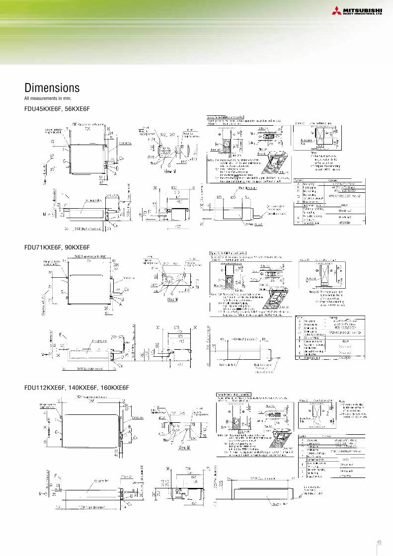
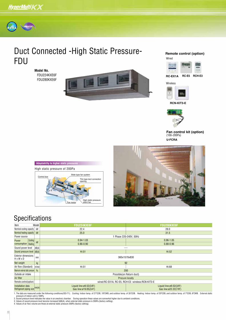
VIEW A
VIEW A
46 47
R410A
Duct Connected -High Static Pressure-FDU
Model No. FDU224KXE6F FDU280KXE6F
DimensionsAll measurements in mm.
U-FCRA
Fan control kit (option)(100~200Pa)
RC-E5
Wired
RCH-E3
Wireless
RCN-KIT3-E
RC-EX1A
Remote control (option)
Control box
Fan motorHigh static pressure silent fan
Slide type fan system
Thin type duct connection opening
High static pressure of 200Pa
Adaptability to higher static pressures
92
22.425.0
28.031.5
1 Phase 220-240V, 50Hz
kWkW
kW
dB(A)dB(A)
mm
kgm3/min
Pa
mm(in)
ItemNominal cooling capacityNominal heating capacityPower source
Power consumption
Sound power levelSound pressure level
Exterior dimensionsH x W x D
Net weightAir flow (Standard)Maximum external static pressureOutside air intakeAir filterRemote control(option)
Installation dataRefrigerant piping size
Possible(on Return duct)Procure locally
wired:RC-EX1A, RC-E5, RCH-E3 wireless:RCN-KIT3-ELiquid line:ø9.52(3/8")Gas line:ø19.05(3/4")
Liquid line:ø9.52(3/8")Gas line:ø22.22(7/8")
Model FDU224KXE6F FDU280KXE6F
Hi:51
Hi:51
360x1570x830
Hi:52
Hi:68200
CoolingHeating
0.94-1.030.86-0.90
0.96-1.050.88-0.96
1. The data are measured under the following conditions(ISO-T1). Cooling: Indoor temp. of 27ºCDB, 19ºCWB, and outdoor temp. of 35ºCDB. Heating: Indoor temp. of 20ºCDB, and outdoor temp. of 7ºCDB, 6ºCWB. External static pressure of indoor unit is 100Pa.
2. Sound pressure level indicates the value in an anechoic chamber. During operation these values are somewhat higher due to ambient conditions.3. Values of sound pressure level become increased 5dB(A), when external static pressure is 200Pa (factory setting).4. Values of air flow volume are those at external static pressure 200Pa (factory setting).
Specifications
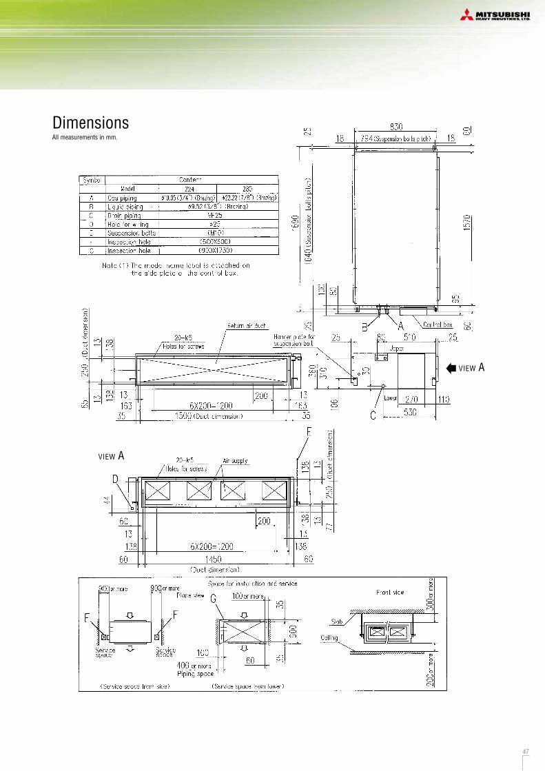
VIEW A
VIEW A
46 47
R410A
Duct Connected -High Static Pressure-FDU
Model No. FDU224KXE6F FDU280KXE6F
DimensionsAll measurements in mm.
U-FCRA
Fan control kit (option)(100~200Pa)
RC-E5
Wired
RCH-E3
Wireless
RCN-KIT3-E
RC-EX1A
Remote control (option)
Control box
Fan motorHigh static pressure silent fan
Slide type fan system
Thin type duct connection opening
High static pressure of 200Pa
Adaptability to higher static pressures
92
22.425.0
28.031.5
1 Phase 220-240V, 50Hz
kWkW
kW
dB(A)dB(A)
mm
kgm3/min
Pa
mm(in)
ItemNominal cooling capacityNominal heating capacityPower source
Power consumption
Sound power levelSound pressure level
Exterior dimensionsH x W x D
Net weightAir flow (Standard)Maximum external static pressureOutside air intakeAir filterRemote control(option)
Installation dataRefrigerant piping size
Possible(on Return duct)Procure locally
wired:RC-EX1A, RC-E5, RCH-E3 wireless:RCN-KIT3-ELiquid line:ø9.52(3/8")Gas line:ø19.05(3/4")
Liquid line:ø9.52(3/8")Gas line:ø22.22(7/8")
Model FDU224KXE6F FDU280KXE6F
Hi:51
Hi:51
360x1570x830
Hi:52
Hi:68200
CoolingHeating
0.94-1.030.86-0.90
0.96-1.050.88-0.96
1. The data are measured under the following conditions(ISO-T1). Cooling: Indoor temp. of 27ºCDB, 19ºCWB, and outdoor temp. of 35ºCDB. Heating: Indoor temp. of 20ºCDB, and outdoor temp. of 7ºCDB, 6ºCWB. External static pressure of indoor unit is 100Pa.
2. Sound pressure level indicates the value in an anechoic chamber. During operation these values are somewhat higher due to ambient conditions.3. Values of sound pressure level become increased 5dB(A), when external static pressure is 200Pa (factory setting).4. Values of air flow volume are those at external static pressure 200Pa (factory setting).
Specifications

48 49
R410A
Duct Connected -Low/Middle Static Pressure-FDUM
Model No. FDUM22KXE6F FDUM28KXE6F FDUM36KXE6F FDUM45KXE6F FDUM56KXE6F
FDUM71KXE6F FDUM90KXE6F FDUM112KXE6F FDUM140KXE6F FDUM160KXE6F
FDUM22KXE6F, 28KXE6F, 36KXE6F, 45KXE6F, 56KXE6F
FDUM71KXE6F, 90KXE6F
FDUM112KXE6F, 140KXE6F, 160KXE6F
Round duct adapter
DimensionsAll measurements in mm.
Hi:32 Me:29 Lo:26 Hi:33 Me:29 Lo:25
5429 34
2.22.5
2.83.2
3.64.0
4.55.0
5.66.3
7.18.0
9.010.0
11.212.5
14.016.0
FDUM22KXE6F FDUM28KXE6F FDUM36KXE6F FDUM45KXE6F FDUM56KXE6F FDUM71KXE6F FDUM90KXE6F FDUM112KXE6F FDUM140KXE6F
Hi:10 Me:9 Lo:8
Hi:38 Me:36 Lo:30 Hi:40 Me:34 Lo:29
Hi:19 Me:15 Lo:10 Hi:28 Me:25 Lo:19 Hi:32 Me:26 Lo:20
1 Phase 220-240V, 50Hz
kWkW
kW
dB(A)dB(A)
mm
kgm3/min
Pa
mm(in)
ItemNominal cooling capacityNominal heating capacityPower source
Power consumption
Sound power levelSound pressure level
Exterior dimensionsH x W x D
Net weightAir flow
Maximum external static pressure
Outside air intakeAir filterRemote control(option)
Installation dataRefrigerant piping size
280 x 750 x 635 280 x 1370 x 740280 x 950 x 635
PossibleFilter kit:UM-FL1EF/UM-FL2EF/UM-FL3EF(option)
wired:RC-EX1A, RC-E5, RCH-E3 wireless:RCN-KIT3-ELiquid line:ø6.35(1/4")
Gas line:ø12.7(1/2")Liquid line:ø9.52(3/8")Gas line:ø15.88(5/8")
Liquid line:ø6.35(1/4")Gas line:ø9.52(3/8")
Model
100
CoolingHeating
0.10-0.100.10-0.10
0.20-0.200.20-0.20
0.33-0.330.33-0.33
16.018.0
FDUM160KXE6F
Hi:40 Me:35 Lo:30
Hi:35 Me:28 Lo:22
0.45-0.450.45-0.45
0.29-0.290.29-0.29
Specifications
1. The data are measured under the following conditions(ISO-T1). Cooling: Indoor temp. of 27ºCDB, 19ºCWB, and outdoor temp. of 35ºCDB. Heating: Indoor temp. of 20ºCDB, and outdoor temp. of 7ºCDB, 6ºCWB. External static pressure of indoor unit is 35Pa(22/28/36/45/56/71/90), 60Pa(112/140/160).
2. Sound pressure level indicates the value in an anechoic chamber. During operation these values are somewhat higher due to ambient conditions.
Filter kit (option)UM-FL1EF : for 22~56UM-FL2EF : for 71, 90UM-FL3EF : for 112, 140, 160
*Filter pressure loss:5pa
Powerful-Hi can be selected. Sound pressure level: FDUM22/28/36/45/56 37dB(A), FDUM71/90 38dB(A), FDUM112 44dB(A), FDUM140 45dB(A), FDUM160 47dB(A). Air flow: FDUM22/28/36/45/56 13m3/min, FDUM71/90 24m3/min, FDUM112 36m3/min, FDUM140 39m3/min, FDUM160 48m3/min.
Remote control (option)
Improvement of the serviceability
H 350
H 280
FDUM112/140KXE6F
H 299
H 280
FDUM22~90KXE6F
70mm less
19mm less
Fan unit (impeller and motor) can be pulled out from the right side or the bottom side of the unit. Maintenance can be available from the right side or the bottom side.
Thin design
The height of all FDUM models is only 280mm.
Maintenance hole
Pipe
Fan unitUnit
Service space
(mm)
60 65
In case of requirements of round duct adapter, please access the followings for details.
Companye-mail
tel
[email protected] +34-902-400-445
NEW
RC-E5
Wired
RCH-E3RC-EX1A
Wireless
RCN-KIT3-E
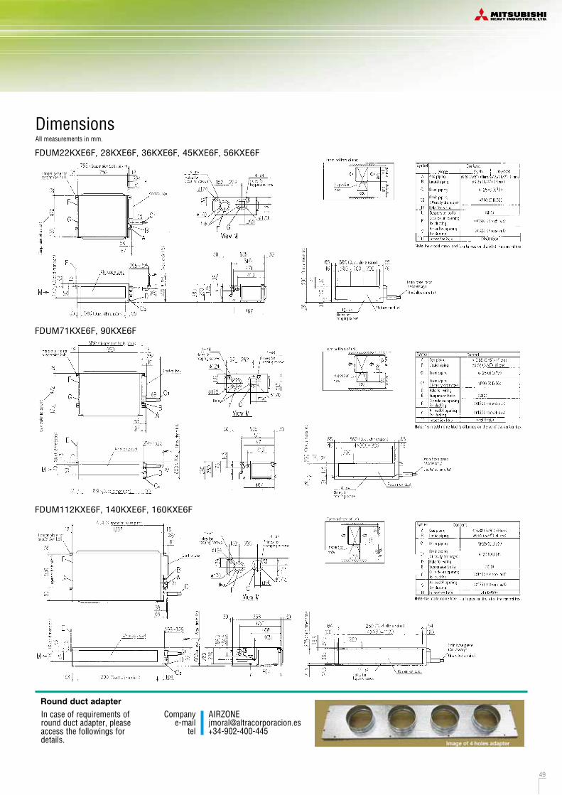
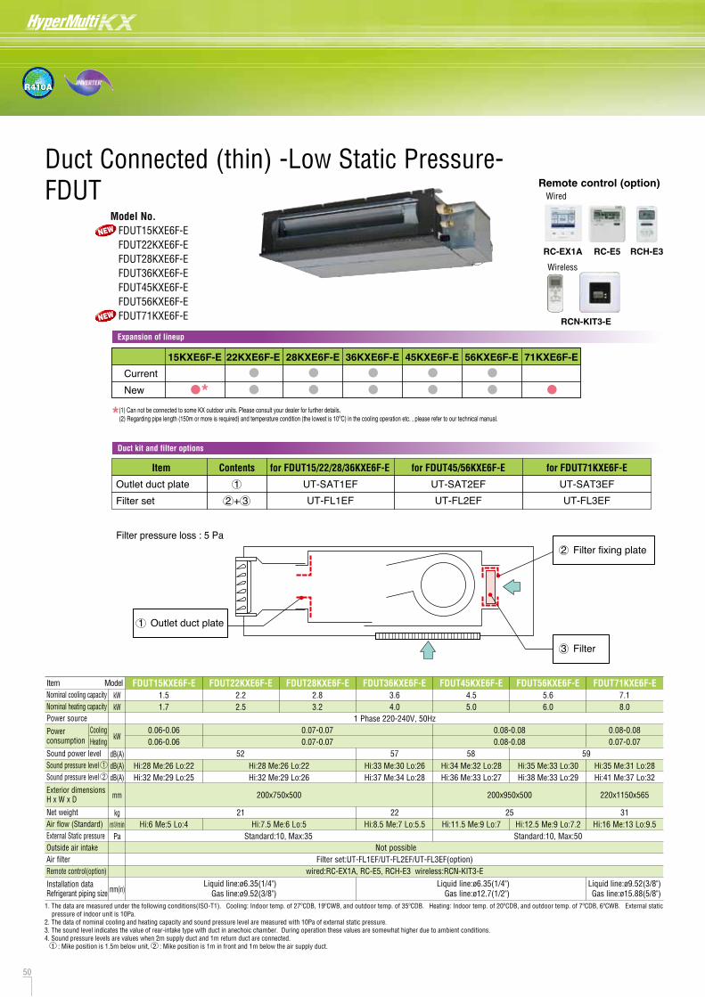
50 51
R410A
Wireless
RCN-KIT3-E
DimensionsAll measurements in mm.
FDUT45KXE6F-E, 56KXE6F-E
FDUT71KXE6F-E
FDUT15KXE6F-E, 22KXE6F-E, 28KXE6F-E, 36KXE6F-E
15,22,28
FDUT28KXE6F-E FDUT36KXE6F-E FDUT45KXE6F-E FDUT56KXE6F-E FDUT71KXE6F-E2.83.2
3.64.0
4.55.0
5.66.0
7.18.0
FDUT22KXE6F-E2.22.5
Hi:28 Me:26 Lo:22Hi:32 Me:29 Lo:26
Hi:28 Me:26 Lo:22Hi:32 Me:29 Lo:25
Hi:33 Me:30 Lo:26Hi:37 Me:34 Lo:28
Hi:34 Me:32 Lo:28Hi:36 Me:33 Lo:27
Hi:35 Me:33 Lo:30Hi:38 Me:33 Lo:29
Hi:35 Me:31 Lo:28Hi:41 Me:37 Lo:32
1.51.7
FDUT15KXE6F-E
1 Phase 220-240V, 50Hz
Not possibleFilter set:UT-FL1EF/UT-FL2EF/UT-FL3EF(option)
wired:RC-EX1A, RC-E5, RCH-E3 wireless:RCN-KIT3-E
kWkW
kW
dB(A)dB(A)dB(A)
mm
kgm3/minPa
mm(in)
ItemNominal cooling capacityNominal heating capacityPower source
Power consumption
Sound power levelSound pressure level 1Sound pressure level 2
Exterior dimensionsH x W x D
Net weightAir flow (Standard)External Static pressure Outside air intakeAir filterRemote control(option)
Installation dataRefrigerant piping size
Model
CoolingHeating
1. The data are measured under the following conditions(ISO-T1). Cooling: Indoor temp. of 27ºCDB, 19ºCWB, and outdoor temp. of 35ºCDB. Heating: Indoor temp. of 20ºCDB, and outdoor temp. of 7ºCDB, 6ºCWB. External static pressure of indoor unit is 10Pa.
2. The data of nominal cooling and heating capacity and sound pressure level are measured with 10Pa of external static pressure.3. The sound level indicates the value of rear-intake type with duct in anechoic chamber. During operation these values are somewhat higher due to ambient conditions.4. Sound pressure levels are values when 2m supply duct and 1m return duct are connected. 1 : Mike position is 1.5m below unit, 2 : Mike position is 1m in front and 1m below the air supply duct.
Hi:7.5 Me:6 Lo:5Hi:6 Me:5 Lo:4 Hi:8.5 Me:7 Lo:5.5 Hi:16 Me:13 Lo:9.5Hi:12.5 Me:9 Lo:7.2Hi:11.5 Me:9 Lo:721 312522
220x1150x565200x950x500200x750x500
Standard:10, Max:35 Standard:10, Max:50
0.07-0.070.07-0.07
0.06-0.060.06-0.06
0.08-0.080.08-0.08
0.08-0.080.07-0.07
Liquid line:ø6.35(1/4")Gas line:ø9.52(3/8")
Liquid line:ø6.35(1/4")Gas line:ø12.7(1/2")
Liquid line:ø9.52(3/8")Gas line:ø15.88(5/8")
52 57 58 59
Duct Connected (thin) -Low Static Pressure-FDUT
Model No. FDUT15KXE6F-E FDUT22KXE6F-E FDUT28KXE6F-E FDUT36KXE6F-E FDUT45KXE6F-E FDUT56KXE6F-E FDUT71KXE6F-E
RC-E5RC-EX1A
Wired
RCH-E3
Remote control (option)
15KXE6F-E 22KXE6F-E 28KXE6F-E 36KXE6F-E 45KXE6F-E 56KXE6F-E 71KXE6F-E
CurrentNew
*(1) Can not be connected to some KX outdoor units. Please consult your dealer for further details. (2) Regarding pipe length (150m or more is required) and temperature condition (the lowest is 10ºC) in the cooling operation etc. , please refer to our technical manual.
Filter pressure loss : 5 Pa
Expansion of lineup
Duct kit and filter options
*
ContentsItem for FDUT15/22/28/36KXE6F-E for FDUT45/56KXE6F-E for FDUT71KXE6F-E
Outlet duct plateFilter set
12 + 3
UT-SAT1EFUT-FL1EF
UT-SAT2EFUT-FL2EF
UT-SAT3EFUT-FL3EF
Filter
Filter fixing plate
Outlet duct plate
3
2
1
NEW
NEW
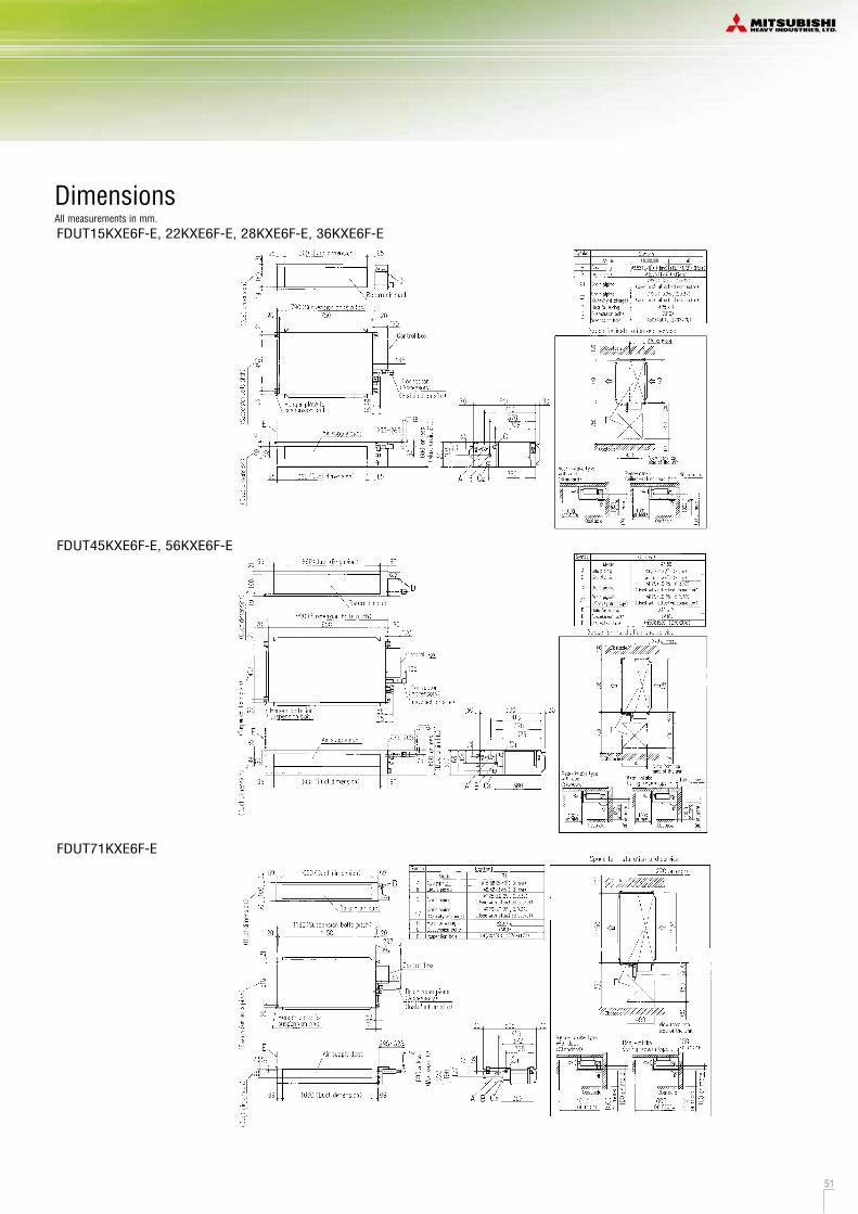

52 53
R410A
Duct Connected (Compact & Flexible)FDUH
Model No. FDUH22KXE6F FDUH28KXE6F FDUH36KXE6F
Compact and thin size, light weight
Our leading high technology has realized the best solution for air conditioning in hotels with compact and thin size units and high energy efficiency. In addition, weight is only 20kg.
Quiet operation
The lowest sound level in the industry can ensure comfortable stay and rest in hotels.
Installation Flexibility
Control box and drain piping can be installed on both side of the unit and air intake to the unit is available from bottom or back side. Our highest technology can satisfy diverse installation requirements.
RCH-E3(option)
Wired remote control
Simple remote controlConsidering specialized usage in hotel rooms, control buttons are limited only to minimum required functions such as ON/OFF, mode, temperature setting and fan speed. It is really simple and easy to use.
257mm
570mm
530mm
Control box
Drain piping
Specifications
DimensionsAll measurements in mm.
Unit:mm
C1,C2 VP20(I.D.20, O.D.26) Note (2)Hole for wiringSuspension bolts
F
DE
ø30
ø9.52 (3/8") (Flare)Gas piping
Drain pipingLiquid piping
AB
Symbol
ø12.7 (1/2") (Flare)ø6.35 (1/4") (Flare)
C o n t e n tM o d e l
(M10)
FDUH22KXE6F,28KXE6F FDUH36KXE6F
Inspection hole (635X890) Note (3)
(As for drain piping, it is possible to choose C1 or C2)
( 1 ) The model name label is attached on the fan case inside the air return grille.
Notes
( 2 ) Prepare the connecting socket (VP20) on site.
( 3 ) When control box is located on the reverse side, Installation space should be modified to new location. ( 4 ) Contorl box and Drain hose piece are able to be relocated on the reverse side.
Supply air duct
(Duct dimension)
Holes fortapping screws
12-ø4 (Duc
t dim
ensio
n)
150 150150 3232494 27.627.6
83.3
145
100
32.5
32.5
30.8 53
C2
530
255.8
40
30.8
66
Space for installation and service
600 100890
610
F
(Standard Accessory)Drain hose piece
(Installed on site)(Suspension bolts pitch)
(Susp
ensio
n bolt
s pitch
)
21
575.2
273
62.1
66.4
2148
8
68(D)
Holes fortapping screws
12-ø4
Air inlet
574
549.2
148.5188.5
150 150150 3232494.2 27.527.5
28.3
200
160
3030
37.6
38.2
E
D
G
C1
Control boxNote(4)
outletAir
inletAir
30.8145.6
66 95.3
156.8
BA
Note(4)
Simple remote control
70
120
15
(Able to be located on the back side)Bottom plate
View G
(After bottom plate is replaced to back side)
In case of Bottom air intake
Holes fortapping screws
12-ø4
Air inlet
15015015050.5 50.5
160
3030
28.5
198.218.2 537.6
View G
Drain up kit (option)(600mm)
UH-DU-E
RC-E5
Wired
RCH-E3
Wireless
RCN-KIT3-E
Filter kit (option)UH-FL1E
*Filter pressure loss:5pa
RC-EX1A
Remote control (option)
2.22.5
2.83.2
3.64.0
Gas line:ø12.7(1/2")Gas line:ø9.52(3/8")
1 Phase 220-240V, 50Hz0.05-0.070.05-0.07
60HI: 33 Me: 30 Lo: 27
257x570x53022
HI: 7 Me: 6.5 Lo: 630
Not possibleFilter kit:UH-FL1E(option)
wired:RC-EX1A, RC-E5, RCH-E3 wireless:RCN-KIT3-E
kWkW
kW
dB(A)dB(A)mmkg
m3/minPa
mm(in)
Nominal cooling capacityNominal heating capacityPower source
Power consumption
Sound power levelSound pressure levelExterior dimensions HxWxDNet weightAir flowExternal static pressureOutside air intakeAir filter Remote control(option)
Installation dataRefrigerant piping size
Model FDUH22KXE6F FDUH28KXE6F FDUH36KXE6F
CoolingHeating
1. The data are measured under the following conditions(ISO-T1). Cooling: Indoor temp. of 27ºCDB, 19ºCWB, and outdoor temp. of 35ºCDB. Heating: Indoor temp. of 20ºCDB, and outdoor temp. of 7ºCDB, 6ºCWB.2. Sound pressure level indicates the value in an anechoic chamber. During operation these values are somewhat higher due to ambient conditions.
Item
Liquid line:ø6.35(1/4")Liquid line:ø6.35(1/4")
Powerful-Hi can be selected. Sound pressure level: FDUH22/28/36 39dB(A). Air flow: FDUH22/28/36 8.5m3/min.
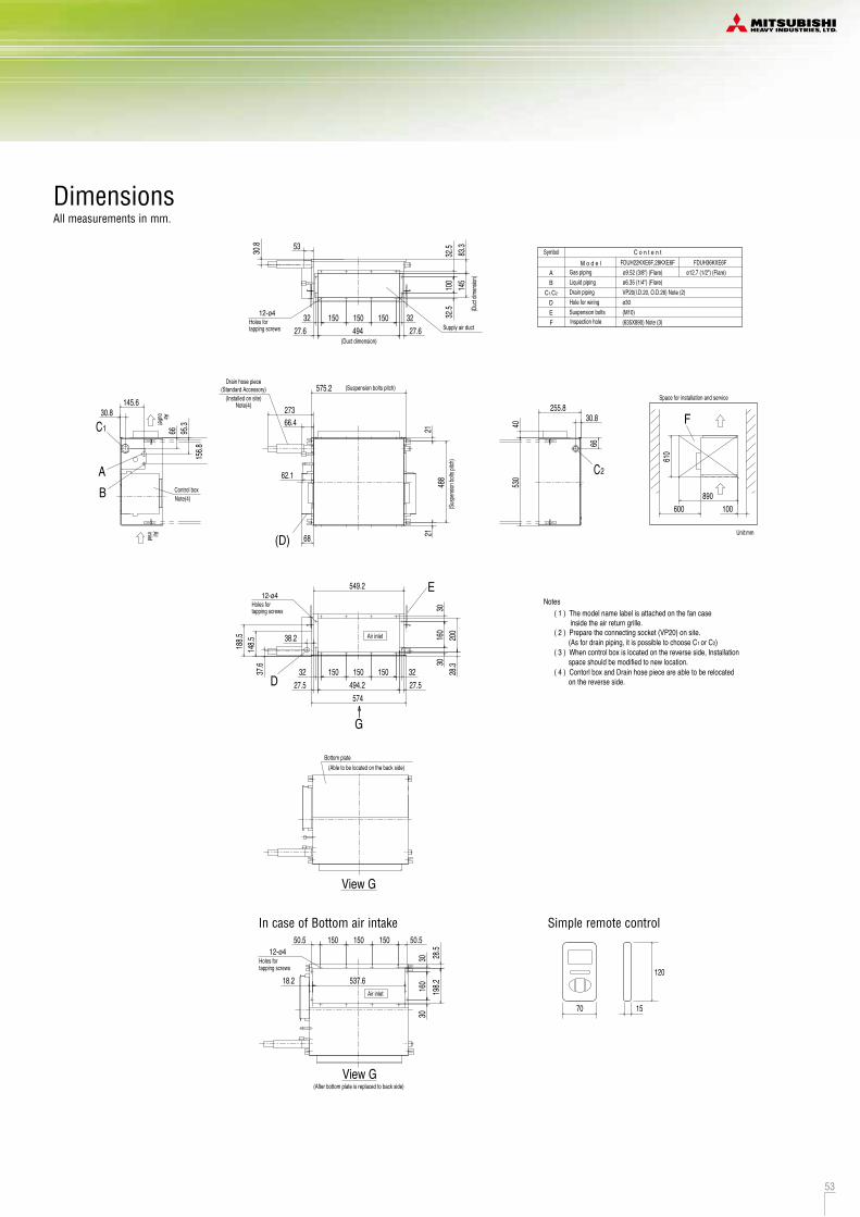
52 53
R410A
Duct Connected (Compact & Flexible)FDUH
Model No. FDUH22KXE6F FDUH28KXE6F FDUH36KXE6F
Compact and thin size, light weight
Our leading high technology has realized the best solution for air conditioning in hotels with compact and thin size units and high energy efficiency. In addition, weight is only 20kg.
Quiet operation
The lowest sound level in the industry can ensure comfortable stay and rest in hotels.
Installation Flexibility
Control box and drain piping can be installed on both side of the unit and air intake to the unit is available from bottom or back side. Our highest technology can satisfy diverse installation requirements.
RCH-E3(option)
Wired remote control
Simple remote controlConsidering specialized usage in hotel rooms, control buttons are limited only to minimum required functions such as ON/OFF, mode, temperature setting and fan speed. It is really simple and easy to use.
257mm
570mm
530mm
Control box
Drain piping
Specifications
DimensionsAll measurements in mm.
Unit:mm
C1,C2 VP20(I.D.20, O.D.26) Note (2)Hole for wiringSuspension bolts
F
DE
ø30
ø9.52 (3/8") (Flare)Gas piping
Drain pipingLiquid piping
AB
Symbol
ø12.7 (1/2") (Flare)ø6.35 (1/4") (Flare)
C o n t e n tM o d e l
(M10)
FDUH22KXE6F,28KXE6F FDUH36KXE6F
Inspection hole (635X890) Note (3)
(As for drain piping, it is possible to choose C1 or C2)
( 1 ) The model name label is attached on the fan case inside the air return grille.
Notes
( 2 ) Prepare the connecting socket (VP20) on site.
( 3 ) When control box is located on the reverse side, Installation space should be modified to new location. ( 4 ) Contorl box and Drain hose piece are able to be relocated on the reverse side.
Supply air duct
(Duct dimension)
Holes fortapping screws
12-ø4 (Duc
t dim
ensio
n)
150 150150 3232494 27.627.6
83.3
145
100
32.5
32.5
30.8 53
C2
530
255.8
40
30.8
66
Space for installation and service
600 100890
610
F
(Standard Accessory)Drain hose piece
(Installed on site)(Suspension bolts pitch)
(Susp
ensio
n bolt
s pitch
)
21
575.2
273
62.1
66.421
488
68(D)
Holes fortapping screws
12-ø4
Air inlet
574
549.2
148.5188.5
150 150150 3232494.2 27.527.5
28.3
200
160
3030
37.6
38.2
E
D
G
C1
Control boxNote(4)
outletAir
inletAir
30.8145.6
66 95.3
156.8
BA
Note(4)
Simple remote control
70
120
15
(Able to be located on the back side)Bottom plate
View G
(After bottom plate is replaced to back side)
In case of Bottom air intake
Holes fortapping screws
12-ø4
Air inlet
15015015050.5 50.5
160
3030
28.5
198.218.2 537.6
View G
Drain up kit (option)(600mm)
UH-DU-E
RC-E5
Wired
RCH-E3
Wireless
RCN-KIT3-E
Filter kit (option)UH-FL1E
*Filter pressure loss:5pa
RC-EX1A
Remote control (option)
2.22.5
2.83.2
3.64.0
Gas line:ø12.7(1/2")Gas line:ø9.52(3/8")
1 Phase 220-240V, 50Hz0.05-0.070.05-0.07
60HI: 33 Me: 30 Lo: 27
257x570x53022
HI: 7 Me: 6.5 Lo: 630
Not possibleFilter kit:UH-FL1E(option)
wired:RC-EX1A, RC-E5, RCH-E3 wireless:RCN-KIT3-E
kWkW
kW
dB(A)dB(A)mmkg
m3/minPa
mm(in)
Nominal cooling capacityNominal heating capacityPower source
Power consumption
Sound power levelSound pressure levelExterior dimensions HxWxDNet weightAir flowExternal static pressureOutside air intakeAir filter Remote control(option)
Installation dataRefrigerant piping size
Model FDUH22KXE6F FDUH28KXE6F FDUH36KXE6F
CoolingHeating
1. The data are measured under the following conditions(ISO-T1). Cooling: Indoor temp. of 27ºCDB, 19ºCWB, and outdoor temp. of 35ºCDB. Heating: Indoor temp. of 20ºCDB, and outdoor temp. of 7ºCDB, 6ºCWB.2. Sound pressure level indicates the value in an anechoic chamber. During operation these values are somewhat higher due to ambient conditions.
Item
Liquid line:ø6.35(1/4")Liquid line:ø6.35(1/4")
Powerful-Hi can be selected. Sound pressure level: FDUH22/28/36 39dB(A). Air flow: FDUH22/28/36 8.5m3/min.

54 55
R410A
Wall MountedFDK
Model No. FDK22KXE6F FDK28KXE6F FDK36KXE6F FDK45KXE6F FDK56KXE6F FDK71KXE6F
DimensionsAll measurements in mm.
The new slimmer design allowseasy & neat installation even in tightspaces.
New FDK models adopt the airflow design that's proven tominimise resistance in a CFDanalysis to achieve uniform airconditioning to the furthestcorners of the room.
259
Also included is a new easy clean mechanism where the frontpanel is opened/closed simply from the bottom to easily accessthe detachable filters.
FDK71
FDK22~56
FDK71KXE6F
FDK22KXE6F, 28KXE6F, 36KXE6F, 45KXE6F, 56KXE6F
Innovative Design Installation Workability
Improved Maintainability
Wireless
RCN-K-E : FDK22~56RCN-K71-E : FDK71
Specifications
Fast SlowColors in the figure show the air speed.
RC-E5
Wired
RCH-E3
Selection of flap position is possible. A flap can be set at different angles.
Upperposition
Movablerange
Lowerposition
Flap control system
*RCH-E3 is not applicable to the Flap control system.
RC-EX1A
Remote control (option)
12 15.512.5 13
2.22.5
2.83.2
3.64.0
4.55.0
5.66.3
7.18.0
1 Phase 220-240V, 50Hz
kWkW
kW
dB(A)
dB(A)
mm
kgm3/min
mm(in)
ItemNominal cooling capacityNominal heating capacityPower source
Power consumption
Sound power level
Sound pressurelevel
Exterior dimensionsH x W x D
Net weightAir flow Outside air intakeAir filter, Q’tyRemote control(option)
Installation dataRefrigerant piping size
Not possiblePolypropylene net x2 (Washable)
wired:RC-EX1A, RC-E5, RCH-E3 wireless:RCN-K-E (for FDK22~56), RCN-K71-E (for FDK71)Liquid line:ø6.35(1/4")
Gas line:ø9.52(3/8")Liquid line:ø6.35(1/4")
Gas line:ø12.7(1/2")Liquid line:ø9.52(3/8")Gas line:ø15.88(5/8")
Model FDK22KXE6F FDK28KXE6F FDK36KXE6F FDK45KXE6F FDK56KXE6F FDK71KXE6F
Hi:46 Me:42 Lo:37Hi:46 Me:42 Lo:37
Hi:47 Me:43 Lo:39Hi:47 Me:43 Lo:39
Hi:42 Me:37 Lo:33Hi:42 Me:37 Lo:33
298 x 840 x 259 318 x 1098 x 248
Hi:35 Me:33 Lo:31Hi:35 Me:33 Lo:31
Hi:14 Me:12 Lo:10 Hi:21 Me:18 Lo:15Hi:10 Me:9 Lo:7 Hi:11 Me:9 Lo:7Hi:8 Me:7 Lo:6
Hi:41 Me:35 Lo:31Hi:39 Me:35 Lo:31
CoolingHeating
CoolingHeating
0.050.04
0.050.05
0.090.09
1. The data are measured under the following conditions(ISO-T1). Cooling: Indoor temp. of 27ºCDB, 19ºCWB, and outdoor temp. of 35ºCDB. Heating: Indoor temp. of 20ºCDB, and outdoor temp. of 7ºCDB, 6ºCWB.2. Sound pressure level indicates the value in an anechoic chamber. During operation these values are somewhat higher due to ambient conditions.
Powerful-Hi can be selected. Sound pressure level: FDK22/28 38dB(A), FDK36 48dB(A)(Cooling)&42dB(A)(Heating), FDK45 48dB(A)(Cooling)&43dB(A)(Heating), FDK56 48dB(A)(Cooling)&47dB(A)(Heating), FDK71 48dB(A). Air flow: FDK22/28 11m3/min, FDK36/45 15m3/min, FDK56 16m3/min, FDK71 24m3/min.
57 60
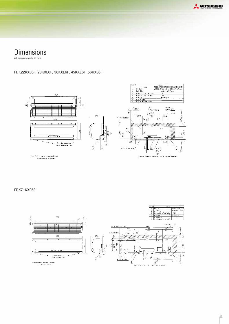
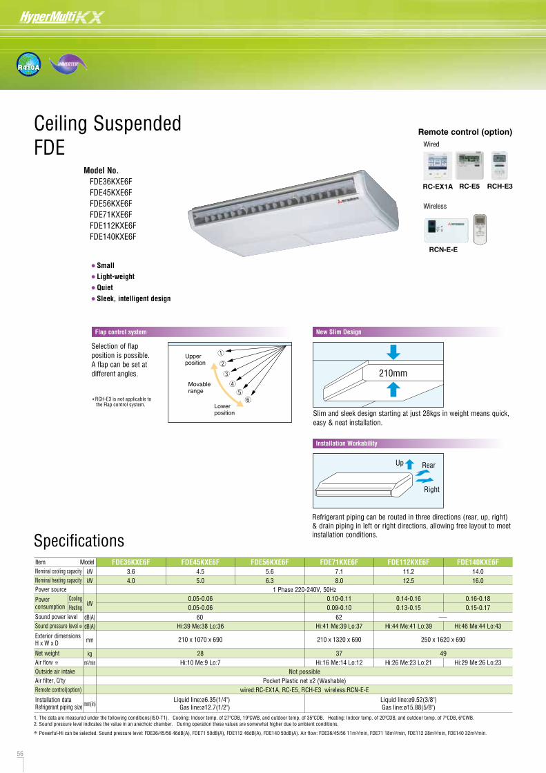
56 57
R410A
Ceiling SuspendedFDE
Model No. FDE36KXE6F FDE45KXE6F FDE56KXE6F FDE71KXE6F FDE112KXE6F FDE140KXE6F
••••
SmallLight-weightQuietSleek, intelligent design
New Slim Design
210mm
Slim and sleek design starting at just 28kgs in weight means quick, easy & neat installation.
Installation Workability
Up Rear
Right
Refrigerant piping can be routed in three directions (rear, up, right) & drain piping in left or right directions, allowing free layout to meet installation conditions.
FDE36KXE6F, 45KXE6F, 56KXE6F
DimensionsAll measurements in mm.
RCN-E-E
Wireless
Specifications
RC-E5
Wired
RCH-E3
Space for installation and service
E
F
Position of top cutout and back cutout
Right side cutout
Remove the cutout using side cutter or similar tool.
Liquid pipingGas piping
Top cutoutBack cutoutHole for suspension boltDrain piping
B
FE
1,2
Symbol
DC
A
PE cover
Content
VP20 (I.D.20)
Note(1)The model name label is attached on the fan casing inside the air return grille.
Air return grilleC2 C1A B
Air supply
75110135
308
4040 990
1070
173 210
521
5
2424
690195
235271
5310
9
5268410135
760 2731
D
AB
Drain hose piece (Accessory, 0.3m)
unit must take decline of 10mm.
10 53
145
2740
108
20 10015
175 1912020
76
Make a space of 4000 or more between the units when installing more than one.
Obstacle
Plate cover
300 o
r more100 or more
MITSUBISHI
Hole for drain piping (for left back)G
G
drain pipingHole for
1022 (Suspension bolts pitch)
290 (Suspension bolts pitch)
(Installed on site)
(for left)
5 or more150 or more
(Knock out)
ø12.7 (1/2") (Flare)ø6.35 (1/4") (Flare)
(M10 or M8)
HEAVY INDUSTRIES,LTD
Note) The slope of drain piping inside the
C1,C2
C1,C2
FDE71KXE6F
Obstacle
E
F
A B75110135
308
4040 1240
1320
173 210
521
5
2424
690195
235271
5310
9
5268410135
760 2731
D
AB
10 53
145
2740
108
20 10015
17519120
20
76
Space for installation and service
Make a space of 4500 or more between the units when installing more than one.
Position of top cutout and back cutout
Right side cutout
Remove the cutout using side cutter or similar tool.
Liquid pipingGas piping
Back cutoutHole for suspension boltDrain piping
B
FE
1,2
Symbol
DC
AContent
VP20 (I.D.20)
fan casing inside the air return grille.
Drain hose piece (Accessory, 0.3m)
Air return grille
Air supply
PE coverPlate cover
G
G
drain pipingHole for
MITSUBISHIHEAVY INDUSTRIES,LTD
1272 (Suspension bolts pitch)
290 (Suspension bolts pitch)
(Installed on site)
Note)The slope of drain piping inside the unit must take decline of 10mm.
Hole for drain piping(for left back) (Knock out)
(M10 or M8)
ø15.88 (5/8") (Flare)ø9.52 (3/8") (Flare)
Top cutout
(for left)
Note(1)The model name label is attached on the
C2 C1
C1,C2
C1,C2
300 o
r more100 or more
5 or more150 or more
FDE112KXE6F, 140KXE6F
68410
690
7675110135
308
5
1CA B
1540
1620
40
24135
250
525
5
173
40
24145
2740
108
20
271235
10953
195
52
AB
7 2731
10015 60
D 10 53
F
E
12020
19175
Symbol Content
Position of top cutout and back cutout
Right side cutout
Remove the cutout using side cutter or similar tool.Air return grille
Space for installation and service
or more
Make a space of 5000 or more between the units when installing more than one.
Air supply
Obstacle
150 or more300
100 or mo
re
or more G
Hole for drain piping
Note(1)The model name label is attached on the fan casing inside the air return grille.
1572 (Suspension bolts pitch)
C2
290 (Suspension bolts pitch)
Drain hose piece (Accessory, 0.3m)(Installed on site)
C1,C2
Note) The slope of drain piping inside the unit must take decline of 10mm.
C1,C2
Gas pipingLiquid pipingDrain pipingHole for suspension boltBack cutoutTop cutoutHole for drain piping (for left back)
AB
C1,2
DEFG
ø15.88 (5/8") (Flare)ø9.52 (3/8") (Flare)VP20 (I.D.20)(M10 or M8)PE coverPlate cover(Knock out)
(for left)
MITSUBISHIHEAVY INDUSTRIES,LTD
Selection of flap position is possible. A flap can be set at different angles.
Upperposition
Movablerange
Lowerposition
Flap control system
*RCH-E3 is not applicable to the Flap control system.
RC-EX1A
Remote control (option)
28 37 49
11.212.5
14.016.0
1 Phase 220-240V, 50Hz
kWkW
kW
dB(A)dB(A)
mm
kgm3/min
mm(in)
ItemNominal cooling capacityNominal heating capacityPower source
Power consumption
Sound power levelSound pressure level
Exterior dimensionsH x W x D
Net weightAir flowOutside air intakeAir filter, Q’tyRemote control(option)
Installation dataRefrigerant piping size
Not possiblePocket Plastic net x2 (Washable)
wired:RC-EX1A, RC-E5, RCH-E3 wireless:RCN-E-ELiquid line:ø6.35(1/4")
Gas line:ø12.7(1/2")Liquid line:ø9.52(3/8")Gas line:ø15.88(5/8")
Model FDE112KXE6F FDE140KXE6F3.64.0
4.55.0
5.66.3
7.18.0
FDE36KXE6F FDE45KXE6F FDE56KXE6F FDE71KXE6F
Hi:44 Me:41 Lo:39Hi:41 Me:39 Lo:37 Hi:46 Me:44 Lo:43
210 x 1070 x 690 250 x 1620 x 690210 x 1320 x 690
Hi:39 Me:38 Lo:36
Hi:26 Me:23 Lo:21 Hi:29 Me:26 Lo:23Hi:16 Me:14 Lo:12Hi:10 Me:9 Lo:7
CoolingHeating
0.05-0.060.05-0.06
0.14-0.160.13-0.15
0.10-0.110.09-0.10
0.16-0.180.15-0.17
1. The data are measured under the following conditions(ISO-T1). Cooling: Indoor temp. of 27ºCDB, 19ºCWB, and outdoor temp. of 35ºCDB. Heating: Indoor temp. of 20ºCDB, and outdoor temp. of 7ºCDB, 6ºCWB.2. Sound pressure level indicates the value in an anechoic chamber. During operation these values are somewhat higher due to ambient conditions.
Powerful-Hi can be selected. Sound pressure level: FDE36/45/56 46dB(A), FDE71 50dB(A), FDE112 46dB(A), FDE140 50dB(A). Air flow: FDE36/45/56 11m3/min, FDE71 18m3/min, FDE112 28m3/min, FDE140 32m3/min.
60 62
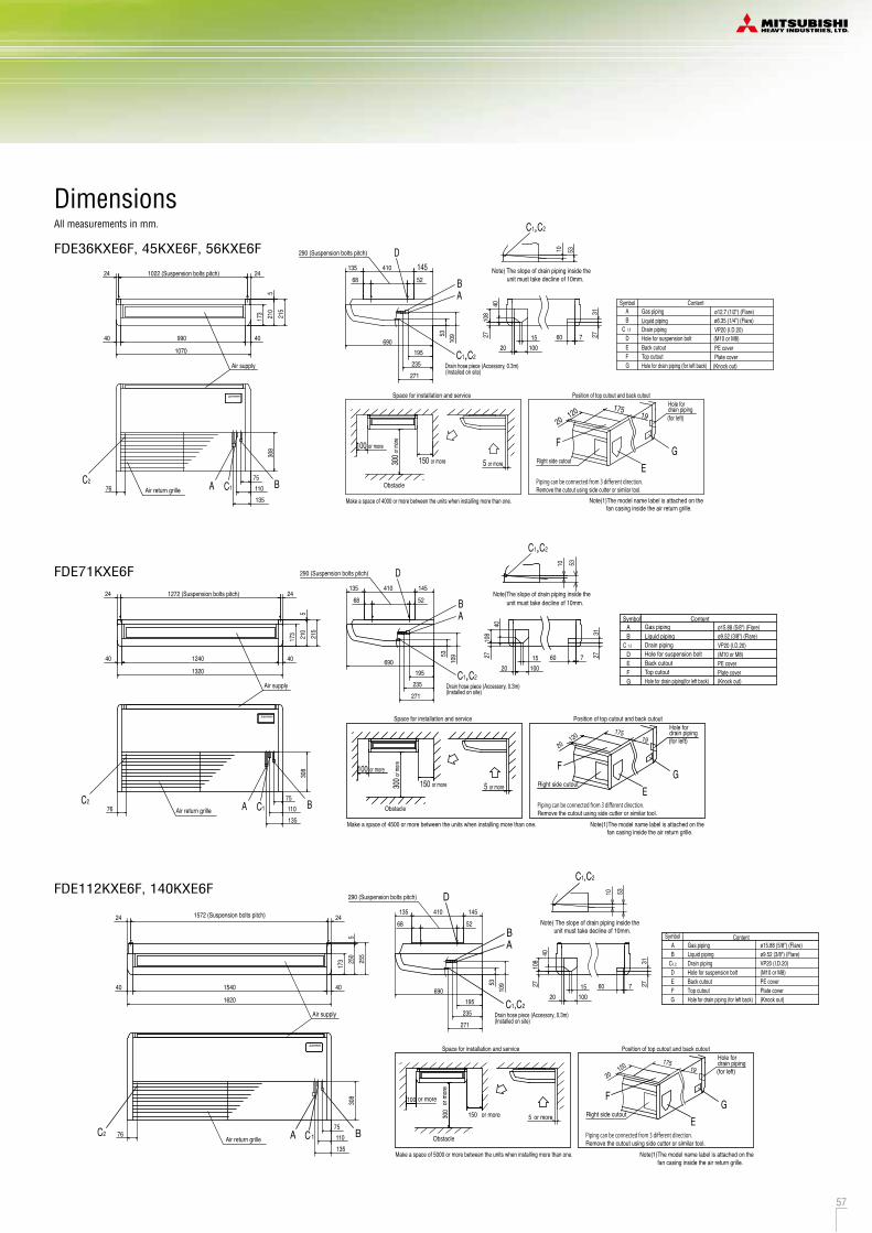
56 57
R410A
Ceiling SuspendedFDE
Model No. FDE36KXE6F FDE45KXE6F FDE56KXE6F FDE71KXE6F FDE112KXE6F FDE140KXE6F
••••
SmallLight-weightQuietSleek, intelligent design
New Slim Design
210mm
Slim and sleek design starting at just 28kgs in weight means quick, easy & neat installation.
Installation Workability
Up Rear
Right
Refrigerant piping can be routed in three directions (rear, up, right) & drain piping in left or right directions, allowing free layout to meet installation conditions.
FDE36KXE6F, 45KXE6F, 56KXE6F
DimensionsAll measurements in mm.
RCN-E-E
Wireless
Specifications
RC-E5
Wired
RCH-E3
Space for installation and service
E
F
Position of top cutout and back cutout
Right side cutout
Remove the cutout using side cutter or similar tool.
Liquid pipingGas piping
Top cutoutBack cutoutHole for suspension boltDrain piping
B
FE
1,2
Symbol
DC
A
PE cover
Content
VP20 (I.D.20)
Note(1)The model name label is attached on the fan casing inside the air return grille.
Air return grilleC2 C1A B
Air supply
75110135
308
4040 990
1070
173 210
521
52424
690195
235271
5310
9
5268410135
760 2731
D
AB
Drain hose piece (Accessory, 0.3m)
unit must take decline of 10mm.
10 53
145
2740
108
20 10015
175 1912020
76
Make a space of 4000 or more between the units when installing more than one.
Obstacle
Plate cover
300 o
r more100 or more
MITSUBISHI
Hole for drain piping (for left back)G
G
drain pipingHole for
1022 (Suspension bolts pitch)
290 (Suspension bolts pitch)
(Installed on site)
(for left)
5 or more150 or more
(Knock out)
ø12.7 (1/2") (Flare)ø6.35 (1/4") (Flare)
(M10 or M8)
HEAVY INDUSTRIES,LTD
Note) The slope of drain piping inside the
C1,C2
C1,C2
FDE71KXE6F
Obstacle
E
F
A B75110135
308
4040 1240
1320
173 210
521
5
2424
690195
235271
5310
9
5268410135
760 2731
D
AB
10 53
145
2740
108
20 10015
17519120
20
76
Space for installation and service
Make a space of 4500 or more between the units when installing more than one.
Position of top cutout and back cutout
Right side cutout
Remove the cutout using side cutter or similar tool.
Liquid pipingGas piping
Back cutoutHole for suspension boltDrain piping
B
FE
1,2
Symbol
DC
AContent
VP20 (I.D.20)
fan casing inside the air return grille.
Drain hose piece (Accessory, 0.3m)
Air return grille
Air supply
PE coverPlate cover
G
G
drain pipingHole for
MITSUBISHIHEAVY INDUSTRIES,LTD
1272 (Suspension bolts pitch)
290 (Suspension bolts pitch)
(Installed on site)
Note)The slope of drain piping inside the unit must take decline of 10mm.
Hole for drain piping(for left back) (Knock out)
(M10 or M8)
ø15.88 (5/8") (Flare)ø9.52 (3/8") (Flare)
Top cutout
(for left)
Note(1)The model name label is attached on the
C2 C1
C1,C2
C1,C2
300 o
r more100 or more
5 or more150 or more
FDE112KXE6F, 140KXE6F
68410
690
7675110135
308
5
1CA B
1540
1620
40
24135
250
525
5
173
40
24145
2740
108
20
271235
10953
195
52
AB
7 2731
10015 60
D 10 53
F
E
12020
19175
Symbol Content
Position of top cutout and back cutout
Right side cutout
Remove the cutout using side cutter or similar tool.Air return grille
Space for installation and service
or more
Make a space of 5000 or more between the units when installing more than one.
Air supply
Obstacle
150 or more300
100 or mo
re
or more G
Hole for drain piping
Note(1)The model name label is attached on the fan casing inside the air return grille.
1572 (Suspension bolts pitch)
C2
290 (Suspension bolts pitch)
Drain hose piece (Accessory, 0.3m)(Installed on site)
C1,C2
Note) The slope of drain piping inside the unit must take decline of 10mm.
C1,C2
Gas pipingLiquid pipingDrain pipingHole for suspension boltBack cutoutTop cutoutHole for drain piping (for left back)
AB
C1,2
DEFG
ø15.88 (5/8") (Flare)ø9.52 (3/8") (Flare)VP20 (I.D.20)(M10 or M8)PE coverPlate cover(Knock out)
(for left)
MITSUBISHIHEAVY INDUSTRIES,LTD
Selection of flap position is possible. A flap can be set at different angles.
Upperposition
Movablerange
Lowerposition
Flap control system
*RCH-E3 is not applicable to the Flap control system.
RC-EX1A
Remote control (option)
28 37 49
11.212.5
14.016.0
1 Phase 220-240V, 50Hz
kWkW
kW
dB(A)dB(A)
mm
kgm3/min
mm(in)
ItemNominal cooling capacityNominal heating capacityPower source
Power consumption
Sound power levelSound pressure level
Exterior dimensionsH x W x D
Net weightAir flowOutside air intakeAir filter, Q’tyRemote control(option)
Installation dataRefrigerant piping size
Not possiblePocket Plastic net x2 (Washable)
wired:RC-EX1A, RC-E5, RCH-E3 wireless:RCN-E-ELiquid line:ø6.35(1/4")
Gas line:ø12.7(1/2")Liquid line:ø9.52(3/8")Gas line:ø15.88(5/8")
Model FDE112KXE6F FDE140KXE6F3.64.0
4.55.0
5.66.3
7.18.0
FDE36KXE6F FDE45KXE6F FDE56KXE6F FDE71KXE6F
Hi:44 Me:41 Lo:39Hi:41 Me:39 Lo:37 Hi:46 Me:44 Lo:43
210 x 1070 x 690 250 x 1620 x 690210 x 1320 x 690
Hi:39 Me:38 Lo:36
Hi:26 Me:23 Lo:21 Hi:29 Me:26 Lo:23Hi:16 Me:14 Lo:12Hi:10 Me:9 Lo:7
CoolingHeating
0.05-0.060.05-0.06
0.14-0.160.13-0.15
0.10-0.110.09-0.10
0.16-0.180.15-0.17
1. The data are measured under the following conditions(ISO-T1). Cooling: Indoor temp. of 27ºCDB, 19ºCWB, and outdoor temp. of 35ºCDB. Heating: Indoor temp. of 20ºCDB, and outdoor temp. of 7ºCDB, 6ºCWB.2. Sound pressure level indicates the value in an anechoic chamber. During operation these values are somewhat higher due to ambient conditions.
Powerful-Hi can be selected. Sound pressure level: FDE36/45/56 46dB(A), FDE71 50dB(A), FDE112 46dB(A), FDE140 50dB(A). Air flow: FDE36/45/56 11m3/min, FDE71 18m3/min, FDE112 28m3/min, FDE140 32m3/min.
60 62
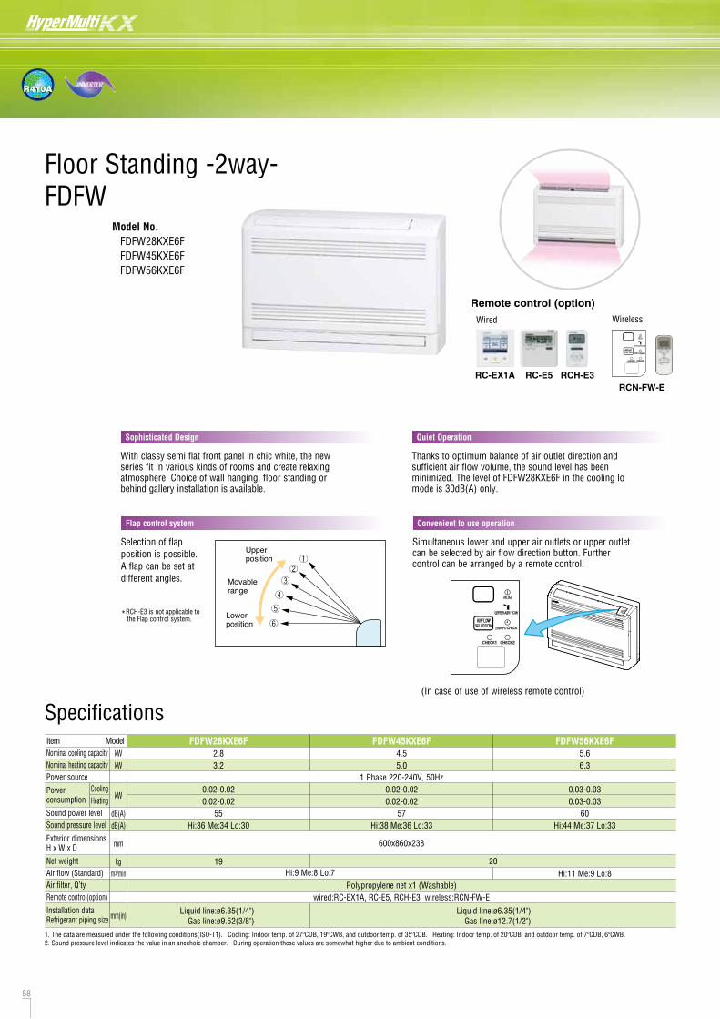
58 59
R410A
DimensionsAll measurements in mm.
Model No. FDFW28KXE6F FDFW45KXE6F FDFW56KXE6F
Specifications
Floor Standing -2way-FDFW
RCN-FW-E
Wireless
RC-E5
Wired
RCH-E3
With classy semi flat front panel in chic white, the new series fit in various kinds of rooms and create relaxing atmosphere. Choice of wall hanging, floor standing or behind gallery installation is available.
Sophisticated Design
Thanks to optimum balance of air outlet direction and sufficient air flow volume, the sound level has been minimized. The level of FDFW28KXE6F in the cooling lo mode is 30dB(A) only.
Quiet Operation
Simultaneous lower and upper air outlets or upper outlet can be selected by air flow direction button. Further control can be arranged by a remote control.
Convenient to use operation
(In case of use of wireless remote control)
Selection of flap position is possible. A flap can be set at different angles.
Flap control system
Upperposition
Movablerange
Lowerposition
*RCH-E3 is not applicable to the Flap control system.
RC-EX1A
Remote control (option)
FDFW28KXE6F2.83.2
0.02-0.020.02-0.02
55Hi:36 Me:34 Lo:30
19
FDFW45KXE6F4.55.0
0.02-0.020.02-0.02
57Hi:38 Me:36 Lo:33
FDFW56KXE6F5.66.3
0.03-0.030.03-0.03
60Hi:44 Me:37 Lo:33
Hi:11 Me:9 Lo:8
1 Phase 220-240V, 50Hz
kWkW
kW
dB(A)dB(A)
mm
kgm3/min
mm(in)
ItemNominal cooling capacityNominal heating capacityPower source
Power consumption
Sound power levelSound pressure level
Exterior dimensionsH x W x D
Net weightAir flow (Standard)Air filter, Q’tyRemote control(option)
Installation dataRefrigerant piping size
600x860x238
Polypropylene net x1 (Washable)wired:RC-EX1A, RC-E5, RCH-E3 wireless:RCN-FW-E
Liquid line:ø6.35(1/4")Gas line:ø9.52(3/8")
Liquid line:ø6.35(1/4")Gas line:ø12.7(1/2")
Model
CoolingHeating
1. The data are measured under the following conditions(ISO-T1). Cooling: Indoor temp. of 27ºCDB, 19ºCWB, and outdoor temp. of 35ºCDB. Heating: Indoor temp. of 20ºCDB, and outdoor temp. of 7ºCDB, 6ºCWB.2. Sound pressure level indicates the value in an anechoic chamber. During operation these values are somewhat higher due to ambient conditions.
Hi:9 Me:8 Lo:720
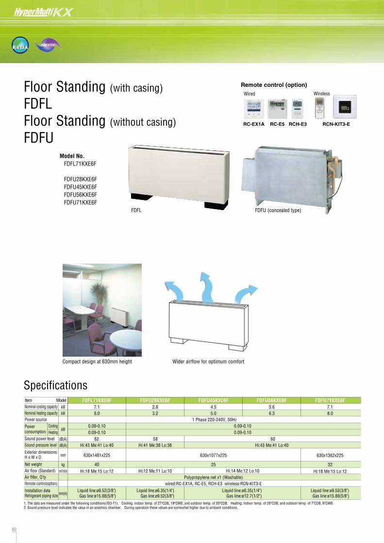
60 61
R410A
Floor Standing (with casing)
FDFLFloor Standing (without casing)
FDFUModel No. FDFL71KXE6F
FDFU28KXE6F FDFU45KXE6F FDFU56KXE6F FDFU71KXE6F
DimensionsAll measurements in mm.
FDFU
FDFL
Compact design at 630mm height Wider airflow for optimum comfort
FDFL FDFU (concealed type)
Dimension Tablemodel
FDFU28KXE6F, 45KXE6F, 56KXE6F
FDFU71KXE6F
a b c d e
786
1071
810
1095
722
1007
750
1035
806
1091
Unit:mm
Specifications
Wireless
RCN-KIT3-ERC-E5
Wired
RCH-E3RC-EX1A
Remote control (option)
Hi:41 Me:38 Lo:36 Hi:43 Me:41 Lo:40Hi:43 Me:41 Lo:40
FDFL71KXE6F7.18.0
FDFU28KXE6F2.83.2
FDFU45KXE6F4.55.0
FDFU56KXE6F5.66.3
FDFU71KXE6F7.18.0
1 Phase 220-240V, 50Hz
kWkW
kW
dB(A)dB(A)
mm
kgm3/min
mm(in)
ItemNominal cooling capacityNominal heating capacityPower source
Power consumption
Sound power levelSound pressure level
Exterior dimensionsH x W x D
Net weightAir flow (Standard)Air filter, Q’tyRemote control(option)
Installation dataRefrigerant piping size
Polypropylene net x1 (Washable)wired:RC-EX1A, RC-E5, RCH-E3 wireless:RCN-KIT3-E
Liquid line:ø9.52(3/8")Gas line:ø15.88(5/8")
Liquid line:ø9.52(3/8")Gas line:ø15.88(5/8")
Liquid line:ø6.35(1/4")Gas line:ø9.52(3/8")
Liquid line:ø6.35(1/4")Gas line:ø12.7(1/2")
Model
Hi:18 Me:15 Lo:12 Hi:14 Me:12 Lo:10Hi:12 Me:11 Lo:10 Hi:18 Me:15 Lo:12
630x1481x225 630x1362x225630x1077x225
40 3225
CoolingHeating
0.09-0.100.09-0.10
0.09-0.100.09-0.10
1. The data are measured under the following conditions(ISO-T1). Cooling: Indoor temp. of 27ºCDB, 19ºCWB, and outdoor temp. of 35ºCDB. Heating: Indoor temp. of 20ºCDB, and outdoor temp. of 7ºCDB, 6ºCWB.2. Sound pressure level indicates the value in an anechoic chamber. During operation these values are somewhat higher due to ambient conditions.
62 58 60
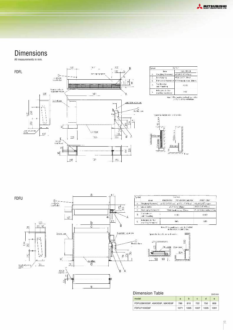
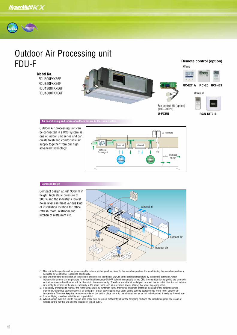
62 63
R410A
Outdoor Air Processing unitFDU-F
Model No. FDU500FKXE6F FDU850FKXE6F FDU1300FKXE6F FDU1800FKXE6F
Air conditioning and intake of outdoor air are in the same system
Compact design
Connectivity with KX6 series
[ A ] [ B ]Outdoor Air processing unit can be connected in a KX6 system as one of indoor unit series and can create fresh and comfortable air supply together from our high advanced technology.
Compact design at just 360mm in height, high static pressure of 200Pa and the industry's lowest noise level can meet various kind of installation location for office, refresh room, restroom and kitchen of restaurant etc.
exhaust air
supply airsupply air
outdoor air
outdoor air
supply supply air
Outdoor Air Processing unit
air conditioning
outsideair supply
indoor unit indoor unit
office
corridor refresh room, rest room
KX6 outdoor unit
(1) This unit is the specific unit for processing the outdoor air temperature closer to the room temperature. For conditioning the room temperature a dedicated air-conditioner is required additionally.
(2) This unit monitors the outdoor air temperature and controls thermostat ON/OFF at the setting temperature by the remote controller, which indicates the outdoor air temperature for controlling thermostat ON/OFF. When thermostat is turned OFF, the operation is changed to the fan mode so that unprocessed outdoor air will be blown into the room directly. Therefore place the air outlet port or orient the air outlet direction not to blow air directly to persons in the room, especially in the small room such as a restroom and/or sanitary hot water supplying room.
(3) It is strictly prohibited to monitor the room temperature by switching to the thermistor at remote controller side and/or the optional remote thermistor. Otherwise dew formation at air outlet port and/or dew dripping may occur during cooling operation due to the lower outdoor air temperature. Therefore keep the remote controller of this unit in place closer to the administrator so as not to be touched it freely by the end user.
(4) Dehumidifying operation with this unit is prohibited.(5) When handing over this unit to the end user, make sure to explain sufficiently about the foregoing cautions, the installation place and usage of
remote control for this unit and the location of the air outlet.
SAF is the energy recovery ventilation unit which can recover heat energy from exhaust air to supply air and "has no air processing function, but FDU-F is air processing unit which can treat the supply air closer to room temperature by cooling or heating in connection with KX6 refrigerant system and exhaust air is discharged to outside of the room.
Combination with KX6 series
In case OA processing units onlyare connected with KX6 outdoor units
In case both of OA processing units and dedicated air-conditioner are connected with KX6 outdoor unit.
The total capacity of FDU-F is 50~100% of outdoor capacity and max quantity of FDU-F is 2 units.
case
A
B
Combination
Concept (Difference between FDU-F and SAF)
FDU-F OA Processing units
SAF
Outside
Direct ExpansionHeat Exchanger
Air SupplyExhaust Air
18HP 6HP 6HP
Less than 30%
10HPFDU850FKXE6F
(5HP)FDU850FKXE6F
(5HP)FDU850FKXE6F
(5HP)
Fan control kit (option)(100~200Pa)
U-FCRB
FDU-F series are connectable to 8~48HP KX6 outdoor units, not connectable to 4~6HP.8 ~ 48 HP : Yes , 4 ~ 6 HP : No
The total capacity of FDU-F and dedicated air-conditioners is 50~100% of outdoor capacity and max quantity of FDU-F should be below 30% of outdoor unit capacity.
Outside
Air SupplyExhaust Air
Wireless
RCN-KIT3-E
RC-E5
Wired
RCH-E3RC-EX1A
Remote control (option)
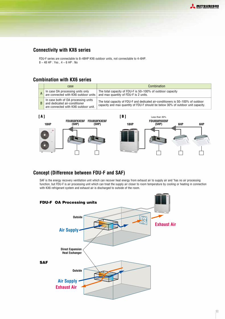
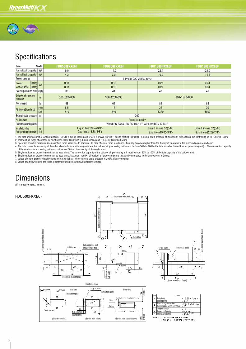
64 65
R410A
FDU500FKXE6F Suspension bolts pitch
Control box
Susp
ensio
n bolt
s pitc
h
(Inne
r size
of d
uct f
lange
)
(Inner size of duct flange)
12-M5 screwDuct connection port for outdoor air inlet
Above
Below
(Belo
w su
spen
sion
bolt
pitc
h)
12-M5 screw Port for air outlet
(Inner size of duct flange)
(Inne
r size
of d
uct f
lange
)
Installation space
Installation spaceInstallation space
or more or more
or more
or more
or m
ore
or m
ore
Plan view Front view
Service space
(Service from side) (Service from below) (Service from side and below)
Piping space
Slab
Ceiling
Gas pipingLiquid pipingDrain piping connectionPower supply wiring connectionSuspension boltInspection OpeningInspection Opening
Symbol Content
FDU1300FKXE6F, FDU1800FKXE6FSuspension bolts pitch
Control box
Susp
ensio
n bolt
s pitc
h
(Inne
r size
of du
ct fla
nge)
(Inner size of duct flange)
20-M5 screwDuct connection port for outdoor air inlet
Above
Below
(Belo
w su
spen
sion
bolt
pitch
)
20-M5 screw Port for air outlet
(Inner size of duct flange)
(Inne
r size
of d
uct f
lange
)
Installation space
Installation spaceor more or more
or more
or more
or m
ore
or m
ore
Plan viewFront view
Service space Service space
(Service from side) (Service from below) (Service from side and below)Piping space
Slab
Ceiling Gas pipingLiquid pipingDrain piping connectionPower supply wiring connectionSuspension boltInspection OpeningInspection Opening
Symbol Content
FDU850FKXE6FSuspension bolts pitch
Control box
Susp
ensio
n bo
lts p
itch
(Inne
r size
of d
uct f
lange
)
(Inner size of duct flange)
16-M5 screwDuct connection port for outdoor air inlet
Above
Below
(Belo
w su
spen
sion
bolt p
itch)
12-M5 screw Port for air outlet
(Inner size of duct flange)
(Inne
r size
of d
uct f
lange
)
Installation space
Installation space
Installation spaceor more or more
or more
or more
or m
ore
or m
ore
Plan view Front view
Service space
(Service from side) (Service from below) (Service from side and below)Piping space
Slab
Ceiling
Gas pipingLiquid pipingDrain piping connectionPower supply wiring connectionSuspension boltInspection OpeningInspection Opening
Symbol Content
DimensionsAll measurements in mm.
Liquid line:ø9.52(3/8") Gas line:ø15.88(5/8")
FDU500FKXE6F9.04.2
0.110.1138
488.5510
FDU850FKXE6F14.07.0
0.160.1641
6214840
FDU1300FKXE6F22.410.9
0.270.2743
8222
1320
Liquid line:ø9.52(3/8")Gas line:ø19.05(3/4")
FDU1800FKXE6F28.014.8
0.310.3146
8430
1800
Liquid line:ø9.52(3/8")Gas line:ø22.22(7/8")
1 Phase 220-240V, 50Hz
200Procure locally
wired:RC-EX1A, RC-E5, RCH-E3 wireless:RCN-KIT3-E
kWkW
kW
dB(A)
mm
kgm3/minCMHPa
mm(in)
ItemNominal cooling capacityNominal heating capacityPower source
Power consumption
Sound pressure level
Exterior dimensionHxWxD
Net weight
Air flow (Standard)
External static pressureAir filter, Q'tyRemote control(option)
Installation dataRefrigerating piping size
360x1570x830360x1200x830360x820x830
Model
CoolingHeating
1. The data are measured at 33ºCDB 28ºCWB (68%RH) during cooling and 0ºCDB-2.9ºCWB (50%RH) during heating (no frost). External static pressure of indoor unit with optional fan controlling kit "U-FCRB" is 100Pa.2. Temperature range of outdoor air must be 20~40ºCDB (32ºCWB) during cooling and -10~24ºCDB during heating.3. Operation sound is measured in an anechoic room based on JIS standard. In case of actual room installation, it usually becomes higher than the displayed value due to the surrounding noise and echo. 4. The total connection capacity of the other standard air conditioning units and the outdoor air processing units must be from 50% to 100% (the total includes the outdoor air processing unit). The connection capacity
of the outdoor air processing unit must not exceed 30% of the capacity of the outdoor unit.5. Single outdoor air processing unit can be used alone. The connection capacity of the outdoor air processing unit must be from 50% to 100% of the total capacity of the outdoor unit.6. Single outdoor air processing unit can be used alone. Maximum number of outdoor air processing units that can be connected to the outdoor unit is 2units.7. Values of sound pressure level become increased 5dB(A), when external static pressure is 200Pa (factory setting).8. Values of air flow volume are those at external static pressure 200Pa (factory setting).
Specifications
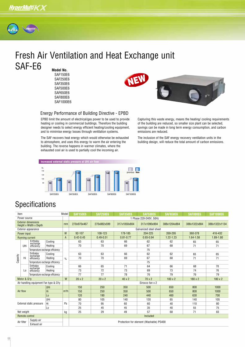
66 67
R410A
Unit:mm
Fresh Air Ventilation and Heat Exchange unitSAF-E6 Model No.
SAF150E6 SAF250E6 SAF350E6 SAF500E6 SAF650E6 SAF800E6 SAF1000E6
DimensionsAll measurements in mm.
NO. Name Qt'yFrame 1
Adaptor 4
Terminal board 1
Inspection Cover 1
Fan 2
Motor 2
Heat Exchange ElementSAF150E6SAF250E6SAF350E6SAF500E6SAF650E6SAF800E6SAF1000E6
1122334
Filter 2
Damper 1
Damper Motor 1
Suspension fitting
Electrical components box
4
1
Model SAF350E6, SAF500E6 and SAF600E6 have different fan and motor locations.
.
Installation reference
Exhaust Air Supply Airoutdoor indoor
10ºC27ºC
27ºC10ºC
Outside Air Room Air
e.g. For cooling in winter time
Heat exchanger element Damper
RA(Room Air)
SA(Supply Air)
EA(Exhaust Air)
OA(Outside Air)
Exhaust Air Supply Airoutdoor indoor
29ºC33ºC
27ºC35ºC
Outside Air Room Air
Energy Performance of Building Directive - EPBD
Structure (SAF800E6) Principle of operation (simple ventilation)FREE COOLING ENERGY RECOVERY
Principle of operation (heat exchanging)
EPBD limit the amount of electrical/gas power to be used to provide heating or cooling in commercial buildings. Therefore the building designer needs to select energy efficient heating/cooling equipment, and to minimise energy losses through ventilation systems.
The SAF recovers heat energy which would otherwise be exhausted to atmosphere, and uses this energy to warm the air entering the building. The reverse happens in warmer climates, where the exhausted cool air is used to partially cool the incoming air.
Capturing this waste energy, means the heating/ cooling requirements of the building are reduced, so smaller size plant can be selected, savings can be made in long term energy consumption, and carbon emissions are reduced.
The inclusion of the SAF energy recovery ventilation units in the building design, will reduce the total amount of carbon emissions.
Item Model SAF250E6 SAF350E6 SAF500E6 SAF800E6 SAF1000E6Power source 1 Phase 220-240V, 50HzExterior dimensionsHeight x Width x Depth 270x882x599 317x1050x804 317x1090x904 388x1322x884 388x1322x1134
Exterior appearance Galvanized steel sheetPower input W
mm
108-123 178-185 204-225 360-378 416-432Running current A 0.49-0.51 0.81-0.77 0.93-0.94 1.64-1.58 1.89-1.80
Cooling 63 66 62 65UHi Heating 70 69 67 71
Temperature exchange efficiency 75Cooling 63 66 62 65
Hi Heating 70 69 67 71
6571
6571
Temperature exchange efficiency 75Cooling 65 71 64 68 70
Lo Heating 72 73 69 74 76Temperature exchange efficiency 77 78 76 76 79
Motor & Q'ty W 20 x 2 40 x 220 x 2Air handling equipment Fan type & Q’ty Sirocco fan x 2
UHi 250 350 500 800 1000Air flow Hi m3/h 250 350 500 800 1000
Lo 190 240 440 630 700UHi 105 140 120 140 105
External static pressure
Net weightRemote control Included
Hi Pa
kg
95 60 60 110 80Lo 45
SAF150E6
270x970x467
92-1070.42-0.45
6370
6370
667377
150150120807025
SAF650E6
388x1204x884
269-2951.22-1.23
6268
6268
667379
65065046065404045 35 55 75
2925 6849 57 71 83
Air filterSupply air
Protection for element (Washable) PS400Exhaust air
Enthalpyexchangeefficiency
Capa
city Enthalpy
exchangeefficiency
Enthalpyexchangeefficiency
%
Specifications
Increased external static pressure at UHi air flow
SAF250E6 SAF350E6
90105
95
140
SAF500E6
105120
SAF1000E6
90105
SAF800E6
140 140140
120
100
80
Pa
Newprevious
Pipe hood
Room intake duct
Inside supply opening
Room intake opening
Outer air intake duct
Pipe hood
Ceiling suspension bolt
Air supply duct
EA(Exhaust Air)
(Supply/exhaust air grill)
(Supply/exhaust air grill)
Heat insulation material
Outside intake duct
OA (Outside Air)
RA(Room Air)
SA(Supply Air)
5
1
10 92
711
6
OA (Outside Air)
RA(Room Air)
4-13 x 30 oblong hole
EA (Exhaust Air)
SA (Supply Air)
12384
SAF150E6SAF250E6SAF350E6
SAF500E6
E F G H I J K L M N P
19
303315580640
270
317
82142112132
82142112132
135
159
159
182
525655860960
810
1018
978
Unit:mm
Model A B C467599804
904
49 95
70
882970
10901050
ø98
ø194
ø144ø164ø110
ø210
ø162
EA (Exhaust Air)
RA(Room Air)
OA (Outside Air)
SA (Supply Air)
4-13 x 30 oblong hole
852 6 10
11 1 7
9
SAF150E6, SAF250E6, SAF350E6, SAF500E6 SAF650E6, SAF800E6, SAF1000E6
SAF150E6SAF250E6SAF350E6SAF500E6
Applied duct
ø100
ø150
ø200
Model No. Nominal diameter
43
12
SAF650E6SAF800E6SAF1000E6
E F G H I J K L M N P
19620428678
388 132
228
560
612194 218
940
1190
1132
1250
A B C
884
1134
70
85
1204
1322
ø194
ø242
ø210
ø258
Model
SAF650E6SAF800E6SAF1000E6
Applied duct
ø200
ø250
Model No. Nominal diameter
Dimension tableDimension table
NEW
70 x 2 100 x 2 180 x 2 180 x 2
1
2
3
4
5
6
7
8
9
10
11
12
Note:An inspection port is needed for cleaning the heat exchanger and filter 1 or 2 times a year.
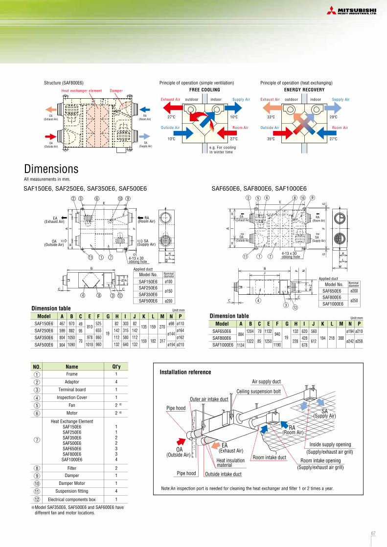

68 69
R410A
SAF-DXTotal heat exchanger
SA
RA
EA
OA
Supply / fresh air temp.sensor
Heating or cooling coil
Return / fresh air temp.sensor
Fresh Air DX Assembly DimensionsAll measurements in mm.
SAF-DX250E6,350E6
SAF-DX800E6 SAF-DX1000E6
SAF-DX500E6
Model No. SAF-DX250E6 SAF-DX350E6 SAF-DX500E6 SAF-DX800E6 SAF-DX1000E6
Drain up kit (option, built-in type)(600mm)
DXA-DU-E
RC-E5
Wired
RCH-E3
Wireless
RCN-KIT3-E
•SAF-DX is a heating or cooling coil incorporating MHI KX6 series controls. It can be used in combination with our SAF series of total heat exchanger.
•Combination of SAF-DX together with other KX6 indoor units is possible. The capacity code index of each model is shown below and must be used when making the system selection. Total capacity code index must be within 100% of outdoor unit capacity code index.
•Remote control option is the same as with other KX6 indoor units (see above). Connection to all superlink controls is also possible.
•Optional condensate lift mechanism is also available (600mm height).
•Return air temp. control or supply air temp. control can be selectable.
SAF-DX can provide heating or cooling to the fresh air supplied through a 3rd party air handling unit or total heat exchanger such as our SAF series.
(Outside Air)
(Exhaust Air)
(Room Air)
(Supply Air)
12.3 13.6 18.416.1
2.01.822
2.82.228
3.62.836
5.64.556
6.35.671
1 Phase 220-240V, 50Hz7.27.20.050.05
kWkW
W
A
mm
kgCMHPa
mm(in)
ItemNominal cooling capacityNominal heating capacityCapacity codePower source
Power consumption
Runningcurrent
Exterior dimensionsH x W x D
Net weightAir flow (Standard) Internal resistanceRemote control(option)
Installation dataRefrigerant piping size
wired: RC-E5, RCH-E3 wireless: RCN-KIT3-E66
Liquid line:ø6.35(1/4")Gas line:ø9.52(3/8")
Liquid line:ø6.35(1/4")Gas line:ø12.7(1/2")
Liquid line:ø9.52(3/8")Gas line:ø15.88(5/8")
Model SAF-DX250E6 SAF-DX350E6
ItemOperationCooling*1Heating*2
Return/fresh air temperature Outdoor air temperature StandardsDB
27ºC20ºC
WB19ºC
DB35ºC7ºC
WB24ºC6ºC
ISO-T1
SAF-DX500E6 SAF-DX800E6 SAF-DX1000E6
315 x 537 x 422315 x 452 x 422 315 x 822 x 422315 x 682 x 422
1000500 80025038
350
CoolingHeatingCoolingHeating
(1) The data are measured at the following conditions.
(2) This air-conditioner is manufactured and tested in conformity with ISO-T1 "UNITARY AIR-CONDITIONERS".
Specifications
*2
*1
Remote control (option)
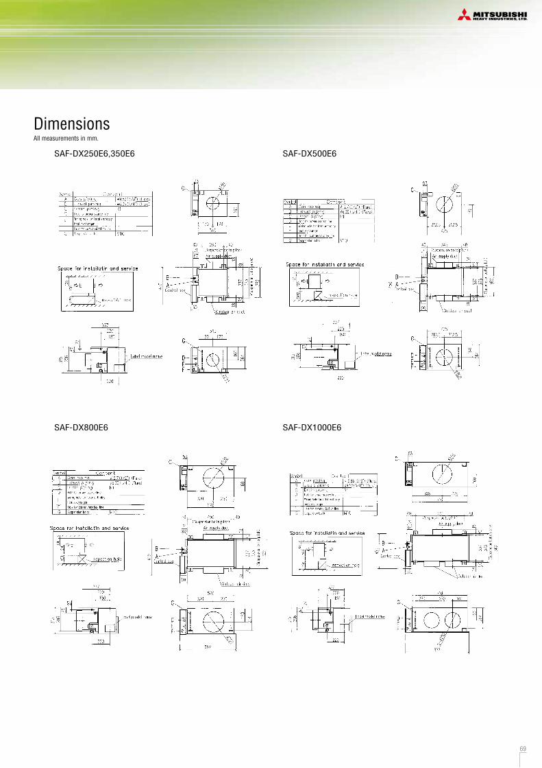
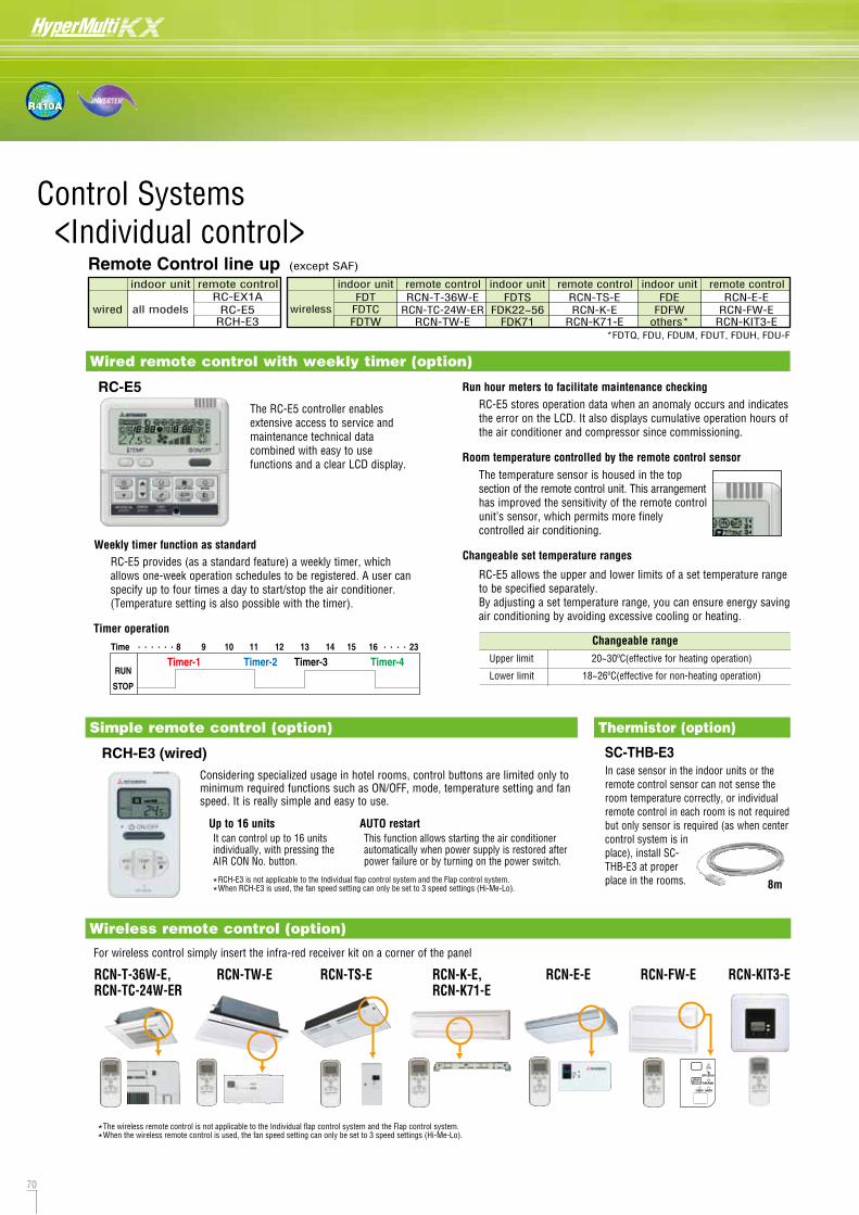
71
R410A
70
Control Systems <Individual control>
3-core cable for connecting indoor and outdoor units
Individual On/Off Control
Multi-KX6 indoor units
Multi-KX6 indoor units
Multi-KX6 indoor unitswith individual room control
3-core + earth cable for connecting indoor and outdoor units
3-core + earth cable
SRK/SRF-ZJXseries
for connecting indoor and outdoor units
SC-ADNA-E
One-to-one Wireless
SC-ADNA-E SC-ADNA-E
3-core cable for connecting indoor and outdoor units
Wirelessremotecontrol
Center Control SC-SL2NA-ECapable of control and monitoring up to 64indoor units. All operational functions, plus enable/disable connected remote control.
SC-ADNA-E
Center Control SC-SL1N-E
Multi-KX6 outdoor units"Micro KX"
KX6 Outdoor units
KX6 twined Outdoor units
SC-BIKN-E
SC-WGWNA-A/BPC Control Interface
<Control System>
MHI has now combined simplicity of installation with our highly sophisticated Superlink- control system, to offer building owners and occupiers a comprehensive control and management system, while providing complete commissioning and service maintenance assistance for installers and service engineers. The Superlink- network utilises two wire, non-polar cable - for further details of wiring.
Superlink- is an advanced high speed data transmission system that can connect up to 128 indoor units and 32 outdoor units as a network. MHI offers a wide range of control options for the Superlink- network to suit any application large or small, as well as connection to new or existing building management systems. Individual MHI split systems can also be integrated on to the Superlink- network using SC-ADNA-E.
SUPERLINK-
RC-E5 provides (as a standard feature) a weekly timer, which allows one-week operation schedules to be registered. A user can specify up to four times a day to start/stop the air conditioner. (Temperature setting is also possible with the timer).
Weekly timer function as standard
It can control up to 16 units individually, with pressing the AIR CON No. button.
Up to 16 unitsThis function allows starting the air conditioner automatically when power supply is restored after power failure or by turning on the power switch.
AUTO restart
Run hour meters to facilitate maintenance checkingRC-E5 stores operation data when an anomaly occurs and indicates the error on the LCD. It also displays cumulative operation hours of the air conditioner and compressor since commissioning.
Room temperature controlled by the remote control sensorThe temperature sensor is housed in the top section of the remote control unit. This arrangement has improved the sensitivity of the remote control unit’s sensor, which permits more finely controlled air conditioning.
Changeable rangeUpper limit 20~30ºC(effective for heating operation)
Lower limit 18~26ºC(effective for non-heating operation)
Changeable set temperature ranges
RC-E5 allows the upper and lower limits of a set temperature range to be specified separately.By adjusting a set temperature range, you can ensure energy saving air conditioning by avoiding excessive cooling or heating.
Timer operation
Wired remote control with weekly timer (option)
Simple remote control (option)
RC-E5
RCH-E3 (wired)Considering specialized usage in hotel rooms, control buttons are limited only to minimum required functions such as ON/OFF, mode, temperature setting and fan speed. It is really simple and easy to use.
RCN-T-36W-E, RCN-TC-24W-ER
RCN-K-E, RCN-K71-E
RCN-E-ERCN-TW-E RCN-TS-E RCN-KIT3-E
For wireless control simply insert the infra-red receiver kit on a corner of the panel
Wireless remote control (option)
Thermistor (option)
RCN-FW-E
SC-THB-E3In case sensor in the indoor units or the remote control sensor can not sense the room temperature correctly, or individual remote control in each room is not required but only sensor is required (as when center control system is in place), install SC-THB-E3 at proper place in the rooms.
The RC-E5 controller enables extensive access to service and maintenance technical data combined with easy to use functions and a clear LCD display.
Remote Control line up (except SAF)
indoor unit remote control
wired all modelsRCH-E3
RC-EX1ARC-E5
indoor unit remote control
wireless RCN-TC-24W-ERRCN-TW-E
RCN-T-36W-EFDTCFDTW
FDTindoor unit remote control
RCN-K-ERCN-K71-E
RCN-TS-EFDK22~56
FDK71
FDTSindoor unit remote control
RCN-FW-ERCN-KIT3-E
RCN-E-EFDFW
others*
FDE
8m*RCH-E3 is not applicable to the Individual flap control system and the Flap control system.
*When RCH-E3 is used, the fan speed setting can only be set to 3 speed settings (Hi-Me-Lo).
*The wireless remote control is not applicable to the Individual flap control system and the Flap control system.
*When the wireless remote control is used, the fan speed setting can only be set to 3 speed settings (Hi-Me-Lo).
*FDTQ, FDU, FDUM, FDUT, FDUH, FDU-F
Center ControlSC-SL4-AE/BE
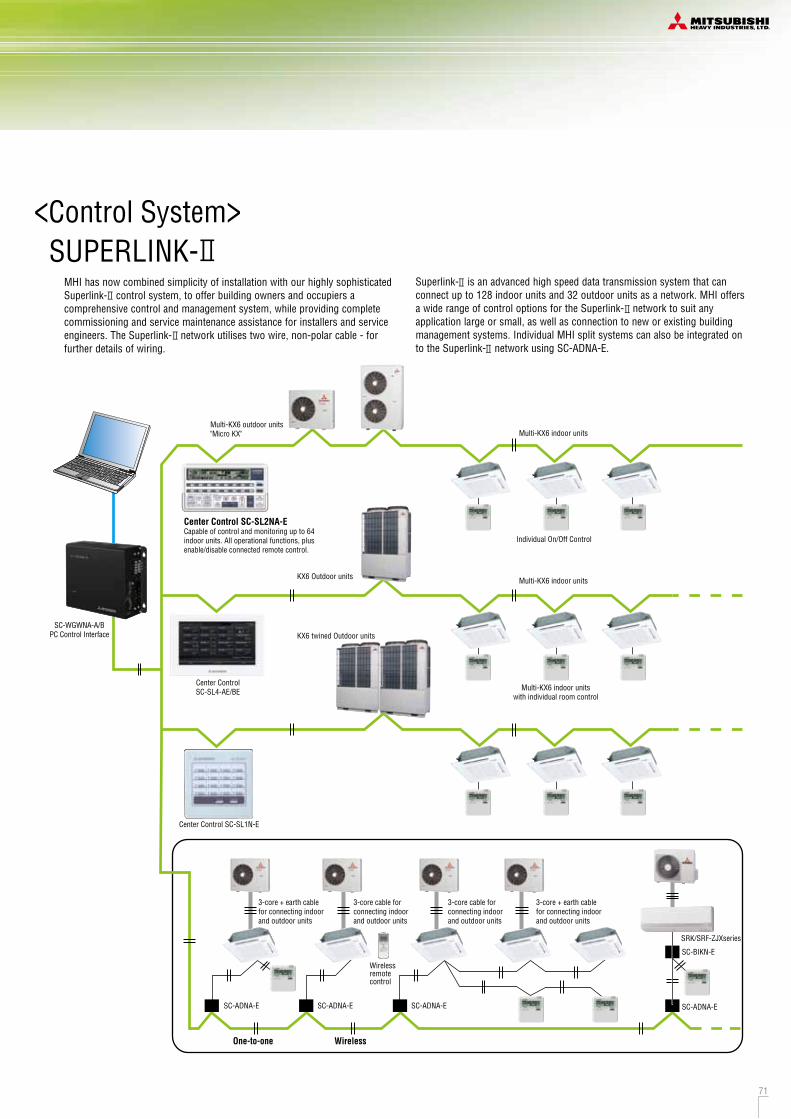
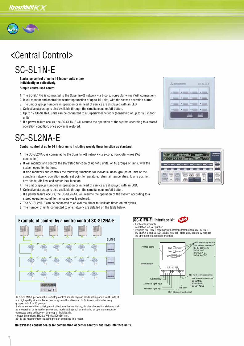
72 73
R410A
Start/stop control of up to 16 indoor units either individually or collectively.
Simple centralised control.
• Applicable products Ventilation fan, Air purifier• By using SC-GIFN-E together with central control such as SC-SL1N-E, SC-SL2NA-E and SC-SL4-AE/BE, you can start-stop, operate & monitor the operation of applicable products.
SC-SL2NA-EControl Monitoring Scheduling Administration/ServiceRun/Stop Operating state Yearly schedule Block definition
Mode (cool/heat/fan/dry/Auto) Mode Today's schedule Group definition
Set temperature Set temperature Special day schedule Unit definition
Operation permitted/prohibited Room temperature Time and date setting
Fan speeds Operation permitted/prohibited Alarm history
Air direction Fan speed Energy consumption calculation period
Filter sign reset Air direction
Filter sign
Energy consumption cumulative operation time
Maintenance (1, 2 or back-up)
Demand control
Demand control (3 steps)
Emergency stop
Electric power calculation function:(for SC-SL4-BE only) Item Model SC-SL4-AE/SC-SL4-BE
Ambient temperature during use 0 ~ 40oC
Power supply 1 Phase 100-240V 50/60Hz
Power consumption 18WExternal dimensions (Height x Width x Depth) 172mm x 250mm x 23 (+70) mm
Net weight 2.0kgNumber of
up to 128 unitsconnectable units (indoor units)
LCD touch panel Colour LCD, 9 inches wide
SL (Superlink) signal inputs
Watt-hour meter pulse input* 8-point pulse width 100ms or more
Emergency stop signal input*1 point non-voltage a contact input
continuous input (closed, forced stop)
Demand signal input*2 point non-voltage a contact input
continuous input (closed, demand control)
Operation output1 point maximum rated current 40mA, 24 V
During full stop; Open. If even one unit is operating; Closed
Error output1 point maximum rated current 40mA, 24 V
Normal; closed. If even one unit is abnormal; Open
* The receiving side power supply is DC 12V (10mA).The air conditioning charges calculations of this unit are based on OIML, the international standard.
Outp
uts
Inpu
ts
Method of data exportCalculation softwareAir-conditioner power proportional distribution pulse input (Maximum)Connecting indoor units number (Maximum)
USB / LANStandard
8
128
SC-SL4-BE
SC-SL4-AE/BEMHI introduces the full colour touch screen central control SC-SL4-AE/BE, with 9 inch interactive LCD display. Offers control, monitoring, scheduling and service/maintenance functions for up to 128 indoor units.Control with PC is available by use of internet explorer.
Indoor units can be controlled, scheduled, monitored and interrogated either individually, as groups or as blocks of groups with the following functions:
SC-SL1N-E
An SC-SL2NA-E performs the start/stop control, monitoring and mode setting of up to 64 units. It is a high quality air conditioner control system that allows up to 64 indoor units to be freely grouped into 1 to 16 groups.It allows not only the start/stop control but also the monitoring, display of operation statuses such as in operation or in need of service and mode setting such as switching of operation modes of connected units collectively, by group or individually.• Outer dimensions: H120 x W215 x D25+35*mm.35* is the measurement including the part contained in a recess.
<Central Control>
Example of control by a centre control SC-SL2NA-E
SL1N-E
Collective stop signal input
Watt-hour meter pulse input
Collective option output
Central control of up to 64 indoor units including weekly timer function as standard.
1. The SC-SL1N-E is connected to the Superlink- network via 2-core, non-polar wires (‘AB’ connection). 2. It will monitor and control the start/stop function of up to 16 units, with the sixteen operation button. 3. The unit or group numbers in operation or in need of service are displayed with an LED. 4. Collective start/stop is also available through the simultaneous on/off button. 5. Up to 12 SC-SL1N-E units can be connected to a Superlink- network (consisting of up to 128 indoor
units). 6. If a power failure occurs, the SC-SL1N-E will resume the operation of the system according to a stored
operation condition, once power is restored.
1. The SC-SL2NA-E is connected to the Superlink- network via 2-core, non-polar wires (‘AB’ connection).
2. It will monitor and control the start/stop function of up to16 units, or 16 groups of units, with the sixteen operation buttons.
3. It also monitors and controls the following functions for individual units, groups of units or the complete network: operation mode, set point temperature, return air temperature, louvre position, error code. Air flow and center lock function.
4. The unit or group numbers in operation or in need of service are displayed with an LCD. 5. Collective start/stop is also available through the simultaneous on/off button.6. If a power failure occurs, the SC-SL2NA-E will resume the operation of the system according to a
stored operation condition, once power is restored. 7. The SC-SL2NA-E can be connected to an external timer to facilitate timed on/off cycles. 8. The number of units connected to one network are detailed on the table below. SC-SL4-BE gives outputs as “electric power consumption kWh data -each
indoor unit, each group, each SUPERLINK- system and each power pulse system-” and uses USB memory.
Indoor unit 128 units
SW1
SW2
SW3
51X
1 2 3 4 5 6 7 8 A B
52 52R
one's place
hundred's place
ten's placePrinted board
Address setting switch
Net work communication line
Set address number will be the address for SC-SL1N-E, SC-SL2NA-E, SC-SL4-AE/BE
To A & B terminal block on SC-SL1N-E, SC-SL2NA-E, SC-SL4-AE/BE
Terminal block
Net work
Start-Stop command output
AC220-240V
Anomalous signal input
Operation signal input
Interface kitSC-GIFN-E NEW
Ethernet 10 BASE-T/100BASE-TX
InternetExplorer HUB
1 systems (Super link- )
Note:Please consult dealer for combination of center controls and BMS interface units.
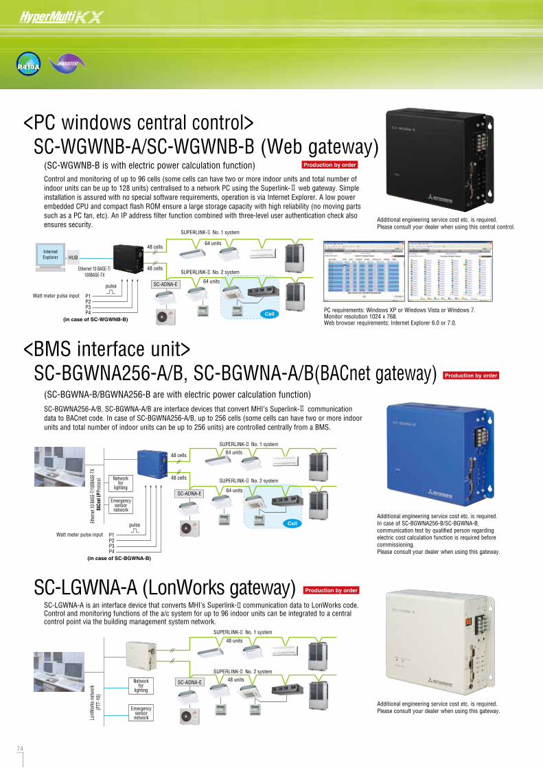
74 75
R410A
Cell
Cell
<BMS interface unit> SC-BGWNA256-A/B, SC-BGWNA-A/B(BACnet gateway)
<PC windows central control> SC-WGWNB-A/SC-WGWNB-B (Web gateway)
(SC-WGWNB-B is with electric power calculation function)
Automatically produced test-run report
Operation data storage when a fault occurs
Operation data storage during servicing
PC requirements: Windows XP or Windows Vista or Windows 7. Monitor resolution 1024 x 768. Web browser requirements: Internet Explorer 6.0 or 7.0.
64 units
Ethe
rnet
10 B
ASE-
T/10
0BAS
E-TX
BACn
et I/
P Pro
toco
l. Networkfor
lighting
Emergencysensor
network
SC-ADNA-E 64 units
48 cells
48 cells
Ethernet 10 BASE-T/100BASE-TX
64 units
64 units
48 cells
48 cells
InternetExplorer HUB
P1
pulse
P2P3P4
SC-LGWNA-A (LonWorks gateway)
LonW
orks
net
work
(F
TT-1
0)
48 units
48 unitsNetworkfor
lighting
Emergencysensor
network
Additional engineering service cost etc. is required.Please consult your dealer when using this central control.
Additional engineering service cost etc. is required.In case of SC-BGWNA256-B/SC-BGWNA-B, communication test by qualified person regarding electric cost calculation function is required before commissioning.Please consult your dealer when using this gateway.
Additional engineering service cost etc. is required.Please consult your dealer when using this gateway.
6
Outdoor unit PCB 7-segment display
Indoorunit
Indoorunit
Indoorunit
Indoorunit
Indoorunit
Indoorunit
Method of connecting Mente PC in the combination Multi system
The design of the outdoor units separates the air flow compartment from the mechanical compartment, allowing easy access to serviceable parts by simply removing the panel.
This design also means that the base plate of the air flow compartment acts as a drain tray connected to a drain pipe that runs through the mechanical compartment, so a simple connection of a drain hose to the base of the unit is all that is required, no need for a separate drain tray to be installed.
Service maintenance and trouble shooting tasks can be carried out easily via the wired remote controller, as well as a cooling test operation to assist commissioning.
The outdoor unit control box is also equipped with a switch to invoke a 'test-run' mode. This function can be used to help detect any installation errors, indoor/outdoor unit matching errors, EEV and valve operation. A 'pump-down' switch on the PCB allows refrigerant to be recovered with the compressor protected.
All outdoor unit PCBs are also equipped with a 7-segment digital display for detailed operation history and fault finding. Operation data is stored for the 30 minute period preceding a fault occurring and details are displayed on the 7-segment reading.
SC-ADNA-E
SC-ADNA-E
SUPERLINK- No. 1 system
SUPERLINK- No. 2 system
SUPERLINK- No. 1 system
SUPERLINK- No. 2 system
SUPERLINK- No. 1 system
SUPERLINK- No. 2 system
SC-LGWNA-A is an interface device that converts MHI’s Superlink- communication data to LonWorks code. Control and monitoring functions of the a/c system for up to 96 indoor units can be integrated to a central control point via the building management system network.
Control and monitoring of up to 96 cells (some cells can have two or more indoor units and total number of indoor units can be up to 128 units) centralised to a network PC using the Superlink- web gateway. Simple installation is assured with no special software requirements, operation is via Internet Explorer. A low power embedded CPU and compact flash ROM ensure a large storage capacity with high reliability (no moving parts such as a PC fan, etc). An IP address filter function combined with three-level user authentication check also ensures security.
(SC-BGWNA-B/BGWNA256-B are with electric power calculation function)SC-BGWNA256-A/B, SC-BGWNA-A/B are interface devices that convert MHI’s Superlink- communication data to BACnet code. In case of SC-BGWNA256-A/B, up to 256 cells (some cells can have two or more indoor units and total number of indoor units can be up to 256 units) are controlled centrally from a BMS.
Watt meter pulse input
(in case of SC-WGWNB-B)
Air flow chamber
Mechanicalchamber
P1
pulse
P2P3P4
Watt meter pulse input
(in case of SC-BGWNA-B)
Production by order
Production by order
Production by order
Service/maintenance and monitoring
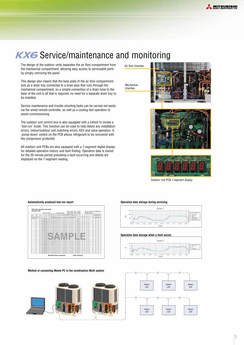
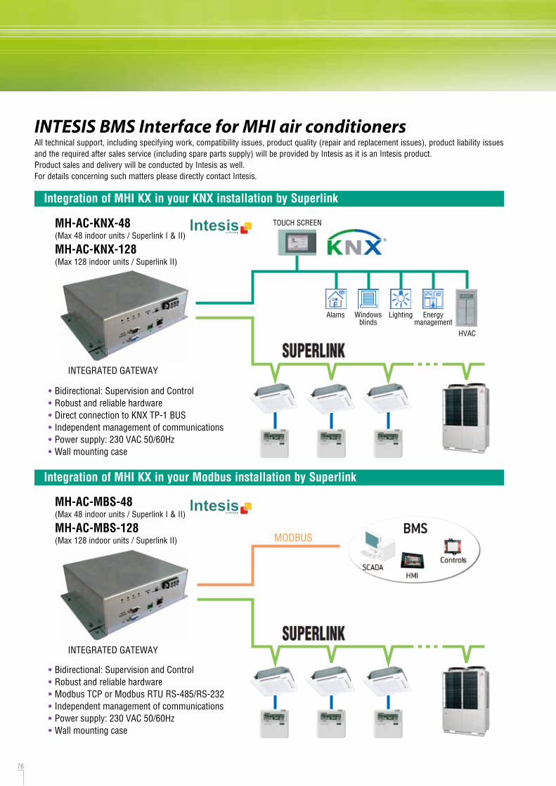
76 77
INTESIS BMS Interface for MHI air conditioners
Integration of MHI KX in your KNX installation by Superlink
Integration of MHI KX in your Modbus installation by Superlink
Integration of MHI PAC in your KNX installation by Remote control line
• Bidirectional: Supervision and Control• Robust and reliable hardware• Direct connection to KNX TP-1 BUS• Independent management of communications• Power supply: 230 VAC 50/60Hz• Wall mounting case
• Bidirectional: Supervision and Control• Robust and reliable hardware• Modbus TCP or Modbus RTU RS-485/RS-232• Independent management of communications• Power supply: 230 VAC 50/60Hz• Wall mounting case
MH-AC-KNX-48(Max 48 indoor units / Superlink I & II)
MH-AC-KNX-128(Max 128 indoor units / Superlink II)
• Protocol : KNX TP-1 bus• Dimension : 71 x 71 x 27 mm• External Power supply : no need
MH-RC-KNX-1i
• Protocol : Modbus RTU (RS-485)• Dimension : 93 x 53 x 58 mm• External Power supply : no need
MH-RC-MBS-1
• Protocol : EnOcean 1i : 868MHz@EU 1iC : 315MHz@USA, ASIA• Dimension : 100 x 70 x 28 mm• External Power supply : no need
MH-RC-ENO-1i/1iC
MH-AC-MBS-48(Max 48 indoor units / Superlink I & II)
MH-AC-MBS-128(Max 128 indoor units / Superlink II)
Integration of MHI PAC in your Modbus installation by Remote control line
Integration of MHI PAC in your EnOcean installation by Remote control line
INTEGRATED GATEWAY
INTEGRATED GATEWAY
Alams
TOUCH SCREEN
MODBUS
MODBUS
Windowsblinds
Lighting Energymanagement
HVAC
Alams
TOUCH SCREEN
Windowsblinds
Lighting
Energymanagement
HVAC
Please access the followings for details.URL
emailtel
http://[email protected]+34 938047 134
Example :Device as Master
Alams
TOUCH SCREEN
Windowsblinds
Lighting
Energymanagement
HVAC
RC-E5
RC-E5
RC-E5
Example :Device as Slave
Example :Device as Master
Example :Device as Slave
Example :Device as Master
Example :Device as Slave
MODBUS
All technical support, including specifying work, compatibility issues, product quality (repair and replacement issues), product liability issues and the required after sales service (including spare parts supply) will be provided by Intesis as it is an Intesis product. Product sales and delivery will be conducted by Intesis as well.For details concerning such matters please directly contact Intesis.
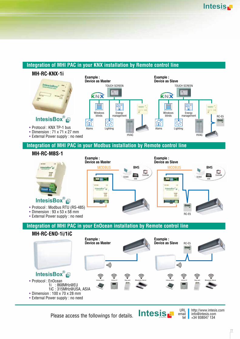
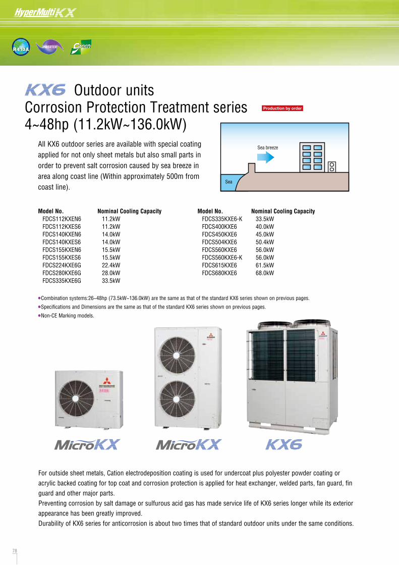
78 79
R410A
All KX6 outdoor series are available with special coating applied for not only sheet metals but also small parts in order to prevent salt corrosion caused by sea breeze in area along coast line (Within approximately 500m from coast line).
Sea breeze
Sea
For outside sheet metals, Cation electrodeposition coating is used for undercoat plus polyester powder coating or acrylic backed coating for top coat and corrosion protection is applied for heat exchanger, welded parts, fan guard, fin guard and other major parts.Preventing corrosion by salt damage or sulfurous acid gas has made service life of KX6 series longer while its exterior appearance has been greatly improved.Durability of KX6 series for anticorrosion is about two times that of standard outdoor units under the same conditions.
CautionEven if the outdoor unit is protected with the anti-salt damage treatment, it cannot be perfectly free from rusting. The following points should be kept in mind during installation and maintenance of the outdoor units.
Installation(1) When installing the outdoor unit close to the coastal area, provide a windbreak to protect it from direct sea breeze and
salt water splash.(2) Select a well-drained place to install.(3) If any scratch or damages occurred on the outdoor unit during installation, repair it carefully.
Maintenance(1) Clean salt grains on the outdoor unit with fresh water periodically.(2) Apply rust preventive at regular intervals for maintenance depending on the conditions at the installation place
(consulting with the withstanding capacity).(3) Confirm reset of screw tap after maintenance, if missing it may cause corrosion occurred from the hole of screw tap.(4) During prolonged non operation periods, protect the unit with covering.
4~48hp (11.2kW~136.0kW)Production by order
•Combination systems:26~48hp (73.5kW~136.0kW) are the same as that of the standard KX6 series shown on previous pages.
•Specifications and Dimensions are the same as that of the standard KX6 series shown on previous pages.
•Non-CE Marking models.
Model No. FDCS112KXEN6 FDCS112KXES6 FDCS140KXEN6 FDCS140KXES6 FDCS155KXEN6 FDCS155KXES6 FDCS224KXE6G FDCS280KXE6G FDCS335KXE6G
Nominal Cooling Capacity 11.2kW 11.2kW 14.0kW 14.0kW 15.5kW 15.5kW 22.4kW 28.0kW 33.5kW
Model No. FDCS335KXE6-K FDCS400KXE6 FDCS450KXE6 FDCS504KXE6 FDCS560KXE6 FDCS560KXE6-K FDCS615KXE6 FDCS680KXE6
Nominal Cooling Capacity 33.5kW 40.0kW 45.0kW 50.4kW 56.0kW 56.0kW 61.5kW 68.0kW
Additional treatment from the standard series showed on previous pages
4~6HP
8~12HP
Fin
pipe
Side plate
4~6HP
8~12HP
4~6HP
8~12HP
4~6HP
8~12HP
4~12HP
undercoat: Cation electrodeposition coatingtopcoat: polyester powder coating or acrylic baked coating
undercoat: Cation electrodeposition coatingtopcoat: polyester powder coating or acrylic baked coating
application of anticorrosion compound
application of anticorrosion compound
Precoated Aluminum Blue Fins in high anticorrosion specification
application of anticorrosion compound
application of anticorrosion compound
application of anticorrosion compound
application of anticorrosion compound
application of anticorrosion compound
application of anticorrosion compound
application of anticorrosion compound
application of anticorrosion compound
zinc coating + chromate treatment + fluorine coating
zinc coating + chromate treatment + fluorine coating
12.20*.14~24HP
undercoat: Cation electrodeposition coatingtopcoat: acrylic baked coating
undercoat: Cation electrodeposition coatingtopcoat: acrylic baked coating
undercoat: Cation electrodeposition coatingtopcoat: acrylic baked coating
application of anticorrosion compound
application of anticorrosion compound
Precoated Aluminum Blue Fins in high anticorrosion specification
application of anticorrosion compound
application of anticorrosion compound
application of anticorrosion compound
application of anticorrosion compound
application of anticorrosion compound
galvanized steel sheet + undercoat: Cation electrodeposition coating+ topcoat: acrylic baked finish
galvanized steel sheet + undercoat: Cation electrodeposition coating+ topcoat: acrylic baking finish
zinc coating + chromate treatment + fluorine coating
zinc coating + chromate treatment + fluorine coating
Corrosion protection treatment complies with regulation of The Japan Refrigeration and Air Conditioning Industry Association (JRA9002)
Exterior panel
Base plate
Drain pan
Fan motor
Compressor
Accumulator
Receiver
Fan motor base
Heat exchanger
Control box
Baffle plate
Service valve bracket
Screw tap for exterior panel
Screw tap for inside of exterior panel
*FDCS335KXE6-K / 560KXE6-K (For combination)
Corrosion Protection Treatment seriesOutdoor units

80 81
R410A
cooling only
•Maximum allowable height difference between the outdoor and the indoor unit located at the lowest height position has been increased from 50m to 100m.
(When the outdoor unit is located at higher position than the indoor unit)
•Non-CE Marking models.
BlueFin
BlueFin
FDCH335CKXE6G-KFDCH400CKXE6GFDCH450CKXE6G
BlueFin
BlueFin
FDCH504~680CKXE6G
Range of operation50
40
30
20
10
0
-10
Cooling
+43ºC
-5ºC
SpecificationsItemNominal horse powerPower sourceNominal capacity
Electrical characteristics
Exterior dimensionsNet weightRefrigerant chargeSound pressure level
Refrigerant piping size
Capacity connectionNumber of connectable indoor units
CoolingStarting currentPower consumptionRunning currentHxWxD
R410ACoolingLiquid lineGas line
CoolingCooling
kWA
kWA
mmkgkg
dB(A)
mm(in)
%
14HP
40.0
11.2718.4-16.9
59.5
ø25.4(1") [ø28.58(1 1/8")]
36
FDCH400CKXE6G16HP
45.0
12.9721.1-19.3
62.5
ø28.58(1 1/8")
40
FDCH450CKXE6G
ø12.7(1/2")
50~200
1690x1350x720326
Model
Item
Combination (FDCH)
Nominal horse powerPower sourceNominal capacity
Electrical characteristics
Exterior dimensionsNet weightRefrigerant charge
Refrigerant piping size
Capacity connectionNumber of connectable indoor units
CoolingStarting currentPower consumptionRunning currentHxWxD
R410ALiquid lineGas line
CoolingCooling
kWA
kWA
mmkgkg
mm(in)
%
FDCH735CKXE6G FDCH800CKXE6G FDCH850CKXE6G FDCH900CKXE6G
3 Phase 380-415V, 50Hz
16
1690x2700x720326x211.5x2
ø19.05(3/4")ø31.8(1 1/4") [ø34.92(1 3/8")]
50~160
335CKXE6G-K400CKXE6G
26HP
73.5
20.2132.9-30.2
53
400CKXE6G400CKXE6G
28HP
80.0
22.5436.8-33.8
58
400CKXE6G450CKXE6G
30HP
85.0
24.2439.5-36.2
61
450CKXE6G450CKXE6G
32HP
90.0
25.9442.2-38.6
65
Model
Item
Combination (FDCH)
Nominal horse powerPower sourceNominal capacity
Electrical characteristics
Exterior dimensionsNet weightRefrigerant charge
Refrigerant piping size
Capacity connectionNumber of connectable indoor units
CoolingStarting currentPower consumptionRunning currentHxWxD
R410ALiquid lineGas line
CoolingCooling
kWA
kWA
mmkgkg
mm(in)
%
FDCH960CKXE6G FDCH1010CKXE6G FDCH1065CKXE6G FDCH1130CKXE6G
3 Phase 380-415V, 50Hz
16
2048x2700x720
11.5x2
450CKXE6G504CKXE6G
34HP
96.0
27.7045.2-41.3
326+358
50~16069
504CKXE6G504CKXE6G
36HP
101.0
29.4648.2-44.0
59
504CKXE6G560CKXE6G
38HP
106.5
31.5251.5-47.1
358x2
50~13062
560CKXE6G560CKXE6G
40HP
113.0
33.5854.8-50.2
66
Model
Item
Combination (FDCH)
Nominal horse powerPower sourceNominal capacity
Electrical characteristics
Exterior dimensionsNet weightRefrigerant charge
Refrigerant piping size
Capacity connectionNumber of connectable indoor units
CoolingStarting currentPower consumptionRunning currentHxWxD
R410ALiquid lineGas line
CoolingCooling
kWA
kWA
mmkgkg
mm(in)
%
FDCH1180CKXE6G560CKXE6G-K615CKXE6G
42HP
118.0
37.1660.5-55.4
69
FDCH1235CKXE6G615CKXE6G615CKXE6G
44HP
123.5
40.7466.2-60.6
72
FDCH1300CKXE6G615CKXE6G680CKXE6G
46HP
130.0
45.3573.4-67.2
76
FDCH1360CKXE6G680CKXE6G680CKXE6G
48HP
136.0
49.9680.6-73.8
80
Model
3 Phase 380-415V, 50Hz
16
2048x2700x720377x211.5x2
ø22.22(7/8")ø38.1(1 1/2")
50~130
1. The data are measured under the following conditions(ISO-T1). Cooling: Indoor temp. of 27ºCDB, 19ºCWB, and outdoor temp. of 35ºCDB. Heating: Indoor temp. of 20ºCDB, and outdoor temp. of 7ºCDB, 6ºCWB. Piping length is 7.5m.2. Sound pressure level indicates the value in an anechoic chamber. During operation these values are somewhat higher due to ambient conditions.3. [ ] : Pipe sizes applicable to European installations are shown in parentheses.4. The above data applies to D service code models. Please check service codes for full specification.
14~48hp (40.0~136.0kW)Production by orderHigh Head series (100m)
FDCH335CKXE6G-K & FDCH560CKXE6G-K are only used for combining with other models.
Model No. FDCH335CKXE6G-K FDCH400CKXE6G FDCH450CKXE6G FDCH504CKXE6G FDCH560CKXE6G FDCH560CKXE6G-K FDCH615CKXE6G FDCH680CKXE6G
Nominal Cooling Capacity 33.5 kW 40.0 kW 45.0 kW 50.4 kW 56.0 kW 56.0 kW 61.5 kW 68.0 kW
Model No. FDCH735CKXE6G (FDCH335-K+FDCH400) FDCH800CKXE6G (FDCH400x2) FDCH850CKXE6G (FDCH400+FDCH450) FDCH900CKXE6G (FDCH450x2) FDCH960CKXE6G (FDCH450+FDCH504) FDCH1010CKXE6G (FDCH504x2) FDCH1065CKXE6G (FDCH504+FDCH560) FDCH1130CKXE6G (FDCH560x2) FDCH1180CKXE6G (FDCH560-K+FDCH615) FDCH1235CKXE6G (FDCH615x2) FDCH1300CKXE6G (FDCH615+FDCH680) FDCH1360CKXE6G (FDCH680x2)
Nominal Cooling Capacity 73.5 kW 80.0 kW 85.0 kW 90.0 kW 96.0 kW 101.0 kW 106.5 kW 113.0 kW 118.0 kW 123.5 kW 130.0 kW 136.0 kW
Total length:1000m
Outdoor unit
Height difference
Max height differencebetween indoor units: 18m
Indoor unit
Indoor unit
Indoor unit
Max height difference: 0.4m
Furthest indoor unit : 160m
Max: 10m
Max: 5mTo the first branch:max 130m
From the first branch to the furthest indoor unit: 90m
50~100m
*1
*2
The difference between the longest and shortest indoor unit piping from the first branch must be within 40m.In case of less than 50m, the High Head models can not be applied.In case Indoor unit is higher than outdoor unit, the High Head models can not be applied.
*1
*2
3 Phase 380-415V, 50Hz
8
35811.5
2048x1350x720
ø15.88(5/8")ø28.58(1 1/8")
50~160
18HP
50.4
14.7324.1-22.0
61.5
36
FDCH504CKXE6G FDCH560CKXE6G20HP
56.0
16.7927.4-25.1
63.0
40
377
FDCH615CKXE6G22HP
61.5
20.3733.1-30.3
64.5
44
FDCH680CKXE6G24HP
68.0
24.9840.3-36.9
65.0
49
ø19.05(3/4")ø31.8(1 1/4")[ø34.92(1 3/8")]
ø22.22(7/8")ø38.1(1 1/2")
Outdoor units
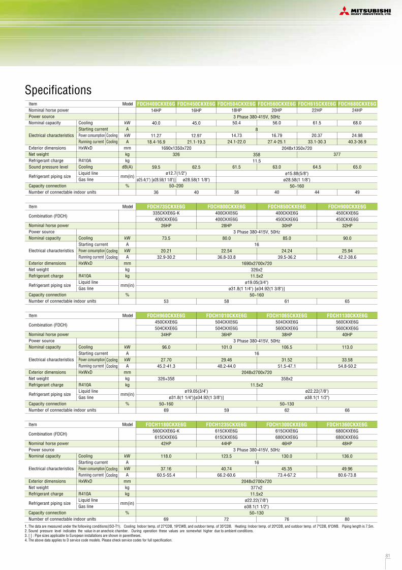

82 83
R410A
When more than one unit is installed
L3
L2 L5 L6 L4
Wal
l hei
ght
H2
Wall height
H4
Wall heightH2
Wall heightH3
L1 (Unit front side)
DimensionsAll measurements in mm.
A
500
10
100
10
0
0
1500
No restrictions
1000
No restrictions
B
Open
200
300
Open
400
400
No restrictions
No restrictions
No restrictions
No restrictions
Dimensions
L1
L2
L3
L4
L5
L6
H1
H2
H3
H4
Installation exampleNotes:(1) The unit must be fixed with anchor bolts.(2) Leave a 2m or larger space above the unit.(3) The unit name plate is attached on the lower right corner of
the front panel.(4) The ports for refrigerant pipe and power cable penetrations
are covered with half-blanks. Please cut off a half-blank with nippers in using these ports.
(5) Use a ø88 port for refrigerant pipe connection.(6) Anchor holes marked “L J” (four holes for M10) are for a
renewal installation.(7) The oil-equalising pipe K should be used when outdoor units
are used in combination. (For 14,16Hp only)
DimensionsAll measurements in mm.
Notes:(1) The unit must be fixed with anchor bolts.(2) Leave a 2m or larger space above the unit.(3) The unit name plate is attached on the lower right corner of
the front panel.(4) The ports for refrigerant pipe and power cable penetrations
are covered with half-blanks. Please cut off a half-blank with nippers in using these ports.
(5) Use a ø88 port for refrigerant pipe connection.(6) Anchor holes marked “L J” (four holes for M10) are for a
renewal installation.(7) The oil-equalising pipe K should be used when outdoor units
are used in combination.
FDCH335CKXE6G-K, 400CKXE6G, 450CKXE6G FDCH504CKXE6G, 560CKXE6G, 560CKXE6G-K, 615CKXE6G, 680CKXE6G
Installation example
1
500
10
100
10
1500
No limited
1000
No limited
2
Open
10
100
Open
–
No limited
No limited
–
Dimensions
L1
L2
L3
L4
H1
H2
H3
H4
Mark ContentABCDFGHKL
Refrigerant gas piping connection pipeRefrigerant liquid piping connection pipeRefrigerant piping exit holePower supply entry holeAnchor bolt holeDrain waste water hose holeDrain holeRefrigerant oil equalization piping connection pipeCarrying in or hole for hanging
ø28.58(Brazing)ø12.7(Flare)ø88(or ø100)
ø50 (right . left . front), long hole 40 x 80 (under side)M10, 4 pcsø45, 3 pcsø20, 10 pcsø9.52(Flare)
230 x 60
Mark Content 335-K 400 450 Installation example
ABCDFGHKL
Refrigerant gas piping connection pipeRefrigerant liquid piping connection pipeRefrigerant piping exit holePower supply entry holeAnchor bolt holeDrain waste water hose holeDrain holeRefrigerant oil equalization piping connection pipeCarrying in or hole for hanging
ø12.7(Flare)ø88(or ø100)
M10, 4 pcsø45, 3 pcsø20, 10 pcsø9.52(Flare)
230 x 60
1
500
10
100
10
1500
No limited
1000
No limited
2
Open
10
100
Open
–
No limited
No limited
–
Dimensions
L1
L2
L3
L4
H1
H2
H3
H4
ø50 (right . left . front), long hole 40 x 80 (under side)
ø25.4(Brazing) ø28.58(Brazing)
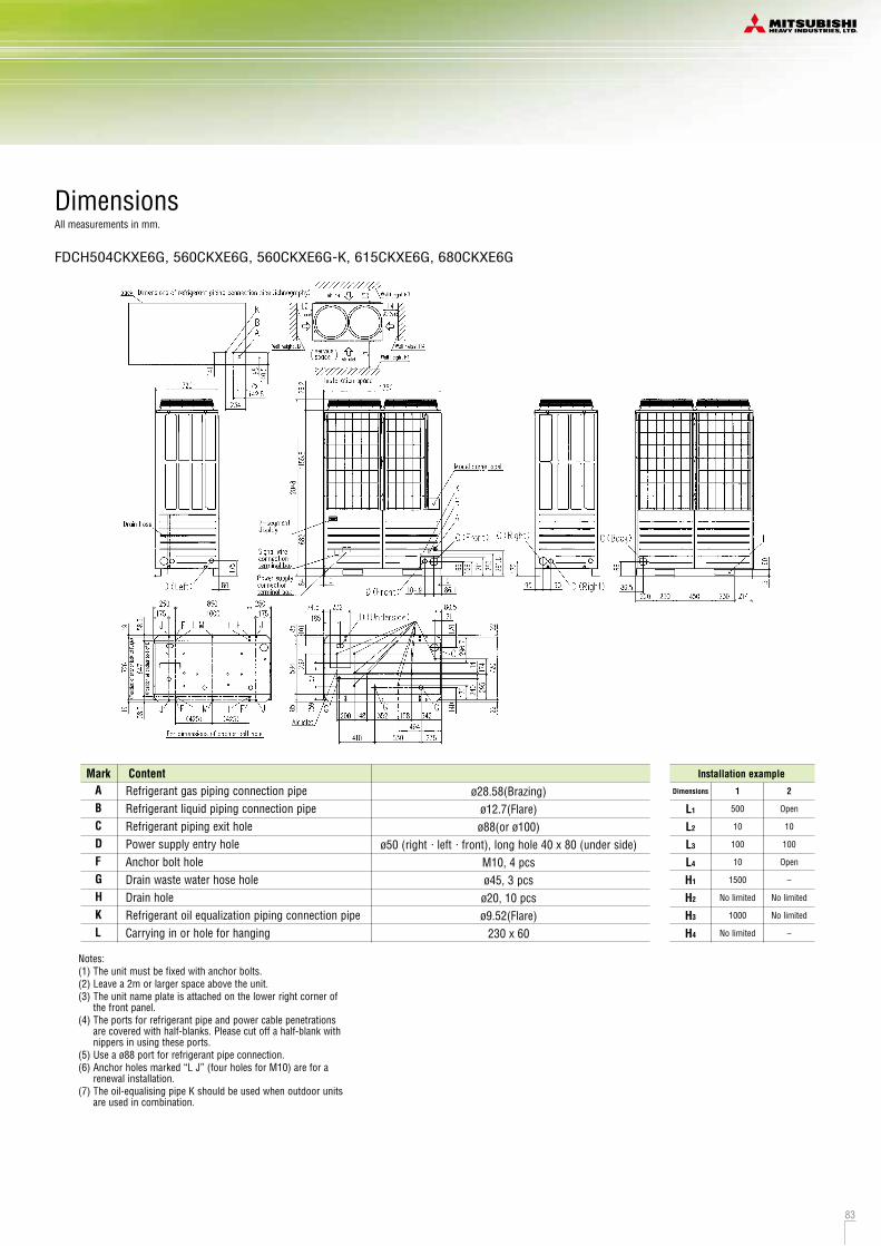
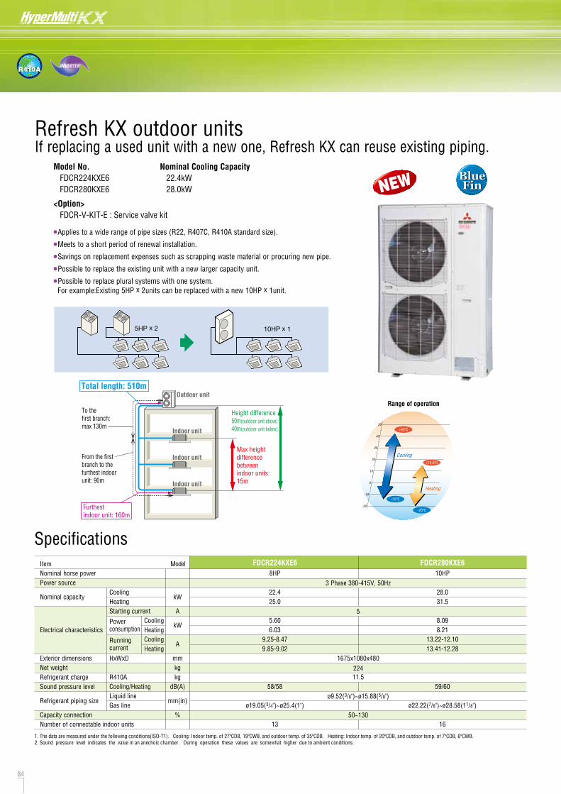
84 85
R410A
DimensionsAll measurements in mm.
When the existing unit is operableThe existing pipe can be reused by cooling operation only. Pipe refresh kit and Service valve kit are not required.
Model No. FDCR224KXE6 FDCR280KXE6
<Option> FDCR-V-KIT-E : Service valve kit
Nominal Cooling Capacity 22.4kW 28.0kW
If replacing a used unit with a new one, Refresh KX can reuse existing piping.
•Applies to a wide range of pipe sizes (R22, R407C, R410A standard size).
•Meets to a short period of renewal installation.
•Savings on replacement expenses such as scrapping waste material or procuring new pipe.
•Possible to replace the existing unit with a new larger capacity unit.
•Possible to replace plural systems with one system. For example:Existing 5HP x 2units can be replaced with a new 10HP x 1unit.
1.Implement cooling operation of all indoor units for more than 30 minutes.2.Implement pump-down after cooling operation.3.Recover refrigerant and remove the existing outdoor unit and indoor unit.
1.Pipe washing operation is implemented by changing dip switch on the outdoor unit PCB.
2.Completing washing is monitored via 7-segment display on the outdoor unit PCB.
3.As washing operation is about 60 minutes, it can meet to a required short period of renewal installation.
When the existing unit is not operableThe existing pipe can be reused by washing operation after connecting Refresh KX, Pipe refresh kit and Service valve kit.Connecting and removing of Refresh KX and Pipe refresh kit is very easy by use of flexible pipe and flanges.
Specifications
1. The data are measured under the following conditions(ISO-T1). Cooling: Indoor temp. of 27ºCDB, 19ºCWB, and outdoor temp. of 35ºCDB. Heating: Indoor temp. of 20ºCDB, and outdoor temp. of 7ºCDB, 6ºCWB.2. Sound pressure level indicates the value in an anechoic chamber. During operation these values are somewhat higher due to ambient conditions.
ItemNominal horse powerPower source
Nominal capacity
Electrical characteristics
Exterior dimensionsNet weightRefrigerant chargeSound pressure level
Refrigerant piping size
Capacity connectionNumber of connectable indoor units
CoolingHeatingStarting current
Powerconsumption
Runningcurrent
HxWxD
R410ACooling/HeatingLiquid lineGas line
CoolingHeatingCoolingHeating
kW
A
kW
A
mmkgkg
dB(A)
mm(in)
%
8HP
22.425.0
5.606.03
9.25-8.479.85-9.02
58/58
ø19.05(3/4")~ø25.4(1")
13
FDCR224KXE610HP
28.031.5
8.098.21
13.22-12.1013.41-12.28
59/60
ø22.22(7/8")~ø28.58(11/8")
16
FDCR280KXE6
ø9.52(3/8")~ø15.88(5/8")
50~130
Notes:(1) It must not be surrounded by walls on the four sides.(2) The unit must be fixed with anchor bolts. An anchor bolt must not
protrude more than 15mm.(3) Where the unit is subject to strong winds, lay it in such a direction that the
blower outlet faces perpendicularly to the dominant wind direction.(4) Leave a 1m or larger space above the unit.(5) A wall in front of the blower outlet must not exceed the units height.(6) The model name label is attached on the lower right corner of the front.(7) Connect the Service valve with local pipe by using the pipe of the
attachment.(Gas side only)(8) Mark shows the connecting position of the local pipe.(Gas side only)
Mark ItemService valve connection of the attached connecting pipe (gas side)Service valve connection (liquid side)Pipe/cable draw-out holeDrain discharge holeAnchor bolt holeCable draw-out holeCable draw-out holeCable draw-out holeCable draw-out holeConnecting position of the local pipe. (gas side)
ABCDEF1
F2
F3
F4
G
ø19.05 (3/4") (Flare)ø12.7 (1/2) (Flare)4placesø20 x 4placesM10 x 4placesø30ø45ø22ø34ø25.4 (1")(Brazing)
Model
22411.5
1675x1080x480
5
3 Phase 380-415V, 50Hz
BlueFin
BlueFin
Refresh KX outdoor units
50
40
30
20
10
0
-10
-20
Heating
Cooling
+43ºC
-15ºC
+15.5ºC
-20ºC
Range of operationOutdoor unit
Total length: 510m
To the first branch:max 130m
From the first branch to the furthest indoor unit: 90m
Height difference50m(outdoor unit above)40m(outdoor unit below)
Furthest indoor unit: 160m
Max height differencebetween indoor units: 15m
Indoor unit
Indoor unit
Indoor unit
NEW
Pipe refresh kit(FDCR-KIT-E)
Service valve kit
Piping systemoutdoor unit
Service valve kit
indoor unit
oil separator
Pipe refresh kit
easy local connection (flexbile pipe)
refrigerant flow
remove the pipe refresh kit after cleaning the used pipe
accumlatorcompressor
heat exchanger
highefficiencystrainer
high efficiencystrainer
5HP x 2 10HP x 1
Advanced refresh function
7-segment display
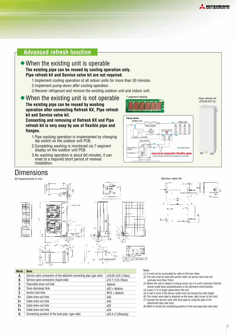
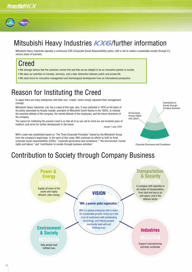
86 87
R410A
Creed
Reason for Instituting the Creed In Japan there are many enterprises with their own “creeds” which simply represent their managementconcept.
Mitsubishi Heavy Industries, Ltd. has a creed of this type, also. It was instituted in 1970 on the basis ofthe policy advocated by Koyata Iwasaki, president of Mitsubishi Goshi Kaisha in the 1920’s, to indicatethe essential attitude of the company, the mental attitude of the employees, and the future directions ofthe company.
The reason for instituting the present creed is so that all of us can call to mind our one hundred years oftradition, and strive for further development in the future.
Power & Energy
MISSIONSupply all areas of the
world with highlyefficient, clean energy VISION
“MHI, a premier global organization.”
MHI is a global enterprise with a vision for sustainable growth, living up to the
trust of customers with outstandingtechnology, and helping people
worldwide lead safe andfulfilling lives.Environment
& SocietyMISSION
Help people leadfulfilled lives
Industries
MISSIONSupport manufacturing
activities worldwide
MISSIONA company with expertise inall modes of transportation,
from land and sea to airand space, and in the
defence sector
MHI’s creed was established based on “The Three Corporate Principles” shared by the Mitsubishi Groupfrom the company’s beginnings. In the spirit of this creed, MHI continues its efforts to fulfil its threecorporate social responsibilities (CSRs): “corporate governance and compliance,” “the environment, humanrights and labour,” and “contribution to society through business activities.” Corporate Governance and Compliance
Issued 1 June 1970
Number of offices/plants by region (Consolidated)
EuropeMajor subsidiaries 18
AsiaMajor subsidiaries 66
as of May, 2013
JapanHead office & domestic officesResearch & development centres 6
Works 14
10
Major domestic subsidiaries 129
OceaniaMajor subsidiaries 2
North, Central & South AmericaMajor subsidiaries 29
In order to make the sustainable development of society possible, a basic policy on environmental matters has been established.
Mitsubishi Heavy Industries operates a continuous CSR (Corporate Social Responsibility) policy, with a role to realise a sustainable society through it’svarious areas of business.
The KX6 product range has been developed in compliance with the Mitsubishi Heavy Industries Policy on the Environment.
•••
We strongly believe that the customer comes first and that we are obliged to be an innovative partner to society.
We base our activities on honesty, harmony, and a clear distinction between public and private life.
We shall strive for innovative management and technological development from an international perspective.
Pursuant to the express provision of Section 1 of its creed that “We strongly believe that customers come first and that we are obligated to be an innovative partner to society,” MHI shall, as a matter of primary importance, strive, through its R&D, manufacturing and other business activities, to play a useful role in the development of society. To this end, while remaining aware that a business enterprise is a member of society, MHI shall endeavour, in all aspects of its business activities, to reduce the burden on the environment and shall concentrate and fully utilise its technological capabilities for the development of technologies and products that will protect the environment, thus contributing to the establishment of a society in which sustainable development is possible.
1. Recognise that environmental protection is top priority in the companyís operations, and encourage the entire company in its endeavours to protect and improve the environment.
2. Define roles and responsibilities regarding environmental protection by developing and maintaining a corporate organisation designated for environmental protection, and create and implement corporate policies and procedures on environmental matters.
3. Endeavour to reduce the burden on the environment by preventing pollution, saving resources, saving energy, reducing waste, reusing materials, and recycling in all aspects of the companyís business activities in R&D, designing, procurement of materials, manufacturing, transportation, use, service and disposal.
4. Endeavour to develop and provide advanced, highly reliable, unique technologies and products that contribute to solving environmental and energy problems. 5. Comply with national and local environmental laws and regulations, beyond mere compliance by enacting, implementing and evaluating voluntary
standards where necessary, and to endeavour to continuously improve and promote environmental protection activities by establishing environmental goals and targets.
6. Endeavour to protect the environments of foreign countries by carefully examining the consequences of the companyís overseas business operations and the exportation of its products, and to become actively involved in technological co-operation overseas in areas of environmental protection.
7. Provide environmental training and other programs to enhance the environmental awareness of all company employees, and take steps to expand public relations activities, such as providing environment-related information to the public and social contribution activities.
In order to realise its basic policy, MHI has set the following seven conduct guidelines.
Contribution to Society through Company Business
Contribution to Society through Company Business
Environment, Human Rightsand Labour
Transportation & Security
Mitsubishi Heavy Industries /further information
AfricaMajor subsidiary 3
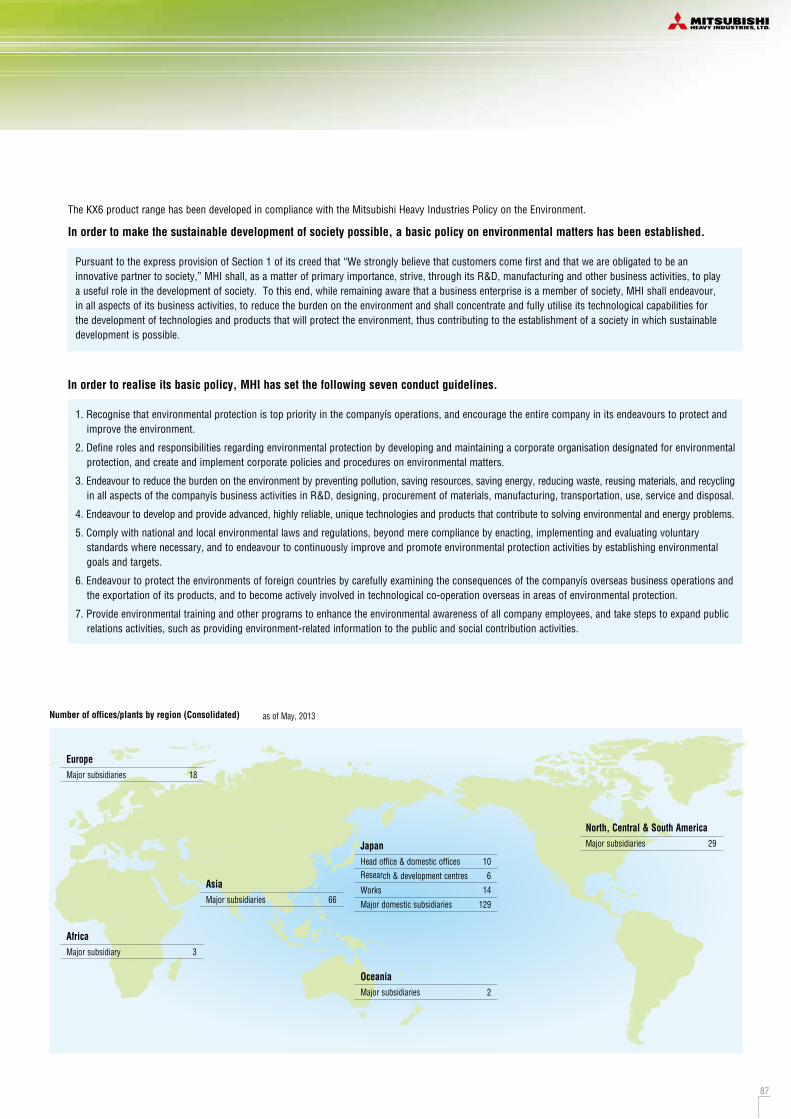
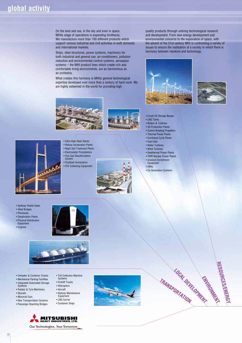
88 89
LEIS
URE/
LIFE
STYL
E
INDU
STRI
AL
INFO
RMATIO
N SYS
TEM
DEVELOPMENT
DEFENCE
TRANSPORTATION
LOCAL DEVELOPMENTENVIRONM
ENTRESOURCES/ENERGY
global activity
On the land and sea, in the sky and even in space, MHIís stage of operations is expanding limitlessly. We manufacture more than 700 different products which support various industrial and civil activities in both domestic and international markets.
Ships, steel structures, power systems, machinery for both industrial and general use, air-conditioners, pollution reduction and environmental control systems, aerospace systems – the MHI product lines which create rich and comfortable living environments, are as harmonious as an orchestra.
What creates this harmony is MHIís general technological expertise developed over more than a century of hard work. We are highly esteemed in the world for providing high
quality products through untiring technological research and development. From new energy development and environmental concerns to the exploration of space, with the advent of the 21st century MHI is confronting a variety of issues to ensure the realisation of a society in which there is harmony between mankind and technology.
• Spillway Radial Gates• Steel Bridges• Penstocks• Desalination Plants• Physical Distribution Equipment• Engines
• Ultra-High Steel Stacks• Refuse Incineration Plants• Night Soil Treatment Plants• Electrostatic Precipitators• Flue Gas Desulfurization System• Fluidized Incinerators• CFC Collecting Equipment
• Unloader & Container Cranes• Mechanical Parking Facilities• Integrated Automated Storage Systems• Rubber & Tyre Machinery• Skyrails• Monorail Cars• New Transportation Systems• Passenger Boarding Bridges
• Toll Collection Machine Systems• Forklift Trucks• Helicopters• Aircraft• Railway Maintenance Equipment• LNG Carrier• Container Ships
• Crude Oil Storage Barges• LNG Tanks• Boilers & Turbines• Oil Production Plants• Contra-Rotating Propellers• Thermal Power Plants• Combined Cycle Plants• Fuel Cells• Water Turbines• Wind Turbines• Geothermal Power Plants• PWR Nuclear Power Plants• Uranium Enrichment Equipment• FBRs• Co-Generation Systems
• Oceanographic Research Ships• Deep Submergence Research Vehicles• Communications Satellite Rockets• Space Transportation• Rockets & Engines
• Cable Layer• Printing Machinery
• Chemical Plants• Wind Tunnel/Experiment Equipment• Casting Machines• Strip Mill• Cement Plant• Stepless Variable Speed Gears• Industrial Robots• Injection Moulding Machines• Pulp & Paper Machinery• Corrugation Machines• Box Making Machines• Machine Tools
• Ceiling Recess Packaged Air Conditioners• Automotive Air Conditioners• Residential Use Split Air Conditioners• Refrigeration Units• Dry Cleaning Machines• Food Machinery• Cruise Ships• Multi-purpose Dome• Stage Machinery Systems
• Submarines• Naval Vessels• Jet Fighters• Helicopters• Missiles• Tanks & Infantry Fighting Vehicles
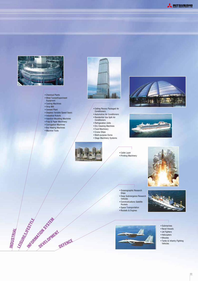
Safety Precautions
Before starting use
HB91-14KX02E
Our factories are ISO9001 and ISO14001 certified.
BIWAJIMA PLANT Mitsubishi Heavy Industries, Ltd.
Air-conditioning & Refrigeration Systems Headquarters
MITSUBISHI HEAVY INDUSTRIES-MAHAJAK AIR CONDITIONERS CO., LTD.
Mitsubishi HeavyIndustries-Haier (Quingdao)
Air-conditioners Co.,Ltd.
MITSUBISHI HEAVY INDUSTRIES-MAHAJAK AIR CONDITIONERS CO.,LTD.
ISO 14001Certificate 04104 1998 0813 E5
Mitsubishi HeavyIndustries-Haier (Quingdao)
Air-conditioners Co.,Ltd.
Certified ISO 9001
BIWAJIMA PLANT Mitsubishi Heavy Industries, Ltd.
Air-conditioning & Refrigeration Systems Headquarters
Certified ISO 14001
Because of our policy of continuous improvement, we reserve right to make changes in all specifications without notice.
Printed in JapanNovember 2013 (2B)R
Mitsubishi Heavy Industries, Ltd.Air-Conditioning & Refrigeration Systems16-5, Konan 2-chome, Minato-ku, Tokyo, 108-8215 Japanhttp://www.mhi.co.jp
2013
Mitsubishi Heavy Industries VRF inverter m
ulti-system Air-Conditioners
50Hz14KX02E
R410A
VRF inverter multi-system Air-Conditioners
InstallationAlways commission the installation to a dealer or specialist. Improper installation will lead to water leakage, electric shocks and fires. Make sure that the outdoor unit is stable in installation. Fix the unit to stable base.
Usage placeDo not install in places where combustible gas could leak or where there are sparks. Installation in a place where combustible gas could be generated, flow or accumulate, or places containing carbon fibers could lead to fires.
Air-conditioner usage targetThe air-conditioner described in this catalog is a dedicated cooling/heating device for human use. Do not use it for special applications such as the storage of foodstuffs, animals or plants, precision devices or valuable art, etc. This could cause the quality of the items to drop, etc. Do not use this for cooling vehicles or ships. Water leakage or current leaks could occur.
Before useAlways read the "User,s Manual" thoroughly before starting use.
Heating performanceThe heating performance values (kW) described in catalog are the values obtained by operating at an outdoor temperature of 7 C and indoor temperature of 20 C as set forth in the ISO Standards. As the heating performance decreases as the outdoor temperature drops, if the outdoor temperature is too low and the heating performance is insufficient, use other heating appliances as well.
Indication of sound valuesThe sound values are the values (A scale) measured in a chamber such as an anechoic chamber following the ISO Standards. In the actual installation state, the value is normally larger than the values given in the catalog due to the effect of surrounding noise and echo. Take this into consideration when installing.
Use in oil atmosphereAvoid installing this unit in as atmosphere where oil scatters or builds up, such as in a kitchen or machine factory. If the oil adheres to the heat exchanger, the heat exchanging performance will drop, mist may be generated, and the synthetic resin parts may deform and break.
Use in acidic or alkaline atmosphereIf this unit is used in acidic atmosphere such as hot spring areas having high level of sulfuric gases or in alkaline atmosphere including ammonia or calcium chloride, places where the exhaust of the heat exchanger is sucked in, or at coastal areas where the unit is subject to salt breezes, the outer plate or heat exchanger, etc., will corrode. Please ask a dealer or specialist when you use an air conditioner in places differing from a general atmosphere. Use in places with high ceilingsIf the ceiling is high, install a circulator to improve the heat and air flow distribution when heating.
Refrigerant leakageThe refrigerant (R410A) used for Air conditioner is non-toxic and inflammable in its original state. However, in consideration of a state where the refrigerant leaks into the room, measures against refrigerant leaks must be taken in small rooms where the tolerable level could be exceeded. Take measures by installing ventilation devices, etc.
Use in snowy areasTake the following measures when installing the outdoor unit in snowy areas.
·Snow preventionInstall a snow-prevention hood so that the snow does not obstruct the air intake port or enter and freeze in the outdoor unit.
·Snow pilingIn areas with heavy snow fall, the piled snow could block the air intake port. In this case, a frame that is 50cm or higher than the estimated snow fall must be installed underneath the outdoor unit.
Automatic defrosting deviceIf the temperature is low, and the humidity is high, frost will stick to the heat exchanger of the outdoor unit. If use is continued, the heating performance will drop. The "Automatic defrosting device" will function to remove this frost. After heating for approx, three to ten minutes, it will stop, and the frost will be removed. After defrosting, hot air will be blown again.
Servicing the air-conditionerAfter the air-conditioner is used for several seasons, dirt will build up in the air-conditioner causing the performance to drop. In addition to regular servicing, we recommend the maintenance contract (charged for) by a specialist.
2013