
Split System Air Conditioners Odyssey 60 Hz / Cooling Units 6
Upload
khangminh22Category
view
0download
0
M O N I T O R I N G & C O N T R O L S O L U T I O N S
Limit Alarms / ComputationProcess TransmittersEthernet, Modbus, Profibus I/O 4-20mA Isolators & Splitters
RELIABILITY
FLEXIBILITY
FAST DELIVERY
ENGINEERING SUPPORT
ONE STOP I/O SHOP
DISTRIBUTED I/O AND SIGNAL CONDITIONERS

Acromag: The I/O LeaderAcromag is a customer-driven manufac-turer focused on developing embedded I/O products that provide the best long term value in the industry. Compare and you’ll find that Acromag products offer an unmatched balance of price, performance, and features.
50+ Years of I/O ExperienceAcromag has more than 50 years of measurement and control experience. Since 1957, we have delivered nearly a million units to thousands of customers around the globe for manufacturing, power, environmental, transportation, and military applications.
Top Quality and a 2-Year WarrantyWe take every measure to guarantee you dependable operation and products that perform at or beyond their specifications. Our state-of-the-art manufacturing and military-grade components add an extra degree of ruggedness. Most products qualify for an extended 2-year warranty. And with ISO9000/AS9100 certified quality control, you get full confidence.
All trademarks are the property of their respective owners.
Online OrderingFor your convenience, Acromag provides full product documentation and pricing information on our website. You can obtain quotes or even place your order directly on our website.
Fast Delivery from StockMost products can be shipped within 24 hours of receiving your order.
Special ServicesWe are happy to accommodate your special requirements and offer the following services: • custom product development • custom calibration • source inspections, quality audits • special shipping, documentation • protective humiseal coating • plastic and stainless steel tagging
Certification and ApprovalsMany Acromag products carry globally recognized agency approvals and safety certifications. • CE • Ethernet conformance • UL, cUL • Modbus conformance • ATEX • Profibus certification • CSA • IECex
Depend on Acromag
Acromag, Incorporated 30765 South Wixom Road Wixom, Michigan 48393 USA
– 2 –
Experience counts:
especially when
you are selecting
an I/O partner.
And with 50+ years
of I/O experience,
Acromag can help
you to improve
reliability, increase
productivity and
reduce your costs.

Voltage AC/DC
Current AC/DC
Thermocouple
RTD / Resistance
Thermistor
Strain / Load Cell
Pot / Slidewire
Discrete Sensors
DC Voltage
DC Current
Relay
Solid-State Switch
Frequency
Pulse WidthModulation
Display / Readout
Ethernet
Modbus
Profibus
HART
Peer-to-Peer
COMMUNICATION
INPUT SIGNALS OUTPUT SIGNALS
Amplify Filter Isolate
Convert Scale Split
Linearize SuppressSurges
TripAlarm
Integrate Totalize Math / Compute
I/O MODULES
Telephone: 877-214-6267 or 248-295-0880 Fax: 248-624-9234 [email protected] www.acromag.com
Industrial Input/Output Solutions
– 3 –
www.acromag.com/transmitters www.acromag.com/isolators
www.acromag.com/alarms www.acromag.com/computation
Ethernet I/O Modbus I/O
Profibus I/O I/O Accessories
Transmitters Isolators / Splitters
Limit Alarms Computation
www.acromag.com/ethernet www.acromag.com/modbus
www.acromag.com/profibus www.acromag.com/accessories
NETWORK I/O SIGNAL CONDITIONERS

Embe
dded
Con
trol
lers
P
Cs &
HM
Is
Rec
ord
ers
L
oop
Cont
rolle
rs
DCS
/ PL
CContinuous / D
iscrete Sensors & A
ctuators
Field Instruments
Power M
onitoring
Signal Is
olation & Transmission
Netw
ork Interface Signal Conve
rsio
n
Signal Interfacing Solutions
Telephone: 877-214-6267 or 248-295-0880 Fax: 248-624-9234 [email protected] www.acromag.com
– 4 –
How Acromag I/O Is UsedAcromag I/O is ideal for for a broad range of monitoring and control operations where controllers communicate with instrumentation on the plant floor or in the field.
Acromag Advantages• wide operating temperature ranges (up to -40 to 85°)• high resistance to RFI, EMI, surges, electrical transients• high-voltage isolation and built-in surge suppression• easy to use and maintain• high channel density to save space• large inventory of stock items for same day shipping• special designs and custom services available• 7-year warranty available at no extra cost• AS9100 and ISO 9001 certified quality management
Operation in All Locations• safe zones and hazardous locations (Zone 2)• explosion-proof locations (Zone 1)• approvals from CE, UL/cUL, FM, CSA, ATEX, IECex
Controller Interface• PLCs, PACs, controllers• DCS distributed control systems• PCs, embedded computers, SCADA systems • operator interface terminals and remote terminal units
Continuous Sensors• temperature • pressure• flow • level• speed • weight / load• position • drives
Discrete Sensors and Switches• dry contacts • PNP, NPN• solid-state • proximity• valves • lights, horns
Actuators and Analytical Instruments• drives, motors • power supplies• heaters, coolers • valves, positioners• displays, indicators • recorders, analyzers
l Conv
Inte

Industries Served
Telephone: 877-214-6267 or 248-295-0880 Fax: 248-624-9234 [email protected] www.acromag.com
– 5 –
Raw Materials ProcessingThese industries rely on Acromag process instruments for accurate and repeatable measurements from sensor signals.
chemical, petrochemical
metal, glass, ceramic
pulp, paper, textile
Oil, Gas, and MiningBuilt for operation in extreme environments, Acromag I/O reliably interfaces sensors to actuators and controllers.
exploration, extraction
production
distribution
Power GenerationAble to resist noise and surges from high-voltage electrical sources, Acromag I/O delivers dependable data to plant control systems.
fossil fuels, hydroelectric, nuclear
solar, wind, geothermal
fuel cells, batteries
Water / WastewaterOffering outstanding value and easy installation, Acromag I/O is the first choice of many municipalities to help manage their water systems.
municipal
industrial
desalinization
irrigation
Factory AutomationFast response times, high reliability, and proven compatibility with control networks make Acromag I/O popular for use on assembly lines.
food, beverage, pharmaceutical
automotive, electronic assembly
building automation, HVAC
Defense, Security, and AerospaceAcromag I/O finds a home in many military and security systems due to their ability to operate over wide temperature ranges.
simulators and trainers
ground / airborne / naval controls
surveillance systems
OEM Machine ControlHigh channel density plus shock and vibration immunity help machine builders add more I/O to monitor and control their equipment.
semiconductor, lithography
boilers, furnaces, generators
test stands, industrial machinery
Research and DevelopmentWhen high-resolution and high-accuracy measurements are required, Acromag I/O ensures precise data collection.
test and measurement systems
data acquisition systems
scientific research
quality control/assurance

Peer-to-Peer CommunicationMany Acromag I/O modules have i2o technology for “input-to-output” peer-to-peer over Ethernet.
Automatically transmits analog or discreteI/O information between modules
Wire-saver, mux/de-mux, splitter tasks
8B I/O ModulesEthernet-enable panel-mounted isolation amplifiers with BusWorks or Ethertstax I/O.
Connect 8B backpanels to AcromagEthernet I/O with DB25 cable(cables also available for 3B/5B/7B)
Over 102 low-cost, high-isolation models
Up to 1500V AC isolation per amplifier
Software Tools OPC, .NET, ActiveX, Visual Basic/C++
Function libraries with C source code
Compatible with Windows, Linux,VxWorks, QNX, OS-9, and other OSs
Power Supplies 10W, 15W, 30W, 60W, 120W, or 240W
Universal input(85-264V AC / 100-370V DC)
Distributed I/O Solutions
Telephone: 877-214-6267 or 248-295-0880 Fax: 248-624-9234 [email protected] www.acromag.com
– 6 –
NEW! BusWorks XT SeriesHigh-performance, space-saving remote analog and discrete I/O modules - with Xtra Technology - for Ethernet networks.
Ethernet/IP, Profinet, Modbus TCP/IP, andi2o peer-to-peer communication
Easy PC/Windows configuration via USB
Redundant and bussed DC power
BusWorks 900 Series
A series of dependable, yet economical, remote analog and discrete I/O modules for Ethernet or RS485 networks.
Ethernet/IP, Modbus TCP/IP, i2o peer-to-peer, Modbus-RTU and Profibus-DPcommunication
Easy configuration using Internet browseror Windows software
EtherStax ES2000 SeriesHigh-density I/O blocks designed for high-reliability operation in Ethernet networks.
Modbus TCP/IP, UDP/IP, and i2o peer-to-peer communication
Up to 96 channels of discrete or analogI/O in a vertically-stackable unit with asmall footprint
Fast scan rates (below 1 millisecond)
Redundant power and communication
www.acromag.com/BusWorksXT
www.acromag.com/BusWorks900
www.acromag.com/EtherStax
AnyEthernet
Media
www.acromag.com/i2o
www.acromag.com/8B
www.acromag.com/software-tools

Signal Conditioning Solutions
Telephone: 877-214-6267 or 248-295-0880 Fax: 248-624-9234 [email protected] www.acromag.com
– 7 –
TT230/330 SeriesA high-performance line of thin transmitters and isolators offering great flexibility.
Easy PC/Windows configuration via USB
Inputs: voltage, current, temperature, ohmic, frequency, potentiometer
Outputs: DC voltage, current
600T SeriesSelect from a broad line of isolators, splitters, and transmitters available in single, dual, quad-channel configurations.
Auto-configuration and self-ranging models for easy setup
Inputs (single and multi-channel): voltage, current, temperature, ohmic
Outputs: DC voltage, current, splitter
IntelliPack 800 SeriesIntelligent, programmable series of transmitters, math modules, and alarms for advanced processing tasks.
PC configuration, push-button adjust
Inputs: voltage, current, temperature, ohmic, frequency, strain/load
Outputs: DC voltage, current, relay trip, frequency, pulse-width-modulation
ST130 SeriesLow-cost, miniature head-mount (DIN Form B) transmitters that deliver outstanding accuracy, linearity and stability.
Easy PC/Windows configuration via USB
Inputs: temperature, voltage, ohmic
Output: 4-20mA DC (sink)
1500 SeriesProgrammable, high-performance head-mount transmitters with optional LCD display and HART protocol output.
Easy configuration by PC, HART, or display
Inputs: temperature, voltage, current, ohmic
Output: 4-20mA DC (sink),optional LCD readout displays in °C/°F
Flat Pack SeriesA full line of analog signal conditioners (transmitters, isolators, and limit alarms)
Wide variety of input, output, and power configurations
Accessories and Services Panel meters, network repeaters
Mounting and wiring accessories
Coatings, tags, certificates, drawings
www.acromag.com/IntelliPacks
www.acromag.com/TT
www.acromag.com/600T
www.acromag.com/ST130
www.acromag.com/1500
NEW!NEW!
www.acromag.com/fp

Product Series Selection Guide
Remote I/O Inputs Outputs Network Protocol
Ethernet I/O Modules
BusWorks XT Series Up to 16 channels/module; analog (current, voltage), discrete Analog (current, voltage), discrete Modbus TCP/IP, Ethernet/IP, Profinet,
i2o peer-to-peer
BusWorks 900EN Series Up to 16 channels/module; analog (TC, RTD, current, voltage), 3B/5B/7B/8B cable interface, discrete Analog (current, voltage), discrete Modbus TCP/IP, Ethernet/IP,
i2o peer-to-peer
Etherstax ES2000 Series Up to 96 channels/module; analog (current, voltage), discrete Analog (current, voltage), discrete Modbus TCP/IP, UDP/IP, i2o peer-to-peer
RS-485 I/O Modules
BusWorks 900MB Series Up to 12 channels/module; analog (TC, RTD, current, voltage), discrete Analog (current, voltage), discrete Modbus-RTU
BusWorks 900PB Up to 12 channels/module; analog (TC, RTD, current, voltage), discrete Analog (current, voltage), discrete Profibus-DP
Tel: 877-214-6267 or 248-295-0880 [email protected] www.acromag.com 30765 S Wixom Rd, Wixom, MI 48393 USA
8400-674 © Acromag, Inc. 2012. Data subject to change without not ice. Pr inted in USA 9/2012
Monitoring and Control Solutions
NEW!
NEW!
NEW!
NEW!
NEW!
Signal Conditioners Inputs Outputs Power
Signal Isolators
TT230 Series (TT236) Single-channel; 4-20mA 4-20mA universal sink/source 2/3-wire; 12-32V DC (output loop power)
TT330 Series (TT336) Single-channel; 4-20mA 4-20mA source 4-wire; 12-32V DC
630T Series (631T, 632T) Single/dual-channel; 4-20mA 4-20mA source 4-wire; 15-36V, 125V DC; 90-250V AC
650T Series (651T, 652T) Single/dual-channel; 4-20mA 4-20mA sink 2-wire; 12-36V DC (output loop power)
670T Series Single/dual/quad-channel; 4-20mA 4-20mA source 2-wire; input loop power
Signal Splitters
630T Series (633T) Single input; 4-20mA Dual output; 4-20mA source 4-wire; 15-36V, 125V DC; 90-250V AC
650T Series (653T) Single input; 4-20mA Dual output; 4-20mA sink 2-wire; 12-36V DC (output loop power)
Signal Transmitters and Converters
ST130 Series Single-channel; thermocouple, RTD, resistance, millivolt 4-20mA sink 2-wire; 9-32V DC (output loop power)
TT230 Series Single-channel; current, voltage, thermocouple, RTD, thermistor, resistance, potentiometer, frequency 4-20mA universal sink/source 2/3-wire; 12-32V DC (output loop power)
TT330 Series Single-channel; current, voltage, thermocouple, RTD, thermistor, resistance, potentiometer, frequency
Scalable ±10V, 0-10V, ±20mA, 0-20mA source 4-wire; 12-32V DC
1500 Series (151T, 155H) Single input; thermocouple, RTD, resistance, mV, current 4-20mA sink, HART; LCD display 2-wire; 12-42V DC (output loop power)
610T Series Single/dual-channel; current, voltage Scalable 0-10V, 0-20mA source 4-wire; 10-36V DC
650T Series (654T) Dual-channel; current, voltage 4-20mA sink 2-wire; 12-50V DC (output loop power)
650T Series (655T, 656T) Single/dual-channel; thermocouple, millivolt 4-20mA sink 2-wire; 12-50V DC (output loop power)
650T Series (657T, 658T) Single/dual-channel; RTD, resistance 4-20mA sink 2-wire; 12-50V DC (output loop power)
800T IntelliPack Series Single/dual-channel; current, voltage, thermocouple, RTD, resistance, frequency/pulse, strain gage (bridge), load cell
Scalable 0-10V, 0-20mA source, alarm relay 4-wire; 10-36V DC
Limit Alarms
800A IntelliPack Series Single/dual-channel; current, voltage, thermocouple, RTD, resistance Single DPDT or dual SPDT 5A relays 4-wire; 10-36V DC
260A / 361A / 461AFlat Pack Series Single-channel; current, voltage Single/dual SPDT 2A or 5A alarm relays 2/3/4-wire; input loop-powered (4-20mA);
10-36V DC; 115/230V ACComputation
IntelliPack (892M, 894M) Dual/quad input; current, voltage Single output; 0-20mA source, 0-10V 4-wire; 10-36V DC
IntelliPack (895M, 896M) Single/dual-channel; current, voltage Frequency, pulse, pwm, alarm relay 4-wire; 10-36V DC
NEW!
Tel 248-295-0880 Fax 248-624-9234 [email protected] www.acromag.com 30765 Wixom Rd, Wixom, MI 48393 USA
Ethernet I/O: BusWorks® XT Series
Bulletin #8400-654c
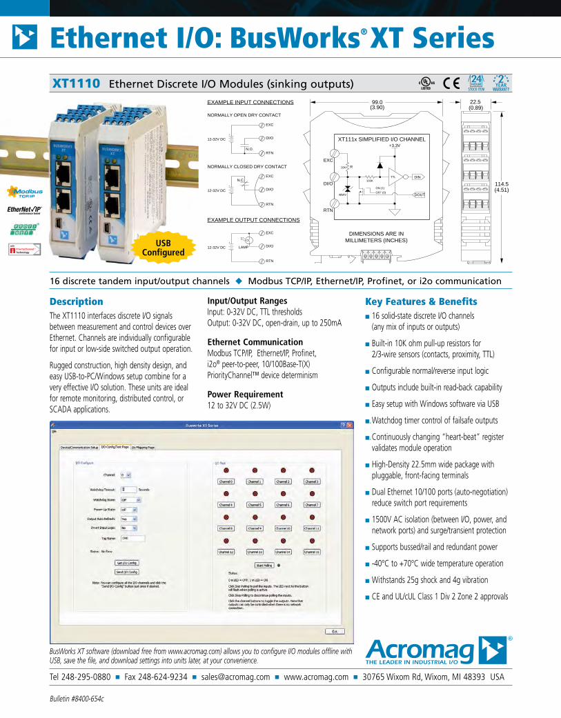
DescriptionThe XT1110 interfaces discrete I/O signals between measurement and control devices over Ethernet. Channels are individually configurable for input or low-side switched output operation.
Rugged construction, high density design, and easy USB-to-PC/Windows setup combine for a very effective I/O solution. These units are ideal for remote monitoring, distributed control, or SCADA applications.
Input/Output RangesInput: 0-32V DC, TTL thresholds Output: 0-32V DC, open-drain, up to 250mA
Ethernet CommunicationModbus TCP/IP, Ethernet/IP, Profinet, i2o® peer-to-peer, 10/100Base-T(X) PriorityChannel™ device determinism
Power Requirement12 to 32V DC (2.5W)
Key Features & Benefits 16 solid-state discrete I/O channels
(any mix of inputs or outputs)
Built-in 10K ohm pull-up resistors for 2/3-wire sensors (contacts, proximity, TTL)
Configurable normal/reverse input logic
Outputs include built-in read-back capability
Easy setup with Windows software via USB
. Watchdog timer control of failsafe outputs
. Continuously changing “heart-beat” register validates module operation
High-Density 22.5mm wide package with pluggable, front-facing terminals
Dual Ethernet 10/100 ports (auto-negotiation) reduce switch port requirements
1500V AC isolation (between I/O, power, and network ports) and surge/transient protection
Supports bussed/rail and redundant power
-40°C to +70°C wide temperature operation
Withstands 25g shock and 4g vibration
CE and UL/cUL Class 1 Div 2 Zone 2 approvals
16 discrete tandem input/output channels Modbus TCP/IP, Ethernet/IP, Profinet, or i2o communication
XT1110 Ethernet Discrete I/O Modules (sinking outputs)
99.0(3.90)
114.5(4.51)
22.5(0.89)
DIMENSIONS ARE INMILLIMETERS (INCHES)
+3.3V
100K
10K
DIN
DOUT
DI/O
RTN
EXC
XT111x SIMPLIFIED I/O CHANNEL
TTL
48WV
R
OFF (0)ON (1)
EXAMPLE INPUT CONNECTIONS
EXAMPLE OUTPUT CONNECTIONS
NORMALLY OPEN DRY CONTACT
DI/O
RTN
EXC
DI/O
RTN
EXC
DI/O
RTN
EXC
N.O.
+
12-32V DC
12-32V DC
12-32V DC
N.C.+
NORMALLY CLOSED DRY CONTACT
+
LAMPUSB Configured
BusWorks XT software (download free from www.acromag.com) allows you to configure I/O modules offline with USB, save the file, and download settings into units later, at your convenience.

Tel 248-295-0880 Fax 248-624-9234 [email protected] www.acromag.com 30765 Wixom Rd, Wixom, MI 48393 USA
All trademarks are property of their respective owners. Copyright © Acromag, Inc. 2013. Data subject to change without notice. Printed in USA 8/2013
Ethernet I/O: BusWorks® XT SeriesXT1110 Ethernet Discrete I/O Modules (sinking outputs)
Performance Specifications
USB InterfaceUSB ConnectorType: USB Mini-B type socket, 5-pin. Data rate: 12Mbps. USB v1.1 and 2.0 compatible. Maximum cable length: 5.0 meters.USB Transient ProtectionTransient voltage suppression on power and data lines.DriverNot required. Uses Windows HID drivers.
InputInput Type16 active-low, buffered inputs, with a common connection. Inputs are tied in tandem to output drains for optional loopback monitoring of output state.Input Signal Voltage Range0 to 32V DC.Input Current280µA, typical at 32V DC.Input Signal Threshold1.7V typical with100mV of hysteresis.Input Resistance100K ohms, typical.Input Response Time10ms, nominal.
OutputOutput Type16 open-drain, smart, n-channel mosfet switches with a common source connection. Provides low-side (sinking) switching between the load and return.Output Voltage 0 to 32V DC.Output “ON” Resistance0.8 ohms typical, 1.6 ohms maximum.Output “ON” Current Range0 to 250mA DC, continuous (up to 4A total for all 16 channels combined). See Operating Temperature specification for effect of channels at full load. See manual for detailed effects of operating temperature.Output Response Time10ms, nominal.
Ethernet CommunicationProtocolsModbus TCP/IP, i2o peer-to-peer, Ethernet/IP, or Profinet depending on model number.Ethernet Communication ControllerInnovasic RapID™ Platform with PriorityChannel™ for determinism at the device regardless of network load.Modbus TCP/IP (slave)Port 502 reserved. Supports up to 10 sockets.i2o Peer-to-Peer (master/slave)Can map 4-channel input groups to output groups at two destination IP addresses. Timed or change-of-state updates. Supports GPRS/GSM systems.Ethernet/IP (adapter)Supports 16 connections. EDS file on website.Profinet (server)Supports 1 connection. GSDML file on website.ConnectorsTwo shielded 8-pin RJ-45 sockets, 10BaseT/100BaseTX.WiringAuto-crossover for MDI or MDI-X.IP AddressUser-configurable. 128.1.1.100 default static IP address.Data RateAuto-negotiated, 10Mbps or 100Mbps.ComplianceIEEE 802.3, 802.3u, 802.3x.
EnvironmentalOperating temperature-40 to 70°C (-40 to 158°F). Max temperature derates -0.625°C per output channel at full load (250mA).Storage temperature-40 to 85°C (-40 to 185°F).Relative humidity5 to 95% non-condensing.Power Requirement12 to 32V DC (102mA maximum @ 24V).Isolation4-way isolation between I/O channels, network (each port), and power. Peak: 1500V AC, ANSI/ISA-82.01-1988. Continuous: 250V AC, 354V DC.Shock and Vibration ImmunityVibration: 4g, per IEC 60068-2-64. Shock: 25g, per IEC 60068-2-27.Electromagnetic Compatibility (EMC) ComplianceRadiated Emissions: BS EN 61000-6-4, CISPR 16. RFI: BS EN 61000-6-2, IEC 61000-4-3. Conducted RFI: BS EN 61000-6-2, IEC 61000-4-6. ESD: BS EN 61000-6-2, IEC 61000-4-2. EFT: BS EN 61000-6-2, IEC 61000-4-4. Surge Immunity: BS EN 61000-6-2, IEC 61000-4-5.ApprovalsCE compliant. UL/cUL Class I; Div. 2 Zone 2.
PhysicalGeneralGeneral purpose plastic enclosure for mounting on 35mm “T-type” DIN rail.Case MaterialSelf-extinguishing polyamide, UL94 V-0 rated, color light gray. General purpose NEMA Type 1 enclosure.Circuit BoardMilitary grade fire-retardant epoxy glass (IPC-4101/98).I/O ConnectorsRemovable plug-in type terminal blocks rated for 12A/250V; AWG #26-12, stranded/solid copper wire.DimensionsWidth = 22.5mm (0.9 inches), Length = 114.5mm (4.51 inches), Depth = 99.0mm (3.90 inches).Shipping Weight0.5 pounds (0.22 Kg) packed.
Ordering Information
ModelsXT1111-000Digital I/O module, Modbus/TCP and i2o protocol.XT1112-000Digital I/O module, Ethernet/IP protocol. XT1113-000Digital I/O module, Profinet protocol.
SoftwareXT-SIP (recommend one kit per customer)Software Interface Package. Includes software (XT-CONFIG), isolator (USB-ISOLATOR), two USB cables (4001-112, 4001-113), Ethernet cable (5035-360).
AccessoriesXTA-120V-6 XTA-240V-36-channel 120V AC/DC or 3-channel 240V AC/DC discrete input module with 5V DC logic outputs. Interfaces with sinking/sourcing DC Inputs.XTA-MRNO-66-ch mechanical relay output module, Form A, SPST normally open 5A relays (5/12/24V DC logic input).XTBUS-KITDIN rail bus power/excitation connector kit. Includes one DIN rail bus connector (1005-070), one left-side female connector terminal block (1005-220) and one right side male connector terminal block (1005-221).USB-ISOLATORUSB-to-USB isolator, includes USB cable (4001-112).
IMPORTANT: To prevent damage or errors from grounded PCs and surges, Acromag strongly recommends use of the USB-ISOLATOR when
configuring an XT1000 I/O module.

Tel 248-295-0880 Fax 248-624-9234 [email protected] www.acromag.com 30765 Wixom Rd, Wixom, MI 48393 USA
Ethernet I/O: BusWorks® XT Series
Bulletin #8400-655c
DescriptionThe XT1120 interfaces discrete I/O signals between measurement and control devices over Ethernet. Channels are individually configurable for input or high-side switched output operation.
Rugged construction, high density design, and easy USB-to-PC/Windows setup combine for a very effective I/O solution. These units are ideal for remote monitoring, distributed control, or SCADA applications.
Input/Output RangesInput: 0-32V DC, TTL thresholds Output: 0-32V DC, open-drain, up to 300mA
Ethernet CommunicationModbus TCP/IP, Ethernet/IP, Profinet, i2o® peer-to-peer, 10/100Base-T(X) PriorityChannel™ device determinism
Power Requirement12 to 32V DC (2.5W)
Key Features & Benefits 16 solid-state discrete I/O channels
(any mix of inputs or outputs)
Built-in 10K ohm pull-up resistors for 2/3-wire sensors (contacts, proximity, TTL)
Configurable normal/reverse input logic
Open-drain outputs switch up to 300mA each and include built-in read-back capability
Easy setup with Windows software via USB
. Watchdog timer control of failsafe outputs
. Continuously changing “heart-beat” register validates module operation
High-Density 22.5mm wide package with pluggable, front-facing terminals
Dual Ethernet 10/100 ports (auto-negotiation) reduce switch port requirements
1500V AC isolation (between I/O, power, and network ports) and surge/transient protection
Supports bussed/rail and redundant power
-40°C to +70°C wide temperature operation
Withstands 25g shock and 4g vibration
CE and UL/cUL Class 1 Div 2 Zone 2 approvals
16 discrete tandem input/output channels Modbus TCP/IP, Ethernet/IP or Profinet communication
XT1120 Ethernet Discrete I/O Modules (sourcing outputs)
99.0(3.90)
114.5(4.51)
22.5(0.89)
DIMENSIONS ARE INMILLIMETERS (INCHES)
EXAMPLE INPUT CONNECTIONS
EXAMPLE OUTPUT CONNECTIONS
LOGIC (TTL)
LAMP CONTROL
VOLTAGE ON/OFF
EXC
+3.3V
100K
10K
DIN
DOUT
XT112xSIMPLIFIEDI/O CHANNEL
TTL
48WV
R
EXC+
OFF (0)
RTN
DI/O
48WV
ON (1)
OFF (0)
pd
PULL-DOWN
TTL
Rlim
V<0.8V
V>2.0V
LOW
HIGH
*OPTIONAL
V
DI/O
RTN
DI/O
RTN
2-32V DC
N.C.
+
OFF (0)
ON (1)ACTIVE-LOW OUTPUT
OUTPUT SINKS LOAD CURRENT
LAMP
+
6-32V DC
DI/O
EXC+
RTN
USB Configured
BusWorks XT software (download free from www.acromag.com) allows you to configure transmitters offline with USB, save the file, and download settings into units later, at your convenience.

Tel 248-295-0880 Fax 248-624-9234 [email protected] www.acromag.com 30765 Wixom Rd, Wixom, MI 48393 USA
All trademarks are property of their respective owners. Copyright © Acromag, Inc. 2013. Data subject to change without notice. Printed in USA 8/2013
Ethernet I/O: BusWorks® XT SeriesXT1120 Ethernet Discrete I/O Modules (sourcing outputs)
Performance Specifications
USB InterfaceUSB ConnectorType: USB Mini-B type socket, 5-pin. Data rate: 12Mbps. USB v1.1 and 2.0 compatible. Maximum cable length: 5.0 meters.USB Transient ProtectionTransient voltage suppression on power and data lines.DriverNot required. Uses Windows HID drivers.
InputInput Type16 active-high, buffered inputs, with a common connection. Inputs are tied in tandem to output drains for optional loopback monitoring of output state.Input Signal Voltage Range0 to 32V DC.Input Current280µA, typical at 32V DC.Input Signal Threshold1.7V typical with100mV of hysteresis.Input Resistance100K ohms, typical.Input Response Time10ms, nominal.
OutputOutput Type16 open-source, smart, p-channel mosfet switches with a common drain connection. Provides high-side (sourcing) switching between excitation and load.Output Voltage 0 to 32V DC.Output “ON” Resistance0.8 ohms typical, 1.6 ohms maximum.Output “ON” Current Range0 to 300mA DC, continuous (up to 4.8A total for all 16 channels combined). See Operating Temperature specification for effect of channels at full load. See manual for detailed effects of operating temperature.Output Response Time10ms, nominal.
Ethernet CommunicationProtocolsModbus TCP/IP, i2o peer-to-peer, Ethernet/IP, or Profinet depending on model number.Ethernet Communication ControllerInnovasic RapID™ Platform with PriorityChannel™ for determinism at the device regardless of network load.Modbus TCP/IP (slave)Port 502 reserved. Supports up to 10 sockets.i2o Peer-to-Peer (master/slave)Can map 4-channel input groups to output groups at two destination IP addresses. Timed or change-of-state updates. Supports GPRS/GSM systems.Ethernet/IP (adapter)Supports 16 connections. EDS file on website.Profinet (server)Supports 1 connection. GSDML file on website.ConnectorsTwo shielded 8-pin RJ-45 sockets, 10BaseT/100BaseTX.WiringAuto-crossover for MDI or MDI-X.IP AddressUser-configurable. 128.1.1.100 default static IP address.Data RateAuto-negotiated, 10Mbps or 100Mbps.ComplianceIEEE 802.3, 802.3u, 802.3x.
EnvironmentalOperating temperature-40 to 70°C (-40 to 158°F). Max temperature derates -0.625°C per output channel at full load (300mA).Storage temperature-40 to 85°C (-40 to 185°F).Relative humidity5 to 95% non-condensing.Power Requirement12 to 32V DC (95mA maximum @ 24V).Isolation4-way isolation between I/O channels, network (each port); and power. Peak: 1500V AC, ANSI/ISA-82.01-1988. Continuous: 250V AC, 354V DC.Shock and Vibration ImmunityVibration: 4g, per IEC 60068-2-64. Shock: 25g, per IEC 60068-2-27.Electromagnetic Compatibility (EMC) ComplianceRadiated Emissions: BS EN 61000-6-4, CISPR 16. RFI: BS EN 61000-6-2, IEC 61000-4-3. Conducted RFI: BS EN 61000-6-2, IEC 61000-4-6. ESD: BS EN 61000-6-2, IEC 61000-4-2. EFT: BS EN 61000-6-2, IEC 61000-4-4. Surge Immunity: BS EN 61000-6-2, IEC 61000-4-5.ApprovalsCE compliant. UL/cUL Class I; Div. 2 Zone 2.
PhysicalGeneralGeneral purpose plastic enclosure for mounting on 35mm “T-type” DIN rail.Case MaterialSelf-extinguishing polyamide, UL94 V-0 rated, color light gray. General purpose NEMA Type 1 enclosure.Circuit BoardMilitary grade fire-retardant epoxy glass (IPC-4101/98).I/O ConnectorsRemovable plug-in type terminal blocks rated for 12A/250V; AWG #26-12, stranded/solid copper wire.DimensionsWidth = 22.5mm (0.9 inches), Length = 114.5mm (4.51 inches), Depth = 99.0mm (3.90 inches).Shipping Weight0.5 pounds (0.22 Kg) packed.
Ordering Information
ModelsXT1121-000Digitial I/O module, Modbus/TCP and i2o protocol.XT1122-000Digitial I/O module, Ethernet/IP protocol. XT1123-000Digitial I/O module, Profinet protocol.
SoftwareXT-SIP (recommend one kit per customer)Software Interface Package. Includes software (XT-CONFIG), isolator (USB-ISOLATOR), two USB cables (4001-112, 4001-113), Ethernet cable (5035-360).
AccessoriesXTA-120V-6 XTA-240V-36-channel 120V AC/DC or 3-channel 240V AC/DC discrete input module with 5V DC logic outputs. Interfaces with sinking/sourcing DC Inputs.XTA-MRNO-66-ch mechanical relay output module, Form A, SPST normally open 5A relays (5/12/24V DC logic input).XTBUS-KITDIN rail bus power/excitation connector kit. Includes one DIN rail bus connector (1005-070), one left-side female connector terminal block (1005-220) and one right side male connector terminal block (1005-221).USB-ISOLATORUSB-to-USB isolator, includes USB cable (4001-112).
IMPORTANT: To prevent damage or errors from grounded PCs and surges, Acromag strongly recommends use of the USB-ISOLATOR when
configuring an XT1000 I/O module.

Tel 248-295-0880 Fax 248-624-9234 [email protected] www.acromag.com 30765 Wixom Rd, Wixom, MI 48393 USA
Ethernet I/O: BusWorks® XT Series
Bulletin #8400-787c
DescriptionThe XT1210 offers an isolated Ethernet network interface for up to eight differential current input channels. Isolated differential inputs deliver better measurements, superior noise rejection, and eliminate the need for current loop isolators.
Rugged construction, high density design, and easy USB-to-PC/Windows setup combine for a very effective and reliable module. These units are ideal for remote monitoring, distributed control, or SCADA applications.
Input Ranges0 to 11mA, 0 to 20mA, 4 to 20mA, ±20mA. 0 to 20 amps AC (with optional AC sensor)
Ethernet CommunicationModbus TCP/IP, Ethernet/IP, Profinet, i2o® peer-to-peer, 10/100Base-T(X) PriorityChannel™ device determinism
Power Requirement12 to 32V DC (2.8W)
Key Features & Benefits Easy setup with Windows software via USB
Low input impedance (27 ohms) reduces loading on current loops
User-configurable sample averaging (1-200) on a per-channel basis
10ms network updates for all 8 input channels
i2o peer-to-peer updates based on percent-of-change and/or timed updates
High-resolution 16-bit Σ-Δ A/D converter ensures precise, high accuracy measurements
High-Density 22.5mm wide package with pluggable, front-facing terminals
Dual Ethernet 10/100 ports (auto-negotiation) reduce switch port requirements
1500V AC isolation (between I/O, power, and network ports) and surge/transient protection
Supports bussed/rail and redundant power
-40°C to +70°C wide temperature operation
Withstands 25g shock and 4g vibration
CE compliant. UL/cUL Class 1 Div 2 Zone 2 approval
8-channel differential analog current input Modbus TCP/IP, Ethernet/IP, Profinet, or i2o communication
XT1210 Ethernet Analog Current Input Modules
99.0(3.90)
114.5(4.51)
22.5(0.89)
DIMENSIONS ARE IN MILLIMETERS (INCHES)
XT121x SIMPLIFIED I/O CHANNEL
EXAMPLE INPUT CONNECTIONS
SOURCED DC CURRENT
IN0+
+
DC CURRENTMILLIAMPS
TWO-WIRE CONNECTION
IN0-
RTN
+
-
IN0+
IN0-
RTN
+
ISOLATEDNETWORK PORTS
IN0+
IN0-
CH0
CH7
16-BITA/D
µC &COMMS
ISOLATEDPOWER
IN7+
IN7-
RTN
RTN
RTN
USB Configured
BusWorks XT software (download free from www.acromag.com) allows you to configure I/O modules offline with USB or save the configuration file and download settings into units later at your convenience.

Tel 248-295-0880 Fax 248-624-9234 [email protected] www.acromag.com 30765 Wixom Rd, Wixom, MI 48393 USA
All trademarks are property of their respective owners. Copyright © Acromag, Inc. 2014. Data subject to change without notice. Printed in USA 9/2014
Ethernet I/O: BusWorks® XT SeriesXT1210 Ethernet Analog Current Input Modules
Performance Specifications
USB InterfaceUSB ConnectorType: USB Mini-B type socket, 5-pin. Data rate: 12Mbps. USB v1.1 and 2.0 compatible. Maximum cable length: 5.0 meters.USB Transient ProtectionTransient voltage suppression on power and data lines.DriverNot required. Uses Windows HID drivers.
InputAccuracy±0.05% of span, typical for nominal input ranges.Analog to Digital Converter (A/D)16-bit Σ-Δ converter. 1.476uA/bit resolution.Noise RejectionBetter than -110dB @ 60Hz.Input Filter Bandwidth-3dB at 25KHz, typical.Input Conversion Rate10ms for all 8 input channels.Input Impedance27.4 ohms.
Ethernet CommunicationProtocolsModbus TCP/IP, i2o peer-to-peer, Ethernet/IP, or Profinet depending on model number.Ethernet Communication ControllerInnovasic RapID™ Platform with PriorityChannel™ for determinism at the device regardless of network load.Modbus TCP/IP (slave)Port 502 reserved. Supports up to 10 sockets.i2o Peer-to-Peer (master/slave)Can map each of 8 analog input channels separately to output channels. Timed (1-65535 sec) or percent-of-change updates. Supports GPRS/GSM systems.Ethernet/IP (adapter)Supports 10 connections. EDS file on website.Profinet (server)Supports 1 connection. GSDML file on website.ConnectorsTwo shielded 8-pin RJ-45 sockets, 10BaseT/100BaseTX.
WiringAuto-crossover for MDI or MDI-X.IP AddressUser-configurable. 192.168.1.100 default IP address.Data RateAuto-negotiated, 10Mbps or 100Mbps.ComplianceIEEE 802.3, 802.3u, 802.3x.
EnvironmentalOperating temperature-40 to 70°C (-40 to 158°F).Storage temperature-40 to 85°C (-40 to 185°F).Relative humidity5 to 95% non-condensing.Power Requirement12 to 32V DC, 2.8W maximum(116mA maximum @ 24V).Isolation4-way isolation between I/O channels, network (each port), and power. Peak: 1500V AC, ANSI/ISA-82.01-1988. Continuous: 250V AC, 354V DC.Shock and Vibration ImmunityVibration: 4g, per IEC 60068-2-64. Shock: 25g, per IEC 60068-2-27.Electromagnetic Compatibility (EMC) ComplianceRadiated Emissions: BS EN 61000-6-4, CISPR 16. RFI: BS EN 61000-6-2, IEC 61000-4-3. Conducted RFI: BS EN 61000-6-2, IEC 61000-4-6. ESD: BS EN 61000-6-2, IEC 61000-4-2. EFT: BS EN 61000-6-2, IEC 61000-4-4. Surge Immunity: BS EN 61000-6-2, IEC 61000-4-5.ApprovalsCE compliant. UL/cUL listed. Designed for Class I; Division 2; Groups ABCD; Zone 2.
PhysicalGeneralGeneral purpose plastic enclosure for mounting on 35mm “T-type” DIN rail.Case MaterialSelf-extinguishing polyamide, UL94 V-0 rated, color light gray. General purpose NEMA Type 1 enclosure.Circuit BoardMilitary grade fire-retardant epoxy glass (IPC-4101/98).I/O ConnectorsRemovable plug-in type terminal blocks rated for 12A/250V; AWG #26-12, stranded/solid copper wire.DimensionsWidth = 22.5mm (0.9 inches), Length = 114.5mm (4.51 inches), Depth = 99.0mm (3.90 inches).Shipping Weight0.5 pounds (0.22 Kg) packed.
Ordering Information
ModelsXT1211-0008-channel differential current input module, Modbus/TCP and i2o protocol.XT1212-0008-channel differential current input module, Ethernet/IP protocol. XT1213-0008-channel differential current input module, Profinet protocol.
SoftwareXT-SIP (recommend one kit per customer)Software Interface Package. Includes software (XT-CONFIG), isolator (USB-ISOLATOR), two USB cables (4001-112, 4001-113), Ethernet cable (5035-360).
AccessoriesXTBUS-KITDIN rail bus power/excitation connector kit. Includes one DIN rail bus connector (1005-070), one left-side female connector terminal block (1005-220) and one right side male connector terminal block (1005-221).USB-ISOLATORUSB-to-USB isolator, includes USB cable (4001-112).5020-350AC current sensor (toroidal transformer).Converts 0-20A AC to 0-11.17mA DC.PS5R-SD24Power supply (24V DC, 2.5A).DIN RAIL 3.0DIN RAIL 16.7DIN rail strip, Type T, 3 inches (75mm) or 16.7 (425mm).20RM-16-DIN19” rack-mount kit with DIN rail.
IMPORTANT: To prevent damage or errors from grounded PCs and surges, Acromag strongly recommends use of the USB-ISOLATOR when
configuring an XT1000 I/O module.

Tel 248-295-0880 Fax 248-624-9234 [email protected] www.acromag.com 30765 Wixom Rd, Wixom, MI 48393 USA
Ethernet I/O: BusWorks® XT Series
Bulletin #8400-788c
DescriptionThe XT1220 offers an isolated Ethernet network interface for up to eight differential voltage input channels. Isolated differential inputs deliver better measurements, superior noise rejection, and eliminate the need for signal isolators.
Rugged construction, high density design, and easy USB-to-PC/Windows setup combine for a very effective and reliable module. These units are ideal for remote monitoring, distributed control, or SCADA applications.
Input Ranges±5V, ±10V, 0 to 5V, 0 to 10V.
Ethernet CommunicationModbus TCP/IP, Ethernet/IP, Profinet, i2o® peer-to-peer, 10/100Base-T(X) PriorityChannel™ device determinism
Power Requirement12 to 32V DC (2.8W)
Key Features & Benefits Easy setup with Windows software via USB
High input impedance (100K ohms) reduces loading on voltage loops
User-configurable sample averaging (1-200) on a per-channel basis
10ms network updates for all 8 input channels
i2o peer-to-peer updates based on percent-of-change and/or timed updates
High-resolution 16-bit Σ-Δ A/D converter ensures precise, high accuracy measurements
High-Density 22.5mm wide package with pluggable, front-facing terminals
Dual Ethernet 10/100 ports (auto-negotiation) reduce switch port requirements
1500V AC isolation (between I/O, power, and network ports) and surge/transient protection
Supports bussed/rail and redundant power
-40°C to +70°C wide temperature operation
Withstands 25g shock and 4g vibration
CE compliant. UL/cUL Class 1 Div 2 Zone 2 approval
8-channel differential analog voltage input Modbus TCP/IP, Ethernet/IP, Profinet, or i2o communication
XT1220 Ethernet Analog Voltage Input Modules
99.0(3.90)
114.5(4.51)
22.5(0.89)
DIMENSIONS ARE IN MILLIMETERS (INCHES)
XT122x SIMPLIFIED I/O CHANNEL
EXAMPLE INPUT CONNECTIONS
DC VOLTAGE INPUT
IN0+DC VOLTAGE
IN0-
RTN
+
-
ISOLATEDNETWORK PORTS
IN0+
IN0-
CH0
CH7
16-BITA/D
µC &COMMS
ISOLATEDPOWER
IN7+
IN7-
RTN
RTN
RTN
USB Configured
BusWorks XT software (download free from www.acromag.com) allows you to configure I/O modules offline with USB or save the configuration file and download settings into units later at your convenience.

Tel 248-295-0880 Fax 248-624-9234 [email protected] www.acromag.com 30765 Wixom Rd, Wixom, MI 48393 USA
All trademarks are property of their respective owners. Copyright © Acromag, Inc. 2014. Data subject to change without notice. Printed in USA 9/2014
Ethernet I/O: BusWorks® XT SeriesXT1220 Ethernet Analog Input Modules
Performance Specifications
USB InterfaceUSB ConnectorType: USB Mini-B type socket, 5-pin. Data rate: 12Mbps. USB v1.1 and 2.0 compatible. Maximum cable length: 5.0 meters.USB Transient ProtectionTransient voltage suppression on power and data lines.DriverNot required. Uses Windows HID drivers.
InputAccuracy±0.05% of span, typical for nominal input ranges.Analog to Digital Converter (A/D)16-bit Σ-Δ converter. 334.85uV/bit resolution.Noise RejectionBetter than -110dB @ 60Hz.Input Filter Bandwidth-3dB at 25KHz, typical.Input Conversion Rate10ms for all 8 input channels.Input Impedance100.2K ohms.
Ethernet CommunicationProtocolsModbus TCP/IP, i2o peer-to-peer, Ethernet/IP, or Profinet depending on model number.Ethernet Communication ControllerInnovasic RapID™ Platform with PriorityChannel™ for determinism at the device regardless of network load.Modbus TCP/IP (slave)Port 502 reserved. Supports up to 10 sockets.i2o Peer-to-Peer (master/slave)Can map each of 8 analog input channels separately to output channels. Timed (1-65535 sec) or percent-of-change updates. Supports GPRS/GSM systems.Ethernet/IP (adapter)Supports 10 connections. EDS file on website.Profinet (server)Supports 1 connection. GSDML file on website.ConnectorsTwo shielded 8-pin RJ-45 sockets, 10BaseT/100BaseTX.
WiringAuto-crossover for MDI or MDI-X.IP AddressUser-configurable. 192.168.1.100 default IP address.Data RateAuto-negotiated, 10Mbps or 100Mbps.ComplianceIEEE 802.3, 802.3u, 802.3x.
EnvironmentalOperating temperature-40 to 70°C (-40 to 158°F).Storage temperature-40 to 85°C (-40 to 185°F).Relative humidity5 to 95% non-condensing.Power Requirement12 to 32V DC, 2.8W maximum(116mA maximum @ 24V).Isolation4-way isolation between I/O channels, network (each port), and power. Peak: 1500V AC, ANSI/ISA-82.01-1988. Continuous: 250V AC, 354V DC.Shock and Vibration ImmunityVibration: 4g, per IEC 60068-2-64. Shock: 25g, per IEC 60068-2-27.Electromagnetic Compatibility (EMC) ComplianceRadiated Emissions: BS EN 61000-6-4, CISPR 16. RFI: BS EN 61000-6-2, IEC 61000-4-3. Conducted RFI: BS EN 61000-6-2, IEC 61000-4-6. ESD: BS EN 61000-6-2, IEC 61000-4-2. EFT: BS EN 61000-6-2, IEC 61000-4-4. Surge Immunity: BS EN 61000-6-2, IEC 61000-4-5.ApprovalsCE compliant. UL/cUL listed. Designed for Class I; Division 2; Groups ABCD; Zone 2.
PhysicalGeneralGeneral purpose plastic enclosure for mounting on 35mm “T-type” DIN rail.Case MaterialSelf-extinguishing polyamide, UL94 V-0 rated, color light gray. General purpose NEMA Type 1 enclosure.Circuit BoardMilitary grade fire-retardant epoxy glass (IPC-4101/98).I/O ConnectorsRemovable plug-in type terminal blocks rated for 12A/250V; AWG #26-12, stranded/solid copper wire.DimensionsWidth = 22.5mm (0.9 inches), Length = 114.5mm (4.51 inches), Depth = 99.0mm (3.90 inches).Shipping Weight0.5 pounds (0.22 Kg) packed.
Ordering Information
ModelsXT1221-0008-channel differential voltage input module, Modbus/TCP and i2o protocol.XT1222-0008-channel differential voltage input module, Ethernet/IP protocol. XT1223-0008-channel differential voltage input module, Profinet protocol.
SoftwareXT-SIP (recommend one kit per customer)Software Interface Package. Includes software (XT-CONFIG), isolator (USB-ISOLATOR), two USB cables (4001-112, 4001-113), Ethernet cable (5035-360).
AccessoriesXTBUS-KITDIN rail bus power/excitation connector kit. Includes one DIN rail bus connector (1005-070), one left-side female connector terminal block (1005-220) and one right side male connector terminal block (1005-221).USB-ISOLATORUSB-to-USB isolator, includes USB cable (4001-112).PS5R-SD24Power supply (24V DC, 2.5A).DIN RAIL 3.0DIN RAIL 16.7DIN rail strip, Type T, 3 inches (75mm) or 16.7 (425mm).20RM-16-DIN19” rack-mount kit with DIN rail.
IMPORTANT: To prevent damage or errors from grounded PCs and surges, Acromag strongly recommends use of the USB-ISOLATOR when
configuring an XT1000 I/O module.

Tel 248-295-0880 Fax 248-624-9234 [email protected] www.acromag.com 30765 Wixom Rd, Wixom, MI 48393 USA
Ethernet I/O: BusWorks® XT Series
Bulletin #8400-797c
DescriptionThe XT1230 offers an isolated Ethernet network interface for up to to sixteen single-ended current input channels. Single-ended inputs enable a higher channel density to save space and a lower cost per channel.
Rugged construction, high density design, and easy USB-to-PC/Windows setup combine for a very effective and reliable module. These units are ideal for remote monitoring, distributed control, or SCADA applications.
Input RangesDC Current:0 to 11mA, 0 to 20mA, 4 to 20mA, ±20mA. 0 to 20 amps AC (with optional AC sensor)
Ethernet CommunicationModbus TCP/IP, Ethernet/IP, Profinet, i2o® peer-to-peer, 10/100Base-T(X) PriorityChannel™ device determinism
Power Requirement12 to 32V DC (2.8W)
Key Features & Benefits Easy setup with Windows software via USB
Low input impedance (27 ohms) reduces loading on current loops
User-configurable sample averaging (1-200) on a per-channel basis
10ms network updates for all 16 input channels
i2o peer-to-peer updates based on percent-of-change and/or timed updates
. High-resolution 16-bit Σ-Δ A/D converter ensures precise, high accuracy measurements
High-Density 22.5mm wide package with pluggable, front-facing terminals
Dual Ethernet 10/100 ports (auto-negotiation) reduce switch port requirements
1500V AC isolation (between I/O, power, and network ports) and surge/transient protection
Supports bussed/rail and redundant power
-40°C to +70°C wide temperature operation
Withstands 25g shock and 4g vibration
CE compliant. UL/cUL Class 1 Div 2 Zone 2 approvals
16-channel single-ended analog current input Modbus TCP/IP, Ethernet/IP, Profinet, or i2o communication
XT1230 Ethernet Analog Input Modules
99.0(3.90)
114.5(4.51)
22.5(0.89)
DIMENSIONS ARE IN MILLIMETERS (INCHES)
XT123x SIMPLIFIED I/O CHANNEL
EXAMPLE INPUT CONNECTIONS
ISOLATEDNETWORK PORTS
IN0+CH0
16-BITA/D
µC &COMMS
ISOLATEDPOWER
RTN
RTN
RTN
IN15+CH15
SOURCED DC CURRENT
IN0+
+
DC CURRENTMILLIAMPS
TWO-WIRE CONNECTION
RTN
+
-
IN0+
RTN
+
USB Configured
BusWorks XT software (download free from www.acromag.com) allows you to configure I/O modules offline with USB or save the configuration file and download settings into units later at your convenience.
Tel 248-295-0880 Fax 248-624-9234 [email protected] www.acromag.com 30765 Wixom Rd, Wixom, MI 48393 USA
All trademarks are property of their respective owners. Copyright © Acromag, Inc. 2014. Data subject to change without notice. Printed in USA 9/2014
Ethernet I/O: BusWorks® XT SeriesXT1230 Ethernet Analog Input Modules
Performance Specifications
USB InterfaceUSB ConnectorType: USB Mini-B type socket, 5-pin. Data rate: 12Mbps. USB v1.1 and 2.0 compatible. Maximum cable length: 5.0 meters.USB Transient ProtectionTransient voltage suppression on power and data lines.DriverNot required. Uses Windows HID drivers.
InputAccuracy±0.05% of span, typical for nominal input ranges.Analog to Digital Converter (A/D)16-bit Σ-Δ converter. 1.476uA/bit resolution.Noise RejectionBetter than -110dB @ 60Hz.Input Filter Bandwidth-3dB at 25KHz, typical.Input Conversion Rate10ms for all 16 input channels.Input Impedance27.4 ohms.
Ethernet CommunicationProtocolsModbus TCP/IP, i2o peer-to-peer, Ethernet/IP, or Profinet depending on model number.Ethernet Communication ControllerInnovasic RapID™ Platform with PriorityChannel™ for determinism at the device regardless of network load.Modbus TCP/IP (slave)Port 502 reserved. Supports up to 10 sockets.i2o Peer-to-Peer (master/slave)Can map each of 16 analog input channels separately to output channels. Timed (1-65535 sec) or percent-of-change updates. Supports GPRS/GSM systems.Ethernet/IP (adapter)Supports 10 connections. EDS file on website.Profinet (server)Supports 1 connection. GSDML file on website.ConnectorsTwo shielded 8-pin RJ-45 sockets, 10BaseT/100BaseTX.
WiringAuto-crossover for MDI or MDI-X.IP AddressUser-configurable. 192.168.1.100 default IP address.Data RateAuto-negotiated, 10Mbps or 100Mbps.ComplianceIEEE 802.3, 802.3u, 802.3x.
EnvironmentalOperating temperature-40 to 70°C (-40 to 158°F).Storage temperature-40 to 85°C (-40 to 185°F).Relative humidity5 to 95% non-condensing.Power Requirement12 to 32V DC, 2.8W maximum(113mA maximum @ 24V).Isolation4-way isolation between I/O channels, network (each port), and power. Peak: 1500V AC, ANSI/ISA-82.01-1988. Continuous: 250V AC, 354V DC.Shock and Vibration ImmunityVibration: 4g, per IEC 60068-2-64. Shock: 25g, per IEC 60068-2-27.Electromagnetic Compatibility (EMC) ComplianceRadiated Emissions: BS EN 61000-6-4, CISPR 16. RFI: BS EN 61000-6-2, IEC 61000-4-3. Conducted RFI: BS EN 61000-6-2, IEC 61000-4-6. ESD: BS EN 61000-6-2, IEC 61000-4-2. EFT: BS EN 61000-6-2, IEC 61000-4-4. Surge Immunity: BS EN 61000-6-2, IEC 61000-4-5.ApprovalsCE compliant. UL/cUL listed. Designed for Class I; Division 2; Groups ABCD; Zone 2.
PhysicalGeneralGeneral purpose plastic enclosure for mounting on 35mm “T-type” DIN rail.Case MaterialSelf-extinguishing polyamide, UL94 V-0 rated, color light gray. General purpose NEMA Type 1 enclosure.Circuit BoardMilitary grade fire-retardant epoxy glass (IPC-4101/98).I/O ConnectorsRemovable plug-in type terminal blocks rated for 12A/250V; AWG #26-12, stranded/solid copper wire.DimensionsWidth = 22.5mm (0.9 inches), Length = 114.5mm (4.51 inches), Depth = 99.0mm (3.90 inches).Shipping Weight0.5 pounds (0.22 Kg) packed.
Ordering Information
ModelsXT1231-00016-channel single-ended current input module, Modbus/TCP and i2o protocol.XT1232-00016-channel single-ended current input module, Ethernet/IP protocol. XT1233-00016-channel single-ended current input module, Profinet protocol.
SoftwareXT-SIP (recommend one kit per customer)Software Interface Package. Includes software (XT-CONFIG), isolator (USB-ISOLATOR), two USB cables (4001-112, 4001-113), Ethernet cable (5035-360).
AccessoriesXTBUS-KITDIN rail bus power/excitation connector kit. Includes one DIN rail bus connector (1005-070), one left-side female connector terminal block (1005-220) and one right side male connector terminal block (1005-221).USB-ISOLATORUSB-to-USB isolator, includes USB cable (4001-112).5020-350AC current sensor (toroidal transformer).Converts 0-20A AC to 0-11.17mA DC.PS5R-SD24Power supply (24V DC, 2.5A).DIN RAIL 3.0DIN RAIL 16.7DIN rail strip, Type T, 3 inches (75mm) or 16.7 (425mm).20RM-16-DIN19” rack-mount kit with DIN rail.
IMPORTANT: To prevent damage or errors from grounded PCs and surges, Acromag strongly recommends use of the USB-ISOLATOR when
configuring an XT1000 I/O module.

Tel 248-295-0880 Fax 248-624-9234 [email protected] www.acromag.com 30765 Wixom Rd, Wixom, MI 48393 USA
Ethernet I/O: BusWorks® XT Series
Bulletin #8400-798d
DescriptionThe XT1240 offers an isolated Ethernet network interface for up to to sixteen single-ended voltage input channels. Single-ended inputs enable a higher channel density to save space and a lower cost per channel.
Rugged construction, high density design, and easy USB-to-PC/Windows setup combine for a very effective and reliable module. These units are ideal for remote monitoring, distributed control, or SCADA applications.
Input RangesDC Voltage:±5V, ±10V, 0 to 5V, 0 to 10V.
Ethernet CommunicationModbus TCP/IP, Ethernet/IP, Profinet, i2o® peer-to-peer, 10/100Base-T(X) PriorityChannel™ device determinism
Power Requirement12 to 32V DC (2.8W)
Key Features & Benefits Easy setup with Windows software via USB
High input impedance (100K ohms) reduces loading on voltage loops
User-configurable sample averaging (1-200) on a per-channel basis
10ms network updates for all 16 input channels
i2o peer-to-peer updates based on percent-of-change and/or timed updates
. High-resolution 16-bit Σ-Δ A/D converter ensures precise, high accuracy measurements
High-Density 22.5mm wide package with pluggable, front-facing terminals
Dual Ethernet 10/100 ports (auto-negotiation) reduce switch port requirements
1500V AC isolation (between I/O, power, and network ports) and surge/transient protection
Supports bussed/rail and redundant power
-40°C to +70°C wide temperature operation
Withstands 25g shock and 4g vibration
CE compliant. UL/cUL Class 1 Div 2 Zone 2 approvals
16-channel single-ended analog voltage input Modbus TCP/IP, Ethernet/IP, Profinet, or i2o communication
XT1240 Ethernet Analog Input Modules
99.0(3.90)
114.5(4.51)
22.5(0.89)
DIMENSIONS ARE IN MILLIMETERS (INCHES)
XT124x SIMPLIFIED I/O CHANNEL
EXAMPLE INPUT CONNECTIONS
DC VOLTAGE INPUT
IN0+DC VOLTAGE
RTN
+
-
ISOLATEDNETWORK PORTS
IN0+CH0
16-BITA/D
µC &COMMS
ISOLATEDPOWER
RTN
RTN
RTN
IN15+CH15
USB Configured
BusWorks XT software (download free from www.acromag.com) allows you to configure I/O modules offline with USB or save the configuration file and download settings into units later at your convenience.

Tel 248-295-0880 Fax 248-624-9234 [email protected] www.acromag.com 30765 Wixom Rd, Wixom, MI 48393 USA
All trademarks are property of their respective owners. Copyright © Acromag, Inc. 2014. Data subject to change without notice. Printed in USA 9/2014
Ethernet I/O: BusWorks® XT SeriesXT1240 Ethernet Analog Input Modules
Performance Specifications
USB InterfaceUSB ConnectorType: USB Mini-B type socket, 5-pin. Data rate: 12Mbps. USB v1.1 and 2.0 compatible. Maximum cable length: 5.0 meters.USB Transient ProtectionTransient voltage suppression on power and data lines.DriverNot required. Uses Windows HID drivers.
InputAccuracy±0.05% of span, typical for nominal input ranges.Analog to Digital Converter (A/D)16-bit Σ-Δ converter. 351.6uV/bit resolution.Noise RejectionBetter than -110dB @ 60Hz.Input Filter Bandwidth-3dB at 25KHz, typical.Input Conversion Rate10mS for all 16 input channels.Input Impedance105.2K ohms.
Ethernet CommunicationProtocolsModbus TCP/IP, i2o peer-to-peer, Ethernet/IP, or Profinet depending on model number.Ethernet Communication ControllerInnovasic RapID™ Platform with PriorityChannel™ for determinism at the device regardless of network load.Modbus TCP/IP (slave)Port 502 reserved. Supports up to 10 sockets.i2o Peer-to-Peer (master/slave)Can map each of 16 analog input channels separately to output channels. Timed (1-65535 sec) or percent-of-change updates. Supports GPRS/GSM systems.Ethernet/IP (adapter)Supports 10 connections. EDS file on website.Profinet (server)Supports 1 connection. GSDML file on website.ConnectorsTwo shielded 8-pin RJ-45 sockets, 10BaseT/100BaseTX.
WiringAuto-crossover for MDI or MDI-X.IP AddressUser-configurable. 192.168.1.100 default IP address.Data RateAuto-negotiated, 10Mbps or 100Mbps.ComplianceIEEE 802.3, 802.3u, 802.3x.
EnvironmentalOperating temperature-40 to 70°C (-40 to 158°F).Storage temperature-40 to 85°C (-40 to 185°F).Relative humidity5 to 95% non-condensing.Power Requirement12 to 32V DC, 2.8W maximum(113mA maximum @ 24V).Isolation4-way isolation between I/O channels, network (each port), and power. Peak: 1500V AC, ANSI/ISA-82.01-1988. Continuous: 250V AC, 354V DC.Shock and Vibration ImmunityVibration: 4g, per IEC 60068-2-64. Shock: 25g, per IEC 60068-2-27.Electromagnetic Compatibility (EMC) ComplianceRadiated Emissions: BS EN 61000-6-4, CISPR 16. RFI: BS EN 61000-6-2, IEC 61000-4-3. Conducted RFI: BS EN 61000-6-2, IEC 61000-4-6. ESD: BS EN 61000-6-2, IEC 61000-4-2. EFT: BS EN 61000-6-2, IEC 61000-4-4. Surge Immunity: BS EN 61000-6-2, IEC 61000-4-5.ApprovalsCE compliant. UL/cUL listed. Designed for Class I; Division 2; Groups ABCD; Zone 2.
PhysicalGeneralGeneral purpose plastic enclosure for mounting on 35mm “T-type” DIN rail.Case MaterialSelf-extinguishing polyamide, UL94 V-0 rated, color light gray. General purpose NEMA Type 1 enclosure.Circuit BoardMilitary grade fire-retardant epoxy glass (IPC-4101/98).I/O ConnectorsRemovable plug-in type terminal blocks rated for 12A/250V; AWG #26-12, stranded/solid copper wire.DimensionsWidth = 22.5mm (0.9 inches), Length = 114.5mm (4.51 inches), Depth = 99.0mm (3.90 inches).Shipping Weight0.5 pounds (0.22 Kg) packed.
Ordering Information
ModelsXT1241-00016-channel single-ended voltage input module, Modbus/TCP and i2o protocol.XT1242-00016-channel single-ended voltage input module, Ethernet/IP protocol. XT1243-00016-channel single-ended voltage input module, Profinet protocol.
SoftwareXT-SIP (recommend one kit per customer)Software Interface Package. Includes software (XT-CONFIG), isolator (USB-ISOLATOR), two USB cables (4001-112, 4001-113), Ethernet cable (5035-360).
AccessoriesXTBUS-KITDIN rail bus power/excitation connector kit. Includes one DIN rail bus connector (1005-070), one left-side female connector terminal block (1005-220) and one right side male connector terminal block (1005-221).USB-ISOLATORUSB-to-USB isolator, includes USB cable (4001-112).PS5R-SD24Power supply (24V DC, 2.5A).DIN RAIL 3.0DIN RAIL 16.7DIN rail strip, Type T, 3 inches (75mm) or 16.7 (425mm).20RM-16-DIN19” rack-mount kit with DIN rail.
IMPORTANT: To prevent damage or errors from grounded PCs and surges, Acromag strongly recommends use of the USB-ISOLATOR when
configuring an XT1000 I/O module.

Tel 248-295-0880 Fax 248-624-9234 [email protected] www.acromag.com 30765 Wixom Rd, Wixom, MI 48393 USA
Ethernet I/O: BusWorks® XT Series
Bulletin #8400-810b
DescriptionThe XT1530 interfaces analog output and discrete I/O signals between measurement and control devices over Ethernet. Discrete I/O are individually configurable for input or high-side switched output operation.
Rugged construction, high density design, and easy USB-to-PC/Windows setup combine for a very effective I/O solution. These units are ideal for remote monitoring, distributed control, or SCADA applications.
Analog Output Ranges0-20mA DC, 4-20mA DC
Discrete Input/Output RangesInput: 0-32V DC, TTL thresholds Output: 0-32V DC, open-source, up to 250mA
Ethernet CommunicationModbus TCP/IP, Ethernet/IP, Profinet, i2o® peer-to-peer, 10/100Base-T(X) PriorityChannel™ device determinism
Power Requirement12 to 32V DC (2.8W)
Key Features & Benefits Multi-function, multi-channel stand alone
module is very economical
Easy setup with Windows software via USB
Dual Ethernet 10/100 ports with built-in switch enables daisy-chain networking to reduce costs
. i2o technology for peer-to-peer communication without a network controller
. Four analog output channels (16-bit DACs) to drive remote instruments, controllers, recorders
Four discrete input/output channels support loopback monitoring of output levels
Built-in 10K ohm pull-down resistors for use with 2/3-wire sensors (contacts, proximity, TTL)
Configurable normal/reverse input logic
. Various diagnostics validate module operation
1500V AC isolation (between I/O, power, and network ports) and surge/transient protection
Slim 22.5mm housing with pluggable terminals
Supports bussed/rail and redundant power
-40°C to +60°C wide temperature operation
CE and UL/cUL Class 1 Div 2 Zone 2 approvals
4 analog current outputs, 4 discrete I/O channels Modbus TCP/IP, Ethernet/IP, Profinet, or i2o communication
XT1530 Ethernet Multi-Function Analog Output & Digital I/O Modules
99.0(3.90)
114.5(4.51)
22.5(0.89)
DIMENSIONS ARE IN MILLIMETERS (INCHES)
XT153x SIMPLIFIED DIAGRAMISOLATED
NETWORK PORTS
ETHERNETSWITCH
ISOLATEDPOWER
16-BITD/A
DIN
DOUT
DIN
DOUT
µC
ANALOGOUTPUT
x4
x4
16-BITD/A
DISCRETEI/O
ANALOG OUTPUT EXAMPLESDC CURRENT OUTPUT
CH+
–RTN0-550 ohms
0-20mA4-20mA
OUTPUTLOAD
DISCRETE INPUT EXAMPLES
DISCRETE OUTPUT EXAMPLES
LOGIC (TTL) VOLTAGE ON/OFF
TTL
V<0.8VLOW
V>2.0VHIGH
*OPTIONALRlim
V
DI/O
RTN
DI/O
RTN
2-32V DC
N.C.
+
OFF (0)
ON (1)
ACTIVE-HIGH OUTPUT
OUTPUT SOURCES CURRENT
LAMP
+
6-32V DC
DI/O
EXC+
RTN
LAMP CONTROL
USB Configured
BusWorks XT software (download free from www.acromag.com) allows you to configure I/O modules offline with USB, save the file, and download settings into units later, at your convenience.

Tel 248-295-0880 Fax 248-624-9234 [email protected] www.acromag.com 30765 Wixom Rd, Wixom, MI 48393 USA
All trademarks are property of their respective owners. Copyright © Acromag, Inc. 2014. Data subject to change without notice. Printed in USA 10/2014
Ethernet I/O: BusWorks® XT SeriesXT1530 Ethernet Multi-Function Analog Output & Digital I/O Modules
Performance Specifications
USB InterfaceUSB ConnectorType: USB Mini-B type socket, 5-pin. Data rate: 12Mbps. USB v1.1 and 2.0 compatible. Maximum cable length: 5.0 meters.USB Transient ProtectionTransient voltage suppression on power and data lines.DriverNot required. Uses Windows HID drivers.
Analog OutputConfiguration4 output channels, each with a 16-bit D/A converter.Output Type0-20mA DC or 4-20mA DC, configurable by channel.AccuracyBetter than ±0.1% of span.Output ExcitationSeparate inputs for 12V (10-15V) and 24V (20-28V) power sources. Diode-coupled to support redundancy.
Discrete InputInput Type4 active-high, buffered inputs, with a common connection. Inputs are tied in tandem to output drains for optional loopback monitoring of output state.Input Signal Voltage Range0 to 32V DC.Input Current280µA, typical at 32V DC.Input Signal Threshold1.7V DC typical with100mV of hysteresis.Input Resistance10K ohms, typical.Input Response Time10ms, nominal.
Discrete OutputOutput Type4 open-source, smart, p-channel mosfet switches with a common drain connection. Provides high-side (sourcing) switching between the load and return.Output Signal Voltage Range0 to 32V DC. 6-32V excitation source required.
Output “ON” Resistance0.5 ohms typical, 1.0 ohms maximum.Output “ON” Current Range0 to 250mA DC, continuous (up to 1A total for all 4 channels combined).Output Response Time10ms, nominal.
Ethernet CommunicationProtocolsModbus TCP/IP, i2o peer-to-peer, Ethernet/IP, or Profinet depending on model number.Ethernet Communication ControllerInnovasic RapID™ Platform with PriorityChannel™ for determinism at the device regardless of network load.Modbus TCP/IP (slave)Port 502 reserved. Supports up to 10 sockets.i2o Peer-to-Peer (master/slave)Can map 4-channel input groups to output groups at two destination IP addresses. Timed or change-of-state updates. Supports GPRS/GSM systems.Ethernet/IP (adapter)Supports 16 connections. EDS file on website.Profinet (server)Supports 1 connection. GSDML file on website.ConnectorsTwo shielded 8-pin RJ-45 sockets, 10BaseT/100BaseTX.WiringAuto-crossover for MDI or MDI-X.IP AddressUser-configurable. 192.168.1.100 default static IP address.Data RateAuto-negotiated, 10Mbps or 100Mbps.ComplianceIEEE 802.3, 802.3u, 802.3x.
EnvironmentalOperating and Storage TemperatureOperating: -40 to 60°C (-40 to 140°F). Storage: -40 to 85°C (-40 to 185°F).Relative Humidity5 to 95% non-condensing.Power Requirement12 to 32V DC (110mA maximum @ 24V).IsolationI/O channels (as a group), network (each port), and power circuits isolated from each other. Peak: 1500V AC, ANSI/ISA-82.01-1988. Continuous: 250V AC, 354V DC.Electromagnetic Compatibility (EMC) ComplianceRadiated Emissions: BS EN 61000-6-4, CISPR 16. RFI: BS EN 61000-6-2, IEC 61000-4-3. Conducted RFI: BS EN 61000-6-2, IEC 61000-4-6. ESD: BS EN 61000-6-2, IEC 61000-4-2. EFT: BS EN 61000-6-2, IEC 61000-4-4. Surge Immunity: BS EN 61000-6-2, IEC 61000-4-5.
Shock and Vibration ImmunityVibration: 4g, per IEC 60068-2-64. Shock: 25g, per IEC 60068-2-27.ApprovalsCE. UL/cUL Class I; Div. 2 Zone 2 approvals (pending)
PhysicalGeneralGeneral purpose plastic enclosure for mounting on 35mm “T-type” DIN rail.Case MaterialSelf-extinguishing polyamide, UL94 V-0 rated, color light gray. General purpose NEMA Type 1 enclosure.Circuit BoardMilitary grade fire-retardant epoxy glass (IPC-4101/98).I/O ConnectorsRemovable plug-in type terminal blocks rated for 12A/250V; AWG #26-12, stranded/solid copper wire.DimensionsWidth = 22.5mm (0.9 inches), Length = 114.5mm (4.51 inches), Depth = 99.0mm (3.90 inches).Shipping Weight0.5 pounds (0.22 Kg) packed.
Ordering Information
ModelsXT1531-000Multi-function 4-ch analog current output, 4-ch digital I/O module, Modbus/TCP and i2o protocol.XT1532-000Multi-function 4-ch analog current output, 4-ch digital I/O module, Ethernet/IP protocol. XT1533-000Multi-function 4-ch analog current output, 4-ch digital I/O module, Profinet protocol.
SoftwareXT-SIP (recommend one kit per customer)Software Interface Package. Includes software (XT-CONFIG), isolator (USB-ISOLATOR), two USB cables (4001-112, 4001-113), Ethernet cable (5035-360).
AccessoriesXTBUS-KITDIN rail bus power/excitation connector kit. Includes one DIN rail bus connector (1005-070), one left-side female connector terminal block (1005-220) and one right side male connector terminal block (1005-221).USB-ISOLATORUSB-to-USB isolator, includes USB cable (4001-112).
IMPORTANT: To prevent damage or errors from grounded PCs and surges, Acromag strongly recommends use of the USB-ISOLATOR when
configuring an XT1000 I/O module.

Tel 248-295-0880 Fax 248-624-9234 [email protected] www.acromag.com 30765 Wixom Rd, Wixom, MI 48393 USA
Ethernet I/O: BusWorks® XT Series
Bulletin #8400-807b
DescriptionThe XT1540 interfaces analog output and discrete I/O signals between measurement and control devices over Ethernet. Discrete I/O are individually configurable for input or high-side switched output operation.
Rugged construction, high density design, and easy USB-to-PC/Windows setup combine for a very effective I/O solution. These units are ideal for remote monitoring, distributed control, or SCADA applications.
Analog Output Ranges±5V, ±10V DC
Discrete Input/Output RangesInput: 0-32V DC, TTL thresholds Output: 0-32V DC, open-source, up to 250mA
Ethernet CommunicationModbus TCP/IP, Ethernet/IP, Profinet, i2o® peer-to-peer, 10/100Base-T(X) PriorityChannel™ device determinism
Power Requirement12 to 32V DC (2.8W)
Key Features & Benefits Multi-function, multi-channel stand alone
module is very economical
Easy setup with Windows software via USB
Dual Ethernet 10/100 ports with built-in switchenables daisy-chain networking to reduce costs
. i2o technology for peer-to-peer communicationwithout a network controller
. Eight analog output channels (16-bit DACs) todrive remote instruments, controllers, recorders
Four discrete input/output channels supportloopback monitoring of output levels
Built-in 10K ohm pull-down resistors for usewith 2/3-wire sensors (contacts, proximity, TTL)
Configurable normal/reverse input logic
. Various diagnostics validate module operation
1500V AC isolation (between I/O, power, andnetwork ports) and surge/transient protection
Slim 22.5mm housing with pluggable terminals
Supports bussed/rail and redundant power
-40°C to +65°C wide temperature operation
CE and UL/cUL Class 1 Div 2 Zone 2 approvals
8 analog voltage outputs, 4 discrete I/O channels Modbus TCP/IP, Ethernet/IP, Profinet, or i2o communication
XT1540 Ethernet Multi-Function Analog Output & Digital I/O Modules
99.0(3.90)
114.5(4.51)
22.5(0.89)
DIMENSIONS ARE IN MILLIMETERS (INCHES)
XT154x SIMPLIFIED DIAGRAMISOLATED
NETWORK PORTS
ETHERNETSWITCH
ISOLATEDPOWER
16-BITD/A
DIN
DOUT
DIN
DOUT
µC
ANALOGOUTPUT
x4
x8
16-BITD/A
DISCRETEI/O
ANALOG OUTPUT EXAMPLES
CH
RTN2mA max
OUTPUTLOAD
DISCRETE INPUT EXAMPLES
DISCRETE OUTPUT EXAMPLES
LOGIC (TTL)
LAMP CONTROL
VOLTAGE ON/OFF
TTL
V<0.8VLOW
V>2.0VHIGH
*OPTIONALRlim
V
DI/O
RTN
DI/O
RTN
2-32V DC
N.C.
+
LAMP
+
6-32V DC
DI/O
EXC+
RTN
±5V DC±10V DC
DC VOLTAGE OUTPUT
OFF (0)
ON (1)
ACTIVE-HIGH OUTPUT
OUTPUT SOURCES CURRENT
+
–
USB Configured
BusWorks XT software (download free from www.acromag.com) allows you to configure I/O modules offline with USB, save the file, and download settings into units later, at your convenience.

Tel 248-295-0880 Fax 248-624-9234 [email protected] www.acromag.com 30765 Wixom Rd, Wixom, MI 48393 USA
All trademarks are property of their respective owners. Copyright © Acromag, Inc. 2014. Data subject to change without notice. Printed in USA 10/2014
Ethernet I/O: BusWorks® XT SeriesXT1540 Ethernet Multi-Function Analog Output & Digital I/O Modules
Performance Specifications
USB InterfaceUSB ConnectorType: USB Mini-B type socket, 5-pin. Data rate: 12Mbps. USB v1.1 and 2.0 compatible. Maximum cable length: 5.0 meters.USB Transient ProtectionTransient voltage suppression on power and data lines.DriverNot required. Uses Windows HID drivers.
Analog OutputConfiguration8 output channels, each with a 16-bit D/A converter.Input Type±10V or ±5V DC, configurable by channel.AccuracyBetter than ±0.1% of span.
Discrete InputInput Type4 active-high, buffered inputs, with a common connection. Inputs are tied in tandem to output drains for optional loopback monitoring of output state.Input Signal Voltage Range0 to 32V DC.Input Current280µA, typical at 32V DC.Input Signal Threshold1.7V DC typical with100mV of hysteresis.Input Resistance10K ohms, typical.Input Response Time10ms, nominal.
Discrete OutputOutput Type4 open-source, smart, p-channel mosfet switches with a common drain connection. Provides high-side (sourcing) switching between the load and return.Output Signal Voltage Range0 to 32V DC. 6-32V excitation source required.
Output “ON” Resistance0.5 ohms typical, 1.0 ohms maximum.Output “ON” Current Range0 to 250mA DC, continuous (up to 1A total for all 4 channels combined).Output Response Time10ms, nominal.
Ethernet CommunicationProtocolsModbus TCP/IP, i2o peer-to-peer, Ethernet/IP, or Profinet depending on model number.Ethernet Communication ControllerInnovasic RapID™ Platform with PriorityChannel™ for determinism at the device regardless of network load.Modbus TCP/IP (slave)Port 502 reserved. Supports up to 10 sockets.i2o Peer-to-Peer (master/slave)Can map 4-channel input groups to output groups at two destination IP addresses. Timed or change-of-state updates. Supports GPRS/GSM systems.Ethernet/IP (adapter)Supports 16 connections. EDS file on website.Profinet (server)Supports 1 connection. GSDML file on website.ConnectorsTwo shielded 8-pin RJ-45 sockets, 10BaseT/100BaseTX.WiringAuto-crossover for MDI or MDI-X.IP AddressUser-configurable. 192.168.1.100 default static IP address.Data RateAuto-negotiated, 10Mbps or 100Mbps.ComplianceIEEE 802.3, 802.3u, 802.3x.
EnvironmentalOperating and Storage TemperatureOperating: -40 to 65°C (-40 to 149°F). Storage: -40 to 85°C (-40 to 185°F).Relative humidity5 to 95% non-condensing.Power Requirement12 to 32V DC (110mA maximum @ 24V).IsolationI/O channels (as a group), network (each port), and power circuits isolated from each other. Peak: 1500V AC, ANSI/ISA-82.01-1988. Continuous: 250V AC, 354V DC.Electromagnetic Compatibility (EMC) ComplianceRadiated Emissions: BS EN 61000-6-4, CISPR 16. RFI: BS EN 61000-6-2, IEC 61000-4-3. Conducted RFI: BS EN 61000-6-2, IEC 61000-4-6. ESD: BS EN 61000-6-2, IEC 61000-4-2. EFT: BS EN 61000-6-2, IEC 61000-4-4. Surge Immunity: BS EN 61000-6-2, IEC 61000-4-5.
Shock and Vibration ImmunityVibration: 4g, per IEC 60068-2-64. Shock: 25g, per IEC 60068-2-27.ApprovalsCE. UL/cUL Class I; Div. 2 Zone 2 approvals (pending)
PhysicalGeneralGeneral purpose plastic enclosure for mounting on 35mm “T-type” DIN rail.Case MaterialSelf-extinguishing polyamide, UL94 V-0 rated, color light gray. General purpose NEMA Type 1 enclosure.Circuit BoardMilitary grade fire-retardant epoxy glass (IPC-4101/98).I/O ConnectorsRemovable plug-in type terminal blocks rated for 12A/250V; AWG #26-12, stranded/solid copper wire.DimensionsWidth = 22.5mm (0.9 inches), Length = 114.5mm (4.51 inches), Depth = 99.0mm (3.90 inches).Shipping Weight0.5 pounds (0.22 Kg) packed.
Ordering Information
ModelsXT1541-000Multi-function 8-ch analog voltage output, 4-ch digital I/O module, Modbus/TCP and i2o protocol.XT1542-000Multi-function 8-ch analog voltage output, 4-ch digital I/O module, Ethernet/IP protocol. XT1543-000Multi-function 8-ch voltage output, 4-ch digital I/O module, Profinet protocol.
SoftwareXT-SIP (recommend one kit per customer)Software Interface Package. Includes software (XT-CONFIG), isolator (USB-ISOLATOR), two USB cables (4001-112, 4001-113), Ethernet cable (5035-360).
AccessoriesXTBUS-KITDIN rail bus power/excitation connector kit. Includes one DIN rail bus connector (1005-070), one left-side female connector terminal block (1005-220) and one right side male connector terminal block (1005-221).USB-ISOLATORUSB-to-USB isolator, includes USB cable (4001-112).
IMPORTANT: To prevent damage or errors from grounded PCs and surges, Acromag strongly recommends use of the USB-ISOLATOR when
configuring an XT1000 I/O module.

Tel 248-295-0880 Fax 248-624-9234 [email protected] www.acromag.com 30765 Wixom Rd, Wixom, MI 48393 USA
Ethernet I/O: BusWorks® XT Series
Bulletin #8400-659c
DescriptionThe XTA-MRNO-6 is an interposing relay module with six digital inputs and six mechanical relay outputs. It is intended for use with BusWorks XT Series discrete I/O or other digital output modules for the purpose of driving high energy loads. This module serves as an interim digital interface to switch high voltage devices at high currents based on digital logic inputs. Each pair of output contacts are individually isolated.
These modules are very easy to use. Removable front-facing terminal blocks on the module’s top and bottom greatly simplify field wiring. Individidual channel LEDs indicate the output state for convenient troubleshooting.
Rugged construction and high density design combine for a very effective I/O solution. These units are ideal for remote monitoring, distributed control, or SCADA applications.
Input Ranges4-32V digital logic (0V OFF, 4-32V ON)
Output RangesRelays drive up to 250V AC / 30V DC at 5A
Power Requirement12 to 32V DC
Key Features & Benefits Six buffered digital logic inputs
Six mechanical relay outputs
Normally open, sealed, Form A mechanical relay contacts (SPST-NO)
Switches both AC and DC voltage loads
1500V AC isolation (between each I/O channel and power) and surge/transient protection
High-Density 22.5mm wide package with pluggable, front-facing terminals
Individual LEDs for each channel
Supports bussed/rail and redundant power
-40°C to +80°C wide temperature operation
Withstands 25g shock and 4g vibration
CE and UL/cUL Class 1 Div 2 Zone 2 approvals
6 discrete input/output channels Form A normally open SPST 5A relays 4-32V logic input
XTA-MRNO Mechanical Relay Output Modules
99.0(3.90)
114.5(4.51)
22.5(0.89)
DIMENSIONS ARE INMILLIMETERS (INCHES)
BUFF
DIGITALINPUT
4-32V DC0-4V DC
1 (CLOSED)0 (OPEN)
RELAYOUTPUT
+7V
10K
38V 0.1uF
100K
RTN
XTA-MRNO-6 SIMPLIFIED I/O CHANNEL (1 OF 6)
DRIVER
LED
ISOLATEDCONTACTS
RELAY
(PULL-DOWN)
TVS
DIGITALINPUT
RELAYOUTPUT
REG+7VPOWER
12-32V
4 +
5 -
3
2
1
NC
NC
NC
BUS CONN5 -
12-32VBUS POWER
+
LOCAL POWER
---
TB3
INPUT/PWRTERMINALS
BOTTOM VIEW
TB1 OF TX1
TB2 OF TX2
IN0
IN1
IN2
IN3
IN4
IN5
RTN
RTN
DC+
RTN
RTN
RTN
TB3 OF TX3
21 3 4
65 7 8
109 11 12
21 3 4
65 7 8
109 11 12
TB6 OF TX6
TB4 OF TX4
R5B
R4B
R4A
R5A
TB5 OF TX5
TERMINALSOUTPUT
R0A
R0B
R1A
R1B
R2A
R2B
R3A
R3B
2221 23 24
1817 19 20
1413 15 16 1413 15 16
1817 19 20
2221 23 24
TOP VIEW
IN+
RTN
RTN
RLY
RLY

Tel 248-295-0880 Fax 248-624-9234 [email protected] www.acromag.com 30765 Wixom Rd, Wixom, MI 48393 USA
All trademarks are property of their respective owners. Copyright © Acromag, Inc. 2013. Data subject to change without notice. Printed in USA 7/2013
Ethernet I/O: BusWorks® XT SeriesXTA-MRNO Mechanical Relay Output Modules
Performance Specifications
Digital Inputs (Logic Side)ConfigurationSix DC voltage inputs share return with power.Input Signal Voltage Range0 to +32V DC, 36V peak.Input Signal Threshold4V DC typical w/100mV hysteresis.Input Impedance10KΩ typical, input includes 10KΩ pull-down to return.Input Response TimeSee Output Response Time.Input Over-Voltage ProtectionBipolar transient voltage suppression (TVS diodes) and capacitive filtering (0.1µF) is included at every input. TVS diodes are rated for a working voltage up to 38V DC, a breakdown voltage of 72V DC, and a clamping voltage of 100V DC.Input Current3.2 mA at 32V DC, typical. Inputs include 10KΩ pull-downs to return.
Relay Outputs (Field Side)ConfigurationSix normally open, isolated, SPST, mechanical relay contacts.Contact Type1 Form A (Six Channels), plastic-sealed contacts.Contact MaterialGold overlay silver-Nickel alloy (Au + Ag 90 Ni 10).Maximum Switching VoltageUp to 277 V AC or 125V DC, maximum.Maximum Switching Current5A maximum.Minimum Load1mA, 5V DCMaximum Switching PowerUp to 1,250VA or 150W, maximum.Contact Resistance1000mΩ at 500V DC, minimum (initial contact resistance).Dielectric Strength750V AC (50/60Hz) for 1 minute between open contacts, 3000V AC (50/60Hz) for 1 minute from contacts to input coil.
Mechanical Life20 x 106 operations, minimum. External contact protection is required for use with inductive loads.Electrical Life100 x 103 operations, minimum at 3A & 250V AC, 30V DC resistive. 50 x 103 operations, minimum at 5A & 250V AC, 30V DC resistive w/ switching frequency at 20 times/minute.Note: It is not recommended to switch mechanical relay contacts at high frequencies for long periods of time as this will quickly degrade the life of the relay.Output Response Time5.25ms typical, 10ms maximum, no bounce measured from input trigger to corresponding output contact closure. Note: External relay contact protection is required for use with inductive loads. Failure to use adequate protection may reduce contact life or damage the unit.
EnvironmentalOperating Temperature-40 to 80°C (-40 to 176°F).Storage Temperature-40 to 80°C (-40 to 176°F).Relative Humidity5 to 95% non-condensing.Power Requirement12–32V DC SELV (Safety Extra Low Voltage), 0.9W. Current draw varies with power voltage as follows (current indicated is with all six relays energized).
Power Supply Current Draw
12V DC 62mA typical, 68mA maximum
15V DC 50mA typical, 55mA maximum
24V DC 32mA typical, 35mA maximum
32V DC 25mA typical, 27mA maximum
IsolationChannel-to-channel and power isolation. Peak: 1500V AC, ANSI/ISA-82.01-1988. Continuous: 250V AC, 354V DC.Shock and Vibration ImmunityVibration: 4g, per IEC 60068-2-64. Shock: 25g, per IEC 60068-2-27.Electromagnetic Compatibility (EMC) ComplianceRadiated Emissions: BS EN 61000-6-4, CISPR 16. RFI: BS EN 61000-6-2, IEC 61000-4-3. Conducted RFI: BS EN 61000-6-2, IEC 61000-4-6. ESD: BS EN 61000-6-2, IEC 61000-4-2. EFT: BS EN 61000-6-2, IEC 61000-4-4. Surge Immunity: BS EN 61000-6-2, IEC 61000-4-5.ApprovalsCE compliant. UL/cUL Class I; Div. 2 Zone 2.
PhysicalGeneralGeneral purpose plastic enclosure for mounting on 35mm “T-type” DIN rail.Case MaterialSelf-extinguishing polyamide, UL94 V-0 rated, color light gray. General purpose NEMA Type 1 enclosure.Circuit BoardMilitary grade fire-retardant epoxy glass per IPC-4101/98 with humi-seal conformal coating.I/O ConnectorsRemovable plug-in type terminal blocks rated for 12A/250V; AWG #26-12, stranded/solid copper wire.DimensionsWidth = 22.5mm (0.9 inches), Length = 114.5mm (4.51 inches), Depth = 99.0mm (3.90 inches).Shipping Weight0.5 pounds (0.22 Kg) packed.
Ordering Information
ModelsXTA-MRNO-66-channel mechanical relay output module
AccessoriesXTBUS-KITDIN rail bus power/excitation connector kit. Includes one DIN rail bus connector (1005-070), one left-side female connector terminal block (1005-220) and one right side male connector terminal block (1005-221).

Tel 248-295-0880 Fax 248-624-9234 [email protected] www.acromag.com 30765 Wixom Rd, Wixom, MI 48393 USA
Ethernet I/O: BusWorks® XT Series
Bulletin #8400-658e
DescriptionThe XTA-120V-6 optocoupler module provides six individually isolated 120V AC/DC digital (discrete) inputs to sense on/off levels and drive open-drain outputs. It is intended for use with BusWorks XT Series discrete I/O and other digital input modules to monitor contact closures or mains power supply high/low voltage levels.
Each channel senses the presence or absence of high-level voltage to determine the status of proximity switches, limit switches, toggle switches, push buttons, contacts, and other devices. Opto-isolators control an open-drain output to safely interface the status of the monitored signal.
These modules are very easy to use. Removable front-facing terminal blocks on the module’s top and bottom greatly simplify field wiring.
Rugged construction and high density design combine for a very effective I/O solution. These units are ideal for remote monitoring, distributed control, or SCADA applications.
Input Ranges0-130Vrms, 130V DC
Output RangesOpen-drain: 1KΩ pull-up to +5.3V DC, 0-32V DC maximum, 150mA sink
Power Requirement12 to 32V DC (0.4W)
Key Features & Benefits Six high-level voltage input channels
Six logic-level output channels (open-drain, low-side switches)
Built-in hysteresis optimized for mains power at 120Vrms
Outputs include 1KΩ pull-ups to +5.3V DC
High-density 22.5mm wide package with pluggable, front-facing terminals
1500V AC isolation (between each input and power/output) and surge/transient protection
Supports bussed/rail and redundant power
-40°C to +70°C wide temperature operation
Withstands 25g shock and 4g vibration
CE and UL/cUL Class 1 Div 2 Zone 2 approvals
6 discrete input/output channels Senses on/off status of AC/DC voltages Supports 5-32V logic output
XTA-120V-6 Optocoupler Modules
99.0(3.90)
114.5(4.51)
22.5(0.89)
DIMENSIONS ARE INMILLIMETERS (INCHES)
BUCKCONVERTER DC+
DC-
12-32V
TB6
4 +
5 -
3
2
1
NC
BUS CONN
NC
NC
40WV
40WV
+5V
INPUTTERMINALS
TB1 OF TX1
TB2 OF TX2
TB3 OF TX3
OUTPUTTERMINALS
TB4 OF TX4
PWR
TB6 OF TX6
RTN
TB5 OF TX5
INPUT OUTPUT
HIGH > 90V ACLOW < 60V AC
5.3V DC (OFF)0V DC (ON)
BOTTOM VIEW
21 3 4
65 7 8
109 11 122221 23 24
1817 19 20
1413 15 16
TOP VIEW
2221 23 24
1817 19 20
1413 15 16 21 3 4
65 7 8
109 11 12
IN1
RTN
1
IN2
RTN
2
OU
T4
OU
T3
OU
T2
OU
T1
IN3
RTN
3
IN4
RTN
4
RTN
RTN
OU
T6
OU
T5
RTN
RTN
DC
–
DC
+
IN5
RTN
5
IN6
RTN
6
XTA-120V-6 SIMPLIFIED I/O CHANNEL (1 OF 6)
OFF (1)
ON (0)ACTIVE-LOW OUTPUT
OUTPUT SINKS LOAD CURRENT
RLIM
SSR
TO LOAD
RTN
+V+VLAMP
+VOUTPUT
RTN
OUTPUT
RTN
OUTPUT
RTN
OUTPUT
POWER CONNECTIONS
LOGICAL OUTPUT SOLID-STATE RELAY COIL/SOLENOID DRIVER LAMP CONTROL
220WV
40K
12.1K
+5V
TTL
30WV
+7V
40K
OUTPUT
+6V AFTER DIODE DROP
1K
RTNRTN
V
INPUT
90-130V AC/DC
V

Tel 248-295-0880 Fax 248-624-9234 [email protected] www.acromag.com 30765 Wixom Rd, Wixom, MI 48393 USA
All trademarks are property of their respective owners. Copyright © Acromag, Inc. 2014. Data subject to change without notice. Printed in USA 7/2014
Ethernet I/O: BusWorks® XT SeriesXTA-120V-6 Optocoupler Modules
Performance Specifications
InputInput TypeSix individually isolated voltage inputs interface voltage levels. Built-in hysteresis provides a sensing threshold for monitoring mains power.Input Signal Voltage Range0-130Vrms, 130V DC.Input Signal ThresholdLow-to-High threshold: 90V AC or DC, typical. High-to-Low threshold: 60V AC (55V DC), typical.Input Hysteresis30V DC, typical.Input Impedance46K ohms, typical.Input Over-Voltage ProtectionMetal Oxide Varistors (MOV) at every channel input. Rated Continuous Voltage: 130Vrms, 130V DC. Rated Maximum Clamping Voltage: 340V DC. Input channels also include capacitive filtering, and series resistance.
OutputOutput TypeSix open-drain, mosfet switches with a common source connection at output return. Low-side (sinking) switching between load and return for DC voltage and current-sinking applications only. Output channels are pulled up to +5.3V with 1KΩ resistors.Output “OFF” Voltage Range0-32V DC maximum.Output “OFF” Leakage Current1µA typical, 50µA maximum (mosfet only, 25°C, 32V DC).Output Pull-Ups1KΩ pull-ups to 5.3V DC.Output Activation
Input Output
HIGH > 90V AC/DC 5.3V (OFF)
LOW < 60V AC/DC 0V (ON)
Output “ON” Current Range0 to 150mA DC, continuous, each channel.Output Rds On Resistance2.5 ohms, maximum (150mA, 85°C).
Output Response Time45ms, typical (measured from input transition to output).Output Pull-upsIndividual output channels include 1KΩ pull-ups to the internal +5.3V DC rail. If a stronger pull-up (lower resistance) is required, a resistor will have to be wired externally in parallel with the output channel. Note: Do not exceed 150mA of drain current per output channel.
EnvironmentalOperating Temperature-40 to 70°C (-40 to 158°F).Storage Temperature-40 to 85°C (-40 to 185°F).Relative Humidity5 to 95% non-condensing.Power Requirement12–32V DC SELV (Safety Extra Low Voltage). Current draw varies with power voltage as follows (current indicated is with all outputs ON).
Power Supply Current Draw
12V DC 23mA typical, 25mA maximum
15V DC 19mA typical, 21mA maximum
24V DC 13mA typical, 15mA maximum
32V DC 11mA typical, 12mA maximum
Power Supply EffectLess than ±0.001% of output span effect per volt DC of supply change. IsolationInputs isolated from each other (channel-to-channel) and from output/power. Peak: 1500V AC, ANSI/ISA-82.01-1988. Continuous: 250V AC, 354V DC.Shock and Vibration ImmunityVibration: 4g, per IEC 60068-2-64. Shock: 25g, per IEC 60068-2-27.Electromagnetic Compatibility (EMC) ComplianceRadiated Emissions: BS EN 61000-6-4, CISPR 16. RFI: BS EN 61000-6-2, IEC 61000-4-3. Conducted RFI: BS EN 61000-6-2, IEC 61000-4-6. ESD: BS EN 61000-6-2, IEC 61000-4-2. EFT: BS EN 61000-6-2, IEC 61000-4-4. Surge Immunity: BS EN 61000-6-2, IEC 61000-4-5.ApprovalsCE compliant. UL/cUL Class I; Div. 2 Zone 2..
PhysicalGeneralGeneral purpose plastic enclosure for mounting on 35mm “T-type” DIN rail.Case MaterialSelf-extinguishing polyamide, UL94 V-0 rated, color light gray. General purpose NEMA Type 1 enclosure.Circuit BoardMilitary grade fire-retardant epoxy glass per IPC-4101/98 with humi-seal conformal coating.I/O ConnectorsRemovable plug-in type terminal blocks rated for 12A/250V; AWG #26-12, stranded/solid copper wire.DimensionsWidth = 22.5mm (0.9 inches), Length = 114.5mm (4.51 inches), Depth = 99.0mm (3.90 inches).Shipping Weight0.5 pounds (0.22 Kg) packed.
Ordering Information
ModelsXTA-120V-66-channel 120V AC/DC discrete input module with open-drain outputs.
AccessoriesXTBUS-KITDIN rail bus power/excitation connector kit. Includes one DIN rail bus connector (1005-070), one left-side female connector terminal block (1005-220) and one right side male connector terminal block (1005-221).

Tel 248-295-0880 Fax 248-624-9234 [email protected] www.acromag.com 30765 Wixom Rd, Wixom, MI 48393 USA
Accessories
Bulletin #8400-791
DescriptionThis compact, industrial-grade isolator provides a high-voltage isolation barrier between a computer and a connected USB device. The isolation protects equipment from electrical surges and transient voltage spikes. It also eliminates ground loop currents flowing between the PC and peripherals which can cause damage and inaccurate measurements. Additionally, isolation minimizes conducted noise from static discharge, magnetic fields, and radio frequency interference.
Acromag’s USB isolator is very easy to use. The isolator inserts in-line with the USB connection and operates transparently. No special software drivers are required. The unit receives power from the PC’s USB port and isolates that power to the connected device. High noise immunity and low radiated emissions ensure reliable data transfer in sensitive applications.
A number of high-performance features help provide convenient and dependable operation. The green LED indicates that power is being received and blinks if the connected device draws too much current. An internal jumper lets you switch from Full Speed (12 Mbps) to Low Speed (1.5 Mbps) communication. The reset button offers a simple way to reinitialize a connected device without breaking the cable connection. High-retention USB sockets keep cables securely attached under shock and vibration.
Key Features & Benefits Isolates and protects a USB peripheral from a
USB host
Electrical isolation up to 1500V AC / 2100V DC
Common mode filtering on all data lines
Built-in surge/transient suppression up to 8kV on all ports
Self-powered through the USB port
Supports USB 2.0 full speed (12 Mbps) and USB 1.1 low speed (1.5 Mbps) data rates with jumper-selection
LED for power indication and diagnostics
Reset button to reinitialize and re-enumerate peripheral devices
Output short circuit protection with auto-retry
No software or configuration required (transparent operation)
Uses standard high-retention USB Type A/B cable connections (includes 1m cable)
Compact size and rugged design for harsh environments
Wide ambient temperature operation -40 to 70°C (-40 to 158°F)
CE, FCC, UL/cUL approvals
Ordering Information
ModelsUSB-ISOLATORUSB isolator, includes USB cable (Part # 4001-112) for isolator-to-PC connectionXT-SIPCD-ROM (Part #5041-094), USB isolator, two USB cables (Part # 4001-112, 4001-113),and one Ethernet cable (Part # 5035-360) for configuration of Acromag BusWorks XT Series Ethernet modules.
Accessories4001-112USB cable, 1 meter, with Type A to Type B plugs4001-113USB cable, 1 meter, with Type A to Mini-B plugs5035-360Ethernet crossover cable, 5 feet, Single-shielded category 5e STP cable with a drain wire and an RJ45 plug at each end.
USB-powered, USB 2.0 and 1.1 compatible 1500V AC / 2100V DC isolation No drivers required
USB-ISOLATOR USB-to-USB Isolator
DE
VIC
EC
ON
NE
CT
PC
CO
NN
EC
T
POWERRESET
CONNECTION
MODEL: USB-ISOLATOR
1.85
” (46
.99m
m)
0.93” (23.50mm) 2.40” (60.96mm)
21
34 3
41
2
USBTYPE B
USBTYPE A
LEFT SIDE TOP VIEW RIGHT SIDE

Tel 248-295-0880 Fax 248-624-9234 [email protected] www.acromag.com 30765 Wixom Rd, Wixom, MI 48393 USA
All trademarks are property of their respective owners. Copyright © Acromag, Inc. 2013. Data subject to change without notice. Printed in USA 12/2013
AccessoriesUSB-ISOLATOR USB-to-USB Isolator
Performance Specifications
USB Port InterfaceStandardsUSB 1.1 and 2.0 compatible, full speed (12Mbps, default) and low speed (1.5Mbps) data rates supported. For low speed data rates, an internal jumper is provided for user setting. Connection is transparent, no software or configuration is required. Isolator will not be enumerated in the device manager.
PhysicalDimensions2.40” Length x 1.85” Wide x 0.925” High (60.96mm x 46.99mm x 23.495mm).ConnectorsStandard high retention USB A/B connectors with minimum withdrawal force of 15 Newtons. 1 meter A/B cable included.PC ConnectorUSB Type B receptacleDevice ConnectorUSB Type A receptacleLED IndicatorGreen LED indicates isolator receiving 5V power from the USB computer bus. Flashing indicates short circuit/retries on peripheral side.Reset ButtonResets the connection to the USB peripheral device for reinitialization and re-enumeration.Enclosure MaterialABS Resin, UL94 rated, IP30 plastic case.
EnvironmentalOperating temperature-40 to 70°C (-40° to 158°F).Storage temperature-40 to 85°C (-40 to 185°F).Relative humidity5 to 95% non-condensing.PowerPC Connect Side: Standard USB bus power (5V DC).Device Connect Side: 5V DC / 120mA with full power connection from PC. Includes over-current protection with auto-retry.Isolation1500V AC / 2100V DC peak isolation. 250V AC continuous safety isolation.Agency Approvals:CE and FCC compliant. UL/cUL Class 1 Div. 2 Zone 2.
Radiated Field Immunity (RFI)Designed to comply with IEC1000-4-3 Level 3 and EN50082-1.Electromagnetic Compatibility (EMC)Minimum immunity per EN61000-6-2:2001Electrostatic Discharge (ESD) ImmunityPer IEC61000-4-2.Radiated Field Immunity (RFI)Per IEC61000-4-3.Electrical Fast Transient Immunity (EFT)Per IEC61000-4-4. Complies with IEC1000-4-4 Level 3 and EN50082-1.Surge ImmunityComplies with IEC1000-4-5 Level 3 and EN50082-1. Per IEC61000-4-5.Conducted RF Immunity (CRFI)Per IEC61000-4-6.EmissionsPer EN61000-6-4:2001.Radiated Frequency EmissionsPer CISPR11 Class A. Meets or exceeds EN50081-1 for Class B equipment.
PERSONAL COMPUTERRUNNING WINDOWS OS
1 METER CABLE
USB-A MALE
TO HOST USB PORTHOSTUSB
HOST USB SERIALPORT CONNECTORAT BACK OF PC
CONFIGURATIONSOFTWARE
ACROMAGHOST PC RUNNING
USB-B MALE
DE
VIC
EC
ON
NE
CT
PC
CO
NN
EC
T
POWERRESET
CONNECTION
AcromagTHE LEADER IN INDUSTRIAL I/O
R
USB-A MALE
USB-ISOLATOR
USB MiniB Socket(Front-Panel of Module)
ANY XT MODULE
USB MiniB MALE
XT SERIES USB MODULE CONNECTIONS
LED
USED FOR CONFIGURATION ONLY IN A SAFE OR ORDINARY LOCATION
CABLE Model 4001-113
CABLE Model 4001-112
BUSWORKSXT
US
B
RU
N
STA
T

Rugged and reliable
Ethernet I/O modules
are ready for your
most challenging
monitoring & control
applications.
EtherStax I/O BlocksEtherStax I/O blocks provide a rugged, high-density solution to interface many analog or discrete signals to your control system. Modbus TCP/UDP/IP support enables reliable host data transfer or peer-to-peer communication. Web-based configuration simplifies setup with any web browser. For OEM systems requiring special mounting, enclosureless versions are available. EtherStax are ideal for a broad range of monitoring and control or SCADA applications.
Rugged, Industrial-Grade DesignEtherStax are designed for high-reliability operation in hostile environments. Units are shock/vibration-resistant and feature 3-way isolation with surge protection. I/O circuitry has over-temperature, over-voltage, and over-current protection.
Redundant Power & CommunicationSelf-healing, redundant communication paths support dual copper or fiber-optic media. Dual DC power connections for battery backup ensure dependable operation. If host communication is lost, outputs fail safely and a relay provides local alarming or shutdown functions.
Stackable, High-Density I/OGet up to 96 channels on a single unit to monitor sensors, control devices, or add local alarms. Aluminum enclosures interlock for secure stacking that saves space mounting on a surface or rail.
i2o peer-to-peer communicationInput channels on one unit can write directly to outputs on another unit without a host controller in between.
Inputs• Analog current/voltage• 8B signal conditioning modules• Discrete level (on/off, open/close, hi/lo)
Outputs• Discrete switches and relays
Power• 18-36V DC
Communication• Modbus TCP/UDP/IP, i2o peer-to-peer
Software Support• Modbus C library
Approvals• CE, UL/cUL Class I Div 2• Modbus TCP/IP conformance
For more information, visit our website at www.acromag.com/EtherStax
4Call 877-214-6267 or 248-295-0880 for technical assistance.
ETHERNET I/O: HIGH-DENSITY

Tel: 248-295-0880 Fax: 248-624-9234 [email protected] www.acromag.com 30765 S Wixom Rd, Wixom, MI 48393 USA
– 4 –
EtherStax ES2000 Series Rugged, Stackable Ethernet I/OEtherStax I/O blocks provide a ruggedized, high-density solution to interface many analog and discrete signals to your control system.A stackable aluminum housing maintains a small footprint and stands up to industrial environments. The Ethernet interface supports Modbus TCP/UDP/IP for reliable host data transfer or peer-to-peer communication. Web-based configuration simplifies setup with any web browser. For OEM systems, or those that require specialized housings, an open-board version without the enclosure is available. EtherStax are ideal for a broad range of measurement and control applications.
Rugged, Industrial-Grade DesignEtherStax are designed for high-reliability operation. Units feature 3-way isolation and surge protection. The I/O circuitry has over-temperature, over-voltage, and over-current protection. Redundant communication paths and DC power ensure dependable operation. If network communication is lost, outputs fail safely and a relay provides local alarming or shutdown functions.
Stackable, High-Density I/OA variety of models offer a mix of analog and discrete I/O interfaces with up to 96 channels on a single unit. Monitor sensors, control devices, or add local alarms. The units interlock for secure stacking that consumes little space when mounted on a surface or DIN rail. .
Key Features & Benefits High-density industrial Ethernet I/O:
Put hundreds of I/O channels in less panel space.
Stackable aluminum or open-board packaging: Choose industrial-strength or low-cost mounting.
Rugged, shock and vibration-resistant design: Mounts on machinery, DIN rail, wall, or flat surface.
Modbus TCP/UDP/IP or i2o peer-to-peer network: Reliable communication to host or between nodes.
Easy web configuration with copy function: Quickly set up units with any web browser.
Dual-port Ethernet hub or switch w/MDI/MDI-X: Get diagnostics, redundancy, and easy expansion.
Ready for STP, RSTP, other redundancy schemes: Supports dual-path communication via copper and fiber.
Local failsafe SPST 5A fault relay: Provides alarm/shutdown if network or power fails.
Surge suppression and 1500Vrms isolation: Protects power, relay, I/O, and each Ethernet Port.
Redundant DC power w/internal diode coupling: For “bump-less” transfer to back-up power.
Extended operating temperature of -40 to 70°C
Designed for CE and UL/cUL Class1 Div 2 ABCD
ES2000 Series Rugged, High-Density Ethernet I/O
Ethernet I/O: EtherStax® Series
P2
P5
P8
1
1
2
2
RST
RST
DFT
R
E1
E1
R
0
8
8
0
2
10
10
2
3
11
11
3
5
13
13
5
6
14
14
6
R
R
16
24
24
16
19
27
TS2
27
19
TS2
22
30
30
22
32
40
40
32
35
43
TS3
43
35
TS3
38
46
46
38P1
P3P4
P6P7
R.M.
1 2
DFT
RST
DFT
R
E1
0
8
2
10
3
11
5
13
6
14
R 16
24
19
TS2
27
22
30
32
40
35
TS3
43
38
46
P7
P8
RESETRX
FAULT
PWR2RX
R.M.
PORT 2
PORT 2
COMSTATUS
1 4
9 12
TS1
9 12
1 4
TS1
7 17
15 E2 25
15 E2 25
7 17
18 2120 23
26 2928 31
26 2928 31
18 2120 23
R 3433 36
E3 4241 44
E3 4241 44
R 3433 36
37 39
45 47
45 47
37 39
P1
P3
P5
FDX/COL
P2
P4
P6
TX
LNK/ACT
PWR1
PWRTX
PORT 2
COMSTATUS
COMSTATUS
1 4
TS1
9 12
7 17
15 E2 25
18 2120 23
26 2928 31
R 3433 36
E3 4241 44
37 39
45 47
EIS-408FX-M
PORT 1
ETHERNET 10/100M
PORT 1
ETHERNET 10/100M
ETHERNET 10/100M
PORT 1
Acromag
Acromag
Acromag
To NIC
Acromag
Connect one unitper switch port
Recommended Connections (switched Ethernet)
Optional Connections (two cascaded nodes)
Use an Ethernet switchto distribute nodes
Remote hostw/ NIC installed
To NIC
Remote hostw/ NIC installed
1 2
1 2
0
8
8
0
1
9
9
1
3
11
11
3
4
12
12
4
6
14
14
6
7
15
15
7
17
25
25
17
20
28
28
20
23
31
31
23
R
R
33
41
41
33
36
44
44
36
39
47
47
39
1 2
0
8
1
9
3
11
4
12
6
14
7
15
17
25
20
28
23
31
R 33
41
36
44
39
47
PORT 1
PORT 1
R
E1RST
E1
R
RST
DFT
2 5
10 13
TS1
10 13
2 5
TS1
R 16 1918
24 27E2 26
TS2
24 27E2 26
R 16 1918
TS2
22 3221
30 4029 E3
30 4029 E3
22 3221
35 3834 37
43 4642 45
TS3
43 4642 45
35 3834 37
TS3
PORT 1
DFT
R
RST
DFT
E1
2 5
TS1
10 13
R 16 1918
TS2
24 27E2 26
22 3221
30 4029 E3
35 3834 37
TS3
43 4642 45
PORT 2
ETHERNET 10/100M
PORT 2
ETHERNET
ETHERNET 10/100M COMSTATUS
PORT 2
Acromag COMSTATUS
A ag COMSTATUS
Acromag
- PC with HMI- Controller- PLC or DCS- Peer-to-PeerOptional fiber-optic
CascadePort 2 toPort 1
CascadePort 2 toPort 1
Connect to Port 1
Units are auto-crossingand do not require across-over cable whenmaking copper networkconnections
Front
Back
Stacked
Open

Tel: 248-295-0880 Fax: 248-624-9234 [email protected] www.acromag.com 30765 S Wixom Rd, Wixom, MI 48393 USA
ES2000 Series Rugged, High-Density Ethernet I/O
Ethernet I/O: EtherStax® Series
Features
Dual Ethernet portsTwo Cu or one Cu / one fiber
Earth ground terminalOne on each side
Port status LEDsIndicate switch/hub mode, link, activ-ity, 10/100Mbps, port faults
Default/Reset toggle switchRestore communication to factory con-figuration or reset the unit.
High-density industrial I/OUp to 96 channels per unit with pluggable terminal blocks.
High-strength aluminum packagingDove-tailed grooves on top for stacking and interlock-ing units
Locking Ethernet connectionRJ45 clip frame provides secure media connections resistant to shock and vibra-tion when used with compatible cables.
Redundant DC PowerPluggable terminalsStatus LEDs
Power, I/O, relay statusFault relayLocal 5A Form A relay
Network and I/O Configuration Screens
Front View
Rear View
8.226” Width
7.25” Depth2.444” Height

Tel: 248-295-0880 Fax: 248-624-9234 [email protected] www.acromag.com 30765 S Wixom Rd, Wixom, MI 48393 USA
– –
Ethernet I/O: EtherStax® SeriesEasy Peer-to-Peer Communication with Acromag i2o®
i2o input-to-output messaging
Acromag’s i2o technology is the easy way to transmit input values for remote output without a PLC, PC or master CPU. With i2o, many Ethernet I/O modules have the ability to operate like a long-distance transmitter. You can convert your sensor inputs at Point A to process control signals at Point B. Or, you can monitor discrete devices at one site by reproducing the discrete levels with a relay output at another location.
Use your existing Ethernet lines to save time and wiring expensesConnect input modules to output modules using your existing copper/fiber infrastructure or with a single new cable. Multiple I/O modules can be multiplexed through a switch or wireless radios.
No complicated controllers. No software. No programming.Acromag Ethernet I/O modules have a built-in web page making it simple to configure using your standard web browser. Just click a few menu settings, enter the IP addresses, and you are done. Fast and easy.
BusWorks 900EN Series I/O Modules
Up to 12 channels per module and reliable, failsafe communicationMonitor up to a dozen devices with a single pair of I/O modules. Discrete I/O modules have twelve channels that you can set up as inputs or as outputs in four-channel groups. This allows bi-directional communication between two modules. Analog input modules measure up to six current, voltage, thermocouple, or RTD sensor signals. This data is then transmitted to a six-channel analog output module providing DC current or voltage output signals.
Wire-saving applicationsOur i2o technology lets an input module speak directly to an output module. It is ideal for non-critical projects that don’t need a PLC or PC master. Reproduce remote signals based on timed or event updates.
Remote monitoring of process variables (temperature, pressure, level, flow) and discrete devices
Remote data display, recording, alarms, or control
Signal splitters
Analyzer system monitoring
Power and water utility monitoring
Tank level, pump, and valve control
Remote monitoring of motor loads and contactor status
Remote control switching stations
Environmental control systems
Process shutdown, alarming, and annunciator systems
RFID systems
Analog
Peer-to-Peer Communication
Inputs
Input-to-Outputinput channel writes
to the output channel
(uni-directional or bi-directional communication)
4-20mA, 0-10V DC,thermocouple,RTD/resistance
Discrete Inputs on/off,high/low,open/close,momentarypush-buttons
Analog Outputs proportional4-20mA or0-10V DC
Discrete Outputs on/off,high/low,open/close
Any Ethernet MediaCopper, fiber,
wireless, or Internet
EtherStax I/O® also supports i2o

Tel: 248-295-0880 Fax: 248-624-9234 [email protected] www.acromag.com 30765 S Wixom Rd, Wixom, MI 48393 USA
Ethernet I/O: EtherStax® Series
– 9 –
Acromag i2o® Technology for Peer-to-Peer Communication
ES2000 SeriesUnits with i2o
Analog Input ModulesES215316 analog current inputs, 16 analog voltage or 8B inputs
Analog Output ModulesES217116 current outputsES217216 voltage outputs
Analog I/O ModulesES215116 analog current inputs, 16 analog voltage or 8B inputs, 16 analog current outputsES215216 analog current inputs, 16 analog voltage or 8B inputs, 16 analog voltage or 8B outputs
Discrete I/O ModulesES211396 solid-state input/outputsES211732 solid-state inputs16 relay outputs
Analog I/O module (ES2152) configuration screen
UnitA
UnitB
Chan1-16
Chan17-32
Chan33-48
Chan49-65
Chan66-81
Chan82-96
UnitA
Chan1-16
P1P2
P4P5
P7P8
P3
P6
R.M.
P5
P7
P8
P6
RX RESET
FAULT
PWR2RX
R.M.
TX PWR
P1
P3
FDX/COL
P2
P4
TX
PWR1
LNK/ACT
EIS-408FX-M
Acromag
Chan1-16
Chan1-16
UnitB
UnitC
Chan49-65
Chan66-81
Chan82-96
Chan1-16
Chan17-32
Chan33-48
Installation #1: Peer-to-Peer Bi-directional Communication
NOTE: Buy modulesin pairs. For example:
AI with AO AIO with AIO DIO with DIO
Installation #2: Peer-to-Peer Signal Splitter (dual outputs)
Copper,Fiber, orWirelessNetwork
Current, voltage, 8Bor discrete inputs
Current, voltage, 8B,or discrete outputs
AnyEthernetMedia

Tel: 248-295-0880 Fax: 248-624-9234 [email protected] www.acromag.com 30765 S Wixom Rd, Wixom, MI 48393 USA
Ethernet I/O: EtherStax® Series
– 10 –
3 portsx
16 DIO
3 portsx
16 DIO
Dual Power
Alarm Relay
PC w/HMIPLC / DCSController
Peer-to-Peer
Dual Ethernet Ports
10/100 Base-TX and100 Base-FXFiber-optic (optional) Simplified I/O Circuit (one channel)
ES2113 with 96 Discrete I/O
N.O.
96 bi-directional discrete I/O channels Modbus TCP/IP, i20 peer-to-peer communication
ES2113 Ethernet Discrete I/O Modules
DescriptionEtherStax I/O blocks provide a ruggedized, high-density solution to interface a very large quantity of discrete I/O signals to your control system. A stackable aluminum housing maintains a small footprint and stands up to harsh, industrial envi-ronments. Web-based configuration simplifies setup with any web browser.
Input Ranges0 to 28V DC, active-low inputs
Output Range0 to 28V DC (0.5A/ch) low-side switches
Ethernet Communication10/100Base-T(X) and 100Base-FX Modbus TCP/IP or UDP/IP protocol Acromag i2o® peer-to-peer technology
Power Requirement18 to 36V DC (redundancy-ready)
ApprovalsCE, UL, & cUL listed Class 1; Division 2; Groups A, B, C, D.
96 discrete I/O channels: Bi-directional channels support any input/output mix in a single unit.
High-density stackable unit: Stacked mounting puts a lot of I/O in a very small footprint to save panel space.
High Speed Channel Updates: Updates all 96 channels in 1mS.
Modbus TCP/IP or UDP/IP protocol: I/O functions as slave to host controller.
Peer-to-peer i2o communication: Inputs to one unit automatically update out-puts on another over Ethernet link.
Change-of-state or timed updates: Event-driven updates transmit data in less than 5mS between peers with i2o.
10 Modbus TCP/IP sockets/sessions: Multiple masters can talk to an EtherStax unit at the same time.
Self-test checks I/O operation: Test I/O channels from a web browser before wiring terminals to devices.
Selectable input “wetting” current: Internal current source eliminates pull-ups and improves dry contact interface.
Automatic change of state detection: Inputs detect quick momentary changes of state that occur between polling.
Internal or external port excitation: Selectable source on each 16-channel port simplifies wiring and adds flexibility for use with 5-28V DC logic.
Loop-back monitoring on all channels: Inputs confirm output states for increased system reliability.
Watchdog timers and failsafe outputs: Communication fault sends output to a pre-defined state or holds the last value.
Output open-load detection: Output fault detection is selectable on indi-vidual channels.
Thermal, current, voltage protection: I/O is protected from excessive levels to reduce downtime.
Open circuit board versions also available.

Tel: 248-295-0880 Fax: 248-624-9234 [email protected] www.acromag.com 30765 S Wixom Rd, Wixom, MI 48393 USA
Ethernet I/O: EtherStax® Series
– 11 –
Performance Specifications
General SpecificationsSee Page 7 for communication and other specs.
InputsConfiguration (active-low inputs)96 channels (six 16-ch ports) with a common return (RTN). Each input is connected in tandem with open-drains of output mosfets. Any mix of I/O occurs as all channels are high impedance inputs unless written. Output channels can be read back at any time (loop-back monitoring).Input Signal Voltage Range0 to 28VDC, 31V maximum. Surge protected.Input Threshold Detection and Sensitivity4V DC threshold. Level or latching inputs.Input “Wetting” CurrentBuilt-in current sources switch from 16mA initially (20ms) to 2mA (continuous), default mode. Sources can be changed to 2mA or turned off.ExcitationInternal (default): 6V DC, 400mA. External: 6 to 28V DC typical. Separate excitation terminal (logic) for each 16-channel port. Internal and external supplies are diode-blocked from each other. Includes reverse polarity protection.Peer-to-peer (i2o) communicationChange-of-state updates: Less than 5mS events. Timed updates: Configurable for 1-90 seconds.
OutputsConfiguration (low-side switches)96 channels (six 16-ch ports) of open-drain mosfet switches with common source connection at port RTN terminal. Each output is con-nected in tandem with buffered inputs.Output “OFF” Voltage Range0 to 28V DC, 31V maximum. Surge protected.Output “ON” Current Range0 to 300mA DC continuous, each output. Output “ON” Maximum Current450mA DC maximum with any 8 channels “on” continuously per 16 channel portOutput Port Maximum Current4.8A: 16 channels @ 300mA continuous 3.6A: 8 channels “off” & 8 channels @ 450mA
Local Alarm OutputConfigurationIsolated relay de-energizes (failsafe) or energizes (non-failsafe) as configured when the watchdog timer detects a media or communication failure. TypeSPST-NO, 1 Form A, Class I, Division II approved.Rating5A @ 24VDC/250VAC, 6000 cycles resistive. 3A @ 24VDC/250VAC, 100,000 cycles general. 2A @ 24VDC/250V AC, Hazardous locationsMaximum Switching Voltage250VAC, 125VDC.
Enclosure and PhysicalHousing Classification and DimensionsIP20: 8.226” x 2.444” x 7.25”. 4 lbs. (1.8 kg) packed (unit weighs 3.4 lbs). Without enclosure: 7.920” x 1.875” x 7.25”. 1.65 lbs. (0.75 kg) packed (unit weighs 1.05 lbs).Safety ApprovalsCE marked and UL/cUL Listed.Hazardous Locations: Class 1; Div. 2; A B C D. Open board units: UL RecognizedShock and Vibration ImmunityRating for single surface-mount unit in enclosure.Mechanical Shock: 50g, 3ms, with 3 half-sine shock pulses in each direction along 3 axes (18 shocks), and 30g, 11ms, with 3 half-sine shock pulses in each direction along 3 axes (18 shocks), per IEC60068-2-27. Random Vibration: 5g, 5-500Hz, in 3 axes at 2 hours/axis per IEC60068-2-64.
EnvironmentalOperating and Storage TemperatureOperating: Open bd,-40 to 75°C(-40 to +167°F) Enclosed bd, -40 to 75°C (all outputs “off”) -40 to 70°C (all outputs “on” at rated Max.). Storage: -40 to +85°C (-40 to +185°F).Power Requirements18-36V DC. Redundant, diode-coupled terminals. Dual copper ports: 2.5W with external excitation, 3.5W with internal excitation. Fiber optic units: Call factory.IsolationI/O, power, relay and Ethernet port-to-port. Peak: 1500V AC, ANSI/ISA-82.01-1988. Continuous: 250V AC, 354V DC.
Ethernet InterfaceInternal Switch or Hub/RepeaterDual-port Ethernet switch. Web-configurable as a true switch (default mode) or hub.Network Connector [10/100 Base-T(X)Copper]One or two 8-pin RJ-45 connectors. Automatic MDI/MDI-X. 100m communication distance.Network Connector (100 Base-FX Fiber-optic)One multi-mode with SC connector. 2km communica-tion distance. Full/half-duplex, selectable.Protocols and AddressingModbus TCP/IP or UDP/IP. i2o peer-to-peer. StaticIP, DHCP, BootP. Configurable IP addresses.Ethernet Modbus TCP/IP Sockets/Sessions1-10 socket/sessions programmable via web page.Ethernet RedundancyCompatible with STP, RSTP, proprietary schemes.
Ordering Information
I/O ModulesES2113-000096 DIO, two copper ports, IP20 enclosureES2113-001096 DIO, two copper ports, open circuit boardES2113-100096 DIO, one Cu & one fiber port, IP20 enclosureES2113-101096 DIO, one Cu & one fiber port, open board
AccessoriesIndustrial Ethernet SwitchesSee Page 33.Hardware Accessories and Power SuppliesSee Page 34.Software SupportSee Page 36.

Tel: 248-295-0880 Fax: 248-624-9234 [email protected] www.acromag.com 30765 S Wixom Rd, Wixom, MI 48393 USA
Ethernet I/O: EtherStax® Series
– 12 –
DescriptionEtherStax I/O blocks provide a ruggedized, high-density solution to interface a large quantity of isolated discrete I/O signals to your control sys-tem. A stackable aluminum housing maintains a small footprint and stands up to harsh, industrial environments. Web-based configuration simpli-fies setup with any web browser.
Input Range20-36V DC
Output RangeOutputs: 2A @ 250V AC or 110V DC SPST Alarm: 2A @ 240V AC or 125V DC SPST
Ethernet Communication10/100Base-T(X) and 100Base-FX Modbus TCP/IP or UDP/IP protocol Acromag i2o® peer-to-peer technology
Power Requirement18 to 36V DC (redundancy-ready)
ApprovalsCE, UL, & cUL listed: Class 1; Division 2; Groups A, B, C, D.
Fully isolated between all circuits: Inputs, outputs, alarm, network ports, enclosure, and power are isolated from each other for safety and noise immunity.
High-density stackable unit: Stacked mounting puts a lot of I/O in a very small footprint to save panel space.
Modbus TCP/IP or UDP/IP protocol: I/O functions as slave to host controller.
Peer-to-peer i2o communication: Inputs to one unit automatically actuate outputs on another over Ethernet link.
Channel-to channel input isolation: Inputs provide high or low-side sensing for AC or DC circuits.
Automatic change of state detection: Inputs detect quick momentary changes of state that occur between polling.
Logic inversion (i2o only): Active high inputs can switch remote peer-to-peer outputs on or off.
Change-of-state or timed updates: Event-driven updates transmit data in less than 10ms between peers with i2o.
10 Modbus TCP/IP sockets/sessions: Multiple masters can talk to unit at same time.
Local alarm function: Dedicated failsafe relay is controlled via watchdog timer and link-loss conditions.
Heavy-duty 2A relays: 16 SPST outputs provide high/low-side 2A switching up to 250V AC or 110VDC
Programmable outputs: Normally open relays are configurable to energize or de-energize on power-up.
Built-in slave relays: Inputs can control outputs on same unit to provide slave relay interface.
Self-test checks I/O operation: Unit checks internal I/O communication and allows verification via web browser.
Watchdog timers: Communication fault sends output to a pre-defined state or holds the last value.
48 Channel-Isolated Discrete I/O (32 DC inputs, 16 AC/DC outputs) Modbus TCP/IP, i20 peer-to-peer
Opt
ocou
pler
Inpu
ts 0
-15
Mec
h Re
lay
Out
puts
0-7
Opt
ocou
pler
Inpu
ts 0
-15
Mec
h Re
lay
Out
puts
0-7
Optocoupler
Inputs 16-31M
ech RelayO
utputs 8-15
Dual Power
Alarm Relay
PC w/HMIPLC / DCSController
Peer-to-Peer
Dual Ethernet Ports
10/100 Base-TX and100 Base-FXFiber-optic (optional)
Simplified Input Circuit (one channel)
Simplified Output Circuit (one channel)
ES2117 with 48 Discrete I/ON.O.
SPST-NO
CPU
+3.3V
OpticalIsolation
+
–
A
B
DCLoad
ES2117 Ethernet Discrete I/O Modules
Open circuit board versions also available.

Tel: 248-295-0880 Fax: 248-624-9234 [email protected] www.acromag.com 30765 S Wixom Rd, Wixom, MI 48393 USA
Ethernet I/O: EtherStax® Series
– 13 –
Performance Specifications
General SpecificationsSee Page 7 for communication and other specs.
InputsConfiguration32 individually isolated, buffered inputs grouped in two 16-ch ports. Active-high operation.Input Voltage Range20-32V DC, 36V DC max. Max voltage/operating temperature: 36V DC @ 65°C max. Input Signal Threshold and HysteresisOFF-ON: 13V min, 20V max, 16V DC typical. ON-OFF: 11V max, 7V min, 9V DC typical.Input Impedance6k ohmsInput Isolation:Channel-to-channel: 150V AC isolation rating. Port-to-port: 250V AC safety isolation rating.Input Response TimeLess than 5ms.Peer-to-peer (i2o) communicationChange-of-state updates: Less than 10ms events. Timed updates: Configurable for 1-90 seconds.
OutputsConfigurationOne 16-ch port of isolated SPST-NO mech. relays.Maximum Switching Voltage / Load Rating250V AC, 110V DC @ 2A.Mechanical Life20 million operations minimum.Electrical Life (@ 20 cycles per minute)100k operations minimum at 2A.Contact Resistance (Initial)30 milliohms, maximum.Output Response TimeLess than 5ms.Minimum Load100µA/100mV DC.
Local Alarm OutputConfigurationFailsafe or non-failsafe (software-configurable) relay trips on power or link-loss failure.TypeSPST-NO, 1 Form A, Class I, Division II approved.Maximum Switching Voltage/Load Rating240V AC, 125V DC @ 2A 100K operations minimum.
Ethernet InterfaceInternal Switch or Hub/RepeaterDual-port Ethernet switch. Web-configurable as a true switch (default mode) or low-latency hub.Network Connector [10/100 Base-T(X)Copper]One or two 8-pin RJ-45 connectors. Automatic MDI/MDI-X. 100m communication distance.Network Connector (100 Base-FX Fiber-optic)One multi-mode with SC connector. 2km communica-tion distance. Full/half-duplex, selectable.Protocols and AddressingModbus TCP/IP or UDP/IP. i2o peer-to-peer. StaticIP, DHCP, BootP. Configurable IP addresses.Ethernet Modbus TCP/IP Sockets/Sessions1-10 socket/sessions programmable via web page.Ethernet RedundancyCompatible with STP, RSTP, proprietary schemes.
EnvironmentalOperating and Storage Temperature*Operating: -40 to 65°C Storage: -40 to 85°C (-40 to 185°F).Power Requirements18-36V DC. Redundant, diode-coupled terminals. 4.7W (copper ports), 6.0W (fiber-optic ports).IsolationI/O, power, relay and Ethernet port-to-port. Peak: 1500V AC, ANSI/ISA-82.01-1988. Continuous: 250V AC, 354V DC (150V AC ch-ch).See User Manual for full temperature specs.
Enclosure and PhysicalHousing Classification and DimensionsIP20: 8.226” x 2.444” x 7.25”, 4 lbs. packed. PCB: 7.920” x 1.875” x 7.25”, 1.65 lbs. packed.Safety Approvals (pending)CE marked and UL/cUL Listed.Hazardous Locations: Class I; Div 2; A, B, C, D. Open board units: UL Recognized.Shock and Vibration Immunity (in enclosure)Mechanical Shock: 50g (3ms), 30g (11ms).Random Vibration: 5g, (5-500Hz).
Ordering Information
EtherStax I/O UnitsAll units have 32 inputs,16 AC/DC outputs and i20 peer-to-peer communication capability.ES2117-000020-36V DC inputs, two Cu ports, IP20 enclosureES2117-001020-36V DC inputs, two Cu ports, open boardES2117-100020-36V DC inputs, Cu & fiber ports, IP20ES2117-101020-36V DC inputs, Cu & fiber ports, open board
AccessoriesIndustrial Ethernet SwitchesSee Page 33.Hardware Accessories and Power SuppliesSee Page 34.Software SupportSee Page 36.

Tel: 248-295-0880 Fax: 248-624-9234 [email protected] www.acromag.com 30765 S Wixom Rd, Wixom, MI 48393 USA
Ethernet I/O: EtherStax® Series
– 14 –
ES2151 Ethernet Analog Input/Output Modules
DescriptionThese EtherStax I/O units provide a rugged, high-density, and high-speed solution to interface a large quantity of analog input signals. Units accept 16 single-ended analog voltage inputs and 16 single-ended current inputs. The ES2151 also provides 16 analog current outputs. Two DB25 ports support an alternate interface of voltage I/O from 8B input or output modules. This combination of high-density analog inputs and outputs is ideal for many sensor interface applications in remote zones.
EtherStax units are built and tested for high reli-ability and dependable performance in hostile environments. Available in an aluminum enclo-sure or as an open circuit board, both formats stack vertically to maintain a very small footprint.
Input Ranges±5V, ±10V, ±20mA, 0-20mA, 4-20mA DC
Output Ranges0-20mA, 4-20mA DC
Ethernet Communication10/100Base-T(X) and 100Base-FX, Automatic MDI/MDI-X on all copper ports, Modbus TCP/IP or UDP/IP protocol i2o peer-to-peer
Power Requirement18 to 36V DC (redundancy-ready)
ApprovalsCE, UL/cUL: Zone 2, Class 1, Division 2, Groups ABCD
Key Features & Benefits 48-channel high-density combination of
analog inputs and outputs
DB25 ports for alternate voltage I/O from 8B signal conditioning backpanels
4-way isolation and surge suppression
High-resolution 16-bit A/D and D/A’s
High-speed scanning for 10 millisecond update of all 48 channels
Automatic zero/span calibration
Built-in loop-back circuit verifies outputs
On-demand self-test verifies calibration
Web browser configuration
User-configurable sample averaging and integration/totalization function with non-volatile registers
Dual-format data registers support 16-bit integers or 32-bit floating point
Scaling registers on all channels
Peer-to-peer i2o communication with percent-of-span and timed updates
32 analog current/voltage inputs 16 analog current outputs Modbus TCP/UDP, i2o communication
Dual Power
Alarm Relay
PC w/HMIPLC / DCSController
Peer-to-Peer
Dual Ethernet Ports
10/100 Base-TXand 100 Base-FX
Fiber-optic (optional)
N.O.
Current O
utput8 C
hannelsC
urrent Output
8 Channels
8B In
terf
ace
Volta
ge In
put
16 C
hann
els
DB25 ports connect tonew 8B or legacy 7B
signal conditioners
ES215116 Current In16 Voltage In
16 Current Out
E C C C C00 01 02 03
C C C C C04 05 06 07
E C C C C00 01 02 03
C C C C C04 05 06 07
00 01 02 03 05 0704Voltage Inputs on Top
06 C
00 01 02 03 05 0704Current Inputs on Bottom
06 C
00 01 02 03 05 0704Voltage Inputs on Top
06 C
00 01 02 03 05 0704Current Inputs on Bottom
06 C
Cur
rent
Inpu
t16
Cha
nnel
svo
ltage
Inpu
t16
Cha
nnel
s
Open circuit board versions are also available.
Select from more than 100 8B input modules.
Interface to 8B signal conditioning modules.

Tel: 248-295-0880 Fax: 248-624-9234 [email protected] www.acromag.com 30765 S Wixom Rd, Wixom, MI 48393 USA
Ethernet I/O: EtherStax® Series
– 15 –
Performance Specifications
General SpecificationsSee Page 7 for communication and other specs.
Analog Field InputsInput Channel Configuration16 single-ended analog voltage inputs and 16 single-ended analog current inputs. Input Ranges (select on per-channel basis)±5V, ±10V, ±20mA, 0-20mA, or 4-20mA DC.Input Scaling (per-channel basis)Floating Point Format: IEEE-754.Input Resolution16-bit maximum, 0.00166% (1 part in 60,000).Input AccuracyCurrent Input: Better than 0.1% of range. Voltage Input: Better than 0.05% of range.Input ImpedanceVoltage: 4M ohms minimum.Current: 100 ohms.Input Scan Groups and Scan TimesEight user-enabled 4-channel scan groups. 770µS update/group (5mS for all 32 channels) with averag-ing, loopback, and totalization functions disabled.Input Overvoltage ProtectionBipolar Transient Voltage Suppressers (TVS), 18V clamp level typical.Noise RejectionCMR (50-60Hz): Better than -72dB.Sample Averaging (user-configurable)0-500 samples. One register for all channels.
External 8B Input and Output ModulesSee Bulletin 8400-479 for details.
Analog Field OutputsOutput Channel Configuration16 current outputs. 9-16V DC external excitation required.Output Ranges (per-channel basis)0-20mA or 4-20mA DC sourced. User-configured on a per-channel basis.Maximum Output Load at Excitation265 ohms @ 9V. 400 ohms @ 12V. 540 ohms @ 15V.Output Resolution and AccuracyResolution: 13-bit maximum, 0.0122%. Accuracy: Better than 0.1% of range.
Local Alarm OutputConfigurationFailsafe or non-failsafe (user-configurable) relay trips on power or link-loss failure.TypeSPST-NO, 1 Form A, Class I, Division II approved.Rating3A @ 24V DC/250V AC, 100,000 cycles general. 2A @ 24V DC/250V AC, Hazardous locations.Maximum Switching Voltage and Power250V AC / 750VA, 125V DC / 90W.
i2o Peer-to-Peer CommunicationEach port of 8 input channels can be mapped to out-put ports of two ES215x units. Updates based on time (100mS resolution) or percent of range change (0.1% resolution).
Ethernet InterfaceInternal Switch or Hub/RepeaterDual-port Ethernet switch. User-configurable as a true switch (default mode) or low-latency hub.Network Connector [10/100 Base-T(X)Copper]One or two 8-pin RJ-45 connectors. Automatic MDI/MDI-X. 100m communication distance.Network Connector (100 Base-FX Fiber-optic)One multi-mode with SC connector. 2km communica-tion distance. Full/half-duplex, selectable.ProtocolsModbus TCP/IP, UDP/IP, i2o peer-to-peer. AddressingStaticIP, DHCP, BootP. Ethernet Modbus TCP/IP Sockets/Sessions1-10 socket/sessions user-configurable.Ethernet RedundancyCompatible with STP, RSTP, or any ring scheme.
EnvironmentalOperating and Storage TemperatureOperating: -40 to 70°C (-40 to 158°F). Storage: -40 to 85°C (-40 to 185°F).Power Requirements18-36V DC. Redundant, diode-coupled terminals. 4.8W (copper ports), 5.8W (fiber-optic ports).IsolationI/O, power, relay and Ethernet port-to-port. Peak: 1500V AC, ANSI/ISA-82.01-1988. Continuous: 250V AC, 354V DC (150V AC ch-ch).
Enclosure and PhysicalHousing Classification and DimensionsIP20: 8.226 x 2.444 x 7.25”, 4 lbs. packed. PCB: 7.920 x 1.875 x 7.25”, 1.65 lbs. packed.Safety ApprovalsCE marked and UL/cUL Listed.Hazardous Locations: Class I; Div 2; A, B, C, D. Open board units: UL Recognized.Shock and Vibration Immunity (in enclosure)Mechanical Shock: 50g (3ms), 30g (11ms).Random Vibration: 5g, (5-500Hz).
Ordering Information
EtherStax I/O UnitsES2151-0000Current/voltage inputs, current outputs, two Cu ports, IP20 enclosureES2151-0010Current/voltage inputs, current outputs, two Cu ports, open board (no IP20 enclosure)ES2151-1000Current/voltage inputs, current outputs, Cu & fiber ports, IP20 enclosureES2151-1010Current/voltage inputs, current outputs, Cu & fiber ports, open board (no IP20 enclosure)
Accessories8B Modules and BackpanelsSee Page 32.Industrial Ethernet SwitchesSee Page 33.Hardware Accessories and Power SuppliesSee Page 34.Software SupportSee Page 36.

Tel: 248-295-0880 Fax: 248-624-9234 [email protected] www.acromag.com 30765 S Wixom Rd, Wixom, MI 48393 USA
Ethernet I/O: EtherStax® Series
– 16 –
DescriptionThese EtherStax I/O units provide a rugged, high-density, and high-speed solution to interface a large quantity of analog input signals. Units accept 16 single-ended analog voltage inputs and 16 single-ended current inputs. The ES2152 also provides 16 analog voltage outputs. Two DB25 ports support an alternate interface of voltage I/O from 8B input or output modules. This combination of high-density analog inputs and outputs is ideal for many sensor interface applications in remote zones.
EtherStax units are built and tested for high reli-ability and dependable performance in hostile environments. Available in an aluminum enclo-sure or as an open circuit board, both formats stack vertically to maintain a very small footprint.
Input Ranges±5V, ±10V, ±20mA, 0-20mA, 4-20mA DC
Output Ranges±5V, ±10 V DC
Ethernet Communication10/100Base-T(X) and 100Base-FX, Automatic MDI/MDI-X on all copper ports, Modbus TCP/IP or UDP/IP protocol i2o peer-to-peer
Power Requirement18 to 36V DC (redundancy-ready)
ApprovalsCE, UL/cUL: Zone 2, Class 1, Division 2, Groups ABCD
Key Features & Benefits 48-channel high-density combination of
analog inputs and outputs
DB25 ports for alternate voltage I/O from 8B signal conditioning backpanels
4-way isolation and surge suppression
High-resolution 16-bit A/D and D/A’s
High-speed scanning for 10 millisecond update of all 48 channels
Automatic zero/span calibration
Built-in loop-back circuit verifies outputs
On-demand self-test verifies calibration
Web browser configuration
User-configurable sample averaging and integration/totalization function with non-volatile registers
Dual-format data registers support 16-bit integers or 32-bit floating point
Scaling registers on all channels
Peer-to-peer i2o communication with percent-of-span and timed updates
32 analog current/voltage inputs 16 analog voltage outputs Modbus TCP/UDP, i2o communication
Dual Power
Alarm Relay
PC w/HMIPLC / DCSController
Peer-to-Peer
Dual Ethernet Ports
10/100 Base-TXand 100 Base-FX
Fiber-optic (optional)
N.O.
Voltage Output
8 Channels
Voltage Output
8 Channels
8B In
terf
ace
Volta
ge In
put
16 C
hann
els
DB25 ports connect tonew 8B or legacy 7B
signal conditioners
8B InterfaceVoltage O
utput16 C
hannels
ES215216 Current In16 Voltage In
16 Voltage Out
E C C C C00 01 02 03
C C C C C04 05 06 07
E C C C C00 01 02 03
C C C C C04 05 06 07
00 01 02 03 05 0704Voltage Inputs on Top
06 C
00 01 02 03 05 0704Current Inputs on Bottom
06 C
00 01 02 03 05 0704Voltage Inputs on Top
06 C
00 01 02 03 05 0704Current Inputs on Bottom
06 C
Cur
rent
Inpu
t16
Cha
nnel
svo
ltage
Inpu
t16
Cha
nnel
s
ES2152 Ethernet Analog Input/Output Modules
Open circuit board versions are also available.
Select from more than 100 8B input modules.
Interface to 8B signal conditioning modules.

Tel: 248-295-0880 Fax: 248-624-9234 [email protected] www.acromag.com 30765 S Wixom Rd, Wixom, MI 48393 USA
Ethernet I/O: EtherStax® Series
– 17 –
Performance Specifications
General SpecificationsSee Page 7 for communication and other specs.
Analog Field InputsInput Channel Configuration16 single-ended analog voltage inputs and 16 single-ended analog current inputs. Input Ranges (select on per-channel basis)±5V, ±10V, ±20mA, 0-20mA, or 4-20mA DC.Input Scaling (per-channel basis)Floating Point Format: IEEE-754.Input Resolution16-bit maximum, 0.00166% (1 part in 60,000).Input AccuracyCurrent Input: Better than 0.1% of range. Voltage Input: Better than 0.05% of range.Input ImpedanceVoltage: 4M ohms minimum.Current: 100 ohms.Input Scan Groups and Scan TimesEight user-enabled 4-channel scan groups. 770µS update/group (5mS for all 32 channels) with averag-ing, loopback, and totalization functions disabled.Input Overvoltage ProtectionBipolar Transient Voltage Suppressers (TVS), 18V clamp level typical.Noise RejectionCMR (50-60Hz): Better than -72dB.Sample Averaging (user-configurable)0-500 samples. One register for all channels.
External 8B Input and Output ModulesSee Bulletin 8400-479 for details.
Analog Field OutputsOutput Channel Configuration16 DC voltage outputs.Output Ranges (per-channel basis)±5V, ±10V DC (at ±1mA). User-configured on a per-channel basis.Output Impedance1 ohm maximum.Output Resolution and AccuracyResolution (±10V): 16-bit maximum, 0.00166%. Resolution (±5V): 15-bit maximum, 0.00305%. Accuracy: Better than 0.05% of range.
Local Alarm OutputConfigurationFailsafe or non-failsafe (user-configurable) relay trips on power or link-loss failure.TypeSPST-NO, 1 Form A, Class I, Division II approved.Rating3A @ 24V DC/250V AC, 100,000 cycles general. 2A @ 24V DC/250V AC, Hazardous locations.Maximum Switching Voltage and Power250V AC / 750VA, 125V DC / 90W.
i2o Peer-to-Peer CommunicationEach port of 8 input channels can be mapped to out-put ports of two ES215x units. Updates based on time (100mS resolution) or percent of range change (0.1% resolution).
Ethernet InterfaceInternal Switch or Hub/RepeaterDual-port Ethernet switch. User-configurable as a true switch (default mode) or low-latency hub.Network Connector [10/100 Base-T(X)Copper]One or two 8-pin RJ-45 connectors. Automatic MDI/MDI-X. 100m communication distance.Network Connector (100 Base-FX Fiber-optic)One multi-mode with SC connector. 2km communica-tion distance. Full/half-duplex, selectable.ProtocolsModbus TCP/IP, UDP/IP, i2o peer-to-peer. AddressingStaticIP, DHCP, BootP. Ethernet Modbus TCP/IP Sockets/Sessions1-10 socket/sessions user-configurable.Ethernet RedundancyCompatible with STP, RSTP, or any ring scheme.
EnvironmentalOperating and Storage TemperatureOperating: -40 to 70°C (-40 to 158°F). Storage: -40 to 85°C (-40 to 185°F).Power Requirements18-36V DC. Redundant, diode-coupled terminals. 4.8W (copper ports), 5.8W (fiber-optic ports).IsolationI/O, power, relay and Ethernet port-to-port. Peak: 1500V AC, ANSI/ISA-82.01-1988. Continuous: 250V AC, 354V DC (150V AC ch-ch).
Enclosure and PhysicalHousing Classification and DimensionsIP20: 8.226 x 2.444 x 7.25”, 4 lbs. packed. PCB: 7.920 x 1.875 x 7.25”, 1.65 lbs. packed.Safety ApprovalsCE marked and UL/cUL Listed.Hazardous Locations: Class I; Div 2; A, B, C, D. Open board units: UL Recognized.Shock and Vibration Immunity (in enclosure)Mechanical Shock: 50g (3ms), 30g (11ms).Random Vibration: 5g, (5-500Hz).
Ordering Information
EtherStax I/O UnitsES2152-0000Current/voltage inputs, voltage outputs, two Cu ports, IP20 enclosureES2152-0010Current/voltage inputs, voltage outputs, two Cu ports, open board (no IP20 enclosure)ES2152-1000Current/voltage inputs, voltage outputs, Cu & fiber ports, IP20 enclosureES2152-1010Current/voltage inputs, voltage outputs, Cu & fiber ports, open board (no IP20 enclosure)
Accessories8B Modules and BackpanelsSee Page 32.Industrial Ethernet SwitchesSee Page 33.Hardware Accessories and Power SuppliesSee Page 34.Software SupportSee Page 36.

Tel: 248-295-0880 Fax: 248-624-9234 [email protected] www.acromag.com 30765 S Wixom Rd, Wixom, MI 48393 USA
Ethernet I/O: EtherStax® Series
– 18 –
DescriptionThese EtherStax I/O units provide a rugged, high-density, and high-speed solution to interface a large quantity of analog input signals. Units accept 16 single-ended analog voltage inputs and 16 single-ended current inputs. A DB25 port supports an alternate interface of voltage inputs from 8B signal conditioning modules. This combi-nation of high-density analog current and voltage inputs is ideal for many sensor interface applica-tions in remote zones.
EtherStax units are built and tested for high reli-ability and dependable performance in hostile environments. Available in an aluminum enclo-sure or as an open circuit board, both formats stack vertically to maintain a very small footprint.
.
Input Ranges±5V, ±10V, ±20mA, 0-20mA, 4-20mA DC
Ethernet Communication10/100Base-T(X) and 100Base-FX, Automatic MDI/MDI-X on all copper ports, Modbus TCP/IP or UDP/IP protocol i2o peer-to-peer
Power Requirement18 to 36V DC (redundancy-ready)
ApprovalsCE, UL/cUL: Zone 2, Class 1, Division 2, Groups ABCD
Key Features & Benefits 32-channel high-density combination of
analog current and voltage inputs
DB25 ports for alternate voltage I/O from 8B signal conditioning backpanels
3-way isolation and surge suppression
High-resolution 16-bit A/Ds
High-speed scanning for 10 millisecond update of all 32 channels
Automatic zero/span calibration
On-demand self-test verifies calibration
Web browser configuration
User-configurable sample averaging and integration/totalization function with non-volatile registers
Dual-format data registers support 16-bit integers or 32-bit floating point
Scaling registers on all channels
Peer-to-peer i2o communication with percent-of-span and timed updates
32 analog inputs (16 current + 16 voltage)s Modbus TCP/IP, UDP/IP, i2o® peer-to-peer communication
Dual Power
Alarm Relay
PC w/HMIPLC / DCSController
Peer-to-Peer
Dual Ethernet Ports
10/100 Base-TXand 100 Base-FX
Fiber-optic (optional)
N.O.
8B In
terf
ace
Volta
ge In
put
16 C
hann
els
DB25 ports connect tonew 8B or legacy 7B
signal conditioners
ES215316 Current Inputs16 Voltage Inputs
00 01 02 03 05 0704Voltage Inputs on Top
06 C
00 01 02 03 05 0704Current Inputs on Bottom
06 C
00 01 02 03 05 0704Voltage Inputs on Top
06 C
00 01 02 03 05 0704Current Inputs on Bottom
06 C
Cur
rent
Inpu
t16
Cha
nnel
svo
ltage
Inpu
t16
Cha
nnel
s
ES2153 Ethernet Analog Input Modules
Open circuit board versions are also available.
Select from more than 100 8B input modules.Interface to 8B signal conditioning modules.

Tel: 248-295-0880 Fax: 248-624-9234 [email protected] www.acromag.com 30765 S Wixom Rd, Wixom, MI 48393 USA
Ethernet I/O: EtherStax® Series
– 19 –
Performance Specifications
General SpecificationsSee Page 7 for communication and other specs.
Analog Field InputsInput Channel Configuration16 single-ended analog voltage inputs and 16 single-ended analog current inputs. Input Ranges (select on per-channel basis)±5V, ±10V, ±20mA, 0-20mA, or 4-20mA DC.Input Scaling (per-channel basis)Floating Point Format: IEEE-754.Input Resolution16-bit maximum, 0.00166% (1 part in 60,000).Input AccuracyCurrent Input: Better than 0.1% of range. Voltage Input: Better than 0.05% of range.Input ImpedanceVoltage: 4M ohms minimum.Current: 100 ohms.Input Scan Groups and Scan TimesEight user-enabled 4-channel scan groups. 770µS update/group (5mS for all 32 channels) with averag-ing, loopback, and totalization functions disabled.Input Overvoltage ProtectionBipolar Transient Voltage Suppressers (TVS), 18V clamp level typical.Noise RejectionCMR (50-60Hz): Better than -72dB.Sample Averaging (user-configurable)0-500 samples. One register for all channels.
External 8B Input and Output ModulesSee Bulletin 8400-479 for details.
Local Alarm OutputConfigurationFailsafe or non-failsafe (user-configurable) relay trips on power or link-loss failure.TypeSPST-NO, 1 Form A, Class I, Division II approved.Rating3A @ 24V DC/250V AC, 100,000 cycles general. 2A @ 24V DC/250V AC, Hazardous locations.Maximum Switching Voltage and Power250V AC / 750VA, 125V DC / 90W.
Ethernet InterfaceInternal Switch or Hub/RepeaterDual-port Ethernet switch. User-configurable as a true switch (default mode) or low-latency hub.Network Connector [10/100 Base-T(X)Copper]One or two 8-pin RJ-45 connectors. Automatic MDI/MDI-X. 100m communication distance.Network Connector (100 Base-FX Fiber-optic)One multi-mode with SC connector. 2km communica-tion distance. Full/half-duplex, selectable.ProtocolsModbus TCP/IP, UDP/IP, i2o peer-to-peer. AddressingStaticIP, DHCP, BootP. Ethernet Modbus TCP/IP Sockets/Sessions1-10 socket/sessions user-configurable.Ethernet RedundancyCompatible with STP, RSTP, or any ring scheme.
i2o Peer-to-Peer CommunicationEach port of 8 input channels can be mapped to out-put ports of two ES215x units. Updates based on time (100mS resolution) or percent of range change (0.1% resolution).
EnvironmentalOperating and Storage TemperatureOperating: -40 to 70°C (-40 to 158°F). Storage: -40 to 85°C (-40 to 185°F).Power Requirements18-36V DC. Redundant, diode-coupled terminals. 4.8W (copper ports), 5.8W (fiber-optic ports).IsolationI/O, power, relay and Ethernet port-to-port. Peak: 1500V AC, ANSI/ISA-82.01-1988. Continuous: 250V AC, 354V DC (150V AC ch-ch).
Enclosure and PhysicalHousing Classification and DimensionsIP20: 8.226 x 2.444 x 7.25”, 4 lbs. packed. PCB: 7.920 x 1.875 x 7.25”, 1.65 lbs. packed.Safety ApprovalsCE marked and UL/cUL Listed.Hazardous Locations: Class I; Div 2; A, B, C, D. Open board units: UL Recognized.Shock and Vibration Immunity (in enclosure)Mechanical Shock: 50g (3ms), 30g (11ms).
Random Vibration: 5g, (5-500Hz).
Ordering Information
EtherStax I/O UnitsES2153-0000Current/voltage inputs, two Cu ports, IP20 enclosureES2153-0010Current/voltage inputs, two Cu ports, open board (no IP20 enclosure)ES2153-1000Current/voltage inputs, Cu & fiber ports, IP20 enclosureES2153-1010Current/voltage inputs, Cu & fiber ports, open board (no IP20 enclosure)
Accessories8B Modules and BackpanelsSee Page 32.Industrial Ethernet SwitchesSee Page 33.Hardware Accessories and Power SuppliesSee Page 34.Software SupportSee Page 36.

Tel: 248-295-0880 Fax: 248-624-9234 [email protected] www.acromag.com 30765 S Wixom Rd, Wixom, MI 48393 USA
Ethernet I/O: EtherStax® Series
– 20 –
DescriptionThese EtherStax I/O units provide a rugged, high-density, and high-speed solution to interface a large quantity of analog input signals. Units accept 32 differential analog current inputs, which are ideal for many sensor interface applications in remote zones. Available in an aluminum enclosure or as an open circuit board, both packages stack vertically to maintain a very small footprint. Many other features help increase reliability, improve performance and protect from harsh environments.
Input Ranges±20mA, 0-20mA, 4-20mA DC
Ethernet Communication10/100Base-T(X) and 100Base-FX, Automatic MDI/MDI-X on all copper ports, Modbus TCP/IP or UDP/IP protocol
Power Requirement18 to 36V DC (redundancy-ready)
ApprovalsCE, UL/cUL: Zone 2, Class 1, Division 2, Groups ABCD
Key Features & Benefits 32 differential current analog inputs
4-way isolation and surge suppression
Configurable from any web browser
High-resolution 16-bit A/D
Fast scanning up to 1KHz
Dual-format data registers support both 16-bit signed integers and 32-bit floating point formats
User-configurable IEEE-754 32-bit floating point scaling registers on all channels
User-configurable integration function on all channels with totalizing 32-bit non-volatile counter registers
User-configurable sample averaging and integration/totalization function with non-volatile registers
Built-in precision voltage source for automatic calibration
On-demand self-test with built-in calibration sources
32-channel differential analog current input Modbus TCP/IP or UDP/IP communication
Dual Power
Alarm Relay
PC w/HMIPLC / DCSController
Dual Ethernet Ports
10/100 Base-TXand 100 Base-FX
Fiber-optic (optional)
Simplified Input Circuit (one channel)
ES2161 with 32 Analog Inputs
N.O.
100
+
–
+
RDCmA
–
+ 01 – + 02 – + 03 – C
Mux
DCCurrent
+mA
+ 00 –
+ 05 – + 06 – + 07 – C+ 04 –
TS1
Earth ground
–
Mux
To A/D(±5V)
Ana
log
Inpu
tC
hann
els
0 -
7A
nalo
g In
put
Cha
nnel
s 8
- 15
Analog Input
Channels 24 - 31
Analog Input
Channels 16 - 23
ES2161 Ethernet Analog Input Modules

Tel: 248-295-0880 Fax: 248-624-9234 [email protected] www.acromag.com 30765 S Wixom Rd, Wixom, MI 48393 USA
Ethernet I/O: EtherStax® Series
– 21 –
Performance Specifications
General SpecificationsSee Page 7 for communication and other specs.
Analog Field InputsInput Channel Configuration32 differential analog inputs. 16 channels on front and rear panels of unit.DC Current Input Ranges (per-channel basis)±20mA, 0-20mA, or 4-20mA DC (default). User-configured on a per-channel basis.Input Scaling (per-channel basis)Floating Point Format: IEEE-754 32-bit configurable for 12 digits with 4 decimal places. 16-bit Signed Integer Format: All channels are repre-sented as ±30,000.Input Resolution and AccuracyResolution: 15-bit maximum, 0.003%. Accuracy: Better than 0.02% of range.Input Impedance100 ohms.Input Scan Groups and Scan TimesEight user-enabled 4-channel scan groups. 5mS (200Hz) update of all 32 channels. 8mS (125Hz) update when totalizing.First 4-channel group updates in 770µS (1.3Khz). Each additional 4-channel group adds 590µS to update time.Sample Averaging0 to 500 samples, user-configurable.Input Overvoltage ProtectionBipolar Transient Voltage Suppressers (TVS), 18V clamp level typical.Noise RejectionCommon Mode (50-60Hz): Better than 72dB.
Local Alarm OutputConfigurationFailsafe or non-failsafe (software-configurable) relay trips on power or link-loss failure.TypeSPST-NO, 1 Form A, Class I, Division II approved.Rating5A @ 24V DC/250V AC, 6000 cycles resistive. 3A @ 24V DC/250V AC, 100,000 cycles general. 2A @ 24V DC/250V AC, Hazardous locations.Maximum Switching Voltage and Power250V AC / 750VA, 125V DC / 90W.
Ethernet InterfaceInternal Switch or Hub/RepeaterDual-port Ethernet switch. Web-configurable as a true switch (default mode) or low-latency hub.Network Connector [10/100 Base-T(X)Copper]One or two 8-pin RJ-45 connectors. Automatic MDI/MDI-X. 100m communication distance.Network Connector (100 Base-FX Fiber-optic)One multi-mode duplex SC connector. 2km communi-cation distance. Full/half-duplex, selectable.Protocols and AddressingModbus TCP/IP or UDP/IP. StaticIP, DHCP, BootP. Configurable IP addresses.Ethernet Modbus TCP/IP Sockets/Sessions1-10 socket/sessions programmable via web page.Ethernet RedundancyCompatible with STP, RSTP, proprietary schemes.
EnvironmentalOperating and Storage TemperatureOperating Ranges: -40 to 70°C (-40 to 158°F). Storage Range: -40 to 85°C (-40 to 185°F).Power Requirements18-36V DC. Redundant, diode-coupled terminals. 4.2W (copper ports), 5.25W (fiber-optic ports).Ambient Temperature EffectLess than 25ppm/°C (0.0025%/°C).IsolationI/O, power, relay and Ethernet port-to-port. Peak: 1500V AC, ANSI/ISA-82.01-1988. Continuous: 250V AC, 354V DC.
Enclosure and PhysicalHousing Classification and DimensionsIP20: 8.226” x 2.444” x 7.25”, 4 lbs. packed. PCB: 7.920” x 1.875” x 7.25”, 1.65 lbs. packed.Safety ApprovalsCE marked and UL/cUL Listed. Hazardous Locations: Class I; Div 2; A, B, C, D. Open board units: UL Recognized.Shock and Vibration Immunity (in enclosure)Mechanical Shock: 50g (3ms), 30g (11ms). Random Vibration: 5g, (5-500Hz).
Ordering Information
ModelsES2161-0000Current inputs, two Cu ports, IP20 enclosureES2161-0010Current inputs, two Cu ports, open boardES2161-1000Current inputs, Cu & fiber ports, IP20 enclosureES2161-1010Current inputs, Cu & fiber ports, open board
AccessoriesIndustrial Ethernet SwitchesSee Page 33.Hardware Accessories and Power SuppliesSee Page 34.Software SupportSee Page 36.

Tel: 248-295-0880 Fax: 248-624-9234 [email protected] www.acromag.com 30765 S Wixom Rd, Wixom, MI 48393 USA
Ethernet I/O: EtherStax® Series
– 22 –
DescriptionThese EtherStax I/O units provide a rugged, high-density, and high-speed solution to inter-face a large quantity of analog input signals. Units natively accept 32 differential high-level analog voltage inputs, which are ideal for most sensor interface applications in remote zones. For systems requiring high channel-to-channel isolation or a variety of input signals (voltage, current, temperature, frequency, load cell, etc.), the ES2162 has two ports that will each inter-face 16 inputs from an 8B signal conditioner backpanel. Available in an aluminum enclosure or as an open circuit board, both packages stack vertically to maintain a very small footprint. Many other features help increase reliability, improve performance and protect from harsh industrial environments.
Input Ranges±5V, ±10V DC
8B Signal Conditioner InterfaceDual DB25 ports provide alternate interface to 8B signal conditioner backpanel systems
Ethernet Communication10/100Base-T(X) and 100Base-FX, Automatic MDI/MDI-X on all copper ports, Modbus TCP/IP or UDP/IP protocol
Power Requirement18 to 36V DC (redundancy-ready)
ApprovalsCE, UL/cUL: Zone 2, Class 1, Division 2, Groups ABCD
Key Features & Benefits 32 differential high-level voltage
analog inputs
Dual DB25 ports for alternate interface to 8B signal conditioning backpanels
4-way isolation and surge suppression
Configurable from any web browser
High-resolution 16-bit A/D
Fast scanning up to 1KHz
Dual-format data registers support both 16-bit signed integers and 32-bit floating point formats
User-configurable IEEE-754 32-bit floating point scaling registers on all channels
User-configurable integration function on all channels with totalizing 32-bit non-volatile counter registers
User-configurable sample averaging and integration/totalization function with non-volatile registers
Built-in precision voltage source for automatic calibration
On-demand self-test with built-in calibration sources
32-channel differential analog voltage input with 8B interface Modbus TCP/IP or UDP/IP communication
Dual Power
Alarm Relay
PC w/HMIPLC / DCSController
Dual Ethernet Ports
10/100 Base-TXand 100 Base-FX
Fiber-optic (optional)
Simplified Input Circuit (one channel)
ES2162 with 32 Analog Inputs
N.O.
R
+
–
+ R
–
+ 01 – + 02 – + 03 – C
Mux
DCVoltage
+V
+ 00 –
+ 05 – + 06 – + 07 – C+ 04 –
TS1
Earth ground
–
Mux
To A/D
Ana
log
Inpu
tC
hann
els
0 -
7A
nalo
g In
put
Cha
nnel
s 8
- 15
8B In
terf
ace
Cha
nnel
s 0
- 15
Analog Input
Channels 24 - 31
Analog Input
Channels 16 - 23
8B InterfaceC
hannels 16 - 31
DB25 ports connect tonew 8B or legacy 7B
signal conditioners
ES2162 Ethernet Analog Input Modules
Open circuit board versions are also available.
Select from more than 100 8B input modules.
Interface to 8B signal conditioning modules.

Tel: 248-295-0880 Fax: 248-624-9234 [email protected] www.acromag.com 30765 S Wixom Rd, Wixom, MI 48393 USA
Ethernet I/O: EtherStax® Series
– 23 –
Performance Specifications
General SpecificationsSee Page 7 for communication and other specs.
Analog Field InputsInput Channel Configuration32 differential analog inputs. 16 channels on front and rear panels of unit.DC Voltage Input Ranges (per-channel basis)±5V or ±10V DC (default). User-configured on a per-channel basis.Input Scaling (per-channel basis)Floating Point Format: IEEE-754 32-bit configurable for 12 digits with 4 decimal places.16-bit Signed Integer Format: All channels are repre-sented as ±30,000.Input Resolution and AccuracyResolution: 16-bit maximum, 0.00167%. Accuracy: Better than 0.02% of range.Input ImpedanceGreater than 1M ohms.Input Scan Groups and Scan TimesEight user-enabled 4-channel scan groups. 5mS (200Hz) update of all 32 channels. 8mS (125Hz) update when totalizing.First 4-channel group updates in 770µS (1.3Khz). Each additional 4-ch. group adds 590µS to update time.Sample Averaging0 to 500 samples, user-configurable.Input Overvoltage ProtectionBipolar Transient Voltage Suppressers (TVS), 18V clamp level typical.Noise RejectionCommon Mode (50-60Hz): Better than 72dB.
8B External InputsSee Bulletin 8400-479 for details.Compatible 8B Modules and BackpanelsDual DB25 (front and rear) ports provide cable connec-tion to industry-standard 8B backpanels with analog input modules only. Each DB25 port alternately con-nects up to 16 input channels to any 8B backpanel via an SCMXCA006 cable. NOTE: Differential input channels are disabled in 8-channel groups when DB25 port(s) are used.Input Configuration (per-channel basis)Web page configuration sets channels to sense inputs via screw terminals or DB25 port.8B Input Module OutputsAll 8B input modules provide 0-5V, 1-5V or ±5V DC outputs.8B Input Module Power8Bs require 5V DC ±5%. For other power options, order one (1) supply per backpanel. 7-34V DC: Model 8BPWR-2 power supply. AC power: Model PS5R-B05 or PWR-4505.8B Input Isolation (CMV Input-to-Output)1500Vrms channel-to-channel isolation.
Local Alarm OutputConfigurationFailsafe or non-failsafe (software-configurable) relay trips on power or link-loss failure.TypeSPST-NO, 1 Form A, Class I, Division II approved.Rating5A @ 24V DC/250V AC, 6000 cycles resistive. 3A @ 24V DC/250V AC, 100,000 cycles general. 2A @ 24V DC/250V AC, Hazardous locations.Maximum Switching Voltage and Power250V AC / 750VA, 125V DC / 90W.
Ethernet InterfaceInternal Switch or Hub/RepeaterDual-port Ethernet switch. Web-configurable as a true switch (default mode) or low-latency hub.Network Connector [10/100 Base-T(X)Copper]One or two 8-pin RJ-45 connectors. Automatic MDI/MDI-X. 100m communication distance.Network Connector (100 Base-FX Fiber-optic)One multi-mode duplex SC connector. 2km communi-cation distance. Full/half-duplex, selectable.Protocols and AddressingModbus TCP/IP or UDP/IP. StaticIP, DHCP, BootP. Configurable IP addresses.Ethernet Modbus TCP/IP Sockets/Sessions1-10 socket/sessions programmable via web page.Ethernet RedundancyCompatible with STP, RSTP, proprietary schemes.
EnvironmentalOperating and Storage TemperatureOperating Ranges: -40 to 70°C (-40 to 158°F). Storage Range: -40 to 85°C (-40 to 185°F).Power Requirements18-36V DC. Redundant, diode-coupled terminals. 4.4W (copper ports), 5.5W (fiber-optic ports).IsolationI/O, power, relay and Ethernet port-to-port. Peak: 1500V AC, ANSI/ISA-82.01-1988. Continuous: 250V AC, 354V DC.
Enclosure and PhysicalHousing Classification and DimensionsIP20: 8.226” x 2.444” x 7.25”, 4 lbs. packed. PCB: 7.920” x 1.875” x 7.25”, 1.65 lbs. packed.Safety ApprovalsCE marked and UL/cUL Listed. Hazardous Locations: Class I; Div 2; A, B, C, D. Open board units: UL Recognized.Shock and Vibration Immunity (in enclosure)Mechanical Shock: 50g (3ms), 30g (11ms). Random Vibration: 5g, (5-500Hz).
Ordering Information
ModelsES2162-0000 ES2162-0010Voltage inputs, two copper ports. IP20 enclosure (-0000) or open board (-0010).ES2162-1000 ES2162-1010Voltage inputs, one copper and one fiber port. IP20 enclosure (-1000) or open board (-1010).
Accessories8B Modules and BackpanelsSee Page 32.Industrial Ethernet SwitchesSee Page 33.Hardware Accessories and Power SuppliesSee Page 34.Software SupportSee Page 36.

Tel: 248-295-0880 Fax: 248-624-9234 [email protected] www.acromag.com 30765 S Wixom Rd, Wixom, MI 48393 USA
Ethernet I/O: EtherStax® Series
– 32 –
8B Signal Conditioning Modules
High-density isolation amplifiers Parallel interface connects to Ethernet Analog Input Modules
DescriptionThis new line of high-density isolated signal conditioners provides 17 family groups with a total of 102 models that interface to a wide variety of voltage, current, temperature, position, frequency, and strain measuring devices. Housed in a package only one-fifth the size of competing products, the 8B module series offers instrument-class performance with superior specifications for accuracy, linearity, filtering, isolation, output noise and much more.
Key Features & Benefits ±0.05% accuracy
±0.02% linearity
1500Vrms isolation
3- to 5-pole low-pass filter
120dB CMR
ANSI/IEEE C37.90.1 transient protection
Field I/O protection from 30 to 240V AC continuous
-40°C to 85° operating temperature range
DB25 connector for Ethernet interface to Acromag BusWorks or EtherStax I/O modules
CE compliant
UL/cUL listing pending for Class 1, Division 2
Applications Systems requiring high channel-to-channel
isolation, noise rejection, surge suppression, and amplification
Designed for front-end signal conditioning or embedded applications:
DCS, PLC, controllers, data acquisition, remote I/O, recorders, etc.
On-board embedded OEM applications
Protects equipment, increases accuracy, and installs/expands easily
Low-cost, high-density amplifier system
Ordering InformationNOTE: Please refer to Acromag Bulletin #8400-479 or visit www.acromag.com for full ordering information.
Input Modules– Current input– Voltage input; 1kHz, 20kHz, or narrow bandwidth– RTD input; linearized; 2-, 3-, or 4-wire RTD– Thermocouple input; linearized or non-linearized– Strain gage input; wide or narrow bandwidth– Potentiometer input– Frequency input
Accessories– 2-, 4-, 8-, and 16-position analog I/O backpanels– Power supplies– Interface cables– 19-Inch metal mounting rack
8Bs also connect to EtherStax analog I/O modules (ES2151, ES2152, ES2153, ES2162, ES2172 models)
BusWorks 958EN analog input module

Tel: 248-295-0880 Fax: 248-624-9234 [email protected] www.acromag.com 30765 S Wixom Rd, Wixom, MI 48393 USA
Ethernet I/O: EtherStax® Series
– 24 –
ES2163 Ethernet Analog Input Modules
DescriptionThese EtherStax I/O modules provide a rugged, high-density, and high-speed solution to inter-face a large quantity of analog input signals to SCADA and distributed I/O systems. Each unit converts up to 64 single-ended analog current signals from various sensors and instruments for transmission to an Ethernet-based control network. Typical applications include process control, automated manufacturing, remote data acquisition, test and measurement, embedded computing, and supervisory monitoring systems.
EtherStax units are built and tested to deliver high reliability and dependable performance in hostile environments. Many features help increase reliability, improve performance and protect from harsh environments. Available in an aluminum enclosure or as an open circuit board, both formats stack vertically to maintain a very small footprint.
Input Ranges±20mA, 0-20mA, 4-20mA DC
Ethernet Communication10/100Base-T(X) and 100Base-FX, Automatic MDI/MDI-X on all copper ports, Modbus TCP/IP or UDP/IP protocol
Power Requirement18 to 36V DC (redundancy-ready)
ApprovalsCE, UL/cUL: Zone 2, Class 1, Division 2, Groups ABCD
Key Features & Benefits 64 single-ended analog current inputs
4-way isolation and surge suppression
High-resolution 16-bit A/D
High-speed scanning with 10 millisecond update of all 64 channels
Automatic zero/span calibration
On-demand self-test verifies calibration
Configurable from any web browser
User-configurable sample averaging and integration/totalization function with non-volatile registers
Dual-format data registers support 16-bit integers or 32-bit floating point
Scaling registers on all channels
64-channel single-ended analog current input Modbus TCP/IP or UDP/IP communication
Dual Power
Alarm Relay
PC w/HMIPLC / DCSController
Dual Ethernet Ports
10/100 Base-TXand 100 Base-FX
Fiber-optic (optional)
Simplified Input Circuit (one channel)
ES2163 with 64 Analog Inputs
N.O.
Ana
log
Inpu
tC
hann
els
0 -
15A
nalo
g In
put
Cha
nnel
s 16
- 3
1
Analog Input
Channels 48 - 63
Analog Input
Channels 32 - 47
00 01 02 03 04 05 06 07 C
DCCurrent
+mA
C08 09 10 11 12 13 14 15
TS1
Earth ground
– Inputs shareanalog common
Open circuit board versions are also available.

Tel: 248-295-0880 Fax: 248-624-9234 [email protected] www.acromag.com 30765 S Wixom Rd, Wixom, MI 48393 USA
Ethernet I/O: EtherStax® Series
– 25 –
Performance Specifications
General SpecificationsSee Page 7 for communication and other specs.
Analog Field InputsInput Channel Configuration64 single-ended analog inputs. 32 channels on front and rear panels of unit.DC Current Input Ranges±20mA, 0-20mA, or 4-20mA DC (default). User-configured on a per-channel basis.Input Scaling (per-channel basis)Floating Point Format: IEEE-754 32-bit configurable for 12 digits with 4 decimal places.16-bit Signed Integer Format: All channels represented as ±30,000.Input Resolution and AccuracyResolution: 15-bit maximum, 0.003%. Accuracy: Better than 0.1% of range.Input Impedance100 ohms.Input Scan Groups and Scan TimesEight user-enabled 8-channel scan groups. 10mS (100Hz) update of all 64 channels.First 8-channel group updates in 1.80mS (555Hz). Each additional 8-channel group adds 1.20mS to the update time.Sample Averaging0 to 500 samples, user-configurable.Input Overvoltage ProtectionBipolar Transient Voltage Suppressors (TVS), 14V working voltage.Noise RejectionCommon Mode (50-60Hz): Better than 72dB.
Local Alarm OutputConfigurationFailsafe or non-failsafe (software-configurable) relay trips on power or link-loss failure.TypeSPST-NO, 1 Form A, Class I, Division II approved.Rating5A @ 24V DC/250V AC, 6000 cycles resistive. 3A @ 24V DC/250V AC, 100,000 cycles general. 2A @ 24V DC/250V AC, Hazardous locations.Maximum Switching Voltage and Power250V AC / 750VA, 125V DC / 90W.
Ethernet InterfaceInternal Switch or Hub/RepeaterDual-port Ethernet switch. Web-configurable as a true switch (default mode) or low-latency hub.Network Connector (10/100 Base-TX Copper)One or two 8-pin RJ-45 connectors. Automatic MDI/MDI-X. 100m communication distance.Network Connector (100 Base-FX Fiber-optic)One multi-mode duplex SC connector. Full-duplex only. 2km communication distance. Protocols and AddressingModbus TCP/IP or UDP/IP. StaticIP, DHCP, BootP. Configurable IP addresses.Ethernet Modbus TCP/IP Sockets/Sessions1-10 socket/sessions programmable via web page.Ethernet RedundancyCompatible with STP, RSTP, proprietary schemes.
EnvironmentalOperating and Storage TemperatureOperating Range: -40 to 70°C (-40 to 158°F). Storage Range: -40 to 85°C (-40 to 185°F).Power Requirements18-36V DC. Redundant, diode-coupled terminals. 4.4W (copper ports), 5.5W (fiber-optic ports).Ambient Temperature EffectLess than 35ppm/°C (0.0035%/°C).IsolationI/O, power, relay and Ethernet port-to-port. Peak: 1500V AC, ANSI/ISA-82.01-1988. Continuous: 250V AC, 354V DC.
Enclosure and PhysicalHousing Classification and DimensionsIP20: 8.226” x 2.444” x 7.25”, 4 lbs. packed. PCB: 7.920” x 1.875” x 7.25”, 1.65 lbs. packed.Safety ApprovalsCE marked and UL/cUL Listed.Hazardous Locations: Class I; Division 2; A, B, C, D. Open board units: UL Recognized.Shock and Vibration Immunity (in enclosure)Mechanical Shock: 50g (3ms), 30g (11ms).Random Vibration: 5g, (5-500Hz).
Ordering Information
ModelsES2163-0000Current inputs, two Cu ports, IP20 enclosureES2163-0010Current inputs, two Cu ports, open boardES2163-1000Current inputs, Cu & fiber ports, IP20 enclosureES2163-1010Current inputs, Cu & fiber ports, open board
AccessoriesIndustrial Ethernet SwitchesSee Page 33.Hardware Accessories and Power SuppliesSee Page 34.Software SupportSee Page 36.

Tel: 248-295-0880 Fax: 248-624-9234 [email protected] www.acromag.com 30765 S Wixom Rd, Wixom, MI 48393 USA
Ethernet I/O: EtherStax® Series
– 26 –
DescriptionThese EtherStax I/O modules provide a rugged, high-density, and high-speed solution to inter-face a large quantity of analog input signals to SCADA and distributed I/O systems. Each unit converts up to 64 single-ended analog voltage signals from various sensors and instruments for transmission to an Ethernet-based control network. Typical applications include process control, automated manufacturing, remote data acquisition, test and measurement, embedded computing, and supervisory monitoring systems.
EtherStax units are built and tested to deliver high reliability and dependable performance in hostile environments. Many features help increase reliability, improve performance and protect from harsh environments. Available in an aluminum enclosure or as an open circuit board, both formats stack vertically to maintain a very small footprint.
Input Ranges±5V, ±10V DC
Ethernet Communication10/100Base-T(X) and 100Base-FX, Automatic MDI/MDI-X on all copper ports, Modbus TCP/IP or UDP/IP protocol
Power Requirement18 to 36V DC (redundancy-ready)
ApprovalsCE, UL/cUL: Zone 2, Class 1, Division 2, Groups ABCD
Key Features & Benefits 64 single-ended analog voltage inputs
4-way isolation and surge suppression
High-resolution 16-bit A/D
High-speed scanning with 10 millisecond update of all 64 channels
Automatic zero/span calibration
On-demand self-test verifies calibration
Configurable from any web browser
User-configurable sample averaging and integration/totalization function with non-volatile registers
Dual-format data registers support 16-bit integers or 32-bit floating point
Scaling registers on all channels
64-channel single-ended analog voltage input Modbus TCP/IP or UDP/IP communication
Dual Power
Alarm Relay
PC w/HMIPLC / DCSController
Dual Ethernet Ports
10/100 Base-TXand 100 Base-FX
Fiber-optic (optional)
Simplified Input Circuit (one channel)
ES2164 with 64 Analog Inputs
N.O.
Ana
log
Inpu
tC
hann
els
0 -
15A
nalo
g In
put
Cha
nnel
s 16
- 3
1
Analog Input
Channels 48 - 63
Analog Input
Channels 32 - 47
00 01 02 03 04 05 06 07 C
DCVoltage
+
C08 09 10 11 12 13 14 15
TS1
Earth ground
– Inputs shareanalog common
ES2164 Ethernet Analog Input Modules
Open circuit board versions are also available.

Tel: 248-295-0880 Fax: 248-624-9234 [email protected] www.acromag.com 30765 S Wixom Rd, Wixom, MI 48393 USA
Ethernet I/O: EtherStax® Series
– 27 –
Performance Specifications
General SpecificationsSee Page 7 for communication and other specs.
Analog Field InputsInput Channel Configuration64 single-ended analog inputs. 32 channels on front and rear panels of unit.DC Voltage Input Ranges (per-channel basis)±5V or ±10V DC (default). User-configured on a per-channel basis.Input ScalingFloating Point Format: IEEE-754 32-bit configurable for 12 digits with 4 decimal places.16-bit Signed Integer Format: All channels represented as ±30,000.Input Resolution and AccuracyResolution: 16-bit maximum, 0.00167%. Accuracy: Better than 0.05% of range.Input ImpedanceGreater than 1M ohms.Input Scan Groups and Scan TimesEight user-enabled 8-channel scan groups. 10mS (100Hz) update of all 64 channels.First 8-channel group updates in 1.80mS (555Hz). Each additional 8-channel group adds 1.20mS to the update time.Sample Averaging0 to 500 samples, user-configurable.Input Overvoltage ProtectionBipolar Transient Voltage Suppressors (TVS), 14V working voltage.Noise RejectionCommon Mode (50-60Hz): Better than 72dB.
Local Alarm OutputConfigurationFailsafe or non-failsafe (software-configurable) relay trips on power or link-loss failure.TypeSPST-NO, 1 Form A, Class I, Division II approved.Rating5A @ 24V DC/250V AC, 6000 cycles resistive. 3A @ 24V DC/250V AC, 100,000 cycles general. 2A @ 24V DC/250V AC, Hazardous locations.Maximum Switching Voltage and Power250V AC / 750VA, 125V DC / 90W.
Ethernet InterfaceInternal Switch or Hub/RepeaterDual-port Ethernet switch. Web-configurable as a true switch (default mode) or low-latency hub.Network Connector (10/100 Base-TX Copper)One or two 8-pin RJ-45 connectors. Automatic MDI/MDI-X. 100m communication distance.Network Connector (100 Base-FX Fiber-optic)One multi-mode duplex SC connector. Full-duplex only. 2km communication distance. Protocols and AddressingModbus TCP/IP or UDP/IP. StaticIP, DHCP, BootP. Configurable IP addresses.Ethernet Modbus TCP/IP Sockets/Sessions1-10 socket/sessions programmable via web page.Ethernet RedundancyCompatible with STP, RSTP, proprietary schemes.
EnvironmentalOperating and Storage TemperatureOperating Range: -40 to 70°C (-40 to 158°F). Storage Range: -40 to 85°C (-40 to 185°F).Power Requirements18-36V DC. Redundant, diode-coupled terminals. 4.4W (copper ports), 5.5W (fiber-optic ports).Ambient Temperature EffectLess than 25ppm/°C (0.0025%/°C).IsolationI/O, power, relay and Ethernet port-to-port. Peak: 1500V AC, ANSI/ISA-82.01-1988. Continuous: 250V AC, 354V DC.
Enclosure and PhysicalHousing Classification and DimensionsIP20: 8.226” x 2.444” x 7.25”, 4 lbs. packed. PCB: 7.920” x 1.875” x 7.25”, 1.65 lbs. packed.Safety ApprovalsCE marked and UL/cUL Listed.Hazardous Locations: Class I; Division 2; A, B, C, D. Open board units: UL Recognized.Shock and Vibration Immunity (in enclosure)Mechanical Shock: 50g (3ms), 30g (11ms).Random Vibration: 5g, (5-500Hz).
Ordering Information
ModelsES2164-0000Voltage inputs, two Cu ports, IP20 enclosureES2164-0010Voltage inputs, two Cu ports, open boardES2164-1000Voltage inputs, Cu & fiber ports, IP20 enclosureES2164-1010Voltage inputs, Cu & fiber ports, open board
AccessoriesIndustrial Ethernet SwitchesSee Page 33.Hardware Accessories and Power SuppliesSee Page 34.Software SupportSee Page 36.

Tel: 248-295-0880 Fax: 248-624-9234 [email protected] www.acromag.com 30765 S Wixom Rd, Wixom, MI 48393 USA
Ethernet I/O: EtherStax® Series
– 28 –
Dual Power
Alarm Relay
PC w/HMIPLC / DCSController
Peer-to-Peer
Dual Ethernet Ports
10/100 Base-TXand 100 Base-FX
Fiber-optic (optional)
N.O.
Current O
utput8 C
hannelsC
urrent Output
8 Channels
ES217116 Current Outputs
E C C C C00 01 02 03
C C C C C04 05 06 07
E C C C C00 01 02 03
C C C C C04 05 06 07
DescriptionThese EtherStax I/O units provide a rugged, high-density, and high-speed solution to interface analog output signals. Each unit provides 16 high-level analog current outputs to control various industrial devices.
Typical applications include driving indicators, display devices, and chart recorders. The outputs can also control variable speed drives, solenoid valves, motors, positioners and other actuators. Another common use is for re-transmission of analog signals to remote SCADA, PLC, or DCS systems.
EtherStax units are built and tested for high reli-ability and dependable performance in hostile environments. Available in an aluminum enclo-sure or as an open circuit board, both formats stack vertically to maintain a very small footprint.
Output Ranges0-20mA, 4-20mA DC
Ethernet Communication10/100Base-T(X) and 100Base-FX, Automatic MDI/MDI-X on all copper ports, Modbus TCP/IP or UDP/IP protocol i2o peer-to-peer
Power Requirement18 to 36V DC (redundancy-ready) 9 to 16V DC output excitation required
ApprovalsCE, UL/cUL: Zone 2, Class 1, Division 2, Groups ABCD
Key Features & Benefits 16-channel high-density analog output
3-way isolation and surge suppression
High-resolution 16-bit D/A
High-speed updates of less than 4 milliseconds for all channels
Built-in loop-back circuit verifies outputs
On-demand self-test verifies calibration
Web browser configuration
Peer-to-peer i2o communication output target device for Model ES215x inputs
i2o Peer-to-Peer MessagingWith Acromag’s i2o technology, you can map inputs from ES215x units to output channels on an ES2171 module. Select updates based on time or on a percent of range change (100mS or 0.1% resolution).
16 analog current outputs Modbus TCP/IP, UDP/IP, i2o® peer-to-peer communication
ES2171 Ethernet Analog Output Modules
Open circuit board versions are also available.
Rear view

Tel: 248-295-0880 Fax: 248-624-9234 [email protected] www.acromag.com 30765 S Wixom Rd, Wixom, MI 48393 USA
Ethernet I/O: EtherStax® Series
– 29 –
Performance Specifications
Analog Field OutputsOutput Channel Configuration16 single-ended current outputs. 9-16V DC external excitation required.Output Ranges (per-channel basis)0-20mA or 4-20mA DC sourced. User-configured on a per-channel basis.Maximum Output Load at Excitation265 ohms @ 9V. 400 ohms @ 12V. 540 ohms @ 15V.Output Resolution and AccuracyResolution: 13-bit maximum, 0.0122%. Accuracy: Better than 0.1% of range.Output Response Time1 channel: Less than 3mS, typical. 16 channels: Less than 4mS, typical.
Local Alarm OutputConfigurationFailsafe or non-failsafe (user-configurable) relay trips on power or link-loss failure.TypeSPST-NO, 1 Form A, Class I, Division II approved.Rating3A @ 24V DC/250V AC, 100,000 cycles general. 2A @ 24V DC/250V AC, Hazardous locations.Maximum Switching Voltage and Power250V AC / 750VA, 125V DC / 90W.
Ethernet InterfaceInternal Switch or Hub/RepeaterDual-port Ethernet switch. User-configurable as a true switch (default mode) or low-latency hub.Network Connector [10/100 Base-T(X) Copper]One or two 8-pin RJ-45 connectors. Automatic MDI/MDI-X. 100m communication distance.Network Connector (100 Base-FX Fiber-optic)One multi-mode with SC connector. 2km communica-tion distance. Full/half-duplex, selectable.ProtocolsModbus TCP/IP, UDP/IP, i2o peer-to-peer. AddressingStaticIP, DHCP. Ethernet Modbus TCP/IP Sockets/Sessions1-10 socket/sessions user-configurable.Ethernet RedundancyCompatible with STP, RSTP, or any ring scheme.
i2o Peer-to-Peer CommunicationEach port of 8 output channels can serve as a target for mapped inputs from ES215x units. Updates are based on time (100mS resolution) or percent of range change (0.1% resolution).
EnvironmentalOperating and Storage TemperatureOperating: -40 to 70°C (-40 to 158°F). Storage: -40 to 85°C (-40 to 185°F).Power Requirements18-36V DC. Redundant, diode-coupled terminals. 3.3W (copper ports), 4.6W (fiber-optic ports), not including excitation power. 9-16V DC @ 400mA external power required for driv-ing the outputs.IsolationI/O, power, relay and Ethernet port-to-port. Peak: 1500V AC, ANSI/ISA-82.01-1988. Continuous: 250V AC, 354V DC (150V AC ch-ch).
Enclosure and PhysicalHousing Classification and DimensionsIP20: 8.226 x 2.444 x 7.25”, 4 lbs. packed. PCB: 7.920 x 1.875 x 7.25”, 1.65 lbs. packed.Safety Approvals)CE marked and UL/cUL Listed.Hazardous Locations: Class I; Div 2; A, B, C, D. Open board units: UL Recognized.Shock and Vibration Immunity (in enclosure)Mechanical Shock: 50g (3ms), 30g (11ms).Random Vibration: 5g, (5-500Hz).
Ordering Information
ModelsES2171-0000Current outputs, two Cu ports, IP20 enclosureES2171-0010Current outputs, two Cu ports, open board (no IP20 enclosure)ES2171-1000Current outputs, Cu & fiber ports, IP20 enclosureES2171-1010Current outputs, Cu & fiber ports, open board (no IP20 enclosure)
AccessoriesIndustrial Ethernet SwitchesSee Page 33.Hardware Accessories and Power SuppliesSee Page 34.Software SupportSee Page 36.
Example i2o peer-to-peer mapping configuration screen from input source module (ES215x model).

Tel: 248-295-0880 Fax: 248-624-9234 [email protected] www.acromag.com 30765 S Wixom Rd, Wixom, MI 48393 USA
Ethernet I/O: EtherStax® Series
– 30 –
DescriptionThese EtherStax I/O units provide a rugged, high-density, and high-speed solution to interface analog output signals. Each unit provides 16 high-level analog voltage outputs to control various industrial devices.
Typical applications include driving indicators, display devices, and chart recorders. The outputs can also control variable speed drives, solenoid valves, motors, positioners and other actuators. Another common use is for re-transmission of analog signals to remote SCADA, PLC, or DCS systems.
EtherStax units are built and tested for high reli-ability and dependable performance in hostile environments. Available in an aluminum enclo-sure or as an open circuit board, both formats stack vertically to maintain a very small footprint.
Output Ranges±5V, ±10 V DC
Ethernet Communication10/100Base-T(X) and 100Base-FX, Automatic MDI/MDI-X on all copper ports, Modbus TCP/IP or UDP/IP protocol i2o peer-to-peer
Power Requirement18 to 36V DC (redundancy-ready)
ApprovalsCE, UL/cUL: Zone 2, Class 1, Division 2, Groups ABCD
Key Features & Benefits 16-channel high-density analog output
3-way isolation and surge suppression
High-resolution 16-bit D/A
High-speed updates of less than 4 milliseconds for all channels
Built-in loop-back circuit verifies outputs
On-demand self-test verifies calibration
Web browser configuration
Peer-to-peer i2o communication output target device for Model ES215x inputs
i2o Peer-to-Peer MessagingWith Acromag’s i2o technology, you can map inputs from ES215x units to output channels on an ES2172 module. Select updates based on time or on a percent of range change (100mS or 0.1% resolution).
16 analog voltage outputs Modbus TCP/IP, UDP/IP, i2o® peer-to-peer communication
ES2172 Ethernet Analog Output Modules
Dual Power
Alarm Relay
PC w/HMIPLC / DCSController
Peer-to-Peer
Dual Ethernet Ports
10/100 Base-TXand 100 Base-FX
Fiber-optic (optional)
N.O.
Voltage Output
8 Channels
Voltage Output
8 Channels
8B InterfaceVoltage O
utput16 C
hannels
ES217216 Voltage Outputs
E C C C C00 01 02 03
C C C C C04 05 06 07
E C C C C00 01 02 03
C C C C C04 05 06 07
Rear view
Open circuit board versions are also available.
Select from a dozen 8B output modules.
Interface to isolated 8B analog output modules.

Tel: 248-295-0880 Fax: 248-624-9234 [email protected] www.acromag.com 30765 S Wixom Rd, Wixom, MI 48393 USA
Ethernet I/O: EtherStax® Series
– 31 –
Performance Specifications
Analog Field OutputsOutput Channel Configuration16 single-ended DC voltage outputs.Output Ranges (per-channel basis)±5V, ±10V DC (at ±1mA). User-configured on a per-channel basis.Output Impedance1 ohm maximum.Output Resolution and AccuracyResolution (±10V): 16-bit maximum, 0.00166%. Resolution (±5V): 15-bit maximum, 0.00305%. Accuracy: Better than 0.05% of range.Output Response Time1 channel: Less than 3mS, typical. 16 channels: Less than 4mS, typical.
External 8B Output Modules
See Bulletin 8400-479 for details.
Local Alarm OutputConfigurationFailsafe or non-failsafe (user-configurable) relay trips on power or link-loss failure.TypeSPST-NO, 1 Form A, Class I, Division II approved.Rating3A @ 24V DC/250V AC, 100,000 cycles general. 2A @ 24V DC/250V AC, Hazardous locations.Maximum Switching Voltage and Power250V AC / 750VA, 125V DC / 90W.
Ethernet InterfaceInternal Switch or Hub/RepeaterDual-port Ethernet switch. User-configurable as a true switch (default mode) or low-latency hub.Network Connector [10/100 Base-T(X) Copper]One or two 8-pin RJ-45 connectors. Automatic MDI/MDI-X. 100m communication distance.Network Connector (100 Base-FX Fiber-optic)One multi-mode with SC connector. 2km communica-tion distance. Full/half-duplex, selectable.ProtocolsModbus TCP/IP, UDP/IP, i2o peer-to-peer. AddressingStaticIP, DHCP. Ethernet Modbus TCP/IP Sockets/Sessions1-10 socket/sessions user-configurable.Ethernet RedundancyCompatible with STP, RSTP, or any ring scheme.
i2o Peer-to-Peer CommunicationEach port of 8 output channels can serve as a target for mapped inputs from ES215x units. Updates are based on time (100mS resolution) or percent of range change (0.1% resolution).
EnvironmentalOperating and Storage TemperatureOperating: -40 to 70°C (-40 to 158°F). Storage: -40 to 85°C (-40 to 185°F).Power Requirements18-36V DC. Redundant, diode-coupled terminals. 3.3W (copper ports), 4.6W (fiber-optic ports), not including excitation power.IsolationI/O, power, relay and Ethernet port-to-port. Peak: 1500V AC, ANSI/ISA-82.01-1988. Continuous: 250V AC, 354V DC (150V AC ch-ch).
Enclosure and PhysicalHousing Classification and DimensionsIP20: 8.226 x 2.444 x 7.25”, 4 lbs. packed. PCB: 7.920 x 1.875 x 7.25”, 1.65 lbs. packed.Safety Approvals)CE marked and UL/cUL Listed.Hazardous Locations: Class I; Div 2; A, B, C, D. Open board units: UL Recognized.Shock and Vibration Immunity (in enclosure)Mechanical Shock: 50g (3ms), 30g (11ms).Random Vibration: 5g, (5-500Hz).
Ordering Information
ModelsES2172-0000Voltage outputs, two Cu ports, IP20 enclosureES2172-0010Voltage outputs, two Cu ports, open board (no IP20 enclosure)ES2172-1000Voltage outputs, Cu & fiber ports, IP20 enclosureES2172-1010Voltage outputs, Cu & fiber ports, open board (no IP20 enclosure)
Accessories8B Modules and BackpanelsSee Page 32.Industrial Ethernet SwitchesSee Page 33.Hardware Accessories and Power SuppliesSee Page 34.Software SupportSee Page 36.
Example i2o peer-to-peer mapping configuration screen from input source module (ES215x model).

These independent,
compact I/O modules
are ideal when you
need to interface a
small quantity of
I/O channels to your
system quickly, easily,
and economically.
BusWorks I/O Modules for EtherNet/IP, Modbus TCP/IPAcromag’s BusWorks 900EN I/O modules are the best way to monitor or control a few I/O devices without all the hassles and expensive startup costs you get with complex block I/O systems.
Each inch-wide module has its own EtherNet/IP or Modbus TCP/IP network port and up to 16 I/O channels. No buscouplers, CPUs, I/O racks, or special power supplies are required. Just connect your sensors, valves, motors, or other devices and the I/O modules will link the data to your control network. If you need any extra channels in the future, just add another I/O module.
Setup is fast and easy, too. A web browser is the only software you need. An embedded web page provides a simple configuration menu to help you quickly set desired operating parameters and functions.
Commercial or Industrial-Grade I/OAsk about commercial-grade models to save money on less demanding projects.
Peer-to-peer communication with i2oInput modules can write directly to remote output modules without a PLC or a PC in between.
Acromag also offers isolated, industrial-grade 5-port switches to simplify your network connections.
Inputs• Thermocouple • DC current/voltage• RTD/resistance • AC current• Millivolt • Discrete level/status• 8B signal conditioning modules
Outputs• DC voltage • Discrete switches• DC current
Power• 15-36V DC
Software Support• Configuration via web browser• Modbus C library • Ethernet/IP .eds files• Utilities
Approvals• CE, ATEX, UL/cUL Class I Div 2• EtherNet/IP, Modbus TCP/IP conformance
For more information, visit our website atwww.acromag.com/BusWorks-900EN
6 Call 877-214-6267 or 248-295-0880 for technical assistance.
ETHERNET I/O: COMPACT SIZE
958ENwith 8Bs

Tel: 248-295-0880 Fax: 248-624-9234 [email protected] www.acromag.com 30765 S Wixom Rd, Wixom, MI 48393 USA
Ethernet I/O: BusWorks® Series
– 14 –
Description
Models961EN: 6 DC current input channels 962EN: 6 DC voltage input channels
These modules provide an isolated Ethernet network interface for six analog input channels. Differential inputs eliminate ground loops and thus the need for isolators in many applications. Multi-range inputs accept signals from a variety of sensors and devices. High-resolution, low noise, A/D converters deliver high accuracy and reliability.
Input RangesRanges are selectable for a 3-channel group.
DC Current: 0 to 1mA, 0 to 11mA, 0 to 20mA, 4 to 20mA 0 to 20 amps AC (with optional AC sensor)
DC Voltage: ±78mV to ±10V DC (eight range options)
Network CommunicationEtherNet/IP or Modbus TCP/IP 10/100Mbps
Power Requirement
15 to 36V DC supply (2 Watts) required
ApprovalsCE/ATEX marked. UL, cUL listed, Class I; Div. 2; Groups A, B, C, D. EtherNet/IP, Modbus/TCP conformance tested.
Key Features & Benefits Configurable from standard web browser
EtherNet/IP or Modbus TCP/IP communication with auto 10/100Mbps data rate negotiation
i2o technology for peer-to-peer communication without a network controller (see Page 6)
6-input stand-alone module is very economical
Differential inputs eliminate ground loops
High-resolution 16-bit Σ-∆ A/D converters ensure precise, high accuracy measurements
Wide operational temperature range permits installation in extreme environments
Performance Specifications InputAccuracyBetter than ±0.05% of span for nominal input ranges.Analog to Digital Converter (A/D)16-bit Σ-∆ converter. 0.005% (1/20000) resolution.Noise RejectionNormal Mode: Better than 40dB @ 60Hz. Common Mode: Better than 140dB @ 60Hz.Input Filter Bandwidth-3dB at 3Hz, typical.Input Conversion Rate80mS per channel.Input ImpedanceDC current input: 25 ohms. DC voltage input: Greater than 110.5K ohms.
EnvironmentalAmbient Temperature and HumidityOperating: -25 to 70°C (-13 to 158°F). Storage: -40 to 85°C (-40 to 185°F). Relative Humidity: 5 to 95%, non-condensing.Isolation1500V AC for 60 seconds or 250V AC continuous. 3-way isolation between I/O, network, and power.
Ordering InformationNOTE: i2o function only on Modbus TCP/IP modules
I/O Modules961EN-4006Current input, 6-channel, Ethernet Modbus TCP/IP, i2o communication961EN-6006Current input, 6-channel, EtherNet/IP962EN-4006Voltage input, 6-channel, Ethernet Modbus TCP/IP, i2o communication962EN-6006Voltage input, 6-channel, EtherNet/IP
AccessoriesIndustrial Ethernet SwitchesSee Page 25.Hardware Accessories and Power SuppliesSee Page 26.Software SupportSee Page 27.
6-channel differential analog current or voltage input Ethernet/IP, Modbus TCP/IP, i20 peer-to-peer
TB1
11
46
13
44
14
43
16
41
TB4
21
36
22
35
24
33
25
32
IN5-
IN0+
IN4-
IN0-
IN4+
IN1-
TB
4
IN2-
GN
D
IN3+
DC
- TB
3
C
RSTDFT
LINK
12
45
TB2
15
42
23 26
3134
ACT
ST
3.7
5(9
5.3)
TB
1
IN5+
3.90(99.1)
IN1+
TB
2T
B2
INPUTS 0, 1
IN2+
IN3-
INPUTS 2, 3
DC
+
PWR
1.05(26.7)
4.6
8(1
18.9
)
RUN
TB3
2.3
4(5
9.4)
"T" RAIL DIN MOUNTING DIN EN 50022, 35mm
ETHERNET
Acromag
INPUTS 4, 5
4.35(110.5)
Model 961EN-4006Model 962EN-4006
961EN, 962EN Ethernet Analog Input Modules
Standard model includes cage clamp terminal blocks. Optional terminals are available (see Page 26).

Tel: 248-295-0880 Fax: 248-624-9234 [email protected] www.acromag.com 30765 S Wixom Rd, Wixom, MI 48393 USA
Ethernet I/O: BusWorks® Series
– 15 –
Description
Models963EN: 12 DC current input channels 964EN: 12 DC voltage input channels
These modules provide an isolated Ethernet network interface for twelve analog input channels. Compact design saves space and lowers system costs. Multi-range inputs accept signals from a variety of sensors and devices. High-resolution, low noise, A/D converters deliver high accuracy and reliability.
Input RangesRanges user-selectable on each terminal block for a group of four input channels (4-channel basis).
DC Current: 0 to 1mA, 0 to 11mA, 0 to 20mA, 4 to 20mA 0 to 20 amps AC (with optional AC sensor)
DC Voltage: ±1V, ±5V, or ±10V DC
Network CommunicationEtherNet/IP or Modbus TCP/IP 10/100Mbps
Power Requirement15 to 36V DC supply (2 Watts) required
ApprovalsCE/ATEX marked. UL, cUL listed, Class I; Div. 2; Groups A, B, C, D. EtherNet/IP, Modbus/TCP conformance tested.
Key Features & Benefits Configurable from standard web browser
EtherNet/IP or Modbus TCP/IP communication with auto 10/100Mbps data rate negotiation
12-input module has very low cost per channel
Universal DC inputs support a wide variety of industrial sensors and signals
High-resolution 16-bit Σ-∆ A/D converters ensure precise, high accuracy measurements
Wide operational temperature range permits installation in extreme environments
Performance Specifications InputAccuracyBetter than ±0.05% of span for nominal input ranges.Analog to Digital Converter (A/D)16-bit Σ-∆ converter. 0.005% (1/20000) resolution.Noise RejectionNormal Mode: Better than 40dB @ 60Hz. Common Mode: Better than 140dB @ 60Hz.Input Filter Bandwidth-3dB at 3Hz, typical.Input Conversion Rate180mS per channel.Input ImpedanceDC Current Input: 49.9 ohms. DC Voltage Input: Greater than 110.5K ohms.
EnvironmentalAmbient Temperature and HumidityOperating: -25 to 70°C (-13 to 158°F). Storage: -40 to 85°C (-40 to 185°F). Relative Humidity: 5 to 95%, non-condensing.Isolation1500V AC for 60 seconds or 250V AC continuous. 3-way isolation between I/O, network, and power. Inputs share a common.
Ordering Information
I/O Modules963EN-4012Current input, 12-channel, Ethernet Modbus TCP/IP963EN-6012Current input, 12-channel, EtherNet/IP964EN-4012Voltage input, 12-channel, Ethernet Modbus TCP/IP964EN-6012Voltage input, 12-channel, EtherNet/IP
AccessoriesIndustrial Ethernet SwitchesSee Page 25.Hardware Accessories and Power SuppliesSee Page 26.Software SupportSee Page 27.
963EN, 964EN Ethernet Analog Input Modules
12-channel single-ended analog current or voltage input Ethernet/IP or Modbus TCP/IP communication
TB1
11
46
13
44
14
43
16
41
TB4
21 22 24
33
25
32
IN00
RT
N
RT
NIN
10
IN02
RT
N
RT
NIN
08
TB
4
IN04
IN05
IN06
GN
D
IN07
DC
- TB
3
C
RSTDFT
LINK
12
45
TB2
15
42
23 26
31
ACT
ST
3.7
5(9
5.3)
IN01
TB
1
IN11
3.90(99.1)
IN03
TB
2
IN09
RT
N
RT
N
PWR
DC
+
1.05(26.7)
4.6
8(1
18.9
)
RUN
TB3
2.3
4(5
9.4)
"T" RAIL DIN MOUNTING DIN EN 50022, 35mm
ETHERNET
Acromag
ANALOG INPUTS: 4-7
4.35(110.5)
ANALOG INPUTS: 0-3
Model 964EN-4012 Shown(963EN-4012 Similar)
ANALOG INPUTS: 8-11
Standard model includes cage clamp terminal blocks. Optional terminals are available (see Page 26).

Tel: 248-295-0880 Fax: 248-624-9234 [email protected] www.acromag.com 30765 S Wixom Rd, Wixom, MI 48393 USA
Ethernet I/O: BusWorks® Series
– 16 –
DescriptionThese modules provide an isolated Ethernet network interface for up to six input channels. Differential inputs eliminate ground noise and each terminal block includes a cold junction compensation (CJC) sensor for more precise temperature measurements. Multi-range inputs accept signals from a variety of sensors and devices. High-resolution, low noise, A/D converters deliver high accuracy and reliability.
Input RangesRanges are selectable for a 3-channel group.
Thermocouple (user-selectable type) Type J, K, T, R, S, E, B, or N
DC Millivolts (user-selectable range) ±100mV or ±1V DC
Network CommunicationEtherNet/IP or Modbus TCP/IP 10/100Mbps with automatic data rate negotiation
Power Requirement15 to 36V DC supply (2 Watts) required
ApprovalsCE/ATEX marked. UL, cUL listed, Class I; Div. 2; Groups A, B, C, D. EtherNet/IP, Modbus/TCP conformance tested.
Key Features & Benefits Configurable from standard web browser
Universal inputs support a variety of sensors
Thermocouple break detection (upscale or downscale) identifies sensor wiring failures
High-resolution 16-bit Σ-∆ A/D converters ensure precise, high accuracy measurements
Wide operational temperature range
Performance Specifications InputAccuracyInput Input Range Accuracy (typical) Type J -210 to 760°C ±0.5°C Type K -200 to 1372°C ±0.5°C Type T -260 to 400°C ±0.5°C Type R -50 to 1768°C ±1.0°C Type S -50 to 1768°C ±1.0°C Type E -200 to 1000°C ±0.5°C Type B 260 to 1820°C ±1.0°C Type N -230 to -170°C ±1.0°C Type N -170 to 1300°C ±0.5°C Voltage ±100mV or ±1V DC ±0.1% of spanCold Junction Compensation (CJC) Accuracy: ±0.5°C.Noise RejectionNormal Mode: Better than 40dB @ 60Hz. Common Mode: Better than 140dB @ 60Hz.Input Filter Bandwidth-3dB at 3Hz, typical.Input Conversion Rate80mS per channel.
EnvironmentalAmbient Temperature and HumidityOperating: -25 to 70°C (-13 to 158°F). Storage: -40 to 85°C (-40 to 185°F). Relative humidity: 5 to 95%, non-condensing.Isolation1500V AC for 60 seconds or 250V AC continuous. 3-way isolation between I/O, network, and power.
Ordering InformationNOTE: i2o function only available on 6-channel Modbus TCP/IP modules
I/O Modules965EN-40044-channel TC/mV input, Ethernet Modbus TCP/IP965EN-60044-channel TC/mV input, EtherNet/IP965EN-40066-channel TC/mV input, Ethernet Modbus TCP/IP, i2o965EN-60066-channel TC/mV input, EtherNet/IP interface
AccessoriesIndustrial Ethernet SwitchesSee Page 25.Hardware Accessories and Power SuppliesSee Page 26.Software SupportSee Page 27.
4 or 6-channel thermocouple/millivolt input Ethernet/IP, Modbus TCP/IP, i20 peer-to-peer messaging
TB1
11
46
13
44
14
43
16
41
TB4
21
36
22
35
24
33
25
32
IN5-
IN0+
IN4-
IN0-
IN4+
IN1-
TB
4
IN2-
GN
D
IN3+
DC
- TB
3
C
RSTDFT
LINK
12
45
TB2
15
42
23 26
3134
ACT
ST
3.7
5(9
5.3)
TB
1
CJC-0
IN5+
3.90(99.1)
IN1+
TB
2T
B2
INPUTS 0, 1
CJC-2
IN2+
IN3-
INPUTS 2, 3
DC
+
PWR
1.05(26.7)
4.6
8(1
18.9
)
RUN
TB3
2.3
4(5
9.4)
"T" RAIL DIN MOUNTING DIN EN 50022, 35mm
ETHERNET
Acromag
INPUTS 4, 5
CJC-1
4.35(110.5)
(Model 965EN-4006 Only)
Model 965EN-4006 Shown (965EN-4004 Similar)
965EN Ethernet Temperature Input Modules
Standard model includes cage clamp terminal blocks. Optional terminals are available (see Page 26).

Tel: 248-295-0880 Fax: 248-624-9234 [email protected] www.acromag.com 30765 S Wixom Rd, Wixom, MI 48393 USA
Ethernet I/O: BusWorks® Series
– 17 –
DescriptionThese modules provide an isolated Ethernet network interface for up to six input channels. Multi-range inputs accept signals from a variety of sensors and devices. High-resolution, low noise, A/D converters deliver high accuracy and reliability. 3-way isolation further improves the system performance.
Input RangesInput ranges are selectable for a 3-channel group.
RTD 2-wire and 3-wire RTDs are supported. Platinum 100 ohm (alpha = 1.3850 or 1.3911) Nickel 120 ohm Copper 10 ohm
Resistance 0 to 500 ohms
Network CommunicationEtherNet/IP or Modbus TCP/IP 10/100Mbps with automatic data rate negotiation
Power Requirement15 to 36V DC supply (2 Watts) required
ApprovalsCE/ATEX marked. UL, cUL listed, Class I; Div. 2; Groups A, B, C, D. EtherNet/IP, Modbus/TCP conformance tested.
Key Features & Benefits Configurable from standard web browser
6-input stand-alone module has much lower start-up cost than multi-piece block I/O systems
Versatile RTD or ohmic inputs support a wide variety of industrial sensors and devices
RTD break detection (upscale or downscale) identifies sensor wiring failures
High-resolution 16-bit Σ-∆ A/D converters ensure precise, high accuracy measurements
Wide operational temperature range permits installation in extreme environments
Performance Specifications InputAccuracyInput Type Input Range Accuracy (typical) Pt 100 ohm -200 to 850°C ±0.25°C Ni 120 ohm -80 to 320°C ±0.25°C Cu 10 ohm -200 to 260°C ±1.25°C Resistance 0 to 500 ohms ±0.05 ohmsRTD Break DetectionUpscale or downscale selection applies to all channels.Noise RejectionNormal Mode: Better than 40dB @ 60Hz. Common Mode: Better than 130dB @ 60Hz.Input Filter Bandwidth-3dB at 3Hz, typical.Input Conversion Rate80mS per channel.
Excitation Current1mA DC typical, all RTD types.
EnvironmentalAmbient Temperature and HumidityOperating: -25 to 70°C (-13 to 158°F). Storage: -40 to 85°C (-40 to 185°F). Relative humidity: 5 to 95%, non-condensing.Isolation1500V AC for 60 seconds or 250V AC continuous. 3-way isolation between I/O, network, and power. Inputs share a common.
Ordering InformationNOTE: i2o function only available on 6-channel Modbus TCP/IP modules
I/O Modules966EN-40044-channel RTD input, Ethernet Modbus TCP/IP966EN-60044-channel RTD input, EtherNet/IP interface966EN-40066-channel RTD input, Ethernet Modbus TCP/IP, i2o966EN-60066-channel RTD input, EtherNet/IP interface
AccessoriesIndustrial Ethernet SwitchesSee Page 25.Hardware Accessories and Power SuppliesSee Page 26.Software SupportSee Page 27.
4 or 6-channel RTD/resistance input Ethernet/IP, Modbus TCP/IP, i20 peer-to-peer messaging
TB1
11
46
13
44
14
43
16
41
21 22 24
33
25
32
IN0+
IN5L
IN0L
IN5+
IN1+
IN4L
IN1L
IN4+ TB
4
IN2+
IN2-
IN3+
GN
D
IN3-
DC
- TB3
C
RS TDFT
LINK
12
45
TB2
15
42
23 26
31
A CT
S T
3.7
5(9
5.3)
IN0-
TB1
IN5-
3.90(99.1)
IN1-
TB2
IN4-
IN2L
IN3L
RTD INP UTS 2,3
DC
+
P W R
1.05(26.7)
4.
68(1
18.9
)
RUN
2.3
4(5
9.4)
"T" RAIL DIN MOUNTINGDIN EN 50022, 35mm
ETHERNET
RTD INP UTS 0,1
Acromag
RTD INP UTS 4,5
4.35(110.5)
Model 966EN-4006Model 966EN-4004
(966EN-4006 ONLY)
TB4 TB3
966EN Ethernet Temperature Input Modules
Standard model includes cage clamp terminal blocks. Optional terminals are available (see Page 26).

Tel: 248-295-0880 Fax: 248-624-9234 [email protected] www.acromag.com 30765 S Wixom Rd, Wixom, MI 48393 USA
Ethernet I/O: BusWorks® Series
– 18 –
Description
Models967EN-4008: Industrial-grade units 967EN-4C08: Commercial-grade units
These modules interface high-level analog input signals to an Ethernet network. A high-performance design ensures reliable measurements and dependable operation.
Industrial-grade models add a configurable integrator/totalizer plus superior accuracy and temperature performance compared to the economical commercial-grade version.
Input Ranges±20mA, 0-20mA, 4-20mA DC (selectable on each channel)
Ethernet CommunicationModbus TCP/IP, 10/100Base-T(X), i2o peer-to-peer
Power Requirement18 to 36V DC, 2.4W
ApprovalsCE, UL/cUL (industrial-grade units only) Zone 2, Class 1, Division 2, ABCD
Key Features & Benefits High-resolution 16-bit A/D
Fast scanning of all channels in 8mS
3-way isolation and surge suppression
Peer-to-peer i2o communication with percent-of-span or timed-based updates
Configurable integration/totalization function with non-volatile registers
Dual-format 16/32-bit data registers
Scaling registers on all channels
Configurable sample averaging
Automatic calibration and self-test
User-adjustable TCP Ports 1-99,999 for advanced network configuration
Web browser configuration with copy utility for fast setup
i2o Peer-to-Peer MessagingWith Acromag’s i2o technology, you can map each input channel to any output channel on a 97xEN-400x output unit. Select updates based on time or on a percent of range change (100mS or 0.1% resolution).
Performance SpecificationsAccuracy967EN-4008: Less than 0.05% of range. 967EN-4C08: Less than 0.10% of range.Input Impedance200 ohms.Operating Temperature and Humidity Ranges967EN-4008: -40 to 70°C (-40 to 158°F). 967EN-4C08: 0 to 55°C (32 to 131°F). Relative humidity: 5 to 95%, non-condensing.Isolation3-way isolation of I/O, power, network circuits. Peak: 1500V AC, ANSI/ISA-82.01-1988. Continuous: 250V AC, 354V DC.
Ordering Information
I/O Modules967EN-4008 industrial-grade8-ch current input module with integrator967EN-4C08 commercial-grade*8-ch current input module* CE approval only, no integrator function
AccessoriesIndustrial Ethernet SwitchesSee Page 25.Hardware Accessories and Power SuppliesSee Page 26.Software SupportSee Page 27.
8-channel differential current input Modbus TCP/IP, i2o® peer-to-peer communication
46 44 43 41 33 32
TB1
11
IN1+
13
IN1-
14
IN2-
16
TB
3
TB4
21
IN3-
22
IN4-
24
IN5+
25
TB
4
ACTLINK
ST45 42
PWR
31
LC
RUN
3.75
(95.
3)
TB
1 IN0-
IN0+
12
36 3435
TB2
TB
2IN2+
15
IN4+
IN3+
IN5-
2623
TB3
4.68
(118
.9)
3.90(99.1)
ETHERNET
DEF
INPUTS 6, 7
2.34
(59.
4)
INPUTS 0, 1, 2
Acromag
INPUTS 3, 4, 5
1.05(26.7)
"T" RAIL DIN MOUNTING DIN EN 50022, 35mm 4.35
(110.5)
Model 967EN-4008Model 967EN-4C08
®
DC
–
IN7+
CO
M
GN
D
DC
+
IN6-
IN6+
CO
M
IN7-
967EN Ethernet Analog Input Modules
Standard model includes cage clamp terminal blocks. Optional terminals are available (see Page 26).

Tel: 248-295-0880 Fax: 248-624-9234 [email protected] www.acromag.com 30765 S Wixom Rd, Wixom, MI 48393 USA
Ethernet I/O: BusWorks® Series
– 19 –
8-channel differential analog voltage input Modbus TCP/IP, i2o® peer-to-peer communication
Description
Models968EN-4008: Industrial-grade units 968EN-4C08: Commercial-grade units
These modules interface high-level analog input signals to an Ethernet network. A high-performance design ensures reliable measurements and dependable operation.
Industrial-grade models add a configurable integrator/totalizer plus superior accuracy and temperature performance compared to the economical commercial-grade version.
Input Ranges±5V, ±10V DC (selectable on each channel)
Ethernet CommunicationModbus TCP/IP, 10/100Base-T(X), i2o peer-to-peer
Power Requirement18 to 36V DC, 2.4W
ApprovalsCE, UL/cUL (industrial-grade units only) Zone 2, Class 1, Division 2, ABCD
Key Features & Benefits High-resolution 16-bit A/D
Fast scanning of all channels in 8mS
3-way isolation and surge suppression
Peer-to-peer i2o communication with percent-of-span or timed-based updates
Configurable integration/totalization function with non-volatile registers
Dual-format 16/32-bit data registers
Scaling registers on all channels
Configurable sample averaging
Automatic calibration and self-test
User-adjustable TCP Ports 1-99,999 for advanced network configuration
Web browser configuration with copy utility for fast setup
i2o Peer-to-Peer MessagingWith Acromag’s i2o technology, you can map each input channel to any output channel on a 97xEN-400x output unit. Select updates based on time or on a percent of range change (100mS or 0.1% resolution).
Performance SpecificationsAccuracy968EN-4008: Less than 0.05% of range. 968EN-4C08: Less than 0.10% of range.Input Impedance4M ohms.Operating Temperature and Humidity Ranges968EN-4008: -40 to 70°C (-40 to 158°F). 968EN-4C08: 0 to 55°C (32 to 131°F). Relative humidity: 5 to 95%, non-condensing.Isolation3-way isolation of I/O, power, network circuits. Peak: 1500V AC, ANSI/ISA-82.01-1988. Continuous: 250V AC, 354V DC.
Ordering Information
I/O Modules968EN-4008 industrial-grade8-ch voltage input module with integrator968EN-4C08 commercial-grade*8-ch voltage input module* CE approval only, no integrator function
AccessoriesIndustrial Ethernet SwitchesSee Page 25.Hardware Accessories and Power SuppliesSee Page 26.Software SupportSee Page 27.
46 44 43 41 33 32
TB1
11
IN1+
13
IN1-
14
IN2-
16
TB
3
TB4
21
IN3-
22
IN4-
24
IN5+
25
TB
4
ACTLINK
ST45 42
PWR
31
LC
RUN
3.75
(95.
3)
TB
1 IN0-
IN0+
12
36 3435
TB2
TB
2IN2+
15
IN4+
IN3+
IN5-
2623
TB3
4.68
(118
.9)
3.90(99.1)
ETHERNET
DEF
INPUTS 6, 7
2.34
(59.
4)
INPUTS 0, 1, 2
Acromag
INPUTS 3, 4, 5
1.05(26.7)
"T" RAIL DIN MOUNTING DIN EN 50022, 35mm 4.35
(110.5)
Model 968EN-4008Model 968EN-4C08
®
DC
–
IN7+
CO
M
GN
D
DC
+
IN6-
IN6+
CO
M
IN7-
968EN Ethernet Analog Input Modules
Standard model includes cage clamp terminal blocks. Optional terminals are available (see Page 26).

Tel: 248-295-0880 Fax: 248-624-9234 [email protected] www.acromag.com 30765 S Wixom Rd, Wixom, MI 48393 USA
Ethernet I/O: BusWorks® Series
– 23 –
Description
Models993EN-4016: Industrial-grade units 993EN-4C16: Commercial-grade units
These modules interface high-level analog input signals to an Ethernet control network. A high-performance design ensures reliable measurements and dependable operation.
Industrial-grade models add a configurable integrator/totalizer plus superior accuracy and temperature performance compared to the economical commercial-grade version.
Input Ranges±20mA, 0-20mA, 4-20mA DC (selectable on each channel)
Ethernet CommunicationModbus TCP/IP, 10/100Base-T(X)
Power Requirement18 to 36V DC, 2.0W
ApprovalsCE, UL/cUL (industrial-grade units only) Zone 2, Class 1, Division 2, ABCD
Key Features & Benefits High-resolution 16-bit A/D
Fast scanning of all channels in 8mS
3-way isolation and surge suppression
Configurable integration/totalization function with non-volatile registers
Dual-format 16/32-bit data registers
Scaling registers on all channels
Configurable sample averaging
Automatic calibration and self-test
User-adjustable TCP Ports 1-99,999 for advanced network configuration
Web browser configuration with copy utility for fast setup
Performance SpecificationsAccuracy993EN-4016: Less than 0.05% of range. 993EN-4C16: Less than 0.10% of range.Input Impedance200 ohms.Operating Temperature and Humidity Ranges993EN-4016: -40 to 70°C (-40 to 158°F). 993EN-4C16: 0 to 55°C (32 to 131°F). Relative humidity: 5 to 95%, non-condensing.Isolation3-way isolation of I/O, power, network circuits. Peak: 1500V AC, ANSI/ISA-82.01-1988. Continuous: 250V AC, 354V DC.
Ordering Information
I/O Modules993EN-4016 industrial-grade16-ch current input module with integrator993EN-4C16 commercial-grade*16-ch current input module* CE approval only, no integrator function
AccessoriesIndustrial Ethernet SwitchesSee Page 25.Hardware Accessories and Power SuppliesSee Page 26.Software SupportSee Page 27.
16-channel single-ended analog current input Modbus TCP/IP communication
46 44 43 41 33 32
TB1
11 13 14 16
TB
3
TB4
21 22 24 25
TB
4
ACTLINK
ST45 42
PWR
31
LC
RUN
3.75
(95.
3)
TB
1
12
36 3435
TB2
TB
2
15 2623
TB3
4.68
(118
.9)
3.90(99.1)
ETHERNET
DEF
2.34
(59.
4)
Acromag
1.05(26.7)
"T" RAIL DIN MOUNTING DIN EN 50022, 35mm 4.35
(110.5)
Model 993EN-4016Model 993EN-4C16
®
DC
–
GN
D
DC
+
IN02
IN03
IN05
IN07
IN09
IN10
IN01
IN00
IN04
IN08
IN06
IN11
ANALOG IN: 12-15
ANALOG IN: 0-5 ANALOG IN: 6-11
IN14
CO
M
IN13
IN12
CO
M
IN15
993EN Ethernet Analog Input Modules
Standard model includes cage clamp terminal blocks. Optional terminals are available (see Page 26).

Tel: 248-295-0880 Fax: 248-624-9234 [email protected] www.acromag.com 30765 S Wixom Rd, Wixom, MI 48393 USA
Ethernet I/O: BusWorks® Series
– 24 –
46 44 43 41 33 32
TB1
11
IN02
13
IN03
14
IN05
16
TB
3
TB4
21
IN07
22
IN09
24
IN10
25
TB
4
ACTLINK
ST45 42
PWR
31
LC
RUN
3.75
(95.
3)
TB
1 IN01
IN00
12
36 3435
TB2
TB
2IN04
15
IN08
IN06
IN11
2623
TB3
4.68
(118
.9)
3.90(99.1)
ETHERNET
DEF
ANALOG IN: 12-15
2.34
(59.
4)
ANALOG IN: 0-5
Acromag
ANALOG IN: 6-11
1.05(26.7)
"T" RAIL DIN MOUNTING DIN EN 50022, 35mm 4.35
(110.5)
Model 994EN-4016Model 994EN-4C16
®
DC
–
IN14
CO
M
GN
D
DC
+
IN13
IN12
CO
M
IN15
Description
Models994EN-4016: Industrial-grade units 994EN-4C16: Commercial-grade units
These modules interface high-level analog input signals to an Ethernet control network. A high-performance design ensures reliable measurements and dependable operation.
Industrial-grade models add a configurable integrator/totalizer plus superior accuracy and temperature performance compared to the economical commercial-grade version.
Input Ranges±5V, ±10V DC (selectable on each channel)
Ethernet CommunicationModbus TCP/IP, 10/100Base-T(X)
Power Requirement18 to 36V DC, 2.0W
ApprovalsCE, UL/cUL (industrial-grade units only) Zone 2, Class 1, Division 2, ABCD
Key Features & Benefits High-resolution 16-bit A/D
Fast scanning of all channels in 8mS
3-way isolation and surge suppression
Configurable integration/totalization function with non-volatile registers
Dual-format 16/32-bit data registers
Scaling registers on all channels
Configurable sample averaging
Automatic calibration and self-test
User-adjustable TCP Ports 1-99,999 for advanced network configuration
Web browser configuration with copy utility for fast setup
Performance SpecificationsAccuracy994EN-4016: Less than 0.05% of range. 994EN-4C16: Less than 0.10% of range.Input Impedance4M ohms.Operating Temperature and Humidity Ranges994EN-4016: -40 to 70°C (-40 to 158°F). 994EN-4C16: 0 to 55°C (32 to 131°F). Relative humidity: 5 to 95%, non-condensing.Isolation3-way isolation of I/O, power, network circuits. Peak: 1500V AC, ANSI/ISA-82.01-1988. Continuous: 250V AC, 354V DC.
Ordering Information
I/O Modules994EN-4016 industrial-grade16-ch voltage input module with integrator994EN-4C16 commercial-grade*16-ch voltage input module* CE approval only, no integrator function
AccessoriesIndustrial Ethernet SwitchesSee Page 25.Hardware Accessories and Power SuppliesSee Page 26.Software SupportSee Page 27.
16-channel single-ended analog voltage input Modbus TCP/IP communication
994EN Ethernet Analog Input Modules
Standard model includes cage clamp terminal blocks. Optional terminals are available (see Page 26).

Tel: 248-295-0880 Fax: 248-624-9234 [email protected] www.acromag.com 30765 S Wixom Rd, Wixom, MI 48393 USA
Ethernet I/O: BusWorks® Series
– 20 –
TB1
11 13 14 16 21
36
22
35
24
33
25
32
I 0+
I 1+
RT
N
RT
N
I 3+
RT
N
RT
NG
ND
I 5+
DC
- TB3
C
R S TD FT
LIN K
12
TB2
15 23 26
3134
A CT
S T
3.7
5(9
5.3)
TB1 R
TN
3.90(99.1)
I 2+
TB2 R
TN
I 4+
AN ALOG OUTP UTS
P W R
DC
+
1.05(26.7)
4.
68(1
18.9
)
R U N
TB3
2.3
4(5
9.4)
"T" RAIL DIN MOUNTING DIN EN 50022, 35mm
ETH E R NET
Acromag
4.35(110.5)
Model972EN-4006 Only
A N A LOG OU TP UTS
Model 972EN-4006(Models 972EN-4004, 973EN-4006,and 973EN-4004 ar e sim ilar )
4 or 6-channel DC current or voltage output Ethernet/IP, Modbus TCP/IP, i20 peer-to-peer messaging
Description
Models972EN: DC current output channels 973EN: DC voltage output channels
These modules provide up to six channels of analog output. Multi-range outputs support a wide variety of industrial devices. They can drive displays and recorders, control drives, or send analog signals to other systems. High-resolution, low noise, D/A converters deliver high accuracy and reliability. 3-way isolation further improves system performance.
Output RangesRanges selectable on channel to channel basis.
DC Current (user-selectable ranges) 0 to 1mA, 0 to 20mA, or 4 to 20mA
DC Voltage (user-selectable ranges) 0 to 1V, 0 to 5V, or 0 to 10V DC
Network CommunicationEtherNet/IP or Modbus TCP/IP10/100Mbps with automatic data rate negotiation
Power Requirement15 to 36V DC supply required 4.6 Watts (972EN) or 2.3 Watts (973EN)
ApprovalsCE/ATEX marked. UL, cUL listed, Class I; Div. 2; Groups A, B, C, D. EtherNet/IP, Modbus/TCP conformance tested.
Key Features & Benefits Configurable from standard web browser
6-input stand-alone module has much lower start-up cost than multi-piece block I/O systems
Universal DC outputs support a wide variety of signals and industrial devices
Three selectable failsafe modes (0%, last-state, or pre-defined) help prevent unsafe conditions
Wide operational temperature range permits installation in extreme environments
Performance Specifications OutputAccuracyBetter than ±0.1% of span, typical. 1.6% for 0 to 1mA range. 0.8% for 0 to 1V range.Digital to Analog Converter (D/A)12-bit converter.Current Output Compliance12V minimum, 13V typical.Current Output Load Resistance Range0 to 625 ohms, typical.Voltage Output Source Current0 to 10mA DC, maximum.
EnvironmentalAmbient Temperature and HumidityOperating: 972EN models -25 to 60°C (-13 to 140°F). 973EN models: -25 to 70°C (-13 to 158°F). Storage: -40 to 85°C (-40 to 185°F). Relative humidity: 5 to 95%, non-condensing.
Isolation1500V AC for 60 seconds or 250V AC continuous. 3-way isolation between I/O, network, and power. Outputs share a common.
Ordering InformationNOTE: i2o function only on Modbus TCP/IP modules
I/O Modules972EN-40044-ch. current output, Ethernet Modbus TCP/IP, i2o972EN-40066-ch. current output, Ethernet Modbus TCP/IP, i2o972EN-60044-channel current output, EtherNet/IP972EN-60066-channel current output, EtherNet/IP973EN-40044-ch. voltage output, Ethernet Modbus TCP/IP, i2o973EN-40066-ch. voltage output, Ethernet Modbus/TCP, i2o973EN-60044-channel voltage output, EtherNet/IP973EN-60066-channel voltage output, EtherNet/IP
AccessoriesIndustrial Ethernet SwitchesSee Page 25.Hardware Accessories and Power SuppliesSee Page 26.Software SupportSee Page 27.
972EN, 973EN Ethernet Analog Output Modules
Standard model includes cage clamp terminal blocks. Optional terminals are available (see Page 26).

Tel: 248-295-0880 Fax: 248-624-9234 [email protected] www.acromag.com 30765 S Wixom Rd, Wixom, MI 48393 USA
Ethernet I/O: BusWorks® Series
– 21 –
46 44 43 41 33
DC
-
32
9
5 6
1 20
11
7
3
TB1
EX
C1
11
RT
N
CH
1
13
CH
10
CH
2
14
CH
9
RT
N
16
EX
C3 TB
4
TB4
EX
C2
21
CH
4
22
CH
6
24
GN
D
CH
7
25
TB
3
CH
. I/O
ST
AT
US
RST
ACTLINK
ST
45 42
PWR
DC
+
31
LC
8
4
RUN
10
3.7
5(9
5.3)
TB
1 CH
0
12
CH
11
TB2
TB
2CH
3
15
CH
8
CH
5
RT
N
2623
TB3
4.6
8(1
18.9
)
3.90(99.1)
ETHERNET
DFT
DIGITAL IN or OUT
2.3
4(5
9.4)
DIGITAL IN or OUT
Acromag
DIGITAL IN or OUT
1.05(26.7)
"T" RAIL DIN MOUNTING DIN EN 50022, 35mm 4.35
(110.5)
Model 983EN-4012 Shown(981EN-4012 & 982EN-4012 Similar)
Description
Models981EN: 12 input channels 982EN: 12 output channels 983EN: 12 input/output channels
These modules provide an isolated Ethernet network interface for twelve discrete input and/or output channels. The outputs provide direct on/off, high/low, or open/close control of industrial devices. The inputs sense the status of motors, pumps, valves and other equipment. The 983EN model with tandem I/O provides output level control and status verification in one unit.
Input Range0 to 35V DC
Output Range0 to 35V DC
Network CommunicationEtherNet/IP or Modbus TCP/IP 10/100Mbps with automatic data rate negotiation
Power Requirement15 to 36V DC supply (2 Watts) required
ApprovalsCE/ATEX marked. UL, cUL listed, Class I; Div. 2; Groups A, B, C, D. EtherNet/IP, Modbus/TCP conformance tested.
Key Features & Benefits Configurable from standard web browser
12-channel stand-alone module has far lower start-up cost than multi-piece block I/O systems
0-35V DC solid-state logic interface can monitor or control a wide variety of devices
Bidirectional I/O models facilitate loopback monitoring of the output state
Socketed SIP resistors provide input and output 5.6K ohm pull-ups to the excitation supply
Three selectable failsafe modes (off, last-state, or pre-defined) help prevent unsafe conditions
Performance Specifications Input (981 & 983 models)Input TypeTwelve active-low, buffered inputs, with a common connection. Built-in 5.6K ohm pullups to excitation terminal socketed for 4-channel groups.Input Signal Voltage Range0 to 35V DC, maximum.Input Impedance100K ohms, typical.Input Signal ThresholdTTL compatible with 100mV of hysteresis, typical.
Output (982 & 983 models)Output Type12 independent, open-drain, MOSFET switches.Output Voltage and ON Resistance0 to 35V DC max. (0 to 500mA/channel continuous). 0.28 ohms maximum ON resistance.
EnvironmentalAmbient Temperature and HumidityOperating: -25 to 70°C (-13 to 158F). Storage: -40 to 85°C (-40 to 185°F). Relative Humidity: 5 to 95%, non-condensing.Isolation1500V AC for 60 seconds or 250V AC continuous. 3-way isolation between I/O, network, and power.
Ordering InformationNOTE: i2o function only on Modbus TCP/IP modules
I/O Modules981EN-4012Discrete input, Ethernet Modbus TCP/IP981EN-6012Discrete input, EtherNet/IP982EN-4012Discrete output, Ethernet Modbus TCP/IP, i2o982EN-6012Discrete output, EtherNet/IP983EN-4012Discrete input/output, Ethernet Modbus TCP/IP, i2o983EN-6012Discrete input/output, EtherNet/IP
AccessoriesIndustrial Ethernet SwitchesSee Page 25.Hardware Accessories and Power SuppliesSee Page 26.Software SupportSee Page 27.
12-channel discrete input and/or output Ethernet/IP, Modbus TCP/IP, i20 peer-to-peer messaging
981EN, 982EN, 983EN Ethernet Discrete I/O Modules
Standard model includes cage clamp terminal blocks. Optional terminals are available (see Page 26).

Tel: 248-295-0880 Fax: 248-624-9234 [email protected] www.acromag.com 30765 S Wixom Rd, Wixom, MI 48393 USA
Ethernet I/O: BusWorks® Series
– 22 –
46 44 43 41 33 32
TB1
11
CH
2
13
CH
3
14
RT
N
16
TB
3
TB4
21
CH
6
22
CH
8
24
CH
9
25
TB
4
ACTLINK
ST
45 42
PWRI/O EXC
31
LC
RUN
3.75
(95.
3)
TB
1 CH
1
CH
0
12
36 3435
TB2
TB
2CH
4
15
CH
7
CH
5
RT
N
2623
TB3
4.68
(118
.9)
3.90(99.1)
ETHERNET
DFT
DIGITAL IN or OUT
2.34
(59.
4)
DIGITAL IN or OUT
Acromag
DIGITAL IN or OUT
1.05(26.7)
"T" RAIL DIN MOUNTING DIN EN 50022, 35mm 4.35
(110.5)
Model 989EN-4016Model 989EN-4C16
®
DC
–
CH
13
CH
12
GN
D
DC
+
RT
N
EX
C+
CH
15
CH
11
CH
10
RT
N
CH
14
Description
Models989EN-4016: Industrial-grade version 989EN-4C16: Commercial-grade (no counters
These modules provide an isolated Ethernet interface for any input/output mix of up to 16 discrete signals. Inputs sense the status of dry contacts, switches, power supplies, and DC logic. Industrial-grade units have eight 32-bit counters with timers, alarms, and non-volatile memory for metering, totalizing, and low-frequency periodic measurement. The outputs control solid-state switching of lamps, horns, and other devices.
Input/Output RangesInput: 0-28V DC, 31V DC maximum Output: 0-28V DC, 0.5A/ch max, 2A total
Counter/Timers (Industrial-grade units)8 up/down counters, 32-bit, 150Hz max 8 timers, 16-bit, 1mS resolution
Ethernet CommunicationModbus TCP/IP, 10/100Base-T(X)
Power Requirement18 to 36V DC (1.33 W)
Approvals (industrial-grade only)CE, UL/cUL Zone 2, Class 1, Division 2, ABCD
Key Features & Benefits 16 solid-state discrete I/O channels
(any mix of inputs/outputs)
3-way isolation and surge suppression
Web browser configuration
Automatic MDI/MDI-X negotiation
Inputs accept 2- or 3-wire sensors and active logic switches (dry contacts, proximity, namur, 5-28V DC logic)
Inputs detect level and change of state
8 configurable counter/timers -32-bit up/down pulse/event counters (with non-volatile memory) -16-bit periodic timers for “last pulse” -Momentary/latch alarms (each counter)
Programmable debounce (0-65 seconds with 1mS resolution)
Programmable power-up conditions
Over-temperature, over-current, and over-voltage output protection
Ability to “read-back” output states
Watchdog timer output configurable for fail-safe or hold-last-value operation
Self-test and auto-copy functions
Performance Specifications EnvironmentalOperating Temperature Range989EN-4016: -40 to 65°C (-40 to 149°F). 989EN-4C16: 0 to 55°C (32 to 131°F).Storage Temperature Range989EN-4016: -40 to 85°C (-40 to 185°F). 989EN-4C16: 0 to 70°C (32 to 158°F).Relative Humidity5 to 95%, non-condensing.Isolation3-way isolation of I/O, power, network circuits. Peak: 1500V AC, ANSI/ISA-82.01-1988. Continuous: 250V AC, 354V DC.
Ordering Information
I/O Modules989EN-401616 I/O channels with pulse counter/timers989EN-4C16Commercial-grade, 16 I/O, no counter/timers
AccessoriesIndustrial Ethernet SwitchesSee Page 25.Hardware Accessories and Power SuppliesSee Page 26.Software SupportSee Page 27.
16-channel discrete I/O 8 counter/timers Modbus TCP/IP communication
989EN Ethernet Discrete I/O Modules with Counter/Timers
Standard model includes cage clamp terminal blocks. Optional terminals are available (see Page 26).

Tel: 248-295-0880 Fax: 248-624-9234 [email protected] www.acromag.com 30765 S Wixom Rd, Wixom, MI 48393 USA
Ethernet I/O: BusWorks® Series
– 10 –
5 A
21
B
3
TB1
11
46
13
44
14
43
16
41
TB4
21
36
22
35
24
33
25
32
DIO
-0
DIO
-2
DIO
-3
DIO
-5
EX
C+
RT
N
RT
N
AO
1+
CO
M
AI
2+
CO
M
AI
0+
GN
D
DC
-
C
DFT
LINK
4
0
RUN
12 15
45 42
TB2
23
TB
3
34
26
31
TB3
L
ETHERNET
ST
DIO
-1
DIO
-4
ANALOG IN
4.35(110.5)
AO
0+
TB
2
EXC
RT
N
PWR
2.3
4(5
9.4)
1.05(26.7)
4.6
8(1
18.9
)
AI
1+
AI
3+
DC
+
RST
TB
4
DIGITAL IN or OUT
TB
1
ACT 3.7
5(9
5.3)
ANALOG OUT
3.90(99.1)
"T" RAIL DIN MOUNTING DIN EN 50022, 35mm
NOTE: Dimensions Are INCHES (MILLIMETERS).
DIO STATUS
Model 951EN-x012 or 952EN-x012 Shown
Acromag
4 analog inputs, 2 analog outputs, 6 discrete I/O channels Ethernet/IP, Modbus TCP/IP, i20 peer-to-peer
951EN, 952EN Ethernet Analog and Discrete I/O Modules
Description
Models951EN: Combo module, analog current inputs 952EN: Combo module, analog voltage inputs
These modules provide an isolated Ethernet network interface for analog and discrete I/O signals. Multi-range analog inputs and outputs support a wide variety of industrial devices. High-resolution, low noise, A/D and D/A converters deliver high accuracy and reliability. 3-way isola-tion further improves system performance. The discrete I/O provide monitoring and control of on/off, high/low, or open/close industrial devices. Tandem I/O provides output level control and status verification in one unit.
The i2o function lets inputs on one module write directly to outputs on another module.
Analog Input RangesDC Current (user-selectable ranges) 0 to 1mA, 0 to 11mA, 0 to 20mA, 4 to 20mA 0 to 20 amps AC (with optional AC sensor)
DC Voltage (user-selectable ranges) ±1V, ±5V, ±10V DC
Analog Output RangesDC Current (user-selectable ranges) 0 to 1mA, 0 to 20mA, or 4 to 20mA (0 to 625 ohm loads, typical)
Discrete I/O Range0 to 35V DC active-high inputs Current sourcing (high-side switched) outputs
Network CommunicationEtherNet/IP or Modbus TCP/IP 10/100 network
Power Requirement15 to 36V DC supply (3.3 Watts) required
ApprovalsCE/ATEX marked. UL, cUL listed, Class I; Div. 2; Groups A, B, C, D. EtherNet/IP, Modbus/TCP conformance tested.
Key Features & Benefits Configurable from standard web browser
EtherNet/IP or Modbus TCP/IP communication with automatic 10/100Mbps negotiation
i2o technology for peer-to-peer communication without a network controller (see Page 6)
Multi-function, multi-channel stand-alone module is very economical
High-resolution 16-bit Σ-∆ A/D and D/A converters ensure precise measurements
0-35V DC solid-state logic interface can monitor or control a wide variety of devices
Discrete I/O channels are individually configu-rable as inputs or outputs in any combination
Bi-directional discrete I/O facilitates read-back monitoring of the output state
Built-in 5.6K ohm pull-down SIP resistors (socketed)
Selectable failsafe modes (0%, off, last-state, or pre-defined) help prevent unsafe conditions
Compact packaging with pluggable terminals saves space and simplifies wiring
Wide operational temperature range permits installation in extreme environments
Standard model includes cage clamp terminal blocks. Optional terminals are available (see Page 26).

Tel: 248-295-0880 Fax: 248-624-9234 [email protected] www.acromag.com 30765 S Wixom Rd, Wixom, MI 48393 USA
Ethernet I/O: BusWorks® Series
– 11 –
Performance Specifications
General SpecificationsSee Page 9 for communication and other specs.
Analog InputConfiguration Four input channels. Input range is selectable as a 4-channel group.AccuracyBetter than ±0.05% of span (0.1% for 0-1mA range), typical. Accuracy near or below 0mA or 0V is degraded if input COM shares AO/DIO RTNs.Analog to Digital Converter (A/D)16-bit Σ-∆ converter. Resolution: 0.005% or 1 part in 20000.Noise RejectionNormal Mode: Better than 40dB @ 60Hz. Common Mode: Better than 140dB @ 60Hz.Input Conversion RateLess than 50mS per channel.Input ImpedanceDC current input (951EN): 49.9 ohms. DC voltage input (952EN): Greater than 110.5K ohms.
Analog OutputConfigurationTwo output channels. Individually selectable ranges.AccuracyBetter than ±0.05% of span (0.1% for 0-1mA range), typical. Digital to Analog Converter (D/A)16-bit converter.Current Output Compliance12V minimum, 13V typical.Current Output Load Resistance Range0 to 625 ohms, typical.
Discrete InputInput TypeSix independent, active-high, buffered inputs with a common connection. Built-in 5.6K ohm pull-down resistors socketed for 3-channel groups.Input Signal Voltage Range0 to 35V DC, maximum.Input Impedance100K ohms, typical.Input Signal ThresholdTTL compatible with 100mV of hysteresis, typical.
Discrete OutputOutput TypeSix independent, open-source, MOSFET switches.Output Voltage and ON ResistanceUp to 35V DC max. (0 to 330mA/ch continuous). 0.15 ohms maximum ON resistance.
EnvironmentalAmbient Temperature and HumidityOperating: -25 to 70°C (-13 to 158°F). Storage: -40 to 85°C (-40 to 185°F). Relative Humidity: 5 to 95%, non-condensing.Isolation1500V AC for 60 seconds or 250V AC continuous. 3-way isolation between I/O, network, and power.
Ordering InformationNOTE: i2o function only on Modbus TCP/IP modules
I/O Modules951EN-4012Combo module, current inputs, Ethernet Modbus TCP/IP interface, i2o communication951EN-6012Combo module, current inputs, EtherNet/IP interface952EN-4012Combo module, voltage inputs, Ethernet Modbus TCP/IP interface, i2o communication952EN-6012Combo module, voltage inputs, EtherNet/IP interface
AccessoriesIndustrial Ethernet SwitchesSee Page 25.Hardware Accessories and Power SuppliesSee Page 26.Software SupportSee Page 27.
i2o™ Input-to-Output Peer-to-Peer Communication
Any Ethernet media
No controller
is required
Analog inputs Analog outputs
Discrete inputs
Discrete outputs
Discrete outputs
Discrete inputs
AI 1 AI 2
Analog outputsAO 3 AO 4
AO 1 AO 2
Analog inputsAI 3 AI 4
DI 1 DI 2 DI 3
DO 1 DO 2 DO 3
DO 4 DO 5 DO 6
DI 4 DI 5 DI 6
Acromag’s i2o technology allows modules to talk directly to another module across any Ethernet media without a PLC, PC, or other controller in between. Input channels on one module can write to output channels on a remote module.
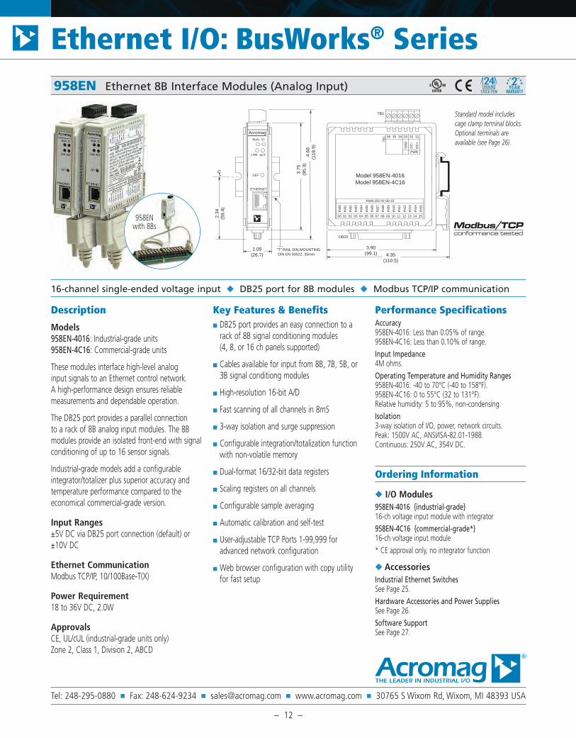
Tel: 248-295-0880 Fax: 248-624-9234 [email protected] www.acromag.com 30765 S Wixom Rd, Wixom, MI 48393 USA
Ethernet I/O: BusWorks® Series
– 12 –
33 32
DB25
TB
1
ACTLINK
ST
PWR
31
LC
RUN
3.75
(95.
3)
36 3435
TB1
4.68
(118
.9)
3.90(99.1)
ETHERNET
DEF
2.34
(59.
4)
Acromag
1.05(26.7)
"T" RAIL DIN MOUNTING DIN EN 50022, 35mm 4.35
(110.5)
Model 958EN-4016Model 958EN-4C16
®
DC
–
GN
D
DC
+
00
IN02
02
IN03
03
IN05
05
IN01
IN00
01
IN04
04 06
IN08
08
IN09
09
IN11
11
IN07
IN06
07
IN10
10
IN12
12
IN13
13
IN15
15
IN14
14
ANALOG IN: 00-15
Description
Models958EN-4016: Industrial-grade units 958EN-4C16: Commercial-grade units
These modules interface high-level analog input signals to an Ethernet control network. A high-performance design ensures reliable measurements and dependable operation.
The DB25 port provides a parallel connection to a rack of 8B analog input modules. The 8B modules provide an isolated front-end with signal conditioning of up to 16 sensor signals.
Industrial-grade models add a configurable integrator/totalizer plus superior accuracy and temperature performance compared to the economical commercial-grade version.
Input Ranges±5V DC via DB25 port connection (default) or ±10V DC
Ethernet CommunicationModbus TCP/IP, 10/100Base-T(X)
Power Requirement18 to 36V DC, 2.0W
ApprovalsCE, UL/cUL (industrial-grade units only) Zone 2, Class 1, Division 2, ABCD
Key Features & Benefits DB25 port provides an easy connection to a
rack of 8B signal conditioning modules (4, 8, or 16 ch panels supported)
Cables available for input from 8B, 7B, 5B, or 3B signal conditiong modules
High-resolution 16-bit A/D
Fast scanning of all channels in 8mS
3-way isolation and surge suppression
Configurable integration/totalization function with non-volatile memory
Dual-format 16/32-bit data registers
Scaling registers on all channels
Configurable sample averaging
Automatic calibration and self-test
User-adjustable TCP Ports 1-99,999 for advanced network configuration
Web browser configuration with copy utility for fast setup
Performance SpecificationsAccuracy958EN-4016: Less than 0.05% of range. 958EN-4C16: Less than 0.10% of range.Input Impedance4M ohms.Operating Temperature and Humidity Ranges958EN-4016: -40 to 70°C (-40 to 158°F). 958EN-4C16: 0 to 55°C (32 to 131°F). Relative humidity: 5 to 95%, non-condensing.Isolation3-way isolation of I/O, power, network circuits. Peak: 1500V AC, ANSI/ISA-82.01-1988. Continuous: 250V AC, 354V DC.
Ordering Information
I/O Modules958EN-4016 industrial-grade16-ch voltage input module with integrator958EN-4C16 commercial-grade*16-ch voltage input module* CE approval only, no integrator function
AccessoriesIndustrial Ethernet SwitchesSee Page 25.Hardware Accessories and Power SuppliesSee Page 26.Software SupportSee Page 27.
16-channel single-ended voltage input DB25 port for 8B modules Modbus TCP/IP communication
958EN Ethernet 8B Interface Modules (Analog Input)
958EN with 8Bs
Standard model includes cage clamp terminal blocks. Optional terminals are available (see Page 26).

Tel: 248-295-0880 Fax: 248-624-9234 [email protected] www.acromag.com 30765 S Wixom Rd, Wixom, MI 48393 USA
Ethernet I/O: BusWorks® Series
– 13 –
8B Signal Conditioning Modules
High-density isolation amplifiers Parallel interface connects to 958EN Ethernet Analog Input Modules
DescriptionThis new line of high-density isolated signal conditioners provides 17 family groups with a total of 102 models that interface to a wide variety of voltage, current, temperature, position, frequency, and strain measuring devices. Housed in a package only one-fifth the size of competing products, the 8B module series offers instrument-class performance with superior specifications for accuracy, linearity, filtering, isolation, output noise and much more.
Key Features & Benefits ±0.05% accuracy
±0.02% linearity
1500Vrms isolation
3- to 5-pole low-pass filter
120dB CMR
ANSI/IEEE C37.90.1 transient protection
Field I/O protection from 30 to 240V AC continuous
-40°C to 85° operating temperature range
CE compliant
UL/cUL listing pending for Class 1, Division 2
Applications Systems requiring high channel-to-channel
isolation, noise rejection, surge suppression, and amplification
Designed for front-end signal conditioning or embedded applications:
DCS, PLC, controllers, data acquisition, remote I/O, recorders, etc.
On-board embedded OEM applications
Protects equipment, increases accuracy, and installs/expands easily
Low-cost, high-density amplifier system
Ordering InformationNOTE: Please refer to Acromag Bulletin #8400-479 or visit www.acromag.com for full ordering information.
Input Modules– Current input– Voltage input; 1kHz, 20kHz, or narrow bandwidth– RTD input; linearized; 2-, 3-, or 4-wire RTD– Thermocouple input; linearized or non-linearized– Strain gage input; wide or narrow bandwidth– Potentiometer input– Frequency input
Accessories– 2-, 4-, 8-, and 16-position analog I/O backpanels– Power supplies– Interface cables– 19-Inch metal mounting rack
8Bs also connect to EtherStax analog I/O modules (ES2151, ES2152, ES2153, ES2162, ES2172 models)

Tel: 248-295-0880 Fax: 248-624-9234 [email protected] www.acromag.com 30765 S Wixom Rd, Wixom, MI 48393 USA
High-performance OPC Server for all Acromag Ethernet I/O Low-cost server exclusively for Acromag I/O
ACMBTCP-OPC Modbus/TCP Master OPC DA Server
DescriptionAcromag’s Modbus/TCP Master OPC DA Server delivers high-speed connectivity to all Acromag Modbus TCP/IP slave devices via Ethernet. This server is designed for all local or remote OPC clients such as HMI, SCADA, operator interface and custom-built (Visual Basic®, Visual C++®) applications.
This OPC server offers the most reliable, cost effective and comprehensive features list available in the OPC/HMI market today.
Our unique read/write tag optimization algorithms provide unmatched data transfer speeds between OPC server and hardware devices.
Acromag’s OPC server has passed the OPC Foundation’s OPC Data Access 3.00 compliance test.
This server includes comprehensive, context-sensitive help systems, Visual Basic OPC client example application with Visual Basic source code, and a pre-built client executable.
Compatible With Leading HMI and SCADA PackagesAcromag’s Data Access Server can be used as a data server to any HMI or SCADA package that is OPC compliant. Additionally, the online help system will guide you through the configuration for popular packages from Wonderware, Intellution, Rockwell, GE, and others.
Key Features & Benefits Runs on Windows® XP, Vista, 7,
2003 Server, 2008 Server
Designed exclusively for use with all Acromag Modbus/TCP Ethernet devices
OPC compliance tested
Unlimited OPC clients, devices, or items
Supports OPC custom and automation interfaces such as Visual Basic and C++
Easy CSV import / export capability
Modbus packet optimization for fast transactions
Runs as a stand-alone executable or unattended with no login required
Device status dialog for easy diagnostics
Free 30-day Trial VersionDownload a no-risk demonstration version and try it free for 30 days. Once you see how easy it is and the robust functionality, you can quickly convert the trial version to a full product license.
Ordering Information
ACMBTCP-OPC*Modbus/TCP Master OPC DA Server. Only available online at www.acromag.com/OPC
Free 30-day Trial*Download a no-risk 30-day demonstration version at www.acromag.com/OPC
* NOTE: This software package is only for use with Acromag Ethernet I/O modules. It cannot be used with third-party instrumentation.
Bulletin #8400-583
Ethernet I/O: Software Support
All trademarks are the property of their respective owners. Copyright © Acromag, Inc. 2010. Data subject to change without notice. Printed in USA 3/2010.

Tel: 248-295-0880 Fax: 248-624-9234 [email protected] www.acromag.com 30765 S Wixom Rd, Wixom, MI 48393 USA
Easy PC-based communication to Acromag BusWorks and EtherStax I/O Modbus/TCP or Modbus/RTU
AMXX Series ActiveX / .NET Controls for Modbus I/O
DescriptionAcromag’s AMXX Series software controls provide a fast, easy way to communicate with any Modbus/RTU or Modbus/TCP slave devices connected to your PC’s serial or network ports. Within minutes, your Visual Basic, Visual C, .NET, Excel, or other compatible applications will be talking Modbus protocol.
AMRX Modbus/RTU ActiveX ControlThe AMRX package is an easy to use ActiveX control that provides a convenient way to communicate to Modbus/RTU slave devices. It also includes a timer for polled data acquisition and a floating point conversion ActiveX control.
AMRN Modbus/RTU Forms ControlAMRN is a simple Windows Forms Control that provides a quick way to communicate with Modbus/RTU slave devices connected to your PC’s serial port.
AMTX Modbus/TCP ActiveX ControlAMTX is an easy to use ActiveX control that simplifies communication with Modbus/TCP slave devices connected to your PC’s wired or wireless network.
AMTN Modbus/TCP Forms ControlAMTN is an easy to use Windows Forms Control for Modbus/TCP to communication with slave devices connected to your PC’s Ethernet port. It can be used on a form or optionally without a form.
Demonstration ProgramsDemonstration versions are available. The demos are complete operating ActiveX controls that have a time limit. After 60-90 minutes, communication functions will be disabled. Re-starting the application will initiate another functional demonstration period.
Key Features & Benefits Any container application that can
embed ActiveX controls can use the AMXX software packages
At design time, you can access your Modbus device from the software’s test property page
Property page device access makes start-up and troubleshooting a snap – all without writing a single line of code
Talking to a Modbus slave is as simple as calling a function with the necessary arguments
The software automatically builds the command, appends a CRC, sends the request over the network, and validates the response
Your program just reads and writes simple 16-bit data values
ActiveX controls include a help file and examples for Excel, Visual Basic, C++
.NET controls include a help file and examples for Visual Basic, C#, and Managed C++
Bulletin #8400-584b
Ethernet I/O: Software Support
All trademarks are the property of their respective owners. Copyright © Acromag, Inc. 2010. Data subject to change without notice. Printed in USA 2/2011.
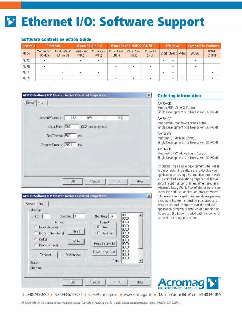
Tel: 248-295-0880 Fax: 248-624-9234 [email protected] www.acromag.com 30765 S Wixom Rd, Wixom, MI 48393 USA
All trademarks are the property of their respective owners. Copyright © Acromag, Inc. 2010. Data subject to change without notice. Printed in USA 2/2011.
Ethernet I/O: Software Support
Ordering Information
AMRX-CDModbus/RTU ActiveX Control, Single Development Site License (on CD-ROM).
AMRN-CDModbus/RTU Windows Forms Control, Single Development Site License (on CD-ROM).
AMTX-CDModbus/TCP ActiveX Control, Single Development Site License (on CD-ROM).
AMTN-CDModbus/TCP Windows Forms Control, Single Development Site License (on CD-ROM).
By purchasing a single development site license you may install the software and develop your application on a single PC and distribute it with your compiled application program royalty free an unlimited number of times. When used in a Microsoft Excel, Word, PowerPoint or other non-compiling end-user application program where full development capabilities are always present, a separate license file must be purchased and installed on each computer that the end-user application program is installed and running on. Please see the EULA included with the demo for complete licensing information.
Controls Protocols Visual Studio 6.0 Visual Studio 2005/2008/2010 Windows Compatible Products
Model Modbus/RTU(RS-485)
Modbus/TCP(Ethernet)
Visual Basic(VB6)
Visual C++(VC6)
Visual Basic(.NET)
Visual C++(.NET)
Visual C#(.NET) Excel 32-bit 64-bit 900MB 900EN
ES2000
AMRX • • • • • •
AMRN • • • • • • •
AMTX • • • • • •
AMTN • • • • • • •
Software Controls Selection Guide

Tel: 248-295-0880 Fax: 248-624-9234 [email protected] www.acromag.com 30765 S Wixom Rd, Wixom, MI 48393 USA
Ethernet I/O: BusWorks® Series
– 27 –
Universal support for five operating systems C source code provided Demo program included
DescriptionAcromag’s Modbus C Library software greatly simplifies development of programs to inter-face with Acromag’s BusWorks® and EtherStax® Ethernet I/O products. The library also supports any standard Ethernet Modbus slave device that communicates via Modbus TCP/IP or UDP/IP protocol. This utility is ideal for developers that are unfamiliar with Modbus protocol or the framing of TCP/IP or UDP/IP messages.
The C library makes programming easy and portable by simply linking user code with the provided function calls (below). Most function calls require passing only a few parameters such as the IP address, Modbus register address, and register count.
Codes Functions01 (01H) Read Coil (Output) Status
02 (02H) Read Input Status
03 (03H) Read Holding Registers
04 (04H) Read Input Registers
05 (05H) Force Single Coil (Output)
06 (06H) Preset Single Register
15 (0FH) Force Multiple Coils (Outputs)
16 (10H) Preset Multiple Registers
17 (11H) Report Slave ID
Example ProgramThe included example program is menu-driven to help users build Modbus TCP/IP and UDP/IP commands. Menu selections let users configure, read, and write Ethernet I/O slave devices such as Acromag’s BusWorks and EtherStax products.
Users may also leverage this demonstration application into a tool for configuration or test by supplying commands and/or data values in the form of a text file. The program will execute each command in the text file as if it had been typed from the console terminal.
Key Features & Benefits Library of function routines simplify communi-
cation with I/O modules
Function calls provided for a variety of operat-ing systems
C source code supplied
Demonstration program included
Saves development time
Ideal for use with Acromag’s BusWorks and EtherStax I/O modules
Compatible with any standard Modbus TCP/IP or UDP/IP device
Ordering InformationESW-MBLIBEthernet Modbus C Library Software (CD-ROM)
ESW-MBLIB Ethernet Modbus C Library Software

Tel: 248-295-0880 Fax: 248-624-9234 [email protected] www.acromag.com 30765 S Wixom Rd, Wixom, MI 48393 USA
Ethernet I/O: BusWorks® Series
– 25 –
900EN-S005 Ethernet SwitchesAcromag’s five-port Ethernet switch is designed for use in industrial applications. Rugged con-struction and a variety of security features ensure reliable operation under demanding conditions. Internal intelligence enables “connect and go” operation for fast and easy network installation with auto-negotiation of data rate, flow control, and crossover signal compatibility. No configura-tion is necessary when the 900EN-S005 is used as a simple switch with Acromag I/O modules. For advanced users, this switch offers numer-ous control functions that are easily configured through DIP-switch settings or programmed using your computer.
Five shielded RJ-45 sockets, 8-pin, 10Base-T / 100Base-TX
1500V port-to-port isolation
Redundant power support
-25 to 70°C operating range
CE, ATEX marked. UL, cUL listed, Class I; Div. 2; Groups A, B, C, D.
.
EIS Series Ethernet Switches
ModelsEIS-358: 8-port (Cu), redundancy, unmanaged EIS-408: 8-port (Cu/fiber), redundancy, managed
EIS series switches are designed for harsh envi-ronments. They feature a rugged IP30 aluminum case, 300,000 hour MTBF, and power supply redundancy for dependable networking.
Managed operationWith web-based setup, managed switches ensure easy installation and maintenance. Managed switches also support many powerful Ethernet features such as port VLAN, Quality of Service (QoS), Internet Group Management Protocol (IGMP) Snooping, and failure alarms.
Self-healing redundant ring capabilitySome models employ redundancy to provide self-recovery if the primary communication path fails. Redundant ring technology instantly reconfigures to provide an alternate path. The fast recovery time protects mission-critical applications from interruptions and temporary malfunctions.
Ultra-fast redundant ring technology (<300mS) supports STP, RSTP and proprietary protocols
-10 to 70°C operating temperature range
Port-to-port isolation (1200V AC)
Built-in RFI/EMI and surge/transient protection
Ordering Information
SwitchesFor more information please visit www.acromag.com. 900EN-S005Ethernet switch, 5-port CopperEIS-358Ethernet switch with redundancy, 8-port CopperEIS408FX-MEthernet switch with redundancy, 6 Cu / 2 Fiber-optic, multi-mode fiber (up to 2 km).EIS-408FX-SEthernet switch with redundancy, 6 Cu / 2 Fiber-optic, single-mode fiber (up to 30 km).
AccessoriesHardware Accessories and Power SuppliesSee Page 26.
8-Port Switch, Managed, FX 8-Port Switch, Unmanaged 5-Port Switch, Unmanaged
900EN Series, EIS Series Industrial Ethernet Switches

These low-cost multi-
channel I/O modules
are ideal for remote
I/O applications with
limited space and
those requiring a
handful of channels
in many locations.
BusWorks® I/O Modules for Modbus-RTUAcromag’s BusWorks 900MB series is a collection of analog and discrete I/O modules with Modbus-RTU network communication. BusWorks modules are ideal for a wide variety of distributed I/O applications including data acquisition, control, process monitoring, and test & measurement.
Analog input modules accept DC current, voltage, or temperature sensor signals and feature local limit alarm capabilities. Analog output modules provide DC current or voltage signals for local displays, recorders, variable frequency drives, valves, and other equipment.
Discrete I/O modules monitor and/or control on/off status of industrial devices.
Windows® configuration software simpli-fies module setup with easy selection of input/output ranges, alarm setpoints, and other operating parameters.
All 900MB Modbus I/O modules com-municate over a high-speed RS-485 net-work supporting data transfer rates up to 115K baud.
Inputs• Thermocouple • DC voltage• RTD/Resistance • DC current• Millivolt • AC current• Frequency • Discrete status
Outputs• DC voltage• DC current• Discrete switches or local limit alarms
Power• 10-36V DC• 24V AC
Approvals• CE, UL/cUL Class I Div 2 Groups ABCD
For more information, visit our website atwww.acromag.com/modbus
10 Call 877-214-6267 or 248-295-0880 for technical assistance.
MODBUS-RTU: REMOTE I/O

Tel: 248-295-0880 Fax: 248-624-9234 e-mail: [email protected] www.acromag.com
60
9 0 0 M B S e r i e sM
odbu
s I/O
BusW
orks
®
913/914MBMulti-ChannelAnalog InputModules
DC Current,DC Voltage orAC Current Input
Limit Alarms orDiscrete Outputs
Models913MB: 4 current input channels914MB: 4 voltage input channels
Input Ranges0 to 20mA DC,±10V DC,0 to 20A AC (with 5020-350 sensor)
OutputFour output channels:Open-drain MOSFETs (1A DC loads)0 to 35V DC
Network CommunicationModbus-RTU high-speed RS-485
Power Requirement10 to 36V DC,24V AC
ApprovalsCE marked. UL, cUL listed Class I; Division 2; Groups A, B, C, D.
n DescriptionThis signal conditioner is a four-channel analoginput module with four discrete outputs. It provides isolation between input, output, power,and network circuits. Network communicationadheres to the industry-standard RS-485 ModbusRTU protocol. AC and DC power sources aresupported with nonpolarized, diode-coupled terminals.
The inputs accommodate wide DC voltage orcurrent ranges. Flexible discrete outputs operateas alarms or on/off controllers. As limit alarms,each discrete output can be configured with highand/or low setpoints exclusively tied to an analoginput channel. Alarm trips function without hostcommunication enabling low-cost stand-alonealarms, as well as local backup for the primarycontrol system. Otherwise, on/off control isbased on commands issued by the host system.
Combining flexible transmitter functions, mixedsignal I/O, alarm support, and a network inter-face in a single package, makes this instrumentextremely powerful. Multi-channel design addscost-efficiency and allows high-density mounting.Plus, safe, rugged construction makes thesemodules reliable for use in both control roomand distributed field I/O applications. Custommodule configurations are also possible (consultfactory for details).
n Special Featuresn Standard Modbus RTU protocol with high-speed
RS-485 communication (up to 115K bps)
n 16-bit sigma-delta A/D yields 0.1% of rangeresolution and accuracy
n Four inputs in a single inch-wide modulereduces system costs and saves panel space
n Four discrete outputs enable local limit alarmsor host-controlled on/off switching
n Heavy-duty 1A solid-state relays providedependable on/off control of industrial devices
n Self-calibration lowers maintenance costs byreducing periodic manual calibration checks
n Watchdog timers provide a configurable failsafe output state for use when host I/O communication is lost
n Four-way isolation eliminates potential groundloops between power, input, output, and network circuitry
n Self-diagnostics monitor microcontroller activityto detect operational failures (lock-up) andexecute a reset to restore communication
Modbus
FourDC Current
orDC Voltage
Inputs RS-485
10-36V DCor 24V AC
Isolation
FourDiscreteOutputs
orLimit Alarms
Power
Outputs (4)Inputs (2)
Inputs (2)
DC Current/Voltage Input Module
TB1/TB2
IN+
IN-
Red
Black
1.35"
1.05"
0.375" dia.
5020-350
AC Current Sensor Model 5020-350
For 913MB. Order separately (one per channel).
Modbus/RS-485
8400100.qxp 3/20/2006 3:17 PM Page 58

Tel: 248-295-0880 Fax: 248-624-9234 e-mail: [email protected] www.acromag.com
61
Modbus I/OM
odbus I/OBusW
orks ®
Performance Specifications
General InputResolution0.005% or 1 part in 20,000.
Noise Rejection Normal mode: 40dB @ 60Hz, typical. Common mode: 140dB @ 60Hz, typical.
Input Filter Bandwidth-3dB at 3Hz, typical.
Input Conversion Rate180ms per channel.
Current Input (913MB)DC Current Input RangesRange user-configured. Range selected applies to all channels. 0 to 1mA, 0 to 20mA, 4 to 20mA, 0 to 11.17mA (for use with 5020-350 AC sensor).
DC Current Input Resistance49.9 ohms.
DC Current Input Accuracy±0.1% of input range.
Voltage Input (914MB)DC Voltage Input RangesRange user-configured. Range selected applies to all channels. ±10V, ±5V, ±2.5V, ±1.25V, ±625mV, ±313mV, ±156mV, ±78mV
Input Impedance110.5K ohms.
DC Voltage Input Accuracy±0.1% of input range.
Discrete OutputOutput TypeFour independent open drain MOSFET switches with a common return that operate as low-side switches.
Output Voltage Range0 to 35V DC. External voltage source required.
Output Current Range0 to 1A DC continuous for each output.
Output OFF Leakage Current50µA maximum.
Output ON Resistance0.15 ohms maximum.
Output Response Time4.1ms typical, from receipt of command to gate transition of the output MOSFET.
OperationDigital outputs are set to their OFF state following a software or power-on reset. Outputs can optionally be set to user-defined states following a watchdog timeout. Watchdog timeout output control takes pre-cedence over limit alarm control. Alarm control takes precedence over host control.
CommunicationSupported Modbus CommandsThe command/response protocol for communicating with this module adheres to the Modbus/RTU standard for the following Modbus Functions.
Read Coil (Output) Status Read Holding Registers Read Input Registers Force Single Coil (Output) Preset Single Register Force Multiple Coils (Output) Preset Multiple Registers Report Slave ID Reset Slave
LED IndicatorsLEDs indicate power, status, and discrete level/alarm.
Power and IsolationPower Requirements10 to 36V DC or 22 to 26V AC.
Supply CurrentSupply Current Draw 10V DC 125mA maximum 24V DC 50mA maximum 24V AC 100mA rms maximum
Isolation1500V AC for 60 seconds or 250V AC continuous. 4-way isolation between input, network, power, and discrete I/O circuits. Inputs are isolated channel-to-channel for common mode voltage to ±4V DC.
Ordering Information
Models913MB-0900 914MB-0900DC current (913MB) or voltage ( 914MB) input module
Accessories900C-SIPConfiguration Software Interface Package (includes software CD-ROM for Windows, RS-232/485 converter, and RS-485/three-wire cable)5034-225 USB-to-RS232 adapter. See page 68 for more info.5020-350AC current sensor for 913MB. One for each channel. (See page 205)TBK-B02Optional terminal block kit, barrier strip style, 4 pcs.TBK-S02Optional terminal block kit, spring clamp style, 4 pcs.PS5R-D24 Power supply (24V DC, 2.1A). See Power Supplies on Page 199.For more information on software, network hardware, and mounting accessories, please see Pages 69-71.
TWO-WIRE TRANSMITTER
ANALOG INPUTCONNECTIONS
TB1/TB2
IN+
DCCURENT
(mA)
IN-
-
+TB1/TB2
IN+
IN-
DIG
ITA
LO
UT
PU
TS
4546
TB4
OUT3
RTN
DIGITAL OUTPUT
TB
4
RTN
OUT2
OUT1
4443
4236
41
TB3
OUT0
11
TB1
1213 IN0+
IN0-
1415
16
IN1+
IN1-
INP
UT
S0,1
TB221
IN3+
IN3-
2526
24 IN2-
23 IN2+
22
INP
UT
S2,3
D
COM
COM
D
RS
485
3334
3531
32
A
B
PW
R
TB
3
TB
1
ANALOGINPUT
ANALOGINPUT
TB
2
AC/DCPOWER
NETWORKCOMMUNICATION
CURRENT INPUT
VOLTAGESOURCE -
+ TB1/TB2
IN+
IN-
VOLTAGE INPUT
XMTR2-WIRE
-
+
DIGITAL OUTPUT CONNECTIONS
UP TO 35V DC
MECHANICALRELAY INTERFACE
+
OUT 3
OUT
OUT 2
RTN
OUT 1
RTNTB4
OUT
RTN
DIGITAL OUTSHARESRETURN
RTN
OUT
10 TO 36V DCOR 24V ACNON-POLARIZED

Tel: 248-295-0880 Fax: 248-624-9234 e-mail: [email protected] www.acromag.com
60
9 0 0 M B S e r i e sM
odbu
s I/O
BusW
orks
®
917/918MBMulti-ChannelAnalog OutputModules
DC Current or DC Voltage Outputs
Discrete Outputs
Models917MB: 4 current output channels918MB: 4 voltage output channels
Analog Output917MB: 0 to 20mA, 4 to 20mA, 0 to 1mA DC918MB: 0 to 10V, 0 to 5V, 0 to 1V DC
Discrete OutputFour output channels:Open-drain MOSFETs (1A DC loads)0 to 35V DC
Network CommunicationModbus-RTU high-speed RS-485
Power Requirement12 to 36V DC (917MB), 10 to 36V DC (918MB),24V AC
ApprovalsCE marked. UL, cUL listed Class I; Division 2; Groups A, B, C, D.
n DescriptionThese modules drive four analog output channelsand also feature four discrete outputs for on/offcontrol. Isolation separates the output, power,and network circuits. Network communicationadheres to the industry-standard RS-485 ModbusRTU protocol. AC and DC power sources aresupported with nonpolarized, diode-coupled terminals.
The analog outputs generate a signal based oncommunication from the host. They accommo-date wide DC voltage or current ranges.
Discrete outputs provide simple on/off switchingcapability (open-drain) for external devices.
Combining analog outputs, on/off controllers,and a network interface in a single package,makes this instrument extremely powerful. Multi-channel design adds cost-efficiency andallows high-density mounting. Plus, safe, ruggedconstruction make it reliable for both controlroom and distributed field I/O use in a broadrange of temperature control applications.Custom module configurations are also possible(consult factory for details).
n Special Featuresn Standard Modbus RTU protocol with high-speed
RS-485 communication (up to 115K bps)
n 12-bit D/A yields 0.1% of span resolution andaccuracy
n Four analog outputs in an inch-wide modulereduces system costs and saves panel space
n Four discrete outputs enable host-controlledon/off switching
n Heavy-duty 1A solid-state relays providedependable on/off control of industrial devices
n Self-calibration lowers maintenance costs byreducing periodic manual calibration checks
n Watchdog timers provide a configurable failsafe output state for use when host I/O communication is lost
n Three-way isolation eliminates potentialground loops between power, output, and network circuitry
n Self-diagnostics monitor microcontroller activityto detect operational failures (lock-up) andexecute a reset to restore communication
Modbus
FourAnalogOutputs
DC Current
orDC Voltage
RS-485
10-36V DCor 24V AC
Isolation
FourDiscreteOutputs
Power
Outputs (4)Outputs (2)
Outputs (2)
Analog Output ModuleModbus/RS-485
8400100.qxp 3/20/2006 3:17 PM Page 60

Tel: 248-295-0880 Fax: 248-624-9234 e-mail: [email protected] www.acromag.com
61
M o d b u s I / OM
odbus I/OBusW
orks ®
n Performance
n General Analog OutputResolutionSee current/voltage output specifications for moreinformation.
Ambient Temperature EffectBetter than ±0.001% of output span per °C, or±1.0uV/°C, whichever is greater.
Ambient TemperatureOperation (917MB): -25°C to 60°C* (-13°F to 140°F*).Operation (918MB): -25°C to 70°C (-13°F to 158°F).Storage: -40°C to +85°C (-40°F to +185°F).* Limit 917MB maximum ambient to 50°C (122°F)when using supply voltages less than 15V DC.
n Current Output (917MB)DC Current Output RangesRange user-configured. Range selected applies to allchannels. Output Range Resolution Accuracy (% span)0 to 1mA 0.554% ±2.0% (±0.002mA)0 to 20mA 0.028% ±0.1% (±0.02mA)4 to 20mA 0.035% ±0.1% (±0.02mA)
Maximum Output Current22.5mA DC typical.
Integral Non-Linearity±0.1% of span or ±2 LSB typical, whichever is larger,for spans equal to or greater than 16mA.
Output Compliance12V minimum, 12.7V typical.
Output Load Resistance Range0 to 630 ohms typical.
Response Time11ms typical into 500 ohms, for measurement toreach 98% of the final value in response to a stepcommand. Actual response time will vary with load.
n Voltage Output (918MB)DC Voltage Output RangesRange user-configured. Selection applies to all channels.Output Range Resolution Accuracy (% span)0 to 1V 0.274% ±0.6% (±6mV)0 to 5V 0.055% ±0.1% (±5mV)0 to 10V 0.027% ±0.1% (±10mV)
Maximum Output Voltage11.255V DC typical.
Integral Non-Linearity±0.1% of span or ±2 LSB typical, whichever is larger,for spans equal to or greater than 5V.
Output Current0 to 10mA DC maximum.
Output Impedance1 ohm.
Output Short Circuit ProtectionIncluded.
Response Time110µs rise time typical, 150µs fall time typical,unloaded, for output to reach 98% of the final valuein response to a step command. Time varies with load.
n Discrete OutputOutput TypeFour independent open drain MOSFET switches with acommon return that operate as low-side switches.
Output Voltage Range0 to 35V DC (up to 1A/channel continuous).External voltage source required.
Output ON Resistance0.15 ohms maximum.
OperationDigital outputs are set to their OFF state following asoftware or power-on reset. Outputs may be set touser-defined states following a watchdog timeout.Watchdog timeout output control takes precedenceover limit alarm control. Alarm control takes prece-dence over host control.
Output Response Time4.1ms typical, from receipt of command to gate transition of the output MOSFET.
n CommunicationSupported Modbus CommandsThe command/response protocol for communicatingwith this module adheres to the Modbus/RTU standardfor the following Modbus Functions.
Read Coil (Output) Status Report Slave IDRead Holding Registers Reset SlaveRead Input RegistersForce Single Coil (Output)Preset Single Register Force Multiple Coils (Output)Preset Multiple Registers
LED IndicatorsLEDs indicate power, status, and discrete level/alarm.
n Power and IsolationPower Requirements10 to 36V DC (918MB), 12 to 36V DC (917MB)22 to 26V AC.
Supply CurrentSupply Current Draw (917) Current Draw (918)10V DC Not Recommended 100mA maximum12V DC 275mA maximum 85mA maximum24V DC 120mA maximum 45mA maximum24V AC 210mA rms max. 85mA rms max.
Isolation1500V AC for 60 seconds or 250V AC continuous. 3-way isolation between outputs, network, and powercircuits.
n Ordering Information
Models917MB-0900918MB-0900DC current (917MB) or voltage (918MB) output module
Accessories900C-SIPConfiguration Software Interface Package(includes software CD-ROM for Windows, RS-232/485converter, and RS-485/three-wire cable)4001-095USB-to-RS232 adapter. See page 70 for more info.TBK-B02Optional terminal block kit, barrier strip style, 4 pcs.TBK-S02Optional terminal block kit, spring clamp style, 4 pcs.PS5R-D24Power supply (24V DC, 2.1A). See Power Supplies on Page 199.For more information on software, network hardware,and mounting accessories, please see Pages 69-71.
DC CURRENT OUTPUT
ANALOG OUTPUT CONNECTIONS D
IGIT
AL
OU
TP
UT
S
45
46
TB4
OUT3
RTN
DIGITAL OUTPUT
TB
4
RTN
OUT2
OUT1
44
43
42
36
41
TB3
OUT0
D
COM
COM
D
RS
48
5
33
34
35
31
32
A
B
PW
R
TB
3
TB
1
ANALOGOUTPUT
ANALOGOUTPUT
TB
2
AC/DCPOWER
NETWORKCOMMUNICATION
DC VOLTAGE OUTPUT
TB1
I0+
RTN
12
11
AN
AL
OG
OU
TP
UT
S
13 RTN
I1+
RTN
14
15
AN
AL
OG
OU
TP
UT
S
16 RTN
TB2
21
22
I2+
RTN
I3+
RTN
23
24
RTN
26
25 RTN
TB1
V0+
RTN
12
11
AN
AL
OG
OU
TP
UT
S
13 RTN
V1+
RTN
14
15
AN
AL
OG
OU
TP
UT
S
16 RTN
TB2
21
22
V2+
RTN
V3+
RTN
23
24
RTN
26
25 RTN
TB1/TB2
+LR
I
TB1/TB2
+LR
WIRING CONNECTIONS SAME AS 913/914MB
10 TO 36V DCOR 24V ACNON-POLARIZED
I+
RTN
V+
RTN
8400100.qxp 3/20/2006 3:18 PM Page 61

Tel: 248-295-0880 Fax: 248-624-9234 e-mail: [email protected] www.acromag.com
62
9 0 0 M B S e r i e sM
odbu
s I/O
BusW
orks
®
924MBMulti-ChannelTemperatureControl Modules
Thermocouple orMillivolt Input
Limit Alarms orDiscrete Outputs
Model924MB: 4 input channels
InputFour input channels:Thermocouple (types J, K, T, R, S, E, B, N),±100mV DC
OutputFour output channels:Open-drain MOSFETs (1A DC loads)0 to 35V DC
Network CommunicationModbus-RTU high-speed RS-485
Power Requirement10 to 36V DC,24V AC
ApprovalsCE marked. UL, cUL listed Class I; Division 2; Groups A, B, C, D.
n DescriptionThis signal conditioner is a four-channel analoginput module with four discrete outputs. It filtersand linearizes thermocouple inputs while provid-ing isolation between input, output, power, andnetwork circuits. Cold junction compensationand upscale/downscale sensor break detectionare standard. AC and DC power sources are sup-ported with nonpolarized, diode-coupled termi-nals.
The programmable inputs accommodate eightthermocouple types plus wide-range millivolt signals. Flexible discrete outputs operate asalarms or on/off controllers. As limit alarms, eachdiscrete output can be configured with highand/or low setpoints exclusively tied to an analoginput channel. Alarm trips function without hostcommunication enabling low-cost stand-alonealarms as well as local backup for the primarycontrol system. Otherwise, on/off control isbased on commands issued by the host system.
Combining flexible transmitter functions, mixedsignal I/O, alarm support, and a network inter-face in a single package, makes this instrumentextremely powerful. Multi-channel design addscost-efficiency and allows high-density mounting.Plus, safe, rugged construction makes thesemodules reliable for use in both control roomand distributed field I/O applications. Custommodule configurations are also possible (consultfactory for details).
n Special Featuresn Standard Modbus RTU protocol with high-speed
RS-485 communication (up to 115K bps)
n 16-bit sigma-delta A/D yields 0.1°C resolutionand 0.5°C measurement accuracy
n Thermocouple linearization and sensor breakdetection ensure reliable measurements
n Four discrete outputs enable local temperaturelimit alarms or host-controlled on/off switching
n Heavy-duty 1A solid-state relays providedependable on/off control of industrial devices
n Self-calibration lowers maintenance costs byreducing periodic manual calibration checks
n Watchdog timers provide a configurable failsafe output state for use when host I/O communication is lost
n Four-way isolation eliminates potential groundloops between power, input, output and network circuitry
n Self-diagnostics monitor microcontroller activityto detect operational failures (lock-up) andexecute a reset to restore communication
Modbus
FourThermocouple
orDC Millivolt
Inputs RS-485
10-36V DCor 24V AC
Isolation
FourDiscreteOutputs
orLimit Alarms
Power
Outputs (4)Inputs (2)
Inputs (2)
Thermocouple/Millivolt Input ModuleModbus/RS-485
8400100.qxp 3/20/2006 3:18 PM Page 62

Tel: 248-295-0880 Fax: 248-624-9234 e-mail: [email protected] www.acromag.com
63
M o d b u s I / OM
odbus I/OBusW
orks ®
n Performance
n General InputResolution±100mV DC input: 0.1%.Thermocouple input: 0.1°C (0.18°F).
Ambient Temperature EffectBetter than ±0.005% of input span per °C, or±1.0uV/°C, whichever is greater.
Noise Rejection Normal mode: 40dB @ 60Hz, typical.Common mode: 140dB @ 60Hz, typical.
Input Filter Bandwidth-3dB at 3Hz, typical.
Input Conversion Rate90ms per channel.
n Thermocouple InputThermocouple Input RangesThermocouple type user-configured. Type selectedapplies to all channels. Signal linearization, cold-junc-tion compensation, and open circuit or lead breakdetection are included.TC °C Range (°F Range) AccuracyJ -210 to 760°C (-346 to 1400°F) ±0.5°CK -200 to 1372°C (-328 to 2502°F) ±0.5°CT -260 to 400°C (-436 to 752°F) ±0.5°CR -50 to 1768°C (-58 to 3214°F) ±1.0°CS -50 to 1768°C (-58 to 3214°F) ±1.0°CE -200 to 1000°C (-328 to 1832°F) ±0.5°CB 260 to 1820°C (500 to 3308°F) ±1.0°CN -230 to 1300°C (-382 to 2372°F) ±1.0°CNote 1: Accuracy is given with CJC switched off.
Relative inaccuracy with CJC enabled may increaseby ±0.5°C.
Thermocouple Break DetectionTC sensor failure can be configured for either upscaleor downscale. Selection applies to all channels.
n DC Millivolt InputMillivolt Input Ranges±100mV DC.
Millivolt Input Accuracy±0.1% of input range.
n Discrete OutputOutput TypeFour independent open drain MOSFET switches with acommon return that operate as low-side switches.
Output Voltage Range0 to 35V DC, 1A DC maximum for each output.External voltage source required.
Output ON Resistance0.15 ohms maximum.
OperationDigital outputs are set to their OFF state following asoftware or power-on reset. Outputs can optionally be set to user-defined states following a watchdogtimeout. Watchdog timeout output control takesprecedence over limit alarm control. Alarm controltakes precedence over host control.
Output Response Time4.1ms typical, from receipt of command to gate transition of the output MOSFET.
n CommunicationSupported Modbus CommandsThe command/response protocol for communicatingwith this module adheres to the Modbus/RTU standardfor the following Modbus Functions.
Read CoilRead Holding RegistersRead Input RegistersForce Single CoilPreset Single Register Force Multiple CoilsPreset Multiple RegistersReport Slave IDReset Slave
LED IndicatorsLEDs indicate power, status, and discrete level/alarm.
n Power and IsolationPower Requirements10 to 36V DC,22 to 26V AC.
Supply CurrentSupply Current Draw10V DC 100mA maximum24V DC 45mA maximum24V AC 85mA rms maximum
Isolation1500V AC for 60 seconds or 250V AC continuous. 4-way isolation between input, network, power anddiscrete I/O circuits. Inputs are isolated channel-to-channel for common mode voltage to ±5V DC.
n Ordering Information
924MB-0900Thermocouple/millivolt input module900C-SIPConfiguration Software Interface Package(includes software CD-ROM for Windows, RS-232/485converter, and RS-485/three-wire cable)4001-095USB-to-RS232 adapter. See page 70 for more info.TBK-B01Optional terminal block kit, barrier strip style, 2 pcs.(Does not include terminal block for input wiring.)TBK-S02Optional terminal block kit, spring clamp style, 2 pcs.(Does not include terminal block for input wiring.)PS5R-D24Power supply (24V DC, 2.1A). See Power Supplies on Page 199.For more information on software, network hardware,and mounting accessories, please see Pages 69-71.
TC INPUT
ANALOG INPUT CONNECTIONS
TB1/TB2
IN+
VOLTAGE
IN-
SOURCE -
+ TB1/TB2
IN+
IN-
DIG
ITA
LO
UT
PU
TS
45
46
TB4
OUT3
RTN
DIGITAL OUTPUT
TB
4
RTN
OUT2
OUT1
44
43
42
36
41
TB3
OUT0
11
TB1
12
CJ
C-0
13 IN0+
IN0-
14
15
16
IN1+
IN1-
INP
UT
S0,1
CJ
C-1
TB2
21
IN3+
IN3-
25
26
24 IN2-
23 IN2+
22
INP
UT
S2,3
D
COMCOM
D
RS
48
5
33
34
35
31
32
A
B
PW
R
TB
3
TB
1
ANALOGINPUT
ANALOGINPUT
TB
2
AC/DCPOWER
NETWORKCOMMUNICATION
VOLTAGE INPUT
DIGITAL OUTPUT CONNECTIONS
OUT 3
OUT 0
OUT 2
RTN
OUT 1
RTNTB4
OUT
RTN
DIGITAL OUT SHARES RETURN
10 TO 36V DCOR 24V ACNON-POLARIZED
UP TO 35V DC
MECHANICALRELAY INTERFACE
+
RTN
OUT
8400100.qxp 3/20/2006 3:18 PM Page 63

Tel: 248-295-0880 Fax: 248-624-9234 e-mail: [email protected] www.acromag.com
64
9 0 0 M B S e r i e sM
odbu
s I/O
BusW
orks
®
932/934MBMulti-ChannelTemperatureControl Modules
RTD or ResistanceInput
Limit Alarms orDiscrete Outputs
Models932MB: 2 input channels, 2 relay outputs934MB: 4 input channels, 4 relay outputs
InputRTD (100 ohm Pt, 120 ohm Ni, 10 ohm Cu),Resistance (0 to 500 ohms)
OutputSolid-state relays, Form A, SPST-NO
Network CommunicationModbus-RTU high-speed RS-485
Power Requirement10 to 36V DC,24V AC
ApprovalsCE marked. UL, cUL listed Class I; Division 2; Groups A, B, C, D.
n DescriptionThis signal conditioner is a dual or quad-channelanalog input module with one discrete/relay out-put per input channel and a Modbus interface. Itfilters and linearizes RTD or resistance inputswhile providing isolation between input, output,power, and network circuits. Lead wire compen-sation and upscale/downscale sensor breakdetection are standard. Low voltage AC and DCpower sources are supported with nonpolarized,diode-coupled terminals.
The programmable inputs accommodate fourRTD types plus wide-range resistance signals.Flexible discrete outputs operate as alarms oron/off controllers. As limit alarms, each discreteoutput can be configured with high and/or lowsetpoints exclusively tied to an analog inputchannel. Alarm trips function without host com-munication enabling low-cost stand-alone alarmsas well as local backup for the primary controlsystem. Otherwise, on/off control is based oncommands issued by the host system.
Combining flexible transmitter functions, mixedsignal I/O, alarm support, and a network inter-face in a single package, makes this instrumentextremely powerful. Multi-channel design addscost-efficiency and allows high-density mounting.Plus, safe, rugged construction makes thesemodules reliable for use in both control roomand distributed field I/O applications. Custommodule configurations are also possible (consultfactory for details).
n Special Featuresn Standard Modbus RTU protocol with high-speed
RS-485 communication (up to 115K bps)
n 16-bit sigma-delta A/D yields 0.1°C resolutionand 0.25°C accuracy (Pt, Ni RTDs)
n RTD linearization and sensor break detectionensure reliable measurements
n Discrete relay outputs enable local temperaturelimit alarms or host-controlled on/off switching
n Heavy-duty 1A solid-state relays providedependable on/off control of industrial devices
n Self-calibration lowers maintenance costs byreducing periodic manual calibration checks
n Watchdog timers provide a configurable failsafe output state for use when host I/O communication is lost
n Four-way isolation eliminates potential groundloops between power, input, output and network circuitry
n Self-diagnostics monitor microcontroller activityto detect operational failures (lock-up) andexecute a reset to restore communication
Modbus
FourRTD
orResistance
Inputs RS-485
10-36V DCor 24V AC
Isolation
FourDiscreteOutputs
orLimit Alarms
Power
Outputs (4)Inputs (2)
Inputs (2)
RTD/Resistance Input ModuleModbus/RS-485
8400100.qxp 3/20/2006 3:18 PM Page 64

Tel: 248-295-0880 Fax: 248-624-9234 e-mail: [email protected] www.acromag.com
65
M o d b u s I / OM
odbus I/OBusW
orks ®
n Performance
n RTD/Resistance InputInput RangesInput type user-configured. Type selected applies to allchannels. RTD linearization, lead wire compensation,and open circuit or lead break detection are included.Input Type Alpha Input Range AccuracyPt 100 ohm 1.3850 -200 to 850°C ±0.25°CPt 100 ohm 1.3911 -200 to 850°C ±0.25°CNi 120 ohm 1.6720 -80 to 320°C ±0.25°CCu 10 ohm 1.4272 -200 to 260°C ±1.00°CResistance linear 0 to 500 ohms ±0.05 ohm
ResolutionInput Type Alpha ResolutionPt 100 ohm 1.3850 0.1°CPt 100 ohm 1.3911 0.1°CNi 120 ohm 1.6720 0.1°CCu 10 ohm 1.4272 0.2°CResistance linear 7.8125 milliohms
Ambient Temperature EffectBetter than ±0.005% of input span per °C, or±1.0uV/°C, whichever is greater.
Noise Rejection Normal mode: 40dB @ 60Hz, typical.Common mode: 130dB @ 60Hz, typical.
Input Filter Bandwidth-3dB at 3Hz, typical.
Input Conversion Rate300ms per channel typical.
RTD Break DetectionSensor failure can be configured for either upscale ordownscale. Selection applies to all channels.
Excitation Current1mA DC typical, all types.
Lead-Wire CompensationInherent for 3-wire RTD. The maximum lead resistanceis 25 ohms per lead (Pt), 20 ohms per lead (Ni), 10ohms per lead (Cu). All lead wires must be of equalsize and length.
n Discrete OutputOutput TypeSolid-State Relay (SSR), one Form A (SPST-NO) switchper input channel. Outputs share a common returnconnection at the RTN terminals for low side switching
Output Voltage Range0 to 48V DC, 1A DC.
Output ON Resistance0.4 ohms maximum.
Output Response Time4.1ms typical, from receipt of command to gate transition of the output MOSFET.
OperationDigital outputs are set to their OFF state following asoftware or power-on reset. Outputs can be set touser-defined states following a watchdog timeout.
n CommunicationSupported Modbus CommandsThe command/response protocol for communicatingwith this module adheres to the Modbus/RTU standardfor the following Modbus Functions.
Read Holding Registers Read CoilRead Input Registers Reset SlavePreset Single Register Report Slave IDForce Multiple Coils Force Single CoilPreset Multiple Register
LED IndicatorsLEDs indicate power, status, and discrete level/alarm.
n Power and IsolationPower Requirements10 to 36V DC (56mA max. at 24V DC).22 to 26V AC (94mA rms max. at 24V AC).
Isolation1500V AC for 60 seconds or 250V AC continuous. 4-way isolation between input, network, power anddiscrete I/O circuits. Inputs are isolated channel-to-channel for common mode voltage to ±5V DC.
n Ordering Information
932MB-0900Two channel RTD/Resistance input module934MB-0900Four channel RTD/Resistance input module
Accessories900C-SIPConfiguration Software Interface Package(includes software CD-ROM for Windows, RS-232/485converter, and RS-485/three-wire cable)4001-095USB-to-RS232 adapter. See page 70 for more info.TBK-B02Optional terminal block kit, barrier strip style, 4 pcs.TBK-S02Optional terminal block kit, spring clamp style, 4 pcs.PS5R-D24Power supply (24V DC, 2.1A). See Power Supplies on Page 199.For more information on software, network hardware,and mounting accessories, please see Pages 69-71.
ANALOG INPUT CONNECTIONS
DIGITAL OUTPUT
TB
4T
B3
TB
1
ANALOGINPUT
ANALOGINPUT
TB
2
AC/DCPOWER
NETWORKCOMMUNICATION
DIGITAL OUTPUT CONNECTIONS
RTN
OUT 0
OUT 2
OUT 1
RTN
OUT 3TB4
OUT
RTN
DIGITAL OUT SHARES RETURN
10 TO 36V DCOR 24V ACNON-POLARIZED
INL
IN-
IN+
IN+ IN+
INL
TB1/TB2
INL
IN-
TB1/TB2
IN-
TB1/TB2
JUMP
DECADE BOX
JUMP
2-WIRE RTD
3-WIRE RTD RESISTANCE
D
D
A
TB1 TB4
12 IN0-
45RTN
13 IN0L
44OUT2
15 IN1-
42RTN
16 IN1L
41OUT0
TB3
21 IN2+
36LRTN
23 INL2
34
24 IN3+
33
26 INL3
31
PW
R
B
1114
IN0+
IN1+
4643
OUT3
OUT1
22 IN2-
TB2
35COM
25 IN3-
32
934MB
On
ly
RS
485
RT
DIN
PU
TS
2,3
932MB
/934MB
DIG
. OU
TD
IG. O
UT
RT
DIN
PU
TS
0,1
UP TO 48V DC
MECHANICALRELAY INTERFACE
+
RTN
OUT
Optional terminal blocks: barrier strip (left) and spring clamp (right). Cage clamp terminal is standard.
8400100.qxp 3/20/2006 3:18 PM Page 65

Tel: 248-295-0880 Fax: 248-624-9234 e-mail: [email protected] www.acromag.com
66
9 0 0 M B S e r i e sM
odbu
s I/O
BusW
orks
®
942MBFrequency/Pulse CounterModules
Periodic or PulseWaveform Input
Limit Alarms orDiscrete Outputs
Model942MB: 2 input channels
InputTwo input channels:0 to 50KHz in three selectable rangesAmplitudes up to 140V AC or 200V peakPulse counter range of 0 to 65535
OutputTwo output channels:Solid-state relays (1A DC loads)0 to 48V DC
Network CommunicationModbus-RTU high-speed RS-485
Power Requirement10 to 36V DC,24V AC
ApprovalsCE marked. UL, cUL listed Class I; Division 2; Groups A, B, C, D.
n DescriptionThis signal conditioner is a two-channel analoginput module with discrete outputs and Modbuscommunication. It conditions periodic or pulsewaveform inputs and provides solid-state relaysfor limit alarms or ON/OFF control.
Versatile inputs accommodate many applicationsusing TTL, magnetic pickups, proximity sensors,or a variety of switches (high/low-side transistor,dry contact, open drain, open collector). Bipolarand unipolar waveforms are supported with aselectable input bias that accepts both zero andnon-zero crossing signals. Voltage threshold andrelative hysteresis are also user selectable.
Inputs may also function as event counters withseparate microcontrollers for each channel. Themodule counts pulses on the positive or negativeedge. It can wrap around to zero for continuouscounting, latch at a programmed count value(setpoint), or automatically reset itself to zeroafter reaching a setpoint value. Software controlsenable remote resets. A variety of filters helpremove noise, jitter, and other mechanical effectsto prevent false counts.
The discrete outputs can operate as independentalarms or provide on/off control regulated by thehost system. As limit alarms, each output can beset for high and/or low setpoints exclusively tiedto an analog input. These low cost modules areideal for standalone alarms as well as for localbackup of the primary control system.
n Special Featuresn Standard Modbus RTU protocol with high-speed
RS-485 communication (up to 115K bps)
n Separate microcontrollers on each channel forpulse counting and period measurement
n Solid-state relay outputs enable local limitalarms or host-controlled on/off switching
n Bipolar and unipolar input signal support
n Programmable pulse counter functions
n Input filtering functions include hysteresis,averaging, debounce, relay time delay, andalarm deadband controls
n 4-way isolation (input, output, power, network)
n Watchdog timers provide a failsafe output
n Self-diagnostics monitor microcontroller activityto detect operational failures (lock-up) andexecute a reset to restore communication
Modbus
Two Frequency
or Pulse
Waveform Inputs
RS-485
10-36V DCor 24V AC
Isolation
Two DiscreteOutputs
orLimit Alarms
Power
Outputs (2)Inputs (2)
Frequency/Counter Module
Optional terminal blocks: barrier strip (left) and spring clamp (right). Cage clamp terminal is standard.
Modbus/RS-485
8400100.qxp 3/20/2006 3:18 PM Page 66

Tel: 248-295-0880 Fax: 248-624-9234 e-mail: [email protected] www.acromag.com
67
M o d b u s I / OM
odbus I/OBusW
orks ®
n Performance
n Frequency/Counter InputInput RangesInput type user-configured. Applies to both channels.Input Range Accuracy Accuracy over Temp.0 to 100Hz ±0.04Hz ±0.06Hz0 to 1000Hz ±0.4Hz ±0.6Hz0 to 50,000Hz ±10Hz ±15Hz0 to 65,535 pulses ±1 pulse ±1 pulse
Unipolar Input ConfigurationAmplitude: 0 to 3V minimum range, 0 to 200V peak maximum range.Threshold: Configurable for 1.5V or 5V, typical.Hysteresis: Configurable for ±25mV (at 1.5V thresh-old), or ±83mV (at 5.0V threshold), typical.
Bipolar (Zero-Crossing) Input ConfigurationAmplitude (0-20KHz): ±50mV minimum (with ±25mVhysteresis), or ±150mV minimum (with ±83mV hys-teresis), to ±200V peak maximum.Amplitude (Above 20KHz): ±100mV minimum (with±25mV hysteresis), or ±200mV minimum (with ±83mVhysteresis), to ±200V peak maximum.Threshold: 0mV nominal, 0.01V typical with ±25mVhysteresis; 0.03V typical with ±83mV hysteresis.Hysteresis: Configurable for ±25mV or ±83mV, typical.
Resolution0 to 100Hz input range: 0.01Hz0 to 1000Hz input range: 0.1Hz0 to 50,000Hz input range: 1HzPulse counter: 1 pulse
Minimum Input Pulse Width10µS (frequency input); 5mS (pulse input).
Counting Rate100Hz maximum counting rate(5mS ON and 5mS OFF for 10mS period or 100Hz).
Input Impedance35K ohms, typical.
Input Filter Bandwidth-3dB at 35kHz, typical.
Input Pullup/PulldownSoftware selectable 2.7K ohm input pullup to +5V anda 1K ohm input pulldown to return. The resistors mayalso be left floating (none).
Input Debounce0 to 1.375 seconds, configurable in 5mS increments.
Noise Rejection Common mode: 80dB @ 60Hz, typical with 100 ohminput unbalance.
n Discrete OutputOutput TypeSolid-State Relay (SSR), one Form A (SPST-NO) switchper input channel. Outputs share a common returnconnection at the RTN terminals for low-side switching
Output Voltage Range0 to 48V DC, 1A DC.
Output ON Resistance0.4 ohms maximum.
Output Response Time4.1ms typical, from receipt of command to gate transition of the output MOSFET.
OperationDigital outputs are set to their OFF state following asoftware or power-on reset. Outputs can be set touser-defined states following a watchdog timeout.
n CommunicationSupported Modbus CommandsThe command/response protocol for communicatingwith this module adheres to the Modbus/RTU standardfor the following Modbus Functions.
Read Holding Registers Read CoilRead Input Registers Reset SlavePreset Single Register Report Slave IDForce Multiple Coils Force Single CoilPreset Multiple Registers
LED IndicatorsLEDs indicate power, status, and discrete level/alarm.
n Power and IsolationPower Requirements10 to 36V DC.22 to 26V AC.
Isolation1500V AC for 60 seconds or 250V AC continuous. 4-way isolation between input, network, power anddiscrete I/O circuits. Inputs are isolated channel-to-channel for common mode voltage to ±5V DC.
n Ordering Information
942MB-0900Frequency/counter input module
Accessories900C-SIPConfiguration Software Interface Package(includes software CD-ROM for Windows, RS-232/485converter, and RS-485/three-wire cable)4001-095USB-to-RS232 adapter. See page 70 for more info.TBK-B02Optional terminal block kit, barrier strip style, 4 pcs.TBK-S02Optional terminal block kit, spring clamp style, 4 pcs.PS5R-D24Power supply (24V DC, 2.1A). See Power Supplies on Page 199.For more information on software, network hardware,and mounting accessories, please see Pages 69-71.
FREQUENCY INPUT
ANALOG INPUT CONNECTIONS D
IGIT
AL
OU
TP
UT
S
45
46
TB4
DIGITAL OUTPUT
TB
4
RTN
OUT1
44
43
42
36
41
TB3
OUT0
11
TB1
12
FR
EQ
. INP
UT
0, 1
13 RTN
NC
14
15
16
FRQ1
RTN
D
COMCOM
D
RS
48
5
33
34
35
31
32
A
B
PW
R
TB
3
TB
1
ANALOGINPUT
AC/DCPOWER
NETWORKCOMMUNICATION
DIGITAL OUTPUT CONNECTIONS
OUT 3
OUT 0
OUT 2
RTN
OUT 1
RTNTB4
OUT
RTN
DIGITAL OUT SHARES RETURN
10 TO 36V DCOR 24V ACNON-POLARIZED
FRQ0
RTN
FRQ1
RTN
FREQUENCYGENERATOR -
+
MAGNETICPICKUP -
+
HIGH-SIDE SWITCH(Open Collector/Drain)
FRQ0
RTN
FRQ0RTN
FRQ0RTN
MAGNETIC INPUT
or
FRQ0
RTNor
V+V+V+V+
LOW-SIDE SWITCH(Open Collector/Drain)
DRY CONTACT
FRQ0RTN
TTLV+V+V+
NC
FRQ0
UP TO 48V DC
MECHANICALRELAY INTERFACE
+
RTN
OUT
TB1
8400100.qxp 3/20/2006 3:18 PM Page 67

Tel: 248-295-0880 Fax: 248-624-9234 e-mail: [email protected] www.acromag.com
54
9 0 0 M B S e r i e sM
odbu
s I/O
BusW
orks
®
901/902/903MBMulti-ChannelDiscrete I/OModules
Active-Low InputsSinking Outputs(Low-Side Switching)
Models901MB: 12 input channels902MB: 12 output channels903MB: 12 input/output channels
InputTwelve input channels (901, 903 models only)0 to 35V DC
OutputTwelve output channels (902, 903 models only)O to 35V DC
Network CommunicationModbus-RTU high-speed RS-485
Power Requirement10 to 36V DC,24V AC
ApprovalsCE marked. UL, cUL listed Class I; Division 2; Groups A, B, C, D.
n DescriptionThese modules provide twelve discrete inputand/or output channels. Isolation separates theI/O, power, and network circuits. Network communication adheres to the industry-standardRS-485 Modbus RTU protocol. Both AC and DCpower sources are supported with wide range,nonpolarized, diode-coupled terminals.
The open-drain outputs are intended for current-sinking or low-side switching applications. Thebuffered inputs are active-low. These models arethe complement of the 904, 905, and 906 unitswhich have open-source, high-side outputswitches and active-high inputs. Socketed pull-upresistors are easily removed or exchanged to sat-isfy your application requirements.
The 903MB model has twelve input/outputpoints that may be used as inputs or outputs ona bit-by-bit basis. Outputs may be read back toverify output settings.
Combining flexible I/O types, wide I/O ranges,and a network interface in a single package,makes this instrument extremely powerful. Multi-channel design adds cost-efficiency andallows high-density mounting. Plus, safe, ruggedconstruction makes these modules reliable foruse in both control room and distributed field I/Oapplications. Custom module configurations arealso possible (consult factory for details).
n Special Featuresn Standard Modbus RTU protocol with high-speed
RS-485 communication (up to 115K bps)
n Twelve I/O channels in a single inch-wide unitreduces system costs and saves panel space
n High-voltage, high-current, open-drain outputsenable direct (low-side) control of externaldevices
n High-voltage buffered inputs monitor discretelevels from a variety of industrial devices
n Tandem input/output circuitry (903 modelsonly) connects input buffers with open-drainoutputs for convenient loopback monitoring ofthe output state
n Outputs have built-in over-temperature andover-current shut-down protection, plus activeclamping circuits for switching inductive loads
n Watchdog timers provide a configurable failsafe output state for use when host I/O communication is lost
n Three-way isolation eliminates potentialground loops between power, I/O, and network circuitry
n Self-diagnostics monitor microcontroller activityto detect operational failures (lock-up) andexecute a reset to restore communication
ModbusRS-485
10-36V DCor 24V AC
Isolation
TwelveDiscrete
Inputs or Outputs
Power
Inputs (4)
or
Outputs (4)
Inputs (4)
or
Outputs (4)
Inputs (4)
or
Outputs (4)
High-Density Discrete I/O ModuleModbus/RS-485
8400100.qxp 3/20/2006 3:17 PM Page 54

Tel: 248-295-0880 Fax: 248-624-9234 e-mail: [email protected] www.acromag.com
57
M o d b u s I / OM
odbus I/OBusW
orks ®
Performance
Discrete Inputs(901 & 903 models only)Input Type12 active-low, buffered inputs, with a common con-nection. Inputs include transient suppression devicesand series connected 100K ohm resistors, plus diodeover-voltage clamps to the internal +5V supply.
Input Signal Voltage Range0 to 35V DC, maximum.
Input Current293µA, typical at 35V DC.
Input Signal ThresholdTTL compatible with 100mV of hysteresis, typical.Low-to-High threshold is 1.7VDC, High-to-Low is1.6VDC, typical. Limited to TTL levels of 0.8VDC(max. LOW level) and 2.0VDC (min. HIGH level).
Input Resistance100K ohms, typical.
Input Hysteresis100mV DC, typical.
Discrete Outputs(902 & 903 models only)Output Type12 independent, open-drain, DMOS MOSFET switcheswith a common source connection that operate aslow-side switches.
Output Voltage Range0 to 35V DC max. (0 to 500mA/channel continuous).External voltage source required.
Output ON Resistance0.28 ohms maximum.
Output Response TimeForce Single Coil: Output updates within 250µs ofreceipt of a command.Force Multiple Coils: First coil updates in 250µs, followed successively by additional coils every 180µs.
GeneralI/O Pull-ups and Socket5.6K ohm pull-up resistor SIPs are installed in socketsat each port (four-channels per port).
Excitation (per port)External excitation voltage for each four-channel portis limited to 35V or less.
Supported Modbus CommandsThe command/response protocol for communicatingwith this module adheres to the Modbus/RTU standardfor the following Modbus Functions.
Read Coil (Output) StatusRead Input Status Read Holding RegistersForce Single Coil (Output)Preset Single RegisterReset SlaveForce Multiple Coils (Outputs)Preset Multiple RegistersReport Slave ID
LED IndicatorsLEDs indicate power, status, and discrete level.
Power Requirements10 to 36V DC, 22 to 26V AC.
Supply CurrentSupply Current Draw10V DC 130mA maximum24V DC 54mA maximum24V AC 95mA maximum
Isolation1500V AC for 60 seconds or 250V AC continuous. 3-way isolation between I/O, network, and power circuits.
OrderingInformation
Models901MB-0900Discrete input module902MB-0900Discrete output module903MB-0900Discrete input/output module
Accessories900C-SIPConfiguration Software Interface Package(includes software CD-ROM for Windows, RS-232/485converter, and RS-485/three-wire cable)4001-095USB-to-RS232 adapter. See page 70 for more info.TBK-B02Optional terminal block kit, barrier strip style, 4 pcs.TBK-S02Optional terminal block kit, spring clamp style, 4 pcs.PS5R-D24Power supply (24V DC, 2.1A). See Power Supplies on Page 199.
For more information on software, network hardware,and mounting accessories, please see Pages 69-71.
DIGITAL INPUT CONNECTIONS (ACTIVE LOW) DIGITAL OUTPUT CONNECTIONS
RTN
+5V
INP
INP
RTN
CH 0
RTN
CH 1
CH 2
CH 3
5V TTL LOGIC - INPUT CAN BE PULLEDUP INTERNALLY OR EXTERNALLY
DIGITAL I/OSHARESRETURN
EXC1TB1
INTERNAL INPUTPULL-UPS ARE PRESENT
DIG
ITAL
INo
rO
UT
CH11
RTN
46
45
44CH10
RS
48
5
41
42
43
EXC3
TB4
CH 8
CH 9
35
36
COM
COM
TB1
DIG
ITAL
INo
rO
UT
12
11
CH 0
EXC1
CH 1
13
14
15
CH 2
CH 3
RTN
16
DIG
ITAL
INo
rO
UT
TB2
21 EXC2
CH 4
22
24
23
CH 6
CH 5
RTN
CH 7
25
26
34
33D
D
31
32
TB3
PW
R
DIGITALI/O
10 TO 36V DCOR 24V ACNON-POLARIZED
DIGITALI/O
DIGITALI/O AC/DC
POWER
NETWORKCOMMUNICATION
903MB shown.901MB & 902MB
are similar.
A
B
TB
3
TB
2
TB
4
TB
1
CH 0
RTN
CH 1
CH 2
CH 3
EXC1TB1
OUT
RTN
DIGITAL I/OSHARESRETURN
EXC
INP
SPSTRELAY
12-24V DC,TYPICAL
+
RTN
EXC
RTN
INP
5-35V
V
RTN
I/O
902MB/903MBON
TO OTHER 3CHAN OF PORT100K
OFF
EXC903MB
+5V
LOAD
Optional terminal blocks: barrier strip (left) and spring clamp (right). Cage clamp terminal is standard.

Tel: 248-295-0880 Fax: 248-624-9234 e-mail: [email protected] www.acromag.com
56
9 0 0 M B S e r i e sM
odbu
s I/O
BusW
orks
®
904/905/906MBMulti-ChannelDiscrete I/OModules
Active-High InputsSourcing Outputs(High-Side Switching)
Models904MB: 12 input channels905MB: 12 output channels906MB: 12 input/output channels
InputTwelve input channels (904, 906 models only)0 to 35V DC
OutputTwelve output channels (905, 906 models only)6 to 35V DC
Network CommunicationModbus-RTU high-speed RS-485
Power Requirement10 to 36V DC,24V AC
ApprovalsCE marked. UL, cUL listed Class I; Division 2; Groups A, B, C, D.
n DescriptionThese modules provide twelve discrete inputand/or output channels. Isolation separates the I/O, power, and network circuits. Networkcommunication adheres to the industry-standardRS-485 Modbus RTU protocol. Both AC and DCpower sources are supported with wide range,nonpolarized, diode-coupled terminals.
The outputs are intended for current-sourcing orhigh-side switching applications. The bufferedinputs are active-high. These models are thecomplement of the 901, 902, and 903 unitswhich have low-side output switches and active-low inputs. Socketed pull-down resistorsare easily removed or exchanged to satisfy yourapplication requirements.
The 906MB model has twelve input/outputpoints that may be used as inputs or outputs ona bit-by-bit basis. Outputs may be read back toverify output settings.
Combining flexible I/O types, wide I/O ranges,and a network interface in a single package,makes this instrument extremely powerful. Multi-channel design adds cost-efficiency andallows high-density mounting. Plus, safe, ruggedconstruction makes these modules reliable foruse in both control room and distributed field I/Oapplications. Custom module configurations arealso possible (consult factory for details).
n Special Featuresn Standard Modbus RTU protocol with high-speed
RS-485 communication (up to 115K bps)
n Twelve I/O channels in a single inch-wide unitreduces system costs and saves panel space
n High-voltage, high-current, open-source outputs enable direct (high-side) control ofexternal devices
n High-voltage buffered inputs monitor discretelevels from a variety of industrial devices
n Tandem input/output circuitry (906 modelsonly) connects input buffers with open-sourceoutputs for convenient loopback monitoring ofthe output state
n Watchdog timers provide a configurable failsafe output state for use when host I/O communication is lost
n Three-way isolation eliminates potentialground loops between power, I/O, and network circuitry
n Self-diagnostics monitor microcontroller activityto detect operational failures (lock-up) andexecute a reset to restore communication
ModbusRS-485
10-36V DCor 24V AC
Isolation
TwelveDiscrete
Inputs or Outputs
Power
Inputs (4)
or
Outputs (4)
Inputs (4)
or
Outputs (4)
Inputs (4)
or
Outputs (4)
High-Density Discrete I/O ModuleModbus/RS-485
8400100.qxp 3/20/2006 3:17 PM Page 56

Tel: 248-295-0880 Fax: 248-624-9234 e-mail: [email protected] www.acromag.com
57
M o d b u s I / OM
odbus I/OBusW
orks ®
n Performance
n Discrete Inputs(904 & 906 models only)Input Type12 active-high, buffered inputs, with a common con-nection. Inputs include transient suppression devicesand series connected 100K ohm resistors, plus diodeover-voltage clamps to the internal +5V supply.
Input Signal Voltage Range0 to 35V DC, maximum.
Input Current293µA, typical at 35V DC.
Input Signal ThresholdTTL compatible with 100mV of hysteresis, typical.Thus, Low-to-High threshold is 1.5VDC, High-to-Low is1.4VDC, typical. Limited to TTL levels of 0.8VDC(max. LOW level) and 2.0VDC (min. HIGH level).
Input Resistance5.6K ohms with standard factory pull-down resistorsinstalled. 100K ohms without pull-downs.
Input Hysteresis100mV DC, typical.
Input Response Time500ns for low-to-high, 2µS for high-to-low, typical.Microcontroller samples inputs as a group every 10mS.
n Discrete Outputs(905 & 906 models only)Output Type12 independent, open-source, MOSFET switches thatoperate as high-side switches.
Output Voltage Range6 to 35V DC (0 to 250mA/channel continuous).External excitation voltage required.
Output ON Resistance0.15 ohms maximum.
Output Response TimeOutputs update within 50ms of a write command andswitch within 5mS of receipt of command. Loopbackresponse (906MB) is 1µS low-to high, 5µS high-to-low.n General
I/O Pull-downs and Socket5.6K ohm pull-down resistor SIPs are installed insockets at each port (four-channels per port).
Excitation (per port)External excitation voltage for each four-channel portis limited to 35V or less.
Supported Modbus CommandsThe command/response protocol for communicatingwith this module adheres to the Modbus/RTU standardfor the following Modbus Functions.
Read Coil (Output) StatusRead Input StatusRead Holding RegistersRead Input RegistersForce Single Coil (Output)Preset Single RegisterReset SlaveForce Multiple Coils (Outputs)Preset Multiple RegistersReport Slave ID
LED IndicatorsLEDs indicate power, status, and discrete level.
Power Requirements10 to 36V DC, 22 to 26V AC.
Supply CurrentSupply Current Draw10V DC 90mA maximum24V DC 40mA maximum24V AC 75mA rms maximum
Isolation1500V AC for 60 seconds or 250V AC continuous. 3-way isolation between I/O, network, and power circuits.
n Ordering Information
Models904MB-0900Discrete input module905MB-0900Discrete output module906MB-0900Discrete input/output module
Accessories900C-SIPConfiguration Software Interface Package(includes software CD-ROM for Windows, RS-232/485converter, and RS-485/three-wire cable)4001-095USB-to-RS232 adapter. See page 70 for more info.TBK-B02Optional terminal block kit, barrier strip style, 4 pcs.TBK-S02Optional terminal block kit, spring clamp style, 4 pcs.PS5R-D24Power supply (24V DC, 2.1A). See Power Supplies on Page 199.For more information on software, network hardware,and mounting accessories, please see Pages 69-71.
DIGITAL INPUT CONNECTIONS (ACTIVE HIGH)
DIG
ITA
L IN
or O
UT
45
46
TB4
CH11
COM
TB
4
CH 9
CH10
CH 8
44
43
42
36
41
TB3
EXC3
10 TO 36V DCOR 24V ACNON-POLARIZED
D
COM
COM
D
RS
48
5
33
34
35
31
32
A
B
PW
R
TB
3
TB
1
DIGITALI/O
DIGITALI/O
DIGITALI/O
TB
2
AC/DCPOWER
NETWORKCOMMUNICATION
TB1
EXC1
CH 0
12
11
DIG
ITA
L IN
or O
UT
13 CH 1
CH 2
CH 3
14
15
16 RTN
TB2
EXC2
CH 4
22
21
DIG
ITA
L IN
or O
UT
23 CH 5
CH 6
CH 7
24
25
26 RTN
906MB shown.904MB & 905MB
are similar.
INP
COM
INP
RTN
+5V
COM
INP
TB1
RTN
CH 3
CH 2
CH 1
CH 0
EXC1
DIGITAL I/OSHARES COMMON
INTERNAL INPUT PULL-DOWNSARE PRESENT
5V TTL LOGIC INPUT IS ACTIVE HIGHAND PULLED DOWN INTERNALLY
DIGITAL OUTPUT CONNECTIONS
CH 0
RTN
CH 1
CH 2
CH 3
EXC1TB1
OUT
RTN
DIGITAL I/O SHARES RETURN
UP TO35V DC
SPSTRELAY
+
RELAY COIL/SOLENOID DRIVER (905MB/906MB)
LocateSnubberat Coil
5-35VTypical
ON (1)EXC
I/O
RTN
905MB
OFF (0)
R TO OTHER 3CHAN OF PORT
CHLED OPEN
INTERNAL PULL-DOWN IS OPEN
FOR 905MB
+
Optional terminal blocks: barrier strip (left) and spring clamp (right). Cage clamp terminal is standard.
8400100.qxp 3/20/2006 3:17 PM Page 57

Tel: 248-295-0880 Fax: 248-624-9234 e-mail: [email protected] www.acromag.com
68
9 0 0 M B S e r i e sM
odbu
s I/O
BusW
orks
®
262524
TB2TB1
(110.5)4.35
(99.1)3.90
232221
TB
2
161512 13 1411
TB
1
D AB
PWR
TB3
33 313236 3435
TB4
414243444546
D
CO
MC
OM
RS485
TB
3
TB
4
DFT
32
10
ST
(118
.9)
4.68
(95.
3)3.
75
AcromagRUN
CL
(26.7)1.05
(59.
4)2.
34
NOTE: ALL DIMENSION ARE IN INCHES (MILLIMETERS)
"T" Rail Din Mounting Din EN 50022, 35mm
900MB Series Technical Diagrams
PERSONAL COMPUTERW/ WINDOWS 95/98 OR NT
RS-232 SERIALPORT CONNECTORAT BACK OF PC
RS-232 TO RS-485 CONVERTERMODEL 5034-214
900C-SIP COMMUNICATION CONNECTIONS
CONNECT THE RS-232SIDE OF CONVERTERTO THE PC
424345 44
TB
4
46
0 1
DFT
TB4
STSTATUS LED (YELLOW)RUN/PWR LED (GREEN)
DEFAULT MODE SWITCH -PUSH FOR DEFAULT MODE.
STATUS LED FLASHES INDEFAULT MODE.
RUNAcromag
INSTALL MODBUSCONFIGURATIONSOFTWARE
CAUTION: DO NOT CONNECT THECABLE DIRECTLY TO THE PC WITHOUTTHE CONVERTER, OR DAMAGE TOTHE MODULE MAY RESULT.
CABLE 5034-202
COM
D
D
CONNECT THE RS-485SIDE OF CONVERTERTO THE CABLE
CONNECT WIRES AS SHOWN
RS-485
GREENC
BLACK
RED
B
A
COLORWIRE
B AC
TB3
D
32
B
PWR
31
A
TB4
COM D
CO
M
CO
M
36 35
DD
34 33
RS485
41
TB
3
16 2221
TB
2
23 24 2625
TB2TB1
REFER TO THE USER'S MANUALTHAT CAME WITH YOUR MODULETO COMPLETE THE MODULE'SPOWER AND I/O CONNECTIONS
32
R
TB1
12 1311
ANY 900MB MODULE
TB
1
14 15
PC RUNNINGACROMAG
MODBUS CONFIGSOFTWARE
8400100.qxp 3/20/2006 3:18 PM Page 68

Tel: 248-295-0880 Fax: 248-624-9234 e-mail: [email protected] www.acromag.com
69
M o d b u s I / OM
odbus I/OBusW
orks ®
SoftwareInterface PackageThis package includes Windows® ConfigurationSoftware, an RS-232-to-485 Serial PortConverter, and an RS-485 Signal Cable. Thesecomponents provide everything you need to setup a Series 900 I/O module from your desktopPC before installing it on the network.
n Ordering Information900C-SIPSoftware Interface Package. Includes Configuration Software (5034-186), Non-isolated RS-232 to RS-485 Serial Port Converter(5034-214), and RS-485 Cable (5034-202).Items can also be ordered separately below.5034-186Configuration Software for Windows (95/98/2000/ME/NT4/XP) on CD-ROM.5034-214Non-isolated RS-232 to RS-485 Serial Port Converter,DB-9F to DB-9F.5034-202RS-485 to 3-wire Cable Converter, DB-9M to 3 x 12AWG RS-485 Cable, 8 ft.
Software Interface Package Model No. 900C-SIP
RS-232 to RS-485 Converter
(non-isolated)
Configuration Software for Windows
RS-485 Cable (DB-9)
Configuration Kit
Universal 50WPower SupplyThe PS5R-D24 is the ideal power source to drive your network.
Input Power RequirementUniversal power85 to 264V AC,105 to 370V DC
Output24V DC, 2.1A (50W)
n Ordering InformationPS5R-D24Universal Power Supply
DIN-RailMountingFor your convenience, Acromag offers severalmounting accessories to simplify your systeminstallation. Our 19” rack-mount kit provides aclean solution for mounting your I/O modulesand a power supply. Or you can buy precut DINrail strips for mounting on any flat surface.
n Ordering Information20RM-16-DIN19" rack-mount kit with DIN rail.DIN RAIL 3.0DIN RAIL 16.7DIN rail strip, Type T, 3 inches (75mm) or16.7 inches (425mm)
V.ADJ
DC ON
M3.5 Terminal Screws
10-ø6.5
4-ø4.5
80
13 13 13 13
90
12
7.35
75605
Top View(dimensions in mm)
35.3
695
3.8
Side View(dimensions in mm)
Dimensions in inches (mm).
RS-232/485Converter
(non-isolated)
5034-214
RS-485to 3-wire
5034-202
Network Power
Mounting Hardware
8400100.qxp 3/20/2006 3:18 PM Page 69

Tel: 248-295-0880 Fax: 248-624-9234 [email protected] www.acromag.com 30765 S Wixom Rd, Wixom, MI 48393 USA
PERSONAL COMPUTERRUNNING WINDOWS
98/ME/2000/XP
6 FEET OF CABLE
USB MALE
DB9P
RS232
4001095USB SERIAL CONVERTER
LED
TO HOST USB PORTHOSTUSB
CONFIGURATIONSOFTWARE
ACROMAGHOST PC RUNNING
Bulletin #8400-572
DescriptionThis device is a USB-to-serial adapter that you can use to communicate with many Acromag I/O products for setup and re-configuration for your application.
Key Features & Benefits Connects to I/O modules via USB
(other adapters may be necessary)
Complete RS232 control signals
Conforms to USB Specification, Version 1.1
USB-powered
Cable length, 6 ft., UL approved
Performance SpecificationsUSB SpecificationVersion 1.1Data rateUp to 115.2KbpsEnvironmental StandardsRoHS-compliantBasic Power Consumption150mAPC RequirementsWindows® 7 (32-/64-bit) / Vista (32-/64-bit) / XP (32-/64-bit) / Server 2003 & 2008 (32-/64-bit) / 2000 / ME / 98SE / 98
Ordering InformationNOTE: For more information visit www.acromag.com.
Adapters4001-095USB to serial adapter. Includes driver CD and manual.5030-913Serial port adapter. DB9S connector to RJ11 jack.5034-202RS-485 to 3-wire cable converter and cable, DB-9M to 3 x 12AWG RS-485 cable, 8 ft. 5032-287RS-232 to 151T transmitter configuration device converter and cable, 6 ft. 5034-214Non-isolated RS-232 to RS-485 Serial Port Converter, DB-9F to DB-9F.
Cables5030-902Cable. 6 feet long with RJ11 plug at each end.
Simplifies configuration of Acromag I/O Modules Enables configuration via USB port
Model 4001-095 USB-to-Serial Adapter
Accessories
All trademarks are property of their respective owners. Copyright © Acromag, Inc. 2009. Data subject to change without notice. Printed in USA 10/2009.
9-PIN CONNECTOR (DB9S)
RJ11 PLUG(6 CONDUCTOR)
(6 CONDUCTOR)RJ11 JACK
INTELLIPACK
MODEL 5030-913
SERIAL ADAPTER
MODEL 5030-902(6 feet long)
BC
D D
RS
-232
COM
A
RS
-485
5034-202
CABLE 5034-202
RS232 TO RS485 SERIALCONVERTER(MODEL 5034-214)
DB9 MALEDB9 FEMALE DB9 FEMALE
6 FEET OF CABLETO
P V
IEW
Acromag1046-016
3&
4W
ireR
TD 3
4
+
-T/C
,m
V+
12 –12
4
PLUG INTO TOPOF TRANSMITTER
TOP VIEW
3
TO RS232
151T TRANSMITTER151C-SIP
INTERFACE ADAPTER
Acrom
ag1046-016
Transm
ittertem
peratureof 151T
plug into top
MODEL 5032-787
IntelliPack 800x Series Adapter and Cable
151T Transmitter Series Adapter and Cable
900MB Modbus Series Adapter and Cable

Tel 248-295-0880 Fax 248-624-9234 [email protected] www.acromag.com 30765 Wixom Rd, Wixom, MI 48393 USA
Network Accessories: 4683 Series
Bulletin #8400-404d
DescriptionModels4683-TTM-1F: 115V AC Power 4683-TTM-2F: 230V AC Power 4683-TTM-3F: 24V AC Power
Acromag’s RS-485 network repeater device allows users to take full advantage of the RS-485 standard’s extended communication distances and multi-dropping capabilities. In addition, these devices offer field selectable End-of-Line Network (EOLN) terminations on both the A and B networks.
Operation is transparent to all devices and no handshaking is required. Up to thirty-two RS-485 devices can be driven. Network repeaters are ready to mount on any base plate. Or, for a harsh environment, it can be installed in a NEMA enclosure of your choice. No enclosure is necessary for use in a laboratory or office. Installation requires mounting, connecting power and cables, and setting the baud rate.
ApprovalsUL/cUL listed: Energy management equipment
Key Features & Benefits Designed for use with Johnson Controls
N2 or BACnet bus
No handshaking
No extra control lines
I/O signal isolation
Baud rates of 600, 1200, 2400, 4800, 9600,19.2K, 38.4K, and 76.8K are switch selectable
Field-selectable end-of-line networkterminations on both A and B sides
Electrical transient protection is provided. Thisprotects the host computer from destructivenoise spikes and othertransient signals.
Status LED’s indicate transmissiondirection, RS-485 bus fault conditions, andpower applied.
24/115/230V AC power available
No separate transformer required with 24V ACunits (4683-TTM-3F)
OperationModel 4683-TTM-xF network repeaters isolate and boost RS-485 signals allowing communication signals to travel another 4000 ft. Each repeater permits the addition of another 32 unit load to a network.
The repeater has two RS-485 “sides” known as the A and B sides. The A side typically connects to the network towards the host and the B side connects to the extended network. Functionally, the A and B sides are equivalent.
Repeaters receive AC power through a 3-screw terminal strip. Transient signal protection is provided on both RS-485 sides.
When both RS-485 lines are idle, each side is in receive mode. When a ‘1’ to ‘0’ transition is detected (signifying a start bit) on either side, the opposite side’s transmitter is enabled. The transmitter stays enabled for one character’s time (based on the baud rate switch setting). The received character is then passed through.
For N2 or BACnet MS/TP bus Drives up to 32 RS-485 devices Isolates and boosts signal up to 4000 ft.
4683-TTM RS-485 to RS-485 Network Repeater
D DD COMDCOM
RS-485SIDE B
BAUDRATE
GW
L2 G
FAULTA
FAULTB
AC (HI)
StatusLEDs
PWR
GROUND
L1
L1 RS-485SIDE A
AC (LO)NETWORK CONNECTIONS
4683-TTM-1F (115VAC)
4683-TTM-2F (230VAC)
4683-TTM-3F (24VAC) GCOMHOT
1 - 6002 - 12003 - 24004 - 4800
5 - 96006 - 19.2K7 - 38.4K8 - 76.8K
RS
-485
SID
E B
24V
DC
RT
N
CO
M
DD DRT
RT _
24V
DC
RS
-485
SID
E A C
OM
DRT
RT _ NC
S1
1 2 3 4 5 6 7 8
TXA - B
TXB - A
StatusLEDs
Baud RateSwitches
ACInput TB1TB2
TB3
ON

Tel 248-295-0880 Fax 248-624-9234 [email protected] www.acromag.com 30765 Wixom Rd, Wixom, MI 48393 USA
All trademarks are property of their respective owners. Copyright © Acromag, Inc. 2013. Data subject to change without notice. Printed in USA 9/2013.
4683-TTM RS-485 to RS-485 Network Repeater
Network Accessories: 4683 Series
Acromag, Inc. Phone: (248) 295-0880 Fax: (248) 624-9234 - 4 - E-mail: [email protected] On-Line: http://www.acromag.com
The station configuration drawing is for general illustration purposes only. Johnson Controls system customers should instead refer to the Metasys® Network Technical Manual for N2 Bus Communication, or the MS/TP Communication Bus Technical Bulletin for wiring connections using the 4683-TTM-xF repeater.
R
R
R
R
T D
32 65 8
D
R R R R
3
2
5
2
3
4
5
7
8
10
11
12
13
6
7
8
9
14
15
17
18
20
22
23
25
R
R R
COM
TXB - A
R
COM 24VDC 24VDC
1
4
1
6
9
16
19
21
24
23
T D
1 4 7
T T D
W L2
POWER FAULT A BAUD
RATE
RS-485SIDE A
A-N3
S1
NCR RS-485SIDE B
TXA - B FAULT
B
RTN
OR
C
A
COM
TX
RX
TX
RX
5 COM
TXRX
7
3
DSR
RX
RTS
G
L1
G
L1
G
A-N2
B2
CD
CTS
TX
AC (LO)
-1 OPTION115VAC
RED POWER LED
AC (LO) COM AC (LO)
-3 OPTION24VAC
3 - 24004 - 4800
7 - 38.4K8 - 76.8K
S1 - BAUD RATE1 - 600 5 - 9600
1 - 600 5 - 96002 - 1200 6 - 19.2K3 - 2400 7 - 38.4K 4 - 4800 8 - 76.8K
B-N1NC A-N32
A-N31
RS232C
BA
HOSTDE9
COM
DB25
Ground
AC (HI)
acromag
Ground
AC (HI)
Ground
HOT AC (HI)
ANYRS485DEVICES
S1 - SET BAUD RATETO MATCH BAUDRATE OF NETWORK.
2 - 1200 6 - 19.2K
RS485 REPEATERMODEL 4683-TTM-X
RS485
A-N30
B-N2 B-N3
RS485
B-N4 B-N5
UP TO 32NODES PERNETWORKSEGMENT
B-N32
COM
SIGNALS ATCONVERTER
HOST
RED RS485 FAULT LED (SIDE A) TRANSMIT DIRECTIONB-TO-A & A-TO-B
-2 OPTION230VAC
DE9
DB25
TO HOST
CONNECTIONSTO HOST COMPUTER
HOST PC
RED RS485 FAULT LED (SIDE B)
NOTE: SIDE-A AND SIDE-B EOLTERMINATION JUMPERS ENABLED
UP TO 32NODES PERNETWORKSEGMENT
120 OHM TERMINATIONRESISTOR REQUIREDAT END OF NETWORKOR LAST DEVICE ONLY
IMPORTANT:MODEL 4683-TTM-X UNITSINCLUDE INTERNAL, FIELDSELECTABLE END-OF-LINE(EOL) TERMINATIONRESISTORS FOR THE A ANDB SIDES. THESE AREENABLED VIA INTERNAL JUMPERS. DO NOT USEEXTERNAL TERMINATIONWITH INTERNAL EOLJUMPERS ENABLED.
SEE UNIT LABELTO VERIFY POWERREQUIREMENTS
NOTE: JUMPERED PINS ARENULL-MODEM CONNECTIONSWHICH ALLOW COMMUNICATIONBETWEEN THE HOST ANDACROMAG SERIES 4100/4200I/O STATIONS.
EXTENDED NETWORK
ANY RS-485 DEVICE
MODEL 4683-TTM-XF REPEATER SYSTEM CONNECTIONS
RS485Converter

Tel 248-295-0880 Fax 248-624-9234 [email protected] www.acromag.com 30765 Wixom Rd, Wixom, MI 48393 USA
All trademarks are property of their respective owners. Copyright © Acromag, Inc. 2013. Data subject to change without notice. Printed in USA 9/2013.
4683-TTM RS-485 to RS-485 Network Repeater
Network Accessories: 4683 Series
3 2 1
J4
2
J1
2 2
J2
23
D
S1
D D
3 2 1
3
1
3
1
3
1
J4
1
8 67
J2J1
5 34 2 1
J3
J2
J4J3
2
J1
COM D COM
32
F1
Vcc
D
D
EOLDISABLED
EOLDISABLED
3
1
RS-485SIDE B
J3
TXA - B
FAULT B
1
TXB - A
BAUDRATE
G W
L2G
FAULT A
AC (HI)
FUSE 3AG0.5A, 250V
StatusLEDs
StatusLEDs
1200 OHMS
PWR
220 OHMS
1200 OHMS
JUMPER PAIR(ONE SIDE)
EOL ENABLED
EOL JumpersSide B (OUT)
EOL ENABLED
EOL JumpersSide A (IN)
GROUND
L1
L1RS-485SIDE A
EOL JUMPERSEQUIVALENT CIRCUIT(4683 UNITS ONLY)
AC (LO)
NETWORK CONNECTIONS
REMOVE THIS SCREW ON EACHSIDE TO REMOVE COVER
Baud RateSwitches
G COM HOT
1 - 6002 - 12003 - 24004 - 4800
5 - 96006 - 19.2K7 - 38.4K8 - 76.8K
MODEL 4683-TTM-1F REPEATERMODEL 4683-TTM-2F REPEATERMODEL 4683-TTM-3F REPEATEREnd-of-Line (EOL) Termination Jumper Locations.Input Power Fuse Location.
RS
-485S
IDE
B
24V D
C
RT
N
CO
M
D DD RT
RT
_
24V D
C
RS
-485S
IDE
ACO
M
D RT
RT
_NC
4683-TTM-1F (115VAC)
4683-TTM-2F (230VAC)
4683-TTM-3F (24VAC)
NOTE:-3F 24V AC units do not require aseparate transformer. 24V AC powerfrom the RS-485 devices may be used.
T
21
S1
543 876
T TD D NC R R D
COM
RTN
24VD
C
4.30
2.10
TYP
0.30
3.70
BAUDRATE
T
(53.34)
(7.62)
(93.98) acromag
FAULT A
6.40
7.0
R R
RS-4
85SI
DE A
TXB - A
COM
RS-4
85SI
DE B
FAULT B
TXA - B
D
24VD
C
(177.80)
TYP
0.30
POWER
(109.22)
(162.56) (7.62)
1 - 6002 - 12003 - 24004 - 4800
5 - 96006 - 19.2K7 - 38.4K8 - 76.8K
Switch Variation Switch Operation
Slide Switch Slide with arrow to turn ON.
Slide opposite to arrow to turn Off.
Toggle Switch Depress toward numbers to turn On (Closed).
Depress toward OPEN to turn Off.

Tel 248-295-0880 Fax 248-624-9234 [email protected] www.acromag.com 30765 Wixom Rd, Wixom, MI 48393 USA
All trademarks are property of their respective owners. Copyright © Acromag, Inc. 2013. Data subject to change without notice. Printed in USA 9/2013
Network Accessories: 4683 Series4683-TTM RS-485 to RS-485 Network Repeater
Performance Specifications
Communication SpecificationsBaud RatesSwitch settings on unit for 600, 1200, 2400, 4800, 9600, 19.2K, 38.4K, and 76.8K baud rates. Switch must be in the proper baud rate position for proper operation.RS-485 Bus LoadingOne unit load equivalent.RS-485 Bus DriveComplete RS-485 compliance for up to 32 unit loads (31 unit loads if a repeater is used).End-of-Line Termination NetworkThe EOLN termination network is shown on the right and is individually selected on both the A and B sides by a pair of shorting clips. The A-side is controlled by jumper pair J1, J2 and the B-side is controlled by jumper pair J3 and J4.The EOLN termination network is enabled for the A side or B side when the associated pair of jumpers are positioned over pins 1 and 2. Conversely, the EOLN is disabled (out of the circuit) when the pair jumpers are positioned over pins 2 and 3.DuplexHalf duplex only.Data FormatTen bits typical (1 start bit, 8 data bits, and 1 stop bit). Other formats are supported.
SpecificationsPower Line Fuse0.5A, 125V, 0.75A, 3AG type.IsolationProvides galvanic and opto-coupler isolation between RS-485(A), RS-485(B), AC power, and chassis ground. Common mode voltages are permitted up to 250V rms or 354V DC (withstands a 1500V AC dielectric strength test for 1 min. without breakdown) on a continuous basis. Complies with requirements outlined in ANSI C39.5-1974 for voltage ratings specificed.RFI ResistanceWithstands an RFI field strength of 10V per meter at 27 Mhz, 151 Mhz, and 467 Mhz with no digital effect, per SAMA PMC 33.1.Line Noise EffectsField and power line terminals withstand ANSI/IEEE C37.90-1978 Surge Withstanding Capability (SWC) Test with no component failures. Unit is tested to a standardized test waveform that is representative of surges (high-frequency transient electrical interference), observed in actual installations.Communications ConnectionsNetwork repeater - both RS-485 connectors use modular terminal blocks with screw clamps. Wire range 14 to 26 AWG.Power Wire ConnectionsNetwork repeater terminal block. See label on unit for power to be applied to unit.Shipping Weight3.0 pounds (1.4 kg) packed per unit.
EnvironmentalOperating temperature-25 to 70° C (-13 to 158° F)Storage temperature-25 to +85° C (-13 to 185° F)Relative humidity0 to 95% RH (noncondensing), up to 40° C (104° F).Power4683-TTM-1F 115VAC ±10%, 50/60 Hz, 0.05A4683-TTM-2F 230VAC ±10%, 50/60 Hz, 0.03A4683-TTM-3F 24VAC ±10%, 50/60 Hz, 0.18A typicalApprovalsUL/cUL listed – energy management equipment.
Ordering Information
Models4683-TTM-1F115V ACPower.4683-TTM-2F230V ACPower.4683-TTM-3F24V ACPower.
AccessoriesSee www.acromag.com for more information.
3 2 1D
3 2 1D
1200Ohms
1200Ohms
220Ohms

Tel: 248-295-0880 Fax: 248-624-9234 [email protected] www.acromag.com 30765 S Wixom Rd, Wixom, MI 48393 USA
Bulletin #8400-568b
DescriptionAcromag’s configuration software is the key to the I/O modules’ easy-to-use operation. The software employs the friendly Windows® interface with pull-down selection menus and fill-in-the-blank fields to speed you through a few brief configuration screens. No programming is required.
This package includes the Configuration Software, an RS232-to-485 Serial Port Converter, RS485 Signal Cable, and an USB to Serial adapter. These components provide everything you need to set up a Series 900 I/O module from your desktop PC before installing it on the network.
Software Compatibility
Windows XP, Vista, 7.
Ordering InformationNOTE: For more information, visit www.acromag.com.
Models900C-SIPConfiguration Software Interface Package. Includes user manual, CD, non-isolated RS232-to-RS485 serial port converter (5034-214), RS485 cable (5034-202), and USB adapter (4001-095).4001-095USB-to-DB9 serial port (RS232) adapter.5034-186Configuration software on CD-ROM.5034-202RS485 to 3-wire cable converter and cable, DB-9M to 3 x 12AWG RS485 cable, 8 ft.5034-214Non-isolated RS232-to-RS485 serial port converter, RS232 port-powered, DB-9F to DB-9F.
Connection DiagramSee following page.
Configuration Software USB-to-RS232 Adapter RS232-to-RS485 Adapter Interface Cable
Model 900C-SIP Configuration Software Interface Package
Series 900MB Modbus RTU I/O

Tel: 248-295-0880 Fax: 248-624-9234 [email protected] www.acromag.com 30765 S Wixom Rd, Wixom, MI 48393 USA
All trademarks are property of their respective owners. Copyright © Acromag, Inc. 2009. Data subject to change without notice. Printed in USA 6/2010.
Series 900MB Modbus RTU I/O
RS
-232
RS
-485
900C-SIP COMMUNICATION CONNECTIONS
6 FEET OF CABLE
USB MALE
DB9 MALE
RS232
USB SERIAL CONVERTER 4001-095
LED
TO HOST USB PORT
OR
HOSTUSB
TO HOST RS232 SERIAL PORT
HOSTRS232
DB9MALE
HOST RS232 SERIALPORT CONNECTOR ORUSB CONNECTOR ATBACK OF PC
CONNECT THE RS232SIDE OF CONVERTERTO THE PC
CONNECT THE RS485SIDE OF CONVERTERTO THE CABLE
RS232 TO RS485 SERIALCONVERTER(MODEL 5034-214)
DB9 FEMALE DB9 FEMALE
PC RUNNINGACROMAGMODBUS CONFIGSOFTWARE
INSTALL MODBUS CONFIGURATION SOFTWARE
WINDOWS-BASED PERSONAL COMPUTER
THE RS232-to-RS45 PORT-POWERED CONVERTER 5034-214IS INTENDED FOR CONFIGURATION PURPOSES FOR ONEDEVICE. IT IS NOT SUITABLE FOR DRIVING A FULLY LOADEDRS485 NETWORK. THE USE OF AN EXTERNALLY POWEREDRS485 CONVERTER IS RECOMMENDED FOR DRIVING MULTIPLEDEVICES OF AN RS485 NETWORK.
2
0
R
ST
TB1
12
45 44
15
42 41
TB2
23
34
BC
26
31
DFT
D
D D
A
B
A
TB4
TB3
3
1
RUN
11 13 14
46 43
2221
36 35
25
32
TB1
Acromag
RS
-232
TB1
RS485
TB4
COM
A
TB2
PWR
B
TB3
RS
-485
RED
COM
D
D
RS-485TB4
CO
M
CO
M
16 24
33
5034-202
STATUS LED (YELLOW)RUN/PWR LED (GREEN)
D C
WIRE
CABLE 5034-202
ANY 900MB MODULE
GREEN
BLACK
CONNECT WIRES AS SHOWN
COLOR
ANY 900MB MODULE
CONNECT THE RS232SIDE OF CONVERTERTO THE PC
CONNECT THE RS485SIDE OF CONVERTERTO THE CABLE
RS232 TO RS485 SERIALCONVERTER(MODEL 5034-214)
CAUTION: DO NOT CONNECT THECABLE DIRECTLY TO THE PC WITHOUTTHE CONVERTER, OR DAMAGE TOTHE MODULE MAY RESULT.
DEFAULT MODE SWITCH -PUSH FOR DEFAULT MODE
STATUS LED FLASHES INDEFAULT MODE
REFER TO THE USER'S MANUALTHAT CAME WITH YOUR MODULETO COMPLETE THE MODULE'SPOWER AND I/O CONNECTIONS
DB9 MALEDB9 FEMALE DB9 FEMALE

BusWorks® I/O Modules for Profibus-DPAcromag’s BusWorks 900PB series is a high-performance line of network-ready analog and discrete I/O modules. They feature universal input/output ranges and an intelligent microcontroller to provide extreme flexibility and powerful monitor-ing and control capabilities. Select from a variety of analog and discrete I/O models to meet your application requirements.
Each module provides a direct network interface for your I/O signals. Unlike “block I/O” devices that combine large, expensive processor blocks with snap-on I/O terminal blocks, 900PB modules handle the network interface and I/O processing in one, compact multi-channel module. This space-saving approach is very cost-effective for systems that need to add a small quantity of I/O channels at existing control sites or network to new remote sites.
To ensure high performance, modules feature an advanced microcontroller technology. On-board address switches and automatic baud rate detection (up to 12 Mbps) simplify installation. Four-way isolation prevents ground loops and increases noise immunity. Indicator LEDs and self-diagnostics help you quickly catch problems.
Inputs• Thermocouple • DC current/voltage• RTD/resistance • AC current• Millivolt • Discrete level/status
Outputs• DC voltage• DC current• Discrete switches
Power• 12-36V DC
Approvals• Profibus PNO, CE, UL/cUL Class I Div 2
For more information, visit our website atwww.acromag.com/profibus
12
Save up to 50%
compared to block
and modular I/O
systems. Acromag’s
BusWorks® modules
do not require special
buscouplers, racks, or
power supplies.
Call 877-214-6267 or 248-295-0880 for technical assistance.
PROFIBUS-DP: REMOTE I/O

961PB, 962PBAnalog Input:
6-Channel Differential Input:DC Current or DC Voltage Signals
Models961PB: 6 DC current input channels962PB: 6 DC voltage input channels
n DescriptionThese modules provide an isolated Profibus-DPnetwork interface for six analog input channels.Differential inputs eliminate ground loops andthus the need for isolators in many applications.Multi-range inputs accept signals from a variety ofsensor and devices. High-resolution, low noise,A/D converters deliver high accuracy and reliability.
Input RangesDC Current (user-selectable ranges)0 to 1mA, 0 to 11mA, 0 to 20mA, 4 to 20mA0 to 20 amps AC (with optional AC sensor)
DC Voltage (user-selectable ranges)±78mV to ±10V DC (eight range options)
Network CommunicationProfibus-DP, RS-485 network up to 12Mbaud
Power Requirement12 to 36V DC supply required
ApprovalsProfibus PNO certified.CE marked. UL, cUL listed.Class I; Division 2; Groups A, B, C, D.
n Special Featuresn Standard Profibus-DP network communication
with industry-standard ASIC (Siemens SPC3)
n 6-input stand-alone module is very economical
n Differential inputs eliminate ground loops
n Universal inputs support a variety of sensors
n High-resolution 16-bit Σ−∆ A/D converters ensure precise, high accuracy measurements
n Compact packaging with pluggable terminalssaves space and simplifies wiring
n Wide operational temperature range permitsinstallation in extreme environments
n Performance
n General SpecificationsSee Page 47 for communication and other specs.
n InputConfigurationInput ranges are selectable for a 3-channel group.
AccuracyBetter than ±0.05% of span for nominal input ranges.
Analog to Digital Converter (A/D)16-bit Σ−∆ converter.
Resolution0.005% or 1 part in 20000.
Noise RejectionNormal Mode: Better than 40dB @ 60Hz.Common Mode: Better than 140dB @ 60Hz.
Input Filter Bandwidth-3dB at 3Hz, typical.
DC Current Input impedance24.9 ohms.
DC Voltage Input impedanceGreater than 110.5K ohms.
n EnvironmentalAmbient TemperatureOperating: -25 to 70°C (-13 to 158°F).Storage: -40 to 85°C (-40 to 185°F).
Relative Humidity5 to 95%, non-condensing.
Isolation1500V AC for 60 seconds or 250V AC continuous. 3-way isolation between I/O, network, and power.
n Ordering Info
Models961PB-2006DC current input module, 6 differential channels962PB-2006DC voltage input module, 6 differential channelsNOTE: Modules include GSD files on CD-ROM.
Accessories (see Page 48)5020-350AC current sensor. Used with 961PB DC current inputmodels. One sensor per channel is required. See page 205.PS5R-D24Power supply (24V DC, 2.1A).See Power Supplies on Page 199.TBK-B03Optional terminal block kit, barrier strip style, 4 pcs. TBK-S03Optional terminal block kit, spring clamp style, 4 pcs.
ProfibusI/OBusW
orks ®
Tel: 248-295-0880 Fax: 248-624-9234 e-mail: [email protected] www.acromag.com
41
9 0 0 P B S e r i e s
Profibus-DP / RS485
LC PROFIBUS
RUN BUS
Acromag
2.34
(59.
4)1.05(26.7)
NOTE: Dimensions Are INCHES (MILLIMETERS).
3.75
(95.
3)
"T" RAIL DIN MOUNTINGDIN EN 50022, 35mm
4.68
(118
.9)
46
IN5
-
45
IN5+
IN0-
43
IN4+
IN1+
42
TB
4
TB
2 IN2+
IN3+
IN3
-
11 12 14 15 22 23 25 26
TB3
TB1
TB
1 IN0+
IN1
-
44 41
TB2
IN2-
TB
3
13 16
IN4-
21 24
INPUTS 0, 1
TB4
INPUTS 4, 5
4.35(110.5)
3.90(99.1)
DC
-
32
DC
+
3133LSD MSD
PWR
SLAVE ADDRESS
(HEX)
INPUTS 2, 3
8400100.qxp 3/20/2006 3:17 PM Page 41

Prof
ibus
I/OBu
sWor
ks®
963/964PBAnalog Input:
12-Channel Single-Ended Input:DC Current or DC Voltage Signals
Models963PB: 12 DC current input channels964PB: 12 DC voltage input channels
n DescriptionThese modules provide an isolated Profibus-DP network interface for twelve analog input chan-nels. Compact design saves space and lowerssystem costs. Multi-range inputs accept signalsfrom a variety of sensors and devices. High-resolution, low noise, A/D converters deliver high accuracy and reliability.
Input RangesDC Current (user-selectable ranges)0 to 1mA, 0 to 11mA, 0 to 20mA, 4 to 20mA0 to 20 amps AC (with optional AC sensor)
DC Voltage (user-selectable ranges)±1V, ±5V, or ±10V DC
Network CommunicationProfibus-DP, RS-485 network up to 12Mbaud
Power Requirement12 to 36V DC supply required
ApprovalsProfibus PNO certified.CE marked. UL, cUL listed.Class I; Division 2; Groups A, B, C, D.
n Special Featuresn Standard Profibus-DP network communication
with industry-standard ASIC (Siemens SPC3)
n 12-input module has very low cost per channel
n Universal DC inputs support a wide variety ofindustrial sensors and signals
n High-resolution 16-bit Σ−∆ A/D converters ensure precise, high accuracy measurements
n Compact packaging with pluggable terminalssaves space and simplifies wiring
n Wide operational temperature range permitsinstallation in extreme environments
n Performance
n General SpecificationsSee Page 47 for communication and other specs.
n InputConfigurationInput ranges are selectable on each terminal block fora group of four input channels (4-channel basis).
AccuracyBetter than ±0.05% of span for nominal input ranges.
Analog to Digital Converter (A/D)16-bit Σ−∆ converter.
Resolution0.005% or 1 part in 20000, typical.
Noise RejectionNormal Mode: Better than 40dB @ 60Hz.Common Mode: Better than 140dB @ 60Hz.
Input Filter Bandwidth-3dB at 3Hz, typical.
DC Current Input impedance49.9 ohms.
DC Voltage Input impedanceGreater than 110.5K ohms.
n EnvironmentalAmbient TemperatureOperating: -25 to 70°C (-13 to 158°F).Storage: -40 to 85°C (-40 to 185°F).
Relative Humidity5 to 95%, non-condensing.
Isolation1500V AC for 60 seconds or 250V AC continuous. 3-way isolation between I/O, network, and power.Inputs share a common.
n Ordering Info
Models963PB-2012DC current input module, 12 single-ended channels964PB-2012DC voltage input module, 12 single-ended channelsNOTE: Modules include GSD files on CD-ROM.
Accessories 5020-350AC current sensor. Used with 963PB DC current inputmodels. One sensor per channel is required.See page 205.PS5R-D24Power supply (24V DC, 2.1A).See Power Supplies on Page 199.TBK-B03Optional terminal block kit, barrier strip style, 4 pcs. TBK-S03Optional terminal block kit, spring clamp style, 4 pcs.
Tel: 248-295-0880 Fax: 248-624-9234 e-mail: [email protected] www.acromag.com
42
9 0 0 P B S e r i e s
Profibus-DP / RS485
LC PROFIBUS
RUN BUS
Acromag
2.34
(59.
4)1.05(26.7)
NOTE: Dimensions Are INCHES (MILLIMETERS).
3.75
(95.
3)
"T" RAIL DIN MOUNTINGDIN EN 50022, 35mm
4.68
(118
.9)
IN00
46
RT
N
IN01
45
IN11
IN02
43
RT
N
IN03
42
IN09
TB
4
TB
2 IN05
RT
N
IN07
DC
-
32
RT
ND
C+
31
11 12 14 15 22 23 25 26
TB3
TB1
TB
1 RT
N
RT
N
44 41
TB2
IN04
IN06
33LSD MSD
TB
3
13 16
IN1
0
IN0
8
21 24
ANALOG INPUTS: 4-7ANALOG INPUTS: 0-3
TB4
PWRANALOG INPUTS: 8-11
4.35(110.5)
3.90(99.1)
SLAVE ADDRESS
(HEX)
8400100.qxp 3/20/2006 3:17 PM Page 42

ProfibusI/OBusW
orks ®
965PBAnalog Input:
4 or 6-Channel Input:Thermocouple orMillivolt Signals
n DescriptionThese modules provide an isolated Profibus-DPnetwork interface for up to six input channels.Differential inputs eliminate ground noise andeach terminal block includes a cold junctioncompensation (CJC) sensor for more precise temperature measurements. Multi-range inputsaccept signals from a variety of sensors anddevices. High-resolution, low noise, A/D converters deliver high accuracy and reliability.
Input RangesThermocouple (user-selectable type)Type J, K, T, R, S, E, B, or N
DC Millivolts (user-selectable range)±100mV or ±1V DC
Network CommunicationProfibus-DP, RS-485 network up to 12Mbaud
Power Requirement12 to 36V DC supply required
ApprovalsProfibus PNO certified.CE marked. UL, cUL listed.Class I; Division 2; Groups A, B, C, D.
n Special Featuresn Standard Profibus-DP network communication
with industry-standard ASIC (Siemens SPC3)
n 6-input stand-alone module is very economical
n Universal inputs support a variety of sensors
n Built-in CJC sensor on each terminal block pro-duces more precise temperature measurements
n Thermocouple break detection (upscale ordownscale) identifies sensor wiring failures
n High-resolution 16-bit Σ−∆ A/D converters ensure precise, high accuracy measurements
n Compact packaging with pluggable terminalssaves space and simplifies wiring
n Wide operational temperature range permitsinstallation in extreme environments
n Performance
n General SpecificationsSee Page 47 for communication and other specs.
n InputConfigurationInput ranges are selectable for a 3-channel group.
AccuracyInput Input Range Accuracy (typical)Type J -210 to 760°C ±0.5°CType K -200 to 1372°C ±0.5°CType T -260 to 400°C ±0.5°CType R -50 to 1768°C ±1.0°CType S -50 to 1768°C ±1.0°CType E -200 to 1000°C ±0.5°CType B 260 to 1820°C ±1.0°CType N -230 to -170°C ±1.0°CType N -170 to 1300°C ±0.5°CVoltage ±100mV or ±1V DC ±0.1% of span
Cold Junction Compensation (CJC) Accuracy±0.5°C.
Thermocouple Break DetectionUpscale or downscale selection applies to all channels.
Analog to Digital Converter (A/D)16-bit Σ−∆ converter.
Noise RejectionNormal Mode: Better than 40dB @ 60Hz.Common Mode: Better than 140dB @ 60Hz.
Input Filter Bandwidth-3dB at 3Hz, typical.
n EnvironmentalAmbient TemperatureOperating: -25 to 70°C (-13 to 158°F).Storage: -40 to 85°C (-40 to 185°F).
Relative Humidity5 to 95%, non-condensing.
Isolation1500V AC for 60 seconds or 250V AC continuous. 3-way isolation between I/O, network, and power.
n Ordering Info
Models965PB-20044-channel thermocouple/millivolt input module965PB-20066-channel thermocouple/millivolt input moduleNOTE: Modules include GSD files on CD-ROM.
Accessories (see Page 48)PS5R-D24Power supply (24V DC, 2.1A).See Power Supplies on Page 199.
Tel: 248-295-0880 Fax: 248-624-9234 e-mail: [email protected] www.acromag.com
43
9 0 0 P B S e r i e s
Profibus-DP / RS485
LC PROFIBUS
RUN BUS
Acromag
2.34
(59.
4)1.05(26.7)
NOTE: Dimensions Are INCHES (MILLIMETERS).
3.75
(95.
3)
"T" RAIL DIN MOUNTINGDIN EN 50022, 35mm
4.68
(118
.9)
46
IN5
-
45
IN5+
IN0-
43
IN4+
IN1+
42
TB
4
TB
2 IN2+
IN3+
IN3
-
11 12 14 15 22 23 25 26
TB3
TB1
TB
1 IN0+
IN1
-
44 41
TB2
IN2-
TB
3
13 16
IN4-
21 24
CJC-0 INPUTS 0, 1
TB4
INPUTS 4, 5 CJC-2
4.35(110.5)
3.90(99.1)
DC
-
32
DC
+
3133LSD MSD
PWR
SLAVE ADDRESS
(HEX)
(Model 965PB-2006 only)
CJC-1 INPUTS 2, 3
8400100.qxp 3/20/2006 3:17 PM Page 43

Prof
ibus
I/OBu
sWor
ks®
966PBAnalog Input:
4 or 6-Channel Input:RTD or ResistanceSignals
n DescriptionThese modules provide an isolated Profibus-DPnetwork interface for up to six input channels.Multi-range inputs accept signals from a varietyof sensors and devices. High-resolution, lownoise, A/D converters deliver high accuracy andreliability. 3-way isolation further improves thesystem performance.
Input RangesRTD (user-selectable type)2-wire and 3-wire RTDs are supported.Platinum 100 ohm (alpha = 1.3850 or 1.3911)Nickel 120 ohmCopper 10 ohm
Resistance0 to 500 ohms
Network CommunicationProfibus-DP, RS-485 network up to 12Mbaud
Power Requirement12 to 36V DC supply required
ApprovalsProfibus PNO certified.CE marked. UL, cUL listed.Class I; Division 2; Groups A, B, C, D.
n Special Featuresn Standard Profibus-DP network communication
with industry-standard ASIC (Siemens SPC3)
n 6-input stand-alone module has much lowerstart-up cost than multi-piece block I/O systems
n Versatile RTD or ohmic inputs support a widevariety of industrial sensors and devices
n RTD break detection (upscale or downscale)identifies sensor wiring failures
n High-resolution 16-bit Σ−∆ A/D converters ensure precise, high accuracy measurements
n Compact packaging with pluggable terminalssaves space and simplifies wiring
n Wide operational temperature range permitsinstallation in extreme environments
n Performance
n General SpecificationsSee Page 47 for communication and other specs.
n InputConfigurationInput ranges are selectable for a 3-channel group.
AccuracyInput Type Input Range Accuracy (typical)Pt 100 ohm -200 to 850°C ±0.25°CNi 120 ohm -80 to 320°C ±0.25°CCu 10 ohm -200 to 260°C ±1.25°CResistance 0 to 500 ohms ±0.05 ohms
RTD Break DetectionUpscale or downscale selection applies to all channels.
Analog to Digital Converter (A/D)16-bit Σ−∆ converter.
Noise RejectionNormal Mode: Better than 40dB @ 60Hz.Common Mode: Better than 130dB @ 60Hz.
Input Filter Bandwidth-3dB at 3Hz, typical.
Excitation Current1mA DC typical, all RTD types.
n EnvironmentalAmbient TemperatureOperating: -25 to 70°C (-13 to 158°F).Storage: -40 to 85°C (-40 to 185°F).
Relative Humidity5 to 95%, non-condensing.
Isolation1500V AC for 60 seconds or 250V AC continuous. 3-way isolation between I/O, network, and power.Inputs share a common.
n Ordering Info
Models966PB-20044-channel RTD/resistance input module966PB-20066-channel RTD/resistance input moduleNOTE: Modules include GSD files on CD-ROM.
Accessories (see Page 48)PS5R-D24Power supply (24V DC, 2.1A).See Power Supplies on Page 199.TBK-B03Optional terminal block kit, barrier strip style, 4 pcs. TBK-S03Optional terminal block kit, spring clamp style, 4 pcs.
Tel: 248-295-0880 Fax: 248-624-9234 e-mail: [email protected] www.acromag.com
44
9 0 0 P B S e r i e s
Profibus-DP / RS485
LC PROFIBUS
RUN BUS
Acromag
2.34
(59.
4)1.05(26.7)
NOTE: Dimensions Are INCHES (MILLIMETERS).
3.75
(95.
3)
"T" RAIL DIN MOUNTINGDIN EN 50022, 35mm
4.68
(118
.9)
46
IN5
L
45
IN5-
IN1+
43
IN4L
IN1-
42
TB
4
TB
2 IN2L
IN3-
IN3
L
11 12 14 15 22 23 25 26
TB3
TB1
TB
1 IN0L
IN1
L
44 41
TB2
IN3+
TB
3
13 16
IN5+
21 24
RTD INPUTS 0, 1
TB4
RTD INPUTS 4, 5
4.35(110.5)
3.90(99.1)
DC
-
32
DC
+
3133LSD MSD
PWR
SLAVE ADDRESS
(HEX)
RTD INPUTS 2, 3
(966PB-2006 only)
IN4-
IN4+
LR
TN
IN0-
IN0+
IN2-
IN2+

ProfibusI/OBusW
orks ®
972/973PBAnalog Output:
4 or 6-Channel Output:DC Current or DC Voltage Signals
Models972PB: DC current output channels973PB: DC voltage output channels
n DescriptionThese modules provide up to six channels of analog output. Multi-range outputs support awide variety of industrial devices. They can drivedisplays and recorders, control drives, or sendanalog signals to other systems. High-resolution,low noise, D/A converters deliver high accuracyand reliability. 3-way isolation further improvessystem performance.
Output RangesDC Current (user-selectable ranges)0 to 1mA, 0 to 20mA, or 4 to 20mA
DC Voltage (user-selectable ranges)0 to 1V, 0 to 5V, or 0 to 10V DC
Network CommunicationProfibus-DP, RS-485 network up to 12Mbaud
Power Requirement16 to 36V DC supply required
ApprovalsProfibus PNO certified.CE marked. UL, cUL listed.Class I; Division 2; Groups A, B, C, D.
n Special Featuresn Standard Profibus-DP network communication
with industry-standard ASIC (Siemens SPC3)
n 6-input stand-alone module has much lowerstart-up cost than multi-piece block I/O systems
n Universal DC outputs support a wide variety ofsignals and industrial devices
n Three selectable failsafe modes (0%, last-state,or pre-defined) help prevent unsafe conditions
n Compact packaging with pluggable terminalssaves space and simplifies wiring
n Wide operational temperature range permitsinstallation in extreme environments
n Performance
n General SpecificationsSee Page 47 for communication and other specs.
ConfigurationOutput ranges are selectable on a channel to channelbasis.
n OutputAccuracyBetter than ±0.1% of span, typical. 1.6% for 0 to 1mA range. 0.8% for 0 to 1V range.
Digital to Analog Converter (D/A)12-bit converter.
Current Output Compliance12V minimum, 13V typical.
Current Output Load Resistance Range0 to 625 ohms, typical.
Voltage Output Source Current0 to 10mA DC, maximum.
n EnvironmentalAmbient TemperatureOperating:
972PB-200x models -25 to 60°C (-13 to 158°F).973PB-200x models: -25 to 70°C (-13 to 140°F).
Storage: -40 to 85°C (-40 to 185°F).
Relative Humidity5 to 95%, non-condensing.
Isolation1500V AC for 60 seconds or 250V AC continuous. 3-way isolation between I/O, network, and power.Outputs share a common.
n Ordering Info
Models972PB-2004DC current output module, 4 channels972PB-2006DC current output module, 6 channels973PB-2004DC voltage output module, 4 channels973PB-2006DC voltage output module, 6 channelsNOTE: Modules include GSD files on CD-ROM.
Accessories (see Page 48)PS5R-D24Power supply (24V DC, 2.1A).See Power Supplies on Page 199.TBK-B03Optional terminal block kit, barrier strip style, 4 pcs. TBK-S03Optional terminal block kit, spring clamp style, 4 pcs.
Tel: 248-295-0880 Fax: 248-624-9234 e-mail: [email protected] www.acromag.com
45
9 0 0 P B S e r i e s
Profibus-DP / RS485
LC PROFIBUS
RUN BUS
Acromag
2.34
(59.
4)1.05(26.7)
NOTE: Dimensions Are INCHES (MILLIMETERS).
3.75
(95.
3)
"T" RAIL DIN MOUNTINGDIN EN 50022, 35mm
4.68
(118
.9)
RT
N
V2+
TB
2 RT
N
11 12 14 15 22 23 25 26
TB3
TB1
TB
1 V1+ RT
N
TB2
RT
N
TB
3
13 16 21 24
ANALOG OUTPUTS
4.35(110.5)
3.90(99.1)
DC
-
32
DC
+
3133LSD MSD
PWR
SLAVE ADDRESS
(HEX)
ANALOG OUTPUTS
RT
N
V0+ RT
N
V3+

Prof
ibus
I/OBu
sWor
ks®
981/982/983PBDiscrete I/O:
12-Channel I/O:Active-Low Inputs,Sinking Outputs(Low-Side Switching)
Models981PB: 12 input channels982PB: 12 output channels983PB: 12 input/output channels
n DescriptionThese modules provide an isolated Profibus-DPnetwork interface for twelve discrete inputand/or output channels. The outputs providedirect on/off, high/low, or open/close control ofindustrial devices. The inputs sense the status ofmotors, pumps, valves and other equipment. The983PB model with tandem I/O provides outputlevel control and status verification in one unit.
Input Range0 to 35V DC
Output Range0 to 35V DC
Network CommunicationProfibus-DP, RS-485 network up to 12Mbaud
Power Requirement12 to 36V DC supply required
ApprovalsProfibus PNO certified.CE marked. UL, cUL listed.Class I; Division 2; Groups A, B, C, D.
n Special Featuresn Standard Profibus-DP network communication
with industry-standard ASIC (Siemens SPC3)
n 12-channel stand-alone module has far lowerstart-up cost than multi-piece block I/O systems
n 0-35V DC solid-state logic interface can monitor or control a wide variety of devices
n Bidirectional I/O models facilitate loopbackmonitoring of the output state
n Socketed SIP resistors provide input and output5.6K ohm pull-ups to the excitation supply
n Three selectable failsafe modes (off, last-state,or pre-defined) help prevent unsafe conditions
n Compact packaging with pluggable terminalssaves space and simplifies wiring
n Wide operational temperature range permitsinstallation in extreme environments
n Performance
n General SpecificationsSee Page 47 for communication and other specs.
n Input (981 & 983 models)Input TypeTwelve active-low, buffered inputs, with a commonconnection. Built-in 5.6K ohm pullups to excitationterminal socketed for 4-channel groups.
Input Signal Voltage Range0 to 35V DC, maximum.
Input Impedance100K ohms, typical.
Input Signal ThresholdTTL compatible with 100mV of hysteresis, typical.
n Output (982 & 983 models)Output Type12 independent, open-drain, DMOS MOSFET switches.
Output Voltage Range0 to 35V DC max. (0 to 500mA/channel continuous).
Output ON Resistance0.28 ohms maximum.
n EnvironmentalAmbient TemperatureOperating: -25 to 70°C (-13 to 158F).Storage: -40 to 85°C (-40 to 185°F).
Relative Humidity5 to 95%, non-condensing.
Isolation1500V AC for 60 seconds or 250V AC continuous. 3-way isolation between I/O, network, and power.
n Ordering Information
Models981PB-2012Discrete input module, 12 channels982PB-2012Discrete output module, 12 channels983PB-2012Discrete input/output module, 12 channelsNOTE: Modules include GSD files on CD-ROM.
Accessories (see Page 48)PS5R-D24Power supply (24V DC, 2.1A).See Power Supplies on Page 199.TBK-B03Optional terminal block kit, barrier strip style, 4 pcs. TBK-S03Optional terminal block kit, spring clamp style, 4 pcs.
Tel: 248-295-0880 Fax: 248-624-9234 e-mail: [email protected] www.acromag.com
46
9 0 0 P B S e r i e s
Profibus-DP / RS485
L
98
54
10
11
76
32
CPROFIBUS
10
RUN BUS
Acromag
2.34
(59.
4)1.05(26.7)
CH
.I/O
ST
AT
US
NOTE: Dimensions Are INCHES (MILLIMETERS).
3.75
(95.
3)
"T" RAIL DIN MOUNTINGDIN EN 50022, 35mm
4.68
(118
.9)
EX
C1
46
RT
N
CH
0
45
CH
11
CH
2
43
CH
9
CH
3
42
CH
8 TB
4
TB
2 CH
4
CH
5
CH
7
RT
N
11 12 14 15 22 23 25 26
TB3
TB1
TB
1 CH
1
RT
N
44 41
TB2
EX
C2
CH
6
TB
3
13 16
CH
10
EX
C3
21 24
DIGITAL IN or OUTDIGITAL IN or OUT
TB4
DIGITAL IN or OUT
4.35(110.5)
3.90(99.1)
DC
-
32
DC
+
3133LSD MSD
PWR
SLAVE ADDRESS
(HEX)
8400100.qxp 3/20/2006 3:17 PM Page 46

ProfibusI/OBusW
orks ®
The following specifications are common to all900PB Series I/O modules.
n CommunicationInterface StandardIsolated, 3-wire RS-485 multi-drop, half-duplex, asynchronous.
Command/Response ProtocolStandard ProfiBus DP (Master/Slave) protocol perEuropean Norm EN50170.
Baud RateSupports rates of 9600, 19.2K, 44.45K, 93.75K, 187.5K,500K, 1.5M, and 12M bits per second, auto-detected.
Communication DistanceUp to 1200 meters without a repeater using Type Awire (<30pF/m).1200m @ 115Kbps or less1000m @ 187.5Kbps400m @ 500Kbps200m @ 1.5Mbps100m @ 12Mbps
AddressSet via two rotary hexadecimal switches or via the SetSlave Address command. Valid setting is 0-125.Address 126 (7EH) is factory default address.
Maximum Message SizeUp to 32 bytes recommended, extendable up to 244bytes of data/node/message, plus 11 bytes of over-head (data frame).
Network CapacityMulti-drop up to 31 modules, plus a host, without arepeater. Up to 125 modules plus a host if fourrepeaters are used (one for every 31 nodes).
n EnvironmentalIsolationI/O channel, power, and network circuits are isolatedfrom each other for common-mode voltages up to250VAC, or 354V DC off DC power ground, on a continuous basis (will withstand 1500VAC dielectricstrength test for one minute without breakdown).Complies with test requirements of ANSI/ISA-82.01-1988 for voltage rating specified.
n ElectromagneticCompatibility (EMC)Immunity per European Norm EN50082-1.Emissions per European Norm EN50081-1.
Electrostatic Discharge (ESD) ImmunityPer EN61000-4-2.
Radiated Field Immunity (RFI)Per EN61000-4-3 and ENV50204.
Electrical Fast Transient Immunity (EFT)Per EN61000-4-4.
Conducted RF Immunity (CRFI)Per EN61000-4-6.
Surge ImmunityPer EN61000-4-5.
Radiated Frequency EmissionsPer EN55022 Class B.
Tel: 248-295-0880 Fax: 248-624-9234 e-mail: [email protected] www.acromag.com
47
9 0 0 P B S e r i e s
on
of f
RUN RUN BUS
RUN BUS
on
BUS
on
of f
BUS
on
RUN
on
of f
RUN
of f o f f
500Kbps
19.2Kbps
400M
1200M
NODE 32'
PROFIBUS
BUS
on
of f
PROFIBUS
on
RUN
PROFIBUS
RUN
BUS
PROFIBUS
BUS
12Mbps
9600bps
93.75Kbps
187.5Kbps
100M
1200M
1000M
1200M
RS485 SIGNALREPEATER
off
1
PROFIBUS PROFIBUS PROFIBUS
1.5Mbps
BAUD
200M
LENGTH
61NODE 2' NODE 5NODE 31
NETWORK LENGTH PERBAUD RATE w/ TYPE APROFIBUS CABLE
END OF NETWORK(TERMINATION ON)
TERMINATIONSWITCH
NODE 2
NODE 1
START OF NETWORK(TERMINATION REQD)
PROFIBUS MASTERPLUG-IN CARDINSTALLED IN PC.
START OF SEGMENT(TERMINATION ON)
NODE 32NODE 1'
2NODE 4NODE 3
3
31
SEGMENT 2 (UP TO 1200 METERS,UP TO 32 NODES PER SEGMENT)
430
SEGMENT 1 (UP TO 1200 METERS, UP TO 32 NODES PER SEGMENT)
END OF SEGMENT(TERMINATION ON)
NOTE: THE PROFIBUS CONNECTORS SHOWN HAVEA TERMINATION NETWORK BUILT-IN. WITHTERMINATION ON, THE OUTGOING CABLE ISDISCONNECTED FROM NETWORK. SWITCHTERMINATION ON ONLY AT THE BEGINNING ANDEND OF A NETWORK OR NETWORK SEGMENT.
PROFIBUS MASTER - AHOST PC WITH PROFIBUSCARD INSTALLED ANDRUNNING APPLICATIONSOFTWARE.
PROFIBUS RS485 NETWORK
A network segment may contain up to 32 nodes without the use of a signal repeater.Transmission distance is up to 1200 meters per segment without a repeater.A 120 ohm termination resistor must be placed at both ends of a network or network-segment.
The total number of nodes and total distance may be extended by using signal repeater(s).The maximum number of modules possible is further limited by the address range from 0 to 125.
General Operation and Performance Specifications
8400100.qxp 3/20/2006 3:17 PM Page 47

Prof
ibus
I/O
BusW
orks
®
Accessories
Tel: 248-295-0880 Fax: 248-624-9234 e-mail: [email protected] www.acromag.com
48
9 0 0 P B S e r i e s
n Ordering Information5020-350AC current sensor (See page 205)
Barrier strip (left) and spring clamp (right).
n Ordering InformationSee individual I/O modules for compatibility.
Terminal Blocks
AC Current Sensor
50W SupplyInput Power Requirement85 to 264V AC or 105 to 370V DC
Output24V DC, 2.1A (50W)
n Ordering InformationPS5R-D24Universal 50W power supply
See Power Supplies on Page 199 for other modelsand more information.
DIN-Rail MountingFor your convenience, Acromag offers severalmounting accessories to simplify your systeminstallation. Our 19” rack-mount kit provides aclean solution for mounting your I/O modulesand a power supply. Or you can buy precut DINrail strips for mounting on any flat surface.
n Ordering Information20RM-16-DIN19" rack-mount kit with DIN rail.DIN RAIL 3.0DIN RAIL 16.7DIN rail strip, Type T, 3 inches (75mm) or16.7 inches (425mm)
3-position: L = 0.66 inches (16.9 mm)
6-position: L = 1.26 inches (32.3 mm)
Spring Clamp Terminal Blocks
Barrier Strip Terminal Blocks
TBK-B01Terminal block kit, two 6-position piecesTBK-B02Terminal block kit, four 6-position pieces
TBK-B03Terminal block kit, one 3-position and three 6-position pieces
3-position: L = 0.87 inches (22.3 mm)
6-position: L = 1.47 inches (37.7 mm)
Wire range: AWG #12-26
Wire range: AWG #12-26
Wire range: AWG #12-26
TBK-S01Terminal block kit, two 6-position piecesTBK-S02Terminal block kit, four 6-position pieces
TBK-S03Terminal block kit, one 3-position and three 6-position pieces
Mounting Hardware Power Supplies
8400100.qxp 3/20/2006 3:17 PM Page 48

600T Series
Isolated Transmitters611T, 612T . . . . . . . . . . . . . . . . . . . . . . . . . . Page 2631T, 632T, 633T . . . . . . . . . . . . . . . . . . . . . . . . . . 4651T, 652T, 653T . . . . . . . . . . . . . . . . . . . . . . . . . . 6654T . . . . . . . . . . . . . . . . . . . . . . . . . . . . . . . . . . . 8655T, 656T, 653T . . . . . . . . . . . . . . . . . . . . . . . . . 10657T, 658T . . . . . . . . . . . . . . . . . . . . . . . . . . . . . 12670T . . . . . . . . . . . . . . . . . . . . . . . . . . . . . . . . . . 14
Technical DocumentationDimensions diagrams . . . . . . . . . .see individual unitsApplication notes . . . . . . . . . . . . . . . . . . . . . Page 16Accessories . . . . . . . . . . . . . . . . . . . . . . . . . . . . . 21
650T Units (2-wire) 630T Units (4-wire) 610T Unites (4-wire)
600T Series Models by Function Guide
610T 630T 650T 670TFunctions4-20mA isolator x xIsolated signal converter/transmitter x x Signal splitter x x
Channel ConfigurationsSingle channel units x x x xDual channel units x x x xQuad channel units xSplitter (one input, two outputs) x xPower ConfigurationsInput loop-powered xOutput loop-powered (2-wire transmitter) x AC-powered xDC-powered x x
InputsDC voltage input x xDC current input x x x xThermocouple/millivolt input xRTD/resistance input xAC current input x
OutputsDC current x x x xDC voltage x
Isolation ConfigurationsInput from output/power x xOutput from input/power x x3-way (input/output/power) x x
Multi-channel, DC-powered isolated transmitters. Designed For high-density panel installations.
Multi-channel AC/DC powered isolators. Provides excitation supply for 2-wire transmitters.
Multi-channel, output loop-powered transmitters with input isolation. Designed to front-end PLC inputs.
Multi-channel, input loop-powered transmitters with output isolation. Designed to isolate PLC outputs to field devices.
670T Unites (2-wire)
Isolated Transmitters: 600T Series
Tel: 248-295-0880 Fax: 248-624-9234 [email protected] www.acromag.com 30765 S Wixom Rd, Wixom, MI 48393 USA
– 1 –

Description
Models611T: Single I/O channel 612T: Dual I/O channel
These units receive DC current or voltage input signals, provide isolation, and output proportion-al DC current or voltage signals . With support for universal DC I/O ranges, 610T series transmitters provide a solution for a wide variety of isolation and signal conversion tasks . The single-channel 611T and dual-channel 612T are ideal for panel shops and end-users who require a high-density signal conditioner that can accomodate a broad range of instrumentation applications .
Installation is fast and simple with Acromag’s built-in auto-configuration feature . Using your standard calibrator, the 610T’s internal microcon-troller automatically senses the input source type (voltage or current) and selects the optimum per-formance range for your zero and full-scale input values . To adjust your output values, simply push the up or down buttons on the front panel until you read the desired output signal on your meter .
Both models provide high-voltage isolation between the input, output and power (3-way) . On dual channel units, each channel operates independently, with inputs isolated from each other, to prevent interaction between channels .
For easy troubleshooting, each channel has diag-nostic LEDs to identify input over/under range conditions . An additional status LED indicates the unit is operating properly or that the front panel pushbutton lockout feature has been invoked .
Input RangesUniversal input with automatic configuration ±100mA (self-ranging), ±100V DC (self-ranging), 0 to 20 amps AC (with optional sensor)
Output RangesUniversal output (user-configured ranges) 0 to 20mA (full range capability), 0 to 10V DC (full range capability)
Power Requirement10 to 36V DC
ApprovalsCE marked . UL, cUL listed .
Key Features & Benefits
Universal DC input and output ranges offerflexibility to fit many applications .
Auto-configuration and self-ranging technolo-gies speed installation without pots, switches,jumpers, or software .
Optical isolation eliminates ground loops,reduces noise, and blocks transient signals .
Push-button calibration simplifies fieldadjustments for faster and easier maintenance .
Configuration lockout safety feature preventstampering and accidental changes .
Reverse-acting output capability enablesinverse proportional control signals .
Each input channel can drive two outputs(a voltage and a current output signal) .
Dual channel model saves space and reducesequipment costs .
High-resolution S-D A/D converters deliversuperior accuracy for reliable measurements .
DC current or voltage input Single/dual-channel DC-powered transmitters
611T, 612T Multi-Channel, Universal DC I/O
IN 1OUT 1
OUT 2
PWR
PLC / DCS612T
3-wayoptical
isolation
V+/I+
RTN
IN 2V+/I+
RTN
V+/I+
RTN
V+/I+
RTN
DC+
DC –
RLOAD
RLOAD
Input
Input
+
–+
–
DIN EN 50022, 35mm"T" RAIL DIN MOUNTING
(59.4)2.34
CL
(95.3)3.75
R
1.05(26.7)
1.05(26.7)
NOTE: ALL DIMENSION ARE IN INCHES (MILLIMETERS)
(118.9)4.68
(99.1)3.90
4.35(110.5)
11 12 13 14 15 16 21 22 23 24 25 26
TB
1
TB
2
TB1
TB4
34 33 32 3136 35
OUTPUT 2 OUTPUT 1
43 42 41 46 45 44
612T-0500 only
TB1 TB2
612T-0500only
RUN
MODE
1
ST
SET
CH2
TB4 TB3
RT
NV+I+
RT
NV+I+
TB
3
TB
4 DC
+D
C-
Power
INPUT 1 INPUT 2
RT
NI+JM
PJM
PV
+
RT
NI+JM
PJM
PV
+
Isolated Transmitters: 600T Series
Tel: 248-295-0880 Fax: 248-624-9234 [email protected] www.acromag.com 30765 S Wixom Rd, Wixom, MI 48393 USA
– 2 –

Performance Specifications
General InputAnalog to Digital Converter (ADC)16-bit S-D A/D converter .
Noise RejectionNormal Mode: Better than 40dB @ 60Hz . Common Mode: Better than 100dB @ 60Hz .
Input Overvoltage ProtectionBipolar Transient Voltage Suppressors (TVS) .
DC Current Input
DC Current Input Range±100mA DC with full range capability . Minimum recommended span is ±4mA .
DC Current Input Impedance10 ohms .
DC Current Input AccuracyBetter than ±0 .1% of output span .
DC Voltage Input
DC Voltage Input Range±100V DC with full range capability . Minimum recommended span is ±40mV .
Input impedance±1V to ±100V input: greater than 100K ohms . ±40mV to ±1V input: 1K ohm
DC Voltage Input AccuracyBetter than ±0 .1% of output span .
AC Current Input
AC Current Input Range (optional)An optional external AC current sensor is required to monitor AC current signals (Model 5020-350) .AC Current Range Primary Turns 0 to 20A AC 1 0 to 10A AC 2 0 to 5A AC 4 0 to 2A AC 10 0 to 1A AC 20
AC Current Input AccuracyBetter than ±0 .5% of output span .
Output (DC V/mA)
Current OutputRange: 0 to 20mA maximum (user-configured range) . Compliance: 11V DC typical . Load resistance range: 0 to 550 ohms .
Voltage OutputRanges: 0 to 10V maximum (user-configured range) . Compliance: 10mA max . with short circuit protection . Output impedance: 1 ohms .
Accuracy (overall input to output)Better than ±0 .1% of span for nominal output ranges of 0 to 10V or 0 to 20mA .
Ambient Temperature EffectBetter than ±0 .018% of output span per °C or ±1µV, whichever is greater .
Output Response Time (for input step change)800mS typical to 98% of final output value .
EnvironmentalAmbient TemperatureOperating: -25 to 70°C (-13 to 158°F) . Storage: -40 to 85°C (-40 to 185°F) .
Relative Humidity5 to 95%, noncondensing .
Power Requirements611T: 10 to 36V DC . 24V DC @ 55mA . 612T: 10 to 36V DC . 24V DC @ 75mA .
Isolation3-way (input/output/power) . 1500V AC for 60 seconds or 250V AC continuous . Dual channel model includes input-to-input isolation and outputs share a common .
Radiated Field Immunity (RFI)Complies with EN61000-4-3 Level 3 and EN50082-1 .
Electromagnetic Field Immunity (EMI)Less than ±0 .25% of output span effect .
Electrical Fast Transient (EFT)Complies with EN61000-4-4 Level 3 and EN50082-1 .
Surge Withstanding Capability (SWC)Complies with EN61000-4-5 Level 3 and EN50082-1 .
Electrostatic Discharge (ESD)Complies with EN61000-4-2 Level 3 and EN50082-1 .
Radiated EmissionsMeets or exceeds EN50081-1 for Class B equipment .
ApprovalsCE marked, UL, cUL listed (USA, Canada) . UL3121 general product safety .
PhysicalEnclosureCase: Self-extinguishing NYLON type 6 .6 polyamide thermoplastic UL94 V-2 NEMA Type 1 enclosure .
Connectors (Removable Terminal Blocks)Wire Range: AWG #12-24 .
Printed Circuit BoardsMilitary grade FR-4 epoxy glass circuit board .
Dimensions1 .05W x 4 .68H x 4 .35D inches . 26 .7W x 118 .9H x 110 .5D millimeters .
Shipping Weight1 pound (0 .45 Kg) packed .
Ordering Information
Models
611T-0500Single channel isolated transmitter
612T-0500Dual channel isolated transmitter Add “-C” suffix for optional factory configuration .
Accessories (see Page 21)5020-350AC current sensor . See Page 20 for details .
PS5R-SD24Power supply (24V DC, 2 .5A) .
TBK-B02Optional terminal block kit, barrier strip style, 4 pcs .
TBK-S02Optional terminal block kit, spring clamp style, 4 pcs .
DIN RAIL 3.0 or DIN RAIL 16.7DIN rail strip, Type T, 3 in .(75mm) or 16 .7 in . (425mm)
20RM-16-DIN19” rack-mount kit with DIN rail . Holds sixteen 610T series transmitters .
AC Current Sensor
Optional terminal blocks: barrier strip (left) and spring clamp (right). Cage clamp terminal is standard.
Isolated Transmitters: 600T Series
Tel: 248-295-0880 Fax: 248-624-9234 [email protected] www.acromag.com 30765 S Wixom Rd, Wixom, MI 48393 USA
– 3 –

631T, 632T, 633T Multi-Channel 4-Wire Isolators
Description
Models631T: Single I/O channel 632T: Dual I/O channel 633T: Single input, dual output (splitter)
These units receive 4-20mA process current inputs and provide isolated 4-20mA output signals . Each channel operates independently and is isolated from the others to prevent interaction between channels . Galvanic isola-tion eliminates ground loops, reduces noise, and blocks transient signals .
Units are shipped with factory calibration for quick installation . These isolators also automati-cally compensate for load resistance variations, so re-calibration is rarely necessary . However, adjustable zero and span trim pots are provided to ensure precise calibration for maintenance requirements and long term serviceability .
These isolators generate a 24V input excitation supply suitable for powering one or two 2-wire transmitters . The supply is current limited at each output to prevent any excitation short from pull-ing down the internal power supply . The internal DC supply improves system performance by isolating loops on a single or dual channel basis . It saves space, complexity, and the expense of installing additional supplies to power your field loops .
Input / Output Ranges4 to 20mA DC input 4 to 20mA DC output
Power Requirement15-36V DC 90-250V AC (125V DC ±10%) Four-wire isolated transmitter
ApprovalsCE marked . UL, cUL listed . Class I, Division 2, Groups A, B, C, D .
Key Features & Benefits Two channels in a single unit saves space and
reduces costs .
Signal splitter model (633T) provides two iden-tical isolated outputs from one input signal .
Built-in isolated excitation supply with shortcircuit protection can drive up to two field2-wire process loops .
Full isolation safely separates each inputchannel, each output channel, the excitationsupply, and power .
Excellent accuracy and stability ensure reliableoperation in hostile environments .
Low input burden keeps voltage drop to lessthan 1 .5V for full-scale current .
Supports wide 0 to 1000 ohm load range andno trimming is required if the load varies .
Current limiting safely limits output to 27mA .
Pluggable terminals, zero/span trim pots andpower LEDs make installation, maintenance,and long term service easy .
DC current input Single/dual-channel AC/DC-powered isolators Signal splitter
2-Wire Xmitter
+
–
Field Device IN 1
IN 2
OUT 1
OUT 2
PWR
PLC / DCS
632T
IN +IN –
EXC1
EXC2
IN+IN–
+
–
+
–
+
–
+
–
RLOAD
RLOAD
Input
Input
+
–
+
–
4-20mA
Limiter
Limiter
24V+
RTN24V+
RTN
4-20mA Source
4-20mA Sink
TB1
11
46
13
44
14
43
16
41
TB4
36 35 33 32
+24V
OU
T-
IN+
IN-
IN-
IN+
OU
T-
+24V
TB
4
TB
3
CL
ZERO
12
45
15
42 3134
SPAN
PWR
PWR
3.7
5(9
5.3)
TB
1 RT
N
EXC
OU
T+
3.90(99.1)
CHAN 1
OU
T+
RT
N
EXC POWER
1.05(26.7)
4.6
8(1
18.9
)CHAN 2
TB3
2.3
4(5
9.4)
"T" RAIL DIN MOUNTING DIN EN 50022, 35mm
ZERO
SPAN
Acromag
CHAN 2
CHAN 1
4.35(110.5)NOTE: Dimensions Are INCHES (MILLIMETERS).
OU
T-
IN-
IN+
+24V
OU
T+
RT
N
EXCCHAN 2 InputPOWER
GN
D
L2
L1
GN
D
DC
-
DC
+
+24V
OU
T-
RT
N
EXC CHAN 1
OU
T+
631T/632T
633T
633T
632T
63xT-0500 (DC)63xT-0100 (AC)
Labeling shownfor each model
Isolated Transmitters: 600T Series
Tel: 248-295-0880 Fax: 248-624-9234 [email protected] www.acromag.com 30765 S Wixom Rd, Wixom, MI 48393 USA
– 4 –

Performance Specifications
Reference Test ConditionsInput/output current 4 to 20mA; Output load 250 ohms; Power 24V DC or 115V AC; 77°F (25°C) .
Input Range4 to 20mA input (each channel) .
Input BurdenVoltage drop (631T, 632T): Less than 1 .5V (75 ohms) at full scale . Voltage drop (633T): Less than 3 .0V (150 ohms) at full scale .
Input Overvoltage ProtectionBipolar Transient Voltage Suppressors (TVS) .
Input Excitation24V DC ±10%, 22mA maximum each . Fully isolated . Includes independent current limiting at EXC1 and EXC2 near 23mA, each .
Output Range4-20mA DC output (each channel) .
Output Trim RangeZero and full-scale adjustment to ±4% .
Output LimitingOutputs are limited to 27mA .
Output Load0 to 1000 ohms (631T) . 0 to 950 ohms (632T, 633T) .
Output Load Resistance EffectLess than ±0 .01% of output span effect for a ±100 ohm change in load resistance .
Output Response Time (for input step change)25mS typical to 98% of final output value .
Accuracy±0 .05% of output span . Error includes the combined effects of isolator repeatability, hysteresis, terminal point linearity and adjustment resolution .
Temperature DriftBetter than ±50ppm/°C (±0 .005%/°C) over the ambi-ent temperature range . This specification includes the combined effects of zero and span over temperature .
CalibrationTwo 15-turn potentiometers (zero and span) per output channel, accessible from front of the unit .
Bandwidth-3dB at 50Hz, typical with a 500 ohm load .
Noise RejectionCommon mode: Better than 100dB at 60Hz, typical . Normal mode: -6dB at 60Hz, typical, 500 ohm load .
LED IndicatorsGreen, one LED per output channel . Constant ON indicates power applied .
EnvironmentalAmbient TemperatureOperating: -25 to 75°C (-13 to 167°F),
[if excitation supplies are used on 632T or 633T -25 to 60°C (-13 to 140°F)] Storage: -40 to 85°C (-40 to 185°F)
Relative Humidity5 to 95% .
Power RequirementDC-powered units: 15-36V DC SELV . AC-powered units: 90-250V AC (125V DC ±10%)631T: 1 .5 watts without excitation, 2 .4 watts with excitation .632T, 633T: 3 .0 watts without excitation, 4 .8 watts with excitation .
IsolationInputs, outputs, individual channels, power, and excitation supplies are isolated from each other for common-mode voltages up to 250V AC, or 354V DC off ground, on a continuous basis (will withstand 1500V AC dielectric strength test for one minute without breakdown) .
Electromagnetic Field Immunity (EMI)Less than ±0 .25% of output span effect under the influence of electromagnetic fields from switching solenoids, commutator motors, and drill motors .
Meets Immunity Standards Per EN50082-1Electrostatic Discharge (ESD) Immunity4KV direct contact and 8KV air-discharge to the enclosure port per EN61000-4-2 .
Radiated Field Immunity (RFI)10V/M, 80 to 1000MHz AM and 900MHz keyed carrier, per EN61000-4-3 and ENV50204 .
Electrical Fast Transient Immunity (EFT)2KV to power and 1KV to signal I/O per EN61000-4-4 .
Conducted RF Immunity (CRFI)10Vrms, 150KHz to 80MHz, per EN61000-4-6 .
Surge Immunity0 .5KV per EN61000-4-5 .
Emissions Per European Norm EN50081-1Radiated Frequency Emissions30 to 1000MHz per EN55022 Class B .
ApprovalsCE marked, UL & cUL listed . Hazardous Locations: Class I: Div . 2; Groups A, B, C, D
PhysicalEnclosureCase: Self-extinguishing NYLON type 6 .6 polyamide thermoplastic UL94 V-2 NEMA Type 1 enclosure .
Connectors (Removable Terminal Blocks)Wire Range: AWG #14-22 (AWG #12 stranded only) .
Printed Circuit BoardsMilitary grade FR-4 epoxy glass circuit board .
Dimensions1 .05W x 4 .68H x 4 .35D inches . 26 .7W x 95 .3H x 110 .5D millimeters .
Ordering Information
Models
631T-0100Single channel isolator, AC-powered
631T-0500Single channel isolator, DC-powered
632T-0100Dual channel isolator, AC-powered
632T-0500Dual channel isolator, DC-powered
633T-0100Single input with dual isolated output, AC-powered
633T-0500Single input with dual isolated output, DC-powered
Accessories (see Page 21)PS5R-SD24Power supply (24V DC, 2 .5A) .
TBK-B02Optional terminal block kit, barrier strip style, 4 pcs .
TBK-S02Optional terminal block kit, spring clamp style, 4 pcs .
DIN RAIL 3.0 DIN RAIL 16.7DIN rail strip, Type T, 3 inches (75mm) or 16 .7 inches (425mm)
20RM-16-DIN19” rack-mount kit with DIN rail . Holds sixteen 630T transmitters .
Isolated Transmitters: 600T Series
Tel: 248-295-0880 Fax: 248-624-9234 [email protected] www.acromag.com 30765 S Wixom Rd, Wixom, MI 48393 USA
– 5 –

651T, 652T, 653T Multi-Channel, Two-Wire Isolators
Description
Models651T: Single I/O channel 652T: Dual I/O channel 653T: Single input, dual output (splitter)
These units receive 4-20mA process current inputs and provide isolated 4-20mA output signals . Each channel operates independently and is isolated from the others to prevent inter-action between channels .
For easy troubleshooting, each unit has LEDs and diagnostic test points . Power LEDs help identify output open loop conditions . The precision 10 ohm sense resistor enables monitoring of the output signal without disturbing field wiring .
Input / Output Ranges4 to 20mA DC input 4 to 20mA DC output
Power Requirement12 to 36V DC (loop-powered) Two-wire transmitter
ApprovalsCE marked . UL, cUL listed Class I, Division 2, Groups A, B, C, D .
Key Features & Benefits Two channels in a single unit
saves space and reduces costs .
Signal splitter model (653T) provides twoidentical outputs from one input signal .
Galvanic isolation eliminates ground loops,reduces noise, and blocks transient signals .
Independent channels prevent signal interac-tion and offer spares for later use .
Power LEDs provide a visual indicationof operational process loops .
Excellent accuracy and stability ensure reliable
DC current input Single/dual-channel DC-powered isolators Signal splitter
Acromag
DIN EN 50022, 35mm"T" RAIL DIN MOUNTING
(59.4)2.34
CL
(95.3)3.75
ZERO
SPAN
R
1.05(26.7)
NOTE: ALL DIMENSION ARE IN INCHES (MILLIMETERS)
(107.1)4.215
(99.1)3.90
4.35(110.5)
CHAN 1
PWRCH1 IN CH1 OUT
IN-
IN+
OU
T-S
NS
OU
T+
11 12 13 14 15 16
TB
1CH2 IN CH2 OUT
IN-
IN+
OU
T-
SN
S
OU
T+
21 22 23 24 25 26
TB
2
TB1
ZERO
SPAN
CHAN 2
PWR
INPUT CH1 OUT
IN-
IN+
OU
T-S
NS
OU
T+
11 12 13 14 15 16
TB
1
CH2 OUT
OU
T-
SN
S
OU
T+
21 22 23 24 25 26
TB
2
Model 652T-0600Model 651T-0600Model 652T-0600
Model 653T-0600
TB1 TB2
Model 653T-0600
INPUT
OUT
PLC / DCS
IN+
– –
+
RL
4-20mA
24V DC
4-20mA
4-20mA Source
651T+
–
FieldDevice –
+
Single channel shown. Dual channel units are available.
Note: 670T series transmitters are for output resistive loads only (sources current). For more information on the 670T Transmitter, refer to Page 14. Application notes are on Page 16.
Note: 650T series transmitters are for two-wire transmitter interfaces (sinks current). For application notes using 650T Transmitters, refer to Page 16.
650T Series Isolation Diagram
OUTOUT
PLC / DCS
IN–
+
RL
4-20mA+
–
+
–
671T
Single channel shown. Quad channel units are available.
4-20mAField
Device
670T Series Isolation Diagram
Isolated Transmitters: 600T Series
Tel: 248-295-0880 Fax: 248-624-9234 [email protected] www.acromag.com 30765 S Wixom Rd, Wixom, MI 48393 USA
– 6 –

Performance Specifications
Reference Test ConditionsInput/Output current: 4 to 20mA; output load 500 ohms; 77°F (25°C) .
Input range4 to 20mA input (each channel) .
Input burdenVoltage drop (651T, 652T): Less than 1 .5V, typical (75 ohm equivalent) . Voltage drop (653T): Less than 3 .0V, typical (150 ohm equivalent) .
Output range4-20mA DC output (each channel) . Rl = (Psupply-12V) / 0 .02
Output compliancePsupply = 12V + (0 .02 x Rload)
Output limitingOutputs are limited to 36mA .
Output rippleLess than ±0 .1% of the maximum output span .
Accuracy±0 .1% of output span . Error includes the combined effects of isolator repeatability, hysteresis, terminal point linearity and adjustment resolution .
Ambient temperature effectLess than ±0 .006% of input span per °F (±0 .01% per °C) over the ambient temperature range for reference test conditions . This specification includes the com-bined effects of zero and span over temperature .
CalibrationTwo 15-turn potentiometers (zero and span) per channel, accessible from front of the unit .
Bandwidth-3dB at 45Hz, typical .
Response timeFor a step input, the output reaches 98% of output span in 15mS, typical .
Noise rejectionCommon mode: 100dB at 60Hz, typical . Normal mode: -5dB at 60Hz, 100 ohm source, typical .
DiagnosticsLED power indicator: Off for output open loop detec-tion, power, or load compliance problem .Field test points: An internal 10 ohm sense resistor provides test points for monitoring the output signal current during field maintenance .
Environmental
Ambient TemperatureOperating: -25 to 70°C (-13 to 158F) . Storage: -40 to 85°C (-40 to 185°F) .
Relative Humidity5 to 95% .
Power Requirement12 to 50V DC for each output channel .
IsolationInputs, outputs, and individual channels are isolated from each other for common-mode voltages up to 250V AC, or 354V DC off ground, on a continuous basis (will withstand 1500V AC dielectric strength test for one minute without breakdown) .
Radiated Field Immunity (RFI)Complies with EN61000-4-3 Level 3 (10V/m, 30 to 1000MHz) and European Norm EN50082-1 .
Electromagnetic Field Immunity (EMI)Less than ±0 .25% of output span effect under the influence of electromagnetic fields from switching solenoids, commutator motors, and drill motors .
Surge ImmunityComplies with EN61000-4-5 Level 3 (2KV) and European Norm EN50082-1 .
Electrical Fast Transient (EFT)Complies with EN61000-4-4 Level 3 (2KV) and European Norm EN50082-1 .
Electrostatic Discharge (ESD)Complies with EN61000-4-2 Level 3 (8KV air, 4KV direct to the enclosure port) and European Norm EN50082-1 .
Radiated EmissionsMeets or exceeds European Norm EN50081-1 for Class B equipment .
ApprovalsCE marked, UL & cUL listed . Hazardous Locations: Class I: Div . 2; Groups A, B, C, D
Physical
EnclosureCase: Self-extinguishing NYLON type 6 .6 polyamide thermoplastic UL94 V-2 NEMA Type 1 enclosure .
Connectors (Removable Terminal Blocks)Wire Range: AWG #14-22 (AWG #12 stranded only) .
Printed Circuit BoardsMilitary grade FR-4 epoxy glass circuit board .
Dimensions1 .05W x 4 .68H x 4 .35D inches . 26 .7W x 95 .3H x 110 .5D millimeters .
Shipping Weight1 pound (0 .45 Kg) packed .
Ordering Information
Models
651T-0600Single channel 2-wire transmitter
652T-0600Dual channel 2-wire transmitter
653T-0600Single input with dual isolated output transmitter
Accessories (see Page 21)PS5R-SD24Power supply (24V DC, 2 .5A) .
TBK-B01Optional terminal block kit, barrier strip style, 2 pcs .
TBK-S01Optional terminal block kit, spring clamp style, 2 pcs .
DIN RAIL 3.0 DIN RAIL 16.7DIN rail strip, Type T, 3 inches (75mm) or 16 .7 inches (425mm)
20RM-16-DIN19” rack-mount kit with DIN rail . Holds sixteen 650T transmitters .
Optional terminal blocks: barrier strip (left) and spring clamp (right). Cage clamp terminal is standard.
Isolated Transmitters: 600T Series
Tel: 248-295-0880 Fax: 248-624-9234 [email protected] www.acromag.com 30765 S Wixom Rd, Wixom, MI 48393 USA
– 7 –

Description
Models654T: Dual DC voltage input channels
These units accept DC voltage input signals, provide isolation, and output proportional DC current signals . With two independent I/O channels in a slim package, the 654T is ideal for panel shops and end-users who require a high-density signal conditioner that can cover a broad range of measurement applications .
Configuration is fast and easy . First, you select the input range for each channel with simple DIP switches . Then, you set your zero/full-scale output values using the noninteractive increase/decrease toggle switches on the front panel to modify the output signal until the desired output value is read on your voltmeter . The switches make it easy to calibrate a normal (proportional) or reverse-acting (inverse) response in seconds . After setting the desired calibration, you can engage the safety lockout feature on the DIP switch to prevent accidental changes and unauthorized tampering .
The 654T provides two independent high-voltage input isolation circuits . Loss of power or a failure on one channel has no effect on the other . The second channel can be used as a built-in spare for reduced downtime should the first channel fail . The spare channel becomes operational by simply moving the wired terminal block over to the vacant channel .
Input RangesBipolar: ±78mV to ±625mV (selectable ranges) Unipolar: 0–1 .25 to 0–10V DC (selectable ranges)
Output Range4 to 20mA DC
Power Requirement12 to 50V DC (loop-powered) Two-wire transmitter
ApprovalsCE marked . UL, cUL listed Class I; Division 2; Groups A, B, C, D .
Key Features & Benefits DIP switch-configuration simplifies installation
without analog pots, jumpers, or software .
Isolation eliminates ground loops, reducesnoise, and blocks transient signals .
One-step calibration with increase/decreasetoggle switches simplifies field adjustments forfaster and easier maintenance .
Automatic self-calibration compensates fortemperature effects and component aging todeliver maintenance-free operation .
Configuration lockout safety feature helpsprevent tampering and accidental calibrationchanges .
Reverse-acting output capability enablesinverse proportional control signals .
Dual channel model saves space and reducesequipment costs .
High-resolution 16-bit S-D A/D convertersdeliver superior accuracy for more reliablemeasurements .
Built-in transient voltage suppressors protectcircuitry from electrical interference .
DC voltage input Dual-channel DC-powered transmitters
654T Multi-Channel, Two-Wire Transmitters
IN 1 OUT 1
OUT 2
PLC / DCS+
–
IN 2+
–
+
–
+
–
RS4-20mA
24V DC
RS
4-20mA
24V DC
Indicator
654T+
–
Ch-to-ChIsolation
DIN EN 50022, 35mm"T" RAIL DIN MOUNTING
(59.4)2.34
CL
(95.3)3.75
1.05(26.7)
NOTE: ALL DIMENSION ARE IN INCHES (MILLIMETERS)
(116.8)4.60
R
CHAN 2
FS
UPDN
Z
CHAN 1
FS
UPDN
Z
(99.1)3.90
4.35(110.5)
36
CHANNEL 2
TB3
33
21 22
35 34 32 31
OU
T-
OU
T+
IN-
IN+
CHANNEL 1
OU
T+
OU
T-
IN+
IN-
23 24 25 26
CH1 Dip Switches
CH2 Dip Switches
TB2
Isolated Transmitters: 600T Series
Tel: 248-295-0880 Fax: 248-624-9234 [email protected] www.acromag.com 30765 S Wixom Rd, Wixom, MI 48393 USA
– 8 –

Performance Specifications
General InputAnalog to Digital Converter (ADC)16-bit S-D A/D converter .
Noise RejectionNormal Mode: Better than 40dB @ 60Hz with 100 ohm input unbalance . Common Mode: Better than 140dB @ 60Hz with 100 ohm input unbalance .
Input Overvoltage ProtectionBipolar Transient Voltage Suppressors (TVS) .
DC Voltage InputInput RangeDIP switch-selectable . See table below .Input Recommended Range Minimum Span (10%) A) ±78mV 15mV B) ±156mV 31mV C) ±313mV 62mV D) ±625mV 124mV E) 0 to 1 .25V 125mVF) 0 to 2 .5V 250mVG) 0 to 5V 500mVH) 0 to 10V 1000mVSpan adjust: See table above . Zero adjust: 100% full range .
Input Impedance110K ohms, typical
OutputOutput RangeRange: 4 to 20mA DC, 3 .8 to 24mA range typical .
Output ComplianceRload = (Vsupply - 12V) / 0 .02A 600 ohms at 24V DC supply
Output Response ControlProportional/inverse selectable .
Ambient Temperature EffectBetter than ±0 .018% of input span per °C (±0 .01% per °F) .
Output ResolutionOutput resolves to 1 part in 6546 for the nominal 4 to 20mA output span .
Output Response Time (for input step change)980mS typical to 98% of final output value .
Accuracy (overall input to output)±0 .1% of output span .
EnvironmentalAmbient TemperatureOperating: -25 to 75°C (-13 to 167°F) . Storage: -40 to 85°C (-40 to 185°F) .
Relative Humidity5 to 95%, noncondensing .
Power Requirement12 to 50V DC @ 25mA for each output channel .
IsolationInputs, outputs, and individual channels are isolated from each other for common-mode voltages up to 250V AC, or 354V DC off ground, on a continuous basis (will withstand 1500V AC dielectric strength test for one minute without breakdown) .
Radiated Field Immunity (RFI)Designed to comply with EN61000-4-3 Level 3 and EN50082-1 .
Electromagnetic Field Immunity (EMI)Less than ±0 .25% of output span effect .
Electrical Fast Transient (EFT)Complies with EN61000-4-4 Level 3 (2KV) and EN50082-1 .
Electrostatic Discharge (ESD)Complies with EN61000-4-2 Level 3 (8KV air or 4KV direct) and EN50082-1 .
Radiated EmissionsMeets or exceeds EN50081-1 for Class B equipment .
ApprovalsCE marked, UL & cUL listed . Hazardous Locations: Class I: Div . 2; Groups A, B, C, D
PhysicalEnclosureCase: Self-extinguishing NYLON type 6 .6 polyamide thermoplastic UL94 V-2 NEMA Type 1 enclosure .
Connectors (Removable Terminal Blocks)Wire Range: AWG #12-24 .
Printed Circuit BoardsMilitary grade FR-4 epoxy glass circuit board .
Dimensions1 .05W x 4 .68H x 4 .35D inches . 26 .7W x 118 .9H x 110 .5D millimeters .
Shipping Weight1 pound (0 .45 Kg) packed .
Ordering Information
Models
654T-0600Dual channel DC voltage 2-wire transmitter . Add “-C” suffix for optional factory configuration .
Accessories (see Page 21)PS5R-SD24Power supply (24V DC, 2 .5A) .
TBK-B01Optional terminal block kit, barrier strip style, 2 pcs .
TBK-S01Optional terminal block kit, spring clamp style, 2 pcs .
DIN RAIL 3.0 DIN RAIL 16.7DIN rail strip, Type T, 3 inches (75mm) or 16 .7 inches (425mm)
20RM-16-DIN19” rack-mount kit with DIN rail . Holds sixteen 650T transmitters .
IN+
IN-
OUT+
OUT-
DCVoltage
4-20mA
RLoad
VoltageSource
+-
Optional terminal blocks: barrier strip (left) and spring clamp (right) . Cage clamp terminal is standard .
Input Connections
Isolated Transmitters: 600T Series
Tel: 248-295-0880 Fax: 248-624-9234 [email protected] www.acromag.com 30765 S Wixom Rd, Wixom, MI 48393 USA
– 9 –

655T, 656T Multi-Channel, Two-Wire Transmitters
Description
Models655T: Single TC/mV input channel 656T: Dual TC/mV input channel
These units accept universal thermocouple and millivolt input signals, provide isolation, and out-put proportional DC current signals . The output can also be linearized to the input sensor signal . Single-channel 655T and dual-channel 656T units are ideal for panel shops and end-users who require a high-density signal conditioner that can cover a broad range of temperature measure-ment applications .
Configuration is fast and easy . First, you select the input type with a simple DIP switch . Then, you set your zero/full-scale output values using a toggle switch on the front panel to increase or decrease the signal until you read the desired output value on your voltmeter . The toggles make it easy to calibrate a normal (proportional) or reverse-acting (inverse) response in seconds . After setting the desired calibration, just press the mode/set toggle and your configuration set-tings are safely saved to nonvolatile memory .
Both models provide high-voltage input isolation (output and power circuits share a common) . On dual channel units, each channel operates inde-pendently, with inputs isolated from each other, to prevent interaction between channels .
Input Ranges
TC types: J, K, T, R, S, E, B, N (DIP switch selection)
DC voltage: ±15 .6mV to ±62 .5mV, 0 to 1V DC
Output Ranges4 to 20mA DC
Power Requirement12 to 50V DC (loop-powered) Two-wire transmitter
ApprovalsCE marked . UL, cUL listed Class I; Division 2; Groups A, B, C, D .
Key Features & Benefits Selectable thermocouple input types offer
flexibility to fit many applications .
DIP switch-configuration and self-rangingtechnologies speed installation without pots,jumpers, or software .
Linearizer function provides an output that islinear to the temperature or millivolt signal .
Isolation eliminates ground loops, reducesnoise, and blocks transient signals .
Toggle-switch calibration simplifies fieldadjustments for faster and easier maintenance .
Configuration lockout safety feature preventstampering and accidental changes .
Reverse-acting output capability enablesinverse proportional control signals .
Dual channel model saves space and reducesequipment costs .
CJC control only requires a millivolt source tocalibrate modules
High-resolution S-D A/D converters deliversuperior accuracy for reliable measurements .
Thermocouple and millivolt input Single/dual channel loop-powered transmitter
IN 1 OUT 1
OUT 2
PLC / DCS+
–
IN 2+
–
+
–
+
–
RS4-20mA
24V DC
RS
4-20mA
24V DC
Indicator
656T+
–Ch-to-ChIsolation
In = OutIsolation
(99.1)3.90
4.35(110.5)
36
OUT
656T-0600
656T-0600
655T-0600
TB3
33
IN CJC
21 22
35 34 32 31
OU
T-
OU
T+
IN-
IN+
CJC IN OUT
OU
T+
OU
T-
IN+
IN-
23 24 25 26
CH1 Dip Switches
CH2 Dip Switches
TB2
DIN EN 50022, 35mm"T" RAIL DIN MOUNTING
(59.4)2.34
CL
(95.3)3.75
1.05(26.7)
NOTE: ALL DIMENSION ARE IN INCHES (MILLIMETERS)
(118.9)4.68
AcromagR
CHAN 2
CHAN 1
FS
Z
DN UP
FS
Z
DN UP
Isolated Transmitters: 600T Series
Tel: 248-295-0880 Fax: 248-624-9234 [email protected] www.acromag.com 30765 S Wixom Rd, Wixom, MI 48393 USA
– 10 –

Performance Specifications
General InputAnalog to Digital Converter (ADC)16-bit S-D A/D converter .
Noise RejectionNormal Mode: Better than 40dB @ 60Hz . Common Mode: Better than 100dB @ 60Hz .
Input Overvoltage ProtectionBipolar Transient Voltage Suppressors (TVS) .
Thermocouple InputInput Ranges (switch-selectable)TC Type Temperature Range Accuracy
J -210 to 760°C (-346 to 1400°F) ±0 .5°C K 200 to 1372°C (-328 to 2502°F) ±0 .5°C T -260 to 400°C (-436 to 752°F) ±0 .5°C R -50 to 1768°C (-58 to 3214°F) ±1 .0°C S -50 to 1768°C (-58 to 3214°F) ±1 .0°C E -200 to 1000°C (-328 to 1832°F) ±0 .5°C B 260 to 1820°C (500 to 3308°F) ±1 .0°C N -230 to 1300°C (-382 to 2372°F) ±0 .5°C
Span adjust: Full range . 100°C or 3mV minimum span recommended . Zero adjust: 0 to 90 % of full range .
Thermocouple LinearizationOn/off selectable .
Thermocouple Break DetectionTC sensor failure can be configured for either upscale or downscale .
Cold Junction Compensation (CJC) ControlOn/off selectable .
Millivolt InputInput RangeRanges: ±15 .6, ±31 .3, ±62 .5mV 0 to 0 .125, 0 .25, 0 .5, 1 .0V DC Span adjust: 10 to 100% of range . Zero adjust: 0 to 90% of range .
OutputOutput RangeRange: 4 to 20mA DC, 3 .8 to 22mA range typical .Output ComplianceRload = (Vsupply - 12V) / 0 .02AOutput Response ControlProportional/inverse selectable .Ambient Temperature EffectBetter than ±0 .006% of input span per °C or ±100ppm/°C, whichever is greater .Output Response Time (for input step change)700mS typical to 98% of final output value .
EnvironmentalAmbient TemperatureOperating: -25 to 75°C (-13 to 167°F) . Storage: -40 to 85°C (-40 to 185°F) .
Relative Humidity5 to 95%, noncondensing .
Power Requirement12 to 50V DC @ 25mA for each output channel .
IsolationInputs, outputs, and individual channels are isolated from each other for common-mode voltages up to 250V AC, or 354V DC off ground, on a continuous basis (will withstand 1500V AC dielectric strength test for one minute without breakdown) .
Radiated Field Immunity (RFI)Complies with EN61000-4-3 Level 3 and EN50082-1 .
Electromagnetic Field Immunity (EMI)Less than ±0 .25% of output span effect .
Electrical Fast Transient (EFT)Complies with EN61000-4-4 Level 3 and EN50082-1 .
Electrostatic Discharge (ESD)Complies with EN61000-4-2 Level 3 and EN50082-1 .
Radiated EmissionsMeets or exceeds EN50081-1 for Class B equipment .
ApprovalsCE marked, UL & cUL listed . Hazardous Locations: Class I: Div . 2; Groups A, B, C, D .
PhysicalEnclosureCase: Self-extinguishing NYLON type 6 .6 polyamide
thermoplastic UL94 V-2 NEMA Type 1 enclosure .
Connectors (Removable Terminal Blocks)Wire Range: AWG #12-24 .
Printed Circuit BoardsMilitary grade FR-4 epoxy glass circuit board .
Dimensions1 .05W x 4 .68H x 4 .35D inches . 26 .7W x 118 .9H x 110 .5D millimeters .
Shipping Weight1 pound (0 .45 Kg) packed .
Ordering Information
Models
655T-0600Single channel TC 2-wire transmitter . Full feature set .
656T-0600Dual channel TC 2-wire transmitter . Full feature set .Add “-C” suffix for optional factory configuration .
656T-E600Dual channel TC 2-wire transmitter . Economy version . TC Type J, K and 0-125mV input ranges only . No linearization . No inverse output (proportional only) .
Accessories (see Page 21)
PS5R-SD24Power supply (24V DC, 2 .5A) .
DIN RAIL 3.0 DIN RAIL 16.7DIN rail strip, Type T, 3 inches (75mm) or 16 .7 inches (425mm)
20RM-16-DIN19” rack-mount kit with DIN rail . Holds sixteen 650T series transmitters .
IN+
IN-
OUT+
OUT-
TCInput
Sensor
CJC
4-20mA
RLoad+-
IN+
IN-
OUT+
OUT-
Millivolt Sensor
CJC
4-20mA
RLoad
VoltageSource
+-
+-
Isolated Transmitters: 600T Series
Tel: 248-295-0880 Fax: 248-624-9234 [email protected] www.acromag.com 30765 S Wixom Rd, Wixom, MI 48393 USA
– 11 –

Description
Models657T: Single RTD input channel 658T: Dual RTD input channels
These units accept universal RTD or resistance input signals and output proportional DC current signals . The output can also be linearized to the input sensor signal . Single-channel 657T and dual-channel 658T units are ideal for panel shops and end-users who require a high-density sig-nal conditioner that can accommodate a broad range of temperature measurement applications .
Configuration is fast and easy . First, you select the input type with a simple DIP switch . Then, you set your zero/full-scale output values using a toggle switch on the front panel to increase or decrease the signal until you read the desired output value on your voltmeter . The toggles make it easy to calibrate a normal (proportional) or reverse-acting (inverse) response in seconds . After completing the calibration, just press the mode/set toggle and your configuration settings are safely saved to nonvolatile memory .
Input RangesRTD: 100 ohm Pt, 120 ohm Ni, 10 ohm Cu Resistance: 0 to 500 ohms
Output Range4 to 20mA DC
Power Requirement12 to 50V DC (loop-powered) Two-wire transmitter
ApprovalsCE marked . UL, cUL listed Class I; Division 2; Groups A, B, C, D .
Key Features & Benefits Selectable RTD input types offer flexibility
to fit many applications .
DIP switch-configuration and self-rangingtechnologies speed installation without pots,jumpers, or software .
Toggle-switch calibration simplifies fieldadjustments for faster and easier maintenance .
Configuration lockout safety feature preventstampering and accidental changes .
Reverse-acting output capability enablesinverse proportional control signals .
Dual channel model saves space and reducesequipment costs .
High-resolution S-D A/D converters deliversuperior accuracy for reliable measurements .
Lead break detection supports upscale ordownscale failsafe mode .
RTD / resistance input Single/dual channel loop-powered transmitter
657T, 658T Multi-Channel, Two-Wire Transmitters
IN 1 OUT 1
OUT 2
PLC / DCS+
–
IN 2+
–
+
–
+
–
RS4-20mA
24V DC
RS
4-20mA
24V DC
Indicator
658T+
–
(99.1)3.90
4.35(110.5)
36
OUT
658T-0600
658T-0600
657T-0600
TB3
33
INPUT
21 22
35 34 32 31
OU
T-
OU
T+
RT
N
IN+
EX
C+
IN-
INPUT OUT
OU
T+
OU
T-
IN-
IN+
EX
C+
RT
N
23 24 25 26
CH1 Dip Switches
CH2 Dip Switches
TB2
DIN EN 50022, 35mm"T" RAIL DIN MOUNTING
(59.4)2.34
CL
(95.3)3.75
1.05(26.7)
NOTE: ALL DIMENSION ARE IN INCHES (MILLIMETERS)
(118.9)4.68
AcromagR
CHAN 2
CHAN 1
FS
Z
DN UP
FS
Z
DN UP
Optional terminal blocks: barrier strip (left) and spring clamp (right). Cage clamp terminal is standard.
Isolated Transmitters: 600T Series
Tel: 248-295-0880 Fax: 248-624-9234 [email protected] www.acromag.com 30765 S Wixom Rd, Wixom, MI 48393 USA
– 12 –

Performance Specifications
General InputAnalog to Digital Converter (ADC)16-bit S-D A/D converter .
Noise RejectionNormal Mode: Better than 40dB @ 60Hz . Common Mode: Better than 100dB @ 60Hz .
Input Overvoltage ProtectionBipolar Transient Voltage Suppressors (TVS) .
Input Impedance400K ohm at 10mV span; input current, ±25nA, typical (±30nA, max .) .
RTD InputRTD Input Ranges100W Pt, 120W Ni, or 10W Cu; user-configured .
RTD °C Range (°F Range) AccuracyPt1 -200 to 850°C (-328 to 1562°F) ±0 .25°C Pt2 -200 to 850°C (-328 to 1562°F) ±0 .25°C Ni -80 to 320°C (-112 to 608°F) ±0 .25°C Cu - 200 to 260°C (-328 to 500°F) ±1 .00°C
Alpha: Pt1 (a = 1 .3850), Pt2 (a = 1 .3911), Ni a = 1 .6720), Cu (a = 1 .4272) .2, 3, or 4-wire configurations supported . Module provides sensor excitation, linearization, lead-wire com-pensation, and sensor break detection .
RTD Excitation Current0 .5mA DC typical, all types .
RTD Lead-Wire Compensation25 ohms per lead .
RTD Break DetectionConfigurable for either upscale or downscale .
Resistance InputResistance Input Range0 to 500 ohms .
Resistance Accuracy±0 .05 ohms .
OutputOutput RangeRange: 4 to 20mA DC, 3 .8 to 22mA range typical .
Output ComplianceRload = (Vsupply - 12V) / 0 .02A
Output Response ControlProportional/inverse selectable .
Ambient Temperature EffectBetter than ±0 .006% of input span per °C or ±100ppm/°C, whichever is greater .
Output Response Time (for input step change)700mS typical to 98% of final output value .
EnvironmentalAmbient TemperatureOperating: -25 to 75°C (-13 to 167°F) . Storage: -40 to 85°C (-40 to 185°F) .
Relative Humidity5 to 95%, noncondensing .
Power Requirement12 to 50V DC @ 25mA for each output channel .
IsolationNot isolated .
Radiated Field Immunity (RFI)Complies with EN61000-4-3 Level 3 and EN50082-1 .
Electromagnetic Field Immunity (EMI)Less than ±0 .25% of output span effect .
Electrical Fast Transient (EFT)Complies with EN61000-4-4 Level 3 and EN50082-1 .
Electrostatic Discharge (ESD)Complies with EN61000-4-2 Level 3 and EN50082-1 .
Radiated EmissionsMeets or exceeds EN50081-1 for Class B equipment .
ApprovalsCE marked, UL & cUL listed . Hazardous Locations: Class I: Div . 2; Groups A, B, C, D .
Physical
EnclosureCase: Self-extinguishing NYLON type 6 .6 polyamide thermoplastic UL94 V-2 NEMA Type 1 enclosure .
Connectors (Removable Terminal Blocks)Wire Range: AWG #12-24 .
Printed Circuit BoardsMilitary grade FR-4 epoxy glass circuit board .
Dimensions1 .05W x 4 .68H x 4 .35D inches . 26 .7W x 118 .9H x 110 .5D millimeters .
Shipping Weight1 pound (0 .45 Kg) packed .
Ordering Information
Models
657T-0600 (add “-C” for factory calibration)Single channel RTD 2-wire transmitter
658T-0600 (add “-C” for factory calibration)Dual channel RTD 2-wire transmitterAdd “-C” suffix for optional factory configuration .
Accessories (see Page 21)
PS5R-SD24Power supply (24V DC, 2 .5A) .
TBK-B01Optional terminal block kit, barrier strip style, 2 pcs .
TBK-S01Optional terminal block kit, spring clamp style, 2 pcs .
DIN RAIL 3.0 DIN RAIL 16.7DIN rail strip, Type T, 3 inches (75mm) or 16 .7 inches (425mm)
20RM-16-DIN19” rack-mount kit with DIN rail . Holds sixteen 650T transmitters .
2-WireRTD
OUT+
OUT-
IN-
EXC+
IN+
RTN
OUT+
OUT-
IN-
EXC+
IN+
RTN
3-WireRTD
4-20mA
RLoad
4-20mA
RLoad
+-
+-
+-
Resistance
4-WireRTD
(Kelvin) OUT+
OUT-
RTN
IN+
EXC+
IN-
OUT+
OUT-
RTN
IN+
EXC+
IN-
4-20mA
RLoad
4-20mA
RLoad
+-
+-
Isolated Transmitters: 600T Series
Tel: 248-295-0880 Fax: 248-624-9234 [email protected] www.acromag.com 30765 S Wixom Rd, Wixom, MI 48393 USA
– 13 –

671T, 672T, 674T Multi-Channel, Two-Wire Isolators
DC current input Single, dual, or quad I/O loop-powered isolators
Description
Models671T: Single I/O channel 672T: Dual I/O channel 674T: Quad I/O channel
These units receive 4-20mA process current inputs and provide isolated 4-20mA output signals . Each channel operates independently and is isolated from the others to prevent inter-action between channels .
For easy troubleshooting, each unit has LEDs and diagnostic test points . Fault LEDs identify output open loop conditions and load compli-ance problems . The precision 10 ohm sense resistor enables monitoring of the output signal without disturbing field wiring .
Input / Output Ranges4 to 20mA DC input 4 to 20mA DC output
Power RequirementLoop-powered (power derived from input signal current)
ApprovalsCE marked . UL, cUL listed . Class I; Division 2; Groups A, B, C, D
Key Features & Benefits Multiple channels on a single unit
saves space and reduces costs .
Galvanicc isolation eliminates ground loops,reduces noise, and blocks transient signals .
Independent channels prevent signal interac-tion and offer spares for later use .
Fault LEDs provide a clear visual warning ofopen or failed process loops .
Single calibration pot per channelenables one-step, precise calibration .
OUTOUT
PLC / DCS
IN–
+
RL
4-20mA+
–
+
–
671T
Single channel shown. Quad channel units are available.
4-20mAField
Device
670T Series Isolation Diagram
Note: 670T series transmitters are for output resistive loads only (sources current). For application notes using 670T Transmitters, refer to Page 16.
OUT
PLC / DCS
IN+
– –
+
RL
4-20mA
24V DC
4-20mA
4-20mA Source
651T+
–
FieldDevice –
+
Single channel shown. Dual channel units are available.
650T Series Isolation Diagram
Acromag
DIN EN 50022, 35mm"T" RAIL DIN MOUNTING
(59.4)2.34
CL
(95.3)3.75
FAULT
CAL
R
1.05(26.7)
NOTE: ALL DIMENSION ARE IN INCHES (MILLIMETERS)
(118.9)4.68
(99.1)3.90
4.35(110.5)
CHAN 1
FAULT
CAL
CHAN 2
FAULT
CAL
CHAN 3
FAULT
CAL
CHAN 446 45 44
CH4 OUTS
NS
OU
T+
OU
T-
TB
4
43 42 41
IN+
IN-
CH4 IN
36 35 34
CH3 OUT
SN
SO
UT
+O
UT-
TB
3
33 32 31
IN+
IN-
CH3 IN
CH1 IN CH1 OUT
IN-
IN+
OU
T-O
UT
+S
NS
11 12 13 14 15 16
TB
1
CH2 IN CH2 OUT
IN-
IN+
OU
T-
OU
T+
SN
S
21 22 23 24 25 26
TB
2
Isolated Transmitters: 600T Series
Tel: 248-295-0880 Fax: 248-624-9234 [email protected] www.acromag.com 30765 S Wixom Rd, Wixom, MI 48393 USA
– 14 –

Performance Specifications
Reference Test ConditionsInput/Output current: 4 to 20mA; output load 250 ohms; 77°F (25°C) .
Input4 to 20mA input (each channel) .
Input burdenThe voltage drop is a function of the input current and load resistance and is calculated as follows:Input Voltage Drop = 4 .9V DC + (0 .0212A x Rload)Example:
For Rload = 250 ohms, Vdrop = 10 .2V DC
Output4-20mA DC output (each channel) .
Output load0 to 525 ohms .
AccuracyBetter than ±0 .1% of output span . Error includes the combined effects of isolator repeatability, hysteresis, terminal point linearity and adjustment resolution .
CalibrationOne 15-turn potentiometer per channel accessible from front of the unit .
Ambient temperature effectLess than ±0 .01% of output span per °F (±0 .018% per °C) over the ambient temperature range for refer-ence test conditions . This specification includes the combined effects of zero and span over temperature .
Output rippleLess than ±0 .1% of the maximum output span .
Bandwidth-3dB at 2 .2Hz, typical .
Response timeFor a step input, the output reaches 98% of output span in less than 300mS, typical, into 250 ohms .
Noise rejectionCommon mode: 110dB at 60Hz, typical .
DiagnosticsLED fault indicator: Lights for output open loop detec-tion or load compliance problem .Field test points: An internal 10 ohm sense resistor provides test points for monitoring the output signal current during field maintenance with a voltmeter .
EnvironmentalAmbient TemperatureOperating: -25 to 70°C (-13 to 158°F) . Storage: -40 to 85°C (-40 to 185°F) .
Relative Humidity5 to 95% .
Power RequirementPower is derived from the input signal loop . In the event of an open output circuit, the input loop volt-age drop is limited below 20V, nominal . Isolator has reverse polarity protection .
IsolationInputs, outputs, and individual channels are isolated from each other for common-mode voltages up to 250V AC, or 354V DC off ground, on a continuous basis (will withstand 1500V AC dielectric strength test for one minute without breakdown) .
Radiated Field Immunity (RFI)Designed to comply with EN61000-4-3 Level 3 (10V/m, 80 to 1000MHz AM and 900MHz keyed) and European Norm EN50082-1 .
Electromagnetic Field Immunity (EMI)Less than ±0 .25% of output span effect under the influence of electromagnetic fields from switching solenoids, commutator motors, and drill motors .
Electrical Fast Transient (EFT)Complies with EN61000-4-4 Level 3 (2KV) and European Norm EN50082-1 .
Surge ImmunityComplies with EN61000-4-5 Level 3 (2KV) and European Norm EN50082-1 .
Electrostatic Discharge (ESD)Complies with EN61000-4-2 Level 3 (8KV air, 4KV direct to the enclosure port) and European Norm EN50082-1 .
Radiated EmissionsMeets or exceeds European Norm EN50081-1 for Class B equipment .
ApprovalsCE marked, UL & cUL listed . Hazardous Locations: Class I: Div . 2; Groups A, B, C, D .
PhysicalEnclosureCase: Self-extinguishing NYLON type 6 .6 polyamide thermoplastic UL94 V-2 NEMA Type 1 enclosure .
Connectors (Removable Terminal Blocks)Wire Range: AWG #14-22 (AWG #12 stranded only) .
Printed Circuit BoardsMilitary grade FR-4 epoxy glass circuit board .
Dimensions1 .05W x 4 .68H x 4 .35D inches . 26 .7W x 118 .9H x 110 .5D millimeters .
Shipping Weight1 pound (0 .45 Kg) packed .
Ordering Information
Models
671T-0600Single channel isolated transmitter
672T-0600Dual channel isolated transmitter
674T-0600Quad channel isolated transmitter
Accessories (see Page 21)PS5R-SD24Power supply (24V DC, 2 .5A) .
TBK-B01Optional terminal block kit, barrier strip style, 2 pcs . (For use with 671T and 672T model .s)
TBK-B02Optional terminal block kit, barrier strip style, 4 pcs . (For use with 674T model .)
TBK-S01Optional terminal block kit, spring clamp style, 2 pcs . (For use with 671T and 672T model .s)
TBK-S02Optional terminal block kit, spring clamp style, 4 pcs . (For use with 674T model .)
DIN RAIL 3.0 DIN RAIL 16.7DIN rail strip, Type T, 3 inches (75mm) or 16 .7 inches (425mm)
20RM-16-DIN19” rack-mount kit with DIN rail . Holds sixteen 670T transmitters .
Isolated Transmitters: 600T Series
Tel: 248-295-0880 Fax: 248-624-9234 [email protected] www.acromag.com 30765 S Wixom Rd, Wixom, MI 48393 USA
– 15 –

Application Notes
Isolated Transmitters: 600T Series
Tel: 248-295-0880 Fax: 248-624-9234 [email protected] www.acromag.com 30765 S Wixom Rd, Wixom, MI 48393 USA
– 16 –
Application 1Retransmitting a signal from a two-wire loop to a second location.
SolutionUse either a model 651T-0600 (single channel) or 652T-0600 (dual channel) transmitter.
Process Measurement* Pressure* Flow* Level* Temperature* Speed
24 V DC
DCS/PLC/Controller
Location #1Input
Output
100.0%
Display
+ - + -
- + - +
2-wiretransmitter
4-20mA
2nd channel on652T-0600 only
24 V DC
Chart Recorder/DCS/PLC
Location #2
651T-0600
P
+
P
+
±
Notes:1. Isolator input load = 75 ohms maximum (1.5V DC drop).2. Input loop is unaffected by faults in output loop.3. Series 652T provides spare channel.
+
-(existing field loop)
(re-transmitted loop)4-20mA
Application 2Splitting a signal from a two-wire loop: two outputs for different locations.
SolutionUse either a 653T-0600 (single input, dual output) or 652T-0600 (dual input, dual output) unit.
2-wiretransmitter
24 V DC
DCS/PLC/Controller
Location #1
24 V DC
Chart Recorder
Location #2
24 V DC
Data Acquisition/RTU
Location #3
-+-+
+
-
+
-
Input Output
652T-0600 performssame function by addingan external jumper toseries inputs as shown.
Process Measurement* Pressure* Flow* Level* Temperature* Speed
±
653T-0600
P
+
P
+
P
+
Notes:1. Input isolator load = 150 ohms maximum (3V DC drop).2. Input loop is unaffected by faults in either output loop.
+
-(existing field loop)
(re-transmitted loop)
4-20mA
4-20mA
(re-transmitted loop)4-20mA

Application Notes
Isolated Transmitters: 600T Series
Tel: 248-295-0880 Fax: 248-624-9234 [email protected] www.acromag.com 30765 S Wixom Rd, Wixom, MI 48393 USA
– 17 –
Application 3Retransmitting a signal output from a controller or a D/A card.
SolutionUse either a model 671T-0600 (single channel) or 672T-0600 (dual channel) transmitter.
Analog inputsController/PLC/DCS
Input
A/D D/A4-20mA out
- + - +
- + - +Output+
-
4-20mA
50 ohms
Chart recorder
Valve
671T-0600
2nd channel on672T-0600 only
Notes:1. Isolator input load equation: Input ohms @20mA = 250 ohms + output resistance (ohms).2. Isolator input voltage drop for this application is 6V DC (300 ohms @ 20mA).3. Series 672T provides spare channel.
+
-
(re-transmitted loop)
(existing field loop)
Application 4Low-cost, channel-to-channel isolation of 4-20mA signals for controllers.
SolutionUse either a 652T-0600 (dual channel) for A/D cards or a 674T-0600 (quad channel) for D/A cards.
A/D
D/A
DCS/PLC/Data Acquisition/RTU
± ±
± ±
± ±
± ±
± ±
± ±
± ±
± ±
Sensor 1
Sensor 2
Sensor 3
Sensor 4
Valve 1
Valve 2
Display
System #2
4-20mA signals goingout to the field
Sourced 4-20mA signals coming in from the field. If sensors are loop-powered, an external power supply isrequired. See Model PS5R-SB24.
24V DC
24V DC
24V DC
24V DC
±
±
±
±
Output
Input
Input
Output
652T-0600(qty. 2)
674T-0600(qty. 1)
Analog Inputs (AI)
Analog Outputs
4-20mA
Notes:1. Three modules require only 3" of panel space!2. High density = high value:
Two AI's per inch of panel space!Four AO's per inch of panel space!
Wired for LoopPowered Inputs
+
+
+
+
(AO)
4-20mA

600T Application Notes
Isolated Transmitters: 600T Series
Tel: 248-295-0880 Fax: 248-624-9234 [email protected] www.acromag.com 30765 S Wixom Rd, Wixom, MI 48393 USA
– 18 –
Application 5Powering field transmitters (2-wire) and providing low-cost isolation of 4-20mA signals for controllers.
SolutionModel 652T-0600 Model 674T-0600 Model PS5R-SB24
A/D
D/A
DCS/PLC/Data Acquisition/RTU
± ±
± ±
± ±
± ±
± ±
± ±
± ±
± ±
Valve 1
Valve 2
Display
System #2
4-20mA signals goingout to the field
24V DC
24V DC
24V DC
24V DC
±
±
±
±
Output
Input Output
652T-0600 (qty. 2)
674T-0600(qty. 1)
Analog Inputs (AI)
Analog Outputs
4-20mA
Notes:1. Three modules require only 3" of panel space!2. High density = high value:
Two AI's per inch of panel space!Four AO's per inch of panel space!
3. PS5R requires 1.5" of panel space!
Wired for LoopPowered Inputs
+
+
+
+
(AO)
4-20mA
4-20mA
4-20mA
4-20mA +-
+-
+-
+-
PS5R-SB24
+
-
Field Transmitters(2-wire devices)
PressureTemperatureLevelFlow
100-240VAC/DC
Application 6Require 4-wire isolators for input and output signals for controller. Built-in excitation supply needed for some field 2-wire devices.
SolutionModel 632T-0100 (dual channel, AC powered) or Model 632T-0500 (dual channel, DC powered). Model 631T for single channel 4-wire isolators.
A/D
D/A
DCS/PLC/Controller/Data Acquisition/RTU
VSD 1
VSD 2
Chart Rec.
System #2
Out
In
In
Out
632T (qty: 4)
Analog Inputs(4-20mA)
Analog Outputs(4-20mA)
4-20mA 4-20mA
4-20mA
Notes:1. Isolator input load (per channel) = 75 ohms max. (1.5V DC drop)2. Input loop(s) are unaffected by faults on output loop(s)3. AC powered models operate on 90 - 265V AC or 125V DC ±10%4. DC powered models operate on 15 - 36V DC5. 63xT 4-wire isolators are ideal for isolating both input and output
signals for a controller/system.
+4-20mA
4-20mA
-
+-
+-
+-
+-
+-
+-
+-
+-
+-
+-
+-
+-
+-
+-
+-
EXC+-
RTNEXC
+-
RTN
EXC+-
RTNEXC
+-
RTN
EXC+-RTNEXC+-RTN
EXC+-RTNEXC+-RTN
+-
+-
+-
+-
Process Measurement
TemperaturePressure
LevelSpeed
Flow #1
Flow #2
AC or DC Powered
2-wire field devices
4-wire field deviceswith source outputs

630T Application Notes
Isolated Transmitters: 600T Series
Tel: 248-295-0880 Fax: 248-624-9234 [email protected] www.acromag.com 30765 S Wixom Rd, Wixom, MI 48393 USA
– 19 –
Application 7Require a 4-wire isolator “splitter” to excite a field device and re-transmit 4-20mA to two locations.
SolutionModel 633T-0100 (AC powered) or Model 633T-0500 (DC powered).
Use additional 633T units for re-transmitting to more locations. Install inputs in series with primary 4-20mA loop or the re-transmitted loops as required.
Process Measurement* Pressure* Flow* Level* Temperature* Speed
DCS/PLC/Controller
Location #1
2-wire transmitter
4-20mA
Location #2
+
-
Chart Recorder/Data Acquisition/DCS/PLC Controller
+
-
+-
+-
EXC
+
-
RTN
+
-+
-
Notes:1. Isolator input load = 150 ohms max. (3V DC drop)2. Input loop is unaffected by faults on either output loop.3. AC-powered models operate on 90 - 265V AC or 125V DC ±10%.4. DC-powered models operate on 15 - 36V DC.
AC or DC Powered
4-20mA
4-20mA
633T
Application 8Require 4-wire isolators to retransmit a 4-20mA signal to three locations.
SolutionModel 633T-0x00 (splitter) and Model 631T-0x00 (one channel isolator). (Where x = 1 or 5 for AC or DC power)
Process Measurement* Pressure* Flow* Level* Temperature* Speed
Primary DCS/PLC/Controller2-wire transmitter
4-20mA+-
+-
Notes:1. Resistance load on primary loop is 225 ohms maximum (4.5V DC drop)2. Input loop is unaffected by faults on any output loop3. AC-powered models operate on 90 - 265V AC or 125V DC ±10%.4. DC-powered models operate on 15 - 36V DC.
AC or DCPowered
EXC + - RTN EXC + - RTN
- +- + - + AC or DCPowered
24V DC
+
631T 633T
4-20mA
4-20mA
4-20mA+
-
+
-
+
-
Retrans Location #1
Retrans Location #2
Retrans Location #3

5020-350 Application Notes
Using Acromag’s AC current sensor Model 5020-350
Isolated Transmitters: 600T Series
Tel: 248-295-0880 Fax: 248-624-9234 [email protected] www.acromag.com 30765 S Wixom Rd, Wixom, MI 48393 USA
– 20 –
Many Acromag instruments with DC current inputc can be used in conjunction with an external AC Current Sensor to precondition an AC current input signal . This sensor is a highly accurate toroidal instru-ment transformer that converts an AC current signal to a safe, low-level, DC milliampere signal (0 to 11 .17mA) . The transmitters only accept the isolated low-level signal produced by the AC current sensing transformer and cannot be connected directly to the source of AC power without damage or safety risk . The AC Current Sensor is fully insulated and designed for mounting near the source of the AC current . The input AC current range is a simple function of the number of turns placed on the AC Current Sensor (see the table below) . The benefits to using an external sensor (external from the transmitter) include the following:
Low losses:It is not practical to run AC currents over long dis-tances because of significant resistance voltage drops at high currents . The low-level DC milliampere signal output from the AC Current Sensor can be transmit-ted safely over long distances, allowing the transmitter to be remotely located from the AC power wiring .
Safety:The AC Current Sensor’s output leads can be open or short circuited and these conditions do not affect the AC current loop or cause damage to the sen-sor . Likewise, the wires connecting the AC Current Sensor to the transmitter can be easily removed from the transmitter’s input terminals without concern or hazard .
Ease of Calibration:The AC current input range can be easily scaled in the field by simply changing the number of primary turns at the sensor, with no additional calibration required . That is, the AC current input span is a simple func-tion of the number of primary turns placed on the AC Current Sensor and sensor/transmitter calibration is not affected by this . Refer to Applications “A” & “B” of the diagrams on the next page .
Sensor Primary AC Current Sensor Output Turns Input Range (red/black wires)
1 0 to 20 Amps AC 0 to 11 .17mA DC2 0 to 10 Amps AC 0 to 11 .17mA DC4 0 to 5 Amps AC 0 to 11 .17mA DC
10 0 to 2 Amps AC 0 to 11 .17mA DC20 0 to 1 Amps AC 0 to 11 .17mA DC
The AC Current Sensor is isolated and can be used in AC circuits up to 250V AC, 50 or 60 Hz . It is designed to be mounted at the source of the AC current to be measured . The transmitter can be located remotely from the AC signal and wired using small gauge wire . The sensor’s output wires can be shorted, open-circuit-ed, or removed from the transmitter’s input terminals, without hazard to personnel or the AC Current Sensor .
DANGER:If the AC Current Sensor is used with an AC Current Transformer (C .T .), disconnect power to the C .T ., or short the output of the C .T ., before removing the wire going through the AC Current Sensor . If this is not done, an open circuited C .T . will generate high volt-ages (hazardous) and possible C .T . damage .The output wires of the sensor are polarized: the Red wire is (+) plus and the Black wire is (-) minus . Normally, these output wires are attached to one end of a cable (user supplied) and the other end connects to the transmitter’s input . Connect the Current Sensor output leads to the transmitter input by connecting Red (+) to the transmitter’s plus (+) terminal, and Black (-) to the transmitter’s minus (-) terminal . Proper polar-ity must be observed .
WARNING:The input to the module can only come from the AC Current Sensor output wires (red/black) . If AC current is directly attached to the transmitter’s input terminals, the transmitter will be destroyed and safety compromised .For most applications, it is recommended that the minus (-) transmitter input terminal be connected to an earth ground . The connections between the AC Current Sensor would be floating if not grounded . Grounding eliminates the risk of high common-mode voltages from showing up on the wires and reduces noise pickup .

Using Acromag’sAC current sensorModel 5020-350Several Acromag transmitters with DC currentinput can be used used in conjunction with anexternal AC Current Sensor to precondition anAC current input signal. This sensor is a highlyaccurate toroidal instrument transformer thatconverts an AC current signal to a safe, low-level, DC milliampere signal (0 to 11.17mA).
The transmitters only accept the isolated low-level signal produced by the AC current sensingtransformer and cannot be connected directly tothe source of AC power without damage orsafety risk. The AC Current Sensor is fully insu-lated and designed for mounting near the sourceof the AC current. The input AC current range isa simple function of the number of turns placedon the AC Current Sensor (see the table below).The benefits to using an external sensor (externalfrom the transmitter) include the following:
Low losses:It is not practical to run AC currents over longdistances because of significant resistance volt-age drops at high currents. The low-level DCmilliampere signal output from the AC CurrentSensor can be transmitted safely over long dis-tances, allowing the transmitter to be remotelylocated from the AC power wiring.
Safety:The AC Current Sensor's output leads can beopen or short circuited and these conditionsdo not affect the AC current loop or causedamage to the sensor. Likewise, the wiresconnecting the AC Current Sensor to thetransmitter can be easily removed from thetransmitter's input terminals without concernor hazard.
Ease of Calibration:The AC current input range can be easilyscaled in the field by simply changing thenumber of primary turns at the sensor, withno additional calibration required. That is, theAC current input span is a simple function ofthe number of primary turns placed on theAC Current Sensor and sensor/transmittercalibration is not affected by this. Refer toApplications "A" & "B" of the diagrams onthe next page.
The AC Current Sensor is isolated and can beused in AC circuits up to 250V AC, 50 or 60 Hz.It is designed to be mounted at the source of theAC current to be measured. The transmitter canbe located remotely from the AC signal andwired using small gauge wire. The sensor's out-put wires can be shorted, open-circuited, orremoved from the transmitter's input terminals,without hazard to personnel or the AC CurrentSensor.
DANGER:If the AC Current Sensor is used with an ACCurrent Transformer (C.T.), disconnect powerto the C.T., or short the output of the C.T.,before removing the wire going through theAC Current Sensor. If this is not done, anopen circuited C.T. will generate high volt-ages (hazardous) and possible C.T. damage.
The output wires of the sensor are polarized: theRed wire is (+) plus and the Black wire is (-)minus. Normally, these output wires areattached to one end of a cable (user supplied)and the other end connects to the transmitter'sinput. Connect the Current Sensor output leadsto the transmitter input by connecting Red (+) tothe transmitter's plus (+) terminal, and Black (-)to the transmitter's minus (-) terminal. Properpolarity must be observed.
WARNING:The input to the module can only come from the AC Current Sensor output wires(red/black). If AC current is directly attachedto the transmitter's input terminals, thetransmitter will be destroyed and safetycompromised.
For most applications, it is recommended thatthe minus (-) transmitter input terminal be con-nected to an earth ground. The connectionsbetween the AC Current Sensor would be float-ing if not grounded. Grounding eliminates therisk of high common-mode voltages from show-ing up on the wires and reduces noise pickup.
Supported Products IntelliPack Series Transmitters and Alarms
610T Series Isolated Transmitters
ACR Series Isolated Transmitters
Flat Pack 250T/350T/450T Series Transmittersand 361A/461A Series Alarms
SmartPack Series LONWORKS® I/O Modules
Acromag's Flat Pack transmitters are shown with the AC current sensor toroidal transformer.
SensorPrimary AC Current Sensor Output Turns Input Range (red/black wires)
1 0 to 20 Amps AC 0 to 11.17mA DC2 0 to 10 Amps AC 0 to 11.17mA DC4 0 to 5 Amps AC 0 to 11.17mA DC
10 0 to 2 Amps AC 0 to 11.17mA DC20 0 to 1 Amps AC 0 to 11.17mA DC
Tel: 248-624-1541 Fax: 248-624-9234 e-mail: [email protected] www.acromag.com
219
A p p l i c a t i o n N o t e sApp Notes

Dimensions and ElectricalConnections
Tel: 248-624-1541 Fax: 248-624-9234 e-mail: [email protected] www.acromag.com
220
A p p l i c a t i o n N o t e sAp
p No
tes

ApplicationExamples
Tel: 248-624-1541 Fax: 248-624-9234 e-mail: [email protected] www.acromag.com
221
A p p l i c a t i o n N o t e sApp Notes

Barrier Strip Terminal Blocks*
Spring Clamp Terminal Blocks*
Ordering Information* I/O modules ship with cage clamp terminal blocks . Terminal block kits are for replacement purposes .See I/O module information for compatibility
Din-Rail MountingFor your convenience, Acromag offers several mounting accessories to simplify your system installation . Our 19” rack-mount kit provides a clean solution for mounting your I/O modules and a power supply . Or you can buy precut DIN rail strips for mounting on any flat surface .
Ordering Information20RM-16-DIN19” rack-mount kit with DIN rail .DIN RAIL 3.0 DIN RAIL 16.7DIN rail strip, Type T, 3 inches (75mm) or 16 .7 inches (425mm)
This external sensor measures a 0-20A AC signal and provides a DC mA output for an Ethernet input module . It enables remote mounting of the I/O module for safe monitoring of the AC signal .
Ordering Information5020-350AC current sensor
60W Universal Slimline Power SupplyInput Power Requirement85 to 264V AC or 100 to 370V DCOutput24V DC, 2 .5A (60W)
Ordering InformationPS5R-SD24Universal 60W power supplyVisit www .acromag .com for additional models and more information .
Ordering Information5035-355Ethernet straight cable, CAT5, 3 feet long, shielded5035-360Ethernet crossover cable, CAT5E, 5 feet long, shielded
Power Supplies
AC Current Sensor
Mounting Hardware Terminal Blocks
Accessories
RJ45 RJ45
CONNECTS 900EN-S005 SWITCHTO 9XXEN ETHERNET I/O MODULE
3 Feet LONG
STRAIGHT CAT5 CABLE
Barrier StripTBK-B01Terminal block kit, two 6-position piecesTBK-B02Terminal block kit, four 6-position piecesTBK-B03Terminal block kit, one 3-position and three 6-position pieces
Spring ClampTBK-S01Terminal block kit, two 6-position piecesTBK-S02Terminal block kit, four 6-position piecesTBK-S03Terminal block kit, one 3-position and three 6-position pieces
Wire range: AWG #12-26
3-position: L = 0 .66 inches (16 .9 mm)
6-position: L = 1 .26 inches (32 .3 mm)
Cables
Isolated Transmitters: 600T Series
Tel: 248-295-0880 Fax: 248-624-9234 [email protected] www.acromag.com 30765 S Wixom Rd, Wixom, MI 48393 USA
– 21 –

F l a t P a c k S e r i e s
270i IsolatorsDC Current InputThe 270i accepts a process current input andprovides an isolated 4 to 20mA process currentoutput signal. Power is received from the inputsignal current.
These isolators use transformer isolation to effectively break the electrical path between thetransmitted signal and the receiving device. Thiseliminates ground loops, reduces noise, andhelps protect against transients for more accurate and reliable measurements.
This product is also extremely easy to install. All units are factory calibrated for loads up to 600 ohms to eliminate any need for load trim adjustments.
Input Rangen 4 to 20mA DC
Output Rangen 4 to 20mA DC
Power Requirementn 12 to 50V DC @ 20mA (loop-powered),
power is derived from the input signal current.Loop-burden: 10.8V@250 ohm output load.
ApprovalsCSA: C22.2 No. 142
Class I; Division 1; Groups A, B, C, DClass I; Division 2; Groups A, B, C, DClass II; Division 1; Groups E, F, G
n Special Featuresn Excellent accuracy and stability ensure reliable
measurements in harsh industrial environments.
n 1500V AC peak isolation (250V AC or 354VDC continuous) prevents ground loops.
n RFI and EMI resistance minimize the effects ofenvironmental noise.
n Calibration is independent of the load toeliminate load compensation adjustments
n Zero and span adjustment enable precise calibration.
n Compact, 1-inch wide housing uses less spacefor easier installation in control panels.
n Input current sense resistor simplifies fielddiagnostics
n Performance
n InputInput Range4 to 20mA input. Power is derived from the input sig-nal loop. Input current should be limited to less than50mA to prevent damage to the isolator. In the eventof an open output circuit, the input loop voltage dropis limited to 20V, nominal. Isolator has reverse polarityprotection.Zero and spanZero and span trim adjustments utilize 22-turn poten-tiometers accessible from front of the unit. Input voltage dropThe voltage drop is a function of the input current andload resistance and is calculated as follows:Input Voltage Drop = 5.4V DC + (0.0216A x RLOAD
Example (RLOAD = 250 ohms):Input Voltage Drop =
5.4V DC + (0.0216A x 250 ohms) = 10.8V DC.Current sense resistorA built-in 10 ohm (±0.1%) resistor can monitor inputcurrent to the isolator. Wiring to the isolator's inputterminals determines if this resistor is included in thecurrent loop. Use of this resistor provides a test signalof 40 to 200mV, representing 4 to 20mA.Continued on the next page.
Tel: 248-295-0880 Fax: 248-624-9234 e-mail: [email protected] www.acromag.com
150
Flat P
ack
OUTOUT
PLC / DCS
IN–
+
RL
4-20mA+
–
+
–
270i4-20mA
Field Device
OUT
PLC / DCS
IN+
– –
+
RL
4-20mA
24V DC
4-20mA
4-20mA Source
250T+
–
Field Device –
+
270i Isolator Diagram
250T Isolator Diagram
For more information about the 250T Transmitter, refer to Page 144.
Isolated Transmitters
8400100.qxp 3/20/2006 3:20 PM Page 150

I s o l a t e d T r a n s m i t t e r s
Performance (continued)
n OutputOutput Range4-20mA DC output.A. For RLOAD from 50 to 600 ohms, connect RLOAD
between Output (+) and Output (-) terminals.B. For RLOAD from 0 to 50 ohms, connect RLOAD
between Output (S) and Output (-) terminals. Foroptimum performance at low values of RLOAD, the iso-lator has a built-in pad resistor of 50 ohms.1. Input Voltage Drop (input sense resistor not used):VDROP = 5.4V DC + (0.0216A x (RLOAD + 50 ohms))2. Input Voltage Drop (input sense resistor used)VDROP = 5.6V DC + (0.0216A x (RLOAD + 50 ohms))Accuracy±0.1% of output span. Error includes the combinedeffects of isolator repeatability, hysteresis, terminalpoint linearity and adjustment resolution. Load resistance effectLess than ±-0.1% of output span as load resistance ischanged over entire range. Allows use of isolator, withinresistance load range, without the need to recalibratethe isolator for a particular load.Output rippleLess than ±0.1% of the maximum output span.Bandwidth-3dB at 3Hz, typical.Response timeFor a step input, the output reaches 98% of outputspan in 180mS, typical.
n EnvironmentalAmbient temperature rangeOperating: -13 to 185°F (-25 to 85°C).Storage: -40 to 185°F (-40 to 85°C).Ambient temperature effectLess than ±0.006% of output span per °F (±0.01%per °C) over the ambient temperature range for refer-ence test conditions. This specification includes thecombined effects of zero and span over temperature.IsolationThe input and output circuits are isolated from eachother for common-mode voltages up to 250V AC, or354V DC off ground, on a continuous basis (will with-stand 1500V AC dielectric strength test for oneminute without breakdown).Noise rejectionCommon mode: 110dB at 60Hz, typical.RFI resistanceLess than ±0.5%, of output span effect.EMI resistanceLess than ±0.25% of output span effect.Surge withstand capability (SWC)Input/Output terminations rated per ANSI/IEEE C37.90-1978. Unit is tested to a standardized test waveformthat is representative of surges (high frequency transientelectrical interference), observed in actual installations.
Input Options-20MA: 4.0 to 20.0mA DC
Mounting OptionsMountings-DIN: DIN rail G or T mount-ST: SNAPTRACK mount-SM: Surface-mountExternal housings-N4: NEMA 4, water-tight, holds two-N12: NEMA 12, oil-tight, holds two-XP: Explosion-proof NEMA 4, holds one
Approval Options-NCR: No certification/approval required.-.-DT1†: CSA approval, Div. 2 hazardous locations:
Class I; Div. 2; Groups A, B, C, D.-EP1††: CSA approval, Explosion-proof for hazardous
locations: Class I; Groups B, C, D Class II; Groups E,F, G. NOTE: Only available with explosion-proofhousing (-XP).
Ordering Notes* Unit requires factory calibration. Append “-C” to
end of model number. Specify ranges on order.† Units are shipped separately from any optional
enclosures (i.e. units are not installed in any externalhousing).
†† Units shipped installed in external enclosure.
AccessoriesPower suppliesSee Power Supplies on Page 199.DIN RAIL 3.0DIN RAIL 16.7DIN rail strip, Type T, 3 inches (75mm) or16.7 inches (425mm)20RM-16-DIN19" rack-mount kit with DIN rail. Holds sixteen 270i isolators.
Tel: 248-295-0880 Fax: 248-624-9234 e-mail: [email protected] www.acromag.com
151
n Ordering InformationSelect one option from each column. Example: 270i-20MA-DIN-NCR
Base Input Mounting Approval
270i -20MA -DIN -N4 -NCR-ST -N12 -DT1-SM -XP -
Flat Pack
8400100.qxp 3/20/2006 3:20 PM Page 151

F l a t P a c k S e r i e s
330i and 430iSignal Isolators
DC Current Input
Models330i: DC-powered transmitter series
430i: AC-powered transmitter series
Input Rangen 4 to 20mA DC
Output Rangen 4 to 20mA DC
Power Requirementsn 330i: 10 to 36V DC
85mA with 15V supply, 55mA at 24V
n 430i: 115V AC @ 0.040A230V AC @ 0.020A
n DescriptionSeries 330i and 430i isolators provide 3-way isolation and do not require recalibration for different loads.
Both the 330i and 430i accept a 4 to 20mAprocess current input and provide a 3-way isolated process current output signal.
These isolators use transformer isolation to effectively break the electrical path between thetransmitted signal, receiving device, and power.This eliminates ground loops, reduces noise, andhelps protect sensitive instruments from transientsfor more accurate and reliable measurements.
The 330i and 430i are also extremely easy to use.Advanced circuitry eliminates the need to recali-brate as loads change and allows us to providefactory calibration regardless of the load. And,for highly reliable field operation, they withstandextreme ambient temperatures and have excel-lent temperature coefficients.
n Special Featuresn 3-way isolation; input, output, and power
circuits are isolated from each other.
n 1500V AC peak isolation (250V AC or 354VDC continuous) prevents ground loops.
n Excellent accuracy and stability ensure reliablemeasurements in harsh industrial environments
n RFI and EMI resistance minimize the effects ofenvironmental noise
n Factory calibration is provided standard
n Calibration is independent of the load to eliminate load compensation adjustments
n Wide power supply range on 330i handlesmore applications to reduce inventory stock
n DC power used with 330i carry lower voltagesand do not require expensive conduit for saferand easier installation.
n Low input burden (1.3V typical), independentof load, helps prevent overloading of the loop
n High load compliance drives output load resistances up to 1050 ohms independent ofsupply voltage
n 25mS response time delivers fast updates tomonitoring and control systems.
n Zero and span adjustment enable precise calibration.
Tel: 248-295-0880 Fax: 248-624-9234 e-mail: [email protected] www.acromag.com
154
Flat P
ack
OUT
PLC / DCS
IN+
– –
+
Rs4-20mA Source
4-20mA
3-way Isolation
430i
115/230V AC
OUT
PLC / DCS
IN+
– –
+
Rs4-20mA Source
10-36V DC
4-20mA
3-way Isolation
330i
330i Isolator Diagram
430i Isolator Diagram
Isolated Transmitters
8400100.qxp 3/20/2006 3:21 PM Page 154

I s o l a t e d T r a n s m i t t e r s
n PerformanceReference test conditionsInput/Output current: 4 to 20mA; output load 250ohms; 25°C ambient; 15V DC or 115V AC supply.
n InputInput4 to 20mA DC, with an input drop less than 1.5V DC(75 ohms) at full-scale. IMPORTANT: Input currentmust not exceed 100mA or damage to the unit mayoccur.Zero and spanZero and span trim adjustments utilize 15-turn potentiometers accessible on front of the unit.
n OutputOutput4 to 20mA DC RLOAD = 0 to 1050 ohms.Output limitingOutput current limited to less than 28mA, nominal.Output rippleLess than ±0.1% of maximum output span.AccuracyBetter than ±0.1% of output span. Error includes thecombined effects of isolator repeatability, hysteresis,terminal point linearity and adjustment resolution.Does not include sensor error.Bandwidth-3dB at 50Hz, typical, with 500 ohm load.Response timeFor a step input, the output reaches 98% of outputspan in 25mS, typical, with a 500 ohm load.Response time will vary with load resistance.
n PowerPower (330i)10V to 36V DC, current draw is a function of supplyvoltage (refer to table below)Supply Supply Current At CurrentVoltage at 20mA Output Limit10V 135mA 200mA12V 105mA 145mA15V 85mA 110mA24V 55mA 70mA36V 45mA 50mA Power (430i)-1: 115V AC ±10%, 50 to 60Hz, 0.040A max.-2: 230V AC ±10%, 50 to 60Hz, 0.020A max.Power supply effect330i: Less than ±0.001% of output span per volt forrated supply variations. 430i: Less than ±0.01% of output span for rated supply variations.
n EnvironmentalAmbient temperature range-13 to 185°F (-25 to 85°C)Ambient temperature effectLess than ±0.003% of output span per °F (±0.005%per °C) over the ambient temperature range for refer-ence test conditions. This specification includes thecombined effects of zero and span over temperature.IsolationThree-way isolation between input, output, and powercircuits for common mode voltages up to 250V AC, or354V DC off ground, on a continuous basis (withstand1500V AC dielectric strength test for sixty secondswithout breakdown).Noise rejectionNormal Mode: -6 dB at 60Hz, typical, 500 ohm load.RFI resistanceLess than ±0.5%, of output span with RFI fieldstrengths of up to 10V/meter at frequencies of 27,151 and 467 MHz.EMI resistanceLess than ±0.25% of output span effect with switch-ing solenoids or commutator motors.Surge withstand capability (SWC)Input/Output terminations rated per ANSI/IEEE C37.90-1978. Unit is tested to a standardized test waveformthat is representative of surges (high frequency transientelectrical interference), observed in actual installations.
n PhysicalConstructionCircuit boards: Military grade FR-4 epoxy glass.Terminals: Compression type, 14 AWG max.Case: Self-extinguishing NYLON Type 6.6 polyamidethermoplastic UL94V-2, color black. General Purpose,NEMA Type 1 enclosure.Circuit board coating: Fungus resistant acrylic conformal coat.Mounting position: Position insensitive.
n OrderingInformation
Isolators330i-C1-Y-DIN-NCRSingle-channel isolator unit, DC-powered.430i-C1-Y-1-DIN-NCRSingle-channel isolator unit, 115V AC-powered.430i-C1-Y-2-DIN-NCRSingle-channel isolator unit, 230V AC-powered.
AccessoriesPower suppliesSee Power Supplies on Page 199.DIN RAIL 3.0DIN RAIL 16.7DIN rail strip, Type T, 3 inches (75mm) or16.7 inches (425mm)20RM-16-DIN19" rack-mount kit with DIN rail. Holds ten 330i or430i transmitters.350T-N4-WMNEMA 4 water-tight enclosure, wall-mount. Holds one 330i/430i transmitter.350T-N12-WMNEMA 12 oil-tight enclosure, wall-mount. Holds one 330i/430i transmitter.
Tel: 248-295-0880 Fax: 248-624-9234 e-mail: [email protected] www.acromag.com
155
Flat Pack
8400100.qxp 3/20/2006 3:21 PM Page 155

F l a t P a c k S e r i e s
340i Isolators
DC Current Input
Input Rangen 4 to 20mA DC
Output Rangen 4 to 20mA DC
Power Requirementn 10 to 36V DC @ 30mA
n DescriptionThe 340i accepts a process current input andprovides an isolated 4 to 20mA process currentoutput signal.
These isolators use transformer isolation toeffectively break the electrical path between the transmitted signal and the receiving device.This eliminates ground loops, reduces noise, and helps protect against transients for moreaccurate and reliable measurements.
This product is also extremely easy to install. All units are factory calibrated to eliminate anyneed for load trim adjustments. Also, up toeight isolators at a location can share a singleAcromag 35PS power supply for a more convenient and cost-effective solution.
n Special Featuresn Excellent accuracy and stability ensure reliable
measurements in harsh industrial environments.
n 1500V AC peak isolation (250V AC or 354VDC continuous) prevents ground loops.
n Calibration is independent of the load to elimi-nate load compensation adjustments
n Zero and span adjustment enable precise calibration.
n RFI and EMI resistance minimize the effects ofenvironmental noise.
n Low power consumption helps prevent expensive upgrades to larger power supplies.
n 25mS response time delivers fast updates tomonitoring and control systems.
n Compact, 1-inch wide housing uses less spacefor easier installation in control panels.
Tel: 248-295-0880 Fax: 248-624-9234 e-mail: [email protected] www.acromag.com
152
Flat P
ack
OUT
PWR
PLC / DCS
Input Isolation
IN
+
L
–
P
–
+
RLOAD
24V DC4-20mA
P
–
+
340i
340i Isolator DiagramIsolated Transmitters
8400100.qxp 3/20/2006 3:21 PM Page 152

I s o l a t e d T r a n s m i t t e r s
n PerformanceReference test conditionsInput/Output current: 4 to 20mA; output load 250ohms; 77°F (25°C); 15V DC supply.
n InputInput4 to 20mA DC, input drop less than 1.5V at full-scale.Input current must not exceed 100mA.Zero and spanThe Zero and Span trim adjustments utilize 15-turnpotentiometers which are accessible from the front ofthe unit. Isolator is DIN-rail mounted.
n OutputOutput4 to 20mA DC. The output shares a common with the power supply. NOTE: Voltage output is not available on this unit, useModel 350T on Page 144 if this is a requirement.Load resistance range equationRLOAD MAX = (Min. VDC supply - 5.0V) / 0.02AAt 10.0V DC supply, RLOAD = 0 to 250 ohms At 15.0V DC supply, RLOAD = 0 to 500 ohmsAt 24.0V DC supply, RLOAD = 0 to 950 ohmsOutput limiting135% of full scale output, nominal.Output rippleLess than ±0.1% of maximum output span.Bandwidth-3dB at 50Hz, typical, with 500 ohm load.Response timeFor a step input, the output reaches 98% of outputspan in 25mS, typical, 500 ohm load.AccuracyBetter than ±0.1% of output span. Error includes thecombined effects of isolator repeatability, hysteresis,terminal point linearity and adjustment resolution.Does not include sensor error.
n PowerPower10.0V to 36.0V DC, 30mA at full scale, 35mA at limit.The external DC power supply is connected betweenthe output (P) and (-) terminals. The current specifiedis for rated supply inputs and full scale output. Diodeon isolator provides reverse polarity protection. Note:Do not exceed 36V DC peak, to avoid damage to theisolator.Power supply effectDC Volts: Less than ±0.001% of output span per volt.60/120Hz Ripple: Less than ±0.01% of span per voltpeak to peak of power supply ripple.
n EnvironmentalAmbient temperature rangeOperating: -13 to 185°F (-25 to 85°C).Storage: -40 to 185°F (-40 to 85°C).Ambient temperature effectLess than ±0.003% of output span per °F (±0.005%per °C) over the ambient temperature range for refer-ence test conditions. This specification includes thecombined effects of zero and span over temperature.IsolationThe input circuit is electrically isolated from the outputand power circuits, allowing the input to operate atup to 250V AC, or 354V DC off ground, on a continu-ous basis (will withstand 1500V AC dielectric strengthtest for one minute without breakdown). Complieswith test requirements outlined in ANSI C39.5-1974for the voltage rating specified.Noise rejectionCommon mode: -6 dB at 60Hz, typical, 500 ohm load.RFI resistanceLess than ±0.5%, of output span with RFI fieldstrengths of up to 10V/meter at frequencies of 27,151 and 467 MHz.EMI resistanceLess than ±0.25% of output span effect with switch-ing solenoids or commutator motors.Surge withstand capability (SWC)Input/Output terminations rated per ANSI/IEEE C37.90-1978. Unit is tested to a standardized test waveformthat is representative of surges (high frequency transientelectrical interference), observed in actual installations.
n PhysicalConstructionCircuit boards: Military grade FR-4 epoxy glass.Terminals: Compression type, 14 AWG max.Case: Self-extinguishing NYLON Type 6.6 polyamidethermoplastic UL94V-2, color black. General Purpose,NEMA Type 1 enclosure.Circuit board coating: Fungus resistant acrylic confor-mal coat.Mounting position: Position insensitive.
n OrderingInformation
Isolator340i-C1-Y-DIN-NCRSingle-channel 4-20mA isolator.
AccessoriesPower suppliesSee Power Supplies on Page 199.DIN RAIL 3.0DIN RAIL 16.7DIN rail strip, Type T, 3 inches (75mm) or16.7 inches (425mm)20RM-16-DIN19" rack-mount kit with DIN rail. Holds sixteen 340itransmitters.350T-N4-WMNEMA 4 water-tight enclosure, wall-mount.Holds two 340i transmitters.350T-N12-WMNEMA 12 oil-tight enclosure, wall-mount. Holds two 340i transmitters.
Tel: 248-295-0880 Fax: 248-624-9234 e-mail: [email protected] www.acromag.com
153
Flat Pack
8400100.qxp 3/20/2006 3:21 PM Page 153

F l a t P a c k S e r i e s
Dimensions
Tel: 248-295-0880 Fax: 248-624-9234 e-mail: [email protected] www.acromag.com
172
Flat P
ack
Transmitters: 250T, 350T
Isolators: 270i, 340i,
Limit Alarms: 260A
Power Supplies: 25PS, 35PS-2U
Surface Mount:250T-SM, 260A-SM, 270i-SM, 25PS-SM
SnaptrackMount:250T-ST,260A-ST,270i-ST,25PS-ST
Dimensions are in inches (millimeters).
8400100.qxp 3/20/2006 3:21 PM Page 172

S i g n a l C o n d i t i o n e r s
Tel: 248-295-0880 Fax: 248-624-9234 e-mail: [email protected] www.acromag.com
173
Dimensions
Explosion-Proof and Industrial Housing
250T-XP, 260A-IH/IHW, 270i-XP
250T Transmitter shown installed in enclosurewith cover removed.
250T Transmitter shown removedfrom enclosure.
NEMA-4 and NEMA-12Enclosures
250T-N4 / N12, 25PS-N4 / N12260A-N4 / N12, 270i-N4 / N12
Dimensions are in inches (millimeters).
Flat Pack
8400100.qxp 3/20/2006 3:21 PM Page 173

F l a t P a c k S e r i e s
Dimensions
Tel: 248-295-0880 Fax: 248-624-9234 e-mail: [email protected] www.acromag.com
174
Transmitters: 450T
Isolators: 330i, 430i,
Limit Alarms: 361A, 461A
Power Supplies: 35PS-8U
NEMA-4 and NEMA-12 Enclosures
350T-N4-WM
350T-N12-WM
Dimensions are in inches (millimeters).
Flat P
ack
8400100.qxp 3/20/2006 3:21 PM Page 174

S i g n a l C o n d i t i o n e r s
Dimensions
Tel: 248-295-0880 Fax: 248-624-9234 e-mail: [email protected] www.acromag.com
175
20RM-16-DIN Rack Mount Kit
Dimensions are in inches (millimeters).
AC Sensor5020-350
Flat Pack
8400100.qxp 3/20/2006 3:21 PM Page 175

1 5 0 0 S e r i e s
151T/155H UnitsUniversal Input(TC, RTD, mV, ohms)
Models151T: PC-configured transmitter155H: HART®-configured transmitterATW-TLD: Optional plug-in LCD display with
two-line text and bar graph readout
Input RangesUniversal input with PC or HART configuration
RTD (2, 3, and 4-wire),100 ohm Pt DIN (alpha = 0.00385),100 ohm Pt SAMA, (alpha = 0.003923)10 ohm Cu, 100 ohm Ni, 120 ohm Ni
Thermocouple: B, C, E, J, K, L, N, R, S, T, U
Millivolt (-15 to 115mV)
4 to 20mA DC (with optional 5 ohm resistor)
Resistance (0 to 500 ohms)
Output Ranges 4 to 20mA (both models)
HART protocol (155H model only)
Power Requirement Loop-powered (2-wire), 12 to 42V DC
Approvals CE marked. CSA:
Class I Division 2 Groups A, B, C, D.
DescriptionThese programmable transmitters convert tem-perature and other sensor inputs to a proportion-al process current signal. A HART protocol outputis optional.
Acromag’s 1500 series transmitters bring thebest elements of analog and smart digital tech-nologies together to offer unsurpassed value fortemperature measurement applications. Theydeliver superior accuracy, unrivaled versatility, andare extremely easy to use. Save time. Cut costs.And improve performance.
Two models are available. The 151T model is astandard PC-configurable two-wire transmitter.The 155H is a two-wire transmitter with a HARTinterface for communication and configuration.
Options include a plug-in LCD display and anexplosion-proof enclosure. The two-line displayprovides a 4½ digit readout in °C or °F, a bargraph, and a text line for tag information. Push-buttons on the display unit allow you to config-ure the transmitter in the field. The enclosure isideal for field mounting in hazardous locations. Awindow maintains visibility for the LCD display.
Special Features Microprocessor reduces setup time, improves
performance, and performs self-diagnostics.
Multivariable transmitter accepts a variety ofinput sensor types to meet most applicationsand help minimize inventory requirements.
Multifunction LCD readout displays tempera-ture in °C or °F, a bar graph, the tag name,and diagnostic data.
Flexible configuration supports setup via a PCwith Acromag’s software interface package, astandard handheld 275 HART communicator(155H only), or by using pushbuttons on theoptional LCD display.
22-breakpoint linearizer table helps the userdefine custom output transfer functions.
Sensor break detection and reporting functionsallow users to specify a failsafe output andpost a message on the optional LCD display.
Automatic cold-junction compensation ensureshigh accuracy over a wide temperature range.
Isolation between input/output circuits allowsthe use of grounded or ungrounded sensors.
Output ranges can be set in engineering unitsanywhere within the input sensor range. Nominimum/maximum span limitation.
Explosion-proof and NEMA 4X stainless steelindustrial enclosures are available.
4
+
1
-SensorInput IN OUT
24V DCRLOAD
250Ω
4-20mA
Optional HART interface
PLC / DCS155H
3
2
PC or HART®-configured Two-Wire Transmitter
Tel: 248-295-0880 Fax: 248-624-9234 e-mail: [email protected] www.acromag.com
180
1500
Ser
ies
Smart Transmitters

Model 151T PC Configuration
1500 SeriesInstallation
Input Connections
Tel: 248-295-0880 Fax: 248-624-9234 e-mail: [email protected] www.acromag.com
181
I s o l a t e d T r a n s m i t t e r s
The Display Data screen shows the current status of the transmitter and simulates the readout on the optionalLCD display.
Configuring Acromag’s 15IT and 155H transmitters is easy. The software interface package provides simple pull-down selection menus and fill-in-the-blank fields.
2
3
JUMPER 3 TO 4
INPUTTC
JUMPER 3 TO 4
-
+
JUMPER 3 TO 4
2
3
-15 to 115mV(standard input)
Optional 5 ohmprecision resistorfor 4-20mA input
(20 to 100mV span)
RESISTANCE
3
2
(KELVIN)
4-WIRERTD
1
4
4
JUMPER 3 TO 4
1
4JUMPER 3 TO 4
RTD3-WIRE
2-WIRE
32
1
4
4
2
3
1
2
3
4
1
1
JUMPER 1 TO 2
RTD
DECADE BOX
JUMPER 1 TO 2
DC mV/mA
Dual RTD connections aresupported for “average”
or “differential” outputs
Dual TC connectionsare also supported for“differential” outputs
also
1500 Series

Tel: 248-295-0880 Fax: 248-624-9234 [email protected] www.acromag.com 30765 S Wixom Rd, Wixom, MI 48393 USA
Bulletin #8400-569
DescriptionAcromag’s configuration software is the key to the 151T and 155H transmitters’ easy-to-use operation. The software employs the friendly Windows® interface with pull-down selection menus and fill-in-the-blank fields to speed you through a few brief configuration screens. No programming is required.
The software interface package for 151T-0600 transmitters includes a user manual, CD-ROM, transmitter-to-DB9 interface adapter, and DB9-to-USB adapter.
The software interface package for 155H-0600 transmitters includes a user manual, CD-ROM, and transmitter-to-DB9 interface adapter.
Software Compatibility
Windows 98, 2000, ME, NT, XP, Vista, 7.
Ordering InformationNOTE: For more information, visit www.acromag.com.
Models151C-SIPSoftware interface package for 151T-0600. Includes user manual, CD, PC serial port adapter (5032-787), and USB adapter (4001-095).155H-SIPSoftware interface package for 155H-0600. Includes user manual, CD, PC serial port adapter (5032-780), and USB adapter (4001-095).4001-095USB-to-DB9 serial port (RS232) adapter.5032-780PC serial port (RS232) adapter for 155H-0600 Transmitter-to-DB9 connection.5032-787PC serial port (RS232) adapter for 151T-0600 Transmitter-to-DB9 connection.
Connection DiagramSee following page.
Configuration Software USB-to-RS232 Adapter RS232 Interface Adapter
Model 151C-SIP, 155H-SIP Configuration Software Interface Package
Series 151T, 155H Transmitters

Tel: 248-295-0880 Fax: 248-624-9234 [email protected] www.acromag.com 30765 S Wixom Rd, Wixom, MI 48393 USA
All trademarks are property of their respective owners. Copyright © Acromag, Inc. 2009. Data subject to change without notice. Printed in USA 6/2010.
Series 151T, 155H Transmitters
12
34
-
LSK M
odem
1046-016
LSK
Modem
14
3 & 4 Wire RT
D
R L
Plug into top
Temperature
Transmitter
+
4-20mA
Acrom
ag
1046-016
Acrom
ag
-T/C
, mV
+ --
+
of 151T
+
9-PIN DB9S CONNECTOR EARTH
12 TO 42VDC
SERIAL PORT OF THEHOST COMPUTER, OR
MATES TO THE DB9P
GREEN LED
2
V-LOAD GROUND
DC
CONNECTOR AT THE
PERSONAL COMPUTER WITHWINDOWS OPERATING SYSTEM
TO
P V
IEW
YELLOW LED
POWER
RECEIVE: GREEN LED BLINKS, YELLOW LED OFF.
LED FUNCTIONS:
SERIES 151T COMPUTER CONNECTIONS
STATIC (NO TRANSFER): BOTH LED's ON.
TRANSMIT: YELLOW LED BLINKS, GREEN LED OFF.
(COM PORTS ARE SOFTWARE CONFIGURED)
ATTACH ADAPTER TO COM1 OR COM2 ON THE PC.
6 FEET OF CABLE
USB MALE
DB9
RS232
USB SERIAL CONVERTER 4001-095
LED
TO HOST USB PORT
OR
HOSTUSB
TO HOST RS232 SERIAL PORT
HOSTRS232
DB9
HOST RS232 SERIALPORT CONNECTOR ORUSB CONNECTOR ATBACK OF PC
ATTACH ADAPTER 5032-787 TO USB ADAPTER 4001-095, OR
PC RUNNINGTRANSMITTER
CONFIGURATIONSOFTWARE
151T-0600 TRANSMITTERPLUG INTO TOPOF TRANSMITTER
TOP VIEW
6 FEET OF CABLE
INTERFACE ADAPTER 5032-787
DISPLAY ATW-TLD MUST BEREMOVED TO INSTALL THEINTERFACE ADAPTER
USB ADAPTER 4001095
4501-771C
+
-
1 2
LR
3 4
1
-T/C, mV+
GROUND
4-20mA
V-LOAD
–
2
EARTH
+ DC
+
4
9 PIN CONNECTOR (DB9S)
SERIAL PORT OF THEHOST COMPUTER
MATES TO THE DB9P
RS232
TEST CLIPS(NON-POLARIZED)
TESTPOINT
3 & 4 Wire RTD
TESTPOINT
CONNECTOR AT THE
PC RUNNINGTRANSMITTER
CONFIGURATIONSOFTWARE
TEST CLIPS MAYCONNECT TO TESTPOINTS OF 155HTRANSMITTER OR ACROSS R-LOAD
155HTRANSMITTER
PERSONAL COMPUTER WITHWINDOWS OPERATING SYSTEM
12 TO 42VDCPOWER
INTERFACE ADAPTER 5032-780
ATTACH ADAPTER TO COM PORT ON THE PC.COM PORTS ARE SOFTWARE CONFIGURED.
THERMOCOUPLE, RTD,or MILLIVOLT INPUT
SERIES 155H COMPUTER CONNECTIONS
6 FOOT OF CABLE
4501-763B

1 5 0 0 S e r i e s
151T/155H UnitsInstallation
Dimensions
Tel: 248-295-0880 Fax: 248-624-9234 e-mail: [email protected] www.acromag.com
182
1500
Ser
ies
ENTER
1.70"(43.18mm)
NEXT
2.30"(58.42mm)
12 3
4
+
3 41
–
-T/C, mV+
2
3 & 4 Wire RTD2.14"(54.36mm)
0.85"(21.59mm)
2.50"(63.5mm)
0.45"(11.43mm)
2.00"(50.8mm)
2.35"(60mm) SET SCREW
(2 PLACES) 5.0"(127mm)
3/4" NPT HOUSING1/2" NPT NIPPLE(2 PLACES)
5/16 DIA(2 PLACES)
5.25"(133mm)
GROUNDSCREW
151T/155HTRANSMITTER
W/ATW-TLDDISPLAY
ENTERNEXT
0.76"(19mm)
5.0"(127mm)
2.5"(63.5mm)0.80"
(20.3mm)
ALLOW 5.65" FORCOVER REMOVAL
4.65"(118.1mm)
PC Configuration Connections
ATW-XPW Dimensions
DIN Rail Mounting
Pipe Mounting
ATW-DIN
ATW-PM2
ATW-SSW Dimensions
0.97
0.97
3.14
2.75
3.50
3.15
2.70 I.D.
0.72
CAP
2.42 INSIDE DEPTH
O-RING
MATERIAL: 304 STAINLESS STEEL SANITARY GRADE 3A
DIMENSIONS: INCHESTOLERANCE: ±0.010 INCHES
1/2 - INCH NPT (2 PLACES)
1.13
0.57
2.25 INCH DIAMETERVIEWING WINDOW
6-32 x 0.375THREADEDSTANDOFF(2 PLACES)
RS232 1 4
3 4
3 & 4 Wire RTD
2
-T/C, mV+
1 2
TESTPOINT
–4-20mA
+
DCPOWER+
+
-R-LOAD
250Ω
TESTPOINT
155H TRANSMITTER
TEST CLIPS(NON-POLARIZED)
6 FOOT OF CABLE
12 TO 42VDC
GROUNDEARTH
3
6 FEET OF CABLETO
P V
IEW
Acromag1046-016
V-LOAD
4-20mA
RL+
-
+ DCPOWER12 TO 42VDC
EARTHGROUND3
&4
Wire
RT
D 34
+
-T/C
,m
V+
12 –12
4
PLUG INTO TOPOF TRANSMITTER
DISPLAY ATW-TLD MUSTBE REMOVED TO INSTALL
INTERFACE ADAPTER
TOP VIEW
3
TO RS232 PORT
151T TRANSMITTER
WINDOWS 95/98/NTPC RUNNING
ACROMAGCONFIGURATION
SOFTWARE
ATTACH ADAPTER TO COM PORT ON THE PC.COM PORTS ARE SOFTWARE CONFIGURED
155C-SIPINTERFACE ADAPTER
151C-SIPINTERFACE ADAPTER
Acrom
ag1046-016
Transm
ittertem
peratureof 151T
plug into top
MODEL 5032-787

Performance
General InputDigital Input Accuracy±0.05% of equivalent millivolt or ohm reading, or theaccuracy shown in range tables, whichever is greater.
Ambient Temperature EffectSelf-correcting over full operating temperature rangefor changes up to 20°C/hour. Error is less than half thereference accuracy plus 0.1°C per 28°C change.
Noise RejectionCommon Mode: Better than 120dB @ 60Hz.
Sensor Break DetectionFailsafe response configurable for upscale (23mA),downscale (3.6mA), or no circuit response.
LinearizationTC and RTD linearization to ±0.05°C. Custom softwareconfiguration table supports up to 22 breakpoints.
Input Conversion Rate7 conversions per second (150mS), typical.
Cold Junction Measurement Accuracy±0.5°C (±0.9°F).
Input ImpedanceThermocouple/millivolt input: 0.2M ohm.RTD/resistance input: 1M ohm.
RTD Input ConfigurationSupports two, three, and four-wire (Kelvin) RTDs.
RTD Excitation Current0.3mA nominal.
Input Ranges & Accuracy
OutputOutput Range4 to 20mA DC.
Output Accuracy±0.05% of span.
Output Load ComplianceRLOAD = (VSUPPLY - 12V) / 23mA. 500 ohm @ 24V DC supply.
Output Response Time (for input step change)250mS typical to 98% of final output value.
Output ActionNormal or reverse acting.
DampingAdjustable from 0 to 32 seconds.
EnvironmentalAmbient Temperature Range (Operating)Electronics: -40 to 85°C (-40 to 185°F).Display: -20 to 70°C (-4 to 158°F).
Relative Humidity5 to 100% non-condensing.
Power Requirements12 to 42V DC @ 25mA.
Isolation250V AC (354V DC) continuous isolation betweeninput and output circuits.
Approvals CE marked.CSA: Class I; Division 2; Groups A, B, C, D.
EMI/RFI SusceptibilityLess than ±0.5% of reading at 10V/m, 20KHz-1GHz.
Electrical Fast Transient (EFT)Complies with EN61000-4-4 Level 3 and EN50082-1.
Surge Withstanding Capability (SWC)Complies with EN61000-4-5 Level 3 and EN50082-1.
Electrostatic Discharge (ESD)Complies with EN61000-4-2 Level 3 and EN50082-1.
Radiated EmissionsMeets or exceeds EN50081-1 for Class B equipment.
PhysicalEnclosureSealed Lexan® plastic with waterproof potting.
ConnectorsWire Range: AWG #10-24.
Printed Circuit BoardsMilitary grade FR-4 epoxy glass circuit board.
Shipping Weight1 pound (0.45 Kg) packed.
OrderingInformation
Models151T-0600-CPC-configured transmitter (no HART protocol).Default calibration TC Type J thermocouple,input: 40 to 200°F, output: 4 to 20mA unless customer specified155H-0600-CHART-configured transmitter, calibration same asabove151C-SIPSoftware interface package for 151T-0600. Includesuser manual, CD-ROM, PC serial port adapter, cable.155H-SIPSoftware interface package for 155H-0600. Includesuser manual, CD-ROM, PC serial port adapter, cable.ATW-TLDPlug-in LCD display (compatible with 151T and 155H)
Accessories5032-850: Precision 5 ohm (4 to 20mA sensing) resistor, 0.1%, 0.75W.5034-225: USB-to-RS232 adapterATW-XPW: Explosion-proof housingATW-SSW: NEMA4X stainless steel non-corrosive housingATW-DIN: DIN-rail mounting adapterATW-PM2:2-inch pipe mount kit for ATW-XPW8500-613: Configuration User’s Manual for use withhand-held 275 HART communicator.All trademarks are the property of their owners.
Tel: 248-295-0880 Fax: 248-624-9234 e-mail: [email protected] www.acromag.com
183
I s o l a t e d T r a n s m i t t e r s
Input Type Input Range Minimum Span AccuracyTC Type B 260 to 1820°C (109 to 3272°F) 100°C (212°F) ±0.8°C (±1.5°F)TC Type C 0 to 2320°C (32 to 4208°F) 100°C (212°F) ±0.8°C (±1.5°F)TC Type E -270 to 1000°C (-454 to 1832°F) 20°C (68°F) ±0.3°C (±0.5°F)TC Type J -210 to 1200°C (-346 to 2192°F) 20°C (68°F) ±0.3°C (±0.5°F)TC Type K -270 to 1372°C (-454 to 2502°F) 20°C (68°F) ±0.3°C (±0.5°F)TC Type L -200 to 900°C (-328 to 1652°F) 20°C (68°F) ±0.3°C (±0.5°F)TC Type N 270 to 1300°C (518 to 2372°F) 20°C (68°F) ±0.3°C (±0.5°F)TC Type R 50 to 1768°C (122 to 3214°F) 25°C (77°F) ±0.8°C (±1.5°F)TC Type S -50 to 1768°C (-58 to 3214°F) 25°C (77°F) ±0.8°C (±1.5°F)TC Type T -270 to 400°C (-454 to 752°F) 20°C (68°F) ±0.3°C (±0.5°F)TC Type U -200 to 600°C (-328 to 1112°F) 100°C (212°F) ±0.8°C (±1.5°F)Millivolt -15 to 115mV DC 3mV ±0.1mVDC current (4-20mA) 20 to 100mV DC Requires 5032-850 precision resistorPlatinum RTD, -200 to 850°C (-328 to 1562°F) 10°C (50°F) ±0.14°C (±0.25°F)100 ohm, alpha = 385, 392Nickel RTD, 120 ohm -80 to 320°C (-112 to 608°F) 10°C (50°F) ±0.14°C (±0.25°F)Nickel RTD, 100 ohm -60 to 250°C (-76 to 482°F) 10°C (50°F) ±0.14°C (±0.25°F)Copper RTD, 10 ohm -70 to 150°C (-94 to 302°F) 100°C (212°F) ±0.14°C (±0.25°F)Resistance 0 to 500 ohm n/a ±0.06 ohm
1500 Series

Tel 248-295-0880 Fax 248-624-9234 [email protected] www.acromag.com 30765 Wixom Rd, Wixom, MI 48393 USA
Transmitters: TT230 Series
Bulletin #8400-660e
DescriptionThe TT231 model is a space-saving two-wire transmitter that converts a 100 ohm Platinum RTD sensor input to a proportional 4-20mA signal. Power is received from the output loop current or a DC supply when using a three-wire connection. The transmitter provides sensor excitation plus performs linearization, lead-wire compensation, and lead-break detection.
Setup and calibration are fast and easy with a convenient USB connection to your PC and Acromag’s Windows configuration software.
Advanced signal processing capabilities, variable range input, and convenient USB programming make this instrument a very versatile temperature measurement device. These transmitters can withstand harsh industrial environments and operate reliably across a wide temperature range with very low drift. They feature RFI, EMI, ESD, EFT, and surge protection plus low radiated emissions.
Key Features & Benefits Easy setup and digital calibration via USB with
Windows configuration software
Flexible RTD or linear resistance input ranges (any 100 ohm Pt RTD with 375-393 alpha)
Space-saving 12.5mm (0.5 inch) unit with pluggable terminals for convenient wiring
High accuracy, linearity, stability, and reliability
Advanced analog signal conditioning ASIC eliminates digitization errors
Low temperature drift (<80ppm/°C)
Supports sink or source output wiring
Programmable over/under-range limits
Selectable upscale or downscale operation for sensor errors and lead-break detection
NAMUR-compliant output loop current
Shock (25g) and vibration (4g) resistant
Mounts on Type T DIN-rail
Wide ambient operation (-40 to 80°C)
CE compliant. UL/cUL Class 1 Div 2 Zone 2 approvals
100 ohm Pt RTD or 0-900 ohm input 4-20mA output (sink/source) 12-32V DC loop/local power
TT231 RTD/resistance input two-wire/three-wire transmitter
+
–
65
I
I
+ RCV
P
DCS/PLCSOURCINGINPUT CARD
24VDC
TOP VIEW(OUTPUT SIDE)
+
–
65
65
7
887 R
I
+
–
LOADC
C
I
24V DCLOCAL
SUPPLY
Local Power Supply w/ Sourced Output
Loop-Powered w/ Sinking Output
+–
+–
SINKINGINPUTCARD
IN–
L
2
1
3
4
2-WIRE3-WIRE4-WIRE
(2-WIRE ONLY)ADD JUMPER
BOTTOM VIEW(INPUT SIDE)
21
43
114.5 mm(4.51 in.)
12.5 mm(0.50 in.)99.0 mm
(3.90 in.)
SIDE VIEW
IN+
HPlatinum RTD or Resistance Input
TT230 Series Transmitter Configuration Software is downloadable (FREE) from www.acromag.com.Windows XP, Vista, 7, & 8
USB Configured

Tel 248-295-0880 Fax 248-624-9234 [email protected] www.acromag.com 30765 Wixom Rd, Wixom, MI 48393 USA
All trademarks are property of their respective owners. Copyright © Acromag, Inc. 2015. Data subject to change without notice. Printed in USA 5/2015
Transmitters: TT230 SeriesTT231 RTD/resistance input two-wire/three-wire transmitter
Performance Specifications
USB InterfaceUSB ConnectorUSB Mini-B type socket, 5-pin.USB Data Rate12Mbps. USB v1.1 and 2.0 compatible.USB Transient ProtectionTransient voltage suppression on power and data lines.USB Cable Length5.0 meters maximum.DriverNot required. Uses built-in Human Interface Device (HID) USB drivers of the Windows operating system.
InputDefault Configuration100Ω Pt RTD, α=0.00385 Ω/Ω/°C, 0-200°C input, 4-20mA output, upscale break detection.Input ConfigurationTwo-, three- or four-wire sensor input connections.Input Ranges100 ohm Platinum RTD, alpha = 375-393, 385 (default), -50 to 850°C (-58 to 1562°F).0 to 900 ohms linear resistance.Programs in °C, °F, or ohmic integer values only.Zero AdjustRTD 3/4 wire: -50, -17.78, or 0°C (-58, 0, 32°F). RTD 2 wire: 0°C (32°F) fixed. RES: 0 or 100 ohms.Full-Scale AdjustRTD: up to 850°C (1562°F), 50°C (58°F) span minimum. Resistance: up to 900 ohms, 8 ohm span minimum.Excitation Current0.5mA, nominal, each ± lead.Lead-Wire Compensation25 ohms per lead.Lead Break (Sensor Burnout) DetectionConfigurable for either upscale or downscale.Input Filter Bandwidth-3dB at 700Hz, typical, normal mode filter.
OutputOutput Range4 to 20mA DC. Under-scale limit adjustable for 2.1 to 3.6mA, nominal. Over-scale limit adjustable for 21 to 30mA, nominal.Output Fault Limits (Sensor Fault)0.4mA below selected under-scale threshold and 1.0mA above over-scale threshold, typical.Output ComplianceRload = (Vsupply - 8.6V) / 0.020A. Rload = 0 to 750 ohms @ 24V DC.Output AccuracyBetter than ±0.1% of span, typical for spans less than 500°C. Includes the effects of repeatability, terminal point conformity, and linearization, but does not include sensor error.Ambient Temperature EffectBetter than ±0.008% per °C of input span or ±80ppm/°C, typical. Includes the combined effects of zero and span drift over temperature.Output Response Time (for step input change)500µS, typical with 250 ohm load (to reach 98% of final output value).
EnvironmentalOperating temperature-40 to 80°C (-40° to 176°F).Storage temperature-40 to 85°C (-40 to 185°F).Relative humidity5 to 95% non-condensing.Power Requirement9-32V DC SELV (Safety Extra Low Voltage), 30mA max.Shock and Vibration ImmunityVibration: 5g, per IEC 60068-2-64. Shock: 50g, per IEC 60068-2-27.Electromagnetic Compatibility (EMC) ComplianceRadiated Emissions: BS EN 61000-6-4, CISPR 16. RFI: BS EN 61000-6-2, IEC 61000-4-3. Conducted RFI: BS EN 61000-6-2, IEC 61000-4-6. ESD: BS EN 61000-6-2, IEC 61000-4-2. EFT: BS EN 61000-6-2, IEC 61000-4-4. Surge Immunity: BS EN 61000-6-2, IEC 61000-4-5.ApprovalsCE compliant. UL/cUL listing. Designed for Class I; Division 2; Groups ABCD; Zone 2
PhysicalGeneralGeneral-purpose enclosure designed for mounting on 35mm “T-type” DIN rail.Case MaterialSelf-extinguishing polyamide, UL94 V-0 rated, color light gray. General-purpose NEMA Type 1 enclosure.I/O ConnectorsRemovable plug-in terminal blocks rated for 12A/250V; AWG #26-12, stranded or solid copper wire.Dimensions12.5 x 114.5 x 99.0 mm (0.5 x 4.51 x 3.90 inches).Shipping Weight0.22 kg (0.5 pounds) packed.
Ordering Information
ModelsTT231-0600Transmitter, RTD/resistance input.
ServicesTT230-Config/CalFactory custom configuration/calibration service. Specify input type, input/output zero and full-scale values, filtering, and sensor fault settings on order.
SoftwareTTC-SIP (recommend one kit per customer)Software Interface Package for Acromag TT Series transmitters. Includes configuration software CD-ROM (5040-944), isolator (USB-ISOLATOR) and two USB cables (4001-112, 4001-113).
AccessoriesSee www.acromag.com for more information.USB-ISOLATORUSB-to-USB isolator, includes USB cable (4001-112).
IMPORTANT: To prevent damage or errors from grounded PCs and surges, Acromag
strongly recommends use of their USB-ISOLATOR when configuring a TT230 Series transmitter.

Tel 248-295-0880 Fax 248-624-9234 [email protected] www.acromag.com 30765 Wixom Rd, Wixom, MI 48393 USA
Transmitters: TT230 Series
Bulletin #8400-661e
DescriptionThe TT233 model is a space-saving two-wire transmitter that isolates and converts a millivolt or thermocouple sensor input to a proportional 4-20mA control signal. Power is received from the output loop current or a DC supply when using a three-wire connection. The transmitter performs thermocouple linearization, cold-junction compensation, and lead-break detection.
High-voltage isolation separates the input from the output circuit. Isolation protects from surges, reduces noise, and eliminates ground loop errors.
Setup and calibration are fast and easy with a convenient USB connection to your PC and Acromag’s Windows configuration software.
Advanced signal processing capabilities, variable range input, and convenient USB programming make this instrument a very versatile temperature measurement device. These transmitters can withstand harsh industrial environments and operate reliably across a wide temperature range with very low drift. They feature RFI, EMI, ESD, EFT, and surge protection plus low radiated emissions.
Key Features & Benefits Easy setup and digital calibration via USB with
Windows configuration software
Universal thermocouple or millivolt input (TC Type J, K, T, R, S, E, B, N or ±100mV)
Space-saving 12.5mm (0.5 inch) unit with pluggable terminals for convenient wiring
High accuracy, linearity, stability, and reliability
Low temperature drift (<80ppm/°C)
User-selectable filtering (none, low, med., high)
Supports sink or source output wiring
Supports reverse-acting (inverse) output
Selectable upscale or downscale operation for sensor errors and lead-break detection
1500V input isolation
NAMUR-compliant output loop current
Shock (25g) and vibration (4g) resistant
Mounts on Type T DIN-rail
Wide ambient operation (-40 to 80°C)
CE compliant. UL/cUL Class 1 Div 2 Zone 2 approvals
Universal thermocouple or ±100mV input 4-20mA output (sink/source) 12-32V DC loop/local power
TT233 Thermocouple/millivolt input two-wire/three-wire transmitter
G
+
–
THERMOCOUPLEJ, K, T, E, R, S, B, OR N
OR MILLIVOLT
BOTTOM VIEW(INPUT SIDE)
21
433
12
S4
+
–
65
I
I
+ RCV
P
DCS/PLCSOURCINGINPUT CARD
24VDC
TOP VIEW(OUTPUT SIDE)
+
–
65
65
7
887 R
I
+
–
LOADC
C
I
24V DCLOCAL
SUPPLY
Local Power Supply w/ Sourced Output
Loop-Powered w/ Sinking Output
+–
114.5 mm(4.51 in.)
12.5 mm(0.50 in.)99.0 mm
(3.90 in.)
SIDE VIEW
OPTIONALSHIELD GROUND
INPUT +/–
SHIELDEDCABLE
OPTIONALEARTH
GROUND
+–
SINKINGINPUTCARD
TT230 Series Transmitter Configuration Software is downloadable (FREE) from www.acromag.com.Windows XP, Vista, 7, & 8
USB Configured
TT233 Model software allows you to configure transmitters offline, save the file, and download settings into units later, at your convenience.

Tel 248-295-0880 Fax 248-624-9234 [email protected] www.acromag.com 30765 Wixom Rd, Wixom, MI 48393 USA
All trademarks are property of their respective owners. Copyright © Acromag, Inc. 2015. Data subject to change without notice. Printed in USA 5/2015
Transmitters: TT230 SeriesTT233 Thermocouple input two-wire/three-wire transmitter
Performance Specifications
USB InterfaceUSB ConnectorUSB Mini-B type socket, 5-pin.USB Data Rate12Mbps. USB v1.1 and 2.0 compatible.USB Transient ProtectionTransient voltage suppression on power and data lines.USB Cable Length5.0 meters maximum.DriverNot required. Uses built-in Human Interface Device (HID) USB drivers of the Windows operating system.
InputDefault Configuration/CalibrationInput: TC J, -210 to 760°C, high filter, Break: up Output: 4 to 20mA.Input Ranges and Accuracy
Input Range Accuracy TC J TC K TC T TC R TC S TC E TC B TC N mV
-210 to 760°C (-346 to 1400°F) -200 to 1372°C (-328 to 2502°F) -260 to 400°C (-436 to 752°F) -50 to 1768°C (-58 to 3214°F) -50 to 1768°C (-58 to 3214°F) -200 to 1000°C (-328 to 1832°F) 260 to 1820°C (500 to 3308°F) -230 to 1300°C (-382 to 2372°F) -100 to 100mV
±0.5°C ±0.5°C ±0.5°C ±1.0°C ±1.0°C ±0.5°C ±1.0°C ±1.0°C ±0.1mV
Error includes the effects of repeatability, terminal point conformity, and linearization. Does not include CJC error.Thermocouple Reference (Cold Junction Compensation)±0.2°C typical, ±0.5°C maximum at 25°C.Ambient Temperature EffectBetter than ±80ppm/°C (±0.008%/°C).Zero Scaling Adjust0 to 95% of range, typical.Full Scale Adjust5 to 100% of full scale range, typical.Lead Break (Sensor Burnout) DetectionConfigurable for either upscale (24mA) or downscale (3.3mA) operation.
Input Over-Voltage ProtectionBipolar Transient Voltage Suppressers (TVS), 5.6V clamp level typical.ResolutionMillivolt input: 0.0025% (1 part in 40,000) Thermocouple input: 0.1°C.Input FilterSelectable digital filtering settings (none, low, medium, high).Input Filter BandwidthNormal mode plus digital filtering within the ADC. Bandwidth (-3dB) varies with digital filter setting from 4Hz without filtering to 0.33Hz with high filtering.Noise Rejection (Common Mode, High Filter)155dB @ 60Hz, typical with 100 ohm input unbalance.
OutputOutput Range4 to 20mA DC. Output ComplianceRload = (Vsupply - 11V) / 0.020A. Rload = 0 to 650 ohms @ 24V DC.Output Response Time (for step input change)
Time to reach 98% of final output value (typical)
No filtering 104 milliseconds
Low filter 380 milliseconds
Medium filter 760 milliseconds
High filter 960 milliseconds
EnvironmentalOperating temperature-40 to 80°C (-40° to 176°F).Storage temperature-40 to 85°C (-40 to 185°F).Relative humidity5 to 95% non-condensing.Power Requirement12-32V DC SELV (Safety Extra Low Voltage), 24mA max.Isolation1500V AC peak. 250V AC (354V DC) continuous isolation between input and output circuits.Shock and Vibration ImmunityVibration: 5g, per IEC 60068-2-64. Shock: 50g, per IEC 60068-2-27.Electromagnetic Compatibility (EMC) ComplianceRadiated Emissions: BS EN 61000-6-4, CISPR 16. RFI: BS EN 61000-6-2, IEC 61000-4-3. Conducted RFI: BS EN 61000-6-2, IEC 61000-4-6. ESD: BS EN 61000-6-2, IEC 61000-4-2. EFT: BS EN 61000-6-2, IEC 61000-4-4. Surge Immunity: BS EN 61000-6-2, IEC 61000-4-5.
ApprovalsCE compliant. UL/cUL listing. Designed for Class I; Division 2; Groups ABCD; Zone 2.
PhysicalGeneralGeneral-purpose enclosure designed for mounting on 35mm “T-type” DIN rail.Case MaterialSelf-extinguishing polyamide, UL94 V-0 rated, color light gray. General-purpose NEMA Type 1 enclosure.I/O ConnectorsRemovable plug-in terminal blocks rated for 12A/250V; AWG #26-12, stranded or solid copper wire.Dimensions12.5 x 114.5 x 99.0 mm (0.5 x 4.51 x 3.90 inches).Shipping Weight0.22 kg (0.5 pounds) packed.
Ordering Information
ModelsTT233-0600Transmitter, thermocouple/millivolt input.
ServicesTT230-Config/CalFactory custom configuration/calibration service. Specify input type, input/output zero and full-scale values, filtering, and sensor fault settings on order.
SoftwareTTC-SIP (recommend one kit per customer)Software Interface Package for Acromag TT Series transmitters. Includes configuration software CD-ROM (5040-944), isolator (USB-ISOLATOR) and two USB cables (4001-112, 4001-113).
AccessoriesSee www.acromag.com for more information.USB-ISOLATORUSB-to-USB isolator, includes USB cable (4001-112).
IMPORTANT: To prevent damage or errors from grounded PCs and surges, Acromag
strongly recommends use of their USB-ISOLATOR when configuring a TT230 Series transmitter.

Tel 248-295-0880 Fax 248-624-9234 [email protected] www.acromag.com 30765 Wixom Rd, Wixom, MI 48393 USA
Transmitters: TT230 Series
Bulletin #8400-662b
DescriptionThe TT234 model is a space-saving two-wire transmitter that isolates and converts a resistive sensor input to a proportional 4-20mA signal. Power is received from the output loop current or a DC supply when using a three-wire connection. The transmitter provides sensor excitation plus performs linearization, lead-wire compensation, and lead-break detection.
Setup and calibration are fast and easy with a convenient USB connection to your PC and Acromag’s Windows configuration software.
Advanced signal processing capabilities, variable range input, and convenient USB programming make this instrument a very versatile temperature measurement device. These transmitters can withstand harsh industrial environments and operate reliably across a wide temperature range with very low drift. They feature RFI, EMI, ESD, EFT, and surge protection plus low radiated emissions.
Key Features & Benefits Easy setup and digital calibration via USB with
Windows configuration software
Interfaces 100-100kΩ potentiometer/slidewire and 100-1MΩ NTC thermistor/rheostat inputs
Customizable thermistor linearization table with preset curves for popular resistances
1500V isolation between input/output circuits
Space-saving 12.5mm (0.5 inch) unit with pluggable terminals for convenient wiring
High accuracy, linearity, stability, and reliability
Supports normal or reverse-acting output
Supports sink or source output wiring
User-selectable filtering (none, low, med., high)
Fast response (as low as 11ms)
Selectable upscale or downscale operation for sensor errors and lead-break detection
NAMUR-compliant output loop current
Shock (25g) and vibration (4g) resistant
Wide ambient operation (-40 to 80°C)
CE and UL/cUL Class 1 Div 2 Zone 2 approvals
Potentiometer/slidewire, thermistor input 4-20mA output (sink/source) 12-32V DC loop/local power
TT234 Potentiometer / thermistor input two-wire transmitter
+
–
65
I
I
+ RCV
P
DCS/PLCSOURCINGINPUT CARD
24VDC
TOP VIEW(OUTPUT SIDE)
+
–
65
65
7
887 R
I
+
–
LOADC
C
I
24V DCLOCAL
SUPPLY
Local Power Supply w/ Sourced Output
Loop-Powered w/ Sinking Output
+–
+–
SINKINGINPUTCARD
BOTTOM VIEW(INPUT SIDE)
21
43
114.5 mm(4.51 in.)
12.5 mm(0.50 in.)99.0 mm
(3.90 in.)
SIDE VIEW
W
H
1
2
3
4
THERMISTORRHEOSTATPOT/SLIDEWIRE
–
+
––
+
Resistance Input
MAX
MIN
TT230 Series Transmitter Configuration Software is downloadable (FREE) from www.acromag.com.Windows XP, Vista, 7, & 8
USB Configured
TT234 Model software allows you to configure transmitters offline, save the file, and download into units later, at your convenience.
The Agility™ Config Tool is downloadable (FREE) at the Google Play Store For Android Devices only

Tel 248-295-0880 Fax 248-624-9234 [email protected] www.acromag.com 30765 Wixom Rd, Wixom, MI 48393 USA
All trademarks are property of their respective owners. Copyright © Acromag, Inc. 2013. Data subject to change without notice. Printed in USA 8/2013
Transmitters: TT230 SeriesTT234 Potentiometer / thermistor input two-wire transmitter
Performance Specifications
USB InterfaceUSB ConnectorUSB Mini-B type socket, 5-pin.USB Data Rate12Mbps. USB v1.1 and 2.0 compatible.USB Transient ProtectionTransient voltage suppression on power and data lines.USB Cable Length5.0 meters maximum.DriverNot required. Uses built-in Human Interface Device (HID) USB drivers of the Windows operating system.
InputDefault ConfigurationPot/slidewire, 0% to 100% input, 4-20mA output, downscale break detect, medium filter.Input ConfigurationTwo- or three-wire sensor input connections. User-configurable thermistor linearization table has preset curves for resistances below at 25°C. Programs in °C, °F, °K, or ohmic integer values only.Input Ranges
Input Type Input Range AccuracyPotentiometer Rheostat Thermistor 2252Ω Thermistor 2752Ω Thermistor 2795Ω Thermistor 3kΩ Thermistor 5kΩ Thermistor 10kΩ Thermistor 30kΩ Custom thermistor
0 to 100% (100 to 100KΩ) 100 to 1MΩ -40 to 100°C (-40 to 212°F) -40 to 100°C -40 to 100°C -40 to 100°C -40 to 100°C -40 to 100°C -40 to 100°C 100 to 1MΩ
< ±0.01% of span < ±0.5% of input < ±0.05°C (±0.09°F) < ±0.05°C (±0.09°F) < ±0.05°C (±0.09°F) < ±0.05°C (±0.09°F) < ±0.05°C (±0.09°F) < ±0.05°C (±0.09°F) < ±0.05°C (±0.09°F) < ±0.5% of input
Input Scaling AdjustZero: 0 to 95% of range, typical. Full scale: 5 to 100% of full scale range, typical.Excitation VoltageThermistor/rheostat: 1.25V DC, typical. Potentiometer: 0.3V DC, limited to 3.35mA, typical.
Lead Break (Sensor Burnout) DetectionConfigurable for either upscale or downscale on thermistor or rheostat inputs. Downscale only on potentiometer/slidewire inputs.
OutputOutput Range4 to 20mA DC. Under-range capability 3.5mA. Over-range capability 24mA.Output ComplianceRload = (Vsupply - 11V) / 0.020A. Rload = 0 to 650 ohms @ 24V DC.Output DAC Resolution16-bit D/A converterOutput AccuracyBetter than ±0.05% of span, typical (±0.1% max.) for for nominal input spans. Includes the effects of repeatability, terminal point conformity, and linearization, but does not include sensor error.Ambient Temperature EffectBetter than ±0.008% per °C of input span or ±80ppm/°C, typical. Includes the combined effects of zero and span drift over temperature.Output Response Time (for step input change)No filter: 11ms. Medium filter: 150ms. Low filter: 40ms. High filter: 1200ms.
EnvironmentalOperating temperature-40 to 80°C (-40° to 176°F).Storage temperature-40 to 85°C (-40 to 185°F).Relative humidity5 to 95% non-condensing.Power Requirement12-32V DC SELV (Safety Extra Low Voltage), 24mA maximum.Shock and Vibration ImmunityVibration: 4g, per IEC 60068-2-64. Shock: 25g, per IEC 60068-2-27.Electromagnetic Compatibility (EMC) ComplianceRadiated Emissions: BS EN 61000-6-4, CISPR 16. RFI: BS EN 61000-6-2, IEC 61000-4-3. Conducted RFI: BS EN 61000-6-2, IEC 61000-4-6. ESD: BS EN 61000-6-2, IEC 61000-4-2. EFT: BS EN 61000-6-2, IEC 61000-4-4. Surge Immunity: BS EN 61000-6-2, IEC 61000-4-5.ApprovalsCE compliant. UL/cUL Class I Div. 2 Zone 2.
PhysicalGeneralGeneral-purpose enclosure designed for mounting on 35mm “T-type” DIN rail.Case MaterialSelf-extinguishing polyamide, UL94 V-0 rated, color light gray. General-purpose NEMA Type 1 enclosure.I/O ConnectorsRemovable plug-in terminal blocks rated for 12A/250V; AWG #26-12, stranded or solid copper wire.Dimensions12.5 x 114.5 x 99.0 mm (0.5 x 4.51 x 3.90 inches).Shipping Weight0.22 kg (0.5 pounds) packed.
Ordering Information
ModelsTT234-0600Transmitter, potentiometer/thermistor input
ServicesTT230-Config/CalFactory custom configuration/calibration service. Specify input type, input/output zero and full-scale values, filtering, and sensor fault settings on order.
SoftwareTTC-SIP (recommend one kit per customer)Software Interface Package for Acromag TT Series transmitters. Includes configuration software CD-ROM (5040-944), isolator (USB-ISOLATOR) and two USB cables (4001-112, 4001-113).
AccessoriesSee www.acromag.com for more information.USB-ISOLATORUSB-to-USB isolator, includes USB cable (4001-112).
IMPORTANT: To prevent damage or errors from grounded PCs and surges, Acromag
strongly recommends use of their USB-ISOLATOR when configuring a TT230 Series transmitter.

Tel 248-295-0880 Fax 248-624-9234 [email protected] www.acromag.com 30765 Wixom Rd, Wixom, MI 48393 USA
Transmitters: TT230 Series
Bulletin #8400-755b
DescriptionThe TT235 model is a space-saving two-wire transmitter that isolates and converts an RTD sensor input to a proportional 4-20mA signal. Power is received from the output loop current or a DC supply when using a three-wire connection. The transmitter provides sensor excitation plus performs linearization, lead-wire compensation, and lead-break detection.
Setup and calibration are fast and easy with a convenient USB connection to your PC and Acromag’s Windows configuration software.
Advanced signal processing capabilities, variable range input, and convenient USB programming make this instrument a very versatile temperature measurement device. These transmitters can withstand harsh industrial environments and operate reliably across a wide temperature range with very low drift. They feature RFI, EMI, ESD, EFT, and surge protection plus low radiated emissions.
Key Features & Benefits Easy setup and digital calibration via USB with
Windows configuration software
Selectable RTD or linear resistance input type: Pt RTD (100Ω, 200Ω, 500Ω, or 1000Ω), Ni RTD (120Ω), Cu RTD (10Ω), or Resistance (0-450Ω)
1500V isolation between input/output circuits
Space-saving 12.5mm (0.5 inch) unit with pluggable terminals for convenient wiring
High accuracy, linearity, stability, and reliability
Supports normal or reverse-acting output
Supports sink or source output wiring
User-selectable filtering (none, low, med., high)
Fast response (as low as 22ms)
Selectable upscale or downscale operation for sensor errors and lead-break detection
NAMUR-compliant output loop current
Shock (25g) and vibration (4g) resistant
Wide ambient operation (-40 to 80°C)
CE and UL/cUL Class 1 Div 2 Zone 2 approvals
RTD (Pt, Ni, Cu) or 0-450 ohm input 4-20mA output (sink/source) 12-32V DC loop/local power
TT235 Isolated RTD/resistance input two-wire transmitter
+
–
65
I
I
+ RCV
P
DCS/PLCSOURCINGINPUT CARD
24VDC
TOP VIEW(OUTPUT SIDE)
+
–
65
65
7
887 R
I
+
–
LOADC
C
I
24V DCLOCAL
SUPPLY
Local Power Supply w/ Sourced Output
Loop-Powered w/ Sinking Output
+–
+–
SINKINGINPUTCARD
BOTTOM VIEW(INPUT SIDE)
114.5 mm(4.51 in.)
12.5 mm(0.50 in.)99.0 mm
(3.90 in.)
SIDE VIEW
RTD Sensor or Resistance Input
21
43
1
2-WIRE3-WIRE4-WIRE
2
4
3
2
4
1
3
2
4
1
3
TT230 Series Transmitter Configuration Software is downloadable (FREE) from www.acromag.com.Windows XP, Vista, 7, & 8
USB Configured
TT235 Model software allows you to configure transmitters offline, save the file, and download into units later, at your convenience.
The Agility™ Config Tool is downloadable (FREE) at the Google Play Store For Android Devices only

Tel 248-295-0880 Fax 248-624-9234 [email protected] www.acromag.com 30765 Wixom Rd, Wixom, MI 48393 USA
All trademarks are property of their respective owners. Copyright © Acromag, Inc. 2013. Data subject to change without notice. Printed in USA 8/2013
Transmitters: TT230 SeriesTT235 Isolated RTD/resistance input two-wire transmitter
Performance Specifications
USB InterfaceUSB ConnectorUSB Mini-B type socket, 5-pin.USB Data Rate12Mbps. USB v1.1 and 2.0 compatible.USB Transient ProtectionTransient voltage suppression on power and data lines.USB Cable Length5.0 meters maximum.DriverNot required. Uses built-in Human Interface Device (HID) USB drivers of the Windows operating system.
InputDefault Configuration100Ω Pt RTD, α=0.00385, -200 to 850°C input, 4-20mA output, upscale break detect, medium filter.Input ConfigurationTwo-, three- or four-wire sensor input connections.Programs in °C, °K, °F, or ohmic integer values only.Input Ranges
Input Type Input Range Accuracy2
RTD, Pt 100Ω RTD, Pt 200Ω RTD, Pt 500Ω RTD, Pt 1000Ω RTD, Ni 120Ω (Minco 7-120) RTD, Cu 10Ω (Minco 16-9) Resistance (linear)1
-200 to 850°C (-328 to 1562°F) -200 to 850°C -200 to 850°C -200 to 850°C -80 to 320°C (-112 to 608°F) -200 to 270°C (-328 to 518°F) 0 to 450Ω
±0.2°C, ±0.019% ±0.3°C, ±0.029% ±0.5°C, ±0.048% ±1.0°C, ±0.095% ±0.08°C, ±0.020% ±0.5°C, ±0.106% ±0.05Ω, ±0.010%
Note 1: Linear resistance input range approaches but does not include 0Ω and 500Ω. If exactly 0Ω or 500Ω is measured, break detection is triggered.Note 2: Rated accuracy (in °C and % of span) applies for input spans greater than 5% of input full-scale.Input Scaling AdjustZero: 0 to 95% of range, typical. Full scale: 5 to 100% of full scale range, typical.Lead Break (Sensor Burnout) DetectionConfigurable for either upscale or downscale.
OutputOutput Range4 to 20mA DC. Under-range capability 3.5mA. Over-range capability 24mA.Output ComplianceRload = (Vsupply - 11V) / 0.020A. Rload = 0 to 650 ohms @ 24V DC.Output DAC Resolution16-bit D/A converterOutput AccuracyBetter than ±0.05% of span, typical (±0.1% max.) for for nominal input spans. Includes the effects of repeatability, terminal point conformity, and linearization, but does not include sensor error.Ambient Temperature EffectBetter than ±0.008% per °C of input span or ±80ppm/°C, typical. Includes the combined effects of zero and span drift over temperature.Output Response Time (for step input change)No filter: 22ms. Low filter: 50ms. Medium filter: 160ms. High filter: 1210ms.
EnvironmentalOperating temperature-40 to 80°C (-40° to 176°F).Storage temperature-40 to 85°C (-40 to 185°F).Relative humidity5 to 95% non-condensing.Power Requirement12-32V DC SELV (Safety Extra Low Voltage), 24mA maximum.Shock and Vibration ImmunityVibration: 4g, per IEC 60068-2-64. Shock: 25g, per IEC 60068-2-27.Electromagnetic Compatibility (EMC) ComplianceRadiated Emissions: BS EN 61000-6-4, CISPR 16. RFI: BS EN 61000-6-2, IEC 61000-4-3. Conducted RFI: BS EN 61000-6-2, IEC 61000-4-6. ESD: BS EN 61000-6-2, IEC 61000-4-2. EFT: BS EN 61000-6-2, IEC 61000-4-4. Surge Immunity: BS EN 61000-6-2, IEC 61000-4-5.ApprovalsCE compliant. UL/cUL Class I Div. 2 Zone 2.
PhysicalGeneralGeneral-purpose enclosure designed for mounting on 35mm “T-type” DIN rail.Case MaterialSelf-extinguishing polyamide, UL94 V-0 rated, color light gray. General-purpose NEMA Type 1 enclosure.I/O ConnectorsRemovable plug-in terminal blocks rated for 12A/250V; AWG #26-12, stranded or solid copper wire.Dimensions12.5 x 114.5 x 99.0 mm (0.5 x 4.51 x 3.90 inches).Shipping Weight0.22 kg (0.5 pounds) packed.
Ordering Information
ModelsTT235-0600Transmitter, isolated RTD/resistance input.
ServicesTT230-Config/CalFactory custom configuration/calibration service. Specify input type, input/output zero and full-scale values, filtering, and sensor fault settings on order.
SoftwareTTC-SIP (recommend one kit per customer)Software Interface Package for Acromag TT Series transmitters. Includes configuration software CD-ROM (5040-944), isolator (USB-ISOLATOR) and two USB cables (4001-112, 4001-113).
AccessoriesSee www.acromag.com for more information.USB-ISOLATORUSB-to-USB isolator, includes USB cable (4001-112).
IMPORTANT: To prevent damage or errors from grounded PCs and surges, Acromag
strongly recommends use of their USB-ISOLATOR when configuring a TT230 Series transmitter.

Tel 248-295-0880 Fax 248-624-9234 [email protected] www.acromag.com 30765 Wixom Rd, Wixom, MI 48393 USA
Transmitters: TT230 Series
Bulletin #8400-663f
DescriptionThe TT236 model is a space-saving two-wire transmitter that isolates and converts a DC current or low voltage input to a proportional 4-20mA control signal. A single unit supports both voltage and current input for extra flexibility. Power is received from the output loop current or a DC supply when using a three-wire connection.
High-voltage isolation separates the input from the output circuit. Isolation protects from surges, reduces noise, and eliminates ground loop errors.
Setup and calibration are fast and easy with a convenient USB connection to your PC and Acromag’s Windows configuration software.
Advanced signal processing capabilities, variable range input, and convenient USB programming make this instrument a very versatile temperature measurement device. These transmitters can withstand harsh industrial environments and operate reliably across a wide temperature range with very low drift. They feature RFI, EMI, ESD, EFT, and surge protection plus low radiated emissions.
Key Features & Benefits Easy setup and digital calibration via USB with
Windows configuration software
Single unit supports unipolar and bipolar input ranges up to ±20mA or ±500mV DC
Accepts 0-20A AC input (with external sensor)
Space-saving 12.5mm (0.5 inch) unit with pluggable terminals for convenient wiring
High accuracy, linearity, stability, and reliability
User-selectable filtering (low, medium, high)
Supports sink or source output wiring
Supports reverse-acting (inverse) output
1500V input isolation
NAMUR-compliant output loop current
Shock (25g) and vibration (4g) resistant
Mounts on Type T DIN-rail
Wide ambient operation (-40 to 80°C)
CE compliant. UL/cUL Class 1 Div 2 Zone 2 approvals
Multi-range ±20mA or ±500mV input 4-20mA output (sink/source) 12-32V DC loop/local power
TT236 Current/millivolt input two-wire/three-wire transmitterBOTTOM VIEW(INPUT SIDE)
21
43
+
–
6
5
I
I
+ RCV
P
DCS/PLCSOURCINGINPUT CARD
24VDC
TOP VIEW(OUTPUT SIDE)
+
–
6
5
65
7
887 R
I
+
–
LOADC
C
I
24V DCLOCAL
SUPPLY
Local Power Supply w/ Sourced Output
Loop-Powered w/ Sinking Output
+–
114.5 mm(4.51 in.)
12.5 mm(0.50 in.)99.0 mm
(3.90 in.)
SIDE VIEW
+–
SINKINGINPUTCARD
INPUT
INPUT
1
2
3
4
TB1
TB2
CURRENT(mA DC) I
VOLTAGE(V DC) V V
SHIELDEDCABLE
SHIELDEDCABLE
+
–
+–
+–
OPTIONALSHIELD
GROUND
USB Configured
TT230 Series Transmitter Configuration Software is downloadable (FREE) from www.acromag.com.Windows XP, Vista, 7, & 8
TT236 Model software allows you to configure transmitters offline, save the file, and download into units later, at your convenience.
The Agility™ Config Tool is downloadable (FREE) at the Google Play Store For Android Devices only

Tel 248-295-0880 Fax 248-624-9234 [email protected] www.acromag.com 30765 Wixom Rd, Wixom, MI 48393 USA
All trademarks are property of their respective owners. Copyright © Acromag, Inc. 2015. Data subject to change without notice. Printed in USA 5/2015
Transmitters: TT230 SeriesTT236 Current/millivolt input two-wire/three-wire transmitter
Performance Specifications
USB InterfaceUSB ConnectorUSB Mini-B type socket, 5-pin.USB Data Rate12Mbps. USB v1.1 and 2.0 compatible.USB Transient ProtectionTransient voltage suppression on power and data lines.USB Cable Length5.0 meters maximum.DriverNot required. Uses built-in Human Interface Device (HID) USB drivers of the Windows operating system.
InputDefault Configuration/CalibrationInput: 4 to 20mA, medium filter. Output: 4 to 20mA.Input Ranges and Accuracy
Range Accuracy ±500mV 0 to 500mV ±20mA 0 to 20mA 4 to 20mA 0 to 11.17mA (for AC sensor) ±1mA
±0.05% of span ±0.05% of span ±0.05% of span ±0.05% of span ±0.05% of span ±0.05% of span ±0.05% of span
Error includes the effects of repeatability, terminal point conformity, and linearization.Ambient Temperature EffectBetter than ±80ppm/°C (±0.008%/°C).Zero Scaling Adjust0 to 95% of range, typical.Full Scale Adjust5 to 100% of full scale range, typical.Input ImpedanceCurrent input: 24.9 ohms. Voltage input: 15M ohms
Input Over-Voltage ProtectionBipolar Transient Voltage Suppressers (TVS), 5.6V clamp level typical.Input ResolutionBipolar input: 1 part in 50000 (±25000) Unipolar input: 1 part in 25000Input FilterSelectable digital filtering settings (low, medium, high).Input Filter BandwidthNormal mode plus digital filtering within the ADC. Bandwidth (-3dB) varies with digital filter setting from 4Hz without filtering to 0.33Hz with high filtering.Noise Rejection (Common Mode, High Filter)138dB @ 60Hz, typical with 100 ohm input unbalance.
OutputOutput Range4 to 20mA DC. Output ComplianceRload = (Vsupply - 11V) / 0.020A. Rload = 0 to 650 ohms @ 24V DC.Output Response Time (for step input change)
Time to reach 98% of final output value (typical)
Low filter 50 milliseconds
Medium filter 150 milliseconds
High filter 1200 milliseconds
EnvironmentalOperating temperature-40 to 80°C (-40° to 176°F).Storage temperature-40 to 85°C (-40 to 185°F).Relative humidity5 to 95% non-condensing.Power Requirement12-32V DC SELV (Safety Extra Low Voltage), 24mA max.Isolation1500V AC peak. 250V AC (354V DC) continuous isolation between input and output circuits.Shock and Vibration ImmunityVibration: 5g, per IEC 60068-2-64. Shock: 50g, per IEC 60068-2-27.Electromagnetic Compatibility (EMC) ComplianceRadiated Emissions: BS EN 61000-6-4, CISPR 16. RFI: BS EN 61000-6-2, IEC 61000-4-3. Conducted RFI: BS EN 61000-6-2, IEC 61000-4-6. ESD: BS EN 61000-6-2, IEC 61000-4-2. EFT: BS EN 61000-6-2, IEC 61000-4-4. Surge Immunity: BS EN 61000-6-2, IEC 61000-4-5.
ApprovalsCE compliant. UL/cUL listing. Designed for Class I; Division 2; Groups ABCD; Zone 2.
PhysicalGeneralGeneral-purpose enclosure designed for mounting on 35mm “T-type” DIN rail.Case MaterialSelf-extinguishing polyamide, UL94 V-0 rated, color light gray. General-purpose NEMA Type 1 enclosure.I/O ConnectorsRemovable plug-in terminal blocks rated for 12A/250V; AWG #26-12, stranded or solid copper wire.Dimensions12.5 x 114.5 x 99.0 mm (0.5 x 4.51 x 3.90 inches).Shipping Weight0.22 kg (0.5 pounds) packed.
Ordering Information
ModelsTT236-0600Two-wire transmitter, current/millivolt input.
ServicesTT230-Config/CalFactory custom configuration/calibration service. Specify input type, input/output zero and full-scale values, filtering, and sensor fault settings on order.
SoftwareTTC-SIP (recommend one kit per customer)Software Interface Package for Acromag TT Series transmitters. Includes configuration software CD-ROM (5040-944), isolator (USB-ISOLATOR) and two USB cables (4001-112, 4001-113).
AccessoriesSee www.acromag.com for more information.USB-ISOLATORUSB-to-USB isolator, includes USB cable (4001-112).5020-350AC current sensor (toroidal transformer); converts 0-20A AC to 0-11.17mA DC.
IMPORTANT: To prevent damage or errors from grounded PCs and surges, Acromag
strongly recommends use of their USB-ISOLATOR when configuring a TT230 Series transmitter.

Tel 248-295-0880 Fax 248-624-9234 [email protected] www.acromag.com 30765 Wixom Rd, Wixom, MI 48393 USA
Transmitters: TT230 Series
Bulletin #8400-664h
DescriptionThe TT237 model is a space-saving two-wire transmitter that isolates and converts a process level DC voltage input to a proportional 4-20mA control signal. A single unit supports multiple voltage input ranges for extra flexibility. Power is received from the output loop current or a local DC supply when using a three-wire connection.
High-voltage isolation separates the input from the output circuit. Isolation protects from surges, reduces noise, and eliminates ground loop errors.
Setup and calibration are fast and easy with a convenient USB connection to your PC and Acromag’s Windows configuration software.
Advanced signal processing capabilities, variable range input, and convenient USB programming make this instrument a very versatile temperature measurement device. These transmitters can withstand harsh industrial environments and operate reliably across a wide temperature range with very low drift. They feature RFI, EMI, ESD, EFT, and surge protection plus low radiated emissions.
Key Features & Benefits Easy setup and digital calibration via USB with
Windows configuration software
Single unit supports ±1V, ±5V, and ±10V DC input ranges
Space-saving 12.5mm (0.5 inch) unit with pluggable terminals for convenient wiring
High accuracy, linearity, stability, and reliability
User-selectable filtering (low, medium, high)
Supports sink or source output wiring
Supports reverse-acting (inverse) output
1500V input isolation
NAMUR-compliant output loop current
Shock (25g) and vibration (4g) resistant
Mounts on Type T DIN-rail
Wide ambient operation (-40 to 80°C)
CE compliant. UL/cUL Class 1 Div 2 Zone 2 approvals
Multi-range ±1V, ±5V, or ±10V input 4-20mA output (sink/source) 12-32V DC loop/local power
TT237 Process voltage input two-wire/three-wire transmitterBOTTOM VIEW(INPUT SIDE)
21
43
+
–
6
5
I
I
+ RCV
P
DCS/PLCSOURCINGINPUT CARD
24VDC
TOP VIEW(OUTPUT SIDE)
+
–
6
5
65
7
887 R
I
+
–
LOADC
C
I
24V DCLOCAL
SUPPLY
Local Power Supply w/ Sourced Output
Loop-Powered w/ Sinking Output
+–
114.5 mm(4.51 in.)
12.5 mm(0.50 in.)99.0 mm
(3.90 in.)
SIDE VIEW
+–
SINKINGINPUTCARD
INPUT
INPUT
1
2
3
4
TB1
TB2
VOLTAGE(±1V DC)
VOLTAGE(±5V DC, ±10V DC)
V V
VSHIELDEDCABLE
SHIELDEDCABLE
+
–
+–
+–
OPTIONALSHIELD
GROUND
USB Configured
TT230 Series Transmitter Configuration Software is downloadable (FREE) from www.acromag.comWindows XP, Vista, 7, & 8.
TT237 Model software allows you to configure transmitters offline, save the file, and download into units later, at your convenience.
The Agility™ Config Tool is downloadable (FREE) at the Google Play Store For Android Devices only

Tel 248-295-0880 Fax 248-624-9234 [email protected] www.acromag.com 30765 Wixom Rd, Wixom, MI 48393 USA
All trademarks are property of their respective owners. Copyright © Acromag, Inc. 2015. Data subject to change without notice. Printed in USA 5/2015
Transmitters: TT230 SeriesTT237 Process voltage input two-wire/three-wire transmitter
Performance Specifications
USB InterfaceUSB ConnectorUSB Mini-B type socket, 5-pin.USB Data Rate12Mbps. USB v1.1 and 2.0 compatible.USB Transient ProtectionTransient voltage suppression on power and data lines.USB Cable Length5.0 meters maximum.DriverNot required. Uses built-in Human Interface Device (HID) USB drivers of the Windows operating system.
InputDefault Configuration/CalibrationInput: ±10V DC, medium filtering. Output: 4 to 20mA.Input Ranges and Accuracy
Range Accuracy ±1V DC ±5V DC ±10V DC
±0.05% of span ±0.05% of span ±0.05% of span
Error includes the effects of repeatability, terminal point conformity, and linearization.Ambient Temperature EffectBetter than ±80ppm/°C (±0.008%/°C).Zero Scaling Adjust0 to 95% of range, typical.Full Scale Adjust5 to 100% of full scale range, typical.Input Impedance±1V input: 15M ohms. ±5V input: >1M ohms. ±10V input: >1M ohms.
Input Over-Voltage ProtectionBipolar Transient Voltage Suppressers (TVS), 14V working and 18V clamp level typical.Input ResolutionBipolar input: 1 part in 50000 (±25000) Unipolar input: 1 part in 25000Input FilterSelectable digital filtering settings (low, medium, high).Input Filter BandwidthNormal mode plus digital filtering within the ADC. Bandwidth (-3dB) varies with digital filter setting from 4Hz without filtering to 0.33Hz with high filtering.Noise Rejection (Common Mode, High Filter)138dB @ 60Hz, typical with 100 ohm input unbalance.
OutputOutput Range4 to 20mA DC. Output ComplianceRload = (Vsupply - 11V) / 0.020A. Rload = 0 to 650 ohms @ 24V DC.Output Response Time (for step input change)
Time to reach 98% of final output value (typical)
Low filter 50 milliseconds
Medium filter 150 milliseconds
High filter 1200 milliseconds
EnvironmentalOperating temperature-40 to 80°C (-40° to 176°F).Storage temperature-40 to 85°C (-40 to 185°F).Relative humidity5 to 95% non-condensing.Power Requirement12-32V DC SELV (Safety Extra Low Voltage), 24mA max.Isolation1500V AC peak. 250V AC (354V DC) continuous isolation between input and output circuits.Shock and Vibration ImmunityVibration: 5g, per IEC 60068-2-64. Shock: 50g, per IEC 60068-2-27.Electromagnetic Compatibility (EMC) ComplianceRadiated Emissions: BS EN 61000-6-4, CISPR 16. RFI: BS EN 61000-6-2, IEC 61000-4-3. Conducted RFI: BS EN 61000-6-2, IEC 61000-4-6. ESD: BS EN 61000-6-2, IEC 61000-4-2. EFT: BS EN 61000-6-2, IEC 61000-4-4. Surge Immunity: BS EN 61000-6-2, IEC 61000-4-5.
ApprovalsCE compliant. UL/cUL listing. Designed for Class I; Division 2; Groups ABCD; Zone 2.
PhysicalGeneralGeneral-purpose enclosure designed for mounting on 35mm “T-type” DIN rail.Case MaterialSelf-extinguishing polyamide, UL94 V-0 rated, color light gray. General-purpose NEMA Type 1 enclosure.I/O ConnectorsRemovable plug-in terminal blocks rated for 12A/250V; AWG #26-12, stranded or solid copper wire.Dimensions12.5 x 114.5 x 99.0 mm (0.5 x 4.51 x 3.90 inches).Shipping Weight0.22 kg (0.5 pounds) packed.
Ordering Information
ModelsTT237-0600Two-wire transmitter, process voltage input.
ServicesTT230-Config/CalFactory custom configuration/calibration service. Specify input type, input/output zero and full-scale values, filtering, and sensor fault settings on order.
SoftwareTTC-SIP (recommend one kit per customer)Software Interface Package for Acromag TT Series transmitters. Includes configuration software CD-ROM (5040-944), isolator (USB-ISOLATOR) and two USB cables (4001-112, 4001-113).
AccessoriesSee www.acromag.com for more information.USB-ISOLATORUSB-to-USB isolator, includes USB cable (4001-112).
IMPORTANT: To prevent damage or errors from grounded PCs and surges, Acromag
strongly recommends use of their USB-ISOLATOR when configuring a TT230 Series transmitter.

Tel 248-295-0880 Fax 248-624-9234 [email protected] www.acromag.com 30765 Wixom Rd, Wixom, MI 48393 USA
Transmitters: TT230 Series
Bulletin #8400-665f
DescriptionThe TT238 model is a space-saving two-wire transmitter that isolates and converts a high level DC voltage input to a proportional 4-20mA control signal. A single unit supports multiple voltage input ranges for extra flexibility. Power is received from the output loop current or a local DC supply when using a three-wire connection.
High-voltage isolation separates the input from the output circuit. Isolation protects from surges, reduces noise, and eliminates ground loop errors.
Setup and calibration are fast and easy with a convenient USB connection to your PC and Acromag’s Windows configuration software.
Advanced signal processing capabilities, variable range input, and convenient USB programming make this instrument a very versatile temperature measurement device. These transmitters can withstand harsh industrial environments and operate reliably across a wide temperature range with very low drift. They feature RFI, EMI, ESD, EFT, and surge protection plus low radiated emissions.
Key Features & Benefits Easy setup and digital calibration via USB with
Windows configuration software
Single unit supports ±15V, ±75V, and ±150V DC input ranges
Space-saving 12.5mm (0.5 inch) unit with pluggable terminals for convenient wiring
High accuracy, linearity, stability, and reliability
User-selectable filtering (low, medium, high)
Supports sink or source output wiring
Supports reverse-acting (inverse) output
1500V input isolation
NAMUR-compliant output loop current
Shock (25g) and vibration (4g) resistant
Mounts on Type T DIN-rail
Wide ambient operation (-40 to 80°C)
CE compliant. UL/cUL Class 1 Div 2 Zone 2 approvals
Multi-range ±15V, ±75V, or ±150V input 4-20mA output (sink/source) 12-32V DC loop/local power
TT238 High voltage input two-wire/three-wire transmitterBOTTOM VIEW(INPUT SIDE)
21
43
+
–
6
5
I
I
+ RCV
P
DCS/PLCSOURCINGINPUT CARD
24VDC
TOP VIEW(OUTPUT SIDE)
+
–
6
5
65
7
887 R
I
+
–
LOADC
C
I
24V DCLOCAL
SUPPLY
Local Power Supply w/ Sourced Output
Loop-Powered w/ Sinking Output
+–
114.5 mm(4.51 in.)
12.5 mm(0.50 in.)99.0 mm
(3.90 in.)
SIDE VIEW
+–
SINKINGINPUTCARD
INPUT
INPUT
1
2
3
4
TB1
TB2
VOLTAGE(±15V DC)
VOLTAGE(±75V DC, ±150V DC)
V V
VSHIELDEDCABLE
SHIELDEDCABLE
+
–
+–
+–
OPTIONALSHIELD
GROUND
USB Configured
TT230 Series Transmitter Configuration Software is downloadable (FREE) from www.acromag.com.Windows XP, Vista, 7, & 8
TT238 Model software allows you to configure transmitters offline, save the file, and download into units later, at your convenience.
The Agility™ Config Tool is downloadable (FREE) at the Google Play Store For Android Devices only

Tel 248-295-0880 Fax 248-624-9234 [email protected] www.acromag.com 30765 Wixom Rd, Wixom, MI 48393 USA
All trademarks are property of their respective owners. Copyright © Acromag, Inc. 2015. Data subject to change without notice. Printed in USA 5/2015
Transmitters: TT230 SeriesTT238 High voltage input two-wire/three-wire transmitter
Performance Specifications
USB InterfaceUSB ConnectorUSB Mini-B type socket, 5-pin.USB Data Rate12Mbps. USB v1.1 and 2.0 compatible.USB Transient ProtectionTransient voltage suppression on power and data lines.USB Cable Length5.0 meters maximum.DriverNot required. Uses built-in Human Interface Device (HID) USB drivers of the Windows operating system.
InputDefault Configuration/CalibrationInput: ±150V, medium filtering. Output: 4 to 20mA.Input Ranges and Accuracy
Range Accuracy ±15V DC ±75V DC ±150V DC
±0.05% of span ±0.05% of span ±0.05% of span
Error includes the effects of repeatability, terminal point conformity, and linearization.Ambient Temperature EffectBetter than ±80ppm/°C (±0.008%/°C).Zero Scaling Adjust0 to 95% of range, typical.Full Scale Adjust5 to 100% of full scale range, typical.Input ImpedanceGreater than 1M ohms.
Input Over-Voltage Protection Bipolar Transient Voltage Suppressers (TVS), 220V working typical.Input ResolutionBipolar input: 1 part in 50000 (±25000) Unipolar input: 1 part in 25000Input FilterSelectable digital filtering settings (low, medium, high).Input Filter BandwidthNormal mode plus digital filtering within the ADC. Bandwidth (-3dB) varies with digital filter setting from 4Hz without filtering to 0.33Hz with high filtering.Noise Rejection (Common Mode, High Filter)138dB @ 60Hz, typical with 100 ohm input unbalance.
OutputOutput Range4 to 20mA DC. Output ComplianceRload = (Vsupply - 11V) / 0.020A. Rload = 0 to 650 ohms @ 24V DC.Output Response Time (for step input change)
Time to reach 98% of final output value (typical)
Low filter 50 milliseconds
Medium filter 150 milliseconds
High filter 1200 milliseconds
EnvironmentalOperating temperature-40 to 80°C (-40° to 176°F).Storage temperature-40 to 85°C (-40 to 185°F).Relative humidity5 to 95% non-condensing.Power Requirement12-32V DC SELV (Safety Extra Low Voltage), 24mA max.Isolation1500V AC peak. 250V AC (354V DC) continuous isolation between input and output circuits.Shock and Vibration ImmunityVibration: 5g, per IEC 60068-2-64. Shock: 50g, per IEC 60068-2-27.Electromagnetic Compatibility (EMC) ComplianceRadiated Emissions: BS EN 61000-6-4, CISPR 16. RFI: BS EN 61000-6-2, IEC 61000-4-3. Conducted RFI: BS EN 61000-6-2, IEC 61000-4-6. ESD: BS EN 61000-6-2, IEC 61000-4-2. EFT: BS EN 61000-6-2, IEC 61000-4-4. Surge Immunity: BS EN 61000-6-2, IEC 61000-4-5.
ApprovalsCE compliant. UL/cUL listing. Designed for Class I; Division 2; Groups ABCD; Zone 2.
PhysicalGeneralGeneral-purpose enclosure designed for mounting on 35mm “T-type” DIN rail.Case MaterialSelf-extinguishing polyamide, UL94 V-0 rated, color light gray. General-purpose NEMA Type 1 enclosure.I/O ConnectorsRemovable plug-in terminal blocks rated for 12A/250V; AWG #26-12, stranded or solid copper wire.Dimensions12.5 x 114.5 x 99.0 mm (0.5 x 4.51 x 3.90 inches).Shipping Weight0.22 kg (0.5 pounds) packed.
Ordering Information
ModelsTT238-0600Two-wire transmitter, high voltage input.
ServicesTT230-Config/CalFactory custom configuration/calibration service. Specify input type, input/output zero and full-scale values, filtering, and sensor fault settings on order.
SoftwareTTC-SIP (recommend one kit per customer)Software Interface Package for Acromag TT Series transmitters. Includes configuration software CD-ROM (5040-944), isolator (USB-ISOLATOR) and two USB cables (4001-112, 4001-113).
AccessoriesSee www.acromag.com for more information.USB-ISOLATORUSB-to-USB isolator, includes USB cable (4001-112).
IMPORTANT: To prevent damage or errors from grounded PCs and surges, Acromag
strongly recommends use of their USB-ISOLATOR when configuring a TT230 Series transmitter.

Tel 248-295-0880 Fax 248-624-9234 [email protected] www.acromag.com 30765 Wixom Rd, Wixom, MI 48393 USA
Transmitters: TT330 Series
Bulletin #8400-672e
DescriptionThe TT339 model is a space-saving four-wire transmitter that isolates and converts frequency, pulse, or pulse-width modulation (PWM) input to a proportional control signal. DC current and voltage output are both supported on a single model. An optional DIN rail bus can deliver primary or redundant power to multiple units without wiring.
High-voltage isolation separates the input from the output circuit. Isolation protects from surges, reduces noise, and eliminates ground loop errors.
Setup and calibration are fast and easy with a convenient USB connection to your PC and Acromag’s Windows configuration software.
Advanced signal processing capabilities, variable range input, and convenient USB programming make this instrument a very versatile frequency measurement device. These transmitters can withstand harsh industrial environments and operate reliably across a wide temperature range with very low drift. They feature RFI, EMI, ESD, EFT, and surge protection plus low radiated emissions.
Amplifier applications include:
• Speed pickup
• Line frequency monitoring
• Turbine flowmeter interface
• PWM sensing/feedback circuits
• Shaft encoder interface
Key Features & Benefits Easy setup and digital calibration via USB with
Windows configuration software
Measures frequency or duty cycle and interfaces many input types up to 100KHz
Accepts input amplitudes up to 120Vrms (±170V DC, unipolar or bipolar)
Adjustable 0Hz cut-off, sample averaging, debounce, and output update time
Universal output connections support ranges up to ±21mA or ±10.5V DC without rewiring
Supports normal or reverse-acting output
Fast response time and high accuracy
Space-saving 17.5mm (0.7 inch) unit with pluggable terminals for convenient wiring
Redundant power ready (rail/local)
1500V isolation, 3-way (power, input, output)
Shock (25g) and vibration (4g) resistant
Mounts on Type T DIN-rail
Wide ambient operation (-40 to 80°C)
CE Compliant and UL/cUL Class 1 Div 2 Zone 2 approvals
Multi-range frequency/pulse input Universal current/voltage output 12-32V DC local/bus power
TT339 Frequency/pulse/PWM input four-wire transmitter
987
121110
BOTTOM VIEW(INPUT SIDE)
TOP VIEW(OUTPUT & POWER SIDE)
17.5 mm(0.69 in.)99.0 mm
(3.90 in.)
SIDE VIEW
OUTPUT
POWER
1
2
4
3
5
114.5 mm(4.51 in.)
TB1
TB2
TB3
TB4
+IN–RTN
COM
COM+EXCCOM
+
6
21 3
54 6
+–
DC SUPPLY(12-32V DC)
EARTHGROUND
+
–12
11
10 –
FUSE
++
–R–
+9
8
7
SHIELDEDCABLE
–
–
++
–R–
EARTHGROUND
I
CURRENTOUTPUT
VOLTAGEOUTPUT
OPTIONALGROUND
RAIL BUSPOWER
35mm DIN Rail
Rail Bus Connector#1005-063
TT300Series
USB
TT300Series
USB
TT300Series
USB
TT300Series
USB
TT300Series
USB
TT300Series
USB
–
Frequency/Pulse Input
MAG PICKUPENCODERLINE FREQTTL/PNP/NPNDRY CONTACT2/3-WIRE PROX SWITCHTURBINE FLOWMETERPULSE UNI/BIPOLARPWM/DUTY CYCLE
TT330 Series Transmitter Configuration Software is downloadable (FREE) from www.acromag.com.
Windows® XP, Vista, 7, 8
USB Configured
TT339 Model software allows you to configure transmitters offline, save the file, and download into units later, at your convenience.
The Agility™ Config Tool is downloadable (FREE) at the Google Play Store For Android Devices only

Tel 248-295-0880 Fax 248-624-9234 [email protected] www.acromag.com 30765 Wixom Rd, Wixom, MI 48393 USA
All trademarks are property of their respective owners. Copyright © Acromag, Inc. 2013. Data subject to change without notice. Printed in USA 10/2013
Transmitters: TT330 SeriesTT339 Frequency/pulse/PWM input four-wire transmitter
Performance Specifications
USB InterfaceUSB ConnectorUSB Mini-B type socket, 5-pin.USB Data Rate12Mbps. USB v1.1 and 2.0 compatible.USB Transient ProtectionTransient voltage suppression on power and data lines.USB Cable Length5.0 meters maximum.DriverNot required. Uses built-in Human Interface Device (HID) USB drivers of the Windows operating system.
InputDefault Configuration/Calibration±5.0V Square Wave; Input Threshold = Bipolar 0.0V; Hysteresis ±25mV; Pull Up/Down = Disabled; Excitation = Enabled; 0Hz Cutoff = 0.5Hz; Sample Average = 1; Output Range = 4-20mA; I/O Scaling = 0Hz to 10KHz, Normal Acting; Output Update = 100ms.Frequency InputConfigurable for any range from 0Hz to 100KHz. Accepts unipolar (non-zero crossing) or bipolar (zero crossing) input signals. 0.5Hz minimum span. 1µs minimum pulse width.Duty Cycle InputCarrier frequency range: Any range from 0 to 20KHz. Duty cycle range: 1 to 99%, depending on freq. range.Input Scaling AdjustZero: Adjustable over 0 to 99% of full-scale input. Full scale: Adjustable over 0.5Hz to 100KHz. Cut-off frequency: Adjustable over 0.01Hz to 100KHz.Unipolar Signal Configuration:Amplitude: 0 to 3V DC min., 0 to 170V DC max.Thresholds: Configurable for 1.6V DC (±25mV hysteresis) or 5V DC (±83mV hysteresis), typical.Bipolar Signal Configuration:Amplitude: ±50 to ±200mV min. (depending on range and hysteresis), 120Vrms max. (±170V DC).Thresholds: 0mV nominal (±25 or ±83mV hysteresis).Input Pull-up/Pull-down (Internal)Software-selectable 2.7KΩ input pull-up to +5V and a 1KΩ input pull-down to –FRTN, or disabled. 15V DC maximum input when used.
Input Excitation Supply+5V DC, current limited to +20mA typical. Input Filter Bandwidth-3dB at 35KHz, typical.Input Impedance37.2K ohms, typical.Noise RejectionNormal mode @ 60Hz: Not applicable. Common mode @ 60Hz: 90dB.
OutputOutput Range
Range Over-Range Resolution±10V ±5V 0 to 10V 0 to 5V ±20mA 0 to 20mA 4 to 20mA
±10.5V ±5.25V –0.5527 to +10.5V –0.27634 to +5.25V ±21mA –1.1054 to +21mA –1.1054 to +21mA
1 part in 62558 1 part in 31278 1 part in 59293 1 part in 60414 1 part in 62400 1 part in 58732 1 part in 46984
Output LoadVoltage output: 1000 ohms minimum. Current output: 525 ohms maximum.Output UpdateSoftware configurable from 10 to 5000ms. Determines rate at which output signal updates, unless optionally overridden by the 0Hz cutoff setting.Output AccuracyBetter than ±0.05% of span, typical (±0.1% max.) for for nominal input spans. Includes the effects of repeatability, terminal point conformity, and linearization, but does not include sensor error.Output RippleLess than ±0.1% of output span.Output Ambient Temperature DriftBetter than ±40ppm/°C (±0.0040%/°C).
EnvironmentalOperating temperature-40 to 80°C (-40° to 176°F).Storage temperature-40 to 85°C (-40 to 185°F).Relative humidity5 to 95% non-condensing.Power Requirement12-32V DC SELV (Safety Extra Low Voltage), 24mA max.Isolation1500V AC peak. 250V AC (354V DC) continuous isolation between input, output, and power (3-way).Shock and Vibration ImmunityVibration: 4g, per IEC 60068-2-64. Shock: 25g, per IEC 60068-2-27ApprovalsCE compliant. UL/cUL Class I Div. 2 Zone 2.
Electromagnetic Compatibility (EMC) ComplianceRadiated Emissions: BS EN 61000-6-4, CISPR 16. RFI: BS EN 61000-6-2, IEC 61000-4-3. Conducted RFI: BS EN 61000-6-2, IEC 61000-4-6. ESD: BS EN 61000-6-2, IEC 61000-4-2. EFT: BS EN 61000-6-2, IEC 61000-4-4. Surge Immunity: BS EN 61000-6-2, IEC 61000-4-5.
PhysicalGeneralGeneral-purpose enclosure designed for mounting on 35mm “T-type” DIN rail.Case MaterialSelf-extinguishing polyamide, UL94 V-0 rated, color light gray. General-purpose NEMA Type 1 enclosure.I/O ConnectorsRemovable plug-in terminal blocks rated for 12A/250V; AWG #26-12, stranded or solid copper wire.Dimensions17.5 x 114.5 x 99.0 mm (0.7 x 4.51 x 3.90 inches).Shipping Weight0.22 kg (0.5 pounds) packed.
Ordering Information
ModelsTT339-0700Transmitter, isolated frequency/pulse/PWM input
ServicesTT330-Config/CalFactory custom configuration/calibration service. Specify input type, input/output zero and full-scale values, filtering, and sensor fault settings on order.
SoftwareTTC-SIP (recommend one kit per customer)Software Interface Package for Acromag TT Series transmitters. Includes configuration software CD-ROM (5040-944), isolator (USB-ISOLATOR) and two USB cables (4001-112, 4001-113).
AccessoriesSee www.acromag.com for more information.USB-ISOLATORUSB-to-USB isolator, includes USB cable (4001-112).TTBUS-KITDIN rail bus power connector and left/right terminal blocks. One kit supports multiple transmitters.
IMPORTANT: To prevent damage or errors from grounded PCs and surges, Acromag
strongly recommends use of their USB-ISOLATOR when configuring a TT330 Series transmitter.

Tel 248-295-0880 Fax 248-624-9234 [email protected] www.acromag.com 30765 Wixom Rd, Wixom, MI 48393 USA
Transmitters: TT Series
Bulletin #8400-836
The Agility™ Config Tool is a mobile application that allows easy setup and configuration of Acromag TT Series transmitters via a tethered mobile device.
This free app is available for Android devices at the Google Play store at Acromag Agility™ Config Tool.
Acromag Agility™ Config Tool Mobile Application
Key Features & Benefits Connects to Acromag TT Series transmitters
(except models TT231 and TT233)
Requires the use of USB OTG Cable(Acromag part #: 5028-565) and USB A to Mini B Cable (Acromag part #: 4001-113)
Configures and calibrates TT Series products via phone or tablet running Android 4.0 ICS (Ice Cream Sandwich) or later.
View wiring diagrams, even without an internet connection
Perform quick and easy field diagnostics and troubleshooting
Ideal for field techniciansWith a couple of taps, quickly configure input, output, unit and scaling options.
Quick and easy access to the wiring diagram, even offline without internet access.

Tel 248-295-0880 Fax 248-624-9234 [email protected] www.acromag.com 30765 Wixom Rd, Wixom, MI 48393 USA
Accessories
Bulletin #8400-742c
DescriptionThis compact, industrial-grade isolator provides a high-voltage isolation barrier between a computer and a connected USB device. The isolation protects equipment from electrical surges and transient voltage spikes. It also eliminates ground loop currents flowing between the PC and peripherals which can cause damage and inaccurate measurements. Additionally, isolation minimizes conducted noise from static discharge, magnetic fields, and radio frequency interference.
Acromag’s USB isolator is very easy to use. The isolator inserts in-line with the USB connection and operates transparently. No special software drivers are required. The unit receives power from the PC’s USB port and isolates that power to the connected device. High noise immunity and low radiated emissions ensure reliable data transfer in sensitive applications.
A number of high-performance features help provide convenient and dependable operation. The green LED indicates that power is being received and blinks if the connected device draws too much current. An internal jumper lets you switch from Full Speed (12 Mbps) to Low Speed (1.5 Mbps) communication. The reset button offers a simple way to reinitialize a connected device without breaking the cable connection. High-retention USB sockets keep cables securely attached under shock and vibration.
Key Features & Benefits Isolates and protects a USB peripheral from a
USB host
Electrical isolation up to 1500V AC / 2100V DC
Common mode filtering on all data lines
Built-in surge/transient suppression up to 8kV on all ports
Self-powered through the USB port
Supports USB 2.0 full speed (12 Mbps) and USB 1.1 low speed (1.5 Mbps) data rates with jumper-selection
LED for power indication and diagnostics
Reset button to reinitialize and re-enumerate peripheral devices
Output short circuit protection with auto-retry
No software or configuration required (transparent operation)
Uses standard high-retention USB Type A/B cable connections (includes 1m cable)
Compact size and rugged design for harsh environments
Wide ambient temperature operation -40 to 70°C (-40 to 158°F)
CE, FCC, UL/cUL approvals
Ordering Information
ModelsUSB-ISOLATORUSB isolator, includes USB cable (Part # 4001-112) for isolator-to-PC connectionTTC-SIPCD-ROM (Part #5040-944), USB isolator and two USB cables (Part # 4001-112, 4001-113) for configuration of Acromag TT Series transmitters
Accessories4001-112USB cable, 1 meter, with Type A to Type B plugs4001-113USB cable, 1 meter, with Type A to Mini-B plugs
USB-powered, USB 2.0 and 1.1 compatible 1500V AC / 2100V DC isolation No drivers required
USB-ISOLATOR USB-to-USB Isolator
DE
VIC
EC
ON
NE
CT
PC
CO
NN
EC
T
POWERRESET
CONNECTION
MODEL: USB-ISOLATOR
1.85
” (46
.99m
m)
0.93” (23.50mm) 2.40” (60.96mm)
21
34 3
41
2
USBTYPE B
USBTYPE A
LEFT SIDE TOP VIEW RIGHT SIDE

Tel 248-295-0880 Fax 248-624-9234 [email protected] www.acromag.com 30765 Wixom Rd, Wixom, MI 48393 USA
All trademarks are property of their respective owners. Copyright © Acromag, Inc. 2013. Data subject to change without notice. Printed in USA 12/2013
AccessoriesUSB-ISOLATOR USB-to-USB Isolator
Performance Specifications
USB Port InterfaceStandardsUSB 1.1 and 2.0 compatible, full speed (12Mbps, default) and low speed (1.5Mbps) data rates supported. For low speed data rates, an internal jumper is provided for user setting. Connection is transparent, no software or configuration is required. Isolator will not be enumerated in the device manager.
PhysicalDimensions2.40” Length x 1.85” Wide x 0.925” High (60.96mm x 46.99mm x 23.495mm).ConnectorsStandard high retention USB A/B connectors with minimum withdrawal force of 15 Newtons. 1 meter A/B cable included.PC ConnectorUSB Type B receptacleDevice ConnectorUSB Type A receptacleLED IndicatorGreen LED indicates isolator receiving 5V power from the USB computer bus. Flashing indicates short circuit/retries on peripheral side.Reset ButtonResets the connection to the USB peripheral device for reinitialization and re-enumeration.Enclosure MaterialABS Resin, UL94 rated, IP30 plastic case.
EnvironmentalOperating temperature-40 to 70°C (-40° to 158°F).Storage temperature-40 to 85°C (-40 to 185°F).Relative humidity5 to 95% non-condensing.PowerPC Connect Side: Standard USB bus power (5V DC).Device Connect Side: 5V DC / 120mA with full power connection from PC. Includes over-current protection with auto-retry.Isolation1500V AC / 2100V DC peak isolation. 250V AC continuous safety isolation.Agency Approvals:CE and FCC compliant. UL/cUL Class 1 Div. 2 Zone 2.
Radiated Field Immunity (RFI)Designed to comply with IEC1000-4-3 Level 3 and EN50082-1.Electromagnetic Compatibility (EMC)Minimum immunity per EN61000-6-2:2001Electrostatic Discharge (ESD) ImmunityPer IEC61000-4-2.Radiated Field Immunity (RFI)Per IEC61000-4-3.Electrical Fast Transient Immunity (EFT)Per IEC61000-4-4. Complies with IEC1000-4-4 Level 3 and EN50082-1.Surge ImmunityComplies with IEC1000-4-5 Level 3 and EN50082-1. Per IEC61000-4-5.Conducted RF Immunity (CRFI)Per IEC61000-4-6.EmissionsPer EN61000-6-4:2001.Radiated Frequency EmissionsPer CISPR11 Class A. Meets or exceeds EN50081-1 for Class B equipment.
PERSONAL COMPUTERRUNNING WINDOWS OS
1 METER CABLE
USB-A MALE
TO HOST USB PORTHOSTUSB
HOST USB SERIALPORT CONNECTORAT BACK OF PC
CONFIGURATIONSOFTWARE
ACROMAGHOST PC RUNNING
USB-B MALE
DE
VIC
EC
ON
NE
CT
PC
CO
NN
EC
T
POWERRESET
CONNECTION
AcromagTHE LEADER IN INDUSTRIAL I/O
R
USB-A MALE
USB-ISOLATOR
USB MiniB Socket(Front-Panel of Module)
MODEL TT2XX TRANSMITTER
USB MiniB MALE
TT SERIES USB TRANSMITTER CONNECTIONS
LED
(RECOMMENDED)
CABLE Model 4001-113
MODEL NO. - USB-ISOLATOR
CABLE Model 4001-112

Tel 248-295-0880 Fax 248-624-9234 [email protected] www.acromag.com 30765 Wixom Rd, Wixom, MI 48393 USA
Transmitters: TT330 Series
Bulletin #8400-666d
DescriptionThe TT333 model is a space-saving four-wire transmitter that isolates and converts a millivolt or thermocouple sensor input to a proportional control signal. DC current and voltage output are both supported on a single model. An optional DIN rail bus can deliver primary or redundant power to multiple units without wiring.
High-voltage isolation separates the input from the output circuit. Isolation protects from surges, reduces noise, and eliminates ground loop errors.
Setup and calibration are fast and easy with a convenient USB connection to your PC and Acromag’s Windows configuration software.
Advanced signal processing capabilities, variable range input, and convenient USB programming make this instrument a very versatile temperature measurement device. These transmitters can withstand harsh industrial environments and operate reliably across a wide temperature range with very low drift. They feature RFI, EMI, ESD, EFT, and surge protection plus low radiated emissions.
Key Features & Benefits Easy setup and digital calibration via USB with
Windows configuration software
Universal thermocouple or millivolt input (TC Type J, K, T, R, S, E, B, N or ±100mV)
Universal output connections support ranges up to ±21mA or ±10.5V DC without rewiring
Space-saving 17.5mm (0.7 inch) unit with pluggable terminals for convenient wiring
High accuracy, linearity, stability, and reliability
User-selectable filtering (none, low, med., high)
Adjustable response times (15ms to 850ms)
Supports reverse-acting (inverse) output
Selectable upscale or downscale operation for sensor faults and lead-break detection
Bus power, local power, or both
Redundant power ready (rail/local)
1500V isolation, 3-way (power, input, output)
Shock (25g) and vibration (4g) resistant
Wide ambient operation (-40 to 80°C)
CE compliant. UL/cUL Class 1 Div 2 Zone 2 approvals
Universal thermocouple/millivolt input Universal current/voltage output 12-32V DC local/bus power
TT333 Thermocouple/millivolt input four-wire transmitterBOTTOM VIEW(INPUT SIDE)
TOP VIEW(OUTPUT & POWER SIDE)
17.5 mm(0.69 in.)99.0 mm
(3.90 in.)
SIDE VIEW
OUTPUT
POWER
114.5 mm(4.51 in.)
TB1 TB3
TB4
+–
DC SUPPLY(12-32V DC)
EARTHGROUND
+
–12
11
987
10 –
121110
FUSE
++
–R–
+9
8
7
SHIELDEDCABLE
–
–
++
–R–
EARTHGROUND
I
CURRENTOUTPUT
VOLTAGEOUTPUT
OPTIONALGROUND
RAIL BUSPOWER
35mm DIN Rail
Rail Bus Connector#1005-063
TT300Series
USB
TT300Series
USB
TT300Series
USB
TT300Series
USB
TT300Series
USB
TT300Series
USB
NC
SHIELDED CABLE
OPTIONALSHIELD
GROUND
THERMOCOUPLETYPE J, K, T, E, R, S, B, OR NOR MILLIVOLT
INPUT
OPTIONALEARTH
GROUND3
1
2
TB121 3
+
–
TT330 Series Transmitter Configuration Software is downloadable (FREE) from www.acromag.com.
Windows® XP, Vista, 7, and 8
USB Configured
TT333 Model software allows you to configure transmitters offline, save the file, and download into units later, at your convenience.
The Agility™ Config Tool is downloadable (FREE) at the Google Play Store For Android Devices only

Tel 248-295-0880 Fax 248-624-9234 [email protected] www.acromag.com 30765 Wixom Rd, Wixom, MI 48393 USA
All trademarks are property of their respective owners. Copyright © Acromag, Inc. 2015. Data subject to change without notice. Printed in USA 5/2015
Transmitters: TT330 SeriesTT333 Thermocouple/millivolt input four-wire transmitter
Performance Specifications
USB InterfaceUSB ConnectorType: USB Mini-B type socket, 5-pin. Data rate: 12Mbps. USB v1.1 and 2.0 compatible. Maximum cable length: 5.0 meters.USB Transient ProtectionTransient voltage suppression on power and data lines.DriverNot required. Uses Windows HID drivers.
InputDefault Configuration/CalibrationInput: TC J, -210 to 760°C, med. filter, break: up Output: 4 to 20mA.Input Ranges and Accuracy
Input Range Accuracy TC J TC K TC T TC R TC S TC E TC B TC N mV
-210 to 760°C (-346 to 1400°F) -200 to 1372°C (-328 to 2502°F) -260 to 400°C (-436 to 752°F) -50 to 1768°C (-58 to 3214°F) -50 to 1768°C (-58 to 3214°F) -200 to 1000°C (-328 to 1832°F) 260 to 1820°C (500 to 3308°F) -230 to 1300°C (-382 to 2372°F) -100 to 100mV
±0.5°C ±0.5°C ±0.5°C ±1.0°C ±1.0°C ±0.5°C ±1.0°C ±1.0°C ±0.1mV
Error includes the effects of repeatability, terminal point conformity, and linearization (but not CJC error).Thermocouple Reference (Cold Junction Compensation)±0.2°C typical, ±0.5°C maximum at 25°C.Ambient Temperature EffectBetter than ±80ppm/°C (±0.008%/°C).Scaling AdjustZero: 0 to 95% of range, typical. Full scale: 5 to 100% of full scale range, typical.Lead Break (Sensor Burnout) DetectionUpscale/downscale ±5% full scale range typical.Input Over-Voltage ProtectionBipolar Transient Voltage Suppressers (TVS), 5.6V clamp level typical.Input ResolutionMillivolt input: 0.0025% (1 part in 40,000) Thermocouple input: 0.1°C.
Input ImpedanceCurrent input: 24.9 ohms. Voltage input: 15M ohmsInput FilterSelectable digital filtering settings (none, low, medium, and high)Noise RejectionNormal mode @ 60Hz: >0.5dB (no filter), >80dB (high filter) Common mode @ 60Hz: >100dB (no filter), >130dB (high filter)
OutputOutput Range
Range Over-Range Resolution±10V ±5V 0 to 10V 0 to 5V ±20mA 0 to 20mA 4 to 20mA
±10.5V ±5.25V –0.5527 to +10.5V –0.27634 to +5.25V ±21mA –1.1054 to 21mA –1.1054 to 21mA
1 part in 62415 1 part in 31208 1 part in 59240 1 part in 60262 1 part in 62259 1 part in 58596 1 part in 46877
Output LoadVoltage output: 1K ohms minimum. Current output: 0-550 ohms.Output Response Time (for step input change)
Time to reach 98% of final output value (typical)No filter Low filter
15 milliseconds 40 milliseconds
Medium filter 120 millisecondsHigh filter 850 milliseconds
Output RippleLess than ±0.1% of output span.Output Ambient Temperature DriftBetter than ±80ppm/°C (±0.0080%/°C.
EnvironmentalOperating temperature-40 to 80°C (-40° to 176°F).Storage temperature-40 to 85°C (-40 to 185°F).Relative humidity5 to 95% non-condensing.Power Requirement12-32V DC SELV (Safety Extra Low Voltage), 24mA max.Isolation1500V AC peak. 250V AC (354V DC) continuous isolation between input, output, and power (3-way).Shock and Vibration ImmunityVibration: 5g, per IEC 60068-2-64. Shock: 50g, per IEC 60068-2-27ApprovalsCE compliant. UL/cUL listing. Designed for Class I; Division 2; Groups ABCD; Zone 2.
Electromagnetic Compatibility (EMC) ComplianceRadiated Emissions: BS EN 61000-6-4, CISPR 16. RFI: BS EN 61000-6-2, IEC 61000-4-3. Conducted RFI: BS EN 61000-6-2, IEC 61000-4-6. ESD: BS EN 61000-6-2, IEC 61000-4-2. EFT: BS EN 61000-6-2, IEC 61000-4-4. Surge Immunity: BS EN 61000-6-2, IEC 61000-4-5.
PhysicalGeneralGeneral-purpose enclosure designed for mounting on 35mm “T-type” DIN rail.Case MaterialSelf-extinguishing polyamide, UL94 V-0 rated, color light gray. General-purpose NEMA Type 1 enclosure.I/O ConnectorsRemovable plug-in terminal blocks rated for 12A/250V; AWG #26-12, stranded or solid copper wire.Dimensions17.5 x 114.5 x 99.0 mm (0.7 x 4.51 x 3.90 inches).Shipping Weight0.22 kg (0.5 pounds) packed.
Ordering Information
ModelsTT333-0700Four-wire transmitter, thermocouple/millivolt input.
ServicesTT330-Config/CalFactory custom configuration/calibration service. Specify input type, input/output zero and full-scale values, filtering, and sensor fault settings on order.
SoftwareTTC-SIP (recommend one kit per customer)Software Interface Package for Acromag TT Series transmitters. Includes configuration software CD-ROM (5040-944), isolator (USB-ISOLATOR) and two USB cables (4001-112, 4001-113).
AccessoriesSee www.acromag.com for more information.USB-ISOLATORUSB-to-USB isolator, includes USB cable (4001-112).TTBUS-KITDIN rail bus power connector and left/right terminal blocks. One kit supports multiple transmitters.
IMPORTANT: To prevent damage or errors from grounded PCs and surges, Acromag
strongly recommends use of their USB-ISOLATOR when configuring a TT330 Series transmitter.

Tel 248-295-0880 Fax 248-624-9234 [email protected] www.acromag.com 30765 Wixom Rd, Wixom, MI 48393 USA
Transmitters: TT330 Series
Bulletin #8400-667b
DescriptionThe TT334 model is a space-saving four-wire transmitter that isolates and converts a resistive sensor input to a proportional control signal. DC current and voltage output are both supported on a single model. An optional DIN rail bus can deliver primary or redundant power to multiple units without wiring.
High-voltage isolation separates the input from the output circuit. Isolation protects from surges, reduces noise, and eliminates ground loop errors.
Setup and calibration are fast and easy with a convenient USB connection to your PC and Acromag’s Windows configuration software.
Advanced signal processing capabilities, variable range input, and convenient USB programming make this instrument a very versatile temperature measurement device. These transmitters can withstand harsh industrial environments and operate reliably across a wide temperature range with very low drift. They feature RFI, EMI, ESD, EFT, and surge protection plus low radiated emissions.
Key Features & Benefits Easy setup and digital calibration via USB with
Windows configuration software
Interfaces 100-100kΩ potentiometer/slidewire and 100-1MΩ NTC thermistor/rheostat inputs
Customizable thermistor linearization table with preset curves for popular resistances
Universal output connections support ranges up to ±21mA or ±10.5V DC without rewiring
Pluggable terminals for convenient wiring
High accuracy, linearity, stability, and reliability
User-selectable filtering (none, low, med., high)
Fast response (as low as 21ms)
Supports normal or reverse-acting output
Selectable upscale or downscale operation for sensor faults and lead-break detection
Bus power, local power, or both for redundant power supplies
1500V isolation, 3-way (power, input, output)
Shock (25g) and vibration (4g) resistant
Wide ambient operation (-40 to 80°C)
CE and UL/cUL Class 1 Div 2 Zone 2 approvals
Pot/slidewire, thermistor input Universal current/voltage output 12-32V DC local/bus power
TT334 Potentiometer / thermistor input four-wire transmitter
987
121110
BOTTOM VIEW(INPUT SIDE)
TOP VIEW(OUTPUT & POWER SIDE)
17.5 mm(0.69 in.)99.0 mm
(3.90 in.)
SIDE VIEW
OUTPUT
POWER
3 NC
114.5 mm(4.51 in.)
TB1
TB2
TB3
TB4
6 NC
21 3
54 6
+–
DC SUPPLY(12-32V DC)
EARTHGROUND
+
–12
11
10 –
FUSE
++
–R–
+9
8
7
SHIELDEDCABLE
–
–
++
–R–
EARTHGROUND
I
CURRENTOUTPUT
VOLTAGEOUTPUT
OPTIONALGROUND
RAIL BUSPOWER
35mm DIN Rail
Rail Bus Connector#1005-063
TT300Series
USB
TT300Series
USB
TT300Series
USB
TT300Series
USB
TT300Series
USB
TT300Series
USB
W
H
1
2
4
5
THERMISTORRHEOSTATPOT
–
+
––
+
Resistance Input
MAX
MIN
TT330 Series Transmitter Configuration Software is downloadable (FREE) from www.acromag.com.
Windows® XP, Vista, 7, and 8
USB Configured
TT334 Model software allows you to configure transmitters offline, save the file, and download into units later, at your convenience.

Tel 248-295-0880 Fax 248-624-9234 [email protected] www.acromag.com 30765 Wixom Rd, Wixom, MI 48393 USA
All trademarks are property of their respective owners. Copyright © Acromag, Inc. 2013. Data subject to change without notice. Printed in USA 8/2013
Transmitters: TT330 SeriesTT334 Potentiometer / thermistor input four-wire transmitter
Performance Specifications
USB InterfaceUSB ConnectorType: USB Mini-B type socket, 5-pin. Data rate: 12Mbps. USB v1.1 and 2.0 compatible. Maximum cable length: 5.0 meters.USB Transient ProtectionTransient voltage suppression on power and data lines.DriverNot required. Uses Windows HID drivers.
InputDefault ConfigurationPot/slidewire, 0% to 100% input, 4-20mA output, downscale break detect, medium filter.Input ConfigurationTwo- or three-wire sensor input connections. User-configurable thermistor linearization table has preset curves for resistances below at 25°C. Programs in °C, °F, °K, or ohmic integer values only.Input Ranges
Input Type Input Range AccuracyPotentiometer Rheostat Thermistor 2252Ω Thermistor 2752Ω Thermistor 2795Ω Thermistor 3kΩ Thermistor 5kΩ Thermistor 10kΩ Thermistor 30kΩ Custom thermistor
0 to 100% (100 to 100KΩ) 100 to 1MΩ -40 to 100°C (-40 to 212°F) -40 to 100°C -40 to 100°C -40 to 100°C -40 to 100°C -40 to 100°C -40 to 100°C 100 to 1MΩ
< ±0.01% of span < ±0.5% of input < ±0.05°C (±0.09°F) < ±0.05°C (±0.09°F) < ±0.05°C (±0.09°F) < ±0.05°C (±0.09°F) < ±0.05°C (±0.09°F) < ±0.05°C (±0.09°F) < ±0.05°C (±0.09°F) < ±0.5% of input
Input Scaling AdjustZero: 0 to 95% of range, typical. Full scale: 5 to 100% of full scale range, typical.Lead Break (Sensor Burnout) DetectionConfigurable for either upscale or downscale on thermistor or rheostat inputs. Downscale only on potentiometer/slidewire inputs.Excitation VoltageThermistor/rheostat: 1.25V DC, typical. Potentiometer: 0.3V DC, limited to 3.35mA, typical.
OutputOutput Range
Range Over-Range Resolution±10V ±5V 0 to 10V 0 to 5V ±20mA 0 to 20mA 4 to 20mA
±10.5V ±5.25V –0.5527 to +10.5V –0.27634 to +5.25V ±21mA –1.1054 to 21mA –1.1054 to 21mA
1 part in 62558 1 part in 31278 1 part in 59293 1 part in 60414 1 part in 62400 1 part in 58732 1 part in 46984
Output AccuracyBetter than ±0.05% of span, typical (±0.1% max.) for for nominal input spans. Includes the effects of repeatability, terminal point conformity, and linearization, but does not include sensor error.Output LoadVoltage output: 1K ohms minimum. Current output: 0-525 ohms.Output Response Time (for step input change)No filter: 21ms. Medium filter: 150ms. Low filter: 40ms. High filter: 1200ms.Output Ambient Temperature DriftBetter than ±80ppm/°C (±0.0080%/°C).
EnvironmentalOperating temperature-40 to 80°C (-40° to 176°F).Storage temperature-40 to 85°C (-40 to 185°F).Relative humidity5 to 95% non-condensing.Power Requirement12-32V DC SELV (Safety Extra Low Voltage), 1.3W max.Isolation1500V AC peak. 250V AC (354V DC) continuous isolation between input, output, and power (3-way).Shock and Vibration ImmunityVibration: 4g, per IEC 60068-2-64. Shock: 25g, per IEC 60068-2-27ApprovalsCE compliant. UL/cUL Class I Div. 2 Zone 2..Electromagnetic Compatibility (EMC) ComplianceRadiated Emissions: BS EN 61000-6-4, CISPR 16. RFI: BS EN 61000-6-2, IEC 61000-4-3. Conducted RFI: BS EN 61000-6-2, IEC 61000-4-6. ESD: BS EN 61000-6-2, IEC 61000-4-2. EFT: BS EN 61000-6-2, IEC 61000-4-4. Surge Immunity: BS EN 61000-6-2, IEC 61000-4-5.
PhysicalGeneralGeneral-purpose enclosure designed for mounting on 35mm “T-type” DIN rail.Case MaterialSelf-extinguishing polyamide, UL94 V-0 rated, color light gray. General-purpose NEMA Type 1 enclosure.I/O ConnectorsRemovable plug-in terminal blocks rated for 12A/250V; AWG #26-12, stranded or solid copper wire.Dimensions17.5 x 114.5 x 99.0 mm (0.7 x 4.51 x 3.90 inches).Shipping Weight0.22 kg (0.5 pounds) packed.
Ordering Information
ModelsTT334-0700Four-wire transmitter, potentiometer/thermistor input
ServicesTT330-Config/CalFactory custom configuration/calibration service. Specify input type, input/output zero and full-scale values, filtering, and sensor fault settings on order.
SoftwareTTC-SIP (recommend one kit per customer)Software Interface Package for Acromag TT Series transmitters. Includes configuration software CD-ROM (5040-944), isolator (USB-ISOLATOR) and two USB cables (4001-112, 4001-113).
AccessoriesSee www.acromag.com for more information.USB-ISOLATORUSB-to-USB isolator, includes USB cable (4001-112).TTBUS-KITDIN rail bus power connector and left/right terminal blocks. One kit supports multiple transmitters.
IMPORTANT: To prevent damage or errors from grounded PCs and surges, Acromag
strongly recommends use of their USB-ISOLATOR when configuring a TT330 Series transmitter.

Tel 248-295-0880 Fax 248-624-9234 [email protected] www.acromag.com 30765 Wixom Rd, Wixom, MI 48393 USA
Transmitters: TT330 Series
Bulletin #8400-668b
DescriptionThe TT335 model is a space-saving four-wire transmitter that isolates and converts an RTD sensor input to a proportional control signal. DC current and voltage output are both supported on a single model. An optional DIN rail bus can deliver primary or redundant power to multiple units without wiring.
High-voltage isolation separates the input from the output circuit. Isolation protects from surges, reduces noise, and eliminates ground loop errors.
Setup and calibration are fast and easy with a convenient USB connection to your PC and Acromag’s Windows configuration software.
Advanced signal processing capabilities, variable range input, and convenient USB programming make this instrument a very versatile temperature measurement device. These transmitters can withstand harsh industrial environments and operate reliably across a wide temperature range with very low drift. They feature RFI, EMI, ESD, EFT, and surge protection plus low radiated emissions.
Key Features & Benefits Easy setup and digital calibration via USB with
Windows configuration software
Selectable RTD or linear resistance input type: Pt RTD (100Ω, 200Ω, 500Ω, or 1000Ω), Ni RTD (120Ω), Cu RTD (10Ω), or Resistance (0-450Ω)
Universal output connections support ranges up to ±21mA or ±10.5V DC without rewiring
Pluggable terminals for convenient wiring
High accuracy, linearity, stability, and reliability
User-selectable filtering (none, low, med., high)
Fast response (as low as 32ms)
Supports normal or reverse-acting output
Selectable upscale or downscale operation for sensor faults and lead-break detection
Bus power, local power, or both for redundant power supplies
1500V isolation, 3-way (power, input, output)
Shock (25g) and vibration (4g) resistant
Wide ambient operation (-40 to 80°C)
CE and UL/cUL Class 1 Div 2 Zone 2 approvals
RTD (Pt, Ni, Cu) or 0-450 ohm input Universal current/voltage output 12-32V DC local/bus power
TT335 Isolated RTD/resistance input four-wire transmitter
987
121110
BOTTOM VIEW(INPUT SIDE)
TOP VIEW(OUTPUT & POWER SIDE)
17.5 mm(0.69 in.)99.0 mm
(3.90 in.)
SIDE VIEW
OUTPUT
POWER
114.5 mm(4.51 in.)
TB1
TB2
TB3
TB4
21 3
54 6
+–
DC SUPPLY(12-32V DC)
EARTHGROUND
+
–12
11
10 –
FUSE
++
–R–
+9
8
7
SHIELDEDCABLE
–
–
++
–R–
EARTHGROUND
I
CURRENTOUTPUT
VOLTAGEOUTPUT
OPTIONALGROUND
RAIL BUSPOWER
35mm DIN Rail
Rail Bus Connector#1005-063
TT300Series
USB
TT300Series
USB
TT300Series
USB
TT300Series
USB
TT300Series
USB
TT300Series
USB
RTD Sensor or Resistance Input
1
2-WIRE3-WIRE4-WIRE
2
5
4
2
5
1
4
2
5
1
4
TT330 Series Transmitter Configuration Software is downloadable (FREE) from www.acromag.com.
Windows® XP, Vista, 7, and 8
USB Configured
TT335 Model software allows you to configure transmitters offline, save the file, and download into units later, at your convenience.

Tel 248-295-0880 Fax 248-624-9234 [email protected] www.acromag.com 30765 Wixom Rd, Wixom, MI 48393 USA
All trademarks are property of their respective owners. Copyright © Acromag, Inc. 2013. Data subject to change without notice. Printed in USA 8/2013
Transmitters: TT330 SeriesTT335 Isolated RTD/resistance input four-wire transmitter
Performance Specifications
USB InterfaceUSB ConnectorType: USB Mini-B type socket, 5-pin. Data rate: 12Mbps. USB v1.1 and 2.0 compatible. Maximum cable length: 5.0 meters.USB Transient ProtectionTransient voltage suppression on power and data lines.DriverNot required. Uses Windows HID drivers.
InputDefault Configuration100Ω Pt RTD, α=0.00385, -200 to 850°C input, 4-20mA output, upscale break detect, medium filter.Input ConfigurationTwo-, three- or four-wire sensor input connections.Programs in °C, °K, °F, or ohmic integer values only.Input Ranges
Input Type Input Range Accuracy2
RTD, Pt 100Ω RTD, Pt 200Ω RTD, Pt 500Ω RTD, Pt 1000Ω RTD, Ni 120Ω (Minco 7-120) RTD, Cu 10Ω (Minco 16-9) Resistance (linear)1
-200 to 850°C (-328 to 1562°F) -200 to 850°C -200 to 850°C -200 to 850°C -80 to 320°C (-112 to 608°F) -200 to 270°C (-328 to 518°F) 0 to 450Ω
±0.2°C, ±0.019% ±0.3°C, ±0.029% ±0.5°C, ±0.048% ±1.0°C, ±0.095% ±0.08°C, ±0.020% ±0.5°C, ±0.106% ±0.05Ω, ±0.010%
Note 1: Linear resistance input range approaches but does not include 0Ω and 500Ω. If exactly 0Ω or 500Ω is measured, break detection is triggered.Note 2: Rated accuracy (in °C and % of span) applies for input spans greater than 5% of input full-scale.Input Scaling AdjustZero: 0 to 95% of range, typical. Full scale: 5 to 100% of full scale range, typical.Lead Break (Sensor Burnout) DetectionConfigurable for either upscale or downscale.
OutputOutput Range
Range Over-Range Resolution±10V ±5V 0 to 10V 0 to 5V ±20mA 0 to 20mA 4 to 20mA
±10.5V ±5.25V –0.5527 to +10.5V –0.27634 to +5.25V ±21mA –1.1054 to 21mA –1.1054 to 21mA
1 part in 62558 1 part in 31278 1 part in 59293 1 part in 60414 1 part in 62400 1 part in 58732 1 part in 46984
Output AccuracyBetter than ±0.05% of span, typical (±0.1% max.) for for nominal input spans. Includes the effects of repeatability, terminal point conformity, and linearization, but does not include sensor error.Output LoadVoltage output: 1K ohms minimum. Current output: 0-525 ohms.Output Response Time (for step input change)No filter: 32ms. Low filter: 50ms. Medium filter: 160ms. High filter: 1210ms.Output Ambient Temperature DriftBetter than ±80ppm/°C (±0.0080%/°C).
EnvironmentalOperating temperature-40 to 80°C (-40° to 176°F).Storage temperature-40 to 85°C (-40 to 185°F).Relative humidity5 to 95% non-condensing.Power Requirement12-32V DC SELV (Safety Extra Low Voltage), 1.3W max.Isolation1500V AC peak. 250V AC (354V DC) continuous isolation between input, output, and power (3-way).Shock and Vibration ImmunityVibration: 4g, per IEC 60068-2-64. Shock: 25g, per IEC 60068-2-27Electromagnetic Compatibility (EMC) ComplianceRadiated Emissions: BS EN 61000-6-4, CISPR 16. RFI: BS EN 61000-6-2, IEC 61000-4-3. Conducted RFI: BS EN 61000-6-2, IEC 61000-4-6. ESD: BS EN 61000-6-2, IEC 61000-4-2. EFT: BS EN 61000-6-2, IEC 61000-4-4. Surge Immunity: BS EN 61000-6-2, IEC 61000-4-5.ApprovalsCE compliant. UL/cUL Class I Div. 2 Zone 2.
PhysicalGeneralGeneral-purpose enclosure designed for mounting on 35mm “T-type” DIN rail.Case MaterialSelf-extinguishing polyamide, UL94 V-0 rated, color light gray. General-purpose NEMA Type 1 enclosure.I/O ConnectorsRemovable plug-in terminal blocks rated for 12A/250V; AWG #26-12, stranded or solid copper wire.Dimensions17.5 x 114.5 x 99.0 mm (0.7 x 4.51 x 3.90 inches).Shipping Weight0.22 kg (0.5 pounds) packed.
Ordering Information
ModelsTT335-0700Four-wire transmitter, isolated RTD/resistance input
ServicesTT330-Config/CalFactory custom configuration/calibration service. Specify input type, input/output zero and full-scale values, filtering, and sensor fault settings on order.
SoftwareTTC-SIP (recommend one kit per customer)Software Interface Package for Acromag TT Series transmitters. Includes configuration software CD-ROM (5040-944), isolator (USB-ISOLATOR) and two USB cables (4001-112, 4001-113).
AccessoriesSee www.acromag.com for more information.USB-ISOLATORUSB-to-USB isolator, includes USB cable (4001-112).TTBUS-KITDIN rail bus power connector and left/right terminal blocks. One kit supports multiple transmitters.
IMPORTANT: To prevent damage or errors from grounded PCs and surges, Acromag
strongly recommends use of their USB-ISOLATOR when configuring a TT330 Series transmitter.

Tel 248-295-0880 Fax 248-624-9234 [email protected] www.acromag.com 30765 Wixom Rd, Wixom, MI 48393 USA
Transmitters: TT330 Series
Bulletin #8400-669c
DescriptionThe TT336 model is a space-saving four-wire transmitter that isolates and converts a DC current or low voltage input to a proportional control signal. DC current and voltage output are both supported on a single model. An optional DIN rail bus can deliver primary or redundant power to multiple units without wiring.
High-voltage isolation separates the input from the output circuit. Isolation protects from surges, reduces noise, and eliminates ground loop errors.
Setup and calibration are fast and easy with a convenient USB connection to your PC and Acromag’s Windows configuration software.
Advanced signal processing capabilities, variable range input, and convenient USB programming make this instrument a very versatile temperature measurement device. These transmitters can withstand harsh industrial environments and operate reliably across a wide temperature range with very low drift. They feature RFI, EMI, ESD, EFT, and surge protection plus low radiated emissions.
Key Features & Benefits Easy setup and digital calibration via USB with
Windows configuration software
Single unit supports unipolar and bipolar input ranges up to ±20mA or ±500mV DC
Compatible with 0-20A AC sensor input
Universal output connections support ranges up to ±21mA or ±10.5V DC without rewiring
Space-saving 17.5mm (0.7 inch) unit with pluggable terminals for convenient wiring
High accuracy, linearity, stability, and reliability
User-selectable filtering (none, low, med., high)
Adjustable response times (10ms to 1200ms)
Supports reverse-acting (inverse) output
Bus power, local power, or both
Redundant power ready (rail/local)
1500V input isolation, 3-way (power, input, output)
Shock (25g) and vibration (4g) resistant
Mounts on Type T DIN-rail
Wide ambient operation (-40 to 80°C)
CE compliant. UL/cUL Class 1 Div 2 Zone 2 approvals
Multi-range ±20mA or ±500mV input Universal current/voltage output 12-32V DC local/bus power
TT336 Current/millivolt input four-wire transmitter
987
121110
BOTTOM VIEW(INPUT SIDE)
TOP VIEW(OUTPUT & POWER SIDE)
17.5 mm(0.69 in.)99.0 mm
(3.90 in.)
SIDE VIEW
INPUT
INPUT
OUTPUT
POWER
1
2
4
3 NC
5
114.5 mm(4.51 in.)
TB1
TB2
TB3
TB4
CURRENT(mA DC) I
VOLTAGE(V DC) V V
SHIELDEDCABLE
SHIELDEDCABLE
+
–
+–
+–
OPTIONALGROUND
6 NC
21 3
54 6
+–
DC SUPPLY(12-32V DC)
EARTHGROUND
+
–12
11
10 –
FUSE
++
–R–
+9
8
7
SHIELDEDCABLE
–
–
++
–R–
EARTHGROUND
I
CURRENTOUTPUT
VOLTAGEOUTPUT
OPTIONALGROUND
RAIL BUSPOWER
35mm DIN Rail
Rail Bus Connector#1005-063
TT300Series
USB
TT300Series
USB
TT300Series
USB
TT300Series
USB
TT300Series
USB
TT300Series
USB
TT330 Series Transmitter Configuration Software is downloadable (FREE) from www.acromag.com.
Windows® XP, Vista, 7, and 8
USB Configured
TT336 Model software allows you to configure transmitters offline, save the file, and download into units later, at your convenience.
The Agility™ Config Tool is downloadable (FREE) at the Google Play Store For Android Devices only

Tel 248-295-0880 Fax 248-624-9234 [email protected] www.acromag.com 30765 Wixom Rd, Wixom, MI 48393 USA
All trademarks are property of their respective owners. Copyright © Acromag, Inc. 2015. Data subject to change without notice. Printed in USA 5/2015
Transmitters: TT330 SeriesTT336 Current/millivolt input four-wire transmitter
Performance Specifications
USB InterfaceUSB ConnectorUSB Mini-B type socket, 5-pin.USB Data Rate12Mbps. USB v1.1 and 2.0 compatible.USB Transient ProtectionTransient voltage suppression on power and data lines.USB Cable Length5.0 meters maximum.DriverNot required. Uses built-in Human Interface Device (HID) USB drivers of the Windows operating system.
InputDefault Configuration/CalibrationInput: 4 to 20mA, medium filter. Output: 4 to 20mA.Input Ranges and Accuracy
Range Accuracy ±500mV 0 to 500mV ±20mA 0 to 20mA 4 to 20mA 0 to 11.17mA (for AC sensor) ±1mA
±0.05% of span ±0.05% of span ±0.05% of span ±0.05% of span ±0.05% of span ±0.05% of span ±0.05% of span
Error includes the effects of repeatability, terminal point conformity, and linearization. Ambient Temperature EffectBetter than ±80ppm/°C (±0.008%/°C).Zero Scaling Adjust0 to 95% of range, typical.Full Scale Adjust5 to 100% of full scale range, typical.Input Over-Voltage ProtectionBipolar Transient Voltage Suppressers (TVS), 5.6V clamp level typical.Input ResolutionBipolar input: 1 part in 50000 (±25000) Unipolar input: 1 part in 25000Input ImpedanceCurrent input: 24.9 ohms. Voltage input: 15M ohms
Input FilterSelectable digital filtering settings (none, low, medium, and high).Noise RejectionNormal mode @ 60Hz: >4dB (no filter), >80dB (high filter) Common mode @ 60Hz: >90dB (no filter), >120dB (high filter)
OutputOutput Range
Range Over-Range Resolution±10V ±5V 0 to 10V 0 to 5V ±20mA 0 to 20mA 4 to 20mA
±10.5V ±5V –0.5527 to +10.5V –0.27634 to +5.25V ±21mA –1.1054 to 21mA –1.1054 to 21mA
1 part in 62415 1 part in 31208 1 part in 59240 1 part in 60262 1 part in 62259 1 part in 59596 1 part in 46877
Output LoadVoltage output: 1K ohms minimum. Current output: 0-550 ohms.Output Response Time (for step input change)
Time to reach 98% of final output value (typical)TB1 (±20mA) TB2 (±500mV)
No filter Low filter
10 milliseconds 34 milliseconds
15 milliseconds 45 milliseconds
Medium filter 136 milliseconds 120 millisecondsHigh filter 1168 milliseconds 1072milliseconds
Output RippleLess than ±0.1% of output span.Output Ambient Temperature DriftBetter than ±80ppm/°C (±0.0080%/°C.
EnvironmentalOperating temperature-40 to 80°C (-40° to 176°F).Storage temperature-40 to 85°C (-40 to 185°F).Relative humidity5 to 95% non-condensing.Power Requirement12-32V DC SELV (Safety Extra Low Voltage), 24mA max.Isolation1500V AC peak. 250V AC (354V DC) continuous isolation between input, output, and power (3-way).Shock and Vibration ImmunityVibration: 5g, per IEC 60068-2-64. Shock: 50g, per IEC 60068-2-27ApprovalsCE compliant. UL/cUL listing. Designed for Class I; Division 2; Groups ABCD; Zone 2.
Electromagnetic Compatibility (EMC) ComplianceRadiated Emissions: BS EN 61000-6-4, CISPR 16. RFI: BS EN 61000-6-2, IEC 61000-4-3. Conducted RFI: BS EN 61000-6-2, IEC 61000-4-6. ESD: BS EN 61000-6-2, IEC 61000-4-2. EFT: BS EN 61000-6-2, IEC 61000-4-4. Surge Immunity: BS EN 61000-6-2, IEC 61000-4-5.
PhysicalGeneralGeneral-purpose enclosure designed for mounting on 35mm “T-type” DIN rail.Case MaterialSelf-extinguishing polyamide, UL94 V-0 rated, color light gray. General-purpose NEMA Type 1 enclosure.I/O ConnectorsRemovable plug-in terminal blocks rated for 12A/250V; AWG #26-12, stranded or solid copper wire.Dimensions17.5 x 114.5 x 99.0 mm (0.7 x 4.51 x 3.90 inches).Shipping Weight0.22 kg (0.5 pounds) packed.
Ordering Information
ModelsTT336-0700Four-wire transmitter, current/millivolt input.
ServicesTT330-Config/CalFactory custom configuration/calibration service. Specify input type, input/output zero and full-scale values, filtering, and sensor fault settings on order.
SoftwareTTC-SIP (recommend one kit per customer)Software Interface Package for Acromag TT Series transmitters. Includes configuration software CD-ROM (5040-944), isolator (USB-ISOLATOR) and two USB cables (4001-112, 4001-113).
AccessoriesSee www.acromag.com for more information.USB-ISOLATORUSB-to-USB isolator, includes USB cable (4001-112).TTBUS-KITDIN rail bus power connector and left/right terminal blocks. One kit supports multiple transmitters. 5020-350AC current sensor (toroidal transformer); converts 0-20A AC to 0-11.17mA DC.
IMPORTANT: To prevent damage or errors from grounded PCs and surges, Acromag
strongly recommends use of their USB-ISOLATOR when configuring a TT330 Series transmitter.

Tel 248-295-0880 Fax 248-624-9234 [email protected] www.acromag.com 30765 Wixom Rd, Wixom, MI 48393 USA
Transmitters: TT330 Series
Bulletin #8400-670d
DescriptionThe TT337 model is a space-saving four-wire transmitter that isolates and converts a process level DC voltage input to a proportional control signal. DC current and voltage output are both supported on a single model. An optional DIN rail bus can deliver primary or redundant power to multiple units without wiring.
High-voltage isolation separates the input from the output circuit. Isolation protects from surges, reduces noise, and eliminates ground loop errors.
Setup and calibration are fast and easy with a convenient USB connection to your PC and Acromag’s Windows configuration software.
Advanced signal processing capabilities, variable range input, and convenient USB programming make this instrument a very versatile temperature measurement device. These transmitters can withstand harsh industrial environments and operate reliably across a wide temperature range with very low drift. They feature RFI, EMI, ESD, EFT, and surge protection plus low radiated emissions.
Key Features & Benefits Easy setup and digital calibration via USB with
Windows configuration software
Single unit supports ±1V, ±5V, and ±10V DC input ranges
Universal output connections support ranges up to ±21mA or ±10.5V DC without rewiring
Space-saving 17.5mm (0.7 inch) unit with pluggable terminals for convenient wiring
High accuracy, linearity, stability, and reliability
User-selectable filtering (none, low, med., high)
Adjustable response times (12ms to 1200ms)
Supports reverse-acting (inverse) output
Bus power, local power, or both
Redundant ready power
1500V input isolation
Shock (25g) and vibration (4g) resistant
Mounts on Type T DIN-rail
Wide ambient operation (-40 to 80°C)
CE compliant. UL/cUL Class 1 Div 2 Zone 2 approvals
Multi-range ±1V, ±5V, or ±10V input Universal current/voltage output 12-32V DC local/bus power
TT337 Process voltage input four-wire transmitter
987
121110
BOTTOM VIEW(INPUT SIDE)
TOP VIEW(OUTPUT & POWER SIDE)
17.5 mm(0.69 in.)99.0 mm
(3.90 in.)
SIDE VIEW
OUTPUT
POWER
114.5 mm(4.51 in.)
TB1
TB2
TB3
TB4
21 3
54 6
+–
DC SUPPLY(12-32V DC)
EARTHGROUND
+
–12
11
10 –
FUSE
++
–R–
+9
8
7
SHIELDEDCABLE
–
–
++
–R–
EARTHGROUND
I
CURRENTOUTPUT
VOLTAGEOUTPUT
OPTIONALGROUND
RAIL BUSPOWER
35mm DIN Rail
Rail Bus Connector#1005-063
TT300Series
USB
TT300Series
USB
TT300Series
USB
TT300Series
USB
TT300Series
USB
TT300Series
USB
INPUT
INPUT
1
2
4
3 NC
5
VOLTAGE(±1V DC)
VOLTAGE(±5V DC,±10V DC)
V V
VSHIELDEDCABLE
SHIELDEDCABLE
+
–
+–
+–
OPTIONALGROUND
6 NC
TT330 Series Transmitter Configuration Software is downloadable (FREE) from www.acromag.com.
Windows® XP, Vista, 7, and 8
USB Configured
TT337 Model software allows you to configure transmitters offline, save the file, and download into units later, at your convenience.
The Agility™ Config Tool is downloadable (FREE) at the Google Play Store For Android Devices only

Tel 248-295-0880 Fax 248-624-9234 [email protected] www.acromag.com 30765 Wixom Rd, Wixom, MI 48393 USA
All trademarks are property of their respective owners. Copyright © Acromag, Inc. 2015. Data subject to change without notice. Printed in USA 5/2015
Transmitters: TT330 SeriesTT337 Process voltage input four-wire transmitter
Performance Specifications
USB InterfaceUSB ConnectorUSB Mini-B type socket, 5-pin.USB Data Rate12Mbps. USB v1.1 and 2.0 compatible.USB Transient ProtectionTransient voltage suppression on power and data lines.USB Cable Length5.0 meters maximum.DriverNot required. Uses built-in Human Interface Device (HID) USB drivers of the Windows operating system.
InputDefault Configuration/CalibrationInput: ±10V, medium filter. Output: 4 to 20mA.Input Ranges and Accuracy
Range Accuracy ±1V DC ±5V DC ±10V DC
±0.05% of span ±0.05% of span ±0.05% of span
Error includes the effects of repeatability, terminal point conformity, and linearization. Ambient Temperature EffectBetter than ±80ppm/°C (±0.008%/°C).Zero Scaling Adjust0 to 95% of range, typical.Full Scale Adjust5 to 100% of full scale range, typical.Input Over-Voltage ProtectionBipolar Transient Voltage Suppressers (TVS), 14V working and 18V clamp level typical.Input ResolutionBipolar input: 1 part in 50000 (±25000) Unipolar input: 1 part in 25000Input Impedance±1V input: 15M ohms. ±5V input: >1M ohms. ±10V input: >1M ohms.
Input FilterSelectable digital filtering settings (none, low, medium, and high).Noise RejectionNormal mode @ 60Hz: >1dB (no filter), >80dB (high filter) Common mode @ 60Hz: >80dB (no filter), >120dB (high filter)
OutputOutput Range
Range Over-Range Resolution±10V ±5V 0 to 10V 0 to 5V ±20mA 0 to 20mA 4 to 20mA
±10.5V ±5V –0.5527 to +10.5V –0.27634 to +5.25V ±21mA –1.1054 to 21mA –1.1054 to 21mA
1 part in 62415 1 part in 31208 1 part in 59293 1 part in 59293 1 part in 62415 1 part in 59293 1 part in 47434
Output LoadVoltage output: 1K ohms minimum. Current output: 0-550 ohms.Output Response Time (for step input change)
Time to reach 98% of final output value (typical)
TB1 (±1V) TB2 (±5V, ±10V)No filterLow filter
12 milliseconds28 milliseconds
78 milliseconds98 milliseconds
Medium filter 115 milliseconds 208 millisecondsHigh filter 1116 milliseconds 1164 milliseconds
Output RippleLess than ±0.1% of output span.Output Ambient Temperature DriftBetter than ±80ppm/°C (±0.0080%/°C.
EnvironmentalOperating temperature-40 to 80°C (-40° to 176°F).Storage temperature-40 to 85°C (-40 to 185°F).Relative humidity5 to 95% non-condensing.Power Requirement12-32V DC SELV (Safety Extra Low Voltage), 24mA max.Isolation1500V AC peak. 250V AC (354V DC) continuous isolation between input, output, and power (3-way).Shock and Vibration ImmunityVibration: 5g, per IEC 60068-2-64. Shock: 50g, per IEC 60068-2-27ApprovalsCE compliant. UL/cUL listing. Designed for Class I; Division 2; Groups ABCD; Zone 2.
Electromagnetic Compatibility (EMC) ComplianceRadiated Emissions: BS EN 61000-6-4, CISPR 16. RFI: BS EN 61000-6-2, IEC 61000-4-3. Conducted RFI: BS EN 61000-6-2, IEC 61000-4-6. ESD: BS EN 61000-6-2, IEC 61000-4-2. EFT: BS EN 61000-6-2, IEC 61000-4-4. Surge Immunity: BS EN 61000-6-2, IEC 61000-4-5.
PhysicalGeneralGeneral-purpose enclosure designed for mounting on 35mm “T-type” DIN rail.Case MaterialSelf-extinguishing polyamide, UL94 V-0 rated, color light gray. General-purpose NEMA Type 1 enclosure.I/O ConnectorsRemovable plug-in terminal blocks rated for 12A/250V; AWG #26-12, stranded or solid copper wire.Dimensions17.5 x 114.5 x 99.0 mm (0.7 x 4.51 x 3.90 inches).Shipping Weight0.22 kg (0.5 pounds) packed.
Ordering Information
ModelsTT337-0700Four-wire transmitter, process voltage input.
ServicesTT330-Config/CalFactory custom configuration/calibration service. Specify input type, input/output zero and full-scale values, filtering, and sensor fault settings on order.
SoftwareTTC-SIP (recommend one kit per customer)Software Interface Package for Acromag TT Series transmitters. Includes configuration software CD-ROM (5040-944), isolator (USB-ISOLATOR) and two USB cables (4001-112, 4001-113).
AccessoriesSee www.acromag.com for more information.USB-ISOLATORUSB-to-USB isolator, includes USB cable (4001-112).TTBUS-KITDIN rail bus power connector and left/right terminal blocks. One kit supports multiple transmitters.
IMPORTANT: To prevent damage or errors from grounded PCs and surges, Acromag
strongly recommends use of their USB-ISOLATOR when configuring a TT330 Series transmitter.

Tel 248-295-0880 Fax 248-624-9234 [email protected] www.acromag.com 30765 Wixom Rd, Wixom, MI 48393 USA
Transmitters: TT330 Series
Bulletin #8400-671e
DescriptionThe TT338 model is a space-saving four-wire transmitter that isolates and converts a high level DC voltage input to a proportional control signal. DC current and voltage output are both supported on a single model. An optional DIN rail bus can deliver primary or redundant power to multiple units without wiring.
High-voltage isolation separates the input from the output circuit. Isolation protects from surges, reduces noise, and eliminates ground loop errors.
Setup and calibration are fast and easy with a convenient USB connection to your PC and Acromag’s Windows configuration software.
Advanced signal processing capabilities, variable range input, and convenient USB programming make this instrument a very versatile temperature measurement device. These transmitters can withstand harsh industrial environments and operate reliably across a wide temperature range with very low drift. They feature RFI, EMI, ESD, EFT, and surge protection plus low radiated emissions.
Key Features & Benefits Easy setup and digital calibration via USB with
Windows configuration software
Single unit supports ±15V, ±75V, and ±150V DC input ranges
Universal output connections support ranges up to ±21mA or ±10.5V DC without rewiring
Space-saving 17.5mm (0.7 inch) unit with pluggable terminals for convenient wiring
High accuracy, linearity, stability, and reliability
User-selectable filtering (none, low, med., high)
Adjustable response times (50ms to 1200ms)
Supports reverse-acting (inverse) output
Bus power, local power, or both
Redundant ready power
1500V input isolation
Shock (25g) and vibration (4g) resistant
Mounts on Type T DIN-rail
Wide ambient operation (-40 to 80°C)
CE compliant. UL/cUL Class 1 Div 2 Zone 2 approvals
Multi-range ±15, ±75, or ±150V input Universal current/voltage output 12-32V DC local/bus power
TT338 High voltage input four-wire transmitter
987
121110
BOTTOM VIEW(INPUT SIDE)
TOP VIEW(OUTPUT & POWER SIDE)
17.5 mm(0.69 in.)99.0 mm
(3.90 in.)
SIDE VIEW
OUTPUT
POWER
114.5 mm(4.51 in.)
TB1
TB2
TB3
TB4
21 3
54 6
+–
DC SUPPLY(12-32V DC)
EARTHGROUND
+
–12
11
10 –
FUSE
++
–R–
+9
8
7
SHIELDEDCABLE
–
–
++
–R–
EARTHGROUND
I
CURRENTOUTPUT
VOLTAGEOUTPUT
OPTIONALGROUND
RAIL BUSPOWER
35mm DIN Rail
Rail Bus Connector#1005-063
TT300Series
USB
TT300Series
USB
TT300Series
USB
TT300Series
USB
TT300Series
USB
TT300Series
USB
INPUT
INPUT
1
2
4
3 NC
5
VOLTAGE(±15V DC)
V V
VSHIELDEDCABLE
SHIELDEDCABLE
+
–
+–
+–
OPTIONALGROUND
6 NC
VOLTAGE(±75V DC,±150V DC)
TT330 Series Transmitter Configuration Software is downloadable (FREE) from www.acromag.com.
Windows® XP, Vista, 7, and 8
USB Configured
TT338 Model software allows you to configure transmitters offline, save the file, and download into units later, at your convenience.
The Agility™ Config Tool is downloadable (FREE) at the Google Play Store For Android Devices only

Tel 248-295-0880 Fax 248-624-9234 [email protected] www.acromag.com 30765 Wixom Rd, Wixom, MI 48393 USA
All trademarks are property of their respective owners. Copyright © Acromag, Inc. 2015. Data subject to change without notice. Printed in USA 5/2015
Transmitters: TT330 SeriesTT338 High voltage input four-wire transmitter
Performance Specifications
USB InterfaceUSB ConnectorUSB Mini-B type socket, 5-pin.USB Data Rate12Mbps. USB v1.1 and 2.0 compatible.USB Transient ProtectionTransient voltage suppression on power and data lines.USB Cable Length5.0 meters maximum.DriverNot required. Uses built-in Human Interface Device (HID) USB drivers of the Windows operating system.
InputDefault Configuration/CalibrationInput: ±15V, medium filter. Output: 4 to 20mA.Input Ranges and Accuracy
Range Accuracy ±15V DC ±75V DC ±150V DC
±0.05% of span ±0.05% of span ±0.05% of span
Error includes the effects of repeatability, terminal point conformity, and linearization. Ambient Temperature EffectBetter than ±80ppm/°C (±0.008%/°C).Zero Scaling Adjust0 to 95% of range, typical.Full Scale Adjust5 to 100% of full scale range, typical.Input Over-Voltage ProtectionBipolar Transient Voltage Suppressers (TVS), 220V working typical.Input ResolutionBipolar input: 1 part in 50000 (±25000) Unipolar input: 1 part in 25000Input ImpedanceGreater than 1M ohms.
Input FilterSelectable digital filtering settings (none, low, medium, and high).Noise RejectionNormal mode @ 60Hz: >15dB (no filter), >80dB (high filter) Common mode @ 60Hz: >70B (no filter), >120dB (high filter)
OutputOutput Range
Range Over-Range Resolution±10V ±5 0 to 10V 0 to 5V ±20mA 0 to 20mA 4 to 20mA
±10.5V ±5V –0.5527 to +10.5V –0.27634 to +5.25V ±21mA –1.1054 to 21mA –1.1054 to 21mA
1 part in 62415 1 part in 31208 1 part in 59293 1 part in 59293 1 part in 62415 1 part in 59293 1 part in 47434
Output LoadVoltage output: 1K ohms minimum. Current output: 0-525 ohms.Output Response Time (for step input change)
Time to reach 98% of final output value (typical)TB1 (±15V) TB2 (±75V,±150V)
No filterLow filter
49 milliseconds69 milliseconds
49 milliseconds68 milliseconds
Medium filter 175 milliseconds 152 millisecondsHigh filter 1164 milliseconds 944 milliseconds
Output RippleLess than ±0.1% of output span.Output Ambient Temperature DriftBetter than ±80ppm/°C (±0.0080%/°C.)
EnvironmentalOperating temperature-40 to 80°C (-40° to 176°F).Storage temperature-40 to 85°C (-40 to 185°F).Relative humidity5 to 95% non-condensing.Power Requirement12-32V DC SELV (Safety Extra Low Voltage), 24mA max.Isolation1500V AC peak. 250V AC (354V DC) continuous isolation between input, output, and power (3-way).Shock and Vibration ImmunityVibration: 5g, per IEC 60068-2-64. Shock: 50g, per IEC 60068-2-27ApprovalsCE compliant. UL/cUL listing. Designed for Class I; Division 2; Groups ABCD; Zone 2.
Electromagnetic Compatibility (EMC) ComplianceRadiated Emissions: BS EN 61000-6-4, CISPR 16. RFI: BS EN 61000-6-2, IEC 61000-4-3. Conducted RFI: BS EN 61000-6-2, IEC 61000-4-6. ESD: BS EN 61000-6-2, IEC 61000-4-2. EFT: BS EN 61000-6-2, IEC 61000-4-4. Surge Immunity: BS EN 61000-6-2, IEC 61000-4-5.
PhysicalGeneralGeneral-purpose enclosure designed for mounting on 35mm “T-type” DIN rail.Case MaterialSelf-extinguishing polyamide, UL94 V-0 rated, color light gray. General-purpose NEMA Type 1 enclosure.I/O ConnectorsRemovable plug-in terminal blocks rated for 12A/250V; AWG #26-12, stranded or solid copper wire.Dimensions17.5 x 114.5 x 99.0 mm (0.7 x 4.51 x 3.90 inches).Shipping Weight0.22 kg (0.5 pounds) packed.
Ordering Information
ModelsTT338-0700Four-wire transmitter, high voltage input.
ServicesTT330-Config/CalFactory custom configuration/calibration service. Specify input type, input/output zero and full-scale values, filtering, and sensor fault settings on order.
SoftwareTTC-SIP (recommend one kit per customer)Software Interface Package for Acromag TT Series transmitters. Includes configuration software CD-ROM (5040-944), isolator (USB-ISOLATOR) and two USB cables (4001-112, 4001-113).
AccessoriesSee www.acromag.com for more information.USB-ISOLATORUSB-to-USB isolator, includes USB cable (4001-112).TTBUS-KITDIN rail bus power connector and left/right terminal blocks. One kit supports multiple transmitters.
IMPORTANT: To prevent damage or errors from grounded PCs and surges, Acromag
strongly recommends use of their USB-ISOLATOR when configuring a TT330 Series transmitter.

Tel 248-295-0880 Fax 248-624-9234 [email protected] www.acromag.com 30765 Wixom Rd, Wixom, MI 48393 USA
Transmitters: TT330 Series
Bulletin #8400-672e
DescriptionThe TT339 model is a space-saving four-wire transmitter that isolates and converts frequency, pulse, or pulse-width modulation (PWM) input to a proportional control signal. DC current and voltage output are both supported on a single model. An optional DIN rail bus can deliver primary or redundant power to multiple units without wiring.
High-voltage isolation separates the input from the output circuit. Isolation protects from surges, reduces noise, and eliminates ground loop errors.
Setup and calibration are fast and easy with a convenient USB connection to your PC and Acromag’s Windows configuration software.
Advanced signal processing capabilities, variable range input, and convenient USB programming make this instrument a very versatile frequency measurement device. These transmitters can withstand harsh industrial environments and operate reliably across a wide temperature range with very low drift. They feature RFI, EMI, ESD, EFT, and surge protection plus low radiated emissions.
Amplifier applications include:
• Speed pickup
• Line frequency monitoring
• Turbine flowmeter interface
• PWM sensing/feedback circuits
• Shaft encoder interface
Key Features & Benefits Easy setup and digital calibration via USB with
Windows configuration software
Measures frequency or duty cycle and interfaces many input types up to 100KHz
Accepts input amplitudes up to 120Vrms (±170V DC, unipolar or bipolar)
Adjustable 0Hz cut-off, sample averaging, debounce, and output update time
Universal output connections support ranges up to ±21mA or ±10.5V DC without rewiring
Supports normal or reverse-acting output
Fast response time and high accuracy
Space-saving 17.5mm (0.7 inch) unit with pluggable terminals for convenient wiring
Redundant power ready (rail/local)
1500V isolation, 3-way (power, input, output)
Shock (25g) and vibration (4g) resistant
Mounts on Type T DIN-rail
Wide ambient operation (-40 to 80°C)
CE Compliant and UL/cUL Class 1 Div 2 Zone 2 approvals
Multi-range frequency/pulse input Universal current/voltage output 12-32V DC local/bus power
TT339 Frequency/pulse/PWM input four-wire transmitter
987
121110
BOTTOM VIEW(INPUT SIDE)
TOP VIEW(OUTPUT & POWER SIDE)
17.5 mm(0.69 in.)99.0 mm
(3.90 in.)
SIDE VIEW
OUTPUT
POWER
1
2
4
3
5
114.5 mm(4.51 in.)
TB1
TB2
TB3
TB4
+IN–RTN
COM
COM+EXCCOM
+
6
21 3
54 6
+–
DC SUPPLY(12-32V DC)
EARTHGROUND
+
–12
11
10 –
FUSE
++
–R–
+9
8
7
SHIELDEDCABLE
–
–
++
–R–
EARTHGROUND
I
CURRENTOUTPUT
VOLTAGEOUTPUT
OPTIONALGROUND
RAIL BUSPOWER
35mm DIN Rail
Rail Bus Connector#1005-063
TT300Series
USB
TT300Series
USB
TT300Series
USB
TT300Series
USB
TT300Series
USB
TT300Series
USB
–
Frequency/Pulse Input
MAG PICKUPENCODERLINE FREQTTL/PNP/NPNDRY CONTACT2/3-WIRE PROX SWITCHTURBINE FLOWMETERPULSE UNI/BIPOLARPWM/DUTY CYCLE
TT330 Series Transmitter Configuration Software is downloadable (FREE) from www.acromag.com.
Windows® XP, Vista, 7, 8
USB Configured
TT339 Model software allows you to configure transmitters offline, save the file, and download into units later, at your convenience.

Tel 248-295-0880 Fax 248-624-9234 [email protected] www.acromag.com 30765 Wixom Rd, Wixom, MI 48393 USA
All trademarks are property of their respective owners. Copyright © Acromag, Inc. 2013. Data subject to change without notice. Printed in USA 10/2013
Transmitters: TT330 SeriesTT339 Frequency/pulse/PWM input four-wire transmitter
Performance Specifications
USB InterfaceUSB ConnectorUSB Mini-B type socket, 5-pin.USB Data Rate12Mbps. USB v1.1 and 2.0 compatible.USB Transient ProtectionTransient voltage suppression on power and data lines.USB Cable Length5.0 meters maximum.DriverNot required. Uses built-in Human Interface Device (HID) USB drivers of the Windows operating system.
InputDefault Configuration/Calibration±5.0V Square Wave; Input Threshold = Bipolar 0.0V; Hysteresis ±25mV; Pull Up/Down = Disabled; Excitation = Enabled; 0Hz Cutoff = 0.5Hz; Sample Average = 1; Output Range = 4-20mA; I/O Scaling = 0Hz to 10KHz, Normal Acting; Output Update = 100ms.Frequency InputConfigurable for any range from 0Hz to 100KHz. Accepts unipolar (non-zero crossing) or bipolar (zero crossing) input signals. 0.5Hz minimum span. 1µs minimum pulse width.Duty Cycle InputCarrier frequency range: Any range from 0 to 20KHz. Duty cycle range: 1 to 99%, depending on freq. range.Input Scaling AdjustZero: Adjustable over 0 to 99% of full-scale input. Full scale: Adjustable over 0.5Hz to 100KHz. Cut-off frequency: Adjustable over 0.01Hz to 100KHz.Unipolar Signal Configuration:Amplitude: 0 to 3V DC min., 0 to 170V DC max.Thresholds: Configurable for 1.6V DC (±25mV hysteresis) or 5V DC (±83mV hysteresis), typical.Bipolar Signal Configuration:Amplitude: ±50 to ±200mV min. (depending on range and hysteresis), 120Vrms max. (±170V DC).Thresholds: 0mV nominal (±25 or ±83mV hysteresis).Input Pull-up/Pull-down (Internal)Software-selectable 2.7KΩ input pull-up to +5V and a 1KΩ input pull-down to –FRTN, or disabled. 15V DC maximum input when used.
Input Excitation Supply+5V DC, current limited to +20mA typical. Input Filter Bandwidth-3dB at 35KHz, typical.Input Impedance37.2K ohms, typical.Noise RejectionNormal mode @ 60Hz: Not applicable. Common mode @ 60Hz: 90dB.
OutputOutput Range
Range Over-Range Resolution±10V ±5V 0 to 10V 0 to 5V ±20mA 0 to 20mA 4 to 20mA
±10.5V ±5.25V –0.5527 to +10.5V –0.27634 to +5.25V ±21mA –1.1054 to +21mA –1.1054 to +21mA
1 part in 62558 1 part in 31278 1 part in 59293 1 part in 60414 1 part in 62400 1 part in 58732 1 part in 46984
Output LoadVoltage output: 1000 ohms minimum. Current output: 525 ohms maximum.Output UpdateSoftware configurable from 10 to 5000ms. Determines rate at which output signal updates, unless optionally overridden by the 0Hz cutoff setting.Output AccuracyBetter than ±0.05% of span, typical (±0.1% max.) for for nominal input spans. Includes the effects of repeatability, terminal point conformity, and linearization, but does not include sensor error.Output RippleLess than ±0.1% of output span.Output Ambient Temperature DriftBetter than ±40ppm/°C (±0.0040%/°C).
EnvironmentalOperating temperature-40 to 80°C (-40° to 176°F).Storage temperature-40 to 85°C (-40 to 185°F).Relative humidity5 to 95% non-condensing.Power Requirement12-32V DC SELV (Safety Extra Low Voltage), 24mA max.Isolation1500V AC peak. 250V AC (354V DC) continuous isolation between input, output, and power (3-way).Shock and Vibration ImmunityVibration: 4g, per IEC 60068-2-64. Shock: 25g, per IEC 60068-2-27ApprovalsCE compliant. UL/cUL Class I Div. 2 Zone 2.
Electromagnetic Compatibility (EMC) ComplianceRadiated Emissions: BS EN 61000-6-4, CISPR 16. RFI: BS EN 61000-6-2, IEC 61000-4-3. Conducted RFI: BS EN 61000-6-2, IEC 61000-4-6. ESD: BS EN 61000-6-2, IEC 61000-4-2. EFT: BS EN 61000-6-2, IEC 61000-4-4. Surge Immunity: BS EN 61000-6-2, IEC 61000-4-5.
PhysicalGeneralGeneral-purpose enclosure designed for mounting on 35mm “T-type” DIN rail.Case MaterialSelf-extinguishing polyamide, UL94 V-0 rated, color light gray. General-purpose NEMA Type 1 enclosure.I/O ConnectorsRemovable plug-in terminal blocks rated for 12A/250V; AWG #26-12, stranded or solid copper wire.Dimensions17.5 x 114.5 x 99.0 mm (0.7 x 4.51 x 3.90 inches).Shipping Weight0.22 kg (0.5 pounds) packed.
Ordering Information
ModelsTT339-0700Transmitter, isolated frequency/pulse/PWM input
ServicesTT330-Config/CalFactory custom configuration/calibration service. Specify input type, input/output zero and full-scale values, filtering, and sensor fault settings on order.
SoftwareTTC-SIP (recommend one kit per customer)Software Interface Package for Acromag TT Series transmitters. Includes configuration software CD-ROM (5040-944), isolator (USB-ISOLATOR) and two USB cables (4001-112, 4001-113).
AccessoriesSee www.acromag.com for more information.USB-ISOLATORUSB-to-USB isolator, includes USB cable (4001-112).TTBUS-KITDIN rail bus power connector and left/right terminal blocks. One kit supports multiple transmitters.
IMPORTANT: To prevent damage or errors from grounded PCs and surges, Acromag
strongly recommends use of their USB-ISOLATOR when configuring a TT330 Series transmitter.

Tel 248-295-0880 Fax 248-624-9234 [email protected] www.acromag.com 30765 Wixom Rd, Wixom, MI 48393 USA
Transmitters: TT Series
Bulletin #8400-836
The Agility™ Config Tool is a mobile application that allows easy setup and configuration of Acromag TT Series transmitters via a tethered mobile device.
This free app is available for Android devices at the Google Play store at Acromag Agility™ Config Tool.
Acromag Agility™ Config Tool Mobile Application
Key Features & Benefits Connects to Acromag TT Series transmitters
(except models TT231 and TT233)
Requires the use of USB OTG Cable(Acromag part #: 5028-565) and USB A to Mini B Cable (Acromag part #: 4001-113)
Configures and calibrates TT Series products via phone or tablet running Android 4.0 ICS (Ice Cream Sandwich) or later.
View wiring diagrams, even without an internet connection
Perform quick and easy field diagnostics and troubleshooting
Ideal for field techniciansWith a couple of taps, quickly configure input, output, unit and scaling options.
Quick and easy access to the wiring diagram, even offline without internet access.

Tel 248-295-0880 Fax 248-624-9234 [email protected] www.acromag.com 30765 Wixom Rd, Wixom, MI 48393 USA
Accessories
Bulletin #8400-742c
DescriptionThis compact, industrial-grade isolator provides a high-voltage isolation barrier between a computer and a connected USB device. The isolation protects equipment from electrical surges and transient voltage spikes. It also eliminates ground loop currents flowing between the PC and peripherals which can cause damage and inaccurate measurements. Additionally, isolation minimizes conducted noise from static discharge, magnetic fields, and radio frequency interference.
Acromag’s USB isolator is very easy to use. The isolator inserts in-line with the USB connection and operates transparently. No special software drivers are required. The unit receives power from the PC’s USB port and isolates that power to the connected device. High noise immunity and low radiated emissions ensure reliable data transfer in sensitive applications.
A number of high-performance features help provide convenient and dependable operation. The green LED indicates that power is being received and blinks if the connected device draws too much current. An internal jumper lets you switch from Full Speed (12 Mbps) to Low Speed (1.5 Mbps) communication. The reset button offers a simple way to reinitialize a connected device without breaking the cable connection. High-retention USB sockets keep cables securely attached under shock and vibration.
Key Features & Benefits Isolates and protects a USB peripheral from a
USB host
Electrical isolation up to 1500V AC / 2100V DC
Common mode filtering on all data lines
Built-in surge/transient suppression up to 8kV on all ports
Self-powered through the USB port
Supports USB 2.0 full speed (12 Mbps) and USB 1.1 low speed (1.5 Mbps) data rates with jumper-selection
LED for power indication and diagnostics
Reset button to reinitialize and re-enumerate peripheral devices
Output short circuit protection with auto-retry
No software or configuration required (transparent operation)
Uses standard high-retention USB Type A/B cable connections (includes 1m cable)
Compact size and rugged design for harsh environments
Wide ambient temperature operation -40 to 70°C (-40 to 158°F)
CE, FCC, UL/cUL approvals
Ordering Information
ModelsUSB-ISOLATORUSB isolator, includes USB cable (Part # 4001-112) for isolator-to-PC connectionTTC-SIPCD-ROM (Part #5040-944), USB isolator and two USB cables (Part # 4001-112, 4001-113) for configuration of Acromag TT Series transmitters
Accessories4001-112USB cable, 1 meter, with Type A to Type B plugs4001-113USB cable, 1 meter, with Type A to Mini-B plugs
USB-powered, USB 2.0 and 1.1 compatible 1500V AC / 2100V DC isolation No drivers required
USB-ISOLATOR USB-to-USB Isolator
DE
VIC
EC
ON
NE
CT
PC
CO
NN
EC
T
POWERRESET
CONNECTION
MODEL: USB-ISOLATOR
1.85
” (46
.99m
m)
0.93” (23.50mm) 2.40” (60.96mm)
21
34 3
41
2
USBTYPE B
USBTYPE A
LEFT SIDE TOP VIEW RIGHT SIDE

Tel 248-295-0880 Fax 248-624-9234 [email protected] www.acromag.com 30765 Wixom Rd, Wixom, MI 48393 USA
All trademarks are property of their respective owners. Copyright © Acromag, Inc. 2013. Data subject to change without notice. Printed in USA 12/2013
AccessoriesUSB-ISOLATOR USB-to-USB Isolator
Performance Specifications
USB Port InterfaceStandardsUSB 1.1 and 2.0 compatible, full speed (12Mbps, default) and low speed (1.5Mbps) data rates supported. For low speed data rates, an internal jumper is provided for user setting. Connection is transparent, no software or configuration is required. Isolator will not be enumerated in the device manager.
PhysicalDimensions2.40” Length x 1.85” Wide x 0.925” High (60.96mm x 46.99mm x 23.495mm).ConnectorsStandard high retention USB A/B connectors with minimum withdrawal force of 15 Newtons. 1 meter A/B cable included.PC ConnectorUSB Type B receptacleDevice ConnectorUSB Type A receptacleLED IndicatorGreen LED indicates isolator receiving 5V power from the USB computer bus. Flashing indicates short circuit/retries on peripheral side.Reset ButtonResets the connection to the USB peripheral device for reinitialization and re-enumeration.Enclosure MaterialABS Resin, UL94 rated, IP30 plastic case.
EnvironmentalOperating temperature-40 to 70°C (-40° to 158°F).Storage temperature-40 to 85°C (-40 to 185°F).Relative humidity5 to 95% non-condensing.PowerPC Connect Side: Standard USB bus power (5V DC).Device Connect Side: 5V DC / 120mA with full power connection from PC. Includes over-current protection with auto-retry.Isolation1500V AC / 2100V DC peak isolation. 250V AC continuous safety isolation.Agency Approvals:CE and FCC compliant. UL/cUL Class 1 Div. 2 Zone 2.
Radiated Field Immunity (RFI)Designed to comply with IEC1000-4-3 Level 3 and EN50082-1.Electromagnetic Compatibility (EMC)Minimum immunity per EN61000-6-2:2001Electrostatic Discharge (ESD) ImmunityPer IEC61000-4-2.Radiated Field Immunity (RFI)Per IEC61000-4-3.Electrical Fast Transient Immunity (EFT)Per IEC61000-4-4. Complies with IEC1000-4-4 Level 3 and EN50082-1.Surge ImmunityComplies with IEC1000-4-5 Level 3 and EN50082-1. Per IEC61000-4-5.Conducted RF Immunity (CRFI)Per IEC61000-4-6.EmissionsPer EN61000-6-4:2001.Radiated Frequency EmissionsPer CISPR11 Class A. Meets or exceeds EN50081-1 for Class B equipment.
PERSONAL COMPUTERRUNNING WINDOWS OS
1 METER CABLE
USB-A MALE
TO HOST USB PORTHOSTUSB
HOST USB SERIALPORT CONNECTORAT BACK OF PC
CONFIGURATIONSOFTWARE
ACROMAGHOST PC RUNNING
USB-B MALE
DE
VIC
EC
ON
NE
CT
PC
CO
NN
EC
T
POWERRESET
CONNECTION
AcromagTHE LEADER IN INDUSTRIAL I/O
R
USB-A MALE
USB-ISOLATOR
USB MiniB Socket(Front-Panel of Module)
MODEL TT2XX TRANSMITTER
USB MiniB MALE
TT SERIES USB TRANSMITTER CONNECTIONS
LED
(RECOMMENDED)
CABLE Model 4001-113
MODEL NO. - USB-ISOLATOR
CABLE Model 4001-112

Tel 248-295-0880 Fax 248-624-9234 [email protected] www.acromag.com 30765 Wixom Rd, Wixom, MI 48393 USA
ST131 RTD input head-mount transmitter
Transmitters: ST130 Series
Bulletin #8400-625j
DescriptionThe ST131 is a low-cost two-wire transmitter that converts a 100 ohm Platinum RTD sensor input to a proportional 4-20mA signal. Power is received from the output loop current. The transmitter provides sensor excitation and includes linearization, lead-wire compensation, and lead-break detection functions. Setup and calibration are fast and easy with a convenient USB connection to your PC and Acromag’s Windows configuration software.
Advanced signal processing capabilities, variable range input, and convenient USB programming make this instrument a very versatile temperature transmitter for RTD and resistance elements. These transmitters are designed to withstand harsh industrial environments and operate reliably across a wide temperature range with very low drift. They feature RFI, EMI, ESD, EFT, and surge protection plus low radiated emissions.
Key Features & Benefits Easy setup and digital calibration via USB with
Windows configuration software
Flexible RTD or linear resistance input ranges
Supports any 100 ohm Pt RTD (375-393 alpha)
High accuracy and linearity
Advanced analog signal conditioning ASIC eliminates digitization errors
Low temperature drift
Fast response time (< 500µS)
Programmable over/under-range limits
Selectable upscale or downscale operation for sensor errors and lead-break detection
NAMUR NE43 compliant fault response
Reverse polarity protected with non-polarized output
Mounts in DIN Form B sensor heads
Optional DIN rail adapter
Wide ambient operation (-40 to 80°C)
Hardened for harsh environments
CE Compliant. UL/cUL Class 1 Div 2 Zone 2 approvals. ATEX Certified.
100 ohm Pt RTD or 0-900 ohm input 4-20mA output Loop-powered, 9-32V DC
2-WIRE3-WIRE4-WIREPT RTD OR RESISTANCE
DC SUPPLY(9-32V)
EARTHGROUNDRLOAD
4-20mA
I
T1
T2
T3
T4 T5
T6
+
–
12
34 5
6
OUTIN+
–
USB
1
2
3
4
IN +
IN –
INPUTTERMINALS
ADD JUMPER (2-WIRE ONLY)
INPUT CONNECTIONS
OUTPUT CONNECTIONS
T1
T2
T3
T4 T5
T6
+
–
12
34 5
6
OUTIN+
–
USB
OUTPUTTERMINALS
+–
–+–
+OUT +
OUT –
6
5
DIMENSIONSDimensions in
millimeters (inches)
33.00(1.299)
16.50(0.650)
5.15(0.203)Ø
6.48(0.255)Ø
5.28(0.208)
20.0°
44.50(1.752)
23.40(0.921)
10.44(0.411)
12.96(0.510)
ST130 Series Transmitter Configuration Software is downloadable (FREE) from www.acromag.com.
USB Configured

Tel 248-295-0880 Fax 248-624-9234 [email protected] www.acromag.com 30765 Wixom Rd, Wixom, MI 48393 USA
All trademarks are property of their respective owners. Copyright © Acromag, Inc. 2013. Data subject to change without notice. Printed in USA 12/2013
Transmitters: ST130 SeriesST131 RTD input head-mount transmitter
Performance Specifications
USB InterfaceUSB ConnectorUSB Mini-B type socket, 5-pin.USB Data Rate12Mbps. USB v1.1 and 2.0 compatible.USB Transient ProtectionTransient voltage suppression on power and data lines.USB Cable Length5.0 meters maximum.DriverNot required. Uses built-in Human Interface Device (HID) USB drivers of the Windows operating system.
InputInput ConfigurationTwo-, three- or four-wire sensor input connections.Input Ranges100 ohm Platinum RTD, alpha = 375-393, 385 (default), -50 to 900°C (-58 to 1652°F).0 to 900 ohms linear resistance.Programs in °C or ohmic integers only.Zero AdjustRTD 3/4 wire: -50, -17.78, or 0°C (-58, 0, 32°F). RTD 2 wire: 0°C (32°F) fixed. RES: 0 or 100 ohms.Full-Scale AdjustRTD: up to 900°C (1652°F), 50°C (58°F) span minimum. Resistance: up to 900 ohms, 8 ohm span minimum.Excitation Current0.5mA, nominal.Lead-Wire Compensation25 ohms per lead.Lead Break (Sensor Burnout) DetectionConfigurable for either upscale or downscale.
OutputOutput Range4 to 20mA DC. Under-scale limit adjustable for 2.1 to 3.6mA, nominal. Over-scale limit adjustable for 21 to 30mA, nominal.Output Fault Limits (Sensor Fault)0.4mA below selected under-scale threshold and 1.0mA above over-scale threshold, typical.
Output ComplianceRload = (Vsupply - 9V) / 0.02A. Rload = 0 to 750 ohms @ 24V DC.Output AccuracyBetter than ±0.1% of span, typical for spans less than 500°C. Includes the effects of repeatability, terminal point conformity, and linearization, but does not include sensor error.Ambient Temperature EffectBetter than ±0.010% per °C of input span or ±80ppm/°C, typical. Includes the combined effects of zero and span drift over temperature.Output Response Time500µS, typical with 250 ohm load.
EnvironmentalOperating temperature-40 to 80°C (-40° to 176°F).Storage temperature-40 to 85°C (-40 to 185°F).Relative humidity5 to 95% non-condensing.Power Requirement9-32V DC SELV (Safety Extra Low Voltage), 28mA max.IsolationNot isolated.Shock and Vibration ImmunityVibration: 5g, per IEC 60068-2-64. Shock: 50g, per IEC 60068-2-27.Radiated EmissionsBS EN 61000-6-4, CISPR 16.Radiated Field Immunity (RFI)BS EN 61000-6-2, IEC 61000-4-3.Conducted RF Immunity (CRFI)BS EN 61000-6-2, IEC 61000-4-6.Electrostatic Discharge (ESD)BS EN 61000-6-2, IEC 61000-4-2.Electrical Fast Transient (EFT)BS EN 61000-6-2, IEC 61000-4-4.Surge ImmunityBS EN 61000-6-2, IEC 61000-4-5.ApprovalsCE compliant. UL/cUL listings. ATEX Certified. Designed for Class I; Division 2; Groups ABCD; Zone 2.
II 3 G Ex nA IIC T4 Gc -40°C < Ta < +80°C
PhysicalGeneralGeneral purpose enclosure with potted circuit designed for mounting in DIN Form B connection heads.DIN-Rail MountingUsing optional ST130-DIN adapter, unit can mount to 35x15mm, T-type or G-type DIN rails.
Case MaterialSelf-extinguishing polycarbonate ABS plastic, UL94 V-0 rated base material. USB dust cap material is Santoprene, 251-70W232.Printed Circuit BoardMilitary grade fire-retardant epoxy glass per IPC-4101/98 with humi-seal conformal coating.I/O ConnectorsBarrier strip type, captive screw terminals. Wire range: AWG #14-28 solid or stranded.DimensionsDiameter = 44.5mm (1.752 inches), Height = 23.4mm (0.921 inches). Conforms to DIN 43 729 Form B size requirements.Shipping Weight0.5 pounds (0.22 Kg) packed.
Ordering Information
ModelsST131-0600Transmitter, 100 ohm Pt RTD input, CE Compliant. Default calibration: Pt385 RTD, 3-wire, 0-200°C input, 4-20mA output, upscale fault detect.ST131-0610Same as ST131-0600 plus UL/cUL Class 1 Div 2 Zone 2 approval and ATEX Certified.If mounting screws are required, order one ST130-MTG with each unit.
ServicesST13x-Config/CalFactory custom configuration/calibration service. Specify input type, input/output zero and full-scale values, filtering, and sensor fault settings on order.
SoftwareST13C-SIPSoftware Interface Package. Includes configuration software (ST130-CONFIG), isolator (USB-Isolator) and two USB cables (Part # 4001-112, 4001-113) for Acromag ST130 Series head-mount transmitters. One (1) kit recommended per customer.
AccessoriesConnection Head EnclosuresSee Bulletin 8400-630 or www.acromag.com for info.ST130-DINDIN-rail adapter.ST130-MTGReplacement mounting kit (screws and relief springs) for installing ST130 transmitter in a DIN Form B connection head. USB-ISOLATORUSB-to-USB isolator, includes USB cable (4001-112).
IMPORTANT: To prevent damage or errors from grounded PCs and surges, Acromag
strongly recommends use of the USB-ISOLATOR when configuring an ST130 transmitter.

Tel 248-295-0880 Fax 248-624-9234 [email protected] www.acromag.com 30765 Wixom Rd, Wixom, MI 48393 USA
Transmitters: ST130 Series
Bulletin #8400-631g
DescriptionThe ST132 is a low-cost two-wire transmitter that converts a millivolt or thermocouple sensor input to a proportional 4-20mA control signal. Power is received from the output loop current. The transmitter performs signal linearization, cold-junction compensation, and lead-break detection functions.
Setup and calibration are fast and easy with a convenient USB connection to your PC and Acromag’s Windows configuration software.
Advanced signal processing capabilities, variable range input, and convenient USB programming make this instrument a very versatile temperature measurement device. These transmitters can withstand harsh industrial environments and operate reliably across a wide temperature range with very low drift. They feature RFI, EMI, ESD, EFT, and surge protection plus low radiated emissions.
Key Features & Benefits Easy setup and digital calibration via USB with
Windows configuration software
Flexible thermocouple or millivolt input ranges (TC Type J, K, T, R, S, E, B, N or ±100mV)
24-bit A/D microcontroller
High accuracy, linearity, stability, and reliability
Low temperature drift (<75ppm/°C)
Fast response time (as low as 8ms)
Supports reverse-acting (inverse) output
Selectable upscale or downscale operation for sensor errors and lead-break detection
Non-polarized output/power connection
Mounts in DIN Form B sensor heads
Shock (50g) and vibration (5g) resistant
Optional DIN rail adapter
Wide ambient operation (-40 to 80°C)
Hardened for harsh environments
CE compliant. UL/cUL Class 1 Div 2 Zone 2 approvals. ATEX Certified.
Universal thermocouple (8 types) or ±100mV input 4-20mA output Loop-powered, 7-32V DC
ST132 Thermocouple/millivolt input head-mount transmitter
MILLIVOLT OR THERMOCOUPLE
DC SUPPLY(7-32V)
EARTHGROUNDRLOAD
4-20mA
I
T1
T2
T3
T4 T5
T6
+
–
12
34 5
6
OUTIN+
–
USB
1
2
3
4
IN +
IN –
INPUTTERMINALS
INPUT CONNECTIONS
OUTPUT CONNECTIONS
T1
T2
T3
T4 T5
T6
+
–
12
34 5
6
OUTIN+
–
USB
OUTPUTTERMINALS
+–
–+–
+OUT +
OUT –
6
5
DIMENSIONSDimensions in
millimeters (inches)
33.00(1.299)
16.50(0.650)
5.15(0.203)Ø
6.48(0.255)Ø
5.28(0.208)
20.0°
44.50(1.752)
23.40(0.921)
10.44(0.411)
12.96(0.510)
±100mV
NC
NC
TYPE J, K, T,R, S, E, B, N
ST130 Series Transmitter Configuration Software is downloadable (FREE) from www.acromag.com.
USB Configured
ST132 software allows you to configure transmitters offline, save the file, and download settings into units later, at your convenience.

Tel 248-295-0880 Fax 248-624-9234 [email protected] www.acromag.com 30765 Wixom Rd, Wixom, MI 48393 USA
All trademarks are property of their respective owners. Copyright © Acromag, Inc. 2013. Data subject to change without notice. Printed in USA 12/2013
Transmitters: ST130 SeriesST132 Thermocouple input head-mount transmitter with USB-configuration
Performance Specifications
USB InterfaceUSB ConnectorUSB Mini-B type socket, 5-pin.USB Data Rate12Mbps. USB v1.1 and 2.0 compatible.USB Transient ProtectionTransient voltage suppression on power and data lines.USB Cable Length5.0 meters maximum.DriverNot required. Uses built-in Human Interface Device (HID) USB drivers of the Windows operating system.
InputDefault Configuration/CalibrationInput: TC J, -17.78 to 60°C, upscale break, high filter. Output: 4 to 20mA.Input Ranges and Accuracy
Input Range Accuracy TC J TC K TC T TC R TC S TC E TC B TC N mV
-210 to 760°C (-346 to 1400°F) -200 to 1372°C (-328 to 2502°F) -260 to 400°C (-436 to 752°F) -50 to 1768°C (-58 to 3214°F) -50 to 1768°C (-58 to 3214°F) -200 to 1000°C (-328 to 1832°F) 260 to 1820°C (500 to 3308°F) -230 to 1300°C (-382 to 2372°F) -100 to 100mV
±0.5°C ±0.5°C ±0.5°C ±1.0°C ±1.0°C ±0.5°C ±1.0°C ±1.0°C ±0.1mV
Error includes the effects of repeatability, terminal point conformity, and linearization at 25°C operating ambient temperature.Thermocouple Reference (Cold Junction Compensation)±0.1°C typical, ±0.3°C maximum at 25°C.Ambient Temperature EffectBetter than ±75ppm/°C (±0.0075%/°C).Zero Scaling Adjust0 to 95% of range, typical.Full Scale Adjust5 to 100% of full scale range, typical.Lead Break (Sensor Burnout) DetectionConfigurable for either upscale or downscale.
Thermocouple Input Bias Current±250nA typical (TC break).Input Over-Voltage ProtectionBipolar Transient Voltage Suppressers (TVS), 5.6V clamp level typical.Input Filter Bandwidth-3dB at 55Hz, typical, normal mode filter.ResolutionMillivolt input: 0.005% (1 part in 20,000) Thermocouple input: 0.1°C.Input FilterNormal mode filtering, plus selectable digital filtering settings (none, low, medium, high) optimized and fixed per input range within the A/D converter.Noise Rejection (Normal Mode)75dB @ 60Hz, typical with 100 ohm input unbalance.
OutputOutput Range4 to 20mA DC. Output ComplianceRload = (Vsupply - 7V) / 0.02A. Rload = 0 to 850 ohms @ 24V DC.Output Response Time (for step input change) Time to reach 98% of final output value ranges from 8ms (with no filtering) to 800ms (with high filtering).
EnvironmentalOperating temperature-40 to 80°C (-40° to 176°F).Storage temperature-40 to 85°C (-40 to 185°F).Relative humidity5 to 95% non-condensing.Power Requirement7-32V DC SELV (Safety Extra Low Voltage), 25mA max.IsolationNot isolated.Shock and Vibration ImmunityVibration: 5g, per IEC 60068-2-64. Shock: 50g, per IEC 60068-2-27.Electromagnetic Compatibility (EMC) ComplianceRadiated Emissions: BS EN 61000-6-4, CISPR 16. RFI: BS EN 61000-6-2, IEC 61000-4-3. Conducted RFI: BS EN 61000-6-2, IEC 61000-4-6. ESD: BS EN 61000-6-2, IEC 61000-4-2. EFT: BS EN 61000-6-2, IEC 61000-4-4. Surge Immunity: BS EN 61000-6-2, IEC 61000-4-5.ApprovalsCE compliant. UL/cUL listings. ATEX Certified. Designed for Class I; Division 2; Groups ABCD; Zone 2.
II 3 G Ex nA IIC T4 Gc -40°C < Ta < +80°C
PhysicalGeneralGeneral purpose enclosure with potted circuit designed for mounting in DIN Form B connection heads.Case MaterialSelf-extinguishing polycarbonate ABS plastic, UL94 V-0 rated base material. USB dust cap material is Santoprene, 251-70W232.I/O ConnectorsBarrier strip type, captive screw terminals. Wire range: AWG #14-28 solid or stranded.Shipping Weight0.5 pounds (0.22 Kg) packed.
Ordering Information
ModelsST132-0600Transmitter, thermocouple/millivolt input, CE approval. ST132-0610Same as ST132-0600 plus UL/cUL Class 1 Division 2 Zone 2 approval and ATEX Certified.If mounting screws are required, order one ST130-MTG with each unit.
ServicesST13x-Config/CalFactory custom configuration/calibration service. Specify input type, input/output zero and full-scale values, filtering, and sensor fault settings on order.
SoftwareST13C-SIP (recommend one kit per customer)Software Interface Package. Includes configuration software (ST130-CONFIG), isolator (USB-ISOLATOR) and two USB cables (Part # 4001-112, 4001-113) for Acromag ST130 Series head-mount transmitters.
AccessoriesConnection Head EnclosuresSee Bulletin 8400-630 or www.acromag.com for info.ST130-DINDIN-rail adapter (Type G or T).ST130-MTGReplacement mounting kit (screws and relief springs) for installing ST130 transmitter in a DIN Form B connection head. USB-ISOLATORUSB-to-USB isolator, includes USB cable (4001-112).
IMPORTANT: To prevent damage or errors from grounded PCs and surges, Acromag
strongly recommends use of the USB-ISOLATOR when configuring an ST130 transmitter.

Tel 248-295-0880 Fax 248-624-9234 [email protected] www.acromag.com 30765 Wixom Rd, Wixom, MI 48393 USA
Transmitters: ST130 Series
Bulletin #8400-632f
DescriptionThe ST133 is a low-cost two-wire transmitter that isolates and converts a millivolt or thermocouple sensor input to a proportional 4-20mA control signal. Power is received from the output loop current. The transmitter performs signal linearization, cold-junction compensation, and lead-break detection functions.
High-voltage isolation separates the input from the output circuit. Isolation protects from surges, reduces noise, and eliminates ground loop errors.
Setup and calibration are fast and easy with a convenient USB connection to your PC and Acromag’s Windows configuration software.
Advanced signal processing capabilities, variable range input, and convenient USB programming make this instrument a very versatile temperature measurement device. These transmitters can withstand harsh industrial environments and operate reliably across a wide temperature range with very low drift. They feature RFI, EMI, ESD, EFT, and surge protection plus low radiated emissions.
Key Features & Benefits Easy setup and digital calibration via USB with
Windows configuration software
Flexible thermocouple or millivolt input ranges (TC Type J, K, T, R, S, E, B, N or ±100mV)
1500V input isolation
24-bit A/D microcontroller
High accuracy, linearity, stability, and reliability
Low temperature drift (<75ppm/°C)
User selectable filtering (none, low, med. high)
Fast response time (as low as 90ms)
Supports reverse-acting (inverse) output
Selectable upscale or downscale operation for sensor errors and lead-break detection
Non-polarized output/power connection
Mounts in DIN Form B sensor heads
Shock (50g) and vibration (5g) resistant
Optional DIN rail adapter
Wide ambient operation (-40 to 80°C)
Hardened for harsh environments
CE compliant. UL/cUL Class 1 Div 2 Zone 2 approvals. ATEX Certified.
Thermocouple (8 types) or ±100mV input 4-20mA output 1500V isolation Loop-powered
ST133 Isolated thermocouple/mV input head-mount transmitter
MILLIVOLT OR THERMOCOUPLE
DC SUPPLY(12-32V)
EARTHGROUNDRLOAD
4-20mA
I
T1
T2
T3
T4 T5
T6
+
–
12
34 5
6
OUTIN+
–
USB
1
2
3
4
IN +
IN –
INPUTTERMINALS
INPUT CONNECTIONS
OUTPUT CONNECTIONS
T1
T2
T3
T4 T5
T6
+
–
12
34 5
6
OUTIN+
–
USB
OUTPUTTERMINALS
+–
–+–
+OUT +
OUT –
6
5
DIMENSIONSDimensions in
millimeters (inches)
33.00(1.299)
16.50(0.650)
5.15(0.203)Ø
6.48(0.255)Ø
5.28(0.208)
20.0°
44.50(1.752)
23.40(0.921)
10.44(0.411)
12.96(0.510)
±100mV
OPT GND
NC
TYPE J, K, T,R, S, E, B, N
ST130 Series Transmitter Configuration Software is downloadable (FREE) from www.acromag.com.
USB Configured
ST133 software allows you to configure transmitters offline, save the file, and download settings into units later, at your convenience.

Tel 248-295-0880 Fax 248-624-9234 [email protected] www.acromag.com 30765 Wixom Rd, Wixom, MI 48393 USA
All trademarks are property of their respective owners. Copyright © Acromag, Inc. 2013. Data subject to change without notice. Printed in USA 4122013
Transmitters: ST130 SeriesST133 Isolated thermocouple input head-mount transmitter with USB-configuration
Performance Specifications
USB InterfaceUSB ConnectorUSB Mini-B type socket, 5-pin.USB Data Rate12Mbps. USB v1.1 and 2.0 compatible.USB Transient ProtectionTransient voltage suppression on power and data lines.USB Cable Length5.0 meters maximum.DriverNot required. Uses built-in Human Interface Device (HID) USB drivers of the Windows operating system.
InputDefault Configuration/CalibrationInput: TC J, -210 to 760°C, upscale fault, high filter. Output: 4 to 20mA.Input Ranges and Accuracy
Input Range Accuracy TC J TC K TC T TC R TC S TC E TC B TC N mV
-210 to 760°C (-346 to 1400°F) -200 to 1372°C (-328 to 2502°F) -260 to 400°C (-436 to 752°F) -50 to 1768°C (-58 to 3214°F) -50 to 1768°C (-58 to 3214°F) -200 to 1000°C (-328 to 1832°F) 260 to 1820°C (500 to 3308°F) -230 to 1300°C (-382 to 2372°F) -100 to 100mV
±0.5°C ±0.5°C ±0.5°C ±1.0°C ±1.0°C ±0.5°C ±1.0°C ±1.0°C ±0.1mV
Error includes the effects of repeatability, terminal point conformity, and linearization at 25°C operating ambient temperature.Thermocouple Reference (Cold Junction Compensation)±0.1°C typical, ±0.3°C maximum at 25°C.Ambient Temperature EffectBetter than ±75ppm/°C (±0.0075%/°C).Zero Scaling Adjust0 to 95% of range, typical.Full Scale Adjust5 to 100% of full scale range, typical.Lead Break (Sensor Burnout) DetectionConfigurable for either upscale (24mA) or downscale (3.3mA) operation.
Thermocouple Input Bias Current±250nA typical (TC break).Input Over-Voltage ProtectionBipolar Transient Voltage Suppressers (TVS), 5.6V clamp level typical.ResolutionMillivolt input: 0.0025% (1 part in 40,000) Thermocouple input: 0.1°C.Input FilterNormal mode filtering, plus selectable digital filtering settings (none, low, medium, high) optimized and fixed per input range within the A/D converter.Noise Rejection (Normal Mode)75dB @ 60Hz, typical with 100 ohm input unbalance.
OutputOutput Range4 to 20mA DC. Output ComplianceRload = (Vsupply - 12V) / 0.024A. Rload = 0 to 500 ohms @ 24V DC.Output Response Time (for step input change)
Time to reach 98% of final output value (typical)
No filtering 90 to 125ms
Low filter 240 to 420ms
Medium filter 550 to 1020ms
High filter 900 to 1500ms
EnvironmentalOperating temperature-40 to 80°C (-40° to 176°F).Storage temperature-40 to 85°C (-40 to 185°F).Relative humidity5 to 95% non-condensing.Power Requirement12-32V DC SELV (Safety Extra Low Voltage), 24mA max.Isolation1500V AC peak. 250V AC (354V DC) continuous isolation between input and output circuits.Shock and Vibration ImmunityVibration: 5g, per IEC 60068-2-64. Shock: 50g, per IEC 60068-2-27.Electromagnetic Compatibility (EMC) ComplianceRadiated Emissions: BS EN 61000-6-4, CISPR 16. RFI: BS EN 61000-6-2, IEC 61000-4-3. Conducted RFI: BS EN 61000-6-2, IEC 61000-4-6. ESD: BS EN 61000-6-2, IEC 61000-4-2. EFT: BS EN 61000-6-2, IEC 61000-4-4. Surge Immunity: BS EN 61000-6-2, IEC 61000-4-5.
ApprovalsCE compliant. UL/cUL listings. ATEX Certified. Designed for Class I; Division 2; Groups ABCD; Zone 2.
II 3 G Ex nA IIC T4 Gc -40°C < Ta < +80°C
PhysicalGeneralGeneral purpose enclosure with potted circuit designed for mounting in DIN Form B connection heads.Case MaterialSelf-extinguishing polycarbonate ABS plastic, UL94 V-0 rated base material. USB dust cap material is Santoprene, 251-70W232.I/O ConnectorsBarrier strip type, captive screw terminals. Wire range: AWG #14-28 solid or stranded.Shipping Weight0.5 pounds (0.22 Kg) packed.
Ordering Information
ModelsST133-1600Transmitter, thermocouple/millivolt input, CE approval. ST133-1610Same as ST133-1600 plus UL/cUL Class 1 Division 2 Zone 2 approval and ATEX Certified.If mounting screws are required, order one ST130-MTG with each unit.
ServicesST13x-Config/CalFactory custom configuration/calibration service. Specify input type, input/output zero and full-scale values, filtering, and sensor fault settings on order.
SoftwareST13C-SIP (recommend one kit per customer)Software Interface Package. Includes configuration software (ST130-CONFIG), isolator (USB-ISOLATOR) and two USB cables (Part # 4001-112, 4001-113) for Acromag ST130 Series head-mount transmitters.
AccessoriesConnection Head EnclosuresSee Bulletin 8400-630 or www.acromag.com for info.ST130-DINDIN-rail adapter (Type G or T).USB-ISOLATORUSB-to-USB isolator, includes USB cable (4001-112).
IMPORTANT: To prevent damage or errors from grounded PCs and surges, Acromag
strongly recommends use of the USB-ISOLATOR when configuring an ST130 transmitter.

Tel: 248-295-0880 Fax: 248-624-9234 [email protected] www.acromag.com 30765 S Wixom Rd, Wixom, MI 48393 USA
Bulletin #8400-630c
DescriptionFor your convenience, Acromag offers a variety of head-mount enclosures and other mounting accessories to simplify your system installation.
Ordering InformationNOTE: For more information visit www.acromag.com.
Mounting AccessoriesST130-MTGReplacement mounting Kit – Includes two (2) M4 mounting screws, (2) 6-32 mounting screws, and (2) two relief springs for mounting an ST130 transmitter in a DIN Form B connection head.4001-115KExplosion-Proof Aluminum Connection Head – FM/FMC, Class I, Division 1, Groups A, B, C, D, T6; Class II, III, Division 1, Groups E, F, G, T6; NEMA 4 rated. Includes M4 mounting screws and springs.4001-116KExplosion-Proof Stainless Steel Connection Head – FM/FMC, Class I, Division 1, Groups A, B, C, D, T6; Class II, Division 1, Groups E, F, G, T6; Class III, NEMA 4X rated. Includes M4 mtg screws and springs.4001-117KGeneral-Purpose Aluminum Connection Head – NEMA 4X and IP68 rated. Includes M4 mounting screws and springs.4001-119KGeneral-Purpose Cast Iron Connection Head – NEMA 4X rated. Includes M4 mtg screws and springs.ST130-DINSeries ST DIN Rail Adapter – Includes a DIN rail bracket with mounting screws that connects a ST130 transmit-ter to a 35mm T-type or G-type DIN rail. Includes M4 mounting screws and springs.
Simplifies mounting of ST130 Series transmitters Ideal for mounting in the field or in a control room
Mounting Accessories Enclosures, adapters, mounting kits
Transmitters: ST130 Series
4001-115K Aluminum Explosion-Proof, NEMA-4 rated
4001-117K Aluminum General-Purpose, NEMA-4X rated
4001-116K Stainless Steel Explosion-Proof, NEMA-4X rated
4001-119K Cast Iron General-Purpose, NEMA-4X rated
3.84
4.37
1.69
1.29
9
1.575
Ø 3.31
1.81
3.35
1.89
Ø 1
.30
1/2”~3/4” PIPE THREAD &SOCKET DIAMETER
Ø 3.39
1.85
3.43
1.89
Ø 1
.42
1/2”~3/4” PIPE THREAD &SOCKET DIAMETER
ST130-DIN DIN-rail Adapter
ST130-MTG Mounting Kit
Dimensions: 4001-117K
Dimensions: 4001-119K
Dimensions: 4001-115K and 4001-116K
Required to mount ST130 transmitter in connection head enclosure.
Includes ST130-MTG
All trademarks are property of their respective owners. Copyright © Acromag, Inc. 2011. Data subject to change without notice. Printed in USA 6/2011

800M Math/Computation 800A Intelligent Alarms 800T Intelligent Transmitters
800 Series Models by Function Guide
IntelliPack transmitter units convert sensor inputs to isolated process current or voltage output signals.
Alarm units monitor sensor inputs and provide relay actuation if conditions exceed user-defined limits.
IntelliPack math modules perform complex mathematical computations.
801T 811T 841T 851T 801A 811/812A 822A 832A 892/894M 895/896MPRIMARY FUNCTIONSIsolated transmitter x x x x x xSingle channel alarm x x x x x xDual channel alarm x x xDual channel math/computation x xQuad channel math/computation xPOWER CONFIGURATIONDC-powered x x x x x x x x x xINPUTSDC voltage/current input x x x xDC millivolt input x x x xThermocouple input x x xRTD input x x xResistance input x x xFrequency input xAC current input (requires external sensor) x x x xStrain gauge/load cell xOUTPUTSDC current x x x x xDC voltage x x x x xFrequency/pulse/pulse-width modulation xSPDT or SPST relay x x x x x x x x xDPDT relay x x
IntelliPack®: 800 Series
Tel: 248-295-0880 Fax: 248-624-9234 [email protected] www.acromag.com 30765 S Wixom Rd, Wixom, MI 48393 USA
– 1 –

IntelliPack 800 Series Signal Conditioners
Intelligent Transmitters Intelligent Alarms Intelligent Math Modules
IntelliPack®IntelligentTransmitters, Alarms, and Math ModulesThe IntelliPack series is a high-performance line of multi-function I/O modules. IntelliPack units feature universal input/output ranges and an intelligent microcontroller to provide extreme flexibility and powerful signal conditioning capabilities.
Since each IntelliPack module supports many I/O configurations, you can handle a broad range of applications with only a few models. Now you can reduce your spare inventory stock and still remain covered in an emergency.
Windows® XP®//Vista/7 software helps you quickly configure IntelliPacks for your application. With just a few mouse clicks, you can select your desired input/output ranges and other operating parameters from a list of available options. And if your operating requirements change, a simple reconfiguration lets you adapt in a hurry with minimal downtime.
Once configured, IntelliPacks are very easy to adjust in the field with standard calibrators (no PC required). Front panel push buttons simplify changes to setpoints, deadbands, and zero/full-scale values. LEDs clearly indicate the status and mode of operation.
Key Features & Benefits
Universal I/O ranges cover a wide range ofapplications to reduce stock inventories.
Windows XP/Vista/7 software configurationsimplifies IntelliPack module setup.
Push button field calibration makesroutine maintenance easy without a PC.
Internal microcontroller providesintelligent signal processing capabilities.
Quick-disconnect terminals facilitate installa-tion and removal of I/O modules.
Field diagnostics enhanced with softwareminimize downtime.
Transmitters IntelliPack transmitter units convert sensor inputs to isolated process current or voltage output signals. Each unit accepts a variety of input and output ranges to support a broad range of applications. An optional relay output enables local alarms. Plus, the internal microcontroller can perform many signal processing and transfer functions.
Input Thermocouple/RTD/ohms/DC millivolts DC voltage/current Frequency/pulse counter AC current
Output Universal DC voltage/current SPDT relay
FunctionsAll functions are standard Signal linearizer Square root computation Signal average computation Pulse counting Limit alarm
IntelliPack 800 Series Signal Conditioners
RJ11 Jack(6 Conductor)
2
ST
RLY
MODE
SET
RST 1
+
10 TO 36VDCPOWER
RST 2
1
RUN
6 Foot Cable
Model 5030-913Serial Port Adapter
PC runningAcromag
Win XP/Vista/7Configuration Software
Model 5030-881
RJ11 Plug(6 Conductor)
RJ11 Plug(6 Conductor)
Model 5030-902Interface Cable
(adapter to IntelliPack)
IntelliPackModule
Configuration Port:Allows fullconfiguration ofIntelliPack module
Configuration Diagram
After the initial software configuration, a PC is no longer required. Field calibration is easily handled with the IntelliPack’s push-buttons, status LEDs and a standard field calibrator.
IntelliPack®: 800 Series
Tel: 248-295-0880 Fax: 248-624-9234 [email protected] www.acromag.com 30765 S Wixom Rd, Wixom, MI 48393 USA
– 2 –

AlarmsIntelliPack alarm units monitor sensor inputs and provide relay actuation if conditions exceed user-defined limits. An internal microcontroller provides signal processing and logic functions, normally found only in expensive controllers, for a variety of intelligent alarm functions. Dual relay units support two different alarm functions at the same time.
Inputs Thermocouple/RTD/ohms/DC millivolts DC voltage/current AC current
Outputs One DPDT relay or two SPDT relays
FunctionsAll functions are standard on every alarm unit. Limit and window (band-pass) alarm Deviation alarm Rate-of-change alarm On/off controller Peak/valley signal detection
Math ModulesIntelliPack math modules perform a variety of complex mathematical computations on up to four input signals and provide a DC or frequency output signal that represents the calculated result. Typical applications include calculating sums, deltas, averages, flow rates, volumes, and tracking minimum/maximum values. Equations are entered using a freeform format, the same as in most popular spreadsheet programs.
Input and Output Ranges
Universal DC voltage/current Frequency, pulse, PWM outputs
Functions Add, subtract, multiply, divide Square root, exponential, logarithmic Absolute value, minimum/maximum High/low selector, track and hold Trigonometric (sine, cosine, tangent) Conditional arguments (if, then, and, or)
Fast InstallationStep 1 Run configuration software offline to
select desired operating parameters.
Step 2 Print configuration or save to disk.
Step 3 Connect PC to IntelliPack and download configuration data.
Step 4 Disconnect PC and install IntelliPack module in the field.
Step 5 Optional. Calibrate in field using push-buttons on front panel.
Easy Software ConfigurationAcromag’s configuration software is the key to the IntelliPack’s easy-to-use operation. The soft-ware employs the friendly Windows XP/Vista/7 interface with pull-down selection menus and fill-in-the-blank fields to speed you through a few brief configuration screens. No programming is required.
An adapter plugs into the serial port of your computer. It serves as an isolated interface between the IntelliPack and the PC. A cable with RJ11 phone-style plugs at each end links the adapter to the IntelliPack’s serial port. The software, adapter, and cable are sold as a kit (Model 800C-SIP) for easy ordering.
Once connected, the software reads the IntelliPack’s non-volatile memory to determine the unit type and loads the appropriate configu-ration form with several property pages. As you select the input range and alarm function on the general property page, the other pages are dynamically customized to speed you through the procedure. After you select the operating parameters, the configuration is downloaded and stored in the IntelliPack’s memory. The con-figuration is also saved to a file for subsequent downloading to other modules or for quick modifications. This capability saves you valuable downtime and archives your settings.
After you complete the configuration, the soft-ware provides a detailed printout to document your application.
Typical software configuration screen. Data is uploaded from the IntelliPack module.
IntelliPack®: 800 Series
Tel: 248-295-0880 Fax: 248-624-9234 [email protected] www.acromag.com 30765 S Wixom Rd, Wixom, MI 48393 USA
– 3 –

Software DiagnosticsThe configuration software also shows you the current status of your IntelliPack module. A test screen (shown at right) indicates the current input signal value and the averaged value. The status of the relay and output signal are also displayed.
You can override the output for 10 seconds to verify the system is responding properly. The screen’s IntelliPack diagram has representative LEDs to help you detect any bulb failures and verify proper operation.
On alarm modules, you can reset latched relays in software by clicking the screen’s reset button with your mouse.
Software CalibrationThe IntelliPack’s configuration software makes calibrating your transmitters and alarms very easy. You can upload your IntelliPack’s current calibration and quickly verify the settings or make changes on the input, output and thermocouple reference junction calibration property sheets.
The output calibration window has a slider con-trol that you can drag with your mouse. This slider allows you to adjust the output current or voltage signal independent of the input signal.
If a unit is miscalibrated or you make a mistake, you can instantly restore the factory calibration settings. The original values are displayed on the screen.
Quickly test or monitor your IntelliPack module with a software screen that displays all current values.
Easily set calibration values by simply typing in the values or restore original factory settings instantly.
IntelliPack®: 800 Series
Tel: 248-295-0880 Fax: 248-624-9234 [email protected] www.acromag.com 30765 S Wixom Rd, Wixom, MI 48393 USA
– 4 –

Simple Push-Button Field ConfigurationAfter the initial software configuration, key functions may be reprogrammed in the field without a PC. Push-buttons let you adjust the IntelliPack’s setpoint, deadband, zero, and full scale signal values with conventional field calibrators. LEDs indicate the mode and guide you through a few short steps. Latched relays may also be reset in the field.
With IntelliPacks, zero and span adjustments are one-step operations. Unlike many potentiom-eter-based instruments, IntelliPack zero/span adjustments are inde-pendent and non-interactive. The internal microprocessor holds the zero setting constant while the span is adjusted for precise calibration in a single iteration.
Transmitter Alarm The following tables describe push-button and LED functions for alarm and transmitter module types.
Push-Buttons (Alarms)Mode: Push to enter field configuration mode.Set: Accepts input data during field calibration.RST 1: Resets a latched alarm for relay 1.RST 2: Resets a latched alarm for relay 2.
Push-Buttons (Transmitters)Mode: Push to enter field configuration mode.Set: Accepts input data during field calibration.: Calibrates (increases) the output signal.: Calibrates (decreases) the output signal.
LED Indicators (Alarms)Run (Green) - Indicates power applied. Flashes when performing diagnostics.ST (Yellow) - Status LED flashes to indicate input is out of range or a sensor break has been detected.Relay 1 Alarm (Yellow) - Constant ON indicates alarm condition for relay 1.Relay 2 Alarm (Yellow) - Constant ON indicates alarm condition for relay 2.
LED Indicators (Transmitters)Run (Green) - Indicates power applied. Flashes when performing diagnostics.ST (Yellow) - Status LED flashes to indicate input is out of range or a sensor break has been detected.Z/FS (Yellow) - Lights or flashes to indicate the input zero or full-scale value is being calibrated.RLY (Yellow) - Lights to indicate alarm condition or relay setpoint adjustments are being made. Flashes for deadband adjustments.
RUNAcromag
MODE
SET
1 2RELAY
ST
RST 2
RST 1
R
RUNAcromag
MODE
Z/FS
ST
SET
R
RLY
SoftwareConfiguration
Port
IntelliPackTransmitter
ProgrammableInput
ProgrammableOutput
ProgrammableFunction
DCPower
RelayOutput
SoftwareConfiguration
Port
IntelliPackMath/Computation Module
ProgrammableInputs
ProgrammableOutputs
ProgrammableMath/Computation
DCPower
RelayOutput
SoftwareConfiguration
Port
IntelliPackAlarm
ProgrammableInputs
RelayOutputs
ProgrammableAlarm Functions
DCPower
IntelliPack®: 800 Series
Tel: 248-295-0880 Fax: 248-624-9234 [email protected] www.acromag.com 30765 S Wixom Rd, Wixom, MI 48393 USA
– 5 –

I n t e l l i P a c k ® 8 0 0 S e r i e s
Tel: 248-295-0880 Fax: 248-624-9234 e-mail: [email protected] www.acromag.com
90
Inte
lliPa
ck®
801TTransmitters
Thermocouple, RTD, Millivolt, andResistance Input
Models801T-0500: Universal temperature transmitter801T-1500: Transmitter with limit alarm
Input RangesTC types: J, K, T, R, S, E, B, NMillivolt: ±15.625mV to ±1.0V DCRTD: 100 ohm Pt, 120 ohm Ni, 10 ohm CuResistance: 0 to 500 ohms
Output Ranges0 to 1mA, 0 to 20mA, 4 to 20mA DC0 to 5V, 0 to 10V DC
Limit AlarmSPDT electro-mechanical relay (-1500 unit only)
Power Requirement10 to 36V DC
ApprovalsCE marked. UL, cUL listed.
n DescriptionThese transmitters isolate and convert sensorinputs to noise-free, proportional DC current orvoltage output signals. An optional relay outputadds a local limit alarm function.
Each unit offers a selection of input and outputranges, as well as several signal conditioningoptions. This flexibility enables a single IntelliPackto handle a broad range of applications. As yourneeds change, you can easily reconfigure theunit for different ranges or functions.
Setup is very easy. IntelliPack modules are quicklyconfigured with the user-friendly Windows soft-ware program. Field adjustments are simple withthe module’s front-panel push-buttons and statusLEDs. Once configured, IntelliPacks operate independent of any host computer.
n Special Featuresn High-resolution Sigma-Delta A/D converter
delivers high accuracy with low noise.
n Advanced microcontroller provides intelligentsignal processing power for linearization, averaging, and square root computations.
n Windows XP/Vista/7 software configuration speeds setup and replacement.
n Multi-purpose inputs and outputs reduce spare stock requirements.
n Relay output option provides local limit alarm capability.
n Performance
n General InputAnalog to Digital Converter (ADC)16-bit Σ−∆ A/D converter.
Resolution±0.005% of span or 0.1°C.
Ambient Temperature EffectBetter than ±0.005% of input span per °C or ±1µV,whichever is greater.
Noise RejectionNormal Mode: Better than 40dB @ 60Hz.Common Mode: Better than 130dB @ 60Hz.
Input Response Time (for input step change)Less than 200mS typical to 98% of final output value.
Input Overvoltage ProtectionBipolar Transient Voltage Suppressors (TVS).
n Thermocouple InputThermocouple Input RangesThermocouple type user configured. Signal linearization, cold-junction compensation, and opencircuit or lead break detection are included.TC °C Range (°F Range) AccuracyJ -210 to 760°C (-346 to 1400°F) ±0.5°CK -200 to 1372°C (-328 to 2502°F) ±0.5°CT -260 to 400°C (-436 to 752°F) ±0.5°CR -50 to 1768°C (-58 to 3214°F) ±1.0°CS -50 to 1768°C (-58 to 3214°F) ±1.0°CE -200 to 1000°C (-328 to 1832°F) ±0.5°CB 260 to 1820°C (500 to 3308°F) ±1.0°CN -230 to 1300°C (-382 to 2372°F) ±1.0°C
Thermocouple Break DetectionTC sensor failure can be configured for either upscaleor downscale.
Isolation
+
RL
Input Output
SignalConditioning
and
IntelligentTransfer
Functions
SPDT Relay(801T-1500)
DC Voltage orCurrent Ouput
Power10 - 36V DC
Power
AlarmN.O.COM
N.C.
+
VoltageOut
RL
CurrentOutI+
JMP
V+
RTN
DC-
DC+
IN+
IN-
EXC+
RTN
TC Input 2-Wire RTD
EXC+
RTN
IN+
IN-
3-Wire RTD
EXC+
RTN
IN+
IN-
4-Wire RTD (Kelvin)
4-Wire RTD w/Loop Comp.
EXC+
RTN
IN+
IN-
EXC+
RTN
IN+
IN-
Millivolt+
EXC+
RTN
IN+
IN-
Resistance
EXC+
RTN
IN+
IN-
Transmitter w/alarm
8400100.qxp 3/20/2006 3:18 PM Page 90

Tel: 248-295-0880 Fax: 248-624-9234 e-mail: [email protected] www.acromag.com
91
n RTD InputRTD Input Ranges100 ohm Platinum, 120 ohm Nickel, or 10 ohm Copper; user-configured.RTD °C Range (°F Range) AccuracyPt1 -200 to 850°C (-328 to 1562°F) ±0.25°CPt2 -200 to 850°C (-328 to 1562°F) ±0.25°CNi -80 to 320°C (-112 to 608°F) ±0.25°CCu -200 to 260°C (-328 to 500°F) ±1.00°CAlpha: Pt1 (a = 1.3850), Pt2 (a = 1.3911), Ni (a = 1.6720), Cu (a = 1.4272).2, 3, or 4-wire configurations supported. Module pro-vides sensor excitation, linearization, lead-wire com-pensation, and sensor break detection.
RTD Excitation Current1mA DC typical, all types.
RTD Lead-Wire Compensation25 ohms per lead.
RTD Break DetectionRTD sensor failure can be configured for either upscaleor downscale.
n Millivolt InputDC Millivolt/Voltage Input Ranges±1.0V ±125mV ±31.25mV±500mV ±62.5mV ±15.625mV±250mV
Millivolt AccuracyBetter than ±0.05% of input span.
n Resistance InputResistance Input Range0 to 500 ohms.
Resistance Accuracy±0.05 ohms.
n Output (DC V/mA)D/A Converter16-bit Σ−∆.
Current OutputRanges: 0-1mA, 0-20mA, 4-20mA.Compliance: 10V minimum (500 ohm load).Accuracy: 0.025% of span.
Voltage OutputRanges: 0-5V, 0-10V.Compliance: 10mA maximum with short circuit pro-tection. 1 ohm output impedance.Accuracy: 0.025% of span.
Accuracy (overall input to output)0.075% of span.
n Output (Relay)RelayOne SPDT electro-mechanical relay.
Relay Ratings (CSA ratings)25V DC @ 5A.120/240V AC @ 5A.
Relay Time DelayAdjustable alarm delay of up to 25 seconds.
Contact MaterialSilver-cadmium oxide (AgCdO).
Expected Mechanical Life20 million operations.
n EnvironmentalAmbient TemperatureOperating: -25 to 70°C (-13 to 158°F).Storage: -40 to 85°C (-40 to 185°F).
Relative Humidity5 to 95%.
Power Requirements10 to 36V DC. 75mA @ 24V. 120mA @ 15V.
Isolation (optical)4-way (input/output/relay/power). 1500V AC for 60 seconds or 250V AC continuous.
Radiated Field Immunity (RFI)EN61000-4-3, EN50082-1.
Electromagnetic Field Immunity (EMI)Less than ±0.25% of output span effect under theinfluence of electromagnetic fields from switchingsolenoids, commutator motors, and drill motors.
Electrical Fast Transient (EFT)EN61000-4-4, EN50082-1.
Surge Withstanding Capability (SWC)EN61000-4-5, EN50082-1.
Electrostatic Discharge (ESD)EN61000-4-2, EN50082-1.
Radiated EmissionsEN50081-1 for Class B equipment.
ApprovalsCE, UL listed (USA, Canada).UL3121 - general product safety.
n ConfigurationSoftware ConfigurationUnits are fully programmable via the WindowsXP/Vista,7 IntelliPack ConfigurationProgram. Configuration downloads from PC throughEIA232 serial port using Acromag 800C-SIP kit.
Field ConfigurationOutput, zero/full-scale, relay setpoint and deadband areconfigurable via push-buttons and a standard calibrator.
LED IndicatorsLEDs indicate power, status, calibration, and alarm.
n PhysicalEnclosureCase: Self-extinguishing NYLON type 6.6 polyamide ther-moplastic UL94 V-2 NEMA Type 1 enclosure.
Connectors (Removable Terminal Blocks)Wire Range: AWG #14-22 (AWG #12 stranded only).
Printed Circuit BoardsMilitary grade FR-4 epoxy glass circuit board.
Dimensions1.05W x 4.68H x 4.35D inches.26.7W x 118.9H x 110.5D millimeters.
Shipping Weight1 pound (0.45 Kg) packed.
n Ordering InformationIMPORTANT: All IntelliPacks require initial software configuration (order 800C-SIP). See Note 1 below.
801T-0500IntelliPack transmitter (TC/RTD/mV/resistance input).801T-1500Same as above, plus an SPDT relay output.800C-SIPSoftware Interface Package. Only one kit is required for all IntelliPack models.See diagram on Page 83 for included parts.5034-225USB-to-RS232 adapter. See page 121 for more info.PS5R-D24Power supply (24V DC, 2.1A). See Power Supplies on Page 199.TBK-B01Optional terminal block kit, barrier strip style, 2 pcs. (Does not include terminal block for input wiring.)TBK-S01Optional terminal block kit, spring clamp style, 2 pcs.(Does not include terminal block for input wiring.)
NOTE 1: To order factory configuration, call Acromagfor a configuration form which must accompany yourorder. Also, append “-C” to model number (example:801T-1500-C). 800C-SIP kit is still recommended.
S i g n a l C o n d i t i o n e r sIntelliPack
®
Optional terminal blocks: barrier strip (left) and spring clamp (right). Cage clamp terminal is standard.
8400100.qxp 3/20/2006 3:18 PM Page 91
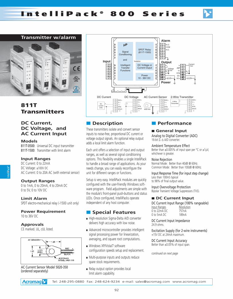
I n t e l l i P a c k ® 8 0 0 S e r i e s
Tel: 248-295-0880 Fax: 248-624-9234 e-mail: [email protected] www.acromag.com
92
Inte
lliPa
ck®
811TTransmitters
DC Current, DC Voltage, and AC Current Input
Models811T-0500: Universal DC input transmitter811T-1500: Transmitter with limit alarm
Input RangesDC Current: 0 to 22mADC Voltage: ±100V DCAC Current: 0 to 20A AC (with external sensor)
Output Ranges0 to 1mA, 0 to 20mA, 4 to 20mA DC0 to 5V, 0 to 10V DC
Limit AlarmSPDT electro-mechanical relay (-1500 unit only)
Power Requirement10 to 36V DC
ApprovalsCE marked. UL, cUL listed.
n DescriptionThese transmitters isolate and convert sensorinputs to noise-free, proportional DC current orvoltage output signals. An optional relay outputadds a local limit alarm function.
Each unit offers a selection of input and outputranges, as well as several signal conditioningoptions. This flexibility enables a single IntelliPackto handle a broad range of applications. As yourneeds change, you can easily reconfigure theunit for different ranges or functions.
Setup is very easy. IntelliPack modules are quicklyconfigured with the user-friendly Windows soft-ware program. Field adjustments are simple withthe module’s front-panel push-buttons and statusLEDs. Once configured, IntelliPacks operate independent of any host computer.
n Special Featuresn High-resolution Sigma-Delta A/D converter
delivers high accuracy with low noise.
n Advanced microcontroller provides intelligentsignal processing power for linearization, averaging, and square root computations.
n Windows XP/Vista/7 software configuration speeds setup and replacement.
n Multi-purpose inputs and outputs reduce spare stock requirements.
n Relay output option provides local limit alarm capability.
n Performance
n General InputAnalog to Digital Converter (ADC)16-bit Σ−∆ A/D converter.
Ambient Temperature EffectBetter than ±0.005% of input span per °C or ±1µV,whichever is greater.
Noise RejectionNormal Mode: Better than 40dB @ 60Hz.Common Mode: Better than 100dB @ 60Hz.
Input Response Time (for input step change)Less than 100mS typical to 98% of final output value.
Input Overvoltage ProtectionBipolar Transient Voltage Suppressors (TVS).
n DC Current InputDC Current Input Range (100% rangeable)Input Ranges Resolution0 to 22mA DC 757nA0 to 5mA DC 189nA
DC Current Input Impedance24.9 ohms.
Excitation Supply (for 2-wire instruments)+15V DC at 24mA maximum.
DC Current Input AccuracyBetter than ±0.05% of input span.
continued on next page
Input
AlarmN.O.COM
N.C.
Isolation
SignalConditioning
and
IntelligentTransfer
Functions
SPDT Relay(811T-1500)
DC Voltage orCurrent Ouput
Power10 - 36V DC
+
RL
Output
Power
+
VoltageOut
RL
CurrentOutI+
JMP
V+
RTN
DC-
DC+
EXC+
SHLD
I +RTN
V + V +
I +
EXC+
RTN
SHLD
+
-
2-WireTransmitter
2-Wire TransmitterDC Voltage
SHLD
I +
RTN
V +
EXC+
-+
5020-350
AC Current SensorDC Current
-
+
EXC+
I +
V +
RTN
SHLD
DCcurrent(mA)
+
AC Current Sensor Model 5020-350(ordered separately)
Transmitter w/alarm
8400100.qxp 3/20/2006 3:18 PM Page 92

Tel: 248-295-0880 Fax: 248-624-9234 e-mail: [email protected] www.acromag.com
93
S i g n a l C o n d i t i o n e r sIntelliPack
®
n DC Voltage InputDC Voltage Input Ranges (100% rangeable) Input Ranges Resolution±100V DC 3.77mV±50V DC 1.88mV±25V DC 942µV±12V DC 471µV±6V DC 236µV±3V DC 118µV
Input impedanceGreater than 500K ohms.
DC Voltage Input AccuracyBetter than ±0.05% of input span.
n AC Current InputAC Current Input Range (optional)An optional external AC current sensor is required tomonitor AC current signals (Model 5020-350).AC Current Range Primary Turns0 to 20A AC 10 to 10A AC 20 to 5A AC 40 to 2A AC 100 to 1A AC 20
AC Current Input AccuracyBetter than ±0.05% of input span.
n Output (DC V/mA)D/A Converter16-bit Σ−∆.
Current OutputRanges: 0-1mA, 0-20mA, 4-20mA.Compliance: 10V minimum (500Ω load).Accuracy: 0.025% of span.
Voltage OutputRanges: 0-5V, 0-10V.Compliance: 10mA maximum with short circuit pro-tection. 1Ω output impedance.Accuracy: 0.025% of span.
Accuracy (overall input to output)0.075% of span.
n Output (Relay)RelayOne SPDT electro-mechanical relay.
Relay Ratings (CSA ratings)25V DC @ 5A.120/240V AC @ 5A.
Relay Time DelayAdjustable alarm delay of up to 25 seconds.
Contact MaterialSilver-cadmium oxide (AgCdO).
Expected Mechanical Life20 million operations.
n EnvironmentalAmbient TemperatureOperating: -25 to 70°C (-13 to 158°F).Storage: -40 to 85°C (-40 to 185°F).
Relative Humidity5 to 95%.
Power Requirements10 to 36V DC. 110mA @ 24V. 170mA @ 15V.
Isolation (optical)4-way (input/output/relay/power). 1500V AC for 60 seconds or 250V AC continuous.
Radiated Field Immunity (RFI)EN61000-4-3, EN50082-1.
Electromagnetic Field Immunity (EMI)Less than ±0.25% of output span effect under theinfluence of electromagnetic fields from switchingsolenoids, commutator motors, and drill motors.
Electrical Fast Transient (EFT)EN61000-4-4, EN50082-1.
Surge Withstanding Capability (SWC)EN61000-4-5, EN50082-1.
Electrostatic Discharge (ESD)EN61000-4-2, EN50082-1.
Radiated EmissionsEN50081-1 for Class B equipment.
ApprovalsCE, UL listed (USA, Canada).UL3121 - general product safety.
n ConfigurationSoftware ConfigurationUnits are fully programmable via the WindowsXP/Vista/7 IntelliPack ConfigurationProgram. Configuration downloads from PC throughEIA232 serial port using Acromag 800C-SIP kit.
Field ConfigurationOutput, zero/full-scale, relay setpoint and deadband areconfigurable via push-buttons and a standard calibrator.
LED IndicatorsLEDs indicate power, status, calibration, and alarm.
n PhysicalEnclosureCase: Self-extinguishing NYLON type 6.6 polyamide ther-moplastic UL94 V-2 NEMA Type 1 enclosure.
Connectors (Removable Terminal Blocks)Wire Range: AWG #14-22 (AWG #12 stranded only).
Printed Circuit BoardsMilitary grade FR-4 epoxy glass circuit board.
Dimensions1.05W x 4.68H x 4.35D inches.26.7W x 118.9H x 110.5D millimeters.
Shipping Weight1 pound (0.45 Kg) packed.
n Ordering InformationIMPORTANT: All IntelliPacks require initial soft-ware configuration (order 800C-SIP). See Note 1 below.
811T-0500IntelliPack transmitter unit (DC voltage/current input).811T-1500Same as above, plus an SPDT relay output.5020-350AC current sensor. Required for AC current inputs.See Page 205 for more information.800C-SIPSoftware Interface Package. Only one kit is required for all IntelliPack models.See diagram on Page 83 for included parts.5034-225USB-to-RS232 adapter. See page 121 for more info.PS5R-D24Power supply (24V DC, 2.1A). See Power Supplies on Page 199.TBK-B01Optional terminal block kit, barrier strip style, 2 pcs.(For use with 811T-0500 model.)TBK-B02Optional terminal block kit, barrier strip style, 4 pcs.(For use with 811T-1500 model with alarm.)TBK-S01Optional terminal block kit, spring clamp style, 2 pcs.(For use with 811T-0500 model.)TBK-S02Optional terminal block kit, spring clamp style, 4 pcs.(For use with 811T-1500 model with alarm.)
NOTE 1: To order factory configuration, call Acromagfor a configuration form which must accompany yourorder. Also, append “-C” to model number (example:811T-1500-C). 800C-SIP kit is still recommended.
Optional terminal blocks: barrier strip (left) and spring clamp (right). Cage clamp terminal is standard.
8400100.qxp 3/20/2006 3:18 PM Page 93

I n t e l l i P a c k ® 8 0 0 S e r i e s
Tel: 248-295-0880 Fax: 248-624-9234 e-mail: [email protected] www.acromag.com
94
Inte
lliPa
ck®
841TTransmitters
Frequency, Pulse Counter Input
Models841T-0500: Frequency input transmitter841T-1500: Transmitter with limit alarm
Input RangesSensor types: TTL, dry contact, open collectorNPN/PNP, NAMUR, magnetic pickups, proximity
Frequency: 0 to 100Hz, 0 to 1KHz, 0 to 50KHzPulse: 0 to 65535 pulses
Output Ranges0 to 1mA, 0 to 20mA, 4 to 20mA DC0 to 5V, 0 to 10V DC
Limit AlarmSPDT electro-mechanical relay (-1500 unit only)
Power Requirement10 to 36V DC
ApprovalsCE marked. UL, cUL listed.
n DescriptionThese transmitters isolate and convert sensorinputs to noise-free, proportional DC currentor voltage output signals. An optional relayoutput adds a local limit alarm function.
Each unit offers a selection of input and out-put ranges, as well as several signal condi-tioning options. This flexibility enables a sin-gle IntelliPack to handle a broad range ofapplications. As your needs change, you caneasily reconfigure the unit for differentranges or functions.
Setup is very easy. IntelliPack modules arequickly configured with the user-friendlyWindows software program. Field adjust-ments are simple with the module’s front-panel push-buttons and status LEDs. Once con-figured, IntelliPacks operate independent of any host computer.
n Special Featuresn High-resolution Sigma-Delta A/D converter
delivers high accuracy with low noise.
n Advanced microcontroller provides intelligentsignal processing power for linearization, averaging, and square root computations.
n Windows XP/Vista/7 software configuration speeds setup and replacement.
n Multi-purpose inputs and outputs reduce spare stock requirements.
n Relay output option provides local limit alarm capability.
n Performance
n General InputResolutionInput Range Resolution0 to 100Hz 0.01Hz0 to 1000Hz 0.1Hz0 to 50,000Hz 1Hz0 to 65,535 pulses 1 pulse
Noise RejectionCommon Mode: Better than 80dB @ 60Hz.
Input Response Time (for input step change)-3dB @ 35KHz.
Input Overvoltage ProtectionBipolar Transient Voltage Suppressors (TVS).
Continued on next page.
Input
AlarmN.O.COM
N.C.
Isolation
SignalConditioning
and
IntelligentTransfer
Functions
SPDT Relay(841T-1500)
DC Voltage orCurrent Ouput
Power10 - 36V DC
+
RL
Output
Power
+
VoltageOut
RL
CurrentOutI+
JMP
V+
RTN
DC-
DC+
V+ V+
+
-
or
FrequencyGenerator
Frequency or TTL Signal Dry Contact
Speedor FlowSensor
Magnetic Pickup orTurbine Flowmeter
OR
Open Collector NPN
Open Collector PNP
NAMUR
CRST
CRTN
BRTN
FQ-IN
EXC+
EXC-CRST
CRTN
BRTN
FQ-IN
EXC+
EXC-
CRST
CRTN
BRTN
FQ-IN
EXC+
EXC-
CRST
CRTN
BRTN
FQ-IN
EXC+
EXC-
CRST
CRTN
BRTN
FQ-IN
EXC+
EXC-
CRST
CRTN
BRTN
FQ-IN
EXC+
EXC-
Transmitter w/alarm
8400100.qxp 3/20/2006 3:19 PM Page 94

Tel: 248-295-0880 Fax: 248-624-9234 e-mail: [email protected] www.acromag.com
95
S i g n a l C o n d i t i o n e r sIntelliPack
®
n Performance
n Frequency InputInput TypesTTL, dry contact, open collector NPN/PNP, NAMUR, mag-netic pickups, proximity sensors.
Frequency Ranges0 to 100Hz0 to 1000Hz0 to 50,000Hz.
Pulse Counter Input Range0 to 65535 pulses.
Minimum Input Pulse WidthFrequency inputs: 10µS.Pulse counting inputs: 5mS.
Voltage RangesUnipolar: 0 to 100V DC.Bipolar: ±50mV to ±100V peak.Zero/Full Scale AdjustmentZero and span: 100% full range adjustment. Pulse counting: Up to 65535 spans within range.
Input Threshold/HysteresisBipolar:
Threshold: 0.01V, typical.Hysteresis: ±25mV or ±83mV.
Unipolar:Threshold: 1.5V or 5V.Hysteresis: ±25mV or ±83mV
Input Debounce (Event Counter)0 to 1000mS (configurable in 5mS increments).
Frequency Excitation SupplySelectable, +8.2V or +12V @ 15mA.
Input Impedance35K ohms, typical.
AccuracyInput Range Accuracy0 to 100Hz ±0.04Hz0 to 1000Hz ±0.4Hz0 to 50,000Hz ±10Hz0 to 65,535 pulses ±1 pulse
n Output (DC V/mA)D/A Converter16-bit Σ−∆.
Current OutputRanges: 0-1mA, 0-20mA, 4-20mA.Compliance: 10V minimum (500Ω load).Accuracy: 0.025% of span.
Voltage OutputRanges: 0-5V, 0-10V.Compliance: 10mA maximum with short circuit pro-tection. 1 ohm output impedance.Accuracy: 0.025% of span.
Accuracy (overall input to output)0.075% of span.
n Output (Relay)RelayOne SPDT electro-mechanical relay.
Relay Ratings (CSA ratings)25V DC @ 5A.120/240V AC @ 5A.
Relay Time DelayAdjustable alarm delay of up to 25 seconds.
Contact MaterialSilver-cadmium oxide (AgCdO).
Expected Mechanical Life20 million operations.
n EnvironmentalAmbient TemperatureOperating: -25 to 70°C (-13 to 158°F).Storage: -40 to 85°C (-40 to 185°F).
Relative Humidity5 to 95%.
Power Requirements10 to 36V DC. 100mA @ 24V. 160mA @ 15V.
Isolation (optical)4-way (input/output/relay/power). 1500V AC for 60 seconds or 250V AC continuous.
Radiated Field Immunity (RFI)EN61000-4-3, EN50082-1.
Electromagnetic Field Immunity (EMI)Less than ±0.25% of output span effect under theinfluence of electromagnetic fields from switchingsolenoids, commutator motors, and drill motors.
Electrical Fast Transient (EFT)EN61000-4-4, EN50082-1.
Surge Withstanding Capability (SWC)EN61000-4-5, EN50082-1.
Electrostatic Discharge (ESD)EN61000-4-2, EN50082-1.
Radiated EmissionsEN50081-1 for Class B equipment.
ApprovalsCE, UL listed (USA, Canada).UL3121 - general product safety.
n ConfigurationSoftware ConfigurationUnits are fully programmable via the WindowsXP/Vista/7 IntelliPack ConfigurationProgram. Configuration downloads from PC throughEIA232 serial port using Acromag 800C-SIP kit.
Field ConfigurationOutput, zero/full-scale, relay setpoint and deadband areconfigurable via push-buttons and a standard calibrator.
LED IndicatorsLEDs indicate power, status, calibration, and alarm.
n PhysicalEnclosureCase: Thermoplastic UL94 V-2 NEMA Type 1 enclosure.
Connectors (Removable Terminal Blocks)Wire Range: AWG #14-22 (AWG #12 stranded only).
Printed Circuit BoardsMilitary grade FR-4 epoxy glass circuit board.
Dimensions and Shipping Weight1.05W x 4.68H x 4.35D in. (26.7 x 118.9 x 110.5 mm)1 pound (0.45 Kg) packed.
n Ordering InformationIMPORTANT: All IntelliPacks require initial soft-ware configuration (order 800C-SIP). See Note 1 below.
841T-0500IntelliPack transmitter unit (freq/pulse counter input).841T-1500Same as above, plus an SPDT relay output.800C-SIPSoftware Interface Package. Only one kit is required for all IntelliPack models.See diagram on Page 83 for included parts.5034-225USB-to-RS232 adapter. See page 121 for more info.PS5R-D24Power supply (24V DC, 2.1A). See Power Supplies on Page 199.TBK-B01Optional terminal block kit, barrier strip style, 2 pcs.(For use with 841T-0500 model.)TBK-B02Optional terminal block kit, barrier strip style, 4 pcs.(For use with 841T-1500 model with alarm.)TBK-S01Optional terminal block kit, spring clamp style, 2 pcs.(For use with 841T-0500 model.)TBK-S02Optional terminal block kit, spring clamp style, 4 pcs.(For use with 841T-1500 model with alarm.)NOTE 1: To order factory configuration, call Acromagfor a configuration form which must accompany yourorder. Also, append “-C” to model number (example:841T-1500-C). 800C-SIP kit is still recommended.
Optional terminal blocks: barrier strip (left) and spring clamp (right). Cage clamp terminal is standard.
8400100.qxp 3/20/2006 3:19 PM Page 95

I n t e l l i P a c k ® 8 0 0 S e r i e s
Tel: 248-295-0880 Fax: 248-624-9234 e-mail: [email protected] www.acromag.com
96
Inte
lliPa
ck®
851TTransmitters
Strain Gauge, Load Cell Input
InputSensor typesLoad cells (4- or 6-wire configurations),Strain gauges (full-, half-, or quarter-bridge),Millivolt
Bridge/gauge resistanceSupports 85 ohms or greater with 10V excitation
Input sensitivityAccepts load cell and strain gauge rated outputsup to 10mV/V DC
Internal excitationAdjustable from 4 to 11V DC, 120mA max.
OutputUniversal output0 to 20mA (user-configured ranges), 0 to 10V DC (user-configured ranges),
Relay Output (optional)5A SPDT dry contact relay
Power Requirement12 to 36V DC
ApprovalsCE marked. UL, cUL listed.
n DescriptionIntelliPack strain gauge and load cell transmittersoffer many powerful features beyond the limitedcapabilities found in typical bridge amplifiers.851T models accept signals from sensors wiredin a Wheatstone bridge configuration. Commonuses include measurement of force, weight, level,torque, acceleration, pressure, and vibration.
The transmitter’s input circuit allows true 6-wirebridge measurement and includes an adjustablebridge excitation supply (4 to 11V DC) with aremote sense feature. Sense wires ensure theprogrammed excitation voltage is applied at thesensor and enable lead-wire compensation. Thedifferential input performs true ratiometric con-versions for extremely stable measurements thatremain accurate over time and temperature. Plus,lead break detection is inherent in the device.
Intellipack configuration software simplifies setupfor use with basic load cells, millivolt inputs, orseven bridge sensor formats. Internal bridgecompletion resistors are supplied for half andquarter bridges. The software also downloadssensor parameters such as gauge factor andPoisson's ratio into the transmitter for internalcalculation of complex equations to determinesensor strain (ε). The strain is then converted to arepresentative process signal output.
Screw terminals enable a remote "auto-tare"function to compensate for non-zero deadweights and other sensor offsets (e.g. containerweight or bridge imbalances). Alternatively, thesesame screw terminals may be used to resetlatched relay alarms.
All these powerful features combined withAcromag's user-friendly configuration software,make the 851T a versatile device that's easy touse and maintain. Plus, a rugged, compactdesign makes it ideal for use out in the field, onthe plant floor, or inside a laboratory.
n Special Featuresn Intelligent signal processing functions
perform math computations for custom output:- strain (ε) calculations- signal linearization (25 breakpoints)- average signal computation
n Relay output option provides local limit alarmcapability in addition to the DC output
n Adjustable bridge excitation supports a widevariety of sensor types
n An internal bridge completion function (half-to-full and quarter-to-full) accommodatesa broad range of applications
n Remote auto-tare function compensates forextraneous loads and corrects for imbalancesin the input bridge
n High-resolution Sigma-Delta A/D converterdelivers high accuracy with low noise.
n Windows XP/Vista/7 software configuration speeds setup and replacement.
Strain Gauge / Load Cell Transmitter with Alarm
DC OUT
SPDT
PWR
PLC / DCS
5-way isolation
BRIDGE INPUTS
R-CALTERMINATION
AUTO-TARE Trigger Input (15-30V DC) TareTrigger
RLOAD
V/mA
R-Cal
exc +
sense +bridge +
bridge –
exc –
sense –
Alarm/ ControlFull, Half, Qtr, Load Cell, mV
ExcADJ: 4-11V DC
12-36V DC
Bridge Interface
8400100.qxp 3/20/2006 3:19 PM Page 96

Tel: 248-295-0880 Fax: 248-624-9234 e-mail: [email protected] www.acromag.com
97
S i g n a l C o n d i t i o n e r sIntelliPack
®
FULL-BRIDGE INPUT (INTERNAL EXCITATION)
FULL-BRIDGE INPUT (EXTERNAL EXCITATION)
HALF-BRIDGE INPUT
QUARTER-BRIDGE INPUT
TB1
SENSE+
EXCITATION+
BRIDGE-
SENSE-
EXCITATION-
BRIDGE+SEN+
IN+
IN-
SEN-
EXC-
EXC+
TB1
EXC+
EXC-
SEN-
IN-
IN+
SEN+
JUMPER
SENSE+
BRIDGE+
BRIDGE-
SENSE-
JUMPER
4-11V +
EXC+TB1
EXC+
IN+
SEN+
QUARTER BRIDGE
ADD JUMPER FORQUARTER-BRIDGECOMPLETION
JUMPER
EXC-
SEN-
TB2
IN-
EXC-
2K
2KDUMMYGAUGE
2K
2K
HALF BRIDGE
TB2
SEN+
EXC+
EXC-
TB1
IN+
SEN-
EXC+
IN-
IN+
EXC-
HALF
IN-
IN+
HALF
IN-
IN+
JUMPER
ADD JUMPERFOR HALF-BRIDGECOMPLETION
INTERNAL HALF- BRIDGE
RATIO- MATCHED TO ±0.02%
INTERNAL HALF- BRIDGE
RATIO- MATCHED TO ±0.02%
DIGITAL INPUT "TRIGGER" (AUTO-TARE/RELAY RESET)
TRIG INPUT IS OPTICALLYISOLATED AND I NCLUDES A6.65K SERIES RESISTOR.
COM
TRIGTB4 6.65K TRIG
TRIG IS ASSERTED FOR VOLTAGES FROM 15-30V DC.
IN+
+ 15-30V
TRIG
NOTE: For 4-wire measureme nts, jumper EXC+ to SENSE+ and jumper EXC- to SENSE -.
TB4
+
RELAY OUTPUT
LOAD
LOADN.C.
N.O. SPDT CONTACTS
N.O.
N.C.
COM
SHUNT CALIBRATION (R-CAL)
SEN-
EXC-
TB1
TB2
EXC+
IN-
IN+
SEN+
SW
CR
HALF
IN-
IN+
*R-CALCR /B
BRIDGE +
SENSE+
EXC+
SENSE-
BRIDGE -
EXC-
SHUNTENABLE
TO BRIDGE
* R-CAL SHUNT RESISTOR IS USER-SUP PLIED
Isolation
+
RL
Bridge Input
Output
SignalConditioning
and
IntelligentTransfer
Functions
DC Voltage orCurrent Ouput
Power10 - 36V DC
Power
Alarm / TriggerN.O.
COM
N.C.
COM
COM
TRIG
EXC +
SEN +
IN +
IN -
SEN -
EXC -
+
VoltageOut
RL
CurrentOutI+
JMP
V+
RTN
DC-
DC+
SPDT Relay(851T-1500)
Trigger Auto-Tare
Bridge Complete
Shunt
IN -
HALF
IN +
SW
CR
CR / B
The configuration software makes it easy to set up the transmitter for use with basic load cell sensor devices. Common input sources include pressure transducers, torque converters, and vibration sensors.
Complex strain (ε) calculations are easily configured and computed for full, half, and quarter-bridge sensors.
8400100.qxp 3/20/2006 3:19 PM Page 97

I n t e l l i P a c k ® 8 0 0 S e r i e s
Tel: 248-295-0880 Fax: 248-624-9234 e-mail: [email protected] www.acromag.com
98
Inte
lliPa
ck®
851T Transmitters
n Performance
n General InputAnalog to Digital Converter (ADC)16-bit Σ−∆ A/D converter.
Resolution±0.01% of span.
Input Reference Test Conditions120 ohm full bridge; Excitation = 10V; Rated Output =3mV/V; Range = ±30mV; Ambient Temperature =25°C; Power Supply = 24V DC; Alarm Delay = 100ms.
Accuracy (overall input to output)Better than ±0.1% of span, typical. This value does not include sensor errors.
Ambient Temperature EffectBetter than ±0.01% of input span per °C(±100ppm/°C), or ±1.0uV/°C, whichever is greater.
Response Time (for input step change)250mS to 98% of final output value (into 500 ohms).
Input Overvoltage ProtectionBipolar Transient Voltage Suppressors (TVS).
n Bridge InputInput TypesSelect from basic load cell, two quarter-bridge options,two half-bridge options, three full-bridge options, ormillivolts.
Input Span/RangeBipolar input range is determined from the ± productof the gauge's rated output and the nominal excitation selection (2mV/V x 10V = ±20mV range).
Input Over-rangeThe actual input range is ±150% typical of the rangeobtained via the ± product of the gauge's rated out-put and the nominal excitation applied.
Input SensitivityAccepts gauge rated outputs up to 10mV/V. The rangeof your input signal is the product of the excitationvoltage and your gauge's rated output.
Input Impedance±IN at 1M ohms min.; ±SEN at 29.09K ohms, typical.
Input Lead ResistanceModule has sufficient overdrive to guarantee 10Vbridge excitation with 5 ohms/lead and 100mA ofinternal excitation current. Larger lead resistances maylimit the maximum achievable bridge excitation.
Input Lead Break DetectionSensor failure detection is upscale only.
Input Bridge Excitation (Internal)Adjustable from 4V to 11V, 120mA maximum. Internalexcitation may be turned OFF for external excitationsupply connection.
Input Bridge Excitation (External)4V to 11V. The internal excitation must be turned OFFfor connection to an external excitation supply.
n Digital (Trigger) InputInput Type“Active High” input.15-30V DC (6.65K ohms).
See connection diagram.
Operation (Tare/Alarm Modes)The trigger function is set for “Auto-Tare” mode bydefault. This input can also be configured to resetlatched alarms via the Configuration Software.
n Output (DC V/mA)D/A Converter16-bit Σ−∆.
Current OutputRanges: 0-1mA, 0-20mA, 4-20mA.Compliance: 10V minimum (500 ohm load).
Voltage OutputRanges: 0-5V, 0-10V.Compliance: 10mA maximum with short circuit pro-tection. 1 ohm output impedance.
n Output (Relay)RelayOne SPDT, Form C, dry contact relay.
Relay Ratings (CSA ratings)25V DC @ 5A, resistive load.120/240V AC @ 5A, resistive load.
Relay Time DelayAdjustable alarm delay of up to 25 seconds.
Relay Response (No Relay Time Delay)Relay contacts switch within 580ms typical, for aninput step change from 10% of span on one side ofan alarm point to 5% of span on the other side of thealarm point.
Initial Dielectric Strength1000V AC rms between open contacts.
Contact MaterialSilver-cadmium oxide (AgCdO).
Expected Mechanical Life20 million operations.
Performance specifications continued on next page.
8400100.qxp 3/20/2006 3:19 PM Page 98

Tel: 248-295-0880 Fax: 248-624-9234 e-mail: [email protected] www.acromag.com
99
S i g n a l C o n d i t i o n e r sIntelliPack
®
n EnvironmentalAmbient TemperatureOperating: -25 to 70°C (-13 to 158°F).Storage: -40 to 85°C (-40 to 185°F).
Relative Humidity5 to 95%.
Power Requirements12 to 36V DC. 11V DC minimum.175mA @ 24V. 290mA @ 15V.
Isolation (optical)5-way (input/output/relays/trigger/power). Input, analog output, trigger, and power circuits areisolated from each other for up to 1500V AC for 60seconds or 250V AC continuous. Optional relay outputs are isolated from other circuits up to 150VAC, or 150V DC.
Radiated Field Immunity (RFI)EN61000-4-3, EN50082-1.
Electromagnetic Field Immunity (EMI)Less than ±0.25% of output span effect under theinfluence of electromagnetic fields from switchingsolenoids, commutator motors, and drill motors.
Electrical Fast Transient (EFT)EN61000-4-4, EN50082-1.
Surge Withstanding Capability (SWC)EN61000-4-5, EN50082-1.
Electrostatic Discharge (ESD)EN61000-4-2, EN50082-1.
Radiated EmissionsEN50081-1 for Class B equipment.
ApprovalsCE, UL listed (USA, Canada).UL3121 - general product safety.
n ConfigurationSoftware ConfigurationUnits are fully programmable via the WindowsXP/Vista/7 IntelliPack ConfigurationProgram. Configuration downloads from PC throughEIA232 serial port using Acromag 800C-SIP kit.
Field ConfigurationOutput, zero/full-scale, relay setpoint and deadband areconfigurable via push-buttons and a standard calibrator.
LED IndicatorsLEDs indicate power, status, calibration, and alarm.
n PhysicalEnclosureCase: Self-extinguishing NYLON type 6.6 polyamide ther-moplastic UL94 V-2 NEMA Type 1 enclosure.
Connectors (Removable Terminal Blocks)Wire Range: AWG #14-22 (AWG #12 stranded only).
Printed Circuit BoardsMilitary grade FR-4 epoxy glass circuit board.
Dimensions1.05W x 4.68H x 4.35D inches.26.7W x 118.9H x 110.5D millimeters.
Shipping Weight1 pound (0.45 Kg) packed.
n Ordering InformationIMPORTANT: All IntelliPacks require initial soft-ware configuration (order 800C-SIP). See Note 1 below.
851T-0500IntelliPack transmitter unit, strain gauge input851T-1500Same as above, plus an SPDT relay output.800C-SIPSoftware Interface Package. Only one kit is required for all IntelliPack models.See diagram on Page 83 for included parts.5034-225USB-to-RS232 adapter. See page 121 for more info.PS5R-D24Power supply (24V DC, 2.1A). See Power Supplies on Page 199.TBK-B02Optional terminal block kit, barrier strip style, 4 pcs.TBK-S02Optional terminal block kit, spring clamp style, 4 pcs.
NOTE 1: To order factory configuration, call Acromagfor a configuration form which must accompany yourorder. Also, append “-C” to model number (example:851T-1500-C). 800C-SIP kit is still recommended.
Optional terminal blocks: barrier strip (left) and spring clamp (right). Cage clamp terminal is standard.
8400100.qxp 3/20/2006 3:19 PM Page 99

Dimensions
Tel: 248-295-0880 Fax: 248-624-9234 e-mail: [email protected] www.acromag.com
120
I n t e l l i P a c k ® 8 0 0 S e r i e sIn
telli
Pack
®
RUNAcromag
DIN EN 50022, 35mm"T" RAIL DIN MOUNTING
(59.4)2.34
CL
MODE
SET
1 2RELAY
ST
(95.3)3.75
RST 2
RST 1
R
1.05(26.7)
NOTE: ALL DIMENSION ARE IN INCHES (MILLIMETERS)
(118.9)4.68
SCREWDRIVER SLOT FORREMOVAL FROM "T" RAIL
(99.1)3.90
4.35(110.5)
8400100.qxp 3/20/2006 3:19 PM Page 120

Tel: 248-295-0880 Fax: 248-624-9234 e-mail: [email protected] www.acromag.com
121
Accessories
S i g n a l C o n d i t i o n e r sIntelliPack
®
n Ordering Information5020-350AC current sensor (See page 205)
Barrier strip (left) and spring clamp (right).
n Ordering InformationSee individual I/O modules for compatibility.
AC Current Sensor
50W SupplyInput Power Requirement85 to 264V AC or 105 to 370V DC
Output24V DC, 2.1A (50W)
n Ordering InformationPS5R-D24Universal 50W power supply
See Power Supplies on Page 199 for other modelsand more information.
DIN-Rail MountingFor your convenience, Acromag offers severalmounting accessories to simplify your systeminstallation. Our 19” rack-mount kit provides aclean solution for mounting your I/O modulesand a power supply. Or you can buy precut DINrail strips for mounting on any flat surface.
n Ordering Information20RM-16-DIN19" rack-mount kit with DIN rail.DIN RAIL 3.0DIN RAIL 16.7DIN rail strip, Type T, 3 inches (75mm) or16.7 inches (425mm)
Length: 3.15 in (8.0 cm)Height: 0.80 in (2.03 cm)Width: 1.75 in (4.44 cm)Weight: 1.6 oz (45.36 g)
n OrderingInformation5034-225USB-to-RS232 adapter
3-position: L = 0.66 inches (16.9 mm)
6-position: L = 1.26 inches (32.3 mm)
Spring Clamp Terminal Blocks
Barrier Strip Terminal Blocks
TBK-B01Terminal block kit, two 6-position piecesTBK-B02Terminal block kit, four 6-position pieces
TBK-B03Terminal block kit, one 3-position and three 6-position pieces
3-position: L = 0.87 inches (22.3 mm)
6-position: L = 1.47 inches (37.7 mm)
Wire range: AWG #12-26
Wire range: AWG #12-26
Wire range: AWG #12-26
TBK-S01Terminal block kit, two 6-position piecesTBK-S02Terminal block kit, four 6-position pieces
TBK-S03Terminal block kit, one 3-position and three 6-position pieces
Mounting HardwareTerminal Blocks Power Supplies
USB / RS232 Adapter
8400100.qxp 3/20/2006 3:19 PM Page 121

F l a t P a c k S e r i e s
AC Voltage andAC Current InputThese models convert sensor inputs to propor-tional process current or voltage output signals.
AC voltage transmitters accept direct voltageinputs. Current models include an external ACcurrent sensor. This toroidal sensor outputs a safeDC milliamp signal which transmits accuratelyover long distances. Input span is a function ofthe primary turns placed on the sensor.
Input Rangesn AC voltage, 50/60Hz
0 to 150V AC
n AC current, 0 to 20A
Output Rangesn DC current: 4 to 20mA
n DC voltage: 0 to 5V or 0 to 10V
Power Requirementsn 250T: 12 to 50V DC @ 20mA (loop-powered)
n 350T: DC voltage source (see table below)
Output range Power4 to 20mA 10 to 36V DC @ 30mA0 to 5V 10 to 36V DC @ 9mA0 to 10V 12.5 to 36V DC @ 9mA
n 450T: 115V or 230V AC, ±10%, 50 to 60Hz
Output range Power4 to 20mA 115V AC @ 0.050A4 to 20mA 230V AC @ 0.025A0 to 5V, 0 to 10V 115V AC @ 0.020A0 to 5V, 0 to 10V 230V AC @ 0.010A
n Special Featuresn Excellent accuracy and stability ensure reliable
measurements in harsh industrial environments.
n External AC current sensor with DC mA outputenables remote mounting of transmitter (forsafe monitoring of the AC signal)
n AC current range is a function of sensor primary turns for easy rescaling in field
n Factory-calibrated AC current transmitter doesnot need recalibration
n RFI and EMI resistance minimize the effects ofenvironmental noise.
n Compact, 1-inch wide housing uses less space.
n Low power consumption. (350T as low as 9mA).
n 1500V AC peak isolation (250V AC or 354VDC continuous) prevents ground loops.
250T models:Input isolated from output/power.
350T models:Input isolated from output and power.Output and power share a common.
450T models:3-way isolation. Input, output, and power circuits are isolated from each other.
n PerformanceAmbient Temperature RangeOperating: -13 to 185°F (-25 to 85°C).Storage: -40 to 185°F (-40 to 85°C).Accuracy±0.5% of calibrated span. Includes repeatability, hysteresis, terminal point linearity, and adjustment resolution.Ambient Temperature EffectLess than ±0.01% of output span per °F (±0.018% per°C). (Specification includes the combined effects of zeroand span over temperature).Noise ResistanceRFI: Less than ±0.5% ,of output span effect.EMI: Less than ±0.25% of output span effect.Noise RejectionCommon Mode (-VAC): 120dB at 60Hz, 100 ohmunbalance.Common Mode (-CACX): 120dB at 60Hz, 1 ohmunbalance.Normal Mode: Not Applicable.Response Time Output reaches 98% of output span in 300mS.Bandwidth-3dB at 3 Hz, typical.Output Compliance250T: RLOAD (max.) = (VSUPPLY - 12V) / 20mA.350T: RLOAD (max.) = (VSUPPLY - 2.5V) / 20mA.450T: RLOAD = 600 ohms.
OUT
PLC / DCS
Input Isolation
IN
+
L
–
S
–
+
RLOAD4-20mA
+24V DC
PSense Resistor
Sensor250T
250T Loop-Powered (2-wire) Transmitter
OUT
PWR
PLC / DCS
Input Isolation
IN
+
L
–
P
–
+
RLOAD
24V DCV/mA
P
–
+ Sensor
350T
350T DC-Powered (3-wire) Transmitter
PWR
OUT
PLC / DCS
3-Way Isolation
IN
+
L
–
S
– +
L1
GW RLOAD
V/mA
–
+Sense Resistor
Sensor450T
450T AC-Powered (4-wire) Transmitter
Tel: 248-295-0880 Fax: 248-624-9234 e-mail: [email protected] www.acromag.com
166
Flat P
ack
Isolated Transmitters
8400100.qxp 3/20/2006 3:21 PM Page 166

I s o l a t e d T r a n s m i t t e r s
Input Options-VAC: AC Voltage,
0 to 150V AC range,Span adjust: 60 to 150V ACZero adjust: 0 to 90VACInput impedance 100k ohmsInput burden is 0.3 volt-amps
-CACX*: AC CurrentAC Current Sensor (5020-350): One sensor is suppliedwith each transmitter. The sensor is a high-accuracytoroidal instrument transformer. See Page 205 formore information.AC Input Range Primary Turns Sensor Output0 to 20 Amps AC 1 0 to 11.17 mA DC0 to 10 Amps AC 2 0 to 11.17 mA DC0 to 5 Amps AC 4 0 to 11.17 mA DC0 to 1 Amps AC 20 0 to 11.17 mA DCInput Burden: A function of the wire gauge resistanceused for the primary turns.Input Overload: The AC Current Sensor withstandsoverloads as follows: 20 times full-scale for 0.01 sec-ond., 10 times full-scale for 0.1 second., and 5 timesfull-scale for 1.0 second.AC Current Sensor to Transmitter Wiring Distance:400 feet maximum for 18 AWG wire gauge. Otherwire gauges can be used as long as the resistance ofboth wires is less than 5.0 ohms.
Output Options (350T, 450T only)-Y: 4 to 20mA DC. -V0: 0 to 10V DC into 10K ohms or greater-V5: 0 to 5V DC into 5K ohms or greater
Power Options (450T only)-1: 115V AC power-2: 230V AC power
Mounting OptionsMountings-DIN: DIN rail G or T mount-ST: SNAPTRACK mount [250T only]-SM: Surface-mount [250T only]External housings-N4: NEMA 4, water-tight [250T only], holds two-N12: NEMA 12, oil-tight [250T only], holds two-XP: Explosion-proof NEMA 4 [250T only], holds one
Approval Options-NCR: No certification/approval required.
Ordering Notes* Unit is factory calibrated for fixed range (adjustable
by windings of sensor). Custom factory calibration‘-C’ option is not available with this input.
AccessoriesPower suppliesSee Power Supplies on Page 199.5020-350AC current sensor. (See page 205)DIN RAIL 3.0DIN RAIL 16.7DIN rail strip, Type T, 3 inches (75mm) or16.7 inches (425mm)20RM-16-DIN19" rack-mount kit with DIN rail. Holds sixteen250T/350Ts or ten 450T transmitters.350T-N4-WMNEMA 4 water-tight enclosure, wall-mount. Holdstwo 350Ts or one 450T transmitter.350T-N12-WMNEMA 12 oil-tight enclosure, wall-mount. Holds two350Ts or one 450T transmitter.
Tel: 248-295-0880 Fax: 248-624-9234 e-mail: [email protected] www.acromag.com
167
n Ordering InformationSelect one option from each column. Example: 450T-VAC-V5-2-DIN-NCR-CTo order factory calibration, append “-C” to end of model number. Specify ranges on order.
Note:All 250Ts have 4 to 20mA output and are loop-powered.
Note:All 350Ts accept10 to 36V DCpower supply.
Base Input Mounting Approval
250T -VAC -DIN -N4 -NCR-CACX -ST -N12
-SM -XP
Base Input Output Mounting Approval
350T -VAC -Y -DIN -NCR-CACX -V0
-V5
Base Input Output Power Mounting Approval
450T -VAC -Y -1 -DIN -NCR-CACX -V0 -2
-V5
AC Current Sensor
Flat Pack
8400100.qxp 3/20/2006 3:21 PM Page 167

F l a t P a c k S e r i e s
DC MillivoltsInputThese models convert sensor inputs to propor-tional process current or voltage output signals.
Models250T: Loop-powered transmitter series
350T: DC-powered transmitter series
450T: AC-powered transmitter series
Input Rangesn Millivolt: -25 to 250mV
narrow span: 3 to 5mV, custom calibration
Output Rangesn DC current: 4 to 20mA
n DC voltage: 0 to 5V or 0 to 10V
Power Requirementsn 250T: 12 to 50V DC @ 20mA (loop-powered)
n 350T: DC voltage source (see table below)
Output range Power4 to 20mA 10 to 36V DC @ 30mA0 to 5V 10 to 36V DC @ 9mA0 to 10V 12.5 to 36V DC @ 9mA
n 450T: 115V or 230V AC, ±10%, 50 to 60Hz
Output range Power4 to 20mA 115V AC @ 0.050A4 to 20mA 230V AC @ 0.025A0 to 5V, 0 to 10V 115V AC @ 0.020A0 to 5V, 0 to 10V 230V AC @ 0.010A
n Special Featuresn Excellent accuracy and stability ensure reliable
measurements in harsh industrial environments.
n RFI and EMI resistance minimize the effects ofenvironmental noise.
n 90% span adjustment enables precise application calibration.
n 1500V AC peak isolation (250V AC or 354VDC continuous) prevents ground loops.
250T models:Input isolated from output/power.
350T models:Input isolated from output and power.Output and power share a common.
450T models:3-way isolation. Input, output, and power circuits are isolated from each other.
n Compact, 1-inch wide housing uses less spacefor easier installation in control panels.
n Low power consumption. 350T units operate on currents as low as 9mA to help preventexpensive upgrades to larger power supplies.
n PerformanceAmbient Temperature RangeOperating: -13 to 185°F (-25 to 85°C).Storage: -40 to 185°F (-40 to 85°C).Accuracy±0.1% of calibrated span or ±0.01mV, whichever isgreater. Includes repeatability, hysteresis, terminalpoint linearity, and adjustment resolution.Ambient Temperature EffectLess than ±0.01% of output span per °F (±0.018% per°C). ±0.025% of output span per °F (±0.045% per °C)for narrow span units. (Specification includes the combined effects of zero and span over temperature).Noise ResistanceRFI: Less than ±0.5% ,of output span effect.EMI: Less than ±0.25% of output span effect.Noise RejectionCommon Mode: 130dB at 60Hz, 100 ohm unbalance.Normal Mode: 30dB at 60Hz, 100 ohm source.Response Time Output reaches 98% of output span in 300mS.Bandwidth-3dB at 3 Hz, typical.Output Compliance250T: RLOAD (max.) = (VSUPPLY - 12V) / 20mA.350T: RLOAD (max.) = (VSUPPLY - 2.5V) / 20mA.450T: RLOAD = 600 ohms.
Input Impedance1.0M ohm at 10mV span, typical; input current, ±10nA, typical.
OUT
PLC / DCS
Input Isolation
IN
+
L
–
S
–
+
RLOAD4-20mA
+24V DC
PSense Resistor
Sensor250T
250T Loop-Powered (2-wire) Transmitter
OUT
PWR
PLC / DCS
Input Isolation
IN
+
L
–
P
–
+
RLOAD
24V DCV/mA
P
–
+ Sensor
350T
350T DC-Powered (3-wire) Transmitter
PWR
OUT
PLC / DCS
3-Way Isolation
IN
+
L
–
S
– +
L1
GW RLOAD
V/mA
–
+Sense Resistor
Sensor450T
450T AC-Powered (4-wire) Transmitter
Tel: 248-295-0880 Fax: 248-624-9234 e-mail: [email protected] www.acromag.com
156
Flat P
ack
Isolated Transmitters
8400100.qxp 3/20/2006 3:21 PM Page 156

I s o l a t e d T r a n s m i t t e r s
Input Options-MV1: Millivolt.
Span adjust: 5 to 55mV DCZero adjust: -5 to 25mV DC
-MV2: Millivolt.Span adjust: 25 to 250mV DCZero adjust: -25 to 125mV DC
-MV3*: Millivolt, narrow span.Span adjust: 3 to 5mV DCZero adjust: -5 to 25mV DCSpecify calibration range on order.
Output Options (350T, 450T only)-Y: 4 to 20mA DC. -V0: 0 to 10V DC into 10K ohms or greater-V5: 0 to 5V DC into 5K ohms or greater
Power Options (450T only)-1: 115V AC power-2: 230V AC power
Mounting OptionsMountings-DIN: DIN rail G or T mount-ST: SNAPTRACK mount [250T only]-SM: Surface-mount [250T only]External housings-N4: NEMA 4, water-tight [250T only], holds two-N12: NEMA 12, oil-tight [250T only], holds two-XP: Explosion-proof NEMA 4 [250T only], holds one
Approval Options-NCR: No certification/approval required.--DT1†: CSA approval, Div. 2 hazardous locations:
Class I; Div. 2; Groups A, B, C, D [250T only].-EP1††: CSA approval, Explosion-proof for hazardous
locations: Class I; Groups B, C, D Class II; Groups E,F, G. NOTE: Only available with explosion-proofhousing (-XP) [250T only].
Ordering Notes* Unit requires factory calibration. Append “-C” to
end of model number. Specify ranges on order.† Units are shipped separately from any optional
enclosures (i.e. units are not installed in any externalhousing).
†† Units shipped installed in external enclosure.
AccessoriesPower suppliesSee Power Supplies on Page 199.DIN RAIL 3.0DIN RAIL 16.7DIN rail strip, Type T, 3 inches (75mm) or16.7 inches (425mm)20RM-16-DIN19" rack-mount kit with DIN rail. Holds sixteen250T/350Ts or ten 450T transmitters.350T-N4-WMNEMA 4 water-tight enclosure, wall-mount. Holds two 350Ts or one 450T transmitter.350T-N12-WMNEMA 12 oil-tight enclosure, wall-mount. Holds two 350Ts or one 450T transmitter.
Tel: 248-295-0880 Fax: 248-624-9234 e-mail: [email protected] www.acromag.com
157
n Ordering InformationSelect one option from each column. Example: 450T-MV1-Y-1-DIN-NCR-CTo order factory calibration, append “-C” to end of model number. Specify ranges on order.
Base Input Mounting Approval
250T -MV1 -DIN -N4 -NCR-MV2 -ST -N12 -DT1-MV3 -SM -XP -
-E
Base Input Output Mounting Approval
350T -MV1 -Y -DIN -NCR-MV2 -V0-MV3 -V5
Base Input Output Power Mounting Approval
450T -MV1 -Y -1 -DIN -NCR-MV2 -V0 -2-MV3 -V5
Note:All 250Ts have 4 to 20mA output and are loop-powered.
Note:All 350Ts accept10 to 36V DCpower supply.
Flat Pack
8400100.qxp 3/20/2006 3:21 PM Page 157

F l a t P a c k S e r i e s
Frequency InputThese transmitters accept periodic or pulse wave-form signals such as those originating fromtachometers, magnetic transducers, and turbineflow meters, and provide a proportional processcurrent or voltage output signal.
Models250T: Loop-powered transmitter series
350T: DC-powered transmitter series
450T: AC-powered transmitter series
Input Rangesn Frequency,
span ranges 0 to 25.6KHz, field-selectable,direct coupled inputs, ±25mV to 150V RMS
Output Rangesn DC current: 4 to 20mA
n DC voltage: 0 to 5V or 0 to 10V
Power Requirementsn 250T: 12 to 50V DC @ 20mA (loop-powered)
n 350T: DC voltage source (see table below)
Output range Power4 to 20mA 10 to 36V DC @ 30mA0 to 5V 10 to 36V DC @ 9mA0 to 10V 12.5 to 36V DC @ 9mA
n 450T: 115V or 230V AC, ±10%, 50 to 60Hz
Output range Power4 to 20mA 115V AC @ 0.050A4 to 20mA 230V AC @ 0.025A0 to 5V, 0 to 10V 115V AC @ 0.020A0 to 5V, 0 to 10V 230V AC @ 0.010A
n Special Featuresn Excellent accuracy and stability ensure reliable
measurements in harsh industrial environments.
n RFI and EMI resistance minimize the effects ofenvironmental noise.
n 90% span adjustment enables precise application calibration.
n Quartz crystal time-base design improves temperature performance
n Field-selectable time constants optimize outputresponse time and ripple characteristics
n Selectable threshold circuits accept unipolar/bipolar inputs (0V bipolar, 1.5V unipolar)
n Excitation/pull-up circuit adds flexibility
n 1500V AC peak isolation (250V AC or 354VDC continuous) prevents ground loops.
250T models:Input isolated from output/power.
350T models:Input isolated from output and power.Output and power share a common.
450T models:3-way isolation. Input, output, and power circuits are isolated from each other.
n PerformanceAmbient Temperature RangeOperating: -13 to 185°F (-25 to 85°C).Storage: -40 to 185°F (-40 to 85°C).Accuracy±0.1% of calibrated span. Includes repeatability, hysteresis, terminal point linearity, and adjustment resolution.Ambient Temperature EffectLess than ±0.01% of output span per °F (±0.018% per°C). (Specification includes the combined effects of zeroand span over temperature).Noise ResistanceRFI: Less than ±0.5% ,of output span effect.EMI: Less than ±0.25% of output span effect.Noise RejectionCommon Mode: 115dB at 60Hz, 100 ohm unbalance.Normal Mode: Not applicable.Response TimeTime for output to reach 98% of output spandepends on jumper-selectable frequency range.
Range 1: 8.0 sec response time (98%).Range 2: 5.0 sec response time (98%).Range 3: 0.4 sec response time (98%).
Bandwidth-3dB at 25,600Hz, typical.Output Compliance250T: RLOAD (max.) = (VSUPPLY - 12V) / 20mA.350T: RLOAD (max.) = (VSUPPLY - 2.5V) / 20mA.450T: RLOAD = 600 ohms.
OUT
PLC / DCS
Input Isolation
IN
+
L
–
S
–
+
RLOAD4-20mA
+24V DC
PSense Resistor
Sensor250T
250T Loop-Powered (2-wire) Transmitter
OUT
PWR
PLC / DCS
Input Isolation
IN
+
L
–
P
–
+
RLOAD
24V DCV/mA
P
–
+ Sensor
350T
350T DC-Powered (3-wire) Transmitter
PWR
OUT
PLC / DCS
3-Way Isolation
IN
+
L
–
S
– +
L1
GW RLOAD
V/mA
–
+Sense Resistor
Sensor450T
450T AC-Powered (4-wire) Transmitter
Tel: 248-295-0880 Fax: 248-624-9234 e-mail: [email protected] www.acromag.com
164
Flat P
ack
Isolated Transmitters
8400100.qxp 3/20/2006 3:21 PM Page 164

I s o l a t e d T r a n s m i t t e r s
Input Options-FQ1: Frequency, range 0 to 25.6KHz
Span adjust: 50 to 100% of range selected below.Zero adjust: 0 to 20% of span.
Jumper-selectable ranges:Range A: 25 to 50 Hz span.Range B: 50 to 100 Hz span.Range C: 100 to 200 Hz span.Range D: 200 to 400 Hz span.Range E: 400 to 800 Hz span.Range F: 800 to 1,600 Hz span.Range G: 1,600 to 3,200 Hz span.Range H: 3,200 to 6,400 Hz span.Range I: 6,400 to 12,800 Hz span.Range J: 12,800 to 25,600 Hz span.
Input Circuit Open ResponseDown-scale drive standard.Bipolar Input ConfigurationThreshold: 0.0V DC.Input Amplitude: ±25mV to 150V RMS.Hysteresis: Fixed: ±25mV, nominal. Switching pointsare -25mV and +25mV (nominal), or 0.0V ±0.025V.Unipolar Input ConfigurationThreshold: 1.5V DC. Attenuator resistors may beinstalled to further reduce sensitivity, consult factory.Hysteresis: Fixed: ±25mV, nominal. Switching pointsare +1.525V and +1.475V (nominal), or +1.5V ±0.025V.Input Amplitude: 0 to 2V to 150V RMS.Unipolar Excitation Supply: For contact closure oropen collector transistor switching circuits. Nominalexcitation/pull-up is 5V DC through 15K ohms(0.333mA, nominal). Minimum Pulse WidthThe minimum pulse width required is 10µS.
Output Options (350T, 450T only)-Y: 4 to 20mA DC. -V0: 0 to 10V DC into 10K ohms or greater-V5: 0 to 5V DC into 5K ohms or greater
Power Options (450T only)-1: 115V AC power-2: 230V AC power
Mounting OptionsMountings-DIN: DIN rail G or T mount-ST: SNAPTRACK mount [250T only]-SM: Surface-mount [250T only]External housings-N4: NEMA 4, water-tight [250T only], holds two-N12: NEMA 12, oil-tight [250T only], holds two-XP: Explosion-proof NEMA 4 [250T only], holds one
Approval OptionsCE marked [250T only].-NCR: No certification/approval required.].-DT1†: CSA approval, Div. 2 hazardous locations:
Class I; Div. 2; Groups A, B, C, D [250T only].-EP1††: CSA approval, Explosion-proof for hazardous
locations: Class I; Div 1, Groups B, C, D Class II; Div 1, Groups E, F, G. NOTE: Only available withexplosion-proof housing (-XP) [250T only].
Ordering Notes* Unit requires factory calibration. Append “-C” to
end of model number. Specify ranges on order.† Units are shipped separately from any optional
enclosures (i.e. units are not installed in any externalhousing).
†† Units shipped installed in external enclosure.
AccessoriesPower suppliesSee Power Supplies on Page 199.DIN RAIL 3.0DIN RAIL 16.7DIN rail strip, Type T, 3 inches (75mm) or16.7 inches (425mm)20RM-16-DIN19" rack-mount kit with DIN rail. Holds sixteen250T/350Ts or ten 450T transmitters.350T-N4-WMNEMA 4 water-tight enclosure, wall-mount. Holdstwo 350Ts or one 450T transmitter.350T-N12-WMNEMA 12 oil-tight enclosure, wall-mount. Holds two350Ts or one 450T transmitter.
Tel: 248-295-0880 Fax: 248-624-9234 e-mail: [email protected] www.acromag.com
165
n Ordering InformationSelect one option from each column. Example: 450T-V4-V0-2-DIN-NCR-CTo order factory calibration, append “-C” to end of model number. Specify ranges on order.
Base Input Mounting Approval
250T -FQ1 -DIN -N4 -NCR --ST -N12 -DT1 -EP1-SM -XP
Base Input Output Mounting Approval
350T -FQ1 -Y -DIN -NCR-V0-V5
Base Input Output Power Mounting Approval
450T -FQ1 -Y -1 -DIN -NCR-V0 -2-V5
Note:All 250Ts have 4 to 20mA output and are loop-powered.
Note:All 350Ts accept10 to 36V DCpower supply.
Flat Pack
8400100.qxp 3/20/2006 3:21 PM Page 165

F l a t P a c k S e r i e s
Potentiometer/Slidewire InputThese models convert sensor inputs to propor-tional process current or voltage output signals.
Models250T: Loop-powered transmitter series
350T: DC-powered transmitter series
450T: AC-powered transmitter series
Input Rangesn Resistance,
100 to 10,000 ohm three-wire pot/slidewire
Output Rangesn DC current: 4 to 20mA
n DC voltage: 0 to 5V or 0 to 10V
Power Requirementsn 250T: 12 to 50V DC @ 20mA (loop-powered)
n 350T: DC voltage source (see table below)
Output range Power4 to 20mA 10 to 36V DC @ 30mA0 to 5V 10 to 36V DC @ 9mA0 to 10V 12.5 to 36V DC @ 9mA
n 450T: 115V or 230V AC, ±10%, 50 to 60Hz
Output range Power4 to 20mA 115V AC @ 0.050A4 to 20mA 230V AC @ 0.025A0 to 5V, 0 to 10V 115V AC @ 0.020A0 to 5V, 0 to 10V 230V AC @ 0.010A
n Special Featuresn Excellent accuracy and stability ensure reliable
measurements in harsh industrial environments.
n RFI and EMI resistance minimize the effects ofenvironmental noise.
n 75% span adjustment enables precise application calibration.
n Compact, 1-inch wide housing uses less spacefor easier installation in control panels.
n Low power consumption. 350T units operate on currents as low as 9mA to help preventexpensive upgrades to larger power supplies.
n 1500V AC peak isolation (250V AC or 354VDC continuous) prevents ground loops.
250T models:Input isolated from output/power.
350T models:Input isolated from output and power.Output and power share a common.
450T models:3-way isolation. Input, output, and power circuits are isolated from each other.
n PerformanceAmbient Temperature RangeOperating: -13 to 185°F (-25 to 85°C).Storage: -40 to 185°F (-40 to 85°C).Accuracy±0.1% of calibrated span. Includes repeatability, hysteresis, terminal point linearity, and adjustment resolution.Ambient Temperature EffectLess than ±0.01% of output span per °F (±0.018% per°C). (Specification includes the combined effects of zeroand span over temperature).Noise ResistanceRFI: Less than ±0.5% ,of output span effect.EMI: Less than ±0.25% of output span effect.Noise RejectionCommon Mode: 120dB at 60Hz, 100 ohm unbalance.Normal Mode: 26dB at 60Hz, 100 ohm source.Response TimeOutput reaches 98% of output span in 300mS.Bandwidth-3dB at 3 Hz, typical.Output Compliance250T: RLOAD (max.) = (VSUPPLY - 12V) / 20mA.350T: RLOAD (max.) = (VSUPPLY - 2.5V) / 20mA.450T: RLOAD = 600 ohms.
OUT
PLC / DCS
Input Isolation
IN
+
L
–
S
–
+
RLOAD4-20mA
+24V DC
PSense Resistor
Sensor250T
250T Loop-Powered (2-wire) Transmitter
OUT
PWR
PLC / DCS
Input Isolation
IN
+
L
–
P
–
+
RLOAD
24V DCV/mA
P
–
+
350T Sensor
350T DC-Powered (3-wire) Transmitter
PWR
OUT
PLC / DCS
3-Way Isolation
IN
+
L
–
S
– +
L1
GW RLOAD
V/mA
–
+Sense Resistor450T
Sensor
450T AC-Powered (4-wire) Transmitter
Tel: 248-295-0880 Fax: 248-624-9234 e-mail: [email protected] www.acromag.com
162
Flat P
ack
Isolated Transmitters
8400100.qxp 3/20/2006 3:21 PM Page 162

I s o l a t e d T r a n s m i t t e r s
Input Options-P: Potentiometer/Slidewire Input
100 to 10,000 ohmsSpan adjust: 25 to 100% of slidewire resistanceZero adjust: 0 to 75% of slidewire resistanceExcitation: 0.2V DC (current limited to 3.0mA).
Output Options (350T, 450T only)-Y: 4 to 20mA DC. -V0: 0 to 10V DC into 10K ohms or greater-V5: 0 to 5V DC into 5K ohms or greater
Power Options (450T only)-1: 115V AC power-2: 230V AC power
Mounting OptionsMountings-DIN: DIN rail G or T mount-ST: SNAPTRACK mount [250T only]-SM: Surface-mount [250T only]External housings-N4: NEMA 4, water-tight [250T only], holds two-N12: NEMA 12, oil-tight [250T only], holds two-XP: Explosion-proof NEMA 4 [250T only], holds one
Approval Options-NCR: No certification/approval required.
AccessoriesPower suppliesSee Power Supplies on Page 199.DIN RAIL 3.0DIN RAIL 16.7DIN rail strip, Type T, 3 inches (75mm) or16.7 inches (425mm)20RM-16-DIN19" rack-mount kit with DIN rail. Holds sixteen250T/350Ts or ten 450T transmitters.350T-N4-WMNEMA 4 water-tight enclosure, wall-mount. Holdstwo 350Ts or one 450T transmitter.350T-N12-WMNEMA 12 oil-tight enclosure, wall-mount. Holds two350Ts or one 450T transmitter.
Tel: 248-295-0880 Fax: 248-624-9234 e-mail: [email protected] www.acromag.com
163
n Ordering InformationSelect one option from each column. Example: 450T-P-V0-2-DIN-NCRNOTE: Factory calibration is not available. Zero and full scale values vary for each application.
Note:All 250Ts have 4 to 20mA output and are loop-powered.
Note:All 350Ts accept10 to 36V DCpower supply.
Base Input Mounting Approval
250T -P -DIN -N4 -NCR-ST -N12-SM -XP
Base Input Output Mounting Approval
350T -P -Y -DIN -NCR-V0-V5
Base Input Output Power Mounting Approval
450T -P -Y -1 -DIN -NCR-V0 -2-V5
Flat Pack
8400100.qxp 3/20/2006 3:21 PM Page 163

F l a t P a c k S e r i e s
RTD InputThese models convert sensor inputs to propor-tional process current or voltage output signals.
Models250T: Loop-powered transmitter series
350T: DC-powered transmitter series
450T: AC-powered transmitter series
Input Rangesn 100 ohm Pt RTD (2, 3, or 4-wire), Pt-385/392
n 10 ohm Cu RTD (2, 3, or 4-wire)
Output Rangesn DC current: 4 to 20mA
n DC voltage: 0 to 5V or 0 to 10V
Power Requirementsn 250T: 12 to 50V DC @ 20mA (loop-powered)
n 350T: DC voltage source (see table below)
Output range Power4 to 20mA 10 to 36V DC @ 30mA0 to 5V 10 to 36V DC @ 9mA0 to 10V 12.5 to 36V DC @ 9mA
n 450T: 115V or 230V AC, ±10%, 50 to 60Hz
Output range Power4 to 20mA 115V AC @ 0.050A4 to 20mA 230V AC @ 0.025A0 to 5V, 0 to 10V 115V AC @ 0.020A0 to 5V, 0 to 10V 230V AC @ 0.010A
n Special Featuresn Excellent accuracy and stability ensure reliable
measurements in harsh industrial environments.
n RTD signal linearization improves accuracy and reduces drift.
n RTD break detection indicates open RTD failures with upscale operation.
n RTD lead wire compensation eliminates theeffect of the wire’s resistance.
n RFI and EMI resistance minimize the effects ofenvironmental noise.
n 75% span adjustment enables precise application calibration.
n Low power consumption (350T as low as 9mA).
n 1500V AC peak isolation (250V AC or 354VDC continuous) prevents ground loops.
250T models:Input isolated from output/power.
350T models:Input isolated from output and power.Output and power share a common.
450T models:3-way isolation. Input, output, and power circuits are isolated from each other.
n PerformanceAmbient Temperature RangeOperating: -13 to 185°F (-25 to 85°C).Storage: -40 to 185°F (-40 to 85°C).Accuracy±0.1% of calibrated span or ±0.25 mV, whichever isgreater. Includes repeatability, hysteresis, terminalpoint linearity, and adjustment resolution.Ambient Temperature Effect-RBPx: ±0.01% of output span per °F (±0.018% / °C). -RBCx: ±0.025% of output span per °F (±0.045% / °C).(Specification includes the combined effects of zeroand span over temperature).Noise ResistanceRFI: Less than ±0.5% ,of output span effect.EMI: Less than ±0.25% of output span effect.Noise RejectionCommon Mode: 120dB at 60Hz, 100 ohm unbalance.Normal Mode: 26dB at 60Hz, 100 ohm source, 20dB at 60Hz, 10 ohm source.Response TimeOutput reaches 98% of output span in 350mS.Bandwidth-3dB at 3 Hz, typical.Output Compliance250T: RLOAD (max.) = (VSUPPLY - 12V) / 20mA.350T: RLOAD (max.) = (VSUPPLY - 2.5V) / 20mA.450T: RLOAD = 600 ohms.
OUT
PLC / DCS
Input Isolation
IN
+
L
–
S
–
+
RLOAD4-20mA
+24V DC
PSense Resistor250T
250T Loop-Powered (2-wire) Transmitter
OUT
PWR
PLC / DCS
Input Isolation
IN
+
L
–
P
–
+
RLOAD
24V DCV/mA
P
–
+
350T
350T DC-Powered (3-wire) Transmitter
PWR
OUT
PLC / DCS
3-Way Isolation
IN
+
L
–
S
– +
L1
GW RLOAD
V/mA
–
+Sense Resistor450T
450T AC-Powered (4-wire) Transmitter
Tel: 248-295-0880 Fax: 248-624-9234 e-mail: [email protected] www.acromag.com
160
Flat P
ack
Isolated Transmitters
8400100.qxp 3/20/2006 3:21 PM Page 160

I s o l a t e d T r a n s m i t t e r s
Input Options
Platinum RTD input-RBP1: Platinum RTD, 100 ohm
Span adjust: 25 to 100°C (45 to 180°F)Zero adjust: -150 to 150°C (-238 to 302°F), Accuracy: ±0.1%
-RBP2: Platinum RTD, 100 ohm Span adjust: 50 to 200°C (90 to 360°F)Zero adjust: -150 to 150°C (-238 to 302°F), Accuracy: ±0.1% -RBP3: Platinum RTD, 100 ohmSpan adjust: 200 to 800°C (360 to 1440°F)Zero adjust: -150 to 150°C (-238 to 302°F), Accuracy: ±0.3%
Copper RTD input-RBC1: 10 ohm Copper RTD
Span: 50 to 100°C (90 to 180°F)Zero: -50 to 50°C (-58 to 122°F)Accuracy: ±0.25%
-RBC2: 10 ohm Copper RTDSpan: 100 to 200°C (180 to 360°F)Zero: -50 to 50°C (-58 to 122°F)Accuracy: ±0.25%
Maximum Excitation CurrentPlatinum RTD: 1.0mA (0.5mA for -RBP3)Copper RTD: 1.5mA.Lead Wire CompensationA. 100 ohm, Pt RTD: Zero shift is less than
0.01%/ohm of lead resistance, for up to 10ohms/leg, with a total maximum shift of 0.1%.
B. 10 ohm Cu RTD: Zero shift is less than 0.05%/ohmof lead resistance, for up to 10 ohms/leg, with atotal maximum shift of 0.5%.
Output Options (350T, 450T only)-Y: 4 to 20mA DC. -V0: 0 to 10V DC into 10K ohms or greater-V5: 0 to 5V DC into 5K ohms or greater
Power Options (450T only)-1: 115V AC power-2: 230V AC power
Mounting OptionsMountings-DIN: DIN rail G or T mount-ST: SNAPTRACK mount [250T only]-SM: Surface-mount [250T only]External housings-N4: NEMA 4, water-tight [250T only], holds two-N12: NEMA 12, oil-tight [250T only], holds two-XP: Explosion-proof NEMA 4 [250T only], holds one
Approval Options-NCR: No certification/approval required.-DT1†: CSA approval, Div. 2 hazardous locations: Class I; Div. 2; Groups A, B, C, D [250T only].
].-S1†: CSA approval, Intrinsically Safe for hazardous
locations: Class I; Groups A, B, C, D. [250T only].F, G. NOTE: Only available with explosion-proofhousing (-XP) [250T only].
-IS1†: CSA approval, Intrinsically Safe for hazardouslocations: Class I; Groups A, B, C, D. [250T only].
n Ordering Notes† Units are shipped separately from any optional
enclosures (i.e. units are not installed in any externalhousing).
†† Units shipped installed in external enclosure.
AccessoriesPower suppliesSee Power Supplies on Page 199.DIN RAIL 3.0DIN RAIL 16.7DIN rail strip, Type T, 3 inches (75mm) or16.7 inches (425mm)20RM-16-DIN19" rack-mount kit with DIN rail. Holds sixteen250T/350Ts or ten 450T transmitters.350T-N4-WMNEMA 4 water-tight enclosure, wall-mount. Holdstwo 350Ts or one 450T transmitter.350T-N12-WMNEMA 12 oil-tight enclosure, wall-mount. Holds two350Ts or one 450T transmitter.
Tel: 248-295-0880 Fax: 248-624-9234 e-mail: [email protected] www.acromag.com
161
n Ordering InformationSelect one option from each column. Example: 450T-RBP2-V0-2-DIN-NCR-CTo order factory calibration, append “-C” to end of model number. Specify ranges on order.
Base Input Mounting Approval
250T -RBP1 -RBC1 -DIN -N4 -NCR-RBP2 -RBC2 -ST -N12 -DT1-RBP3 -SM -XP
Base Input Output Mounting Approval
350T -RBP1 -RBC1 -Y -DIN -NCR-RBP2 -RBC2 -V0-RBP3 -V5
Base Input Output Power Mounting Approval
450T -RBP1 -RBC1 -Y -1 -DIN -NCR-RBP2 -RBC2 -V0 -2-RBP3 -V5
Note:All 250Ts have 4 to 20mA output and are loop-powered.
Note:All 350Ts accept10 to 36V DCpower supply.
Flat Pack
8400100.qxp 3/20/2006 3:21 PM Page 161

F l a t P a c k S e r i e s
ThermocoupleInputThese models convert sensor inputs to propor-tional process current or voltage output signals.
Models250T: Loop-powered transmitter series
350T: DC-powered transmitter series
450T: AC-powered transmitter series
Input Rangesn Thermocouple types J, K, T, R, S, E, B
n Linearized thermocouple (custom ranges)
Output Rangesn DC current: 4 to 20mA
n DC voltage: 0 to 5V or 0 to 10V
Power Requirementsn 250T: 12 to 50V DC @ 20mA (loop-powered)
n 350T: DC voltage source (see table below)
Output range Power4 to 20mA 10 to 36V DC @ 30mA0 to 5V 10 to 36V DC @ 9mA0 to 10V 12.5 to 36V DC @ 9mA
n 450T: 115V or 230V AC, ±10%, 50 to 60Hz
Output range Power4 to 20mA 115V AC @ 0.050A4 to 20mA 230V AC @ 0.025A0 to 5V, 0 to 10V 115V AC @ 0.020A0 to 5V, 0 to 10V 230V AC @ 0.010A
n Special Featuresn Excellent accuracy and stability ensure reliable
measurements in harsh industrial environments.
n Field-selectable input types reduce stockingrequirements.
n Thermocouple reference junction compensa-tion reduces drift and corrects nonlinearity.
n TC linearizer (5-slope) improves accuracy.
n TC break detection indicates open circuit fail-ures with selectable up/downscale operation.
n RFI and EMI resistance minimize the effects ofenvironmental noise.
n 75% span adjustment enables precise application calibration.
n 1500V AC peak isolation (250V AC or 354VDC continuous) prevents ground loops.
250T models:Input isolated from output/power.
350T models:Input isolated from output and power.Output and power share a common.
450T models:3-way isolation. Input, output, and power circuits are isolated from each other.
n PerformanceAmbient Temperature RangeOperating: -13 to 185°F (-25 to 85°C).Storage: -40 to 185°F (-40 to 85°C).Accuracy±0.1% of calibrated span or ±0.01mV, whichever isgreater. Includes repeatability, hysteresis, terminalpoint linearity, and adjustment resolution.Ambient Temperature EffectLess than ±0.01% of output span per °F (±0.018% per°C). ±0.025% of output span per °F (±0.045% per °C)for narrow span units. (Specification includes the com-bined effects of zero and span over temperature).Noise ResistanceRFI: Less than ±0.5% ,of output span effect.EMI: Less than ±0.25% of output span effect.Noise RejectionCommon Mode: 130dB at 60Hz, 100 ohm unbalance.Normal Mode: 30dB at 60Hz, 100 ohm source.Response Time Output reaches 98% of output span in 300mS.Bandwidth-3dB at 3 Hz, typical.Output Compliance250T: RLOAD (max.) = (VSUPPLY - 12V) / 20mA.350T: RLOAD (max.) = (VSUPPLY - 2.5V) / 20mA.450T: RLOAD = 600 ohms.Linearization (-xLxx) Option5-segment TC linearizer provides minimum 10 to 1improvement ±0.1% in the linearity curve.
OUT
PLC / DCS
Input Isolation
IN
+
L
–
S
–
+
RLOAD4-20mA
+24V DC
PSense Resistor250T
250T Loop-Powered (2-wire) Transmitter
OUT
PWR
PLC / DCS
Input Isolation
IN
+
L
–
P
–
+
RLOAD
24V DCV/mA
P
–
+
350T
350T DC-Powered (3-wire) Transmitter
PWR
OUT
PLC / DCS
3-Way Isolation
IN
+
L
–
S
– +
L1
GW RLOAD
V/mA
–
+Sense Resistor450T
450T AC-Powered (4-wire) Transmitter
Tel: 248-295-0880 Fax: 248-624-9234 e-mail: [email protected] www.acromag.com
158
Flat P
ack
Isolated Transmitters
8400100.qxp 3/20/2006 3:21 PM Page 158

I s o l a t e d T r a n s m i t t e r s
Input Options
Nonlinearized Input Options(output linear to millivolts)-TC1: Thermocouple;
Field-selectable for J,K,T,R,S,E,BType J: Span: 100 to 760°C (180 to 1368°F) Zero: -100 to 450°C (-148 to 842°F)Type K: Span: 100 to 1200°C (180 to 2160°F) Zero: -100 to 600°C (-148 to 1112°F)Type T: Span: 150 to 400°C (270 to 720°F) Zero: -150 to 300°C (-238 to 572°F)Type E: Span: 100 to 700°C (180 to 1260°F) Zero: -100 to 350°C (-148 to 662°F)Type R: Span: 550 to 1750°C (990 to 3150°F) Zero: 0 to 1200°C (32 to 2192°F)Type S: Span: 550 to 1750°C (990 to 3150°F) Zero: 0 to 1200°C (32 to 2192°F)Type B: Span: 1000 to 1820°C (1800 to 3276°F) Zero: 0 to 1000°C (32 to 2192°F)
-TC3*: Narrow span TC, Field selectable J,K,T,R,S,E,B;(spans from 3 to 5mV ); . Specify ranges on order.
Linearized Input Options(output linear to temperature for spans over 5mV consult factory for spans under 5mV)-JL00*: Linearized TC for Type J
Specify ranges on order.-KL00*: Linearized TC for Type K
Specify ranges on order.-TL00*: Linearized TC for Type T
Specify ranges on order.-RL00*: Linearized TC for Type R
Specify ranges on order.-SL00*: Linearized TC for Type S
Specify ranges on order.-EL00*: Linearized TC for Type E
Specify ranges on order.-BL00*: Linearized TC for Type B
Specify ranges on order.Input ImpedanceWithout TC Break Detection: 1.0M ohm at 10mVspan, typical; input current, ±10nA, typical.With TC Break Detection: 400K ohm at 10mV span;input current, ±25nA, typical (±30nA, max.).
Output Options (350T, 450T only)-Y: 4 to 20mA DC. -V0: 0 to 10V DC into 10K ohms or greater-V5: 0 to 5V DC into 5K ohms or greater
Power Options (450T only)-1: 115V AC power-2: 230V AC power
Mounting OptionsMountings-DIN: DIN rail G or T mount-ST: SNAPTRACK mount [250T only]-SM: Surface-mount [250T only]External housings-N4: NEMA 4, water-tight [250T only], holds two-N12: NEMA 12, oil-tight [250T only], holds two-XP: Explosion-proof NEMA 4 [250T only], holds one
Approval Options-NCR: No certification/approval required.-.-DT1†: CSA approval, Div. 2 hazardous locations:
Class I; Div. 2; Groups A, B, C, D [250T only].-
.F, G. NOTE: Only available with explosion-proofhousing (-XP) [250T only].
-IS1†: CSA approval, Intrinsically Safe for hazardouslocations: Class I; Groups A, B, C, D. [250T only].
n Ordering Notes* Unit requires factory calibration. Append “-C” to
end of model number. Specify ranges on order.† Units are shipped separately from any optional
enclosures (i.e. units are not installed in any externalhousing).
†† Units shipped installed in external enclosure.
AccessoriesPower suppliesSee Power Supplies on Page 199.DIN RAIL 3.0DIN RAIL 16.7DIN rail strip, Type T, 3 inches (75mm) or16.7 inches (425mm)20RM-16-DIN19" rack-mount kit with DIN rail. Holds sixteen250T/350Ts or ten 450T transmitters.350T-N4-WMNEMA 4 water-tight enclosure, wall-mount. Holdstwo 350Ts or one 450T transmitter.350T-N12-WMNEMA 12 oil-tight enclosure, wall-mount. Holds two350Ts or one 450T transmitter.
Tel: 248-295-0880 Fax: 248-624-9234 e-mail: [email protected] www.acromag.com
159
n Ordering InformationSelect one option from each column. Example: 450T-TC3-Y-1-DIN-NCR-CTo order factory calibration, append “-C” to end of model number. Specify ranges on order.
Note:All 250Ts have 4 to 20mA output and are loop-powered.
Note:All 350Ts accept10 to 36V DCpower supply.
Base Input Mounting Approval
250T -TC1 -RL00* -DIN -N4 -NCR-TC3* -SL00* -ST -N12 -DT1-JL00* -EL00* -SM -XP --KL00* -BL00* --TL00* -IS1
Base Input Output Mounting Approval
350T -TC1 -RL00* -Y -DIN -NCR-TC3* -SL00* -V0-JL00* -EL00* -V5-KL00* -BL00*-TL00*
Base Input Output Power Mounting Approval
450T -TC1 -RL00* -Y -1 -DIN -NCR-TC3* -SL00* -V0 -2-JL00* -EL00* -V5-KL00* -BL00*-TL00*
Flat Pack
8400100.qxp 3/20/2006 3:21 PM Page 159

F l a t P a c k S e r i e s
DC Voltage and DC Current InputThese models convert sensor inputs to propor-tional process current or voltage output signals.
Models250T: Loop-powered transmitter series
350T: DC-powered transmitter series
450T: AC-powered transmitter series
Input Rangesn DC voltage,
±100mV to ±100.0V DC
n DC current,0 to 20mA (10 ohm input load)
Output Rangesn DC current: 4 to 20mA
n DC voltage: 0 to 5V or 0 to 10V
Power Requirementsn 250T: 12 to 50V DC @ 20mA (loop-powered)
n 350T: DC voltage source (see table below)
Output range Power4 to 20mA 10 to 36V DC @ 30mA0 to 5V 10 to 36V DC @ 9mA0 to 10V 12.5 to 36V DC @ 9mA
n 450T: 115V or 230V AC, ±10%, 50 to 60Hz
Output range Power4 to 20mA 115V AC @ 0.050A4 to 20mA 230V AC @ 0.025A0 to 5V, 0 to 10V 115V AC @ 0.020A0 to 5V, 0 to 10V 230V AC @ 0.010A
n Special Featuresn Excellent accuracy and stability ensure reliable
measurements in harsh industrial environments.
n RFI and EMI resistance minimize the effects ofenvironmental noise.
n 90% span adjustment enables precise application calibration.
n Compact, 1-inch wide housing uses less spacefor easier installation in control panels.
n Low power consumption. 350T units operate on currents as low as 9mA to help preventexpensive upgrades to larger power supplies.
n 1500V AC peak isolation (250V AC or 354VDC continuous) prevents ground loops.
250T models:Input isolated from output/power.
350T models:Input isolated from output and power.Output and power share a common.
450T models:3-way isolation. Input, output, and power circuits are isolated from each other.
n PerformanceAmbient Temperature RangeOperating: -13 to 185°F (-25 to 85°C).Storage: -40 to 185°F (-40 to 85°C).Accuracy±0.1% of calibrated span or ±0.25 mV, whichever isgreater. Includes repeatability, hysteresis, terminalpoint linearity, and adjustment resolution.Ambient Temperature EffectLess than ±0.01% of output span per °F (±0.018% per°C). (Specification includes the combined effects of zeroand span over temperature).Noise ResistanceRFI: Less than ±0.5% ,of output span effect.EMI: Less than ±0.25% of output span effect.Noise RejectionCommon Mode: 120dB at 60Hz, 100 ohm unbalance.Normal Mode: 30dB at 60Hz, 100 ohm source.Response TimeOutput reaches 98% of output span in 300mS.Bandwidth-3dB at 3 Hz, typical.Output Compliance250T: RLOAD (max.) = (VSUPPLY - 12V) / 20mA.350T: RLOAD (max.) = (VSUPPLY - 2.5V) / 20mA.450T: RLOAD = 600 ohms.
OUT
PLC / DCS
Input Isolation
IN
+
L
–
S
–
+
RLOAD4-20mA
+24V DC
PSense Resistor250T
250T Loop-Powered (2-wire) Transmitter
OUT
PWR
PLC / DCS
Input Isolation
IN
+
L
–
P
–
+
RLOAD
24V DCV/mA
P
–
+
350T
350T DC-Powered (3-wire) Transmitter
PWR
OUT
PLC / DCS
3-Way Isolation
IN
+
L
–
S
– +
L1
GW RLOAD
V/mA
–
+Sense Resistor450T
450T AC-Powered (4-wire) Transmitter
Tel: 248-295-0880 Fax: 248-624-9234 e-mail: [email protected] www.acromag.com
148
Flat P
ack
Isolated Transmitters
8400100.qxp 3/20/2006 3:20 PM Page 148

I s o l a t e d T r a n s m i t t e r s
Input Options-C1: Current range 0 to 20mA
Span adjust: 4.0 to 20.0mA DCZero adjust: 0.0 to 16.0mA DCInput impedance: 10 ohms.
-V1: Voltage range 0 to 1V DCSpan adjust: 0.1 to 1.0V DCZero adjust: 0 to 25% of input spanInput impedance: 40M ohms at 0.4V span.
-V2: Voltage range 0 to 10V DCSpan adjust: 1.0 to 10.0V DCZero adjust: 0 to 25% of input spanInput impedance: 100K ohms.
-V3: Voltage range 0 to 100V DCSpan adjust: 10.0 to 100.0V DCZero adjust: 0 to 25% of input spanInput impedance: 500K ohms.
-V4: Voltage range ±1V DCSpan adjust: ±0.1 to ±1.0V DCZero adjust: symmetrical around 0VInput impedance: 80M ohms at 0.8V span.
-V5: Voltage range ±10V DCSpan adjust: ±1.0 to ±10.0V DCZero adjust: symmetrical around 0VInput impedance: 100K ohms.
-V6: Voltage range ±100V DCSpan adjust: ±10.0 to ±100.0V DCZero adjust: symmetrical around 0VInput impedance: 500K ohms.
Output Options (350T, 450T only)-Y: 4 to 20mA DC. -V0: 0 to 10V DC into 10K ohms or greater-V5: 0 to 5V DC into 5K ohms or greater
Power Options (450T only)-1: 115V AC power-2: 230V AC power
Mounting OptionsMountings-DIN: DIN rail G or T mount-ST: SNAPTRACK mount [250T only]-SM: Surface-mount [250T only]External housings-N4: NEMA 4, water-tight [250T only], holds two-N12: NEMA 12, oil-tight [250T only], holds two-XP: Explosion-proof NEMA 4 [250T only], holds one
Approval Options-NCR: No certification/approval required.-.-DT1†: CSA approval, Div. 2 hazardous locations:
Class I; Div. 2; Groups A, B, C, D [250T only].-EP1††: CSA approval, Explosion-proof for hazardous
locations: Class I; Groups B, C, D Class II; Groups E,F, G. NOTE: Only available with explosion-proofhousing (-XP) [250T only].
Ordering Notes* Unit requires factory calibration. Append “-C” to
end of model number. Specify ranges on order.† Units are shipped separately from any optional
enclosures (i.e. units are not installed in any externalhousing).
†† Units shipped installed in external enclosure.
AccessoriesPower suppliesSee Power Supplies on Page 199.DIN RAIL 3.0DIN RAIL 16.7DIN rail strip, Type T, 3 inches (75mm) or16.7 inches (425mm)20RM-16-DIN19" rack-mount kit with DIN rail. Holds sixteen250T/350Ts or ten 450T transmitters.350T-N4-WMNEMA 4 water-tight enclosure, wall-mount. Holds two 350Ts or one 450T transmitter.350T-N12-WMNEMA 12 oil-tight enclosure, wall-mount. Holds two 350Ts or one 450T transmitter.
Tel: 248-295-0880 Fax: 248-624-9234 e-mail: [email protected] www.acromag.com
149
n Ordering InformationSelect one option from each column. Example: 450T-V4-V0-2-DIN-NCR-CTo order factory calibration, append “-C” to end of model number. Specify ranges on order.
Base Input Mounting Approval
250T -C1 -V4 -DIN -N4 -NCR-V1 -V5 -ST -N12 -DT1-V2 -V6 -SM -XP --V3 -EP1
Base Input Output Mounting Approval
350T -C1 -V4 -Y -DIN -NCR-V1 -V5 -V0-V2 -V6 -V5-V3
Base Input Output Power Mounting Approval
450T -C1 -V4 -Y -1 -DIN -NCR-V1 -V5 -V0 -2-V2 -V6 -V5-V3
Note:All 250Ts have 4 to 20mA output and are loop-powered.
Note:All 350Ts accept10 to 36V DCpower supply.
Flat Pack
8400100.qxp 3/20/2006 3:20 PM Page 149

F l a t P a c k S e r i e s
Dimensions
Tel: 248-295-0880 Fax: 248-624-9234 e-mail: [email protected] www.acromag.com
172
Flat P
ack
Transmitters: 250T, 350T
Isolators: 270i, 340i,
Limit Alarms: 260A
Power Supplies: 25PS, 35PS-2U
Surface Mount:250T-SM, 260A-SM, 270i-SM, 25PS-SM
SnaptrackMount:250T-ST,260A-ST,270i-ST,25PS-ST
Dimensions are in inches (millimeters).
8400100.qxp 3/20/2006 3:21 PM Page 172

S i g n a l C o n d i t i o n e r s
Tel: 248-295-0880 Fax: 248-624-9234 e-mail: [email protected] www.acromag.com
173
Dimensions
Explosion-Proof and Industrial Housing
250T-XP, 260A-IH/IHW, 270i-XP
250T Transmitter shown installed in enclosurewith cover removed.
250T Transmitter shown removedfrom enclosure.
NEMA-4 and NEMA-12Enclosures
250T-N4 / N12, 25PS-N4 / N12260A-N4 / N12, 270i-N4 / N12
Dimensions are in inches (millimeters).
Flat Pack
8400100.qxp 3/20/2006 3:21 PM Page 173

F l a t P a c k S e r i e s
Dimensions
Tel: 248-295-0880 Fax: 248-624-9234 e-mail: [email protected] www.acromag.com
174
Transmitters: 450T
Isolators: 330i, 430i,
Limit Alarms: 361A, 461A
Power Supplies: 35PS-8U
NEMA-4 and NEMA-12 Enclosures
350T-N4-WM
350T-N12-WM
Dimensions are in inches (millimeters).
Flat P
ack
8400100.qxp 3/20/2006 3:21 PM Page 174

S i g n a l C o n d i t i o n e r s
Dimensions
Tel: 248-295-0880 Fax: 248-624-9234 e-mail: [email protected] www.acromag.com
175
20RM-16-DIN Rack Mount Kit
Dimensions are in inches (millimeters).
AC Sensor5020-350
Flat Pack
8400100.qxp 3/20/2006 3:21 PM Page 175

I n t e l l i P a c k ® 8 0 0 S e r i e s
Tel: 248-295-0880 Fax: 248-624-9234 e-mail: [email protected] www.acromag.com
104
Inte
lliPa
ck®
801A Alarms
Thermocouple, RTD,and Millivolt Input
Models801A-0100: Alarm with one DPDT relay801A-0200: Alarm with two SPDT relays
Input RangesTC types: J, K, T, R, S, E, B, NMillivolt: ±15.625mV to ±1.0V DCRTD: 100 ohm Pt, 120 ohm Ni, 10 ohm CuResistance: 0 to 500 ohms
Alarm OutputsSingle DPDT electro-mechanical 5A relay (-0100),Dual SPDT electro-mechanical 5A relays (-0200)
Power Requirement10 to 36V DC
ApprovalsCE marked. UL, cUL listed.
n DescriptionIntelliPack alarms compare inputs against user-defined limit setpoints to control built-in relays.
Each unit offers a selection of input ranges andalarm functions to handle a broad range ofapplications. As your needs change, you caneasily reconfigure the unit for different ranges orfunctions. Alarm functions available on all mod-els include on/off controller, limit alarm, windowalarm, deviation alarm, rate-of-change alarm,and peak/valley detection.
Setup is very easy. IntelliPack alarms are config-ured through a user-friendly WindowsXP/Vista/7 program. Field adjust-ments and recalibration are quickly performedwith front-panel push-buttons and status LEDs.Once configured, IntelliPacks operate independ-ent of any host computer.
n Special Featuresn Integrated microcontroller performs intelligent
signal processing for advanced alarm functions.
n Windows XP/Vista/7 software configuration speeds setup and replacement.
n Push-button reprogrammability facilitateschanges in the field without a host PC.
n Multi-purpose inputs accept numerous rangesto reduce spare stock requirements.
n High-resolution Sigma-Delta A/D converterdelivers high accuracy with low noise.
n Input excitation supply on each input providespower for a two-wire transmitter.
n Dual alarm operation lets you perform twoalarm functions at the same time.
n Performance
n General InputAnalog to Digital (A/D) Converter 16-bit Σ−∆ A/D converter.
Resolution±0.005% of span or 0.1°C/ LSB. ADC typically yieldsresolutions finer than 0.1°C/LSB.
Ambient Temperature EffectBetter than ±0.005% of input span per °C or ±1µV,whichever is greater.
Noise RejectionNormal Mode: Better than 40dB @ 60Hz.Common Mode: Better than 130dB @ 60Hz.
Input FilterNormal mode filtering, plus digital filtering optimizedand fixed per input range within Σ-∆ ADC.
Input Response TimeLess than 200mS to 98% of final value for a stepchange in the input. A software programmable delaycan be implemented for filtering transients.
Relay Time DelayAdjustable alarm delay of up to 25 seconds.
Input Overvoltage ProtectionBipolar Transient Voltage Suppressors (TVS).
Continued on next page.
Isolation
Output
Power
SignalConditioning
and
IntelligentAlarm
Functions
Input
DPDT Relay(801A-0100)
orDual SPDT
(801A-0200)
N.O. 1
COM 1N.C. 1
N.O. 2COM 2
N.C. 2
DC+
DC-
10 - 36VDC Power
+
IN+
IN-
EXC+
RTN
TC Input 2-Wire RTD
EXC+
RTN
IN+
IN-
3-Wire RTD
EXC+
RTN
IN+
IN-
4-Wire RTD (Kelvin)
4-Wire RTD w/Loop Comp.
EXC+
RTN
IN+
IN-
EXC+
RTN
IN+
IN-
Millivolt+
EXC+
RTN
IN+
IN-
Resistance
EXC+
RTN
IN+
IN-
Intelligent Alarms
8400100.qxp 3/20/2006 3:19 PM Page 104

Tel: 248-295-0880 Fax: 248-624-9234 e-mail: [email protected] www.acromag.com
105
S i g n a l C o n d i t i o n e r sIntelliPack
®
n DC Millivolt InputDC Millivolt/Voltage Input Ranges±1.0V ±125mV ±31.25mV±500mV ±62.5mV ±15.625mV±250mV
Millivolt AccuracyBetter than ±0.05% of input span.
n Thermocouple InputThermocouple Input RangesThermocouple type user configured. Signal lineariza-tion, cold-junction compensation, and open circuit orlead break detection are included.TC °C Range (°F Range) AccuracyJ -210 to 760°C (-346 to 1400°F) ±0.5°CK -200 to 1372°C (-328 to 2502°F) ±0.5°CT -260 to 400°C (-436 to 752°F) ±0.5°CR -50 to 1768°C (-58 to 3214°F) ±1.0°CS -50 to 1768°C (-58 to 3214°F) ±1.0°CE -200 to 1000°C (-328 to 1832°F) ±0.5°CB 260 to 1820°C (500 to 3308°F) ±1.0°CN -230 to 1300°C (-382 to 2372°F) ±0.5°C
n RTD InputRTD Input Ranges100Ω Pt, 120Ω Ni, or 10Ω Cu; user-configured.RTD °C Range (°F Range) AccuracyPt1 -200 to 850°C (-328 to 1562°F) ±0.25°CPt2 -200 to 850°C (-328 to 1562°F) ±0.25°CNi -80 to 320°C (-112 to 608°F) ±0.25°CCu -200 to 260°C (-328 to 500°F) ±1.00°CAlpha: Pt1 (α = 1.3850), Pt2 (α = 1.3911), Ni (α = 1.6720), Cu (α = 1.4272).2, 3, or 4-wire configurations supported. Module pro-vides sensor excitation, linearization, lead-wire com-pensation, and sensor break detection.
RTD Excitation Current1mA DC typical, all types.
RTD Lead-Wire Compensation25 ohms per lead.
RTD Break DetectionConfigurable for either upscale or downscale.
n Resistance InputResistance Input Range0 to 500 ohms.
Resistance Accuracy±0.05 ohms.
n OutputRelay (801A-0100 models)One DPDT electro-mechanical relay.Contact material Silver Nickel (AgNi 90/10).
Relays (801A-0200 models)Two independent SPDT electro-mechanical relays.Contact material Silver-Cadmium Oxide (AgCdO).
Relay Ratings (CSA ratings)25V DC @ 5A. 120/240V AC @ 5A.
Expected Mechanical Life20 million operations.
n EnvironmentalAmbient TemperatureOperating: -25 to 70°C (-13 to 158°F).Storage: -40 to 85°C (-40 to 185°F).
Relative Humidity5 to 95%.
Power Requirements10 to 36V DC. 55mA @ 24V. 75mA @ 15V.
Isolation3-way (input/output/power). 1500V AC for 60 seconds or 250V AC continuous.
Radiated Field Immunity (RFI)EN61000-4-3, EN50082-1.
Electromagnetic Field Immunity (EMI)No relay trips will occur beyond ±0.25% of input spanfrom setpoint under the influence of electromagneticfields from switching solenoids, commutator motors,and drill motors.
Electrical Fast Transient (EFT)EN61000-4-4, EN50082-1.
Surge Withstanding Capability (SWC)EN61000-4-5, EN50082-1.
Electrostatic Discharge (ESD)EN61000-4-2, EN50082-1.
Radiated EmissionsEN50081-1 for Class B equipment.
ApprovalsCE marked, UL, cUL listed (USA, Canada).UL3121 - general product safety.
n ConfigurationSoftware ConfigurationUnits are fully programmable via the WindowsXP/Vista/7 IntelliPack ConfigurationProgram. Configuration downloads from PC throughEIA232 serial port using Acromag 800C-SIP kit.
Field ConfigurationSetpoint and deadband are configurable via push-buttons and a standard calibrator.
LED IndicatorsLEDs indicate power, status, and alarm.
n PhysicalEnclosureCase: Self-extinguishing NYLON type 6.6 polyamide ther-moplastic UL94 V-2, color beige; general purpose NEMAType 1 enclosure.
Connectors (Removable terminal blocks)Wire Range: AWG #14-22 (AWG #12 stranded only).
Printed Circuit BoardsMilitary grade FR-4 epoxy glass circuit board.
Dimensions1.05W x 4.68H x 4.35D inches.26.7W x 118.9H x 110.5D millimeters.
Shipping Weight1 pound (0.45 Kg) packed.
n Ordering InformationIMPORTANT: All IntelliPacks require initial software configuration (order 800C-SIP). See Note 1 below.
801A-0100IntelliPack alarm unit. One TC/RTD/millivolt input, one DPDT relay.801A-0200Same as above except two SPDT relays.800C-SIPSoftware Interface Package. Only one kit is required for all IntelliPack models.See diagram on Page 83 for included parts.5034-225USB-to-RS232 adapter. See page 121 for more info.PS5R-D24Power supply (24V DC, 2.1A). See Power Supplies on Page 199.TBK-B01Optional terminal block kit, barrier strip style, 2 pcs. (Does not include terminal block for input wiring.)TBK-S01Optional terminal block kit, spring clamp style, 2 pcs.(Does not include terminal block for input wiring.)
NOTE 1: To order factory configuration, call Acromagfor a configuration form which must accompany yourorder. Also, append “-C” to model number (example:801A-0200-C). 800C-SIP kit is still recommended.
Optional terminal blocks: barrier strip (left) and spring clamp (right). Cage clamp terminal is standard.
8400100.qxp 3/20/2006 3:19 PM Page 105

I n t e l l i P a c k ® 8 0 0 S e r i e s
Tel: 248-295-0880 Fax: 248-624-9234 e-mail: [email protected] www.acromag.com
106
Inte
lliPa
ck®
811A Alarm,812A Dual Alarm
DC Current, DC Voltage, and AC Current Input
Models811A-0100: Alarm with one DPDT relay811A-0200: Alarm with two SPDT relays812A-0200: Dual alarm with two SPDT relays
Input RangesDC Current: 0 to 22mADC Voltage: ±100V DCAC Current: 0 to 20A AC (with AC current sensor)
Alarm OutputsSingle DPDT electro-mechanical 5A relay (-0100),Dual SPDT electro-mechanical 5A relays (-0200)
Power Requirement10 to 36V DC
ApprovalsCE marked. UL, cUL listed.
n DescriptionIntelliPack alarms compare inputs against user-defined limit setpoints to control built-in relays.
Each unit offers a selection of input ranges andalarm functions to handle a broad range ofapplications. As your needs change, you caneasily reconfigure the unit for different ranges orfunctions. Alarm functions available on all mod-els include on/off controller, limit alarm, windowalarm, deviation alarm, rate-of-change alarm,and peak/valley detection.
Setup is very easy. IntelliPack alarms are config-ured through a user-friendly WindowsXP/Vista/7 program. Field adjust-ments and recalibration are quickly performedwith front-panel push-buttons and status LEDs.Once configured, IntelliPacks operate independ-ent of any host computer.
n Special Featuresn Integrated microcontroller performs intelligent
signal processing for advanced alarm functions.
n Windows XP/Vista/7 software configuration speeds setup and replacement.
n Push-button reprogrammability facilitateschanges in the field without a host PC.
n Multi-purpose inputs accept numerous rangesto reduce spare stock requirements.
n High-resolution Sigma-Delta A/D converterdelivers high accuracy with low noise.
n Input excitation supply on each input providespower for a two-wire transmitter.
n Dual alarm operation lets you perform twoalarm functions at the same time.
n Performance
n General InputAnalog to Digital (A/D) Converter 16-bit Σ−∆ A/D converter.
Ambient Temperature EffectBetter than ±0.005% of input span per °C or ±1µV,whichever is greater.
Noise RejectionNormal Mode: Better than 40dB @ 60Hz.Common Mode: Better than 100dB @ 60Hz.
Input FilterNormal mode filtering, plus digital filtering optimizedand fixed per input range within Σ-∆ ADC.
Input Response TimeLess than 100mS to 98% of final value for a stepchange in the input. A software programmable delaycan be implemented for filtering transients.
Relay Time DelayAdjustable alarm delay of up to 25 seconds.
Input Overvoltage ProtectionBipolar Transient Voltage Suppressors (TVS).
Accuracy (DC Voltage/Current Inputs)Better than ±0.05% of input span.
Continued on next page.
Output
Power
Input 1N.O. 1
COM 1N.C. 1
N.O. 2COM 2
N.C. 2
DC+
DC-
+
Input 2
SignalConditioning
and
IntelligentAlarm
Functions Power10 - 36V DC
Isolation
(812A only)
DPDT Relay(811A-0100)
orDual SPDT(81xA-0200)
EXC+
SHLD
I +RTN
V + V +
I +
EXC+
RTN
SHLD
+
-
2-WireTransmitter
2-Wire TransmitterDC Voltage
SHLD
I +
RTN
V +
EXC+
-+
5020-350
AC Current SensorDC Current
-
+
EXC+
I +
V +
RTN
SHLD
DCcurrent(mA)
+
AC Current Sensor Model 5020-350(ordered separately)
Intelligent Alarms
8400100.qxp 3/20/2006 3:19 PM Page 106

Tel: 248-295-0880 Fax: 248-624-9234 e-mail: [email protected] www.acromag.com
107
S i g n a l C o n d i t i o n e r sIntelliPack
®
n DC Current InputDC Current Input RangeInput Ranges Resolution0 to 5mA DC 189nA/LSB0 to 22mA DC 757nA/LSB
DC Current Input Impedance24.9 ohms.
Excitation Supply (for 2-wire instruments)+15V DC, 24mA maximum.
n DC voltage InputDC Voltage Input Ranges Input Ranges Resolution±100V DC 3.77mV±50V DC 1.88mV±25V DC 942µV±12V DC 471µV±6V DC 236µV±3V DC 118µV
Input impedanceGreater than 500K ohms.
n AC Current InputAC Current Input Range (optional)An optional external AC current sensor is required tomonitor AC current signals (Model 5020-350).AC Current Range Primary Turns0 to 20A AC 10 to 10A AC 20 to 5A AC 40 to 2A AC 100 to 1A AC 20
n OutputRelay (811A-0100 model)One DPDT electro-mechanical relay.Contact material Silver Nickel (AgNi 90/10).
Relays (811A-0200, 812A-0200 models)Two independent SPDT electro-mechanical relays.Contact material Silver-Cadmium Oxide (AgCdO).
Relay Ratings (CSA ratings)25V DC @ 5A.120/240V AC @ 5A.
Expected Mechanical Life20 million operations.
n EnvironmentalAmbient TemperatureOperating: -25 to 70°C (-13 to 158°F).Storage: -40 to 85°C (-40 to 185°F).
Relative Humidity5 to 95%.
Power Requirements811A:10 to 36V DC. 70mA @ 24V. 110mA @ 15V.812A:10 to 36V DC. 110mA @ 24V. 155mA @ 15V.
Isolation3-way (input/output/power). 1500V AC for 60 seconds or 250V AC continuous.Inputs share a common on 812A Model.
Radiated Field Immunity (RFI)EN61000-4-3, EN50082-1.
Electromagnetic Field Immunity (EMI)No relay trips will occur beyond ±0.25% of input spanfrom setpoint under the influence of electromagneticfields from switching solenoids, commutator motors,and drill motors.
Electrical Fast Transient (EFT)EN61000-4-4, EN50082-1.
Surge Withstanding Capability (SWC)EN61000-4-5, EN50082-1.
Electrostatic Discharge (ESD)EN61000-4-2, EN50082-1.
Radiated EmissionsEN50081-1 for Class B equipment.
ApprovalsCE marked, UL, cUL listed (USA, Canada).UL3121 - general product safety.
n ConfigurationSoftware ConfigurationUnits are fully programmable via the WindowsXP/Vista/7 IntelliPack ConfigurationProgram. Configuration downloads from PC throughEIA232 serial port using Acromag 800C-SIP kit.
Field ConfigurationSetpoint and deadband are configurable via push-buttons and a standard calibrator.
LED IndicatorsLEDs indicate power, status, and alarm.
n PhysicalEnclosureCase: Self-extinguishing NYLON type 6.6 polyamide ther-moplastic UL94 V-2, color beige; general purpose NEMAType 1 enclosure.
Connectors (Removable terminal blocks)Wire Range: AWG #14-22 (AWG #12 stranded only).
Printed Circuit BoardsMilitary grade FR-4 epoxy glass circuit board.
Dimensions1.05W x 4.68H x 4.35D inches.26.7W x 118.9H x 110.5D millimeters.
Shipping Weight1 pound (0.45 Kg) packed.
n Ordering InformationIMPORTANT: All IntelliPacks require initial software configuration (order 800C-SIP). See Note 1 below.
811A-0100IntelliPack alarm unit. One DC voltage/current input, one DPDT relay.811A-0200Same as above except two SPDT relays.812A-0200IntelliPack alarm unit. Two DC voltage/current inputs, two SPDT relays.5020-350AC current sensor. Required for AC current inputs.See page 205 for more information.800C-SIPSoftware Interface Package. Only one kit is required for all IntelliPack models.See diagram on Page 83 for included parts.5034-225USB-to-RS232 adapter. See page 121 for more info.PS5R-D24Power supply (24V DC, 2.1A). See Power Supplies on Page 199.TBK-B02Optional terminal block kit, barrier strip style, 4 pcs.TBK-S02Optional terminal block kit, spring clamp style, 4 pcs.
NOTE 1: To order factory configuration, call Acromagfor a configuration form which must accompany yourorder. Also, append “-C” to model number (example:811A-0200-C). 800C-SIP kit is still recommended.
Optional terminal blocks: barrier strip (left) and spring clamp (right). Cage clamp terminal is standard.
8400100.qxp 3/20/2006 3:19 PM Page 107

I n t e l l i P a c k ® 8 0 0 S e r i e s
Tel: 248-295-0880 Fax: 248-624-9234 e-mail: [email protected] www.acromag.com
108
Inte
lliPa
ck®
822A Dual Alarm
Thermocouple andMillivolt Input
Models822A-0200: Dual input alarm with two SPDT relays
Input RangesTC types: J, K, T, R, S, E, B, NMillivolt: ±15.625mV to ±1.0V DC
Alarm OutputsDual SPDT electro-mechanical 5A relays
Power Requirement10 to 36V DC
ApprovalsCE marked. UL, cUL listed.
n DescriptionIntelliPack alarms compare inputs against user-defined limit setpoints to control built-in relays.
Each unit offers a selection of input ranges andalarm functions to handle a broad range ofapplications. As your needs change, you caneasily reconfigure the unit for different ranges orfunctions. Alarm functions available on all mod-els include on/off controller, limit alarm, windowalarm, deviation alarm, rate-of-change alarm,and peak/valley detection.
Setup is very easy. IntelliPack alarms are config-ured through a user-friendly Windows95/98/ME/NT/XP/2000 program. Field adjust-ments and recalibration are quickly performedwith front-panel push-buttons and status LEDs.Once configured, IntelliPacks operate independ-ent of any host computer.
n Special Featuresn Integrated microcontroller performs intelligent
signal processing for advanced alarm functions.
n Windows XP/Vista/7 software configuration speeds setup and replacement.
n Push-button reprogrammability facilitateschanges in the field without a host PC.
n Multi-purpose inputs accept numerous rangesto reduce spare stock requirements.
n High-resolution Sigma-Delta A/D converterdelivers high accuracy with low noise.
n Input excitation supply on each input providespower for a two-wire transmitter.
n Dual alarm operation lets you perform twoalarm functions at the same time.
Output
Power
Input 1
Dual SPDT Relays
Power10 - 36V DC
N.O. 1
COM 1N.C. 1
N.O. 2COM 2
N.C. 2
DC+
DC-
+
Input 2
Isolation
SignalConditioning
and
IntelligentAlarm
Functions
IN+IN-BKA
SHLDBKB
NC
IN+IN-BKABKBSHLDNC
TC Break Downscalejumpers shown below
TC Break Upscale jumpers shown below
TC Input TC Input
IN-IN+
SHLDBKABKB
NC
Millivolt
+
Intelligent Alarms
8400100.qxp 3/20/2006 3:19 PM Page 108

Tel: 248-295-0880 Fax: 248-624-9234 e-mail: [email protected] www.acromag.com
109
S i g n a l C o n d i t i o n e r sIntelliPack
®
n Performance
n General InputAnalog to Digital (A/D) Converter 16-bit Σ−∆ A/D converter.
Resolution±0.005% of span or 0.1°C/ LSB. ADC typically yieldsresolutions finer than 0.1°C/LSB.
Ambient Temperature EffectBetter than ±0.005% of input span per °C or ±1µV,whichever is greater.
Noise RejectionNormal Mode: Better than 40dB @ 60Hz.Common Mode: Better than 130dB @ 60Hz.
Input FilterNormal mode filtering, plus digital filtering optimizedand fixed per input range within Σ-∆ ADC.
Input Response TimeLess than 500mS to 98% of final value for a stepchange in the input. A software programmable delaycan be implemented for filtering transients.
Relay Time DelayAdjustable alarm delay of up to 25 seconds.
Input Overvoltage ProtectionBipolar Transient Voltage Suppressors (TVS).
n Thermocouple InputThermocouple Input RangesThermocouple type user configured. Signal lineariza-tion, cold-junction compensation, and open circuit orlead break detection are included.TC °C Range (°F Range) AccuracyJ -210 to 760°C (-346 to 1400°F) ±0.5°CK -200 to 1372°C (-328 to 2502°F) ±0.5°CT -260 to 400°C (-436 to 752°F) ±0.5°CR -50 to 1768°C (-58 to 3214°F) ±1.0°CS -50 to 1768°C (-58 to 3214°F) ±1.0°CE -200 to 1000°C (-328 to 1832°F) ±0.5°CB 260 to 1820°C (500 to 3308°F) ±1.0°CN -230 to 1300°C (-382 to 2372°F) ±0.5°C
Thermocouple Break DetectionUpscale or downscale.
n DC Millivolt InputDC Millivolt/Voltage Input Ranges±1.0V ±125mV ±31.25mV±500mV ±62.5mV ±15.625mV±250mV
Millivolt AccuracyBetter than ±0.05% of input span.
n OutputRelaysTwo independent SPDT electro-mechanical relays.Contact material Silver-Cadmium Oxide (AgCdO).
Relay Ratings (CSA ratings)25V DC @ 5A.120/240V AC @ 5A.
Expected Mechanical Life20 million operations.
n EnvironmentalAmbient TemperatureOperating: -25 to 70°C (-13 to 158°F).Storage: -40 to 85°C (-40 to 185°F).
Relative Humidity5 to 95%.
Power Requirements10 to 36V DC. 60mA @ 24V. 90mA @ 15V.
Isolation3-way (input/output/power). 1500V AC for 60 seconds or 250V AC continuous.Inputs are isolated (up to 48V) from each other.
Radiated Field Immunity (RFI)EN61000-4-3, EN50082-1.
Electromagnetic Field Immunity (EMI)No relay trips will occur beyond ±0.25% of input spanfrom setpoint under the influence of electromagneticfields from switching solenoids, commutator motors,and drill motors.
Electrical Fast Transient (EFT)EN61000-4-4, EN50082-1.
Surge Withstanding Capability (SWC)EN61000-4-5, EN50082-1.
Electrostatic Discharge (ESD)EN61000-4-2, EN50082-1.
Radiated EmissionsEN50081-1 for Class B equipment.
ApprovalsCE marked, UL, cUL listed (USA, Canada).UL3121 - general product safety.
n ConfigurationSoftware ConfigurationUnits are fully programmable via the WindowsXP/Vista/7 IntelliPack ConfigurationProgram. Configuration downloads from PC throughEIA232 serial port using Acromag 800C-SIP kit.
Field ConfigurationSetpoint and deadband are configurable via push-buttons and a standard calibrator.
LED IndicatorsLEDs indicate power, status, and alarm.
n PhysicalEnclosureCase: Self-extinguishing NYLON type 6.6 polyamide ther-moplastic UL94 V-2, color beige; general purpose NEMAType 1 enclosure.
Connectors (Removable terminal blocks)Wire Range: AWG #14-22 (AWG #12 stranded only).
Printed Circuit BoardsMilitary grade FR-4 epoxy glass circuit board.
Dimensions1.05W x 4.68H x 4.35D inches.26.7W x 118.9H x 110.5D millimeters.
Shipping Weight1 pound (0.45 Kg) packed.
n Ordering InformationIMPORTANT: All IntelliPacks require initial software configuration (order 800C-SIP). See Note 1 below.
822A-0200IntelliPack alarm unit. Two thermocouple/millivolt inputs, two SPDT relays.800C-SIPSoftware Interface Package. Only one kit is required for all IntelliPack models.See diagram on Page 83 for included parts.5034-225USB-to-RS232 adapter. See page 121 for more info.PS5R-D24Power supply (24V DC, 2.1A). See Power Supplies on Page 199.TBK-B01Optional terminal block kit, barrier strip style, 2 pcs. (Does not include terminal block for input wiring.)TBK-S01Optional terminal block kit, spring clamp style, 2 pcs.(Does not include terminal block for input wiring.)
NOTE 1: To order factory configuration, call Acromagfor a configuration form which must accompany yourorder. Also, append “-C” to model number (example:822A-0200-C). 800C-SIP kit is still recommended.
Optional terminal blocks: barrier strip (left) and spring clamp (right). Cage clamp terminal is standard.
8400100.qxp 3/20/2006 3:19 PM Page 109

I n t e l l i P a c k ® 8 0 0 S e r i e s
Tel: 248-295-0880 Fax: 248-624-9234 e-mail: [email protected] www.acromag.com
110
Inte
lliPa
ck®
832A Dual Alarm
RTD and Resistance Input
Models832A-0200: Dual input alarm with two SPDT relays
Input RangesRTD: 100 ohm Pt, 120 ohm Ni, 10 ohm CuResistance: 0 to 500 ohms
Alarm OutputsDual SPDT electro-mechanical 5A relays
Power Requirement10 to 36V DC
ApprovalsCE marked. UL, cUL listed.
n DescriptionIntelliPack alarms compare inputs against user-defined limit setpoints to control built-in relays.
Each unit offers a selection of input ranges andalarm functions to handle a broad range ofapplications. As your needs change, you caneasily reconfigure the unit for different ranges orfunctions. Alarm functions available on all mod-els include on/off controller, limit alarm, windowalarm, deviation alarm, rate-of-change alarm,and peak/valley detection.
Setup is very easy. IntelliPack alarms are config-ured through a user-friendly WindowsXP/Vista/7 program. Field adjustmentsand recalibration are quickly performedwith front-panel push-buttons and status LEDs.Once configured, IntelliPacks operate independ-ent of any host computer.
n Special Featuresn Integrated microcontroller performs intelligent
signal processing for advanced alarm functions.
n Windows XP/Vista/7 software configuration speeds setup and replacement.
n Push-button reprogrammability facilitateschanges in the field without a host PC.
n Multi-purpose inputs accept numerous rangesto reduce spare stock requirements.
n High-resolution Sigma-Delta A/D converterdelivers high accuracy with low noise.
n Input excitation supply on each input providespower for a two-wire transmitter.
n Dual alarm operation lets you perform twoalarm functions at the same time.
Output
Power
Input 1N.O. 1
COM 1N.C. 1
N.O. 2COM 2
N.C. 2
DC+
DC-
+
SignalConditioning
and
IntelligentAlarm
Functions
Dual SPDT Relays
Power10 - 36V DC
Input 2
Isolation
RTN
IN+EXC+
IN-
SHLD
IN+
SHLD
RTN
EXC+
IN-
IN+
SHLD
RTN
EXC+
IN-IN+
SHLD
RTN
EXC+
IN-
IN+
SHLD
RTN
EXC+
IN-
2-Wire RTD 3-Wire RTD
4-Wire RTD (Kelvin)
4-Wire RTD w/Loop Comp.
Resistance
Intelligent Alarms
8400100.qxp 3/20/2006 3:19 PM Page 110

Tel: 248-295-0880 Fax: 248-624-9234 e-mail: [email protected] www.acromag.com
111
S i g n a l C o n d i t i o n e r sIntelliPack
®
n Performance
n General InputAnalog to Digital (A/D) Converter 16-bit Σ−∆ A/D converter.
Resolution0.1°C/ LSB. ADC typically yields resolutions finer than0.1°C/LSB.
Ambient Temperature EffectBetter than ±0.005% of input span per °C or ±1µV,whichever is greater.
Noise RejectionNormal Mode: Better than 40dB @ 60Hz.Common Mode: Better than 130dB @ 60Hz.
Input FilterNormal mode filtering, plus digital filtering optimizedand fixed per input range within Σ-∆ ADC.
Input Response TimeLess than 300mS to 98% of final value for a stepchange in the input. A software programmable delaycan be implemented for filtering transients.
Relay Time DelayAdjustable alarm delay of up to 25 seconds.
Input Overvoltage ProtectionBipolar Transient Voltage Suppressors (TVS).
n Resistance InputResistance Input Range0 to 500 ohms.
Resistance Accuracy±0.05 ohms.
n RTD InputRTD Input Ranges100 ohm Platinum, 120 ohm Nickel, or10 ohm Copper; user-configured.RTD °C Range (°F Range) AccuracyPt1 -200 to 850°C (-328 to 1562°F) ±0.25°CPt2 -200 to 850°C (-328 to 1562°F) ±0.25°CNi -80 to 320°C (-112 to 608°F) ±0.25°CCu -200 to 260°C (-328 to 500°F) ±1.00°CAlpha: Pt1 (α = 1.3850), Pt2 (α = 1.3911), Ni (α = 1.6720), Cu (α = 1.4272).2, 3, or 4-wire configurations supported. Module pro-vides sensor excitation, linearization, lead-wire com-pensation, and sensor break detection.
RTD Excitation Current1mA DC typical, all types.
RTD Lead-Wire Compensation25 ohms per lead.
RTD Break DetectionRTD sensor failure can be configured for either upscaleor downscale.
n OutputRelaysTwo independent SPDT electro-mechanical relays.Contact material Silver-Cadmium Oxide (AgCdO).
Relay Ratings (CSA ratings)25V DC @ 5A.120/240V AC @ 5A.
Expected Mechanical Life20 million operations.
n EnvironmentalAmbient TemperatureOperating: -25 to 70°C (-13 to 158°F).Storage: -40 to 85°C (-40 to 185°F).
Relative Humidity5 to 95%.
Power Requirements10 to 36V DC. 55mA @ 24V. 80mA @ 15V.
Isolation3-way (input/output/power). 1500V AC for 60 seconds or 250V AC continuous.Inputs share a common.
Radiated Field Immunity (RFI)EN61000-4-3, EN50082-1.
Electromagnetic Field Immunity (EMI)No relay trips will occur beyond ±0.25% of input spanfrom setpoint under the influence of electromagneticfields from switching solenoids, commutator motors,and drill motors.
Electrical Fast Transient (EFT)EN61000-4-4, EN50082-1.
Surge Withstanding Capability (SWC)EN61000-4-5, EN50082-1.
Electrostatic Discharge (ESD)EN61000-4-2, EN50082-1.
Radiated EmissionsEN50081-1 for Class B equipment.
ApprovalsCE marked, UL, cUL listed (USA, Canada).UL3121 - general product safety.
n ConfigurationSoftware ConfigurationUnits are fully programmable via the WindowsXP/Vista/7 IntelliPack ConfigurationProgram. Configuration downloads from PC throughEIA232 serial port using Acromag 800C-SIP kit.
Field ConfigurationSetpoint and deadband are configurable via push-buttons and a standard calibrator.
LED IndicatorsLEDs indicate power, status, and alarm.
n PhysicalEnclosureCase: Self-extinguishing NYLON type 6.6 polyamide ther-moplastic UL94 V-2, color beige; general purpose NEMAType 1 enclosure.
Connectors (Removable terminal blocks)Wire Range: AWG #14-22 (AWG #12 stranded only).
Printed Circuit BoardsMilitary grade FR-4 epoxy glass circuit board.
Dimensions1.05W x 4.68H x 4.35D inches.26.7W x 118.9H x 110.5D millimeters.
Shipping Weight1 pound (0.45 Kg) packed.
n Ordering InformationIMPORTANT: All IntelliPacks require initial software configuration (order 800C-SIP). See Note 1 below.
832A-0200IntelliPack alarm unit. Two RTD/resistance inputs, two SPDT relays.800C-SIPSoftware Interface Package. Only one kit is required for all IntelliPack models.See diagram on Page 83 for included parts.5034-225USB-to-RS232 adapter. See page 121 for more info.PS5R-D24Power supply (24V DC, 2.1A). See Power Supplies on Page 199.TBK-B02Optional terminal block kit, barrier strip style,4 pcs.TBK-S02Optional terminal block kit, spring clamp style, 4 pcs.
NOTE 1: To order factory configuration, call Acromagfor a configuration form which must accompany yourorder. Also, append “-C” to model number (example:832A-0200-C). 800C-SIP kit is still recommended.
Optional terminal blocks: barrier strip (left) and spring clamp (right). Cage clamp terminal is standard.
8400100.qxp 3/20/2006 3:19 PM Page 111

F l a t P a c k S e r i e s
260A SeriesFailsafeLimit AlarmsThe 260A accepts a 4 to 20mA input signal andprovides a dry contact relay output if the inputexceeds a user-defined setpoint limit. Power isreceived from the input loop.
These alarm relays are ideal for local failsafealarming with existing process transmitters. Theyare easily installed on a process loop becausethey do not require an additional power supplyand feature a very low voltage burden. A longlist of features allows the 260A to adapt to mostapplications.
Input4 to 20mA DC
Output2A SPDT dry contact relay
Power Requirement4.5V DC (loop-powered)
ACCC
Special FeaturesExcellent accuracy and stability ensure reliablemeasurements in harsh industrial environments.
RFI and EMI resistance minimize the effects ofenvironmental noise.
Loop-power design and low 4.5V DC voltagedrop enable easy installation.
Hi/low failsafe option trips alarms above orbelow setpoint.
Automatic or manual reset option permits latching alarms.
Adjustable setpoint (4 to 24mA) handles moreapplications.
LED gives visual indication of alarm status.
Six deadband levels (DIP switch select) offerfurther flexibility.
50mS response time delivers fast alarm notification.
Compact, 1-inch wide housing uses less spacefor easier installation.
PerformanceReference test conditionsInput: 4 to 20mA; Setpoint at 20mA (1.0VDC);Failsafe High Alarm; Deadband 0.5%; Ambient 77°F (25°C).
InputInput4 to 20mA input. Power to operate the loop-alarm isderived from the input signal loop. Input currentshould be limited to 50mA or less to prevent damageto the alarm. Alarm input is reverse polarity protected.Input Impedance225 ohms at 20mA (input voltage drop: 4.5V DC) typical.Setpoint adjustThe alarm setpoint is adjustable from 0 to 125% ofinput current span, readable as 0V DC (0mA) to 1.2VDC (24mA) at terminals. Resolution is 0.1% of span,continuous, on 22-turn potentiometer. The setpointvoltage represents the true trip-point to within ±0.5%of span. By monitoring the input current and adjust-ing the setpoint pot, the setpoint may be set to within0.1%.Deadband adjust (hysteresis)Field selectable deadband: 0.5, 1, 2, 4, 8 and 16 percent of span, set via an internal DIP switch.Continued on the next page.
Tel: 248-295-0880 Fax: 248-624-9234 e-mail: [email protected] www.acromag.com
168
Flat P
ack
Input+
RelayNC
COM
NO
IN
+
Device
4-20mA
260A
260A Loop-Powered Limit AlarmRelay Trips
8400100.qxp 3/20/2006 3:21 PM Page 168

L i m i t A l a r m s
n PerformanceContinued from the previous page.
n Output/RelaysOutputSingle-Pole, Double Throw (SPDT), Form C, dry contactrelay. Isolated contacts rated at 2A (3A max.), 28V DCor 120V AC resistive. RelayContact material: Fine silver. Breakdown: 500V AC across contact gaps. Life: 1 Million operations at 1 amp, 28V DC.Operation: failsafe, coil normally energized, de-energizes on alarm.Alarm LEDThe LED will be ON if the setpoint is exceeded (relaynot energized).Alarm actionFailsafe high or low alarm. Can be field configured totrip on increasing signal (Failsafe HI Alarm), or decreas-ing signal (Failsafe LOW Alarm), via an internal DIPswitch (S2). Set S2 to C2 position for High Alarm, orthe C1 position for Low Alarm. Relay is normallyenergized and becomes de-energized on alarm or sig-nal failure.Alarm latchAutomatic Reset (Non-Latching or Latching). Latchaction enabled via internal DIP switch. In the Non-Latching mode, the alarm will reset to its non-alarmstate as soon as the signal is outside of the selecteddeadband. In the Latched mode, the alarm will resetwhen the local Reset button is pushed. Latch actioncan be locked out by pushing down and turning theReset button 1/4-turn to lock it in its depressed state,or via the on-board DIP switch.AccuracyRepeatable within ±0.1% of input span for constantconditions (25°C).Response timeThe relay contacts switch from closed to open within50mS for a step input change from 10% of span onone side of the alarm point, to 5% of span on theother side of the alarm point, for high or low alarms. Minimum time between events: 100mSec.
n EnvironmentalAmbient temperature range-13 to 167°F (-25 to 75°C).Ambient temperature effectLess than ±0.01% of output span per °F (±0.018%per °C) over the ambient temperature range for reference test conditions.IsolationThe output contacts are isolated from the input/powercircuits for common-mode voltages up to 250V AC, or354V DC off ground, on a continuous basis (will with-stand 1500V AC dielectric strength test for oneminute without breakdown). This complies with testrequirements outlined in ANSI C39.5-1974 for thevoltage rating specified.Noise rejectionNormal mode: 10dB at 60 Hz, typical.RFI resistanceUnit will not trip, under influence of RFI, when input is±0.5% of input span from setpoint voltage, with RFIfield strengths of up to 10V/meter at frequencies of27, 151 and 467 MHz.EMI resistanceUnit will not trip when input is ±0.25% of input spanfrom setpoint voltage with switching solenoids orcommutator motors.Surge withstand capability (SWC)Input/Output terminations rated per ANSI/IEEE C37.90-1978. Unit is tested to a standardized test waveformthat is representative of surges (high frequency transientelectrical interference), observed in actual installations.
AC.C.
n PhysicalConstructionCircuit board: Military grade FR-4 epoxy glass circuit boardTerminals: Compression type, 14 AWG max.DIP switch contacts: Gold flash over Nickel contacts.Printed circuit board coating: Fungus resistant acrylicconformal coat.Mounting position: Position insensitive.
n Ordering Notes
Input Option-20MA: 4 to 20mA
Output Option-SN: SPDT dry contact relay
Mounting optionsMountings-DIN: DIN rail G or T mount-ST: SNAPTRACK mount-SM: Surface-mountExternal housings-N4: NEMA 4, water-tight, holds two-N12: NEMA 12, oil-tight, holds two-IH: Rugged pipe mount housing, water-tight-IHW: Same as -IH above with window
Approval Options-NCR: No certification required--
locations: Class I; Groups B, C, D Class II; Groups E,F, G. NOTE: Only available with explosion-proofhousing options (-IH, or -IHW).
Ordering Notes† Units are shipped separately from any optional
enclosures (i.e. units are not installed in any external housing).
†† Units shipped installed in external enclosure.
AccessoriesPower suppliesSee Power Supplies on Page 199.DIN RAIL 3.0DIN RAIL 16.7DIN rail strip, Type T, 3 inches (75mm) or16.7 inches (425mm)20RM-16-DIN19" rack-mount kit with DIN rail. Holds sixteen 260A alarms.
Tel: 248-295-0880 Fax: 248-624-9234 e-mail: [email protected] www.acromag.com
169
n Ordering InformationSelect one option from each column. Example: 260A-20MA-SN-DIN-NCR-CTo order factory calibration, append “-C” to end of model number. Specify ranges on order.
See Ordering Notes for model number descriptions.
Base Input Output Mounting Approval
260A -20MA -SN -DIN -N4 -NCR-ST -N12 --SM -IH
-IHW
Flat Pack
8400100.qxp 3/20/2006 3:21 PM Page 169

F l a t P a c k S e r i e s
361A and 461ALimit AlarmsThese alarms accept DC voltage/current inputsignals and provide relay output if the inputexceeds user-defined setpoint limits.
Numerous options and features make thesealarms easy to use and well-suited for a widerange of limit monitoring and on/off controllerapplications. Three-way isolation eliminatesground loops to simplify installation. And foreasier use in the field, these alarms withstandextreme temperatures and have accessible set-point voltage test points. Other features includealarm/power status LEDs and independent set-point and deadband adjustment pots.
Models361A: DC-powered461A: AC-powered
Input Rangesn 0 to 20mA DC
n 0 to 1V, 0 to 5V, 0 to 10V, 0 to 50V, 0 to 100V DC
n 0 to 20A AC (with external AC current sensor)
Outputn Electromechanical SPDT dry contact sealed
relays; CSA rated for 5A
Power Requirementsn 361A: 10 to 36V DC (0.9W max.)
n 461A:115V AC (0.0320A) or230V AC (0.016A)
n Special Featuresn 100% adjustable setpoint via 15-turn pot
handles more applications and provides betterresolution.
n 100% adjustable deadband via 15-turn potprevents false trips and eliminates alarm chatter.
n Setpoint test points are accessible on front ofunit for quick verification with digital voltmeterprobe.
n Dual relays offer the flexibility of high/low,high/high, or low/low alarm setpoint operation.
n Three-way isolation eliminates ground loops.
n Jumper-selectable DC voltage or current inputreduces inventory stock.
n Jumper-selectable failsafe operation enablesalarm actuation on power loss in critical applications.
n Wide power supply range (361A) handlesmore applications to reduce inventory stock.
n DC power units (361A only) carry lower voltages and do not require expensive conduitfor safer and easier installation.
n Diode-coupled power (361A only) supports theuse of redundant power supplies for criticalapplications.
n Excellent accuracy, stability and no loose internal wiring ensure reliable alarm trips.
n Performance
n InputInput-V1: 0 to 1V DC. 1M ohm input impedance or 0 to 20mA DC via 50 ohm internal resistor.-V5: 0 to 5V DC.1M ohm input impedance or 0 to 20mA DC via 250 ohm internal resistor.-V0: 0 to 10V DC. 100K ohm input impedance.-V50: 0 to 50V DC. 500K ohm input impedance.-V100: 0 to 100V DC. 1M ohm input impedance.AC current sensor (5020-350)Used with -V1 input option only.Input range is function of turns placed on sensor. 1 turn = 0 to 20A AC; 2 turns = 0 to 10A; 4 turns = 0 to 5A; 10 turns = 0 to 2A.Setpoint adjust0 to 115% of input span via 15-turn potentiometer.Resolution better than 0.1% of span, continuous.Deadband adjust (hysteresis)1 to 100% of input span for each channel via 15-turnpotentiometer(s). Adjustments are independent on dualalarm models.Automatic reset (non-latching alarms)The alarm resets to its non-alarm state as soon as inputsignal is outside of the selected deadband. If the dead-band is set to its extreme (100%), then the alarm iseffectively latching and will not reset till the input signalis at or below 0%.RepeatabilityRepeatable to better than ±0.1% of input spanContinued on the next page.
Tel: 248-295-0880 Fax: 248-624-9234 e-mail: [email protected] www.acromag.com
170
Flat P
ack
NC
COM
NO
IN+
– 3-way Isolation
RELAY
10 to 36V DC
361A
361A DC-Powered Limit Alarm
NC
COM
NO
IN+
–
115/230V AC
3-way Isolation
RELAY461A
461A AC-Powered Limit Alarm
Relay Trips
8400100.qxp 3/20/2006 3:21 PM Page 170

L i m i t A l a r m s
n PerformanceContinued from the previous page.
n Output/RelaysOutput-SMRN: Single alarm. One SPDT dry-contact sealed relay. -DMRN: Dual Alarm, two SPDT relays.Electrical Life - CSA Ratings:25V DC, 5A, 100,000 operations, resistive.48V DC, 0.8A, 100,000 operations, resistive.120V AC, 5A, 30,000 operations, resistive.240V AC, 5A, 30,000 operations, resistive.Contact Material : Silver-cadmium oxide.Breakdown Voltage: Between open contacts:1000VAC rms.Between contacts and coil: 1500VACrms, 50-60 Hz for one minute.Mechanical Life: 20 million operations.Response timeFixed delay of 100mS (nominal). Relay transfers≤100mS, typical, after input signal exceeds setpoint.Relay transfers within 50mS after input passes dead-band, as it returns to normal range.
n PowerPower requirement (361A)10V to 36V DC.Current draw is a function of supply voltage. Currents specified are maximum values with therelay(s) energized.Supply Mechanical Relay OutputVoltage Single Dual10V 65mA 100mA12V 50mA 75mA15V 40mA 60mA24V 30mA 40mA36V 25mA 30mAPower requirement (461A)-1: 115V AC ±10%, 50 to 60Hz, 0.032A.-2: 230V AC ±10%, 50 to 60Hz, 0.032A.Power supply effect (461A)Trip-point varies less than ±0.05% of input span.
n EnvironmentalAmbient temperature range-13°F to 167°F (-25°C to 75°C).Ambient temperature effectLess than ±0.01% of output span per °F (±0.018%per °C) over the ambient range.IsolationThree way; input, contacts, and power are isolatedfrom each other for common mode voltages up to250V AC, or 354V DC, continuous (withstands 1500VAC for sixty seconds without breakdown).Noise rejectionCommon mode: Better than 100dB at 60 Hz, 250ohmunbalance, typical. Normal mode: 26dB at 60 Hz, 250ohm source, typical.RFI resistanceUnit will not trip under influence of RFI when input is±0.5% of input span from setpoint voltage for RFIfield strengths of up to 10V/meter, at frequencies of27MHz, 151MHz, and 467MHz.EMI resistanceUnit will not trip when input is ±0.25% of input spanfrom setpoint voltage with switching solenoids orcommutator motors.Surge withstand capability (SWC)Meets ANSI/IEEE C37.90-1978.
n PhysicalConstructionCircuit boards: Military grade FR-4 epoxy glass circuitboard, 0.063 inches thick.Coating: Fungus resistant acrylic conformal coat.Terminals: Compression type, wire 14 AWG max.Case: Self-extinguishing NYLON Type 6.6 polyamide ther-moplastic, UL94 V-2. NEMA 1 enclosure.Test points (setpoint): Accepts 0.080" dia. probe.Mounting position: Position insensitive.
n Ordering Notes
Input Options-V1: 0 to 1V DC, 0 to 20mA DC, or
0 to 20A AC with AC current sensor-V5: 0 to 5V DC or 0 to 20mA DC-V0: 0 to 10V DC-V50: 0 to 50V DC-V100: 0 to 100V DC
Output Options-SMRN: One SPDT relay, single setpoint alarm-DMRN: Two SPDT relays, dual setpoint alarm
Power Options-1: 115V AC power-2: 230V AC power
Mounting Option-DIN: DIN rail G or T mount
Approval Option-NCR: No certification/approval required.
AccessoriesPower suppliesSee Power Supplies on Page 199.5020-350AC current sensor. (See page 205)DIN RAIL 3.0 or DIN RAIL 16.7DIN rail strip, Type T, 3 inches (75mm) or16.7 inches (425mm)20RM-16-DIN19" rack-mount kit with DIN rail. Holds ten alarms.350T-N4-WMNEMA 4 water-tight enclosure, wall-mount. Holds one 361A or 461A alarm.350T-N12-WMNEMA 12 oil-tight enclosure, wall-mount. Holds one 361A or 461A alarm.
Tel: 248-295-0880 Fax: 248-624-9234 e-mail: [email protected] www.acromag.com
171
n Ordering InformationSelect one option from each column. Example: 461A-V5-DMRN-1-DIN-NCR-CTo order factory calibration, append “-C” to end of model number. Specify ranges on order.
See Ordering Notes for model number descriptions.
Base Input Output Mounting Approval
361A -V1 -V50 -SMRN -DIN -NCR-V5 -V100 -DMRN-V0
Base Input Output Power Mounting Approval
461A -V1 -V50 -SMRN -1 -DIN -NCR-V5 -V100 -DMRN -2-V0
Note:All 361As accept10 to 36V DCpower supply.
AC Current Sensor
Flat Pack
8400100.qxp 3/20/2006 3:21 PM Page 171

I n t e l l i P a c k ® 8 0 0 S e r i e s
890M Units
Model Typesn 892M: Dual DC voltage/current input
with universal DC voltage/current output
n 894M: Quad DC voltage/current input with universal DC voltage/current output
n 895M: Single DC voltage/current input with frequency/pulse output
n 896M: Dual DC voltage/current input with frequency/pulse output
Functions32-bit floating point math processing ensuresprecise computing for highly accurate output.
n Add, subtract, multiply, divide
n Square root
n Exponential (en) and power (Xn)
n Logarithmic (natural and base 10)
n Sine, cosine, tangent, and inverse
n Absolute value
n Minimum/maximum
n Conditional arguments (if, then, else, and, or, >, <, <>, =, <=, >=)
n Input scaling
n High/low signal selector or discriminator
n Track and hold
n DescriptionIntelliPack math modules perform complex mathematical computations and convert DCinput signals to scaled DC or frequency outputs.They are ideal for isolating and interfacing analog signals to a PLC or controller as a voltage,current, or a pulsed input. Typical applicationsinclude calculating a sum, delta’s, average, flowrate, volume, weight, power, and other scaled or computed variables.
Math modules are available with either DC volt-age/current output or frequency/pulse-widthmodulated output. The frequency output modelsalso provide two solid-state relays for control oralarm functions. Each output (DC, frequency, andrelay channels) is controlled by a unique, user-defined equation. On relay output channels,zero/nonzero equation results and true/false conditions control the on/off state.
Frequency output models are ideal for integrator/totalizer applications. They support ultra-low fre-quency pulses as slow as 10 cph. And, adjustablezero dropout levels apply a minimum inputthreshold to filter noise and unwanted pulses.
The math/computation equations are enteredinto the IntelliPack configuration software in afreeform format, the same as in most popularspreadsheet programs. A simulator screen pro-vides instant feedback to test equations and seethe output response before actual installation.
n Special Featuresn Universal DC analog I/O ranges provide flexi-
bility for changing application requirements.
n Individual channel input/output scaling displayssignal values in engineering units.
n Track and hold function enables easy identification of critical events and their corresponding signal values.
n 200-character equation fields (50-char. max. on895/896M) support complex transfer functions.
n Software simulation feature allows off-linetesting of equations to quickly check outputsignal response for a variety of conditions.
n Excitation supply for two 2-wire transmittersprovides 15V DC @ 48mA to eliminate needfor additional power supplies. 892/894M only.
n Diagnostic LEDs provide quick, visual indicationof an out-of-range input value.
Frequency output models (895/896M) onlyn Pulse output supports integrator and totalizer
applications using an external counter to calculate flow, volume, weight, power, etc.
n Pulse-width modulation capability allows theuser to vary the output signal’s pulse width ona user-defined carrier frequency.
n Solid-state relays provide on/off control or localalarms with failsafe/ nonfailsafe capability.
Tel: 248-295-0880 Fax: 248-624-9234 e-mail: [email protected] www.acromag.com
112
Inte
lliPa
ck®
DC IN 1 DC OUT
PWR
PLC / DCS
3-way isolation
DC IN 2
DC IN 3
DC IN 4
TRACK & HOLD
Relay Input
Track and hold trip
or
or
or
or
RLOAD
V/mA
DC to DC Conversion: 892/894M Math Modules
DC IN 1 FRQ OUT 1
FRQ OUT 2
PWR
PLC / DCS
3-way isolation
DC IN 2
SSR 1
TRACK & HOLD
SSR 2
Counter/ Integrator
Control Outputs
Relay Inputs
Track and hold trips
or
or
DC to Frequency Conversion: 895/896M Math Modules
Math/Computation
8400100.qxp 3/20/2006 3:19 PM Page 112

Tel: 248-295-0880 Fax: 248-624-9234 e-mail: [email protected] www.acromag.com
113
Input Connections
n IntelliPack Featuresn Advanced microcontroller has integrated,
downloadable flash memory and EEPROM forintelligent signal processing.
n Windows 95/98/ME/NT/XP/2000 software configuration speeds setup and replacement.
n Plug-in terminal blocks make module installation and removal easy.
n Built-in self-diagnostic routines operateupon power-up and during operation for easymaintenance and troubleshooting.
n 3-way optical isolation separates inputs, outputs, and power from each other.
n EMC compliant. Ruggedized circuitry meetsdirectives to provide increased transient immunity and low emissions.
n Wide ambient temperature range ensuresreliable performance from -25 to 70°C.
n Wide DC supply range has diode-coupledreverse polarity protection.
S i g n a l C o n d i t i o n e r s
Input 3, 4
ExcitationEXCA
EXCBHOLD
Isolation
Signal Conditioning
and
Intelligent Transfer
Functions
2-Wire Xmitter Supply
DC Voltage or Current Ouput
Power 10 - 36V DC
Input 1, 2
GND
HOLD
+
RL
Output
Power
+
Voltage Out
RL
Current OutI+
JMP
V+
RTN
DC-
DC+
V1+
I2+
RTNV2+
I1+
I1+
RTN
V1+
V2+
I2+
+
-2-Wire
Transmitter
2-Wire Xmitter
(892 and 894M only)
DC Voltage
5020-350
AC Current Sensor
DC Current
-
+V1+
RTN
I1+
V2+
I2+
DC current (mA)
+
RTN
RTN
-
+V1+
RTN
I1+
V2+
I2+RTN
EXCB
HOLD
EXCA
GND
RTN
Relay 1, 2
Output 1, 2PUL1
FRQ1COM
PUL2
FRQ2COM
Isolation
Signal Conditioning
Frequency/PWM Open-Drain
Outputs
Track and Hold Function
Power 10 - 36V DC +
RL
Track & Hold
Power
RL
RL
Input 1, 2
SW1+
SW1-
SW2+
SW2-
Normally Open
Solid-State Switches
(on/off control and alarms)
HRTN
HOLD2HOLD1
892/894M DC Output Math Module
895/896M Frequency Output Math Module
IntelliPack®
8400100.qxp 3/20/2006 3:19 PM Page 113

I n t e l l i P a c k ® 8 0 0 S e r i e s
892/894M DC OutputMath Modules
Application ExampleA typical application involves calculating thecomposite flow rate of several flows. The 894Measily sums up to four inputs and provides thetotal as an output scaled in engineering units.
Configuration Procedures1) Enter optional tag identifiers and other desired
application information.
2) Select your input ranges from the pull-downmenus and identify the sources.
3) Select the output range and either normal orreverse acting (proportional/inverse) mode.
Tel: 248-295-0880 Fax: 248-624-9234 e-mail: [email protected] www.acromag.com
114
Inte
lliPa
ck®
IntelliPack Configuration Software makes it very easyto set up your input and output ranges and otheroperational parameters.
The IntelliPack math module’s configuration propertysheet simplifies the entry of equations.
The pop-up simulator sheet helps you test equations in software with slider bars to simulate input conditions.
4) Enter the zero/full scale values in engineeringunits for input variables A, B, C and D.
5) Enter the output scaling parameters, also inengineering units.
6) Enter your equation (up to 200-characters) inthe equation field to define the output.
7) Use the I/O equation simulator (shown below)to verify the expected results for various fieldconditions.
8400100.qxp 3/20/2006 3:19 PM Page 114

Tel: 248-295-0880 Fax: 248-624-9234 e-mail: [email protected] www.acromag.com
115
895/896M Frequency OutputMath Modules
Application ExampleBoth models are designed for integrator/totalizerapplications. The 896M is ideal for demandmetering applications. With one high speedpulse output and one low speed output to apulse counter, you can measure the sum, flow,rate, and total volume.
Configuration Procedures1) Enter optional tag identifiers and application
information.
2) Select input ranges and zero dropout valuesfrom pull-down lists and identify the device.
3) Select output ranges from the pull-downmenu and set the duty cycle (on-time).
S i g n a l C o n d i t i o n e r s
IntelliPack Configuration Software makes it very easyto set up your input and output ranges and otheroperational parameters.
The IntelliPack math module’s configuration propertysheet simplifies the entry of equations.
The pop-up simulator sheet helps you test equations in software with slider bars to simulate input conditions.
4) Enter the scaling parameters in engineeringunits for input variables A and D.
5) Enter the frequency scaling parameters foroutputs B and E.
6) Enter the initial start-up conditions foroutputs B, C, E, and F in engineering units.
7) Enter up to four 50-character equations in thescroll-down fields to define each output.
8) Use the I/O equation simulator (shown below)to verify the expected results for various fieldconditions.
IntelliPack®
8400100.qxp 3/20/2006 3:19 PM Page 115

I n t e l l i P a c k ® 8 0 0 S e r i e s
Real TimeMonitoring
892/894M DC OutputMath Modules
Models892M-0500: Two input channels894M-0500: Four input channels
Input Ranges0 to 1mA, 0 to 20mA, or 4 to 20mA DC0 to 5V or 0 to 10V DC0 to 20A AC (with AC current sensor)
Output Ranges0 to 1mA, 0 to 20mA, or 4 to 20mA DC,0 to 5V or 0 to 10V DC
Arithmetic Functions
Function EquationAddition A+B+C+D
Subtraction A - B+C - D
Multiplication 4*A - 2*B+3*C - 6*D
Division (A/4+B/2 - 3*C)/8
Square Root SQRT(A - B+C - D)
Absolute Value ABS(A - B+C - D)
Exponential EXP(2*A) = e2A
Power POWER(A, B) = AB
Natural Log LN(A+B)
Log Base 10 LOG10(A/B)
SIN, COS, TAN, SIN(A - B)ASIN, ACOS, ATAN ACOS(A*B)
Minimum MIN(A/2, B/4, 3*C, D)
Maximum MAX((A - B)/4, C+D)
Conditional
Function EquationIf, Then, Else, IF (A>B) THEN (2*C)And, Or>, <, <>, IF (OR (A=B, B>=C)=, >=, <= THEN (D)
Track & Hold FunctionA digital input on the math module accepts alogic level signal from PLCs and other devices tohold the output constant at the last knownvalue.
Tel: 248-295-0880 Fax: 248-624-9234 e-mail: [email protected] www.acromag.com
116
Inte
lliPa
ck®
The test property sheet displays run-time input/output values for easy troubleshooting and diagnostics.
AC Current Sensor Model 5020-350(ordered separately)
8400100.qxp 3/20/2006 3:19 PM Page 116

Tel: 248-295-0880 Fax: 248-624-9234 e-mail: [email protected] www.acromag.com
117
Real TimeMonitoring
895/896M Frequency OutputMath Modules
Models895M-0800: Single I/O channel896M-0800: Dual I/O channels
Input Ranges0 to 1mA, 0 to 20mA, or 4 to 20mA DC0 to 5V or 0 to 10V DC0 to 20A AC (with AC current sensor)
Output Ranges0 to 36,000 pulse counts per hour,0 to 10KHz Open-drain MOSFETs (60V DC @ 1A),Solid-state relays (60V DC @ 500mA)
High-voltage open-drain outputs interface to avariety of discrete level devices and to TTL levelsystems with the use of internal 5V pull-ups.
Arithmetic Functions
Function EquationAddition A + D
Subtraction A - D
Multiplication 4*A - 6*D
Division (A/4 + D/2) / 8
Square Root SQRT (A + D)
Absolute Value ABS (A - D)
Exponential EXP (2*A) = e2A
Power POWER (A, D) = AD
Natural Log LN (A + D)
Log Base 10 LOG10 (A/D)
SIN, COS, TAN, SIN (A - D)ASIN, ACOS, ATAN ACOS (A*D)
Minimum MIN (A/2, 3*D)
Maximum MAX ((A - D)/4, A + D)
Conditional
Function EquationIf, Then, Else, IF (A > D) THEN (2*B)And, Or>, <, <>, IF (OR (A = D, D <= 4*A)=, >=, <= THEN (E/2)
Track & Hold FunctionDiscrete inputs on the math module accept logiclevel signals from PLCs and other devices to holdthe associated output constant at the last knownvalue. This function is helpful in determiningconditions at the time of a critical event.
S i g n a l C o n d i t i o n e r s
The test property sheet continuously displays polled information and input/output signal values for easy troubleshooting and diagnostic checkout.
IntelliPack®
AC Current Sensor Model 5020-350(ordered separately)
8400100.qxp 3/20/2006 3:19 PM Page 117

I n t e l l i P a c k ® 8 0 0 S e r i e s
Tel: 248-295-0880 Fax: 248-624-9234 e-mail: [email protected] www.acromag.com
118
Inte
lliPa
ck®
892/894MPerformance Specs
GeneralAnalog to Digital Converter (ADC)16-bit Σ−Δ A/D converter.
Ambient Temperature EffectBetter than ±0.005% of input span per °C or ±1µV,whichever is greater.
Noise RejectionNormal Mode: 40dB @ 60Hz, 100 ohm unbalance.Common Mode: 100dB @ 60Hz, .100 ohm unbalance.(49.9 ohm unbalance for process current inputs).
Response Time (for input step change)800mS typical to 98% of final output value.
Input Overvoltage ProtectionBipolar Transient Voltage Suppressors (TVS).
DC Current InputDC Current Input RangesInput Ranges Resolution0 to 1mA DC 0.0370%0 to 20mA DC 0.0025%4 to 20mA DC 0.0025%
DC Current Input Impedance49.9 ohms.
DC Current Input AccuracyBetter than 0.05% of input span, typical.Better than 0.3% of input span typ. for 0-1mA range.
DC Voltage InputDC Voltage Input Ranges Input Ranges Resolution0 to 5V DC 0.0030%0 to 10V DC 0.0025%
Input impedanceGreater than 500K ohms.
DC Voltage Input AccuracyBetter than 0.05% of input span, typical.
Output (DC V/mA)D/A Converter16-bit Σ−Δ.
Current OutputRanges: 0-1mA, 0-20mA, 4-20mA.Compliance: 10V minimum (500Ω load).Accuracy: 0.025% of span (0-1mA: 0.3% of span).
Voltage OutputRanges: 0-5V, 0-10V.Compliance: 10mA maximum with short circuit protection. 1 ohm output impedance.Accuracy: 0.025% of span.
Accuracy (overall input to output)Better than 0.075% of span, typical.Better than 0.5% of span for 0-1mA, typical
EnvironmentalAmbient TemperatureOperating: -25 to 70°C (-13 to 158°F).Storage: -40 to 85°C (-40 to 185°F).
Relative Humidity5 to 95%.
Power Requirements10 to 36V DC. 120mA @ 24V. 200mA @ 15V.
Isolation (optical)3-way (input/output/power). Input circuits share a common.1500V AC peak or 250V AC (354V DC) continuous.
Radiated Field Immunity (RFI)EN61000-4-3, EN50082-1.
Electromagnetic Field Immunity (EMI)Less than ±0.25% of output span effect under theinfluence of electromagnetic fields from switchingsolenoids, commutator motors, and drill motors.
Electrical Fast Transient (EFT)EN61000-4-4, EN50082-1.
Surge Withstanding Capability (SWC)EN61000-4-5, EN50082-1.
Electrostatic Discharge (ESD)EN61000-4-2, EN50082-1.
Radiated EmissionsEN50081-1 for Class B equipment.
ApprovalsCE marked.UL listed cUL listed Hazardous Loc.: Class I; Division 2; Groups A, B, C, D.
ConfigurationSoftware ConfigurationUnits are fully programmable via the WindowsXP/Vista/7 IntelliPack ConfigurationProgram. Configuration downloads from PC throughEIA232 serial port using Acromag 800C-SIP kit.
LED IndicatorsLEDs indicate power and status.
PhysicalEnclosureCase: Self-extinguishing NYLON type 6.6 polyamide ther-moplastic UL94 V-2 NEMA Type 1 enclosure.
Connectors (Removable Terminal Blocks)Wire Range: AWG #14-22 (AWG #12 stranded only).
Printed Circuit BoardsMilitary grade FR-4 epoxy glass circuit board.
Dimensions1.05W x 4.68H x 4.35D inches.26.7W x 118.9H x 110.5D millimeters.
Shipping Weight1 pound (0.45 Kg) packed.
OrderingInformationIMPORTANT: All IntelliPack units require initialsoftware configuration (order 800C-SIP). See Note 1 below.
892M-0500Dual input computation module with single output.894M-0500Quad input computation module with single output.5020-350AC current sensor. Required for AC inputs..See Page 205 for more information.800C-SIPSoftware Interface Package. Only one kit is required for all IntelliPack models.See diagram on Page 83 for included parts.5034-225USB-to-RS232 adapter. See page 121 for more info.PS5R-D24Power supply (24V DC, 2.1A). See Power Supplies on Page 199.TBK-B02Optional terminal block kit, barrier strip style, 4 pcs.TBK-S02Optional terminal block kit, spring clamp style, 4 pcs.
NOTE 1: To order factory configuration, call Acromagfor a configuration form which must accompany yourorder. Also, append “-C” to model number (example:892M-0500-C). 800C-SIP kit is still recommended.
Optional terminal blocks: barrier strip (left) and spring clamp (right). Cage clamp terminal is standard.

Tel: 248-295-0880 Fax: 248-624-9234 e-mail: [email protected] www.acromag.com
119
S i g n a l C o n d i t i o n e r sIntelliPack
®
n 895/896MPerformance Specs
n GeneralAnalog to Digital Converter (ADC)16-bit Σ−∆ A/D converter.
Input AccuracyBetter than ±0.05% of input span.
Input Zero Dropout Threshold0 to 10% of input span, user-defined.
Ambient Temperature EffectBetter than ±0.005% of input span per °C or ±1µV,whichever is greater.
Noise RejectionNormal Mode: Better than 40dB @ 60Hz.Common Mode: Better than 100dB @ 60Hz.
Input Overvoltage ProtectionBipolar Transient Voltage Suppressors (TVS).
Input ScalingInput signal endpoints are scaled using IntelliPackConfiguration Software.
Response Time (for input step change)70mS typical to 98% of final output value.
n DC Current InputsDC Current Input Ranges0 to 1mA, 0 to 20mA, 4 to 20mA DC.
DC Current Input Impedance49.9 ohms.
n DC Voltage InputsDC Voltage Input Ranges 0 to 5V, 0 to 10V DC.
DC Voltage Input impedanceGreater than 500K ohms.
n Frequency OutputOutput TypeOpen -drain MOSFETs, 60V DC @ 1A DC.On resistance: 0.2 ohms.
Frequency Range0 to 10KHz (100% scalable) or0 to 36,000 counts per hour (CPH).
Output ScalingOutput signal endpoints are scaled using IntelliPackConfiguration Software. Output frequency is limitedfrom a minimum span of 0-10Hz to a maximum spanof 0-10KHz or from 0-10CPH to 0-36000 CPH.
Output Pullups470 ohms to 5V via pullup terminals. 60V DC with external pullup resistor.
Output Duty CycleUser-defined on-time from 0 to 100% of frequencyrange.
n Relay Control OutputsSolid-State RelayForm A normally-open switch.Maximum current: 500mA DC.Maximum off-state voltage: 60V DC.Maximum on-state resistance: 0.7 ohms.
n EnvironmentalAmbient TemperatureOperating: -25 to 70°C (-13 to 158°F).Storage: -40 to 85°C (-40 to 185°F).
Relative Humidity5 to 95%.
Power Requirements10 to 36V DC. 55mA @ 24V.
Isolation (optical)4-way (input/output/relays/power). Input circuits share a common.1500V AC peak or 250V AC (354V DC) continuous.
Radiated Field Immunity (RFI)EN61000-4-3, EN50082-1.
Electromagnetic Field Immunity (EMI)Less than ±0.25% of output span effect under theinfluence of electromagnetic fields from switchingsolenoids, commutator motors, and drill motors.
Electrical Fast Transient (EFT)EN61000-4-4, EN50082-1.
Surge Withstanding Capability (SWC)EN61000-4-5, EN50082-1.
Electrostatic Discharge (ESD)EN61000-4-2, EN50082-1.
Radiated EmissionsEN50081-1 for Class B equipment.
ApprovalsCE, UL listed (USA, Canada).UL3121 - general product safety.
n ConfigurationSoftware ConfigurationUnits are fully programmable via the WindowsXP/Vista/7 IntelliPack ConfigurationProgram. Configuration downloads from PC throughEIA232 serial port using Acromag 800C-SIP kit.
LED IndicatorsLEDs indicate power, status, and relay.
n PhysicalEnclosureCase: Self-extinguishing NYLON type 6.6 polyamide ther-moplastic UL94 V-2 NEMA Type 1 enclosure.
Connectors (Removable Terminal Blocks)Wire Range: AWG #14-24.
Printed Circuit BoardsMilitary grade FR-4 epoxy glass circuit board.
Dimensions1.05W x 4.68H x 4.35D inches.26.7W x 118.9H x 110.5D millimeters.
Shipping Weight1 pound (0.45 Kg) packed.
n OrderingInformationIMPORTANT: All IntelliPack units require initialsoftware configuration (order 800C-SIP). See Note 1 below.
895M-0800Single channel math module with one frequency output and one control/relay output.896M-0800Dual channel math module with two frequency outputs and two control/relay outputs.5020-350AC current sensor. Required for AC inputs..See Page 205 for more information.800C-SIPSoftware Interface Package. Only one kit is required for all IntelliPack models.See diagram on Page 83 for included parts.5034-225USB-to-RS232 adapter. See page 121 for more info.PS5R-D24Power supply (24V DC, 2.1A). See Power Supplies on Page 199.TBK-B02Optional terminal block kit, barrier strip style, 4 pcs.TBK-S02Optional terminal block kit, spring clamp style, 4 pcs.
NOTE 1: To order factory configuration, call Acromagfor a configuration form which must accompany yourorder. Also, append “-C” to model number (example:892M-0500-C). 800C-SIP kit is still recommended.
Optional terminal blocks: barrier strip (left) and spring clamp (right). Cage clamp terminal is standard.
8400100.qxp 3/20/2006 3:19 PM Page 119

APM SeriesAP
M S
erie
s
Tel: 248-295-0880 Fax: 248-624-9234 e-mail: [email protected] www.acromag.com
APM765 Panel Meter
DescriptionThe APM765 displays data collected from process current, DC voltage and temperature inputs. Several output options convert the display into a transmitter with proportional 4-20mA output or a serial communication interface. A relay output option adds limit alarm and pump control capabilities.
Process inputs can be scaled with or without applying an input for virtually any engineering units. Temperature inputs can be programmed to display in degrees Fahrenheit or Celsius.
Inputs4-20mA DC, ±20mA DC, ±10V DC, Type J, K, T, E thermocouples,100 ohm platinum RTDs
Outputs (optional)4-20mA (sink/source)Dual SPDT (Form C) 3A relaysRS-232, RS-422/485 serial communication
Power RequirementsStandard unit: 85-265V AC or 90-265V DC Optional: 12-24V AC or 12-36V DC
Operating Temperature0 to 65°C
ApprovalsCE marked. UL, cUL listed.
Special Features
Universal input (TC, RTD, mA, V DC)
Sunlight-readable display (adjustable intensity)
Push-button or PC programmable
Dual relay option for limit alarms orpump control (with alternation)
Isolated 4-20mA output options (sink/source)
Single/dual 24V DC isolated power options
Modbus RTU communication option
Data acquisition and logging capabilitieswith MeterView software
Universal power supply 90-265 VAC/VDC
Shallow depth package (3.6” behind panel)
Easy SetupThe APM765 is very easy to set up and program using the simple four-button configuration interface. There is only one switch on the entire meter – no jumpers – and never any need to open the case. The meter is also programmable using a PC and the MeterView software. A copy function quickly clones setups from other units.
Applications
Process & temperature monitoring
High & low alarms
Latching or non-latching relays
Pump alternation control
Time delay & fail-safe relays
Minimum & maximum readings
Data LoggingSoftware provides a convenient way to collect data generated by the APM765’s serial output. Users can select the logging time interval and the engineering units for display on the com-puter screen. Data is written to a file that can be imported into spreadsheets or other applications.
NEMA-4X, IP65 Meter with Relays Option
EXC T+V+ mA+ COM
RTD
SWITCH
TC
TC
RTD
1 2 3 4 5 6
3 41 2 5
24V OUT POWER
COM NONO NC NC COM
RELAY2 RELAY14 36 5 2 1 2 12 1
P+ P-
+ -
Rear View
Front Bezel
Gasket
2.45"(62mm)
1.76"(45mm)
0.59"(15mm)
3.20"(81mm)
3.60"(91mm)
4.68"(119mm)
3.61"(92mm)
2.50"(64mm)
Panel cutout required:1.772" x 3.622" (45mm x 92mm)

Digital Panel MetersAPM
Series ®
Tel: 248-295-0880 Fax: 248-624-9234 e-mail: [email protected] www.acromag.com
DC Process and Temperature Inputs
The APM765 is factory calibrated to accept 4-20 mA, ±10 VDC, Type J, K, T, E thermocouples and 100 ohm platinum RTDs. Process inputs can be scaled with or without applying an input for virtually any engineering units. Temperature inputs can be programmed to display in degrees Fahrenheit or Celsius and a type K thermocouple can display up to 2300°F.
Current/Voltage InputSetting up the meter to accept a current or voltage input is very easy. All setup steps are performed by pushbuttons or through software so there are no switches or jumpers to adjust.
Thermocouple/RTD InputSetting up the APM765 to accept thermocouple or RTD input is simply a matter of setting a switch at the rear of the case and selecting the input type from the menu.
Meters accept J, K, T, or E type thermocouples as well as two, three, or four-wire 100 ohm platinum RTDs.
Isolated 4-20mA Output
Serial or Modbus OutputThe APM765 can be used as a data acquisition device, with the added benefit of a digital display, by connecting an optional RS-232 or RS-422/485 serial communication adapter.
Acromag offers MeterView software for simple data acquisition and to program the meter.
Serial CommunicationsMETER ADDRESSModbus protocol: 1 - 247 (default 247).
BAUD RATE300 - 19,200 bps (default 2400).
TRANSMIT TIME DELAYProgrammable between 0 and 199mS or Transmitter always on for RS422 communication (default 10mS).
DATA8 bit (1 start bit, 1 stop bit).
PARITYNone, even, or odd (default even).
BYTE-TO-BYTE TIMEOUT0.01 - 2.54 seconds (default 0.01 seconds).
TURN AROUND DELAYLess than 2mS (fixed).
MeterView SoftwareMeterView software enables PC programming of the APM765 and sets up data logger operation.
Remote ProgrammingMeterView software allows all setup parameters to be programmed from a PC and saved to a file for reporting or programming other meters.
Data AcquisitionMeterView software provides a convenient way to collect the data generated from the serial output of up to 100 panel meters. The user can select the logging time interval and the engineering units that will be displayed on the computer screen. Data is written to a file that could then be imported into a spreadsheet or other application.
Sample File Generated by MeterView
Transmitter Powered by External Supply
Transmitters Powered by Internal Supply(Optional)
SIGNALCONNECTOR
V+ mA+ EXC T+ COM V+ mA+ EXC T+ COM1 2 3 4 5
SIGNALCONNECTOR
1 2 3 4 5
ExternalPowerSupply
4-20mATransmitter
VoltageSignal
SIGNALCONNECTOR
24VOUT
24VOUT
V+ mA+ EXC T+ COM1 2
P+ P-2 1
P+ P-2 13 4 5
SIGNALCONNECTOR
V+ mA+ EXC T+ COM1 2 3 4 5
2-Wire4-20mA
Transmitter
3-Wire4-20mA
Transmitter
+- -+ -+
- + - P+
SIGNALCONNECTOR
V+ mA+ EXC T+ COM1 2 3 4 5
SIGNALCONNECTOR
V+ mA+ EXC T+ COM1 2 3 4 5
SwitchPosition
SwitchPosition
+ -
TC
RTDSensor
RTD TC RTD TC
Sourced 4-20 mA Output andInput Signal Powered by Panel Meter
(using dual 24V supplies)
Standard 4-20 mA Sinking Output(powered externally)
SIGNALCONNECTOR
V+ mA+ EXC T+ COM1 2 3 4 5
mA Out 24V OutI- I+ P1+ P1- P2+6 5 4 3 2
P2-1
2-Wire4-20mA
Transmitter
Remote Display,Chart Recorder,
etc.+
- + -
mA OutI- I+6 5
DCS/PLC
24V
Date & Time Tag Number Address Display Units Relay 1 Relay 22/26/2004 5:34:12 PM Tank 1 Level 06 17.70 Feet P1 On P2 Off
2/26/2004 5:34:12 PM Tank 2 Level 07 18.18 Feet P3 Off P4 Off
2/26/2004 5:34:12 PM Tank 3 Level 08 20.54 Feet P5 On P6 Off
2/26/2004 5:34:12 PM Tank 1 Temp 09 74 °F Off Off
2/26/2004 5:34:12 PM Tank 2 Temp 10 72 °F Off Off
2/26/2004 5:34:12 PM Tank 3 Temp 11 72 °F Off Off
2/26/2004 5:34:22 PM Tank 1 Level 06 17.58 Feet P1 On P2 Off
2/26/2004 5:34:22 PM Tank 2 Level 07 18.04 Feet P3 Off P4 Off
2/26/2004 5:34:22 PM Tank 3 Level 08 19.79 Feet P5 Off P6 Off
2/26/2004 5:34:22 PM Tank 1 Temp 09 74 °F Off Off
2/26/2004 5:34:22 PM Tank 2 Temp 10 72 °F Off Off
2/26/2004 5:34:22 PM Tank 3 Temp 11 72 °F Off Off
2/26/2004 5:34:32 PM Tank 1 Level 06 16.47 Feet P1 On P2 Off
2/26/2004 5:34:32 PM Tank 2 Level 07 16.87 Feet P3 Off P4 Off
2/26/2004 5:34:32 PM Tank 3 Level 08 17.10 Feet P5 Off P6 Off
2/26/2004 5:34:32 PM Tank 1 Temp 09 74 °F Off Off
PD765 Log File Name: C:\MV3Logfile.htm Created: 2/26/2004 5:34:12 PM
Serial Port: Connection speed: Logging rate: COM 1 2400 Baud 1 update every 10 seconds
Tx Rx P
Serial Adapter

APM SeriesAP
M S
erie
s
Tel: 248-295-0880 Fax: 248-624-9234 e-mail: [email protected] www.acromag.com
Performance SpecificationsSpecifications apply to operation at 25°C.
GeneralDISPLAY0.56”(14.2 mm) red LEDs. Four digits (-1999 to 9999).
DISPLAY INTENSITYEight user-selectable intensity levels.
FRONT PANELNEMA 4X, IP65. Panel gasket provided.
PROGRAMMING METHODSFour front panel push buttons, PC and MeterView software, or cloning with Copy feature.
NOISE FILTERProgrammable between 2 - 199 (0 will disable filter).
DISPLAY UPDATE RATE1.8-2.5/sec for TC input or 3.7-5/sec for process/RTD.
OVERRANGE AND UNDERRANGEDisplay flashes 9999 (over) or -1999 (under).
MAX/MIN DISPLAYStored until reset by user or meter is turned off.
NON-VOLATILE MEMORYAll programmed settings are stored in nonvolatile memory for a minimum of ten years if power is lost.
POWERAC: 85-265 VAC, 50/60 Hz, 20 VA.DC: 90-265 VDC, 20 W.Option: 12-36 VDC or 12-24 VAC.
REQUIRED FUSEUL Recognized, 5A max, slow blow (up to six meters may share one fuse).
NORMAL MODE REJECTION64 dB at 50/60 Hz.
ISOLATIONInput or output to power line: 4kV.Input or output to P1 or P2: 500V.Input to output: 500V.P1 to P2: 500V.
ENVIRONMENTALOperating range: 0 to 65°C (32 to 149°F).Storage range: -40 to 85°C (-40 to 185°F).Relative humidity: 0 to 90% non-condensing.
CONNECTIONSPower & Signal: removable screw terminal blocks accept 12 to 26 AWG. Serial: RJ11 header, standard on all meters.
ENCLOSURE1/8 DIN, high impact plastic, 94V-0, color; gray.
WEIGHT8 oz (2.27 g) (no options).
WARRANTY3 years parts and labor.
Process InputsINPUTSField selectable: ±20 mA DC and ±10 VDC
ACCURACY±0.05% of calibrated span ±1 count, square root: 10-100% F.S.
LOW-FLOW CUTOFF0 to 9999 (0 disables cutoff function).
DECIMAL POINTUp to three decimal places: d.ddd, dd.dd, ddd.d,or dddd.
CALIBRATIONInternal or external signal or with PC.
CALIBRATION RANGEUser Programmable over entire range of meter.
INPUT IMPEDANCEVoltage range: greater than 1M ohms.Current range: 50-100 ohms.
INPUT OVERLOADProtected by automatically resettable fuse.
TEMPERATURE DRIFT±50 PPM/°C.
TRANSMITTER SUPPLYIsolated, one or two transmitter supplies (optional)P1 (-1 option): 24 VDC ±10% @ 200mA max.P1/P2 (-2 option)
P1: 24 VDC ±10% @ 200mA.P2: 24 VDC ±10% @ 40mA.
Temperature InputsINPUTSFactory calibrated, field selectable: type J, K, T, or E thermocouples and 100 ohm. platinum RTD (0.00385 or 0.00392 curve).
RESOLUTION1°; type T, 1° or 0.1°.
ACCURACYType Temperature Range AccuracyJ -58 to 1382°F (-50 to 750°C) ±2°F (±1°C)K -58 to 2300°F (-50 to 1260°C) ±2°F (±1°C)T -292 to 700°F (-180 to 371°C) ±2°F (±1°C)E -58 to 1578°F (-50 to 870°C) ±2°F (±1°C)RTD -328 to 1382°F (-200 to 750°C) ±1°F (±1°C)
COLD JUNCTION REFERENCEAutomatic.
TEMPERATURE DRIFT±2°C maximum; 0 to 65°C ambient temperature.
OFFSET ADJUSTMENTProgrammable to ±19.9°. This allows the user to apply an offset value to the temperature being displayed.
INPUT IMPEDANCEGreater than 100k ohms.
SENSOR BREAKAll relays and alarm status LEDs go to alarm state.Analog output may go to pre-programmed state. Display will flash.
RelaysRATING2 SPDT (form C); rated 3 amps @ 30 VDC or 3 amps @ 250 VAC resistive load; 1/14 HP @ 125/250 VAC for inductive loads.
DEADBAND0-100% of full scale, user selectable.
HIGH OR LOW ALARMUser may program any alarm for high or low.
RELAY OPERATION1. Automatic (non-latching).2. Latching.3. Pump alternation control.
RELAY RESETUser selectable via front panel buttons or PC.1. Automatic reset only (non-latching).2. Automatic + manual reset any time (non-latching).3. Manual reset only, at any time (latching).4. Manual reset only after alarm condition has cleared(latching).Automatic reset: Resets when input passes reset point.Manual reset: Front panel ACK button.
TIME DELAY0 to 199 seconds, on and off delays; programmable.
FAIL-SAFE OPERATIONProgrammable, independent for each relay. Relay coils are energized in normal condition. In case of alarm or power failure, relays will go to de-energized state.
AUTO INITIALIZATIONWhen power is applied to the meter, relays will reflect the state of the input to the meter.
Isolated 4-20mA OutputOUTPUT RANGE1.00 to 23.00mA typical. Scalable for 0.00 to 23.99mA. Factory calibrated for 4-20 mA.
ACCURACY±0.1% F.S. ±0.004 mA.
TEMPERATURE DRIFT50 PPM/°C from 0 to 65°C ambient.Note: Analog output drift is separate from input drift.
OUTPUT LOOP RESISTANCEPower Supply Minimum Maximum24 VDC 10 ohms 700 ohms35 VDC (external) 100 ohms 1200 ohms
OUTPUT MAXIMUM LOADRLOAD (max) = (VSUPPLY - 10V) / 0.020A
EXTERNAL POWER RANGE10-35 VDC.

Digital Panel MetersAPM
Series ®
Tel: 248-295-0880 Fax: 248-624-9234 e-mail: [email protected] www.acromag.com
AccessoriesAPMA2801NEMA 4X plastic enclosure, holds one APM765 meterAPMA6845Pipe-mount kit (2-inch pipe) for use with APMA2801.APMA7232RS-232 serial adapter, APMA7420 includedAPMA7420Standard modular cable, 7ft. (2.1m).APMA7422RS-422/485 serial adapter, APM7420 includedAPMA7503-1, APMA7503-2, APMA7503-3MeterView software with 1 meter license (-1 model), 10 meter license (-2), or 100 meter license (-3).
Field EnclosuresLow-Cost Plastic NEMA 4X EnclosureThe APMA2801 is a low-cost, compact, plastic NEMA 4X enclosure that will house one meter.
Pipe Mount KitThe APMA6845 kit mounts a panel meter inside an APMA2801 NEMA 4X enclosure to a 2-inch pipe.
Model No.Power: 85-265V AC
or 90-265V DCPower: 12-36V DC
or 12-24V AC 24V DCSupply
Dual 24V DCSupplies
TwoRelays
4-20mAOutput
ModbusInterface
APM765-6R0-00 • •
APM765-6R0-10 • • •
APM765-6R2-00 • • •
APM765-6R2-10 • • • •
APM765-6R3-00 • • •
APM765-6R3-10 • • • •
APM765-6R3-20 • • • •
APM765-7R0-00 • •
APM765-7R2-00 • • •
APM765-7R3-00 • • •
Mounting Plate Hole Pattern
4.10" (104mm)
8.20" (208mm)
Ordering Information
Panel MetersPlease select models from the table below.

A P M S e r i e sAP
M S
erie
s
Tel: 248-624-1541 Fax: 248-624-9234 e-mail: [email protected] www.acromag.com
68
High Alarm
Reset"Pump Off"
R2 Energized
R1 Energized
Relay 2
Relay 1
Relay 1 & 2Reset
Pump Down
R1 & R2De-energized
2-Wire Level Transmitter
+-
High Level Trip"Pump On"
P+ (24V DC)
mA +
COM
P-
*R1
*R2
AC (85-265V AC)DC (90-265V DC)
*Relay contacts shownin de-energized or"shelf" state.
To pump motorstarter circuit
To high alarm audible/visual circuit
1 2 3 4
Application #1: Pump down with high alarm
Problem: Need to excite a 2-wire, 4-20mA continuous level sensor, and pro-vide two relay outputs. One relay for pump down and one relay for highalarm with automatic or manual reset.
SolutionModel APM765-6R2-10 panel meter
Relay Operation Timing Diagrams
R2 Set
R1 Set
R1 & R2Reset
De-energized
EnergizedDe-energized
Energized
R2
R1
LED 2
ACK Pressed
t
APM Configuration & Set-up ExampleInput: 4-20mA
Dec. Point: As needed (d.ddd, dd.dd, ddd.d, or dddd)
Relay 1 Action: Automatic reset
Relay 1 Setpoint: As needed (e.g.; 16mA)
Relay 1 Reset: As needed (e.g.; 8mA)
Relay 2 Action: Auto-manual reset
Relay 2 Setpoint: As needed (e.g.; 18mA)
Relay 2 Reset: As needed or same as relay 1
Failsafe Operation: None
Time Delay: None
Display Scale 1: 4mA = 0% (or as needed)
Display Scale 2: 20mA = 100% (or as needed)

D i g i t a l P a n e l M e t e r sAPM
Series ®
Tel: 248-624-1541 Fax: 248-624-9234 e-mail: [email protected] www.acromag.com
69
High Level Trip"Both Pumps On"
ResetBoth Pumps Off
R1 & R2 Energized
R1 or R2 Energized
Relay 2
Relay 1
Relay 1 & 2Reset
Pump Downwith Alternation
R1 & R2De-energized
2-Wire Level Transmitter
+-
High Level Trip"One" Pump On
Pump Down with2 Pumps
*Relay contacts shownin de-energized or"shelf" state.
To pump 1 motorstarter circuit
To pump 2 motor starter circuit
P+ (24V DC)
mA +
COM
P-
*R1
*R2
AC (85-265V AC)DC (90-265V DC)
1 2 3 4
Application #2: Pump down with duplex pump control
Problem: Need to excite a 2-wire, 4-20mA continuous level sensor, and providetwo relay outputs for duplex pump control with alternation. Both pumps mustbe turned on if one can’t handle the duty.
SolutionModel APM765-6R2-10 panel meter
For extra high/low alarm relays with built-in silence circuit (manualreset and acknowledge), use additional APM765-6R2-00 and wire inseries with 4-20mA loop.
Relay Operation Timing Diagrams
R2 Set
R1 Set
R1 & R2Reset
De-energized
Energized
De-energized
Energized
Pump 1
Pump 2
t
Input
APM Configuration & Set-up ExampleInput: 4-20mA
Dec. Point: As needed (d.ddd, dd.dd, ddd.d, or dddd)
Relay 1 Action: Alternate
Relay 1 Setpoint: As needed (e.g.; 16mA)
Relay 1 Reset: As needed (e.g.; 8mA)
Relay 2 Action: Alternate
Relay 2 Setpoint: Above relay 1 (e.g.; 18mA)
Relay 2 Reset: Same as relay 1
Failsafe Operation: None
Time Delay: None
Display Scale 1: 4mA = 0% (or as needed)
Display Scale 2: 20mA = 100% (or as needed)

A P M S e r i e sAP
M S
erie
s
Tel: 248-624-1541 Fax: 248-624-9234 e-mail: [email protected] www.acromag.com
70
High Alarm (overfill)Reset
"Pump Off"Relay 2
Relay 1Pump Up
Relay 1 De-energized
Relay 2 De-energized
Relay 2 Energized
Relay 1 Energized
2-Wire Level Transmitter
+-
Low LevelTrip
"Pump On"
*Relay contacts shownin de-energized or"shelf" state.
To pumpmotor starter circuit
To high alarm audible/visual circuit
P+ (24V DC)
mA +
COM
P-
*R1
*R2
AC (85-265V AC)DC (90-265V DC)
1 2 3 4
Application #3: Pump Up with overfill alarm
Problem: Need to excite a 2-wire, 4-20mA continuous level sensor, andprovide two relay outputs. One relay is for pump control (filling) and theother relay is for high alarm (overfill) with automatic or manual reset.
SolutionModel APM765-6R2-10 panel meter
Relay Operation Timing Diagrams
R2 Set
R1 Set
R1 & R2Reset
De-energized
Energized De-energized
Energized
R1
R2
LED 2
ACK
t
APM Configuration &Set-up ExampleInput: 4-20mA
Dec. Point: As needed (d.ddd, dd.dd, ddd.d, or dddd)
Relay 1 Action: Automatic
Relay 1 Setpoint: As needed (e.g.; 6mA)
Relay 1 Reset: As needed (e.g.; 16mA)
Relay 2 Action: Auto manual
Relay 2 Setpoint: As needed (e.g.; 18mA)
Relay 2 Reset: As needed (e.g.; 16mA)
Failsafe Operation: None
Time Delay: None
Display Scale 1: 4mA = 0% (or as needed)
Display Scale 2: 20mA = 100% (or as needed)

Phone: 877-214-6267 (toll-free) or 248-295-0880 Fax: 248-624-9234 E-mail: [email protected] Website: www.acromag.com
8B Modules
2
8B8B Isolated Analog Signal Conditioners
8B ModulesThis new line of high-density isolated analog signal conditioners provides17 family groups with a total of 102 models that interface to a wide variety of voltage, current, temperature, position, frequency, and strain measuring devices. Housed in a package only one-fifth the size of competing products, the 8B module series offers fully functional instrument-class performance with superior specifications such as 0.05% accuracy, 0.02% linearity, 3- to 5-pole filtering, 1500Vrms isolation, low output noise and much more.
Custom Signal ConditioningCustom modules are available: consult factory for minimum quantity and pricing details on custom input ranges, output ranges, bandwidth, and other key parameters.
Features
• 0.05% Accuracy
• 0.02% Linearity
• 1500Vrms Isolation
• 3- to 5-Pole Low-Pass Filter
• 120dB CMR
• ANSI/IEEE C37.90.1 Transient Protection
• Field I/O Protection from 30 to 240VACContinuous
• -40 C to 85 C Operating TemperatureRange
• CE Compliant
• UL Listing Pending
Applications
• Systems Requiring High Channel-to-ChannelIsolation, Noise Rejection, Surge Suppression,and Amplification
• Designed for “Front-End” Signal Conditioningor Embedded Applications:
• DCS, PLC, Controllers, Data Acquisition,Remote I/O, Recorders, etc.
• Acromag EtherStax® Analog I/O Modules
• Acromag BusWorks® Analog I/O Modules
• Acromag VME, Industry Pack, PCI, andCompactPCI Analog I/O Modules
• “On-Board” Embedded OEM Applications
• Protects Equipment, Increases Accuracy,and Installs/Expands Easily
• Low-Cost, High-Density Amplifier System
8B modules are an ideal front-end for Acromag Ethernet I/O modules.

Phone: 877-214-6267 or 248-295-0880 E-mail: [email protected] www.acromag.com
Isolated Analog Signal Conditioners
3
THERMOCOUPLE INPUT MODULES (0 to +5V OUTPUT, 3Hz BW) Page 18
MODEL TYPE INPUT RANGE
8B37J J –100°C to +760°C (–148°F to +1400°F)8B37K K –100°C to +1350°C (–148°F to +2462°F)8B37T T –100°C to +400°C (–148°F to +752°F)8B37R R 0°C to +1750°C (+32°F to +3182°F)8B37S S 0°C to +1750°C (+32°F to +3182°F)
STRAIN GAGE INPUT MODULES Page 20
MODEL INPUT RANGE EXCITATION SENS OUTPUT BWVOLTAGE RANGE
8B38-01 ±10mV +3.333V 3mV/V ±5V 3kHz8B38-02 ±30mV +10.0V 3mV/V ±5V 3kHz8B38-05 ±20mV +10.0V 2mV/V ±5V 3kHz
8B38-31 ±10mV +3.333V 3mV/V ±5V 3Hz8B38-32 ±30mV +10.0V 3mV/V ±5V 3Hz8B38-35 ±20mV +10.0V 2mV/V ±5V 3Hz
CURRENT OUTPUT MODULES, 100Hz BANDWIDTH Page 22
MODEL INPUT RANGE OUTPUT RANGE
8B39-01 0 to +5V 4 to 20mA8B39-02 ±5V 4 to 20mA8B39-03 0 to +5V 0 to 20mA8B39-04 ±5V 0 to 20mA8B39-07 ±5V -20 to 20mA
VOLTAGE INPUT MODULES, 1kHz BANDWIDTH Page 24
MODEL INPUT RANGE OUTPUT RANGE
8B40-01 ±10mV ±5V8B40-02 ±50mV ±5V8B40-03 ±100mV ±5V
8B41-01 ±1V ±5V8B41-02 ±5V ±5V8B41-03 ±10V ±5V8B41-04 ±1V 0 to +5V8B41-05 ±5V 0 to +5V8B41-06 ±10V 0 to +5V8B41-07 ±20V ±5V8B41-08 ±20V 0 to +5V8B41-09 ±40V ±5V8B41-10 ±40V 0 to +5V8B41-12 ±60V ±5V8B41-13 ±60V 0 to +5V
VOLTAGE INPUT MODULES, 3Hz BANDWIDTH Page 6
MODEL INPUT RANGE OUTPUT RANGE
8B30-01 ±10mV ±5V8B30-02 ±50mV ±5V8B30-03 ±100mV ±5V
8B31-01 ±1V ±5V8B31-02 ±5V ±5V8B31-03 ±10V ±5V8B31-04 ±1V 0 to +5V8B31-05 ±5V 0 to +5V8B31-06 ±10V 0 to +5V8B31-07 ±20V ±5V8B31-08 ±20V 0 to +5V8B31-09 ±40V ±5V8B31-10 ±40V 0 to +5V8B31-12 ±60V ±5V8B31-13 ±60V 0 to +5V
CURRENT INPUT MODULES, 3Hz Page 8
MODEL INPUT RANGE OUTPUT RANGE
8B32-01 4 to 20mA 0 to +5V8B32-02 0 to 20mA 0 to +5V
LINEARIZED 2- OR 3-WIRE RTD MODULES (0 to +5V OUTPUT, 3Hz BW) Page 12
MODEL TYPE INPUT RANGE
8B34-01 100Ω Pt –100°C to +100°C (–148°F to +212°F)8B34-02 100Ω Pt 0°C to +100°C (+32°F to +212°F)8B34-03 100Ω Pt 0°C to +200°C (+32°F to +392°F)8B34-04 100Ω Pt 0°C to +600°C (+32°F to +1112°F)
LINEARIZED 4-WIRE RTD MODULES (0 to +5V OUTPUT, 3Hz BW) Page 14
MODEL TYPE INPUT RANGE
8B35-01 100Ω Pt –100°C to +100°C (–148°F to +212°F)8B35-02 100Ω Pt 0°C to +100°C (+32°F to +212°F)8B35-03 100Ω Pt 0°C to +200°C (+32°F to +392°F)8B35-04 100Ω Pt 0°C to +600°C (+32°F to +1112°F)
POTENTIOMETER INPUT MODULES (0 to +5V OUTPUT, 3Hz BW) Page 16
MODEL INPUT RANGE OUTPUT RANGE
8B36-01 0 to 100Ω 0 to +5V8B36-02 0 to 500Ω 0 to +5V8B36-03 0 to 1kΩ 0 to +5V8B36-04 0 to 10kΩ 0 to +5V
ISOLATED TRUE RMS INPUT MODULES Page 10
MODEL
8B33-018B33-028B33-038B33-048B33-058B33-06
INPUT RANGE
0mV to 100mV0V to 1 V0V to 10V0V to 100V0V to 300V0A to 1A
OUTPUT RANGE
0V to +5V0V to +5V0V to +5V0V to +5V0V to +5V0V to +5V

Phone: 877-214-6267 (toll-free) or 248-295-0880 Fax: 248-624-9234 E-mail: [email protected] Website: www.acromag.com
8B Modules
2-WIRE TRANSMITTER INTERFACE MODULES Page 26
MODEL INPUT RANGE OUTPUT RANGE
8B42-01 4 to 20mA 0 to +5V8B42-02 4 to 20mA +1 to +5V
FREQUENCY INPUT MODULES Page 28
MODEL INPUT RANGE OUTPUT RANGE
8B45-01 0 to 500Hz 0 to +5V8B45-02 0 to 1kHz 0 to +5V8B45-03 0 to 2.5kHz 0 to +5V8B45-04 0 to 5kHz 0 to +5V8B45-05 0 to 10kHz 0 to +5V8B45-06 0 to 25kHz 0 to +5V8B45-07 0 to 50kHz 0 to +5V8B45-08 0 to 100kHz 0 to +5V
LINEARIZED THERMOCOUPLE INPUT MODULES (0 to +5V OUTPUT, 3Hz BW)Page 30
MODEL TYPE INPUT RANGE
8B47J-01 J 0°C to+760°C (+32°F to +1400°F)8B47J-02 J –100°C to +300°C (–148°F to +572°F)8B47J-03 J 0°C to+500°C (+32°F to +932°F)8B47J-12 J –100°C to +760°C (–148°F to +1400°F)8B47K-04 K 0°C to +1000°C (+32°F to +1832°F)8B47K-05 K 0°C to +500°C (+32°F to +932°F)8B47K-13 K –100°C to +1350°C (–148°F to +2462°F)8B47K-14 K 0°C to+1200°C (+32°F to +2192°F)8B47T-06 T –100°C to +400°C (–148°F to +752°F)8B47T-07 T 0°C to+200°C (+32°F to +392°F)
VOLTAGE OUTPUT MODULES, 100Hz BANDWIDTH Page 32
MODEL INPUT RANGE OUTPUT RANGE
8B49-01 0 to +5V -5V to +5V8B49-02 ±5V -5V to +5V8B49-03 ±5V 0 to +5V8B49-04 0 to +10V -10V to +10V8B49-05 ±10V -10V to +10V8B49-06 ±10V 0 to+10V8B49-07 ±5V -10V to +10V
VOLTAGE INPUT MODULES, 20kHz BANDWIDTH Page 34
MODEL INPUT RANGE OUTPUT RANGE
8B50-01 ±20mV ±5V8B50-02 ±50mV ±5V8B50-03 ±100mV ±5V
8B51-01 ±1V ±5V8B51-02 ±5V ±5V8B51-03 ±10V ±5V8B51-04 ±1V 0 to +5V8B51-05 ±5V 0 to +5V8B51-06 ±10V 0 to +5V8B51-07 ±20V ±5V8B51-08 ±20V 0 to +5V8B51-09 ±40V ±5V8B51-10 ±40V 0 to +5V8B51-12 ±60V ±5V8B51-13 ±60V 0 to +5V
8B Selection Guide (Continued)
ACCESSORIES Start on Page 37
MODEL DESCRIPTION
8BP02 Standard 2-channel backpanel8BP02-1 8BP02 without cold junction compensation sensor8BP02-2 8BP02 with DIN rail mounting option8BP02-3 8BP02-1 with DIN rail mounting option8BP04 Standard 4-channel backpanel8BP04-1 8BP04 without cold junction compensation sensor8BP04-2 8BP04 with DIN rail mounting option8BP04-3 8BP04-1 with DIN rail mounting option8BP08 Standard 8-channel backpanel8BP08-1 8BP08 without cold junction compensation sensor8BP08-2 8BP08 with DIN rail mounting option8BP08-3 8BP08-1 with DIN rail mounting option8BP16 Standard 16-channel backpanel8BP16-1 8BP16 without cold junction compensation sensor8BP16-2 8BP16 with DIN rail mounting option8BP16-3 8BP16-1 with DIN rail mounting option8BPWR-2 Power Supply ModuleSCMXPRT-001 Power supply, 1A, 5VDC, 120VACSCMXPRE-001 Power supply, 1A, 5VDC, 220VACSCMXPRT-003 Power supply, 3A, 5VDC, 120VACSCMXPRE-003 Power supply, 3A, 5VDC, 220VACPWR-4505 Power supply, 5A, 5VDC, 85-264VACSCMXCA006-xx System interface cable for backpanels4001-111 System interface cable for backpanels8BXIF DB25 to screw terminal interface boardSCMXRK-002 19-inch metal rack for mounting backpanelsSCMXRAIL1-XX DIN EN50022-35x7.5 (slotted steel), length -XX in metersSCMXRAIL2-XX DIN EN50035-G32 (slotted steel), length -XX in metersSCMXRAIL3-XX DIN EN50022-35x15 (slotted steel), length -XX in meters
4

Up to 12 analog voltage signals per unit
To Remote I/O
To Field I/O
Up to 6 analog voltage signals per unit
Phone: 877-214-6267 or 248-295-0880 E-mail: [email protected] www.acromag.com
Isolated Analog Signal Conditioners
5
Connecting to Acromag Ethernet I/O Modules
Acromag EtherStax® ES2162 Anaog I/O Module
DB25 serial connector (front and back) for up to16 analog inputs
For more information on EtherStax I/O Modules, please go to www.acromag.com/etherstax.cfm.
Ethernet network ports (CAT5 or fibre) for Modbus TCP/IP or UDP/IP communication
SCMXCA006-xxSerial Interface Cable
8B Backpanels - Page 37
8BP16: 16-channels8BP08: 8-channels (shown)8BP04: 4-channels8BP02: 2-channels
Acromag BusWorks® 964ENAnalog Input Module Acromag BusWorks® 973EN
Analog Output Module
Ethernet network port for Ethernet/IP or Modbus TCP/IP communication
For more information on BusWorks I/O Modules, please go to www.acromag.com/900EN.cfm.
8B Backpanels - Page 37
8BP16: 16-channels (shown)8BP08: 8-channels8BP04: 4-channels8BP02: 2-channels
Modbus and Profibus BusWorks I/O Modulesare also available

Bulletin #8400-538b
Description
ModelsPS5R-SB05: 10W power supply, 22.5mm wide PS5R-SB12: 15W power supply, 22.5mm wide PS5R-SB24: 15W power supply, 22.5mm wide PS5R-SC12: 30W power supply, 36mm wide PS5R-SC24: 30W power supply, 36mm wide PS5R-SD24: 60W power supply, 36mm wide PS5R-SE24: 90W power supply, 46mm wide PS5R-SF24: 120W power supply, 50mm wide PS5R-SG24: 240W power supply, 80mm wide
Input Power RequirementUniversal Input 85 to 264V AC 100 to 370V DC (10W to 90W units) 100 to 350V DC (120W and 240W units)
Output5V DC, 12V DC, or 24V DC
PS5R-S Slim Line models give you all the power of a traditional power supply in only half the space. They feature universal voltage inputs and all the convenient features you’ve come to expect. Use them in tight spaces or save valuable DIN rail space while still filling your requirements for power. With nine models available, it’s easy to find the one that’s right for your application!
The PS5R-S Slim Line series has worldwide approvals. It is UL508 listed and approved for Class I Div 2 hazardous locations. The 10W, 15W, 30W and 60W models are also NEC Class 2 rated, while the 120W and 240W even comply with SEMI F47 sag immunity requirements.
For accessibility and convenience, the PS5R-S series has spring-up screw terminals, fused inputs and overload protection. They are DIN Rail or direct surface mountable. No derating means you save money, space and time. You get the power you need; the way you need it.
Key Features & Benefits Lightweight and compact size
Universal Input (85-264V AC / 100-370V DC)
Worldwide approvals: CE, UL/cUL, TÜV
- UL 1604, Class 1, Div 2, Groups ABCD hazardous locations (all units)
- UL 508 (all units)
- UL 1310, NEC Class 2 (10W – 60W only)
- EN50178:1997
- LVD: EN60950:2000
- EMC: Directive EN61204-3:2000 (EMI: Class B, EMS: Industrial)
Power factor correction (EN61000-3-2)(60W to 240W only)
Meets SEMI F47 sag immunity(120W and 240W only)
Over-current protection, auto reset
Over-voltage protection, shut down
Output voltage adjust (+ / -10%)
Unique spring-up finger-safe terminals, IP20
DIN rail or surface mount
Universal Input Power 10W to 240W Power Range Compact Design Worldwide Approvals
PS5R-S Slim Line Universal Power Supplies
Power Supplies: PS5R-S Series
22.5mm
Finger-safe spring-up screw terminals
Power Supplies: PS5R-S Series
Tel: 248-295-0880 Fax: 248-624-9234 [email protected] www.acromag.com 30765 S Wixom Rd, Wixom, MI 48393 USA
– 1 –

Power Supplies: PS5R-S SeriesEasy-to-useFast and Easy InstallationIDEC power supplies can quickly snap onto a DIN rail with built-in DIN rail clips that require no additional brackets. They can also be directly mounted on a panel, which means installation is a snap.
IP20 Finger-safe, Spring-up Screw TerminalsDon’t worry about losing screws or getting an inadvertent shock from a terminal. The terminals are captive spring-up screws, which makes using them as easy as pushing a screw down and tightening it. They are shock and vibration resis-tant, and work with ring lugs, fork connectors or stripped wire connections. The terminals are rated IP20 (when tightened) meaning they are recessed to keep fingers and objects from touch-ing the input contacts.
Universal AC/DC InputsThe power inputs have a range of 85-264V AC to 100-350V DC, and automatically adjust to the correct input power. This makes PS5R-S power supplies suitable for use anywhere in the world.
Output Voltage AdjustmentThe output voltage can be easily adjusted within ±10% of the rated voltage.
DC Low Indicator(15W, 120W & 240W only)The indicator turns on when the output voltage drops below 80% of the rated value. This assists in troubleshooting power supply problems.
DC ON IndicatorThe indicator turns on when the unit is powered up. This is a convenient way to know when the power supply is receiving power.
Reliable OperationHigh-performance OutputWith very low output ripples of less than 1% peak to peak, the 120W and 240W power supplies are some of the best in the industry. The 240W power supply also has the convenience of two output terminals.
Power Factor Correction (EN61000-3-2)(60W, 90W, 120W & 240W only)Power factor correction has also been included to minimize harmonic distortion, resulting in a longer operating life and increased reliability.
Overload ProtectionAll PS5R-S power supplies are designed with over-current and over-voltage protection to elimi-nate power supply or equipment damage. With over-current protection, the output voltage auto-matically drops to zero due to excessive current. When the load returns to a normal level, normal output voltage is restored. With over-voltage protection, the power shuts down when an over-voltage occurs. Only a manual reset can turn the power back on.
Long Life ExpectancyPS5R-S power supplies are very reliable, witha life expectancy of 70,000 hrs. (minimum) orlonger, depending on usage.
Ventilation GrillProvides cooling for the power supply and pre-vents small objects from falling into the power supply circuitry.
Safety ApprovalsSEMI F47 (for 120W & 240W only)The semiconductor industry requires SEMI F47 approved equipment for use in semiconductor fabrication machinery. The EIAC Corp. is a third party agency and a global leader in conducting voltage sag testing on semiconductor equipment. They certified the 120W and 240W to the SEMI F47 standard.
Class I, Div. 2, Groups ABCD (Ansi/ISA-12.12.01-2011)All PS5R-S Slim Line power supplies are approved for use in Class I, Div. 2 environments. They can be used in hazardous locations where flammable liquids, gases, and vapors exist or are normally confined within closed containers.
NEC Class 2 (UL 1310)he 10W, 15W, 30W and 60W PS5R-S Slim Line power supplies are listed according to UL1310, making them compliant to the NEC (National Electric Code) Class 2 rating. For UL1310, the output of the power supplies must be less than 100V AC (under all conditions), have electric shock protection and meet the National Fire Protection Association standards.
SELV (Safety Extra Low Voltage)All PS5R-S power supplies are SELV compliant. For safety purposes, regulatory agencies defined the highest voltage a person can sustain, without causing any injury, at approximately 30V AC or 42.4V DC.
All Slim Line power supplies are listed to UL508, which allows operation at 100% capacity inside a panel. This eliminates the need to use oversize power supplies or utilize two power supplies derated at 50% of their rated output.
The charts above show that the PS5R-S 10W and 15W (at 60ºC), 30W/60W/90W (at 55ºC), 120W (at 40ºC), and 240W (at 45ºC) meet the ambient temperature required by UL508 and EN60950 standards to operate at an output current of 100%. The output current starts to derate beyond the required temperature.
Output DeratingPS5R-SG
Output DeratingPS5R-SB, -SC, -SD, -SE, -SF
StandardMounting
Configuration
Safety Charts - Derating Curves
* Use lower derating curve for -SB units when using non-standard (rotated) mounting configurations.
Power Supplies: PS5R-S Series
Tel: 248-295-0880 Fax: 248-624-9234 [email protected] www.acromag.com 30765 S Wixom Rd, Wixom, MI 48393 USA

Power Supplies: PS5R-S SeriesPerformance Specifications
InputInput Voltage (single-phase, 2-wire)85 to 264V AC, 105 to 370V DC (10W - 90W units)85 to 264V AC, 105 to 350V DC (120W, 240W units).Input Current (maximum)PS5R-SB05, PS5R-SB12, PS5R-SB24:0.45A at 100V AC, 0.3A at 200V AC.PS5R-SC12, PS5R-SC24:0.9A at 100V AC, 0.6A at 200V AC.PS5R-SD24:1.7A at 100V AC, 1.0A at 200V AC.PS5R-SE24:2.3A at 100V AC, 1.4A at 200V AC.PS5R-SF24:1.8A at 100V AC, 1.0A at 200V AC.PS5R-SG24:3.5A at 100V AC, 1.7A at 200V AC.Internal Fuse RatingPS5R-SB05, PS5R-SB12, PS5R-SB24: 2A.PS5R-SC12, PS5R-SC24, PS5R-SD24: 3.15A.PS5R-SE24, PS5R-SF24: 4A.PS5R-SG24: 6.3A.Inrush Current (cold start)50A maximum (at 200V AC).Leakage Current (at no load)PS5R-SB05, PS5R-SB12, PS5R-SB24 : 132V AC: 0.38mA max.; 264V AC: 0.75mA max.PS5R-SC12, PS5R-SC24, PS5R-SD24, PS5R-SE24:0.75mA maximum.PS5R-SF24, PS5R-SG24:1mA maximum.Typical EfficiencyPS5R-SB05, PS5R-SB12, PS5R-SB24: 69% at 5V DC, 75% at 12VDC, 79% at 24V DC.PS5R-SC12, PS5R-SC24: 78% at 12V DC, 80% at 24V DC.PS5R-SD24: 83% at 24V DC.PS5R-SE24: 82% at 24V DC.PSR5-SF24, PS5R-SG24: 84% at 24V DC.
OutputOutput Voltage and Current RatingsSee derating curve charts on previous page.PS5R-SB05, PS5R-SB12, PS5R-SB24: 2.0A at 5V DC, 1.2A at 12V DC, 0.65A at 24V DC.PS5R-SC12, PS5R-SC24: 2.5A at 12V DC, 1.3A at 24V DC.PS5R-SD24: 2.5A at 24V DC.PS5R-SE24: 3.75A at 24V DC.PSR5-SF24: 5A at 24V DC.PS5R-SG24: 10A at 24V DC.Voltage Adjustment±10% (V. ADJ control on front).
Output Holding Time20ms minimum (at rated input and output).Starting TimePS5R-SB05, PS5R-SB12, PS5R-SB24: 200ms maximum.PSR5-SF24: 650ms maximum.PS5R-SG24: 500ms maximum.Rise TimeAll units except PSR5-SF24, PS5R-SG24:100ms maximum (at rated input and output).PSR5-SF24, PS5R-SG24: 200ms maximum.Line Regulation0.4% maximumLoad RegulationAll units except PS5R-SG24: 1.5% maximum.PS5R-SG24: 0.8% maximum.Temperature Regulation0.05% °C maximum.Ripple VoltageAll units except PSR5-SF24, PS5R-SG24: 2% peak-to-peak maximum (including noise).PSR5-SF24, PS5R-SG24: 1% peak-to-peak maximum (including noise).Over-current ProtectionPS5R-SB05, PS5R-SB12, PS5R-SB24: 105% or more, auto resetPS5R-SC12, PS5R-SC24, PS5R-SD24: 105% or more, auto resetPS5R-SE24: 105 to 130%, auto resetPS5R-SF24, PS5R-SG24: 103 to 110%, auto resetOver-voltage Protection120% minimum shutdown.
EnvironmentalDielectric StrengthBetween input and ground: 2000V AC, 1 minute.Between input and output: 3000V AC, 1 minute.Between output and ground: 500V AC, 1 minute.Insulation Resistance100M ohms min. between input and output terminals.Operating TemperatureSee derating curve charts on previous page.PS5R-SB05, PS5R-SB12, PS5R-SB24: -10 to 65°C (14 to 149°F)All other units: -10 to 60°C (14 to 140°F)Storage Temperature-25 to 75°C (-13 to 167°F)Operating Humidity20 to 90% relative humidity (no condensation)Vibration Resistance10 to 55Hz frequency, 0.375mm amplitude.Shock Resistance300m/S2, (30G) 3 times each in 6 axes.
PhysicalDimensions and WeightSee dimension diagrams on next page.Terminal ScrewM3.5 Phillips head screw (screw terminal type).IP ProtectionIP20 finger-safe.LED IndicatorsOperation: Green.Voltage low: Amber (10W, 15W, 120W, 240W only).ApprovalsEMC: EN61204-3 (EMI: Class B, EMS: Industrial), c-UL (CSA 22.2 No. 14), ANSI/ISA-12.12.01-2011, UL508, LVD: EN60950, EN50178
Ordering Information
ModelsPS5R-SB05Power supply, 10W, 2.0A at 5V DCPS5R-SB12Power supply, 15W, 1.2A at 12V DCPS5R-SB24Power supply, 15W, 0.65A at 24V DCPS5R-SC12Power supply, 30W, 2.5A at 12V DCPS5R-SC24Power supply, 30W, 1.3A at 24V DCPS5R-SD24Power supply, 60W, 2.5A at 24V DCPS5R-SE24Power supply, 90W, 3.75A at 24V DCPS5R-SF24Power supply, 120W, 5A at 24V DCPS5R-SG24Power supply, 240W, 10A at 24V DC
AccessoriesPS9Z-5R1BPanel mounting bracket for model PS5R-SBPS9Z-5R2BPanel mounting bracket for model PS5R-SB(flat side mounting)PS9Z-5R1CPanel mounting bracket for models PS5R-SB, PS5R-SDPS9Z-5R1GPanel mounting bracket for models PS5R-SF, PS5R-SGBNL5Din rail end stop, smallBNL6Din rail end stop, medium
Power Supplies: PS5R-S Series
Tel: 248-295-0880 Fax: 248-624-9234 [email protected] www.acromag.com 30765 S Wixom Rd, Wixom, MI 48393 USA

All trademarks are property of their respective owners. Copyright © Acromag, Inc. 2009/2012. Data subject to change without notice. Printed in USA 4/2012.
Dimensions
Power Supplies: PS5R-S Series
22.5
PS5R-SB
108.
0.
95.0
36.0
PS5R-SC
46.0
115.
012
1.0
PS5R-SE
129.
0
50.0
115.
0
PS5R-SF
80.0
125.
014
9.5
PS5R-SG
95.0
90.0 Height 95.0mm (3.74”)
Width 36.0mm (1.42”)Depth 108.0mm (4.25”)
108.
0.
95.0
36.0
PS5R-SD
Height 95.0mm (3.74”)Width 36.0mm (1.42”)Depth 108.0mm (4.25”)
Height 90mm (3.54”)Width 22.5mm (0.89”) Depth 95mm (3.74”)
Height 115.0mm (4.53”)Width 46.0mm (1.81”)Depth 121.0mm (4.77”)
Height 115.0mm (4.53”)Width 50.0mm (1.97”)Depth 129.0mm (5.08”)
Height 125.0mm (4.92”)Width 80.0mm (3.15”)Depth 149.5mm (5.89”)
Weight 0.16kg (0.35lb.) Weight 0.25kg (0.55lb.) Weight 0.29kg (0.63lb.)
Weight 0.44kg (0.97lb.) Weight 0.63kg (1.39lb.) Weight 1.00kg (2.20lb.)
Power Supplies: PS5R-S Series
Tel: 248-295-0880 Fax: 248-624-9234 [email protected] www.acromag.com 30765 S Wixom Rd, Wixom, MI 48393 USA

Tel: 248-295-0880 Fax: 248-624-9234 [email protected] www.acromag.com 30765 S Wixom Rd, Wixom, MI 48393 USA
Bulletin #8400-570b
DescriptionThis device is a USB-to-Ethernet adapter that you can use to communicate with any Acromag Ethernet I/O product for the purpose of setup and re-configuration for your application. It is recommended for initial communication with Acromag Ethernet devices so that you do not have to disrupt your existing network connection.
Small and light, the adapter connects to the USB port of your PC and provides an Ethernet jack to connect to your Ethernet I/O modules. The adapter gets its power through the USB connec-tion, so no power cord is necessary. It’s compat-ible with USB 1.0, 1.1, and 2.0 ports.
Key Features & Benefits Connects to 10/100 Ethernet networks via USB
Compact and rugged for greater portability
Powered via USB—no external power needed
One Type-A male USB connector compatiblewith USB 1.0, 1.1 and 2.0 ports
One RJ-45 network port connects to any10/100 Mbps network
Plug-and-Play compatible with Windows 98SE,ME, 2000, XP
Performance SpecificationsStandards USB 1.0, 1.1, 2.0 IEEE 802.3, IEEE 802.3uPorts One Type-A Male Connector, One RJ-45 PortLEDs Link/ActivityCabling Type Cat 5 Ethernet CableDimensions 7.96” x 1.00” x 0.69” (202.3 x 25.35 x 17.65 mm)Weight 0.8 oz (23 kg)Power 3.3V low power consumptionCertification FCC Class B, CE Class B, ULOperating Temp. 32 to 158°F (0 to 70°C)Storage Temp. 32 to 158°F (0 to 70°C)Operating Humidity 10 to 90% non-condensingStorage Humidity 10 to 90% non-condensing
Ordering InformationNOTE: For more information visit www.acromag.com.
Adapter4001-096#USB Ethernet AdapterPackage Contents• One USB Ethernet Adapter• One Driver Installation CD• One Quick Installation Guide• One User Guide included on Installation CD• One Acromag Ethernet I/O Instruction Sheet• One IP Address Batch Configuration CD
CablesSee following page for diagrams.5035-355Category 5e STP patch cable, 3 foot long, single-shielded with drain wire, RJ45 plug at both ends5035-360Category 5e STP crossover cable, 5 foot long, single-shielded with a drain wire, RJ45 plug at both ends ESA-CTKCable termination kit for EtherStax units, accommodates IP20 clip-type plug connectors for secure connections.
Simplifies configuration of Acromag Ethernet I/O Modules Prevents disruption of existing LANs
Model 4001-096 USB-to-Ethernet Adapter
Accessories
All trademarks are property of their respective owners. Copyright © Acromag, Inc. 2009. Data subject to change without notice. Printed in USA 10/2009.
Acromag Ethernet I/O Module
To PC’s USB port

Tel: 248-295-0880 Fax: 248-624-9234 [email protected] www.acromag.com 30765 S Wixom Rd, Wixom, MI 48393 USA
All trademarks are property of their respective owners. Copyright © Acromag, Inc. 2009/2012. Data subject to change without notice. Printed in USA 01/2012.
Diagrams
Accessories
1
1
3
6
1
6
23
1
8
2
8 1
8
8
1
PINS: 1 TO 32 TO 63 TO 16 TO 2
RJ45 (Clip Side Down) RJ45 (Clip Side Down)
FOR DIRECT PC TOETHERNET MODULECONNECTIONS
CROSSOVER CABLE 5035-360FOR MDI TO MDIOR MDI-X TO MDI-X
CROSSOVERCONNECTIONS
ST
DFT RST
LINK
RUN
ETHERNET
ACT
Acromag
HOST PC
(Use Crossover Cable)
CAT-5 UTP CABLEUP TO 100 METERS
Order Cable Model 5035-360
S1 S2
DC
-
33
DC
+
32
RS
9 01
6 5
2 13
100M
LK /
P1
X3 X4
TB
3
CH
. I/
O S
TA
TU
S
RUN
X5
X5
X4
X1
GN
D
34
DC
+
31
8
4
0
RUN
DA
LINK
11
7
ST
CO
L
AC
T
X5
X3
X2
X1 X2
PGMPORT
PU
SH
TO
RE
SE
T
ACT
POWER
ETHERNET SWITCH
Acromag
ETHERNET
Acromag
HOST PC
Order Acromag Cable Model 5035-355
CAT-5 UTP CABLEUP TO 100 METERS
ETHERNETSWITCH
DIP SW S1/S2CFG OPTIONS
(Straight-Through Cable)
CAT-5 UTP CABLEUP TO 100 METERS
STRAIGHT-THROUGH CABLE 5035-355
PORT 2 PORT 1
ETHERNET 10/100M
ETHERSTAX UNIT
RJ45 Clip Framefor secure mediaconnections.
RJ45 PLUG
ESA-CTK IP20 CAT5 CABLE TERMINATION KIT
IP20 SLEEVEHOUSING
CAT5 CABLE(NOT INCLUDED)
ESA-CTK CLAMPS TO RJ45 CLIP FRAME

Tel 248-295-0880 Fax 248-624-9234 [email protected] www.acromag.com 30765 Wixom Rd, Wixom, MI 48393 USA
Accessories
Bulletin #8400-623c
DescriptionThis compact, industrial-grade isolator provides a high-voltage isolation barrier between a computer and a connected USB device. The isolation protects equipment from electrical surges and transient voltage spikes. It also eliminates ground loop currents flowing between the PC and peripherals which can cause damage and inaccurate measurements. Additionally, isolation minimizes conducted noise from static discharge, magnetic fields, and radio frequency interference.
Acromag’s USB isolator is very easy to use. The isolator inserts in-line with the USB connection and operates transparently. No special software drivers are required. The unit receives power from the PC’s USB port and isolates that power to the connected device. High noise immunity and low radiated emissions ensure reliable data transfer in sensitive applications.
A number of high-performance features help provide convenient and dependable operation. The green LED indicates that power is being received and blinks if the connected device draws too much current. An internal jumper lets you switch from Full Speed (12 Mbps) to Low Speed (1.5 Mbps) communication. The reset button offers a simple way to reinitialize a connected device without breaking the cable connection. High-retention USB sockets keep cables securely attached under shock and vibration.
Key Features & Benefits Isolates and protects a USB peripheral from a
USB host
Electrical isolation up to 1500V AC / 2100V DC
Common mode filtering on all data lines
Built-in surge/transient suppression up to 8kVon all ports
Self-powered through the USB port
Supports USB 2.0 full speed (12 Mbps) andUSB 1.1 low speed (1.5 Mbps) data rates withjumper-selection
LED for power indication and diagnostics
Reset button to reinitialize and re-enumerateperipheral devices
Output short circuit protection with auto-retry
No software or configuration required(transparent operation)
Uses standard high-retention USB Type A/Bcable connections (includes 1m cable)
Compact size and rugged design for harshenvironments
Wide ambient temperature operation-40 to 70°C (-40 to 158°F)
CE, FCC, UL/cUL approvals
Ordering Information
ModelsUSB-ISOLATORUSB isolator, includes USB cable (Part # 4001-112) for isolator-to-PC connectionST13C-SIPUSB isolator and two USB cables (Part # 4001-112, 4001-113) for configuration of Acromag ST130 Series head-mount transmitters
Accessories4001-112USB cable, 1 meter, with Type A to Type B plugs4001-113USB cable, 1 meter, with Type A to Mini-B plugs
USB-powered, USB 2.0 and 1.1 compatible 1500V AC / 2100V DC isolation No drivers required
USB-ISOLATOR USB-to-USB Isolator
DE
VIC
EC
ON
NE
CT
PC
CO
NN
EC
T
POWERRESET
CONNECTION
MODEL: USB-ISOLATOR
1.85
” (46
.99m
m)
0.93” (23.50mm) 2.40” (60.96mm)
21
34 3
41
2
USBTYPE B
USBTYPE A
LEFT SIDE TOP VIEW RIGHT SIDE

Tel 248-295-0880 Fax 248-624-9234 [email protected] www.acromag.com 30765 Wixom Rd, Wixom, MI 48393 USA
All trademarks are property of their respective owners. Copyright © Acromag, Inc. 2013. Data subject to change without notice. Printed in USA 6/2013
AccessoriesUSB-ISOLATOR USB-to-USB Isolator
Performance Specifications
USB Port InterfaceStandardsUSB 1.1 and 2.0 compatible, full speed (12Mbps, default) and low speed (1.5Mbps) data rates supported. For low speed data rates, an internal jumper is provided for user setting. Connection is transparent, no software or configuration is required. Isolator will not be enumerated in the device manager.
PhysicalDimensions2.40” Length x 1.85” Wide x 0.925” High (60.96mm x 46.99mm x 23.495mm).ConnectorsStandard high retention USB A/B connectors with minimum withdrawal force of 15 Newtons. 1 meter A/B cable included.PC ConnectorUSB Type B receptacleDevice ConnectorUSB Type A receptacleLED IndicatorGreen LED indicates isolator receiving 5V power from the USB computer bus. Flashing indicates short circuit/retries on peripheral side.Reset ButtonResets the connection to the USB peripheral device for reinitialization and re-enumeration.Enclosure MaterialABS Resin, UL94 rated, IP30 plastic case.
EnvironmentalOperating temperature-40 to 70°C (-40° to 158°F).Storage temperature-40 to 85°C (-40 to 185°F).Relative humidity5 to 95% non-condensing.PowerPC Connect Side: Standard USB bus power (5V DC).Device Connect Side: 5V DC / 120mA with full power connection from PC. Includes over-current protection with auto-retry.Isolation1500V AC / 2100V DC peak isolation. 250V AC continuous safety isolation.Agency Approvals:CE and FCC compliant. UL/cUL Class 1 Div. 2 Zone 2.
Radiated Field Immunity (RFI)Designed to comply with IEC1000-4-3 Level 3 and EN50082-1.Electromagnetic Compatibility (EMC)Minimum immunity per EN61000-6-2:2001Electrostatic Discharge (ESD) ImmunityPer IEC61000-4-2.Radiated Field Immunity (RFI)Per IEC61000-4-3.Electrical Fast Transient Immunity (EFT)Per IEC61000-4-4. Complies with IEC1000-4-4 Level 3 and EN50082-1.Surge ImmunityComplies with IEC1000-4-5 Level 3 and EN50082-1. Per IEC61000-4-5.Conducted RF Immunity (CRFI)Per IEC61000-4-6.EmissionsPer EN61000-6-4:2001.Radiated Frequency EmissionsPer CISPR11 Class A. Meets or exceeds EN50081-1 for Class B equipment.
WINDOWSOS
1 METER
USB-A
USB-ISOLATOR
LED
HOST USB
USB-B
DE
VIC
EC
ON
NE
CT
PC
CO
NN
EC
T
POWER RESETCONNECTION
MODEL:USB-ISOLATOR
4001-113 CABLE
USB-A
USB Mini-B
ACROMAGTRANSMITTER
ST131-0600
EXAMPLE USB CONNECTION DRAWING
HOST COMPUTER4001-112 CABLE
1 METER

Tel: 248-295-0880 Fax: 248-624-9234 [email protected] www.acromag.com 30765 S Wixom Rd, Wixom, MI 48393 USA
PERSONAL COMPUTERRUNNING WINDOWS
98/ME/2000/XP
6 FEET OF CABLE
USB MALE
DB9P
RS232
4001095USB SERIAL CONVERTER
LED
TO HOST USB PORTHOSTUSB
CONFIGURATIONSOFTWARE
ACROMAGHOST PC RUNNING
Bulletin #8400-572
DescriptionThis device is a USB-to-serial adapter that you can use to communicate with many Acromag I/O products for setup and re-configuration for your application.
Key Features & Benefits Connects to I/O modules via USB
(other adapters may be necessary)
Complete RS232 control signals
Conforms to USB Specification, Version 1.1
USB-powered
Cable length, 6 ft., UL approved
Performance SpecificationsUSB SpecificationVersion 1.1Data rateUp to 115.2KbpsEnvironmental StandardsRoHS-compliantBasic Power Consumption150mAPC RequirementsWindows® 7 (32-/64-bit) / Vista (32-/64-bit) / XP (32-/64-bit) / Server 2003 & 2008 (32-/64-bit) / 2000 / ME / 98SE / 98
Ordering InformationNOTE: For more information visit www.acromag.com.
Adapters4001-095USB to serial adapter. Includes driver CD and manual.5030-913Serial port adapter. DB9S connector to RJ11 jack.5034-202RS-485 to 3-wire cable converter and cable, DB-9M to 3 x 12AWG RS-485 cable, 8 ft. 5032-287RS-232 to 151T transmitter configuration device converter and cable, 6 ft. 5034-214Non-isolated RS-232 to RS-485 Serial Port Converter, DB-9F to DB-9F.
Cables5030-902Cable. 6 feet long with RJ11 plug at each end.
Simplifies configuration of Acromag I/O Modules Enables configuration via USB port
Model 4001-095 USB-to-Serial Adapter
Accessories
All trademarks are property of their respective owners. Copyright © Acromag, Inc. 2009. Data subject to change without notice. Printed in USA 10/2009.
9-PIN CONNECTOR (DB9S)
RJ11 PLUG(6 CONDUCTOR)
(6 CONDUCTOR)RJ11 JACK
INTELLIPACK
MODEL 5030-913
SERIAL ADAPTER
MODEL 5030-902(6 feet long)
BC
D D
RS
-232
COM
A
RS
-485
5034-202
CABLE 5034-202
RS232 TO RS485 SERIALCONVERTER(MODEL 5034-214)
DB9 MALEDB9 FEMALE DB9 FEMALE
6 FEET OF CABLETO
P V
IEW
Acromag1046-016
3&
4W
ireR
TD 3
4
+
-T/C
,m
V+
12 –12
4
PLUG INTO TOPOF TRANSMITTER
TOP VIEW
3
TO RS232
151T TRANSMITTER151C-SIP
INTERFACE ADAPTER
Acrom
ag1046-016
Transm
ittertem
peratureof 151T
plug into top
MODEL 5032-787
IntelliPack 800x Series Adapter and Cable
151T Transmitter Series Adapter and Cable
900MB Modbus Series Adapter and Cable

Tel: 248-295-0880 Fax: 248-624-9234 [email protected] www.acromag.com 30765 S Wixom Rd, Wixom, MI 48393 USA
Industrial housings Explosion-proof, NEMA-4 water-tight, NEMA-4X stainless steel, NEMA-12 oil-tight
Bulletin #8400-593
DescriptionFor your convenience, Acromag offers a variety of mounting enclosures to simplify your system installation. Select from units for field-mount, pipe-mount, and wall-mount applications. Consult the factory about agency approvals and certifications.
Ordering InformationNOTE: For more information visit www.acromag.com.
Mounting Accessories350T-N4-WMNEMA-4 water-tight enclosure350T-N12-WMNEMA-12 oil-tight enclosure
ATW-XPWExplosion-proof enclosure, for 151T or 155H transmittersATW-SSWNEMA-4X stainless steel non-corrosive enclosure, for 151T or 155H transmittersATW-DINDIN-rail adapter for ATW-XPWATW-PM22-inch pipe-mount adapter for ATW-XPW
Enclosures Explosion-proof and NEMA-rated housings
Accessories
NEMA-4 and NEMA-12 Enclosures
350T-N4-WM350T-N12-WM
Dimensions are in inches (millimeters).

Tel: 248-295-0880 Fax: 248-624-9234 [email protected] www.acromag.com 30765 S Wixom Rd, Wixom, MI 48393 USA
All trademarks are property of their respective owners. Copyright © Acromag, Inc. 2010. Data subject to change without notice. Printed in USA 04/2010.
AccessoriesDimensions
SET SCREW(2 PLACES) 5.0"
(127mm)
3/4" NPT HOUSING1/2" NPT NIPPLE(2 PLACES)
5/16 DIA(2 PLACES)
5.25"(133mm)
GROUNDSCREW
151T/155HTRANSMITTER
W/ATW-TLDDISPLAY
ENTERNEXT
0.76"(19mm)
5.0"(127mm)
2.5"(63.5mm)0.80"
(20.3mm)
ALLOW 5.65" FORCOVER REMOVAL
4.65"(118.1mm)
ATW-XPW Dimensions
DIN Rail Mounting
Pipe Mounting
ATW-DIN
ATW-PM2
ATW-SSW Dimensions
0.97
0.97
3.14
2.75
3.50
3.15
2.70 I.D.
0.72
CAP
2.42 INSIDE DEPTH
O-RING
MATERIAL: 304 STAINLESS STEEL SANITARY GRADE 3A
DIMENSIONS: INCHESTOLERANCE: ±0.010 INCHES
1/2 - INCH NPT (2 PLACES)
1.13
0.57
2.25 INCH DIAMETERVIEWING WINDOW
6-32 x 0.375THREADEDSTANDOFF(2 PLACES)
Explosion-Proof and Industrial Housing
250T-XP270i-XP260A-IH/IHW
250T Transmitter shown installed in enclosurewith cover removed.
emoved
Dimensions are in inches (millimeters).
The above housings must be ordered in combination with a Flat Pack transmitter, isolator, or alarm. Please consult factory for ordering information..

Tel: 248-295-0880 Fax: 248-624-9234 [email protected] www.acromag.com 30765 S Wixom Rd, Wixom, MI 48393 USA
Ethernet I/O: EtherStax® Series
– 34 –
Mounting Mounting kits, DIN rail strips and accessories
Interlocked units without mounting kit. ESA-DIN-VMK kit (vertical terminals). ESA-DIN-VMK supports two stacked units.
ESA-DIN-HMK kit (horizontal terminals). ESA-DIN-HMK supports three stacked units. ESA-SMK surface/machine mounting kit.
ESA-OMK open board stacking kit. One kit sup-plies standoffs to stack two units.
Units stacked with ESA-OMK kit can mount on a DIN rail with ESA-DIN-HMK kit plate.
Side-by-side 19-inch rack mounting with ESA-DIN-HMK kit on a DIN rail.
16.5 inches
Rubber grommets dampen shock and vibration

Tel: 248-295-0880 Fax: 248-624-9234 [email protected] www.acromag.com 30765 S Wixom Rd, Wixom, MI 48393 USA
Bulletin #8400-571b
DescriptionFor your convenience, Acromag offers several mounting accessories to simplify your system installation. Our 19” rack-mount kit provides a clean solution for mounting your I/O modules and a power supply. Or, you can buy pre-cut DIN rail strips for mounting on any flat surface.
Ordering InformationNOTE: For more information visit www.acromag.com.
Mounting Accessories1025-673Retro-fit mounting bracket for 150T-XJSM explosion-proof housing (enables Flat Pack 250T mounting)20RM-16-DIN19” rack-mount kit with DIN railDIN RAIL 3.0DIN rail strip, Type T, 3 inches (75mm)DIN RAIL 16.7DIN rail strip, Type T, 16.7 inches (425mm)ESA-DIN-HMKDIN rail horizonal mounting kit, holds three EtherStax units.ESA-DIN-VMKDIN rail vertical mounting kit, holds two EtherStax units.ESA-OMKOpen circuit board EtherStax mounting kit, stacks two units.ESA-SMKSurface mounting EtherStax kit, mounts up to three units.
Simplifies mounting of Acromag I/O Modules Ideal for mounting in test stands and instrument racks
Mounting Mounting kits, DIN rail strips and accessories
Accessories
ESA-DIN-VMK kit (vertical terminals).
ESA-DIN-HMK kit (horizontal terminals). ESA-SMK surface/machine mounting kit.
Rubber grommets dampen shock and vibration
ESA-OMK open board stacking kit. One kit sup-plies standoffs to stack two units.
Model 20RM-16-DIN19” Rack Mount Kit

Tel 248-295-0880 Fax 248-624-9234 [email protected] www.acromag.com 30765 Wixom Rd, Wixom, MI 48393 USA
All trademarks are property of their respective owners. Copyright © Acromag, Inc. 2010. Data subject to change without notice. Printed in USA 11/2010
AccessoriesMounting Mounting kits, DIN rail strips and accessories
150T-XJSM-WM, 150T-XJSM-PM (retired products), Explosion-Proof Housing Wall-Mount, Pipe-Mount
Replace original bracket with Part #1025-673for mounting of Flat Pack 250T transmitters
1025-673 Mounting BracketFor retro-fit of 150T explosion-proof housings with Flat Pack instruments
1025-673

Tel: 248-295-0880 Fax: 248-624-9234 [email protected] www.acromag.com 30765 S Wixom Rd, Wixom, MI 48393 USA
3-position: L = 0.66 inches (16.9 mm)
6-position: L = 1.26 inches (32.3 mm)
Spring Clamp Terminal Blocks
Barrier Strip Terminal Blocks
Standard Cage Clamp Terminal Blocks
3-position: L = 0.87 inches (22.3 mm)6-position: L = 1.47 inches (37.7 mm)
Wire range: AWG #12-26
Wire range: AWG #12-26
Wire range: AWG #12-28
.977
.550
.010
.144
.050
L
.022
.200
.147
Dimensions in mm
Bulletin #8400-575
DescriptionThese optional terminal blocks provide safe and secure wiring connections. Large captive screw terminals or spring clamps enable fast, easy connections. Pluggable terminals are removable for simple disconnection of the module without disturbing the wiring.
Optional terminal blocks are compatible with Acromag’s “white box” modules including BusWorks 900 Series, IntelliPack 800 Series, and isolated transmitters 600 Series.
Barrier Strip Spring Clamp
Standard Cage Clamp
Performance SpecificationsBarrier Strip Terminal BlocksWire Range: 12-26 AWGSafety Ratings: UL, CSA, CE, TUV.Current/Voltage Rating: 15A, 300V.Pin Spacing: 5.08mm (0.2”).Housing Material: PPO, UL 94 V-0, Black.Contacts: Tin-Lead Plated Phosphor Bronze.Screw: M3, Nickel Plated Steel.Insulation Resistance: ≥105 Megohms.Dielectric Withstand: <3000V.
Spring Clamp Terminal BlocksWire Range: 12-28 AWG.Safety Ratings: UL, CSA, CE, TUV.Current/Voltage Rating: 15A, 300V.Pin Spacing: 5.08mm (0.2”)Housing Material: PPO, UL 94 V-0, Black.Contacts: Tin-Lead Plated Phosphor Bronze.Spring Clamp: Stainless Steel.Insulation Resistance: ≥105 Megohms.Dielectric Withstand: <3000V.
Acromag Standard Cage Clamp Terminal BlocksWire Range: 12-24 AWG.Current/Voltage Rating: 12A, 300V (UL).Pin Spacing: 5.08mm (0.2”).Housing Material: UL 94 V-0.Terminal: Brass, nickel plated.Wire Protector with Contact: Copper alloy tin plating.Screw: M3, steel, nickel over copper plating.Contact Resistance: ≤10 milliohms per circuit.
Ordering InformationNOTE: For more information visit www.acromag.com.
Terminal BlocksRefer to I/O module data sheets for compatibility.TBK-B01Terminal Block Kit, barrier strip style, includes two 6-position terminal blocks. Kit does not include ther-mocouple terminal blocks.TBK-B02Terminal Block Kit, barrier strip style, includes four 6-position terminal blocks.TBK-B03Terminal Block Kit, barrier strip style, includes one 3-position and three 6-position terminal blocks.TBK-S01Terminal Block Kit, spring clamp style, includes two 6-position terminal blocks. Kits do not include thermo-couple terminal blocks.TBK-S02Terminal Block Kit, spring clamp style, includes four 6-position terminal blocks. TBK-S03Terminal Block Kit, spring clamp style, includes one 3-position and three 6-position terminal blocks.
Simplifies wiring connections on Acromag I/O Modules Barrier strip or spring clamp terminal block kits
Terminal Blocks Optional Pluggable Wiring Terminals
Accessories
All trademarks are property of their respective owners. Copyright © Acromag, Inc. 2009. Data subject to change without notice. Printed in USA 10/2009.

Acromag, Inc.P.O. Box #437,30765 South Wixom Road,Wixom, MI 48393-7037 USA
Tel : 248-295-0880Fax: 248-624-9234http: / /[email protected]
8400-100i © Acromag, Inc. 2011. Data subject to change without not ice. Pr inted in USA 5/2011
Visit us at www.acromag.com!• Product data sheets, manuals, and price information
• Order online with your credit card or purchase order
• Technical support, tutorials, and application notes
• Subscribe to our monthly e-newsletter
DEPENDABLE VALUE.
Copyright © 2022 FDOKUMEN