
Hitachi VRF Systems SET FREE Σ
48
Hitachi VRF Systems SET FREE Σ HEAT PUMP type NS SERIES
-
Upload
khangminh22 -
Category
Documents
-
view
0 -
download
0
Transcript of Hitachi VRF Systems SET FREE Σ

Hitachi VRF SystemsSET FREE Σ
HEAT PUMP type NS SERIES

01

22 Specifications / Dimensions
Service Space
36 Options
45 GlobalFootprint
03 What can Hitachi VRF offer ?
05 Line-up Overview
07 Features and Benefits Overview
09 Design Flexibility
13 Adaptability
16 High Efficiency
Index
Hitachi VRF Systems SET FREE Σ
HEAT PUMP type NS SERIES
02

What can Hitachi VRF offer ?
What can Hitachi VRF offer ?
An average of up to 39% energy savings for some applications compared to conventional HVAC systems.
GreaterPerformance
Meet any local requirements and constraints with a number of improvements of Outdoor unit (e.g. Larger capacity range or Smaller footprints).
GreaterDesign Flexibility
Delivering precisely the correct amount of heating or cooling to each zone leads to the comfortability, and also quiet operation and defrosting are upgraded.
Comfort
Overall cost/time reduction thanks to the lightweight and modular VRF systems.
EasierInstallation
- Higher efficiency ratioin APF, EER and COP
- Lower CO2 emissions
- Lower power consumption
- Larger capacity with smaller footprint
- Better piping limit
- Extended external static pressure
- Overall lighter cabinet (16% lighter on average)
- Available for the lift transportation
- New package design to be craned more easily
- Smart compressor control: keep indoor temperature moreconstant
- Lower noise operation
- New defrosting technology
03

SystemIntegration
Delivering the ability of Integrating all management systems, from individual IDU to whole building, which leads to both time saving and cost saving.
VRF can operate for 20-30 years with whole easier maintenance, that leads to “Better Lifecycle Costs”!
Betterlife-cycle costs
Easier maintenance thanks to Both the elimination of any water treatment like pumps etc., and Design change in unit.
Maintenance Ease
- H-LINK solution
- Advanced individual and centralized control system
- Easy BMS connection
- All PCB visible and easily accessible
- Easy access to compressors and valves
- Smart refrigerant pump-down
- More Efficiency Operation thanks to DX system
- Maintenance Ease
- Higher Control capacity thanks to Advanced Individual/Centralized control system
Let alone total line-up of Ceiling Concealed type of IDU, Ceiling Cassette type of IDU are also designed not to be the noise in space.
Aesthetics
- Higher ESP ODU: the better visual aesthetics compared to outdoor installment
- Wide range of ceiling concealed type of IDU (Ducted type) will suit to your interior requirement
- Ceiling cassette type IDU are also designed to be clean and simple without any disturbance to indoor space.
04

1675
mm
1210mm765mm
14HP : RAS-14FSNS 268kg16HP : RAS-16FSNS 310kg18HP : RAS-18FSNS 311kg
Line-up Overview
1675
mm
950mm765mm
8HP : RAS-8FSNS 190kg10HP : RAS-10FSNS 190kg12HP : RAS-12FSNS 210kg
1675
mm
1600mm765mm
20HP : RAS-20FSNS 350kg22HP : RAS-22FSNS 364kg24HP : RAS-24FSNS 365kg
1675
mm
2180mm765mm
26HP : RAS-26FSNS 478kg28HP : RAS-28FSNS 520kg30HP : RAS-30FSNS 521kg
1675
mm
2440mm 765mm
32HP : RAS-32FSNS 579kg34HP : RAS-34 FSNS 621kg36HP : RAS-36FSNS 622kg
1675
mm
2830mm 765mm
38HP : RAS-38FSNS 633kg40HP : RAS-40FSNS 675kg42HP : RAS-42FSNS 676kg
1675
mm
3220mm 765mm
44HP : RAS-44FSNS 728kg46HP : RAS-46FSNS 729kg48HP : RAS-48FSNS 730kg
1675
mm
3670mm 765mm
50HP : RAS-50FSNS 890kg52HP : RAS-52FSNS 932kg54HP : RAS-54FSNS 933kg
NS SERIES
Base Unit
Combiantion of Base Units
Nomenclature
Standard Type
Refrigerant TypeN: R410A
SET FREE SystemFS: Heat Pump System (2 Pipes System)
System Capacity (HP)
Unit TypeRAS: Outdoor Unit
Line-up Overview
-RAS 8 FS N S
05

Design Flexibility 9- COMPACT- EASY TRANSPORTATION- IMPROVED EXTERNAL STATIC PRESSURE- PIPING CONNECTION WORKABILITY- OPERATION TEMPERATURE RANGE- IDU COMBINATIONS RANGE
Adaptability 13- LOW NOISE OPERATION
- SILENT MODE
- IMPROVED STRENGTH
- DEFROSTING
- TO PREVENT FAILURE AND EMERGENCY
OPERATION IN CASE OF FAILURE
- MAINTENANCE EASE
High Efficiency 16- EFFICIENCY RATIO
- 4 ADVANCED TECHNOLOGY
FAN
HEAT EXCHANGER
COMPRESSOR
COMPRESSOR CONTROL
- FOR BOTH YOU AND THE EARTH
Features andBenefits Overview
Summary Table
Item Unit Current Model(FSXN1) NS Series
Capacity HP 8-54 8-54
Nominal Cooling Capacity KW 22.4 - 150.0 22.4-150.0
Nominal Heating Capacity KW 25.0 - 165.0 25.0-165.0
Maximum Connectable Indoor Unit Quantity 64 64
Combination Capacity Ratio Between ODU and IDU % 50-130 50-130
Total Piping Length m (ft) 1000 (3281) 1000 (3281)
Maximum Piping Length Between ODU and IDU m (ft) 165 (541) 165 (541)
Maximum Equivalent Piping Length Between ODU and IDU m (ft) 190 (623) 190 (623)
Maximum Piping Length Between 1st Branch and IDU m (ft) 90 (295) 90 (295)
Maximum Height Difference Between ODU and IDU *(when ODU is higher than IDU) m (ft) 90 (295) 110 (361)
Maximum Height Difference Between ODU and IDU(when IDU is higher than ODU) m (ft) 40 (131) 40 (131)
Maximum Height Difference Between IDU and IDU m (ft) 30 (98) 30 (98)
Cooling Operation Range ** °C DB(°F)
-5 to 43(23 to 109)
-5 to 48 (23 to 118)
Heating Operation Range ** °C WB(°F)
-20 to 15(–4 to 59)
-20 to 15 (-4 to 59)
* Please consult your distributor or dealer if the height different is over 50m.** For more details, please consult your distributors or dealer, or, refer to technical manuals.
Benefit to
Educational Facilities
HealthCare
Multi-tenant residential Building
FactoryHistoricStructures
Office Building
Hotels
06

Features and Benefits Overview
Features and Benefits Overview
FEATURES ADVANTAGES BENEFITS
MECHANICALCONTRACTOR
& INSTALLER
Compact footprint • Requires less indoor space than conventional systems • Ease of transportation leads to time/cost saving in installation
Lighter cabinet • 16 % lighter cabinet on average compared to Current Model (FSX N1)
• Ease of transportation leads to time/cost saving in installation
New Package of ODU • Easy to understand for craning • Reduces installation time and cost
Installation simplicity
• Outdoor unit piping can be connected from front, back or underneath.
• Small and light indoor units are easy to handle without heavy equipment
• Reduces installation time and cost
Comprehensive training • Modules tailored to specific job functions • Enables professional, high-quality, timely installation
Consistent, reliable product delivery • Ensures correct components are delivered to job sites on time
• Enhances installation efficiency • Allows efficient labor scheduling
Easy maintenance access
• The upper panel (on the side of an electric box) independently detached from the lower panel (on the compressor chamber side)
• All PCB visible and easily accessible including 7-segment display • More Space in lower section, easy access to compressors
and each valve • Refrigerant evacuation: Enforced operation to open ODU
EVO/EVB, IDU EVI, and Hi/Low pressure Bi-pass SVB
• Speeds up time spent on maintenance, repair, and troubleshooting
Improved Strength • Rigidity ratio increased by 36.7% • Extends service life
Technical Support Web • All product information is available on TS-Web http://www.jci-hitachi.com/support/technical • Reduce time to check up the necessary resources
FEATURES ADVANTAGES BENEFITS
ARCHITECT &
SYSTEMDESIGNER
Heat pump VRF systems • Precisely heats or cools multiple zones • Provides extreme system design flexibility
ODU Compact footprint • Requires less indoor space than conventional systems • Expands options for positioning outdoor units
Modular components ODU • Provides flexibility to customize systems to each project’s needs
• Simplifies design process• Allows easy updates as space is reconfigured or expanded
Piping flexibility: with pipe runs up to 1000 meter
• Suitable for short or long runs; accommodates nearly all projects • Allows design freedom
Higher ESP: up to 80 Pa • Provides more options for outdoor units to be installed inside building by using ducts
• Leads to both less piping length and lower installation cost• Better efficiency • Better visual aesthetics compared to outdoor installment
Temperature Range • Operates from -20℃ to 48℃ • Allows design freedom
Silent Mode • Lower sound power/sound pressure level by Three steps • Meet the local limitations to sound level
Non-ducted systems • Ultimate in design flexibility • Reduces clearance between building floors
• Reduces system costs • Ideal for historic renovations
Ducted systems
• Accommodates retrofits by making use of existing duct infrastructure
• Suits unique buildings that include ducted and non-ducted areas
• Reduces overall construction costs
Connectable IDU/ODU capacity ratio Up • Up to 130% for Combination Capacity • Reduces system costs
VRF Selection Software • Intuitive functionality that simplifies and speeds designs • Allows confident selection and right-sizing of systems
H-LINK: Hitachi original communication system to control multiple ODUs and IDUs from one control point.
• No connection boundary among RAC, PAC and VRF • Flexible wiring routes
• Allows design freedom• Reduces system costs
07

FEATURES ADVANTAGES BENEFITS
BUILDING OWNER
System
Rotational operation• In multiple-unit applications at partial load, outdoor units operate alternately so that operating hours are shared equally.
• Optimizes efficiency • Extends service life • Increases reliability
Backup operation function • Allows one outdoor unit to be taken off-line for maintenance while remaining units keep operating.
• Avoids system downtime • Protects occupant comfort
Efficiency optimized for part-load operation • APF cooling among industry’s highest for VRF systems • Saves energy
Optimum individualized comfort • Heat pump systems deliver simultaneous heating and cooling
• Efficient heating/cooling • Maximizes occupant comfort
Noise reduction preference mode
• Let users choose from three settings for a “not to exceed” sound level
• Extremely quiet (24.5-28 dB for indoor units)• Ideal where outdoor units are positioned on side of building or in locations where there are noise restrictions
Compressor
DC inverter-driven scroll compressor
• Engineered to deliver the optimum efficiency at normal load conditions
• Among industry’s most efficient VRF systems: • Highest EER • Highest APF • Highest COP in low and high heating modes
Newly introduced compressor shield cover • New cover can shield up the compressor sound • Lower sound pressure level
Compressor modulation in 0.1 Hz increments
• Smoothly delivers only the exact amount of refrigerant needed for the load
• Allows fine control for optimum comfort • Saves energy
Outdoor Units
Demand control• Users can select from a wide variety of power settings from 100% to 60% and program “not to exceed” a given power level
• Limits electric demand charges • Limits equipment wear and tear • Reduces noise
Smooth Drive: new compressor control operation system • Controls compressor more efficiently • Saves energy
• Constant room temperature
Load shedding • Allows programming to turn units on/off in rotation at 10- to 20-minute intervals
• Saves energy • Limits demand charges
Low noise operation • Improved compressor cover • Improved Fan + Fan-inlet structure • More quiet operation
New Heat Exchanger (which looks like Σ) • Heat exchange are increased by more than 10 % (12HP) • Greater heat exchange rate
• More efficient operation
New long blade propeller fan • Longer fan blades increase airflow quantity by 25%, resulting in higher static pressure
• Operates more efficiently • Extends motor life
Indoor Units
As high as 200Pa static pressure in ducted systems
• Offers adjustable speeds to match the static pressure requirement • Flexibility to accommodate long or short ductwork runs
Widest range of line-up • meets any of your indoor requirement • keeps aesthetic
Optional motion and radiant sensors
• Sets back temperature when space is unoccupied, increasing efficiency even further • Saves energy
Controls
"H-LINK" Protocol
• Controls multiple indoor and outdoor units from one control point • Adds versatility to connect various central control options
• Maximizes indoor comfort • Saves energy • Improves system management
Temperature control • Adjusts in 0.5/1 degree C increments • Adjustable fan speeds
• Auto-adjusts for daylight saving time • Provides options to satisfy multiple projects/buildings
H-LINK BACnet adapter for integration into BMS
• Enables control of VRF systems by way of a building management system (e.g. Metasys®) for almost unlimited control in a building of campus enterprise.
• Optimizes comfort • Saves energy • Unified interface for all HVAC systems
08

Design Flexibility
COMPACT
Currentmodel
1,210mm(47 5/8inch)
1,920mm(75 3/5inch)
New Model Currentmodel
1,600mm(63inch)
2,180mm(85 4/5inch)
New Model Currentmodel
2,830mm(111 2/5inch)
3,410mm(134 1/4inch)
New Model Currentmodel
3,670mm(144 2/5inch)
4,380mm(172 11/25inch)
New Model18HP
Space:1.47m2 0.93m2
Weight:445kg 311kg
Currentmodel
1,210mm(47 5/8inch)
1,920mm(75 3/5inch)
New Model Currentmodel
1,600mm(63inch)
2,180mm(85 4/5inch)
New Model Currentmodel
2,830mm(111 2/5inch)
3,410mm(134 1/4inch)
New Model Currentmodel
3,670mm(144 2/5inch)
4,380mm(172 11/25inch)
New Model24HPCurrent
model
1,210mm(47 5/8inch)
1,920mm(75 3/5inch)
New Model Currentmodel
1,600mm(63inch)
2,180mm(85 4/5inch)
New Model Currentmodel
2,830mm(111 2/5inch)
3,410mm(134 1/4inch)
New Model Currentmodel
3,670mm(144 2/5inch)
4,380mm(172 11/25inch)
New Model
42HP
Currentmodel
1,210mm(47 5/8inch)
1,920mm(75 3/5inch)
New Model Currentmodel
1,600mm(63inch)
2,180mm(85 4/5inch)
New Model Currentmodel
2,830mm(111 2/5inch)
3,410mm(134 1/4inch)
New Model Currentmodel
3,670mm(144 2/5inch)
4,380mm(172 11/25inch)
New Model
Space:1.67m2 1.22m2
Weight:540kg 365kg
Space:2.61m2 2.16m2
Weight:850kg 676kg
54HP
Space:3.35m2 2.81m2
Weight:1080kg 933kg
Space Weight
More Compact Case (Compare to Current Model)
11%reduction
on average
16%lighter
on average
37%reduction
30%lighter
Combination Comparison of Outdoor Unit
HP 8 to 16 18 to 24 26 to 32 34 to 48 50 to 54
Current Model(RAS-FSXN1)
Single Module Two Units Two Units Three Units Four Units
New Model(RAS-FSNS)
Single Module Single Module Two Units Two Units Three Units
New
Expand single module capacity
27%reduction
32%lighter
17%reduction
20%lighter
16%reduction
17%lighter
Design Flexibility
09

800
765
1350
1210
EASY TRANSPORTATION
IMPROVED EXTERNAL STATIC PRESSURE
High static pressure for outdoor units: can handle up to 80Pa
Can be transported in an elevator by pallet jack (up to 18HP)
Lift Crane
New packagedesign to be
cranedmore easily
New
LighterSmaller
Current Model New Model
Wall
Wall
Outdoor Unit
Duct (Field Supplied)
Wall
Wall
Outdoor Unit
Duct (Field Supplied)
Wall
Wall
Outdoor Unit
Duct (Field Supplied)
Wall
Wall
Outdoor Unit
Duct (Field Supplied)
60PA 80PA
offers more options for the indoor installation
of the outdoor unit
• Less piping length• Lower installation cost• Visual aesthetics
10

For Piping from Bottom base to Left, Right and Rear side
Liquid Pipe
Gas Pipe
Control Wiring
Transition Wiring
Power SourceWiring
Cover gaps withpackings(field-supplied)
Piping Cover
TransitionWiring
Control Wiring
Cover gapswith packings.(field-supplied)
Power SourceWiring
Liquid Pipe Gas Pipe
The pipes can be installed in three directions (front, rear or bottom side) from the bottom base.
Piping Direction
For Piping from Front cover
PIPING CONNECTION WORKABILITY
Improvement of restrictions on piping construction
30m
Up
to 1
10m
*
190m
90m
• Suitable for a high-rise building or complex facilities.
• Leads to cost/time saving for designers, with more efficient design.
* Please consult your distributor or dealer if the height difference is over 50m.
Total piping length 1000m
Longest length actual (Equivalent) 165m (190m)
Longest length after first branch 90m
Level difference between ODU and IDUHigher ODU Standard 50m Optional 110m(*)
Lower ODU 40m
Level difference between IDUs 30m
For more service space
in front.
Design Flexibility
image: bottomimage: front
11
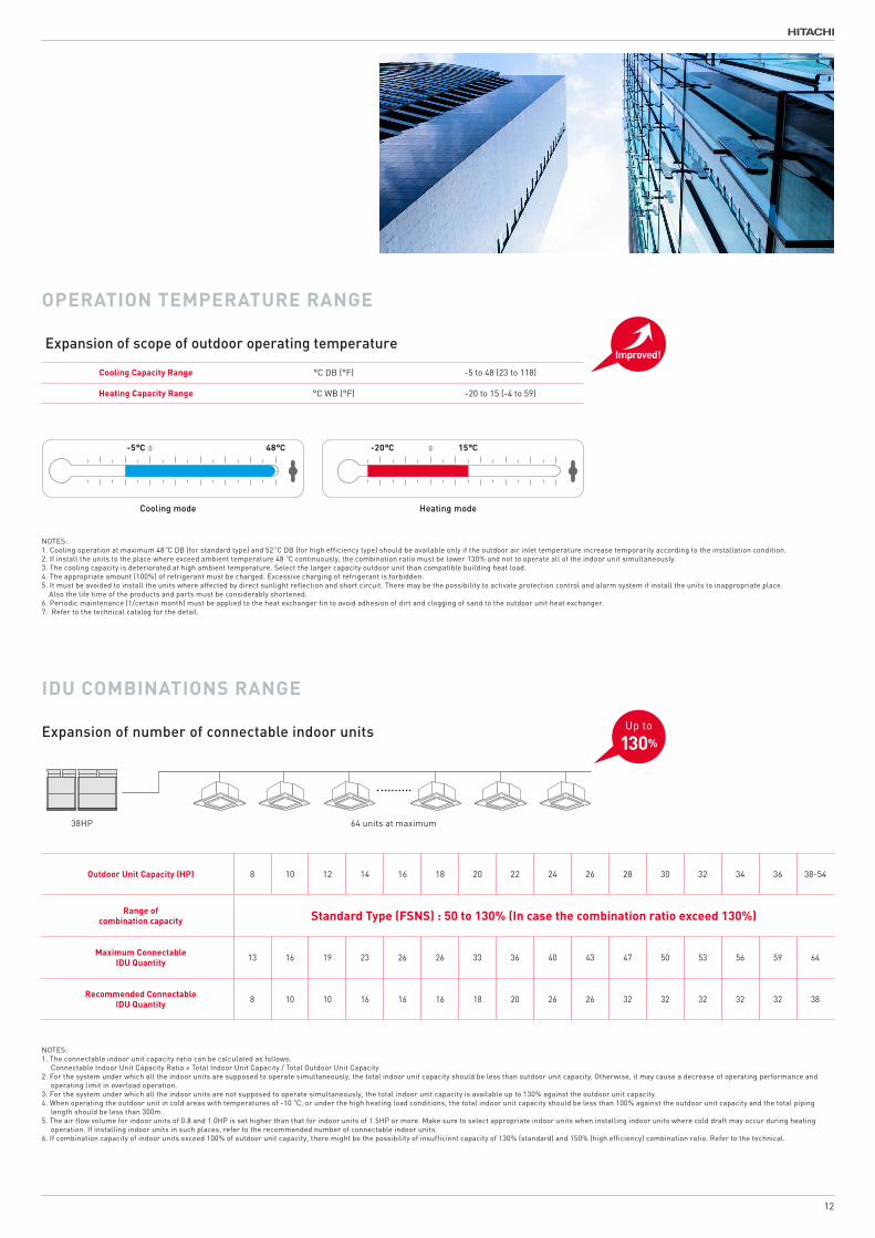
NOTES:1. The connectable indoor unit capacity ratio can be calculated as follows. Connectable Indoor Unit Capacity Ratio = Total Indoor Unit Capacity / Total Outdoor Unit Capacity2. For the system under which all the indoor units are supposed to operate simultaneously, the total indoor unit capacity should be less than outdoor unit capacity. Otherwise, it may cause a decrease of operating performance and operating limit in overload operation.3. For the system under which all the indoor units are not supposed to operate simultaneously, the total indoor unit capacity is available up to 130% against the outdoor unit capacity.4. When operating the outdoor unit in cold areas with temperatures of -10oC, or under the high heating load conditions, the total indoor unit capacity should be less than 100% against the outdoor unit capacity and the total piping length should be less than 300m.5. The air flow volume for indoor units of 0.8 and 1.0HP is set higher than that for indoor units of 1.5HP or more. Make sure to select appropriate indoor units when installing indoor units where cold draft may occur during heating operation. If installing indoor units in such places, refer to the recommended number of connectable indoor units.6. If combination capacity of indoor units exceed 100% of outdoor unit capacity, there might be the possibility of insufficient capacity of 130% (standard) and 150% (high efficiency) combination ratio. Refer to the technical.
Outdoor Unit Capacity (HP) 8 10 12 14 16 18 20 22 24 26 28 30 32 34 36 38-54
Range of combination capacity Standard Type (FSNS) : 50 to 130% (In case the combination ratio exceed 130%)
Maximum ConnectableIDU Quantity 13 16 19 23 26 26 33 36 40 43 47 50 53 56 59 64
Recommended ConnectableIDU Quantity 8 10 10 16 16 16 18 20 26 26 32 32 32 32 32 38
OPERATION TEMPERATURE RANGE
Expansion of scope of outdoor operating temperature
IDU COMBINATIONS RANGE
Expansion of number of connectable indoor units
Cooling mode Heating mode
-5°C 52°C -20°C 15°C
Cooling mode Heating mode
-5°C 0 48°C -20°C 15°C0
Cooling mode Heating mode
-5°C 52°C -20°C 15°C
Cooling mode Heating mode
-5°C 0 48°C -20°C 15°C0
NOTES:1. Cooling operation at maximum 48oC DB (for standard type) and 52oC DB (for high efficiency type) should be available only if the outdoor air inlet temperature increase temporarily according to the installation condition. 2. If install the units to the place where exceed ambient temperature 48oC continuously, the combination ratio must be lower 130% and not to operate all of the indoor unit simultaneously.3. The cooling capacity is deteriorated at high ambient temperature. Select the larger capacity outdoor unit than compatible building heat load.4. The appropriate amount (100%) of refrigerant must be charged. Excessive charging of refrigerant is forbidden.5. It must be avoided to install the units where affected by direct sunlight reflection and short circuit. There may be the possibility to activate protection control and alarm system if install the units to inappropriate place. Also the life time of the products and parts must be considerably shortened.6. Periodic maintenance (1/certain month) must be applied to the heat exchanger fin to avoid adhesion of dirt and clogging of sand to the outdoor unit heat exchanger.7. Refer to the technical catalog for the detail.
Up to
130%
64 units at maximum38HP
Improved!
Cooling Capacity Range °C DB (°F) -5 to 48 (23 to 118)
Heating Capacity Range °C WB (°F) -20 to 15 (-4 to 59)
12

Sound Power Level dB(A)
HP 8 10 12 14 16 20 22 24
Current Model 81.5 82.5 84 85.4 85.5 86 87 87
New Model 80 82 82 85 85 86 84 86
dB(A)
18HP 42HP
Noise Reduction mode Sound Power Level Sound Power Level
Nominal 86 89
Step1 82.5 86
Step2 77.5 81
Step3 72.5 76
Adaptability
LOW NOISE OPERATION
New Cover
Thanks to below 2 Design Changes
Improved!
image
Rigidityimproved !
Setting example
SoundPowerLevel
NightDay Day
86dB(A) Nominal
86dB(A) Nominal
72.5dB(A) Step2
86dB(A) Nominal 72.5dB(A) Step2
*The range of performance and operation is limited, since the rotation frequency of the compressor and ODU fan are forcibly decreased.
Compressor: The model is louder than conventional models due to the utilization of a compact high-speed compressor, but it can reduce the level of the sound pressure by up to 2dB(A) due to the utilization of new pressure covers.
Air blower: The air blower has a new structure where it is placed above the heat exchanger, meaning that the noise on the reverse side can be suppressed.
SILENT MODEThe user can set a (three-step) nighttime low-noise schedule using the control unit remote controller. The user can set a schedule for operation that takes the ambient environment into account.
Rigidity ratio (measured value) in the front and back direction : increased by 36.7%
IMPROVED STRENGTH
New Model
NewModel
NewCover
Adaptability
-1.5 on Average !The performance capability has
increased, but the running Sound Power Lebel (dB(A)) has decreased.
13

Even while defrosting, Hitachi’s original sensing function has improved the system for detecting the frost amount.
In addition, the defrosting interval has been increased by more than 200%, from 120 minutes to 250 minutes.Undertakes defrosting more efficiently, rather than unnecessary defrosting every two hours.
Time
Roo
mTe
mpe
ratu
re
on on on on on onoff offoffoffoff
Heatingon
Defrosting
Time
on on onoffoff
Roo
mTe
mpe
ratu
re
Current Model (image) New Model (image)
DEFROSTING
for defrosting prevention, the model controls frost and ice formation during heating operation by running mid-temperature coolant (5°C-20°C) before decreasing the pressure through a heat exchanger to control frost and ice formation on the lower part of the outdoor heat exchanger.
Prevention
Better Sensing
More efficient defrostingimage
Unstable Temperature More constant Temperature
image
NewModel
Sensing ability increased
Improved!
hot
warm
cold
frosting
defrosting
Heating durationmore than 200%
longer
More efficient and
comfortable
No cold air flow to Indoor thanks to automatic IDU step
14

open
Newly adopted window for 7-segment display:Adopting access door to the electrical box in the upper panel, which leads to easy access to 7-segment display, PSW & DSW and so on.
New DSW setting for Refrigerant pump-down:Refrigerant evacuation: Enforced operation to open ODU EVO/EVB, IDU EVI, and Hi/Low pressure Bi-pass SVB
Combined ODU
New Structure:In upper section, all PCB visible and easily accessible
New Structure:More Space in lower section, easy access to compressors or valves
TO PREVENT FAILURE AND EMERGENCY OPERATION IN CASE OF FAILURE
MAINTENANCE EASE
Total Structure Change
Standardize the running time of the individual outdoor units and distribute the load by rotating the order of operation of the compressors of the outdoor units.
Full introduction of backup operation function. If one outdoor unit should fail, the model can continue to operate using the remaining outdoor units, thereby preventing total system failure.
To prevent failure Back up function
onoff on
on off onon offonRotation
New Panel:The upper panel (on the side of anelectric box) can be independentlydetached from the lower panel (on the compressor chamber side)
Totally New!
Adaptability
15

1) FAN 2) Heat Exchanger 3) Compressor 4) Compressor Control
6.0
4.5
3.0
1.5
0.0
5.55.9
5.2 5.1
5.76.0
5.0 4.9
5.6 5.5 5.4 5.3 5.2 5.15.4 5.5 5.5 5.5
8.0 10.0 12.0 14.0 16.0 18.0 20.0 22.0 24.0
Old NewNOTES:APF (As Reference in the Japanese seasonal performance benchmark for VRF)APF is meant for cooling/heating capacity per 1kW of operating power consumption under certain conditions throughout the year.APF = Accumulated cooling/heating loads (kWh) / Accumulated power input in cooling/heating (kWh)
NOTES:1. The graphs below show the EER/COP of single units for Oceania.2. The above values indicate the EER/COP per outdoor unit when it is combined with specified indoor units.3. The specification of EER/COP of each country is different according to the regulation. Please contact to the Sales person for more information.4. EER = Energy efficiency ratio = Cooling capacity or Heating capacity ÷ Power consumption of an air conditioner5. COP = Coefficient of performance of an air conditioner = Output KW (cooling capacity) ÷ Input KW (power consumption)
5.01 4.91
4.27
3.49 3.44 3.44 3.523.18
3.58
8.0 10.0 12.0 14.0 16.0 18.0 20.0 22.0 24.0
5.00
4.00
3.00
7.00
6.00
2.00
1.00
4.354.00 3.93
3.26 3.323.49
3.07
8.0 10.0 12.0 14.0 16.0 18.0 20.0 22.0 24.0
3.00 2.94
HPHP
5.00
4.00
3.00
7.00
6.00
2.00
1.00
EFFICIENCY RATIO
WHAT'S IMPROVED?
APF: Annual Performance Factor
NS Type
High Efficiency
High Efficiency of Overall lineup,
with APF improved by
7% on average.
APF
5.01 4.91
4.27
3.49 3.44 3.44 3.523.18
3.58
8.0 10.0 12.0 14.0 16.0 18.0 20.0 22.0 24.0
5.00
4.00
3.00
7.00
6.00
2.00
1.00
4.354.00 3.93
3.26 3.323.49
3.07
8.0 10.0 12.0 14.0 16.0 18.0 20.0 22.0 24.0
3.00 2.94
HPHP
5.00
4.00
3.00
7.00
6.00
2.00
1.00
COPEER
16

High Efficiency
IMPROVED FAN POWER
Expansion of Air Outlets
• Improvement of airflow volume by 23% (12HP)
• Energy consumption in the driving shaft has decreased by 20% on average
Improvement in bell-mouth
Current model New model
Narrower!Less short
circuit
Smoother air Flow
17
Twin-fan
Air volume area : 6334cm2Air volume area : 4403cm2
1210mm1211mm
Current model New model
Air outlets are increased by more than
40%

IMPROVED HEAT EXCHANGER
New shape
New angle
• The heat exchange area has been increased by more than 10% (12HP)
• Gre-ater heat exchange efficiency
Current model (14,16HP) New model (14-24HP)
Improved angle of the curve
18
Current model (14,16HP) New model (14-24HP)
Split left-right heat exchanger

100%
20%
Inve
rter
Com
pres
sor
Con
trol
Cap
acity
Cooling Load Max.Min.
100%
10%
Inve
rter
Com
pres
sor
Con
trol
Cap
acity
Cooling Load Max.Min.
InverterCompressor
InverterCompressor
Oil Pump
Motor Stator
Motor Rotor
Counterweight
Oldham’s CouplingOrbiting Scroll
Fixed Scroll
Pressure bypass valve
Main Bearing
Thrust Bearing
Frame Seal
Crankshaft
Sub Bearing
10.09.89.69.49.29.08.88.68.48.28.0
100.0%
8.98
DA65PHD-A1Y2
APF
102.2%
9.17
AA50PHD-A2Y2
104.6%
9.39
DB65PHD-A2Y2
103.3%
9.27
DC80PHD-A2Y2
Current model New model
100%
20%
Inve
rter
Com
pres
sor
Con
trol
Cap
acity
Cooling Load Max.Min.
100%
10%
Inve
rter
Com
pres
sor
Con
trol
Cap
acity
Cooling Load Max.Min.
InverterCompressor
InverterCompressor
IMPROVED COMPRESSOR
New design compressor
Greater capacity control
The 13 colored parts are new!
11Hz ~ 110Hz
990 Steps(by 0.1Hz)
15Hz ~ 100Hz85 Steps(by 1Hz)
The highly improved performance as well as greater energy saving is achieved by adopting newly developed high efficiency DC inverter compressor, with outstandingly precise control technology of 0.1Hz increments inverter frequency. Another feature is the dramatically extended working range, menabled by expanding the compressor’s operating frequency band, both upwards and downwards.
Current model* New model*
The performance increased
by 2.2-4.6%
*Example at 12HP
High Efficiency
19

IDU
ODU
Refrigerant flow
IDU
Transmission Wire
Piping
INVcompressor
Transmitloadinformation
Transmitloadinformation
060 120 180Time(mm)
Power(kW)
RoomTemp
(°C)
5
10
15
20
25
30
Room Temperature(°C)Power(kW)
Unstable Temperature
Energy Consumption Loss
060 120 180Time(mm)
5
10
15
20
25
30
Power(kW)
RoomTemp
(°C)
Room Temperature(°C)Power(kW)
Constant Room Temperature
Smoother operation
The model calculates the appropriate amount of coolant supplied by the outdoor units on the basis of information about the required load from the individual indoor units. The model employs smooth operation control to control the number of revolutions of the inverter compressor. The model supplies the appropriate amount of coolant to the indoor units according to the required load. The model increases energy-saving efficiency by operating smoothly while controlling the switching on and off of the compressor at low-load operation.
IMPROVED COMPRESSOR CONTROL
Smooth Drive
Current model New model
HitachiOriginal!
Around 40% lessenergy consumption
20
Calculation of proper refrigerant amount
Charge proper amount of refrigerant

Significant reduction of CO2 emissions
Significant reduction of power consumption
By reducing power consumption, we have significantly reduced CO2 emissions and reduced the environmental impact. (Reduction amount)
By increasing the performance of air blowers, heat exchangers and compressors and improving compressor control, we have significantly reduced annual power consumption. (Comparison of power consumption during a specific period)
FOR BOTH YOU AND THE EARTH
NOTE:1. CO2 emissions are a trial calculation value based on JIS B 8616: 2015 (Tokyo office). The CO2 emissions coefficient is 0.534 kg-CO2/kWh.2. Based on the end-use intensity of CO2 emissions (actual emission coefficient in FY 2014) specified by the Federation of Electric Power Companies.3. As reference in Japanese domestic model
15 years ago Model
CO2 EMISSIONS (FOR A 10HP EQUIVALENT SYSTEM)
New Model
About 5,188 kg/year
About 2,523 kg/year
ReductionAbout 2,665
kg/year
NOTE:1. Seasonal power consumption is a calculated value based on JIS B 8616: 2015 (Tokyo office), and it may vary depending on the area or usage conditions.2. As reference in Japanese domestic model
15 years ago Model
COMPARISON OF SEASONAL POWER CONSUMPTION (FOR A SYSTEM EQUIVALENT TO 10HP)
New Model
(kwh/year)
4,537 kWh/year
9,331 kWh/year
Reduced byabout 51%
0 1,000 2,000 3,000 4,000 5,000 6,000 7,000 8,000 9,000 10,000
High Efficiency
21

Specifications /Dimensions
Service space
NOTE:1. Seasonal power consumption is a calculated value based on JIS B 8616: 2015 (Tokyo office), and it may vary depending on the area or usage conditions.2. As reference in Japanese domestic model
NOTES:
1
The cooling and heating performances are the values when combined with our specified indoor units.Cooling Operation Conditions
Heating Operation Conditions
Indoor Air Inlet Temperature: 27oC DB (80oF DB) / 19.0oC WB (66.2oF WB)Outdoor Air Inlet Temperature: 35oC DB (95oF DB)
Indoor Air Inlet Temperature: 20oC DB (68oF DB)Outdoor Air Inlet Temperature: 7oC DB (45oF DB) / 6oC WB (43oF WB)
Piping Length: 7.5 MetersPiping Lift: 0 Meter
2
The sound pressure is based on the following conditions.The above data is based on the cooling mode. In case of heating mode, the sound pressure level increases by approximately 1~2 dB.The above data was measured in an anechoic chamber so that reflected sound should be taken into consideration in the field.
3 Except for the specified combination in the table (26~54HP), there is no other combination of the base unit.
4 The width of outer dimension, it is the value when each distance between the base outdoor units is specified to 20mm.

Model RAS-8FSNS RAS-10FSNS RAS-12FSNS RAS-14FSNS RAS-16FSNS RAS-18FSNS
Power Supply AC 3φ, 380-415V/50Hz, 400V/50Hz, 380V/60Hz, 220V/60Hz
Nominal Cooling Capacity kW 22.4 28.0 33.5 40.0 45.0 50.0
Nominal Heating Capacity kW 25.0 31.5 37.5 45.0 50.0 56.0
Cabinet
Color Munsell Code Natural Gray (1.0Y 8.5/0.5)
Dimensions H*W*D mm 1,675 × 950 × 765 1,675 × 1,210 × 765
Footprint m2 0.73 0.93
Weight
N/W
380-415V/50Hz, 400V/50Hz,380V/60Hz
kg 190 210 268 310 311
220V/60Hz kg 185 205 263 305 306
G/W
380-415V/50Hz, 400V/50Hz,380V/60Hz
kg 206 226 286 328 329
220V/60Hz kg 201 221 281 323 324
Refrigerant GasType R410A
Charged Amount kg 5.0 7.2 8.9 9.9 10.7
Refrigeration OilType FVC68D
Charged Amount L/Unit 6.0 6.9 7.9
Flow Control Micro-Computer Control Expansion Valve
Compressor
Type Hermetic (Scroll)
Model AA50PHD DC80PHDAA50PHD
AA50PHD
Number per unit 1 2
Motor Output (Pole) kW 3.3(6) 4.3(6) 5.4(6) 8.0(6) 4.5(6) × 2 5.0(6) × 2
Heat Exchanger
Type Multi-Pass Cross-Finned Tube
Number of Coil per Unit 1 2
Maximum Operating Pressure MPa 4.15
Total Face Area m2 2.36 3.12
Tube
Material Copper Tube
Diameter φmm 7.0
Rows 2 3
Number of tubes 116 174
FinnMaterial Aluminium
Pitch mm 1.7
Condenser Fan
Type Propeller Fan
Number per unit 1 2
Outer Diameter mm 644 544 + 544
Nominal Air Flow Rate m3/min. 165 170 190 239 256
Outdoor Fan Motor
Type Drip-Proof Type Enclosure
Starting Method DC Motor
Motor Output (Pole) kW 0.26(8) 0.28(8) 0.42(8) 0.33(8) × 2 0.39(8) × 2
Number per unit 1 2
Insulation Class E
Main Refrigerant Piping
Liquid Line mm (in.) φ9.52 (3/8) φ12.7 (1/2) φ15.88 (5/8)
mm (in.) φ19.05 (3/4) φ22.2 (7/8) φ25.4 (1) φ28.58 (1-1/8)Gas line
Sound LevelSound Power Level dB(A) 80 82 85 86
Sound Pressure Level dB(A) 58 60 59 63 65
PackageDimentions H*W*D mm 1,800 × 1,030 × 810 1,800 × 1,290 × 810
Measurement m3 1.5 1.9
Specifications / Dimension
23

33195 92 576 92
269
950
267
1675
1348
601432
729
1818
131131
268
Liqu
id L
ine
163
Gas
Lin
e
131 Gas Line117 Liquid Line
765
Hole for Suspention
Hole for Suspention
205239
245
87
382
720 115
80
127
6580
12724010
092
65305
225
248
253
M12 Anchor Bolt Mooting Hole(4-38×15 Long Hole]
Service cover
Liquid Line Refrigerant Piping Connection
Refrigerant Piping andWiring Connection Hole(Knockout Hole)
Gas Line RefrigerantPiping Connection
TB Box(Only 380-415V/50Hz 380V/60Hz model)
Electrical Control Box
Access Door
Mounting Position forDrain Boss (Optional)(Ø26×2)
Mounting Position forDrain Cap (Optional)(Ø26×2)
Power SourceCable Outlet(Ø65 Knockout Hole)
Power TransitionCable Outlet(Ø33 Knockout Hole)
Control Cable Outlet(Ø33 Knockout Hole)
※N/A in This Unit
Refrigerant Piping Outlet (Gas,Liquid)(Knockout Square Hole)
Power TransitionCable Outlet(Ø55 Knockout Hole)
Control Cable Outlet(Ø33 Knockout Hole)
Power Source Cable Outlet(Ø65 Knockout Hole)
RefrigerantPiping Outlet(Gas,Liquid)(Knockout Square Hole)
Not Used
(※2)688
(Anchor Bolt Hole Pitch)
(Anc
hor
Bol
t Hol
e P
itch)
Knockout Hole/Drain Hole (Top View)
Refrigerant Piping and Wiring Connection
DIMENSIONAL DRAWING OF HITACHI AIR-TO-AIR HEAT PUMP AIR CONDITIONER,SET-FREE
( OUTDOOR UNIT ,MODELS: RAS-8FSNS,RAS-10FSNS and RAS-12FSNS
NOTES:
Choose a well drained place to install units or provide a ditch to drain.
If inevitable,provide the second drain pan to run drainage.
3.Do not install above the corridors.Drainage may fall.
1.Refer to "System Pipe Drawing"for diameters.
is prohibited.Drainage in the pipes may frozen and cause cracks on the pipes.
2.Drainage to come out during heating or defrost operation,and rain water,too.
4.Use a drain boss(optional)if drain setup for Outdoor Unit is necessary.
However,installation of the drain boss in regions where drainage may frozen
Follow the instructions on Installation Manual provided with drain boss.
317T158469
317T158469
CAD
23 01 201723 01 201723 01 2017
Y.KAGEYAMAY.UCHINO
DIMENSIONALDRAWING NTS
C
D
E
F
B
A
4 531 2
C
D
B
A
E
F
4 531 2 6 7 8
PROJECTIONSCALETITLE
APPD.
REMARKS
CHKD.DWN. SH. REGD.REV.
- -
REVISIONSCHKD. APPD.REVD.DATE
- -
SYM.
- -
SHIMIZU DWG. NO.
This drawing is under license by Johnson Controls-Hitachi Air Conditioning Technology(Hong Kong)Limited
1872
9
131 131
18
948
8780
267
1675
1348
Service cover
178239
9592
83692
1210
14
60
32
263
Liqu
id L
ine
160
Gas
Lin
e
130 Gas Line
112 Liquid Line
765
230 152
520230
147 127
127147
212
132
100
93
248
253
65
M12 Anchor Bolt Mooting Hole(4-38×15 Long Hole]
Electrical Control Box
483
115
Hole for Suspention
TB Box(Only 380-415V/50Hz,380/60Hz)
Access Door
Gas Line RefrigerantPiping Connection
Liquid Line RefrigerantPiping Connection
Refrigerant Piping andWiring Connection Hole(Knockout Hole)
Hole for Suspention
806524
5
Power SourceCable Outlet(Ø65 Knockout Hole)
Power TransitionCable Outlet(Ø33 Knockout Hole)
Control Cable Outlet(Ø33 Knockout Hole)
Mounting Position forDrain Boss (Optional)(Ø26×2)
Mounting Position forDrain Cap (Optional)(Ø26×2)
Control Cable Outlet(Ø33 Knockout Hole)
Power TransitionCable Outlet(Ø55 Knockout Hole)
RefrigerantPiping Outlet(Gas,Liquid)(Knockout Square Hole)
Power Source Cable Outlet(Ø65 Knockout Hole)
※N/A in This Unit
Refrigerant Piping Outlet(Gas,Liquid)(Knockout Square Hole)
Not Used
(Anc
hor
Bol
t Hol
e P
itch)
(Anchor Bolt Hole Pitch)
Knockout Hole/Drain Hole (Top View)
Refrigerant Piping and Wiring Connection
DIMENSIONAL DRAWING OF HITACHI AIR-TO-AIR HEAT PUMP AIR CONDITIONER,SET-FREE
( OUTDOOR UNIT ,MODELS: RAS-14FSNS,RAS-16FSNS and RAS-18FSNS
1.Refer to "System Pipe Drawing"for diameters.
NOTES:
If inevitable,provide the second drain pan to run drainage.
3.Do not install above the corridors.Drainage may fall.
is prohibited.Drainage in the pipes may frozen and cause cracks on the pipes.
Choose a well drained place to install units or provide a ditch to drain.
However,installation of the drain boss in regions where drainage may frozen
Follow the instructions on Installation Manual provided with drain boss.
2.Drainage to come out during heating or defrost operation,and rain water,too.
4.Use a drain boss(optional)if drain setup for Outdoor Unit is necessary.
317T158470
317T158470
CAD
23 01 201723 01 201723 01 2017
Y.KAGEYAMAY.UCHINO
DIMENSIONALDRAWING NTS
C
D
E
F
B
A
4 531 2
C
D
B
A
E
F
4 531 2 6 7 8
PROJECTIONSCALETITLE
APPD.
REMARKS
CHKD.DWN. SH. REGD.REV.
- -
REVISIONSCHKD. APPD.REVD.DATE
- -
SYM.
- -
SHIMIZU DWG. NO.
This drawing is under license by Johnson Controls-Hitachi Air Conditioning Technology(Hong Kong)Limited
RAS-8FSNS, RAS-10FSNS AND RAS-12FSNS
RAS-14FSNS, RAS-16FSNS AND RAS-18FSNS
24
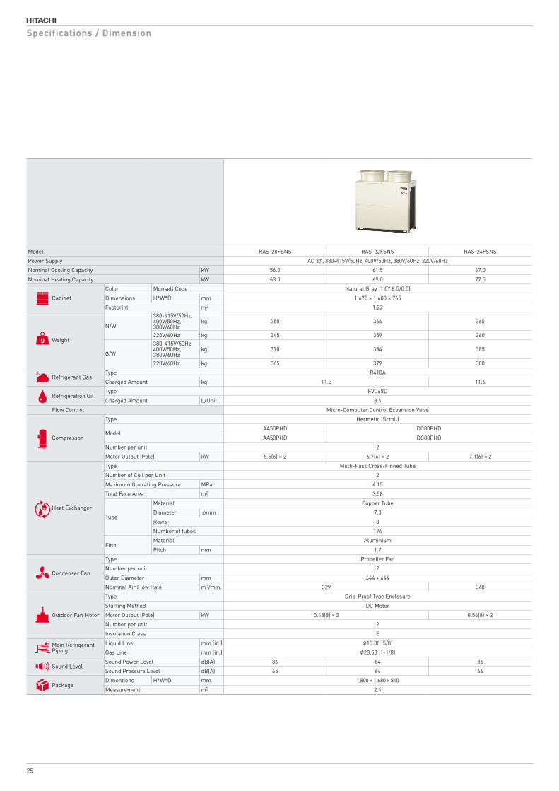
Model RAS-20FSNS RAS-22FSNS RAS-24FSNS
Power Supply AC 3φ, 380-415V/50Hz, 400V/50Hz, 380V/60Hz, 220V/60Hz
Nominal Cooling Capacity kW 56.0 61.5 67.0
Nominal Heating Capacity kW 63.0 69.0 77.5
Cabinet
Color Munsell Code Natural Gray (1.0Y 8.5/0.5)
Dimensions H*W*D mm 1,675 × 1,600 × 765
Footprint m2 1.22
Weight
N/W
380-415V/50Hz, 400V/50Hz,380V/60Hz
kg 350 364 365
220V/60Hz kg 345 359 360
G/W
380-415V/50Hz, 400V/50Hz,380V/60Hz
kg 370 384 385
220V/60Hz kg 365 379 380
Refrigerant GasType R410A
Charged Amount kg 11.3 11.6
Refrigeration OilType FVC68D
Charged Amount L/Unit 8.4
Flow Control Micro-Computer Control Expansion Valve
Compressor
Type Hermetic (Scroll)
ModelAA50PHD DC80PHD
AA50PHD DC80PHD
Number per unit 2
Motor Output (Pole) kW 5.5(6) × 2 6.7(6) × 2 7.1(6) × 2
Heat Exchanger
Type Multi-Pass Cross-Finned Tube
Number of Coil per Unit 2
Maximum Operating Pressure MPa 4.15
Total Face Area m2 3.58
Tube
Material Copper Tube
Diameter φmm 7.0
Rows 3
Number of tubes 174
FinnMaterial Aluminium
Pitch mm 1.7
Condenser Fan
Type Propeller Fan
Number per unit 2
Outer Diameter mm 644 + 644
Nominal Air Flow Rate m3/min. 329 348
Outdoor Fan Motor
Type Drip-Proof Type Enclosure
Starting Method DC Motor
Motor Output (Pole) kW 0.48(8) × 2 0.56(8) × 2
Number per unit 2
Insulation Class E
Main Refrigerant Piping
Liquid Line mm (in.) φ15.88 (5/8)
Gas Line mm (in.) φ28.58 (1-1/8)
Sound LevelSound Power Level dB(A) 86 84 86
Sound Pressure Level dB(A) 65 64 66
PackageDimentions H*W*D mm 1,800 × 1,680 × 810
Measurement m3 2.4
Specifications / Dimension
25

RAS-20FSNS, RAS-22FSNS AND RAS-24FSNS
95
92
1226
92
1600
1818
131 669 669 131
729
14 60
1675
267
1348
32
Hole forSuspention
Service cover
259
Liqu
id L
ine
160
Gas
Lin
e
765
152 Gas Line
132 Liquid Line
93
248
253
212
132
147 127
100
65
177239
Hole for Suspention
ElectricalControl Box
TB Box(Only380-415V/50Hz,380/60Hz)
M12 Anchor Bolt Mooting Hole
Access Door
Power TransitionCable Outlet(Ø55 Knockout Hole)
Control Cable Outlet(Ø33 Knockout Hole)
Gas LineRefrigerantPiping Connection
Liquid LineRefrigerantPiping Connection
RefrigerantPiping and wiringConnection Hole(Knockout Hole)
Power Source Cable Outlet(Ø65 Knockout Hole)
Refrigerant Piping Outlet(Gas,Liquid)(Knockout Square Hole)
6580
Power TransitionCable Outlet(Ø33 Knockout Hole)
Control Cable Outlet(Ø33 Knockout Hole)
Power SourceCable Outlet(Ø65 Knockout Hole)
635
462 339 239339
Mounting Positionfor Drain Cap(Optional)
Mounting Positionfor Drain Boss(Optional)
110
147 127 Refrigerant Piping Outlet(Gas,Liquid)(Knockout Square Hole)
8011
0
250
Not Used
(6-38 ×15 Long Hole]
※N/A in This Unit
(Ø26×2)
(Ø26×2)
(Anc
hor
Bol
t Hol
e P
itch)
(Anchor Bolt Hole Pitch)(Anchor Bolt Hole Pitch)
Knockout Hole/Drain Hole (Top View)
Refrigerant Piping and Wiring Connection
0
DIMENSIONAL DRAWING OF HITACHI AIR-TO-AIR HEAT PUMP AIR CONDITIONER,SET-FREE
( OUTDOOR UNIT ,MODEL: RAS-20FSNS,RAS-22FSNS and 24FSNS
NOTES:
1.Refer to "System Pipe Drawing"for diameters.
If inevitable,provide the second drain pan to run drainage.
Follow the instructions on Installation Manual provided with drain boss.
is prohibited.Drainage in the pipes may frozen and cause cracks on the pipes.
However,installation of the drain boss in regions where drainage may frozen
3.Do not install above the corridors.Drainage may fall.
2.Drainage to come out during heating or defrost operation,and rain water,too.
Choose a well drained place to install units or provide a ditch to drain.
4.Use a drain boss(optional)if drain setup for Outdoor Unit is necessary.
317T158471
317T158471
CAD
23 01 201723 01 201723 01 2017
Y.KAGEYAMAY.UCHINO
DIMENSIONALDRAWING NTS
C
D
E
F
B
A
4 531 2
C
D
B
A
E
F
4 531 2 6 7 8
PROJECTIONSCALETITLE
APPD.
REMARKS
CHKD.DWN. SH. REGD.REV.
- -
REVISIONSCHKD. APPD.REVD.DATE
- -
SYM.
- -
SHIMIZU DWG. NO.
This drawing is under license by Johnson Controls-Hitachi Air Conditioning Technology(Hong Kong)Limited
26

Model RAS-26FSNS RAS-28FSNS RAS-30FSNS RAS-32FSNS RAS-34FSNS RAS-36FSNS
Combination of Base Unit RAS-14FSNS RAS-16FSNS RAS-18FSNS RAS-18FSNS RAS-18FSNS RAS-18FSNS
RAS-12FSNS RAS-12FSNS RAS-12FSNS RAS-14FSNS RAS-16FSNS RAS-18FSNS
Power Supply AC 3φ, 380-415V/50Hz, 400V/50Hz, 380V/60Hz, 220V/60Hz
Nominal Cooling Capacity kW 73.0 77.5 85.0 90.0 95.0 100.0
Nominal Heating Capacity kW 82.5 90.0 95.0 100.0 106.0 112.0
Cabinet
Color Munsell Code Natural Gray (1.0Y 8.5/0.5)
Dimensions H*W*D mm 1,675 × 2,180 × 765 1,675 × 2,440 × 765
Footprint m2 1.67 1.87
Weight
N/W
380-415V/50Hz, 400V/50Hz,380V/60Hz
kg 210 + 268 210 + 310 210 + 311 268 + 311 310 + 311 311 + 311
220V/60Hz kg 205 + 263 205 + 305 205 + 306 263 + 306 305 + 306 306 + 306
G/W
380-415V/50Hz,400V/50Hz, 380V/60Hz
kg 226 + 286 226 + 328 226 + 329 286 + 329 328 + 329 329 + 329
220V/60Hz kg 221 + 281 221 + 323 221 + 324 281 + 324 323 + 324 324 + 324
Refrigerant GasType R410A
Charged Amount kg 16.1 17.1 17.9 19.6 20.6 21.4
Refrigeration OilType FVC68D
Charged Amount L/Unit 12.9 13.9 14.8 15.8
Flow Control Micro-Computer Control Expansion Valve
Compressor
Type Hermetic (Scroll)
Model
DC80PHD DC80PHD DC80PHD DC80PHD AA50PHD AA50PHD
DC80PHD AA50PHD AA50PHD AA50PHD AA50PHD AA50PHD
AA50PHD AA50PHD AA50PHD AA50PHD AA50PHD
AA50PHD AA50PHD
Quantity 2 3 4
Motor Output (Pole) kW 5.4 (6) × 1 + 8.0 (6) × 1 5.4 (6) × 1 + 4.5 (6) × 2 5.4 (6) × 1 + 5.0 (6) × 2 8.0 (6) × 1 + 5.0 (6) × 2 4.5 (6) × 2 + 5.0 (6) × 2 5.0 (6) × 2 + 5.0 (6) × 2
Heat Exchanger
Type Multi-Pass Cross-Finned Tube
Number of Coil per Unit 3 4
Maximum Operating Pressure MPa 4.15
Total Face Area m2 2.36 + 3.12 3.12 + 3.12
Tube
Material Copper Tube
Diameter φmm 7.0
Rows 3 + 3
Number of tubes 174 + 174
FinnMaterial Aluminium
Pitch mm 1.7
Condenser Fan
Type Propeller Fan
Number per unit 3 4
Outer Diameter mm 644 + 544 + 544 544 + 544 + 544 + 544
Nominal Air Flow Rate m3/min. 190 + 239 190 + 256 239 + 256 256 + 256
Outdoor Fan Motor
Type Drip-Proof Type Enclosure
Starting Method DC Motor
Motor Output (Pole) kW 0.42 (8) + 0.33 (8) × 2 0.42 (8) + 0.39 (8) × 2 0.33 (8) × 2 + 0.39 (8) × 2 0.39 (8) × 2 + 0.39 (8) × 2
Number per unit 3 4
Insulation Class E + E
Main Refrigerant Piping
Liquid Line mm (in.) φ19.05 (3/4)
Gas Line mm (in.) φ31.75 (1-1/4) φ38.1 (1-1/2)
Sound LevelSound Power Level dB(A) 87 89
Sound Pressure Level dB(A) 64.5 66 67 68
Specifications / Dimension
27
18
131
1872
9
688MIN.282
M12 Anchor Bolt Mooting Hole
131 948
765
950
(2180)MIN.20
1675
1210
OUTDOOR UNIT A OUTDOOR UNIT B
to Indoor UnitPiping Connection Kit
(Anchor Bolt Hole Pitch)(Anchor Bolt Hole Pitch)
(Anc
hor
Bol
t Hol
e P
itch)
to Indoor Unit
DIMENSIONAL DRAWING OF HITACHI AIR-TO-AIR HEAT PUMP AIR CONDITIONER,SET-FREE( OUTDOOR UNIT ,MODELS: RAS-26FSNS,RAS-28FSNS and RAS-30FSNS )
NOTES:
2.Check "Piping System" and "Dimensional Drawing" for the piping connection kit and piping connection size.
Arrange the outdoor units according to the
1.Make sure that the outdoor unit A is placed on the indoor unit side.
�@�@�����������������C�`���a�D
Dimension of piping outlet and Cable outlet.3.Check the "Dimensional Drawing" for the
4.This drawing shows that there is 20mm clearance between the base units. For outdoor unit snowproof hood,clearance is 50mm or more.�T�D�s�����@���������������������@�������������@���������@�@�¦�@�������������������@ the mounting pitch dimension for anchor bolts.
RAS-26FSNS
OUTDOOR UNIT A OUTDOOR UNIT B
RAS-14FSNS
RAS-16FSNSRAS-28FSNS
RAS-18FSNSRAS-30FSNS
RAS-12FSNS
RAS-12FSNS
Outdoor Unit ModelCombination of Base Unit Models
RAS-18FSNS
RAS-14FSNS
RAS-16FSNS
Combination ofBase Unit Models
RAS-12FSNS
Drawing NO.ofDimension
317T158469
317T158470
317T158470
317T158470
RAS-12FSNS
(8-38 ×15 Long Hole]
317T158472
317T158472
CAD
23 01 201723 01 201723 01 2017
Y.KAGEYAMAY.UCHINO
DIMENSIONALDRAWING NTS
C
D
E
F
B
A
4 531 2
C
D
B
A
E
F
4 531 2 6 7 8
PROJECTION SCALETITLE
APPD.
REMARKS
CHKD.DWN. SH. REGD.REV.
- -
REVISIONSCHKD. APPD.REVD.DATE
- -
SYM.
- -
SHIMIZU DWG. NO.
This drawing is under license by Johnson Controls-Hitachi Air Conditioning Technology(Hong Kong)Limi ted
131 948MIN.282
1675
1210
(2440)
1210
948 131
M12 Anchor Bolt Mooting Hole
1872
918
765
MIN.20
(8-38 ×15 Long Hole]
OUTDOOR UNIT A OUTDOOR UNIT B
to Indoor UnitPiping Connection Kit
(Anchor Bolt Hole Pitch) (Anchor Bolt Hole Pitch)
(Anc
hor
Bol
t Hol
e P
itch)
DIMENSIONAL DRAWING OF HITACHI AIR-TO-AIR HEAT PUMP AIR CONDITIONER,SET-FREE
( OUTDOOR UNIT ,MODELS: RAS-32FSNS,RAS-34FSNS and RAS-36FSNS )
�T�D�s�����@���������������������@�������������@���������@�@�¦�@�������������������@
NOTES:
2.Check "Piping System" and "Dimensional Drawing"
for the piping connection kit and piping
connection size.
Arrange the outdoor units according to the
1.Make sure that the outdoor unit A is placed
on the indoor unit side.
�@�@�����������������C�`���a�D
3.Check the "Dimensional Drawing" for the
Dimension of piping outlet and Cable outlet.
4.This drawing shows that there is 20mm clearance
50mm or more.
For outdoor unit snowproof hood,clearance is
between the base units.
the mounting pitch dimension for anchor bolts.
RAS-32FSNS
OUTDOOR UNIT A OUTDOOR UNIT B
RAS-18FSNS
RAS-18FSNSRAS-34FSNS
RAS-18FSNSRAS-36FSNS
RAS-16FSNS
RAS-18FSNS
Outdoor Unit ModelCombination of Base Unit Models
RAS-16FSNS
RAS-18FSNS
Combination ofBase Unit Models
RAS-14FSNS
Drawing NO.ofDimension
317T158470
317T158470
317T158470
RAS-14FSNS
317T158473
317T158473
CAD
23 01 201723 01 201723 01 2017
Y.KAGEYAMAY.UCHINO
DIMENSIONALDRAWING NTS
C
D
E
F
B
A
4 531 2
C
D
B
A
E
F
4 531 2 6 7 8
PROJECTIONSCALETITLE
APPD.
REMARKS
CHKD.DWN. SH. REGD.REV.
- -
REVISIONSCHKD. APPD.REVD.DATE
- -
SYM.
- -
SHIMIZU DWG. NO.
This drawing is under license by Johnson Controls-Hitachi Air Conditioning Technology(Hong Kong)Limited
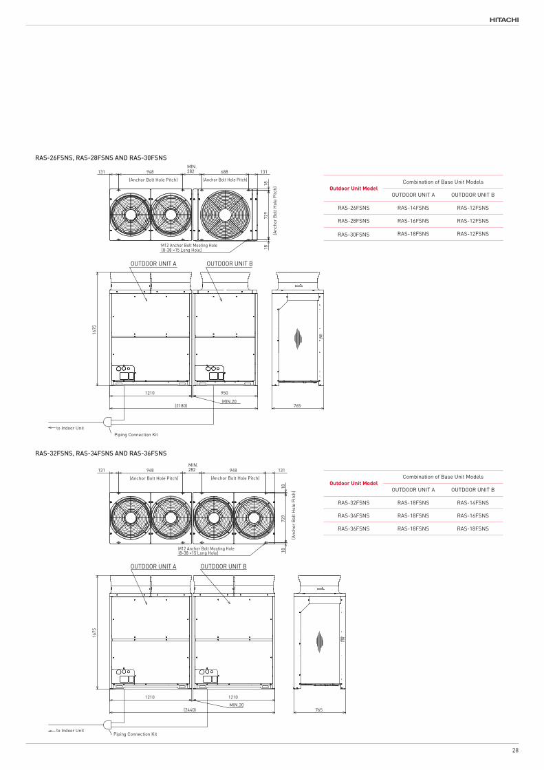
RAS-26FSNS, RAS-28FSNS AND RAS-30FSNS
RAS-32FSNS, RAS-34FSNS AND RAS-36FSNS
Outdoor Unit ModelCombination of Base Unit Models
OUTDOOR UNIT A OUTDOOR UNIT B
RAS-26FSNS RAS-14FSNS RAS-12FSNS
RAS-28FSNS RAS-16FSNS RAS-12FSNS
RAS-30FSNS RAS-18FSNS RAS-12FSNS
Outdoor Unit ModelCombination of Base Unit Models
OUTDOOR UNIT A OUTDOOR UNIT B
RAS-32FSNS RAS-18FSNS RAS-14FSNS
RAS-34FSNS RAS-18FSNS RAS-16FSNS
RAS-36FSNS RAS-18FSNS RAS-18FSNS
28

Model RAS-38FSNS RAS-40FSNS RAS-42FSNS RAS-44FSNS RAS-46FSNS RAS-48FSNS
Combination of Base Unit RAS-24FSNS RAS-22FSNS RAS-24FSNS RAS-22FSNS RAS-24FSNS RAS-24FSNS
RAS-14FSNS RAS-18FSNS RAS-18FSNS RAS-22FSNS RAS-22FSNS RAS-24FSNS
Power Supply AC 3φ, 380-415V/50Hz, 400V/50Hz, 380V/60Hz, 220V/60Hz
Nominal Cooling Capacity kW 106.0 112.0 118.0 122.0 128.0 136.0
Nominal Heating Capacity kW 118.0 125.0 132.0 140.0 145.0 150.0
Cabinet
Color Munsell Code Natural Gray (1.0Y 8.5/0.5)
Dimensions H*W*D mm 1,675 × 2,830 × 765 1,675 × 3,220 × 765
Footprint m2 2.16 2.46
Weight
N/W
380-415V/50Hz, 400V/50Hz,380V/60Hz
kg 268 + 365 311 + 364 311 + 365 364 + 364 364 + 365 365 + 365
220V/60Hz kg 263 + 360 306 + 359 306 + 360 359 + 359 359 + 360 360 + 360
G/W
380-415V/50Hz, 400V/50Hz,380V/60Hz,
kg 286 + 385 329 + 384 329 + 385 384 + 384 384 + 385 385 + 385
220V/60Hz kg 281 + 380 324 + 379 324 + 380 379 + 379 379 + 380 380 + 380
Refrigerant GasType R410A
Charged Amount kg 20.5 22.0 22.3 22.6 22.9 23.2
Refrigeration OilType FVC68D
Charged Amount L/Unit 15.3 16.3 16.8
Flow Control Micro-Computer Control Expansion Valve
Compressor
Type Hermetic (Scroll)
Model
DC80PHD AA50PHD AA50PHD DC80PHD DC80PHD DC80PHD
DC80PHD AA50PHD AA50PHD DC80PHD DC80PHD DC80PHD
DC80PHD DC80PHD DC80PHD DC80PHD DC80PHD DC80PHD
DC80PHD DC80PHD DC80PHD DC80PHD DC80PHD
Quantity 3 4
Motor Output (Pole) kW 8.0 (6) × 1 + 7.1 (6) × 2 5.0 (6) × 2 + 6.7 (6) × 2 5.0 (6) × 2 + 7.1 (6) × 2 6.7 (6) × 2 + 6.7 (6) × 2 6.7 (6) × 2 + 7.1 (6) × 2 7.1 (6) × 2 + 7.1 (6) × 2
Heat Exchanger
Type Multi-Pass Cross-Finned Tube
Number of Coil per Unit 4
Maximum Operating Pressure MPa 4.15
Total Face Area m2 3.12 + 3.58 3.58 + 3.58
Tube
Material Copper Tube
Diameter φmm 7.0
Rows 3 + 3
Number of tubes 174 + 174
FinnMaterial Aluminium
Pitch mm 1.7
Condenser Fan
Type Propeller Fan
Number per unit 4
Outer Diameter mm 544 + 544 + 644 + 644 644 + 644 + 644 + 644
Nominal Air Flow Rate m3/min. 239 + 348 256 + 329 256 + 348 329 + 329 329 + 348 348 + 348
Outdoor Fan Motor
Type Drip-Proof Type Enclosure
Starting Method DC Motor
Motor Output (Pole) kW 0.33 (8) × 2 + 0.56 (8) × 2 0.39 (8) × 2 + 0.48 (8) × 2 0.39 (8) × 2 + 0.56 (8) × 2 0.48 (8) × 2 + 0.48 (8) × 2 0.48 (8) × 2 + 0.56 (8) × 2 0.56 (8) × 2 + 0.56 (8) × 2
Number per unit 4
Insulation Class E + E
Main Refrigerant Piping
Liquid Line mm (in.) φ19.05 (3/4)
Gas Line mm (in.) φ38.1 (1-1/2)
Sound Level(2 Pipes)
Sound Power Level dB(A) 89 88 89 87 88 89
Sound Pressure Level dB(A) 68 67.5 68.5 67 68 69
Specifications / Dimension
29

Model RAS-38FSNS RAS-40FSNS RAS-42FSNS RAS-44FSNS RAS-46FSNS RAS-48FSNS
Combination of Base Unit RAS-24FSNS RAS-22FSNS RAS-24FSNS RAS-22FSNS RAS-24FSNS RAS-24FSNS
RAS-14FSNS RAS-18FSNS RAS-18FSNS RAS-22FSNS RAS-22FSNS RAS-24FSNS
Power Supply AC 3φ, 380-415V/50Hz, 400V/50Hz, 380V/60Hz, 220V/60Hz
Nominal Cooling Capacity kW 106.0 112.0 118.0 122.0 128.0 136.0
Nominal Heating Capacity kW 118.0 125.0 132.0 140.0 145.0 150.0
Cabinet
Color Munsell Code Natural Gray (1.0Y 8.5/0.5)
Dimensions H*W*D mm 1,675 × 2,830 × 765 1,675 × 3,220 × 765
Footprint m2 2.16 2.46
Weight
N/W
380-415V/50Hz, 400V/50Hz,380V/60Hz
kg 268 + 365 311 + 364 311 + 365 364 + 364 364 + 365 365 + 365
220V/60Hz kg 263 + 360 306 + 359 306 + 360 359 + 359 359 + 360 360 + 360
G/W
380-415V/50Hz, 400V/50Hz,380V/60Hz,
kg 286 + 385 329 + 384 329 + 385 384 + 384 384 + 385 385 + 385
220V/60Hz kg 281 + 380 324 + 379 324 + 380 379 + 379 379 + 380 380 + 380
Refrigerant GasType R410A
Charged Amount kg 20.5 22.0 22.3 22.6 22.9 23.2
Refrigeration OilType FVC68D
Charged Amount L/Unit 15.3 16.3 16.8
Flow Control Micro-Computer Control Expansion Valve
Compressor
Type Hermetic (Scroll)
Model
DC80PHD AA50PHD AA50PHD DC80PHD DC80PHD DC80PHD
DC80PHD AA50PHD AA50PHD DC80PHD DC80PHD DC80PHD
DC80PHD DC80PHD DC80PHD DC80PHD DC80PHD DC80PHD
DC80PHD DC80PHD DC80PHD DC80PHD DC80PHD
Quantity 3 4
Motor Output (Pole) kW 8.0 (6) × 1 + 7.1 (6) × 2 5.0 (6) × 2 + 6.7 (6) × 2 5.0 (6) × 2 + 7.1 (6) × 2 6.7 (6) × 2 + 6.7 (6) × 2 6.7 (6) × 2 + 7.1 (6) × 2 7.1 (6) × 2 + 7.1 (6) × 2
Heat Exchanger
Type Multi-Pass Cross-Finned Tube
Number of Coil per Unit 4
Maximum Operating Pressure MPa 4.15
Total Face Area m2 3.12 + 3.58 3.58 + 3.58
Tube
Material Copper Tube
Diameter φmm 7.0
Rows 3 + 3
Number of tubes 174 + 174
FinnMaterial Aluminium
Pitch mm 1.7
Condenser Fan
Type Propeller Fan
Number per unit 4
Outer Diameter mm 544 + 544 + 644 + 644 644 + 644 + 644 + 644
Nominal Air Flow Rate m3/min. 239 + 348 256 + 329 256 + 348 329 + 329 329 + 348 348 + 348
Outdoor Fan Motor
Type Drip-Proof Type Enclosure
Starting Method DC Motor
Motor Output (Pole) kW 0.33 (8) × 2 + 0.56 (8) × 2 0.39 (8) × 2 + 0.48 (8) × 2 0.39 (8) × 2 + 0.56 (8) × 2 0.48 (8) × 2 + 0.48 (8) × 2 0.48 (8) × 2 + 0.56 (8) × 2 0.56 (8) × 2 + 0.56 (8) × 2
Number per unit 4
Insulation Class E + E
Main Refrigerant Piping
Liquid Line mm (in.) φ19.05 (3/4)
Gas Line mm (in.) φ38.1 (1-1/2)
Sound Level(2 Pipes)
Sound Power Level dB(A) 89 88 89 87 88 89
Sound Pressure Level dB(A) 68 67.5 68.5 67 68 69
1210
(2830)
948 131MIN.282
M12 Anchor Bolt Mooting Hole
1872
918
765
131 669 669
1675
1600
MIN.20
OUTDOOR UNIT A OUTDOOR UNIT B
to Indoor UnitPiping Connection Kit
(Anchor Bolt Hole Pitch)
(Anc
hor
Bol
t Hol
e Pi
tch)
(Anchor Bolt Hole Pitch) (Anchor Bolt Hole Pitch)
DIMENSIONAL DRAWING OF HITACHI AIR-TO-AIR HEAT PUMP AIR CONDITIONER,SET-FREE
( OUTDOOR UNIT ,MODELS: RAS-38FSNS,RAS-40FSNS and RAS-42FSNS )
NOTES:
2.Check "Piping System" and "Dimensional Drawing"
for the piping connection kit and piping
connection size.
Arrange the outdoor units according to the
1.Make sure that the outdoor unit A is placed
on the indoor unit side.
�@�@�����������������C�`���a�D
3.Check the "Dimensional Drawing" for the
Dimension of piping outlet and Cable outlet.
4.This drawing shows that there is 20mm clearance
between the base units.
For outdoor unit snowproof hood,clearance is
the mounting pitch dimension for anchor bolts.
50mm or more.
�T�D�s�����@���������������������@�������������@���������@�@�¦�@�������������������@
RAS-38FSNS
OUTDOOR UNIT A OUTDOOR UNIT B
RAS-22FSNSRAS-40FSNS
RAS-24FSNSRAS-42FSNS
RAS-18FSNS
RAS-18FSNS
Outdoor Unit ModelCombination of Base Unit Models
RAS-24FSNS
RAS-18FSNS
RAS-22FSNS
Combination ofBase Unit Models
RAS-14FSNS
Drawing NO.ofDimension
317T158470
317T158470
317T158471
317T158471
RAS-24FSNS RAS-14FSNS
317T158474
317T158474
CAD
23 01 201723 01 201723 01 2017
Y.KAGEYAMAY.UCHINO
DIMENSIONALDRAWING NTS
C
D
E
F
B
A
4 531 2
C
D
B
A
E
F
4 531 2 6 7 8
PROJECTIONSCALETITLE
APPD.
REMARKS
CHKD.DWN. SH. REGD.REV.
- -
REVISIONSCHKD. APPD.REVD.DATE
- -
SYM.
- -
SHIMIZU DWG. NO.
This drawing is under license by Johnson Controls-Hitachi Air Conditioning Technology(Hong Kong)Limited
(10-38 ×15 Long Hole]
131 669 669MIN.282 669 669 131
1675
1600
(3220)MIN.20
1600
1872
918M12 Anchor Bolt Mooting Hole
765
(12-38 ×15 Long Hole]
OUTDOOR UNIT A OUTDOOR UNIT B
to Indoor UnitPiping Connection Kit
(Anchor Bolt Hole Pitch) (Anchor Bolt Hole Pitch)
(Anc
hor B
olt H
ole
Pitc
h)
(Anchor Bolt Hole Pitch) (Anchor Bolt Hole Pitch)
DIMENSIONAL DRAWING OF HITACHI AIR-TO-AIR HEAT PUMP AIR CONDITIONER,SET-FREE
( OUTDOOR UNIT ,MODELS: RAS-44FSNS,RAS-46FSNS and RAS-48FSNS )
NOTES:
2.Check "Piping System" and "Dimensional Drawing"
for the piping connection kit and piping
connection size.
Arrange the outdoor units according to the
1.Make sure that the outdoor unit A is placed
on the indoor unit side.
�@�@�����������������C�`���a�D
�T�D�s�����@���������������������@�������������@���������@�@�¦�@�������������������@
the mounting pitch dimension for anchor bolts.
3.Check the "Dimensional Drawing" for the
Dimension of piping outlet and Cable outlet.
4.This drawing shows that there is 20mm clearance
between the base units.
For outdoor unit snowproof hood,clearance is
50mm or more.
RAS-44FSNS
OUTDOOR UNIT A OUTDOOR UNIT B
RAS-22FSNS
RAS-24FSNSRAS-46FSNS
RAS-24FSNSRAS-48FSNS RAS-24FSNS
Outdoor Unit ModelCombination of Base Unit Models
RAS-24FSNS
Combination ofBase Unit Models
Drawing NO.ofDimension
317T158471 RAS-22FSNS
317T158471
RAS-22FSNS
RAS-22FSNS
317T158475
317T158475
CAD
23 01 201723 01 201723 01 2017
Y.KAGEYAMAY.UCHINO
DIMENSIONALDRAWING NTS
C
D
E
F
B
A
4 531 2
C
D
B
A
E
F
4 531 2 6 7 8
PROJECTIONSCALETITLE
APPD.
REMARKS
CHKD.DWN. SH. REGD.REV.
- -
REVISIONSCHKD. APPD.REVD.DATE
- -
SYM.
- -
SHIMIZU DWG. NO.
This drawing is under license by Johnson Controls-Hitachi Air Conditioning Technology(Hong Kong)Limited
RAS-38FSNS, RAS-40FSNS AND RAS-42FSNS
RAS-44FSNS, RAS-46FSNS AND RAS-48FSNS
Outdoor Unit ModelCombination of Base Unit Models
OUTDOOR UNIT A OUTDOOR UNIT B
RAS-38FSNS RAS-24FSNS RAS-14FSNS
RAS-40FSNS RAS-22FSNS RAS-18FSNS
RAS-42FSNS RAS-24FSNS RAS-18FSNS
Outdoor Unit ModelCombination of Base Unit Models
OUTDOOR UNIT A OUTDOOR UNIT B
RAS-44FSNS RAS-22FSNS RAS-22FSNS
RAS-46FSNS RAS-24FSNS RAS-22FSNS
RAS-48FSNS RAS-24FSNS RAS-24FSNS
30

Model RAS-50FSNS RAS-52FSNS RAS-54FSNS
Combination of Base Unit
RAS-18FSNS RAS-18FSNS RAS-18FSNS
RAS-18FSNS RAS-18FSNS RAS-18FSNS
RAS-14FSNS RAS-16FSNS RAS-18FSNS
Power Supply AC 3φ, 380-415V/50Hz, 400V/50Hz, 380V/60Hz, 220V/60Hz
Nominal Cooling Capacity kW 140.0 145.0 150.0
Nominal Heating Capacity kW 155.0 160.0 165.0
Cabinet
Color Munsell Code Natural Gray (1.0Y 8.5/0.5)
Dimensions H*W*D mm 1,675 × 3,670 × 765
Footprint m2 2.81
Weight
N/W
380-415V/50Hz, 400V/50Hz, 380V/60Hz
kg 268 + 311 + 311 310 + 311 + 311 311 + 311 + 311
220V/60Hz kg 263 + 306 + 306 305 + 306 + 306 306 + 306 + 306
G/W
380-415V/50Hz, 400V/50Hz,380V/60Hz
kg 286 + 329 + 329 328 + 329 + 329 329 + 329 + 329
220V/60Hz kg 281 + 324 + 324 323 + 324 + 324 324 + 324 + 324
Refrigerant GasType R410A
Charged Amount kg 30.3 31.3 32.1
Refrigeration OilType FVC68D
Charged Amount L/Unit 22.7 23.7
Flow Control Micro-Computer Control Expansion Valve
Compressor
Type Hermetic (Scroll)
Model
DC80PHD AA50PHD AA50PHD
AA50PHD AA50PHD AA50PHD
AA50PHD AA50PHD AA50PHD
AA50PHD AA50PHD AA50PHD
AA50PHD AA50PHD AA50PHD
AA50PHD AA50PHD
Quantity 5 6
Motor Output (Pole) kW 8.0 (6) × 1 + 5.0 (6) × 2 + 5.0 (6) × 2 4.5 (6) × 2 + 5.0 (6) × 2 + 5.0 (6) × 2 5.0 (6) × 2 + 5.0 (6) × 2 + 5.0 (6) × 2
Heat Exchanger
Type Multi-Pass Cross-Finned Tube
Number of Coil per Unit 6
Maximum Operating Pressure MPa 4.15
Total Face Area m2 3.12 + 3.12 + 3.12
Tube
Material Copper Tube
Diameter φmm 7.0
Rows 3 + 3 + 3
Number of tubes 174 + 174 + 174
FinnMaterial Aluminium
Pitch mm 1.7
Condenser Fan
Type Propeller Fan
Number per unit 6
Outer Diameter mm 544 + 544 + 544 + 544 + 544 + 544
Nominal Air Flow Rate m3/min. 239 + 256 × 2 256 × 3
Outdoor Fan Motor
Type Drip-Proof Type Enclosure
Starting Method DC Motor
Motor Output (Pole) kW 0.33 (8) × 2 + 0.39 (8) × 2 + 0.39 (8) × 2 0.39 (8) × 2 + 0.39 (8) × 2 + 0.39 (8) × 2
Number per unit 6
Insulation Class E + E + E
Main Refrigerant Piping
Liquid Line mm (in.) φ19.05 (3/4)
mm (in.) φ38.1 (1-1/2)Gas Line
Sound LevelSound Power Level dB(A) 90 91
Sound Pressure Level dB(A) 69 70
Specifications / Dimension
31

765
1675
1210
MIN.20(3670)
1210
MIN.20
1210
948 948 131
M12 Anchor Bolt Mooting Hole
1872
918
131 948MIN.282
MIN.282
OUTDOOR UNIT A OUTDOOR UNIT B OUTDOOR UNIT C
Piping Connection Kit 1 Piping Connection Kit 2to Indoor Unit
(Anchor Bolt Hole Pitch)(Anchor Bolt Hole Pitch)(Anchor Bolt Hole Pitch)
(Anc
hor
Bol
t Hol
e P
itch)
DIMENSIONAL DRAWING OF HITACHI AIR-TO-AIR HEAT PUMP AIR CONDITIONER,SET-FREE
( OUTDOOR UNIT ,MODELS: RAS-50FSNS,RAS-52FSNS and RAS-54FSNS )
�T�D�s�����@���������������������@�������������@���������@�@�¦�@�������������������@
bolts. the mounting pitch dimension for anchor
6.The entire modular length and anchor bolt positions are determined by the clearances.
NOTES:
Arrange the outdoor units according to the�@�@�����������������C�`���a���b�D
placed on the indoor unit side.1.Make sure that the outdoor unit A is
piping connection size. Drawing" for the piping connection kit and2.Check "Piping System" and "Dimensional
3.Check the "Dimensional Drawing" for the Dimension of piping outlet and Cable outlet.
clearance between the base units.4.This drawing shows that there is 20mm
is 50mm or more. For outdoor unit snowproof hood,clearance
RAS-50FSNS
OUTDOOR UNIT A OUTDOOR UNIT B
RAS-18FSNS
RAS-18FSNSRAS-52FSNS
RAS-18FSNSRAS-54FSNS
RAS-18FSNS
RAS-18FSNS
OUTDOOR UNIT C
RAS-16FSNS
RAS-18FSNS
RAS-18FSNS
Outdoor Unit ModelCombination of Base Unit Models
RAS-14FSNS
Combination ofBase Unit Models
Drawing NO.ofDimension
RAS-14FSNS
317T158470RAS-16FSNS
317T158470
RAS-18FSNS 317T158470
317T158476
317T158476
CAD
23 01 201723 01 201723 01 2017
Y.KAGEYAMAY.UCHINO
DIMENSIONALDRAWING NTS
C
D
E
F
B
A
4 531 2
C
D
B
A
E
F
4 531 2 6 7 8
PROJECTIONSCALETITLE
APPD.
REMARKS
CHKD.DWN. SH. REGD.REV.
- -
REVISIONSCHKD. APPD.REVD.DATE
- -
SYM.
- -
SHIMIZU DWG. NO.
This drawing is under license by Johnson Controls-Hitachi Air Conditioning Technology(Hong Kong)Limited
(12-38 ×15 Long Hole]
RAS-50FSNS, RAS-52FSNS AND RAS-54FSNS
Outdoor Unit ModelCombination of Base Unit Models
OUTDOOR UNIT A OUTDOOR UNIT B OUTDOOR UNIT C
RAS-50FSNS RAS-18FSNS RAS-18FSNS RAS-14FSNS
RAS-52FSNS RAS-18FSNS RAS-18FSNS RAS-16FSNS
RAS-54FSNS RAS-18FSNS RAS-18FSNS RAS-18FSNS
32

Make the service space when outdoor unit is installed as follows.If the service spaces for air inlet and outlet are insufficient, it may cause a performance degradation and some abnormalities due to insufficient air intake.Additionally, the service space is required for facilitating the maintenance.
- In the case of no walls on the front side and the rear side, the service space is required as follows.
* Front Side: Min. 500mm
* Rear Side: Min. 300mm
* Right and Left Sides: Min. 10mm (In the case that the field-supplied snow protection food or the air outlet duct is amounted to the unit, the spaces of min. 50mm are required.)
- If the wall on the front side is over 1,500mm high, the space of (500 + h2/2) mm for the front side is required.
- If the wall on the rear side is over 500mm high, the space of (300 + h1/2) mm for the rear side is required.
- When the units are surrounded by walls on more than 2 sides, the space indicated in the figure above is required.
- For walls on more than 2 sides, secure the service space as shown in the following figures.
- If the space between the unit and an obstacle above the unit is less than 1,500mm or the space above the unit is closed, set up the duct at the air outlet side in order to prevent short circuit.
- When there are obstacles above the unit, the four (front, rear, right and left) sides of the unit shall be open in principle.
SERVICE SPACE
P5417001 19
Min
.
1500
Min. 500 + h2/2 Min. 300 + h1/2
1500
h2
h150
0
765
(Unit: mm)
Vent Hole
FrontSide
RearSide
< Side View >
Service Space
33

1) Walls on 2 SidesIn case that the units are installed adjacent to tall buildings and there are no walls on 2 sides, the minimum rear side space must be 300mm.
2) Walls on 3 Sides
• SINGLE INSTALLATION
• SINGLE INSTALLATION
• MULTIPLE / SERIAL INSTALLATION
• MULTIPLE / SERIAL INSTALLATION [ INSTALLATION IN THE SAME DIRECTION ] [ REAR TO REAR INSTALLATION ]
20 P5417001
Min. 300 + h1/2
Min.10 *1)
Min.20*1) Min.20*1)Min.20*1) Min.20*1)
No limit for side wall height.No limit for side wall height.
Min. 500 + h2/2 Min. 500 + h2/2
Min. 500 Min. 900
Min. 500 + h2/2
Min.10 *1)
(Side Space)
FrontSide
FrontSide
Min. 300 + h1/2
Min. 10 *1)
Min. 500 + h2/2
No limit for side wall height.
“ ”
Min. 300
Min. 10 *1)
No limit forside wall height.
Min. 300
Min. 400 Min. 400
Min. 200
Front Side Front Side Front Side Front Side
No limit forside wall height.
No limit forside wall height.
Min. 300
Min. 500 + h2/2<Top View>
<Top View>
<Top View> <Top View>
<Top View><Top View>
(Rear Side Space)
Front Side
Front Side
Front Side
Front Side
(Rear Side Space) (Rear Side Space)
This indicates the direction of the unit(Front Side) when installing the units.
*1): In the case that the field-supplied snow protection hood or the air outlet duct is adopted, the space of minimum 50mm is required.
34

3) Walls on 4 Sides
• SINGLE INSTALLATION
• MULTIPLE / SERIAL INSTALLATION
P5417001 21
1 Group (Max. 6 Outdoor Units)Min. 1m
▼
▼
No limit for side wall height.
No limit for side wall height.
Min. 200Min. 200
Min. 500 + h2/2Min. 200Min. 200
Min. 900
Min. 800*2)
OpenMin. 800*2 )
Open
Min. 300 + h1/2
▼
Min. 200 Min. 200
Min. 800*2)
OpenFront Side
Front Side
Front Side
No limit for side wall height.
No limit for side wall height.
Min. 300 + h1/2
Min. 500 + h2/2
▼
▼ ▼ ▼
No limit for side wall height. No limit for
side wall height.
Min. 200
Min. 200Min. 200 Min. 500 + h2/2
Front Side
Min. 1600
Min. 200
Min. 800*2)
OpenMin. 800*2)
Open
(Side Space)
Min. 500 + h2/2
<Top View>
<Top View>
<Top View>
Front Side
NOTES:1. Keep the upper side open to prevent mutual interference of inlet and
outlet air of each outdoor unit.2. The figure dimensions indicate sufficient spaces around outdoor units
for operation and maintenance at typical installation conditions as follows. [ Operation Mode: Cooling Operation, Outside Temp.: 35oC ]
In case that the outdoor unit ambient temperature is higher and also the short circuit is likely to occur compared to the installation condition, find an appropriate dimension by calculating air flow current.
3. For the multiple installation, 1 group shall consist of 6 outdoor units (max.).Keep 1-meter interval between each unit group.
*2): Partly open a wall if the unit is surrounded by walls on four sides.
[ INSTALLATION IN THE SAME DIRECTION ]
[ REAR TO REAR INSTALLATION ]
Service Space
35

Options

ItemApplicable Outdoor Unit
Model RemarksHP Connectivity Number
PipingConnection Kit
26 - 48 2 MC-NP21SA for Gas: 1for Liquid: 1
50 - 54 3 MC-NP30SA for Gas: 2for Liquid: 2
NOTE:The old model (MC-TTA1) is not available.
*Perform the piping connection between outdoor units according to this figure.*Refer to the Installation & Maintenance Manual of the outdoor unit for the dimensions and distance between outdoor units and between piping connection kits.
1. PIPING CONNECTION KIT
Piping Connection Kit for the divergence between outdoor units
images:MC-NP30SA
For Piping from Bottom Base
Options
37
Accessory Pipe(Z-Shape)
Accessory Pipe(Z-Shape)
Base(Field-Supplied)
Outdoor Unit C
Outdoor Unit B
Outdoor Unit A
Piping ConnectionKit 1 (Liquid)
Piping ConnectionKit 1 (Gas)
Liquid Piping(Field-Supplied)
Piping ConnectionKit 2 (Gas)
Gas Piping(Field-Supplied)
Gas Piping(Field-Supplied)
Gas Piping(Field-Supplied)
Liquid Piping(Field-Supplied)
Accessory Pipe(L-Shape)
Accessory Pipe(L-Shape)
Piping ConnectionKit 2 (Liquid)
-Perform the piping connection between outdoor units according to this figure.
-Refer to “Installation & Maintenance Manual” of the outdoor unit for the dimension and distance between outdoor units and between piping connection kits.

MC-NP30SA
MC-NP21SA
378
303
80
ID15.88
ID9.52ID12.7
ID19.05
IDU
ODU
ODUID19.05ID15.88
130
61
OD19.05
ID9.52
ID15.88
ID12.7
382
469
ID25.4ID28.58
ID22.2
ID28.58
IDU
ODU
ODU
ID38.1ID31.75
83
158
95
OD28.58
ID28.58
ID25.4ID22.2
ID28.58ID25.4
ID22.2
OD28.58
Reducer
Reducer Reducer
Insulation Insulation
GAS Side
378
30380
ID15.88
ID9.52ID12.7
ID19.05
IDU
ODU
ODUID19.05ID15.88
130
61
OD19.05
ID9.52
ID15.88
ID12.7
382
469
ID25.4ID28.58
ID22.2
ID28.58
IDU
ODU
ODU
ID38.1ID31.75
83
158
95
OD28.58
ID28.58
ID25.4ID22.2
ID28.58ID25.4
ID22.2
OD28.58
Reducer
Reducer Reducer
Insulation Insulation
Reducer
378
303
80
ID15.88
ID9.52ID12.7
ID19.05
IDU
ODU
ODUID19.05ID15.88
130
61
OD19.05
ID9.52
ID15.88
ID12.7
382
469
ID25.4ID28.58
ID22.2
ID28.58
IDU
ODU
ODU
ID38.1ID31.75
83
158
95
OD28.58
ID28.58
ID25.4ID22.2
ID28.58ID25.4
ID22.2
OD28.58
Reducer
Reducer Reducer
Insulation Insulation
Liquid Side
OD19.05
ID15.88
ID12.7ID9.52
80
303
IDU
ODU
ID19.05 61
130
378
ODUID15.88
ID9.52ID12.7ID15.88
ID19.05
95
ID28.58382
ID31.75ID28.58
472ID25.4
ID38.1ID31.75
IDU
ODU
ODU
83
158
OD31.75
ID38.1
OD15.88
ID19.05
ID31.75
OD31.75
OD28.58
ID25.4
ID28.58
OD28.58
ID25.4
ID22.2
ID28.58
Insulation Insulation
Reducer
Reducer
Reducer
Reducer
Reducer
Reducer
GAS Side
OD19.05
ID15.88
ID12.7ID9.52
80
303
IDU
ODU
ID19.05 61
130
378
ODUID15.88
ID9.52ID12.7ID15.88
ID19.05
95
ID28.58382
ID31.75ID28.58
472ID25.4
ID38.1ID31.75
IDU
ODU
ODU
83
158
OD31.75
ID38.1
OD15.88
ID19.05
ID31.75
OD31.75
OD28.58
ID25.4
ID28.58
OD28.58
ID25.4
ID22.2
ID28.58
Insulation Insulation
Reducer
Reducer
Reducer
Reducer
Reducer
Reducer
ReducerOD19.05
ID15.88
ID12.7ID9.52
80
303
IDU
ODU
ID19.05 61
130
378
ODUID15.88
ID9.52ID12.7ID15.88
ID19.05
95
ID28.58382
ID31.75ID28.58
472ID25.4
ID38.1ID31.75
IDU
ODU
ODU
83
158
OD31.75
ID38.1
OD15.88
ID19.05
ID31.75
OD31.75
OD28.58
ID25.4
ID28.58
OD28.58
ID25.4
ID22.2
ID28.58
Insulation Insulation
Reducer
Reducer
Reducer
Reducer
Reducer
Reducer
Liquid Side
Dimensions
38

Header branchTotal Indoor Unit HP No. of Header Branches Model
5 - 8 4 MH-NP224A
5 - 10 8 MH-NP288A
Branching for indoor and outdoor connecting pipes
2. MULTI-KIT
Line Branch
Pipe diameter after the first branch and multi-kit
Total Indoor Unit HPDiameter (mm)
ModelGas Pipe Liquid Pipe
< 6 Φ 15.88 Φ 9.52
MW-NP282A3 6 - 8.99 Φ 19.05 Φ 9.52
9 - 11.99 Φ 22.2 Φ 9.52
12 - 15.99 Φ 25.4 Φ 12.7MW-NP452A3
16 - 17.99 Φ 28.58 Φ 12.7
18 - 25.99 Φ 28.58 Φ 15.88 MW-NP692A3
26 - 35.99 Φ 31.75 Φ 19.05MW-NP902A3< 36 Φ 38.1 Φ 19.05
First branching pipesOutdoor Unit HP Model
5 - 10 MW-NP282A3
12 - 16 MW-NP452A3
18 - 24 MW-NP692A3
26 - 54 MW-NP902A3
images:MW-NP282A3
images:MH-NP224A
Options
39

MH-NP224A
MW-NP452A3
MW-NP282A3
ID9.52
OD6.35
67426
251
206
178ID19.05
ID15.88ID12.7
IDU
ODU
ID15.88ID19.05ID22.2 ID22.2
ID19.05ID15.88
ID12.7main piping
256
170
100
50ID9.52 ID9.52
ID6.35
ID9.52ID6.35
IDUODU
main piping
122
Insulation
Insulation
Reducer
ID9.52
OD6.35
67426
251
206
178ID19.05
ID15.88ID12.7
IDU
ODU
ID15.88ID19.05ID22.2 ID22.2
ID19.05ID15.88
ID12.7main piping
256
17010
0
50ID9.52 ID9.52
ID6.35
ID9.52ID6.35
IDUODU
main piping
122
Insulation
Insulation
Reducer
ID9.52
OD6.35
OD28.58 ID15.88ID25.4
ID22.2 ID19.05
ID12.7
77
251
365
219
262
173
139
56
163
290
ID22.2ID25.4
ID28.58ID28.58
ID22.2
ID19.05ID15.88
ID12.7IDU
ODU
ODU
ID12.7 ID12.7ID9.52
main pipingmain piping
ID12.7
ID9.52ID6.35
IDU
Insulation Insulation
ReducerReducer
ID9.52
OD6.35
OD28.58 ID15.88ID25.4
ID22.2 ID19.05
ID12.7
77
251
365
219
262
173
139
56
163
290
ID22.2ID25.4
ID28.58ID28.58
ID22.2
ID19.05ID15.88
ID12.7IDU
ODU
ODU
ID12.7 ID12.7ID9.52
main pipingmain piping
ID12.7
ID9.52ID6.35
IDU
Insulation Insulation
ReducerReducer
109
ID12.7
ID15.88
ID19.05
ID15.88
ID6.35
400
375
81
ID9.53
85
ID9.53
Insulation
Insulation
Insulation
OD6.35
55
ID9.53
3×60=180
60
3×60=180
60
109
ID12.7
ID15.88
ID19.05
ID15.88
ID6.35
400
375
81
ID9.53
85
ID9.53
Insulation
Insulation
Insulation
OD6.35
55
ID9.53
3×60=180
60
3×60=180
60
GAS Side
ID9.52
OD6.35
67426
251
206
178ID19.05
ID15.88ID12.7
IDU
ODU
ID15.88ID19.05ID22.2 ID22.2
ID19.05ID15.88
ID12.7main piping
256
170
100
50ID9.52 ID9.52
ID6.35
ID9.52ID6.35
IDUODU
main piping
122
Insulation
Insulation
Reducer
ReducerLiquid Side
GAS Side Liquid Side
ID9.52
OD6.35
OD28.58 ID15.88ID25.4
ID22.2 ID19.05
ID12.7
77
251
365
219
262
173
139
56
163
290
ID22.2ID25.4
ID28.58ID28.58
ID22.2
ID19.05ID15.88
ID12.7IDU
ODU
ODU
ID12.7 ID12.7ID9.52
main pipingmain piping
ID12.7
ID9.52ID6.35
IDU
Insulation Insulation
ReducerReducer
Reducer
ID9.52
OD6.35
OD28.58 ID15.88ID25.4
ID22.2 ID19.05
ID12.7
77
251
365
219
262
173
139
56
163
290
ID22.2ID25.4
ID28.58ID28.58
ID22.2
ID19.05ID15.88
ID12.7IDU
ODU
ODU
ID12.7 ID12.7ID9.52
main pipingmain piping
ID12.7
ID9.52ID6.35
IDU
Insulation Insulation
ReducerReducer
GAS Side
109
ID12.7
ID15.88
ID19.05
ID15.88
ID6.35
400
375
81
ID9.53
85
ID9.53
Insulation
Insulation
Insulation
OD6.35
55
ID9.53
3×60=180
60
3×60=180
60
ReducerLiquid Side
Dimensions
40

MW-NP692A3
OD28.58 ID15.88ID25.4
ID22.2 ID19.05
ID12.7
ID9.52
OD6.35
251
77
365
219 19
1
387
251
219
67
290
ODU
ID22.2
ID19.05
ID15.88ID12.7
main piping
ID28.58
ID28.58ID25.4
ID22.2
IDU
main piping
ID15.88ID19.05
ID22.2ID15.88
ID12.7
ID15.88
ID12.7
ID9.52ID6.35
IDU
ODU
ID9.52
InsulationInsulation
ReducerReducer
ID9.52
OD28.58ID15.88ID25.4
ID22.2 ID19.05ID12.7
ID22.2
ID25.4OD31.75
ID28.58OD6.35
240
67
429
251
212
IDU
ODU
ID6.35ID9.52 ID12.7
ID15.88
ID9.52
ID22.2ID19.05
ID12.7
ID15.88
ID15.88ID19.05
ID22.2
main piping
257
220
IDU
477
ODU
main piping
ID31.75
ID34.92
ID38.1
ID28.58
308
ID31.75ID38.1
87
ReducerReducerReducer
InsulationInsulation
ID9.52
OD28.58ID15.88ID25.4
ID22.2 ID19.05ID12.7
ID22.2
ID25.4OD31.75
ID28.58OD6.35
240
67
429
251
212
IDU
ODU
ID6.35ID9.52 ID12.7
ID15.88
ID9.52
ID22.2ID19.05
ID12.7
ID15.88
ID15.88ID19.05
ID22.2
main piping
257
220
IDU
477
ODU
main piping
ID31.75
ID34.92
ID38.1
ID28.58
308
ID31.75ID38.1
87
ReducerReducerReducer
InsulationInsulation
615
ID15.88
ID19.05 ID22.2
685
ID12.7
ID9.53ID6.35
ID9.53
80
OD15.88 ID19.05
55
OD6.35 ID9.53
8584
7×60=42060
ID15.88
ID12.7
111
7×60=420
60
Insulation
Insulation
Insulation
615
ID15.88
ID19.05 ID22.2
685
ID12.7
ID9.53ID6.35
ID9.53
80
OD15.88 ID19.05
55
OD6.35 ID9.53
8584
7×60=42060
ID15.88
ID12.7
111
7×60=420
60
Insulation
Insulation
Insulation
615
ID15.88
ID19.05 ID22.2
685
ID12.7
ID9.53ID6.35
ID9.53
80
OD15.88 ID19.05
55
OD6.35 ID9.53
8584
7×60=42060
ID15.88
ID12.7
111
7×60=420
60
Insulation
Insulation
Insulation
GAS Side ReducerLiquid Side
GAS Side ReducerLiquid Side
MW-NP902A3
ID9.52
OD28.58ID15.88ID25.4
ID22.2 ID19.05ID12.7
ID22.2
ID25.4OD31.75
ID28.58OD6.35
240
67
429
251
212
IDU
ODU
ID6.35ID9.52 ID12.7
ID15.88
ID9.52
ID22.2ID19.05
ID12.7
ID15.88
ID15.88ID19.05
ID22.2
main piping
257
220
IDU
477
ODU
main piping
ID31.75
ID34.92
ID38.1
ID28.58
308
ID31.75ID38.1
87
ReducerReducerReducer
InsulationInsulation
MH-NP288A
GAS Side ReducerLiquid Side
Dimensions
Options
41

Ø32
43
Ø20Ø25
30
Ø32
Ø25
43
30
(48)
42
90
(90)
(247)
Drain pipingfield supplyed install Drain boll 2 points
ODU rear side
install Drain cap2 points
back front
bottom base
Drain capDrain boss
The drain boss is for the drain pipe connection in order to use the bottom base of the outdoor unit as a drain pan.
3. DRAIN BOSS
Ø32
43
Ø20Ø25
30
Ø32
Ø25
43
30
(48)
42
90
(90)
(247)
Drain pipingfield supplyed install Drain boll 2 points
ODU rear side
install Drain cap2 points
back front
bottom base
Drain capDrain boss
QuantityApplicable Outdoor Unit HP Q'ty
8 - 18 120 - 36 238 , 40 342 - 48 450 - 54 3
-456
Model NameName Model
Drain Boss DBS-TP10A
Drain water is discharged during heating and defrosting operation. (Rain water is also discharged.) Pay attention to the following.1. Choose a location where well drainage is available, or provide a drain ditch.2. Do not install the unit over a walkway, as condensation water may drip onto people. In the case of installing the unit in such a location, provide an additional drain pan.3. Do not use the drain boss in a cold area. The drain water in the drain pipe may freeze, and the drain pipe may crack.
Drain Water Treatment
Dimensions
Bottom view Side view
Drain Boss×2 Drain Cap×2To close the drain hall
Ø32
43
Ø20Ø25
30
Ø32
Ø25
43
30
(48)
42
90
(90)
(247)
Drain pipingfield supplyed install Drain boll 2 points
ODU rear side
install Drain cap2 points
back front
bottom base
Drain capDrain boss
Ø3243
Ø20Ø25
30
Ø32
Ø25
43
30
(48)
42
90
(90)
(247)
Drain pipingfield supplyed install Drain boll 2 points
ODU rear side
install Drain cap2 points
back front
bottom base
Drain capDrain boss
images:DBS-TP10A
Drain Boss + Rubber Cap Drain Cap + Rubber Cap
How to use
42

Left Side
Rear SideRight Side
Left Side
Rear SideRight Side
4. CABINET COVER
HPAir Inlet Grille
Rear Right Left8 - 12 PSN-TP20BA PSN-TP20R PSN-TP20L
14 - 18 PSN-TP20BB PSN-TP20R × 220 - 24 PSN-TP20BC PSN-TP20R × 2
HPProtection Net
Rear Right Left8 - 12 PN-TP20BA PN-TP20R PN-TP20L
14 - 18 PN-TP20BB PN-TP20R × 220 - 24 PN-TP20BC PN-TP20R × 2
NOTE:Refer to the Technical Catalog for the Optional Parts selection.
HPSnow Protection Hood
Upper Rear Right LeftZinc Coated Steel
8 - 12 ASG-TP50FA ASG-TP50BA ASG-TP50R ASG-TP50L14 - 18 ASG-TP50FB ASG-TP50BB ASG-TP50R × 220 - 24 ASG-TP50FC ASG-TP50BC ASG-TP50R × 2
Stainless8-12 ASG-TP50FAS ASG-TP50BAS ASG-TP50RS ASG-TP50LS
14-18 ASG-TP50FBS ASG-TP50BBS ASG-TP50RS × 220-24 ASG-TP50FS ASG-TP50BCS ASG-TP50RS × 2
image:Air Inlet Grille image:Protection Net
image:Snow Protection Hood
(for Air Outlet)
(for Right SideAir Inlet)
(for Left SideAir Inlet)
(for Rear SideAir Inlet)
Outdoor Unit
φ2 Wire
Fastening Fitting
Anchor Bolt(Field-Supplied)
Foundation
image:Toppling Prevention Tool
Options
HP Toppling Prevention Tool8 - 24 ASG-SW20A
43

The standard of the installation distance from the beach(conditions vary according to the installation environment)
• Points to note for installation (regarding maintenance and management)The units of JRA specifications for resistance to salt damage and resistance to heavy salt damage are made with strengthened materials and paints, but they are not fully protected against corrosion.It is therefore necessary to increase the anti-corrosion effects by carrying out the following installation plans and maintenance work.
(1) Please install the device in a location that avoids direct sea water splashes and sea breezes as much as possible.
-Please install the device on the leeward side of a building.-If you have to install a device on the side of the beach, please avoid exposing it to direct sea breezes by erecting a wind-protective board.-Please be careful about the direction of installation. (The degree of corrosion differs depending on whether a device is installed parallel to the coastline or perpendicular to the coastline.)
(2) Please ensure that any sea salt particles that adhere to the exterior panels will be washed away by the rain.(3) Because the pooling of water on the bottom base of the outdoor unit significantly boosts the corrosion effects, please be careful about the inclination so that the ability for water to run through the bottom base of an outdoor unit will not be affected.(4) For a device installed in a beach area, please rinse it with water on a regular basis to remove all salt adhering to the device.(5) Please install the device in a location where water drains away well. In particular, please secure the drainage of the foundation parts.(6) Please be sure to repair any scratches that are created during the installation and maintenance work.(7) Please inspect the conditions of the device on a regular basis. (If necessary, please apply anti-rust treatments or replace parts.)
Points to note for installation, maintenance and management
• Points to note for maintenance-Please carry out sufficient maintenance work on the device.-If you stop using the device for a long time, such as during the off-season, please take measures such as putting a cover on the device.
About the installation location
Resistance to salt damage specifications Resistance to heavy salt damage specifications
A location that is not exposed to sea breezes, but that appears to be suitable for such an atmosphere
A place that is susceptible to sea breezes(But the device is not directly exposed to water containing salt.)
- A location where the outdoor unit is rinsed by the rain
- A location that is not exposed to sea breezes
- A location where the distance from the installation location of the
outdoor unit to the sea is between approximately 300 meters and
one kilometer
- A location where the outdoor unit is in the shelter of a building
- A location where the outdoor unit receives little rain
- A location that is directly exposed to sea breezes
- A location where the distance from the installation location of the outdoor unit to the
sea is up to approximately 300 meters
- A location where the outdoor unit is mounted on the front of a building (beach side)
- A location where corrugated iron roofs and the steel parts of balconies near the
installation location of the outdoor unit are often repainted
ODU
ODU
sea sea
ODU
ODU
sea sea
Inst
alla
tion
Loca
tion
Req
uire
men
ts fo
rin
stal
lati
on lo
cati
on
A location that does not receive direct sea breezes2
300m 500m 1000m
Resistance to heavy salt damageResistance to salt damage
The standard of the installation distance
(1) A region that faces an inland sea
(2) A region that faces the open sea
(3) Okinawa and remote islands
The standard of the installation distance
(1) A region that faces an inland sea
(2) A region that faces the open sea
(3) Okinawa and remote islandsResistance to heavy salt damageResistance to salt damage
1 A location that receives direct sea breezes
300m 500m 1000m
44
Resistance to Salt Damage Specifications Products for Order
*If you install the device in a special atmosphere, you will need to undertake sufficient special consideration.Units that are resistant to salt damage are based on the “Standard of Testing Resistance to Salt Damage of Air Conditioning Devices JRA9002” of the Japan Refrigeration and Air Conditioning Industry Association (JRAIA).

Global Footprint
Global Footprint
45

46

Johnson Controls - Hitachi Air Conditioning
http://www.jci-hitachi.com
Manufactured by
Distributed by
We are a domestic business office designing and manufacturing air conditioners. We have obtained the international standard ISO 9001 certification regarding quality management systems.
Shimizu Air Conditioning Headquarters, Professional-Use Air Conditioning Business Division, Johnson Controls – Hitachi Air ConditioningJQA-1084 obtained in November 1995
ISO 9000 series The quality of our design and manufacturing systems has been approved.
JQA-1084
EC97J1107
We are a domestic business office designing and manufacturing air conditioners. We have obtained the international standard ISO 14001 certification regarding environmental management systems.
Shimizu Business Office, Johnson Controls – Hitachi Air Conditioning EC97J1107 obtained in October 1997
ISO 14000 series Our environmental preservation activities have been approved.
Hitachi VRF SystemsSET FREE Σ