Hitachi Command Suite User Guide
524
Hitachi Command Suite Hitachi Command Suite User Guide MK-90HC172-19
-
Upload
khangminh22 -
Category
Documents
-
view
2 -
download
0
Transcript of Hitachi Command Suite User Guide
Hitachi Command Suite
Hitachi Command SuiteUser Guide
MK-90HC172-19
© 2014, 2015 Hitachi, Ltd. All rights reserved.
No part of this publication may be reproduced or transmitted in any form or by any means, electronic or mechanical,including photocopying and recording, or stored in a database or retrieval system for any purpose without theexpress written permission of Hitachi, Ltd.
Hitachi, Ltd., reserves the right to make changes to this document at any time without notice and assumes noresponsibility for its use. This document contains the most current information available at the time of publication.When new or revised information becomes available, this entire document will be updated and distributed to allregistered users.
Some of the features described in this document might not be currently available. Refer to the most recent productannouncement for information about feature and product availability, or contact Hitachi Data Systems Corporation at https://portal.hds.com.
Notice: Hitachi, Ltd., products and services can be ordered only under the terms and conditions of the applicableHitachi Data Systems Corporation agreements. The use of Hitachi, Ltd., products is governed by the terms of youragreements with Hitachi Data Systems Corporation.
Hitachi is a registered trademark of Hitachi, Ltd., in the United States and other countries. Hitachi Data Systems is aregistered trademark and service mark of Hitachi, Ltd., in the United States and other countries.
Archivas, Essential NAS Platform, HiCommand, Hi-Track, ShadowImage, Tagmaserve, Tagmasoft, Tagmasolve,Tagmastore, TrueCopy, Universal Star Network, and Universal Storage Platform are registered trademarks of HitachiData Systems.
AIX, AS/400, DB2, Domino, DS6000, DS8000, Enterprise Storage Server, ESCON, FICON, FlashCopy, IBM, Lotus,MVS, OS/390, RS/6000, S/390, System z9, System z10, Tivoli, VM/ESA, z/OS, z9, z10, zSeries, z/VM, and z/VSE areregistered trademarks or trademarks of International Business Machines Corporation.
All other trademarks, service marks, and company names in this document or web site are properties of theirrespective owners.
Microsoft product screen shots are reprinted with permission from Microsoft Corporation.
Notice on Export Controls. The technical data and technology inherent in this Document may be subject to U.S.export control laws, including the U.S. Export Administration Act and its associated regulations, and may be subjectto export or import regulations in other countries. Reader agrees to comply strictly with all such regulations andacknowledges that Reader has the responsibility to obtain licenses to export, re-export, or import the Document andany Compliant Products.
2Hitachi Command Suite User Guide
Contents
Preface............................................................................................... 15Intended audience................................................................................................. 16Product version......................................................................................................16Release notes........................................................................................................ 16Related documents.................................................................................................16Document conventions........................................................................................... 16Conventions for storage capacity values...................................................................17Accessing product documentation........................................................................... 18Getting help...........................................................................................................18Comments.............................................................................................................18
1 Overview of Hitachi Command Suite......................................................21About Hitachi Command Suite.................................................................................22Features................................................................................................................23What's new............................................................................................................24System configuration..............................................................................................25Process flow.......................................................................................................... 28Navigating the interface..........................................................................................29Navigating help......................................................................................................31
2 Setting up Hitachi Command Suite........................................................ 33Configuring Hitachi Command Suite.........................................................................34Configuring your browser and Java for Hitachi Command Suite..................................34
About configuring browser settings.................................................................... 34Checking management server name resolution................................................... 35Disabling pop-up blocking for Internet Explorer...................................................36Setting security options for using Internet Explorer............................................. 37Setting security options for Firefox..................................................................... 39Setting the Java™ Web Start (versions 6.0 and 7.0) proxy to link with otherproducts.......................................................................................................... 39Configuring JRE versions from JWS version 6.0...................................................40Clearing the cache when upgrading Hitachi Command Suite................................ 41
3Hitachi Command Suite User Guide
Logging in to Hitachi Command Suite...................................................................... 41Logging in when HCS is not available.......................................................................42Setting up security................................................................................................. 43
About configuring security options..................................................................... 43Setting a password policy..................................................................................44Setting automatic account locking......................................................................44Setting a warning banner message.................................................................... 45
Downloading components.......................................................................................45About downloading components........................................................................ 45Downloading agents, CLI, and Host Data Collector files....................................... 45
Managing HCS licenses...........................................................................................46About HCS license management........................................................................ 46Registering an HCS license................................................................................ 46Checking HCS license information...................................................................... 47
Managing licenses for Virtual Storage Platform G1000 storage systems...................... 48About license key types.....................................................................................48Installing a software application.........................................................................48Enabling a license.............................................................................................49Disabling a license............................................................................................ 50Removing a software application........................................................................50Updating license status..................................................................................... 50Viewing license information............................................................................... 51License information on the License Keys window.................................................51
3 Discovering, registering, and adding management targets...................... 53Setting up storage resources...................................................................................54Registering storage systems....................................................................................54
About registering and removing a storage system............................................... 55Prerequisites for registering a storage system..................................................... 55Registering a storage system.............................................................................58Changing storage system information.................................................................59Removing a storage system...............................................................................60About acquiring the most recent storage system information............................... 61Acquiring the most recent storage system information.........................................61Operations available to SMI-S enabled storage systems....................................... 62
Registering hosts................................................................................................... 63About registering a host....................................................................................63Methods for registering hosts............................................................................ 63Priority for acquiring the WWN or iSCSI name.....................................................65Registering hosts by using Host Data Collector....................................................66Registering hosts manually by specifying the WWN or iSCSI name....................... 67Registering hosts using host scan...................................................................... 68Registering hosts using merge hosts.................................................................. 69About changing host settings and information.....................................................70Workflow for detecting hosts............................................................................. 71Updating host information registered by using Host Data Collector....................... 72Changing settings for a manually registered host................................................ 73Changing settings for a host registered by using Device Manager agent................74Refreshing vCenter hosts...................................................................................75About removing hosts and related resources, or vCenters....................................76Removing hosts and releasing associated resources............................................ 77
4Hitachi Command Suite User Guide
Registering file servers........................................................................................... 78About registering and removing file servers........................................................ 78Environment settings for Hitachi NAS Platform family.......................................... 79Registering file servers......................................................................................81Changing the name of a file server.....................................................................82Changing the Admin services EVS settings of Hitachi NAS Platform.......................83
4 Setting up users and access control...................................................... 85Setting up users and access control.........................................................................86About user accounts and controlling access to resources...........................................86Creating and managing user accounts..................................................................... 89
Creating a user account.................................................................................... 89User ID and password policies........................................................................... 90Editing the profile for a user account..................................................................91Editing your own user profile............................................................................. 92Changing the password for a user account......................................................... 92Changing your own password............................................................................92Changing permissions for a user account............................................................93Changing the lock status of user accounts.......................................................... 93Configuring external authentication for users...................................................... 94Configuring external authentication for groups....................................................95Deleting user accounts......................................................................................96
Controlling access to resources............................................................................... 97About access control.........................................................................................97Access control examples....................................................................................98About resource groups.................................................................................... 100Prerequisites for creating resource groups........................................................ 102Creating resource groups.................................................................................102Editing a resource group................................................................................. 103Deleting resource groups.................................................................................104About user groups.......................................................................................... 104User group roles............................................................................................. 107Custom roles.................................................................................................. 108Required roles and resource groups by function................................................ 111Creating user groups.......................................................................................128Editing a user group........................................................................................129Assigning resource groups and roles to a user group......................................... 130Changing a user’s user group...........................................................................130Deleting user groups.......................................................................................130
5 Provisioning storage........................................................................... 133Creating a storage operating environment..............................................................134Allocating storage.................................................................................................135Creating and deleting parity groups....................................................................... 136
About creating parity groups............................................................................136Creating parity groups.....................................................................................137Create parity groups dialog box........................................................................138About deleting parity groups............................................................................139Deleting parity groups.....................................................................................140Spare drives and copy-back mode....................................................................141
5Hitachi Command Suite User Guide
Assigning spare drives.....................................................................................141Releasing spare drives.....................................................................................142Editing copy-back mode.................................................................................. 142
Creating and deleting volumes.............................................................................. 143About creating volumes...................................................................................143Notes on performing quick formats.................................................................. 144Creating volumes............................................................................................145Create Volumes dialog box...............................................................................146About shredding volume data.......................................................................... 149Shredding volume data....................................................................................149About deleting unallocated volumes................................................................. 150Deleting unallocated volumes.......................................................................... 150About creating a LUSE volume......................................................................... 151Creating a LUSE volume.................................................................................. 152About releasing a LUSE volume........................................................................153Releasing a LUSE volume................................................................................ 153
Virtualizing external storage.................................................................................. 154About virtualizing and unvirtualizing volumes.................................................... 154Virtualizing volumes of a registered storage system...........................................156Discovering and virtualizing volumes of an unregistered storage system............. 157Unvirtualizing volumes.....................................................................................159Virtualize Volumes dialog box...........................................................................160
Virtualizing storage capacity (HDP/HDT)................................................................ 164About virtualizing storage capacity................................................................... 164Creating a DP pool..........................................................................................166Create Pool dialog box.....................................................................................169Verifying DP pool information...........................................................................173Expanding DP pools........................................................................................ 174Shrinking a DP pool.........................................................................................176Modifying DP pool settings...............................................................................177Deleting DP pools........................................................................................... 177Expanding DP volumes....................................................................................178Reclaiming zero pages.....................................................................................179Changing an access attribute to read/write....................................................... 179
Virtualizing storage tiers (HDT)..............................................................................180About virtualizing storage tiers.........................................................................181Manually starting or stopping the monitoring of HDT pools................................ 183Manually starting or stopping the tier relocation of an HDT pool.........................184Scheduling monitoring and tier relocation of HDT pools..................................... 185Editing tier relocation for HDT volumes.............................................................185Applying a tiering policy to HDT volumes.......................................................... 186Customizing a tiering policy for HDT volumes....................................................187Notes on data placement profiles for HDT volumes............................................187Creating a data placement profile for HDT volumes........................................... 189Updating a data placement profile for HDT volumes.......................................... 190Editing a data placement profile for HDT volumes............................................. 191Applying a data placement profile for HDT volumes...........................................191Scheduling data placement profiles for HDT volumes.........................................192Editing an external LDEV tiering rank for an HDT pool....................................... 193
Allocating and unallocating volumes.......................................................................194About allocating volumes.................................................................................194Volume allocation methods.............................................................................. 196
6Hitachi Command Suite User Guide
Prerequisites for allocating volumes..................................................................197Allocating volumes from general tasks.............................................................. 198Allocating volumes to selected hosts................................................................ 199Allocating volumes to selected file servers........................................................ 199Allocating selected volumes to hosts................................................................ 201Allocating volumes to clustered hosts............................................................... 202Allocating volumes by using a keyword search.................................................. 203Allocating volumes by using a criteria search.................................................... 204Allocating volumes by using existing volume settings.........................................205Allocate Volumes dialog box.............................................................................206About clustered-host storage........................................................................... 216Creating clustered-host storage........................................................................217About unallocating volumes............................................................................. 218Unallocating volumes from hosts......................................................................219Unallocating volumes from file servers..............................................................220Unallocate volumes dialog box......................................................................... 221
Configuring Fibre Channel ports.............................................................................224Enabling LUN security on a port....................................................................... 224Disabling LUN security on a port...................................................................... 225Setting the data transfer speed on a Fibre Channel port.....................................225Setting the Fibre Channel port address............................................................. 227Setting the fabric switch.................................................................................. 228
Managing LUN Paths.............................................................................................229About LUN path management..........................................................................229Editing LUN paths........................................................................................... 230Editing the host mode and host mode options...................................................232Editing LUN paths when exchanging a failed HBA..............................................233Editing LUN paths when adding or exchanging an HBA...................................... 234Removing LUN paths after adding an HBA........................................................ 236
Managing Hitachi NAS Platform file systems and shares.......................................... 236About managing Hitachi NAS Platform file systems and shares........................... 237Workflow for providing NAS Platform file shares................................................ 241Conditions for parity groups that are used in storage pools................................ 244Conditions for DP pools that are used in storage pools.......................................244Best practices for configuring storage pools...................................................... 245Notes on NAS Platform file system capacity...................................................... 247Notes on setting LUN paths for NAS Platform.................................................... 248Creating a NAS Platform storage pool (v11.3 or later)........................................248Expanding a NAS Platform storage pool (v11.3 or later).....................................250Changing a NAS Platform storage pool name.................................................... 251Creating a NAS Platform storage pool (earlier than v11.3)..................................252Expanding a NAS Platform storage pool (earlier than v11.3)...............................253Changing NAS Platform storage pool settings....................................................254Deleting NAS Platform storage pools................................................................ 254Creating a NAS Platform file system................................................................. 255Expanding a NAS Platform file system.............................................................. 256Changing NAS Platform file system settings...................................................... 257Mounting NAS Platform file systems................................................................. 258Unmounting NAS Platform file systems............................................................. 259Deleting a NAS Platform file system..................................................................260Adding NAS Platform file shares....................................................................... 260Changing NAS Platform file share settings.........................................................262
7Hitachi Command Suite User Guide
Deleting NAS Platform file shares..................................................................... 263Managing Hitachi NAS Platform F and Hitachi Data Ingestor file systems and shares. 263
About managing Hitachi NAS Platform F and Hitachi Data Ingestor file systems andshares............................................................................................................264Workflow for providing HNAS F and HDI file shares (HFSM)............................... 265Creating HNAS F or HDI file systems (HFSM v3.2 or later)................................. 266Creating HDI file systems (HFSM v3.1)............................................................. 268Changing HNAS F or HDI file system settings (HFSM v3.1 or later)..................... 268Deleting HNAS F or HDI file systems................................................................ 269File share configuration examples.................................................................... 270
6 Managing virtual storage machines......................................................273About virtual storage machines............................................................................. 274Prerequisites for allocating resources to virtual storage machines.............................278Creating virtual storage machines..........................................................................279Allocating volumes to hosts by using virtual storage machine resources....................280Editing virtual storage machines............................................................................ 281Deleting virtual storage machines.......................................................................... 283
7 Replicating volumes for continuous access........................................... 285About global-active device.................................................................................... 286Setting up a global-active device environment........................................................ 292
About global-active device setup...................................................................... 292Prerequisites for global-active device setup.......................................................294Select primary and secondary storage systems..................................................295Configuring remote paths................................................................................ 296Configuring the quorum disk............................................................................297Configuring pair management servers.............................................................. 299Configuring the virtual storage machine............................................................300
Monitoring and managing global-active device pairs................................................301Allocating global-active device pairs................................................................. 301Allocating global-active device pairs based on like volumes................................ 304Allocating global-active device pairs using allocated volumes..............................306Checking global-active device pair status.......................................................... 308Protecting global-active device pairs.................................................................309Monitoring global-active device pair performance.............................................. 310Unallocating global-active device pairs..............................................................312Unallocating individual global-active device volumes..........................................313
Recovering from global-active device failures..........................................................314About global-active device failures................................................................... 314Recovering from HBA-related host path failures.................................................315
Discontinuing a global-active device environment................................................... 316Volume replication................................................................................................317
About replicating volumes (pair management).................................................. 317Copy pair management operations................................................................... 318Adding command devices................................................................................ 319Editing command devices................................................................................ 320Defining copy pairs......................................................................................... 320Changing the status of a copy pair................................................................... 321Deleting command devices.............................................................................. 322
8Hitachi Command Suite User Guide
8 Migrating data using nondisruptive migration....................................... 323About nondisruptive migration...............................................................................324About migration planning......................................................................................325Setting up migration projects and jobs...................................................................326
Understanding migration projects and jobs....................................................... 326Navigating migration projects and jobs.............................................................327Preparing storage resources for migration.........................................................331Creating a migration project............................................................................ 333Creating a migration job..................................................................................335
Migrating volumes to the target storage system......................................................336Volume and copy pair configuration migration workflow.....................................336Step 1: Virtualize and Allocate Volumes............................................................ 339Step 2: Change host I/O paths.........................................................................340Step 3: Unallocate source volumes...................................................................341Step 4: Nondisruptive migration.......................................................................342Step 5: Unvirtualize source volumes................................................................. 344
Migrating copy pair configurations to the target storage system...............................345Preparing target secondary volumes.................................................................345Allocating target secondary volumes.................................................................346Migrating configuration definition files.............................................................. 347Creating copy pairs on the target storage system.............................................. 348
Managing migration projects and jobs....................................................................349Tracking migration project status..................................................................... 349Tracking migration job status........................................................................... 351About resuming failed migration jobs................................................................352Changing the status of a failed migration job.................................................... 353Editing a migration project...............................................................................354Editing a migration job.................................................................................... 355Canceling a migration job................................................................................ 356Canceling a volume from a migration job..........................................................356Deleting a migration project.............................................................................357
Post-migration tasks............................................................................................. 357Shredding or deleting source volumes.............................................................. 358Removing the source storage system from Hitachi Command Suite.....................358Reclaiming zero pages for target volumes.........................................................358Optimizing the target storage configuration...................................................... 359
9 Optimizing storage performance..........................................................361About optimizing storage...................................................................................... 362About optimizing HBA configurations..................................................................... 363
Adding an HBA............................................................................................... 364About high temperature mode...............................................................................365
Enabling high temperature mode for VSP G1000 storage systems.......................366Managing cache logical partitions.......................................................................... 366
Creating a CLPR..............................................................................................366Migrating resources to and from a CLPR........................................................... 368Editing the settings of an existing CLPR............................................................ 369Adjusting the cache capacity of a CLPR............................................................ 370Deleting a CLPR..............................................................................................371
Data mobility....................................................................................................... 372
9Hitachi Command Suite User Guide
About data mobility.........................................................................................372Reports for logical groups displayed in the Mobility tab...................................... 374Reports for DP pools displayed in the Mobility tab............................................. 374Optimizing data placement in a logical group.................................................... 376Optimizing data placement in a DP pool............................................................377
Data migration..................................................................................................... 378About data migration...................................................................................... 378Notes on performing data migration................................................................. 380Conditions for data migration...........................................................................381Migrating data for volume performance............................................................ 386Migrating data to a different storage system..................................................... 388Migrate data dialog box...................................................................................389Prerequisites for migrating data from an SMI-S enabled storage system to anotherstorage system............................................................................................... 393Migrating data from an SMI-S enabled storage system to another storage system..................................................................................................................... 395
10 Grouping resources............................................................................ 397Managing logical groups....................................................................................... 398
About logical groups....................................................................................... 398Creating logical groups....................................................................................403Viewing logical group reports...........................................................................404Editing logical groups...................................................................................... 405Performing operations from a logical group.......................................................405Deleting logical groups.................................................................................... 406
Managing storage tiers......................................................................................... 406About tier-based storage management............................................................. 406Values to ensure acceptable tier performance................................................... 407Creating tiers..................................................................................................407Expanding a tier............................................................................................. 408Deleting tiers..................................................................................................409
11 Managing storage system information................................................. 411Managing resource labels......................................................................................412
About managing resource labels...................................................................... 412Editing resource labels.................................................................................... 413Searching resource labels................................................................................ 413Importing storage system resource labels.........................................................414
Managing WWNs by using nicknames.................................................................... 414About managing WWNs by using nicknames..................................................... 414Editing a WWN nickname................................................................................ 416
Searching HCS resources...................................................................................... 417About searching HCS resources........................................................................417Keyword search.............................................................................................. 418Criteria search................................................................................................ 419Criteria search dialog box................................................................................ 420
Generating resource reports..................................................................................423About generating reports.................................................................................423Exporting host information to a CSV file............................................................423Exporting file server information to a CSV file....................................................424
10Hitachi Command Suite User Guide
Exporting logical group information to a CSV file............................................... 425Exporting search results to a CSV file............................................................... 425Exporting access control information for resources to a CSV file......................... 426
Using reports to verify system changes.................................................................. 426Viewing a Device Manager - Storage Navigator report....................................... 426Downloading and viewing a system configuration report....................................427Viewing a report in the Reports window............................................................427Creating a configuration report........................................................................ 428Deleting a configuration report.........................................................................428
12 Managing tasks..................................................................................429About tasks..........................................................................................................430Customizing which tasks display in the global monitoring bar...................................433Viewing HCS task status....................................................................................... 433Rescheduling HCS tasks waiting to be executed......................................................434Stopping running data migration or data placement profile tasks............................. 434Canceling scheduled HCS tasks............................................................................. 435Moving HCS tasks to the HCS Task History tab........................................................435Restarting a failed or stopped HCS task..................................................................436Deleting HCS tasks............................................................................................... 437Viewing system task status................................................................................... 437Managing system tasks.........................................................................................438Troubleshooting system tasks................................................................................439Viewing data collection task status........................................................................ 440Restarting a data collection task............................................................................ 441
13 Monitoring managed resources and resolving alerts.............................443Monitoring storage resources................................................................................ 444Viewing information summaries.............................................................................445
About checking system status in the dashboard................................................ 445Accessing the dashboard................................................................................. 447Customizing the dashboard..............................................................................448About the Storage Systems tree.......................................................................449Viewing current storage system information......................................................449Viewing MP Blade information..........................................................................449About the Hosts tree....................................................................................... 450Viewing current host information......................................................................450About the file server view................................................................................451Monitoring file servers.....................................................................................451
Analyzing storage system performance.................................................................. 451About analyzing storage system performance....................................................451Identifying storage system performance problems.............................................453Analyzing and load balancing MP Blades or MP Units......................................... 455Analyzing storage performance on a host basis................................................. 457Metrics of volumes of Virtual Storage Platform G200, G400, G600, Virtual StoragePlatform G1000, Virtual Storage Platform, and HUS VM (Identify PerformanceProblems wizard)............................................................................................ 459Metrics of volumes of Universal Storage Platform V/VM and Hitachi USP (IdentifyPerformance Problems wizard).........................................................................460
11Hitachi Command Suite User Guide
Metrics of volumes of midrange storage systems (Identify Performance Problemswizard)...........................................................................................................462Creating periodic health check reports for storage systems performance analysis..................................................................................................................... 463Editing periodic health check schedule..............................................................465Exporting health check reports.........................................................................465Viewing and deleting health check reports........................................................ 466Metrics of resources of Virtual Storage Platform G200, G400, G600, Virtual StoragePlatform G1000, Virtual Storage Platform, and HUS VM (Health Check Report).... 466Metrics of resources of Universal Storage Platform V/VM and Hitachi USP (HealthCheck Report).................................................................................................467Metrics of resources of midrange storage systems (Health Check Report)............468Changing peformance threshold settings to correctly analyze storage systemperformance...................................................................................................469Configuring the Performance Reporter display...................................................470Performance Reporter and Analytics tab display differences............................... 472
Analyzing Universal Replicator performance............................................................474About analyzing Universal Replicator performance.............................................474Prerequisites for analyzing Universal Replicator performance..............................475Monitoring Universal Replicator performance.....................................................476Configuring network bandwidth for analysis......................................................477Configuring metric thresholds for M-JNL analysis............................................... 478Metrics for Universal Replicator performance analysis........................................ 479Analyzing Universal Replicator performance in wizard mode...............................482Analyzing Universal Replicator performance in advanced mode...........................483Exporting Universal Replicator performance reports...........................................485About the P-VOL Write Transfer Rate metric......................................................486About refreshing UR Performance Analysis data................................................ 487
Managing alerts....................................................................................................487About alerts....................................................................................................487Confirming an alert......................................................................................... 488
A Managing storage resources that have virtual IDs.................................489About managing storage resources that have virtual IDs......................................... 490Displaying virtual ID information............................................................................492Allocating volumes to hosts with virtual IDs............................................................492
B Linking related products..................................................................... 495Launching other Hitachi Command Suite products.................................................. 496
About launching other Hitachi Command Suite products.................................... 496Starting related products................................................................................. 497Starting related products from a list of hosts.....................................................497Notes on starting Element Manager..................................................................497Starting Element Manager............................................................................... 499Starting System Management Unit (SMU)......................................................... 500Starting Hitachi File Services Manager (HFSM).................................................. 500
Linking with Compute Systems Manager................................................................ 501About linking with Compute Systems Manager.................................................. 501Resynchronizing hosts of Compute Systems Manager........................................ 502
12Hitachi Command Suite User Guide
Glossary............................................................................................ 503
Index................................................................................................ 517
13Hitachi Command Suite User Guide

14Hitachi Command Suite User Guide
PrefaceThis manual provides information for Hitachi Command Suite (HCS).
□ Intended audience
□ Product version
□ Release notes
□ Related documents
□ Document conventions
□ Conventions for storage capacity values
□ Accessing product documentation
□ Getting help
□ Comments
Preface 15Hitachi Command Suite User Guide
Intended audienceThis document provides instructions for storage administrators.
Product versionThis document revision applies to HCS v8.1.3 or later.
Release notesRead the release notes before installing and using this product. They maycontain requirements or restrictions that are not fully described in thisdocument or updates or corrections to this document.
Related documentsThe Hitachi documents below are referenced in this document or containmore information about the features described in this document. They can befound on the applicable Hitachi documentation media.• Hitachi Command Suite Installation and Configuration Guide, MK-90HC173• Hitachi Command Suite Administrator Guide, MK-90HC175• Hitachi Command Suite CLI Reference Guide, MK-90HC176• Hitachi Command Suite Tiered Storage Manager CLI Reference Guide,
MK-90HC177• Hitachi Command Suite Messages, MK-90HC178• Hitachi Command Suite Audit Log Reference Guide, MK-92HC213• Hitachi Command Suite Mainframe Agent Installation and Configuration
Guide, MK-96HC130• Hitachi Command Suite System Requirements, MK-92HC209
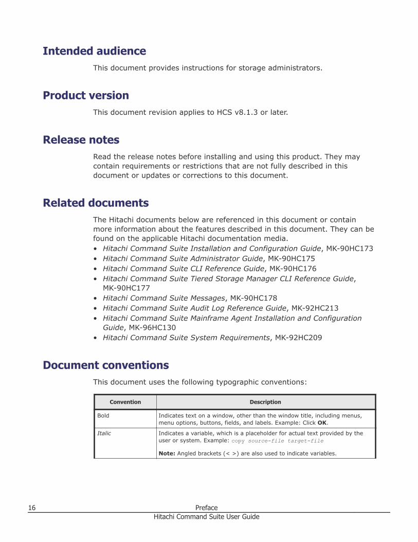
Document conventionsThis document uses the following typographic conventions:
Convention Description
Bold Indicates text on a window, other than the window title, including menus,menu options, buttons, fields, and labels. Example: Click OK.
Italic Indicates a variable, which is a placeholder for actual text provided by theuser or system. Example: copy source-file target-file
Note: Angled brackets (< >) are also used to indicate variables.
16 PrefaceHitachi Command Suite User Guide
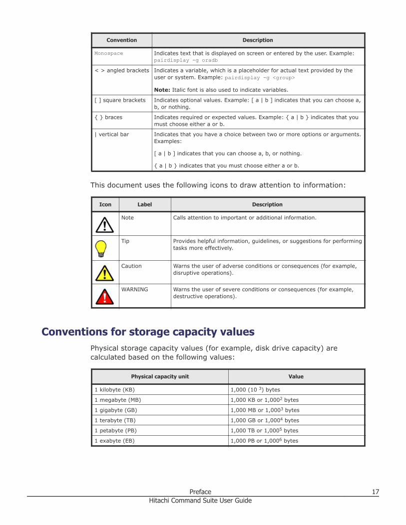
Convention Description
Monospace Indicates text that is displayed on screen or entered by the user. Example:pairdisplay -g oradb
< > angled brackets Indicates a variable, which is a placeholder for actual text provided by theuser or system. Example: pairdisplay -g <group>
Note: Italic font is also used to indicate variables.
[ ] square brackets Indicates optional values. Example: [ a | b ] indicates that you can choose a,b, or nothing.
{ } braces Indicates required or expected values. Example: { a | b } indicates that youmust choose either a or b.
| vertical bar Indicates that you have a choice between two or more options or arguments.Examples:
[ a | b ] indicates that you can choose a, b, or nothing.
{ a | b } indicates that you must choose either a or b.
This document uses the following icons to draw attention to information:
Icon Label Description
Note Calls attention to important or additional information.
Tip Provides helpful information, guidelines, or suggestions for performingtasks more effectively.
Caution Warns the user of adverse conditions or consequences (for example,disruptive operations).
WARNING Warns the user of severe conditions or consequences (for example,destructive operations).
Conventions for storage capacity valuesPhysical storage capacity values (for example, disk drive capacity) arecalculated based on the following values:
Physical capacity unit Value
1 kilobyte (KB) 1,000 (10 3) bytes
1 megabyte (MB) 1,000 KB or 1,0002 bytes
1 gigabyte (GB) 1,000 MB or 1,0003 bytes
1 terabyte (TB) 1,000 GB or 1,0004 bytes
1 petabyte (PB) 1,000 TB or 1,0005 bytes
1 exabyte (EB) 1,000 PB or 1,0006 bytes
Preface 17Hitachi Command Suite User Guide
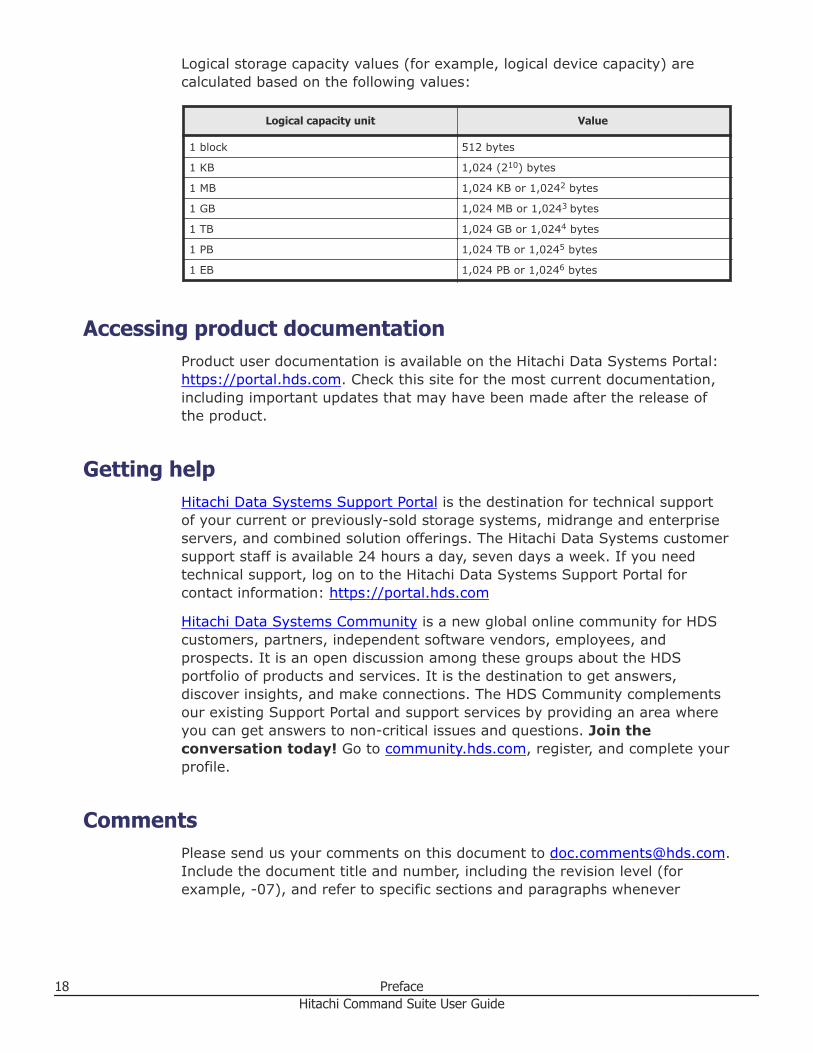
Logical storage capacity values (for example, logical device capacity) arecalculated based on the following values:
Logical capacity unit Value
1 block 512 bytes
1 KB 1,024 (210) bytes
1 MB 1,024 KB or 1,0242 bytes
1 GB 1,024 MB or 1,0243 bytes
1 TB 1,024 GB or 1,0244 bytes
1 PB 1,024 TB or 1,0245 bytes
1 EB 1,024 PB or 1,0246 bytes
Accessing product documentationProduct user documentation is available on the Hitachi Data Systems Portal: https://portal.hds.com. Check this site for the most current documentation,including important updates that may have been made after the release ofthe product.
Getting helpHitachi Data Systems Support Portal is the destination for technical supportof your current or previously-sold storage systems, midrange and enterpriseservers, and combined solution offerings. The Hitachi Data Systems customersupport staff is available 24 hours a day, seven days a week. If you needtechnical support, log on to the Hitachi Data Systems Support Portal forcontact information: https://portal.hds.com
Hitachi Data Systems Community is a new global online community for HDScustomers, partners, independent software vendors, employees, andprospects. It is an open discussion among these groups about the HDSportfolio of products and services. It is the destination to get answers,discover insights, and make connections. The HDS Community complementsour existing Support Portal and support services by providing an area whereyou can get answers to non-critical issues and questions. Join theconversation today! Go to community.hds.com, register, and complete yourprofile.
CommentsPlease send us your comments on this document to [email protected] the document title and number, including the revision level (forexample, -07), and refer to specific sections and paragraphs whenever
18 PrefaceHitachi Command Suite User Guide
possible. All comments become the property of Hitachi Data SystemsCorporation.
Thank you!
Preface 19Hitachi Command Suite User Guide

20 PrefaceHitachi Command Suite User Guide
1Overview of Hitachi Command Suite
Hitachi Command Suite (HCS) is a comprehensive software suite providingmanagement services for storage systems and hosts. Storage configuration,virtualization, reporting, and monitoring tools are fully supported.
□ About Hitachi Command Suite
□ Features
□ What's new
□ System configuration
□ Process flow
□ Navigating the interface
□ Navigating help
Overview of Hitachi Command Suite 21Hitachi Command Suite User Guide
About Hitachi Command SuiteHitachi Command Suite consists of a number of storage managementsoftware products used for managing storage resources in large-scale,complex SAN environments.
HCS includes:• Hitachi Device Manager: Supports registration of physical resources to
be managed, including storage systems, file-servers, hosts, and relatedtasks such as volume allocation and grouping of resources for easiermanagement and access.
• Hitachi Tiered Storage Manager: Supports storage tiers of differingperformance characteristics so that volume data storage costs andperformance can be optimized.
• Hitachi Replication Manager: Supports volume data replication forbackup and disaster recovery.
• Hitachi Tuning Manager: Supports optimizing the performance ofstorage resources.
• Hitachi Compute Systems Manager: Supports centralized monitoringand management of hosts, including rebooting and power management.
• Hitachi Command Director: Supports sophisticated business centricviews of storage environments, such as adherence to service levelagreements and data usage trends to forecast future storagerequirements.
• Hitachi Automation Director: Supports automation of storagemanagement and provisioning tasks through the use of pre-configuredservice templates.
• Hitachi Dynamic Link Manager: Supports the use of multiple pathsbetween resources such as hosts and storage for path fail-over and loadbalancing.
• Hitachi Global Link Manager: Supports management of multi-pathmanagement software between resources, such as hosts and storage.
Each product must be licensed for use in HCS. At minimum, you must licenseDevice Manager. Additional licensing can be added as needed for otherstorage management products. Related functionality becomes available in theHCS user interface in the form of activated menu choices, and new orupdated tabs and related screens and buttons.
For Hitachi Virtual Storage Platform G200, G400, G600 and Hitachi VirtualStorage Platform G1000, additional functionality for configuring the storagesystem is available from launch points in HCS to Hitachi Device Manager -Storage Navigator. Use the right-click menu from the list of storage systemson the Resources tab, or click the System GUI link on the application pane toaccess the additional functionality. Hitachi Virtual Storage Platform G200,
22 Overview of Hitachi Command SuiteHitachi Command Suite User Guide
G400, G600 also supports launching the maintenance utility from the list ofstorage systems on the Resources tab.
Instances of the management software products above can be installed onone or more HCS servers depending on the scale of resources undermanagement and geographic location. For information about supported HCSserver operating systems and other system requirements, see HitachiCommand Suite System Requirements. For information about productinstallation options, see the Hitachi Command Suite Installation andConfiguration Guide.
Related concepts
• Features on page 23• What's new on page 24• System configuration on page 25• Navigating the interface on page 29• Navigating help on page 31
Related tasks
• Logging in to Hitachi Command Suite on page 41
FeaturesHitachi Command Suite provides a wide variety of security, scalability, datamigration, replication, performance, and administrative features formanaging your storage system needs in this release.
Hitachi Command Suite includes the following functionality:• Server architecture supports resource scalability (millions of storage
objects) and geographic scalability.• Provides secure remote management over Internet and wide area
networks (WANs) using a sophisticated web client.• Provides multiple levels of security and access for storage administrators,
integration with external authentication servers, and use of resourcegroups to control access to specific resources.
• Security tools to prevent unauthorized access, such as account locking,and restricted login retry attempts.
• Provides for automation scripts using component CLIs.• Supports agentless discovery and mapping of servers (hosts) and storage.• Supports hosts such as Microsoft Windows, Sun Solaris, HP-UX, IBM AIX,
and Linux.• Supports virtualization servers such as Microsoft Hyper-V and VMware
ESX.• Supports FC, iSCSI, and FCoE connected hosts.• Supports a wide variety of block, file, unified (hybrid) and SMI-S compliant
storage systems.• Supports virtualization of volumes from external storage.
Overview of Hitachi Command Suite 23Hitachi Command Suite User Guide
• Supports volume migration between supported source and target storagesystems.
• Provides simplified volume provisioning in complex environments.• Provides logical, physical, and host view storage management.• Provides efficient, cost effective use of storage capacity as needed using
DP pools.• Supports optimized application performance with an installed Tiered
Storage Manager license when DP pools are configured to supportperformance tiers. Using the Mobility tab, you can optimize data placementtasks when migrating online data between tiers.
• Supports analyzing storage system performance with an installed TuningManager license, by using the Analytics tab.
• Integrates with other products and software tools that provide extendedcapabilities. For example, integration with Hitachi Command Directorsupports SLA/SLO compliance monitoring and reporting and links withnative storage management tools where necessary.
• Provides volume replication services for data protection and supportsanalyzing Universal Replicator C/T delta performance on the Replicationtab (with an installed Replication Manager and Tuning Manager license).
• Provides keyword and criteria based searching of managed resources, andmanaged resource reporting with data export to CSV files.
Related concepts
• About Hitachi Command Suite on page 22
What's newHitachi Command Suite v8.1.3 includes the following new or enhancedfunctionality:
Device Manager now supports:• Support for Virtual Storage Platform G200, G400, G600 storage systems.• Support for enabling SSL/TLS settings for the Device Manager server
during HCS installation.• Analytics tab now supports analyzing storage performance on a host basis.• Identify Performance Problems wizard now provides root cause analysis for
the performance problems, which helps you identify and resolve issuesquickly.
Tiered Storage Manager now supports:• Support for Virtual Storage Platform G200, G400, G600 storage systems.
This list highlights new software (GUI) features. It is not an exhaustive list ofenhancements.
24 Overview of Hitachi Command SuiteHitachi Command Suite User Guide
For complete information about new features and enhancements, see HitachiDevice Manager Release Notes and Hitachi Tiered Storage Manager ReleaseNotes.
For a complete list of system requirements for the management server, HostData Collector, Device Manager agent, CLI, and storage systems, see HitachiCommand Suite System Requirements.
Related concepts
• About Hitachi Command Suite on page 22
Related tasks
• Analyzing storage performance on a host basis on page 457
System configurationAs part of a basic storage network configuration, Hitachi Command Suite iscomprised of HCS server-based components, agents, and clients that enableyou to manage storage resources.
The following figure illustrates Hitachi Command Suite management servercomponents, and the basic configuration of the storage network.
Overview of Hitachi Command Suite 25Hitachi Command Suite User Guide
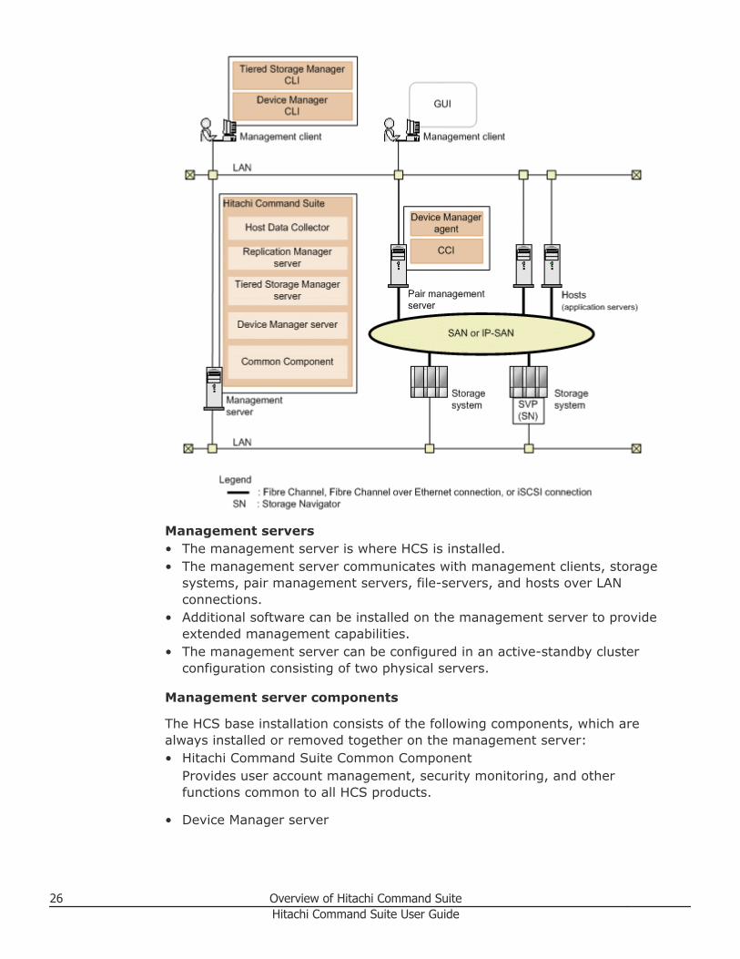
Management servers• The management server is where HCS is installed.• The management server communicates with management clients, storage
systems, pair management servers, file-servers, and hosts over LANconnections.
• Additional software can be installed on the management server to provideextended management capabilities.
• The management server can be configured in an active-standby clusterconfiguration consisting of two physical servers.
Management server components
The HCS base installation consists of the following components, which arealways installed or removed together on the management server:• Hitachi Command Suite Common Component
Provides user account management, security monitoring, and otherfunctions common to all HCS products.
• Device Manager server
26 Overview of Hitachi Command SuiteHitachi Command Suite User Guide
HCS uses this component to manage storage system volumes.
• Tiered Storage Manager serverTiered Storage Manager uses this component to manage storage systemvolume migration.
• Replication Manager serverReplication Manager uses this component to manage storage systemvolume replication.
• Host Data CollectorHCS uses this component to collect information about the volumes used bythe hosts.
Note: The Host Data Collector component can be installed on otherservers and accessed remotely by HCS.
Management clients• Manage storage resources from the management server by using the HCS
web client (GUI), or by using the CLI client software to issue commands.• CLI client components (Device Manager and Tiered Storage Manager)
require a separate installation from the web client.• From the web client, with a Device Manager license, launch Replication
Manager to use a subset of Replication Manager functionality.
Hosts• File servers and hosts (application servers) access volumes in storage
systems that are managed by HCS.• Hosts access storage over SAN (Fibre Channel) or LAN (iSCSI and FCoE)
connections.• Hosts can be virtualization servers (VMware ESX/ESXi) and their virtual
machines, and mainframe hosts.• Hosts can be file servers (Hitachi NAS Platform family, Hitachi NAS
Platform F, and Hitachi Data Ingestor).
File servers and hosts (application servers) access volumes in storagesystems that are managed by HCS over a Storage Area Network (SAN) or anIP-SAN.
Pair management servers• Collects management information about copy pair configurations and
related status information, and provides for copy pair operations.
• Command Control Interface (CCI) and Device Manager agent are installedfor copy pair monitoring and management.
Overview of Hitachi Command Suite 27Hitachi Command Suite User Guide
For information about performing the base installation, see the HitachiCommand Suite Installation and Configuration Guide.
For information about customizing and extending the base installation, seethe Hitachi Command Suite Administrator Guide.
Related concepts
• About Hitachi Command Suite on page 22
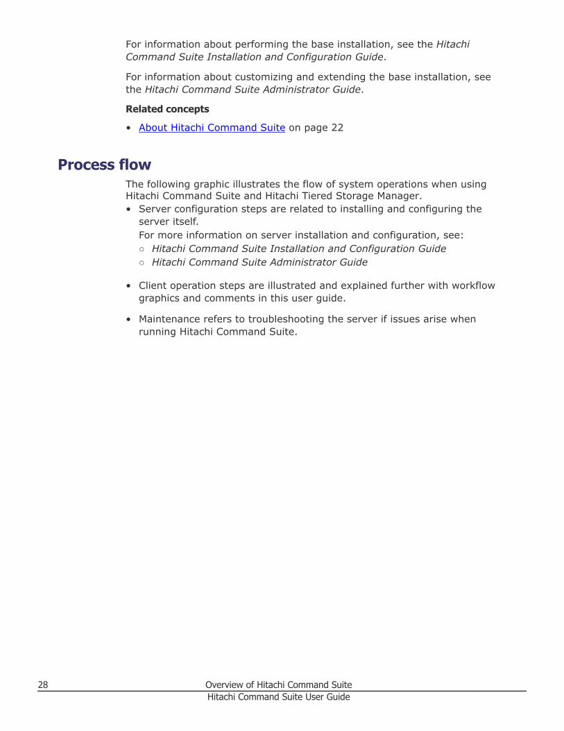
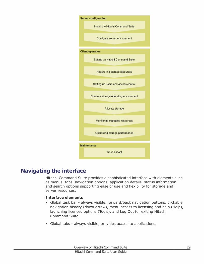
Process flowThe following graphic illustrates the flow of system operations when usingHitachi Command Suite and Hitachi Tiered Storage Manager.• Server configuration steps are related to installing and configuring the
server itself.For more information on server installation and configuration, see:○ Hitachi Command Suite Installation and Configuration Guide○ Hitachi Command Suite Administrator Guide
• Client operation steps are illustrated and explained further with workflowgraphics and comments in this user guide.
• Maintenance refers to troubleshooting the server if issues arise whenrunning Hitachi Command Suite.
28 Overview of Hitachi Command SuiteHitachi Command Suite User Guide
Navigating the interfaceHitachi Command Suite provides a sophisticated interface with elements suchas menus, tabs, navigation options, application details, status informationand search options supporting ease of use and flexibility for storage andserver resources.
Interface elements• Global task bar - always visible, forward/back navigation buttons, clickable
navigation history (down arrow), menu access to licensing and help (Help),launching licenced options (Tools), and Log Out for exiting HitachiCommand Suite.
• Global tabs - always visible, provides access to applications.
Overview of Hitachi Command Suite 29Hitachi Command Suite User Guide
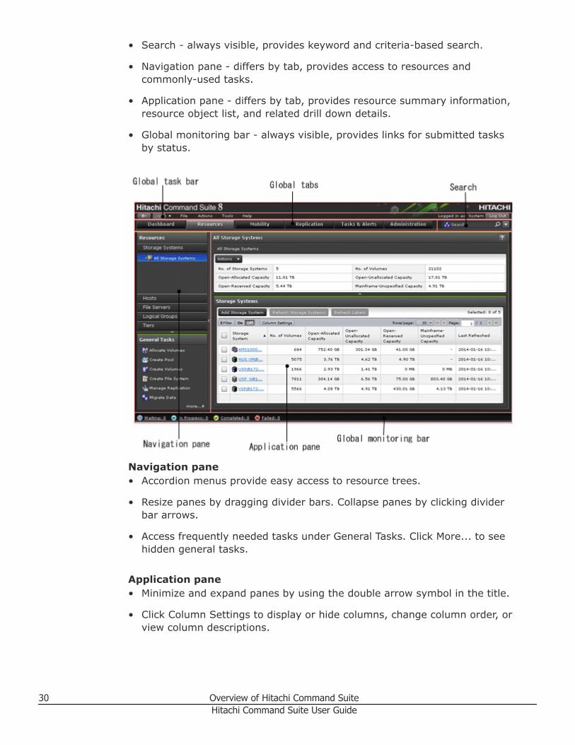
• Search - always visible, provides keyword and criteria-based search.
• Navigation pane - differs by tab, provides access to resources andcommonly-used tasks.
• Application pane - differs by tab, provides resource summary information,resource object list, and related drill down details.
• Global monitoring bar - always visible, provides links for submitted tasksby status.
Navigation pane• Accordion menus provide easy access to resource trees.
• Resize panes by dragging divider bars. Collapse panes by clicking dividerbar arrows.
• Access frequently needed tasks under General Tasks. Click More... to seehidden general tasks.
Application pane• Minimize and expand panes by using the double arrow symbol in the title.
• Click Column Settings to display or hide columns, change column order, orview column descriptions.
30 Overview of Hitachi Command SuiteHitachi Command Suite User Guide
• Right-click a table heading and select menu options, such as Hide Columnor Show all Columns.
• Arrange columns by using drag-and-drop.
• Sort lists by clicking the column title.
• Navigate large lists by using Page controls.
• Click Filter to reduce large lists, or to find specific items by defining specificsearch conditions. Filter allows multiple conditions to be defined.
• In a list, click a link to display more detail about the item. As you drill-down, the breadcrumb list (item > detail) above the summary pane isupdated and serves as a useful navigation tool.
• In a list, rows are highlighted as you roll your mouse over them, indicatingyour row position. To select a specific item, select the desired check box orclick the row and the darker highlight indicates the row is selected.
• To select multiple rows, select the desired check boxes or rows. You canalso use Shift+click to select a range of items. To select all rows, select thecheck box for the title row, or clear the check box to de-select all rows.
• Selecting rows implies you intend to perform an action on the selecteditem or items. Actions are initiated with buttons or from the Actions menu.
• To copy cell or row data, select one or more rows with data, right-click andselect Copy This Cell or Copy Selected Rows. This is useful for emailingsmall amounts of data about a storage resource. If you select empty rows,the copy options do not appear when you right-click. For reporting on largenumbers of objects and for more complete data, use CSV export.
Related concepts
• About Hitachi Command Suite on page 22• Navigating help on page 31
Navigating helpThe Help system provides brief explanations of the features of this productand helps you understand its capabilities. Navigating is the means by whichyou access the information in the Help system.
When you access Help > Online Help from the menu bar, the navigation panedisplays.
If you select the help icon [?] from the application pane or a dialog box, clickShow All Contents to display the navigation pane and access the Contents,Index, Search, and Glossary.
Overview of Hitachi Command Suite 31Hitachi Command Suite User Guide
Navigating• To navigate between topics, use the navigation pane, or right-click the
topic and select Back or Forward.
• Use the breadcrumb trail at the top of each topic to see your location, or toreturn to a higher level topic.
• To find information for a specific topic, click the Related topics links.
Using navigation buttons• Contents
Open book icons in the navigation pane to reveal topic entries andsubsections. As you move through Help, the current topic is highlighted.
• IndexAn alphabetical list of topics. Click an Index entry to display one or moretopics that you can choose to view.
• SearchSearch for word or phrase occurrences. Click search results to display thecorresponding topics.
• GlossaryProvides brief explanations of product-related terms.
Printing topics
• To print topics, right-click the topic and select Print or click the printer iconon the button bar.
Related concepts
• About Hitachi Command Suite on page 22• Navigating the interface on page 29
32 Overview of Hitachi Command SuiteHitachi Command Suite User Guide
2Setting up Hitachi Command SuiteThis module describes how to configure basic Hitachi Command Suitesettings.
□ Configuring Hitachi Command Suite
□ Configuring your browser and Java for Hitachi Command Suite
□ Logging in to Hitachi Command Suite
□ Logging in when HCS is not available
□ Setting up security
□ Downloading components
□ Managing HCS licenses
□ Managing licenses for Virtual Storage Platform G1000 storage systems
Setting up Hitachi Command Suite 33Hitachi Command Suite User Guide
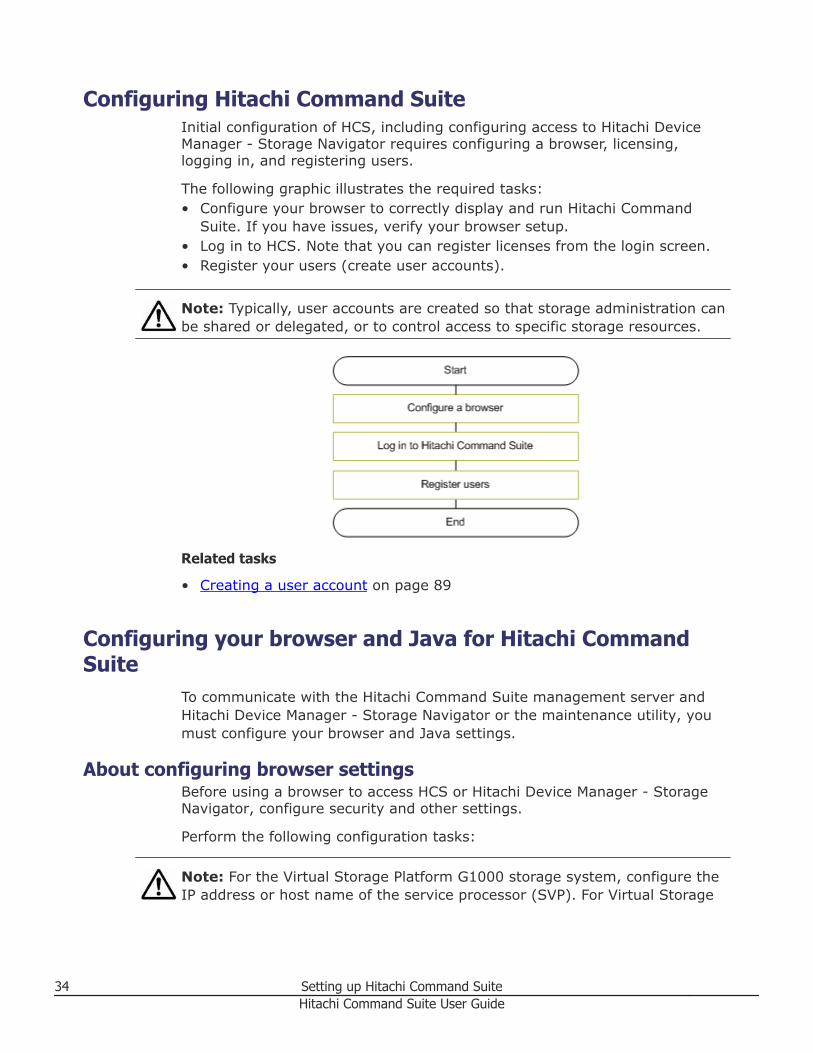
Configuring Hitachi Command SuiteInitial configuration of HCS, including configuring access to Hitachi DeviceManager - Storage Navigator requires configuring a browser, licensing,logging in, and registering users.
The following graphic illustrates the required tasks:• Configure your browser to correctly display and run Hitachi Command
Suite. If you have issues, verify your browser setup.• Log in to HCS. Note that you can register licenses from the login screen.• Register your users (create user accounts).
Note: Typically, user accounts are created so that storage administration canbe shared or delegated, or to control access to specific storage resources.
Related tasks
• Creating a user account on page 89
Configuring your browser and Java for Hitachi CommandSuite
To communicate with the Hitachi Command Suite management server andHitachi Device Manager - Storage Navigator or the maintenance utility, youmust configure your browser and Java settings.
About configuring browser settingsBefore using a browser to access HCS or Hitachi Device Manager - StorageNavigator, configure security and other settings.
Perform the following configuration tasks:
Note: For the Virtual Storage Platform G1000 storage system, configure theIP address or host name of the service processor (SVP). For Virtual Storage
34 Setting up Hitachi Command SuiteHitachi Command Suite User Guide
Platform G200, G400, G600 storage systems, configure the IP addresses ofthe SVP and the maintenance utility.
• Disable pop-up blocking• Disable plug-ins• Set security options• Configure proxy settings• Configure log output settings• Configure Java Web Start settings• Clear your browser’s cache when upgrading• Browser must allow first-party, third-party, and session cookies
Note: For specific instructions on configuring your browser, refer to thebrowser product documentation.
After you configure your browser settings, verify the following:• The Java™ software environment is installed and the Java software is
configured• Communications with HCS are secure• Check the management server name resolution
Note: If you have issues with general access, or with using a component ofHitachi Command Suite, first verify that the problem is not related to themanagement server, or a network connectivity issue.
For troubleshooting problems related to Device Manager servers, see theHitachi Command Suite Administrator Guide.
Related tasks
• Checking management server name resolution on page 35• Setting security options for using Internet Explorer on page 37• Setting security options for Firefox on page 39• Setting the Java™ Web Start (versions 6.0 and 7.0) proxy to link with
other products on page 39• Configuring JRE versions from JWS version 6.0 on page 40• Clearing the cache when upgrading Hitachi Command Suite on page 41
Checking management server name resolutionHCS management servers host names must resolve to an IP address.
After logging in to Device Manager, before you can start another HCSproduct, such as Replication Manager or Tuning Manager, or if you aremanaging a Virtual Storage Platform G200, G400, G600 or Virtual StoragePlatform G1000, the host name of the management server must be set sothat it can be resolved to the IP address. If the name cannot be resolved,startup of the HCS product might fail or the Help might not display correctly.
Setting up Hitachi Command Suite 35Hitachi Command Suite User Guide
Procedure
1. Verify whether the management server on which products such as theDevice Manager server, Tuning Manager server, or Replication Managerserver are installed can be accessed by using the host name.
Note: If you are having issues with general access, or with using acomponent of Hitachi Command Suite, first make sure the problem is notrelated to the management server, or related to networking.
For troubleshooting problems related to Device Manager servers, see theHitachi Command Suite Administrator Guide.
Related concepts
• About configuring browser settings on page 34
Disabling pop-up blocking for Internet ExplorerYou can disable pop-up blocking, or configure URLs, so that HCS can displayall windows.
If you are using HCS on a browser for which pop-up blocking is enabled, youmust disable pop-up blocking.
Alternatively, you can register the URLs of HCS products and the IP addressor host name of SVP as allowed sites. For Hitachi Virtual Storage PlatformG200, G400, G600, to start the maintenance utility, register the IP addressesof both controller 1 and controller 2 of the storage system.
If SSL or TLS is being used for communication between the managementserver and the management client, also register the URLs for SSLcommunication in the pop-up blocker settings.
Prerequisites
The IP address or host name of the Device Manager server
Tip: For Internet Explorer, in When a pop-up is encountered, select a radiobutton other than Always open pop-ups in a new tab, or the pop-up might bedisplayed behind another window. If you receive a pop-up blocked warningmessage, you can unblock pop-ups so that they will be displayed at all times.
Procedure
1. Start Internet Explorer.2. From the Tools menu, select Pop-up Blocker, then select Pop-up
Blocker Settings.3. Add the URLs below to the Address of website to allow text box, and
then click Add.
36 Setting up Hitachi Command SuiteHitachi Command Suite User Guide
For SSL: https://IP-address-or-host-name-of-the-Device-Manager-server
For non-SSL: http://IP-address-or-host-name-of-the-Device-Manager-server
Related concepts
• About configuring browser settings on page 34
Setting security options for using Internet ExplorerTo communicate with the HCS management server and Hitachi DeviceManager - Storage Navigator, and for correctly displaying windows whenusing Internet Explorer, configure Internet Explorer security options.
Note: To communicate with Hitachi Device Manager - Storage Navigator onVirtual Storage Platform G200, G400, G600 or Virtual Storage PlatformG1000 storage systems, the IP address or host name of the service processor(SVP) must be registered as a trusted site in Internet Explorer. For HitachiVirtual Storage Platform G200, G400, G600, to start the maintenance utility,register the IP addresses of both controller 1 and controller 2 of the storagesystem.
Procedure
1. Start Internet Explorer.2. From the Tools menu, select Internet Options.3. In the Internet Options dialog box, click the Security tab, and then
click Trusted sites.4. Click Sites and add the IP address or host name (alias name) for Device
Manager and the related management servers that contain the softwareto be started from Device Manager. To manage Virtual Storage PlatformG200, G400, G600 or Virtual Storage Platform G1000 storage systems,you must also add the URL for the SVP. For Hitachi Virtual StoragePlatform G200, G400, G600, to start the maintenance utility, register theIP addresses of both controller 1 and controller 2 of the storage system.
5. Click Custom Level.6. In the Security Settings dialog box, verify that the items in the dialog
box are configured as follows:• Run ActiveX controls and plug-ins is set to Enable.• Script ActiveX controls marked safe for scripting is set to Enable.• Launching programs and files in an IFRAME is set to Prompt or
Enable.• Submit non-encrypted form data is set to Prompt or Enable.• Active scripting is set to Enable.• File download is set to Enable.
Setting up Hitachi Command Suite 37Hitachi Command Suite User Guide
• Allow Web sites to prompt for information using scripted windows isset to Enable.
7. In the Internet Options dialog box, select the Privacy tab, and thenenable cookies.
8. In the Internet Options dialog box, select the Advanced tab, thenselect Use TLS 1.0, Use TLS 1.1, and Use TLS 1.2, Warn aboutcertificate address mismatch, and Show pictures. For VirtualStorage Platform G200, G400, G600 or Virtual Storage Platform G1000storage systems, clear the do not save encrypted pages to diskcheck-box.
9. If the logged-in user does not have administrator permissions and usesInternet Explorer 10 or 11, disable the protected mode.
10. From the Tools menu, select Manage Add-ons, and enableShockwave Flash Object.
11. If Internet Explorer 10 or 11 is used in Windows Server 2012, start theserver manager. Select in the sequence of Dashboard, Add roles andfeatures wizard, and Features, and then install Desktop Experience.
Result
Security options are set.
Note that when using Internet Explorer in Windows Server 2008 or WindowsServer 2012, if the loading animation does not start or if files cannot bedownloaded from a server for which HTTPS is enabled, disable InternetExplorer Enhanced Security Configuration.
If you use Internet Explorer 10 or 11, specify the same protected mode forthe Internet domain for accessing Device Manager and for the Internetdomains of other programs that cooperative with Device Manager. If differentmodes are specified, the other programs cannot start. For example, in thecase that Device Manager and Tuning Manager server are connectedremotely.
The following problems might occur:• Online Help might not display properly.• An error message displays that indicates that Adobe Flash Player is not
installed.
If you encounter these problems, disable ActiveX filtering, and from InternetExplorer, in Compatibility View settings, register the IP address or the hostname of the Device Manager server. If the online Help does not displayproperly even after these settings are applied, press F5 to refresh thebrowser window.
Tip: Set the text size to Medium or Larger. If you set text size to Largest,text characters might overlap.
38 Setting up Hitachi Command SuiteHitachi Command Suite User Guide
Related concepts
• About configuring browser settings on page 34
Related tasks
• Disabling pop-up blocking for Internet Explorer on page 36
Setting security options for FirefoxTo communicate with the HCS management server and Hitachi DeviceManager - Storage Navigator, configure Firefox security options.
Firefox settings not described here are optional.
Note: To communicate with Hitachi Device Manager - Storage Navigator onHitachi Virtual Storage Platform G200, G400, G600 or Virtual StoragePlatform G1000 storage systems, the IP address or host name of the serviceprocessor (SVP) must be registered. For Hitachi Virtual Storage PlatformG200, G400, G600, to start the maintenance utility, register the IP addressesof both controller 1 and controller 2 of the storage system.
Procedure
1. Start Firefox.2. In the environment settings window, set the items as follows:
• Enable first-party, third-party, and session cookies.• Disable pop-up blocker and plug-ins.• Enable TLS 1.0, TLS 1.1, and TLS 1.2 when using Virtual Storage
Platform G200, G400, G600 or Virtual Storage Platform G1000.• Load images automatically (for Firefox versions earlier than ESR 24).• Enable JavaScript (for Firefox versions earlier than ESR 24).• Use the default font.
Related concepts
• About configuring browser settings on page 34
Setting the Java™ Web Start (versions 6.0 and 7.0) proxy to linkwith other products
You must set up Java Web Start so that it uses the correct version of JRE toexecute the JAVA GUI to run with other products. This procedure is for JavaWeb Start versions 6.0 and 7.0.
Note: To connect to Hitachi Device Manager - Storage Navigator behindrestrictive firewalls, you must set up a proxy to route communicationsbetween HCS and Hitachi Device Manager - Storage Navigator, and thenconfigure Java Web Start to use the correct proxy settings to enablecommunication.
Setting up Hitachi Command Suite 39Hitachi Command Suite User Guide
Procedure
1. Start the Java Control Panel.2. On the General tab, click Network Settings.3. In the Network Settings window, select the method to be used to set
up the proxy.• If the proxy setting is enabled in the web browser, select Use
browser settings, and then proceed to step 7.
• To manually set up a proxy, select Use proxy server, enter thefollowing values, and proceed to step 4.- Address: IP address or name of the proxy server- Port: Port number of the proxy server
• If not setting a proxy, select Direct connection and proceed to step7.
4. Click Advanced.The Advanced Network Settings window appears.
5. In the exceptions field, enter the IP address or the name of the DeviceManager server.
6. Click OK.7. In the Network Settings window, click OK.8. In the Java Control Panel, click OK and exit the control panel.
Related concepts
• About configuring browser settings on page 34
Configuring JRE versions from JWS version 6.0When there are multiple versions of JRE and some of these versions are thesame as or later than the version required for a Java application, Java™ WebStart determines which version of JRE to use.
You must set up Java Web Start version 6.0 so that it uses the correctversion of JRE to start the GUI.
Note: For GUI requirements, see the Hitachi Command Suite SystemRequirements.
Procedure
1. Set up the JRE version required to use Java control panel. Use the setupmethod appropriate to the JWS version.• For JWS version 6.0, use the Java control panel.• For GUI requirements, see the Hitachi Command Suite System
Requirements.
40 Setting up Hitachi Command SuiteHitachi Command Suite User Guide
Related concepts
• About configuring browser settings on page 34
Clearing the cache when upgrading Hitachi Command SuiteAfter upgrading HCS, you must clear the cache for Java™ Web Start and foryour browser.
Procedure
1. For Java™ Web Start version 6.0 use the Java Control Panel to deletetemporary internet files.
2. For the browser you are using, delete temporary internet files.
Related concepts
• About configuring browser settings on page 34
Logging in to Hitachi Command SuiteTo log in to Hitachi Command Suite use the correct URL in your browser andregister licenses if necessary.
Prerequisites
Before you can log in to Hitachi Command Suite, you must first register validlicenses using the Licenses button.
Note: To log in with a user account other than a built-in user account, youmust first set up new user accounts, or user groups and roles. This requiresthe User Management permission, and the Admin role for All Resources.
Procedure
1. Start a web browser and enter the URL of the HCS server:
http://server-IP-or-name:port-number/DeviceManager/• server-IP-or-name: IP address or host name of the Device Manager
server.• port-number: Port number of the HBase Storage Mgmt Web Service.
URL examples:• http://localhost:22015/DeviceManager/• https://localhost:22016/DeviceManager/
Note: Using the localhost name entry implies you are logged in at thatserver. To access the interface from another system, specify an IP
Setting up Hitachi Command Suite 41Hitachi Command Suite User Guide
address or host name in the URL. For a secure connection, use the httpsURL on port 22016.
2. Enter values in the User ID and Password fields, and click Log In.
Tip: To authenticate with an external authentication server, use itsauthentication password.
Related concepts
• About HCS license management on page 46• About user accounts and controlling access to resources on page 86• About access control on page 97• About launching other Hitachi Command Suite products on page 496• About Hitachi Command Suite on page 22• About configuring browser settings on page 34
Related tasks
• Registering an HCS license on page 46
Related references
• User ID and password policies on page 90
Logging in when HCS is not availableFor the Virtual Storage Platform G200, G400, G600 and Virtual StoragePlatform G1000 storage systems, if HCS is not available and you have anadministrator login account with the required permissions, you can log indirectly to Device Manager - Storage Navigator.
Prerequisites• You are managing a Virtual Storage Platform G200, G400, G600 or Virtual
Storage Platform G1000 storage system.• You must have an administrator login account with the required
permissions. For information about creating user accounts in StorageNavigator, see the Hitachi Command Suite Installation and ConfigurationGuide.
Procedure
1. Start a web browser and enter the following URL:https://IP-address-or-host-name-of-the-SVP/sanproject/emergency.do
2. The following actions might be required to open the login dialog box,depending on your environment:
42 Setting up Hitachi Command SuiteHitachi Command Suite User Guide
• If a message indicates that the enhanced security configuration isenabled on the computer, select In the future, do not show thismessage and click OK.
• If the SVP is set to support SSL-encrypted communication and securitymessages appear, make sure the certificate is correct and follow theinstructions in the dialog box.
• If a messages indicates that certain web sites are blocked, make sureyou have added the SVP to the trusted sites zone.
3. Enter the user ID and password for the account.4. Click Log In.5. If the Security Information dialog box appears, click Yes.6. If an Adobe Flash Player local storage area pop-up dialog box appears,
click Allow to open the Device Manager - Storage Navigator mainwindow.The cache function of Flash Player optimizes the process of DeviceManager - Storage Navigator. Denial of the request might reduceprocessing speed.
Note: If the login process fails three times with the same user ID, DeviceManager - Storage Navigator will stop responding for one minute. This isfor security purposes and is not a system failure. Wait, and then tryagain.
Setting up securityThis module describes how to configure security settings and policies.
About configuring security optionsFor tighter login security, you can specify security options from HCS, such as:• Password policy conditions to prevent users from specifying easy-to-guess
passwords.
• Automatic locking of user accounts when successive login attempts havefailed.
• Display of a specific message (a warning banner) during user login.
You can also set security options from the management server. For details,see the Hitachi Command Suite Administrator Guide.
Related tasks
• Setting a password policy on page 44• Setting automatic account locking on page 44• Setting a warning banner message on page 45
Setting up Hitachi Command Suite 43Hitachi Command Suite User Guide
Setting a password policyCreate a password policy to enforce the use of strong passwords.
Procedure
1. On the Administration tab, select Security to launch the securitywindow.
2. On the Security window, select Password to display the currentpassword policy.
3. Click Edit Settings and configure a password policy. For example,configure a minimum password length, and a minimum number ofrequired uppercase, lowercase, numeric, and symbolic characters.
4. Click OK to save the new password policy.5. Select Password again to confirm the updated password policy.
Related concepts
• About configuring security options on page 43
Related tasks
• Setting automatic account locking on page 44
Related references
• User ID and password policies on page 90
Setting automatic account lockingA user account can be automatically locked after a specified number of failedlogin attempts. You can specify the number of failed attempts before a useraccount is locked by configuring an account lock policy.
Procedure
1. On the Administration tab, select Security.2. From the tree, select Account Lock.3. Click Edit Settings and specify a number.4. Confirm the settings were changed by selecting Account Lock in the
Security tree and viewing the current settings.
Related concepts
• About configuring security options on page 43
Related tasks
• Setting a password policy on page 44• Setting a warning banner message on page 45
44 Setting up Hitachi Command SuiteHitachi Command Suite User Guide
Setting a warning banner messageYou can set a warning banner message that will appear in the Login windowwhen a user logs on.
Procedure
1. On the Administration tab, select Security.2. From the tree, select Warning Banner.3. Click Edit Message and enter the warning message text in the Message
box.You can preview the message by clicking Preview and viewing themessage in the Preview box.
4. Click OK to save the message.5. Confirm the warning banner displays in the Login window.
Related concepts
• About configuring security options on page 43
Related tasks
• Setting automatic account locking on page 44• Setting a password policy on page 44
Downloading componentsThis module describes how to download components.
About downloading componentsA download menu allows you to download Device Manager agent, the CLIapplication, or Host Data Collector installation files.
Related tasks
• Downloading agents, CLI, and Host Data Collector files on page 45
Downloading agents, CLI, and Host Data Collector filesUse the download feature to download agents, the CLI application, or HostData Collector installation files:
Procedure
1. From the Tools menu, select Download.The download dialog box opens.
2. Choose from the links in the dialog box to download the desiredinstallation files.
Setting up Hitachi Command Suite 45Hitachi Command Suite User Guide
3. Click the ReadMe links for installation instructions.
Related concepts
• About downloading components on page 45
Managing HCS licensesThis module describes how to manage HCS licenses.
About HCS license managementBefore you can log on to Hitachi Command Suite, you must register valid HCSlicenses.
Each product managed from HCS also requires a registered license.
Licenses that are registered while you are logged in are not enabled until youlog out and log in again.
The following license types are available:• Permanent• Term• Subscription• Emergency• Temporary
Note: Before you log in for the first time, a License Alert appears on the loginwindow.
When a problem occurs, such as when a license expires or capacity limits areexceeded, an alert is displayed in the main window.
Related tasks
• Registering an HCS license on page 46• Checking HCS license information on page 47
Registering an HCS licenseBefore you can log on to Hitachi Command Suite, you must register valid HCSlicenses.
Each product managed from HCS also requires a registered license.
Prerequisites
If you are using Firefox, before you register the license key file, disable SSLcommunication if SSL communication is being used between the DeviceManager server and the management client. For information about changingSSL communication settings, see the Hitachi Command Suite AdministratorGuide.
46 Setting up Hitachi Command SuiteHitachi Command Suite User Guide
Procedure
1. On the login window, click Licenses.If you are already logged in, from the Help menu, select About.
2. See License Type and License Messages to review the current statusof licenses.
3. Register one or more licenses using one of these methods:• Enter the license key manually• Specify the license key file (recommended)
4. Click Save.If you registered the license after you logged in, you must log out andthen log in again for the license to be enabled.
5. Confirm that the license is successfully registered by viewing thedisplayed message.
Related concepts
• About HCS license management on page 46
Related tasks
• Checking HCS license information on page 47
Checking HCS license informationYou can check license information and the license expiration date. All userscan perform this task.
Procedure
1. On the login window click Licenses. If you are already logged in, fromthe Help menu, select About.
2. Check the license status displayed in License Type and LicenseMessages.
3. Click the license name link for each product to check the storage capacitylimit and expiration date for each license.
Related concepts
• About HCS license management on page 46
Related tasks
• Registering an HCS license on page 46
Setting up Hitachi Command Suite 47Hitachi Command Suite User Guide
Managing licenses for Virtual Storage Platform G1000storage systems
This module describes how to manage Storage Navigator licenses for VirtualStorage Platform G1000. For information about managing licenses for VirtualStorage Platform G200, G400, G600, see the Hitachi Virtual Storage PlatformG200, G400, G600 System Administrator Guide.
About license key typesTo use a particular software application, you must enter a unique license keyfor the software application in Device Manager - Storage Navigator. Licensekeys are provided when you purchase software. The license key types aredescribed in the following table:
Type Description Effective term1Estimating
licensedcapacity
permanent For purchase No limit Required
term For purchase 365 days Required
temporary For trial use before purchase (Try andBuy)
120 days Not required
emergency For emergency use 30 days Not required
Note:1. When you log in to Device Manager - Storage Navigator, a warning message appears if 45
days or less remain before the expiration.
Related tasks
• Enabling a license on page 49• Viewing license information on page 51• Installing a software application on page 48
Installing a software application
Procedure
1. On the Resources tab, expand the Storage Systems tree and selectthe target storage system.
2. For VSP G1000 storage systems, select License Keys.3. In the License Keys window, click Install Licenses.4. Select whether to enter a key code or specify a license key file.
• Key Code: Enter a key code to install the software. In Key Code,enter the license key code for the software.
48 Setting up Hitachi Command SuiteHitachi Command Suite User Guide
• File: Specify a license key file to install the software. Click Browseand specify the license key file. You can use a file name of up to 200alphanumeric characters (ASCII codes) excluding several symbols (",\, ; , : , *, ?, <, >, |, /, ,). The file extension is "plk".
5. Click Add.6. In the Selected License Keys table, set the status of license keys for
each software application.• Enable Licenses: Installs license keys in enabled status. You can
select more than one software application to install licenses for.• Disable Licenses: Installs license keys in disabled status. You can
select more than one software application to install licenses for.• Clear All: Delete all license keys from the Selected License Keys
table.7. Click Finish. The Confirm window opens.8. In the Confirm window, check the settings and enter a task name in
Task Name.9. Click Apply. The task is registered. If the Go to tasks window for
status check box is checked, the Task window opens.If a software installation fails, the Error Message window opens. Todisplay the cause of the error, from the Error Message window, selectthe software and click Detail.
Related concepts
• About license key types on page 48
Related tasks
• Removing a software application on page 50
Enabling a licenseYou can enable a license that is in disabled status.
Procedure
1. On the Resources tab, expand the Storage Systems tree and selectthe target storage system.
2. For VSP G1000 storage systems, select License Keys. The LicenseKeys window opens.
3. Select one or more licenses to enable.4. In the License Keys window, click Enable Licenses.5. Check the settings and click Apply.
Related concepts
• About license key types on page 48
Setting up Hitachi Command Suite 49Hitachi Command Suite User Guide
Related tasks
• Updating license status on page 50• Disabling a license on page 50
Disabling a licenseYou can disable a license that is in enabled status.
Procedure
1. On the Resources tab, expand the Storage Systems tree and selectthe target storage system.
2. For VSP G1000 storage systems, select License Keys.3. Select one or more licenses to disable.4. In the License Keys window, click Disable Licenses.5. Click Finish.6. Check the settings and click Apply.
Related tasks
• Enabling a license on page 49
Removing a software application
Note: On rare occasions, a software option that is listed as Not Installed butstill has available licensed capacity (shown as XX TB) might remain in the list.In this case, select that option and uninstall the software.
Procedure
1. On the Resources tab, expand the Storage Systems tree and selectthe target storage system.
2. For VSP G1000 storage systems, select License Keys.3. In the License Keys window, select one or more licenses to remove.4. In the License Keys window, click Uninstall Licenses.5. Check the settings and click Apply.
Related tasks
• Installing a software application on page 48
Updating license statusIn the following cases, the status of software may remain at Not EnoughLicense or Grace Period. In that case, update the license status.• When the licensed capacity exceeds the mounted capacity after you reduce
the number of LDEVs• When the licensed capacity exceeds the used capacity after you delete
pairs or pool volumes
50 Setting up Hitachi Command SuiteHitachi Command Suite User Guide
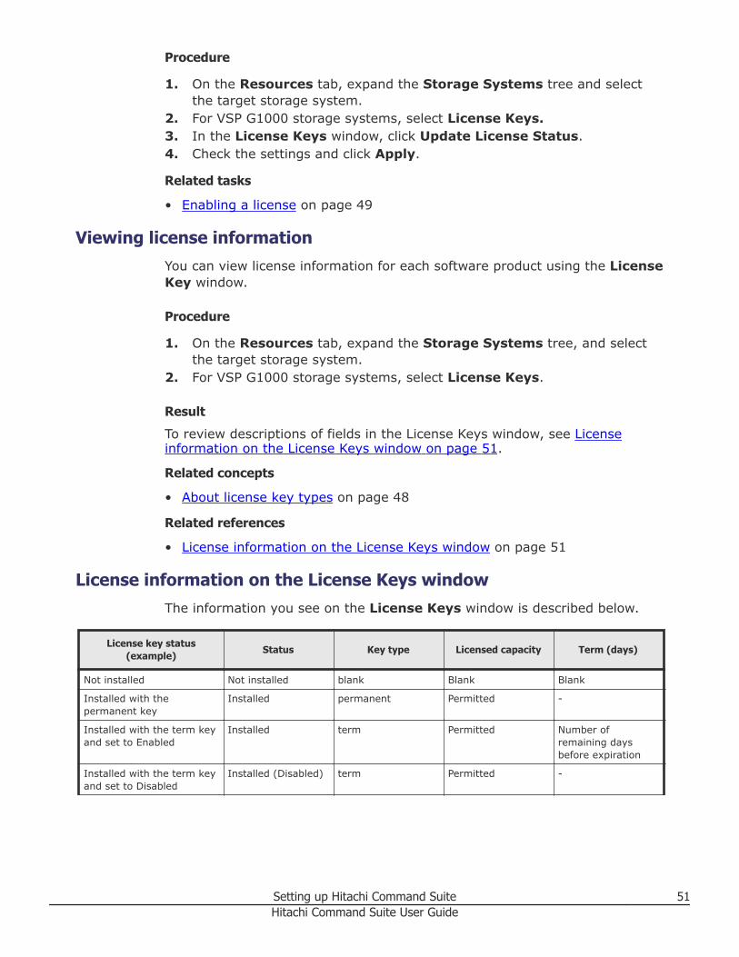
Procedure
1. On the Resources tab, expand the Storage Systems tree and selectthe target storage system.
2. For VSP G1000 storage systems, select License Keys.3. In the License Keys window, click Update License Status.4. Check the settings and click Apply.
Related tasks
• Enabling a license on page 49
Viewing license informationYou can view license information for each software product using the LicenseKey window.
Procedure
1. On the Resources tab, expand the Storage Systems tree, and selectthe target storage system.
2. For VSP G1000 storage systems, select License Keys.
Result
To review descriptions of fields in the License Keys window, see Licenseinformation on the License Keys window on page 51.
Related concepts
• About license key types on page 48
Related references
• License information on the License Keys window on page 51
License information on the License Keys windowThe information you see on the License Keys window is described below.
License key status(example)
Status Key type Licensed capacity Term (days)
Not installed Not installed blank Blank Blank
Installed with thepermanent key
Installed permanent Permitted -
Installed with the term keyand set to Enabled
Installed term Permitted Number ofremaining daysbefore expiration
Installed with the term keyand set to Disabled
Installed (Disabled) term Permitted -
Setting up Hitachi Command Suite 51Hitachi Command Suite User Guide
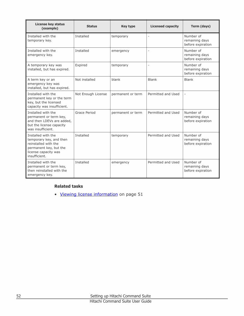
License key status(example)
Status Key type Licensed capacity Term (days)
Installed with thetemporary key.
Installed temporary - Number ofremaining daysbefore expiration
Installed with theemergency key.
Installed emergency - Number ofremaining daysbefore expiration
A temporary key wasinstalled, but has expired.
Expired temporary - Number ofremaining daysbefore expiration
A term key or anemergency key wasinstalled, but has expired.
Not installed blank Blank Blank
Installed with thepermanent key or the termkey, but the licensedcapacity was insufficient.
Not Enough License permanent or term Permitted and Used -
Installed with thepermanent or term key,and then LDEVs are added,but the license capacitywas insufficient.
Grace Period permanent or term Permitted and Used Number ofremaining daysbefore expiration
Installed with thetemporary key, and thenreinstalled with thepermanent key, but thelicense capacity wasinsufficient.
Installed temporary Permitted and Used Number ofremaining daysbefore expiration
Installed with thepermanent or term key,then reinstalled with theemergency key.
Installed emergency Permitted and Used Number ofremaining daysbefore expiration
Related tasks
• Viewing license information on page 51
52 Setting up Hitachi Command SuiteHitachi Command Suite User Guide
3Discovering, registering, and adding
management targetsManaging storage resources requires them to be registered in HitachiCommand Suite. Registration automatically occurs after discovery.
□ Setting up storage resources
□ Registering storage systems
□ Registering hosts
□ Registering file servers
Discovering, registering, and adding management targets 53Hitachi Command Suite User Guide
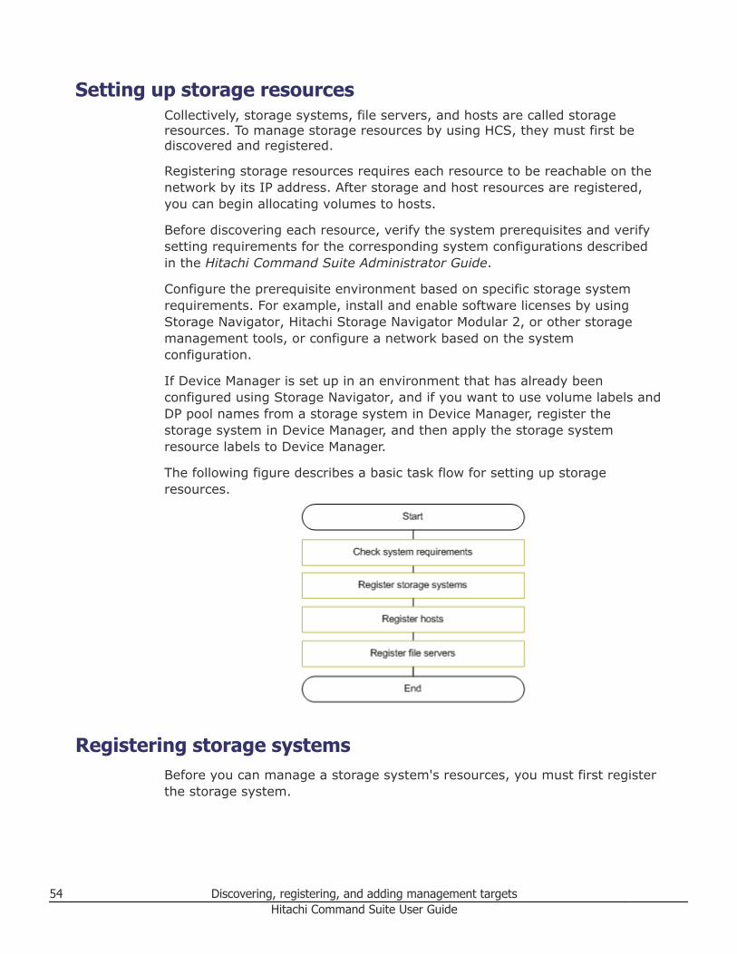
Setting up storage resourcesCollectively, storage systems, file servers, and hosts are called storageresources. To manage storage resources by using HCS, they must first bediscovered and registered.
Registering storage resources requires each resource to be reachable on thenetwork by its IP address. After storage and host resources are registered,you can begin allocating volumes to hosts.
Before discovering each resource, verify the system prerequisites and verifysetting requirements for the corresponding system configurations describedin the Hitachi Command Suite Administrator Guide.
Configure the prerequisite environment based on specific storage systemrequirements. For example, install and enable software licenses by usingStorage Navigator, Hitachi Storage Navigator Modular 2, or other storagemanagement tools, or configure a network based on the systemconfiguration.
If Device Manager is set up in an environment that has already beenconfigured using Storage Navigator, and if you want to use volume labels andDP pool names from a storage system in Device Manager, register thestorage system in Device Manager, and then apply the storage systemresource labels to Device Manager.
The following figure describes a basic task flow for setting up storageresources.
Registering storage systemsBefore you can manage a storage system's resources, you must first registerthe storage system.
54 Discovering, registering, and adding management targetsHitachi Command Suite User Guide
About registering and removing a storage systemRegistering a storage system in HCS is done when it is discovered, whichthen enables you to manage its resources, including:• Parity Groups• LDEVs• Volumes• DP pools• Resources available through external storage connections
When you specify an IP address (or host name) and authenticationinformation for a storage system, the storage system is discovered andregistered based on the specified information. For Storage ManagementInitiative Specification (SMI-S) enabled storage systems, the SMI-Sprovider's IP address is used.
You can modify information about a storage system after a storage system isregistered.
If managing a storage system with HCS is no longer necessary (for examplebecause of reorganization), you can remove the registered storage system.Removing a storage system results in the following:• Configuration information such as parity groups, volumes, and allocated
paths are retained within the storage systems.• Any information configured or specified in HCS, such as tiers and data
placement profiles, is deleted.
Related concepts
• About acquiring the most recent storage system information on page 61
Related tasks
• Registering a storage system on page 58• Changing storage system information on page 59• Removing a storage system on page 60
Related references
• Prerequisites for registering a storage system on page 55
Prerequisites for registering a storage systemBefore you can discover and register a storage system, collect storagesystem-related information and complete the following prerequisite tasks.
Collect and confirm the following storage system information:
Discovering, registering, and adding management targets 55Hitachi Command Suite User Guide
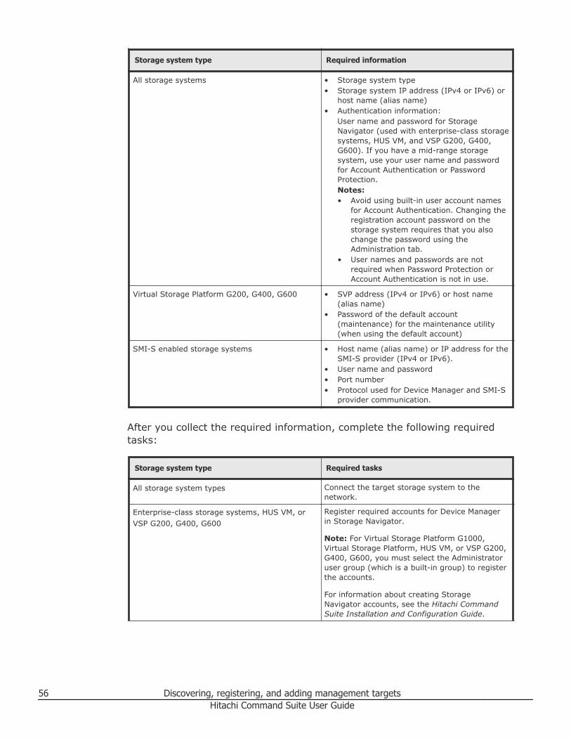
Storage system type Required information
All storage systems • Storage system type• Storage system IP address (IPv4 or IPv6) or
host name (alias name)• Authentication information:
User name and password for StorageNavigator (used with enterprise-class storagesystems, HUS VM, and VSP G200, G400,G600). If you have a mid-range storagesystem, use your user name and passwordfor Account Authentication or PasswordProtection.Notes:• Avoid using built-in user account names
for Account Authentication. Changing theregistration account password on thestorage system requires that you alsochange the password using theAdministration tab.
• User names and passwords are notrequired when Password Protection orAccount Authentication is not in use.
Virtual Storage Platform G200, G400, G600 • SVP address (IPv4 or IPv6) or host name(alias name)
• Password of the default account(maintenance) for the maintenance utility(when using the default account)
SMI-S enabled storage systems • Host name (alias name) or IP address for theSMI-S provider (IPv4 or IPv6).
• User name and password• Port number• Protocol used for Device Manager and SMI-S
provider communication.
After you collect the required information, complete the following requiredtasks:
Storage system type Required tasks
All storage system types Connect the target storage system to thenetwork.
Enterprise-class storage systems, HUS VM, orVSP G200, G400, G600
Register required accounts for Device Managerin Storage Navigator.
Note: For Virtual Storage Platform G1000,Virtual Storage Platform, HUS VM, or VSP G200,G400, G600, you must select the Administratoruser group (which is a built-in group) to registerthe accounts.
For information about creating StorageNavigator accounts, see the Hitachi CommandSuite Installation and Configuration Guide.
56 Discovering, registering, and adding management targetsHitachi Command Suite User Guide
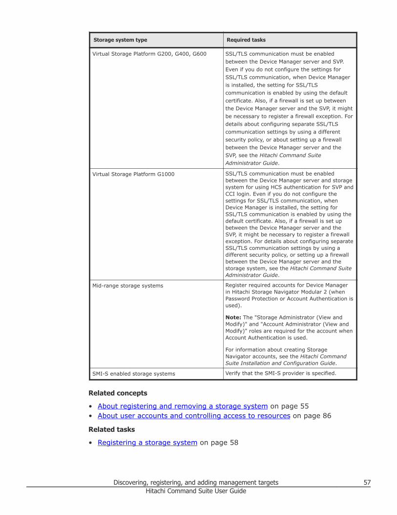
Storage system type Required tasks
Virtual Storage Platform G200, G400, G600 SSL/TLS communication must be enabledbetween the Device Manager server and SVP.Even if you do not configure the settings forSSL/TLS communication, when Device Manageris installed, the setting for SSL/TLScommunication is enabled by using the defaultcertificate. Also, if a firewall is set up betweenthe Device Manager server and the SVP, it mightbe necessary to register a firewall exception. Fordetails about configuring separate SSL/TLScommunication settings by using a differentsecurity policy, or about setting up a firewallbetween the Device Manager server and theSVP, see the Hitachi Command SuiteAdministrator Guide.
Virtual Storage Platform G1000 SSL/TLS communication must be enabledbetween the Device Manager server and storagesystem for using HCS authentication for SVP andCCI login. Even if you do not configure thesettings for SSL/TLS communication, whenDevice Manager is installed, the setting forSSL/TLS communication is enabled by using thedefault certificate. Also, if a firewall is set upbetween the Device Manager server and theSVP, it might be necessary to register a firewallexception. For details about configuring separateSSL/TLS communication settings by using adifferent security policy, or setting up a firewallbetween the Device Manager server and thestorage system, see the Hitachi Command SuiteAdministrator Guide.
Mid-range storage systems Register required accounts for Device Managerin Hitachi Storage Navigator Modular 2 (whenPassword Protection or Account Authentication isused).
Note: The "Storage Administrator (View andModify)" and "Account Administrator (View andModify)" roles are required for the account whenAccount Authentication is used.
For information about creating StorageNavigator accounts, see the Hitachi CommandSuite Installation and Configuration Guide.
SMI-S enabled storage systems Verify that the SMI-S provider is specified.
Related concepts
• About registering and removing a storage system on page 55• About user accounts and controlling access to resources on page 86
Related tasks
• Registering a storage system on page 58
Discovering, registering, and adding management targets 57Hitachi Command Suite User Guide
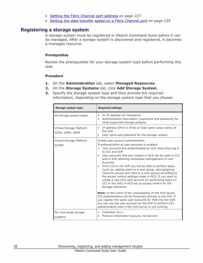
• Setting the Fibre Channel port address on page 227• Setting the data transfer speed on a Fibre Channel port on page 225
Registering a storage systemA storage system must be registered in Hitachi Command Suite before it canbe managed. After a storage system is discovered and registered, it becomesa managed resource.
Prerequisites
Review the prerequisites for your storage system type before performing thistask.
Procedure
1. On the Administration tab, select Managed Resources.2. On the Storage Systems tab, click Add Storage System.3. Specify the storage system type and then provide the required
information, depending on the storage system type that you choose:
Storage system type Required settings
All storage system types • An IP address (or hostname).• Authentication information (username and password) for
most supported storage systems.
Virtual Storage Platform
G200, G400, G600
• IP address (IPv4 or IPv6) or host name (alias name) ofthe SVP.
• User name and password for the storage system.
Virtual Storage Platform
G1000
Enable user account authentication.If authentication of user accounts is enabled:• User accounts are authenticated by HCS when they log in
to CCI and SVP.• User accounts that are created in HCS can be used in CCI
and in SVP, allowing centralized management of useraccounts.
• From CCI or the SVP you will be able to perform tasks(such as, adding users to a user group, and assigningresource groups and roles to a user group) according tothe access control settings made in HCS. If you want tocreate a new HCS user account for performing tasks onCCI or the SVP, in HCS set up access control for thestorage resources.
Note: In the event of the unavailability of the HCS server,CCI authentication will be forwarded directly to the SVP. Ifyou register the same user accounts for HCS into the SVP,you can use the user account for the SVP to perform CCIauthentication even if the HCS server is not running.
For mid-range storage
systems
• Controller (0,1)• Protocol information (secure, not secure)
58 Discovering, registering, and adding management targetsHitachi Command Suite User Guide
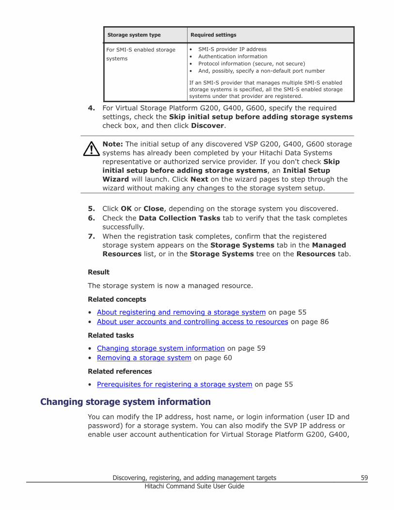
Storage system type Required settings
For SMI-S enabled storage
systems
• SMI-S provider IP address• Authentication information• Protocol information (secure, not secure)• And, possibly, specify a non-default port number
If an SMI-S provider that manages multiple SMI-S enabledstorage systems is specified, all the SMI-S enabled storagesystems under that provider are registered.
4. For Virtual Storage Platform G200, G400, G600, specify the requiredsettings, check the Skip initial setup before adding storage systemscheck box, and then click Discover.
Note: The initial setup of any discovered VSP G200, G400, G600 storagesystems has already been completed by your Hitachi Data Systemsrepresentative or authorized service provider. If you don't check Skipinitial setup before adding storage systems, an Initial SetupWizard will launch. Click Next on the wizard pages to step through thewizard without making any changes to the storage system setup.
5. Click OK or Close, depending on the storage system you discovered.6. Check the Data Collection Tasks tab to verify that the task completes
successfully.7. When the registration task completes, confirm that the registered
storage system appears on the Storage Systems tab in the ManagedResources list, or in the Storage Systems tree on the Resources tab.
Result
The storage system is now a managed resource.
Related concepts
• About registering and removing a storage system on page 55• About user accounts and controlling access to resources on page 86
Related tasks
• Changing storage system information on page 59• Removing a storage system on page 60
Related references
• Prerequisites for registering a storage system on page 55
Changing storage system informationYou can modify the IP address, host name, or login information (user ID andpassword) for a storage system. You can also modify the SVP IP address orenable user account authentication for Virtual Storage Platform G200, G400,
Discovering, registering, and adding management targets 59Hitachi Command Suite User Guide
G600 storage systems. You can select multiple storage systems to modify atone time, but when selecting multiple storage systems, only login information(user ID and password) can be modified.
Procedure
1. On the Administration tab, select Managed Resources.2. On the Storage Systems tab, select the storage system, or storage
systems, you want to modify.3. Click Edit Storage Systems.4. Specify the appropriate information and click OK.5. Check the Data Collection Tasks tab to verify that the task has
completed successfully.6. Confirm that the information in the storage system list is updated.
Tip: For VSP G200, G400, G600, refresh the storage system to updatethe latest information after you change the IP address of the storagesystem controller on the SVP.
Related concepts
• About registering and removing a storage system on page 55
Related tasks
• Registering a storage system on page 58
Removing a storage systemIf managing a storage system with Hitachi Command Suite is no longernecessary (for example because of reorganization), you can remove theregistered storage system.
Procedure
1. On the Administration tab, select Managed Resources.2. On the Storage Systems tab, select one or more storage systems.3. Click Remove Storage Systems.4. When the task completes, confirm that the removed storage system does
not appear on the Storage Systems tab of Managed Resources, or inthe Storage Systems tree on the Resources tab.
Result
The storage system is removed.
Related concepts
• About registering and removing a storage system on page 55
60 Discovering, registering, and adding management targetsHitachi Command Suite User Guide
About acquiring the most recent storage system informationTo get the most current information about a target storage system, manuallyrefresh the system to display it.
When you click Refresh Storage System to refresh it, the followinginformation is updated for storage resources:• Volumes• Parity groups• DP Pools• External storage connections
Tip: If you mapped volumes in the external storage system by using CCI orStorage Navigator, you can confirm the mapped volumes from the internalstorage system by refreshing storage system information in the followingorder:• External storage system• Internal storage system
When data placement profiles for HDT volumes are being managed, you canspecify an option in the Refresh Storage Systems dialog box to search forinconsistencies in data placement profiles.
To update information about hosts, such as the host name, WWNs, or iSCSIname, refresh the hosts.
To update host bus adapter (HBA) WWN nicknames, refresh one or morestorage systems. Refreshing host information does not update WWNnicknames. When several WWN nicknames are assigned to a single HBA, onlyone of the nicknames is displayed for that HBA.
If connected to Hitachi Tuning Manager, users can also update performanceinformation that is displayed in the Mobility tab. To automatically update thestorage system information, specify proper settings in theserver.properties file or dispatcher.properties file of the managementserver. For details about specifiable values, see the Hitachi Command SuiteAdministrator Guide.
Related concepts
• About registering and removing a storage system on page 55
Related tasks
• Acquiring the most recent storage system information on page 61• Viewing current storage system information on page 449
Acquiring the most recent storage system informationRefreshing a storage system updates and displays the latest storage systeminformation.
Discovering, registering, and adding management targets 61Hitachi Command Suite User Guide

Prerequisites
For VSP G200, G400, G600, if you change the IP address of the storagesystem controller, you must update the storage system information on theSVP before you refresh the storage system.
Procedure
1. On the Administration tab, select Managed Resources.2. On the Storage Systems tab, select one or more storage systems to
refresh.3. Click Refresh Storage Systems, then click OK.4. Check the Data Collection Tasks tab to verify that the task completed.
Result
Updated storage system information displays in the list of storage systems.Updated storage system information is also displayed on the Resources tab,in the Storage Systems tree.
Note: Label information for volumes and DP pools is not refreshed. To applyexisting label information from a storage system to HCS, click Refresh Labels.For Virtual Storage Platform G1000, refreshing labels is unnecessary sincelabel information from the storage system to HCS will always match.
Related concepts
• About acquiring the most recent storage system information on page 61
Operations available to SMI-S enabled storage systemsDiscovering and registering storage systems that support an SMI-S providerfor storage system management enables you to perform certain tasks.
The Storage Management Initiative Specification (SMI-S) defines softwaredevelopment standards in support of storage management interoperability.An SMI-S provider is the software component that resides on a resource,such as a storage system, providing network management (over HTTP/HTTPS) by management clients, such as Hitachi Command Suite.
When you manage storage systems that support an SMI-S provider, the SMI-S enabled storage systems become Hitachi Command Suite resources onwhich you can perform the following tasks:• Register, change, delete, and update the SMI-S enabled storage systems.• Display summary information for SMI-S enabled storage systems.• Operate SMI-S enabled storage systems from the SMI-S enabled storage
system management tool (launch the management tool from ElementManager).
• Externally connect and virtualize an SMI-S enabled storage system formigrating data.
62 Discovering, registering, and adding management targetsHitachi Command Suite User Guide
Tip: Virtualizing an SMI-S enabled storage system without registering thesystem in HCS can also be done by using the port scan and volume discoveryfunctionality.
You must be assigned All Resources to view or perform tasks on SMI-Senabled storage systems.
Related tasks
• Discovering and virtualizing volumes of an unregistered storage system onpage 157
Registering hostsYou can register hosts as managed resources using Device Manager so thatstorage system volumes can be used by hosts and their applications.
About registering a hostDiscover and register hosts to manage them in Hitachi Command Suite.
The following host types can be added to HCS:• Normal hosts (an open host that is not virtualized)• Virtualization servers (a physical server on which virtualization software is
installed)• Virtual machines (a machine that is created on the virtualization server
and uses virtualization software)
Depending on the purpose, there are multiple methods for discovering andadding hosts, including manually, by using Host Data Collector (agentlessdiscovery), or by using a Device Manager agent. For host prerequisites andenvironment settings, see the Hitachi Command Suite Administrator Guide.
You can also monitor the usage status of storage resources from the hostpoint of view by generating reports that reflect the actual capacity being usedby each host.
Related concepts
• Methods for registering hosts on page 63• About changing host settings and information on page 70
Related references
• Priority for acquiring the WWN or iSCSI name on page 65
Methods for registering hostsThere are a variety of methods to register one or more hosts including usingits WWN, using host-installed agents, or agentless discovery.
Discovering, registering, and adding management targets 63Hitachi Command Suite User Guide
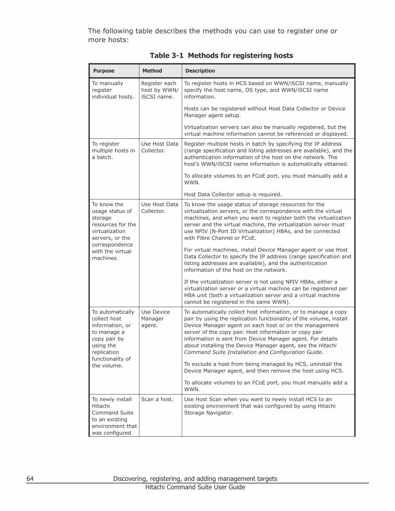
The following table describes the methods you can use to register one ormore hosts:
Table 3-1 Methods for registering hosts
Purpose Method Description
To manuallyregisterindividual hosts.
Register eachhost by WWN/iSCSI name.
To register hosts in HCS based on WWN/iSCSI name, manuallyspecify the host name, OS type, and WWN/iSCSI nameinformation.
Hosts can be registered without Host Data Collector or DeviceManager agent setup.
Virtualization servers can also be manually registered, but thevirtual machine information cannot be referenced or displayed.
To registermultiple hosts ina batch.
Use Host DataCollector.
Register multiple hosts in batch by specifying the IP address(range specification and listing addresses are available), and theauthentication information of the host on the network. Thehost’s WWN/iSCSI name information is automatically obtained.
To allocate volumes to an FCoE port, you must manually add aWWN.
Host Data Collector setup is required.
To know theusage status ofstorageresources for thevirtualizationservers, or thecorrespondencewith the virtualmachines.
Use Host DataCollector.
To know the usage status of storage resources for thevirtualization servers, or the correspondence with the virtualmachines, and when you want to register both the virtualizationserver and the virtual machine, the virtualization server mustuse NPIV (N-Port ID Virtualization) HBAs, and be connectedwith Fibre Channel or FCoE.
For virtual machines, install Device Manager agent or use HostData Collector to specify the IP address (range specification andlisting addresses are available), and the authenticationinformation of the host on the network.
If the virtualization server is not using NPIV HBAs, either avirtualization server or a virtual machine can be registered perHBA unit (both a virtualization server and a virtual machinecannot be registered in the same WWN).
To automaticallycollect hostinformation, orto manage acopy pair byusing thereplicationfunctionality ofthe volume.
Use DeviceManageragent.
To automatically collect host information, or to manage a copypair by using the replication functionality of the volume, installDevice Manager agent on each host or on the managementserver of the copy pair. Host information or copy pairinformation is sent from Device Manager agent. For detailsabout installing the Device Manager agent, see the HitachiCommand Suite Installation and Configuration Guide.
To exclude a host from being managed by HCS, uninstall theDevice Manager agent, and then remove the host using HCS.
To allocate volumes to an FCoE port, you must manually add aWWN.
To newly installHitachiCommand Suiteto an existingenvironment thatwas configured
Scan a host. Use Host Scan when you want to newly install HCS to anexisting environment that was configured by using HitachiStorage Navigator.
64 Discovering, registering, and adding management targetsHitachi Command Suite User Guide
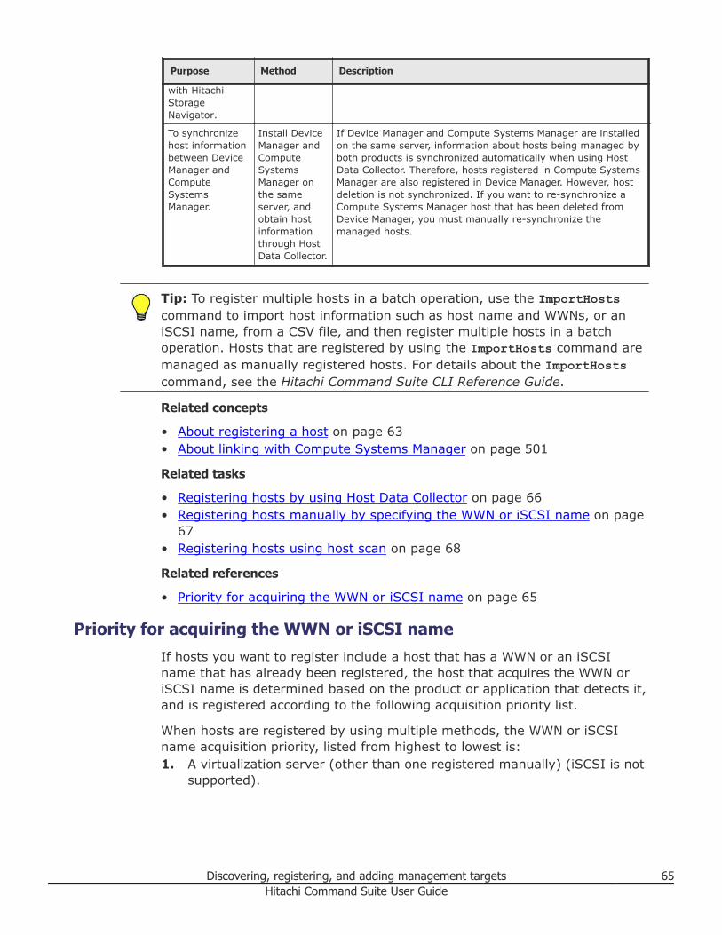
Purpose Method Description
with HitachiStorageNavigator.
To synchronizehost informationbetween DeviceManager andComputeSystemsManager.
Install DeviceManager andComputeSystemsManager onthe sameserver, andobtain hostinformationthrough HostData Collector.
If Device Manager and Compute Systems Manager are installedon the same server, information about hosts being managed byboth products is synchronized automatically when using HostData Collector. Therefore, hosts registered in Compute SystemsManager are also registered in Device Manager. However, hostdeletion is not synchronized. If you want to re-synchronize aCompute Systems Manager host that has been deleted fromDevice Manager, you must manually re-synchronize themanaged hosts.
Tip: To register multiple hosts in a batch operation, use the ImportHostscommand to import host information such as host name and WWNs, or aniSCSI name, from a CSV file, and then register multiple hosts in a batchoperation. Hosts that are registered by using the ImportHosts command aremanaged as manually registered hosts. For details about the ImportHostscommand, see the Hitachi Command Suite CLI Reference Guide.
Related concepts
• About registering a host on page 63• About linking with Compute Systems Manager on page 501
Related tasks
• Registering hosts by using Host Data Collector on page 66• Registering hosts manually by specifying the WWN or iSCSI name on page
67• Registering hosts using host scan on page 68
Related references
• Priority for acquiring the WWN or iSCSI name on page 65
Priority for acquiring the WWN or iSCSI nameIf hosts you want to register include a host that has a WWN or an iSCSIname that has already been registered, the host that acquires the WWN oriSCSI name is determined based on the product or application that detects it,and is registered according to the following acquisition priority list.
When hosts are registered by using multiple methods, the WWN or iSCSIname acquisition priority, listed from highest to lowest is:1. A virtualization server (other than one registered manually) (iSCSI is not
supported).
Discovering, registering, and adding management targets 65Hitachi Command Suite User Guide
2. A virtualization server that is registered manually (iSCSI is not supportedfor virtualization servers).
3. A host registered by using Device Manager agent.4. A normal host or a virtual machine registered either manually or by using
Host Data Collector.
When hosts with the same WWN or iSCSI name are registered by using thesame method:• If a host is registered without using the Device Manager agent, the WWN
or iSCSI name of the host that was registered first is retained.• If a host is registered by using the Device Manager agent, the WWN or
iSCSI name is registered to the host that was registered last.
Related concepts
• About registering a host on page 63• Methods for registering hosts on page 63
Registering hosts by using Host Data CollectorUse Host Data Collector to discover and register multiple hosts, virtualizationservers, and virtual machines in a single task.
When using Host Data Collector, if Device Manager is linked with ComputeSystems Manager, hosts managed by Compute Systems Manager will beregistered in Device Manager.
Prerequisites• Gather the following information:
○ Host OS type○ Host IP address (IPv4)
Note: To detect multiple hosts at the same time, specify a subnet or arange of 256 or fewer IP addresses, or specify individual IP addresses.
○ User name and password for logging on to the host (with Administratoror superuser permissions)
Note: When specifying users other than the root, you need to specifyenvironment settings for when general users are used to collect hostinformation on the host side. For details about how to specify settings,see the Hitachi Command Suite Administrator Guide.
○ IP address of Host Data Collector (IPv4 or IPv6) or Host Name
• Gather the following information when registering a virtualization server:○ IP address of Host Data Collector (IPv4 or IPv6) or Host Name○ IP address of VMware vCenter Server or a virtualization server (IPv4 or
IPv6)
66 Discovering, registering, and adding management targetsHitachi Command Suite User Guide
Note: To register a virtualization server, you cannot specify a subnet, arange, and multiple IP addresses.
○ User name and password of a user (who has the role of systemadministrator) for logging on to vCenter Server or virtualization servers
Note: If vCenter Server is being used, enter the user name andpassword for vCenter Server. If vCenter Server is not being used, youneed to enter and register user names and passwords of virtualizationservers one by one if multiple virtualization servers are being managed.
• Verify that target hosts are connected to the network.• Specify environment settings for virtualization servers. For details see the
Hitachi Command Suite Administrator Guide.
Procedure
1. On the Administration tab, select Managed Resources.2. On the Hosts tab, click Add Hosts.3. In the Add Hosts dialog box, click Discover Hosts.
If you are registering a virtualization server, select VMware from OSType.
4. Specify the necessary items, select the Host Data Collector to be used,and then submit the task.The task is registered and listed on the Data Collection Tasks tab.
5. Verify task status on the Data Collection Tasks tab.
Result
Registered hosts can be viewed in the Resources list on the Navigation pane.
Tip: If you want to allocate volumes to an FCoE port, you need to manuallyadd a WWN.
Related concepts
• Methods for registering hosts on page 63
Registering hosts manually by specifying the WWN or iSCSI nameYou can register hosts manually to manage and monitor the hosts byspecifying a WWN or iSCSI name.
Prerequisites• Host name• OS type• Unregistered WWN or iSCSI name
Discovering, registering, and adding management targets 67Hitachi Command Suite User Guide
Procedure
1. On the Administration tab, select Managed Resources.2. On the Hosts tab, click Add Hosts.3. In the Add Hosts dialog box, select Add Hosts Manually.4. Specify the appropriate information, and then click OK to submit the
task.If specifying a virtualization server, in OS Type select VMware.
Result
All registered hosts, virtual machines, and virtualization servers are displayedby each host OS type (for example: AIX, HP-UX, Linux, Solaris, Windows,Virtualization Servers, or Others) in the Resources list on the Navigationpane.
Related concepts
• Methods for registering hosts on page 63
Registering hosts using host scanYou can register hosts by using host scan to discover hosts so that they canbe managed and monitored.
Scanning for hosts automatically creates hosts with host names that matchthe WWNs or iSCSI names that are registered in the host group or iSCSItargets on the storage system. For best results, your environment shouldsatisfy the following conditions:• The name of a host group or iSCSI target should be the same as the actual
host, and the WWN or iSCSI name for that host is set for LUN security.• Only a single host can be related to each host group or iSCSI target.
Prerequisites
• Install LUN Manager on the target storage system.
Procedure
1. On the Administration tab, select Managed Resources.2. On the Hosts tab, click Host Scan.3. Confirm that your environment meets the recommended conditions, and
then select storage systems on which to scan for hosts.4. Click Submit.
Result
All registered Data Collection Tasks hosts, virtual machines, and virtualizationservers can be viewed by host OS type (for example: AIX, HP-UX, Linux,Solaris, Windows, Virtualization Servers, or Others) in the Resources list onthe Navigation pane. If a virtualization server that has an iSCSI name isscanned, it is displayed in host OS type, Others.
68 Discovering, registering, and adding management targetsHitachi Command Suite User Guide
Tip: If one host has multiple WWNs or iSCSI names detected, even if it isone host in the actual environment, it might occasionally be registered asmultiple hosts by Device Manager. This is because hosts are generated inhost groups or iSCSI targets when one host has multiple WWNs or iSCSInames . In this case, the hosts must be merged, meaning merge the WWNsor iSCSI name. Merge the hosts that have been added as multiple hosts inDevice Manager into one host, meaning that WWN or iSCSI name informationis merged, and the source hosts are deleted automatically.
Related concepts
• Methods for registering hosts on page 63
Related tasks
• Registering hosts using merge hosts on page 69• Installing a software application on page 48
Related references
• Workflow for detecting hosts on page 71
Registering hosts using merge hostsYou can use merge hosts to combine source and target host information intoa single surviving target host that is registered. The maximum number ofWWNs and iSCSI name that you can merge at one time is 100.
Prerequisites
• Identify the names of the source and target host. Note that the sourcehost is merged into the target host, then the source host is deleted.
• Ensure the source host has been registered either manually or by hostscan.
• Ensure the target host is not a mainframe host, a file server, or avirtualization server (except for manually registered virtualization servers).
• Ensure the target host has at least one registered WWN or iSCSI name.
Procedure
1. On the Administration tab, select Managed Resources.2. Select the Hosts tab, select the target host row, click More Actions and
select Merge Hosts.3. In the merge hosts window, select the source host, then click Show
Plan.4. Review the target (surviving host) and source (host to be deleted)
information.• If the target and source host information is correct, click Submit.• If the target or source host information must be changed, click Back.• To abandon the task, click Cancel.
Discovering, registering, and adding management targets 69Hitachi Command Suite User Guide
5. On the Resources tab, in the hosts tree, confirm the target hostinformation and the source host removal. You can also confirm this onthe Administration tab in the Hosts tree under Managed Resources.
Related concepts
• Methods for registering hosts on page 63
About changing host settings and informationYou can change host settings and update previously registered hostinformation.
Depending on how a host is registered, you change host settings andinformation by using the Refresh Hosts or Edit Hosts options. The RefreshHosts option on the Hosts tab updates a host by obtaining information fromthe Host Data Collector or Device Manager agent. The Edit Hosts optionallows you to manually change host settings.
On the vCenters tab, Refresh vCenters can be used to refresh information forvirtualization servers that are managed by VMware vCenter Server.
Note: If a Device Manager host is registered on Compute Systems Manager,and if you update host information using Compute Systems Manager, thatinformation is automatically updated in Device Manager.
You can update other host-related information when replacing host HBAs byexchanging the WWN settings in the LUN paths so that the new HBA inheritsthe WWN settings from the old HBA. Perform this settings exchange by usingthe Exchange HBAs dialog box when you replace a host HBA due to failure, orby using the Add HBAs dialog box and the Remove HBAs dialog box when youcomplete a planned HBA replacement as part of scheduled maintenance toprevent performance degradation.
Tip: The settings for the host WWN or iSCSI name are not linked to thesettings for the host group or iSCSI target on the storage system side. Forexample, even if you delete the host WWN or iSCSI name, the WWN or iSCSIname is not deleted from the host group or iSCSI target.
To delete the WWN after replacing HBAs, use the Remove HBAs dialog box.To delete the WWNor iSCSI name from a host group at a time other thanwhen replacing an HBA, use the ModifyPort command.
For details about using the ModifyPort command, see the Hitachi CommandSuite CLI Reference Guide.
Related concepts
• About registering a host on page 63
70 Discovering, registering, and adding management targetsHitachi Command Suite User Guide
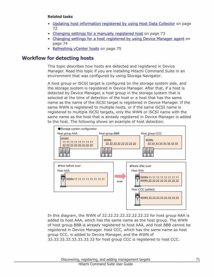
Related tasks
• Updating host information registered by using Host Data Collector on page72
• Changing settings for a manually registered host on page 73• Changing settings for a host registered by using Device Manager agent on
page 74• Refreshing vCenter hosts on page 75
Workflow for detecting hostsThis topic describes how hosts are detected and registered in DeviceManager. Read this topic if you are installing Hitachi Command Suite in anenvironment that was configured by using Storage Navigator.
A host group or iSCSI target is configured on the storage system side, andthe storage system is registered in Device Manager. After that, if a host isdetected by Device Manager, a host group in the storage system that isselected at the time of detection of the host or a host that has the samename as the name of the iSCSI target is registered in Device Manager. If thesame WWN is registered to multiple hosts, or if the same iSCSI name isregistered to multiple iSCSI targets, only the WWN or iSCSI name with thesame name as the host that is already registered in Device Manager is addedto the host. The following shows an example of host detection:
In this diagram, the WWN of 22.22.22.22.22.22.22.22 for host group AAA isadded to host AAA, which has the same name as the host group. The WWNof host group BBB is already registered to host AAA, and host BBB cannot beregistered in Device Manager. Host CCC, which has the same name as hostgroup CCC, is added to Device Manager, and the WWN of33.33.33.33.33.33.33.33 for host group CCC is registered to host CCC.
Discovering, registering, and adding management targets 71Hitachi Command Suite User Guide
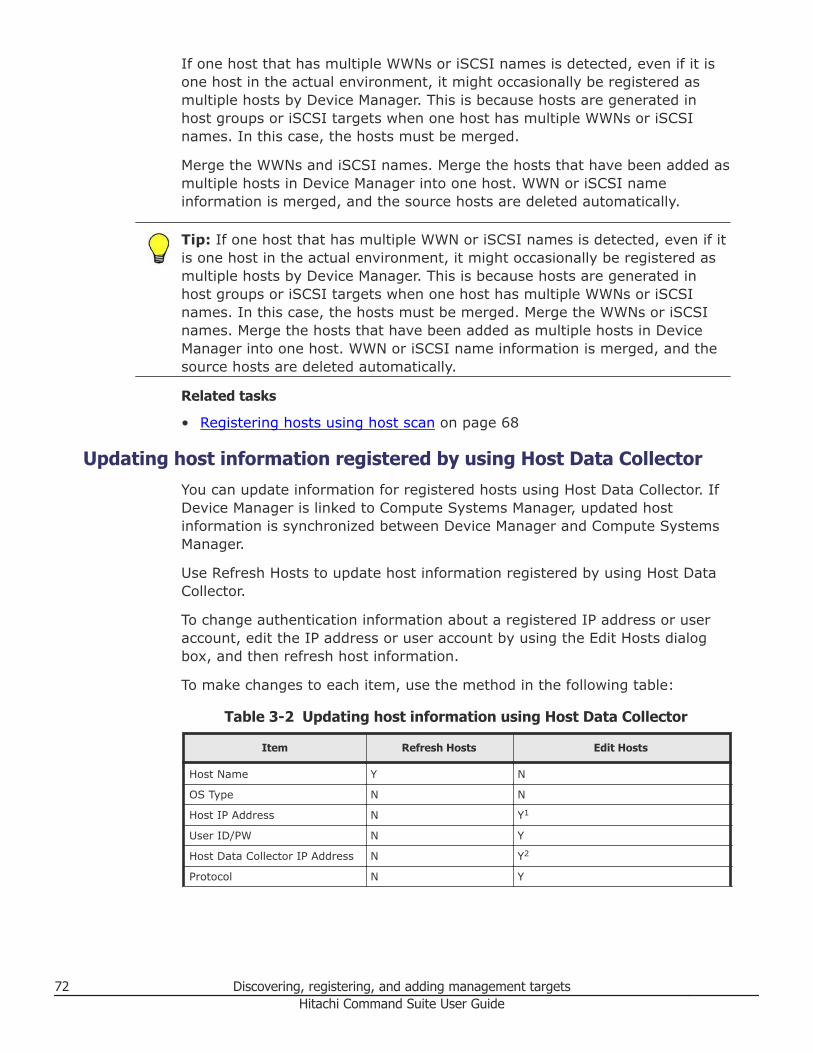
If one host that has multiple WWNs or iSCSI names is detected, even if it isone host in the actual environment, it might occasionally be registered asmultiple hosts by Device Manager. This is because hosts are generated inhost groups or iSCSI targets when one host has multiple WWNs or iSCSInames. In this case, the hosts must be merged.
Merge the WWNs and iSCSI names. Merge the hosts that have been added asmultiple hosts in Device Manager into one host. WWN or iSCSI nameinformation is merged, and the source hosts are deleted automatically.
Tip: If one host that has multiple WWN or iSCSI names is detected, even if itis one host in the actual environment, it might occasionally be registered asmultiple hosts by Device Manager. This is because hosts are generated inhost groups or iSCSI targets when one host has multiple WWNs or iSCSInames. In this case, the hosts must be merged. Merge the WWNs or iSCSInames. Merge the hosts that have been added as multiple hosts in DeviceManager into one host. WWN or iSCSI name information is merged, and thesource hosts are deleted automatically.
Related tasks
• Registering hosts using host scan on page 68
Updating host information registered by using Host Data CollectorYou can update information for registered hosts using Host Data Collector. IfDevice Manager is linked to Compute Systems Manager, updated hostinformation is synchronized between Device Manager and Compute SystemsManager.
Use Refresh Hosts to update host information registered by using Host DataCollector.
To change authentication information about a registered IP address or useraccount, edit the IP address or user account by using the Edit Hosts dialogbox, and then refresh host information.
To make changes to each item, use the method in the following table:
Table 3-2 Updating host information using Host Data Collector
Item Refresh Hosts Edit Hosts
Host Name Y N
OS Type N N
Host IP Address N Y1
User ID/PW N Y
Host Data Collector IP Address N Y2
Protocol N Y
72 Discovering, registering, and adding management targetsHitachi Command Suite User Guide
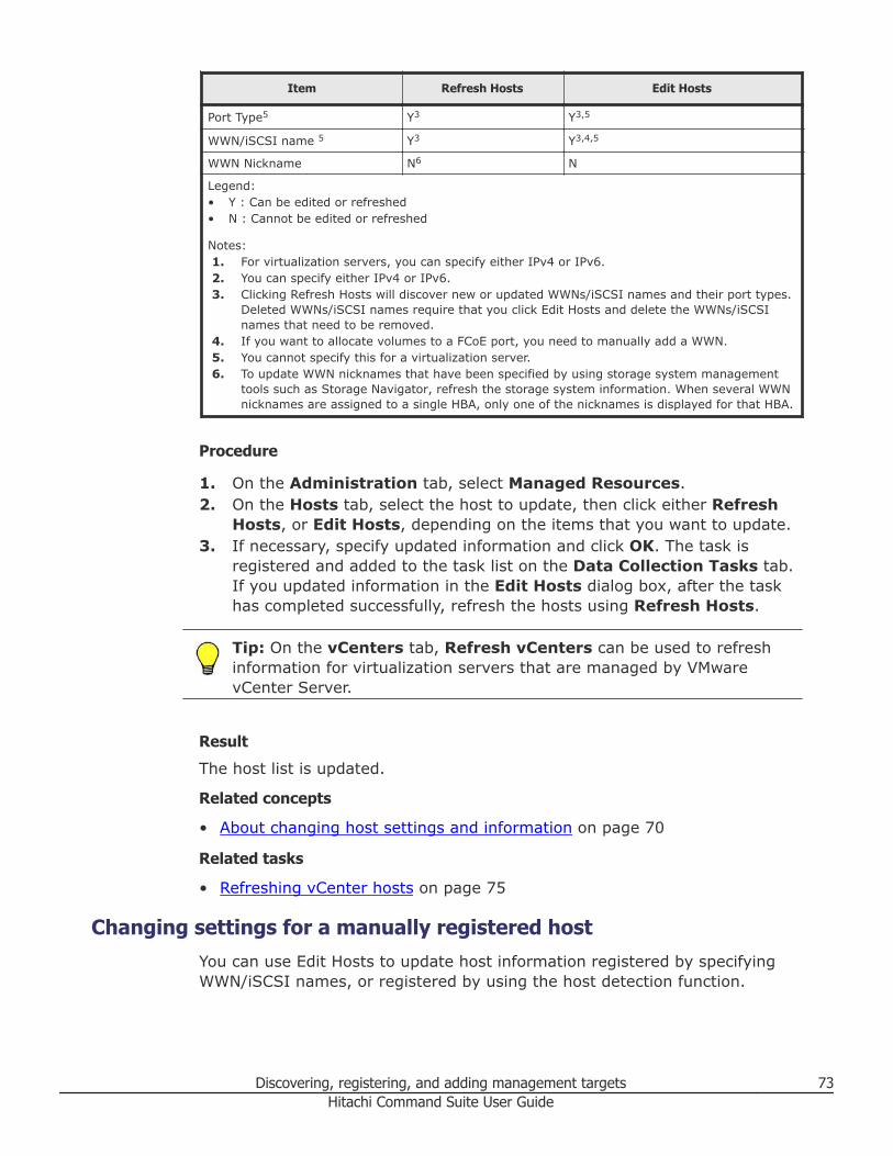
Item Refresh Hosts Edit Hosts
Port Type5 Y3 Y3,5
WWN/iSCSI name 5 Y3 Y3,4,5
WWN Nickname N6 N
Legend:• Y : Can be edited or refreshed• N : Cannot be edited or refreshed
Notes:1. For virtualization servers, you can specify either IPv4 or IPv6.2. You can specify either IPv4 or IPv6.3. Clicking Refresh Hosts will discover new or updated WWNs/iSCSI names and their port types.
Deleted WWNs/iSCSI names require that you click Edit Hosts and delete the WWNs/iSCSInames that need to be removed.
4. If you want to allocate volumes to a FCoE port, you need to manually add a WWN.5. You cannot specify this for a virtualization server.6. To update WWN nicknames that have been specified by using storage system management
tools such as Storage Navigator, refresh the storage system information. When several WWNnicknames are assigned to a single HBA, only one of the nicknames is displayed for that HBA.
Procedure
1. On the Administration tab, select Managed Resources.2. On the Hosts tab, select the host to update, then click either Refresh
Hosts, or Edit Hosts, depending on the items that you want to update.3. If necessary, specify updated information and click OK. The task is
registered and added to the task list on the Data Collection Tasks tab.If you updated information in the Edit Hosts dialog box, after the taskhas completed successfully, refresh the hosts using Refresh Hosts.
Tip: On the vCenters tab, Refresh vCenters can be used to refreshinformation for virtualization servers that are managed by VMwarevCenter Server.
Result
The host list is updated.
Related concepts
• About changing host settings and information on page 70
Related tasks
• Refreshing vCenter hosts on page 75
Changing settings for a manually registered hostYou can use Edit Hosts to update host information registered by specifyingWWN/iSCSI names, or registered by using the host detection function.
Discovering, registering, and adding management targets 73Hitachi Command Suite User Guide
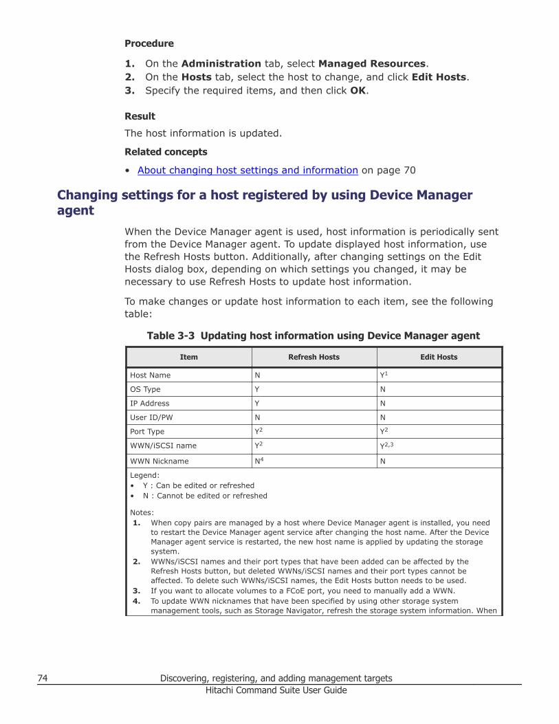
Procedure
1. On the Administration tab, select Managed Resources.2. On the Hosts tab, select the host to change, and click Edit Hosts.3. Specify the required items, and then click OK.
Result
The host information is updated.
Related concepts
• About changing host settings and information on page 70
Changing settings for a host registered by using Device Manageragent
When the Device Manager agent is used, host information is periodically sentfrom the Device Manager agent. To update displayed host information, usethe Refresh Hosts button. Additionally, after changing settings on the EditHosts dialog box, depending on which settings you changed, it may benecessary to use Refresh Hosts to update host information.
To make changes or update host information to each item, see the followingtable:
Table 3-3 Updating host information using Device Manager agent
Item Refresh Hosts Edit Hosts
Host Name N Y1
OS Type Y N
IP Address Y N
User ID/PW N N
Port Type Y2 Y2
WWN/iSCSI name Y2 Y2,3
WWN Nickname N4 N
Legend:• Y : Can be edited or refreshed• N : Cannot be edited or refreshed
Notes:1. When copy pairs are managed by a host where Device Manager agent is installed, you need
to restart the Device Manager agent service after changing the host name. After the DeviceManager agent service is restarted, the new host name is applied by updating the storagesystem.
2. WWNs/iSCSI names and their port types that have been added can be affected by theRefresh Hosts button, but deleted WWNs/iSCSI names and their port types cannot beaffected. To delete such WWNs/iSCSI names, the Edit Hosts button needs to be used.
3. If you want to allocate volumes to a FCoE port, you need to manually add a WWN.4. To update WWN nicknames that have been specified by using other storage system
management tools, such as Storage Navigator, refresh the storage system information. When
74 Discovering, registering, and adding management targetsHitachi Command Suite User Guide
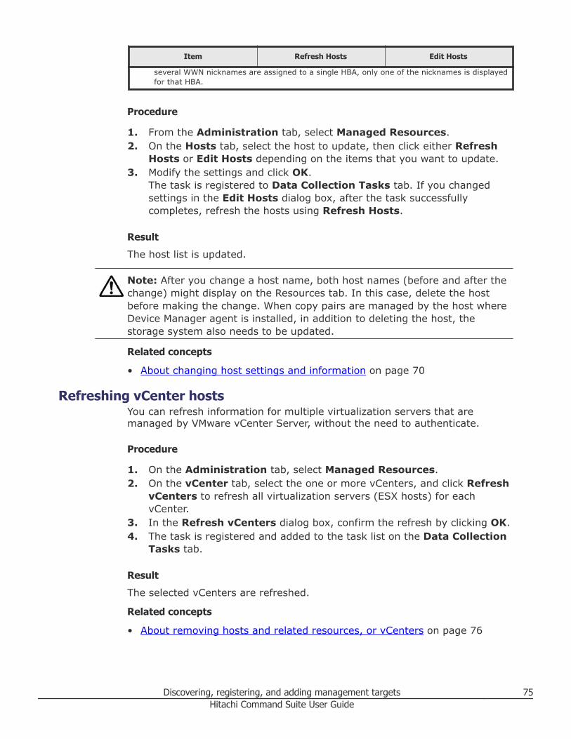
Item Refresh Hosts Edit Hosts
several WWN nicknames are assigned to a single HBA, only one of the nicknames is displayedfor that HBA.
Procedure
1. From the Administration tab, select Managed Resources.2. On the Hosts tab, select the host to update, then click either Refresh
Hosts or Edit Hosts depending on the items that you want to update.3. Modify the settings and click OK.
The task is registered to Data Collection Tasks tab. If you changedsettings in the Edit Hosts dialog box, after the task successfullycompletes, refresh the hosts using Refresh Hosts.
Result
The host list is updated.
Note: After you change a host name, both host names (before and after thechange) might display on the Resources tab. In this case, delete the hostbefore making the change. When copy pairs are managed by the host whereDevice Manager agent is installed, in addition to deleting the host, thestorage system also needs to be updated.
Related concepts
• About changing host settings and information on page 70
Refreshing vCenter hostsYou can refresh information for multiple virtualization servers that aremanaged by VMware vCenter Server, without the need to authenticate.
Procedure
1. On the Administration tab, select Managed Resources.2. On the vCenter tab, select the one or more vCenters, and click Refresh
vCenters to refresh all virtualization servers (ESX hosts) for eachvCenter.
3. In the Refresh vCenters dialog box, confirm the refresh by clicking OK.4. The task is registered and added to the task list on the Data Collection
Tasks tab.
Result
The selected vCenters are refreshed.
Related concepts
• About removing hosts and related resources, or vCenters on page 76
Discovering, registering, and adding management targets 75Hitachi Command Suite User Guide
About removing hosts and related resources, or vCentersFor VMware vCenter Servers:• If all virtualization servers managed by VMware vCenter Server are
deleted, the VMware vCenter Server is automatically deleted from the listof VMware vCenter Servers in the vCenters tab.
For hosts:
When hosts no longer need to be managed, for example due to areorganization, you can remove the registered hosts and exclude them fromHCS management. Related storage resources, such as volumes allocated tothe target host and path setting information, can also be removed. However,storage resources that are allocated to other hosts are not released. Whenremoving storage resources, you can select to:• Unallocate volumes• If the volumes that are unallocated when a host is removed are global-
active device paired volumes, the following information is released at thesame time:- Copy pairs- Copy groups- Configuration definition files (HORCM)
• Delete associated host groups or iSCSI targets• Release LUSE volumes• Delete virtual LDEV ID. This applies when managing resources that have
virtual IDs set.• Delete associated volumes• Shred associated volumes. Format the volumes if shredding is unavailable.
By automatically executing these options as an extension of removing a host,the process is simplified.
Note: When removing storage resources related to a host, verify that there isnot any related data remaining on the volumes.
Tip: If you are removing a host that was registered using Device Manageragent, uninstall the Device Manager agent from the host, then remove thehost using HCS.
Note: If host information is synchronized between HCS and ComputeSystems Manager, the removal of hosts by HCS is not reflected in ComputeSystems Manager.
Related concepts
• About unallocating volumes on page 218• About managing storage resources that have virtual IDs on page 490
76 Discovering, registering, and adding management targetsHitachi Command Suite User Guide
• About deleting unallocated volumes on page 150• About releasing a LUSE volume on page 153
Related tasks
• Removing hosts and releasing associated resources on page 77• Refreshing vCenter hosts on page 75• Unallocating global-active device pairs on page 312• Unallocating individual global-active device volumes on page 313
Removing hosts and releasing associated resourcesWhen you no longer need to manage a host, remove the host and release itsassociated related storage resources, such as allocated volumes and pathsettings.
Prerequisites
• Gather the following information:○ Target host names○ Target volumes
• Back up the target volumes• Stop input and output to the target volumes
Procedure
1. On the Administration tab, select Managed Resources and click theHosts tab.
2. From the lists of hosts, select the host you want to remove and clickMore Actions > Remove Hosts.
3. In the Remove Hosts dialog box, select one or more options from thefollowing:• Remove only selected hosts• Unallocate volumes and remove hosts
When you unallocate the volumes that are used by the selected hostsand clean up the volumes, select from the following:• Delete associated host groups or iSCSI targets• Delete associated volumes• Shred associated volumes
Note: Shred during off hours, such as overnight, so that theshredding process does not adversely affect system performance. Toverify the standard required times for shredding, see the HitachiVolume Shredder User Guide.
• Release LUSE volumes
Discovering, registering, and adding management targets 77Hitachi Command Suite User Guide
• Delete virtual LDEV ID. This applies when managing resources thathave virtual IDs set.
4. Click Plan Details to confirm that the information about associatedresources is correct.
5. (Optional) Update the task name and provide a description.6. (Optional) Expand Schedule to specify the task schedule.
You can schedule the task to run immediately or later. The default settingis Now. If the task is scheduled to run immediately, you can select Viewtask status to monitor the task after it is submitted.
7. Click Submit.If the task is scheduled to run immediately, the process begins.
8. (Optional) Check the progress and result of the task on the Tasks &Alerts tab. Click the task name to view details of the task.
Result
When the task completes, the host is removed and the selected associatedstorage resources are released.
Related concepts
• About removing hosts and related resources, or vCenters on page 76
Registering file serversThis module describes how to register file servers.
About registering and removing file serversYou can register file servers to be managed by Device Manager so that thevolumes of the storage system can be used by the file server.
Device Manager manages file servers based on information sent from HitachiNAS Platform family, Hitachi NAS Platform F, or Hitachi Data Ingestor.
Note: A system drive is the basic (logical) storage element managed by theHitachi NAS Platform family, and is equivalent to a storage system volume.Where volumes and system drives do not need to be differentiated, they aregenerically and collectively referred to as volumes.
When a file server is registered you can:• Allocate and unallocate volumes• Examine file server information• Determine the usage status of storage resources from the file server point
of view
From Device Manager, you can activate the file server management software,and change the settings of the file server or reference detailed file serverinformation.
78 Discovering, registering, and adding management targetsHitachi Command Suite User Guide
From Device Manager, in addition to the operations above, and depending onthe versions of the file server management software that are linked and thefile server type, file systems can be created, shares can be added, and fileserver reports and alerts can be viewed in the dashboard.
If the file server to be registered is Hitachi NAS Platform v10.2.3071 or later,use Device Manager to set the Admin services EVS information (the IPaddress of Admin services EVS and the supervisor account information) afterthe registration. This enables file systems to be created on Hitachi NASPlatform EVSs by using Device Manager.
If file servers become unnecessary for reasons such as reorganization, usefile server management software to remove the settings for linking to DeviceManager, then remove the file servers from the file server list by using HCS.The file servers are excluded from management by HCS, but configurationinformation, such as the file system and file sharing created on the fileserver, and paths set during volume allocation, are retained.
For details about the system requirements of the file server, see the HitachiCommand Suite Administrator Guide.
Related concepts
• About managing Hitachi NAS Platform file systems and shares on page237
• About managing Hitachi NAS Platform F and Hitachi Data Ingestor filesystems and shares on page 264
Related tasks
• Registering file servers on page 81• Changing the name of a file server on page 82• Changing the Admin services EVS settings of Hitachi NAS Platform on page
83• Allocating volumes to selected file servers on page 199
Related references
• Environment settings for Hitachi NAS Platform family on page 79• Workflow for providing NAS Platform file shares on page 241
Environment settings for Hitachi NAS Platform familyTo manage the Hitachi NAS Platform using Device Manager, the managementserver must be in a system configuration in which communication with SMUand Admin services EVS can be performed.
The following diagram illustrates the network relationships between thepublic management network and its connectivity with the NAS platform overpublic IP addresses (SMU and Admin services EVS). The storage systemconnectivity illustrates the use of storage system volumes by the file server,
Discovering, registering, and adding management targets 79Hitachi Command Suite User Guide
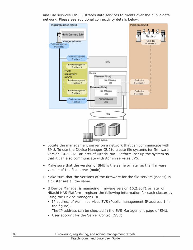
and File services EVS illustrates data services to clients over the public datanetwork. Please see additional connectivity details below.
• Locate the management server on a network that can communicate withSMU. To use the Device Manager GUI to create file systems for firmwareversion 10.2.3071 or later of Hitachi NAS Platform, set up the system sothat it can also communicate with Admin services EVS.
• Make sure that the version of SMU is the same or later as the firmwareversion of the file server (node).
• Make sure that the versions of the firmware for the file servers (nodes) ina cluster are all the same.
• If Device Manager is managing firmware version 10.2.3071 or later ofHitachi NAS Platform, register the following information for each cluster byusing the Device Manager GUI:• IP address of Admin services EVS (Public management IP address 1 in
the figure).The IP address can be checked in the EVS Management page of SMU.
• User account for the Server Control (SSC).
80 Discovering, registering, and adding management targetsHitachi Command Suite User Guide
A supervisor account is set up as the default user.
Note: If you want to use the Device Manager GUI to check informationsuch as the system drive and storage pool information of the file server,the file system information, or the sharing and exporting information, youneed to configure LUN security for the file server from the storage systemvolume.
Related concepts
• About registering and removing file servers on page 78
Registering file serversTo register the file server (Hitachi NAS Platform family, Hitachi NAS PlatformF, or Hitachi Data Ingestor) as the resource managed by Device Manager,specify the Device Manager information by using the management softwareon the file server.
If you register Hitachi NAS Platform version 10.2.3071 or later, specify theAdmin services EVS information by using Device Manager. This establisheslinkage between Device Manager and the Admin services EVS software on theHitachi NAS Platform.
Prerequisites
• In Device Manager, register the storage system that the file server uses.• Set up the file server management software:
○ System Management Unit (SMU) for Hitachi NAS Platform family○ Hitachi File Services Manager for Hitachi NAS Platform F and Hitachi
Data Ingestor• If the file server to be registered is Hitachi NAS Platform v10.2.3071 or
later, gather IP addresses for Admin services EVS (a virtual machine thatmanages the file server), and the user account for the Server Control(SSC).
Procedure
1. Register Device Manager information by using the file servermanagement software.Device Manager users that are specified in the management software ofthe file server must belong to the PeerGroup as a user group.
2. Additionally, if the file server to be registered is Hitachi NAS Platformv10.2.3071 or later, perform the following steps from Device Manager toset the Admin services EVS information:a. On the Administration tab, select Managed Resources.b. On the File Servers tab, select the Hitachi NAS Platform to be
registered, and click Edit File Server.
Discovering, registering, and adding management targets 81Hitachi Command Suite User Guide
c. Enter the Admin services EVS information, and then submit the task.d. From the Data Collection Tasks tab, verify the task status.
Result
File server information will be sent to Device Manager at regular intervals,and can be viewed in the File Servers tree on the Resources tab.
Tip: To remove registered file servers, use file server management softwareto remove the settings for linking to Device Manager. Then select the fileservers to be removed from the HCS file server list in the Administration tab,and click Remove File Servers.
Related concepts
• About registering and removing file servers on page 78
Related references
• Priority for acquiring the WWN or iSCSI name on page 65• Workflow for providing HNAS F and HDI file shares (HFSM) on page 265
Changing the name of a file serverYou can change the file server name or IP address by changing theinformation registered in Device Manager, followed by changing theinformation on the file server.
Procedure
1. On the Administration tab, select Managed Resources.2. On the File Servers tab, select a file server whose name you want to
change and click Edit File Server.3. Enter the new name for the file server using the format file-server-
[email protected] Hitachi NAS Platform in a non-cluster configuration, if an IP addressis not assigned to the node, enter the file server name in the followingformat:• If an IPv4 address is assigned to Admin services EVS: file-server-
name@IP-address-of-Admin-services-EVS.• If an IPv4 address is not assigned to Admin services EVS: file-server-
name.4. On the file server side, change the file server settings on the target file
server.5. If you are using System Management Unit (SMU) v10.2.3071 or later,
perform the following step:a. In SMU, perform the operation to synchronize information between the
file server and Device Manager.
82 Discovering, registering, and adding management targetsHitachi Command Suite User Guide
Note: If the file server name or IP address on the file server side doesnot match the file server name (file-server-name@IP-address) registeredin Device Manager, Device Manager cannot correctly recognize which fileserver information has been sent when the information is sent from a fileserver, and the same file server might be repeatedly registered underdifferent names. Therefore, file server information might not be updatedor an SNMP trap sent from the file server might not be displayed as analert. If a file server is repeatedly registered, you need to remove the fileserver registered with the wrong name or an old name from DeviceManager.
Related concepts
• About registering and removing file servers on page 78
Changing the Admin services EVS settings of Hitachi NAS PlatformIf you change the Admin services EVS information (IP address, or useraccount for the Server Control (SSC)) of Hitachi NAS Platform v10.2.3071 orlater, you also need to change the Admin services EVS settings registered inDevice Manager.
Procedure
1. Change the settings of Admin services EVS on the file server side.2. On the Administration tab of Device Manager, select Managed
Resources.3. On the File Servers tab, select a file server and click Edit File Server.4. Enter the changed Admin services EVS information, and then submit the
task.5. Verify the task status on the Data Collection Tasks tab.
Result
The file server status displayed in the list of file servers on the Administrationtab is Normal.
Related concepts
• About registering and removing file servers on page 78
Discovering, registering, and adding management targets 83Hitachi Command Suite User Guide

84 Discovering, registering, and adding management targetsHitachi Command Suite User Guide
4Setting up users and access control
This module describes how to control access to managed resources.
□ Setting up users and access control
□ About user accounts and controlling access to resources
□ Creating and managing user accounts
□ Controlling access to resources
Setting up users and access control 85Hitachi Command Suite User Guide
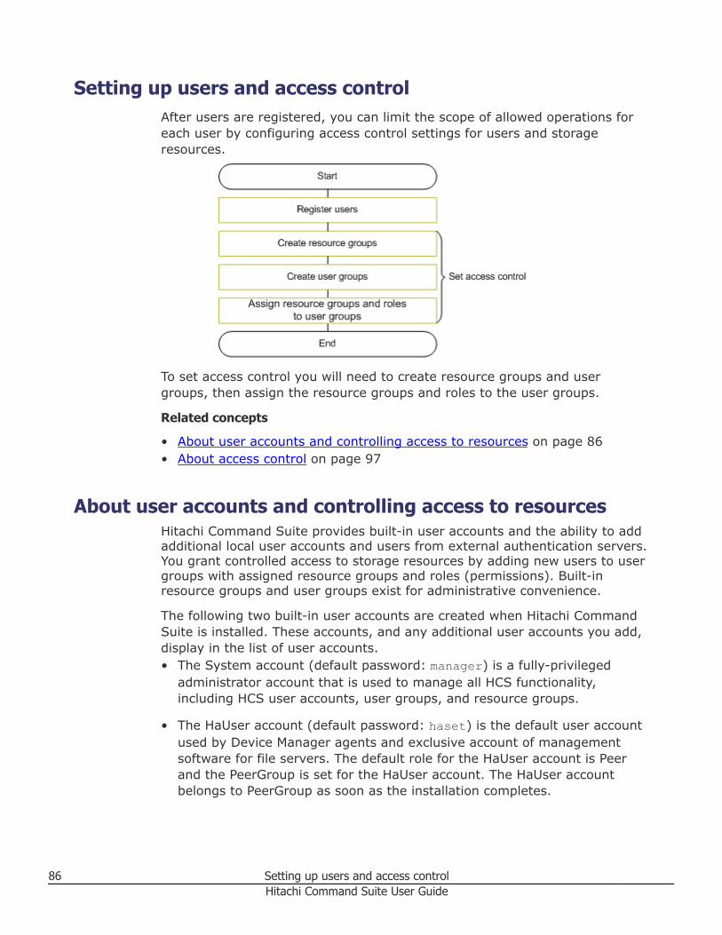
Setting up users and access controlAfter users are registered, you can limit the scope of allowed operations foreach user by configuring access control settings for users and storageresources.
To set access control you will need to create resource groups and usergroups, then assign the resource groups and roles to the user groups.
Related concepts
• About user accounts and controlling access to resources on page 86• About access control on page 97
About user accounts and controlling access to resourcesHitachi Command Suite provides built-in user accounts and the ability to addadditional local user accounts and users from external authentication servers.You grant controlled access to storage resources by adding new users to usergroups with assigned resource groups and roles (permissions). Built-inresource groups and user groups exist for administrative convenience.
The following two built-in user accounts are created when Hitachi CommandSuite is installed. These accounts, and any additional user accounts you add,display in the list of user accounts.• The System account (default password: manager) is a fully-privileged
administrator account that is used to manage all HCS functionality,including HCS user accounts, user groups, and resource groups.
• The HaUser account (default password: haset) is the default user accountused by Device Manager agents and exclusive account of managementsoftware for file servers. The default role for the HaUser account is Peerand the PeerGroup is set for the HaUser account. The HaUser accountbelongs to PeerGroup as soon as the installation completes.
86 Setting up users and access controlHitachi Command Suite User Guide
Log in using the System account to access user management functionality onthe Administration tab to create local HCS user accounts. While creating useraccounts, you can list available applications (as installed on the managementserver) and set user permissions for those applications. You must add usersto at least one, or more, resource groups to determine the storage they canaccess. Together, application permissions and resource group/user groupmembership determine the scope of what each user can do in HCS.
When managing a Virtual Storage Platform G200, G400, G600 or VirtualStorage Platform G1000 storage system:
• For Virtual Storage Platform G1000, enable user authentication in HCS sothat user accounts are authenticated when they log in to CCI and the SVPso that user accounts can be centrally managed.
• Secure communication settings:○ For a Virtual Storage Platform G200, G400, G600 storage system,
SSL/TLS communication must be enabled between the Device Managerserver and SVP. Even if you do not configure the settings for SSL/TLScommunication, when Device Manager is installed, the setting forSSL/TLS communication is enabled by using the default certificate. Also,if a firewall is set up between the Device Manager server and the SVP, itmight be necessary to register a firewall exception. For details aboutconfiguring separate SSL/TLS communication settings by using adifferent security policy, or setting up a firewall between the DeviceManager server and the SVP, see the Hitachi Command SuiteAdministrator Guide.
○ For a Virtual Storage Platform G1000 storage system, SSL/TLScommunication must be enabled between the Device Manager serverand storage system for using HCS authentication for SVP and CCI login.Even if you do not configure the settings for SSL/TLS communication,when Device Manager is installed, the setting for SSL/TLScommunication is enabled by using the default certificate. Also, if afirewall is set up between the Device Manager server and the SVP, itmight be necessary to register a firewall exception. For details aboutconfiguring separate SSL/TLS communication settings by using adifferent security policy, or setting up a firewall between the DeviceManager server and the storage system, see the Hitachi Command SuiteAdministrator Guide.
• User accounts should be created with user names and passwordscompatible with HCS and the Virtual Storage Platform G200, G400, G600or Virtual Storage Platform G1000 components.
• For Virtual Storage Platform G1000, if a user account that is used toperform operations by using CCI or the SVP is already registered in HitachiDevice Manager - Storage Navigator, also register that user account inHCS.
• Create an administrator user account for Hitachi Device Manager - StorageNavigator that can be used if HCS is not available.
Setting up users and access control 87Hitachi Command Suite User Guide
Note: Observe the following when setting up user ID accounts:• For Virtual Storage Platform G200, G400, G600, when registering a user
ID for logging into the storage system and using software other than HCS,specify a user ID different from any user ID that is registered in HCS.
• For Virtual Storage Platform G1000, if HCS authentication of user accountsis disabled when logging into CCI or SVP, you must specify the same useraccount information and access control to storage resources in both HCSand Hitachi Device Manager - Storage Navigator.
You can also manage user accounts by linking to an external authenticationserver, such as an LDAP directory server, RADIUS server, or Kerberos server.However, the built-in accounts (System and HaUser) cannot be authenticatedon an external authentication server. The HCS user account used to connectto external authentication servers and external authorization servers ismanaged as a Windows Active Directory (authorization) group. Permissionsthat are specified for authorized groups are also applied to users who belongto nested groups.
Application permissions
After adding basic user information such as username, password, email, anddescription, set permissions for available applications, such as:• Tier management (CLI)• Replication management• Performance management
Permissions include View, Execute, Modify, and Admin. These permissionscontrol what the user can do on the related tabs, and possibly elsewhere.
By selecting the admin permission for the User Management application,users can assist in user management tasks, such as:• Specifying user settings• Creating user groups for Device Manager and Tiered Storage Manager• Assigning resources and roles to user groups• Reporting user, and user group information in CSV format• Specifying security settings (such as locking an account)
Resource groups and User groups
All Resources is a built-in resource group (created by default) that containsthe built-in user groups called AdminGroup, ModifyGroup, PeerGroup, andViewGroup. Adding a user to ViewGroup allows that user to see all registeredstorage systems and related details such as parity groups. Adding the user toModifyGroup enables task-related buttons and tasks listed under GeneralTasks, thus allowing the user to work with registered resources. Essentially,as a member of an All Resources group, you have access to the DeviceManager GUI and Tiered Storage Manager GUI elements.
88 Setting up users and access controlHitachi Command Suite User Guide
Each storage system has a resource group named Default ResourceGroup. Ifyou have three registered storage systems you will see three of these groupslisted in addition to All Resources. Default ResourceGroup is used to provideAdmin, Modify, or View permissions (roles) to one or more users in a user-defined user group so they have access to the specific resources of thestorage system. In other words, instead of placing a user in the All Resourcesgroup, you can place them in one or more storage system resource groups tonarrow the scope of what they can view or manage. To do this, you mustcreate a named user-defined group and edit the resource group to add theuser-defined group and one or more users, whose permissions (roles) can beset independently as you add them. Additionally, if the default resource groupis for a Virtual Storage Platform G200, G400, G600 or Virtual StoragePlatform G1000, you can select Custom roles which are more specific, suchas roles for provisioning, or copy pair management and tasks. Multiple rolescan be combined.
For very specific control over access to resources, consider creating user-defined resource groups. You can identify specific parity groups and LDEVsthat members of your user-defined user group can access. As with defaultresource groups, for a Virtual Storage Platform G200, G400, G600 or VirtualStorage Platform G1000, you can select Custom roles.
Tip: For details about the required permissions for executing each commandof the Tiered Storage Manager CLI, see the Hitachi Command Suite TieredStorage Manager CLI Reference Guide.
Related tasks
• Creating a user account on page 89
Related references
• User ID and password policies on page 90
Creating and managing user accountsCreate user accounts and assign permissions.
Creating a user accountAll users not allowed to log in with the System account require a user accountfor access to HCS.
A user account consists of general user profile information (User ID,Password, Full Name, E-mail, and Description).
Procedure
1. On the Administration tab, click Users and Permissions.This will launch a user management window.
Setting up users and access control 89Hitachi Command Suite User Guide
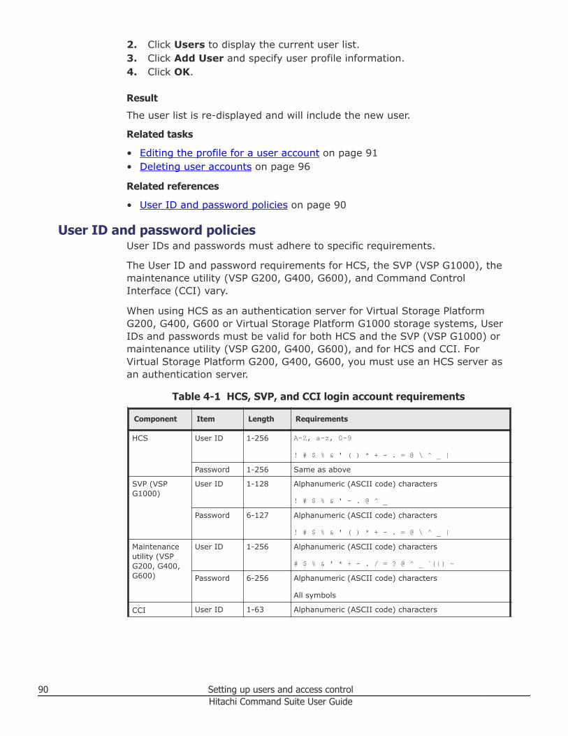
2. Click Users to display the current user list.3. Click Add User and specify user profile information.4. Click OK.
Result
The user list is re-displayed and will include the new user.
Related tasks
• Editing the profile for a user account on page 91• Deleting user accounts on page 96
Related references
• User ID and password policies on page 90
User ID and password policiesUser IDs and passwords must adhere to specific requirements.
The User ID and password requirements for HCS, the SVP (VSP G1000), themaintenance utility (VSP G200, G400, G600), and Command ControlInterface (CCI) vary.
When using HCS as an authentication server for Virtual Storage PlatformG200, G400, G600 or Virtual Storage Platform G1000 storage systems, UserIDs and passwords must be valid for both HCS and the SVP (VSP G1000) ormaintenance utility (VSP G200, G400, G600), and for HCS and CCI. ForVirtual Storage Platform G200, G400, G600, you must use an HCS server asan authentication server.
Table 4-1 HCS, SVP, and CCI login account requirements
Component Item Length Requirements
HCS User ID 1-256 A-Z, a-z, 0-9
! # $ % & ' ( ) * + - . = @ \ ^ _ |Password 1-256 Same as above
SVP (VSPG1000)
User ID 1-128 Alphanumeric (ASCII code) characters
! # $ % & ' - . @ ^ _Password 6-127 Alphanumeric (ASCII code) characters
! # $ % & ' ( ) * + - . = @ \ ^ _ |Maintenanceutility (VSPG200, G400,G600)
User ID 1-256 Alphanumeric (ASCII code) characters
# $ % & ' * + - . / = ? @ ^ _ `{|} ~Password 6-256 Alphanumeric (ASCII code) characters
All symbols
CCI User ID 1-63 Alphanumeric (ASCII code) characters
90 Setting up users and access controlHitachi Command Suite User Guide
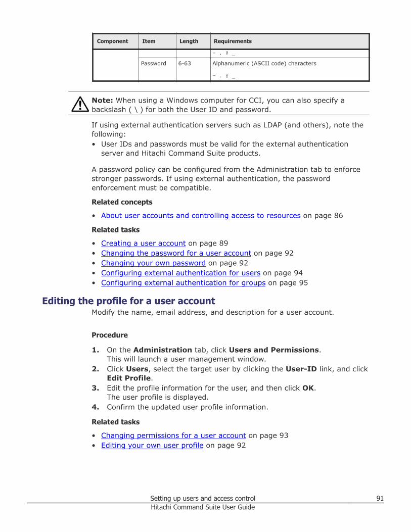
Component Item Length Requirements
- . @ _Password 6-63 Alphanumeric (ASCII code) characters
- . @ _
Note: When using a Windows computer for CCI, you can also specify abackslash ( \ ) for both the User ID and password.
If using external authentication servers such as LDAP (and others), note thefollowing:• User IDs and passwords must be valid for the external authentication
server and Hitachi Command Suite products.
A password policy can be configured from the Administration tab to enforcestronger passwords. If using external authentication, the passwordenforcement must be compatible.
Related concepts
• About user accounts and controlling access to resources on page 86
Related tasks
• Creating a user account on page 89• Changing the password for a user account on page 92• Changing your own password on page 92• Configuring external authentication for users on page 94• Configuring external authentication for groups on page 95
Editing the profile for a user accountModify the name, email address, and description for a user account.
Procedure
1. On the Administration tab, click Users and Permissions.This will launch a user management window.
2. Click Users, select the target user by clicking the User-ID link, and clickEdit Profile.
3. Edit the profile information for the user, and then click OK.The user profile is displayed.
4. Confirm the updated user profile information.
Related tasks
• Changing permissions for a user account on page 93• Editing your own user profile on page 92
Setting up users and access control 91Hitachi Command Suite User Guide
Editing your own user profileAs your user attributes change, you will need to update your user profile.
Procedure
1. On the Administration tab, click User Profile.Your user information is displayed.
2. Click Edit Profile.3. Edit the profile information and click OK.4. Confirm that the updated user profile information appears in the Users
area.
Related tasks
• Changing your own password on page 92
Changing the password for a user accountAs user passwords expire or are compromised, they can be changed.
Procedure
1. On the Administration tab, click Users and Permissions.This will launch a user management window.
2. Click Users, select the target user by clicking the User-ID link, and clickChange Password.
3. Enter the new password and verify it.4. Click OK.5. Confirm that the user account can log in with the new password.
Related tasks
• Changing your own password on page 92
Changing your own passwordAs your password expires or is compromised, it will need to be changed.
Procedure
1. On the Administration tab, click User Profile.Your information is displayed.
2. Click Change Password.3. Type the new password and verify it.4. Click OK.5. Log in with your new password.
92 Setting up users and access controlHitachi Command Suite User Guide
Result
Your password is changed.
Related concepts
• About user accounts and controlling access to resources on page 86
Related tasks
• Changing the password for a user account on page 92
Related references
• User ID and password policies on page 90
Changing permissions for a user accountTo grant a user new permissions or remove existing permissions, changepermission settings in the user account.
Tip: For a user of Device Manager or Tiered Storage Manager (GUI), specifya role for the user group which is assigned to the user, instead of grantinguser permissions.
Procedure
1. On the Administration tab, click Users and Permissions.This will launch a user management window.
2. Click Users, select the target user by clicking the User-ID link, and clickChange Permission.
3. Edit the permissions and click OK.The user account is re-displayed, including granted permission.
4. Verify the correct user permissions are selected.
Result
The user permissions are changed.
Related references
• Required roles and resource groups by function on page 111
Changing the lock status of user accountsA user account can be locked or unlocked by an administrator.
Procedure
1. On the Administration tab, select Users and Permissions.This will launch a user management window.
2. Click Users, select the check box for the user whose lock status youwant to change.
3. Click Lock Users or Unlock Users.
Setting up users and access control 93Hitachi Command Suite User Guide
A verification dialog box displays.4. Click Ok to lock or unlock the account, or click Cancel.5. Verify that the user account has been locked (a lock icon displays in the
user list), or that the previously locked user can now log in.
Related concepts
• About user accounts and controlling access to resources on page 86
Related tasks
• Changing the password for a user account on page 92
Configuring external authentication for usersExternal authentication systems can be used to authenticate user logins.
External authentication systems, such as LDAP (for example, ActiveDirectory), RADIUS, or Kerberos may be used to authenticate HCS users asthey log in. You can re-configure existing accounts, or create new accounts touse external authentication.
Prerequisites• The HCS server must be linked to an external authentication server. See
the Hitachi Command Suite Administrator Guide.• The HCS server must be configured to support user authentication, which
activates the Change Auth button in the GUI, and which presentsauthentication options such as Internal for a local account, or LDAP forexternal authentication.
• The HCS user ID must exist on the external authentication server. It isrecommended that user ID information be acquired from the externalauthentication server administrator before creating accounts.
Procedure
1. From the Administration tab, select Users and Permissions.2. Select Users folder, then select one or more users (using the check box)
whose authentication method you want to change, or click Add User tocreate a new account.
Note: When creating a new account, only the User ID is required forexternal authentication, and must match a user ID on the externalauthentication server. For a local (internal) account, a User ID andPassword are both required. When external authentication is available,new user accounts created without a password value are automaticallyconfigured to use external authentication (for example, LDAP is selectedfor you). Fill in the desired fields, and click OK to create the useraccount.
94 Setting up users and access controlHitachi Command Suite User Guide
3. If you have selected existing users, click Change Auth. A dialog box isdisplayed. From the drop down list, select the desired authenticationmethod (for example, LDAP) and click OK. The user list will be re-displayed.
4. Review the Authentication column to verify the authentication method.
Result
On the next login attempt by each user, the users login credentials (user IDand password) will be validated using the external authentication server.
Tip: Set permissions or roles so that the registered user can performnecessary operations using HCS products. Also consider adding user accountsto user groups with assigned roles for controlled access to resource groups.
Related concepts
• About user accounts and controlling access to resources on page 86
Related tasks
• Configuring external authentication for groups on page 95
Configuring external authentication for groupsExternal authentication systems can be used to authenticate user groups.
External authentication systems, such as LDAP (for example, ActiveDirectory), RADIUS, or Kerberos may be used to authenticate HCS usergroup members as they log in. You can configure one or more user groups,from one or more external authentication servers.
When linking with an external authentication server, if using together withActive Directory as an external authorization server, user permissions can bemanaged by using the Active Directory groups (authorization groups)registered on the external authorization server. In this case, user permissionsare specified for each group.
Prerequisites• The HCS server must be linked to an external authentication
(authorization) server. See the Hitachi Command Suite AdministratorGuide.
• The HCS server must be configured to support group authentication, whichactivates the Groups folder in the GUI.
• The HCS user group must exist on the external authentication(authorization) server. It is recommended that domain and groupinformation, as required below, be acquired from the externalauthentication server administrator.
Setting up users and access control 95Hitachi Command Suite User Guide
Procedure
1. From the Administration tab, select Users and Permissions.2. Click the Groups folder to display the Domain List. This is a list of
external authentication servers listed by domain name, and host name orIP address. If the Groups folder is not displayed, see the pre-requisitesabove.
3. Select the desired Domain Name to display the Group List, which maybe empty ('No Groups' is displayed). Click Add Groups.
4. Enter the Distinguished Name for the group. Use Check DN to verify acorrect DN entry. Click Ok to save your group and re-display the GroupList. Note that the Group Name is derived from the entered DN. Tospecify multiple groups, note that:• You can add multiple DNs at the same time using the "+" button• If multiple DNs are listed, you can remove an entry with the "-" button• Reset clears all DN entries
5. From the Group List, click the Group Name link, then click ChangePermission and set the HCS permissions for the group (repeat this foreach new group).
6. Your groups will now be visible from the Administration tab, UserGroups. You can affiliate the groups with resource groups and roles, justlike HCS user groups. If you delete external authentication groups fromUsers and Permissions at a later time, the groups are also removedfrom the User Groups list.
Result
On the next login attempt by each group member, the users login credentials(User ID and Password) will be validated using the external authentication(authorization) server.
Tip: To delete registered authorization groups, select the check boxes of thegroups to be deleted, and then click Delete Groups.
Related concepts
• About user accounts and controlling access to resources on page 86
Related tasks
• Configuring external authentication for users on page 94
Deleting user accountsIf user accounts are no longer needed for accessing HCS, for example if usersleave the organization, you can delete the user accounts.
Procedure
1. On the Administration tab, select Users and Permissions.
96 Setting up users and access controlHitachi Command Suite User Guide
2. Select Users in the navigation pane, and then select the users to delete.3. Click Delete Users.4. Click OK.
Result
The user accounts you deleted no longer appear in the list of user accounts.
Controlling access to resourcesThis module describes how to control access to resources.
About access controlCreate an access control policy to allow secure data handling in multi-tenantenvironments and support more efficient and secure operations.
An access control policy is used for:• Data center hosting services• Management of departments in an organization• Management of locations in an organization
To create an access control policy in a managed SAN environment, you createuser accounts, add them to user groups, and then affiliate the user groupswith resource groups and assigned roles to provide controlled access tofunctionality available in Device Manager and Tiered Storage Manager (GUI).
A user group, which is made up of local user accounts or accounts fromexternal authentication systems, is a group of users who can access thesame resources with the same user permissions. A resource group consists ofstorage system resources (storage systems, parity groups, DP pools, LDEVIDs, and storage ports). Assigned roles for resource groups provide eitherfull, partial, or read-only access to resource group resources. When youassign resource groups and roles (user permissions, such as Admin, Modify,View or Custom) to a user group, resources are consistently controlled for theusers in that group.
For Virtual Storage Platform G200, G400, G600 or Virtual Storage PlatformG1000 storage systems, you can use custom roles to specify one or moreroles and user permissions at a more detailed, granular level. For example,you can allow:• Provisioning operations• Remote copy operations• System resource operations• Storage encryption key and authentication management• Audit log management
Setting up users and access control 97Hitachi Command Suite User Guide
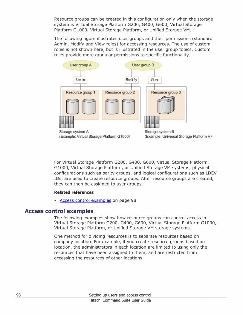
Resource groups can be created in this configuration only when the storagesystem is Virtual Storage Platform G200, G400, G600, Virtual StoragePlatform G1000, Virtual Storage Platform, or Unified Storage VM.
The following figure illustrates user groups and their permissions (standardAdmin, Modify and View roles) for accessing resources. The use of customroles is not shown here, but is illustrated in the user group topics. Customroles provide more granular permissions to specific functionality.
For Virtual Storage Platform G200, G400, G600, Virtual Storage PlatformG1000, Virtual Storage Platform, or Unified Storage VM systems, physicalconfigurations such as parity groups, and logical configurations such as LDEVIDs, are used to create resource groups. After resource groups are created,they can then be assigned to user groups.
Related references
• Access control examples on page 98
Access control examplesThe following examples show how resource groups can control access inVirtual Storage Platform G200, G400, G600, Virtual Storage Platform G1000,Virtual Storage Platform, or Unified Storage VM storage systems.
One method for dividing resources is to separate resources based oncompany location. For example, if you create resource groups based onlocation, the administrators in each location are limited to using only theresources that have been assigned to them, and are restricted fromaccessing the resources of other locations.
98 Setting up users and access controlHitachi Command Suite User Guide
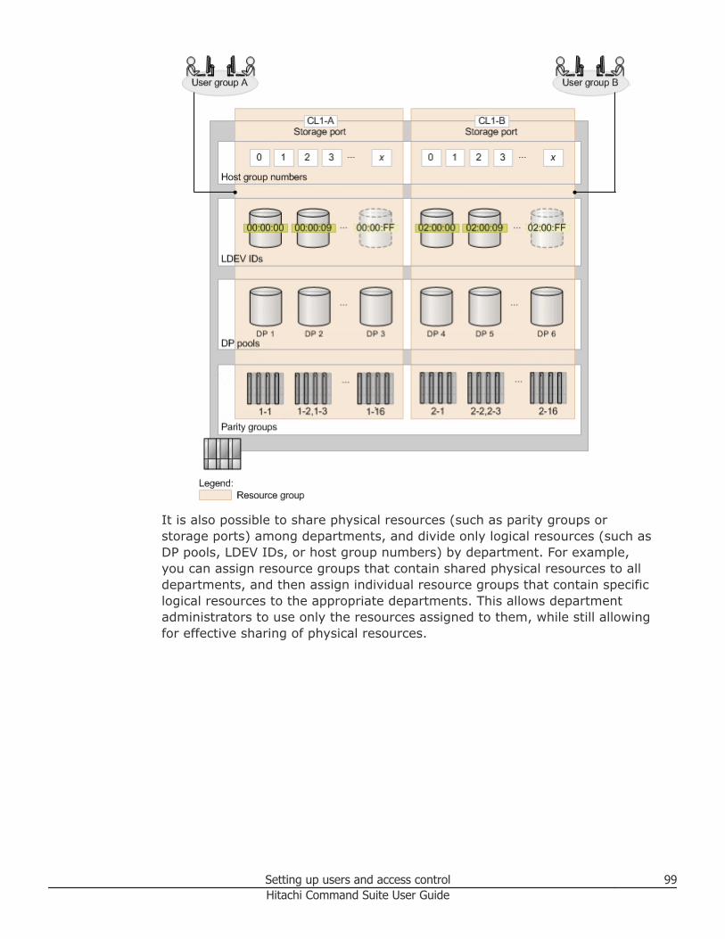
It is also possible to share physical resources (such as parity groups orstorage ports) among departments, and divide only logical resources (such asDP pools, LDEV IDs, or host group numbers) by department. For example,you can assign resource groups that contain shared physical resources to alldepartments, and then assign individual resource groups that contain specificlogical resources to the appropriate departments. This allows departmentadministrators to use only the resources assigned to them, while still allowingfor effective sharing of physical resources.
Setting up users and access control 99Hitachi Command Suite User Guide
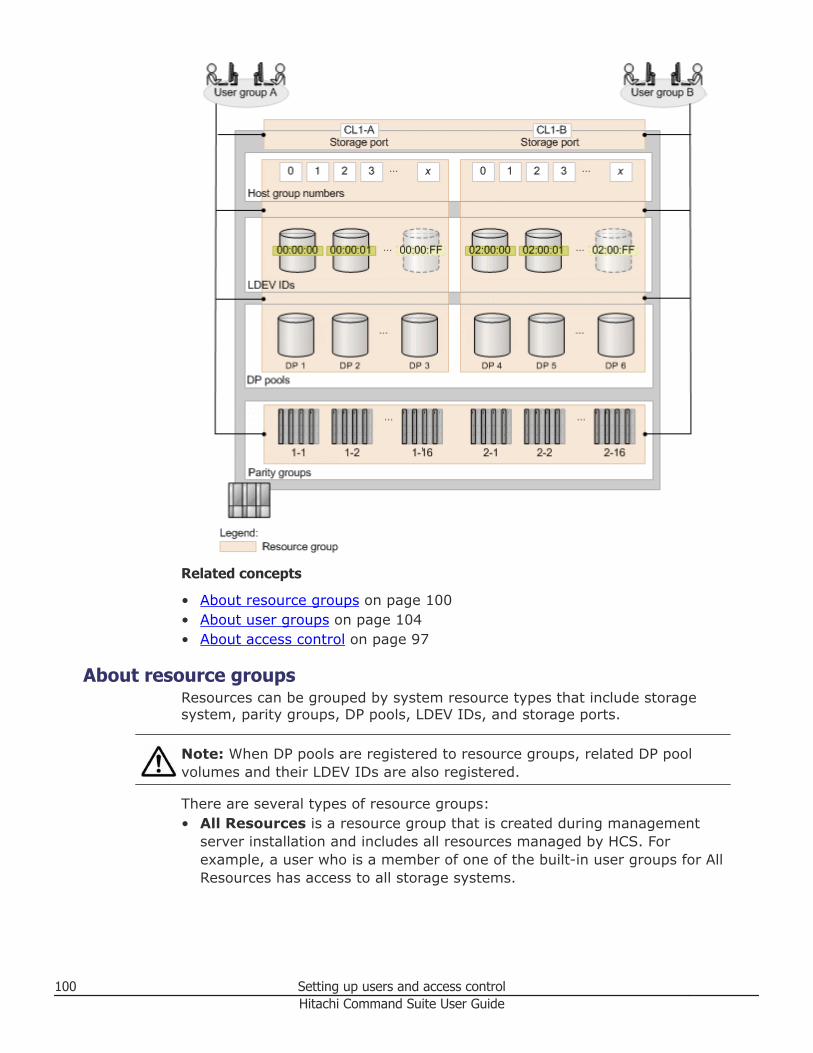
Related concepts
• About resource groups on page 100• About user groups on page 104• About access control on page 97
About resource groupsResources can be grouped by system resource types that include storagesystem, parity groups, DP pools, LDEV IDs, and storage ports.
Note: When DP pools are registered to resource groups, related DP poolvolumes and their LDEV IDs are also registered.
There are several types of resource groups:• All Resources is a resource group that is created during management
server installation and includes all resources managed by HCS. Forexample, a user who is a member of one of the built-in user groups for AllResources has access to all storage systems.
100 Setting up users and access controlHitachi Command Suite User Guide
• Default ResourceGroup is the name for default resource groups that arecreated for a storage system when it is discovered and registered. A userwho is a member of a user group in a default resource group has access toall of the storage system resources.
• Resource pool is another type of resource group. A resource pool is aresource group to which resources of a virtual storage machine in a VirtualStorage Platform G1000 belong, when the resources have not been addedto any individual resource group. There are two types of resource pools.There are resource pools on the default virtual storage machine, andresource pools that are automatically created on user-defined virtualstorage machines. You can check the resource pools on user-definedvirtual storage machines from the resource group list.
• User-defined resource groups defining more specific storage access can becreated for the Virtual Storage Platform G200, G400, G600, VirtualStorage Platform G1000, Virtual Storage Platform, and Unified Storage VMdepending on the operating environment. Resources can be grouped byparity groups, DP pools, LDEV IDs, or storage ports. Resource groupdefinitions in Device Manager are applied to Virtual Storage Platform G200,G400, G600 or Virtual Storage Platform G1000 storage systems. However,these resource group definitions are not applied to other storage systems.
Each resource is automatically registered in the All Resources and Defaultresource groups created for its storage system (this group cannot bedeleted). If a volume that is part of a LUSE volume is registered in a resourcegroup, other volumes in that LUSE volume are also registered in the sameresource group.
For the Hitachi Virtual Storage Platform G200, G400, G600 or Virtual StoragePlatform G1000, when you register a part of a parity group that is part of aconcatenated parity group to a resource group, other parity groups that are apart of the concatenated parity group will also be registered in the sameresource group automatically. If the resource is in a Virtual Storage PlatformG200, G400, G600, Virtual Storage Platform, Virtual Storage Platform G1000,or Unified Storage VM system, you can register it in only one user-definedresource group.
Related concepts
• About user groups on page 104• About virtual storage machines on page 274
Related tasks
• Creating resource groups on page 102• Editing a resource group on page 103• Assigning resource groups and roles to a user group on page 130
Related references
• Prerequisites for creating resource groups on page 102
Setting up users and access control 101Hitachi Command Suite User Guide
• Access control examples on page 98
Prerequisites for creating resource groupsResources can be grouped by system resource types that include storagesystems, parity groups, DP pools, LDEV IDs, and storage ports.
The following list identifies the conditions for creating a user-defined usergroup for Virtual Storage Platform G200, G400, G600, Virtual StoragePlatform G1000, Virtual Storage Platform, or Unified Storage VM.• Parity Groups: Includes parity groups and volumes in external storage
systems. Users with Modify, Storage Administrator (Provisioning), orhigher roles for parity groups, or the LDEV ID of a DP pool volume, and anunused LDEV ID is assigned to the user, the user can create a volume. ForVirtual Storage Platform G200, G400, G600 and Virtual Storage PlatformG1000 storage systems, when you register a part of a parity group that ispart of a concatenated parity group to a resource group, other paritygroups that are a part of the concatenated parity group will also beregistered in the same resource group automatically.
• DP Pools: Includes DP pools consisting of DP pool volumes with LDEV IDs.• LDEV IDs: Includes parity groups and volumes in external storage
systems. Non-existent IDs can also be specified. Users with Modify,Storage Administrator (Provisioning), or higher roles for parity groups orDP pools and assigned an unused volume ID, can create a volume.
• Storage Ports: Users with Modify, Storage Administrator (Provisioning),or higher roles for ports and assigned an unused Host Group Number cancreate a host group that has that host group number.
• Host Group Number: Non-existent numbers can also be specified. Userswith Modify, Storage Administrator (Provisioning), or higher roles for portsand assigned an unused Host Group Number can create a host group oriSCSI target.
Related concepts
• About resource groups on page 100
Related tasks
• Creating resource groups on page 102
Creating resource groupsUser created resource groups can be used to group system resource typesincluding storage systems, parity groups, DP pools, LDEV IDs, and storageports.
Resource groups, which are user defined, can be created for the followingstorage systems:• Hitachi Virtual Storage Platform G200, G400, G600• Virtual Storage Platform G1000• Virtual Storage Platform
102 Setting up users and access controlHitachi Command Suite User Guide
• Unified Storage VM
Procedure
1. On the Administration tab, in the Administration pane, selectResource Groups.
2. Click Create Resource Group.3. Enter a name and description, and select the storage system providing
the resources.4. Using the tabs, specify the parity groups, DP pools, LDEVs, ports, host
groups, iSCSI targets (or a mix of resources) for the resource group.5. Click Submit to register this as a task.6. You can check the progress and result of the task on the Tasks & Alerts
tab. Click the task name to view details of the task.
Result
The new resource group is displayed, and can be assigned to an existing usergroup using the Edit User Group button. You can also assign resource groupswhen creating new user groups with Create User Group.
Related tasks
• Editing a resource group on page 103• Assigning resource groups and roles to a user group on page 130• Deleting resource groups on page 104
Related references
• Access control examples on page 98• Prerequisites for creating resource groups on page 102
Editing a resource groupYou can edit storage system resources in an existing resource group.
Information about resource groups can be modified to reflect changing accesscontrol requirements.
Procedure
1. On the Administration tab, in the Administration pane, selectResource Groups.
2. To edit a resource group, do one of the following:• From the Resource Groups pane, select the resource group, and
click Edit Resource Group.• Click the resource group link, click Actions and select Edit Resource
Group.3. You can modify the resource group name and description, but not the
storage system.
Setting up users and access control 103Hitachi Command Suite User Guide
4. Modify the parity groups, DP pools, LDEVs, ports, iSCSI targets, or hostgroups to reflect your access control requirements.
Note: To add or delete DP pool volumes, you must add or delete DPpools.
5. Click Submit to register this as a task.6. You can check the progress and result of the task on the Tasks & Alerts
tab. Click the task name to view details of the task.
Result
Depending on how you initiated your edit (see step 2), the resource group isdisplayed and you can confirm your changes, or you will be in the ResourceGroups pane and can click the resource group link to confirm your changes.
Related tasks
• Creating resource groups on page 102• Assigning resource groups and roles to a user group on page 130
Related references
• Access control examples on page 98
Deleting resource groupsIf resource groups are no longer needed, you can delete the resource groups.
Procedure
1. On the Administration tab, select Resource Groups.2. Select the resource groups to delete.
The storage system default resource groups, All Resources, and resourcepools cannot be deleted.
3. Click Delete Resource Groups.4. Click Submit.
Result
The resource groups you deleted no longer appear in the list of resourcegroups.
About user groupsA user group consists of one or more users having the same permissions(role) for the same resources. An external authentication group can also beused as a user group. There are also built-in resource and user groups foradministrative convenience.
For a user group, one or more resource groups are added, and a roleassigned for each resource group. The types of roles are:
104 Setting up users and access controlHitachi Command Suite User Guide
• Admin• Modify• View• Custom
User group members are able to work with each resource group according tothe assigned role (permissions) for the resource group. For example, a usergroup member with View access to a resource group can monitor, but notchange the resource. Users can belong to multiple user groups, each withassigned resource groups and roles. Resource groups can be registered tomultiple user groups.
For hosts and volumes that are managed as logical groups that correspond tobusinesses or organizations, when the logical groups are registered as privatelogical groups, only users who belong to the same user group will be able touse the logical groups.
The following default (built-in) user groups are assigned to the AllResources resource group (also built-in):• AdminGroup (role: Admin and the permission for creating resource
groups)• ModifyGroup (role: Modify)• ViewGroup (role: View)• PeerGroup (role: Peer. This user group cannot be assigned to a resource
group)
Note: If Hitachi Compute Systems Manager (HCSM) v8.1 or later is installedon the HCS management server with Device Manager, the following usergroups are also created:• HCSM_AdminGroup• HCSM_ModifyGroup• HCSM_ViewGroup
If Hitachi Automation Director v8.1.1 or later is installed on the HCSmanagement server with Device Manager, the following user groups uniqueto Automation Director are created:• SubmitGroup• DevelopGroup
Two special case user group assignments exist:• The built-in account (user ID: HaUser) used by Device Manager agents and
file servers is set to the PeerGroup immediately after the installation iscompleted, but can be set to another group later. To assign the Peer role toa user, register the user in PeerGroup.
• Authorized groups that have been registered to Hitachi Command Suiteproducts can be used as user groups. Roles assigned to authorized groupsare also applied to users who belong to nested groups.
Setting up users and access control 105Hitachi Command Suite User Guide
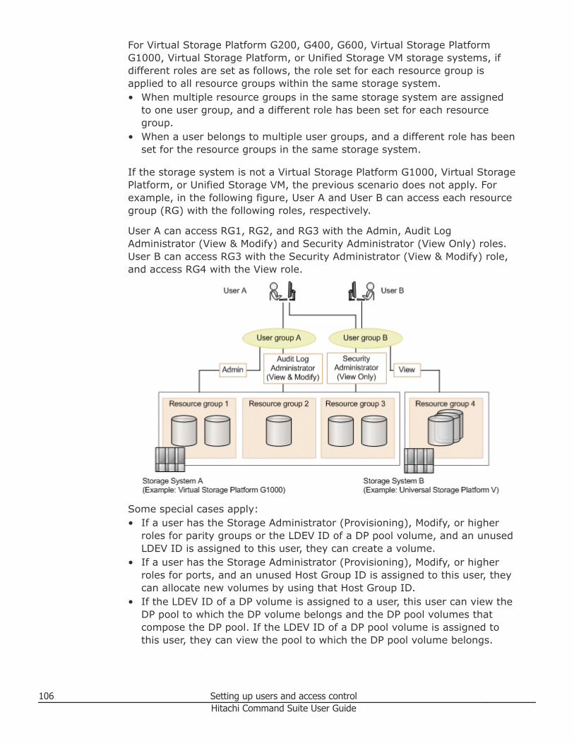
For Virtual Storage Platform G200, G400, G600, Virtual Storage PlatformG1000, Virtual Storage Platform, or Unified Storage VM storage systems, ifdifferent roles are set as follows, the role set for each resource group isapplied to all resource groups within the same storage system.• When multiple resource groups in the same storage system are assigned
to one user group, and a different role has been set for each resourcegroup.
• When a user belongs to multiple user groups, and a different role has beenset for the resource groups in the same storage system.
If the storage system is not a Virtual Storage Platform G1000, Virtual StoragePlatform, or Unified Storage VM, the previous scenario does not apply. Forexample, in the following figure, User A and User B can access each resourcegroup (RG) with the following roles, respectively.
User A can access RG1, RG2, and RG3 with the Admin, Audit LogAdministrator (View & Modify) and Security Administrator (View Only) roles.User B can access RG3 with the Security Administrator (View & Modify) role,and access RG4 with the View role.
Some special cases apply:• If a user has the Storage Administrator (Provisioning), Modify, or higher
roles for parity groups or the LDEV ID of a DP pool volume, and an unusedLDEV ID is assigned to this user, they can create a volume.
• If a user has the Storage Administrator (Provisioning), Modify, or higherroles for ports, and an unused Host Group ID is assigned to this user, theycan allocate new volumes by using that Host Group ID.
• If the LDEV ID of a DP volume is assigned to a user, this user can view theDP pool to which the DP volume belongs and the DP pool volumes thatcompose the DP pool. If the LDEV ID of a DP pool volume is assigned tothis user, they can view the pool to which the DP pool volume belongs.
106 Setting up users and access controlHitachi Command Suite User Guide
• If a parity group is assigned to a user, this user can view all volumes thatbelong to the parity group from a list of volumes that appears whendisplaying the parity group information. If a parity group is not assigned toa user and only the LDEV IDs of the volumes belonging to the parity groupare assigned to this user, they cannot view that parity group.
Note: The roles above determine the operation permissions of DeviceManager and the Tiered Storage Manager GUI. To grant permissions to usersin a user group for operating Tiered Storage Manager CLI, assign the usergroup to All Resources resource group and assign Device Manager roles, andthen set the Tiered Storage Manager permissions required to execute eachcommand. For details about the Device Manager roles and the permissionsrequired to execute each command, see the Hitachi Command Suite TieredStorage Manager CLI Reference Guide.
Related concepts
• About access control on page 97
User group rolesIn Device Manager and Tiered Storage Manager (GUI), permissions aregranted by assigning resource groups and roles to users in a user group.
For other HCS products, permissions are granted by setting permissions foreach user, which, for example, allows you to grant permissions for the DeviceManager GUI and CLI operations and for the Tiered Storage Manager GUI. Togrant permissions to users in a user group for operating Tiered StorageManager CLI, assign the user group to All Resources resource group andassign Device Manager roles, and then set the Tiered Storage Managerpermissions required to execute each command. For details about the DeviceManager roles and the permissions required to execute each command, seethe Hitachi Command Suite Tiered Storage Manager CLI Reference Guide.
By specifying roles, resources are displayed for resources that belong to aresource group for which a user has permissions. The user can performoperations or reference information for the displayed resources.
Roles can be set for an external authentication group, just like for other usergroups, when the external authentication group is used as a user group. Bydefault, the View role is set for All Resources.
The following table describes roles and the tasks that can be performed whenthose roles are assigned.
Setting up users and access control 107Hitachi Command Suite User Guide
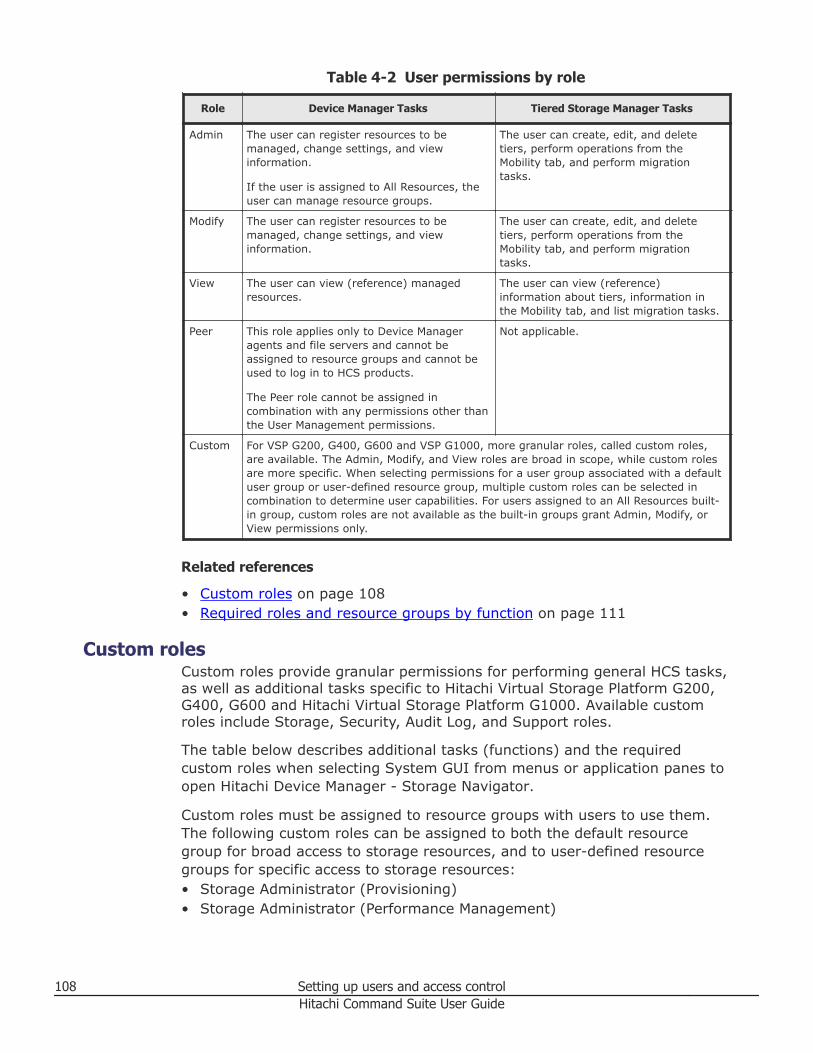
Table 4-2 User permissions by role
Role Device Manager Tasks Tiered Storage Manager Tasks
Admin The user can register resources to bemanaged, change settings, and viewinformation.
If the user is assigned to All Resources, theuser can manage resource groups.
The user can create, edit, and deletetiers, perform operations from theMobility tab, and perform migrationtasks.
Modify The user can register resources to bemanaged, change settings, and viewinformation.
The user can create, edit, and deletetiers, perform operations from theMobility tab, and perform migrationtasks.
View The user can view (reference) managedresources.
The user can view (reference)information about tiers, information inthe Mobility tab, and list migration tasks.
Peer This role applies only to Device Manageragents and file servers and cannot beassigned to resource groups and cannot beused to log in to HCS products.
The Peer role cannot be assigned incombination with any permissions other thanthe User Management permissions.
Not applicable.
Custom For VSP G200, G400, G600 and VSP G1000, more granular roles, called custom roles,are available. The Admin, Modify, and View roles are broad in scope, while custom rolesare more specific. When selecting permissions for a user group associated with a defaultuser group or user-defined resource group, multiple custom roles can be selected incombination to determine user capabilities. For users assigned to an All Resources built-in group, custom roles are not available as the built-in groups grant Admin, Modify, orView permissions only.
Related references
• Custom roles on page 108• Required roles and resource groups by function on page 111
Custom rolesCustom roles provide granular permissions for performing general HCS tasks,as well as additional tasks specific to Hitachi Virtual Storage Platform G200,G400, G600 and Hitachi Virtual Storage Platform G1000. Available customroles include Storage, Security, Audit Log, and Support roles.
The table below describes additional tasks (functions) and the requiredcustom roles when selecting System GUI from menus or application panes toopen Hitachi Device Manager - Storage Navigator.
Custom roles must be assigned to resource groups with users to use them.The following custom roles can be assigned to both the default resourcegroup for broad access to storage resources, and to user-defined resourcegroups for specific access to storage resources:• Storage Administrator (Provisioning)• Storage Administrator (Performance Management)
108 Setting up users and access controlHitachi Command Suite User Guide
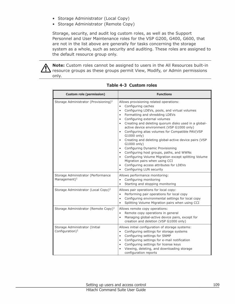
• Storage Administrator (Local Copy)• Storage Administrator (Remote Copy)
Storage, security, and audit log custom roles, as well as the SupportPersonnel and User Maintenance roles for the VSP G200, G400, G600, thatare not in the list above are generally for tasks concerning the storagesystem as a whole, such as security and auditing. These roles are assigned tothe default resource group only.
Note: Custom roles cannot be assigned to users in the All Resources built-inresource groups as these groups permit View, Modify, or Admin permissionsonly.
Table 4-3 Custom roles
Custom role (permission) Functions
Storage Administrator (Provisioning)1 Allows provisioning related operations:• Configuring caches• Configuring LDEVs, pools, and virtual volumes• Formatting and shredding LDEVs• Configuring external volumes• Creating and deleting quorum disks used in a global-
active device environment (VSP G1000 only)• Configuring alias volumes for Compatible PAV(VSP
G1000 only)• Creating and deleting global-active device pairs (VSP
G1000 only)• Configuring Dynamic Provisioning• Configuring host groups, paths, and WWNs• Configuring Volume Migration except splitting Volume
Migration pairs when using CCI• Configuring access attributes for LDEVs• Configuring LUN security
Storage Administrator (PerformanceManagement)1
Allows performance monitoring:• Configuring monitoring• Starting and stopping monitoring
Storage Administrator (Local Copy)1 Allows pair operations for local copy:• Performing pair operations for local copy• Configuring environmental settings for local copy• Splitting Volume Migration pairs when using CCI
Storage Administrator (Remote Copy)1 Allows remote copy operations:• Remote copy operations in general• Managing global-active device pairs, except for
creation and deletion (VSP G1000 only)
Storage Administrator (InitialConfiguration)1
Allows initial configuration of storage systems:• Configuring settings for storage systems• Configuring settings for SNMP• Configuring settings for e-mail notification• Configuring settings for license keys• Viewing, deleting, and downloading storage
configuration reports
Setting up users and access control 109Hitachi Command Suite User Guide
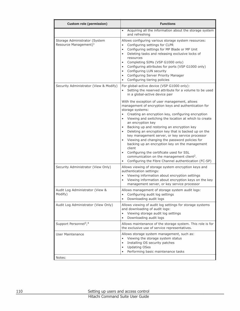
Custom role (permission) Functions
• Acquiring all the information about the storage systemand refreshing
Storage Administrator (SystemResource Management)1
Allows configuring various storage system resources:• Configuring settings for CLPR• Configuring settings for MP Blade or MP Unit• Deleting tasks and releasing exclusive locks of
resources• Completing SIMs (VSP G1000 only)• Configuring attributes for ports (VSP G1000 only)• Configuring LUN security• Configuring Server Priority Manager• Configuring tiering policies
Security Administrator (View & Modify) For global-active device (VSP G1000 only):• Setting the reserved attribute for a volume to be used
in a global-active device pair
With the exception of user management, allowsmanagement of encryption keys and authentication forstorage systems:• Creating an encryption key, configuring encryption• Viewing and switching the location at which to create
an encryption key• Backing up and restoring an encryption key• Deleting an encryption key that is backed up on the
key management server, or key service processor• Viewing and changing the password policies for
backing up an encryption key on the managementclient
• Configuring the certificate used for SSLcommunication on the management client2.
• Configuring the Fibre Channel authentication (FC-SP)
Security Administrator (View Only) Allows viewing of storage system encryption keys andauthentication settings:• Viewing information about encryption settings• Viewing information about encryption keys on the key
management server, or key service processor
Audit Log Administrator (View &Modify)
Allows management of storage system audit logs:• Configuring audit log settings• Downloading audit logs
Audit Log Administrator (View Only) Allows viewing of audit log settings for storage systemsand downloading of audit logs:• Viewing storage audit log settings• Downloading audit logs
Support Personnel3,4 Allows maintenance of the storage system. This role is forthe exclusive use of service representatives.
User Maintenance Allows storage system management, such as:• Viewing the storage system status• Installing OS security patches• Updating OSes• Performing basic maintenance tasks
Notes:
110 Setting up users and access controlHitachi Command Suite User Guide
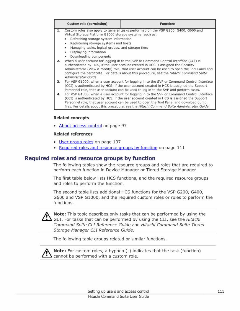
Custom role (permission) Functions
1. Custom roles also apply to general tasks performed on the VSP G200, G400, G600 andVirtual Storage Platform G1000 storage systems, such as:• Refreshing storage system information• Registering storage systems and hosts• Managing tasks, logical groups, and storage tiers• Displaying information• Downloading components
2. When a user account for logging in to the SVP or Command Control Interface (CCI) isauthenticated by HCS, if the user account created in HCS is assigned the SecurityAdministrator (View & Modify) role, that user account can be used to open the Tool Panel andconfigure the certificate. For details about this procedure, see the Hitachi Command SuiteAdministrator Guide.
3. For VSP G1000, when a user account for logging in to the SVP or Command Control Interface(CCI) is authenticated by HCS, if the user account created in HCS is assigned the SupportPersonnel role, that user account can be used to log in to the SVP and perform tasks.
4. For VSP G1000, when a user account for logging in to the SVP or Command Control Interface(CCI) is authenticated by HCS, if the user account created in HCS is assigned the SupportPersonnel role, that user account can be used to open the Tool Panel and download dumpfiles. For details about this procedure, see the Hitachi Command Suite Administrator Guide.
Related concepts
• About access control on page 97
Related references
• User group roles on page 107• Required roles and resource groups by function on page 111
Required roles and resource groups by functionThe following tables show the resource groups and roles that are required toperform each function in Device Manager or Tiered Storage Manager.
The first table below lists HCS functions, and the required resource groupsand roles to perform the function.
The second table lists additional HCS functions for the VSP G200, G400,G600 and VSP G1000, and the required custom roles or roles to perform thefunctions.
Note: This topic describes only tasks that can be performed by using theGUI. For tasks that can be performed by using the CLI, see the HitachiCommand Suite CLI Reference Guide and Hitachi Command Suite TieredStorage Manager CLI Reference Guide.
The following table groups related or similar functions.
Note: For custom roles, a hyphen (-) indicates that the task (function)cannot be performed with a custom role.
Setting up users and access control 111Hitachi Command Suite User Guide
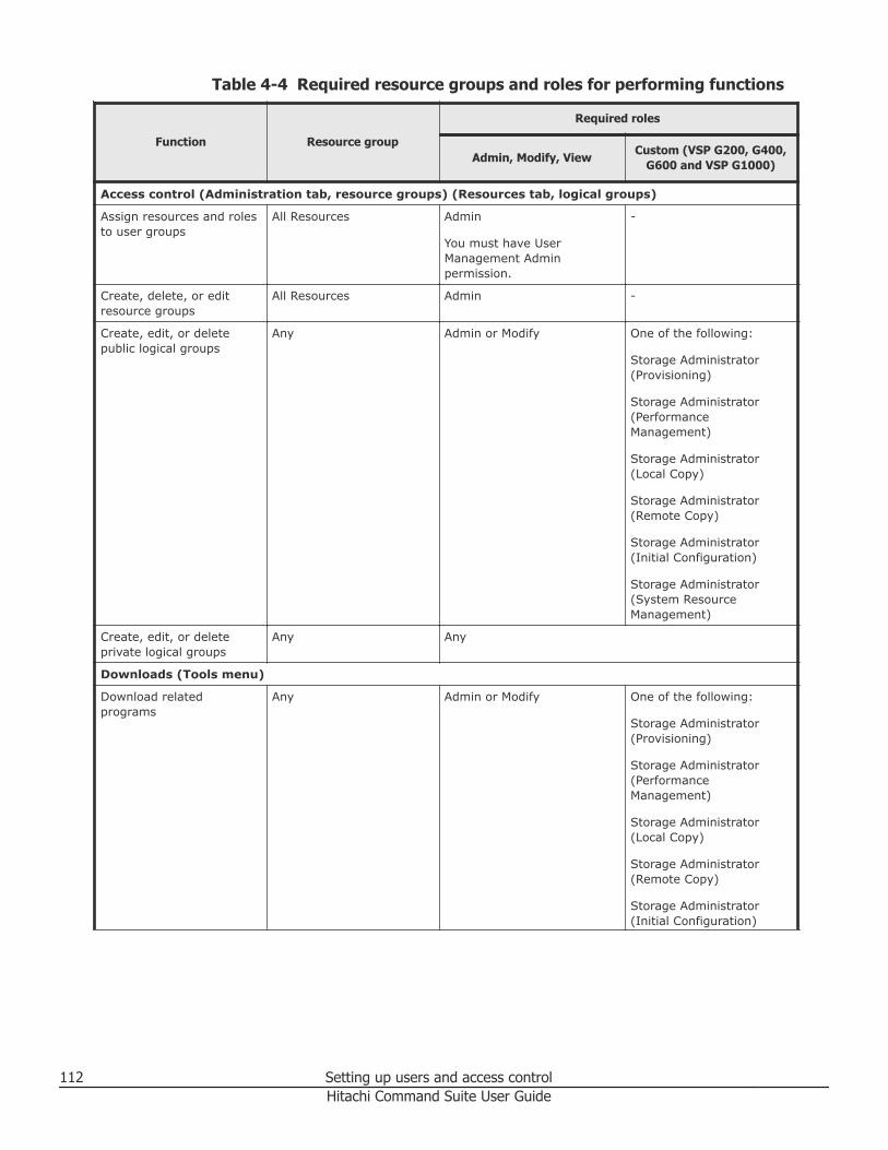
Table 4-4 Required resource groups and roles for performing functions
Function Resource group
Required roles
Admin, Modify, ViewCustom (VSP G200, G400,
G600 and VSP G1000)
Access control (Administration tab, resource groups) (Resources tab, logical groups)
Assign resources and rolesto user groups
All Resources Admin
You must have UserManagement Adminpermission.
-
Create, delete, or editresource groups
All Resources Admin -
Create, edit, or deletepublic logical groups
Any Admin or Modify One of the following:
Storage Administrator(Provisioning)
Storage Administrator(PerformanceManagement)
Storage Administrator(Local Copy)
Storage Administrator(Remote Copy)
Storage Administrator(Initial Configuration)
Storage Administrator(System ResourceManagement)
Create, edit, or deleteprivate logical groups
Any Any
Downloads (Tools menu)
Download relatedprograms
Any Admin or Modify One of the following:
Storage Administrator(Provisioning)
Storage Administrator(PerformanceManagement)
Storage Administrator(Local Copy)
Storage Administrator(Remote Copy)
Storage Administrator(Initial Configuration)
112 Setting up users and access controlHitachi Command Suite User Guide
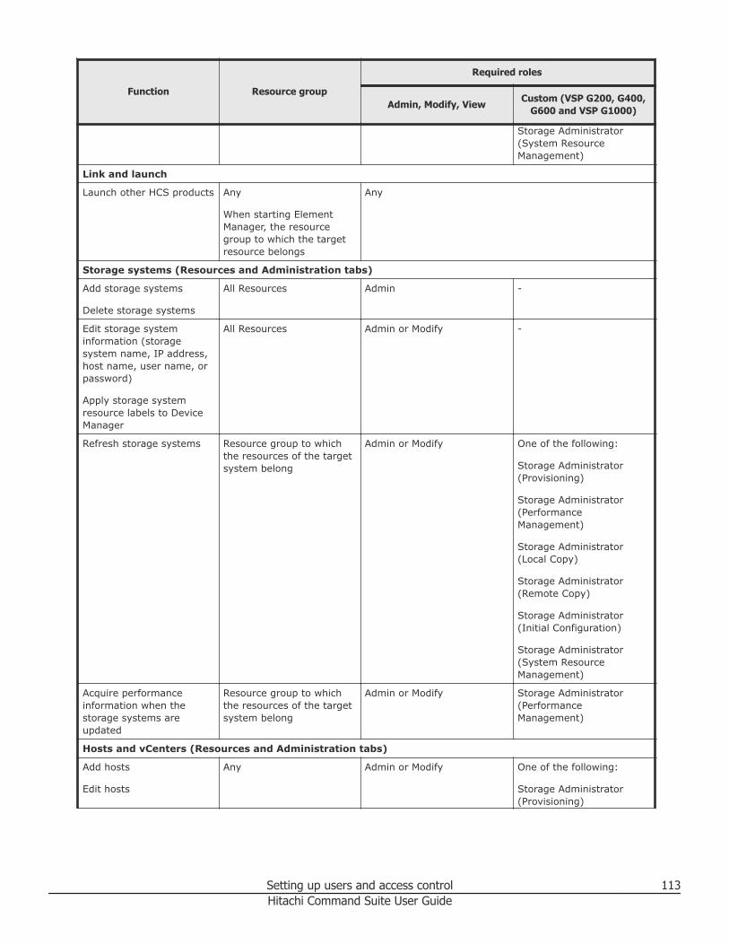
Function Resource group
Required roles
Admin, Modify, ViewCustom (VSP G200, G400,
G600 and VSP G1000)
Storage Administrator(System ResourceManagement)
Link and launch
Launch other HCS products Any
When starting ElementManager, the resourcegroup to which the targetresource belongs
Any
Storage systems (Resources and Administration tabs)
Add storage systems
Delete storage systems
All Resources Admin -
Edit storage systeminformation (storagesystem name, IP address,host name, user name, orpassword)
Apply storage systemresource labels to DeviceManager
All Resources Admin or Modify -
Refresh storage systems Resource group to whichthe resources of the targetsystem belong
Admin or Modify One of the following:
Storage Administrator(Provisioning)
Storage Administrator(PerformanceManagement)
Storage Administrator(Local Copy)
Storage Administrator(Remote Copy)
Storage Administrator(Initial Configuration)
Storage Administrator(System ResourceManagement)
Acquire performanceinformation when thestorage systems areupdated
Resource group to whichthe resources of the targetsystem belong
Admin or Modify Storage Administrator(PerformanceManagement)
Hosts and vCenters (Resources and Administration tabs)
Add hosts
Edit hosts
Any Admin or Modify One of the following:
Storage Administrator(Provisioning)
Setting up users and access control 113Hitachi Command Suite User Guide
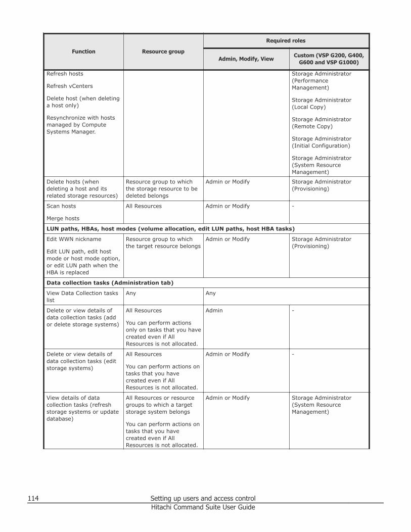
Function Resource group
Required roles
Admin, Modify, ViewCustom (VSP G200, G400,
G600 and VSP G1000)
Refresh hosts
Refresh vCenters
Delete host (when deletinga host only)
Resynchronize with hostsmanaged by ComputeSystems Manager.
Storage Administrator(PerformanceManagement)
Storage Administrator(Local Copy)
Storage Administrator(Remote Copy)
Storage Administrator(Initial Configuration)
Storage Administrator(System ResourceManagement)
Delete hosts (whendeleting a host and itsrelated storage resources)
Resource group to whichthe storage resource to bedeleted belongs
Admin or Modify Storage Administrator(Provisioning)
Scan hosts
Merge hosts
All Resources Admin or Modify -
LUN paths, HBAs, host modes (volume allocation, edit LUN paths, host HBA tasks)
Edit WWN nickname
Edit LUN path, edit hostmode or host mode option,or edit LUN path when theHBA is replaced
Resource group to whichthe target resource belongs
Admin or Modify Storage Administrator(Provisioning)
Data collection tasks (Administration tab)
View Data Collection taskslist
Any Any
Delete or view details ofdata collection tasks (addor delete storage systems)
All Resources
You can perform actionsonly on tasks that you havecreated even if AllResources is not allocated.
Admin -
Delete or view details ofdata collection tasks (editstorage systems)
All Resources
You can perform actions ontasks that you havecreated even if AllResources is not allocated.
Admin or Modify -
View details of datacollection tasks (refreshstorage systems or updatedatabase)
All Resources or resourcegroups to which a targetstorage system belongs
You can perform actions ontasks that you havecreated even if AllResources is not allocated.
Admin or Modify Storage Administrator(System ResourceManagement)
114 Setting up users and access controlHitachi Command Suite User Guide
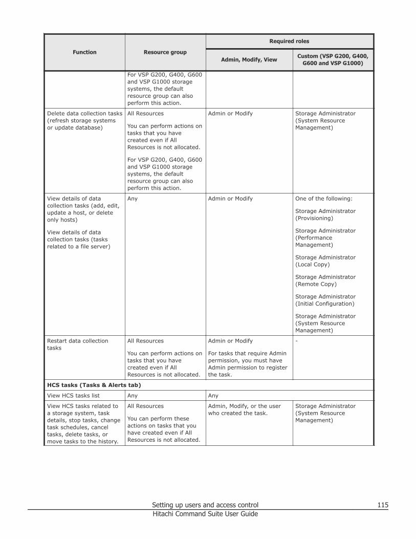
Function Resource group
Required roles
Admin, Modify, ViewCustom (VSP G200, G400,
G600 and VSP G1000)
For VSP G200, G400, G600and VSP G1000 storagesystems, the defaultresource group can alsoperform this action.
Delete data collection tasks(refresh storage systemsor update database)
All Resources
You can perform actions ontasks that you havecreated even if AllResources is not allocated.
For VSP G200, G400, G600and VSP G1000 storagesystems, the defaultresource group can alsoperform this action.
Admin or Modify Storage Administrator(System ResourceManagement)
View details of datacollection tasks (add, edit,update a host, or deleteonly hosts)
View details of datacollection tasks (tasksrelated to a file server)
Any Admin or Modify One of the following:
Storage Administrator(Provisioning)
Storage Administrator(PerformanceManagement)
Storage Administrator(Local Copy)
Storage Administrator(Remote Copy)
Storage Administrator(Initial Configuration)
Storage Administrator(System ResourceManagement)
Restart data collectiontasks
All Resources
You can perform actions ontasks that you havecreated even if AllResources is not allocated.
Admin or Modify
For tasks that require Adminpermission, you must haveAdmin permission to registerthe task.
-
HCS tasks (Tasks & Alerts tab)
View HCS tasks list Any Any
View HCS tasks related toa storage system, taskdetails, stop tasks, changetask schedules, canceltasks, delete tasks, ormove tasks to the history.
All Resources
You can perform theseactions on tasks that youhave created even if AllResources is not allocated.
Admin, Modify, or the userwho created the task.
Storage Administrator(System ResourceManagement)
Setting up users and access control 115Hitachi Command Suite User Guide
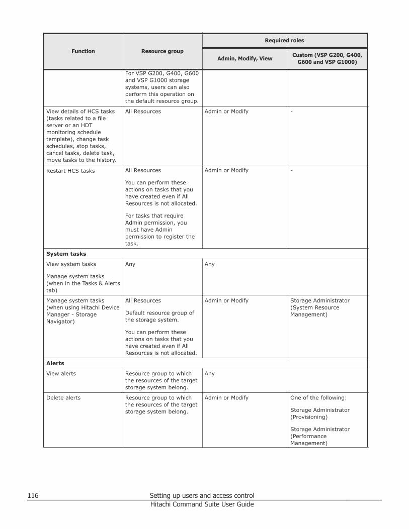
Function Resource group
Required roles
Admin, Modify, ViewCustom (VSP G200, G400,
G600 and VSP G1000)
For VSP G200, G400, G600and VSP G1000 storagesystems, users can alsoperform this operation onthe default resource group.
View details of HCS tasks(tasks related to a fileserver or an HDTmonitoring scheduletemplate), change taskschedules, stop tasks,cancel tasks, delete task,move tasks to the history.
All Resources Admin or Modify -
Restart HCS tasks All Resources
You can perform theseactions on tasks that youhave created even if AllResources is not allocated.
For tasks that requireAdmin permission, youmust have Adminpermission to register thetask.
Admin or Modify -
System tasks
View system tasks
Manage system tasks(when in the Tasks & Alertstab)
Any Any
Manage system tasks(when using Hitachi DeviceManager - StorageNavigator)
All Resources
Default resource group ofthe storage system.
You can perform theseactions on tasks that youhave created even if AllResources is not allocated.
Admin or Modify Storage Administrator(System ResourceManagement)
Alerts
View alerts Resource group to whichthe resources of the targetstorage system belong.
Any
Delete alerts Resource group to whichthe resources of the targetstorage system belong.
Admin or Modify One of the following:
Storage Administrator(Provisioning)
Storage Administrator(PerformanceManagement)
116 Setting up users and access controlHitachi Command Suite User Guide
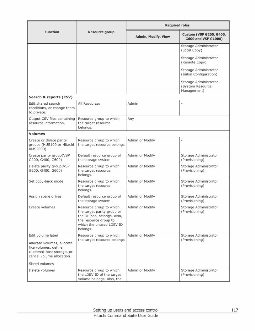
Function Resource group
Required roles
Admin, Modify, ViewCustom (VSP G200, G400,
G600 and VSP G1000)
Storage Administrator(Local Copy)
Storage Administrator(Remote Copy)
Storage Administrator(Initial Configuration)
Storage Administrator(System ResourceManagement)
Search & reports (CSV)
Edit shared searchconditions, or change themto private.
All Resources Admin -
Output CSV files containingresource information.
Resource group to whichthe target resourcebelongs.
Any
Volumes
Create or delete paritygroups (HUS100 or HitachiAMS2000)
Resource group to whichthe target resource belongs
Admin or Modify -
Create parity group(VSPG200, G400, G600)
Default resource group ofthe storage system.
Admin or Modify Storage Administrator(Provisioning)
Delete parity group(VSPG200, G400, G600)
Resource group to whichthe target resourcebelongs.
Admin or Modify Storage Administrator(Provisioning)
Set copy-back mode Resource group to whichthe target resourcebelongs.
Admin or Modify Storage Administrator(Provisioning)
Assign spare drives Default resource group ofthe storage system.
Admin or Modify Storage Administrator(Provisioning)
Create volumes Resource group to whichthe target parity group orthe DP pool belongs. Also,the resource group towhich the unused LDEV IDbelongs.
Admin or Modify Storage Administrator(Provisioning)
Edit volume label
Allocate volumes, allocatelike volumes, defineclustered-host storage, orcancel volume allocation.
Shred volumes
Resource group to whichthe target resource belongs
Admin or Modify Storage Administrator(Provisioning)
Delete volumes Resource group to whichthe LDEV ID of the targetvolume belongs. Also, the
Admin or Modify Storage Administrator(Provisioning)
Setting up users and access control 117Hitachi Command Suite User Guide
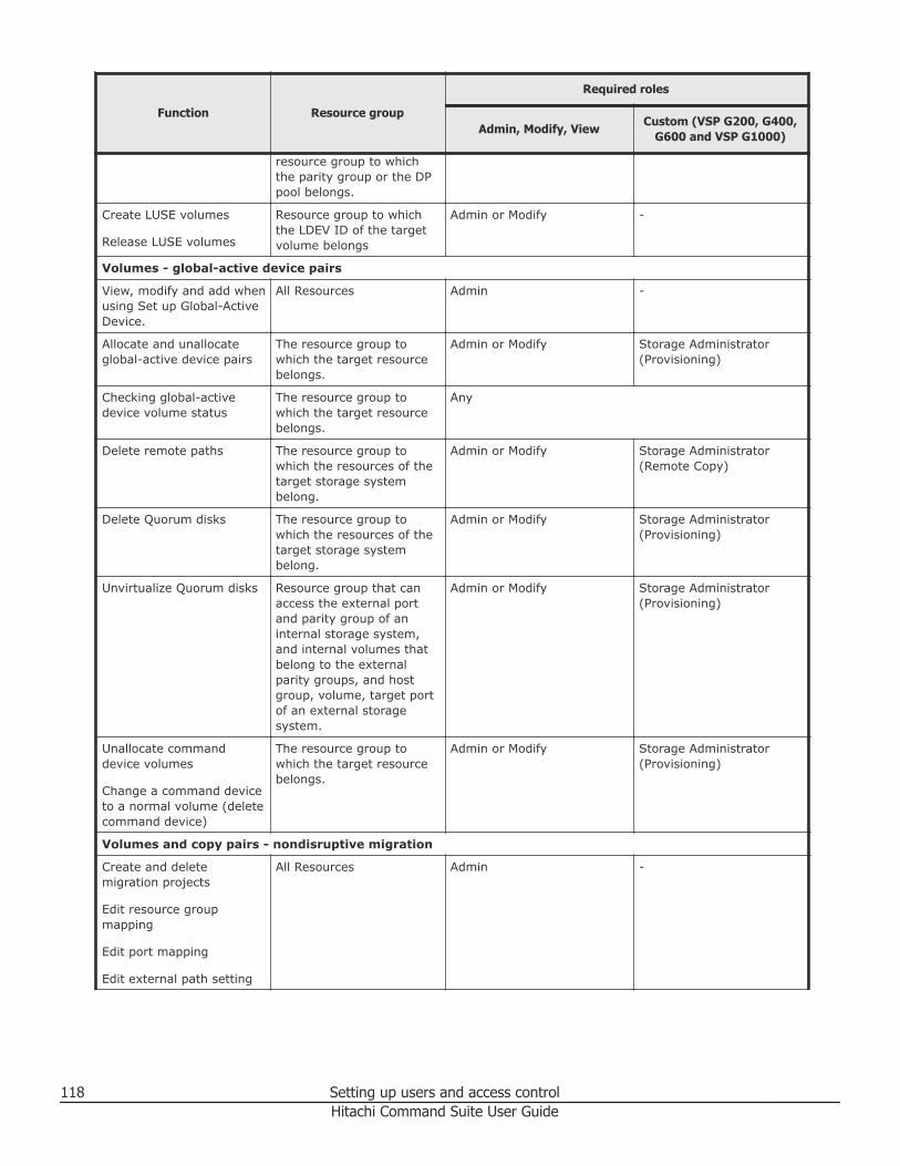
Function Resource group
Required roles
Admin, Modify, ViewCustom (VSP G200, G400,
G600 and VSP G1000)
resource group to whichthe parity group or the DPpool belongs.
Create LUSE volumes
Release LUSE volumes
Resource group to whichthe LDEV ID of the targetvolume belongs
Admin or Modify -
Volumes - global-active device pairs
View, modify and add whenusing Set up Global-ActiveDevice.
All Resources Admin -
Allocate and unallocateglobal-active device pairs
The resource group towhich the target resourcebelongs.
Admin or Modify Storage Administrator(Provisioning)
Checking global-activedevice volume status
The resource group towhich the target resourcebelongs.
Any
Delete remote paths The resource group towhich the resources of thetarget storage systembelong.
Admin or Modify Storage Administrator(Remote Copy)
Delete Quorum disks The resource group towhich the resources of thetarget storage systembelong.
Admin or Modify Storage Administrator(Provisioning)
Unvirtualize Quorum disks Resource group that canaccess the external portand parity group of aninternal storage system,and internal volumes thatbelong to the externalparity groups, and hostgroup, volume, target portof an external storagesystem.
Admin or Modify Storage Administrator(Provisioning)
Unallocate commanddevice volumes
Change a command deviceto a normal volume (deletecommand device)
The resource group towhich the target resourcebelongs.
Admin or Modify Storage Administrator(Provisioning)
Volumes and copy pairs - nondisruptive migration
Create and deletemigration projects
Edit resource groupmapping
Edit port mapping
Edit external path setting
All Resources Admin -
118 Setting up users and access controlHitachi Command Suite User Guide
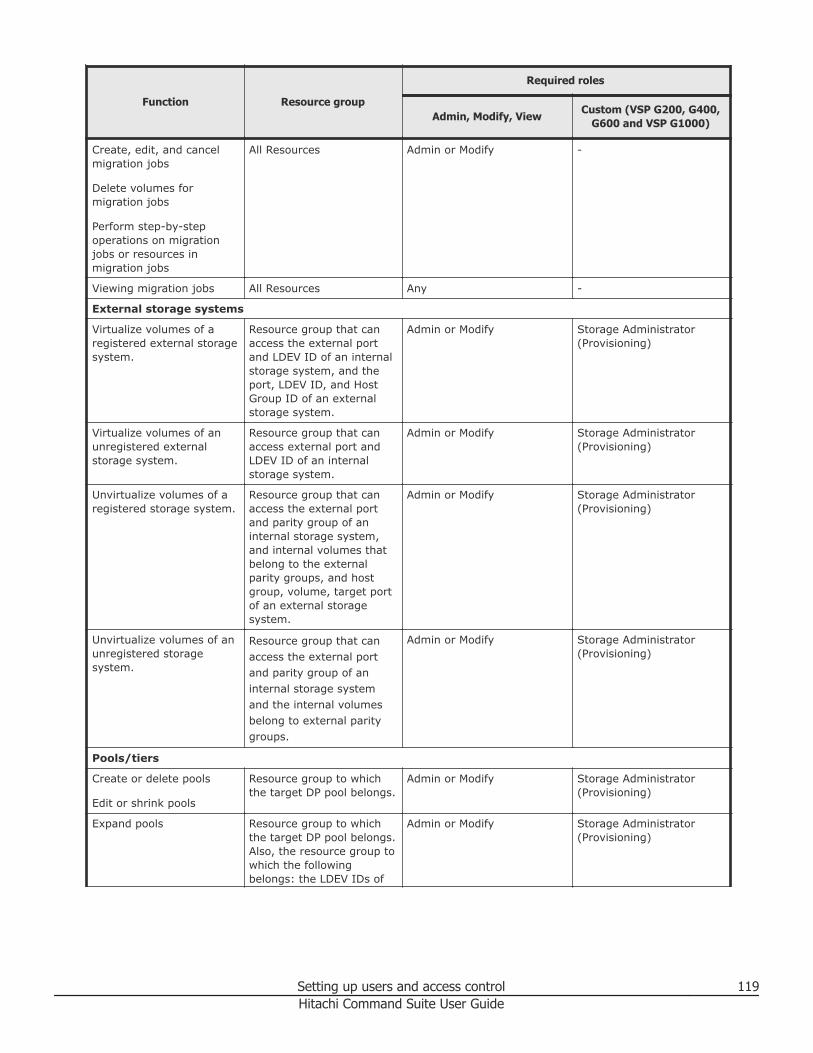
Function Resource group
Required roles
Admin, Modify, ViewCustom (VSP G200, G400,
G600 and VSP G1000)
Create, edit, and cancelmigration jobs
Delete volumes formigration jobs
Perform step-by-stepoperations on migrationjobs or resources inmigration jobs
All Resources Admin or Modify -
Viewing migration jobs All Resources Any -
External storage systems
Virtualize volumes of aregistered external storagesystem.
Resource group that canaccess the external portand LDEV ID of an internalstorage system, and theport, LDEV ID, and HostGroup ID of an externalstorage system.
Admin or Modify Storage Administrator(Provisioning)
Virtualize volumes of anunregistered externalstorage system.
Resource group that canaccess external port andLDEV ID of an internalstorage system.
Admin or Modify Storage Administrator(Provisioning)
Unvirtualize volumes of aregistered storage system.
Resource group that canaccess the external portand parity group of aninternal storage system,and internal volumes thatbelong to the externalparity groups, and hostgroup, volume, target portof an external storagesystem.
Admin or Modify Storage Administrator(Provisioning)
Unvirtualize volumes of anunregistered storagesystem.
Resource group that canaccess the external portand parity group of aninternal storage systemand the internal volumesbelong to external paritygroups.
Admin or Modify Storage Administrator(Provisioning)
Pools/tiers
Create or delete pools
Edit or shrink pools
Resource group to whichthe target DP pool belongs.
Admin or Modify Storage Administrator(Provisioning)
Expand pools Resource group to whichthe target DP pool belongs.Also, the resource group towhich the followingbelongs: the LDEV IDs of
Admin or Modify Storage Administrator(Provisioning)
Setting up users and access control 119Hitachi Command Suite User Guide
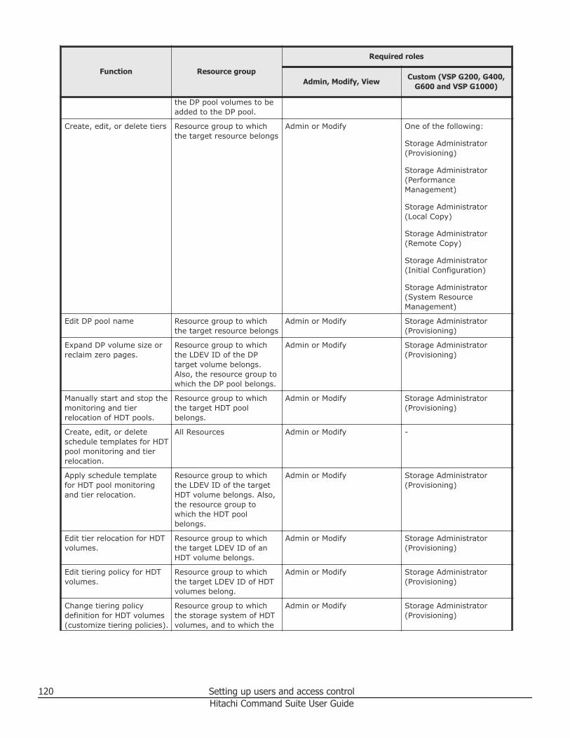
Function Resource group
Required roles
Admin, Modify, ViewCustom (VSP G200, G400,
G600 and VSP G1000)
the DP pool volumes to beadded to the DP pool.
Create, edit, or delete tiers Resource group to whichthe target resource belongs
Admin or Modify One of the following:
Storage Administrator(Provisioning)
Storage Administrator(PerformanceManagement)
Storage Administrator(Local Copy)
Storage Administrator(Remote Copy)
Storage Administrator(Initial Configuration)
Storage Administrator(System ResourceManagement)
Edit DP pool name Resource group to whichthe target resource belongs
Admin or Modify Storage Administrator(Provisioning)
Expand DP volume size orreclaim zero pages.
Resource group to whichthe LDEV ID of the DPtarget volume belongs.Also, the resource group towhich the DP pool belongs.
Admin or Modify Storage Administrator(Provisioning)
Manually start and stop themonitoring and tierrelocation of HDT pools.
Resource group to whichthe target HDT poolbelongs.
Admin or Modify Storage Administrator(Provisioning)
Create, edit, or deleteschedule templates for HDTpool monitoring and tierrelocation.
All Resources Admin or Modify -
Apply schedule templatefor HDT pool monitoringand tier relocation.
Resource group to whichthe LDEV ID of the targetHDT volume belongs. Also,the resource group towhich the HDT poolbelongs.
Admin or Modify Storage Administrator(Provisioning)
Edit tier relocation for HDTvolumes.
Resource group to whichthe target LDEV ID of anHDT volume belongs.
Admin or Modify Storage Administrator(Provisioning)
Edit tiering policy for HDTvolumes.
Resource group to whichthe target LDEV ID of HDTvolumes belong.
Admin or Modify Storage Administrator(Provisioning)
Change tiering policydefinition for HDT volumes(customize tiering policies).
Resource group to whichthe storage system of HDTvolumes, and to which the
Admin or Modify Storage Administrator(Provisioning)
120 Setting up users and access controlHitachi Command Suite User Guide
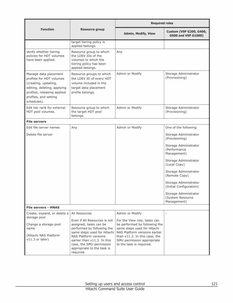
Function Resource group
Required roles
Admin, Modify, ViewCustom (VSP G200, G400,
G600 and VSP G1000)
target tiering policy isapplied belongs.
Verify whether tieringpolicies for HDT volumeshave been applied.
Resource group to whichthe LDEV IDs of thevolumes to which thetiering policy has beenapplied belongs.
Any
Manage data placementprofiles for HDT volumes(creating, updating,editing, deleting, applyingprofiles, releasing appliedprofiles, and settingschedules).
Resource groups to whichthe LDEV ID of every HDTvolume included in thetarget data placementprofile belongs.
Admin or Modify Storage Administrator(Provisioning)
Edit tier rank for externalHDT pool volumes.
Resource group to whichthe target HDT poolbelongs.
Admin or Modify Storage Administrator(Provisioning)
File servers
Edit file server names
Delete file server
Any Admin or Modify One of the following:
Storage Administrator(Provisioning)
Storage Administrator(PerformanceManagement)
Storage Administrator(Local Copy)
Storage Administrator(Remote Copy)
Storage Administrator(Initial Configuration)
Storage Administrator(System ResourceManagement)
File servers - HNAS
Create, expand, or delete astorage pool
Change a storage poolname
(Hitachi NAS Platformv11.3 or later)
All Resources
Even if All Resources is notassigned, tasks can beperformed by following thesame steps used for HitachiNAS Platform versionsearlier than v11.3. In thiscase, the SMU permissionappropriate to the task isrequired.
Admin or Modify
For the View role, tasks canbe performed by following thesame steps used for HitachiNAS Platform versions earlierthan v11.3. In this case, theSMU permission appropriateto the task is required.
-
Setting up users and access control 121Hitachi Command Suite User Guide
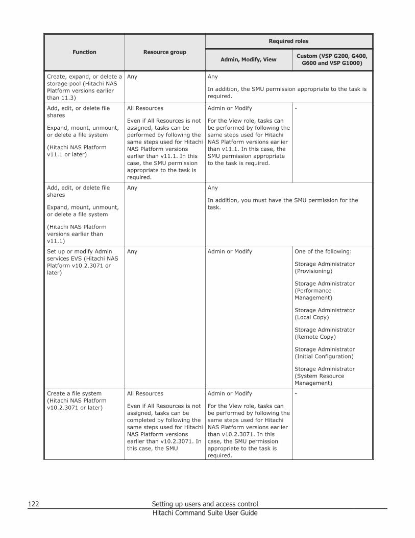
Function Resource group
Required roles
Admin, Modify, ViewCustom (VSP G200, G400,
G600 and VSP G1000)
Create, expand, or delete astorage pool (Hitachi NASPlatform versions earlierthan 11.3)
Any Any
In addition, the SMU permission appropriate to the task isrequired.
Add, edit, or delete fileshares
Expand, mount, unmount,or delete a file system
(Hitachi NAS Platformv11.1 or later)
All Resources
Even if All Resources is notassigned, tasks can beperformed by following thesame steps used for HitachiNAS Platform versionsearlier than v11.1. In thiscase, the SMU permissionappropriate to the task isrequired.
Admin or Modify
For the View role, tasks canbe performed by following thesame steps used for HitachiNAS Platform versions earlierthan v11.1. In this case, theSMU permission appropriateto the task is required.
-
Add, edit, or delete fileshares
Expand, mount, unmount,or delete a file system
(Hitachi NAS Platformversions earlier thanv11.1)
Any Any
In addition, you must have the SMU permission for thetask.
Set up or modify Adminservices EVS (Hitachi NASPlatform v10.2.3071 orlater)
Any Admin or Modify One of the following:
Storage Administrator(Provisioning)
Storage Administrator(PerformanceManagement)
Storage Administrator(Local Copy)
Storage Administrator(Remote Copy)
Storage Administrator(Initial Configuration)
Storage Administrator(System ResourceManagement)
Create a file system(Hitachi NAS Platformv10.2.3071 or later)
All Resources
Even if All Resources is notassigned, tasks can becompleted by following thesame steps used for HitachiNAS Platform versionsearlier than v10.2.3071. Inthis case, the SMU
Admin or Modify
For the View role, tasks canbe performed by following thesame steps used for HitachiNAS Platform versions earlierthan v10.2.3071. In thiscase, the SMU permissionappropriate to the task isrequired.
-
122 Setting up users and access controlHitachi Command Suite User Guide
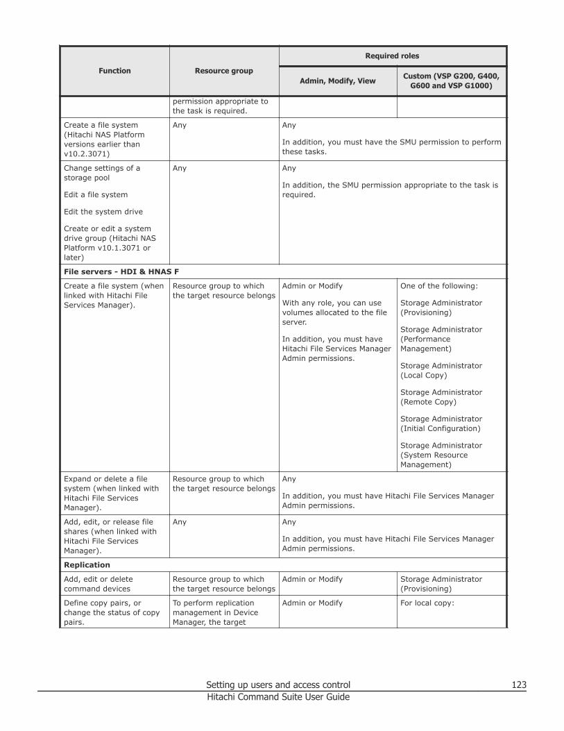
Function Resource group
Required roles
Admin, Modify, ViewCustom (VSP G200, G400,
G600 and VSP G1000)
permission appropriate tothe task is required.
Create a file system(Hitachi NAS Platformversions earlier thanv10.2.3071)
Any Any
In addition, you must have the SMU permission to performthese tasks.
Change settings of astorage pool
Edit a file system
Edit the system drive
Create or edit a systemdrive group (Hitachi NASPlatform v10.1.3071 orlater)
Any Any
In addition, the SMU permission appropriate to the task isrequired.
File servers - HDI & HNAS F
Create a file system (whenlinked with Hitachi FileServices Manager).
Resource group to whichthe target resource belongs
Admin or Modify
With any role, you can usevolumes allocated to the fileserver.
In addition, you must haveHitachi File Services ManagerAdmin permissions.
One of the following:
Storage Administrator(Provisioning)
Storage Administrator(PerformanceManagement)
Storage Administrator(Local Copy)
Storage Administrator(Remote Copy)
Storage Administrator(Initial Configuration)
Storage Administrator(System ResourceManagement)
Expand or delete a filesystem (when linked withHitachi File ServicesManager).
Resource group to whichthe target resource belongs
Any
In addition, you must have Hitachi File Services ManagerAdmin permissions.
Add, edit, or release fileshares (when linked withHitachi File ServicesManager).
Any Any
In addition, you must have Hitachi File Services ManagerAdmin permissions.
Replication
Add, edit or deletecommand devices
Resource group to whichthe target resource belongs
Admin or Modify Storage Administrator(Provisioning)
Define copy pairs, orchange the status of copypairs.
To perform replicationmanagement in DeviceManager, the target
Admin or Modify For local copy:
Setting up users and access control 123Hitachi Command Suite User Guide
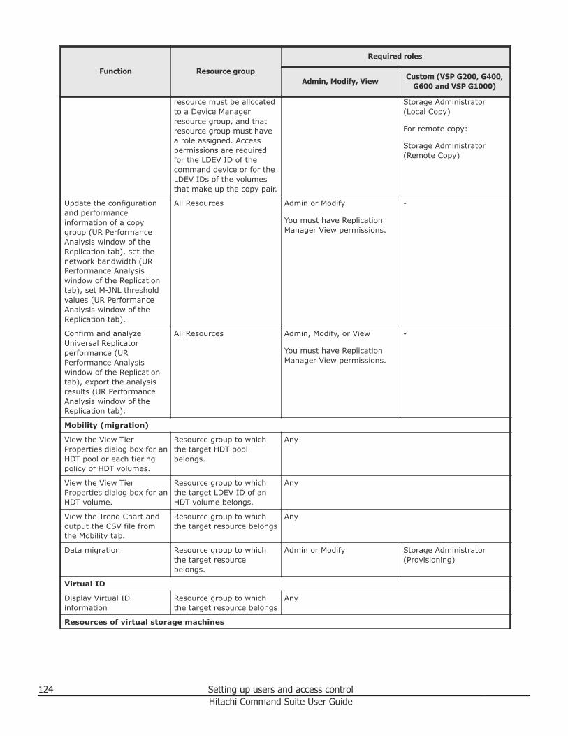
Function Resource group
Required roles
Admin, Modify, ViewCustom (VSP G200, G400,
G600 and VSP G1000)
resource must be allocatedto a Device Managerresource group, and thatresource group must havea role assigned. Accesspermissions are requiredfor the LDEV ID of thecommand device or for theLDEV IDs of the volumesthat make up the copy pair.
Storage Administrator(Local Copy)
For remote copy:
Storage Administrator(Remote Copy)
Update the configurationand performanceinformation of a copygroup (UR PerformanceAnalysis window of theReplication tab), set thenetwork bandwidth (URPerformance Analysiswindow of the Replicationtab), set M-JNL thresholdvalues (UR PerformanceAnalysis window of theReplication tab).
All Resources Admin or Modify
You must have ReplicationManager View permissions.
-
Confirm and analyzeUniversal Replicatorperformance (URPerformance Analysiswindow of the Replicationtab), export the analysisresults (UR PerformanceAnalysis window of theReplication tab).
All Resources Admin, Modify, or View
You must have ReplicationManager View permissions.
-
Mobility (migration)
View the View TierProperties dialog box for anHDT pool or each tieringpolicy of HDT volumes.
Resource group to whichthe target HDT poolbelongs.
Any
View the View TierProperties dialog box for anHDT volume.
Resource group to whichthe target LDEV ID of anHDT volume belongs.
Any
View the Trend Chart andoutput the CSV file fromthe Mobility tab.
Resource group to whichthe target resource belongs
Any
Data migration Resource group to whichthe target resourcebelongs.
Admin or Modify Storage Administrator(Provisioning)
Virtual ID
Display Virtual IDinformation
Resource group to whichthe target resource belongs
Any
Resources of virtual storage machines
124 Setting up users and access controlHitachi Command Suite User Guide
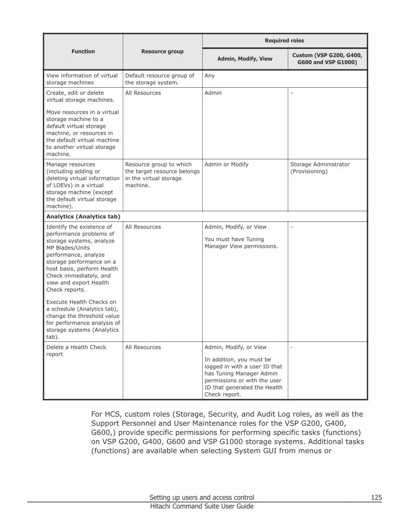
Function Resource group
Required roles
Admin, Modify, ViewCustom (VSP G200, G400,
G600 and VSP G1000)
View information of virtualstorage machines
Default resource group ofthe storage system.
Any
Create, edit or deletevirtual storage machines.
Move resources in a virtualstorage machine to adefault virtual storagemachine, or resources inthe default virtual machineto another virtual storagemachine.
All Resources Admin -
Manage resources(including adding ordeleting virtual informationof LDEVs) in a virtualstorage machine (exceptthe default virtual storagemachine).
Resource group to whichthe target resource belongsin the virtual storagemachine.
Admin or Modify Storage Administrator(Provisioning)
Analytics (Analytics tab)
Identify the existence ofperformance problems ofstorage systems, analyzeMP Blades/Unitsperformance, analyzestorage performance on ahost basis, perform HealthCheck immediately, andview and export HealthCheck reports.
Execute Health Checks ona schedule (Analytics tab),change the threshold valuefor performance analysis ofstorage systems (Analyticstab).
All Resources Admin, Modify, or View
You must have TuningManager View permissions.
-
Delete a Health Checkreport
All Resources Admin, Modify, or View
In addition, you must belogged in with a user ID thathas Tuning Manager Adminpermissions or with the userID that generated the HealthCheck report.
-
For HCS, custom roles (Storage, Security, and Audit Log roles, as well as theSupport Personnel and User Maintenance roles for the VSP G200, G400,G600,) provide specific permissions for performing specific tasks (functions)on VSP G200, G400, G600 and VSP G1000 storage systems. Additional tasks(functions) are available when selecting System GUI from menus or
Setting up users and access control 125Hitachi Command Suite User Guide
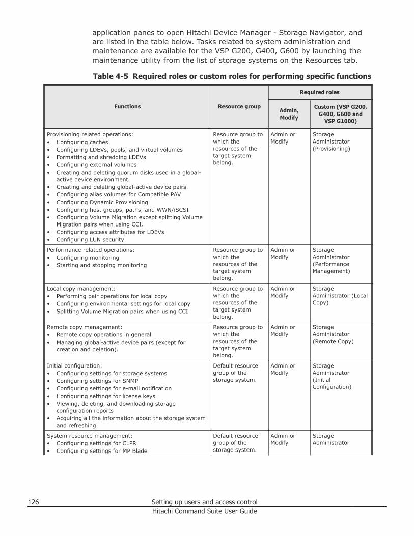
application panes to open Hitachi Device Manager - Storage Navigator, andare listed in the table below. Tasks related to system administration andmaintenance are available for the VSP G200, G400, G600 by launching themaintenance utility from the list of storage systems on the Resources tab.
Table 4-5 Required roles or custom roles for performing specific functions
Functions Resource group
Required roles
Admin,Modify
Custom (VSP G200,G400, G600 and
VSP G1000)
Provisioning related operations:• Configuring caches• Configuring LDEVs, pools, and virtual volumes• Formatting and shredding LDEVs• Configuring external volumes• Creating and deleting quorum disks used in a global-
active device environment.• Creating and deleting global-active device pairs.• Configuring alias volumes for Compatible PAV• Configuring Dynamic Provisioning• Configuring host groups, paths, and WWN/iSCSI• Configuring Volume Migration except splitting Volume
Migration pairs when using CCI.• Configuring access attributes for LDEVs• Configuring LUN security
Resource group towhich theresources of thetarget systembelong.
Admin orModify
StorageAdministrator(Provisioning)
Performance related operations:• Configuring monitoring• Starting and stopping monitoring
Resource group towhich theresources of thetarget systembelong.
Admin orModify
StorageAdministrator(PerformanceManagement)
Local copy management:• Performing pair operations for local copy• Configuring environmental settings for local copy• Splitting Volume Migration pairs when using CCI
Resource group towhich theresources of thetarget systembelong.
Admin orModify
StorageAdministrator (LocalCopy)
Remote copy management:• Remote copy operations in general• Managing global-active device pairs (except for
creation and deletion).
Resource group towhich theresources of thetarget systembelong.
Admin orModify
StorageAdministrator(Remote Copy)
Initial configuration:• Configuring settings for storage systems• Configuring settings for SNMP• Configuring settings for e-mail notification• Configuring settings for license keys• Viewing, deleting, and downloading storage
configuration reports• Acquiring all the information about the storage system
and refreshing
Default resourcegroup of thestorage system.
Admin orModify
StorageAdministrator(InitialConfiguration)
System resource management:• Configuring settings for CLPR• Configuring settings for MP Blade
Default resourcegroup of thestorage system.
Admin orModify
StorageAdministrator
126 Setting up users and access controlHitachi Command Suite User Guide
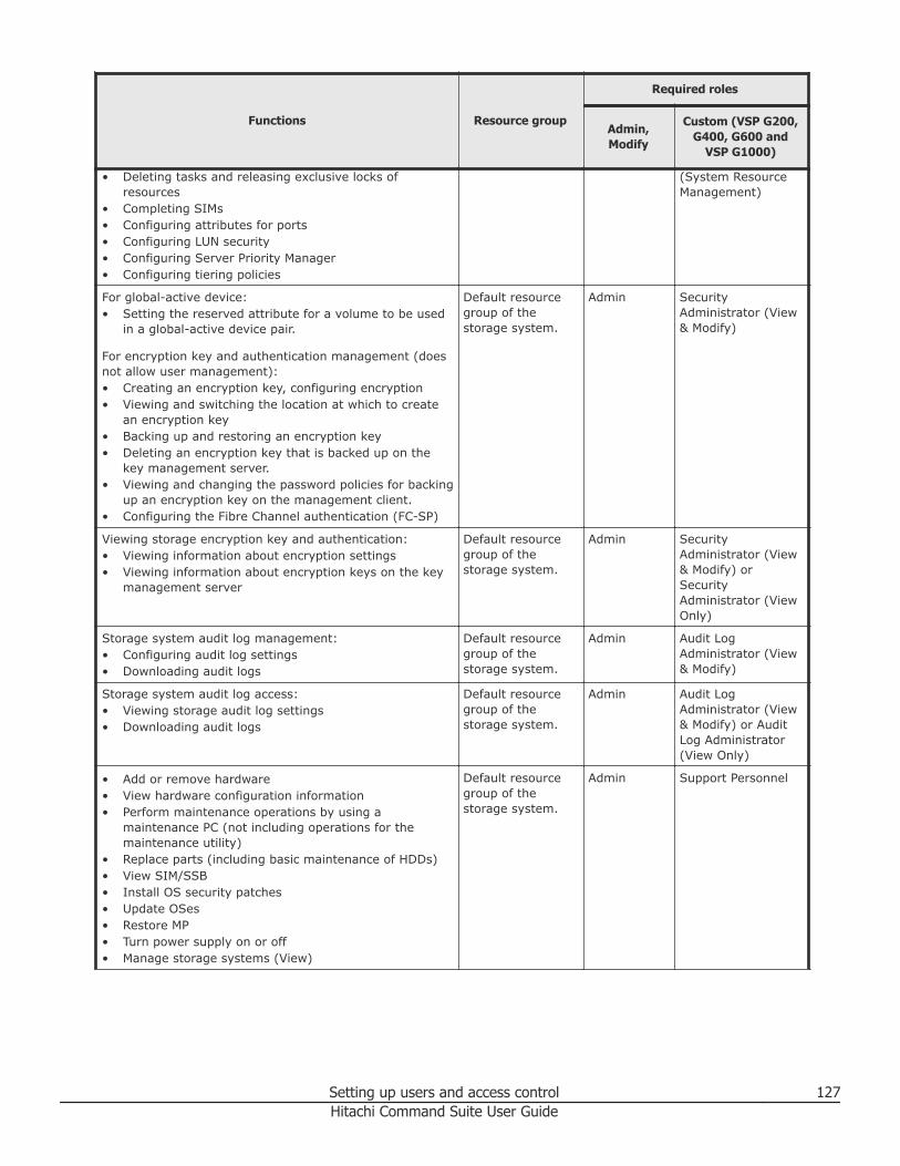
Functions Resource group
Required roles
Admin,Modify
Custom (VSP G200,G400, G600 and
VSP G1000)
• Deleting tasks and releasing exclusive locks ofresources
• Completing SIMs• Configuring attributes for ports• Configuring LUN security• Configuring Server Priority Manager• Configuring tiering policies
(System ResourceManagement)
For global-active device:• Setting the reserved attribute for a volume to be used
in a global-active device pair.
For encryption key and authentication management (doesnot allow user management):• Creating an encryption key, configuring encryption• Viewing and switching the location at which to create
an encryption key• Backing up and restoring an encryption key• Deleting an encryption key that is backed up on the
key management server.• Viewing and changing the password policies for backing
up an encryption key on the management client.• Configuring the Fibre Channel authentication (FC-SP)
Default resourcegroup of thestorage system.
Admin SecurityAdministrator (View& Modify)
Viewing storage encryption key and authentication:• Viewing information about encryption settings• Viewing information about encryption keys on the key
management server
Default resourcegroup of thestorage system.
Admin SecurityAdministrator (View& Modify) orSecurityAdministrator (ViewOnly)
Storage system audit log management:• Configuring audit log settings• Downloading audit logs
Default resourcegroup of thestorage system.
Admin Audit LogAdministrator (View& Modify)
Storage system audit log access:• Viewing storage audit log settings• Downloading audit logs
Default resourcegroup of thestorage system.
Admin Audit LogAdministrator (View& Modify) or AuditLog Administrator(View Only)
• Add or remove hardware• View hardware configuration information• Perform maintenance operations by using a
maintenance PC (not including operations for themaintenance utility)
• Replace parts (including basic maintenance of HDDs)• View SIM/SSB• Install OS security patches• Update OSes• Restore MP• Turn power supply on or off• Manage storage systems (View)
Default resourcegroup of thestorage system.
Admin Support Personnel
Setting up users and access control 127Hitachi Command Suite User Guide
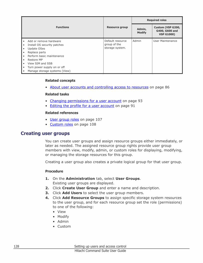
Functions Resource group
Required roles
Admin,Modify
Custom (VSP G200,G400, G600 and
VSP G1000)
• Add or remove hardware• Install OS security patches• Update OSes• Replace parts• Perform basic maintenance• Restore MP• View SIM and SSB• Turn power supply on or off• Manage storage systems (View)
Default resourcegroup of thestorage system.
Admin User Maintenance
Related concepts
• About user accounts and controlling access to resources on page 86
Related tasks
• Changing permissions for a user account on page 93• Editing the profile for a user account on page 91
Related references
• User group roles on page 107• Custom roles on page 108
Creating user groupsYou can create user groups and assign resource groups either immediately, orlater as needed. The assigned resource group rights provide user groupmembers with view, modify, admin, or custom roles for displaying, modifying,or managing the storage resources for this group.
Creating a user group also creates a private logical group for that user group.
Procedure
1. On the Administration tab, select User Groups.Existing user groups are displayed.
2. Click Create User Group and enter a name and description.3. Click Add Users to select the user group members.4. Click Add Resource Groups to assign specific storage system resources
to the user group, and for each resource group set the role (permissions)to one of the following:• View• Modify• Admin• Custom
128 Setting up users and access controlHitachi Command Suite User Guide
5. Click OK.You can click the user group name to verify group membership (list ofusers) on the Users tab. On the Resource Groups tab, you can verifythe resource groups and roles specified during user group creation. AddResource Groups, Remove Resource Groups, and Edit Rolesbuttons allow you to modify resources and access rights for the usergroup.
Result
The new user group is displayed and a new private logical group is created.
Related concepts
• About user groups on page 104
Related tasks
• Editing a user group on page 129• Assigning resource groups and roles to a user group on page 130• Deleting user groups on page 130
Editing a user groupAs user information and membership in user groups change, you can updatethis information.
Procedure
1. On the Administration tab, select User Groups.2. Select the target user group and click Edit User Group.
Note: If the Edit User Group button is not activated, the selected usergroup cannot be edited. This occurs when selecting a built in user groupfor which editing is not allowed.
3. Change the name of the user group, or the user who manages the usergroup.
Result
Editing changes appear in the list in the User Groups tab.
Related concepts
• About user groups on page 104• About access control on page 97
Related tasks
• Assigning resource groups and roles to a user group on page 130
Setting up users and access control 129Hitachi Command Suite User Guide
Assigning resource groups and roles to a user groupYou can assign resource groups and roles to a user group.
Procedure
1. Select the Administration tab and click on User Groups.2. In the User Groups tab, click the name of the target user group.3. In the Resource Groups tab, click Add Resource Groups.4. Set the roles to be assigned to the user group. The assigned resource
groups and roles are displayed in detail by clicking the link for the usergroup name.
Related tasks
• Creating resource groups on page 102• Creating user groups on page 128
Changing a user’s user groupYou can modify information about the user groups that a user belongs to.
Procedure
1. On the Administration tab, select User Groups.2. In the Users tab select the target user group and click Assign User
Groups.3. Change the user groups to which a user belongs.
Result
Changes will appear in the Users tab.
Related concepts
• About access control on page 97
Related tasks
• Creating user groups on page 128• Assigning resource groups and roles to a user group on page 130• Editing a user group on page 129
Deleting user groupsDeleting a user group deletes the associated private logical group and alllogical groups that belong to that private logical group. Deleting a user groupdoes not delete the related resource groups.
130 Setting up users and access controlHitachi Command Suite User Guide
Procedure
1. On the Administration tab, select User Groups.2. Select the user groups to delete.3. Click Delete Groups.
Note: If the Delete Groups button is not activated, the selected usergroup cannot be deleted. This occurs when selecting a built in user groupthat is not allowed to be deleted, or if the user group is associated withanother group, such as a resource group, and deletion is not allowed.
4. Click OK.
Result
The user groups you deleted no longer appear in the list of user groups.
Setting up users and access control 131Hitachi Command Suite User Guide

132 Setting up users and access controlHitachi Command Suite User Guide
5Provisioning storage
This module describes provisioning storage.
□ Creating a storage operating environment
□ Allocating storage
□ Creating and deleting parity groups
□ Creating and deleting volumes
□ Virtualizing external storage
□ Virtualizing storage capacity (HDP/HDT)
□ Virtualizing storage tiers (HDT)
□ Allocating and unallocating volumes
□ Configuring Fibre Channel ports
□ Managing LUN paths
□ Managing Hitachi NAS Platform file systems and shares
□ Managing Hitachi NAS Platform F and Hitachi Data Ingestor file systemsand shares
Provisioning storage 133Hitachi Command Suite User Guide
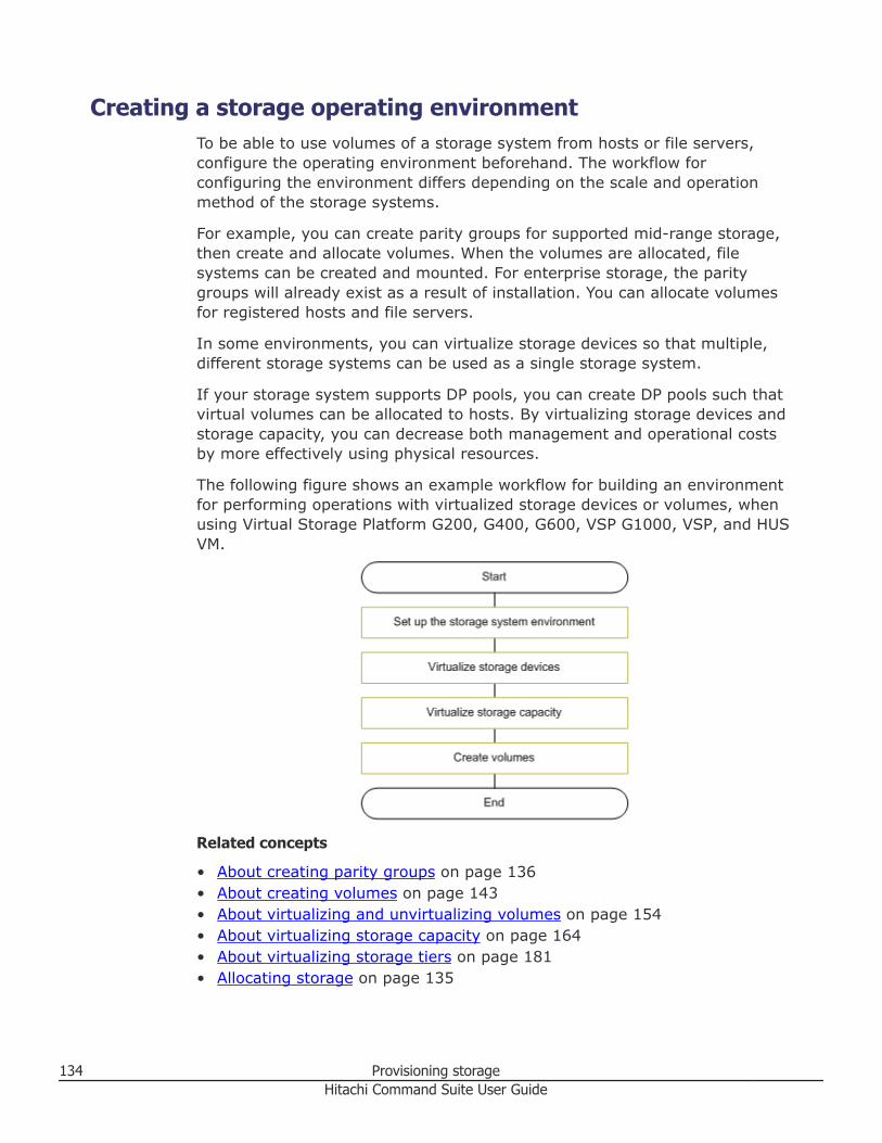
Creating a storage operating environmentTo be able to use volumes of a storage system from hosts or file servers,configure the operating environment beforehand. The workflow forconfiguring the environment differs depending on the scale and operationmethod of the storage systems.
For example, you can create parity groups for supported mid-range storage,then create and allocate volumes. When the volumes are allocated, filesystems can be created and mounted. For enterprise storage, the paritygroups will already exist as a result of installation. You can allocate volumesfor registered hosts and file servers.
In some environments, you can virtualize storage devices so that multiple,different storage systems can be used as a single storage system.
If your storage system supports DP pools, you can create DP pools such thatvirtual volumes can be allocated to hosts. By virtualizing storage devices andstorage capacity, you can decrease both management and operational costsby more effectively using physical resources.
The following figure shows an example workflow for building an environmentfor performing operations with virtualized storage devices or volumes, whenusing Virtual Storage Platform G200, G400, G600, VSP G1000, VSP, and HUSVM.
Related concepts
• About creating parity groups on page 136• About creating volumes on page 143• About virtualizing and unvirtualizing volumes on page 154• About virtualizing storage capacity on page 164• About virtualizing storage tiers on page 181• Allocating storage on page 135
134 Provisioning storageHitachi Command Suite User Guide
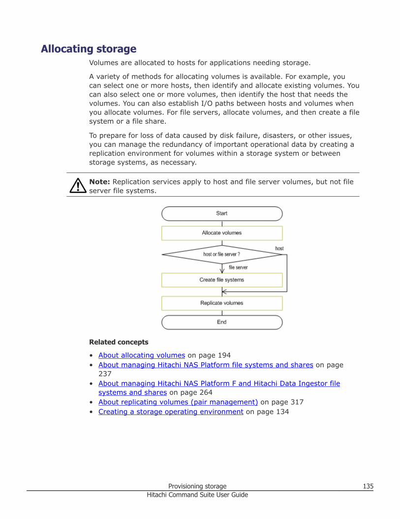
Allocating storageVolumes are allocated to hosts for applications needing storage.
A variety of methods for allocating volumes is available. For example, youcan select one or more hosts, then identify and allocate existing volumes. Youcan also select one or more volumes, then identify the host that needs thevolumes. You can also establish I/O paths between hosts and volumes whenyou allocate volumes. For file servers, allocate volumes, and then create a filesystem or a file share.
To prepare for loss of data caused by disk failure, disasters, or other issues,you can manage the redundancy of important operational data by creating areplication environment for volumes within a storage system or betweenstorage systems, as necessary.
Note: Replication services apply to host and file server volumes, but not fileserver file systems.
Related concepts
• About allocating volumes on page 194• About managing Hitachi NAS Platform file systems and shares on page
237• About managing Hitachi NAS Platform F and Hitachi Data Ingestor file
systems and shares on page 264• About replicating volumes (pair management) on page 317• Creating a storage operating environment on page 134
Provisioning storage 135Hitachi Command Suite User Guide
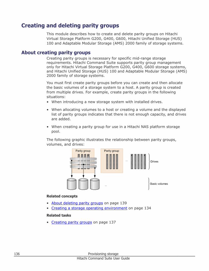
Creating and deleting parity groupsThis module describes how to create and delete parity groups on HitachiVirtual Storage Platform G200, G400, G600, Hitachi Unified Storage (HUS)100 and Adaptable Modular Storage (AMS) 2000 family of storage systems.
About creating parity groupsCreating parity groups is necessary for specific mid-range storagerequirements. Hitachi Command Suite supports parity group managementonly for Hitachi Virtual Storage Platform G200, G400, G600 storage systems,and Hitachi Unified Storage (HUS) 100 and Adaptable Modular Storage (AMS)2000 family of storage systems.
You must first create parity groups before you can create and then allocatethe basic volumes of a storage system to a host. A parity group is createdfrom multiple drives. For example, create parity groups in the followingsituations:• When introducing a new storage system with installed drives.
• When allocating volumes to a host or creating a volume and the displayedlist of parity groups indicates that there is not enough capacity, and drivesare added.
• When creating a parity group for use in a Hitachi NAS platform storagepool.
The following graphic illustrates the relationship between parity groups,volumes, and drives:
Related concepts
• About deleting parity groups on page 139• Creating a storage operating environment on page 134
Related tasks
• Creating parity groups on page 137
136 Provisioning storageHitachi Command Suite User Guide
Related references
• Create parity groups dialog box on page 138• Conditions for parity groups that are used in storage pools on page 244
Creating parity groupsYou can create and manage parity groups for Hitachi Virtual Storage PlatformG200, G400, G600 storage systems, and for the Hitachi Unified Storage(HUS) 100 and Adaptable Modular Storage (AMS) 2000 family of storagesystems.
Prerequisites
• Register the target storage system• Identify the target storage system name• Identify the required number of parity groups, and related capacities• Identify desired RAID levels, drive types and speeds (RPM)
Procedure
1. On the Resources tab, right-click on a supported storage system andchoose Create Parity Groups.
2. Depending on your storage system type, do one of the following:• In the Create Parity Groups dialog box, select drive types, RAID
level, and parity group options. Proceed to step 3.• In the Create Parity Groups wizard page, select drive types, RAID
level, and parity group options, click Next, verify the settings, andthen click Finish to register a System task. Proceed to step 7.
3. Click Show Plan and confirm that the information in the plan summaryis correct. If changes are required, click Back.
4. (Optional) Update the task name and provide a description.5. (Optional) Expand Schedule to specify the task schedule.
You can schedule the task to run immediately or later. The default settingis Now. If the task is scheduled to run immediately, you can select Viewtask status to monitor the task after it is submitted.
6. Click Submit.If the task is scheduled to run immediately, the process begins.
7. (Optional) Check the progress and result of the task on the Tasks &Alerts tab. Click the task name to view details of the task.
Result
Created parity groups are added to the target storage system parity grouplist.
Related concepts
• About creating parity groups on page 136• About deleting parity groups on page 139
Provisioning storage 137Hitachi Command Suite User Guide
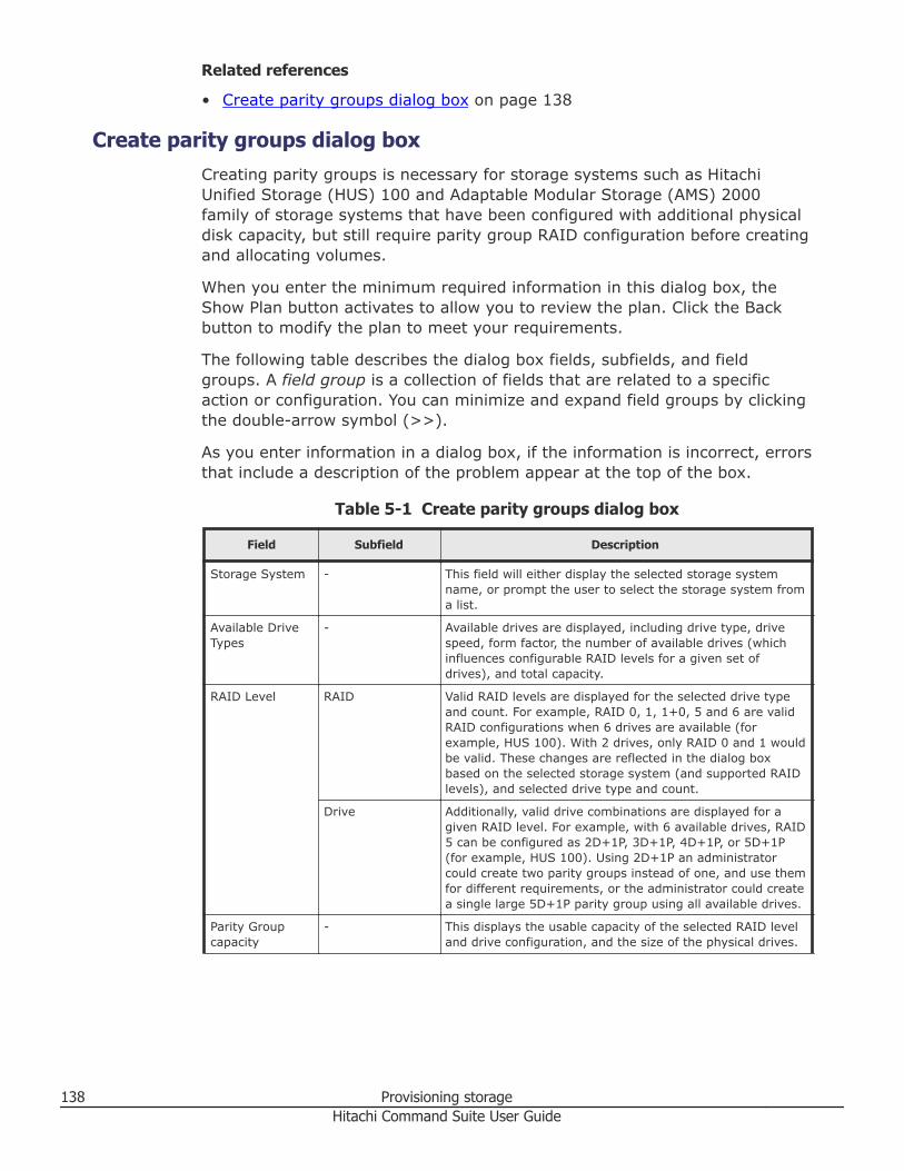
Related references
• Create parity groups dialog box on page 138
Create parity groups dialog boxCreating parity groups is necessary for storage systems such as HitachiUnified Storage (HUS) 100 and Adaptable Modular Storage (AMS) 2000family of storage systems that have been configured with additional physicaldisk capacity, but still require parity group RAID configuration before creatingand allocating volumes.
When you enter the minimum required information in this dialog box, theShow Plan button activates to allow you to review the plan. Click the Backbutton to modify the plan to meet your requirements.
The following table describes the dialog box fields, subfields, and fieldgroups. A field group is a collection of fields that are related to a specificaction or configuration. You can minimize and expand field groups by clickingthe double-arrow symbol (>>).
As you enter information in a dialog box, if the information is incorrect, errorsthat include a description of the problem appear at the top of the box.
Table 5-1 Create parity groups dialog box
Field Subfield Description
Storage System - This field will either display the selected storage systemname, or prompt the user to select the storage system froma list.
Available DriveTypes
- Available drives are displayed, including drive type, drivespeed, form factor, the number of available drives (whichinfluences configurable RAID levels for a given set ofdrives), and total capacity.
RAID Level RAID Valid RAID levels are displayed for the selected drive typeand count. For example, RAID 0, 1, 1+0, 5 and 6 are validRAID configurations when 6 drives are available (forexample, HUS 100). With 2 drives, only RAID 0 and 1 wouldbe valid. These changes are reflected in the dialog boxbased on the selected storage system (and supported RAIDlevels), and selected drive type and count.
Drive Additionally, valid drive combinations are displayed for agiven RAID level. For example, with 6 available drives, RAID5 can be configured as 2D+1P, 3D+1P, 4D+1P, or 5D+1P(for example, HUS 100). Using 2D+1P an administratorcould create two parity groups instead of one, and use themfor different requirements, or the administrator could createa single large 5D+1P parity group using all available drives.
Parity Groupcapacity
- This displays the usable capacity of the selected RAID leveland drive configuration, and the size of the physical drives.
138 Provisioning storageHitachi Command Suite User Guide
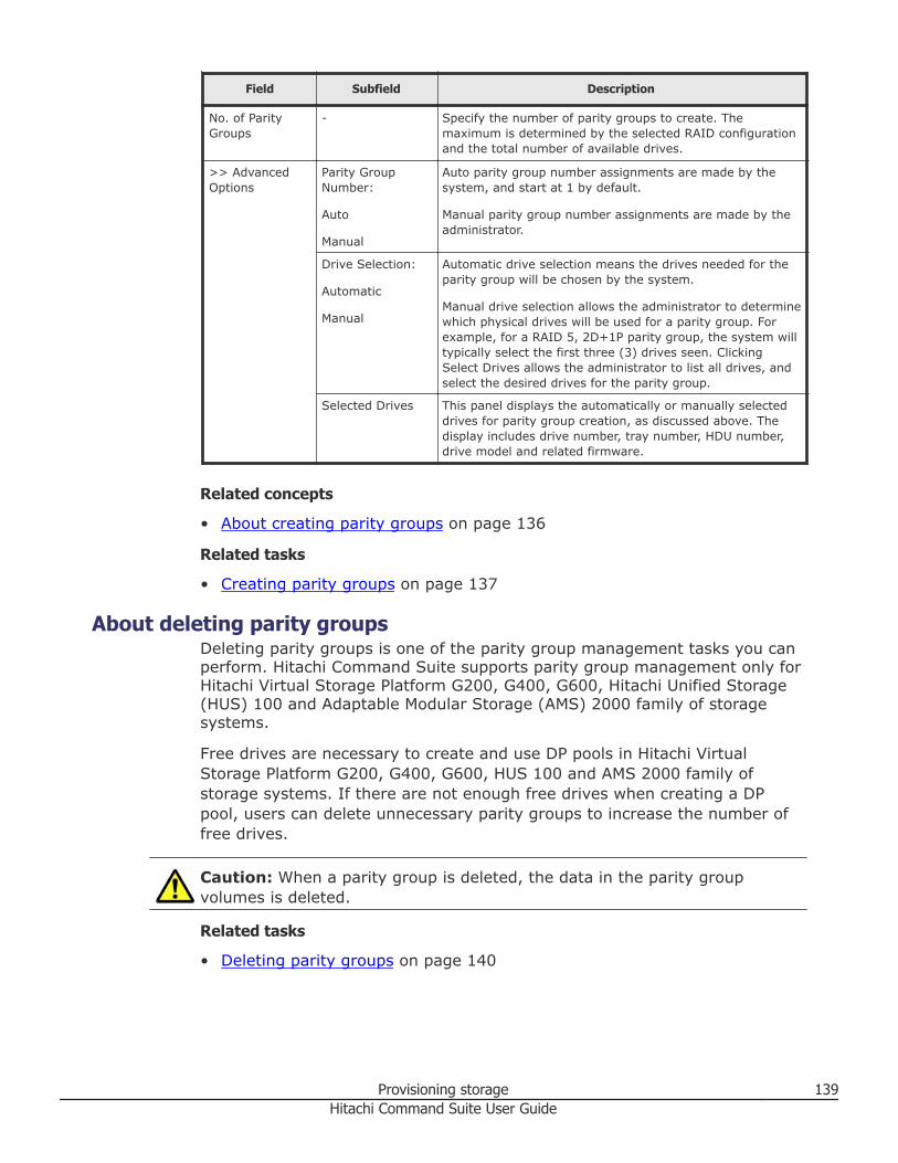
Field Subfield Description
No. of ParityGroups
- Specify the number of parity groups to create. Themaximum is determined by the selected RAID configurationand the total number of available drives.
>> AdvancedOptions
Parity GroupNumber:
Auto
Manual
Auto parity group number assignments are made by thesystem, and start at 1 by default.
Manual parity group number assignments are made by theadministrator.
Drive Selection:
Automatic
Manual
Automatic drive selection means the drives needed for theparity group will be chosen by the system.
Manual drive selection allows the administrator to determinewhich physical drives will be used for a parity group. Forexample, for a RAID 5, 2D+1P parity group, the system willtypically select the first three (3) drives seen. ClickingSelect Drives allows the administrator to list all drives, andselect the desired drives for the parity group.
Selected Drives This panel displays the automatically or manually selecteddrives for parity group creation, as discussed above. Thedisplay includes drive number, tray number, HDU number,drive model and related firmware.
Related concepts
• About creating parity groups on page 136
Related tasks
• Creating parity groups on page 137
About deleting parity groupsDeleting parity groups is one of the parity group management tasks you canperform. Hitachi Command Suite supports parity group management only forHitachi Virtual Storage Platform G200, G400, G600, Hitachi Unified Storage(HUS) 100 and Adaptable Modular Storage (AMS) 2000 family of storagesystems.
Free drives are necessary to create and use DP pools in Hitachi VirtualStorage Platform G200, G400, G600, HUS 100 and AMS 2000 family ofstorage systems. If there are not enough free drives when creating a DPpool, users can delete unnecessary parity groups to increase the number offree drives.
Caution: When a parity group is deleted, the data in the parity groupvolumes is deleted.
Related tasks
• Deleting parity groups on page 140
Provisioning storage 139Hitachi Command Suite User Guide
Deleting parity groupsYou can delete parity groups from Hitachi Virtual Storage Platform G200,G400, G600 storage systems, and from Hitachi Unified Storage (HUS) 100and Adaptable Modular Storage (AMS) 2000 family of storage systems.
Note: When you remove an encrypted parity group in HUS 150 systems, thiscancels the encryption for all drives that make up the target parity group,and releases the encryption on all volumes in the parity group.
Prerequisites
• Identify the target storage system that is associated with the parity groupsyou want to delete.
• Identify the target parity groups to delete.• Unallocate all volumes in the target parity groups.
Procedure
1. On the Resources tab, select Storage Systems.2. Expand the tree, select the target storage system, and select Parity
Groups.3. From the list of parity groups, select one or more target parity groups to
delete, and click Delete Parity Groups.
Tip: When deleting parity groups that compose a concatenated paritygroup, select the parity group that has the smallest number within theconcatenated parity group. When you do this, all concatenated paritygroups are deleted.
4. Depending on your storage system type, do one of the following:• In the Delete Parity Groups dialog box, confirm that the information
displayed is correct. Optionally, update the task name and provide adescription.
• In the Delete Parity Groups wizard page, confirm that theinformation displayed is correct, and then click Apply.
5. Expand Schedule to specify the task schedule.The task can be run immediately or scheduled for later. The defaultsetting is Now.
6. Click Submit.If you selected Now, the delete parity groups process begins.
7. You can check the progress and the result of the delete parity groupstask on the Tasks & Alerts tab.Verify the results for each task by viewing the details of the task.
140 Provisioning storageHitachi Command Suite User Guide
Result
The deleted parity group no longer appears in the parity groups list for thetarget storage system.
Related concepts
• About deleting parity groups on page 139
Spare drives and copy-back modeSpare drives are mounted in Hitachi Virtual Storage Platform G200, G400,G600 storage systems separately from the data drives for usual write andread operation. If a failure occurs in a data drive, data is copied to a sparedrive so that the storage system can continue to be available.
Copy-back mode determines whether data on a spare drive is returned to adata drive after recovery. If copy-back mode is enabled, when a failed driveis recovered, data is moved from the spare drive to the recovered drive. Ifcopy-back mode is disabled, when a failed drive is recovered, data is left onthe spare drive. This mode can be specified for each parity group.
The following maximum number of spare drives can be specified for eachstorage system:• Virtual Storage Platform G200: 12• Virtual Storage Platform G400 or Virtual Storage Platform G600: 32
Related tasks
• Assigning spare drives on page 141• Releasing spare drives on page 142• Editing copy-back mode on page 142
Assigning spare drivesSpare drives are used in Hitachi Virtual Storage Platform G200, G400, G600storage systems to store data if a data drive fails.
Procedure
1. On the Resources tab, click Storage Systems, and then expand AllStorage Systems and the target storage system.
2. Right click Parity Groups, and then select Assign Spare Drives.3. In the Available Drives table, select one or more drive boxes, and then
click Add.The selected drive boxes are moved to the Selected Spare Drivestable.
4. Click Finish.The Confirm window opens.
5. In the Confirm window verify the settings.
Provisioning storage 141Hitachi Command Suite User Guide
6. In the Task Name field enter a unique name or accept the default, andthen click Apply.If Go to tasks window for status is checked the Tasks window opens.
Related tasks
• Releasing spare drives on page 142
Releasing spare drivesYou can release spare drives in Hitachi Virtual Storage Platform G200, G400,G600 storage systems so they can be used as data drives.
Procedure
1. On the Resources tab, click Storage Systems, and then expand AllStorage Systems and the target storage system.
2. Right click Parity Groups, and then select Assign Spare Drives.3. In the Selected Spare Drives table, select one or more drive boxes,
and then click Remove.The selected drive boxes are moved to the Available Drives table.
4. Click Finish.The Confirm window opens.
5. In the Confirm window verify the settings.6. In the Task Name field enter a unique name or accept the default, and
then click Apply.If Go to tasks window for status is checked the Tasks window opens.
Related tasks
• Assigning spare drives on page 141
Editing copy-back modeCopy-back mode determines whether data on spare drives in Hitachi VirtualStorage Platform G200, G400, G600 storage systems is restored after a faileddrive is recovered.
When editing the copy-back mode of parity groups that are part of aconcatenated parity group, select the parity group that has the smallestnumber. When you do this, the copy-back modes of all parity groups in theconcatenated parity group are changed.
Procedure
1. On the Resources tab, click Storage Systems, and then expand AllStorage Systems and the target storage system.
2. Click Parity Groups.3. Select one or more parity groups, and then click Edit Copy-back Mode.
142 Provisioning storageHitachi Command Suite User Guide

4. In the Edit Copy-back Mode window, select one of the followingoptions:• Enable: When a failed drive is recovered, data that was copied to the
spare drive is returned to the recovered drive.• Disable: When a failed drive is recovered, data that was copied to the
spare drive is left on the spare drive.5. Click Finish.6. In the Confirm window verify the settings.7. In the Task Name field enter a unique name or accept the default, and
then click Apply.If Go to tasks window for status is checked the Tasks window opens.
Related tasks
• Assigning spare drives on page 141
• Spare drives and copy-back mode on page 141
Creating and deleting volumesThis module describes how to create volumes and delete unallocatedvolumes.
About creating volumesYou create volumes, then allocate them to a host.
You create volumes by using the available space in a DP pool or parity group.You can then access the volumes when you are ready to allocate them to ahost. If, while allocating volumes to a host, no volumes match the specifiedrequirements, volumes are automatically created using the available space.Note that when a basic volume is created, the volume is also formatted atthe same time.
Newly created volumes are included in the list of Open-Unallocated volumesuntil you allocate them to a host.
Because creating volumes takes time, you should create volumes in advance.
Tip: For Hitachi Virtual Storage Platform G200, G400, G600 or VirtualStorage Platform G1000 storage systems, you can block volumes separatedfrom parity groups, recover parity groups from errors, and format volumesby using the windows available by clicking the System GUI link. To access theSystem GUI link, on the Resources tab, right-click Parity Groups for thetarget storage system, and then select System GUI from the menu. Or, clickParity Groups for the target storage system, and then click the System GUIlink that appears in the application pane.
Provisioning storage 143Hitachi Command Suite User Guide
Additionally, you can format, block, and restore volumes, configure commanddevices, edit command devices, assign MP blades, and force delete copy pairs(TC, UR, and GAD) by using the windows available by clicking the SystemGUI link. To access these windows, on the Resources tab, right-click Volumesfor the target storage system, and then select System GUI from the menu.
For information about how to perform tasks that are available by clickingSystem GUI, see the Help for the appropriate window, the Hitachi VirtualStorage Platform G200, G400, G600 Provisioning Guide, or the Hitachi VirtualStorage Platform G1000 Provisioning Guide for Open Systems.
When you are linking with Hitachi NAS Platform v11.3 or later and volumesare created for creating or expanding storage pools, it is recommended thatyou create volumes using the Create Storage Pool or Expand Storage Pooldialog boxes. Device Manager can automatically specify the number ofvolumes and capacity, and create volumes following the best practices forconfiguring storage pools.
Related concepts
• About deleting unallocated volumes on page 150• Creating a storage operating environment on page 134
Related tasks
• Creating volumes on page 145
Related references
• Notes on performing quick formats on page 144• Create Volumes dialog box on page 146
Notes on performing quick formatsA quick format might impose a heavy workload on some components andlower I/O performance of all hosts running in the target storage system.
We recommend running a quick format when system activity is low andmajor system operations are not running.
We also recommend running a quick format on a maximum of eight volumesat first, and then confirming that the quick format has not lowered host I/Operformance. After that, when you perform a quick format on other volumes,we recommend increasing the number of volumes to be formatted inincrements of four.
In particular, if the storage system components are configured as follows, thehost I/O performance is likely to be lowered when a quick format isperformed:• Components such as cache memory, CHAs (channel adapters), and DKAs
(disk adapters) are in the minimum configuration.
144 Provisioning storageHitachi Command Suite User Guide
• The number of installed components is extremely different among DKCs(controller chassis) or modules within a single storage system.
In these configurations, run a quick format on only one volume at first,review the host I/O performance, and then continue to run a quick format onother volumes one by one.
Related concepts
• About creating volumes on page 143
Related tasks
• Creating volumes on page 145• Creating HNAS F or HDI file systems (HFSM v3.2 or later) on page 266
Related references
• Create Volumes dialog box on page 146• Allocate Volumes dialog box on page 206
Creating volumesFor registered storage systems, volumes are created so they can be allocatedto hosts.
Prerequisites
• Identify the storage system• Identify the number of volumes to create• Identify volume types and capacities• Create and format parity groups and create DP pools.
Procedure
1. On the Resources tab you can create volumes from several locations:• From General Tasks, select Create Volumes.• Select the storage system, click Actions, and select Create
Volumes.• Select the storage system, list existing parity groups, and click Create
Volumes.• Select the storage system, list existing DP pools, and click the Create
Volumes button or select Create Volumes from Actions.2. In the create volumes dialog box, configure volumes and their
characteristics.3. Click Show Plan and confirm that the information in the plan summary
is correct. If changes are required, click Back.4. (Optional) Update the task name and provide a description.5. (Optional) Expand Schedule to specify the task schedule.
Provisioning storage 145Hitachi Command Suite User Guide
You can schedule the task to run immediately or later. The default settingis Now. If the task is scheduled to run immediately, you can select Viewtask status to monitor the task after it is submitted.
6. Click Submit.If the task is scheduled to run immediately, the process begins.
7. (Optional) Check the progress and result of the task on the Tasks &Alerts tab. Click the task name to view details of the task.
Result
Created volumes are added to the target storage system Open-Unallocatedvolume list.
Tip: If a task to create multiple volumes fails, some volumes might havebeen created even when the Status in Volume Information displayed in theTask Details window is other than Completed. Refresh the target storagesystem information, and then in the Open-Unallocated volume list, confirmwhether volumes were created.
Related concepts
• About creating volumes on page 143
Related references
• Notes on performing quick formats on page 144• Create Volumes dialog box on page 146
Create Volumes dialog boxNewly created volumes are placed in the Open-Unallocated folder of the userselected storage system until they can be allocated to hosts as needed.
When you enter the minimum required information in this dialog box, theShow Plan button activates to allow you to review the plan. Click the Backbutton to modify the plan to meet your requirements.
The following table describes the dialog box fields, subfields, and fieldgroups. A field group is a collection of fields that are related to a specificaction or configuration. You can minimize and expand field groups by clickingthe double-arrow symbol (>>).
As you enter information in a dialog box, if the information is incorrect, errorsthat include a description of the problem appear at the top of the box.
146 Provisioning storageHitachi Command Suite User Guide
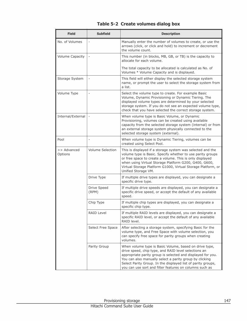
Table 5-2 Create volumes dialog box
Field Subfield Description
No. of Volumes - Manually enter the number of volumes to create, or use thearrows (click, or click and hold) to increment or decrementthe volume count.
Volume Capacity - This number (in blocks, MB, GB, or TB) is the capacity toallocate for each volume.
The total capacity to be allocated is calculated as No. ofVolumes * Volume Capacity and is displayed.
Storage System - This field will either display the selected storage systemname, or prompt the user to select the storage system froma list.
Volume Type - Select the volume type to create. For example BasicVolume, Dynamic Provisioning or Dynamic Tiering. Thedisplayed volume types are determined by your selectedstorage system. If you do not see an expected volume type,check that you have selected the correct storage system.
Internal/External - When volume type is Basic Volume, or DynamicProvisioning, volumes can be created using availablecapacity from the selected storage system (internal) or froman external storage system physically connected to theselected storage system (external).
Pool - When volume type is Dynamic Tiering, volumes can becreated using Select Pool.
>> AdvancedOptions
Volume Selection This is displayed if a storage system was selected and thevolume type is Basic. Specify whether to use parity groupsor free space to create a volume. This is only displayedwhen using Virtual Storage Platform G200, G400, G600,Virtual Storage Platform G1000, Virtual Storage Platform, orUnified Storage VM.
Drive Type If multiple drive types are displayed, you can designate aspecific drive type.
Drive Speed(RPM)
If multiple drive speeds are displayed, you can designate aspecific drive speed, or accept the default of any availablespeed.
Chip Type If multiple chip types are displayed, you can designate aspecific chip type.
RAID Level If multiple RAID levels are displayed, you can designate aspecific RAID level, or accept the default of any availableRAID level.
Select Free Space After selecting a storage system, specifying Basic for thevolume type, and Free Space with volume selection, youcan specify free space for parity groups when creatingvolumes.
Parity Group When volume type is Basic Volume, based on drive type,drive speed, chip type, and RAID level selections anappropriate parity group is selected and displayed for you.You can also manually select a parity group by clickingSelect Parity Group. In the displayed list of parity groups,you can use sort and filter features on columns such as
Provisioning storage 147Hitachi Command Suite User Guide
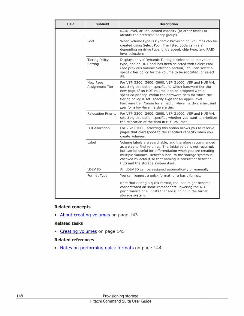
Field Subfield Description
RAID level, or unallocated capacity (or other fields) toidentify the preferred parity groups.
Pool When volume type is Dynamic Provisioning, volumes can becreated using Select Pool. The listed pools can varydepending on drive type, drive speed, chip type, and RAIDlevel selections.
Tiering PolicySetting
Displays only if Dynamic Tiering is selected as the volumetype, and an HDT pool has been selected with Select Pool(see previous Volume Selection section). You can select aspecific tier policy for the volume to be allocated, or selectAll.
New PageAssignment Tier
For VSP G200, G400, G600, VSP G1000, VSP and HUS VM,selecting this option specifies to which hardware tier thenew page of an HDT volume is to be assigned with aspecified priority. Within the hardware tiers for which thetiering policy is set, specify High for an upper-levelhardware tier, Middle for a medium-level hardware tier, andLow for a low-level hardware tier.
Relocation Priority For VSP G200, G400, G600, VSP G1000, VSP and HUS VM,selecting this option specifies whether you want to prioritizethe relocation of the data in HDT volumes.
Full Allocation For VSP G1000, selecting this option allows you to reservepages that correspond to the specified capacity when youcreate volumes.
Label Volume labels are searchable, and therefore recommendedas a way to find volumes. The Initial value is not required,but can be useful for differentiation when you are creatingmultiple volumes. Reflect a label to the storage system ischecked by default so that naming is consistent betweenHCS and the storage system itself.
LDEV ID An LDEV ID can be assigned automatically or manually.
Format Type You can request a quick format, or a basic format.
Note that during a quick format, the load might becomeconcentrated on some components, lowering the I/Operformance of all hosts that are running in the targetstorage system.
Related concepts
• About creating volumes on page 143
Related tasks
• Creating volumes on page 145
Related references
• Notes on performing quick formats on page 144
148 Provisioning storageHitachi Command Suite User Guide
About shredding volume dataBefore deleting a volume that you no longer need, completely remove thedata from the volume to avoid unauthorized use of information. The data canbe removed by shredding or reformatting the volume.
Volume data is shredded by overwriting it repeatedly with dummy data,which securely destroys the original data. Some volumes, such as basicvolumes and DP volumes that are allocated to hosts or used for replication,cannot be shredded.
Some storage systems do not support the shredding functionality. For thosestorage systems, delete volume information by reformatting the volumes.
Related tasks
• Shredding volume data on page 149
Shredding volume dataSpecify one or more volumes that are not allocated to a host and shred thedata on the volumes.
Prerequisites• Identify the storage system name that includes the volumes that you want
to shred• Identify the volumes to be shredded• Unallocate the volumes to be shredded from the host
Caution: You cannot restore shredded data.
Procedure
1. On the Resources tab, select Storage Systems.2. Expand the Storage Systems tree, select a storage system, and from the
volumes list, select the volumes whose data you want to shred.3. Click Shred Volumes.
Note: Shred during off hours, such as overnight, so that the shreddingprocess does not adversely affect system performance. To verify thestandard required times for shredding, see the Hitachi Volume ShredderUser Guide.
4. In the Shred Volumes dialog box, check the target volume to beshredded and edit the writing data pattern, if needed.If the storage system does not support shredding, the data will beformatted.
Provisioning storage 149Hitachi Command Suite User Guide
5. (Optional) Update the task name and provide a description.6. (Optional) Expand Schedule to specify the task schedule. You can
specify the task to run immediately or later. The default setting is Now.If the task is scheduled to run immediately, you can select View taskstatus to monitor the task after it is submitted.
7. Click Submit. If the task is scheduled to run immediately, the processbegins.
8. You can check the progress and result of the task on the Tasks & Alertstab. Click the task name to view details of the task.
Result
When the task completes, the data is shredded or reformatted from thevolume.
Related concepts
• About shredding volume data on page 149
Related tasks
• Deleting unallocated volumes on page 150• Unallocating volumes from file servers on page 220• Unallocating volumes from hosts on page 219
About deleting unallocated volumesVolumes that are not allocated to any host can be deleted and their spaceadded to the unused capacity of DP pools or parity groups. To completely andsecurely remove the data, shred the volume data before deleting the volume.
Related concepts
• About creating volumes on page 143• About removing hosts and related resources, or vCenters on page 76• About releasing a LUSE volume on page 153
Related tasks
• Deleting unallocated volumes on page 150
Deleting unallocated volumesYou can delete unallocated volumes from a registered storage system.
Prerequisites• Identify the target storage system• Identify the target volumes• Shred volume data, if needed• Unallocate volumes
150 Provisioning storageHitachi Command Suite User Guide
Procedure
1. On the Resources tab, select the target storage system.2. Expand the tree and select the storage system from which you want to
delete volumes.3. Select Open-Unallocated or DP Pools and then select the DP Vols tab
of the target DP pool.4. From the volume list, select the volumes that you want to delete, and
then click Delete Volumes.5. Specify additional information, as appropriate:
• Verify the information that is displayed.• Enter a name in Task Name.• Specify when to execute the task.
6. Click Submit, and confirm task completion.
Result
When the task completes, deleted volumes no longer appear in the Open-Unallocated or DP volume list.
Related concepts
• About deleting unallocated volumes on page 150
Related tasks
• Shredding volume data on page 149• Unallocating volumes from file servers on page 220• Unallocating volumes from hosts on page 219
About creating a LUSE volumeThe functionality to create LUSE volumes is supported by mid-range andenterprise storage systems. However, mid-range storage systems do notensure data integrity when creating LUSE volumes. Therefore, hostadministrators must back up data to a server or other location beforehand.
A LUSE volume is collection of two or more basic volumes that have beengrouped together to increase available capacity.
If the capacity of the LUSE volumes or basic volumes that have already beenallocated to hosts becomes insufficient, you can increase capacity by addingunallocated volumes or creating LUSE volumes.
LUSE volumes are created by using volumes that belong to the sameresource group, have the same drive type, and are at the same RAID level.When using FMD/SSD flash drives in a Virtual Storage Platform or HUS VMstorage system, you can still create a LUSE volume even if the drive typesare different.
Provisioning storage 151Hitachi Command Suite User Guide
Note: For Virtual Storage Platform G200, G400, G600, or Virtual StoragePlatform G1000, you can not create LUSE volumes.
Related tasks
• Creating a LUSE volume on page 152
Creating a LUSE volumeLUN size expansion (LUSE) volumes are created by aggregating volumes intoa larger logical volume.
Prerequisites• Gather the name of the target host• Identify the target volumes (LUSE volumes or basic volumes that are
already allocated to the host).• Back up the target volume (for mid-range storage systems this includes
HUS 100, Hitachi AMS 2000, Hitachi SMS, and Hitachi AMS/WMS). Beforecreating LUSE volumes in mid-range storage systems, such as the AMSseries, host administrators must back up data to a server or other location.This is because data might be corrupted when LUSE volumes are created.
• Create volumes to be added
Procedure
1. On the Resources tab, select Hosts.2. Expand the tree and select the target OS.3. Select the target host from the list of hosts, and from the displayed list
of volumes, select the LUSE volume or basic volume, and then clickCreate LUSE Volume.
4. Click Add Volumes and select volumes to be added.5. Click Show Plan and confirm that the information in the plan summary
is correct. If changes are required, click Back.6. (Optional) Update the task name and provide a description.7. (Optional) Expand Schedule to specify the task schedule.
You can schedule the task to run immediately or later. The default settingis Now. If the task is scheduled to run immediately, you can select Viewtask status to monitor the task after it is submitted.
8. Click Submit.If the task is scheduled to run immediately, the process begins.
9. (Optional) Check the progress and result of the task on the Tasks &Alerts tab. Click the task name to view details of the task.
Result
Information about the created LUSE volume can be verified in the list ofvolumes for the target host on the Resources tab.
152 Provisioning storageHitachi Command Suite User Guide
Related concepts
• About creating a LUSE volume on page 151
About releasing a LUSE volumeTo release a LUSE setting, the LUSE volume must first be unallocated from allhosts. Users can release a LUSE setting either by selecting it or using theUnallocating Volumes dialog box.
Note: For Virtual Storage Platform G1000, you cannot release LUSE volumes.
Related concepts
• About removing hosts and related resources, or vCenters on page 76• About deleting unallocated volumes on page 150
Related tasks
• Releasing a LUSE volume on page 153
Related references
• Unallocate volumes dialog box on page 221
Releasing a LUSE volumeReleasing the LUSE setting for a target volume releases the LUSE volume.
Prerequisites
Before releasing a LUSE volume, make sure that the volume has beenunallocated from all hosts.
Procedure
1. On the Resources tab, expand the Storage Systems tree, and for thetarget storage system, select Volumes and Open-Unallocated.
2. From the list of volumes, select the volume for which the LUSE setting isto be released, and click Release LUSE Volumes.
3. Verify that the information in the Plan Summary is correct.4. (Optional) Update the task name and provide a description.5. (Optional) Expand Schedule to specify the task schedule.
You can schedule the task to run immediately or later. The default settingis Now. If the task is scheduled to run immediately, you can select Viewtask status to monitor the task after it is submitted.
6. Click Submit.If the task is scheduled to run immediately, the process begins.
7. (Optional) Check the progress and result of the task on the Tasks &Alerts tab. Click the task name to view details of the task.
Provisioning storage 153Hitachi Command Suite User Guide
Result
When the task completes, the LUSE setting for the target volume is released.
Related concepts
• About releasing a LUSE volume on page 153
Virtualizing external storageThis module describes virtualizing external storage so that external volumescan be managed.
About virtualizing and unvirtualizing volumesVirtualizing volumes is the process of mapping external storage systemvolumes to an internal storage system.
Virtualized volumes allow for centralized management of volumes frommultiple external storage systems, in addition to the volumes from the singlestorage system being managed with Hitachi Command Suite.
The volumes in the external storage system (registered and referred to asexternal volumes) can be managed in the same way as the volumes in theinternal storage system (registered and referred to as internal volumes).Volume virtualization provides the capability to optimize storage services toapplications by facilitating movement of data between tiers and migration ofdata between different generations of technology.
Note: Internal and external storage systems can be connected by FibreChannel or Fibre Channel over Ethernet, but connections between differentport types with switches that convert between Fibre Channel and FibreChannel over Ethernet are not supported.
When external storage is managed by an internal storage system, externalvolumes will be listed in the External Storage folder of the internal storagesystem.
External volumes can be used for various purposes:• External volumes can be allocated to hosts the same as internal volumes
are.• Important data on internal volumes can be backed up to external volumes.• Infrequently accessed data on internal volumes can be moved to external
volumes for archiving.
You can virtualize volumes in two ways:• Virtualizing volumes:
In HCS, external volumes are mapped by specifying the external storagesystem, internal storage system, external volumes, and number of
154 Provisioning storageHitachi Command Suite User Guide
external paths. Although HCS manages only registered storage systems,external volumes in unregistered storage systems can also be mapped.If the external storage system is registered in HCS, you can directlyspecify individual external volumes in that storage system, or you canspecify just the size and number of volumes. HCS suggests mapping plansaccordingly.
• Discovering and virtualizing volumes:If HCS does not manage the external storage system, HCS detects theexternal volumes allocated to the internal storage system's external ports,and then selects the volume to be used. If no volume that meets theconditions exists in the external storage system, a volume is automaticallycreated from free space in the parity group.
When you want to perform a data migration or discard devices, you mustcancel the virtualization. When you unvirtualize volumes, the virtualizedvolumes are unmapped from the specified external storage.• If you are unvirtualizing volumes from a registered storage system, the
volumes are automatically unallocated. You also have the options to deletethe volumes or host group.
• If you are unvirtualizing volumes from an unregistered storage system, thevolumes are only unmapped. Other management tasks are not available.
Tip: For Hitachi Virtual Storage Platform G200, G400, G600 or VirtualStorage Platform G1000 storage systems, you can reconnect or disconnectexternal storage systems, reconnect or disconnect external volumes, editpath configurations, or unvirtualize external volumes by using the windowsavailable by clicking the System GUI link. To access the System GUI link, onthe Resources tab, right-click External Storage for the target storage system,and then select System GUI from the menu. Or, click External Storage for thetarget storage system, and then click the System GUI link that appears in theapplication pane.
For information about how to perform tasks that are available by clickingSystem GUI, see the Help for the appropriate window, Hitachi Virtual StoragePlatform G200, G400, G600 Provisioning Guide, or see the Hitachi VirtualStorage Platform G1000 Provisioning Guide for Open Systems.
For related information about external storage virtualization, see the HitachiUniversal Volume Manager User Guide.
Related concepts
• Creating a storage operating environment on page 134
Related tasks
• Virtualizing volumes of a registered storage system on page 156• Discovering and virtualizing volumes of an unregistered storage system on
page 157
Provisioning storage 155Hitachi Command Suite User Guide
• Unvirtualizing volumes on page 159
Virtualizing volumes of a registered storage systemChoose from a list of existing unallocated volumes in the external storagesystem to be virtualized. Or specify the number of volumes and volumecapacity to search for volumes that meet the criteria.
Prerequisites• The internal and external storage systems are registered in Hitachi
Command Suite.• The external storage system is connected to one or more external ports of
the internal storage system.• Hitachi Universal Volume Manager (UVM) is installed on the internal
storage system.• Specify the volumes or identify the number and capacity of volumes you
are virtualizing.• Identify the number of external paths between the external and internal
storage systems. The maximum number of external paths that can be setis eight.
Procedure
1. From the Actions menu or General Tasks pane, select VirtualizeVolumes.
2. From the list, select an external storage system. A storage system ispreselected if you selected a storage system from the Storage Systemstree and launched the dialog box.
3. From the list, select an internal storage system.4. Choose the volumes by clicking one of the following options:
• Select from existing available volumes: Click Add/RemoveVolumes to select from a list of available volumes, then click Add toadd them to the Selected Volumes table.
• Specify number of volumes and volume capacity: From the list,select the No. of Volumes and enter the Volume Capacity. ClickAdvanced Options to specify drive type, drive speed, RAID level, orparity group in the volume criteria. The storage system will search forvolumes that match the criteria.
5. Specify the No. of External Paths per Volume.6. (Optional) Click External Path Priority Settings to configure the
external path and increase or decrease external path priority.7. (Optional) Click Host Group and LUN Settings to configure the host
group settings and LUN number.8. (Optional) Click Internal Volume Configuration to configure the
options for the volume to be virtualized, such as the parity group ID,CLPR, inflow control, LDEV labels, and LDEV IDs.
156 Provisioning storageHitachi Command Suite User Guide
9. Click Show Plan and confirm that the information in the plan summaryis correct. If changes are required, click Back.
10. (Optional) Update the task name and provide a description.11. (Optional) Expand Schedule to specify the task schedule.
You can schedule the task to run immediately or later. The default settingis Now. If the task is scheduled to run immediately, you can select Viewtask status to monitor the task after it is submitted.
12. Click Submit.If the task is scheduled to run immediately, the process begins.
13. (Optional) Check the progress and result of the task on the Tasks &Alerts tab. Click the task name to view details of the task.
Result
When the task completes, the existing volumes are allocated to the internalstorage system and virtualized.
Tip: When the task to virtualize volumes fails, if external paths are alreadyset but have not been mapped to volumes in the internal storage system,from the external storage systems drop-down list in the Virtualize Volumesdialog box, select Search new systems/volumes by port scan to map thepaths.
Related concepts
• About virtualizing and unvirtualizing volumes on page 154
Related tasks
• Unvirtualizing volumes on page 159• Installing a software application on page 48
Discovering and virtualizing volumes of an unregistered storagesystem
Use the port scan and volume discovery functionality to detect externalstorage system volumes allocated to the external port and then virtualize theavailable volumes.
Prerequisites• The internal storage system is discovered in Hitachi Command Suite.• The internal storage system is the Virtual Storage Platform G200, G400,
G600, Virtual Storage Platform G1000, Virtual Storage Platform, or HUSVM that has the port scan and volume discovery functionality.
• The external storage system is connected to one or more external ports ofthe internal storage system.
• The external mapping volumes are already allocated to the external ports.• Hitachi Universal Volume Manager (UVM) is installed on the internal
storage system.
Provisioning storage 157Hitachi Command Suite User Guide
Procedure
1. From the Actions menu or General Tasks pane, select VirtualizeVolumes.
2. From the list of external storage systems, select Search new systems/volumes by port scan.
3. From the list, select an internal storage system.4. Specify the external paths by choosing one of the following options:
• Click Select newly discovered external paths and continue withstep 5.
• Click Select an existing external path group, select an externalpath group from the list, and continue with step 7.
5. Click Start Port Scan.The external storage is discovered and the port ID and external WWN aredisplayed.
Note: Because the external storage is discovered, you can virtualizeadditional volumes at a later time without doing a port scan, providedthat the same external paths are used. If you are virtualizing additionalvolumes at a later time and not using the same external paths, then youneed to use the port scan functionality to discover available externalstorage volumes.
6. Select an external storage, then choose the external paths to be used forvirtualization and click OK.
7. (Optional) Click External Path Priority Settings to configure theexternal path and increase or decrease external path priority.
8. Click Start Volume Discovery.The volumes that can be accessed using the selected external paths aredisplayed.
9. Review the list of volumes to be virtualized and click OK.10. (Optional) Click Internal Volume Configuration to configure the
options for the volume to be virtualized, such as the parity group ID,CLPR, inflow control, LDEV labels, and LDEV IDs.
11. Click Show Plan and confirm that the information in the plan summaryis correct. If changes are required, click Back.
12. (Optional) Update the task name and provide a description.13. (Optional) Expand Schedule to specify the task schedule.
You can schedule the task to run immediately or later. The default settingis Now. If the task is scheduled to run immediately, you can select Viewtask status to monitor the task after it is submitted.
14. Click Submit.If the task is scheduled to run immediately, the process begins.
15. (Optional) Check the progress and result of the task on the Tasks &Alerts tab. Click the task name to view details of the task.
158 Provisioning storageHitachi Command Suite User Guide
Result
When the task completes, the volumes on the discovered external storagesystem are virtualized and can be managed from HCS.
Related concepts
• About virtualizing and unvirtualizing volumes on page 154
Related tasks
• Unvirtualizing volumes on page 159• Installing a software application on page 48
Unvirtualizing volumesWhen you unvirtualize volumes, virtualized volumes are unmapped from thespecified external storage system.
Prerequisites• Volumes to be unmapped on the storage system are virtualized.
Procedure
1. From the Actions menu or General Tasks, select UnvirtualizeVolumes.
2. From the list, select an external storage system.3. From the list, select an internal storage system.
The parity groups that correspond to the virtualized volumes from theselected external storage system are displayed in the Selected ParityGroups table. Only parity groups that are available to unmap are listed inthe table.
4. (Optional) Click Add/Remove Parity Groups. In the Selected ParityGroups table, select any external parity groups that you do not wantunmapped and click Remove to move them to the Existing Parity Groupstable. You can select several external parity groups at one time.
5. (Optional) Click Advanced Options to configure deleting the host group,releasing LUSE volumes, or deleting volumes.
Note: If the selected external storage system is not a registered storagesystem, you can unmap volumes only.
6. Click Show Plan and confirm that the information in the plan summaryis correct. If changes are required, click Back.
7. (Optional) Update the task name and provide a description.8. (Optional) Expand Schedule to specify the task schedule.
You can schedule the task to run immediately or later. The default settingis Now. If the task is scheduled to run immediately, you can select Viewtask status to monitor the task after it is submitted.
9. Click Submit.
Provisioning storage 159Hitachi Command Suite User Guide
If the task is scheduled to run immediately, the process begins.10. (Optional) Check the progress and result of the task on the Tasks &
Alerts tab. Click the task name to view details of the task.
Result
When the task completes, the volumes on the selected external storagesystem are unmapped.
Related concepts
• About virtualizing and unvirtualizing volumes on page 154
Related tasks
• Virtualizing volumes of a registered storage system on page 156• Discovering and virtualizing volumes of an unregistered storage system on
page 157
Virtualize Volumes dialog boxVolume virtualization provides the capability to optimize storage services toapplications by facilitating movement of data between tiers and migration ofdata between different generations of technology.
When you enter the minimum required information in a dialog box, the ShowPlan button activates to allow you to review the plan. Click the Back button tomodify the plan to meet your requirements.
The following table describes the dialog box fields, subfields, and fieldgroups. A field group is a collection of fields that are related to a specificaction or configuration. You can minimize and expand field groups by clickingthe double arrow symbol (>>).
As you enter information in a dialog box, if the information is incorrect, errorsthat include a description of the problem appear at the top of the box.
Table 5-3 Virtualize Volumes dialog box
Field Subfield Description
Select theexternal andinternal storagesystems
- External storage system is displayed if you selected aregistered storage system and launched the dialog box.If you did not, select an external storage system fromthe list.
From the list of external storage systems, selectSearch new systems/volumes by port scan to scanports and discover volumes of unregistered storagesystems.
From the list of internal storage systems, select theinternal storage system that you want to use.
Start Port Scan Available when Search new systems/volumes by portscan is selected.
160 Provisioning storageHitachi Command Suite User Guide
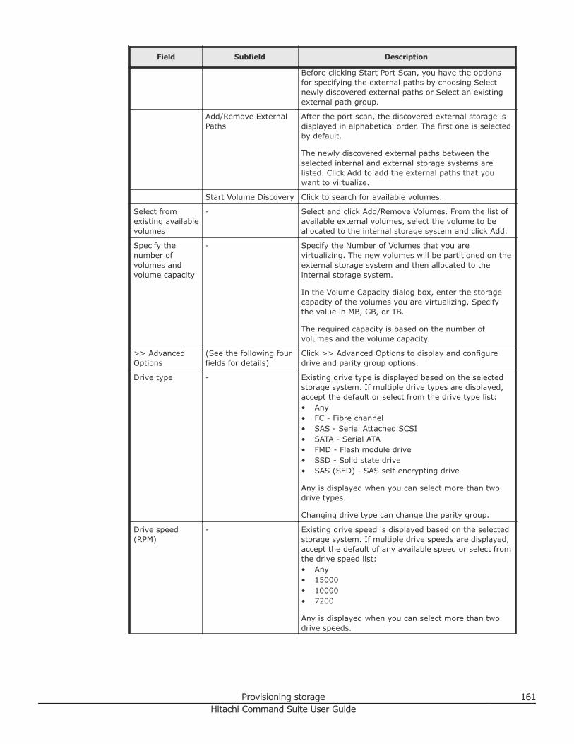
Field Subfield Description
Before clicking Start Port Scan, you have the optionsfor specifying the external paths by choosing Selectnewly discovered external paths or Select an existingexternal path group.
Add/Remove ExternalPaths
After the port scan, the discovered external storage isdisplayed in alphabetical order. The first one is selectedby default.
The newly discovered external paths between theselected internal and external storage systems arelisted. Click Add to add the external paths that youwant to virtualize.
Start Volume Discovery Click to search for available volumes.
Select fromexisting availablevolumes
- Select and click Add/Remove Volumes. From the list ofavailable external volumes, select the volume to beallocated to the internal storage system and click Add.
Specify thenumber ofvolumes andvolume capacity
- Specify the Number of Volumes that you arevirtualizing. The new volumes will be partitioned on theexternal storage system and then allocated to theinternal storage system.
In the Volume Capacity dialog box, enter the storagecapacity of the volumes you are virtualizing. Specifythe value in MB, GB, or TB.
The required capacity is based on the number ofvolumes and the volume capacity.
>> AdvancedOptions
(See the following fourfields for details)
Click >> Advanced Options to display and configuredrive and parity group options.
Drive type - Existing drive type is displayed based on the selectedstorage system. If multiple drive types are displayed,accept the default or select from the drive type list:• Any• FC - Fibre channel• SAS - Serial Attached SCSI• SATA - Serial ATA• FMD - Flash module drive• SSD - Solid state drive• SAS (SED) - SAS self-encrypting drive
Any is displayed when you can select more than twodrive types.
Changing drive type can change the parity group.
Drive speed(RPM)
- Existing drive speed is displayed based on the selectedstorage system. If multiple drive speeds are displayed,accept the default of any available speed or select fromthe drive speed list:• Any• 15000• 10000• 7200
Any is displayed when you can select more than twodrive speeds.
Provisioning storage 161Hitachi Command Suite User Guide
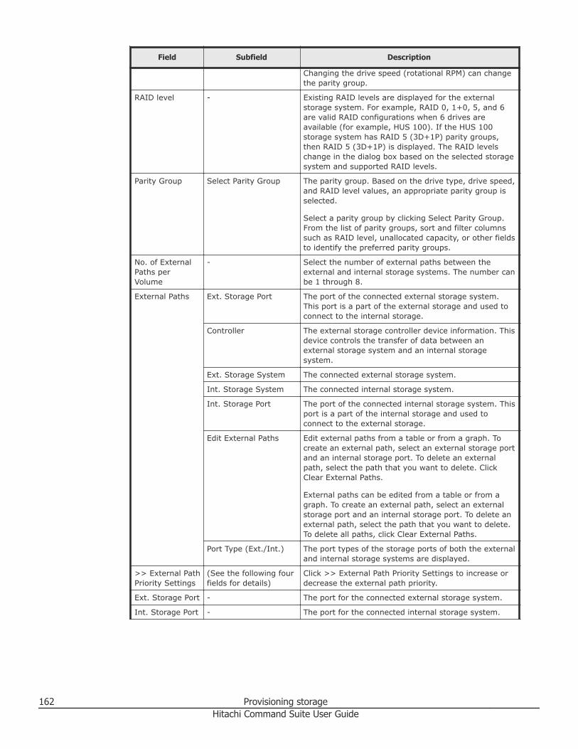
Field Subfield Description
Changing the drive speed (rotational RPM) can changethe parity group.
RAID level - Existing RAID levels are displayed for the externalstorage system. For example, RAID 0, 1+0, 5, and 6are valid RAID configurations when 6 drives areavailable (for example, HUS 100). If the HUS 100storage system has RAID 5 (3D+1P) parity groups,then RAID 5 (3D+1P) is displayed. The RAID levelschange in the dialog box based on the selected storagesystem and supported RAID levels.
Parity Group Select Parity Group The parity group. Based on the drive type, drive speed,and RAID level values, an appropriate parity group isselected.
Select a parity group by clicking Select Parity Group.From the list of parity groups, sort and filter columnssuch as RAID level, unallocated capacity, or other fieldsto identify the preferred parity groups.
No. of ExternalPaths perVolume
- Select the number of external paths between theexternal and internal storage systems. The number canbe 1 through 8.
External Paths Ext. Storage Port The port of the connected external storage system.This port is a part of the external storage and used toconnect to the internal storage.
Controller The external storage controller device information. Thisdevice controls the transfer of data between anexternal storage system and an internal storagesystem.
Ext. Storage System The connected external storage system.
Int. Storage System The connected internal storage system.
Int. Storage Port The port of the connected internal storage system. Thisport is a part of the internal storage and used toconnect to the external storage.
Edit External Paths Edit external paths from a table or from a graph. Tocreate an external path, select an external storage portand an internal storage port. To delete an externalpath, select the path that you want to delete. ClickClear External Paths.
External paths can be edited from a table or from agraph. To create an external path, select an externalstorage port and an internal storage port. To delete anexternal path, select the path that you want to delete.To delete all paths, click Clear External Paths.
Port Type (Ext./Int.) The port types of the storage ports of both the externaland internal storage systems are displayed.
>> External PathPriority Settings
(See the following fourfields for details)
Click >> External Path Priority Settings to increase ordecrease the external path priority.
Ext. Storage Port - The port for the connected external storage system.
Int. Storage Port - The port for the connected internal storage system.
162 Provisioning storageHitachi Command Suite User Guide
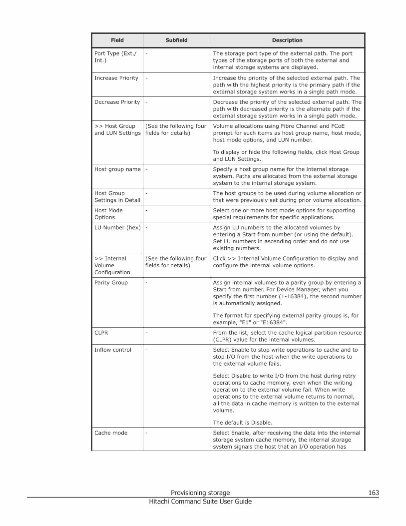
Field Subfield Description
Port Type (Ext./Int.)
- The storage port type of the external path. The porttypes of the storage ports of both the external andinternal storage systems are displayed.
Increase Priority - Increase the priority of the selected external path. Thepath with the highest priority is the primary path if theexternal storage system works in a single path mode.
Decrease Priority - Decrease the priority of the selected external path. Thepath with decreased priority is the alternate path if theexternal storage system works in a single path mode.
>> Host Groupand LUN Settings
(See the following fourfields for details)
Volume allocations using Fibre Channel and FCoEprompt for such items as host group name, host mode,host mode options, and LUN number.
To display or hide the following fields, click Host Groupand LUN Settings.
Host group name - Specify a host group name for the internal storagesystem. Paths are allocated from the external storagesystem to the internal storage system.
Host GroupSettings in Detail
- The host groups to be used during volume allocation orthat were previously set during prior volume allocation.
Host ModeOptions
- Select one or more host mode options for supportingspecial requirements for specific applications.
LU Number (hex) - Assign LU numbers to the allocated volumes byentering a Start from number (or using the default).Set LU numbers in ascending order and do not useexisting numbers.
>> InternalVolumeConfiguration
(See the following fourfields for details)
Click >> Internal Volume Configuration to display andconfigure the internal volume options.
Parity Group - Assign internal volumes to a parity group by entering aStart from number. For Device Manager, when youspecify the first number (1-16384), the second numberis automatically assigned.
The format for specifying external parity groups is, forexample, "E1" or "E16384".
CLPR - From the list, select the cache logical partition resource(CLPR) value for the internal volumes.
Inflow control - Select Enable to stop write operations to cache and tostop I/O from the host when the write operations tothe external volume fails.
Select Disable to write I/O from the host during retryoperations to cache memory, even when the writingoperation to the external volume fail. When writeoperations to the external volume returns to normal,all the data in cache memory is written to the externalvolume.
The default is Disable.
Cache mode - Select Enable, after receiving the data into the internalstorage system cache memory, the internal storagesystem signals the host that an I/O operation has
Provisioning storage 163Hitachi Command Suite User Guide
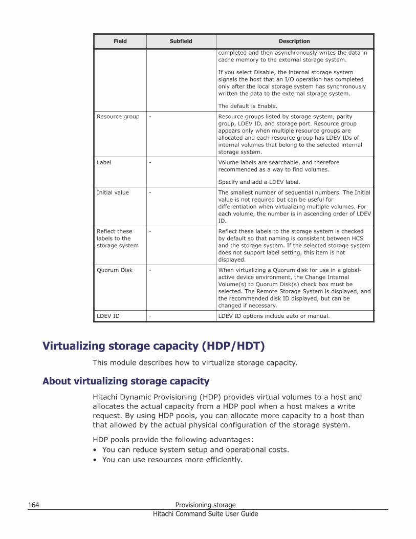
Field Subfield Description
completed and then asynchronously writes the data incache memory to the external storage system.
If you select Disable, the internal storage systemsignals the host that an I/O operation has completedonly after the local storage system has synchronouslywritten the data to the external storage system.
The default is Enable.
Resource group - Resource groups listed by storage system, paritygroup, LDEV ID, and storage port. Resource groupappears only when multiple resource groups areallocated and each resource group has LDEV IDs ofinternal volumes that belong to the selected internalstorage system.
Label - Volume labels are searchable, and thereforerecommended as a way to find volumes.
Specify and add a LDEV label.
Initial value - The smallest number of sequential numbers. The Initialvalue is not required but can be useful fordifferentiation when virtualizing multiple volumes. Foreach volume, the number is in ascending order of LDEVID.
Reflect theselabels to thestorage system
- Reflect these labels to the storage system is checkedby default so that naming is consistent between HCSand the storage system. If the selected storage systemdoes not support label setting, this item is notdisplayed.
Quorum Disk - When virtualizing a Quorum disk for use in a global-active device environment, the Change InternalVolume(s) to Quorum Disk(s) check box must beselected. The Remote Storage System is displayed, andthe recommended disk ID displayed, but can bechanged if necessary.
LDEV ID - LDEV ID options include auto or manual.
Virtualizing storage capacity (HDP/HDT)This module describes how to virtualize storage capacity.
About virtualizing storage capacityHitachi Dynamic Provisioning (HDP) provides virtual volumes to a host andallocates the actual capacity from a HDP pool when a host makes a writerequest. By using HDP pools, you can allocate more capacity to a host thanthat allowed by the actual physical configuration of the storage system.
HDP pools provide the following advantages:• You can reduce system setup and operational costs.• You can use resources more efficiently.
164 Provisioning storageHitachi Command Suite User Guide
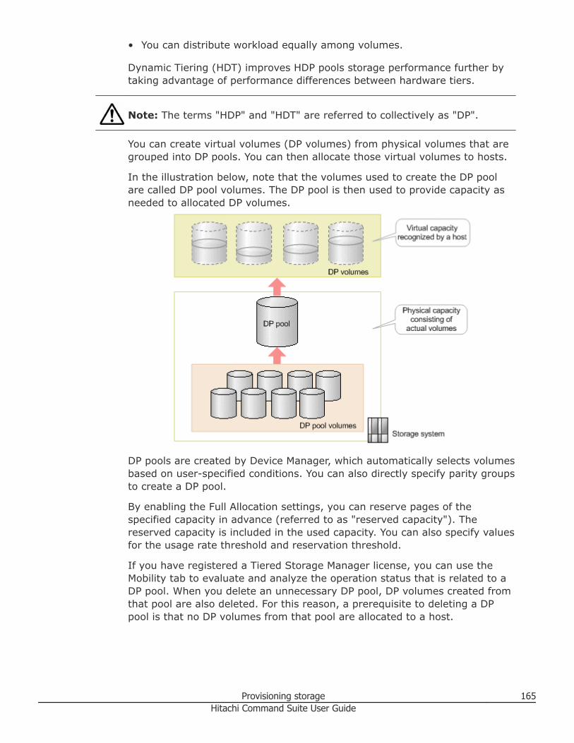
• You can distribute workload equally among volumes.
Dynamic Tiering (HDT) improves HDP pools storage performance further bytaking advantage of performance differences between hardware tiers.
Note: The terms "HDP" and "HDT" are referred to collectively as "DP".
You can create virtual volumes (DP volumes) from physical volumes that aregrouped into DP pools. You can then allocate those virtual volumes to hosts.
In the illustration below, note that the volumes used to create the DP poolare called DP pool volumes. The DP pool is then used to provide capacity asneeded to allocated DP volumes.
DP pools are created by Device Manager, which automatically selects volumesbased on user-specified conditions. You can also directly specify parity groupsto create a DP pool.
By enabling the Full Allocation settings, you can reserve pages of thespecified capacity in advance (referred to as "reserved capacity"). Thereserved capacity is included in the used capacity. You can also specify valuesfor the usage rate threshold and reservation threshold.
If you have registered a Tiered Storage Manager license, you can use theMobility tab to evaluate and analyze the operation status that is related to aDP pool. When you delete an unnecessary DP pool, DP volumes created fromthat pool are also deleted. For this reason, a prerequisite to deleting a DPpool is that no DP volumes from that pool are allocated to a host.
Provisioning storage 165Hitachi Command Suite User Guide
Tip: For Hitachi Virtual Storage Platform G200, G400, G600 or VirtualStorage Platform G1000 storage systems, you can restore DP pools, completeSIMs, and export tier relocation log files by using the windows available byclicking the System GUI link. To access the System GUI link, on theResources tab, right-click DP Pools for the target storage system, and thenselect System GUI from the menu. Or, click DP Pools for the target storagesystem, and then click the System GUI link that appears in the applicationpane.
For information about how to perform tasks that are available by clickingSystem GUI, see the Help for the appropriate window, Hitachi Virtual StoragePlatform G200, G400, G600 Provisioning Guide, or see the Hitachi VirtualStorage Platform G1000 Provisioning Guide for Open Systems.
For Hitachi Unified Storage (HUS) 100 family of storage systems, thereplication data and replication management area, which are used by Copy-on-Write Snapshot or TrueCopy Extended Distance, are stored in the createdDP pool.
Related concepts
• Creating a storage operating environment on page 134
Related tasks
• Creating a DP pool on page 166• Verifying DP pool information on page 173• Expanding DP pools on page 174• Shrinking a DP pool on page 176• Modifying DP pool settings on page 177• Deleting DP pools on page 177• Expanding DP volumes on page 178• Reclaiming zero pages on page 179
Related references
• Create Pool dialog box on page 169• Conditions for DP pools that are used in storage pools on page 244
Creating a DP poolYou can create an HDP or HDT pool, which provides more efficient use ofphysical storage for virtual volumes that are allocated to hosts from the DPpool. DP pool performance can be improved if you use the entire capacity of aparity group for a single DP pool.
Prerequisites
• Register the target storage system.• When defining an external LDEV tier rank, externally connect a storage
system that has multiple performance levels.
166 Provisioning storageHitachi Command Suite User Guide
• Verify the following when using Virtual Storage Platform G200, G400,G600, Virtual Storage Platform G1000, Virtual Storage Platform, UniversalStorage Platform V/VM, or HUS VM storage systems for DP pools:○ Parity groups from which volumes have already been created can be
added○ Drive type characteristics (for example: drive type and drive speed) in
parity groups and RAID level• Verify the following when using Hitachi Unified Storage (HUS) 100 and the
Adaptable Modular Storage (AMS) 2000 family of storage systems for DPpools:○ Drive type and RPM (only drives in which a parity group has not been
created can be targets)
○ Parity group RAID level and capacity
○ Number of parity groups
Note: In HDT pools, if different drive types and/or RAID levels are mixed in asingle tier, they will all be considered equal for data placement regardless ofpage access frequency. As a result, I/O performance will be dependent on thedrive type characteristics and RAID level on which any given page resides.
Note: In HDP pools, if different drive types and/or RAID levels are mixed inan HDP pool, I/O performance will be dependent on the drive typecharacteristics and RAID level on which any given page resides.
Procedure
1. On the Resources tab, expand the storage system, list existing DPPools, and click Create Pool.
2. In the Create Pool dialog box, specify a pool name, and optionally selectReflect this pool name to the storage system.
3. To configure an HDP pool, select a Pool Type of HDP and configure thefollowing:a. In the Additional Parity Groups table, click Add Parity Groups.b. (Optional) Select 'Allow to mix different drive types/speeds, chip
types, RAID levels or volume locations' to allow combining resourceswith different characteristics.
c. Select one or more parity groups, and click Add to Pool and thenClose. The Pool Summary information is updated.
d. (Optional) Click Advanced Options to configure Pool ID, UsedThreshold, Subscription Thresholds, and DP volume protection options,as needed.
e. Go to step 7.4. To configure an HDT pool, select a Pool Type of HDT, and then in the
Additional Parity Groups table, choose Standard or Mixed mode to
Provisioning storage 167Hitachi Command Suite User Guide
disallow or allow combining resources with different characteristics. ForMixed mode, go to step 6.
5. For a Standard mode HDT pool, do the following:a. Click + to add a new tier.b. In the Add New Tier dialog box, select a volume to configure Tier 1,
and click Select. The Tier Configuration table in Pool Summary isupdated.
c. Click Add Parity Groups, select the parity group, click Add to Pool,and click Close. Select an available parity group that best meets yourperformance or capacity needs (Tier 1 for best performance, Tier 2 fornext best performance, and Tier 3 for capacity).
d. (Optional) Click + to add Tier 2 and Tier 3, configure the tiers basedon your performance and capacity needs using the choices in AddNew Tier dialog box. The Tier Configuration table in Pool Summary isupdated.
Tip: To delete an existing tier, click X in the Tier tab.
e. (Optional) Click Advanced Options to configure Pool ID, UsedThreshold, Subscription Thresholds, and DP volume protection options,as needed.
f. Click HDT Options, and configure the tier management options asneeded.
g. Go to step 7.6. For a Mixed mode HDT pool, do the following:
a. Click Add Parity Groups.
Note: There are two parity group tab choices from which you canselect: Internal Parity Groups and External Parity Groups (theInternal Parity Groups tab is set by default). If you select theExternal Parity Groups tab and select one or more parity groups,this enables the External LDEV Tier Rank menu from which youmust choose a ranking for the tier.
b. For mixed mode in the Internal Parity Groups tab or the ExternalParity Groups tab, select parity groups that you want to add to theHDT pool, click Add to Pool, and click Close. The Tier Configurationtable in Pool Summary shows the new tier configuration status foreach tier.
c. (Optional) Click Advanced Options to configure Pool ID, UsedThreshold, Subscription Thresholds, and DP volume protection options,as needed.
d. Click HDT Options, and configure the tier management options asneeded.
168 Provisioning storageHitachi Command Suite User Guide
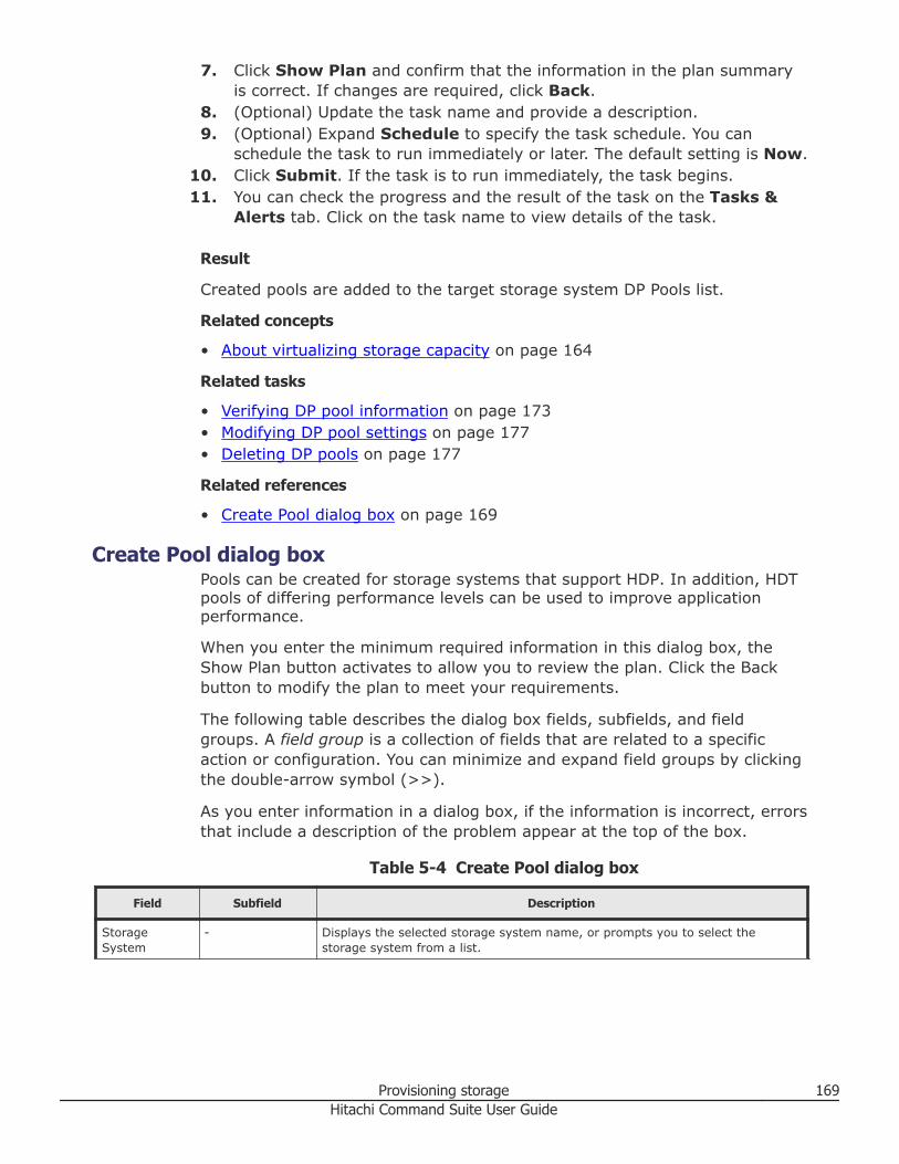
7. Click Show Plan and confirm that the information in the plan summaryis correct. If changes are required, click Back.
8. (Optional) Update the task name and provide a description.9. (Optional) Expand Schedule to specify the task schedule. You can
schedule the task to run immediately or later. The default setting is Now.10. Click Submit. If the task is to run immediately, the task begins.11. You can check the progress and the result of the task on the Tasks &
Alerts tab. Click on the task name to view details of the task.
Result
Created pools are added to the target storage system DP Pools list.
Related concepts
• About virtualizing storage capacity on page 164
Related tasks
• Verifying DP pool information on page 173• Modifying DP pool settings on page 177• Deleting DP pools on page 177
Related references
• Create Pool dialog box on page 169
Create Pool dialog boxPools can be created for storage systems that support HDP. In addition, HDTpools of differing performance levels can be used to improve applicationperformance.
When you enter the minimum required information in this dialog box, theShow Plan button activates to allow you to review the plan. Click the Backbutton to modify the plan to meet your requirements.
The following table describes the dialog box fields, subfields, and fieldgroups. A field group is a collection of fields that are related to a specificaction or configuration. You can minimize and expand field groups by clickingthe double-arrow symbol (>>).
As you enter information in a dialog box, if the information is incorrect, errorsthat include a description of the problem appear at the top of the box.
Table 5-4 Create Pool dialog box
Field Subfield Description
StorageSystem
- Displays the selected storage system name, or prompts you to select thestorage system from a list.
Provisioning storage 169Hitachi Command Suite User Guide
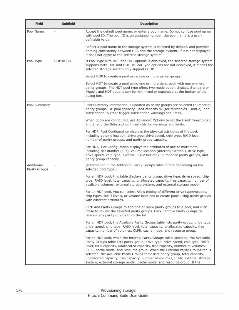
Field Subfield Description
Pool Name - Accept the default pool name, or enter a pool name. Do not confuse pool namewith pool ID. The pool ID is an assigned number, the pool name is a user-definable value.
Reflect a pool name to the storage system is selected by default, and providesnaming consistency between HCS and the storage system. If it is not displayed,it does not apply to the selected storage system.
Pool Type HDP or HDT If Pool Type with HDP and HDT options is displayed, the selected storage systemsupports both HDP and HDT. If Pool Type options are not displayed, it means theselected storage system only supports HDP.
Select HDP to create a pool using one or more parity groups.
Select HDT to create a pool using one or more tiers, each with one or moreparity groups. The HDT pool type offers two mode option choices, Standard orMixed , and HDT options can be minimized or expanded at the bottom of thedialog box.
Pool Summary - Pool Summary information is updated as parity groups are selected (number ofparity groups, DP pool capacity, used capacity % (for thresholds 1 and 2), andsubscription % (that trigger subscription warnings and limits).
When pools are configured, use Advanced Options to set the Used Thresholds 1and 2, and the Subscription thresholds for warnings and limits.
For HDP, Pool Configuration displays the physical attributes of the pool,including volume location, drive type, drive speed, chip type, RAID level,number of parity groups, and parity group capacity.
For HDT, Tier Configuration displays the attributes of one or more tiers,including tier number (1-3), volume location (internal/external), drive type,drive speed, chip type, external LDEV tier rank, number of parity groups, andparity group capacity.
AdditionalParity Groups
- (Information in the Additional Parity Groups table differs depending on theselected pool type.)
For an HDP pool, this table displays parity group, drive type, drive speed, chiptype, RAID level, total capacity, unallocated capacity, free capacity, number ofavailable volumes, external storage system, and external storage model.
For an HDP pool, you can select Allow mixing of different drive types/speeds,chip types, RAID levels, or volume locations to create pools using parity groupswith different attributes.
Click Add Parity Groups to add one or more parity groups to a pool, and clickClose to review the selected parity groups. Click Remove Parity Groups toremove any parity groups from the list.
For an HDP pool, the Available Parity Groups table lists parity group, drive type,drive speed, chip type, RAID level, total capacity, unallocated capacity, freecapacity, number of volumes, CLPR, cache mode, and resource group.
For an HDT pool, when the Internal Parity Groups tab is selected, the AvailableParity Groups table lists parity group, drive type, drive speed, chip type, RAIDlevel, total capacity, unallocated capacity, free capacity, number of volumes,CLPR, cache mode, and resource group. When the External Parity Groups tab isselected, the Available Parity Groups table lists parity group, total capacity,unallocated capacity, free capacity, number of volumes, CLPR, external storagesystem, external storage model, cache mode, and resource group. If the
170 Provisioning storageHitachi Command Suite User Guide
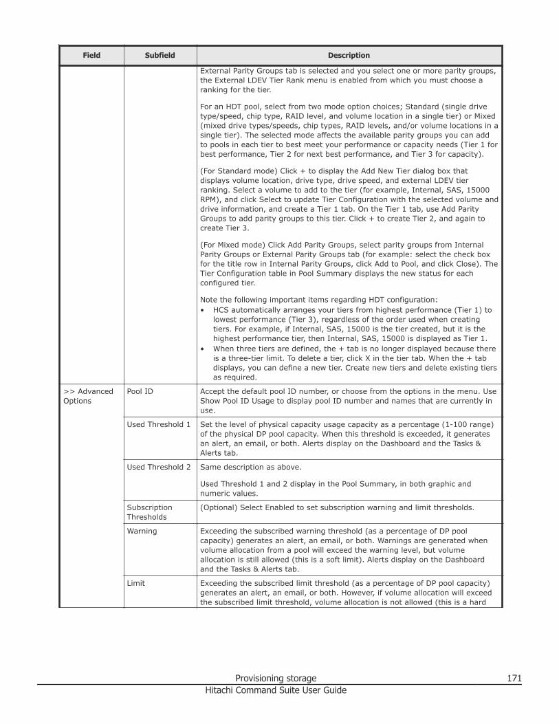
Field Subfield Description
External Parity Groups tab is selected and you select one or more parity groups,the External LDEV Tier Rank menu is enabled from which you must choose aranking for the tier.
For an HDT pool, select from two mode option choices; Standard (single drivetype/speed, chip type, RAID level, and volume location in a single tier) or Mixed(mixed drive types/speeds, chip types, RAID levels, and/or volume locations in asingle tier). The selected mode affects the available parity groups you can addto pools in each tier to best meet your performance or capacity needs (Tier 1 forbest performance, Tier 2 for next best performance, and Tier 3 for capacity).
(For Standard mode) Click + to display the Add New Tier dialog box thatdisplays volume location, drive type, drive speed, and external LDEV tierranking. Select a volume to add to the tier (for example, Internal, SAS, 15000RPM), and click Select to update Tier Configuration with the selected volume anddrive information, and create a Tier 1 tab. On the Tier 1 tab, use Add ParityGroups to add parity groups to this tier. Click + to create Tier 2, and again tocreate Tier 3.
(For Mixed mode) Click Add Parity Groups, select parity groups from InternalParity Groups or External Parity Groups tab (for example: select the check boxfor the title row in Internal Parity Groups, click Add to Pool, and click Close). TheTier Configuration table in Pool Summary displays the new status for eachconfigured tier.
Note the following important items regarding HDT configuration:• HCS automatically arranges your tiers from highest performance (Tier 1) to
lowest performance (Tier 3), regardless of the order used when creatingtiers. For example, if Internal, SAS, 15000 is the tier created, but it is thehighest performance tier, then Internal, SAS, 15000 is displayed as Tier 1.
• When three tiers are defined, the + tab is no longer displayed because thereis a three-tier limit. To delete a tier, click X in the tier tab. When the + tabdisplays, you can define a new tier. Create new tiers and delete existing tiersas required.
>> AdvancedOptions
Pool ID Accept the default pool ID number, or choose from the options in the menu. UseShow Pool ID Usage to display pool ID number and names that are currently inuse.
Used Threshold 1 Set the level of physical capacity usage capacity as a percentage (1-100 range)of the physical DP pool capacity. When this threshold is exceeded, it generatesan alert, an email, or both. Alerts display on the Dashboard and the Tasks &Alerts tab.
Used Threshold 2 Same description as above.
Used Threshold 1 and 2 display in the Pool Summary, in both graphic andnumeric values.
SubscriptionThresholds
(Optional) Select Enabled to set subscription warning and limit thresholds.
Warning Exceeding the subscribed warning threshold (as a percentage of DP poolcapacity) generates an alert, an email, or both. Warnings are generated whenvolume allocation from a pool will exceed the warning level, but volumeallocation is still allowed (this is a soft limit). Alerts display on the Dashboardand the Tasks & Alerts tab.
Limit Exceeding the subscribed limit threshold (as a percentage of DP pool capacity)generates an alert, an email, or both. However, if volume allocation will exceedthe subscribed limit threshold, volume allocation is not allowed (this is a hard
Provisioning storage 171Hitachi Command Suite User Guide
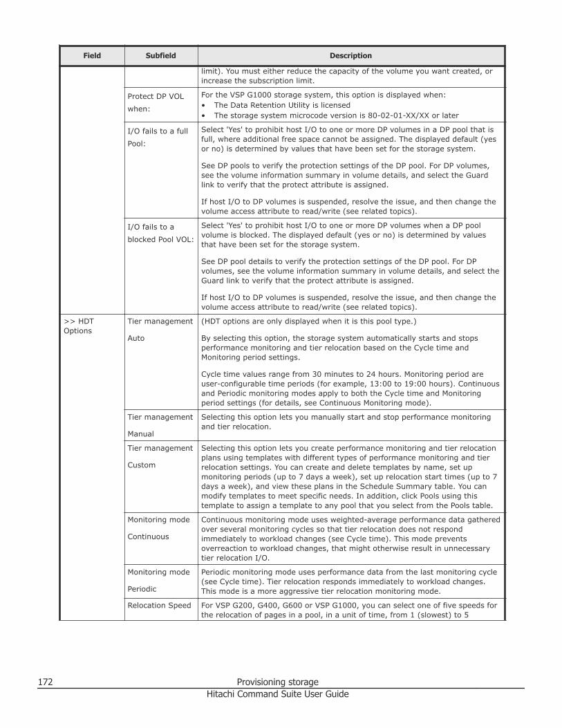
Field Subfield Description
limit). You must either reduce the capacity of the volume you want created, orincrease the subscription limit.
Protect DP VOL
when:
For the VSP G1000 storage system, this option is displayed when:• The Data Retention Utility is licensed• The storage system microcode version is 80-02-01-XX/XX or later
I/O fails to a full
Pool:
Select 'Yes' to prohibit host I/O to one or more DP volumes in a DP pool that isfull, where additional free space cannot be assigned. The displayed default (yesor no) is determined by values that have been set for the storage system.
See DP pools to verify the protection settings of the DP pool. For DP volumes,see the volume information summary in volume details, and select the Guardlink to verify that the protect attribute is assigned.
If host I/O to DP volumes is suspended, resolve the issue, and then change thevolume access attribute to read/write (see related topics).
I/O fails to a
blocked Pool VOL:
Select 'Yes' to prohibit host I/O to one or more DP volumes when a DP poolvolume is blocked. The displayed default (yes or no) is determined by valuesthat have been set for the storage system.
See DP pool details to verify the protection settings of the DP pool. For DPvolumes, see the volume information summary in volume details, and select theGuard link to verify that the protect attribute is assigned.
If host I/O to DP volumes is suspended, resolve the issue, and then change thevolume access attribute to read/write (see related topics).
>> HDTOptions
Tier management
Auto
(HDT options are only displayed when it is this pool type.)
By selecting this option, the storage system automatically starts and stopsperformance monitoring and tier relocation based on the Cycle time andMonitoring period settings.
Cycle time values range from 30 minutes to 24 hours. Monitoring period areuser-configurable time periods (for example, 13:00 to 19:00 hours). Continuousand Periodic monitoring modes apply to both the Cycle time and Monitoringperiod settings (for details, see Continuous Monitoring mode).
Tier management
Manual
Selecting this option lets you manually start and stop performance monitoringand tier relocation.
Tier management
Custom
Selecting this option lets you create performance monitoring and tier relocationplans using templates with different types of performance monitoring and tierrelocation settings. You can create and delete templates by name, set upmonitoring periods (up to 7 days a week), set up relocation start times (up to 7days a week), and view these plans in the Schedule Summary table. You canmodify templates to meet specific needs. In addition, click Pools using thistemplate to assign a template to any pool that you select from the Pools table.
Monitoring mode
Continuous
Continuous monitoring mode uses weighted-average performance data gatheredover several monitoring cycles so that tier relocation does not respondimmediately to workload changes (see Cycle time). This mode preventsoverreaction to workload changes, that might otherwise result in unnecessarytier relocation I/O.
Monitoring mode
Periodic
Periodic monitoring mode uses performance data from the last monitoring cycle(see Cycle time). Tier relocation responds immediately to workload changes.This mode is a more aggressive tier relocation monitoring mode.
Relocation Speed For VSP G200, G400, G600 or VSP G1000, you can select one of five speeds forthe relocation of pages in a pool, in a unit of time, from 1 (slowest) to 5
172 Provisioning storageHitachi Command Suite User Guide
Field Subfield Description
(fastest). The default is 3 (standard). To reduce the load on the storage system,specify a slower page relocation speed. To give a higher priority to pagerelocations for the pool, specify a faster relocation speed.
Buffer Space forNew pageassignment
Sets the buffer space used for new page assignments to HDT tiers (using thedefault values is recommended).
Buffer Space forTier relocation
Sets the buffer space used for tier page relocations between HDT tiers (usingthe default values is recommended).
Note: After configuring the pools, click Show Plan and perform all of theconfirming, scheduling, and submitting tasks needed to create the pools.
Related concepts
• About virtualizing storage capacity on page 164
Related tasks
• Creating a DP pool on page 166• Changing an access attribute to read/write on page 179
Verifying DP pool informationYou can check the DP pools summary information to verify the currentnumber of pools, the virtual volume capacity, the pools usage, and the totaland used pool capacity.
Prerequisites• Create pools• Discover (register) pools
Procedure
1. On the Resources tab, select DP Pools under the target storagesystem.A list of DP pools, (DP pool volumes and DP volumes) provides summaryinformation that includes the number of pools, the virtual volumecapacity, pool usage, and the total and used pool capacity.
2. Select a DP pool to display more detailed information about that pool.Use the detailed pools information to verify expected changes in capacityor performance. Configuration information for each DP volume isdisplayed by clicking the volume link from the list in the DP Vols tab.
If you configured HDT pool tiers to be managed automatically usingElement Manager, you can also verify the following:• Monitoring Information• Last Monitoring Start Date
Provisioning storage 173Hitachi Command Suite User Guide
• Last Monitoring End Date• Monitoring Status• Relocation Status• Relocation Progress (%)
Related concepts
• About virtualizing storage capacity on page 164
Related tasks
• Creating a DP pool on page 166
Expanding DP poolsPool capacity can be increased by expanding DP pools or by converting HDPpools into HDT pools.
Expand a DP pool by adding volumes to it. Expand an existing HDP pool byconverting it into an HDT pool, which changes the pool type and allows you toconfigure tiers that support a mix of drive types and RAID levels.
Prerequisites• Register the storage system.• Verify the external connections for any storage system with multiple
performance levels before defining an external LDEV tier rank.• Verify the following when using Virtual Storage Platform G200, G400,
G600, Virtual Storage Platform G1000, Virtual Storage Platform, UniversalStorage Platform V/VM, or HUS VM storage systems for DP pools:○ Parity groups from which volumes have already been created can be
added○ Drive type characteristics (for example: drive type and drive speed) in
parity groups and RAID level
• Verify the following when using HUS 100 or Hitachi AMS 2000 family ofstorage systems for DP pools:○ Parity group capacity to add○ Number of parity groups to add○ There are drives in which a parity group has not been created
Note: In HDT pools, if different drive types and/or RAID levels are mixed in asingle tier, they will all be considered equal for data placement regardless ofpage access frequency. As a result, I/O performance will be dependent on thedrive type characteristics and RAID level on which any given page resides.
Note: In HDP pools, if different drive types and/or RAID levels are mixed inan HDP pool, I/O performance will be dependent on the drive typecharacteristics and RAID level on which any given page resides.
174 Provisioning storageHitachi Command Suite User Guide
Procedure
1. On the Resources tab, expand the storage systems, select an HDP poolon the target storage system, and click Expand Pool.
2. To expand an HDP pool:a. In Additional Parity Groups, click Add Parity Groups.b. Select one of more parity groups, click Add to Pool, and then click
Close. The Pool Summary is updated.
Tip: To change an existing HDP pool into an HDT pool, click Changes toan HDT pool.
3. To expand an HDT pool, in Additional Parity Groups, choose Standard orMixed mode.For Standard mode (single drive type/speed, chip type, RAID level, andvolume location in a single tier):• Tier 1 is the default, click Add Parity Groups, select the parity group,
click Add to Pool, and click Close. Select an available parity groupthat best meets your performance or capacity needs (Tier 1 for bestperformance, Tier 2 for next best performance, and Tier 3 forcapacity).
• (Optional) Click + to add Tier 2 and Tier 3, configure the tiers basedon your performance or capacity needs from volume choices in theAdd New Tier dialog box. The Tier Configuration table in PoolSummary is updated.
Tip: To delete an existing tier, click X in the Tier tab.
For Mixed mode (mixed drive types/speeds, chip types, RAID levels,and/or volume locations in a single tier):• Click Add Parity Groups.
Note: There are two parity group tab choices from which you canselect: Internal Parity Groups and External Parity Groups (theInternal Parity Groups tab is set by default). If you select theExternal Parity Groups tab and select one or more parity groups,this enables the External LDEV Tier Rank menu from which youmust choose a ranking for the tier.
• For mixed mode in the Internal Parity Groups tab or the ExternalParity Groups tab, select parity groups that you want to add to theHDT pool, click Add to Pool, and click Close. The Tier Configurationtable in Pool Summary shows the new tier configuration status foreach tier.
Provisioning storage 175Hitachi Command Suite User Guide
4. Click Show Plan and confirm that the information in the plan summaryis correct. If changes are required, click Back.
5. (Optional) Update the task name and provide a description.6. (Optional) Expand Schedule to specify the task schedule. You can
schedule the task to run immediately or later. The default setting is Now.If scheduled for Now, select View task status to monitor the task afterit is submitted.
7. Click Submit. If the task is to run immediately, the task begins.8. You can check the progress and the result of the task on the Tasks &
Alerts tab. Click on the task name to view details of the task.
Result
When the task is complete, the DP pools are expanded. You can verify theupdated information on the DP Pools list.
Related concepts
• About virtualizing storage capacity on page 164
Related tasks
• Shrinking a DP pool on page 176• Expanding DP volumes on page 178• Reclaiming zero pages on page 179
Shrinking a DP poolShrinking a DP pool allows the recovery of excess free capacity.
Note: When you shrink a DP pool, Hitachi Command Suite automaticallyperforms an immediate quick format when the volumes that were DP poolvolumes are internal volumes, and a basic format when the volumes thatwere DP pool volumes are external volumes, but became basic volumesbecause those volumes were removed from the DP pool, which allows thesebasic volumes to be used again. A best practice is to run this task whensystem activity is low and major system operations are not running.
Procedure
1. On the Resources tab, select Storage Systems in the navigation tree.2. Expand the tree for the target storage system that includes the DP pool
you want to shrink, and select it in DP Pools.3. In the DP Pool Vols tab, select DP pool volumes, and then click Shrink
Pool.4. Review the plan and specify additional information, as appropriate:
• Verify the information that is displayed.• Enter a name in Task Name.• Specify when to execute the task.
176 Provisioning storageHitachi Command Suite User Guide
5. Click Submit.The plan is registered as a task.
6. On the Tasks & Alerts tab, confirm that the task completed.7. In the Storage Systems tree, return to the target storage system, click
DP Pools, and confirm that the information is updated.
Result
Excess free capacity has been recovered from the DP pool.
Note: If a DP pool volume becomes blocked and the processing failed duringexecution of the Shrink Pool task, execute the FormatLU command in theDevice Manager CLI. For details about the FormatLU command, see theHitachi Command Suite CLI Reference Guide.
Related concepts
• About virtualizing storage capacity on page 164
Related tasks
• Expanding DP pools on page 174
Modifying DP pool settingsAfter setting up a DP pool, you can modify DP pool settings.
Procedure
1. On the Resources tab, select DP Pools under the target storagesystem.
2. From the list of DP pools, select the pool you want to modify and clickEdit Pool.
3. Modify the settings as appropriate and click Submit.4. On the Tasks & Alerts tab, confirm that all tasks are completed.5. In the Storage Systems tree, return to the target storage system and
click DP Pools to confirm that the information is updated.
Related concepts
• About virtualizing storage capacity on page 164
Related tasks
• Creating a DP pool on page 166
Deleting DP poolsAfter unallocating the DP volumes belonging to a DP pool, you can delete theDP pool.
Provisioning storage 177Hitachi Command Suite User Guide
Note: When you remove an encrypted DP pool in HUS 150 systems, thiscancels the encryption for all drives that comprise the target DP pool, andreleases the encryption on all DP pool volumes in the DP pool.
Prerequisites
Before you delete DP pools, first unallocate the DP volumes that belong tothe DP pools to be deleted.
Note: When you delete a DP pool, HCS automatically performs an immediatequick format only on those volumes that were DP pool volumes, but becamebasic volumes because the associated DP pools were deleted. This allowsthese basic volumes to be used again. A best practice for deleting a pool is torun this task when system activity is low and major system operations arenot running.
Procedure
1. On the Resources tab, select Storage Systems.2. Expand the tree, select the target storage system, and select DP Pools.3. From the list of pools, select one or more target DP pools to delete, and
click Delete Pools.4. In the Delete Pool dialog box, confirm that the information matches the
DP pools to be deleted.Optionally, update the task name and provide a description.
5. Click Submit.The delete DP pools process begins.
6. You can check the progress and the result of the delete DP pools task onthe Tasks & Alerts tabVerify the results for each task by viewing the details of the task.
Result
The deleted DP pool no longer appears in the DP pool list for the targetstorage system.
Related concepts
• About virtualizing storage capacity on page 164
Related tasks
• Creating a DP pool on page 166
Related references
• Notes on performing quick formats on page 144
Expanding DP volumesYou can expand the size of a DP volume to expand its capacity.
178 Provisioning storageHitachi Command Suite User Guide
Procedure
1. On the Resources tab, select Storage Systems in the navigation tree.2. Expand the tree for the target storage system that includes the pool you
want to modify, and select the DP pool in DP Pools.3. On the DP Vols tab, select one or more volumes you want to expand
and click Expand DP Volume.4. Specify the new capacity for the volume.5. Click Submit.6. On the Tasks & Alerts tab, confirm that all tasks are completed.7. In the Storage Systems tree, return to the target storage system, click
the target DP pool and view the DP Vols tab to confirm that theinformation is updated.
Related concepts
• About virtualizing storage capacity on page 164
Related tasks
• Expanding DP pools on page 174
Reclaiming zero pagesReclaiming unused zero pages for a DP pool releases unused capacity.
Procedure
1. On the Resources tab, select Storage Systems in the navigation tree.2. Expand the tree for the target storage system that includes the
appropriate DP pool, and select the DP pool in DP Pools.3. On the DP Vols tab, select one or more volumes and click Reclaim Zero
Pages.4. Click Submit.5. In the task list, confirm that the task is completed.
Related concepts
• About virtualizing storage capacity on page 164
Related tasks
• Expanding DP pools on page 174
Changing an access attribute to read/write
Prerequisites
Before changing the access attribute from read-only or protect to read/write,considering the following:
Provisioning storage 179Hitachi Command Suite User Guide
• Do not assign an access attribute to a volume if any job is manipulatingdata on the volume. If you assign an access attribute to such a volume,the job will possibly end abnormally.
• Make sure that the retention term is expired. If expired, the RetentionTerm column in the Data Retention window shows 0. To change theaccess attribute to read/write within the retention term, contact theHitachi Data Systems customer support.
• Make sure that Expiration Lock indicates Disable > Enable. If it indicatesEnable > Disable, changing to read/write is restricted by an administratorfor some reason. Contact the administrator of your system to ask if youcan change the access attribute. .
PrerequisitesThe Storage Administrator (Provisioning) role is required to perform this task.
Procedure
1. On the Resources tab, click Storage Systems, and then expand AllStorage Systems and the target storage system.
2. Choose one of the following options.• For Virtual Storage Platform G200, G400, G600 or Virtual Storage
Platform G1000:Right-click the target storage system, and then select OtherFunctions.
• For other available storage systems:From the Actions list in the application pane, select ElementManager. Refer to the documentation for the native management toolfor your storage system.
3. In the Hitachi Device Manager - Storage Navigator main window, clickActions > Other Function > Data Retention.
4. Click to change to Modify mode.5. Select an LDKC number, click a group from the CU Group list, and then
select a CU.6. Right-click the volume or volumes with the access attributes you want to
change. Select Attribute, and then click Read/Write.7. Click Apply.
Related references
• Create Pool dialog box on page 169
Virtualizing storage tiers (HDT)This module describes how to manage data relocation for HDT volumes.
180 Provisioning storageHitachi Command Suite User Guide
About virtualizing storage tiersDynamic Tiering functionality lets you configure the monitoring frequencymodes at which data is accessed and relocate that data in a specific pool andtier based on the results.
For example, you might create a pool that combines volumes having differentcost performances, such as combining high-speed volumes (SSD, FMD, orSAS) with inexpensive low-speed volumes (SATA). The data in this pool isthen automatically relocated among the volumes depending on the I/O load:• High-load pages are allocated to high-speed volumes• Low-load pages are allocated to low-speed volumes
By using Hitachi Command Suite, you can fine-tune settings related to themonitoring of HDT pools and data relocation depending on operatingconditions.
You can configure a tiering policy in an HDT pool so that parity groups areassigned to specific tiers (Tier 1, Tier 2, and Tier 3) to take advantage ofdrive types, drive speeds, chip types, and RAID levels to optimize yourperformance and capacity needs. Tiering allows data in a host volume to bespread across multiple tiers (Tier 1 for high-speed, Tier 2 for next highestspeed, and Tier 3 for additional capacity independent of drive type or RAIDlevel), which provides the flexibility to specify settings that address yourbusiness conditions or the characteristics of certain applications. Tieringallows you to optimize data placement, improve volume performance, andreduce costs through more effective use of your resources.
HDT settings that can be specified using HCS include:• Monitoring HDT pools and relocating data
Monitoring and data relocation can be configured to run automatically byspecifying a time or interval in advance, or you can manually monitor andrelocate data as required. For VSP G1000 and VSP G200, G400, G600storage systems, data relocation speed can be set. For example, using aslower relocation speed will reduce the impact of relocation on other I/Orequests.
• Specifying the buffer space for HDT poolsWhen HDT pools are created or edited, on each hardware tier you canspecify a ratio corresponding to the buffer space for new page assignment(an area reserved for increasing used capacity). Similarly, you can specifya ratio corresponding to the buffer space for tier relocation (a working areareserved for the storage system to use when relocating data). However, beaware that changing the default values might degrade performance.
• Applying a tiering policy and setting priority to HDT volumesYou can regulate tiering to balance performance and cost, such as bypreventing more data than is necessary from being placed in a fasthardware tier and thereby reducing management costs. After thesesettings are configured, regularly review the status of the settings of that
Provisioning storage 181Hitachi Command Suite User Guide
tiering policy and the amount of capacity in use by each hardware tier toverify that resources are being appropriately allocated. Configurationsettings can be changed any time if costs increase or performance is lowerthan expected.In an HDT pool, data with a high frequency of I/O operations isautomatically preferentially placed in a high-speed hardware tier.Configure the following settings to control data placement, ensuring thatimportant data is placed in a fast hardware tier, according to your businessrequirements.○ Apply a tiering policy
To ensure that data with high importance but with few I/O operations isplaced in a hardware tier that maintains a certain speed at all times,you can specify the target hardware tier. You can also apply a tieringpolicy to HDT volumes that determines the capacity ratio of eachhardware tier, by defining such a policy in advance.
○ Specify a new page assignment tierWhen HDT volumes are created or allocated, specify which hardwaretier the new page of an HDT volume will be assigned with priority.Among the hardware tiers defined by a tiering policy, specify High for anupper-level hardware tier, Middle for a medium-level hardware tier, andLow for a low-level hardware tier.
○ Set relocation priorityWhen HDT volumes are created or allocated, specify whether toprioritize relocation of the data of the target HDT volumes.
• Editing a tier rank for an external HDT pool volumeWhen an external volume is included in an HDT pool volume that is one ofthe volumes making up an HDT pool, you can define the external LDEV tierrank (high, medium, or low) according to the performance.
A registered Tiered Storage Manager license enables the following:• Evaluating and analyzing the operation status of HDT pools
Use the Mobility tab to evaluate and analyze the operation status that isrelated to an HDT pool.
• Setting a schedule for relocating data and monitoring HDT poolsRegister the time of HDT pool monitoring and data replacement as atemplate schedule.
• Editing tier relocation for HDT volumes (preventing relocation by volume)Specify whether data can be relocated for each HDT volume. Tierrelocation can be controlled according to the characteristics and operatingstatus of applications using HDT volumes, such as by preventing otherapplications from relocating data of the volumes they are using when thereis an application for which data relocation takes a high priority.
• Restoring a data placement by applying a data placement profile of HDTvolumes
182 Provisioning storageHitachi Command Suite User Guide
Restore a previous data placement by saving data placements of optimizedHDT volumes per page as profiles, and applying them according tooperation. For example, if an HDT volume is being used for multipleoperations that have different access characteristics (such as online andbatch processing), you can create data placement profiles that fit thedifferent processes and apply the appropriate profile before beginningprocessing. By doing so, you can restore a data placement that fits thecharacteristics of the target processing in advance, which prevents I/Operformance from dropping. In addition, by setting up a schedule, you canupdate and apply profiles at regular intervals to suit the operation ofapplications. Profiles are applied only to pages placed in Tier 1 of HDTpools.
Related concepts
• Creating a storage operating environment on page 134
Related tasks
• Manually starting or stopping the monitoring of HDT pools on page 183• Manually starting or stopping the tier relocation of an HDT pool on page
184• Scheduling monitoring and tier relocation of HDT pools on page 185• Editing tier relocation for HDT volumes on page 185• Applying a tiering policy to HDT volumes on page 186• Customizing a tiering policy for HDT volumes on page 187• Creating a data placement profile for HDT volumes on page 189• Updating a data placement profile for HDT volumes on page 190• Editing a data placement profile for HDT volumes on page 191• Applying a data placement profile for HDT volumes on page 191• Scheduling data placement profiles for HDT volumes on page 192• Editing an external LDEV tiering rank for an HDT pool on page 193
Related references
• Notes on data placement profiles for HDT volumes on page 187
Manually starting or stopping the monitoring of HDT poolsYou can start or stop monitoring of an HDT pool manually.
Prerequisites
A Tiered Storage Manager license is required to perform the operation fromthe Mobility tab.
After confirming that the HDT pools setting for Tier Management is set toManual or Custom, you can start or stop monitoring of an HDT pool.
Provisioning storage 183Hitachi Command Suite User Guide
Procedure
1. From the tree view in the Resources tab, select Storage Systems (oruse the Mobility tab).
2. Expand the tree and select DP Pools under the target storage system.3. Select one or more HDT pools and click either the Start Monitoring or
Stop Monitoring button, both found in the More Actions menu.4. Set the desired items and execute the task.5. View the list of tasks to check execution results.6. Click the link for the task name and check that monitoring of each HDT
pool has started or stopped.
Related concepts
• About virtualizing storage tiers on page 181
Manually starting or stopping the tier relocation of an HDT poolYou can manually start or stop tier relocation of an HDT pool.
Prerequisites
A Tiered Storage Manager license is required to perform the operation fromthe Mobility tab.
After confirming the following, you can start relocation of an HDT pool:• Existence of two or more hardware tiers in the target HDT pools• The HDT pools setting for Tier Management is Manual or Custom
To stop relocation of an HDT pool, confirm:• The HDT pool setting for Tier Management is Manual or Custom
Procedure
1. From the tree view in the Resources tab, select Storage Systems (oruse the Mobility tab).
2. Expand the tree and select DP Pools under the target storage system.3. Select one or more HDT pools and click either the Start Relocation or
Stop Relocation button.4. Set the desired items and execute the task.5. View the list of tasks to make sure that all tasks have completed.6. Click the link for the task name and check that tier relocation of each
HDT pool has started or stopped.
Related concepts
• About virtualizing storage tiers on page 181
184 Provisioning storageHitachi Command Suite User Guide
Scheduling monitoring and tier relocation of HDT poolsYou can specify the schedule for monitoring and relocating HDT pools.
Prerequisites
A Tiered Storage Manager license must be registered.
Procedure
1. From the Mobility tab, select DP Pools.2. Expand the tree view and select the target storage system. From the list
of DP pools, select the HDT pool for which the schedule is to be set.3. On the Summary panel, click Actions, and select Edit Pool.4. In the Edit Pool dialog box, click HDT Settings. In Tier Management
select the Custom radio button. Click Select Template to use anexisting schedule template, or click Create Template to create a newschedule template.
5. Specify the necessary items by following the instructions in the windowand create and execute the plan.
6. View a list of tasks to make sure that all tasks completed.7. In the Mobility tab select the HDT pool. Then from Tier Management
in Summary confirm the template names.
Related concepts
• About virtualizing storage tiers on page 181• About data mobility on page 372
Editing tier relocation for HDT volumesThere are conditions where it is useful to disable tier relocation of volumes toprevent unnecessary data movement. For example, to preferentially performtier relocation of volumes whose I/O activity varies greatly, and suppress tierrelocation of other volumes.
Prerequisites
A Tiered Storage Manager license must be registered.
Procedure
1. Click the Mobility tab, and select Logical Groups in the navigationpane.Logical Groups can contain both Public Logical Groups and PrivateLogical Groups. You can discover and register not only at the logicalgroup level, but also at the host or HDT volume level.
Provisioning storage 185Hitachi Command Suite User Guide
Note: If you want to register by host, you can start this process byselecting the Resources tab.
2. Expand the tree to select the target logical group from Public LogicalGroups or Private Logical Groups.
3. If you want to set all HDT volumes in the logical group at the same time,select Actions located in the corner of the application pane, then EditTier Relocation. If you want to specify the target volumes, select one ormore HDT volumes from the list of volumes, and then click the Edit TierRelocation button.
4. Select Enable to enable tier relocation for HDT volumes. Select Disableto disable tier relocation.
5. Set any required items in the window, and then execute the task.6. Verify that the task completed.
Result
The applied tier location settings can be checked from Summary or the list ofvolumes, which are displayed by selecting a logical group from the Mobilitytab.
Related concepts
• About virtualizing storage tiers on page 181
Applying a tiering policy to HDT volumes
Prerequisites
• Two or more hardware tiers must exist in an HDT pool.• If selecting multiple HDT volumes from a logical group, all selected HDT
volumes must belong to the same HDT pool.• A Tiered Storage Manager license is required to perform operations from
the Mobility tab.
Procedure
1. From the tree view in the Resources tab, select Storage Systems.You can also perform this step from the Mobility tab.If editing from logical groups, perform this step from the Mobility tab.
2. Expand the tree and select the target HDT pools.3. Select one or more HDT volumes from the list of volumes on the DP Vols
tab, and then click Edit Tiering Policy.4. Select the tiering policy, and then execute the task.
You can schedule the task to be executed later.5. View the list of tasks to make sure that all tasks are complete.
186 Provisioning storageHitachi Command Suite User Guide
Result
The tiering policy is applied.
Tip: The capacity ratio of Tier 1 might exceed the value specified for themaximum allocation threshold if a data placement profile and a tiering policyare being used concurrently.
Related concepts
• About virtualizing storage tiers on page 181
Customizing a tiering policy for HDT volumesYou can set the value for the allocation threshold of a hardware tier. When atiering policy is specified for HDT volumes, make sure changing the definitionwill not cause a problem.
Prerequisites
• A Tiered Storage Manager license must be registered to perform this taskfrom the Mobility tab.
• Verify the tiering policy to be changed.
Procedure
1. On the Resources tab, expand the Storage Systems tree.Note that you can also update tiering policies on the Mobility tab.
2. For the applicable storage system, select DP Pools.3. On the Tiering Policies tab, select a tiering policy to change, and click
Customize Tiering Policy.4. Specify the required items, and then submit the task.5. After the task is complete, on the Resources tab, select DP Pools.6. On the Tiering Policies tab, select the tiering policy you changed to
verify that the can verify the changes.
Result
The tiering policy is updated.
Related concepts
• About virtualizing storage tiers on page 181
Notes on data placement profiles for HDT volumesWhen using data placement profiles for HDT volumes, it is useful tounderstand the following:• Data placement profiles are applied only to pages placed in Tier 1 of HDT
pools.
Provisioning storage 187Hitachi Command Suite User Guide
• For pages to which both a data placement profile and tiering policy are set,the settings of the profile are prioritized.
• After a data placement profile has been applied and monitoring and datarelocation of HDT pools has been performed, a data placement is restored.Therefore, users need to determine the timing at which to apply a profileby taking into account the period during which the monitoring and datarelocation are performed.
• When performing a create, update, apply, or release of a data placementprofile, or when searching for or repairing an inconsistency in a dataplacement profile, users cannot perform other operations for the targetstorage system.
• A task to create, update, apply, or release a data placement profile or tosearch for or repair an inconsistency in a data placement profile takes timeto complete after it is executed. This time might affect other operations, somake a plan based on the displayed time estimate. Keep in mind that thelarger the number of target volumes, the more likely that the estimatedtime and the actual execution time will differ greatly. You can also stoptasks that are being executed, and then restart them.
• Regardless of the allocated resource groups, data placement profilescreated by another user can also referenced in the list of profiles. However,operation that can be performed on such profiles are restricted based onthe allocated resource group and role.
• If the number of managed data placement profiles exceeds 200, displayingthe profile list might take some time. In this case, set the [Rows/page] ofthe profile list to no more than 100.
• When the operations listed below are performed, users need to perform asearch inconsistency operation from the Refresh Storage Systems dialogbecause the profile that is actually applied to the volume in a storagesystem might not match the profile information that can be referencedfrom Hitachi Command Suite.○ When the Hitachi Command Suite database was overwritten, due to an
import or restoration, while the applied profile existed.○ When the storage system that contains an applied profile is deleted, and
the storage system is re-registered.
Tip: If inconsistencies are detected, a message will be displayed in ManageData Placement Profiles dialog. From the link shown in the message, performthe repair inconsistencies operation and release the profile. This canavoid unintended data to be fixed into a high-speed hardware tier by a profilethat was applied in the past.
Related concepts
• About virtualizing storage tiers on page 181
188 Provisioning storageHitachi Command Suite User Guide
Creating a data placement profile for HDT volumesTo restore a data replacement appropriate for application processing, theuser creates a data placement profile when HDT volumes provide sufficientperformance. A profile can be created for each logical group, and is managedwith the corresponding logical group.
Prerequisites• A Tiered Storage Manager license must be registered• Gather the name of the target logical group• Specify settings for checking performance information, such as settings for
linking to Hitachi Tuning Manager, or settings for the performancemonitoring software of each application.
Tip: If linked to Hitachi Tuning Manager, you can view performance trendcharts for the volumes in the logical group from the Manage DataPlacement Profiles dialog box. For details on the linking method, see theHitachi Command Suite Administrator Guide.
Procedure
1. From the Mobility tab, General Tasks pane, select Manage DataPlacement Profiles.
2. Click the Logical Group View button, and specify the necessary items.Check the performance of the target logical group by using theperformance trend charts or software for checking performanceinformation, and then click the Create Profile button.
3. To create a plan, specify the necessary items by following theinstructions in the window.
4. If there is no problem with the plan, execute it.5. View the list of tasks to see the execution results.
Result
The created profile can be checked in the list of profiles displayed by clickingthe Logical Group View button in the Manage Data Placement Profiles dialogbox.
Tip: To delete data placement profiles, select the data placement profiles tobe deleted, and click Delete Profiles.
Note: Regardless of the allocated resource groups, data placement profilescreated by another user can also be referenced in the list of profiles.However, operations that can be performed on such profiles are restrictedbased on the allocated resource group and role. Therefore, specify profilenames and descriptions to make it clear which operations are available.
Provisioning storage 189Hitachi Command Suite User Guide
Related concepts
• About virtualizing storage tiers on page 181
Updating a data placement profile for HDT volumesYou can update an existing data placement profile to reflect the latest HDTvolume data placement in the profile.
Tip: To change the target HDT volumes of a profile due to changes in thelogical group configuration or other reasons, re-create the profile.
Prerequisites• Register a Tiered Storage Manager license.• Determine the name of the target logical group.• Specify settings for checking performance information, such as settings for
linking to Hitachi Tuning Manager, or settings for the performancemonitoring software of each application.
Tip: If linked to Hitachi Tuning Manager, you can view performance trendcharts for the volumes in the logical group from the Manage DataPlacement Profiles dialog box. For details on the linking method, see theHitachi Command Suite Administrator Guide.
Procedure
1. From the Mobility tab, General Tasks pane, select Manage DataPlacement Profiles.
2. Click the Logical Group View button, specify the necessary items.Check the performance of the target logical group by using theperformance trend charts or software for checking performanceinformation, select the row of the profile to be updated (only one profilecan be selected) from the list of data placement profiles, and then clickthe Update Profile button.
3. To create a plan, specify the necessary items by following theinstructions in the window.
4. If there is no problem with the plan, execute it.5. View the list of tasks to see the execution results.
Result
The updated profile information can be viewed from the profile operationhistory list, which is displayed by clicking the Logical Group View button inthe Manage Data Placement Profiles dialog box.
Tip: When you want to periodically update the profile according to theintervals for monitoring HDT pools and replacing data, you can set a schedulefor updates by using the Schedule Profiles button. Also, When an applied
190 Provisioning storageHitachi Command Suite User Guide
profile is updated, the profile in a condition before the update will continue tobe used until the updated profile is reapplied.
Related concepts
• About virtualizing storage tiers on page 181
Editing a data placement profile for HDT volumesYou can change the name and description of an existing data placementprofile.
Prerequisites
A Tiered Storage Manager license must be registered.
Procedure
1. From the Mobility tab, General Tasks pane, select Manage DataPlacement Profiles.
2. Click Overall Profile View or Logical Group View, select the row ofthe profile to be edited from the list of data placement profiles (only oneprofile can be selected), and then click Edit Profile.
3. Edit the necessary items and submit the task.
Result
When the task completes, the data placement profile is updated.
Related concepts
• About virtualizing storage tiers on page 181
Applying a data placement profile for HDT volumesBefore beginning application processing, apply a data placement profile torestore a data placement that fits the characteristics of the processing. Afterconfirming that the data placement is restored and performance is improved,release the applied profile to return to normal HDT operation.
Tip:• To apply or release the profile periodically to match the application
operations, click Schedule Profiles to schedule when to apply and releasethe profile. When you apply the profile, you can also specify a releaseschedule.
• The capacity ratio of Tier 1 might exceed the value specified for themaximum allocation threshold if a data placement profile and a tieringpolicy are being used concurrently.
Provisioning storage 191Hitachi Command Suite User Guide
Prerequisites• A Tiered Storage Manager license must be registered• A data placement profile must be created• Gather the name of the target logical group• Specify settings for checking performance information, such as settings for
linking to Hitachi Tuning Manager, or settings for the performancemonitoring software of each application
Tip: If linked to Hitachi Tuning Manager, you can view performance trendcharts for the volumes in the logical group from the Manage DataPlacement Profiles dialog box. For details on the linking method, see theHitachi Command Suite Administrator Guide.
Procedure
1. On the Mobility tab, General Tasks pane, select Manage DataPlacement Profiles.
2. Click the Overall Profile View button, or Logical Group View button,to view the creation date, usage, and effect of applying profiles in thepast, and select the row of the profile to be applied (only one profile canbe selected) from the list of data placement profiles, and then click theApply Profile button.
3. To create a plan, specify the necessary items by following theinstructions in the window.
4. If there is no problem with the plan, execute it.5. View the list of tasks to see the execution results.
After the monitoring and data relocation of HDT pools finish, perform thefollowing operations to check the effect of applying the profile, and torelease the applied profile.
6. Using the software for checking the performance information, check theeffects of applying the profiles.If linked with Hitachi Tuning Manager, from the Manage DataPlacement Profiles dialog box, click Logical Group View to check theperformance trend chart of the target logical group.
7. To return to normal HDT pools operation, click Release Profile, specifythe necessary items, and then release the applied profile.
Related concepts
• About virtualizing storage tiers on page 181
Scheduling data placement profiles for HDT volumesYou can set weekly or monthly schedules for applying, releasing, andupdating data placement profiles.
192 Provisioning storageHitachi Command Suite User Guide
Tip: If multiple operation schedules are registered for a single logical group,the task list displays the operation that will be executed first. For example, ifa schedule to apply a profile is set followed by a schedule to release theprofile, then the application task is displayed until the profile is applied. Afterthe profile is applied, the task to release the profile is displayed.
Prerequisites• Register a Tiered Storage Manager license.• Create a data placement profile.• Identify the name of the target logical group.
Procedure
1. On the Mobility tab, select General Tasks, then select Manage DataPlacement Profiles.
2. Click the Overall Profile View button, or Logical Group View button,then click the Schedule Profiles button.
3. To create a plan, specify the necessary items by following theinstructions in the window.
4. If there is no problem with the plan, submit it.5. View the list of tasks to make sure that the operation for which a
schedule is set is registered as a task.
Related concepts
• About virtualizing storage tiers on page 181
Editing an external LDEV tiering rank for an HDT poolYou can edit the external LDEV tiering rank (Low/Medium/High) for a poolvolume.
Prerequisites• Virtualize sufficient storage.• Define hardware tiers that consist of external volumes.• Connect the external storage system.
Procedure
1. On the Resources tab, select Storage Systems, and then select thetarget DP Pools.
2. Select the target HDT pool, and click the DP Pool Vols tab.3. Select the target HDT pool volume the DP Pools Vols list, and then click
Edit External LDEV Tier Rank.4. In the External LDEV Tier Rank menu, change the tier ranking (Low/
Middle/High) to a different value.5. (Optional) Update the task name and provide a description.
Provisioning storage 193Hitachi Command Suite User Guide
6. (Optional) Expand Schedule to specify the task schedule. You canschedule the task to run immediately or later, The default setting is Now.If scheduled for Now, select View task status to monitor the task afterit is submitted.
7. Click Submit. If the task is to run immediately, the task begins.8. You can check the progress and the result of the task on the Tasks &
Alerts tab. Click on the task name to view details of the task.
Result
The external LDEV tiering rank for the HDT pool volume has been changed onthe target storage system.
Related concepts
• About virtualizing storage tiers on page 181
Allocating and unallocating volumesThis module describes volume allocation, provides information about volumeallocation requirements, describes multiple ways in which you can allocatevolumes, and provides related procedures for allocating volumes and editingvolume or host access.
About allocating volumesVolume allocation makes storage capacity available to host applications andfile servers. Hosts and file servers must already be registered before volumeallocation.
Depending on your registered storage systems, volumes can be allocatedusing basic volumes, pool volumes, or volumes from a tier. Basic volumes arevolumes from a parity group. Any storage system can provide basic volumes.Allocating DP pool volumes involves grouping resources on storage systemsthat support this feature. DP pools must exist prior to volume allocation froma DP pool. To allocate volumes from a tier, a Tiered Storage Manager licenseis required, and tier policies must be established for storage systems thatsupport tier policy configuration.
The following rules and behaviors apply when allocating volumes:• Settings that are assigned when allocating volumes to a host become the
default settings for the next time you allocate a volume to the same host.You can change these settings during volume allocation.
• If a variety of volumes with different characteristics have been allocated toa host, when you allocate a new volume, you can select an existingvolume to set the volume allocation criteria.
• When allocating a volume, if no volumes match the specifiedrequirements, new volumes are created from unused capacity andallocated to the host. When a basic volume is created, the volume is alsoformatted at the same time.
194 Provisioning storageHitachi Command Suite User Guide
• You can use keyword or criteria-based searches to find existing unallocatedvolumes that meet your requirements.
• When you allocate volumes to a host, LUN paths are assignedautomatically.LUN paths are storage port to host port mappings that provide host accessto volumes. The host port is a host bus adapter (HBA), or an iSCSI name.WWN nicknames can be displayed to confirm target HBAs for a host whileediting LUN paths during, or after, volume allocation.
• Volumes can be allocated on ports where LUN security is not enabled. Allhosts with access to the port can access the volume.
• Volume allocation to a clustered host should be done by using logicalgroups. Using logical groups ensures that the same volumes are allocatedto all hosts in the cluster.
• Volume allocation is not complete until you approve the volume allocationplan and submit the volume allocation task.
• When volumes are allocated to a host OS, you must create a file systemon them and mount them, before they can be used by host applications.
• When you are linking with Hitachi NAS Platform v11.3 or later and volumesare allocated for creating or expanding storage pools, it is recommendedthat you allocate volumes using the Create Storage Pool or ExpandStorage Pool dialog boxes. Device Manager can automatically specify avolume and path configuration for allocating volumes that follows the bestpractices for configuring storage pools.
• When volumes are allocated to a Hitachi NAS Platform F or Hitachi DataIngestor, and Hitachi File Services Manager v3.2 is installed, you cancreate a file system and allocate the volume by using the Create FileSystem dialog box.
Note: Before allocating volumes, review the available volume allocationmethods. Understanding the available starting points for volume allocationwill enable you to perform volume allocation in a way that best suits yourrequirements, and will help you understand the Allocate Volumes dialog boxand the Define Clustered-Host Storage dialog box.
Related concepts
• Allocating storage on page 135
Related tasks
• Allocating volumes to selected file servers on page 199
Related references
• Prerequisites for allocating volumes on page 197• Notes on performing quick formats on page 144• Volume allocation methods on page 196• Allocate Volumes dialog box on page 206• Workflow for providing NAS Platform file shares on page 241
Provisioning storage 195Hitachi Command Suite User Guide
• Notes on setting LUN paths for NAS Platform on page 248
Volume allocation methodsWhen you allocate volumes, you can use the Allocate Volumes dialog box orthe Define Clustered-Host Storage dialog box.
Begin by selecting resources, such as volumes or hosts, and then clickAllocate Volumes, which opens the Allocate Volumes dialog box.
Click Allocate Volumes without first selecting a resource, such as a volume orhost.
There are multiple methods in which to begin allocating volumes. The visiblefields in the Allocate Volumes dialog box will vary depending on the startingpoint and whether you have selected a resource to begin the procedure. Forexample, if you select resources first, the Allocate Volumes dialog box willprompt you for less information.
If you are linking with Hitachi NAS Platform v11.3 or later and allocatingvolumes to a file server when creating or expanding storage pools, thefollowing is recommended:• Use the Create Storage Pool dialog box or the Expand Storage Pool dialog
box instead of the Allocate Volumes dialog box to create or expand storagepools and allocate volumes at the same time.
Device Manager can automatically specify a volume and path configurationfor allocating volumes that follows the best practices for configuring storagepools.
When using the Allocate Volumes dialog box, the following conditions applywhen you begin volume allocation using these available methods and startingpoints:• From the General tasks pane
On the Resources or Mobility tab, from General Tasks, click AllocateVolumes. Because no resource was selected first, you must specify host,volume, and other volume allocation requirements.
• Selecting hosts or file serversFrom the Resources tab, select one or more hosts or file servers, and clickAllocate Volumes. The dialog will display the selected host or file servernames instead of prompting.
• Selecting volumesFrom the Resources tab, select one or more volumes, and click AllocateVolumes. The dialog will prompt for host or file server name, but will notprompt for volume criteria.
• Selecting clustered hostsConfiguring clustered hosts in a logical group helps ensure that volumeallocations will be consistent for all members of the cluster. From theResources tab, select a logical group, select all host members of the group,and then click Allocate Volumes. If clustered hosts are not in a logical
196 Provisioning storageHitachi Command Suite User Guide
group, from General Tasks or Actions, click Allocate Volumes and selectmultiple hosts. You may also use the Resources tab to locate clusteredhosts, and then Allocate Volumes. The use of logical groups isrecommended to avoid host selection errors.
• Searching for volumesYou can search for volumes that meet specific criteria (such as storagesystem, specific allocation status, volume type, drive type, drive speed, orchip type), select one or more volumes from the search results, and clickAllocate Volumes.You can also search using full or partial text keywords such as storagesystem name or host name, and then allocate volumes to the selectedresource. Searching eliminates the need to manually navigate to theresource.
• Using existing volume settingsFrom the Resources tab, select an allocated volume that has desiredattributes and criteria for the new volume allocation, and click Allocate LikeVolumes.
When using the Define Clustered-Host Storage dialog box for Fibre Channeland Fibre Channel over Ethernet (FCoE) connections, when you create acluster configuration using existing hosts or when you add a new host to anexisting host group or cluster, allocate the same volumes that are assigned tothe existing hosts in the host group to the new host.
Related concepts
• About allocating volumes on page 194
Related tasks
• Allocating volumes from general tasks on page 198• Allocating volumes to selected hosts on page 199• Allocating volumes to selected file servers on page 199• Allocating selected volumes to hosts on page 201• Allocating volumes to clustered hosts on page 202• Allocating volumes by using a keyword search on page 203• Allocating volumes by using a criteria search on page 204• Allocating volumes by using existing volume settings on page 205
Related references
• Allocate Volumes dialog box on page 206
Prerequisites for allocating volumesBefore allocating volumes to a host or file server, you must verify that thehost, file server, and storage systems are registered in Hitachi CommandSuite.
Provisioning storage 197Hitachi Command Suite User Guide
If you want to select volumes from a tier, Tiered Storage Manager licensemust be enabled.
In addition, determine:• The target host or file server• The volume type, count, capacity, and performance characteristics• An appropriate storage system
Related concepts
• About allocating volumes on page 194
Allocating volumes from general tasksThe General Tasks list is conveniently located for volume allocation (and otherfrequent tasks). Because you have not selected a specific resource (forexample, a volume or a host) the dialog will prompt for all necessaryinformation.
Procedure
1. On the Resources or Mobility tab, select Allocate Volumes.
Tip: If you do not see Allocate Volumes listed, click more... to see allmenu items.
2. On the Allocate Volumes dialog box, specify volume allocationrequirements.
3. Click Show Plan and confirm that the information in the plan summaryis correct. If changes are required, click Back.
4. (Optional) Update the task name and provide a description.5. (Optional) Expand Schedule to specify the task schedule.
You can schedule the task to run immediately or later. The default settingis Now. If the task is scheduled to run immediately, you can select Viewtask status to monitor the task after it is submitted.
6. Click Submit.If the task is scheduled to run immediately, the process begins.
7. (Optional) Check the progress and result of the task on the Tasks &Alerts tab. Click the task name to view details of the task.
Result
A completed task indicates a successful volume allocation.
Related references
• Prerequisites for allocating volumes on page 197• Volume allocation methods on page 196• Allocate Volumes dialog box on page 206
198 Provisioning storageHitachi Command Suite User Guide
Allocating volumes to selected hostsWhen one or more hosts are selected, the hosts are displayed in theAllocate Volumes dialog box. The dialog box prompts for all additionalinformation.
Procedure
1. On the Resources tab, select Hosts.2. Hosts are grouped by operating system. Click the operating system for
the target hosts.
Tip: If you do not know the host OS, searching for the host may be thebetter method for locating the host and allocating volumes.
3. Select one or more hosts, and click Allocate Volumes.4. In the Allocate Volumes dialog box, specify volume allocation
requirements.5. Click Show Plan and confirm that the information in the plan summary
is correct. If changes are required, click Back.6. (Optional) Update the task name and provide a description.7. (Optional) Expand Schedule to specify the task schedule.
You can schedule the task to run immediately or later. The default settingis Now. If the task is scheduled to run immediately, you can select Viewtask status to monitor the task after it is submitted.
8. Click Submit.If the task is scheduled to run immediately, the process begins.
9. (Optional) Check the progress and result of the task on the Tasks &Alerts tab. Click the task name to view details of the task.
Result
A completed task indicates a successful volume allocation.
Related tasks
• Viewing HCS task status on page 433
Related references
• Prerequisites for allocating volumes on page 197• Volume allocation methods on page 196• Allocate Volumes dialog box on page 206
Allocating volumes to selected file serversWhen a file server or file server cluster are selected, the file server isdisplayed in the volume allocation dialog. The dialog will prompt for alladditional information.
Provisioning storage 199Hitachi Command Suite User Guide
To allocate volumes to a file server or file server cluster:
Procedure
1. On the Resources tab, select File Servers, then select All FileServers.
2. In the Servers/Clusters list, select the row of the target file server orcluster (only one row can be selected), and click Allocate Volumes.The Allocate Volumes dialog box will launch.
3. Specify your volume allocation requirements.4. Click Show Plan and confirm that the information in the plan summary
is correct. If changes are required, click Back.5. (Optional) Update the task name and provide a description.6. (Optional) Expand Schedule to specify the task schedule.
You can schedule the task to run immediately or later. The default settingis Now. If the task is scheduled to run immediately, you can select Viewtask status to monitor the task after it is submitted.
7. Click Submit.If the task is scheduled to run immediately, the process begins.
8. You can check the progress and the result of the task on the Tasks &Alerts tab. Click on the task name to view details of the task.
Tip: If you are linking with Hitachi NAS Platform v11.3 or later andallocating volumes to a file server when creating or expanding storagepools, the following is recommended: Use the Create Storage Pooldialog box or the Expand Storage Pool dialog box instead of theAllocate Volumes dialog box to create or expand storage pools andallocate volumes at the same time.
Device Manager can automatically specify a volume and pathconfiguration for allocating volumes that follows the best practices forconfiguring storage pools.
Tip: For Hitachi NAS Platform family, in cases such as node additions, ifyou want to allocate volumes to file server nodes that are in clusters, usethe Define Clustered-Host Storage dialog box.
A completed task indicates a successful volume allocation.9. To verify the volume allocation, select the file server or cluster to which
the volumes were allocated, and then select the System Drives tab forHitachi NAS Platform family, or select the Volumes tab for Hitachi NASPlatform F or Hitachi Data Ingestor to confirm that the volumes wereallocated successfully.
200 Provisioning storageHitachi Command Suite User Guide
Result
Volumes have been allocated to a file server, or file server cluster, andverified.
Related concepts
• About registering and removing file servers on page 78• About allocating volumes on page 194
Related references
• Prerequisites for allocating volumes on page 197• Volume allocation methods on page 196• Allocate Volumes dialog box on page 206• Workflow for providing NAS Platform file shares on page 241• Workflow for providing HNAS F and HDI file shares (HFSM) on page 265
Allocating selected volumes to hostsWhen volumes are selected, they are displayed in the Allocate Volumesdialog box, which prompts you for all additional information to allocateselected volumes to one or more hosts.
Procedure
1. On the Resources tab, select Storage Systems.2. Expand All Storage Systems, and select a specific storage system.
Links for volume groups are listed in the Detailed Information list onthe application pane. Listed groups represent available pools, paritygroups, and volumes.
3. Select a group from the Resources tree, or click a link from theDetailed Information list.Individual pools, parity groups, and volumes are listed.
4. Select an appropriate resource. For example, select a pool or paritygroup with available capacity, or select an open-unallocated volume.
5. Click Allocate Volumes.
Tip: Open-reserved volumes cannot be allocated. Open-allocated can beused to allocate like volumes.
6. On the Allocate Volumes dialog box, specify volume allocationrequirements.
7. Click Show Plan and confirm that the information in the plan summaryis correct. If changes are required, click Back.
8. (Optional) Update the task name and provide a description.9. (Optional) Expand Schedule to specify the task schedule.
You can schedule the task to run immediately or later. The default settingis Now. If the task is scheduled to run immediately, you can select Viewtask status to monitor the task after it is submitted.
Provisioning storage 201Hitachi Command Suite User Guide
10. Click Submit.If the task is scheduled to run immediately, the process begins.
11. (Optional) Check the progress and result of the task on the Tasks &Alerts tab. Click the task name to view details of the task.
Result
A completed task indicates a successful volume allocation.
Related references
• Prerequisites for allocating volumes on page 197• Volume allocation methods on page 196• Allocate Volumes dialog box on page 206
Allocating volumes to clustered hostsTo prevent possible errors with cluster host selection, group hosts that belongto a cluster into a public logical group or a private logical group. Alternatively,you can select multiple hosts or file servers in the Allocate Volumes dialogbox.
Tip: When you create a cluster configuration using existing hosts or whenyou add a new host to an existing host group or cluster, use the DefineClustered-Host Storage dialog box to allocate volumes to the new host.When using the Define Clustered-Host Storage dialog box, you can addthe WWN of the new host to the same host group as the WWN of the existinghosts.
Prerequisites
• Add clustered hosts into the desired logical group type.• Confirm the names of the hosts that belong to the target cluster (if you
have not already added clustered hosts into a logical group).
Procedure
1. On the Resources tab, select Logical Groups.2. Expand the Public Logical Groups or Private Logical Groups root
folder, and locate an appropriate logical group.3. Locate the Hosts and Volumes tabs under the summary pane, and
select all hosts for the cluster.
Note: You can allocate volumes to cluster hosts that are not in a logicalgroup. However, you must ensure that your host selection is correct.Logical groups are strongly recommended.
4. Click Allocate Volumes.
202 Provisioning storageHitachi Command Suite User Guide
Tip: To allocate volumes to cluster hosts, verify that all cluster hostnames are displayed in the Allocate Volumes dialog box to prevent anincorrect allocation.
5. On the Allocate Volumes dialog box, specify volume allocationrequirements.
6. Click Show Plan and confirm that the information in the plan summaryis correct. If changes are required, click Back.
7. (Optional) Update the task name and provide a description.8. (Optional) Expand Schedule to specify the task schedule.
You can schedule the task to run immediately or later. The default settingis Now. If the task is scheduled to run immediately, you can select Viewtask status to monitor the task after it is submitted.
9. Click Submit.If the task is scheduled to run immediately, the process begins.
10. (Optional) Check the progress and result of the task on the Tasks &Alerts tab. Click the task name to view details of the task.
Result
A completed task indicates a successful volume allocation.
The same volumes have been allocated to the individual hosts that belong toa cluster.
Related tasks
• Viewing HCS task status on page 433
Related references
• Prerequisites for allocating volumes on page 197• Volume allocation methods on page 196• Allocate Volumes dialog box on page 206
Allocating volumes by using a keyword searchA keyword search is a full or partial text search. For example, you can searchfor storage systems, hosts, volumes, parity groups, DP pools, and logicalgroups by entering a full or partial name. Note that file servers are notsubject to search. Using a keyword search provides an alternate method ofnavigating to a resource to allocate volumes.
Procedure
1. Enter a value in the search box and press Enter on your keyboard. AllResources is the default selection criteria. You can limit the scope ofsearched resources by using the drop-down menu.
Provisioning storage 203Hitachi Command Suite User Guide
Note: As the number of searchable objects grows, identify a specificresource to search, for example Logical Groups, to decrease searchtime.
2. Click the link for appropriate resource. For example, assuming yousearched for hosts, from your search results, click the host name link.The appropriate location in the Resources tab is displayed. The host iseffectively selected.
3. Click Actions > Allocate Volumes.4. On the Allocate Volumes dialog box, specify your volume allocation
requirements.5. Click Show Plan and confirm that the information in the plan summary
is correct. If changes are required, click Back.6. (Optional) Update the task name and provide a description.7. (Optional) Expand Schedule to specify the task schedule.
You can schedule the task to run immediately or later. The default settingis Now. If the task is scheduled to run immediately, you can select Viewtask status to monitor the task after it is submitted.
8. Click Submit.If the task is scheduled to run immediately, the process begins.
9. (Optional) Check the progress and result of the task on the Tasks &Alerts tab. Click the task name to view details of the task.
Result
A completed task indicates a successful volume allocation.
Related references
• Prerequisites for allocating volumes on page 197• Volume allocation methods on page 196• Allocate Volumes dialog box on page 206
Allocating volumes by using a criteria searchUsing a criteria search allows finding volumes with specific attributes, such asdrive type or RAID level, and allocating them.
Procedure
1. From the search box drop-down menu, select More Searches.2. Specify the search criteria and execute your search. There are Basic and
Advanced tabs presenting criteria options. Basic criteria for volumestatus, type, drive performance, RAID level, or capacity requirementshould meet most needs. Advanced criteria are more specialized.
204 Provisioning storageHitachi Command Suite User Guide
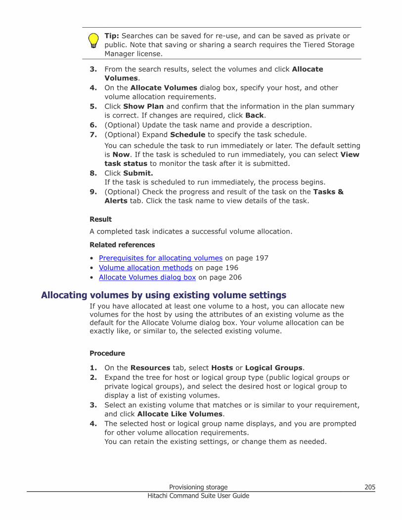
Tip: Searches can be saved for re-use, and can be saved as private orpublic. Note that saving or sharing a search requires the Tiered StorageManager license.
3. From the search results, select the volumes and click AllocateVolumes.
4. On the Allocate Volumes dialog box, specify your host, and othervolume allocation requirements.
5. Click Show Plan and confirm that the information in the plan summaryis correct. If changes are required, click Back.
6. (Optional) Update the task name and provide a description.7. (Optional) Expand Schedule to specify the task schedule.
You can schedule the task to run immediately or later. The default settingis Now. If the task is scheduled to run immediately, you can select Viewtask status to monitor the task after it is submitted.
8. Click Submit.If the task is scheduled to run immediately, the process begins.
9. (Optional) Check the progress and result of the task on the Tasks &Alerts tab. Click the task name to view details of the task.
Result
A completed task indicates a successful volume allocation.
Related references
• Prerequisites for allocating volumes on page 197• Volume allocation methods on page 196• Allocate Volumes dialog box on page 206
Allocating volumes by using existing volume settingsIf you have allocated at least one volume to a host, you can allocate newvolumes for the host by using the attributes of an existing volume as thedefault for the Allocate Volume dialog box. Your volume allocation can beexactly like, or similar to, the selected existing volume.
Procedure
1. On the Resources tab, select Hosts or Logical Groups.2. Expand the tree for host or logical group type (public logical groups or
private logical groups), and select the desired host or logical group todisplay a list of existing volumes.
3. Select an existing volume that matches or is similar to your requirement,and click Allocate Like Volumes.
4. The selected host or logical group name displays, and you are promptedfor other volume allocation requirements.You can retain the existing settings, or change them as needed.
Provisioning storage 205Hitachi Command Suite User Guide
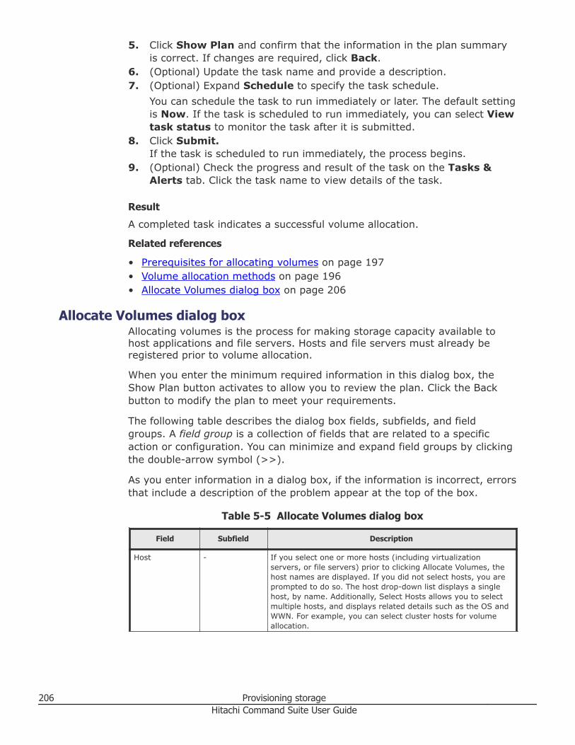
5. Click Show Plan and confirm that the information in the plan summaryis correct. If changes are required, click Back.
6. (Optional) Update the task name and provide a description.7. (Optional) Expand Schedule to specify the task schedule.
You can schedule the task to run immediately or later. The default settingis Now. If the task is scheduled to run immediately, you can select Viewtask status to monitor the task after it is submitted.
8. Click Submit.If the task is scheduled to run immediately, the process begins.
9. (Optional) Check the progress and result of the task on the Tasks &Alerts tab. Click the task name to view details of the task.
Result
A completed task indicates a successful volume allocation.
Related references
• Prerequisites for allocating volumes on page 197• Volume allocation methods on page 196• Allocate Volumes dialog box on page 206
Allocate Volumes dialog boxAllocating volumes is the process for making storage capacity available tohost applications and file servers. Hosts and file servers must already beregistered prior to volume allocation.
When you enter the minimum required information in this dialog box, theShow Plan button activates to allow you to review the plan. Click the Backbutton to modify the plan to meet your requirements.
The following table describes the dialog box fields, subfields, and fieldgroups. A field group is a collection of fields that are related to a specificaction or configuration. You can minimize and expand field groups by clickingthe double-arrow symbol (>>).
As you enter information in a dialog box, if the information is incorrect, errorsthat include a description of the problem appear at the top of the box.
Table 5-5 Allocate Volumes dialog box
Field Subfield Description
Host - If you select one or more hosts (including virtualizationservers, or file servers) prior to clicking Allocate Volumes, thehost names are displayed. If you did not select hosts, you areprompted to do so. The host drop-down list displays a singlehost, by name. Additionally, Select Hosts allows you to selectmultiple hosts, and displays related details such as the OS andWWN. For example, you can select cluster hosts for volumeallocation.
206 Provisioning storageHitachi Command Suite User Guide
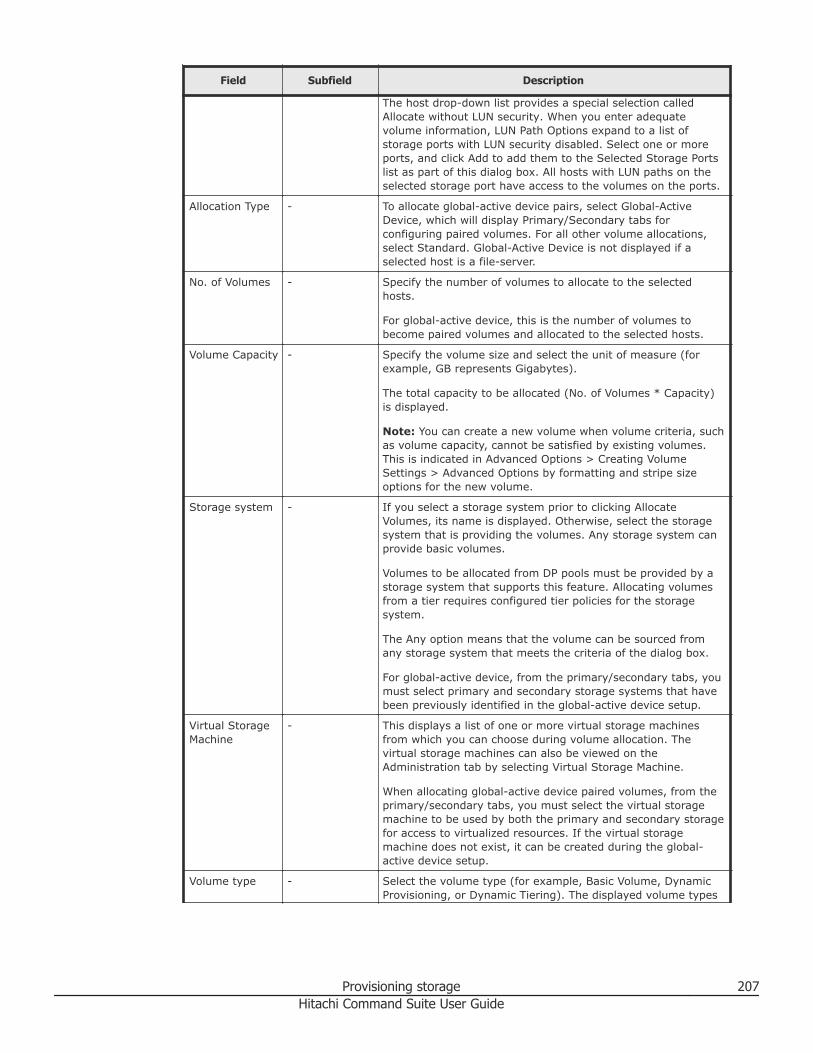
Field Subfield Description
The host drop-down list provides a special selection calledAllocate without LUN security. When you enter adequatevolume information, LUN Path Options expand to a list ofstorage ports with LUN security disabled. Select one or moreports, and click Add to add them to the Selected Storage Portslist as part of this dialog box. All hosts with LUN paths on theselected storage port have access to the volumes on the ports.
Allocation Type - To allocate global-active device pairs, select Global-ActiveDevice, which will display Primary/Secondary tabs forconfiguring paired volumes. For all other volume allocations,select Standard. Global-Active Device is not displayed if aselected host is a file-server.
No. of Volumes - Specify the number of volumes to allocate to the selectedhosts.
For global-active device, this is the number of volumes tobecome paired volumes and allocated to the selected hosts.
Volume Capacity - Specify the volume size and select the unit of measure (forexample, GB represents Gigabytes).
The total capacity to be allocated (No. of Volumes * Capacity)is displayed.
Note: You can create a new volume when volume criteria, suchas volume capacity, cannot be satisfied by existing volumes.This is indicated in Advanced Options > Creating VolumeSettings > Advanced Options by formatting and stripe sizeoptions for the new volume.
Storage system - If you select a storage system prior to clicking AllocateVolumes, its name is displayed. Otherwise, select the storagesystem that is providing the volumes. Any storage system canprovide basic volumes.
Volumes to be allocated from DP pools must be provided by astorage system that supports this feature. Allocating volumesfrom a tier requires configured tier policies for the storagesystem.
The Any option means that the volume can be sourced fromany storage system that meets the criteria of the dialog box.
For global-active device, from the primary/secondary tabs, youmust select primary and secondary storage systems that havebeen previously identified in the global-active device setup.
Virtual StorageMachine
- This displays a list of one or more virtual storage machinesfrom which you can choose during volume allocation. Thevirtual storage machines can also be viewed on theAdministration tab by selecting Virtual Storage Machine.
When allocating global-active device paired volumes, from theprimary/secondary tabs, you must select the virtual storagemachine to be used by both the primary and secondary storagefor access to virtualized resources. If the virtual storagemachine does not exist, it can be created during the global-active device setup.
Volume type - Select the volume type (for example, Basic Volume, DynamicProvisioning, or Dynamic Tiering). The displayed volume types
Provisioning storage 207Hitachi Command Suite User Guide
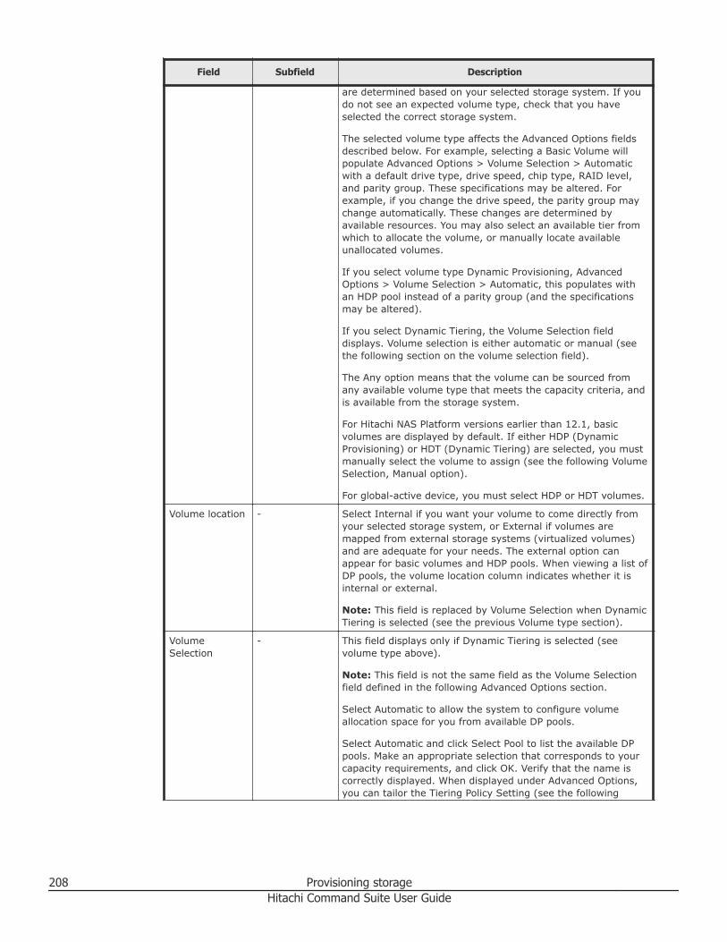
Field Subfield Description
are determined based on your selected storage system. If youdo not see an expected volume type, check that you haveselected the correct storage system.
The selected volume type affects the Advanced Options fieldsdescribed below. For example, selecting a Basic Volume willpopulate Advanced Options > Volume Selection > Automaticwith a default drive type, drive speed, chip type, RAID level,and parity group. These specifications may be altered. Forexample, if you change the drive speed, the parity group maychange automatically. These changes are determined byavailable resources. You may also select an available tier fromwhich to allocate the volume, or manually locate availableunallocated volumes.
If you select volume type Dynamic Provisioning, AdvancedOptions > Volume Selection > Automatic, this populates withan HDP pool instead of a parity group (and the specificationsmay be altered).
If you select Dynamic Tiering, the Volume Selection fielddisplays. Volume selection is either automatic or manual (seethe following section on the volume selection field).
The Any option means that the volume can be sourced fromany available volume type that meets the capacity criteria, andis available from the storage system.
For Hitachi NAS Platform versions earlier than 12.1, basicvolumes are displayed by default. If either HDP (DynamicProvisioning) or HDT (Dynamic Tiering) are selected, you mustmanually select the volume to assign (see the following VolumeSelection, Manual option).
For global-active device, you must select HDP or HDT volumes.
Volume location - Select Internal if you want your volume to come directly fromyour selected storage system, or External if volumes aremapped from external storage systems (virtualized volumes)and are adequate for your needs. The external option canappear for basic volumes and HDP pools. When viewing a list ofDP pools, the volume location column indicates whether it isinternal or external.
Note: This field is replaced by Volume Selection when DynamicTiering is selected (see the previous Volume type section).
VolumeSelection
- This field displays only if Dynamic Tiering is selected (seevolume type above).
Note: This field is not the same field as the Volume Selectionfield defined in the following Advanced Options section.
Select Automatic to allow the system to configure volumeallocation space for you from available DP pools.
Select Automatic and click Select Pool to list the available DPpools. Make an appropriate selection that corresponds to yourcapacity requirements, and click OK. Verify that the name iscorrectly displayed. When displayed under Advanced Options,you can tailor the Tiering Policy Setting (see the following
208 Provisioning storageHitachi Command Suite User Guide
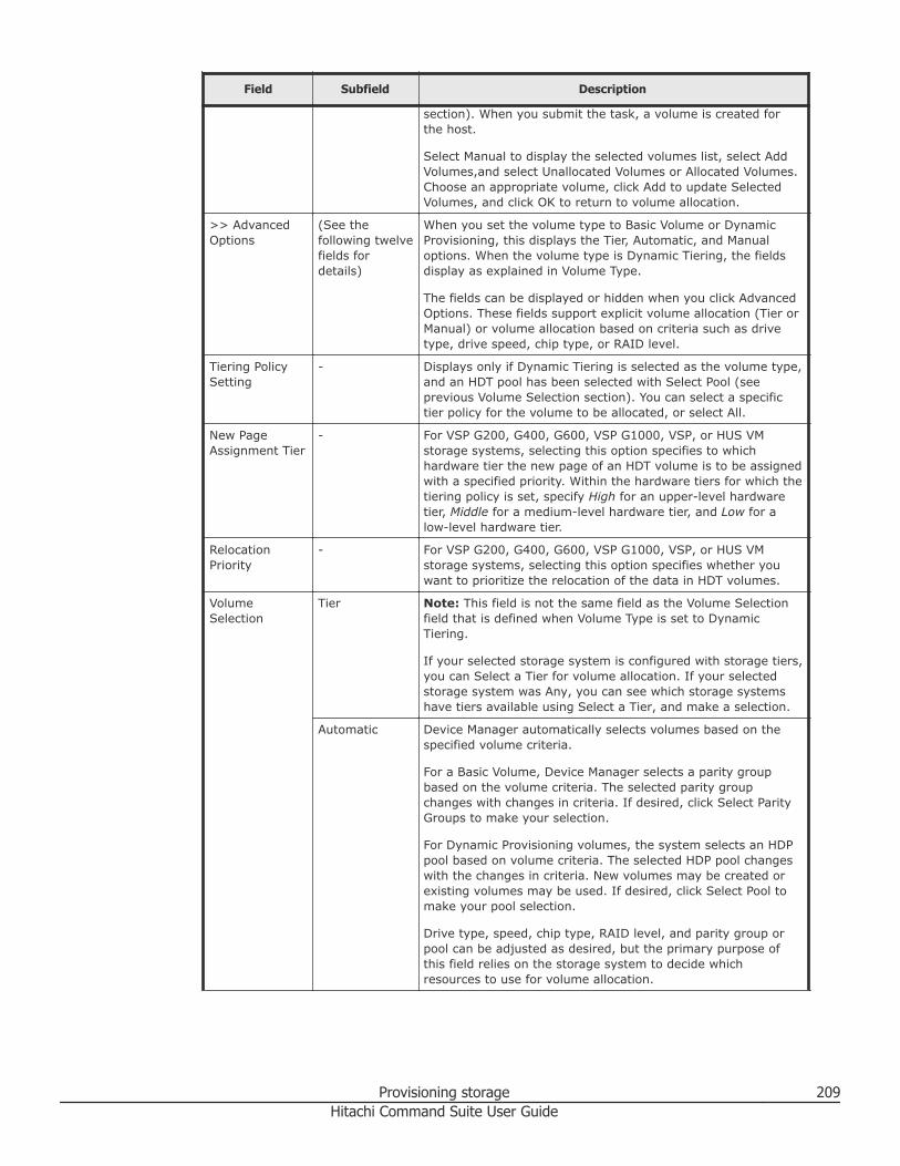
Field Subfield Description
section). When you submit the task, a volume is created forthe host.
Select Manual to display the selected volumes list, select AddVolumes,and select Unallocated Volumes or Allocated Volumes.Choose an appropriate volume, click Add to update SelectedVolumes, and click OK to return to volume allocation.
>> AdvancedOptions
(See thefollowing twelvefields fordetails)
When you set the volume type to Basic Volume or DynamicProvisioning, this displays the Tier, Automatic, and Manualoptions. When the volume type is Dynamic Tiering, the fieldsdisplay as explained in Volume Type.
The fields can be displayed or hidden when you click AdvancedOptions. These fields support explicit volume allocation (Tier orManual) or volume allocation based on criteria such as drivetype, drive speed, chip type, or RAID level.
Tiering PolicySetting
- Displays only if Dynamic Tiering is selected as the volume type,and an HDT pool has been selected with Select Pool (seeprevious Volume Selection section). You can select a specifictier policy for the volume to be allocated, or select All.
New PageAssignment Tier
- For VSP G200, G400, G600, VSP G1000, VSP, or HUS VMstorage systems, selecting this option specifies to whichhardware tier the new page of an HDT volume is to be assignedwith a specified priority. Within the hardware tiers for which thetiering policy is set, specify High for an upper-level hardwaretier, Middle for a medium-level hardware tier, and Low for alow-level hardware tier.
RelocationPriority
- For VSP G200, G400, G600, VSP G1000, VSP, or HUS VMstorage systems, selecting this option specifies whether youwant to prioritize the relocation of the data in HDT volumes.
VolumeSelection
Tier Note: This field is not the same field as the Volume Selectionfield that is defined when Volume Type is set to DynamicTiering.
If your selected storage system is configured with storage tiers,you can Select a Tier for volume allocation. If your selectedstorage system was Any, you can see which storage systemshave tiers available using Select a Tier, and make a selection.
Automatic Device Manager automatically selects volumes based on thespecified volume criteria.
For a Basic Volume, Device Manager selects a parity groupbased on the volume criteria. The selected parity groupchanges with changes in criteria. If desired, click Select ParityGroups to make your selection.
For Dynamic Provisioning volumes, the system selects an HDPpool based on volume criteria. The selected HDP pool changeswith the changes in criteria. New volumes may be created orexisting volumes may be used. If desired, click Select Pool tomake your pool selection.
Drive type, speed, chip type, RAID level, and parity group orpool can be adjusted as desired, but the primary purpose ofthis field relies on the storage system to decide whichresources to use for volume allocation.
Provisioning storage 209Hitachi Command Suite User Guide
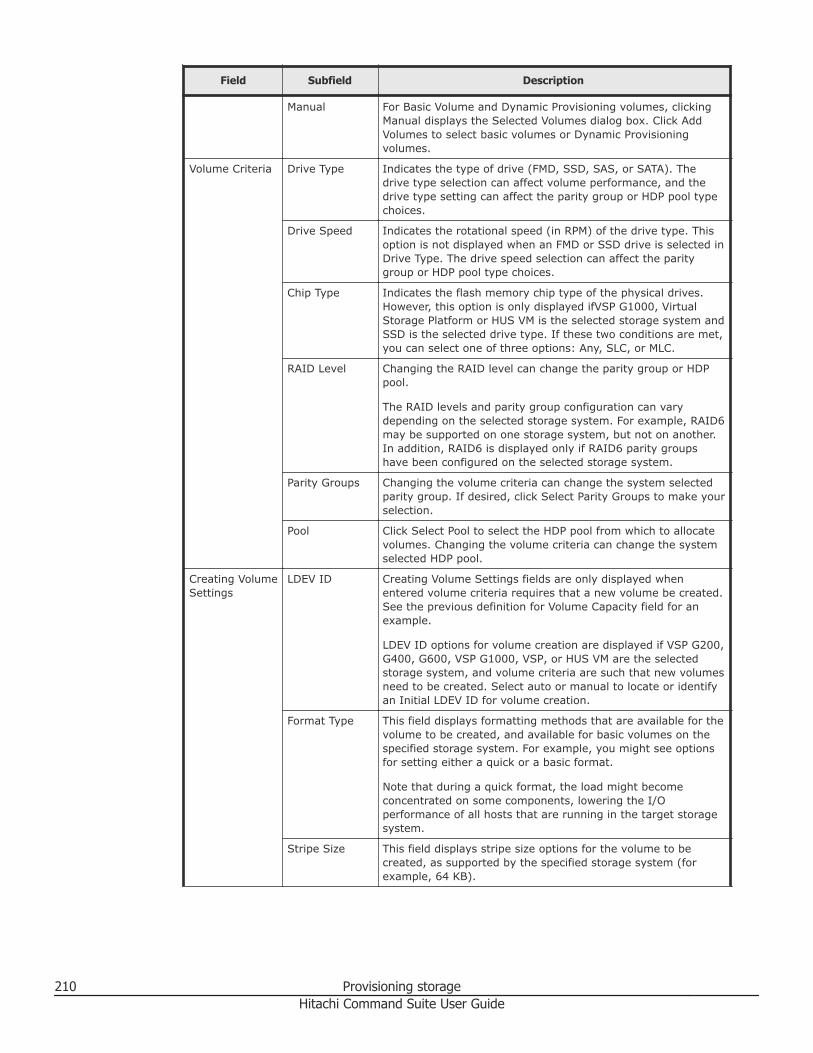
Field Subfield Description
Manual For Basic Volume and Dynamic Provisioning volumes, clickingManual displays the Selected Volumes dialog box. Click AddVolumes to select basic volumes or Dynamic Provisioningvolumes.
Volume Criteria Drive Type Indicates the type of drive (FMD, SSD, SAS, or SATA). Thedrive type selection can affect volume performance, and thedrive type setting can affect the parity group or HDP pool typechoices.
Drive Speed Indicates the rotational speed (in RPM) of the drive type. Thisoption is not displayed when an FMD or SSD drive is selected inDrive Type. The drive speed selection can affect the paritygroup or HDP pool type choices.
Chip Type Indicates the flash memory chip type of the physical drives.However, this option is only displayed ifVSP G1000, VirtualStorage Platform or HUS VM is the selected storage system andSSD is the selected drive type. If these two conditions are met,you can select one of three options: Any, SLC, or MLC.
RAID Level Changing the RAID level can change the parity group or HDPpool.
The RAID levels and parity group configuration can varydepending on the selected storage system. For example, RAID6may be supported on one storage system, but not on another.In addition, RAID6 is displayed only if RAID6 parity groupshave been configured on the selected storage system.
Parity Groups Changing the volume criteria can change the system selectedparity group. If desired, click Select Parity Groups to make yourselection.
Pool Click Select Pool to select the HDP pool from which to allocatevolumes. Changing the volume criteria can change the systemselected HDP pool.
Creating VolumeSettings
LDEV ID Creating Volume Settings fields are only displayed whenentered volume criteria requires that a new volume be created.See the previous definition for Volume Capacity field for anexample.
LDEV ID options for volume creation are displayed if VSP G200,G400, G600, VSP G1000, VSP, or HUS VM are the selectedstorage system, and volume criteria are such that new volumesneed to be created. Select auto or manual to locate or identifyan Initial LDEV ID for volume creation.
Format Type This field displays formatting methods that are available for thevolume to be created, and available for basic volumes on thespecified storage system. For example, you might see optionsfor setting either a quick or a basic format.
Note that during a quick format, the load might becomeconcentrated on some components, lowering the I/Operformance of all hosts that are running in the target storagesystem.
Stripe Size This field displays stripe size options for the volume to becreated, as supported by the specified storage system (forexample, 64 KB).
210 Provisioning storageHitachi Command Suite User Guide
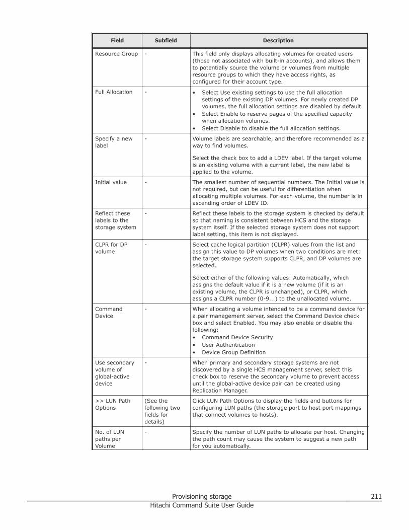
Field Subfield Description
Resource Group - This field only displays allocating volumes for created users(those not associated with built-in accounts), and allows themto potentially source the volume or volumes from multipleresource groups to which they have access rights, asconfigured for their account type.
Full Allocation - • Select Use existing settings to use the full allocationsettings of the existing DP volumes. For newly created DPvolumes, the full allocation settings are disabled by default.
• Select Enable to reserve pages of the specified capacitywhen allocation volumes.
• Select Disable to disable the full allocation settings.
Specify a newlabel
- Volume labels are searchable, and therefore recommended as away to find volumes.
Select the check box to add a LDEV label. If the target volumeis an existing volume with a current label, the new label isapplied to the volume.
Initial value - The smallest number of sequential numbers. The Initial value isnot required, but can be useful for differentiation whenallocating multiple volumes. For each volume, the number is inascending order of LDEV ID.
Reflect theselabels to thestorage system
- Reflect these labels to the storage system is checked by defaultso that naming is consistent between HCS and the storagesystem itself. If the selected storage system does not supportlabel setting, this item is not displayed.
CLPR for DPvolume
- Select cache logical partition (CLPR) values from the list andassign this value to DP volumes when two conditions are met:the target storage system supports CLPR, and DP volumes areselected.
Select either of the following values: Automatically, whichassigns the default value if it is a new volume (if it is anexisting volume, the CLPR is unchanged), or CLPR, whichassigns a CLPR number (0-9...) to the unallocated volume.
CommandDevice
- When allocating a volume intended to be a command device fora pair management server, select the Command Device checkbox and select Enabled. You may also enable or disable thefollowing:• Command Device Security• User Authentication• Device Group Definition
Use secondaryvolume ofglobal-activedevice
- When primary and secondary storage systems are notdiscovered by a single HCS management server, select thischeck box to reserve the secondary volume to prevent accessuntil the global-active device pair can be created usingReplication Manager.
>> LUN PathOptions
(See thefollowing twofields fordetails)
Click LUN Path Options to display the fields and buttons forconfiguring LUN paths (the storage port to host port mappingsthat connect volumes to hosts).
No. of LUNpaths perVolume
- Specify the number of LUN paths to allocate per host. Changingthe path count may cause the system to suggest a new pathfor you automatically.
Provisioning storage 211Hitachi Command Suite User Guide
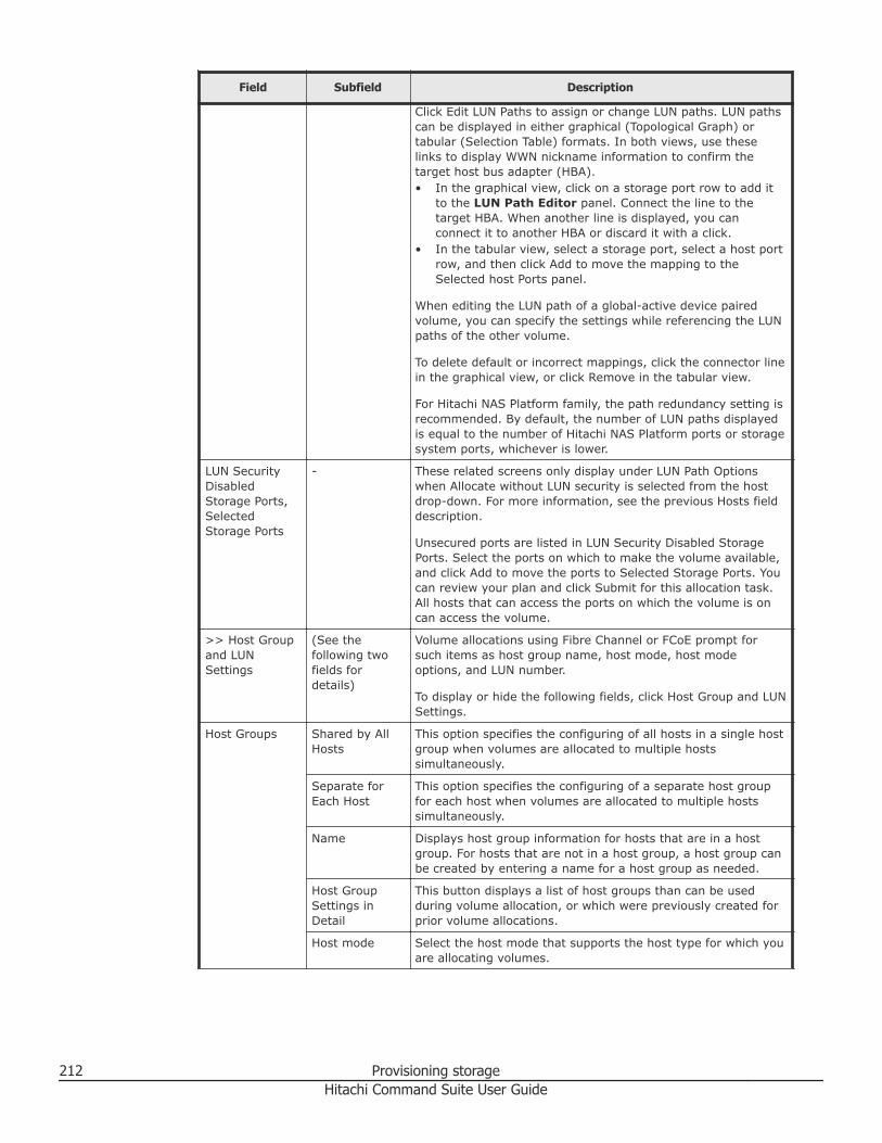
Field Subfield Description
Click Edit LUN Paths to assign or change LUN paths. LUN pathscan be displayed in either graphical (Topological Graph) ortabular (Selection Table) formats. In both views, use theselinks to display WWN nickname information to confirm thetarget host bus adapter (HBA).• In the graphical view, click on a storage port row to add it
to the LUN Path Editor panel. Connect the line to thetarget HBA. When another line is displayed, you canconnect it to another HBA or discard it with a click.
• In the tabular view, select a storage port, select a host portrow, and then click Add to move the mapping to theSelected host Ports panel.
When editing the LUN path of a global-active device pairedvolume, you can specify the settings while referencing the LUNpaths of the other volume.
To delete default or incorrect mappings, click the connector linein the graphical view, or click Remove in the tabular view.
For Hitachi NAS Platform family, the path redundancy setting isrecommended. By default, the number of LUN paths displayedis equal to the number of Hitachi NAS Platform ports or storagesystem ports, whichever is lower.
LUN SecurityDisabledStorage Ports,SelectedStorage Ports
- These related screens only display under LUN Path Optionswhen Allocate without LUN security is selected from the hostdrop-down. For more information, see the previous Hosts fielddescription.
Unsecured ports are listed in LUN Security Disabled StoragePorts. Select the ports on which to make the volume available,and click Add to move the ports to Selected Storage Ports. Youcan review your plan and click Submit for this allocation task.All hosts that can access the ports on which the volume is oncan access the volume.
>> Host Groupand LUNSettings
(See thefollowing twofields fordetails)
Volume allocations using Fibre Channel or FCoE prompt forsuch items as host group name, host mode, host modeoptions, and LUN number.
To display or hide the following fields, click Host Group and LUNSettings.
Host Groups Shared by AllHosts
This option specifies the configuring of all hosts in a single hostgroup when volumes are allocated to multiple hostssimultaneously.
Separate forEach Host
This option specifies the configuring of a separate host groupfor each host when volumes are allocated to multiple hostssimultaneously.
Name Displays host group information for hosts that are in a hostgroup. For hosts that are not in a host group, a host group canbe created by entering a name for a host group as needed.
Host GroupSettings inDetail
This button displays a list of host groups than can be usedduring volume allocation, or which were previously created forprior volume allocations.
Host mode Select the host mode that supports the host type for which youare allocating volumes.
212 Provisioning storageHitachi Command Suite User Guide
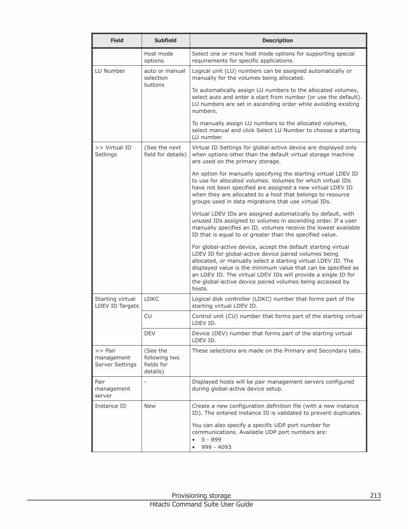
Field Subfield Description
Host modeoptions
Select one or more host mode options for supporting specialrequirements for specific applications.
LU Number auto or manualselectionbuttons
Logical unit (LU) numbers can be assigned automatically ormanually for the volumes being allocated.
To automatically assign LU numbers to the allocated volumes,select auto and enter a start from number (or use the default).LU numbers are set in ascending order while avoiding existingnumbers.
To manually assign LU numbers to the allocated volumes,select manual and click Select LU Number to choose a startingLU number.
>> Virtual IDSettings
(See the nextfield for details)
Virtual ID Settings for global-active device are displayed onlywhen options other than the default virtual storage machineare used on the primary storage.
An option for manually specifying the starting virtual LDEV IDto use for allocated volumes. Volumes for which virtual IDshave not been specified are assigned a new virtual LDEV IDwhen they are allocated to a host that belongs to resourcegroups used in data migrations that use virtual IDs.
Virtual LDEV IDs are assigned automatically by default, withunused IDs assigned to volumes in ascending order. If a usermanually specifies an ID, volumes receive the lowest availableID that is equal to or greater than the specified value.
For global-active device, accept the default starting virtualLDEV ID for global-active device paired volumes beingallocated, or manually select a starting virtual LDEV ID. Thedisplayed value is the minimum value that can be specified asan LDEV ID. The virtual LDEV IDs will provide a single ID forthe global-active device paired volumes being accessed byhosts.
Starting virtualLDEV ID Targets
LDKC Logical disk controller (LDKC) number that forms part of thestarting virtual LDEV ID.
CU Control unit (CU) number that forms part of the starting virtualLDEV ID.
DEV Device (DEV) number that forms part of the starting virtualLDEV ID.
>> PairmanagementServer Settings
(See thefollowing twofields fordetails)
These selections are made on the Primary and Secondary tabs.
Pairmanagementserver
- Displayed hosts will be pair management servers configuredduring global-active device setup.
Instance ID New Create a new configuration definition file (with a new instanceID). The entered instance ID is validated to prevent duplicates.
You can also specify a specific UDP port number forcommunications. Available UDP port numbers are:• 0 - 899• 999 - 4093
Provisioning storage 213Hitachi Command Suite User Guide
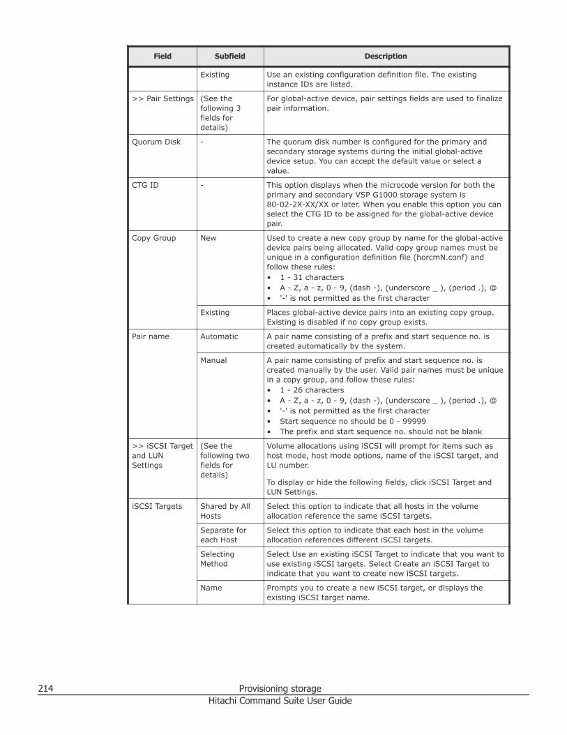
Field Subfield Description
Existing Use an existing configuration definition file. The existinginstance IDs are listed.
>> Pair Settings (See thefollowing 3fields fordetails)
For global-active device, pair settings fields are used to finalizepair information.
Quorum Disk - The quorum disk number is configured for the primary andsecondary storage systems during the initial global-activedevice setup. You can accept the default value or select avalue.
CTG ID - This option displays when the microcode version for both theprimary and secondary VSP G1000 storage system is80-02-2X-XX/XX or later. When you enable this option you canselect the CTG ID to be assigned for the global-active devicepair.
Copy Group New Used to create a new copy group by name for the global-activedevice pairs being allocated. Valid copy group names must beunique in a configuration definition file (horcmN.conf) andfollow these rules:• 1 - 31 characters• A - Z, a - z, 0 - 9, (dash -), (underscore _ ), (period .), @• '-' is not permitted as the first character
Existing Places global-active device pairs into an existing copy group.Existing is disabled if no copy group exists.
Pair name Automatic A pair name consisting of a prefix and start sequence no. iscreated automatically by the system.
Manual A pair name consisting of prefix and start sequence no. iscreated manually by the user. Valid pair names must be uniquein a copy group, and follow these rules:• 1 - 26 characters• A - Z, a - z, 0 - 9, (dash -), (underscore _ ), (period .), @• '-' is not permitted as the first character• Start sequence no should be 0 - 99999• The prefix and start sequence no. should not be blank
>> iSCSI Targetand LUNSettings
(See thefollowing twofields fordetails)
Volume allocations using iSCSI will prompt for items such ashost mode, host mode options, name of the iSCSI target, andLU number.
To display or hide the following fields, click iSCSI Target andLUN Settings.
iSCSI Targets Shared by AllHosts
Select this option to indicate that all hosts in the volumeallocation reference the same iSCSI targets.
Separate foreach Host
Select this option to indicate that each host in the volumeallocation references different iSCSI targets.
SelectingMethod
Select Use an existing iSCSI Target to indicate that you want touse existing iSCSI targets. Select Create an iSCSI Target toindicate that you want to create new iSCSI targets.
Name Prompts you to create a new iSCSI target, or displays theexisting iSCSI target name.
214 Provisioning storageHitachi Command Suite User Guide
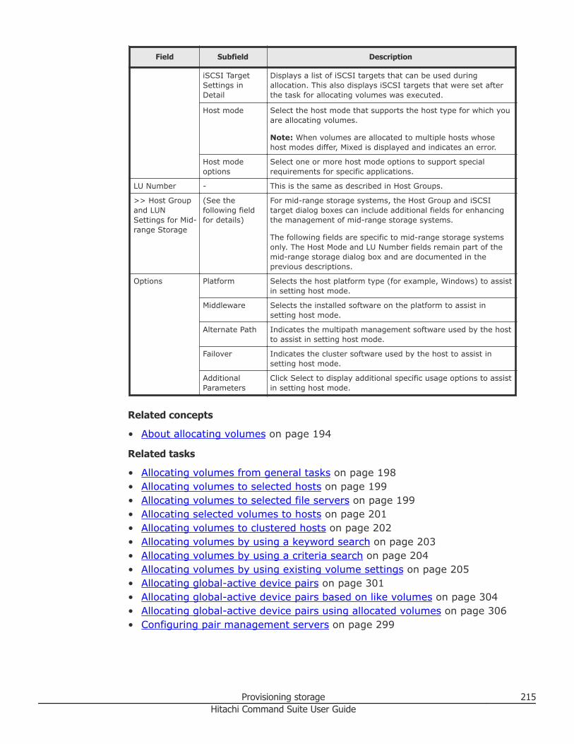
Field Subfield Description
iSCSI TargetSettings inDetail
Displays a list of iSCSI targets that can be used duringallocation. This also displays iSCSI targets that were set afterthe task for allocating volumes was executed.
Host mode Select the host mode that supports the host type for which youare allocating volumes.
Note: When volumes are allocated to multiple hosts whosehost modes differ, Mixed is displayed and indicates an error.
Host modeoptions
Select one or more host mode options to support specialrequirements for specific applications.
LU Number - This is the same as described in Host Groups.
>> Host Groupand LUNSettings for Mid-range Storage
(See thefollowing fieldfor details)
For mid-range storage systems, the Host Group and iSCSItarget dialog boxes can include additional fields for enhancingthe management of mid-range storage systems.
The following fields are specific to mid-range storage systemsonly. The Host Mode and LU Number fields remain part of themid-range storage dialog box and are documented in theprevious descriptions.
Options Platform Selects the host platform type (for example, Windows) to assistin setting host mode.
Middleware Selects the installed software on the platform to assist insetting host mode.
Alternate Path Indicates the multipath management software used by the hostto assist in setting host mode.
Failover Indicates the cluster software used by the host to assist insetting host mode.
AdditionalParameters
Click Select to display additional specific usage options to assistin setting host mode.
Related concepts
• About allocating volumes on page 194
Related tasks
• Allocating volumes from general tasks on page 198• Allocating volumes to selected hosts on page 199• Allocating volumes to selected file servers on page 199• Allocating selected volumes to hosts on page 201• Allocating volumes to clustered hosts on page 202• Allocating volumes by using a keyword search on page 203• Allocating volumes by using a criteria search on page 204• Allocating volumes by using existing volume settings on page 205• Allocating global-active device pairs on page 301• Allocating global-active device pairs based on like volumes on page 304• Allocating global-active device pairs using allocated volumes on page 306• Configuring pair management servers on page 299
Provisioning storage 215Hitachi Command Suite User Guide
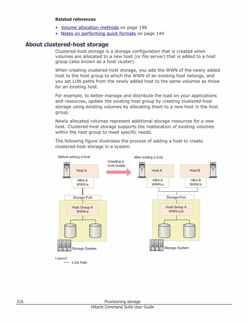
Related references
• Volume allocation methods on page 196• Notes on performing quick formats on page 144
About clustered-host storageClustered-host storage is a storage configuration that is created whenvolumes are allocated to a new host (or file server) that is added to a hostgroup (also known as a host cluster).
When creating clustered-host storage, you add the WWN of the newly addedhost to the host group to which the WWN of an existing host belongs, andyou set LUN paths from the newly added host to the same volumes as thosefor an existing host.
For example, to better manage and distribute the load on your applicationsand resources, update the existing host group by creating clustered-hoststorage using existing volumes by allocating them to a new host in the hostgroup.
Newly allocated volumes represent additional storage resources for a newhost. Clustered-host storage supports the reallocation of existing volumeswithin the host group to meet specific needs.
The following figure illustrates the process of adding a host to createclustered-host storage in a system.
216 Provisioning storageHitachi Command Suite User Guide
Related concepts
• About allocating volumes on page 194• About managing WWNs by using nicknames on page 414• About LUN path management on page 229
Related tasks
• Creating clustered-host storage on page 217• Allocating volumes to selected hosts on page 199
Creating clustered-host storageYou create clustered-host storage by allocating volumes to a new host withinan existing host group (also known as a host cluster).
Creating clustered-host storage involves allocating new or additional volumesto a new host that has been added to an existing host group, setting newLUN paths to the new host, and adding the WWN of the new host to anexisting host group.
Prerequisites• Discover (and register) new hosts.• Allocate volumes to existing hosts.• Verify that the host connections are Fibre Channel or Fibre Channel over
Ethernet (FCoE)
Procedure
1. On the Resources tab, click Hosts, and select All Hosts to list thehosts by OS type in the Application pane.
2. From the list of hosts, select one or more hosts (or from the list ofvolumes, select one or more volumes allocated to these hosts).
3. Click More Actions, and select Define Clustered-Host Storage.4. Select secondary hosts to add to the cluster:
• To add one host, select the host name in the Select a host/fileserver list.
• To add multiple hosts, click Select Hosts/File Servers, highlighteach host name, and click Add.
5. From the Selected Storage System list, select the storage system toassociate with the selected host.If two or more storage systems are allocated to the selected host, selectonly one storage system.
6. In the Add WWN list, select the WWN of the new host to add to anavailable host group.View the host groups to which the new host can be added in theAvailable Host Groups list.
7. In the Available Host Groups list, select a host group, and click Add.
Provisioning storage 217Hitachi Command Suite User Guide
You can see the volumes that are associated with the selected host groupin A list of affected volumes, and also verify the added LUN paths foreach entry in the Available LUN Path list.
Note: To add more new hosts and associated WWNs, repeat steps 4through 7 as needed. If you need to modify host information, expand theHost Group and LUN Settings to set host group information.
8. Click Show Plan and confirm that the information in the plan summaryis correct.If changes are required, click Back.
9. (Optional) Update the task name and provide a description.10. (Optional) Expand Schedule to specify the task schedule.
You can schedule the task to run immediately or later. The default settingis Now. If scheduled for Now, select View task status to monitor thetask after it is submitted.
11. Click Submit.If the task is scheduled to run immediately, the task begins.
12. You can check the progress and the result of the task on the Tasks &Alerts tab.Click on the task name to view details of the task.
Result
The new host is added to the designated host group, which created clustered-host storage by virtue of the following:• LUN paths are created between new host and host group• WWN of new host is added to host group
Tip: You can also use the Edit LUN Paths dialog box to confirm that the WWNof the new host is successfully added to the host group.
Related concepts
• About clustered-host storage on page 216
Related tasks
• Allocating volumes to selected hosts on page 199• Editing a WWN nickname on page 416• Editing LUN paths on page 230
About unallocating volumesYou can unallocate volumes from hosts or file servers.
You can also unallocate global-active device paired volumes from hosts.
Unallocated volumes can be:
218 Provisioning storageHitachi Command Suite User Guide
• Re-allocated (with existing data) to a host or file server that can recognizethe existing data (file system).
• Used for other storage requirements.
Unallocating a volume deletes all LUN paths that connect the volumes to thehost or file server.
Unallocating volumes does not delete existing volume data by default.However, during unallocation there is an option to delete the volume (volumedata is lost) and return it to unused capacity, or you can delete theunallocated volume later. As a precaution, to retain volume data, back upvolumes before unallocating them (for example, for volumes to be re-allocated to a new host).
Related concepts
• About removing hosts and related resources, or vCenters on page 76
Related tasks
• Unallocating volumes from hosts on page 219• Unallocating volumes from file servers on page 220
Related references
• Unallocate volumes dialog box on page 221
Unallocating volumes from hostsUnallocated volumes can be re-allocated (with existing data) or can be madeavailable for other storage requirements.
Prerequisites• Identify the name of the target host, and the volumes to unallocate.• If necessary, backup data on the target volumes.• Unmount all allocated volumes that you plan to unallocate. An IT
administrator might have to perform this task.
Procedure
1. On the Resources tab you can unallocate volumes from severallocations:• From General Tasks, select Unallocate Volumes.• Select a host OS, select one or more target hosts, and click
Unallocate Volumes.• Select a host OS, click a target host name to display volumes, select
one or more volumes, and click Unallocate Volumes.• Search for a host, click the host name and go directly to the volume
list, and click Unallocate Volumes
The Unallocate Volumes dialog is launched.
Provisioning storage 219Hitachi Command Suite User Guide
2. Select the host and host volumes to unallocate. Note that if the host andhost volumes were selected prior to launching the Unallocate Volumesdialog box, you will go directly to the plan summary mentioned in thenext step.
3. Click Show Plan and confirm that the information in the plan summaryis correct. If changes are required, click Back.
4. (Optional) Update the task name and provide a description.5. (Optional) Expand Schedule to specify the task schedule.
You can schedule the task to run immediately or later. The default settingis Now. If the task is scheduled to run immediately, you can select Viewtask status to monitor the task after it is submitted.
6. Click Submit.If the task is scheduled to run immediately, the process begins.
7. (Optional) Check the progress and result of the task on the Tasks &Alerts tab. Click the task name to view details of the task.
Result
Unallocated volumes are added back to the storage system Open-Unallocatedvolume list.
Related concepts
• About unallocating volumes on page 218
Related tasks
• Shredding volume data on page 149• Deleting unallocated volumes on page 150
Related references
• Unallocate volumes dialog box on page 221
Unallocating volumes from file serversUnallocated volumes can be re-allocated (with existing data) or can be madeavailable for other storage requirements.
Prerequisites• Identify the name of the target cluster or file server and the volumes you
want to unallocate.• If necessary, back up data on the target volumes.• Unmount all allocated volumes that you plan to unallocate. An IT
administrator might have to perform this task.
Procedure
1. On the Resources tab, select File Servers, then select All FileServers.
220 Provisioning storageHitachi Command Suite User Guide
• From the Servers/Clusters list, select the row of the target cluster orfile server (only one row can be selected), and then click UnallocateVolumes.
• To unallocate individual volumes, select the target cluster or file serverin the tree, and then select the target volumes from the SystemDrives tab for Hitachi NAS Platform, or the Volumes tab for HitachiNAS Platform F or Hitachi Data Ingestor, and then click UnallocateVolumes.
2. Specify the appropriate settings for creating a plan.3. Verify the plan and click Submit.4. In the task list, confirm that the task is completed.
Tip: For Hitachi NAS Platform family, for reasons such as node deletion,if you want to unallocate volumes from individual file server nodes thatare in clusters, click the link of the cluster name and select the PhysicalView tab. From the list, select the row of the target file server (node)and click the Unallocate Volumes button.
Related concepts
• About unallocating volumes on page 218
Related tasks
• Shredding volume data on page 149• Deleting unallocated volumes on page 150
Related references
• Unallocate volumes dialog box on page 221
Unallocate volumes dialog boxSuccessfully unallocated volumes are placed in the Open-Unallocated folderof the storage system from which they originated. Unallocated volumes canbe reallocated to another host, with data intact.
Volumes can be deleted using this dialog box and returned to unusedcapacity if eligible, or previously unallocated volumes can be reallocated toanother host.
When you enter the minimum required information in this dialog box, theShow Plan button activates to allow you to review the plan. Click the Backbutton to modify the plan to meet your requirements.
The following table describes the dialog box fields, subfields, and fieldgroups. A field group is a collection of fields that are related to a specificaction or configuration. You can minimize and expand field groups by clickingthe double-arrow symbol (>>).
As you enter information in a dialog box, if the information is incorrect, errorsthat include a description of the problem appear at the top of the box.
Provisioning storage 221Hitachi Command Suite User Guide
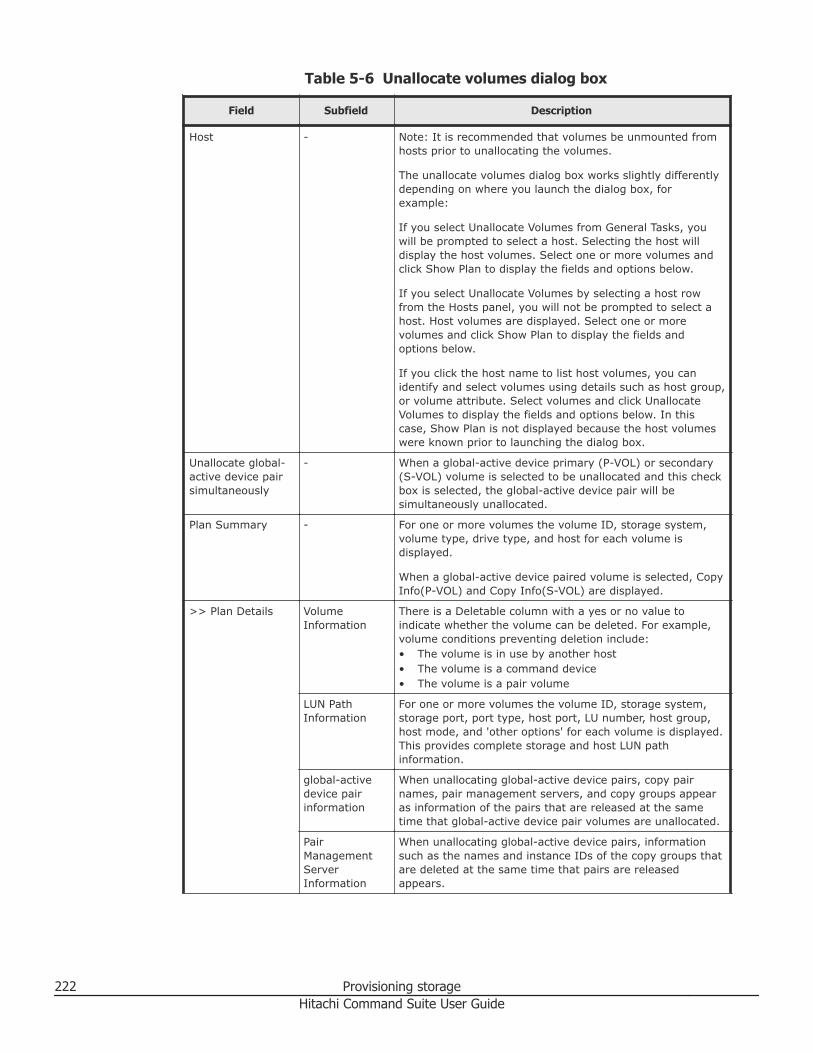
Table 5-6 Unallocate volumes dialog box
Field Subfield Description
Host - Note: It is recommended that volumes be unmounted fromhosts prior to unallocating the volumes.
The unallocate volumes dialog box works slightly differentlydepending on where you launch the dialog box, forexample:
If you select Unallocate Volumes from General Tasks, youwill be prompted to select a host. Selecting the host willdisplay the host volumes. Select one or more volumes andclick Show Plan to display the fields and options below.
If you select Unallocate Volumes by selecting a host rowfrom the Hosts panel, you will not be prompted to select ahost. Host volumes are displayed. Select one or morevolumes and click Show Plan to display the fields andoptions below.
If you click the host name to list host volumes, you canidentify and select volumes using details such as host group,or volume attribute. Select volumes and click UnallocateVolumes to display the fields and options below. In thiscase, Show Plan is not displayed because the host volumeswere known prior to launching the dialog box.
Unallocate global-active device pairsimultaneously
- When a global-active device primary (P-VOL) or secondary(S-VOL) volume is selected to be unallocated and this checkbox is selected, the global-active device pair will besimultaneously unallocated.
Plan Summary - For one or more volumes the volume ID, storage system,volume type, drive type, and host for each volume isdisplayed.
When a global-active device paired volume is selected, CopyInfo(P-VOL) and Copy Info(S-VOL) are displayed.
>> Plan Details VolumeInformation
There is a Deletable column with a yes or no value toindicate whether the volume can be deleted. For example,volume conditions preventing deletion include:• The volume is in use by another host• The volume is a command device• The volume is a pair volume
LUN PathInformation
For one or more volumes the volume ID, storage system,storage port, port type, host port, LU number, host group,host mode, and 'other options' for each volume is displayed.This provides complete storage and host LUN pathinformation.
global-activedevice pairinformation
When unallocating global-active device pairs, copy pairnames, pair management servers, and copy groups appearas information of the pairs that are released at the sametime that global-active device pair volumes are unallocated.
PairManagementServerInformation
When unallocating global-active device pairs, informationsuch as the names and instance IDs of the copy groups thatare deleted at the same time that pairs are releasedappears.
222 Provisioning storageHitachi Command Suite User Guide
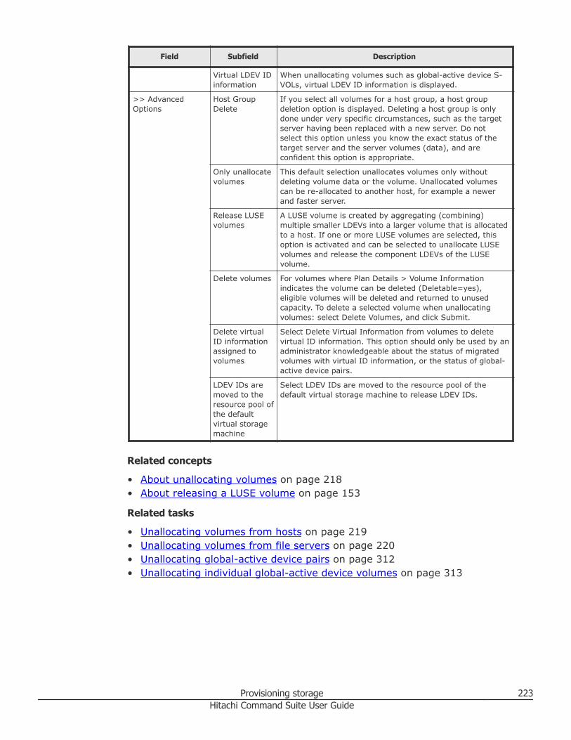
Field Subfield Description
Virtual LDEV IDinformation
When unallocating volumes such as global-active device S-VOLs, virtual LDEV ID information is displayed.
>> AdvancedOptions
Host GroupDelete
If you select all volumes for a host group, a host groupdeletion option is displayed. Deleting a host group is onlydone under very specific circumstances, such as the targetserver having been replaced with a new server. Do notselect this option unless you know the exact status of thetarget server and the server volumes (data), and areconfident this option is appropriate.
Only unallocatevolumes
This default selection unallocates volumes only withoutdeleting volume data or the volume. Unallocated volumescan be re-allocated to another host, for example a newerand faster server.
Release LUSEvolumes
A LUSE volume is created by aggregating (combining)multiple smaller LDEVs into a larger volume that is allocatedto a host. If one or more LUSE volumes are selected, thisoption is activated and can be selected to unallocate LUSEvolumes and release the component LDEVs of the LUSEvolume.
Delete volumes For volumes where Plan Details > Volume Informationindicates the volume can be deleted (Deletable=yes),eligible volumes will be deleted and returned to unusedcapacity. To delete a selected volume when unallocatingvolumes: select Delete Volumes, and click Submit.
Delete virtualID informationassigned tovolumes
Select Delete Virtual Information from volumes to deletevirtual ID information. This option should only be used by anadministrator knowledgeable about the status of migratedvolumes with virtual ID information, or the status of global-active device pairs.
LDEV IDs aremoved to theresource pool ofthe defaultvirtual storagemachine
Select LDEV IDs are moved to the resource pool of thedefault virtual storage machine to release LDEV IDs.
Related concepts
• About unallocating volumes on page 218• About releasing a LUSE volume on page 153
Related tasks
• Unallocating volumes from hosts on page 219• Unallocating volumes from file servers on page 220• Unallocating global-active device pairs on page 312• Unallocating individual global-active device volumes on page 313
Provisioning storage 223Hitachi Command Suite User Guide
Configuring Fibre Channel portsEnable LUN security and configure data transfer speeds, port addresses, andfabric switch settings.
Enabling LUN security on a portTo protect mission-critical data in your storage system from illegal access,secure the logical volumes in the storage system. Use LUN Manager to secureLUs from illegal access by enabling LUN security on ports.
By default, LUN security is disabled on each port. When registering hosts inmultiple host groups, you must enable LUN security (set the switch toenabled). When you change LUN security from disabled to enabled, you mustspecify the WWN of the host bus adapter.
Caution: It is best to enable LUN security on each port when configuringyour storage system. Although you can enable LUN security on a port whenhost I/O is in progress, I/O is rejected with a security guard after enabling.
Procedure
1. On the Resources tab, click Storage Systems, and then expand AllStorage Systems and the target storage system.
2. Choose one of the following options.• For Virtual Storage Platform G200, G400, G600:
Click Ports/Host Groups/iSCSI Targets.• For Virtual Storage Platform G1000:
Click Ports/Host Groups.• For other available storage systems:
From the Actions list in the application pane, select ElementManager. Refer to the documentation for the native management toolfor your storage system.
3. On the Ports tab, select the desired port.4. Click Edit Ports.5. Select the Port Security check box, and then select Enable.6. Click Finish. A message appears, confirming whether to switch the LUN
security.7. Click OK to open the Confirm window.8. In the Confirm window, confirm the settings.9. Enter a unique Task Name or accept the default, and then click Apply.
If Go to tasks window for status is checked, the Tasks windowopens.
224 Provisioning storageHitachi Command Suite User Guide
Related tasks
• Disabling LUN security on a port on page 225• Setting the data transfer speed on a Fibre Channel port on page 225• Setting the Fibre Channel port address on page 227• Setting the fabric switch on page 228
Disabling LUN security on a portUse this procedure to disable LUN security on a port.
Caution: Do not disable LUN security on a port when host I/O is in progress.
Procedure
1. On the Resources tab, click Storage Systems, and then expand AllStorage Systems and the target storage system.
2. Choose one of the following options.• For Virtual Storage Platform G200, G400, G600:
Click Ports/Host Groups/iSCSI Targets.• For Virtual Storage Platform G1000:
Click Ports/Host Groups.• For other available storage systems:
From the Actions list in the application pane, select ElementManager. Refer to the documentation for the native management toolfor your storage system.
3. On the Ports tab, select the desired port.4. Click Edit Ports.5. Select the Port Security check box, and then select Disable.6. Click Finish. If disabling LUN security, a message appears, indicating
that only host group 0 (the group whose number is 00) is to be enabled.Clicking OK opens the Confirm window.
7. In the Confirm window, confirm the settings.8. Enter a unique Task Name or accept the default, and then click Apply.
If Go to tasks window for status is checked, the Tasks windowopens.
Related tasks
• Enabling LUN security on a port on page 224
Setting the data transfer speed on a Fibre Channel portAs system operation continues, you might notice that a large amount of datais transferred at some ports, but a small amount of data is transferred atother ports. You can optimize system performance on a Fibre Channel port bysetting a faster data transfer speed on ports where a larger amount of data is
Provisioning storage 225Hitachi Command Suite User Guide
transferred, and setting a slower data transfer speed on ports where asmaller amount of data is transferred.
Note: For Virtual Storage Platform G1000: In Fibre Channel over Ethernet(FCoE) networks, the port speed is fixed at 10 Gbps and cannot be changed.
Procedure
1. On the Resources tab, click Storage Systems, and then expand AllStorage Systems and the target storage system.
2. Choose one of the following options.• For Virtual Storage Platform G200, G400, G600:
Click Ports/Host Groups/iSCSI Targets.• For Virtual Storage Platform G1000:
Click Ports/Host Groups.• For other available storage systems:
From the Actions list in the application pane, select ElementManager. Refer to the documentation for the native management toolfor your storage system.
3. On the Ports tab, select the desired port.4. Click Edit Ports.5. In the Edit Ports window, select the Port Speed check box, and then
select the desired port speed.Select the speed of the Fibre Channel port. If Auto is selected, thestorage system automatically sets the speed to 2, 4, 8, 10, or 16 Gbps.
Note: Observe the following cautions when setting speed on a FibreChannel port:• If the HBAs (host bus adapters) and switches support 2 Gbps, use the
fixed speed of 2 Gbps for the channel adapter for Fibre Channel (CHF)or channel board for Fibre Channel (CHB(FC)) port speed. If theysupport 4, 8, 10, or 16 Gbps, use 4, 8, 10, or 16 Gbps for the CHF orCHB(FC) port speed, respectively.
• For Virtual Storage Platform G1000: If 8FC16 channel package is used,when Initiator or RCU Target is specified to the port attribute, Autocannot be specified to the port speed. If these port attributes areused, specify 4, 8, 10, or 16 Gbps.
• If the Auto Negotiation setting is required, some links might not be upwhen the server is restarted. Check the channel lamp. If it is flashing,disconnect the cable, and then reconnect it to recover from the link-down state.
• If the CHF or CHB(FC) port speed is set to Auto, some equipmentmight not be able to transfer data at the maximum speed.
226 Provisioning storageHitachi Command Suite User Guide
• When you start a storage system, HBA, or switch, check the hostspeed appearing in the Port list. If the transfer speed is different fromthe maximum speed, select the maximum speed from the list on theright, or disconnect, and then reconnect the cable.
6. Click Finish.7. In the Confirm window, confirm the settings.8. Enter a unique Task Name or accept the default, and then click Apply.
If Go to tasks window for status is checked, the Tasks windowopens.
Related tasks
• Setting the Fibre Channel port address on page 227• Enabling LUN security on a port on page 224
Setting the Fibre Channel port addressWhen configuring your storage system, set addresses for Fibre Channel ports.When addressing Fibre Channel ports, use AL-PA (arbitrated-loop physicaladdress) or loop IDs as the addresses.
Note: In FCoE networks, you do not need to set the address of a FibreChannel port.
Procedure
1. On the Resources tab, click Storage Systems, and then expand AllStorage Systems and the target storage system.
2. Choose one of the following options.• For Virtual Storage Platform G200, G400, G600:
Click Ports/Host Groups/iSCSI Targets.• For Virtual Storage Platform G1000:
Click Ports/Host Groups.• For other available storage systems:
From the Actions list in the application pane, select ElementManager. Refer to the documentation for the native management toolfor your storage system.
3. On the Ports tab, select the desired port.4. Click Edit Ports.5. In the Edit Ports window, select the Address (Loop ID) check box,
and then select the address.6. Click Finish.7. In the Confirm window, confirm the settings.8. Enter a unique Task Name or accept the default, and then click Apply.
Provisioning storage 227Hitachi Command Suite User Guide
If Go to tasks window for status is checked, the Tasks windowopens.
Related tasks
• Setting the data transfer speed on a Fibre Channel port on page 225• Enabling LUN security on a port on page 224
Setting the fabric switchWhen you configure your storage system, specify whether the hosts and thestorage system are connected via a fabric switch.
Note: In FCoE networks, Fabric is fixed to ON. Therefore, you do not need toset Fabric.
Procedure
1. On the Resources tab, click Storage Systems, and then expand AllStorage Systems and the target storage system.
2. Choose one of the following options.• For Virtual Storage Platform G200, G400, G600:
Click Ports/Host Groups/iSCSI Targets.• For Virtual Storage Platform G1000:
Click Ports/Host Groups.• For other available storage systems:
From the Actions list in the application pane, select ElementManager. Refer to the documentation for the native management toolfor your storage system.
3. On the Ports tab, select the desired port.4. Click Edit Ports.5. In the Edit Ports window, click the Fabric check box.
Select ON to set the fabric switch. Select OFF if you do not want to setthe fabric switch.
6. Click Finish.7. In the Confirm window, confirm the settings.8. Enter a unique Task Name or accept the default, and then click Apply.
If Go to tasks window for status is checked, the Tasks windowopens.
Related tasks
• Enabling LUN security on a port on page 224
228 Provisioning storageHitachi Command Suite User Guide
Managing LUN pathsThis module describes path management; how to specify LUN paths, edithost mode and host mode options, and how to specify LUN paths afterreplacing or exchanging a host bus adapter.
About LUN path managementWhen you allocate a volume to a host, Hitachi Command Suite allows you toassign or edit LUN paths between one or more volumes and one or morehosts.
LUN paths provide volume access for the host by pairing storage ports andhost ports. For example, one or more storage ports can be mapped to one ormore host ports or iSCSI targets.
After volumes have been allocated to a host, you can edit existing LUN pathinformation to add new paths or delete existing paths from a list of allocatedvolumes in the storage systems tree, hosts tree, logical groups tree, or fileservers tree, and from a list of volumes returned from a search.
To set a new LUN path between a specific volume and a host or file server,perform the allocate volume operation, and to delete all the LUN pathsettings between a specific volume and a host or file server, perform theunallocate volume operation. In contrast, in LUN path editing, you canchange the number of LUN paths and the connection-destination portsaccording to operations. In particular, edit LUN paths to achieve thefollowing:• Improvement of I/O performance
If the usage frequency of an application increases, you can add LUN pathsto increase the data transmission speed and improve the I/O performance.If the usage frequency decreases, you can delete the LUN paths.
• Enhancements to system redundancyTo prepare for an error in storage systems or host ports, you can enhancethe system redundancy by configuring multiple LUN paths, with each usinga different port.
• Response to failuresWhen a port is disabled because of an error, you can configure LUN pathsthat temporarily use alternate ports to continue system operation.
Because allocated volumes belong to a specific host group or iSCSI target,the same target host port is set for all volumes in any given host group oriSCSI target. Therefore, when adding or deleting a host port for one or morevolumes, you must select all of the volumes that belong to that host group oriSCSI target to maintain consistent LUN path assignments for all volumes.
Provisioning storage 229Hitachi Command Suite User Guide
When a FC or FCoE connection is used, you can change host modes and hostmode options depending on the situation, for example when an application isadded to the host and the operating system is upgraded.
You can add or exchange HBAs to improve performance and throughputrequirements. To edit LUN paths when replacing a failed HBA or performing aplanned HBA replacement, use any of the following options, depending onyour task purpose:• Add HBA• Exchange HBA• Remove HBA
You can use the LUN paths that were set for the old HBA for the new HBA,and delete LUN paths set for an HBA that is no longer necessary. You can alsoedit LUN paths for multiple HBAs collectively.
Related tasks
• Editing LUN paths on page 230• Editing the host mode and host mode options on page 232• Editing LUN paths when exchanging a failed HBA on page 233• Editing LUN paths when adding or exchanging an HBA on page 234• Removing LUN paths after adding an HBA on page 236
Editing LUN pathsYou can manage the LUN paths between storage systems and hosts byadding or deleting them as needed.
You manage LUN paths on your storage system by controlling theconnections between the storage systems and hosts. This allows you tobetter adapt to changing storage system and network conditions.
As conditions change, you can create new paths or delete selected paths on aLUN path basis that are established between multiple host bus adapters(HBA) of a host within a host group. For example, some HBAs may becomeunnecessary when the related applications are unneeded or infrequentlyused, and you can delete selected LUN paths for such cases.
Prerequisites
Allocate volumes to the existing hosts.
Procedure
1. On the Resources tab, expand the tree for storage systems, hosts, fileservers, or logical groups to display volumes.
2. Select one or more volumes for which you want to edit LUN paths. Ifselecting multiple volumes, they must belong to the same configurationhost group.
3. In the selected volume, click More Actions, and select Edit LUN Paths.
230 Provisioning storageHitachi Command Suite User Guide
4. In the Edit LUN Paths dialog box, use the topographical graph orselection table view to map storage ports to host ports. In both views,you can use links to view WWN nickname information to confirm thetarget HBA.
Tip: When editing the LUN path of a global-active device paired volume,you can specify the settings while referencing the LUN paths of the othervolume.
a. In Topological Graph (or graph view), click on a storage port row toadd it to the LUN Path Editor panel. Connect the line to the targetHBA. Another line is displayed, which you can connect to another HBAor discard with a click.
b. In Selection Table (or table view), first select a storage port, thenselect a host port row, and click Add to move the mapping toSelected host Ports list.
If you add an incorrect mapping and want to delete it, click the connectorline in graph view, or use the remove button in table view, or clickCancel to close the dialog box and start over.
5. To delete an existing path, which is indicated by a green line in graphview, or by the 'In Use' state in the Selected host ports list in SelectionTable, do the following:
Tip: To delete all the LUN paths between a specific volume and a host,file server so that there are no paths left, delete LUN path settings byunallocating the volumes.
a. In graph view, click the green line. The line will now be gray and thinwhich indicates that the LUN path is removed.
b. In table view, select the mapping row and click Remove to changethe state from 'In Use' to 'Remove.'
6. Change any other required settings.7. Click Show Plan and confirm that the information in the plan summary
is correct.Optionally, update the task name and provide a description.
8. Expand Schedule to specify the task schedule.The task can be run immediately or scheduled for later. The defaultsetting is Now.
9. Click Submit.If you selected Now, the editing LUN path process begins
10. You can check the progress and result of the editing LUN paths task onthe Tasks & Alerts tab.Verify the results for each task by viewing the details of the task.
Provisioning storage 231Hitachi Command Suite User Guide
Result
The LUN path settings you edited are displayed correctly.
Related concepts
• About LUN path management on page 229
Related tasks
• Allocating global-active device pairs on page 301• Allocating global-active device pairs based on like volumes on page 304• Allocating global-active device pairs using allocated volumes on page 306
Editing the host mode and host mode optionsManage your host group information by editing the host mode and host modeoptions after the volumes have been allocated.
You can edit host group information (host group name, host mode, and hostmode options) for an existing host group by editing its LUN paths when ahost, to which volumes are allocated, has been added to a host cluster. Youcan verify host mode option IDs when host group information is being editedor when new volumes are allocated.
Tip: In addition to when you are editing LUN paths, you can also edit hostgroup information when allocating volumes, allocating like volumes, anddefining clustered-host storage.
Prerequisites• Allocate volumes to hosts.• Verify that the host connections are Fibre Channel or Fibre Channel over
Ethernet (FCoE).
Procedure
1. On the Resources tab, choose one of the following options to expandthe tree for storage systems, hosts, file servers, or logical groups todisplay volumes.• Storage Systems > All Storage Systems• Hosts > All Hosts• File Servers > All File Servers• Logical Groups > Public Logical Groups or Private Logical
Groups2. Select a volume that belongs to the target host group (if selecting
multiple volumes, they must belong to the same configuration hostgroup).
3. Click More Actions, and select Edit LUN Paths.4. In the Edit LUN Paths dialog box, click Host Group and LUN Settings,
and modify the host group name, host mode, or host mode options asneeded.
232 Provisioning storageHitachi Command Suite User Guide
5. Click Show Plan and confirm that the information in the plan summaryis correct.If changes are required, click Back.
6. (Optional) Update the task name and provide a description.7. (Optional) Expand Schedule to specify the task schedule.
You can schedule the task to run immediately or later. The default settingis Now. If scheduled for Now, select View task status to monitor thetask after it is submitted.
8. Click Submit.If the task is scheduled to run immediately, the task begins.
9. You can check the progress and the result of the task on the Tasks &Alerts tab.Click on the task name to view details of the task.
Tip: Click Host Group and LUN Settings in the Edit LUN Paths dialogbox to check that all edited host mode or host mode option selections arecorrect.
Related concepts
• About changing host settings and information on page 70
Related tasks
• Editing LUN paths on page 230• Creating clustered-host storage on page 217
Editing LUN paths when exchanging a failed HBAExchange a failed HBA with a new HBA and restore the LUN path settings tothe new HBA.
Prerequisites• Identify the new WWN for the HBA that is being added• Identify the WWN from which to model paths• Verify that the new HBA is physically connected.
Procedure
1. On the Resources tab, select Hosts.2. After selecting the target operating system, select the target host row,
and click More Actions > Exchange HBAs.3. Enter the New WWN or select a WWN from the table.4. Enter the WWN from which to model paths or select a WWN from the
list.The selected WWN will be removed from the host.
5. Click Add.
Provisioning storage 233Hitachi Command Suite User Guide
6. In the WWN Pairs list, verify that the listed HBA WWN combinationbefore and after the replacement are paired correctly.
Tip:• If the WWN information is updated when the host is refreshed, the
target WWN might not be displayed in the list. In this case, you needto manually enter the WWN of the failed HBA.
• To edit a WWN nickname from list of WWN Pairs, click Edit WWNNicknames.
7. Click Show Plan and confirm that the information in the plan summaryis correct. If changes are required, click Back.
8. (Optional) Update the task name and provide a description.9. (Optional) Expand Schedule to specify the task schedule.
You can schedule the task to run immediately or later. The default settingis Now. If the task is scheduled to run immediately, you can select Viewtask status to monitor the task after it is submitted.
10. Click Submit.If the task is scheduled to run immediately, the process begins.
11. (Optional) Check the progress and result of the task on the Tasks &Alerts tab. Click the task name to view details of the task.
Result
When the task completes, the LUN path settings are restored to the new HBAand the original WWN is removed from the host.
Related concepts
• About LUN path management on page 229• About managing WWNs by using nicknames on page 414
Related tasks
• Editing a WWN nickname on page 416
Editing LUN paths when adding or exchanging an HBAYou can add or exchange HBAs to improve performance and throughputrequirements. When adding an HBA, specify the WWN of the new HBA andthen select a WWN of an existing HBA from which to model paths.
Prerequisites• Identify the new WWN for the HBA that is being added• Identify the WWN from which to model paths• Verify that the new HBA is physically connected.
234 Provisioning storageHitachi Command Suite User Guide
Procedure
1. On the Resources tab, select Hosts.2. After selecting the target operating system, select the target host row,
and click More Actions > Add HBAs.3. Enter the New WWN or select a WWN from the list.4. Enter the WWN from which to model paths or select a WWN from the
list.5. Click Add.6. In the WWN Pairs list, verify that the listed HBA WWN combination before
and after the replacement are paired correctly.
Tip:• If the WWN information is updated when the host is refreshed, the
target WWN might not be displayed in the list. In this case, you needto manually enter the WWN of the HBA you are adding.
• To edit a WWN nickname from list of WWN Pairs, click Edit WWNNicknames.
7. Click Show Plan and confirm that the information in the plan summaryis correct. If changes are required, click Back.
8. (Optional) Update the task name and provide a description.9. (Optional) Expand Schedule to specify the task schedule.
You can schedule the task to run immediately or later. The default settingis Now. If the task is scheduled to run immediately, you can select Viewtask status to monitor the task after it is submitted.
10. Click Submit.If the task is scheduled to run immediately, the process begins.
11. (Optional) Check the progress and result of the task on the Tasks &Alerts tab. Click the task name to view details of the task.
Result
When the task completes, the new WWN is added and related LUN pathsettings are restored to the host.
Postrequisites
If you are performing a planned HBA replacement, remove any unnecessaryWWNs and LUN path settings.
Related concepts
• About LUN path management on page 229
Related tasks
• Removing LUN paths after adding an HBA on page 236• Editing a WWN nickname on page 416
Provisioning storage 235Hitachi Command Suite User Guide
Removing LUN paths after adding an HBARemove a WWN from the host and also delete the related LUN paths.
Prerequisites• Identify the WWN of the HBA you are removing
Procedure
1. On the Resources tab, select Hosts.2. After selecting the target operating system, select the target host row,
and click More Actions > Remove HBAs.3. Enter the WWN to be removed from the host or select a WWN from the
list.4. (Optional) Select the check box Delete Host Group to delete the
selected host group. By default, the check box is clear.5. Click Show Plan and confirm that the information in the plan summary
is correct. If changes are required, click Back.6. (Optional) Update the task name and provide a description.7. (Optional) Expand Schedule to specify the task schedule.
You can schedule the task to run immediately or later. The default settingis Now. If the task is scheduled to run immediately, you can select Viewtask status to monitor the task after it is submitted.
8. Click Submit.If the task is scheduled to run immediately, the process begins.
9. (Optional) Check the progress and result of the task on the Tasks &Alerts tab. Click the task name to view details of the task.
Result
When the task completes, the WWN and related LUN path settings areremoved from the host.
Related concepts
• About LUN path management on page 229
Related tasks
• Editing LUN paths when adding or exchanging an HBA on page 234
Managing Hitachi NAS Platform file systems and sharesThis module describes how to create file systems and shares for Hitachi NASPlatform (HNAS) file servers.
236 Provisioning storageHitachi Command Suite User Guide
About managing Hitachi NAS Platform file systems and sharesThe Hitachi NAS Platform family (HNAS) provides high performance fileserver capabilities using storage system volumes.
The Hitachi NAS Platform family (HNAS), which is managed using SystemsManagement Unit (SMU), includes the following models:• Hitachi NAS Platform 3080/3090• Hitachi NAS Platform 3100/3200• Hitachi NAS Platform 4060/4080/4100
Note: Model references are used in this section only if necessary. Forexample, to describe features that are supported only on specific models.
When HNAS is registered to Device Manager, you can use the volume of thestorage system to create storage pools and file systems, and provide fileshares by using the Device Manager GUI. On the Device Manager dashboard,you can monitor the usage rate of storage pools and file systems, as well ascheck HNAS alerts.
The operations that can be performed by using the Device Manager GUI differdepending on the versions of HNAS or SMU the system is linked to.Operations that are not supported by Device Manager can be performed bylaunching SMU.
Managing storage pools
Create a storage pool using volumes (system drives) allocated to the fileserver, and use the storage pool for file systems or cache.
The configuration of the storage pool is affected by the file systemperformance and reliability, capacity efficiency, and expandability. By usingthe Device Manager GUI, you can apply best practices and easily configurestorage pools.
Storage pools can be configured not only from basic volumes, but also fromDP volumes. However, note that both a basic volume and DP volume cannotcoexist within the same storage pool. If a DP volume is used as a systemdrive, the I/O of the parity group is equalized due to the rebalancingfunctionality of Dynamic Provisioning. As a result, the storage pool willsufficiently perform.
You can check the usage of the storage pool from the Top 10 File ServerStorage Pool report in File Server view or on the dashboard. Expand thestorage pool when the used capacity of the file system increases and if thestorage pool capacity becomes insufficient.
If you delete a storage pool that is no longer necessary by using DeviceManager, volumes that are related to that storage pool are also deleted.
Provisioning storage 237Hitachi Command Suite User Guide
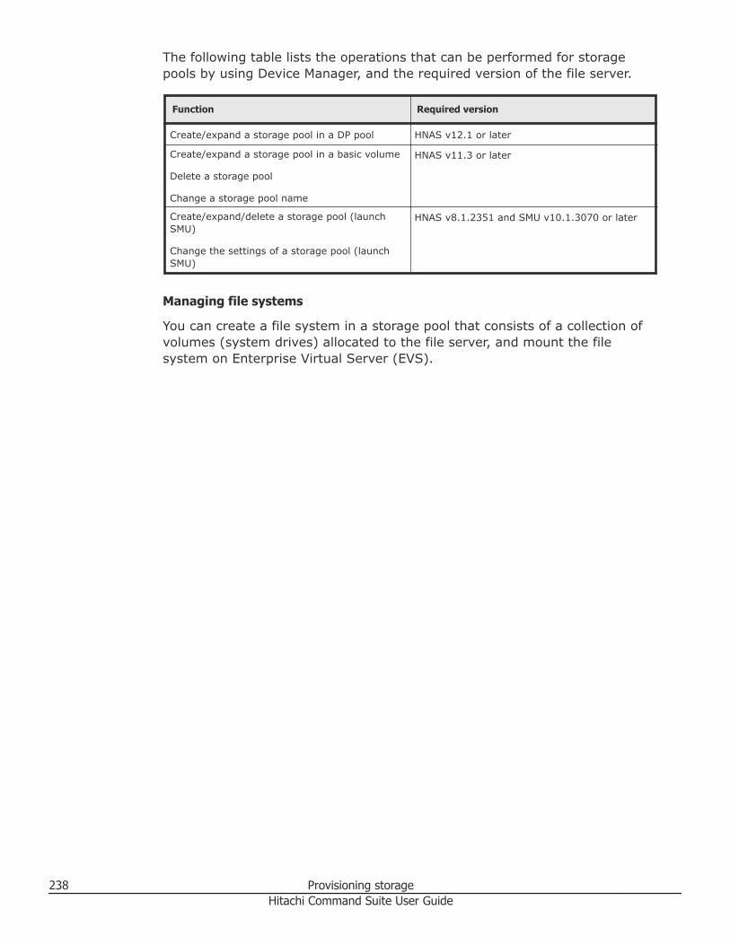
The following table lists the operations that can be performed for storagepools by using Device Manager, and the required version of the file server.
Function Required version
Create/expand a storage pool in a DP pool HNAS v12.1 or later
Create/expand a storage pool in a basic volume
Delete a storage pool
Change a storage pool name
HNAS v11.3 or later
Create/expand/delete a storage pool (launchSMU)
Change the settings of a storage pool (launchSMU)
HNAS v8.1.2351 and SMU v10.1.3070 or later
Managing file systems
You can create a file system in a storage pool that consists of a collection ofvolumes (system drives) allocated to the file server, and mount the filesystem on Enterprise Virtual Server (EVS).
238 Provisioning storageHitachi Command Suite User Guide
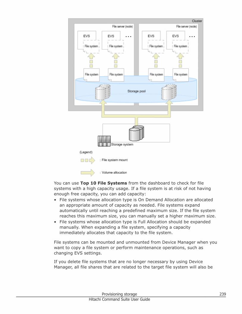
You can use Top 10 File Systems from the dashboard to check for filesystems with a high capacity usage. If a file system is at risk of not havingenough free capacity, you can add capacity:• File systems whose allocation type is On Demand Allocation are allocated
an appropriate amount of capacity as needed. File systems expandautomatically until reaching a predefined maximum size. If the file systemreaches this maximum size, you can manually set a higher maximum size.
• File systems whose allocation type is Full Allocation should be expandedmanually. When expanding a file system, specifying a capacityimmediately allocates that capacity to the file system.
File systems can be mounted and unmounted from Device Manager when youwant to copy a file system or perform maintenance operations, such aschanging EVS settings.
If you delete file systems that are no longer necessary by using DeviceManager, all file shares that are related to the target file system will also be
Provisioning storage 239Hitachi Command Suite User Guide
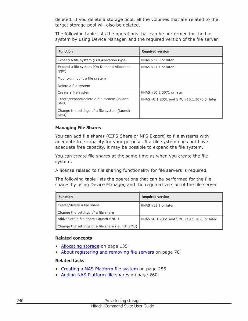
deleted. If you delete a storage pool, all the volumes that are related to thetarget storage pool will also be deleted.
The following table lists the operations that can be performed for the filesystem by using Device Manager, and the required version of the file server.
Function Required version
Expand a file system (Full Allocation type) HNAS v12.0 or later
Expand a file system (On Demand Allocationtype)
Mount/unmount a file system
Delete a file system
HNAS v11.1 or later
Create a file system HNAS v10.2.3071 or later
Create/expand/delete a file system (launchSMU)
Change the settings of a file system (launchSMU)
HNAS v8.1.2351 and SMU v10.1.3070 or later
Managing File Shares
You can add file shares (CIFS Share or NFS Export) to file systems withadequate free capacity for your purpose. If a file system does not haveadequate free capacity, it may be possible to expand the file system.
You can create file shares at the same time as when you create the filesystem.
A license related to file sharing functionality for file servers is required.
The following table lists the operations that can be performed for the fileshares by using Device Manager, and the required version of the file server.
Function Required version
Create/delete a file share
Change the settings of a file share
HNAS v11.1 or later
Add/delete a file share (launch SMU )
Change the settings of a file share (launch SMU)
HNAS v8.1.2351 and SMU v10.1.3070 or later
Related concepts
• Allocating storage on page 135• About registering and removing file servers on page 78
Related tasks
• Creating a NAS Platform file system on page 255• Adding NAS Platform file shares on page 260
240 Provisioning storageHitachi Command Suite User Guide
• Expanding a NAS Platform file system on page 256• Changing NAS Platform file share settings on page 262• Creating a NAS Platform storage pool (v11.3 or later) on page 248• Expanding a NAS Platform storage pool (v11.3 or later) on page 250• Creating a NAS Platform storage pool (earlier than v11.3) on page 252• Expanding a NAS Platform storage pool (earlier than v11.3) on page 253• Changing NAS Platform storage pool settings on page 254
Related references
• Workflow for providing NAS Platform file shares on page 241• File share configuration examples on page 270• Conditions for parity groups that are used in storage pools on page 244• Conditions for DP pools that are used in storage pools on page 244
Workflow for providing NAS Platform file sharesUse Device Manager to create files systems and files shares (CIFS or NFSExport) when a Hitachi NAS Platform file server is managed using SystemManagement Unit (SMU) v10.1.3070 or later.
Tip: When a file server is managed by an SMU version earlier thanv10.1.3070, first allocate volumes to the file server by using Device Manager,and then create file systems by using SMU.
The workflow for registering a file server to providing file systems and sharesis indicated in the following figure:
Provisioning storage 241Hitachi Command Suite User Guide
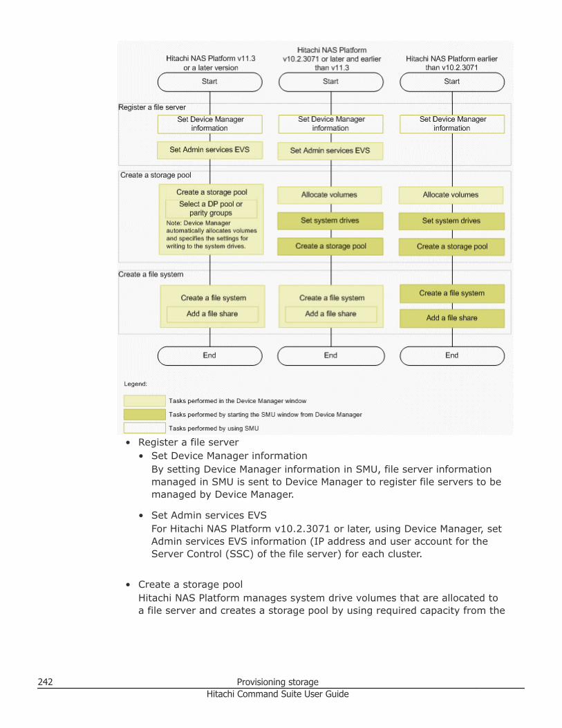
• Register a file server• Set Device Manager information
By setting Device Manager information in SMU, file server informationmanaged in SMU is sent to Device Manager to register file servers to bemanaged by Device Manager.
• Set Admin services EVSFor Hitachi NAS Platform v10.2.3071 or later, using Device Manager, setAdmin services EVS information (IP address and user account for theServer Control (SSC) of the file server) for each cluster.
• Create a storage poolHitachi NAS Platform manages system drive volumes that are allocated toa file server and creates a storage pool by using required capacity from the
242 Provisioning storageHitachi Command Suite User Guide
system drives. The method depends on the version of Hitachi NASPlatform.○ Hitachi NAS Platform v12.1 or later
When DP pools are specified, Device Manager automatically createsstorage pools that have suitable performance and expandability. DeviceManager automatically allocates volumes and specifies the settings forwriting to the system drives.
○ Hitachi NAS Platform v11.3 or laterUsing Device Manager, create a storage pool by specifying the paritygroups that have suitable performance and capacity for your storagepool purposes. Device Manager automatically allocates volumes andspecifies the settings for writing to the system drives.
○ Hitachi NAS Platform earlier than v11.3Create a volume on Device Manager and allocate the volumes to a fileserver. Then from Device Manager, open the SMU dialog box and createa storage pool. If you are using a version of Hitachi NAS Platform earlierthan v11.2, the system drives in the storage pool must belong to asystem drive group.
• Create a file system and add file sharesCreate a file system on the storage pool, and add file shares. The methoddepends on the version of Hitachi NAS Platform.○ Hitachi NAS Platform v10.2.3071 or later
You can use Device Manager to create a file system and file shares atthe same time.
○ Hitachi NAS Platform earlier than v10.2.3071Launch SMU from Device Manager to create a file system and add fileshares.
Tip: For SMU v10.2.3071 or later, if configuration changes or versionupgrades performed on the file server side are not applied to DeviceManager, use SMU to synchronize the information between the file server andDevice Manager.
Related concepts
• About managing Hitachi NAS Platform file systems and shares on page 237• About registering and removing file servers on page 78• About allocating volumes on page 194
Related tasks
• Creating a NAS Platform file system on page 255• Adding NAS Platform file shares on page 260• Creating a NAS Platform storage pool (v11.3 or later) on page 248• Creating a NAS Platform storage pool (earlier than v11.3) on page 252• Allocating volumes to selected file servers on page 199
Provisioning storage 243Hitachi Command Suite User Guide
Related references
• File share configuration examples on page 270• Conditions for parity groups that are used in storage pools on page 244• Conditions for DP pools that are used in storage pools on page 244
Conditions for parity groups that are used in storage poolsThis topic describes the recommended conditions for parity groups fromwhich you configure storage pools when creating a storage pool in HitachiNAS Platform.
To maximize the file server performance and efficiently use the storagecapacity, use parity groups that meet the following conditions for creating orexpanding storage pools:
• The parity groups are not used by any server or cluster other than thetarget server or cluster.
• A volume has not been created or only one volume has been created byusing the entire capacity of the parity group.
• There are two or more parity groups. Parity groups are needed for eachcreation or expansion operation.
• All parity groups have the same capacity.
• All parity groups have the same attribute for the following:○ The system is an external storage system or internal storage system.○ Drive type○ Drive RPM○ Chip Type○ RAID level
If linking with Hitachi NAS Platform v11.3 or later, when you selectappropriate parity groups, Device Manager automatically creates or expandsa storage pool with the optimum configuration based on best practices forHitachi NAS Platform.
Conditions for DP pools that are used in storage poolsThis topic describes the recommended conditions for creating a storage poolin Hitachi NAS Platform when using DP pools to create the system drives thatcomprise storage pools.
To maximize the file server performance and efficiently use the storagecapacity, use DP pools that meet the following conditions for creating storagepools:
• The DP pool type is HDP.• The DP pool is not being used in a server or cluster other than the target
server or cluster.
244 Provisioning storageHitachi Command Suite User Guide
• The DP volumes are not created from DP pools.• The DP pool has the same attributes for the following:
○ The system is an external storage system or internal storage system.○ Drive type○ Drive RPM○ Chip Type○ RAID level
• For the Hitachi Unified Storage (HUS) 100 and Adaptable Modular Storage(AMS) 2000 family of storage systems, the stripe size of the DP pool mustbe 64 KB. The DP pool must be created by specifying the stripe size inHitachi Storage Navigator Modular 2.
If linking with Hitachi NAS Platform v12.1 or later, when you selectappropriate DP pools, Device Manager automatically creates or expands astorage pool with the optimum configuration based on best practices forHitachi NAS Platform.
Related references
• Best practices for configuring storage pools on page 245
Best practices for configuring storage poolsThis topic describes the best practices for configuring storage pools tomaximize the performance and reliability of Hitachi NAS Platform and toefficiently use as much of the storage capacity as possible.
Storage pool configuration greatly affects performance, reliability, capacityefficiency, and expandability of file systems used. Follow the best practicessuggested by Hitachi NAS Platform for creating or expanding a storage pool.Following is an overview of the best practices.
DP pool and parity group• Volume attributes
Volumes that configure a storage pool must have the same attributes(drive type, drive speed in RPM, chip type, RAID level, and whether thedrive is external or internal). If the attributes are different, overallperformance is degraded by the volume with the lowest performance.
• Configuration of LUN pathsIf too many LUN paths exist between system drives and file server nodes,the system might stop.
• Settings for writing to system drivesYou can achieve high I/O performance by specifying appropriate writesettings for the performance of the device for each storage system type.In addition, if the stripe size of volumes can be defined, specify a size thatis compatible with the characteristics of Hitachi NAS Platform to improvedata access efficiency.
Provisioning storage 245Hitachi Command Suite User Guide
• Chunk size of storage poolsFor Hitachi NAS Platform versions earlier than 11.2, you can specify thechunk size when creating a storage pool. There is a limit to the number ofchunks that a file system can use. The chunk size affects the expandabilityof a file system. Small chunk sizes compromise expandability but havebetter performance. Large chunk sizes have better expandability butcompromise performance.
DP pool only• DP pool configuration
For Hitachi NAS Platform v12.1 or later, create the storage pool using anexisting DP pool to support increased performance when expanding thestorage pool. The storage pool and the DP pool must have a one-to-onerelationship, meaning that a storage pool consists of a single DP pool. Also,use DP pools with uncreated DP volumes. DP volumes are used toautomatically create the system drives for the storage pools and if DPvolumes are already created, the capacity of the storage pool createdautomatically might decrease.To increase performance, configure:• The capacity and number of DP volumes for the storage pool as 8 TB x
8 DP volumes (total of 64 TB).• The number of volumes must be a minimum of four.• The number of drives that comprise a storage pool must be 24 or
greater.
• DP pool stripe sizeFor the Hitachi Unified Storage (HUS) 100 and Adaptable Modular Storage(AMS) 2000 family of storage systems, the stripe size of the DP pool mustbe 64 KB.
Parity group only• Number and capacity of volumes
For creating or expanding a storage pool, separate out volumes from twoor more parity groups to ensure performance.For using volumes for system drives, separate out fewer and largervolumes from each parity group. It is recommended to use the entirecapacity of a parity group to create one volume. The reasons are:○ Separating out many volumes from a parity group reduces performance.○ When volumes that constitute a storage pool are small, the lower the
upper expansion limit becomes for a storage or file system.
In addition, the capacity of volumes that configure a storage pool needs tobe equal. If you use volumes with different capacities, some areas mightnot be used and capacity efficiency deteriorates.
246 Provisioning storageHitachi Command Suite User Guide
If linking with Hitachi NAS Platform v11.3 or later, Device Managerautomatically creates or expands a storage pool with the optimumconfiguration based on best practices. You just need to select the DP pools orparity groups that meet the conditions.
Related references
• Conditions for parity groups that are used in storage pools on page 244• Conditions for DP pools that are used in storage pools on page 244
Notes on NAS Platform file system capacityWhen creating a file system for Hitachi NAS Platform family, the file systemcapacity entered by a user might differ from the capacity that is actuallycreated.
Below are recommendations for specifying file system creation parameters,and reasons why specified capacity and actual capacity may differ.
For Hitachi NAS Platform family, a file system is created in chunks. Therefore,the actual capacity of a file system is a multiple of the chunk size.
If the file server is Hitachi NAS Platform v10.2.3071 or later, the value set forFile System Capacity is rounded down to the nearest multiple of a chunk anddisplayed for Guideline Capacity as an approximation of the actual file systemcapacity. If you are creating a storage pool in Device Manager, the chunk sizeis set to 18 GB.
For example, if you specify 750 GB for File System Capacity, and then selecta storage pool whose chunk size is 18 GB, 738 GB is displayed for GuidelineCapacity.
When setting the file system capacity, consider the followingrecommendations:• Create a file system with a capacity of 18 GB or more:
If you set a value smaller than 18 GB for the file system capacity, themetadata area for managing the file system becomes large, and the actualfile system capacity might become much larger than the specified value.
• If the chunk size is large for the file system capacity, the value of GuidelineCapacity can easily differ from the actual file system capacity. On the otherhand, if the chunk size is small, the maximum file system capacity alsobecomes small because the maximum number of chunks usable by the filesystem is limited.
If the free capacity of the selected storage system is smaller than the valuespecified for File System Capacity, a file system is created with the size of thefree capacity of the storage pool. Therefore, the actual file system capacitydiffers from the value of Guideline Capacity.
Provisioning storage 247Hitachi Command Suite User Guide
Tip: If you are using a version of Hitachi NAS Platform prior to v11.2,consider the following recommendations:• Create a chunk size of 1 GB or more.• The size of a created chunk may not match the specified size. If you create
a file system by using a storage pool that has this chunk size, the capacityof the file system also may not match the value of Guideline Capacity.
For example, if you specify 10 GB for the chunk size when creating a storagepool, depending on the available capacity at the time of creation, a chunkmight be created with 9.8 GB instead of 10 GB. In addition, when you expandthe storage pool, depending on how much capacity you choose to expand, achunk might then be created with a chunk size (for example 10.3 GB) thatdiffers from the chunk size created originally (for example 9.8 GB). For thisreason, the capacity of a file system you can create varies depending on thechunk that can be used when a file system is created.
Notes on setting LUN paths for NAS PlatformThis topic describes recommended storage port guidelines when allocatingvolumes from storage systems to Hitachi NAS Platform.
Recommendations for volumes and storage ports include:• Set the number of volumes to less than or equal to the maximum values
allowed for the number of storage ports that are being used.• If the I/O load on the file server is high, increase the number of storage
ports to be used according to the number of volumes.
For Virtual Storage Platform G1000, Virtual Storage Platform, UniversalStorage Platform V/VM, or Unified Storage VM storage systems, themaximum number of volumes that can be allocated to a single file server(node) are:• 64 x number-of-storage-ports
For Hitachi USP:• 32 x number-of-storage-ports
For mid-range storage systems:• 16 x number-of-storage-ports
If the number of volumes exceeds the maximum value recommended,system performance might be affected.
Creating a NAS Platform storage pool (v11.3 or later)Creating a storage pool on a cluster or a file server when the file server isHitachi NAS Platform v11.3 or later.
248 Provisioning storageHitachi Command Suite User Guide
Note: When expanding the storage pool, specify the number of systemdrives to be added as a number equal to or larger than the number of systemdrives specified when the storage pool was created.
Prerequisites
Identify the target Hitachi NAS platform.• For cluster configurations, identify the name of the target cluster.• For non-cluster configurations, identify the name of the target file server.
Identify requirements for the storage pools to be created, and preparenecessary resources.• For creating a storage pool, identify settings such as the storage pool
name and capacity.• To improve performance, reliability, and capacity efficiency of storage
pools, set conditions for DP pools or parity groups that are used in storagepools.
Register the target Hitachi NAS Platform to Device Manager.• The file server must be registered in Device Manager.• Device Manager must be linked to Admin services EVS.
Procedure
1. On the Resources tab, select File Servers > All File Servers.2. Select the target cluster or file server.3. Click Create Storage Pool and specify the required items.4. Click Show Plan and confirm that the information in the plan summary
is correct. If changes are required, click Back.5. (Optional) Update the task name and provide a description.6. (Optional) Expand Schedule to specify the task schedule.
You can schedule the task to run immediately or later. The default settingis Now. If the task is scheduled to run immediately, you can select Viewtask status to monitor the task after it is submitted.
7. Click Submit.If the task is scheduled to run immediately, the process begins.
8. (Optional) Check the progress and result of the task on the Tasks &Alerts tab. Click the task name to view details of the task.
Result
The storage pool is created on the NAS Platform file server.
Related concepts
• About managing Hitachi NAS Platform file systems and shares on page 237
Provisioning storage 249Hitachi Command Suite User Guide
Related tasks
• Deleting NAS Platform storage pools on page 254
Related references
• Conditions for parity groups that are used in storage pools on page 244• Conditions for DP pools that are used in storage pools on page 244
Expanding a NAS Platform storage pool (v11.3 or later)If the file server is Hitachi NAS Platform v11.3 or later and the capacity of astorage pool is insufficient, expand the already created storage pool.
Note: When expanding the storage pool, specify the number of systemdrives to be added as a number equal to or larger than the number of systemdrives specified when the storage pool was created.
Prerequisites
Identify the target Hitachi NAS platform.• For cluster configurations, identify the name of the target cluster.• For non-cluster configurations, identify the name of the target file server.
Identify requirements for the storage pools to be expanded, and preparenecessary resources.• For expanding a storage pool, identify settings such as the storage pool
capacity.• For DP volume configurations, the DP pools that comprise the storage pool
must have enough capacity.• To improve performance, reliability, and capacity efficiency of storage
pools, set conditions for DP pools or parity groups that are used in storagepools.
Register the target Hitachi NAS Platform to Device Manager.• The file server must be registered in Device Manager.• Device Manager must be linked to Admin services EVS.
Procedure
1. On the Resources tab, select File Servers.2. Select the target cluster or file server.3. On the Storage Pools tab, select the row of the target storage pool.4. Click Expand Storage Pool and specify the necessary items.5. Click Show Plan and confirm that the information in the plan summary
is correct. If changes are required, click Back.6. (Optional) Update the task name and provide a description.7. (Optional) Expand Schedule to specify the task schedule.
250 Provisioning storageHitachi Command Suite User Guide
You can schedule the task to run immediately or later. The default settingis Now. If the task is scheduled to run immediately, you can select Viewtask status to monitor the task after it is submitted.
8. Click Submit.If the task is scheduled to run immediately, the process begins.
9. (Optional) Check the progress and result of the task on the Tasks &Alerts tab. Click the task name to view details of the task.
Result
The storage pool capacity is expanded on the NAS Platform file server.
Related concepts
• About managing Hitachi NAS Platform file systems and shares on page 237
Related references
• Conditions for parity groups that are used in storage pools on page 244• Conditions for DP pools that are used in storage pools on page 244• Notes on setting LUN paths for NAS Platform on page 248
Changing a NAS Platform storage pool nameThis topic describes changing the name of an existing storage pool when thefile server is Hitachi NAS Platform v11.3 or later.
Note: You can also change a storage pool name when the file server is aHitachi NAS Platform earlier than v11.3 by changing the NAS platformstorage pool settings.
Prerequisites
• For cluster configurations, identify the name of the target cluster• For non-cluster configurations, identify the name of the target file server• For editing a storage pool, identify settings such as storage pool name• The file server must be registered in Device Manager• Device Manager must be linked to Admin services EVS
Procedure
1. On the Resources tab, select File Servers > All File Servers.2. Select the target cluster or file server.3. On the Storage Pools tab, select the row of the target storage pool.4. Click Edit Storage Pool and specify the necessary items.5. (Optional) Update the task name and provide a description.6. Click Submit.7. (Optional) Check the progress and result of the task on the Tasks &
Alerts tab. Click the task name to view details of the task.
Provisioning storage 251Hitachi Command Suite User Guide
Result
The storage pool name is changed.
Related tasks
• Changing NAS Platform storage pool settings on page 254
Creating a NAS Platform storage pool (earlier than v11.3)When the file server is Hitachi NAS Platform versions earlier than 11.3,launch System Management Unit (SMU) from Device Manager to create astorage pool on the file server.
Prerequisites
• The file server must be registered in Device Manager• Allocate volumes to the cluster or file server• For cluster configurations, identify the name of the target cluster• For non-cluster configurations, identify the name of the target file server• For creating a storage pool, identify settings such as the storage pool
name and capacity
Procedure
1. On the Resources tab, select File Servers.2. Expand the tree and select the target cluster or file server.3. From the Actions menu, select Manage System Drives.4. In the SMU dialog box, change the settings so that the required system
drive can be accessed.On the System Drives tab of Device Manager, Allowed is displayed inthe Access column of the target system drive. If you are using a versionof Hitachi NAS Platform earlier than v11.2, continue to step 5. If you areusing v11.2 or a later version, skip to step 7.
5. From the Actions menu, select Create System Drive Group. If asystem drive that belongs to the same parity group or DP pool as for thetarget system drive is included in the already existing system drivegroup, select Manage System Drive Groups and add the target systemdrive into that system drive group.
6. In the SMU dialog box, perform the operations.7. On the Storage Pools tab, click Create Storage Pool.8. In the SMU dialog box, specify the required items.
For explanations of items and procedures in the SMU dialog box, see theSMU online help.
9. Check the created storage pool in Device Manager, on the StoragePools tab of the target cluster or file server.
252 Provisioning storageHitachi Command Suite User Guide
Result
The storage pool is created on the NAS Platform file server.
Expanding a NAS Platform storage pool (earlier than v11.3)When the file server is Hitachi NAS Platform versions earlier than 11.3, if thecapacity of a storage pool server is insufficient, launch System ManagementUnit (SMU) from Device Manager to expand the already created storage poolon the file server.
Prerequisites
• The file server must be registered in Device Manager• Allocate volumes to the cluster or file server• For cluster configurations, identify the name of the target cluster• For non-cluster configurations, identify the name of the target file server• For expanding a storage pool, identify settings such as the storage pool
name and capacity
Procedure
1. On the Resources tab, select File Servers.2. Expand the tree and select the target cluster or file server.3. From the Actions menu, select Manage System Drives.4. In the SMU dialog box, change the settings so that the required system
drive can be accessed.On the System Drives tab of Device Manager, Allowed is displayed inthe Access column of the target system drive. If you are using a versionof Hitachi NAS Platform earlier than v11.2, continue to step 5. If you areusing v11.2 or a later version, skip to step 7.
5. From the Actions menu, select Create System Drive Group. If asystem drive that belongs to the same parity group or DP pool as for thetarget system drive is included in the already existing system drivegroup, select Manage System Drive Groups and add the target systemdrive into that system drive group.
6. In the SMU dialog box, specify the required items.7. On the Storage Pools tab, click Manage Storage Pool.8. In the SMU dialog box, specify the required items.
For explanations of items and procedures in the SMU dialog box, see theSMU online help.
9. Check the expanded storage pool in Device Manager, in the StoragePools tab of the target cluster or file server.
Result
The storage pool is expanded on the NAS Platform file server.
Provisioning storage 253Hitachi Command Suite User Guide
Changing NAS Platform storage pool settingsWhen the file server is Hitachi NAS Platform, launch System ManagementUnit (SMU) from Device Manager to change settings of a storage pool, suchas accessibility to the storage pool, and availability of auto-expansion for thefile system. For NAS Platform versions earlier than 11.3, use this procedureto change the storage pool name.
Prerequisites
• The file server must be registered in Device Manager• For cluster configurations, identify the name of the target cluster• For non-cluster configurations, identify the name of the target file server• For changing a storage pool settings, identify the storage pool name and
settings to be changed
Procedure
1. On the Resources tab, select File Servers.2. Expand the tree and select the target cluster or file server.3. On the Storage Pools tab, select the target storage pool.4. Click Manage Storage Pool.5. In the SMU dialog box, specify the required items.6. On the Storage Pools tab, click Manage Storage Pool.7. In the SMU dialog box, specify the required items.
For explanations of items and procedures in the SMU dialog box, see theSMU online help.
8. Check the changed storage pool settings in Device Manager, on theStorage Pools tab of the target cluster or file server.
Result
The storage pool settings are changed on the NAS Platform file server.
Deleting NAS Platform storage poolsYou can delete storage pools on a cluster or a file server when the storagepools are no longer needed.
If both a storage pool and a LUN path are deleted, and:• The storage pool consists of DP pools, the DP volumes are also deleted.• The storage pool consists of normal volumes, the normal volumes are also
deleted.
Prerequisites
Identify the name of the target storage pool.
254 Provisioning storageHitachi Command Suite User Guide
Procedure
1. On the Resources tab, select File Servers > All File Servers.2. Select the target cluster or file server.3. On the Storage Pools tab, select the storage pool to delete. Volumes
related to the target storage pools are also deleted.• Hitachi NAS Platform v11.3 or later:
Click Delete Storage Pools and skip to step 4.• Hitachi NAS Platform versions earlier than 11.3:
Click Manage Storage Pool. In the SMU dialog box, delete thestorage pool, and then skip to step 6.
4. Click Submit.If the task is scheduled to run immediately, the process begins.
5. (Optional) Check the progress and result of the task on the Tasks &Alerts tab. Click the task name to view details of the task.
6. On the Storage Pools tab of the target cluster or file server, verify thedeleted storage pool.
Result
The storage pool is deleted on the NAS Platform file server.
Creating a NAS Platform file systemDepending on the version of Hitachi NAS Platform you are using, create a filesystem and file shares on the file server by using either HCS or SystemManagement Unit (SMU).
Prerequisites• The file server must be registered in Device Manager• Create a storage pool• For cluster configurations, identify the target cluster name• For non-cluster configurations, identify the target file server name• Identify the EVS to which the file system should be assigned.• Identify the storage pool name• Identify file system name, allocation type, and capacity• Identify block size• In addition, verify the following when using Hitachi NAS Platform version
10.2.3071 or later:○ Device Manager must be linked to Admin services EVS○ Identify file share protocols, names, and paths○ When intending to set access permissions for CIFS shares, add a CIFS
server from the CIFS setup window in System Management Unit, andset up information on an authentication server, such as Active Directory.
Provisioning storage 255Hitachi Command Suite User Guide
Procedure
1. On the Resources tab, from the tree, select File Servers, then All FileServers.
2. From the Servers/Clusters list, select the row of the target cluster or fileserver, and click Create File System.
3. Create a storage pool or file share depending on the version of HitachiNAS Platform:• Hitachi NAS Platform v10.2.3071 or later:
Specify the required items and skip to step 4.• Hitachi NAS Platform versions earlier than 10.2.3071:
In the SMU dialog box, select whether to create a new storage pool oruse an already created storage pool, specify the required items, andthen skip to step 7.
4. Click Show Plan and confirm that the information in the plan summaryis correct. If changes are required, click Back.
5. Click Submit.If the task is scheduled to run immediately, the process begins.
6. (Optional) Check the progress and result of the task on the Tasks &Alerts tab. Click the task name to view details of the task.
7. To verify that the file system was created, select the target cluster or fileserver, and then click the File Systems tab. To verify that the file sharewas created, select the target file system, and then click the Shares/Exports tab.
Result
The file system or file shares are created on the file server.
Related concepts
• About managing Hitachi NAS Platform file systems and shares on page 237
Related tasks
• Changing NAS Platform file share settings on page 262• Deleting a NAS Platform file system on page 260
Related references
• Workflow for providing NAS Platform file shares on page 241• Notes on NAS Platform file system capacity on page 247
Expanding a NAS Platform file systemDepending on the version of Hitachi NAS Platform you are using, increase themaximum allowed file system size by using either HCS or SystemManagement Unit (SMU).
Prerequisites• The file server must be registered in Device Manager
256 Provisioning storageHitachi Command Suite User Guide
• For cluster configurations, identify the target cluster name• For non-cluster configurations, identify the target file server name• Identify the name of the target file system• Identify the maximum size of the capacity to be allocated• In addition, verify the following when using Hitachi NAS Platform v11.1 or
later:○ Device Manager must be linked to Admin services EVS
Procedure
1. On the Resources tab, from the tree, select File Servers.2. From the tree, select the target cluster or file server, and on the File
Systems tab, select the file system to expand.3. Expand the file system depending on the version of Hitachi NAS
Platform:• Hitachi NAS Platform v12.0 or later:
Click Expand File System, enter the capacity, and then skip to step4.
• Hitachi NAS Platform v11.1 or later and earlier than v12.0:For On Demand Allocation, click Expand File System, specify theallocation limit size, and then skip to step 4. For Full Allocation, clickManage File System, and in the SMU dialog box, expand the filesystem. Then skip to step 7.
• Hitachi NAS Platform versions earlier than 11.1:Click Manage File System. In the SMU dialog box, expand the filesystem, and then skip to step 7.
4. Click Show Plan and confirm that the information in the plan summaryis correct. If changes are required, click Back.
5. Click Submit.If the task is scheduled to run immediately, the process begins.
6. (Optional) Check the progress and result of the task on the Tasks &Alerts tab. Click the task name to view details of the task.
7. On the File Systems tab of the target cluster or file server, verify theexpanded file system.
Result
The selected file system is expanded.
Related concepts
• About managing Hitachi NAS Platform file systems and shares on page 237
Changing NAS Platform file system settingsWhen the file server is Hitachi NAS Platform v10.1.3070 or later, launchSystem Management Unit (SMU) from Device Manager to change a filesystem's name, or change the threshold value for the usage rate.
Provisioning storage 257Hitachi Command Suite User Guide
Prerequisites• The file server must be registered in Device Manager• Identify the name of the target cluster or target file server.
Procedure
1. On the Resources tab, from the tree, select File Servers.2. In the tree, select the target cluster or file server, and on the File
Systems tab, select the file system.3. Click Manage File System.4. In the SMU dialog box, specify the required items.
For explanations of items and procedures in the SMU dialog box, see theSMU online help.
5. Select the target cluster or file server in Device Manager, and on the FileSystems tab, confirm that the settings are changed.
Result
The file system settings are changed.
Related concepts
• About managing Hitachi NAS Platform file systems and shares on page 237
Related tasks
• Creating a NAS Platform file system on page 255
Related references
• Workflow for providing NAS Platform file shares on page 241• Notes on NAS Platform file system capacity on page 247
Mounting NAS Platform file systemsDepending on the version of Hitachi NAS Platform you are using, mount filesystems by using either HCS or System Management Unit (SMU).
Prerequisites
• The file server must be registered in Device Manager• For cluster configurations, identify the target cluster name• For non-cluster configurations, identify the target file server name• Identify the name of the target file system• In addition, verify the following when using Hitachi NAS Platform v11.1 or
later:○ Device Manager must be linked to Admin services EVS
Procedure
1. On the Resources tab, from the tree, select File Servers.
258 Provisioning storageHitachi Command Suite User Guide
2. From the tree, select the target cluster or file server, and on the FileSystems tab, select the file systems to mount.
3. Mount the file systems depending on the version of Hitachi NAS Platform:• Hitachi NAS Platform v11.1 or later:
Click Mount File Systems and skip to step 4.• Hitachi NAS Platform versions earlier than 11.1:
Click Manage File System. In the SMU dialog box, mount the filesystems, and then skip to step 6.
4. Click Submit.If the task is scheduled to run immediately, the process begins.
5. (Optional) Check the progress and result of the task on the Tasks &Alerts tab. Click the task name to view details of the task.
6. On the File Systems tab of the target cluster or file server, verify themounted file systems.
Result
The selected file systems are mounted.
Unmounting NAS Platform file systemsDepending on the version of Hitachi NAS Platform you are using, unmount filesystems by using either HCS or System Management Unit (SMU).
Prerequisites
• The file server must be registered in Device Manager• For cluster configurations, identify the target cluster name• For non-cluster configurations, identify the target file server name• Identify the name of the target file system• In addition, verify the following when using Hitachi NAS Platform v11.1 or
later:○ Device Manager must be linked to Admin services EVS
Procedure
1. On the Resources tab, from the tree, select File Servers.2. From the tree, select the target cluster or file server, and on the File
Systems tab, select the file systems to unmount.3. Unmount the file systems depending on the version of Hitachi NAS
Platform:• Hitachi NAS Platform v11.1 or later:
Click Unmount File Systems and skip to step 4.
• Hitachi NAS Platform versions earlier than 11.1:Click Manage File System, in the SMU dialog box, unmount the filesystems, and then skip to step 6.
4. Click Submit.
Provisioning storage 259Hitachi Command Suite User Guide
If the task is scheduled to run immediately, the process begins.5. (Optional) Check the progress and result of the task on the Tasks &
Alerts tab. Click the task name to view details of the task.6. On the File Systems tab of the target cluster or file server, verify the
unmounted file systems.
Result
The selected file systems are unmounted.
Deleting a NAS Platform file systemIf a NAS Platform file system is no longer needed, for example if the filesystem is being decommissioned and the needed data is saved, you candelete the file system.
Prerequisites
Identify the name of the target file system.
Procedure
1. On the Resources tab, from the tree, select File Servers, and thenselect All File Servers.
2. From the list of file systems, select the file system that you want todelete.• Hitachi NAS Platform v11.1 or later:
Click Delete File Systems and skip to step 3.• Hitachi NAS Platform versions earlier than 11.1:
Click Manage File System. In the SMU dialog box, delete the filesystem, and then skip to step 5.
3. Click Submit.If the task is scheduled to run immediately, the process begins.
4. (Optional) Check the progress and result of the task on the Tasks &Alerts tab. Click the task name to view details of the task.
5. From the All File Servers list of file systems, verify the deleted filesystem.
Result
The file system you deleted no longer appears in the list of file servers.
Adding NAS Platform file sharesDepending on the version of Hitachi NAS Platform you are using, you can addfile shares to existing file systems on the file server by using either HCS orSystem Management Unit (SMU).
260 Provisioning storageHitachi Command Suite User Guide
Prerequisites
• The file server must be registered in Device Manager• For cluster configurations, identify the target cluster name• For non-cluster configurations, identify the target file server name• Identify the EVS to which the target file system belongs• Identify the name of the target file system• Identify file share protocols, names, paths, and access permissions• In addition, verify the following when using Hitachi NAS Platform v11.1 or
later:○ Device Manager must be linked to Admin services EVS○ When intending to set access permissions for CIFS shares, add a CIFS
server from the CIFS setup window in System Management Unit, andset up information on an authentication server (such as ActiveDirectory).
Procedure
1. On the Resources tab, from the tree, select File Servers.2. From the tree, select the target cluster or file server, and on the File
Systems tab, select the file system where file shares will be added.3. Add the file shares depending on the version of Hitachi NAS Platform:
• Hitachi NAS Platform v11.1 or later:Click Add Share/Export, specify the required items, and skip to step4.
• Hitachi NAS Platform versions earlier than 11.1:Click Add CIFS Share or Add NFS Export, depending on theprotocol of the file share you are adding. In the SMU dialog box, addthe file share, and skip to step 7.
4. Click Show Plan and confirm that the information in the plan summaryis correct. If changes are required, click Back.
5. Click Submit.If the task is scheduled to run immediately, the process begins.
6. (Optional) Check the progress and result of the task on the Tasks &Alerts tab. Click the task name to view details of the task.
7. On the Shares/Exports tab of the EVS where the target file systembelongs, verify the added file shares.
Result
The file shares are added to existing the file systems on the file server.
Related tasks
• Changing NAS Platform file share settings on page 262• Deleting NAS Platform file shares on page 263
Provisioning storage 261Hitachi Command Suite User Guide
Related references
• Workflow for providing NAS Platform file shares on page 241• File share configuration examples on page 270
Changing NAS Platform file share settingsDepending on the version of Hitachi NAS Platform you are using, edit settingsfor existing file shares using either HCS or System Management Unit (SMU).
Prerequisites
• The file server must be registered in Device Manager• Identify the file share name• For cluster configurations, identify the target cluster name of the file share• For non-cluster configurations, identify the target file server name of the
file share• Identify the EVS to which the file share belongs• In addition, verify the following when using Hitachi NAS Platform v11.1 or
later:○ Device Manager must be linked to Admin services EVS○ When intending to set access permissions for CIFS shares, add a CIFS
server from the CIFS setup window in System Management Unit, andset up information on an authentication server (such as ActiveDirectory).
Procedure
1. On the Resources tab, from the tree, select File Servers.2. From the tree, select the target cluster or file server.3. From the tree, select the target EVS, and on the Shares/Exports tab,
select the file share you want to modify.4. Change the file share settings depending on the version of Hitachi NAS
Platform:• Hitachi NAS Platform v11.1 or later:
Click Edit Share/Export, specify the required items, and skip to step5.
• Hitachi NAS Platform versions earlier than 11.1:From the list of file shares, select the file share you want to modify,and click Manage Share/Export. In the SMU dialog box, change thefile share, and skip to step 8.
5. Click Show Plan and confirm that the information in the plan summaryis correct. If changes are required, click Back.
6. Click Submit.If the task is scheduled to run immediately, the process begins.
7. (Optional) Check the progress and result of the task on the Tasks &Alerts tab. Click the task name to view details of the task.
262 Provisioning storageHitachi Command Suite User Guide
8. On the Shares/Exports tab of the target EVS, verify the modified fileshare settings. In SMU, click Manage Share/Export to verify themodified file share settings.
Result
The file share settings are changed.
Related tasks
• Adding NAS Platform file shares on page 260
Deleting NAS Platform file sharesIf NAS Platform file shares are no longer needed, you can delete the fileshares.
Prerequisites
Identify the name of the target file share.
Procedure
1. On the Resources tab, from the tree, select File Servers, and thenselect All File Servers.
2. From the list of file systems, select the file system that has the fileshares you want to delete.
3. On the Shares/Exports tab, select the target file share.• Hitachi NAS Platform v11.1 or later:
Click Delete Shares/Exports, and then skip to step 4.• Hitachi NAS Platform versions earlier than 11.1:
Click Manage Share/Export. In the SMU dialog box, delete the fileshare, and then skip to step 6.
4. Click Submit.If the task is scheduled to run immediately, the process begins.
5. (Optional) Check the progress and result of the task on the Tasks &Alerts tab. Click the task name to view details of the task.
6. On the Shares/Exports tab, verify the deleted file shares.
Result
The file shares you deleted no longer appear in the list of file shares.
Managing Hitachi NAS Platform F and Hitachi Data Ingestorfile systems and shares
This module describes how to create file systems and shares for Hitachi NASPlatform F (HNAS F) and Hitachi Data Ingestor (HDI) file servers.
Provisioning storage 263Hitachi Command Suite User Guide
About managing Hitachi NAS Platform F and Hitachi Data Ingestorfile systems and shares
When introducing a new Hitachi Platform F (HNAS F) or Hitachi Data Ingestor(HDI) file server, register the file server in Device Manager by using HitachiFile Services Manager (HFSM) management software, then allocate storagesystem volumes to the file server to create file systems and shares.
HDI tasks can be performed using HFSM. Common tasks can also beperformed from the HCS GUI, for ease of use.
Depending on the HFSM software version, and the HCS version in use, taskswill either describe using HFSM, or describe using the HCS GUI.
If HFSM v3.1 or later is installed on the same server as Device Manager youcan:• Create a file system
You can create a file system on a file server by using storage systemvolumes. You can also allocate volumes to the file server and create fileshares at the same time you create a file system.
• Expand a file systemYou can use Top 10 File Systems from the dashboard to check for filesystems with a high capacity usage. If a file system does not havesufficient free capacity, you can allocate the necessary amount of volumesto expand the file system. When settings are specified so that SNMP trapsare received from the file server, you can check, by using alerts, whetherthe usage rate of a file system exceeds a threshold. For details aboutsettings for receiving SNMP traps, see the Hitachi Command SuiteAdministrator Guide.
• Delete a file systemYou can delete file systems that are no longer required. Volumes used bythose file systems can be reused for other file systems. If you do not reusevolumes for new file systems, consider releasing the volume allocationfrom the file server, after deleting the file systems, so the volume can beused elsewhere.
• Add file sharesYou can add file shares in response to a request from a file server user.Check the purpose of the file shares or the free capacity of the filesystems, and then select a file system to which file shares are to beadded.
• Edit or release file sharesYou can edit file share attributes and release unnecessary file shares.When you want to release shares that are used by both CIFS and NFSprotocols, releasing one of the protocols allows both protocols to bereleased.
264 Provisioning storageHitachi Command Suite User Guide
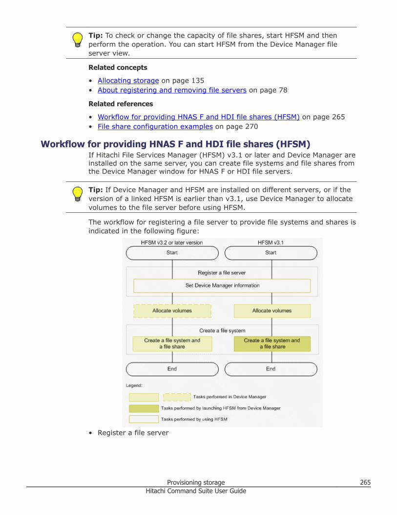
Tip: To check or change the capacity of file shares, start HFSM and thenperform the operation. You can start HFSM from the Device Manager fileserver view.
Related concepts
• Allocating storage on page 135• About registering and removing file servers on page 78
Related references
• Workflow for providing HNAS F and HDI file shares (HFSM) on page 265• File share configuration examples on page 270
Workflow for providing HNAS F and HDI file shares (HFSM)If Hitachi File Services Manager (HFSM) v3.1 or later and Device Manager areinstalled on the same server, you can create file systems and file shares fromthe Device Manager window for HNAS F or HDI file servers.
Tip: If Device Manager and HFSM are installed on different servers, or if theversion of a linked HFSM is earlier than v3.1, use Device Manager to allocatevolumes to the file server before using HFSM.
The workflow for registering a file server to provide file systems and shares isindicated in the following figure:
• Register a file server
Provisioning storage 265Hitachi Command Suite User Guide
By setting Device Manager information in HFSM, file server informationmanaged in HFSM is sent to Device Manager to register file servers to bemanaged by Device Manager.
• Allocate volumes Use Device Manager to allocate volumes to a file server.If HFSM v3.2 or a later version and Device Manager are installed on thesame server, volumes that match the requirements can be automaticallyallocated when the file system is created.
• Create a file systemCreate a file system and a file share. The creation procedure variesdepending on the version of HFSM, which is installed on the same serveras Device Manager.○ HFSM v3.2 or later
You can use Device Manager to create a file system. You can alsoallocate volumes to the file server and create file shares in a batchoperation at the same time you create a file system. When the capacityof the file system to be created is specified, a volume allocation plan isautomatically provided. A volume that is already allocated to the fileserver can also be used. If allocation is performed by specifying one fileserver (node) in a cluster, volumes are also automatically allocated tothe other file server (node).
○ HFSM v3.1You can create a file system and a file share by starting the HFSM dialogbox from the Device Manager window.
Related concepts
• About managing Hitachi NAS Platform F and Hitachi Data Ingestor filesystems and shares on page 264
Related tasks
• Creating HNAS F or HDI file systems (HFSM v3.2 or later) on page 266• Creating HDI file systems (HFSM v3.1) on page 268• Changing HNAS F or HDI file system settings (HFSM v3.1 or later) on page
268• Registering file servers on page 81• Allocating volumes to selected file servers on page 199
Related references
• File share configuration examples on page 270
Creating HNAS F or HDI file systems (HFSM v3.2 or later)If Hitachi File Services Manager (HFSM) v3.2 or later is installed on the sameserver as Device Manager, you can allocate volumes to HNAS F or HDI fileservers, create a file system, and create file shares in a batch operation. Youcan also use volumes already allocated to the file server to create a filesystem.
266 Provisioning storageHitachi Command Suite User Guide
Note: To use a volume that has already been allocated, alternate pathsbelonging to the same host group are set between the file server andvolume.
Prerequisites
• Identify the name of the target cluster or target file server.• Identify the name and capacity of the file systems to be created.• Identify the file share protocol if creating shares.
Procedure
1. On the Resources tab, from the tree, select File Servers, and thenselect All File Servers.
2. From the Servers/Clusters list, select the row of the target cluster, andthen click Create File System. If you will use volumes that have alreadybeen allocated to a file server, select the cluster of the target file server(node) in the tree view. Select the target volumes on the Volumes tab,click Create File System, and specify the required items.
3. Click Show Plan and confirm that the information in the plan summaryis correct. If changes are required, click Back.
4. Click Submit.If the task is scheduled to run immediately, the process begins.
5. (Optional) Check the progress and result of the task on the Tasks &Alerts tab. Click the task name to view details of the task.
6. Select the target cluster, and on the File Systems tab, verify the createdfile system. Select the target file system, and then on the Shares tab,verify the created file share.
Result
The file system and file shares are created on the file server.
For details about the requirements for the environment settings of the fileserver, see the Hitachi Command Suite Administrator Guide.
Related tasks
• Changing HNAS F or HDI file system settings (HFSM v3.1 or later) on page268
• Deleting HNAS F or HDI file systems on page 269
Related references
• Workflow for providing HNAS F and HDI file shares (HFSM) on page 265• File share configuration examples on page 270• Notes on performing quick formats on page 144
Provisioning storage 267Hitachi Command Suite User Guide
Creating HDI file systems (HFSM v3.1)When Hitachi File Services Manager (HFSM) v3.1 is installed on the sameserver as Device Manager, you can open an HFSM dialog box from DeviceManager, and perform operations such as creating file systems on an HDI fileserver. You can also create file shares at the same time you create a filesystem.
Prerequisites
• Identify the name of the target cluster or target file server.• Allocate volumes to the file server.• Identify the name and capacity of the file systems to be created.• Identify the name, protocol, and owners of file shares.
Procedure
1. On the Resources tab, from the tree, select File Servers, then selectAll File Servers.
2. From the Servers/Clusters list of file servers, select the row of the clusterof the target file server (node).
3. Click Create File System or Create and Share File System.4. From the HFSM dialog box, specify the required items.
For explanations of items and procedures in the HFSM dialog box, seethe HFSM online help.
5. Select the target cluster in Device Manager, and on the File Systemstab, verify the created file system. Select the target file system, and onthe Shares tab, verify the created file share.
Result
The HDI file system is created on the file server.
For details about the requirements for the environment settings of the fileserver, see the Hitachi Command Suite Administrator Guide.
Related tasks
• Changing HNAS F or HDI file system settings (HFSM v3.1 or later) on page268
• Deleting HNAS F or HDI file systems on page 269
Related references
• Workflow for providing HNAS F and HDI file shares (HFSM) on page 265• File share configuration examples on page 270
Changing HNAS F or HDI file system settings (HFSM v3.1 or later)When Hitachi File Services Manager (HFSM) v3.1 or later is installed on thesame server as Device Manager, you can open an HFSM dialog box from
268 Provisioning storageHitachi Command Suite User Guide
Device Manager, and perform operations such as expanding a file system andadding file shares created on an HNAS F or HDI file server.
Procedure
1. On the Resources tab, from the tree, select File Servers.2. In the tree, select the cluster of the target file server (node), and then
select the row of the target file systems in the File Systems tab.3. Depending on the task that you are doing, click Expand File System or
Add Share.4. In the HFSM dialog box, specify the required items.
For explanations of items and procedures in the HFSM dialog box, seethe HFSM online help.
5. Select the target cluster in Device Manager, and on the File Systemstab, verify the expanded file system. Select the target file system, andon the Shares tab, verify the added file share.
Result
The file system settings are changed.
Related tasks
• Creating HDI file systems (HFSM v3.1) on page 268• Creating HNAS F or HDI file systems (HFSM v3.2 or later) on page 266
Related references
• Workflow for providing HNAS F and HDI file shares (HFSM) on page 265
Deleting HNAS F or HDI file systemsYou can delete HNAS F or HDI file systems when they are no longer needed.Save required data prior to deleting the file system.
Prerequisites
Identify the name of the target file system.
Procedure
1. On the Resources tab, from the tree, select File Servers, and thenselect All File Servers.
2. From the list of file systems, select the file system that you want todelete.You can delete the file systems of HFSM v3.2 or later and HFSM v3.1.
3. Click Delete File Systems.4. Click Show Plan and confirm that the information in the plan summary
is correct. If changes are required, click Back.5. Click Submit.
Provisioning storage 269Hitachi Command Suite User Guide
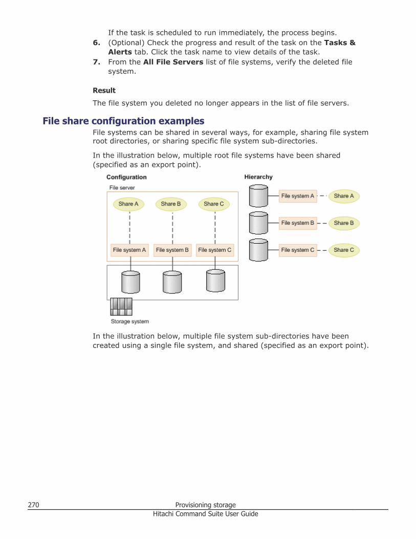
If the task is scheduled to run immediately, the process begins.6. (Optional) Check the progress and result of the task on the Tasks &
Alerts tab. Click the task name to view details of the task.7. From the All File Servers list of file systems, verify the deleted file
system.
Result
The file system you deleted no longer appears in the list of file servers.
File share configuration examplesFile systems can be shared in several ways, for example, sharing file systemroot directories, or sharing specific file system sub-directories.
In the illustration below, multiple root file systems have been shared(specified as an export point).
In the illustration below, multiple file system sub-directories have beencreated using a single file system, and shared (specified as an export point).
270 Provisioning storageHitachi Command Suite User Guide
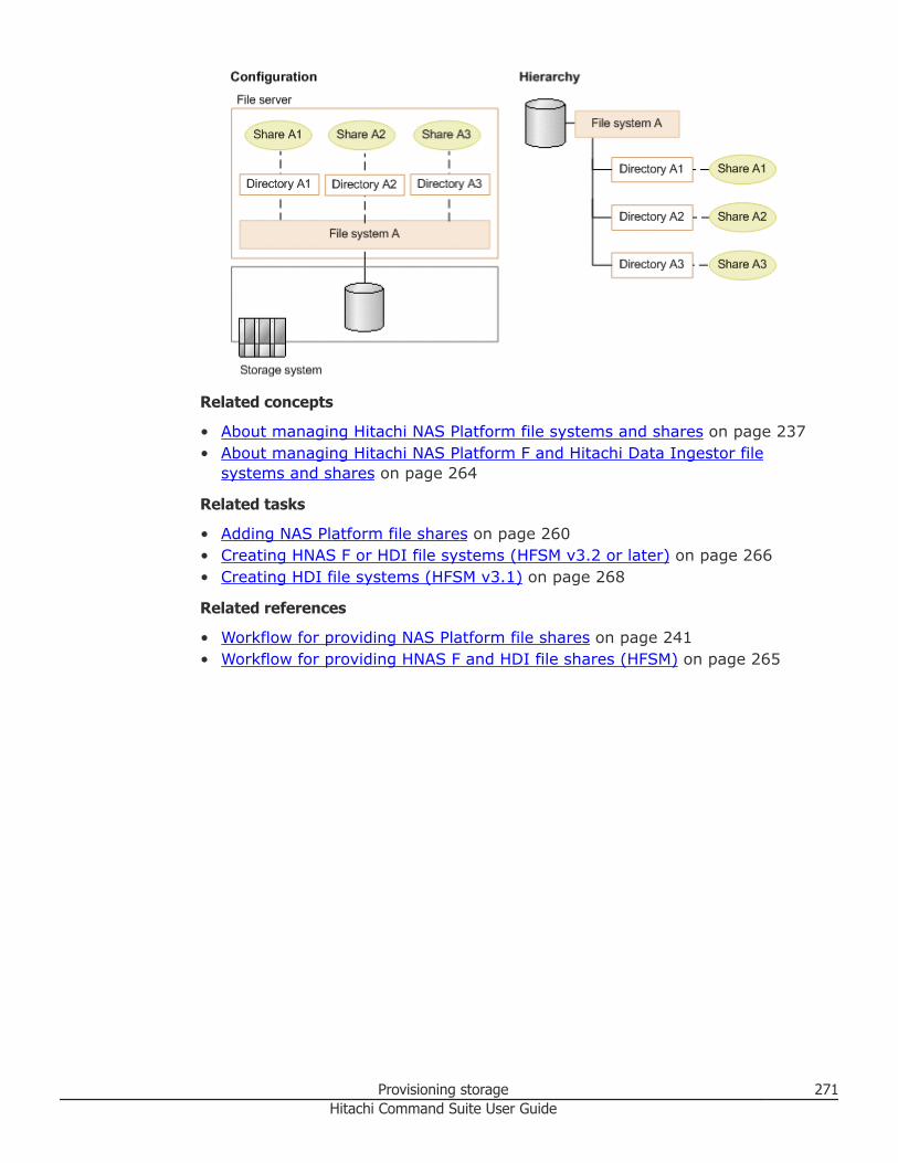
Related concepts
• About managing Hitachi NAS Platform file systems and shares on page 237• About managing Hitachi NAS Platform F and Hitachi Data Ingestor file
systems and shares on page 264
Related tasks
• Adding NAS Platform file shares on page 260• Creating HNAS F or HDI file systems (HFSM v3.2 or later) on page 266• Creating HDI file systems (HFSM v3.1) on page 268
Related references
• Workflow for providing NAS Platform file shares on page 241• Workflow for providing HNAS F and HDI file shares (HFSM) on page 265
Provisioning storage 271Hitachi Command Suite User Guide

272 Provisioning storageHitachi Command Suite User Guide
6Managing virtual storage machines
Virtual storage machines are used to achieve continuous access to data forglobal-active device volumes and for data migration.
□ About virtual storage machines
□ Prerequisites for allocating resources to virtual storage machines
□ Creating virtual storage machines
□ Allocating volumes to hosts by using virtual storage machine resources
□ Editing virtual storage machines
□ Deleting virtual storage machines
Managing virtual storage machines 273Hitachi Command Suite User Guide
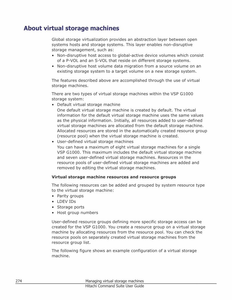
About virtual storage machines
Global storage virtualization provides an abstraction layer between opensystems hosts and storage systems. This layer enables non-disruptivestorage management, such as:• Non-disruptive host access to global-active device volumes which consist
of a P-VOL and an S-VOL that reside on different storage systems.• Non-disruptive host volume data migration from a source volume on an
existing storage system to a target volume on a new storage system.
The features described above are accomplished through the use of virtualstorage machines.
There are two types of virtual storage machines within the VSP G1000storage system:• Default virtual storage machine
One default virtual storage machine is created by default. The virtualinformation for the default virtual storage machine uses the same valuesas the physical information. Initially, all resources added to user-definedvirtual storage machines are allocated from the default storage machine.Allocated resources are stored in the automatically created resource group(resource pool) when the virtual storage machine is created.
• User-defined virtual storage machinesYou can have a maximum of eight virtual storage machines for a singleVSP G1000. This maximum includes the default virtual storage machineand seven user-defined virtual storage machines. Resources in theresource pools of user-defined virtual storage machines are added andremoved by editing the virtual storage machines.
Virtual storage machine resources and resource groups
The following resources can be added and grouped by system resource typeto the virtual storage machine:• Parity groups• LDEV IDs• Storage ports• Host group numbers
User-defined resource groups defining more specific storage access can becreated for the VSP G1000. You create a resource group on a virtual storagemachine by allocating resources from the resource pool. You can check theresource pools on separately created virtual storage machines from theresource group list.
The following figure shows an example configuration of a virtual storagemachine.
274 Managing virtual storage machinesHitachi Command Suite User Guide
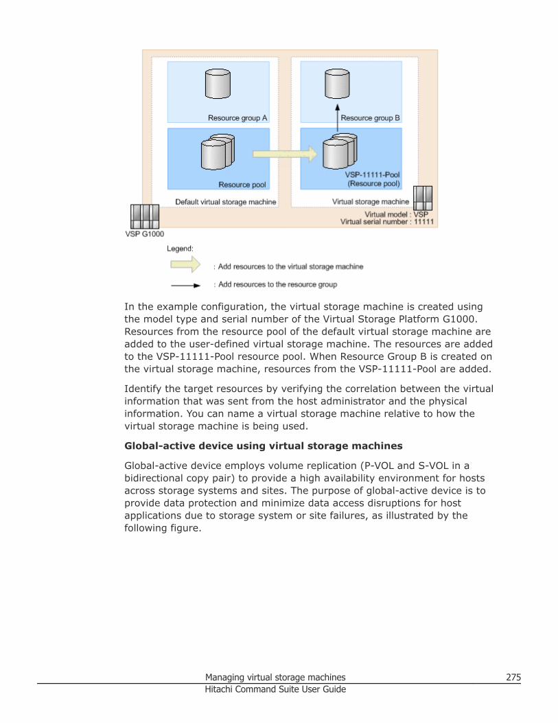
In the example configuration, the virtual storage machine is created usingthe model type and serial number of the Virtual Storage Platform G1000.Resources from the resource pool of the default virtual storage machine areadded to the user-defined virtual storage machine. The resources are addedto the VSP-11111-Pool resource pool. When Resource Group B is created onthe virtual storage machine, resources from the VSP-11111-Pool are added.
Identify the target resources by verifying the correlation between the virtualinformation that was sent from the host administrator and the physicalinformation. You can name a virtual storage machine relative to how thevirtual storage machine is being used.
Global-active device using virtual storage machines
Global-active device employs volume replication (P-VOL and S-VOL in abidirectional copy pair) to provide a high availability environment for hostsacross storage systems and sites. The purpose of global-active device is toprovide data protection and minimize data access disruptions for hostapplications due to storage system or site failures, as illustrated by thefollowing figure.
Managing virtual storage machines 275Hitachi Command Suite User Guide
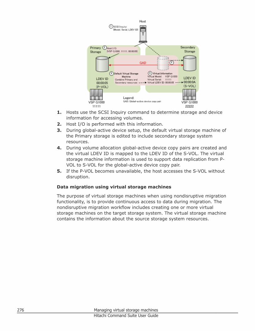
1. Hosts use the SCSI Inquiry command to determine storage and deviceinformation for accessing volumes.
2. Host I/O is performed with this information.3. During global-active device setup, the default virtual storage machine of
the Primary storage is edited to include secondary storage systemresources.
4. During volume allocation global-active device copy pairs are created andthe virtual LDEV ID is mapped to the LDEV ID of the S-VOL. The virtualstorage machine information is used to support data replication from P-VOL to S-VOL for the global-active device copy pair.
5. If the P-VOL becomes unavailable, the host accesses the S-VOL withoutdisruption.
Data migration using virtual storage machines
The purpose of virtual storage machines when using nondisruptive migrationfunctionality, is to provide continuous access to data during migration. Thenondisruptive migration workflow includes creating one or more virtualstorage machines on the target storage system. The virtual storage machinecontains the information about the source storage system resources.
276 Managing virtual storage machinesHitachi Command Suite User Guide
During the three stages of data migration, accessing the information changesfrom using physical to virtual information.• Before data migration (using physical information)
Before data migration, a host uses physical information to access thesource storage system resources.
• During the data migration (using virtual information)Configure virtual storage machine information on the target storagesystem, and then migrate the data from the source storage system. Aspart of the data migration workflow, the host I/O paths are changed fromthe source storage system to the target storage system.
• After data migrationThe host can now use virtual information to access the resources on thetarget storage system. For example, when a Hitachi Universal StoragePlatform V/VM is replaced by a VSP G1000 and the information in HitachiUniversal Storage Platform V/VM is configured on a virtual storagemachine, host configuration changes are not needed. The host can viewand access the volumes on the VSP G1000 virtual storage machine in thesame way that the volumes were accessed on the Hitachi UniversalStorage Platform V/VM.
For resources that have virtual information configured after data migration:• User-defined virtual storage machine volumes cannot be allocated to a file
server.• To manage copy pairs, such as global-active device pairs by using the
resources of a virtual storage machine, review the prerequisites for system
Managing virtual storage machines 277Hitachi Command Suite User Guide
configuration. For details, see the Hitachi Command Suite AdministratorGuide.
Related concepts
• About resource groups on page 100• About global-active device on page 286
Related tasks
• Creating virtual storage machines on page 279• Editing virtual storage machines on page 281• Deleting virtual storage machines on page 283
Related references
• Prerequisites for allocating resources to virtual storage machines on page278
• Prerequisites for creating resource groups on page 102
Prerequisites for allocating resources to virtual storagemachines
The following list identifies the conditions for resource allocation to virtualstorage machines.
The following resources can be allocated to a virtual storage machine for aVirtual Storage Platform G1000.• Parity Groups: Includes parity groups in external storage systems. When
you register a part of a parity group that is part of a concatenated paritygroup to a virtual storage machine, other parity groups that are a part ofthe concatenated parity group will also be registered in the same virtualstorage machine automatically.
• LDEV IDs: Includes volumes in external storage systems. LDEV IDs can beadded only if they are not allocated to a host and do not have virtualinformation. Non-existent IDs can also be specified.
• Storage Ports: Includes storage system ports.
• Host Group Numbers: Host group numbers can be added only if they arenot allocated to a host and do not have virtual information. Non-existentnumbers can also be specified.
Note the following additional conditions:• If the LDEV ID of a DP volume is registered to a virtual storage machine,
you can also view the DP pool to which the DP volume belongs and the DPpool volumes that compose the DP pool.
278 Managing virtual storage machinesHitachi Command Suite User Guide
• If a DP pool volume is registered to a virtual storage machine, othervolumes that compose the DP pool are automatically registered to thesame virtual storage machine.
Related concepts
• About virtual storage machines on page 274
Related tasks
• Creating virtual storage machines on page 279• Editing virtual storage machines on page 281
Creating virtual storage machinesYou can create a maximum of seven virtual storage machines for a single VSPG1000. Resources specified, such as parity groups or LDEV IDs, are added tothe resource pools on the user-defined virtual storage machines.
Prerequisites
Serial number, if you are specifying a storage system that is not registeredwith HCS.
Procedure
1. On the Administration tab, select Virtual Storage Machine.2. In the application pane, click Create Virtual Storage Machine.3. Enter a name for the virtual storage machine.4. Choose one of the following options to specify the virtual model and
serial number.• Click Select a storage system already registered on HCS from
list.• Click Specify manually, select a model from the list, and then specify
a virtual serial number.5. On the Storage Systems tab, click Add Storage Systems, and then
select the storage system to add.Displays the storage system and the resources in the storage systemthat can be added to the virtual storage machine. Resources areorganized by resource type, such as parity groups, LDEV IDs, storageports, and host group numbers.
6. (Optional) On the Parity Groups tab, click Add Parity Groups, selectthe parity groups from the list, and then click OK.
7. (Optional) On the LDEV IDs tab, click Add LDEV IDs, specify thenumber of LDEV IDs or select available LDEV IDs to add from a table,and then click OK.
8. (Optional) On the Storage Ports tab, click Add Storage Ports, selectthe storage ports to add, and then click OK.
Managing virtual storage machines 279Hitachi Command Suite User Guide
9. (Optional) On the Host Group Numbers tab, click Add Host GroupNumbers, specify storage ports and the number of host group numbersto add per port, or specify host groups from a list, and then click OK.
10. Click Submit.If the task is scheduled to run immediately, the process begins.
11. (Optional) Check the progress and result of the task on the Tasks &Alerts tab. Click the task name to view details of the task.
Result
The user-defined virtual storage machine is created and can be viewed in thelist of virtual storage machines.
Related concepts
• About virtual storage machines on page 274
Related references
• Prerequisites for allocating resources to virtual storage machines on page278
Allocating volumes to hosts by using virtual storagemachine resources
The storage administrator can allocate volumes to hosts by using theresources of a virtual storage machine. The volumes of the default virtualstorage machine can also be allocated. The default virtual storage machine iscreated in VSP G1000.
Prerequisites• Identify the name of the target host.• The volumes to be allocated must satisfy one of the following conditions:
○ The volumes must belong to the same virtual storage machine to whichthe host group of the target host belongs.
○ The volume must belong to the resource pool of the default virtualstorage machine.
Procedure
1. On the Resources tab, select Hosts.2. Expand the tree and select an operating system.3. Select one or more hosts and click Allocate Volumes.4. Select the No. of Volumes and enter the Volume Capacity.5. From the list of storage systems, select the physical storage system.6. From the list of virtual storage machines, select the virtual storage
machine that contains the volumes to be allocated.
280 Managing virtual storage machinesHitachi Command Suite User Guide
Note: When allocating volumes from the default virtual storage machine,you do not need to select a virtual storage machine. The default virtualstorage machine is selected by default.
7. Select the volume type and volume location.8. (Optional) Click Advanced Options to specify tier, drive type, drive
speed, RAID level, or parity group in the volume criteria. The storagesystem will search for volumes that match the criteria.
9. Click LUN Path Options to configure the number of LUN paths toallocate per host and assign or change LUN paths.
10. (Optional) Click Host Group and LUN Settings to configure the hostgroup settings and LUN number.
11. Click Show Plan and confirm that the information in the plan summaryis correct. If changes are required, click Back.
12. (Optional) Update the task name and provide a description.13. (Optional) Expand Schedule to specify the task schedule.
You can schedule the task to run immediately or later. The default settingis Now. If the task is scheduled to run immediately, you can select Viewtask status to monitor the task after it is submitted.
14. Click Submit.If the task is scheduled to run immediately, the process begins.
15. (Optional) Check the progress and result of the task on the Tasks &Alerts tab. Click the task name to view details of the task.
16. On the Resources tab, select hosts to verify that volumes have beenallocated. The virtual information is set to the allocated volumes. When adefault virtual storage machine volume is allocated, the volume isregistered to the virtual storage machine to which the host groupsbelong.
Tip: When you are canceling volume allocation, you can delete thevirtual information and move the volume to the default virtual storagemachine.
Related references
• Prerequisites for allocating volumes on page 197
Editing virtual storage machinesYou can add resources or remove resources from a virtual storage machine.You can also change the name of the virtual storage machine.
To support global-active device pairs, edit the virtual storage machine to addsecondary storage system resources to a default or user-defined virtualstorage machine on the primary storage system to provide a single view ofthe primary and secondary storage system resources.
Managing virtual storage machines 281Hitachi Command Suite User Guide
Prerequisites
From the host, unallocate volumes that are related to resources that belongto the virtual storage machine you are removing.
Procedure
1. On the Administration tab, select Virtual Storage Machine, select avirtual storage machine in the list, and then click Edit Virtual StorageMachine.
Note: If you are setting up global-active device, click Edit VirtualStorage Machine in the Set Up Global-Active Device window.
2. Verify the Name and Virtual Model and Serial No. of the virtualstorage machine that you are modifying. If you are setting up a global-active device pair, verify that the virtual storage machine is on theprimary storage system.
3. Add or remove resources, such as parity groups or LDEV IDs, for thevirtual storage machine. If you are setting up a global-active device pair,click Add Storage Systems, select the secondary storage system, andthen click OK. Then add secondary storage system resources, such asParity Groups, LDEV IDs, Storage Ports, and Host Group Numbersto the virtual storage machine.
Note: If you are setting up global-active device, the primary storagesystem resources already belong to the default virtual storage machine.
4. Enter an optional task description, select whether you want to view theprogress of the task when the task completes, and then click Submit.
5. (Optional) Check the progress and result of the task on the Tasks &Alerts tab. Click the task name to view details of the task.
Result
The selected virtual storage machine is edited and can be verified in the listof virtual storage machines. If you are creating a global-active device pair,you have a single view of the primary and secondary storage systemresources.
Related concepts
• About virtual storage machines on page 274
Related references
• Prerequisites for allocating resources to virtual storage machines on page278
282 Managing virtual storage machinesHitachi Command Suite User Guide
Deleting virtual storage machinesYou can delete virtual storage machines that are no longer required. Deletinga virtual storage machine also deletes all of the virtual information about theresources that belong to that virtual storage machine and removes theresources from the virtual storage machine.
Prerequisites
From the host, unallocate the volumes that belong to the virtual storagemachine that you are deleting.
Procedure
1. On the Administration tab, select Virtual Storage Machine.2. From the list of virtual storage machines, select the virtual storage
machine that you want to delete and click Delete Virtual StorageMachine.
3. Click Submit.4. On the Tasks & Alerts tab, confirm the task completion.
Result
The selected virtual storage machine is deleted.
Related concepts
• About virtual storage machines on page 274
Managing virtual storage machines 283Hitachi Command Suite User Guide

284 Managing virtual storage machinesHitachi Command Suite User Guide
7Replicating volumes for continuous
accessVolume replication is used for creating in-system or remote storage systemvolume copies for data protection. Global-active device provides copy pairreplication for active-active high availability in a multi-site environment.
□ About global-active device
□ Setting up a global-active device environment
□ Monitoring and managing global-active device pairs
□ Recovering from global-active device failures
□ Discontinuing a global-active device environment
□ Volume replication
Replicating volumes for continuous access 285Hitachi Command Suite User Guide
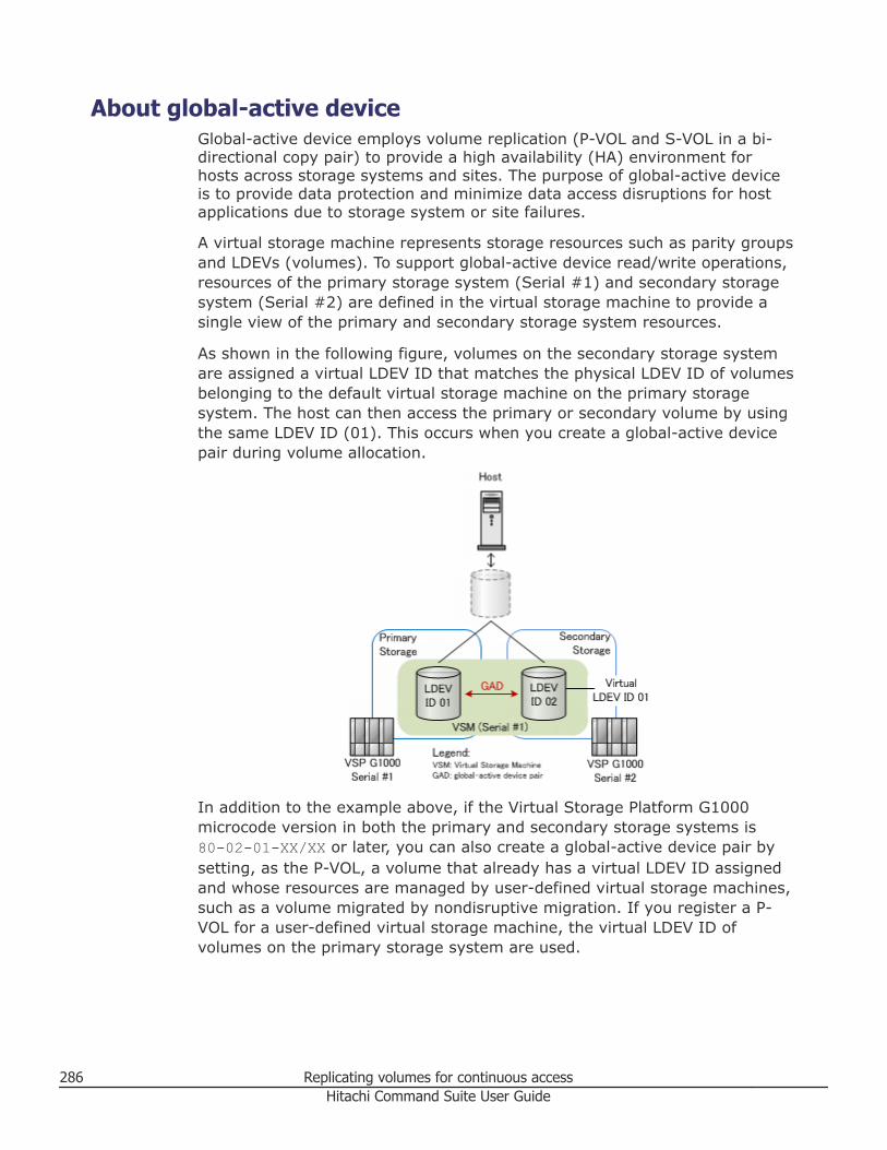
About global-active deviceGlobal-active device employs volume replication (P-VOL and S-VOL in a bi-directional copy pair) to provide a high availability (HA) environment forhosts across storage systems and sites. The purpose of global-active deviceis to provide data protection and minimize data access disruptions for hostapplications due to storage system or site failures.
A virtual storage machine represents storage resources such as parity groupsand LDEVs (volumes). To support global-active device read/write operations,resources of the primary storage system (Serial #1) and secondary storagesystem (Serial #2) are defined in the virtual storage machine to provide asingle view of the primary and secondary storage system resources.
As shown in the following figure, volumes on the secondary storage systemare assigned a virtual LDEV ID that matches the physical LDEV ID of volumesbelonging to the default virtual storage machine on the primary storagesystem. The host can then access the primary or secondary volume by usingthe same LDEV ID (01). This occurs when you create a global-active devicepair during volume allocation.
In addition to the example above, if the Virtual Storage Platform G1000microcode version in both the primary and secondary storage systems is80-02-01-XX/XX or later, you can also create a global-active device pair bysetting, as the P-VOL, a volume that already has a virtual LDEV ID assignedand whose resources are managed by user-defined virtual storage machines,such as a volume migrated by nondisruptive migration. If you register a P-VOL for a user-defined virtual storage machine, the virtual LDEV ID ofvolumes on the primary storage system are used.
286 Replicating volumes for continuous accessHitachi Command Suite User Guide
The global-active device environment resolves the details of all read/writeactivity to the global-active device pair. For example, when the host writesdata to LDEV ID 01, data is replicated to LDEV ID 02. If the host path toprimary storage fails, the host can continue to perform read/write operationsusing the secondary storage volume.
When a global-active device pair is established, application server high-availability benefits include:• Continuous I/O:
If a primary volume becomes unavailable, the host will continue totransparently access the secondary volume.
• Clustered host failover:You do not need to perform storage system tasks, such as suspending orre-syncing a global-active device pair to recover from a host failure.
• Virtual machine migration:If a server is running a virtual machine creating a high load, you can movethe virtual machine to the host at the other site, which can access thesame data, so data migration between storage systems is unnecessary.
A global-active device environment can be implemented within a single siteor across two sites or three sites. Implementation across three sites providesthe best protection against site failures because the primary, secondary, andquorum storage systems exist at different physical locations, or sites, asshown in the following figure.
Replicating volumes for continuous access 287Hitachi Command Suite User Guide
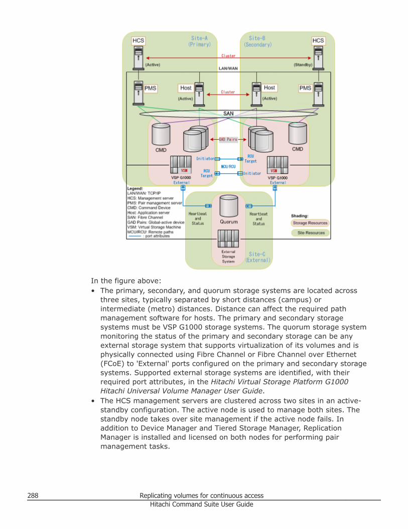
In the figure above:• The primary, secondary, and quorum storage systems are located across
three sites, typically separated by short distances (campus) orintermediate (metro) distances. Distance can affect the required pathmanagement software for hosts. The primary and secondary storagesystems must be VSP G1000 storage systems. The quorum storage systemmonitoring the status of the primary and secondary storage can be anyexternal storage system that supports virtualization of its volumes and isphysically connected using Fibre Channel or Fibre Channel over Ethernet(FCoE) to 'External' ports configured on the primary and secondary storagesystems. Supported external storage systems are identified, with theirrequired port attributes, in the Hitachi Virtual Storage Platform G1000Hitachi Universal Volume Manager User Guide.
• The HCS management servers are clustered across two sites in an active-standby configuration. The active node is used to manage both sites. Thestandby node takes over site management if the active node fails. Inaddition to Device Manager and Tiered Storage Manager, ReplicationManager is installed and licensed on both nodes for performing pairmanagement tasks.
288 Replicating volumes for continuous accessHitachi Command Suite User Guide
Note: In a global-active device environment, a single HCS managementserver node should be used to discover the primary, secondary andquorum storage systems, and the required hosts and pair managementservers at the primary and secondary sites. A complete view of resourcesis required for HCS global-active device setup tasks, for allocating global-active device pairs using the pair management servers, and for displayingP-VOL/S-VOL I/O metrics in the Analytics tab.
If you discover resources by using separate management servers locatedat the primary and secondary sites, you cannot use HCS to perform global-active device setup tasks, or Device Manager to allocate global-activedevice pairs. Instead, use Replication Manager for pair configuration andpair management.
• Pair management servers are located at both the primary site andsecondary site. Each pair management server must include DeviceManager Agent and Command Control Interface (CCI) to perform pairmanagement tasks as directed by HCS, or directly from the pairmanagement server itself. Command devices (CMD) are used forprocessing pair management commands. The primary and secondary sitepair management servers are used by the HCS management server forglobal-active device pair operations.
• The application servers are clustered across two sites with HBA (FibreChannel) paths to both storage systems. Application servers can beconfigured in an active-standby or active-active cluster. In an active-activecluster configuration both nodes can perform read-write I/O. Depending onthe multi-path software being used, an application server can use anyavailable path to access data, or will use the shortest available path ifconfigured to do so, meaning an application server at the primary sitewould read data from primary site storage, and an application server atthe secondary site would read data from secondary site storage. Write I/Oto global-active device pairs results in the same data being written to thepair, regardless of which storage system and port the write I/O occurs on.Data is always written to the primary volume first, then the secondaryvolume using the physical remote path (MCU/RCU) connections for bi-directional data transfers.
Note: Hitachi Dynamic Link Manager (HDLM) provides features foridentifying non-preferred (longer) paths for I/O, ensuring the use of theshortest I/O path under normal conditions. If a path failure occurs, thelonger path is used for I/O. This optimizes I/O performance while retaininghigh-availability. See the Hitachi Command Suite Dynamic Link ManagerUser Guide for your host OS.
Replicating volumes for continuous access 289Hitachi Command Suite User Guide
If the host OS is HP-UX 11iv3 and you are using the native multi-pathingfeatures, execute the following command in advance to disable the multi-pathing features for legacy device special files:
scsimgr save_attr -a leg_mpath_enable=false
The following workflow describes the necessary planning and implementationsteps for creating, monitoring and managing a global-active deviceenvironment.
290 Replicating volumes for continuous accessHitachi Command Suite User Guide
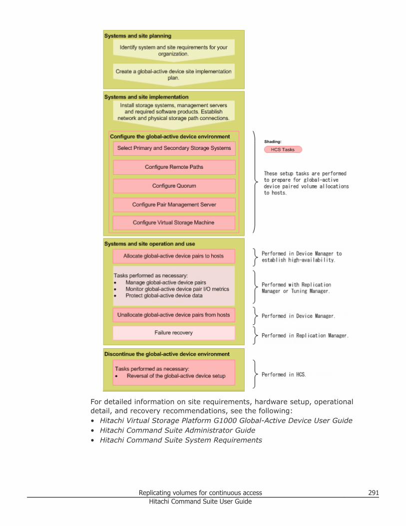
For detailed information on site requirements, hardware setup, operationaldetail, and recovery recommendations, see the following:• Hitachi Virtual Storage Platform G1000 Global-Active Device User Guide• Hitachi Command Suite Administrator Guide• Hitachi Command Suite System Requirements
Replicating volumes for continuous access 291Hitachi Command Suite User Guide
Related concepts
• About global-active device setup on page 292
Setting up a global-active device environmentAfter the HCS management server has discovered resources, you can use theSet up Global-Active Device window for setup tasks that must be performedbefore global-active device pairs can be allocated.
About global-active device setupThe global-active device setup window provides a workflow for configuringrequired storage system resources before global-active device pairedvolumes can be allocated.
Access to the global-active device setup window is provided from:• The Actions menu on the global task bar• The Replication tab, from General Tasks
The setup window provides access to various HCS or Replication Managerdialog boxes. As tasks are completed, or if tasks have already beencompleted by other procedures, the setup window identifies completed tasksand provides a link to configuration details. If you close the setup windowand reopen it later, the completed tasks remain identified.
292 Replicating volumes for continuous accessHitachi Command Suite User Guide
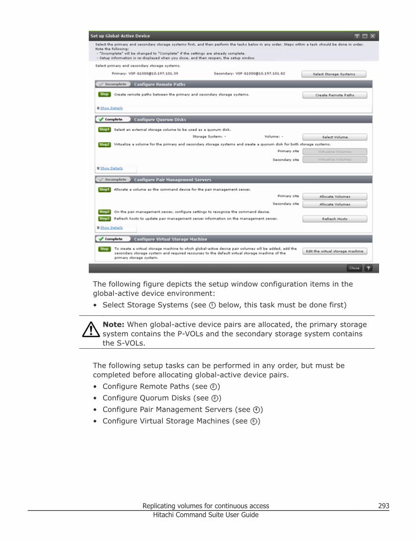
The following figure depicts the setup window configuration items in theglobal-active device environment:• Select Storage Systems (see below, this task must be done first)
Note: When global-active device pairs are allocated, the primary storagesystem contains the P-VOLs and the secondary storage system containsthe S-VOLs.
The following setup tasks can be performed in any order, but must becompleted before allocating global-active device pairs.• Configure Remote Paths (see )• Configure Quorum Disks (see )• Configure Pair Management Servers (see )• Configure Virtual Storage Machines (see )
Replicating volumes for continuous access 293Hitachi Command Suite User Guide
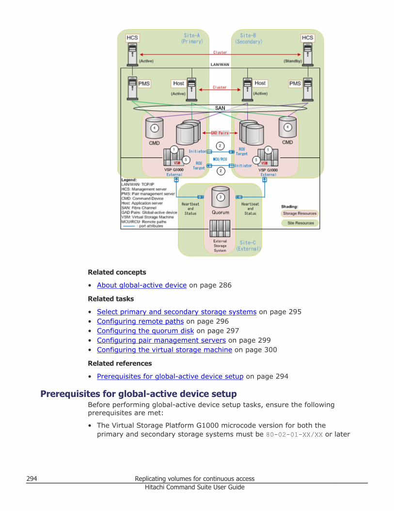
Related concepts
• About global-active device on page 286
Related tasks
• Select primary and secondary storage systems on page 295• Configuring remote paths on page 296• Configuring the quorum disk on page 297• Configuring pair management servers on page 299• Configuring the virtual storage machine on page 300
Related references
• Prerequisites for global-active device setup on page 294
Prerequisites for global-active device setupBefore performing global-active device setup tasks, ensure the followingprerequisites are met:
• The Virtual Storage Platform G1000 microcode version for both theprimary and secondary storage systems must be 80-02-01-XX/XX or later
294 Replicating volumes for continuous accessHitachi Command Suite User Guide
to create global-active device pairs where the P-VOLs already have avirtual LDEV ID assigned and are managed by user-defined virtual storagemachines, as with nondisruptive migration. This requirement is notnecessary for global-active device pairs created by adding secondarystorage resources to the primary storage default virtual storage machine.
• Global-active device has been licensed (which includes ReplicationManager).
• Replication Manager is installed and linked to HCS.• A pair management server is installed with Device Manager Agent and
Command Control Interface (CCI) at the primary and secondary storagesites.
• The external port of the primary and secondary storage systems areconnected to the quorum storage system by Fibre Channel or FibreChannel over Ethernet.
• You have registered (discovered) the primary, secondary, and quorumstorage systems. If you are configuring quorum disks by using virtualizedvolumes as external volumes, registration of the quorum storage system isnot necessary.
Related concepts
• About global-active device on page 286• About global-active device setup on page 292
Related tasks
• Registering a storage system on page 58• Creating virtual storage machines on page 279
Select primary and secondary storage systemsSelect primary and secondary storage systems listed by the global-activedevice setup. Only valid storage systems with the correct firmware revisionare listed.
Procedure
1. Open the global-active device setup window:• From the Actions menu, select Set up Global-Active Device.• On the Replication tab, General Tasks, select Set up Global-
Active Device.2. On the Set up Global-Active Device window, click Select Storage
Systems.3. From the Select Storage Systems window, select the primary storage
system from the list of available storage systems.4. Select the secondary storage system from the list of available storage
systems.
Replicating volumes for continuous access 295Hitachi Command Suite User Guide
5. If given the option, select a default or user-defined virtual storagemachine on the primary storage system in which global-active devicepairs will be created.
Note: If the microcode version of both storage systems is 80-02-01-XX/XX or later, the primary storage system virtual storage machine list isdisplayed.
6. Confirm the selected storage systems and virtual storage machineinformation are correct and click OK.The selected information is displayed on the setup window asconfirmation.
Result
The storage systems and virtual storage machine are selected, and becomedefault values for the remaining setup tasks.
Related concepts
• About global-active device on page 286• About global-active device setup on page 292
Configuring remote pathsConfigure remote paths between the primary and secondary storagesystems.
Prerequisites
The primary and secondary storage systems have been selected.
Procedure
1. Open the global-active device setup window:• From the Actions menu, select Set up Global-Active Device• On the Replication tab, General Tasks, select Set up Global-
Active Device2. From Configure Remote Paths, click Create Remote Paths.
The Create Remote Path wizard opens.3. On the Select Remote Storage System page:
a. Verify that Copy Type is set to Universal Replicator/global-activedevice.
b. Verify the displayed Primary Storage System and SecondaryStorage System information, and click Next to define paths.
Tip: The MCU/RCU check box is disabled by design for the global-active device dialog.
4. On the Define Remote Path page:
296 Replicating volumes for continuous accessHitachi Command Suite User Guide
a. Ensure that the Select reverse direction path check box is selected.b. (Optional) Enter a Label for identifying the remote paths for global-
active device.c. (Optional) Enter a non-default Path group ID.d. Using the Local Port and Remote Port lists, select the Initiator and
RCU target ports from the Existing Ports list for both the primaryand secondary storage systems.
Tip: The port list on the left shows primary to secondary storageports, and the port list on the right shows secondary to primarystorage ports. Note that the listed existing ports are unallocated hostports, meaning a port attribute of target not in use by any hosts.
e. Click Next to review the remote path settings.5. On the Confirm page:
a. Under Initiator/RCU Targets, review selected ports and portattribute settings (before and after).
b. In the Remote Path area, check the copy direction for the local andremote port pairs. If the port pairs are correct, select the confirmationmessage check box, and click Confirm to set the port attributes(Initiator or RCU Target).
Tip: Port pairs on the left (Local -> Remote) are primary to secondarystorage remote paths. Port pairs on the right (Local <- Remote) arethe secondary to primary storage remote paths.
Note: For more information about remote paths, see the HitachiCommand Suite Replication Manager User Guide.
Result
The remote paths between the primary and secondary storage systems areconfigured, and can be confirmed by clicking Show Details.
Related concepts
• About global-active device on page 286• About global-active device setup on page 292
Configuring the quorum diskThe quorum disk detects the status of the primary and secondary storagesystems. Configure the quorum disk by selecting a volume and virtualizing itas an external volume of the primary and secondary storage systems.
When the Virtual Storage Platform G1000 microcode version for both theprimary and secondary storage systems is 80-02-2X-XX/XX or later, you canalso configure the quorum disk by using a virtualized volume as an externalvolume of the primary or secondary storage system.
Replicating volumes for continuous access 297Hitachi Command Suite User Guide
Prerequisites
The primary and secondary storage systems have been selected.
Procedure
1. Open the global-active device setup window:• From the Actions menu, select Set up Global-Active Device.• On the Replication tab, General Tasks, select Set up Global-
Active Device.2. From Configure Quorum Disks, when the Virtual Storage Platform
G1000 microcode version for both the primary and secondary storagesystems is 80-02-2X-XX/XX or later, do one of the following:• Click Create a new external volume to virtualize a volume as an
external volume, and then continue with step 3.• Click Configure an existing external volume to use a virtualized
volume as an external volume, and then click Configure QuorumDisks for the Primary Site and Secondary Site. On the QuorumDisk tab, click Add Quorum Disks, and then follow the instructionsin the Help.
3. In the Select Volume window, select a Storage system to provide thequorum disk, and then do one of the following:• From the Available Volumes list, select a volume, click OK, and then
go to step 12.• If no suitable volume is listed, click Create Volumes.
4. In the Create Volumes window, create a volume to be used as thequorum disk.
5. From the Volume Type list select a volume type.6. (Optional) Click Advanced Options to configure volume options or
specify a quorum disk label.7. Click Show Plan and confirm that the information in the plan summary
is correct. If changes are required, click Back.8. (Optional) Update the task name and provide a description.9. (Optional) Expand Schedule to specify the task schedule.
You can schedule the task to run immediately or later. The default settingis Now.
10. Click Submit.If the task is scheduled to run immediately, the process begins.
11. (Optional) Check the progress and result of the task on the Tasks &Alerts tab. Click the task name to view details of the task.
12. From Configure Quorum Disks, for the primary storage, clickVirtualize Volumes.
13. In the Virtualize Volumes dialog box:a. Verify the external and internal storage systems are correct.b. Click Edit External Paths to set or change external paths.
298 Replicating volumes for continuous accessHitachi Command Suite User Guide
c. (Optional) Select External Path Priority Settings to increase ordecrease path priority.
d. Select Internal Volume Configuration and verify that ChangeInternal Volume(s) to Quorum Disk(s) is selected by default. Thedefault ID is recommended, but can be changed to another value ifnecessary.
14. Click Show Plan and submit the task.15. Repeat steps 12 through 14 for the secondary storage system.
Note that for the secondary storage system, the secondary storagesystem name will be displayed.
Result
The quorum disk is created and virtualized for both the primary andsecondary storage, and can be confirmed by clicking Show Details.
Related concepts
• About global-active device on page 286• About global-active device setup on page 292
Related references
• Create Volumes dialog box on page 146• Virtualize Volumes dialog box on page 160
Configuring pair management serversConfigure the command devices for the pair management servers from theprimary and secondary storage systems. Command devices are used tocommunicate pair management directives.
Prerequisites
The primary and secondary storage systems have been selected.
Procedure
1. Open the global-active device setup window:• From the Actions menu, select Set up Global-Active Device• On the Replication tab, General Tasks, select Set up Global-
Active Device2. From Configure Pair Management Server, click Allocate Volumes
for the primary storage system.3. In the Allocate Volumes dialog box, verify that the Storage System is
correct.4. For Host, select the pair management server for the storage system.5. Click Advanced Options, verify that Command Device is checked, and
that User Authentication is Enabled.
Replicating volumes for continuous access 299Hitachi Command Suite User Guide
6. Click Show Plan and confirm that the information in the plan summaryis correct. If changes are required, click Back.
7. (Optional) Update the task name and provide a description.8. (Optional) Expand Schedule to specify the task schedule.
You can schedule the task to run immediately or later. The default settingis Now.
9. Click Submit.If the task is scheduled to run immediately, the process begins.
10. (Optional) Check the progress and result of the task on the Tasks &Alerts tab. Click the task name to view details of the task.
11. Repeat steps 2 through 10 for the secondary storage system. For Host,be sure to specify the pair management server for the secondary storagesystem.
12. Ensure that the pair management servers recognize the commanddevices, and then from Configure Pair Management Server, clickRefresh Hosts.
Result
The command devices for the primary and secondary pair managementservers are allocated, and pair management server information is current,and can be confirmed by clicking Show Details.
Related concepts
• About global-active device on page 286• About global-active device setup on page 292
Related references
• Allocate Volumes dialog box on page 206
Configuring the virtual storage machineTo support global-active device pairs, add secondary storage systemresources to the default or user-defined virtual storage machine on theprimary storage system. Configuring the virtual storage machine provides asingle view of the primary and secondary storage system resources.
Prerequisites
The primary and secondary storage systems have been selected in the Set upGlobal-Active Device window.
Procedure
1. Open the global-active device setup window:• From the Actions menu, select Set up Global-Active Device• On the Replication tab, General Tasks, select Set up Global-
Active Device
300 Replicating volumes for continuous accessHitachi Command Suite User Guide
2. From Configure Virtual Storage Machine, click Edit Virtual StorageMachine.
3. In the Edit Virtual Storage Machine dialog box, on the StorageSystems tab, verify that the displayed Name and Virtual Model andSerial No. show the primary storage system values and that the primarystorage system is listed.
4. Click Add Storage Systems, select the secondary storage system, andthen click OK.
5. Add secondary storage system resources, such as Parity Groups, LDEVIDs, Storage Ports and Host Group Numbers to the virtual storagemachine by clicking the respective tabs.
Note: The primary storage system resources already belong to thevirtual storage machine.
6. When you are finished adding resources from the secondary storagesystem, enter an optional task description, select whether you want toview the progress of the task, and then click Submit.
Result
The storage system resources are configured for the virtual storage machine.
Related concepts
• About global-active device on page 286• About global-active device setup on page 292
Related tasks
• Creating virtual storage machines on page 279• Editing virtual storage machines on page 281
Monitoring and managing global-active device pairsThis module describes the required tasks to allocate, monitor, and unallocateglobal-active device pairs for hosts.
Allocating global-active device pairsAllocate new global-active device pairs to hosts (application servers). Whenyou allocate global-active device pairs, an initial copy is performed for theprimary and secondary volumes.
Prerequisites
You must be authenticated to the storage system and logged in to the pairmanagement server. For details, see the Hitachi Command SuiteAdministrator Guide.
Replicating volumes for continuous access 301Hitachi Command Suite User Guide
Procedure
1. On the Resources tab, General Tasks, select Allocate Volumes.
Tip: If you do not see Allocate Volumes listed, click more... to see allmenu items.
2. In the Allocate Volumes dialog box, select the hosts for the global-active device pair.
Note: File-servers are not supported for global-active device pairallocations.
3. For Allocation Type select global-active device.4. Specify the number and capacity of the volumes.5. On the Primary tab, configure the following options:
a. Select the primary Storage system, Virtual Storage Machine, andVolume type (HDP or HDT).Only valid storage systems and virtual storage machine information isdisplayed. If you specify HDP as the volume type, select the Volumelocation. If you specify HDT as the volume, the Volume Selectionoptions are available. You cannot allocate Basic volumes.
b. Click Advanced Options for further configuration.c. In LUN Path Options:
Edit LUN paths from primary storage ports to hosts.d. Click Host Group and LUN settings for further configuration.e. In Pair management Server Settings:
Select an available host as the pair management server. For InstanceID, click Existing to use a current configuration definition file andrelated instance ID number on the pair management server, or clickNew to create a new configuration definition file, and enter a newinstance ID number which will be validated as an available instanceID. You can also specify a UDP Port number for the instance.
6. On the Secondary tab, configure the following options:a. Select the secondary Storage system, Virtual Storage Machine,
and Volume type (HDP or HDT).Virtual storage machine information defaults to the primary tab value.
b. In Advanced options:Unlike the Primary tab, the Secondary tab allows you to selectsecondary storage system DP pools (Pools for S-VOL ) that correspondto primary storage system DP pools configured on the primary tab(Pools for P-VOL). For example, automatic selection of DP volumes willdisplay primary DP pools, and eligible secondary DP pools for volumeallocation. You can examine primary tab DP pool and volume detailswith links. You can accept the DP pools selected for secondary
302 Replicating volumes for continuous accessHitachi Command Suite User Guide
volumes, or make a manual selection by clicking Select Pool to listand select eligible DP pools, and selecting eligible volumes from theDP pools.
c. In LUN Path Options:Edit LUN paths from secondary storage ports to hosts. Under LUNPath Setting Information on Primary Site, you will see theprimary storage system, and No. of LUN Paths per volume. Clickingthe link will display primary storage system mapping information.
d. Click Host Group and LUN settings for further configuration.e. In Pair management Server Settings:
Select an available host as the pair management server. For InstanceID, click Existing to use a current configuration definition file andrelated instance ID number on the pair management server, or clickNew to create a new configuration definition file, and enter a newinstance ID number which will be validated as an available instanceID. You can also specify a UDP Port number for the instance.
7. Click Virtual ID Settings for further configuration.These settings are displayed only in a configuration where options otherthan the default virtual storage machine are used on the primary side.
8. In Pair Settings:a. Select the Quorum Disk, and then select whether pairs should belong
to a new or existing Copy Group for management purposes. ClickNew to assign a new copy group to the global-active device pair.Select the CTG ID check box to assign a consistency group (CTG) IDto the new copy group. Click Existing to assign an existing copygroup to the global-active device pair. The existing CTG ID will be usedif it exists for the selected copy group.
b. Manually enter a name (Prefix and Start Sequence No.) or selectAutomatic for Pair Name and a name will be created.
9. Click Show Plan and confirm that the information in the plan summaryis correct. If changes are required, click Back.
10. (Optional) Update the task name and provide a description.11. (Optional) Expand Schedule to specify the task schedule.
You can schedule the task to run immediately or later. The default settingis Now.
12. Click Submit.If the task is scheduled to run immediately, the process begins.
13. (Optional) Check the progress and result of the task on the Tasks &Alerts tab. Click the task name to view details of the task.
14. Confirm the global-active device pair is allocated.
Result
The global-active device pair is allocated to the target host, and initial copyperformed. Reclaiming zero pages is also automatically performed.
Replicating volumes for continuous access 303Hitachi Command Suite User Guide
Related tasks
• Allocating global-active device pairs based on like volumes on page 304• Allocating global-active device pairs using allocated volumes on page 306• Editing LUN paths on page 230
Related references
• Allocate Volumes dialog box on page 206
Allocating global-active device pairs based on like volumesSelect an existing allocated global-active device volume, and allocate aglobal-active device pair using the characteristics of the selected primary orsecondary volume.
Prerequisites
You must be authenticated to the storage system and logged in to the pairmanagement server. For details, see the Hitachi Command SuiteAdministrator Guide.
Procedure
1. On the Resources tab, select a global-active device volume from theOpen-Allocated volume list, or for a specific host using global-activedevice paired volumes, select an already allocated volume to use in anew global-active device pair, and click Allocate Like Volumes.
Tip: Regardless of whether the primary volume (P-VOL) or the secondaryvolume (S-VOL) is selected as the existing volume, the settings for theexisting P-VOL are used for the newly allocated primary volume and thesettings for the existing S-VOL are used for the newly allocatedsecondary volume.
However, if characteristics such as drive type and drive speed of theexisting volumes do not match between the primary and secondarystorage systems, a secondary volume whose characteristics match thoseof the primary volume is recommended.
2. In the Allocate Like Volumes dialog box, verify the information for theselected volume and make any necessary changes.
3. On the Primary tab, configure the following options:a. Select the primary Storage system, Virtual Storage Machine, and
Volume type (HDP or HDT).Only valid storage and virtual storage machine information isdisplayed. If volume type is HDP, select the Volume location. Ifvolume type is HDT, the Volume Selection options are displayed. Youcannot allocate Basic volumes.
b. Click Advanced Options for further configuration.
304 Replicating volumes for continuous accessHitachi Command Suite User Guide
c. In LUN Path Options:Edit LUN paths from primary storage ports to hosts.
d. Click Host Group and LUN settings for further configuration.e. In Pair Management Server Settings:
Select an available host as the pair management server. For InstanceID, click Existing to use a current configuration definition file andrelated instance ID number on the pair management server, or clickNew to create a new configuration definition file, and enter a newinstance ID number which will be validated as an available instanceID. You can also specify a UDP Port number for the instance.
4. On the Secondary tab, configure the following options:a. Select the secondary Storage system, Virtual Storage Machine,
and Volume type (HDP or HDT):Virtual storage machine information defaults to the primary tab value.
b. In Advanced Options:Unlike the Primary tab, select DP pools for the secondary storagesystem (Pools for S-VOL) that correspond to the DP pools configuredon the primary tab (Pools for P-VOL). For example, automatic selectionof DP volumes will display primary DP pools, and eligible secondary DPpools for volume allocation. You can examine primary tab DP pool andvolume details with links. You can accept the DP pools selected forsecondary volumes, or make a manual selection by clicking SelectPool to list and select eligible DP pools, and selecting eligible volumesfrom the DP pools.
c. In LUN Path options:Edit LUN paths from secondary storage ports to hosts. LUN PathSetting Information on Primary Site lists the primary storagesystem, and No. of LUN Paths per volume. Click the link to displayprimary storage system mapping information.
d. Click Host Group and LUN settings for further configuration.e. Click Pair Management Server Settings for further configuration.
5. Click Virtual ID Settings for further configuration.These settings display only when options other than the default virtualstorage machine are used on the primary storage.
6. In Pair Settings:a. Select the Quorum Disk, and then select whether pairs should belong
to a new or existing Copy Group for management purposes. ClickNew to assign a new copy group to the global-active device pair.Select the CTG ID check box to assign a consistency group (CTG) IDto the new copy group. Click Existing to assign an existing copygroup to the global-active device pair. The existing CTG ID will be usedif it exists for the selected copy group.
b. Manually enter a name (Prefix and Start Sequence No.) or selectAutomatic for Pair Name and a name will be created.
Replicating volumes for continuous access 305Hitachi Command Suite User Guide
7. Click Show Plan and confirm that the information in the plan summaryis correct. If changes are required, click Back.
8. (Optional) Update the task name and provide a description.9. (Optional) Expand Schedule to specify the task schedule.
You can schedule the task to run immediately or later. The default settingis Now.
10. Click Submit.If the task is scheduled to run immediately, the process begins.
11. (Optional) Check the progress and result of the task on the Tasks &Alerts tab. Click the task name to view details of the task.
12. Confirm the global-active device paired volumes are allocated.
Result
The global-active device pair is allocated to the target host, and initial copyperformed. Reclaiming zero pages is also automatically performed.
Related tasks
• Allocating global-active device pairs on page 301• Allocating global-active device pairs using allocated volumes on page 306• Editing LUN paths on page 230
Related references
• Allocate Volumes dialog box on page 206
Allocating global-active device pairs using allocated volumesExisting open-allocated volumes in the same storage system belonging to thesame host group (with the same LUN paths) can be converted to P-VOLs, andthe P-VOL data migrated to S-VOLs to create a global-active device pair.
Prerequisites
You must be authenticated to the storage system and logged in to the pairmanagement server. For details, see the Hitachi Command SuiteAdministrator Guide.
Procedure
1. On the Resources tab, or by searching, locate allocated volumes toconvert into global-active device pairs.
2. Select the volume, and click Change to Global-Active DeviceVolumes.
3. On the Primary tab, configure the following options:a. Verify the displayed hosts, storage systems virtual storage machines
for the selected volumes.
306 Replicating volumes for continuous accessHitachi Command Suite User Guide
b. Selected Volumes are allocated volumes eligible to become a P-VOLin a global-active device pair. Details such as WWN, host group, andvolume characteristics are displayed.
c. In Pair Management Server Settings:Select an available host as the pair management server. For InstanceID, select Existing to use a current configuration definition file andrelated instance ID number on the pair management server, or selectNew to create a new configuration definition file, and enter a newinstance ID number which will be validated as an available instanceID. You can also specify a UDP Port number for the instance.
4. On the Secondary tab, configure the following options:a. Verify the displayed hosts for the selected volumes, and click Select
other Hosts to specify more hosts that can access global-activedevice pairs.
b. Select the secondary storage system where the S-VOLs will becreated.
c. Verify the displayed virtual storage machine.d. Click Advanced Options for further configuration.e. Click LUN Path Options for further configuration.
The previously allocated primary path is displayed.f. Click Host Group and LUN settings for further configuration.g. In Pair Management Server Settings:
Select an available host as the pair management server. For InstanceID, select Existing to use a current configuration definition file andrelated instance ID number on the pair management server, or selectNew to create a new configuration definition file, and enter a newinstance ID number which will be validated as an available instanceID. You can also specify a UDP Port number for the instance.
5. In Pair Settings:a. Select the Quorum Disk, and then select whether pairs should belong
to a new or existing Copy Group for management purposes. ClickNew to assign a new copy group to the global-active device pair.Select the CTG ID check box to assign a consistency group (CTG) IDto the new copy group. Click Existing to assign an existing copygroup to the global-active device pair. The existing CTG ID will be usedif it exists for the selected copy group.
b. Manually enter a name (Prefix and Start Sequence No.) or selectAutomatic for Pair Name and a name will be created.
6. Click Show Plan and confirm that the information in the plan summaryis correct. If changes are required, click Back.
7. (Optional) Update the task name and provide a description.8. (Optional) Expand Schedule to specify the task schedule.
You can schedule the task to run immediately or later. The default settingis Now.
9. Click Submit.
Replicating volumes for continuous access 307Hitachi Command Suite User Guide
If the task is scheduled to run immediately, the process begins.10. (Optional) Check the progress and result of the task on the Tasks &
Alerts tab. Click the task name to view details of the task.11. Confirm the global-active device paired volumes are created by checking
volume status information.
Result
The global-active device pair has been created from open-allocated volumes,and initial copy performed. Reclaiming zero pages is also automaticallyperformed.
Related tasks
• Allocating global-active device pairs on page 301• Allocating global-active device pairs based on like volumes on page 304• Editing LUN paths on page 230
Related references
• Allocate Volumes dialog box on page 206
Checking global-active device pair statusYou can review information (including status) of global-active device pairs orreserved volumes from the volume list and volume details windows in HCS.
Note: You can also use Replication Manager to check global-active devicepair status. Open Tools > Replication Manager and locate copy groups orpairs to view pair status. For more information about pair status, conditionsunder which certain copy pair statuses can be changed, and about how tochange the status of a copy pair by using the Change Pair Status wizard seethe Replication Manager help.
Procedure
1. Review global-active device status using one or more of the followingoptions:• On the Resources tab, select Storage Systems, select a Virtual
Storage Platform G1000, select Volumes, and then list Open-Allocated volumes to view global-active device information, asfollows:- Volume Attribute- Copy Info (P-VOL)- Copy Info (S-VOL)- GAD Status
Tip: You might need to configure column settings to see global-activedevice information.
308 Replicating volumes for continuous accessHitachi Command Suite User Guide
Click volume links to view detailed information for global-active devicepairs, Quorum disks, and command devices.
• On the Resources tab, select Hosts, select an operating system,then select a host using global-active device pairs, and review volumestatus.
• Search for hosts or volumes to locate global-active device volumes,and review volume status.
Result
The status of global-active device pairs is displayed.
Related tasks
• Monitoring global-active device pair performance on page 310• Protecting global-active device pairs on page 309
Protecting global-active device pairsUsing Replication Manager, configure in-system replication to furthersafeguard the data on global-active device pairs in use by hosts on primaryand secondary storage systems.
Prerequisites• The copy type is ShadowImage or Thin Image.• The authentication mode is valid for the command device allocated to the
pair management server.• If the primary and secondary storage systems are managed by one pair
management server, you cannot use the virtual IDs of the virtual storagemachine used by the global-active device pair. To use virtual IDs, adedicated pair management server is required for each storage system.
Procedure
1. On the global task bar, from the Tools menu, select ReplicationManager.
2. Select a global-active device volume and click Pair Management.The Pair Configuration Wizard opens.
3. In the Copy Topology window, select the P-VOL, click Add Group, andin the Add Pair Group dialog box, select SI as the copy type. Click OK.The Copy Topology window graphically reflects the addition of the SIpair group to the P-VOL.
Note: When you add a copy group to an existing copy pair, it is known asa multi-target configuration when created on the primary side and acascade on the secondary side. For more information, see the HitachiCommand Suite Replication Manager User Guide.
Replicating volumes for continuous access 309Hitachi Command Suite User Guide
4. In the Copy Topology window, select the S-VOL, click Add Group, inthe Add Pair Group dialog box, select SI as the copy type, and thenclick OK.The Copy Topology window graphically reflects the addition of the SIpair group to the S-VOL.
Tip: On the My Copy Groups tab, you can perform pair operations byclicking the icon for SI (which displays SI pair information), and clickingChange Pair Status.
5. Select the Finish page in the Pair Configuration Wizard to complete thetask.
Result
The global-active device pair is further protected with in-system SIreplication.
Related tasks
• Checking global-active device pair status on page 308
Monitoring global-active device pair performanceHitachi Tuning Manager will collect and display performance information forglobal-active device pairs. If an administrator suspects a performanceproblem, or receives an alert indicating a performance problem, theadministrator can investigate and resolve the issue.
Because global-active device pairs are kept synchronized, I/O issues oneither the primary or secondary storage system can impact hostperformance. Status information and I/O metrics related to P-VOL and S-VOLperformance can be examined to identify the problem, and resolve host I/Oissues.
Prerequisites
• Hitachi Tuning Manager must be installed, licensed and configured.• When selecting one member of a global-active device pair, a single Device
Manager managing the pair is required for analyzing the performance ofthe P-VOL and S-VOL simultaneously.
Procedure
1. On the Analytics tab, open the Hosts tree, select a host OS, and thenselect the target host as follows:a. Select the radio button next to the target host name, and then click
Identify Performance Problems.b. Click Host Name to select target host volumes, and then click
Identify Performance Problems.
310 Replicating volumes for continuous accessHitachi Command Suite User Guide
Tip: When you select volumes from a host volume list or from within theIdentify Performance Problems wizard, if you select a global-activedevice volume in a single Device Manager environment, the P-VOL andS-VOL will both be targets for analysis. To identify global-active devicevolumes, use Column Settings to include Copy Info (P-VOL), CopyInfo (S-VOL), GAD Pair Status, and Virtual LDEV ID in the hostvolume list or the Identify Performance Problems wizard.
The Identify Performance Problems wizard is displayed (starting onthe Introduction page). Review displayed messages.
2. Click Next.3. On the Target Selection page:
a. If prompted, select the Storage system type/volume type(location), for example VSP G1000 and DP volumes.
b. Click List of added volumes to view analysis targets, includingglobal-active device volumes.
Note: When the global-active device pair (P-VOL and S-VOL) of aselected global-active device volume are not found in HCS, the volumecannot be set to a target for analysis. These volumes are listedseparately.
c. In Select volumes to analyze, Select all selects all listed volumesfor analysis. Click Select manually to individually select volumes orglobal-active device pairs (P-VOL and S-VOL) for analysis, and thenclick Add to update the Selected Volumes list.
d. For Select time period to analyze within 30 days before thecurrent time, configure the time period to analyze.
e. Click Next.4. On the Overview page:
a. Check the analysis results and cautions. If there is a resource thatexceeds a threshold value, there might be a performance issue relatedto the storage system.
b. Click Next.5. On the Volume page:
a. Review the Response Time and IOPS graphs displaying both P-VOLand S-VOL performance metrics.
Tip: If there is a large disparity between the performance metrics forthe P-VOL and S-VOL, complete the wizard steps to investigate theissue further and determine the root cause. For example, there couldbe significant load variances between the connected hosts for theprimary/secondary storage systems, remote path latencies, or multi-path software configuration issues.
Replicating volumes for continuous access 311Hitachi Command Suite User Guide
6. Continue stepping through the Identify Performance Problems wizardto review further information on Cache, MP Blades, and Parity Groups.
Result
The performance metrics of global-active device pairs have been displayedfor analysis.
Related concepts
• About analyzing storage system performance on page 451
Related tasks
• Checking global-active device pair status on page 308
Unallocating global-active device pairsWhen a host with global-active device pairs is no longer needed, or thevolume redundancy provided by global-active device pairs is no longerrequired, you can unallocate the global-active device pairs.
Depending on conditions, when a user unallocates global-active devicevolumes, the copy pair relationship will be ended, and related copy groupsand configuration definition files (horcmN.conf) could be deleted as a result.
Prerequisites• Identify the name of the target host, and the global-active device volumes
to unallocate.• If necessary, back up data on the target volumes.• Unmount all allocated volumes that you plan to unallocate. An IT
administrator might have to perform this task.
Procedure
1. Select a host OS, then select a host using global-active device volumesand click Unallocate Volumes.
Tip: If you select specific volumes for the host, Unallocate Volumeswill go directly to the Show Plan window.
2. From the Unallocate Volumes dialog box, verify that the host iscorrect, and then select the P-VOL or S-VOL of the global-active devicepair, and select Unallocate global-active device pairsimultaneously.
3. Click Show Plan and confirm that the information in the plan summaryis correct. If changes are required, click Back.
4. (Optional) Update the task name and provide a description.5. (Optional) Expand Schedule to specify the task schedule.
312 Replicating volumes for continuous accessHitachi Command Suite User Guide
You can schedule the task to run immediately or later. The default settingis Now. If the task is scheduled to run immediately, you can select Viewtask status to monitor the task after it is submitted.
6. Click Submit.If the task is scheduled to run immediately, the process begins.
7. (Optional) Check the progress and result of the task on the Tasks &Alerts tab. Click the task name to view details of the task.
Result
Unallocated global-active device volumes are added back to the storagesystem Open-Unallocated volume list.
Related concepts
• About removing hosts and related resources, or vCenters on page 76
Related tasks
• Unallocating individual global-active device volumes on page 313• Discontinuing a global-active device environment on page 316
Related references
• Unallocate volumes dialog box on page 221
Unallocating individual global-active device volumesIndividual global-active device primary or secondary volumes can beunallocated.
Prerequisites• Identify the name of the target host, and the global-active device primary
or secondary volume to unallocate.• If necessary, backup data for the target volume.
Procedure
1. On the Resources tab, select a host OS, then select a host using global-active device volumes, and click Unallocate Volumes.
Tip: If you select specific volumes for the host, Unallocate Volumeswill go directly to the Show Plan window.
2. In the Unallocate Volumes dialog box, verify that the host is correct,and then select the P-VOL or S-VOL of the global-active device pair tounallocate.
Replicating volumes for continuous access 313Hitachi Command Suite User Guide
Note: When unallocating the secondary volume, the primary volume isretained as a normal volume. When unallocating the primary volume, thesecondary volume is retained as a normal volume.
3. Click Show Plan and confirm that the information in the plan summaryis correct. If changes are required, click Back.
4. (Optional) Update the task name and provide a description.5. (Optional) Expand Schedule to specify the task schedule.
You can schedule the task to run immediately or later. The default settingis Now. If the task is scheduled to run immediately, you can select Viewtask status to monitor the task after it is submitted.
6. Click Submit.If the task is scheduled to run immediately, the process begins.
7. (Optional) Check the progress and result of the task on the Tasks &Alerts tab. Click the task name to view details of the task.
Result
Unallocated global-active device primary or secondary volumes are addedback to the storage system Open-Unallocated volume list.
Related concepts
• About removing hosts and related resources, or vCenters on page 76
Related tasks
• Unallocating global-active device pairs on page 312• Discontinuing a global-active device environment on page 316
Related references
• Unallocate volumes dialog box on page 221
Recovering from global-active device failuresThis module provides an overview of global-active device failures, where tofind detailed information, and specific tasks that can be performed from HCS.
About global-active device failuresFailures need to be identified when they occur, and actions taken to remedythe failure and re-synchronize global-active device pairs.
Failure types include:• Host path failures (HBAs, SAN switches, or Target ports) between hosts
and primary or secondary storage systems.• Remote path failures (Initiator/RCU Target ports) between primary and
secondary storage systems.
314 Replicating volumes for continuous accessHitachi Command Suite User Guide
• External storage (quorum) path failures between the external storagesystem and primary/secondary storage systems, or failure of the quorumdisk, or failure of the quorum storage system.
• Primary or Secondary storage system failure.• Primary or Secondary site failure.
Failures typically cause global-active device pair status to change fromnormal (for example, PAIR status) to some combination of status informationindicating unavailability of a P-VOL, an S-VOL, or both.
For all failures (except host path failures) SIM reference codes anddescriptions are used to identify the nature of the failure. For detailedinformation on SIMs related to the global-active device environment, relatedpair status information indicating the volume with the most recent data, andrecovery recommendations, see the Hitachi Virtual Storage Platform G1000Global-Active Device User Guide. When the failure has been resolved, copypairs need to be re-synchronized using CCI or Replication Manager.
HCS can be used to perform a limited number of recovery tasks that areincluded in this section.
Related tasks
• Recovering from HBA-related host path failures on page 315
Recovering from HBA-related host path failuresRemedy the HBA-related host path failure that is preventing host I/O to thestorage system.
A SIM is not generated from a host path failure. However, there is a failure onthe physical path between the host and the storage system.
Procedure
1. Using multi-path or SAN management software, identify the failurelocation.
2. Remedy the failure by doing one of the following:• Reconnect the physical path or reconfigure the SAN to recover from
the path failure.• If you confirm a failed HBA, replace it.
3. Using multi-path software, resume I/O for the host on the recoveredpath.Note that I/Os from the host might be resumed automatically.
Result
The failed path is operating again.
Replicating volumes for continuous access 315Hitachi Command Suite User Guide
Related concepts
• About global-active device failures on page 314
Related tasks
• Editing LUN paths when exchanging a failed HBA on page 233
Discontinuing a global-active device environmentTo discontinue the use of a global-active device environment, you mustdelete remote path settings, delete and unvirtualize the quorum disk, deletethe command devices for pair management servers, and delete the virtualstorage machine.
Prerequisites
• Data on affected global-active device pairs has been saved.• All global-active device pairs are unallocated, or the global-active device S-
VOLs unallocated leaving normal volumes in use by hosts.
Procedure
1. Delete global-active device remote path settings.a. On the Resources tab, right-click the target storage system, and
select Remote Connections.b. To delete a remote path, select a remote connection to be deleted in
the Connections (To) tab, and then select Remove Remote Paths.c. To delete all remote paths allocated to the secondary storage system
on the primary storage system, select the remote connections to bedeleted in the Connections (To) tab, and then select RemoveRemote Connections.
2. Delete and unvirtualize the global-active device quorum disk.a. On the Resources tab, in the Storage Systems tree, select and then
right-click the target storage system. From the menu, select RemoteConnections.
b. In the Remote Connections window, on the Quorum disk tab,select the quorum disk, confirm it is correct, and delete it.
Note: To delete a quorum disk, all global-active device pairs that usethe quorum disk must be unallocated.
c. From General Tasks, select Unvirtualize Volumes. In theUnvirtualize Volumes dialog box, select the external storage system(quorum) and the internal storage system (primary or secondarystorage system) and unvirtualize the external volume (quorum disk).Be sure to perform this for both the primary and secondary storage.
316 Replicating volumes for continuous accessHitachi Command Suite User Guide
3. Delete the command devices for global-active device pair managementservers.a. In the Unallocate Volumes dialog box, unallocate the pair
management server and the command device.b. On the Resources tab, in the Storage Systems tree, select the
primary or secondary storage system, and select Volumes. In theapplication area, click the System GUI link.
c. From the volume list (LDEVs) that appear, select the command devicethat you want to delete.
Tip: Look for Command Device in the Attribute column.
d. From More Actions, select Edit Command Devices and in the dialogbox that appears, delete the command device.
4. Delete the global-active device virtual storage machine and remove thesecondary storage system resources from the global-active device virtualstorage machine.
Note: Before removing secondary storage system resources, you mustunallocate the volumes on the global-active device virtual storagemachine.
a. On the Administration tab, select Virtual Storage Machine.b. Select the virtual storage machine related to global-active device pairs
and click Edit Virtual Storage Machine.c. In the Edit Virtual Storage Machine window, select the secondary
storage system, and then select Remove Storage Systems.
Result
The global-active device environment no longer exists.
Related tasks
• Unallocating global-active device pairs on page 312• Unallocating individual global-active device volumes on page 313
Volume replicationThis module describes how to replicate volumes within a storage system, andto another storage system for data protection.
About replicating volumes (pair management)Volume replication is used to make copies of critical data for volumesallocated to hosts or file servers. You can make a local copy of a volume in
Replicating volumes for continuous access 317Hitachi Command Suite User Guide
the same storage system, or make a remote copy of a volume in a differentstorage system.
HCS provides several volume replication solutions based on pair managementrequirements and related licensing:• This section addresses using a basic version of Replication Manager
(included with the Device Manager license) that provides for common pairmanagement tasks (for example, create a pair) using the Actions menu,Manage Replication.
• To use full Replication Manager functionality from the Tools menu, youmust register a Replication Manager license, and launch ReplicationManager with a user account that has Replication Manager permissions.You can use wizards to visualize complex replication configurations whiledefining, editing, viewing, and troubleshooting copy pairs.For information about setting up Replication Manager, see the:• Hitachi Command Suite Administrator Guide• Hitachi Command Suite System Requirements
For information about using Replication Manager, see the:• Hitachi Command Suite Replication Manager User Guide
• If Replication Manager and Tuning Manager are installed and licensed, youcan use the UR Performance Analysis window to check the C/T delta (timelag) trend between primary and secondary volumes, and to analyze, thenresolve, possible Universal Replicator performance bottlenecks.See About analyzing Universal Replicator performance on page 474
Note: To back up file systems created on a file server, use file servermanagement software.
Related concepts
• Allocating storage on page 135
Related tasks
• Adding command devices on page 319• Editing command devices on page 320• Defining copy pairs on page 320• Changing the status of a copy pair on page 321
Related references
• Copy pair management operations on page 318
Copy pair management operationsYou can perform the following pair management functions in HitachiCommand Suite:• Define, create, and delete open volume copy pairs
318 Replicating volumes for continuous accessHitachi Command Suite User Guide
• Modify copy-pair tasks○ create: Creates a copy pair○ split: Separates a copy pair○ resync: Synchronizes a secondary volume with the primary volume○ restore: Restores the copy pair from a secondary volume to the primary
volume○ delete: Releases a copy pair and changes the status to simplex
• View information from the Hosts, Storage Systems, and Copy-PairConfiguration Definitions trees
• View tasks• View workflows• Add, edit, or delete command devices• View event logs• Switch to maintenance mode
To access other pair management functionality, you must register aReplication Manager license and log in to HCS with Replication Managerpermissions.
Related concepts
• About replicating volumes (pair management) on page 317
Adding command devicesA command device supports replication operations by providing acommunication channel between hosts and storage for replication commands.
Procedure
1. From the Actions menu, select Manage Replication to start theReplication Manager.
2. From the Explorer menu, select Resources and then StorageSystems.
3. Expand the tree and select the desired storage system.4. Click the Open link, and then on the Cmd Devs tab, click Add Cmd
Devices and add the command device.
Result
The added command device can be viewed by clicking the Open link from thestorage system name shown in the Replication Manager. The list of addedcommand devices are displayed in the Cmd Devs tab.
Related tasks
• Defining copy pairs on page 320• Changing the status of a copy pair on page 321• Deleting command devices on page 322
Replicating volumes for continuous access 319Hitachi Command Suite User Guide
Related references
• Copy pair management operations on page 318
Editing command devicesYou can edit an existing command device.
Procedure
1. From the Actions menu, select Manage Replication to start ReplicationManager.
2. From the Explorer menu select Resources and then StorageSystems.
3. Expand the tree and select the desired storage system.4. Click the Open link and then on the Cmd Devs tab click the pencil and
paper icon and edit the command device.5. Follow the instructions in the window to edit the command device.
Result
The edited command device can be viewed by clicking the Open link from thestorage system name in Replication Manager. The list of edited commanddevices are displayed in the Cmd Devs tab.
Related tasks
• Defining copy pairs on page 320• Changing the status of a copy pair on page 321
Related references
• Copy pair management operations on page 318
Defining copy pairsBefore you define copy pairs, determine the volumes that will be used todefine copy pairs and verify that the volumes are allocated to a host.
Procedure
1. From the Actions menu, select Manage Replication to start ReplicationManager.
2. Display a list of volumes from the Hosts tree or the Storage Systemstree.
3. On the Unpaired tab, select the volumes from which copy pairs will bedefined and click Pair Management.The Pair Configuration wizard opens.
4. Follow the steps in the Pair Configuration wizard to define copy pairs.For details about how to specify copy-pair conditions and how to use thePair Configuration wizard, see the Replication Manager online help.
320 Replicating volumes for continuous accessHitachi Command Suite User Guide
5. From the Explorer menu, select Tasks, and then select Tasks again toconfirm that the task was properly executed.
6. Confirm the copy-pair definitions in the Pair Configurations or StorageSystems view in Replication Manager.From the list of volumes associated with Hosts tree or StorageSystems, view the current copy pair status.
Tip: To display the most recent SplitTime in Device Manager afterperforming operations on a Copy-on-Write Snapshot or Thin Image copypair, you need to refresh the storage system information.
Related references
• Copy pair management operations on page 318
Changing the status of a copy pairYou can change the status of a copy pair.
Procedure
1. From the Actions menu, select Manage Replication to start ReplicationManager.
2. From the Hosts tree, select a host and click Refresh Hosts.All copy pairs associated with that host are refreshed.
3. Display the list of volumes from the Hosts tree.4. Click the icon to change the pair status.5. Change the copy pair status by using the Change Pair Status wizard.
For details on the conditions under which certain copy pair statuses canbe changed and on how to change the status of a copy pair by using theChange Pair Status wizard, see the Replication Manager online Help.
6. From the Explorer menu, select Tasks, then select Tasks again toconfirm that the task is completed.
7. Confirm the copy pair status was changed by viewing the list of volumesin the Hosts view or the Storage view in Replication Manager.From the list of volumes in the Hosts tree or the Storage Systemstree, view the current copy pair status.
Tip: To display the most recent SplitTime in Device Manager afterperforming operations on a Copy-on-Write Snapshot or Thin Image copypair, you need to refresh the storage system information.
Related concepts
• About replicating volumes (pair management) on page 317
Replicating volumes for continuous access 321Hitachi Command Suite User Guide
Deleting command devicesIf you decommission the pair management server, delete the commanddevice. When you delete command devices, the communication channelbetween hosts and storage for replication commands is deleted.
Procedure
1. From the Actions menu, select Manage Replication to start theReplication Manager.
2. From the Explorer menu, select Resources and then StorageSystems.
3. Expand the tree and select the desired storage system.4. Click the Open link, and then on the Cmd Devs tab select command
devices and click Delete Cmd Devices.
Result
The command devices you deleted no longer appear in the list of commanddevices.
322 Replicating volumes for continuous accessHitachi Command Suite User Guide
8Migrating data using nondisruptive
migrationThe nondisruptive migration functionality allows the migration of host data(volumes and copy pair configurations) from an existing storage system to anewer storage system while maintaining continuous host I/O. Continuoushost I/O is accomplished by using physical connections between storagesystems for data migration, physical host I/O paths to the new storagesystem, and by using global storage virtualization features, such as virtualstorage machines and virtual IDs assigned to volumes.
□ About nondisruptive migration
□ About migration planning
□ Setting up migration projects and jobs
□ Migrating volumes to the target storage system
□ Migrating copy pair configurations to the target storage system
□ Managing migration projects and jobs
□ Post-migration tasks
Migrating data using nondisruptive migration 323Hitachi Command Suite User Guide
About nondisruptive migrationHCS enables nondisruptive migration, a licensed feature, that facilitatesmigrating data from an existing (source) storage system to a new (target)storage system. The source storage system must be a Hitachi UniversalStorage Platform V/VM and the target storage system must be a HitachiVirtual Storage Platform G1000.
You can migrate the following types of data:• Volumes• Copy pair configurations (ShadowImage)
To migrate volumes and copy pair configurations, you create a migrationproject for a source and target storage system. You create one or moremigration jobs within a migration project. Then, you perform individualmigration steps for each migration job to complete the migration over time ata sustainable work load.
When you create a migration project, a virtual storage machine is created onthe target storage system. This virtual storage machine contains theinformation about the source storage system. Source volumes that areselected for migration are virtualized, masking the physical characteristics ofthe target storage system, and the data is migrated to target volumes on thetarget storage system. As far as the host is concerned, I/O requests are stillbeing serviced by the source target system during the migration process.
Note: In this guide, target volume means the virtualized source volume thatresolves to the target volume, and target volume for data migration meansthe physical target storage system volume to which migration data will bewritten.
HCS nondisruptive migration has several benefits:• Data is migrated between storage systems without interrupting host
applications.• You can maintain data replication throughout the migration process by
allowing the target storage system to inherit pair configurations beforemigrating the actual data.
• You can reduce the overall migration effort by importing configurationdefinition files instead of having to reconfigure pairs on the target storagesystem.
• The migration process is designed to be carried out in stages to reducedemands on network bandwidth.
• You can easily monitor migration project and migration job progress andstatus by reviewing both numerical and graphical data, which includesestimated information about how long the migration is likely to take.
• Up to seven source storage systems can be consolidated into a single VSPG1000 target storage system.
324 Migrating data using nondisruptive migrationHitachi Command Suite User Guide
For detailed information about nondisruptive migration, including supportedsource and target storage systems and their required microcode versions, seethe Hitachi Virtual Storage Platform G1000 Nondisruptive Migration UserGuide and Hitachi Command Suite System Requirements.
Related concepts
• About migration planning on page 325• Understanding migration projects and jobs on page 326
About migration planningTo successfully perform nondisruptive migration, detailed and carefulplanning is required before using HCS to implement nondisruptive migration.
Planning tasks include:• Identifying the capacity of volumes and copy pairs to be migrated from a
source storage system to a target storage system.• Estimating migration overhead (when to migrate, how much data to
migrate, and order of migration).• Identifying target storage system ports to use as external ports for
connecting the source and target storage systems for data migration.• Identifying target storage system ports to be used as alternate paths for
hosts whose volumes and copy pairs are being migrated from the sourcestorage system.
• Identifying path management software, host OS software, or FibreChannel switches to use to bring alternate paths online for hosts.
Caution: You must carefully plan a nondisruptive migration. For completeplanning information, including concepts, requirements, limits, andrestrictions, see the Hitachi Virtual Storage Platform G1000 NondisruptiveMigration User Guide.
After you create a comprehensive migration plan, you can use HCS wizardsfor the preparation, execution, and completion phases of nondisruptivemigration, as illustrated in the following workflow.
Migrating data using nondisruptive migration 325Hitachi Command Suite User Guide
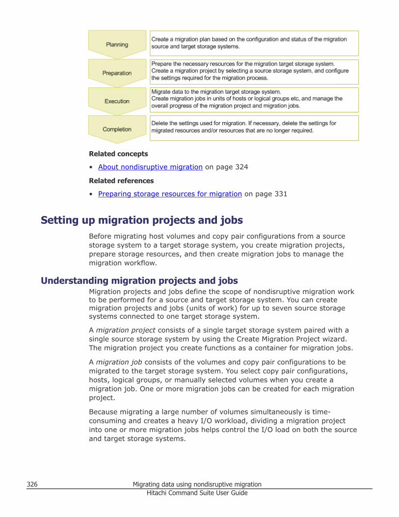
Related concepts
• About nondisruptive migration on page 324
Related references
• Preparing storage resources for migration on page 331
Setting up migration projects and jobsBefore migrating host volumes and copy pair configurations from a sourcestorage system to a target storage system, you create migration projects,prepare storage resources, and then create migration jobs to manage themigration workflow.
Understanding migration projects and jobsMigration projects and jobs define the scope of nondisruptive migration workto be performed for a source and target storage system. You can createmigration projects and jobs (units of work) for up to seven source storagesystems connected to one target storage system.
A migration project consists of a single target storage system paired with asingle source storage system by using the Create Migration Project wizard.The migration project you create functions as a container for migration jobs.
A migration job consists of the volumes and copy pair configurations to bemigrated to the target storage system. You select copy pair configurations,hosts, logical groups, or manually selected volumes when you create amigration job. One or more migration jobs can be created for each migrationproject.
Because migrating a large number of volumes simultaneously is time-consuming and creates a heavy I/O workload, dividing a migration projectinto one or more migration jobs helps control the I/O load on both the sourceand target storage systems.
326 Migrating data using nondisruptive migrationHitachi Command Suite User Guide
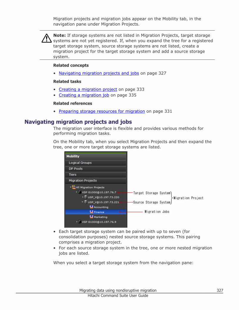
Migration projects and migration jobs appear on the Mobility tab, in thenavigation pane under Migration Projects.
Note: If storage systems are not listed in Migration Projects, target storagesystems are not yet registered. If, when you expand the tree for a registeredtarget storage system, source storage systems are not listed, create amigration project for the target storage system and add a source storagesystem.
Related concepts
• Navigating migration projects and jobs on page 327
Related tasks
• Creating a migration project on page 333• Creating a migration job on page 335
Related references
• Preparing storage resources for migration on page 331
Navigating migration projects and jobsThe migration user interface is flexible and provides various methods forperforming migration tasks.
On the Mobility tab, when you select Migration Projects and then expand thetree, one or more target storage systems are listed.
• Each target storage system can be paired with up to seven (forconsolidation purposes) nested source storage systems. This pairingcomprises a migration project.
• For each source storage system in the tree, one or more nested migrationjobs are listed.
When you select a target storage system from the navigation pane:
Migrating data using nondisruptive migration 327Hitachi Command Suite User Guide
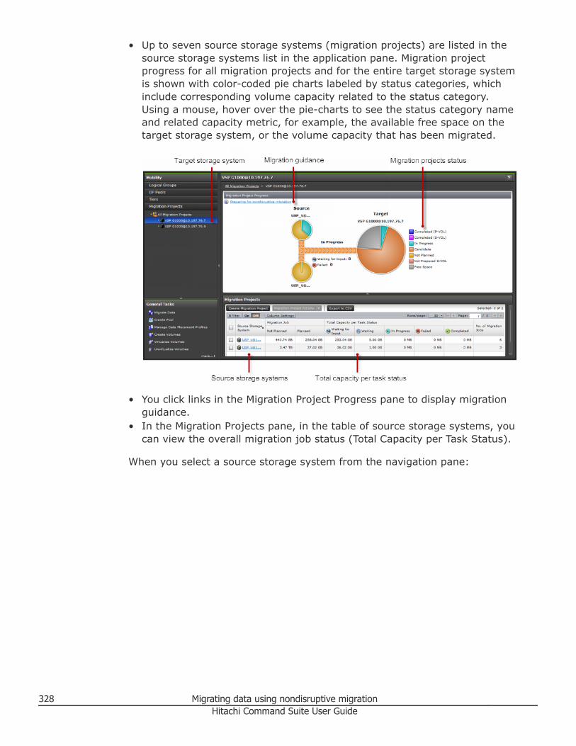
• Up to seven source storage systems (migration projects) are listed in thesource storage systems list in the application pane. Migration projectprogress for all migration projects and for the entire target storage systemis shown with color-coded pie charts labeled by status categories, whichinclude corresponding volume capacity related to the status category.Using a mouse, hover over the pie-charts to see the status category nameand related capacity metric, for example, the available free space on thetarget storage system, or the volume capacity that has been migrated.
• You click links in the Migration Project Progress pane to display migrationguidance.
• In the Migration Projects pane, in the table of source storage systems, youcan view the overall migration job status (Total Capacity per Task Status).
When you select a source storage system from the navigation pane:
328 Migrating data using nondisruptive migrationHitachi Command Suite User Guide
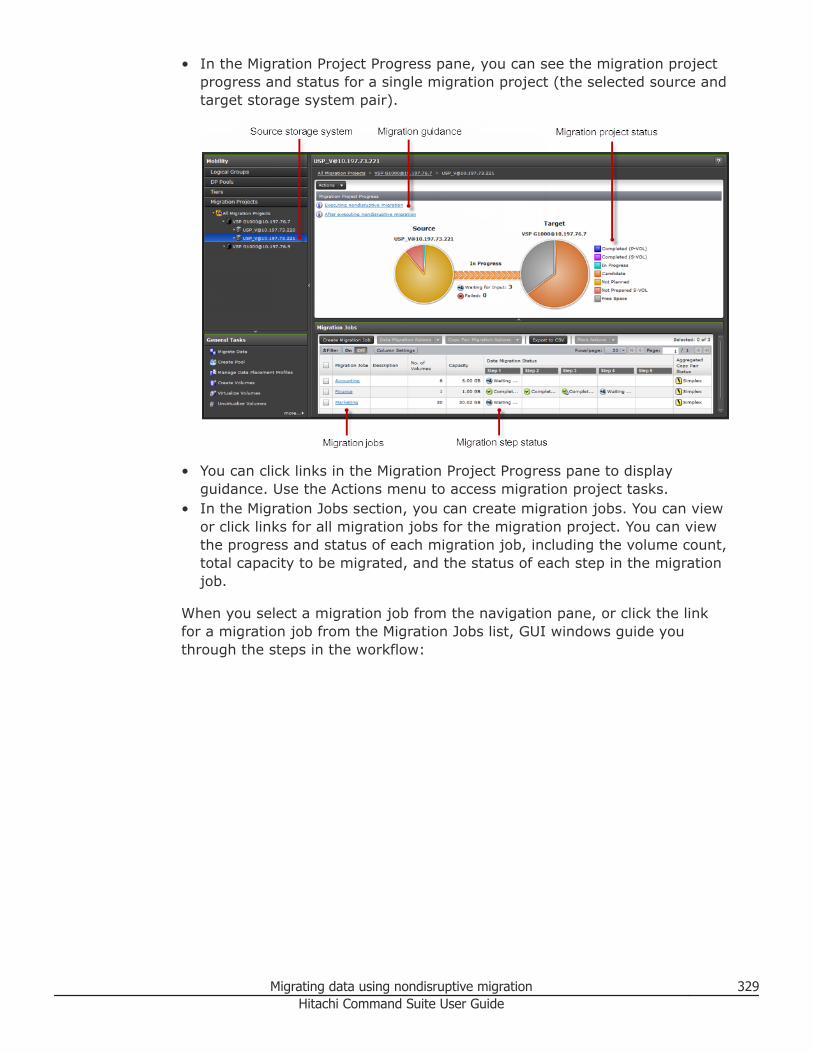
• In the Migration Project Progress pane, you can see the migration projectprogress and status for a single migration project (the selected source andtarget storage system pair).
• You can click links in the Migration Project Progress pane to displayguidance. Use the Actions menu to access migration project tasks.
• In the Migration Jobs section, you can create migration jobs. You can viewor click links for all migration jobs for the migration project. You can viewthe progress and status of each migration job, including the volume count,total capacity to be migrated, and the status of each step in the migrationjob.
When you select a migration job from the navigation pane, or click the linkfor a migration job from the Migration Jobs list, GUI windows guide youthrough the steps in the workflow:
Migrating data using nondisruptive migration 329Hitachi Command Suite User Guide
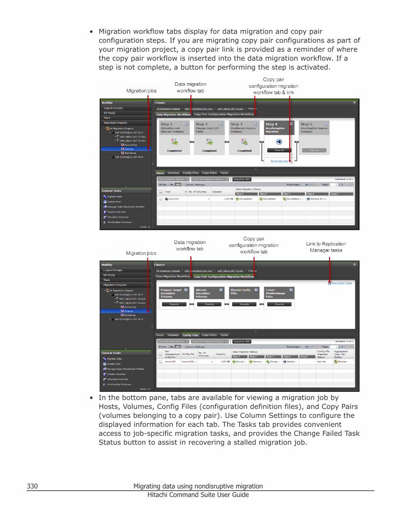
• Migration workflow tabs display for data migration and copy pairconfiguration steps. If you are migrating copy pair configurations as part ofyour migration project, a copy pair link is provided as a reminder of wherethe copy pair workflow is inserted into the data migration workflow. If astep is not complete, a button for performing the step is activated.
• In the bottom pane, tabs are available for viewing a migration job byHosts, Volumes, Config Files (configuration definition files), and Copy Pairs(volumes belonging to a copy pair). Use Column Settings to configure thedisplayed information for each tab. The Tasks tab provides convenientaccess to job-specific migration tasks, and provides the Change Failed TaskStatus button to assist in recovering a stalled migration job.
330 Migrating data using nondisruptive migrationHitachi Command Suite User Guide
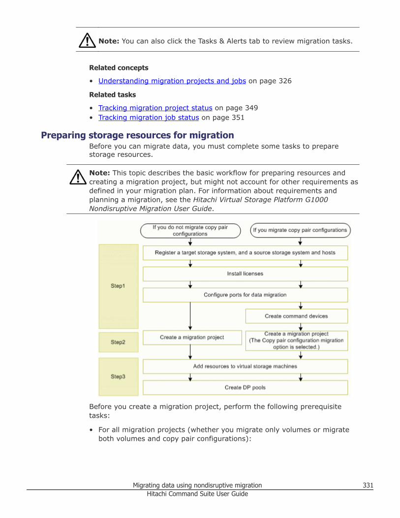
Note: You can also click the Tasks & Alerts tab to review migration tasks.
Related concepts
• Understanding migration projects and jobs on page 326
Related tasks
• Tracking migration project status on page 349• Tracking migration job status on page 351
Preparing storage resources for migrationBefore you can migrate data, you must complete some tasks to preparestorage resources.
Note: This topic describes the basic workflow for preparing resources andcreating a migration project, but might not account for other requirements asdefined in your migration plan. For information about requirements andplanning a migration, see the Hitachi Virtual Storage Platform G1000Nondisruptive Migration User Guide.
Before you create a migration project, perform the following prerequisitetasks:
• For all migration projects (whether you migrate only volumes or migrateboth volumes and copy pair configurations):
Migrating data using nondisruptive migration 331Hitachi Command Suite User Guide
○ Create a migration plan for each source and target storage system to bepaired.
○ Register the target storage system in HCS.○ Register the source storage system in HCS.○ Register hosts in HCS that include volumes or copy pair configurations
that you intend to migrate. If copy pair configurations are included,refresh the storage system.
○ Install the nondisruptive migration license on the target storage system.○ Configure the external ports on the target storage system to use for
data migration.
• For copy pair configuration migration projects:○ Register a host (pair management server) that manages the
configuration definition files in HCS, and refresh the storage system.○ Create the target storage system command device and allocate it to the
pair management server.○ Create the command device in the resource group (meta_resource) on
the target storage system whose resource group ID is 0.○ To connect the command device, use a port that is different from the
one that manages the migration target volume that is used fornondisruptive migration.
○ Disable user authentication for the command device.○ Change instances of HORCM_LDEVG to HORCM_LDEV. You cannot
migrate configuration definition files in which HORCM_LDEVG is defined.The list of available configuration definition files will not include anyconfiguration definition files in which HORCM_LDEVG is defined.
After you complete the prerequisite tasks, create the migration project usingthe Create Migration Project wizard:• Pair the target and source storage systems.• Create a virtual storage machine on the target storage system.• Select the option for migrating copy pair configurations. If you do so, the
copy pair configuration migration workflow will be used.• Set up storage port mappings for host I/O alternate paths.• Configure external paths for data migration between source and target
storage systems.
After you create the migration project:• Add necessary resources to the virtual storage machine.• If necessary, create one or more DP pools on the target storage system to
provide DP volumes for migration.
Related concepts
• Methods for registering hosts on page 63
332 Migrating data using nondisruptive migrationHitachi Command Suite User Guide
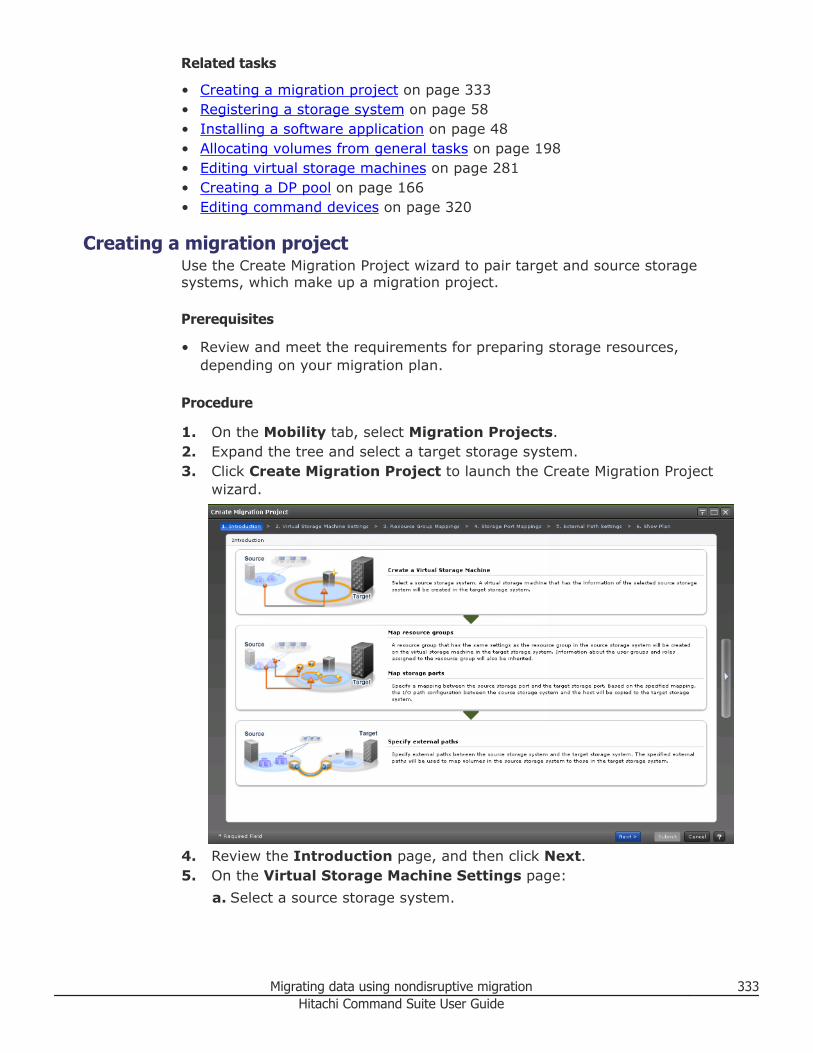
Related tasks
• Creating a migration project on page 333• Registering a storage system on page 58• Installing a software application on page 48• Allocating volumes from general tasks on page 198• Editing virtual storage machines on page 281• Creating a DP pool on page 166• Editing command devices on page 320
Creating a migration projectUse the Create Migration Project wizard to pair target and source storagesystems, which make up a migration project.
Prerequisites
• Review and meet the requirements for preparing storage resources,depending on your migration plan.
Procedure
1. On the Mobility tab, select Migration Projects.2. Expand the tree and select a target storage system.3. Click Create Migration Project to launch the Create Migration Project
wizard.
4. Review the Introduction page, and then click Next.5. On the Virtual Storage Machine Settings page:
a. Select a source storage system.
Migrating data using nondisruptive migration 333Hitachi Command Suite User Guide
b. Accept the displayed virtual storage machine name, or enter a validvirtual storage machine name.
c. (Optional) Select the Migrate SI Pair Configuration option to enablemigration of copy pair configurations.If you select this option, do not make any changes to the configurationdefinition files until the migration is complete.
Note:• Valid configuration definition files are indicated by Yes in the Can the
Copy Pair be Migrated column. If No appears in this column for oneor more of the configuration definition files you want to migrate, clickCancel, fix the configuration definition files, refresh hosts and thestorage system, and then create the migration project again. For moreinformation, see the planning chapter of the Hitachi Virtual StoragePlatform G1000 Nondisruptive Migration User Guide.
• When you finish creating the migration project, all source storagesystem configuration definition files are copied to the followinglocations, whether or not configuration definition files are valid:For Windows:Device-Manager-agent-installation-folder\agent\config\migration\backupFor UNIX:Device-Manager-agent-installation-directory/agent/config/migration/backup
6. Click Next.7. On the Resource Group Mappings page, click Next.8. On the Storage Port Mappings page, specify the mapping between the
source and target storage ports, and then click Next.You can verify the port details for each selected target storage port in thePort Details table.
9. On the External Path Settings page, configure the external pathsbetween the port of the source storage system and the external port ofthe target storage system. Click Increase Priority or DecreasePriority to adjust the priority of the path. Click Edit External Paths toverify the external path configuration, to edit external paths using thetopographical map or selection table, or to clear external path settings.When you are finished, click Next.
10. On the Show Plan page, confirm that the information in the plansummary and plan details are correct. If changes are required, clickBack.
11. (Optional) Update the task name and provide a description.12. (Optional) Expand Schedule to specify the task schedule.
You can schedule the task to run immediately or later. The default settingis Now. If the task is scheduled to run immediately, you can select Viewtask status to monitor the task after it is submitted.
334 Migrating data using nondisruptive migrationHitachi Command Suite User Guide
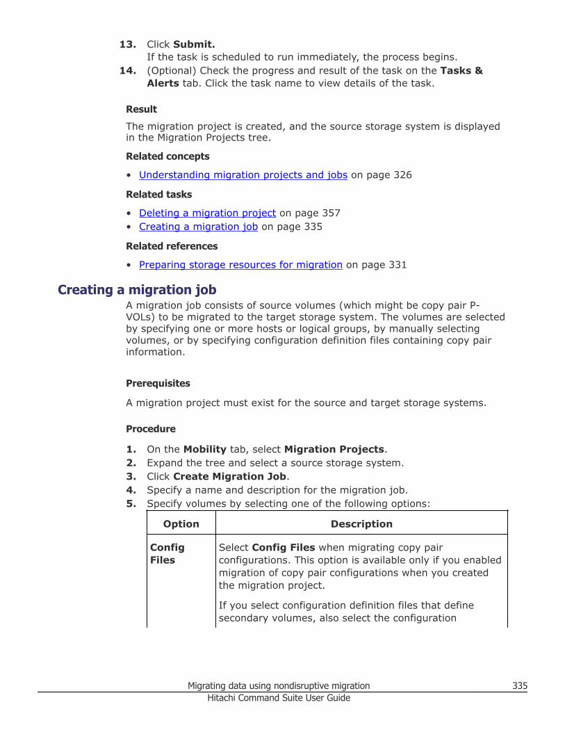
13. Click Submit.If the task is scheduled to run immediately, the process begins.
14. (Optional) Check the progress and result of the task on the Tasks &Alerts tab. Click the task name to view details of the task.
Result
The migration project is created, and the source storage system is displayedin the Migration Projects tree.
Related concepts
• Understanding migration projects and jobs on page 326
Related tasks
• Deleting a migration project on page 357• Creating a migration job on page 335
Related references
• Preparing storage resources for migration on page 331
Creating a migration jobA migration job consists of source volumes (which might be copy pair P-VOLs) to be migrated to the target storage system. The volumes are selectedby specifying one or more hosts or logical groups, by manually selectingvolumes, or by specifying configuration definition files containing copy pairinformation.
Prerequisites
A migration project must exist for the source and target storage systems.
Procedure
1. On the Mobility tab, select Migration Projects.2. Expand the tree and select a source storage system.3. Click Create Migration Job.4. Specify a name and description for the migration job.5. Specify volumes by selecting one of the following options:
Option Description
ConfigFiles
Select Config Files when migrating copy pairconfigurations. This option is available only if you enabledmigration of copy pair configurations when you createdthe migration project.
If you select configuration definition files that definesecondary volumes, also select the configuration
Migrating data using nondisruptive migration 335Hitachi Command Suite User Guide
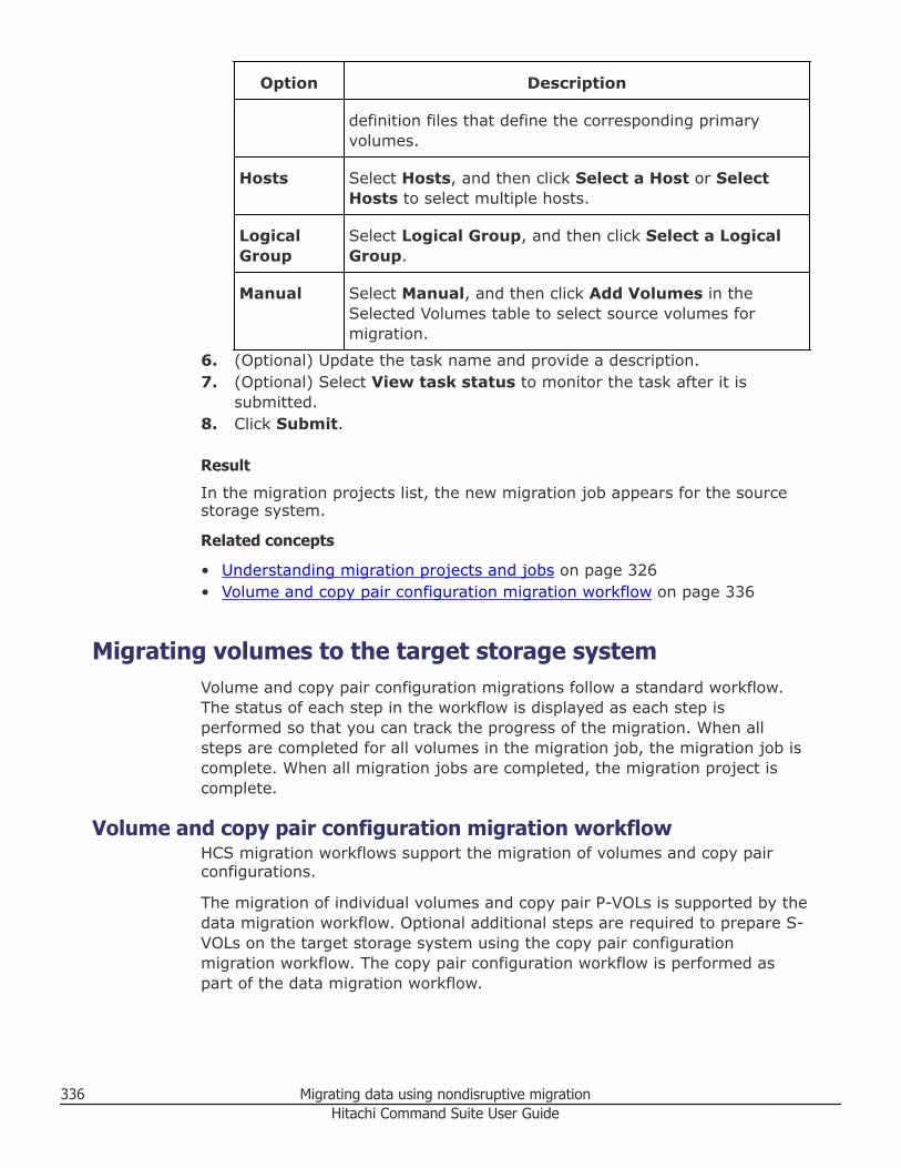
Option Description
definition files that define the corresponding primaryvolumes.
Hosts Select Hosts, and then click Select a Host or SelectHosts to select multiple hosts.
LogicalGroup
Select Logical Group, and then click Select a LogicalGroup.
Manual Select Manual, and then click Add Volumes in theSelected Volumes table to select source volumes formigration.
6. (Optional) Update the task name and provide a description.7. (Optional) Select View task status to monitor the task after it is
submitted.8. Click Submit.
Result
In the migration projects list, the new migration job appears for the sourcestorage system.
Related concepts
• Understanding migration projects and jobs on page 326• Volume and copy pair configuration migration workflow on page 336
Migrating volumes to the target storage systemVolume and copy pair configuration migrations follow a standard workflow.The status of each step in the workflow is displayed as each step isperformed so that you can track the progress of the migration. When allsteps are completed for all volumes in the migration job, the migration job iscomplete. When all migration jobs are completed, the migration project iscomplete.
Volume and copy pair configuration migration workflowHCS migration workflows support the migration of volumes and copy pairconfigurations.
The migration of individual volumes and copy pair P-VOLs is supported by thedata migration workflow. Optional additional steps are required to prepare S-VOLs on the target storage system using the copy pair configurationmigration workflow. The copy pair configuration workflow is performed aspart of the data migration workflow.
336 Migrating data using nondisruptive migrationHitachi Command Suite User Guide
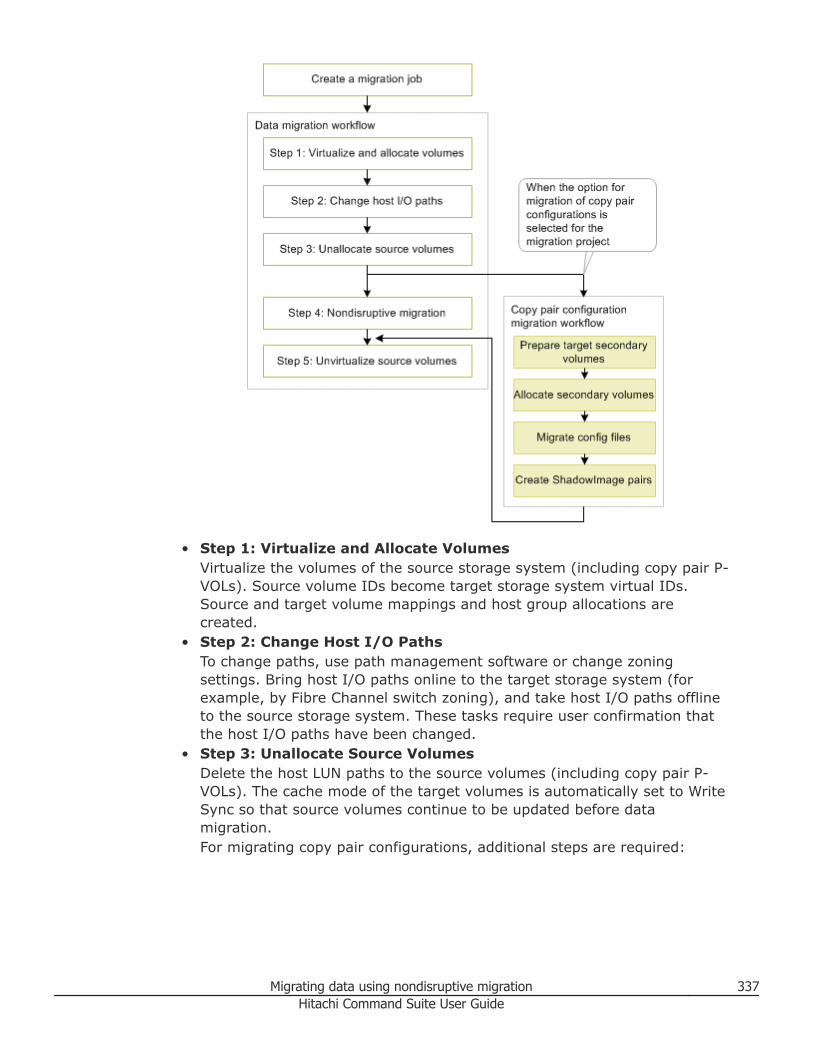
• Step 1: Virtualize and Allocate VolumesVirtualize the volumes of the source storage system (including copy pair P-VOLs). Source volume IDs become target storage system virtual IDs.Source and target volume mappings and host group allocations arecreated.
• Step 2: Change Host I/O PathsTo change paths, use path management software or change zoningsettings. Bring host I/O paths online to the target storage system (forexample, by Fibre Channel switch zoning), and take host I/O paths offlineto the source storage system. These tasks require user confirmation thatthe host I/O paths have been changed.
• Step 3: Unallocate Source VolumesDelete the host LUN paths to the source volumes (including copy pair P-VOLs). The cache mode of the target volumes is automatically set to WriteSync so that source volumes continue to be updated before datamigration.For migrating copy pair configurations, additional steps are required:
Migrating data using nondisruptive migration 337Hitachi Command Suite User Guide
Note: To maintain copy pair redundancy during volume migration(recommended), complete the copy pair configuration migration workflowbefore performing nondisruptive migration (step 4). Alternatively, you canperform the copy pair configuration migration workflow after nondisruptivemigration (step 4) is complete for the P-VOL, and before unvirtualizingsource volumes (step 5).
○ Prepare Target Secondary VolumesOn the target storage system, create volumes to use as S-VOLs for P-VOLs whose data will be migrated. The source S-VOL ID is used as thevirtual LDEV ID of target S-VOL. Assign target S-VOLs to a host group.
○ Allocate Secondary VolumesDelete the paths from S-VOLs on the source storage system to thebackup server, and then allocate the S-VOLs on the target storagesystem to the backup server. Remove the backup server WWN from thesource host group, and add the backup server WWN to the target hostgroup.
○ Migrate Config FilesSelect source storage system configuration definition files to bemigrated to the target storage system environment.
○ Create ShadowImage PairsReestablish source storage system copy pairs on the target storagesystem using the Change Pair Status Wizard in Replication Manager.
• Step 4: Nondisruptive MigrationMigrate source volume data to the target volume for data migration.
Note: In this guide, target volume means the virtualized source volumethat resolves to the target volume, and target volume for data migrationmeans the physical target storage system volume to which migration datawill be written.
• Step 5: Unvirtualize Source VolumesAfter data migration is completed, unvirtualize the source volumes. If thesource volume is a copy pair volume, delete the copy pair from the sourcestorage system before unvirtualizing the source volume.
Related tasks
• Creating a migration job on page 335• Step 1: Virtualize and Allocate Volumes on page 339• Step 2: Change host I/O paths on page 340• Step 3: Unallocate source volumes on page 341• Step 4: Nondisruptive migration on page 342• Step 5: Unvirtualize source volumes on page 344• Preparing target secondary volumes on page 345• Allocating target secondary volumes on page 346
338 Migrating data using nondisruptive migrationHitachi Command Suite User Guide
• Migrating configuration definition files on page 347• Creating copy pairs on the target storage system on page 348
Step 1: Virtualize and Allocate VolumesTo migrate data, you must virtualize source volumes and allocate them to thetarget storage system.
Prerequisites• A migration job must exist for the migration project.• Verify that the target host is not registered in host groups that have
different host modes or host mode options.• Verify that if the target host is already registered in a host group of the
target storage system, that the WWNs of the host group of the targetstorage system and corresponding host group of the source storagesystem are the same.
Procedure
1. On the Mobility tab, select Migration Projects.2. Expand the tree for a source storage system, and select a migration job.3. On the Data Migration Workflow tab, click Execute for Step 1:
Virtualize and Allocate Volumes.
Note: To resume a step for one or more migration job resources, forexample, resources with a failed step task or sub-task, select theresources, and from the Data Migration Actions menu, select the stepto resume.
4. On the Virtualize Volumes Setting page, verify the source and targetstorage systems and the migration job name.
5. (Optional) Change the parity group start number setting.For example, even though parity groups are automatically numberedstarting from 1, you can add another source storage system to a targetstorage system and select a start number to easily differentiate thesource of the parity groups.
6. (Optional) Change the cache logical partition (CLPR) to be used for amigration.
7. Verify the external path information, and then click Next.8. On the Allocate Volumes Setting page, click the Volume Path tab,
and confirm the volume path mapping between source and targetvolumes.
9. Click the Host Group tab and click the provided links to verify hostgroup mapping and other information, such as the scope of LUNSecurity and that the Host Group Attributes have not changed for thesource and target.
Migrating data using nondisruptive migration 339Hitachi Command Suite User Guide
10. Click Edit Host Group Setting to verify or change the host group nameand the resource group for the host group.
11. Click Next.12. On the Show Plan page, verify the plan summary and plan details,
optionally add a task name and description, and then click Submit.13. Confirm this task is Completed for the migration job.
Result
Source volumes are virtualized and allocated to hosts in the target storagesystem.
Related tasks
• Step 2: Change host I/O paths on page 340
Related references
• Preparing storage resources for migration on page 331
Step 2: Change host I/O pathsTo redirect host I/O to the target storage system, host I/O paths must beonline for the target storage system and offline for the source storagesystem.
Prerequisites
Volumes must be virtualized and allocated.
Procedure
1. On the Mobility tab, select Migration Projects.2. Expand the tree for a source storage system, and select a migration job.3. On the Data Migration Workflow tab, click Execute for Step 2:
Change Host I/O Paths.
Note: To resume performing a step on one or more migration jobresources, for example, resources with a failed step task or sub-task,select the resources, and from the Data Migration Actions menu,select the step to resume.
4. In the Change Host I/O Paths window, carefully review the Step 1instructions for changing and verifying the status of host I/O paths to thetarget storage system.
Note: This window only displays information about path changes. Tochange paths, you must use path management software or changezoning settings.
340 Migrating data using nondisruptive migrationHitachi Command Suite User Guide
To help you review and make the necessary changes, click Export toCSV to create a file that you can reference for the target LUN pathinformation.
5. Verify the target LUN path information, and then select the check boxlabeled I have confirmed that all target LUN paths are online.
6. Review the Step 2 instructions for changing and verifying the status ofhost I/O paths to the source storage system. To help you review thesource LUN path information, click Export to CSV to create a file thatyou can reference.
7. Verify the source LUN path information, and then select the check boxlabeled I have confirmed that all source LUN paths are offline.
8. (Optional) Update the task name and provide a description.9. Click OK to submit the task.
10. Confirm this task is Completed for the migration job.
Result
Host I/O paths are online to the target storage system and offline for thesource storage system.
Related tasks
• Step 1: Virtualize and Allocate Volumes on page 339• Step 3: Unallocate source volumes on page 341
Related references
• Preparing storage resources for migration on page 331
Step 3: Unallocate source volumesDelete the source storage system LUN paths for hosts with migration sourcevolumes, and change the cache mode on the target storage system.
Prerequisites
Host I/O paths must be online for the target storage system and offline forthe source storage system.
Procedure
1. On the Mobility tab, select Migration Projects.2. Expand the tree for a source storage system, and select a migration job.3. On the Data Migration Workflow tab, click Execute for Step 3:
Unallocate Source Volumes.
Note: To resume performing a step on one or more migration jobresources, for example, resources with a failed step task or sub-task,select the resources, and from the Data Migration Actions menu,select the step to resume.
Migrating data using nondisruptive migration 341Hitachi Command Suite User Guide
4. Verify the source LUN path information.The target storage system cache mode is automatically changed fromThrough to Write Sync to forward write I/O to the source storage systemvolume.
5. (Optional) Update the task name and provide a description.6. (Optional) Expand Schedule to specify the task schedule.
You can schedule the task to run immediately or later. The default settingis Now. If the task is scheduled to run immediately, you can select Viewtask status to monitor the task after it is submitted.
7. Click Submit.If the task is scheduled to run immediately, the process begins.
8. Confirm this task is Completed for the migration job.
Result
Source volumes are unallocated from the host, the cache mode is set toWrite Sync, and host I/O continues to update the source volume.
Postrequisites
If you are migrating copy pair configurations, follow the copy pairconfiguration migration workflow before continuing to Step 4: NondisruptiveMigration. Alternatively, you can perform the copy pair configurationmigration workflow after nondisruptive migration (step 4) is complete for theP-VOL, but before you unvirtualize the source volumes (step 5).
Related tasks
• Step 2: Change host I/O paths on page 340• Step 4: Nondisruptive migration on page 342• Preparing target secondary volumes on page 345
Related references
• Preparing storage resources for migration on page 331
Step 4: Nondisruptive migrationMigrate source volume data to the target volume for data migration.
Note: To maintain copy pair redundancy during volume migration(recommended), complete the copy pair configuration migration workflowbefore performing nondisruptive migration (step 4). Alternatively, you canperform the copy pair configuration migration workflow after nondisruptivemigration (step 4) is complete for the P-VOL, but before unvirtualizing sourcevolumes (step 5).
Prerequisites
Source volumes must be unallocated.
342 Migrating data using nondisruptive migrationHitachi Command Suite User Guide
Procedure
1. On the Mobility tab, select Migration Projects.2. Expand the tree for a source storage system, and select a migration job.3. On the Data Migration Workflow tab, click Execute for Step 4:
Nondisruptive Migration.
Note: To resume performing a step on one or more migration jobresources, for example, resources with a failed step task or sub-task,select the resources, and from the Data Migration Actions menu,select the step to resume.
4. Verify the source and target storage systems and migration job name.The estimated migration time is shown for the migration job.
5. Click Set Target Volumes for Data Migration to specify a specific DPpool or parity group for the target volume for data migration, and thenselect either Create new volumes or Use existing volumes. Click OK.
6. (Optional) Select Zero Page Reclaim to reclaim capacity aftermigration. This option is enabled by default. Zero page reclaim can takea long time. The estimated time is shown next to the check box. If youclear the check box, you can perform zero page reclaim after themigration job completes.
7. (Optional) Select the option to send email notification to a specified emailaddress when the data migration completes.
Note: Email notifications for Tiered Storage Manager events must be setup in advance. For more information see the Hitachi Command SuiteAdministrator Guide.
8. (Optional) Update the task name and provide a description.9. (Optional) Expand Schedule to specify the task schedule.
You can schedule the task to run immediately or later. The default settingis Now. If the task is scheduled to run immediately, you can select Viewtask status to monitor the task after it is submitted.
10. Click Submit.If the task is scheduled to run immediately, the process begins.
11. Confirm this task is Completed for the migration job.
Result
Source volume data is migrated to target volumes for data migration.
Related tasks
• Step 3: Unallocate source volumes on page 341• Step 5: Unvirtualize source volumes on page 344
Migrating data using nondisruptive migration 343Hitachi Command Suite User Guide
Related references
• Preparing storage resources for migration on page 331
Step 5: Unvirtualize source volumesUnvirtualize source storage system volumes in the target storage system.
Prerequisites• The migration of the data must be completed.• Copy pair configuration migration workflow steps (started after step 3 or
step 4) must be completed.• If the source volume is a ShadowImage copy pair volume, delete the
source storage system copy pair before you unvirtualize the volume.
Procedure
1. On the Mobility tab, select Migration Projects.2. Expand the tree for a source storage system, and select a migration job.3. On the Data Migration Workflow tab, click Execute for Step 5:
Unvirtualize Source Volumes.
Note: To resume performing a step on one or more migration jobresources, for example, resources with a failed step task or sub-task,select the resources, and from the Data Migration Actions menu,select the step to resume.
4. Verify that the Plan Summary information is correct.5. Verify the list of source volumes to unvirtualize and their corresponding
internal volume and parity group information.6. Verify the external paths to be unallocated.7. (Optional) Update the task name and provide a description.8. (Optional) Expand Schedule to specify the task schedule.
You can schedule the task to run immediately or later. The default settingis Now. If the task is scheduled to run immediately, you can select Viewtask status to monitor the task after it is submitted.
9. Click Submit.If the task is scheduled to run immediately, the process begins.
10. Confirm this task is Completed for the migration job.
Result
Source volumes are unvirtualized and the migration job is completed.
Related concepts
• Volume and copy pair configuration migration workflow on page 336
Related tasks
• Step 4: Nondisruptive migration on page 342
344 Migrating data using nondisruptive migrationHitachi Command Suite User Guide
Related references
• Preparing storage resources for migration on page 331
Migrating copy pair configurations to the target storagesystem
Copy pair configurations can be migrated from the source storage system tothe target storage system using the copy pair configuration migrationworkflow. Copy pair redundancy can be maintained throughout the migrationprocess. Configuration definition files are backed up, and are inherited by thetarget storage system for reestablishing copy pairs.
Preparing target secondary volumesCreate S-VOLs on the target storage system. The source S-VOL ID becomesthe virtual LDEV ID of target storage system S-VOLs.
Prerequisites
• Source volumes must be unallocated.• A target storage system command device must be created and allocated to
the pair management server.• The option to migrate copy pair configurations was selected when the
migration project was created.
Procedure
1. On the Mobility tab, select Migration Projects.2. Expand the tree for a source storage system, and select a migration job.3. Verify that steps 1 through step 3 on the Data Migration Workflow tab
are completed, and then click the Go to copy pair link.4. On the Copy Pair Configuration Migration Workflow tab, click
Execute for Prepare Target Secondary Volumes.5. On the Create Target Secondary Volumes page, select the S-VOL,
and then click Set Target Secondary Volumes to specify a specific DPPool or Parity Group for the target S-VOL, and then select Create newvolumes or Use existing volumes. Click OK.
6. In the Target Pools/Parity Groups Information area, review thecapacity changes for DP pools or parity groups.
7. Repeat steps 5 and 6 for each displayed source and target S-VOL pair,and then click Next.
8. On the Set Paths for Target Secondary Volumes page, compare theLUN path between the source secondary volume and the backup serverwith the corresponding LUN path setting of the target storage system.On the Volumes tab, you can see which backup server is allocated toeach volume. On the Host Groups tab, you can compare the host group
Migrating data using nondisruptive migration 345Hitachi Command Suite User Guide
settings. As required, edit the names of the host groups created on thetarget storage system and the resource groups in which the host groupswill be created. Enter the necessary settings, and then click Next.
9. Review the plan, and then click Submit.10. Confirm this task is completed.
Result
Target storage system secondary volumes are prepared.
Related tasks
• Step 3: Unallocate source volumes on page 341• Allocating target secondary volumes on page 346
Related references
• Preparing storage resources for migration on page 331
Allocating target secondary volumesDelete the backup server paths for source storage system S-VOLs, and thenestablish backup server paths for target storage system S-VOLs.
Prerequisites
• Source volumes must be unallocated.• The target storage system secondary volumes are prepared.• Stop the backup script that is running on the backup server.
Procedure
1. On the Mobility tab, select Migration Projects.2. Expand the tree for a source storage system, and select a migration job.3. On the Copy Pair Configuration Migration Workflow tab, click
Execute for Allocate Secondary Volumes.4. Note the host group information for the source and target storage
systems, which will assist you when you are changing the backup serverpaths from the source storage system to the target storage system.
5. Delete the source storage system backup server WWN:a. Launch Element Manager to run the native management tool for the
source storage system to delete the backup server WWN from the hostgroup of the source storage system.
b. Verify that the backup server WWN has been deleted from the hostgroup of the source storage system.
6. Add the backup server WWN to the target storage system:a. On the Resources tab, for the target storage system, select Ports/
Host Groups and add the backup server WWN to the host group ofthe target storage system.
346 Migrating data using nondisruptive migrationHitachi Command Suite User Guide
b. Verify that the backup server WWN has been added to the host groupof the target storage system.
Result
Backup server paths for source storage system S-VOLs are deleted, andbackup server paths for target storage system S-VOLs are created.
Related tasks
• Step 3: Unallocate source volumes on page 341• Migrating configuration definition files on page 347• Starting Element Manager on page 499
Related references
• Preparing storage resources for migration on page 331
Migrating configuration definition filesFor the migration job, selected configuration definition files can be migratedfor use on the target storage system.
Prerequisites
• Source volumes must be unallocated.• Target secondary volumes must be allocated.
Procedure
1. On the Mobility tab, select Migration Projects.2. Expand the tree for a source storage system, and select a migration job.3. On the Copy Pair Configuration Migration Workflow tab, click
Migrate Config Files.4. Click Add/Remove Config Files.
Note: The configuration definition file to be migrated must be specifiedin HORCM_LDEV format. Files in which HORCM_LDEVG is defined cannotbe migrated and does not appear in the list.
5. Click Add and Remove to populate the list of configuration definitionfiles to be migrated, and then click OK.
6. (Optional) Update the task name and provide a description.7. (Optional) Expand Schedule to specify the task schedule.
You can schedule the task to run immediately or later. The default settingis Now. If the task is scheduled to run immediately, you can select Viewtask status to monitor the task after it is submitted.
8. Click Submit.If the task is scheduled to run immediately, the process begins.
9. Confirm this task is Completed for the migration job.
Migrating data using nondisruptive migration 347Hitachi Command Suite User Guide
Result
Configuration definition files are migrated for use on the target storagesystem. HORCM instances for the migrated configuration definition files arerestarted. If a HORCM instance is running on the source storage system, theconfiguration definition file is migrated to the target storage system.
Related tasks
• Step 3: Unallocate source volumes on page 341• Creating copy pairs on the target storage system on page 348
Related references
• Preparing storage resources for migration on page 331
Creating copy pairs on the target storage systemCreate ShadowImage pairs on the target storage system based on migratedconfiguration definition files.
Prerequisites
• Source volumes must be unallocated.• Migration of configuration definition files must be completed.• Review the limitations for creating copy pairs in the Hitachi Virtual Storage
Platform G1000 Nondisruptive Migration User Guide.
Procedure
1. On the Mobility tab, select Migration Projects.2. Expand the tree for a source storage system, and select a migration job.3. On the Copy Pair Configuration Migration Workflow tab, click
Execute for Create ShadowImage Pairs.4. In the Create ShadowImage Pairs dialog box, select the copy group
you want.5. Click Create Copy Pairs.6. In the Replication Manager Change Pair Status Wizard, on the Select
Copy Pairs page, select the copy pair you want and click Next.7. On the Select Pair Operation page, review the copy pair information
and click Next.8. On the Set Schedule page, select Execute on Schedule to schedule
the task for a specific date and time, or select Execute Immediately,and then click Next.
Note: You cannot edit the created task. If you want to reschedule thetask, delete it and create a new task.
9. On the Confirm page, verify the copy pair settings, select the check boxlabeled Yes. I have confirmed the above information and wish tochange pair status, and then click Confirm.
348 Migrating data using nondisruptive migrationHitachi Command Suite User Guide
10. On the Finish page, confirm the task and then click Finish. The task isregistered as a Replication Manager task.
11. To verify the status of the Replication Manager task:a. On the Copy Pair Configuration Migration Workflow tab, click
View HRpM Tasks to display the Replication Manager task list.b. Open the Create ShadowImage Pairs dialog box and check Status.
Result
Copy pairs are created on the target storage system.
Postrequisites
Restart the backup script of the backup server for the target storage systemif necessary.
Related tasks
• Step 4: Nondisruptive migration on page 342
Related references
• Preparing storage resources for migration on page 331
Managing migration projects and jobsAfter you create migration projects and jobs, you can monitor them andperform maintenance tasks on them.
Tracking migration project statusThe progress of migration projects is tracked and displayed graphically.
The following aggregated status information from migration jobs is displayed:• The total capacity of volumes for a migration project.
○ You can estimate the time required to complete the migration project byreviewing the remaining capacity and up-to-date elapsed time formigrations.
○ You can determine if you need to add physical storage capacity, orcreate additional DP pools, by comparing the data capacity to bemigrated against the free capacity of the target storage system.
• The completion state of migration jobs, which provides a snapshot ofremaining migration activity for project completion.
Prerequisites
A migration project with migration jobs must exist.
Procedure
1. On the Mobility tab, select Migration Projects.
Migrating data using nondisruptive migration 349Hitachi Command Suite User Guide
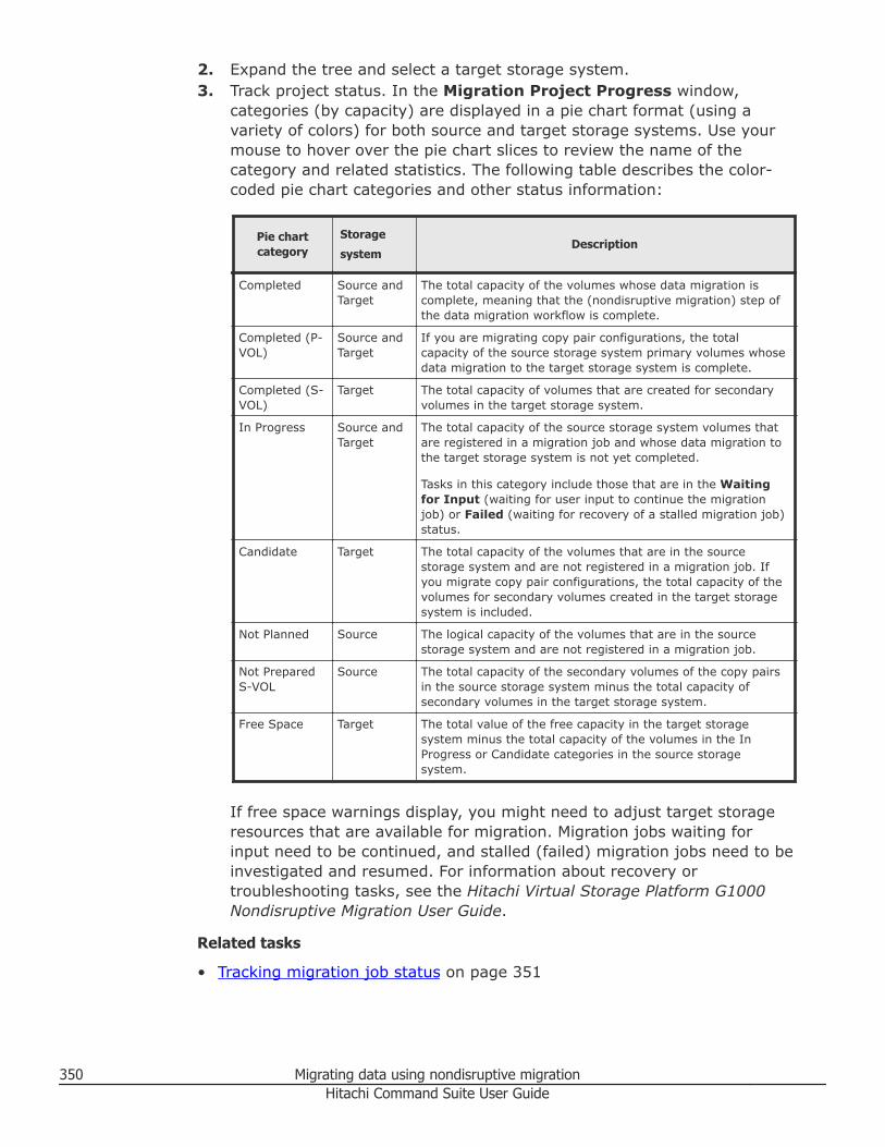
2. Expand the tree and select a target storage system.3. Track project status. In the Migration Project Progress window,
categories (by capacity) are displayed in a pie chart format (using avariety of colors) for both source and target storage systems. Use yourmouse to hover over the pie chart slices to review the name of thecategory and related statistics. The following table describes the color-coded pie chart categories and other status information:
Pie chartcategory
Storage
systemDescription
Completed Source andTarget
The total capacity of the volumes whose data migration iscomplete, meaning that the (nondisruptive migration) step ofthe data migration workflow is complete.
Completed (P-VOL)
Source andTarget
If you are migrating copy pair configurations, the totalcapacity of the source storage system primary volumes whosedata migration to the target storage system is complete.
Completed (S-VOL)
Target The total capacity of volumes that are created for secondaryvolumes in the target storage system.
In Progress Source andTarget
The total capacity of the source storage system volumes thatare registered in a migration job and whose data migration tothe target storage system is not yet completed.
Tasks in this category include those that are in the Waitingfor Input (waiting for user input to continue the migrationjob) or Failed (waiting for recovery of a stalled migration job)status.
Candidate Target The total capacity of the volumes that are in the sourcestorage system and are not registered in a migration job. Ifyou migrate copy pair configurations, the total capacity of thevolumes for secondary volumes created in the target storagesystem is included.
Not Planned Source The logical capacity of the volumes that are in the sourcestorage system and are not registered in a migration job.
Not PreparedS-VOL
Source The total capacity of the secondary volumes of the copy pairsin the source storage system minus the total capacity ofsecondary volumes in the target storage system.
Free Space Target The total value of the free capacity in the target storagesystem minus the total capacity of the volumes in the InProgress or Candidate categories in the source storagesystem.
If free space warnings display, you might need to adjust target storageresources that are available for migration. Migration jobs waiting forinput need to be continued, and stalled (failed) migration jobs need to beinvestigated and resumed. For information about recovery ortroubleshooting tasks, see the Hitachi Virtual Storage Platform G1000Nondisruptive Migration User Guide.
Related tasks
• Tracking migration job status on page 351
350 Migrating data using nondisruptive migrationHitachi Command Suite User Guide
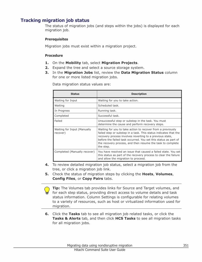
Tracking migration job statusThe status of migration jobs (and steps within the jobs) is displayed for eachmigration job.
Prerequisites
Migration jobs must exist within a migration project.
Procedure
1. On the Mobility tab, select Migration Projects.2. Expand the tree and select a source storage system.3. In the Migration Jobs list, review the Data Migration Status column
for one or more listed migration jobs.
Data migration status values are:
Status Description
Waiting for Input Waiting for you to take action.
Waiting Scheduled task.
In Progress Running task.
Completed Successful task.
Failed Unsuccessful step or substep in the task. You mustdetermine the cause and perform recovery steps.
Waiting for Input (Manuallyrecover)
Waiting for you to take action to recover from a previouslyfailed step or substep in a task. This status indicates that therecovery process involves reverting to a previous state,before the failed task occurred. You set this status as part ofthe recovery process, and then resume the task to completethe step.
Completed (Manually recover) You have resolved an issue that caused a failed state. You setthis status as part of the recovery process to clear the failureand allow the migration to proceed.
4. To review detailed migration job status, select a migration job from thetree, or click a migration job link.
5. Check the status of migration steps by clicking the Hosts, Volumes,Config Files, or Copy Pairs tabs.
Tip: The Volumes tab provides links for Source and Target volumes, andfor each step status, providing direct access to volume details and taskstatus information. Column Settings is configurable for relating volumesto a variety of resources, such as host or virtualized information used formigration.
6. Click the Tasks tab to see all migration job related tasks, or click theTasks & Alerts tab, and then click HCS Tasks to see all migration tasksfor all migration jobs.
Migrating data using nondisruptive migration 351Hitachi Command Suite User Guide
Note: To recover from conditions that cause a Failed status at themigration job step or substep level, see the Hitachi Virtual StoragePlatform G1000 Nondisruptive Migration User Guide for detailedtroubleshooting information and recommendations.
Related tasks
• Tracking migration project status on page 349• Changing the status of a failed migration job on page 353
About resuming failed migration jobsA migration job is performed in a series of steps, each step consisting of onetask and one or more sub-tasks. If the task or one or more sub-tasks fails, astatus of Failed is displayed for the step.
You cannot continue a migration job until you do one of the following items:• You must correct the failed task or failed sub-tasks for the step, and then
change status of the failed migration job so that the job can be resumed.You do this by:○ Correcting the state of a resource, and then manually changing the
failed job status to Completed (Manually recover) to indicate that theissue is corrected, which allows you to resume the job beginning withthe next step.
○ Restoring a resource to its previous state before the task or sub-taskwas executed, and then manually changing the failed job status toWaiting for Input (Manually recover) to indicate that the issue iscorrected, which allows you to resume the job at the failed step andthen continue with remaining steps.
• Under some circumstances one or more migration job volumes might needto be deleted, and added to a new migration job.
• Under some circumstances, a migration job might need to be deleted andre-created.
For information about how to recover from conditions causing a failed statusat the migration job step or sub-step level, see the Hitachi Virtual StoragePlatform G1000 Nondisruptive Migration User Guide, which provides detailedtroubleshooting information and recommendations for specific steps and sub-steps, including guidance on restoring a resource to its previous state, orcorrecting the state of a resource through remedial actions.
Related tasks
• Tracking migration job status on page 351• Changing the status of a failed migration job on page 353• Canceling a migration job on page 356• Canceling a volume from a migration job on page 356
352 Migrating data using nondisruptive migrationHitachi Command Suite User Guide
Changing the status of a failed migration jobIf a task fails, after recovery actions have been performed, change the statusof the failed task to continue the migration job.
Prerequisites
Correct the issue that is causing the failed task or subtask.
Caution: If you do not correct the issue that is causing a failed task or sub-task for a migration step before you change the status of the failed step toWaiting for Input (Manually recover) or Completed (Manually recover) in theChange Failed Task Status dialog box, the step cannot be resumed by usingthe GUI.
You must cancel (delete) affected volumes from the migration job, returnthem to the state before the task ran, and then create a new migration jobfor the volumes.
For information about how to recover from conditions that cause a failedstatus at the migration job step or sub-step level, see the Hitachi VirtualStorage Platform G1000 Nondisruptive Migration User Guide, which providesdetailed troubleshooting information and recommendations for specific stepsand sub-steps, including guidance on restoring a resource to its previousstate, or correcting the state of a resource through remedial actions.
Procedure
1. On the Mobility tab, select Migration Projects.2. Expand the tree, and select the migration job with the failed task.3. On the Volumes or Tasks tab, do one of the following:
• On the Volumes tab, select the volume for which recovery has beenperformed, and then from the More Actions menu, select ChangeFailed Task Status.
• On the Volumes or Tasks tab, locate the task for which recovery hasbeen performed, click the Failed status link, review task details, andclick Change Failed Task Status.
4. In the Change Failed Task Status dialog box, verify the displayedinformation, and then select the Status Change check box to confirmthat recovery has been performed.
5. From the Select a Status list, select one of the following:• Waiting for Input (Manually recover): Resumes the task from the
step during which the task failed.• Completed (Manually recover): Resumes the task from the next
step.
6. (Optional) Update the task name and provide a description.
Migrating data using nondisruptive migration 353Hitachi Command Suite User Guide
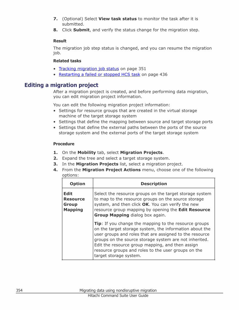
7. (Optional) Select View task status to monitor the task after it issubmitted.
8. Click Submit, and verify the status change for the migration step.
Result
The migration job step status is changed, and you can resume the migrationjob.
Related tasks
• Tracking migration job status on page 351• Restarting a failed or stopped HCS task on page 436
Editing a migration projectAfter a migration project is created, and before performing data migration,you can edit migration project information.
You can edit the following migration project information:• Settings for resource groups that are created in the virtual storage
machine of the target storage system• Settings that define the mapping between source and target storage ports• Settings that define the external paths between the ports of the source
storage system and the external ports of the target storage system
Procedure
1. On the Mobility tab, select Migration Projects.2. Expand the tree and select a target storage system.3. In the Migration Projects list, select a migration project.4. From the Migration Project Actions menu, choose one of the following
options:
Option Description
EditResourceGroupMapping
Select the resource groups on the target storage systemto map to the resource groups on the source storagesystem, and then click OK. You can verify the newresource group mapping by opening the Edit ResourceGroup Mapping dialog box again.
Tip: If you change the mapping to the resource groupson the target storage system, the information about theuser groups and roles that are assigned to the resourcegroups on the source storage system are not inherited.Edit the resource group mapping, and then assignresource groups and roles to the user groups on thetarget storage system.
354 Migrating data using nondisruptive migrationHitachi Command Suite User Guide
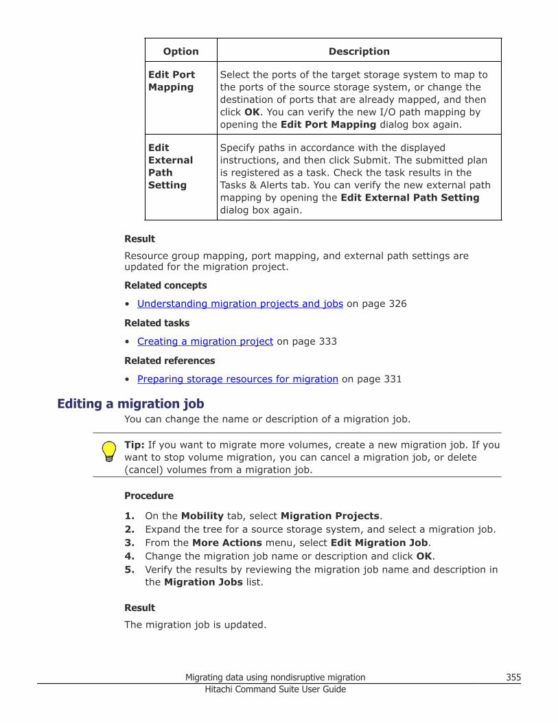
Option Description
Edit PortMapping
Select the ports of the target storage system to map tothe ports of the source storage system, or change thedestination of ports that are already mapped, and thenclick OK. You can verify the new I/O path mapping byopening the Edit Port Mapping dialog box again.
EditExternalPathSetting
Specify paths in accordance with the displayedinstructions, and then click Submit. The submitted planis registered as a task. Check the task results in theTasks & Alerts tab. You can verify the new external pathmapping by opening the Edit External Path Settingdialog box again.
Result
Resource group mapping, port mapping, and external path settings areupdated for the migration project.
Related concepts
• Understanding migration projects and jobs on page 326
Related tasks
• Creating a migration project on page 333
Related references
• Preparing storage resources for migration on page 331
Editing a migration jobYou can change the name or description of a migration job.
Tip: If you want to migrate more volumes, create a new migration job. If youwant to stop volume migration, you can cancel a migration job, or delete(cancel) volumes from a migration job.
Procedure
1. On the Mobility tab, select Migration Projects.2. Expand the tree for a source storage system, and select a migration job.3. From the More Actions menu, select Edit Migration Job.4. Change the migration job name or description and click OK.5. Verify the results by reviewing the migration job name and description in
the Migration Jobs list.
Result
The migration job is updated.
Migrating data using nondisruptive migration 355Hitachi Command Suite User Guide
Related tasks
• Creating a migration job on page 335
Canceling a migration jobYou can delete (cancel) a migration job that has not been started, meaningno migration activity has occurred. After you cancel a migration job, itsvolumes can be specified as migration source volumes in another migrationjob.
You can also delete a migration job in progress. However, to use the deletedvolumes of migration jobs for other migration jobs, you must manuallyrecover the volumes of the deleted migration jobs. To do so, follow theinstructions in displayed messages. For details about how to manuallyrecover the volume status, see the Hitachi Virtual Storage Platform G1000Nondisruptive Migration User Guide.
Procedure
1. On the Mobility tab, select Migration Projects.2. Select a source storage system.3. From the Migration Jobs list, select one or more migration jobs.4. From the More Actions menu, select Cancel Migration Jobs.5. Verify the displayed information, select the check box to confirm that you
have reviewed and understand the plan, and then click Submit.6. Confirm that the job is deleted by reviewing the migration jobs list again.
Result
The migration job is deleted.
Related tasks
• Creating a migration job on page 335
Canceling a volume from a migration jobYou can delete individual volumes from a migration job, unless migration forthe volume is already complete. Deleted volumes can be specified asmigration source volumes in another migration job.
Procedure
1. On the Mobility tab, select Migration Projects.2. Expand the tree for a source storage system, and select a migration job.3. On the Volumes tab, select the volumes to delete.4. From the More Actions menu, choose Cancel Migration Volumes.5. Verify the displayed information, select the check box to confirm you
have reviewed and understand the plan, and then click Submit.6. Confirm the volume deletions by selecting the migration job again.
356 Migrating data using nondisruptive migrationHitachi Command Suite User Guide
Result
The selected volumes are deleted from the migration job.
Related tasks
• Creating a migration job on page 335• Editing a migration job on page 355
Deleting a migration projectYou can delete a migration project that has no active tasks. You might wantto delete a migration project after the migration is complete or if themigration fails and you want to try again by creating another migrationproject. This procedure deletes the settings associated with the migrationproject. It does not delete the individual tasks in the project.
Prerequisites
Verify that there are no tasks that are active for the migration jobs in themigration project.
Procedure
1. On the Mobility tab, select Migration Projects.2. Expand the tree and select a target storage system.3. In the Migration Projects list, select a migration project.4. From the Migration Project Actions menu, select Delete Migration
Project.5. Verify that the plan is correct, and then click Submit.
The plan is registered as a task.6. Check the task results in the Tasks & Alerts tab.
Result
The migration project is deleted.
Related concepts
• Understanding migration projects and jobs on page 326
Related tasks
• Creating a migration project on page 333
Post-migration tasksAfter a migration project is complete, you can perform clean up and storageoptimization tasks. Review the tasks to determine if they are applicable toyour completed migration project.
Migrating data using nondisruptive migration 357Hitachi Command Suite User Guide
Shredding or deleting source volumesYou can use Hitachi Command Suite to shred or delete source storage systemvolumes, including volumes that are configured as copy pairs at the migrationsource, whose data migration is complete.
Prerequisites• Ensure that source storage system volumes or source storage system copy
pairs to be shredded or deleted are unallocated.
Procedure
1. Shred the source storage system volumes and source storage systemcopy pair volumes (P-VOLs and S-VOLS) whose migration is complete.
Note: Shredding writes bit patterns to a volume that overwrite theexisting volume data. Original volume data cannot be restored after it isshredded.
2. Delete the source volumes and source storage system copy pair volumes(P-VOLs and S-VOLS) whose migration is complete.
Note: You can delete the primary volume (source P-VOL) and secondaryvolumes (S-VOLS) at the same time.
Related concepts
• About shredding volume data on page 149
Related tasks
• Deleting unallocated volumes on page 150
Removing the source storage system from Hitachi Command SuiteAfter a migration project is complete, and you have completed post-migrationtasks such as volume shredding and deletion, you can remove (unregister)the source storage system from HCS.
You might want to remove a source storage system from HCS, for example,because the storage system is being decommissioned and physicallyremoved, or it is being redeployed.
Related tasks
• Removing a storage system on page 60
Reclaiming zero pages for target volumesYou can use Hitachi Command Suite to reclaim zero pages for target volumesthat were created using DP pools. You can reclaim zero pages if migrationjobs are complete, but the zero page reclaim option was not specified.
358 Migrating data using nondisruptive migrationHitachi Command Suite User Guide
Zero page reclaim looks for allocated but unused DP pool pages, and reclaimsthe empty pages for later allocation to DP volumes that require expansion.
Related tasks
• Reclaiming zero pages on page 179
Optimizing the target storage configurationMigration adds host I/O load to the target storage system. You can tune theperformance of the target storage system and configure settings that werenot automatically migrated.
Performance tuning tasks can include:• Setting the cache of the target storage system• Tuning MP blade performance for the newly added host I/O loads• Adding I/O paths for the host• Configuring tier profiles for HDT volumes
Configuration setting tasks include:• Configuring copy pairs and logical groups• Configuring volume information, such as filter, label, and search values
Related concepts
• About optimizing HBA configurations on page 363
Related tasks
• Analyzing and load balancing MP Blades or MP Units on page 455• Creating a CLPR on page 366• Optimizing data placement in a DP pool on page 377
Migrating data using nondisruptive migration 359Hitachi Command Suite User Guide

360 Migrating data using nondisruptive migrationHitachi Command Suite User Guide
9Optimizing storage performance
This module describes how to improve your storage.
□ About optimizing storage
□ About optimizing HBA configurations
□ About high temperature mode
□ Managing cache logical partitions
□ Data mobility
□ Data migration
Optimizing storage performance 361Hitachi Command Suite User Guide
About optimizing storageHitachi Command Suite allows you to manage storage by allocating volumes,expanding tiers and DP pools, and performing migration, based oninformation acquired from checking summaries, alerts, performancestatistics, and the operating status of storage resources. Storage utilizationcan also be improved with effective management of HBA and cache (CLPRs)resources.
Using HDT pools, you can manage performance and capacity to optimizestorage by creating parity groups in the following dynamic tiers:• Tier 1 using parity groups for best performance• Tier 2 using parity groups for next best performance• Tier 3 using parity groups for capacity independent of drive type or RAID
level
Common storage optimization issues include:• If the used capacity for a DP pool has reached or exceeded its threshold,
or a volume that satisfies a capacity requirement cannot be created orassigned because of insufficient unused capacity, add DP pool volumes toincrease the capacity of the DP pools. If the capacity of a specific drive isinsufficient when using an HDT pool, increase the capacity by mixingdifferent drive types or RAID levels in Tier 3.
• If the usage rate of the file system has reached the threshold value,expand the file system to increase the capacity that can be allocated.
• If C/T delta values have degenerated and reached the threshold, use theReplication tab to confirm the degeneration factor and countermeasures,and use Device Manager, Replication Manager or Storage Navigator toresolve the problem.
• If the performance of a DP pool has decreased and data I/O is slow, addmore DP pool volumes to distribute loads within the DP pools. Anotheroption is to perform volume migration to distribute I/O loads on the DPpools.
• When using the HDT pool, performance problems may occur at certaintimes. Ensure that monitoring occurs during periods when I/O loads areoccurring. You can:○ Start or stop the monitoring/relocation process manually in accordance
with known times for load changes.○ Cancel the monitoring process during periods of low activity.
• If HDT volume applications switch between online and batch processing, itcan be helpful to save optimized volume data placements, by processingmethod, as profiles. By applying the corresponding profile beforebeginning processing, the data placement that fits the characteristics ofthe processing method is restored.
• When using HDT pools, you want to prioritize the data relocation of HDTvolumes for which capacity and access patterns vary widely, but I/O
362 Optimizing storage performanceHitachi Command Suite User Guide
operations decrease without relocating effectively. You can disable therelocation of HDT volumes for which the current data location presents noproblems, to reduce relocation load.
• When using HDT pools, important data is allocated to the lower hardwaretier because it has fewer I/O accesses. To prevent unwanted relocations,set a specific hardware tier for the HDT pool by configuring tiering (Tier 1,Tier 2, and Tier 3).
• When using HDT pools, use the flexibility of tiering to spread the data in ahost volume across multiple layers of parity groups (high-speed, nexthighest speed, and low-speed) that are contained in a pool structured forthis purpose.
• When using HDT pools, understand that if different drive types and/orRAID levels are mixed in a single tier, they will all be considered equal fordata placement regardless of page access frequency. As a result I/Operformance will be dependent on the drive type characteristics and RAIDlevel on which any given page resides.
• If the load on a volume is too high when volume data is backed up to tape,create a copy pair for the volume. Then do a tape backup by using thecopied volume (as a secondary volume).
• If it is not possible to assign a high-performance volume to a host becauseall unassigned volumes are low performance, perform volume migration sothat less frequently used data is migrated to a low-performance volume,and then assign the now available high-performance volume to anappropriate host.
• If the usage frequency of an application increases, you can add an HBAand increase LUN paths to improve data transmission performance andthroughput requirements.
Related concepts
• About data mobility on page 372• About data migration on page 378• About optimizing HBA configurations on page 363
Related tasks
• Creating a CLPR on page 366
About optimizing HBA configurationsUsing HCS, optimize or maintain server HBA configurations in support of highavailability and performance/throughput requirements.
The initial allocation of volumes to a server typically occurs with the allocatevolumes dialog. LUN paths are established at this time. Host groups are usedto control access to ports and volumes, meaning all the hosts in the groupare using the same ports to access allocated volumes for the hosts.
Optimizing storage performance 363Hitachi Command Suite User Guide
Over time, heavily used servers might exhibit the need for improved high-availability, and/or improved I/O and throughput performance. HCS providesfor the optimization and maintenance of server HBA configurations, asfollows:• For optimizing a server HBA configuration, you can add one or more HBAs
to a server, and simultaneously identify one or more HBAs (WWNs) in thehost group for the purpose of inheriting existing LUN path information forthe newly added HBAs. This provides a fast and easy way to add HBAs, forexample increasing from one HBA to two HBAs, or two HBAs to four HBAs.
• In terms of maintaining current performance levels, you can remove afailed HBA and add a new HBA, or you can add a new HBA then removethe failed HBA after the new HBA is in service.
Note that redundant HBAs can provide improved high availability,performance and throughput for a server, unless the server itself fails. Thesolution for server failure is clustering.
Related tasks
• Adding an HBA on page 364
Adding an HBAAdd an HBA to improve performance and throughput requirements. Whenadding an HBA, specify the WWN of the new HBA and then select a WWN ofan existing HBA from which to model paths.
Prerequisites• Identify the new WWN for the HBA that is being added• Identify the WWN from which to model paths• Verify that the new HBA is physically connected
Procedure
1. On the Resources tab, select Hosts.2. After selecting the target operating system, select the target host row
and click More Actions > Add HBAs.3. Enter the New WWN or select a WWN from the list.4. Enter the WWN from which to model paths or select a WWN from the
list.5. Click Add.6. In the WWN Pairs list, verify that the listed HBA WWN combination are
paired correctly.
Tip:• If the WWN information is updated when the host is refreshed, the
target WWN might not be displayed in the list. In this case, you needto manually enter the WWN of the HBA you are adding.
364 Optimizing storage performanceHitachi Command Suite User Guide
• To edit a WWN nickname from the list of WWN Pairs, click EditWWN Nicknames.
7. Click Show Plan and confirm that the information in the plan summaryis correct. If changes are required, click Back.
8. (Optional) Update the task name and provide a description.9. (Optional) Expand Schedule to specify the task schedule.
You can schedule the task to run immediately or later. The default settingis Now. If the task is scheduled to run immediately, you can select Viewtask status to monitor the task after it is submitted.
10. Click Submit.If the task is scheduled to run immediately, the process begins.
11. (Optional) Check the progress and result of the task on the Tasks &Alerts tab. Click the task name to view details of the task.
Result
When the task completes, the new WWN is added and LUN path settings areestablished to the host.
Related tasks
• Editing LUN paths when exchanging a failed HBA on page 233• Editing LUN paths when adding or exchanging an HBA on page 234
About high temperature modeFor Virtual Storage Platform G1000 storage systems, you can use HitachiCommand Suite to enable high temperature mode, which is a licensedfeature that allows the VSP G1000 storage system to run at highertemperatures (60.8°F to 104°F / 16°C to 40°C), saving energy and coolingcosts.
When high temperature mode is disabled, the VSP G1000 storage systemruns at standard temperatures (60.8°F to 89.6°F / 16°C to 32°C).
Normal and high temperature alerts
When high temperature mode is disabled, an alert displays when thetemperature in the storage system exceeds 89.6°F / 32°C.
When high temperature mode is enabled, an alert displays when thetemperature in the storage system exceeds 104°F / 40°C.
Caution: Before you enable high temperature mode, review the HitachiVirtual Storage Platform G1000 Hardware Guide for restrictions andimportant information.
Optimizing storage performance 365Hitachi Command Suite User Guide
Related references
• Enabling high temperature mode for VSP G1000 storage systems on page366
Enabling high temperature mode for VSP G1000 storage systemsFor Virtual Storage Platform G1000 storage systems, you can enable hightemperature mode.
Prerequisites
• You must install a valid license for this feature.
Caution: Before you enable high temperature mode, see the Hitachi VirtualStorage Platform G1000 Hardware Guide for important information.
Procedure
1. On the Resources tab, click Storage Systems, and then expand AllStorage Systems and the target storage system.
2. Click Components.3. Click Edit High Temperature Mode4. Click Enable (16-40 degrees C).5. Click Finish.6. In the Confirm window, verify the settings and enter a task name.7. Click Apply to register the task. If the Go to tasks window for status
check box is checked, the Task window opens.
Result
After the task completes, high temperature mode is enabled.
Related concepts
• About high temperature mode on page 365
Managing cache logical partitionsThis module describes how to manage cache logical partitions (CLPR),including managing the assignment of resources to the CLPR.
Creating a CLPRYou can create partitioned cache as a means of providing predictableperformance levels for server applications, and providing memory protection.
Caution: Creating CLPRs can significantly degrade host performance andshould be performed during the initial installation and setup of the storage
366 Optimizing storage performanceHitachi Command Suite User Guide
system or during a maintenance window. Before creating a CLPR, readCautions and restrictions for Virtual Partition Manager.
If no CLPRs have been created, the entire cache is displayed as CLPR0. Whenthe first CLPR is created, CLPR1 is added. Up to CLPR31 can be created.
The default cache capacity is 8 GB. CLPRs can be created by assigning thenecessary capacity from CLPR0. If you use Cache Residency, the remainingcache capacity after subtracting the Cache Residency capacity from the cachecapacity of CLPR0 must be at least 8 GB.
Procedure
1. On the Resources tab, expand the Storage Systems tree, and selectthe target storage system.
2. Choose one of the following options.• For Virtual Storage Platform G200, G400, G600 and Virtual Storage
Platform G1000 storage systems:Select Cache Partitions.
• For other available storage systems:From the Actions list in the application pane, select ElementManager. Refer to the documentation for the native management toolfor your storage system.
3. On the Cache Partitions tab, click Create CLPRs to open the CreateCLPRs window. CLPR ID displays the first available CLPR number or ablank if no CLPR number is available.
4. In CLPR Name, enter a CLPR name (maximum 16 alphanumericcharacters). Each CLPR name must be unique. You cannot use a CLPRname that is already reserved.
5. In Total Cache Size select the cache capacity.The default size is 8 GB. You can select 8 GB or a higher value inincrements of 4 GB. The maximum value is 504 GB (by subtracting 8 GBfrom the cache capacity of the storage system), but the maximumavailable capacity (by subtracting the total usage capacity of other CLPRsfrom the total capacity of the storage system) is displayed as the upperlimit value.
6. In Resident Cache Size select the resident cache capacity.The default is 0 GB, and you can select 0 GB or higher value inincrements of 0.5 GB. The maximum value is 504 GB (cache residencycapacity of the storage system), but the maximum available capacity (bysubtracting the total usage capacity of other CLPRs from the totalcapacity of the storage system) is displayed as the upper limit value.
7. In Number of Resident Extents, enter the number of resident cache.The default is 0, and you can specify 0 to 16384. The maximum availablecapacity (by subtracting the total usage capacity of other CLPRs from the
Optimizing storage performance 367Hitachi Command Suite User Guide
total capacity of the storage system) is displayed as the upper limitvalue.
8. Click Add. The created CLPR is added to the Selected CLPRs table.To delete a CLPR from the Selected CLPRs table, select the CLPR andclick Remove. To change the settings of an existing CLPR, select theCLPR and Change Settings to open the Change Settings window.
9. Click Finish.10. Check the settings in the Confirm window, enter the task name in Task
Name, and click Apply.
Result
The CLPR is created. A newly created CLPR has no resources (parity groups).To migrate resources to the new CLPR, see Migrating resources to and from aCLPR.
Related tasks
• Migrating resources to and from a CLPR on page 368• Editing the settings of an existing CLPR on page 369• Adjusting the cache capacity of a CLPR on page 370• Deleting a CLPR on page 371
Migrating resources to and from a CLPRAfter creating a CLPR, you can migrate resources (parity groups) fromexisting CLPRs to the new CLPR. Before deleting a CLPR, you must firstmigrate resources that you want to keep to other CLPRs.
Caution: Migrating resources to and from CLPRs can significantly degradehost performance and should be performed during the initial installation andsetup of the storage system or during a maintenance window.
When migrating resources to and from CLPRs:• You can migrate resources only within the same CU• All interleaved parity groups must be in the same CLPR• If a parity group contains one or more LDEVs that have defined Cache
Residency Manager extents, you cannot migrate that parity group toanother CLPR.
Procedure
1. On the Resources tab, expand the Storage Systems tree, and selectthe target storage system.
2. Choose one of the following options.• For Virtual Storage Platform G200, G400, G600 and Virtual Storage
Platform G1000 storage systems:Select Cache Partitions.
• For other available storage systems:
368 Optimizing storage performanceHitachi Command Suite User Guide
From the Actions list in the application pane, select ElementManager. Refer to the documentation for the native management toolfor your storage system.
3. In CLPR on the Migrate CLPR Resources window, select the CLPRnumber to which the resource is assigned.
4. In CU, select the CU to which the resource is assigned.5. In Available Parity Groups or Available Virtual Volumes, select the
resource that you want to migrate, and then click Set>. This adds theselected resource to the CLPR table.To check the information of the CLPR, select the CLPR and click Detail toopen the CLPR Properties window.
6. When you are done adding resources to migrate, click Finish.7. On the Confirm window, check the settings carefully.8. Click Finish.9. When you are ready to start the resource migration, enter the task name
in the Confirm window, and then click Apply.
Result
The specified resources are migrated.
Related tasks
• Editing the settings of an existing CLPR on page 369• Creating a CLPR on page 366
Editing the settings of an existing CLPR
You can change the following settings after creating a CLPR:• CLPR name• Total cache size• Resident cache size• Number of resident cache extents
Procedure
1. On the Resources tab, expand the Storage Systems tree, and selectthe target storage system.
2. Choose one of the following options.• For Virtual Storage Platform G200, G400, G600 and Virtual Storage
Platform G1000 storage systems:Select Cache Partitions.
• For other available storage systems:From the Actions list in the application pane, select ElementManager. Refer to the documentation for the native management toolfor your storage system.
3. On the Cache Partitions tab, select the CLPR to be edited, and thenclick Edit CLPR to open the Edit CLPR window.
Optimizing storage performance 369Hitachi Command Suite User Guide
4. Edit the CLPR settings as follows. The CLPR number cannot be changed.a. In CLPR Name, edit the CLPR name as needed. You can use up to 16
alphanumeric characters but you cannot specify CLPR names that arealready reserved.
b. In Total Cache Size, edit the CLPR cache capacity as needed. Theminimum cache size is 8 GB, and the size can be changed inincrements of 4 GB. The maximum available capacity (by subtractingthe total usage capacity of other CLPRs from the total capacity of thestorage system) is displayed as the maximum size. The remainingcache capacity (by subtracting the resident cache size from the totalcache size) must be 8 GB or more. Ensure that the remaining capacityin CLPR0 is at least 8 GB when selecting the total cache size orresident cache size.
c. In Resident Cache Size, edit the resident cache capacity as needed.The minimum size is 0 GB, and the size can be changed in incrementsof 0.5 GB. The maximum available capacity (by subtracting the totalusage capacity of other CLPRs from the total capacity of the storagesystem) is displayed as the maximum size. If resident cache exists inthe selected CLPR and you select a resident cache size that is smallerthan the existing resident cache, an error will occur. Before decreasingthe size, check the resident cache capacity set in the selected CLPR.
d. In Number of Resident Extents, edit the number of resident cacheextents as needed. You can specify from 0 to 16384. The maximumavailable capacity (by subtracting the total usage capacity of otherCLPRs from the total capacity of the storage system) is displayed asthe maximum value. If resident cache exists in the selected CLPR andyou select fewer resident cache extents than the existing number ofextents, an error will occur. Before decreasing the number, check thenumber of resident extents set in the selected CLPR.
5. When you are done editing the CLPR settings, click Finish.6. On the Confirm window, check the settings carefully.7. When you are ready to change the settings, enter the task name in the
Confirm window, and then click Apply.
Result
The specified resources are changed.
Related tasks
• Adjusting the cache capacity of a CLPR on page 370• Creating a CLPR on page 366
Adjusting the cache capacity of a CLPRYou need to adjust the cache capacity of a CLPR when Cache ResidencyManager operations decrease the cache capacity of the CLPR.
370 Optimizing storage performanceHitachi Command Suite User Guide
Procedure
1. Cancel the Cache Residency Manager bind mode or priority mode setting.2. Edit the settings of an existing CLPR to change the cache capacity of the
CLPR.3. Set the bind mode or priority mode again.
Result
The cache capacity is adjusted.
Related tasks
• Creating a CLPR on page 366• Editing the settings of an existing CLPR on page 369
Deleting a CLPRYou can only delete CLPRs that you created. CLPR0 cannot be deleted.
Caution: Deleting a CLPR deletes all resources and data in the CLPR. Beforedeleting a CLPR, migrate all resources that you want to keep (for example,parity groups) to another CLPR that will not be deleted.
Procedure
1. On the Resources tab, expand the Storage Systems tree, and selectthe target storage system.
2. Choose one of the following options.• For Virtual Storage Platform G200, G400, G600 and Virtual Storage
Platform G1000 storage systems:Select Cache Partitions.
• For other available storage systems:From the Actions list in the application pane, select ElementManager. Refer to the documentation for the native management toolfor your storage system.
3. On the Cache Partitions tab, select the CLPR that you want to delete,and then click Delete CLPRs to open the Delete CLPRs window.
4. In the Selected CLPRs table, check the CLPR that you want to delete. Ifyou want to cancel the deletion, click Cancel to go back to the CachePartitions tab.
5. Click Apply.
Result
The CLPR is deleted.
Related tasks
• Migrating resources to and from a CLPR on page 368
Optimizing storage performance 371Hitachi Command Suite User Guide
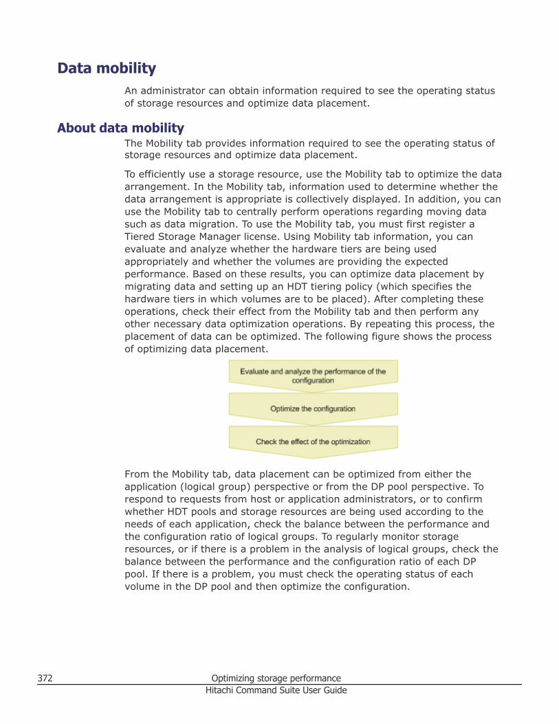
Data mobilityAn administrator can obtain information required to see the operating statusof storage resources and optimize data placement.
About data mobilityThe Mobility tab provides information required to see the operating status ofstorage resources and optimize data placement.
To efficiently use a storage resource, use the Mobility tab to optimize the dataarrangement. In the Mobility tab, information used to determine whether thedata arrangement is appropriate is collectively displayed. In addition, you canuse the Mobility tab to centrally perform operations regarding moving datasuch as data migration. To use the Mobility tab, you must first register aTiered Storage Manager license. Using Mobility tab information, you canevaluate and analyze whether the hardware tiers are being usedappropriately and whether the volumes are providing the expectedperformance. Based on these results, you can optimize data placement bymigrating data and setting up an HDT tiering policy (which specifies thehardware tiers in which volumes are to be placed). After completing theseoperations, check their effect from the Mobility tab and then perform anyother necessary data optimization operations. By repeating this process, theplacement of data can be optimized. The following figure shows the processof optimizing data placement.
From the Mobility tab, data placement can be optimized from either theapplication (logical group) perspective or from the DP pool perspective. Torespond to requests from host or application administrators, or to confirmwhether HDT pools and storage resources are being used according to theneeds of each application, check the balance between the performance andthe configuration ratio of logical groups. To regularly monitor storageresources, or if there is a problem in the analysis of logical groups, check thebalance between the performance and the configuration ratio of each DPpool. If there is a problem, you must check the operating status of eachvolume in the DP pool and then optimize the configuration.
372 Optimizing storage performanceHitachi Command Suite User Guide
When periodically monitoring logical groups or DP pools during routine work,check the ranking reports in the Mobility tab so you can efficiently find logicalgroups or DP pools that have problems in their operational status.
The Mobility tab can be used to check the total capacity and used capacityrate for each logical group, DP pool, or each volume in a logical group or DPpool. As with HDT pools, you can also check which volumes are using thelargest proportions of each hardware tier. In addition, the followingperformance information can also be viewed:• Quantity of I/O operations compared to the calculated maximum number
of I/O operations
In addition, if linked with Hitachi Tuning Manager, the following performanceinformation can also be viewed:• Throughput (IOPS) for DP pools, volumes, and hardware tiers• Past volume performance data (to look for trends)• Response time of the volume• Busy rate for parity groups
For details on linking to Hitachi Tuning Manager, see the Hitachi CommandSuite Administrator Guide.
Note: If Hitachi Tuning Manager is not linked, or information cannot beobtained due to storage system type, or the Tuning Manager - Agent for RAIDsoftware version, hyphens are displayed in performance information columns.
From the Mobility tab, the following operations can be performed to optimizedata placement:• Configuring and editing of an HDT tiering policy• Migrating volumes• Manually starting or stopping the monitoring and relocation of HDT pools• Editing tier relocation of HDT volumes• Expanding, shrinking, or changing settings for DP pools• Expanding DP volumes and reclaiming zero pages• Referencing trend charts, which indicate capacity data and performance
data for DP pools, and exporting data to CSV files
By creating tiers of volumes or DP pools based on use or performance, youcan migrate data to volumes or DP pools that match the relevant conditionssimply by specifying a tier as the migration target.
Related tasks
• Optimizing data placement in a logical group on page 376• Optimizing data placement in a DP pool on page 377
Optimizing storage performance 373Hitachi Command Suite User Guide
Reports for logical groups displayed in the Mobility tabSeveral reports are available on a logical group basis for monitoringperformance related items such as response time and unused capacity.
You can display one of the following ranking reports for a logical group in theMobility tab by selecting a top folder of the Public or Private folder, and a top-level folder for each user group under the Private Logical Group folder:• Bottom 10: Logical Groups with High Response Time
Checks for logical groups including volumes whose response time is slow.Used to determine logical groups which do not satisfy requiredperformances. This ranking is displayed only when you have the license forHitachi Tuning Manager.
• Top 10: Logical Groups with Lowest Unused CapacityChecks for logical groups that have little unused capacity left for theallocated DP volumes. Used to determine logical groups which do not haveenough capacity.
• Top 10: Logical Group Used Capacity by Drive TypesChecks for logical groups that use a large amount of capacity by drivetype. Used to determine whether an unexpected volume is occupying ahigh-speed drive or logical groups which have invalid data arrangements.
The following summary information is displayed when each logical group isselected:• Summary
Provides summarized information in a list, such as the number of volumesand the total capacity of a logical group, or the last update date. Based onthis information, you can review the usage status of the storage resourcesin the logical group.
• Drive Type SummaryChecks whether the logical group has the necessary capacity. Checks thetotal capacity of the volumes and the used capacity of each drive typewithin the logical group.
• Drive Type DistributionChecks how many of each drive type is used for each DP pool that isincluded in a logical group. Used to check whether the configuration of thehardware tier is appropriate.
Related concepts
• About data mobility on page 372
Reports for DP pools displayed in the Mobility tabThe Mobility tab displays several types of reports for DP pools related toperformance and capacity utilization.
Ranking reports for DP groups displayed in the Mobility tab are as follows:• Top 10: Pools with the Highest Used Capacity %
374 Optimizing storage performanceHitachi Command Suite User Guide
Check on a regular basis for DP pools with a high used capacity rate todetermine DP pools that need pool expansion or data migration.
• Top 10: Pools with the Highest SubscriptionCheck on a regular basis for DP pools with a high reservation rate todetermine DP pools that need pool expansion or data migration on aregular basis.
• Top 10: Tiers with the Highest Performance UtilizationCheck on a regular basis for hardware tier configurations with high ratio ofactual I/O operations to the calculated maximum number of I/Ooperations. Used to determine HDT pools that include hardware tierconfigurations with saturated performance.
The information displayed when each DP pool is selected is as follows:• Summary
Summarizes information in a list, such as the total capacity and usage ofDP pools, and the reservation rate. Based on this information, you canreview the usage status of the DP pool.In addition, you can determine whether you need to add capacity to theDP pool by selecting Show Trend Chart from the Actions menu, and thenchecking each pool's trends in the increase of IOPS and in capacity usage.You can change the display period of the trend chart as needed, or savethe trend chart as a report after exporting it to a CSV file.
If an HDT pool is selected, the following information can also be viewed:• Tier Summary
Check information such as drive type, drive rotational speed, and capacityusage rate for each hardware tier. Based on this information, you canreview the usage status of hardware tiers. Note that this summary onlyappears for HDT pools.
• Capacity & Performance UtilizationCheck the total capacity and used capacity of the HDT pools for eachhardware tier. This lets you confirm whether the HDT pool has thenecessary capacity and identifies which hardware tier needs more capacityadded to it. This summary only appears for HDT pools. For example, ifcapacity is increasing, but IOPS shows little change, then adding morecapacity for future use is suggested with this capacity added to Tier 2 orTier 3. If capacity shows little change, but IOPS is increasing, then addingmore capacity for future use is suggested with this capacity added to theupper tiers (Tier 1 and Tier 2), or reducing Tier 3 by the amount needed.If both capacity and IOPS are increasing, then adding more capacity forfuture use is necessary. You can determine to which tiers this capacity isadded based on the trend graph and distribution chart for each tier.
• Show Trend ChartCheck the trend chart, which combines and displays the capacity usageand performance information for each hardware tier. Based on thisinformation, you can determine whether the hardware tier configuration inthe HDT pool is appropriate, and which hardware tiers need additional
Optimizing storage performance 375Hitachi Command Suite User Guide
capacity. You can change the display period of the trend chart as needed,or save the trend chart as a report after exporting it to a CSV file. If thedisplay period of the trend chart is seven days or more, the chart displaysthe average of the obtained information for each day.
• Capacity UtilizationCheck the total capacity and used capacity of the HDT pools for eachhardware tier. Based on this information, you can check whether the HDTpool has the necessary capacity. You need to perform capacity planning forpools in which the remaining capacity is small. Look at the trends for howpool contents increase, and estimate when you must increase capacity,and possibly add additional media.
• Performance UtilizationCheck the ratio of actual I/O operations to the calculated maximumnumber of I/O operations for each hardware tier. Based on thisinformation, you can determine the hardware tiers whose performance isin a saturated state that then require an optimization operation (such asediting the tiering policy or data migration).
• Top 10: Volumes Sharing Tier CapacityCheck the usage ranking of volumes that have the largest use capacity ineach hardware tier. Based on this information, you can check whether dataplacement is appropriate, for example by checking whether an unexpectedvolume is occupying a high-speed drive. This summary only appears forHDT pools.
• View Tier PropertiesCheck the page access distribution per average number of I/O operations,which is based on the monitoring information of HDT pools.Based on this information, you can check whether the hardware tierconfiguration or tiering policy settings are appropriate.From the page access distribution for HDT pools, you can narrow the rangeof displayed items to only tiering policies or only HDT volumes, asrequired.
Related concepts
• About data mobility on page 372
Optimizing data placement in a logical groupData placement can be optimized in either of the supported logical grouptypes (Public Logical Groups or Private Logical Groups).
Prerequisites• A registered Tiered Storage Manager license.• A registered Hitachi Tuning Manager license (when referencing
performance information). If Hitachi Command Suite is linked with HitachiTuning Manager, you can display the Historical Report and checkperformance information by clicking Analyze Performance. For information
376 Optimizing storage performanceHitachi Command Suite User Guide
about changing the report window settings for the Historical Report, seethe Hitachi Command Suite Tuning Manager User Guide.
Procedure
1. From the tree view of the Mobility tab, select Logical Groups.2. From Logical Groups, select either Public Logical Groups or Private
Logical Groups, and in the logical group ranking, check for logicalgroups that are responding late, have a small unused capacity, or have alarge used capacity for each drive type (for example: FMD, SSD, SAS, orSATA).
3. If the capacity or performance of the entire logical group is notsatisfactory, click the link of the logical group name to check the totalcapacity of the volumes and the used capacity of each drive type (forexample: FMD, SSD, SAS, or SATA) within the logical group.
4. If the balance between the logical group performance and configurationratio is not satisfactory, select the row of the target volume, and clickMigrate Data, Edit Tiering Policy, or one of the other buttons toremedy the problem.
5. Select Logical Groups from the Mobility tab to check optimization ofthe data placement.
Related concepts
• About data mobility on page 372
Related tasks
• Optimizing data placement in a DP pool on page 377
Optimizing data placement in a DP poolData placement can be optimized in a DP pool.
Prerequisites• A registered Tiered Storage Manager license.• A registered Hitachi Tuning Manager license (when referencing
performance information). If Hitachi Command Suite is linked with HitachiTuning Manager, you can display the Historical Report and checkperformance information by clicking Analyze Performance. For informationabout changing the report window settings for the Historical Report, seethe Hitachi Command Suite Tuning Manager User Guide.
• Ensure that HDT pools are being monitored (when referencing PerformanceUtilization, IOPS for a hardware tier, or View Tier Properties).
Procedure
1. From the tree view of the Mobility tab, select DP Pools.
Optimizing storage performance 377Hitachi Command Suite User Guide
2. Select DP Pool to check for DP pools whose used capacity rate,reservation rate, or performance usage rate is high.
3. If a DP pool does not meet the expectations for capacity or performance,click the link of the DP pool in the ranking.
4. Check the usage status and performance of each hardware tier in the DPpools by performing the following:• To check if the usage capacity of the HDP pool is appropriate, from the
Actions menu, select Show Trend Chart, and then check the IOPSand usage capacity of each pool.
• To check if the configuration and performance of each hardware tier inthe HDT pool is appropriate, from the Actions menu (or from theCapacity & Performance Utilization link), select Show TrendChart, and then check the capacity and performance of eachhardware tier. To save the contents of the Trend Chart as a report,click Export to CSV and save the contents as a CSV file to a locationof your choice.
• To check page access distribution per average number of I/Ooperations, from the Actions menu, select View Tier Properties.
5. Select the DP volumes that have a problem and optimize the dataplacement by clicking:• Migrate Data• Edit Tiering Policy• Expand DP Volume, or one of the other buttons
6. On the Mobility tab, select DP Pools to confirm data placementoptimization.
Related concepts
• About data mobility on page 372
Related tasks
• Optimizing data placement in a logical group on page 376
Data migrationThis module describes data migration.
About data migrationData migration involves moving data from a set of source volumes to a set ofdestination volumes or DP pools, including those in externally-connectedstorage systems.
For example, you can migrate data when your volume performance decreasesor your environment changes. When relocating data based on the results ofperformance monitoring for volumes being used by servers and applications,or when migrating data from an old storage system to a newly set-up storage
378 Optimizing storage performanceHitachi Command Suite User Guide
system, the data in multiple volumes can be migrated to other volumes or DPpools.
The source volume can be selected by host, file server or by logical group.The source volume also can be selected from some of the volumes allocatedto a host, file server, some of the volumes displayed in the list of volumes inthe file server, some of the volumes in a logical group, some of the volumesin a tier. Migration source volumes can also be selected from volume searchresults. If a volume that cannot be migrated is included in the selectedvolumes, that volume is excluded from migration and only volumes that canbe migrated, will be migrated.
Migration targets are selected from tiers, DP pools, or resource searchresults. If DP pools are selected, DP volumes with the same capacity as themigration-source volumes are automatically created. The existing DP volumesalso can be specified as migration targets.
Note the following:• When the migration source and the migration target are selected,
individual pairs of migration source volumes and migration target volumes(or DP pools) are automatically created. Although, you can change thesepairs, pairs of volumes that cannot be migrated will not be created.
• During migration, data can still be accessed.• When data migration is completed normally, the LDEV ID and host I/O of
the migration source volumes are changed to those of the migration targetvolumes. The procedure for accessing migrated data is not changed beforeor after migration.
• When you create a migration task, you can select whether to delete themigration source volume after the migration completes. As an alternative,after migrating, you can delete the data of the source volumes.
• After volumes are migrated to DP volumes, unused capacity in the targetvolumes is returned to the pool (zero page reclaim) if the zero pagereclaim option is on. We recommend that the migration source volume bedeleted if it is a DP volume and you will not use it. If you do not delete themigration source volume, we recommend that the zero page of themigration source volume be discarded after the migration task finishes.
• You cannot work with volumes (such as copy pair or volume allocation)until the migration tasks are completed.
You must have a Tiered Storage Manager license registered to perform DataMigration.
Related tasks
• Migrating data for volume performance on page 386• Migrating data to a different storage system on page 388
Related references
• Notes on performing data migration on page 380
Optimizing storage performance 379Hitachi Command Suite User Guide
• Conditions for data migration on page 381
Notes on performing data migrationThe number of volumes that are candidates for migration target volumes arenarrowed down and displayed when selecting a migration target volume. Ifyou want to display all the volumes, in the migration.properties file on theDevice Manager server set a value for themigration.plan.candidateVolumeCountLimit property.
For details on the properties file, refer to the Hitachi Command SuiteAdministrator Guide. To avoid insufficient memory, we recommend that youuse the default.
The maximum number of volumes that can be displayed as migration targetcandidates is 2,000 volumes. Exceeding this value will produce an error.
The maximum number of volumes that can be displayed as migration sourcecandidates is 500 volumes. Exceeding this value will produce an error.
Data migration tasks take a long time from start of execution to completion.This might affect the performance of access from hosts to target volumes. Toavoid executing such tasks while the access frequency is high, check the timerequired to complete the tasks and set a task execution schedule beforeregistering the tasks. Actual required time might differ considerably in casessuch as performing migration for the first time, migrating a volume smallerthan 170 GB, or migrating many volumes at the same time.
When storage systems or hosts are under a heavy load, migration might fail.In this case, reduce the load on the storage systems, and then perform datamigration again.
If data migration fails, the integrity of data on the migration target cannot beensured. Therefore, data migration must be restarted.
If a data migration fails, and operations for the migration target such as re-execution of data migration and volume allocation cannot be performed, thestorage system must be refreshed.
Related concepts
• About data migration on page 378
Related tasks
• Migrating data for volume performance on page 386• Migrating data to a different storage system on page 388
380 Optimizing storage performanceHitachi Command Suite User Guide
Conditions for data migrationData migration conditions include conditions that apply to all volumes(volume migration requirements), and conditions that depend on the type ofvolume (volume migration requirements related to volume type).
For some volumes, when you try to select those volumes as migration-sourcevolumes, the reasons why they cannot be selected as migration-sourcevolumes are displayed on-screen.
Volume migration requirements
All volumes for which data migration is to be performed must meet thefollowing conditions:• Migration-source and migration-target volumes exist within one of the
following storage systems (chassis):○ Virtual Storage Platform G200, G400, G600○ Virtual Storage Platform G1000○ Virtual Storage Platform○ Universal Storage Platform V/VM○ Universal Storage Platform○ HUS VM
• The emulation type, number of blocks, and size are the same for thesource and target migration volumes. However, note the followingexceptions:○ If the micro version of Universal Storage Platform V/VM is
60-03-20-00/00-xx or later and if both the migration source and themigration target volumes are DP volumes, the emulation type can bebetween OPEN-V and OPEN-0V.
○ If a volume whose emulation type is OPEN-V is a normal volume, and ifthe size of a migration target volume is larger than a migration sourcevolume, a volume that has the same size of the migration sourcevolume is re-created. The remaining capacity can be reused. If you seta value for the propertymigration.plan.candidateCapacityGroupDisplayMaxCount in themigration.properties file, you can specify how many volumes with alarger capacity than the migration source volume to display, in additionto the volumes with the same capacity as the migration source volume.
• The LDKC:CU:LDEV number for the volume is in the range from 00:00:00to 00:FE:FF
• Volumes can be accessed, and are not reserved by other programs, DeviceManager, or tasks.
• The emulation type is neither 3390-V nor 6588-A.• The emulation type is not OPEN-V, and both the migration source and the
migration target volumes are normal, or both are CVS volumes.
Optimizing storage performance 381Hitachi Command Suite User Guide
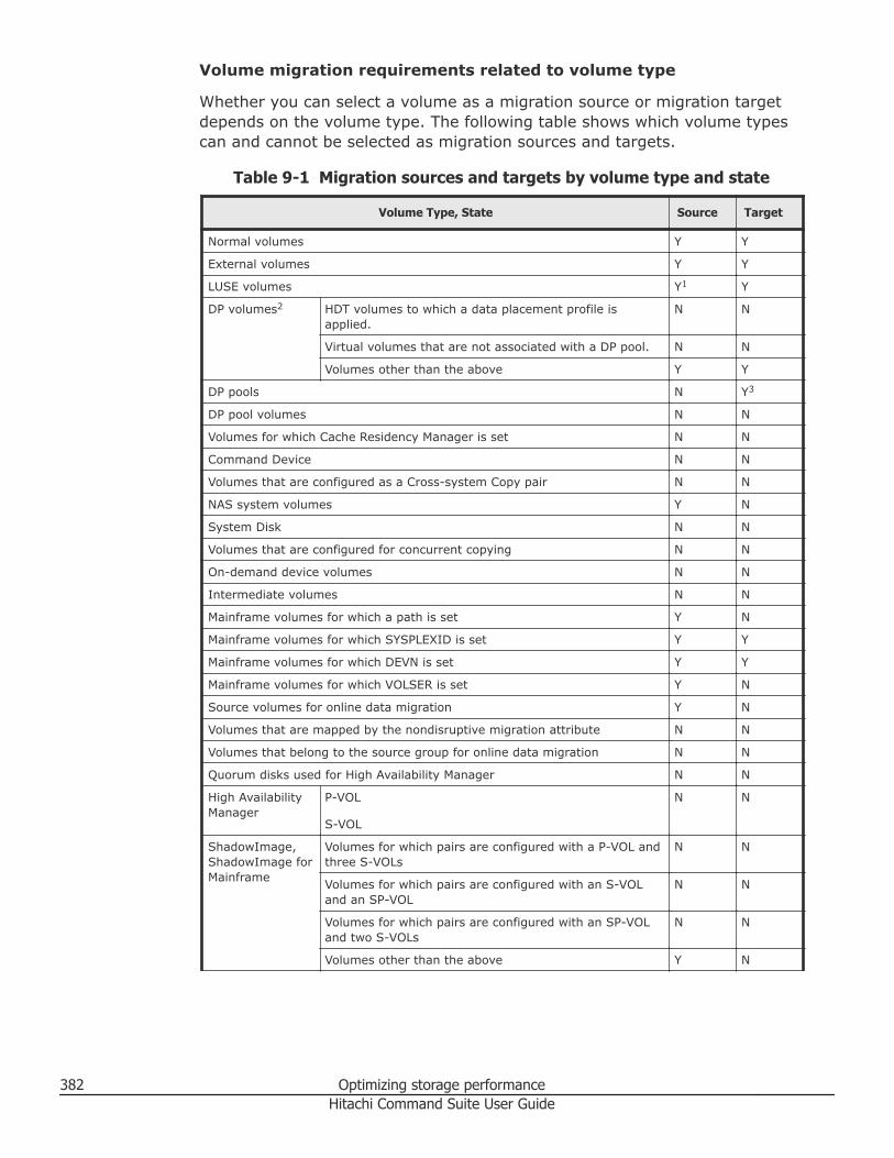
Volume migration requirements related to volume type
Whether you can select a volume as a migration source or migration targetdepends on the volume type. The following table shows which volume typescan and cannot be selected as migration sources and targets.
Table 9-1 Migration sources and targets by volume type and state
Volume Type, State Source Target
Normal volumes Y Y
External volumes Y Y
LUSE volumes Y1 Y
DP volumes2 HDT volumes to which a data placement profile isapplied.
N N
Virtual volumes that are not associated with a DP pool. N N
Volumes other than the above Y Y
DP pools N Y3
DP pool volumes N N
Volumes for which Cache Residency Manager is set N N
Command Device N N
Volumes that are configured as a Cross-system Copy pair N N
NAS system volumes Y N
System Disk N N
Volumes that are configured for concurrent copying N N
On-demand device volumes N N
Intermediate volumes N N
Mainframe volumes for which a path is set Y N
Mainframe volumes for which SYSPLEXID is set Y Y
Mainframe volumes for which DEVN is set Y Y
Mainframe volumes for which VOLSER is set Y N
Source volumes for online data migration Y N
Volumes that are mapped by the nondisruptive migration attribute N N
Volumes that belong to the source group for online data migration N N
Quorum disks used for High Availability Manager N N
High AvailabilityManager
P-VOL
S-VOL
N N
ShadowImage,ShadowImage forMainframe
Volumes for which pairs are configured with a P-VOL andthree S-VOLs
N N
Volumes for which pairs are configured with an S-VOLand an SP-VOL
N N
Volumes for which pairs are configured with an SP-VOLand two S-VOLs
N N
Volumes other than the above Y N
382 Optimizing storage performanceHitachi Command Suite User Guide
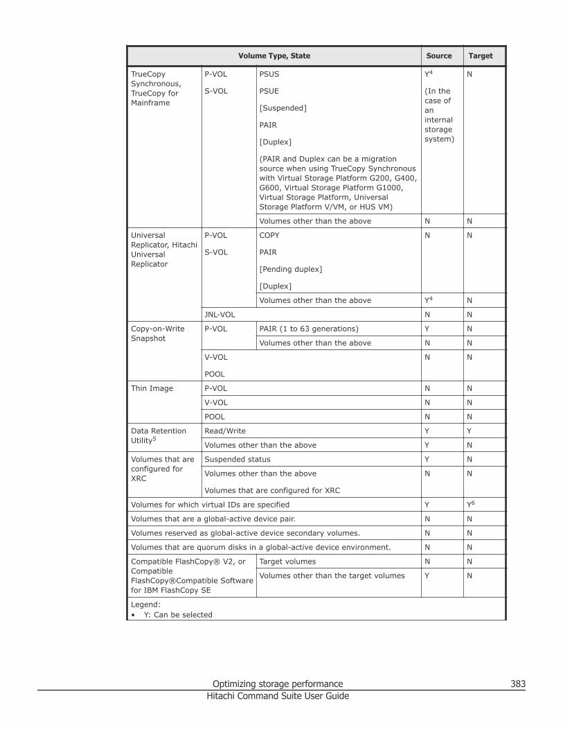
Volume Type, State Source Target
TrueCopySynchronous,TrueCopy forMainframe
P-VOL
S-VOL
PSUS
PSUE
[Suspended]
PAIR
[Duplex]
(PAIR and Duplex can be a migrationsource when using TrueCopy Synchronouswith Virtual Storage Platform G200, G400,G600, Virtual Storage Platform G1000,Virtual Storage Platform, UniversalStorage Platform V/VM, or HUS VM)
Y4
(In thecase ofaninternalstoragesystem)
N
Volumes other than the above N N
UniversalReplicator, HitachiUniversalReplicator
P-VOL
S-VOL
COPY
PAIR
[Pending duplex]
[Duplex]
N N
Volumes other than the above Y4 N
JNL-VOL N N
Copy-on-WriteSnapshot
P-VOL PAIR (1 to 63 generations) Y N
Volumes other than the above N N
V-VOL
POOL
N N
Thin Image P-VOL N N
V-VOL N N
POOL N N
Data RetentionUtility5
Read/Write Y Y
Volumes other than the above Y N
Volumes that areconfigured forXRC
Suspended status Y N
Volumes other than the above
Volumes that are configured for XRC
N N
Volumes for which virtual IDs are specified Y Y6
Volumes that are a global-active device pair. N N
Volumes reserved as global-active device secondary volumes. N N
Volumes that are quorum disks in a global-active device environment. N N
Compatible FlashCopy® V2, orCompatibleFlashCopy®Compatible Softwarefor IBM FlashCopy SE
Target volumes N N
Volumes other than the target volumes Y N
Legend:• Y: Can be selected
Optimizing storage performance 383Hitachi Command Suite User Guide
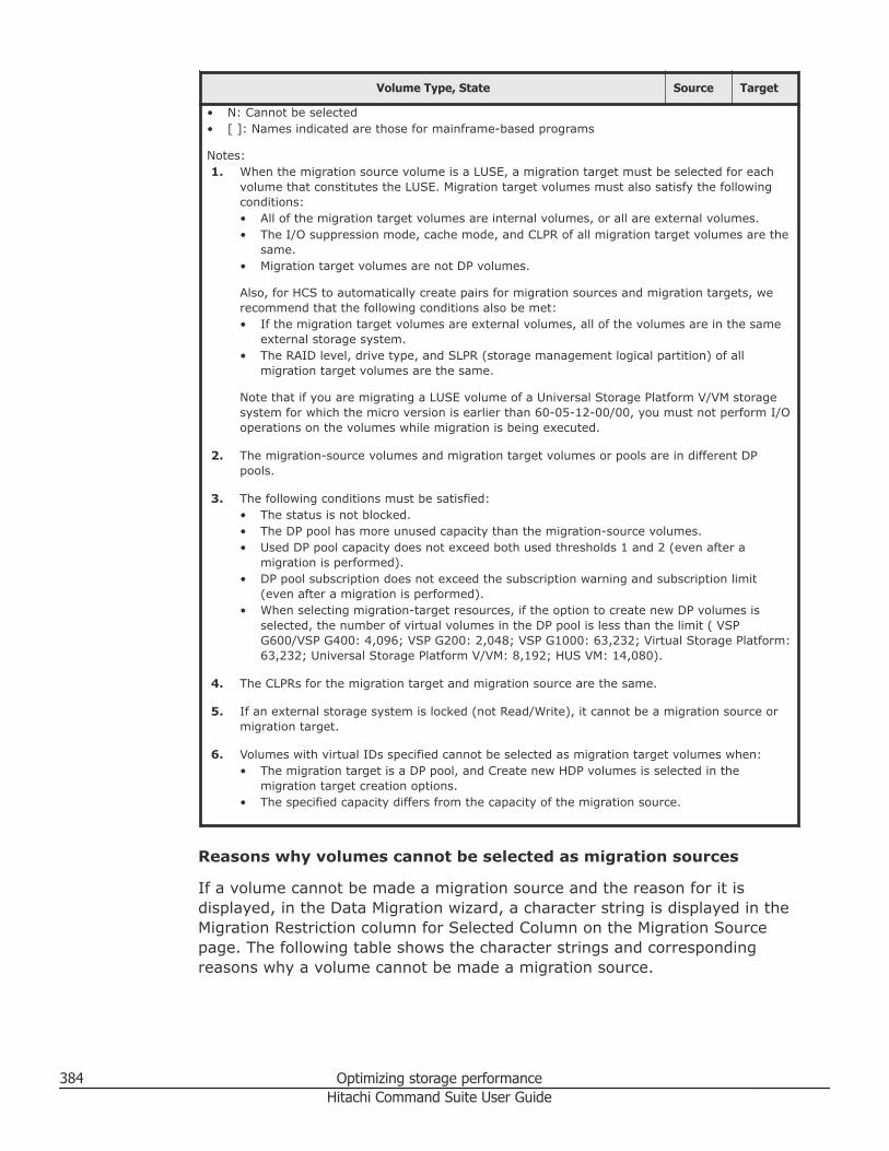
Volume Type, State Source Target
• N: Cannot be selected• [ ]: Names indicated are those for mainframe-based programs
Notes:1. When the migration source volume is a LUSE, a migration target must be selected for each
volume that constitutes the LUSE. Migration target volumes must also satisfy the followingconditions:• All of the migration target volumes are internal volumes, or all are external volumes.• The I/O suppression mode, cache mode, and CLPR of all migration target volumes are the
same.• Migration target volumes are not DP volumes.
Also, for HCS to automatically create pairs for migration sources and migration targets, werecommend that the following conditions also be met:• If the migration target volumes are external volumes, all of the volumes are in the same
external storage system.• The RAID level, drive type, and SLPR (storage management logical partition) of all
migration target volumes are the same.
Note that if you are migrating a LUSE volume of a Universal Storage Platform V/VM storagesystem for which the micro version is earlier than 60-05-12-00/00, you must not perform I/Ooperations on the volumes while migration is being executed.
2. The migration-source volumes and migration target volumes or pools are in different DPpools.
3. The following conditions must be satisfied:• The status is not blocked.• The DP pool has more unused capacity than the migration-source volumes.• Used DP pool capacity does not exceed both used thresholds 1 and 2 (even after a
migration is performed).• DP pool subscription does not exceed the subscription warning and subscription limit
(even after a migration is performed).• When selecting migration-target resources, if the option to create new DP volumes is
selected, the number of virtual volumes in the DP pool is less than the limit ( VSPG600/VSP G400: 4,096; VSP G200: 2,048; VSP G1000: 63,232; Virtual Storage Platform:63,232; Universal Storage Platform V/VM: 8,192; HUS VM: 14,080).
4. The CLPRs for the migration target and migration source are the same.
5. If an external storage system is locked (not Read/Write), it cannot be a migration source ormigration target.
6. Volumes with virtual IDs specified cannot be selected as migration target volumes when:• The migration target is a DP pool, and Create new HDP volumes is selected in the
migration target creation options.• The specified capacity differs from the capacity of the migration source.
Reasons why volumes cannot be selected as migration sources
If a volume cannot be made a migration source and the reason for it isdisplayed, in the Data Migration wizard, a character string is displayed in theMigration Restriction column for Selected Column on the Migration Sourcepage. The following table shows the character strings and correspondingreasons why a volume cannot be made a migration source.
384 Optimizing storage performanceHitachi Command Suite User Guide
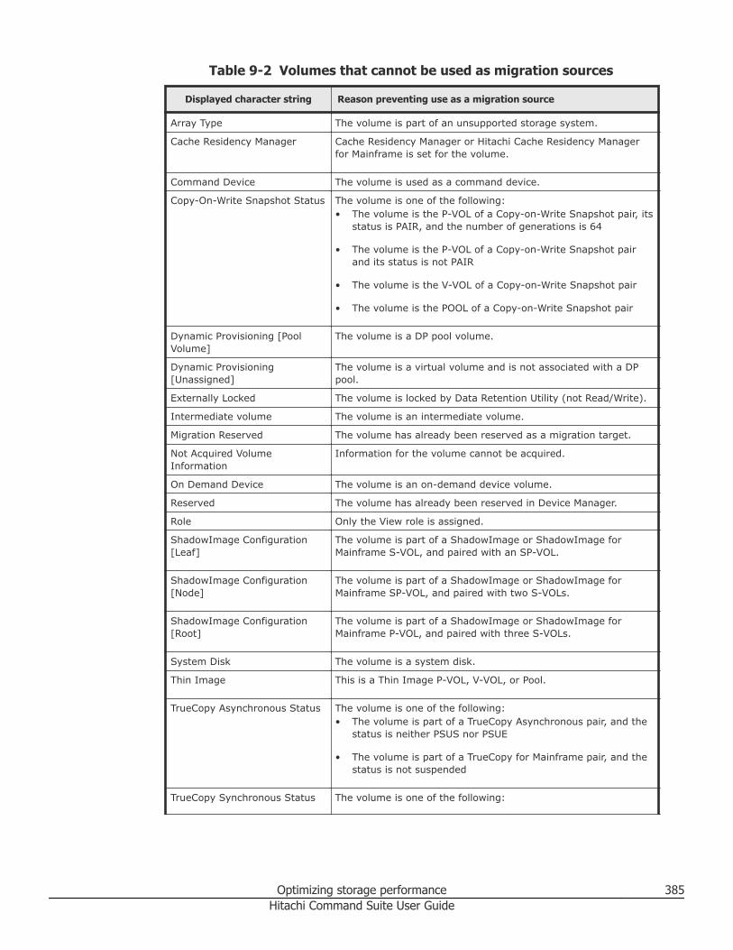
Table 9-2 Volumes that cannot be used as migration sources
Displayed character string Reason preventing use as a migration source
Array Type The volume is part of an unsupported storage system.
Cache Residency Manager Cache Residency Manager or Hitachi Cache Residency Managerfor Mainframe is set for the volume.
Command Device The volume is used as a command device.
Copy-On-Write Snapshot Status The volume is one of the following:• The volume is the P-VOL of a Copy-on-Write Snapshot pair, its
status is PAIR, and the number of generations is 64
• The volume is the P-VOL of a Copy-on-Write Snapshot pairand its status is not PAIR
• The volume is the V-VOL of a Copy-on-Write Snapshot pair
• The volume is the POOL of a Copy-on-Write Snapshot pair
Dynamic Provisioning [PoolVolume]
The volume is a DP pool volume.
Dynamic Provisioning[Unassigned]
The volume is a virtual volume and is not associated with a DPpool.
Externally Locked The volume is locked by Data Retention Utility (not Read/Write).
Intermediate volume The volume is an intermediate volume.
Migration Reserved The volume has already been reserved as a migration target.
Not Acquired VolumeInformation
Information for the volume cannot be acquired.
On Demand Device The volume is an on-demand device volume.
Reserved The volume has already been reserved in Device Manager.
Role Only the View role is assigned.
ShadowImage Configuration[Leaf]
The volume is part of a ShadowImage or ShadowImage forMainframe S-VOL, and paired with an SP-VOL.
ShadowImage Configuration[Node]
The volume is part of a ShadowImage or ShadowImage forMainframe SP-VOL, and paired with two S-VOLs.
ShadowImage Configuration[Root]
The volume is part of a ShadowImage or ShadowImage forMainframe P-VOL, and paired with three S-VOLs.
System Disk The volume is a system disk.
Thin Image This is a Thin Image P-VOL, V-VOL, or Pool.
TrueCopy Asynchronous Status The volume is one of the following:• The volume is part of a TrueCopy Asynchronous pair, and the
status is neither PSUS nor PSUE
• The volume is part of a TrueCopy for Mainframe pair, and thestatus is not suspended
TrueCopy Synchronous Status The volume is one of the following:
Optimizing storage performance 385Hitachi Command Suite User Guide
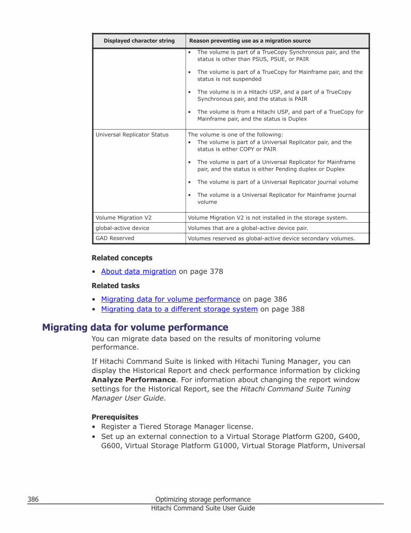
Displayed character string Reason preventing use as a migration source
• The volume is part of a TrueCopy Synchronous pair, and thestatus is other than PSUS, PSUE, or PAIR
• The volume is part of a TrueCopy for Mainframe pair, and thestatus is not suspended
• The volume is in a Hitachi USP, and a part of a TrueCopySynchronous pair, and the status is PAIR
• The volume is from a Hitachi USP, and part of a TrueCopy forMainframe pair, and the status is Duplex
Universal Replicator Status The volume is one of the following:• The volume is part of a Universal Replicator pair, and the
status is either COPY or PAIR
• The volume is part of a Universal Replicator for Mainframepair, and the status is either Pending duplex or Duplex
• The volume is part of a Universal Replicator journal volume
• The volume is a Universal Replicator for Mainframe journalvolume
Volume Migration V2 Volume Migration V2 is not installed in the storage system.
global-active device Volumes that are a global-active device pair.
GAD Reserved Volumes reserved as global-active device secondary volumes.
Related concepts
• About data migration on page 378
Related tasks
• Migrating data for volume performance on page 386• Migrating data to a different storage system on page 388
Migrating data for volume performanceYou can migrate data based on the results of monitoring volumeperformance.
If Hitachi Command Suite is linked with Hitachi Tuning Manager, you candisplay the Historical Report and check performance information by clickingAnalyze Performance. For information about changing the report windowsettings for the Historical Report, see the Hitachi Command Suite TuningManager User Guide.
Prerequisites• Register a Tiered Storage Manager license.• Set up an external connection to a Virtual Storage Platform G200, G400,
G600, Virtual Storage Platform G1000, Virtual Storage Platform, Universal
386 Optimizing storage performanceHitachi Command Suite User Guide
Storage Platform V/VM, Universal Storage Platform, or HUS VM storagesystem.
• Create a tier in which the target mainframe volumes are grouped (onlywhen migrating mainframe volumes).
• Gather the following information:○ Migration source host, file server, logical group, tier, or storage system.○ Migration target DP pools, tier or migration target volumes.
Procedure
1. In the Resources or Mobility tab, select a migration source host orlogical group. From a list of hosts or logical groups, you can also selectmigration source volumes. If migrating data from a mainframe volume,expand the Tiers tree on the Resources tab or the Mobility tab, andthen select the corresponding tier.
2. Click Migrate Data.3. Verify that the correct migration source volumes are selected, and then
click Next.4. Specify the migration target, DP pool, or tier and then click Next. When
the parity group selection rule is set, a candidate volume that isappropriate as a migration target is selected depending on theapplication that is being used or the usage rate of the parity group.Specifically, the system attempts one of the following:• Balance Capacity: Selects a migration target candidate so that the
remaining capacity of the targeted parity group is equalized with otherparity groups.
• Maximum Coverage: Selects a candidate for the migration targetfrom as many parity groups as possible.
• Minimum Coverage: Selects a candidate for the migration targetfrom as few parity groups as possible.
If Hitachi Command Suite is linked with Hitachi Tuning Manager, paritygroup busy rate for the migration target volume can be checked.
5. Confirm that all migration source volumes and target volumes or DPpools are paired properly, confirm that no other problems exist, and thenclick Next. If necessary, change the pairs. To change a pair, first selectthe volume pair, then from the Other Candidates for Migration list,select the target volume to change to, and then click Map Volume.
6. Specify plan options as necessary, and then run the task.7. In the tasks list, confirm the result of the task. After a task is created,
you must not perform any operations on volumes included in the task byusing Hitachi Command Suite or other programs until the task hasfinished executing.
Related concepts
• About data migration on page 378
Optimizing storage performance 387Hitachi Command Suite User Guide
Related tasks
• Migrating data to a different storage system on page 388
Related references
• Conditions for data migration on page 381
Migrating data to a different storage systemYou can migrate data to a different storage system.
If Hitachi Command Suite is linked with Hitachi Tuning Manager, you candisplay the Historical Report and check performance information by clickingAnalyze Performance. For information about changing the report windowsettings for the Historical Report, see the Hitachi Command Suite TuningManager User Guide.
Prerequisites• Register a Tiered Storage Manager license• Set up an external connection to a Virtual Storage Platform G200, G400,
G600, Virtual Storage Platform G1000, Virtual Storage Platform, UniversalStorage Platform V/VM, Universal Storage Platform, or HUS VM storagesystem.
• Create a tier in which the target mainframe volumes are grouped (onlywhen migrating mainframe volumes).
• Identify the migration source host, file server, logical group, tier, or storagesystem.
• Identify the migration target DP pools, tier, or migration target volumes.
Procedure
1. On the Resources tab, select Storage Systems.2. Expand the tree for the source storage system that is to be migrated,
select the volumes to be migrated from the list of external storagesystems, and then click Migrate Data.
3. Confirm that the correct migration source volumes are selected, and thenclick Next.
4. Specify the migration target, DP pools, or tier and then click Next. Whenthe parity group selection rule is set, a candidate volume that isappropriate as a migration target will be selected depending on theapplication that is being used or the usage rate of the parity group.Specifically:• Balance Capacity: System attempts to select a migration target
candidate so that the remaining capacity of the targeted parity groupis equalized with other parity groups.
• Maximum Coverage: Select a candidate for the migration targetfrom as many parity groups as possible.
388 Optimizing storage performanceHitachi Command Suite User Guide
• Minimum Coverage: Select a candidate for the migration target fromas few parity groups as possible.
If Hitachi Command Suite is linked with Hitachi Tuning Manager, paritygroup busy rate for the migration target volume can be checked.
5. Confirm that all migration source volumes and target volumes or DPpools are paired properly, confirm that no other problems exist, and thenclick Next. If necessary, change the pairs. To change a pair, first selectthe volume pair, then from the Other Candidates for Migration Targetlist, select the target volume to change to, and then click Map Volume.
6. Specify plan options as necessary and then execute the task.7. In the tasks list, confirm the execution result of the task. After a task is
created, you must not perform operations on volumes included in thetask by using Hitachi Command Suite or other programs until the taskhas finished executing.
Related concepts
• About data migration on page 378
Related tasks
• Migrating data for volume performance on page 386
Related references
• Conditions for data migration on page 381
Migrate data dialog boxData migration provides the capability for moving data from a set of sourcevolumes to a set of destination volumes or DP pools, including those inexternally-connected storage systems.
The Migrate data dialog box is a wizard that guides you in configuring thetask for migrating selected data from a source location to a destinationtarget.
For example, when you select a specific host, storage system, pool type, andclick Apply, the corresponding volume information is displayed in the list ofselected volumes because this information is already known and is non-configurable. To create a data migration task, you must complete a four-stepconfiguration process using the migrate data wizard.
When you enter the minimum required information in a dialog box, reviewthe Plan Summary, and click Submit to complete the configuration of thismigration task. Click the Back button to modify the plan to meet yourrequirements.
The following table describes the dialog box fields, subfields, and fieldgroups. A field group is a collection of fields that are related to a specificaction or configuration. You can minimize and expand field groups by clickingthe double arrow symbol (>>).
Optimizing storage performance 389Hitachi Command Suite User Guide
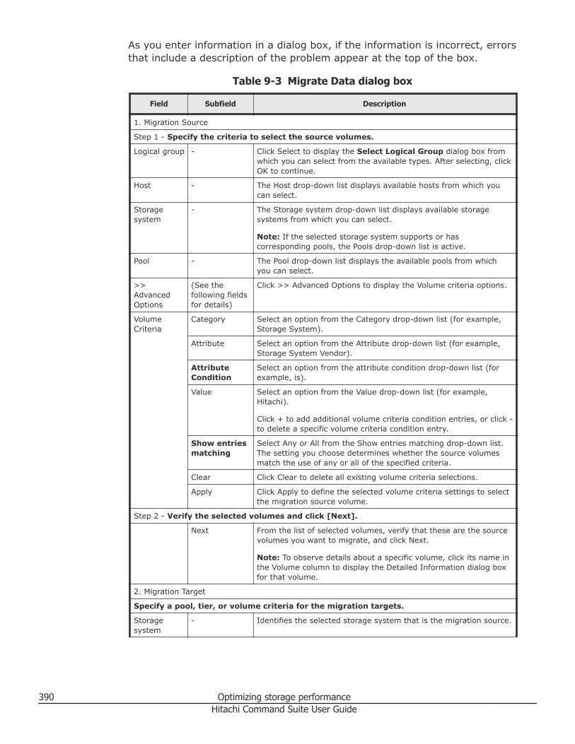
As you enter information in a dialog box, if the information is incorrect, errorsthat include a description of the problem appear at the top of the box.
Table 9-3 Migrate Data dialog box
Field Subfield Description
1. Migration Source
Step 1 - Specify the criteria to select the source volumes.
Logical group - Click Select to display the Select Logical Group dialog box fromwhich you can select from the available types. After selecting, clickOK to continue.
Host - The Host drop-down list displays available hosts from which youcan select.
Storagesystem
- The Storage system drop-down list displays available storagesystems from which you can select.
Note: If the selected storage system supports or hascorresponding pools, the Pools drop-down list is active.
Pool - The Pool drop-down list displays the available pools from whichyou can select.
>>AdvancedOptions
(See thefollowing fieldsfor details)
Click >> Advanced Options to display the Volume criteria options.
VolumeCriteria
Category Select an option from the Category drop-down list (for example,Storage System).
Attribute Select an option from the Attribute drop-down list (for example,Storage System Vendor).
AttributeCondition
Select an option from the attribute condition drop-down list (forexample, is).
Value Select an option from the Value drop-down list (for example,Hitachi).
Click + to add additional volume criteria condition entries, or click -to delete a specific volume criteria condition entry.
Show entriesmatching
Select Any or All from the Show entries matching drop-down list.The setting you choose determines whether the source volumesmatch the use of any or all of the specified criteria.
Clear Click Clear to delete all existing volume criteria selections.
Apply Click Apply to define the selected volume criteria settings to selectthe migration source volume.
Step 2 - Verify the selected volumes and click [Next].
Next From the list of selected volumes, verify that these are the sourcevolumes you want to migrate, and click Next.
Note: To observe details about a specific volume, click its name inthe Volume column to display the Detailed Information dialog boxfor that volume.
2. Migration Target
Specify a pool, tier, or volume criteria for the migration targets.
Storagesystem
- Identifies the selected storage system that is the migration source.
390 Optimizing storage performanceHitachi Command Suite User Guide
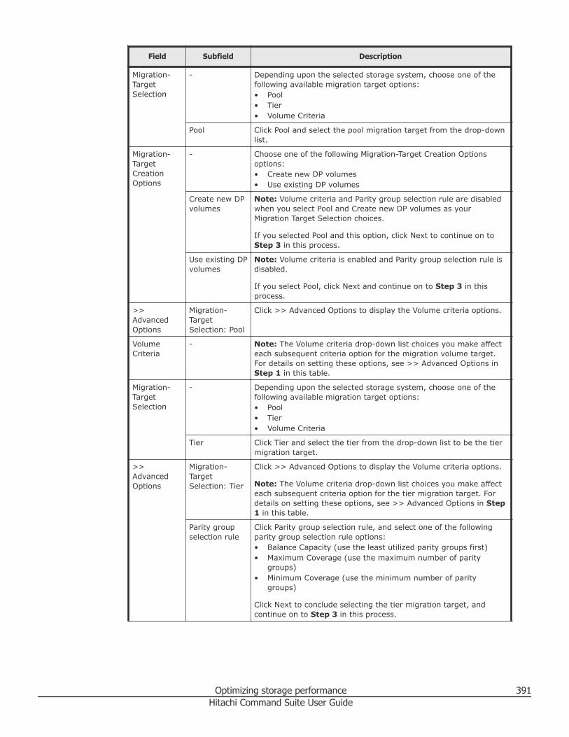
Field Subfield Description
Migration-TargetSelection
- Depending upon the selected storage system, choose one of thefollowing available migration target options:• Pool• Tier• Volume Criteria
Pool Click Pool and select the pool migration target from the drop-downlist.
Migration-TargetCreationOptions
- Choose one of the following Migration-Target Creation Optionsoptions:• Create new DP volumes• Use existing DP volumes
Create new DPvolumes
Note: Volume criteria and Parity group selection rule are disabledwhen you select Pool and Create new DP volumes as yourMigration Target Selection choices.
If you selected Pool and this option, click Next to continue on toStep 3 in this process.
Use existing DPvolumes
Note: Volume criteria is enabled and Parity group selection rule isdisabled.
If you select Pool, click Next and continue on to Step 3 in thisprocess.
>>AdvancedOptions
Migration-TargetSelection: Pool
Click >> Advanced Options to display the Volume criteria options.
VolumeCriteria
- Note: The Volume criteria drop-down list choices you make affecteach subsequent criteria option for the migration volume target.For details on setting these options, see >> Advanced Options inStep 1 in this table.
Migration-TargetSelection
- Depending upon the selected storage system, choose one of thefollowing available migration target options:• Pool• Tier• Volume Criteria
Tier Click Tier and select the tier from the drop-down list to be the tiermigration target.
>>AdvancedOptions
Migration-TargetSelection: Tier
Click >> Advanced Options to display the Volume criteria options.
Note: The Volume criteria drop-down list choices you make affecteach subsequent criteria option for the tier migration target. Fordetails on setting these options, see >> Advanced Options in Step1 in this table.
Parity groupselection rule
Click Parity group selection rule, and select one of the followingparity group selection rule options:• Balance Capacity (use the least utilized parity groups first)• Maximum Coverage (use the maximum number of parity
groups)• Minimum Coverage (use the minimum number of parity
groups)
Click Next to conclude selecting the tier migration target, andcontinue on to Step 3 in this process.
Optimizing storage performance 391Hitachi Command Suite User Guide
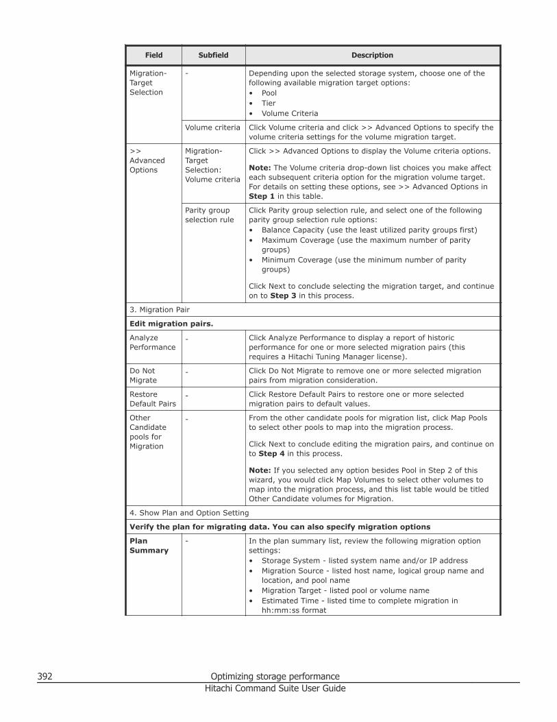
Field Subfield Description
Migration-TargetSelection
- Depending upon the selected storage system, choose one of thefollowing available migration target options:• Pool• Tier• Volume Criteria
Volume criteria Click Volume criteria and click >> Advanced Options to specify thevolume criteria settings for the volume migration target.
>>AdvancedOptions
Migration-TargetSelection:Volume criteria
Click >> Advanced Options to display the Volume criteria options.
Note: The Volume criteria drop-down list choices you make affecteach subsequent criteria option for the migration volume target.For details on setting these options, see >> Advanced Options inStep 1 in this table.
Parity groupselection rule
Click Parity group selection rule, and select one of the followingparity group selection rule options:• Balance Capacity (use the least utilized parity groups first)• Maximum Coverage (use the maximum number of parity
groups)• Minimum Coverage (use the minimum number of parity
groups)
Click Next to conclude selecting the migration target, and continueon to Step 3 in this process.
3. Migration Pair
Edit migration pairs.
AnalyzePerformance
- Click Analyze Performance to display a report of historicperformance for one or more selected migration pairs (thisrequires a Hitachi Tuning Manager license).
Do NotMigrate
- Click Do Not Migrate to remove one or more selected migrationpairs from migration consideration.
RestoreDefault Pairs
- Click Restore Default Pairs to restore one or more selectedmigration pairs to default values.
OtherCandidatepools forMigration
- From the other candidate pools for migration list, click Map Poolsto select other pools to map into the migration process.
Click Next to conclude editing the migration pairs, and continue onto Step 4 in this process.
Note: If you selected any option besides Pool in Step 2 of thiswizard, you would click Map Volumes to select other volumes tomap into the migration process, and this list table would be titledOther Candidate volumes for Migration.
4. Show Plan and Option Setting
Verify the plan for migrating data. You can also specify migration options
PlanSummary
- In the plan summary list, review the following migration optionsettings:• Storage System - listed system name and/or IP address• Migration Source - listed host name, logical group name and
location, and pool name• Migration Target - listed pool or volume name• Estimated Time - listed time to complete migration in
hh:mm:ss format
392 Optimizing storage performanceHitachi Command Suite User Guide
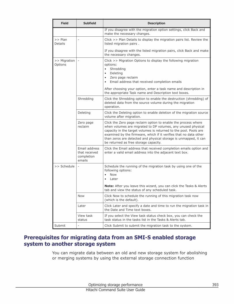
Field Subfield Description
If you disagree with the migration option settings, click Back andmake the necessary changes.
>> PlanDetails
- Click >> Plan Details to display the migration pairs list. Review thelisted migration pairs .
If you disagree with the listed migration pairs, click Back and makethe necessary changes.
>> MigrationOptions
- Click >> Migration Options to display the following migrationoptions:• Shredding• Deleting• Zero page reclaim• Email address that received completion emails
After choosing your option, enter a task name and description inthe appropriate Task name and Description text boxes.
Shredding Click the Shredding option to enable the destruction (shredding) ofdeleted data from the source volume during the migrationoperation.
Deleting Click the Deleting option to enable deletion of the migration sourcevolume after migration.
Zero pagereclaim
Click the Zero page reclaim option to enable the process wherewhen volumes are migrated to DP volumes, any unused physicalcapacity in the target volumes is returned to the pool. Pools areexamined by the firmware, which if it verifies that no data otherthan zeros are detected and physical storage is unmapped, it canbe returned as free storage capacity.
Email addressthat receivedcompletionemails
Click the Email address that received completion emails option andenter a valid email address into the adjacent text box.
>> Schedule - Schedule the running of the migration task by using one of thefollowing options:• Now• Later
Note: After you leave this wizard, you can click the Tasks & Alertstab and view the status of any scheduled task.
Now Click Now to schedule the running of this migration task now(which is the default).
Later Click Later and specify a date and time to run the migration task inthe Date and Time text boxes.
View taskstatus
If you select the View task status check box, you can check thetask status in the tasks list in the Tasks & Alerts tab.
Submit - Click Submit to submit the migration task to the system.
Prerequisites for migrating data from an SMI-S enabled storagesystem to another storage system
You can migrate data between an old and new storage system for abolishingor merging systems by using the external storage connection function
Optimizing storage performance 393Hitachi Command Suite User Guide
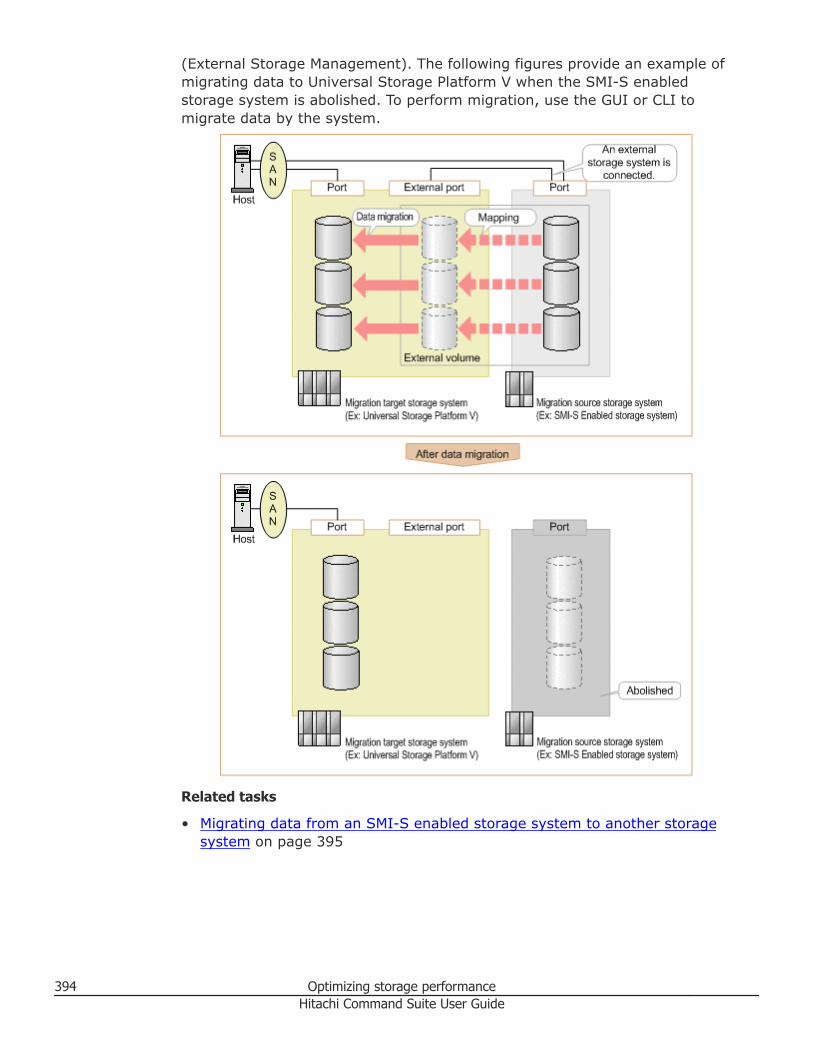
(External Storage Management). The following figures provide an example ofmigrating data to Universal Storage Platform V when the SMI-S enabledstorage system is abolished. To perform migration, use the GUI or CLI tomigrate data by the system.
Related tasks
• Migrating data from an SMI-S enabled storage system to another storagesystem on page 395
394 Optimizing storage performanceHitachi Command Suite User Guide
Migrating data from an SMI-S enabled storage system to anotherstorage system
You can migrate data from an SMI-S enabled storage system to anotherstorage system.
Prerequisites• Register a Tiered Storage Manager license.• Set up Tiered Storage Manager CLI (if necessary).• Set up Device Manager CLI (if necessary)• Connect the port on the SMI-S enabled storage system to the External
port of the storage system by using Fibre Channel or Fibre Channel overEthernet.
• Assign the volumes on the SMI-S enabled storage system to an Externalport (performed by the management tool of the SMI-S enabled storagesystem).
• Gather the following information:○ Name or IP address of the allocation target host.○ WWN and LUN associated with the migration source SMI-S enabled
storage system that was assigned to the External port.
For details about the specified values specified for parameters and syntax ofeach CLI command of Device Manager and Tiered Storage Manager to beused in tasks, see the Hitachi Command Suite CLI Reference Guide and theTiered Storage Manager CLI Reference Guide.
Procedure
1. Register the migration target storage system and the migration sourceSMI-S enabled storage system in Hitachi Command Suite. Use the GUI toregister the storage systems, or run the AddStorageArray command(Device Manager CLI).
Note: Registering or updating a storage system might take a long timedepending on its configuration or scale, so you need to perform theseoperations systematically.
Note: If the migration target or source storage system has already beenregistered, you need to update the migration target or source storagesystem in order to obtain the latest configuration information.
2. Stop the hosts to which the storage systems are connected.Observe that the following steps (3 - 4) need to be performed while thehost is stopped, so you need a plan that considers host operations.
Optimizing storage performance 395Hitachi Command Suite User Guide
3. Map the volumes of the migration source SMI-S enabled storage systemto the migration target storage system as external volumes.Use the GUI to map the volumes or run the AddExternalArrayGroupcommand (Device Manager CLI).
4. Allocate the external volumes mapped to the migration target storagesystem to the host.Use the GUI to allocate the volumes, or run the AddLun command(Device Manager CLI).
5. Start the host, and then change the target that the host (applications)accesses from the migration source storage system to the migrationtarget storage system.Perform this step by using the configuration tools of the host whileapplications are stopped.
6. Migrate data in the external volumes (migration source) to an internalvolume of the migration target storage system (data migration). Use theGUI to migrate data, or run the following commands (Tiered StorageManager CLI):• CreateStorageTier command• CreateMigrationGroup command• CreateMigrationPlan command• CreateMigrationTask command• ExecuteTask command
7. Unmap the external volumes (migration source) from the migrationtarget storage system.Use the GUI to unmap (unvirtualize) the volumes or run theDeleteExternalArrayGroup command (Device Manager CLI).
8. Delete the migration source SMI-S enabled storage system from themanagement targets of Hitachi Command Suite.Use the GUI to delete a storage system, or run the DeleteStorageArraycommand in the Device Manager CLI.
Result
The data of the migration source SMI-S enabled storage system can now beused as an internal volume of the migration target storage system. Themigration source SMI-S enabled storage system can be removed.
Related references
• Operations available to SMI-S enabled storage systems on page 62
396 Optimizing storage performanceHitachi Command Suite User Guide
10Grouping resources
This module describes how to group logical groups and storage tiers(resources).
□ Managing logical groups
□ Managing storage tiers
Grouping resources 397Hitachi Command Suite User Guide
Managing logical groupsThis module describes how to manage the two supported logical group types:public and private. Public and private logical groups are listed in thenavigation pane (Resources > Logical Groups) under the Public LogicalGroups root folder and the Private Logical Groups root folder, respectively.
About logical groupsA logical group is a mechanism for the grouping of storage resources (hostsand volumes) by storage administrators, and can be organized according tobusiness operations, geographic locations, or other organizational divisions.
Using grouped storage resources as logical groups allows you to:• Create summary reports that indicate current resource use in a storage
environment by organization.You can create logical groups that generate usage summary reports foreach organization that uses storage, if you manage an entire system.
• Monitor volumes and perform storage system operations by groupingtogether managed resources (hosts and volumes).You can categorize volumes according to the organizations that use thestorage, if you manage a part of a system. Grouping and categorizingvolumes makes finding volumes easier and allows you to perform dailyoperations for volume resources.
You can add multiple hosts or volumes to a logical group at one time byspecifying a range of IP addresses, or by specifying multiple items, such asoperating system type and drive type. The same hosts or volumes can beregistered to multiple logical groups.
When you need to, you can add or remove hosts and volumes from a logicalgroup, or change the hierarchy, or structure, of existing logical group folders,depending on the logical group type. Any volumes allocated to a host in alogical group are automatically assigned to the logical group. Note that childgroups cannot be created below host or volume groups (child groups can becreated only below folders).
Hitachi Command Suite supports two types of logical groups: public andprivate. A key distinction between public and private logical groups is the rootlocation in the work area for the user, and these two logical group types havethe following basic structure in the navigation pane:
Public logical groups• Logical group folders that contains groups of hosts and volumes that are
grouped by business function, geographic, or other organizationaldivisions.
• Logical groups of hosts.• Logical groups of volumes.
398 Grouping resourcesHitachi Command Suite User Guide
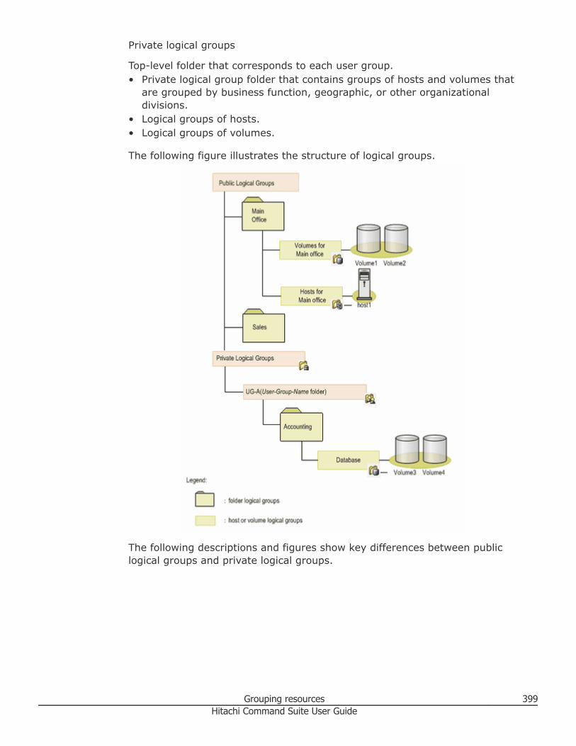
Private logical groups
Top-level folder that corresponds to each user group.• Private logical group folder that contains groups of hosts and volumes that
are grouped by business function, geographic, or other organizationaldivisions.
• Logical groups of hosts.• Logical groups of volumes.
The following figure illustrates the structure of logical groups.
The following descriptions and figures show key differences between publiclogical groups and private logical groups.
Grouping resources 399Hitachi Command Suite User Guide
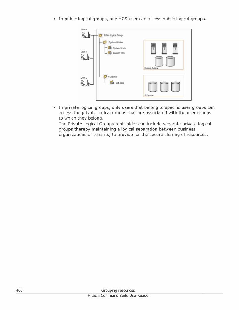
• In public logical groups, any HCS user can access public logical groups.
• In private logical groups, only users that belong to specific user groups canaccess the private logical groups that are associated with the user groupsto which they belong.The Private Logical Groups root folder can include separate private logicalgroups thereby maintaining a logical separation between businessorganizations or tenants, to provide for the secure sharing of resources.
400 Grouping resourcesHitachi Command Suite User Guide
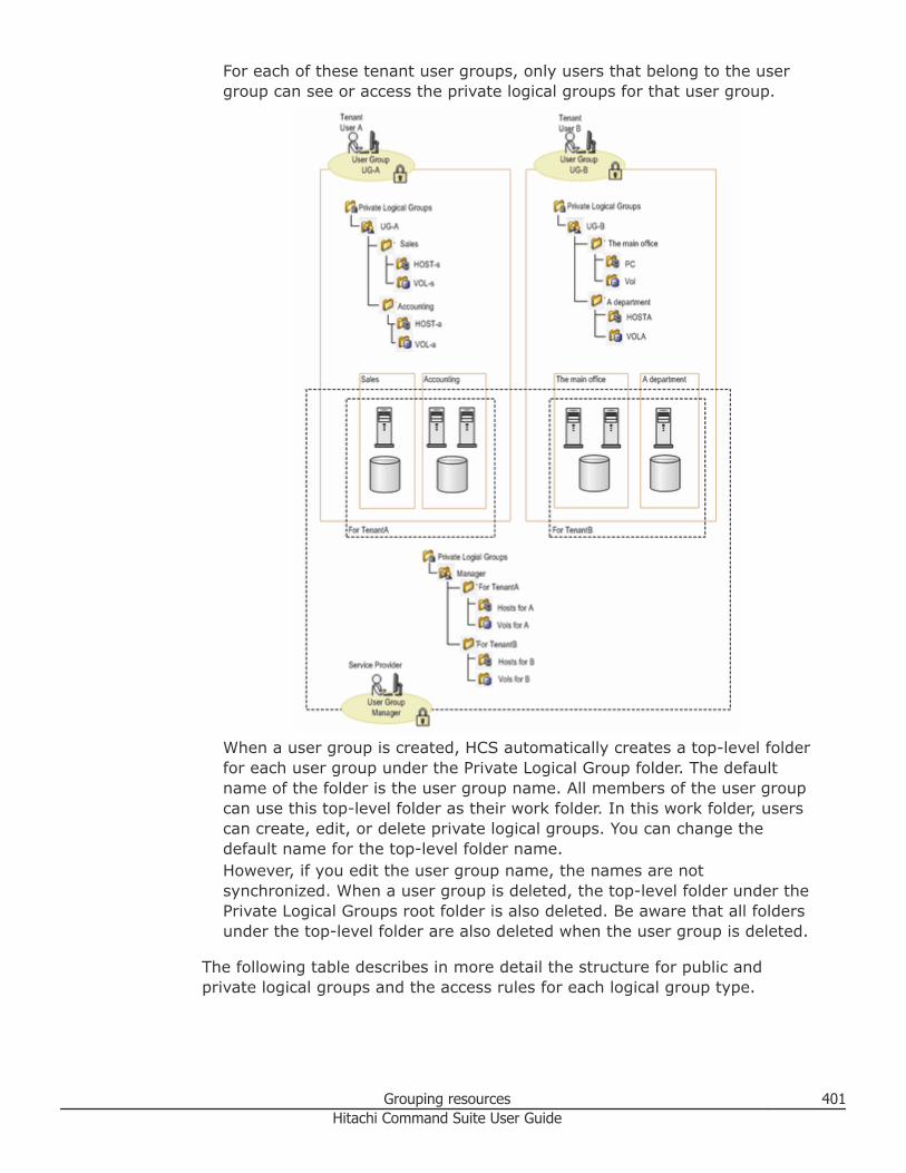
For each of these tenant user groups, only users that belong to the usergroup can see or access the private logical groups for that user group.
When a user group is created, HCS automatically creates a top-level folderfor each user group under the Private Logical Group folder. The defaultname of the folder is the user group name. All members of the user groupcan use this top-level folder as their work folder. In this work folder, userscan create, edit, or delete private logical groups. You can change thedefault name for the top-level folder name.However, if you edit the user group name, the names are notsynchronized. When a user group is deleted, the top-level folder under thePrivate Logical Groups root folder is also deleted. Be aware that all foldersunder the top-level folder are also deleted when the user group is deleted.
The following table describes in more detail the structure for public andprivate logical groups and the access rules for each logical group type.
Grouping resources 401Hitachi Command Suite User Guide
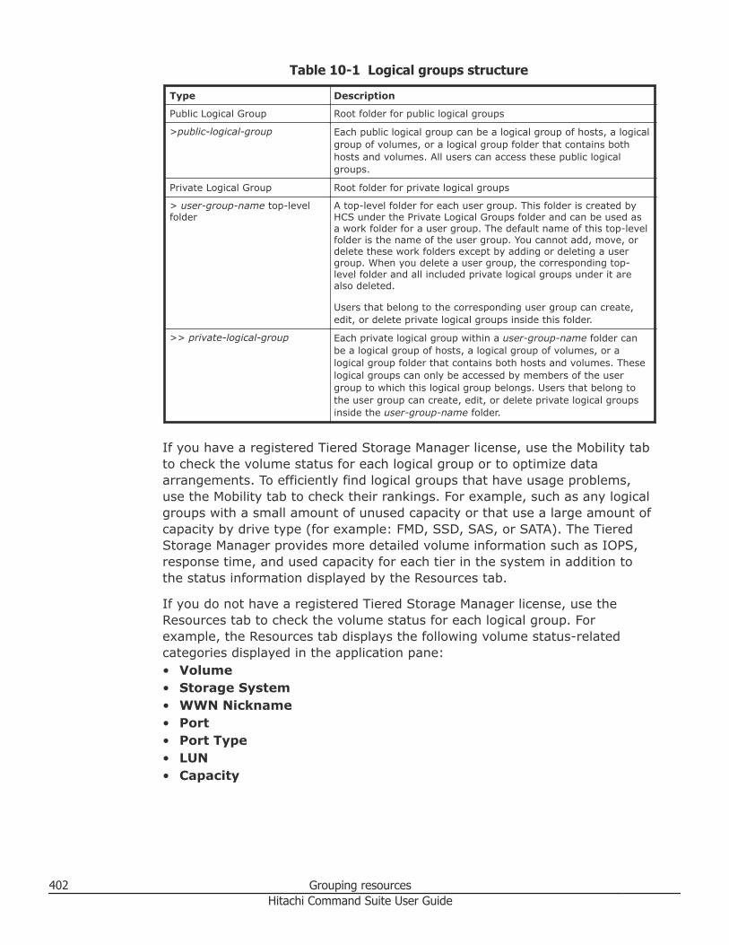
Table 10-1 Logical groups structure
Type Description
Public Logical Group Root folder for public logical groups
>public-logical-group Each public logical group can be a logical group of hosts, a logicalgroup of volumes, or a logical group folder that contains bothhosts and volumes. All users can access these public logicalgroups.
Private Logical Group Root folder for private logical groups
> user-group-name top-levelfolder
A top-level folder for each user group. This folder is created byHCS under the Private Logical Groups folder and can be used asa work folder for a user group. The default name of this top-levelfolder is the name of the user group. You cannot add, move, ordelete these work folders except by adding or deleting a usergroup. When you delete a user group, the corresponding top-level folder and all included private logical groups under it arealso deleted.
Users that belong to the corresponding user group can create,edit, or delete private logical groups inside this folder.
>> private-logical-group Each private logical group within a user-group-name folder canbe a logical group of hosts, a logical group of volumes, or alogical group folder that contains both hosts and volumes. Theselogical groups can only be accessed by members of the usergroup to which this logical group belongs. Users that belong tothe user group can create, edit, or delete private logical groupsinside the user-group-name folder.
If you have a registered Tiered Storage Manager license, use the Mobility tabto check the volume status for each logical group or to optimize dataarrangements. To efficiently find logical groups that have usage problems,use the Mobility tab to check their rankings. For example, such as any logicalgroups with a small amount of unused capacity or that use a large amount ofcapacity by drive type (for example: FMD, SSD, SAS, or SATA). The TieredStorage Manager provides more detailed volume information such as IOPS,response time, and used capacity for each tier in the system in addition tothe status information displayed by the Resources tab.
If you do not have a registered Tiered Storage Manager license, use theResources tab to check the volume status for each logical group. Forexample, the Resources tab displays the following volume status-relatedcategories displayed in the application pane:• Volume• Storage System• WWN Nickname• Port• Port Type• LUN• Capacity
402 Grouping resourcesHitachi Command Suite User Guide
Related tasks
• Creating logical groups on page 403• Editing logical groups on page 405• Viewing logical group reports on page 404• Performing operations from a logical group on page 405• Deleting logical groups on page 406• Creating user groups on page 128
Creating logical groupsHCS supports two types of logical groups: Public Logical Groups and PrivateLogical Groups.
Prerequisites
• Verify that any host to be assigned to a logical group is a normal host, avirtualization server, or a virtual machine registered as a host.
Observe the following restrictions:• File servers cannot be assigned to a logical group.• Mainframe volumes (MF-Vols) cannot be assigned to a logical group.• Child groups cannot be created below host or volume groups. Child groups
can be created only below folders.
Procedure
1. On the Resources tab, select Logical Groups.2. Create a logical group using one of the following methods:
• For a Public Logical Group, select the Public Logical Groups root folderand click Create Logical Group.
• For a Private Logical Group, select the Private Logical Groups rootfolder, select a top-level folder for each user group under the PrivateLogical Group folder, and then click Create Logical Group.
3. In the Create Logical Group dialog box, enter information in the Nameand Description fields, and select one of the following Create asoptions: Folder, Group of hosts, or Group of volumes.• To create a folder, click the Folder option and click OK.• To create a group of hosts, click the Group of hosts option, and
choose how to specify hosts for a logical group by selecting one of thefollowing Specify hosts options: By Search Criteria or Manually.If you selected By Search Criteria, click Add Criteria in the list ofcriteria. In the Add Conditions dialog box, specify values for IPAddress Criteria, Name Criteria, and Operating System Criteriaas needed. You can also choose to click Search Result Preview,select one or more hosts in the list of hosts, and click Add to addthem to the list of hosts, and then click OK.
Grouping resources 403Hitachi Command Suite User Guide
If you selected Manually, click Add Hosts and in the Add Hostsdialog box, select one or more hosts from the lists of hosts, click Addto add them to the list of selected hosts, and then click OK.
• To create a group of volumes, click the Group of volumes option,and choose how to specify volumes for a logical group by selecting oneof the following Specify volumes options: By Search Criteria orManually.If you selected By Search Criteria, click Add Criteria in the list ofcriteria. In the Add Conditions dialog box, specify values for UsageCriteria, Storage System Criteria, and Volume Criteria as needed.You can also choose to click Search Result Preview, select one ormore volumes in the list of selected volumes, click Add, and then clickOK.If you selected Manually, click Add Volume and in the AddVolumes dialog box, select one or more volumes from the list ofavailable volumes, click Add to add them to the list of selectedvolumes, and then click OK.
4. Repeat this process for each new logical group that you want to create.5. To create a hierarchy of logical groups, repeat step 2.
Result
New logical groups appear on the Resources tab under Logical Groups.
Tip: To delete logical groups, select the logical groups to be deleted, clickDelete Logical Groups, and click OK.
Related concepts
• About logical groups on page 398
Related tasks
• Editing logical groups on page 405
Viewing logical group reportsYou can view summary reports for specified logical groups.
Procedure
1. On the Resources tab, click Logical Groups.2. Expand the tree and select the target logical group.
Related concepts
• About logical groups on page 398
Related tasks
• Creating logical groups on page 403
404 Grouping resourcesHitachi Command Suite User Guide
Editing logical groupsYou can edit a logical group to change the name and description, move alogical group to another logical group folder, select a new parent logicalgroup, or edit a logical group to add or remove hosts or volumes.
If data placement profiles for HDT volumes are created, a change of logicalgroups is reflected for the structure of data placement profiles.
Procedure
1. On the Resources tab, click Logical Groups.2. Select Public Logical Groups or Private Logical Groups.3. In the list of logical groups on the application pane, click the row for the
logical group you want to edit, and click Edit Logical Group.4. Edit the name or description of the logical group.5. Click Change Location to move the logical group to another logical
group folder, select a new parent logical group, and click OK.6. Select the logical group for the volumes or hosts that you want to add or
remove, and click OK .7. Click OK to finish editing the logical group.
Result
Changes are reflected in the Logical Groups tree in the navigation pane, andin the details of the logical groups.
Related concepts
• About logical groups on page 398
Related tasks
• Creating logical groups on page 403
Performing operations from a logical groupYou can perform tasks on storage systems by starting from a logical group.
Procedure
1. On the Resources tab, select Logical Groups, and select either PublicLogical Groups or Private Logical Groups.
2. Expand the appropriate logical groups tree and select the target logicalgroup.
3. Select a host or volume.4. Click on the task type you want to perform such as Allocate Like
Volumes, Edit Labels, Edit LUN Paths, or Export to CSV, or clickMore Actions for additional choices.
5. If needed, update the task name and provide a description.
Grouping resources 405Hitachi Command Suite User Guide
6. Click Submit.7. You can check the progress and result of the selected task on the Tasks
& Alerts tab, and verify the results.
Related concepts
• About logical groups on page 398
Related tasks
• Creating logical groups on page 403
Deleting logical groupsYou can delete logical groups when they are no longer required.
Procedure
1. On the Resources tab, select Logical Groups.2. Depending on the type of logical group you want to delete (public or
private), do one of the following:• Click Public Logical Groups in the navigation pane, and then select a
logical group from the list of logical groups in the application pane.• Expand Private Logical Groups in the navigation pane, select a
logical group folder from the navigation pane, and then select a logicalgroup from the list of logical groups in the application pane.
3. Click Delete Logical Groups.
Tip: Deleting a user group deletes the private logical group folder and allthe logical groups in that folder. You cannot delete a top-level folder foreach user group under the Private Logical Group folder.
4. Click OK to confirm and delete the logical group.
Result
The logical group you deleted no longer appears in the list of logical groups.
Related tasks
• Deleting user groups on page 130
Managing storage tiersThis module describes how to manage tiers.
About tier-based storage managementIn Hitachi Command Suite, you must have a Tiered Storage Manager licenseto perform tier-based storage management operations.
406 Grouping resourcesHitachi Command Suite User Guide
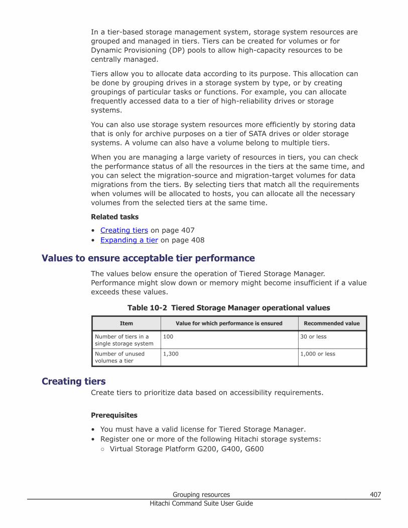
In a tier-based storage management system, storage system resources aregrouped and managed in tiers. Tiers can be created for volumes or forDynamic Provisioning (DP) pools to allow high-capacity resources to becentrally managed.
Tiers allow you to allocate data according to its purpose. This allocation canbe done by grouping drives in a storage system by type, or by creatinggroupings of particular tasks or functions. For example, you can allocatefrequently accessed data to a tier of high-reliability drives or storagesystems.
You can also use storage system resources more efficiently by storing datathat is only for archive purposes on a tier of SATA drives or older storagesystems. A volume can also have a volume belong to multiple tiers.
When you are managing a large variety of resources in tiers, you can checkthe performance status of all the resources in the tiers at the same time, andyou can select the migration-source and migration-target volumes for datamigrations from the tiers. By selecting tiers that match all the requirementswhen volumes will be allocated to hosts, you can allocate all the necessaryvolumes from the selected tiers at the same time.
Related tasks
• Creating tiers on page 407• Expanding a tier on page 408
Values to ensure acceptable tier performanceThe values below ensure the operation of Tiered Storage Manager.Performance might slow down or memory might become insufficient if a valueexceeds these values.
Table 10-2 Tiered Storage Manager operational values
Item Value for which performance is ensured Recommended value
Number of tiers in asingle storage system
100 30 or less
Number of unusedvolumes a tier
1,300 1,000 or less
Creating tiersCreate tiers to prioritize data based on accessibility requirements.
Prerequisites
• You must have a valid license for Tiered Storage Manager.• Register one or more of the following Hitachi storage systems:
○ Virtual Storage Platform G200, G400, G600
Grouping resources 407Hitachi Command Suite User Guide
○ Virtual Storage Platform G1000○ Virtual Storage Platform○ Universal Storage Platform V/VM○ USP○ HUS VM
Procedure
1. On the Resources tab, select Tiers.2. Select the storage system for which to create a tier.3. Click Create Tier.4. Specify the appropriate information.5. Click OK.
Result
The tier is created and added to the storage system.
Related concepts
• About tier-based storage management on page 406
Related tasks
• Expanding a tier on page 408• Deleting tiers on page 409
Expanding a tierEdit a tier to expand it.
Prerequisites
A Tiered Storage Manager license must be registered.
Procedure
1. On the Resources tab, select Tiers.2. Expand the tree, and select the storage system with the tier you want to
expand.3. From the list of tiers in the application pane, select the tier you want to
expand and click Edit Tier.4. Specify the appropriate values.5. Click OK.6. Confirm that the tier has expanded.
Related concepts
• About tier-based storage management on page 406
408 Grouping resourcesHitachi Command Suite User Guide
Related tasks
• Creating tiers on page 407
Deleting tiersYou can delete storage tiers that you no longer need.
Procedure
1. On the Resources tab, select Tiers.2. Select the tiers to delete.3. Click Delete Tier.4. Click Delete.5. Confirm that the tier is deleted.
Result
The tiers you deleted no longer appear in the list of tiers.
Grouping resources 409Hitachi Command Suite User Guide

410 Grouping resourcesHitachi Command Suite User Guide
11Managing storage system information
This module describes how to manage resource labels and WWN nicknames,how to search managed resources, and how to generate storage systemreports.
□ Managing resource labels
□ Managing WWNs by using nicknames
□ Searching HCS resources
□ Generating resource reports
□ Using reports to verify system changes
Managing storage system information 411Hitachi Command Suite User Guide
Managing resource labelsThis module describes how to manage resource labels.
About managing resource labelsUser-defined resource labels can be assigned to volumes and DP pools.Specifically, resource labels can be volume labels, or DP pool names.
Resource labels help you:• Search for volumes or DP pools• Differentiate between listed volumes or DP pools• Confirm the correct resource is being acted upon
When searching resource labels, you can:• Allocate volumes or DP pools• Edit volume LUN paths
Resource labels are assigned using:• Device Manager• Storage Navigator
For storage systems where resource labels have already been configuredusing Storage Navigator, you can apply (import) the resource labels toDevice Manager in a batch operation.
If Device Manager and Storage Navigator are both actively used, and HCS isthe primary management software, labels assigned in Device Manager can beapplied (exported) to storage systems managed by Storage Navigator.Volume labels can be assigned when creating or allocating volumesdepending on their use for hosts or applications. For Virtual Storage PlatformG200, G400, G600 or Virtual Storage Platform G1000, importing andexporting labels is unnecessary because the label information from thestorage system and the HCS labels will always match.
Note: Due to differences between Device Manager and storage systems,incompatible character type or string length issues will be reported with pop-up messages. Use the message to resolve resource label naming issues.
Tip: You can apply any current label to the storage system by specifying thefollowing settings:• For volume labels, select Reflect current labels to the storage systems.• For DP pool names, select Reflect this pool name to the storage system.
Related tasks
• Editing resource labels on page 413• Searching resource labels on page 413
412 Managing storage system informationHitachi Command Suite User Guide
• Importing storage system resource labels on page 414
Editing resource labelsYou can create or edit resource labels for volumes or DP pool names.
Procedure
1. On the Resources tab, expand Storage Systems to display the list ofvolumes or DP pools.
2. Select a volume or DP pool.3. Choose one of the following options:
• Click Edit Labels to edit a volume label.• Click Edit Pool to edit a DP pool name.
4. Specify a new label or DP pool name.5. (Optional) Update the task name and provide a description.6. (Optional) Expand Schedule to specify the task schedule.
You can schedule the task to run immediately or later. The default settingis Now. If the task is scheduled to run immediately, you can select Viewtask status to monitor the task after it is submitted.
7. Click Submit.If the task is scheduled to run immediately, the process begins.
8. (Optional) Check the progress and result of the task on the Tasks &Alerts tab. Click the task name to view details of the task.
Result
The revised volume or DP pool name appears in the list of volumes or DPpools.
Related concepts
• About managing resource labels on page 412
Searching resource labelsYou can search, filter and sort on resource labels to locate volumes or DPpools and perform actions on them.
Procedure
1. Locate volumes or DP pools by using one of the following methods:• Using the search box, enter a volume label or DP pool name, and
perform a search. You can use Search Keyword for to specify theresources you want to search, for example Volumes.
• From the search box, you can also search volume labels by usingMore Searches, selecting Volume, and selecting the category Labelfrom the Advanced tab.
Managing storage system information 413Hitachi Command Suite User Guide
• To filter, from the Resources tab expand the tree to display the list ofvolumes or DP pools, and click Filter to specify the volume label or DPpool name.
• To sort, from the Resources tab expand the tree to display the list ofvolumes or DP pools, and click Label or Name column headings tosort by volume label or DP pool name.
2. Select volumes or DP pools from the search, filter, or sort results.3. Perform the desired task.
Related concepts
• About managing resource labels on page 412
Importing storage system resource labelsIn an environment where storage system resource labels have already beenset using Storage Navigator, you can apply (import) the storage systemresource labels to Device Manager.
Note: Applying storage system resource labels overwrites all the volumelabels and DP pool names in HCS for the selected storage system. For VirtualStorage Platform G200, G400, G600 or Virtual Storage Platform G1000,refreshing the labels is unnecessary because the label information from thestorage system to HCS will always match.
Procedure
1. On the Resources tab, from the list of Storage Systems in theapplication pane, select the storage system whose labels you want toapply.
2. Click Refresh Labels.3. Select the resource labels to apply, and submit the task.4. Check the task results in Tasks & Alerts.
Result
Make sure the labels are changed in the volume list, and that pool names arechanged in the DP pool list.
Related concepts
• About managing resource labels on page 412
Managing WWNs by using nicknamesThis module describes how to specify, change or delete WWN nicknames.
About managing WWNs by using nicknamesEach host bus adapter (HBA) has a unique World Wide Name (WWN)identifier that consists of a 64-bit physical address. The purpose of specifying
414 Managing storage system informationHitachi Command Suite User Guide
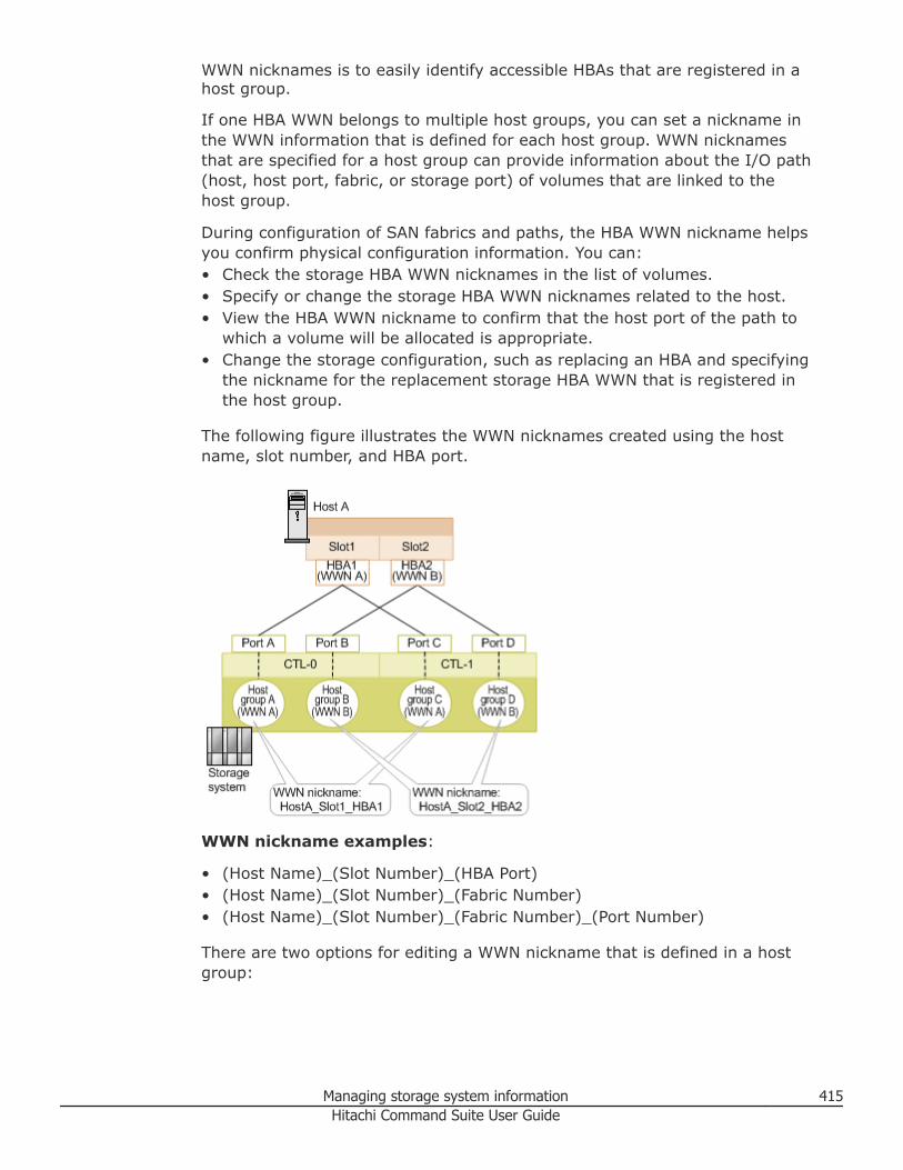
WWN nicknames is to easily identify accessible HBAs that are registered in ahost group.
If one HBA WWN belongs to multiple host groups, you can set a nickname inthe WWN information that is defined for each host group. WWN nicknamesthat are specified for a host group can provide information about the I/O path(host, host port, fabric, or storage port) of volumes that are linked to thehost group.
During configuration of SAN fabrics and paths, the HBA WWN nickname helpsyou confirm physical configuration information. You can:• Check the storage HBA WWN nicknames in the list of volumes.• Specify or change the storage HBA WWN nicknames related to the host.• View the HBA WWN nickname to confirm that the host port of the path to
which a volume will be allocated is appropriate.• Change the storage configuration, such as replacing an HBA and specifying
the nickname for the replacement storage HBA WWN that is registered inthe host group.
The following figure illustrates the WWN nicknames created using the hostname, slot number, and HBA port.
WWN nickname examples:
• (Host Name)_(Slot Number)_(HBA Port)• (Host Name)_(Slot Number)_(Fabric Number)• (Host Name)_(Slot Number)_(Fabric Number)_(Port Number)
There are two options for editing a WWN nickname that is defined in a hostgroup:
Managing storage system information 415Hitachi Command Suite User Guide
• Collectively edit the WWN nickname for all related host groups. When thisoption is selected, the WWN nickname is applied to all host groups thathave the same WWN.
• Edit the WWN nickname of an individual host group. When this option isselected, only the WWN nickname of the individual host group is changed.
Tip: If a nickname is set to a WWN by using a storage system managementtool, such as Storage Navigator, you can view the latest WWN nickname byrefreshing the storage system information. Also, if there are multiple WWNnicknames set to the host groups on the storage system, only one WWNnickname for the port on the host is selected and displayed automatically.
Related tasks
• Editing a WWN nickname on page 416
Editing a WWN nicknameYou can specify a new WWN nickname, or change or delete an existingnickname, for storage HBA WWNs that are registered in a host group.
Prerequisites
Register HBA WWNs for which nicknames will be specified in the host group.
Procedure
1. On the Resources tab, select Hosts.2. After selecting the target operating system, select a target host, and
then click More Actions > Edit WWN Nicknames.3. From the Storage system drop-down list, select a storage system.
• All Storage Systems: Displays a list of WWNs that belong to the hostgroup related to the selected host.
• Specific storage system: Displays a list of WWNs that belong to thehost group related to the selected host and storage system.
4. From Edit option, select one of the following:• Edit WWN nickname for all related host groups: Applies the WWN
nickname setting to all storage host groups.
• Edit WWN nickname for individual host groups: Applies the WWNnickname to individual host groups in the storage system selected.
5. In the Nickname column, enter a WWN nickname or modify the existingWWN nickname. If All Storage Systems and Edit WWN nickname forall related host groups is selected, the minimum number of characterlimit allowed is applied to all storage systems.
416 Managing storage system informationHitachi Command Suite User Guide
Tip: To delete a WWN nickname, clear the text.
6. (Optional) Update the task name and provide a description.7. (Optional) Expand Schedule to specify the task schedule.
You can schedule the task to run immediately or later. The default settingis Now. If the task is scheduled to run immediately, you can select Viewtask status to monitor the task after it is submitted.
8. Click Submit.If the task is scheduled to run immediately, the process begins.
9. (Optional) Check the progress and result of the task on the Tasks &Alerts tab. Click the task name to view details of the task.
Result
The WWN nickname edits are applied to the WWNs registered in the hostgroup.
Related concepts
• About managing WWNs by using nicknames on page 414
Searching HCS resourcesThis module describes using search to locate, work with, and report onstorage resources.
About searching HCS resourcesSearch finds storage and host resources quickly and easily, and allows you towork with the resources from the search results.
Search is useful for:• Investigating and working with storage resources - for example, you can
quickly find a host and allocate a volume to the host. Note that when youclick on a search results link, you will automatically go to the resource inthe Resources tab so you can work with the resource, or you will get moredetail on the item, as with volumes.
• Reporting on storage resources - for reporting, search results and relateddetail can be saved as CSV files using the Export to CSV button, or fromthe Actions menu. Note that CSV (comma separated values) files can beopened by many spreadsheet applications for review or editing.
Search methods include:• Keyword search - a search on user entered text. You can enter a full or
partial text string and search specific fields related to storage resources,such as:○ Storage Systems - search names, IP addresses, and serial numbers
Managing storage system information 417Hitachi Command Suite User Guide
○ Hosts - search names, IP addresses, iSCSI names and WWNs○ Volumes - search volume IDs that match the keyword, or volume labels○ Parity Groups - search parity group names○ DP Pools - search IDs that match the keyword, and names○ Logical Groups - search names or descriptions
• Criteria search - a search on attribute information, for example a volumesearch where the volume belongs to a RAID 5 parity group.○ Criteria searches can be saved by the user, and optionally, shared with
others○ Note that saving searches requires a Tiered Storage Manager license
Related tasks
• Keyword search on page 418• Criteria search on page 419
Keyword searchTo perform a keyword search, locate the Search box on the upper right sideof the GUI. The search box is always visible.
Procedure
1. Enter a full or partial text string in the Search box. A partial string willgenerally produce more search results.
2. By default, all resources are searched when you press Enter. You cannarrow the scope of your search using the down arrow, selectingSearch Keyword for, and selecting a specific resource to search on.This executes the search and displays results. Each resource has an iconthat appears in the search box when it has been selected, and is the newdefault resource.
3. The Keyword Search dialog box is displayed. If there are no searchresults for an All Resources search or you entered a null string, you willsee a help message. A search on a specific resource with no resultsdisplays a resources tab with no results listed.
4. When search results are displayed, click the resource name hyperlink togo to the Resources tab for the resource. When viewing the detail panefor the resource (for example, a list of volumes for a host) you can usethe Export to CSV button (or Actions menu) to generate a resourcereport for selected detail pane items (for example, all or some of thevolumes for a host), or you can select detail pane items to perform anoperation (for example, selecting a volume and editing the volume label).
5. If the current search results do not meet your needs, or you want to runmultiple searches without closing the Keyword Search dialog box, youcan repeatedly enter a new search string, and select the resource tosearch. To perform a criteria search for storage resources, click the MoreSearches button to start the Search dialog box.
418 Managing storage system informationHitachi Command Suite User Guide
Related concepts
• About searching HCS resources on page 417
Related tasks
• Criteria search on page 419
Criteria searchTo perform a criteria search, locate the Search box on the upper right side ofthe GUI. The search box is always visible.
Note: A Tiered Storage Manager license is required to save searches, asdescribed below.
Procedure
1. To start the Search dialog box, click down arrow, and select MoreSearches.• Search criteria are specified in the left pane.• Search results are displayed in the right pane.
2. Use Search for: to select one of the following storage resources:• Volumes• Parity Groups• DP Pools• Free Space
3. To the right of Search for:, select All storage systems, or select aspecific storage system.
4. The Basic and Advanced tabs provide further refinements for yoursearch. The selected storage resource (volumes, parity groups, etc.)affects the search criteria available under the Basic and Advanced tabs.This can be seen by changing the selected storage resource andreviewing available options.
5. To run your search, click Search. When results are displayed, displaycontrols are provided for easier viewing, including tiling options, amaximize control, and the Column Settings button for controlling whatdata is displayed. Depending on the resource being displayed, you willsee buttons for performing an action on selected resources. For example,when looking at a list of volumes, you will be able to Allocate Volumes(to a host), Create Pool (only for storage systems supporting thisfeature), Edit Label (volume labels, which can be searched on later),Export to CSV (reporting) or More Actions (more volume relatedtasks).
6. To save a search, click Save, and enter a name and description, thenselect Save as a public search (check box) to share the search withothers. Note that saved searches are displayed according to the storageresource. For example, if you run a parity group search and save it, it
Managing storage system information 419Hitachi Command Suite User Guide
only displays when the selected storage resource is Parity Group.Similarly, changing the storage resource to Volumes will display onlysaved volume searches.
7. To run a saved search, select the storage resource, and select the savedsearch.
8. To edit a saved search, run it, then click Save to start the edit dialogbox. Leave Name: as is. You may edit Description: and change Saveas a public search, then click Save to close the edit dialog box. If youhave a saved search selected and change the search criteria, run thesearch, click Save, edit the description etc., and click Save.
9. To delete a saved search, run the saved search. When the searchcompletes, click Delete Saved Search.
Related concepts
• About searching HCS resources on page 417
Related tasks
• Keyword search on page 418
Related references
• Criteria search dialog box on page 420
Criteria search dialog boxUse this dialog box to refine the search criteria you use for the volumes,parity groups, DP pools, and free space.
After you have selected the storage resources and storage systems to search,you can choose the Basic tab or the Advanced tab options in this dialog boxto refine your search.
Options differ with the selected storage resource as indicated by Vo(volumes), PG (parity groups), TP (DP pools), and FS (free space) in thefollowing table.
When you enter the minimum required information in this dialog box, theSearch button activates the search using the defined criteria. Click the Savebutton to name and save the search criteria you defined for later use.
The following table describes the dialog box fields, subfields, and fieldgroups. In the Basic tab, a field group is a collection of fields that are relatedto a specific action or configuration. You can minimize and expand fieldgroups by clicking the double-arrow symbol (>>).
The Advanced tab contains the following attributes:• All available categories for a search type (volumes, parity group, etc.) can
be combined into a compound search using the +/- buttons.• You can create a compound search where All/Any conditions need to be
met (and/or logic).
420 Managing storage system informationHitachi Command Suite User Guide
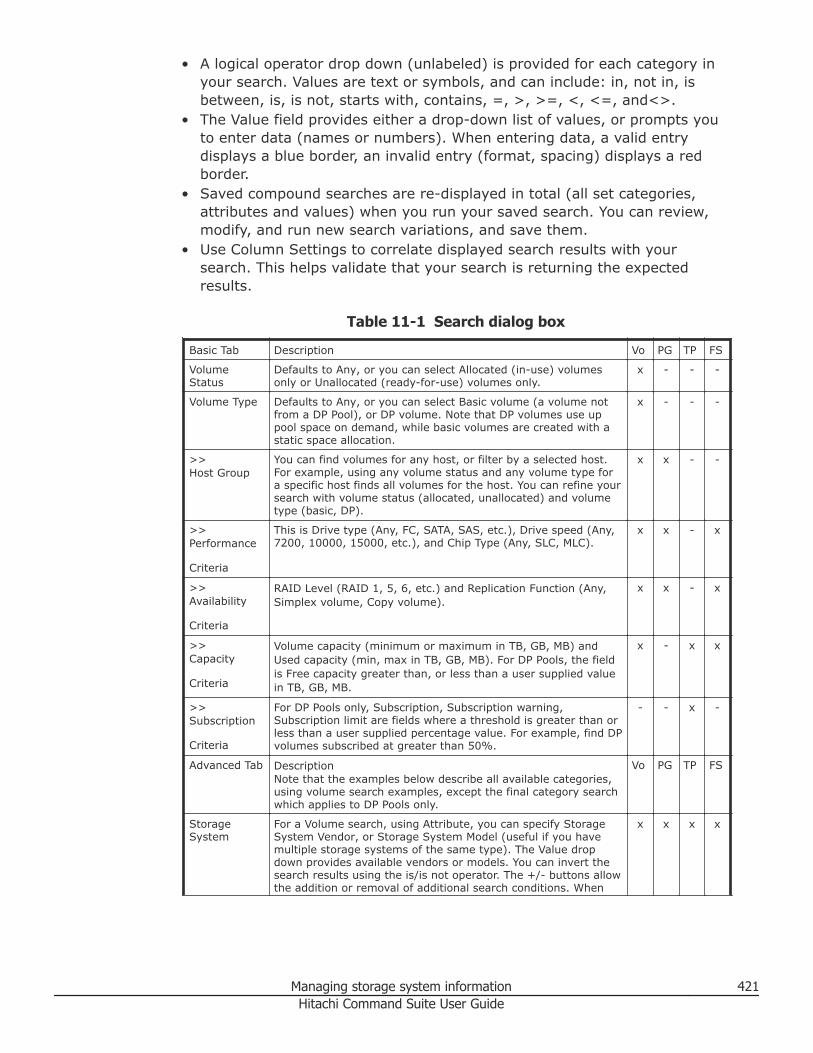
• A logical operator drop down (unlabeled) is provided for each category inyour search. Values are text or symbols, and can include: in, not in, isbetween, is, is not, starts with, contains, =, >, >=, <, <=, and<>.
• The Value field provides either a drop-down list of values, or prompts youto enter data (names or numbers). When entering data, a valid entrydisplays a blue border, an invalid entry (format, spacing) displays a redborder.
• Saved compound searches are re-displayed in total (all set categories,attributes and values) when you run your saved search. You can review,modify, and run new search variations, and save them.
• Use Column Settings to correlate displayed search results with yoursearch. This helps validate that your search is returning the expectedresults.
Table 11-1 Search dialog box
Basic Tab Description Vo PG TP FS
VolumeStatus
Defaults to Any, or you can select Allocated (in-use) volumesonly or Unallocated (ready-for-use) volumes only.
x - - -
Volume Type Defaults to Any, or you can select Basic volume (a volume notfrom a DP Pool), or DP volume. Note that DP volumes use uppool space on demand, while basic volumes are created with astatic space allocation.
x - - -
>>Host Group
You can find volumes for any host, or filter by a selected host.For example, using any volume status and any volume type fora specific host finds all volumes for the host. You can refine yoursearch with volume status (allocated, unallocated) and volumetype (basic, DP).
x x - -
>>Performance
Criteria
This is Drive type (Any, FC, SATA, SAS, etc.), Drive speed (Any,7200, 10000, 15000, etc.), and Chip Type (Any, SLC, MLC).
x x - x
>>Availability
Criteria
RAID Level (RAID 1, 5, 6, etc.) and Replication Function (Any,Simplex volume, Copy volume).
x x - x
>>Capacity
Criteria
Volume capacity (minimum or maximum in TB, GB, MB) andUsed capacity (min, max in TB, GB, MB). For DP Pools, the fieldis Free capacity greater than, or less than a user supplied valuein TB, GB, MB.
x - x x
>>Subscription
Criteria
For DP Pools only, Subscription, Subscription warning,Subscription limit are fields where a threshold is greater than orless than a user supplied percentage value. For example, find DPvolumes subscribed at greater than 50%.
- - x -
Advanced Tab DescriptionNote that the examples below describe all available categories,using volume search examples, except the final category searchwhich applies to DP Pools only.
Vo PG TP FS
StorageSystem
For a Volume search, using Attribute, you can specify StorageSystem Vendor, or Storage System Model (useful if you havemultiple storage systems of the same type). The Value dropdown provides available vendors or models. You can invert thesearch results using the is/is not operator. The +/- buttons allowthe addition or removal of additional search conditions. When
x x x x
Managing storage system information 421Hitachi Command Suite User Guide
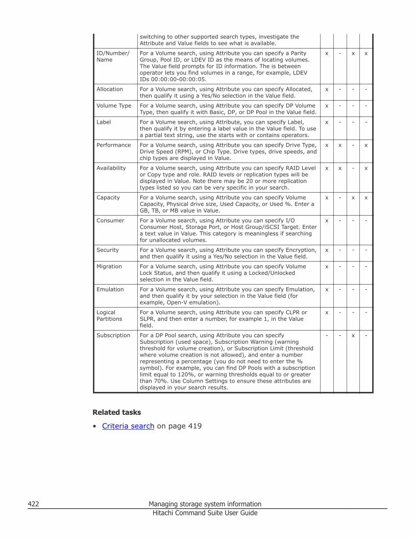
switching to other supported search types, investigate theAttribute and Value fields to see what is available.
ID/Number/Name
For a Volume search, using Attribute you can specify a ParityGroup, Pool ID, or LDEV ID as the means of locating volumes.The Value field prompts for ID information. The is betweenoperator lets you find volumes in a range, for example, LDEVIDs 00:00:00-00:00:05.
x - x x
Allocation For a Volume search, using Attribute you can specify Allocated,then qualify it using a Yes/No selection in the Value field.
x - - -
Volume Type For a Volume search, using Attribute you can specify DP VolumeType, then qualify it with Basic, DP, or DP Pool in the Value field.
x - - -
Label For a Volume search, using Attribute, you can specify Label,then qualify it by entering a label value in the Value field. To usea partial text string, use the starts with or contains operators.
x - - -
Performance For a Volume search, using Attribute you can specify Drive Type,Drive Speed (RPM), or Chip Type. Drive types, drive speeds, andchip types are displayed in Value.
x x - x
Availability For a Volume search, using Attribute you can specify RAID Levelor Copy type and role. RAID levels or replication types will bedisplayed in Value. Note there may be 20 or more replicationtypes listed so you can be very specific in your search.
x x - x
Capacity For a Volume search, using Attribute you can specify VolumeCapacity, Physical drive size, Used Capacity, or Used %. Enter aGB, TB, or MB value in Value.
x - x x
Consumer For a Volume search, using Attribute you can specify I/OConsumer Host, Storage Port, or Host Group/iSCSI Target. Entera text value in Value. This category is meaningless if searchingfor unallocated volumes.
x - - -
Security For a Volume search, using Attribute you can specify Encryption,and then qualify it using a Yes/No selection in the Value field.
x - - -
Migration For a Volume search, using Attribute you can specify VolumeLock Status, and then qualify it using a Locked/Unlockedselection in the Value field.
x - - -
Emulation For a Volume search, using Attribute you can specify Emulation,and then qualify it by your selection in the Value field (forexample, Open-V emulation).
x - - -
LogicalPartitions
For a Volume search, using Attribute you can specify CLPR orSLPR, and then enter a number, for example 1, in the Valuefield.
x - - -
Subscription For a DP Pool search, using Attribute you can specifySubscription (used space), Subscription Warning (warningthreshold for volume creation), or Subscription Limit (thresholdwhere volume creation is not allowed), and enter a numberrepresenting a percentage (you do not need to enter the %symbol). For example, you can find DP Pools with a subscriptionlimit equal to 120%, or warning thresholds equal to or greaterthan 70%. Use Column Settings to ensure these attributes aredisplayed in your search results.
- - x -
Related tasks
• Criteria search on page 419
422 Managing storage system informationHitachi Command Suite User Guide
Generating resource reportsThis module describes how to export information about hosts, file servers,logical groups (public and private), user groups, and search results to a CSVfile.
About generating reportsInformation about registered storage systems and hosts and other items canbe output to a CSV file. The CSV file can be used as a report, or used as asource file to generate customized reports.
The following items are examples of types of information that can be outputto a CSV file:• Host information
○ A list of hosts managed by Device Manager○ Information about hosts for each OS○ Information about volumes assigned to hosts
• File server information○ A list of file servers managed by Device Manager○ Information about file systems or file shares created on the file server○ Information about volumes assigned to the file server
• Logical group information○ A list of logical groups managed by Device Manager○ Information about hosts or volumes in the selected logical group
• Resource search results○ Information about volumes, parity groups, DP pools, and free capacity
displayed in search results.• Access control information
○ Relationship between user groups and users○ Relationship between user groups, resource groups, and roles
Related tasks
• Exporting host information to a CSV file on page 423• Exporting file server information to a CSV file on page 424• Exporting logical group information to a CSV file on page 425• Exporting search results to a CSV file on page 425• Exporting access control information for resources to a CSV file on page
426
Exporting host information to a CSV fileHost information and a summary of the volume capacity allocated to hostscan be output to a CSV file.
Managing storage system information 423Hitachi Command Suite User Guide
Procedure
1. From the Resources tab, select Hosts.2. Expand the tree and select the resource whose information you want to
export to a CSV file.• To export a list of all hosts managed by Device Manager, select All
Hosts, and from the Actions menu located in the corner of theapplication pane, select Export to CSV.
• To export a list of hosts for a specific OS, select the target OS in thetree view, and click the Export to CSV button.
• To export host volume information, from the Hosts list click the hostname link to list volumes, and click Export to CSV.
3. Click the Save button and specify the storage location for the CSV file.
Result
A CSV file is saved to the specified location.
Related concepts
• About generating reports on page 423
Exporting file server information to a CSV fileFile server information, including assigned volumes and created file systems,can be exported to a CSV file. For cluster configurations, information isoutput for each cluster.
Procedure
1. From the Resources tab, select File Servers.2. Select the resources whose information you want to export to a CSV file.
• To output a list of all clusters and all file servers managed by DeviceManager, select All File Servers.
• If the file server belongs to the Hitachi NAS Platform family (HNAS), tooutput information about system drives assigned to the file server or alist of file systems on the file server, expand the tree, select the targetcluster or file server, and then select tabs according to the informationthat you need. To output a list of file systems or information about fileshares for each Enterprise Virtual Server (EVS), expand the tree,select the target EVS, and then select tabs according to theinformation that you need.
• If the file server is a Hitachi NAS Platform F (HNAS F) or Hitachi DataIngestor (HDI), to output information about volumes assigned to thefile server or a list of file systems on the file server, expand the tree,select the target cluster, and then select tabs according to theinformation that you need. To output a list of file systems orinformation about file shares for each file server (node), expand the
424 Managing storage system informationHitachi Command Suite User Guide
tree, select the target file server (node), and then select tabsaccording to the information that you need.
3. Click Export to CSV.4. Click the Save button and specify the storage location for the CSV file.
Result
A CSV file is saved to the specified location.
Related concepts
• About generating reports on page 423
Exporting logical group information to a CSV fileYou can save information about either of the supported logical group types(Public Logical Groups or Private Logical Groups) to a CSV file, includingallocated volume capacity and assigned hosts and volumes.
Procedure
1. From the Resources tab, select Logical Groups.2. Select the logical group whose information you want to export to a CSV
file.• To output a list of all logical groups managed by Device Manager,
select Logical Groups.• To output information about hosts or volumes included in logical
groups, expand the tree, and then select the logical groups.3. Select Export to CSV from the Actions menu located in the corner of
the application pane.4. Click the Save button and specify the storage location for the CSV file.
Result
A CSV file is saved to the specified location.
Related concepts
• About generating reports on page 423
Exporting search results to a CSV fileYou can save your storage resource search results to a CSV file.
Procedure
1. From the Search pull-down menu, select More Searches, then specifysearch conditions and perform your search.
2. Click the Export to CSV button.3. Click the Save button and specify the storage location for the CSV file.
Managing storage system information 425Hitachi Command Suite User Guide
Result
A CSV file is saved to the specified location.
Related concepts
• About generating reports on page 423
Exporting access control information for resources to a CSV fileYou can export user-related information, such as access control information,to a CSV file.
Procedure
1. From the Administration tab, select User Groups.2. From the User Groups tab or Users tab, click the Export to CSV
button.3. Click the Save button and specify the storage location for the CSV file.
Result
A CSV file is saved to the specified location.
Related concepts
• About generating reports on page 423
Using reports to verify system changesThis topic explains Device Manager - Storage Navigator reports and providesinstructions for creating, viewing, and deleting them.
You can create reports of your storage system’s physical configurations andlogical settings. Doing this provides a copy of the settings when you intend tomake changes. If you make a similar report after the changes, then you cancompare the reports to verify that new settings were made as intended.
Device Manager - Storage Navigator reports can be saved in a CSV or HTMLfile. Tables in the HTML version of the configuration report are sortable.
Viewing a Device Manager - Storage Navigator reportPrerequisites• Users that create the report can view the report.• Adobe Flash Player is necessary to view reports.
426 Managing storage system informationHitachi Command Suite User Guide
Downloading and viewing a system configuration report
Procedure
1. On the Resources tab, click Storage Systems, and then expand AllStorage Systems and the target storage system.
2. Choose one of the following options.• For Virtual Storage Platform G200, G400, G600 or Virtual Storage
Platform G1000:Right-click on the storage system, and then select Reports.
• For other available storage systems:From the Actions list in the application pane, select ElementManager. Refer to the documentation for the native management toolfor your storage system.
3. Specify the report to download.4. Click Download Reports.5. Specify a folder in which to save a .tgz file.6. Extract the downloaded .tgz file.7. Display the report in the following ways:
• For an HTML format report:Open html\index.html file in the extracted folder.
• For a CSV format report:Open a csv file in csv folder in the extracted folder.
Viewing a report in the Reports windowYou can view only HTML format reports in the Reports window. You can viewCSV format reports in the previous procedure.
Procedure
1. On the Resources tab, click Storage Systems, and then expand AllStorage Systems and the target storage system.
2. Choose one of the following options.• For Virtual Storage Platform G200, G400, G600 or Virtual Storage
Platform G1000:Right-click on the storage system, and then select Reports.
• For other available storage systems:From the Actions list in the application pane, select ElementManager. Refer to the documentation for the native management toolfor your storage system.
3. Click the report name to display in the Reports window.The report is displayed in the Reports window.
In the Reports window, click the reports name in the list at the left, andthen view the report at the right.
Managing storage system information 427Hitachi Command Suite User Guide
Creating a configuration reportYou can create up to 20 configuration reports and then view or downloadthem.
Procedure
1. On the Resources tab, click Storage Systems, and then expand AllStorage Systems and the target storage system.
2. Choose one of the following options.• For Virtual Storage Platform G200, G400, G600 or Virtual Storage
Platform G1000:Right-click on the storage system, and then select Reports.
• For other available storage systems:From the Actions list in the application pane, select ElementManager. Refer to the documentation for the native management toolfor your storage system.
3. Click Create Configuration Report.4. Specify a task name and click Apply. This task name is used as the
report name in the Reports window. This process takes approximately10 minutes to complete.
5. Click Refresh to update the Reports window. The created reportappears in the list.
Deleting a configuration reportYou can delete a report when you no longer need it, or to make room in theReports window when the report limit is about to be reached.
Procedure
1. On the Resources tab, click Storage Systems, and then expand AllStorage Systems and the target storage system.
2. Choose one of the following options.• For Virtual Storage Platform G200, G400, G600 or Virtual Storage
Platform G1000:Right-click on the storage system, and then select Reports.
• For other available storage systems:From the Actions list in the application pane, select ElementManager. Refer to the documentation for the native management toolfor your storage system.
3. Specify the report to delete.4. Click Delete Reports.5. Click Apply.
428 Managing storage system informationHitachi Command Suite User Guide
12Managing tasks
This module describes how to manage tasks.
□ About tasks
□ Customizing which tasks display in the global monitoring bar
□ Viewing HCS task status
□ Rescheduling HCS tasks waiting to be executed
□ Stopping running data migration or data placement profile tasks
□ Canceling scheduled HCS tasks
□ Moving HCS tasks to the HCS Task History tab
□ Restarting a failed or stopped HCS task
□ Deleting HCS tasks
□ Viewing system task status
□ Managing system tasks
□ Troubleshooting system tasks
□ Viewing data collection task status
□ Restarting a data collection task
Managing tasks 429Hitachi Command Suite User Guide
About tasksTasks are submitted to perform specific functions, such as to allocate orcreate volumes, or to group storage resources. For tasks that you or otherusers submit, task status and task results display in a task list.
The method for submitting tasks and the tasks you can run differ dependingon the task type. There are three types of tasks in HCS:• HCS Tasks
HCS tasks are tasks that are submitted using Hitachi Command Suite.Typically, you schedule HCS tasks to run at a time that is best suited foryour storage system environment, such as during a period of low storagesystem activity. Resources connected to a task, such as volumes andparity groups, are reserved so that other tasks that use these resources donot run at the same time. The status of each registered task changeswhen the task finishes by completing successfully, failing, or stopping.Until a registered task finishes, you should not perform any other tasks onany volumes included in the task.From the Tasks & Alerts tab, HCS Tasks list, depending on the status of thetask, you can:○ Cancel tasks that are in Waiting status○ Stop migration tasks or data placement profile tasks○ Move finished tasks to the HCS Task History tab
You cannot restart deleted tasks or tasks that have been moved to theHCS Task History tab. Additionally, HCS tasks that have been moved tothe history are automatically deleted in order beginning from the oldestwhen the number of tasks exceeds 100,000.
○ Reschedule tasks that are in Waiting status○ Delete completed tasks○ Restart failed or stopped tasks
To restart a task, it must meet the requirements that allow it to berestarted. Restarted tasks inherit the same configured values that wereinitially set when the task was registered and submitted. Theconfiguration of the resource might have changed between the timewhen the task was initially submitted and when it is restarted, so whenrestarting a task, verify the configuration to determine whether you canrestart it.
○ Receive email notification of the completion of migration tasks byspecifying an email address when submitting migration tasks. Emailnotification is sent when the task completes, either by completingsuccessfully, failing, or stopping, which makes it unnecessary tomanually monitor the progress of a task. Use email notification in caseswhere you want to verify the results for a task, when it is necessary tocontact a server administrator or application administrator regarding
430 Managing tasksHitachi Command Suite User Guide
changes to storage system settings, or when you submit a task thatcould take a long time to complete.
• System TasksSystem tasks are specific to Hitachi Virtual Storage Platform G200, G400,G600 or Virtual Storage Platform G1000 storage systems, and aresubmitted from Hitachi Device Manager - Storage Navigator.From the Tasks & Alerts tab, System Tasks list, you can view:• Task name• Task type• User• Storage system• Status (link)
Clicking the status link will display additional status information in aStatus Details window. For example, when a system task runs (DeleteLDEVs for example) an Update Database sub-task that applies storageconfiguration changes to the HCS database also runs. When you click thestatus link of the primary task (Delete LDEVs), you will see the UpdateDatabase sub-task displayed in the Status Details window. Note that theUpdate Database task is also displayed in the Data Collection Tasks tab likeother HCS data collection activities.To take further action on a system task, you would click Manage SystemTasks and in the displayed window actions would include:• View task details• Delete or modify task settings• Apply configuration changes as a result of the task completion• Suspend or resume tasks (system tasks cannot be restarted)
• Data Collection TasksData collection tasks are listed on the Administration tab, under ManagedResources, on the Data Collection Tasks tab. These tasks can be sortedand filtered like tasks listed on the Tasks & Alerts tab.Data collection tasks are created by adding, refreshing, editing, andremoving storage systems, file servers, and hosts from the Administrationtab or the Resources tab.Data collection tasks are also created by submitting System tasks thatperform an Update Database sub task.On the Data Collection Tasks tab, in the data collection tasks list, you can:• Check task results and task status• Delete tasks• Restart tasks
Note: Adding a file server is not registered as a data collection task becauseadding a file server is performed by registering Device Manager informationin the management software of the file server.
Managing tasks 431Hitachi Command Suite User Guide
Host information can be synchronized with Compute Systems Manager hosts.This task is listed as a data collection task.
The global monitoring bar provides the following task functionality:• Displayed at the bottom of the HCS GUI, these task status links provide
convenient access for reviewing and managing HCS task and System taskinformation from the Tasks & Alerts tab. The numbers displayed on theglobal monitoring bar are the sum of HCS tasks and system tasks. Notethat data collection tasks cannot be accessed from the global monitoringbar. Task status links provide easy access to the following task categories:○ Waiting (Waiting, Suspended)○ In Progress (In Progress, Stopping, Stopping Immediate, Canceling, or
Deleting, or Updating Database)○ Completed (Completed, Canceled, or Stopped)○ Failed (Failed or Database Update Failed)
• Clicking a task status link will display a dialog box where you can reviewand manage HCS tasks and System tasks on separate tabs. Filtering anddisplay controls in the dialog box are the same as in the Tasks & Alertstab. The management options available in the dialog box depend on thetask status category. For example, you can stop an in progress HCS task,but the stop option would not be available for completed or failed HCStasks.
• Depending on the category of tasks you select, you can also control whichtasks are visible using a cut off date, or by moving tasks to task history.
Take the following actions to troubleshoot task errors:• If, during the execution of a task, an error message displays indicating a
database blockage, terminate the Device Manager server, and then recoverthe database. After recovering the database, restart the Device Managerserver, and then refresh the storage systems. For the task that ended inan error, review the storage system logs and then, if necessary, run thetask again.
• If a window does not display or if information to be displayed cannot beobtained, follow the instructions in the displayed error message, check thenetwork status, and then run the task again or contact the serveradministrator.
Related tasks
• Viewing HCS task status on page 433• Rescheduling HCS tasks waiting to be executed on page 434• Stopping running data migration or data placement profile tasks on page
434• Canceling scheduled HCS tasks on page 435• Moving HCS tasks to the HCS Task History tab on page 435• Restarting a failed or stopped HCS task on page 436• Managing system tasks on page 438
432 Managing tasksHitachi Command Suite User Guide
• Viewing data collection task status on page 440• Customizing which tasks display in the global monitoring bar on page 433
Customizing which tasks display in the global monitoringbar
You can control which tasks are visible when using the task status links byfiltering tasks with a cut off date or moving failed tasks to task history.
The cut off date serves as a filter for the tasks from the Tasks & Alerts tab.You can change the date to restore older tasks to your view.
Moved tasks are can be displayed from Tasks & Alerts, HCS Task History tab.
Note: The Move to History button is also available in the Tasks & Alerts taband applies to all task types, not just failed tasks. You may also select failedtasks and click Delete Tasks to permanently remove them.
Procedure
1. Specify a cut off date to reduce the number of displayed tasks, and/ormove failed tasks to the HCS Task History tab, as follows:a. Click Failed or Completed to display tasks. Click Edit Duration and
specify a cutoff date, and click OK.b. Click Failed, select HCS failed tasks, and click Move to History.
Result
The size of the visible task list is reduced.
Related concepts
• About tasks on page 430
Viewing HCS task statusView the status of HCS tasks to see if the task has completed, summaryinformation about the task, and task configuration details.
Procedure
1. On the Tasks & Alerts tab, select All Tasks.2. View the Status column on the HCS Tasks tab or on the HCS Task
History tab to determine if a task has completed.3. Click the task name link in the Task column on either the HCS Tasks
tab or the HCS Task History tab to view the Task Details window,which provides the task details and task summary.
Managing tasks 433Hitachi Command Suite User Guide
If a task has failed, the Message field provides a description for why thetask failed.
Related concepts
• About tasks on page 430
Rescheduling HCS tasks waiting to be executedYou may reschedule HCS tasks waiting to be executed.
Procedure
1. On the Tasks & Alerts tab, select All Tasks.2. Select the waiting task you want to reschedule from the HCS Tasks tab
and click the Reschedule Tasks button to specify a new schedule fromthe dialog box.
3. You can now either execute the rescheduled task or confirm that thewaiting task is rescheduled by viewing the HCS Tasks list.
Related concepts
• About tasks on page 430
Related tasks
• Viewing HCS task status on page 433
Stopping running data migration or data placement profiletasks
Data migration or data placement profile tasks can be stopped duringexecution, in the following ways:
• Normal stop:A task stop request is issued and processing that is currently beingperformed is continued. For data migration, tasks are stopped when datamoving processing completes. For Data Placement Profile operations, tasksare stopped when processing for each storage system completes.Processing that has not been started is stopped. It might take a long timeafter a task stop request is issued before the task stops completely.Stopped tasks can be restarted.
• Immediate stop:If you select the Stop the tasks immediately check box (immediate stop),or if a task is performed that searches for inconsistent data placementprofiles when a storage system is refreshed, all processes are stoppedimmediately. For data migration tasks, since data that was being migratedremains in the target volume, the user must delete the data in the target
434 Managing tasksHitachi Command Suite User Guide
volume. Therefore, we recommend that you use immediate stop only foremergencies.
The storage administrator checks the task progress and results in the Tasks &Alerts tab allowing the schedule of a task that is waiting to be changed.
Procedure
1. In the Tasks & Alerts tab, select All Tasks.2. From the HCS Tasks tab, select one or more running tasks that you
want to stop, and click Stop Tasks.3. In the confirmation dialog box, click OK.4. In the HCS tasks list window, confirm that the status of the task is
stopped.
Note: To access the Task Details dialog box to see the point at which atask was stopped, click All Tasks in the Tasks & Alerts tree and clickthe task name link in the summary column of the HCS Tasks tab.
Related concepts
• About tasks on page 430
Canceling scheduled HCS tasksYou can cancel scheduled HCS tasks that have not yet started.
Note: You can only cancel tasks that are in Waiting status.
Procedure
1. On the Tasks & Alerts tab, select All Tasks and select a task from theHCS tasks list.
2. Click Cancel Tasks.
Result
Upon cancellation of a task the status of the task appears as Canceled.
Related concepts
• About tasks on page 430
Moving HCS tasks to the HCS Task History tabYou can move completed, failed, stopped, or canceled tasks from the HCSTasks tab to the HCS Task History tab.
Managing tasks 435Hitachi Command Suite User Guide
For example, you could manage the completed and cancelled tasks bymoving them to the HCS Task History tab and keep the submitted, stopped,and failed tasks in the HCS Tasks tab until these tasks run to completion orare resolved.
After a task has been moved to the HCS Task History tab, it cannot be movedback to the HCS Tasks tab.
Note: After a task has been moved to the HCS Task History tab, the taskcannot be restarted again.
Procedure
1. On the Tasks & Alerts tab, select All Tasks.2. On the HCS Tasks tab, select one or more tasks and click Move to
History.3. Verify the tasks to move and click OK.
Result
The selected tasks are moved to the HCS Task History tab.
Related concepts
• About tasks on page 430
Related tasks
• Deleting HCS tasks on page 437
Restarting a failed or stopped HCS taskAny HCS tasks that have failed or stopped prior to completion can berestarted. Restarted tasks inherit the values that were set at the time thetask was submitted.
Note: After a HCS task has been moved to the HCS Task History tab or hasbeen deleted, it cannot be restarted. If a HCS task has been restarted severaltimes, and the last instance of the task that you attempted to restart isdeleted, the task cannot be restarted again.
Prerequisites
Verify that the status of the target HCS task is Failed or Stopped.
Procedure
1. On the Tasks & Alerts tab, click the HCS Tasks tab, and select aFailed or Stopped task.
436 Managing tasksHitachi Command Suite User Guide
2. For the selected Failed or Stopped task, view the Task Details dialogbox, and verify in the Message field whether the task can be restarted.
3. Click Restart Task.4. Click Submit to restart the process.5. You can check the progress and the result of the task on the Tasks &
Alerts tab.Verify the results for each restarted task by viewing the details of thetask.
Result
The status of the task you restarted no longer appears as Failed or Stoppedin the list of HCS tasks.
Related concepts
• About tasks on page 430
Related tasks
• Viewing HCS task status on page 433
Deleting HCS tasksYou can delete tasks from the HCS Tasks tab or the HCS Task History tab.
Procedure
1. On the Tasks & Alerts tab, select All Tasks.2. On the HCS Tasks tab or HCS Task History tab, select one or more
tasks and click Delete Tasks.3. Click OK.
Result
The selected tasks are deleted.
Viewing system task statusViewing the status of system tasks allows you to see if the task hascompleted, as well as other details.
Procedure
1. On the Tasks & Alerts tab, select All Tasks.2. On the System Tasks tab, view the Status column to determine if a
task has completed.
Managing tasks 437Hitachi Command Suite User Guide
3. To view task details, on the System Tasks tab, click Manage SystemTasks, select the storage system for which the task was submitted, clickOK, and review the task list.
Note: Click the Status column link to view the Status Details window,allowing you to view the progress of sub-tasks such as Update Database.Use the Data Collection Tasks tab to view details of the UpdateDatabase sub-task or to re-execute the task.
Related concepts
• About tasks on page 430
Related tasks
• Managing system tasks on page 438• Troubleshooting system tasks on page 439
Managing system tasksIf your storage system is Hitachi Virtual Storage Platform G200, G400, G600or Virtual Storage Platform G1000, some tasks are registered as systemtasks.
With system tasks, you can view task details, and suspend, resume, cancel,or prevent tasks from being automatically deleted.
Procedure
1. On the Tasks & Alerts tab, select All Tasks.2. On the System Tasks tab, click Manage System Tasks.3. Select the storage system where the task is registered and click OK.4. Select a task and choose one of the following options:
• Click Delete Tasks to delete or cancel a task.• Click Suspend Tasks to suspend a queued task.• Click Resume Tasks to resume a suspended task.• Click More Actions > Enable Auto Delete to delete completed tasks
when the task list is full.
Note: HCS can manage many storage systems. Therefore you canmanage up to 100,000 tasks before the oldest tasks start gettingdeleted. The system task list will display 384 tasks (for each storagesystem), including up to 128 tasks with a status of In Progress,Waiting, or Suspended, and up to 256 tasks with a status ofCompleted or Failed. Enable Auto Delete is recommended.
• Click More Actions > Disable Auto Delete to keep tasks after theyare completed.
438 Managing tasksHitachi Command Suite User Guide
5. Verify the settings and click Apply.
Tip: The Tasks pane automatically updates every 60 seconds by default.To change the interval, from the tree view, right-click the target storagesystem, and then select Other Functions. From the displayed window,click Setting > Environmental Settings > Edit Information DisplaySetting, then specify the refresh interval for the tasks list.
Related concepts
• About tasks on page 430
Related tasks
• Troubleshooting system tasks on page 439• Viewing system task status on page 437
Troubleshooting system tasksVerify the status of queued system tasks in Hitachi Virtual Storage PlatformG200, G400, G600 or Virtual Storage Platform G1000 storage systems thatdo not successfully complete within a reasonable amount of time andtroubleshoot as necessary.
Check the details of a system task that has not completed successfully.System tasks cannot be restarted but system tasks can be suspended orresumed.
Note: This procedure is for troubleshooting problems for tasks related tochanging a storage systems configuration, not for update database tasks,which are recorded in the Data Collection Tasks tab.
Procedure
1. On the Tasks & Alerts tab, select All Tasks.2. Check the task Status column in the System Tasks tab to determine if
a task has completed.3. To view task details, click Manage System Tasks, select the storage
system where the task is registered, and click OK.4. Verify the task status and details by performing the following actions:
• When a task status is Failed, click the link to view the reason. Youcan correct the problem and submit the task again. Click DeleteTasks to delete the task that failed.
• When a task does not complete, it might be that the task listcontained more than the maximum number of tasks allowed (384). Toresolve this problem, click More Actions > Enable Auto Delete.When Enable Auto Delete is set, tasks are automatically deleted
Managing tasks 439Hitachi Command Suite User Guide
after they successfully complete and exceed the maximum allowednumber.
Note: HCS can manage many storage systems. Therefore you canmanage up to 100,000 tasks before the oldest tasks start gettingdeleted. The system task list will display 384 tasks, including up to128 tasks with a status of In Progress, Waiting, or Suspended, and upto 256 tasks with a status of Completed or Failed. Enable Auto Deleteis recommended.
• When a task does not complete, it can be that the storage systemconfiguration changed. To diagnose this, check whether the ResourceLock is displayed for a long time. If so, this can indicate that anotherprogram is still running. Wait until that program finishes and submitthe task again.
• When the percentage of progress for an ongoing task is slow toindicate a change, it can be that another task operation is in progress.Continue to check on the status of the task until it completes.
Related concepts
• About tasks on page 430
Related tasks
• Managing system tasks on page 438• Viewing system task status on page 437
Viewing data collection task statusViewing the status of data collection tasks allows you to see if the task hascompleted, as well as other details.
Procedure
1. On the Administration tab, select Managed Resources.2. On the Data Collection Tasks tab, view the Status column to
determine if a task has completed.3. To view task details, on the Data Collection Tasks tab, click the task
Status link to review the Data Collection Task Detail dialog box. If atask has failed, look for a diagnostic message in the Message field.
Note: If you see Update Database tasks, these are the result of Systemtasks being submitted. For example, if a System task is run to deleteLDEVs, an Update Database sub-task to update the HCS database is alsorun and is recorded under Data Collection Tasks.
440 Managing tasksHitachi Command Suite User Guide
Related concepts
• About tasks on page 430
Related tasks
• Restarting a data collection task on page 441
Restarting a data collection taskData collection tasks might fail due to a communication error or because thetarget storage system has an exclusive control lock in place. Data collectiontasks that fail before they complete can be restarted. Restarted tasks inheritthe values that were set when the task was registered.
Procedure
1. On the Administration tab, select Managed Resources.2. On the Data Collection Tasks tab, review the Status column for failed
tasks, and click the Status column link for the data collection task youwant to restart.View the Message box in the Data Collection Task Detail dialog box todetermine whether the task can be restarted.
3. Click Restart Task and verify the information in the summary list of theRestart Task dialog box.
4. Click Submit to restart the task.5. Verify the task status on the Data Collection Tasks tab.
Verify the results for each task by viewing the details of the task.
Result
The status of the restarted data collection task no longer appears as Failed inthe list of tasks.
Related concepts
• About tasks on page 430
Related tasks
• Viewing data collection task status on page 440
Managing tasks 441Hitachi Command Suite User Guide

442 Managing tasksHitachi Command Suite User Guide
13Monitoring managed resources and
resolving alertsThis module describes how to monitor managed resources and alerts in aStorage Area Network (SAN).
□ Monitoring storage resources
□ Viewing information summaries
□ Analyzing storage system performance
□ Analyzing Universal Replicator performance
□ Managing alerts
Monitoring managed resources and resolving alerts 443Hitachi Command Suite User Guide
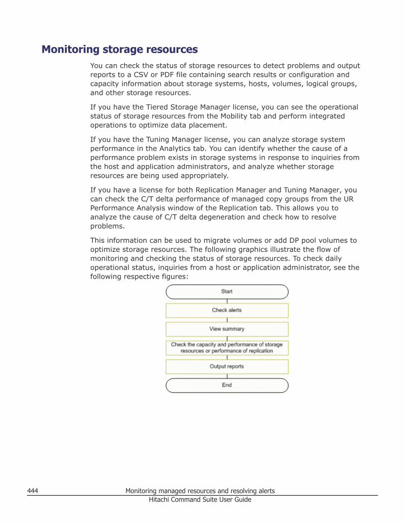
Monitoring storage resourcesYou can check the status of storage resources to detect problems and outputreports to a CSV or PDF file containing search results or configuration andcapacity information about storage systems, hosts, volumes, logical groups,and other storage resources.
If you have the Tiered Storage Manager license, you can see the operationalstatus of storage resources from the Mobility tab and perform integratedoperations to optimize data placement.
If you have the Tuning Manager license, you can analyze storage systemperformance in the Analytics tab. You can identify whether the cause of aperformance problem exists in storage systems in response to inquiries fromthe host and application administrators, and analyze whether storageresources are being used appropriately.
If you have a license for both Replication Manager and Tuning Manager, youcan check the C/T delta performance of managed copy groups from the URPerformance Analysis window of the Replication tab. This allows you toanalyze the cause of C/T delta degeneration and check how to resolveproblems.
This information can be used to migrate volumes or add DP pool volumes tooptimize storage resources. The following graphics illustrate the flow ofmonitoring and checking the status of storage resources. To check dailyoperational status, inquiries from a host or application administrator, see thefollowing respective figures:
444 Monitoring managed resources and resolving alertsHitachi Command Suite User Guide
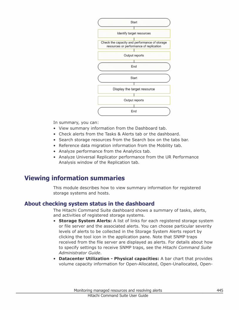
In summary, you can:• View summary information from the Dashboard tab.• Check alerts from the Tasks & Alerts tab or the dashboard.• Search storage resources from the Search box on the tabs bar.• Reference data migration information from the Mobility tab.• Analyze performance from the Analytics tab.• Analyze Universal Replicator performance from the UR Performance
Analysis window of the Replication tab.
Viewing information summariesThis module describes how to view summary information for registeredstorage systems and hosts.
About checking system status in the dashboardThe Hitachi Command Suite dashboard shows a summary of tasks, alerts,and activities of registered storage systems.• Storage System Alerts: A list of links for each registered storage system
or file server and the associated alerts. You can choose particular severitylevels of alerts to be collected in the Storage System Alerts report byclicking the tool icon in the application pane. Note that SNMP trapsreceived from the file server are displayed as alerts. For details about howto specify settings to receive SNMP traps, see the Hitachi Command SuiteAdministrator Guide.
• Datacenter Utilization - Physical capacities: A bar chart that providesvolume capacity information for Open-Allocated, Open-Unallocated, Open-
Monitoring managed resources and resolving alerts 445Hitachi Command Suite User Guide
Reserved, Mainframe, and Free volumes. This chart applies to all of themanaged storage systems, collectively. Because capacities are calculatedbased on actual volume capacities, the capacity of virtual volumes, such asDP volumes, is not included.
• Failed HCS Tasks: A list of failed HCS tasks submitted by you or otherusers. Each item includes the task name, task type, and description for thefailed task. Clicking the Task column link for a task that you submittedallows you to view task details, including error messages. You may notview task details for tasks that you did not submit.
• Failed System Tasks: A list of failed System tasks submitted by you orother users. Each item includes the task name, task type, and descriptionfor the failed task. Clicking the Status column link for a task that yousubmitted allows you to view the processing status.
• Top 10 Consumers: A list of the ten hosts or file servers having thelargest combination of allocated physical and virtual storage capacity. Forfile servers in a cluster configuration, if the file servers are being managedby System Management Unit v10.1.3070 or later, or by Hitachi FileServices Manager v3.2 or later, information is displayed by cluster.○ The Capacity column reports (capacity of basic volumes + subscribed
capacity of DP volumes).○ The Used Capacity column reports (capacity of basic volumes + used
capacity of DP volumes).○ File System Used Capacity indicates the file system space used by file
servers or hosts as (the total value calculated from File system Used %for each volume).
Note: The File System Used Capacity is displayed only for hosts that cancollect information by using Host Data Collector or Device Manager agent ,or for file servers.
This value cannot be collected for a virtualization server.
You can click host or file server links on the Resources tab to see volumedetails related to capacity, used capacity, and volume type. By reviewingthis capacity information, you can efficiently use storage resources anddetermine whether to migrate data to DP volumes.
• Tier Residency: A chart displaying the usage of hardware tiers for eachlogical group. You can compare the operating information of a logicalgroup and the usage of hardware tiers by checking whether the hardwaretiers for the logical group are configured appropriately. You can also selectlogical groups whose configuration is to be displayed. Click the tool icon inthe application pane to configure logical groups that display the usagestatus of hardware tiers.
• The following file server reporting is available in the Hitachi CommandSuite dashboard, when the file servers are registered in Device Manager:
446 Monitoring managed resources and resolving alertsHitachi Command Suite User Guide
○ Top 10 File Systems: When HCS is linked with a file server (HitachiNAS Platform family, Hitachi NAS Platform F (HNAS F) or Hitachi DataIngestor (HDI)), information about file systems that have a largecapacity usage rate or free area can be checked to see if there isinsufficient free space. By default, the allocated capacity usage rate isdisplayed in descending order. Clicking the column header of otheritems displays the top 10 file system information again, ordered by theselected item. You can also change the items displayed by clicking thetool icon in the application pane.
○ Top 10 File Server Storage Pools: When HCS is linked with a fileserver (Hitachi NAS Platform family), information about storage poolsthat have a large capacity usage rate can be checked to see if there isinsufficient free space. By default, the capacity usage rate is displayedin descending order. Clicking the column header of other items displaysthe information again, ordered by the selected item.
○ Top 10 File System Snapshots: When HCS is linked with a file server(Hitachi NAS Platform F), information about volumes having a highcapacity usage rate can be checked to see if there insufficient freespace.
○ File Level Tier Residency: When HCS is linked with a file server(Hitachi NAS Platform F), a graph is displayed for each file system tier,showing the usage status of the file systems and the volumes for filesnapshots. You can review the usage rate and the used capacity andthen expand the file system to increase free space and optimize theused capacity distributed among tiers. If you click the tools icon to startHitachi File Services Manager, you can review the policy settings on thetiered file system.
Related tasks
• Accessing the dashboard on page 447• Customizing the dashboard on page 448
Accessing the dashboardWhen you log in to HCS, the Dashboard tab and reports are displayed bydefault.
The Dashboard tab reports include:• Datacenter Utilization - Physical Capacities• Top 10 Consumers• Top 10 File Systems• Top 10 File Server Storage Pools• Storage System Alerts• Failed HCS Tasks• Failed System Tasks• Tier Residency
Click Dashboard Settings to select reports to display.
Monitoring managed resources and resolving alerts 447Hitachi Command Suite User Guide
The title bar of each report has a right arrow icon [–>] that when clicked,takes you to another tab to review related detail information.
For example, clicking the arrow icon for the Storage System Alerts reportdisplays the Tasks & Alerts tab with summary and detail information foralerts.
Click the Dashboard tab to re-display the dashboard reports.
When viewing Dashboard reports, click links to review specific detail.
For example, in the Top 10 Consumers report, clicking a specific host orfile-server link displays the Resources tab, expands the hosts or file-servertree, and displays related summary and volume information.
Related concepts
• About checking system status in the dashboard on page 445
Related tasks
• Customizing the dashboard on page 448
Customizing the dashboardSelect dashboard reports, position reports, and change the column layout.
Click Dashboard Settings to:• Select reports you want to display using the check boxes. Select all reports
using the column header.• Clear reports using the check boxes. Clear all reports using the column
header.• Choose the number of display columns for reports.• Restore the default dashboard by setting No. of Dashboard Columns to 2
and checking Report Name to select all of the reports.• HCS will retain changes across login sessions.
Using the title bar of each report:• Re-locate a report by dragging the title bar to a new location.• Double-click the title bar to maximize the report.• Double-click the title bar again to minimize the report.• You can also use the maximize/restore button.• There is an up-arrow/down-arrow button that hides a report except for the
title bar, providing more area for other reports.• Use the close button to remove the report. To display it again, use
Dashboard Settings.• If shown, the tool button (a wrench) is for configuration of the report.
Related concepts
• About checking system status in the dashboard on page 445
448 Monitoring managed resources and resolving alertsHitachi Command Suite User Guide
About the Storage Systems treeHitachi Command Suite lists registered storage systems and providesinformation summaries in the Storage Systems tree on the Resources tab.
The Storage Systems tree lists:• Storage systems• DP Pools• Parity groups• Volumes
○ Open-Allocated○ Open-Unallocated○ Open-Reserved○ Mainframe-Unspecified
• External Storage
The Storage Systems tree is the starting point for changing the configurationof these resources.
Related tasks
• Viewing current storage system information on page 449
Viewing current storage system informationConfiguration information for all managed resources is available on theResources tab.
Procedure
1. On the Resources tab, select Storage Systems.2. Select the parent group from the Storage Systems tree to view a
volume summary and additional detailed information in the applicationpane.
3. Click on the link for a storage system to access additional details.4. Continue to view more details by clicking the links on subsequent views.
Related concepts
• About the Storage Systems tree on page 449
Viewing MP Blade informationYou can view and edit the MP Blade information.
Procedure
1. On the Resources tab, expand the Storage Systems tree, and select atarget storage system.
Monitoring managed resources and resolving alerts 449Hitachi Command Suite User Guide
2. Choose one of the following options:• For Virtual Storage Platform G1000 storage systems:
Select Components.• For other available storage systems:
From the Actions list in the application pane, select ElementManager, and then from the Storage Systems tree, selectComponents.
3. On the Components window, click Chassis ID.
Result
The MP Blade information is displayed.
Tip: For details about editing MP Blade information, click Help.
About the Hosts treeHitachi Command Suite lists registered hosts by operating system in theHosts tree on the Resources tab.
You can register both physical hosts and virtualization servers. You can alsogroup the WWNs or iSCSI names used by specific storage systems and set upthat group as a host. You select a host from the Hosts tree to allocate orunallocate volumes. Note that you can reference all registered hosts, but forthe list of volumes that are allocated to each host, you can only referencevolumes that fall within your resource group assignments.
Related tasks
• Viewing current host information on page 450
Viewing current host informationInformation for all managed hosts is available on the Resources tab.
Procedure
1. On the Resources tab, select Hosts to expand the tree.2. Select an operating system to see an information summary and a list of
hosts on the application pane.3. Click the link for a host to access additional details.4. Continue to view more details by clicking the links on subsequent views.
Related concepts
• About the Hosts tree on page 450
450 Monitoring managed resources and resolving alertsHitachi Command Suite User Guide
About the file server viewYou view information about the volumes and file systems of managed fileservers through the file server view.
Information acquired by the Device Manager can be hierarchically displayedby registering a file server as a Device Manager resource. Users can select afile server from the file server view to allocate or unallocate.
You can execute setting operations such as allocation and unallocation bycluster or by file server (node).
Related tasks
• Monitoring file servers on page 451
Monitoring file serversYou can check on the status of your file servers and review volume and filesystem information.
Procedure
1. On the Resources tab, select File Servers.2. Expand the tree and select the resource whose information you want to
browse.3. In the application area, select the resource you want to reference.4. Browse the information such as volumes and file systems.
Related concepts
• About the file server view on page 451
Analyzing storage system performanceThis module describes procedures for analyzing storage system performanceto determine if a storage system is the source of application performanceproblems.
About analyzing storage system performanceThe Analytics tab provides information for analyzing storage systemperformance issues, and assists storage administrators in monitoring shortterm and long term trends.
Note: A Tuning Manager license is required to use the Analytics tab. Fordetails on Tuning Manager, see the Hitachi Command Suite Tuning ManagerUser Guide.
Use the Analytics tab to check storage system performance:
Monitoring managed resources and resolving alerts 451Hitachi Command Suite User Guide
• Identifying performance problems for storage systems:○ If there is an application performance issue, obtain the information
needed to identify a logical group. For example, this could be the hostwhere the problem occurred, the label of the volume, or the mountpoint. Based on the acquired information, specify the period (up to thepast 30 days) for analyzing the performance and the logical group orthe host that corresponds to the application in order to analyze theperformance issue. Check that no resources exceed the threshold valuesand determine whether the cause of the performance issue is in thestorage system.
• Analyzing and load balancing MP Blades or MP Units:○ Identify MP Blade/Unit busy rates that exceed threshold values, and
view resources placing a heavy load on the MP Blade/Unit. If possible,reduce the processing load or change the execution time of theprocessing using the resources. If you want to allocate resources to adifferent MP Blade/Unit, you can create a plan and simulate the effect ofassigning resources to another MP Blade/Unit with a lower busy rate. Toimplement the plan, generate a raidcom command script based on theplan, and run the script using CCI to re-assign the resources.
Note: You can analyze MP Blades or MP Units only for Virtual StoragePlatform G200, G400, G600, Virtual Storage Platform G1000, VirtualStorage Platform, or HUS VM storage systems. The term MP Blade is usedfor Virtual Storage Platform G1000 and Virtual Storage Platform. The termMP Unit is used for Virtual Storage Platform G200, G400, G600 and HUSVM.
• Analyzing storage performance on a host basis:When a performance problem occurs, for example when you receivenotification from a host administrator or application owner, or when youreceive health check system alerts, you might want to analyze the storagesystem performance on a host basis to determine if any hosts areincreasing the load on the storage system. Identify the hosts withperformance problems based on response time metrics, and plot a trendchart for response time metrics. Identify the hosts that are increasing theworkload on the storage system based on IOPS and Data Transfer Ratemetrics and plot trend charts for IOPS and Data Transfer Rate metrics.Compare the trend charts to determine which hosts are affecting thestorage system performance.
• Performing periodic performance analysis of storage systems:○ Analyze the performance of storage systems to periodically check that
resources are being used appropriately.○ The target storage system can be automatically analyzed at a specific
interval; for example, weekly or monthly. For multiple storage systems,analysis schedules can be set to execute in a batch process to reducethe workload of storage system management. In addition, you canspecify settings for performance analysis to send notifications by email
452 Monitoring managed resources and resolving alertsHitachi Command Suite User Guide
of any errors that occur during analysis, as well as attach thisinformation in the form of PDF-format analysis results reports to anemail message.
○ By using these analysis results reports, you can check whether aresource exists that exceeds or nearly exceeds the threshold value. Ifthere is a problem in the resource, check the detailed performanceinformation from the report that corresponds to each resource metric.Based on performance information such as the number of I/Ooperations (IOPS) and data traffic displayed in the report, discuss whatmeasures to take and perform any volume allocation or data migrationtasks. Resolving performance problems can prevent errors.
○ By referring to past analysis results, problems can be specified andactions can be determined more easily. The analysis report can beoutput to a PDF or CSV file. If output to a PDF file, the contents and asummary are created so that the report can be submitted as is. Ifoutput to a CSV file, the report is useful as a general-purpose file, and itcan be effectively used to create materials by editing the format.
For more detailed performance information, by starting PerformanceReporter, you can perform an analysis in minute units or analysis of long-term trends. If you import a report definition to Performance Reporter inTuning Manager in advance, you can display a report with items thatcorrespond to the items in the Identify Performance Problems wizard or aHealth Check report.
An appropriate default value is set for the threshold values to judge if thereare problems with storage system performance. You can change thethreshold values for their environment if necessary. In accordance with thespecified threshold values, the background of the displayed analysis resultchart is colored for each threshold range. The Caution threshold range isdisplayed in yellow. The Warning threshold range is displayed in pink.
Related tasks
• Identifying storage system performance problems on page 453• Analyzing and load balancing MP Blades or MP Units on page 455• Analyzing storage performance on a host basis on page 457
Identifying storage system performance problemsWith Tuning Manager installed, you can identify storage system performanceproblems from the Analytics tab.
Prerequisites• Install Tuning Manager and link it to HCS.• Register the Tuning Manager license.• Import the report definition file in Tuning Manager before analyzing
performance with the Analytics tab (ensure that you delete the report
Monitoring managed resources and resolving alerts 453Hitachi Command Suite User Guide
definition file for the previous version before importing the latest reportdefinition file).
• Identify the date and time of the performance problem.• Identify application information such as host or logical group name.
For information about linking with Tuning Manager and importing the reportdefinition file in Tuning Manager, see the Hitachi Command SuiteAdministrator Guide.
Procedure
1. From the tree in the Analytics tab, select the target logical group andclick Identify Performance Problems. You can also select a host orspecific volumes in the target logical group.
2. Read the Introduction and click Next.3. Based on the application information acquired from the host
administrator, set the storage system type, volumes, and period toanalyze, and then click Next.
4. In Overview, check for resources with performance threshold cautions:• For an MP Blade/Unit with threshold cautions, click Analyze MP
Blades/Units to analyze MP Blade/Unit busy rate metrics and createa plan for reassigning resources to a less busy MP Blade or MP Unit toload balance host I/O requests.
• For other resources that exceed a threshold value, there might be aproblem with the storage system. If this is the case, click Next.
Tip: If there is no resource that exceeds a threshold value, it is likelythat the problem does not originate from the storage system. If this isthe case, close the Wizard.
5. Check the information for each metric displayed for each type of storagesystem type, and then click Next. Check the analysis report. Theanalysis result chart displays the Warning threshold range in pink.If you analyze enterprise-class storage (such as Virtual Storage PlatformG200, G400, G600, Virtual Storage Platform G1000, Virtual StoragePlatform, Universal Storage Platform V/VM, Universal Storage Platform,or HUS VM), and when all volumes that belong to a parity group areincluded in the following list of volumes, the chart displaying Read Hitrate is not displayed:• ShadowImage S-VOLs• TrueCopy S-VOLs• Universal Replicator S-VOLs• Copy-on-Write Snapshot V-VOLs• Copy-on-Write Snapshot Pool volume• Thin Image V-VOLs• Thin Image Pool volume• DP pool volume
454 Monitoring managed resources and resolving alertsHitachi Command Suite User Guide
Tip: To view detailed performance information, start PerformanceReporter. From Performance Reporter, display the report by selectingIdentify Performance Problems under Identify PerformanceProblems and Health Check. You can analyze on a per-minute basis oron a long-term trend basis by setting the appropriate display conditions.
For details on using Performance Reporter, see the Hitachi CommandSuite Tuning Manager User Guide.
Related concepts
• About analyzing storage system performance on page 451• About global-active device on page 286
Related tasks
• Creating periodic health check reports for storage systems performanceanalysis on page 463
• Analyzing and load balancing MP Blades or MP Units on page 455• Analyzing storage performance on a host basis on page 457
Related references
• Configuring the Performance Reporter display on page 470
Analyzing and load balancing MP Blades or MP UnitsOn the Analytics tab you can identify MP Blades and MP Units with a busyrate exceeding caution thresholds, and assign resources to an MP Blade or MPUnit with a lower busy rate to improve host application performance orbalance I/O requests for disks with varying performance levels (HDD, SSD,FMD).
Prerequisites• Install Tuning Manager and link it to HCS.• Register the Tuning Manager license.• Import the report definition file from Tuning Manager before analyzing
performance with the Analytics tab (ensure that you delete the reportdefinition file for the previous version before importing the latest reportdefinition file).
• To analyze MP Blade or MP Unit busy rates, the storage system must be aVirtual Storage Platform G200, G400, G600, Virtual Storage PlatformG1000, Virtual Storage Platform, or HUS VM. For more information, seethe Hitachi Command Suite Administrator Guide.
• The storage administrator must have permission to log in to the serverwhere CCI is installed, and permission to use raidcom commands tomodify the target storage system so that MP Blade or MP Unit resourceassignments can be completed.
Monitoring managed resources and resolving alerts 455Hitachi Command Suite User Guide
Procedure
1. On the Analytics tab, choose an MP blade to analyze by doing one of thefollowing:• Select a target host or logical group and click Identify Performance
Problems. From the Overview page (if MP blade cautions appear) orfrom MP Blade/Unit page, click Analyze MP Blades/Units.
• Expand the storage system tree, select a storage system from theapplication pane, and then click Analyze MP Blades/Units. TheAnalyze MP Blades/Units window opens.
2. On the Analyze MP Blades/Units window, verify that the AnalysisTarget information is correct.
3. In MP Blades/Units Busy Rate, examine the busy rate graph anddetermine which MP Blade is a candidate (based on exceedingthresholds, or having the highest busy rate) for reassigning resources toa less busy MP Blade. If a target MP Blade is not already selected, selectthe target MP Blade and click Choose as Target MP Blade/Unit.
4. In Selected MP Blades/Units, identify the resources causing the highbusy rate.
5. After identifying busy resources for the target MP Blade, return to MPBlades/Units Busy Rate and select the destination MP Blade to whichyou want to assign resources, and then click Choose as DestinationMP Blades/Units.
6. Select resources and click Move to assign resources to the destinationMP Blade and create the assignment plan.
Tip: For target MP Blade resources that should be excluded from theassignment plan, select the resource and click the Lock button. Forexample, system disks or disks that cannot afford a temporarydeterioration in response time due to cache operations incurred whenreassigning the resource to another MP Blade.
7. Verify that the created plan is acceptable, and then click GenerateScript Commands to create the raidcom command script.
8. Log in to the server where CCI is installed.9. Execute the raidcom command script from CCI to physically reassign
resources.10. Run Performance Reporter to check that the busy rate for the target MP
Blade and destination MP Blade are acceptable.
Tip: To view detailed performance information, start Tuning Managerfrom the Tools menu. By displaying Performance Reporter reports fromTuning Manager, you can analyze information on a per-minute basis orbased on long-term trends. For details on how to use PerformanceReporter, see the Hitachi Command Suite Tuning Manager User Guide.
456 Monitoring managed resources and resolving alertsHitachi Command Suite User Guide
Result
The busy rate for the target and destination MP Blades is adjusted by thereassignment of resources.
Related concepts
• About analyzing storage system performance on page 451
Related tasks
• Identifying storage system performance problems on page 453• Changing peformance threshold settings to correctly analyze storage
system performance on page 469
Related references
• Configuring the Performance Reporter display on page 470
Analyzing storage performance on a host basisOn the Analytics tab, you can analyze storage system performance byidentifying the hosts that are increasing the workload on the storage system.You can plot the trend charts for response time, IOPS, and Data Transfer Ratemetrics, and then compare the trends to identify which hosts are increasingthe workload.
Note:• Hovering your mouse in the plot area displays a reference line (red vertical
line) which lets you view the date and time for a data point. You can showor hide the reference line by right-clicking the mouse.
• The host performance metrics are calculated by aggregating theperformance values of all the LDEVs connected to the host. If the targethost is sharing and managing an LDEV with another host, the performancevalues of the target host might include the performance values of the hostwith which the LDEV is shared.
Prerequisites• Install Tuning Manager and link it to HCS.• Register the Tuning Manager license.• Verify if the hosts are registered in HCS.
Procedure
1. In the HCS search box, enter the target host name to perform a keywordsearch.
2. From the returned search results, click the link for a host to display a listof volumes and information about the storage systems used by that host.If there is more than one storage system listed, you might want toanalyze each storage system.
Monitoring managed resources and resolving alerts 457Hitachi Command Suite User Guide
3. On the Analytics tab, select the storage system for which you want toanalyze performance, and click Storage Performance Analysis perHost.
4. In the Storage Performance Analysis per Host window, identify thehosts with performance problems based on response time metrics.To create a chart for average response time metrics:a. In the Hosts table, sort the hosts by Average Response Time.
The hosts and file servers are listed in the Hosts table.b. Select the hosts with high response time values.
You can use the Worst Response Time metrics to analyze the peakworkload periods.
c. Select New Analysis View, and click Show Chart.The data points are plotted for the default time period. The defaulttime period is 3 to 4 hours.
d. In the performance trend chart displayed, you can view how theresponse times vary. The trend analysis helps you determine thevariations in the response times and if the response times are longerthan desired.
e. (Optional) Change the time period and repeat the analysis to see howthe response time data changes over time and how it affects theoverall performance of the host applications.To change the time range, select the start and end dates, select DataGranularity, specify the number of minutes, hours, or days, and thenclick Apply.You can also customize the time period settings by clicking the VisualSettings button, which lets you adjust the time range using the slider.To change the time range using the slider, one or more performancecharts must be displayed in an analysis view.
Note: When analyzing the performance data in minutes, specify atime period no longer than 24 hours. When the specified time periodexceeds 24 hours, the web browser might close. For per-minute datagranularity, use the following calculation as a guideline: number-of-days x number-of-hosts-selected-in-the-hosts-table x number-of-charts-to-display ≤ 200
5. Identify the hosts that are increasing the load on the storage systembased on IOPS or Data Transfer Rate metrics.To create a chart for IOPS or Data Transfer Rate metrics:a. In the Hosts table, sort the hosts by IOPS, or Data Transfer Rate
metrics.b. Select the hosts with high IOPS or Data Transfer Rate.c. Select New Analysis View, and then click Show Chart.
458 Monitoring managed resources and resolving alertsHitachi Command Suite User Guide
The data points are plotted for the default time period. The defaulttime period is 3 to 4 hours.
d. In the performance chart, you can view how the number of I/Ooperations or Data Transfer Rate varies. You can also determine thefrequency of the peak and non-peak workload periods.
e. (Optional) Change the time period and repeat the analysis to see howthe workload changes over time and how it affects the overallperformance of the host.To change the time range, select the start and end dates, select DataGranularity, specify the number of minutes, hours, or days, and thenclick Apply.You can also customize the time period settings by clicking the VisualSettings button, which lets you adjust the time range using the slider.In order for you to change the time range using the slider, one ormore performance charts must be displayed in an analysis view.
6. Compare the performance charts to determine the hosts for which IOPSor Data Transfer Rate changes when the response time changes.Analyzing the performance metrics helps you identify the hosts that areincreasing the workload on the storage system.
7. (Optional)To analyze the performance of the volumes that are connectedto a host, use the Identify Performance Problems wizard.a. On the Analytics tab, expand the Hosts tree, and select a host OS.b. In the hosts list, select the target host and click Identify
Performance Problems, or click the host name link to select thetarget volumes and then click Identify Performance Problems.Follow the wizard prompts to continue the analysis.
8. (Optional) To improve the host application performance and balance I/Oworkload, allocate additional storage resources or distribute workloadequally among existing storage resources.
Related concepts
• About analyzing storage system performance on page 451• Allocating storage on page 135
Related tasks
• Identifying storage system performance problems on page 453• Analyzing and load balancing MP Blades or MP Units on page 455
Metrics of volumes of Virtual Storage Platform G200, G400, G600,Virtual Storage Platform G1000, Virtual Storage Platform, and HUSVM (Identify Performance Problems wizard)
Volume metrics for enterprise storage systems, as shown in the performanceproblem wizard, can help identify performance issues.
Monitoring managed resources and resolving alerts 459Hitachi Command Suite User Guide
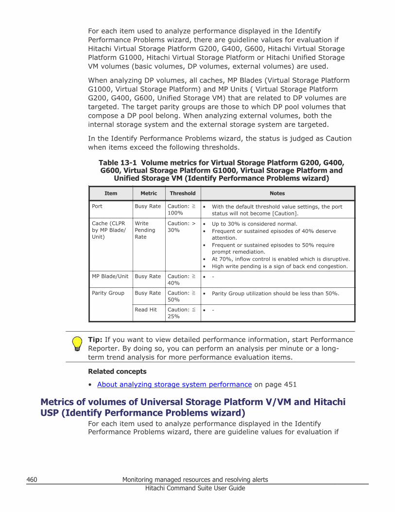
For each item used to analyze performance displayed in the IdentifyPerformance Problems wizard, there are guideline values for evaluation ifHitachi Virtual Storage Platform G200, G400, G600, Hitachi Virtual StoragePlatform G1000, Hitachi Virtual Storage Platform or Hitachi Unified StorageVM volumes (basic volumes, DP volumes, external volumes) are used.
When analyzing DP volumes, all caches, MP Blades (Virtual Storage PlatformG1000, Virtual Storage Platform) and MP Units ( Virtual Storage PlatformG200, G400, G600, Unified Storage VM) that are related to DP volumes aretargeted. The target parity groups are those to which DP pool volumes thatcompose a DP pool belong. When analyzing external volumes, both theinternal storage system and the external storage system are targeted.
In the Identify Performance Problems wizard, the status is judged as Cautionwhen items exceed the following thresholds.
Table 13-1 Volume metrics for Virtual Storage Platform G200, G400,G600, Virtual Storage Platform G1000, Virtual Storage Platform and
Unified Storage VM (Identify Performance Problems wizard)
Item Metric Threshold Notes
Port Busy Rate Caution: ≧100%
• With the default threshold value settings, the portstatus will not become [Caution].
Cache (CLPRby MP Blade/Unit)
WritePendingRate
Caution: >30%
• Up to 30% is considered normal.• Frequent or sustained episodes of 40% deserve
attention.• Frequent or sustained episodes to 50% require
prompt remediation.• At 70%, inflow control is enabled which is disruptive.• High write pending is a sign of back end congestion.
MP Blade/Unit Busy Rate Caution: ≧40%
• -
Parity Group Busy Rate Caution: ≧50%
• Parity Group utilization should be less than 50%.
Read Hit Caution: ≦25%
• -
Tip: If you want to view detailed performance information, start PerformanceReporter. By doing so, you can perform an analysis per minute or a long-term trend analysis for more performance evaluation items.
Related concepts
• About analyzing storage system performance on page 451
Metrics of volumes of Universal Storage Platform V/VM and HitachiUSP (Identify Performance Problems wizard)
For each item used to analyze performance displayed in the IdentifyPerformance Problems wizard, there are guideline values for evaluation if
460 Monitoring managed resources and resolving alertsHitachi Command Suite User Guide
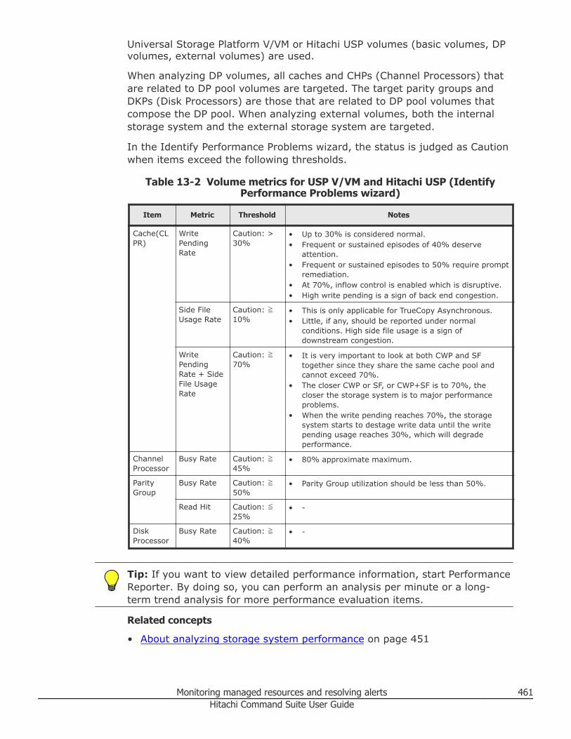
Universal Storage Platform V/VM or Hitachi USP volumes (basic volumes, DPvolumes, external volumes) are used.
When analyzing DP volumes, all caches and CHPs (Channel Processors) thatare related to DP pool volumes are targeted. The target parity groups andDKPs (Disk Processors) are those that are related to DP pool volumes thatcompose the DP pool. When analyzing external volumes, both the internalstorage system and the external storage system are targeted.
In the Identify Performance Problems wizard, the status is judged as Cautionwhen items exceed the following thresholds.
Table 13-2 Volume metrics for USP V/VM and Hitachi USP (IdentifyPerformance Problems wizard)
Item Metric Threshold Notes
Cache(CLPR)
WritePendingRate
Caution: >30%
• Up to 30% is considered normal.• Frequent or sustained episodes of 40% deserve
attention.• Frequent or sustained episodes to 50% require prompt
remediation.• At 70%, inflow control is enabled which is disruptive.• High write pending is a sign of back end congestion.
Side FileUsage Rate
Caution: ≧10%
• This is only applicable for TrueCopy Asynchronous.• Little, if any, should be reported under normal
conditions. High side file usage is a sign ofdownstream congestion.
WritePendingRate + SideFile UsageRate
Caution: ≧70%
• It is very important to look at both CWP and SFtogether since they share the same cache pool andcannot exceed 70%.
• The closer CWP or SF, or CWP+SF is to 70%, thecloser the storage system is to major performanceproblems.
• When the write pending reaches 70%, the storagesystem starts to destage write data until the writepending usage reaches 30%, which will degradeperformance.
ChannelProcessor
Busy Rate Caution: ≧45%
• 80% approximate maximum.
ParityGroup
Busy Rate Caution: ≧50%
• Parity Group utilization should be less than 50%.
Read Hit Caution: ≦25%
• -
DiskProcessor
Busy Rate Caution: ≧40%
• -
Tip: If you want to view detailed performance information, start PerformanceReporter. By doing so, you can perform an analysis per minute or a long-term trend analysis for more performance evaluation items.
Related concepts
• About analyzing storage system performance on page 451
Monitoring managed resources and resolving alerts 461Hitachi Command Suite User Guide
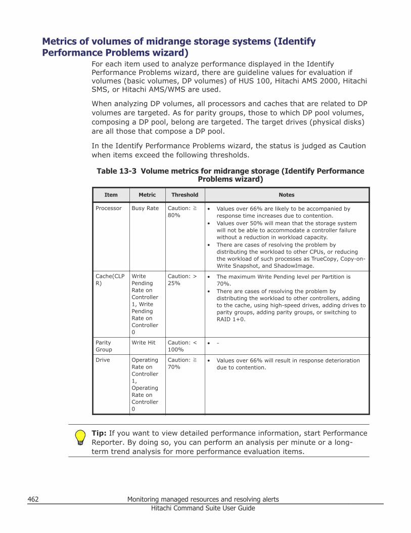
Metrics of volumes of midrange storage systems (IdentifyPerformance Problems wizard)
For each item used to analyze performance displayed in the IdentifyPerformance Problems wizard, there are guideline values for evaluation ifvolumes (basic volumes, DP volumes) of HUS 100, Hitachi AMS 2000, HitachiSMS, or Hitachi AMS/WMS are used.
When analyzing DP volumes, all processors and caches that are related to DPvolumes are targeted. As for parity groups, those to which DP pool volumes,composing a DP pool, belong are targeted. The target drives (physical disks)are all those that compose a DP pool.
In the Identify Performance Problems wizard, the status is judged as Cautionwhen items exceed the following thresholds.
Table 13-3 Volume metrics for midrange storage (Identify PerformanceProblems wizard)
Item Metric Threshold Notes
Processor Busy Rate Caution: ≧80%
• Values over 66% are likely to be accompanied byresponse time increases due to contention.
• Values over 50% will mean that the storage systemwill not be able to accommodate a controller failurewithout a reduction in workload capacity.
• There are cases of resolving the problem bydistributing the workload to other CPUs, or reducingthe workload of such processes as TrueCopy, Copy-on-Write Snapshot, and ShadowImage.
Cache(CLPR)
WritePendingRate onController1, WritePendingRate onController0
Caution: >25%
• The maximum Write Pending level per Partition is70%.
• There are cases of resolving the problem bydistributing the workload to other controllers, addingto the cache, using high-speed drives, adding drives toparity groups, adding parity groups, or switching toRAID 1+0.
ParityGroup
Write Hit Caution: <100%
• -
Drive OperatingRate onController1,OperatingRate onController0
Caution: ≧70%
• Values over 66% will result in response deteriorationdue to contention.
Tip: If you want to view detailed performance information, start PerformanceReporter. By doing so, you can perform an analysis per minute or a long-term trend analysis for more performance evaluation items.
462 Monitoring managed resources and resolving alertsHitachi Command Suite User Guide
Related concepts
• About analyzing storage system performance on page 451
Creating periodic health check reports for storage systemsperformance analysis
You can create storage system health check (performance) reports, andcontrol scheduling, the data collection time period, and data interval settings.You can review the health check reports when completed, and later byreviewing health check history.
Prerequisites
• Install Tuning Manager and link it to HCS.• Register the Tuning Manager license.• Import the report definition file in Tuning Manager before analyzing
performance with the Analytics tab (ensure that you delete the reportdefinition file for the previous version before importing the latest reportdefinition file).
• To receive the results of Health Check execution by email, you mustspecify the SMTP server and edit the server.properties file of the DeviceManager server.
• For more details on these tasks, see the Hitachi Command SuiteAdministrator Guide.
Procedure
1. On the Analytics tab, select Storage Systems.2. Select one or more storage systems, and click Create Schedule.3. Specify the required items, and run the task.4. After verifying that the task is complete, check for any performance
problems. If there is a problem, check the Health Check report of thecorresponding storage system. In accordance with the specified thresholdvalues, the background of the displayed analysis result chart is coloredfor each threshold range. The Caution threshold range is displayed inyellow. The Warning threshold range is displayed in pink.
5. Verify the problem areas from the report information, and then analyzeand identify the problems.
Tip: Observe the following guidelines when analyzing the reportinformation:• If you are using the UR Performance Analysis window of the
Replication tab for Universal Replicator performance analysis, and aperiodic refresh schedule has been configured for data collection,make sure that storage system health checks (performance reports)run at a different time to ensure the distribution of processing loads.
Monitoring managed resources and resolving alerts 463Hitachi Command Suite User Guide
• If you want to analyze the performance of storage systemsimmediately, select the target storage systems, and then click RunHealth Check. You can view the execution results in the Tasks &Alerts tab.
• If you want to delete a schedule, from Schedule, select the targetschedule from the Health Check Schedules list, and then clickDelete Schedule.
• The Utilization Reports (Threshold Exceeded) chart of a health checkreport displays the maximum value among the monitored targets thatexceeded the threshold value. For other report charts, an averagevalue of the monitored targets is displayed.
• If you want to view detailed performance information, start TuningManager from the Tools menu. By displaying Performance Reporterreports from Tuning Manager, you can analyze performance based ona per-minute basis or on a long-term trend basis. For informationabout how to use Performance Reporter, see the Hitachi CommandSuite Tuning Manager User Guide.
• If you want to view performance information about the resourcesassociated with a pool, select the target storage system, then on theDP Vols tab, or the Parity Groups tab, display the Historical Reportby clicking the View Performance Reports button. For informationabout changing the report window settings for the Historical Report,see the Hitachi Command Suite Tuning Manager User Guide.
Tip: The following categories are part of the health check reports, butare not displayed when using the Analytics tab. These health checkreport categories represent storage system total front-end and back-endmetrics that can be used with the Performance Reporter metrics to geta better understanding of storage system performance:• Storage system total front-end IOPS: represents the total number of
IOPS (inclusive reads and writes) issued to a storage system by itsconnected hosts.
• Storage system total front-end MB/s: represents the total number inmegabytes per second that are read from or written to a storagesystem by its connected hosts.
• Storage system total back-end IOPS: represents the part of thestorage system total front-end IOPS that was not served by the cachememory in the storage system.
Related concepts
• About analyzing storage system performance on page 451
Related tasks
• Editing periodic health check schedule on page 465• Exporting health check reports on page 465
464 Monitoring managed resources and resolving alertsHitachi Command Suite User Guide
• Viewing and deleting health check reports on page 466
Editing periodic health check scheduleYou can change a previously created storage system health check schedule.
Procedure
1. From the Analytics tab, select Schedule.2. Select the schedule to change, and click Edit Schedule.3. Specify the required items, and then execute the task.
Result
Display the window showing the target schedule in detail, and confirm thatthe schedule has been changed.
Tip: If you are using the UR Performance Analysis window of the Replicationtab, and a periodic refresh schedule has been configured for data collection,make sure that storage system health checks (performance reports) run at adifferent time to ensure the distribution of processing loads.
Related concepts
• About analyzing storage system performance on page 451
Related tasks
• Creating periodic health check reports for storage systems performanceanalysis on page 463
Exporting health check reportsYou can export health check reports to a PDF or CSV file for reportingpurposes.
Procedure
1. From the Analytics tab, select Report History.2. From the Reports list, select the report to export, and click Export
Reports.3. Select the required items and click Submit.4. Select the export location for the health check report.
Result
A CSV file or PDF file is saved in the specified location.
Related concepts
• About analyzing storage system performance on page 451
Monitoring managed resources and resolving alerts 465Hitachi Command Suite User Guide
Related tasks
• Viewing and deleting health check reports on page 466
Viewing and deleting health check reportsPreviously created health check reports can be reviewed to check for andresolve performance issues.
Procedure
1. From the Analytics tab, select Report History.2. From the Reports list, select the report to review, and click View
Report of the Health Status column.3. Review the displayed health check report.
In accordance with the specified threshold values, the background of thedisplayed analysis result chart is colored for each threshold range. TheCaution threshold range is displayed in yellow. The Warning thresholdrange is displayed in pink.
Result
Based on the health check report, resolve performance issues if necessary.
Tip: To delete reports that are no longer needed, select the reports to bedeleted, and click Delete Reports button.
Related concepts
• About analyzing storage system performance on page 451
Related tasks
• Creating periodic health check reports for storage systems performanceanalysis on page 463
• Exporting health check reports on page 465
Metrics of resources of Virtual Storage Platform G200, G400, G600,Virtual Storage Platform G1000, Virtual Storage Platform, and HUSVM (Health Check Report)
Volume metrics for enterprise storage systems, as shown in the health checkreport, can help identify performance issues.
The following provides the values for evaluating items that are used byHealth Check to verify whether there is a performance problem for VirtualStorage Platform G200, G400, G600, Virtual Storage Platform G1000, VirtualStorage Platform or HUS VM.
During Health Check, if items exceed the following thresholds, the status isjudged as Caution or Warning.
466 Monitoring managed resources and resolving alertsHitachi Command Suite User Guide
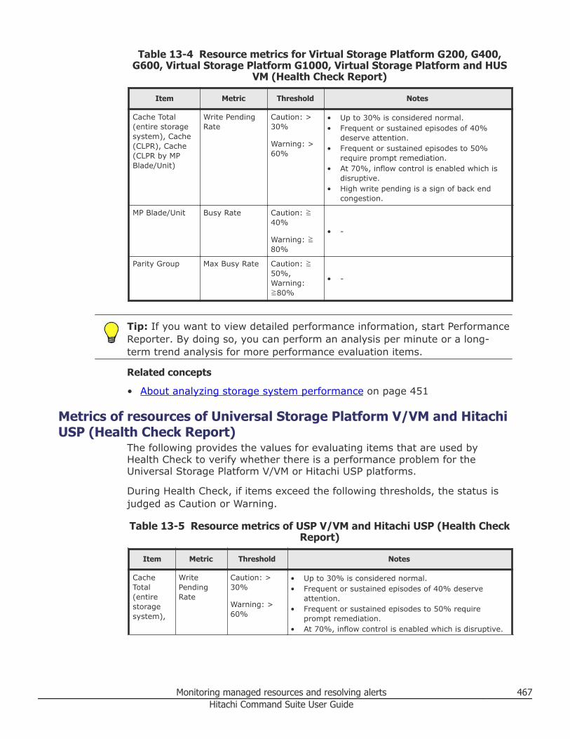
Table 13-4 Resource metrics for Virtual Storage Platform G200, G400,G600, Virtual Storage Platform G1000, Virtual Storage Platform and HUS
VM (Health Check Report)
Item Metric Threshold Notes
Cache Total(entire storagesystem), Cache(CLPR), Cache(CLPR by MPBlade/Unit)
Write PendingRate
Caution: >30%
Warning: >60%
• Up to 30% is considered normal.• Frequent or sustained episodes of 40%
deserve attention.• Frequent or sustained episodes to 50%
require prompt remediation.• At 70%, inflow control is enabled which is
disruptive.• High write pending is a sign of back end
congestion.
MP Blade/Unit Busy Rate Caution: ≧40%
Warning: ≧80%
• -
Parity Group Max Busy Rate Caution: ≧50%,Warning:≧80%
• -
Tip: If you want to view detailed performance information, start PerformanceReporter. By doing so, you can perform an analysis per minute or a long-term trend analysis for more performance evaluation items.
Related concepts
• About analyzing storage system performance on page 451
Metrics of resources of Universal Storage Platform V/VM and HitachiUSP (Health Check Report)
The following provides the values for evaluating items that are used byHealth Check to verify whether there is a performance problem for theUniversal Storage Platform V/VM or Hitachi USP platforms.
During Health Check, if items exceed the following thresholds, the status isjudged as Caution or Warning.
Table 13-5 Resource metrics of USP V/VM and Hitachi USP (Health CheckReport)
Item Metric Threshold Notes
CacheTotal(entirestoragesystem),
WritePendingRate
Caution: >30%
Warning: >60%
• Up to 30% is considered normal.• Frequent or sustained episodes of 40% deserve
attention.• Frequent or sustained episodes to 50% require
prompt remediation.• At 70%, inflow control is enabled which is disruptive.
Monitoring managed resources and resolving alerts 467Hitachi Command Suite User Guide
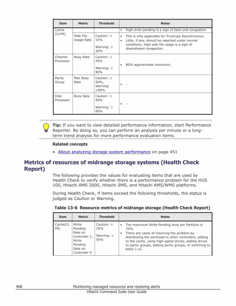
Item Metric Threshold Notes
Cache(CLPR)
• High write pending is a sign of back end congestion.
Side FileUsage Rate
Caution: ≧10%
Warning: ≧20%
• This is only applicable for TrueCopy Asynchronous.• Little, if any, should be reported under normal
conditions. High side file usage is a sign ofdownstream congestion.
ChannelProcessor
Busy Rate Caution: ≧45%
Warning: ≧80%
• 80% approximate maximum.
ParityGroup
Max BusyRate
Caution: ≧50%,Warning:≧80%
• -
DiskProcessor
Busy Rate Caution: ≧40%
Warning: ≧80%
• -
Tip: If you want to view detailed performance information, start PerformanceReporter. By doing so, you can perform an analysis per minute or a long-term trend analysis for more performance evaluation items.
Related concepts
• About analyzing storage system performance on page 451
Metrics of resources of midrange storage systems (Health CheckReport)
The following provides the values for evaluating items that are used byHealth Check to verify whether there is a performance problem for the HUS100, Hitachi AMS 2000, Hitachi SMS, and Hitachi AMS/WMS platforms.
During Health Check, if items exceed the following thresholds, the status isjudged as Caution or Warning.
Table 13-6 Resource metrics of midrange storage (Health Check Report)
Item Metric Threshold Notes
Cache(CLPR)
WritePendingRate onController 1,WritePendingRate onController 0
Caution: >25%
Warning: >50%
• The maximum Write Pending level per Partition is70%.
• There are cases of resolving the problem bydistributing the workload to other controllers, addingto the cache, using high-speed drives, adding drivesto parity groups, adding parity groups, or switching toRAID 1+0.
468 Monitoring managed resources and resolving alertsHitachi Command Suite User Guide
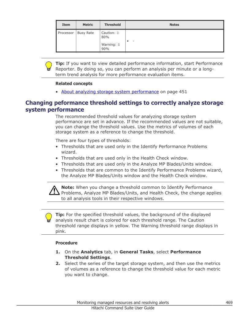
Item Metric Threshold Notes
Processor Busy Rate Caution: ≧80%
Warning: ≧90%
• -
Tip: If you want to view detailed performance information, start PerformanceReporter. By doing so, you can perform an analysis per minute or a long-term trend analysis for more performance evaluation items.
Related concepts
• About analyzing storage system performance on page 451
Changing peformance threshold settings to correctly analyze storagesystem performance
The recommended threshold values for analyzing storage systemperformance are set in advance. If the recommended values are not suitable,you can change the threshold values. Use the metrics of volumes of eachstorage system as a reference to change the threshold.
There are four types of thresholds:• Thresholds that are used only in the Identify Performance Problems
wizard.• Thresholds that are used only in the Health Check window.• Thresholds that are used only in the Analyze MP Blades/Units window.• Thresholds that are common to the Identify Performance Problems wizard,
the Analyze MP Blades/Units window and the Health Check window.
Note: When you change a threshold common to Identify PerformanceProblems, Analyze MP Blades/Units, and Health Check, the change appliesto all analysis tools in their respective windows.
Tip: For the specified threshold values, the background of the displayedanalysis result chart is colored for each threshold range. The Cautionthreshold range displays in yellow. The Warning threshold range displays inpink.
Procedure
1. On the Analytics tab, in General Tasks, select PerformanceThreshold Settings.
2. Select the series of the target storage system, and then use the metricsof volumes as a reference to change the threshold value for each metricyou want to change.
Monitoring managed resources and resolving alerts 469Hitachi Command Suite User Guide
3. Change the threshold settings.a. Select the target storage system.b. Select the analysis tool whose metrics you want to change (for
example Analyze MP Blades/Units) or select All to display and changeall available metrics.
Tip: Metrics might be deactivated based on your analysis toolselection.
c. Change the caution and warning (Health Check only) thresholds tomeet your requirements.
d. Click OK.
Result
Metrics are changed for one or more analysis tools.
Related concepts
• About analyzing storage system performance on page 451
Related tasks
• Identifying storage system performance problems on page 453• Analyzing and load balancing MP Blades or MP Units on page 455• Creating periodic health check reports for storage systems performance
analysis on page 463
Related references
• Metrics of volumes of Virtual Storage Platform G200, G400, G600, VirtualStorage Platform G1000, Virtual Storage Platform, and HUS VM (IdentifyPerformance Problems wizard) on page 459
• Metrics of volumes of Universal Storage Platform V/VM and Hitachi USP(Identify Performance Problems wizard) on page 460
• Metrics of volumes of midrange storage systems (Identify PerformanceProblems wizard) on page 462
• Metrics of resources of Virtual Storage Platform G200, G400, G600, VirtualStorage Platform G1000, Virtual Storage Platform, and HUS VM (HealthCheck Report) on page 466
• Metrics of resources of Universal Storage Platform V/VM and Hitachi USP(Health Check Report) on page 467
• Metrics of resources of midrange storage systems (Health Check Report)on page 468
Configuring the Performance Reporter displayAfter activating Performance Reporter, you can analyze detailed storagesystem information based on Identify Performance Problems results or HealthCheck report results.
470 Monitoring managed resources and resolving alertsHitachi Command Suite User Guide
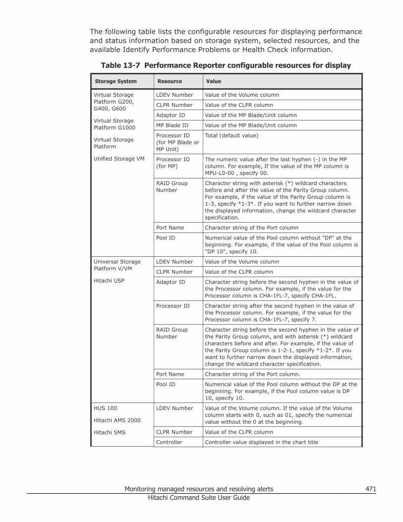
The following table lists the configurable resources for displaying performanceand status information based on storage system, selected resources, and theavailable Identify Performance Problems or Health Check information.
Table 13-7 Performance Reporter configurable resources for display
Storage System Resource Value
Virtual StoragePlatform G200,G400, G600
Virtual StoragePlatform G1000
Virtual StoragePlatform
Unified Storage VM
LDEV Number Value of the Volume column
CLPR Number Value of the CLPR column
Adaptor ID Value of the MP Blade/Unit column
MP Blade ID Value of the MP Blade/Unit column
Processor ID(for MP Blade orMP Unit)
Total (default value)
Processor ID(for MP)
The numeric value after the last hyphen (-) in the MPcolumn. For example, If the value of the MP column isMPU-L0-00 , specify 00.
RAID GroupNumber
Character string with asterisk (*) wildcard charactersbefore and after the value of the Parity Group column.For example, if the value of the Parity Group column is1-3, specify *1-3*. If you want to further narrow downthe displayed information, change the wildcard characterspecification.
Port Name Character string of the Port column
Pool ID Numerical value of the Pool column without "DP" at thebeginning. For example, if the value of the Pool column is"DP 10", specify 10.
Universal StoragePlatform V/VM
Hitachi USP
LDEV Number Value of the Volume column
CLPR Number Value of the CLPR column
Adaptor ID Character string before the second hyphen in the value ofthe Processor column. For example, if the value for theProcessor column is CHA-1FL-7, specify CHA-1FL.
Processor ID Character string after the second hyphen in the value ofthe Processor column. For example, if the value for theProcessor column is CHA-1FL-7, specify 7.
RAID GroupNumber
Character string before the second hyphen in the value ofthe Parity Group column, and with asterisk (*) wildcardcharacters before and after. For example, if the value ofthe Parity Group column is 1-2-1, specify *1-2*. If youwant to further narrow down the displayed information,change the wildcard character specification.
Port Name Character string of the Port column.
Pool ID Numerical value of the Pool column without the DP at thebeginning. For example, if the Pool column value is DP10, specify 10.
HUS 100
Hitachi AMS 2000
Hitachi SMS
LDEV Number Value of the Volume column. If the value of the Volumecolumn starts with 0, such as 01, specify the numericalvalue without the 0 at the beginning.
CLPR Number Value of the CLPR column
Controller Controller value displayed in the chart title
Monitoring managed resources and resolving alerts 471Hitachi Command Suite User Guide
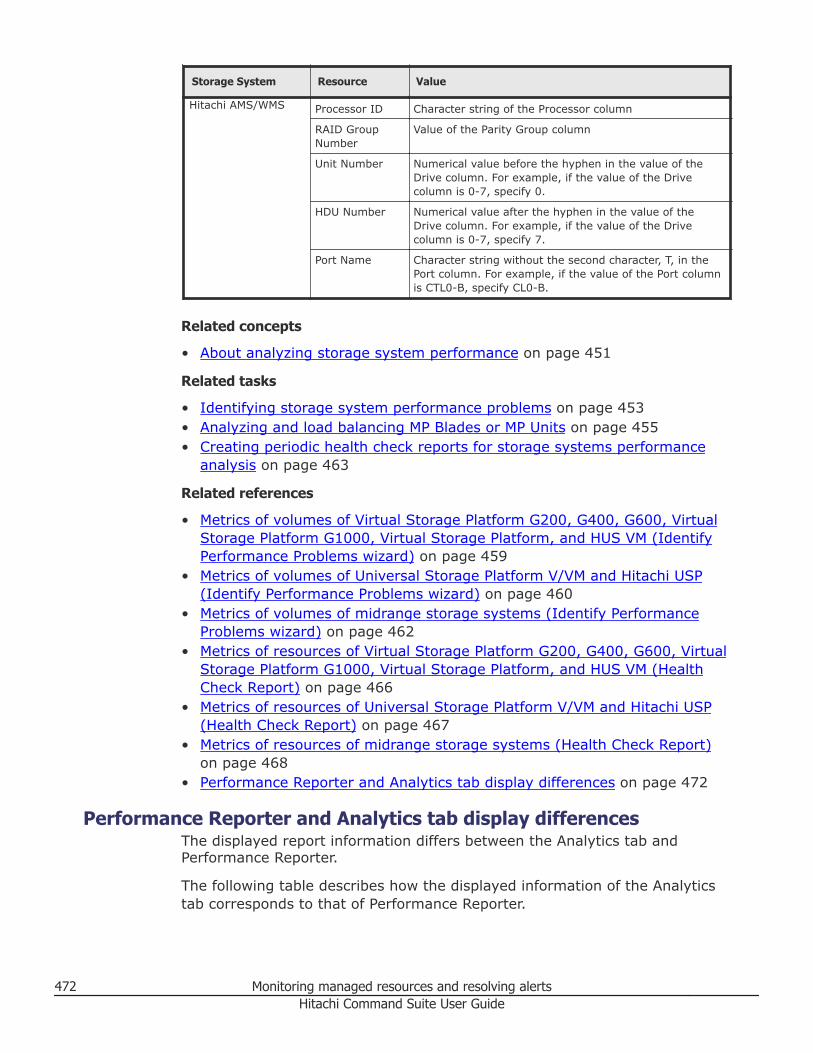
Storage System Resource Value
Hitachi AMS/WMS Processor ID Character string of the Processor column
RAID GroupNumber
Value of the Parity Group column
Unit Number Numerical value before the hyphen in the value of theDrive column. For example, if the value of the Drivecolumn is 0-7, specify 0.
HDU Number Numerical value after the hyphen in the value of theDrive column. For example, if the value of the Drivecolumn is 0-7, specify 7.
Port Name Character string without the second character, T, in thePort column. For example, if the value of the Port columnis CTL0-B, specify CL0-B.
Related concepts
• About analyzing storage system performance on page 451
Related tasks
• Identifying storage system performance problems on page 453• Analyzing and load balancing MP Blades or MP Units on page 455• Creating periodic health check reports for storage systems performance
analysis on page 463
Related references
• Metrics of volumes of Virtual Storage Platform G200, G400, G600, VirtualStorage Platform G1000, Virtual Storage Platform, and HUS VM (IdentifyPerformance Problems wizard) on page 459
• Metrics of volumes of Universal Storage Platform V/VM and Hitachi USP(Identify Performance Problems wizard) on page 460
• Metrics of volumes of midrange storage systems (Identify PerformanceProblems wizard) on page 462
• Metrics of resources of Virtual Storage Platform G200, G400, G600, VirtualStorage Platform G1000, Virtual Storage Platform, and HUS VM (HealthCheck Report) on page 466
• Metrics of resources of Universal Storage Platform V/VM and Hitachi USP(Health Check Report) on page 467
• Metrics of resources of midrange storage systems (Health Check Report)on page 468
• Performance Reporter and Analytics tab display differences on page 472
Performance Reporter and Analytics tab display differencesThe displayed report information differs between the Analytics tab andPerformance Reporter.
The following table describes how the displayed information of the Analyticstab corresponds to that of Performance Reporter.
472 Monitoring managed resources and resolving alertsHitachi Command Suite User Guide
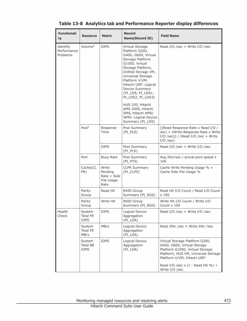
Table 13-8 Analytics tab and Performance Reporter display differences
Functionality
Resource MetricRecordName(Record ID)
Field Name
IdentifyPerformanceProblems
Volume1 IOPS Virtual StoragePlatform G200,G400, G600, VirtualStorage PlatformG1000, VirtualStorage Platform,Unified Storage VM,Universal StoragePlatform V/VM,Hitachi USP: LogicalDevice Summary(PI_LDS, PI_LDS1,PI_LDS2, PI_LDS3)
HUS 100, HitachiAMS 2000, HitachiSMS, Hitachi AMS/WMS: Logical DeviceSummary (PI_LDS)
Read I/O /sec + Write I/O /sec
Pool1 ResponseTime
Pool Summary(PI_PLS)
((Read-Response-Rate x Read I/O /sec) + (Write-Response-Rate x WriteI/O /sec)) / (Read I/O /sec + WriteI/O /sec)
IOPS Pool Summary(PI_PLS)
Read I/O /sec + Write I/O /sec
Port Busy Rate Pool Summary(PI_PTS)
Avg Xfer/sec / actual-port-speed x100
Cache(CLPR)
WritePendingRate + SideFile UsageRate
CLPR Summary(PI_CLPS)
Cache Write Pending Usage % +Cache Side File Usage %
ParityGroup
Read Hit RAID GroupSummary (PI_RGS)
Read Hit I/O Count / Read I/O Countx 100
ParityGroup
Write Hit RAID GroupSummary (PI_RGS)
Write Hit I/O Count / Write I/OCount x 100
HealthCheck
SystemTotal FEIOPS
IOPS Logical DeviceAggregation(PI_LDA)
Read I/O /sec + Write I/O /sec
SystemTotal FEMB/s
MB/s Logical DeviceAggregation(PI_LDA)
Read Xfer /sec + Write Xfer /sec
SystemTotal BEIOPS
IOPS Logical DeviceAggregation(PI_LDA)
Virtual Storage Platform G200,G400, G600, Virtual StoragePlatform G1000, Virtual StoragePlatform, HUS VM, Universal StoragePlatform V/VM, Hitachi USP:
Read I/O /sec x (1 - Read Hit %) +Write I/O /sec
Monitoring managed resources and resolving alerts 473Hitachi Command Suite User Guide
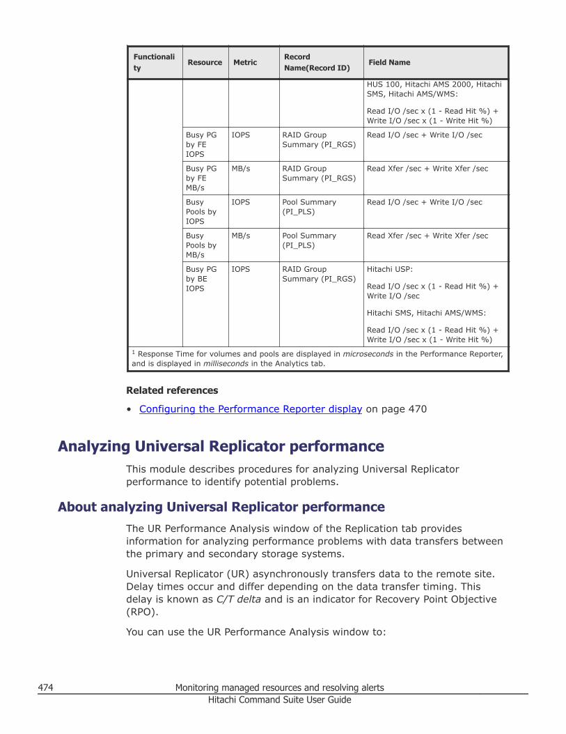
Functionality
Resource MetricRecordName(Record ID)
Field Name
HUS 100, Hitachi AMS 2000, HitachiSMS, Hitachi AMS/WMS:
Read I/O /sec x (1 - Read Hit %) +Write I/O /sec x (1 - Write Hit %)
Busy PGby FEIOPS
IOPS RAID GroupSummary (PI_RGS)
Read I/O /sec + Write I/O /sec
Busy PGby FEMB/s
MB/s RAID GroupSummary (PI_RGS)
Read Xfer /sec + Write Xfer /sec
BusyPools byIOPS
IOPS Pool Summary(PI_PLS)
Read I/O /sec + Write I/O /sec
BusyPools byMB/s
MB/s Pool Summary(PI_PLS)
Read Xfer /sec + Write Xfer /sec
Busy PGby BEIOPS
IOPS RAID GroupSummary (PI_RGS)
Hitachi USP:
Read I/O /sec x (1 - Read Hit %) +Write I/O /sec
Hitachi SMS, Hitachi AMS/WMS:
Read I/O /sec x (1 - Read Hit %) +Write I/O /sec x (1 - Write Hit %)
1 Response Time for volumes and pools are displayed in microseconds in the Performance Reporter,and is displayed in milliseconds in the Analytics tab.
Related references
• Configuring the Performance Reporter display on page 470
Analyzing Universal Replicator performanceThis module describes procedures for analyzing Universal Replicatorperformance to identify potential problems.
About analyzing Universal Replicator performanceThe UR Performance Analysis window of the Replication tab providesinformation for analyzing performance problems with data transfers betweenthe primary and secondary storage systems.
Universal Replicator (UR) asynchronously transfers data to the remote site.Delay times occur and differ depending on the data transfer timing. Thisdelay is known as C/T delta and is an indicator for Recovery Point Objective(RPO).
You can use the UR Performance Analysis window to:
474 Monitoring managed resources and resolving alertsHitachi Command Suite User Guide
• Identify instances where the C/T delta threshold was exceeded.View the top five copy groups and their C/T delta rates in a chart. You canquickly identify copy groups that consistently exceed the maximum writetime delay (C/T delta threshold).
• Analyze the C/T delta threshold against the performance of primary,secondary, and network resources. The analysis process supports twomodes:○ Wizard mode: a step-by-step guide that compares trends and helps
users identify the cause of the problem.○ Advanced mode: a selection of charts that lets advanced users
correlate multiple trends and identify the problematic resource.
Related tasks
• Monitoring Universal Replicator performance on page 476• Configuring network bandwidth for analysis on page 477• Analyzing Universal Replicator performance in wizard mode on page 482• Analyzing Universal Replicator performance in advanced mode on page
483
Related references
• Prerequisites for analyzing Universal Replicator performance on page 475• Metrics for Universal Replicator performance analysis on page 479
Prerequisites for analyzing Universal Replicator performanceBefore attempting analysis, verify the site configuration, necessary software,and user access controls.
You must satisfy the following requirements before using the UR PerformanceAnalysis window:• Ensure that your site configuration meets all the configuration
requirements for Universal Replicator performance analysis described inthe Hitachi Command Suite Administrator Guide.
• Ensure that Hitachi Tuning Manager and Replication Manager are installedand linked to HCS.
• Ensure that users have the necessary permissions (roles and resourceaccess) for the UR Performance Analysis window of the Replication tabdescribed in Required roles and resource groups by function on page 111.
Note: The performance analysis function supports copy groups consisting ofopen volumes. Copy groups that are defined by device group, use multiplejournal groups in a Universal Replicator MxN configuration, or use virtualcommand devices, are not supported.
Related concepts
• About analyzing Universal Replicator performance on page 474
Monitoring managed resources and resolving alerts 475Hitachi Command Suite User Guide
Related tasks
• Monitoring Universal Replicator performance on page 476
Related references
• Required roles and resource groups by function on page 111
Monitoring Universal Replicator performance
Prerequisites
You must satisfy the following requirements before using the UR PerformanceAnalysis window:• Ensure that your site configuration meets all the configuration
requirements for Universal Replicator performance analysis described inthe Hitachi Command Suite Administrator Guide.
• Ensure that Hitachi Tuning Manager and Replication Manager are installedand linked to HCS.
• Ensure that users have the necessary permissions (roles and resourceaccess) for the UR Performance Analysis window of the Replication tab.
Note: The performance analysis function supports copy groups consisting ofopen volumes. Copy groups that are defined by device group, use multiplejournal groups in a Universal Replicator MxN configuration, or use virtualcommand devices, are not supported.
You can monitor Universal Replicator performance (C/T delta) from the URPerformance Analysis window. If you see problems, you can then perform ananalysis to discover the root cause.
Tip: By default, performance data is collected every four hours, andconfiguration information (including storage systems, copy pairs, and pairmanagement servers) is refreshed every 24 hours. The Refresh PerformanceData button allows you to do a manual refresh of the performance data, anddisplays an option to refresh the configuration as well (Also refresh copygroup information).
Procedure
1. Open the Replication tab.2. Examine the C/T delta trend in the UR Performance Analysis window:
• The five copy groups with the largest percentage of C/T deltathreshold are displayed.
• The text in the bar graph displays the actual C/T delta and thresholdvalues.
• The default Time Period is one day. Use the range buttons to adjustthe view.
476 Monitoring managed resources and resolving alertsHitachi Command Suite User Guide
• The Copy Groups tab includes a table with copy group informationand key usage statistics.
• For reference, the Alerts tab includes a summary of alerts that arecreated by Replication Manager.
Note: You cannot change alerts from the Alerts tab. You can modifythem only from Replication Manager.
3. If the C/T delta threshold for a copy group is exceeded, you can performan analysis:• In advanced mode, you can perform the analysis yourself by viewing a
series of graphs to determine the root cause of the problem.• In wizard mode, you are guided through a selection of key metrics and
presented with a summary of possible causes and solutions.
Caution: The following operations will cause previous C/T delta valuesand JNLG usage rates not to be displayed:• Deleting copy pair configuration definition files• Making changes to the pair management server that manages a target
copy group, including changing the WWN
Note: You cannot access previous C/T delta values during a takeoveroperation (disaster recovery) because the relationship between theprimary and secondary volumes is temporarily reversed. When the copygroup relationship is restored (takeback), the data can be accessedagain. For more information about disaster recovery operations, see theHitachi Command Suite Replication Manager User Guide.
Related concepts
• About analyzing Universal Replicator performance on page 474
Related tasks
• Analyzing Universal Replicator performance in advanced mode on page483
• Analyzing Universal Replicator performance in wizard mode on page 482• Configuring network bandwidth for analysis on page 477
Related references
• Prerequisites for analyzing Universal Replicator performance on page 475• Metrics for Universal Replicator performance analysis on page 479
Configuring network bandwidth for analysisThe UR Performance Analysis function gives you the option of supplyingvalues for the effective network bandwidth.
Monitoring managed resources and resolving alerts 477Hitachi Command Suite User Guide
The effective network bandwidth is the actual speed at which data can betransmitted on a remote path based on your replication environment. Checkyour network and supply a proper bandwidth value for each path group.
Tip:• In addition to the main UR Performance Analysis screen, this option is
also available during analysis (wizard and advanced mode).• Setting the bandwidth is not required. If values are not set, a warning is
displayed that can be ignored.
Procedure
1. On the Replication tab, in General Tasks, select ConfigureThresholds for Network Analysis.
2. Supply one value for all remote path groups or select each individually.
Related concepts
• About analyzing Universal Replicator performance on page 474
Related tasks
• Monitoring Universal Replicator performance on page 476
Related references
• Prerequisites for analyzing Universal Replicator performance on page 475• Metrics for Universal Replicator performance analysis on page 479
Configuring metric thresholds for M-JNL analysisThe UR Performance Analysis window includes an option to set thresholds forthe following metrics:• Host Write Transfer Rate to M-JNL• M-JNL Async Transfer Rate to RCU• Host Write IOPS to M-JNL
The threshold values are used to plot a horizontal lines in graphs indicatingwhere the limit has been exceeded. Although defaults are defined, the valuesshould be based on your replication environment.
Tip: In addition to appearing under General Tasks in the main screen, thisoption is also available during analysis (wizard and advanced mode).
Procedure
1. On the Replication tab, in General Tasks, select ConfigureThresholds for M-JNL Analysis.
2. Select a metric using the M-JNL Threshold buttons.
478 Monitoring managed resources and resolving alertsHitachi Command Suite User Guide
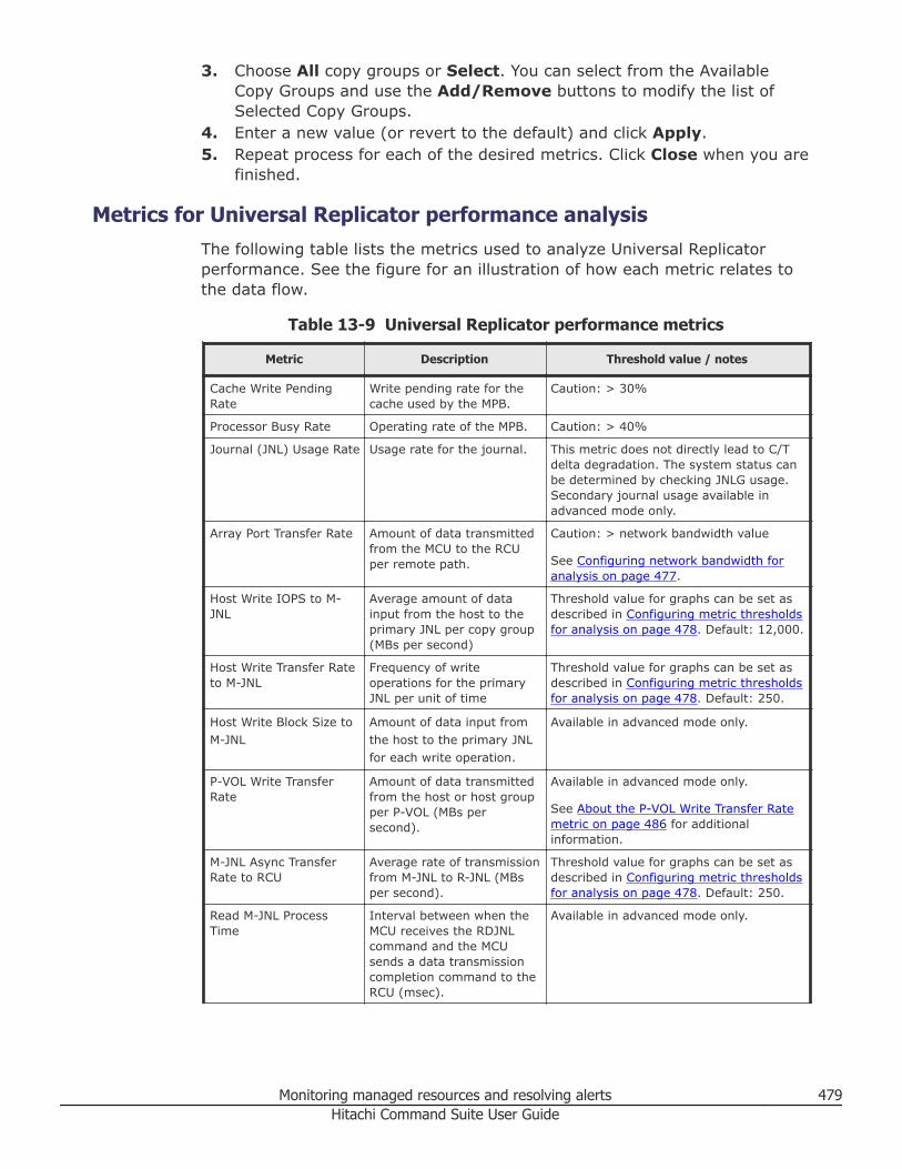
3. Choose All copy groups or Select. You can select from the AvailableCopy Groups and use the Add/Remove buttons to modify the list ofSelected Copy Groups.
4. Enter a new value (or revert to the default) and click Apply.5. Repeat process for each of the desired metrics. Click Close when you are
finished.
Metrics for Universal Replicator performance analysisThe following table lists the metrics used to analyze Universal Replicatorperformance. See the figure for an illustration of how each metric relates tothe data flow.
Table 13-9 Universal Replicator performance metrics
Metric Description Threshold value / notes
Cache Write PendingRate
Write pending rate for thecache used by the MPB.
Caution: > 30%
Processor Busy Rate Operating rate of the MPB. Caution: > 40%
Journal (JNL) Usage Rate Usage rate for the journal. This metric does not directly lead to C/Tdelta degradation. The system status canbe determined by checking JNLG usage.Secondary journal usage available inadvanced mode only.
Array Port Transfer Rate Amount of data transmittedfrom the MCU to the RCUper remote path.
Caution: > network bandwidth value
See Configuring network bandwidth foranalysis on page 477.
Host Write IOPS to M-JNL
Average amount of datainput from the host to theprimary JNL per copy group(MBs per second)
Threshold value for graphs can be set asdescribed in Configuring metric thresholdsfor analysis on page 478. Default: 12,000.
Host Write Transfer Rateto M-JNL
Frequency of writeoperations for the primaryJNL per unit of time
Threshold value for graphs can be set asdescribed in Configuring metric thresholdsfor analysis on page 478. Default: 250.
Host Write Block Size toM-JNL
Amount of data input fromthe host to the primary JNLfor each write operation.
Available in advanced mode only.
P-VOL Write TransferRate
Amount of data transmittedfrom the host or host groupper P-VOL (MBs persecond).
Available in advanced mode only.
See About the P-VOL Write Transfer Ratemetric on page 486 for additionalinformation.
M-JNL Async TransferRate to RCU
Average rate of transmissionfrom M-JNL to R-JNL (MBsper second).
Threshold value for graphs can be set asdescribed in Configuring metric thresholdsfor analysis on page 478. Default: 250.
Read M-JNL ProcessTime
Interval between when theMCU receives the RDJNLcommand and the MCUsends a data transmissioncompletion command to theRCU (msec).
Available in advanced mode only.
Monitoring managed resources and resolving alerts 479Hitachi Command Suite User Guide
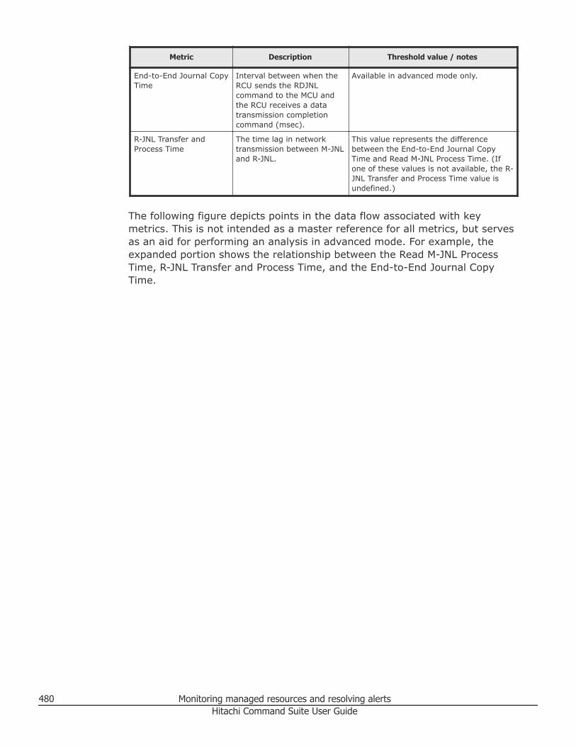
Metric Description Threshold value / notes
End-to-End Journal CopyTime
Interval between when theRCU sends the RDJNLcommand to the MCU andthe RCU receives a datatransmission completioncommand (msec).
Available in advanced mode only.
R-JNL Transfer andProcess Time
The time lag in networktransmission between M-JNLand R-JNL.
This value represents the differencebetween the End-to-End Journal CopyTime and Read M-JNL Process Time. (Ifone of these values is not available, the R-JNL Transfer and Process Time value isundefined.)
The following figure depicts points in the data flow associated with keymetrics. This is not intended as a master reference for all metrics, but servesas an aid for performing an analysis in advanced mode. For example, theexpanded portion shows the relationship between the Read M-JNL ProcessTime, R-JNL Transfer and Process Time, and the End-to-End Journal CopyTime.
480 Monitoring managed resources and resolving alertsHitachi Command Suite User Guide
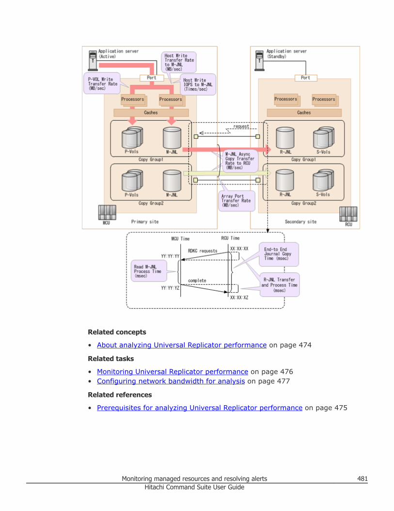
Related concepts
• About analyzing Universal Replicator performance on page 474
Related tasks
• Monitoring Universal Replicator performance on page 476• Configuring network bandwidth for analysis on page 477
Related references
• Prerequisites for analyzing Universal Replicator performance on page 475
Monitoring managed resources and resolving alerts 481Hitachi Command Suite User Guide
Analyzing Universal Replicator performance in wizard modeIn wizard mode, the GUI guides you through the process of examiningresource metrics and suggests possible solutions.
Prerequisites
You must satisfy the following requirements before using the UR PerformanceAnalysis window:• Ensure that your site configuration meets all the configuration
requirements for Universal Replicator performance analysis described inthe Hitachi Command Suite Administrator Guide.
• Ensure that Hitachi Tuning Manager and Replication Manager are installedand linked to HCS.
• Ensure that users have the necessary permissions (roles and resourceaccess) for the UR Performance Analysis window of the Replication tab.
Note: The performance analysis function supports copy groups consisting ofopen volumes. Copy groups that are defined by device group, use multiplejournal groups in a Universal Replicator MxN configuration, or use virtualcommand devices, are not supported.
Procedure
1. Open the Replication tab.2. On the Copy Groups tab, select a copy group and click Analyze UR
Performance (Wizard Mode).3. Read the Introduction and click Next.4. Using the slider below the graph, choose a Time Period as instructed
and then click Next.
Note: If you see cache or processor resources listed that are notassociated with the copy group you are analyzing, execute RefreshStorage System on the Administration tab and then, select RefreshPerformance Data on the Replication tab with the Also refresh copygroup configuration check box selected.
• By default, Replication Manager polls information sources for copy pairstatus every 5 minutes. Depending on the data interval you set, thiscan affect how the display is refreshed in the UR Performance Analysiswindow.
• By default, new performance data is collected through Tuning Managerevery four hours. A gray zone in the graph indicates uncollected data.If you click Refresh Performance Data at this point, the wizardcloses and you restart this procedure when the task is complete.
482 Monitoring managed resources and resolving alertsHitachi Command Suite User Guide
5. On the displayed pages, examine each metric and use the check box tomark any resources that exceed the threshold. (You can select Markresources that exceed pre-set threshold to select them all.)Click Next to proceed.
6. The Results Report page includes the detected issues and the possiblecauses and solutions based on your selections. Click the Show Detaillink to display the resources and the graphed data.
Result
The solutions include instructions to check each resource to confirm theproblem and apply the suggested solution.
Related concepts
• About analyzing Universal Replicator performance on page 474• About refreshing UR Performance Analysis data on page 487
Related tasks
• Analyzing Universal Replicator performance in advanced mode on page483
• Exporting Universal Replicator performance reports on page 485
Related references
• Prerequisites for analyzing Universal Replicator performance on page 475• Metrics for Universal Replicator performance analysis on page 479
Analyzing Universal Replicator performance in advanced modeIn advanced mode, UR Performance Analysis creates graphs that are basedon a selection of metrics to highlight possible performance problems.
Prerequisites
You must satisfy the following requirements before using the UR PerformanceAnalysis window:• Ensure that your site configuration meets all the configuration
requirements for Universal Replicator performance analysis described inthe Hitachi Command Suite Administrator Guide.
• Ensure that Tuning Manager and Replication Manager are installed andlinked to HCS.
• Ensure that users have the necessary permissions (roles and resourceaccess) for the UR Performance Analysis window of the Replication tab.
Note: The performance analysis function supports copy groups consisting ofopen volumes. Copy groups that are defined by device group, use multiplejournal groups in a Universal Replicator MxN configuration, or use virtualcommand devices, are not supported.
Monitoring managed resources and resolving alerts 483Hitachi Command Suite User Guide
Note: If you see cache or processor resources listed that are not associatedwith the copy group you are analyzing, execute Refresh Storage System onthe Administration tab and then, select Refresh Performance Data on theReplication tab with the Also refresh copy group configuration check boxselected.
Procedure
1. Open the Replication tab.2. On the Copy Groups tab, select a copy group and click Analyze UR
Performance (Advanced Mode).
Result
The default dashboard includes four panes that plot metrics for S-VOL, M-JNL, R-JNL, and Network. Each panel has a Report list to choose metrics toplot in a graph. Use the maximize control to view a single pane.
Tip: The M-JNL pane includes reports featuring the P-VOL Write TransferRate, a metric that displays the amount of data transmitted from host or hostgroup per P-VOL.
You can customize the display in several ways:• Time Settings adjusts the time period for all panes.• View Settings selects the panes to display in the dashboard.• Each report includes a list for selecting the metric, and Configure Chart
customizes the display:○ You can select an existing entry from the Charts list to modify (or
remove). Clicking Add creates a chart.○ Chart Settings sets the title, chooses metrics for the left and right axes,
and the chart position.• When a pane is maximized, Vertical Comparison adds a second graph.• When the Network pane is maximized, the graph is maximized.
- If you click the Volumes Sharing Path Group button while the Networkpane is maximized, a list of primary volumes in the copy group that usesthe same remote path as the Universal Replicator copy group that is beinganalyzed is displayed in the Related Volumes window.
• You can also annotate a graph with memos, text windows that allow you totake notes.○ Click Add Memo to start a new note. You can also add a note by double-
clicking within a graph.○ As with any window, you can move, minimize, or delete it using the
controls in the title bar.• Configure Thresholds for M-JNL Analysis changes the threshold value
(horizontal red line) in the chart.
484 Monitoring managed resources and resolving alertsHitachi Command Suite User Guide
Tip: By default, Replication Manager polls information sources for copy pairstatus every 5 minutes. Depending on the data interval you set, this canaffect how the display is refreshed in the UR Performance Analysis window.
Related concepts
• About analyzing Universal Replicator performance on page 474• About the P-VOL Write Transfer Rate metric on page 486• About refreshing UR Performance Analysis data on page 487
Related tasks
• Analyzing Universal Replicator performance in wizard mode on page 482• Exporting Universal Replicator performance reports on page 485
Related references
• Metrics for Universal Replicator performance analysis on page 479• Prerequisites for analyzing Universal Replicator performance on page 475• Metrics for Universal Replicator performance analysis on page 479
Exporting Universal Replicator performance reportsYou can export Universal Replicator performance data to a PDF file forreporting purposes.
Tip: You can also obtain UR performance data (in CSV form) using thefollowing command line tools:• GetCopyGroup• RefreshReplicationPerformanceData• GetReplicationPerformanceData
For more information, see the Hitachi Command Suite CLI Reference Guide.
The UR Performance Analysis window includes an export function to saveoutput to a PDF file on the following panes:• Analyze UR Performance (main screen)• Results Report (wizard mode)• Analysis Target (advanced mode)
Procedure
1. If you are exporting data from the Analyze Universal Replicatorperformance main screen, first select a copy group from the CopyGroups tab.
2. Click Export.If you are exporting data from the main screen, you are prompted toselect a Time Period.
Monitoring managed resources and resolving alerts 485Hitachi Command Suite User Guide
3. For graphs in the advanced mode pane, any memos you created areincluded by default. To exclude your memos from the report, de-selectDisplay the memos on the graphs.
4. Click Submit.5. Select the export location for the report.
The PDF file is saved in the specified location.
Tip: It is useful to save a C/T delta baseline so that you can later detectany gradual worsening of C/T delta performance over time. An accuratebaseline requires stable host I/O. Wait for the completion of any settingsand status changes that affect C/T delta (such as initial copies of newlyadded copy groups, or a copy group that shares a remote path). For bestresults, when using the Export function on the main screen, select aTime Period of one day (1d).
Related tasks
• Analyzing Universal Replicator performance in wizard mode on page 482• Analyzing Universal Replicator performance in advanced mode on page
483
Related references
• Prerequisites for analyzing Universal Replicator performance on page 475
About the P-VOL Write Transfer Rate metricThe P-VOL Write Transfer Rate metric is used to calculate the amount of datawritten (in MB/sec) for each of the P-VOLs that comprise a copy group.Normally, the total of P-VOL Write Transfer Rate values in a copy groupapproximates the value of the Host Write Transfer Rate to M-JNL. The P-VOLWrite Transfer Rate metric is available in the M-JNL pane of the advancedmode window.
The P-VOL Write Transfer Rate can be used to narrow down possible causesafter identifying the copy group where C/T delta degradation has beenobserved. There are two basic scenarios:• P-VOL traffic may be dominating network bandwidth.
For best results, first observe the Array Port Transfer Rate (amount of dataoutput from a port) or the M-JNL Async Transfer Rate to RCU (amount ofdata output for each M-JNL). Once you have identified the specific copygroup, you can use the P-VOL Write Transfer Rate to determine whichapplication/host uses the constituent P-VOLs, or which host group haswritten the largest amount of data.
• P-VOL traffic may be overloading storage resources.If you observe the Host Write Transfer Rate to M-JNL increase during orbefore a C/T Delta increase, storage resources (such as processor, cache,or parity group) may be overtaxed. In this case, analyze the P-VOL Write
486 Monitoring managed resources and resolving alertsHitachi Command Suite User Guide
Transfer Rate to identify the responsible host/application. You can thenchoose to tune the application or add resources.
Tip: When you select a report that includes the P-VOL Write Transfer Rate,the graph includes a filter that permits you to narrow down the number of P-VOLs to be plotted.
About refreshing UR Performance Analysis dataBy default, Replication Manager polls information sources for copy pair statusevery 5 minutes. (This setting is part of the Replication Manager GUI, not theUR Performance Analysis window.) If you have increased this polling setting(refresh value) to be longer than the data interval in the UR PerformanceAnalysis window, the plot in the graph is updated less often (regardless of thedata interval setting). For example, a refresh value of 30 minutes updatesthe graph every half hour, even if the data interval is set to 10 minutes.Setting the refresh value to less than 10 minutes helps ensure the plot isupdated every 10 minutes (assuming data interval of 10 minutes). However,you might also need to consider the load balance if you reduce the refreshvalue because (in some cases) refreshing the copy pair status will actuallytake longer than the setting indicates.
Managing alertsThis module describes how to view, confirm, and manage alerts.
About alertsHitachi Command Suite regularly monitors storage system and file server(Hitachi NAS Platform v12.0 or later only) status.
Alerts are reported on the Dashboard, in the Storage System Alerts report.You can select the severity levels of alerts to be collected in this report byclicking the tool icon application pane.
Alert details can be confirmed on the Tasks & Alerts tab.• Resolved alerts can be deleted manually from the list.• The upper limit of the alerts that are managed by HCS is 500,000. When
the number of alerts exceeds the upper limit, older alerts are deleted.
For Virtual Storage Platform G200, G400, G600, you can view and outputerror information (SIM) by launching the maintenance utility on theResources tab under the storage system name. For information about alertsfor Virtual Storage Platform G200, G400, G600 and about how to configureSNMP trap and email notification settings, see the Hitachi Virtual StoragePlatform G200, G400, G600 System Administrator Guide .
Alerts can also be delivered in email when SNMP traps are received fromstorage systems or file servers (Hitachi NAS Platform v12.0 or later, Hitachi
Monitoring managed resources and resolving alerts 487Hitachi Command Suite User Guide
NAS Platform F, and Hitachi Data Ingestor only). You can also configureVirtual Storage Platform G1000 to receive failure information (SIM) throughsyslog, SNMP trap, and email. For information about how to configure HCSand your storage to receive failure information, see the Hitachi CommandSuite Administrator Guide.
Related tasks
• Confirming an alert on page 488
Confirming an alertYou can list, review, and delete alerts.
Procedure
1. On the Tasks & Alerts tab, click All Alerts.2. Click on an alert to review the alert details and take appropriate action.
Result
The alert is resolved.
Tip: When the number of alerts for a storage system or file server nodeexceeds 10,000 alerts, memory might become insufficient. We recommendthat you manually delete alerts that are no longer necessary. However, forHNAS, if the number of alerts for a single cluster exceeds 10,000, the alertsfor that cluster are automatically deleted starting from the oldest alert.
As alerts are confirmed as resolved, select the resolved alerts, and clickDelete Alerts.
Related concepts
• About alerts on page 487
488 Monitoring managed resources and resolving alertsHitachi Command Suite User Guide

AManaging storage resources that have
virtual IDsThis module describes specific functionality available for virtualized volumeresources for which virtual IDs are assigned.
□ About managing storage resources that have virtual IDs
□ Displaying virtual ID information
□ Allocating volumes to hosts with virtual IDs
Managing storage resources that have virtual IDs 489Hitachi Command Suite User Guide
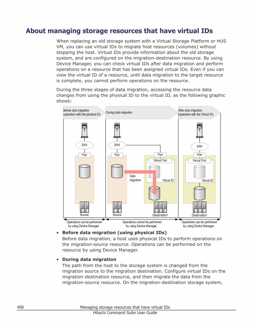
About managing storage resources that have virtual IDsWhen replacing an old storage system with a Virtual Storage Platform or HUSVM, you can use virtual IDs to migrate host resources (volumes) withoutstopping the host. Virtual IDs provide information about the old storagesystem, and are configured on the migration-destination resource. By usingDevice Manager, you can check virtual IDs after data migration and performoperations on a resource that has been assigned virtual IDs. Even if you canview the virtual ID of a resource, until data migration to the target resourceis complete, you cannot perform operations on the resource.
During the three stages of data migration, accessing the resource datachanges from using the physical ID to the virtual ID, as the following graphicshows:
• Before data migration (using physical IDs)Before data migration, a host uses physical IDs to perform operations onthe migration-source resource. Operations can be performed on theresource by using Device Manager.
• During data migrationThe path from the host to the storage system is changed from themigration source to the migration destination. Configure virtual IDs on themigration-destination resource, and then migrate the data from themigration-source resource. On the migration-destination storage system,
490 Managing storage resources that have virtual IDsHitachi Command Suite User Guide
while data migration is in progress, operations cannot be performed on theresource by using Device Manager.
• After data migration (using virtual IDs)After all of the target resources are migrated, operations can be performedon a resource by using Device Manager. After data migration, a host usesvirtual IDs to access resources and perform operations on the migration-destination storage system.
Items such as virtual LDEV ID and virtual ports can be used to verify virtualID information.
Check the correspondence between the virtual ID information received fromthe host administrator and the physical ID information to identify the targetresource.
You can perform any of the following tasks on resources that have virtualIDs:• Expand DP volumes• Reclaim zero pages of DP volumes• Edit tier relocation of HDT volumes• Edit tiering policy of HDT volumes• Manage data placement profiles of HDT volumes• Allocate volumes1
• Allocate like volumes1
• Edit LUN paths• Unallocate volumes2
• Define copy pairs3
• Change the status of a copy pair3
• Migrate data by using Tiered Storage Manager• Create logical group• Create tier• Edit volume labels• Refresh volume labels
Notes:1. For volumes for which no virtual ID is specified, you can specify new
virtual IDs, and then allocate the volumes to host groups for whichvirtual IDs have already been specified.
2. You can also delete virtual IDs at the same time that volumes areunallocated.
3. To perform operations on a copy pair that contains volumes for whichvirtual IDs have been specified, you must update in advance theinformation (physical ID information) of the post-migration storagesystem with the configuration definition file of the copy pair. For detailsabout the contents of configuration definition files, as well as the systemconfiguration required to perform operations on copy pairs that contain
Managing storage resources that have virtual IDs 491Hitachi Command Suite User Guide
volumes for which virtual IDs have been specified, see the HitachiCommand Suite Administrator Guide.
Related concepts
• About removing hosts and related resources, or vCenters on page 76
Displaying virtual ID informationYou can display virtual ID information in the volume list to identify the targetresource from the virtual ID information. Virtual ID information of resourcescan be displayed per host, storage system, or logical group.
Procedure
1. On the Resources tab, select Hosts, Storage Systems, or LogicalGroups.
2. Expand the tree and select the target resource to display the volume list.3. Click the Column Settings button.4. From the displayed dialog box, select check boxes to display virtual ID
information, such as Virtual LDEV ID and Virtual Port.
Result
Virtual ID information is displayed in the list of volumes, enabling you to mapthe virtual ID with the ID (physical ID) information assigned by thedestination storage system.
Tip: After checking the virtual ID information for the volume, we recommendediting the volume label so that the volumes can be identified from thevirtual ID information, thus enabling you to identify the target volumes fromwindows that do not display virtual ID information.
Virtual ID information can also be displayed in the tables for Allocatevolumes, Allocate like volumes, Unallocate volumes, or Edit LUN Paths dialogboxes. If virtual IDs are set but you cannot set columns in the tables in thesedialog boxes, virtual ID information will be automatically displayed.
Allocating volumes to hosts with virtual IDsYou can allocate volumes to hosts that belong to resource groups being usedfor data migration and that are using virtual IDs. You can also allocatevolumes for which no virtual IDs are specified. In this case, such volumes areassigned new virtual IDs. A resource group used for a data migration thatuses virtual IDs is the resource group specified for the storage system whenmigrating data, not a resource group specified in Hitachi Command Suite.
492 Managing storage resources that have virtual IDsHitachi Command Suite User Guide
Prerequisites
• Identify the name of the target host.• Identify the volumes to be allocated, if manually selecting such volumes.• Identify the necessary volume capacity and size, if allocating volumes by
specifying conditions.• Verify that volumes to be allocated meet one of the following conditions:
○ The volumes belong to resource groups used for a data migration thatuses virtual IDs, and the resource group is the same resource group towhich the host group belongs.
○ The resource group ID of the storage system is 0 (it belongs tometa_resource). Note that meta_resource is a resource group speciallymanaged on the storage system. It contains resources that are not apart of individual resource groups.
Procedure
1. On the Resources tab, select Hosts.2. Expand the tree and select an operating system.3. Select one or more hosts, and click Allocate Volumes.4. Allocate volumes with existing virtual ID information, or volumes
requiring virtual ID assignments as follows:a. To allocate volumes that belong to resource groups being used for a
data migration that uses virtual IDs, reference the virtual IDinformation and manually select volumes, and then click Show Planto register this as a task.
b. To assign new virtual IDs to volumes that belong to meta_resource,and then allocate those volumes to a host, specify volume conditionsor manually select volumes whose storage system resource group IDis 0 (meta_resource), and then click Show Plan to register this as atask. Use Column Settings to display storage system resource groupIDs.
5. Confirm that the information in the plan summary is correct. If changesare required, click Back.
6. (Optional) Update the task name and provide a description.7. (Optional) Expand Schedule to specify the task schedule. You can
schedule the task to run immediately or later. The default setting is Now.If scheduled for Now, select View task status to monitor the task afterit is submitted.
8. Click Submit. If the task is scheduled to run immediately, the taskbegins.
9. You can check the progress and the result of the task on the Tasks &Alerts tab. Click on the task name to view details of the task.Using the Resources tab, select the hosts to verify that the designatedvolumes are allocated. Volumes for which no virtual ID is specified areassigned a new virtual ID. When allocating volumes whose storage
Managing storage resources that have virtual IDs 493Hitachi Command Suite User Guide
system resource group ID is 0, the volumes are registered in the sameresource group as the host group.
Result
The designated volumes are allocated on the selected hosts.
Tip: When allocating like volumes, you can also allocate volumes for whichno virtual IDs are specified, as described in this procedure.
Note: When unallocating volumes, you can also delete virtual IDs at thesame time. To delete virtual IDs, specify conditions in Advanced Options >Virtual ID Information.
494 Managing storage resources that have virtual IDsHitachi Command Suite User Guide
BLinking related products
This module describes the link and launch feature that is used to access otherrelated Hitachi Command Suite products.
□ Launching other Hitachi Command Suite products
□ Linking with Compute Systems Manager
Linking related products 495Hitachi Command Suite User Guide
Launching other Hitachi Command Suite productsOther integrated Hitachi Command Suite products for which you have alicense installed and registered may be used via the link-and-launch feature.
About launching other Hitachi Command Suite productsBy starting related products from HCS, you can configure more detailedsettings or verify the whole image of the storage resource.
An integrated single sign-on is used for all HCS products for which you havean installed and registered license. Related HCS products must be installedon the same system as HCS to use the link-and-launch feature.
Link-and-launch enables you to easily move across storage managementsoftware for a full view of storage resources. HCS provides link-and-launchintegration with the following software applications:• Hitachi Tuning Manager• Hitachi Global Link Manager• Hitachi Replication Manager• Hitachi Storage Services Manager• Hitachi Protection Manager• Hitachi Compute Systems Manager• Hitachi Automation Director• File server management software
You can start the file server management software from Device Manager,which allows you to view detailed information about file servers and createfile systems when allocating volumes.• For Hitachi NAS Platform family, the file server management software is
System Management Unit (SMU)• For Hitachi NAS Platform F and Hitachi Data Ingestor the file server
management software is Hitachi File Services Manager (HFSM)
• Element ManagerFor storage systems other than Hitachi Virtual Storage Platform G200,G400, G600 and Hitachi Virtual Storage Platform G1000, you can startElement Manager from Device Manager, which allows you to view storagesystem information or remotely operate the storage system.
Note: If you have problems starting HCS products or Element Manager,follow the instructions in the displayed message, check the network status,and then try again, or report to the server administrator which product couldnot be activated.
Related tasks
• Starting related products on page 497
496 Linking related productsHitachi Command Suite User Guide
• Starting related products from a list of hosts on page 497• Starting Element Manager on page 499• Starting System Management Unit (SMU) on page 500• Starting Hitachi File Services Manager (HFSM) on page 500
Starting related productsBefore you can start related products, you must register their licenses.
Procedure
1. From the Tools menu, select the product you want to start.2. Navigate to the newly launched browser to access the product.
Related concepts
• About launching other Hitachi Command Suite products on page 496
Related tasks
• Starting related products from a list of hosts on page 497
Starting related products from a list of hostsYou must first register the licenses of all products you want to start.
Hitachi Protection Manager, Hitachi Protection Manager Console, and a DeviceManager agent must be installed on each host managed by Device Manager.For more information, see the Hitachi Protection Manager Console User’sGuide.
Procedure
1. From the Resources tab, select Hosts.2. From the Actions menu located in the corner of the application pane,
select Protection Manager.3. Navigate to the newly launched browser to access the product.
Related concepts
• About launching other Hitachi Command Suite products on page 496
Related tasks
• Starting related products on page 497
Notes on starting Element ManagerWhen starting the storage system software (Element Manager) from HitachiCommand Suite, keep the following in mind.
For HUS 100, Hitachi AMS 2000, Hitachi SMS, and Hitachi AMS/WMS:
Linking related products 497Hitachi Command Suite User Guide
• When Element Manager is left inactive for a certain period of time, autolog off is executed, and the user cannot use the software. If auto log off isexecuted when password protection is enabled, the user remains logged into the storage system, and cannot perform a refresh or create volumes onthe storage system from HCS. In this case, restart Element Manager, andthen manually close the window.For details about auto log off, see the manuals for each storage system.
For HUS 100, Hitachi AMS 2000, and Hitachi SMS:• Element Manager can be started from one management client for each
storage system. Do not start Element Manager from multiple managementclients at the same time.
For HUS 100 and Hitachi AMS 2000:• When Account Authentication is used, executing the following operations
while Element Manager is being started causes the user to remain loggedin to the storage system, preventing operations on storage systems fromElement Manager and HCS until the session times out:○ Log out from HCS○ Stop the services of Hitachi Command Suite common components and
Hitachi Command Suite products by using the hcmdssrv command.○ Close Element Manager with nodes (such as components and groups)
below the storage system name selected on the navigation tree ofElement Manager.Closing Element Manager with the storage system name (route node)selected on the navigation tree causes the user to be logged out.
For details about the hcmdssrv command, see the Hitachi Command SuiteAdministrator Guide.For details about session timeout times, see the manuals for each storagesystem.
For Hitachi AMS and Hitachi WMS:• To use Firefox ESR 23 or later, you need to disable the setting that blocks
non-SSL active content that coexists on SSL pages. In the address bar ofFirefox, enter about:config to open the configuration window, and thenchange the value of security.mixed_content.block_active_content tofalse.
For SMI-S enabled storage systems:• The management tool sometimes cannot start with an SMI-S enabled
storage system because the URL of management tool is incorrect. In thiscase, you need to perform either of the following operations:○ Use the AddURLLink command of Device Manager CLI to register in the
Device Manager server the URL of the management tool of the SMI-Senabled storage system. For details about the AddURLLink command,see the Hitachi Command Suite CLI Reference Guide.
498 Linking related productsHitachi Command Suite User Guide
○ Review the settings of the SMI-S provider, and then refresh the SMI-Senabled storage system from Device Manager.
Related tasks
• Starting Element Manager on page 499
Starting Element ManagerElement Manager is a menu selection for launching native storage systemmanagement tools, which allows you to remotely view, configure, andoperate storage systems, including SMI-S enabled storage.
Element Manager is available for enterprise storage systems, and specificmid-range storage systems, as soon as the storage system is registered withan IP address and user login information.
This includes Virtual Storage Platform, Universal Storage Platform V/VM,Universal Storage Platform, and mid-range systems such as HUS 100, HitachiAMS 2000, and Hitachi SMS.
For example, after Virtual Storage Platform discover and registrationcompletes, you are able to launch Storage Navigator using the ElementManager menu selection.
If Element Manager does not display in the Actions menu, the mid-rangestorage system may require environmental settings. See the followingprerequisites.
Prerequisites• Configure the environment for starting Element Manager.
For details, see Element Manager in the Hitachi Command SuiteAdministrator Guide.
Procedure
1. On the Resources tab, select Storage Systems.2. Select a storage system.3. From the Actions menu in the application pane, select Element
Manager.
Result
Confirm the storage system management tool is started and available foruse.
Related tasks
• Starting System Management Unit (SMU) on page 500• Starting Hitachi File Services Manager (HFSM) on page 500
Linking related products 499Hitachi Command Suite User Guide
Related references
• Notes on starting Element Manager on page 497
Starting System Management Unit (SMU)In HCS, you can start the System Management Unit (SMU) software toperform Hitachi NAS Platform (HNAS) management tasks.
Prerequisites
Register the Hitachi NAS Platform family file server in Device Manager.
Procedure
1. From the Resources tab, select File Servers, then All File Servers.2. In the Server/Cluster list, select the Hitachi NAS Platform (HNAS) cluster
or file server, and click File Server Manager.
Result
The browser opens running System Management Unit (SMU).
Related tasks
• Starting Hitachi File Services Manager (HFSM) on page 500• Starting Element Manager on page 499
Starting Hitachi File Services Manager (HFSM)In HCS, you can start Hitachi File Services Manager (HFSM) software toperform Hitachi NAS Platform (HNAS F) or Hitachi Data Ingestor (HDI)management tasks.
Prerequisites
Register the Hitachi NAS Platform (HNAS F) or Hitachi Data Ingestor (HDI)file server in Device Manager.
Procedure
1. From the Resources tab, select File Servers, then All File Servers.2. Open the tree and select a Hitachi NAS Platform (HNAS F) or Hitachi Data
Ingestor (HDI) node, and from the Actions menu in the corner of theapplication pane, select File Server Manager.
Result
The browser opens running Hitachi File Services Manager (HFSM).
Related tasks
• Starting System Management Unit (SMU) on page 500
500 Linking related productsHitachi Command Suite User Guide
• Starting Element Manager on page 499
Linking with Compute Systems ManagerThis module describes how to link to Compute Systems Manager.
About linking with Compute Systems ManagerIf the host management product Hitachi Compute Systems Manager (HCSM)is installed on the Device Manager server and linked, information about hostsbeing managed by both products will be synchronized automatically whenusing Host Data Collector.
When Device Manager and Compute Systems Manager are linked, hosts areregistered or updated simultaneously between the two products. For thisreason, Compute Systems Manager hosts can automatically be registered orupdated as hosts of Device Manager. Similarly, hosts that have beenregistered or updated in Device Manager can automatically be registered orupdated in Compute Systems Manager. Therefore, it is no longer necessaryfor both the storage and server administrators to separately register orupdate the same hosts.
To synchronize host information, the requirements are:• Hosts must have either a WWN or an iSCSI name.
Among the Compute Systems Manager hosts, information about those thathave a WWN or an iSCSI name is sent to Device Manager. ComputeSystems Manager does not obtain iSCSI names when hosts are registered,but Device Manager hosts that have iSCSI names are also registered inCompute Systems Manager.
• Hosts must be normal hosts or virtual machines whose information wasobtained by using Host Data Collector.Among Device Manager hosts, information about those that wereregistered using Host Data Collector is sent to Compute Systems Manager.Information about Compute Systems Manager hosts is also sent to DeviceManager through Host Data Collector. Hosts that were registered by usinga method other than Host Data Collector (such as a Device Manager agentor a host scan) and virtualization servers are not synchronized. For detailsabout setting up Host Data Collector, see the Hitachi Command SuiteAdministrator Guide.
Note that even when Device Manager and Compute Systems Manager arelinked, host deletions are not synchronized. Therefore, deleting a host fromDevice Manager does not affect Compute Systems Manager. ComputeSystems Manager hosts that have been deleted from Device Manager can bemanually re-synchronized, if necessary.
You can also start and perform operations in Compute Systems Manager fromDevice Manager by using the single sign-on functionality.
Linking related products 501Hitachi Command Suite User Guide
Related concepts
• Methods for registering hosts on page 63
Related tasks
• Resynchronizing hosts of Compute Systems Manager on page 502
Resynchronizing hosts of Compute Systems ManagerUsers can re-synchronize Compute Systems Manager hosts that have beendeleted from Device Manager.
Procedure
1. In the Administration tab, select the Hosts tab, and click Add Hosts.2. Select Re-sync Hosts with CSM, and then submit the task.
The task is registered in the Data Collection Tasks tab.3. Check the task status in the Data Collection Tasks tab.
Result
If the task completed, a host is added to the Hosts tab.
Related concepts
• About linking with Compute Systems Manager on page 501
502 Linking related productsHitachi Command Suite User Guide
Glossary
A
allocated volume
A logical device (LDEV) for which one or more host LUN paths are defined.
C
C/T
See consistency time.
C/T delta
The consistency time difference, or write-delay time, of data transferbetween the primary and secondary storage systems.
cache
A set of RAM (Random Access Memory) modules used to store datatemporarily.
cache logical partition (CLPR)
Virtual cache memory that is set up to be allocated to hosts that are incontention for cache memory. CLPRs can be used to segment storagesystem cache that is assigned to parity groups.
capacity
The amount of data storage space available on a physical storage device,generally measured in bytes (MB, GB, TB, and so on).
CCI
See Command Control Interface.
Glossary 503Hitachi Command Suite User Guide
CLI
command line interface
CLPR
See cache logical partition.
Command Control Interface (CCI)
Software used to control volume replication functionality (such asTrueCopy or ShadowImage) by means of commands issued from a host toa storage system. A command device must be set up in the storagesystem to enable the storage system to receive commands from CCI.
In an open system, Replication Manager uses the CCI configurationdefinition files to modify copy pair configurations and to acquireconfiguration information. Copy pair modification processing, such assplitting and resynchronizing copy pairs, is executed on the storagesystem via CCI.
concatenated parity group
The concatenation of two or more parity groups into one group. Using aconcatenated parity group reduces the time that is required to accessdata (especially sequential data).
consistency time (C/T)A replication policy or threshold that indicates the amount of time that areplication target (volume, journal group, or extended consistency group,for example) is allowed to lag behind replication of the master, or source,volume.
control unit (CU)
Created in an enterprise-class storage system. Also called a CU image.The LDEVs created in a storage system are connected to a single CU, anda number is assigned to each CU for identifying its LDEVs. Therefore,volumes (LDEVs) in a storage system are specified by the CU number(CU#) and LDEV number.
copy pair
A primary and secondary volume pair linked by the volume replicationfunctionality of a storage system. The primary volume contains originaldata, and the secondary volume contains the copy of the original.
Copy operations can be synchronous or asynchronous, and the volumes ofthe copy pair can be located in the same storage system (local copy) or indifferent storage systems (remote copy).
504 GlossaryHitachi Command Suite User Guide
CSV
comma-separated values
CU
See control unit.
D
DB
database
device (dev or DEV)
A physical or logical unit with a specific function.
DEVN
Device number that is assigned to each logical address when using anLDEV on a mainframe host.
DHCP
Dynamic Host Configuration Protocol
discovery
A process that finds and identifies network objects. For example,discovery may find and identify all hosts within a specified IP addressrange.
DKP
Disk processor
DP poolThe area where DP pool volumes (actual volumes) are registered. When aDP volume (virtual volume) receives a write operation from a host, thatdata is stored in a DP pool volume.
When Dynamic Provisioning and Dynamic Tiering must be differentiated,this document uses the terms HDP pool and HDT pool.
DP pool volumeAn actual volume that is one of the volumes making up a DP pool.
When Dynamic Provisioning and Dynamic Tiering need to bedistinguished, this manual uses the terms HDP pool volume or HDT poolvolume.
Glossary 505Hitachi Command Suite User Guide
DP volumeA virtual volume that is created from a Dynamic Provisioning (DP) pool(that is, it is associated with a DP pool).
When Dynamic Provisioning and Dynamic Tiering must be differentiated,this document uses the terms HDP volume and HDT volume.
drive
A physical data storage device that can be either a hard disk drive (HDD)or a flash (solid-state) drive.
E
EVS
Enterprise Virtual Server
external path
A path from a storage port of a storage system to a volume on aconnected external storage system.
external volume
A logical volume whose data resides on drives that are physically locatedin an externally connected storage system.
F
FC
Fibre Channel
FCoE
Fibre Channel over Ethernet. An encapsulation of Fibre Channel framesover Ethernet networks. This allows Fibre Channel to use 10-gigabitEthernet networks (or higher speeds) while preserving the Fibre Channelprotocol.
flash module drive (FMD)
A storage device, which is developed by Hitachi, that uses flash memory.
FMD
See flash module drive.
506 GlossaryHitachi Command Suite User Guide
G
global-active device
A storage system feature that provides high-availability copy pairs tosupport simultaneous, uninterrupted host and cluster active-active I/Owithin and across geographically disparate data centers. This featureprotects against storage system and site failures by providing continuousaccess to data.
GUI
graphical user interface
H
HBA
See host bus adapter.
HDP
See Hitachi Dynamic Provisioning.
HDT
See Hitachi Dynamic Tiering.
Hitachi Dynamic Provisioning (HDP)
Functionality that allocates virtual volumes to a host and uses the physicalcapacity that is necessary according to the data write request.
Hitachi Dynamic Tiering (HDT)
Functionality that is used with Hitachi Dynamic Provisioning that placesdata in a hardware tier according to the I/O load. For example, a dataarea that has a high I/O load is placed in a high-speed hardware tier, anda data area that has a low I/O load is placed in a low-speed hardware tier.
host bus adapter (HBA)
One or more dedicated adapter cards that are installed in a host, haveunique WWN addresses, and provide Fibre Channel I/O connectivity tostorage systems, typically through Fibre Channel switches. Unlikegeneral-purpose Ethernet adapters, which handle a multitude of networkprotocols, host bus adapters are dedicated to high-speed block transfersfor optimized I/O performance.
Glossary 507Hitachi Command Suite User Guide
host group
Custom grouping of hosts that segregates hosts in a meaningful way, forexample, a group of hosts that is segregated by operating system. A hostgroup can be shared with another virtual port or another physical port foralternate path support.
HTML
Hypertext Markup Language
HTTP
Hypertext Transfer Protocol
HTTPS
Hypertext Transfer Protocol Secure
I
I/O
input/output
internal volume
A logical volume whose data resides on drives that are physically locatedwithin the storage system.
Internet protocol (IP)
The protocol that governs the breakup of data messages into packets(units of data), the routing scheme for transmitting them, and thereassembly of the packets into the original data messages at thedestination. Most networks combine IP with a higher-level protocol calledTransmission Control Protocol (TCP), which establishes a virtualconnection between a source and a destination.
IOPS
I/Os per second
IP
See Internet protocol.
iSCSI
Internet Small Computer Systems Interface
508 GlossaryHitachi Command Suite User Guide
J
JRE
Java Runtime Environment
JVM
Java Virtual Machine
JWS
Java Web Start
L
LAN
See local area network.
LDAP
Lightweight Directory Access Protocol
LDEV
See logical device.
LDKC
Logical disk controller
local area network (LAN)
A computer network that spans a relatively small geographic area, suchas a single building or group of buildings.
logical device (LDEV)
A volume created in a storage system. See also LU.
logical group
A user-defined collection of managed resources (hosts and volumes) thatare grouped according to business operations, geographic locations, orother organizational divisions. Logical groups can be public or private:• Public logical groups are accessible by any HCS user.• Private logical groups are accessible only by HCS users who belong to
user groups that are associated with the logical group.
Glossary 509Hitachi Command Suite User Guide
logical unit (LU)
A volume, or LDEV, created in an open storage system, or configured foruse by an open-systems host, for example, OPEN-V.
logical unit number (LUN)
A unique management number that identifies a logical unit (LU) in astorage system. A logical unit can be an end user, a file, a disk drive, aport, a host group that is assigned to a port, an application, or virtualpartitions (or volumes) of a RAID set.
Logical unit numbers (LUNs) are used in SCSI protocols to differentiatedisk drives in a common SCSI target device, such as a storage system. Anopen-systems host uses a LUN to access a particular LU.
LU
See logical unit.
LUN
See logical unit number.
LUSE
LUN expansion; LU size expansion
M
M-JNL
See master journal.
main control unit (MCU)
A storage system at a primary, or main, site that contains primaryvolumes of remote replication pairs. The main control unit (MCU) isconfigured to send remote I/O instructions to one or more storagesystems at the secondary, or remote, site, called remote control units(RCUs). RCUs contain the secondary volumes of the remote replicationpairs. See also remote control unit (RCU).
management client
A computer used to operate a graphical user interface client or acommand-line interface client.
510 GlossaryHitachi Command Suite User Guide
master journal (M-JNL)
The primary, or main, journal volume. A master journal holds differentialdata on the primary replication system until the data is copied to therestore journal (R-JNL) on the secondary system. See also restore journal.
MCU
See main control unit.
N
NAS
Network attached storage
NIC
Network interface card
P
P-VOL
See primary volume.
pair status
Indicates the condition of a copy pair. A pair must have a specific statusfor specific operations. When a pair operation completes, the status of thepair changes to a different status determined by the type of operation.
pathA path from a storage system volume to a host group.
In this manual, the term "path" may mean a path, external path, or LUNpath without making distinctions among them.
pool volume (pool-VOL)
A logical volume that is reserved for storing Copy-on-Write Snapshot dataor Dynamic Provisioning write data.
primary volume (P-VOL)
In a volume pair, the source volume that is copied to another volumeusing the volume replication functionality of a storage system. The dataon the P-VOL is duplicated synchronously or asynchronously on thesecondary volume (S-VOL).
Glossary 511Hitachi Command Suite User Guide
properties file
A file that defines aspects of the operating environment. The operatingenvironment can be modified by changing the appropriate properties file.
R
R-JNL
See restore journal.
RACF
See Resource Access Control Function.
RADIUS
Remote Authentication Dial In User Service
RAID
redundant array of independent disks
A collection of two or more disk drives that presents the image of a singlelogical disk drive to the system. Part of the physical storage capacity isused to store redundant information about user data stored on theremainder of the storage capacity. In the event of a single device failure,the data can be read or regenerated from the other disk drives.
RAID employs the technique of disk striping, which involves partitioningeach drive's storage space into units ranging from a sector (512 bytes) upto several megabytes. The stripes of all the disks are interleaved andaddressed in order.
RAID level
The type of RAID implementation. RAID levels include RAID 0, RAID 1,RAID 2, RAID 3, RAID 4, RAID 5 and RAID 6.
RCU
See remote control unit.
recovery point objective (RPO)
In business continuity planning, the maximum tolerable period in whichdata can be lost from an IT service due to a major incident.
refresh
To update the database using the most recent information.
512 GlossaryHitachi Command Suite User Guide
remote control unit (RCU)
A storage system at a secondary, or remote, site that is configured toreceive remote I/O instructions from one or more storage systems at theprimary, or main, site. See also main control unit.
Resource Access Control Function (RACF)
Functionality for controlling user authentication and resource access onthe mainframe host.
resource group
A collection of resources that are grouped by one or more systemresource types.
resource poolA type of resource group to which resources of a virtual storage machinein a Virtual Storage Platform G1000 system belong, if those resourceshave not been added to another resource group. There are two types ofresource pools: the resource pool on the default virtual storage machineand the resource pool that is created automatically for each virtualstorage machine that you create on a VSP G1000 system.
restore journal (R-JNL)
The secondary, or remote, journal volume. A restore journal holdsdifferential data on the secondary replication system until the data iscopied to the secondary volume (S-VOL). See also master journal (M-JNL).
role
Permissions that are assigned to users in a user group to control access toresources in a resource group. Resource groups can be assigned todifferent user groups with different roles.
RPO
See recovery point objective.
S
S-VOL
See secondary volume.
SAN
See storage area network.
Glossary 513Hitachi Command Suite User Guide
SAS
See Serial Attached SCSI.
SATA
See Serial Advanced Technology Attachment.
SCSI
Small Computer System Interface. A standard that defines I/O busesprimarily intended for connecting storage systems and devices to hoststhrough host bus adapters.
secondary volume (S-VOL)
After a backup, the volume in a copy pair that is the copy of the originaldata on the primary volume (P-VOL). Recurring differential data updateskeep the data in the S-VOL consistent with the data in the P-VOL.
Secure Sockets Layer (SSL)
A common protocol for managing the security of message transmissionover the Internet.
Two SSL-enabled peers use their private and public keys to establish asecure communication session, with each peer encrypting transmitteddata with a randomly generated and agreed-upon symmetric key.
Serial Advanced Technology Attachment (SATA)
A computer bus technology primarily designed for the transfer of data toand from hard disks and optical drives. SATA is the evolution of the legacyAdvanced Technology Attachment (ATA) interface from a parallel bus toserial connection architecture.
Serial Attached SCSI (SAS)
A replacement for Fibre Channel drives in high-performance applications.See also SCSI.
SLPR
Storage Local Partition
Small Computer System Interface
See SCSI.
SMU
System Management Unit
514 GlossaryHitachi Command Suite User Guide

SNMP
Simple Network Management Protocol
SSD
Solid-state drive
storage area network (SAN)
A network of shared storage devices that contain disks for storing data.
storage pool
A collection of system drives or the logical container of a file system.Storage pools are created in the Hitachi NAS Platform family of products.Storage pools are also called spans.
system drive
The basic (logical) storage element that is managed by the Hitachi NASPlatform family of products. A system drive is equivalent to a storagesystem volume.
T
tiered storage
A layered structure of performance levels, or tiers, that matches dataaccess requirements with the appropriate performance tiers.
U
unallocated volume
A volume (LDEV) for which no host paths are assigned.
URL
Uniform Resource Locator
user group
A collection of users who have access to the same resources and have thesame permissions for those resources. Permissions for users aredetermined by the user groups to which they belong. Users and resourcegroups can be assigned to multiple user groups.
Glossary 515Hitachi Command Suite User Guide
V
virtual storage machine
A virtual storage system that you create on VSP G1000 systems thatallows multiple resource groups to be treated as a single device.
VOLSER
The label of a volume assigned by the mainframe host.
volume (vol or VOL)
A name for the logical device (LDEV), or logical unit (LU), or concatenatedLDEVs, that are created in a storage system that have been defined toone or more hosts as a single data storage unit.
W
web clientAn application that is used on a client machine to access a server onwhich management software is installed. A web client contains two parts:dynamic web pages and the web browser.
WWN nickname
World wide name nickname. A name that is set for the WWN of an HBAthat identifies which HBA to operate on. The WWN nickname easilyidentifies accessible HBAs that are registered in a host group. You candisplay a list of WWN nicknames to confirm target HBAs for a host whileyou edit LUN paths during or after volume allocation or when you replacean HBA.
516 GlossaryHitachi Command Suite User Guide
IndexA
access attributeschanging to read/write 179
access control 86, 98users 97
accountscreating 89editing 91, 92lock status 93locking (automatic) 44managing (overview) 86strong passwords 44
adding redundancyglobal-active device 306
agentsdownloading 45
alertsconfirming 488deleting 488description 487
allocating existing volumesglobal-active device 304
allocating new pairsglobal-active device 301
analytics tabdisplay differences 472
Attribute command 179authentication
external, groups 95external, users 94
Bbottleneck
detection 453, 469MP blade, unit 455overview 451
browserclearing cache 41configuring (overview) 34
Cchecking status
global-active device 308CLI
downloading 45CLPR
creating 366deleting 371editing 369migrating 368, 370
clustered-host storage(overview) 216creating 217
command devicesglobal-active device 299
Compute System Manager 502linking 501
copy pairsdefining 320managing (overview) 317operations 318status, changing 319–321status, deleting 322
copy-back modesetting 142
creating a report 428creating file systems, NAS 255criteria search
dialog box 420CSV file 425
file server 424hosts 423, 426logical groups 425types 423
customroles 108
Ddashboard
accessing 447customizing 448description 445
Index 517Hitachi Command Suite User Guide
data collection tasksrestarting 441status 440
Data Collectordownloading 45
data migrationdialog box 389
data mobilityoverview 372
data optimizationlogical group 376pools 377
data transfer speedFibre Channel ports 225
deleting a report 428discontinue
global-active device 316download software 45
Eelement manager
notes 497starting 499
Element Managerstarting products 497
EVS, updating HCS linkage 83
Ffailures
global-active device 314Fibre Channel ports
configuring 228data transfer speed 225
file serveradding volumes 199export CSV 424unallocating volumes 220
file server, name change 82file servers
registering 81file servers, registering 78file systems
creating, HNAS 237Firefox
security 39functions
roles, permissions 111
Gglobal-active device
adding redundancy 306allocating existing volumes pairs 304allocating new pairs 301checking status 308command devices 299
discontinue 316failures 314host path failure 315monitoring pairs 310overview 286prerequisites 294protecting pairs 309quorum disk 297replication paths 296selecting storage 295setup window 292unallocating 312unallocating volume 313virtual storage machine 300
HHBA
add 364optimize 363remove 234, 236replace, exchange 233
HCScomponents 22configuration (overview) 34features 23features, new 24login, licensing 41navigating the interface 29process flow 28system configuration 25
HDI, create file systems HFSM 3.1 268health check
edit schedule 465exporting 465history 466scheduling 463
Helpnavigating 31
high temperature modeenabling 366
high temperature mode, about 365HNAS F or HDI file system
deleting 269HNAS F/HDI
file systems/shares 264HNAS F/HDI, create file systems HFSM 3.2+ 266HNAS F/HDI, file system settings HFSM 3.1+ 268HNAS F/HDI, HFSM workflow 265HNAS F/HDI, launching HFSM 500HNAS, launching SMU 500host path failure
global-active device 315host workflow
detecting, merging 71hosts
change manually registered 73device manger updates 74exporting 423, 426
518 IndexHitachi Command Suite User Guide
HDC updates 72registering, about 63registering, HDC 66registering, host scan 68registering, merge host 69registering, methods 63registering, WWN/iSCSI 67removing 77removing, about 76settings, information 70starting products 497vCenter refresh 75viewing 450, 451
Hosts view (overview) 450
IIE browser
pop-up blocking 36Internet Explorer
security 37
JJava Web Start
clearing cache 41log output 130multiple JREs 40
Java Web Start 6.0/7.0 39
Llaunching
optional software 496launching other products 496license
management 46registering 46
license keytypes 48
licenseschecking 47
licenses, viewing 51log output 130logging in 42logging on 41logical groups
creating 403defined 398deleting 406editing 405exporting 425operations, performing 405reports, viewing 404
LUN pathsediting host group information 232editing paths in host clusters 230editing WWN nicknames 230, 232
managing WWN nicknames 229LUN security
enabling on ports 224LUN security on ports
disabling 225LUSE
expansion 151, 152releasing 153
Mmanaging (overview) 98metrics 460, 462, 467, 468, 479metrics, health check 466metrics, performance wizard 459migration
about projects and jobs 326allocating target S-VOLs 346changing host I/O paths 340changing job descriptions 355changing job names 355changing status of failed jobs 353creating a project 333creating copy pairs 348creating jobs 335delete source volumes 358deleting a job 356deleting job volumes 356deleting projects 357editing projects 354job status 351migrating config files 347migrating volume data 342migration job workflow 336optimizing target storage 359overview 324pre-migration planning 325preparing storage resources 331preparing target S-VOLs 345project status 349removing source storage 358resuming failed jobs 352shred source volumes 358unallocate source volumes 341unvirtualize source volumes 344user interface overview 327virtualizing source volumes 339zero page reclaim 358
monitoringoverview 444
monitoring pairsglobal-active device 310
MP Bladeviewing 449
Nname resolution
management server 35
Index 519Hitachi Command Suite User Guide
NASconfiguring 245
NAS Platform file sharesdeleting 263
NAS Platform file systemdeleting 260
NAS Platform storage pooldeleting 254
NAS, add file shares 260NAS, changing file system settings 257NAS, changing storage pool name
11.3 or later 251NAS, creating storage pools
earlier than v11.3 252v11.3 or later 248
NAS, DP pools 244NAS, edit file shares 262NAS, environment settings 79NAS, expand file system 256NAS, expand storage pool
v11.3 or later 250NAS, expanding storage pools
earlier than v11.3 253, 254NAS, file system capacity 247NAS, LUN paths 248NAS, mount 258NAS, parity groups pools 244NAS, unmount 259NAS, Workflow 241NAS/HDI, file share concepts 270navigating
Help 31
Ooverview
global-active device 286
PP-VOL Write Transfer Rate 486pair management 318parity group
creation 136, 137deleting 140deletion 139
parity groupscreate, dialog box 138
passwordchanging 92
path management 229, 414performance
optimizing by setting data transfer speed for aFibre Channel port 225
performance reporterdisplay configuration 470display differences 472
permissionsby function 111
changing 93policy
User ID, password 90pools
deleting 177threshold, modifying 177creating 166, 176creating, dialog box 169expanding or converting 174expanding volumes 178overview 164verifying 173
port scan and volume discovery 157prerequisites
global-active device 294profile
editing 91, 92protecting pairs
global-active device 309
Qquorum disk
global-active device 297
Rreclaiming zero pages 179replication
UR wizard 482analytics, UR expert 483metric thresholds 478performance 476Replication, bandwidth 477reports 485
Replication Manager 317replication paths
global-active device 296Report Viewer window 427reports
downloading 426DP pools, ranking 374logical groups, ranking 374types 423using 426
resource groupscreating 102deleting 104editing 103overview 100prerequisites 102, 278
resource labelsediting 413importing 414overview 412searching 413
resynchronizing hosts 502roles
custom 108
520 IndexHitachi Command Suite User Guide
user 107
Ssearch
exporting CSV file 425security
about 43account lock status 93account locking 44Firefox 39Internet Explorer 37strong passwords 44warning banner 45
selecting storageglobal-active device 295
setup windowglobal-active device 292
SMI-S 393, 395software
downloading 45spare drives
assigning 141removing 142
storageallocation (overview) 135monitoring (overview) 444optimization, about 362refreshing status 61registering (overview) 55searching (overview) 417tier-based management 406virtualization with pools 164virtualized 134virtualized tiers 181
Storage Navigatorreports 426
storage performance by hostanalyzing 457
storage resourcessearching 418, 419
storage systemsediting 59, 130logical groups 405refreshing 61registering 58registering, prerequisites 55removing 60viewing 449
Storage viewabout 449
system taskstroubleshooting 439status 437
Ttasks
about 430
canceling (scheduled) 435data retention 433deleting 437failed 435, 438rescheduling 434restarting failed or stopped 436status 433stopping (running) 434summary, moving 435, 438
tierscreating 407deleting 409expanding 408performance 407storage management 406
Uunallocating
global-active device 312unallocating volume
global-active device 313Universal Replicator
performance 474, 486upgrade
clearing cache 41UR Performance Analysis window
prerequisites 475refresh 487
userroles 107
user accountsdeleting 96password, changing 92passwords 92
user groupediting 129
user groupscreating 128deleting 130overview 104
usersaccess control 97creating 89lock status 93locking (automatic) 44managing (overview) 86password, changing 92permissions, changing 93profile, editing 91, 92
Vviewing a report 426virtual IDs
displaying 492volume allocation 492volume migration 490
Index 521Hitachi Command Suite User Guide
virtual storage machineallocating volumes 280global-active device 300
virtual storage machinesabout 274creating 279deleting 283editing 281
virtualize volumes dialog boxvolumes, virtualize 160
virtualizing tiersoverview 181
volumeallocation 203, 205
volumesallocating 198, 199, 201, 202, 204, 217allocating (overview) 149, 194allocating, dialog box 206allocating, prerequisites 196, 197creating 145, 150creating (overview) 143, 150creating, dialog box 146data migration 381data migration, notes 380data placement profile, applying 191data placement profile, creating 189data placement profile, editing 191data placement profile, scheduling 192data placement profile, updating 190data placement, notes 187migrating (overview) 378migrating data in, prerequisites 193, 386, 388pair management 317port scan 157quick format 144shredding 149tier relocation, editing 185tier relocation, monitoring 183tier relocation, scheduling 185tier relocation, starting 184tiering policy, applying 186tiering policy, customizing 187unallocating 219unallocating (overview) 218unallocating, dialog box 221unallocating, prerequisites 219unvirtualizing 159virtualizing (overview) 154virtualizing discovered external storage system156virtualizing undiscovered external storagesystem 157
Wwarning banner
setting 45Web client
configuring (overview) 34
WWNacquiring, conditions 65nicknames 61, 206, 229
WWN nicknameediting 416
WWN nicknamesoverview 414
522 IndexHitachi Command Suite User Guide

Hitachi Command Suite User Guide
Hitachi Data Systems
Corporate Headquarters2845 Lafayette StreetSanta Clara, California 95050-2639U.S.A.www.hds.com
Regional Contact Information
Americas+1 408 970 [email protected]
Europe, Middle East, and Africa+44 (0) 1753 [email protected]
Asia Pacific+852 3189 [email protected]
MK-90HC172-19