Hitachi L100 Series Inverter Instruction Manual - Hitachi US
Upload
khangminh22Category
view
1download
0
MK-96RD646-02
Hitachi Cache Manager User’s Guide Hitachi Universal Storage Platform V
Hitachi Universal Storage Platform VM Hitachi TagmaStore® Universal Storage Platform Hitachi TagmaStore® Network Storage Controller
Hitachi Lightning 9900™ V Series Hitachi Lightning 9900™
FASTFIND LINKS
Document Organization
Product Version
Getting Help
Contents

ii
Hitachi Cache Manager User’s Guide
Copyright © 2008 Hitachi Data Systems Corporation, ALL RIGHTS RESERVED
Notice: No part of this publication may be reproduced or transmitted in any form or by any means, electronic or mechanical, including photocopying and recording, or stored in a database or retrieval system for any purpose without the express written permission of Hitachi Data Systems Corporation (hereinafter referred to as “Hitachi Data Systems”).
Hitachi Data Systems reserves the right to make changes to this document at any time without notice and assumes no responsibility for its use. Hitachi Data Systems products and services can only be ordered under the terms and conditions of Hitachi Data Systems’ applicable agreements. All of the features described in this document may not be currently available. Refer to the most recent product announcement or contact your local Hitachi Data Systems sales office for information on feature and product availability.
This document contains the most current information available at the time of publication. When new and/or revised information becomes available, this entire document will be updated and distributed to all registered users.
Hitachi Data Systems is a registered trademark and service mark of Hitachi, Ltd., and the Hitachi Data Systems design mark is a trademark and service mark of Hitachi, Ltd.
Lightning 9900 and TagmaStore are registered trademarks or trademarks of Hitachi Data Systems.
All other brand or product names are or may be trademarks or service marks of and are used to identify products or services of their respective owners.

Contents iii
Hitachi Cache Manager User’s Guide
Contents
Preface................................................................................................... v
Intended Audience ..............................................................................................vi Product Version...................................................................................................vi Document Revision Level .....................................................................................vi Source Document(s) for this Revision ...................................................................vi Changes in this Revision ......................................................................................vi Document Organization ...................................................................................... vii Referenced Documents....................................................................................... vii Document Conventions...................................................................................... viii Convention for Storage Capacity Values ................................................................ ix Getting Help ....................................................................................................... ix Comments ...........................................................................................................x
Overview of Hitachi Cache Manager ....................................................... 1-1
About Cache Manager Operations .......................................................... 2-1
Cache Manager Operations ................................................................................2-2 Cache Extents ............................................................................................2-3
Methods to Specify Cache Data ..........................................................................2-4 Units Used to Specify Data for Cache Storage CCH, VTOC, VTOC Index...........2-4
Overview of Priority Mode and Bind Mode ...........................................................2-5 Priority Mode..............................................................................................2-5 Bind Mode..................................................................................................2-6
Preparing for Cache Manager Operations................................................ 3-1
System Requirements........................................................................................3-2 Installing Cache Manager...................................................................................3-4

iv Contents
Hitachi Cache Manager User’s Guide
Launching Cache Manager ................................................................................ 3-6 Launching HRUDCRX.................................................................................. 3-6 Launching HRUDCRT.................................................................................. 3-9
Estimating Required Memory ........................................................................... 3-10
Performing Cache Manager Operations .................................................. 4-1
HRUDCRX Commands....................................................................................... 4-2 Using Bind to Place or Release Data From the Cache .................................... 4-2 Using COUNTS to Display Cache Volume or Dataset Statistics ........................ 4-5 Using STATUS to Display the Cache Status................................................... 4-9 Using DSMODE to Define Tracks for Dataset Statistics ................................ 4-15 Using JCL Run Commands ........................................................................ 4-18
Using HRUDCRT Commands to Display Information at the Console..................... 4-20 Using COUNTS to Display Cache Volume or Dataset Statistics ...................... 4-20 Using STATUS to Display the Cache Status................................................. 4-23 Displaying Help for HRUDCRT Commands .................................................. 4-26
Return Codes, Output Messages, and Error Codes................................... 5-1
Return Codes ................................................................................................... 5-2 Output Messages.............................................................................................. 5-3 Error Codes...................................................................................................... 5-4
Troubleshooting ................................................................................... 6-1
Troubleshooting ............................................................................................... 6-2 Calling the Hitachi Data Systems Support Center................................................. 6-2
Acronyms and Abbreviations ..................................................... Acronyms-1
Glossary .................................................................................... Glossary-1

Preface v
Hitachi Cache Manager User’s Guide
Preface
This document describes and provides instructions for using the Hitachi Cache Manager software for the Hitachi RAID storage systems. Hitachi Cache Manager enables the user to perform Hitachi Cache Residency Manager operations from the mainframe host.
Please read this document carefully to understand how to use this product, and maintain a copy for reference purposes.
This preface includes the following information:
Intended Audience
Product Version
Document Revision Level
Changes in this Revision
Document Organization
Referenced Documents
Document Conventions
Convention for Storage Capacity Values
Getting Help
Comments
Notice: The use of Hitachi Cache Manager and all other Hitachi Data Systems products is governed by the terms of your agreement(s) with Hitachi Data Systems.

vi Preface
Hitachi Cache Manager User’s Guide
Intended Audience
This document is intended for system administrators, Hitachi Data Systems representatives, and Authorized Service Providers who are involved in installing, configuring, and operating the Hitachi RAID storage systems.
This document assumes the following:
• The user has a background in data processing and understands RAID storage systems and their basic functions.
• The user is familiar with the Hitachi RAID storage system(s) and has read the User and Reference Guide for the storage system.
• The user is familiar with the operating system hosting the Cache Manager software.
Product Version
This document revision applies to Hitachi Cache Manager version 01-07-00 and higher.
Document Revision Level
Revision Date Description
MK-96RD646-P February 2007 Preliminary Release
MK-96RD646-00 May 2007 Initial Release, supersedes and replaces MK-96RD646-P. This revision also supersedes and replaces MK-91RD045-07.
MK-96RD646-01 September 2007 Revision 1, supersedes and replaces MK-96RD646-00
MK-96RD646-02 January 2008 Revision 2, supersedes and replaces MK-96RD646-01
Source Document(s) for this Revision • CMG: Cache Manager Users Guide, revision 8 dated 2007/4/13.
Changes in this Revision • Corrected the Cache Manager product version referenced in the preface
(Product Version).

Preface vii
Hitachi Cache Manager User’s Guide
Document Organization
The following table provides an overview of the contents and organization of this document. Click the chapter title in the left column to go to that chapter. The first page of each chapter provides links to the sections in that chapter.
Chapter Description
Overview of Hitachi Cache Manager
Provides an overview of the features and functions of Hitachi Cache Manager.
About Cache Manager Operations
Provides the Cache Manager specifications and describes Priority mode and Bind mode.
Preparing for Cache Manager Operations
Provides information on installing and launching Cache Manager, including the HRUDCRX and HRUDCRT programs.
Performing Cache Manager Operations
Explains the commands and parameters for executing Cache Manager operations.
Return Codes, Output Messages, and Error Codes
Lists the return and error codes as well as the output messages.
Troubleshooting Provides troubleshooting information and instructions for getting help.
Acronyms and Abbreviations Defines the acronyms and abbreviations used in this document.
Glossary Defines the special terms used in this document.
Referenced Documents
Hitachi Universal Storage Platform V/VM:
• User and Reference Guide, MK-96RD635
• ShadowImage for z/OS User’s Guide, MK-96RD619
• Performance Manager User’s Guide, MK-96RD617
• Virtual LVI/LUN and Volume Shredder User’s Guide, MK-96RD630
Hitachi TagmaStore Universal Storage Platform and Network Storage Controller:
• Universal Storage Platform User and Reference Guide, MK-94RD231
• Network Storage Controller User and Reference Guide, MK-95RD279
• ShadowImage for z/OS User’s Guide, MK-94RD212
• Performance Manager User’s Guide, MK-94RD218
• LUN Expansion and Virtual LVI/LUN User’s Guide, MK-94RD205

viii Preface
Hitachi Cache Manager User’s Guide
Document Conventions
The terms “Universal Storage Platform V/VM” and “USP V/M” refer to all models of the Hitachi Universal Storage Platform V/M, unless otherwise noted.
This document uses the following typographic conventions: Typographic Convention Description
Bold Indicates text on a window, other than the window title, including menus, menu options, buttons, fields, and labels. Example: Click OK.
Italic Indicates a variable, which is a placeholder for actual text provided by the user or system. Example: copy source-file target-file
Note: Angled brackets (< >) are also used to indicate variables.
screen/code Indicates text that is displayed on screen or entered by the user. Example: # pairdisplay -g oradb
< > angled brackets Indicates a variable, which is a placeholder for actual text provided by the user or system. Example: # pairdisplay -g <group>
Note: Italic font is also used to indicate variables.
[ ] square brackets Indicates optional values. Example: [ a | b ] indicates that you can choose a, b, or nothing.
{ } braces Indicates required or expected values. Example: { a | b } indicates that you must choose either a or b.
| vertical bar Indicates that you have a choice between two or more options or arguments. Examples:
[ a | b ] indicates that you can choose a, b, or nothing.
{ a | b } indicates that you must choose either a or b.
underline Indicates the default value. Example: [ a | b ]
This document uses the following icons to draw attention to information:
Icon Meaning Description
Note Calls attention to important and/or additional information.
Tip Provides helpful information, guidelines, or suggestions for performing tasks more effectively.
Caution Warns the user of adverse conditions and/or consequences (e.g., disruptive operations).
WARNING Warns the user of severe conditions and/or consequences (e.g., destructive operations).

Preface ix
Hitachi Cache Manager User’s Guide
Convention for Storage Capacity Values
Physical storage capacity values (e.g., disk drive capacity) are calculated based on the following values:
1 KB = 1,000 bytes 1 MB = 1,0002 bytes 1 GB = 1,0003 bytes 1 TB = 1,0004 bytes 1 PB = 1,0005 bytes
Logical storage capacity values (e.g., logical device capacity) are calculated based on the following values:
1 KB = 1,024 bytes 1 MB = 1,0242 bytes 1 GB = 1,0243 bytes 1 TB = 1,0244 bytes 1 PB = 1,0245 bytes 1 block = 512 bytes
Getting Help
If you need to call the Hitachi Data Systems Technical Support Center, be sure to provide as much information about the problem as possible, including the circumstances surrounding the error or failure, the exact content of any messages displayed on Storage Navigator, and the severity levels and reference codes of the SIMs displayed/logged by the mainframe host.
The Hitachi Data Systems customer support staff is available 24 hours/day, seven days a week. If you need technical support, please call:
• United States: (800) 446-0744
• Outside the United States: (858) 547-4526

x Preface
Hitachi Cache Manager User’s Guide
Comments
Please send us your comments on this document. Make sure to include the document title, number, and revision. Please refer to specific section(s) and paragraph(s) whenever possible.
• E-mail: [email protected]
• Fax: 858-695-1186
• Mail: Technical Writing, M/S 35-10 Hitachi Data Systems 10277 Scripps Ranch Blvd. San Diego, CA 92131
Thank you! (All comments become the property of Hitachi Data Systems Corporation.)

1
Overview of Hitachi Cache Manager 1-1
Hitachi Cache Manager User’s Guide
Overview of Hitachi Cache Manager
Cache Manager enables users to perform Cache Residency Manager operations on Hitachi RAID storage systems from the mainframe host console. Cache Residency Manager enables users to store specific data in cache memory to make the data available to the host at front-end access speeds without having to access the disk drives.
For more information about Cache Residency Manager, please see the Hitachi Cache Residency Manager User’s Guide for the storage system.
Figure 1-1 illustrates some of the differences between Cache Residency Manager and Cache Manager.
Mainframe HOST System
Cache Manager
Hitachi RAID Storage System
CACHE for DCR002E 003D
USER.FILE
Remote Console PC SVP
Cache Residency: Specify by physical address (CCHH) Example: specify physical address “002E-003D”
Cache Manager: Specify by dataset name, VTOC and physical address (CCHH) Example: specify dataset name “USER>FILE”
Figure 1-1 Specifying Cache by Dataset Name, VTOC and CCHH

1-2 Overview of Hitachi Cache Manager
Hitachi Cache Manager User’s Guide

2
About Cache Manager Operations 2-1
Hitachi Cache Manager User’s Guide
About Cache Manager Operations
This chapter provides the Cache Manager specifications and describes Priority mode and Bind mode.
Cache Manager Operations
Methods to Specify Cache Data
Overview of Priority Mode and Bind Mode

2-2 About Cache Manager Operations
Hitachi Cache Manager User’s Guide
Cache Manager Operations
This section provides important information about Cache Manager operations.
• If a user needs an entire mainframe volume in Cache Manager, using a smaller Virtual LVI volume will use less cache. For more information on Virtual LVI, please refer to the Virtual LVI/LUN user document for the storage system(s) (e.g., Hitachi USP V/VM Virtual LVI/LUN and Volume Shredder User’s Guide, MK-96RD630).
• All write I/Os to cache are duplex writes, guaranteeing full data integrity. The data remains fixed in cache until the user manually deletes it. Deletion of extents will de-stage any write data to the affected volume(s).
• It is possible to expand the amount of cache without canceling the existing settings. Please call the Hitachi Data Systems Technical Support Center for assistance.
• Defragmentation will reallocate the datasets. If you want to defragment a disk, first release the datasets and then reassign them to cache when you are finished.
• If a BIND command to assign discontinuous plural extents to cache as one dataset terminates abnormally, Cache Manager will automatically release the resident area. If an error occurs in the process of releasing the resident area, Cache Manager will display the remaining extents that should be released. If this occurs, manually release the remaining extents then re-execute the BIND command.
• If a BIND command to release data from cache terminates abnormally, correct the errors and re-execute the command for the remaining area(s).
• You can reset areas that were set with Cache Manager by using Cache Residency, and vice versa. The commands are accepted in the order in which they were received.
• Warning: Do not simultaneously access the Cache Residency Manager or Cache Manager functions from more than one source, or the commands may interfere with each other.

About Cache Manager Operations 2-3
Hitachi Cache Manager User’s Guide
Cache Extents
The Cache Manager areas (called cache extents) have the following parameters:
• Cache extents are dynamic and can only be added and deleted online.
• Data defined by a continuous CCHH area will be considered as one extent. A BIND mode area and a PRIO (priority) mode area are considered different extents (see Overview of Priority Mode and Bind Mode). The number of datasets and the number of resident extents will not necessarily match (e.g., when a dataset consists of noncontiguous extents).
• The maximum number of extents is limited:
Universal Storage Platform V
– No more than 4096 extents per logical volume
– No more than 16384 extents for the storage system
Universal Storage Platform/Network Storage Controller
– No more than 4096 extents per logical volume
– No more than 4096 extents for the storage system
Lightning 9900V and Lightning 9900
– No more than 1024 extents per logical volume
– No more than 1024 extents for the storage system
User data can be removed from cache, and the cache extent information is either maintained in the disk controller or deleted:
• Cache extent information is maintained in the following cases:
– When using the SETCACHE command (provided by the IDCAMS utilities) with the REINITIALIZE parameter.
– When there is an offline microcode change.
– When there is a cache memory failure (partial or module down) during maintenance.
• Cache extent information is deleted in the following cases:
– When using the BIND command with the DISABLE parameter.
– When using the SETCACHE command (provided by IDCAMS utilities) with the SYSTEM OFF or DEVICE OFF parameter.
2-4 About Cache Manager Operations
Hitachi Cache Manager User’s Guide
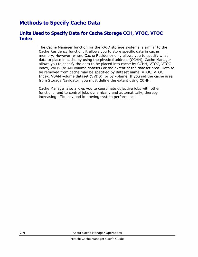
Methods to Specify Cache Data
Units Used to Specify Data for Cache Storage CCH, VTOC, VTOC Index
The Cache Manager function for the RAID storage systems is similar to the Cache Residency function; it allows you to store specific data in cache memory. However, where Cache Residency only allows you to specify what data to place in cache by using the physical address (CCHH), Cache Manager allows you to specify the data to be placed into cache by CCHH, VTOC, VTOC index, VVDS (VSAM volume dataset) or the extent of the dataset area. Data to be removed from cache may be specified by dataset name, VTOC, VTOC Index, VSAM volume dataset (VVDS), or by volume. If you set the cache area from Storage Navigator, you must define the extent using CCHH.
Cache Manager also allows you to coordinate objective jobs with other functions, and to control jobs dynamically and automatically, thereby increasing efficiency and improving system performance.

About Cache Manager Operations 2-5
Hitachi Cache Manager User’s Guide
Overview of Priority Mode and Bind Mode
Priority Mode
In Priority Mode (normal mode), the total capacity of cache required is:
Standard cache + cache required for Cache Manager + Additional cache
The main advantage of priority mode is that read data is transferred at host data transfer speed. In priority mode the cache extents are used to hold read data for specific extents on volumes. Write data is write duplexed in normal cache and de-staged to disk using standard algorithms. Because there is no duplexed write data in the cache reserved for Cache Manager, all priority mode cache extents are 100% utilized by user read-type data.
For mainframe volumes, one slot is 66 KB. This requires 4 cache segments (16.5 KB/segment). Sixteen (16) slot images for mainframe require 1,056 KB of reserved cache.
Note: Even though a track for 3390 volumes is 56 KB, because cache is divided into 16.5 KB segments, it will require four segments. A 3380 slot (track) is 48 KB, so three 16 KB segments will be sufficient.

2-6 About Cache Manager Operations
Hitachi Cache Manager User’s Guide
Bind Mode
In Bind Mode, the total capacity of cache required is:
Standard cache + cache required for Cache Manager
In bind mode the cache extents are used to hold read and write data for specific extent(s) on volume(s). Any data written to the bind area is not de-staged to the disk. To ensure data integrity, write data must be duplexed in the cache area, which consumes a significant amount of the cache.
The primary advantage of bind mode is that all targeted read and write data is transferred at host data transfer speed. In addition, the accessibility of read data is the same as priority mode; write operations do not have to wait for available cache segments; and there will be no backend contention caused by destaging data.
RAID-5/6. For RAID-5 and RAID-6 array groups the amount of cache required is three times the space required for the user data. For RAID-5/6 mainframe volumes, one slot is 66 KB, which requires 12 cache segments (16.5 KB/segment). For example, 16 slot images require 3,168 KB of reserved cache.
• Note: Even though tracks for 3390 LVIs are 56 KB, because cache is divided into 16.5 KB segments, it will require four segments. Slots for 3380 LVIs are 46 KB, so three segments are sufficient.
• Note: If a RAID-5/6 volume area is changed from priority mode to bind mode and no cache is added, then only 33% of the user data will fit in the area previously assigned for priority mode.
RAID-1 and external storage. For RAID-1/external array groups the amount of cache required is two times the space required for user data. For 3390 volumes, One slot is 66 KB, which requires eight cache segments (16.5 KB/segment). For example, 16 slot images require 2,112 KB of reserved cache.
• Note: If a RAID-1 volume area is changed from priority mode to bind mode and no cache is added, then only 50% of the user data will fit in the area previously assigned for priority mode, and the remaining 50% is used to save read/write data.

3
Preparing for Cache Manager Operations 3-1
Hitachi Cache Manager User’s Guide
Preparing for Cache Manager Operations
This chapter provides information on installing and launching Cache Manager, including the HRUDCRX and HRUDCRT programs.
System Requirements
Installing Cache Manager
Launching Cache Manager
Estimating Required Memory

3-2 Preparing for Cache Manager Operations
Hitachi Cache Manager User’s Guide
System Requirements
Hitachi Cache Manager operations involve the data on the Hitachi RAID storage system(s), the licensed Cache Manager utility, and the licensed Cache Residency Manager feature. Table 3-1 lists the system requirements for Hitachi Cache Manager. Table 3-2 lists the Hitachi storage system requirements for Hitachi Cache Manager.
Table 3-1 Specifications of Cache Manager
No Item Specification
Hitachi Universal Storage Platform V Hitachi Universal Storage Platform VM Hitachi TagmaStore Universal Storage Platform Hitachi TagmaStore Network Storage Controller Hitachi Lightning 9900V Hitachi Lightning 9900
1 Storage Systems
Additional cache memory module and Cache Residency Manager (FlashAccess) software are required.
Control Emulation Types 3990-3, 6, 2105-E20, F20, 2107 2
Device Emulation Types 3390-1, 2, 3, 9; 3380-E, J, K, 3
Maximum number of cylinders for 3390-9 = 32,760
Convert using the following values:
3390 emulation = 66 KB/track
3380 emulation on USP V/USP = 66 KB/track
3380 emulation on 9900V/9900 = 49.5 KB/track
System Environment
3 OS MVS/ESA, OS/390®, z/OS®
Basic Function
4 Set or reset residence (BIND command) Supported
5 Display volume statistical information (COUNTS command)
Supported
6 Display dataset statistical information (COUNTS command)
Supported
7 Display volume or dataset status information (STATUS command)
Supported
8 Set or reset extent for dataset statistics information (DSMODE command)
Supported
9 Setting cache memory for CRM/FlashAccess Contact the Hitachi Data Systems Support Center.
Other (Processing Type)
10 Batch Supported
11 TSO command Supported

Preparing for Cache Manager Operations 3-3
Hitachi Cache Manager User’s Guide
No Item Specification
Software/Cache Residency Manager (FlashAccess) Specification
Lightning 9900V/9900 USP V, TagmaStore USP
12 Maximum number of resident extent Logical Volume: ≤1024 extents
Storage System: ≤1024 extents
USP V:
Logical Volume: ≤4096 extents
Storage System: ≤16,384 extents
USP:
Logical Volume: ≤4096 extents
Storage System: ≤4096 extents
13 Maximum number of extent for dataset statistics information
Logical Volume: ≤64 extents
Storage System: ≤64 extents
USP V:
Logical Volume: ≤64 extents
LCU: ≤64 extents
Storage System: ≤32,640 extents
USP:
Logical Volume: ≤64 extents
Storage System: ≤64 extents
14 Unit to specify for cache residency 1 track
15 Minimum/maximum size of cache residency 1 track / logical volume size
Maximum size depends on No.13’s maximum available size of cache memory for Cache Residency Manager (FlashAccess).
16 Additional cache memory module Required
17 Maximum available size of cache memory for Cache Residency Manager (FlashAccess).
Maximum size depends on No.13’s maximum available size of cache memory for Cache Residency Manager (FlashAccess).
Additional cache memory size for Cache Residency Manager (FlashAccess).
Residing 256 MB area actually occupies 512 MB cache memory in RAID1 or 768 MB in RAID5/6.
Table 3-2 Microcode Requirements for Hitachi Cache Manager
Hitachi RAID Storage System Required Microcode Level
Hitachi Universal Storage Platform V/VM ESCON channel: 60-01-xx and higher FICON channel: 60-01-xx and higher
Hitachi TagmaStore Universal Storage Platform and Network Storage Controller
ESCON channel: 50-01-xx and higher FICON channel: 50-01-xx and higher
Hitachi Lightning 9900 V Series ESCON channel: 21-01-24-00/00 and higher FICON channel: 21-02-23-00/00 and higher
Hitachi Lightning 9900 ESCON channel: 01-13-18-00/07 and higher FICON channel: 01-17-94-00/00 and higher
3-4 Preparing for Cache Manager Operations
Hitachi Cache Manager User’s Guide
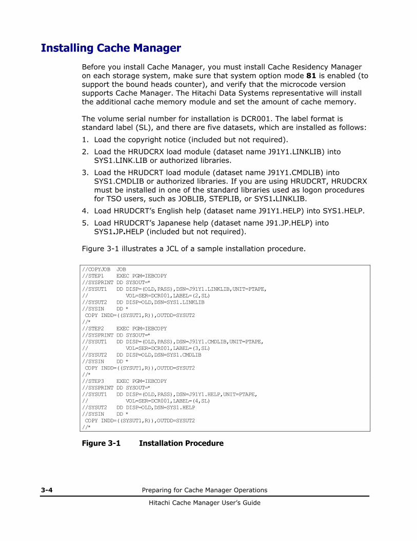
Installing Cache Manager
Before you install Cache Manager, you must install Cache Residency Manager on each storage system, make sure that system option mode 81 is enabled (to support the bound heads counter), and verify that the microcode version supports Cache Manager. The Hitachi Data Systems representative will install the additional cache memory module and set the amount of cache memory.
The volume serial number for installation is DCR001. The label format is standard label (SL), and there are five datasets, which are installed as follows:
1. Load the copyright notice (included but not required).
2. Load the HRUDCRX load module (dataset name J91Y1.LINKLIB) into SYS1.LINK.LIB or authorized libraries.
3. Load the HRUDCRT load module (dataset name J91Y1.CMDLIB) into SYS1.CMDLIB or authorized libraries. If you are using HRUDCRT, HRUDCRX must be installed in one of the standard libraries used as logon procedures for TSO users, such as JOBLIB, STEPLIB, or SYS1.LINKLIB.
4. Load HRUDCRT’s English help (dataset name J91Y1.HELP) into SYS1.HELP.
5. Load HRUDCRT’s Japanese help (dataset name J91.JP.HELP) into SYS1.JP.HELP (included but not required).
Figure 3-1 illustrates a JCL of a sample installation procedure.
//COPYJOB JOB //STEP1 EXEC PGM=IEBCOPY //SYSPRINT DD SYSOUT=* //SYSUT1 DD DISP=(OLD,PASS),DSN=J91Y1.LINKLIB,UNIT=PTAPE, // VOL=SER=DCR001,LABEL=(2,SL) //SYSUT2 DD DISP=OLD,DSN=SYS1.LINKLIB //SYSIN DD * COPY INDD=((SYSUT1,R)),OUTDD=SYSUT2 //* //STEP2 EXEC PGM=IEBCOPY //SYSPRINT DD SYSOUT=* //SYSUT1 DD DISP=(OLD,PASS),DSN=J91Y1.CMDLIB,UNIT=PTAPE, // VOL=SER=DCR001,LABEL=(3,SL) //SYSUT2 DD DISP=OLD,DSN=SYS1.CMDLIB //SYSIN DD * COPY INDD=((SYSUT1,R)),OUTDD=SYSUT2 //* //STEP3 EXEC PGM=IEBCOPY //SYSPRINT DD SYSOUT=* //SYSUT1 DD DISP=(OLD,PASS),DSN=J91Y1.HELP,UNIT=PTAPE, // VOL=SER=DCR001,LABEL=(4,SL) //SYSUT2 DD DISP=OLD,DSN=SYS1.HELP //SYSIN DD * COPY INDD=((SYSUT1,R)),OUTDD=SYSUT2 //*
Figure 3-1 Installation Procedure

Preparing for Cache Manager Operations 3-5
Hitachi Cache Manager User’s Guide
Note: DCRT is an alias of HRUDCRT. You can invoke Cache Manager in TSO by specifying either HRUDCRT or DCRT as the program name. One issue reported with using DCRT, however, is a missing file for online help. If your installation CD is missing the DCRT help file, avoid using the DCRT alias, or contact HDS for the DCRT help file.
HRUDCRX must be registered as authorized libraries, as follows:
1. Register in SYS1.PARMLIB(IKJTSOxx).
2. Add HRUDCRT and the alias DCRT as AUTHCMD NAMES.
3. Add HRUDCRX as AUTHPGM NAMES.
If you are not using IKJTSOxx:
1. Specify the authorized command and authorized program by using CSECT IKJEFTE2 or IKJEFTE8.
2. To update, assemble them, then reassemble them to link them with load module IKJTABLS in SYS1.LPALIB, then re-IPL the system.
Figure 3-2 illustrates the registration process using TSO commands:
AUTHCMD NAMES( + DCRT HRUDCRT + : : ) AUTHPGM NAMES( + HRUDCRX + : : )
Figure 3-2 Registering HRUDCRT and HRUDCRX

3-6 Preparing for Cache Manager Operations
Hitachi Cache Manager User’s Guide
Launching Cache Manager
Launching HRUDCRX 1. Call the HRUDCRX program. The line count must be from 20 to 99, and the
default value is 60. See Figure 3-3 for an example.
2. Use the DD statement to define the volume type. The operand of the statement must specify the unit and volume, and the DISP operand must specify OLD.
Note: If more than one DD statement is defined, only the first one will be processed. If you need to include more than one DD statement, you must divide the job step.
3. The RAIDPARM DD statement specifies a sequential dataset to describe the device address when you use STATUS and COUNTS commands with DKC parameter. The DCB information of the dataset is as follows:
– Dataset format (DSORG): SAM (PS)
– Record format (RECFM) Fixed or Fixed Block (F or FB)
– Record Length (LRECL) 80
– Block Length (BLKSIZE) 80 x n
– You can specify up to 1024 devices.
4. The format and parameter requirements of the RAIDPARM dataset is as follows:
– RAIDUNIT (CCUU [ - CCUU] [, CCUU] [, ...] )
– You can specify up to 1024 devices.
– The record size is 80 bytes, but you can only use columns 1 through 71. Data in columns 72 through 80 will be ignored.
– You may not put a space between the comma, hyphen, bracket or parameter.
– The description must be on one line, with no comments on that line.
– The device number may contain either 3 or 4 digits.
– If you use a hyphen to specify device number, you must put the lesser number to the left and use the same CC value. All device numbers that are between the two numbers will be included.
5. The SYSPRINT DD statement specifies a sequential dataset to store the output messages. The record length must be 132-byte fixed-length record format.
6. The SYSIN DD statement must specify a dataset that includes HRUDCRX commands, and the record length must be 80 byte fixed-length record format of SAM or PAM. Note: HRUDCRX will return normal end (CC=0), even though user does not specify a command and parameter in the SYSIN DD statement.

Preparing for Cache Manager Operations 3-7
Hitachi Cache Manager User’s Guide
7. If you are executing a DSMODE command with either an ENABLE or a DISABLE parameter, in order to log any eccentric areas (those that are not part of a dataset), you must specify DCRLOG DD statement. Note: This command will be ignored if another command or parameter is specified. The required format is as follows:
– Dataset format (DSORG): SAM (PS)
– Record format (RECFM): Variable (V) or Variable Length Block (VB)
– Record length (LRECL): 130
– Block length (BLKSIZE): 130 x n + 4
// EXEC PRG=HRUDCRX,PARM=‘LINECNT(m)’
Figure 3-3 Launching HRUDCRUX
Figure 3-4 is an example of a JCL specifying a BIND command:
//JOBNAME JOB // EXEC PGM=HRUDCRX,PARM=....,REGION=1024K //SYSPRINT DD SYSOUT=A //VOL2 DD UNIT=SYSDA,VOL=SER=VSN001,DISP=OLD //RAIDPARM DD DSN=DATASET1,UNIT=SYSDA,DISP=SHR, // VOL=SER=ABC001,DCB=(BLKSIZE=.....) //DCRLOG DD DSN=DATASET2,UNIT=SYSDA,DISP=SHR, // VOL=SER=ABC002,DCB=(BLKSIZE=.....) //SYSIN DD * BIND ENABLE - DDNAME(VOL2) - DATASET(‘USER.FILE’) /* //
Figure 3-4 BIND Command
The required format for control statements is as follows:
• Specify the control statements in the first line (columns 1 through 71).
• If a control statement is longer than one line (columns 72 and higher), you can continue the statement on the next line as follows:
– Specify a plus sign after the last parameter if the letters of a parameter are continued to next line.
– Specify a hyphen after the last parameter if other parameters are continued to next line.
• You cannot specify a space (empty) line between each control statement.

3-8 Preparing for Cache Manager Operations
Hitachi Cache Manager User’s Guide
The format for comments is as follows:
• The first column must have a forward slash and an asterisk sign (/*).
• Comment statements can be written after a parameter. Example: STATUS DEV(5837) DKU /*COMMENT*/
• Comment statements can be written between parameters. Example: BIND EA DEV(5837) /*COMMENT*/ VTOC
• Comment statements can be written after commands. Example: STATUS /*COMMENT*/ DEV(5837) DKU
• Comment statements can be written before commands. Example: /*COMMENT*/ BIND DA DEV(5837) DKU
• Comment statements can be written after a parameter using a semicolon (;). Example: STATUS DEV(5837) DKU ;COMMENT
• Parameters can be continued to the next line using a plus sign (+). Example: BIND EA DEV(58+37) VTOC
• Parameters can be continued to the next line using a hyphen (-). Example: STATUS - DEV(5837) DKU

Preparing for Cache Manager Operations 3-9
Hitachi Cache Manager User’s Guide
Launching HRUDCRT
To launch HRUDCRT:
1. The terminal monitor program will issue an ATTACH macro that generates a task and activates the command processor. Register 1 will have a pointer to the command processor parameter list (CPPL).
2. The executed command processor will analyze the operands as follows:
– Call the CALLTSSR macro.
– Make a parameter control list (PCL), including operand description and abbreviated value.
– Hand the analyzed parameter list (PPL) to the operand analyze routine.
– Set the described parameters, and return control to the command processor.
3. The command processor (HRUDCRT) will call the Cache Manager utility by issuing a LOAD/CALL macro to activate Cache Manager (HRUDCRX). HRUDCRT then allocates a SYSIN dataset, sets the input command and operand, and allocates an output dataset (OUTDD).
Note: You must allocate the input dataset (RAIDPARM) before executing a HRUDCRT command.
4. The command processor will then collect and edit the Cache Manager output, then display it on screen.
Figure 3-5 Interface Between Command Processor and Operand Analyze Routine

3-10 Preparing for Cache Manager Operations
Hitachi Cache Manager User’s Guide
Estimating Required Memory
To calculate the required memory for HRUDCRX, start with 170 KB, which is the basic requirement. Add to that the variable requirement, which is calculated as follows:
(A + B + 2,112 +C * (5D + 1,024)) / 1,024 (KB)
A is either 160 (if you are using JOB stream input) or 5 * the block length of the SYSIN dataset.
B is either 242 (if you are using SYSOUT output) or 5 * the block length of the SYSPRINT dataset.
C is either 1 (if you are specifying a RAIDPARM dataset) or 0.
D is the block length of the RAIDPARM dataset.

4
Performing Cache Manager Operations 4-1
Hitachi Cache Manager User’s Guide
Performing Cache Manager Operations
This chapter explains the commands and parameters for executing Cache Manager operations.
HRUDCRX Commands
Using HRUDCRT Commands to Display Information at the Console
WARNING:. Do not perform the ShadowImage quick restore operation or Volume Migration operations on Cache Manager volumes. These operations swap the internal locations of the source and target volumes. For further information on these operations, please refer to the ShadowImage and Volume Migration documentation for the Hitachi RAID storage system.

4-2 Performing Cache Manager Operations
Hitachi Cache Manager User’s Guide
HRUDCRX Commands
HRUDCRX supports the following commands:
• BIND either places data into cache or releases it from cache.
• COUNTS displays the cache volume or dataset statistics. This command can also reset the counters if necessary.
• STATUS displays the cache status information.
• DSMODE either defines the tracks for dataset statistics or releases that definition.
• HRUDCRX commands can also be combined using JCL.
Using Bind to Place or Release Data From the Cache
Figure 4-1 illustrates BIND command parameters.
• ENABLE will place data into a specified area of cache.
• DISABLE will release data from cache.
• You can specify the target data either by DDNAME (using volume, unit and disp number), VOLUME (volume serial number), or DEVICE (device number).
• You can specify the cache area by VTOC, CCHH, DATASET, CCHH or SYSTEMDS (either physical VTOC, INDEX VTOC, or VVDS). If you specify ENABLE, you must also specify one of these parameters.
• DKU|FREESPACE is used if you want to release tracks from cache (DISABLE). The DKU command releases all tracks on a particular volume. FREESPACE releases all eccentric areas on a volume. DKU is the default value.
• PRIO is used to specify tracks to be bound into priority mode (ENABLE). If you do not specify PRIO, BIND mode is the default.
[ ENABLE | DISABLE ] DDNAME (dd name) VOLUME (volume serial number) DEVICE (device number) VTOC DATASET (dataset name) CCHH { (low CCCCHHHH△1high CCCCHHHH) | (low CCCCc-HHHH△1high CCCCc-HHHH) } SYSTEMDS [ DKU | FREESPACE ] [ PRIO ]
Figure 4-1 BIND Command Parameters
Performing Cache Manager Operations 4-3
Hitachi Cache Manager User’s Guide
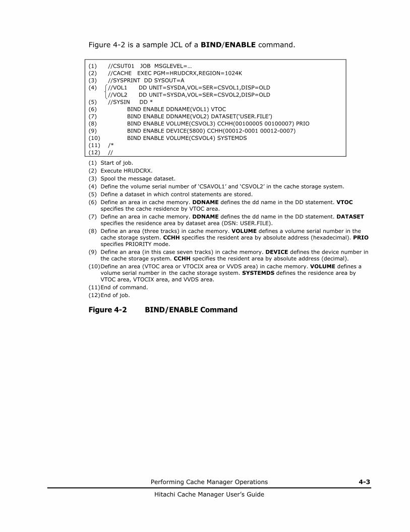
Figure 4-2 is a sample JCL of a BIND/ENABLE command.
(1) (2) (3) (4) (5) (6) (7) (8) (9) (10) (11) (12)
//CSUT01 JOB MSGLEVEL=… //CACHE EXEC PGM=HRUDCRX,REGION=1024K //SYSPRINT DD SYSOUT=A //VOL1 DD UNIT=SYSDA,VOL=SER=CSVOL1,DISP=OLD //VOL2 DD UNIT=SYSDA,VOL=SER=CSVOL2,DISP=OLD //SYSIN DD * BIND ENABLE DDNAME(VOL1) VTOC BIND ENABLE DDNAME(VOL2) DATASET(‘USER.FILE’) BIND ENABLE VOLUME(CSVOL3) CCHH(00100005 00100007) PRIO BIND ENABLE DEVICE(5800) CCHH(00012-0001 00012-0007) BIND ENABLE VOLUME(CSVOL4) SYSTEMDS /* //
(1) Start of job. (2) Execute HRUDCRX. (3) Spool the message dataset. (4) Define the volume serial number of ‘CSAVOL1’ and ‘CSVOL2’ in the cache storage system. (5) Define a dataset in which control statements are stored. (6) Define an area in cache memory. DDNAME defines the dd name in the DD statement. VTOC
specifies the cache residence by VTOC area. (7) Define an area in cache memory. DDNAME defines the dd name in the DD statement. DATASET
specifies the residence area by dataset area (DSN: USER.FILE). (8) Define an area (three tracks) in cache memory. VOLUME defines a volume serial number in the
cache storage system. CCHH specifies the resident area by absolute address (hexadecimal). PRIO specifies PRIORITY mode.
(9) Define an area (in this case seven tracks) in cache memory. DEVICE defines the device number in the cache storage system. CCHH specifies the resident area by absolute address (decimal).
(10) Define an area (VTOC area or VTOCIX area or VVDS area) in cache memory. VOLUME defines a volume serial number in the cache storage system. SYSTEMDS defines the residence area by VTOC area, VTOCIX area, and VVDS area.
(11) End of command. (12) End of job.
Figure 4-2 BIND/ENABLE Command

4-4 Performing Cache Manager Operations
Hitachi Cache Manager User’s Guide
Figure 4-3 is a sample JCL of a BIND/DISABLE command.
(1) (2) (3) (4) (5) (6) (7) (8) (9) (10) (11) (12) (13)
//CSUT02 JOB MSGLEVEL=(1,1) //CACHE EXEC PGM=HRUDCRX,REGION=1024K //SYSPRINT DD SYSOUT=A //VOL1 DD UNIT=SYSDA,VOL=SER=CSVOL1,DISP=OLD //VOL2 DD UNIT=SYSDA,VOL=SER=CSVOL2,DISP=OLD //SYSIN DD * BIND DISABLE DDNAME(VOL1) VTOC BIND DISABLE DDNAME(VOL2) DATASET(‘USER.FILE’) BIND DISABLE VOLUME(CSVOL3) DKU BIND DISABLE VOLUME(CSVOL4) CCHH(00100005 00100007) BIND DISABLE VOLUME(CSVOL4) SYSTEMDS BIND DISABLE VOLUME(CSVOL4) FREESPACE /* //
(1) Start of job. (2) Execute HRUDCRX. (3) Spool the message dataset. (4) Define the volume serial number of ‘CSAVOL1’ and ‘CSVOL2’ in the cache storage system. (5) Define a dataset in which control statements are stored. (6) Define an area to release residence in cache memory. DDNAME defines the dd name in the DD
statement. VTOC specifies the cache residence to be released by VTOC area. (7) Define an area to release residence in cache memory. DDNAME defines the dd name in the DD
statement. This is a required parameter to define dd name (VOL2) in DD statement (4). DATASET specifies the residence area to be released by dataset area (DSN: USER.FILE).
(8) Define an area to release residence in cache memory. VOLUME defines a volume serial number in the storage system. DKU releases all resident areas in the volume serial number of ‘CSVOL3’.
(9) Define an area (three tracks) to release residence in cache memory. VOLUME defines a volume serial number in the cache storage system. CCHH specifies the resident area to be released by absolute address (hexadecimal).
(10) Define an area (using VTOC area, VTOCIX area, and VVDS area) to release residence in cache memory. VOLUME defines a volume serial number in the cache storage system. SYSTEMDS releases the resident area (defined by VTOC, VTOCIX or VVDS).
(11) Define an area to release residence in cache memory that has no dataset. VOLUME defines a volume serial number in the cache storage system. FREESPACE releases resident extents with no dataset.
(12) End of command. (13) End of job.
Figure 4-3 BIND/DISABLE Command

Performing Cache Manager Operations 4-5
Hitachi Cache Manager User’s Guide
Using COUNTS to Display Cache Volume or Dataset Statistics
The COUNTS command allows you to get statistics on cache memory usage and status information. Note: Be sure to reset the counter before accessing cache statistic information.
WARNING: If other applications are using the cache statistics information, resetting the counter will interfere with those operations.
The COUNTS command will display either volume or dataset statistics.
• You can specify the target data by DDNAME (using volume, unit and disp number), VOLUME (volume serial number), or DEVICE (device number).
• REPORT is a command to print cache statistics information. (REPORT is the default value.)
• NO REPORT is a command to not print cache statistics information.
• RESET will reset the counter to zero.
• NO RESET will leave the counter unchanged. (NORESET is the default value.)
• DKU specifies a target range as a particular volume. (DKU is the default value.)
• DKC specifies a target range in the same storage system ID (SSID). You need to specify RAIDPARM in the DD statement.
• DSEXTENT specifies that dataset statistics information will be included. Note: If you use DSEXTENT, do not use the RESET parameter.
• NOEXTENT specifies that volume statistics information will be included. (NOEXTENT is the default value.)
DDNAME (dd name) VOLUME (volume serial number) DEVICE (device number) [ REPORT | NOREPORT ] [ RESET | NORESET ] [ DKU | DKC ] [ DSEXTENT | NOEXTENT ]
Figure 4-4 COUNTS Command Parameters
4-6 Performing Cache Manager Operations
Hitachi Cache Manager User’s Guide
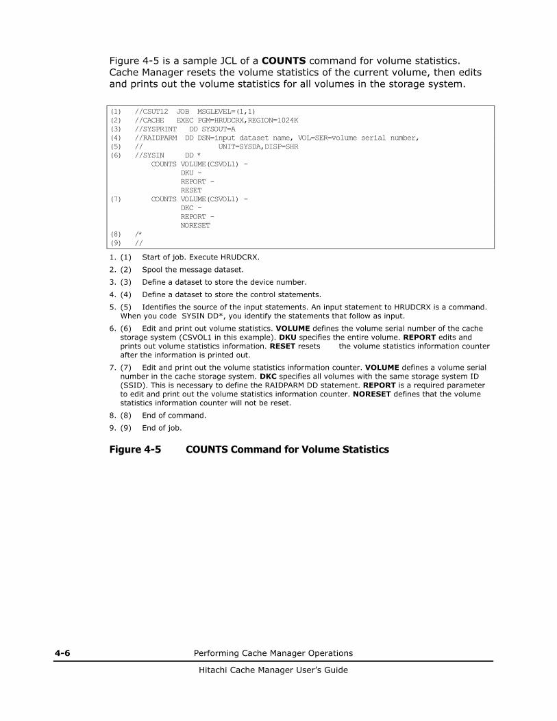
Figure 4-5 is a sample JCL of a COUNTS command for volume statistics. Cache Manager resets the volume statistics of the current volume, then edits and prints out the volume statistics for all volumes in the storage system.
(1) //CSUT12 JOB MSGLEVEL=(1,1) (2) //CACHE EXEC PGM=HRUDCRX,REGION=1024K (3) //SYSPRINT DD SYSOUT=A (4) //RAIDPARM DD DSN=input dataset name, VOL=SER=volume serial number, (5) // UNIT=SYSDA,DISP=SHR (6) //SYSIN DD * COUNTS VOLUME(CSVOL1) - DKU - REPORT - RESET (7) COUNTS VOLUME(CSVOL1) - DKC - REPORT - NORESET (8) /* (9) //
1. (1) Start of job. Execute HRUDCRX.
2. (2) Spool the message dataset.
3. (3) Define a dataset to store the device number.
4. (4) Define a dataset to store the control statements.
5. (5) Identifies the source of the input statements. An input statement to HRUDCRX is a command. When you code SYSIN DD*, you identify the statements that follow as input.
6. (6) Edit and print out volume statistics. VOLUME defines the volume serial number of the cache storage system (CSVOL1 in this example). DKU specifies the entire volume. REPORT edits and prints out volume statistics information. RESET resets the volume statistics information counter after the information is printed out.
7. (7) Edit and print out the volume statistics information counter. VOLUME defines a volume serial number in the cache storage system. DKC specifies all volumes with the same storage system ID (SSID). This is necessary to define the RAIDPARM DD statement. REPORT is a required parameter to edit and print out the volume statistics information counter. NORESET defines that the volume statistics information counter will not be reset.
8. (8) End of command.
9. (9) End of job.
Figure 4-5 COUNTS Command for Volume Statistics
Performing Cache Manager Operations 4-7
Hitachi Cache Manager User’s Guide
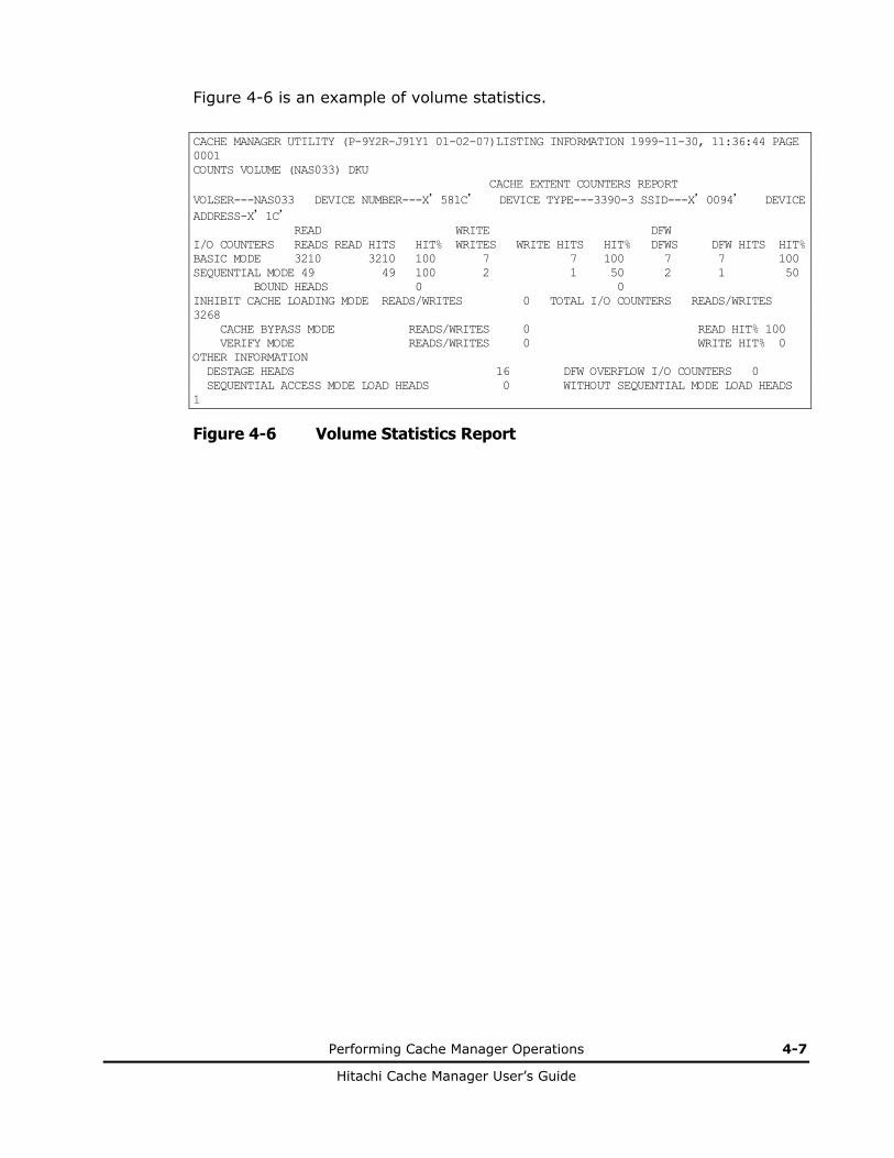
Figure 4-6 is an example of volume statistics.
CACHE MANAGER UTILITY (P-9Y2R-J91Y1 01-02-07)LISTING INFORMATION 1999-11-30, 11:36:44 PAGE 0001 COUNTS VOLUME (NAS033) DKU CACHE EXTENT COUNTERS REPORT VOLSER---NAS033 DEVICE NUMBER---X’581C’ DEVICE TYPE---3390-3 SSID---X’0094’ DEVICE ADDRESS-X’1C’ READ WRITE DFW I/O COUNTERS READS READ HITS HIT% WRITES WRITE HITS HIT% DFWS DFW HITS HIT% BASIC MODE 3210 3210 100 7 7 100 7 7 100 SEQUENTIAL MODE 49 49 100 2 1 50 2 1 50 BOUND HEADS 0 0 INHIBIT CACHE LOADING MODE READS/WRITES 0 TOTAL I/O COUNTERS READS/WRITES 3268 CACHE BYPASS MODE READS/WRITES 0 READ HIT% 100 VERIFY MODE READS/WRITES 0 WRITE HIT% 0 OTHER INFORMATION DESTAGE HEADS 16 DFW OVERFLOW I/O COUNTERS 0 SEQUENTIAL ACCESS MODE LOAD HEADS 0 WITHOUT SEQUENTIAL MODE LOAD HEADS 1
Figure 4-6 Volume Statistics Report

4-8 Performing Cache Manager Operations
Hitachi Cache Manager User’s Guide
Figure 4-7 is a sample JCL of a COUNTS command for dataset statistics. Cache Manager edits and prints out dataset statistics information for the specified datasets, then edits and prints out dataset statistics information for all volumes with the same storage system ID (SSID).
(1) (2) (3) (4) (5) (6) (7) (8) (9)
//CSUT22 JOB MSGLEVEL=(1,1) //CACHE EXEC PGM=HRUDCRX,REGION=1024K //SYSPRINT DD SYSOUT=A //RAIDPARM DD DSN=input dataset name, VOL=SER=volume serial number, // UNIT=SYSDA,DISP=SHR //SYSIN DD * COUNTS VOLUME(CSVOL1) - DKU - DSEXTENT - REPORT COUNTS VOLUME(CSVOL1) - DKC – DSEXTENT - REPORT /* //
(1) Start of job. (2) Execute HRUDCRX. (3) Spool the message dataset. (4) Define a dataset to store the device number. (5) Define a dataset to store the control statements. (6) Edit statistics information and print out it. VOLUME defines a volume serial number in the cache
storage system. DKU specifies the entire volume. DSEXTENT processes dataset statistics information of specified datasets. REPORT edits and prints out statistics information.
(7) Edit and print out the statistics information counter. VOLUME defines a volume serial number in the cache storage system. DKC specifies all volumes with the same storage system ID (SSID). This is necessary to define the RAIDPARM DD statement. DSEXTENT processes dataset statistics information of the specified datasets. REPORT edits and prints out statistics information.
(8) End of command. (9) End of job.
Figure 4-7 COUNTS Command for Dataset Statistics

Performing Cache Manager Operations 4-9
Hitachi Cache Manager User’s Guide
Figure 4-8 is an example of dataset statistics.
CACHE MANAGER UTILITY (P-9Y2R-J91Y1 01-02-07) LISTING INFORMATION 2000-03-23,10:01:05 PAGE 0001 COUNTS VOL(RAID31) DKU DSEXTENT CACHE EXTENT COUNTERS REPORT VOLSER----RAID31 DEVICE NUMBER----X’2001’ DEVICE TYPE----3390-3 SSID----X’0094’ DEVICE ADDRESS-- X’01’ USED DATASET COUNT---- 6 ----DATASET NAME---- I/O COUNTERS------ -----------DSEXTENT- ---EXTENT---- READS WRITES STATUS COUNT ***** VTOC ***** 967295 67296 EQUAL 1 SYS1.VTOCIX.RAID31 967295 967296 EQUAL 1 SYS1.VVDS.VRAID31 967295 296 EQUAL 1 USER1.AAAA.BBBB.CCCC 4967295 296 EQUAL 2 USER1.AAAA.BBBB.DDDD 294967295 67296 EQUAL- 2 *USER1.AAAA.BBBB.EEEE 95 6 EQUAL 0
Figure 4-8 Dataset Statistics Report
Using STATUS to Display the Cache Status
The STATUS command displays volume or dataset status information, including the size of the cache memory, the residence area of the cache extents, and the extent of the dataset statistics information. See the glossary for status definitions.
Figure 4-9 illustrates STATUS command parameters.
• You can specify target data by DDNAME, (using volume, unit and disp number), VOLUME (volume serial number) or DEVICE (device number).
• You can specify a target data range as either DKU (a volume defined by DDNAME or volume) or DKC (all volumes in the same storage system ID). (DKU is the default value.)
• EXTENT specifies that cache extent information will be printed.
• NOEXTENT specifies that cache extent information will not be printed. (NOEXTENT is default value.)
• DSEXTENT specifies that extent information of dataset statistics will be printed. If this is combined with a DKC command, you must also define RAIDPARM.
DDNAME (dd name) VOLUME (volume serial number) DEVICE (device number) [ DKU | DKC ] [ EXTENT | NOEXTENT | DSEXTENT ]
Figure 4-9 STATUS Command Parameters

4-10 Performing Cache Manager Operations
Hitachi Cache Manager User’s Guide
Figure 4-10 is an example of a cache memory STATUS report.
** CACHE MANAGER UTILITY (P-9Y2R-J91Y1 01-02-07) ** LISTING INFORMATION 2000-03-23, 10:01:05 PAGE 0001 STATUS VOL (RAID31) DKC CACHE SUBSYSTEM STATUS REPORT DISK CONTROLLER INFORMATION CU-TYPE---- 3990-3 SSID---- X’0080’ DEVICE ADDRESS---- X’01’ CACHE NVS PINNED DATA STATUS ENABLED ENABLED NONE FLASH ACCESS CONFIGURATION REMAINING AREA 2097152 USED AREA 2097152 FLASH ACCESS AVAILABLE 4194304 USED AREA COUNT 1024
Figure 4-10 Cache Memory STATUS Report

Performing Cache Manager Operations 4-11
Hitachi Cache Manager User’s Guide
Figure 4-11 is an example of a cache extent STATUS report.
** CACHE MANAGER UTILITY (P-9Y2R-J91Y1 01-02-07) ** LISTING INFORMATION 2000-03-23, 10:01:05 PAGE 0001 STATUS VOL(RAID31) DKU CACHE EXTENT STATUS REPORT VOLSER--RAID31 DEVICE NUMBER---- X’2001’ DEVICE TYPE----3390-3 SSID----X’0094’ DEVICE ADDRESS---- X’01’ CACHE ACCESS--ENABLED DRIVE STATUS--ENABLED DFW STATUS----- ENABLED USED AREA COUNT-- 5 ----FROM---- ----TO---- ----SIZE---- ----DCR---- --EXTENT--- -DATASET NAME--- CC HH CC HH CYLS HEADS TYPE RELATION 00000-0001 00010-0001 10 1 BIND ALL USER1.AAAA.BBBB.CCCC 00050-0000 00100-0014 51 0 PRIO PART USER1.AAAA.BBBB.DDDD 00128-0000 00160-0008 32 9 BIND PART USER1.AAAA.BBBB.DDDD 01000-0000 01009-0014 10 0 PRIO ALL USER1.AAAA.BBBB.EEEE 01010-0000 01010-0014 1 0 PRIO ALL *** VTOC **** 01011-0000 01011-0014 1 0 PRIO ALL SYS1.VTOCIX.RAID31 01012-0000 01012-0014 1 0 PRIO ALL SYS1.VVDS.VRAID31 01013-0000 01013-0014 1 0 BIND ALL ***FREE SPACE ***
Figure 4-11 Cache Extent STATUS Report
Figure 4-12 is an example of a CLPR for Cache Residency Manager STATUS report.
** CACHE MANAGER UTILITY (P-9Y2R-J91Y1 01-06-03) ** LISTING INFORMATION 2005-02-16, 10:01:05 PAGE 0001 STATUS VOL(RAID31) CLPR CACHE SUBSYSTEM STATUS REPORT DISK CONTROLLER INFORMATION CU-TYPE---- 3990-3 SSID---- X'0080' DEVICE ADDRESS---- X'01' CACHE NVS PINNED DATA STATUS ENABLED ENABLED NONE CLPR NO. 32 CURRENT CLPR CONFIGRATION REMAINING AREA 2000000 USED AREA 2000000 FLASH ACCESS AVAILABLE 4000000 MAXIMUM AREA COUNT 2048 USED AREA COUNT 1024 DEVICE USED AREA COUNT 512
Figure 4-12 CLPR Extent STATUS Report

4-12 Performing Cache Manager Operations
Hitachi Cache Manager User’s Guide
Figure 4-13 is an illustration of a JCL for volume STATUS.
(1) (2) (3) (4) (5) (6) (7) (8) (9)
//CSUT13 JOB MSGLEVEL=(1,1) //CACHE EXEC PGM=HRUDCRX,REGION=1024K //SYSPRINT DD SYSOUT=A //RAIDPARM DD DSN=input dataset name, VOL=SER=volume serial number, // UNIT=SYSDA,DISP=SHR //SYSIN DD * STATUS VOLUME(CSVOL2) - DKU STATUS VOLUME(CSVOL3) - DKC - EXTENT /* //
(1) Start of job. (2) Execute HRUDCRX. (3) Spool the message dataset. (4) Define a dataset to store the device number. (5) Define a dataset to store the control statements. (6) Edit the cache status, nonvolatile memory status and capacity information and store them in the
dataset. VOLUME defines a volume serial number in the cache storage system. DKU is a required parameter to specify the entire volume of ‘CSVOL2’.
(7) Edit the cache status and extent information and store them in the dataset. VOLUME defines a volume serial number in the cache storage system. DKC specifies all volumes with the same storage system ID (SSID). This is necessary to define the RAIDPARM DD statement. EXTENT defines the cache extent as all volumes that belong to same storage system ID (SSID).
(8) End of command. (9) End of job.
Figure 4-13 Volume STATUS Command

Performing Cache Manager Operations 4-13
Hitachi Cache Manager User’s Guide
Figure 4-14 illustrates a sample JCL for a dataset STATUS command. Cache Manager stores, edits and prints the extent information (dataset statistics) for all volumes, including a specified volume with the same storage system ID (SSID).
(1) (2) (3) (4) (5) (6) (7) (8) (9)
//CSUT23 JOB MSGLEVEL=(1,1) //CACHE EXEC PGM=HRUDCRX,REGION=1024K //SYSPRINT DD SYSOUT=A //RAIDPARM DD DSN=input dataset name, VOL=SER=volume serial number, // UNIT=SYSDA,DISP=SHR //SYSIN DD * STATUS VOLUME(CSVOL2) - DKU – DSEXTENT STATUS VOLUME(CSVOL3) - DKC - DSEXTENT /* //
(1) Start of job. (2) Execute HRUDCRX. (3) Spool the message dataset. (4) Define a dataset to store the device number. (5) Define a dataset to store the control statements. (6) Edit the cache status, nonvolatile memory status and capacity information and store them in the
dataset. VOLUME defines a volume serial number in the cache storage system. DKU is a required parameter to specify the entire volume of ‘CSVOL2’. DSEXTENT processes dataset statistics information of specified datasets.
(7) Edit the cache status and extent information and store them in the dataset. VOLUME defines a volume serial number in the cache storage system. DKC specifies all volumes with the same storage system ID (SSID). This is necessary to define the RAIDPARM DD statement. DSEXTENT processes specified dataset statistics information for all volumes with the same storage system ID (SSID).
(8) End of command. (9) End of job.
Figure 4-14 Dataset STATUS Command

4-14 Performing Cache Manager Operations
Hitachi Cache Manager User’s Guide
Figure 4-15 is an example of a dataset STATUS report.
** CACHE MANAGER UTILITY (P-9Y2R-J91Y1 01-02-07)**LISTING INFORMATION 2000-03-23, 10:01:05 PAGE 0001 STATUS VOL(RAID31) DKU DSEXTENT CACHE EXTENT STATUS REPORT VOLSER----RAID31 DEVICE NUMBER----X’2001’ DEVICE TYPE---3390-3 SSID---- X’0094’ DEVICE ADDRESS---- X’01’ CACHE ACCESS—ENABLED DRIVE STATUS-- ENABLED DFW STATUS----- ENABLED USED AREA COUNT-- 8 ----FROM---- ----TO---- ----SIZE---- ----EXTENT---- ----DATASET NAME---- CC HH CC HH CYLS HEADS RELATION 00000-0001 00010-0001 10 1 ALL *USER1.AAAA.BBBB.CCCC 00050-0000 00100-0014 51 0 PART USER1.AAAA.BBBB.DDDD 00128-0000 00160-0008 32 9 PART USER1.AAAA.BBBB.DDDD 01000-0000 01009-0014 10 0 ALL *USER1.AAAA.BBBB.EEEE 01010-0000 01010-0014 1 0 ALL ***** VTOC ***** 01011-0000 01011-0014 1 0 ALL SYS1.VTOCIX.RAID31 01012-0000 01012-0014 1 0 ALL SYS1.VVDS.VRAID31 01013-0000 01013-0014 1 0 ALL *** FREE SPACE ***
Figure 4-15 Dataset STATUS Report
Figure 4-16 illustrates the output of a volume STATUS command.
** CACHE MANAGER UTILITY (P-9Y2R-J91Y1 01-02-07) ** LISTING INFORMATION 000-03-23, 10:01:05 PAGE 0001 STATUS VOL(RAID31) DKC CACHE SUBSYSTEM STATUS REPORT DISK CONTROLLER INFORMATION CU-TYPE---- 3990-3 SSID---- X’0080’ DEVICE ADDRESS---- X’01’ CACHE NVS PINNED DATA STATUS ENABLED ENABLED NONE FLASH ACCESS CONFIGURATION REMAINING AREA 2097152 USED AREA 2097152 FLASH ACCESS AVAILABLE 4194304 USED AREA COUNT 1024
Figure 4-16 Volume STATUS Command

Performing Cache Manager Operations 4-15
Hitachi Cache Manager User’s Guide
Using DSMODE to Define Tracks for Dataset Statistics
Figure 4-17 illustrates DSMODE command parameters. The DSMODE command allows you to define a cache extent for dataset statistics information and then release it. Once the dataset is defined, Cache Manager can display I/O counts for each extent (refer to Figure 4-8).
• ENABLE will set dataset statistics information for the specified area, defined either by VTOC or DATASET.
• DISABLE will release dataset statistics information, defined either by VTOC, DATASET, DKU (all tracks on a particular volume), or ECCENTRICAREA. An ECCENTRICAREA is a cache extent that does not belong to a dataset managed by the VTOC. Note: If you specify DKU or ECCENTRICAREA, do not use VTOC or DATASET.
• You can specify target data by DDNAME (using volume, unit and disp number), VOLUME (volume serial number) or DEVICE (device number).
ENABLE | DISABLE ] DDNAME (dd name) VOLUME (volume serial number) DEVICE (device number) [ VTOC | DATASET (dataset name)] [ DKU | ECCENTRICAREA ]
Figure 4-17 DSMODE Command Parameters
4-16 Performing Cache Manager Operations
Hitachi Cache Manager User’s Guide
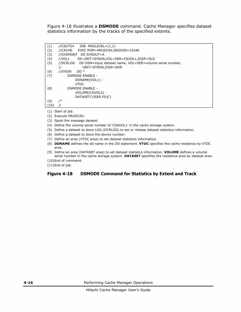
Figure 4-18 illustrates a DSMODE command. Cache Manager specifies dataset statistics information by the tracks of the specified extents.
(1) (2) (3) (4) (5) (6) (7) (8) (9) (10)
//CSUT24 JOB MSGLEVEL=(1,1) //CACHE EXEC PGM=HRUDCRX,REGION=1024K //SYSPRINT DD SYSOUT=A //VOL1 DD UNIT=SYSDA,VOL=SER=CSVOL1,DISP=OLD //DCRLOG DD DSN=input dataset name, VOL=SER=volume serial number, // UNIT=SYSDA,DISP=SHR //SYSIN DD * DSMODE ENABLE - DDNAME(VOL1) - VTOC DSMODE ENABLE - VOLUME(CSVOL2) - DATASET(‘USER.FILE’) /* //
(1) Start of job. (2) Execute HRUDCRX. (3) Spool the message dataset. (4) Define the volume serial number of ‘CSAVOL1’ in the cache storage system. (5) Define a dataset to store LOG (DCRLOG) to set or release dataset statistics information. (6) Define a dataset to store the device number. (7) Define an area (VTOC area) to set dataset statistics information. (8) DDNAME defines the dd name in the DD statement. VTOC specifies the cache residence by VTOC
area. (9) Define an area (DATASET area) to set dataset statistics information. VOLUME defines a volume
serial number in the cache storage system. DATASET specifies the residence area by dataset area. (10) End of command. (11) End of job.
Figure 4-18 DSMODE Command for Statistics by Extent and Track

Performing Cache Manager Operations 4-17
Hitachi Cache Manager User’s Guide
Figure 4-19 illustrates a DSMODE command. Cache Manager releases dataset statistics information for the specified extent(s) or volume(s).
(1) (2) (3) (4) (5) (6) (7) (8) (9) (10) (11) (12)
//CSUT25 JOB MSGLEVEL=(1,1) //CACHE EXEC PGM=HRUDCRX,REGION=1024K //SYSPRINT DD SYSOUT=A //DCRLOG DD DSN=input dataset name, VOL=SER=volume serial number, // UNIT=SYSDA,DISP=SHR //VOL1 DD UNIT=SYSDA,VOL=SER=CSVOL1,DISP=OLD //VOL2 DD UNIT=SYSDA,VOL=SER=CSVOL2,DISP=OLD //SYSIN DD * DSMODE DISABLE - DDNAME(VOL1) - VTOC DSMODE DISABLE - DDNAME(VOL2) - DATASET(‘USER.FILE’) DSMODE DISABLE - VOLUME(CSVOL3) - DKU DSMODE DISABLE - VOLUME(CSVOL4) - ECCENTRICAREA /* //
(1) Start of job. (2) Execute HRUDCRX. (3) Spool the message dataset. (4) Define a dataset to store LOG (DCRLOG) to set or release dataset statistics information. (5) Define the volume serial number of ‘CSAVOL1, CSAVOL2’ in the cache storage system. (6) Define a dataset to store the device number. (7) Define an area (VTOC area) to release dataset statistics information. (8) DDNAME defines the dd name in the DD statement. VTOC specifies the cache residence to be
released by VTOC area. DDNAME defines the dd name in the DD statement. DATASET specifies the residence area to be released by dataset area (DSN: USER.FILE).
(9) Define an area to release dataset statistics information. VOLUME defines a volume serial number in the cache storage system. DKU releases all statistics area in the volume serial number of ‘CSVOL3’.
(10) Define an area to release dataset statistics information. VOLUME is a required parameter to define a volume serial number of ‘CSVOL4’ in the cache storage system. ECCENTRICAREA is a parameter to release only eccentric areas(s).
(11) End of command. (12) End of job.
Figure 4-19 DSMODE Command Releasing Dataset Statistics Information

4-18 Performing Cache Manager Operations
Hitachi Cache Manager User’s Guide
Using JCL Run Commands
Figure 4-20 illustrates a JCL of combined volume commands. Cache Manager edits and prints out the statistics information counter, resets the counter, then resides the VTOC of the specified volumes. Then Cache Manager edits and prints out the extent information.
(1) (2) (3) (4) (5) (6) (7) (8) (9) (10) (11)
//CSUT16 JOB MSGLEVEL=(1,1) //CACHE EXEC PGM=HRUDCRX,REGION=1024K //SYSPRINT DD SYSOUT=A //RAIDPARM DD DSN=input dataset name, VOL=SER=volume serial number, // UNIT=SYSDA,DISP=SHR //VOL1 DD VOL=SER=CSVOL1,UNIT=SYSDA,DISP=OLD //VOL2 DD VOL=SER=CSVOL2,UNIT=SYSDA,DISP=OLD //SYSIN DD * COUNTS DDNAME(VOL1) DKC REPORT RESET BIND ENABLE DDNAME(VOL1) VTOC BIND ENABLE DDNAME(VOL2) VTOC STATUS DDNAME(VOL1) DKC EXTENT /* //
(1) Start of job. (2) Execute HRUDCRX. (3) Spool the message dataset. (4) Define a dataset to store the device number. (5) Define volume serial number in the cache storage system. (6) Define a dataset to store the control statements. (7) Edit statistics information counter and print out it and reset the counter. (8) Reside the physical VTOC area of ‘CSVOL1’ and ‘CSVOL2’. (9) Edit and print out the extent information. (10) End of command. (11) End of job.
Figure 4-20 Combined Volume Commands

Performing Cache Manager Operations 4-19
Hitachi Cache Manager User’s Guide
Figure 4-21 illustrates a JCL of combined dataset commands. Cache Manager edits and prints out the dataset statistics information counter, then sets the dataset statistics information for the VTOC of the specified volumes. Then Cache Manager edits and prints out the cache status and dataset statistics.
(1) (2) (3) (4) (5) (6) (7) (8) (9) (10) (11)
//CSUT26 JOB MSGLEVEL=(1,1) //CACHE EXEC PGM=HRUDCRX,REGION=1024K //SYSPRINT DD SYSOUT=A //RAIDPARM DD DSN=input dataset name, VOL=SER=volume serial number, // UNIT=SYSDA,DISP=SHR //VOL1 DD VOL=SER=CSVOL1,UNIT=SYSDA,DISP=OLD //VOL2 DD VOL=SER=CSVOL2,UNIT=SYSDA,DISP=OLD //SYSIN DD * COUNTS DDNAME(VOL1) DKC DSEXTENT REPORT NORESET DSMODE ENABLE DDNAME(VOL1) VTOC DSMODE ENABLE DDNAME(VOL2) VTOC STATUS DDNAME(VOL1) DKC DSEXTENT /* //
(1) Start of job. (2) Execute HRUDCRX. (3) Spool the message dataset. (4) Define a dataset to store the device number. (5) Define volume serial number in the cache storage system. (6) Define a dataset to store the control statements. (7) Edit and print out dataset statistics information. (8) Set dataset statistics information for the physical VTOC area of ‘CSVOL1’ and ‘CSVOL2’. (9) Edit and print out cache status and dataset statistics. (10) End of command. (11) End of job.
Figure 4-21 Combined Dataset Commands
4-20 Performing Cache Manager Operations
Hitachi Cache Manager User’s Guide
Using HRUDCRT Commands to Display Information at the Console
HRUDCRT supports the following commands:
• COUNTS displays cache volume or dataset statistics. This command can also reset the counters if necessary.
• STATUS displays cache status information.
• HELP displays definitions of terms that appear on screen.
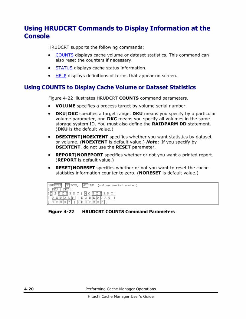
Using COUNTS to Display Cache Volume or Dataset Statistics
Figure 4-22 illustrates HRUDCRT COUNTS command parameters.
• VOLUME specifies a process target by volume serial number.
• DKU|DKC specifies a target range. DKU means you specify by a particular volume parameter, and DKC means you specify all volumes in the same storage system ID. You must also define the RAIDPARM DD statement. (DKU is the default value.)
• DSEXTENT|NOEXTENT specifies whether you want statistics by dataset or volume. (NOEXTENT is default value.) Note: If you specify by DSEXTENT, do not use the RESET parameter.
• REPORT|NOREPORT specifies whether or not you want a printed report. (REPORT is default value.)
• RESET|NORESET specifies whether or not you want to reset the cache statistics information counter to zero. (NORESET is default value.)
HRUDCRT COUNTS, VOLUME (volume serial number) [ DKU | DKC ] [D S E X T E N T | N O E X T E N T ] [ R E P O R T | N O R E P O R T ] [ R E S E T | N O R E S E T ]
Figure 4-22 HRUDCRT COUNTS Command Parameters
Performing Cache Manager Operations 4-21
Hitachi Cache Manager User’s Guide
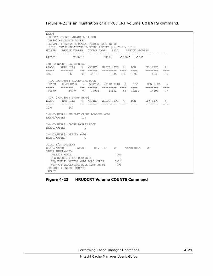
Figure 4-23 is an illustration of a HRUDCRT volume COUNTS command.
READY HRUDCRT COUNTS VOL(RAID31) DKU JSE800I-I COUNTS ACCEPT JSE001I-I END OF HRUDCRX, RETURN CODE IS 00 ***** CACHE SUBSYSTEM COUNTERS REPORT (01-02-07) ***** VOLSER DEVICE NUMBER DEVICE TYPE SSID DEVICE ADDRESS -------- -------------- -------------- -------- ------------------------- RAID31 X’2001’ 3390-3 X’0080’ X’01’ I/O COUNTERS: BASIC MODE READS READ HITS % WRITES WRITE HITS % DFW DFW HITS % ----- -------- --- ------ --------- ---- ---- -------- ---- 3458 3269 94 2210 1835 83 1602 1538 96 I/O COUNTERS: SEQUENTIAL MODE READS READ HITS % WRITES WRITE HITS % DFW DFW HITS % ----- -------- --- ------ --------- ---- ---- -------- ---- 46879 34774 74 17964 14192 64 18219 14192 77 I/O COUNTERS: BOUND HEADS READS READ HITS % WRITES WRITE HITS % DFW DFW HITS % ----- -------- --- ------ --------- ---- ---- -------- ---- 1096 647 I/O COUNTERS: INHIBIT CACHE LOADING MODE READS/WRITES 104 I/O COUNTERS: CACHE BYPASS MODE READS/WRITES 0 I/O COUNTERS: VERIFY MODE READS/WRITES 0 TOTAL I/O COUNTERS READS/WRITES 72538 READ HIT% 54 WRITE HIT% 22 OTHER INFORMATION DESTAGE HEADS 505 DFW OVERFLOW I/O COUNTERS 0 SEQUENTIAL ACCESS MODE LOAD HEADS 1215 WITHOUT SEQUENTIAL MODE LOAD HEADS 791 JSE801I-I END OF COUNTS READY
Figure 4-23 HRUDCRT Volume COUNTS Command

4-22 Performing Cache Manager Operations
Hitachi Cache Manager User’s Guide
Figure 4-24 is an illustration of a HRUDCRT dataset COUNTS command.
READY HRUDCRT COUNTS VOL(RAID31) DKU DSEXTENT JSE800I-I COUNTS ACCEPT JSE001I-I END OF HRUDCRX, RETURN CODE IS 00 ***** CACHE SUBSYSTEM COUNTERS REPORT (01-02-07) ***** VOLSER DEVICE NUMBER DEVICE TYPE SSID DEVICE ADDRESS ------ ------------- ----------- ----- --------------- RAID31 X’2001’ 3390-3 ‘0080’ X’01’ USED DATASET COUNT --------------------------------- 6 I/O COUNTERS DSEXTENT EXTENT DATASET NAME READS WRITES STATUS COUNT ------------ ------ -------- ------- ------- ***** VTOC ***** 2147483647 2147483647 EQUAL 1 SYS1.VTOCIX.RAID31 2147483647 2147483647 EQUAL 1 SYS1.VVDS.VRAID31 2147483647 2147483647 EQUAL 1 USER1.AAAA.BBBB.CCCC.DDDD.EEEE.FFFF.GGGG.HHH* 2147483647 2147483647 EQUAL 1 USER1.AAAA.BBBB.DDDD 2147483647 2147483647 EQUAL 2 USER1.AAAA.BBBB.EEEE 2147483647 2147483647 EQUAL- 2 JSE801I-I END OF COUNTS READY
Figure 4-24 HRUDCRT Dataset COUNTS Command
Note: If the dataset name is over 40 characters, the data will be shown in the following line.

Performing Cache Manager Operations 4-23
Hitachi Cache Manager User’s Guide
Using STATUS to Display the Cache Status
Figure 4-25 illustrates HRUDCRT STATUS command parameters. See the glossary for further definition of the types of cache status.
• VOLUME allows you to specify a process target by volume serial number.
• DKU|DKC|CLPR allows you to specify a target range. DKU specifies the target range by a particular volume parameter, and DKC specifies the target range as all volumes in the same storage system ID. You must also define the RAIDPARM DD statement. (DKU is the default value.) For installation of Cache Logical Partition (CLPR) function, CMG outputs CLPR information, which volume belongs to a specified.
• EXTENT specifies that cache extent information will be printed.
• NOEXTENT specifies that cache extent information will not be printed. (NOEXTENT is the default value.)
• DSEXTENT specifies that dataset statistics information will be printed. If this is combined with a DKC command, you must also define the RAIDPARM DD statement.
Figure 4-26 is an illustration of a HRUDCRT device STATUS command.
HRUDCRT STATUS, VOLUME (volume serial number) [ DKU | DKC | CLPR] [ E X T E N T | N O E X T E N T | D S E X T E N T ]
Figure 4-25 HRUDCRT STATUS Command Parameters
READY HRUDCRT STATUS VOL(RAID31) DKC JSE800I-I STATUS ACCEPT JSE001I-I END OF HRUDCRX, RETURN CODE IS 00 ***** CACHE SUBSYSTEM STATUS REPORT (01-02-07) ***** DISK CONTROLLER INFORMATION CU-TYPE SSID DEVICE ADDRESS -------- ----- --------------- 3990-3 X’0080’ X’01’ CACHE NVS PINNED DATA ----------- ------------- --------- ------------- STATUS ENABLED ENABLED NONE DCR CONFIGURATION REMAINING AREA 734656 USED AREA 313920 DCR AVAILABLE BYTE 1048576 USED AREA COUNT 17 JSE801I-I END OF STATUS READY
Figure 4-26 HRUDCRT Device STATUS Command

4-24 Performing Cache Manager Operations
Hitachi Cache Manager User’s Guide
Figure 4-27 is an illustration of a HRUDCRT residence STATUS command.
READY HRUDCRT STATUS VOL(RAID31) DKU JSE800I-I STATUS ACCEPT JSE001I-I END OF HRUDCRX, RETURN CODE IS 00 ***** CACHE SUBSYSTEM STATUS REPORT (01-02-07) ***** VOLSER DEVICE NUMBER DEVICE TYPE SSID DEVICE ADDRESS -------- ------------- ------------ ----- ------------------ RAID31 X’2001’ 3390-3 X’0080’ X’01’ CACHE ACCESS DRIVE STATUS DFW STATUS USED AREA COUNT ------------- -------------- ----------- --------------------------- ENABLED ENABLED ENABLED 5 FROM TO SIZE DCR EXTENT CC HH CC HH CYLS HEADS TYPE RELATION DATASET NAME --------- --------- ----- ------- ---- --------- ----------------------- 00000-0001 00010-0001 10 1 BIND ALL USER1.AAAA.BBBB.1111 00050-0000 00100-0014 51 0 PRIO PART USER1.AAAA.BBBB.2222 00128-0000 00160-0008 32 9 BIND PART USER1.AAAA.BBBB.2222 01000-0000 01009-0014 10 0 PRIO ALL USER1.AAAA.BBBB.CCCC.33*33 01010-0000 01010-0014 1 0 PRIO ALL ***** VTOC ***** 01011-0000 01011-0014 1 0 PRIO ALL SYS1.VTOCIX.SYSC02 01012-0000 01012-0014 1 0 PRIO ALL SYS1.VVDS.VSYSC02 01013-0000 01013-0014 1 0 BIND ALL ***** FREE SPACE ***** JSE801I-I END OF STATUS READY
Figure 4-27 HRUDCRT Residence STATUS Command
Figure 4-28 is an illustration of a HRUDCRT dataset STATUS command.
READY HRUDCRT STATUS VOL(RAID31) DKU DSEXTENT JSE800I-I STATUS ACCEPT JSE001I-I END OF HRUDCRX, RETURN CODE IS 00 ***** CACHE SUBSYSTEM STATUS REPORT (01-02-07) ***** VOLSER DEVICE NUMBER DEVICE TYPE SSID DEVICE ADDRESS ------ ------------- ----------- ---- ---------------- RAID31 X’2001’ 3390-3 X’0080’ X’01’ CACHE ACCESS DRIVE STATUS DFW STATUS USED AREA COUNT ------------- ------------ ---------- --------------------- ENABLED ENABLED ENABLED 8 FROM TO SIZE EXTENT CC HH CC HH CYLS HEADS RELATION DATASET NAME -------- ------- ------------ -------- ------------------------ 00000-0001 00010-0001 10 1 ALL USER1.AAAA.BBBB.1111 00050-0000 00100-0014 51 0 PART USER1.AAAA.BBBB.2222 00128-0000 00160-0008 32 9 PART USER1.AAAA.BBBB.2222 01000-0000 01009-0014 10 0 ALL USER1.AAAA.BBBB.CCCC.33*33 01010-0000 01010-0014 1 0 ALL ***** VTOC ***** 01011-0000 01011-0014 1 0 ALL SYS1.VTOCIX.RAID31 01012-0000 01012-0014 1 0 ALL SYS1.VVDS.VRAID31 01013-0000 01013-0014 1 0 ALL ***** FREE SPACE ***** JSE801I-I END OF STATUS READY
Figure 4-28 HRUDCRT Dataset STATUS Command

Performing Cache Manager Operations 4-25
Hitachi Cache Manager User’s Guide
Figure 4-29 is an illustration of a HRUDCRT dataset STATUS command.
READY HRUDCRT STATUS VOL(RAID31) CLPR JSE800I-I STATUS ACCEPT JSE001I-I END OF HRUDCRX, RETURN CODE IS 00 ***** CACHE SUBSYSTEM STATUS REPORT (01-06-03) ***** DISK CONTROLLER INFORMATION CU-TYPE SSID DEVICE ADDRESS ------- ------- -------------- 3990-3 X'0080' X'01' CACHE NVS PINNED DATA --------------- ------------- ----------- STATUS ENABLED ENABLED NONE CLPR NO. 32 CURRENT CLPR CONFIGURATION REMAINING AREA 2000000 USED AREA 2000000 FLASH ACCESS AVAILABLE 4000000 MAXIMUM AREA COUNT 2048 USED AREA COUNT 1024 DEVICE USED AREA COUNT 512 JSE801I-I END OF STATUS READY
Figure 4-29 HRUDCRT CLPR STATUS Command
4-26 Performing Cache Manager Operations
Hitachi Cache Manager User’s Guide
Displaying Help for HRUDCRT Commands
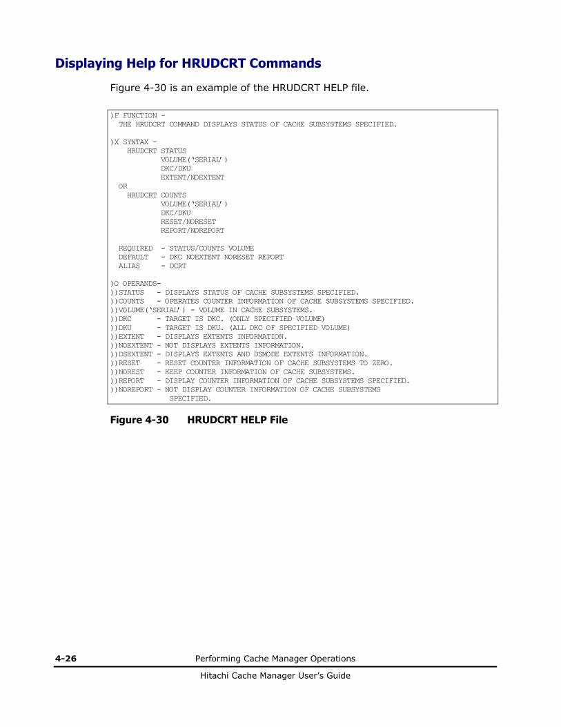
Figure 4-30 is an example of the HRUDCRT HELP file.
)F FUNCTION - THE HRUDCRT COMMAND DISPLAYS STATUS OF CACHE SUBSYSTEMS SPECIFIED. )X SYNTAX - HRUDCRT STATUS VOLUME(‘SERIAL’) DKC/DKU EXTENT/NOEXTENT OR HRUDCRT COUNTS VOLUME(‘SERIAL’) DKC/DKU RESET/NORESET REPORT/NOREPORT REQUIRED - STATUS/COUNTS VOLUME DEFAULT - DKC NOEXTENT NORESET REPORT ALIAS - DCRT )O OPERANDS- ))STATUS - DISPLAYS STATUS OF CACHE SUBSYSTEMS SPECIFIED. ))COUNTS - OPERATES COUNTER INFORMATION OF CACHE SUBSYSTEMS SPECIFIED. ))VOLUME(‘SERIAL’) - VOLUME IN CACHE SUBSYSTEMS. ))DKC - TARGET IS DKC. (ONLY SPECIFIED VOLUME) ))DKU - TARGET IS DKU. (ALL DKC OF SPECIFIED VOLUME) ))EXTENT - DISPLAYS EXTENTS INFORMATION. ))NOEXTENT - NOT DISPLAYS EXTENTS INFORMATION. ))DSEXTENT - DISPLAYS EXTENTS AND DSMODE EXTENTS INFORMATION. ))RESET - RESET COUNTER INFORMATION OF CACHE SUBSYSTEMS TO ZERO. ))NOREST - KEEP COUNTER INFORMATION OF CACHE SUBSYSTEMS. ))REPORT - DISPLAY COUNTER INFORMATION OF CACHE SUBSYSTEMS SPECIFIED. ))NOREPORT - NOT DISPLAY COUNTER INFORMATION OF CACHE SUBSYSTEMS SPECIFIED.
Figure 4-30 HRUDCRT HELP File

5
Return Codes, Output Messages, and Error Codes 5-1
Hitachi Cache Manager User’s Guide
Return Codes, Output Messages, and Error Codes
This chapter lists the return and error codes as well as the output messages.
Return Codes
Output Messages
Error Codes

5-2 Return Codes, Output Messages, and Error Codes
Hitachi Cache Manager User’s Guide
Return Codes
HRUDCRX has the following return codes:
• 0 indicates that all commands were successfully executed.
• 4 indicates that a slight error occurred that doesn’t affect the execution of the commands. The process continues, but an attention message will display.
• 8 indicates that an error occurred during the command execution, and the process ended abnormally. The listed commands (if any were specified) will be executed.
• 12 indicates that a serious error occurred during the command execution, and the process ended abnormally. The listed commands (if any were specified) will not be executed.
• 16 indicates that the command failed to open either a SYSIN dataset or a SYSPRINT dataset. It can also indicate that a virtual storage memory for command execution was not sufficient. The specified commands were not executed.
HRUDCRT has the following return codes:
• 0 indicates that all commands were successfully executed.
• 4 indicates that a slight error occurred that doesn’t affect the execution of the commands. The process continues, but an attention message will display.
• 8 indicates that an error occurred during the command execution.
• 12 indicates that a serious error occurred during the command execution.
• 16 indicates that an error occurred during the HRUDCRX execution.
• 20 indicates that the command failed to allocate a temporary dataset.

Return Codes, Output Messages, and Error Codes 5-3
Hitachi Cache Manager User’s Guide
Output Messages
The output message for HRUDCRX is stored in a sequential dataset. The message includes input control statements, which are printed out with each command followed by the result of the command execution. If you want to print out cache statistics information, specify COUNTS and then REPORT. If you want to print out status information, specify STATUS and then REPORT.
The output for HRUDCRT is displayed on a TSO terminal. If you want to display statistics information, specify COUNTS and then REPORT. If you want to display status information, specify STATUS and then REPORT.
Both HRUDCRX and HRUDCRT messages contain a nine-character ID statement, formatted as follows: JSEnnnI-C. In this example, JSE indicates a message, nnn indicates the message number, and I-C indicates the severity code. (S) indicates an action by the Cache Manager utility, and (P) indicates an action by the user.
The severity codes are as follows:
• I indicates that all commands were successfully implemented.
• W indicates that the process was completed, but there is an attention message.
• E indicates that an error occurred during the command execution, and the process ended abnormally. The listed commands (if specified) will be executed.
• S indicates that a serious error occurred during the command execution, and the process ended abnormally. The listed commands (if specified) were skipped.
• U indicates that a serious error occurred during the command execution, and the process ended abnormally. The specified commands were skipped.

5-4 Return Codes, Output Messages, and Error Codes
Hitachi Cache Manager User’s Guide
Error Codes
Table 5-1 Error Codes
Error Number
Error Message Recommended Action
JSE001I-I END OF HRUDCRX, RETURN CODE IS return code
HRUDCRX has been executed. The return code has the maximum value of return codes during the execution of HRUDCRX.
JSE002I-I [VTOC, dataset name, FROM cchh TO cchh] ON [volume serial number or disk drive unit number] WAS BOUND TO CACHE
HRUDCRX specified cache residence by VTOC, DATASET, or CCHH.
(S) Process the next command. (Return code is 0.)
JSE003I-I VTOC, VTOCIX, VVDS ON [volume serial number or disk drive unit number] WAS BOUND TO CACHE
HRUDCRX ordered to reside [VTOC, VTOCIX, or VVDS] tracks in the volume specified by [volume serial number, or disk drive unit number]. If the VTOCIX is [******] or the VVDS is [****], HRUDCRX did not reside those tracks to cache, because HRUDCRX could not find those tracks.
(S) Process the next command. (Return code is 0.)
JSE004I-I [VTOC, dataset name or FROM cchh TO cchh] ON [volume serial number or disk drive unit number] WAS UNBOUND FROM CACHE
HRUDCRX released residence of the tracks specified by [VTOC, DATASET, or CCHH].
(S) Process the next command. (Return code is 0.)
JSE005I-I ALL TRACKS ON [volume serial number or disk drive unit number] WERE UNBOUND FROM CACHE
HRUDCRX released residence of all tracks in the volume specified by [volume serial number or disk drive unit number].
(S) Process the next command. (Return code is 0.)
JSE006I-I FREE SPACE ON [volume serial number, disk drive unit number] WAS UNBOUND FROM CACHE
HRUDCRX released the remaining non-managed area of residence in the volume specified by [volume serial number, or disk drive unit number].
(S) Process the next command. (Return code is 0.)
JSE007I-I VTOC, VTOCIX, VVDS ON [volume serial number or disk drive number] WAS UNBOUND FROM CACHE
HRUDCRX released residence of [VTOC, VTOCIX, or VVDS] tracks in the volume specified by the [volume serial number, or disk drive unit number]. If the VTOCIX is [******] or the VVDS is [****], HRUDCRX did not release the cache residence, because HRUDCRX could not find the tracks.
(S) Process the next command. (Return code is 0.)
JSE008I-I [VTOC or dataset name] EXTENT MODE ON [volume serial number or disk drive unit number] WAS [ENABLED or DISABLED].
HRUDCRX either enabled or disabled the data statistics area for the specified [VTOC extent mode or dataset], as defined by the [volume serial number or disk drive unit number].
(S) Process the next command. (Return code is 0.)
JSE009I-I ALL TRACKS EXTENT MODE ON [volume serial number or disk drive unit number] WERE DISABLED
HRUDCRX disabled all dataset statistics in the volume specified by [volume serial number, or disk drive unit number].
(S) Process the next command. (Return code is 0.)
JSE010I-I FREE SPACE EXTENT MODE ON [volume serial number or disk drive unit number] WAS DISABLED
HRUDCRX released the dataset statistics of the remaining non-managed tracks in the volume specified by [volume serial number, or disk drive unit number].
(S) Process the next command. (Return code is 0.)

Return Codes, Output Messages, and Error Codes 5-5
Hitachi Cache Manager User’s Guide
Error Number
Error Message Recommended Action
JSE101I-E OPERAND ‘operand’ IS INCONSISTENT
The set of operands is inconsistent. This operand can not be used with the other specified operand.
(S) Terminate the command process, but the next process continues. (Return code is 8.)
(P) Correct the error and execute the command again.
JSE102I-E ‘operand’ SPECIFIED BUT REQUIRED OPERAND MISSING
The specified operand requires another operand.
(S) Terminate the command process, but the next process continues. (Return code is 8.)
(P) Correct the error and execute the command again.
JSE103I-E INVALID COMMAND NAME ‘command name’
The [command name or PARM information] is incorrect. If the PARM information is incorrect, the error message will indicate [PARM] in place of command name.
(S) Terminate the command process, but the next process continues. (Return code is 8.)
(P) Correct the error and execute the command again.
JSE104I-E INVALID KEYWORD VALUE ‘keyword value’
There is an error in the [dataset name, volume serial number, dd name, disk drive unit address, track address, or other]. For example, there may be too many characters, or some invalid characters.
(S) Terminate the command process, but the next process continues. (Return code is 8.)
(P) Correct the error and execute the command again.
JSE105I-E INVALID KEYWORD ‘keyword value’
The specified keyword is not defined for this command.
(S) Terminate the command process, but the next process continues.(Return code is 8.)
(P) Correct the error and execute the command again.
JSE106I-E INVALID CCHH PARAMETER
The CCHH value is invalid because of one or more of the following reasons:
1. The number of characters is not eight or ten.
2. There is at least one invalid character.
3. The HH value exceeds the value of the last track number in a cylinder.
(S) Terminate the command process, but the next process continues. (Return code is 8.)
(P) Correct the error and execute the command again.
JSE107I-E LOWER LIMIT IS GREATER THAN UPPER LIMIT
The upper value specified by CCHH parameter exceeds the maximum address of a volume.
(S) Terminate the command process, but the next process continues. (Return code is 8.)
(P) Correct the upper CCHH value and execute the command again.
JSE2011E SPECIFIED CCHH LIMIT EXCEEDS VOLUME CAPACITY
The upper value specified by CCHH parameter exceeds the maximum address of a volume.
(S) Terminate the command process, but the next process goes on (return code is 8.)
(P) Correct the cchh value and execute the command again.
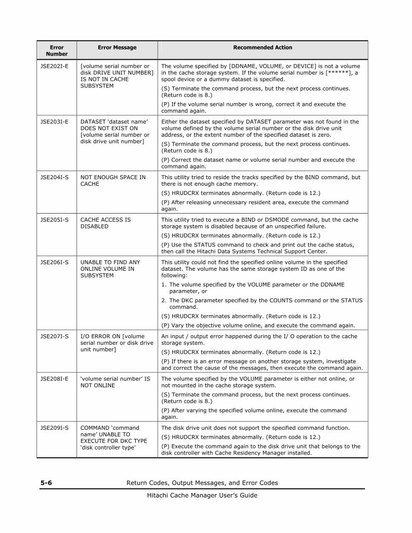
5-6 Return Codes, Output Messages, and Error Codes
Hitachi Cache Manager User’s Guide
Error Number
Error Message Recommended Action
JSE202I-E [volume serial number or disk DRIVE UNIT NUMBER] IS NOT IN CACHE SUBSYSTEM
The volume specified by [DDNAME, VOLUME, or DEVICE] is not a volume in the cache storage system. If the volume serial number is [******], a spool device or a dummy dataset is specified.
(S) Terminate the command process, but the next process continues. (Return code is 8.)
(P) If the volume serial number is wrong, correct it and execute the command again.
JSE203I-E DATASET ‘dataset name’ DOES NOT EXIST ON [volume serial number or disk drive unit number]
Either the dataset specified by DATASET parameter was not found in the volume defined by the volume serial number or the disk drive unit address, or the extent number of the specified dataset is zero.
(S) Terminate the command process, but the next process continues. (Return code is 8.)
(P) Correct the dataset name or volume serial number and execute the command again.
JSE204I-S NOT ENOUGH SPACE IN CACHE
This utility tried to reside the tracks specified by the BIND command, but there is not enough cache memory.
(S) HRUDCRX terminates abnormally. (Return code is 12.)
(P) After releasing unnecessary resident area, execute the command again.
JSE205I-S CACHE ACCESS IS DISABLED
This utility tried to execute a BIND or DSMODE command, but the cache storage system is disabled because of an unspecified failure.
(S) HRUDCRX terminates abnormally. (Return code is 12.)
(P) Use the STATUS command to check and print out the cache status, then call the Hitachi Data Systems Technical Support Center.
JSE206I-S UNABLE TO FIND ANY ONLINE VOLUME IN SUBSYSTEM
This utility could not find the specified online volume in the specified dataset. The volume has the same storage system ID as one of the following:
1. The volume specified by the VOLUME parameter or the DDNAME parameter, or
2. The DKC parameter specified by the COUNTS command or the STATUS command.
(S) HRUDCRX terminates abnormally. (Return code is 12.)
(P) Vary the objective volume online, and execute the command again.
JSE207I-S I/O ERROR ON [volume serial number or disk drive unit number]
An input / output error happened during the I/ O operation to the cache storage system.
(S) HRUDCRX terminates abnormally. (Return code is 12.)
(P) If there is an error message on another storage system, investigate and correct the cause of the messages, then execute the command again.
JSE208I-E ‘volume serial number’ IS NOT ONLINE
The volume specified by the VOLUME parameter is either not online, or not mounted in the cache storage system.
(S) Terminate the command process, but the next process continues. (Return code is 8.)
(P) After varying the specified volume online, execute the command again.
JSE209I-S COMMAND ‘command name’ UNABLE TO EXECUTE FOR DKC TYPE ‘disk controller type’
The disk drive unit does not support the specified command function.
(S) HRUDCRX terminates abnormally. (Return code is 12.)
(P) Execute the command again to the disk drive unit that belongs to the disk controller with Cache Residency Manager installed.

Return Codes, Output Messages, and Error Codes 5-7
Hitachi Cache Manager User’s Guide
Error Number
Error Message Recommended Action
JSE210I-S COMMAND ‘command name’ OPERAND ‘operand’ UNABLE TO EXECUTE FOR DKC TYPE ‘disk controller type’
The disk drive unit does not support the specified command function. If this was a DSMODE command, all operands are checked.
(S) HRUDCRX terminates abnormally. (Return code is 12.)
(P) Execute the command again to the disk drive unit that belongs to the disk storage system with Cache Residency Manager installed.
JSE211I-S CMG RECEIVED UNEXPECTED RETURN VALUE (RAID TYPE) ON [volume serial number or disk drive unit number]
HRUDCRX detected an unexpected failure during the execution of the I/O request to the cache storage system. The cache storage system may have a malfunction.
(S) HRUDCRX terminates abnormally. (Return code is 12.)
(P) Call customer engineer and ask to investigate the disk storage system.
JSE213I-S I/O ERROR OCCURRED ON [volume serial number, disk drive unit number, sense byte]
An input / output error happened during the I/O operation to the cache storage system.
(S) HRUDCRX terminates abnormally. (Return code is 12.)
(P) Investigate and correct the specified error, then execute the command again.
JSE215I-E ‘disk drive unit number’ IS NOT FOUND
The specified disk drive unit number does not exist.
(S) Terminate the command process, but the next process continues. (Return code is 8.)
(P) Execute the command again by specifying the correct disk drive unit number.
JSE217I-E ‘disk drive unit number’ IS NOT MOUNTED ON SYSTEM
The volume specified by disk drive unit number is not mounted.
(S) Terminate the command process, but the next process continues. (Return code is 8.)
(P) After mounting the volume specified by the disk drive unit number, execute the command again.
JSE231I-S ALREADY BOUND TO CACHE BY [BIND or PRIO] MODE
The command to reside data using PRIO mode was made to the BIND mode area, or vice versa.
(S) HRUDCRX terminates abnormally. (Return code is 12.)
(P) Check the mode of the already resident area and correct the parameter, then execute the command again.
JSE232I-S EXTENT OVER ON BOUND TO CACHE
The number of resident extents exceeds the limitation. Maximum number of extents is:
For USP V/VM, 4096 per volume or 16384 per storage system.
For USP/NSC, 4096 per volume or 4096 per storage system.
For 9900V/9900, 1024 per volume or 1024 per storage system.
(S) HRUDCRX terminates abnormally. (Return code is 12.)
(P) Check the remaining number of available resident extents. If the number is too small, release the unnecessary resident extents, then execute the command again.
JSE233I-S EXTENT MODE LIMIT IS DUPLICATED
The area specified by the DSMODE/ENABLE command has already been enabled.
(S) HRUDCRX terminates abnormally. (Return code is 12.)
(P) Disable the area using the DSMODE/ECCENTRIC operand, then reissue the command.

5-8 Return Codes, Output Messages, and Error Codes
Hitachi Cache Manager User’s Guide
Error Number
Error Message Recommended Action
JSE234I-S EXTENT MODE LIMIT IS A PART OF DATASET EXTENT
The area specified by the DSMODE/DISABLE command has already been enabled.
(S) HRUDCRX terminates abnormally. (Return code is 12.)
(P) Disable the area using the DSMODE/ECCENTRIC operand, then reissue the command.
JSE235I-S EXTENT MODE OVER ON BOUND TO CACHE SUBSYSTEM
The number of dataset statistics extents exceeds the maximum, which is 64 per storage system.
(S) HRUDCRX terminates abnormally. (Return code is 12.)
(P) Check the remaining dataset extents. If the number is too small, release any unnecessary area. Then execute the command again.
JSE2361-S UNABLE TO EXECUTE FOR DKC
The command was executed on a storage system that does not have Cache Residency Manager installed.
(S) HRUDCRX terminates abnormally. (Return code is ‘8’.)
(P) Install Cache Residency Manager in DKC and then execute the command again.
JSE2371-E CLPR FUNCTION UNABLE TO EXECUTE FOR DKC KIND=xx
The command cannot be executed because the Cache Logical Partition (CLPR) function is not installed in the DKC.
DKC KIND: 05 for USP V/VM, 04 for USP/NSC, 03 for 9900V, 02 for 9900
(S) HRUDCRX terminates abnormally. (Return code is ‘8’.)
(P) Install the Cache Logical Partition (CLPR) program product in DKC and then execute the command again
JSE2381-E CLPR FUNCTION IS INVALID
The specified volume does not belong to the Cache logical Partition (CLPR).
(S) HRUDCRX terminates abnormally. (Return code is ‘8’.)
(P) Check the definition of Cache Logical Partition (CLPR) information and then execute the command again.
JSE2391-E CATALOG ACCESS ERROR(return code, reason code, module ID) {CATALOG ‘catalog name’ DATASET ‘dataset name’}
The error occurred on accessing to catalog.
(S) HRUDCRX terminates abnormally. (Return code is ‘8’.)
(P) Check the specified dataset name or catalog name and then execute the command again.
JSE2401-E DATASET ‘dataset name’ DOES NOT EXIST IN CATALOG
The specified dataset did not exist in specified catalog.
(S) HRUDCRX terminates abnormally. (Return code is ‘8’.)
(P) Check the specified dataset name and catalog name and then execute the command again.
JSE2411-W DATASET TYPE CAN NOT CACHE PROCESS ‘dataset name’
The specified dataset is not supported under CMG environment.
(S) HRUDCRX stops the command process and continues to be process in next command. (Return code is ‘4’.)
(P) Check the specified dataset name and catalog name and then execute the command again if it needs.
JSE2421-S MODULE (module name) NOT FOUND
Load module did not exist.
(S) HRUDCRX terminates abnormally. (Return code is ‘12’.)
(P) Check the system dataset and then execute the command again.

Return Codes, Output Messages, and Error Codes 5-9
Hitachi Cache Manager User’s Guide
Error Number
Error Message Recommended Action
JSE2431-S UNABLE TO EXECUTE BIND COMMAND DURING PRE-STAGING
BIND command cannot execute because pre-staging is performing.
(S) HRUDCRX terminates abnormally. (Return code is ‘12’.)
(P) Confirm the end of pre-staging and then execute the command again.
JSE301I-E DD STATEMENT ‘dd name’ NOT FOUND
User specified neither the DD statement that corresponds to the dd name specified by the command, nor a RAIDPARM DD statement.
(S) Terminate the command process, but the next process continues. (Return code is 8.)
(P) Specify the necessary DD statements or correct the dd name and execute the command again.
JSE302I-E DSORG/RECFM/BLKSIZE/LRECL OF ‘dd name’ IS INVALID
The output dataset of the COUNT or STATUS command lacks one or more of the following required attributes:
Dataset format (DSORG): SAM (PS), Record format (RECFM): Variable length block (VB), Record length (LRECL): 100 or more, Block length (BLKSIZE): 104 or more.
(S) Terminate the command process, but the next process continues. (Return code is 8.)
(P) Check the DCB attribute of output dataset. Then correct the invalid parameter and execute the command again.
JSE303I-S INSUFFICIENT MAIN STORAGE, COMMAND TERMINATED
The utility could not get sufficient main storage area to execute the command.
(S) HRUDCRX terminates abnormally. (Return code is 12.)
(P) Expand the virtual main storage area allocated to user region, and execute the command again.
JSE304I-E DYNALLOC ERROR, RETURN CODE return code, ERROR CODE X’error code’, INFO CODE X ‘detail code’
The following error happened during the operation of volume dynamic allocation [DYNALLOC macro process].
The return code (the contents of general register 15) is indicated in decimal form.
error code: The error code of DYNALLOC macro.
detail code: The detail code of DYNALLOC macro.
(S) Terminate the command process, but the next process continues. (Return code is 8.)
(P) Examine these codes in detail and correct the error, then execute the command again.
JSE306I-E I/O ERROR ON OUTDD (dd name)
I/O error has been detected during the output operation to the output dataset of COUNTS or STATUS command. Other error message(s) will have more detailed information.
(S) Terminate the command process, but the next process continues. (Return code is 8.)
(P) Examine the other error messages.
JSE307I-E I/O ERROR job name, step name, disk drive unit number, device type, dd name, order, error type, BBCCHHR, QSAM
I/O error has been detected during the output operation of the COUNTS or STATUS command. See “SYNADAF macro” explanation for more detail.
(S) Terminate the command process, but the next process continues. (Return code is 8.)
(P) Examine the error message.

5-10 Return Codes, Output Messages, and Error Codes
Hitachi Cache Manager User’s Guide
Error Number
Error Message Recommended Action
JSE500I-U INVALID RAIDPARM PARAMETER
The specified contents of the dataset in RAIDPARM DD statement has a coding rule error.
(S) HRUDCRX terminates abnormally. (Return code is 16.)
(P) Correct the error and execute the command again.
JSE501I-U DEVICE NUMBER EXCEEDS LIMIT
The total number of disk drive units specified by the dataset in the RAIDPARM DD statement exceeds the maximum.
(S) HRUDCRX terminates abnormally. (Return code is 16.)
(P) Correct the error and execute the command again.
JSE502I-W ‘disk drive unit number’ IS DUPLICATED
The dataset in RAIDPARM DD statement includes a duplicated disk drive unit number.
(S) Ignore the duplicated parameter, and the process continues. (Return code is 4.)
JSE503I-W ‘disk drive unit number’ IS NOT IN CACHE SUBSYSTEM
The disk drive unit number specified by the dataset in RAIDPARM DD statement does not exist in this cache storage system.
(S) Terminate the process for this disk drive unit, but the process continues for the following disk drive units. (Return code is 4.)
JSE504I-W ‘disk drive unit number’ IS NOT ONLINE
The disk drive unit number specified by the dataset in RAIDPARM DD statement is either not online or not mounted in the cache storage system.
(S) Terminate the process for this disk drive unit, but the process continues for the following disk drive units. (Return code is 4.)
JSE505I-W RAIDPARM IS EMPTY The dataset specified by RAIDPARM DD statement has no record.
(S) The process continues. (Return code is 4.)
JSE506I-S I/O ERROR ON ‘disk drive unit number’
An input/output error happened during the I/ O operation to the cache storage system of the disk drive unit number specified by the dataset in RAIDPARM DD statement.
(S) If you are specifying the DKC parameter by a STATUS command or a COUNTS command, terminate the process for the volume, but the process continues for the following volumes. (Return code is 12.)
(P) If another system has some error messages, review them, address the problem(s), then execute the command again.
JSE507I-S I/O ERROR ON ‘disk drive unit number’, ‘sense byte’
An input/output error happened during the I/O operation to the cache storage system of the disk drive unit number specified by the dataset in RAIDPARM DD statement.
(S) If you are specifying the DKC parameter by a STATUS command or a COUNTS command, terminate the process for that volume, but the process continues for the other volumes. (Return code is 12.)
(P) Examine the contents of the message and correct the error, then execute the command again.
JSE510I-S DATASET ‘dataset name’ EXTENT FROM CCHH TO CCHH IS [BOUND, UNBOUND or NOT CHANGE].
The utility indicates (hexadecimal) that the resident extents of the dataset specified by DATASET parameter were not processed. In case that an input/output error to the cache storage system happened during the operation, the utility prints out the status of all dataset extents.
BOUND: The extents reside in cache memory. UNBOUND: The extents do not reside in cache memory. NOT CHANGE: The extents have not changed from the previous command, because the process was not executed.
(S) HRUDCRX terminates abnormally. (Return code is 12.)
(P) Examine the contents of the message and correct the error, then execute the command again.
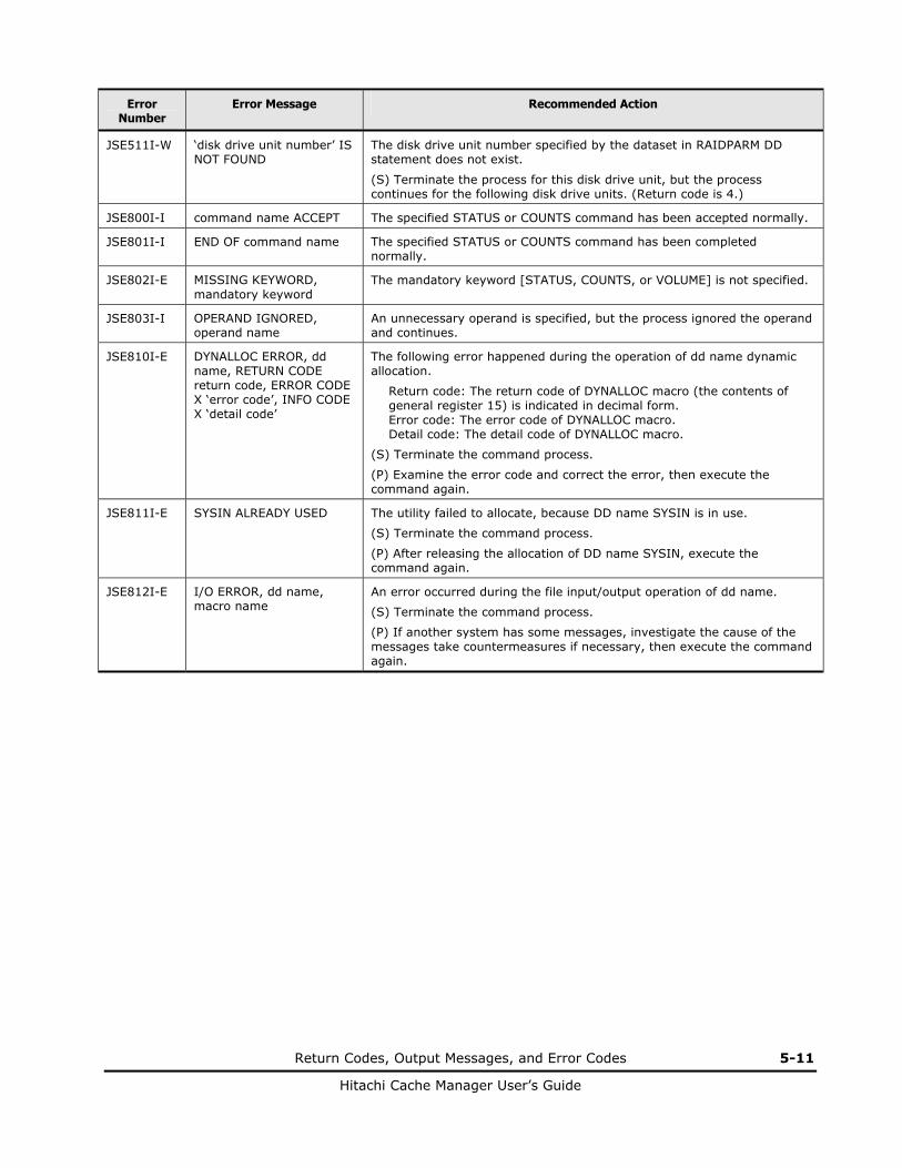
Return Codes, Output Messages, and Error Codes 5-11
Hitachi Cache Manager User’s Guide
Error Number
Error Message Recommended Action
JSE511I-W ‘disk drive unit number’ IS NOT FOUND
The disk drive unit number specified by the dataset in RAIDPARM DD statement does not exist.
(S) Terminate the process for this disk drive unit, but the process continues for the following disk drive units. (Return code is 4.)
JSE800I-I command name ACCEPT The specified STATUS or COUNTS command has been accepted normally.
JSE801I-I END OF command name The specified STATUS or COUNTS command has been completed normally.
JSE802I-E MISSING KEYWORD, mandatory keyword
The mandatory keyword [STATUS, COUNTS, or VOLUME] is not specified.
JSE803I-I OPERAND IGNORED, operand name
An unnecessary operand is specified, but the process ignored the operand and continues.
JSE810I-E DYNALLOC ERROR, dd name, RETURN CODE return code, ERROR CODE X ‘error code’, INFO CODE X ‘detail code’
The following error happened during the operation of dd name dynamic allocation.
Return code: The return code of DYNALLOC macro (the contents of general register 15) is indicated in decimal form. Error code: The error code of DYNALLOC macro. Detail code: The detail code of DYNALLOC macro.
(S) Terminate the command process.
(P) Examine the error code and correct the error, then execute the command again.
JSE811I-E SYSIN ALREADY USED The utility failed to allocate, because DD name SYSIN is in use.
(S) Terminate the command process.
(P) After releasing the allocation of DD name SYSIN, execute the command again.
JSE812I-E I/O ERROR, dd name, macro name
An error occurred during the file input/output operation of dd name.
(S) Terminate the command process.
(P) If another system has some messages, investigate the cause of the messages take countermeasures if necessary, then execute the command again.

5-12 Return Codes, Output Messages, and Error Codes
Hitachi Cache Manager User’s Guide

6
Troubleshooting 6-1
Hitachi Cache Manager User’s Guide
Troubleshooting
This chapter provides troubleshooting information for Cache Manager and instructions for calling technical support.
Troubleshooting
Calling the Hitachi Data Systems Support Center

6-2 Troubleshooting
Hitachi Cache Manager User’s Guide
Troubleshooting
The Hitachi RAID storage systems provide continuous data availability and are not expected to fail in any way that would interrupt access to user data. For troubleshooting information, please refer to the User and Reference Guide for the storage system.
Calling the Hitachi Data Systems Support Center
If you need to call the Hitachi Data Systems Support Center, make sure to provide as much information about the problem as possible, including:
• The circumstances surrounding the error or failure
• The exact content of any messages displayed on the host system(s).
The Hitachi Data Systems customer support staff is available 24 hours/day, seven days a week. If you need technical support, please call:
• United States: (800) 446-0744
• Outside the United States: (858) 547-4526

Acronyms and Abbreviations Acronyms-1
Hitachi Cache Manager User’s Guide
Acronyms and Abbreviations
CC cylinder cylinder CPPL command processor parameter list CU control unit
DCR Dynamic Cache Residency (another name for Cache Residency Manager) DFW DASD fast write
ESA Enterprise Systems Architecture
GB gigabyte
HH head head
IPL initial program load
JCL job control language
KB kilobyte
LCU logical control unit LVI logical volume image (also called device emulation)
max maximum MB megabyte(s) MVS Multiple Virtual Storage
NSC Network Storage Controller NVS non-volatile storage
PB petabyte(s) PPL parameter list
SIM service information message SSID storage system identification
TSO Time Sharing Option
USP Universal Storage Platform
VOLSER volume serial number VTOC volume table of contents

Acronyms-2 Acronyms and Abbreviations
Hitachi Cache Manager User’s Guide

Glossary Glossary-1
Hitachi Cache Manager User’s Guide
Glossary
This glossary defines some of the special terms used in this document.
bound heads Read and write counts from cache.
cache extents Areas used for Cache Residency or Cache Manager. Cache Residency Manager
Other names for this product are: FlashAccess, Dynamic Cache Residency (DCR).
cache status: cache off error Cache failed to stop. disabled Cache is offline. disconnected Cache is disabled for maintenance. enabled Status is normal. cache error Cache error occurred, so cache function has been stopped. initializing cache status is being changed to “enabled”.
destaged heads Number of tracks written to disk asynchronously.
extent count Number of cache or dataset extents. Extent Relation:
ALL The extent range for dataset statistics information is equal to the extent range managed by the VTOC. The object dataset has one extent.
ALL- The extent range for dataset statistics information is smaller than the extent range managed by the VTOC. The object dataset has one extent.
ALL+ The extent range for dataset statistics information is larger than the extent range managed by the VTOC. The object dataset has one extent.
PART The extent range for dataset statistics information is equal to the extent range for the dataset. The object dataset has more than one extent.
PART+ The extent range for dataset statistics information is larger than the extent range for the dataset. The object dataset has more than one extent.
PART- The extent range for dataset statistics information is smaller than the extent range for the dataset. The object dataset has more than one extent.

Glossary-2 Glossary
Hitachi Cache Manager User’s Guide
Extent Relation (continued):
EQUAL The number of dataset extents managed by the VTOC is the same as the number of datasets from which statistics are derived.
EQUAL- The number of dataset extents managed by the VTOC is less than the number of datasets from which statistics are derived.
LONG The number of dataset extents from which statistics are derived includes extents that do not have datasets.
SHORT The number of dataset extents from which statistics are derived includes datasets that do not have extents.
NVS: destaging Write-pending data is being destaged to disk. disabled Non-volatile storage cache is offline, and DFW function is
stopped. disconnected Non-volatile storage is offline due to maintenance. enabled Non-volatile storage is normal status. NVS error Non-volatile storage cache memory error has occurred, and
DFW function has been stopped. NVS off error Non-volatile storage function failed to stop.
parity group A set of hard disk drives that have the same capacity and are treated as one RAID group. Another name for parity group is array group.

Hitachi Cache Manager User’s Guide

MK-96RD646-02
Hitachi Data Systems
Corporate Headquarters 750 Central Expressway Santa Clara, California 95050-2627 U.S.A. Phone: 1 408 970 1000 www.hds.com [email protected]
Asia Pacific and Americas 750 Central Expressway Santa Clara, California 95050-2627 U.S.A. Phone: 1 408 970 1000 [email protected]
Europe Headquarters Sefton Park Stoke Poges Buckinghamshire SL2 4HD United Kingdom Phone: + 44 (0)1753 618000 [email protected]
Copyright © 2022 FDOKUMEN