– SideSmart - Hitachi AC Hong Kong
108
Variable Refrigerant Flow system Slim Modular outdoor units Air source heat pump type – SideSmart TM
-
Upload
khangminh22 -
Category
Documents
-
view
18 -
download
0
Transcript of – SideSmart - Hitachi AC Hong Kong

Variable Refrigerant Flow systemSlim Modular outdoor unitsAir source heat pump type
–SideSmartTM

Living Harmony
At Hitachi Cooling & Heating we like to think of this as creating harmony with your interior environment.When we achieve that wonderful balance, productivity, learning, happiness and health can thrive. We call this ‘Living Harmony’ and it’s at the center of everything we do.
The future together
Living Harmony puts people first. By balancing the human needs of our customers with an uncompromisingapproach to innovation and quality, we can continue to create the technologies for a more comfortable and balanced world. Your world. We live in it together.
The beauty of balance
No matter what the weather is like outside, when you're indoors, you want to have complete control over your environment. At work or play, awake or asleep, you're free to create your own atmosphere; balancing energy with calm, sound with silence and light with shade.It's the same for cooling and heating. When the air around you is in balance, you can enjoy life indoors that much more.
Air. It’s a wonderful thing.Invisible, silent and life-giving, air makes our entire world possible. It surrounds us, continuously energizing, cooling and warming. It can be unpredictable and sometimes challenging, but when air is in harmony with us, everything seems that much easier.This is our vision. To create the air that makes life better.in VRF, exclusive FrostWashTM technology will clean the coil without effort.
03
02
02 Message
01 06 Outdoor Units
08 | The world's first slim modular VRF
10 | SideSmartTM : The power of ubiquity
12 | Features & Benefits
20 | Specifications
29 | Optional parts
30 | Accessories
32 Indoor Units
34 | Line-up summary
36 | Our key indoor features
40 | Solutions
66 | Specifications & accessories
04
78 Ventilation
80 | Our ventilation line-up
82 | Ventilation Solutions
84 | DX-kit
86 Controllers
88 | Centralized controllers
94 | Individual controllers
102 | Accessories
104 | H-lINK: Enjoy more freedom
–Index
3
Side
Smar
tTMVA
RIAB
LE R
EFRI
GERA
NT
FLO
W S
YSTE
M

10 reasons to chooseHitachi VRF
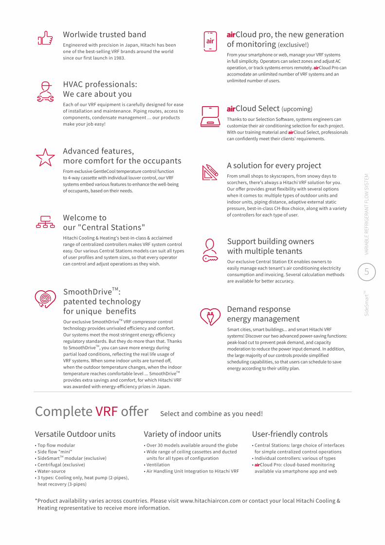
HVAC professionals: We care about youEach of our VRF equipment is carefully designed for ease of installation and maintenance. Piping routes, access to components, condensate management ... our products make your job easy!
Welcome to our "Central Stations" Hitachi Cooling & Heating's best-in-class & acclaimed range of centralized controllers makes VRF system control easy. Our various Central Stations models can suit all types of user profiles and system sizes, so that every operator can control and adjust operations as they wish.
Advanced features, more comfort for the occupantsFrom exclusive GentleCool temperature control function to 4-way cassette with individual louver control, our VRF systems embed various features to enhance the well-being of occupants, based on their needs.
SmoothDriveTM: patented technology for unique benefits Our exclusive SmoothDriveTM VRF compressor control technology provides unrivaled efficiency and comfort. Our systems meet the most stringent energy efficiency regulatory standards. But they do more than that. Thanks to SmoothDriveTM, you can save more energy during partial load conditions, reflecting the real life usage of VRF systems. When some indoor units are turned off, when the outdoor temperature changes, when the indoor temperature reaches comfortable level ... SmoothDriveTM provides extra savings and comfort, for which Hitachi VRF was awarded with energy-efficiency prizes in Japan.
Cloud Select (upcoming) Thanks to our Selection Software, systems engineers can customize their air conditioning selection for each project. With our training material and Cloud Select, professionals can confidently meet their clients' requirements.
Demand response energy managementSmart cities, smart buildings... and smart Hitachi VRF systems! Discover our two advanced power-saving functions: peak-load cut to prevent peak demand, and capacity moderation to reduce the power input demand. In addition, the large majority of our controls provide simplified scheduling capabilities, so that users can schedule to save energy according to their utility plan.
Support building owners with multiple tenantsOur exclusive Central Station EX enables owners to easily manage each tenant's air conditioning electricity consumption and invoicing. Several calculation methods are available for better accuracy.
A solution for every projectFrom small shops to skyscrapers, from snowy days to scorchers, there's always a Hitachi VRF solution for you. Our offer provides great flexibility with several options when it comes to: multiple types of outdoor units and indoor units, piping distance, adaptive external static pressure, best-in-class CH-Box choice, along with a variety of controllers for each type of user.
Worlwide trusted bandEngineered with precision in Japan, Hitachi has been one of the best-selling VRF brands around the world since our first launch in 1983.
Cloud pro, the new generation of monitoring (exclusive!)From your smartphone or web, manage your VRF systems in full simplicity. Operators can select zones and adjust AC operation, or track systems errors remotely. Cloud Pro can accomodate an unlimited number of VRF systems and an unlimited number of users.
* Product availability varies across countries. Please visit www.hitachiaircon.com or contact your local Hitachi Cooling & Heating representative to receive more information.
Versatile Outdoor units• Top flow modular• Side flow "mini"• SideSmartTM modular (exclusive)• Centrifugal (exclusive)• Water-source• 3 types: Cooling only, heat pump (2-pipes),
heat recovery (3-pipes)
Variety of indoor units• Over 30 models available around the globe• Wide range of ceiling cassettes and ducted
units for all types of configuration• Ventilation• Air Handling Unit Integration to Hitachi VRF
User-friendly controls• Central Stations: large choice of interfaces
for simple centralized control operations• Individual controllers: various of types• Cloud Pro: cloud-based monitoring
available via smartphone app and web
Select and combine as you need!Complete VRF offer
5
Side
Smar
tTMVA
RIAB
LE R
EFRI
GERA
NT
FLO
W S
YSTE
M

01
–Outdoorunits

08 THE WORLD'S FIRST SLIM MODULAR VRF
10 SIDESMARTTM : THE POWER OF UBIQUITY
12 FEATURES & BENEFITS
12 Meet your project requirements14 Small size, yet maximal efficiency15 Improved operation16 Reliability: enjoy peace of mind18 Improved components
20 SPECIFICATIONS
20 Single cabinet 22 Standard combination25 Premium combination26 Economy combination
29 OPTIONAL PARTS
30 ACCESSORIES
Striving for innovative VRF technology!Meet SideSmartTM, our latest innovation in the Hitachi VRF family. Offering unprecedented flexibility and high efficiency, SideSmartTM will delight HVAC professionals, while it delivers to end-users the comfort they deserve.
7
Side
Smar
tTMVA
RIAB
LE R
EFRI
GERA
NT
FLO
W S
YSTE
M
7
Side
Smar
tTMVA
RIAB
LE R
EFRI
GERA
NT
FLO
W S
YSTE
M

–The world's first slim modular VRF!
Single Cabinet HP 8 10 12 14 16 18Dimensions (H x W x D) mm 1,650 x 1,050 x 420 1,650 x 1,190 x 420
Net Weight380-415V kg 185 197 203 219 225 225
220V kg 188 200 205 223 231 231
Cooling Capacity kW 22.4 28.0 33.5 40.0 45.0 50.0
Heating Capacity kW 25.0 31.5 37.5 45.0 50.0 54.0
PerformanceEER (Cooling) 4.51 4.26 4.27 3.85 3.79 3.54
COP (Heating) 4.92 4.44 4.68 4.40 4.41 3.90
Air Flow Volume (m3/min) 160 185 200 250 258 258
Noise level dB(A) SPL*1 (Cooling/Heating) dB(A) 55/56 59/60 60/62 60/61 62/64 62/64
*1 SPL is measured by an anechoic room, so that reflected sound should be taken into consideration in the field.
SideSmart™ is an exclusive solution, offering until now an unseen combination of benefits: performance equaling large top-flow units, with slim modular units which can fit anywhere.
5SMART
CONCEPTModularity with
great performanceBenefit from the highest
level of Hitachi VRF efficiency
DESIGNConnectable
slim side-flow modules
For the first time, side-flow slim units can be connected to combine
their capacities
CONFIGURATIONCan be installed
on different floors ... thanks to flexibile
capacities and options for indoor locations.
SPACE LAYOUTSave building space
Reserve your rooftop for other purposes, and optimize your
indoor layout
INVESTMENT Save cost at every stage
Fewer piping runs, a simplified installation
and energy-saving operation.
For more information and specifications, please go to page xx. Please refer to the Technical Catalog for more details.*1 EER/COP: average ratio
Modular combination & superior efficiency.............................................................................................................................................................................................................................................................................................................................................
Energy efficiency*1
Footprint
Initial cost
Economy combination (Base single cabinet: 8-18HP)
(Modular combinations: 20-72HP)
EER 3.79 / COP 4.19
Standard combination (Base single cabinet: 8-18HP)
(Modular combinations: 20-72HP)
EER 3.93 / COP 4.42
Premium combination (Base single cabinet: 8-14HP)
(Modular combinations: 16-48HP)
EER 4.32 / COP 4.70
1 2 3

SideSmartTM key figures.
20HP to 72HP With our various modules, SideSmartTM offers a vast array of capacities.
100% preserved rooftopBy choosing to install SideSmartTM in the building’s floors, your rooftop will be free of air conditioning equipment.
42cm slimSideSmartTM modules are only 42cm deep, so they can fit even in narrow spaces.
EER average of 4.32SideSmartTM delivers the same astonishing level of energy savings as the largest VRF systems:∙ Single cabinet 8HP EER up to 4.51.∙ EER 4.32 / COP4.70 average
for premium combination.
Extra savings at <40% part-loadHitachi exclusive SmoothDriveTM micro-precision technology boosts energy efficiency during part-load operation, to meet real life conditions.
Up to 500m of pipingIt adapts to your building's layout, with up to 500m of total piping runs and up to 120m between outdoor units and indoor units. Up to 150m equivalent distance between outdoor unit and indoor unit.
-13% refrigerant chargeA lower amount of refrigerant is required compared to our VRF systems with top-flow outdoor units.
20 types of indoor unitsSideSmartTM is compatible with as many as 20 types of Hitachi indoor units, featuring the most advanced indoor comfort innovations.
3 patentsA true innovation! Only SideSmartTM canachieve this level of flexibility & efficiency:∙ Round-shaft motor clamp.∙ Tandem sub-cooling system.∙ Heating rapid-start technology.
From 1 to 4 modulesCombine and connect up to 4 modules together!
9
Side
Smar
tTMVA
RIAB
LE R
EFRI
GERA
NT
FLO
W S
YSTE
M
9
Side
Smar
tTMVA
RIAB
LE R
EFRI
GERA
NT
FLO
W S
YSTE
M
01. OUTDOOR UNITS | THE WORLD'S FIRST SLIM MODULAR VRF
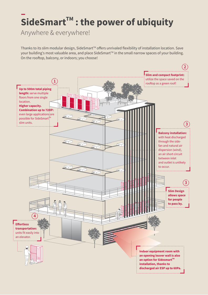
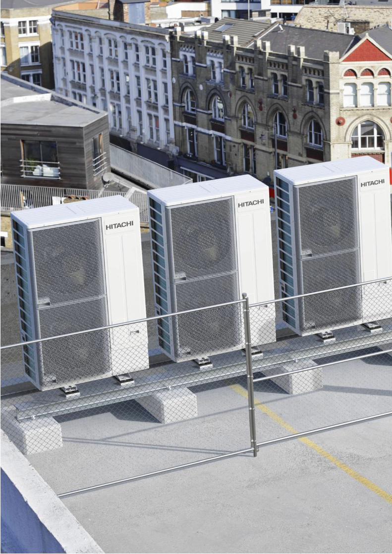
Thanks to its slim modular design, SideSmartTM offers unrivaled flexibility of installation location. Save your building's most valuable area, and place SideSmartTM in the small narrow spaces of your building. On the rooftop, balcony, or indoors; you choose!
–SideSmartTM : the power of ubiquityAnywhere & everywhere!
Up to 500m total pipinglength: serve multiplefloors from one singlelocation.Higher capacity. Combination up to 72HP: even large applications are possible for SideSmartTM slim units.
Slim and compact footprint: utilize the space saved on the rooftop as a green roof!
Balcony installation: with heat discharged through the side-fan and natural air dispersion (wind), an air short circuit between inlet and outlet is unlikely to occur.
Effortless transportation: units fit easily into an elevator.
Indoor equipment room with an opening louver wall is also an option for SidesmartTM installation, thanks to discharged air ESP up to 60Pa.
Slim Design allows space for people to pass by.
1
2
3
3
4

Too much service space required!!
No space!
Ideal for extensions: complement your existing VRF system with SideSmartTM.If only narrow space remains to extend to an existing top-flow system, SideSmartTM is the ideal solution.
Adding top-flow units requires more service space than available. The extension is not possible.
Existing top-flow VRF.New extension with SideSmartTM!
DISCOVER THE SIDESMARTTM ADVANTAGES!
..................................................................................................................................................................................................................................................................................................................................................
SideSmartTM requires fewer pipes.
One outdoor unit covers one floor, so more piping is needed. Maximum piping length is not sufficient to reach the 1st floor.
Compared with: conventional side-flow VRF.
1 SideSmartTM saves space!
Each outdoor unit has a larger footprint and takes up significant space. Contrary to the slim SideSmartTM, 8 units cannot fit in the roof.
Compared with: conventional top-flow VRF.
2
The cabinet is too voluminous. People cannot walk around them on a balcony. Air short circuits are likely to occur, because the air discharge is too close to the ceiling.
Compared with: conventional top-flow VRF.
When installed on the balcony, since the air comes out to the front of SideSmartTM, air short circuits are not likely to occur.
3
Units cannot be lifted by humans. A crane is necessary.Compared with: conventional top-flow VRF.
SideSmartTM is a size that can be carried by an elevator.4
Takes up space
Close to the ceiling
Difficult to pass
11
Side
Smar
tTMVA
RIAB
LE R
EFRI
GERA
NT
FLO
W S
YSTE
M
11
Side
Smar
tTMVA
RIAB
LE R
EFRI
GERA
NT
FLO
W S
YSTE
M
01. OUTDOOR UNITS | SIDESMARTTM : THE POWER OF UBIQUITY

Lc LdLb
L3
L3
H2
H1
H5
L1L2
L3L3
Piping Connection Kit 1
Piping Connection Kit 1
FirstBranch
La
For single unit, and 2 and 3 unit combinations
For 4 unit combination
Lb LcLa
Multi-Kit (Header Branch)
IDU IDU IDU
Multi-Kit
IDU IDU IDU
–Features & benefitsFlexibility: meet your project requirements.
MARK
Maximum Piping Length
Total m 500 -
From (Piping Connection Kit 1) to the furthest IDU
m 120 (Actual) L1
m 150 (Equivalent)
Between (Piping Connection Kit 1) and each ODU m 10 La, b, c, d
Between (First Branch) and the furthest IDU m 90 L2
Between each (Multi-Kit) and each IDU m 40 L3
Maximum Height Difference
Between ODUs m 0.1 H5
Between ODU and IDU (ODU above IDU) m 50 H1
Between ODU and IDU (IDU above ODU) m 40
Between IDUs m 30 H2
∙ Suitable for a medium-size buildings or complex facilities.∙ Leads to cost & time saving for designers, with improved
system design efficiency.
GREAT PIPING FLEXIBILITY..................................................................................................................................................................................................................................................................................................................................................
Equipment balcony. Installation room.
SideSmartTM can also be accommodated indoors, thanks to its external static pressure options up to 60Pa. ∙ Effective heat discharge to the outside is ensured.
∙ SideSmartTM units are completely invisible from the building facade.
ESP:30Pa
ESP:60Pa
ESP: FLEXIBLE INDOOR INSTALLATION..................................................................................................................................................................................................................................................................................................................................................
Note: factory default is 0Pa, 2-step additional static pressure can be selected (30Pa or 60Pa) by the dip switch setting!
Indoor air inlet temperature (°C DB)
Interval operation
Out
door
air
inle
t tem
pera
ture
(°C
WB)
16.0
-20.0
-15.0
15.010.0 27.0
Continuous Heating
Indoor air inlet temperature (°C WB)
Out
door
air
tem
pera
ture
(°C
DB)
52.0
48.0
-5.0
15.0 23.0 25.0
Continuous Cooling
Interval operation
1,050mm950mm
765m
m
420m
m
Top flow ODU(RAS-FSNS)
SideSmartTM
Android IOS
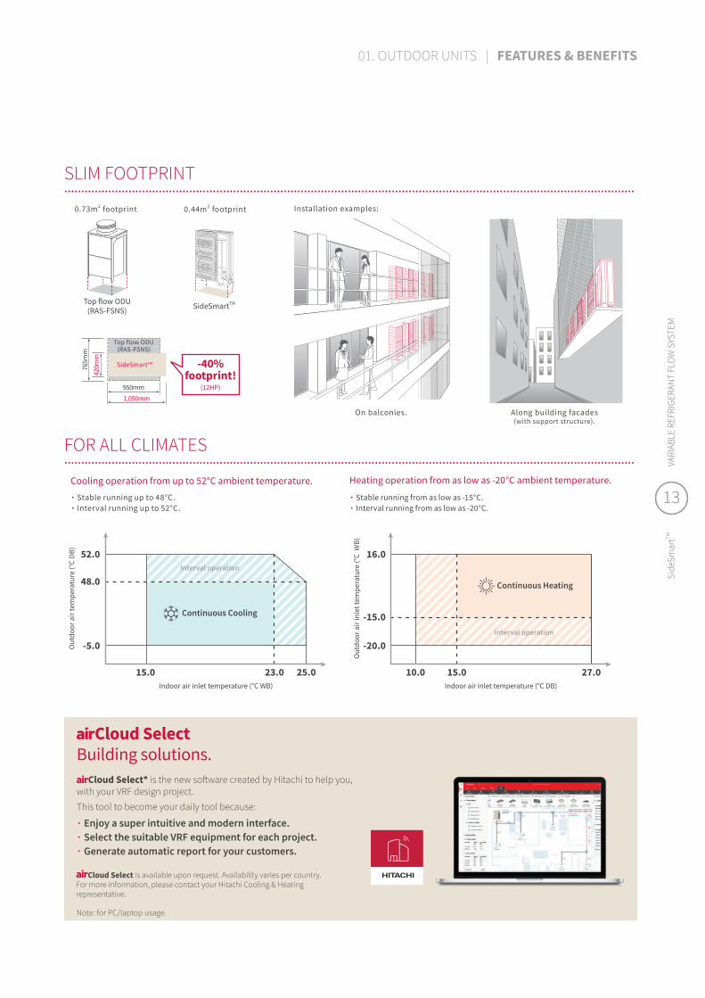
Installation examples:
Along building facades (with support structure).
On balconies.
0.73m2 footprint
Top flow ODU (RAS-FSNS) SideSmartTM
0.44m2 footprint
-40% footprint!
(12HP)
SLIM FOOTPRINT..................................................................................................................................................................................................................................................................................................................................................
Cooling operation from up to 52°C ambient temperature. Heating operation from as low as -20°C ambient temperature.
∙ Stable running up to 48°C.∙ Interval running up to 52°C.
∙ Stable running from as low as -15°C.∙ Interval running from as low as -20°C.
FOR ALL CLIMATES..................................................................................................................................................................................................................................................................................................................................................
∙ Enjoy a super intuitive and modern interface.∙ Select the suitable VRF equipment for each project.∙ Generate automatic report for your customers.
Cloud Select is available upon request. Availability varies per country. For more information, please contact your Hitachi Cooling & Heating representative.
Cloud SelectBuilding solutions.
Note: for PC/laptop usage.
Cloud Select* is the new software created by Hitachi to help you, with your VRF design project.This tool to become your daily tool because:
13
Side
Smar
tTMVA
RIAB
LE R
EFRI
GERA
NT
FLO
W S
YSTE
M
13
Side
Smar
tTMVA
RIAB
LE R
EFRI
GERA
NT
FLO
W S
YSTE
M
01. OUTDOOR UNITS | FEATURES & BENEFITS

5.0
4.0
3.0
2.0
1.0
0.010HP 28.0
12HP 33.5
14HP 40.0
16HP 45.0
18HP 50.0
8HP 22.4
4.51 4.26 4.273.85 3.79 3.54
Capacity[kW]
EER[
- ]
5.0
4.0
3.0
2.0
1.0
0.010HP 31.5
12HP 37.5
14HP 45.0
16HP 50.0
18HP 54.0Capacity[kW]
COP[
- ]
8HP 25.0
4.92 4.44 4.68 4.40 4.413.90
Notes:1. EER and COP does not include Indoor unit power consumption.2. This performance is achieved by 4 way cassette combination. For more details about IDU specifications, please refer to the Technical Catalog.3. Above ratio is on single cabinet (standard combination & economy combination).
SIDESMARTTM OFFERS SUPERIOR EFFICIENCY..................................................................................................................................................................................................................................................................................................................................................
Heating COP up to 4.92Cooling EER up to 4.51
–Features & benefitsSmall size, yet maximal efficiency.
For more information and specifications, please go to page xx. Please refer to the Technical Catalog for more details.*1 EER/COP: average ratio
Modular combination & superior efficiency.............................................................................................................................................................................................................................................................................................................................................
Energy efficiency*1
Footprint
Initial cost
Economy combination (Base single cabinet: 8-18HP)
(Modular combinations: 20-72HP)
EER 3.79 / COP 4.19
Standard combination (Base single cabinet: 8-18HP)
(Modular combinations: 20-72HP)
EER 3.93 / COP 4.42
Premium combination (Base single cabinet: 8-14HP)
(Modular combinations: 16-48HP)
EER 4.32 / COP 4.70
1 2 3
060 120 180
Time(min)
Room temperature (°C)Power (kW)
Constant room temperature
Smoother operationPower
(kW)
RoomTemp
(°C)
5.0
10.0
15.0
20.0
25.0
30.0
060 120 180
Time(min)
Power(kW)
RoomTemp
(°C)
5.0
10.0
15.0
20.0
25.0
30.0
Room temperature (°C)Power (kW)
Unstable temperature
Energy consumption loss
-39% energy consumption!
0 10 20 30 40 50 6080
240
260
200
220
160
180
100
120
140
Load factor (%)
EER
ratio
aga
inst
bef
ore
Smoo
thDr
iveTM
(%)
0 20 40 60 80 100 1200.0
2.0
4.0
6.0
8.0
10.0
12.0
Pow
er c
onsu
mpt
ion(
kW)
Load factor (%)
Before SmoothDriveTM
SmoothDriveTM
SmoothDriveTM 2.0
Piping
Indoor unit
Outdoor unitTransmission line
Allows proper amount of refrigerant to flow to IDU at each loading condition.
Indoor unit
Refrigerant flow
Calculates the correct refrigerant mass-flow according to load information.
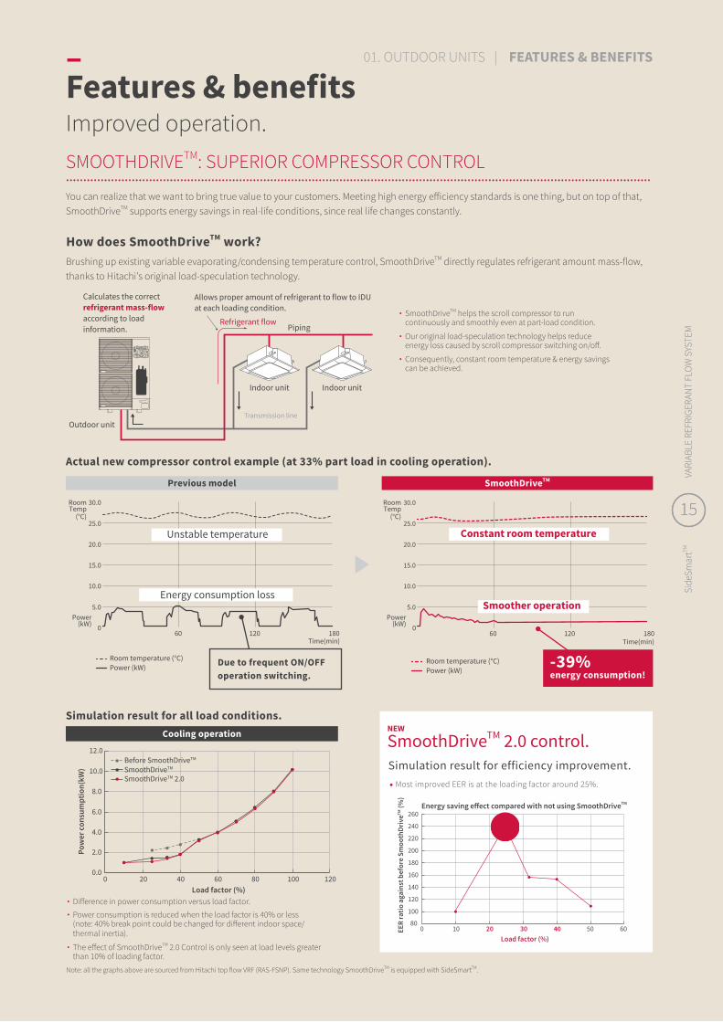
SMOOTHDRIVETM: SUPERIOR COMPRESSOR CONTROL..................................................................................................................................................................................................................................................................................................................................................You can realize that we want to bring true value to your customers. Meeting high energy efficiency standards is one thing, but on top of that, SmoothDriveTM supports energy savings in real-life conditions, since real life changes constantly.
∙ SmoothDriveTM helps the scroll compressor to run continuously and smoothly even at part-load condition.
∙ Our original load-speculation technology helps reduce energy loss caused by scroll compressor switching on/off.
∙ Consequently, constant room temperature & energy savings can be achieved.
How does SmoothDriveTM work?Brushing up existing variable evaporating/condensing temperature control, SmoothDriveTM directly regulates refrigerant amount mass-flow, thanks to Hitachi's original load-speculation technology.
Energy saving effect compared with not using SmoothDriveTM
Simulation result for all load conditions.
∙ Difference in power consumption versus load factor.
∙ Power consumption is reduced when the load factor is 40% or less (note: 40% break point could be changed for different indoor space/ thermal inertia).
∙ The effect of SmoothDriveTM 2.0 Control is only seen at load levels greater than 10% of loading factor.
Actual new compressor control example (at 33% part load in cooling operation).
Previous model SmoothDriveTM
Due to frequent ON/OFF operation switching.
Simulation result for efficiency improvement.• Most improved EER is at the loading factor around 25%.
NEW
SmoothDriveTM 2.0 control.Cooling operation
Note: all the graphs above are sourced from Hitachi top flow VRF (RAS-FSNP). Same technology SmoothDriveTM is equipped with SideSmartTM.
–Features & benefitsImproved operation.
15
Side
Smar
tTMVA
RIAB
LE R
EFRI
GERA
NT
FLO
W S
YSTE
M
15
Side
Smar
tTMVA
RIAB
LE R
EFRI
GERA
NT
FLO
W S
YSTE
M
01. OUTDOOR UNITS | FEATURES & BENEFITS

HighLow
One-unitoperation
Two-unitoperation
Three-unitoperation
Revolution of
Revolution of
Activation order Activation order
Activation order
Operating load
Revo
lutio
n of
inve
rter
com
pres
sor
1
1 1
2
2 233
33
1 1 1
2 2
123
33
1 2
Operation is controlled sothat the rotational speedsof compressors and become the same.
At the time of compressorstart-up, or when 2 hours have elapsed from start of operation.
ROTATIONAL OPERATION TO DISTRIBUTE OUTDOOR UNITS LOAD..................................................................................................................................................................................................................................................................................................................................................
Compressor rotation frequency control (example).
Regulating the operation time of each outdoor unit*1 leads to load reduction on compressors.*2
During multiple unit operation, maintaining the same rotation frequency of the compressors results in an equivalent load on each compressor, thereby helping enhance outdoor unit durability.
*1 At least 2 outdoor units are required for this function.*2 Comparison between the rotation operation function and non-rotation operation function based on the same system.
BACKUP OPERATION FEATURE FOR EMERGENCIES..................................................................................................................................................................................................................................................................................................................................................When 2 or more modules are combined: ∙ The backup operation function prevents
the system from coming to a complete stop if outdoor unit failure occurs.
∙ If one module unit should fail, the system can continue to operate using the remaining modules.
∙ An alarm is triggered and emergency operation can be activated via an individual remote control.
∙ At least 2 module units (as a combined unit) are required for this feature.
∙ Emergency operation can be performed within 8 hours following unit stoppage.
PC-ARF1PC-ARFG
Notes:Emergency operation can be performed within 8 hours after unit stoppage. Emergency operation cannot be performed once 8 hours have elapsed since unit stoppage.
Even if one unit fails, the others continue to operate continuously.*
Failed outdoor unit
[Front/Right/Bottom] [Rear]
RELY ON US AND ENJOY YOUR PEACE OF MIND..................................................................................................................................................................................................................................................................................................................................................Piping options in 4 directions. Easier removal of front service cover.Depending on the installation situation, installers can choose from 4 running pipe direction options.
The screws you need to open/close the front service cover are all on the front side.
Remove the 3 screws and the front panel will open.
Front panel screw
Front panel screw
For PC-ARFG, press "Back" key for 3 seconds.For PC-ARF1, press "Menu" key for 3 seconds.And the emergency operation starts.
Temporary is display on the screen.
–Features & benefitsReliability: enjoy peace of mind.

Android IOS
Connect SideSmartTM to Cloud Pro and monitor your system from anywhere.Please refer to p90-91
For stand-alone and multi-site applications.
Note: SideSmartTM monitoring with airCloud Pro available from May 2021.
17
Side
Smar
tTMVA
RIAB
LE R
EFRI
GERA
NT
FLO
W S
YSTE
M
17
Side
Smar
tTMVA
RIAB
LE R
EFRI
GERA
NT
FLO
W S
YSTE
M
01. OUTDOOR UNITS | FEATURES & BENEFITS
Top flow ODU
SideSmartTM
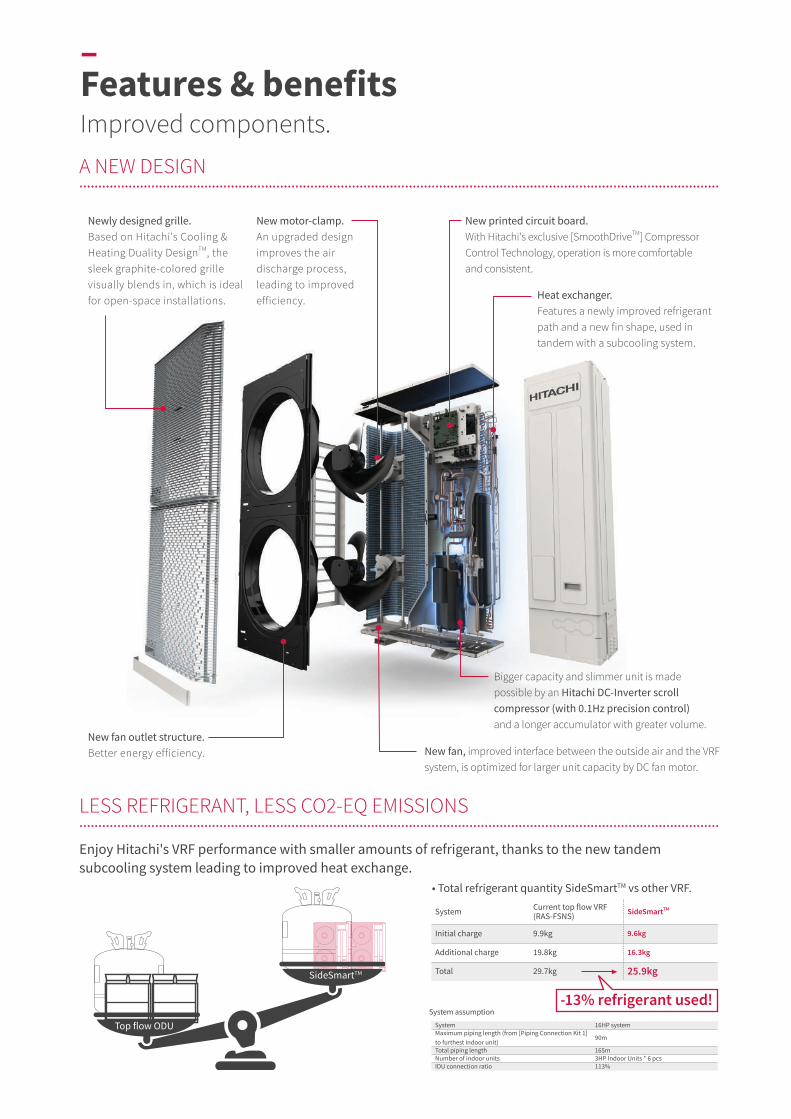
Enjoy Hitachi's VRF performance with smaller amounts of refrigerant, thanks to the new tandem subcooling system leading to improved heat exchange.
System assumption
System 16HP systemMaximum piping length (from [Piping Connection Kit 1] to furthest indoor unit)
90m
Total piping length 165mNumber of indoor units 3HP Indoor Units * 6 pcsIDU connection ratio 113%
Newly designed grille.Based on Hitachi's Cooling &Heating Duality DesignTM, the sleek graphite-colored grille visually blends in, which is ideal for open-space installations.
New fan outlet structure. Better energy efficiency. New fan, improved interface between the outside air and the VRF
system, is optimized for larger unit capacity by DC fan motor.
Bigger capacity and slimmer unit is madepossible by an Hitachi DC-Inverter scrollcompressor (with 0.1Hz precision control) and a longer accumulator with greater volume.
New motor-clamp.An upgraded designimproves the airdischarge process,leading to improvedefficiency.
New printed circuit board.With Hitachi's exclusive [SmoothDriveTM] Compressor Control Technology, operation is more comfortable and consistent.
Heat exchanger. Features a newly improved refrigerant path and a new fin shape, used in tandem with a subcooling system.
• Total refrigerant quantity SideSmartTM vs other VRF.
System Current top flow VRF(RAS-FSNS) SideSmartTM
Initial charge 9.9kg 9.6kg
Additional charge 19.8kg 16.3kg
Total 29.7kg 25.9kg
-13% refrigerant used!
LESS REFRIGERANT, LESS CO2-EQ EMISSIONS..................................................................................................................................................................................................................................................................................................................................................
A NEW DESIGN..................................................................................................................................................................................................................................................................................................................................................
–Features & benefitsImproved components.

• Total refrigerant quantity SideSmartTM vs other VRF.
19
Side
Smar
tTMVA
RIAB
LE R
EFRI
GERA
NT
FLO
W S
YSTE
M

HP 8HP 10HP 12HP 14HP 16HP 18HPModel Name RAS-080HNCEL(/R)W RAS-100HNCEL(/R)W RAS-120HNCEL(/R)W RAS-140HNCEL(/R)W RAS-160HNCEL(/R)W RAS-180HNCEL(/R)W
Modules for Series
Unit-1 - - - - - -Unit-2 - - - - - -Unit-3 - - - - - -Unit-4 - - - - - -
Power Supply V/Ph/Hz 380-415V/3Ph/50Hz, 380V/3Ph/60Hz (R: 220V/3Ph/60Hz)
CapacityCooling kW 22.4 28.0 33.5 40.0 45.0 50.0 Heating kW 25.0 31.5 37.5 45.0 50.0 54.0
Power InputCooling kW 4.97 6.58 7.84 10.40 11.88 14.14 Heating kW 5.08 7.10 8.02 10.23 11.35 13.86
EfficiencyEER kW/kW 4.51 4.26 4.27 3.85 3.79 3.54 COP kW/kW 4.92 4.44 4.68 4.40 4.41 3.90
Air Flow Rate Standard m3/min 160 185 200 250 258 258
Max. Current380-415V/3Ph/50, 60Hz A 18 21 27 32 36 40220V/3Ph/60Hz A 31 39 49 53 60 66
Dimensions H×W×D mm 1650×1050×420 1650×1050×420 1650×1050×420 1650×1190×420 1650×1190×420 1650×1190×420
Net Weight380-415V/3Ph/50, 60Hz kg 185 197 203 219 225 225220V/3Ph/60Hz kg 188 200 205 223 231 231
Outdoor Unit Color — Natural Gray (1.0Y 85/0.5)
Natural Gray (1.0Y 85/0.5)
Natural Gray (1.0Y 85/0.5)
Natural Gray (1.0Y 85/0.5)
Natural Gray (1.0Y 85/0.5)
Natural Gray (1.0Y 85/0.5)
Footprint Area m2 0.44 0.44 0.44 0.50 0.50 0.50Compressor type — Scroll Scroll Scroll Scroll Scroll Scroll
RefrigerantType — R410A R410A R410A R410A R410A R410AInitial Charge Amount kg 6.0 7.7 7.7 8.3 9.6 9.6
Number of Fan Motors — 2 2 2 2 2 2External Static Pressure of Fan Pa 0/30/60 0/30/60 0/30/60 0/30/60 0/30/60 0/30/60Capacity Ratio of IDU/ODU — 50% - 130% 50% - 130% 50% - 130% 50% - 130% 50% - 130% 50% - 130%
Noise Level
SPL, GB, Anechoic, Cooling dB(A) 55 59 60 60 62 62
SPL, GB, Anechoic, Heating dB(A) 56 60 62 61 64 64
Main Piping Size
Liquid (φ)mm 9.52 9.52 12.70 12.70 12.70 12.70Gas (φ)mm 19.05 22.20 25.40 25.40 28.58 28.58
Connectable IDU Number
Recommended - 8 10 10 16 16 16Maximum - 13 16 19 23 26 26
Working Temp. Range (*7)
Cooling °C DB -5 ~ 48 (/52) -5 ~ 48 (/52) -5 ~ 48 (/52) -5 ~ 48 (/52) -5 ~ 48 (/52) -5 ~ 48 (/52)Heating °C WB (-20/) -15 ~ 16 (-20/) -15 ~ 16 (-20/) -15 ~ 16 (-20/) -15 ~ 16 (-20/) -15 ~ 16 (-20/) -15 ~ 16
MaximumPiping Length (*8)
Total m 500 (300) 500 (300) 500 (300) 500 (300) 500 (300) 500 (300)From Piping connection kit 1 to Furthest IDU m 120/150
(Actual/Equivalent)120/150
(Actual/Equivalent)120/150
(Actual/Equivalent)120/150
(Actual/Equivalent)120/150
(Actual/Equivalent)120/150
(Actual/Equivalent)Between Piping Connection Kit and Each ODU
m 10 10 10 10 10 10
Between 1st branch and the furthest IDU m 90 (40) 90 (40) 90 (40) 90 (40) 90 (40) 90 (40)
Between each branch and each IDU m 40 (30) 40 (30) 40 (30) 40 (30) 40 (30) 40 (30)
MaximumHeight Difference (*9)
Between ODUs m 0.1 0.1 0.1 0.1 0.1 0.1Between ODU and IDU (ODU above IDU) m 50 50 50 50 50 50
Between ODU and IDU (IDU above ODU) m 40 40 40 40 40 40
Between IDUs m 30 30 30 30 30 30
Notes:1. The cooling and heating performance are the values when combined with our specificities indoor units.
1-1. Cooling operation conditions:
Indoor air inlet temperature: 27.0ᵒC DB (80ᵒF DB) / 19.0ᵒC WB (66ᵒF WB).
Outdoor air inlet temperature: 35.0ᵒC DB (95ᵒF DB).
1-2. Heating operation conditions:
Indoor air inlet temperature: 20.0ᵒC DB (68ᵒF DB).
Outdoor air inlet temperature: 7.0ᵒC DB (45ᵒF DB) / 6.0ᵒC WB (43ᵒF WB).
1-3. Piping length: 8-18HP is 7.5 meter / Piping lift: 0 meter.
2. The sound pressure is based on the following conditions.
The above data was measured in an anechoic chamber so that reflected sound should be taken into consideration in the field.
3. Sound pressure level data was measured at rated cooling and heating condition which same as performance measurement condition. If working condition is different against rated condition, sound may increase.
4. If set to the high static mode, since the fan rotation speed will be increased, sound may increase 5 to 7 dBA.
5. Regarding performance values, EER and COP is not including Indoor unit power consumption.
6. For width of outer dimension, it shows 'module+module' unit dimension only, but actually the distance between each modules should be at least 100mm for installation, please check Technical Manual for details.
(*7) The (XX˚) limit temperature applies to interval air conditioning operation.
(*8) In case of connecting number of indoor unit is less than recommended connectable IDU & (when connecting more than recommended number of indoor units).
(*9) In case of connecting number of indoor unit is less than recommended connectable IDU.
L: AC3Φ/380V-415V/50Hz/4 wire AC3Φ/380V/60Hz/4 wire R: AC3Φ/220V/60Hz/3 wire
SINGLE CABINET....................................................................................................................................................................................................................................................................................................................................................
–Specifications
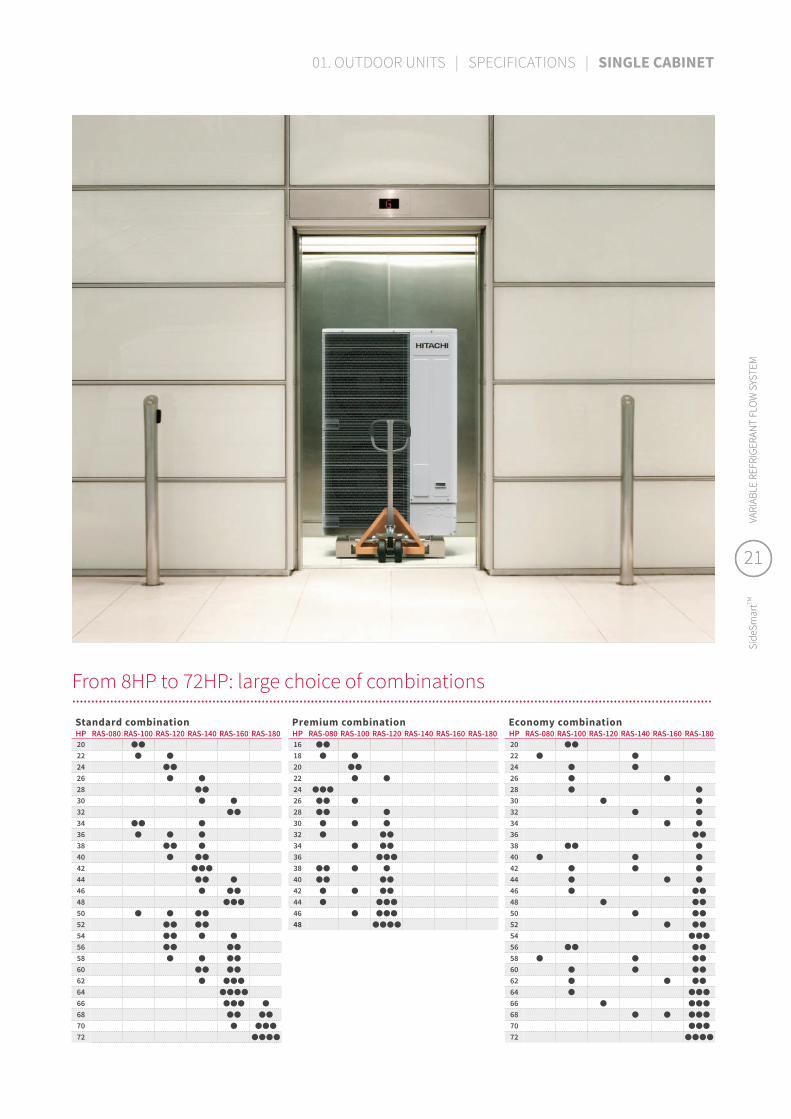
From 8HP to 72HP: large choice of combinations..................................................................................................................................................................................................................................................................................................................................................Standard combinationHP RAS-080 RAS-100 RAS-120 RAS-140 RAS-160 RAS-1802022242628303234 36384042444648505254565860626466687072
Premium combinationHP RAS-080 RAS-100 RAS-120 RAS-140 RAS-160 RAS-1801618202224262830323436384042444648
Economy combinationHP RAS-080 RAS-100 RAS-120 RAS-140 RAS-160 RAS-180202224262830323436384042444648505254565860626466687072
21
Side
Smar
tTMVA
RIAB
LE R
EFRI
GERA
NT
FLO
W S
YSTE
M
21
Side
Smar
tTMVA
RIAB
LE R
EFRI
GERA
NT
FLO
W S
YSTE
M
01. OUTDOOR UNITS | SPECIFICATIONS | SINGLE CABINET

HP 20HP 22HP 24HP 26HP 28HP 30HP
Model Name RAS-200HNCEL(R)WS RAS-220HNCEL(R)WS RAS-240HNCEL(R)WS RAS-260HNCEL(R)WS RAS-280HNCEL(R)WS RAS-300HNCEL(R)WS
Modules for Series
Unit-1 RAS-100HNCEL(R)W RAS-100HNCEL(R)W RAS-120HNCEL(R)W RAS-140HNCEL(R)W RAS-140HNCEL(R)W RAS-160HNCEL(R)WUnit-2 RAS-100HNCEL(R)W RAS-120HNCEL(R)W RAS-120HNCEL(R)W RAS-120HNCEL(R)W RAS-140HNCEL(R)W RAS-140HNCEL(R)WUnit-3 - - - - - -Unit-4 - - - - - -
Power Supply V/Ph/Hz 380-415V/3Ph/50Hz, 380V/3Ph/60Hz (R: 220V/3Ph/60Hz)
DimensionsHeight mm 1,650 1,650 1,650 1,650 1,650 1,650Depth mm 2,200 2,200 2,200 2,340 2,480 2,480Width mm 420 420 420 420 420 420
CapacityCooling kW 56.0 61.5 67.0 73.5 80.0 85.0 Heating kW 63.0 69.0 75.0 82.5 90.0 95.0
PerformanceEER - 4.26 4.26 4.27 4.03 3.85 3.82 COP - 4.44 4.56 4.68 4.52 4.40 4.40
Main Pipe Size
Gas mm 28.58 28.58 28.58 31.75 31.75 31.75 Liquid mm 15.88 15.88 15.88 19.05 19.05 19.05
Connectable IDU
Recommended Qty 18 20 26 26 32 32Maximum Qty 33 36 40 43 47 50
Connectable IDU Ratio % 50 - 130 50 - 130 50 - 130 50 - 130 50 - 130 50 - 130
HP 32HP 34HP 36HP 38HP 40HP 42HP
Model Name RAS-320HNCEL(R)WS RAS-340HNCEL(R)WS RAS-360HNCEL(R)WS RAS-380HNCEL(R)WS RAS-400HNCEL(R)WS RAS-420HNCEL(R)WS
Modules for Series
Unit-1 RAS-160HNCEL(R)W RAS-140HNCEL(R)W RAS-140HNCEL(R)W RAS-140HNCEL(R)W RAS-140HNCEL(R)W RAS-140HNCEL(R)WUnit-2 RAS-160HNCEL(R)W RAS-100HNCEL(R)W RAS-120HNCEL(R)W RAS-120HNCEL(R)W RAS-140HNCEL(R)W RAS-140HNCEL(R)WUnit-3 - RAS-100HNCEL(R)W RAS-100HNCEL(R)W RAS-120HNCEL(R)W RAS-120HNCEL(R)W RAS-140HNCEL(R)WUnit-4 - - - - - -
Power Supply V/Ph/Hz 380-415V/3Ph/50Hz, 380V/3Ph/60Hz (R: 220V/3Ph/60Hz)
DimensionsHeight mm 1,650 1,650 1,650 1,650 1,650 1,650Depth mm 2,480 3,490 3,490 3,490 3,630 3,770Width mm 420 420 420 420 420 420
CapacityCooling kW 90.0 96.0 101.5 107.0 113.5 120.0 Heating kW 100.0 108.0 114.0 120.0 127.5 135.0
PerformanceEER - 3.79 4.07 4.09 4.10 3.96 3.85 COP - 4.41 4.42 4.50 4.57 4.48 4.40
Main Pipe Size
Gas mm 31.75 31.75 38.10 38.10 38.10 38.10 Liquid mm 19.05 19.05 19.05 19.05 19.05 19.05
Connectable IDU
Recommended Qty 32 32 32 38 38 38Maximum Qty 53 56 59 64 64 64
Connectable IDU Ratio % 50 - 130 50 - 130 50 - 130 50 - 130 50 - 130 50 - 130
HP 44HP 46HP 48HP 50HP 52HP 54HP
Model Name - RAS-440HNCEL(R)WS RAS-460HNCEL(R)WS RAS-480HNCEL(R)WS RAS-500HNCEL(R)WS RAS-520HNCEL(R)WS RAS-540HNCEL(R)WS
Modules for Series
Unit-1 RAS-160HNCEL(R)W RAS-160HNCEL(R)W RAS-160HNCEL(R)W RAS-140HNCEL(R)W RAS-140HNCEL(R)W RAS-160HNCEL(R)W
Unit-2 RAS-140HNCEL(R)W RAS-160HNCEL(R)W RAS-160HNCEL(R)W RAS-140HNCEL(R)W RAS-140HNCEL(R)W RAS-140HNCEL(R)W
Unit-3 RAS-140HNCEL(R)W RAS-140HNCEL(R)W RAS-160HNCEL(R)W RAS-120HNCEL(R)W RAS-120HNCEL(R)W RAS-120HNCEL(R)W
Unit-4 - - - RAS-100HNCEL(R)W RAS-120HNCEL(R)W RAS-120HNCEL(R)W
Power Supply V/Ph/Hz 380-415V/3Ph/50Hz, 380V/3Ph/60Hz (R: 220V/3Ph/60Hz)
Dimensions
Height mm 1,650 1,650 1,650 1,650 1,650 1,650
Depth mm 3,770 3,770 3,770 4,780 4,780 4,780
Width mm 420 420 420 420 420 420
CapacityCooling kW 125.0 130.0 135.0 141.5 147.0 152.0
Heating kW 140.0 145.0 150.0 159.0 165.0 170.0
PerformanceEER - 3.82 3.81 3.79 4.02 4.03 4.00
COP - 4.40 4.40 4.41 4.47 4.52 4.52
Main Pipe SizeGas mm 38.10 38.10 38.10 38.10 38.10 38.10
Liquid mm 19.05 19.05 19.05 19.05 19.05 19.05
Connectable IDU
Recommended Qty 38 38 38 38 38 38
Maximum Qty 64 64 64 64 64 64
Connectable IDU Ratio % 50 - 130 50 - 130 50 - 130 50 - 130 50 - 130 50 - 130
STANDARD COMBINATION................................................................................................................................................................................................................................................................................................................................................
–Specifications
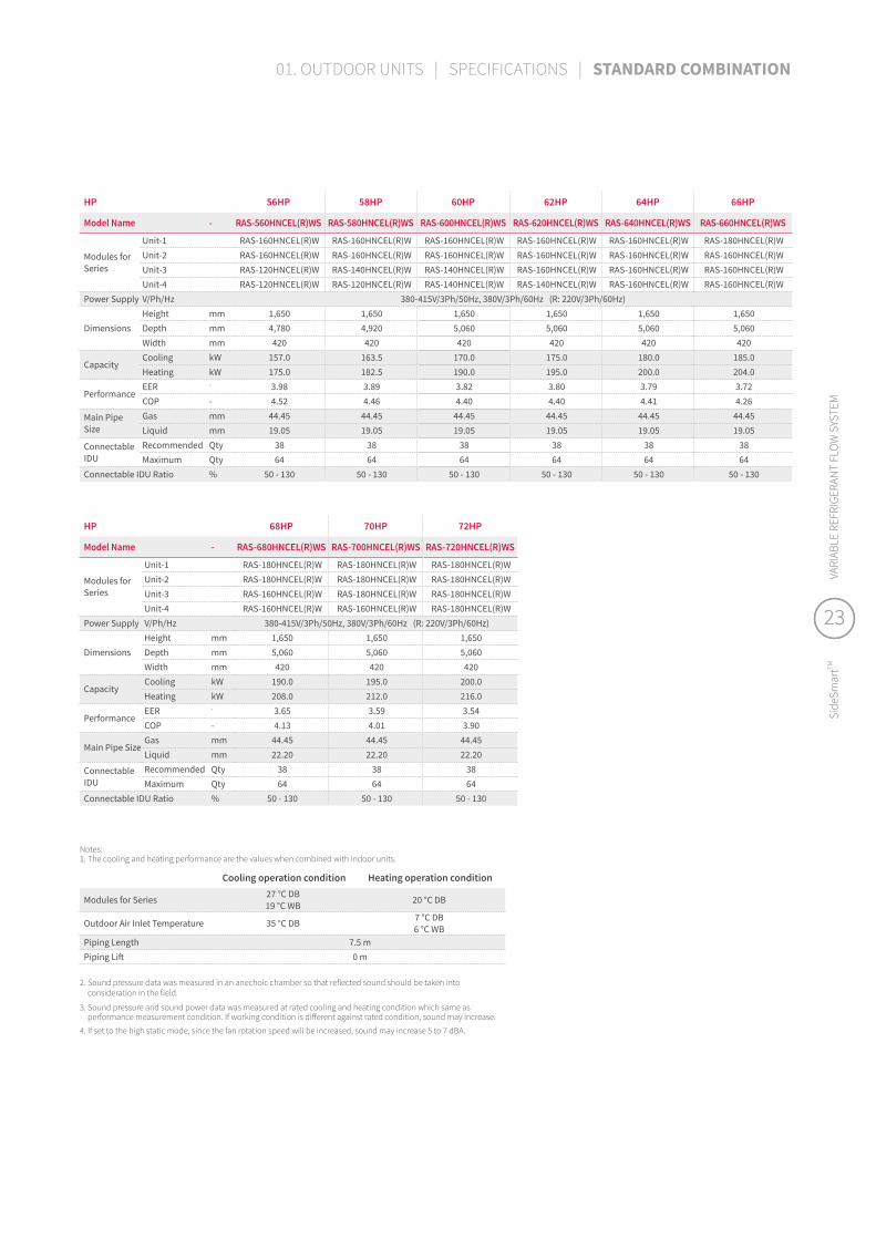
HP 56HP 58HP 60HP 62HP 64HP 66HP
Model Name - RAS-560HNCEL(R)WS RAS-580HNCEL(R)WS RAS-600HNCEL(R)WS RAS-620HNCEL(R)WS RAS-640HNCEL(R)WS RAS-660HNCEL(R)WS
Modules for Series
Unit-1 RAS-160HNCEL(R)W RAS-160HNCEL(R)W RAS-160HNCEL(R)W RAS-160HNCEL(R)W RAS-160HNCEL(R)W RAS-180HNCEL(R)WUnit-2 RAS-160HNCEL(R)W RAS-160HNCEL(R)W RAS-160HNCEL(R)W RAS-160HNCEL(R)W RAS-160HNCEL(R)W RAS-160HNCEL(R)WUnit-3 RAS-120HNCEL(R)W RAS-140HNCEL(R)W RAS-140HNCEL(R)W RAS-160HNCEL(R)W RAS-160HNCEL(R)W RAS-160HNCEL(R)WUnit-4 RAS-120HNCEL(R)W RAS-120HNCEL(R)W RAS-140HNCEL(R)W RAS-140HNCEL(R)W RAS-160HNCEL(R)W RAS-160HNCEL(R)W
Power Supply V/Ph/Hz 380-415V/3Ph/50Hz, 380V/3Ph/60Hz (R: 220V/3Ph/60Hz)
DimensionsHeight mm 1,650 1,650 1,650 1,650 1,650 1,650Depth mm 4,780 4,920 5,060 5,060 5,060 5,060Width mm 420 420 420 420 420 420
CapacityCooling kW 157.0 163.5 170.0 175.0 180.0 185.0 Heating kW 175.0 182.5 190.0 195.0 200.0 204.0
PerformanceEER - 3.98 3.89 3.82 3.80 3.79 3.72 COP - 4.52 4.46 4.40 4.40 4.41 4.26
Main Pipe Size
Gas mm 44.45 44.45 44.45 44.45 44.45 44.45 Liquid mm 19.05 19.05 19.05 19.05 19.05 19.05
Connectable IDU
Recommended Qty 38 38 38 38 38 38Maximum Qty 64 64 64 64 64 64
Connectable IDU Ratio % 50 - 130 50 - 130 50 - 130 50 - 130 50 - 130 50 - 130
HP 68HP 70HP 72HP
Model Name - RAS-680HNCEL(R)WS RAS-700HNCEL(R)WS RAS-720HNCEL(R)WS
Modules for Series
Unit-1 RAS-180HNCEL(R)W RAS-180HNCEL(R)W RAS-180HNCEL(R)WUnit-2 RAS-180HNCEL(R)W RAS-180HNCEL(R)W RAS-180HNCEL(R)WUnit-3 RAS-160HNCEL(R)W RAS-180HNCEL(R)W RAS-180HNCEL(R)WUnit-4 RAS-160HNCEL(R)W RAS-160HNCEL(R)W RAS-180HNCEL(R)W
Power Supply V/Ph/Hz 380-415V/3Ph/50Hz, 380V/3Ph/60Hz (R: 220V/3Ph/60Hz)
DimensionsHeight mm 1,650 1,650 1,650Depth mm 5,060 5,060 5,060Width mm 420 420 420
CapacityCooling kW 190.0 195.0 200.0 Heating kW 208.0 212.0 216.0
PerformanceEER - 3.65 3.59 3.54 COP - 4.13 4.01 3.90
Main Pipe SizeGas mm 44.45 44.45 44.45 Liquid mm 22.20 22.20 22.20
Connectable IDU
Recommended Qty 38 38 38Maximum Qty 64 64 64
Connectable IDU Ratio % 50 - 130 50 - 130 50 - 130
Notes:1. The cooling and heating performance are the values when combined with indoor units.
Cooling operation condition Heating operation condition
Modules for Series 27 °C DB19 °C WB 20 °C DB
Outdoor Air Inlet Temperature 35 °C DB 7 °C DB6 °C WB
Piping Length 7.5 mPiping Lift 0 m
2. Sound pressure data was measured in an anechoic chamber so that reflected sound should be taken into consideration in the field.
3. Sound pressure and sound power data was measured at rated cooling and heating condition which same as performance measurement condition. If working condition is different against rated condition, sound may increase.
4. If set to the high static mode, since the fan rotation speed will be increased, sound may increase 5 to 7 dBA.
23
Side
Smar
tTMVA
RIAB
LE R
EFRI
GERA
NT
FLO
W S
YSTE
M
23
Side
Smar
tTMVA
RIAB
LE R
EFRI
GERA
NT
FLO
W S
YSTE
M
01. OUTDOOR UNITS | SPECIFICATIONS | STANDARD COMBINATION

HP 16HP 18HP 20HP 22HP 24HP 26HP
Model Name RAS-160HNCEL(R)WP RAS-180HNCEL(R)WP RAS-180HNCEL(R)WP RAS-220HNCEL(R)WS RAS-240HNCEL(R)WP RAS-260HNCEL(R)WP
Modules for Series
Unit-1 RAS-080HNCEL(R)W RAS-100HNCEL(R)W RAS-120HNCEL(R)W RAS-120HNCEL(R)W RAS-080HNCEL(R)W RAS-100HNCEL(R)WUnit-2 RAS-080HNCEL(R)W RAS-080HNCEL(R)W RAS-080HNCEL(R)W RAS-100HNCEL(R)W RAS-080HNCEL(R)W RAS-080HNCEL(R)WUnit-3 - - - - RAS-080HNCEL(R)W RAS-080HNCEL(R)WUnit-4 - - - - - -
Power Supply V/Ph/Hz 380-415V/3Ph/50Hz, 380V/3Ph/60Hz (R: 220V/3Ph/60Hz)
DimensionsHeight mm 1,650 1,650 1,650 1,650 1,650 1,650Depth mm 2,200 2,200 2,200 2,200 3,350 3,350Width mm 420 420 420 420 420 420
CapacityCooling kW 44.8 50.4 55.9 61.5 67.2 72.8 Heating kW 50.0 56.5 62.5 69.0 75.0 81.5
PerformanceEER - 4.51 4.36 4.36 4.26 4.51 4.41 COP - 4.92 4.64 4.77 4.56 4.92 4.72
Main Pipe Size
Gas mm 28.58 28.58 28.58 28.58 28.58 31.75 Liquid mm 12.70 12.70 15.88 15.88 15.88 19.05
Connectable IDU
Recommended Qty 16.0 16.0 18.0 20.0 26.0 26.0 Maximum Qty 26.0 26.0 33.0 36.0 40.0 43.0
Connectable IDU Ratio % 50 - 130 50 - 130 50 - 130 50 - 130 50 - 130 50 - 130
HP 28HP 30HP 32HP 34HP 36HP 38HP
Model Name RAS-280HNCEL(R)WP RAS-300HNCEL(R)WP RAS-320HNCEL(R)WP RAS-340HNCEL(R)WP RAS-360HNCEL(R)WP RAS-380HNCEL(R)WP
Modules for Series
Unit-1 RAS-120HNCEL(R)W RAS-120HNCEL(R)W RAS-120HNCEL(R)W RAS-120HNCEL(R)W RAS-120HNCEL(R)W RAS-120HNCEL(R)WUnit-2 RAS-080HNCEL(R)W RAS-100HNCEL(R)W RAS-120HNCEL(R)W RAS-120HNCEL(R)W RAS-120HNCEL(R)W RAS-100HNCEL(R)WUnit-3 RAS-080HNCEL(R)W RAS-080HNCEL(R)W RAS-080HNCEL(R)W RAS-100HNCEL(R)W RAS-120HNCEL(R)W RAS-080HNCEL(R)WUnit-4 - - - - - RAS-080HNCEL(R)W
Power Supply V/Ph/Hz 380-415V/3Ph/50Hz, 380V/3Ph/60Hz (R: 220V/3Ph/60Hz)
DimensionsHeight mm 1,650 1,650 1,650 1,650 1,650 1,650Depth mm 3,350 3,350 3,350 3,350 3,350 4,500Width mm 420 420 420 420 420 420
CapacityCooling kW 78.3 83.9 89.4 95.0 100.5 106.3 Heating kW 87.5 94.0 100.0 106.5 112.5 119.0
PerformanceEER - 4.40 4.33 4.33 4.27 4.27 4.36 COP - 4.81 4.65 4.74 4.60 4.68 4.71
Main Pipe Size
Gas mm 31.75 31.75 31.75 31.75 31.75 38.10 Liquid mm 19.05 19.05 19.05 19.05 19.05 19.05
Connectable IDU
Recommended Qty 32.0 32.0 32.0 32 32 38Maximum Qty 47.0 50.0 53.0 56 59 64
Connectable IDU Ratio % 50 - 130 50 - 130 50 - 130 50 - 130 50 - 130 50 - 130
HP 40HP 42HP 44HP 46HP 48HP
Model Name - RAS-400HNCEL(R)WP RAS-420HNCEL(R)WP RAS-440HNCEL(R)WP RAS-460HNCEL(R)WP RAS-480HNCEL(R)WP
Modules for Series
Unit-1 RAS-120HNCEL(R)W RAS-120HNCEL(R)W RAS-120HNCEL(R)W RAS-120HNCEL(R)W RAS-120HNCEL(R)W
Unit-2 RAS-120HNCEL(R)W RAS-120HNCEL(R)W RAS-120HNCEL(R)W RAS-120HNCEL(R)W RAS-120HNCEL(R)W
Unit-3 RAS-080HNCEL(R)W RAS-100HNCEL(R)W RAS-120HNCEL(R)W RAS-120HNCEL(R)W RAS-120HNCEL(R)W
Unit-4 RAS-080HNCEL(R)W RAS-080HNCEL(R)W RAS-080HNCEL(R)W RAS-100HNCEL(R)W RAS-120HNCEL(R)WPower Supply V/Ph/Hz 380-415V/3Ph/50Hz, 380V/3Ph/60Hz (R: 220V/3Ph/60Hz)
Dimensions
Height mm 1,650 1,650 1,650 1,650 1,650
Depth mm 4,500 4,500 4,500 4,500 4,500
Width mm 420 420 420 420 420
CapacityCooling kW 111.8 117.4 122.9 128.5 134.0
Heating kW 125.0 131.5 137.5 144.0 150.0
PerformanceEER - 4.36 4.31 4.31 4.27 4.27
COP - 4.77 4.66 4.72 4.62 4.68
Main Pipe Size
Gas mm 38.10 38.10 38.10 38.10 38.10
Liquid mm 19.05 19.05 19.05 19.05 19.05
Connectable IDU
Recommended Qty 38 38 38 38 38
Maximum Qty 64 64 64 64 64
Connectable IDU Ratio % 50 - 130 50 - 130 50 - 130 50 - 130 50 - 130
PREMIUM COMBINATION..................................................................................................................................................................................................................................................................................................................................................
Note: please refer to the same notes in standard/economic combination
25
Side
Smar
tTMVA
RIAB
LE R
EFRI
GERA
NT
FLO
W S
YSTE
M
25
Side
Smar
tTMVA
RIAB
LE R
EFRI
GERA
NT
FLO
W S
YSTE
M
01. OUTDOOR UNITS | SPECIFICATIONS | PREMIUM COMBINATION

HP 20HP 22HP 24HP 26HP 28HP 30HP
Model Name RAS-200HNCEL(R)WS RAS-220HNCEL(R)WE RAS-240HNCEL(R)WE RAS-260HNCEL(R)WE RAS-280HNCEL(R)WE RAS-300HNCEL(R)WE
Modules for Series
Unit-1 RAS-100HNCEL(R)W RAS-140HNCEL(R)W RAS-140HNCEL(R)W RAS-160HNCEL(R)W RAS-180HNCEL(R)W RAS-180HNCEL(R)WUnit-2 RAS-100HNCEL(R)W RAS-080HNCEL(R)W RAS-100HNCEL(R)W RAS-100HNCEL(R)W RAS-100HNCEL(R)W RAS-120HNCEL(R)WUnit-3 - - - - - -Unit-4 - - - - - -
Power Supply V/Ph/Hz 380-415V/3Ph/50Hz, 380V/3Ph/60Hz (R: 220V/3Ph/60Hz)
DimensionsHeight mm 1,650 1,650 1,650 1,650 1,650 1,650 Depth mm 2,200 2,340 2,340 2,340 2,340 2,340 Width mm 420 420 420 420 420 420
CapacityCooling kW 56.0 62.4 68.0 73.0 78.0 83.5 Heating kW 63.0 70.0 76.5 81.5 85.5 91.5
PerformanceEER - 4.26 4.06 4.00 3.95 3.76 3.80 COP - 4.44 4.57 4.41 4.42 4.08 4.18
Main Pipe Size
Gas mm 28.58 28.58 28.58 31.75 31.75 31.75 Liquid mm 15.88 15.88 15.88 19.05 19.05 19.05
Connectable IDU
Recommended Qty 18 20 26 26 32 32 Maximum Qty 33 36 40 43 47 50
Connectable IDU Ratio % 50 - 130 50 - 130 50 - 130 50 - 130 50 - 130 50 - 130
HP 32HP 34HP 36HP 38HP 40HP 42HP
Model Name RAS-320HNCEL(R)WE RAS-340HNCEL(R)WE RAS-360HNCEL(R)WE RAS-380HNCEL(R)WE RAS-400HNCEL(R)WE RAS-420HNCEL(R)WE
Modules for Series
Unit-1 RAS-180HNCEL(R)W RAS-180HNCEL(R)W RAS-180HNCEL(R)W RAS-180HNCEL(R)W RAS-180HNCEL(R)W RAS-180HNCEL(R)WUnit-2 RAS-140HNCEL(R)W RAS-160HNCEL(R)W RAS-180HNCEL(R)W RAS-100HNCEL(R)W RAS-140HNCEL(R)W RAS-140HNCEL(R)WUnit-3 - - - RAS-100HNCEL(R)W RAS-080HNCEL(R)W RAS-100HNCEL(R)WUnit-4 - - - - - -
Power Supply V/Ph/Hz 380-415V/3Ph/50Hz, 380V/3Ph/60Hz (R: 220V/3Ph/60Hz)
DimensionsHeight mm 1,650 1,650 1,650 1,650 1,650 1,650 Depth mm 2,480 2,480 2,480 3,490 3,630 3,630 Width mm 420 420 420 420 420 420
CapacityCooling kW 90.0 95.0 100.0 106.0 112.4 118.0 Heating kW 99.0 104.0 108.0 117.0 124.0 130.5
PerformanceEER - 3.67 3.65 3.54 3.88 3.81 3.79 COP - 4.11 4.13 3.90 4.17 4.25 4.18
Main Pipe Size
Gas mm 31.75 31.75 38.10 38.1 38.10 38.10 Liquid mm 19.05 19.05 19.05 19.05 19.05 19.05
Connectable IDU
Recommended Qty 32 32 32 38 38 38 Maximum Qty 53 56 59 64 64 64
Connectable IDU Ratio % 50 - 130 50 - 130 50 - 130 50 - 130 50 - 130 50 - 130
HP 44HP 46HP 48HP 50HP 52HP 54HP
Model Name - RAS-440HNCEL(R)WE RAS-460HNCEL(R)WE RAS-480HNCEL(R)WE RAS-500HNCEL(R)WE RAS-520HNCEL(R)WE RAS-540HNCEL(R)WE
Modules for Series
Unit-1 RAS-180HNCEL(R)W RAS-180HNCEL(R)W RAS-180HNCEL(R)W RAS-180HNCEL(R)W RAS-180HNCEL(R)W RAS-180HNCEL(R)W
Unit-2 RAS-160HNCEL(R)W RAS-180HNCEL(R)W RAS-180HNCEL(R)W RAS-180HNCEL(R)W RAS-180HNCEL(R)W RAS-180HNCEL(R)W
Unit-3 RAS-100HNCEL(R)W RAS-100HNCEL(R)W RAS-120HNCEL(R)W RAS-140HNCEL(R)W RAS-160HNCEL(R)W RAS-180HNCEL(R)W
Unit-4 - - - - - -Power Supply V/Ph/Hz 380-415V/3Ph/50Hz, 380V/3Ph/60Hz (R: 220V/3Ph/60Hz)
Dimensions
Height mm 1,650 1,650 1,650 1,650 1,650 1,650
Depth mm 3,630 3,630 3,630 3,770 3,770 3,770
Width mm 420 420 420 420 420 420
CapacityCooling kW 123.0 128.0 133.5 140.0 145.0 150.0
Heating kW 135.5 139.5 145.5 153.0 158.0 162.0
PerformanceEER - 3.77 3.69 3.70 3.62 3.61 3.54
COP - 4.19 4.01 4.07 4.03 4.04 3.90
Main Pipe Size
Gas mm 38.10 38.10 38.10 38.10 38.10 38.10
Liquid mm 19.05 19.05 19.05 19.05 19.05 19.05
Connectable IDU
Recommended Qty 38 38 38 38 38 38
Maximum Qty 64 64 64 64 64 64
Connectable IDU Ratio % 50 - 130 50 - 130 50 - 130 50 - 130 50 - 130 50 - 130
ECONOMY COMBINATION....................................................................................................................................................................................................................................................................................................................................................
–Specifications

HP 56HP 58HP 60HP 62HP 64HP 66HP
Model Name RAS-560HNCEL(R)WE RAS-580HNCEL(R)WE RAS-600HNCEL(R)WE RAS-620HNCEL(R)WE RAS-640HNCEL(R)WE RAS-660HNCEL(R)WE
Modules for Series
Unit-1 RAS-180HNCEL(R)W RAS-180HNCEL(R)W RAS-180HNCEL(R)W RAS-180HNCEL(R)W RAS-180HNCEL(R)W RAS-180HNCEL(R)WUnit-2 RAS-180HNCEL(R)W RAS-180HNCEL(R)W RAS-180HNCEL(R)W RAS-180HNCEL(R)W RAS-180HNCEL(R)W RAS-180HNCEL(R)WUnit-3 RAS-100HNCEL(R)W RAS-140HNCEL(R)W RAS-140HNCEL(R)W RAS-160HNCEL(R)W RAS-180HNCEL(R)W RAS-180HNCEL(R)WUnit-4 RAS-100HNCEL(R)W RAS-080HNCEL(R)W RAS-100HNCEL(R)W RAS-100HNCEL(R)W RAS-100HNCEL(R)W RAS-120HNCEL(R)W
Power Supply V/Ph/Hz 380-415V/3Ph/50Hz, 380V/3Ph/60Hz (R: 220V/3Ph/60Hz)
DimensionsHeight mm 1,650 1,650 1,650 1,650 1,650 1,650Depth mm 4,780 4,920 4,920 4,920 4,920 4,920Width mm 420 420 420 420 420 420
CapacityCooling kW 156.0 162.4 168.0 173.0 178.0 183.5 Heating kW 171.0 178.0 184.5 189.5 193.5 199.5
PerformanceEER - 3.76 3.72 3.71 3.70 3.63 3.65 COP - 4.08 4.14 4.10 4.10 3.97 4.02
Main Pipe Size
Gas mm 44.45 44.45 44.45 44.45 44.45 44.45 Liquid mm 19.05 19.05 19.05 19.05 19.05 19.05
Connectable IDU
Recommended Qty 38 38 38 38 38 38Maximum Qty 64 64 64 64 64 64
Connectable IDU Ratio % 50 - 130 50 - 130 50 - 130 50 - 130 50 - 130 50 - 130
HP 68HP 70HP 72HP
Model Name RAS-680HNCEL(R)WE RAS-700HNCEL(R)WS RAS-720HNCEL(R)WS
Modules for Series
Unit-1 RAS-180HNCEL(R)W RAS-180HNCEL(R)W RAS-180HNCEL(R)WUnit-2 RAS-180HNCEL(R)W RAS-180HNCEL(R)W RAS-180HNCEL(R)WUnit-3 RAS-180HNCEL(R)W RAS-180HNCEL(R)W RAS-180HNCEL(R)WUnit-4 RAS-140HNCEL(R)W RAS-160HNCEL(R)W RAS-180HNCEL(R)W
Power Supply V/Ph/Hz 380-415V/3Ph/50Hz, 380V/3Ph/60Hz (R: 220V/3Ph/60Hz)
DimensionsHeight mm 1,650 1,650 1,650Depth mm 5,060 5,060 5,060Width mm 420 420 420
CapacityCooling kW 190.0 195.0 200.0 Heating kW 207.0 212.0 216.0
PerformanceEER - 3.60 3.59 3.54 COP - 4.00 4.01 3.90
Main Pipe Size
Gas mm 44.45 44.45 44.45 Liquid mm 22.20 22.20 22.20
Connectable IDU
Recommended Qty 38 38 38Maximum Qty 64 64 64
Connectable IDU Ratio % 50 - 130 50 - 130 50 - 130
Notes:1. The cooling and heating performance are the values when combined with indoor units.
Cooling operation condition Heating operation condition
Modules for Series 27 °C DB19 °C WB 20 °C DB
Outdoor Air Inlet Temperature 35 °C DB 7 °C DB6 °C WB
Piping Length 7.5 mPiping Lift 0 m
2. Sound pressure data was measured in an anechoic chamber so that reflected sound should be taken into consideration in the field.
3. Sound pressure and sound power data was measured at rated cooling and heating condition which same as performance measurement condition. If working condition is different against rated condition, sound may increase.
4. If set to the high static mode, since the fan rotation speed will be increased, sound may increase 5 to 7 dBA.
27
Side
Smar
tTMVA
RIAB
LE R
EFRI
GERA
NT
FLO
W S
YSTE
M
27
Side
Smar
tTMVA
RIAB
LE R
EFRI
GERA
NT
FLO
W S
YSTE
M
01. OUTDOOR UNITS | SPECIFICATIONS | ECONOMY COMBINATION

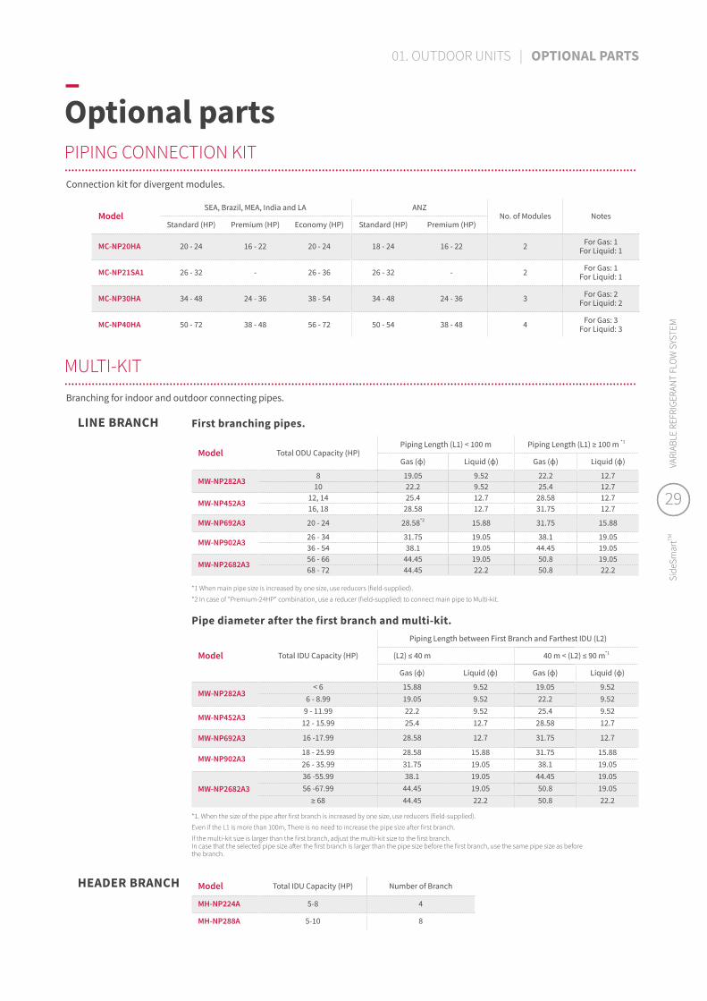
–Optional partsPIPING CONNECTION KIT..................................................................................................................................................................................................................................................................................................................................................
MULTI-KIT..................................................................................................................................................................................................................................................................................................................................................
ModelSEA, Brazil, MEA, India and LA ANZ
No. of Modules NotesStandard (HP) Premium (HP) Economy (HP) Standard (HP) Premium (HP)
MC-NP20HA 20 - 24 16 - 22 20 - 24 18 - 24 16 - 22 2 For Gas: 1 For Liquid: 1
MC-NP21SA1 26 - 32 - 26 - 36 26 - 32 - 2 For Gas: 1 For Liquid: 1
MC-NP30HA 34 - 48 24 - 36 38 - 54 34 - 48 24 - 36 3 For Gas: 2 For Liquid: 2
MC-NP40HA 50 - 72 38 - 48 56 - 72 50 - 54 38 - 48 4 For Gas: 3 For Liquid: 3
Connection kit for divergent modules.
HEADER BRANCH Model Total IDU Capacity (HP) Number of Branch
MH-NP224A 5-8 4
MH-NP288A 5-10 8
Branching for indoor and outdoor connecting pipes.
LINE BRANCH
*1 When main pipe size is increased by one size, use reducers (field-supplied).
*2 In case of "Premium-24HP" combination, use a reducer (field-supplied) to connect main pipe to Multi-kit.
Model Total ODU Capacity (HP)Piping Length (L1) < 100 m Piping Length (L1) ≥ 100 m *1
Gas (ɸ) Liquid (ɸ) Gas (ɸ) Liquid (ɸ)
MW-NP282A38 19.05 9.52 22.2 12.7
10 22.2 9.52 25.4 12.7
MW-NP452A312, 14 25.4 12.7 28.58 12.716, 18 28.58 12.7 31.75 12.7
MW-NP692A3 20 - 24 28.58*2 15.88 31.75 15.88
MW-NP902A326 - 34 31.75 19.05 38.1 19.0536 - 54 38.1 19.05 44.45 19.05
MW-NP2682A356 - 66 44.45 19.05 50.8 19.0568 - 72 44.45 22.2 50.8 22.2
First branching pipes.
*1. When the size of the pipe after first branch is increased by one size, use reducers (field-supplied).
Even if the L1 is more than 100m, There is no need to increase the pipe size after first branch.
If the multi-kit size is larger than the first branch, adjust the multi-kit size to the first branch. In case that the selected pipe size after the first branch is larger than the pipe size before the first branch, use the same pipe size as before the branch.
Model Total IDU Capacity (HP)
Piping Length between First Branch and Farthest IDU (L2)
(L2) ≤ 40 m 40 m < (L2) ≤ 90 m*1
Gas (ɸ) Liquid (ɸ) Gas (ɸ) Liquid (ɸ)
MW-NP282A3< 6 15.88 9.52 19.05 9.52
6 - 8.99 19.05 9.52 22.2 9.52
MW-NP452A39 - 11.99 22.2 9.52 25.4 9.52
12 - 15.99 25.4 12.7 28.58 12.7
MW-NP692A3 16 -17.99 28.58 12.7 31.75 12.7
MW-NP902A318 - 25.99 28.58 15.88 31.75 15.8826 - 35.99 31.75 19.05 38.1 19.05
MW-NP2682A336 -55.99 38.1 19.05 44.45 19.0556 -67.99 44.45 19.05 50.8 19.05
≥ 68 44.45 22.2 50.8 22.2
Pipe diameter after the first branch and multi-kit.
29
Side
Smar
tTMVA
RIAB
LE R
EFRI
GERA
NT
FLO
W S
YSTE
M
29
Side
Smar
tTMVA
RIAB
LE R
EFRI
GERA
NT
FLO
W S
YSTE
M
01. OUTDOOR UNITS | OPTIONAL PARTS

–AccessoriesAIR FLOW GUIDE..........................................................................................................
Model Name Necessary Quantity
ODU single base unit (HP)
AG-SP20A 28,10,12
FA-SP20A 1
AG-SP20B 214,16,18
FA-SP20A 1
Model Name Necessary Quantity
ODU single base unit (HP)
PSN-SP20A 1 8,10,12
PSN-SP20B 1 14,16,18
Model Name Necessary Quantity
ODU single base unit (HP)
WSP-SP20A 28,10,12
FA-SP20A 1
WSP-SP20B 214,16,18
FA-SP20A 1
Model Name Necessary Quantity
ODU single base unit (HP)
PN-SP20A 18,10,12
FA-SP20A 1
PN-SP20B 114,16,18
FA-SP20A 1
Model Name Necessary Quantity
ODU single base unit (HP)
PN-SP20A 1 8,10,12,14,16,18
AIR INLET GRILLE..........................................................................................................
WIND GUARD..................................................................................................................
PROTECTION NET..................................................................................................................
BackFront
WIND PROTECTION TOOL..................................................................................................................
DRAIN ADAPTER..........................................................................................................
Straight type L-shaped type
Model Name
Necessary Quantity
ODU single base unit (HP) Note
DBS-26 2 8,10,12,14,16,18 Straight type
DBS-26L 2 8,10,12,14,16,18 L-Shaped type
31
Side
Smar
tTMVA
RIAB
LE R
EFRI
GERA
NT
FLO
W S
YSTE
M
00. XXX | XXX | XXX
31
Side
Smar
tTMVA
RIAB
LE R
EFRI
GERA
NT
FLO
W S
YSTE
M

02
–Indoorunits

34 LINE-UP SUMMARY
36 OUR KEY INDOOR FEATURES
44 SOLUTIONS
44 Ducted units46
47
48
49
High ESP [RPI-FSR, RPI-FSN1] (DC) NEW
Medium ESP [RPIM-FSR] (DC) NEW
High ESP [RPIH-HNAUNQ, RPI-FSNQ] (AC) Medium ESP [RPIM-HNAUNQ, RPI-FSN3Q] (AC)Low ESP [RPIL-HNAUNQ] (AC) Compact [RPIZ-HNDTSQ] (DC)Compact [RPIZ-HNATNQ] (AC)Larger air volume [RPI-FSN2SQ] (AC)
50 Ceiling cassettes NEW
5254555657
Silent-Iconic™ (4-way cassette design panel) 4-way cassette [RCI-FSRP] (DC) 4-way compact cassette [RCIM-FSRE] (DC) 2-way cassette [RCD-FSR] (DC) 1-way cassette [RCS-FSR] (DC)
58 Others606162636465
Wall mounted [RPK-FSRM, RPK-FSRHM] (DC) NEW
Wall mounted [RPK-FSNQS] (AC) Floor/Ceiling convertible [RPFC-FSNQ] (AC)Ceiling suspended [RPC-FSR] (DC) NEW
Floor exposed [RPF-FSN2E] (AC)Floor concealed [RPFI-FSN2E] (AC)Floor concealed [RPFI-FSNQ] (AC)
66 SPECIFICATIONS & ACCESSORIES
Comfort firstFor each space its own indoor unit. Our wide range of units can meet any type of requirement and space layout, and seamlessly integrate with interiors. With seamless and quiet operation, your customers can relax and enjoy the air while using only the amount energy needed. Advanced functions such as GentleCool and AutoBoost allow you to customize the air in each space to suit your customers’ preferences, while smart design minimizes the need for maintenance.
33
Side
Smar
tTMVA
RIAB
LE R
EFRI
GERA
NT
FLO
W S
YSTE
M
33
Side
Smar
tTMVA
RIAB
LE R
EFRI
GERA
NT
FLO
W S
YSTE
M
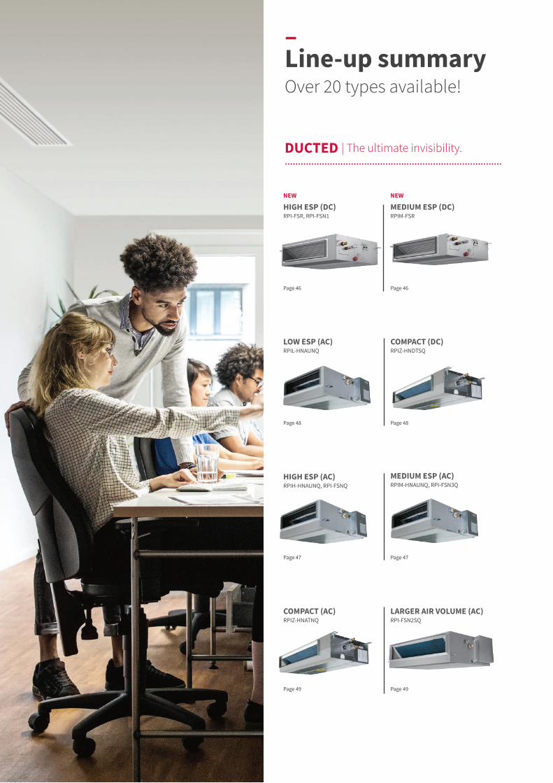
DUCTED | The ultimate invisibility.....................................................................................................................................................................
COMPACT (AC) RPIZ-HNATNQ
LARGER AIR VOLUME (AC) RPI-FSN2SQ
Page 49Page 49
HIGH ESP (AC) RPIH-HNAUNQ, RPI-FSNQ
MEDIUM ESP (AC)RPIM-HNAUNQ, RPI-FSN3Q
Page 47Page 47
LOW ESP (AC) RPIL-HNAUNQ
COMPACT (DC)RPIZ-HNDTSQ
Page 48Page 48
Page 46Page 46
–Line-up summary Over 20 types available!
NEW
MEDIUM ESP (DC) RPIM-FSR
NEW
HIGH ESP (DC) RPI-FSR, RPI-FSN1
new
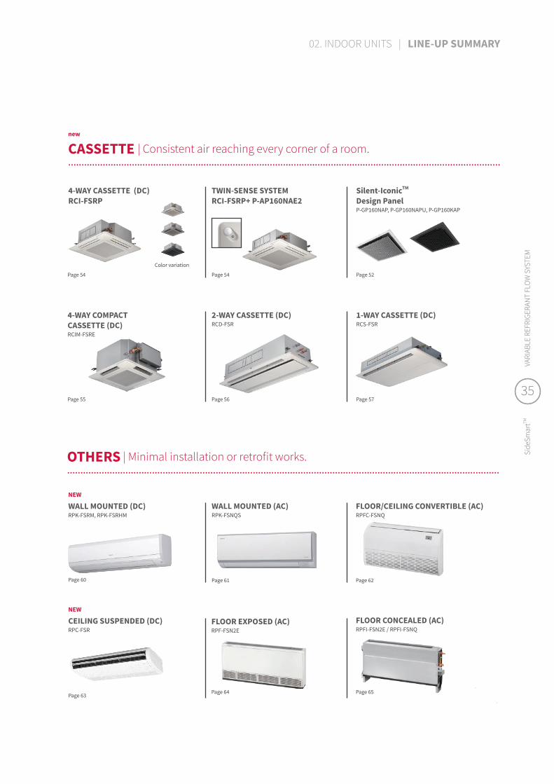
CASSETTE | Consistent air reaching every corner of a room.......................................................................................................................................................................................................................................................................................................................................
OTHERS | Minimal installation or retrofit works.......................................................................................................................................................................................................................................................................................................................................
FLOOR CONCEALED (AC) RPFI-FSN2E / RPFI-FSNQ
WALL MOUNTED (AC) RPK-FSNQS
FLOOR/CEILING CONVERTIBLE (AC)RPFC-FSNQ
FLOOR EXPOSED (AC)RPF-FSN2E
Page 60
Page 64 Page 65
1-WAY CASSETTE (DC) RCS-FSR
2-WAY CASSETTE (DC) RCD-FSR
4-WAY COMPACT CASSETTE (DC) RCIM-FSRE
Page 55 Page 56 Page 57
Silent-IconicTM Design PanelP-GP160NAP, P-GP160NAPU, P-GP160KAP
TWIN-SENSE SYSTEM RCI-FSRP+ P-AP160NAE2
4-WAY CASSETTE (DC) RCI-FSRP
Color variation
Page 54 Page 54 Page 52
Page 61 Page 62
NEW
WALL MOUNTED (DC)RPK-FSRM, RPK-FSRHM
Page 63
NEW
CEILING SUSPENDED (DC) RPC-FSR
35
Side
Smar
tTMVA
RIAB
LE R
EFRI
GERA
NT
FLO
W S
YSTE
M
35
Side
Smar
tTMVA
RIAB
LE R
EFRI
GERA
NT
FLO
W S
YSTE
M
02. INDOOR UNITS | LINE-UP SUMMARY

>12.0°C
GentleCool
LOW
GentleCool
>14.0°C
MED
GentleCool
>16.0°C
HIGH
GentleCool
OFF
>8.0°C → COLD DRAFT
–Our key indoor featuresHitachi air, making a difference.
Set not only your desired room temperature, but the cooled air temperature!
Without GentleCool, the unit might blow cooler air than expected when adjusting the indoor air temperature, causing a cool draft sensation at the beginning of operation. With GentleCool, users have control over how discharged air reaches a preferred temperature setting, ensuring a smoother cooling down effect.
GentleCool might affect the speed of the room's cooling down to the set temperature.
Potential discomfort.
RPI-FSRRPIM-FSRRPI-FSN1
RPK-FSRMRPK-FSRHM
RPC-FSRRCI-FSRP (all panels)
RCI-FSKDNQ
RCIM-FSRE RCD-FSR RCS-FSR PC-ARF1 PC-ARFG
GentleCool : no cold draft.
EXCLUSIVE
GENTLECOOL (FOR COOLING OPERATION)..................................................................................................................................................................................................................................................................................................................................................
NEW & EXCLUSIVE
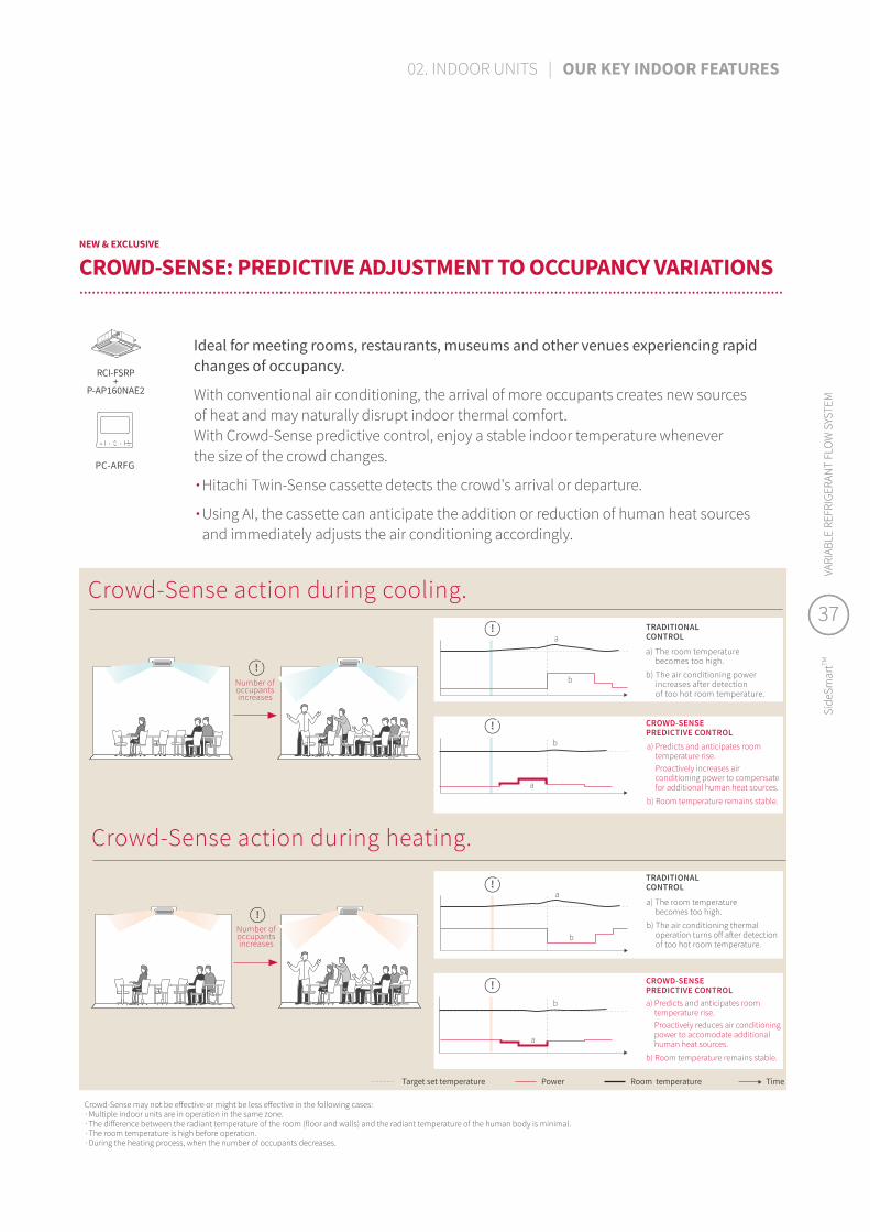
CROWD-SENSE: PREDICTIVE ADJUSTMENT TO OCCUPANCY VARIATIONS..................................................................................................................................................................................................................................................................................................................................................
PC-ARFG
RCI-FSRP+
P-AP160NAE2
Crowd-Sense action during cooling.
Crowd-Sense action during heating.
Ideal for meeting rooms, restaurants, museums and other venues experiencing rapid changes of occupancy.
With conventional air conditioning, the arrival of more occupants creates new sources of heat and may naturally disrupt indoor thermal comfort. With Crowd-Sense predictive control, enjoy a stable indoor temperature whenever the size of the crowd changes.
∙ Hitachi Twin-Sense cassette detects the crowd's arrival or departure.
∙ Using AI, the cassette can anticipate the addition or reduction of human heat sources and immediately adjusts the air conditioning accordingly.
Crowd-Sense may not be effective or might be less effective in the following cases:∙ Multiple indoor units are in operation in the same zone.∙ The difference between the radiant temperature of the room (floor and walls) and the radiant temperature of the human body is minimal.∙ The room temperature is high before operation.∙ During the heating process, when the number of occupants decreases.
Target set temperature Power Room temperature Time
a) Predicts and anticipates room temperature rise. Proactively reduces air conditioning power to accomodate additional human heat sources.
b) Room temperature remains stable.
a) The room temperature becomes too high.
b) The air conditioning thermal operation turns off after detection of too hot room temperature.
TRADITIONAL CONTROL
Number of occupants increases
a) Predicts and anticipates room temperature rise. Proactively increases air conditioning power to compensate for additional human heat sources.
b) Room temperature remains stable.
CROWD-SENSE PREDICTIVE CONTROL
a) The room temperature becomes too high.
b) The air conditioning power increases after detection of too hot room temperature.
TRADITIONAL CONTROL
CROWD-SENSE PREDICTIVE CONTROL
!
!
!
!
!
!
Number of occupants increases
a
b
b
b
b
a
a
a
37
Side
Smar
tTMVA
RIAB
LE R
EFRI
GERA
NT
FLO
W S
YSTE
M
37
Side
Smar
tTMVA
RIAB
LE R
EFRI
GERA
NT
FLO
W S
YSTE
M
02. INDOOR UNITS | OUR KEY INDOOR FEATURES

0 10
25
20
15
10
520 30
Tem
pera
ture
in fo
ot a
rea
(°C)
Elapsed time (minutes)
Conventional heating
The temperature in the foot area rises by about 2°C.
Heating with FeetWarmFeetWarm effect
Head to toe comfort during winter.
PC-ARFG
RCI-FSRP+
P-AP160NAE2
Intelligent heated air distribution, tailored for the human body.
FeetWarm is complex yet effortless comfort function integrating various parameters together. Available in our Twin-Sense cassette, it prevents the natural effect of cold air sinking and hot air rising, to create enveloping warmth for all occupants.
[Image based on calculation results]
Effect of FeetWarm- Step 1.
NEW
FEETWARM (FOR HEATING OPERATION)..................................................................................................................................................................................................................................................................................................................................................
FeetWarm's boasts 4 intelligent features:
∙ Thanks to the Twin-Sense radiant sensor, it can detect heat stratification effects inside the room, which usually cause the floor and lower levels to be cooler.
∙ A 2-step action to first create consistent warmth, then to maintain it.
∙ Advanced heat air flow optimization, by sophisticated control of the 4-way cassette's individual louvers.
∙ The lower levels of the room (floor level, feet level, leg level) reach desired temperatures, for total comfort.
Temperature transition in the foot area (average temperature 30cm above the floor)
1 The radiant sensor detects a temperature drop in the floor and around your feet.
2 The cassette partially closes two louvers automatically.
3 The air flow strengthens through the two remaining open louvers, and targets the floor to warm it up quickly*1. Louver openings alternate every three minutes from wide open to partially closed to cover a wider floor area.
4 As louver openings close, suction increases in the central inlet grill for a faster warming effect.*1 Caution: when the indoor unit changes to heating, the sudden change in air flow might cause occupants to feel a cold draft sensation.
Step 1.
About 2°C rise
Feet warm up more quickly!
Conventional heating
Average temperature 30cm above the floor = 15.4°C Average temperature 30cm above the floor = 17.9°C
Heating with FeetWarm
How does it work?..................................................................................................................................................................................................................................................................................................................................................
Temperature distribution around the area of the feet (30min after air conditioning heating operation starts).
–Our key indoor featuresHitachi air, making a difference.
Alternately repeats every 3 minutes
22 33
11 11
33 22
44 44
swing swingswing
swingswing
swing
swing
11
22
3333
33
44
Warm and even temperature!
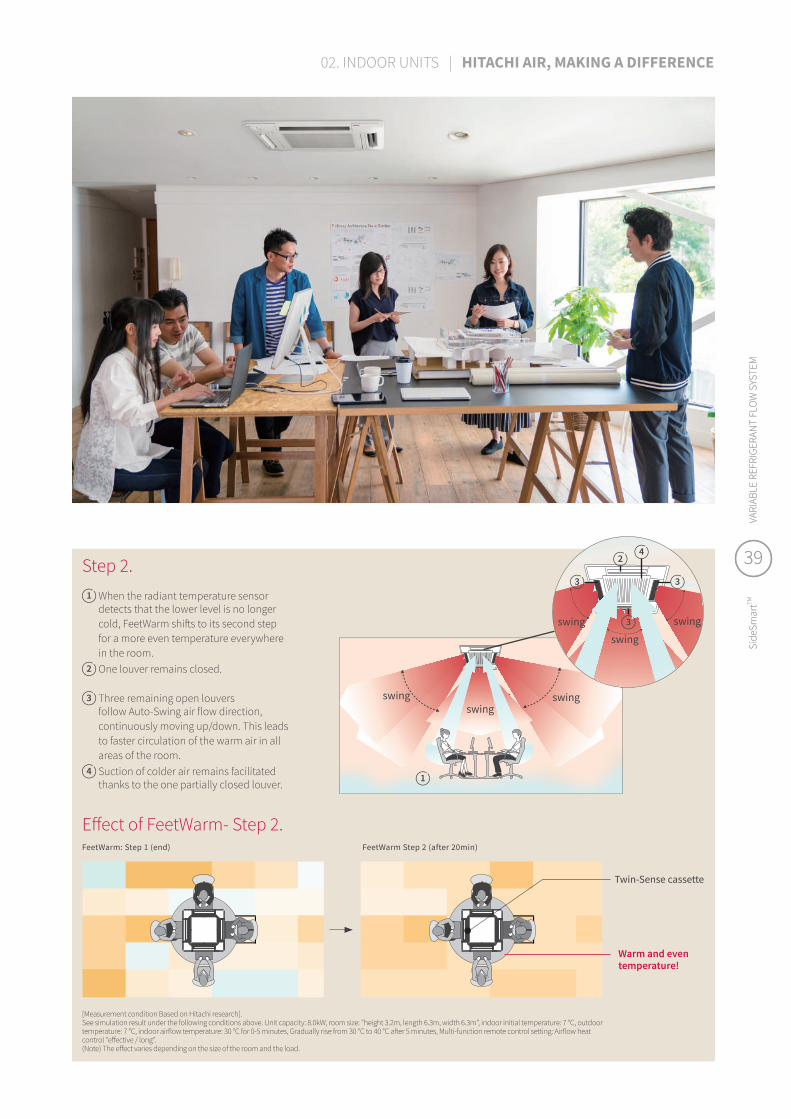
1 When the radiant temperature sensor detects that the lower level is no longer cold, FeetWarm shifts to its second step for a more even temperature everywhere in the room.
2 One louver remains closed.
3 Three remaining open louvers follow Auto-Swing air flow direction, continuously moving up/down. This leads to faster circulation of the warm air in all areas of the room.
4 Suction of colder air remains facilitated thanks to the one partially closed louver.
Twin-Sense cassette
Effect of FeetWarm- Step 2.
[Measurement condition Based on Hitachi research].See simulation result under the following conditions above. Unit capacity: 8.0kW, room size: "height 3.2m, length 6.3m, width 6.3m", indoor initial temperature: 7 °C, outdoor temperature: 7 °C, indoor airflow temperature: 30 °C for 0-5 minutes, Gradually rise from 30 °C to 40 °C after 5 minutes, Multi-function remote control setting: Airflow heat control "effective / long".(Note) The effect varies depending on the size of the room and the load.
FeetWarm: Step 1 (end) FeetWarm Step 2 (after 20min)
Step 2. 39
Side
Smar
tTMVA
RIAB
LE R
EFRI
GERA
NT
FLO
W S
YSTE
M
39
Side
Smar
tTMVA
RIAB
LE R
EFRI
GERA
NT
FLO
W S
YSTE
M
02. INDOOR UNITS | HITACHI AIR, MAKING A DIFFERENCE
move
1
32
NEW
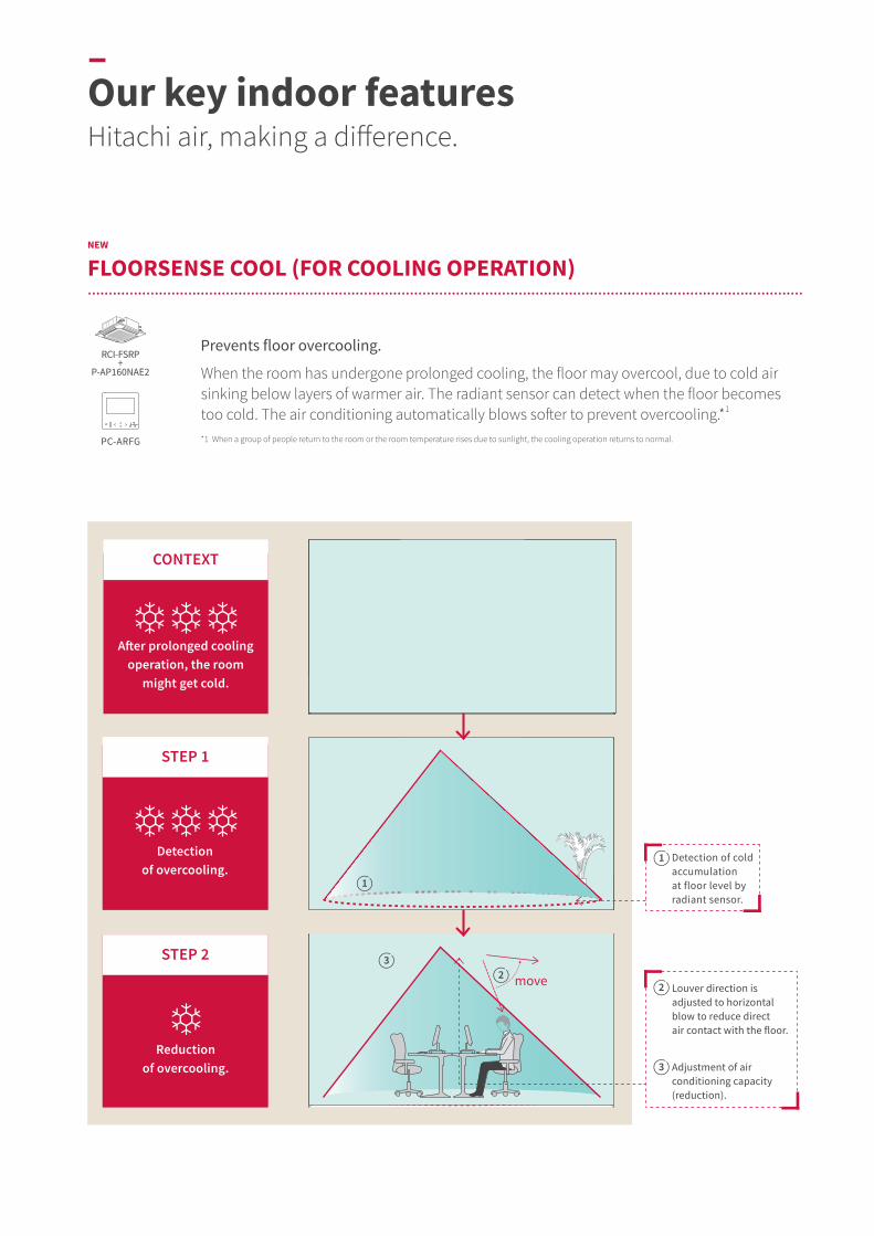
FLOORSENSE COOL (FOR COOLING OPERATION)......................................................................................................................................................................................................................................................................................................................................................
Prevents floor overcooling.
When the room has undergone prolonged cooling, the floor may overcool, due to cold air sinking below layers of warmer air. The radiant sensor can detect when the floor becomes too cold. The air conditioning automatically blows softer to prevent overcooling.*1
*1 When a group of people return to the room or the room temperature rises due to sunlight, the cooling operation returns to normal.PC-ARFG
RCI-FSRP+
P-AP160NAE2
–Our key indoor featuresHitachi air, making a difference.
After prolonged cooling operation, the room
might get cold.
CONTEXT
Detection of overcooling.
STEP 1
Reduction of overcooling.
STEP 2
Detection of cold accumulation at floor level by radiant sensor.
1
Louver direction is adjusted to horizontal blow to reduce direct air contact with the floor.
Adjustment of air conditioning capacity (reduction).
2
3

Want to feel the air? Or do you prefer imperceptible air? Choose the preferred air sensation and let the air conditioner adjusts the louver direction to your liking.Our 4-zone motion sensor divides the room into 4 areas and can detect presence in each of them.
∙ Choose Direct air flow: the Twin-Sense cassette will target the corners with human activity.
∙ Choose Indirect air flow: Twin-Sense cassette will avoid the corners where occupants are detected.
NEW
CHOICE OF DIRECT OR INDIRECT AIR FLOW..................................................................................................................................................................................................................................................................................................................................................
PC-ARFG
RCI-FSRP+
P-AP160NAE2
PC-ARF1
Ideal in places where occupants remain immobile for a long time: restaurants, offices, theaters...
Ideal in places where occupants need quick warm up or cool down: entrance areas and corridors, hotel lobby...
Indirect air flow: a gentle, subtle air to go unnoticed.
Direct air flow: air flowing sensation to the body.
Horizontal air flow, for circulation above and around occupants without air blowing directly on them.
Auto swing of louvers, to ensure that every occupant can feel the air blowing.
Notes: When room vacancy is detected, the air is directed in the way the controller (PC-ARFG) is set up. (Note) 4-zone motion sensor may not be effective in the following cases: ∙ If the room is occupied but the movement is minimal, the system might consider the room as vacant. ∙ If an object with a temperature different to the surrounding is in motion, it might be considered as human presence.
Horizontal airflow
Detect people Auto swing
Detect people
41
Side
Smar
tTMVA
RIAB
LE R
EFRI
GERA
NT
FLO
W S
YSTE
M
41
Side
Smar
tTMVA
RIAB
LE R
EFRI
GERA
NT
FLO
W S
YSTE
M
02. INDOOR UNITS | OUR KEY INDOOR FEATURES

Room cardRoom card
OUT OUT ININ
–Our key indoor featuresHitachi air, making a difference.
Interlock the air conditioner with hotel key card, and set an eco temperature for the time of room vacancy.
Save more energy while improving comfort!
When adding a motion sensor to the indoor unit, auto-save function will adjust the air conditioning output to the human activity level.
AC
DB
30.0°C
23.0°C
Room card in
Room card out
Room card in
Returning to set temperature when room key inserted.
A
30.0°C
C
27.0°C
Room cardRoom card
23.0°C
Room cardRoom cardB
23.0°C
Room cardRoom card
RPC-FSR(SOR-NEP)
RCI-FSRP(P-AP160NAE2)
RCI-FSKDNQ(PS-MSK2)
RCIM-FSRE(SOR-NEC)
RCD-FSR(SOR-NED)
RCS-FSR(SOR-NES)
PC-ARF1 PC-ARFGRPI-FSRRPI-FSN1RPIM-FSR(SOR-NEZ)
RPC-FSRRCI-FSRP (all panels)
RCI-FSKDNQ
RCIM-FSRE RCD-FSR RCS-FSR PC-ARF1 PC-ARFGRPI-FSRRPI-FSN1RPIM-FSR
D
AUTO-SAVE (WITH MOTION SENSOR)..................................................................................................................................................................................................................................................................................................................................................
HOTEL SETBACK..................................................................................................................................................................................................................................................................................................................................................
Motion sensor
Floor 0.8m
Detects human activity in each of the 4 zones
Motion sensor Auto-save
Before check-in Guest checks in Guest away Guest back
27.0°CSetback
temperature! When AC is off, room might become too hot/too cold.
Setback automatically activates.
AC adopts Setback eco temperature.
How does it work?..................................................................................................................................................................................................................................................................................................................................................
∙ Detected: High level of human activity
∙ Output: Full capacity
∙ Detected: Low level of human activity
∙ Output: Small reduction of capacity (savings!)
∙ Detected: Human activity stops
∙ Output: More reduction of capacity (more savings!)
∙ Detected: Prolonged vacancy (you can select the duration)
∙ Output: The AC turns off completely
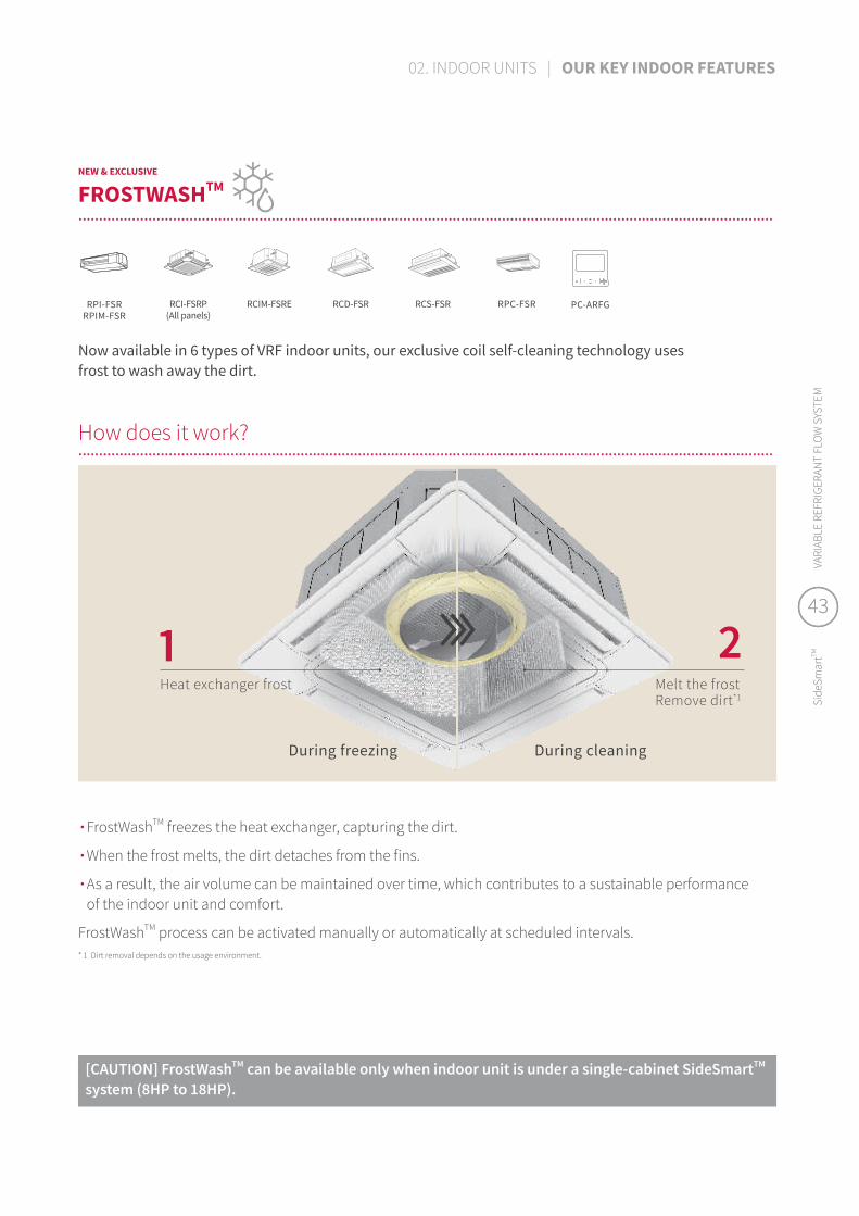
21Heat exchanger frost
During freezing During cleaning
Melt the frostRemove dirt*1
RPI-FSRRPIM-FSR
RCIM-FSRE RCD-FSR RCS-FSR PC-ARFGRPC-FSRRCI-FSRP(All panels)
NEW & EXCLUSIVE
FROSTWASHTM
..................................................................................................................................................................................................................................................................................................................................................
* 1 Dirt removal depends on the usage environment.
∙ FrostWashTM freezes the heat exchanger, capturing the dirt.
∙ When the frost melts, the dirt detaches from the fins.
∙ As a result, the air volume can be maintained over time, which contributes to a sustainable performance of the indoor unit and comfort.
FrostWashTM process can be activated manually or automatically at scheduled intervals.
Now available in 6 types of VRF indoor units, our exclusive coil self-cleaning technology uses frost to wash away the dirt.
[CAUTION] FrostWashTM can be available only when indoor unit is under a single-cabinet SideSmartTM system (8HP to 18HP).
How does it work?..................................................................................................................................................................................................................................................................................................................................................
43
Side
Smar
tTMVA
RIAB
LE R
EFRI
GERA
NT
FLO
W S
YSTE
M
43
Side
Smar
tTMVA
RIAB
LE R
EFRI
GERA
NT
FLO
W S
YSTE
M
02. INDOOR UNITS | OUR KEY INDOOR FEATURES
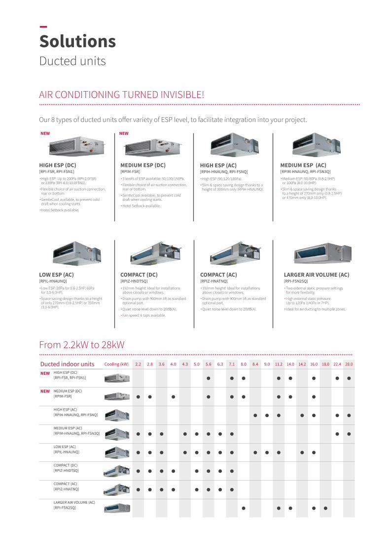
NEW NEW
NEW
NEW
Our 8 types of ducted units offer variety of ESP level, to facilitate integration into your project.
AIR CONDITIONING TURNED INVISIBLE!........................................................................................................................................................................................................................................................................................................................................................
HIGH ESP (DC) [RPI-FSR, RPI-FSN1]
∙ High ESP: Up to 200Pa (RPI-2.0FSR) or 230Pa (RPI-8.0/10.0FSN1).
∙ Flexible choice of air suction connection, rear or bottom.
∙ GentleCool available, to prevent cold draft when cooling starts.
∙Hotel Setback available.
MEDIUM ESP (DC)[RPIM-FSR]
∙3 levels of ESP available: 50/100/150Pa.
∙ Flexible choice of air suction connection, rear or bottom.
∙ GentleCool available, to prevent cold draft when cooling starts.
∙Hotel Setback available.
COMPACT (DC)[RPIZ-HNDTSQ]
∙ 192mm height! Ideal for installations above closets or windows.
∙ Drain-pump with 900mm lift as standard optional part.
∙Quiet noise level down to 20dB(A).
∙Fan speed: 6 taps available.
LOW ESP (AC)[RPIL-HNAUNQ]
∙ Low ESP (30Pa for 0.8-2.5HP, 60Pa for 3.0-6.0HP).
∙ Space saving design thanks to a height of only 270mm (0.8-2.5HP) or 350mm (3.0-6.0HP).
HIGH ESP (AC)[RPIH-HNAUNQ, RPI-FSNQ]
∙High ESP (90/120/180Pa).
∙ Slim & space saving design thanks to a height of 300mm only (RPIH-HNAUNQ).
COMPACT (AC)[RPIZ-HNATNQ]
∙ 192mm height! Ideal for installations above closets or windows.
∙ Drain-pump with 900mm lift as standard optional part.
∙ Quiet noise level down to 20dB(A).
MEDIUM ESP (AC)[RPIM-HNAUNQ, RPI-FSN3Q]
∙ Medium ESP: 50/80Pa (0.8-2.5HP) or 100Pa (8.0-10.0HP).
∙ Slim & space saving design thanks to a height of 270mm only (0.8-2.5HP) or 470mm only (8.0-10.0HP).
LARGER AIR VOLUME (AC)[RPI-FSN2SQ]
∙ Two external static pressure settings for more flexibility.
∙ High external static pressure: Up to 120Pa (140Pa in 7HP).
∙ Ideal for air ducting to multiple zones.
Ducted indoor units Cooling (kW) 2.2 2.8 3.6 4.0 4.3 5.0 5.6 6.3 7.1 8.0 8.4 9.0 11.2 14.0 14.2 16.0 18.0 22.4 28.0
HIGH ESP (DC)[RPI-FSR, RPI-FSN1]
MEDIUM ESP (DC)[RPIM-FSR]
HIGH ESP (AC)[RPIH-HNAUNQ, RPI-FSNQ]
MEDIUM ESP (AC)[RPIM-HNAUNQ, RPI-FSN3Q]
LOW ESP (AC)[RPIL-HNAUNQ]
COMPACT (DC)[RPIZ-HNDTSQ]
COMPACT (AC)[RPIZ-HNATNQ]
LARGER AIR VOLUME (AC)[RPI-FSN2SQ]
From 2.2kW to 28kW................................................................................................................................................................................................................................................................................................................................................
–SolutionsDucted units

HIGH/MEDIUM ESP
(DC)
HIGH ESP (8/10HP )
(DC)
HIGH ESP (AC)
HIGH/MEDIUM ESP
(8/10HP )(AC)
MEDIUM/LOW ESP
(AC)
COMPACT (DC)
COMPACT (AC)
LARGER AIR VOLUME
(AC)
Model
RPI-FSRRPIM-FSR RPI-FSN1 RPIH-
HNAUNQRPI-FSNQ
RPI-FSN3QRPIM-HNAUNQRPIL-HNAUNQ
RPIZ-HNDTSQ
RPIZ-HNATNQ RPI-FSN2SQ
COMFORT
Temperature Setting Rate 0.5°C/1.0°C 0.5°C/1.0°C 1.0°C 1.0°C 1.0°C 1.0°C 1.0°C 1.0°C
Fan Speed 4 taps 4 taps 3 taps 1 tap 3 taps 6 taps 3 taps 3 taps
Louver Direction - - - - - - - -
Individual Louver Setting - - - - - - - -
Auto Louver Setting - - - - - - - -
Dry mode Availability
Setback (Away Function) - - - - - -
Cold Draft Prevention (*1)(*4)
Comfort setting
Control Cool Air (GentleCool) (*2) - - - - - -
Direct/Indirect louver direction in COOL - - - - - - - -
Direct/Indirect louver direction in HEAT - - - - - - - -
FeetWarm air flow control - - - - - - - -
FloorSense Cool air flow control - - - - - - - -
POWER-SAVING
Power Saving with Motion Sensor (*2) - - - - - -
Outdoor Unit capacity control (*2)
Peak cut control - - - - - -
Moderate control - - - - - -
Indoor Unit Rotation Control (*2)
Indoor Unit Address - - - - - -
Indoor Air Temperature difference - - - - - -
Automatic Fan Operation
MENU
AutoBoost (quick function) (*2) - - - - - -
Daylight Saving Time
Power Consumption visualization (*2) - - - - - -
Weekly Schedule Setting
Power-Saving Setting (*2) - - - - - -
MAINTENANCE
NEW FrostWashTM auto-cleaning - - - - - - -
Filter cleaning reminder
Check Menu
Sensor Condition Check
Model Display (*2) - - - - - -
Indoor/Outdoor PCB Check
Alarm History Display
Motion Sensor SOR-NEZ SOR-NEZ - - - - - -
Receiver Kit for wireless remote controller PC-ALHZ1 PC-ALHZ1 PC-RLH11PC-ALHZ1
PC-RLH11PC-ALHZ1
PC-RLH11PC-ALHZ1
PC-RLH11PC-ALHZ1
PC-RLH11PC-ALHZ1
PC-RLH11PC-ALHZ1
Drain-up mechanism availability (*3) (*3) DUPI-361Q DUPI-15H2Q DUPI-131QDUPI-361Q (*3) (*3) -
Air filter F-56/90/160LIB-56/90/160LI
F-280LIB-280LI KW-PP9/10Q - KW-PP7/
8/9/10QKW-PP5QKW-PP6Q
KW-PP5QKW-PP6Q -
OPTIONAL ACCESSORY
(*1) This function is utilized to prevent cold discharged air at start-up of heating operation, after defrosting operation, etc. (*2) Advanced wired remote controller PC-ARF1 needs to be connected.(*3) Included as standard equipment.(*4) Please consult your distributor.
NEW NEW
FEATURES COMPARISON........................................................................................................................................................................................................................................................................................................................................................
45
Side
Smar
tTMVA
RIAB
LE R
EFRI
GERA
NT
FLO
W S
YSTE
M
45
Side
Smar
tTMVA
RIAB
LE R
EFRI
GERA
NT
FLO
W S
YSTE
M
02. INDOOR UNITS | SOLUTIONS | DUCTED UNITS
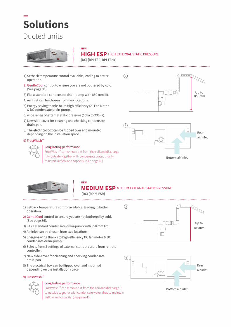
Rear air inlet
Bottom air inlet
Up to 850mm
Up to 850mm
Rear air inlet
Bottom air inlet
Long lasting performanceFrostWashTM can remove dirt from the coil and discharge it to outside together with condensate water, thus to maintain airflow and capacity. (See page 43)
9) FrostWashTM
1) Setback temperature control available, leading to better operation.
2) GentleCool control to ensure you are not bothered by cold.(See page 36).
3) Fits a standard condensate drain-pump with 850 mm lift.
4) Air Inlet can be chosen from two locations.
5) Energy-saving thanks to its High Efficiency DC Fan Motor & DC condensate drain-pump.
6) wide range of external static pressure (50Pa to 230Pa).
7) New side-cover for cleaning and checking condensate drain-pan.
8) The electrical box can be flipped over and mounted depending on the installation space.
1) Setback temperature control available, leading to better operation.
2) GentleCool control to ensure you are not bothered by cold. (See page 36).
3) Fits a standard condensate drain-pump with 850 mm lift.
4) Air inlet can be chosen from two locations.
5) Energy-saving thanks to high efficiency DC fan motor & DC condensate drain-pump.
6) Selects from 3 settings of external static pressure from remote controller.
7) New side-cover for cleaning and checking condensate drain-pan.
8) The electrical box can be flipped over and mounted depending on the installation space.
Long lasting performanceFrostWashTM can remove dirt from the coil and discharge it to outside together with condensate water, thus to maintain airflow and capacity. (See page 43)
9) FrostWashTM
HIGH ESP HIGH EXTERNAL STATIC PRESSURE
(DC) [RPI-FSR, RPI-FSN1]
NEW
MEDIUM ESP MEDIUM EXTERNAL STATIC PRESSURE
(DC) [RPIM-FSR]
NEW
4
3
4
3
–SolutionsDucted units

L-shaped space U-shaped space
L-shaped space U-shaped space
Air inlet
Air inlet
Air inlet
Air inlet
Up to900mm
Up to900mm
1) High ESP. (90/120/180Pa)
2 ) Space saving design thanks to a height of only 300mm. (RPIH-HNAUNQ)
3) Flexible installation. Options allow for multiple configurations.
4) Air inlet can be chosen from 2 locations.
5) Optional drain pump. Drain-up mechanism can be supplied as optional part.
1) Medium ESP. (50/80Pa for 0.8-2.5HP class, 100Pa for 8.0-10.0HP class)
2) Space saving design thanks to a height of only 270mm. (0.8-2.5HP class) or 470mm (8.0-10.0HP class)
3) Flexible installation. Options allow for multiple configurations.
4) Air inlet can be chosen from 2 locations.
5) Optional drain pump. Drain-up mechanism can be supplied as optional part.
HIGH ESP HIGH EXTERNAL STATIC PRESSURE
(AC) [RPIH-HNAUNQ, RPI-FSNQ]
4
4 5
MEDIUM ESP MEDIUM EXTERNAL STATIC PRESSURE
(AC) [RPIM-HNAUNQ, RPI-FSN3Q]
3
3
5
47
Side
Smar
tTMVA
RIAB
LE R
EFRI
GERA
NT
FLO
W S
YSTE
M
47
Side
Smar
tTMVA
RIAB
LE R
EFRI
GERA
NT
FLO
W S
YSTE
M
02. INDOOR UNITS | SOLUTIONS | DUCTED UNITS

In dropped ceiling, over window Over a closet
Air inlet
Air inlet
Up to900mm
In dropped ceiling, over window Over a closet
1) Low ESP. (30Pa for 0.8-2.5HP class, 60Pa for 3.0-6.0HP class)
2) Space saving design thanks to a height of only 270mm (0.8-2.5HP class) or 300mm (3.0-6.0HP class).
3) Air inlet can be chosen from 2 locations.
4) Optional drain pump. Drain-up mechanism can be supplied as optional part.
1) Ideal for installation over closets or windows thanks to a more compact design, 192mm high.
2) Drain-pump with 900mm lift as standard optional part.
3) Quiet operation level. (as low as 22.5dB(A))
4) Fan air flow rate up to 6 taps. (DC motor model only)
COMPACT (DC) [RPIZ-HNDTSQ]
4
3
LOW ESP (LOW EXTERNAL STATIC PRESSURE)
(AC) [RPIL-HNAUNQ]
Over a closet In dropped ceiling, over window 1
–SolutionsDucted units

L-shaped space U-shaped space
L-shaped space U-shaped space
In dropped ceiling, over window Over a closet In dropped ceiling, over window Over a closet
1) Ideal for installation over closets or windows thanks a more compact design, 192mm high.
2) Drain-pump with 900mm lift as standard optional part.
3) Quiet operation level. (as low as 20dB(A))
4) Fan air flow rate up to 6 taps. (DC motor model only)
1) Two external static pressure settings for improved flexibility. (70Pa or 120Pa)
2) High external static pressure: Up to 120Pa. (140Pa in 7HP class)
3) Suitable for air distribution for multiple zone.
4) Flexible installation options allow for multiple configurations.
COMPACT(AC) [RPIZ-HNATNQ]
4
LARGER AIR VOLUME
(AC) [RPI-FSN2SQ]
U-shaped space
L-shaped space
Over a closet In dropped ceiling, over window 1
49
Side
Smar
tTMVA
RIAB
LE R
EFRI
GERA
NT
FLO
W S
YSTE
M
49
Side
Smar
tTMVA
RIAB
LE R
EFRI
GERA
NT
FLO
W S
YSTE
M
02. INDOOR UNITS | SOLUTIONS | DUCTED UNITS
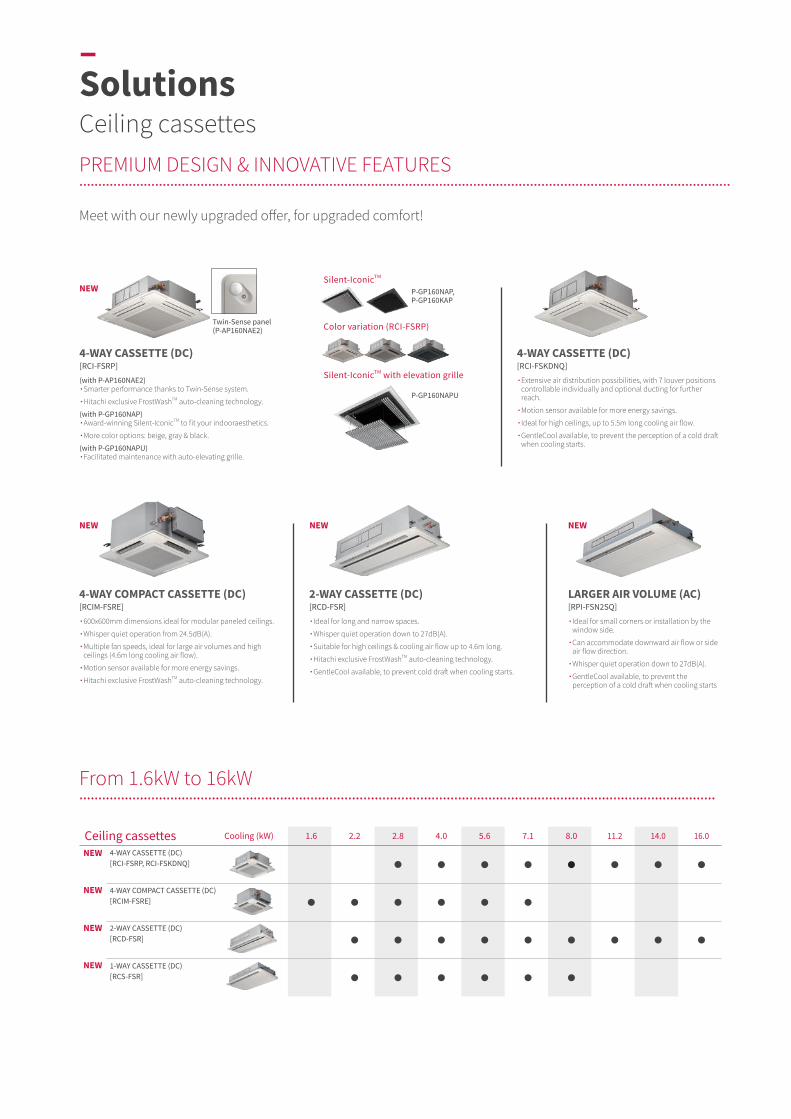
NEW
NEW NEW NEW
Meet with our newly upgraded offer, for upgraded comfort!
PREMIUM DESIGN & INNOVATIVE FEATURES........................................................................................................................................................................................................................................................................................................................................................
4-WAY CASSETTE (DC)[RCI-FSRP]
(with P-AP160NAE2) ∙ Smarter performance thanks to Twin-Sense system.
∙ Hitachi exclusive FrostWashTM auto-cleaning technology.
(with P-GP160NAP) ∙ Award-winning Silent-IconicTM to fit your indooraesthetics.
∙ More color options: beige, gray & black.
(with P-GP160NAPU) ∙ Facilitated maintenance with auto-elevating grille.
2-WAY CASSETTE (DC) [RCD-FSR]
∙ Ideal for long and narrow spaces.
∙ Whisper quiet operation down to 27dB(A).
∙ Suitable for high ceilings & cooling air flow up to 4.6m long.
∙ Hitachi exclusive FrostWashTM auto-cleaning technology.
∙ GentleCool available, to prevent cold draft when cooling starts.
4-WAY COMPACT CASSETTE (DC)[RCIM-FSRE]
∙ 600x600mm dimensions ideal for modular paneled ceilings.
∙ Whisper quiet operation from 24.5dB(A).
∙ Multiple fan speeds, ideal for large air volumes and high ceilings (4.6m long cooling air flow).
∙ Motion sensor available for more energy savings.
∙ Hitachi exclusive FrostWashTM auto-cleaning technology.
4-WAY CASSETTE (DC)[RCI-FSKDNQ]
∙ Extensive air distribution possibilities, with 7 louver positions controllable individually and optional ducting for further reach.
∙ Motion sensor available for more energy savings.
∙ Ideal for high ceilings, up to 5.5m long cooling air flow.
∙ GentleCool available, to prevent the perception of a cold draft when cooling starts.
LARGER AIR VOLUME (AC)[RPI-FSN2SQ]
∙ Ideal for small corners or installation by the window side.
∙ Can accommodate downward air flow or side air flow direction.
∙ Whisper quiet operation down to 27dB(A).
∙ GentleCool available, to prevent the perception of a cold draft when cooling starts
Twin-Sense panel (P-AP160NAE2)
P-GP160NAPU
P-GP160NAP, P-GP160KAP
Color variation (RCI-FSRP)
Silent-IconicTM
Silent-IconicTM with elevation grille
From 1.6kW to 16kW................................................................................................................................................................................................................................................................................................................................................
Ceiling cassettes Cooling (kW) 1.6 2.2 2.8 4.0 5.6 7.1 8.0 11.2 14.0 16.0
4-WAY CASSETTE (DC)[RCI-FSRP, RCI-FSKDNQ]
4-WAY COMPACT CASSETTE (DC)[RCIM-FSRE]
2-WAY CASSETTE (DC)[RCD-FSR]
1-WAY CASSETTE (DC)[RCS-FSR]
NEW
NEW
NEW
NEW
–SolutionsCeiling cassettes

FEATURES COMPARISON........................................................................................................................................................................................................................................................................................................................................................
4-WAY CASSETTE TYPE(DC MOTOR TYPE)
4-WAY CASSETTE COMPACT TYPE
(DC MOTOR TYPE)
2-WAY CASSETTE TYPE(DC MOTOR TYPE)
1-WAY CASSETTE TYPE(DC MOTOR TYPE)
Model
RCI-FSRP RCI-FSKDNQ RCIM-FSRE RCD-FSR RCS-FSR
COMFORT
Temperature Setting Rate 0.5°C/1.0°C 0.5°C/1.0°C 0.5°C/1.0°C 0.5°C/1.0°C 0.5°C/1.0°C
Fan Speed 4 taps 4 taps 4 taps 4 taps 4 taps
Louver Direction 7 (*4) 7 (*4) 7 (*4) 7 (*4) 7 (*5)
Individual Louver Setting -
Auto Louver Setting
Dry mode Availability
Setback (Away Function)
Cold Draft Prevention Availability (*1)
Comfort setting Control Cool Air (GentleCool) (*2)
NEW Direct/Indirect louver direction in COOL - - - -
NEW Direct/Indirect louver direction in HEAT - - - -
NEW FeetWarm air flow control - - - -
NEW FloorSense Cool air flow control - - - -
POWER-SAVING
Power Saving with Motion Sensor (*2)
Outdoor Unit capacity control (*2)
Peak cut control
Moderate control
Indoor Unit Rotation Control (*2)
Indoor Unit Address
Indoor Air Temperature difference
Automatic Fan Operation
MENU
AutoBoost (quick function) (*2)
Daylight Saving Time
Power Consumption visualization (*2)
Weekly Schedule Setting
Power-Saving Setting (*2)
MAINTENANCE
NEW FrostWashTM auto-cleaning -
Filter cleaning reminder
Check Menu
Sensor Condition Check
Model Display (*2) - -
Indoor/Outdoor PCB Check
Alarm History Display
OPTIONAL ACCESSORY
Colored Panel availability (*6) - - (*6) (*6)
Motion Sensor P-AP160NAE2 PS-MSK2 SOR-NEC SOR-NED SOR-NES
Receiver Kit for wireless remote controller PC-ALH3 HR4A10NEWQPC-ALH3
P-AP56NAMRPC-ALHC1 PC-ALHD1 PC-ALHS1
Drain-up mechanism availability (*3) (*3) (*3) (*3) (*3)
Fresh air intake accessory (*7) - (*7) (*7) (*7)
Air filter
F-160L-KF-71L-D1
F-160L-D1B-160H3
- -
F-90MD-K1F-160MD-K1
B-90HDB-160HD
-
(*1) You can use this function to prevent cold discharged air at startup of the heating... (*2) Advanced wired remote controller PC-ARF1 needs to be connected.(*3) Included as standard equipment.(*4) 7 angles are available for individual louver setting, 5 angles only for the operation of Cooling or Dry.(*5) 5 steps only for the operation of Cooling or Dry.(*6) 3 colors are available (Beige, Grey, and Black).(*7) A Duct Adapter (Optional part) is available.
NEW NEW NEW NEW
51
Side
Smar
tTMVA
RIAB
LE R
EFRI
GERA
NT
FLO
W S
YSTE
M
51
Side
Smar
tTMVA
RIAB
LE R
EFRI
GERA
NT
FLO
W S
YSTE
M
02. INDOOR UNITS | SOLUTIONS | CEILING CASSETTES

Blind-like shapes of the air inlet central grille
Black air-outlet portInvisible open/close flaps
Exclusive panel: architectural designers will love it!
Inspired by Japanese aesthetics, the Silent-IconicTM panel is designed to blend subtly into any type of interior. Refined and pure lines create elegance and harmony without compromising on performance.
Visual integration into your space
The Silent-IconicTM panel completely preserves the capacity and high efficiency of Hitachi 4-way cassette.
No sacrifice on performance
iF Design Award 2020Award Winning
(Category: Product)
SILENT-ICONICTM 4-WAY CASSETTE DESIGN PANEL
................................................................................................................................................................................................................................................................................................................................................
NEW
–SolutionsCeiling cassettes

[Device] iPhone*1 iPhone 11 Pro / iPhone 11 Pro Max / iPhone 11 / iPhone XS / iPhone XS Max / iPhone XR / iPhone X /
iPhone 8 Plus / iPhone 8 / iPhone 7 Plus / iPhone 7 / iPhone 6s Plus / iPhone 6s / iPhone SE iPad*2 iPad Pro (all models) / iPad (6th generation) / iPad (5th generation)
Operating environment
[OS] iOS*3 12.1 or later
[Browser] Safari*4/ Google Chrome*5 / Firefox*6
iPhone Augmented Reality: try and visualize Silent-IconicTM design in your space!
Silent-IconicTM White
Silent-IconicTM Black
4-way Cassette Air Conditioner
With Augmented Reality, you can visualize Hitachi 4-way cassette or Silent-IconicTM cassette installed in your actual space.
*1 iPhone is a trademark of Apple Inc., registered in the United States and other countries. *2 iPad is a trademark of Apple Inc., registered in the United States and other countries. *3 iOS is the Operating System name of Apple Inc. iOS is a registered trademark or trademark of Cisco Systems, Inc. or its affiliates in the United States and other countries and is used under
license. *4 Safari is a trademark of Apple Inc., registered in the United States and other countries. *5 Google Chrome is a trademark or registered trademark of Google Inc. *6 Firefox is a trademark or registered trademark of the United States Mozilla Foundation in the United States and other countries. *7 QR code is a registered trademark of Denso Wave Incorporated.
Instructions for use.1. Scan the QR code*7and open
the web page. Display the web page with a QR code, URL, etc.
3. AR mode is activated. Hold out the camera toward the ceiling and get it to detect the environment by moving it in a circular motion. You may not be able to scan a single-colored ceiling so scan a place where objects such as downlights or ceiling ventilation fans are installed.
4. Adjustment of placement location. You can shift then move it with a single finger, and rotate or zoom it out/zoom it in with two fingers to adjust the size that fits the space. There is also a capture button, so you can take and share the pictures you have placed.
2. Tap the icon. Tap the icon displayed at the bottom right of the 3D Viewer. If the icon is not displayed, please unhide it in Safari or check the OS version.
53
Side
Smar
tTMVA
RIAB
LE R
EFRI
GERA
NT
FLO
W S
YSTE
M
53
Side
Smar
tTMVA
RIAB
LE R
EFRI
GERA
NT
FLO
W S
YSTE
M
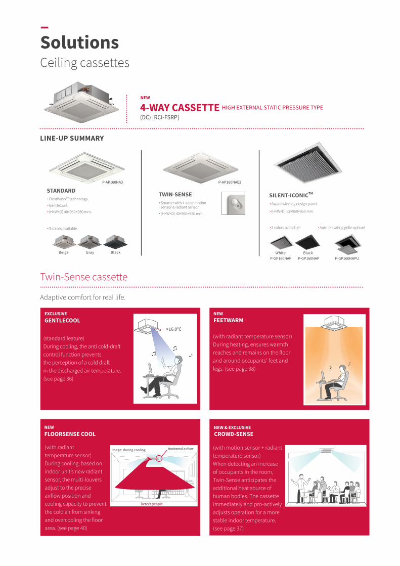
>16.0°C
Detect people
Horizontal airflowImage: during cooling
FEETWARM
CROWD-SENSE
(with radiant temperature sensor) During heating, ensures warmth reaches and remains on the floor and around occupants' feet and legs. (see page 38)
(with motion sensor + radiant temperature sensor) When detecting an increase of occupants in the room, Twin-Sense anticipates the additional heat source of human bodies. The cassette immediately and pro-actively adjusts operation for a more stable indoor temperature.(see page 37)
LINE-UP SUMMARY
White BlackBeige Gray Black
GENTLECOOL
FLOORSENSE COOL
(standard feature) During cooling, the anti cold-draft control function prevents the perception of a cold draft in the discharged air temperature. (see page 36)
(with radiant temperature sensor) During cooling, based on indoor unit’s new radiant sensor, the multi-louvers adjust to the precise airflow position and cooling capacity to prevent the cold air from sinking and overcooling the floor area. (see page 40)
Adaptive comfort for real life.
4-WAY CASSETTE HIGH EXTERNAL STATIC PRESSURE TYPE
(DC) [RCI-FSRP]
NEW
Twin-Sense cassette..................................................................................................................................................................................................................................................................................................................................................
STANDARD∙ FrostWashTM technology.
∙ GentleCool.
∙(H×W×D) 40×950×950 mm.
∙ 3 colors available.
TWIN-SENSE∙ Smarter with 4-zone motion
sensor & radiant sensor.
∙(H×W×D) 40×950×950 mm.
SILENT-ICONICTM
∙ Award winning design panel.
∙(H×W×D) 52×950×950 mm.
∙ 2 colors available! ∙ Auto-elevating grille option!
NEW NEW & EXCLUSIVE
NEWEXCLUSIVE
P-AP160NA3 P-AP160NAE2
P-GP160NAP P-GP160NAP P-GP160NAPU
–SolutionsCeiling cassettes

Suspension ceiling system600mm×600mm
Standard ceiling panel: 570mm
570 mm
The 600x600 unit can fit in between lighting panels without any disruption.
850mm
drain
(Cooling)Up to
4.6mdown
Fully opened louvers do not extend over the panel's surface area.
Only 30mm thick
40dB(A)LIBRARY
30dB(A)MIDNIGHTCLOCK
20dB(A)
NEW
Ideal for suspended ceilings.
Suitable for high ceilings. Standard drain pump: up to 850mm lift.
FrostWashTM
* Air flow rate: Hi2* 2.0-2.5 FSRE
Whisper quiet sound level.
Esthetics.
Minimal sleek design
4-WAY COMPACT CASSETTE (DC) [RCIM-FSRE]
1
2 4
5
3
2,5HP
Sound pressure level (dB(A))
2HP
0,6HP0,8HP
1HP 1,5HP
Long lasting performanceFrostWashTM can remove dirt from the coil and discharge it to outside together with condensate water, thus to maintain airflow and capacity. (See page 43)
27,5 31 3524,5
55
Side
Smar
tTMVA
RIAB
LE R
EFRI
GERA
NT
FLO
W S
YSTE
M
55
Side
Smar
tTMVA
RIAB
LE R
EFRI
GERA
NT
FLO
W S
YSTE
M
02. INDOOR UNITS | SOLUTIONS | CEILING CASSETTES

850mm
drain
(Cooling)Up to
4.6mdown
Louver opens up to60°
Horizontally-blowing air (imperceptible, above-the-head air circulation) 25°
Corner pocket
Panel
Easier height Adjustment
Suitable for high ceilings.
Standard drain pump: up to 850mm rise.* Air flow rate: Hi2* 2.0-6.0 FSR
Individually controlled louvers.
Tailor the air flow direction to both ends of the room.
Facilitated installation.
2-WAY CASSETTE(DC) [RCD-FSR]
NEW
Long lasting performanceFrostWashTM can remove dirt from the coil and discharge it to outside together with condensate water, thus to maintain airflow and capacity. (See page 43)
FrostWashTM
1
2 3
4
–SolutionsCeiling cassettes

850mm
drain
(Cooling)Up to
5.3mdown
Sound pressure level (dB(A))
30dB(A)MIDNIGHTCLOCK
20dB(A)
FrostWashTM
NEW
1-WAY CASSETTE(DC) [RCS-FSR]
With closed louvers & ceiling horizontal vent.
Suitable for design that focuses on lighting and suspended ceilings, in case the unit is unable to be directly embedded in the ceiling.
Open louver & ceiling horizontal vent.
Get two directions with 1-way cassette! Connect the cassette with a horizontal vent on the side, and create both downward air flow and horizontal air flow at the same time.
In corner with open louvers (typical).
Allows for ceiling planning for lighting and interiors, suitable for installation near the window.
Reduced sound pressure thanks to new design in fan inlet and fan.
*Air flow rate: Hi2*2.5-3.0 FSR*standard corner type
3 types of installation.
Whisper quiet sound level. Suitable for high ceilings. Standard drain pump: up to 850mm lift.
1
2 4
3
2.2kW4.0KW 5.6KW2.8kW 8.0kW7.1kW
Long lasting performanceFrostWashTM can remove dirt from the coil and discharge it to outside together with condensate water, thus to maintain airflow and capacity. (See page 43)
27 28 32 3331
57
Side
Smar
tTMVA
RIAB
LE R
EFRI
GERA
NT
FLO
W S
YSTE
M
57
Side
Smar
tTMVA
RIAB
LE R
EFRI
GERA
NT
FLO
W S
YSTE
M
02. INDOOR UNITS | SOLUTIONS | CEILING CASSETTES
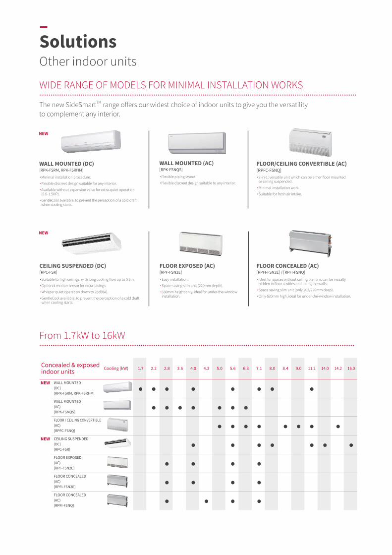
The new SideSmartTM range offers our widest choice of indoor units to give you the versatility to complement any interior.
Concealed & exposed indoor units Cooling (kW) 1.7 2.2 2.8 3.6 4.0 4.3 5.0 5.6 6.3 7.1 8.0 8.4 9.0 11.2 14.0 14.2 16.0
WALL MOUNTED(DC)[RPK-FSRM, RPK-FSRHM]
WALL MOUNTED(AC)[RPK-FSNQS]
FLOOR / CEILING CONVERTIBLE (AC)[RPFC-FSNQ]
CEILING SUSPENDED(DC)[RPC-FSR]
FLOOR EXPOSED(AC)[RPF-FSN2E]
FLOOR CONCEALED(AC)[RPFI-FSN2E]
FLOOR CONCEALED(AC)[RPFI-FSNQ]
From 1.7kW to 16kW................................................................................................................................................................................................................................................................................................................................................
NEW
CEILING SUSPENDED (DC)[RPC-FSR]
∙ Suitable to high ceilings, with long cooling flow up to 5.6m.
∙ Optional motion sensor for extra savings.
∙ Whisper quiet operation down to 28dB(A).
∙ GentleCool available, to prevent the perception of a cold draft when cooling starts.
FLOOR EXPOSED (AC)[RPF-FSN2E]
∙ Easy installation.
∙ Space saving slim unit (220mm depth).
∙ 630mm height only, ideal for under-the-window installation.
FLOOR CONCEALED (AC)[RPFI-FSN2E] / [RPFI-FSNQ]
∙ Ideal for spaces without ceiling plenum, can be visually hidden in floor cavities and along the walls.
∙ Space saving slim unit (only 202/220mm deep).
∙ Only 620mm high, ideal for under-the-window installation.
NEW
WALL MOUNTED (DC)[RPK-FSRM, RPK-FSRHM]
∙ Minimal installation procedure.
∙ Flexible discreet design suitable for any interior.
∙ Available without expansion valve for extra-quiet operation (0.6-1.5HP).
∙ GentleCool available, to prevent the perception of a cold draft when cooling starts.
WALL MOUNTED (AC)[RPK-FSNQS]
∙ Flexible piping layout.
∙ Flexible discreet design suitable to any interior.
FLOOR/CEILING CONVERTIBLE (AC)[RPFC-FSNQ]∙ 2-in-1: versatile unit which can be either floor mounted
or ceiling suspended.
∙ Minimal installation work.
∙ Suitable for fresh air intake.
NEW
NEW
WIDE RANGE OF MODELS FOR MINIMAL INSTALLATION WORKS..................................................................................................................................................................................................................................................................................................................................................
–SolutionsOther indoor units
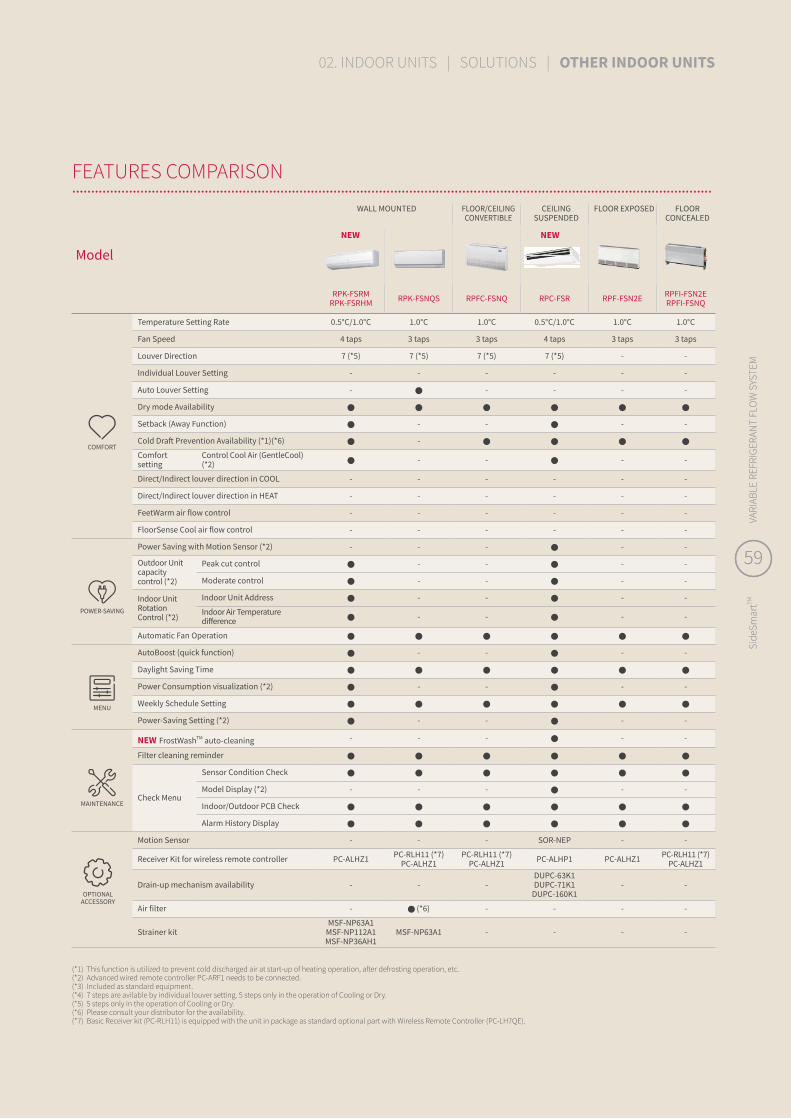
WALL MOUNTED FLOOR/CEILING CONVERTIBLE
CEILING SUSPENDED
FLOOR EXPOSED FLOOR CONCEALED
Model
RPK-FSRMRPK-FSRHM RPK-FSNQS RPFC-FSNQ RPC-FSR RPF-FSN2E RPFI-FSN2E
RPFI-FSNQ
COMFORT
Temperature Setting Rate 0.5°C/1.0°C 1.0°C 1.0°C 0.5°C/1.0°C 1.0°C 1.0°C
Fan Speed 4 taps 3 taps 3 taps 4 taps 3 taps 3 taps
Louver Direction 7 (*5) 7 (*5) 7 (*5) 7 (*5) - -
Individual Louver Setting - - - - - -
Auto Louver Setting - - - - -
Dry mode Availability
Setback (Away Function) - - - -
Cold Draft Prevention Availability (*1)(*6) -
Comfort setting
Control Cool Air (GentleCool) (*2) - - - -
Direct/Indirect louver direction in COOL - - - - - -
Direct/Indirect louver direction in HEAT - - - - - -
FeetWarm air flow control - - - - - -
FloorSense Cool air flow control - - - - - -
POWER-SAVING
Power Saving with Motion Sensor (*2) - - - - -
Outdoor Unit capacity control (*2)
Peak cut control - - - -
Moderate control - - - -
Indoor Unit Rotation Control (*2)
Indoor Unit Address - - - -
Indoor Air Temperature difference - - - -
Automatic Fan Operation
MENU
AutoBoost (quick function) - - - -
Daylight Saving Time
Power Consumption visualization (*2) - - - -
Weekly Schedule Setting
Power-Saving Setting (*2) - - - -
MAINTENANCE
NEW FrostWashTM auto-cleaning - - - - -
Filter cleaning reminder
Check Menu
Sensor Condition Check
Model Display (*2) - - - - -
Indoor/Outdoor PCB Check
Alarm History Display
Motion Sensor - - - SOR-NEP - -
Receiver Kit for wireless remote controller PC-ALHZ1 PC-RLH11 (*7)PC-ALHZ1
PC-RLH11 (*7)PC-ALHZ1 PC-ALHP1 PC-ALHZ1 PC-RLH11 (*7)
PC-ALHZ1
Drain-up mechanism availability - - -DUPC-63K1DUPC-71K1
DUPC-160K1- -
Air filter - (*6) - - - -
Strainer kitMSF-NP63A1
MSF-NP112A1MSF-NP36AH1
MSF-NP63A1 - - - -
(*1) This function is utilized to prevent cold discharged air at start-up of heating operation, after defrosting operation, etc. (*2) Advanced wired remote controller PC-ARF1 needs to be connected.(*3) Included as standard equipment.(*4) 7 steps are avilable by individual louver setting. 5 steps only in the operation of Cooling or Dry.(*5) 5 steps only in the operation of Cooling or Dry.(*6) Please consult your distributor for the availability.(*7) Basic Receiver kit (PC-RLH11) is equipped with the unit in package as standard optional part with Wireless Remote Controller (PC-LH7QE).
OPTIONAL ACCESSORY
NEW NEW
FEATURES COMPARISON..................................................................................................................................................................................................................................................................................................................................................
59
Side
Smar
tTMVA
RIAB
LE R
EFRI
GERA
NT
FLO
W S
YSTE
M
59
Side
Smar
tTMVA
RIAB
LE R
EFRI
GERA
NT
FLO
W S
YSTE
M
02. INDOOR UNITS | SOLUTIONS | OTHER INDOOR UNITS
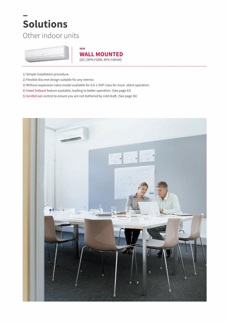
1) Simple installation procedure.
2) Flexible discreet design suitable for any interior.
3) Without expansion-valve model available for 0.6-1.5HP class for more silent operation.
4) Hotel Setback feature available, leading to better operation. (See page 42)
5) GentleCool control to ensure you are not bothered by cold draft. (See page 36)
WALL MOUNTED(DC) [RPK-FSRM, RPK-FSRHM]
NEW
–SolutionsOther indoor units

1) Simple installation procedure. Refrigerant piping can be connected from the rear, base, or left of the unit, providing much greater flexibility for piping and selection of installation sites.
2) Flexible design suitable for any décor. With smooth flat covers, the units match most modern interiors. Their compact size enables them to blend in, even in small spaces.
3) Easy maintenance. Front flat panel keeps the unit from dust and facilitates maintenance work. The front grille hinges open easily—no tools are needed to gain quick access to the filter. The filter can be removed and cleaned as required.
Discontinued in 2021.Please consult your distributor for more detail.
WALL MOUNTED (AC) [RPK-FSNQS]
61
Side
Smar
tTMVA
RIAB
LE R
EFRI
GERA
NT
FLO
W S
YSTE
M
61
Side
Smar
tTMVA
RIAB
LE R
EFRI
GERA
NT
FLO
W S
YSTE
M
02. INDOOR UNITS | SOLUTIONS | OTHER INDOOR UNITS
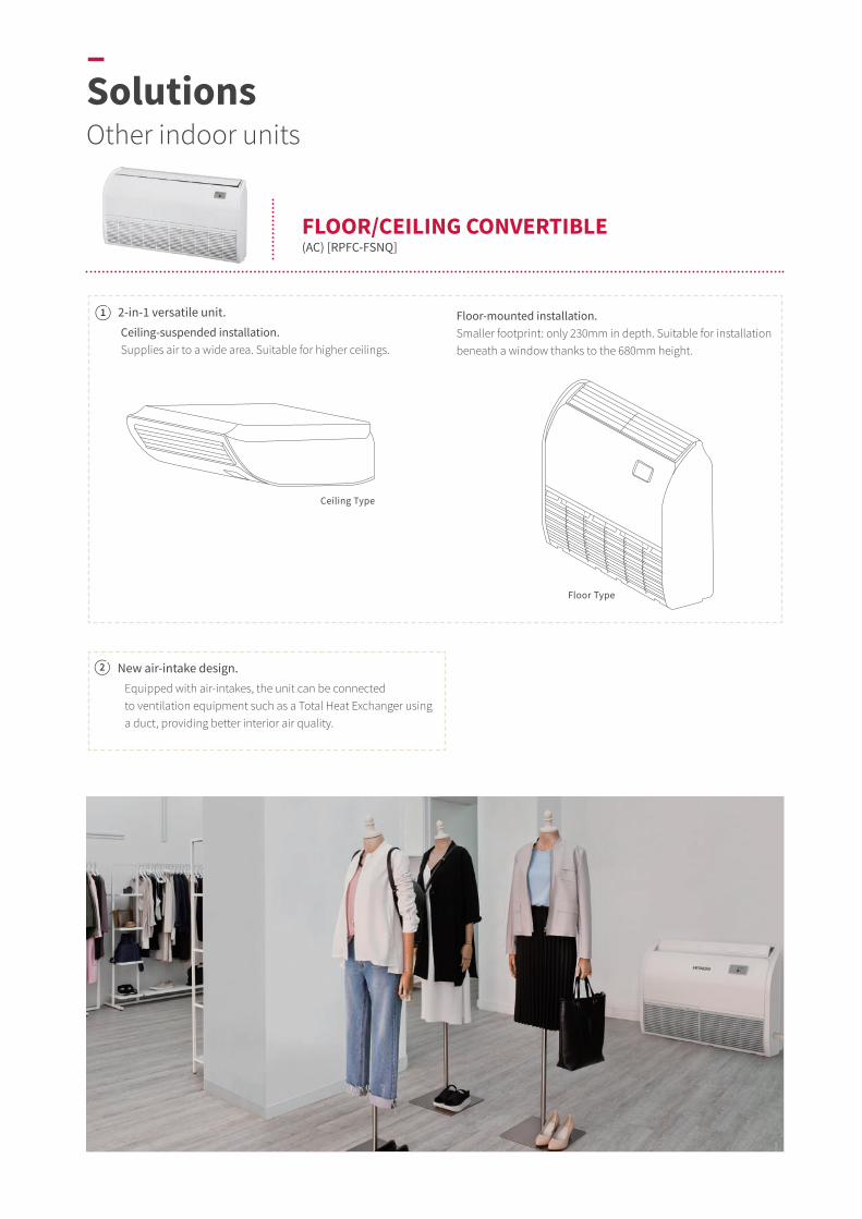
Ceiling Type
Equipped with air-intakes, the unit can be connected to ventilation equipment such as a Total Heat Exchanger using a duct, providing better interior air quality.
Floor Type
Ceiling-suspended installation.Supplies air to a wide area. Suitable for higher ceilings.
Floor-mounted installation.Smaller footprint: only 230mm in depth. Suitable for installation beneath a window thanks to the 680mm height.
2-in-1 versatile unit.
New air-intake design.
FLOOR/CEILING CONVERTIBLE(AC) [RPFC-FSNQ]
1
2
–SolutionsOther indoor units
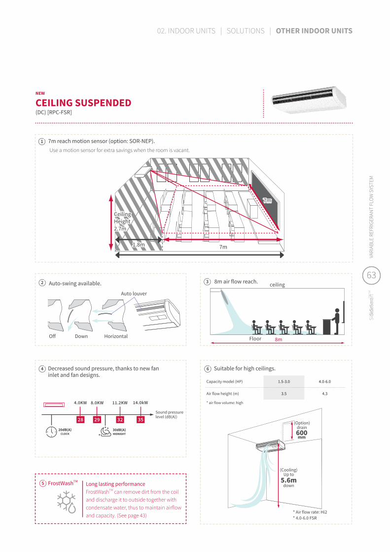
7m
7m
Ceiling Height2.7m
1.8m
Off Down Horizontal
Auto louver
(Option)drain600mm
(Cooling)Up to
5.6mdown
ceiling
Floor 8m
30dB(A)MIDNIGHTCLOCK
20dB(A)
Auto-swing available. 8m air flow reach.
7m reach motion sensor (option: SOR-NEP).Use a motion sensor for extra savings when the room is vacant.
* Air flow rate: Hi2* 4.0-6.0 FSR
Suitable for high ceilings.
Capacity model (HP) 1.5-3.0 4.0-6.0
Air flow height (m) 3.5 4.3
* air flow volume: high
Decreased sound pressure, thanks to new fan inlet and fan designs.
CEILING SUSPENDED (DC) [RPC-FSR]
NEW
1
2 3
4 6
Long lasting performanceFrostWashTM can remove dirt from the coil and discharge it to outside together with condensate water, thus to maintain airflow and capacity. (See page 43)
FrostWashTM5
4.0KW
Sound pressure level (dB(A))
8.0KW 11.2KW 14.0kW
28 29 32 35
63
Side
Smar
tTMVA
RIAB
LE R
EFRI
GERA
NT
FLO
W S
YSTE
M
63
Side
Smar
tTMVA
RIAB
LE R
EFRI
GERA
NT
FLO
W S
YSTE
M
02. INDOOR UNITS | SOLUTIONS | OTHER INDOOR UNITS

1,045mm
Air outlet
Air inlet
∙ Floor Exposed units can be installed with a minimum of disruption to walls and floors, making them an excellent retrofitting option.
∙ The 220mm depth means that little installation space is required.
∙ With a total height of up to 630mm, they are well suited to installation beneath a window.
FLOOR EXPOSED(AC) [RPF-FSN2E]
–SolutionsOther indoor units

620m
m
220mm
Air outlet
Air inlet
Cavity that conceals the unit
848-1,223mm
620m
m
202mm
Air outlet
Air inlet
Cavity that conceals the unit
900-1,170mm
FLOOR CONCEALED (AC) [RPFI-FSN2E]
∙ Blends unobtrusively with any interior décor: only the suction and discharge grilles are visible.
∙ Its low height (only 620mm) enables the unit to fit perfectly beneath a window.
∙ Requires little installation space thanks to its slim 220mm depth.
∙ Blends unobtrusively with any interior décor: only the suction and discharge grilles are visible.
∙ Its low height (only 620mm) enables the unit to fit perfectly beneath a window.
∙ Requires little installation space thanks to its slim 202mm depth.
FLOOR CONCEALED (AC) [RPFI-FSNQ]
65
Side
Smar
tTMVA
RIAB
LE R
EFRI
GERA
NT
FLO
W S
YSTE
M
65
Side
Smar
tTMVA
RIAB
LE R
EFRI
GERA
NT
FLO
W S
YSTE
M
02. INDOOR UNITS | SOLUTIONS | OTHER INDOOR UNITS

Notes:1. The nominal cooling capacity is the combined capacity of the Hitachi standard split system, and is based on
the JIS standard B8616.
2. The sound pressure level is based on following conditions. 1.5 metre Beneath the Unit. With Discharge Duct (2.0 metre) and Return Duct (1.0 metre). Voltage of the power source for the indoor fan motor is 220V. The above data was measured in an anechoic chamber so that reflected sound should be taken into consideration in the field.
3. The data for external pressure (*3) indicates "Standard Pressure Setting (High Pressure Setting1 - High Pressure Setting2)" values when a filter is not used. The sound pressure level is based on the Standard Pressure Setting.
Cooling Operation ConditionsIndoor Air Inlet Temperature: .........27.0ᵒC DB 19.0ᵒC WBOutdoor Air Inlet Temperature: .....35.0ᵒC DBPiping Length:7.5 metrePiping Lift:0 metre
Heating Operation ConditionsIndoor Air Inlet Temperature: .........20.0ᵒC DBOutdoor Air Inlet Temperature: .....7.0ᵒC DB 6.0ᵒC WBPiping Length:7.5 metrePiping Lift:0 metre
Receiver kit Advanced PC-ALHZ1Motion Sensor SOR-NEZ
Condensate Drain Pump Kit - (included as standard equipment)
Antifungal Long-Life Filter
2.0 (HP) F-56LI2.5-3.0 (HP) F-90LI4.0-6.0 (HP) F-160LI
Filter Box for Long-Life Filter
2.0 (HP) B-56LI2.5-3.0 (HP) B-90LI4.0-6.0 (HP) B-160LI
Long-Life Filter Kit/ Long-Life Filter 8.0-10.0 (HP) F-280LI
MotioFilter Boxn Sensor 8.0-10.0 (HP) B-280LI
Model RPI-2.0FSR RPI-2.5FSR RPI-3.0FSR RPI-4.0FSR RPI-5.0FSR RPI-6.0FSR RPI-8.0FSN1 RPI-10.0FSN1
Indoor Unit Power Supply AC 1Φ, [220-240V/50Hz] [220V/60Hz]Nominal Cooling Capacity kW 5.6 7.1 8.0 11.2 14.0 16.0 22.4 28.0Nominal Heating Capacity kW 6.3 8.5 9.0 12.5 16.0 18.0 25.0 31.5Sound Pressure Level (Overall A Scale)(Hi2/Hi/Me/Lo) dB(A) 41/38/35/32 37/35/32/30 39/36/33/31 40/37/34/32 42/39/36/33 44/40/37/34 44/40/37/34 44/40/37/34
Sound Power Level (Overall A Scale)(Hi2/Hi/Me/Lo) dB(A) 59/56/53/50 55/53/50/48 57/54/51/49 58/55/52/50 60/57/54/51 62/58/55/52 45/43/40/36 50/48/46/39
Outer Dimensions H×W×D mm 300×700×800 300×1,050×800 300×1,050×800 300×1,400×800 300×1,400×800 300×1,400×800 470×1,380×1,060 470×1,380×1,060
Net Weight kg 29 38 38 48 48 48 94 94Refrigerant R410A R410A R410A R410A R410A R410A R410A R410A
Indoor Fan Air Flow Rate (Hi2/Hi/Me/Lo)
m3/min (cfm)
14.5/13/ 11/9.5
(512/459/ 388/335)
18.5/16.5/ 14.5/12
(653/582/ 512/423)
20/17.5/ 15.5/13
(706/618/ 547/459)
30/26.5/ 23/20
(1,059/935/ 812/706)
33.5/29.5/ 26/22
(1,182/1,041/ 917/776)
36/31.5/ 27.5/24
(1,270/1,112/ 970/847)
63/58/ 50/38
(2,224/2,048/ 1,765/1,341)
80/72/ 64/48
(2,825/2,542/ 2,260/1,695)
External Pressure (*3) Pa 50(100-200) 50(100-200) 50(100-200) 50(100-200) 50(100-200) 50(100-200) 50(100-230) 50(100-230)Motor W 157 190 190 259 259 259 840 840Connections m3 Flare-Nut Connection (with Flare Nuts)
Refrigerant Piping
Liquid Line mm Φ6.35 Φ9.52 Φ9.52 Φ9.52 Φ9.52 Φ9.52 Φ9.52 Φ9.52Gas Line mm Φ12.7 Φ15.88 Φ15.88 Φ15.88 Φ15.88 Φ15.88 Φ19.05 Φ22.2Condensate Drain VP25 VP25 VP25 VP25 VP25 VP25 VP25 VP25
Approximate Packing Measurement m3 0.28 0.39 0.39 0.50 0.50 0.50 0.97 0.97
–Specifications & accessories
NEW
HIGH ESP HIGH EXTERNAL STATIC PRESSURE
(DC) [RPI-FSR, RPI-FSN1]
Model RPIM-0.8FSR RPIM-1.0FSR RPIM-1.5FSR RPIM-2.0FSR RPIM-2.5FSR RPIM-3.0FSR RPIM-4.0FSR RPIM-5.0FSR RPIM-6.0FSR
Indoor Unit Power Supply AC 1Φ, [220-240V/50Hz] [220V/60Hz]Nominal Cooling Capacity kW 2.2 2.8 4.0 5.6 7.1 8.0 11.2 14.0 16.0Nominal Heating Capacity kW 2.5 3.2 4.8 6.3 8.5 9.0 12.5 16.0 18.0Sound Pressure Level (Overall A Scale)(Hi2/Hi/Me/Lo) dB(A) 32/30/28/27 33/31/29/28 38/35/32/30 40/37/34/31 37/35/33/31 38/36/33/31 40/38/35/32 42/39/36/34 43/40/37/34
Sound Power Level (Overall A Scale)(Hi2/Hi/Me/Lo) dB(A) 50/48/46/45 51/49/47/46 56/53/50/48 58/55/52/49 55/53/51/49 56/54/51/49 58/56/53/50 60/57/54/52 61/58/55/52
Outer Dimensions H×W×D mm 250×700×800 250×700×800 250×700×800 250×700×800 250×1,050×800 250×1,050×800 250×1,400×800 250×1,400×800 250×1,400×800
Net Weight kg 26 26 27 27 36 36 44 44 44Refrigerant R410A R410A R410A R410A R410A R410A R410A R410A R410A
Indoor FanAir Flow Rate (Hi2/Hi/Me/Lo)
m3/min (cfm)
8.5/7.5/ 6.5/5.5
(300/265/229/194)
9.5/8.5/ 7.5/6.5
(335/300/265/229)
13/11.5/ 10/8.5
(459/406/353/300)
14.5/13/ 11/9.5
(512/459/388/335)
18.5/16.5/ 14/12
(653/582/494/423)
20/17.5/ 15.5/13
(706/618/547/459)
30/26.5/23/20
(1,059/935/812/706)
33.5/29.5/ 26/22
(1,182/1,041/917/776)
36/31.5/ 27.5/24
(1270/1,112/970/847)
External Pressure (*3) Pa 50(100-150) 50(100-150) 50(100-150) 50(100-150) 50(100-150) 50(100-150) 50(100-150) 50(100-150) 50(100-150)Motor W 157 157 157 157 190 190 259 259 259Connections m3 Flare-Nut Connection (with Flare Nuts)
Refrigerant Piping
Liquid Line mm Φ6.35 Φ6.35 Φ6.35 Φ6.35 Φ9.52 Φ9.52 Φ9.52 Φ9.52 Φ9.52Gas Line mm Φ12.7 Φ12.7 Φ12.7 Φ12.7 Φ15.88 Φ15.88 Φ15.88 Φ15.88 Φ15.88Condensate Drain VP25 VP25 VP25 VP25 VP25 VP25 VP25 VP25 VP25
Approximate Packing Measurement m3 0.24 0.24 0.24 0.24 0.33 0.33 0.42 0.42 0.42
2. The sound pressure level is based on following conditions. 1.5 metre Beneath the Unit. With Discharge Duct (2.0 metre) and Return Duct (1.0 metre). Voltage of the power source for the indoor fan motor is 220V. The above data was measured in an anechoic chamber so that reflected sound should be taken into consideration in the field.
3. The data for external pressure (*3) indicates "Standard Pressure Setting (High Pressure Setting1 - High Pressure Setting2)" values when a filter is not used. The sound pressure level is based on the Standard Pressure Setting.
Notes:1. The nominal cooling capacity is the combined capacity of the Hitachi standard
split system, and is based on the JIS standard B8616.
Cooling Operation ConditionsIndoor Air Inlet Temperature: .........27.0ᵒC DB 19.0ᵒC WBOutdoor Air Inlet Temperature: .....35.0ᵒC DBPiping Length:7.5 metrePiping Lift:0 metre
Heating Operation ConditionsIndoor Air Inlet Temperature: .........20.0ᵒC DBOutdoor Air Inlet Temperature: .....7.0ᵒC DB 6.0ᵒC WBPiping Length:7.5 metrePiping Lift:0 metre
Receiver kit Advanced PC-ALHZ1Motion Sensor SOR-NEZ
Condensate Drain Pump Kit - (included as standard equipment)
Antifungal Long-Life Filter
0.8-2.0 (HP) F-56LI2.5-3.0 (HP) F-90LI4.0-6.0 (HP) F-160LI
Filter Box for Long-Life Filter
0.8-2.0 (HP) B-56LI2.5-3.0 (HP) B-90LI4.0-6.0 (HP) B-160LI
NEW
MEDIUM ESP MEDIUM EXTERNAL STATIC PRESSURE
(DC) [RPIM-FSR]

Model RPIH-3.0HNAUNQ RPIH-3.3HNAUNQ RPIH-4.0HNAUNQ RPIH-5.0HNAUNQ RPIH-6.0HNAUNQ RPI-8.0FSNQ RPI-10.0FSNQ
Indoor Unit Power Supply AC 1Φ, [220-240V/50Hz] AC 3Φ, [380-415V/50Hz]
Nominal CapacityCooling kW 8.4 9.0 11.2 14.2 16.0 22.4 28.0 Heating kW 9.6 10.0 13.0 16.3 18.0 25.0 31.5
Sound Pressure Level (Hi/Me/Lo) dB(A) 42/39/34 42/39/34 43/39/34 44/41/37 48/42/37 50 52
Outer Dimension H×W×D mm 300×1,175×800 300×1,175×800 300×1,175×800 300×1,475×800 300×1,475×800 470×1,060×1,120 470×1,250×1,120
Net Weight kg 45 45 45 53 54 96 104Refrigerant R410A R410A R410A R410A R410A R410A R410AIndoor Fan Air Flow Rate (Hi/Me/Lo) m3/min 30/28/23 30/28/23 30/28/23 35.5/32/27 41/33/26 58 72
External Static Pressure (*3) Pa 120(90) 120(90) 120(90) 120(90) 120(90) 180 180Connections Flare-Nut Connection (with Flare Nuts) BrazingRefrigerant Piping Diameter
Liquid Line mm Φ9.52 Φ9.52 Φ9.52 Φ9.52 Φ9.52 Φ9.52 Φ9.52Gas Line mm Φ15.88 Φ15.88 Φ15.88 Φ15.88 Φ15.88 Φ19.05 Φ22.23
Condensate Drain VP25 VP25 VP25 VP25 VP25 VP25 VP25Approximate Packing Volume m3 0.40 0.40 0.40 0.49 0.49 0.90 1.06
Receiver KitBasic PC-RLH11
Advanced PC-ALHZ1Condensate Drain Pump Kit
PRIH-HNAUNQ DUPI-361QPRI-FSNQ DUPI-15H2Q
Air filter3.0-4.0 (HP) KW-PP9Q
5.0-6.0 (HP) KW-PP10Q
Notes:1. The cooling capacities above show the maximum capacities when the outdoor and indoor temperature are under
the following conditions.
Cooling Operation ConditionsIndoor Air Inlet Temperature: .........27.0ᵒC DB 19.0ᵒC WBOutdoor Air Inlet Temperature: .....35.0ᵒC DBPiping Length:7.5 metrePiping Lift:0 metre
Heating Operation ConditionsIndoor Air Inlet Temperature: .........20.0ᵒC DBOutdoor Air Inlet Temperature: .....7.0ᵒC DB 6.0ᵒC WBPiping Length:7.5 metrePiping Lift:0 metre
2. The sound pressure level is based on following conditions. 1.4 metre Beneath the unit.With Discharge Duct (2.0 metre) and Return Duct (1.0 metre). Voltage of the power source for the indoor fan motor is 220V.(In case of the power source of 240V, the sound pressure level increases by about 1~2dB(A).)The above data was measured in an anechoic chamber so that reflected sound should be taken into consideration in the field.
3. The data for external pressure (*3) indicates "Standard Pressure Setting values when a filter is not used.
HIGH ESP HIGH EXTERNAL STATIC PRESSURE
(AC) [RPIH-HNAUNQ, RPI-FSNQ]
Receiver KitBasic PC-RLH11
Advanced PC-ALHZ1Condensate Drain Pump Kit
0.8-2.5 (HP) DUPI-131Q8.0-10.0 (HP) DUPI-15H2Q
Air filter0.8-1.5 (HP) KW-PP7Q1.8-2.5 (HP) KW-PP8Q
Model RPIM-0.8HNAUNQ
RPIM-1.0HNAUNQ
RPIM-1.3HNAUNQ
RPIM-1.5HNAUNQ
RPIM-1.8HNAUNQ
RPIM-2.0HNAUNQ
RPIM-2.3HNAUNQ
RPIM-2.5HNAUNQ
RPI-8.0FSN3Q
RPI-10.0FSN3Q
Indoor Unit Power Supply AC 1Φ, [220-240V/50Hz] AC 3Φ, [380-415V/50Hz]
Nominal CapacityCooling kW 2.2 2.8 3.6 4.3 5.0 5.6 6.3 7.1 22.4 28.0 Heating kW 2.8 3.3 4.2 4.9 5.6 6.5 7.5 8.5 25.0 31.5
Sound Pressure Level (Hi/Me/Lo) dB(A) 32/27/24 32/27/24 35/33/28 35/33/28 35.5/33/28 35.5/33/28 39/34/26 39/34/26 50 52
Outer Dimension (H×W×D) mm 270×725×720
270×725×720
270×725×720
270×725×720
270×975×720
270×975×720
270×975×720
270×975×720
470×1,060×1,120
470×1,250×1,120
Net Weight kg 24 24 25 25 31 31 32 32 96 104Refrigerant R410A R410A R410A R410A R410A R410A R410A R410A R410A R410AIndoor Fan Air Flow Rate (Hi/Me/Lo) m3/min 10/8/7 10/8/7 12/11/9 12/11/9 16/14/11.5 16/14/11.5 20/16/11 20/16/11 58(56*) 72(70*)
External Static Pressure (*3) Pa 50(80) 50(80) 50(80) 50(80) 50(80) 50(80) 50(80) 50(80) 100 100Connections Flare-Nut Connection (with Flare Nuts) BrazingRefrigerant Piping Diameter
Liquid Line mm Φ6.35 Φ6.35 Φ6.35 Φ6.35 Φ6.35 Φ6.35 Φ9.52 Φ9.52 Φ9.52 Φ9.52Gas Line mm Φ12.7 Φ12.7 Φ12.7 Φ12.7 Φ15.88 Φ15.88 Φ15.88 Φ15.88 Φ19.05 Φ22.23
Condensate Drain VP25 VP25 VP25 VP25 VP25 VP25 VP25 VP25 VP25 VP25Approximate Packing Volume m3 0.22 0.22 0.22 0.22 0.28 0.28 0.28 0.28 0.90 1.06
Notes:1. The cooling capacities above show the maximum capacities when the outdoor and indoor temperature are under the following
conditions.
Cooling Operation ConditionsIndoor Air Inlet Temperature: .........27.0ᵒC DB 19.0ᵒC WBOutdoor Air Inlet Temperature: .....35.0ᵒC DBPiping Length:7.5 metrePiping Lift:0 metre
Heating Operation ConditionsIndoor Air Inlet Temperature: .........20.0ᵒC DBOutdoor Air Inlet Temperature: .....7.0ᵒC DB 6.0ᵒC WBPiping Length:7.5 metrePiping Lift:0 metre
2. The sound pressure level is based on following conditions. 1.4 metre Beneath the unit. With Discharge Duct (2.0 metre) and Return Duct (1.0 metre). Voltage of the power source for the indoor fan motor is 220V. (In case of the power source of 240V, the sound pressure level increases by about 1~2dB(A).) The above data was measured in an anechoic chamber so that reflected sound should be taken into consideration in the field.
3. The data for external pressure (*3) indicates "Standard Pressure Setting values when a filter is not used.
MEDIUM ESP MEDIUM EXTERNAL STATIC PRESSURE
(AC) [RPIM-HNAUNQ, RPI-FSN3Q]
67
Side
Smar
tTMVA
RIAB
LE R
EFRI
GERA
NT
FLO
W S
YSTE
M
67
Side
Smar
tTMVA
RIAB
LE R
EFRI
GERA
NT
FLO
W S
YSTE
M
02. INDOOR UNITS | SPECIFICATIONS & ACCESSORIES
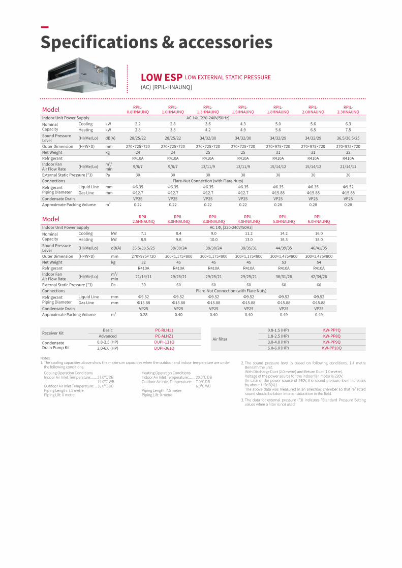
Model RPIL-0.8HNAUNQ
RPIL-1.0HNAUNQ
RPIL-1.3HNAUNQ
RPIL-1.5HNAUNQ
RPIL-1.8HNAUNQ
RPIL-2.0HNAUNQ
RPIL-2.3HNAUNQ
Indoor Unit Power Supply AC 1Φ, [220-240V/50Hz] Nominal Capacity
Cooling kW 2.2 2.8 3.6 4.3 5.0 5.6 6.3Heating kW 2.8 3.3 4.2 4.9 5.6 6.5 7.5
Sound Pressure Level (Hi/Me/Lo) dB(A) 28/25/22 28/25/22 34/32/30 34/32/30 34/32/29 34/32/29 36.5/30.5/25
Outer Dimension (H×W×D) mm 270×725×720 270×725×720 270×725×720 270×725×720 270×975×720 270×975×720 270×975×720Net Weight kg 24 24 25 25 31 31 32Refrigerant R410A R410A R410A R410A R410A R410A R410AIndoor Fan Air Flow Rate (Hi/Me/Lo) m3/
min 9/8/7 9/8/7 13/11/9 13/11/9 15/14/12 15/14/12 21/14/11
External Static Pressure (*3) Pa 30 30 30 30 30 30 30Connections Flare-Nut Connection (with Flare Nuts)Refrigerant Piping Diameter
Liquid Line mm Φ6.35 Φ6.35 Φ6.35 Φ6.35 Φ6.35 Φ6.35 Φ9.52Gas Line mm Φ12.7 Φ12.7 Φ12.7 Φ12.7 Φ15.88 Φ15.88 Φ15.88
Condensate Drain VP25 VP25 VP25 VP25 VP25 VP25 VP25Approximate Packing Volume m3 0.22 0.22 0.22 0.22 0.28 0.28 0.28
Model RPIL-2.5HNAUNQ
RPIL-3.0HNAUNQ
RPIL-3.3HNAUNQ
RPIL-4.0HNAUNQ
RPIL-5.0HNAUNQ
RPIL-6.0HNAUNQ
Indoor Unit Power Supply AC 1Φ, [220-240V/50Hz] Nominal Capacity
Cooling kW 7.1 8.4 9.0 11.2 14.2 16.0Heating kW 8.5 9.6 10.0 13.0 16.3 18.0
Sound Pressure Level (Hi/Me/Lo) dB(A) 36.5/30.5/25 38/30/24 38/30/24 38/35/31 44/39/35 46/41/35
Outer Dimension (H×W×D) mm 270×975×720 300×1,175×800 300×1,175×800 300×1,175×800 300×1,475×800 300×1,475×800Net Weight kg 32 45 45 45 53 54Refrigerant R410A R410A R410A R410A R410A R410AIndoor Fan Air Flow Rate (Hi/Me/Lo) m3/
min 21/14/11 29/25/21 29/25/21 29/25/21 36/31/26 42/34/26
External Static Pressure (*3) Pa 30 60 60 60 60 60Connections Flare-Nut Connection (with Flare Nuts)Refrigerant Piping Diameter
Liquid Line mm Φ9.52 Φ9.52 Φ9.52 Φ9.52 Φ9.52 Φ9.52Gas Line mm Φ15.88 Φ15.88 Φ15.88 Φ15.88 Φ15.88 Φ15.88
Condensate Drain VP25 VP25 VP25 VP25 VP25 VP25Approximate Packing Volume m3 0.28 0.40 0.40 0.40 0.49 0.49
2. The sound pressure level is based on following conditions. 1.4 metre Beneath the unit.With Discharge Duct (2.0 metre) and Return Duct (1.0 metre).Voltage of the power source for the indoor fan motor is 220V.(In case of the power source of 240V, the sound pressure level increases by about 1~2dB(A).)The above data was measured in an anechoic chamber so that reflected sound should be taken into consideration in the field.
3. The data for external pressure (*3) indicates "Standard Pressure Setting values when a filter is not used.
Notes:1. The cooling capacities above show the maximum capacities when the outdoor and indoor temperature are under
the following conditions.Cooling Operation ConditionsIndoor Air Inlet Temperature: .......27.0ᵒC DB 19.0ᵒC WB Outdoor Air Inlet Temperature: ...35.0ᵒC DB Piping Length: 7.5 metrePiping Lift: 0 metre
Heating Operation ConditionsIndoor Air Inlet Temperature: ....... 20.0ᵒC DBOutdoor Air Inlet Temperature: ... 7.0ᵒC DB 6.0ᵒC WBPiping Length: 7.5 metrePiping Lift: 0 metre
Receiver KitBasic PC-RLH11
Advanced PC-ALHZ1Condensate Drain Pump Kit
0.8-2.5 (HP) DUPI-131Q3.0-6.0 (HP) DUPI-361Q
Air filter
0.8-1.5 (HP) KW-PP7Q1.8-2.5 (HP) KW-PP8Q3.0-4.0 (HP) KW-PP9Q5.0-6.0 (HP) KW-PP10Q
–Specifications & accessories
LOW ESP LOW EXTERNAL STATIC PRESSURE
(AC) [RPIL-HNAUNQ]
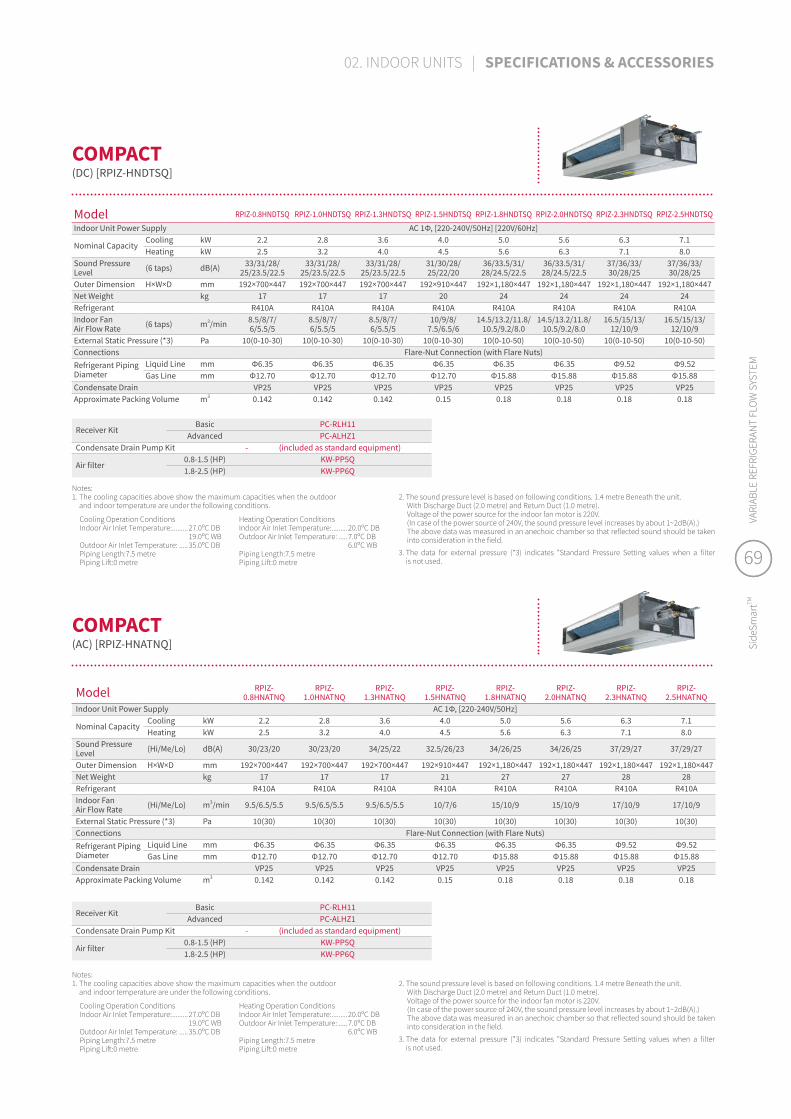
Model RPIZ-0.8HNDTSQ RPIZ-1.0HNDTSQ RPIZ-1.3HNDTSQ RPIZ-1.5HNDTSQ RPIZ-1.8HNDTSQ RPIZ-2.0HNDTSQ RPIZ-2.3HNDTSQ RPIZ-2.5HNDTSQ
Indoor Unit Power Supply AC 1Φ, [220-240V/50Hz] [220V/60Hz]
Nominal CapacityCooling kW 2.2 2.8 3.6 4.0 5.0 5.6 6.3 7.1Heating kW 2.5 3.2 4.0 4.5 5.6 6.3 7.1 8.0
Sound Pressure Level (6 taps) dB(A) 33/31/28/
25/23.5/22.533/31/28/
25/23.5/22.533/31/28/
25/23.5/22.531/30/28/25/22/20
36/33.5/31/28/24.5/22.5
36/33.5/31/28/24.5/22.5
37/36/33/30/28/25
37/36/33/30/28/25
Outer Dimension H×W×D mm 192×700×447 192×700×447 192×700×447 192×910×447 192×1,180×447 192×1,180×447 192×1,180×447 192×1,180×447Net Weight kg 17 17 17 20 24 24 24 24Refrigerant R410A R410A R410A R410A R410A R410A R410A R410AIndoor Fan Air Flow Rate (6 taps) m3/min 8.5/8/7/
6/5.5/58.5/8/7/ 6/5.5/5
8.5/8/7/ 6/5.5/5
10/9/8/ 7.5/6.5/6
14.5/13.2/11.8/10.5/9.2/8.0
14.5/13.2/11.8/10.5/9.2/8.0
16.5/15/13/12/10/9
16.5/15/13/12/10/9
External Static Pressure (*3) Pa 10(0-10-30) 10(0-10-30) 10(0-10-30) 10(0-10-30) 10(0-10-50) 10(0-10-50) 10(0-10-50) 10(0-10-50)Connections Flare-Nut Connection (with Flare Nuts)Refrigerant Piping Diameter
Liquid Line mm Φ6.35 Φ6.35 Φ6.35 Φ6.35 Φ6.35 Φ6.35 Φ9.52 Φ9.52Gas Line mm Φ12.70 Φ12.70 Φ12.70 Φ12.70 Φ15.88 Φ15.88 Φ15.88 Φ15.88
Condensate Drain VP25 VP25 VP25 VP25 VP25 VP25 VP25 VP25Approximate Packing Volume m3 0.142 0.142 0.142 0.15 0.18 0.18 0.18 0.18
Receiver KitBasic PC-RLH11
Advanced PC-ALHZ1Condensate Drain Pump Kit - (included as standard equipment)
Air filter0.8-1.5 (HP) KW-PP5Q1.8-2.5 (HP) KW-PP6Q
2. The sound pressure level is based on following conditions. 1.4 metre Beneath the unit.With Discharge Duct (2.0 metre) and Return Duct (1.0 metre).Voltage of the power source for the indoor fan motor is 220V.(In case of the power source of 240V, the sound pressure level increases by about 1~2dB(A).)The above data was measured in an anechoic chamber so that reflected sound should be taken into consideration in the field.
3. The data for external pressure (*3) indicates "Standard Pressure Setting values when a filter is not used.
Notes:1. The cooling capacities above show the maximum capacities when the outdoor
and indoor temperature are under the following conditions.
Cooling Operation ConditionsIndoor Air Inlet Temperature: .........27.0ᵒC DB 19.0ᵒC WBOutdoor Air Inlet Temperature: .....35.0ᵒC DBPiping Length:7.5 metrePiping Lift:0 metre
Heating Operation ConditionsIndoor Air Inlet Temperature: .........20.0ᵒC DBOutdoor Air Inlet Temperature: .....7.0ᵒC DB 6.0ᵒC WBPiping Length:7.5 metrePiping Lift:0 metre
COMPACT
(DC) [RPIZ-HNDTSQ]
Model RPIZ-0.8HNATNQ
RPIZ-1.0HNATNQ
RPIZ-1.3HNATNQ
RPIZ-1.5HNATNQ
RPIZ-1.8HNATNQ
RPIZ-2.0HNATNQ
RPIZ-2.3HNATNQ
RPIZ-2.5HNATNQ
Indoor Unit Power Supply AC 1Φ, [220-240V/50Hz]
Nominal CapacityCooling kW 2.2 2.8 3.6 4.0 5.0 5.6 6.3 7.1Heating kW 2.5 3.2 4.0 4.5 5.6 6.3 7.1 8.0
Sound Pressure Level (Hi/Me/Lo) dB(A) 30/23/20 30/23/20 34/25/22 32.5/26/23 34/26/25 34/26/25 37/29/27 37/29/27
Outer Dimension H×W×D mm 192×700×447 192×700×447 192×700×447 192×910×447 192×1,180×447 192×1,180×447 192×1,180×447 192×1,180×447Net Weight kg 17 17 17 21 27 27 28 28Refrigerant R410A R410A R410A R410A R410A R410A R410A R410AIndoor Fan Air Flow Rate (Hi/Me/Lo) m3/min 9.5/6.5/5.5 9.5/6.5/5.5 9.5/6.5/5.5 10/7/6 15/10/9 15/10/9 17/10/9 17/10/9
External Static Pressure (*3) Pa 10(30) 10(30) 10(30) 10(30) 10(30) 10(30) 10(30) 10(30)Connections Flare-Nut Connection (with Flare Nuts)Refrigerant Piping Diameter
Liquid Line mm Φ6.35 Φ6.35 Φ6.35 Φ6.35 Φ6.35 Φ6.35 Φ9.52 Φ9.52Gas Line mm Φ12.70 Φ12.70 Φ12.70 Φ12.70 Φ15.88 Φ15.88 Φ15.88 Φ15.88
Condensate Drain VP25 VP25 VP25 VP25 VP25 VP25 VP25 VP25Approximate Packing Volume m3 0.142 0.142 0.142 0.15 0.18 0.18 0.18 0.18
Receiver KitBasic PC-RLH11
Advanced PC-ALHZ1Condensate Drain Pump Kit - (included as standard equipment)
Air filter0.8-1.5 (HP) KW-PP5Q1.8-2.5 (HP) KW-PP6Q
Notes:1. The cooling capacities above show the maximum capacities when the outdoor
and indoor temperature are under the following conditions.
Cooling Operation ConditionsIndoor Air Inlet Temperature: .........27.0ᵒC DB 19.0ᵒC WBOutdoor Air Inlet Temperature: .....35.0ᵒC DBPiping Length:7.5 metrePiping Lift:0 metre
Heating Operation ConditionsIndoor Air Inlet Temperature: .........20.0ᵒC DBOutdoor Air Inlet Temperature: .....7.0ᵒC DB 6.0ᵒC WBPiping Length:7.5 metrePiping Lift:0 metre
2. The sound pressure level is based on following conditions. 1.4 metre Beneath the unit.With Discharge Duct (2.0 metre) and Return Duct (1.0 metre).Voltage of the power source for the indoor fan motor is 220V.(In case of the power source of 240V, the sound pressure level increases by about 1~2dB(A).)The above data was measured in an anechoic chamber so that reflected sound should be taken into consideration in the field.
3. The data for external pressure (*3) indicates "Standard Pressure Setting values when a filter is not used.
COMPACT
(AC) [RPIZ-HNATNQ]
69
Side
Smar
tTMVA
RIAB
LE R
EFRI
GERA
NT
FLO
W S
YSTE
M
69
Side
Smar
tTMVA
RIAB
LE R
EFRI
GERA
NT
FLO
W S
YSTE
M
02. INDOOR UNITS | SPECIFICATIONS & ACCESSORIES

Model RPI-3.0FSN2SQ RPI-4.0FSN2SQ RPI-5.0FSN2SQ RPI-6.0FSN2SQ RPI-7.0FSN2SQ
Indoor Unit Power Supply AC 1 Φ, [220-240V/50Hz] AC 1Φ, [240V/50Hz]Nominal Cooling Capacity kW 8.0 11.2 14.0 16.0 18.0Nominal Heating Capacity kW 9.0 12.5 16.0 18.0 20.0
Sound Pressure Level (Overall A Scale)(Hi/Me/Lo)
High Pressure Setting dB(A) 46/44/40 48/45/41 49/46/43 53/49/45 51/47/42
Standard Pressure Setting
dB(A) 45/43/39 47/44/40 48/45/42 52/48/44 -
Outer Dimensions H×W×D mm 350×1,076×800 350×1,076×800 350×1,300×800 350×1,300×800 440×1,430×550Net Weight kg 52 57 61 63 75Refrigerant R410A R410A R410A R410A R410A
Indoor Fan High Pressure Setting
m3/min (l/s)
29/26/20 (483/433/333)
36/33/25 (600/550/417)
47/43/34 (783/717/567)
56/50/40 (933/833/667)
65/57/46 (1,083/950/767)
Air Flow Rate (Hi/Me/Lo)
Standard Pressure Setting
m3/min (l/s)
29/26/20 (483/433/333)
36/29/25 (600/483/417)
47/39/36 (783/650/600)
56/48/42 (933/800/700) -
External Pressure (*1) Pa 120 (70) 120 (70) 120 (70) 120 (70) 140Motor Output W 250 300 420 550 650Connections Flare-Nut Connection (with Flare Nuts)
Refrigerant Piping
Liquid Line mm Φ9.52 Φ9.52 Φ9.52 Φ9.52 Φ9.52Gas Line mm Φ15.88 Φ15.88 Φ15.88 Φ15.88 Φ15.88Condensate Drain VP25 VP25 VP25 VP25 VP25
Approximate Packing Measurement m3 0.49 0.49 0.57 0.57 0.54
Receiver kitBasic PC-RLH11
Advanced PC-ALHZ1
Notes:1. The cooling capacities above show the maximum capacities when the outdoor and indoor temperature are under
the following conditions.Cooling Operation ConditionsIndoor Air Inlet Temperature: ........... 27.0ᵒC DB 19.0ᵒC WBOutdoor Air Inlet Temperature: ....... 35.0ᵒC DBPiping Length: 7.5 metrePiping Lift: 0 metre
Heating Operation ConditionsIndoor Air Inlet Temperature: ...........20.0ᵒC DBOutdoor Air Inlet Temperature: .......7.0ᵒC DB 6.0ᵒC WBPiping Length: 7.5 metrePiping Lift: 0 metre
2. The sound pressure level is based on following conditions. 1.5 metre Beneath the Unit. With Discharge Duct (2.0 metre) and Return Duct (1.0 metre). Voltage of the power source for the indoor fan motor is 220V. In case of the power source of 240V, the sound pressure level increases by about 1 or 2dB(A). The data in the table above was measured in an anechoic chamber so that reflected sound should be taken into consideration in the field.
3. The data for external pressure (*1) indicates "High Pressure Setting (Standard Pressure Setting)" values when a filter is not used. The sound pressure level is based on the Standard Pressure Setting.
LARGER AIR VOLUME (AC) [RPI-FSN2SQ]
–Specifications & accessories

Model RCI-1.0FSRP RCI-1.5FSRP RCI-2.0FSRP RCI-2.5FSRP RCI-3.0FSRP RCI-4.0FSRP RCI-5.0FSRP RCI-6.0FSRP
Indoor Unit Power Supply AC 1Φ, [220-240V/50Hz] [220V/60Hz]Nominal Capacity
Cooling kW 2.8 4.0 5.6 7.1 8.0 11.2 14.0 16.0Heating kW 3.2 4.8 6.3 8.5 9.0 12.5 16.0 18.0
Sound Pressure Level (Hi2/Hi/Me/Lo) dB(A) 33/30/28/27 35/31/30/27 37/32/30/27 42/36/32/28 42/36/32/28 48/43/39/33 48/45/40/35 48/46/41/37
Outer Dimension (H×W×D) mm 248×840×840 248×840×840 248×840×840 248×840×840 298×840×840 298×840×840 298×840×840 298×840×840Net Weight kg 20 21 21 22 26 26 26 26Refrigerant R410A R410A R410A R410A R410A R410A R410A R410AIndoor Fan Air Flow Rate (Hi2/Hi/Me/Lo) m3/min 15/13/11/9 21/17/14/11 22/17/14/11 27/23/18/14 27/23/18/14 37/31/24/20 37/33/26/21 37/35/28/22
Connections Flare-Nut Connection (with flare Nuts)Refrigerant Piping Diameter
Liquid Line mm Φ6.35 Φ6.35 Φ6.35 Φ9.52 Φ9.52 Φ9.52 Φ9.52 Φ9.52Gas Line mm Φ12.7 Φ12.7 Φ15.88 Φ15.88 Φ15.88 Φ15.88 Φ15.88 Φ15.88
Condensate Drain VP25 VP25 VP25 VP25 VP25 VP25 VP25 VP25Approximate Packing Volume m3 0.21 0.21 0.21 0.21 0.25 0.25 0.25 0.25
2. The sound pressure level is based on following conditions. 1.5 metre Beneath the unit. The data in the table above was measured in an anechoic chamber so that reflected sound should be taken into consideration in the field.
Cooling Operation ConditionsIndoor Air Inlet Temperature: ...................... 27.0ᵒC DB 19.0ᵒC WBOutdoor Air Inlet Temperature: .................. 35.0ᵒC DBPiping Length:7.5 metrePiping Lift:0 metre
Heating Operation ConditionsIndoor Air Inlet Temperature: ...................... 20.0ᵒC DBOutdoor Air Inlet Temperature: .................. 7.0ᵒC DB 6.0ᵒC WBPiping Length:7.5 metrePiping Lift:0 metre
Notes:1. The cooling and heating capacities above show the maximum capacities when the outdoor and indoor
temperature are under the following conditions.
Decoration panelTwin-Sense panel P-AP160NAE2Standard (without
sensor) P-AP160NA3
Receiver kit Advanced PC-ALH3
Condensate Drain Pump Kit - (Standard)
Duct Adapter PD-75AFresh Air Intake Kit OACI-160K3
3-Way Outlet Parts Set PI-160LS2T-Pipe Connection Kit TKCI-160KAntibacterial Long Life Air Filter F-160L-K
Deodorant Air Filter1.0-2.5 (HP) F-71L-D13.0-6.0 (HP) F-160L-D1
Filter Box B-160H3
4-WAY CASSETTE(DC) [RCI-FSRP]
NEW
Neutral White Beige Gray Black
Model RCI-1.0FSKDNQ RCI-1.5FSKDNQ RCI-2.0FSKDNQ RCI-2.5FSKDNQ RCI-3.0FSKDNQ RCI-4.0FSKDNQ RCI-5.0FSKDNQ RCI-6.0FSKDNQ
Indoor Unit Power Supply AC 1Φ, [220-240V/50Hz] [220V/60Hz]Nominal Capacity
Cooling kW 2.8 4.0 5.6 7.1 8.0 11.2 14.0 16.0Heating kW 3.2 4.8 6.3 8.5 9.0 12.5 16.0 18.0
Sound Pressure Level (Hi2/Hi/Me/Lo) dB(A) 33/30/28/27 35/31/30/27 37/32/30/27 42/36/32/28 42/36/32/28 48/43/39/33 48/45/40/35 48/46/41/37
Outer Dimension (H×W×D) mm 238×840×840 238×840×840 238×840×840 238×840×840 288×840×840 288×840×840 288×840×840 288×840×840Net Weight kg 20 21 21 22 26 26 26 26Refrigerant R410A R410A R410A R410A R410A R410A R410A R410AIndoor Fan Air Flow Rate (Hi2/Hi/Me/Lo) m3/min 15/13/11/9 21/17/14/11 22/17/14/11 27/23/18/14 27/23/18/14 37/31/24/20 37/33/26/21 37/35/28/22
Connections Flare-Nut Connection (with flare Nuts)Refrigerant Piping Diameter
Liquid Line mm Φ6.35 Φ6.35 Φ6.35 Φ9.52 Φ9.52 Φ9.52 Φ9.52 Φ9.52Gas Line mm Φ12.7 Φ12.7 Φ12.7 Φ15.88 Φ15.88 Φ15.88 Φ15.88 Φ15.88
Condensate Drain VP25 VP25 VP25 VP25 VP25 VP25 VP25 VP25Approximate Packing Volume m3 0.21 0.21 0.21 0.21 0.25 0.25 0.25 0.25
2. The sound pressure level is based on following conditions. 1.5 metre Beneath the unit. The data in the table above was measured in an anechoic chamber so that reflected sound should be taken into consideration in the field.
3. Decoration panel is included.
Cooling Operation ConditionsIndoor Air Inlet Temperature: ...................... 27.0ᵒC DB (80.0ᵒF DB) 19.0ᵒC WB (66.2ᵒF WB)Outdoor Air Inlet Temperature: .................. 35.0ᵒC DB (95.0ᵒF DB)Piping Length: 7.5 metrePiping Lift: 0 metre
Heating Operation ConditionsIndoor Air Inlet Temperature: ...................... 20.0ᵒC DB (68.0ᵒF DB)Outdoor Air Inlet Temperature: .................. 7.0ᵒC DB (45.0ᵒF DB) 6.0ᵒC WB (43.0ᵒF WB)Piping Length: 7.5 metrePiping Lift: 0 metre
Notes:1. The cooling and heating capacities above show the maximum capacities when the outdoor and indoor temperature are under the following conditions.
Decoration Panel - (Standard)
Receiver KitBasic HR4A10NEWQ
Advanced PC-ALH3Motion Sensor PS-MSK2Condensate Drain Pump Kit - (Standard)Duct Adapter PD-75A
4-WAY CASSETTE
(DC) [RCI-FSKDNQ]
71
Side
Smar
tTMVA
RIAB
LE R
EFRI
GERA
NT
FLO
W S
YSTE
M
71
Side
Smar
tTMVA
RIAB
LE R
EFRI
GERA
NT
FLO
W S
YSTE
M
02. INDOOR UNITS | SPECIFICATIONS & ACCESSORIES

2. The sound pressure level is based on following conditions. 1.5 metre Beneath the unit. The data in the table above was measured in an anechoic chamber so that reflected sound should be taken into consideration in the field.
3. RCIM-0.6FSRE cannot be connected to HNRQ series. Please refer to the technical catalogue for the details.
Cooling Operation ConditionsIndoor Air Inlet Temperature: ......................27.0ᵒC DB 19.0ᵒC WBOutdoor Air Inlet Temperature: .................. 35.0ᵒC DBPiping Length:7.5 metrePiping Lift:0 metre
Heating Operation ConditionsIndoor Air Inlet Temperature: ...................... 20.0ᵒC DBOutdoor Air Inlet Temperature: .................. 7.0ᵒC DB 6.0ᵒC WBPiping Length:7.5 metrePiping Lift:0 metre
Notes:1. The cooling and heating capacities above show the maximum capacities when the outdoor and indoor temperature are under the following conditions.
Model RCIM-0.6FSRE RCIM-0.8FSRE RCIM-1.0FSRE RCIM-1.5FSRE RCIM-2.0FSRE RCIM-2.5FSRE
Indoor Unit Power Supply AC 1Φ, [230V/50Hz] [220-240V/50Hz] [220V/60Hz]Nominal Capacity
Cooling kW 1.6 2.2 2.8 4.0 5.6 7.1Heating kW 1.9 2.5 3.2 4.8 6.3 8.5
Sound Pressure Level (Hi2/Hi/Me/Lo) dB(A) 34/30/28/24.5 36/33/29/24.5 38/34/30/24.5 41/37/33/27.5 45/39/35/31 47/43/39/35
Outer Dimension (H×W×D) mm 285×570×570 285×570×570 285×570×570 285×570×570 285×570×570 285×570×570Net Weight kg 16 16 16 16 17 17Refrigerant R410A R410A R410A R410A R410A R410AIndoor Fan Air Flow Rate (Hi2/Hi/Me/Lo) m3/min 10/8.5/7.5/6 11/9.5/8/6 12/10/8.5/6 13/11/9.5/7 15/12/10/8 16/14/12/10
Connections Flare-Nut Connection (with Flare Nuts)Refrigerant Piping Diameter
Liquid Line mm Φ6.35 Φ6.35 Φ6.35 Φ6.35 Φ6.35 Φ9.52Gas Line mm Φ12.7 Φ12.7 Φ12.7 Φ12.7 Φ12.7 Φ15.88
Condensate Drain VP25 VP25 VP25 VP25 VP25 VP25Approximate Packing Volume m3 0.13 0.13 0.13 0.13 0.13 0.13
Decoration panel P-AP56NAMDecoration panel with Receiver Kit Advanced P-AP56NAMRReceiver kit Advanced PC-ALHC1Motion Sensor SOR-NECCondensate Drain Pump Kit - (Standard)Duct Adapter PD-75C
Model P-GP160NAP P-GP160NAPU P-GP160KAP
Standard/option Design Panel Standard Design Panel with an Elevation Grille Design Panel Standard
Color Natural White Natural White Black
–Specifications & accessories
NEW
4-WAY CASSETTE COMPACT (DC) [RCIM-FSRE]
SILENT-ICONICTM 4-WAY CASSETTE DESIGN PANEL
FOR 4-WAY CASSETTE [RCI-FSRP]
NEW
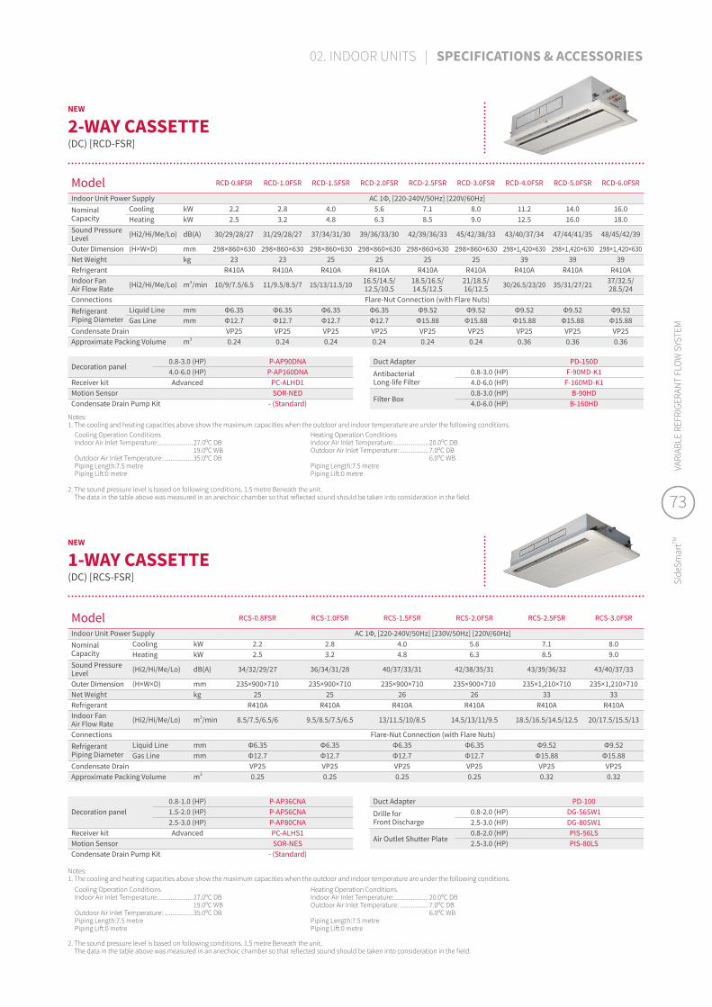
Model RCD-0.8FSR RCD-1.0FSR RCD-1.5FSR RCD-2.0FSR RCD-2.5FSR RCD-3.0FSR RCD-4.0FSR RCD-5.0FSR RCD-6.0FSR
Indoor Unit Power Supply AC 1Φ, [220-240V/50Hz] [220V/60Hz]Nominal Capacity
Cooling kW 2.2 2.8 4.0 5.6 7.1 8.0 11.2 14.0 16.0Heating kW 2.5 3.2 4.8 6.3 8.5 9.0 12.5 16.0 18.0
Sound Pressure Level (Hi2/Hi/Me/Lo) dB(A) 30/29/28/27 31/29/28/27 37/34/31/30 39/36/33/30 42/39/36/33 45/42/38/33 43/40/37/34 47/44/41/35 48/45/42/39
Outer Dimension (H×W×D) mm 298×860×630 298×860×630 298×860×630 298×860×630 298×860×630 298×860×630 298×1,420×630 298×1,420×630 298×1,420×630Net Weight kg 23 23 25 25 25 25 39 39 39Refrigerant R410A R410A R410A R410A R410A R410A R410A R410A R410AIndoor Fan Air Flow Rate (Hi2/Hi/Me/Lo) m3/min 10/9/7.5/6.5 11/9.5/8.5/7 15/13/11.5/10 16.5/14.5/
12.5/10.518.5/16.5/ 14.5/12.5
21/18.5/ 16/12.5 30/26.5/23/20 35/31/27/21 37/32.5/
28.5/24Connections Flare-Nut Connection (with Flare Nuts)Refrigerant Piping Diameter
Liquid Line mm Φ6.35 Φ6.35 Φ6.35 Φ6.35 Φ9.52 Φ9.52 Φ9.52 Φ9.52 Φ9.52Gas Line mm Φ12.7 Φ12.7 Φ12.7 Φ12.7 Φ15.88 Φ15.88 Φ15.88 Φ15.88 Φ15.88
Condensate Drain VP25 VP25 VP25 VP25 VP25 VP25 VP25 VP25 VP25Approximate Packing Volume m3 0.24 0.24 0.24 0.24 0.24 0.24 0.36 0.36 0.36
2. The sound pressure level is based on following conditions. 1.5 metre Beneath the unit. The data in the table above was measured in an anechoic chamber so that reflected sound should be taken into consideration in the field.
Cooling Operation ConditionsIndoor Air Inlet Temperature: ...................... 27.0ᵒC DB 19.0ᵒC WBOutdoor Air Inlet Temperature: .................. 35.0ᵒC DBPiping Length:7.5 metrePiping Lift:0 metre
Heating Operation ConditionsIndoor Air Inlet Temperature: ...................... 20.0ᵒC DBOutdoor Air Inlet Temperature: .................. 7.0ᵒC DB 6.0ᵒC WBPiping Length:7.5 metrePiping Lift:0 metre
Notes:1. The cooling and heating capacities above show the maximum capacities when the outdoor and indoor temperature are under the following conditions.
Decoration panel0.8-3.0 (HP) P-AP90DNA4.0-6.0 (HP) P-AP160DNA
Receiver kit Advanced PC-ALHD1Motion Sensor SOR-NEDCondensate Drain Pump Kit - (Standard)
Duct Adapter PD-150D
Antibacterial Long-life Filter
0.8-3.0 (HP) F-90MD-K14.0-6.0 (HP) F-160MD-K1
Filter Box0.8-3.0 (HP) B-90HD4.0-6.0 (HP) B-160HD
Model RCS-0.8FSR RCS-1.0FSR RCS-1.5FSR RCS-2.0FSR RCS-2.5FSR RCS-3.0FSR
Indoor Unit Power Supply AC 1Φ, [220-240V/50Hz] [230V/50Hz] [220V/60Hz]Nominal Capacity
Cooling kW 2.2 2.8 4.0 5.6 7.1 8.0Heating kW 2.5 3.2 4.8 6.3 8.5 9.0
Sound Pressure Level (Hi2/Hi/Me/Lo) dB(A) 34/32/29/27 36/34/31/28 40/37/33/31 42/38/35/31 43/39/36/32 43/40/37/33
Outer Dimension (H×W×D) mm 235×900×710 235×900×710 235×900×710 235×900×710 235×1,210×710 235×1,210×710Net Weight kg 25 25 26 26 33 33Refrigerant R410A R410A R410A R410A R410A R410AIndoor Fan Air Flow Rate (Hi2/Hi/Me/Lo) m3/min 8.5/7.5/6.5/6 9.5/8.5/7.5/6.5 13/11.5/10/8.5 14.5/13/11/9.5 18.5/16.5/14.5/12.5 20/17.5/15.5/13
Connections Flare-Nut Connection (with Flare Nuts)Refrigerant Piping Diameter
Liquid Line mm Φ6.35 Φ6.35 Φ6.35 Φ6.35 Φ9.52 Φ9.52Gas Line mm Φ12.7 Φ12.7 Φ12.7 Φ12.7 Φ15.88 Φ15.88
Condensate Drain VP25 VP25 VP25 VP25 VP25 VP25Approximate Packing Volume m3 0.25 0.25 0.25 0.25 0.32 0.32
2. The sound pressure level is based on following conditions. 1.5 metre Beneath the unit. The data in the table above was measured in an anechoic chamber so that reflected sound should be taken into consideration in the field.
Cooling Operation ConditionsIndoor Air Inlet Temperature: ...................... 27.0ᵒC DB 19.0ᵒC WBOutdoor Air Inlet Temperature: .................. 35.0ᵒC DBPiping Length:7.5 metrePiping Lift:0 metre
Heating Operation ConditionsIndoor Air Inlet Temperature: ...................... 20.0ᵒC DBOutdoor Air Inlet Temperature: .................. 7.0ᵒC DB 6.0ᵒC WBPiping Length:7.5 metrePiping Lift:0 metre
Notes:1. The cooling and heating capacities above show the maximum capacities when the outdoor and indoor temperature are under the following conditions.
Decoration panel0.8-1.0 (HP) P-AP36CNA1.5-2.0 (HP) P-AP56CNA2.5-3.0 (HP) P-AP80CNA
Receiver kit Advanced PC-ALHS1Motion Sensor SOR-NESCondensate Drain Pump Kit - (Standard)
Duct Adapter PD-100
Drille for Front Discharge
0.8-2.0 (HP) DG-56SW12.5-3.0 (HP) DG-80SW1
Air Outlet Shutter Plate0.8-2.0 (HP) PIS-56LS2.5-3.0 (HP) PIS-80LS
NEW
2-WAY CASSETTE(DC) [RCD-FSR]
NEW
1-WAY CASSETTE(DC) [RCS-FSR]
73
Side
Smar
tTMVA
RIAB
LE R
EFRI
GERA
NT
FLO
W S
YSTE
M
73
Side
Smar
tTMVA
RIAB
LE R
EFRI
GERA
NT
FLO
W S
YSTE
M
02. INDOOR UNITS | SPECIFICATIONS & ACCESSORIES

Refrigerant pipe
Solid foreign substances
Strainer kit
Filter
Type Expansion Valve built-in type
Model RPK-0.6FSRM RPK-0.8FSRM RPK-1.0FSRM RPK-1.5FSRM RPK-2.0FSRM RPK-2.5FSRM RPK-3.0FSRM RPK-4.0FSRM
Indoor Unit Power Supply AC 1Φ, [220-240V/50Hz] [220V/60Hz]
Nominal CapacityCooling kW 1.7 2.2 2.8 4.0 5.6 7.1 8.0 11.2
Heating kW 1.9 2.5 3.2 4.8 6.3 8.5 9.0 12.5Sound Pressure Level (Hi2/Hi/Me/Lo) dB(A) 35/32/31/29 39/35/32/30 39/35/32/30 46/40/36/33 40/37/34/31 45/42/38/35 47/44/40/35 51/48/44/39
Color WhiteOuter Dimension (H×W×D) mm 300×790×230 300×790×230 300×790×230 300×900×230 300×1,100×260 300×1,100×260 300×1,100×260 300×1,100×260Net Weight kg 10 10 10 11 14.5 15 15 15Refrigerant R410A R410A R410A R410A R410A R410A R410A R410A
Indoor Fan Air Flow Rate (Hi2/Hi/Me/Lo) m3/min 8/7.5/7/6 10/8/7/6.5 10/8/7/6.5 14/11/9/7.5 14.5/13/11/9.5 18.5/16.5/14/12 20/17.5/15.5/12.5 23/20/17.5/14.5
Motor 38 38 38 38 38 38 38 38Connections Flare-Nut Connection (with Flare Nuts)Refrigerant Piping Diameter
Liquid Line mm Φ6.35 Φ6.35 Φ6.35 Φ6.35 Φ6.35 Φ9.52 Φ9.52 Φ9.52Gas Line mm Φ12.7 Φ12.7 Φ12.7 Φ12.7 Φ12.7 Φ15.88 Φ15.88 Φ15.88
Condensate Drain VP16 VP16 VP16 VP16 VP16 VP16 VP16 VP16Approximate Packing Volume m3 0.09 0.09 0.09 0.11 0.14 0.14 0.14 0.14
Accessory included Wall Mounting Bracket
Type External Expansion Valve type
Model RPK-0.6FSRHM RPK-0.8FSRHM RPK-1.0FSRHM RPK-1.5FSRHM
Indoor Unit Power Supply AC 1Φ, [220-240V/50Hz] [220V/60Hz]
Nominal CapacityCooling kW 1.7 2.2 2.8 4.0Heating kW 1.9 2.5 3.2 4.8
Sound Pressure Level (Hi2/Hi/Me/Lo) dB(A) 35/32/31/29 39/35/32/30 39/35/32/30 46/40/36/33
Color WhiteOuter Dimension (H×W×D) mm 300×790×230 300×790×230 300×790×230 300×900×230Net Weight kg 10 10 10 11Refrigerant R410A R410A R410A R410AIndoor Fan Air Flow Rate (Hi2/Hi/Me/Lo) m3/min 8/7.5/7/6 10/8/7/6.5 10/8/7/6.5 14/11/9/7.5
Motor 38 38 38 38Connections Flare-Nut Connection (with Flare Nuts)Refrigerant Piping Diameter
Liquid Line mm Φ6.35 Φ6.35 Φ6.35 Φ6.35Gas Line mm Φ12.7 Φ12.7 Φ12.7 Φ12.7
Condensate Drain VP16 VP16 VP16 VP16Approximate Packing Volume m3 0.09 0.09 0.09 0.11Accessory included Wall Mounting Bracket
Receiver kit Advanced PC-ALHZ1
Strainer kit
FSRM: 0.6-2.0 (HP) MSF-NP63A1
FSRM: 2.5-4.0 (HP) MSF-NP112A1
FSRHM: 0.6-1.5 (HP) MSF-NP36AH1
External Expansion Valve Kit FSRHM EV-1.5N1
2. The sound pressure level is based on following conditions. 1.0 metre Beneath the Unit. 1.0 metre from Discharge Grille. The above data was measured in an anechoic chamber so that reflected sound should be taken into consideration in the field. When bottom air inlet is adopted, sound pressure will increase according to factors such as installation mode and the room structure.
Cooling Operation ConditionsIndoor Air Inlet Temperature: ...................... 27.0ᵒC DB 19.0ᵒC WBOutdoor Air Inlet Temperature: .................. 35.0ᵒC DBPiping Length: 7.5 metrePiping Lift: 0 metre
Heating Operation ConditionsIndoor Air Inlet Temperature: ...................... 20.0ᵒC DBOutdoor Air Inlet Temperature: .................. 7.0ᵒC DB 6.0ᵒC WBPiping Length: 7.5 metrePiping Lift: 0 metre
Notes:1. The cooling and heating capacities above show the maximum capacities when the outdoor and indoor
temperature are under the following conditions.
Strainer kitA strainer kit ensures that solid foreign substances, like small particles of metal, are caught before they enter the electric expansion valves of a wall-mounted indoor unit.Without the strainer kit’s filter, these particles may prevent the valves from being fully sealed, creating a risk of explosive condensation when the unit becomes active.
–Specifications & accessories
NEW
WALL MOUNTED (DC) [RPK-FSRM, RPK-FSRHM]

Model RPK-0.8FSNQS RPK-1.0FSNQS RPK-1.3FSNQS RPK-1.5FSNQS RPK-1.8FSNQS RPK-2.0FSNQS RPK-2.3FSNQS
Indoor Unit Power Supply AC 1Φ, [220-240V/50Hz]
Nominal CapacityCooling kW 2.2 2.8 3.6 4.0 5.0 5.6 6.3Heating kW 2.5 3.3 4.0 4.5 5.6 6.3 7.1
Sound Pressure Level (Hi/Me/Lo) dB(A) 38/36/32 38/36/32 40/36/34 41/38/36 42/39/35 42/39/35 45/42/39
Color WhiteOuter Dimension (H×W×D) mm 280×780×220 280×780×220 280×780×220 280×780×220 290×1,050×220 290×1,050×220 290×1,050×220Net Weight kg 10 10 10 10 12.5 12.5 12.5Refrigerant R410A R410A R410A R410A R410A R410A R410AIndoor Fan Air Flow Rate (Hi/Me/Lo) m3/min 8.5/7.5/6.5 8.5/7.5/6.5 9.2/7.5/6.7 10/8.5/7.5 12/10.3/8.7 12/10.3/8.7 13.7/12/10.3
Connections Flare-Nut Connection (with Flare Nuts)Refrigerant Piping Diameter
Liquid Line mm Φ6.35 Φ6.35 Φ6.35 Φ6.35 Φ6.35 Φ6.35 Φ6.35Gas Line mm Φ12.7 Φ12.7 Φ12.7 Φ12.7 Φ15.88 Φ15.88 Φ15.88
Condensate Drain VP16 VP16 VP16 VP16 VP16 VP16 VP16Approximate Packing Volume m3 0.12 0.12 0.12 0.12 0.15 0.15 0.15
Notes:1. The cooling and heating capacities above show the maximum capacities when the outdoor and indoor temperature are under the following conditions.
2. The sound pressure level is based on following conditions. 1.0 metre Beneath the unit. 1.0 metre from Discharge grille. The above data was measured in an anechoic chamber so that reflected sound should be taken into consideration in the field. When bottom air inlet is adopted, sound pressure will increase according to factors such as installation mode and the room structure.
Cooling Operation ConditionsIndoor Air Inlet Temperature: ...................... 27.0ᵒC DB (80.0ᵒF DB) 19.0ᵒC WB (66.2ᵒF WB)Outdoor Air Inlet Temperature: .................. 35.0ᵒC DB (95.0ᵒF DB)Piping Length:7.5 metrePiping Lift:0 metre
Heating Operation ConditionsIndoor Air Inlet Temperature: ...................... 20.0ᵒC DB (68.0ᵒF DB)Outdoor Air Inlet Temperature: .................. 7.0ᵒC DB (45.0ᵒF DB) 6.0ᵒC WB (43.0ᵒF WB)Piping Length:7.5 metrePiping Lift:0 metre
Receiver kitBasic PC-RLH11
Advanced PC-ALHZ1Strainer kit MSF-NP63A1
Model RPFC-1.8FSNQ RPFC-2.0FSNQ RPFC-2.3FSNQ RPFC-2.5FSNQ RPFC-3.0FSNQ RPFC-3.3FSNQ RPFC-4.0FSNQ RPFC-5.0FSNQ
Indoor Unit Power Supply AC 1Φ, [220-240V/50Hz] [220V/60Hz]Nominal Capacity
Cooling kW 5.0 5.6 6.3 7.1 8.4 9.0 11.2 14.2Heating kW 5.6 6.5 7.5 8.5 9.6 10.0 13.0 16.3
Sound Pressure Level
Ceiling Mode dB(A) 39/35/30 39/35/30 45/41/37 45/41/37 43/39/34 45/40/36 51/46/40 50/46/42Floor Mode dB(A) 43/38/35 43/38/35 48/44/40 48/44/40 46/41/37 48/43/39 54/49/43 55/50/46
Outer Dimension (H×W×D) mm 230×990×680 230×990×680 230×990×680 230×990×680 230×1,285×680 230×1,285×680 230×1,285×680 230×1,580×680Net Weight kg 31 31 32 32 39 40 41 47Refrigerant R410A R410A R410A R410A R410A R410A R410A R410AIndoor Fan Air Flow Rate (Hi/Me/Lo) m3/h 780/660/540 780/660/540 966/840/678 966/840/678 1,092/912/732 1,164/978/798 1,488/1,230/978 1,980/1,680/1,380
Connections Flare-Nut Connection (with Flare Nuts)Refrigerant Piping Diameter
Liquid Line mm Φ6.35 Φ6.35 Φ9.52 Φ9.52 Φ9.52 Φ9.52 Φ9.52 Φ9.52Gas Line mm Φ15.88 Φ15.88 Φ15.88 Φ15.88 Φ15.88 Φ15.88 Φ15.88 Φ15.88
Condensate Drain VP25 VP25 VP25 VP25 VP25 VP25 VP25 VP25Approximate Packing Volume m3 0.31 0.31 0.31 0.31 0.40 0.40 0.40 0.48
2. The sound pressure level is based on following conditions. 1.0 metre Beneath the unit. 1.0 metre from Discharge grille. The above data was measured in an anechoic chamber so that reflected sound should be taken into consideration in the field. When bottom air inlet is adopted, sound pressure will increase according to factors such as installation mode and the room structure.
Cooling Operation ConditionsIndoor Air Inlet Temperature: ...................... 27.0ᵒC DB 19.0ᵒC WBOutdoor Air Inlet Temperature: .................. 35.0ᵒC DBPiping Length: 7.5 metrePiping Lift: 0 metre
Heating Operation ConditionsIndoor Air Inlet Temperature: ...................... 20.0ᵒC DBOutdoor Air Inlet Temperature: .................. 7.0ᵒC DB 6.0ᵒC WBPiping Length: 7.5 metrePiping Lift: 0 metre
Notes:1. The cooling and heating capacities above show the maximum capacities when the outdoor and indoor
temperature are under the following conditions.
Receiver kitBasic PC-RLH11
Advanced PC-ALHZ1
FLOOR/CEILING CONVERTIBLE(AC) [RPFC-FSNQ]
WALL MOUNTED(AC) [RPK-FSNQS]
Discontinued in 2021.Please consult your distributor for more detail.
75
Side
Smar
tTMVA
RIAB
LE R
EFRI
GERA
NT
FLO
W S
YSTE
M
75
Side
Smar
tTMVA
RIAB
LE R
EFRI
GERA
NT
FLO
W S
YSTE
M
02. INDOOR UNITS | SPECIFICATIONS & ACCESSORIES
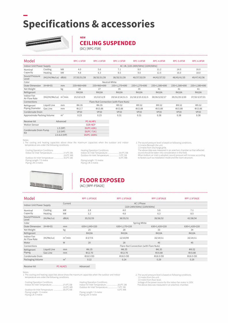
Model RPC-1.5FSR RPC-2.0FSR RPC-2.5FSR RPC-3.0FSR RPC-4.0FSR RPC-5.0FSR RPC-6.0FSR
Indoor Unit Power Supply AC 1Φ, [220-240V/50Hz] [220V/60Hz]Nominal Capacity
Cooling kW 4.0 5.6 7.1 8.0 11.2 14.0 16.0Heating kW 4.8 6.3 8.5 9.0 12.5 16.0 18.0
Sound Pressure Level (Hi2/Hi/Me/Lo) dB(A) 37/35/31/28 38/35/31/28 38/35/31/28 40/37/33/29 44/42/37/32 48/45/41/35 49/47/42/36
Color Neutral WhiteOuter Dimension (H×W×D) mm 235×960×690 235×960×690 235×1,270×690 235×1,270×690 235×1,580×690 235×1,580×690 235×1,580×690Net Weight kg 26 27 35 35 41 41 41Refrigerant R410A R410A R410A R410A R410A R410A R410AIndoor Fan Air Flow Rate (Hi2/Hi/Me/Lo) m3/min 15/13/11/9 15/13/11/9 19/16.5/14/11.5 21/18.5/15.5/12.5 30/26.5/22/17 35/31/25.5/20 37/32.5/27/21
Connections Flare-Nut Connection (with Flare Nuts)Refrigerant Piping Diameter
Liquid Line mm Φ6.35 Φ6.35 Φ9.52 Φ9.52 Φ9.52 Φ9.52 Φ9.52Gas Line mm Φ12.7 Φ15.88 Φ15.88 Φ15.88 Φ15.88 Φ15.88 Φ15.88
Condensate Drain VP20 VP20 VP20 VP20 VP20 VP20 VP20Approximate Packing Volume m3 0.23 0.23 0.31 0.31 0.38 0.38 0.38
2. The sound pressure level is based on following conditions. 1.0 metre Beneath the unit. 1.0 metre from Discharge grille. The above data was measured in an anechoic chamber so that reflected sound should be taken into consideration in the field. When bottom air inlet is adopted, sound pressure will increase according to factors such as installation mode and the room structure.
Cooling Operation ConditionsIndoor Air Inlet Temperature: ...................... 27.0ᵒC DB 19.0ᵒC WBOutdoor Air Inlet Temperature: .................. 35.0ᵒC DBPiping Length: 7.5 metrePiping Lift: 0 metre
Heating Operation ConditionsIndoor Air Inlet Temperature: ...................... 20.0ᵒC DBOutdoor Air Inlet Temperature: .................. 7.0ᵒC DB 6.0ᵒC WBPiping Length: 7.5 metrePiping Lift: 0 metre
Notes:1. The cooling and heating capacities above show the maximum capacities when the outdoor and indoor
temperature are under the following conditions.
Receiver kit Advanced PC-ALHP1Motion Sensor SOR-NEP
Condensate Drain Pump Kit
1.5 (HP) DUPC-63K12.0 (HP) DUPC-71K1
2.5-6.0 (HP) DUPC-160K1
Model RPF-1.0FSN2E RPF-1.5FSN2E RPF-2.0FSN2E RPF-2.5FSN2E
Indoor Unit Power SupplyCurrent AC 1 Phase
[220-240V/50Hz] [220V/60Hz]Nominal Capacity
Cooling kW 2.8 4.0 5.6 7.1Heating kW 3.2 4.8 6.3 8.5
Sound Pressure Level (Hi/Me/Lo) dB(A) 35/32/29 38/35/31 39/36/32 42/38/34
Color Spring WhiteOuter Dimension (H×W×D) mm 630×1,045×220 630×1,170×220 630×1,420×220 630×1,420×220Net Weight kg 25 28 33 34Refrigerant R410A R410A R410A R410AIndoor Fan Air Flow Rate (Hi/Me/Lo) m3/min 8.5/7/6 12/10/09 16/14/11 16/14/11
Motor W 20 28 45 45Connections Flare-Nut Connection (with Flare Nuts)Refrigerant Piping
Liquid Line mm Φ6.35 Φ6.35 Φ6.35 Φ9.52Gas Line mm Φ12.70 Φ12.70 Φ15.88 Φ15.88
Condensate Drain Φ18.5 OD Φ18.5 OD Φ18.5 OD Φ18.5 ODPackaging Volume m3 0.22 0.24 0.29 0.29
2. The sound pressure level is based on following conditions. 1.0 metre from the unit. 1.0 metre from floor level. Voltage of the power source for the indoor fan motor is 220V.The above data was measured in an anechoic chamber.
Cooling Operation ConditionsIndoor Air Inlet Temperature: ...................... 27.0ᵒC DB 19.0ᵒC WBOutdoor Air Inlet Temperature: .................. 35.0ᵒC DBPiping Length: 7.5 metrePiping Lift: 0 metre
Heating Operation ConditionsIndoor Air Inlet Temperature: ...................... 20.0ᵒC DBOutdoor Air Inlet Temperature: .................. 7.0ᵒC DB 6.0ᵒC WBPiping Length: 7.5 metrePiping Lift: 0 metre
Notes:1. The cooling and heating capacities above show the maximum capacities when the outdoor and indoor
temperature are under the following conditions.
Receiver kit PC-ALHZ1 Advanced
–Specifications & accessories
NEW
CEILING SUSPENDED(DC) [RPC-FSR]
FLOOR EXPOSED(AC) [RPF-FSN2E]
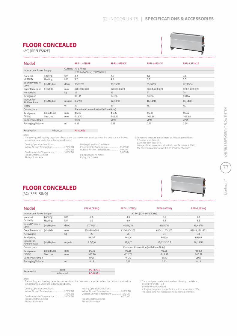
Model RPFI-1.0FSNQ RPFI-1.5FSNQ RPFI-2.0FSNQ RPFI-2.5FSNQ
Indoor Unit Power Supply AC 1Φ, [220-240V/50Hz]Nominal Capacity
Cooling kW 2.8 4.3 5.6 7.1Heating kW 3.3 4.9 6.5 8.5
Sound Pressure Level (Hi/Me/Lo) dB(A) 37/34/31 40/38/35 42/38/36 45/43/40
Outer Dimension (H×W×D) mm 620×900×202 620×900×202 620×1,170×202 620×1,170×202Net Weight kg 25 26 34 34Refrigerant R410A R410A R410A R410AIndoor Fan Air Flow Rate (Hi/Me/Lo) m3/min 8.5/7/6 12/8/7 16/12.5/10.5 16/14/11
Connections Flare-Nut Connection (with Flare Nuts)Refrigerant Piping
Liquid Line mm Φ6.35 Φ6.35 Φ6.35 Φ9.52Gas Line mm Φ12.70 Φ12.70 Φ15.88 Φ15.88
Condensate Drain VP25 VP25 VP25 VP25Packaging Volume m3 0.19 0.19 0.23 0.23
Cooling Operation ConditionsIndoor Air Inlet Temperature: ...................... 27.0ᵒC DB 19.0ᵒC WBOutdoor Air Inlet Temperature: .................. 35.0ᵒC DBPiping Length: 7.5 metrePiping Lift: 0 metre
Heating Operation ConditionsIndoor Air Inlet Temperature: ...................... 20.0ᵒC DBOutdoor Air Inlet Temperature: .................. 7.0ᵒC DB 6.0ᵒC WBPiping Length: 7.5 metrePiping Lift: 0 metre
Notes:1. The cooling and heating capacities above show the maximum capacities when the outdoor and indoor
temperature are under the following conditions.
Receiver kitBasic PC-RLH11
Advanced PC-ALHZ1
Model RPFI-1.0FSN2E RPFI-1.5FSN2E RPFI-2.0FSN2E RPFI-2.5FSN2E
Indoor Unit Power SupplyCurrent AC 1 Phase
[220-240V/50Hz] [220V/60Hz]Nominal Capacity
Cooling kW 2.8 4.0 5.6 7.1Heating kW 3.2 4.8 6.3 8.5
Sound Pressure Level (Hi/Me/Lo) dB(A) 35/32/29 38/35/31 39/36/32 42/38/34
Outer Dimension (H×W×D) mm 620×848×220 620×973×220 620×1,223×220 620×1,223×220Net Weight kg 19 23 27 28Refrigerant R410A R410A R410A R410AIndoor Fan Air Flow Rate (Hi/Me/Lo) m3/min 8.5/7/6 12/10/09 16/14/11 16/14/11
Motor W 20 28 45 45Connections Flare-Nut Connection (with Flare Nuts)Refrigerant Piping
Liquid Line mm Φ6.35 Φ6.35 Φ6.35 Φ9.52Gas Line mm Φ12.70 Φ12.70 Φ15.88 Φ15.88
Condensate Drain VP25 VP25 VP25 VP25Packaging Volume m3 0.22 0.23 0.25 0.25
2. The sound pressure level is based on following conditions. 1.0 metre from the unit. 1.0 metre from floor level. Voltage of the power source for the indoor fan motor is 220V.The above data was measured in an anechoic chamber.
Cooling Operation ConditionsIndoor Air Inlet Temperature: ...................... 27.0ᵒC DB 19.0ᵒC WBOutdoor Air Inlet Temperature: .................. 35.0ᵒC DBPiping Length: 7.5 metrePiping Lift: 0 metre
Heating Operation ConditionsIndoor Air Inlet Temperature: ...................... 20.0ᵒC DBOutdoor Air Inlet Temperature: .................. 7.0ᵒC DB 6.0ᵒC WBPiping Length: 7.5 metrePiping Lift: 0 metre
Notes:1. The cooling and heating capacities above show the maximum capacities when the outdoor and indoor
temperature are under the following conditions.
Receiver kit Advanced PC-ALHZ1
FLOOR CONCEALED (AC) [RPFI-FSN2E]
FLOOR CONCEALED(AC) [RPFI-FSNQ]
2. The sound pressure level is based on following conditions. 1.0 metre from the unit. 1.0 metre from floor level. Voltage of the power source for the indoor fan motor is 220V.The above data was measured in an anechoic chamber.
77
Side
Smar
tTMVA
RIAB
LE R
EFRI
GERA
NT
FLO
W S
YSTE
M
77
Side
Smar
tTMVA
RIAB
LE R
EFRI
GERA
NT
FLO
W S
YSTE
M
02. INDOOR UNITS | SPECIFICATIONS & ACCESSORIES

03
–Ventilation

80 OUR VENTILATION LINE-UP
82 VENTILATION SOLUTIONS
82 All fresh air unit83 Total heat exchanger
84 DX-KIT
Improve indoor air quality!Today, the average person spends more than 75% of their day indoors. Without proper ventilation, CO2 levels rise, pollutants circulate and potentially harmful bacterias build-up, impacting on the wellbeing, comfort and productivity of occupants. Make these spaces as healthy and comfortable as possible by connecting our ventilation solutions into your Hitachi VRF systems.
79
Side
Smar
tTMVA
RIAB
LE R
EFRI
GERA
NT
FLO
W S
YSTE
M
79
Side
Smar
tTMVA
RIAB
LE R
EFRI
GERA
NT
FLO
W S
YSTE
M
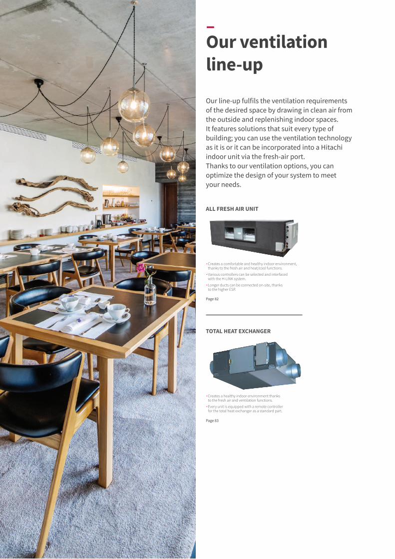
Our line-up fulfils the ventilation requirements of the desired space by drawing in clean air from the outside and replenishing indoor spaces. It features solutions that suit every type of building; you can use the ventilation technology as it is or it can be incorporated into a Hitachi indoor unit via the fresh-air port. Thanks to our ventilation options, you can optimize the design of your system to meet your needs.
Page 82
Page 83
∙ Creates a comfortable and healthy indoor environment, thanks to the fresh air and heat/cool functions.
∙ Various controllers can be selected and interfaced with the H-LINK system.
∙ Longer ducts can be connected on-site, thanks to the higher ESP.
∙ Creates a healthy indoor environment thanks to the fresh air and ventilation functions.
∙ Every unit is equipped with a remote controller for the total heat exchanger as a standard part.
TOTAL HEAT EXCHANGER
–Our ventilation line-up
ALL FRESH AIR UNIT

EXTRA AIR-RENEWAL SOLUTION OFFERINGS..................................................................................................................................................................................................................................................................................................................................................
Fan Air Flow Rate (m3/h) 150 200 210 230 300 400 500 550 650 700 800 1,000 1,080 1,250 1,500 1,680 2,000 2,100 2,500 3,000 4,000 5,000 6,000
All Fresh Air Unit
Total Heat Exchanger
We offer two additional options to meet both occupants' needs and your building's requirements.
From 150 to 6,000m3/h..................................................................................................................................................................................................................................................................................................................................................
∙ Optional duct adapter which enables fresh air into the unit so that it can be blown out with conditioned air.
FRESH-AIR INTAKE PORT
∙ Connects with the indoor units: 4-way cassette type, 4-way compact cassette type, 2-way cassette type, 1-way cassette type.
DX-KIT∙ Offers great flexibility by enabling you
to integrate Hitachi VRF into your building's existing air handling units (AHU).
∙ Wide capacity range (available up to 96HP AHU).
∙ Wide configuration options with AHU/Indoor units.
81
Side
Smar
tTMVA
RIAB
LE R
EFRI
GERA
NT
FLO
W S
YSTE
M
81
Side
Smar
tTMVA
RIAB
LE R
EFRI
GERA
NT
FLO
W S
YSTE
M
03. VENTILATION | OUR VENTILATION LINE-UP

–Ventilation solutions
Model RPI-5.0KFNQ RPI-8.0KFNQ RPI-10.0KFNQ RPI-12.0KFNQ
Power SupplyAC 1Φ
220-240V/50Hz
AC 1Φ 220V/60Hz
AC 1Φ220-240V/
50Hz
AC 1Φ 220V/60Hz
AC 1Φ 220-240V/
50Hz
AC 1Φ 220V/60Hz
AC 3Φ 380-415V/
50Hz
AC 3Φ 380V/60Hz
Connectable Outdoor Unit Slim Modular VRF SideSmartTM (Heat Pump Type) RAS-120HNCEL(/R)W
CoolingCapacity kW 14.0 14.0 22.4 22.4 28.0 28.0 33.5 33.5 Power kW 0.30 0.35 0.48 0.55 0.50 0.58 0.68 0.78 Nominal Current A 1.4 1.61 2.2 2.53 2.3 2.65 1.43 1.64
HeatingCapacity kW 13.7 13.7 21.9 21.9 24.5 24.5 26.8 26.8 Power kW 0.30 0.35 0.48 0.55 0.50 0.58 0.68 0.78 Nominal Current A 1.4 1.61 2.2 2.53 2.3 2.65 1.43 1.64
Sound Pressure Level(overall a scale) dB(A) 42 42 44 44 47 47 56 56
Dimensions H×W×D mm 370×1320×800 486×1270×1069 486×1270×1069 486×1270×1069Net Weight kg 63 63 110 110 110 110 110 110Refrigerant R410A R410A R410A R410A R410A R410A R410A R410A
Air Flow Rate m3/min 18 18 28 28 35 35 50 50
External Pressure Pa 200 200 220 220 220 220 220 220
PipingLiquid mm Φ9.53 Φ9.53 Φ9.53 Φ9.53 Φ9.53 Φ9.53 Φ12.7 Φ12.7Gas mm Φ15.88 Φ15.88 Φ19.05 Φ19.05 Φ22.2 Φ22.2 Φ25.4 Φ25.4Condensate Drain VP25, Outer Diameter: Φ32mm
Temperature range of fresh air drawn Cooling: 20.0°C~43.0°C, Heating: -7.0°C~15.0°C
Notes:1. Cooling capacity and heating capacity tested in the following conditions:
Cooling conditions: 33.0°CDB, 28.0°CWB, pipeline length 7.5 metre, pipe height difference 0 metre. Heating conditions: 0°CDB, -2.9°CWB, pipeline length 7.5 metre, pipe height difference 0 metre (heating is the data without defrosting).
2. Noise test conditions are as follows: At a distance of 1.5 metre from the unit surface. The above parameters are measured in the anechoic chamber without reflected echo, therefore the impact of the reflected echo must be counted at the scene.
3. An air filter with dust removal efficiency of 50% or more needs to be installed at the air inlet.
4. When the field duct resistance is small and the fan speed is too high, the unit will appear the phenomena of abnormal shutdown, fault, water spray etc., and the duct pipe should be insulated to prevent generating dew.
5. Air processor can only be used for processing fresh air, indoor air conditioning load processing need to use other air conditioners.
6. Fresh air processing unit should be connected with Slim Modular VRF SideSmartTM, Heat Pump Type, outdoor unit. When fresh air processing unit and other indoor units air all connected to the same SideSmartTM outdoor unit, Its equivalent cooling capacity is calculated by the following criteria: Type_5HP class: 21.0kW; 8HP class: 33.3kW; 10HP class: 42.0kW.
7. Refer to capacity restrains shown on Table below for indoor unit capacity connectable to outdoor unit.
Mixed system is only available with RPI-5.0/8.0/10.0KFNQ. RPI-12.0KFNQ or above is only available as one to one All Fresh Air Unit system.
8. When outdoor temperature is below 20.0°C in cooling operation, the system will be automatically converted to ventilation operation. When outdoor temperature is higher than 15.0°C in heating operation, it will be automatically converted to ventilation operation. When lower than -7.0°C, the fresh air processing unit will stop running.
System All Fresh Air Unit System (Only All Fresh Air Unit)
Mixed System (All Fresh Air Unit and Other Indoor Unit)
Range of Combination Capacity
80 to 100%i) 80 to 100% andii) Total Capacity of All Fresh Air: 30%
Model RPI-16.0KFNQL RPI-16.0KFNQH RPI-20.0KFNQL RPI-20.0KFNQH RPI-20.0KFNQLF RPI-20.0KFNQHF
Power SupplyAC 3Φ
380-415V/50Hz
AC 3Φ 380V/60Hz
AC 3Φ380-415V/
50Hz
AC 3Φ 380V/60Hz
AC 3Φ380-415V/
50Hz
AC 3Φ 380V/60Hz
AC 3Φ380-415V/
50Hz
AC 3Φ 380V/60Hz
AC 3Φ380-415V/
50Hz
AC 3Φ 380V/60Hz
AC 3Φ380-415V/
50Hz
AC 3Φ 380V/60Hz
Connectable Outdoor Unit RAS-160HNCEL(/R)W RAS-200HNCEL(R)WS, RAS-200HNCEL(R)WP, RAS-200HNCEL(R)WS
CoolingCapacity kW 45.0 45.0 45.0 45.0 56.0 56.0 56.0 56.0 56.0 56.0 56.0 56.0 Power kW 0.72 0.83 1.06 1.22 1.06 1.22 1.39 1.6 1.39 1.60 1.72 1.98 Nominal Current A 1.8 2.07 2.2 2.53 2.22 2.55 3.14 3.61 3.0 3.45 3.9 4.45
HeatingCapacity kW 36.0 36.0 36.0 36.0 44.8 44.8 44.8 44.8 44.8 44.8 44.8 44.8 Power kW 0.72 0.83 1.06 1.22 1.06 1.22 1.39 1.6 1.39 1.60 1.72 1.98 Nominal Current A 1.8 2.07 2.2 2.53 2.22 2.55 3.14 3.61 3.0 3.45 3.9 4.45
Sound Pressure Level(overall a scale) dB(A) 58 58 62 62 61 61 65 65 63 63 67 67
Dimensions H×W×D mm 635×1950×805 635×1950×805 735×1950×805 735×1950×805 735×1950×805 735×1950×805Net Weight kg 196 196 196 196 222 222 222 222 222 222 222 222Refrigerant R410A R410A R410A R410A R410A R410A R410A R410A R410A R410A R410A R410AAir Flow Rate m3/min 67 67 67 67 83 83 83 83 100 100 100 100 External Pressure Pa 200 200 300 300 200 200 300 300 200 200 300 300
PipingLiquid mm Φ12.7 Φ12.7 Φ12.7 Φ12.7 Φ15.88 Φ15.88 Φ15.88 Φ15.88 Φ15.88 Φ15.88 Φ15.88 Φ15.88Gas mm Φ25.4 Φ25.4 Φ25.4 Φ25.4 Φ28.6 Φ28.6 Φ28.6 Φ28.6 Φ28.6 Φ28.6 Φ28.6 Φ28.6Condensate Drain RC1 (Internal Screw)
Temperature range of fresh air drawn Cooling: 20.0°C~43.0°C, Heating: -7.0°C~15.0°C
ALL FRESH AIR UNIT
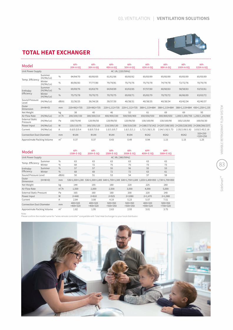
TOTAL HEAT EXCHANGER
Model KPI- 20H-A-GQ
KPI- 30H-A-GQ
KPI- 40H-A-GQ
KPI-50H-A-GQ
KPI-65H-A-GQ
KPI-80H-A-GQ
KPI-100H-A-GQ
KPI-125H-A-GQ
Unit Power Supply AC 1Φ, [220/50Hz]
Temp. Efficiency
Summer(Hi/Me/Lo) % 64/64/70 60/60/65 61/61/66 60/60/62 65/65/69 65/65/69 65/65/69 65/65/69
Winter(Hi/Me/Lo) % 80/80/83 77/77/80 79/79/81 75/75/76 75/75/78 74/74/78 72/72/76 70/70/78
Enthalpy Efficiency
Summer(Hi/Me/Lo) % 69/69/76 63/63/70 64/64/69 63/63/65 57/57/60 60/60/63 58/58/63 53/53/61
Winter(Hi/Me/Lo) % 75/75/78 70/70/75 70/70/75 69/69/71 65/65/70 70/70/72 66/66/69 63/63/72
Sound Pressure Level (Hi/Me/Lo) dB(A) 32/30/25 36/34/28 39/37/30 40/38/31 40/38/35 40/38/34 43/42/34 42/40/37
Outer Dimension (H×W×D) mm 220×962×735 220×962×735 220×1,112×735 220×1,112×735 388×1,119×884 388×1,119×884 388×1,119×884 430×1,250×1,135
Net Weight kg 38 40 46 52 61 69 69 95Air Flow Rate (Hi/Me/Lo) m3/h 200/200/150 300/300/210 400/400/230 500/500/400 650/650/550 800/800/650 1,000/1,000/700 1,250/1,250/800External Static Pressure (Hi/Me/Lo) Pa 100/70/40 120/90/50 120/90/50 120/90/50 130/100/90 130/100/90 165/120/60 100/50/30
Power Input (Hi/Me/Lo) W 120/110/75 165/155/120 210/200/130 330/310/230 2×(188/173/142) 2×(207/188/165) 2×(250/228/205) 2×(308/266/237)Current (Hi/Me/Lo) A 0.6/0.5/0.4 0.8/0.7/0.6 1.0/1.0/0.7 1.6/1.5/1.1 1.72/1.58/1.31 2.04/1.93/1.73 2.35/2.09/1.92 3.03/2.45/2.18
Connection Duct Diameter mm Φ144 Φ144 Φ144 Φ194 Φ242 Φ242 Φ242 320×250+320×250
Approximate Packing Volume m3 0.37 0.37 0.43 0.49 0.94 1.15 1.15 1.25
Model KPI- 150H-E-GQ
KPI- 200H-E-GQ
KPI- 250H-E-GQ
KPI- 300H-E-GQ
KPF- 400H-E-GQ
KPF- 500H-E-GQ
Unit Power Supply AC 3Φ, [380/50Hz]
Temp. EfficiencySummer % 63 63 63 63 63 63Winter % 68 72 75 75 73 73
Enthalpy Efficiency
Summer % 57 57 55 56 55 53Winter % 68 68 72 72 63 61
Sound Pressure Level dB(A) 50 51 53 54 57 58Outer Dimension (H×W×D) mm 536×1,500×1,300 536×1,500×1,400 640×1,700×1,500 640×1,750×1,600 1,655×1,400×850 1,730×1,700×850
Net Weight kg 144 155 180 220 225 260Air Flow Rate m3/h 1,500 2,000 2,500 3,000 4,000 5,000External Static Pressure Pa 165 160 180 200 220 240Power Input W 2×440 2×810 2×925 2×1080 2×1,470 2×1,980Current A 2.84 3.08 4.19 5.23 5.57 7.51
Connection Duct Diameter mm 400×320+400×320
400×320+400×320
500×350+500×350
500×350+500×350
400×320+590×320
500×350+700×320
Approximate Packing Volume m3 1.82 1.95 2.63 2.93 3.01 3.75
Note:Please confirm the model name for “wires remote controller” compatible with Total Heat Exchanger to your local distributor.
83
Side
Smar
tTMVA
RIAB
LE R
EFRI
GERA
NT
FLO
W S
YSTE
M
83
Side
Smar
tTMVA
RIAB
LE R
EFRI
GERA
NT
FLO
W S
YSTE
M
03. VENTILATION | VENTILATION SOLUTIONS

230
400 H:112
327
22
9
419
W:435
D:34
9
COIL
THIS WAY UP
270
202W:437
242
98D:16
6
H:61
Dimensions
Control box Expansion valve box
(mm)
Capacity (HP) 2 4 6 8/10 12~20 22~30
Model DXF-2.0A1 DXF-4.0A1 DXF-6.0A1 DXF-10.0A1 DXF-20.0A1 DXF-30.0A1
Control Box(C Box)
Power Supply AC1Φ, [220-240V /50Hz] [220V 60Hz]Height mm 112 112 112 112 112 112Width mm 435 435 435 435 435 435Depth mm 349 349 349 349 349 349Weight kg 5.2 5.2 5.2 5.2 5.2 5.2Material Steel Plate + White Grey Coating
Expansion Valve Box(EXV Box)
Height mm 61 61 61 61 61 61Width mm 437 437 437 437 437 437Depth mm 166 166 166 166 166 166Weight kg 1.7 1.7 1.7 1.7 1.7 1.7Quantity 1 1 1 1 1 2Material Steel Plate + White Grey CoatingLiquid Pipe Diameter φ6.35 φ9.52 φ9.52 φ9.52 φ12.7 φ12.7
AHU Suction Temperature Range
Cooling 21.0°C to 32.0°C (DB) / 15.0°C to 23.0°C (WB) Heating 15.0°C to 27.0°C (DB)
Connection Ratio in different configurations→ Total AHU or AHU & IDU Connection Ratio against
ODU capacity = X (In case of "Inlet Air Temperature Control")
• 1 ODU to 1 AHU : 50% < X ≤ 100%• 1 ODU to 1 AHU (Separate Heat Exchanger Type) : 50% < X ≤ 100%
• 1 ODU to Multiple AHUs : 50% < X ≤ 100%• 1 ODU to AHU & IDUs :
(1) 50% < X ≤ 100% → Total AHU capacity: No limitation / Each AHU capacity: No limitation (2) 100% < X ≤ 110% → Total AHU capacity: less than 30% of total capacity / Each AHU capacity: between 2-6HP class
Maximum Piping Length
Total m • 1,000 (When the number of connected [AHU & IDU] in the system is the same or less than the recommended.)• 300 (When the number of connected [AHU & IDU] in the system is more than the recommended.)
Between AHU Heat Exchanger and EXV Box m 5 5 5 5 5 5
Maximum Level Difference
Between ODU and [AHU/IDU] m • 50 (When ODU is above [AHU & IDU & DX-Kit].)
• 40 (When ODU is below [AHU & IDU & DX-Kit].)Between AHU Heat Exchanger and EXV Box m 2 2 2 2 2 2
Maximum Length
Control wiring between AHU Heat Exchanger and EXV Box m 10 10 10 10 10 10
Thermistor to AHU Heat Exchanger from C Box m 10 10 10 10 10 10
Temperature Control Modes (*1)• Inlet Air Temperature Control• Outlet Air Temperature Control• Duty Control
(*1) [Outlet Air Temperature Control] & [Duty Control] are available only in case of connections "1 ODU to 1 AHU" & "1 ODU to 1 AHU(Separate Heat Exchanger Type)".
–DX-Kit
Integrate Hitachi VRF into your pre-existing Air Handling Units (AHU).

8HP52HP 4HP 4HP4HP
6HP
30HP
60HP
H1H1
EXV BoxEXV Box
DX-Kit
C BoxC Box
L1L1
L3L3L2L2
VRF ODU
AHU
VRF IDU4-WAY CASSETTE
Refrigeration piping
ELECTRONICSGROCERYCOSMETICS
MENS FASHION BOUTIQUIESPORT
∙(DX-Kit) Single capacity from 2HP to 30HP∙ (Custom AHU) up to 96HP available by DX-Kit combination
Our DX-Kit can cover from small to large capacity AHU.It can meet any requirement in any application!
Wide range of capacity:
→ 1 VRF outdoor unit + 1 AHU→ 1 VRF outdoor unit + 1 AHU (external heat exchanger)→ 1 VRF Outdoor unit + multiple AHUs→ 1 VRF Outdoor unit + VRF indoor units + AHUs
4 examples of configuration:
[Example] DX-KitLeft: Control Box (C Box)Right: Expansion Valve Box (EXV Box)
Up to 5 heat exchangers can be connected via DX-Kit!
Flexible combination with VRF indoor units.
Various available AHU capacity connections.
∙Both outdoor & indoor installation of DX-Kit available∙Design Flexibility in wiring & piping
DX-Kit facilitates system design!
Flexible installation:
Both outdoor & indoor installations available!
Item Max (m)
Level difference between AHU Heat Exchanger and EXV Box
H1 2
Piping length between AHU Heat Exchanger and EXV Box
L1 5
Length of control wiring between AHU HeatExchanger and EXV Box
L2 10
Length of the thermistor to AHU Heat Exchanger from C Box
L3 10
DX-KIT: GREAT FLEXIBILITY FOR SIMPLIFIED HVAC UPGRADE................................................................................................................................................................................................................................................................................................................................................
DX-KitAbove : Expansion Valve Box (EXV Box).Below : Control Box (C Box).
1 2
3
85
Side
Smar
tTMVA
RIAB
LE R
EFRI
GERA
NT
FLO
W S
YSTE
M
85
Side
Smar
tTMVA
RIAB
LE R
EFRI
GERA
NT
FLO
W S
YSTE
M
03. VENTILATION | DX-KIT

04
–Controllers

88 CENTRALIZED CONTROLLERS
88 Line up overview90 Cloud Pro92 Central Station EX93 Central Station EZ93 Central Station mini
94 INDIVIDUAL CONTROLLERS
94 Line up overview96 Advanced color wired remote controller99 Advanced wired remote controller
100 Wired remote controller100 Simplified wired remote controller101 Advanced wireless remote controller101 Wireless remote controller101 Receiver kit
102 ACCESSORIES
104 H-LINK: ENJOY MORE FREEDOM
New generation: simple and smart!Everyone deserves comfort, but comfort does not mean the same to everyone. That’s why control is key.Our controllers offer best-in-class simplicity. Using our praised central stations, building managers can instantly optimize air conditioning in targeted zones. For occupants, our new advanced color controller provides intuitive navigation with a premium design.With airCloud Pro, our exclusive new-generation solution, users can manage from one indoor unit to several systems remotely via IoT (web/smartphone).
87
Side
Smar
tTMVA
RIAB
LE R
EFRI
GERA
NT
FLO
W S
YSTE
M
87
Side
Smar
tTMVA
RIAB
LE R
EFRI
GERA
NT
FLO
W S
YSTE
M
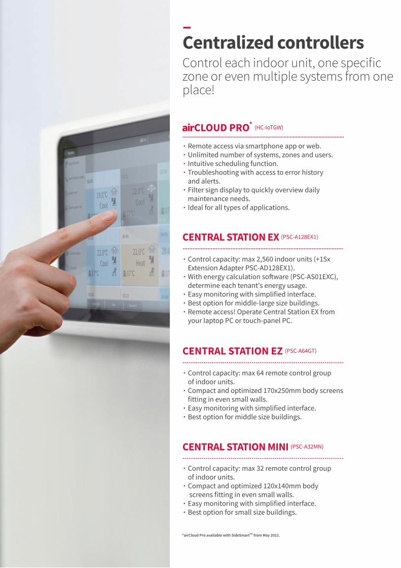
CLOUD PRO* (HC-IoTGW)......................................................................................................................................................................................................................
∙ Remote access via smartphone app or web.∙ Unlimited number of systems, zones and users.∙ Intuitive scheduling function.∙ Troubleshooting with access to error history
and alerts.∙ Filter sign display to quickly overview daily
maintenance needs.∙ Ideal for all types of applications.
CENTRAL STATION EX (PSC-A128EX1)
..................................................................................................................................................................................................∙ Control capacity: max 2,560 indoor units (+15x
Extension Adapter PSC-AD128EX1).∙ With energy calculation software (PSC-AS01EXC),
determine each tenant's energy usage.∙ Easy monitoring with simplified interface.∙ Best option for middle-large size buildings.∙ Remote access! Operate Central Station EX from
your laptop PC or touch-panel PC.
CENTRAL STATION EZ (PSC-A64GT)
........................................................................................................................................................................∙ Control capacity: max 64 remote control group
of indoor units. ∙ Compact and optimized 170x250mm body screens
fitting in even small walls.∙ Easy monitoring with simplified interface.∙ Best option for middle size buildings.
CENTRAL STATION MINI (PSC-A32MN)
........................................................................................................................................................................∙ Control capacity: max 32 remote control group
of indoor units. ∙ Compact and optimized 120x140mm body
screens fitting in even small walls.∙ Easy monitoring with simplified interface.∙ Best option for small size buildings.
–Centralized controllers Control each indoor unit, one specific zone or even multiple systems from one place!
*airCloud Pro available with SideSmartTM from May 2021.

CLOUD PRO* CENTRAL STATION MINI CENTRAL STATION EZ CENTRAL STATION EX
HC-IoTGW PSC-A32MN PSC-A64GT PSC-A128EX1
Capacity comparison
Total Connection capacity
RC group 64 (*6) 32 64 2,560 (*1)
Group 64 (*6) 32 64 2,048 (*1)
Block Unlimited (*7) 2/4/8/16 4 512 (*2)
Area Unlimited (*7) - - 512 (*2)
Indoor unit 80 (*6) 160 160 2,560 (*1)
Outdoor unit 16 (*6) 64 64 1,024 (*1)
Building scale Small to Large Small Medium Large
Operation Web + Mobile Phone Touch screen Touch screen Touch screen + Web (New!)
Display
Operation panel size options Adaptive 3 2 7
Layout - - -
List options - - - 3
Operation unit
All together
By layout - - -
By area - -
By block
By group - -
By RC group - -
By indoor unit - -
Control Function
Main 5 functions (*5)
Individual controller lock △ (*3)
Filter sign reset
Outdoor unit capacity control - △ (*4) -
Outdoor unit noise control - - -
Monitor Function
Main 5 functions (*5)
Individual controller lock
Alarm status & code
Filter sign
Air inlet temperature of indoor unit - -
Air inlet temperature of outdoor unit - -
Schedule Function
Weekly
Setting times per day 16 10 10 16
Special day setting 5 - - 5
Holiday setting - - -
Annual/Summer/Winter schedule Future Version - -
Other function
Alarm history (records number) Unlimited 100 100 10,000
External in/output history - - - 1,000
Management report visualization(*11) Energy Estimation (*8) - Future
Data output by external media Download from Web - Future - - SD card, USB flash device
IoT FunctionsConnectivity Ethernet + 4G (*9) - - -
Future Extendability Firmware OTA (*10)Web + Mobile Update - - -
* airCloud Pro available with SideSmartTM from May 2021.(*1) One Extension Adapter (PSC-AD128EX1) enable CENTRAL STATION EX to control additional 160 RC groups /128 groups / 160 IDUs / 64 ODUs, and up to 15 adapters can connect
to one Central Station EX.(*2) No restriction on the number of H-LINK.(*3) Individual Feature Control in Each Remote Controller is not available.(*4) Applicable only with Schedule function or external signal input. You cannot set it up directly from monitoring panel. (*5) Main 5 functions meaning: 1) Run/Stop 2) Operation mode 3) Temperature setting 4) Fan speed 5) Louver control.(*6) Ability to connect unlimited number of "HC-IoTGW" in one project and control all AC units via one single screen on Web or Mobile Phone.(*7) Unlimited creation of zones, across multiple "HC-IoTGW" units within the same project.(*8) Visualization of outdoor unit energy consumption.(*9) 4G available through optional 4G module; 4G module package comes with global SIM and pre-paid global data plan.(*10) OTA: Over-the-air firmware update, provides always up-to-date firmware and latest functionalities.(*11) Mini , EZ : Accumulated operation time ( min ) , Accumulated thermo - ON ( min ).
EX : Accumulated operation time ( min ) , Accumulated thermo - ON time ( min ) , Average air intake temperature of indoor unit , Average air intake temperature of outdoor unit , Average setting temperature , Average RC sensor temperature.
SMALL TO LARGE SYSTEMS & FIXED OR CLOUD-BASED................................................................................................................................................................................................................................................................................................................................................
–Centralized controllers Control each indoor unit, one specific zone or even multiple systems from one place!
89
Side
Smar
tTMVA
RIAB
LE R
EFRI
GERA
NT
FLO
W S
YSTE
M
89
Side
Smar
tTMVA
RIAB
LE R
EFRI
GERA
NT
FLO
W S
YSTE
M
04. CONTROLLERS | CENTRALIZED CONTROLLERS
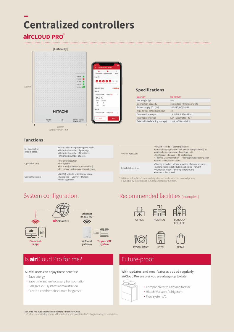
Ethernetor 3G / 4G*3
From webor app
airCloud gateway
To your VRFsystem
H-LINK
∙ Compatible with new and former ∙ Hitachi Variable Refrigerant ∙ Flow systems*1
All VRF users can enjoy these benefits! ∙ Save energy ∙ Save time and unnecessary transportation ∙ Delegate VRF systems administration ∙ Create a comfortable climate for guests
Is Cloud Pro for me?
With updates and new features added regularly, airCloud Pro ensures you are always up to date.
Future-proof
SpecificationsGateway HC–IoTGWNet weight (g) 540Connection capacity 16 outdoor + 80 indoor unitsPower supply (V) | (Hz) 100-240, AC | 50/60 Max. power consumption (W) 10Communication port 1 H-LINK, 1 RS485 PortInternet connection LAN (Ethernet) or 4G*3
External interface (log storage) 1 micro SD card slot
Monitor Function
• On/Off • Mode • Set temperature • Air intake temperature • RC sensor temperature (*3) • Air intake temperature of outdoor unit • Fan Speed • Louver • RC prohibition • Thermo-ON information • Filter sign/Auto cleaning fault • Alarm status/Alarm codes
Schedule function
• Weekly schedule • Easy selection of days and zones• Setting items in schedule is as below; • On/Off• Operation mode • Setting temperature• Louver • Fan speed
IoT connection(cloud-based)
• Access via smartphone app or web• Unlimited number of gateways• Unlimited number of locations• Unlimited number of users
Operation unit• Per entire location• Per system• Per zone (unlimited zone creation)• Per indoor unit remote control group
Control function• On/Off • Mode • Set temperature• Fan speed • Louver • RC lock • Filter sign reset * “All Groups Run/Stop” command signal exception function for selected groups
is available by “Exception of Run/Stop Operation.” function.
Functions
[Gateway]
*airCloud Pro available with SideSmartTM from May 2021.*1 Confirm compatibility of your VRF installation with your Hitachi Cooling & Heating representative.
CLOUD PRO*
..............................................................................................................................................................................................................................................................................................................................................
–Centralized controllers
138mmLateral view: 41mm
200mm
System configuration. Recommended facilities (examples.)
HOTEL
OFFICE HOSPITAL
RESTAURANT RETAIL
SCHOOL/COLLEGE

Android IOS
*2 Functions not available as of September 2019, coming soon.*3 4G module available as a side accessory.
A simple yet powerful tool.
The pilot app makes managing your VRF systems easy.
• Centralized control Control your entire VRF system or selected zones in one touch.
• Simplified troubleshooting A clear error history, concise error description and follow-up.
• Smartphone alerts*2 In the event of a critical malfunction.
• Flexible user management*2 Add users and custom access restrictions.
Simplify your job
Monitor energy consumption and optimize usage.
• Energy consumption data*2 Simple gr aphs visualize power consumption.
• Intuitive scheduling Plan operations ahead based on your business hours.
• Individual controller lock Prevent inappropriate usage from occupants.
Save more energy
Adjust temperature, fan speed, and modes with ease, creating total comfort and the ideal climate throughout your building.
An integrated weather forecast*2 display helps you determine the most suitable conditions for your indoor spaces all year round.
Create better comfort
Our airCloud gateway makes installation a breeze. Connect to the airCloud via 3G/4G*3 or ethernet and pair your VRF systems via QR code scan. With automatic detection of indoor units and an optimized installer view, configuring your site and zones has never been quicker.
Easy plug-and-play
Best-in-class standards: TLS.v1.2, HTTPS 2038 encryption.
Minimal personal details: Only your name, email address and phone number are required for login.
+ data security
Control is in your hands.24/7 control at your fingertips on smartphone, tablet, or PC.
airCloud Pro is designed to make your job easier. An intuitive app that anyone can use, airCloud Pro makes managing your VRF systems easier than ever before.
Intuitive simplicity✓
Enjoy the freedom of remote access from your smartphone, tablet or laptop. airCloud Pro allows you to remotely control your VRF system(s) from a single app, saving you travel time.
Control from anywhere✓
For stand-alone and multi-site applications.
91
Side
Smar
tTMVA
RIAB
LE R
EFRI
GERA
NT
FLO
W S
YSTE
M
91
Side
Smar
tTMVA
RIAB
LE R
EFRI
GERA
NT
FLO
W S
YSTE
M
04. CONTROLLERS | CENTRALIZED CONTROLLERS

Staff room
EXLAN
SD
32.5 27.8
Functions
Operation unit
All together Each area Each block Each group Each indoor unit
Control function
On/Off Mode Set temperature Fan speed Louver RC prohibition Filter sign reset Function selection for indoor units (*1) Function selection for outdoor units (*2) Capacity control for outdoor units (*2) Lower noise control for outdoor units (*2)
Monitor function
On/Off Mode Set temperature Air intake temperature RC sensor temperature (*3) Air intake temperature of outdoor unit Fan Speed Louver RC prohibition Thermo-ON information Filter sign/Auto cleaning fault Alarm status/Alarm codes
Schedule function
Each of the following settings is available in 3 different [annual] [summer][winter] categories: → Weekly schedule → Up to 16 actions can be set per day → Exception day setting: 5 different types → Holiday setting Setting items in schedule is as below: • On/Off • Operation mode • Setting temperature • Louver • Fan speed • RC operation prohibition • Capacity control for outdoor units • Lower noise control for outdoor units
HistoryAlarm history: 10,000 records External In/Output history: 1,000 recordsPulse input history: 6 months
Management report visualization
Up to 2 years worth of data history can be displayed for the following: • Accumulated operation time (min.) • Accumulated thermo-ON time (min.) • Average air intake temp temperature of
indoor unit• Average air intake temperature of outdoor
unit• Average setting temperature • Average RC sensor temperature
External input / output
Energy saving: • Run/Stop• RC prohibition• Temperature shift (For Cool/Dry mode: +1.0°C~+9.0°C (+1.0°F~+18.0°F)) (For Heat mode: -1.0°C~-9.0°C (-1.0°F~-18.0°F))• Mode shift (Mode shifted to Fan when in Cool/Dry mode,
and shifted to Stop in Heat mode)• Capacity control on outdoor units• Lower noise control for outdoor units Control/Monitor → Controlled items:• Run/Stop• Mode (Cool/Heat)→ Monitored items:• Run/Stop• Mode (Cool/Heat)• Alarm state Others: • Power consumption signal input• Emergency stop
(*1) Some indoor units may not fully support all functions.(*2) Available for applicable outdoor units only.(*3) Whether this is shown on the screen depends
on the remote controller settings.
H-LINK 16RC group 2,560 (*1)Group 2,048 (*1)Block 512 (*2)Area 512 (*2)Indoor unit 2,560 (*1)Outdoor unit 1,024 (*1)Building scale Large
Capacity
Rated power supply 100~240VAC ±10% (50/60Hz)Electrical power consumption 50W (Max.)Communication unit Units of Adopting for H-LINKCommunication line Two-wire non-polarCommunication speed 9,600bpsWiring length 1,000m (Total Length)Display 12.1 inch TFT color liquid crystal displayDisplay control Touch Panel
Specifications
For middle or large-scale buildings buildings such as hotels, educational facilities, and hospitals, our Central Station EX features a highly intuitive and functional 12.1-inch wide, wall-mountable, color LCD screen.
Control up to 2,560 indoor units with our proprietary H-LINK system with 15 extension adapters (PSC-AD128EX1).
Also, with energy calculation software (PSC-AS01EXC), Central Station EX can help you easily manage each tenant's electricity & report the power consumption of VRF system for each tenant.
Install by add-on software and activate, then, you can select electricity ratio or usage ratio from several methods.
Lateral view (mm)372mm
227.2mm
–Centralized controllers CENTRAL STATION EX FOR LARGE-SCALE BUILDINGS
(PSC-A128EX1)................................................................................................................................................................................................................................................................................................................................................
You can now operate Central Station EX from your laptop PC or touch panel PC. Install our software and you can connect from anywhere, using our VPN network.
Remote access.
PSC-AD128EX1 PSC-AS01EXC
Extension adapter Energy calculation software*
Example: school
1) 1 extension adapter (PSC-AD128EX1) enables Central Station EX to control additional 160 RC groups / 128 groups / 160 IDUs / 64 ODUs. Central Station EX can connect up to 15 adapters.
(*2) No restriction on the number of H-LINK

22 52.7
25 5580
140mm
120mm
CENTRAL STATION EZ FOR MEDIUM-SCALE BUILDINGS
(PSC-A64GT)....................................................................................................................................................................................................................................................................................................................................................
CENTRAL STATION MINI FOR SMALL-SCALE BUILDINGS
(PSC-A32MN)....................................................................................................................................................................................................................................................................................................................................................
With easy control via an 8.5 inch color touch panel, its detailed control functionalities such as Weekly Scheduling, Operation hours tracking, and more, help you save energy. Up to 64 remote-controlled groups and up to 160 indoor units can be connected to the Central Station EZ.
170mm
250mm
RC group 64Group 64Block 4Indoor Unit 160Outdoor Unit 64Building Scale Small-Medium
Capacity
Rated Power Supply 1-, AC 100-240V, 50/60HzElectrical Power Consumption 30W (Max.)Communication Unit Units of Adopting for H-LINKCommunication Line Non-polar 2-wireCommunication Speed 9,600bpsWiring Length 1,000m (Total Length)Display 8.5-inch Wide Color LCD (Full Dot)Display Control Touch Panel
Specifications
Monitor Function
• Run/Stop/Abnormality • Setting Temperature• RC Operation Prohibited Setting• Accumulated Operating Time• Operation Mode • Setting Fan Speed• Setting Louver • Filter Sign • Alarm Code
Control Function
• Run/Stop* • Fan Speed• Operation Mode • Louver• Temperature Setting • RC Operation Prohibited• Filter Sign Reset
* The “All Groups Run/Stop” command signal exception function for selected groups is available via the “Exception of Run/Stop Operation” function.
Functions
With easy control via an 5.0 inch color touch panel, its detailed control functionalities such as weekly scheduling, operation hours tracking, help you save energy. Up to 32 remote-controlled groups and up to 160 indoor units can be connected to the Central Station mini.
Lateral view (mm)
RC group 32Group 32Block 4 Patterns (2/4/8/16)Indoor Unit 160 Outdoor Unit 64Building Scale Small
Capacity
Rated Power Supply 1-, AC 100-240V, 50/60Hz Electrical Power Consumption 20W (Max.)Communication Unit Units of Adopting for H-LINKCommunication Line Non-polar 2-wireCommunication Speed 9,600bpsWiring Length 1,000m (Total Length)Display 5.0-inch Wide Color LCD (Full Dot)Display Control Touch Panel
Specifications
Monitor Function
• Run/Stop/Abnormality • Setting Temperature • RC Operation Prohibited Setting • Accumulated Operating Time • Operation Mode • Setting Fan Speed • Setting Louver • Filter Sign • Alarm Code"
Control Function
• Run/Stop* • Fan Speed • Operation Mode • Louver • Temperature Setting• RC Operation Prohibited • Filter Reset Signal
* “All Groups Run/Stop” command signal exception function for selected groups is available by “Exception of Run/Stop Operation.” function.
Functions
Lateral view (mm)
93
Side
Smar
tTMVA
RIAB
LE R
EFRI
GERA
NT
FLO
W S
YSTE
M
93
Side
Smar
tTMVA
RIAB
LE R
EFRI
GERA
NT
FLO
W S
YSTE
M
04. CONTROLLERS | CENTRALIZED CONTROLLERS

ADVANCED COLOR WIRED REMOTE CONTROLLER (PC-ARFG)........................................................................................................................................................................................................
∙ Exclusive color screen & Award-winning design.∙ Simplified menu and enhanced UIUX.∙ Includes latest VRF features such as FrostWashTM
and several comfort settings.
ADVANCED WIRED REMOTE CONTROLLER (PC-ARF1)........................................................................................................................................................................................................
∙ 120mm square controller with LCD screen.∙ Multiple power-saving features.∙ Best option for spaces frequented by the same users,
e.g. offices.
WIRED REMOTE CONTROLLER (HCWA10NEGQ)..........................................................................................................................................................................................................
∙ 88mm square controller with LCD screen.∙ Smaller body with multiple features.∙ Best option for spaces frequented by recurring users,
e.g. offices.
SIMPLIFIED WIRED REMOTE CONTROLLER (PC-ARH1)..........................................................................................................................................................................................................
∙ Focused on easy operation.∙ Mainly for temperature setting.∙ Ideal for spaces that accommodate short-term
visitors, e.g. hotels and hospital rooms.
ADVANCED WIRELESS REMOTE CONTROLLER (PC-AWR)..........................................................................................................................................................................................................
∙ Wireless remote controller with more features.∙ Several temperature units and settings available;
0.5°C/1.0°C/1.0°F. ∙ Ideal for controlling the unit from anywhere
in the room, e.g. residential spaces.
WIRELESS REMOTE CONTROLLER (PC-LH7QE)..........................................................................................................................................................................................................
∙ Budget option featuring primary control settings.∙ 1.0°C temperature step. ∙ Ideal for visitors to control the unit from anywhere
in the room, e.g. hotel suite.
–Individual controllers
NEW

ADVANCED COLOR WIRED REMOTE CONTROLLER
ADVANCED WIRED REMOTE CONTROLLER
WIRED REMOTE CONTROLLER
SIMPLIFIED WIRED REMOTE CONTROLLER
ADVANCED WIRELESS REMOTE
CONTROLLER
WIRELESS REMOTE
CONTROLLER
PC-ARFG PC-ARF1 HCWA10NEGQ PC-ARH1 PC-AWR PC-LH7QE
Connection CapacityRC Groups 1 1 1 1 - -Indoor units (*1) 16 16 16 16 - -
Setting
Temperature Setting Rate (*2) 0.5°C/1.0°C/1.0°F 0.5°C/1.0°C/1.0°F 0.5°C/1.0°C/1.0°F 0.5°C/1.0°C/1.0°F 0.5°C/1.0°C/1.0°F 1.0°C
Indoor Fan Speed (*2) (*3) 3/4/6 taps 3/4/6 taps 3/4/6 taps 3/4/6 taps 3/4/6 taps 3/4/6 tapsLouver Direction (*2)Individual Louver Setting (*2) - - -Remote Control Primary-Secondary Setting - - -
In Use of Total-Heat-Exchanger
Ventilation - - - -
Total Heal Exchanger Setting - - - -
Function Selection
Automatic Restart with Eco-operation - - - -Automatic Reset Temperature (Cooling) - -Temperature Indication (*4) - - -
Service & Installation
Admin Password Setting - - - - -Filter Signal - - -Filter Signal Reset -Louver Open/Close - - - -Room Name Setting - - - -Alarm Signal - -Side-by-side indoor unit identification - - - -Hotel mode - - - - -Fan Speed at Thermo-Off (Cooling/Heating) (*7) (*7) (*7) - -
Screen
Screen Adjustment - - - -
Language
English, Japanese, Chinese
(traditional & simplified),
French, Spanish, Portuguese
English, French - - - -
Temperature Unit_°C/°F (*5) (*5) -Run Indicator brightness adjustment - - - -Key touch sound - - - -
Check Menu
Sensor Condition Check - -Sensor Data Check - -Model Display (*2) - - - -Indoor/Outdoor PCB Check - - - -Alarm History Display - - -
Test Run
Test Run - - -Function Selection (Optional Function Setting) - -Thermistor Selection (*7) (*7) (*7) - -Thermistor Calibration (*7) - (*7) - -Input / Output Setting - -Indoor Unit Address Change - - -Indoor Unit Address Operation Check - - - -Indoor Unit Address Initialization - - - -Input / Output Setting Initialization - - - -Compressor Pre-Heat Control Cancellation - - - -Contact Information Registration - - - -
Management
Operation Lock/Set (*7) (*6)(*7) (*7) - -Lower Limit for Cooling Operation (*7) (*7) (*7) - -Upper Limit for Heating Operation (*7) (*7) (*7) - -Simple Timer (On/Off) -Date/time setting - - -Automatic OFF Timer Setting (*7) - (*7) - -
Schedule
Weekly Schedule - - -Settable Timer Operation Times (Per Day) 5 5 1 - - -Holiday Setting - - - -Schedule On/Off - - - -
Power-Saving
Power-Saving with Motion Sensor - - - -Outdoor Unit Capacity Control
Peak cut control - - - -
moderate control - - - -
Indoor Unit Rotation Control
Indoor Unit Address - - - -Indoor Air Temperature difference - - - -With Motion Sensor - - - -
Automatic Fan Operation - - - -
MENU
Auto-Elevating Grille - - - -ODU Night Quiet Mode - - - -AutoBoost (quick function) - - - -
Comfort Setting
Control Cool Air (GentleCool) - - - -Direct/Indirect louver direction in COOL - - - -Direct/Indirect louver direction in HEAT - - - -Radiant Sensor Control for Heating - - - - -FeetWarm; Heat Air Flow - - - - -FloorSense; Cool Air Flow - - - - -
Power Saving/Night Quiet Schedule - - - -Filter Cleaning - - - -FrostWashTM Setting - - - - -Daylight Saving Time - - - -Setback (Hotel Temperature Setback) - - - -Power Consumption Display - - - -
(*1) All 16 indoor units need to be connected with transition wire.(*2) Actual availability may vary depending on the indoor unit model connected to
the controller. Please consult your Hitachi Cooling & Heating representative for more details.(*3) 6 steps available in RPIZ-HNDTSQ compact ducted indoor unit only.(*4) Reference room temperature can be chosen: from indoor unit's air inlet thermistor
or from the thermistor built-in the controller itself.
(*5) Please contact your distributor in case temperature unit needs to be changed from °C to °F.
(*6) Only "bulk operation lock" available.(*7) Optional setting Items for function selection.
NEW
FROM BASIC TO ADVANCED CONTROLS............................................................................................................................
95
Side
Smar
tTMVA
RIAB
LE R
EFRI
GERA
NT
FLO
W S
YSTE
M
95
Side
Smar
tTMVA
RIAB
LE R
EFRI
GERA
NT
FLO
W S
YSTE
M
04. CONTROLLERS | INDIVIDUAL CONTROLLERS
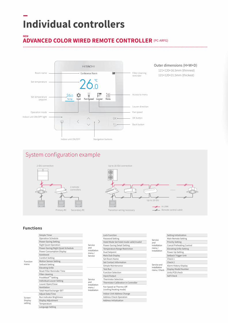
........
–Individual controllers ADVANCED COLOR WIRED REMOTE CONTROLLER (PC-ARFG)
..................................................................................................................................................................................................................................................................................................................................................
NEW
Filter cleaning reminder
Set temperature
Set temperature setpoint
Indoor unit ON/OFF light
Operation mode
Indoor unit ON/OFF Navigation buttons
Access to menu
Louver direction
Fan speed
OK button
Back button
Room name
Functions
Outer dimensions (H×W×D) 121×120×16.5mm (thinnest)
121×120×21.5mm (thickest)
Function menu
Simple TimerOperation SchedulePower-Saving SettingNight Quiet OperationPower-Saving/Night Quiet SchedulePower Consumption DisplayAutoboostComfort SettingMotion Sensor SettingSetback SettingElevating GrilleReset Filter Reminder TimeFilter cleaningFrostWashTM SettingIndividual Louver SettingLouver Open/CloseVentilationTotal Heat Exchanger SET
Screen Display setting
Adjust Date/TimeRun Indicator BrightnessDisplay AdjustmentTemperatureLanguage Setting
Service and installation menu / Installation
Setting InitializationMain Remote SettingPriority SettingCancel Preheating ControlElevating Grille SettingPower Up SettingSetback Trigger Unit
Service and installation menu / Check
Check 1Check 2Alarm History DisplayDisplay Model NumberUnits PCB checkSelf Check
Service and installation menu / Service
Lock FunctionPassword SettingHotel Mode Set hotel mode valid/invalidPower-Saving Detail SettingTemperature Range RestrictionDual SetpointMain/Sub DisplaySet Room NameSet Contact InformationSimple Maintenance
Service and installation menu / Installation
Test RunFunction SelectionInput/OutputThermistor SelectionThermistor Calibration in Controller
Fan Speed at Thermo-Off (cooling/heating mode)
Indoor Unit Address ChangeAddress Check OperationAddress Initialization
Up to 16 IDU connection
Up to 16 IDU
Transition wiring necessaryPrimary RC Secondary RC
H-LINKRemote control cable
2 IDU connection
2 remote controllers
System configuration example

Schedule menu
FrostWashTM menu
Capacity control setting
Heating mode(Color: warm orange)
Cooling mode(Color: warm blue)
Auto mode(Color: sand)
Fan mode(Color: cool purple)
Dry mode(Color: cool turquoise)
From basic to advanced functionsAdjust the air conditioning to enhance comfort and save energy with ease.
1) Functions include GentleCool, which controls the temperature of discharged air, for smooth cooling down and cold drafts prevention. AutoBoost activates for 30 minutes every time the AC is turned on, helping the room reach the desired temperature faster with a powerful automatic mode.
2) AC scheduling is easier than ever, thanks to flexible options such as a holiday calendar.
3) Save even more energy with power-saving functions for VRF system operators. Cut peak capacity, rotate the thermal operation of indoor units, and use Hitachi’s dedicated power-saving schedule to match your utility tariff plan.
Additional functions∙ Activate, schedule and check the history of indoor units’ FrostWashTM
function.∙ Minimize outdoor unit noise at night with the schedulable quiet mode.∙ NEW Hotel mode display provides quick access to the most popular
AC functions for guests, including language selection.
Outstanding design and user experience.
With a sleek, award-winning design, our new advanced color controller offers elegance and ease-of-use.A simplified, intuitive and colorful menu makes controlling your ideal climate a breeze.
97
Side
Smar
tTMVA
RIAB
LE R
EFRI
GERA
NT
FLO
W S
YSTE
M
97
Side
Smar
tTMVA
RIAB
LE R
EFRI
GERA
NT
FLO
W S
YSTE
M
04. CONTROLLERS | INDIVIDUAL CONTROLLERS
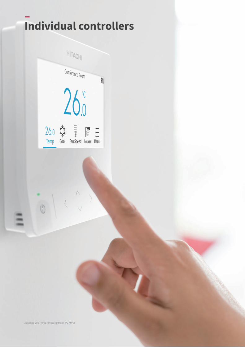
–Individual controllers
Advanced Color wired remote controller (PC-ARFG)
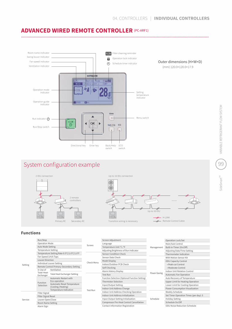
........
Fan speed indicator
Swing louver indicator
Settingtemperatureindicator
Operation modeindicator
Operation guideindicator
Run indicator
Directional key ECOswitch
Enter key Back/Helpswitch
Run/Stop switch
Menu switch
Ventilation indicator
Room name indicator Filter cleaning reminder
Operation lock indicator
Schedule timer indicator
Functions
Outer dimensions (H×W×D) (mm) 120.0×120.0×17.9
Setting
Run/StopOperation ModeAuto Mode SettingTemperature SettingTemperature Setting Rate 0.5°C/1.0°C/1.0°FFan Speed 3/4/6 TapsLouver DirectionIndividual Louver SettingRemote Control Primary-Secondary SettingIn Use of Total-Heat-Exchanger
Ventilation
Total Heal Exchanger Setting
Function Selection
Automatic Restart with Eco-operationAutomatic Reset Temperature(Cooling /Heating)Temperature Indication
Service
Filter SignalFilter Signal ResetLouver Open/CloseRoom Name SettingAlarm Sign
Management
Operation Lock/SetMain/Sub ControlBuilt-in-Timer (On/Off)Adjusting Date/Time SettingThermometer Indication
Power-Saving
With Motion Sensor KitODU Capacity Control • Peak-cut Control • Moderate ControlIndoor Unit Rotation ControlAutomatic Fan OperationAuto Recovery of TemperatureUpper Limit for Heating OperationLower Limit for Cooling OperationPower Consumption Visualization
Schedule
Weekly ScheduleSet Timer Operation Times (per day): 5Holiday SettingSchedule On/OffODU Noise Reduction Schedule
Screen
Screen AdjustmentLanguageTemperature Unit °C /°FAdjusting Brightness of Run Indicator
Check Menu
Sensor Condition CheckSensor Data CheckModel DisplayIndoor/Outdoor PCB CheckSelf CheckingAlarm History Display
Test Run
Test RunFunction Selection (Optional Function Setting)Thermistor SelectionInput/Output SettingIndoor Unit Address ChangeIndoor Unit Address Checking OperationIndoor Unit Address InitializationInput-Output Setting InitializationCompressor Pre-Heat Control CancellationContact Information Registration
Up to 16 IDU connection
Up to 16 IDU
Transition wiring is necessary
H-LINKRemote Control Cable
2 IDU connection
2 remote controllers
Primary RC Secondary RC
System configuration example
ADVANCED WIRED REMOTE CONTROLLER (PC-ARF1)
..................................................................................................................................................................................................................................................................................................................................................
99
Side
Smar
tTMVA
RIAB
LE R
EFRI
GERA
NT
FLO
W S
YSTE
M
99
Side
Smar
tTMVA
RIAB
LE R
EFRI
GERA
NT
FLO
W S
YSTE
M
04. CONTROLLERS | INDIVIDUAL CONTROLLERS

ON/OFF button
Liquid Crystal Display (LCD) screen
Up button & down button
Timer/Clock settingFan speed setting
Mode button
Timer ON
Timer OFF Timer valid for one timeTimer valid for one dayTimer set for a week
Timer setting
Room temperature
Set temperature
Temperature display
(fl ickering)
Fan speed
MAX
MIN
Cooling mode
Operation mode
Heating mode
Dry mode
Fan mode
Auto mode
By repeatedly pressing the button, the setting
will change sequentially. By repeatedly pressing the button,the fan speed setting will change sequentially.
Run indicator (red)ON/OFF switch
Fan speed switch
Operation mode switch Swing louver switch
TEMP switch (temperature setting)
(swing louver operation): FAN: COOL: HEAT
: DRY: AUTO
Outer dimensions (H×W×D) (mm) 120.0×70.0×17.0
Functions
Setting
Run/StopOperation ModeAuto Mode SettingTemperature SettingTemperature Setting Rate 0.5°C/1.0°C/1.0°FBack-light screenFan Speed 3/4/6 tapsLouver Direction
Test Run
Function Selection (Optional Function Setting)Thermistor SelectionThermistor CalibrationInput / Output Setting
Management
Operation Lock/SetLower Limit for Cooling OperationUpper Limit for Heating OperationAutomatic OFF Timer Setting
*Please contact your dealer in case “temperature setting rate” needs to be changed from °C to °F.
Functions
Setting
Run/StopOperation ModeAuto Mode SettingTemperature SettingTemperature Setting Rate 0.5°C/1.0°C/1.0°FBack-light screenFan Speed 3/4/6 tapsLouver DirectionKey touch sound
ServiceSensor Condition CheckSensor Data CheckAlarm History Display
Test Run
Test RunFunction Selection (Optional Function Setting)Thermistor SelectionThermistor CalibrationInput / Output SettingIndoor Unit Address Change
ManagementOperation Lock/SetLower Limit for Cooling OperationUpper Limit for Heating Operation
ScheduleSimple Timer (On/Off)Date/time setting
Notes:1. Fan speed taps setting unit availability varies with the indoor
unit. Please check each technical catalog in advance.2. Initial setting of temperature display is "Set temperature"
display only. Please contact your dealer to display room temperature.
Outer dimensions (H×W×D) (mm) 88.0×88.0×15.5
–Individual controllers WIRED REMOTE CONTROLLER (HCWA10NEGQ)
................................................................................................................................................................................................................................................................................................................................................
SIMPLIFIED WIRED REMOTE CONTROLLER (PC-ARH1)
................................................................................................................................................................................................................................................................................................................................................

ADVANCED WIRELESS REMOTE CONTROLLER (PC-AWR)
..............................................................................................................................................................
RECEIVER KIT FOR WIRELESS REMOTE CONTROLLER
..................................................................................................................................................................................................................................................................................................................................................
Transmitter
Reset switch
Timer switches
Mode selection switch
Transmitter
Transmitting indication
LCD (Liquid Crystal Display)
Fan speed switchOn switch
Off switch
Louver angle switch
Filter reset switchTemp. switch
Transmitting indication
LCD (Liquid Crystal Display)
Reset switch
Louver angle switch
Temp. switchRun/Stop switch
Timer switches
Model
HR4A10NEWQ(Basic)
PC-ALH3(Advanced)
PC-ALHC1(Advanced)
P-AP56NAMR(Advanced)
PC-ALHD1(Advanced)
PC-ALHS1(Advanced)
PC-ALHP1(Advanced)
PC-ALHZ1 (Advanced)
Indoor unit
4-wayCassette
4-wayCassette
4-way compactCassette
4-way compactCassette
2-wayCassette
1-wayCassette
Ceiling Suspended Wall-Mounted Floor
ExposedFloor
ConcealedDucted
High ESPDucted
Medium ESP
RCI-FSKDNQ RCI-FSRP RCIM-FSRE RCIM-FSRE RCD-FSR RCS-FSR RPC-FSR RPK-FSRMRPK-FSRHM RPF-FSN2E RPFI-FSN2E RPI-FSR
RPI-FSN1 RPIM-FSR
Advanced Wireless Remote Controller
Standard WirelessRemote Controller — — — — — — — — — — —
PC-AWR
PC-LH7QE
Model
Indoor unit
Ducted High ESP
(AC Motor)
Ducted Medium ESP
(AC Motor)
Ducted Low ESP
(AC Motor)
Ducted Compact Ducted Larger Air Volume (AC Motor)
Wall-Mounted (AC Motor)
Floor / Ceiling Convertible
Floor ConcealedAC Motor DC Motor
RPI-HNAUNQ RPI-FSNQ
RPIM-HNAUNQ RPI-FSN3Q RPIL-HNAUNQ RPIZ-HNATNQ RPIZ-HNDTSQ RPI-FSN2SQ RPK-FSNQS RPFC-FSNQ RPFI-FSNQ
Advanced Wireless Remote Controller
Standard WirelessRemote Controller
PC-RLH11 (Basic) PC-ALHZ1 (Advanced)
PC-AWR
PC-LH7QE
Notes:When using a basic receiver kit PC-RLH11 or HR4A10NEWQ together with wireless remote controller PC-LH7QE:1) It won't be possible to lock individual remote controllers from Hitachi Central Stations (mini/EZ/EX)2) It won't be possible to apply min/max restrictions on set temperature from Hitachi Central Stations (mini/EZ/EX)
(*) Basic function receiver kit is installed as a standard part in this wall-mounted unit. Wireless remote controller (PC-LH7QE) is delivered as a standard accessory as well. If separate placement of receiver kit is required, please use optional basic receiver kit [PC-RLH11] or optional advanced receiver kit [PC-ALHZ1].
Basic Limited function available for centralized controllers Temperature setting rate [1.0°C] only
Advanced Full function available for centralized controllers Temperature setting rate [0.5°C/1.0°C/1.0°F]
Outer dimensions (H×W×D) (mm) 140.0×52.0×19.3
Functions
Setting
Run/StopOperation ModeAuto Mode SettingTemperature SettingTemperature Setting Rate 1.0°CFan Speed 3/4/6 TapsLouver Direction
ServiceSide-by-side indoor unit identification Temperature Unit °C
Schedule Built-in Timer (On/Off)
Outer dimensions (H×W×D) (mm) 140.0×55.0×16.8
Functions
Setting
Run/StopOperation ModeAuto Mode SettingTemperature SettingTemperature Setting Rate 0.5°C/1.0°C/1.0°FFan Speed 3/4/6 TapsLouver Direction
Service
Filter Sign ResetSide-by-side indoor unit identification Temperature Unit °C/°F
Schedule Built-in Timer (On/Off)
WIRELESS REMOTE CONTROLLER (PC-LH7QE)
............................................................................................................................................................
101
Side
Smar
tTMVA
RIAB
LE R
EFRI
GERA
NT
FLO
W S
YSTE
M
101
Side
Smar
tTMVA
RIAB
LE R
EFRI
GERA
NT
FLO
W S
YSTE
M
04. CONTROLLERS | INDIVIDUAL CONTROLLERS

3
321
1
2
* PC-ARFG & PC-ARF1 does not include a remote control cable. Use this cable if you don’t have one available in your field.
–Accessories
PRC-5K PRC-10K PRC-15KLength m 5.00 10.00 15.00
H-LINKRemote control cable
Shielded twist-pair cable50mm 100mm
«PRC-5K, 10K, 15K»
System configuration example
Operation example∙ Cooling operation:
Compressor is ON by closing terminals 2 and 3 of CN3. Compressor is OFF by opening terminals 2 and 3 of CN3.
∙ Heating operation: Compressor is ON by closing terminals 1 and 2 of CN3. Compressor is OFF by opening terminals 1 and 2 of CN3.
H-LINKRemote control cable
* One set contains five 3P connector cables.* PCC-1A can connect to external signal input-output terminal both in outdoor unit and indoor unit.
«PCC-1A»
Thermostat
Temperature increase
CN3
Indoor unit PCB
Remote ON/OFF device
System configuration example
3P CONNECTOR CABLE PCC-1AFOR CONNECTION TO REMOTE ON/OFF DEVICE/RECEIPT OF OUTPUT SIGNAL
* When the room temperature thermistor (remote sensor) is connected to the auxiliary connector, the unit is controlled at average air temperature at the indoor inlet and remote sensor point.
* Not compatible with wall type(RPK) indoor unit.
H-LINKRemote sensor cord
«THM-R2A»
System configuration exampleOuter dimensions (H×W×D) (mm) 50.0×50.0×15.0
Length m 8.00
REMOTE SENSOR THM-R2AROOM TEMPERATURE SENSOR
REMOTE CONTROL CABLE PRC-5K, 10K, 15KFOR PC-ARFG & PC-ARF1 CONNECTION (TO IDU)
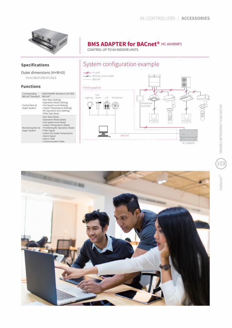
HC-A64BNP1
H-LINKRemote control cableBACnet®
Field-supplied
BACnet ®
Centralizedcontroller
VentilationLightingFirealarm Lift
System configuration exampleOuter dimensions (H×W×D) (mm) 68.0×240.0×154.0
FunctionsCorresponding BACnet® Standard
ANSI/ASHRAE Standard 135-2004 BACnet®
Control Item at Upper System
• Run Stop (Setting)• Operation Mode (Setting)• Fan Speed Level (Setting)• Indoor Temperature (Setting)• RC Operation lock (Setting)• Filter Sign Reset
Monitoring Item at Upper System
• Run Stop (State)• Operation Mode (State)• Fan Speed Level (State)• Indoor Temperature (State)• Prohibiting RC Operation (State)• Filter Signal• Indoor Air Intake Temperature• Alarm Signal• Alarm Code• Communication State
BMS ADAPTER for BACnet® HC-A64BNP1CONTROL UP TO 64 INDOOR UNITS
Specifications
103
Side
Smar
tTMVA
RIAB
LE R
EFRI
GERA
NT
FLO
W S
YSTE
M
103
Side
Smar
tTMVA
RIAB
LE R
EFRI
GERA
NT
FLO
W S
YSTE
M
04. CONTROLLERS | ACCESSORIES

H-LINK is Hitachi Cooling & Heating original communication system to control multiple VRF refrigerant systems from one centralized control point.
H-LINK simplifies commissioning and service maintenance for installers and service engineers. For building owners and occupants, it provides outstanding versatility enabling the connection of various types of central control options, enabling better system management. Our proprietary high-performance communication system enables the connection of control wiring between indoor and outdoor units, and between a centralized control system and indoor/outdoor units across two or more refrigerant systems.
Rehabilitation facilities or hospitals where it is necessary to minimize the burden on users.
Hotels where it is preferable to complete installation work during late evenings.
Educational institutions such as primary schools where installation work cannot be performed on weekdays.
1 CS-NET/Central station Hitachi original centralized controller.
2 RC Group (Remote Controller System Group) Stands for a number of indoor units (up to 16 units) connected using "same remote controller" wiring. In this group, connected indoor units are all controlled in the same way.
3 Group Stands for the multiple "RC groups" that are registered in the centralized controller network setting.
4 Block Stands for the multiple "groups" that are registered in the centralized controller network setting.
Definition of terms in Hitachi centralized control systemsOutdoor unit
Indoor unit
RC Group RC Group RC Group RC Group RC Group
–H-LINK: enjoy more freedom
WHAT IS H-LINK?......................................................................................................................................................................
Examples
3xmorebenefits!
Flexible wiring routes:
no restrictions & time-saving
at installation.
Can connect with various types of
Hitachi air conditioning products, including VRF
and mini splits, for centralized controls.
No adapter is needed!
Simple connection to terminal blocks.
21 3
Block4
CS-NET1
GroupGroup3 3
2 2 2 2 2

Remote control cableH-LINKH-LINK solution
CENTRALIZED CONTROLS: FLEXIBLE WIRING ROUTE!..................................................................................................................................................................................................................................................................................................................................................
(1) • Multiple refrigerant systems located in one area.
• Central monitoring room in separate area.
H-LINK SOLUTION Wire the central station to the closest indoor unit.
Wiring distance is reduced substantially.
(2) • Refrigeration systems in different places.
• Some indoor units of each respective system are close to one another.
H-LINK SOLUTION Where two indoor units of each respective system are close together: you can connect two refrigerant systems via the indoor units. Wiring distance is reduced substantially.
(4) • Each refrigerant system in separate areas.
• Indoor units are closer from one group to another.
H-LINK SOLUTION Centralized control can be achieved by connecting the refrigerant systems via the closer indoor units. Wiring can be indoors only.
(3) • One refrigerant system far away from theremaining ones.
H-LINK SOLUTION Connect the farthest refrigerant system directly to central station either to outdoor units or indoor units. The central station can make the central link between the different refrigerant systems.
CENTRAL CONTROL ROOM AREA 1
AREA 1 AREA 2
AREA 4AREA 3AREA 2AREA 1
CENTRAL CONTROL ROOM
AREA 2AREA 1CENTRAL CONTROL
ROOM
CENTRAL CONTROL ROOM
105
Side
Smar
tTMVA
RIAB
LE R
EFRI
GERA
NT
FLO
W S
YSTE
M
105
Side
Smar
tTMVA
RIAB
LE R
EFRI
GERA
NT
FLO
W S
YSTE
M
04. CONTROLLERS | H-LINK: ENJOY MORE FREEDOM

–Notes

107
Side
Smar
tTMVA
RIAB
LE R
EFRI
GERA
NT
FLO
W S
YSTE
M
107
Side
Smar
tTMVA
RIAB
LE R
EFRI
GERA
NT
FLO
W S
YSTE
M
–Johnson Controls-Hitachi Air Conditioning Trading (Hong Kong) Ltd12/F, Millenium City 6, 392 Kwun Tong, Kowloon, Hong Kong.
hitachiaircon.hk
SALES OFFICE
SOCIAL MEDIA
WARRANTY
CERTIFICATE
GENERAL HOTLINE +852 259 000 12
[email protected] Outdoor Unit Manufacturing Site: Johnson Controls-Hitachi Air Conditioning Wuhu Co., Ltd.Concerning Hitachi Slim-Modular VRF SideSmart
The specifications of this catalog may change without prior notice to allowHitachi Cooling & Heating to incorporate the latest innovations for its customers.The information contained in this catalog is merely informative.Hitachi Cooling & Heating declines any responsibility in the broadest sense, fordamage, direct or indirect, arising from the use and / or interpretation of therecommendations in this catalog.
Find the products Hitachi Cooling & Heatingwith the best service and conditions at yourHitachi Distributor.
WARRANTY
5COMPRESSOR
1