Hitachi Highly - Ries GmbH
21
Hitachi Highly Rollkolbenverdichter Rotary Compressors Spezifikation Manual BSA645DT-R1EN RIES GmbH, Rudolf-Diesel-Str. 10, D 64569 Nauheim, GERMANY Phone: +49 6152 9741 0, Fax: +49 6152 9741 21, Email: [email protected] , Website: www.ries-gmbh.de Änderungen jederzeit vorbehalten We reserve the right to change at any time without prrior notice
-
Upload
khangminh22 -
Category
Documents
-
view
0 -
download
0
Transcript of Hitachi Highly - Ries GmbH
Hitachi Highly Rollkolbenverdichter
Rotary Compressors
Spezifikation Manual
BSA645DT-R1EN
RIES GmbH, Rudolf-Diesel-Str. 10, D 64569 Nauheim, GERMANY
Phone: +49 6152 9741 0, Fax: +49 6152 9741 21, Email: [email protected], Website: www.ries-gmbh.de
Änderungen jederzeit vorbehaltenWe reserve the right to change at
any time without prrior notice
7/24
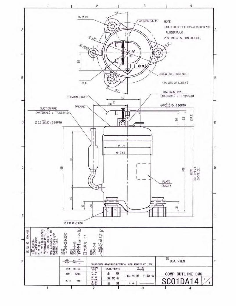
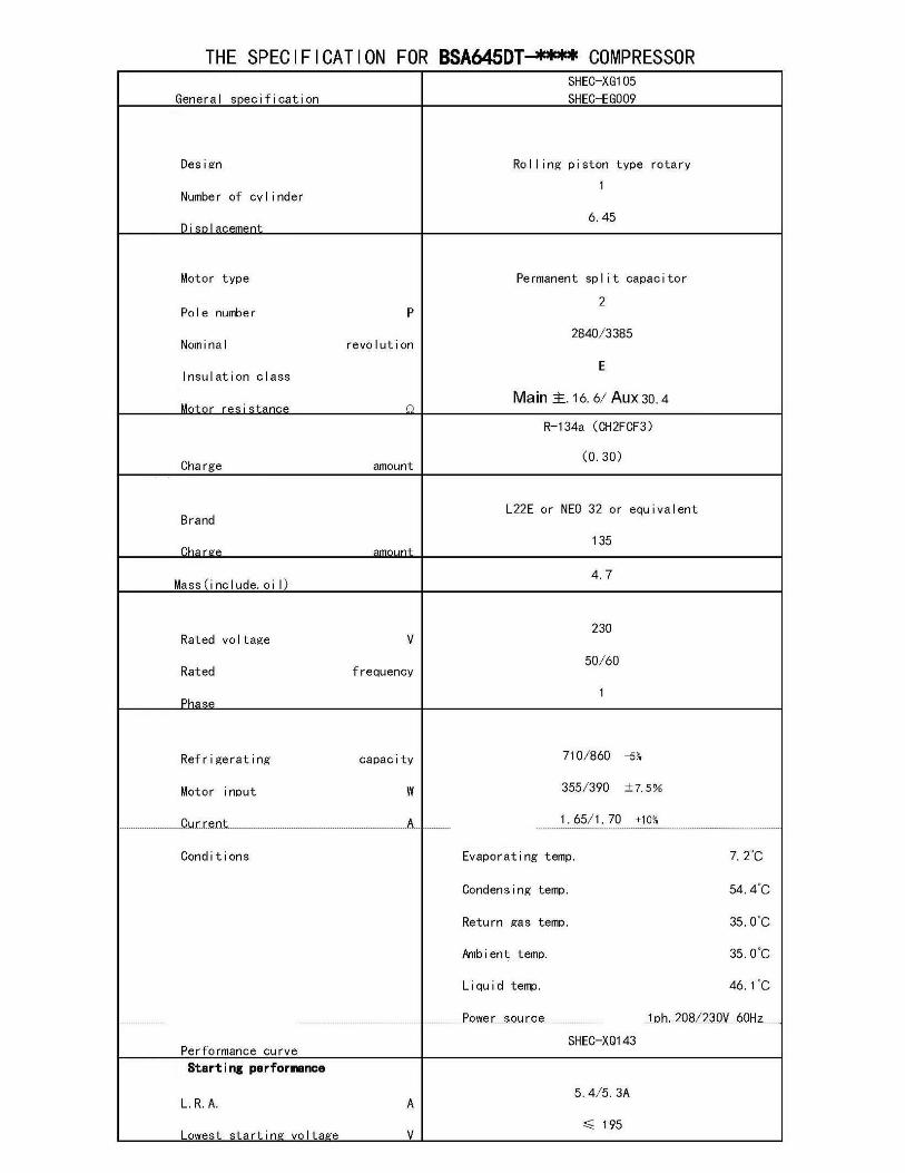
THE GENERAL SPECIFICATIONS
FOR BSA***DT SERIES ROTARY COMPRESSOR
If a compressor is not operated properly, not only will it be impossible to display its performance to the full, but it
may lead to a shortened service life and even malfunctions and breakdowns. These operating instructions have
been prepared so that the rotary compressor will be used properly and efficiently without malfunctions and
breakdowns, and here lists the operation standards and handling precautions. It is recommended that you acquire a
full understanding of the special properties of the compressor and that you operate it properly.
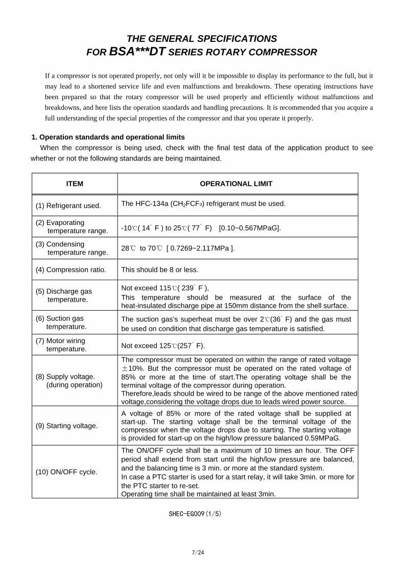
1. Operation standards and operational limits
When the compressor is being used, check with the final test data of the application product to see
whether or not the following standards are being maintained.
ITEM OPERATIONAL LIMIT
(1) Refrigerant used. The HFC-134a (CH2FCF3) refrigerant must be used.
(2) Evaporating temperature range. -10℃( 14
。F ) to 25℃( 77
。F) [0.10~0.567MPaG].
(3) Condensing temperature range.
28℃ to 70℃ [ 0.7269~2.117MPa ].
(4) Compression ratio. This should be 8 or less.
(5) Discharge gas temperature.
Not exceed 115℃( 239。
F ), This temperature should be measured at the surface of the heat-insulated discharge pipe at 150mm distance from the shell surface.
(6) Suction gas temperature.
The suction gas’s superheat must be over 2℃(36。
F) and the gas must be used on condition that discharge gas temperature is satisfied.
(7) Motor wiring temperature. Not exceed 125℃(257
。F).
(8) Supply voltage. (during operation)
The compressor must be operated on within the range of rated voltage ±10%. But the compressor must be operated on the rated voltage of 85% or more at the time of start.The operating voltage shall be the terminal voltage of the compressor during operation. Therefore,leads should be wired to be range of the above mentioned rated voltage,considering the voltage drops due to leads wired power source.
(9) Starting voltage.
A voltage of 85% or more of the rated voltage shall be supplied at start-up. The starting voltage shall be the terminal voltage of the compressor when the voltage drops due to starting. The starting voltage is provided for start-up on the high/low pressure balanced 0.59MPaG.
(10) ON/OFF cycle.
The ON/OFF cycle shall be a maximum of 10 times an hour. The OFF period shall extend from start until the high/low pressure are balanced, and the balancing time is 3 min. or more at the standard system. In case a PTC starter is used for a start relay, it will take 3min. or more for the PTC starter to re-set. Operating time shall be maintained at least 3min.
SHEC-EG009(1/5)
8/24
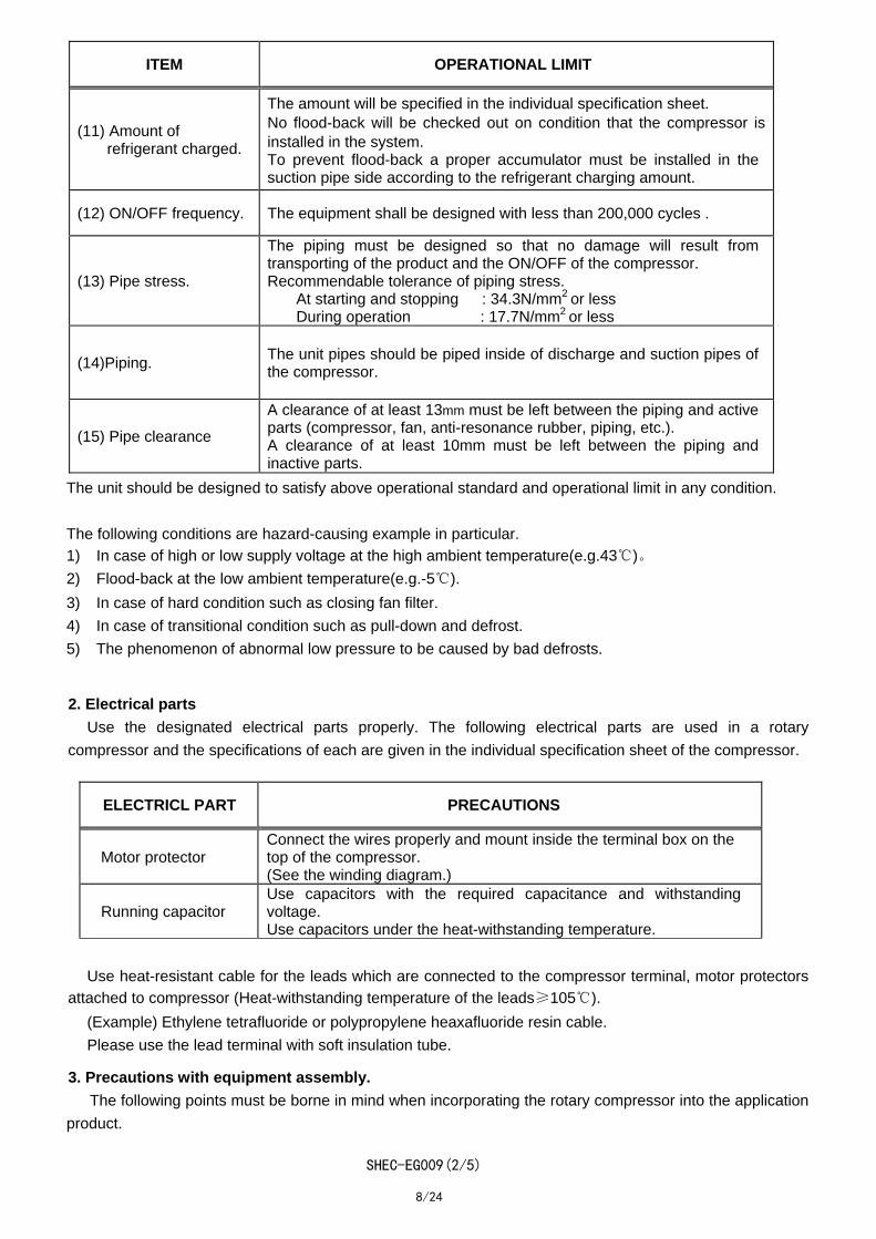
ITEM OPERATIONAL LIMIT
(11) Amount of refrigerant charged.
The amount will be specified in the individual specification sheet. No flood-back will be checked out on condition that the compressor is installed in the system. To prevent flood-back a proper accumulator must be installed in the suction pipe side according to the refrigerant charging amount.
(12) ON/OFF frequency. The equipment shall be designed with less than 200,000 cycles .
(13) Pipe stress.
The piping must be designed so that no damage will result from transporting of the product and the ON/OFF of the compressor. Recommendable tolerance of piping stress.
At starting and stopping : 34.3N/mm2 or less During operation : 17.7N/mm2 or less
(14)Piping. The unit pipes should be piped inside of discharge and suction pipes of the compressor.
(15) Pipe clearance
A clearance of at least 13mm must be left between the piping and active parts (compressor, fan, anti-resonance rubber, piping, etc.). A clearance of at least 10mm must be left between the piping and inactive parts.
The unit should be designed to satisfy above operational standard and operational limit in any condition.
The following conditions are hazard-causing example in particular.
1) In case of high or low supply voltage at the high ambient temperature(e.g.43℃)。
2) Flood-back at the low ambient temperature(e.g.-5℃).
3) In case of hard condition such as closing fan filter.
4) In case of transitional condition such as pull-down and defrost.
5) The phenomenon of abnormal low pressure to be caused by bad defrosts.
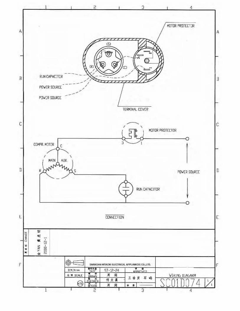
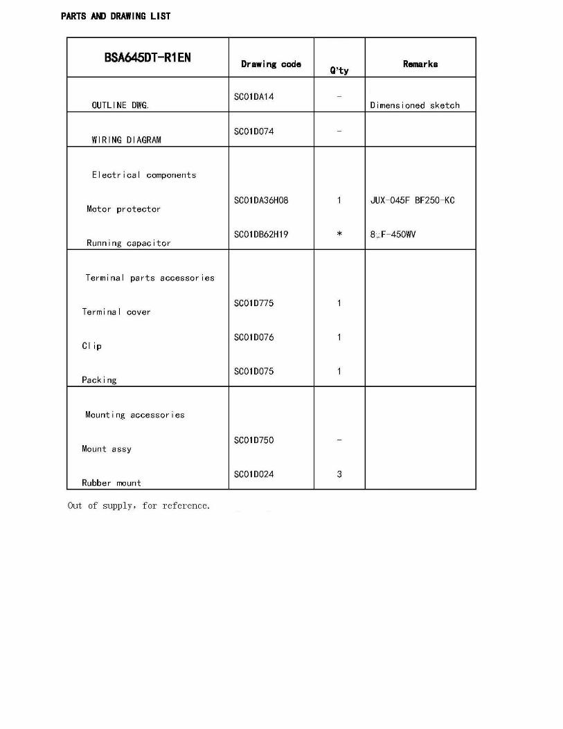
2. Electrical parts
Use the designated electrical parts properly. The following electrical parts are used in a rotary
compressor and the specifications of each are given in the individual specification sheet of the compressor.
ELECTRICL PART PRECAUTIONS
Motor protector Connect the wires properly and mount inside the terminal box on the top of the compressor. (See the winding diagram.)
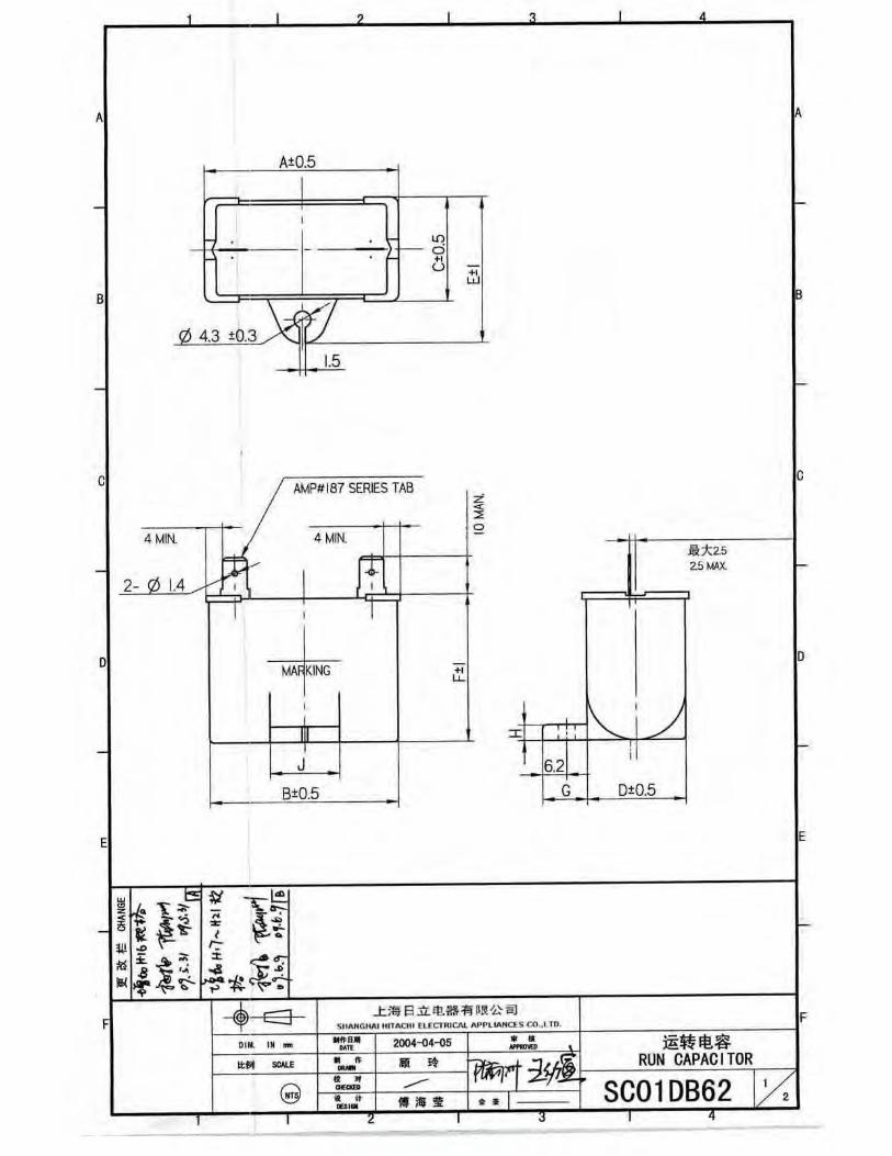
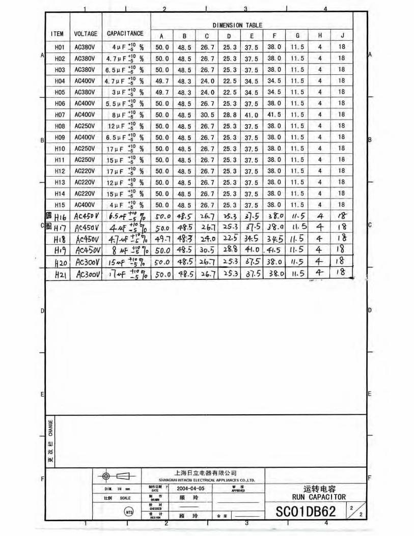
Running capacitor Use capacitors with the required capacitance and withstanding voltage. Use capacitors under the heat-withstanding temperature.
Use heat-resistant cable for the leads which are connected to the compressor terminal, motor protectors
attached to compressor (Heat-withstanding temperature of the leads≥105℃).
(Example) Ethylene tetrafluoride or polypropylene heaxafluoride resin cable.
Please use the lead terminal with soft insulation tube.
3. Precautions with equipment assembly.
The following points must be borne in mind when incorporating the rotary compressor into the application
product.
SHEC-EG009(2/5)
9/24
3-1. Refrigeration system (1) The virgin unit should be used absolutely.
Especially the compressor must not be set in the used unit which has been experienced CFC or HCFC refrigerant such as R12,R22,R502.
(2) Solvents which contain chlorine should not be applied for cleaning the apparatus. If applying the solvents by any means ,it should be considered sufficiently that chlorine is not
remained in the apparatus. *Chloride remnants should be less than 100ppm of charged refrigerant (Including the chloride contained in refrigerant).
(3) Organic material parts which are unknown concerning to compatibility with HFC-134a refrigeration system, should not be applied. (Please let us confirm it if necessary.)
(4) Dryer for HFC-134a should be applied. The dryer can absorb 50mg moisture per 1g and use sufficient the dryer to absorb the moisture in refrigerant circuit. The dryer should be installed as soon as possible after the package is opened. (e.g. “XH-9”made by UNION SHOWA)
(5) Process oil ( machining oil ) used for forming pipes and equipment must be removed. It should be confirmed that the oil complies with HFC134a refrigeration system. (Please let us confirm if it is necessary.) Especially as remained high viscosity oil may causes choke of refrigerant cycle, do not remain it. HFC refrigerant does not solves almost all oil.
3-2. Removal of rubber plugs
The rubber plugs must be removed from the high pressure side ( dis.pipe and process pipe ). The
compressor is filled with dry-air at the pressure of 0.05~0.1MPaG. If the rubber plugs are removed from the
lower pressure side (suction pipe),it is feared that oil in the compressor is gushed out.
3-3. Welding method
Take care not to allow flux, dirt, foreign matter or moisture to enter the refrigeration circuit while welding
between pipes or welding the pipes to the compressor.
3-4. Refrigerant charging method
The compressor is supplied with oil. Check the “OIL IN” mark.
Create the vacuum from both the high and low pressure side. ( If it is possible to the create the vacuum
from one side only, take sufficient time at the high pressure side and check that the prescribed vacuum gas
has been created.)
Always charge the refrigerant from the high pressure side ( condenser ) of the unit.
Do not use the refrigerant charger which has been used for HCFC or CFC.
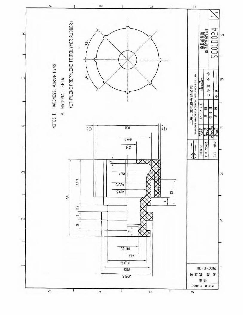
3-5. Parts securing
Secure the compressor properly with the prescribed method and using the prescribed anti-vibration
rubber pieces.
The secured compressor must lean less than 5°from the perpendicular.
3-6. Starting method
(1) Connect the proper circuits and then start up the compressor.
(2) Make the time span from power OFF to re-start the same as the time taken for the high and low
pressure to be balanced ( about 3min. ), then balanced starting.
3-7. Moisture
Keep the amount of balanced moisture inside the refrigeration circuit ( including compressor ) within
350mg(Cold-trap test).
Moisture level in the refrigeration system should be maintained as low as possible.
SHEC-EG009(3/5)
10/24
3-8. Contaminants / foreign obstacles
(1) Carefully avoid the fluxes, contaminants ( such as metal or fiber scraps ) to mingle inside the refrigerant
circuit.
(2) Install a strainer ( with about 100 mesh ) within the refrigeration circuit and avoid the clogging of
capillary tube, etc..
3-9. Evacuation
A degree of vacuum about 133Pa[abs] is desirable.
3-10. Packings used for couplings in the vacuum pump and the refrigerant charger.
The material of packings (O-ring) used for couplings in the vacuum pump and the refrigerant charger
should be not applied to chloroprene rubber (CR).
The packing made of CR may not be a durabity. Acryl-nitoryl butadiene rubber (H-NBR) is
recommended as its material.
Please ask the couplings manufacturer in detail.
3-11. General handling precautions
(1) The compressor should be installed in the refrigeration system within 1 year from the manufactured
date.
(2) The compressor should not be left for more than 30 minutes unsealed.
(3) Do not carry out compressor self-actuated vacuum condition.
(4) Never operate the compressor as an air compressor.
(5) Never supply electricity under the vacuum condition.
(6) Do not severely tilt the compressor, drop it or cause it to topple over while transporting.
(7) Do not scratch the painted surfaces.
(8) Do not use the compressor in cars, trains and small size ships.
3-12. Refrigerant
Refrigerant R-134a 99.9% in purity should be used for apparatus. 99.95% is recommended,if
possible.In particular, the refrigerant containing the minimum volume of chloride should be used.
3-13. Refrigeration oil
In order to maintain a high reliability, one specially developed refrigeration oil for rotary compressors is
used. This oil has excellent load-withstanding and heat stability properties. No other type of oil must
therefore be used.
As HFC refrigerant does not solve this oil, confirm following “Oil returns”.
3-14. Oil returns
It is important for the piping to be designed with sufficient consideration given to oil return during the
refrigeration cycle since the refrigeration oil in the compressor is sometimes discharged in volume inside the
equipment as a transitional phenomenon (due to the storing of the refrigerant ) during start-up, etc.
Oil is liable to collect when an auxiliary accumulator is attached within the refrigerating cycle, which
necessitates an oil-return structure. Care is required with short ON/OFF cycles.
It is necessary to confirm oil return with above care.Please confirm that the oil level is sufficient to the
operation standand,running with the compressor equipped with sight glass,in the unit operation limit
condition that high to low ambient temperature,on the mode pull-down,On-Off cycle.
SHEC-EG009(4/5)
11/24
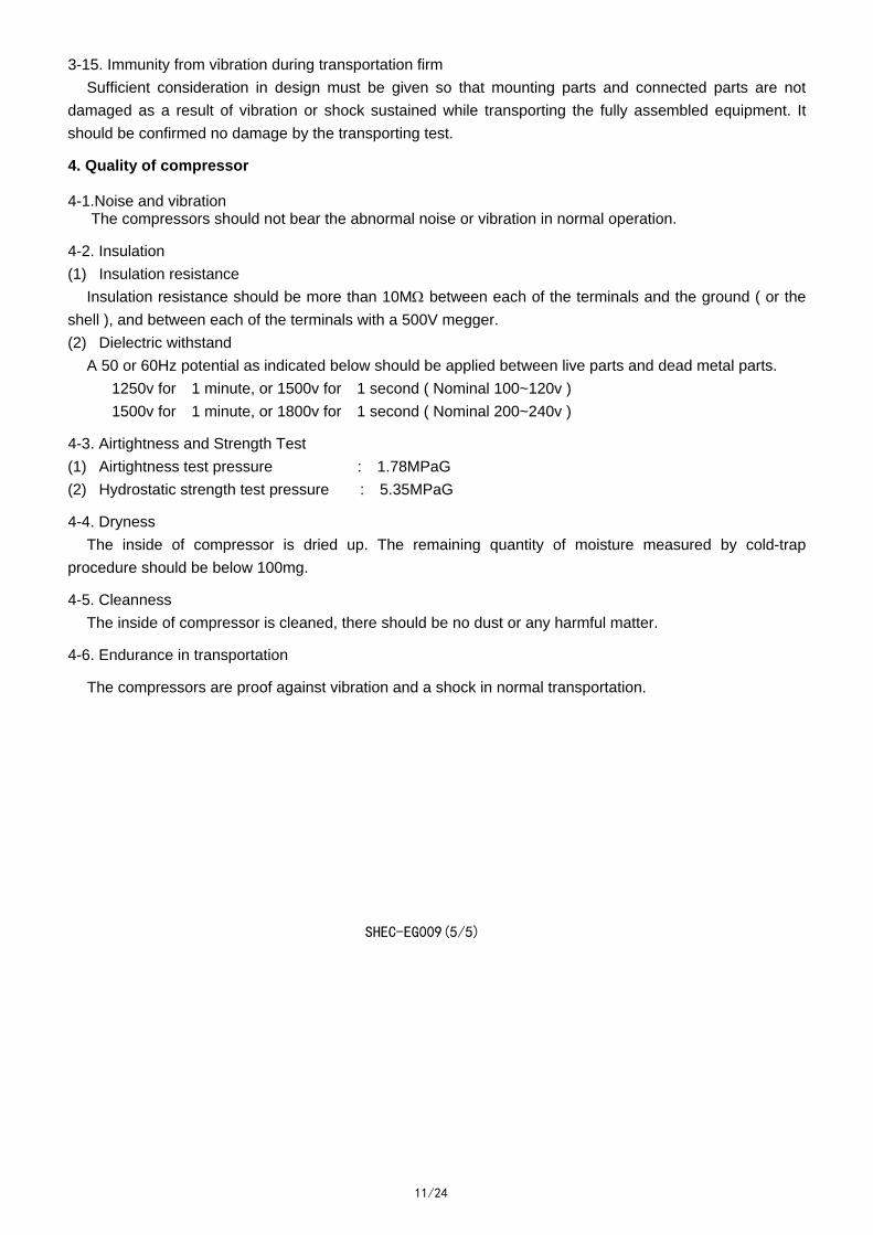
3-15. Immunity from vibration during transportation firm
Sufficient consideration in design must be given so that mounting parts and connected parts are not
damaged as a result of vibration or shock sustained while transporting the fully assembled equipment. It
should be confirmed no damage by the transporting test.
4. Quality of compressor 4-1.Noise and vibration The compressors should not bear the abnormal noise or vibration in normal operation.
4-2. Insulation
(1) Insulation resistance
Insulation resistance should be more than 10M between each of the terminals and the ground ( or the
shell ), and between each of the terminals with a 500V megger.
(2) Dielectric withstand
A 50 or 60Hz potential as indicated below should be applied between live parts and dead metal parts.
1250v for 1 minute, or 1500v for 1 second ( Nominal 100~120v )
1500v for 1 minute, or 1800v for 1 second ( Nominal 200~240v )
4-3. Airtightness and Strength Test
(1) Airtightness test pressure : 1.78MPaG
(2) Hydrostatic strength test pressure : 5.35MPaG
4-4. Dryness
The inside of compressor is dried up. The remaining quantity of moisture measured by cold-trap
procedure should be below 100mg.
4-5. Cleanness
The inside of compressor is cleaned, there should be no dust or any harmful matter.
4-6. Endurance in transportation
The compressors are proof against vibration and a shock in normal transportation.
SHEC-EG009(5/5)
12/24
13/24