Provisioning Guide - Hitachi Vantara Knowledge
862
Hitachi Virtual Storage Platform Gx00 and Fx00 SVOS 7.3.1 Provisioning Guide This document describes and provides instructions for performing provisioning operations on Hitachi Virtual Storage Platform G200, G400, G600, G800 (VSP Gx00 models) and Hitachi Virtual Storage Platform F400, F600, F800 (VSP Fx00 models). The provisioning software includes LUN Manager, Virtual LUN, Resource Partition Manager, Dynamic Provisioning, Dynamic Tiering, and Data Retention Utility. MK-94HM8014-10 December 2017
-
Upload
khangminh22 -
Category
Documents
-
view
1 -
download
0
Transcript of Provisioning Guide - Hitachi Vantara Knowledge

Hitachi Virtual Storage Platform Gx00 and Fx00SVOS 7.3.1
Provisioning GuideThis document describes and provides instructions for performing provisioning operations on HitachiVirtual Storage Platform G200, G400, G600, G800 (VSP Gx00 models) and Hitachi Virtual StoragePlatform F400, F600, F800 (VSP Fx00 models). The provisioning software includes LUN Manager, VirtualLUN, Resource Partition Manager, Dynamic Provisioning, Dynamic Tiering, and Data Retention Utility.
MK-94HM8014-10December 2017

© 2015, 2017 Hitachi, Ltd. All rights reserved.
No part of this publication may be reproduced or transmitted in any form or by any means, electronic or mechanical, including copying andrecording, or stored in a database or retrieval system for commercial purposes without the express written permission of Hitachi, Ltd., orHitachi Vantara Corporation (collectively “Hitachi”). Licensee may make copies of the Materials provided that any such copy is: (i) created as anessential step in utilization of the Software as licensed and is used in no other manner; or (ii) used for archival purposes. Licensee may notmake any other copies of the Materials. “Materials” mean text, data, photographs, graphics, audio, video and documents.
Hitachi reserves the right to make changes to this Material at any time without notice and assumes no responsibility for its use. The Materialscontain the most current information available at the time of publication.
Some of the features described in the Materials might not be currently available. Refer to the most recent product announcement forinformation about feature and product availability, or contact Hitachi Vantara Corporation at https://support.hitachivantara.com/en_us/contact-us.html.
Notice: Hitachi products and services can be ordered only under the terms and conditions of the applicable Hitachi agreements. The use ofHitachi products is governed by the terms of your agreements with Hitachi Vantara Corporation.
By using this software, you agree that you are responsible for:
1. Acquiring the relevant consents as may be required under local privacy laws or otherwise from authorized employees and otherindividuals to access relevant data; and
2. Verifying that data continues to be held, retrieved, deleted, or otherwise processed in accordance with relevant laws.
Notice on Export Controls. The technical data and technology inherent in this Document may be subject to U.S. export control laws, includingthe U.S. Export Administration Act and its associated regulations, and may be subject to export or import regulations in other countries. Readeragrees to comply strictly with all such regulations and acknowledges that Reader has the responsibility to obtain licenses to export, re-export, orimport the Document and any Compliant Products.
Hitachi is a registered trademark of Hitachi, Ltd., in the United States and other countries.
AIX, AS/400e, DB2, Domino, DS6000, DS8000, Enterprise Storage Server, eServer, FICON, FlashCopy, IBM, Lotus, MVS, OS/390, PowerPC, RS/6000,S/390, System z9, System z10, Tivoli, z/OS, z9, z10, z13, z/VM, and z/VSE are registered trademarks or trademarks of International BusinessMachines Corporation.
Active Directory, ActiveX, Bing, Excel, Hyper-V, Internet Explorer, the Internet Explorer logo, Microsoft, the Microsoft Corporate Logo, MS-DOS,Outlook, PowerPoint, SharePoint, Silverlight, SmartScreen, SQL Server, Visual Basic, Visual C++, Visual Studio, Windows, the Windows logo,Windows Azure, Windows PowerShell, Windows Server, the Windows start button, and Windows Vista are registered trademarks or trademarksof Microsoft Corporation. Microsoft product screen shots are reprinted with permission from Microsoft Corporation.
All other trademarks, service marks, and company names in this document or website are properties of their respective owners.
Contents
Preface................................................................................................... 25Intended audience............................................................................................. 25
Product version..................................................................................................25
Release notes....................................................................................................25
Changes in this revision.....................................................................................25
Referenced documents......................................................................................26
Document conventions...................................................................................... 26
Conventions for storage capacity values........................................................... 28
Accessing product documentation.....................................................................29
Getting help........................................................................................................29
Comments..........................................................................................................29
Chapter 1: Introduction to provisioning............................................. 31About provisioning............................................................................................. 31
Key terms...........................................................................................................31
Basic provisioning..............................................................................................33
Overview of fixed-sized provisioning............................................................ 33
Overview of custom-sized provisioning........................................................ 35
Basic provisioning workflow..........................................................................36
Complementary functions.................................................................................. 36
Dynamic Provisioning........................................................................................ 36
About Dynamic Provisioning.........................................................................37
Dynamic Provisioning concepts ...................................................................37
Advantages of using Dynamic Provisioning ................................................ 38
Storing Thin Image pair and snapshot data in a Dynamic Provisioningpool...............................................................................................................39
ContentsProvisioning Guide for Hitachi Virtual Storage Platform Gx00 and Fx00 3
About DP-VOLs with data direct mapping attribute......................................40
Dynamic Provisioning high-level workflow....................................................44
Capacity saving and accelerated compression functions.............................45
Capacity saving function: data deduplication and compression...................48
Use cases for capacity saving.................................................................53
About pool volumes from accelerated compression-enabled paritygroups...........................................................................................................54
Accelerated compression-enabled parity groups....................................54
Storing data written to DP-VOLs.............................................................55
Monitoring used pool capacity and used pool capacity reserved forwriting......................................................................................................56
Dynamic Tiering ................................................................................................ 58
Dynamic Tiering............................................................................................58
Overview of tiers...........................................................................................59
Active flash .................................................................................................. 59
System requirements for provisioning .............................................................. 61
Shared memory requirements......................................................................62
Cache management device requirements....................................................62
Calculating the number of cache management devices required forDP-VOLs.................................................................................................62
System option modes for provisioning......................................................... 63
Resource access requirements for Device Manager - Storage Navigatoroperations.....................................................................................................83
Access requirements for Dynamic Provisioning and Dynamic Tiering....83
Access requirements for Encryption License Key...................................84
Access requirements for LUN Manager..................................................85
Access requirements for Performance Monitor.......................................88
Access requirements for ShadowImage................................................. 88
Access requirements for Thin Image...................................................... 89
Access requirements for TrueCopy.........................................................89
Access requirements for global-active device.........................................90
Access requirements for Universal Replicator........................................ 91
ContentsProvisioning Guide for Hitachi Virtual Storage Platform Gx00 and Fx00 4

Access requirements for Universal Volume Manager............................. 93
Access requirements for Virtual LUN......................................................95
Access requirements for Virtual Partition Manager.................................96
Access requirements for Volume Shredder............................................ 97
Access requirements for Server Priority Manager.................................. 97
Chapter 2: Managing virtual storage machine resources.................99About virtual storage machines and virtualized resources................................ 99
Using virtual storage machines for nondisruptive migration............................ 100
Using virtual storage machines for global-active device..................................101
Requirements and specifications for global storage virtualization................... 102
Virtual storage machine operations in CCI and Device Manager -Storage Navigator.......................................................................................103
Performing provisioning operations for resources in a virtual storagemachine......................................................................................................104
Pair operations with virtual storage machine pairs.....................................105
Creating a virtual storage machine.................................................................. 106
Enabling the virtualization management setting for LDEVs.............................109
Editing virtual LDEV ID and virtual volume configuration................................. 111
Disabling the virtualization management setting for LDEVs............................ 113
Chapter 3: Configuring custom-sized provisioning.........................115Virtual LUN functions....................................................................................... 115
Configuring volumes in a parity group .............................................................115
Configuration of interleaved parity groups....................................................... 116
Virtual LUN requirements.................................................................................117
Virtual LUN specifications................................................................................ 117
RAID level support for CVs and pool-VOLs................................................117
CV capacity.................................................................................................118
Virtual LUN size calculations............................................................................119
Calculating OPEN-V volume size (CV capacity unit is MB)........................119
Calculating OPEN-V volume size (CV capacity unit is blocks)...................120
Calculating fixed-size volume size (CV capacity unit is MB)...................... 121
ContentsProvisioning Guide for Hitachi Virtual Storage Platform Gx00 and Fx00 5

Calculating fixed-size volume size (CV capacity unit is blocks)................. 121
Management area capacity of a volume.................................................... 122
Boundary values of volumes...................................................................... 122
Capacity of a slot........................................................................................123
Enabling accelerated compression..................................................................123
Disabling accelerated compression................................................................. 124
Parity groups and volumes.............................................................................. 125
Managing parity groups................................................................................... 125
Create parity groups by selecting drives manually.....................................125
Creating parity groups by selecting drives automatically........................... 126
Formatting parity groups.............................................................................127
Deleting parity groups................................................................................ 128
Spare drives and copy-back mode.................................................................. 128
Assigning spare drives............................................................................... 129
Releasing spare drives...............................................................................129
Editing copy-back mode............................................................................. 130
Create LDEV function...................................................................................... 130
Creating an LDEV.......................................................................................130
Finding an LDEV ID....................................................................................134
Blocking LDEVs............................................................................................... 135
Formatting LDEVs............................................................................................135
About formatting LDEVs.............................................................................135
Quick Format function................................................................................ 136
Quick Format specifications..................................................................136
Formatting a specific LDEV........................................................................139
Formatting all LDEVs in a parity group.......................................................140
Stopping the LDEV formatting process...................................................... 140
Restoring blocked LDEVs................................................................................141
Editing an LDEV name.................................................................................... 142
Deleting an LDEV (converting to free space).................................................. 142
Assigning an MP unit....................................................................................... 143
ContentsProvisioning Guide for Hitachi Virtual Storage Platform Gx00 and Fx00 6

Enabling and disabling MP unit auto assignment.......................................143
Changing the MP unit assigned to an LDEV.............................................. 144
Chapter 4: Configuring thin provisioning ........................................147Dynamic Provisioning overview....................................................................... 147
Dynamic Tiering overview................................................................................147
Active flash overview....................................................................................... 147
Thin provisioning requirements........................................................................148
License requirements................................................................................. 148
Pool requirements...................................................................................... 148
Pool-VOL requirements..............................................................................151
DP-VOL requirements................................................................................ 154
Deduplication system data volume requirements.......................................156
Pool capacity consumed by metadata........................................................157
Requirements for increasing DP-VOL capacity..........................................158
Estimating the required capacity of pool-VOLs with system area in thepool with data direct mapping enabled.......................................................159
V-VOL page reservation requirement ........................................................160
Operating system and file system capacity................................................ 161
Using Dynamic Provisioning and Dynamic Tiering with other softwareproducts........................................................................................................... 163
Interoperability of DP-VOLs and pool-VOLs...............................................163
ShadowImage pair status for reclaiming zero pages................................. 168
TrueCopy....................................................................................................169
Global-active device................................................................................... 170
Universal Replicator................................................................................... 171
ShadowImage.............................................................................................171
Volume Migration........................................................................................172
Interoperability restrictions for Thin Image................................................. 173
Virtual Partition Manager CLPR setting......................................................174
Dynamic Provisioning workflow....................................................................... 174
Dynamic Tiering and active flash..................................................................... 174
ContentsProvisioning Guide for Hitachi Virtual Storage Platform Gx00 and Fx00 7

About tiered storage................................................................................... 175
Tier monitoring and data relocation............................................................ 175
Multi-tier pool..............................................................................................175
How the tier relocation process works........................................................176
Tier monitoring and relocation cycles......................................................... 178
Auto execution mode............................................................................ 179
Manual execution mode........................................................................180
Tier relocation rules, restrictions, and guidelines....................................... 182
Buffer area of a tier.....................................................................................187
Setting external volumes for each tier........................................................ 189
Execution modes for tier relocation............................................................ 190
Execution modes when using Hitachi Device Manager - StorageNavigator ..............................................................................................190
Viewing monitor and tier relocation information in HDvM - SN............. 191
Execution modes when using Command Control Interface.................. 194
Viewing monitor and tier relocation information using CCI................... 194
Relocation speed........................................................................................195
Monitoring modes.......................................................................................195
Downloading the tier relocation log file.......................................................197
Tier relocation log file contents............................................................. 197
Tiering policy.............................................................................................. 205
Custom policies.....................................................................................206
Tiering policy examples.........................................................................206
Setting tiering policy on a DP-VOL....................................................... 207
Tiering policy levels...............................................................................208
Viewing the tiering policy in the performance graph............................. 209
Reserving tier capacity when setting a tiering policy............................ 210
Example of reserving tier capacity........................................................ 211
Notes on tiering policy settings............................................................. 213
Execution mode settings and tiering policy...........................................214
New page assignment tier.................................................................... 215
ContentsProvisioning Guide for Hitachi Virtual Storage Platform Gx00 and Fx00 8

Relocation priority................................................................................. 218
Assignment tier when pool-VOLs are deleted.......................................219
Formatted pool capacity........................................................................221
Used capacity, mapped capacity, and reserved capacity......................221
Rebalancing the usage level among parity groups............................... 221
Changing the tiering policy level of a DP-VOL......................................222
Changing new page assignment tier of a V-VOL....................................... 223
Opening the Edit Tiering Policies window.................................................. 223
Changing a tiering policy name.................................................................. 223
Changing an allocation threshold............................................................... 224
Changing relocation priority setting of a V-VOL......................................... 225
Functions overview for active flash and Dynamic Tiering...........................226
Page relocation by active flash...................................................................227
Dynamic Tiering workflow...........................................................................227
Active flash workflow.................................................................................. 229
User interface specifications for Dynamic Tiering tasks............................. 231
Managing Dynamic Tiering and active flash...............................................235
Changing a Dynamic Provisioning pool to a Dynamic Tiering pool.......235
Viewing pool tier information.................................................................237
Changing monitoring and tier relocation settings..................................237
Changing monitoring mode settings..................................................... 238
Changing relocation speed................................................................... 238
Changing buffer space for new page assignment setting..................... 239
Changing buffer space for tier relocation setting...................................239
Enabling active flash on an existing Dynamic Tiering pool................... 240
Changing a Dynamic Tiering or active flash pool to a pool forDynamic Provisioning............................................................................241
Working with pools...........................................................................................242
About pools.................................................................................................242
About pool-VOLs........................................................................................ 242
Creating pools............................................................................................ 243
ContentsProvisioning Guide for Hitachi Virtual Storage Platform Gx00 and Fx00 9

Creating Dynamic Provisioning pools by selecting pool-VOLsmanually................................................................................................244
Creating Dynamic Provisioning pools by selecting pool-VOLsautomatically......................................................................................... 247
Creating Dynamic Tiering or active flash pools by selecting pool-VOLs manually......................................................................................250
Creating a Dynamic Tiering or active flash pool by automaticallyselecting pool-VOLs..............................................................................253
Working with DP-VOLs.................................................................................... 256
About DP-VOLs..........................................................................................256
Relationship between a pool and DP-VOLs............................................... 256
DP-VOL protection function........................................................................257
Configuring the DP-VOL protection function options............................ 258
Creating DP-VOLs......................................................................................259
Changing DP-VOL settings........................................................................ 262
Workflow for migrating V-VOL data............................................................ 263
Monitoring capacity and performance..............................................................263
Monitoring pool capacity.............................................................................263
Protecting data during pool shortages.................................................. 264
Monitoring performance..............................................................................264
Managing I/O usage rates example...................................................... 265
Tuning with Dynamic Tiering...................................................................... 265
Improving performance by monitoring pools.............................................. 266
Thresholds for monitoring pools...................................................................... 268
Pool utilization thresholds...........................................................................268
Pool subscription limit.................................................................................269
Monitoring total DP-VOL subscription for a pool...................................270
Changing pool thresholds...........................................................................271
Changing the pool subscription limit...........................................................271
Controlling Thin Image pair behavior in a Dynamic Provisioning pool....... 272
Working with SIMs .......................................................................................... 273
About SIMs.................................................................................................273
ContentsProvisioning Guide for Hitachi Virtual Storage Platform Gx00 and Fx00 10

SIMs for HDP/HDT..................................................................................... 273
Managing pools and DP-VOLs........................................................................ 284
Viewing pool information............................................................................ 285
Viewing the capacity information for a pool................................................285
Viewing the used pool capacity of a Thin Image root volume.................... 286
Viewing formatted pool capacity.................................................................286
Reasons to check pool capacity........................................................... 287
Viewing the progress of rebalancing the usage level among paritygroups ........................................................................................................287
Expanding a pool........................................................................................288
Changing a pool name............................................................................... 289
Enabling deduplication on an existing pool................................................ 290
Disabling deduplication on a pool...............................................................291
Recovering a blocked pool......................................................................... 291
Decreasing pool capacity........................................................................... 292
About decreasing pool capacity............................................................ 292
Shrinking a pool ................................................................................... 294
Stopping the decrease of pool capacity................................................ 295
Deleting a tier in a pool...............................................................................295
Deleting a pool........................................................................................... 296
Changing the tier rank of an external pool-VOL......................................... 297
Increasing DP-VOL capacity...................................................................... 298
Changing the name of a DP-VOL...............................................................299
About releasing pages in a DP-VOL.......................................................... 299
Releasing pages in a DP-VOL.............................................................. 300
Stopping the release of pages in a DP-VOL......................................... 302
Changing full allocation settings in DP-VOLs.............................................302
Enabling or disabling tier relocation of a DP-VOL...................................... 303
Enabling capacity saving on DP-VOLs.......................................................304
Disabling the capacity saving functions on DP-VOLs................................ 305
Deleting a DP-VOL.....................................................................................306
ContentsProvisioning Guide for Hitachi Virtual Storage Platform Gx00 and Fx00 11

Deleting all capacity saving-enabled DP-VOLs in a pool........................... 308
Starting pool monitoring manually................................................................... 308
Stopping pool monitoring manually..................................................................309
Starting tier relocation manually...................................................................... 309
Stopping tier relocation manually.....................................................................310
Enabling data direct mapping for external volumes, pools, and DP-VOLs...... 310
Creating external volumes with data direct mapping enabled....................310
Creating pools with data direct mapping enabled...................................... 312
Creating DP-VOLs with data direct mapping enabled................................314
Enabling and disabling the data direct mapping attribute for a pool...........315
Chapter 5: Protecting volumes using Data Retention Utility..........317About access attributes................................................................................... 317
Access attribute requirements......................................................................... 318
Access attributes and permitted operations.....................................................318
Access attribute restrictions.............................................................................318
Access attributes workflow...............................................................................319
Assigning an access attribute to a volume...................................................... 319
Changing an access attribute to read-only or protect...................................... 320
Changing an access attribute to read/write..................................................... 321
Enabling or disabling the expiration lock......................................................... 322
Disabling an S-VOL......................................................................................... 323
Reserving volumes.......................................................................................... 323
Troubleshooting for Data Retention Utility....................................................... 324
Chapter 6: Managing logical volumes...............................................327LUN Manager overview................................................................................... 327
LUN Manager operations........................................................................... 327
Fibre Channel and iSCSI functions............................................................ 327
Host groups and LU path configuration (Fibre Channel)............................328
Workflow for configuring logical units (Fibre Channel)............................... 329
Rules, restrictions, and guidelines for managing LUs................................ 329
ContentsProvisioning Guide for Hitachi Virtual Storage Platform Gx00 and Fx00 12

Configuring hosts and Fibre Channel ports..................................................... 331
Configuring Fibre Channel ports......................................................................331
Setting the data transfer speed on a Fibre Channel port........................... 331
Available data-transfer speeds for FC ports..........................................332
Setting the Fibre Channel port address......................................................333
Addresses for Fibre Channel ports....................................................... 334
Setting the fabric switch..............................................................................335
Fibre Channel topology.............................................................................. 336
Example of FC-AL and point-to-point topology..................................... 336
Setting the Fibre Channel topology............................................................ 336
Configuring hosts.............................................................................................337
Configure hosts workflow........................................................................... 337
Host modes for host groups....................................................................... 337
Host mode options......................................................................................339
How to find the WWN of a host bus adapter.............................................. 345
Finding a WWN on a Windows host......................................................346
Finding a WWN on a Solaris host......................................................... 346
Finding a WWN on an AIX, IRIX, or Sequent host................................347
Finding a WWN on an HP-UX host.......................................................347
Creating a host group and registering hosts in the host group (FibreChannel).....................................................................................................348
Setting a command device.............................................................................. 350
Configuring LU paths....................................................................................... 352
Configure LU paths workflow..................................................................... 353
Defining LU paths.......................................................................................353
Setting a UUID............................................................................................354
UUID requirements............................................................................... 355
Correspondence table for defining devices................................................ 356
Defining alternate LU paths........................................................................356
Copying all LU paths defined in a host group....................................... 356
Copying all LU paths defined in an iSCSI target...................................357
ContentsProvisioning Guide for Hitachi Virtual Storage Platform Gx00 and Fx00 13
Copying selected (but not all) LU paths defined in a host group.......... 357
Copying selected (but not all) LU paths defined in an iSCSI target...... 358
Managing LU paths.................................................................................... 358
Deleting LU paths..................................................................................359
Clearing a UUID setting........................................................................ 360
Viewing LU path settings.......................................................................360
Releasing LUN reservation by host................................................................. 360
LUN security on ports...................................................................................... 361
Examples of enabling and disabling LUN security on ports....................... 361
Enabling LUN security on a port.................................................................362
Disabling LUN security on a port................................................................363
Setting Fibre Channel authentication...............................................................364
User authentication.................................................................................... 364
Settings for authentication of hosts.......................................................365
Settings for authentication of ports (required if performing mutualauthentication).......................................................................................365
Host and host group authentication............................................................366
Example of authenticating hosts in a Fibre Channel environment........367
Port settings and connection results..................................................... 368
Fabric switch authentication....................................................................... 369
Fabric switch settings and connection results............................................ 371
Mutual authentication of ports.................................................................... 372
Fibre Channel authentication..................................................................... 372
Enabling or disabling host authentication on a host group................... 372
Registering host user information......................................................... 372
Changing host user information registered on a host group................. 374
Deleting host user information.............................................................. 374
Registering user information for a host group (for mutualauthentication).......................................................................................375
Clearing user information from a host group.........................................376
Fibre Channel port authentication.............................................................. 376
Setting Fibre Channel port authentication.............................................376
ContentsProvisioning Guide for Hitachi Virtual Storage Platform Gx00 and Fx00 14

Registering user information on a Fibre Channel port.......................... 377
Registering user information on a fabric switch.................................... 378
Clearing fabric switch user information................................................. 379
Setting the fabric switch authentication mode.......................................379
Enabling or disabling fabric switch authentication................................ 380
Overview of iSCSI operations..........................................................................380
Network configuration for iSCSI................................................................. 381
Multi VLAN operations with iSCSI virtual port mode.................................. 382
Managing hosts............................................................................................... 383
Changing WWN or nickname of a host bus adapter.................................. 383
Changing HBA iSCSI name or nickname of a host bus adapter................ 384
Changing the name, host mode, or host mode options of a host group.....385
Changing iSCSI target setting.................................................................... 386
Removing hosts from iSCSI targets........................................................... 387
Initializing host group 0...............................................................................388
Deleting a host bus adapter from a host group.......................................... 388
Deleting WWNs from the WWN table.........................................................389
Deleting a host group................................................................................. 389
Deleting an iSCSI target.............................................................................390
Deleting login iSCSI names........................................................................391
Adding a selected host to a host group...................................................... 391
Adding a host to the selected host group................................................... 392
Adding a host to the selected iSCSI target.................................................392
Confirming communication status.............................................................. 393
Creating LDEVs used as system drives of NAS.........................................393
Setting the T10 PI mode on a port...................................................................394
Creating iSCSI targets and registering hosts in an iSCSI target..................... 395
Editing iSCSI port settings............................................................................... 397
Adding CHAP users.........................................................................................398
Editing CHAP users......................................................................................... 399
Removing CHAP users....................................................................................400
ContentsProvisioning Guide for Hitachi Virtual Storage Platform Gx00 and Fx00 15
Removing target CHAP users..........................................................................400
Removing port CHAP users.............................................................................401
Chapter 7: Working with ALUs and SLUs for vSphere VVOL......... 403Creating LDEVs with the ALU attribute............................................................403
Viewing the ALUs and SLUs in the storage system.........................................405
Unbinding the SLUs from the ALUs.................................................................405
Chapter 8: Troubleshooting for provisioning...................................407Troubleshooting Dynamic Provisioning............................................................407
Resolving errors when using CCI to perform Dynamic Provisioningoperations (SSB1: 0x2e31/0xb96d/0xb980) ..............................................418
Troubleshooting Data Retention Utility............................................................ 421
Troubleshooting for Data Retention Utility..................................................421
Resolving errors when using CCI to perform Data Retention Utilityoperations (SSB1:2E31/B9BF/B9BD)........................................................ 422
Contacting customer support...........................................................................424
Appendix A: CCI command reference for provisioning.................. 425Provisioning tasks and CCI commands........................................................... 425
Appendix B: Guidelines for pools when acceleratedcompression is enabled..................................................................... 429
Checking whether accelerated compression can be enabled......................... 429
Estimating required FMC capacity...................................................................429
Hitachi Data Reduction Estimation Tool..................................................... 429
Estimating FMC capacity for a new pool.................................................... 430
Estimating FMC capacity to expand an existing pool.................................432
Creating parity groups, LDEVs, and pools with accelerated compression...... 433
Monitoring the pool capacity............................................................................ 436
Estimating FMC capacity when pool capacity is insufficient............................437
Disabling accelerated compression on a parity group..................................... 438
Appendix C: LDEV GUI reference......................................................441
ContentsProvisioning Guide for Hitachi Virtual Storage Platform Gx00 and Fx00 16
Parity Groups window......................................................................................441
Parity Groups tab: Internal or external volume................................................ 448
LDEVs tab: Internal or external volumes......................................................... 452
Logical Devices window...................................................................................458
Create LDEVs wizard.......................................................................................467
Create LDEVs window................................................................................468
Create LDEVs confirmation window...........................................................479
Edit LDEVs wizard........................................................................................... 483
Edit LDEVs window.................................................................................... 483
Edit LDEVs confirmation window............................................................... 485
Change LDEV Settings window.......................................................................487
Select Free Spaces window............................................................................ 489
Select Pool window..........................................................................................490
View LDEV IDs window................................................................................... 493
View Physical Location window....................................................................... 494
Format LDEVs wizard......................................................................................496
Format LDEVs window...............................................................................496
Format LDEVs confirmation window.......................................................... 496
Restore LDEVs window................................................................................... 498
Block LDEVs window.......................................................................................500
Delete LDEVs window..................................................................................... 502
LDEV Properties window................................................................................. 504
ALUs / SLUs window....................................................................................... 520
Unbind SLUs window.......................................................................................521
Components window....................................................................................... 522
DKC: Controller Boards & MP Units tab.......................................................... 523
Edit MP Units wizard........................................................................................525
Edit MP Units window.................................................................................525
Edit MP Units confirmation window............................................................ 526
Assign MP Unit wizard.....................................................................................527
Assign MP Unit window..............................................................................527
ContentsProvisioning Guide for Hitachi Virtual Storage Platform Gx00 and Fx00 17

Assign MP Unit confirmation window......................................................... 527
View Management Resource Usage window.................................................. 529
Create Parity Groups wizard............................................................................530
Create Parity Groups window.....................................................................530
Create Parity Groups confirmation window................................................ 534
Change Settings (Parity Group) window..........................................................536
Assign Spare Drives wizard.............................................................................538
Assign Spare Drives window......................................................................538
Assign Spare Drives confirmation window................................................. 539
Edit Parity Groups wizard................................................................................ 540
Edit Parity Groups window......................................................................... 540
Edit Parity Groups confirmation window.....................................................541
Format Parity Groups window..........................................................................543
Delete Parity Groups window.......................................................................... 543
Parity Group Properties window...................................................................... 544
Appendix D: Dynamic Provisioning, Dynamic Tiering, and activeflash GUI reference............................................................................. 547
Pools window...................................................................................................547
Pools: Volume tabs.......................................................................................... 561
Create Pools wizard.........................................................................................585
Create Pools window..................................................................................585
Create Pools confirmation window............................................................. 596
Expand Pool wizard......................................................................................... 600
Expand Pool window.................................................................................. 600
Expand Pool confirmation window............................................................. 601
Edit Pools wizard............................................................................................. 602
Edit Pools window...................................................................................... 602
Edit Pools confirmation window..................................................................610
Delete Pools wizard......................................................................................... 615
Delete Pools window.................................................................................. 615
Delete Pools confirmation window............................................................. 616
ContentsProvisioning Guide for Hitachi Virtual Storage Platform Gx00 and Fx00 18

Expand V-VOLs wizard....................................................................................618
Expand V-VOLs window.............................................................................618
Expand V-VOLs confirmation window........................................................ 619
Restore Pools window..................................................................................... 620
Shrink Pool window..........................................................................................622
Stop Shrinking Pools window.......................................................................... 624
Select Pool VOLs window................................................................................625
Reclaim Zero Pages window........................................................................... 630
Stop Reclaiming Zero Pages window.............................................................. 631
Pool Property window...................................................................................... 632
Tier Properties window.................................................................................... 636
Monitor Pools window......................................................................................646
Stop Monitoring Pools window.........................................................................647
Start Tier Relocation window........................................................................... 649
Stop Tier Relocation window........................................................................... 650
View Pool Management Status window...........................................................652
Edit External LDEV Tier Rank wizard.............................................................. 660
Edit External LDEV Tier Rank window....................................................... 660
Edit External LDEV Tier Rank confirmation window...................................661
Edit Tiering Policies wizard.............................................................................. 662
Edit Tiering Policies window....................................................................... 662
Edit Tiering Policies confirmation window.................................................. 663
Change Tiering Policy window.........................................................................664
Change Pool Configuration Pattern window.................................................... 666
Change Deduplication System Data Volume Options window........................ 668
Edit Deduplication System Data Volume window............................................ 669
Appendix E: Data Retention Utility GUI reference........................... 673Data Retention window....................................................................................673
Error Detail dialog box..................................................................................... 676
Appendix F: LUN Manager GUI reference.........................................679
ContentsProvisioning Guide for Hitachi Virtual Storage Platform Gx00 and Fx00 19

Ports/Host Groups/iSCSI Targets window....................................................... 679
Port/Host Groups: Host Groups and Hosts tabs (Fibre Channel)....................690
Ports / Host Groups / iSCSI Targets: Hosts, LUNs, Host Mode Options, andCHAP Users tabs.............................................................................................694
Ports/iSCSI Targets: iSCSI Targets, Hosts, and CHAP Users tabs (iSCSI).... 716
Add LUN Paths wizard.....................................................................................723
Select LDEVs window................................................................................ 723
Select Host Groups/iSCSI Targets window................................................ 726
Add LUN Paths window..............................................................................729
Add LUN Paths confirmation window......................................................... 732
Create Host Groups wizard..............................................................................734
Create Host Groups window.......................................................................734
Create Host Groups confirmation window..................................................736
Edit Host Groups wizard.................................................................................. 737
Edit Host Groups window........................................................................... 737
Edit Host Groups confirmation window...................................................... 739
Add to Host Groups wizard (when specific host is selected)........................... 740
Add to Host Groups window.......................................................................740
Add to Host Groups confirmation window.................................................. 741
Add Hosts wizard (when specific hosts group is selected).............................. 742
Add Hosts window......................................................................................742
Add Hosts confirmation window................................................................. 745
Delete LUN Paths wizard.................................................................................748
Delete LUN Paths window..........................................................................748
Delete LUN Paths confirmation window..................................................... 750
Edit Host wizard...............................................................................................752
Edit Host window........................................................................................752
Edit Host confirmation window................................................................... 753
Edit Ports wizard..............................................................................................755
Edit Ports window.......................................................................................755
Edit Ports confirmation window.................................................................. 759
ContentsProvisioning Guide for Hitachi Virtual Storage Platform Gx00 and Fx00 20

Create Alternative LUN Paths wizard.............................................................. 763
Create Alternative LUN Paths window....................................................... 763
Create Alternative LUN Paths confirmation window...................................764
Copy LUN Paths wizard...................................................................................767
Copy LUN Paths window............................................................................767
Copy LUN Paths confirmation window....................................................... 770
Remove Hosts wizard......................................................................................773
Remove Hosts window...............................................................................773
Remove Hosts confirmation window.......................................................... 773
Edit UUIDs wizard............................................................................................774
Edit UUIDs window.....................................................................................774
Edit UUIDs confirmation window................................................................ 775
Add New Host window.....................................................................................776
Change LUN IDs window.................................................................................778
Delete Host Groups window............................................................................ 779
Delete Login WWNs window............................................................................780
Delete UUIDs window......................................................................................780
Host Group Properties window........................................................................ 781
LUN Properties window................................................................................... 782
Authentication window..................................................................................... 788
Authentication window (Fibre Channel folder selected)............................. 788
Authentication window (Fibre Channel port selected)................................ 790
Add New User Information (Host) window..................................................792
Change User Information (Host) window................................................... 793
Clear Authentication information window................................................... 794
Specify Authentication Information window................................................795
Set Port Information....................................................................................796
Default Setting(User Name/Secret) window...............................................796
Edit Command Devices wizard........................................................................797
Edit Command Devices window.................................................................798
Edit Command Devices confirmation window............................................ 799
ContentsProvisioning Guide for Hitachi Virtual Storage Platform Gx00 and Fx00 21

Host-Reserved LUNs window..........................................................................801
Release Host-Reserved LUNs wizard............................................................. 802
Release Host-Reserved LUNs window...................................................... 802
View Login WWN Statuses window.................................................................803
View Login iSCSI Name Statuses window.......................................................804
Port Properties window....................................................................................805
CHAP User Properties window........................................................................808
Host Properties window................................................................................... 810
Create iSCSI Targets wizard............................................................................811
Create iSCSI Targets window.....................................................................811
Create iSCSI Targets Confirm window....................................................... 818
Edit iSCSI Targets wizard................................................................................ 819
Edit iSCSI Targets window......................................................................... 820
Edit iSCSI Targets Confirm window............................................................822
Add CHAP Users wizard when selected iSCSI target..................................... 824
Add CHAP Users window...........................................................................824
Add CHAP Users Confirm window............................................................. 826
Edit CHAP User wizard....................................................................................827
Edit CHAP User window.............................................................................828
Edit CHAP User confirm window................................................................829
iSCSI Target Properties window...................................................................... 830
Add New CHAP User window..........................................................................831
Delete iSCSI Targets window.......................................................................... 832
Delete Login iSCSI Names window................................................................. 833
Remove CHAP Users window......................................................................... 834
Remove Target CHAP Users window.............................................................. 835
Remove Port CHAP Users window..................................................................836
Remove Hosts window.................................................................................... 836
Test Communication Statuses window............................................................ 837
Edit T10 PI Mode wizard..................................................................................838
Edit T10 PI Mode window...........................................................................838
ContentsProvisioning Guide for Hitachi Virtual Storage Platform Gx00 and Fx00 22

Edit T10 PI Mode confirmation window...................................................... 839
Appendix G: Notices...........................................................................841LZ4 Library.......................................................................................................841
Glossary...........................................................................................843
Index................................................................................................. 853
ContentsProvisioning Guide for Hitachi Virtual Storage Platform Gx00 and Fx00 23

Preface
This document describes and provides instructions for performing provisioningoperations on Hitachi Virtual Storage Platform G200, G400, G600, G800 (VSP Gx00models) and Hitachi Virtual Storage Platform F400, F600, F800 (VSP Fx00 models). Theprovisioning software includes LUN Manager, Virtual LUN, Resource Partition Manager,Dynamic Provisioning, Dynamic Tiering, and Data Retention Utility.
Please read this document carefully to understand how to use these products, andmaintain a copy for your reference.
Intended audienceThis document is intended for system administrators, Hitachi Vantara representatives,and authorized service providers who install, configure, and operate VSP Gx00 models orVSP Fx00 models.
Readers of this document should be familiar with the following:■ Data processing and RAID storage systems and their basic functions.■ The VSP Gx00 models or VSP Fx00 models and the Product Overview.■ The software and System Administrator Guide.■ The concepts and functionality of storage provisioning operations.
Product versionThis document revision applies to:■ Firmware 83-05-01■ SVOS 7.3.1 or later
Release notesRead the release notes before installing and using this product. They may containrequirements or restrictions that are not fully described in this document or updates orcorrections to this document. Release notes are available on Hitachi Vantara SupportConnect: https://knowledge.hitachivantara.com/Documents.
Changes in this revision■ Certain host modes for host groups have been deprecated (01, 0C).
PrefaceProvisioning Guide for Hitachi Virtual Storage Platform Gx00 and Fx00 25

Referenced documents
The following documents are referenced in this guide:■ Hitachi Thin Image User Guide, MK-92RD8011■ Performance Guide, MK-94HM8012■ Product Overview, MK-94HM8013■ System Administrator Guide, MK-94HM8016■ Hitachi TrueCopy® User Guide, MK-92RD8019■ Hitachi ShadowImage® User Guide, MK-92RD8021■ Hitachi Universal Replicator User Guide, MK-92RD8023■ Hitachi Universal Volume Manager User Guide, MK-92RD8024■ Hitachi Volume Shredder User Guide, MK-92RD8025
Document conventions
This document uses the following storage system terminology conventions:
Convention Description
VSP Gx00 models Refers to all of the following models, unless otherwise noted.■ Hitachi Virtual Storage Platform G200■ Hitachi Virtual Storage Platform G400■ Hitachi Virtual Storage Platform G600■ Hitachi Virtual Storage Platform G800
VSP Fx00 models Refers to all of the following models, unless otherwise noted.■ Hitachi Virtual Storage Platform F400■ Hitachi Virtual Storage Platform F600■ Hitachi Virtual Storage Platform F800
This document uses the following typographic conventions:
Convention Description
Bold ■ Indicates text in a window, including window titles, menus,menu options, buttons, fields, and labels. Example:
Click OK.■ Indicates emphasized words in list items.
Referenced documents
PrefaceProvisioning Guide for Hitachi Virtual Storage Platform Gx00 and Fx00 26

Convention Description
Italic ■ Indicates a document title or emphasized words in text.■ Indicates a variable, which is a placeholder for actual text
provided by the user or for output by the system. Example:
pairdisplay -g group
(For exceptions to this convention for variables, see the entry forangle brackets.)
Monospace Indicates text that is displayed on screen or entered by the user.Example: pairdisplay -g oradb
< > anglebrackets
Indicates variables in the following scenarios:■ Variables are not clearly separated from the surrounding text or
from other variables. Example:
Status-<report-name><file-version>.csv
■ Variables in headings.
[ ] squarebrackets
Indicates optional values. Example: [ a | b ] indicates that you canchoose a, b, or nothing.
{ } braces Indicates required or expected values. Example: { a | b } indicatesthat you must choose either a or b.
| vertical bar Indicates that you have a choice between two or more options orarguments. Examples:
[ a | b ] indicates that you can choose a, b, or nothing.
{ a | b } indicates that you must choose either a or b.
This document uses the following icons to draw attention to information:
Icon Label Description
Note Calls attention to important or additional information.
Tip Provides helpful information, guidelines, or suggestions forperforming tasks more effectively.
Caution Warns the user of adverse conditions and/or consequences(for example, disruptive operations, data loss, or a systemcrash).
Document conventions
PrefaceProvisioning Guide for Hitachi Virtual Storage Platform Gx00 and Fx00 27

Icon Label Description
WARNING Warns the user of a hazardous situation which, if notavoided, could result in death or serious injury.
Conventions for storage capacity valuesPhysical storage capacity values (for example, disk drive capacity) are calculated basedon the following values:
Physical capacity unit Value
1 kilobyte (KB) 1,000 (103) bytes
1 megabyte (MB) 1,000 KB or 1,0002 bytes
1 gigabyte (GB) 1,000 MB or 1,0003 bytes
1 terabyte (TB) 1,000 GB or 1,0004 bytes
1 petabyte (PB) 1,000 TB or 1,0005 bytes
1 exabyte (EB) 1,000 PB or 1,0006 bytes
Logical capacity values (for example, logical device capacity, cache memory capacity) arecalculated based on the following values:
Logical capacity unit Value
1 block 512 bytes
1 cylinder Mainframe: 870 KB
Open-systems:■ OPEN-V: 960 KB■ Others: 720 KB
1 KB 1,024 (210) bytes
1 MB 1,024 KB or 1,0242 bytes
1 GB 1,024 MB or 1,0243 bytes
1 TB 1,024 GB or 1,0244 bytes
1 PB 1,024 TB or 1,0245 bytes
1 EB 1,024 PB or 1,0246 bytes
Conventions for storage capacity values
PrefaceProvisioning Guide for Hitachi Virtual Storage Platform Gx00 and Fx00 28

Accessing product documentationProduct user documentation is available on Hitachi Vantara Support Connect: https://knowledge.hitachivantara.com/Documents. Check this site for the most currentdocumentation, including important updates that may have been made after the releaseof the product.
Getting helpHitachi Vantara Support Connect is the destination for technical support of products andsolutions sold by Hitachi Vantara. To contact technical support, log on to Hitachi VantaraSupport Connect for contact information: https://support.hitachivantara.com/en_us/contact-us.html.
Hitachi Vantara Community is a global online community for Hitachi Vantara customers,partners, independent software vendors, employees, and prospects. It is the destinationto get answers, discover insights, and make connections. Join the conversation today!Go to community.hitachivantara.com, register, and complete your profile.
CommentsPlease send us your comments on this document [email protected]. Include the document title and number, includingthe revision level (for example, -07), and refer to specific sections and paragraphswhenever possible. All comments become the property of Hitachi Vantara Corporation.
Thank you!
Accessing product documentation
PrefaceProvisioning Guide for Hitachi Virtual Storage Platform Gx00 and Fx00 29


Chapter 1: Introduction to provisioning
There are several provisioning strategies that you can implement on your storage systemto solve business requirements. Provisioning your storage system requires balancing thecosts of the solution with the benefits that the solution provides.
About provisioningProvisioning is a method or strategy of managing the logical devices (LDEVs), also calledvolumes, on a storage system. Some provisioning methods are host-based, while othermethods use inherent storage system capabilities such as concatenated parity groups.Provisioning methods can also be primarily hardware-based or software-based. Eachmethod has its particular uses and benefits in a specific storage environment, such asoptimizing capacity, reliability, performance, or cost. When used in the right scenario,each method can be cost-effective, efficient, reliable, and straightforward to configureand maintain. On the other hand, inappropriate implementations can be expensive,awkward, time-consuming to maintain, and potentially error prone. Your supportrepresentatives are available to help you configure the highest quality solution for yourstorage environment.
Provisioning strategies fall into the following two fundamental categories:■ Basic provisioning (or traditional provisioning). Basic provisioning involves defining
logical devices (LDEVs) on physical storage that are fixed-size volumes or custom-sizevolumes.
■ Thin provisioning (or virtual provisioning). Thin provisioning involves the use ofvirtualization to pool physical storage and provide on-demand allocation of volumesto hosts.
Key terms
Term Description
access attributes Security function used to restrict the access to a logical volume.Using Data Retention Utility, you can assign an access attributeto each volume: read only, read/write, or protect.
capacity expansion The data compression services provided by the FMC drives,called accelerated compression.
capacity saving The data deduplication and data compression functionsprovided by the storage system controllers.
Chapter 1: Introduction to provisioningProvisioning Guide for Hitachi Virtual Storage Platform Gx00 and Fx00 31

Term Description
CV Custom-size volume. CVs are created by dividing a fixed-sizevolume (FV) into user-defined sizes.
deduplicationsystem data volume
The volume used to manage data deduplication in a pool. Thededuplication system data volume (also called DSD volume) iscreated when you enable deduplication on a pool.
DP pool A group of DP-VOLs. The DP pool consists of one or more pool-VOLs.
DP-VOL A virtual volume (V-VOL) used for Dynamic Provisioning.
expiration lock Security option used to allow or prevent changing of the DataRetention Utility access attribute on a volume.
FMC (flash modulecompression)
A large-capacity flash module drive (FMD) that supports theaccelerated compression functionality. A dedicated drive box isrequired for the FMC drives. The FMC drives and the dedicatedFMC drive box are collectively referred to as Accelerated FlashDC2 (HAF DC2).
FV Fixed-sized volume.
With the exception of OPEN-V, an FV is a logical volume of aspecific device emulation type (for example, OPEN-3) thatconstitutes a parity group immediately after installation. The FVsize varies according to the emulation type.
meta_resource A resource group to which additional resources (other thanexternal volumes) and the resources existing before installingResource Partition Manager belong.
page In Dynamic Provisioning, a page is 42 MB of continuous storageallocated from a DP pool to store data written to a DP-VOL.
pool A set of volumes that are reserved for storing DynamicProvisioning or Thin Image write data.
pool threshold In Dynamic Provisioning, the proportion (%) of used capacity ofthe pool to the total pool capacity. Each pool has its own poolthreshold values for warning and depletion.
pool volume (pool-VOL)
A volume that is reserved for storing Dynamic Provisioning dataor Thin Image operations.
resource group A group that consists of one or more resources of the storagesystem. The resources that can be assigned to a resource groupare LDEV IDs, parity groups, iSCSI targets, external volumes,ports, and host group IDs.
Key terms
Chapter 1: Introduction to provisioningProvisioning Guide for Hitachi Virtual Storage Platform Gx00 and Fx00 32

Term Description
subscription limit In a thin-provisioned storage system, the proportion (%) of totalDP-VOL capacity associated with the pool versus the totalcapacity of the DP pool.
You can set the percentage of DP-VOL capacity that can becreated to the total capacity of the pool. This can help preventDP-VOL blocking caused by a full pool.
For example, when the subscription limit is set to 100%, the totalDP-VOL capacity is equal to the DP pool capacity.
tier boundary The value of the reached maximum I/O counts that each tier canprocess.
tier relocation A combination of determining the appropriate storage tier andmigrating the pages to the appropriate tier.
tiered storage A storage hierarchy of layered structures of data drivesconsisting of different performance levels, or tiers, that matchdata access requirements with the appropriate performancetiers.
Basic provisioningSeveral basic provisioning techniques traditionally are used to manage storage volumes.These strategies are useful in specific scenarios based on user needs, such as what typeof storage to use or how to manually size volumes. Basic provisioning relies on carvingup physical storage into logical devices. Custom-size volumes are configured by using theVirtual LUN software.
Basic provisioning includes fixed-size provisioning and custom-size provisioning.■ Overview of fixed-sized provisioning (on page 33)■ Overview of custom-sized provisioning (on page 35)
Overview of fixed-sized provisioning
Two traditional fixed-size host-based volume management methods typically are usedon open systems to organize storage space on a server. One method is the direct use ofphysical volumes as devices for use either as raw space or as a local file system. Theseare fixed-size volumes with a fixed number of disks, and as such, each has a certaininherent physical random input/output operation per second (IOPS) or sequentialthroughput (megabytes per second) capacity. A system administrator manages theaggregate server workloads against them. As workloads exceed the volume's availablespace or its IOPS capacity, the data is manually moved onto a larger or faster volume, ifpossible.
The following figure illustrates a simple fixed-size provisioning environment usingindividual fixed volumes on a host:
Basic provisioning
Chapter 1: Introduction to provisioningProvisioning Guide for Hitachi Virtual Storage Platform Gx00 and Fx00 33

The other method is to use a host-based Logical Volume Manager (LVM) where theplanned workloads require either more space or IOPS capacity than the individualphysical volumes can provide. LVM is the disk management feature available on UNIX-based operating systems, including Linux, that manages their logical volumes.
The following illustrates a fixed-size provisioning environment using LUNs in host-managed logical volumes:
With either method, hosts recognize the size as fixed regardless of the actual used size.Therefore, it is not necessary to expand the volume (LDEV) size in the future if the actualused size does not exceed the fixed size.
When such a logical volume runs out of space or IOPS capacity, you can replace it withone that was created with even more physical volumes then copy over all of the userdata. In some cases, it is best to add a second logical volume then manually relocate onlypart of the existing data to redistribute the workload across two such volumes. Thesetwo logical volumes would be mapped to the server using separate host paths.
Disadvantages
Some disadvantages to using fixed-sized provisioning are:■ If you use only part of the entire capacity specified by an emulation type, the rest of
the capacity is wasted.■ After creating fixed-sized volumes, typically some physical capacity will be wasted.■ In a fixed-sized environment, manual intervention can become a costly and tedious
exercise when a larger volume size is required.
Overview of fixed-sized provisioning
Chapter 1: Introduction to provisioningProvisioning Guide for Hitachi Virtual Storage Platform Gx00 and Fx00 34

When to use fixed-sized provisioning
Use fixed-sized provisioning when custom-sized provisioning is not supported.
Overview of custom-sized provisioning
Custom-sized (or variable-sized) provisioning has more flexibility than fixed-sizedprovisioning and is the traditional storage-based volume management strategy.
To create custom-sized volumes on a storage system, an administrator creates volumesof the desired size from individual array groups. These volumes are then individuallymapped to one or more host ports as logical units (LUs).
Custom-sized provisioning provides advantages in the following three scenarios:■ In fixed-sized provisioning, when several important files are located on the same
volume and one unimportant file is being accessed, users cannot access theimportant files because of logical device contention. If the custom-sized feature isused to divide the volume into several smaller volumes and I/O workload is balanced(each file is allocated to a different volume), then access contention is reduced andaccess performance is improved.
■ In fixed-sized provisioning, all of the volume's capacity might not be used. Unusedcapacity on the volume will remain inaccessible to other users. If the custom-sizedfeature is used, you can create smaller volumes that do not waste capacity.
■ Applications that require the capacity of many fixed-sized volumes can instead begiven fewer large volumes to relieve device addressing constraints.
The following illustrates custom-sized provisioning in an open-systems environmentusing standard volumes of independent array groups:
Disadvantages
A disadvantage is that manual intervention can become costly and tedious. For example,to change the size of a volume already in use, you must first create a new volume larger(if possible) than the old volume, and then move the contents of the old volume to thenew volume. The new volume is then remapped on the server to take the mount point ofthe old volume, which is then retired.
When to use custom-sized provisioning
Use custom-sized provisioning when you want to manually control and monitor yourstorage resources and usage scenarios.
Overview of custom-sized provisioning
Chapter 1: Introduction to provisioningProvisioning Guide for Hitachi Virtual Storage Platform Gx00 and Fx00 35

Basic provisioning workflow
The following figure shows the basic provisioning workflow.
Complementary functionsThe following functions supplement the provisioning features of the storage system:■ External storage: Universal Volume Manager enables you to map volumes in external
storage systems to volumes within the storage system.■ Performance: The following performance features enable you to monitor, control, and
optimize the performance of the storage system: Performance Monitor, ServerPriority Manager (see the Performance Guide).
■ Partitioning: Virtual Partition Manager enables you to create cache logical partitions(CLPRs) to control host utilization of cache (see the Performance Guide).
■ Encryption: Encryption License Key enables you to encrypt the data on the drives inthe storage system.
Dynamic ProvisioningThin provisioning is an approach to managing storage that maximizes physical storagecapacity. Instead of reserving a fixed amount of storage for a volume, capacity from theavailable physical pool is assigned when data is actually written to the storage media.
Thin provisioning provides automatic performance optimization and storage spacesavings across pools of virtual capacity. Provisioning storage from a virtual pool reducesadministration costs by cutting the time to provision new storage. Capacity is allocated toan application without it being physically mapped until it is used. In this approach, it ispossible to achieve overall higher rates of storage utilization with just-in-timeprovisioning. It also simplifies performance optimization by transparently spreading
Basic provisioning workflow
Chapter 1: Introduction to provisioningProvisioning Guide for Hitachi Virtual Storage Platform Gx00 and Fx00 36

workloads across many physical devices, thereby reducing performance managementconcerns and self-optimizing performance and throughput.
About Dynamic Provisioning
While basic or traditional provisioning strategies can be appropriate and useful inspecific scenarios, they can be expensive to set up, time-consuming to configure, difficultto monitor, and error prone. Dynamic Provisioning allows you to reserve virtual storagecapacity based on anticipated future capacity needs, using virtual volumes instead ofphysical disk capacity. Although Dynamic Provisioning requires some additional setupsteps, it can provide a simpler and more beneficial alternative to traditional provisioningmethods.
Overall storage use rates can improve because you can potentially provide more virtualcapacity to applications while using fewer physical drives. Dynamic Provisioning canprovide lower initial cost, greater efficiency, and ease of storage management for storageadministrators. The Dynamic Provisioning feature offers the following benefits:■ Simplifies storage management■ Provides a better balance of resources and performance optimization by default than
traditional provisioning■ Optimizes physical drive usage■ Reduces device address requirements over traditional provisioning by providing larger
volume sizes
When to use Dynamic Provisioning
Dynamic Provisioning is a best fit in an open-systems environment in the followingscenarios:■ When the aggregation of storage pool capacity usage across many volumes provides
the best opportunity for performance optimization.■ For stable environments and large consistently growing files or volumes.■ When device addressing constraints are a concern.
Dynamic Provisioning concepts
Dynamic Provisioning is a volume management feature that allows storage managersand system administrators to efficiently plan and allocate storage to users orapplications. It provides a platform for the array to dynamically manage data andphysical capacity without frequent manual involvement.
Dynamic Provisioning provides three important capabilities: as-needed provisioning ofstorage, enhanced volume performance, and larger volume sizes.
Dynamic Provisioning is more efficient than traditional provisioning strategies. It isimplemented by creating one or more Dynamic Provisioning pools (DP pools) of physicalstorage space using multiple LDEVs. Then, you can establish virtual DP volumes (DP-VOLs) and associate them to the individual DP pools. In this way, capacity to support datacan be optimally assigned on demand within the pool.
DP-VOLs are of a user-specified logical size without any corresponding physical space.Actual physical space allocated (in 42-MB pool page units) is automatically assigned to aDP-VOL from the associated DP pool as that volume's logical space is written to overtime. A new DP-VOL does not have any pool pages assigned to it. The pages are loaned
About Dynamic Provisioning
Chapter 1: Introduction to provisioningProvisioning Guide for Hitachi Virtual Storage Platform Gx00 and Fx00 37
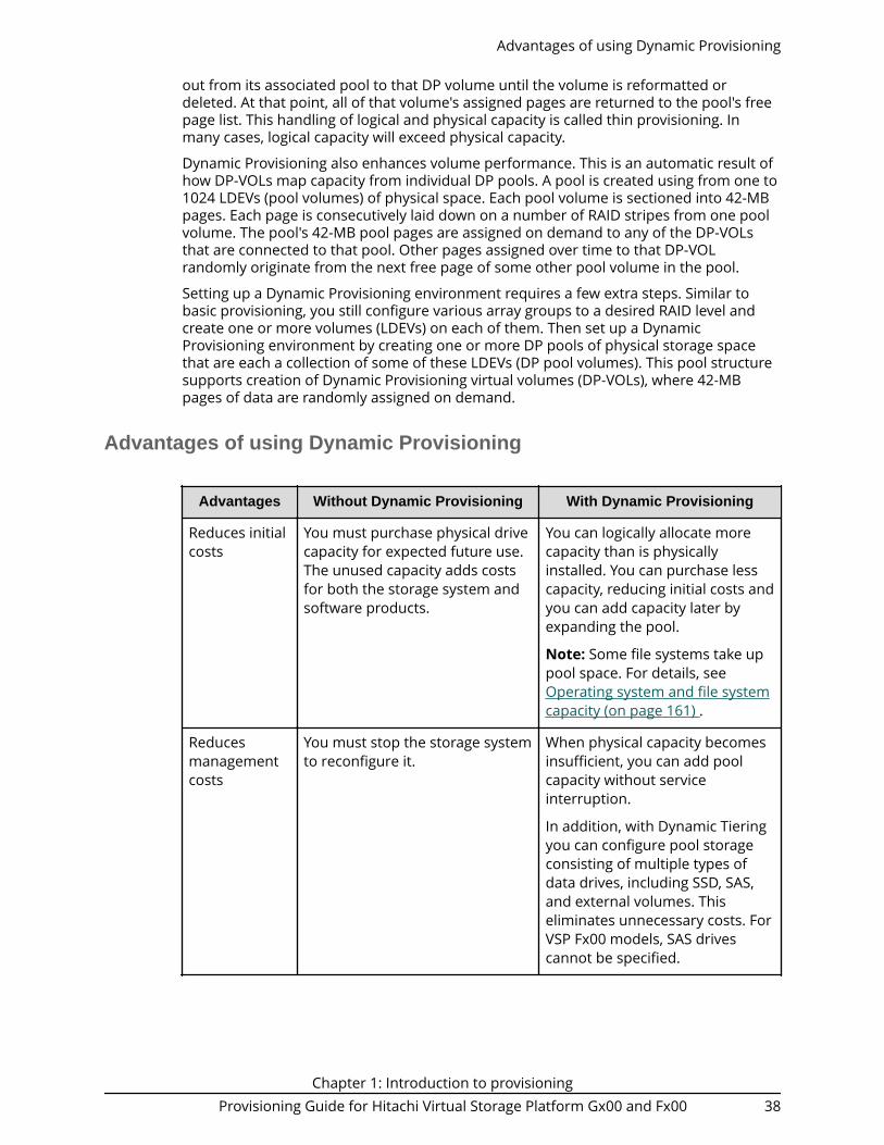
out from its associated pool to that DP volume until the volume is reformatted ordeleted. At that point, all of that volume's assigned pages are returned to the pool's freepage list. This handling of logical and physical capacity is called thin provisioning. Inmany cases, logical capacity will exceed physical capacity.
Dynamic Provisioning also enhances volume performance. This is an automatic result ofhow DP-VOLs map capacity from individual DP pools. A pool is created using from one to1024 LDEVs (pool volumes) of physical space. Each pool volume is sectioned into 42-MBpages. Each page is consecutively laid down on a number of RAID stripes from one poolvolume. The pool's 42-MB pool pages are assigned on demand to any of the DP-VOLsthat are connected to that pool. Other pages assigned over time to that DP-VOLrandomly originate from the next free page of some other pool volume in the pool.
Setting up a Dynamic Provisioning environment requires a few extra steps. Similar tobasic provisioning, you still configure various array groups to a desired RAID level andcreate one or more volumes (LDEVs) on each of them. Then set up a DynamicProvisioning environment by creating one or more DP pools of physical storage spacethat are each a collection of some of these LDEVs (DP pool volumes). This pool structuresupports creation of Dynamic Provisioning virtual volumes (DP-VOLs), where 42-MBpages of data are randomly assigned on demand.
Advantages of using Dynamic Provisioning
Advantages Without Dynamic Provisioning With Dynamic Provisioning
Reduces initialcosts
You must purchase physical drivecapacity for expected future use.The unused capacity adds costsfor both the storage system andsoftware products.
You can logically allocate morecapacity than is physicallyinstalled. You can purchase lesscapacity, reducing initial costs andyou can add capacity later byexpanding the pool.
Note: Some file systems take uppool space. For details, seeOperating system and file systemcapacity (on page 161) .
Reducesmanagementcosts
You must stop the storage systemto reconfigure it.
When physical capacity becomesinsufficient, you can add poolcapacity without serviceinterruption.
In addition, with Dynamic Tieringyou can configure pool storageconsisting of multiple types ofdata drives, including SSD, SAS,and external volumes. Thiseliminates unnecessary costs. ForVSP Fx00 models, SAS drivescannot be specified.
Advantages of using Dynamic Provisioning
Chapter 1: Introduction to provisioningProvisioning Guide for Hitachi Virtual Storage Platform Gx00 and Fx00 38

Advantages Without Dynamic Provisioning With Dynamic Provisioning
Reducesmanagementlabor andincreasesavailability ofstoragevolumes forreplication
As the expected physical drivecapacity is purchased, the unusedcapacity of the storage systemalso needs to be managed on thestorage system and on licensedproducts.
Licenses for storage systemsoftware products are based onused capacity rather than thetotal defined capacity.
You can allocate volumes of up to256 TB regardless of physicaldrive capacity.
Dynamic Tiering allows you to usestorage efficiently byautomatically migrating data tothe most suitable data drive.
Increases theperformanceefficiency ofthe data drive
Because physical drive capacity isinitially purchased and installedto meet expected future needs,portions of the capacity may beunused. I/O loads mayconcentrate on just a subset ofthe storage which might decreaseperformance.
Effectively combines I/O patternsof many applications and evenlyspreads the I/O activity acrossavailable physical resources,preventing bottlenecks in paritygroup performance. Configuringthe volumes from multiple paritygroups improves parity groupperformance. This also increasesstorage use while reducing powerand pooling requirements (totalcost of ownership).
Dynamic Provisioning advantage example
To illustrate the advantages of a Dynamic Provisioning environment, assume you have 12LDEVs from 12 RAID1 (2D+2D) array groups assigned to a DP pool. All 48 drivescontribute their IOPS and throughput power to all DP volumes assigned to that pool.Instead, if more random read IOPS horsepower is desired for a pool, then the DP poolcan be created with 32 LDEVs from 32 RAID5 (3D+1P) array groups, thus providing 128drives of IOPS power to that pool. Up to 1024 LDEVs can be assigned to a single pool,providing a considerable amount of I/O capability to just a few DP volumes.
Storing Thin Image pair and snapshot data in a Dynamic Provisioningpool
You can create Thin Image (TI) pairs and store snapshot data in a Dynamic Provisioningpool.
The following figure shows a Dynamic Provisioning pool that contains Thin Image pairand snapshot data. When you use Dynamic Provisioning and Thin Image in one poolcreated from one parity group, the total capacity used by Dynamic Provisioning and ThinImage is required. Dynamic Tiering and active flash pools cannot be used for Thin Imagepairs.
Storing Thin Image pair and snapshot data in a Dynamic Provisioning pool
Chapter 1: Introduction to provisioningProvisioning Guide for Hitachi Virtual Storage Platform Gx00 and Fx00 39

When you create Thin Image pairs in a Dynamic Provisioning pool, you can use theSuspend TI pairs when the depletion threshold is exceeded option to prevent ThinImage pair operations from affecting the DP-VOLs in the pool. When this option isenabled and the depletion threshold for the pool is exceeded, Thin Image pairoperations are suspended, so the depletion threshold of the pool functions as the upperlimit capacity for the Thin Image pairs.■ When the depletion threshold is not exceeded:
● Thin Image pairs can be created.● Thin Image pairs can be split.
■ When the depletion threshold is exceeded and the Suspend TI Pairs option is notenabled:● Thin Image pairs cannot be created.● Thin Image pairs can be split.
■ When the depletion threshold is exceeded and the Suspend TI Pairs option is enabled:● SIM code 62Exxx is output.● Thin Image pairs cannot be created.● Thin Image pairs cannot be split.
For a Dynamic Provisioning pool that contains Thin Image pairs and snapshot data, thecapacity of snapshot data is included in the used capacity of the pool.
If you are concerned about operations when Dynamic Provisioning and Thin Image sharea pool, it is recommended that you use separate pools for Dynamic Provisioning andThin Image.
About DP-VOLs with data direct mapping attribute
By using a DP-VOL for which the data direct mapping attribute is enabled, you can createa mapping of an external volume larger than 4 TB without having to change its capacityas a DP-VOL of the local storage system.
A DP-VOL with the data direct mapping attribute enabled is associated with the followingpool-VOLs: an external volume for which the data direct mapping attribute is enabled,and a pool-VOL with System Area.
To use DP-VOLs with the data direct mapping attribute enabled, you must enable thedata direct mapping attribute for pool-VOLs, pools, and DP-VOLs.
About DP-VOLs with data direct mapping attribute
Chapter 1: Introduction to provisioningProvisioning Guide for Hitachi Virtual Storage Platform Gx00 and Fx00 40

Procedure
1. In the Add External Volumes window, add a volume of an external storage systemto an external volume group.
2. In the Create LDEVs window, create an external volume for which the data directmapping attribute enabled.
3. In the Create Pools window, create a Dynamic Provisioning pool for which the datadirect mapping attribute is enabled. Specify the following volumes as pool-VOLs:
■ The external volume with the data direct mapping attribute enabled.
■ One or more normal volumes or external volumes.
4. In the Create LDEVs window, create a DP-VOL with the data direct mappingattribute enabled.
5. In the Add LUN Paths window, configure a LU path to the DP-VOL with the datadirect mapping attribute enabled.
The following table shows what kind of external volumes can be added as pool-VOLs.
Operation
Data direct mapping attribute of external volumes
Disabled Enabled
Add volumes to a poolwith the data directmapping attributeenabled
The volumes can beadded.
The volumes can beadded.
About DP-VOLs with data direct mapping attribute
Chapter 1: Introduction to provisioningProvisioning Guide for Hitachi Virtual Storage Platform Gx00 and Fx00 41

Operation
Data direct mapping attribute of external volumes
Disabled Enabled
Add volumes to thefollowing pools:
■ Dynamic Provisioningpools
■ Dynamic Tiering pools(including active flash)
The volumes can beadded.
The volumes cannot beadded.
The following table shows what kind of operations can be performed when the datadirect mapping attribute of a Dynamic Provisioning pool is enabled or disabled.
Operation
Data direct mapping attribute of the pool
Disabled Enabled
Add an LDEV for whichthe data direct mappingattribute is disabled tothe pool
The operation can beperformed.
The operation can beperformed.
Add an external volumefor which the data directmapping attribute isenabled to the pool
The operation cannot beperformed.
The operation can beperformed.
Set the depletionthreshold and thewarning threshold
The operation can beperformed.
The operation cannot beperformed.
Set subscription The operation can beperformed.
The operation can beperformed.
Protect V-VOLs when I/Ofails to Blocked Pool VOL
The operation can beperformed.
The operation can beperformed.
Protect V-VOLs when I/Ofails to Full Pool
The operation can beperformed.
The operation can beperformed.
Performing rebalancing The operation can beperformed.
The operation can beperformed.
Define the used capacityof the pool
The sum of the reservedpages capacity and themapped capacity
The sum of the reservedpages capacity and themapped capacity
About DP-VOLs with data direct mapping attribute
Chapter 1: Introduction to provisioningProvisioning Guide for Hitachi Virtual Storage Platform Gx00 and Fx00 42

Operation
Data direct mapping attribute of the pool
Disabled Enabled
Define the licensedcapacity
The sum of the pool-VOLs The sum of pool-VOLs forwhich the data directmapping attribute isdisabled.
However, the licensecapacity does not includethe capacity of pool-VOLsfor which the data directmapping attribute isenabled.
Expand pool The operation can beperformed.
The operation can beperformed.
However, the capacity ofpool-VOLs with SystemArea must be reserved inadvance. For details onhow to estimate thecapacity of pool-VOLswith System Area.
Shrink pool The operation can beperformed.
The operation can beperformed.
However, if a pool-VOLfor which the data directmapping attribute isenabled is associatedwith a DP-VOL, youcannot shrink the pool.
Delete pool The operation can beperformed.
Note: You can delete apool only when there areno DP-VOLs associatedwith the pool.
The operation can beperformed.
Note: You can delete apool only when there areno DP-VOLs associatedwith the pool.
Create DP-VOL You can only create DP-VOLs for which the datadirect mapping attributeis disabled.
You can only create DP-VOLs for which the datadirect mapping attributeis enabled.
About DP-VOLs with data direct mapping attribute
Chapter 1: Introduction to provisioningProvisioning Guide for Hitachi Virtual Storage Platform Gx00 and Fx00 43

Operation
Data direct mapping attribute of the pool
Disabled Enabled
Implement a change toDynamic Tiering(including active flashpool)
The operation can beperformed.
The operation can beperformed.
The following table shows what kind of operations can be performed when the datadirect mapping attribute of a DP-VOL is enabled or disabled.
Operation
Data direct mapping attribute of the DP-VOL
Disabled Enabled
Configure LU paths The operation can beperformed.
The operation can beperformed.
Format LDEVs The operation can beperformed.
The operation can beperformed.
Delete LDEVs The operation can beperformed.
The operation can beperformed.
Expand V-VOLs The operation can beperformed.
The operation cannot beperformed.
Reclaim zero pages The operation can beperformed.
The operation cannot beperformed.
Execute the V-VOL fullallocation function
The operation can beperformed.
The operation cannot beperformed.
Protect V-VOLs when I/Ofails to Blocked Pool VOL
The operation can beperformed.
The operation can beperformed.
Protect V-VOLs when I/Ofails to Full Pool
The operation can beperformed.
The operation can beperformed.
Apply to LDEVs of SLUattribution
The operation can beperformed.
The operation cannot beperformed.
Dynamic Provisioning high-level workflow
The following illustrates the Dynamic Provisioning workflow.
Dynamic Provisioning high-level workflow
Chapter 1: Introduction to provisioningProvisioning Guide for Hitachi Virtual Storage Platform Gx00 and Fx00 44

Capacity saving and accelerated compression functions
The VSP G series and VSP F series storage systems provide the following functions tomake efficient use of user capacity:■ Capacity saving: The capacity saving function includes data deduplication and data
compression. Capacity saving enables you to reduce your bitcost for the stored databy deduplicating and compressing the data. Data deduplication and compression areperformed by the controllers of the storage system. You can specify the post-processmode or inline mode to control when capacity saving processing occurs.
■ Accelerated compression: The accelerated compression function enables you toreduce your bitcost for the stored data by allowing you to take advantage of thecompression function in the FMC drives. Accelerated compression allows you toassign FMC capacity to a pool that is larger than the physical capacity of the FMCparity groups. The data access performance of the storage system is maintainedwhen the accelerated compression function is used, as the compression engine isoffloaded to the FMC drives.
The following table lists the combinations of applying accelerated compression andcapacity saving and describes the functionality of each combination.
Combination Functionality
Use onlyacceleratedcompression
Data compression is performed by the FMC drives. The storagecontroller does not perform the compression.
I/O performance is not affected because there is no overheaddue to compression processing by the storage controller.
Capacity saving and accelerated compression functions
Chapter 1: Introduction to provisioningProvisioning Guide for Hitachi Virtual Storage Platform Gx00 and Fx00 45

Combination Functionality
Use only controller-based compression
The storage controller compresses data and stores thecompressed data in the pool. Use controller-based compressionfor drives other than FMC and for encrypted drives.
Using accelerated compression and controller-basedcompression at the same time results in compression beingperformed in the FMC drives only. Because of differences instoring and managing data by the storage controller,performance is lower than when only accelerated compressionis used. Therefore, when accelerated compression can beenabled, you should use accelerated compression instead ofcontroller-based compression. Use controller-basedcompression only when accelerated compression cannot beenabled.
Use acceleratedcompression anddeduplication andcompression
See Example 1below
When multiple copies of identical data are stored in a pool, thestorage controller keeps only one copy (deduplication). Forcompression, the storage controller detects that acceleratedcompression is enabled* and uses it instead of controller-basedcompression.
*Accelerated compression must be enabled for all parity groupsin the pool.
Use deduplicationand compression
See Example 2below
The storage controller performs compression and deduplicationprocessing. The storage controller has the largest overhead ofthe capacity saving processing.
Note:■ When BED encryption is not being utilized, use accelerated compression.■ When accelerated compression is being utilized, do not enable controller-
based compression.
Example 1: Applying deduplication (post-process mode) and accelerated compression
Capacity saving and accelerated compression functions
Chapter 1: Introduction to provisioningProvisioning Guide for Hitachi Virtual Storage Platform Gx00 and Fx00 46

Example 2: Applying deduplication (post-process mode) and compression (capacitysaving function)
Capacity saving and accelerated compression functions
Chapter 1: Introduction to provisioningProvisioning Guide for Hitachi Virtual Storage Platform Gx00 and Fx00 47

Capacity saving function: data deduplication and compression
When the capacity saving function is in use, the controller of the storage systemperforms data deduplication and compression to reduce the size of data to be stored.Capacity saving can be enabled on DP-VOLs in Dynamic Provisioning pools. You can usethe capacity saving function on internal flash drives only, including data stored onencrypted flash drives.
How capacity saving works
The capacity saving function includes deduplication and compression:■ Deduplication
The data deduplication function deletes duplicate copies of data written to differentaddresses in the same pool and maintains only a single copy of the data at oneaddress. The deduplication function is enabled on a Dynamic Provisioning pool and
Capacity saving function: data deduplication and compression
Chapter 1: Introduction to provisioningProvisioning Guide for Hitachi Virtual Storage Platform Gx00 and Fx00 48

then on the desired DP-VOLs in the pool. When deduplication is enabled, data thathas multiple copies between DP-VOLs assigned to that pool is removed.
When you enable deduplication on a pool, the deduplication system data volume(DSD volume) for that pool is created. The DSD volume is used exclusively by thestorage system to manage the deduplication function. A search table in the DSDvolume is used to locate redundant data in the pool.
■ Compression
The data compression function utilizes the LZ4 compression algorithm to compressthe data. The compression function is also enabled per DP-VOL.
The following figure illustrates the capacity saving function.
Data received by the storage controller is stored in a temporary area in the pool. Whenthe data is classified as inactive (one hour since the last update for DynamicProvisioning), the capacity saving processing is performed, and the post-process data isstored in the data storage area. When post-process data is updated again, the datastored in the data storage area is no longer required. The used capacity of the poolincreases until garbage collection, which collects old data that is no longer required. Thepool capacity that is eventually required is the sum of the physical data capacity aftercapacity saving plus the amount of metadata.
Note:■ The temporary area and the data storage area are not assigned fixed
capacities. They share the pool and use the pool as needed.■ The temporary area is used when the post-process mode is applied. When
the inline mode is applied, capacity saving processing is performed
Capacity saving function: data deduplication and compression
Chapter 1: Introduction to provisioningProvisioning Guide for Hitachi Virtual Storage Platform Gx00 and Fx00 49

simultaneously with receiving of data from the host, and host data is notstored in the temporary area.
The capacity overheads associated with the capacity saving function include thefollowing:■ Capacity consumed by metadata
The capacity consumed by metadata for the capacity saving function (deduplicationand compression) is approximately 3% of the consumed DP-VOL capacity that hasbeen processed by capacity saving. For example, if the consumed capacity of a DP-VOL is 150 TB and the capacity saving feature has processed 100 TB of the 150 TBconsumed capacity and reduced it to 30 TB, the capacity consumed by metadata forcapacity saving function is approximately 3 TB (3% of 100 TB). The total consumedcapacity of this DP-VOL at this instant is 83 TB (30 TB + 50 TB + 3 TB).
■ Capacity consumed by garbage (invalid) data
The capacity consumed by garbage data is approximately 7% of the total consumedcapacity of all DP-VOLs with capacity saving enabled. The capacity is dynamicallyconsumed based on garbage data created by the capacity saving process and cleanedby the background garbage collection process. The garbage collection process is abackground process with a lower priority than host I/O, so the capacity consumed bygarbage data depends on both the garbage created and the host I/O rate.
The total capacity consumed by these overheads is about 10% (3% for metadata + 7% forgarbage data) of the consumed capacity of DP-VOLs with capacity saving enabled. Duringperiods of high write activity from the host, this capacity might increase over 10%temporarily, and then it returns to around 10% when host write activity decreases.
Caution: Do not use capacity saving and NAS deduplication on the samevolumes, because the additional processing decreases the I/O performancesubstantially. For information about the NAS deduplication function, see theFile Services Administration Guide.
Capacity saving processing for existing data
The compression and deduplication processing is performed asynchronously for pagesthat store data, and the free area of the pool can be increased, thereby reducing the costof purchasing drives over time.
Capacity saving function: data deduplication and compression
Chapter 1: Introduction to provisioningProvisioning Guide for Hitachi Virtual Storage Platform Gx00 and Fx00 50

Capacity saving processing for new write data
The capacity saving mode of a DP-VOL (post-process mode or inline mode) determineshow capacity saving is applied to new write data from the host:■ Post-process mode: When you apply capacity saving with the post-process mode to a
DP-VOL, the compression and deduplication processing are performedasynchronously for new write data. Since capacity saving processing is not performedat the time the new data is written, the post-process mode can reduce the impact ofcapacity saving processing on I/O performance, but pool capacity is required to storethe new write data until the capacity saving processing is performed.
When you enable capacity saving on a DP-VOL using Device Manager - StorageNavigator, post-process mode is applied.
■ Inline mode (CCI only): When you apply capacity saving with the inline mode to a DP-VOL, the compression and deduplication processing are performed synchronously fornew write data. The inline mode minimizes the pool capacity required to store newwrite data but can impact I/O performance more than the post-process mode. Theinline mode should be applied when writing data with sequential I/Os, for example,when writing data to target volumes of data migration or secondary volumes of copypairs. When the data migration or copy pair creation has completed, the mode shouldbe changed from the inline mode to the post-process mode.
If you want to use inline mode, you must use CCI (raidcom add ldev [-capacity_saving_mode <saving mode>]).
The following example illustrates how the pool used capacity changes over time whenperforming data migration. The red line shows the capacity when the post-process mode
Capacity saving function: data deduplication and compression
Chapter 1: Introduction to provisioningProvisioning Guide for Hitachi Virtual Storage Platform Gx00 and Fx00 51

is applied, and the black line shows the capacity when the inline mode is applied. Thisexample assumes that the writing speed (GB/h) for the new data is faster than the initialcapacity saving processing (GB/h).
When the inline mode is applied, capacity saving processing is performed synchronouslyfor the writing of data. When the post-process mode is applied, capacity savingprocessing is performed asynchronously for the writing of data, and the temporarystorage area is required for the write data. The capacity required for the temporarystoring area depends on the writing speed of the new data, or on the frequency of dataupdates during migration.
The following table shows the processing method (synchronous or asynchronous) forinitial data, new write data, and update data. For new write data, the capacity savingprocessing is performed at different times for the post-process mode and the inlinemode.
Mode Initial data*
New write data Updated write data
Compression
processing
Deduplication
processing
Compression
processing
Deduplication
processing
Post-processmode
Asynchronous
Asynchronous
Asynchronous
Synchronous whencompresseddata isupdated
Asynchronous whenuncompressed data isupdated
Asynchronous
Capacity saving function: data deduplication and compression
Chapter 1: Introduction to provisioningProvisioning Guide for Hitachi Virtual Storage Platform Gx00 and Fx00 52

Mode Initial data*
New write data Updated write data
Compression
processing
Deduplication
processing
Compression
processing
Deduplication
processing
Inline mode Asynchronous
Synchronous
Synchronous for datawhosetransferlength is 256KB or more.
Asynchronous for datawhosetransferlength is lessthan 256 KB.
Synchronous whencompresseddata isupdated
Asynchronous whenuncompressed data isupdated
Asynchronous
* The initial data is the existing data on the DP-VOL when the capacity saving functionis enabled. Both compression and deduplication processing are performedasynchronously for the initial data.
Use cases for capacity saving
The results of enabling the capacity saving functions of deduplication and compressiondepend on the properties and access patterns of the stored data. In addition, whencapacity saving is enabled, some storage behaviors are different from conventionalbehaviors because of the increase in load of storage controller processing caused bydata scanning and garbage collection by data update. Before implementing capacitysaving, you need to confirm whether it should be applied to your specific storageenvironment.
The following table lists several storage use cases and describes the application ofcapacity saving to each use case.
Use case Settings Description
Office Deduplication andcompression
Because there are many identical filecopies, deduplication is effective.
VDI Deduplication andcompression
Deduplication is very effective because ofOS area cloning.
Database(TPC-H)
Compression Deduplication is not effective because thedatabase has unique information for eachblock.
For a database that has many dataupdates, garbage data is increased, so it isnot suitable.
Use cases for capacity saving
Chapter 1: Introduction to provisioningProvisioning Guide for Hitachi Virtual Storage Platform Gx00 and Fx00 53

Use case Settings Description
Database(TPC-C)
Compression
Image/video Not suitable (Disable) Compressed by application.
Backup/archive
Deduplication andcompression
Deduplication is effective betweenbackups.
Caution:■ I/O performance to data with compression and deduplication is degraded.
Verify the performance by utilizing best practices or Cache OptimizationTool (COT) tool before using the capacity saving function.
■ Because approximately 10% is used for metadata and garbage data,capacity saving should be applied only when the result is expected to be20% or higher.
■ In deduplication and compression, processing is performed per 8 KB.Therefore, if the block size of the file system is an integral multiple of 8 KB,capacity saving is likely to be effective.
■ The capacity saving function is not a good fit for high-write workloads. Ifthe write workload rate is higher than garbage collection throughput,Cache Write Pending increases, causing performance degradation. Contactcustomer support to determine the garbage collection throughput foryour configuration.
About pool volumes from accelerated compression-enabled paritygroups
Volumes carved from accelerated compression-enabled parity groups can only be usedas pool volumes to create or expand a pool. Pools that contain pool volumes fromaccelerated compression-enabled parity groups must be monitored to ensure adequatepool capacity. You can set thresholds for used pool capacity that trigger the output ofSIMs when exceeded, enabling you to expand the pool or delete unwanted data beforethe pool becomes full.
Accelerated compression-enabled parity groups
Data on LDEVs carved from parity groups comprised of FMC drives is compressed beforeit is stored onto the drives. The default setting of accelerated compression is Disabled.You must set this feature to Enable to take advantage of the data compression serviceson the FMC drives.
Note: If encryption is enabled on an FMC parity group, acceleratedcompression cannot be enabled on that parity group. You can use thededuplication and compression functions on encrypted FMC parity groups.
When you enable accelerated compression on a parity group comprised of FMC drives:
About pool volumes from accelerated compression-enabled parity groups
Chapter 1: Introduction to provisioningProvisioning Guide for Hitachi Virtual Storage Platform Gx00 and Fx00 54

■ The capacity of the parity group expands the usable physical capacity of the paritygroup. You can potentially carve out LDEVs from this expanded capacity and use themas pool volumes to create or expand a pool. When you do this, you can utilize theincreased available capacity because the data on the FMC drives has beencompressed.
■ LDEVs carved from the accelerated compression-enabled parity groups can only beused as pool volumes to create or expand a pool. These LDEVs cannot be assigneddirectly to a host and must be assigned to a single pool as pool volumes. LDEVs froma single parity group cannot be shared among multiple pools.
Storing data written to DP-VOLs
Data written by hosts to DP-VOLs is stored in pool volumes on a page basis. If poolvolumes are created from the parity group used by FMC drives, data is compressed andstored to drives. The compression ratio of data varies for each data update or datadeletion operation. Therefore, the capacity of data that can be stored fully is the capacityof the physical area of the FMC used to create the parity group. For a pool containingpool volumes with accelerated compression enabled, the smaller of the following twocapacities is the FMC capacity that corresponds to the pool capacity reserved for writing:■ The total capacity of the pool volumes■ The FMC capacity of the parity group to which the pool volumes belong
If pool volumes carved from the FMC parity group and pool volumes carved from otherparity groups are intermixed, the total capacity that corresponds to the pool capacityreserved for writing is calculated by the following formula:
Total capacity that corresponds to the pool capacity reserved for writing = FMC capacity of theparity group to which the pool volumes belong + Total capacity of pool volumes carved fromother parity groups.
The purchased license of Dynamic Provisioning is consumed with respect to the definedpool capacity. However, if you are using a pool comprised of pool volumes assigned byaccelerated compression-enabled parity groups, the purchased license of DynamicProvisioning is used with respect to the pool capacity reserved for writing.
Storing data written to DP-VOLs
Chapter 1: Introduction to provisioningProvisioning Guide for Hitachi Virtual Storage Platform Gx00 and Fx00 55

Monitoring used pool capacity and used pool capacity reserved for writing
■ Monitoring used pool capacity
The used pool capacity must always be monitored. As data is written to DP-VOLs andstored in the pool, in cases where DP-VOLs are over-provisioned, the pool mightbecome full before the DP-VOLs become full. Therefore, the used pool capacity mustalways be monitored to prevent this from happening. A threshold value is set for theused pool capacity. If the used pool capacity exceeds the threshold value, a SIM isreported and a notification is sent to the hosts. If these SIMs are reported, you canresolve the status of threshold exceeded by expanding the pool capacity or bydeleting data. For details about the threshold values, see Thresholds for monitoringpools (on page 268) .
■ Monitoring used pool capacity reserved for writing
For the pools consisting of pool volumes carved from accelerated compression-enabled parity groups, you must monitor both the used pool capacity and the usedpool capacity reserved for writing. If the used pool capacity reserved for writingexceeds the threshold value, a SIM is reported. The used pool capacity and the poolcapacity reserved for writing are not always the same, and the SIMs are independentof each other. The following conditions can occur:
Monitoring used pool capacity and used pool capacity reserved for writing
Chapter 1: Introduction to provisioningProvisioning Guide for Hitachi Virtual Storage Platform Gx00 and Fx00 56

● The used pool capacity exceeds the threshold, but the used pool capacity reservedfor writing is lower than the threshold.
● The used pool capacity is lower than the threshold, but the used pool capacityreserved for writing exceeds the threshold.
● Both used capacities exceed the threshold.
If SIMs are reported, you can resolve the status of the exceeded threshold by expandingthe pool capacity or by deleting unwanted data.
If pool volumes that are carved from accelerated compression-enabled parity group areused to create a new pool, you must estimate the data savings percentage beforehand.
For a pool with a pool volume that has accelerated compression enabled, the used poolcapacity and the used pool capacity reserved for writing are monitored. The followingshows the threshold values for the used pool capacity and used pool capacity reservedfor writing that trigger output of SIMs when exceeded:■ Warning Threshold: You can set a value from 1% to 100% in 1% increments. The initial
value is 70%.■ Depletion Threshold: You can set a value from 1% to 100% in 1% increments. The
initial value is 80%.■ Prefixed Depletion Threshold: The value is set for the used capacity of the parity
group. The value is fixed at 90%.
The following figure shows the used pool capacity and used pool capacity reserved forwriting with threshold values. Hereinafter, the smaller free capacity between the pool ordrive is called the remaining free capacity reserved for writing. The used capacityreserved for writing is the result of deducting the remaining free capacity for writingfrom the total capacity reserved for writing.
Monitoring used pool capacity and used pool capacity reserved for writing
Chapter 1: Introduction to provisioningProvisioning Guide for Hitachi Virtual Storage Platform Gx00 and Fx00 57

Dynamic TieringHitachi Dynamic Tiering (HDT) simplifies storage administration by automaticallyoptimizing data placement in 1, 2 or 3 tiers of storage that can be defined and usedwithin a single virtual volume. Tiers of storage can be made up of internal or external(virtualized) storage, and use of HDT can lower capital costs. Simplified and unifiedmanagement of HDT allows for lower operational costs and reduces the challenges ofensuring applications are placed on the appropriate classes of storage.
Dynamic Tiering
When you use Dynamic Provisioning to implement a thin provisioning strategy, the arrayhas all the elements in place to offer automatic self-optimizing storage tiers provided byHitachi Dynamic Tiering (HDT). Dynamic Tiering enables you to configure a storagesystem with multiple storage tiers consisting of different types of data drives (forexample, SSD, SAS) to improve the speed and cost of performance. Dynamic Tieringextends and improves the functionality and value of the Dynamic Provisioning feature.Both features use pools of physical storage against which virtual disk capacity, or V-VOLs,is defined. Each thin provisioning pool can be configured to operate either as a DP poolor as a Dynamic Tiering pool. Dynamic Tiering is supported only on VSP Gx00 models.
Automated tiering of physical storage is the ability of the array to dynamically monitorusage and relocate data to the appropriate storage tier based on performancerequirements. Data relocation focuses on data segments rather than on entire volumes.The Dynamic Tiering functionality is entirely within the array and does not require anyhost level involvement.
Dynamic Tiering enables you to:■ Configure physical storage into tiers based on drive performance. Host volumes are
configured as usual from a common pool, but the pool consists of multiple types ofdrives that offer different levels of performance (for example, high-speed SSDs andlower-speed SAS).
■ Automatically migrate data to the most suitable tier according to access frequency.Data that is accessed frequently is placed on the high-performance drives, while datathat is accessed infrequently is placed on the lower-performance drives.
Dynamic Tiering simplifies storage administration by automating and eliminating thecomplexities of efficiently using tiered storage. It automatically moves data on pages inDynamic Provisioning virtual volumes to the most appropriate storage media, accordingto workload, to maximize service levels and minimize total cost of storage.
Dynamic Tiering gives you:■ Improved storage resource usage■ Improved return on high-cost storage tiers■ Reduced storage management effort■ More automation■ Nondisruptive storage management■ Reduced costs■ Improved overall performance
Dynamic Tiering
Chapter 1: Introduction to provisioningProvisioning Guide for Hitachi Virtual Storage Platform Gx00 and Fx00 58

Overview of tiers
When not using Dynamic Tiering data is allocated to only one kind of data drive (typicallyan expensive high-speed data drive) without regard to the workload because thevolumes are configured with only one kind of data drive. When using Dynamic Tiering,frequently access data is automatically allocated to the higher-speed HDT pool volumesand the lower speed drive to the volumes of low workload. This improves performanceand reduces costs.
Dynamic Tiering places the host volume's data across multiple tiers of storage containedin a pool. There can be up to three tiers (high-, medium-, and low-speed layers) in a pool.Dynamic Tiering determines tier usage based on data access levels. It allocates the pagewith high I/O load to the upper tier, which contains a higher speed drive, and the pagewith low I/O load to the lower tier, which contains a lower speed drive.
The following figure illustrates the basic tier concept.
Active flash
The active flash feature of Dynamic Tiering monitors page accesses over a set time frameand attempts to keep the most frequently accessed pages in Tier 1.
The active flash feature monitors a page's access frequency level real time and promotespages that suddenly became busy from a slower media to high-performance flashmedia, in real-time.
The active flash feature can be enabled on any Dynamic Tiering pool as long as you haveSSD drives in Tier 1 of the pool. No special configuration beyond what is needed foractive flash is required.
Prompt Promotion
A primary goal of Dynamic Tiering and active flash is to have the most frequently accesspages in Tier 1. As the workload varies in both the frequency of access and the type ofaccess, reads or writes, the threshold for moving pages from one tier to anotherchanges. Dynamic Tiering generates a dynamic tier range value that is used to determinewhich pages need to be in Tier 1 and which need to be in a lower tier.
The active flash feature compares the recent the access frequency of each page to thePrompt Promotion threshold to determine whether a page should be promoted to Tier1. The Prompt Promotion threshold is a dynamic threshold that adjusts based uponchanges in workload to make most efficient use of the SSD drives. If the recent access
Overview of tiers
Chapter 1: Introduction to provisioningProvisioning Guide for Hitachi Virtual Storage Platform Gx00 and Fx00 59

frequency for a page meets or exceeds the Prompt Promotion threshold, the page isrelocated to Tier 1 without waiting for the next Dynamic Tiering relocation cycle.
Certain type of I/O benefit more from being served by flash media then others. Toachieve the best performance gains for certain I/O, active flash gives read I/O greaterweight than write I/O when calculating the total access frequency for a page.
High Prioritized Demotion
In order to be certain that there is always some room for active flash to do PromptPromotion of pages to Tier 1, High Prioritized Demotion is used to demote pages out ofTier 1. Pages that have the lowest IOPH are candidates for High Prioritized Demotion.Similar to Prompt Promotion, High Prioritized Demotion does not wait for the currentDynamic Tiering cycle to end to make relocation decisions.
Page demotion is only triggered when:■ Tier 1 free capacity is depleted■ performance utilization reaches 80%
Peak performance utilization is predefined for a particular media.
Performance utilization of a tier is the maximum amount of I/O it can receive. Themaximum I/O load that should be targeted to a tier depends upon the media type usedto make the tier. A performance utilization of 100% means that the tier is receiving themaximum amount of I/O it can sustain. When performance utilization reaches about the60% level, response time to the particular media becomes noticeably slower.
The following diagram shows the differences in the way pools are managed betweenDynamic Provisioning, Dynamic Tiering, and active flash
Active flash
Chapter 1: Introduction to provisioningProvisioning Guide for Hitachi Virtual Storage Platform Gx00 and Fx00 60

System requirements for provisioningThe system requirements for provisioning include basic hardware and licensingrequirements as well as additional requirements for shared memory and cachemanagement devices.■ The storage system hardware and firmware must be configured and ready for use.■ The parity groups in the storage system must be configured and ready for use.■ Hitachi Device Manager - Storage Navigator must be configured and ready for use.
For details and instructions, see the System Administrator Guide for your storagesystem.
■ The license keys for the provisioning software products must be enabled. For detailsand instructions, see the System Administrator Guide for your storage system.
System requirements for provisioning
Chapter 1: Introduction to provisioningProvisioning Guide for Hitachi Virtual Storage Platform Gx00 and Fx00 61

■ The required amount of shared memory for your operational environment must beinstalled in the storage system.
■ The required number of cache management devices must be available.■ The desired system option modes (SOMs) must be enabled on your storage system
before you begin operations. For information about SOMs, contact customer support.
Shared memory requirements
Additional shared memory is required when Dynamic Provisioning is used in conjunctionwith Dynamic Tiering, active flash, capacity saving (deduplication and compression), orThin Image pools. The amount of additional shared memory needed depends on the sizeof the Dynamic Provisioning and Dynamic Tiering pools.
Shared memory is installed and removed by your service representative. For detailsabout the installation and removal of shared memory, see the hardware reference guidefor your storage system.
Caution: Before shared memory is removed, all Dynamic Provisioning,Dynamic Tiering, and active flash pools must be deleted.
Cache management device requirements
Cache management devices are used to manage the cache associated with volumes(LDEVs). Each volume (LDEV) requires at least one cache management device. An LDEVthat is not a DP-VOL requires one cache management device. For an LDEV that is a DP-VOL, you need to calculate the number of cache management devices required.
The storage system can manage the following number of cache management devices:■ VSP G800, Virtual Storage Platform F800: 32,512■ VSP G400, G600, VSP F400, F600: 7,936■ VSP G200: 3,840
The View Management Resource Usage window in Device Manager - Storage Navigatordisplays the number of cache management devices in use and the maximum number ofcache management devices. To open the View Management Resource Usage window,click Actions and then select View Management Resource Usage.
Calculating the number of cache management devices required for DP-VOLs
A volume that is not a DP-VOL requires one cache management device. The number ofcache management devices that a DP-VOL requires depends on the capacity of the V-VOL(capacity of the user area) and the maximum capacity of the cache management device.The maximum capacity of a cache management device depends on the pool attribute(internal volume or external volume) associated with V-VOL.
The following table explains the relationship between the pool attribute and themaximum capacity of the cache management device.
Shared memory requirements
Chapter 1: Introduction to provisioningProvisioning Guide for Hitachi Virtual Storage Platform Gx00 and Fx00 62

Maximum capacity of cache management device
Pool attribute of V-VOL
MB
(TB) Blocks
Internal volume 3,145,548 MB
(2.99 TB)
6,442,082,304 blocks
External volume 3,145,548 MB
(2.99 TB)
6,442,082,304 blocks
Use the following formula to calculate the number of cache management devices that aDP-VOL requires. In this formula, the user-specified capacity is the user area capacity of aV-VOL.
ceiling(user-specified-capacity / max-capacity-of-cache-management-device)
where■ ceiling: The value enclosed in ceiling( ) must be rounded up to the nearest whole
number.
Note:■ For a DP-VOL with the deduplication or compression function enabled, use
twice the number of the cache management devices calculated by thisformula.
■ For each deduplication system data volume, 14 cache managementdevices are used.
System option modes for provisioning
To provide greater flexibility, the storage systems have additional operationalparameters called system option modes (SOMs) that allow you to tailor the storagesystem to your unique operating requirements. The SOMs are set on the serviceprocessor (SVP) by your service representative. Review the SOMs for your storagesystem, and work with your service representative to ensure that the appropriate SOMsfor your operational environment are configured on your storage system.
The following table lists and describes the SOMs that apply to Dynamic Provisioning,Dynamic Tiering, Virtual LVI/LUN, and Data Retention Utility. For a complete list of SOMs,see the System Administrator Guide for your storage system.
Note: The SOM information might have changed since this document waspublished. Contact customer support for the latest SOM information.
System option modes for provisioning
Chapter 1: Introduction to provisioningProvisioning Guide for Hitachi Virtual Storage Platform Gx00 and Fx00 63

Table 1 System option modes for provisioning
Mode Category Description Default MCU/RCU
729 DynamicProvisioning
DataRetentionUtility
When a DP pool is full, if any write operation isrequested to the area where the page allocation isnot provided, this SOM can enable the DRU Protectattribute for the target DP-VOL.
Mode 729 = ON: Set the DRU Protect attribute forthe target DP-VOL when any write operation isrequested to the area where the page allocation isnot provided at a time when the DP pool is full.(Not to set in the case of Read request.)
Mode 729 = OFF (default): Do not set the DRUProtect attribute for the target DP-VOL when anywrite operation is requested to the area where thepage allocation is not provided at a time when DPpool is full.
For details, contact customer support (see SOM729& 803 sheet).
Notes:
1. This SOM is applied when:
■ The threshold of pool is high (for example,95%) and the pool may be full.
■ File system is used.
■ Data Retention Utility is installed.
2. Since the Protect attribute is set for V-VOL, theRead operation cannot be allowed as well.
3. When Data Retention Utility is not installed,the desired effect is not achieved.
4. Protect attribute can be released from theData Retention window of Device Manager -Storage Navigator after releasing the fullstatus of the pool by adding a Pool-VOL.
5. With 83-01-21-x0/00 and later, the VirtualVolume Protection (VVP) function issupported. VVP can be enabled/disabled foreach pool. With SOM 729 disabled, VVP is alsodisabled by default, but you can enable VVPfor each pool as needed. With SOM 729enabled, VVP is also enabled automatically (bydefault) when you create a new pool.Caution: A pool is NOT protected by ANYFUNCTION if you deliberately turn VVP for thepool from ON (default) to OFF, even with SOM729 enabled.
OFF -
System option modes for provisioning
Chapter 1: Introduction to provisioningProvisioning Guide for Hitachi Virtual Storage Platform Gx00 and Fx00 64

Mode Category Description Default MCU/RCU
6. With or 83-01-21-x0/00 and later, when HMO63 or 73 is set to ON, the setting of the HMOis prioritized over the SOM 729 setting, so thatthe behavior remains the same as when SOM729 is OFF even when it is set to ON.
734 DynamicProvisioning
When exceeding the pool threshold, the SIM isreported as follows:
Mode 734 = ON: A SIM is reported at the timewhen the pool usage rate exceeds the poolthreshold (warning, system, or depletion). Oncethe pool usage rate falls below the pool threshold,and then exceeds again, the SIM is reported again.If the pool usage rate continues to exceed thewarning threshold and the depletion threshold, theSIM (SIM-RC625000) is repeatedly reported everyeight (8) hours until the pool usage rate falls belowthe depletion threshold.
Mode 734 = OFF (default): A SIM is reported at thetime when the pool usage rate exceeds the poolthreshold (warning, system, or depletion). Oncethe pool usage rate falls below the pool threshold,and then exceeds again, the SIM is reported again.The SIM is not reported while the pool usage ratecontinues to exceed the warning threshold and thedepletion threshold.
Notes:
1. This SOM is turned ON to prevent the writeI/O operation from being unavailable due topool full.
2. If the exceeding pool threshold SIM occursfrequently, other SIMs may not be reported.
3. Though turning on this SOM can increase thewarning effect, if measures such as adding apool fail to be done in time so that the poolbecomes full, SOM 729 can be used to preventfile systems from being destroyed.
4. Turning on SOM 741 can provide the SIMreport to not only the users but also theservice personnel.
OFF -
System option modes for provisioning
Chapter 1: Introduction to provisioningProvisioning Guide for Hitachi Virtual Storage Platform Gx00 and Fx00 65

Mode Category Description Default MCU/RCU
741 DynamicProvisioning
This SOM enables to switch over whether to reportthe following SIM for users to the servicepersonnel:
SIM-RC 625000 (DP pool usage rate continues toexceed the threshold)
Mode 741 = ON: SIM is reported to the servicepersonnel.
Mode 741 = OFF (default): SIM is not reported tothe service personnel.
Notes:
1. This SOM is set to ON to have SIM for usersreported to the service personnel:
■ For the system where SNMP and E-mailnotification are not set.
■ If Device Manager - Storage Navigator isnot periodically activated.
2. When SOM 734 is turned OFF, SIM-RC625000is not reported; accordingly the SIM is notreported to the service personnel eventhough this SOM is ON.
OFF -
749 DynamicProvisioning
DynamicTiering
Thin Image
This SOM disables the HDP Rebalance function andthe HDT Tier relocation function which allow thedrives of all ECC Groups in the pool to share theload.
Mode 749 = ON: The HDP Rebalance function andthe HDT Tier relocation function are disabled.
Mode 749 = OFF (default): The HDP Rebalancefunction and the HDT Tier relocation function areenabled.
Notes:
1. This SOM is applied when no change inperformance characteristic is desired.
2. When a pool is newly installed, the load maybe concentrated on the installed poolvolumes.
3. When 0 data discarding is executed, load maybe unbalanced among pool volumes.
4. Pool VOL deletion while this SOM is set to ONfails. To delete pool VOLs, set this SOM to OFF.
OFF -
System option modes for provisioning
Chapter 1: Introduction to provisioningProvisioning Guide for Hitachi Virtual Storage Platform Gx00 and Fx00 66
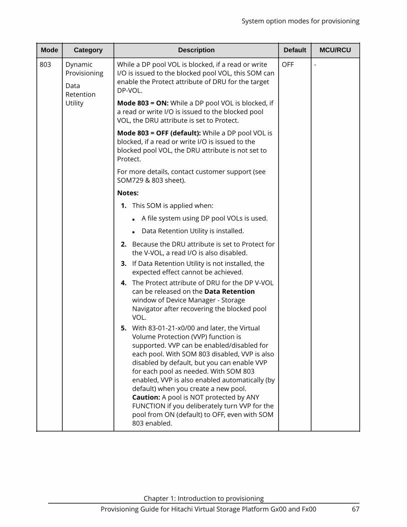
Mode Category Description Default MCU/RCU
803 DynamicProvisioning
DataRetentionUtility
While a DP pool VOL is blocked, if a read or writeI/O is issued to the blocked pool VOL, this SOM canenable the Protect attribute of DRU for the targetDP-VOL.
Mode 803 = ON: While a DP pool VOL is blocked, ifa read or write I/O is issued to the blocked poolVOL, the DRU attribute is set to Protect.
Mode 803 = OFF (default): While a DP pool VOL isblocked, if a read or write I/O is issued to theblocked pool VOL, the DRU attribute is not set toProtect.
For more details, contact customer support (seeSOM729 & 803 sheet).
Notes:
1. This SOM is applied when:
■ A file system using DP pool VOLs is used.
■ Data Retention Utility is installed.
2. Because the DRU attribute is set to Protect forthe V-VOL, a read I/O is also disabled.
3. If Data Retention Utility is not installed, theexpected effect cannot be achieved.
4. The Protect attribute of DRU for the DP V-VOLcan be released on the Data Retentionwindow of Device Manager - StorageNavigator after recovering the blocked poolVOL.
5. With 83-01-21-x0/00 and later, the VirtualVolume Protection (VVP) function issupported. VVP can be enabled/disabled foreach pool. With SOM 803 disabled, VVP is alsodisabled by default, but you can enable VVPfor each pool as needed. With SOM 803enabled, VVP is also enabled automatically (bydefault) when you create a new pool.Caution: A pool is NOT protected by ANYFUNCTION if you deliberately turn VVP for thepool from ON (default) to OFF, even with SOM803 enabled.
OFF -
System option modes for provisioning
Chapter 1: Introduction to provisioningProvisioning Guide for Hitachi Virtual Storage Platform Gx00 and Fx00 67

Mode Category Description Default MCU/RCU
867 DynamicProvisioning
DynamicTiering
All-page reclamation (discarding all mappinginformation between DP pool and DP volumes) isexecuted in DP-VOL LDEV format. This new methodis enabled or disabled by setting this SOM to ON orOFF.
Mode 867 = ON (default*): LDEV format of theDP-VOL is performed with page reclamation.
Mode 867 = OFF:LDEV format of the DP-VOL isperformed with 0 data writing.
*The default is OFF for VSP, HUS VM, and VSP Fx00models and VSP Gx00 models with firmware 83-03-xx and earlier.
Notes:
1. This SOM is applied from factory shipment.2. Do not change the setting of this SOM during
DP-VOL format.3. If the setting of this SOM is changed during
DP-VOL format, the change is not reflected tothe format of the DP-VOL being executed butthe format continues in the same method.
ON -
System option modes for provisioning
Chapter 1: Introduction to provisioningProvisioning Guide for Hitachi Virtual Storage Platform Gx00 and Fx00 68

Mode Category Description Default MCU/RCU
896 DynamicProvisioning
DynamicTiering
Thin Image
This SOM enables or disables the backgroundformat function performed on an unformattedarea of a DP/DT/TI pool.
For information regarding operating conditions,see the Provisioning Guide for your storage system.
Mode 896 = ON: The background format functionis disabled.
Mode 896 = OFF (default): The background formatfunction is enabled.
Notes:
1. This SOM is applied when a customer requiresthe background format for a DP/DT/TI pool inthe environment where new page allocation(in the case that system files are created froma host for newly created multiple DP-VOLs, forexample) frequently occurs and the writeperformance degrades because of an increasein write pending rate.
2. When the background format function isenabled, because up to 42 MB/s of ECCGperformance is used, local copy performancemay degrade by about 10%. Therefore,confirm whether the 10% performancedegradation is acceptable or not beforeenabling the function.
3. When a Dynamic Provisioning VOL on anexternal storage system, which is used as anexternal VOL, is used as a pool VOL, if theexternal pool on the external storage sidebecomes full due to the background format,the external VOL may be blocked.
If the external pool capacity is smaller thanthe external VOL capacity (DynamicProvisioning VOL of external storage system),do not enable the background formatfunction.
4. If the background format function is disabledby changing this SOM setting, the formatprogress is initialized and the entire areabecomes unformatted.
5. The background format for FMC drives is notdisabled. When FMC drives are used, use SOM1093.
OFF -
System option modes for provisioning
Chapter 1: Introduction to provisioningProvisioning Guide for Hitachi Virtual Storage Platform Gx00 and Fx00 69

Mode Category Description Default MCU/RCU
897 DynamicTiering
By the combination of SOM 897 and 898 setting,the expansion width of Tier Range upper I/O value(IOPH) can be changed as follows.
Mode 897 = ON:■ SOM 898 is OFF: 110%+0IO■ SOM 898 is ON: 110%+2IO
Mode 897 = OFF (default):■ SOM 898 is OFF: 110%+5IO (default)■ SOM 898 is ON: 110%+1IO
By setting the SOMs to ON to lower the upper limitfor each tier, the gray zone between other tiersbecomes narrow and the frequency of pageallocation increases.
Notes:
1. Apply this SOM when the upper tier usage islow and lower tier usage is high.
2. This SOM must be used with SOM 898.3. Narrowing the gray zone increases the
number of pages to migrate between tiers perrelocation.
4. When Tier1 is SSD while SOM 901 is set to ON,the effect of SOM 897 and 898 to the grayzone of Tier1 and Tier2 is disabled and theSOM 901 setting is enabled instead. Inaddition, the settings of SOM 897 and 898 areeffective for Tier2 and Tier3.
For more details about the interactions betweenSOMs 897, 898, and 901, contact customer support(see SOM897_898_901 sheet).
OFF -
System option modes for provisioning
Chapter 1: Introduction to provisioningProvisioning Guide for Hitachi Virtual Storage Platform Gx00 and Fx00 70

Mode Category Description Default MCU/RCU
898 DynamicTiering
By the combination of SOM 898 and 897 setting,the expansion width of Tier Range upper I/O value(IOPH) can be changed as follows.
Mode 898 = ON:■ SOM 897 is OFF: 110%+1IO■ SOM 897 is ON: 110%+2IO
Mode 898 = OFF (default):■ SOM 897 is OFF: 110%+5IO (default)■ SOM 897 is ON: 110%+0IO
By setting the SOMs to ON to lower the upper limitfor each tier, the gray zone between other tiersbecomes narrow and the frequency of pageallocation increases.
Notes:
1. Apply this SOM when the usage of upper tieris low and that of lower tier is high.
2. This SOM must be used with SOM 897.3. Narrowing the gray zone increases the
number of pages to migrate between tiers perrelocation.
4. When Tier1 is SSD while SOM 901 is set to ON,the effect of SOM 897 and 898 to the grayzone of Tier1 and Tier2 is disabled and theSOM 901 setting is enabled instead. Inaddition, the settings of SOM 897 and 898 areeffective for Tier2 and Tier3.
For more details about the interactions betweenSOMs 897, 898, and 901, contact customer support(see SOM897_898_901 sheet).
OFF -
System option modes for provisioning
Chapter 1: Introduction to provisioningProvisioning Guide for Hitachi Virtual Storage Platform Gx00 and Fx00 71

Mode Category Description Default MCU/RCU
901 DynamicTiering
By setting this SOM to ON or OFF, the pageallocation method of Tier Level ALL when the drivetype of tier1 is SSD changes as follows.
Mode 901 = ON: For tier1 (drive type is SSD), pagesare allocated until the capacity reaches the limit.Without consideration of exceeding performancelimitation, allocation is done from highly loadedpages until reaching the capacity limit
When the capacity of tier1 reaches the thresholdvalue, the minimum value of the tier range is set tothe starting value of the lower IOPH zone, and themaximum value of the lower tier range is set to theboundary value.
Mode 901 = OFF (default): For tier1 (drive type isSSD), page allocation is performed based onperformance potential limitation. Withconsideration of exceeding performance limitation,allocation is done from highly loaded pages but atthe point when the performance limitation isreached, pages are not allocated any more eventhere is free space.
When the capacity of tier1 reaches the thresholdvalue, the minimum value of the tier range is set tothe boundary value, and the maximum value ofthe lower tier range is set to a value of boundary-value × 110% + 5 [IOPH].
Notes:
1. This SOM is applied when pages with themaximum capacity need to be allocated totier1 (drive type is SSD) with Dynamic Tiering.
2. When Tier1 is SSD while SOM 901 is set to ON,the effect of SOM 897 and 898 to the grayzone of Tier1 and Tier2 is disabled and theSOM 901 setting is enabled instead. Inaddition, the settings of SOM 897 and 898 areeffective for Tier2 and Tier3.
3. The following is recommended when applyingSOM 901.
actual I/O value (total number of I/Os of alltiering policies) < performance potential valueof Tier1* × 0.6
OFF -
System option modes for provisioning
Chapter 1: Introduction to provisioningProvisioning Guide for Hitachi Virtual Storage Platform Gx00 and Fx00 72
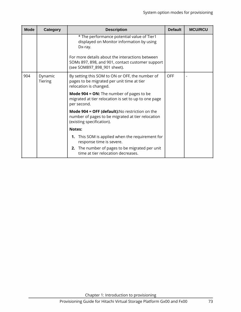
Mode Category Description Default MCU/RCU
* The performance potential value of Tier1displayed on Monitor information by usingDx-ray.
For more details about the interactions betweenSOMs 897, 898, and 901, contact customer support(see SOM897_898_901 sheet).
904 DynamicTiering
By setting this SOM to ON or OFF, the number ofpages to be migrated per unit time at tierrelocation is changed.
Mode 904 = ON: The number of pages to bemigrated at tier relocation is set to up to one pageper second.
Mode 904 = OFF (default):No restriction on thenumber of pages to be migrated at tier relocation(existing specification).
Notes:
1. This SOM is applied when the requirement forresponse time is severe.
2. The number of pages to be migrated per unittime at tier relocation decreases.
OFF -
System option modes for provisioning
Chapter 1: Introduction to provisioningProvisioning Guide for Hitachi Virtual Storage Platform Gx00 and Fx00 73

Mode Category Description Default MCU/RCU
930 DynamicProvisioning
DynamicTiering
ShadowImage
When this SOM is set to ON, all of the zero datapage reclamation operations in processing arestopped. (Also the zero data page reclamationcannot be started.)
* Zero data page reclamation by WriteSame andUNMAP functions, and IO synchronous pagereclamation are not disabled.
Mode 930 = ON: All of the zero data pagereclamation operations in processing are stoppedat once. (Also the zero data reclamation cannot benewly started.)
Mode 930 = OFF (default): The zero data pagereclamation is performed.
For details about interactions with SOM 755,contact customer support (see SOM930 sheet).
Notes:
1. This SOM is applied when stopping ordisabling zero data page reclamation by userrequest is required.
2. When this SOM is set to ON, the zero datapage reclamation does not work at all.
* Zero data page reclamation by Write Sameand UNMAP, and IO synchronous pagereclamation can work.
3. When downgrading micro-program to aversion that does not support this SOM whilethis SOM is set to ON, set this SOM to OFFafter the downgrade.
* Because the zero data page reclamationdoes not work at all while this SOM is set toON.
4. This SOM is related to SOM 755.
OFF -
System option modes for provisioning
Chapter 1: Introduction to provisioningProvisioning Guide for Hitachi Virtual Storage Platform Gx00 and Fx00 74

Mode Category Description Default MCU/RCU
937 DynamicProvisioning
DynamicTiering
By setting this SOM to ON, HDT monitoring data iscollected even if the pool is a DP pool.
Mode 937 = ON: HDT monitoring data is collectedeven if the pool is a DP pool.
Only Manual execution mode and Period mode aresupported.
Mode 937 = OFF (default): HDT monitoring data isnot collected if the pool is a DP pool
Notes:
1. This SOM is applied when HDT monitoringdata collection is required in DP environment.
2. When HDT is already used, do not set thisSOM to ON.
3. For HDT monitoring data collection, sharedmemory for HDT must be installed. Fordetails, contact customer support (seeSOM937 sheet).
4. If monitoring data collection is performedwithout shared memory for HDT installed, anerror is reported and the monitoring datacollection fails.
5. Before removing the shared memory for HDT,set this SOM to OFF and wait for 30 minutes.
6. Tier relocation with monitoring data collectedwhen this SOM is set to ON is disabled.
7. When DP is converted into HDT (afterpurchase of software license), the collectedmonitoring data is discarded.
8. Before downgrading the micro-program to anunsupported version, set SOM 937 to OFF andwait for at least 30 minutes.
OFF -
System option modes for provisioning
Chapter 1: Introduction to provisioningProvisioning Guide for Hitachi Virtual Storage Platform Gx00 and Fx00 75

Mode Category Description Default MCU/RCU
1079 DynamicProvisioning
DynamicTiering
This SOM is set not to run the Proprietary ANCHORcommand during microcode downgrade from aversion that supports the Proprietary ANCHORcommand to a version that does not support thecommand.
Mode 1079 = ON: The Proprietary ANCHORcommand is unavailable.
Mode 1079 = OFF (default): The ProprietaryANCHOR command is available.
Notes:
1. This SOM is applied when downgrading themicrocode from a version that supports theProprietary ANCHOR command to a versionthat does not support the command.
2. Whether the Proprietary ANCHOR commandcan be run or not varies depending on thesetting combination of SOM 1079 and HMO97 as follows:
a. SOM 1079 setting ON/HMO 97 settingON --> Proprietary ANCHOR commandUnavailable
b. SOM 1079 setting ON/HMO 97 settingOFF --> Proprietary ANCHOR commandUnavailable
c. SOM 1079 setting OFF/HMO 97 settingON --> Proprietary ANCHOR commandAvailable
d. SOM 1079 setting OFF/HMO 97 settingOFF --> Proprietary ANCHOR commandUnavailable
OFF -
System option modes for provisioning
Chapter 1: Introduction to provisioningProvisioning Guide for Hitachi Virtual Storage Platform Gx00 and Fx00 76

Mode Category Description Default MCU/RCU
1083 DynamicProvisioning
UniversalVolumeManager
This SOM enables or disables DP-VOL deletionwhile an external volume associated with the DP-VOL with data direct mapping attribute is notdisconnected.
Mode 1083 = ON: DP-VOL deletion is enabled.
Mode 1083 = OFF (default): DP-VOL deletion isdisabled.
Notes:
1. This SOM is applied when the followingconditions are met.
■ A DP-VOL with data direct mappingattribute is deleted.
■ The data of external volume with datadirect mapping attribute associated with adeletion target DP-VOL with data directmapping attribute will not be used again.
2. When SOM 1083 is set to ON, the data ofexternal volumes cannot be guaranteed.
3. When DP-VOL deletion is performed withoutdisconnecting an external volume, the data ofthe external volume cannot be guaranteed.
OFF -
System option modes for provisioning
Chapter 1: Introduction to provisioningProvisioning Guide for Hitachi Virtual Storage Platform Gx00 and Fx00 77

Mode Category Description Default MCU/RCU
1086 DynamicProvisioning
UniversalVolumeManager
This SOM enables or disables the performanceimprovement for Dynamic Provisioning volumesthat are Universal Volume Manager volumes usedas pool volumes.
Mode 1086 = ON (default): The performanceimprovement is enabled.
Mode 1086 = OFF: The performance improvementis disabled.
Notes:
1. This SOM is applied when the IOPSperformance of an external storage system ishigher than 80k × the number of installedMPBs, which is the value of IOPS that anentire local storage system sends to anexternal storage system.
2. When it is required to set this SOM to OFF, ifIOPS sent from the local storage system to theexternal storage system is higher than 80k ×the number of installed MPBs, reduce theIOPS to lower than 80k × the number ofinstalled MPBs, and then set this SOM to OFF.(Otherwise CWP increases and cache isoverloaded.)
ON -
1093 DynamicProvisioning
DynamicTiering
Thin Image
This SOM is used to disable background unmapduring microcode downgrade from a version thatsupports pool reduction rate correction to aversion that does not support the function.
Mode 1093 = ON: Background unmap cannotwork.
Mode 1093 = OFF (default): Background unmapcan work.
Note: This SOM is applied when downgradingmicrocode from a version that supports poolreduction rate correction to a version that does notsupport the function is disabled.
OFF -
System option modes for provisioning
Chapter 1: Introduction to provisioningProvisioning Guide for Hitachi Virtual Storage Platform Gx00 and Fx00 78

Mode Category Description Default MCU/RCU
1106 DynamicProvisioning
DynamicTiering
This SOM is used to monitor the page usage rate ofparity groups defined to a pool, and performrebalance to balance the usage rate if the ratediffers significantly among parity groups.
Mode 1106 = ON: The usage rate is checked once aday and the rebalance works if the rate is not even.
Mode 1106 = OFF (default): The rebalance doesnot work even when the usage rate is notbalanced.
The pool usage rate is determined as unbalancedwhen there is 25% or more difference between theusage rate of each parity group in the pool and theaverage.
Note: The term "page usage rate" refers to thepercentage of the number of assigned pages ineach PG compared to the total number of pages inthe pool. For HDT pools, the term "total number ofpages" is the number of pages assigned withineach specific tier.
Examples:
1. In an HDP pool, if the usage rates of PG1, PG2,and PG3 are 50%, 40%, and 30% respectively,it is not determined as unbalanced.
Because the average parity group usage rateis (50%+ 40%+ 30%) / 3 = 40% and thedifference in the rate between each paritygroup and the average is 10% at themaximum.
2. In an HDP pool, if the usage rates of PG1, PG2,and PG3 are 80%, 40%, and 30% respectively,it is determined as unbalanced.
Because the average parity group usage rateis (80%+ 40%+ 30%) / 3 = 50% and thedifference in the rate between each paritygroup and the average is 30% at themaximum.
3. In an HDT pool, if the usage rates of PG1, PG2,and PG3 are 80% (SSD), 40% (SAS15K) and30% (SAS15K), it is not determined asunbalanced, because:
OFF -
System option modes for provisioning
Chapter 1: Introduction to provisioningProvisioning Guide for Hitachi Virtual Storage Platform Gx00 and Fx00 79

Mode Category Description Default MCU/RCU
■ The average parity group usage rate ofTier1 is (80%) / 1 = 80% and the differencein the rate between the parity group andthe average is 0%.
■ The average parity group usage rate ofTier2 is (40%+ 30%) / 2 = 35% and thedifference in the rate between the paritygroup and the average is 5% at themaximum.
Note: This SOM is applied when balancing theusage rate is required at a customer site where theusage rate is not even.
System option modes for provisioning
Chapter 1: Introduction to provisioningProvisioning Guide for Hitachi Virtual Storage Platform Gx00 and Fx00 80

Mode Category Description Default MCU/RCU
1115 DeduplicationandCompression
When this SOM is set to ON, data is initializedwithout using metadata at LDEV format for avirtual volume with Capacity Saving enabled.
Mode 1115 = ON: When LDEV format is performedfor a virtual volume whose capacity saving settingis Compression, the data is initialized without usingthe metadata.
Mode 1115 = OFF (default): When LDEV format isperformed for a virtual volume whose capacitysaving setting is Compression, normal formattingis performed, but if one of the following conditionsis met, the data is initialized without usingmetadata.■ There is a pinned slot.■ The capacity saving status is “Failed”.■ The virtual volume is blocked (Normal restore
cannot be performed).
Notes:
1. This SOM is applied to recover a blocked poolvolume in a pool to which a virtual volumewhose capacity saving setting is Compressionbelongs.
For the information of setting timing, refer tothe procedure for blocked pool volumerecovery in the Maintenance Manual.
2. The processing time increases with increase inpool capacity.
Estimate of processing time:
Processing time (minutes) = ceiling(poolcapacity (TB)/40) + 5
ceiling: The value enclosed in ceiling( ) mustbe rounded up to the nearest whole number.
The processing finishes early if there is lesscapacity of allocated pages.
3. Do not change this SOM setting during LDEVformat for a virtual volume whose capacitysaving setting is Compression. If the setting ischanged, the processing cannot be performedcorrectly and may end abnormally dependingon the timing.
OFF -
System option modes for provisioning
Chapter 1: Introduction to provisioningProvisioning Guide for Hitachi Virtual Storage Platform Gx00 and Fx00 81

Mode Category Description Default MCU/RCU
4. This SOM is effective only for LDEV format fora virtual volume whose capacity saving settingis Compression, so that there is no side effectin relation to user data, but the processingmay take more time than that when this SOMis set to OFF depending on the pool capacity.Therefore, basically do not use this SOM forcases other than pool volume blockagerecovery.
1119 DeduplicationandCompression
This SOM is used to downgrade the microcode asfollows while capacity saving is enabled:■ VSP Fx00 models, VSP Gx00 models: From
83-04-03-x0/00 or later to 83-04-01-x0/00 or83-04-02-x0/00
New control information is added with 83-04-03 forthe inflow control processing when capacity savingis enabled. However, it must be guaranteed thatthe area is not used when the microcode version is83-04-01 or later. This SOM disables the controlinformation added with 83-04-21 when capacitysaving is enabled to enable microcode downgrade.
Mode 1119 = ON: The control information is notused when capacity saving is enabled.
Mode 1119 = OFF (default): The controlinformation is used when capacity saving isenabled.
Notes:
1. Set this SOM to ON when the microcodedowngrade described above is performed,even if capacity saving is not currently in usebut has been used before.
2. After the microcode downgrade is complete,make sure to set this SOM to OFF.
3. This SOM is effective for the entire storagesystem.
4. The write performance might degrade whenthis SOM is ON.
OFF -
System option modes for provisioning
Chapter 1: Introduction to provisioningProvisioning Guide for Hitachi Virtual Storage Platform Gx00 and Fx00 82

Mode Category Description Default MCU/RCU
1120 DynamicProvisioning
Thin Image
This SOM disables TI pair creation in DP pools andreleases cache management devices to enable themicrocode downgrade from 80-05-44 or later toearlier than 80-05-44 or from 83-04-44 or later toearlier than 83-04-44.
Mode 1120 = ON: TI pair creation with DP poolspecified is disabled. Also, if any cachemanagement devices are reserved while there isno TI pool in the storage system, all cachemanagement devices are released.
Mode 1120 = OFF (default): No action.
Notes:
1. Set this SOM to ON when the microcodedowngrade described above is performedwhile there is a DP pool in the storage system.
2. Set this SOM to ON only when downgradingthe microcode.
3. Before setting this SOM to ON, delete all TIpairs in DP pools.
4. After the microcode downgrade is complete,make sure to set this SOM to OFF.
OFF -
Resource access requirements for Device Manager - StorageNavigator operations
When you log on to Device Manager - Storage Navigator, your user access privilegesdetermine the resources you can view and the operations you can perform. User accessprivileges are determined by the user groups to which the user belongs and theresources assigned to those user groups. To perform an operation on the storagesystem, you must have access to the resources (for example, volumes, pools, ports) thatare required for the operation.
The following tables specify the resource access requirements for Device Manager -Storage Navigator operations. For details about user groups and resource groups, seethe System Administrator Guide.
Access requirements for Dynamic Provisioning and Dynamic Tiering
The following table specifies the resource access requirements for Dynamic Provisioningand Dynamic Tiering operations.
Resource access requirements for Device Manager - Storage Navigator operations
Chapter 1: Introduction to provisioningProvisioning Guide for Hitachi Virtual Storage Platform Gx00 and Fx00 83

Operation name Condition
Create LDEVs If DP-VOLs are created, the following must be assigned tothe Storage Administrator group that is permitted tomanage them.■ LDEV ID■ Pool-VOL of the pool
Delete LDEVs If DP-VOLs are deleted, the following must be assigned tothe Storage Administrator group that is permitted tomanage them.■ LDEV ID■ Pool-VOL of the pool
Create pools
Expand pools
Volumes to be specified as pool-VOLs must be assigned tothe Storage Administrator group permitted to managethem.
All the volumes that are specified when creating a pool mustbelong to the same resource group.
Edit pools
Delete pools
Pool-VOLs of the specified pool must be assigned to theStorage Administrator group permitted to manage them.
Expand V-VOLs You can expand only the DP-VOLs that are assigned to theStorage Administrator group permitted to manage them.
Reclaim zero pages
Stop reclaiming zeropages
You can reclaim or stop reclaiming zero pages only for theDP-VOLs that are assigned to the Storage Administratorgroup permitted to manage them.
Access requirements for Encryption License Key
The following table specifies the resource access requirements for Encryption LicenseKey operations.
Operation name Condition
Edit encryption keys When you specify a parity group and open the EditEncryption window, the specified parity group and LDEVscarved from the parity group must be assigned to theStorage Administrator group permitted to manage them.
When you open the Edit Encryption window withoutspecifying a parity group, more than one parity group andLDEVs carved from the parity group must be assigned to theStorage Administrator group permitted to manage them.
Access requirements for Encryption License Key
Chapter 1: Introduction to provisioningProvisioning Guide for Hitachi Virtual Storage Platform Gx00 and Fx00 84

Access requirements for LUN Manager
The following table specifies the resource access requirements for LUN Manageroperations.
For Fibre Channel
Operation name Condition
Add LUN paths When you specify host groups and open the Add LUNPaths window, the specified host groups must be assignedto the Storage Administrator group permitted to managethem.
When you specify LDEVs and open the Add LUN pathswindow, the specified LDEVs must be assigned to theStorage Administrator group permitted to manage them.
Delete LUN paths When you specify a host group and open the Delete LUNPaths window, the specified host group must be assigned tothe Storage Administrator group permitted to managethem.
When you specify LDEVs and open the Delete LUN Pathswindow, the specified LDEVs must be assigned to theStorage Administrator group permitted to manage them.
When selecting the Delete all defined LUN paths to aboveLDEVs check box, the host groups of all the alternate pathsin the LDEV displayed on the Selected LUNs table must beassigned to the Storage Administrator group permitted tomanage them.
Edit host groups The specified host groups and initiator ports must beassigned to the Storage Administrator group permitted tomanage them.
Add hosts The specified host groups must be assigned to the StorageAdministrator group permitted to manage them.
Edit hosts The specified host group must be assigned to the StorageAdministrator group permitted to manage them.
When you select the Apply same settings to the HBA WWNof all ports check box, all the host groups where thespecified HBA WWNs are registered must be assigned to theStorage Administrator group permitted to manage them.
Remove hosts When you select the Remove hosts from all host groupscontaining the hosts in the storage system check box, all thehost groups where the HBA WWNs displayed in the SelectedHosts table are registered must be assigned to the StorageAdministrator group permitted to manage them.
Access requirements for LUN Manager
Chapter 1: Introduction to provisioningProvisioning Guide for Hitachi Virtual Storage Platform Gx00 and Fx00 85

Operation name Condition
Edit ports The specified port must be assigned to the StorageAdministrator group permitted to manage them.
Create alternative LUNpaths
The specified host groups and all the LDEVs where the pathsare set to the host groups must be assigned to the StorageAdministrator group permitted to manage them.
Copy LUN paths The specified host groups and the LDEVs where the pathsare set must be assigned to the Storage Administratorgroup permitted to manage them.
Edit command devices LDEVs where the specified paths are set must be assignedto the Storage Administrator group permitted to managethem.
Edit UUIDs The specified LDEV must be assigned to the StorageAdministrator group permitted to manage them.
Delete UUIDs The specified LDEV must be assigned to the StorageAdministrator group permitted to manage them.
Create host groups When you open the Create Host Groups window byspecifying host groups, the specified host groups must beassigned to the Storage Administrator group permitted tomanage them.
Delete host groups The specified host groups and all the LDEVs where the pathsare set to the host groups must be assigned to the StorageAdministrator group permitted to manage them.
Release Host-ReservedLUNs
LDEVs where the specified paths are set must be assignedto you.
For iSCSI
Operation name Condition
Add LUN paths When you specify host groups and open the Add LUNPaths window, the specified iSCSI target must be assignedto the Storage Administrator group permitted to managethem.
When you specify LDEVs and open the Add LUN pathswindow, the specified LDEVs must be assigned to theStorage Administrator group permitted to manage them.
Access requirements for LUN Manager
Chapter 1: Introduction to provisioningProvisioning Guide for Hitachi Virtual Storage Platform Gx00 and Fx00 86

Operation name Condition
Delete LUN paths When you specify an iSCSI target and open the Delete LUNPaths window, the specified iSCSI target must be assignedto the Storage Administrator group permitted to managethem.
When you specify LDEVs and open the Delete LUN Pathswindow, the specified LDEVs must be assigned to theStorage Administrator group permitted to manage them.
When selecting the Delete all defined LUN paths to aboveLDEVs check box, the iSCSI target of all the alternate pathsin the LDEV displayed on the Selected LUNs table must beassigned to the Storage Administrator group permitted tomanage them.
Add hosts The specified iSCSI target must be assigned to the StorageAdministrator group permitted to manage them.
Edit hosts The specified iSCSI target must be assigned to the StorageAdministrator group permitted to manage them.
When you select the Apply same settings to the HBA WWNof all ports check box, all the iSCSI targets where thespecified HBA WWNs are registered must be assigned to theStorage Administrator group permitted to manage them.
Remove hosts The specified iSCSI target must be assigned to the StorageAdministrator group permitted to manage them.
Edit ports The specified port must be assigned to the StorageAdministrator group permitted to manage them.
Create alternative LUNpaths
The specified iSCSI target and all the LDEVs where the pathsare set to the iSCSI target must be assigned to the StorageAdministrator group permitted to manage them.
Copy LUN paths The specified iSCSI target and the LDEVs where the pathsare set must be assigned to the Storage Administratorgroup permitted to manage them.
Edit command devices LDEVs where the specified paths are set must be assignedto the Storage Administrator group permitted to managethem.
Edit UUIDs The specified LDEV must be assigned to the StorageAdministrator group permitted to manage them.
Delete UUIDs The specified LDEV must be assigned to the StorageAdministrator group permitted to manage them.
Release Host-ReservedLUNs
LDEVs where the specified paths are set must be assignedto you.
Access requirements for LUN Manager
Chapter 1: Introduction to provisioningProvisioning Guide for Hitachi Virtual Storage Platform Gx00 and Fx00 87

Operation name Condition
Create iSCSI targets When you open the Create iSCSI targets window byspecifying iSCSI targets, the specified iSCSI targets must beassigned to the Storage Administrator group permitted tomanage them.
Edit iSCSI targets The specified iSCSI targets and ports must be assigned tothe Storage Administrator group permitted to managethem.
Delete iSCSI targets The specified iSCSI targets and all the LDEVs where thepaths are set to the iSCSI targets must be assigned to theStorage Administrator group permitted to manage them.
Access requirements for Performance Monitor
The following table specifies the resource access requirements for Performance Monitoroperations.
Operation name Condition
Add to ports The specified ports must be assigned to the StorageAdministrator group permitted to manage them.
Add new monitoredWWNs
Edit WWNs
Access requirements for ShadowImage
The following table specifies the resource access requirements for ShadowImageoperations.
Operation name Condition
Create pairs Both primary volume and secondary volumes must beassigned to the Storage Administrator group permitted tomanage them.
Split pairs Primary volumes must be assigned to the StorageAdministrator group permitted to manage them.
Suspend pairs
Resynchronize pairs
Release pairs
Access requirements for Performance Monitor
Chapter 1: Introduction to provisioningProvisioning Guide for Hitachi Virtual Storage Platform Gx00 and Fx00 88

Access requirements for Thin Image
The following table specifies the resource access requirements for Thin Imageoperations.
Operation name Condition
Create LDEVs If LDEVs for Thin Image are created, the following must beassigned to the Storage Administrator group that ispermitted to manage them.■ LDEV ID■ Pool VOL of the pool
Delete LDEVs If LDEVs for Thin Image are deleted, the following must beassigned to the Storage Administrator group that ispermitted to manage them.■ LDEV ID■ Pool VOL of the pool
Create pools
Expand Pool
Volumes that are specified when creating or expandingpools must be assigned to the Storage Administrator groupthat is permitted to manage them.
All the volumes that are specified when creating pools mustbelong to the same resource group.
Edit Pools
Delete Pools
Pool-VOLs of the specified pools must be assigned to theStorage Administrator group that is permitted to managethem.
Create pairs Both primary volumes and secondary volumes must beassigned to the Storage Administrator group that ispermitted to manage them.
Split pairs Primary volumes must be assigned to the StorageAdministrator group that is permitted to manage them.
Suspend pairs
Resynchronize pairs
Release pairs
Access requirements for TrueCopy
The following table specifies the resource access requirements for TrueCopy operations.
Operation name Condition
Edit Ports Specified ports must be assigned to the user.
Access requirements for Thin Image
Chapter 1: Introduction to provisioningProvisioning Guide for Hitachi Virtual Storage Platform Gx00 and Fx00 89

Operation name Condition
Add Remote Connection Specified initiator ports must be assigned to the user.
Edit Remote ConnectionOptions
Operation can be performed with no conditions.
Create Pairs Primary volumes must be assigned to the user.
Initiator ports of remote paths that are connected with theprimary volume in the remote storage must be assigned tothe user.
Split Pairs Specified primary volumes or secondary volumes must beassigned to the user.
Resync Pairs Primary volumes must be assigned to the user.
Delete Pairs Specified volumes must be assigned to the user.
If primary volumes are specified, the initiator ports ofremote paths that are connected with the primary volumein the remote storage must be assigned to the user.
Edit Pair Options Primary volumes must be assigned to the user.
Add Remote Paths Specified initiator ports must be assigned to the user.
Remove Remote Paths Specified initiator ports must be assigned to the user.
Edit Remote ConnectionOptions
Initiator ports of remote paths that are connected to aspecified remote storage must be assigned to the user.
Remove RemoteConnections
Initiator ports of remote paths that are connected to aspecified remote storage must be assigned to the user.
Force Delete Pairs Specified primary volumes or secondary volumes must beassigned to the user.
Access requirements for global-active device
The following table specifies the resource access requirements for global-active deviceoperations.
Operation name Condition
Edit Ports Specified ports must be assigned to the user.
Add Remote Connection Specified initiator ports must be assigned to the user.
Edit Remote ConnectionOptions
Operation can be performed with no conditions.
Access requirements for global-active device
Chapter 1: Introduction to provisioningProvisioning Guide for Hitachi Virtual Storage Platform Gx00 and Fx00 90

Operation name Condition
Create Pairs Primary volumes must be assigned to the user.
Initiator ports of remote paths that are connected with theprimary volume in the remote storage must be assigned tothe user.
Split Pairs Specified primary volumes or secondary volumes must beassigned to the user.
Resync Pairs Primary volumes must be assigned to the user.
Delete Pairs Specified volumes must be assigned to the user.
If primary volumes are specified, the initiator ports ofremote paths that are connected with the primary volumein the remote storage must be assigned to the user.
Edit Pair Options Primary volumes must be assigned to the user.
Add Remote Paths Specified initiator ports must be assigned to the user.
Remove Remote Paths Specified initiator ports must be assigned to the user.
Edit Remote ConnectionOptions
Initiator ports of remote paths that are connected to aspecified remote storage must be assigned to the user.
Remove RemoteConnections
Initiator ports of remote paths that are connected to aspecified remote storage must be assigned to the user.
Force Delete Pairs Specified primary volumes or secondary volumes must beassigned to the user.
Add Quorum Disks LDEVs to be set as quorum disks must be assigned to theuser.
Remove Quorum Disks LDEVs to be set as quorum disks must be assigned to theuser.
Access requirements for Universal Replicator
The following table specifies the resource access requirements for Universal Replicatoroperations.
Operation name Condition
Edit Ports Specified ports must be assigned to the user.
Add Remote Connection Specified initiator ports must be assigned to the user.
Add Remote Paths Specified initiator ports must be assigned to the user.
Access requirements for Universal Replicator
Chapter 1: Introduction to provisioningProvisioning Guide for Hitachi Virtual Storage Platform Gx00 and Fx00 91

Operation name Condition
Create Journals All LDEVs that are specified when creating a journal mustbelong to the same resource group. Volumes to be assignedto a journal must be assigned to the user.
Assign Journal Volumes Volumes to be assigned to a journal must be assigned to theuser. All volumes to be assigned to a journal must belong toa same resource group to which the existing journalvolumes belong.
Assign MP Unit Journal volumes must be assigned to the user.
Edit Remote ConnectionOptions
Operation can be performed with no conditions.
Create Pairs Journal volumes for pair volumes and primary volumesmust be assigned to the user.
Initiator ports of remote paths that are connected with theprimary volume in the remote storage must be assigned tothe user.
Split Pairs Specified primary volumes or secondary volumes must beassigned to the user.
Split Mirrors All data volumes configured to a mirror must be assigned tothe user.
Resync Pairs Primary volumes must be assigned to the user.
Resync Mirrors All data volumes configured to a mirror must be assigned tothe user.
Delete Pairs Specified volumes or secondary volume must be assignedto the user.
Initiator ports of remote paths that are connected with theprimary volume in the remote storage must be assigned tothe user.
Delete Mirrors All data volumes configured to a mirror must be assigned tothe user.
Edit Pair Options Primary volumes must be assigned to the user.
Force Delete Pairs Specified volumes must be assigned to the user.
Edit Journal Options All data volumes consisting of the specified journal must beassigned to the user.
Journal volumes must be assigned to the user.
Access requirements for Universal Replicator
Chapter 1: Introduction to provisioningProvisioning Guide for Hitachi Virtual Storage Platform Gx00 and Fx00 92
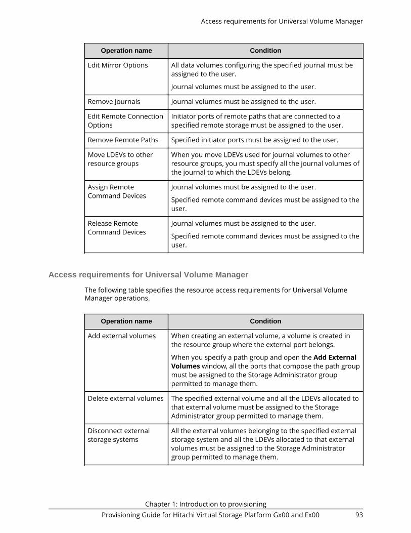
Operation name Condition
Edit Mirror Options All data volumes configuring the specified journal must beassigned to the user.
Journal volumes must be assigned to the user.
Remove Journals Journal volumes must be assigned to the user.
Edit Remote ConnectionOptions
Initiator ports of remote paths that are connected to aspecified remote storage must be assigned to the user.
Remove Remote Paths Specified initiator ports must be assigned to the user.
Move LDEVs to otherresource groups
When you move LDEVs used for journal volumes to otherresource groups, you must specify all the journal volumes ofthe journal to which the LDEVs belong.
Assign RemoteCommand Devices
Journal volumes must be assigned to the user.
Specified remote command devices must be assigned to theuser.
Release RemoteCommand Devices
Journal volumes must be assigned to the user.
Specified remote command devices must be assigned to theuser.
Access requirements for Universal Volume Manager
The following table specifies the resource access requirements for Universal VolumeManager operations.
Operation name Condition
Add external volumes When creating an external volume, a volume is created inthe resource group where the external port belongs.
When you specify a path group and open the Add ExternalVolumes window, all the ports that compose the path groupmust be assigned to the Storage Administrator grouppermitted to manage them.
Delete external volumes The specified external volume and all the LDEVs allocated tothat external volume must be assigned to the StorageAdministrator group permitted to manage them.
Disconnect externalstorage systems
All the external volumes belonging to the specified externalstorage system and all the LDEVs allocated to that externalvolumes must be assigned to the Storage Administratorgroup permitted to manage them.
Access requirements for Universal Volume Manager
Chapter 1: Introduction to provisioningProvisioning Guide for Hitachi Virtual Storage Platform Gx00 and Fx00 93

Operation name Condition
Reconnect externalstorage systems
All the external volumes belonging to the specified externalstorage system and all the LDEVs allocated to that externalvolumes must be assigned to the Storage Administratorgroup permitted to manage them.
Disconnect externalvolumes
The specified external volume and all the LDEVs allocated tothe external volumes must be assigned to the StorageAdministrator group permitted to manage them.
Reconnect externalvolumes
The specified external volume and all the LDEVs allocated tothe external volumes must be assigned to the StorageAdministrator group permitted to manage them.
Edit external volumes The specified external volume must be assigned to theStorage Administrator group permitted to manage them.
Assign MP Unit The specified external volumes and all the ports of theexternal paths connecting the external volumes must beassigned to the Storage Administrator group permitted tomanage them.
Disconnect externalpaths
Ports of the specified external paths and all the externalvolumes connecting with the external path must beassigned to the Storage Administrator group permitted tomanage them.
When you specify By Ports, all the external paths connectingwith the specified ports and all the external volumesconnecting with the external paths must be assigned to theStorage Administrator group permitted to manage them.
When you specify By External WWNs, all the ports of theexternal paths connecting to the specified external WWNand all the external volumes connecting with those externalpaths must be assigned to the Storage Administrator grouppermitted to manage them.
Access requirements for Universal Volume Manager
Chapter 1: Introduction to provisioningProvisioning Guide for Hitachi Virtual Storage Platform Gx00 and Fx00 94

Operation name Condition
Reconnect externalpaths
Ports of the specified external paths and all the externalvolumes connecting with those external paths must beassigned to the Storage Administrator group permitted tomanage them.
When you specify By Ports, all the external paths connectingwith the specified ports and all the external volumesconnecting with the external paths must be assigned to theStorage Administrator group permitted to manage them.
When you specify By External WWNs, all the ports of theexternal paths connecting to the specified external WWNand all the external volumes connecting with those externalpaths must be assigned to the Storage Administrator grouppermitted to manage them.
Edit external WWNs All the ports of the external paths connecting to thespecified external WWN and all the external volumesconnecting with the external paths must be assigned to theStorage Administrator group permitted to manage them.
Edit external pathconfiguration
Ports of all the external paths composing the specified pathgroup and all the external volumes that belong to the pathgroup must be assigned to the Storage Administrator grouppermitted to manage them.
Access requirements for Virtual LUN
The following table specifies the resource access requirements for Virtual LUNoperations.
Operation name Condition
Create LDEVs When you specify a parity group and open the CreateLDEVs window, the parity group must be assigned to theStorage Administrator group permitted to manage them.
When you create an internal or external volumes paritygroups where the LDEV belongs and ID of the new LDEVmust be assigned to the Storage Administrator grouppermitted to manage them.
Delete LDEVs When deleting an internal or external volume, the deletedLDEV and parity groups where the LDEV belongs must beassigned to the Storage Administrator group permitted tomanage them.
Edit LDEVs The specified LDEV must be assigned to the StorageAdministrator group permitted to manage them.
Access requirements for Virtual LUN
Chapter 1: Introduction to provisioningProvisioning Guide for Hitachi Virtual Storage Platform Gx00 and Fx00 95

Operation name Condition
Restore LDEVs When you specify LDEVs and open the Restore LDEVswindow, the specified LDEVs must be assigned to theStorage Administrator group permitted to manage them.
When you specify a parity group and open the RestoreLDEVs window, the specified parity group and all the LDEVsin the parity group must be assigned to the StorageAdministrator group permitted to manage them.
Block LDEVs When you specify LDEVs and open the Block LDEVswindow, the specified LDEVs must be assigned to theStorage Administrator group permitted to manage them.
When you specify a parity group and open the Block LDEVswindow, the specified parity group and all the LDEVs in theparity group must be assigned to the Storage Administratorgroup permitted to manage them.
Format LDEVs When you specify LDEV and open the Format LDEVswindow, the specified LDEV must be assigned to the StorageAdministrator group permitted to manage them.
When you specify a parity group and open the FormatLDEVs window, the specified parity group and all the LDEVsin the parity group must be assigned to the StorageAdministrator group permitted to manage them.
Delete Parity Groups When deleting a parity group, the parity group to be deletedmust be assigned to the Storage Administrator grouppermitted to manage them.
Format Parity Groups When you specify a parity group and open the FormatParity Groups window, the specified parity group must beassigned to the Storage Administrator group permitted tomanage them.
Access requirements for Virtual Partition Manager
The following table specifies the resource access requirements for Virtual PartitionManager operations.
Access requirements for Virtual Partition Manager
Chapter 1: Introduction to provisioningProvisioning Guide for Hitachi Virtual Storage Platform Gx00 and Fx00 96

Operation name Condition
Migrate parity groups When you specify virtual volumes, the specified LDEV mustbe assigned to the Storage Administrator group permittedto manage them.
When you specify a parity group, the specified parity groupmust be assigned to the Storage Administrator grouppermitted to manage them.
Access requirements for Volume Shredder
The following table specifies the resource access requirements for Volume Shredderoperations.
Operation name Condition
Shred LDEVs When you specify LDEVs and open the Shred LDEVswindow, the specified LDEVs must be assigned to theStorage Administrator group permitted to manage them.
When you specify a parity group and open the Shred LDEVswindow, the specified parity group and all the LDEVs in theparity group must be assigned to the Storage Administratorgroup permitted to manage them.
Access requirements for Server Priority Manager
The following table specifies the resource access requirements for Server PriorityManager operations.
Operation name Conditions
Set priority of ports (attribute/threshold/upper limit)
The specified ports must be assigned to theStorage Administrator group permitted tomanage them.
Release settings on ports by thedecrease of ports
Set priority of WWNs (attribute/upper limit)
Change WWNs and SPM names
Add WWNs (add WWNs to SPMgroups)
Delete WWNs (delete WWNs fromSPM groups)
Access requirements for Volume Shredder
Chapter 1: Introduction to provisioningProvisioning Guide for Hitachi Virtual Storage Platform Gx00 and Fx00 97

Operation name Conditions
Add SPM groups and WWNs
Delete SPM groups
Set priority of SPM groups(attribute/upper limit)
Rename SPM groups
Add WWNs
Delete WWNs
Initialization All ports must be assigned to the StorageAdministrator group permitted to manage them.
Set threshold
Chapter 1: Introduction to provisioningProvisioning Guide for Hitachi Virtual Storage Platform Gx00 and Fx00 98

Chapter 2: Managing virtual storage machineresources
Virtual storage machines are used to achieve continuous access to data for global-activedevice volumes and for data migration.
About virtual storage machines and virtualized resourcesThe virtual storage machine is the unit that is used to manage virtualized storage systemresources. When you use global storage virtualization functions (global-active device,nondisruptive migration), you create a virtual storage machine within a physical storagesystem to enable the host server to recognize two storage systems as one virtual storagesystem.
For example, when nondisruptive migration is used to migrate a storage system to aVirtual Storage Platform G200, G400, G600, G800Hitachi Virtual Storage Platform G1x00storage system, a virtual storage machine for the migration source storage system iscreated in the migration target storage system. For nondisruptive migration, themigration source storage system is the virtualized storage system. When global-activedevice (GAD) is used to provide nondisruptive host access to volumes that reside ondifferent storage systems, a virtual storage machine for the storage system that containsthe primary volumes (P-VOLs) of the GAD pairs is created in the secondary storagesystem. For GAD, the primary storage system is the virtualized storage system.
The following figure illustrates the relationship between a (physical) storage system andvirtual storage machines.
Chapter 2: Managing virtual storage machine resourcesProvisioning Guide for Hitachi Virtual Storage Platform Gx00 and Fx00 99

Virtual IDs
For operations involving virtualized resources in a virtual storage machine, physicalresources must be linked to virtualized resources. For example, when you performoperations on LDEVs in a virtual storage machine, you must specify physical LDEV IDs(not virtual LDEV IDs) that link to resources in the virtual storage machine. The followingtable lists the virtual IDs that must be set for resources in the (physical) storage systemto enable the host server to recognize two storage systems as one virtual storagesystem.
Virtual IDResource on which the virtual ID
is set
Model type of the virtualized storage system
Serial number of the virtualized storage system
Resource group
LDEV ID
Emulation type
CVS
LUSE volume number
SSID
LDEV
Using virtual storage machines for nondisruptive migrationThe nondisruptive migration (NDM) software is used to migrate data nondisruptivelyfrom a source storage system to a target storage system. When NDM is used, theprogram product configuration data is also migrated to enable business operations tocontinue without interruption.
When NDM migration is performed, a resource group is created in the target storagesystem, and the model type and serial number of the source storage system areassigned to the resource group to create the virtual storage machine.
Using virtual storage machines for nondisruptive migration
Chapter 2: Managing virtual storage machine resourcesProvisioning Guide for Hitachi Virtual Storage Platform Gx00 and Fx00 100

You can use NDM to migrate the following storage systems:■ Migration source:
● Universal Storage Platform V/VM● Virtual Storage Platform● Unified Storage VM
■ Migration target:● VSP Gx00 models● VSP Fx00 models● VSP G1x00● VSP F1500
For details about nondisruptive migration, see the Nondisruptive Migration User Guide.
Using virtual storage machines for global-active deviceGlobal-active device (GAD) enables you to create and maintain synchronous, remotecopies of data volumes. Both volumes of a GAD pair can receive the same data from theserver.
When you use GAD, a resource group is created in the secondary storage system, andthe model type and serial number of the primary storage system are assigned to theresource group to create the virtual storage machine. The server then recognizes bothstorage systems (the storage systems at the primary and secondary sites) as the samestorage system and can synchronously access both volumes of a GAD pair.
Using virtual storage machines for global-active device
Chapter 2: Managing virtual storage machine resourcesProvisioning Guide for Hitachi Virtual Storage Platform Gx00 and Fx00 101

Global-active device is supported on the following storage systems.■ VSP Gx00 models■ VSP Fx00 models■ VSP G1x00■ VSP F1500
For details about global-active device, see the Global-Active Device User Guide.
Requirements and specifications for global storagevirtualization
The following table lists the requirements and specifications for global storagevirtualization.
Item Requirement
Storage system The following storage systems support global storagevirtualization:■ VSP G1x00■ VSP F1500■ VSP Gx00 models■ VSP Fx00 models
Requirements and specifications for global storage virtualization
Chapter 2: Managing virtual storage machine resourcesProvisioning Guide for Hitachi Virtual Storage Platform Gx00 and Fx00 102

Item Requirement
Virtual storage machine The following storage system models can be virtualizedas virtual storage machines:■ USP V/VM■ VSP■ VSP G1x00■ VSP F1500■ HUS VM■ VSP Gx00 models■ VSP Fx00 models
Maximum number ofvirtual storage machinesper storage system
You can define up to 7 virtual storage machines in asingle physical storage system.
User interface ■ Command Control Interface (CCI)■ Device Manager - Storage Navigator■ Hitachi Command Suite
For details about using CCI and Device Manager - StorageNavigator, see Virtual storage machine operations in CCIand Device Manager - Storage Navigator (on page 103) .
For details about using Hitachi Command Suite, see theHitachi Command Suite User Guide and the NondisruptiveMigration User Guide.
Virtual storage machine operations in CCI and Device Manager -Storage Navigator
You can use Command Control Interface (CCI) and Device Manager - Storage Navigator toperform operations with virtual storage machines. Both CCI and Device Manager -Storage Navigator display all virtual storage machine information, but some operationscan only be performed using CCI.
The following table lists the virtual storage machine operations and indicates whetherthe operations can be performed in CCI, Device Manager - Storage Navigator, or both.
Operation CCIDevice Manager -Storage Navigator
Creating/deleting virtual storage machines Yes No
Reserving host groups in a virtual storagemachine
Yes No
Virtual storage machine operations in CCI and Device Manager - Storage Navigator
Chapter 2: Managing virtual storage machine resourcesProvisioning Guide for Hitachi Virtual Storage Platform Gx00 and Fx00 103

Operation CCIDevice Manager -Storage Navigator
Deleting default virtual LDEV IDs Yes No
Reserving virtual LDEV IDs in a virtual storagemachine
Yes No
Setting virtual LDEV IDs Yes Yes
Setting device parameters for virtual LDEVs Yes Yes
Viewing virtual storage machine information(model type, serial number)
Yes Yes
Viewing virtual LDEV information Yes Yes
Viewing virtual storage machine information in Device Manager - StorageNavigator
Information about the virtualized resources of a virtual storage machine is displayed inDevice Manager - Storage Navigator with associated physical storage information. If theinformation about these resources is not displayed by default, change the settings forthe table columns displayed in the window.
Device Manager - Storage Navigator uses the following terms about virtualizedresources:■ LDEV for which virtualization management is enabled: . An LDEV that satisfies one
of these conditions:● The virtual storage machine that manages the resource group with the LDEV is
different than the storage system involved in the operation (their model types andserial numbers are different).
● The virtual storage machine that manages the resource group with the LDEV is thesame as the storage system involved in the operation (their model types and serialnumbers are the same), but the virtual LDEV ID and the LDEV ID are different.
■ LDEV for which virtualization management is disabled: . An LDEV that satisfiesboth of these conditions:● The virtual storage machine that manages the resource group with the LDEV is the
same as the storage system involved in the operation (their model types and serialnumbers are the same).
● The virtual LDEV ID and the LDEV ID are the same.
Performing provisioning operations for resources in a virtual storagemachine
CCI is used to perform provisioning operations on virtualized resources.
For provisioning operations that involve virtualized resources in a virtual storagemachine, you can perform provisioning operations that specify conventional physicalresources or virtualized resources. As shown in the following figure, for example,provisioning operations in which "LDEV ID:10:00" is specified can be performed as usual,
Performing provisioning operations for resources in a virtual storage machine
Chapter 2: Managing virtual storage machine resourcesProvisioning Guide for Hitachi Virtual Storage Platform Gx00 and Fx00 104

but provisioning operations in which "Virtual ID(LDEV ID): 20:00" is specified are limited.For details about performing provisioning operations for virtualized resources, see theCommand Control Interface User and Reference Guide.
Pair operations with virtual storage machine pairs
Specifying virtual IDs in pair operations
You can perform pair operations by specifying both of the following in the HORCM_LDEVparameters of the Command Control Interface configuration definition file:■ Serial number of the virtual storage machine in the Serial# parameter■ Virtual LDEV number in the CU:LDEV(LDEV#) parameter
You can perform conventional pair operations by specifying both of the following in theHORCM_LDEV parameters of the configuration definition file:■ Serial number of the physical storage system in the Serial# parameter■ Physical LDEV number in the CU:LDEV(LDEV#) parameter
Caution:
If the following condition exists, the local copy pair operation cannot beperformed by specifying virtual IDs:■ Primary volume and secondary volume are defined differently for the
virtual storage machine.
If both of the following conditions exist, remote copy pair operations cannotbe performed by specifying virtual IDs:■ The primary volume is an LDEV in a VSP, HUS VM, or USP V/VM storage
system.■ The secondary volume is an LDEV in a VSP G200, G400, G600, G800 or VSP
F400, F600, F800 storage system.
Caution:
Global-active device pair operations that specify the virtual ID cannot beperformed.
Pair operations with virtual storage machine pairs
Chapter 2: Managing virtual storage machine resourcesProvisioning Guide for Hitachi Virtual Storage Platform Gx00 and Fx00 105

Displaying pair information
You can create pairs by specifying both of following in the HORCM_LDEV parameters ofthe Command Control Interface configuration definition file:■ Serial number of the physical storage system in the Serial# parameter■ Virtual LDEV number in the CU:LDEV(LDEV#) parameter
If the pair is created under the above conditions, the following are displayed as results ofexecuting the pairdisplay command:■ Serial number of the virtual storage machine in the Seq# parameter■ Virtual LDEV number in the LDEV# parameter
You can create pairs by specifying both of the following in the HORCM_LDEV parametersof the configuration definition file:■ Serial number of the physical storage system in the Serial# parameter■ Physical LDEV number in the CU:LDEV(LDEV#) parameter
If the pair is created under the above conditions, the following are displayed as results ofexecuting the pairdisplay command:■ Physical serial number of the virtual storage machine in the Seq# parameter■ Physical virtual LDEV number in the LDEV# parameter
Caution:
You can create pairs by specifying both of the following in the HORCM_LDEVparameters of the configuration definition file:■ Serial number of the physical storage system in the Serial# parameter
■ Physical LDEV number in the CU:LDEV(LDEV#) parameter
For pairs created under the above conditions, the device information that isrecognized by the server and the device information that results fromexecuting the pairdisplay command are different.
Creating a virtual storage machineUse the following workflow to create a virtual storage machine. You must use CCI tocreate a virtual storage machine.
To create a virtual storage machine, you add a resource group and assign the model typeand serial number of the virtualized storage system to the resource group.
Before you begin
You will need to enter the following information when you create a virtual storagemachine:■ Model type and serial number of the storage system to be virtualized■ Port/host group information of the LDEVs to be virtualized (for example, CL1-A-1)■ LDEV IDs of the LDEVs to be virtualized
Creating a virtual storage machine
Chapter 2: Managing virtual storage machine resourcesProvisioning Guide for Hitachi Virtual Storage Platform Gx00 and Fx00 106

Procedure
1. Create a virtual storage machine by using the raidcom add resource command.For example:
raidcom add resource -resource_name rsg_vir -virtual_type 20000 R700
where:
■ rsg_vir is the name of the new resource group that will contain the virtualizedresources.
■ 200000 is the serial number of the virtual storage machine.
■ R700 is the model type of the virtual storage machine.
The following model types are supported:
■ USP V: R600
■ USP VM: RK600
■ VSP: R700
■ VSP G1x00, VSP F1500: R800
■ HUS VM: M700
■ VSP Gx00 models, VSP Fx00 models: M800
2. In the virtual storage machine, reserve the ID for the host group that will beaccessed by the host server.For example:
raidcom add resource -resource_name rsg_vir -port CL1-A-1
Creating a virtual storage machine
Chapter 2: Managing virtual storage machine resourcesProvisioning Guide for Hitachi Virtual Storage Platform Gx00 and Fx00 107

3. Delete the default virtual ID.By default, virtual IDs are set in the LDEVs in the storage system. Delete the defaultvirtual ID from the LDEV that you plan to use by using the raidcom unmapresource command. For example:
raidcom unmap resource -ldev_id 10:00 -virtual_ldev_id 10:00
4. Reserve the ID for the LDEV in the resource group.In the resource group, reserve the LDEV ID for the LDEV that you plan to use in thevirtual storage machine. For this operation, use the raidcom add resourcecommand. For example:
raidcom add resource -resource_name rsg_vir -ldev_id 10:00
Creating a virtual storage machine
Chapter 2: Managing virtual storage machine resourcesProvisioning Guide for Hitachi Virtual Storage Platform Gx00 and Fx00 108

5. Setting the virtual ID for the LDEV.Set the virtual ID for the LDEV in the virtual storage machine by using the raidcommap resource command. For example:
raidcom map resource -ldev_id 10:00 -virtual_ldev_id 20:00
Enabling the virtualization management setting for LDEVsUse this procedure to enable the virtualization management setting of volumes usingDevice Manager - Storage Navigator. When virtualization management is enabled for avolume, you can set the virtual LDEV ID and specify the virtual volume configuration ofthe volume.
Before you begin■ You must have the Security Administrator (View & Modify) role to perform this task.
Enabling the virtualization management setting for LDEVs
Chapter 2: Managing virtual storage machine resourcesProvisioning Guide for Hitachi Virtual Storage Platform Gx00 and Fx00 109

Procedure
1. In the Administration tree, select Resource Groups.2. Select the resource group that contains the target volume.3. In the LDEVs tab, select the target volume, and click Edit Virtualization
Management Settings.4. In Virtualization Management Settings, select Enable or Enable (Not Set).
■ Enable: Virtualization management can be used. You can set the virtual LDEV IDand specify the virtual LDEV configuration using Device Manager - StorageNavigator.
■ Enable (Not Set): Virtualization management can be used, but you cannot setthe virtual LDEV ID or specify the virtual LDEV configuration using DeviceManager - Storage Navigator.
■ Disable: Virtualization management cannot be used for the selected volume.
5. If you selected Enable in Virtualization Management Settings, set the virtualLDEV ID for the selected volume.If you selected more than one volume, set the starting virtual LDEV ID in InitialVirtual LDEV ID, and set the interval for the subsequent LDEV IDs in Interval.Virtual LDEV IDs that are not used in the virtual storage machine are assignedsequentially at the specified interval, starting from the specified virtual LDEV ID.
Note: If the virtual storage machine is the same as the storage system,assign a virtual LDEV ID that is different from the LDEV ID of the selectedLDEV. If the virtual storage machine is the same as the storage systemand you need to assign a virtual LDEV ID that is the same as the LDEV IDof the selected LDEV, select Disable in Virtualization ManagementSettings.
Caution: If the virtual storage machine is configured in multiple storagesystems, a virtual LDEV ID that is already used in another storage systemmight be assigned. In such a configuration, set the interval so that avirtual LDEV ID that is already used in another storage system is notassigned.
6. If you selected Enable in Virtualization Management Settings, select VirtualConfiguration to specify the volume configuration information. For the virtualvolume configuration, the specified values are set for all selected LDEVs.
■ If the volume configuration of the virtual LDEV and the LDEV are the same, selectNot Set.
■ If the volume configuration of the virtual LDEV and the LDEV are different, selectSpecify, and then set the following parameters:
a. In Emulation Type, select the virtual emulation type. For the virtual emulationtype, which is similar to the emulation type, set one of the emulation types thatexists in the same group of 32 volumes with LDEV IDs.
b. Select CVS Settings.c. If the virtual LDEV is a LUSE volume, in Number of Concatenated LDEVs
specify the number of concatenated LDEVs (decimal number from 2 to 36).If the virtual LDEV is not a LUSE volume, enter 1.
d. In SSID, specify the virtual SSID (hexadecimal number from 0004 to FFFE).
Enabling the virtualization management setting for LDEVs
Chapter 2: Managing virtual storage machine resourcesProvisioning Guide for Hitachi Virtual Storage Platform Gx00 and Fx00 110

Set a virtual SSID for each virtual LDEV address (64, 128, 256) in the virtualstorage machine.
7. Click Finish.8. Enter the task name in Task Name.
If you want the Tasks window to open automatically, select Go to tasks window forstatus.
9. Click Apply to register the task.
Caution:
If the LDEV virtualization management setting is canceled, Failed isdisplayed in the Status column of the Task window and Transient isdisplayed for the Virtual LDEV ID. To resolve the transient status, performone of the following operations on the LDEVs:
■ Resolve the cause of the failure by addressing the error message inthe Task window, and then retry the operation by using the EditVirtualization Management Settings window.
■ In the Edit Virtualization Management Settings window, setVirtual Management Settings to Disable before applying the settingto the storage system.
Editing virtual LDEV ID and virtual volume configurationUse this procedure to edit the virtual LDEV ID and volume configuration (emulation type,CVS and LUSE settings, and SSID) of a virtualized volume using Device Manager - StorageNavigator.
Before you begin■ You must have the Security Administrator (View & Modify) role to perform this task.■ The virtualization management setting for the target volume must be set to Enabled.
Procedure
1. In the Administration tree, select Resource Groups.2. Select the resource group that contains the target volume.3. In the LDEVs tab, select the target volume, and click Edit Virtualization
Management Settings.4. In Virtualization Management Settings, make sure that Enable is selected.
If Enable (Not Set) or Disable is selected, you cannot edit the virtual LDEV ID or thevolume configuration.
5. Edit the virtual LDEV ID for the selected volume.If you selected more than one volume, set the starting virtual LDEV ID in InitialVirtual LDEV ID, and set the interval for the subsequent LDEV IDs in Interval.Virtual LDEV IDs that are not used in the virtual storage machine are assignedsequentially at the specified interval, starting from the specified virtual LDEV ID.
Note: If the virtual storage machine is the same as the storage system,assign a virtual LDEV ID that is different from the LDEV ID of the selected
Editing virtual LDEV ID and virtual volume configuration
Chapter 2: Managing virtual storage machine resourcesProvisioning Guide for Hitachi Virtual Storage Platform Gx00 and Fx00 111

LDEV. If the virtual storage machine is the same as the storage systemand you need to assign a virtual LDEV ID that is the same as the LDEV IDof the selected LDEV, select Disable in Virtualization ManagementSettings.
Caution: If the virtual storage machine is configured in multiple storagesystems, a virtual LDEV ID that is already used in another storage systemmight be assigned. In such a configuration, set the interval so that avirtual LDEV ID that is already used in another storage system is notassigned.
6. Select Virtual Configuration to edit the volume configuration information. For thevirtual volume configuration, the specified values are set for all selected LDEVs.
■ If the volume configuration of the virtual LDEV and the LDEV are the same, selectNot Set.
■ If the volume configuration of the virtual LDEV and the LDEV are different, selectSpecify, and then set the following parameters:
a. In Emulation Type, select the virtual emulation type. For the virtual emulationtype, which is similar to the emulation type, set one of the emulation types thatexists in the same group of 32 volumes with LDEV IDs.
b. Select CVS Settings.c. If the virtual LDEV is a LUSE volume, in Number of Concatenated LDEVs
specify the number of concatenated LDEVs (decimal number from 2 to 36).If the virtual LDEV is not a LUSE volume, enter 1.
d. In SSID, specify the virtual SSID (hexadecimal number from 0004 to FFFE).Set a virtual SSID for each virtual LDEV address (64, 128, 256) in the virtualstorage machine.
7. Click Finish.8. Enter the task name in Task Name.
If you want the Tasks window to open automatically, select Go to tasks window forstatus.
9. Click Apply to register the task.
Caution:
If the LDEV virtualization management setting is canceled, Failed isdisplayed in the Status column of the Task window and Transient isdisplayed for the Virtual LDEV ID. To resolve the transient status, performone of the following operations on the LDEVs:
■ Resolve the cause of the failure by addressing the error message inthe Task window, and then retry the operation by using the EditVirtualization Management Settings window.
■ In the Edit Virtualization Management Settings window, setVirtual Management Settings to Disable before applying the settingto the storage system.
Editing virtual LDEV ID and virtual volume configuration
Chapter 2: Managing virtual storage machine resourcesProvisioning Guide for Hitachi Virtual Storage Platform Gx00 and Fx00 112

Disabling the virtualization management setting for LDEVsUse this procedure to disable the virtualization management setting of volumes usingDevice Manager - Storage Navigator. When virtualization management is disabled for avolume, you cannot set the virtual LDEV ID or specify the virtual volume configuration ofthe volume.
Before you begin■ You must have the Security Administrator (View & Modify) role to perform this task.
Procedure
1. In the Administration tree, select Resource Groups.2. Select the resource group that contains the target volume.3. In the LDEVs tab, select the target volume, and click Edit Virtualization
Management Settings.4. In Virtualization Management Settings, select Disable.5. Click Finish.6. Enter the task name in Task Name.7. Click Apply.
The task is registered. If Go to tasks window for status is selected, the Taskswindow opens automatically.
Caution:
If the LDEV virtualization management setting is canceled, Failed isdisplayed in the Status column of the Task window and Transient isdisplayed for the Virtual LDEV ID. To resolve the transient status, performone of the following operations on the LDEVs:
■ Resolve the cause of the failure by addressing the error message inthe Task window, and then retry the operation by using the EditVirtualization Management Settings window.
■ In the Edit Virtualization Management Settings window, setVirtual Management Settings to Disable before applying the settingto the storage system.
Disabling the virtualization management setting for LDEVs
Chapter 2: Managing virtual storage machine resourcesProvisioning Guide for Hitachi Virtual Storage Platform Gx00 and Fx00 113

Chapter 2: Managing virtual storage machine resourcesProvisioning Guide for Hitachi Virtual Storage Platform Gx00 and Fx00 114

Chapter 3: Configuring custom-sizedprovisioning
Configuring custom-sized provisioning involves creating and configuring custom-sizevolumes (CVs). CVs are created by dividing a fixed-sized volume (FV) into several smallervolumes of arbitrary sizes.
Virtual LUN functionsVirtual LUN function is used to create, configure, or delete a customized volume (LDEV).
The Virtual LUN function is an open systems function available in Open VolumeManagement software.
A parity group usually consists of some fixed-sized volumes (FVs) and some free space.The number of FVs is determined by the emulation type. A Virtual LUN volume usuallyconsists of at least one FV, one or more customized volumes (CVs), and some free space.
Use the Virtual LUN function to configure variable-sized volumes that efficiently exploitthe capacity of a disk. Variable-sized volumes are logical volumes that are divided intosmaller than normal fixed-size volumes. This configuration is desirable when frequentlyaccessed files are distributed across smaller multiple logical volumes. This generallyimproves the data accessing performance, though file access may be delayed in someinstances.
The Virtual LUN function can also divide a logical volume into multiple smaller volumesto reduce unused capacity and provide a more efficient use of space for small volumessuch as command devices. The Virtual LUN function can efficiently exploit the capacity ofa disk by not wasting capacity using larger volumes when the extra capacity is notneeded.
Configuring volumes in a parity groupThe Virtual LUN functions of Delete LDEVs and Create LDEVs are performed on eachparity group. Parity groups are also separated from each other by boundary limitations.Therefore, you cannot define a volume across two or more parity groups beyond theseboundaries.
As the result of the Virtual LUN operations, a parity group contains FVs, CVs, and freespaces that are delimited in logical cylinders. Sequential free spaces are combined into asingle free space.
The following depicts an example of configuring volumes in a parity group:
Chapter 3: Configuring custom-sized provisioningProvisioning Guide for Hitachi Virtual Storage Platform Gx00 and Fx00 115

Configuration of interleaved parity groupsIf RAID configurations are RAID1 (2D+2D) or RAID5 (7D+1P), the interleaved parity groupcan be created by concatenating multiple of parity groups. The following table lists theRAID configurations and the number of parity groups that can be concatenated.
RAID configuration 2 concatenating 4 concatenating
RAID1 (2D+2D) Available Not Available
RAID5 (7D+1P) Available Available
When concatenating parity groups, data in LDEVs that are FV or CV is allocated betweenthe interleaved parity groups. Therefore, loads are dispersed because of the parity groupconcatenation, and the LDEV performance is improved.
The capacity of the created LDEV is managed by each of the parity groups that are in theinterleaved parity group. The maximum capacity of an LDEV is the same as the capacityof the interleaved parity group.
Note: Even if the parity groups are concatenated, the total capacity of theinterleaved parity group is not large.
See the following examples:■ Creating the interleaved parity group by concatenating of parity groups of PG1-1 and
PG1-2.■ Creating LDEVs in each parity group that are in the interleaved parity group.
● LDEV 1 in PG1-1● LDEV 2 in PG1-2
Configuration of interleaved parity groups
Chapter 3: Configuring custom-sized provisioningProvisioning Guide for Hitachi Virtual Storage Platform Gx00 and Fx00 116

Virtual LUN requirementsUse of Virtual LUN on your storage system to configure variable-sized volumes requiresthe following:■ A license key for the Virtual LUN software product. This is available in Open Volume
Management software for open systems.
For details about license key or software product installation, see the SystemAdministrator Guide.
Virtual LUN specifications
RAID level support for CVs and pool-VOLs
The following table specifies the RAID level support for custom volumes (CVs) and poolvolumes (pool-VOLs).
RAID levelRAID configuration that can be
applied to CVRAID configuration that can be
applied to pool volume
RAID 1 2D+2D, or two concatenated 2D+2D parity groups
2D+2D, or two concatenated 2D+2D parity groups
Virtual LUN requirements
Chapter 3: Configuring custom-sized provisioningProvisioning Guide for Hitachi Virtual Storage Platform Gx00 and Fx00 117

RAID levelRAID configuration that can be
applied to CVRAID configuration that can be
applied to pool volume
RAID 5 ■ 2D+1P■ 3D+1P■ 4D+1P■ 5D+1P■ 6D+1P■ 7D+1P, or two concatenated
7D+1P parity groups, or fourconcatenated 7D+1P paritygroups
■ 8D+1P
■ 3D+1P■ 4D+1P■ 6D+1P■ 7D+1P, or two concatenated
7D+1P parity groups, or fourconcatenated 7D+1P paritygroups
RAID 6 ■ 4D+2P■ 6D+2P■ 8D+2P■ 10D+2P■ 12D+2P■ 14D+2P
■ 6D+2P■ 12D+2P■ 14D+2P
CV capacity
Defines the minimum capacity and maximum capacity for an OPEN-V volume (internaland external).
Emulation type*Minimum CV
capacityMaximum CV
capacityNumber of control
cylinders
OPEN-V 48,000 KB (96,000blocks)
■ Internalvolume*:3,221,159,680 KB(2.99 TB,6,442,319,360blocks)
■ External volume:4,294,967,296 KB(4 TB,8,589,934,592blocks)
None
*If the parity group is 2D+1P or 4D+2P, the maximum CV capacity is 2 TB, which is4,294,967,296 blocks.
CV capacity
Chapter 3: Configuring custom-sized provisioningProvisioning Guide for Hitachi Virtual Storage Platform Gx00 and Fx00 118

Virtual LUN size calculationsWhen you create custom volumes (CVs), you can specify the capacity of each CV.However, rounding will produce different values for the user-specified CV capacity andthe actual entire CV capacity. To calculate the actual capacity of a CV, you must use amathematical formula. The following topics explain how to calculate the user areacapacity and the entire capacity of a CV.
The entire capacity of a CV or an LDEV consists of two types of capacity. One type is theuser area capacity that stores the user data. The second type is the capacity of all areasthat are necessary for an LDEV implementation including control information. The sumof these two types of capacities is called the entire capacity.
Implemented LDEVs consume the entire capacity from the parity group capacity.Therefore, even if the sum of user areas of multiple CVs is the same as the user area ofone CV, the remaining free space generated when multiple CVs are created can besmaller than the free space in the parity group when one CV is created.
When you create an LDEV, the actual capacity of the LDEV depends on whether youselect the Capacity Compatibility Mode (Offset boundary) option on the Create LDEVswindow. If the Capacity Compatibility Mode (Offset boundary) option is not selected, theLDEV is created with the specified capacity. If the Capacity Compatibility Mode (Offsetboundary) option is selected, the specified LDEV capacity is offset by conforming to theprescribed boundary values, and an LDEV is created. The prescribed boundary valuedepends on the device emulation type and RAID level. For details about boundary values,see Boundary values of volumes (on page 122) .■ When to select the Capacity Compatibility Mode (Offset boundary) option: . In
the storage system, data is managed based on a slot, and RAID data protection isperformed based on a parity stripe unit. For an LDEV created with capacity offset by aboundary, the efficiency of the drive capacity is improved because the capacity of theLDEV is offset by the unit of the data management. Therefore, if there is an emphasison the efficiency of the drive capacity, select the Capacity Compatibility Mode (Offsetboundary) option when creating LDEVs.
■ When NOT to select the Capacity Compatibility Mode (Offset boundary) option: .If you want the LDEV capacity to be a specific size, do not select the CapacityCompatibility Mode (Offset boundary) option when creating LDEVs. For example, ifyou want to create copy pairs with VSP, HUS VM, or other previous storage systemmodels, you must use exactly the same LDEV capacity for the volumes in a pair.
Note: When you use CCI to create a CV, the CV is created with the specifiedsize regardless of the capacity calculation. Therefore, even if you specify thesame capacity size (for example, 1 TB), the actual capacity size might bedifferent between CVs created using CCI and CVs created using Hitachi DeviceManager - Storage Navigator.
Calculating OPEN-V volume size (CV capacity unit is MB)
The methods for calculating the user area capacity and the entire capacity of a CV varydepending on the CV capacity unit that is specified when creating the CV.
To calculate the user area capacity of a CV whose capacity unit is defined as megabytes:
ceiling(ceiling(user-specified-CV-capacity * 1024 / 64) / 15) * 64 * 15
Virtual LUN size calculations
Chapter 3: Configuring custom-sized provisioningProvisioning Guide for Hitachi Virtual Storage Platform Gx00 and Fx00 119

where■ the value enclosed in ceiling( ) must be rounded up to the nearest whole
number.■ user-specified-CV-capacity is expressed in megabytes.■ The resulting user area capacity is expressed in kilobytes.
To calculate the entire capacity of a CV:
ceiling(user-area-capacity / boundary-value) * boundary-value / 1024
where■ the value enclosed in ceiling( ) must be rounded up to the nearest whole
number.■ user-area-capacity is expressed in kilobytes■ boundary value is expressed in kilobytes. The boundary value depends on volume
emulation types and RAID levels (see Boundary values of volumes (on page 122) ).■ The resulting entire capacity is expressed in megabytes.
Calculating OPEN-V volume size (CV capacity unit is blocks)
To calculate the user area capacity of a CV whose capacity unit is defined as blocks:
ceiling(user-specified-CV-capacity / 2)
where■ the value enclosed in ceiling( ) must be rounded up to the nearest whole
number.■ user-specified-CV-capacity is expressed in blocks.■ The resulting user area capacity is expressed in kilobytes.
To calculate the entire capacity of a CV:
ceiling(user-specified-CV-capacity / (boundary-value * 2)) * (boundary-value * 2)
where■ the value enclosed in ceiling( ) must be rounded up to the nearest whole
number.■ user-specified-CV-capacity is expressed in blocks.■ boundary-value is expressed in kilobytes. The boundary value depends on volume
emulation types and RAID levels (see Boundary values of volumes (on page 122) ).■ The resulting entire capacity is expressed in blocks. To convert the resulting entire
capacity into megabytes, divide this capacity by 2,048.
Calculating OPEN-V volume size (CV capacity unit is blocks)
Chapter 3: Configuring custom-sized provisioningProvisioning Guide for Hitachi Virtual Storage Platform Gx00 and Fx00 120

Calculating fixed-size volume size (CV capacity unit is MB)
To calculate the user area capacity of a CV whose capacity unit is defined as megabytes:
ceiling(ceiling(user-specified-CV-capacity * 1024 / capacity-of-a-slot) / 15) * capacity-of-a-slot * 15
where■ the value enclosed in ceiling( ) must be rounded up to the nearest whole
number.■ user-specified-CV-capacity is expressed in megabytes.■ capacity-of-a-slot is expressed in kilobytes (256 KB for OPEN-V).■ The resulting user area capacity is expressed in kilobytes.
To calculate the entire capacity of a CV:
ceiling((user-area-capacity + management-area-capacity) /boundary-value) * boundary-value / 1024
where■ The value enclosed in ceiling( ) must be rounded up to the nearest whole
number.■ user-area-capacity is expressed in kilobytes.■ management-area-capacity is expressed in kilobytes. The management area capacity
depends on the device emulation type (0 KB for OPEN-V).■ boundary-value is expressed in kilobytes. The boundary value depends on the device
emulation type and RAID level (see Boundary values of volumes (on page 122) ).■ The resulting entire capacity is expressed in megabytes.
Calculating fixed-size volume size (CV capacity unit is blocks)
To calculate the user area capacity of a CV whose capacity unit is defined as blocks:
user-specified-CV-capacity / 2
where■ user-specified-CV-capacity is expressed in blocks.■ The resulting user area capacity is expressed in kilobytes.
To calculate the entire capacity of a CV:
ceiling((user-specified-CV-capacity + management-area-capacity * 2)/ (boundary-value * 2)) * (boundary-value * 2)
where■ the value enclosed in ceiling( ) must be rounded up to the nearest whole
number.
Calculating fixed-size volume size (CV capacity unit is MB)
Chapter 3: Configuring custom-sized provisioningProvisioning Guide for Hitachi Virtual Storage Platform Gx00 and Fx00 121

■ user-specified-CV-capacity is expressed in blocks.■ management-area-capacity is expressed in kilobytes. The management area capacity
depends on volume emulation types (see Management area capacity of a volume (onpage 122) ).
■ boundary-value is expressed in kilobytes. The boundary value depends on volumeemulation types and RAID levels (see Boundary values of volumes (on page 122) ).
■ The CV capacity recognized by hosts is the same as the CV capacity calculated by theabove formula.
■ If block is selected as the LDEV capacity unit in the Create LDEVs window and dialogboxes, the window and dialog boxes correctly show the calculated LDEV capacity.However, if MB, GB, or TB is selected as the LDEV capacity unit in the Create LDEVswindow and dialog boxes, the capacity values shown might have a margin of errordue to unit conversion reasons. If you need to know the exact LDEV capacity, selectblock as the capacity unit.
■ The resulting entire capacity is expressed in blocks. To convert the resulting entirecapacity into megabytes, divide this capacity by 2,048:
Management area capacity of a volume
Emulation type Management area capacity (KB)
OPEN-V 0
Boundary values of volumes
The following table provides the boundary values (expressed as kilobytes) for internalvolumes. The boundary value for an external volume is always one kilobyte, regardlessof RAID level.
RAID level Boundary value (KB)
RAID 1 (2D+2D) 1,024
RAID 5 (3D+1P) 1,536
(4D+1P) 2,048
(6D+1P) 3,072
(7D+1P) 3,584
RAID 6 (6D+2P) 3,072
(12D+2P) 6,144
(14D+2P) 7,168
Management area capacity of a volume
Chapter 3: Configuring custom-sized provisioningProvisioning Guide for Hitachi Virtual Storage Platform Gx00 and Fx00 122

Capacity of a slot
Emulation type Capacity of a slot
OPEN-V 256 KB
Note: Slot capacity is expressed in kilobytes.
Enabling accelerated compressionUse this procedure to enable accelerated compression on a parity group.
Before you begin■ You must have the Storage Administrator role.■ The drive type of the target parity group must be FMC.■ The emulation type of the target parity group must be OPEN-V.■ The RAID level and drive configuration of the target parity group must be accessible
for use for pool volumes.■ The target parity group must be an internal parity group, block, or file. Parity groups
for the embedded NAS module are supported.■ The status of LDEVs in the target parity group must be Normal or Blocked.■ All LDEVs in the parity group must already be added to the same pool.■ The capacity of the defined internal volumes must be 8 GB or more. (The capacity is
equal to or greater than the minimum capacity of a pool volume.)■ If the defined internal volumes are used as pool volumes, those pool volumes belong
to the same Dynamic Provisioning pool or Thin Image pool.■ The defined internal volumes must have no LUN path definitions.■ The defined internal volumes must not be used by Volume Migration.■ The defined internal volumes must not be reserved by the Data Retention Utility.■ The defined internal volumes must not have the Protect, Read Only, or S-VOL Disable
attribute of Data Retention Utility.■ The encryption setting of the parity group must be disabled.■ There must not be any DP-VOL page reserved areas.
Procedure
1. In the Device Manager - Storage Navigator Explorer pane, select Storage Systems,and then expand the tree for the storage system.
2. Display the parity group for which you want to enable accelerated compression.
■ To display all parity groups in the storage system, click Parity Groups.
■ To display only internal parity groups, expand Parity Groups, and then clickInternal.
Capacity of a slot
Chapter 3: Configuring custom-sized provisioningProvisioning Guide for Hitachi Virtual Storage Platform Gx00 and Fx00 123

3. Select the desired parity group, and then click More Actions > Edit Parity Groups.4. In Accelerated Compression, check Enable.
Caution:
When you enable accelerated compression, confirm if the data reductionefficiency can be achieved. For details, see Guidelines for pools whenaccelerated compression is enabled (on page 429) .
5. Click Finish.6. In the Confirm window, confirm the settings. In Task Name, type a unique name
for this task or accept the default, and then click Apply. If Go to tasks window forstatus is checked, the Tasks window opens.
Disabling accelerated compression
Before you begin■ You must have the Storage Administrator (Provisioning) role.■ Set the parity group drive type to FMC.■ You should format the parity group.■ The emulation type of the target parity group must be OPEN-V.■ The target parity group must be an internal parity group.■ The RAID level and drive configuration of the target parity group must be accessible
for use for pool volumes.■ The status of LDEVs in the target parity group must be Normal or Blocked.■ The Expanded Spaced Used column for the parity group must be No.
Procedure
1. Format the parity group.
Caution:
Before you can disable accelerated compression, the parity group mustbe formatted.
2. In the Device Manager - Storage Navigator Explorer pane, select Storage Systems,and then expand the tree for the storage system.
3. Display the parity group for which you want to disable accelerated compression.
■ To display all parity groups in the storage system, click Parity Groups.
■ To display only internal parity groups, expand Parity Groups, and then clickInternal.
4. Select the parity group, and click More Actions > Edit Parity Groups.5. In the Accelerated Compression setting, check Disable.6. Click Finish.
Disabling accelerated compression
Chapter 3: Configuring custom-sized provisioningProvisioning Guide for Hitachi Virtual Storage Platform Gx00 and Fx00 124

7. In the Confirm window, confirm the settings. In Task Name, type a unique namefor this task or accept the default, then click Apply. If Go to tasks window forstatus is checked, the Tasks window opens.
Parity groups and volumes
When adding drives to increase LDEV free space, the free space can be increased in thestorage system by configuring RAID. The storage systems support RAID 1, RAID 5, andRAID 6.
In one parity group, a maximum of 2,048 fixed-size volumes (FVs) and some free space isavailable. The maximum number of LDEVs in each storage system model is:■ VSP G800: maximum 16,384 LDEVs■ VSP G400, G600 or VSP F400, F600: maximum 4,096 LDEVs■ VSP G200: maximum 2,048 LDEVs
Managing parity groupsYou can use Device Manager - Storage Navigator to create, format, and delete paritygroups on VSP Gx00 models and VSP Fx00 models.
Create parity groups by selecting drives manually
Use this procedure to create parity groups by selecting drives manually.
Before you begin
The Storage Administrator (Provisioning) role is required to perform this task.
Procedure
1. Click Storage Systems, and then expand the Storage Systems tree.2. Click Parity Groups.3. On the Parity Groups tab, select Create Parity Groups.4. Select a drive from the Drive Type/RPM/Capacity list.5. Select a RAID level from the RAID Level list.6. Select Manual from the Drive Selection field.7. In the Available Drives table, select drives. Drives must be selected up to the
number displayed in The number you have to select.8. Click Options.9. In the Initial Parity Group ID text box, type the number of the initial parity group
ID.The smallest available number is displayed in the text box by default. When youspecify a parity group ID that was already registered, the smallest available ID isdisplayed. If a parity group ID is unavailable, no number is displayed.
10. Select the CLPR number from the Cache Partition list.11. In the Encryption field, select Enable or Disable.
Parity groups and volumes
Chapter 3: Configuring custom-sized provisioningProvisioning Guide for Hitachi Virtual Storage Platform Gx00 and Fx00 125

12. In the accelerated compression field, select Enable or Disable.If Enable is selected in the Encryption field, you cannot select Enable in theaccelerated compression.
Tip: To use accelerated compression-enabled parity group, if you changethe accelerated compression from enable to disable, you must formatthe parity group. Therefore, we recommend that the acceleratedcompressionmust be enabled only when the data reduction efficiencycan be surely performed.
13. In the Copy-Back Mode field, select Enable or Disable.14. Click Add.
The created parity group is added to the Selected Parity Groups table. If invalidvalues are set, an error message appears.
Tip:
■ When you select multiple rows and click Concatenate, click OK. Ifselected parity groups cannot be concatenated, an error messageappears.
■ If you select a row and click Change Settings, the Change Settingswindow appears. After you change parity group settings, click OK.
■ If you select a row and click Detail, the Parity Group Propertieswindow appears.
■ When you select a row and click Remove, click OK.
15. Click Next.The Create LDEVs window appears.
16. Click Finish. The Confirm window appears.17. In the Confirm window, click Apply to register the setting in the task.
If the Go to tasks window for status check box is selected, the Tasks windowappears.
Creating parity groups by selecting drives automatically
Use this procedure to create parity groups by selecting drives automatically.
Before you begin
The Storage Administrator (Provisioning) role is required to perform this task.
Procedure
1. Click Storage Systems, and then expand the Storage Systems tree.2. Click Parity Groups.3. On the Parity Groups tab, select Create Parity Groups.4. Select a drive from the Drive Type/RPM/Capacity list.5. Select a RAID level from the RAID Level list.6. Select Auto from the Drive Selection field.7. In the Number of Parity Groups text box, enter the number you want to create.8. Click Options.
Creating parity groups by selecting drives automatically
Chapter 3: Configuring custom-sized provisioningProvisioning Guide for Hitachi Virtual Storage Platform Gx00 and Fx00 126

9. In the Initial Parity Group ID text box, type the number of the initial parity groupID.The smallest available number is displayed in the text box by default. When youspecify a parity group ID that was already registered, the smallest available ID isdisplayed. If a parity group ID is unavailable, no number is displayed.
10. Select a drive box type from the Drive Box Type list.11. Select a drive box from the Initial Drive Box list.12. In the Drive Select Type field, select Disperse or Linear.
Tip: This item is not available with Virtual Storage Platform G200. If thisstorage system is used, only Linear is available.
13. Select the CLPR number from the Cache Partition list.14. In the Encryption field, select Enable or Disable.15. In the accelerated compression field, select Enable or Disable.
If Enable is selected in the Encryption field, you cannot select Enable in theaccelerated compression.
Tip: If you have enabled accelerated compression on a parity group andthen later you want to disable accelerated compression on that paritygroup, you must format the parity group. Therefore, we recommend thatyou enable accelerated compression only when the data reductionefficiency can be surely performed.
16. In the Copy-Back Mode field, select Enable or Disable.17. Click Add.
The created parity group is added to the Selected Parity Groups table. If invalidvalues are set, an error message appears.
Tip:
■ When you select multiple rows and click Concatenate, click OK. Ifselected parity groups cannot be concatenated, an error messageappears.
■ If you select a row and click Change Settings, the Change Settingswindow appears. After you change parity group settings, click OK.
■ If you select a row and click Detail, the Parity Group Propertieswindow appears.
■ When you select a row and click Remove, click OK.
18. Click Next.The Create LDEVs window appears.
19. Click Finish. The Confirm window appears.20. In the Confirm window, click Apply to register the setting in the task.
If the Go to tasks window for status check box is selected, the Tasks windowappears.
Formatting parity groups
Use this procedure to format parity groups.
Formatting parity groups
Chapter 3: Configuring custom-sized provisioningProvisioning Guide for Hitachi Virtual Storage Platform Gx00 and Fx00 127

Note: If parity group formatting is performed on the same storage system bymultiple applications, the operation requested first is performed, and theoperations requested later fail. For example, if parity group formatting isbeing performed by a maintenance PC and a parity group format is requestedby the SVP, the parity group formatting requested by the SVP fails.
Before you begin
The Storage Administrator (Provisioning) role is required to perform this task.
Procedure
1. Block all LDEVs in the target parity groups. For instructions, see Blocking LDEVs (onpage 135) .
2. Perform one of the following to display the Format Parity Groups window.
■ Click Format Parity Groups.
■ Click Actions > Parity Group > Format Parity Groups to open the window.
3. In the Format Parity Groups window, in Task Name type a unique name for thistask or accept the default, then click Apply.If Go to tasks window for status is checked, the Tasks window opens.
Deleting parity groups
Before you begin
The Storage Administrator (Provisioning) role is required to perform this task.
Procedure
1. Perform one of the following to display the Delete Parity Groups window.
■ Click More Actions > Delete Parity Groups.
■ Click Actions > Parity Group > Delete Parity Groups to open the window.
2. In the Confirm window, , confirm the settings. In Task Name type a unique namefor this task or accept the default, then click Apply.A message appears asking whether you want to delete the selected parity group orparity groups. To remove the row, click Apply. If Go to tasks window for status ischecked, the Tasks window opens.
Spare drives and copy-back modeSpare drives are mounted separately from the data drives that are used for host readand write operations. If a failure occurs in a data drive, data is copied to a spare drive sothat the storage system can continue to be available to hosts.
Copy-back mode determines whether the data on a spare drive is returned to a datadrive after recovery. If copy-back mode is enabled, when a failed drive is recovered, datais moved from the spare drive to the recovered drive. If copy-back mode is disabled,when a failed drive is recovered, data is left on the spare drive. You can enable or disablecopy-back mode for each parity group.
Deleting parity groups
Chapter 3: Configuring custom-sized provisioningProvisioning Guide for Hitachi Virtual Storage Platform Gx00 and Fx00 128

The following maximum number of spare drives can be specified for each storagesystem:■ VSP G200: 16■ VSP G400, G600, VSP F400, F600: 32■ VSP G800, VSP F800: 64
Assigning spare drives
Spare drives are used to store data if a data drive fails.
Before you begin
The Storage Administrator (Provisioning) role is required to perform this task.
Procedure
1. Click Storage Systems, and then expand the Storage Systems tree.2. Click Parity Groups.3. Select the Drive tab.
If desired, select one or more drive boxes that have the value Free in the Usagecolumn.
4. Click Assign Spare Drives.5. In the Available Drives table, select one or more drive boxes, and then click Add.
The selected drive boxes are moved to the Selected Spare Drives table.6. Click Finish.7. In the Confirm window verify the settings.8. In Task Name enter a unique name or accept the default, and then click Apply.
If Go to tasks window for status is checked the Tasks window opens.
Releasing spare drives
You can release spare drives so they can be used as data drives.
Before you begin
The Storage Administrator (Provisioning) role is required to perform this task.
Procedure
1. Click Storage Systems, and then expand the Storage Systems tree.2. Click Parity Groups.3. Select the Drive tab.
If desired, select one or more drive boxes that have the value Free in the Usagecolumn.
4. Click Assign Spare Drives.5. In the Selected Spare Drives table, select one or more drive boxes, and then click
Remove.The selected drive boxes are moved to the Available Drives table.
6. Click Finish.7. In the Confirm window verify the settings.
Assigning spare drives
Chapter 3: Configuring custom-sized provisioningProvisioning Guide for Hitachi Virtual Storage Platform Gx00 and Fx00 129

8. In Task Name enter a unique name or accept the default, and then click Apply.If Go to tasks window for status is checked the Tasks window opens.
Editing copy-back mode
Copy-back mode determines whether data on spare drives is restored after a failed driveis recovered.
Before you begin
The Storage Administrator (Provisioning) role is required to perform this task.
Procedure
1. Click Storage Systems, and then expand the Storage Systems tree.2. Click Parity Groups.3. On the Parity Groups tab, select a parity group.4. Click More Actions > Edit Copy-back Mode.5. Select Edit Copy-Back Mode, and then select one of the following options:
■ Enable: When a failed drive is recovered, data that was copied to the spare driveis returned to the recovered drive.
■ Disable: When a failed drive is recovered, data that was copied to the spare driveis left on the spare drive.
6. Click Finish.7. In the Confirm window verify the settings.8. In Task Name enter a unique name or accept the default, and then click Apply.
If Go to tasks window for status is checked the Tasks window opens.
Create LDEV functionUse the Create LDEV function of Virtual LUN to create a custom-size volume (CV).
The following diagram shows how custom-size volumes (CVs) are created. First youdelete fixed-size volumes (FVs) to create free space, and then you can create one or moreCVs of any size in that free space.
Creating an LDEV
Use this procedure to create one or more internal or external logical volumes (LDEVs) ina selected storage system. You can create multiple LDEVs at once, for example, when you
Editing copy-back mode
Chapter 3: Configuring custom-sized provisioningProvisioning Guide for Hitachi Virtual Storage Platform Gx00 and Fx00 130

are setting up your storage system. After the storage system is set up, you can addLDEVs as needed.
Before you can create an LDEV in a storage system, you might need to create free space.Before deleting volumes to create free space, remove the LU paths to the open-systemvolumes.
Before you begin■ The Storage Administrator (Provisioning) role is required to perform this task.■ You can create LDEVs using any of the following tabs in Hitachi Device Manager -
Storage Navigator:● Parity Groups tab when selecting Parity Groups.
You can create multiple LDEVs in the specified free space by setting the necessaryitems collectively. If multiple free spaces are in one parity group, the number offree spaces appears in Total Selected Free Space in the Parity Group Selectionsection on the Create LDEVs window. Confirm the number of free spaces, and thencreate the LDEVs accordingly.
For example, if you are creating LDEVs in parity group PG1-1 and it contains twofree spaces, 2 appears in Total Selected Free Space. In this case, if you specify 1 inNumber of LDEVs per Free Space, and continue to create the LDEV, two LDEVs arecreated because one LDEV is created for each free space.
When you select parity groups in the Parity Groups window or the Internal/External window, and open the Create LDEVs window, all free spaces in the paritygroups are selected in the initial setting of the Select Free Spaces window. Whenyou select the interleaved (concatenated) parity group in the Parity Groupswindow or the Internal/External window, and open the Create LDEVs window, allfree spaces in every parity groups are selected in the initial setting of the SelectFree Spaces window.
In this case, if LDEVs are created by the initial setting without confirming thenumber of free spaces, more LDEVs than necessary can be created. When youcreate LDEVs, confirm the number of free spaces displayed on the Select FreeSpaces window in the Create LDEVs window
● LDEVs tab when selecting any parity group in Parity Groups.● LDEVs tab when selecting Logical Devices.
Procedure
1. In the Device Manager - Storage Navigator Explorer pane, click Storage Systems,expand the target storage system, and then click Logical Devices.
2. In the LDEVs tab, click Create LDEVs.3. In the Create LDEVs window, from the Provisioning Type list, select the
provisioning type for the LDEV to be created.4. If you are creating an internal volume, select the parity group and free spaces to be
assigned to the volume as follows:a. In Parity Group Selection, select the desired Drive Type/RPM and RAID
Level, and then click Select Free Spaces.b. In the Select Free Spaces window, select the free spaces to be assigned to the
volume.
Tip:
Creating an LDEV
Chapter 3: Configuring custom-sized provisioningProvisioning Guide for Hitachi Virtual Storage Platform Gx00 and Fx00 131

■ To confirm where the selected free space is physically located,click View Physical Location.
■ To apply filter conditions to the table, click Filter, specify thedesired conditions, and then click Apply.
■ To select all free spaces in the table, click Select All Pages. Tocancel the selection, click Select All Pages again.
■ To change the capacity unit or the number of rows to view, clickOptions.
c. In the Select Free Spaces window, if the selected free spaces have no issues,click OK.
5. If you are creating an external volume, select the free spaces to be assigned to thevolume as follows:
a. In External Volume Selection, click Select Free Spaces.b. In the Select Free Spaces window, select the free spaces to be assigned to the
volume.
Tip:
■ To confirm where the selected free space is physically located,click View Physical Location.
■ To apply filter conditions to the table, click Filter, specify thedesired conditions, and then click Apply.
■ To select all free spaces in the table, click Select All Pages. Tocancel the selection, click Select All Pages again.
■ To change the capacity unit or the number of rows to view, clickOptions.
c. In the Select Free Spaces window, if the selected free spaces have no issues,click OK.
6. If you want to offset the specified LDEV capacity by boundary, set the CapacityCompatibility Mode (Offset boundary) to ON. Capacity Compatibility Mode(Offset boundary) is set to OFF by default.
7. In LDEV Capacity, type the amount of LDEV capacity to be created and select acapacity unit from the list.Enter the capacity within the range of figures displayed below the text box. You canenter the number with 2 digits after decimal point. You can change the capacity unitfrom the list.
8. In Number of LDEVs, type the number of LDEVs to be created.
■ If you create internal volume, Number of LDEVs per Free Space appears.
■ If you create external volume, Number of LDEVs per External Volume appears.
Caution:
If creating LDEVs in the free space of the parity group with acceleratedcompression enabled, estimate the LDEV capacity and the number ofLDEVs. For details, see Guidelines for pools when acceleratedcompression is enabled (on page 429) .
Creating an LDEV
Chapter 3: Configuring custom-sized provisioningProvisioning Guide for Hitachi Virtual Storage Platform Gx00 and Fx00 132

9. In LDEV Name, specify a name for this LDEV.a. In Prefix, type the characters that will become the fixed characters for the
beginning of the LDEV name. The characters are case-sensitive.b. In Initial Number, type the initial number that will follow the prefix name.
10. In Format Type, select the desired format type for the LDEV.
■ For an internal volume, select Normal Format, Quick Format, Parity GroupFormat, or No Format.
If you are creating an LDEV in a parity group with Accelerated Compressionenabled, Quick Format cannot be selected.
If you select No Format, format the volume after creating the LDEV.
■ For an external volume, select Normal Format or No Format.
If the external volume can be used as it is, select No Format. The created LDEVcan be used without formatting.
If the external volume needs to be formatted, select No Format and then formatthe volume with the external storage system, or select Normal Format.
Caution: In some cases, Quick Format operations can affect hostperformance because shared resources such as MP blades and cachepaths are used during Quick Format. If you select Quick Format whileQuick Format operations are already in progress, host I/Os might beaffected. For details, see Quick Format function (on page 136) .
11. Click Options to show more options.12. In Initial LDEV ID, make sure that an LDEV ID is set. To confirm the used number
and unavailable number, click View LDEV IDs to open the View LDEV IDs window.a. In Initial LDEV ID in the Create LDEVs window, click View LDEV IDs.
In the View LDEV IDs window, the matrix vertical scale represents the second-to-last digit of the LDEV number, and the horizontal scale represents the lastdigit of the LDEV number. The LDEV IDs table shows the available, used, anddisabled LDEV IDs.
In the table, used LDEV numbers appear in blue, unavailable numbers appearin gray, and unused numbers appear in white. LDEV numbers that areunavailable may be already in use, or already assigned to another emulationgroup (group by 32 LDEV numbers).
b. Click Close.
13. In the Create LDEVs window, from the MP Unit list, select a MP unit to be used bythe LDEVs.
■ If you assign a specific MP unit, select the ID of the MP unit.
■ If you can assign any MP unit, click Auto.
14. In T10 PI, select Enable or Disable.The T10 PI attribute can be specified when creating a Basic volume of emulationtype OPEN-V.
Caution: The T10 PI attribute can only be defined during the initialcreation of LDEVs. The defined attribute cannot be removed from LDEVson which it is already set.
Creating an LDEV
Chapter 3: Configuring custom-sized provisioningProvisioning Guide for Hitachi Virtual Storage Platform Gx00 and Fx00 133

15. Click Add.The LDEVs to be created are added to the Selected LDEVs table.
The Provisioning Type, Parity Group Selection, LDEV Capacity, and Number ofLDEVs per Free Space or Number of LDEVs per External Volume fields must beset. If these required items are not registered, you cannot click Add.
16. For the LDEVs in the Selected LDEVs table, you can change the following LDEVsettings: LDEV name, initial LDEV ID, T10 PI, and MP unit.
17. If you need to delete an LDEV from the Selected LDEVs table, select the LDEV, andthen click Remove.
18. When the information in the Selected LDEVs table is correct, click Finish.The Confirm window appears.
To continue the operation for setting the LU path and defining a logical unit, clickNext.
19. In the Task Name text box, type a unique name for the task or accept the default.
You can enter up to 32 ASCII characters and symbols, with the exception of: \ / : , ;* ? " < > |. The value "date-window name" is entered by default.
20. Click Apply.If Go to tasks window for status is selected, the Tasks window opensautomatically.
Finding an LDEV ID
When creating volumes, the LDEV ID (LDKC: CU: LDEV) must be specified. Use thisprocedure to determine the LDEV IDs in use in the storage system so you can specify thecorrect LDEV.
Procedure
1. Click Storage Systems, and then expand the Storage Systems tree.2. Click Logical Devices.3. In the LDEVs pane, click Create LDEVs.4. In the Create LDEVs window, scroll down to Initial LDEV ID and click View LDEV
IDs.5. In the View LDEV IDs window, review the list to confirm the LDEV IDs. The LDEV IDs
table shows the available, used, and disabled LDEV IDs.The matrix vertical scale represents the second-to-last digit of the LDEV number,and the horizontal scale represents the last digit of the LDEV number.
In the table, used LDEV numbers appear in blue, unavailable LDEV numbers appearin gray, and unused LDEV IDs appear in white. LDEV numbers that are unavailablemay be already in use, or already assigned to another emulation group (group by 32LDEV numbers).
6. Click Close.
Finding an LDEV ID
Chapter 3: Configuring custom-sized provisioningProvisioning Guide for Hitachi Virtual Storage Platform Gx00 and Fx00 134

Blocking LDEVsUse this procedure to block internal and external volumes (LDEVs). A volume must beblocked before you can format it or shred it.
When you want to block volumes, you can locate and select the volumes using any of thefollowing methods:■ Use the Parity Groups window if you want to block one or more volumes in a specific
parity group.■ Use the Pools window if you want to block one or more volumes in a specific pool.■ Use the Logical Devices window if you want to select the volumes to be blocked from
a list of all volumes in the storage system.
Before you begin■ The Storage Administrator (Provisioning) role is required to perform this task.
Procedure
1. Click Storage Systems, and then expand the Storage Systems tree.2. Locate and select the volumes to be blocked:
■ To block one or more volumes in a specific parity group, expand Parity Groups,expand Internal or External, select the desired parity group in the tree, andthen select the desired volumes on the LDEVs tab.
■ To block all volumes in a specific parity group, click Parity Groups, and thenselect the desired parity group on the Parity Groups tab.
■ To block one or more volumes in a specific pool, expand Pools, select the desiredpool, click the Virtual Volumes tab, and then select the desired volumes.
■ To select the volumes from a list of all volumes in the storage system, clickLogical Devices, and then select the desired volumes. You can sort the volumelist as needed by clicking on the desired column.
3. Click More Actions > Block LDEVs.4. Verify the settings in the Confirm window, enter a unique Task Name or accept the
default, and then click Apply.If Go to tasks window for status is checked, the Tasks window opens.
Formatting LDEVsIf you initialize LDEVs that are being used, you will need to format the LDEVs.
About formatting LDEVs
The LDEV formatting function, which includes Normal Format and Quick Format, enablesyou to format volumes (LDEVs). Volumes must be in the blocked status to be formatted.
The following table lists the formatting functions and specifies the LDEV types on whicheach formatting function can be performed.
Blocking LDEVs
Chapter 3: Configuring custom-sized provisioningProvisioning Guide for Hitachi Virtual Storage Platform Gx00 and Fx00 135

Formatting function Corresponding volume
Normal Format1 Internal volume
Virtual volume
External volume
Quick Format 2 Internal volume, except for a volume in a parity group withaccelerated compression enabled
Notes:
1. If Normal LDEV formatting is performed on the same storage system by multipleapplications, the operation requested first is performed, and the operationsrequested later fail. For example, if Normal LDEV formatting is being performedby a maintenance PC and a Normal LDEV format is requested by the SVP, the LDEVformat requested by the SVP fails.
2. Quick LDEV formatting operations to multiple parity groups can be requested bymultiple applications. For example, if Quick LDEV formatting is being performedby a maintenance PC and another Quick LDEV format operation is requested bythe SVP, all quick format operations are processed in parallel.
When an LDEV is added, the storage system performs one of the following actionsdepending on the setting:■ The storage system automatically formats the added LDEV. This is the default setting.■ The storage system blocks the LDEV and does not automatically format it.
To confirm or change the formatting setting on the storage system, contact theadministrator. Users who have the Storage Administrator (Provisioning) role can changethe formatting setting.
Quick Format function
The Quick Format function allows you to format internal volumes (LDEVs) in thebackground. While Quick Format operations are in process, you can perform other tasksto configure the storage system. I/O operations from hosts are allowed during QuickFormat, but performance might be affected because shared resources such as MP unitsand cache paths are used during Quick Format operations.
Do not start more than four quick format operations at the same time.
Quick Format specifications
Item Description
Preparation forexecuting the QuickFormat feature
The internal volume must be in blocked status.
Quick Format function
Chapter 3: Configuring custom-sized provisioningProvisioning Guide for Hitachi Virtual Storage Platform Gx00 and Fx00 136

Item Description
Maximum numberof parity groups thatcan undergo QuickFormat
Quick Format can be performed for one or more parity groupsat the same time. The number of parity groups on which QuickFormat can be performed concurrently depends on the totalnumber of entries for the parity groups. The number of entriesfor a parity group is based on the capacity of the drives in theparity group as follows:■ One parity group consisting of drives whose capacity is 8 TB
or less: 1 entry■ One parity group consisting of drives whose capacity is
greater than 8 TB: 2 entries
The maximum number of Quick Format operations that can beperformed at the same time depends on the storage systemmodel as follows:■ VSP G800 or VSP F800: 72 entries■ VSP G400, G600 or VSP F400, F600: 36 entries■ VSP G200: 18 entries
There is no limit on the number of volumes that can undergoQuick Format concurrently.
Concurrent QuickFormat operations
While one Quick Format operation is in progress, another QuickFormat operation can be performed. The maximum number ofconcurrent Quick Format operations is determined by thenumber of entries for the model as specified above.
Preliminaryprocessing
At the beginning of the Quick Format operation, preliminaryprocessing is performed to generate management information.If a volume is undergoing preliminary processing, the status ofthe volume is Preparing Quick Format. While preliminaryprocessing is in progress, hosts cannot perform I/O access tothe volume.
Quick Format specifications
Chapter 3: Configuring custom-sized provisioningProvisioning Guide for Hitachi Virtual Storage Platform Gx00 and Fx00 137

Item Description
Blocking andrestoring of volumes
If a volume undergoing Quick Format is blocked, the storagesystem recognizes that the volume is undergoing Quick Format.After the volume is restored, the status of the volume changesto Normal (Quick Format).
The number of parity groups in which all volumes undergoQuick Format depends on the number of entries of performingof the Quick Format. To calculate the number of entries ofparity groups that have not undergone but can undergo QuickFormat, use the following formula for your storage systemmodel:■ VSP G800 or VSP F800: 72 - X - Y■ VSP G400, G600 or VSP F400, F600: 36 - X - Y■ VSP G200: 18 - X - Y
Where:
X = entries number of parity groups on which Quick Format isbeing performed.
Y = entries number of parity groups for which all volumes areblocked during Quick Format.
Storage system ispowered off andback on
The Quick Format operation resumes when power is turnedback on.
Restrictions ■ Quick Format cannot be executed on LDEV in the paritygroup with Accelerated Compression enabled, externalvolumes, virtual volumes, or journal volumes of UniversalReplicator.
■ The volume migration feature or the QuickRestore featurecannot be applied to volumes undergoing Quick Format.When you use Command Control Interface to execute thevolume migration operation or the QuickRestore operationon volumes undergoing Quick Format, EX_CMDRJE will bereported to Command Control Interface. In this case, checkthe volume status.
■ Quick format cannot be performed on a deduplicationsystem data volume.
SIM which is outputwhen finishing of thequick format
If a quick format is performed, SIM=0x410100 is output whenthe format processing is finished. If multiple quick formats areperformed, SIM=0x410100 is output when all format processingis finished.
Quick Format specifications
Chapter 3: Configuring custom-sized provisioningProvisioning Guide for Hitachi Virtual Storage Platform Gx00 and Fx00 138

Formatting a specific LDEV
Use this procedure to perform Normal or Quick formatting on a volume.
Note:■ Formatting DP-VOLs with deduplication and compression enabled might
take a while to complete. Also, the pool usage might increase by theformat processing.
If you want to format all DP-VOLs in a pool that have the capacity savingsetting enabled, first block and then format the deduplication system datavolume, and then format the DP-VOLs. Blocking and formatting thededuplication system data volume first can reduce the DP-VOL formatprocessing time and prevent the increase in pool usage.
■ If you format DP-VOLs for which the capacity saving setting is disabled in apool for which Deduplication Data is Enabled, the capacity saving settingfor the DP-VOLs might become Compression. Therefore, verify thecapacity saving setting of the DP-VOLs after the format operationcompletes.
■ If you format the deduplication system data volume for a pool that hasDP-VOLs for which the capacity saving setting is disabled andDeduplication Data is Enabled, the capacity saving setting for the DP-VOLsmight become Deduplication and compression. Therefore, verify thecapacity saving setting of the DP-VOLs after the format operationcompletes.
■ If Normal formatting is performed on the same storage system by multipleapplications, the operation requested first is performed, and theoperations requested later fail. For example, if Normal LDEV formatting isbeing performed by a maintenance PC and a Normal LDEV format isrequested by the SVP, the LDEV format requested by the SVP fails.
Before you begin■ The Storage Administrator (Provisioning) role is required to perform this task.■ The status of the LDEV to be formatted must be Blocked. For information about
blocking internal volumes, see Blocking LDEVs (on page 135) . For information aboutblocking external volumes, see the Hitachi Universal Volume Manager User Guide.
Procedure
1. Click Storage Systems, and then expand the Storage Systems tree.2. Click Logical Devices.3. In the Logical Devices window, select the LDEV ID of the LDEV you want to format.
Note: When you format a deduplication system data volume, you mustselect only the (one) deduplication system data volume. Do not selectany other volumes.
4. Click More Actions, and select Format LDEVs.5. In the Format LDEVs window, select the desired format type (Normal or Quick),
and then click Finish.
Formatting a specific LDEV
Chapter 3: Configuring custom-sized provisioningProvisioning Guide for Hitachi Virtual Storage Platform Gx00 and Fx00 139

You can select Quick only when the Provisioning Type of the selected LDEV is Basicand the parity group to which it belongs does not have accelerated compressionenabled.
6. Verify the settings in the Confirm window, enter a unique Task Name or accept thedefault, and click Apply.If Go to tasks window for status is checked, the Tasks window opens.
Formatting all LDEVs in a parity group
Use this procedure to perform Normal formatting on all of the volumes (LDEVs) in theparity group you select.
When formatting all LDEVs in a parity group do the following:■ Specify a parity group■ Format the LDEV
Before you begin
The Storage Administrator (Provisioning) role is required to perform this task.
Before you format the LDEVs in the selected parity group, make sure that all the LDEVs inthe parity group have been blocked. See Blocking LDEVs (on page 135) for blocking aninternal volume. See the Hitachi Universal Volume Manager User Guide for blocking anexternal volume.
Procedure
1. Click Storage Systems, and then expand the Storage Systems tree.2. Click Parity Groups.3. In the Parity Groups window, select a Parity Group ID of parity group with the
LDEVs you want to format.You can select multiple parity groups that are listed together or separately.
4. Block the LDEV to be formatted.For information about blocking internal volumes, see Blocking LDEVs (on page 135) .For information about blocking external volumes, see the Hitachi Universal VolumeManager User Guide.
5. Click More Actions, and select Format LDEVs.6. In the Format LDEVs window, select the format type from the Format Type list, and
then click Finish.In the Confirm window, click Next to go to the next operation.
7. Click Apply.If Go to tasks window for status is checked, the Tasks window opens.
Stopping the LDEV formatting process
Use this procedure to stop the normal LDEV formatting process. You can stop only thenormal LDEV formatting process. The quick LDEV formatting process cannot be stoppedafter it has started.
If you want to restart the LDEV formatting process, you must specify the LDEVs andformat the LDEVs again.
Formatting all LDEVs in a parity group
Chapter 3: Configuring custom-sized provisioningProvisioning Guide for Hitachi Virtual Storage Platform Gx00 and Fx00 140

Before you begin
The Storage Administrator (Provisioning) role is required to perform this task.
Procedure
1. To stop all normal LDEV formatting tasks in the storage system, select LogicalDevices in the Device Manager - Storage Navigator tree, select the LDEVs tab, andclick More Actions > Interrupt LDEV Task > Interrupt Format Task.
2. In the Confirm window, click Apply.If Go to tasks window for status is checked, the Tasks window opens.
Restoring blocked LDEVsUse this procedure to restore blocked volumes (LDEVs).
When you want to restore blocked volumes, you can locate and select the volumes usingany of the following methods:■ Use the Parity Groups window if you want to restore one or more volumes in a
specific parity group.■ Use the Pools window if you want to restore one or more volumes in a specific pool.■ Use the Logical Devices window if you want to select the volumes to be restored
from a list of all volumes in the storage system.
Before you begin■ The Storage Administrator (Provisioning) role is required to perform this task.
Procedure
1. Click Storage Systems, and then expand the Storage Systems tree.2. Locate and select the blocked volumes to be restored:
■ To restore one or more volumes in a specific parity group, expand ParityGroups, expand Internal or External, select the desired parity group in the tree,and then select the desired volumes on the LDEVs tab.
■ To restore all volumes in a specific parity group, click Parity Groups, and thenselect the desired parity group on the Parity Groups tab.
■ To restore one or more volumes in a specific pool, expand Pools, select thedesired pool, click the Virtual Volumes tab, and then select the desired volumes.
■ To select the volumes from a list of all volumes in the storage system, clickLogical Devices, and then select the desired volumes. You can sort the volumelist as needed by clicking on the desired column.
3. Click More Actions > Restore LDEVs.4. Verify the settings in the Confirm window, enter a unique Task Name or accept the
default, and click Apply.If Go to tasks window for status is checked, the Tasks window opens.
Restoring blocked LDEVs
Chapter 3: Configuring custom-sized provisioningProvisioning Guide for Hitachi Virtual Storage Platform Gx00 and Fx00 141

Editing an LDEV nameUse this procedure to edit the name of a registered internal volume.
Before you begin
The Storage Administrator (Provisioning) role is required to perform this task.
Procedure
1. Click Storage Systems, and then expand the Storage Systems tree.2. Click Logical Devices.3. Select the LDEV ID of the LDEV you want to edit.4. Click Edit LDEVs.5. In the Edit LDEVs window, edit the LDEV Name.6. Click Finish.
The Confirm window appears.7. In the Task Name text box, enter the task name.
You can enter up to 32 ASCII characters and symbols in all, except for \ / : , ; * ? " < >|. The value "date-window name" is entered by default.
8. In the Confirm window, click Apply to register the setting in the task.If the Go to tasks window for status check box is selected, the Tasks windowappears.
Deleting an LDEV (converting to free space)You can convert one or more of the LDEVs on a selected parity group into free space bydeleting the LDEVs. That free space can be used to either create one or more variable-sized volumes (CVs) using the Create LDEVs function, or left as free space for future use.
Warning: Deleting LDEVs will erase your data. Back up your data beforedeleting LDEVs.
An LDEV cannot be deleted successfully if it is:■ In the defined path (including the pair volumes of TrueCopy, global-active device, and
Universal Replicator).■ A pool-VOL.■ A journal volume.■ A remote command device.■ A volume security volume.■ A quorum disk used by global-active device.■ An LDEV that has the Read/Write access attribute.
When you delete an LDEV, the alias information contained in the LDEV is also deleted.Therefore, if you delete an LDEV related to an alias device, you should do one of thefollowing:■ Allocate another LDEV to the alias device, and then delete the LDEV.
Editing an LDEV name
Chapter 3: Configuring custom-sized provisioningProvisioning Guide for Hitachi Virtual Storage Platform Gx00 and Fx00 142

■ Delete the LDEV first, and then allocate another LDEV to the alias device.
For information about how to delete a registered external volume, see the HitachiUniversal Volume Manager User Guide.
Before you begin■ The Storage Administrator (Provisioning) role is required to perform this task.■ Back up your data before deleting LDEVs.
Procedure
1. Click Storage Systems, and then expand the Storage Systems tree.2. Click Logical Devices.3. Select the LDEV ID of the LDEV you want to delete.4. Click More Actions and select Delete LDEVs.
The LDEV is deleted.5. Note the settings in the Confirm window and enter a unique Task Name or accept
the default, and then click Apply.
If Go to tasks window for status is checked, the Tasks window opens.
Assigning an MP unit
Enabling and disabling MP unit auto assignment
Use this procedure to enable or disable auto assignment of a specific MP unit.
When auto assignment is enabled, the MP unit can be automatically assigned toresources in the storage system (logical devices, external volumes, and journal volumes).When auto assignment is disabled, the MP unit cannot be automatically assigned toresources in the storage system. For details about how MP units are assigned toresources, contact customer support.
Caution: Enabling and disabling MP unit auto assignment can have asignificant impact on storage system performance. Contact customer supportfor assistance before enabling or disabling auto assignment of an MP unit.
Before you begin
The Storage Administrator (System Resource Management) role is required to performthis task.
Procedure
1. Click Storage Systems, and then expand the Storage Systems tree.2. Expand Components, and click the controller (DKC) containing the MP unit that you
want to change.3. On the MP Units tab, select the MP Unit ID of the MP unit that you want to change,
and then click Edit MP Units.When the Edit MP Units window opens, the current auto assignment setting of theselected MP unit is displayed. For example, if auto assignment is currently enabled,the Edit MP Units window opens with Enable selected.
Assigning an MP unit
Chapter 3: Configuring custom-sized provisioningProvisioning Guide for Hitachi Virtual Storage Platform Gx00 and Fx00 143

4. In the Edit MP Units window, select Enable to enable auto assignment for theselected unit, or select Disable to disable auto assignment for the selected unit.
5. Click Finish.6. In the Task Name text box, type a unique name for the task or accept the default.
You can enter up to 32 ASCII characters and symbols, with the exception of: \ / : , ;* ? " < > |. The value "date-window name" is entered by default.
7. Click Apply.If Go to tasks window for status is selected, the Tasks window opens.
Changing the MP unit assigned to an LDEV
Use this procedure to change the MP unit assigned to an LDEV.
Before you begin
The Storage Administrator (System Resource Management) role is required to performthis task.
Caution:■ Changes to the MP unit ID of an LDEV should be made during off-peak
hours when the I/O load is as low as possible. Before and after changesare made, it is recommended that the cache write-pending rate (%) for allCLPRs is lower than 50%. Do not change the MP unit ID when the I/O loadis high -- for example: during initial copy of ShadowImage, TrueCopy,global-active device, or Universal Replicator.
■ When you change the MP unit ID of an LDEV, you should use PerformanceMonitor before and after the change to check the load status of devices.Do not change several LDEV MP unit IDs during a short period of time. As aguideline, you can change 10% or less of the total number or the fullworkload of LDEV MP unit IDs assigned to the same MP unit ID at thesame time.
■ After you change the MP unit for an LDEV, wait more than 30 minutesbefore you try to change the ID again for the same LDEV.
Procedure
1. Click Storage Systems, and then expand the Storage Systems tree.2. Click Logical Devices.3. In the Logical Devices window, select the LDEV ID of the LDEV that has the MP unit
you want to change.4. Click More Actions, and then select Assign MP Unit.5. In the Assign MP Unit window, specify the MP unit in MP Unit.6. Click Finish.
The Confirm window appears.7. In the Task Name text box, type a unique name for the task or accept the default.
You can enter up to 32 ASCII characters and symbols, with the exception of: \ / : , ;* ? " < > |. The value "date-window name" is entered by default.
8. Click Apply.
Changing the MP unit assigned to an LDEV
Chapter 3: Configuring custom-sized provisioningProvisioning Guide for Hitachi Virtual Storage Platform Gx00 and Fx00 144

If Go to tasks window for status is selected, the Tasks window appears.
Changing the MP unit assigned to an LDEV
Chapter 3: Configuring custom-sized provisioningProvisioning Guide for Hitachi Virtual Storage Platform Gx00 and Fx00 145

Chapter 3: Configuring custom-sized provisioningProvisioning Guide for Hitachi Virtual Storage Platform Gx00 and Fx00 146

Chapter 4: Configuring thin provisioning
Thin provisioning technology allows you to allocate virtual storage capacity based onanticipated future capacity needs, using virtual volumes instead of physical disks. Thinprovisioning is an optional provisioning strategy for your storage systems. Thinprovisioning is implemented by creating one or more Dynamic Provisioning pools (DPpools) of physical storage space.
Dynamic Provisioning overviewDynamic Provisioning is an advanced thin-provisioning software product that allows youto save money on storage purchases and reduce storage management expenses.
You can use Device Manager - Storage Navigator and Command Control Interface toperform Dynamic Provisioning operations.
Dynamic Tiering overviewDynamic Tiering is a software that helps you reduce storage costs and increase storageperformance by supporting a volume configured with different storage media ofdifferent cost and performance capabilities. This support allows you to allocate dataareas with heavy I/O loads to higher-speed media and to allocate data areas with low I/Oloads to lower-speed media. In this way, you can make the best use of the capabilities ofinstalled storage media. Up to three storage tiers consisting of different types of datadrives are supported in a single pool of storage.
Active flash overviewThe active flash feature of Dynamic Tiering automatically promotes pages when theiraccess frequency suddenly becomes high.
Based on functions for Dynamic Tiering, active flash can promote pages to Tier 1 if theirlatest access frequency suddenly becomes high. The active flash feature can improveTier 1 I/O performance by reallocating Tier 2 pages if their I/O loads have increasedsuddenly.
Chapter 4: Configuring thin provisioningProvisioning Guide for Hitachi Virtual Storage Platform Gx00 and Fx00 147

Thin provisioning requirements
License requirements
Before you use Dynamic Provisioning, the Dynamic Provisioning must be installed on thestorage system. For this, you will need to purchase the Storage Virtualization OperatingSystem (SVOS) license.
Before you use the capacity saving function, Dynamic Provisioning and dedupe andcompression must be installed on the storage system. For this, you will need to purchasethe Storage Virtualization Operating System (SVOS) license and the dedupe andcompression license.
Before you use Dynamic Tiering, Dynamic Provisioning and Dynamic Tiering must beinstalled on the storage system. For this, you will need to purchase the StorageVirtualization Operating System (SVOS) license and the Dynamic Tiering license.
You need the Dynamic Tiering license to access the total capacity of the pool with the tierfunction enabled.
For Dynamic Provisioning, Dynamic Tiering, and active flash, the same license capacity asthe pool capacity is required. If you are using a pool comprised of pool volumes from theaccelerated compression-enabled parity group, you must purchase the license forphysical capacity.
For Dynamic Tiering, and active flash, the same license capacity as the pool capacity isrequired. If you are using a pool comprised of pool volumes from the acceleratedcompression-enabled parity group, you must purchase the license for physical capacity.
For active flash, the same license capacity as the pool capacity is required. If you areusing a pool comprised of pool volumes from the accelerated compression-enabledparity group, you must purchase the license for physical capacity.
Before you use active flash, the Dynamic Provisioning, and Dynamic Tiering softwaremust be installed on the storage system.
If the DP-VOLs of Dynamic Provisioning or Dynamic Tiering are used for the primaryvolumes and secondary volumes of ShadowImage, TrueCopy, Universal Replicator,Volume Migration, global-active device, or Thin Image, you will need the ShadowImage,TrueCopy, Universal Replicator, Volume Migration, global-active device, and Thin Imagelicenses for the total pool capacity in use. If you are using a pool comprised of poolvolumes from the accelerated compression-enabled parity group, you must purchase thelicense for physical capacity.
If you expand a Dynamic Provisioning pool that contains Thin Image pairs and snapshotdata, the licensed capacity for both Dynamic Provisioning and Thin Image is required.
If you exceed the licensed capacity, you will be able to use the additional unlicensedcapacity for 30 days. For more information about temporary license capacity, see theSystem Administrator Guide.
Pool requirements
A pool is a set of volumes reserved for storing Dynamic Provisioning write data.
Thin provisioning requirements
Chapter 4: Configuring thin provisioningProvisioning Guide for Hitachi Virtual Storage Platform Gx00 and Fx00 148

Items Requirements
Pool capacity Calculate pool capacity using the followingformula:
Capacity of the pool (MB) = total-number-of-pages * 42 - 4200.
4200 in the formula is the management areasize of the pool-VOL with System Area.
Total number of pages =Σ(floor(floor(pool-VOL number ofblocks / 512) / 168)) for each pool-VOL.floor( ): Truncates the value calculated from theformula in parentheses after the decimal point(that is, round down to nearest whole number).■ VSP G800 or VSP F800: the total capacity of
all pools is 6.5 PB if shared memory isinstalled.
■ VSP G400, G600 or VSP F400, F600: the totalcapacity of all pools is 6.5 PB if sharedmemory is installed.
■ VSP G200: the total capacity of all pools is3.5 PB if shared memory is installed.
Max number of pool-VOLs From 1 to 1,024 volumes (per pool).
A volume can be registered as a pool-VOL toone pool only.
Maximum number of pools ■ VSP G800 or VSP F800: Up to a total of 128pools per storage system. Pool numbers (0to 127) are assigned as pool identifiers.
■ VSP G400, G600 or VSP F400, F600: Up to atotal of 64 pools per storage system. Poolnumbers (0 to 63) are assigned as poolidentifiers.
■ VSP G200 : Up to a total of 64 pools perstorage system. Pool numbers (0 to 63) areassigned as pool identifiers.
The maximum number of pools includesfollowing pool types:■ Dynamic Provisioning (including Dynamic
Tiering and active flash)■ Thin Image
Pool requirements
Chapter 4: Configuring thin provisioningProvisioning Guide for Hitachi Virtual Storage Platform Gx00 and Fx00 149
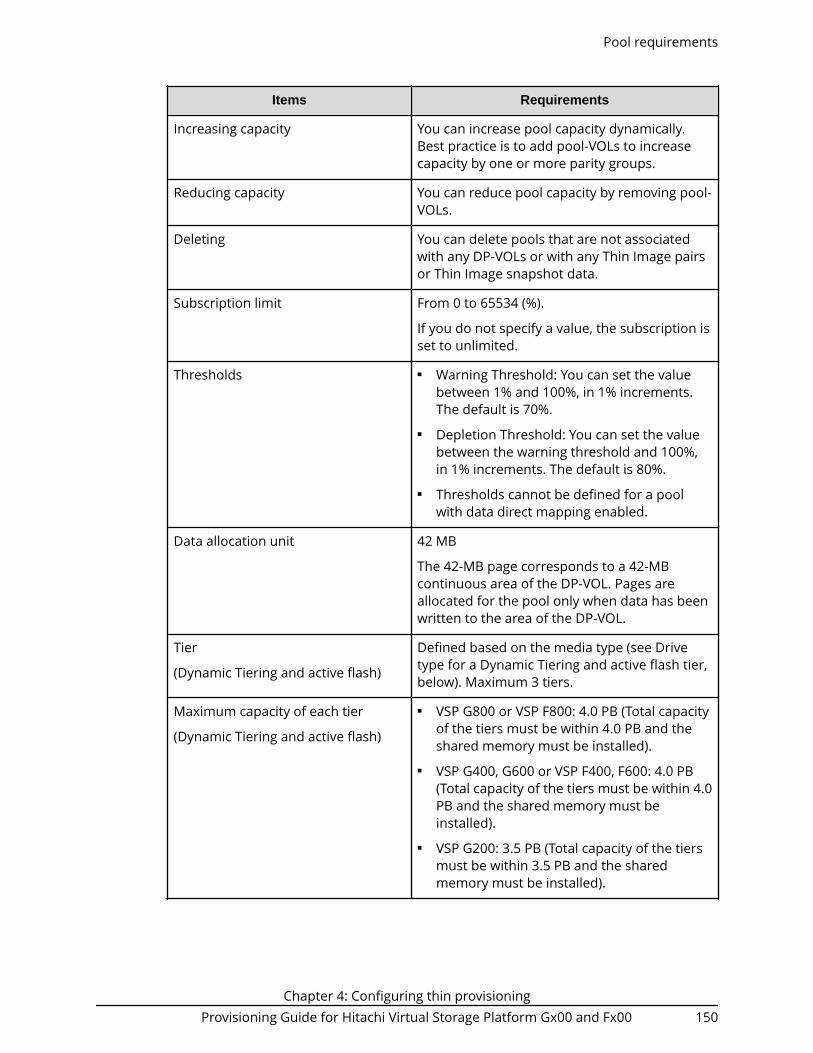
Items Requirements
Increasing capacity You can increase pool capacity dynamically.Best practice is to add pool-VOLs to increasecapacity by one or more parity groups.
Reducing capacity You can reduce pool capacity by removing pool-VOLs.
Deleting You can delete pools that are not associatedwith any DP-VOLs or with any Thin Image pairsor Thin Image snapshot data.
Subscription limit From 0 to 65534 (%).
If you do not specify a value, the subscription isset to unlimited.
Thresholds ■ Warning Threshold: You can set the valuebetween 1% and 100%, in 1% increments.The default is 70%.
■ Depletion Threshold: You can set the valuebetween the warning threshold and 100%,in 1% increments. The default is 80%.
■ Thresholds cannot be defined for a poolwith data direct mapping enabled.
Data allocation unit 42 MB
The 42-MB page corresponds to a 42-MBcontinuous area of the DP-VOL. Pages areallocated for the pool only when data has beenwritten to the area of the DP-VOL.
Tier
(Dynamic Tiering and active flash)
Defined based on the media type (see Drivetype for a Dynamic Tiering and active flash tier,below). Maximum 3 tiers.
Maximum capacity of each tier
(Dynamic Tiering and active flash)
■ VSP G800 or VSP F800: 4.0 PB (Total capacityof the tiers must be within 4.0 PB and theshared memory must be installed).
■ VSP G400, G600 or VSP F400, F600: 4.0 PB(Total capacity of the tiers must be within 4.0PB and the shared memory must beinstalled).
■ VSP G200: 3.5 PB (Total capacity of the tiersmust be within 3.5 PB and the sharedmemory must be installed).
Pool requirements
Chapter 4: Configuring thin provisioningProvisioning Guide for Hitachi Virtual Storage Platform Gx00 and Fx00 150

Pool-VOL requirements
Pool-VOLs make up a DP pool.
Item Requirements
Volume type Logical volume (LDEV)
While pool-VOLs can coexist with other volumes in the sameparity group, for best performance:■ Pool-VOLs for a pool should not share a parity group with
other volumes.■ Pool-VOLs should not be located on concatenated parity
groups.
Pool-VOLs cannot be used for any other purpose. For instance,you cannot specify the following volumes as DynamicProvisioning, Dynamic Tiering, and active flash pool-VOLs:■ Volumes used by ShadowImage, Volume Migration,
TrueCopy, global-active device, or Universal Replicator■ Volumes already registered in Thin Image, Dynamic
Provisioning, Dynamic Provisioning or active flash pools■ Volumes used as Thin Image P-VOLs or S-VOLs■ Volumes reserved by Data Retention Utility■ Data Retention Utility volumes with a Protect, Read Only, or
S-VOL Disable attribute■ LDEVs whose status is other than Normal, Correction
Access, or Copying. You cannot specify volumes in blockedstatus or volumes in copying process.
■ Command devices■ Quorum disks used by global-active device
The following volume cannot be specified as a pool-VOL forDynamic Tiering:■ An external volume with the data direct mapping attribute
enabled.
If pool-VOLs are LDEVs created from the parity group withaccelerated compression enabled, these pool-VOLs must beapplied to one pool.
Emulation type OPEN-V
Pool-VOL requirements
Chapter 4: Configuring thin provisioningProvisioning Guide for Hitachi Virtual Storage Platform Gx00 and Fx00 151

Item Requirements
RAID level for aDynamic Provisioningpool
All RAID levels of pool-VOLs can be added. Pool-VOLs of RAID5, RAID 6, RAID 1, and external volumes can coexist in thesame pool. For pool-VOLs in the same pool:■ RAID 6 is the recommended RAID level for pool-VOLs,
especially for a pool where the recovery time of a poolfailure due to a drive failure is not acceptable.
■ Pool-VOLs of the same drive type with different RAID levelscan coexist in the same pool. We recommend that you setone RAID level for pool-VOLs. If you register pool-VOLs withmultiple RAID levels to the same pool, the I/O performancedepends on the RAID levels of pool-VOLs to be registered.In that case, note the I/O performance of the drives.
RAID level for aDynamic Tiering oractive flash pool
All RAID levels of pool-VOLs can be added. Pool-VOLs of RAID5, RAID 6, RAID 1, and external volumes can coexist in thesame pool. For pool-VOLs in the same pool:■ RAID 6 is the recommended RAID level for pool-VOLs,
especially for a pool where the recovery time of a poolfailure due to a drive failure is not acceptable.
■ Pool-VOLs of the same drive type with different RAID levelscan coexist in the same pool. We recommend that you setone RAID level for pool-VOLs. If you register pool-VOLs withmultiple RAID levels to the same pool, the I/O performancedepends on the RAID levels of pool-VOLs to be registered.In that case, note the I/O performance of the drives.
■ Because the speed of RAID 6 is slower than other RAIDlevels, tiers that use other RAID levels should not be placedunder a tier that uses RAID 6.
Pool-VOL requirements
Chapter 4: Configuring thin provisioningProvisioning Guide for Hitachi Virtual Storage Platform Gx00 and Fx00 152

Item Requirements
Data drive type for aDynamic Provisioningpool
SSD*, SAS15K, SAS10K, SAS7.2K, and external volumes can beused as the data drive type. These data drive types can coexistin the same pool.
* SSD includes FMC, FMD, and MLC. VSP Fx00 models only SSDcan be specified.
Cautions:■ Best practice is for drives of different types not to coexist in
the same pool. If multiple pool-VOLs with different drivetypes are registered in the same pool, the I/O performancedepends on the drive type of the pool-VOL to which thepage is assigned. Therefore, if different drive types areregistered in the same pool, ensure that the required I/Operformance is not degraded by using less desirable drivetypes.
■ If multiple data drives coexist in the same pool, werecommend not using data drives that are the same typesand different capacities.
Data drive type for aDynamic Tiering oractive flash pool
SAS15K, SAS10K, SAS7.2K, SSD*, and external volumes can beused as the data drive type. These data drive types can coexistin the same pool. If active flash is used, SSDs must be installedin advance.
* SSD includes FMC, FMD, and MLC. VSP Fx00 models only SSDcan be specified.
Caution: If multiple data drives coexist in the same pool, werecommend not using data drives that are the same types anddifferent capacity sizes.
Volume capacity Internal volume: From 8 GB to 2.9 TB
External volume: From 8 GB to 4 TB
External volume with the data direct mapping attribute: From8 GB to 256 TB
LDEV format The LDEV format operation can be performed on pool-VOLsonly when all of the following conditions are satisfied:■ There are no DP-VOLs defined for the pool, or all DP-VOLs
defined for the pool are blocked.■ The pool does not contain any Thin Image pairs or
snapshot data.
Path definition You cannot specify a volume with a path definition as a pool-VOL.
Pool-VOL requirements
Chapter 4: Configuring thin provisioningProvisioning Guide for Hitachi Virtual Storage Platform Gx00 and Fx00 153
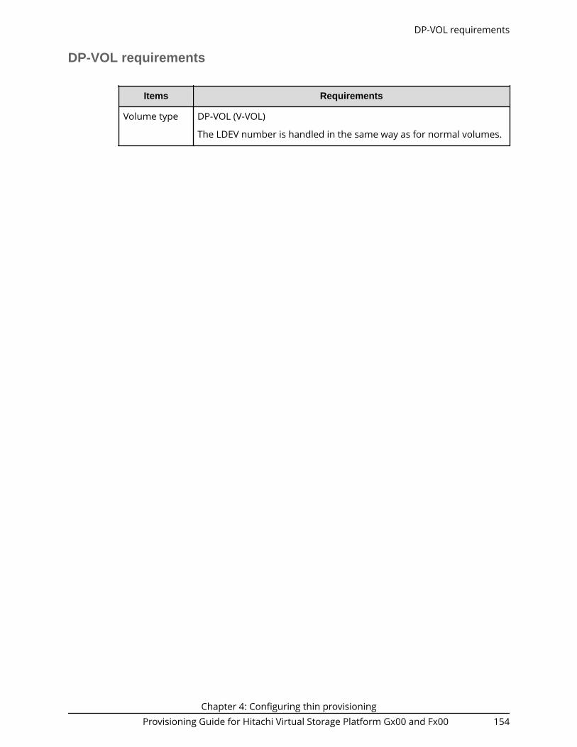
DP-VOL requirements
Items Requirements
Volume type DP-VOL (V-VOL)
The LDEV number is handled in the same way as for normal volumes.
DP-VOL requirements
Chapter 4: Configuring thin provisioningProvisioning Guide for Hitachi Virtual Storage Platform Gx00 and Fx00 154

Items Requirements
Maximumnumber of DP-VOLs
For VSP Fx00 models, only SSD can be specified.
For VSP G800 or VSP F800:■ Up to 14,080 per pool (For a pool with data direct mapping
enabled, up to 1,023 per pool). Any number of available DP-VOLscan be associated with a pool.
■ For a pool with Deduplication enabled, the maximum number ofDP-VOLs with Compression or Deduplication and Compressionenabled is 14,080.
■ For a pool with Deduplication disabled, the maximum number ofDP-VOLs with Compression enabled is 14,080.
■ Up to 14,080 volumes per system. If external volumes and V-VOLsare used, the total number of external volumes and V-VOLs mustbe 14,080 or fewer.
For VSP G400, G600 and VSP F400, F600:■ Up to 4,095 per pool (For a pool with data direct mapping enabled,
up to 1,023 per pool). Any number of available DP-VOLs can beassociated with a pool.
■ For a pool with Deduplication enabled, the maximum number ofDP-VOLs with Compression or Deduplication and Compressionenabled is 3,960.
■ For a pool with Deduplication disabled, the maximum number ofDP-VOLs with Compression enabled is 3,967.
■ Up to 4,095 volumes per system. If external volumes and V-VOLsare used, the total number of external volumes and V-VOLs mustbe 4,095 or fewer.
For VSP G200:■ Up to 2,047 per pool (For a pool with data direct mapping enabled,
up to 1,023 per pool). Any number of available DP-VOLs can beassociated with a pool.
■ For a pool with Deduplication enabled, the maximum number ofDP-VOLs with Compression or Deduplication and Compressionenabled is 1,912.
■ For a pool with Deduplication disabled, the maximum number ofDP-VOLs with Compression enabled is 1,919.
■ Up to 2,047 volumes per system. If external volumes and V-VOLsare used, the total number of external volumes and V-VOLs mustbe 2,047 or fewer.
DP-VOL requirements
Chapter 4: Configuring thin provisioningProvisioning Guide for Hitachi Virtual Storage Platform Gx00 and Fx00 155

Items Requirements
Volumecapacity
Volume capacity from 46.87 MB to 256 TB per volume.■ TB: 0.01 to 256■ GB: 0.04 to 262,144■ MB: 46.87 to 268,435,456■ Blocks: 96,000 to 549,755,813,888
Total maximum volume capacity is as follows:■ VSP G800 or VSP F800: 6.5 PB (the shared memory must be
installed)■ VSP G400, G600 or VSP F400, F600: 6.5 PB (the shared memory
must be installed)■ VSP G200: 3.5 PB (the shared memory must be installed)
Path definition Available.
LDEV format Available. Quick Format is not available.
System option mode (SOM) 867 ON: When you format an LDEV on aDP-VOL, the capacity mapped to the DP-VOL is released to the pool asfree space.
When you format a DP-VOL, the storage system releases the allocatedpage area in the DP-VOL. The quick format operation cannot beperformed. If the LDEV format is applied to V-VOLs that are enabledfor full allocation, the used capacity of the pool is not changed beforethe LDEV format is applied.
Caution:■ For a DP-VOL with deduplication and compression enabled, a
deduplication system data volume whose LDEV status is Blockedcannot be formatted.
■ For a DP-VOL with deduplication and compression enabled, adeduplication system data volume whose capacity saving status isFailed cannot be formatted.
Deduplication system data volume requirements
When you enable deduplication on a pool, the deduplication system data volume (DSDvolume) for the pool is created. The deduplication system data volume is usedexclusively by the storage system to manage the data deduplication function. Thededuplication system data volume for a pool is deleted automatically when you disablethe Capacity Saving setting for the pool or delete the pool.
The following table lists the requirements for the deduplication system data volume.
Deduplication system data volume requirements
Chapter 4: Configuring thin provisioningProvisioning Guide for Hitachi Virtual Storage Platform Gx00 and Fx00 156

Items Requirements
Volume type DP-VOL (V-VOL)
Emulationtype
OPEN-V
Number perpool
One deduplication system data volume per pool (fixed)
Volumecapacity
40 TB (fixed)
Path definition Not available
LDEV format Available
Warning: Format a deduplication system data volume only when youwant to delete all deduplication-enabled DP-VOLs in the associatedpool. After the deduplication system data volume has beenformatted, all deduplication-enabled DP-VOLs assigned to the poolare not usable and must be formatted and deleted.
When you format a deduplication system data volume, you mustspecify only one deduplication system data volume and no othervolumes in the Format LDEVs window.
Resourcegroup
A deduplication system data volume and its associated pool volumesmust be in the same resource group.
Cachemanagementdevices
Each deduplication system data volume uses 14 cache managementdevices.
Pool capacity consumed by metadata
When you use the capacity saving function, the following two kinds of capacities areconsumed for the pool capacity:■ Used capacity of the pool consumed by user data■ Used capacity of the pool consumed by metadata
Metadata for the compression function. When the compression function is enabled,2% of the total used capacity of the compression-enabled DP-VOLs is consumed as themetadata for the compression function. The capacity of the metadata for thecompression function is added to the used capacity of the pool. To view the usedcapacity of the pool, see Pool Capacity (Used/Total) in the Pools window.
Metadata for the deduplication function. When the deduplication function is enabled,the capacity of the metadata of the deduplication function depends on the total usedcapacity of the deduplication-enabled DP-VOLs. The metadata of the deduplicationfunction is stored in the deduplication system data volume. To view the capacity of themetadata for the deduplication function, see the capacity of the deduplication system
Pool capacity consumed by metadata
Chapter 4: Configuring thin provisioningProvisioning Guide for Hitachi Virtual Storage Platform Gx00 and Fx00 157

data volume displayed on the Edit Deduplication System Data Volume window. Thecapacity of the metadata of the deduplication function is added to the used capacity ofthe pool. To view the used capacity of the pool, see Pool Capacity (Used/Total) in thePools window.
The following table shows the relationship between the total used capacity ofdeduplication-enabled DP-VOLs and the capacity of the metadata of the deduplicationfunction.
Total usedcapacity ofDP-VOLs to
bededuplicated Capacity of the metadata of the deduplication function
Less than 32GB
Up to 4.0 GB
64 GB 4.1 GB
100 GB 4.2 GB
256 GB 4.9 GB
512 GB 5.9 GB
1,024 GB 7.9 GB
2,048 GB 11.9 GB
4,096 GB ormore
19.9 GB or more
Requirements for increasing DP-VOL capacity
You can increase the capacity of a DP-VOL up to 256 TB.
To notify the host that the DP-VOL capacity has been increased, make sure host modeoption 40 is enabled. Processing differs as follows, depending on the value of host modeoption 40:■ When host mode option 40 is not enabled, the host will not be notified that the DP-
VOL capacity has been increased. Therefore, the DP-VOL data has to be read again bythe host after the capacity is increased.
■ When host mode option 40 is enabled, the host is notified that the DP-VOL capacityhas increased. If the operating system cannot recognize the value of capacity that wasincreased, the DP-VOL data has to be read again by your storage system.
The following requirements are important when increasing the DP-VOL capacity:■ The DP-VOL to be increased is not shared with a software product that does not allow
increasing the volume capacity (see Increasing DP-VOL capacity (on page 298) ).■ The DP-VOL is not undergoing LDEV formatting.■ The DP-VOL does not have data direct mapping enabled.
Requirements for increasing DP-VOL capacity
Chapter 4: Configuring thin provisioningProvisioning Guide for Hitachi Virtual Storage Platform Gx00 and Fx00 158

■ The DP-VOL is not a deduplication system data volume.■ The capacity to be added to the DP-VOL must be specified within the range indicated
below LDEV Capacity in the Expand V-VOLs window.■ The pool related to the DP-VOLs to be increased is in any one of the following
statuses:● Normal● Exceeding the subscription limit threshold● In progress of pool capacity shrinking
Caution: When increasing DP-VOL capacity, do not perform the followingoperations. When you perform these operations, do not increase DP-VOLcapacity.■ Operations using Virtual LUN■ Creating DP-VOLs■ Restoring pools■ Deleting DP-VOLs■ Operations to increase the DP-VOL capacity in another instance of CCI■ Maintenance of your storage system
After increasing DP-VOL capacity, refresh the display and confirm that the DP-VOL isincreased. If the DP-VOL capacity is not increased, wait a while, refresh the display again,and confirm that the DP-VOL is increased. If you perform an operation without makingsure that the DP-VOL is increased, operations from Device Manager - Storage Navigatormay fail.
If one of the following operations is being performed, the DP-VOL capacity might not beincreased:■ Volume Migration■ Configuration change of journal used by Universal Replicator■ Quick Restore by ShadowImage
Estimating the required capacity of pool-VOLs with system area in thepool with data direct mapping enabled
If you want to expand a pool for which data direct mapping is enabled, you must free upspace in the pool. Make sure that the estimated capacity of free space is available beforeexpanding the pool.
Use the following mathematical formulas to estimate the capacity of free space requiredin the pool:■ Formula 1:
Required-free-space-for-a-pool-to-be-added-of-one-external-volume-of-the-data-direct-mapping-attribute [in MB] = (ceiling (pool-VOL-capacity [in MB] / 3,145,548 MB) * 4 pages * 42 MB) + ( ceiling (pool-VOL-capacity [in MB] / 42 MB) - floor (pool-VOL-capacity [in MB] / 42 MB) )
Estimating the required capacity of pool-VOLs with system area in the pool with data direct mappingenabled
Chapter 4: Configuring thin provisioningProvisioning Guide for Hitachi Virtual Storage Platform Gx00 and Fx00 159

* 42MB
■ Formula 2:
Required-capacity-of-pool-VOL-with-system-area-in-one-pool-of-a-data-direct-mapping-attribute [in MB] = Total-of-calculated-values-by-the-Formula-1-for-each-volume + Management area (4200) [in MB] + 42 [in MB]
where■ ceiling: The value enclosed in ceiling( ) must be rounded up to the nearest whole
number.■ floor: The value enclosed in floor( ) must be rounded down to the nearest whole
number.
Note:
A DP-VOL with data direct mapping attribute uses the following capacities:■ Mapped capacity uses multiple of 42 MB in the capacity of the pool
volume as well as the capacity for one page (the area of the capacity otherthan multiples of 42 MB).
■ Control information (168 MB is used per 3,145,548 MB)
The pool-VOL with the system area contains the one page capacity andcontrol information.
V-VOL page reservation requirement
The V-VOL full allocation is performed in a range less than the depletion threshold size ofthe pool. If the capacity of V-VOLs is larger than the depletion threshold size, the fullallocation operation is rejected.
Caution: The page reservation function is not supported by the followingpools. To prevent data writing from being disabled due to pool overflow, youmust monitor the free area of these pools frequently.■ Pools that contain pool volumes belonging to a parity group with
accelerated compression enabled■ Pools with capacity saving enabled
Use the following formula to calculate the reserved page capacity for each pool. In theformula, the value enclosed in ceiling( ) must be rounded up to the nearest wholenumber.
Reserved capacity for each pool [block] =ceiling(CV-capacity-of-V-VOL [block] / 86016) * 86016 + ceiling(CV-capacity-of-V-VOL [block] /6442082304) * 4 * 86016 - used-capacity-of-V-VOL [block]
V-VOL page reservation requirement
Chapter 4: Configuring thin provisioningProvisioning Guide for Hitachi Virtual Storage Platform Gx00 and Fx00 160

Operating system and file system capacity
When initializing a DP-VOL operating systems and file systems will consume someDynamic Provisioning pool space. Some combinations initially take up little pool space,while other combinations take as much pool space as the virtual capacity of the DP-VOL.
The following table shows the effects of some combinations of operating system and filesystem capacity. For more information, contact your service representative.
OS File System Metadata Writing Pool Capacity Consumed
Windows Server2003, WindowsServer 2008*
NTFS Writes metadata tofirst block.
Effective reduction of poolcapacity: Small (one page)
If file update is repeated,allocated capacity increaseswhen files are updated(overwritten). Therefore, theeffectiveness of reducingthe pool capacityconsumption decreases.
Linux XFS Writes metadata inAllocation Group Sizeintervals.
Effective reduction of poolcapacity: Depends uponallocation group size. Theamount of pool spaceconsumed will beapproximately [DP-VOL Size]× [42 MB/Allocation GroupSize]
Ext2
Ext3
Writes metadata in128-MB increments.
Effective reduction of poolcapacity: About 33% of thesize of the DP-VOL.
The default block size forthese file systems is 4 KB.This results in 33% of theDP-VOL acquiring DP poolpages. If the file systemblock size is changed to 2 KBor less then the DP-VOLPage consumption becomes100%.
Solaris UFS Writes metadata in52-MB increments.
No effective reduction ofpool capacity.
Size of DP-VOL.
VxFS Writes metadata tothe first block.
Effective reduction of poolcapacity: Small (one page).
Operating system and file system capacity
Chapter 4: Configuring thin provisioningProvisioning Guide for Hitachi Virtual Storage Platform Gx00 and Fx00 161

OS File System Metadata Writing Pool Capacity Consumed
AIX JFS Writes metadata in 8-MB increments.
No effective reduction ofpool capacity.
Size of DP-VOL.
If you change the AllocationGroup Size settings whenyou create the file system,the metadata can be writtento a maximum interval of 64MB. Approximately 65% ofthe pool is used at thehigher group size setting.
JFS2 Writes metadata tothe first block.
Effective reduction of poolcapacity: Small (one page).
VxFS Writes metadata tothe first block.
Effective reduction of poolcapacity: Small (one page).
HP-UX JFS (VxFs) Writes metadata tothe first block.
Effective reduction of poolcapacity: Small (one page).
HFS Writes metadata in10-MB increments.
No effective reduction ofpool capacity.
Size of DP-VOL.
* In a Windows environment, both Normal Format and Quick Format are commonlyused. In this environment, Quick Format consumes less thin provisioning poolcapacities than Normal Format:■ On Windows Server 2008, using Normal Format issues Write commands to the
overall volume (for example, overall "D" drive). When Write commands are issued,pages corresponding to the overall volume are allocated, so pool capacitiescorresponding to the ones of the overall volume are consumed. In this case, thethin provisioning advantage of reducing capacities is lost.
■ Quick Format issues Write commands only to management information (forexample, index information). Therefore, pages corresponding to the managementinformation areas are allocated, but the capacities are smaller than the onesconsumed by Normal Format.
Operating system and file system capacity
Chapter 4: Configuring thin provisioningProvisioning Guide for Hitachi Virtual Storage Platform Gx00 and Fx00 162

Using Dynamic Provisioning and Dynamic Tiering with othersoftware products
Interoperability of DP-VOLs and pool-VOLs
DP-VOLs and pool-VOLs can be used in conjunction with other software products withcertain limitations and restrictions. The following table lists the software products andindicates the operations that are permitted and not permitted for each product.
Software product(user guide) Permitted Not permitted
Data Retention Utility(Provisioning Guide)
Performing operations onDP-VOLs.
■ Performing operations on DPpool-VOLs.
■ Performing operations on anexternal volume with datadirect mapping enabled.
■ Performing operations onLDEVs with acceleratedcompression enabled.
■ Performing operations on adeduplication system datavolume.
global-active device(Global-Active DeviceUser Guide)
Using a DP-VOL as a global-active device primaryvolume (P-VOL) orsecondary volume (S-VOL).
■ Using a DP-VOL as a quorumdisk.
■ Using a pool-VOL as a global-active device P-VOL or S-VOL.
■ Increasing the capacity of aDP-VOL used by global-activedevice.
■ Using an external volumewith data direct mappingenabled as a quorum disk.
■ Using a DP-VOL with datadirect mapping enabled as aquorum disk.
■ Using a deduplication systemdata volume as a global-active device P-VOL or S-VOL.
Using Dynamic Provisioning and Dynamic Tiering with other software products
Chapter 4: Configuring thin provisioningProvisioning Guide for Hitachi Virtual Storage Platform Gx00 and Fx00 163

Software product(user guide) Permitted Not permitted
LUN Manager(Provisioning Guide)
LUN Security(Provisioning Guide)
Performing operations onDP-VOLs.
■ Performing operations on DPpool-VOLs.
■ Performing operations on anexternal volume with datadirect mapping enabled.
■ Performing operations onLDEVs with acceleratedcompression enabled.
■ Performing operations on adeduplication system datavolume.
ShadowImage (HitachiShadowImage® UserGuide)
Using a DP-VOL as aShadowImage primaryvolume (P-VOL) orsecondary volume (S-VOL).
If a pool contains both theP-VOL and S-VOL of a pairand deduplication isenabled for the pool, onlyone copy of the P-VOL datais saved physically due todeduplication of the P-VOLand S-VOL data. If you wantto protect the P-VOL data,use separate pools for theP-VOL and S-VOL.
■ Using a pool-VOL as aShadowImage P-VOL or S-VOL.
■ Increasing the capacity of aDP-VOL used byShadowImage.
■ Reclaiming zero pages of aDP-VOL is determined by thepair status. For details, seeShadowImage pair status forreclaiming zero pages (onpage 168) .
■ Using a deduplication systemdata volume as aShadowImage P-VOL or S-VOL.
Interoperability of DP-VOLs and pool-VOLs
Chapter 4: Configuring thin provisioningProvisioning Guide for Hitachi Virtual Storage Platform Gx00 and Fx00 164

Software product(user guide) Permitted Not permitted
Thin Image (HitachiThin Image User Guide)
Using a DP-VOL as a ThinImage primary volume.
■ Using a DP-VOL as a ThinImage secondary volume orpool-VOL.
■ Using a Dynamic Provisioningor Dynamic Tiering pool-VOLas a Thin Image primaryvolume, secondary volume,or pool-VOL.
■ Increasing the capacity of aDynamic Provisioning,Dynamic Tiering, or activeflash DP-VOL that is used as aprimary volume or secondaryvolume of a Thin Image pair.
■ Reclaiming zero pages of ThinImage secondary volumeswith the cascade attributedisabled.
■ Reclaiming zero pages of ThinImage secondary volumeswith the cascade and cloneattributes enabled.Reclaiming zero pages can beperformed for Thin Imagesecondary volumes with thecascade and snapshotattributes enabled.
■ Using an external volumewith data direct mappingenabled as a Thin Imageprimary volume, secondaryvolume, or pool-VOL.
■ Using a normal LDEV withaccelerated compressionenabled as a primary volumeor secondary volume of aThin Image pair.
■ Using a deduplication systemdata volume as a primaryvolume or secondary volumeof a Thin Image pair.
Interoperability of DP-VOLs and pool-VOLs
Chapter 4: Configuring thin provisioningProvisioning Guide for Hitachi Virtual Storage Platform Gx00 and Fx00 165

Software product(user guide) Permitted Not permitted
TrueCopy (HitachiTrueCopy® User Guide)
Using a DP-VOL as aTrueCopy primary volume(P-VOL) or secondaryvolume (S-VOL).
For disaster recovery (DR)operations, apply the samecapacity saving setting tothe P-VOL and S-VOL of thepair by assuming failover.
■ Using a pool-VOL as aTrueCopy P-VOL or S-VOL.
■ Increasing the capacity of DP-VOL used as a P-VOL or S-VOLof a TrueCopy pair.
■ Using a deduplication systemdata volume as a TrueCopy P-VOL or S-VOL.
Universal Replicator(Hitachi UniversalReplicator User Guide)
Using a DP-VOL as aUniversal Replicatorprimary volume (P-VOL),secondary volume (S-VOL),or journal volume.However, the journalvolume must be a DP-VOLthat has OPEN-V emulationtype.
For disaster recovery (DR)operations, apply the samecapacity saving setting tothe P-VOL and S-VOL of thepair by assuming failover.
■ Using a DP pool-VOL as aUniversal Replicator P-VOL, S-VOL, or journal volume.
■ Increasing the capacity of aDP-VOL used as a P-VOL or S-VOL of a Universal Replicatorpair.
■ Reclaiming zero pages of aDP-VOL used by a journalvolume.
■ Using an external volumewith data direct mappingenabled as a journal volume.
■ Using a DP-VOL with datadirect mapping enabled as ajournal volume.
■ Using a DP-VOL with capacitysaving enabled (DRD volume)as a journal volume.
■ Using a deduplication systemdata volume (DSD volume) asa Universal Replicator P-VOLor S-VOL.
Interoperability of DP-VOLs and pool-VOLs
Chapter 4: Configuring thin provisioningProvisioning Guide for Hitachi Virtual Storage Platform Gx00 and Fx00 166
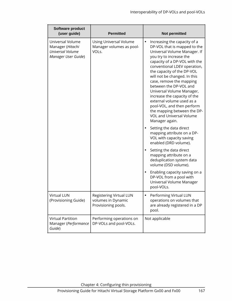
Software product(user guide) Permitted Not permitted
Universal VolumeManager (HitachiUniversal VolumeManager User Guide)
Using Universal VolumeManager volumes as pool-VOLs.
■ Increasing the capacity of aDP-VOL that is mapped to theUniversal Volume Manager. Ifyou try to increase thecapacity of a DP-VOL with theconventional LDEV operation,the capacity of the DP-VOLwill not be changed. In thiscase, remove the mappingbetween the DP-VOL andUniversal Volume Manager,increase the capacity of theexternal volume used as apool-VOL, and then performthe mapping between the DP-VOL and Universal VolumeManager again.
■ Setting the data directmapping attribute on a DP-VOL with capacity savingenabled (DRD volume).
■ Setting the data directmapping attribute on adeduplication system datavolume (DSD volume).
■ Enabling capacity saving on aDP-VOL from a pool withUniversal Volume Managerpool-VOLs.
Virtual LUN(Provisioning Guide)
Registering Virtual LUNvolumes in DynamicProvisioning pools.
■ Performing Virtual LUNoperations on volumes thatare already registered in a DPpool.
Virtual PartitionManager (PerformanceGuide)
Performing operations onDP-VOLs and pool-VOLs.
Not applicable
Interoperability of DP-VOLs and pool-VOLs
Chapter 4: Configuring thin provisioningProvisioning Guide for Hitachi Virtual Storage Platform Gx00 and Fx00 167

Software product(user guide) Permitted Not permitted
Volume Migration
(For details, contactcustomer support.)
Using a DP-VOL as amigration source or amigration target.
The maximum capacity of aDP-VOL used as amigration source or targetis the same as themaximum capacity of a DP-VOL.
■ Using on pool-VOLs.■ Increasing the capacity of DP-
VOL used by VolumeMigration.
■ Reclaiming zero pages of V-VOL used by VolumeMigration.
■ Using on a deduplicationsystem data volume.
Volume Shredder(Hitachi VolumeShredder User Guide)
Use on DP-VOLs. ■ Using on pool-VOLs.■ Performing operations on an
LDEV that has acceleratedcompression enabled.
■ Increasing the capacity of DP-VOL used by VolumeShredder.
■ Reclaiming zero pages of V-VOL used by VolumeShredder.
■ Performing operations on aDP-VOL with capacity savingenabled (DRD volume).
■ Performing operations on adeduplication system datavolume.
ShadowImage pair status for reclaiming zero pages
You can use this table to determine whether reclaiming zero pages is possible for aparticular pair status
Pair status
Reclaim zeropages from HitachiDevice Manager -Storage Navigator
Reclaim zero pages from CommandControl Interface
SMPL, status of anunpaired volume
Enabled Enabled
COPY(PD)/COPY Disabled Disabled
ShadowImage pair status for reclaiming zero pages
Chapter 4: Configuring thin provisioningProvisioning Guide for Hitachi Virtual Storage Platform Gx00 and Fx00 168

Pair status
Reclaim zeropages from HitachiDevice Manager -Storage Navigator
Reclaim zero pages from CommandControl Interface
PAIR Disabled Disabled
COPY(SP) Disabled Disabled
PSUS(SP)/PSUS Disabled Disabled
PSUS Enabled Enabled
COPY(RS)/COPY Disabled Disabled
COPY(RS-R)/RCPY Disabled Disabled
PSUE Disabled Disabled
TrueCopy
You can use Dynamic Provisioning, Dynamic Tiering, or active flash in combination withTrueCopy to replicate V-VOLs.
The following figure illustrates the interaction when the TrueCopy primary volume andsecondary volume are also V-VOLs.
TrueCopy P-VOL TrueCopy S-VOL Explanation
DP-VOLs DP-VOLs Supported.
DP-VOLs Normal (ordinary)volumes1
Supported.
Normal (ordinary)volumes1
DP-VOLs Supported.
Note, however, that this combinationconsumes the same amount of poolcapacity as the original normal volume(primary volume).
TrueCopy
Chapter 4: Configuring thin provisioningProvisioning Guide for Hitachi Virtual Storage Platform Gx00 and Fx00 169

TrueCopy P-VOL TrueCopy S-VOL Explanation
Note:
1. Normal volumes include the internal volumes and external volumes that aremapped to the volumes of the external storage system using Universal VolumeManager. For more information about external volumes, see the Hitachi UniversalVolume Manager User Guide.
You cannot specify a Dynamic Provisioning, Dynamic Tiering, or active flash pool-VOL asa primary volume or secondary volume.
Global-active device
You can use Dynamic Provisioning, Dynamic Tiering, or active flash in combination withglobal-active device to replicate V-VOLs. The following figure illustrates the interactionwhen the global-active device primary volume and secondary volume are also V-VOLs.
Global-active device P-VOL
Global-active device S-VOL Explanation
DP-VOLs DP-VOLs Supported.
DP-VOLs Normal (ordinary)volumes1
Not supported.
Normal (ordinary)volumes1
DP-VOLs Not supported.
Note:
1. Normal volumes include the internal volumes and external volumes that aremapped to the volumes of the external storage system using by Universal VolumeManager. For more information about external volumes, see the Hitachi UniversalVolume Manager User Guide.
You cannot specify a Dynamic Provisioning, Dynamic Tiering, or active flash pool-VOL asa primary volume or secondary volume. For more information, see the Global-ActiveDevice User Guide.
Global-active device
Chapter 4: Configuring thin provisioningProvisioning Guide for Hitachi Virtual Storage Platform Gx00 and Fx00 170

Universal Replicator
You can use Dynamic Provisioning, Dynamic Tiering, or active flash in combination withUniversal Replicator to replicate DP-VOLs.
The following table lists the supported Universal Replicator and Dynamic Provisioning,Dynamic Tiering or active flash volume combinations.
UniversalReplicator P-VOL
UniversalReplicator S-
VOL
UniversalReplicator
journal volume Explanation
DP-VOLs DP-VOLs DP-VOL that hasthe OPEN-Vemulation type
Supported.
DP-VOLs Normal(ordinary)volumes1
DP-VOL that hasthe OPEN-Vemulation type
Supported.
Normal (ordinary)volumes1
DP-VOLs DP-VOL that hasthe OPEN-Vemulation type
Supported.
Note, however, that thiscombination consumes thesame amount of poolcapacity as the originalnormal volume (primaryvolume).
Notes:
1. Normal volumes include the internal volumes and external volumes that aremapped to the volumes of the external storage system using Universal VolumeManager. For more information about external volumes, see the Hitachi UniversalVolume Manager User Guide.
You cannot specify a Dynamic Provisioning, Dynamic Tiering, or active flash pool-VOL asa primary volume, secondary volume, or journal volume.
ShadowImage
You can use Dynamic Provisioning, Dynamic Tiering, or active flash in combination withShadowImage to replicate DP-VOLs.
Universal Replicator
Chapter 4: Configuring thin provisioningProvisioning Guide for Hitachi Virtual Storage Platform Gx00 and Fx00 171

The following table lists the interaction when the ShadowImage primary volume andsecondary volume are also DP-VOLs.
ShadowImage P-VOL
ShadowImage S-VOL Explanation
DP-VOLs DP-VOLs Supported.
DP-VOLs Normal (ordinary)volumes1
Supported.
The Quick Restore function is unavailable.
Normal (ordinary)volumes1
DP-VOLs Supported.
Note, however, that this combinationconsumes the same amount of poolcapacity as the normal volume.
The Quick Restore function is unavailable.
Note:
1. Normal volumes include the internal volumes and external volumes that aremapped to the volumes of the external storage system using Universal VolumeManager. For more information about external volumes, see the Hitachi UniversalVolume Manager User Guide.
You cannot specify a Dynamic Provisioning, Dynamic Tiering or active flash pool-VOL as aprimary volume or secondary volume.
Volume Migration
You can use Dynamic Provisioning or Dynamic Tiering in combination with VolumeMigration to migrate DP-VOLs.
The following shows the interaction when the Volume Migration source volume andtarget volume are also DP-VOLs.
Volume Migration
Chapter 4: Configuring thin provisioningProvisioning Guide for Hitachi Virtual Storage Platform Gx00 and Fx00 172

Volume Migrationsource volume
Volume Migrationtarget volume Explanation
DP-VOLs DP-VOLs Supported.
DP-VOLs Normal (ordinary)volumes*
Supported.
Normal (ordinary)volumes*
DP-VOLs Supported.
Note, however, that this combinationconsumes the same amount of poolcapacity as the normal volume.
*Normal volumes include the internal volumes and external volumes that are mappedto the volumes of the external storage system by Universal Volume Manager. For moreinformation about external volumes, see the Hitachi Universal Volume Manager UserGuide.
You cannot specify a Dynamic Provisioning or Dynamic Tiering pool-VOL as a VolumeMigration source volume and target volume.
If you specify the DP-VOL as the source volume, you must not specify the DP-VOL thatuses the same pool of the source volume.
For details about the migration of DP-VOLs used in the following pairs, see Hitachi VolumeMigration User Guide.■ ShadowImage■ Universal Replicator
Interoperability restrictions for Thin Image
When you are using Thin Image and Dynamic Provisioning, Dynamic Tiering, or activeflash in the same storage system, the following interoperability restrictions apply.■ The maximum total number of pools per storage system, including Thin Image,
Dynamic Provisioning, Dynamic Tiering, and active flash pools, is 128.■ A Thin Image pool-VOL cannot be shared with Dynamic Provisioning, Dynamic Tiering,
or active flash.
Interoperability restrictions for Thin Image
Chapter 4: Configuring thin provisioningProvisioning Guide for Hitachi Virtual Storage Platform Gx00 and Fx00 173

Virtual Partition Manager CLPR setting
If DP-VOLs and pool-VOLs related to the same pool are assigned to a CLPR, the DP-VOLsand pool-VOLs in the same pool should be assigned to the same CLPR.
For details about CLPRs, see the Performance Guide.
Dynamic Provisioning workflowThe following diagram shows the workflow for setting up Dynamic Provisioning on thestorage system.
Use Device Manager - Storage Navigator or Command Control Interface to create poolsand DP-VOLs.
Dynamic Tiering and active flashHitachi Dynamic Tiering (HDT) simplifies storage administration by automaticallyoptimizing data placement in 1, 2, or 3 tiers of storage that can be defined and usedwithin a single virtual volume. Tiers of storage can be made up of internal or external(virtualized) storage, and use of HDT can lower capital costs. Simplified and unifiedmanagement of HDT allows for lower operational costs and reduces the challenges ofensuring applications are placed on the appropriate classes of storage.
Virtual Partition Manager CLPR setting
Chapter 4: Configuring thin provisioningProvisioning Guide for Hitachi Virtual Storage Platform Gx00 and Fx00 174

About tiered storage
In a tiered storage environment, storage tiers can be configured to accommodatedifferent categories of data. A tier is a group of storage media (pool volumes) in a DPpool. Tiers are determined by a single storage media type. A storage tier can be one typeof data drive, including SSD, SAS, or external volumes. Media of high-speed performancemake up the upper tiers. Media of low-speed response become the lower tiers. Up to amaximum of three tiers can coexist in each Dynamic Tiering pool.
Categories of data may be based on levels of protection needed, performancerequirements, frequency of use, and other considerations. Using different types ofstorage tiers helps reduce storage costs and improve performance.
Because assigning data to particular media may be an ongoing and complex activity,Dynamic Tiering software automatically manages the process based on user-definedpolicies.
As an example of the additional implementation of tiered storage, tier 1 data (such asmission-critical or recently accessed data) might be stored on expensive and high-qualitymedia such as double-parity RAIDs (redundant arrays of independent disks). Tier 2 data(such as financial or seldom-used data) might be stored on less expensive storage media.
Tier monitoring and data relocation
Dynamic Tiering uses tiers to manage data storage. It classifies the specified drives in thepool into tiers (storage hierarchy). Up to three tiers can be defined in a pool dependingon the processing capacity of the data drives. Tiering allocates more frequently accesseddata to the upper tier and less frequently accessed data, stored for a long period of time,to the lower tier.
Multi-tier pool
With Dynamic Tiering, you can enable the Multi-Tier pool option for an existing pool. Thedefault is to allow tier relocation for each DP-VOL. Only the DP-VOLs for which tierrelocation is enabled are subject to calculation of the tier range value, and tier relocationwill be performed on them. If tier relocation is disabled for all DP-VOLs in a pool, tierrelocation is not performed.
The following figure illustrates the relationship between multi-tier pool and tierrelocation.
About tiered storage
Chapter 4: Configuring thin provisioningProvisioning Guide for Hitachi Virtual Storage Platform Gx00 and Fx00 175

Example of adding a tier
If the added pool-VOL is a different media type, then a new tier is created in the pool.The tier is added to the appropriate position according to its performance. The followingfigure illustrates the process of adding a tier.
Example of deleting a tier
If a tier no longer has any pool-VOLs when you delete them, the tier is deleted from thepool. The following figure illustrates deleting a tier.
How the tier relocation process works
The term tier relocation refers to the process of determining the appropriate storage tierand migrating the pages to that tier. The following figure shows the tier relocationprocess.
Explanation of the tier relocation process:
1. Allocate pages and map them to DP-VOLs
Pages are allocated and mapped to DP-VOLs on an on-demand basis. Pageallocation occurs when a write is performed to an area of any DP-VOL that does not
How the tier relocation process works
Chapter 4: Configuring thin provisioningProvisioning Guide for Hitachi Virtual Storage Platform Gx00 and Fx00 176

already have a page mapped to that location. Normally, a free page is selected forallocation from an upper tier with a free page. If the capacity of the upper tier isinsufficient for the allocation, the pages are allocated to the nearest lower tier. ADP-VOL set to a tier policy is assigned a new page that is based on the tier policysetting. The relative tier for new page allocations can be specified during operationsto create and edit LDEVs. If the capacity of all the tiers is insufficient, an errormessage is sent to the host.
2. Gather I/O load information of each page
Performance monitoring gathers monitoring information of each page in a pool todetermine the physical I/O load per page in a pool. I/Os associated with pagerelocation, however, are not counted.
3. Create frequency distribution graph
The frequency distribution graph, which shows the relationship between I/O counts(I/O load) and capacity (total number of pages), is created.
You can use the View Tier Properties window to view this graph. The vertical scaleof the graph indicates ranges of I/Os per hour and the horizontal scale indicates acapacity that received the I/O level. Note that the horizontal scale is accumulative.
Caution: When the number of I/Os is counted, the number of I/Ossatisfied by cache hits are not counted. Therefore, the number of I/Oscounted by Performance Monitoring is different from the number of I/Osfrom the host. The number of I/Os per hour is shown in the graph. If themonitoring time is less than an hour, the number of I/Os shown in thegraph might be higher than the actual number of I/Os.
Monitoring mode settings of Period or Continuous influences the values shown onthe performance graph. Period mode will report the most recent completedmonitor cycle I/O data on the performance graph. Continuous mode will report aweighted average of I/O data that uses recent monitor cycle data, along withhistorical data on the performance graph.
4. Determine the tier range values
The page is allocated to the appropriate tier according to performance monitoringinformation. The tier is determined as follows.
a. Determine the tier boundary
The tier range value of a tier is calculated using the frequency distributiongraph. This acts as a boundary value that separates tiers.
The pages of higher I/O load are allocated to the upper tier in sequence. Tierrange is defined as the lowest I/Os per hour (IOPH) value at which the totalnumber of stored pages matches the capacity of the target tier (less somebuffer percentage) or the IOPH value that will reach the maximum I/O load thatthe tier should process. The maximum I/O load that should be targeted to atier is the limit performance value, and the rate of I/O to the limit performancevalue of a tier is called the performance utilization percent. A performanceutilization of 100% indicates that the target I/O load to a tier is beyond theforecasted limit performance value.
Caution: The limit performance value is proportional to thecapacity of the pool volumes used in the tier. The total capacity of
How the tier relocation process works
Chapter 4: Configuring thin provisioningProvisioning Guide for Hitachi Virtual Storage Platform Gx00 and Fx00 177

the parity group should be used for a pool to further improve thelimit performance.
b. Determine the tier delta values
The tier range values are set as the lower limit boundary of each tier. The deltavalues are set above and below the tier boundaries (+10 to 20%) to preventpages from being migrated unnecessarily. If all pages subject to tier relocationcan be contained in the upper tier, both the tier range value (lower limit) andthe delta value will be zero.
c. Determine the target tier of a page for relocation.
The IOPH recorded for the page is compared against the tier range value todetermine the tier to which the page moves.
5. Migrate the pages
The pages are moved to the appropriate tier. After migration, the page usage ratesare averaged out in all tiers. I/Os that occur in the page migration are notmonitored.
Tier monitoring and relocation cycles
Performance monitoring and tier relocation can be set to execute in one of twoexecution modes: Auto and Manual. You can set up execution modes, or switch betweenmodes by using either Hitachi Device Manager - Storage Navigator or Command ControlInterface.
In Auto execution mode, monitoring and relocation are continuous and automaticallyscheduled. In Manual execution mode, the following operations are initiated manually.■ Start monitoring■ Stop monitoring and recalculate tier range values■ Start relocation■ Stop relocation
In both execution modes, relocation of data is automatically determined based onmonitoring results. The settings for these execution modes can be changednondisruptively while the pool is in use.
Tier monitoring and relocation cycles
Chapter 4: Configuring thin provisioningProvisioning Guide for Hitachi Virtual Storage Platform Gx00 and Fx00 178

Auto execution mode
Auto execution mode performs monitoring and tier relocation based on informationcollected by monitoring at a specified constant frequency: every 0.5, 1, 2, 4, or 8 hours.All auto execution mode cycle frequencies have a starting point at midnight (00:00). Forexample, if you select a 1 hour monitoring period, the starting times would be 00:00,01:00, 02:00, 03:00, and so on.
As shown in the following table, the 24-hour monitoring cycle allows you to specify thetimes of day to start and stop performance monitoring. The 24-hour monitoring cycledoes not have to start at midnight. Tier relocation begins at the end of each cycle.
Monitoring cycle(hours) Start Times Finish Times
0.5 0.5 hours from 00:00 AM. Forexample 00:00, 00:30, and01:00
0.5 hours after the start time
1 1 hour from 00:00 AM. Forexample 00:00, 01:00, and02:00
1 hour after the start time
2 2 hours from 00:00 AM. Forexample 00:00, 02:00, and04:00
2 hours after the start time
4 4 hours from 00:00 AM. Forexample 00:00, 04:00, and08:00
4 hours after the start time
8 8 hours from 00:00 AM. Forexample 00:00, 08:00, and16:00
8 hours after the start time
24 (monitoring timeperiod can bespecified)
Specified time Specified time
If the setting of the monitoring cycle is changed, performance monitoring begins at thenew start time. The collection of monitoring information and tier relocation operationsalready in progress are not interrupted when the setting is changed.
Example 1: If the monitoring cycle is changed from 1 hour to 4 hours at 01:30 AM, thecollection of monitoring information and tier relocation in progress at 01:30 AMcontinues. At 02:00 AM and 03:00 AM, however, monitoring information is not collectedand tier relocation is not performed. From 04:00 AM, the collection of monitoringinformation and tier relocation operations are started again. These operations are thenperformed at 4-hour intervals.
Example 2: If the monitoring cycle is changed from 4 hours to 1 hour at 01:30 AM, thecollection of monitoring information and tier relocation in progress at 01:30 AMcontinues. From 04:00 AM, the collection of monitoring information and tier relocationoperations are started again. These operations are then performed at 1-hour intervals.
Auto execution mode
Chapter 4: Configuring thin provisioningProvisioning Guide for Hitachi Virtual Storage Platform Gx00 and Fx00 179

In auto execution mode, the collection of monitoring data and tier relocation operationsare performed in parallel in the next cycle. Data from these parallel processes are storedin two separate fields.■ Data while monitoring is in progress in the next cycle.■ Fixed monitoring information used in the tier relocation.
Manual execution mode
You can start and stop performance monitoring and tier relocation at any time. Youshould keep the duration of performance monitoring to less than 7 days (168 hours). Ifperformance monitoring exceeds 7 days, then monitoring stops automatically.
Manual execution mode starts and ends monitoring and relocation at the time thecommand is issued. You can use scripts, which provide flexibility to control monitoringand relocation tasks based on a schedule for each day of the week.
In manual execution mode, the next monitoring cycle can be started with the collectionof monitoring data and tier relocation operations performed in parallel. Data from theseparallel processes are stored in two separate fields.■ Data while monitoring is in progress in the next cycle.■ Fixed monitoring information used in the tier relocation.
The following figure illustrates the collection of monitoring data to tier relocationworkflow in manual execution mode.
Manual execution mode
Chapter 4: Configuring thin provisioningProvisioning Guide for Hitachi Virtual Storage Platform Gx00 and Fx00 180

Case 1: If the second collection of the monitoring information is finished during the firsttier relocation, the latest monitoring information is the second collection. In that case,the first collection of monitoring information is referenced only after the first tierrelocation has completed.
Case 2: When tier relocation is performed with the first collection of monitoringinformation, the second collection of monitoring information can be performed.However, the third collection cannot be started. Because only two fields are used storecollected monitoring information, the third collection cannot be overwritten.
In that case, the third collection of the monitoring information is started after the firsttier relocation is stopped or tier relocation has completed.
The collection of the monitoring information is not started under these conditions aswell:
Manual execution mode
Chapter 4: Configuring thin provisioningProvisioning Guide for Hitachi Virtual Storage Platform Gx00 and Fx00 181
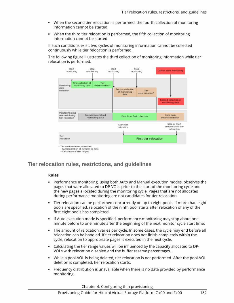
■ When the second tier relocation is performed, the fourth collection of monitoringinformation cannot be started.
■ When the third tier relocation is performed, the fifth collection of monitoringinformation cannot be started.
If such conditions exist, two cycles of monitoring information cannot be collectedcontinuously while tier relocation is performed.
The following figure illustrates the third collection of monitoring information while tierrelocation is performed.
Tier relocation rules, restrictions, and guidelines
Rules■ Performance monitoring, using both Auto and Manual execution modes, observes the
pages that were allocated to DP-VOLs prior to the start of the monitoring cycle andthe new pages allocated during the monitoring cycle. Pages that are not allocatedduring performance monitoring are not candidates for tier relocation.
■ Tier relocation can be performed concurrently on up to eight pools. If more than eightpools are specified, relocation of the ninth pool starts after relocation of any of thefirst eight pools has completed.
■ If Auto execution mode is specified, performance monitoring may stop about oneminute before to one minute after the beginning of the next monitor cycle start time.
■ The amount of relocation varies per cycle. In some cases, the cycle may end before allrelocation can be handled. If tier relocation does not finish completely within thecycle, relocation to appropriate pages is executed in the next cycle.
■ Calculating the tier range values will be influenced by the capacity allocated to DP-VOLs with relocation disabled and the buffer reserve percentages.
■ While a pool-VOL is being deleted, tier relocation is not performed. After the pool-VOLdeletion is completed, tier relocation starts.
■ Frequency distribution is unavailable when there is no data provided by performancemonitoring.
Tier relocation rules, restrictions, and guidelines
Chapter 4: Configuring thin provisioningProvisioning Guide for Hitachi Virtual Storage Platform Gx00 and Fx00 182

■ While the frequency distribution graph is being created or the tier range values arebeing calculated, the frequency distribution graph is not available. The time requiredfor determining the tier range values varies depending on the number of DP-VOLsand total capacity. The maximum time is about 20 minutes.
■ To balance the usage levels of all parity groups, rebalancing may be performed afterseveral tier relocation operations. If rebalancing is in progress, the next cycle of tierrelocation might be delayed.
Performance monitoring or tier relocation conditions
The following table lists monitoring and execution conditions and specifies the datacollection status, fixed monitoring status, and tier relocation operations for eachcondition. The latest fixed monitoring information is referenced when tiers are relocated.
Monitoringinformation or
executionconditions
Status of datacollection in
progress
Status of fixedmonitoringinformationused in tierrelocation
Tierrelocationoperations Solutions
Unallocatedpages.
Pages are notmonitored.
No monitoringinformationabout pages.
Tiers of thepages are notrelocated.
Unnecessary.After the pagesare allocated,monitoring andrelocation areperformedautomatically.
Zero data isdiscardedduring datamonitoring.
Monitoring onpages is reset.
Only monitoringinformationabout pages isinvalid.
Tiers of thepages are notrelocated.
Unnecessary.After the pagesare allocated,monitoring andrelocation areperformedautomatically.
V-VOL settingsdo not allowtier relocation.
Volume ismonitored.
Monitoringinformationabout thevolume is valid.
If the tierrelocationsetting isbeingdisabled attheperformancemonitoringfinish time,tiers of thevolume arenot relocated.
N/A
Tier relocation rules, restrictions, and guidelines
Chapter 4: Configuring thin provisioningProvisioning Guide for Hitachi Virtual Storage Platform Gx00 and Fx00 183

Monitoringinformation or
executionconditions
Status of datacollection in
progress
Status of fixedmonitoringinformationused in tierrelocation
Tierrelocationoperations Solutions
When V-VOLsare deleted.
Volume is notmonitored.
Only monitoringinformationabout thevolume isinvalid.
Tierrelocation ofthe volume issuspended.
N/A
Whenexecutionmode ischanged toManual fromAuto or viceversa.
Suspended. Monitoringinformationcollected beforesuspension isvalid.
Suspended. Collect themonitoringinformationagain ifnecessary.1
When thepower switch ispower ON orOFF.
Monitoring issuspended bypowering OFFand is notresumed evenafter poweringON.1
Monitoringinformationcollected duringthe previouscycle iscontinuouslyvalid.
Tierrelocation issuspended bypowering OFFand isresumedafterpowering ON.
Collect themonitoringinformationagain ifnecessary.1
■ WhenVolumeMigration isperformed.
■ When QuickRestore ofShadowImage isperformed.
Themonitoringinformation ofthe volume isnot collectedat the presentmoment. Inthe nextmonitoringperiod, themonitoringinformationwill becollected.
Monitoringinformation isinvalid and thevolumes need tobe monitored.
Tierrelocation tovolumes issuspended.
Collect themonitoringinformationagain ifnecessary.1
Tier relocation rules, restrictions, and guidelines
Chapter 4: Configuring thin provisioningProvisioning Guide for Hitachi Virtual Storage Platform Gx00 and Fx00 184

Monitoringinformation or
executionconditions
Status of datacollection in
progress
Status of fixedmonitoringinformationused in tierrelocation
Tierrelocationoperations Solutions
S-VOL of thefollowingproducts whenthe initial copyoperation isperformed:■ TrueCopy■ Global-
active device■ Universal
Replicator
Monitoringinformation iscollectedcontinuously,but themonitoring ofthe volumes isreset.2
No effect on thefixed monitoringinformation. Themonitoringinformationcollected duringthe previouscycle continuesto be valid.
Tierrelocation tovolumes issuspended.
Collect themonitoringinformationagain ifnecessary.1
■ When thenumber oftiersincreases byadding pool-VOLs.
■ When thepool-VOLs ofthe tiers areswitched byadding pool-VOLs.3
■ When tierrank of theexternalLDEV ischanged.
Continued. Fixedmonitoringinformation isinvalid becausethe monitoringinformation wasdiscarded. Ifmonitoring isset to thecontinuousmode, weighteddata calculatedby using themonitoringinformation inpast periods isalso discarded.
Suspended. Relocate tiersagain.1
When pool-VOLs aredeleted.
Continued. Monitoringinformation isinvalidtemporarily. Themonitoringinformation iscalculated againafter deleting ofpool-VOLs.4
Deleting thepool-VOLstops the tierrelocation.The processresumes afterthe pool-VOLis deleted.
N/A
Tier relocation rules, restrictions, and guidelines
Chapter 4: Configuring thin provisioningProvisioning Guide for Hitachi Virtual Storage Platform Gx00 and Fx00 185

Monitoringinformation or
executionconditions
Status of datacollection in
progress
Status of fixedmonitoringinformationused in tierrelocation
Tierrelocationoperations Solutions
When cache isblocked.
Continued. No effect on thefixed monitoringinformation. Themonitoringinformationcollected duringthe previouscycle continuesto be valid.
Suspended.5 After recoveringthe faulty area,relocate tiersagain.1
When an LDEVis blocked(pool-VOL or V-VOL).
Continued. No effect on thefixed monitoringinformation. Themonitoringinformationcollected duringthe previouscycle continuesto be valid.
Suspended.5 After recoveringthe faulty area,relocate tiersagain.1
When thedepletionthreshold ofthe pool isnearlyexceededduringrelocation.
Continued. No effect on thefixed monitoringinformation. Themonitoringinformationcollected duringthe previouscycle continuesto be valid.
Suspended.5 Add pool-VOLs,then collectmonitoringinformation andrelocate tiersagain.1
Whenexecutionmode is Autoand theexecution cycleends duringtier relocation.
At the endtime ofexecutioncycle, datamonitoringstops.
The monitoringinformationcollected beforemonitoringperformancestops is valid.
Suspended.5 Unnecessary. Therelocation isperformedautomatically inthe next cycle.
Tier relocation rules, restrictions, and guidelines
Chapter 4: Configuring thin provisioningProvisioning Guide for Hitachi Virtual Storage Platform Gx00 and Fx00 186

Monitoringinformation or
executionconditions
Status of datacollection in
progress
Status of fixedmonitoringinformationused in tierrelocation
Tierrelocationoperations Solutions
Whenexecutionmode isManual and 7days elapseaftermonitoringstarts.
Suspended. The monitoringinformationcollected beforesuspension isvalid.
Continued. Collect themonitoringinformationagain ifnecessary.1
Notes:
1. The execution mode is Auto or the script is written in manual execution mode,information is monitored again, and tiers are relocated automatically.
2. All pages of the S-VOLs are not allocated, and the monitoring information of thevolume is reset. After the page is allocated to the new page, the monitoringinformation is collected.
3. Example: Pool-VOLs of SAS15K are added to the following Configuration 1:
■ Configuration 1 (before change): Tier 1 is SSD, Tier 2 is SAS10K, and Tier 3 isSAS7.2K.
■ Configuration 2 (after change): Tier 1 is SSD, Tier 2 is SAS15K, and Tier 3 isSAS10K and SAS7.2K.
4. The monitoring information status is changed from invalid (INV) to calculating(PND). After completion of calculating, the monitor information status changesfrom calculating (PND) to valid (VAL).
5. The SIM code 641xxx is displayed if "Notify an alert when tier relocation issuspended by system" is enabled on the "Edit Advanced System Settings" window.
Buffer area of a tier
Dynamic Tiering uses buffer percentages to reserve pages for new page assignmentsand allow the tier relocation process. Areas necessary for processing these operationsare distributed corresponding to settings used by Dynamic Tiering. The followingdescribes how processing takes place to handle the buffer percentages.
Buffer space: The following table shows the default rates (rate to capacity of a tier) ofbuffer space used for tier relocation and new page assignments, listed by drive type.
Drive typebuffer area for tier
relocationbuffer area for newpage assignment Total
SSD 2% 0% 2%
Buffer area of a tier
Chapter 4: Configuring thin provisioningProvisioning Guide for Hitachi Virtual Storage Platform Gx00 and Fx00 187

Drive typebuffer area for tier
relocationbuffer area for newpage assignment Total
Non-SSD 2% 8% 10%
New page assignment: New pages are assigned based on a number of optional settings.Pages are then assigned to the next lower tier, leaving a buffer area (2% per tier bydefault) for tier relocation. After 98% of capacity of all tiers is assigned, the remaining 2%of the buffer space is assigned from the upper tier. The buffer space for tier relocation is2% in all tiers.
The following illustrates the workflow of a new page assignment.
For a pool comprised of pool volumes from parity groups with accelerated compressionenabled, the capacity of the parity group equivalent to 20% of the FMC tier is used as thecompression buffer area. When free space other than the FMC tier is not available, pagesare assigned to this buffer area just before the capacity depletes.
Buffer area of a tier
Chapter 4: Configuring thin provisioningProvisioning Guide for Hitachi Virtual Storage Platform Gx00 and Fx00 188

Setting external volumes for each tier
If you use external volumes as pool-VOLs, you can put the external volumes in tiers bysetting the External LDEV Tier Rank for the external volumes. The External LDEV TierRank consists of the following three types: High, Middle, and Low. The followingexamples describe how tiers may be configured:
Example 1: Configuring tiers by using external volumes only
Tier 1: External volumes (High)
Tier 2: External volumes (Middle)
Tier 3: External volumes (Low)
Example 2: Configuring tiers by combining internal volumes and external volumes
Tier 1: Internal volumes (SSD)
Tier 2: External volumes (High)
Tier 3: External volumes (Low)
You can set the External LDEV Tier Rank when creating the pool, changing the poolcapacity, or setting the Edit External LDEV Tier Rank window. The following tableexplains the performance priority (from the top) of data drives.
Priority Data drive type
1 SSD
2 SAS 15K rpm
3 SAS 10K rpm
4 SAS 7.2K rpm
5 External volume* (High)
6 External volume* (Middle)
7 External volume* (Low)
*Displays as External Storage in the Drive Type/RPM.
Reserved pages for relocation operation: A small percentage of pages, normally 2, arereserved per tier to allow relocation to operate. These are the buffer spaces for tierrelocation.
Tier relocation workflow: Tier relocation is performed taking advantage of the bufferspace allocated for tier relocation, as mentioned previously. Tier relocation is alsoperformed to secure the space reserved in each tier for new page assignment. The areais called the buffer space for new page assignments. When tier relocation is performed,Dynamic Tiering reserves buffer spaces for relocation and new page assignment.
During relocation, a tier may temporarily be assigned over 98% of capacity, or well underthe allowance for the buffer areas.
Setting external volumes for each tier
Chapter 4: Configuring thin provisioningProvisioning Guide for Hitachi Virtual Storage Platform Gx00 and Fx00 189

Execution modes for tier relocation
Execution modes when using Hitachi Device Manager - Storage Navigator
Dynamic Tiering performs tier relocations using one of two execution modes: Auto andManual. You can switch between modes by using Hitachi Device Manager - StorageNavigator.
Auto execution mode
In Auto execution mode, the system automatically and periodically collects monitoringdata and performs tier relocation. You can select an Auto execution cycle of 0.5, 1, 2, 4, or8 hours, or a specified time.
The following illustrates tier relocation processing in a 2-hour Auto execution mode:
Manual execution mode
In Manual execution mode, you can manually collect monitoring data and relocate a tier.You can issue commands to manually:
1. Start monitoring.2. Stop monitoring.3. Perform tier relocation.
The following illustrates tier relocation processing in Manual execution mode:
Execution modes for tier relocation
Chapter 4: Configuring thin provisioningProvisioning Guide for Hitachi Virtual Storage Platform Gx00 and Fx00 190

Notes on performing monitoring■ You can collect the monitoring data even while performing the relocation.■ After stopping the monitoring, the tier range is automatically calculated.■ The latest available monitoring information, which is collected just before the
relocation is performed, is used for the relocation processing.■ When the relocation is performed, the status of the monitor information must be
valid.
Viewing monitor and tier relocation information in HDvM - SN
Hitachi Device Manager - Storage Navigator (HDvM - SN) displays the followinginformation about monitor and tier relocation.
Field Windows Details
Monitoring Status ■ Pools window■ Pool Volumes tab■ View Pool Management
Status window
Displays the status of poolmonitoring.■ In Progress: The monitoring
is being performed.■ During Computation: The
calculating is beingprocessed.
Other than these cases, ahyphen (-) is displayed.
Viewing monitor and tier relocation information in HDvM - SN
Chapter 4: Configuring thin provisioningProvisioning Guide for Hitachi Virtual Storage Platform Gx00 and Fx00 191

Field Windows Details
Recent Monitor Data ■ Pools window■ Pool Volumes tab
Displays the latest monitoringdata.■ If the monitoring data exists,
the monitoring period of timeis displayed.
Example: 2010/11/15 00:00 -2010/11/15 23:59
■ If the monitoring data isbeing obtained, only thestarting time is displayed.
Example: 2010/11/15 00:00 -■ If the latest monitoring data
does not exist, a hyphen (-) isdisplayed.
Pool Management Task ■ Pools window■ Pool Volumes tab
Displays the pool managementtask being performed to thepool.■ Waiting for Relocation: The
tier relocation process iswaiting.
■ Relocating: The tier relocationprocess is being performed.
For details about the relocationprogress rate, check the tierrelocation log.
Pool Management Task (Status/Progress)
View Pool Management Statuswindow
Displays the status of the poolmanagement task beingperformed, each V-VOL progressratio in the pool and its average.■ Waiting for Relocation: The
tier relocation process iswaiting.
■ Relocating: The tier relocationprocess is being performed.
For details about the relocationprogress rate, check the tierrelocation log.
Viewing monitor and tier relocation information in HDvM - SN
Chapter 4: Configuring thin provisioningProvisioning Guide for Hitachi Virtual Storage Platform Gx00 and Fx00 192

Field Windows Details
Relocation Result ■ Pools window■ Pool Volumes tab■ View Pool Management
Status window
Displays the status of the tierrelocation processing.■ In Progress: The status of
Pool Management Task isWaiting for Relocationor Relocating.
■ Completed: The tierrelocation operation is not inprogress, or the tierrelocation is complete.
■ Uncompleted (n% relocated):The tier relocation issuspended at the indicatedpercentage progression.
■ - (hyphen): The pool is not aDynamic Tiering pool.
Relocation Speed ■ Pools window■ View Pool Management
Status window■ Create Pools window■ Edit Pools window■ Start Tier Relocation
window■ Stop Tier Relocation
window
Displays the tier relocationspeed settings.■ 1(Slowest)■ 2(Slower)■ 3(Standard)■ 4(Faster)■ 5(Fastest)
Relocation Priority ■ Pool Volumes tab■ View Pool Management
Status window
Displays the relocation priority.■ Prioritized: The priority is set
to V-VOL.■ Blank: The priority is not set
to V-VOL.■ - (hyphen): V-VOL is not a
Dynamic Tiering V-VOL, orthe tier relocation function isdisabled.
Performance Graph View Tier Properties window The performance graph for theavailable monitor information isdisplayed in the View TierProperties window.
Viewing monitor and tier relocation information in HDvM - SN
Chapter 4: Configuring thin provisioningProvisioning Guide for Hitachi Virtual Storage Platform Gx00 and Fx00 193

Execution modes when using Command Control Interface
Manual execution mode
In Manual execution mode, you can manually collect monitoring data and relocate a tier.You can execute commands to do the following:
1. Start monitoring.2. Stop monitoring.3. Perform tier relocation.
The following illustrates tier relocation processing when in Manual execution mode:
Notes on performing monitoring■ You can collect the monitoring data even while performing the relocation.■ After stopping the monitoring, the tier range is automatically calculated.■ The latest available monitoring information, which is collected just before the
relocation is performed, is used for the relocation processing.■ When the relocation is performed, the status of the monitor information must be
valid.
Viewing monitor and tier relocation information using CCI
To view the monitoring information and tier relocation information, execute the raidcomget dp_pool command with the -key opt option specified. For details, see theCommand Control Interface Command Reference.
The following items are displayed:■ STS
This item displays the operational status of the performance monitor and the tierrelocation.
Execution modes when using Command Control Interface
Chapter 4: Configuring thin provisioningProvisioning Guide for Hitachi Virtual Storage Platform Gx00 and Fx00 194

● STP: The performance monitor and the tier relocation are stopped.
● RLC: The performance monitor is stopped. The tier relocation is operating.
● MON: The performance monitor is operating. The tier relocation is stopped.
● RLM: The performance monitor and the tier relocation are operating.
■ DAT
This item displays the status of the monitor information.● VAL: Valid.
● INV: Invalid.
● PND: Being calculated.
■ R(%)
This item displays the progress percentage of tier relocation.
0 to 99: Shows one of the following statuses.● When the value of STS is RLC or RLM: Relocation is in progress.● When the value of STS is STP or MON: Relocation is suspended at the indicated
percentage progression.
100: Shows if the relocation operation is not in progress, or the relocation is complete.
Relocation speed
Relocation speed: The page relocation speed can be set to 1(Slowest), 2(Slower),3(Standard), 4(Faster), and 5(Fastest). The default is 3(Standard). If you want to performtier relocation at high speed, use the 5(Fastest) setting. If you set a speed that is slowerthan 3(Standard), the load to data drives is low when tier relocation is performed.
Based on the number of the parity groups that constitute a pool, this function adjuststhe number of V-VOLs for which tier relocation can be performed at one time. Tierrelocation can be performed on as many as 32 V-VOLs in a storage system at once.
After changing the setting, the relocation speed does not change and the data drive loadmay not change in the following cases:■ The number of parity groups is very few.■ The number of V-VOLs associated with the pool is very few.■ Tier relocations are being performed on the multiple pools.
Monitoring modes
When you create or edit a pool, you set the Dynamic Tiering monitoring mode: periodmode, or continuous mode. When you change the monitoring mode, the new monitoringsetting becomes effective when the next monitoring period starts.
Relocation speed
Chapter 4: Configuring thin provisioningProvisioning Guide for Hitachi Virtual Storage Platform Gx00 and Fx00 195

Period mode (default)
When Period mode is enabled, tier range values and page relocations are determinedbased solely on the monitoring data from the last complete cycle. Relocation isperformed according to any changes in I/O loads. However, if the I/O loads vary greatly,relocation might not finish in one cycle.
Continuous mode
When Continuous mode is enabled, the weighted average efficiency is calculated byweighting the latest monitoring information and the collected monitoring information inthe past cycles. By performing the tier relocation based on the weighted averageefficiency, even if a temporary decrease or an increase of the I/O load occurs,unnecessary relocation can be avoided.
Cautions when using monitoring modes■ When Continuous monitoring mode is used, best practice is to collect monitoring
information using the following execution modes:● Auto execution mode● Manual execution mode with collecting the periodic monitoring information by
defining a script using CCI
If Manual execution mode is used without scripts, Continuous monitoring mode canbe set. However, in this case, unexpected results might be calculated because the
Monitoring modes
Chapter 4: Configuring thin provisioningProvisioning Guide for Hitachi Virtual Storage Platform Gx00 and Fx00 196

weighted average efficiency is calculated based on very different duration (short andlong) periods information obtained in the past cycles.
■ When Continuous monitoring mode is used, the frequency distributions are displayedfor each pool and V-VOL calculated by using the monitor value on which the weightedcalculation is done.
These calculated values are the predictive values for the next cycle after successfullyrelocating all pages. Therefore, these values might differ from an actual monitoringresult when they appear.
In Performance Utilization of each tier, regardless of the type of the monitoring modesetting, the monitor values that were already collected in the current cycle aredisplayed.
If you switch the monitoring mode from Period to Continuous or from Continuous toPeriod, the current cycle's monitoring data that is being collected is not discarded.However, the data calculated by using past monitor cycle information on which theweighted calculation is done will be reset.
Downloading the tier relocation log file
Use this procedure to download the log file that contains the results of past tierrelocations. For information about the contents of the log file, see Tier relocation log filecontents (on page 197) .
Before you begin
The Storage Administrator (Provisioning) role is required to perform this task.
Procedure
1. From the Actions menu, select Pool > Export Tier Relocation Log.2. In the dialog box, specify a folder for the log file, and then click Save.
If you change the file name from the default, make sure the file name is appendedwith the .tsv extension before saving the file.
Tier relocation log file contents
In every cycle in which tier relocation is performed, information about each pool and V-VOL is exported to the tier relocation log. The time required to incorporate the latest tierrelocation results may be approximately 30 minutes. The tier relocation log file is tab-delimited and contains the following information.
Item
Does eachpool output the
loginformation?
Does each V-VOL output
the loginformation?
Type ofinformation Description
Cycle ID Yes Yes Common ID of each cycle of a tierrelocation.
A common ID is allocated topool logs and V-VOL logs thatare collected in one cycle.
Downloading the tier relocation log file
Chapter 4: Configuring thin provisioningProvisioning Guide for Hitachi Virtual Storage Platform Gx00 and Fx00 197

Item
Does eachpool output the
loginformation?
Does each V-VOL output
the loginformation?
Type ofinformation Description
Log FormatVersion
Yes Yes Common Version number of the tierrelocation log format.
DKC SerialNumber
Yes Yes Common Serial number of the storagesystem.
Log Type Yes Yes Common Following log types aredisplayed.
POOL: Log information of eachpool.
V-VOL: Log information of eachV-VOL.
LDEV ID No Yes Common LDEV ID of a V-VOL exported toa log.
Pool ID Yes Yes Common Pool ID of a pool exported to alog.
Num of V-VOLs Yes No Common The number of V-VOLs to beprocessed when tier relocationis performed.
Tiering Policy No Yes Tier relocationresult
Value of the tiering policy.Values from All(0) to Level31(31)can be displayed.
From Level6(6) to Level31(31),the names of tiering policies canbe changed. If these nameshave changed, the new namesappear.
Tier1 Total Yes No Capacityinformation
Total pages of tier 1.
Tier2 Total Yes No Capacityinformation
Total pages of tier 2.
Tier3 Total Yes No Capacityinformation
Total pages of tier 3.
Tier1 Used Yes Yes Capacityinformation
Pages assigned to tier 1 at thestart of tier relocation.
Tier2 Used Yes Yes Capacityinformation
Pages assigned to tier 2 at thestart of tier relocation.
Tier relocation log file contents
Chapter 4: Configuring thin provisioningProvisioning Guide for Hitachi Virtual Storage Platform Gx00 and Fx00 198

Item
Does eachpool output the
loginformation?
Does each V-VOL output
the loginformation?
Type ofinformation Description
Tier3 Used Yes Yes Capacityinformation
Pages assigned to tier 3 at thestart of tier relocation.
StartRelocationDate
Yes Yes1 Common Starting date of the tierrelocation.
StartRelocationTime
Yes Yes1 Common Starting time of the tierrelocation.
End RelocationDate
Yes Yes1 Common Ending date of the tierrelocation.
End RelocationTime
Yes Yes1 Common Ending time of the tierrelocation.
Result Status Yes Yes1 Tier relocationresult
Statuses of a tier relocation.
Normal End: Tier relocation andoptimization ended normally.
Normal End (Optimizationremains): Tier relocation endednormally, but tier optimizationterminated in the middle ofprocessing.2
Suspend: Tier relocationsuspended.
Tier relocation log file contents
Chapter 4: Configuring thin provisioningProvisioning Guide for Hitachi Virtual Storage Platform Gx00 and Fx00 199

Item
Does eachpool output the
loginformation?
Does each V-VOL output
the loginformation?
Type ofinformation Description
Detail Status Yes Yes1 Tier relocationresult
If the Result Status is Suspend,one of following reasons isdisplayed.
Monitor discarded: Suspendeddue to the discard of monitoringdata.3
End of cycle: Suspended due toincomplete tier relocationduring a monitoring cycle.
Requested by user: Suspendeddue to request by a user2.
Threshold exceeded:Suspended because the usedcapacity of pools reaches athreshold due to a tierrelocation. When the usedcapacity of a pool reaches thedepletion threshold, this reasonis logged.
FMC threshold exceeded:Suspended because the usedcapacity of the physical capacityin the accelerated compression-enabled FMC parity group poolreached its full capacity.
Cache blocked: Suspendedbecause a cache memory isblocked.
Volume blocked: Suspendedbecause an LDEV which is pool-VOL or V-VOL is blocked.
The tier management changed(Auto/Manual): Suspendedbecause the tier managementmode is changed from Auto toManual, or Manual to Auto.
Other reasons: Suspended forreasons other than the above,such as:
Tier relocation log file contents
Chapter 4: Configuring thin provisioningProvisioning Guide for Hitachi Virtual Storage Platform Gx00 and Fx00 200

Item
Does eachpool output the
loginformation?
Does each V-VOL output
the loginformation?
Type ofinformation Description
■ A V-VOL was specified as thesecondary volume of theTrueCopy pair and an initialcopy operation wasperformed.
■ A V-VOL was specified as thesecondary volume of theglobal-active device devicepair and an initial copyoperation was performed
■ A V-VOL was specified as thesecondary volume of theUniversal Replicator pair, andan initial copy operation wasperformed.
CompletedRate (%)
Yes Yes Tier relocationresult
Progress percentage rate at thetime tier relocation ends or issuspended.
RemediationRate (%)
Yes Yes Tier relocationresult
IOPH (I/O per hour) remediationrate at the time tier relocationends or is suspended.
The remediation rate = ((TotalIOPH of pages after thepromotion1) / (Total IOPH of allpages to be performed ofpromotion1)) * 100
1: Promotion is the pagemigration from a lower tohigher tier.
Planned Tier1->Tier2
Yes Yes Tier relocation Number of pages that areplanned to move from the tier 1to tier 2.
Planned Tier1->Tier3
Yes Yes Tier relocation Number of pages that areplanned to move from the tier 1to tier 3.
Planned Tier2->Tier1
Yes Yes Tier relocation Number of pages that areplanned to move from the tier 2to tier 1.
Tier relocation log file contents
Chapter 4: Configuring thin provisioningProvisioning Guide for Hitachi Virtual Storage Platform Gx00 and Fx00 201

Item
Does eachpool output the
loginformation?
Does each V-VOL output
the loginformation?
Type ofinformation Description
Planned Tier2->Tier3
Yes Yes Tier relocation Number of pages that areplanned to move from the tier 2to tier 3.
Planned Tier3->Tier1
Yes Yes Tier relocation Number of pages that areplanned to move from the tier 3to tier 1.
Planned Tier3->Tier2
Yes Yes Tier relocation Number of pages that areplanned to move from the tier 3to tier 2.
Moved Tier1->Tier2
Yes Yes Tier relocation Number of pages that aremoved from the tier 1 to tier 2.
Moved Tier1->Tier3
Yes Yes Tier relocation Number of pages that aremoved from the tier 1 to tier 3.
Moved Tier2->Tier1
Yes Yes Tier relocation Number of pages that aremoved from the tier 2 to tier 1.
Moved Tier2->Tier3
Yes Yes Tier relocation Number of pages that aremoved from the tier 2 to tier 3.
Moved Tier3->Tier1
Yes Yes Tier relocation Number of pages that aremoved from the tier 3 to tier 1.
Moved Tier3->Tier2
Yes Yes Tier relocation Number of pages that aremoved from the tier 3 to tier 2.
IOPH Yes Yes Monitoringresult
IOPHs of all pools or V-VOLs.
IOPH Tier1 (%) Yes Yes Monitoringresult
Percentage of IOPH for tier 1.
IOPH Tier2 (%) Yes Yes Monitoringresult
Percentage of IOPH for tier 2.
IOPH Tier3 (%) Yes Yes Monitoringresult
Percentage of IOPH for tier 3.
PerformanceUtil Tier1 (%)
Yes No Monitoringresult
Performance utilization of tier 1.The performance utilization isthe current I/O percentagebased on the maximumperformance of tier 1.
Tier relocation log file contents
Chapter 4: Configuring thin provisioningProvisioning Guide for Hitachi Virtual Storage Platform Gx00 and Fx00 202

Item
Does eachpool output the
loginformation?
Does each V-VOL output
the loginformation?
Type ofinformation Description
PerformanceUtil Tier2 (%)
Yes No Monitoringresult
Performance utilization of tier 2.The performance utilization isthe current I/O percentagebased on the maximumperformance of tier 2.
PerformanceUtil Tier3 (%)
Yes No Monitoringresult
Performance utilization of tier 3.The performance utilization isthe current I/O percentagebased on the maximumperformance of tier 3.
Tier1 LowRange
No Yes Monitoringresult
Lower limit in a range for tier 1.
Tier2 HighRange
No Yes Monitoringresult
Higher limit in a range for tier 2.
Tier2 LowRange
No Yes Monitoringresult
Lower limit in a range for tier 2.
Tier3 HighRange
No Yes Monitoringresult
Higher limit in a range for tier 3.
Reclaim ZeroPage Num
Yes Yes Tier relocation Number of pages processed inan operation to reclaim zeropages.
Non CompliantTiering PolicyNumber
Yes No Monitoringresult
Number of a tiering policy thatdoes not conform to the currenttier configuration. A non-compliant policy prevents tierrelocation.
RealtimeMoved Tier2->Tier1(Unplanned)
Yes Yes Tier relocation Number of pages moved fromtier 2 to tier 1 by active flashwhile performing the tierrelocation by Dynamic Tiering.However, the pages migration isnot planned by Dynamic Tiering.
RealtimeMoved Tier3->Tier1(Unplanned)
Yes Yes Tier relocation Number of pages moved fromtier 3 to tier 1 by active flashwhile performing the tierrelocation by Dynamic Tiering.However, the pages migration isnot planned by Dynamic Tiering.
Tier relocation log file contents
Chapter 4: Configuring thin provisioningProvisioning Guide for Hitachi Virtual Storage Platform Gx00 and Fx00 203

Item
Does eachpool output the
loginformation?
Does each V-VOL output
the loginformation?
Type ofinformation Description
RealtimeMoved Tier2->Tier1(Planned)
Yes Yes Tier relocation Number of pages moved fromtier 2 to tier 1 by active flashwhile performing the tierrelocation by Dynamic Tiering.The pages migration is plannedby Dynamic Tiering.
RealtimeMoved Tier3->Tier1(Planned)
Yes Yes Tier relocation Number of pages moved fromtier 3 to tier 1 by active flashwhile performing the tierrelocation by Dynamic Tiering.The pages migration is plannedby Dynamic Tiering.
RealtimeMoved Tier1->Tier2
Yes Yes Tier relocation Number of pages moved fromtier 1 to tier 2 by active flashwhile performing the tierrelocation for Dynamic Tiering.
RealtimeMoved Tier1->Tier3
Yes Yes Tier relocation Number of pages moved fromtier 1 to tier 3 by active flashwhile performing the tierrelocation for Dynamic Tiering.
RealtimeMoved Tier2->Tier1 (NonCompliant)
Yes Yes Tier relocation In the total pages moved fromtier 2 to tier 1 by active flash,the number of migrated pagesthat do not conform to the planof Dynamic Tiering pagemigration.
RealtimeMoved Tier3->Tier1 (NonCompliant)
Yes Yes Tier relocation In the total pages moved fromtier 3 to tier 1 by active flash,the number of migrated pagesthat do not conform to the planof Dynamic Tiering pagemigration.
RealtimeMoved Tier1->Tier2 (NonCompliant)
Yes Yes Tier relocation In the total pages moved fromtier 1 to tier 2 by active flash,the number of migrated pagesthat do not conform to the planof Dynamic Tiering pagemigration.
Tier relocation log file contents
Chapter 4: Configuring thin provisioningProvisioning Guide for Hitachi Virtual Storage Platform Gx00 and Fx00 204

Item
Does eachpool output the
loginformation?
Does each V-VOL output
the loginformation?
Type ofinformation Description
RealtimeMoved Tier1->Tier3 (NonCompliant)
Yes Yes Tier relocation In the total pages moved fromtier 1 to tier 3 by active flash,the number of migrated pagesthat do not conform to the planof Dynamic Tiering pagemigration.
Notes
1. If the log file is lfv2 (Log Format Version 2) or later, the log file information of each V-VOL appears.If the log file is lfv 1, a hyphen appears.
2. If the log file is lfv5 (Log Format Version 5) or later, this information appears.3. When deleting pool-VOLs, ex-valid monitor information are discarded, so that the tier relocation
is interrupted. After completion of the pool-VOLs deleting, the tier determination calculationperforms again and completes. Processed by this way, the valid monitor information are re-created.
Tiering policy
The tiering policy function is used to assign a specific storage tier to a specific DP-VOL. Atiering policy specifies subset of tiers that is available to a given set of DP-VOLs.
Tier relocation changes the location of previously stored data. It is performed inconformance to the tiering policy. If a DP-VOL is initially allocated to a low-speed tier andthe tiering policy is changed to a high-speed tier, relocation is performed in the nextcycle.
For example, if you set the tiering policy level on a V-VOL (DP-VOL) to a tier with a highI/O speed, the data is always stored on the high-speed tier when relocating tiers. Whenyou use that V-VOL (DP-VOL), regardless of the actual size of the I/O load, you can alwaysget high-speed responses. See Tiering policy levels (on page 208) .
When you create the DP-VOL, you can designate one of six existing tiering policies anddefine up to 26 new tiering policies. See Tiering policy levels (on page 208) and Settingtiering policy on a DP-VOL (on page 207) .
Use the Edit LDEVs window to change the tiering policy settings. When tier relocationoccurs, the related tiering policy set for the DP-VOL is used to relocate data to thedesired tier or tiers.
The tiering policy does not own pool capacity. Rather, pool capacity is shared amongtiers. Pages are allocated in order of priority from upper to lower tiers in a tiering policy.When you specify a new allocation tier, pages are allocated starting from the tier that youspecify.
The tier range, frequency distribution, and used capacity are displayed per tiering policy:existing tier level All(0), Level1(1) through Level5(5), and Level6(6) to Level31(31).
Tiering policy
Chapter 4: Configuring thin provisioningProvisioning Guide for Hitachi Virtual Storage Platform Gx00 and Fx00 205

Custom policies
The settings of the tiering policy can be changed and these tiering policies changed by auser are called custom policies. Custom policies can be defined for IDs of tiering policiesfrom 6 to 31 (from Level6(6) to Level31(31)). The following items can be set in the custompolicy:■ Rename custom policy■ Change allocation threshold
Custom policy name
A custom policy name can be changed arbitrarily. You can change the names of custompolicies from Level6(6) to Level31(31). For example, if you change the name of Level6(6)to Policy06, Policy06(6) will then be displayed.
Allocation threshold
You can define allocation thresholds in new policies from Level6(6) to Level31(31).
For all DP-VOLs that have the tiering policy in a pool, Dynamic Tiering performs therelocation of pages to each tier based on the tiering policy setting.
Max(%) and Min(%) parameters: When a tiering policy is created, 4 types of parameterscan be set: Tier1 Max and Tier 1 Min, Tier 3 Max and Tier 3 Min. Each parameter settingis a ratio that corresponds to the total capacity of the allocated area of DP-VOLs thathave the same tiering policy set for a pool.
Tier1 and Tier3 parameter settings can also limit the capacity for all volumes in aconfiguration that contain multiple DP-VOLs that have the same intended use. Thesesettings can prevent conditions such as the following from occurring:■ Excess allocation of SSD capacity for unimportant applications.■ Degradation in average response time for high performance operations.
Tiering policy examples
The following figure shows the allocation threshold settings Tier1 Max=40%, Tier1Min=20%, Tier3 Max=40%, and Tier3 Min=20% for a DP-VOL with a Level6(6) setting whenthe initial mapped capacity is 100GB.
Custom policies
Chapter 4: Configuring thin provisioningProvisioning Guide for Hitachi Virtual Storage Platform Gx00 and Fx00 206

The following figure shows an example of data allocation when the default tiering policylevel All(0) is specified. Pages in the DP-VOL are relocated to any tier.
The following figure shows an example of data allocation when setting the tiering policyto Level1(1) (see Level1(1) in Tiering policy levels (on page 208) ). In this case, pages inthe DP-VOL are relocated to tier 1, and are not relocated to other tiers.
Setting tiering policy on a DP-VOL
The setting of a tiering policy for a DP-VOL is optional. If one is not selected, the default isthe All(0) tiering policy level. The available levels are listed in Tiering policy levels (onpage 208) . DP-VOLs of different tiering policies can coexist in one pool. If you specifythe level of the tiering policy, DP-VOLs with the policy are grouped together.■ All(0) is the default policy. In this case, data is stored to all of the tiers.■ When a tier is added to the pool after setting the tiering policy on a DP-VOL, the DP-
VOL is relocated according to the new tier lineup.
Setting tiering policy on a DP-VOL
Chapter 4: Configuring thin provisioningProvisioning Guide for Hitachi Virtual Storage Platform Gx00 and Fx00 207

For example, if you set the tiering policy to level 5, the data is always allocated to thetier of the low I/O speed. If the pool has two tiers, data is stored in tier 2. If a new tieris added, the number of tiers becomes three and if the new tier is the lowest tier,relocation will be performed to move data into tier 3.
For more information about tiering policy and groups, see Tiering policy levels (onpage 208) .
Tiering policy levels
Tiering policy1 tierpool
2 tierpool
3 tierpool Note
All(0) SingleTier
Bothtiers
All 3tiers
Default Tiering Policy
Level1(1) Same asAll(0)
Tier 1 Tier 1 Data is located to the Top Tier. Anyoverflow moves to the next lower tier.
Level2(2) Same asAll(0)
Sameas All(0)
Tier 1andTier 2
Seenote
Data is located to the Top Tier afterLevel1(1) assignments are processed.Any overflow moves to the next lowertier.
Level3(3) Same asAll(0)
Sameas All(0)
Tier 2
Seenote
Data is located to the Middle Tier. Anyoverflow moves to the top tier.
Level4(4) Same asAll(0)
Sameas All(0)
Tier 2andTier 3
Seenote
Data is located to the Middle Tier afterLevel3(3) assignments are processed.Any overflow moves to the next lowertier.
Level5(5) Same asAll(0)
Tier 2 Tier 3
Seenote
Data is located to the bottom tier. Anyoverflow moves to the next highertier.
From Level6(6)to Level31(31)
Same asAll(0)
Depends onusersetting
Depends onusersetting
Tiering policy levels
Chapter 4: Configuring thin provisioningProvisioning Guide for Hitachi Virtual Storage Platform Gx00 and Fx00 208

Tiering policy1 tierpool
2 tierpool
3 tierpool Note
For example:
If additional capacity is added to the pool and the capacity defines a new Tier 1 or newTier 2, the DP-VOLs with a Level 5(5) assignment will not physically move but Level 5(5)will be associated with Tier 3.
If additional capacity is added to the pool and the capacity defines a new Tier 3, theDP-VOLs with a Level 5(5) assignment will physically move to the new Tier 3 and Level5(5) will be associated with Tier 3.
Viewing the tiering policy in the performance graph
You can view the frequency distribution graph of the pool by selecting either the level ofthe tiering policy or the entire pool on the performance graph in the View TierProperties window.
The following table shows how tiering policy is shown in the performance graph. How thegraph appears depends on the number of tiers set in a pool and tiering policy levelselected when viewing the performance graph.
Tiering policyselected withperformance
graph V-VOL displayed in the performance graph
All(0) In the performance graph, you can display a frequency distributionof a DP-VOL, set to all tiers.
Level 1(1) In the performance graph, you can display the frequencydistribution of a DP-VOL set to level 1.
Level 2(2) In the performance graph, you can display the frequencydistribution of a DP-VOL set to level 2.
Level 3(3) In the performance graph, you can display the frequencydistribution of a DP-VOL set to level 3.
Level 4(4) In the performance graph, you can display the frequencydistribution of a DP-VOL set to level 4.
Level 5(5) In the performance graph, you can display the frequencydistribution of a DP-VOL set to level 5.
From Level6(6)to Level31(31)
In the performance graph, you can display the frequencydistribution of a DP-VOL set to custom policy.
Viewing the tiering policy in the performance graph
Chapter 4: Configuring thin provisioningProvisioning Guide for Hitachi Virtual Storage Platform Gx00 and Fx00 209
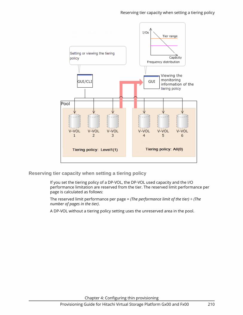
Reserving tier capacity when setting a tiering policy
If you set the tiering policy of a DP-VOL, the DP-VOL used capacity and the I/Operformance limitation are reserved from the tier. The reserved limit performance perpage is calculated as follows:
The reserved limit performance per page = (The performance limit of the tier) ÷ (Thenumber of pages in the tier).
A DP-VOL without a tiering policy setting uses the unreserved area in the pool.
Reserving tier capacity when setting a tiering policy
Chapter 4: Configuring thin provisioningProvisioning Guide for Hitachi Virtual Storage Platform Gx00 and Fx00 210

Example of reserving tier capacity
The reservation priority depends on the level of tiering policy. The following figureillustrates the reservation priority. Tiers are reserved in order of priority from (1) to (7) inthe figure. If the pool-VOL capacity is deficient when you reserve a tier, the nearest tier ofyour specified tier is allocated. If you specify two tiers like level 2 or level 4 of the tieringpolicy, first of all the upper tier is reserved. At this time, if the capacity of the pool-VOLassigned to the upper tier is deficient, the lower tier defined by the tiering policy isreserved automatically. For example, in case of level 2 in the diagram below, tier 1 isreserved first. If the capacity of tier 1 is deficient at this point, tier 2 is reservedautomatically. For details, see Notes on tiering policy settings (on page 213) .
Example of reserving tier capacity
Chapter 4: Configuring thin provisioningProvisioning Guide for Hitachi Virtual Storage Platform Gx00 and Fx00 211

Tierreservation
priorityTiering policy Reserved tier
1 Level1(1) Tier 1
2 Level3(3) Tier 2
3 Level5(5) Tier 3
From 4 to 29 From Level6(6) toLevel31(31)
The custom policy whose number issmall is prioritized.
Tier 1: From Level6(6) to Level31(31),each of the Tier1 Min values arereserved.
Tier 2: From Level6(6) to Level31(31),each of values that deducted the totalvalue of Tier1 Max and Tier3 Max from100(%) are reserved.
Tier 3: From Level6(6) to Level31(31),each of the Tier3 Min values arereserved.
30 All(0) All tiers
Level2(2) Tier 1 and Tier 2
Level4(4) Tier 2 and Tier 3
From Level6(6) toLevel31(31)
Tier 1: From Level6(6) to Level31(31),each of the Tier1 Max values arereserved.
Tier 3: From Level6(6) to Level31(31),each of the Tier3 Max values arereserved.
Example of reserving tier capacity
Chapter 4: Configuring thin provisioningProvisioning Guide for Hitachi Virtual Storage Platform Gx00 and Fx00 212

Notes on tiering policy settings
■ If Auto is set as the execution mode, tier relocation is performed based on themonitoring cycle. Therefore, when the tiering policy setting is changed, tier relocationwill automatically implement the tiering policy at the end of the current monitoringcycle. See Example 1 in Execution mode settings and tiering policy (on page 214) .
■ If Manual is set as the execution mode, you must manually perform monitoring, issuea monitor stop, and then start relocation (see Example 2, Case 1, in Execution modesettings and tiering policy (on page 214) ). If you change the tiering policy settingswhile obtaining monitoring data, the monitoring data is used for the next tierrelocation (see Example 2, Case 2, in Execution mode settings and tiering policy (onpage 214) ). Therefore, you do not need to perform new monitoring.
■ If a capacity shortage exists in the tier being set, a message may appear in the ViewTier Property window that the page allocation cannot be completed according to thetiering policy specified for the V-VOL. Should that occur, the page allocation in theentire pool, including the tier that defines the tiering policy might not be optimized.
Note: The message that page allocation cannot be completed according tothe tiering policy does not appear when these tiering policies are set:■ All(0)■ In a 2-tier configuration, Level2(2), Level3(3), or Level4(4) which is
equivalent to All(0)
Notes on tiering policy settings
Chapter 4: Configuring thin provisioningProvisioning Guide for Hitachi Virtual Storage Platform Gx00 and Fx00 213

When a capacity shortage exists in a tier, you can revise the setting of the tieringpolicy or the configuration of tiers. If the capacity of one tier is fully exhausted, themigrating pages are assigned to the next tier according to the tiering policy.● Level1(1): When tier 1 is full, the remaining pages are allocated to tier 2. If tier 2 is
full, the remaining pages are allocated to tier 3.● Level3(3): When tier 2 is full, the remaining pages are allocated to tier 1. If tier 1 is
full, the remaining pages are allocated to tier 3.● Level5(5): When tier 3 is full, the remaining pages are allocated to tier 2. If tier 2 is
full, the remaining pages are allocated to tier 1.● Level2(2), Level4(4), and from Level6(6) to Level31(31): When the specified tier is
full, the unallocated pages are kept in the prior tier or they are allocated to the tierthat has free space. From Level 6 (6) to Level 31 (31), the names of tiering policiescan be changed. If these names have changed, the new names appear.
■ If a performance shortage exists in the tier being set, pages may not be allocated inconformance to the tiering policy specified for the V-VOL. In that case, pages areallocated according to the performance ratio of each tier.
As shown in the following table, allocation capacity considerations are based on thetiering policy.
Tiering Policy Allocation capacity considerations
All(0), Level2(2), orLevel4(4)
Tier range and I/O performance
Level1(1), Level3(3), orLevel5(5)
Tier range
From Level6(6) toLevel31(31)
First phase: Tier range.
Allocation capacities in each tier.■ Tier1: The setting value(%) in Tier1 Min.■ Tier2: The value deducted Tier1 Max(%) and Tier3
Max(%) from 100(%).■ Tier3: The setting value(%) in Tier3 Min.
Second phase: Tier range and I/O performance.
Capacities deducted from the mapped capacities of thefirst phase from the total used capacity, are mapped toeach tier.
Execution mode settings and tiering policy
The following figure depicts how tier relocation is performed after changing the tieringpolicy setting while Auto execution mode is used.
Execution mode settings and tiering policy
Chapter 4: Configuring thin provisioningProvisioning Guide for Hitachi Virtual Storage Platform Gx00 and Fx00 214

The following figure depicts two cases of how tier relocation is performed after changingthe tiering policy setting while Manual execution mode is used.
New page assignment tier
If you set the new page assignment tier value, when a new page is needed by a DP-VOLthe page is taken from the specified tier aligned with the new page assignment tier value.You can set this function by using Hitachi Device Manager - Storage Navigator. Inaddition, this function becomes effective just after setting. The following table listssetting values:
New page assignment tier
Chapter 4: Configuring thin provisioningProvisioning Guide for Hitachi Virtual Storage Platform Gx00 and Fx00 215

Setting value Description
High The new page is assigned from the higher tier of tiers set inthe tiering policy.
Middle The new page is assigned from the middle tier of tiers set inthe tiering policy.
Low The new page is assigned from the lower tier of tiers set inthe tiering policy.
The following tables show the tiers to which new pages are preferentially assigned.
TieringPolicy
Whenspecifying
High
Whenspecifying
Middle
Whenspecifying
Low Note
All From tier 1 to 2 From tier 1 to2
From tier 2 to1
If you set Low, tier 2is given a priorityover tier 1.
Level 1 From tier 1 to 2 From tier 1 to2
From tier 1 to2
Assignmentsequences whenHigh, Middle, andLow are same.
Level 2 From tier 1 to 2 From tier 1 to2
From tier 2 to1
Every assignmentsequence is thesame as when All isspecified as thetiering policy.
Level 3 From tier 1 to 2 From tier 1 to2
From tier 2 to1
Every assignmentsequence is thesame as when All isspecified as thetiering policy.
Level 4 From tier 1 to 2 From tier 1 to2
From tier 2 to1
Every assignmentsequence is thesame as when All isspecified as thetiering policy.
Level 5 From tier 2 to 1 From tier 2 to1
From tier 2 to1
Assignmentsequences whenHigh, Middle, andLow are same.
New page assignment tier
Chapter 4: Configuring thin provisioningProvisioning Guide for Hitachi Virtual Storage Platform Gx00 and Fx00 216

Number Condition Order of new page allocation
1 T1 MIN = 100% Same as Level1(1)
2 T1 MAX = 0% Same as Level5(5)
3 T1 MAX > 0% Same as All(0)
Tiering policy
Whenspecifying
High
Whenspecifying
Middle
Whenspecifying
Low Note
All From tier 1, 2,to 3.
From tier 2, 3,to 1.
From tier 3, 2,to 1.
Specifying High,Middle or Low tothe assignmentsequence iseffective.
Level 1 From tier 1, 2,to 3.
From tier 1, 2,to 3.
From tier 1, 2,to 3.
Assignmentsequences whenHigh, Middle, andLow are same.
Level 2 From tier 1, 2,to 3.
From tier 1, 2,to 3.
From tier 2, 1,to 3.
If you set Low, tier 2is given a priorityover tier 1.
Level 3 From tier 2, 3,to 1
From tier 2, 3,to 1
From the 2, 3,to 1
Assignmentsequences whenHigh, Middle, andLow are same.
Level 4 From tier 2, 3,to 1
From tier 2, 3,to 1
From tier 3, 2,to 1
If you set Low, tier 3is given priority overtier 2.
Level 5 From tier 3, 2,to 1
From tier 3, 2,to 1
From tier 3, 2,to 1
Assignmentsequences whenHigh, Middle, andLow are same.
Number Condition Order of new page allocation
1 T1 MIN = 100% Same as Level1(1)
2 T3 MIN = 100% Same as Level5(5)
New page assignment tier
Chapter 4: Configuring thin provisioningProvisioning Guide for Hitachi Virtual Storage Platform Gx00 and Fx00 217

Number Condition Order of new page allocation
3 T1 MAX > 0% and T3 MAX =0%
Same as Level2(2)
4 T1 MAX = 0% and T3 MAX =0%
Same as Level3(3)
5 T1 MAX = 0% and T3 MAX >0%
Same as Level4(4)
6 T1 MAX > 0% and T3 MAX >0%
Same as All(0)
Relocation priority
If you use the relocation priority function, you can set the selection priority of a DP-VOLwhen performing relocation. With this setting, a prioritized DP-VOL can be relocatedearlier during a relocation cycle. You can set this function by using Hitachi DeviceManager - Storage Navigator. The function is activated after the monitoring data iscollected.■ If no relocation priority is set for all DP-VOLs, the general order of DP-VOL selection is
to select the next DP-VOL in LDEV number order after the last DP-VOL that fullyperformed relocation. This selection order persists across relocation cycles.
■ If one or more DP-VOLs is assigned a relocation priority, the prioritized DP-VOLs areoperated upon in the early portion of the relocation cycle, before others in thegeneral order of DP-VOL selection.
■ If V-VOL is not given priority for relocation:
For example, if LDEVs of LDEV IDs with LDEV#1, LDEV#2, LDEV#3, LDEV#4, andLDEV#5 are not given priority for relocation, LDEVs are relocated with the followingsequences. In this example, three LDEVs are relocated in each period, but the numberof LDEVs to relocate may change by the relocation cycle or the data size.
Relocatingcycle
Relocatingsequenceof LDEV#1
in eachcycle
Relocatingsequenceof LDEV#2
in eachcycle
Relocatingsequence ofLDEV#3 ineach cycle
Relocatingsequenceof LDEV#4
in eachcycle
Relocatingsequence ofLDEV#5 ineach cycle
T1 1st 2nd 3rd Unperformed
Unperformed
T2 3rd Unperformed
Unperformed
1st 2nd
T3 Unperformed
1st 2nd 3rd Unperformed
Relocation priority
Chapter 4: Configuring thin provisioningProvisioning Guide for Hitachi Virtual Storage Platform Gx00 and Fx00 218

Relocatingcycle
Relocatingsequenceof LDEV#1
in eachcycle
Relocatingsequenceof LDEV#2
in eachcycle
Relocatingsequence ofLDEV#3 ineach cycle
Relocatingsequenceof LDEV#4
in eachcycle
Relocatingsequence ofLDEV#5 ineach cycle
T4 2nd 3rd Unperformed
Unperformed
1st
■ If V-VOL is given priority for relocation:
For example, if LDEVs of LDEV IDs with LDEV#3 and LDEV#4 are set priority forrelocation from LDEV#1 to LDEV#5, LDEVs are relocated with the following sequences.In this example, three LDEVs are relocated in each period, but the number of LDEVs torelocate may change by the relocation cycle or data size.
Relocatingcycle
Relocatingsequenceof LDEV#1
in eachcycle
Relocatingsequence ofLDEV#2 ineach cycle
Relocatingsequence ofLDEV#3 ineach cycle
Relocatingsequenceof LDEV#4
in eachcycle
Relocatingsequenceof LDEV#5
in eachcycle
T1 3rd Unperformed
1st 2nd Unperformed
T2 Unperformed
3rd 1st 2nd Unperformed
T3 Unperformed
Unperformed
1st 2nd 3rd
T4 3rd Unperformed
1st 2nd Unperformed
Assignment tier when pool-VOLs are deleted
When you delete pool-VOLs, the pages allocated to the pool-VOLs are moved to otherpool-VOLs. The following table shows the tier numbers to which pages are allocatedbefore and after pool-VOLs are deleted. This operation does not depend on the tieringpolicy or the settings of newly assigned tiers. Relocate tiers after deleting pool-VOLs.
The following table describes page allocation in a 3-tier configuration.
Assignment tier when pool-VOLs are deleted
Chapter 4: Configuring thin provisioningProvisioning Guide for Hitachi Virtual Storage Platform Gx00 and Fx00 219

Tier of deleted pool-VOLs
Order in which pagesare allocated to tiers Description
Tier 1 Tier 1, Tier 2, and Tier 3 If there is free space in Tier 1,pages are allocated to Tier 1.
If there is no free space in Tier 1,pages are allocated to Tier 2.
If there is no free space in Tier 1and Tier 2, pages are allocated toTier 3.
Tier 2 Tier 2, Tier 1, and Tier 3 If there is free space in Tier 2,the pages are allocated to Tier 2.
If there is no free space in Tier 2,pages are allocated to Tier 1.
If there is no free space in Tier 1and Tier 2, pages are allocated toTier 3.
Tier 3 Tier 3, Tier 2, and Tier 1 If there is free space in Tier 3,pages are allocated to Tier 3.
If there is no free space in Tier 3,pages are allocated to Tier 2.
If there is no free space in Tier 2and Tier 3, pages are allocated toTier 1.
The following table describes page allocation in a 2-tier configuration.
Tier of deleted pool-VOLs
Order in which pagesare allocated to tiers Description
Tier 1 Tier 1 and Tier 2 If there is free space in Tier 1,pages are allocated to Tier 1.
If there is no free space in Tier 1,pages are allocated to Tier 2.
Tier 2 Tier 2 and Tier 1 If there is free space in Tier 2,pages are allocated to Tier 2.
If there is no free space in Tier 2,pages are allocated to Tier 1.
Assignment tier when pool-VOLs are deleted
Chapter 4: Configuring thin provisioningProvisioning Guide for Hitachi Virtual Storage Platform Gx00 and Fx00 220

Formatted pool capacity
The formatted pool capacity equals the capacity of the initialized free space and thereserved capacity of a pool, but not the capacity of all free space and reserved capacityof the pool. The free space of the pool is monitored by a storage system. Space isformatted automatically if needed. You can confirm the formatted pool capacity in theView Pool Management Status window. Dependent on the load of the storage system,the format speed of free space and reserved capacity of the pool is adjusted.
For a pool with pool-VOLs that have accelerated compression enabled, the formattedpool capacity is not the parity group capacity. Instead, it is the pool capacity.
New pages are allocated, then initialized, during data write operations to the V-VOL. If asignificant number of new pages are allocated, initialization might be delayed as a resultof conflicts between data write and new page initialization processes. Such conflictscould occur, for example, when you create a file system of new DP-VOLs from the host.You can initialize the free space of a pool in advance to prevent delays in data writeoperations.
If you want to change the method of performing the function to format the free space ofa pool, contact customer support.
Used capacity, mapped capacity, and reserved capacity
The used capacity is the total capacity of pages that are assigned and reserved for eachV-VOL. The mapped capacity is the total of pages which contain user data and controlinformation of each V-VOL. The reserved capacity is the total of pages reserved in each V-VOL for which the full allocation function is enabled.
Rebalancing the usage level among parity groups
If multiple parity groups that contain LDEVs used as pool volumes exist, rebalancing canimprove biased usage rates in parity groups. Rebalancing is performed as if each paritygroup were a single pool volume. After rebalancing, the usage rates of LDEVs in a paritygroup may not be balanced, but the usage rate in the entire pool is balanced.
The usage level among parity groups is automatically rebalanced when these operationsare in progress:
Note: In pools comprised of pool volumes assigned by parity groups withaccelerated compression enabled, the rebalancing operation is performedwith consideration of the parity group's used capacity. Therefore, after
Formatted pool capacity
Chapter 4: Configuring thin provisioningProvisioning Guide for Hitachi Virtual Storage Platform Gx00 and Fx00 221
performing the rebalancing operation, the capacity of the pool volume maynot be reduced.
■ Expanding pool capacity■ Shrinking pool capacity■ Reclaiming zero pages■ Reclaiming zero pages in a page release request issued by the host with the Write
Same command, for example.■ Performing tier relocations
If you expand the pool capacity, Dynamic Provisioning moves data to the added space ona per-page basis. When the data is moved, the usage rate among parity groups of thepool volumes is rebalanced.
Host I/O performance may decrease when data is moved. If you do not want to have theusage level of parity groups automatically balanced, call the customer support.
You can see the rebalancing progress of the usage level among parity groups in the ViewPool Management Status window. Dynamic Provisioning automatically stops balancingthe usage levels among parity groups if the cache memory is not redundant or the poolusage rate reaches up to the threshold.
Changing the tiering policy level of a DP-VOL
Use this procedure to change the tiering policy level of a DP-VOL.
Note: This operation cannot be performed on the following types of DP-VOLs:■ Deduplication system data volume■ DP-VOLs with capacity saving enabled
Before you begin
The Storage Administrator (Provisioning) role is required to perform this task.
Procedure
1. Click Storage Systems, and then expand the Storage Systems tree.2. Click Logical Devices.3. In the LDEVs pane of the Logical Devices window, select the LDEV ID of the LDEV
with the tiering policy you want to change.4. Click Edit LDEVs.5. In the Edit LDEVs window, click Tiering Policy, and then select a tiering policy.6. Click Finish.
The Confirm window appears.7. In the Task Name text box, type a unique name for the task or accept the default.
You can enter up to 32 ASCII characters and symbols, with the exception of: \ / : , ;* ? " < > |. The value "date-window name" is entered by default.
8. Click Apply.If the Go to tasks window for status check box is selected, the Tasks windowappears.
Changing the tiering policy level of a DP-VOL
Chapter 4: Configuring thin provisioningProvisioning Guide for Hitachi Virtual Storage Platform Gx00 and Fx00 222

Changing new page assignment tier of a V-VOL
Use this procedure to change the new page assignment tier of a V-VOL.
Caution: This operation cannot be performed on the following types of DP-VOLs:■ Deduplication system data volume■ DP-VOL with Compression or Deduplication and Compression enabled
Before you begin
The Storage Administrator (Provisioning) role is required to perform this task.
Procedure
1. Click Storage Systems, and then expand the Storage Systems tree.2. Click Logical Devices.3. In the LDEVs pane of the Logical Devices window, select an LDEV ID.4. Click More Actions, and then select Edit LDEVs.5. In the Edit LDEVs window, select New Page Assignment Tier, and select the new
page assignment tier you want to use.6. Click Finish.
The Confirm window appears.7. In the Task Name text box, type a unique name for the task or accept the default.
You can enter up to 32 ASCII characters and symbols, with the exception of: \ / : , ;* ? " < > |. The value "date-window name" is entered by default.
8. Click Apply.If the Go to tasks window for status check box is selected, the Tasks windowappears.
Opening the Edit Tiering Policies window
Follow these steps to open the Edit Tiering Policies window.
Before you begin
The Storage Administrator (Provisioning) role is required to perform this task.
Procedure
1. Click Storage Systems, and then expand the Storage Systems tree.2. Click Pools.3. In the Pools window, click Edit Tiering Policies.
Changing a tiering policy name
Use this procedure to change a tiering policy name.
From Level6(6) to Level31(31), the names of tiering policies can be changed. However, fortiering policies from All(0) to Level5(5), names cannot be changed.
Changing new page assignment tier of a V-VOL
Chapter 4: Configuring thin provisioningProvisioning Guide for Hitachi Virtual Storage Platform Gx00 and Fx00 223

Before you begin
The Storage Administrator (System Resource Management) role is required to performthis task.
Procedure
1. Click Storage Systems, and then expand the Storage Systems tree.2. Click Pools.3. In the Pools window, click Edit Tiering Policies.4. In the Edit Tiering Policies window, select the tiering policy that you want to
change, and then click Change.The Change Tiering Policy window appears. Policies with ID 0 to 5 cannot bechanged.
5. Select the Change Tiering Policy check box.6. Enter the name of the tiering policy.
You can enter up to 32 alphanumeric characters.7. Click OK.8. Return to the Edit Tiering Policies window. Each tiering policy value needs to meet
the conditions described in the following table.9. Click Finish.
The Confirm window appears.10. In the Task Name text box, type a unique name for the task or accept the default.
You can enter up to 32 ASCII characters and symbols, with the exception of: \ / : , ;* ? " < > |. The value "date-window name" is entered by default.
11. Click Apply.If the Go to tasks window for status check box is selected, the Tasks windowappears.
Changing an allocation threshold
Use this procedure to change an allocation threshold.
From Level6(6) to Level31(31), allocation thresholds can be changed. However, for tieringpolicies from All(0) to Level5(5), allocation thresholds cannot be changed.
Before you begin
The Storage Administrator (System Resource Management) role is required to performthis task.
Procedure
1. Click Storage Systems, and then expand the Storage Systems tree.2. Click Pools.3. In the Pools window, click Edit Tiering Policies.4. In the Edit Tiering Policies window, select the tiering policy that you want to
change and click Change. The Change Tiering Policy window appears.5. Select the Allocation Threshold checkbox.6. Change thresholds, and click OK.7. Return to the Edit Tiering Policies window.
Changing an allocation threshold
Chapter 4: Configuring thin provisioningProvisioning Guide for Hitachi Virtual Storage Platform Gx00 and Fx00 224

Each allocation threshold value is needed in order to meet the conditions describedin the following table.
8. Click Finish.The Confirm window appears.
9. In the Task Name text box, type a unique name for the task or accept the default.You can enter up to 32 ASCII characters and symbols, with the exception of: \ / : , ;* ? " < > |. The value "date-window name" is entered by default.
10. Click Apply.If the Go to tasks window for status check box is selected, the Tasks windowappears.
Item Explanation
Tier1 Max Satisfy either one of following:
Equal to Tier1 Min
Bigger than Tier1 Min
Tier1 Min* Satisfy either one of following:
Equal to Tier1 Max
Smaller than Tier1 Max
Tier3 Max Satisfy either one of following:
Equal to Tier3 Min
Bigger than Tier3 Min
Tier3 Min* SSD
Satisfy either one of following:
Equal to Tier3 Max
Smaller than Tier3 Max
* The sum of Tier1 Min and Tier3 Min must be 100 (%) or less.
Changing relocation priority setting of a V-VOL
Use this procedure to change the relocation priority setting of a V-VOL.
Caution: This operation cannot be performed on the following types of DP-VOLs:■ Deduplication system data volume■ DP-VOL with Compression or Deduplication and Compression enabled
Before you begin
The Storage Administrator (System Resource Management) role is required to performthis task.
The Storage Administrator (Provisioning) role is required to perform this task.
Changing relocation priority setting of a V-VOL
Chapter 4: Configuring thin provisioningProvisioning Guide for Hitachi Virtual Storage Platform Gx00 and Fx00 225

Procedure
1. Click Storage Systems, and then expand the Storage Systems tree.2. Click Logical Devices.3. In the Logical Devices window, select the LDEV ID of the volume with the relocation
priority you want to change.4. Click Edit LDEVs.5. In the Edit LDEVs window, select the Relocation Priority and click Default or
Prioritize.If you choose Prioritize, the LDEV is relocated preferentially.
6. Click Finish.The Confirm window appears.
7. In the Task Name text box, enter the task name.You can enter up to 32 ASCII characters and symbols, with the exception of: \ / : , ;* ? " < > |. The value "date-window name" is entered by default.
8. Click Apply.If the Go to tasks window for status check box is selected, the Tasks windowappears.
Functions overview for active flash and Dynamic Tiering
Tier management is performed by both active flash and Dynamic Tiering. The differencesin supported functionality are included in the table below.
Category Functions active flashDynamicTiering
Initial pageallocation
Assigning new pages tothe write data of thehost
Supported Supported
Monitoring ofperformance
Monitoring tiers basedon the specified cycletime
Supported N/A
Tier relocation Promoting pages tothe tier which isdetermined by thescheduledperformancemonitoring
Supported Supported
Promoting pages fromthe tier 2 or 3 to tier 1,the pages where thelatest access frequencyis suddenly high
Supported N/A
Functions overview for active flash and Dynamic Tiering
Chapter 4: Configuring thin provisioningProvisioning Guide for Hitachi Virtual Storage Platform Gx00 and Fx00 226

Category Functions active flashDynamicTiering
To maintain capacity inthe tier 1, demotingpages from the tier 1to tier 2 or 3, the pageswhere the latest accessfrequency is low
Supported N/A
Page relocation by active flash
The active flash feature identifies the frequently accessed pages by counting the numberof I/Os to specific pages. As shown in the following figure, pages that are accessedfrequently are promoted to tier 1, and pages whose latest access frequency is low areallocated to lower tiers.
Dynamic Tiering workflow
The following illustration shows the workflow for setting up Dynamic Tiering on thestorage system.
Page relocation by active flash
Chapter 4: Configuring thin provisioningProvisioning Guide for Hitachi Virtual Storage Platform Gx00 and Fx00 227

As shown in the illustration, Hitachi Device Manager - Storage Navigator and CommandControl Interface (CCI) have different workflows. This document describes how to set upDynamic Tiering using Hitachi Device Manager - Storage Navigator . For details abouthow to set up Dynamic Tiering using CCI, see the Command Control Interface CommandReference and Command Control Interface User and Reference Guide. Use Hitachi DeviceManager - Storage Navigator to create pools and DP-VOLs.
*Notes:
Dynamic Tiering workflow
Chapter 4: Configuring thin provisioningProvisioning Guide for Hitachi Virtual Storage Platform Gx00 and Fx00 228

1. When you create a pool using CCI, you cannot enable the multi-tier pool option orregister multiple media as pool-VOLs. Before making tiers, enable the multi-tier pooloption.
2. Enabling the multi-tier pool option from CCI automatically sets Tier Management toManual. You must use Hitachi Device Manager - Storage Navigator to change TierManagement to Auto.
Caution: When you delete a pool, its pool-VOLs (LDEVs) are blocked, and youmust format the blocked LDEVs before using them.
Active flash workflow
The active flash feature of Dynamic Tiering can be set up using either Hitachi DeviceManager - Storage Navigator or Command Control Interface.
The following illustration shows the workflow for a Storage Administrator to set up activeflash on the storage system. As shown in the illustration, Hitachi Device Manager -Storage Navigator and Command Control Interface have different workflows. The detailsabout how to set up active flash using Hitachi Device Manager - Storage Navigator arecovered in subsequent topics. For details about how to set up active flash usingCommand Control Interface, see the Command Control Interface Command Reference andCommand Control Interface User and Reference Guide. Use Hitachi Device Manager -Storage Navigator to create pools and DP-VOLs.
Active flash workflow
Chapter 4: Configuring thin provisioningProvisioning Guide for Hitachi Virtual Storage Platform Gx00 and Fx00 229

■ In Command Control Interface, when creating a pool, you cannot enable Multi-TierPool and cannot register multiple media as pool-VOLs. Before making tiers, enableMulti-Tier Pool.
■ Enabling Multi-Tier Pool from Command Control Interface automatically sets TierManagement to Manual. To change Tier Management to Auto, you must do this inHitachi Device Manager - Storage Navigator.
Active flash workflow
Chapter 4: Configuring thin provisioningProvisioning Guide for Hitachi Virtual Storage Platform Gx00 and Fx00 230

Note: If you delete a pool, its pool-VOLs (LDEVs) will be blocked. If they areblocked, format them before using them.
User interface specifications for Dynamic Tiering tasks
The following tables list the Dynamic Tiering tasks and indicate whether the tasks can beperformed using Device Manager - Storage Navigator or CCI or both.
Table 2 Tasks and parameter settings
Task GUI CCI
DP pool Create
(Setting item)
Create Yes Yes
Pool Name Yes Yes
Threshold Yes Yes
Multi-Tier Pool: Enable/Disable Yes No1
active flash: Enable/Disable Yes No1
Tier Management: Auto mode Yes No
Tier Management: Manual mode Yes No
Rate of space for new pageassignment
Yes3 No
Buffer Space for Tier relocation Yes No
Cycle Time Yes No
Monitoring Period Yes No
Monitoring Mode Yes No
External LDEV Tier Rank Yes No
Relocation speed Yes No
Delete Yes Yes
Change Settings
(Setting item)
Change Settings Yes Yes
Pool Name Yes Yes2
Threshold Yes Yes
Multi-Tier Pool: Enable/Disable Yes Yes
active flash: Enable/Disable Yes Yes
Tier Management: Auto toManual
Yes Yes
User interface specifications for Dynamic Tiering tasks
Chapter 4: Configuring thin provisioningProvisioning Guide for Hitachi Virtual Storage Platform Gx00 and Fx00 231

Task GUI CCI
Tier Management: Manual toAuto
Yes No
Buffer Space for New pageassignment
Yes3 Yes3
Buffer Space for Tier relocation Yes Yes
Cycle Time Yes No
Monitoring Period Yes No
Monitoring Mode Yes Yes
External LDEV Tier Rank Yes No
Relocation speed Yes No
DP pool Add pool-VOLs Yes Yes
Delete pool-VOLs Yes Yes
Restore Pools Yes Yes
Monitoring start/end Yes Yes
Tier relocation start/stop Yes Yes
DP-VOL Create
(Setting item)
Create Yes Yes
DP-VOL Name Yes Yes
Multi-Tier Pool relocation:Disable
No No
Tiering Policy Yes No
New page assignment tier Yes No
Relocation priority Yes No
Expand Yes Yes
Reclaim zero pages Yes Yes
Delete Yes Yes
Change Settings
(Setting item)
Change Settings Yes Yes
Tier relocation: Enable/Disable Yes Yes
Tiering Policy Yes Yes
New page assignment tier Yes Yes
User interface specifications for Dynamic Tiering tasks
Chapter 4: Configuring thin provisioningProvisioning Guide for Hitachi Virtual Storage Platform Gx00 and Fx00 232

Task GUI CCI
Relocation priority Yes No
Relocationlog
Download relocation log Yes No
Notes:
1. Set to Disable if the pool is created by Command Control Interface.
Command Control Interface cannot be used to create Dynamic Tiering poolsinitially. You can use the raidcom modify pool command to modify DynamicProvisioning pools for use as Dynamic Tiering or active flash pools.
2. You can rename a pool when adding pool-VOLs to it.3. Recommendation is to specify 0% for SSD and 8% for other drives.
Table 3 Display items: Setting parameters
No. Category Output information GUI
CommandControl Interface
1 DP pool Multi-Tier Pool: Disable Yes Yes
2 active flash: Enable/Disable Yes Yes
3 Tier Management mode: Auto/Manual
Yes Yes
4 Rate of space for new pageassignment
Yes Yes
5 Cycle Time Yes* No
6 Monitoring Period Yes* No
7 Monitoring Mode Yes Yes
8 External LDEV Tier Rank Yes No
9 Relocation speed Yes No
10 DP-VOL Tier relocation: Enable/Disable Yes Yes
11 Tiering Policy Yes Yes
12 New page assignment tier Yes Yes
13 Relocation priority Yes No
*You can view this item only in the Auto execution mode.
User interface specifications for Dynamic Tiering tasks
Chapter 4: Configuring thin provisioningProvisioning Guide for Hitachi Virtual Storage Platform Gx00 and Fx00 233

Table 4 Display items: Capacity usage for each tier
No. Category Output information GUI
CommandControl Interface
1 DP pool Capacity for each tier (Total) Yes Yes
2 Capacity for each tier (Usage) Yes Yes
3 DP-VOL Capacity for each tier (Usage) Yes Yes
Table 5 Display items: Performance monitor statistics
No. Category Output information GUI
CommandControl Interface
1 DP pool Frequency distribution Yes1 No
2 Tier range Yes1 Yes2
3 Performance utilization Yes Yes
4 Monitoring Period starting time Yes No
5 Monitoring Period ending time Yes No
6 DP-VOL Frequency distribution Yes No
7 Tier range Yes No
8 Monitoring Period starting time Yes No
9 Monitoring Period ending time Yes No
Notes:
1. You can select either each level of the tiering policy or the entire pool. If you setother than All(0), the tier range is not displayed when you select the entire pool.
2. The tier range when the tiering policy All(0) is selected is displayed.
Table 6 Display items: Operation status of performance monitor/relocation
No. Category Output information GUI
CommandControl Interface
1 DP pool Monitor operation status:Stopped/Operating
Yes Yes
2 Performance monitor information:Valid/Invalid/Calculating
Yes Yes
3 Relocation status: Relocating/Stopped
Yes Yes
User interface specifications for Dynamic Tiering tasks
Chapter 4: Configuring thin provisioningProvisioning Guide for Hitachi Virtual Storage Platform Gx00 and Fx00 234

No. Category Output information GUI
CommandControl Interface
4 Relocation progress: 0 to 100% Yes Yes
Managing Dynamic Tiering and active flash
Changing a Dynamic Provisioning pool to a Dynamic Tiering pool
Use this procedure to change a Dynamic Provisioning pool to a pool for Dynamic Tieringor active flash.
Before you begin■ The Storage Administrator (Provisioning) role is required to perform this task.
Procedure
1. Click Storage Systems, and then expand the Storage Systems tree.2. Click Pools.3. From the Pools table, select the pool you want to edit.4. Perform one of the following to display the Edit Pools window.
- Click More Actions and select Edit Pools.- Click Actions > Pool > Edit Pools to open the window.
5. Check Multi-Tier Pool.6. Select Enable from the Multi-Tier Pool field.7. If active flash is used, select the Active Flash check box. If there is no pool volume
whose drive type is SSD, the check box cannot be selected.8. Select the Tier Management check box.9. In the Tier Management field, select Auto or Manual.
Normally Auto should be set.
When you select Auto, monitoring and tier relocation can be automaticallyexecuted.
When you select Manual, monitoring and tier relocation can be executed with theCommand Control Interface commands or the Pools window.
When you change the setting of Auto to Manual while monitoring and tierrelocation is executing, it is cancelled.
10. From the Cycle Time list, select the cycle of performance monitoring and tierrelocation.
Note:
■ When you change the Cycle Time while performance monitoring andtier relocation are being executed, the setting becomes effective forthe next cycle after the current cycle is complete.
When you select 24 Hours (default):
Managing Dynamic Tiering and active flash
Chapter 4: Configuring thin provisioningProvisioning Guide for Hitachi Virtual Storage Platform Gx00 and Fx00 235

Monitoring and tier relocation is performed once a day. In theMonitoring Period field, specify the time of starting and ending ofmonitoring in 00:00 to 23:59 (default value).
■ If you specify the starting time later than the ending time, themonitoring continues until the time you specified as the ending timeon the next day. Any time that is not in the specified range of themonitor period is not monitored.
■ You can view the information gathered by monitoring with HitachiDevice Manager - Storage Navigator and Command Control Interface.
■ When you change the time range of performance monitoring, thesetting becomes effective from the next cycle after the cycle that isexecuting is complete.
When you select any of 0.5 Hours, 1 Hour, 2 Hours, 4 Hours or 8Hours:
Performance monitoring is performed every duration you selectedstarting at 00:00.
You cannot specify the monitoring period.
11. Select the Monitoring Mode check box.12. From the Monitoring Mode options, select Period Mode or Continuous Mode.
If you want to perform tier relocation using the monitor results from the prior cycle,select Period Mode. If you want to perform tier relocation weighted to the pastperiod monitoring result, select Continuous Mode.
13. Select the speed to use for page relocation in Relocation speed. You can set thespeed to: 1(Slowest), 2(Slower), 3(Standard), 4(Faster), or 5(Fastest). The default is3(Standard). If the speed specified is slower than 3(Standard), the data drive load islow when tier relocation is performed.
14. Select the Buffer Space for New page assignment check box.15. In the Buffer Space for New page assignment text box, enter an integer value
from 0 to 50 as the percentage (%) to set for each tier.16. Select the Buffer Space for Tier relocation check box.17. In the Buffer Space for Tier relocation text box, enter an integer value from 2 to
40 as the percentage (%) to set for each tier.18. Click Finish.
The Confirm window appears.19. In the Task Name text box, enter the task name.
You can enter up to 32 ASCII characters and symbols in all, except for \ / : , ; * ? " < >|. The value "date-window name" is entered by default.
20. In the Confirm window, click Apply to register the setting in the task.If the Go to tasks window for status check box is selected, the Tasks windowappears.
Changing a Dynamic Provisioning pool to a Dynamic Tiering pool
Chapter 4: Configuring thin provisioningProvisioning Guide for Hitachi Virtual Storage Platform Gx00 and Fx00 236

Viewing pool tier information
Before you begin
The Storage Administrator (Provisioning) role is required to perform this task.
Procedure
1. Click Storage Systems, and then expand the Storage Systems tree.2. Click Pools.3. In the Pools window, select a pool with the properties you want to view.4. Perform one of the following to display the View Tier Properties window.
■ Click More Actions and select View Tier Properties.
■ Click Actions > Pool > View Tier Properties to open the window.
5. Select the target pool to display the graph.
Changing monitoring and tier relocation settings
You can change the following monitoring and tier relocation settings of Dynamic Tieringpools:■ Automatic or manual execution of monitoring and tier relocation■ Cycle time of monitoring and tier relocation■ Time period of monitoring
Before you begin
The Storage Administrator (Provisioning) role is required to perform this task.
Procedure
1. Click Storage Systems, and then expand the Storage Systems tree.2. Click Pools.3. From the Pools table, click the row of a pool you want to change.4. Perform one of the following to display the Edit Pools window.
- Click More Actions and select Edit Pools.- Click Actions > Pool > Edit Pools to open the window.
5. Select the Tier Management check box.6. In Tier Management, select Auto or Manual.
Normally Auto should be set to allow relocation to be automatically executed.
When you select Manual, monitoring and tier relocation can be executed with theCommand Control Interface commands or from the Pools window.
When you change the setting from Auto to Manual during performance monitoringand tier relocation is executing, the operation is cancelled and is no longerperformed.
7. If Auto is selected from the Cycle Time list, select the cycle of performancemonitoring and tier relocation.
8. Click Finish.The Confirm window appears.
Viewing pool tier information
Chapter 4: Configuring thin provisioningProvisioning Guide for Hitachi Virtual Storage Platform Gx00 and Fx00 237

9. In the Task Name text box, enter the task name.You can enter up to 32 ASCII characters and symbols in all, except for \ / : , ; * ? " < >|. The value "date-window name" is entered by default.
10. In the Confirm window, click Apply to register the setting in the task.If the Go to tasks window for status check box is selected, the Tasks windowappears.
Changing monitoring mode settings
Before you begin
The Storage Administrator (Provisioning) role is required to perform this task.
Procedure
1. Click Storage Systems, and then expand the Storage Systems tree.2. Click Pools.3. From the Pools table, click the row of a pool for which you want to change.4. Perform one of the following to display the Edit Pools window.
- Click More Actions and select Edit Pools.- Click Actions > Pool > Edit Pools to open the window.
5. Click the Monitoring Mode check box.6. Select Period Mode or Continuous Mode.
If you want to perform tier relocation using the monitor results from the prior cycle,select Period Mode. If you want to perform tier relocation weighted to the pastperiod monitoring result, select Continuous Mode.
7. Click Finish.The Confirm window appears.
8. In the Task Name text box, enter the task name.You can enter up to 32 ASCII characters and symbols in all, except for \ / : , ; * ? " < >|. The value "date-window name" is entered by default.
9. In the Confirm window, click Apply to register the setting in the task.If the Go to tasks window for status check box is selected, the Tasks windowappears.
Changing relocation speed
Use this procedure to change the relocation speed.
Before you begin
The Storage Administrator (Provisioning) role is required to perform this task.
Procedure
1. Click Storage Systems, and then expand the Storage Systems tree.2. Click Pools.3. In the Pools table, click the row of a pool you want to change.4. Perform one of the following to display the Edit Pools window.
- Click More Actions and select Edit Pools.- Click Actions > Pool > Edit Pools to open the window.
Changing monitoring mode settings
Chapter 4: Configuring thin provisioningProvisioning Guide for Hitachi Virtual Storage Platform Gx00 and Fx00 238

5. Set the Relocation Speed check box to ON.6. Use the Relocation Speed option to set the speed for page relocation to
1(Slowest), 2(Slower), 3(Standard), 4(Faster), and 5(Fastest).The default is 3(Standard). If you want to perform tier relocation at high speed, set5(Fastest). If the speed specified is slower than 3(Standard), the data drive load islow when tier relocation is performed.
7. Click Finish.The Confirm window appears.
8. In the Task Name text box, enter the task name.You can enter up to 32 ASCII characters and symbols in all, except for \ / : , ; * ? " < >|. The value "date-window name" is entered by default.
9. In the Confirm window, click Apply to register the setting in the task.If the Go to tasks window for status check box is selected, the Tasks windowappears.
Changing buffer space for new page assignment setting
Before you begin
The Storage Administrator (Provisioning) role is required to perform this task.
Procedure
1. Click Storage Systems, and then expand the Storage Systems tree.2. Click Pools.3. In the Pools table, click the row of a pool you want to change.4. Perform one of the following to display the Edit Pools window.
- Click More Actions and select Edit Pools.- Click Actions > Pool > Edit Pools to open the window.
5. Select the Buffer Space for New page assignment check box.6. In the Buffer Space for New page assignment text box, enter an integer value
from 0 to 50 as the percentage (%) to set for each tier.7. Click Finish.
The Confirm window appears.8. In the Task Name text box, enter the task name.
You can enter up to 32 ASCII characters and symbols in all, except for \ / : , ; * ? " < >|. The value "date-window name" is entered by default.
9. In the Confirm window, click Apply to register the setting in the task.If the Go to tasks window for status check box is selected, the Tasks windowappears.
Changing buffer space for tier relocation setting
Use this procedure to change the buffer space for tier relocation.
Before you begin
The Storage Administrator (Provisioning) role is required to perform this task.
Changing buffer space for new page assignment setting
Chapter 4: Configuring thin provisioningProvisioning Guide for Hitachi Virtual Storage Platform Gx00 and Fx00 239

Procedure
1. Click Storage Systems, and then expand the Storage Systems tree.2. Click Pools.3. In the DP Pools table, click the row of a pool you want to change.4. Perform one of the following to display the Edit Pools window.
- Click More Actions and select Edit Pools.- Click Actions > Pool > Edit Pools to open the window.
5. Select the Buffer Space for Tier relocation check box.6. In the Buffer Space for Tier relocation text box, enter an integer value from 2 to
40 as the percentage (%) to set for each tier.7. Click Finish.
The Confirm window appears.8. In the Task Name text box, enter the task name.
You can enter up to 32 ASCII characters and symbols in all, except for \ / : , ; * ? " < >|. The value "date-window name" is entered by default.
9. In the Confirm window, click Apply to register the setting in the task.If the Go to tasks window for status check box is selected, the Tasks windowappears.
Enabling active flash on an existing Dynamic Tiering pool
Use this procedure to enable the active flash feature on a Dynamic Tiering pool.
Note: Active flash cannot be enabled in the following cases:■ The pool contains DP-VOLs for which capacity saving is enabled.■ The pool contains a deduplication system data volume.
Before you begin■ The Storage Administrator (Provisioning) role is required to perform this task.■ Pool volumes whose drive type is SSD must be installed.■ If tier relocation is set to Manual mode, you must change tier relocation to Auto
before beginning this procedure.■ If pool-VOLs are being deleted, you must wait until the delete pool-VOL operations are
complete before beginning this procedure.■ If zero pages are being reclaimed, you must wait until the reclaim zero page
operations are complete before beginning this procedure.
Procedure
1. In the Storage Systems tree on the left pane of the main window, select Pools.2. From the Pools table, select the pool you want to change, and click More Actions >
Edit Pools.3. Check Active Flash to ON.
If there is no pool volume whose drive type is SSD, the check box cannot beselected.
4. Click Finish.
Enabling active flash on an existing Dynamic Tiering pool
Chapter 4: Configuring thin provisioningProvisioning Guide for Hitachi Virtual Storage Platform Gx00 and Fx00 240

The Confirm window appears.5. In the Task Name text box, enter the task name.
You can enter up to 32 ASCII characters and symbols in all, except for \ / : , ; * ? " < >|. The value "date-window name" is entered by default.
6. In the Confirm window, click Apply to register the setting in the task. If the Go totasks window for status check box is selected, the Tasks window appears.
Changing a Dynamic Tiering or active flash pool to a pool for DynamicProvisioning
You can use this procedure to change a Dynamic Tiering or active flash pool to aDynamic Provisioning pool.
Note: You cannot change a Dynamic Tiering pool to a Dynamic Provisioningpool in the following cases:■ Tier relocation is being executed manually.■ Pool-VOLs are being deleted.■ Zero pages are being reclaimed.
Before you begin
The Storage Administrator (Provisioning) role is required to perform this task.
Procedure
1. Click Storage Systems, and then expand the Storage Systems tree.2. Click Pools.3. In the Pools tab, select a pool to be changed.4. Perform one of following to display the Edit Pools window.
a. Click More Actions and select Edit Pools.b. Click Actions > Pool > Edit Pools to open the window.
5. In the Edit Pools window, check Multi-Tier Pool.6. Select Disable and click OK in the warning message.7. Click Finish.
The Confirm window appears.8. In the Task Name text box, enter the task name.
You can enter up to 32 ASCII characters and symbols in all, except for \ / : , ; * ? " < >|. The value "date-window name" is entered by default.
9. In the Confirm window, click Apply to register the setting in the task.If the Go to tasks window for status check box is selected, the Tasks windowappears.
Changing a Dynamic Tiering or active flash pool to a pool for Dynamic Provisioning
Chapter 4: Configuring thin provisioningProvisioning Guide for Hitachi Virtual Storage Platform Gx00 and Fx00 241

Working with pools
About pools
Dynamic Provisioning requires the use of pools. A pool consists of more than one pool-VOL. Pages in the pool are assigned to store user data and control information. Fourpages on a DP-VOL are required for the control information.
A storage system supports up to 128 pools, each of which can contain up to 1024 pool-VOLs and 63,232 DP-VOLs per pool. The pool for Dynamic Provisioning cannot be used inconjunction with other pools.
The 128-pool maximum per storage system applies to the total number of DynamicProvisioning pools and Dynamic Tiering pools. The pool for Dynamic Provisioning orDynamic Tiering cannot be used in conjunction with other pools.
A pool number must be assigned to a pool. Multiple DP-VOLs can be related to one pool.
The total pool capacity combines the capacity of all the registered Dynamic Provisioningpool-VOLs assigned to the pool. Pool capacity is calculated using the following formulas:■ capacity of the pool (MB) = total number of pages * 42 - 4200
4200 in the formula is the management area size of the pool-VOL with System Area.■ total number of pages = Σ(floor(floor(pool-VOL number of blocks ÷ 512) ÷ 168)) for each
pool-VOL
where■ floor( ) means to truncate the part of the formula within the parentheses after the
decimal point.
About pool-VOLs
Pool-VOLs are grouped together to create a pool. When a new pool is created, theavailable pool-VOLs are selected in the Select Pool VOLs window and added to theSelected Pool Volumes table. Every pool must have a pool-VOL with System Area.
When adding a volume to the pool for which Multi-Tier Pool is enabled, note thefollowing:■ Up to three different drives types/RPM are allowed between all the pool-VOLs to be
added.■ Volumes to be added to the same pool must have the same RAID level across all the
same drive type/RPM pool-VOLs.
For example, you cannot add a volume whose drive type/RPM is SAS/15k and whoseRAID level is 5 (3D+1P) when a volume whose drive type/RPM is also SAS/15k butwhose RAID level is 5 (7D+1P) is already in the pool.
■ Up to three values are allowed for Drive Type/RPM for the volume.
If you increase the pool capacity by adding a pool-VOL, a portion of the existing data inthe pool automatically migrates from an older pool-VOL to the newly added pool-VOL,balancing the usage levels of all the pool-VOLs. If you do not want to automate balancingof the usage levels of pool-VOLs, call customer support for assistance.
Dynamic Provisioning does not automatically balance the usage levels among pool-VOLsif the cache memory is not redundant or if the pool usage reaches up to the threshold.
Working with pools
Chapter 4: Configuring thin provisioningProvisioning Guide for Hitachi Virtual Storage Platform Gx00 and Fx00 242

The pool-VOLs contained in a pool can be added or deleted. Removing a pool-VOL doesnot delete the pool or any related DP-VOLs. You must delete all DP-VOLs related to thepool before the pool can be deleted. When the pool is deleted, all data in the pool is alsodeleted.
Creating pools
When you create a pool, you select the pool volumes (pool-VOLs) for the pool (manuallyor automatically) and set options such as the subscription limit and the warning anddepletion thresholds for the pool. You can also enable options such as V-VOL protectionand data deduplication.
The following procedures describe how to create pools for Dynamic Provisioning andDynamic Tiering.■ Creating Dynamic Provisioning pools by selecting pool-VOLs manually (on page 244)■ Creating Dynamic Provisioning pools by selecting pool-VOLs automatically (on
page 247)■ Creating Dynamic Tiering or active flash pools by selecting pool-VOLs manually (on
page 250)■ Creating a Dynamic Tiering or active flash pool by automatically selecting pool-VOLs
(on page 253)
Prerequisites for creating pools■ Before you can create pools, the proper amount of shared memory must be installed,
and you must have a V-VOL management area in shared memory. When sharedmemory is added, the V-VOL management area is automatically created. To addshared memory, contact your service representative.
■ One pool-VOL with system area is defined for a pool. The priority of the pool-VOL withsystem area is assigned according to the drive type. The available capacity of the pool-VOL with system area is deducted from the management area capacity. Themanagement area capacity stores the management information of software that usesthe pool. If Dynamic Provisioning, Dynamic Tiering, or Thin Image is used on an opensystem, 4.2 GB is used as the management area in the pool-VOL with system area.
■ When a pool is created, a pool-VOL with system area is assigned the priority shown inthe following table. If multiple pool-VOLs of the same drive type exist, the priority ofeach is determined by the internal index of the storage system.
Priority Drive type
1 SAS 7.2K
2 SAS 10K
3 SAS 15K
4 SSD
5 External volume
Creating pools
Chapter 4: Configuring thin provisioningProvisioning Guide for Hitachi Virtual Storage Platform Gx00 and Fx00 243

Creating Dynamic Provisioning pools by selecting pool-VOLs manually
You can use Storage Navigator to create a Dynamic Provisioning pool with manuallyselected pool-VOLs.
Before you begin
The Storage Administrator (Provisioning) role is required to perform this task.
Procedure
1. Click Storage Systems, expand the Storage Systems tree, and select Pools.2. In the Pools window, click Create Pools.3. From the Pool Type list, select Dynamic Provisioning.4. For Multi-Tier Pool, select Disable.5. If you plan to add external volumes larger than 4 TB to this pool, select Enable for
Data Direct Mapping.6. For Pool Volume Selection, select Manual.7. Select pool-VOLs as follows:
a. From the Drive Type/RPM list, select the desired data drive type and RPM.b. From the RAID Level list, select the desired RAID level.
If you selected External Storage for Drive Type/RPM, a hyphen (-) is displayedand you cannot select the RAID level.
c. Click Select Pool VOLs.The Select Pool VOLs window opens.
d. In the Available Pool Volumes table, select the pool-VOLs to be associatedwith the pool, and then click Add. You can add up to 1,024 volumes to a pool.To set another tier rank for an external volume, select the desired tier rankfrom External LDEV Tier Rank and click Add.
Note:
■ LDEVs that belong to a parity group with acceleratedcompression enabled can be assigned to only one pool.
■ We recommend that LDEVs that belong to parity groups withaccelerated compression enabled and LDEVs that belong toparity groups with accelerated compression disabled do notcoexist in the same pool.
Caution:
For details about adding LDEVs that belong to parity groups withaccelerated compression enabled, see Guidelines for pools whenaccelerated compression is enabled (on page 429) .
Tip:
■ To apply filter conditions to the table, click Filter, specify thedesired conditions, and then click Apply.
■ To select all pool-VOLs in the table, click Select All Pages. Tocancel the selection, click Select All Pages again.
Creating Dynamic Provisioning pools by selecting pool-VOLs manually
Chapter 4: Configuring thin provisioningProvisioning Guide for Hitachi Virtual Storage Platform Gx00 and Fx00 244

■ To change the capacity unit or the number of rows to view, clickOptions.
e. In the Select Pool VOLs window, if the selected pool-VOLs have no issues, clickOK.The information in the Selected Pool Volumes table is applied to TotalSelected Pool Volumes and Total Selected Capacity in the Create Poolswindow.
8. In Assign Deduplication System Data Volume, select Yes if you want to enablededuplication on the pool, or select No if you do not want to enable deduplicationon the pool.
Note: You cannot select Yes in the following cases:
■ Enable is selected for Data Direct Mapping.
■ The dedupe and compression license is not installed.
■ Enable is selected for Multi-Tier Pool.
■ Pool volumes are not selected.
■ The number of available LDEV IDs is not enough.
■ The number of available cache management devices is not enough.
9. If you want to change the deduplication system data volume options, click ChangeDeduplication System Data Volume Options:
a. To change LDEV Name, specify the prefix characters and the initial number forthis LDEV.
b. To change Initial LDEV ID, specify the number of LDKC, CU, LDEV, and Interval.To confirm used LDEV IDs, click View LDEV IDs to confirm the used LDEV IDs inthe View LDEV IDs window.
c. To change Initial SSID, specify the 4-digit SSID as a hexadecimal number (0004to FFFE). To confirm used SSIDs, click View SSIDs to confirm the used SSIDs inthe View SSIDs window.
d. Click OK to save your changes and return to the Create Pools window.
10. In Pool Name, enter the desired name for the pool.11. Click Options.12. In Initial Pool ID, type the number of the initial pool ID (from 0 to 127).
If you specify a pool ID that is already used, the smallest available ID is displayed bydefault instead of the ID you specified. If a pool ID is unavailable, no number isdisplayed.
13. In Subscription Limit, enter the desired subscription limit (%) for the pool (integervalue from 0 to 65534). To set the subscription limit to unlimited, leave this fieldblank (do not enter a number).The subscription limit is the ratio (%) of the total DP-VOL capacity that has beenconfigured to the total capacity of the pool. When the subscription limit is set, youcannot configure another DP-VOL if the new DP-VOL capacity would cause thesubscription limit to be exceeded.
Note: The subscription limit for a Thin Image pool is unlimited.Therefore, if the pool will contain Thin Image pairs and snapshot data,set unlimited (do not enter a number).
Creating Dynamic Provisioning pools by selecting pool-VOLs manually
Chapter 4: Configuring thin provisioningProvisioning Guide for Hitachi Virtual Storage Platform Gx00 and Fx00 245

Caution: If you are creating a pool comprised of pool volumes thatbelong to accelerated compression-enabled parity groups, you cancreate a DP-VOL with a capacity larger than the pool capacity, and writingis assured even if the subscription limit is defined to 100% or less. In thiscase, the free area of the pool must be monitored.
This is not a requirement for monitoring the free area of the pool, but ifyou want to specify the pool subscription limit, specify a value lowerthan the value calculated by the following formula:
100% * (Pool physical capacity / Pool capacity)
14. In Warning Threshold, enter the desired Warning Threshold (%) for the pool(integer value from 1 to 100, default = 70%).If the pool used-capacity is equal to or greater than the Warning Threshold, aservice information message (SIM) is issued by the storage system.
15. In Depletion Threshold, enter the desired Depletion Threshold (%) for the pool(integer value from 1 to 100, default = 80%). Enter a value that is equal to or greaterthan the Warning Threshold.If the pool used-capacity is equal to or greater than the Depletion Threshold, a SIMis issued by the storage system.
16. In Suspend TI pairs when depletion threshold is exceeded, select Yes or No.This option enables you to stop the Thin Image pair split process and prioritize thewriting process to DP-VOLs when the free capacity of a Dynamic Provisioning poolthat contains Thin Image pairs and snapshot data is depleted.If you select Yes, SIM code 62Exxx is output when the pool used capacity exceedsthe depletion threshold. After this SIM code is output, if you split a Thin Image pairin the depleted pool, the operation fails and the pair is suspended by error (PSUE).
17. In Protect V-VOLs when I/O fails to Blocked Pool VOL, select Yes or No. If Yes isselected, when the pool-VOL is blocked, DP-VOL is protected from reading andwriting requests. And at the same instant, the access attribute of the DP-VOL ischanged to the Protect attribute.This option applies only to DP-VOLs. It does not apply to V-VOLs used by Thin Imagepairs.
18. In Protect V-VOLs when I/O fails to Full Pool, select Yes or No. If Yes is selected,when the pool usage reaches the full size, DP-VOL is protected from reading andwriting requests. And at the same instant, the access attribute of the DP-VOL ischanged to the Protect attribute.This option applies only to DP-VOLs. It does not apply to V-VOLs used by Thin Imagepairs.
19. Click Add.The specified pool is added to the Selected Pools table. If invalid values are set, anerror message is displayed.
The Pool Type, Pool Volume Selection, and Pool Name must be set. If theserequired items are not entered or selected, you cannot click Add.
To view the detailed properties of a pool in the Selected Pools table, select the pooland click Detail.
To remove a pool from the Selected Pools table, select the pool, click Remove, andthen click OK.
Creating Dynamic Provisioning pools by selecting pool-VOLs manually
Chapter 4: Configuring thin provisioningProvisioning Guide for Hitachi Virtual Storage Platform Gx00 and Fx00 246

20. If you want to create DP-VOLs in the new pool at this time, click Next to go to theCreate LDEVs window. If the Subscription Limit of the specified pool is set to 0%,an error message is displayed and the Create LDEVs window does not open.If you do not want to create DP-VOLs in the new pool at this time, click Finish to goto the Confirmation window.
21. Click Finish.22. Check the settings in the Confirmation window, and then enter the task name in
Task Name.To view the detailed properties of a pool, select the pool and then click Details.
23. Click Apply.The create pool task is registered. If Go to tasks window for status is selected, theTasks window opens automatically.
Creating Dynamic Provisioning pools by selecting pool-VOLs automatically
Use this procedure to create a Dynamic Provisioning pool by selecting pool-VOLsautomatically.
Before you begin
The Storage Administrator (Provisioning) role is required to perform this task.
Procedure
1. Click Storage Systems, expand the Storage Systems tree, and click Pools.2. Click Create Pools.3. In the Create Pools window, select Dynamic Provisioning for the Pool Type.4. For Multi-Tier Pool, select Disable.5. For Pool Volume Selection, select Auto.
Note: If you are creating a pool that will contain LDEVs in a parity groupwith accelerated compression enabled, you must select Manual.
6. Select pool-VOLs as follows:a. For Resource Group, select the resource group name of the pool-VOL.b. For Performance, select the performance of the pool.c. In Total Capacity, specify the capacity of the pool.
Values are displayed in Total Pool Volumes and Total Capacity. These valuesare greater than the specified value of the pool capacity.
d. If you want to change the pool configuration that is automatically selected,click Change Pool Configuration to open the Change Pool ConfigurationPattern window.In the Pool Configuration Patterns table, select the desired poolconfiguration, click Select, and then click OK.
Note:
■ You can select the pool configuration on a parity group basis.
■ The priority of the pool configuration is determined by theseconditions:
Creating Dynamic Provisioning pools by selecting pool-VOLs automatically
Chapter 4: Configuring thin provisioningProvisioning Guide for Hitachi Virtual Storage Platform Gx00 and Fx00 247

Priority 1: There is no free space in the parity group and oneLDEV exists in the group.
Priority 2: There is no free space in the parity group and multipleLDEVs exist in the group.
Priority 3: There is free space in the parity group and multipleLDEVs exist in the group.
■ The following items are not displayed in the Pool ConfigurationPatterns table:
Parity groups with LDEVs that cannot be used as pool-VOLs.
Pool configuration patterns that contain more than 1,024 LDEVs.
The information in the Pool Configuration Patterns table is applied to TotalPool Volumes and Total Capacity in the Create Pools window.
7. In Assign Deduplication System Data Volume, select Yes if you want to enablededuplication on the pool, or select No if you do not want to enable deduplicationon the pool.
Note: You cannot select Yes in the following cases:
■ Enable is selected for Data Direct Mapping.
■ The dedupe and compression license is not installed.
■ Enable is selected for Multi-Tier Pool.
■ Pool volumes are not selected.
■ The number of available LDEV IDs is not enough.
■ The number of available cache management devices is not enough.
8. If you want to change the deduplication system data volume options, click ChangeDeduplication System Data Volume Options:
a. To change LDEV Name, specify the prefix characters and the initial number forthis LDEV.
b. To change Initial LDEV ID, specify the number of LDKC, CU, LDEV, and Interval.To confirm used LDEV IDs, click View LDEV IDs to confirm the used LDEV IDs inthe View LDEV IDs window.
c. To change Initial SSID, specify the 4-digit SSID as a hexadecimal number (0004to FFFE). To confirm used SSIDs, click View SSIDs to confirm the used SSIDs inthe View SSIDs window.
d. Click OK to save your changes and return to the Create Pools window.
9. In Pool Name, enter the desired name for the pool.10. Click Options.11. In Initial Pool ID, type the number of the initial pool ID (from 0 to 127).
If you specify a pool ID that is already used, the smallest available ID is displayed bydefault instead of the ID you specified. If a pool ID is unavailable, no number isdisplayed.
12. In Subscription Limit, enter the desired subscription limit (%) for the pool (integervalue from 0 to 65534). To set the subscription limit to unlimited, leave this fieldblank (do not enter a number).
Creating Dynamic Provisioning pools by selecting pool-VOLs automatically
Chapter 4: Configuring thin provisioningProvisioning Guide for Hitachi Virtual Storage Platform Gx00 and Fx00 248

The subscription limit is the ratio (%) of the total DP-VOL capacity that has beenconfigured to the total capacity of the pool. When the subscription limit is set, youcannot configure another DP-VOL if the new DP-VOL capacity would cause thesubscription limit to be exceeded.
Note: The subscription limit for a Thin Image pool is unlimited.Therefore, if the pool will contain Thin Image pairs and snapshot data,set unlimited (do not enter a number).
13. In Warning Threshold, enter the desired Warning Threshold (%) for the pool(integer value from 1 to 100, default = 70%).If the pool used-capacity is equal to or greater than the Warning Threshold, aservice information message (SIM) is issued by the storage system.
14. In Depletion Threshold, enter the desired Depletion Threshold (%) for the pool(integer value from 1 to 100, default = 80%). Enter a value that is equal to or greaterthan the Warning Threshold.If the pool used-capacity is equal to or greater than the Depletion Threshold, a SIMis issued by the storage system.
15. In Suspend TI pairs when depletion threshold is exceeded, select Yes or No.This option enables you to stop the Thin Image pair split process and prioritize thewriting process to DP-VOLs when the free capacity of a Dynamic Provisioning poolthat contains Thin Image pairs and snapshot data is depleted.If you select Yes, SIM code 62Exxx is output when the pool used capacity exceedsthe depletion threshold. After this SIM code is output, if you attempt to split a ThinImage pair, the operation fails and the pair is suspended by error (PSUE).
16. In Protect V-VOLs when I/O fails to Blocked Pool VOL, select Yes or No. If Yes isselected, when the pool-VOL is blocked, DP-VOL is protected from reading andwriting requests. At the same instant, the access attribute of the DP-VOL is changedto the Protect attribute.This option applies only to DP-VOLs. It does not apply to V-VOLs used by Thin Imagepairs.
17. In Protect V-VOLs when I/O fails to Full Pool, select Yes or No. If Yes is selected,when the pool usage reaches the full size, DP-VOL is protected from reading andwriting requests. At the same instant, the access attribute of the DP-VOL is changedto the Protect attribute.This option applies only to DP-VOLs. It does not apply to V-VOLs used by Thin Imagepairs.
18. Click Add.The specified pool is added to the Selected Pools table. If invalid values are set, anerror message appears.
If an item that must be set is not entered or selected, you cannot click Add.
The Pool Type, Pool Volume Selection, and Pool Name must be set. If theserequired items are not entered or selected, you cannot click Add.
To view the detailed properties of a pool in the Selected Pools table, select the pooland click Detail.
To remove a pool from the Selected Pools table, select the pool, click Remove, andthen click OK.
19. If you want to create DP-VOLs in the new pool at this time, click Next to go to theCreate LDEVs window. If the Subscription Limit of the specified pool is set to 0%,an error message is displayed and the Create LDEVs window does not open.
Creating Dynamic Provisioning pools by selecting pool-VOLs automatically
Chapter 4: Configuring thin provisioningProvisioning Guide for Hitachi Virtual Storage Platform Gx00 and Fx00 249

If you do not want to create DP-VOLs in the new pool at this time, click Finish to goto the Confirmation window.
20. Check the settings in the Confirmation window, and then enter the task name inTask Name.To view the detailed properties of a pool, select the pool and then click Details.
21. Click Apply.The create pools task is registered. If the Go to tasks window for status check boxis selected, the Tasks window appears.
Creating Dynamic Tiering or active flash pools by selecting pool-VOLs manually
Use this procedure to create pool-VOLs manually. These pools can be used by DynamicTiering and by active flash.
Before you begin■ The Storage Administrator (Provisioning) role is required to perform this task.■ If you are creating a pool for active flash, LDEVs whose drive type is SSD must be
created in advance.
Procedure
1. Click Storage Systems, expand the Storage Systems tree, and select Pools.2. In the Pools window, click Create Pools.3. In the Create Pools window, select Dynamic Provisioning from the Pool Type list.4. From the Multi-Tier Pool field, select Enable.
If the storage system has only external volumes with the Cache Mode set toDisable, you cannot select Enable.
5. If the pool is to be used by active flash, select Active Flash.
Note:
To use active flash, pool volumes whose drive type is SSD must beinstalled in advance. If there are no pool volumes whose drive type isSSD, this check box cannot be selected.
6. From the Pool Volume Selection field, select Manual.7. Select pool-VOLs as follows:
a. In the Drive Type/RPM list, select Mixable.b. In the RAID Level list, select Mixable.c. Click Select Pool VOLs.
The Select Pool VOLs window opens.d. In the Available Pool Volumes table, select the pool-VOLs to be associated
with the pool, and then click Add. You can add up to 1,024 volumes to a pool.
You can add volumes with the same drive type/RPM and different RAID levelsto the pool. For example, you can add volumes from a SAS/15K RAID5(3D+1P)parity group and volumes from a SAS/15K RAID5(7D+1P) parity group to thesame pool.
To set another tier rank for an external volume, select the desired tier rankfrom External LDEV Tier Rank and click Add.
Creating Dynamic Tiering or active flash pools by selecting pool-VOLs manually
Chapter 4: Configuring thin provisioningProvisioning Guide for Hitachi Virtual Storage Platform Gx00 and Fx00 250

Note:
■ LDEVs that belong to a parity group with acceleratedcompression enabled can be assigned to only one pool.
■ We recommend that LDEVs that belong to parity groups withaccelerated compression enabled and LDEVs that belong toparity groups with accelerated compression disabled do notcoexist in the same pool.
Caution:
For details about adding LDEVs that belong to parity groups withaccelerated compression enabled, see Guidelines for pools whenaccelerated compression is enabled (on page 429) .
Tip:
■ To apply filter conditions to the table, click Filter, specify thedesired conditions, and then click Apply.
■ To select all pool-VOLs in the table, click Select All Pages. Tocancel the selection, click Select All Pages again.
■ To change the capacity unit or the number of rows to view, clickOptions.
e. In the Select Pool VOLs window, if the selected pool-VOLs have no issues, clickOK.The information in the Selected Pool Volumes table is applied to TotalSelected Pool Volumes and Total Selected Capacity in the Create Poolswindow.
8. In Pool Name, enter the desired name for the pool.9. Click Options.
10. In Initial Pool ID, type the number of the initial pool ID (from 0 to 127).If you specify a pool ID that is already used, the smallest available ID is displayed bydefault instead of the ID you specified. If a pool ID is unavailable, no number isdisplayed.
11. In Subscription Limit, enter the desired subscription limit (%) for the pool (integervalue from 0 to 65534). To set the subscription limit to unlimited, leave this fieldblank (do not enter a number).The subscription limit is the ratio (%) of the total DP-VOL capacity that has beenconfigured to the total capacity of the pool. When the subscription limit is set, youcannot configure another DP-VOL if the new DP-VOL capacity would cause thesubscription limit to be exceeded.
12. In Warning Threshold, enter the desired Warning Threshold (%) for the pool(integer value from 1 to 100, default = 70%).If the pool used-capacity is equal to or greater than the Warning Threshold, aservice information message (SIM) is issued by the storage system.
13. In Depletion Threshold, enter the desired Depletion Threshold (%) for the pool(integer value from 1 to 100, default = 80%). Enter a value that is equal to or greaterthan the Warning Threshold.
Creating Dynamic Tiering or active flash pools by selecting pool-VOLs manually
Chapter 4: Configuring thin provisioningProvisioning Guide for Hitachi Virtual Storage Platform Gx00 and Fx00 251

If the pool used-capacity is equal to or greater than the Depletion Threshold, a SIMis issued by the storage system.
14. Configure Dynamic Tiering as follows:a. For Tier Management, select Auto or Manual. The selection is usually Auto
which allows performance monitoring and tier relocation to be performedautomatically.If you select Manual, use the Command Control Interface or Hitachi DeviceManager - Storage Navigator to manually perform performance monitoringand tier relocation.
b. For Cycle Time, select the cycle for performance monitoring and tierrelocation.
When you select 24 Hours (default), performance monitoring and tierrelocation is performed once a day. In Monitoring Period, set the times tostart and end performance monitoring (default is 00:00 to 23:59). Set one ormore hours between the starting and ending times. If you specify a startingtime that is later than the ending time, the performance monitoring continuesuntil the ending time on the next day.
When you select 0.5 Hours, 1 Hour, 2 Hours, 4 Hours, 8 Hours, performancemonitoring is performed every hour that is selected, starting at 00:00. Youcannot set a specific time to start performance monitoring.
Caution: When Auto is set, all of the V-VOL pages might not becompletely migrated in one cycle. In the next cycle, migration starts byupdating information for the last processed V-VOL. At that point, thecollection of performance monitoring information is switched to thecurrent cycle.
15. For Monitoring Mode, select Period Mode or Continuous Mode.If you perform tier relocation in a specified cycle, Period Mode is selected bydefault. If you perform tier relocation weighted to the monitoring result of the pastperiod, select Continuous Mode.
16. For Relocation Speed, select the desired page relocation speed for the pool:1(Slowest), 2(Slower), 3(Standard) (default), 4(Faster), or 5(Fastest).
■ If you want tier relocation to be performed at high speed, select 5(Fastest).
■ If you want to minimize the data drive load when tier relocation is performed,select 1(Slowest) or 2(Slower).
17. In Buffer Space for New page assignment, enter the percentage (%) for each tier(integer value from 0 to 50).The default value depends on the data drive type of the pool-VOLs in each tier:default for SSD = 0%, default for other than SSD = 8%.
18. In Buffer Space for Tier relocation, enter the percentage (%) to set for each tier(integer value from 2 to 40, default = 2%).
19. Click Add.The specified pool is added to the Selected Pools table. If invalid values are set, anerror message is displayed.
The Pool Type, Multi-Tier Pool, Pool Volume Selection, and Pool Name must beset. If the required items are not registered, you cannot click Add.
To view the detailed properties of a pool in the Selected Pools table, select the pooland click Detail.
Creating Dynamic Tiering or active flash pools by selecting pool-VOLs manually
Chapter 4: Configuring thin provisioningProvisioning Guide for Hitachi Virtual Storage Platform Gx00 and Fx00 252

To remove a pool from the Selected Pools table, select the pool, click Remove, andthen click OK.
20. If you want to create DP-VOLs in the new pool at this time, click Next to go to theCreate LDEVs window. If the Subscription Limit of the specified pool is set to 0%,an error message is displayed and the Create LDEVs window does not open.If you do not want to create DP-VOLs in the new pool at this time, click Finish to goto the Confirmation window.
21. Check the settings in the Confirmation window, and then enter the task name inTask Name.To view the detailed properties of a pool, select the pool and then click Details.
22. Click Apply.The create pools task is registered. If Go to tasks window for status is selected,the Tasks window opens automatically.
Creating a Dynamic Tiering or active flash pool by automatically selecting pool-VOLs
Use this procedure to create pool-VOLs automatically. These pools can be used byDynamic Tiering and by active flash.
Before you begin■ The Storage Administrator (Provisioning) role is required to perform this task.■ If you are creating a pool for active flash, LDEVs whose drive type is SSD must be
created in advance.
Procedure
1. Click Storage Systems, expand the Storage Systems tree, and click Pools.2. Click Create Pools.3. From the Pool Type list, select Dynamic Provisioning.4. For Multi-Tier Pool, select Enable.5. If the pool will be used by active flash, select Active Flash.
If there are no pool volumes whose drive type is SSD, Active Flash cannot beselected.
6. For Pool Volume Selection, select Auto.
Note: If you are creating a pool that will contain LDEVs in a parity groupwith accelerated compression enabled, you must select Manual.
7. Select pool-VOLs as follows:a. For Resource Group, select the resource group name of the pool.b. For Performance, select the performance of the pool.c. In Total Capacity, specify the capacity of the pool.
Values are displayed in Total Pool Volumes and Total Capacity. These valuesare greater than the specified value of the pool capacity.
d. If you want to change the pool configuration that is automatically selected,click Change Pool Configuration to open the Change Pool ConfigurationPattern window.In the Pool Configuration Patterns table, select the desired poolconfiguration, click Select, and then click OK.
Creating a Dynamic Tiering or active flash pool by automatically selecting pool-VOLs
Chapter 4: Configuring thin provisioningProvisioning Guide for Hitachi Virtual Storage Platform Gx00 and Fx00 253

Note:
■ You can select the pool configuration on a parity group basis.
■ The priority of the pool configuration is determined by theseconditions:
Priority 1: There is no free space in the parity group and oneLDEV exists in the group.
Priority 2: There is no free space in the parity group and multipleLDEVs exist in the group.
Priority 3: There is free space in the parity group and multipleLDEVs exist in the group.
■ If Active Flash is selected, only the pool configurations thatcontain LDEVs created by SSD are displayed.
■ The following items are not displayed in the Pool ConfigurationPatterns table:
Parity groups with LDEVs that cannot be used as pool-VOLs.
Pool configuration patterns that contain more than 1,024 LDEVs.
The information in the Pool Configuration Patterns table is applied to TotalPool Volumes and Total Capacity in the Create Pools window.
8. In Pool Name, enter the desired name for the pool.9. Click Options.
10. In Initial Pool ID, type the number of the initial pool ID (from 0 to 127).If you specify a pool ID that is already used, the smallest available ID is displayed bydefault instead of the ID you specified. If a pool ID is unavailable, no number isdisplayed.
11. In Subscription Limit, enter the desired subscription limit (%) for the pool (integervalue from 0 to 65534). To set the subscription limit to unlimited, leave this fieldblank (do not enter a number).The subscription limit is the ratio (%) of the total DP-VOL capacity that has beenconfigured to the total capacity of the pool. When the subscription limit is set, youcannot configure another DP-VOL if the new DP-VOL capacity would cause thesubscription limit to be exceeded.
12. In Warning Threshold, enter the desired Warning Threshold (%) for the pool(integer value from 1 to 100, default = 70%).If the pool used-capacity is equal to or greater than the Warning Threshold, aservice information message (SIM) is issued by the storage system.
13. In Depletion Threshold, enter the desired Depletion Threshold (%) for the pool(integer value from 1 to 100, default = 80%). Enter a value that is equal to or greaterthan the Warning Threshold.If the pool used-capacity is equal to or greater than the Depletion Threshold, a SIMis issued by the storage system.
14. In Protect V-VOLs when I/O fails to Blocked Pool VOL, select Yes or No. If Yes isselected, when the pool-VOL is blocked, DP-VOL is protected from reading andwriting requests. And at the same instant, the access attribute of the DP-VOLischanged to the Protect attribute.
Creating a Dynamic Tiering or active flash pool by automatically selecting pool-VOLs
Chapter 4: Configuring thin provisioningProvisioning Guide for Hitachi Virtual Storage Platform Gx00 and Fx00 254

15. In Protect V-VOLs when I/O fails to Full Pool, select Yes or No. If Yes is selected,when the pool usage reaches the full size, DP-VOL is protected from reading andwriting requests. And at the same instant, the access attribute of the DP-VOL ischanged to the Protect attribute.
16. Configure Dynamic Tiering as follows:
a. For Tier Management, select Auto or Manual. The selection is usually Autowhich allows performance monitoring and tier relocation to be performedautomatically.If you select Manual, use the Command Control Interface or Hitachi DeviceManager - Storage Navigator to manually perform performance monitoringand tier relocation.
b. For Cycle Time, select the cycle for performance monitoring and tierrelocation.
When you select 24 Hours (default), performance monitoring and tierrelocation is performed once a day. In Monitoring Period, set the times tostart and end performance monitoring (default is 00:00 to 23:59). Set one ormore hours between the starting and ending times. If you specify a startingtime that is later than the ending time, the performance monitoring continuesuntil the ending time on the next day.
When you select 0.5 Hours, 1 Hour, 2 Hours, 4 Hours, 8 Hours, performancemonitoring is performed every hour that is selected, starting at 00:00. Youcannot set a specific time to start performance monitoring.
Caution: When Auto is set, all of the V-VOL pages might not becompletely migrated in one cycle. In the next cycle, migration starts byupdating information for the last processed V-VOL. At that point, thecollection of performance monitoring information is switched to thecurrent cycle.
17. For Monitoring Mode, select Period Mode or Continuous Mode.If you perform tier relocation in a specified cycle or you do not need to specify theMonitoring Mode option, select Period Mode. If you perform tier relocationweighted to the monitoring result of the past period, select Continuous Mode.
18. For Relocation Speed, select the desired page relocation speed for the pool:1(Slowest), 2(Slower), 3(Standard) (default), 4(Faster), or 5(Fastest).
■ If you want tier relocation to be performed at high speed, select 5(Fastest).
■ If you want to minimize the data drive load when tier relocation is performed,select 1(Slowest) or 2(Slower).
19. In Buffer Space for New page assignment, enter an integer value from 0 to 50 asthe percentage (%) for each tier.The default value depends on the data drive type of the pool-VOL in each tier. Thedefault value of SSD is 0%. The default value of a type other than SSD is 8%.
20. In the Buffer Space for Tier relocation text box, enter the percentage (%) to set foreach tier (integer value from 2 to 40, default = 2%).
21. Click Add.The specified pool is added to the Selected Pools table. If invalid values are set, anerror message is displayed.
If an item that must be set is not entered or selected, you cannot click Add.
Creating a Dynamic Tiering or active flash pool by automatically selecting pool-VOLs
Chapter 4: Configuring thin provisioningProvisioning Guide for Hitachi Virtual Storage Platform Gx00 and Fx00 255

The Pool Type, Multi-Tier Pool, Pool Volume Selection, and Pool Name must beset. If these required items are not entered or selected, you cannot click Add.
To view the detailed properties of a pool in the Selected Pools table, select the pooland click Detail.
To remove a pool from the Selected Pools table, select the pool, click Remove, andthen click OK.
22. If you want to create DP-VOLs in the new pool at this time, click Next to go to theCreate LDEVs window. If the Subscription Limit of the specified pool is set to 0%,an error message is displayed and the Create LDEVs window does not open.If you do not want to create DP-VOLs in the new pool at this time, click Finish to goto the Confirmation window.
23. Check the settings in the Confirmation window, and then enter the task name inTask Name.To view the detailed properties of a pool, select the pool and then click Details.
24. Click Apply.The create pools task is registered. If Go to tasks window for status is selected,the Tasks window opens automatically.
Working with DP-VOLs
About DP-VOLs
Dynamic Provisioning requires the use of DP-VOLs, which are virtual volumes with nophysical memory space. In Dynamic Provisioning, multiple DP-VOLs can be created.
A DP-VOL is a volume in a thin provisioning storage system. It is the virtual volume froma DP pool. Data in the DP pool is used via a DP-VOL. A DP-VOL is a virtual LU to somehosts.
Relationship between a pool and DP-VOLs
Before you can use Dynamic Provisioning, a DP-VOL and a pool are required. DynamicProvisioning uses the pool volumes in a pool through the DP-VOLs.
The following figure shows the relationship between a pool and DP-VOLs.
Working with DP-VOLs
Chapter 4: Configuring thin provisioningProvisioning Guide for Hitachi Virtual Storage Platform Gx00 and Fx00 256

DP-VOL protection function
The DP-VOL protection function enables you to protect the DP-VOLs in a pool from readand write requests when problems occur in the pool or pool volumes. For example, in apool consisting of pool volumes assigned to parity groups with accelerated compressionenabled, the access attribute of the DP-VOLs changes to Protect when the capacityreserved for writing is depleted.
You can use the Create Pools window or the Edit Pools window to set the following DP-VOL protection options:■ Protect V-VOLs when I/O fails to Full Pool: Enable this option to protect the DP-
VOLs using the pool from read and write requests when the pool usage reaches thefull size.
■ Protect V-VOLs when I/O fails to Blocked Pool VOL: Enable this option to protectthe DP-VOLs using the pool from read and write requests when the pool-VOL isblocked.
The requirements for using the DP-VOL protection function are:■ Data Retention Utility (DRU) must be installed.■ The pool type must be Dynamic Provisioning or Dynamic Tiering. The DP-VOL
protection function cannot be set for Thin Image pools.
The behavior of the DP-VOL protection function depends on the settings of systemoption modes (SOMs) 729 and 803, as specified in the following tables.
DP-VOL protection function
Chapter 4: Configuring thin provisioningProvisioning Guide for Hitachi Virtual Storage Platform Gx00 and Fx00 257

SOM 729
Protect V-VOLs whenI/O fails toFull Pool Behavior
OFF Disabled DRU Protect attribute is not set
OFF Enabled DRU Protect attribute is set
ON Disabled DRU Protect attribute is not set
ON Enabled DRU Protect attribute is set
SOM 803Protect V-VOLs when I/O fails to
Blocked Pool VOL Behavior
OFF Disabled DRU Protect attribute is not set
OFF Enabled DRU Protect attribute is set
ON Disabled DRU Protect attribute is not set
ON Enabled DRU Protect attribute is set
When the access attribute of a V-VOL was changed to Protect, if you change the accessattribute to other than Protect, use the Data Retention window. The setting by the DP-VOL protection function has no connection to the access attribute status of DP-VOL. Forexample, even if you disabled the DP-VOL protection function to the pool while theProtect attribute was being enabled on the DP-VOL, the Protect attribute would still beenabled on the DP-VOL.
If you remove the Data Retention Utility feature, the V-VOL protection function settingsremain set in the pool but are no longer active. In this case, if you reinstall DataRetention Utility, the protection function settings made before Data Retention Utility wasremoved are reactivated in the pool.
Caution: If you use the DP-VOL protection function, you cannotsimultaneously use the following host mode options. You cannot use the DP-VOL protection function for V-VOLs associated with the host group for whichone or both of the following host mode options are enabled:■ Host mode option 63 ((VAAI) Support Option for vStorage APIs based on
T10 standards)■ Host mode option 73 (Support Option for Windows Server 2012)
Configuring the DP-VOL protection function options
Use this procedure to configure (enable or disable) the DP-VOL protection functionoptions on an existing pool.
The DP-VOL protection function options are:
Configuring the DP-VOL protection function options
Chapter 4: Configuring thin provisioningProvisioning Guide for Hitachi Virtual Storage Platform Gx00 and Fx00 258

■ Protect V-VOLs when I/O fails to Full Pool: Enable this option to protect the DP-VOLs using the pool from read and write requests when the pool usage reaches thefull size.
■ Protect V-VOLs when I/O fails to Blocked Pool VOL: Enable this option to protectthe DP-VOLs using the pool from read and write requests when the pool-VOL isblocked.
Note: When either of these options is enabled for a Dynamic Provisioningpool that contains Thin Image pairs and snapshot data, if pool VOLs areblocked or the pool is full, only DP-VOLs are protected.
Before you begin■ The Storage Administrator (Provisioning) role is required to perform this task.■ The pool must meet all of the following conditions:
● Data Retention Utility is installed.● The pool type is Dynamic Provisioning, Dynamic Tiering with Multi-Tier Pool
enabled, or Active Flash.
Procedure
1. Click Storage Systems, and expand the Storage Systems tree.2. Click Pools.3. In the Pools table, select the pool for which you want to enable or disable the DP-
VOL protection function options.4. Click More Actions, and select Edit Pools.5. In the Edit Pools window, select the desired options for Protect V-VOLs when I/O
fails to Blocked Pool VOL and Protect V-VOLs when I/O fails to Full Pool.6. Click Finish on the Edit Pools window.
The Confirm window opens.7. In the Task Name text box, type a unique name for the task or accept the default.
You can enter up to 32 ASCII characters and symbols, with the exception of: \ / : , ;* ? " < > |. The value "date-window name" is entered by default.
8. Click Apply.If Go to tasks window for status is selected, the Tasks window opensautomatically.
Creating DP-VOLs
Before you begin■ The Storage Administrator (Provisioning) role is required to perform this task.■ If you are creating DP-VOLs for active flash, pool volumes whose drive type is SSD
must be installed in advance.
Procedure
1. Click Create LDEVs.The Create LDEVs window appears.
Creating DP-VOLs
Chapter 4: Configuring thin provisioningProvisioning Guide for Hitachi Virtual Storage Platform Gx00 and Fx00 259

2. From the Provisioning Type list, confirm Dynamic Provisioning is selected.If not, select Dynamic Provisioning from the list.
3. To use the capacity saving function, in Capacity Saving, select Compression orDeduplication and Compression. If you select Deduplication and Compression,you will not be able to change the setting to Compression later.If Deduplication is Not Available in the target pool, or if the LDEV status of thededuplication system data volume in the selected pool is other than Normal,Deduplication and Compression cannot be selected.
Capacity Saving is set to Disabled in the following cases:
■ Data Direct Mapping is set to Enable.
■ The dedupe and compression license is not installed.
■ Multi-Tier Pool is set to Enable.
Caution: If a pool has LDEVs in a parity group with acceleratedcompression enabled, select Deduplication and Compression if youwant to enable capacity saving. Selecting Compression might result inlower I/O performance than using accelerated compression only.
Do not use capacity saving and NAS deduplication on the same volumes,because the additional processing decreases the I/O performancesubstantially. For information about the NAS deduplication function, seethe File Services Administration Guide.
4. If you want to create a V-VOL for Dynamic Tiering, select Enable from the Multi-TierPool field. If not, select Disable.If no pool is set to Enable in Dynamic Tiering, Disable is fixed.
5. If the pool is to be used by active flash, select Active Flash.
Note:
To use active flash, pool volumes whose drive type is SSD must alreadybe installed. If there are no pool volumes whose drive type is SSD, thischeckbox cannot be selected.
6. Select the pool as follows:a. From the Drive Type/RPM list in Pool Selection, select the data drive type and
RPM.b. From the RAID level list, select the RAID level.c. Click Select Pool.
The Select Pool window appears.d. In the Available Pools table, select a pool.
Note:
You can specify a pool when creating DP-VOLs if the pool status isone of the following:
■ Normal
■ Exceeded Threshold
■ In progress of pool capacity shrinking
Creating DP-VOLs
Chapter 4: Configuring thin provisioningProvisioning Guide for Hitachi Virtual Storage Platform Gx00 and Fx00 260

You can select only one pool. When Enable is selected in step 6, theDynamic Tiering pools appear, and when Disable is selected, onlythe non-Dynamic Tiering pools appear.
Perform the following if necessary:
■ Click Filter to open the menu, specify the filtering, and thenApply.
■ Click Options to specify the units of pools or the number of rowsto be displayed.
e. Click OK.The Select Pool window closes. The selected pool name appears in SelectedPool Name (ID), and the total capacity of the selected pool appears inSelected Pool Capacity.
7. If you want to offset the specified LDEV capacity by boundary, change the defaultCapacity Compatibility Mode (Offset boundary) from OFF to ON.
8. In the LDEV Capacity text box, enter the DP-VOL capacity to be created.You can enter the capacity within the range of figures displayed below the text box.You can enter the number with 2 digits after the decimal point. You can change thecapacity unit from the list.
9. In the Number of LDEVs text box, enter the number of LDEVs to be created.You can enter the number of LDEVs within a range of the figures displayed belowthe text box.
10. In the LDEV Name text box, enter the DP-VOL name.In the Prefix text box, enter the alphanumeric characters, which are fixedcharacters of the head of the DP-VOL name. The characters are case-sensitive.
In the Initial Number text box, type the initial number following the prefix name,which can be up to 9 digits.
You can enter up to the 32 characters including the initial number.
11. Click Option.12. In the Initial LDEV ID field, make sure that LDEV ID is set.
To confirm the used number and unavailable number, click View LDEV IDs todisplay the View LDEV IDs window.
In the table, used LDEV numbers appear in blue, unavailable numbers appear ingray, and unused numbers appear in white. LDEV numbers that are unavailable mayalready be in use or already assigned to another emulation group (group by 32LDEV numbers).
13. From the Cache Partition list, select CLPR.14. From the MP Unit list, select a MP unit.
Select an MP unit to be used by the LDEVs. If you assign a specific MP unit, selectthe ID of the MP unit. If you can assign any MP unit, click Auto.
15. From the Full Allocation field, select Enable or Disable. To reserve pages in thepool that are the same size as the LDEV capacity, select Enable.If Compression or Deduplication and Compression is set for Capacity Saving,Disable is set for Full Allocation.
16. From the Tiering Policy field, select the tiering policy to be used by the LDEVs.
Creating DP-VOLs
Chapter 4: Configuring thin provisioningProvisioning Guide for Hitachi Virtual Storage Platform Gx00 and Fx00 261

If you assign a specific tiering policy, select any policy. All(0) is selected by default.You can change a level from Level1(1) to Level5(5) or from Level6(6) to Level31(31).You can specify the function when the Multi-Tier Pool is enabled.
From Level6(6) to Level31(31), the names of tiering policies can be changed. If thesenames have changed, the new names appear.
For a DP-VOL with capacity saving enabled, you can select All(0) or Level1(1) throughLevel5(5).
17. From the New Page Assignment Tier list, select a new page assignment tier. Youcan select from levels High, Middle, and Low.You can specify the function when the Multi-Tier Pool is enabled.
18. In the Relocation Priority option, select a priority.To relocate the LDEV preferentially, set Prioritize. You can select Default orPrioritize. You can specify this function when the Multi-Tier Pool is enabled.
19. In T10 PI, select Enable or Disable.The T10 PI attribute can be specified when the emulation type is OPEN-V.
Caution: The T10 PI attribute can only be defined during the initialcreation of LDEVs. The defined attribute cannot be removed from LDEVson which it is already set.
20. If necessary, change the settings of the V-VOLs.
■ Click Change LDEV Settings to open the Change LDEV Settings window.
21. If necessary, delete a row from the Selected LDEVs table.Select a row to be deleted, then click Remove.
22. Click Add.The created V-VOLs are added to the right Selected LDEVs table. If invalid valuesare set, an error message appears.
The Provisioning Type, Pool Selection, Drive Type/RPM, RAID Level, LDEVCapacity, and Number of LDEVs fields must be set. If these required items are notregistered, you cannot click Add.
23. Click Finish.The Confirm window appears.
To continue the operation for setting the LU path and define LUN, click Next.
24. In the Task Name in the text box, enter the task name.You can enter up to 32 ASCII characters and symbols in all, except for \ / : , ; * ? " < >|. "yymmdd-window name" is entered as a default.
25. Click Apply.If the Go to tasks window for status check box is selected, the Tasks windowappears.
Changing DP-VOL settings
Before registering a DP-VOL, you may need to change the DP-VOL settings.
Before you begin
The Storage Administrator (Provisioning) role is required to perform this task.
Changing DP-VOL settings
Chapter 4: Configuring thin provisioningProvisioning Guide for Hitachi Virtual Storage Platform Gx00 and Fx00 262

Procedure
1. Click Storage Systems, and then expand the Storage Systems tree.2. Click Pools.3. On the Pools tab, click Create LDEVs.4. In the Selected LDEVs table of the Create LDEVs window, select an LDEV, and then
click Change LDEV Settings.5. In the Change LDEV Settings window, you can change the setting of LDEV Name,
Initial LDEV ID, or MP Unit.
■ If you change LDEV Name, specify the prefix characters and the initial numberfor this LDEV.
■ If you change Initial LDEV ID, specify the number of LDKC, CU, DEV, and Interval.To check used LDEVs, click View LDEV IDs to confirm the used LDEVs.
■ If you change MP Unit, click the list and specify the MP unit ID. If the specific MPunit is specified, select the MP unit ID. If any MP unit is specified, click Auto.
6. Change the settings, then click OK.7. In the Create LDEVs window, click Finish.8. In the Confirm window, click Apply.
If Go to tasks window for status is checked, the Tasks window opens.
Workflow for migrating V-VOL data
Use this workflow to migrate V-VOL data.
When you migrate V-VOL data through the host, unallocated areas of the volume mightbe copied as well. The used capacity of the pool increases after the data migrationbecause the areas that were unallocated before the data migration have becomeallocated areas due to the migration.
To migrate the V-VOL data
1. Copy all data of V-VOLs from the source to the target.2. Perform the operation to reclaim zero pages for each V-VOL.
When data migration is done on a file-by-file basis, perform the operation to reclaimzero pages only if necessary.
To restore the backup data
1. Restore the V-VOL data.2. Perform the operation to reclaim zero pages for each V-VOL.
Monitoring capacity and performance
Monitoring pool capacity
The storage system monitors the pool's free capacity in accordance with thresholdvalues defined when you create pools. If the pool capacity reaches the threshold values,the storage system issues service information messages (SIMs) and SNMP traps.
Workflow for migrating V-VOL data
Chapter 4: Configuring thin provisioningProvisioning Guide for Hitachi Virtual Storage Platform Gx00 and Fx00 263
You can provision a larger virtual capacity beyond the pool capacity by using DP-VOLs ofDynamic Provisioning or Dynamic Tiering. However, when the pool's free capacity isdepleted, you can lose access to DP-VOLs that require more pool capacity. For example,if the pool usage rate is 100% due to increased write operations, then I/O is not acceptedand I/O will be stopped for a DP-VOL that failed to receive needed pool capacity.Therefore, you should carefully monitor the pool usage or pool free capacity as well asthe level of provisioned virtual capacity.
Note: The pool usage rate values displayed on the GUI are truncated afterthe decimal point. For example, when the actual pool usage rate is 50.4%, theGUI displays 50%. If the threshold is set to 50%, a SIM and an SNMP trap arereported, even though the pool usage rate displayed on the GUI does notindicate that the threshold is exceeded.
Protecting data during pool shortages
To protect data from reading and writing to the DP-VOL when the pool is full, you canapply access attributes to a volume. To do this, you need to enable the Hitachi DataRetention Utility by ensuring the license is installed and by using system option mode729. This protection method applies the Protect attribute to the DP-VOL to protectvolumes against write operations when the pool is full.
The Protect attribute is applied to the DP-VOL and is used in conjunction with othersoftware products. When the Protect attribute is applied to the DP-VOL, Permittedappears in the S-VOL field and 0 day appears in the Validation field of the Hitachi DataRetention Utility window. However, when the Protect attribute is added to the DP-VOLwith the S-VOL unacceptable attribute available in the Hitachi Data Retention Utility, NotPermitted appears in the S-VOL field in the Data Retention window.
Monitoring performance
You can monitor system performance using Performance Monitor. For moreinformation, see the Performance Guide.
You can monitor information about pools and DP-VOLs using Command ControlInterface (CCI). For more information, see the Command Control Interface User andReference Guide.
The following activities help you to monitor and control performance of DP-VOLs.Collecting monitor information and subsequent tuning may increase throughput and theoperating rates.■ Collecting monitor information:
Collecting the following monitor information helps you determine the pool load(including the access frequency, and the access load upon data drives) and DP-VOLload (including the access frequency). You can then use this monitor information totune the appropriate allocation.● Access frequency of DP-VOL, read hit rates, and write hit rates (using Performance
Monitor)● Usage rates of parity groups of pools (using Performance Monitor)● Pool usage (using Hitachi Device Manager - Storage Navigator)● DP-VOL usage (using Hitachi Device Manager - Storage Navigator)● Dynamic Tiering performance monitoring of pool storage
Protecting data during pool shortages
Chapter 4: Configuring thin provisioningProvisioning Guide for Hitachi Virtual Storage Platform Gx00 and Fx00 264

■ Possible tuning actions (without Dynamic Tiering):
The following techniques using ShadowImage or Hitachi Tiered Storage Manager willmove a DP-VOL:● The DP-VOL is copied using ShadowImage from a pool with an I/O bottleneck. For
more information, see the Hitachi ShadowImage® User Guide.● When normal volumes exist in the same parity group as the pool-VOL, Hitachi
Tiered Storage Manager can be used to move the normal volume to another paritygroup that is not shared with a pool-VOL.
● ShadowImage copies a DP-VOL with a high I/O load to a pool with a lower accesslevel to adjust the pool load.
Managing I/O usage rates example
The following figure illustrates an example of managing I/O usage rates.
Tuning with Dynamic Tiering
If Dynamic Tiering is active on your storage system, you can monitor access frequencyand performance while Dynamic Tiering automatically relocates data to the mostsuitable data drive (tier). You can configure monitoring to be automatic or manual. Inboth cases, relocation of the data is automatically determined based on monitoring.
For details, see Dynamic Tiering and active flash (on page 174)
Managing I/O usage rates example
Chapter 4: Configuring thin provisioningProvisioning Guide for Hitachi Virtual Storage Platform Gx00 and Fx00 265

Improving performance by monitoring pools
When the multi-tier pool is enabled, and the performance of the pools and DP-VOLs isnot as expected, use the workflow below to detect problems and improve theperformance.
1. Confirm the performance of pools and DP-VOLs
Using Performance Monitor, confirm the performance of pools and DP-VOLs. If theperformance of pools and DP-VOLs is poor, go to Step 2.
2. Confirm the Dynamic Tiering setting
Using Hitachi Device Manager - Storage Navigator or Command Control Interface,confirm the Dynamic Tiering setting. If the values are set but do not conform to thedesign of pools or LDEVs, change the settings. If the values are set and conform to thedesign of pools or LDEVs, go to Step 3.
3. Confirm and improve the progress of tier relocation processing
Confirm the progress of tier relocation processing in Completed Rate (%) in the tierrelocation log file. If the progress of the tier relocation process is low, there might bemany pages where the page allocation is not optimized. In this case, change theMonitoring Mode or Cycle Time setting. The recommended values are as follows:
Monitoring Mode: If Period Mode is set, change to Continuous Mode.
Cycle Time: Set a longer period than the current setting.
Improving performance by monitoring pools
Chapter 4: Configuring thin provisioningProvisioning Guide for Hitachi Virtual Storage Platform Gx00 and Fx00 266

If the recommended values are already set or if the progress of tier relocation processingis still low even after the settings are changed, go to Step 4.
4. Confirm Performance Utilization of each tier
You can confirm the performance utilization of each tier in the View Tier Propertieswindow or with the raidcom get dp_pool command. The performance utilization isthe ratio (%) of the number of I/Os against the performance potential of the tier. Forexample, if the performance utilization is 90% or more, a workload greater than theprocessing capacity of the tier is being applied to the tier.
If Performance Utilization is 90% or more on one or more of the tiers, or if PerformanceUtilization is 60% on all tiers, add drives and expand the pool capacity.
1. In the case that Performance Utilization is 90% or more on a tier:
Add drives to the tier where Performance Utilization is 90% or more and confirm theusage ratio of the capacity. The recommended drives to be added are as follows:
Drives to be added to the tier wherePerformance Utilization is 90% or more Recommended pool volumes to be added
SSD Add SSD pool volumes.
SAS10K or SAS15K If the performance is given greater prioritythan the bit-cost: Add SSD pool volumes.
If the bit-cost is given greater priority thanthe performance: Add SAS10K or SAS15Kpool volumes. However, add SSD poolvolumes if the capacity utilization of theSAS tier (SAS10K or SAS15K) is low.
SAS7.2K If the performance is given greater prioritythan the bit-cost: Add SAS (SAS10K orSAS15K) pool volumes.
If the bit-cost is given greater priority thanthe performance: Add SAS7.2K poolvolumes. However, add SAS (SAS10K orSAS15K) pool volumes if the capacityutilization of the SAS 7.2K tier is low.
2. In the case that Performance Utilization is 90% or more on two or more tiers:
a. Collect the frequency distribution on the View Tier Properties window.
b. From the frequency distribution and the performance limit of each tier, seek the ratioof the most suitable tier capacity.
The performance limit of tier 2 is the maximum average IOPH on one page that the driverelated to tier 2 can process. The performance limit of tier 3 is the maximum averageIOPH on one page that the tier 3 drive can process. Based on these values, calculate themost suitable tier capacity for the tier 1, tier 2, and tier 3.
The most suitable tier capacity for tier 1: The capacity from 0 GB to the capacity relatedto the performance limit of tier 2
Improving performance by monitoring pools
Chapter 4: Configuring thin provisioningProvisioning Guide for Hitachi Virtual Storage Platform Gx00 and Fx00 267

The most suitable tier capacity for tier 2: The capacity from the performance limit of tier2 to tier 3 of that capacity.
The most suitable tier capacity for tier 3: The capacity from the performance limit of tier3 to the maximum capacity of tier 3
Then, based on the most suitable tier capacity for each tier, calculate the most suitablecapacity ratio of tier 1, tier 2, and tier 3 as follows:
The most suitable tier capacity for tier 1 : The most suitable tier capacity for tier 2 : Themost suitable tier capacity for tier 3
c. Compare the ratio of the real tier capacity to the ratio of the most suitable tiercapacity.
Comparing the ratio of tier capacity Pool volumes suggested to be added
The ratios of the most suitable tiercapacity and real tier capacity aredifferent.
Add pool volumes to the tier that islacking capacity.
The ratios of the most suitable tiercapacity and real tier capacity are thesame.
If the performance is given greater prioritythan the bit-cost: Add SSD or SAS (SAS10Kor SAS15K) pool volumes.
If the bit-cost is given greater priority thanthe performance: Add SAS (SAS10K orSAS15K) pool volumes. However, add SSDpool volumes if the capacity utilization ofthe SAS tier (SAS10K or SAS15K) is low.
d. Add drives and expand the pool capacity.
3. In the case that Performance Utilization is 60% on all tiers:
Add drives in the upper tier and expand the pool capacity.
Thresholds for monitoring poolsDynamic Provisioning monitors pool capacity using thresholds. A threshold is theproportion (%) of the used capacity of the pool to the total capacity of the pool, or theproportion (%) of the physical used capacity of the pool to the total capacity reserved forwriting of the pool.
Pool utilization thresholds
When the used capacity of a pool reaches or exceeds the utilization thresholds set forthe pool, you will be alerted so that you can take the appropriate action.
You can set the following threshold values for each pool:■ Warning Threshold: Range = 1% to 100%, in 1% increments. Default = 70%.■ Depletion Threshold: Range = 1% and 100%, in 1% increments. Default = 80%. The
Depletion Threshold must be higher than the Warning Threshold.
Thresholds for monitoring pools
Chapter 4: Configuring thin provisioningProvisioning Guide for Hitachi Virtual Storage Platform Gx00 and Fx00 268

If the pool used-capacity is equal to or greater than the Warning or Depletion Threshold,a service information message (SIM) is issued by the storage system. SIMs are displayedby Device Manager - Storage Navigator and other management software and reported tothe open-system hosts as SNMP traps.
The following figure shows a pool with a total pool capacity of 1,000 GB, a WarningThreshold of 50%, and a Depletion Threshold of 80%. If the used capacity of this pool isequal to or greater than 50% (500 GB) of the total pool capacity, a SIM and an SNMP trapare reported. If the used capacity of this pool increases further and is equal to or greaterthan the Depletion Threshold (80%), another SIM and SNMP trap are reported.
Pool subscription limit
The following figure depicts setting the subscription limit of pool capacity.
The value of using a subscription limit is to manage the maximum amount of over-provisioning that is acceptable for a pool. By managing the pool subscription limit, youcan control the potential demand for storing data that might exceed the pool capacity.
The subscription limit is the ratio (%) of the total DP-VOL capacity that has beenconfigured to the total capacity of the pool. When the subscription limit is set, youcannot configure another DP-VOL if the new DP-VOL capacity would cause thesubscription limit to be exceeded.
The subscription limit includes pages required to store user data and controlinformation. The total capacity of DP-VOLs that are created from the pool is smaller thanthe subscription limit capacity. The formula used to calculate the required pages for oneDP-VOL includes the control information. To determine the total pages required in apool, multiply the number of calculated pages by the number of DP-VOLs. The value
Pool subscription limit
Chapter 4: Configuring thin provisioningProvisioning Guide for Hitachi Virtual Storage Platform Gx00 and Fx00 269

enclosed in ceiling( ) must be rounded up to the nearest whole number. The number ofpages for the DP-VOL including the control information equals:
Number of pages for the DP-VOL including the control information = ceiling((one-DP-VOL-capacity (MB) + ceiling(one-DP-VOL-capacity (MB) / 3,145,548 (MB)) * 4 (pages) * 42(MB)) / 42 (MB))
For example, if the pool capacity is 100 GB and the subscription limit is 150%, you canconfigure up to a total of 150 GB of capacity to the DP-VOLs related to the pool.
Note:
If you are using a pool comprised of pool-VOLs assigned to acceleratedcompression-enabled parity groups, the pool subscription limit is definedwith respect to the pool capacity not reserved for writing. In this case, the freearea of the pool must be monitored even if the subscription limit is defined to100%.
If you do not want to monitor the free area of the pool, specify thesubscription limit conforming to the following formula:
pool-capacity / pool-capacity-reserved-for-data-writing * subscription-limit =100%
For example, if 100 TB of the pool capacity and 80 TB of the pool capacityreserved for writing exist, specify 80% as the subscription limit.
Note:■ For a Dynamic Provisioning pool that contains Thin Image pairs and
snapshot data, the pool subscription limit should be defined as unlimitedbecause in most cases the pool used capacity by the snapshot data issmaller than the used capacity permitted by the pool subscription limit.
■ For a Dynamic Provisioning pool that contains Thin Image pairs andsnapshot data, the required pool capacity as a subscription limit is thetotal capacity of all DP-VOLs and Thin Image pairs. For details aboutcalculating the Thin Image pair capacity for Dynamic Provisioning pools,see the Hitachi Thin Image User Guide.
Monitoring total DP-VOL subscription for a pool
You can configure the subscription limit of total DP-VOL capacity to pool capacity. Thisprevents a new DP-VOL capacity that exceeds the configured subscription limit frombeing allocated and is associated with the pool. If you specify more than 100% as thesubscription limit or the subscription limit is not set, you must monitor the free capacityof the pool because it is possible that writes to the DP-VOLs may exceed pool capacity.
The used value displayed in the cell for Current in the Subscription (%) is truncated afterthe decimal point of the calculated value. Therefore, the actual percentage of DP-VOLassigned to the pool may be larger than the value displayed in the window. If you createa new DP-VOL of the same size as the existing DP-VOL, the larger capacity which isdisplayed in the Current cell is necessary.
For example, if 3 GB V-VOL is related to an 11.89 GB pool, the capacity (%) is calculated asfollows:
Monitoring total DP-VOL subscription for a pool
Chapter 4: Configuring thin provisioningProvisioning Guide for Hitachi Virtual Storage Platform Gx00 and Fx00 270

(( ceiling(3,072 (MB) / 3,145,548 (MB)) * 4 (Pages) * 42 (MB)) + 3,072 (MB)) / 12,175.36(MB)) * 100 = 26.61....(%)
In this case, 26% is displayed in the cell for Current in the Subscription (%). If you create anew V-VOL of the same size as the existing V-VOL, 27% or more remaining capacity isnecessary.
Changing pool thresholds
Use this procedure to change the threshold of a pool.
Before you begin
The Storage Administrator (Provisioning) role is required to perform this task.
Procedure
1. Click Storage Systems, and then expand the Storage Systems tree.2. Click Pools.3. From the Pools table, select the pool with the threshold you want to change.4. Click More Actions, and then select Edit Pools.5. In the Edit Pools window, check Warning Threshold or Depletion Threshold.6. Type the threshold values in the text box.
The threshold value can be within the range of values indicated below the text box.The Depletion Threshold value can be equal to or greater than the WarningThreshold.
7. Click Finish.The Confirm window appears.
8. In the Task Name text box, type a unique name for the task or accept the default.You can enter up to 32 ASCII characters and symbols, with the exception of: \ / : , ;* ? " < > |. The value "date-window name" is entered by default.
9. Click Apply.If the Go to tasks window for status check box is selected, the Tasks windowappears.
Changing the pool subscription limit
Use this procedure to change the subscription limit of a pool.
Note: If the pool contains Thin Image pairs and snapshot data, you shouldset the pool subscription limit to unlimited because the setting of theSubscription Limit for a Thin Image pool is unlimited.
Before you begin
The Storage Administrator (Provisioning) role is required to perform this task.
Procedure
1. Click Storage Systems, and then expand the Storage Systems tree.2. Click Pools.3. From the Pools table, select the pool with the threshold you want to change.
Changing pool thresholds
Chapter 4: Configuring thin provisioningProvisioning Guide for Hitachi Virtual Storage Platform Gx00 and Fx00 271

4. Click More Actions, and then select Edit Pools.5. In the Edit Pools window, check Subscription Limit, and then type the subscription
limit percentage.If the subscription limit is blank, then it is disabled, and any number of DP-VOLs canbe created regardless of the pool free capacity.
6. Click Finish.The Confirm window appears.
Caution:
If you are using a pool comprised of pool volumes assigned byaccelerated compression-enabled parity groups, you can create a DP-VOL with a capacity larger than the pool capacity and writing is assuredeven if the subscription limit is defined to 100% or less. In this case, thefree area of the pool must be monitored.
The pool subscription limit is not a requirement for monitoring the freearea of the pool, but if you want to specify the pool subscription limit,specify a value lower than the value calculated by the following formula:
100% × (Pool physical capacity ÷ Pool capacity)
7. In the Task Name text box, type a unique name for the task or accept the default.You can enter up to 32 ASCII characters and symbols, with the exception of: \ / : , ;* ? " < > |. The value "date-window name" is entered by default.
8. Click Apply.If the Go to tasks window for status check box is selected, the Tasks windowappears.
Controlling Thin Image pair behavior in a Dynamic Provisioning pool
Use this procedure to control whether Thin Image pairs are suspended when the freecapacity of a Dynamic Provisioning pool that contains Thin Image pairs and snapshotdata is depleted.
The Suspend TI pairs when depletion threshold is exceeded option enables you to stopThin Image pair copy operations in a Dynamic Provisioning pool and prioritize the writingprocess to DP-VOLs when the free capacity of the pool is depleted. When this option isenabled and the pool used capacity exceeds the depletion threshold, SIM code 62Exxx isoutput. After this SIM code is output, if you split a Thin Image pair in the depleted pool,the operation fails and the pair is suspended by error (PSUE). You can restore thesuspended Thin Image pairs when the pool used capacity has decreased below thedepletion threshold and the SIM code has been cleared.
Before you begin■ The Storage Administrator (Provisioning) role is required to perform this task.■ The target pool must be a Dynamic Provisioning pool that contains Thin Image pairs
and snapshot data.
Procedure
1. Click Storage Systems, and then expand the Storage Systems tree.2. Click Pools.
Controlling Thin Image pair behavior in a Dynamic Provisioning pool
Chapter 4: Configuring thin provisioningProvisioning Guide for Hitachi Virtual Storage Platform Gx00 and Fx00 272

3. In the Pools table, select the pool you want to edit, click More Actions, and selectEdit Pools.
4. In the Edit Pools window, expand Options, and then select Suspend TI pairs whendepletion threshold is exceeded.
5. Select Yes to enable the option, or select No to disable the option.6. Click Finish.7. Check the settings in the Confirmation window, and then enter the task name in
Task Name.You can enter up to 32 ASCII characters and symbols in all, except for \ / : , ; * ? " < >|. The value "date-window name" is entered by default.
8. Click Apply.The task is registered. If you selected Go to tasks window for status, the Taskswindow appears.
Working with SIMs
About SIMs
Dynamic Provisioning and Dynamic Tiering provide service information messages (SIMs)to report the status of the DP-VOLs and pools. If an event associated with a pool occurs,a SIM and an SNMP trap are reported.
An example of a SIM condition is when the used capacity of a pool reaches or exceedsthe Warning Threshold set for the pool. For example, if the Warning Threshold is set to50% and the used capacity of the pool reaches or exceeds 50%, a SIM and an SNMP trapare reported.
SIMs for HDP/HDT
The following table lists and describes the SIM reference codes associated with DynamicProvisioning and Dynamic Tiering operations and provides solutions for the conditions.
Working with SIMs
Chapter 4: Configuring thin provisioningProvisioning Guide for Hitachi Virtual Storage Platform Gx00 and Fx00 273

SIM code
(SIM level) EventThresholdsor values
Types of reports
SolutionsSent tohost?
Useroperationsrequired?
620xxx*
(Moderate)
DynamicProvisioningpool usage level(Used (1%))exceeded theWarningThreshold
1% to 100%(in 1%increments)
Default:70%
Yes No Solutions■ Add some
pool-VOLs tothe pool.
■ Reclaim zeropages toreleasepages inwhich zerodata arestored.
SIMs for HDP/HDT
Chapter 4: Configuring thin provisioningProvisioning Guide for Hitachi Virtual Storage Platform Gx00 and Fx00 274
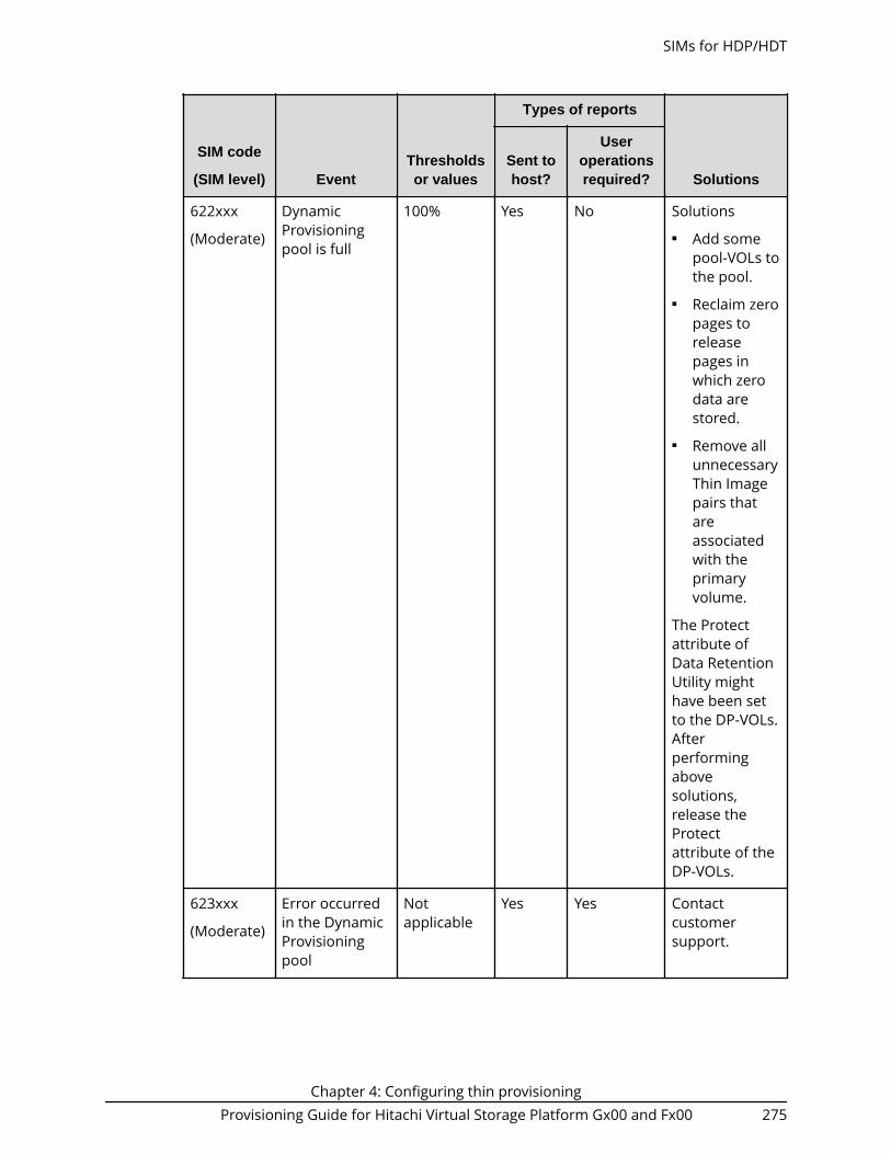
SIM code
(SIM level) EventThresholdsor values
Types of reports
SolutionsSent tohost?
Useroperationsrequired?
622xxx
(Moderate)
DynamicProvisioningpool is full
100% Yes No Solutions■ Add some
pool-VOLs tothe pool.
■ Reclaim zeropages toreleasepages inwhich zerodata arestored.
■ Remove allunnecessaryThin Imagepairs thatareassociatedwith theprimaryvolume.
The Protectattribute ofData RetentionUtility mighthave been setto the DP-VOLs.Afterperformingabovesolutions,release theProtectattribute of theDP-VOLs.
623xxx
(Moderate)
Error occurredin the DynamicProvisioningpool
Notapplicable
Yes Yes Contactcustomersupport.
SIMs for HDP/HDT
Chapter 4: Configuring thin provisioningProvisioning Guide for Hitachi Virtual Storage Platform Gx00 and Fx00 275

SIM code
(SIM level) EventThresholdsor values
Types of reports
SolutionsSent tohost?
Useroperationsrequired?
624000
(Moderate)
No space in theshared memory
Notapplicable
Yes Yes Solutions■ Remove
pools thatare notused.
■ Remove DP-VOLs thatare notused.
■ Remove allunnecessaryThin Imagepairs thatareassociatedwith theprimaryvolume.
■ Shrink thepoolcapacities.
SIMs for HDP/HDT
Chapter 4: Configuring thin provisioningProvisioning Guide for Hitachi Virtual Storage Platform Gx00 and Fx00 276
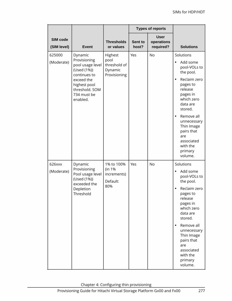
SIM code
(SIM level) EventThresholdsor values
Types of reports
SolutionsSent tohost?
Useroperationsrequired?
625000
(Moderate)
DynamicProvisioningpool usage level(Used (1%))continues toexceed thehighest poolthreshold. SOM734 must beenabled.
Highestpoolthreshold ofDynamicProvisioning
Yes No Solutions■ Add some
pool-VOLs tothe pool.
■ Reclaim zeropages toreleasepages inwhich zerodata arestored.
■ Remove allunnecessaryThin Imagepairs thatareassociatedwith theprimaryvolume.
626xxx
(Moderate)
DynamicProvisioningPool usage level(Used (1%))exceeded theDepletionThreshold
1% to 100%(in 1%increments)
Default:80%
Yes No Solutions■ Add some
pool-VOLs tothe pool.
■ Reclaim zeropages toreleasepages inwhich zerodata arestored.
■ Remove allunnecessaryThin Imagepairs thatareassociatedwith theprimaryvolume.
SIMs for HDP/HDT
Chapter 4: Configuring thin provisioningProvisioning Guide for Hitachi Virtual Storage Platform Gx00 and Fx00 277

SIM code
(SIM level) EventThresholdsor values
Types of reports
SolutionsSent tohost?
Useroperationsrequired?
627xxx
(Moderate)
Pool-VOL isblocked
Notapplicable
Yes Yes Contactcustomersupport.
SIMs for HDP/HDT
Chapter 4: Configuring thin provisioningProvisioning Guide for Hitachi Virtual Storage Platform Gx00 and Fx00 278

SIM code
(SIM level) EventThresholdsor values
Types of reports
SolutionsSent tohost?
Useroperationsrequired?
628000
(Service)
Protectattribute ofData RetentionUtility is set
Notapplicable
Yes Yes Solutions■ Add pool-
VOLs to thepool toincrease thefree space inthe pool.
■ Reclaim zeropages toreleasepages inwhich zerodata arestored.
■ Contactcustomersupport torestore thepool-VOL.
■ If theblockedpool-VOL isan externalvolume,verify thestatus of thepathblockadeand theexternal
SIMs for HDP/HDT
Chapter 4: Configuring thin provisioningProvisioning Guide for Hitachi Virtual Storage Platform Gx00 and Fx00 279

SIM code
(SIM level) EventThresholdsor values
Types of reports
SolutionsSent tohost?
Useroperationsrequired?
storagesystem.
Afterperforming theabovesolutions,release theProtectattribute (DataRetentionUtility) of theDP-VOL.
629xxx
(Moderate)
In the DynamicProvisioningpool, the usedcapacityreserved forwritingexceeded theWarningThreshold.
This SIM isreported if theDynamicProvisioningpool containsone or moreLDEVs in theparity groupwithacceleratedcompressionenabled.
1% to 100%(in 1%increments)
Default:70%
Yes No Estimate theFMC capacity tobe added, andthen add theFMC capacity.
SIMs for HDP/HDT
Chapter 4: Configuring thin provisioningProvisioning Guide for Hitachi Virtual Storage Platform Gx00 and Fx00 280

SIM code
(SIM level) EventThresholdsor values
Types of reports
SolutionsSent tohost?
Useroperationsrequired?
62Axxx
(Moderate)
In the DynamicProvisioningpool, thecapacityreserved forwriting is full.
This SIM isreported if theDynamicProvisioningpool containsone or moreLDEVs in theparity groupwithacceleratedcompressionenabled.
100% Yes No Estimate theFMC capacity tobe added, andthen add theFMC capacity.
62B000
(Moderate)
In theDynamicProvisioningpool, the usedcapacityreserved forwritingcontinues toexceed thehighest poolthreshold. SOM734 must beenabled.
This SIM isreported if theDynamicProvisioningpool containsone or moreLDEVs in theparity groupwithacceleratedcompressionenabled.
Highestpoolthreshold ofDynamicProvisioning
Yes No Estimate theFMC capacity tobe added, andthen add theFMC capacity.
SIMs for HDP/HDT
Chapter 4: Configuring thin provisioningProvisioning Guide for Hitachi Virtual Storage Platform Gx00 and Fx00 281

SIM code
(SIM level) EventThresholdsor values
Types of reports
SolutionsSent tohost?
Useroperationsrequired?
62Cxxx
(Moderate)
In the DynamicProvisioningpool, the usedcapacityreserved forwritingexceeded theDepletionThreshold.
This SIM isreported if theDynamicProvisioningpool containsone or moreLDEVs in theparity groupwithacceleratedcompressionenabled.
1% to 100%(in 1%increments)
Default:80%
Yes No Estimate theFMC capacity tobe added, andthen add theFMC capacity.
SIMs for HDP/HDT
Chapter 4: Configuring thin provisioningProvisioning Guide for Hitachi Virtual Storage Platform Gx00 and Fx00 282

SIM code
(SIM level) EventThresholdsor values
Types of reports
SolutionsSent tohost?
Useroperationsrequired?
62Dxxx
(Moderate)
In the DynamicProvisioningpool, the usedcapacityreserved forwritingexceeded thePrefixedDepletionThreshold.
This SIM isreported if theDynamicProvisioningpool containsone or moreLDEVs in theparity groupwithacceleratedcompressionenabled.
90% Yes No Estimate theFMC capacity tobe added, andthen add theFMC capacity.
62Exxx DynamicProvisioningpool usage levelexceeded thedepletionthreshold. ThisSIM is outputwhen the pooloption"Suspend TIpairs whendepletionthreshold isexceeded" isenabled.
Depletionthreshold
Yes No Solution:Resolve thecause of SIM626xxx(depletionthresholdexceeded), andthen deletesnapshot dataand create thepair again forthe Thin Imagepair whose pairstatus is PSUE.
SIMs for HDP/HDT
Chapter 4: Configuring thin provisioningProvisioning Guide for Hitachi Virtual Storage Platform Gx00 and Fx00 283

SIM code
(SIM level) EventThresholdsor values
Types of reports
SolutionsSent tohost?
Useroperationsrequired?
641xxx
(Service)
In the DynamicTiering pool,the tierrelocationoperation issuspended bythe system.This SIM can bedisplayed if"Notify an alertwhen tierrelocation issuspended bysystem" isenabled on the"Edit AdvancedSystemSettings"window.
Notapplicable
Yes Yes Determine whythe tierrelocation wassuspended.
* xxx = hexadecimal pool number
Managing pools and DP-VOLsObserve the following cautions when working with pools.
Caution:■ In one pool, if you need to perform two or more operations to edit several
items, wait until the first task has been applied before performing the nexttask. If the next task is performed while the first task is being applied, thefirst task is canceled and the next task is applied to the storage system.
■ If you modified pool parameters by using Command Control Interface andthen use Device Manager - Storage Navigator, click File > Refresh All todisplay the latest pool information before performing the next operationby using Device Manager - Storage Navigator. If you use Device Manager -Storage Navigator without refreshing the windows, the informationupdated by Command Control Interface might not yet be displayed on theDevice Manager - Storage Navigator windows, so if you perform anoperation the result might be different from what you expect.
Managing pools and DP-VOLs
Chapter 4: Configuring thin provisioningProvisioning Guide for Hitachi Virtual Storage Platform Gx00 and Fx00 284

Viewing pool information
Use this procedure to view pool information.
Before you begin
The Storage Administrator (Provisioning) role is required to perform this task.
Procedure
1. Click Storage Systems, and then expand the Storage Systems tree.2. Click Pools.
The Pools window displays information about all of the pools in the storage system.
3. To view details about a specific pool, expand Pools, and then select the desiredpool.
Viewing the capacity information for a pool
Use this procedure to view the capacity information for a specific pool.
Before you begin
The Storage Administrator (Provisioning) role is required to perform this task.
Viewing pool information
Chapter 4: Configuring thin provisioningProvisioning Guide for Hitachi Virtual Storage Platform Gx00 and Fx00 285

Procedure
1. Click Storage Systems, and then expand the Storage Systems tree.2. Click Pools.
For details about the capacity information displayed in the Pools window, see Poolswindow (on page 547) .
Viewing the used pool capacity of a Thin Image root volume
Use this procedure to view the used pool capacity of a Thin Image root volume.
Before you begin
The Storage Administrator (Provisioning) role is required to perform this task.
Procedure
1. Click Storage Systems, and then expand the Storage Systems tree.2. Click Pools.3. In the Pools tab, click the pool that contains the desired Thin Image root volume.
When you select a Thin Image pool, the Root Volumes tab is displayed. When youselect a Dynamic Provisioning pool, the TI Root Volumes tab is displayed.
4. Click the Root Volumes or TI Root Volumes tab.The Used Pool Capacity column displays the used pool capacity of each Thin Imageroot volume in the selected pool.
Viewing formatted pool capacity
Use this procedure to view the formatted pool capacity.
Before you begin
The Storage Administrator (Provisioning) role is required to perform this task.
Procedure
1. Click Storage Systems, and then expand the Storage Systems tree.2. Click Pools.3. From the Pools table, click the row of a pool with the free pool capacity you want to
check.4. Click More Actions to select View Pool Management Status.
The View Pool Management Status window appears.
Viewing the used pool capacity of a Thin Image root volume
Chapter 4: Configuring thin provisioningProvisioning Guide for Hitachi Virtual Storage Platform Gx00 and Fx00 286

Reasons to check pool capacity
The following are cases in which the free space of the pool is not formatted. In thesecases, the free space of the pool may not increase:■ Pools other than the selected pool are being formatted.■ The pool usage level reaches up to the warning threshold or the depletion threshold.■ The selected pool is blocked.■ I/O loads to the storage system are high.■ The cache memory is blocked.■ Pool-VOLs in the selected pool are blocked.■ Pool-VOLs which are external volumes in the selected pool are blocked.■ Correction access executes to the pool-VOL in the selected pool.
Note: The following are cases in which the formatted pool capacity maydecrease:■ New pages are being allocated.■ LDEV format is being performed on the pool-VOL.■ Correction copy is being executed.
Viewing the progress of rebalancing the usage level among paritygroups
Use this procedure to view the progress of rebalancing the usage level among paritygroups of a pool.
Before you begin
The Storage Administrator (Provisioning) role is required to perform this task.
Procedure
1. Click Storage Systems, and then expand the Storage Systems tree.2. Click Pools.3. From the Pools table, click the row of a pool with you want to check the progress of
rebalancing the usage level among parity groups.4. Click More Actions to select View Pool Management Status.
The View Pool Management Status window appears.
Note: The following are cases in which the progress ratio may notincrease:
■ The usage level is being rebalanced among the parity groups in poolsother than the selected pool.
■ Tier relocation is performed.
Reasons to check pool capacity
Chapter 4: Configuring thin provisioningProvisioning Guide for Hitachi Virtual Storage Platform Gx00 and Fx00 287

Expanding a pool
To expand a pool (that is, increase the capacity of the pool), you add pool-VOLs to thepool.
Note:■ You cannot expand a pool while the pool is being shrunk.■ When you add pool volumes to a Dynamic Tiering pool, tier relocation
activities that are in process are stopped.■ When you add pool volumes with available monitoring information to a
Dynamic Tiering pool, tier relocation is performed. When you add poolvolumes without available monitoring information to a pool, the pageusage rate is averaged in the tier.
Before you begin
The Storage Administrator (Provisioning) role is required to perform this task.
Procedure
1. Click Storage Systems, and then expand the Storage Systems tree.2. Click Pools.3. From the Pools table, select the pool you want to expand. You can expand only one
pool at a time.4. Click Expand Pool.5. In the Expand Pool window, select the pool-VOL.
a. Click Select Pool VOLs.b. In the Select Pool VOLs window, from the Available Pool Volumes table,
select the pool-VOLs you want to assign, and then click Add.The selected pool-VOLs are registered in the Selected Pool Volumes table.
Up to 1024 volumes can be added including the volumes already in the pool.You can use the Filter option to choose volumes by parameter.
Caution: For details about adding of LDEVs carved from acceleratedcompression-enabled parity groups, see Guidelines for pools whenaccelerated compression is enabled (on page 429) .
Note: If necessary, perform the following steps:
■ From Filter option, select ON to filter the rows.
■ Click Select All Pages to select pool-VOLs in the table. To cancelthe selection, click Select All Pages again.
■ Click Options to specify the unit of volumes or the number ofrows to be viewed.
■ To set the tier rank of an external volume to a value other thanMiddle, select a tier rank from External LDEV Tier Rank, thenclick Add.
Expanding a pool
Chapter 4: Configuring thin provisioningProvisioning Guide for Hitachi Virtual Storage Platform Gx00 and Fx00 288

■ For a pool, you can add volumes whose Drive Type/RPMsettings are the same and whose RAID Levels are different. Forexample, you can add the following volumes to the same pool:
Volume whose Drive Type/RPM is SAS/15K and whose RAIDLevel is 5 (3D+1P)
Volume whose Drive Type/RPM is SAS/15K and whose RAIDLevel is 5 (7D+1P)
■ When assigning a pool with DP-VOL enabled with full allocation,LDEVs cannot be added in the parity group with acceleratedcompression enabled.
c. Click OK.The Select Pool VOLs window closes. The number of the selected poolvolumes appears in Total Selected Pool Volumes, and the total capacity of theselected pool-VOL appears in Total Selected Capacity.
6. Click Finish.The Confirm window appears.
7. In the Task Name text box, type a unique name for the task or accept the default.You can enter up to 32 ASCII characters and symbols, with the exception of: \ / : , ;* ? " < > |. The value "date-window name" is entered by default.
8. Click Apply.If Go to tasks window for status is selected, the Tasks window appears.
Changing a pool name
Use this procedure to change a pool name.
Before you begin
The Storage Administrator (Provisioning) role is required to perform this task.
Procedure
1. Click Storage Systems, and then expand the Storage Systems tree.2. Click Pools.3. From the Pools table, select the pool with the name you want to change.4. Click More Actions, and then select Edit Pools.5. In the Edit Pools window, in Pool Name, specify a name for this pool.
a. In Prefix, type the characters that will become the fixed characters for thebeginning of the pool name. The characters are case-sensitive.
b. In Initial Number, type the initial number that will follow the prefix name.
6. Click Finish.The Confirm window appears.
7. In the Task Name text box, type a unique name for the task or accept the default.You can enter up to 32 ASCII characters and symbols, with the exception of: \ / : , ;* ? " < > |. The value "date-window name" is entered by default.
8. Click Apply.
Changing a pool name
Chapter 4: Configuring thin provisioningProvisioning Guide for Hitachi Virtual Storage Platform Gx00 and Fx00 289
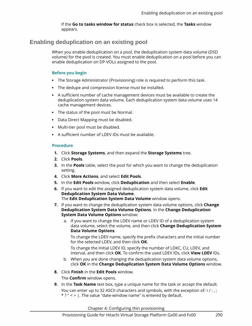
If the Go to tasks window for status check box is selected, the Tasks windowappears.
Enabling deduplication on an existing pool
When you enable deduplication on a pool, the deduplication system data volume (DSDvolume) for the pool is created. You must enable deduplication on a pool before you canenable deduplication on DP-VOLs assigned to the pool.
Before you begin■ The Storage Administrator (Provisioning) role is required to perform this task.■ The dedupe and compression license must be installed.■ A sufficient number of cache management devices must be available to create the
deduplication system data volume. Each deduplication system data volume uses 14cache management devices.
■ The status of the pool must be Normal.■ Data Direct Mapping must be disabled.■ Multi-tier pool must be disabled.■ A sufficient number of LDEV IDs must be available.
Procedure
1. Click Storage Systems, and then expand the Storage Systems tree.2. Click Pools.3. In the Pools table, select the pool for which you want to change the deduplication
setting.4. Click More Actions, and select Edit Pools.5. In the Edit Pools window, click Deduplication and then select Enable.6. If you want to edit the assigned deduplication system data volume, click Edit
Deduplication System Data Volume.The Edit Deduplication System Data Volume window opens.
7. If you want to change the deduplication system data volume options, click ChangeDeduplication System Data Volume Options. In the Change DeduplicationSystem Data Volume Options window:
a. If you want to change the LDEV name or LDEV ID of a deduplication systemdata volume, select the volume, and then click Change Deduplication SystemData Volume Options.To change the LDEV name, specify the prefix characters and the initial numberfor the selected LDEV, and then click OK.To change the Initial LDEV ID, specify the number of LDKC, CU, LDEV, andInterval, and then click OK. To confirm the used LDEV IDs, click View LDEV IDs.
b. When you are done changing the deduplication system data volume options,click OK in the Change Deduplication System Data Volume Options window.
8. Click Finish in the Edit Pools window.The Confirm window opens.
9. In the Task Name text box, type a unique name for the task or accept the default.You can enter up to 32 ASCII characters and symbols, with the exception of: \ / : , ;* ? " < > |. The value "date-window name" is entered by default.
Enabling deduplication on an existing pool
Chapter 4: Configuring thin provisioningProvisioning Guide for Hitachi Virtual Storage Platform Gx00 and Fx00 290

10. Click Apply.If Go to tasks window for status is selected, the Tasks window opensautomatically.
Disabling deduplication on a pool
Use this procedure to disable the deduplication function on a pool.
Before you begin■ The Storage Administrator (Provisioning) role is required to perform this task.■ DP-VOLs with Deduplication and Compression enabled must not be assigned to the
target pool.■ For the target pool, the value of Saving Effect > Deduplication (%) must be 0%.
Procedure
1. Click Storage Systems, and then expand the Storage Systems tree.2. Click Pools.3. In the Pools table, select the pool for which you want to change the deduplication
setting.4. Click More Actions, and select Edit Pools.5. In the Edit Pools window, click Deduplication and then select Disable.6. Click Finish.
The Confirm window appears.7. In the Task Name text box, type a unique name for the task or accept the default.
You can enter up to 32 ASCII characters and symbols, with the exception of: \ / : , ;* ? " < > |. The value "date-window name" is entered by default.
8. Click Apply.If the Go to tasks window for status check box is selected, the Tasks windowappears.
Recovering a blocked pool
You can perform failure recovery of a blocked pool. Ordinarily, you should not need touse this procedure. A recovered pool can be used, but the former data is lost.
The recovery time for pools varies depending on pool usage or DP-VOL usage. Allowroughly 20 minutes of recovery time for every 100 TB of pool or DP-VOL usage. Recoverytime may vary depending on the workload of the storage system at the time of recovery.
Before you begin
The Storage Administrator (Provisioning) role is required to perform this task.
Procedure
1. Click Storage Systems, and then expand the Storage Systems tree.2. Click Pools.3. On the Pools tab, select the pool to be recovered.4. Click More Actions, and then select Restore Pools.
Disabling deduplication on a pool
Chapter 4: Configuring thin provisioningProvisioning Guide for Hitachi Virtual Storage Platform Gx00 and Fx00 291

5. In the Confirm window, confirm the settings.6. Enter a unique Task Name or accept the default.
If Go to tasks window for status is checked, the Tasks window opens.
Decreasing pool capacity
When you want to decrease the capacity of, or shrink, a pool, you delete one or morepool volumes (pool-VOLs) from the pool.
About decreasing pool capacity
When you want to decrease the capacity of, or shrink, a pool, you delete one or morepool volumes (pool-VOLs) from the pool. When a pool-VOL is removed from a pool, all ofthe used pages in the pool-VOL are moved to other pool-VOLs in the pool. If you deletethe pool-VOL with the pool's system area, the used capacity and the management areaare moved to other pool-VOLs in the pool. A pool must include one or more pool-VOLs.
For a pool to which a DP-VOL with the data direct mapping attribute disabled belongs, ifa pool-VOL is released after the pool shrinking, the released pool-VOLs (LDEVs) areblocked. If the pool-VOLs (LDEVs) are blocked, format them before using them. If theblocked pool-VOL is an external volume, use Normal Format when formatting thevolume. If the pool-VOL being deleted is an external volume and is disconnected duringdeletion, reconnect the external volume and then retry deleting the pool-VOL.
Note: You cannot perform the following operations on a pool while the shrinkpool operation is in process. Wait until shrinking completes, or stop theshrinking process.■ Expand Pool■ Shrink Pools■ Edit Pools■ Restore Pools
If you delete the pool-VOL with system area, a different system area pool-VOL will beassigned automatically according to the priority shown in the following table. If multiplepool-VOLs of the same drive type exist, the priority of each is determined by internalindex of the storage system.
Priority Data drive type
1 SAS7.2K
2 SAS10K
3 SAS15K
4 SSD
5 External volume
Decreasing pool capacity
Chapter 4: Configuring thin provisioningProvisioning Guide for Hitachi Virtual Storage Platform Gx00 and Fx00 292

Notes on shrinking a Dynamic Provisioning pool
You cannot delete a pool-VOL from a Dynamic Provisioning pool under the followingconditions:■ If the pool-VOL is deleted, the total of the used pool capacity will exceed the pool
threshold.■ If the pool-VOL is deleted, the subscription rate of the total DP-VOL capacity including
the control information will exceed the subscription limit. For details about calculatingthe required pages for one DP-VOL including the control information, see Poolsubscription limit (on page 269) .
■ If the pool-VOL with system area is deleted, the free space in the pool will be less than4.2 GB.
■ In the case that pool-VOLs assigned to the accelerated compression-enabled paritygroup are deleted, the pool-VOLs cannot be deleted if the used capacity reserved forwriting (after the deletion of pool-VOLs) exceeds the threshold due to deleting pool-VOLs.
The used capacity reserved for writing (after deleting pool-VOLs) is calculated asfollows:
Used capacity reserved for writing (after deleting pool-VOLs) = Used capacity reserved for writing (before deleting pool-VOLs) + Total used capacity of pool-VOLs to be deleted × FMC saving ratio
The used capacity reserved for writing (after deleting pool-VOLs) is larger than theused capacity reserved for writing (before deleting pool-VOLs). Because data stored inpool-VOLs belonging to the accelerated compression-enabled parity group ismigrated in the following parity groups due to the shrinking of pool:■ Parity group with accelerated compression is not supported (for example, SAS
drives)■ Parity group with accelerated compression is disabled
Notes on shrinking a Dynamic Tiering pool■ You cannot delete a pool-VOL from a Dynamic Tiering pool under the following
conditions:● If the pool-VOL is deleted, the total of the used pool capacity will exceed the pool
threshold.● If the pool-VOL is deleted, the subscription rate of the total DP-VOL capacity
including the control information will exceed the subscription limit. For detailsabout calculating the required pages for one DP-VOL including the controlinformation, see Pool subscription limit (on page 269) .
● If the pool-VOL with system area is deleted, the free space in the pool will be lessthan 4.2 GB.
■ When the pool-VOL is deleted, the pages contained in the deleted pool-VOL transferto another pool-VOL in the same tier. If the used capacity in the tier exceeds Rate ofFree Space Newly Allocated to, the overflowing pages transfer to another tier.
■ When pool-VOLs in the tier are empty, the appropriate tier is deleted.
About decreasing pool capacity
Chapter 4: Configuring thin provisioningProvisioning Guide for Hitachi Virtual Storage Platform Gx00 and Fx00 293

■ Deleting the pool-VOL stops the tier relocation. The process resumes after the pool-VOL is deleted.
Notes on shrinking a Thin Image pool
You cannot delete a pool-VOL from a Thin Image pool under the following conditions:■ If the pool-VOL is deleted, the used capacity of the pool will exceed the pool
threshold.■ If the pool-VOL with system area is deleted, the free space in the pool will be less than
4.2 GB.
Shrinking a pool
Use this procedure to shrink, or decrease the capacity of, a pool.
Note:■ You can shrink up to eight pools at the same time.■ If you decrease the pool capacity soon after creating the pool or adding a
pool-VOL, processing might take a while to complete.■ You cannot decrease the pool capacity when any of the following
operations is in process in the target pool:● When the pool is being created or deleted● When the pool capacity is being increased or decreased● When the pool is being recovered● When the shrink pool operation is being stopped● When the threshold is being changed● When zero pages are being reclaimed● When DP-VOLs are being created● When DP-VOL capacity is being increased
■ Do not issue a Command Control Interface command to decrease thecapacity of a pool whose capacity is already in the process of beingdecreased.
Before you begin
The Storage Administrator (Provisioning) role is required to perform this task.
Procedure
1. Click Storage Systems, and then expand the Storage Systems tree.2. Click Pools, and then select the pool that you want to shrink.3. On the Pool volumes tab, select the pool-VOL to be deleted.
You can delete the pool-VOL when Yes is displayed in the Shrinkable column.4. Click Shrink Pool.5. In Task Name, type a unique name for the task or accept the default.
Shrinking a pool
Chapter 4: Configuring thin provisioningProvisioning Guide for Hitachi Virtual Storage Platform Gx00 and Fx00 294

You can enter up to 32 ASCII characters and symbols, with the exception of: \ / : , ;* ? " < > |. The value "date-window name" is entered by default.
6. In Estimated Result of Shrinking, review the details of Before Shrinking andAfter Shrinking, including the total pool capacity, the used pool capacity, and thefree pool capacity.
7. If the estimated result of shrinking is acceptable, click Apply.If Go to tasks window for status is selected, the Tasks window appears.
Stopping the decrease of pool capacity
Use this procedure to stop the decrease of pool capacity.
Before you begin
The Storage Administrator (Provisioning) role is required to perform this task.
Procedure
1. Click Storage Systems, and then expand the Storage Systems tree.2. Click Pools.3. From the Pools, select the pool with the capacity you want to stop decreasing.4. Click Stop Shrinking Pools.5. Click Finish.
The Confirm window appears.6. In the Task Name text box, type a unique name for the task or accept the default.
You can enter up to 32 ASCII characters and symbols, with the exception of: \ / : , ;* ? " < > |. The value "date-window name" is entered by default.
7. Click Apply.If Go to tasks window for status is selected, the Tasks window opens.
Deleting a tier in a pool
You must delete all the pool-VOLs in the tier to be deleted. When pool-VOLs in the tierare empty, the appropriate tier is deleted.
If you delete a pool, its pool-VOLs (LDEVs) will be blocked. If they are blocked, formatthem before using them.
You cannot delete the pool-VOL when:■ Creating the pool.■ Deleting the pool.■ Increasing the pool capacity.■ Decreasing the pool capacity.■ Restoring the pool.■ Stopping decreasing the pool capacity.■ Changing the threshold.■ Initializing the pool capacity.■ Changing the external LDEV tier rank.
Stopping the decrease of pool capacity
Chapter 4: Configuring thin provisioningProvisioning Guide for Hitachi Virtual Storage Platform Gx00 and Fx00 295

Notes on deleting a tier in a pool
You cannot delete a pool-VOL under these conditions.■ The used capacity of the pool-VOL would exceed the pool threshold if the pool-VOL
were deleted.■ The subscription rate of the total V-VOL capacity including the control information
would exceed the subscription limit if the pool-VOL were deleted. For details aboutthe formula used to calculate the required pages for one DP-VOL including the controlinformation, see Pool subscription limit (on page 269) .
■ The pool-VOL with system area has less than 4.2 GB of free space. There must be 4.2GB of free space in the pool in order to delete the pool-VOL with system area.
Deleting the pool-VOL stops the tier relocation. The process resumes after the pool-VOLis deleted.
Before you begin
The Storage Administrator (Provisioning) role is required to perform this task.
Procedure
1. Click Storage Systems, and then expand the Storage Systems tree.2. Click Pools.3. Select the pool that contains the pool-VOLs to be deleted.4. Select the Pool volumes tab and select all the pool-VOLs contained in the tier to be
deleted.You cannot delete a pool-VOL unless Shrinkable has been applied.
5. Click Shrink Pool.6. In the Shrink Pool window, verify the changes.
The details of Before Shrinking and After Shrinking, including the pool capacity,the used pool capacity and the free pool capacity, appears in Prediction ofShrinking.
7. Click Finish.The Confirm window appears.
8. In the Task Name text box, type a unique name for the task or accept the default.You can enter up to 32 ASCII characters and symbols, with the exception of: \ / : , ;* ? " < > |. The value "date-window name" is entered by default.
9. Click Apply.If the Go to tasks window for status check box is selected, the Tasks windowappears.
Deleting a pool
Use this procedure to delete a pool.
For a pool that contains a DP-VOL with a disabled data direct mapping attribute, if pool-VOLs are released after the pool shrinking, the released pool-VOLs (LDEVs) will beblocked.
You can delete a pool only after all of the DP-VOLs have been deleted.
Deleting a pool
Chapter 4: Configuring thin provisioningProvisioning Guide for Hitachi Virtual Storage Platform Gx00 and Fx00 296

Caution: When you delete a pool, its pool-VOLs (LDEVs) are blocked. Blockedvolumes must be formatted before use. If a blocked pool-VOL is an externalvolume, select Normal Format when formatting the volume.
Before you begin■ The Storage Administrator (Provisioning) role is required to perform this task.■ No DP-VOLs other than the deduplication system data volume must be associated
with the target pool.
Procedure
1. Click Storage Systems, and then expand the Storage Systems tree.2. Click Pools.3. From the Pools table, select the pool to be deleted.4. Click More Actions, and then select Delete Pools.
The Delete Pools window opens.5. Click Finish.
The Confirm window opens.To continue with the shredding operation and delete volume data, click Next. Fordetails about the shredding operation, see the Hitachi Volume Shredder User Guide.If the pool is blocked, you might not be able to perform shredding operations.
6. In the Task Name text box, type a unique name for the task or accept the default.You can enter up to 32 ASCII characters and symbols, with the exception of: \ / : , ;* ? " < > |. The value "date-window name" is entered by default.
7. Click Apply.If the Go to tasks window for status check box is selected, the Tasks windowappears.
Note: When the pool-VOLs of a pool are empty, the appropriate tier isdeleted.
Changing the tier rank of an external pool-VOL
Use this procedure to change the tier rank of an external pool-VOL.
Note: You cannot change the tier rank of an external pool-VOL in thefollowing cases:■ The pool contains DP-VOLs with capacity saving enabled.■ The pool contains a deduplication system data volume.
Before you begin
The Storage Administrator (Provisioning) role is required to perform this task.
Procedure
1. Click Storage Systems, and then expand the Storage Systems tree.2. Expand Pools, and then select the pool that contains the external pool-VOL whose
tier rank you want to change.
Changing the tier rank of an external pool-VOL
Chapter 4: Configuring thin provisioningProvisioning Guide for Hitachi Virtual Storage Platform Gx00 and Fx00 297

3. In the Pool volumes table, select the external pool-VOL whose tier rank you want tochange.External pool-VOLs are indicated by External Volume in the Drive Type/RPMcolumn.
4. Click More Actions > Edit External LDEV Tier Rank.5. In the Edit External LDEV Tier Rank, select the external pool-VOL.6. Click Change, and then select the desired tier rank (High, Middle, or Low).7. Click Finish.
The Confirm window appears.8. In the Task Name text box, enter the task name.
You can enter up to 32 ASCII characters and symbols in all, except for \ / : , ; * ? " < >|. "date-window name" is entered by default.
9. Click Apply to register the setting in the task.If Go to tasks window for status is selected, the Tasks window opens.
Increasing DP-VOL capacity
Use this procedure to increase the capacity of a DP-VOL.
Before you begin
The Storage Administrator (Provisioning) role is required to perform this task.
Procedure
1. Click Storage Systems, and then expand the Storage Systems tree.2. Click Pools.3. Select the pool associated with the DP-VOL that has the capacity that you want to
increase.4. Select the Virtual Volumes tab.5. From the table, select the DP-VOL with the capacity you want to increase.6. Click Expand V-VOLs.
The Expand V-VOLs window opens. If the DP-VOL is selected from the LDEV table inthe Logical Devices window, click More Actions, and then click Expand V-VOLs.
7. Select Specify total capacity or Specify additional capacity.8. If you want to offset the specified LDEV capacity by boundary, change the default
Capacity Compatibility Mode (Offset boundary) from OFF to ON.9. In Capacity, type the capacity amount.
Enter the LDEV capacity to two decimal places within the range of values indicatedbelow the text box.
10. Click Finish.The Confirm window appears.
11. In the Task Name text box, type a unique name for the task or accept the default.You can enter up to 32 ASCII characters and symbols, with the exception of: \ / : , ;* ? " < > |. The value "date-window name" is entered by default.
12. Click Apply.If the Go to tasks window for status check box is selected, the Tasks windowappears.
Increasing DP-VOL capacity
Chapter 4: Configuring thin provisioningProvisioning Guide for Hitachi Virtual Storage Platform Gx00 and Fx00 298

Changing the name of a DP-VOL
Use this procedure to change the name of a DP-VOL.
Before you begin
The Storage Administrator (Provisioning) role is required to perform this task.
Procedure
1. Click Storage Systems, and then expand the Storage Systems tree.2. Click Pools.3. In the Pools window, click the link of the Pool Name associated with the DP-VOL
you want to rename.4. Select the Virtual Volumes tab, click More Actions, and then Edit LDEVs.5. Check LDEV Name and change the LDEV name, if necessary.
a. In Prefix, type the characters that will become the fixed characters for thebeginning of the LDEV name. The characters are case-sensitive.
b. In Initial Number, type the initial number that will follow the prefix name.
6. Click Finish.The Confirm window appears.
7. In the Task Name text box, type a unique name for the task or accept the default.You can enter up to 32 ASCII characters and symbols, with the exception of: \ / : , ;* ? " < > |. The value "date-window name" is entered by default.
8. Click Apply.If the Go to tasks window for status check box is selected, the Tasks windowappears.
About releasing pages in a DP-VOL
Releasing pages in a DP-VOL frees up pool capacity. When a page in the DP-VOL containszero data, the free capacity of a pool increases after the pages are released. You canreclaim zero pages on each V-VOL and then monitor the progress on the View PoolManagement Status window. If you stop the reclaim zero pages operation, the zeropages that have already been reclaimed cannot be restored.
Logically, there is no difference between a page with zero data and the area of a DP-VOLwithout a page allotted. Both are effectively identical. However, a page with zero datauses pool capacity, whereas a DP-VOL without a page allotted does not use pool capacity.
Zero pages can be reclaimed when all the following conditions are satisfied:■ The DP-VOL is not used in conjunction with another storage system software product
that does not support reclaiming zero pages.
See Using Dynamic Provisioning and Dynamic Tiering with other software products(on page 163) .
■ LDEV formatting is not being performed on the DP-VOL.■ The DP-VOL is not blocked.■ The DP-VOL does not have the data direct mapping attribute enabled.■ The DP-VOL is not a deduplication system data volume.■ The DP-VOL is associated with a pool.
Changing the name of a DP-VOL
Chapter 4: Configuring thin provisioningProvisioning Guide for Hitachi Virtual Storage Platform Gx00 and Fx00 299

■ The pool associated with the DP-VOL is not blocked, or is full and blocked.■ The LUN path is not defined between DP-VOL and the host group enabled with host
mode option 97.
Pages that include control cylinders are not processed when releasing pages in a DP-VOL.
Pages that include file system metadata cannot be reclaimed. Refer to Operating systemand file system capacity (on page 161) for a table of the Pool Capacity Consumed by thefile system.
While releasing pages from a DP-VOL, performance of the host I/O to the DP-VOL maytemporarily decrease due to scanning for non-zero data.
If you stop an operation to reclaim zero pages in mid-stream, the pages that have beenreleased will remain as free pool capacity.
After an operation to reclaim zero pages, Dynamic Provisioning automatically balancesusage levels among parity groups in the pool. This rebalancing is performed on paritygroups related to the pool. If you do not want automatic balancing of the usage levels ofparity groups, call the customer support to change your configuration.
Note: If an operation to reclaim zero pages performs on pools comprised ofpool volumes assigned by parity groups with accelerated compressionenabled, the capacity reserved for writing data may not be reduced incomparison with the reduced pool capacity.
Dynamic Provisioning does not automatically balance the usage levels among paritygroups if the cache memory is not redundant or if the pool usage reaches the threshold.
If all the tracks that belong to a page assigned to a DP-VOL have no records written, youcan reclaim the page and return it to the pool's available capacity.
Caution:
In the following cases, an operation of the reclaim zero pages stops and DP-VOL pages might not be released.■ The pool-VOL accessed by the target DP-VOL is blocked.■ The pool associated with the target DP-VOL is blocked while the operation
to reclaim zero pages is in progress.■ Cache memory failure occurs while the operation to reclaim zero pages is
in progress.■ While the operation to reclaim zero pages is in progress, the initial copy
operation of the TrueCopy pair, the Universal Replicator pair, the global-active device pair, or the ShadowImage pair is performed on the DP-VOL.
■ The LUN path is defined between DP-VOL and the host group enabled withhost mode option 97 while the operation to reclaim zero pages is inprogress.
Releasing pages in a DP-VOL
You can reclaim pages in a DP-VOL to free pool capacity. If a page assigned to a DP-VOLcontains only zero binary data, you can reclaim the page by performing the operation torelease zero pages. Reclaiming the page decreases the used capacity of the pool. Before
Releasing pages in a DP-VOL
Chapter 4: Configuring thin provisioningProvisioning Guide for Hitachi Virtual Storage Platform Gx00 and Fx00 300

releasing pages in a DP-VOL, see About releasing pages in a DP-VOL (on page 299) . If theoperation to release zero pages is performed on V-VOLs enabled for full allocation, theused capacity of the pool is not changed before the operation to release zero pages isperformed.
Before you begin
The Storage Administrator (Provisioning) role is required to perform this task.
Procedure
1. Click Storage Systems, and then expand the Storage Systems tree.2. Click Pools.3. From the table, select the LDEV ID of the volume with the pages you want to
release.4. Click More Actions, and then select Reclaim Zero Pages.
The Reclaim Zero Pages window opens.
You cannot release pages in a DP-VOL when the DP-VOL is not in a normal status orthe DP-VOL is in the process of reclaiming zero pages.
5. Click Finish.The Confirm window appears.
6. In the Task Name text box, type a unique name for the task or accept the default.You can enter up to 32 ASCII characters and symbols, with the exception of: \ / : , ;* ? " < > |. The value "date-window name" is entered by default.
7. Click Apply.If the Go to tasks window for status check box is selected, the Tasks windowappears.After the operation to reclaim zero pages is complete, refresh the display to updatethe Page Status. If the Page Status is not immediately updated, wait a while, thenrefresh the display again.
Note: Completed is displayed as the Page Status even when no pagescan be reclaimed.
If you have started the reclaiming zero pages operation, and the storage system ispowered off the reclaiming zero pages operation will not automatically continueafter the storage system restarts.
In any of the following cases, the reclaiming zero pages will stop, and DP-VOL pageswill not be released:
■ LDEV formatting was performed while reclaiming zero pages.
■ The pool-VOL that is being accessed by the target DP-VOL was blocked.
■ The pool associated with the target DP-VOL was blocked while reclaiming zeropages.
■ Cache memory failure occurred while reclaiming zero pages.
■ The DP-VOL was deleted when zero pages were reclaimed.
■ The initial copy operation between the TrueCopy pair or the Universal Replicatorpair was performed on the DP-VOL in which zero pages were being reclaimed.
Releasing pages in a DP-VOL
Chapter 4: Configuring thin provisioningProvisioning Guide for Hitachi Virtual Storage Platform Gx00 and Fx00 301

Stopping the release of pages in a DP-VOL
Use this procedure to stop the release of pages in a DP-VOL.
Before you begin
The Storage Administrator (Provisioning) role is required to perform this task.
Procedure
1. Click Storage Systems, and then expand the Storage Systems tree.2. Click Pools.3. Select the pool associated with the DP-VOL with pages you want to stop from being
released.4. Select the Virtual Volumes tab.5. From the table, select the DP-VOL with pages you want to stop from being released.6. Click More Actions, and then select Stop Reclaiming Zero Pages.
The Stop Reclaiming Zero Pages window opens.
You cannot stop releasing the pages in a DP-VOL in which zero pages are not beingreclaimed.
7. Click Finish.The Confirm window appears.
8. In the Task Name text box, type a unique name for the task or accept the default.You can enter up to 32 ASCII characters and symbols, with the exception of: \ / : , ;* ? " < > |. The value "date-window name" is entered by default.
9. Click Apply.If the Go to tasks window for status check box is selected, the Tasks windowappears.
Changing full allocation settings in DP-VOLs
Use the following procedure to change full allocation settings in DP-VOLs.
Caution: This operation cannot be performed on the following types of DP-VOLs:■ Deduplication system data volumes■ DP-VOLs with a capacity saving function enabled
Before you begin
The Storage Administrator (Provisioning) role is required to perform this task.
Procedure
1. Click Storage Systems, and then expand the Storage Systems tree.2. Click Pools.3. On the Pools tab, click the link of the Pool Name associated with the volume that
has settings that you want to change.4. Select the Virtual Volumes tab, click More Actions, then Edit LDEVs.
The Edit LDEVs window opens.
Stopping the release of pages in a DP-VOL
Chapter 4: Configuring thin provisioningProvisioning Guide for Hitachi Virtual Storage Platform Gx00 and Fx00 302

5. In the Edit LDEVs window, check Full Allocation and select Enable or Disable.
■ Enable: All pages of a DP-VOL are allocated to the current pool.
■ Disable: All pages of a DP-VOL might not be allocated to the current pool.
Tip: If the pool of DP-VOL contains an LDEV enabled with acceleratedcompression in the parity group, the item of Enable is inactive.
6. Click Finish.The Confirm window appears.
7. In the Task Name text box, type a unique name for the task or accept the default.You can enter up to 32 ASCII characters and symbols, with the exception of: \ / : , ;* ? " < > |. The value "date-window name" is entered by default.
8. Click Apply.If the Go to tasks window for status check box is selected, the Tasks windowappears.
Enabling or disabling tier relocation of a DP-VOL
You can enable or disable tier relocation of individual DP-VOLs or on all DP-VOLs.
DP-VOLs on which tier relocation is disabled are excluded from the targets for the tierrange calculation, and are not reflected in the performance information of pools. If tierrelocation is disabled on all DP-VOLs in a pool, performance information of a pool isunavailable in the View Tier Properties window.
Caution: This operation cannot be performed on the following types of DP-VOLs:■ Deduplication system data volumes■ DP-VOLs with a capacity saving function enabled
Before you begin
The Storage Administrator (Provisioning) role is required to perform this task.
Procedure
1. Click Storage Systems, and then expand the Storage Systems tree.2. Click Pools.3. On the Pools tab, click the link of the Pool Name associated with the DP-VOL you
want to rename.4. Click the Virtual Volumes tab, select an LDEV ID, click More Actions, and then
select Edit LDEVs.5. In the Edit LDEVs window, check tier relocation and select Enable or Disable.
Enable allows tier relocation to be performed to the DP-VOL.
Disable does not allow tier relocation to be performed on the DP-VOL in the case ofboth automatic and manual tier relocation.
6. Click Finish.The Confirm window appears.
7. In the Task Name text box, type a unique name for the task or accept the default.
Enabling or disabling tier relocation of a DP-VOL
Chapter 4: Configuring thin provisioningProvisioning Guide for Hitachi Virtual Storage Platform Gx00 and Fx00 303

You can enter up to 32 ASCII characters and symbols, with the exception of: \ / : , ;* ? " < > |. The value "date-window name" is entered by default.
8. Click Apply.If the Go to tasks window for status check box is selected, the Tasks windowappears.
Enabling capacity saving on DP-VOLs
Use this procedure to enable the capacity saving function (compression, or deduplicationand compression) on an existing DP-VOL. If the DP-VOL is in a Dynamic Tiering pool withactive flash enabled, you cannot enable the capacity saving function.
Requirements for enabling deduplication on a DP-VOL:■ The dedupe and compression license must be installed.■ The deduplication function must be enabled on the pool.■ The pool must not be blocked.■ A sufficient number of cache management devices must be available.■ The LDEV status of the DP-VOL must be Normal.■ The emulation type of the DP-VOL must be OPEN-V.■ The capacity saving status of the pool must not be Deleting Volume, Failed, or
Rehydrating.■ Data Direct Mapping must be disabled.■ Full Allocation must be disabled.■ The DP-VOL must not be used as a Universal Replicator journal volume.
Caution: Do not use capacity saving and NAS deduplication on the samevolumes, because the additional processing decreases the I/O performancesubstantially. For information about the NAS deduplication function, see theFile Services Administration Guide.
Before you begin■ The Storage Administrator (Provisioning) role is required to perform this task.
Procedure
1. Click Storage Systems, and then expand the Storage Systems tree.2. Click Logical Devices.3. In the LDEVs pane, select an LDEV ID, and click Edit LDEVs.4. In the Edit LDEVs window, click Capacity Saving, and then select either
Compression or Deduplication and Compression.
Caution: If you enable Deduplication and Compression on a DP-VOL,you will not be able to change the setting from Deduplication andCompression to Compression later.
Note:
Enabling capacity saving on DP-VOLs
Chapter 4: Configuring thin provisioningProvisioning Guide for Hitachi Virtual Storage Platform Gx00 and Fx00 304
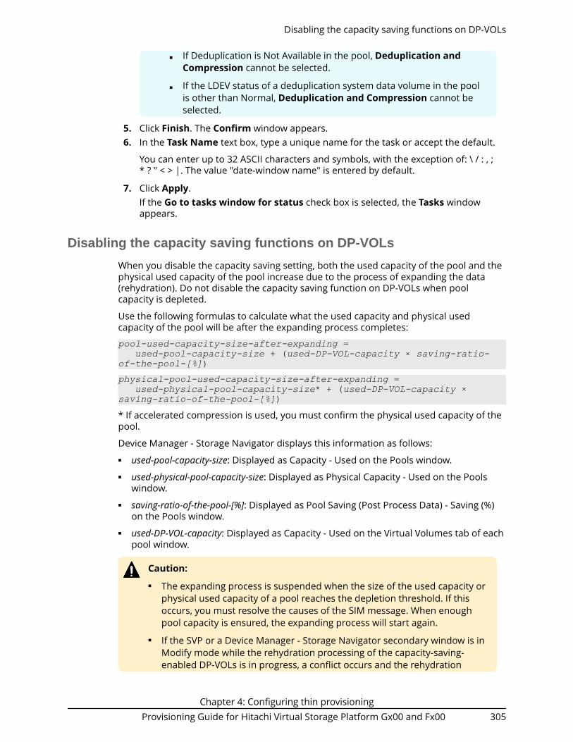
■ If Deduplication is Not Available in the pool, Deduplication andCompression cannot be selected.
■ If the LDEV status of a deduplication system data volume in the poolis other than Normal, Deduplication and Compression cannot beselected.
5. Click Finish. The Confirm window appears.6. In the Task Name text box, type a unique name for the task or accept the default.
You can enter up to 32 ASCII characters and symbols, with the exception of: \ / : , ;* ? " < > |. The value "date-window name" is entered by default.
7. Click Apply.If the Go to tasks window for status check box is selected, the Tasks windowappears.
Disabling the capacity saving functions on DP-VOLs
When you disable the capacity saving setting, both the used capacity of the pool and thephysical used capacity of the pool increase due to the process of expanding the data(rehydration). Do not disable the capacity saving function on DP-VOLs when poolcapacity is depleted.
Use the following formulas to calculate what the used capacity and physical usedcapacity of the pool will be after the expanding process completes:
pool-used-capacity-size-after-expanding = used-pool-capacity-size + (used-DP-VOL-capacity × saving-ratio-of-the-pool-[%])physical-pool-used-capacity-size-after-expanding = used-physical-pool-capacity-size* + (used-DP-VOL-capacity × saving-ratio-of-the-pool-[%])* If accelerated compression is used, you must confirm the physical used capacity of thepool.
Device Manager - Storage Navigator displays this information as follows:■ used-pool-capacity-size: Displayed as Capacity - Used on the Pools window.■ used-physical-pool-capacity-size: Displayed as Physical Capacity - Used on the Pools
window.■ saving-ratio-of-the-pool-[%]: Displayed as Pool Saving (Post Process Data) - Saving (%)
on the Pools window.■ used-DP-VOL-capacity: Displayed as Capacity - Used on the Virtual Volumes tab of each
pool window.
Caution:■ The expanding process is suspended when the size of the used capacity or
physical used capacity of a pool reaches the depletion threshold. If thisoccurs, you must resolve the causes of the SIM message. When enoughpool capacity is ensured, the expanding process will start again.
■ If the SVP or a Device Manager - Storage Navigator secondary window is inModify mode while the rehydration processing of the capacity-saving-enabled DP-VOLs is in progress, a conflict occurs and the rehydration
Disabling the capacity saving functions on DP-VOLs
Chapter 4: Configuring thin provisioningProvisioning Guide for Hitachi Virtual Storage Platform Gx00 and Fx00 305

processing does not complete (Capacity Saving Status remainsRehydrating). In this case, change the SVP or secondary window to Viewmode.
Note: Disabling the capacity saving setting for DP-VOLs with deduplicationand compression enabled might take a while to complete. After theprocessing to disable the setting has started, it cannot be stopped. I/Os canbe received during rehydration (Rehydrating status).
Before you begin■ The Storage Administrator (Provisioning) role is required to perform this task.■ The status of the pool must be other than Blocked by pool failure.■ The Capacity Saving status must be other than Deleting Volume or Failed.
Procedure
1. Click Storage Systems, and then expand the Storage Systems tree.2. Click Logical Devices.3. In the LDEVs pane, select the desired LDEV ID, and click Edit LDEVs.4. In the Edit LDEVs window, click Capacity Saving, and select Disabled.
Note: If the LDEV status of the deduplication system data volume in thepool is other than Normal, you cannot change the setting fromDeduplication and Compression to Disabled.
5. Click Finish. The Confirm window appears.6. In the Task Name text box, type a unique name for the task or accept the default.
You can enter up to 32 ASCII characters and symbols, with the exception of: \ / : , ;* ? " < > |. The value "date-window name" is entered by default.
7. Click Apply.If Go to tasks window for status is selected, the Tasks window opensautomatically.
Deleting a DP-VOL
Use this procedure to delete a DP-VOL.
Note:■ You cannot delete a deduplication system data volume (DSD volume). The
deduplication system data volume for a pool is deleted automaticallywhen you disable the Capacity Saving setting for the pool or delete thepool.
■ You cannot delete a DP-VOL if the status is online.■ If you are deleting a DP-VOL with Deduplication and Compression enabled,
you must first disable Deduplication and Compression on the DP-VOLbefore beginning this procedure.
Deleting a DP-VOL
Chapter 4: Configuring thin provisioningProvisioning Guide for Hitachi Virtual Storage Platform Gx00 and Fx00 306
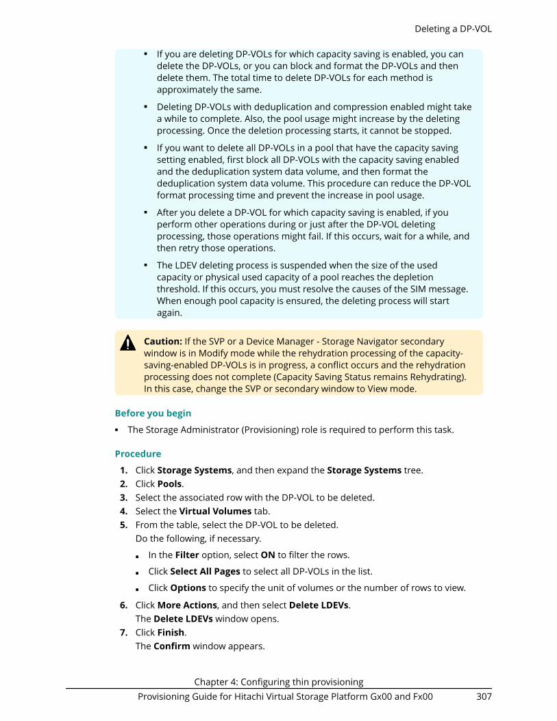
■ If you are deleting DP-VOLs for which capacity saving is enabled, you candelete the DP-VOLs, or you can block and format the DP-VOLs and thendelete them. The total time to delete DP-VOLs for each method isapproximately the same.
■ Deleting DP-VOLs with deduplication and compression enabled might takea while to complete. Also, the pool usage might increase by the deletingprocessing. Once the deletion processing starts, it cannot be stopped.
■ If you want to delete all DP-VOLs in a pool that have the capacity savingsetting enabled, first block all DP-VOLs with the capacity saving enabledand the deduplication system data volume, and then format thededuplication system data volume. This procedure can reduce the DP-VOLformat processing time and prevent the increase in pool usage.
■ After you delete a DP-VOL for which capacity saving is enabled, if youperform other operations during or just after the DP-VOL deletingprocessing, those operations might fail. If this occurs, wait for a while, andthen retry those operations.
■ The LDEV deleting process is suspended when the size of the usedcapacity or physical used capacity of a pool reaches the depletionthreshold. If this occurs, you must resolve the causes of the SIM message.When enough pool capacity is ensured, the deleting process will startagain.
Caution: If the SVP or a Device Manager - Storage Navigator secondarywindow is in Modify mode while the rehydration processing of the capacity-saving-enabled DP-VOLs is in progress, a conflict occurs and the rehydrationprocessing does not complete (Capacity Saving Status remains Rehydrating).In this case, change the SVP or secondary window to View mode.
Before you begin■ The Storage Administrator (Provisioning) role is required to perform this task.
Procedure
1. Click Storage Systems, and then expand the Storage Systems tree.2. Click Pools.3. Select the associated row with the DP-VOL to be deleted.4. Select the Virtual Volumes tab.5. From the table, select the DP-VOL to be deleted.
Do the following, if necessary.
■ In the Filter option, select ON to filter the rows.
■ Click Select All Pages to select all DP-VOLs in the list.
■ Click Options to specify the unit of volumes or the number of rows to view.
6. Click More Actions, and then select Delete LDEVs.The Delete LDEVs window opens.
7. Click Finish.The Confirm window appears.
Deleting a DP-VOL
Chapter 4: Configuring thin provisioningProvisioning Guide for Hitachi Virtual Storage Platform Gx00 and Fx00 307

8. In the Task Name text box, type a unique name for the task or accept the default.You can enter up to 32 ASCII characters and symbols, with the exception of: \ / : , ;* ? " < > |. The value "date-window name" is entered by default.
9. Click Apply.If the Go to tasks window for status check box is selected, the Tasks windowappears.
Deleting all capacity saving-enabled DP-VOLs in a pool
When a deduplication system data volume is assigned to a pool, use this workflow todelete all of the capacity saving-enabled DP-VOLs in the pool. If the pool does not have adeduplication system data volume, you must use the delete DP-VOL procedure.
This operation formats DP-VOLs. Its execution time is increased by one minute per totalcapacity 40 TB of all DP-VOLs whose Deduplication Data status is Enabled.
Execution time = 5 [min.] + ceiling(total capacity [TB] / 40 [TB])
For example, when the total capacity is 100 TB, the execution time is calculated asfollows:
5 + ceiling(100 / 40) = 5 + ceiling(2.5) = 8 [min.]
1. Block all of the following volumes that are allocated to the target pool using theBlock LDEVs window. For instructions, see Blocking LDEVs (on page 135) .
■ All of the DP-VOLs whose Deduplication Data status is Enabled.
■ The deduplication system data volume for the pool.
2. Format the (blocked) deduplication system data volume using the Format LDEVswindow. Make sure to specify only the single deduplication system data volume forthe target pool. For instructions, see Formatting a specific LDEV (on page 139) .
3. Format all of the (blocked) DP-VOLs whose Deduplication Data status is Enabled inthe pool using the Format LDEVs window. For instructions, see Formatting aspecific LDEV (on page 139) .
Note: The formatting operations for DP-VOLs whose Deduplication Datastatus is Enabled might take a lot of time.
4. Delete all of the (formatted) DP-VOLs whose Deduplication Data status is Enabled inthe pool.
You cannot delete a deduplication system data volume (DSD volume). Thededuplication system data volume for a pool is deleted automatically when youdisable the Capacity Saving setting for the pool or delete the pool.
Starting pool monitoring manuallyUse this procedure to start pool monitoring manually.
Before you begin
The Storage Administrator (Provisioning) role is required to perform this task.
Deleting all capacity saving-enabled DP-VOLs in a pool
Chapter 4: Configuring thin provisioningProvisioning Guide for Hitachi Virtual Storage Platform Gx00 and Fx00 308

Procedure
1. Click Storage Systems, and then expand the Storage Systems tree.2. Click Pools.3. On the Pools tab, click the row of a pool you want to start monitoring.4. Click More Actions, and then select Monitor Pools.5. In the Task Name text box of the Monitor Pools window, enter the task name.
You can enter up to 32 ASCII characters and symbols in all, except for \ / : , ; * ? " < >|. "date-window name" is entered by default.
6. Click Apply to register the setting in the task.If Go to tasks window for status is selected, the Tasks window opens.
Stopping pool monitoring manuallyUse this procedure to stop pool monitoring manually.
Before you begin
The Storage Administrator (Provisioning) role is required to perform this task.
Procedure
1. Click Storage Systems, and then expand the Storage Systems tree.2. Click Pools.3. From the Pools table, click the row of a pool you want to stop monitoring.4. Click More Actions to select Stop Monitoring Pools.5. In the Task Name text box of the Stop Monitoring Pools window, enter the task
name.You can enter up to 32 ASCII characters and symbols in all, except for \ / : , ; * ? " < >|. "date-window name" is entered by default.
6. Click Apply to register the setting in the task.If Go to tasks window for status is selected, the Tasks window opens.
Starting tier relocation manuallyUse this procedure to start tier relocation manually.
Before you begin
The Storage Administrator (Provisioning) role is required to perform this task.
Procedure
1. Click Storage Systems, and then expand the Storage Systems tree.2. Click Pools.3. On the Pools tab, click the row of a pool you want to start monitoring.4. Click More Actions and select Start Tier Relocation.5. In the Task Name text box of the Start Tier Relocation window, enter the task
name.
Stopping pool monitoring manually
Chapter 4: Configuring thin provisioningProvisioning Guide for Hitachi Virtual Storage Platform Gx00 and Fx00 309

You can enter up to 32 ASCII characters and symbols in all, except for \ / : , ; * ? " < >|. "date-window name" is entered by default.
6. In the Start Tier Relocation window, click Apply to register the setting in the task.If Go to tasks window for status is selected, the Tasks window opens.
Stopping tier relocation manuallyUse this procedure to stop tier relocation manually.
Before you begin
The Storage Administrator (Provisioning) role is required to perform this task.
Procedure
1. Click Storage Systems, and then expand the Storage Systems tree.2. Click Pools.3. From the Pools, click the row of a pool you want to start monitoring.4. Click More Actions to select Stop Tier Relocation.
The Stop Tier Relocation window appears.5. In the Task Name text box of the Stop Tier Relocation window, enter the task
name.You can enter up to 32 ASCII characters and symbols in all, except for \ / : , ; * ? " < >|. "date-window name" is entered by default.
6. In the Stop Tier Relocation window, click Apply to register the setting in the task.If the Go to tasks window for status check box is selected, the Tasks windowappears.
Enabling data direct mapping for external volumes, pools,and DP-VOLs
Creating external volumes with data direct mapping enabled
Before you begin
The Storage Administrator (Provisioning) role is required to perform this task.
Procedure
1. Click Storage Systems, and then expand the Storage Systems tree.2. Click Logical Devices.3. In the LDEVs pane of the Logical Devices window, click Create LDEVs.4. In the Create LDEVs window, from the Provisioning Type list, select External as a
provisioning type for the LDEV to be created.5. In Data Direct Mapping, select Enable.6. Click Select Free Spaces.
Stopping tier relocation manually
Chapter 4: Configuring thin provisioningProvisioning Guide for Hitachi Virtual Storage Platform Gx00 and Fx00 310

7. In the Select Free Spaces window, in the Available Free Spaces table, select thefree space to be assigned to the volumes. Do the following, if necessary:
■ To specify the conditions and show the free space, click Filter, specify theconditions, and then click Apply.
■ To specify the unit for capacity and the number of rows to view, click Options.
8. Click View Physical Location.9. In the View Physical Location window, confirm where the selected free space is
physically located, and then click Close.10. In the Select Free Spaces window, if the selected free spaces have no issues, click
OK.11. In the Number of LDEVs per External Volume, confirm that 1 is displayed.12. In LDEV Name, specify a name for this LDEV.
a. In Prefix, type the characters that will become the fixed characters for thebeginning of the LDEV name. The characters are case-sensitive.
b. In Initial Number, type the initial number that will follow the prefix name.
13. In Format Type, select the format type for the LDEV from the list.For an external volume, if you create the LDEV whose emulation type is the opensystem, select Normal Format or No Format.If the external volume can be used as it is, select No Format. The created LDEV canbe used without formatting.If the external volume needs to be formatted, select No Format and then formatthe volume with the external storage system, or select Normal Format.
14. Click Options to show more options.15. In Initial LDEV ID, make sure that an LDEV ID is set. To confirm the used number
and unavailable number, click View LDEV IDs to open the View LDEV IDs window.a. In Initial LDEV ID in the Create LDEVs window, click View LDEV IDs. In the
View LDEV IDs window, the matrix vertical scale represents the second-to-lastdigit of the LDEV number, and the horizontal scale represents the last digit ofthe LDEV number. The LDEV IDs table shows the available, used, and disabledLDEV IDs. In the table, used LDEV numbers appear in blue, unavailablenumbers appear in gray, and unused numbers appear in white. LDEV numbersthat are unavailable may be already in use, or already assigned to anotheremulation group (group by 32 LDEV numbers).
b. Click Close.
16. In the Create LDEVs window, from the MP Unit ID list, select a MP unit to be usedby the LDEVs.
■ If you assign a specific MP unit, select the ID of the MP unit.
■ If you can assign any MP unit, click Auto.
17. Click Add.
The created LDEVs are added to the Selected LDEVs table.
If these required items are not registered, you cannot click Add.
18. If necessary, change the following LDEV settings:a. Click Change LDEV Settings to open the Change LDEV Settings window.
19. If necessary, delete an LDEV from the Selected LDEVs table. Select an LDEV todelete, and then click Remove.
Creating external volumes with data direct mapping enabled
Chapter 4: Configuring thin provisioningProvisioning Guide for Hitachi Virtual Storage Platform Gx00 and Fx00 311

20. Click Finish. The Confirm window appears.To continue the operation for setting the LU path and defining a logical unit, clickNext.
21. In the Task Name text box, type a unique name for the task or accept the default.
You can enter up to 32 ASCII characters and symbols, with the exception of: \ / : , ;* ? " < > |. The value "date-window name" is entered by default.
22. Click Apply.If the Go to tasks window for status check box is selected, the Tasks windowappears.
Creating pools with data direct mapping enabled
Before you begin
The Storage Administrator (Provisioning) role is required to perform this task.
Procedure
1. Click Storage Systems, and then expand the Storage Systems tree.2. Click Pools.3. Click Create Pools.4. From the Pool Type list, select Dynamic Provisioning.5. From the Multi-Tier Pool field, select Disable.6. From the Data Direct Mapping field, select Enable.7. Follow the steps below to select pool-VOLs.
a. From the Drive Type/RPM list, select a data drive type and RPM.b. From the RAID Level list, select RAID level.
If you select External Storage from the Drive Type/RPM list, a hyphen (-)appears and you cannot select the RAID level.
c. Click Select Pool VOLs.The Select Pool VOLs window appears.
d. In the Available Pool Volumes table, select the pool-VOL row to be associatedwith a pool, then click Add.
Select one or more volumes to use as pool-VOLs with system area. For theattribute of the volume, which can be used as the pool-VOLs with system area,a hyphen(-) appears in the Attribute column. In addition, the external volumeof the data direct mapping attribute can be selected as an option. For theattribute of the external volume of the data direct mapping attribute, DataDirect Mapping appears in the Attribute column. After creating the pool, youcan also add the external volume of the data direct mapping attribute.
You can select a value other than Middle from External LDEV Tier Rank andclick Add to set another tier rank for an external volume.The selected pool-VOL is registered in the Selected Pool Volumes table. Up to1,024 volumes can be added to a pool.If LDEVs in an accelerated compression enabled parity group are used as pool-VOLs, these LDEVs can be assigned to only one pool. LDEVs in an acceleratedcompression enabled parity group cannot be assigned to multiple pools aspool-VOLs.
Creating pools with data direct mapping enabled
Chapter 4: Configuring thin provisioningProvisioning Guide for Hitachi Virtual Storage Platform Gx00 and Fx00 312

Tip: Perform the following steps if necessary:
■ Click Filter to open the menu, specify the filtering conditions,and click Apply.
■ Click Select All Pages to select all pool-VOLs in the table. Tocancel the selection, click Select All Pages again.
e. Click OK.The information in the Selected Pool Volumes table is applied to TotalSelected Pool Volumes and Total Selected Capacity.
8. Enter the name in the Pool Name text box.9. Click Options.
10. In the Initial Pool ID text box, type the number of the initial pool ID, from 0 to 127.When you specify a pool ID that was previously registered, the smallest available IDis displayed by default instead of the value you entered. If a pool ID unavailable, nonumber is displayed.
11. In the Subscription Limit text box, enter an integer value from 0 to 65534 as thesubscription rate (%) for the pool.If no number is entered, the subscription rate is set to unlimited.
12. In Protect V-VOLs when I/O fails to Blocked Pool VOL, select Yes or No. If Yes isselected, when the pool-VOL is blocked, DP-VOL is protected from reading andwriting requests. And at the same instant, the access attribute of the DP-VOL ischanged to the Protect attribute.
13. In Protect V-VOLs when I/O fails to Full Pool, select Yes or No. If Yes is selected,when the pool usage reaches the full size, DP-VOL is protected from reading andwriting requests. And at the same instant, the access attribute of the DP-VOL ischanged to the Protect attribute.
14. Click Add.The created pool is added to the Selected Pools table. If invalid values are set, anerror message appears.
The Pool Type, Pool Volume Selection, and Pool Name must be set. If therequired items are not entered or selected, you cannot click Add.
If you select a row and click Detail, the Pool Properties window appears. If youselect a row and click Remove, the message appears asking whether you want toremove the selected row or rows. If you want to remove the row, click OK.
15. Click Next.The Create LDEVs window appears.If Subscription Limit of the created pool is set to 0%, the Create LDEVs windowdoes not appear.
16. Click Finish and the Confirmation window appears.17. Check the settings in the Confirmation window, and then enter the task name in
Task Name. Select the pool radio button and then click Details. The Pool Propertieswindow appears.
18. Click ApplyThe tasks are registered. If the Go to tasks window for status check box isselected, the Tasks window appears.
Creating pools with data direct mapping enabled
Chapter 4: Configuring thin provisioningProvisioning Guide for Hitachi Virtual Storage Platform Gx00 and Fx00 313

Creating DP-VOLs with data direct mapping enabled
Before you begin
The Storage Administrator (Provisioning) role is required to perform this task.
Procedure
1. Click Storage Systems, and then expand the Storage Systems tree.2. Click Logical Devices.3. In the LDEVs pane of the Logical Devices window, click Create LDEVs.4. In the Create LDEVs window, from the Provisioning Type list, select Dynamic
Provisioning.5. From the Data Direct Mapping field, select Enable.6. From the Multi-Tier Pool field, select Disable.7. From the Available Volumes table, select LDEV.8. In the LDEV Name text box, enter the DP-VOL name.
In the Prefix text box, enter the alphanumeric characters, which are fixedcharacters of the head of the DP-VOL name. The characters are case-sensitive.In the Initial Number text box, type the initial number following the prefix name,which can be up to 9 digits.You can enter up to the 32 characters including the initial number.
9. Click Option.10. In the Initial LDEV ID field, make sure that LDEV ID is set.
To confirm the used number and unavailable number, click View LDEV IDs todisplay the View LDEV IDs window.In the table, used LDEV numbers appear in blue, unavailable numbers appear ingray, and unused numbers appear in white. LDEV numbers that are unavailable maybe already in use, or already assigned to another emulation group (group by 32LDEV numbers).
11. From the Cache Partition list, select CLPR.12. From the MP Unit list, select an MP unit.
Select an MP unit to be used by the LDEVs. If you assign a specific MP unit, selectthe ID of the MP unit. If you can assign any MP unit, click Auto.
13. If necessary, change the settings of the V-VOLs.
■ Click Change LDEV Settings to open the Change LDEV Settings window.
14. If necessary, delete a row from the Selected LDEVs table.Select a row to be deleted, then click Remove.
15. Click Add.The created V-VOLs are added to the correct Selected LDEVs table. If invalid valuesare set, an error message appears: The Provisioning Type, Pool Selection, DriveType/RPM, RAID Level, LDEV Capacity, and Number of LDEVs fields must be set.If these required items are not registered, you cannot click Add.
16. Click Finish.The Confirm window appears. To continue the operation for setting the LU pathand define LUN, click Next.
17. In the Task Name in the text box, enter the task name.
Creating DP-VOLs with data direct mapping enabled
Chapter 4: Configuring thin provisioningProvisioning Guide for Hitachi Virtual Storage Platform Gx00 and Fx00 314

You can enter up to 32 ASCII characters and symbols in all, except for \ / : , ; * ? " < >|. "yymmdd-window name" is entered as a default.
18. Click Apply.If the Go to tasks window for status check box is selected, the Tasks windowappears.
Enabling and disabling the data direct mapping attribute for a pool
Use this procedure to enable or disable data direct mapping on an existing pool.
Before you begin
The Storage Administrator (Provisioning) role is required to perform this task.
Procedure
1. Click Storage Systems, and then expand the Storage Systems tree.2. Click Pools.3. If you are enabling data direct mapping on a Dynamic Tiering or active flash pool,
first enable the Multi-Tier Pool option on the pool and apply the setting to thestorage system, and then continue with this procedure.
4. From the Pools table, select the pool for which you want to change the data directmapping attribute.
5. Click More Actions, and then select Edit Pools.6. Select Data Direct Mapping, and then select Enable or Disable.7. Click Finish.
The Confirm window opens.8. In the Task Name text box, type a unique name for the task or accept the default.
You can enter up to 32 ASCII characters and symbols, with the exception of: \ / : , ;* ? " < > |. The value "date-window name" is entered by default.
Enabling and disabling the data direct mapping attribute for a pool
Chapter 4: Configuring thin provisioningProvisioning Guide for Hitachi Virtual Storage Platform Gx00 and Fx00 315

Chapter 4: Configuring thin provisioningProvisioning Guide for Hitachi Virtual Storage Platform Gx00 and Fx00 316

Chapter 5: Protecting volumes using DataRetention Utility
After provisioning your system, you can assign access attributes to open-system volumesto protect the volumes against read, write, and copy operations and to prevent usersfrom configuring LU paths and command devices. Data Retention Utility software isrequired to assign access attributes to volumes.
About access attributesOpen-systems volumes, by default, are subject to read and write operations by open-systems hosts. With open-system volumes in this default condition, data might bedamaged or lost if an open-systems host performs erroneous write operations. Inaddition, confidential data on open-systems volumes might be stolen if a maliciousoperator performs read operations on open-systems hosts.
Therefore, it is recommended that you change the default read and write conditions byassigning an access attribute to each logical volume. Access attributes can be set to read/write, read-only, or protect.
By assigning access attributes, you can:■ Protect a volume against both read and write operations of all hosts.■ Protect a volume against write operations of all hosts, but allow read operations.■ Protect a volume against erroneous copy operations, but allow other write
operations.■ Prevent other users from configuring LU paths and command devices.
One of the following access attributes can be assigned to each logical volume:■ Read/write
If a logical volume has the read/write attribute, open-systems hosts can perform bothread and write operations on the logical volume.
You can use replication software to copy data to logical volumes that have read/writeattribute. However, if necessary, you can prevent copying data to logical volumes thathave read/write attribute.
All open-systems volumes have the read/write attribute by default.■ Read-only
If a logical volume has the read-only access attribute, open-systems hosts canperform read operations but cannot perform write operations on the logical volume.
■ Protect
Chapter 5: Protecting volumes using Data Retention UtilityProvisioning Guide for Hitachi Virtual Storage Platform Gx00 and Fx00 317

If a logical volume has the protect access attribute, open-systems hosts cannot accessthe logical volume. Open-systems hosts cannot perform either read nor writeoperations on the logical volume.
Access attribute requirementsTo assign access attributes, the Hitachi Data Retention Utility software must be installed.
The Hitachi Data Retention Utility software performs on the secondary window of HitachiDevice Manager - Storage Navigator. For details about the setting for the secondarywindow, see the System Administrator Guide.
Access attributes and permitted operations
AccessAttribute
ReadOperationsfrom Hosts
WriteOperationsfrom Hosts
Specified as P-VOL
Specified as S-VOL
Read/Write Yes Yes Yes Yes
Read-only Yes No Depends on thereplicationsoftware
No
Protect No No Depends on thereplicationsoftware
No
Read/Writeand S-VOLdisable
Yes Yes Yes No
Access attribute restrictionsSome restrictions apply when you use the following VSP G200, G400, G600, G800 or VSPF400, F600, F800 products or functions on a volume that has an access attributeassigned to it.
Virtual LUN■ You cannot convert into spaces volumes that do not have the read/write attribute.■ You cannot initialize customized volumes that do not have the read/write attribute.
Access attribute requirements
Chapter 5: Protecting volumes using Data Retention UtilityProvisioning Guide for Hitachi Virtual Storage Platform Gx00 and Fx00 318

Command Control Interface■ You can use Command Control Interface to make some Data Retention Utility
settings. You can view some of the CCI settings in the Data Retention Utility userinterface.
■ When viewing the Data Retention window, another user might be using CCI tochange an access attribute of a volume. If the CCI user changes an access attribute ofa volume when you are viewing the Data Retention window, you will be unable tochange the access attribute of the volume by using Data Retention Utility. If youattempt to change the access attribute of the volume by using the Data RetentionUtility, an error occurs. If the error occurs, refresh the display, then retry changing theaccess attribute of the volume.
Automatically started software
If any software that can start automatically is enabled, you must do one of the following:■ Perform Data Retention Utility operations when the program is not running.■ Cancel the setting of the program start time.
Some software is likely to start automatically at the time specified by the user. Forexample, if a Volume Migration user or a Performance Monitoring user specifies the timefor starting the monitor, the monitor will automatically start at the specified time.
Access attributes workflowAccess attribute workflow includes the following steps:
1. Changing an access attribute to read-only or protect (on page 320)2. Changing an access attribute to read/write (on page 321)3. Enabling or disabling the expiration lock (on page 322)4. Disabling an S-VOL (on page 323)5. Reserving volumes (on page 323)
Assigning an access attribute to a volumeIf you want to protect volumes against both read and write operations from hosts,change the access attribute to protect. To protect volumes against write operations fromhosts and allow read operations, change the access attribute to read-only. In both ways,if you set the attribute to a volume using the GUI, S-VOL Disable is automatically set toprevent data in a volume from being overwritten by replication software. If you useCommand Control Interface to set the attribute to a volume, you can select whether theS-VOL Disable is set or not. If you set the Protect attribute to the volume when theDynamic Provisioning pool is full, the S-VOL Disable is not set to the volume.
After you change an access attribute to read-only or protect, the access attribute cannotbe changed to read/write for a certain period of time. You can specify the length of thisperiod (retention term) when changing the access attribute to read-only or protect. Theretention term can be extended but cannot be shortened.
During the retention term■ Read-only access can be changed to protect or protect can be changed to read-only.
Access attributes workflow
Chapter 5: Protecting volumes using Data Retention UtilityProvisioning Guide for Hitachi Virtual Storage Platform Gx00 and Fx00 319

■ If you need to change an access attribute to read/write, you must ask themaintenance personnel to do so.
After the retention term is over■ The access attribute can be changed to read/write.■ The access attribute remains read-only or protect until changed back to read/write.
Changing an access attribute to read-only or protectWhen changing an access attribute to read-only or protect, observe the following:■ Hitachi Device Manager - Storage Navigator secondary windows must be defined for
use in advance. Select Modify from the Data Retention secondary window to setaccess attributes and prevent other users or programs from changing storage systemsettings. When you close the secondary window, Modify mode is released. For moreinformation about Hitachi Device Manager - Storage Navigator secondary windowsand Modify mode, see the System Administrator Guide.
■ Do not assign an access attribute to a volume if any job is manipulating data on thevolume. If you assign an access attribute to such a volume, the job will possibly endabnormally.
■ The volume must not be one of the following:● Volumes that do not exist● Volumes that are configured as command devices● TrueCopy secondary volumes*
● Universal Replicator secondary volumes* or journal volumes● ShadowImage secondary volumes*
● Thin Image secondary volumes*
● Pool volume● Thin Image virtual volume● Volume assigned by the accelerated compression-enabled parity group● In a configuration that has a NAS module installed, volumes that are used from the
NAS module.
*Note: The access attribute of secondary volumes may be changed depending on thepair status.
Before you begin
The Storage Administrator (Provisioning) role is required to perform this task.
Procedure
1. Click Actions > Other Function > Data Retention.
2. Click to change to Modify mode.
3. Select an LDKC number in the LDKC list, select a group that the CU belongs in theCU Group list, then click a CU in the tree.
Changing an access attribute to read-only or protect
Chapter 5: Protecting volumes using Data Retention UtilityProvisioning Guide for Hitachi Virtual Storage Platform Gx00 and Fx00 320

4. Right-click a volume whose access attribute you want to change. You may selectmultiple volumes.
5. Click Attribute, and then select Read Only or Protect.
6. In the Term Setting dialog box, specify the retention term. During this period, theaccess attribute cannot be changed to read/write. You can enter the number ofyears and days, or select Unlimited. The retention term can be extended butcannot be shortened.
■ years: Specify the number of years within the range of 0 to 60. One year iscounted as 365 days, whether the year is a leap year.
■ days: Specify the number of days within the range of 0 to 21900.
For example, if 10 years 5 days or 0 years 3655 days is specified, the accessattribute of the volume cannot be changed to read/write in the next 3,655 days.
7. Click OK to close the dialog box.8. In the Data Retention window, click Apply to apply the setting.
To extend the retention term later, open the Data Retention window, right-click thevolume, and then select Retention Term.
Changing an access attribute to read/writeBefore changing the access attribute from read-only or protect to read/write, consideringthe following:■ Hitachi Device Manager - Storage Navigator secondary windows must be defined for
use in advance. Select Modify from the Data Retention secondary window to setaccess attributes and prevent other users or programs from changing storage systemsettings. When you close the secondary window, Modify mode is released. For moreinformation about Hitachi Device Manager - Storage Navigator secondary windowsand Modify mode, see the System Administrator Guide.
■ Do not assign an access attribute to a volume if any job is manipulating data on thevolume. If you assign an access attribute to such a volume, the job will possibly endabnormally.
■ Make sure that the retention term is expired. If expired, the Retention Term column inthe Data Retention window shows 0. To change the access attribute to read/writewithin the retention term, contact customer support.
■ Make sure that Expiration Lock indicates Disable > Enable. If it indicates Enable >Disable, changing to read/write is restricted by an administrator for some reason.Contact the administrator of your system to ask if you can change the accessattribute. For details, see the Provisioning Guide for your storage system.
Before you begin
The Storage Administrator (Provisioning) role is required to perform this task.
Changing an access attribute to read/write
Chapter 5: Protecting volumes using Data Retention UtilityProvisioning Guide for Hitachi Virtual Storage Platform Gx00 and Fx00 321

Procedure
1. Click Actions > Other Function > Data Retention.
2. Click to change to Modify mode.
3. Select an LDKC number in the LDKC list, select a group in which the CU belongs inthe CU Group list, then click a CU in the tree.
4. Right-click a volume for which you want to change access attributes. You may selectmultiple volumes, select Attribute, then click Read/Write.
5. Click Apply to apply the setting.
Enabling or disabling the expiration lockThe expiration lock provides enhanced volume protection. Enabling the expiration lockensures that read-only volumes and protect volumes cannot be changed to read/writevolumes, even after the retention term ends. Disabling the expiration lock changes theaccess attribute to read/write after the retention term ends. This setting applies to allvolumes in the storage system with the read-only and protect attribute.
Hitachi Device Manager - Storage Navigator secondary windows must be defined for usein advance. When you select Modify from the Data Retention secondary window toenable or disable the expiration lock, other users or programs are prevented fromchanging storage system settings. When you close the secondary window, Modify modeis released. For more information about Hitachi Device Manager - Storage Navigatorsecondary windows and Modify mode, see the System Administrator Guide.
Before you begin
The Storage Administrator (Provisioning) role is required to perform this task.
Procedure
1. Click Actions > Other Function > Data Retention.
2. Click to change to Modify mode.
3. In the Data Retention window, verify which button appears beside ExpirationLock.
■ If Disable > Enable appears, go to the next step.
■ If Enable > Disable appears, expiration lock is already enabled. You do not needto follow the rest of this procedure because attempts to change access attributeto read/write are already prohibited.
4. Click Disable > Enable. A confirmation message appears.5. Click OK. The button changes to Enable > Disable, and the expiration lock is
enabled.When the expiration lock is enabled, the access attributes of volumes cannot bechanged to read/write even after the retention term ends.
To disable the expiration lock, click Enable > Disable. The access attribute can thenbe changed to read/write after the retention term ends.
Enabling or disabling the expiration lock
Chapter 5: Protecting volumes using Data Retention UtilityProvisioning Guide for Hitachi Virtual Storage Platform Gx00 and Fx00 322

Disabling an S-VOLAssigning a read-only or protect attribute is one of the ways to prevent data in a volumefrom being overwritten by replication software. Volumes having the read-only or protectattribute are not only protected against these copy operations, but are also protectedagainst any other form of write operations.
To protect a volume only from copy operations, you must ensure that the volume has theread/write attribute then assign the S-VOL Disable attribute to the volume. This settingprohibits the volume from being used as a secondary volume for copy operations.
Hitachi Device Manager - Storage Navigator secondary windows must be defined for usein advance. When you select Modify from the Data Retention secondary window todisable an S-VOL, other users or programs are prevented from changing storage systemsettings. When you close the secondary window, Modify mode is released. For moreinformation about Hitachi Device Manager - Storage Navigator secondary windows andModify mode, see the System Administrator Guide.
Before you begin■ The Storage Administrator (Provisioning) role is required to perform this task.
■ The volume is other than the volume assigned by the accelerated compression-enabled parity group
Procedure
1. Click Actions > Other Function > Data Retention.
2. Click to change to Modify mode.
3. Select an LDKC number in the LDKC list, select a group that the CU belongs in theCU Group list, and then click a CU in the tree.
4. Right-click a volume for which the S-VOL column shows Enable. You may selectmultiple volumes.
5. Select S-VOL > Disable.6. Click Apply to apply the setting.
To use a volume as an S-VOL, ensure that the volume has the read/write attributethen assign the S-VOL Enable attribute to the volume.
Reserving volumesBy default, all Hitachi Device Manager - Storage Navigator users with proper permissionscan make LU path settings and command device settings. If you perform the followingprocedure in Hitachi Device Manager - Storage Navigator, all users, including yourself,will not be allowed to make LU path settings and command device settings on thespecified volume. Command Control Interface users can still make LU path settings andcommand device settings on the volume.
Hitachi Device Manager - Storage Navigator secondary windows must be defined for usein advance. When you select Modify from the Data Retention secondary window todisable an S-VOL, other users or programs are prevented from changing storage systemsettings. When you close the secondary window, Modify mode is released. For more
Disabling an S-VOL
Chapter 5: Protecting volumes using Data Retention UtilityProvisioning Guide for Hitachi Virtual Storage Platform Gx00 and Fx00 323

information about Hitachi Device Manager - Storage Navigator secondary windows andModify mode, see the System Administrator Guide.
Before you begin■ The Storage Administrator (Provisioning) role is required to perform this task.
■ The volume is not assigned to an accelerated compression-enabled parity group
Procedure
1. Click Actions > Other Function > Data Retention.
2. Click to change to Modify mode.
3. In the Data Retention window, select an LDKC number in the LDKC list, select agroup that the CU belongs in the CU Group list, and then click a CU in the tree.
4. Select a volume where the Reserved column contains a hyphen. You may selectmultiple volumes.
5. Right-click the selected volume or volumes, and then select Reserved > Set.6. Click Apply to apply the setting.
To permit users to make LU path settings and command device settings on avolume, follow the steps above and select Reserved > Release. Then call customersupport to ask for Storage Navigator settings.
Troubleshooting for Data Retention UtilityThe following table provides troubleshooting information for Data Retention Utility.
Problems Probable cause and solution
The Disable/ Enable or theEnable/Disable button onthe Data Retentionwindow is unavailable.Nothing happens when youclick the button.
You have been making changes in the Data Retentionwindow, but the changes have not been applied to thestorage system. Apply the changes first, and thenperform the extension lock operation.
You can find the changes by:■ Scrolling the current list up and down.■ Selecting another CU from the tree and then scrolling
the list up and down.
Open-systems hosts cannotread from or write to avolume.
■ The volume is protected by the read-only attribute.Write failure is reported as an error message.
■ The volume is protected by the Protect attribute.Read (or write) failure is reported as an errormessage.
Troubleshooting for Data Retention Utility
Chapter 5: Protecting volumes using Data Retention UtilityProvisioning Guide for Hitachi Virtual Storage Platform Gx00 and Fx00 324

Problems Probable cause and solution
The number of days inRetention Term does notdecrease
The number of days in Retention Term is calculatedbased on the operating time of the storage system.Therefore, the number of days in Retention Term mightnot decrease.
Troubleshooting for Data Retention Utility
Chapter 5: Protecting volumes using Data Retention UtilityProvisioning Guide for Hitachi Virtual Storage Platform Gx00 and Fx00 325

Chapter 5: Protecting volumes using Data Retention UtilityProvisioning Guide for Hitachi Virtual Storage Platform Gx00 and Fx00 326

Chapter 6: Managing logical volumes
After provisioning your system, you can begin to manage open-system logical volumes.Managing logical volumes includes tasks such as configuring hosts and ports, configuringLU paths, setting LUN security on ports, and setting up Fibre Channel authentication.LUN Manager is required to manage logical volumes.
LUN Manager overview
LUN Manager operations
The VSP G200, G400, G600, G800 and VSP F400, F600, F800 storage systems can beconnected to open-system server hosts of different platforms (for example, UNIX serversand PC servers). To configure your storage system for operation with open-system hosts,use LUN Manager to configure logical volumes and ports.
One of the important tasks when configuring logical volumes is to define I/O paths fromhosts to logical volumes. When paths are defined, the hosts can send commands anddata to the logical volumes and can receive data from the logical volumes.
After the system begins operating, you might need to modify the system configuration.For example, if hosts or drives are added, you will need to add new I/O paths. You canmodify the system configuration using LUN Manager when the system is running. You donot need to restart the system after modifying the system configuration.
Fibre Channel and iSCSI functions
The Fibre Channel functions include the Fibre security control function and the hostgroup function:■ The Fibre security control function controls the access from specific hosts or specific
commands.■ The host group function also enables the storage system to make a suitable response
to each host connected, even within the same port, by grouping connected hostswithin a port and setting the logical unit mapping and the host connection mode foreach host group. You can set up to 255 host groups per port.
The iSCSI functions include the iSCSI security control function and the iSCSI targetfunction.■ The iSCSI security control function controls the access from specific hosts or specific
commands.■ The iSCSI target function enables the storage system to respond to each connected
host, even within the same port, by grouping the connected hosts within a port andsetting LUs and host mode options for each group. You can set up to 255 iSCSI targetsper port. Authentication can be performed for each target by using the CHAPauthentication concurrently.
Chapter 6: Managing logical volumesProvisioning Guide for Hitachi Virtual Storage Platform Gx00 and Fx00 327

Host groups and LU path configuration (Fibre Channel)
After open-system hosts and the storage system are physically connected by cables,hubs, and so on, you can establish I/O paths between the hosts and the logical volumes.This defines which host can access which logical volume. Logical volumes that can beaccessed by open-system hosts are referred to as logical units (LUs). The paths betweenthe open-system hosts and the LUs are referred to as LU paths.
Before defining LU paths, you must classify server hosts by host groups. For example, ifLinux hosts and Windows hosts are connected to the storage system, you must createone host group for the Linux hosts and another host group for the Windows hosts. Then,you must register the host bus adapters of the Linux hosts in the Linux host group, andyou must also register the host bus adapters of the Windows hosts in the Windows hostgroup.
A host group can contain only hosts that are connected to the same port. For example, iftwo Windows hosts are connected to port 1A and three Windows hosts are connected toport 1B, you cannot register all five Windows hosts in one host group. You must registerthe two Windows hosts on port 1A in one host group, and then register the threeWindows hosts on port 1B in another host group.
After server hosts are classified into host groups, you associate the host groups withlogical volumes. The following figure illustrates LU path configuration in a Fibre Channelenvironment. The figure shows host group hg-lnx associated with three logical volumes(00:00:00, 00:00:01, and 00:00:02). LU paths are defined between the two hosts in thehg-lnx group and the three logical volumes.
You can define paths between a single server host and multiple LUs. The figure showsthat each of the two hosts in the host group hg-lnx can access the three LUs.
Host groups and LU path configuration (Fibre Channel)
Chapter 6: Managing logical volumesProvisioning Guide for Hitachi Virtual Storage Platform Gx00 and Fx00 328

You can also define paths between multiple server hosts and a single LU. The figureshows that the LU identified by the LDKC:CU:LDEV number 00:00:00 is accessible fromthe two hosts that belong to the hg-lnx host group.
The figure also shows that the LUs associated with the hg-lnx host group are addressedby numbers 0000 to 0002. The address number of an LU is referred to as a LUN (logicalunit number). When software manipulates LUs, the software use LUNs to specify the LUsto be manipulated.
You can add, change, and delete LU paths when the system is in operation. For example,if new disks or server hosts are added to your storage system, you can add new LUpaths. If an existing server host is to be replaced, you can delete the LU paths thatcorrespond to the host before replacing the host. You do not need to restart the systemwhen you add, change, or delete LU paths.
If a hardware failure (for example, CHA failure) occurs, there is a chance that some LUpaths are disabled and some I/O operations are stopped. To avoid such a situation, youcan define alternate LU paths; if one LU path fails, the alternate path takes over the hostI/O.
Workflow for configuring logical units (Fibre Channel)
Use the following workflow to configure LUs in a Fibre Channel environment.
1. Configure the ports.2. Configure the hosts.3. Configure the LU paths.4. Enable LUN security.5. Set Fibre Channel authentication.6. Manage the hosts.
Rules, restrictions, and guidelines for managing LUs
Rules■ In a Fibre Channel environment, up to 2,048 LU paths can be defined for one host
group, and up to 2,048 LU paths can be defined for one port.■ In an iSCSI environment, up to 2,048 LU paths can be defined for one iSCSI target, and
up to 2,048 LU paths can be defined for one port.■ Up to 255 host groups can be created for one Fibre Channel port.■ Up to 255 iSCSI targets can be created for one iSCSI port.■ For an LDEV with the ALU attribute, you can define the LU path to only one host
group.■ For an LDEV with the ALU attribute, you can define the LU path to only one iSCSI
target.
Restrictions■ You cannot define an LU path to the following types of volumes:
● Journal volumes● Pool volumes
Workflow for configuring logical units (Fibre Channel)
Chapter 6: Managing logical volumesProvisioning Guide for Hitachi Virtual Storage Platform Gx00 and Fx00 329

● External volumes with the data direct mapping attribute● LDEVs created from an accelerated compression-enabled parity group● Deduplication system data volumes
■ When defining LU paths, you must not use Command Control Interface and HitachiDevice Manager - Storage Navigator at the same time. If both programs are usedsimultaneously, operations might not be performed in the expected order, and thestorage configuration might be defined incorrectly.
■ If an LDEV of the ALU attribute is binding to LDEVs with the SLU attribute, the LU pathcannot be removed.
■ To define an LU path between a port and an LDEV that has the T10 PI attributeenabled, the port must have T10 PI mode enabled.
Guidelines■ Queue depth: To ensure smooth processing at the ports and best average
performance, the recommended queue depth setting (max tag count) for VSP Gx00models and VSP Fx00 models is 1,024 per port and 32 per LDEV. Other queue depthsettings, higher or lower than these recommended values, can provide improvedperformance for certain workload conditions.
Caution: Higher queue depth settings (greater than 1,024 per port) canimpact host response times or cause failures such as job abend. Cautionmust be exercised in modifying the recommended queue depth settings.
■ Hitachi multipathing best practice is Single-Initiator Single-Targets configuration inwhich each HBA has only one path to the same LU. For example, you can provide fourpaths to each LU if you have four HBAs. For details, contact customer support.
■ If you attempt to apply many settings in the LUN Manager windows, the SVP might beunable to continue processing. Therefore, you should make no more thanapproximately 1,000 settings. Note that many settings are likely to be made whendefining alternate paths, even though only two commands are required for definingalternate paths.
■ Do not perform the following when host I/O is in progress and hosts are in reservedstatus (mounted):● Remove LU paths● Disable LUN security on a port● Change the data transfer speed for Fibre Channel ports● Change AL-PAs or loop IDs● Change settings of fabric switches● Change the topology● Change the host modes● Remove host groups● Remove iSCSI targets● Setting command devices
■ When a port has a path defined for an LDEV with the GAD reserve attribute and youneed to configure the port (delete a host group, set a command device, or change thehost mode, topology, AL-PA, or transfer speed), the operation might fail if you
Rules, restrictions, and guidelines for managing LUs
Chapter 6: Managing logical volumesProvisioning Guide for Hitachi Virtual Storage Platform Gx00 and Fx00 330

configure more than one port at a time. For ports that have a path defined for anLDEV with the GAD reserve attribute, perform these operations on one port at a time.
Configuring hosts and Fibre Channel portsWhen provisioning your system, configure hosts and Fibre Channel ports using LUNManager. You can manage hosts, modify the host configuration, and modify the portconfiguration when the system is in operation.■ Configuring Fibre Channel ports (on page 331)■ Configuring hosts (on page 337)
Configuring Fibre Channel ports
Setting the data transfer speed on a Fibre Channel port
As system operation continues, you might notice that a large amount of data istransferred at some ports, but a small amount of data is transferred at other ports. Youcan optimize system performance on a Fibre Channel port by setting a faster datatransfer speed on ports where a large amount of data is transferred, and setting a slowerdata transfer speed on ports where a smaller amount of data is transferred.
Caution: When a port has a path defined for an LDEV with the GAD reserveattribute and you need to change the transfer speed, the operation might failif you configure more than one port at a time. For ports that have a pathdefined for an LDEV with the GAD reserve attribute, perform this operationon one port at a time.
Before you begin
The Storage Administrator (Provisioning) role is required to perform this task.
Procedure
1. Click Storage Systems, and then expand the Storage Systems tree.2. Click Ports/Host Groups/iSCSI Targets.3. In the Ports/Host Groups/iSCSI Targets window, click the Ports tab.4. Select the desired port, and then click Edit Ports.5. In the Edit Ports window, select the Port Speed check box, and then select the
desired port speed.Select the speed of the Fibre Channel port in the unit of Gbps (Gigabit per second).If Auto is selected, the storage system automatically sets the speed to 2, 4, 8, or 16Gbps.
Caution: Observe the following cautions when setting speed on a FibreChannel port:
■ If the host bus adapters (HBAs) and switches support 2 Gbps, use thefixed speed of 2 Gbps for the channel board for Fibre Channel
Configuring hosts and Fibre Channel ports
Chapter 6: Managing logical volumesProvisioning Guide for Hitachi Virtual Storage Platform Gx00 and Fx00 331

(CHB(FC)) port speed. If they support 4, 8, or 16 Gbps, use 4, 8, or 16Gbps for the CHB(FC) port speed, respectively.
■ If the Auto Negotiation setting is required, some links might not be upwhen the server is restarted. Check the channel lamp. If it is flashing,disconnect the cable, and then reconnect it to recover from the link-down state.
■ If the CHB(FC) port speed is set to Auto, some equipment might notbe able to transfer data at the maximum speed.
■ When you start a storage system, HBA, or switch, check the hostspeed appearing in the Port list. If the transfer speed is different fromthe maximum speed, select the maximum speed from the list on theright, or disconnect, and then reconnect the cable.
■ The available port speed which is specified in Port Speed is limiteddue to the combination of the type of the Fibre Channel port and thetopology which is specified in Connection Type.
6. Click Finish.The Confirm window appears.
7. In the Task Name text box, type a unique name for the task or accept the default.You can enter up to 32 ASCII characters and symbols, with the exception of: \ / : , ;* ? " < > |. The value <date>-<window name> is entered by default.
8. Click Apply.If the Go to tasks window for status check box is selected, the Tasks windowappears.
Available data-transfer speeds for FC ports
The available data-transfer speeds for the Fibre Channel ports depend on the port typeand the connection type.
The following table shows the available data-transfer speeds for 8-Gbps Fibre Channelports.
Connection type
Data transfer speeds for 8-Gbps ports
2 Gbps 4 Gbps 8 Gbps 16 Gbps 32 Gbps Auto
FC-AL Available Available Available Notavailable
Notavailable
Available(default)
P-to-P Available Available Available Notavailable
Notavailable
Available
Fabric Available Available Available Notavailable
Notavailable
Available
The following table shows the available data-transfer speeds for 16-Gbps Fibre Channelports and for 16-Gbps SFPs on the 4-port FC 32-Gbps package.
Available data-transfer speeds for FC ports
Chapter 6: Managing logical volumesProvisioning Guide for Hitachi Virtual Storage Platform Gx00 and Fx00 332

Connection type
Data transfer speeds for 16-Gbps ports/SFPs
2 Gbps 4 Gbps 8 Gbps 16 Gbps 32 Gbps Auto
FC-AL Notavailable
Available Available Notavailable
Notavailable
Available1
P-to-P Notavailable
Available Available Available Notavailable
Available(default2)
Fabric Available Available Available Available Notavailable
Available
Notes:
1. If this combination is specified, the maximum transfer speed that is automaticallyspecified is 8 Gbps.
2. If this default value is set, Fabric is set to ON automatically.
The following table shows the available data-transfer speeds for 32-Gbps ports (32-GbpsSFPs on the 4-port FC 32-Gbps package).
Connection type
Data transfer speeds for 32-Gbps ports
2 Gbps 4 Gbps 8 Gbps 16 Gbps 32 Gbps Auto
FC-AL Notavailable
Notavailable
Available Notavailable
Notavailable
Available1
P-to-P Notavailable
Notavailable
Available Available Available Available(default2)
Fabric Available Available Available Available Available Available
Notes:
1. If this combination is specified, the maximum transfer speed that is automaticallyspecified is 8 Gbps.
2. If this default value is set, Fabric is set to ON automatically.
Setting the Fibre Channel port address
When configuring your storage system, set addresses for Fibre Channel ports. Whenaddressing Fibre Channel ports, use AL-PA (arbitrated-loop physical address) or loop IDsas the addresses.
Before you begin
The Storage Administrator (Provisioning) role is required to perform this task.
Setting the Fibre Channel port address
Chapter 6: Managing logical volumesProvisioning Guide for Hitachi Virtual Storage Platform Gx00 and Fx00 333
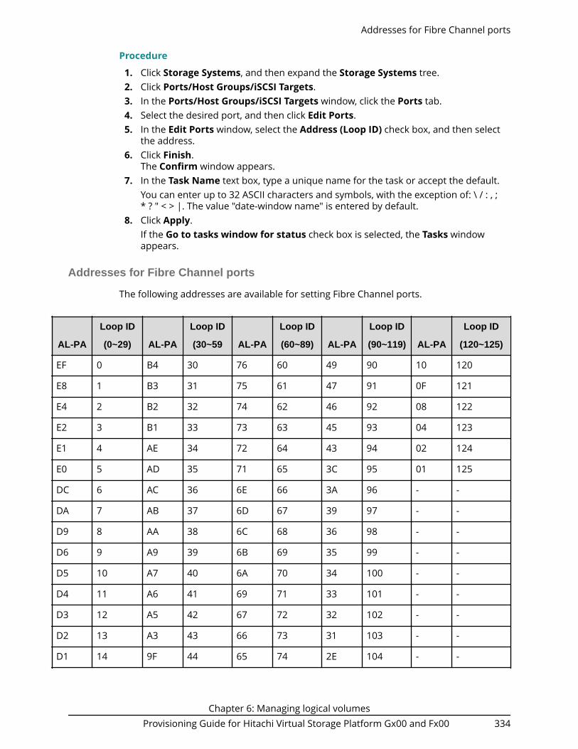
Procedure
1. Click Storage Systems, and then expand the Storage Systems tree.2. Click Ports/Host Groups/iSCSI Targets.3. In the Ports/Host Groups/iSCSI Targets window, click the Ports tab.4. Select the desired port, and then click Edit Ports.5. In the Edit Ports window, select the Address (Loop ID) check box, and then select
the address.6. Click Finish.
The Confirm window appears.7. In the Task Name text box, type a unique name for the task or accept the default.
You can enter up to 32 ASCII characters and symbols, with the exception of: \ / : , ;* ? " < > |. The value "date-window name" is entered by default.
8. Click Apply.If the Go to tasks window for status check box is selected, the Tasks windowappears.
Addresses for Fibre Channel ports
The following addresses are available for setting Fibre Channel ports.
AL-PA
Loop ID
(0~29) AL-PA
Loop ID
(30~59 AL-PA
Loop ID
(60~89) AL-PA
Loop ID
(90~119) AL-PA
Loop ID
(120~125)
EF 0 B4 30 76 60 49 90 10 120
E8 1 B3 31 75 61 47 91 0F 121
E4 2 B2 32 74 62 46 92 08 122
E2 3 B1 33 73 63 45 93 04 123
E1 4 AE 34 72 64 43 94 02 124
E0 5 AD 35 71 65 3C 95 01 125
DC 6 AC 36 6E 66 3A 96 - -
DA 7 AB 37 6D 67 39 97 - -
D9 8 AA 38 6C 68 36 98 - -
D6 9 A9 39 6B 69 35 99 - -
D5 10 A7 40 6A 70 34 100 - -
D4 11 A6 41 69 71 33 101 - -
D3 12 A5 42 67 72 32 102 - -
D2 13 A3 43 66 73 31 103 - -
D1 14 9F 44 65 74 2E 104 - -
Addresses for Fibre Channel ports
Chapter 6: Managing logical volumesProvisioning Guide for Hitachi Virtual Storage Platform Gx00 and Fx00 334

AL-PA
Loop ID
(0~29) AL-PA
Loop ID
(30~59 AL-PA
Loop ID
(60~89) AL-PA
Loop ID
(90~119) AL-PA
Loop ID
(120~125)
CE 15 9E 45 63 75 2D 105 - -
CD 16 9D 46 5C 76 2C 106 - -
CC 17 9B 47 5A 77 2B 107 - -
CB 18 98 48 59 78 2A 108 - -
CA 19 97 49 56 79 29 109 - -
C9 20 90 50 55 80 27 110 - -
C7 21 8F 51 54 81 26 111 - -
C6 22 88 52 53 82 25 112 - -
C5 23 84 53 52 83 23 113 - -
C3 24 82 54 51 84 1F 114 - -
BC 25 81 55 4E 85 1E 115 - -
BA 26 80 56 4D 86 1D 116 - -
B9 27 7C 57 4C 87 1B 117 - -
B6 28 7A 58 4B 88 18 118 - -
B5 29 79 59 4A 89 17 119 - -
Setting the fabric switch
When you configure your storage system, specify whether the hosts and the storagesystem are connected via a fabric switch.
Before you begin
The Storage Administrator (Provisioning) role is required to perform this task.
Procedure
1. Click Storage Systems, and then expand the Storage Systems tree.2. Click Ports/Host Groups/iSCSI Targets.3. In the Ports/Host Groups/ISCSI Targets window, click the Ports tab.4. Select the desired port, and then click Edit Ports.5. Select a check box of Fabric, and select ON if you set the fabric switch. If you do not
set the fabric switch, select OFF.6. Click Finish.
The Confirm window appears.7. In the Task Name text box, type a unique name for the task or accept the default.
Setting the fabric switch
Chapter 6: Managing logical volumesProvisioning Guide for Hitachi Virtual Storage Platform Gx00 and Fx00 335

You can enter up to 32 ASCII characters and symbols, with the exception of: \ / : , ;* ? " < > |. The value "date-window name" is entered by default.
8. Click Apply.If the Go to tasks window for status check box is selected, the Tasks windowappears.
Fibre Channel topology
The term Fibre Channel topology indicates how devices are connected to each other.Fibre channel provides the following types of topology:■ Fabric: Uses a fabric switch to connect a large number of devices (up to 16 million)
together.■ FC-AL (Fibre Channel-Arbitrated Loop): A shared interface that can connect up to 126
devices (AL-ports) together.■ Point-to-point: The simplest fibre topology connects two devices directly together.
When configuring your storage system, use the LUN Manager window to specify whetherthe hosts and the storage system are connected using a fabric switch.
If a fabric switch is used, specify FC-AL or point-to-point in the LUN Manager window. If afabric switch is used, consult the documentation for the fabric switch to learn whetherFC-AL or point-to-point should be used. Some fabric switches require you to specifypoint-to-point to get the system running.
If no fabric switch is used, specify FC-AL.
The combination of the topology which is specified in Connection Type and the portspeed which is specified in Port Speed is restricted. For details, see Available data-transfer speeds for FC ports (on page 332) .
Example of FC-AL and point-to-point topology
Setting the Fibre Channel topology
Use this procedure to set the topology (FC-AL or P-to-P) of a Fibre Channel port.
Caution: When a port has a path defined for an LDEV with the GAD reserveattribute and you need to change the topology, the operation might fail if youconfigure more than one port at a time. For ports that have a path defined
Fibre Channel topology
Chapter 6: Managing logical volumesProvisioning Guide for Hitachi Virtual Storage Platform Gx00 and Fx00 336

for an LDEV with the GAD reserve attribute, perform this operation on oneport at a time.
Procedure
1. Click Storage Systems, and then expand the Storage Systems tree.2. Click Ports/Host Groups/iSCSI Targets.3. In the Ports/Host Groups/iSCSI Targets window, click the Ports tab.4. Select the desired port, and then click Edit Ports.5. Under Connection Type, select FC-AL or P-to-P.6. Click Finish.
The Confirm window opens.7. In the Task Name text box, type a unique name for the task or accept the default.
You can enter up to 32 ASCII characters and symbols, with the exception of: \ / : , ;* ? " < > |. The value <date>-<window name> is entered by default.
8. Click Apply.If the Go to tasks window for status check box is selected, the Tasks windowappears.
Configuring hostsYou can configure hosts in your storage system. You can also modify the hostconfiguration with LUN Manager when the system is in operation.
Read the following topics concerning host modes before configuring hosts:■ Host modes for host groups (on page 337)■ Host mode options (on page 339)
Configuring hosts includes the following tasks:■ How to find the WWN of a host bus adapter (on page 345)■ Creating a host group and registering hosts in the host group (Fibre Channel) (on
page 348) )
Configure hosts workflow
1. Determine the host modes and host mode options you will use.2. Determine the WWN of the host bus adapters that you will use.3. Create host groups.4. Register host groups.
Host modes for host groups
The following table lists the host modes that are available for use on your storagesystem. Carefully review and determine which host modes you will need to use whenconfiguring your system and observe the cautions concerning using certain host modes.Host modes and host mode options must be set on the port before the host isconnected. If you change host modes or host mode options after the host is connected,the host (server) will not recognize it.
Configuring hosts
Chapter 6: Managing logical volumesProvisioning Guide for Hitachi Virtual Storage Platform Gx00 and Fx00 337

Host mode When to select this mode
00 Standard When registering Red Hat Linux server hosts or IRIX server hostsin the host group. When connected to Hitachi NAS Platform(unified or external) version 12.5 or later, select 00 Standard forNAS Platform (User LU) ports and NAS Platform (System LU)ports.
01 (Deprecated)VMware
When registering VMware server hosts in the host group1
03 HP When registering HP-UX server hosts in the host group
05 OpenVMS When registering OpenVMS server hosts in the host group
07 Tru64 When registering Tru64 server hosts in the host group
09 Solaris When registering Solaris server hosts in the host group
0A NetWare When registering NetWare server hosts in the host group
0C (Deprecated)Windows
When registering Windows server hosts in the host group2
0F AIX When registering AIX server hosts in the host group
21 VMwareExtension
When registering VMware server hosts in the host group. If thevirtual host on VMware recognizes LUs by the Raw DeviceMapping (RDM) method, set the host mode related to OS of thevirtual host.
Example: If a LUN/LDEV is formatted as VMFS (where virtualmachines and their VMDK’s usually reside), it should be set withHMO 21. However, if a LUN/LDEV is formatted as a specific filesystem format (for example, NTFS) and has applicationrequirements to be presented directly to a virtual machine as anRDM, it should be set to the HMO specific to that OS/filesystem(e.g., such as HMO 2C for Windows).
A common example of VM’s with this mix would be:
C: drive – OS VMDK on VMFS
D: drive – RDM for application data
In this example, 2 different Host Groups should be created for asingle host with different HMO and LUN’s assigned.
2C WindowsExtension
When registering Windows server hosts in the host group.
Host modes for host groups
Chapter 6: Managing logical volumesProvisioning Guide for Hitachi Virtual Storage Platform Gx00 and Fx00 338

Host mode When to select this mode
Notes:
1. There are no functional differences between host mode 01 and 21. When you firstconnect a host, it is recommended that you set host mode 21.
2. There are no functional differences between host mode 0C and 2C. When you firstconnect a host, it is recommended that you set host mode 2C.
Host mode options
The following table lists the host mode options (HMOs) that are available to use forconfiguring hosts on your storage system.
No. Host mode option When to select this option
2 VERITAS DatabaseEdition/ AdvancedCluster
Oracle Solaris Cluster(Sun Cluster)
When VERITAS Database Edition/Advanced Cluster forOracle Real Application Clusters or VERITAS ClusterServer 4.0 or later (I/O fencing function) is used.
When Oracle Solaris Cluster (Sun Cluster) is used.
6 TPRLO When all of the following conditions are satisfied:■ The host mode 0C (Deprecated) Windows or 2C
Windows Extension is used.
■ The Emulex host bus adapter is used.■ The mini-port driver is used.■ TPRLO=2 is specified for the mini-port driver
parameter of the host bus adapter.
7 Automatic recognitionfunction of LUN
When all of the following conditions are satisfied:■ The host mode 00 Standard or 09 Solaris is
used.■ SUN StorEdge SAN Foundation Software Version 4.2
or later is used.■ You want to automate recognition of increase and
decrease of devices when genuine SUN HBA isconnected.
Enable this HMO when connected to Hitachi NASPlatform version 12.5 or later.
Note: When you use Hitachi Storage Advisor to allocatestorage to the NAS modules on ports 1A and 2A, thisHMO is enabled automatically.
Host mode options
Chapter 6: Managing logical volumesProvisioning Guide for Hitachi Virtual Storage Platform Gx00 and Fx00 339

No. Host mode option When to select this option
12 No display for ghostLUN
When all of the following conditions are satisfied:■ The host mode 03 HP is used.
■ You want to suppress creation of device files fordevices to which paths are not defined.
13 SIM report at linkfailure1
When you want to be informed by SIM (serviceinformation message) that the number of link failuresdetected between ports exceeds the threshold.
14 HP TruCluster withTrueCopy function
When all of the following conditions are satisfied:■ The host mode 07 Tru64 is used.
■ You want to use TruCluster to set a cluster to each ofprimary volume and secondary volume for TrueCopyor Universal Replicator.
15 HACMP/PowerHA® When all of the following conditions are satisfied:■ The host mode 0F AIX is used.
■ HACMP* or PowerHA® is used.
* HACMP 4.5 version 4.5.0.13 or later, HACMP 5.1version 5.1.0.4 or later, or HACMP 5.2 or later.
22 Veritas Cluster Server
Oracle Solaris Cluster(Sun Cluster)
When Veritas Cluster Server is used.
When Oracle Solaris Cluster (Sun Cluster) is used.
25 Support SPC-3behavior onPersistentReservation
When one of the following conditions are satisfied:■ Using Windows Server Failover Clustering (WSFC)■ Using Microsoft Failover Cluster (MSFC)■ Using Symantec Cluster Server, also known as Veritas
Cluster Server (VCS)■ Using a configuration other than above with the
PERSISTENT RESERVE OUT (Service Action=REGISTERAND IGNORE EXISTING KEY) command, change thestatus response from Reservation-Conflict to Good-Status when there is not a registered key to bedeleted
Host mode options
Chapter 6: Managing logical volumesProvisioning Guide for Hitachi Virtual Storage Platform Gx00 and Fx00 340

No. Host mode option When to select this option
33 Set/Report DeviceIdentifier enable
When all of the following conditions are satisfied:■ Host mode 03 HP or 05 OpenVMS1 is used.
■ You want to enable commands to assign a nicknameof the device.
■ You want to set UUID to identify a logical volumefrom the host.
39 Change the nexusspecified in the SCSITarget Reset
When you want to control the following ranges per hostgroup when receiving Target Reset:■ Range of job resetting.■ Range of UAs (Unit Attentions) defined.
40 V-VOL expansion When all of the following conditions are satisfied:■ The host mode 0C (Depreated) Windows or 2C
Windows Extension is used.
■ You want to automate recognition of the DP-VOLcapacity after increasing the DP-VOL capacity.
41 Prioritized devicerecognition command
When you want to execute commands to recognize thedevice preferentially.
43 Queue Full Response When the command queue is full in your storage systemconnecting with the HP-UX host, and if you want torespond Queue Full, instead of Busy, from the storagesystem to the host.
49 BB Credit Set UpOption1
When you want to adjust the number of buffer-to-buffercredits (BBCs) to control the transfer data size by theFibre Channel, for example when the distance betweenMCU and RCU of the TrueCopy (or global-active device)pair is long (approximately 100 kilometers) and thePoint-to-Point topology is used.
Use the combination of this host mode option and thehost mode option 50.
50 BB Credit Set UpOption2
When you want to adjust the number of buffer-to-buffercredits (BBCs) to control the transfer data size by theFibre Channel, for example when the distance betweenMCU and RCU of the TrueCopy (or global-active device)pair is long (approximately 100 kilometers) and thePoint-to-Point topology is used.
Use the combination of this host mode option and thehost mode option 49.
Host mode options
Chapter 6: Managing logical volumesProvisioning Guide for Hitachi Virtual Storage Platform Gx00 and Fx00 341
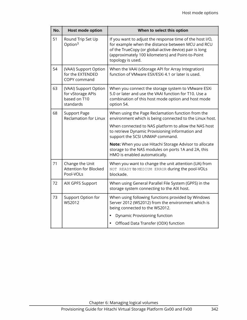
No. Host mode option When to select this option
51 Round Trip Set UpOption3
If you want to adjust the response time of the host I/O,for example when the distance between MCU and RCUof the TrueCopy (or global-active device) pair is long(approximately 100 kilometers) and Point-to-Pointtopology is used.
54 (VAAI) Support Optionfor the EXTENDEDCOPY command
When the VAAI (vStorage API for Array Integration)function of VMware ESX/ESXi 4.1 or later is used.
63 (VAAI) Support Optionfor vStorage APIsbased on T10standards
When you connect the storage system to VMware ESXi5.0 or later and use the VAAI function for T10. Use acombination of this host mode option and host modeoption 54.
68 Support PageReclamation for Linux
When using the Page Reclamation function from theenvironment which is being connected to the Linux host.
When connected to NAS platform to allow the NAS hostto retrieve Dynamic Provisioning information andsupport the SCSI UNMAP command.
Note: When you use Hitachi Storage Advisor to allocatestorage to the NAS modules on ports 1A and 2A, thisHMO is enabled automatically.
71 Change the UnitAttention for BlockedPool-VOLs
When you want to change the unit attention (UA) fromNOT READY to MEDIUM ERROR during the pool-VOLsblockade.
72 AIX GPFS Support When using General Parallel File System (GPFS) in thestorage system connecting to the AIX host.
73 Support Option forWS2012
When using following functions provided by WindowsServer 2012 (WS2012) from the environment which isbeing connected to the WS2012.■ Dynamic Provisioning function■ Offload Data Transfer (ODX) function
Host mode options
Chapter 6: Managing logical volumesProvisioning Guide for Hitachi Virtual Storage Platform Gx00 and Fx00 342

No. Host mode option When to select this option
78 The non-preferredpath option
When all of following conditions are satisfied:■ Global-active device is used in the configuration with
the data centers (Metro configuration).■ Hitachi Dynamic Link Manager is used as the
alternative path software.■ The host group is on the non-optimized path of
Hitachi Dynamic Link Manager.■ The performance deterioration of I/O responses can
be avoided without I/O using the non-optimized pathof Hitachi Dynamic Link Manager.
80 Multi Text OFF By using the iSCSI interface, if the storage systemconnects with the host of which OS is not supported ofthe Multi Text function. For instance, connecting thestorage system and the host of RHEL5.0 which does notsupport the Multi Text-function.
81 NOP-In SuppressMode
In the environment by iSCSI connection, the delayreplying of the Delayed Acknowledgment function whichis located on the upper layer is restrained by sendingNOP-IN of executing of sense commands such asInquiry, Test unit ready, or Mode sense. However, selectthis option when connecting the storage system and thehost which is not necessary of the NOP-IN sending.However, when connecting the storage system and thehost which does not need of the NOP-IN sending, selectthis option.
For instance:■ When connecting the storage system and the Open
Enterprise Server of Novell Co., Ltd.■ When connecting the storage system and winBoot/i
of emBoot Co., Ltd..
82 Discovery CHAP Mode Select this option when the CHAP authentication isperformed at the time of the discovery login In the iSCSIconnection environment.
For instance: When the CHAP authentication isperformed at the time of the discovery login in the iSCSIenvironment of the VMware host and storage system
Host mode options
Chapter 6: Managing logical volumesProvisioning Guide for Hitachi Virtual Storage Platform Gx00 and Fx00 343

No. Host mode option When to select this option
83 Report iSCSI FullPortal List Mode
When configuring alternate paths in the environment ofconnecting the VMware host and storage system: Ifwaiting of replying of the target information from thehost option mode 83 enabled port other than ports ofdiscovery login, select this host mode option.
Apply this host mode option when all of the followingconditions are met:■ Configuring alternate paths in the environment of
connecting the VMware host and storage system.■ Waiting for replying of the target information from
the ports other than ports of discovery login.
88 Nondisruptivemigration with HP-UXhosts
When converging multiple host-target ports used in themigration source storage system on the migration targetstorage system, and enable LUN path definition from ahost group belonging to a virtual storage machine to anLDEV defined in a different virtual storage machine.■ ON: LUN path definition is enabled.■ OFF: LUN path definition is disabled.
Note:
1. Apply this host mode option when all the followingconditions are met:
- You are using the nondisruptive migrationfunction to migrate volumes in multiple old storagemodels that use the same server.
- You need to reduce the number of Target portsused on the migration target storage system.
- The host is an HP-UX server.
2. Applying this option to a server other than HP-UXcan cause the following:
- Path addition from the server to the migrationtarget storage system might fail.
- Display of devices that the server recognizes mightbe invalid.
3. If a LUN path is defined to an LDEV defined in avirtual storage machine different from the one towhich the host group belongs, this option cannotbe set to OFF.
Host mode options
Chapter 6: Managing logical volumesProvisioning Guide for Hitachi Virtual Storage Platform Gx00 and Fx00 344

No. Host mode option When to select this option
91 Disable I/O wait forOpenStack Option
When manually creating host groups (for Fibre Channel)or iSCSI targets (for iSCSI) that are used as the I/O datapaths for OpenStack.
96 Change the nexusspecified in the SCSILogical Unit Reset
When you want to control the following ranges per hostgroup when receiving LU Reset:■ Range of job resetting.■ Range of UAs (Unit Attentions) defined.
97 Proprietary ANCHORcommand support
When connecting to Hitachi NAS Platform.
100 Hitachi HBA (FabricEmulation Mode)Connection Option1
Select this option when connecting the 8-Gbps channelport (in the storage system) and the adapter ofBladeSymphony/HA8000 Hitachi Gigabit Fibre Channelby using the Fabric Emulation mode.
102 (GAD) StandardInquiry Expansion forHitachi CommandSuite
When all of the following conditions are satisfied:■ The OS of the host is Windows (host mode 0C
(Deprecated) Windows or 2C WindowsExtension) or AIX (host mode 0F AIX), and theMPIO function is used.
■ Global-active device (GAD) or nondisruptive migration(NDM) is used.
■ Hitachi Device Manager (HDvM) agent is used.
105 Task Set Full responsein the event of I/Ooverload
When all of following conditions are satisfied:■ The host mode 0C Windows or 2C Windows
Extension is used.■ You want to return Task Set Full response from the
storage system to the host when an overload of I/Osoccurs on the storage system.
Notes:
1. Configure these host mode options only when requested to do so.2. Set the UUID when you set host mode option 33 and host mode 05 openvms is
used.3. Set the host mode option 51 for ports on the remote site of the Hitachi TrueCopy®
pair or the global-active device pair.
How to find the WWN of a host bus adapter
Before physically attaching the storage system to hosts, some preparation work needs tobe performed. After you verify that the Fibre Channel adapters and device drivers are
How to find the WWN of a host bus adapter
Chapter 6: Managing logical volumesProvisioning Guide for Hitachi Virtual Storage Platform Gx00 and Fx00 345

installed on the open-system hosts, you must find the World Wide Name (WWN) of eachhost bus adapter that will be connected to the storage system.
The WWN is a unique identifier (16 hexadecimal digits) for a host bus adapter in anopen-systems host. The method for finding the WWN of a host adapter depends on theoperating system of the host. Make sure to record the WWNs of the host adapters,because you will need to enter these WWNs in Device Manager - Storage Navigatorwindows when you specify the hosts connected to your storage system.■ Finding a WWN on a Windows host (on page 346)■ Finding a WWN on a Solaris host (on page 346)■ Finding a WWN on an AIX, IRIX, or Sequent host (on page 347)■ Finding a WWN on an HP-UX host (on page 347)
Finding a WWN on a Windows host
Emulex Fibre Channel adapters are supported in a Windows environment. For furtherinformation about Fibre Channel adapter support, or when using a Fibre Channeladapter other than Emulex, contact customer support for instructions on finding theWWN.
Before attempting to acquire the WWN of an Emulex adapter, confirm whether the driverinstalled in the Windows 2000 or Windows Server 2003 environment is an Emulex portdriver or an Emulex mini-port driver, and then follow the driver instructions.
Procedure
1. Verify that the Fibre Channel adapters and device drivers are installed.2. Log on to the Windows host with administrator access.3. Go to the LightPulse Utility to open the LightPulse Utility window. If you do not
have a shortcut to the utility:a. Go to the Start menu, select Find and choose the Files and Folders option.b. On the Find dialog box, in Named type lputilnt.exe, and from the Look in
list, choose the data drive that contains the Emulex mini-port driver.c. Choose Find Now to search for the LightPulse utility.
If you still cannot find the LightPulse utility, contact Emulex technical support.d. Select lputilnt.exe from the Find: Files named list, and then press Enter.
4. On the LightPulse Utility window, verify that any installed adapters appear in thetree.
5. In the Category list, choose the Configuration Data option.6. In the Region list, choose the 16 World-Wide Name option. The WWN of the
selected adapter appears in the list on the right of the window.
Finding a WWN on a Solaris host
JNI Fibre Channel adapters are supported in a Solaris environment. For furtherinformation about Fibre Channel adapter support, or if using a Fibre Channel adapterother than JNI, contact customer support for instructions for finding the WWN.
Procedure
1. Verify that the Fibre Channel adapters and device drivers are installed.2. Log on to the Solaris host with root access.
Finding a WWN on a Windows host
Chapter 6: Managing logical volumesProvisioning Guide for Hitachi Virtual Storage Platform Gx00 and Fx00 346

3. Use the dmesg |grep Fibre command to list the installed Fibre Channel devicesand their WWNs.
4. Verify that the Fibre Channel adapters listed are correct, and record the listedWWNs.Example:
# dmesg |grep Fibre <- Enter the dmesg command. : fcaw1: JNI Fibre Channel Adapter model FCW fcaw1: Fibre Channel WWN: 200000e0694011a4 <- Record the WWN. fcaw2: JNI Fibre Channel Adapter model FCW fcaw2: Fibre Channel WWN: 200000e06940121e <- Record the WWN.#
Finding a WWN on an AIX, IRIX, or Sequent host
To find the WWN in an IBM AIX, SGI Irix, or Sequent environment, use the fabric switchthat is connected to the host. The method of finding the WWN of the connected serveron each port using the fabric switch depends on the type of switch. For instructions onfinding the WWN, see the manual of the corresponding switch.
Finding a WWN on an HP-UX host
You can find the WWN in an HP-UX environment.
Procedure
1. Verify that the Fibre Channel adapters and the Fibre Channel device drivers areinstalled.
2. Log in to the HP-UX host with root access.3. At the command line prompt, type:
/usr/sbin/ioscan -fnC lanThis will list the attached Fibre Channel devices and their device file names. Recordthe Fibre Channel device file name (for example, /dev/fcms0).
Note: When the A5158 Fibre Channel adapter is used, at the commandline prompt, enter /usr/sbin/ioscan -fnC fc for the device name.
4. Use the fcmsutil command along with the Fibre Channel device name to list theWWN for that Fibre Channel device. For example, to list the WWN for the device withthe device file name /dev/fcms0, type:/opt/fcms/bin/fcmsutil /dev/fcms0Record the Fibre Channel device file name (for example, /dev/td0).
Note: When using the A5158 Fibre Channel adapter, list the WWN forthe device with the device file name as follows:
/opt/fcms/bin/fcmsutil <device file name>5. Record the WWN and repeat the above steps for each Fibre Channel device that you
want to use.
Finding a WWN on an AIX, IRIX, or Sequent host
Chapter 6: Managing logical volumesProvisioning Guide for Hitachi Virtual Storage Platform Gx00 and Fx00 347
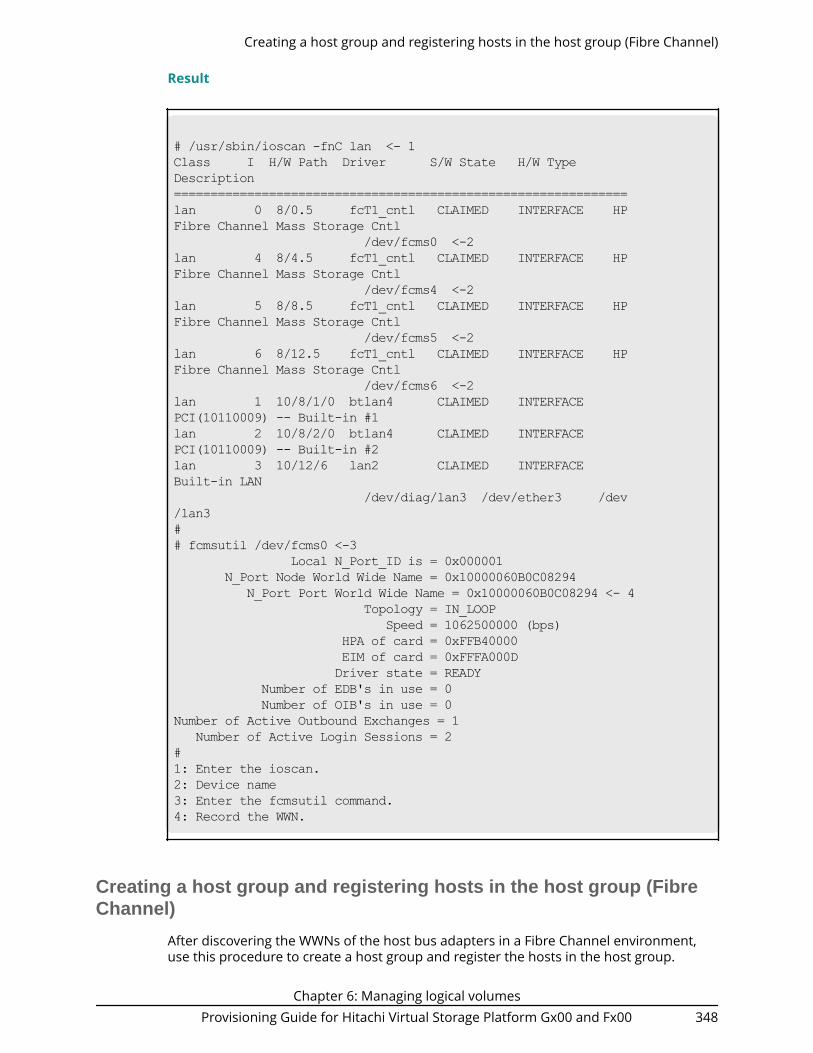
Result
# /usr/sbin/ioscan -fnC lan <- 1Class I H/W Path Driver S/W State H/W TypeDescription==============================================================lan 0 8/0.5 fcT1_cntl CLAIMED INTERFACE HPFibre Channel Mass Storage Cntl /dev/fcms0 <-2 lan 4 8/4.5 fcT1_cntl CLAIMED INTERFACE HPFibre Channel Mass Storage Cntl /dev/fcms4 <-2lan 5 8/8.5 fcT1_cntl CLAIMED INTERFACE HPFibre Channel Mass Storage Cntl /dev/fcms5 <-2lan 6 8/12.5 fcT1_cntl CLAIMED INTERFACE HPFibre Channel Mass Storage Cntl /dev/fcms6 <-2lan 1 10/8/1/0 btlan4 CLAIMED INTERFACEPCI(10110009) -- Built-in #1lan 2 10/8/2/0 btlan4 CLAIMED INTERFACEPCI(10110009) -- Built-in #2lan 3 10/12/6 lan2 CLAIMED INTERFACEBuilt-in LAN /dev/diag/lan3 /dev/ether3 /dev/lan3## fcmsutil /dev/fcms0 <-3 Local N_Port_ID is = 0x000001 N_Port Node World Wide Name = 0x10000060B0C08294 N_Port Port World Wide Name = 0x10000060B0C08294 <- 4 Topology = IN_LOOP Speed = 1062500000 (bps) HPA of card = 0xFFB40000 EIM of card = 0xFFFA000D Driver state = READY Number of EDB's in use = 0 Number of OIB's in use = 0Number of Active Outbound Exchanges = 1 Number of Active Login Sessions = 2#1: Enter the ioscan.2: Device name3: Enter the fcmsutil command.4: Record the WWN.
Creating a host group and registering hosts in the host group (FibreChannel)
After discovering the WWNs of the host bus adapters in a Fibre Channel environment,use this procedure to create a host group and register the hosts in the host group.
Creating a host group and registering hosts in the host group (Fibre Channel)
Chapter 6: Managing logical volumesProvisioning Guide for Hitachi Virtual Storage Platform Gx00 and Fx00 348

You can connect multiple server hosts of different platforms to each port of your storagesystem. When configuring your storage system, you should group server hostsconnected to the storage system by host groups. For example, if HP-UX hosts andWindows hosts are connected to a port, create one host group for HP-UX hosts andanother host group for Windows hosts, and then register the HP-UX hosts to the HP-UXhost group and register the Windows hosts to the Windows host group.
Note: This example applies to configurations in which all HP-UX hosts are onthe same cluster.
Before you begin■ The Storage Administrator (Provisioning) role is required to perform this task.■ Before you can set LU paths, you must register the hosts in host groups. For example,
if HP-UX hosts and Windows hosts are connected to a port, register HP-UX hosts andWindows hosts separately in two different host groups.
■ When registering a host, you must also specify the WWN of the host bus adapters.■ When registering hosts in multiple host groups, set the security switch (LUN security)
to enabled, and then specify the WWN of the host bus adapter.■ When registering a host, you can assign a nickname to the host bus adapter. If you
assign a nickname, you can easily identify each host bus adapter in the LUN Managerwindow. Although WWNs are also used to identify each host bus adapter, thenickname that you assign will be more helpful because you can name host busadapters after the host installation site or for the host owners.
Procedure
1. Click Storage Systems, and then expand the Storage Systems tree.2. Click Ports/Host Groups/iSCSI Targets.3. Click Create Host Groups.4. In the Create Host Groups window, enter the host group name in the Host Group
Name box.
■ It is convenient if you name each host group after the host platform.
■ A host group name can consist of up to 32 ASCII characters (letters, numerals,and symbols). However, you cannot use the following symbols for host groupnames: \ / : , ; * ? " < > |
■ You cannot use space characters for the first and the last characters in hostgroup names.
■ Host group names are case-sensitive. For example, the host group names wntand Wnt represent different host groups.
5. Select the resource group in which a host group is created.If you select Any, ports to which you may add host groups within all ports assignedto a user are displayed in the Available Ports list. If you select other than Any,ports to which you may add host groups within the ports assigned to the selectedresource group are displayed in the Available Ports list.
6. Select a host mode from the Host Mode list. When selecting a host mode, you mustconsider the platform and some other factors.
7. Select hosts to be registered in a host group.If the desired host has ever been connected with a cable to another port in thestorage system, select the desired host bus adapter from the Available Hosts list.
Creating a host group and registering hosts in the host group (Fibre Channel)
Chapter 6: Managing logical volumesProvisioning Guide for Hitachi Virtual Storage Platform Gx00 and Fx00 349

If there is no host to be registered, skip this step and move to the next step.Otherwise, a host group with no host would be created.
If the desired host has never been connected via a cable to any port in the storagesystem, perform the following steps:
a. Click Add New Host under the Available Hosts list.The Add New Host dialog box opens.
b. Enter the desired WWN in the HBA WWN box.c. If necessary, enter a nickname for the host bus adapter in the Host Name box.d. Click OK to close the Add New Host dialog box.e. Select the desired host bus adapter from the Available Hosts list.
8. Select the port to which you want to add the host group. For details about hostmodes, see Host modes for host groups (on page 337) .If you select multiple ports, you may add the same host group to multiple ports byone operation.
9. If necessary, click Option and select host mode options. For details about hostmode options, see Host mode options (on page 339) .
Note: When you click Option, the dialog box expands to display the listof host mode options. The Mode No. column indicates option numbers.Select an option you want to specify and click Enable.
10. Click Add to add the host group.By repeating steps from 2 to 8, you can create multiple host groups.
If you select a row and click Detail, the Host Group Properties window appears. Ifyou select a row and click Remove, the message appears asking whether you wantto remove the selected row or rows. If you want to remove the row, click OK.
11. Click Finish to display the Confirm window.To continue to add LUN paths, click Next.
12. Confirm the settings and enter the task name in the Task Name box.A task name can consist of up to 32 ASCII characters (letters, numerals, andsymbols). Task names are case-sensitive. (date) - (task name) is input by default.
If you select a row and click Detail, the Host Group Properties window appears.
13. Click Apply in the Confirm window.If the Go to tasks window for status check box is selected, the Tasks windowappears.
Setting a command deviceUse this procedure to set a command device for Command Control Interface (CCI) in-band operations.
If you plan to execute CCI commands from an open-systems host (in-band method), youmust set at least one logical device as a CCI command device. The command devicefunctions as the interface to the CCI software on the host. The command device isdedicated to CCI operations and cannot be used by any other applications. You canconfigure more than one command device (primary and alternate command devices) toensure continued operations in the event the primary command device is blocked.
Setting a command device
Chapter 6: Managing logical volumesProvisioning Guide for Hitachi Virtual Storage Platform Gx00 and Fx00 350

A command device can be any OPEN-x device that is accessible to the host on which CCIis installed. A Virtual LUN volume as small as 36 MB can be used as a command device.Make sure the volume to be used as a command device does not contain any user data.The command device will be inaccessible to host applications.
Note: The following volumes cannot be specified as a command device:■ Volume whose access attribute is other than read/write.■ TrueCopy pair volume.■ Global-active device pair volume.■ ShadowImage pair volume.■ Universal Replicator pair volume.■ Virtual volume (V-VOL) for Thin Image.■ Volume reserved by Data Retention Utility.■ Journal volume.■ Pool volume that includes a DP-VOL with the direct mapping attribute
enabled.■ Remote command device.■ LDEV with the ALU attribute.■ Quorum disk for global-active device.■ LDEV with ALUA mode enabled.■ LDEV with the T10 PI attribute enabled.■ LDEV with NAS Platform (User LU) enabled.■ LDEV with NAS Platform (System LU) enabled.
Procedure
1. Click Storage Systems, expand the Storage Systems tree, and click LogicalDevices.
2. On the LDEVs tab, select the volume, and then click More Actions > Edit CommandDevices.
Setting a command device
Chapter 6: Managing logical volumesProvisioning Guide for Hitachi Virtual Storage Platform Gx00 and Fx00 351

3. For Command Device, select Enable.4. In Command Device Attributes, enable the desired attributes.
Option Description
Command DeviceSecurity
Enable this attribute if you plan to use the CCIData Protection Facility.
User Authentication Enable this attribute if you plan to executeprovisioning commands (raidcom) on the storagesystem.
Device Group Definition Enable this attribute if you plan to use devicegroups.
For details about these functions, see the Command Control Interface User andReference Guide.
5. Click Finish.6. In the Confirm window, verify the settings, and enter the task name.
You can enter up to 32 ASCII characters and symbols, with the exception of: \ / : , ;* ? " < > |. The value "date-window name" is entered by default.
7. Click Apply.
If Go to tasks window for status is selected, the Tasks window appears.
Next steps
After you set the command devices on the storage system, you must define thecommand devices in the CCI configuration definition file. For details, see the CCIdocumentation.
Configuring LU pathsWhen provisioning your storage system, and after configuring ports, hosts, and hostgroups, you must configure Fibre Channel LU paths. LUN Manager is required for thesetasks. You can also modify the LU paths configuration when the system is in operation.
Configuring LU paths
Chapter 6: Managing logical volumesProvisioning Guide for Hitachi Virtual Storage Platform Gx00 and Fx00 352

Configure LU paths workflow
■ Define LU paths.■ Set a UUID, if desired.■ Define alternate LU paths.
Defining LU paths
In a Fibre Channel or iSCSI environment, you must define LU paths and associate hostgroups or iSCSI targets with logical volumes. For example, if you associate a host groupor an iSCSI target consisting of three hosts with logical volumes, LU paths are definedbetween the three hosts and the logical volumes.
Before you begin
The Storage Administrator (Provisioning) role is required to perform this task.
Procedure
1. Click Storage Systems, and then expand the Storage Systems tree.2. Click Ports/Host Groups/iSCSI Targets, and select the target host group or iSCSI
target.3. Click Add LUN Paths.4. In the Add LUN Paths window, select the desired LDEVs from the Available LDEVs
table, and then click Add.Selected LDEVs are listed in the Selected LDEVs table.
5. Click Next.6. In Selection Object, click Fibre.7. Select the desired host groups from the Available Host Groups or Available iSCSI
Targets table, and then click Add.Selected host groups are listed in the Selected Host Groups or Available iSCSITargets table.
8. Click Next.9. Confirm the defined LU paths.
If the LDEV name or the LUN ID is edited, perform the following:
1. Select the checkboxes of LDEV IDs that you want to change.2. Click Change LDEV Settings.3. In the Change LDEV Settings window, specify values in Prefix and Initial
Number.4. Click OK.
To change the LUN ID, perform the following:
1. In the LUN ID column (Any number Sets of Paths), select the host groups (iSCSITargets) checkboxes.
2. Select the checkbox of the LDEV ID that you want to change.3. Click Change LUN IDs.4. In the Change LUN IDs window, specify the value in Initial LUN ID.5. Click OK.
Configure LU paths workflow
Chapter 6: Managing logical volumesProvisioning Guide for Hitachi Virtual Storage Platform Gx00 and Fx00 353

10. Click Finish.The Confirm window appears.
11. In the Task Name text box, type a unique name for the task or accept the default.You can enter up to 32 ASCII characters and symbols, with the exception of: \ / : , ;* ? " < > |. The value "date-window name" is entered by default.
12. Click Apply.If the Go to tasks window for status check box is selected, the Tasks windowappears.
Setting a UUID
You can set an arbitrary ID to identify a logical volume from the host when host modeoption 33 is set to on. The ID is referred to as the UUID (universally unique identifier) andis typically composed of a Prefix and an Initial Number.
Note the following when setting a UUID:■ If host mode 05 OpenVMS is used with host mode option 33 set to ON, LUs that do
not have UUID settings are inaccessible.■ If host mode 05 OpenVMS is used with host mode option 33 set to OFF, LUs that have
UUID settings are inaccessible.
The following rules apply to setting a UUID:■ These characters cannot be used for UUID: \ / : , ; * ? " < > |■ A space character cannot be used as the first or the last character of a UUID.■ UUID is case-sensitive. For example, Abc and abc are different UUIDs.
To keep track of device information, create a correspondence table similar to theexample in Correspondence table for defining devices (on page 356) .
Before you begin■ The Storage Administrator (Provisioning) role is required to perform this task.■ Before editing UUID settings, review the information about UUID requirements (on
page 355) .
Procedure
1. Click Storage Systems, and then expand the Storage Systems tree.2. Click Ports/Host Groups/iSCSI Targets.3. In the Host Groups/iSCSI Targets tab, click the link of the Port ID of the host group.4. Click the link of a Host Group Name.5. Click the LUNs tab.6. Select one or more logical units to which volumes are assigned (if a volume is
assigned to an LU, the columns on the right of the LUN column are not empty).When multiple LUs are selected, the same UUID is set to all selected LUs.
7. Click More Actions, and then select Edit UUIDs.8. In the Edit UUIDs window, in Prefix, type the UUID.
If a UUID is already specified, you can change it. The UUID before changing appearsin UUID in the Edit UUIDs window. However, if multiple LUs, or N/As are selected,the Prefix box is blank.
Setting a UUID
Chapter 6: Managing logical volumesProvisioning Guide for Hitachi Virtual Storage Platform Gx00 and Fx00 354

For an OpenVMS server host, enter a UUID composed of a Prefix and an InitialNumber. The Prefix may include up to 5 digits, from 1 to 32767, and the InitialNumber may include up to 5 digits, from 0 to 32767.
For a server host other than OpenVMS, enter a UUID composed of a Prefix and anInitial Number. The Prefix may include up to 64 ASCII characters (letters, numeralsand symbols) and the Initial Number may include up to 9 digits.
When changing the server host OS from HP-UX to OpenVMS, or from OpenVMS toHP-UX, the same UUID cannot be used continuously. Clear the UUID setting (seeClearing a UUID setting (on page 360) ), and then set the proper UUID for a serverhost.
9. To sequentially number the UUIDs, type the first digit in the Initial Number box.The following rules apply to the Initial Number:
1: Up to 9 numbers are added (1, 2, 3, ... 9).08: Up to 92 numbers are added (08, 09, 10, ... 99).If the host mode is set to OpenVMS, the numbers are as follows:8, 9, 10, ... 9923: Up to 77 numbers are added (23, 24, 25, ... 99).
10. Click Finish.The Confirm window appears.
11. In the Task Name text box, type a unique name for the task or accept the default.You can enter up to 32 ASCII characters and symbols, with the exception of: \ / : , ;* ? " < > |. The value "date-window name" is entered by default.
12. Click Apply.If the Go to tasks window for status check box is selected, the Tasks windowappears.
UUID requirements
A UUID (user-definable LUN identifier) is typically composed of a Prefix and an InitialNumber.
The following rules apply to defining a UUID:■ These characters cannot be used for a UUID: \ / : , ; * ? " < > |■ A space character cannot be used as the first or the last character of a UUID.■ UUIDs are case-sensitive. For example, Abc and abc are different UUIDs.
Also note the following when defining a UUID:■ If host mode 05 OpenVMS is used with host mode option 33 set to ON, LUs that do not
have UUID settings are inaccessible.■ If host mode 05 OpenVMS is used with host mode option 33 set to OFF, LUs that have
UUID settings are inaccessible.■ For an OpenVMS server host, the Prefix can include up to 5 digits, from 1 to 32767,
and the Initial Number can include up to 5 digits, from 0 to 32767.■ For a server host other than OpenVMS, the Prefix can include up to 64 ASCII
characters (letters, numerals and symbols) and the Initial Number can include up to 9digits.
UUID requirements
Chapter 6: Managing logical volumesProvisioning Guide for Hitachi Virtual Storage Platform Gx00 and Fx00 355

Correspondence table for defining devices
When configuring the storage system, you will need definition information about devicesset by LUN Manager, for example, LUs, LDKC:CU:LDEV, or UUID. A correspondence tablesimilar to the example below is useful and recommended when collecting thisinformation.
Port LU LDKC:CU:LDEV UUIDOpenVMS device
file name
BR 0000 00:00:30 148 $1$dga148
BR 0001 00:00:31 149 $1$dga149
.
.
.
.
.
.
.
.
.
.
.
.
.
.
.
Defining alternate LU paths
The Storage Administrator (Provisioning) role is required to perform this task.
You may want to define alternate LU paths so that if one LU path fails, you will be able toswitch to its alternate path.
To create an alternate LU path, copy the original LU path from one port to another. Forexample, if you want to define an alternate for the LU path from the CL1-A port to logicalvolume 00:00:01, copy the LU path from the CL1-A port to another port.
Use one of these methods to copy LU paths:■ Copy all the LU paths defined in a host group or an iSCSI target■ Copy one or more (but not all) LU paths defined in a host group or an iSCSI target
Before taking the following steps:■ See Rules, restrictions, and guidelines for managing LUs (on page 329) for important
information.■ To define alternate paths when LUN security is disabled, you must redefine the LU
path.
Copying all LU paths defined in a host group
Use this procedure to copy all LU paths defined in a host group.
Before you begin
The Storage Administrator (Provisioning) role is required to perform this task.
Procedure
1. Click Storage Systems, and then expand the Storage Systems tree.2. Expand the target host group and click Ports/Host Groups/iSCSI Targets.3. In the Host Groups pane, select the Port ID of a host group.
Correspondence table for defining devices
Chapter 6: Managing logical volumesProvisioning Guide for Hitachi Virtual Storage Platform Gx00 and Fx00 356

4. Click More Actions and select Create Alternative LUN Paths.5. In the Create Alternative LUN Paths window, select the copy destination port from
the Available Ports table, and then click Add.The selected ports appear in the Selected Ports table.
6. Click Finish.The Confirm window appears.
7. In the Task Name text box, type a unique name for the task or accept the default.You can enter up to 32 ASCII characters and symbols, with the exception of: \ / : , ;* ? " < > |. The value "date-window name" is entered by default.
8. Click Apply.
If the Go to tasks window for status check box is selected, the Tasks windowappears.
Copying all LU paths defined in an iSCSI target
Use this procedure to copy all LU paths defined in a host group.
Before you begin
The Storage Administrator (Provisioning) role is required to perform this task.
Procedure
1. Click Storage Systems, and then expand the Storage Systems tree.2. Expand the target host group, and click Ports/Host Groups/iSCSI Targets.3. In the iSCSI Targets pane, select the Port ID of a iSCSI target.4. Click More Actions and select Create Alternative LUN Paths.5. In the Create Alternative LUN Paths window, select the copy destination port from
the Selected Ports table, and then click Add.The selected ports appear in the Selected Ports table.
6. Click Finish.The Confirm window appears.
7. In the Task Name text box, type a unique name for the task or accept the default.You can enter up to 32 ASCII characters and symbols, with the exception of: \ / : , ;* ? " < > |. The value "date-window name" is entered by default.
8. Click Apply.
If the Go to tasks window for status check box is selected, the Tasks windowappears.
Copying selected (but not all) LU paths defined in a host group
You can use this procedure to copy the LU paths associated with a selected host group.
Procedure
1. Click Storage Systems, and then expand the Storage Systems tree.2. Click Ports/Host Groups/iSCSI Targets.3. In the Host Groups/iSCSI Targets tab, click the link of the Port ID of the host group.4. Click the link of a Host Group Name.5. Click LUNs tab.
Copying all LU paths defined in an iSCSI target
Chapter 6: Managing logical volumesProvisioning Guide for Hitachi Virtual Storage Platform Gx00 and Fx00 357

6. Select one or more logical units to which volumes are assigned (if a volume isassigned to a logical unit, the columns on the right of the LUN column are notempty).
7. Select Copy LUN Paths.8. In the Copy LUN Paths window, select the host group to which you want to paste
paths from the Available Host Groups table, and then click Add.The selected host groups appear in the Selected Host Groups table.
9. Click Finish.The Confirm window appears.
10. In the Task Name text box, type a unique name for the task or accept the default.You can enter up to 32 ASCII characters and symbols, with the exception of: \ / : , ;* ? " < > |. The value "date-window name" is entered by default.
11. Click Apply.If the Go to tasks window for status check box is selected, the Tasks windowappears.
Copying selected (but not all) LU paths defined in an iSCSI target
You can use this procedure to copy the LU paths associated with a selected host group.
Procedure
1. Click Storage Systems, and then expand the Storage Systems tree.2. Click Ports/Host Groups/iSCSI Targets.3. In the Host Groups/iSCSI Targets tab, click the link of the Port ID of the iSCSI
target.4. Click the link of a iSCSI target.5. Click LUNs tab.6. Select one or more logical units to which volumes are assigned (if a volume is
assigned to a logical unit, the columns on the right of the LUN column are notempty).
7. Select Copy LUN Paths.8. In the Copy LUN Paths window, select the iSCSI target to which you want to paste
paths from the Available iSCSI Targets table, and then click Add.The selected host groups appear in the Selected iSCSI Targets table.
9. Click Finish.The Confirm window appears.
10. In the Task Name text box, type a unique name for the task or accept the default.You can enter up to 32 ASCII characters and symbols, with the exception of: \ / : , ;* ? " < > |. The value "date-window name" is entered by default.
11. Click Apply.If the Go to tasks window for status check box is selected, the Tasks windowappears.
Managing LU paths
You can modify the LU paths configuration with LUN Manager when the system is inoperation, but not when host I/O is in progress. Managing LU paths includes thefollowing tasks:
Copying selected (but not all) LU paths defined in an iSCSI target
Chapter 6: Managing logical volumesProvisioning Guide for Hitachi Virtual Storage Platform Gx00 and Fx00 358

■ Deleting LU paths (on page 359)■ Clearing a UUID setting (on page 360)■ Viewing LU path settings (on page 360)
Deleting LU paths
Before you begin
The Storage Administrator (Provisioning) role is required to perform this task.
Caution: Do not delete LU paths when host I/O is in progress.
Procedure
1. Click Storage Systems, and then expand the Storage Systems tree.2. Click Ports/Host Groups/iSCSI Targets.3. Click the link of a host group.4. Select the LUNs tab.5. Select the LU path you want to delete.
Caution: When an LDEV is selected and Delete LUN Paths is performed,all LUN paths of the selected LDEV are deleted by default.
6. Click More Actions and select Delete LUN Paths.7. In the Delete LUN Paths window, confirm that the LU paths that you want to delete
are listed in Selected LUN Paths.If LU paths that you do not want to delete are listed, select the LU path you do notwant to delete, and then click Remove from Delete process.
Caution: When an LDEV is selected and Delete LUN Paths is performed,all LUN paths of the selected LDEV are deleted by default.
8. If necessary, check the Delete all defined LUN paths to above LDEVs check box.When checked, all additional LU paths on the selected LDEVs will be deleted.
9. Click Finish to open the Confirm window.If you want to start shredding operations to delete the data of the volume, clickNext. For detailed information about shredding operations, see the Hitachi VolumeShredder User Guide.
10. Click Finish.The Confirm window appears.
11. In the Task Name text box, type a unique name for the task or accept the default.You can enter up to 32 ASCII characters and symbols, with the exception of: \ / : , ;* ? " < > |. The value "date-window name" is entered by default.
12. Click Apply.
If the Go to tasks window for status check box is selected, the Tasks windowappears.
If you delete many paths at one time, the deletion process may take time and thedialog box may seem to hang temporarily.
Deleting LU paths
Chapter 6: Managing logical volumesProvisioning Guide for Hitachi Virtual Storage Platform Gx00 and Fx00 359

Clearing a UUID setting
You can clear the UUID setting that has been set to identify a logical volume from thehost.
Before you begin
The Storage Administrator (Provisioning) role is required to perform this task.
Procedure
1. Click Storage Systems, and then expand the Storage Systems tree.2. Click Logical Devices.3. In the LDEVs pane of the Logical Devices window, click Create LDEVs.4. Select the LDEVs with the UUID setting you want to clear.5. Select Delete UUIDs. The Delete UUIDs window opens.6. Click Finish.
The Confirm window appears.7. In the Task Name text box, type a unique name for the task or accept the default.
You can enter up to 32 ASCII characters and symbols, with the exception of: \ / : , ;* ? " < > |. The value "date-window name" is entered by default.
8. Click Apply.
If the Go to tasks window for status check box is selected, the Tasks windowappears.
Viewing LU path settings
Before you begin
The Storage Administrator (Provisioning) role is required to perform this task.
Procedure
1. Click Storage Systems, and then expand the Storage Systems tree.2. Click Ports/Host Groups/iSCSI Targets.3. Click the link of a host group or iSCSI target.4. Select the LUNs tab.5. Select a LUN ID to open the LUN Properties window.
Releasing LUN reservation by hostThe following explains how to release forcibly a LUN reservation by a host.
Before you begin
You must have the Storage Administrator (System Resource Management) role toperform this task.
Caution: If you perform the releasing a LUN reservation by a host, the hostwhich is connected to LDEV by LUN path is affected.
Clearing a UUID setting
Chapter 6: Managing logical volumesProvisioning Guide for Hitachi Virtual Storage Platform Gx00 and Fx00 360

Procedure
1. Click Storage Systems, and then expand the Storage Systems tree.2. Click Ports/Host Groups/iSCSI Targets.3. Click the link of a Host Group Name.4. Select the LUNs tab.5. Click More Actions, and then click View Host-Reserved LUNs.6. In the Host-Reserved LUNs window, select a LUN, and then click Release Host-
Reserved LUNs.7. Confirm the settings and enter a unique Task Name.
A task name can consist of up to 32 ASCII characters (letters, numerals, andsymbols). Task names are case-sensitive. (date) - (task name) is input by default.
8. Click Apply.If Go to tasks window for status is checked, the Tasks window opens.
LUN security on portsTo protect mission-critical data in your storage system from illegal access, apply securitypolicies to logical volumes. Use LUN Manager to enable LUN security on ports tosafeguard LUs from illegal access.
If LUN security is enabled on ports, host groups affect which host can access which LUs.Hosts can access only the LUs associated with the host group to which the hosts belong.Hosts cannot access LUs associated with other host groups. For example, hosts in thehp-ux host group cannot access LUs associated with the windows host group. Also,hosts in the windows host group cannot access LUs associated with the hp-ux hostgroup.
Examples of enabling and disabling LUN security on ports
Enabling LUN security
In the following example, LUN security is enabled on port CL1-A. The two hosts in thehg-lnx host group can access only three LUs (00:00:00, 00:00:01, and 00:00:02). The twohosts in the hg-hpux host group can access only two LUs (00:02:01 and 00:02:02). Thetwo hosts in the hg-solar host group can access only two LUs (00:01:05 and 00:01:06).
LUN security on ports
Chapter 6: Managing logical volumesProvisioning Guide for Hitachi Virtual Storage Platform Gx00 and Fx00 361

Disabling LUN security
Typically, you do not need to disable LUN security on ports. For example, if LUN securityis disabled on a port, the connected hosts can access only the LUs associated with hostgroup 0, and cannot access LUs associated with any other host group.
Host group 0 is the only host group reserved, by default, for each port. If you use theLUN Manager window to view a list of host groups in a port, host group 0, indicated bythe number 00, usually appears at the top of the list.
The default name of host group 0 consists of the port name, a hyphen, and the number00. For example, the default name of host group 0 for port 1A is 1A-G00. However, youcan change the default name of the host group 0.
LUN security is disabled, by default, on each port. When you configure your storagesystem, you must enable LUN security on each port to which hosts are connected.
Enabling LUN security on a port
Enabling LUN security on a port
Chapter 6: Managing logical volumesProvisioning Guide for Hitachi Virtual Storage Platform Gx00 and Fx00 362

Before you begin
One of the following roles is required to perform this task:■ Storage Administrator (System Resource Management)■ Storage Administrator (Provisioning)
To protect mission-critical data in your storage system from illegal access, secure thelogical volumes in the storage system. Use LUN Manager to secure LUs from illegalaccess by enabling LUN security on ports.
By default, LUN security is disabled on each port. When registering hosts in multiple hostgroups, you must enable LUN security (set the switch to enabled). When you change LUNsecurity from disabled to enabled, you must specify the WWN of the host bus adapter.
Caution: It is best to enable LUN security on each port when configuring yourstorage system. Although you can enable LUN security on a port when hostI/O is in progress, I/O is rejected with a security guard after enabling.
Procedure
1. Click Storage Systems, and then expand the Storage Systems tree.2. Click Ports/Host Groups/iSCSI Targets.3. In the Ports/Host Groups/iSCSI Targets window, click the Ports tab.4. Select the desired port, and then click Edit Ports.5. Select the Port Security check box, and then select Enable.6. Click Finish. A message appears, confirming whether to switch the LUN security.
Clicking OK opens the Confirm window.7. In the Confirm window, confirm the settings, in Task Name type a unique name for
this task or accept the default, and then click Apply.If Go to tasks window for status is checked, the Tasks window opens.
Disabling LUN security on a port
Before you begin
One of the following roles is required to perform this task:■ Storage Administrator (System Resource Management)■ Storage Administrator (Provisioning)
Caution: Do not disable LUN security on a port when host I/O is in progress.
Procedure
1. Click Storage Systems, and then expand the Storage Systems tree.2. Click Ports/Host Groups/iSCSI Targets.3. In the Ports/Host Groups/iSCSI Targets window, click the Ports tab.4. Select the desired port, and then click Edit Ports.5. Select the Port Security check box, and then select Disable.6. Click Finish. If disabling LUN security, a message appears, indicating that only host
group 0 (the group whose number is 00) is to be enabled. Clicking OK opens theConfirm window.
Disabling LUN security on a port
Chapter 6: Managing logical volumesProvisioning Guide for Hitachi Virtual Storage Platform Gx00 and Fx00 363

7. In the Confirm window, confirm the settings, in Task Name type a unique name forthis task or accept the default, and then click Apply.If Go to tasks window for status is checked, the Tasks window opens.
Setting Fibre Channel authenticationWhen configuring a Fibre Channel environment, use the Authentication window to setuser authentication on host groups, Fibre Channel ports, and fabric switches of thestorage system.
Note: Authentication operations are performed in a Device Manager -Storage Navigator secondary window. For more information about enablingand using secondary windows, see the System Administrator Guide.
The hosts to be connected must be configured for authentication by host groups (andfor authentication of host groups by the host, if required). For details on how toconfigure the host for CHAP authentication, see the documentation of the operatingsystem and Fibre Channel driver in your environment.
The following topics provide information for managing user authentication on hostgroups, Fibre Channel ports, and fabric switches:■ User authentication (on page 364)■ Fibre Channel authentication (on page 372)■ Fibre Channel port authentication (on page 376)■ Setting Fibre Channel port authentication (on page 376)■ Registering user information on a Fibre Channel port (on page 377)■ Registering user information on a fabric switch (on page 378)■ Clearing fabric switch user information (on page 379)■ Setting the fabric switch authentication mode (on page 379)■ Enabling or disabling fabric switch authentication (on page 380)
User authentication
When configuring a Fibre Channel environment, use LUN Manager to set userauthentication for ports between your storage system and hosts. In a Fibre Channelenvironment, the ports and hosts use Null DH-CHAP or CHAP (Challenge HandshakeAuthentication Protocol with a Null Diffie-Hellmann algorithm) as the authenticationmethod.
Note: User authentication is not supported for the CHB ports of the 4HF32Rpackage.
User authentication is performed in a Fibre Channel environment in three phases:
1. A host group of the storage system authenticates a host that attempts to connect(authentication of hosts).
2. The host authenticates the connection-target host group of the storage system(authentication of host groups).
Setting Fibre Channel authentication
Chapter 6: Managing logical volumesProvisioning Guide for Hitachi Virtual Storage Platform Gx00 and Fx00 364

Caution: Because the host bus adapters at present do not support thisfunction, this authentication phase is unusable in the Fibre Channelenvironment.
3. A target port of the storage system authenticates a fabric switch that attempts toconnect (authentication of fabric switches).
The storage system performs user authentication by host groups. Therefore, the hostgroups and hosts need to have their own user information for performing userauthentication.
When a host attempts to connect to the storage system, the authentication of hostsphase starts. In this phase, first it is determined whether the host group requiresauthentication of the host. If it does not, the host connects to the storage system withoutauthentication. If it does, authentication is performed for the host, and when the host isauthenticated successfully, processing goes on to the next phase.
After successful authentication of the host, if the host requires user authentication forthe host group that is the connection target, the authentication of host groups phasestarts. In this way, the host groups and hosts authenticate with each other, that is,mutual authentication. In the authentication of host groups phase, if the host does notrequire user authentication for the host group, the host connects to the storage systemwithout authentication of the host group.
The settings for authentication of host groups are needed only when you want toperform mutual authentication. The following topics explain the settings required foruser authentication.■ Settings for authentication of hosts (on page 365)■ Settings for authentication of ports (required if performing mutual authentication) (on
page 365)
Settings for authentication of hosts
On the storage system, use LUN Manager to specify whether to authenticate hosts oneach host group.
On a host group that performs authentication, register user information (group name,user name, and secret) of the hosts that are allowed to connect to the host group. Asecret is a password used in CHAP authentication. When registering user information,you can also specify whether to enable or disable authentication on a host basis.
On hosts, configure the operating system and Fibre Channel host bus adapter driver forauthentication by host groups with CHAP. You need to specify the user name and secretof the host used for CHAP. For details, see the documentation of the operating systemand Fibre Channel host bus adapter driver in your environment.
Settings for authentication of ports (required if performing mutual authentication)
On the storage system, use LUN Manager to specify user information (user name andsecret) of each host group.
On hosts, configure the operating system and Fibre Channel host bus adapter driver forauthenticating host groups with CHAP. You need to specify the user name and secret ofthe host group that is the connection target. For details, see the documentation of theoperating system and Fibre Channel host bus adapter driver in your environment.
Settings for authentication of hosts
Chapter 6: Managing logical volumesProvisioning Guide for Hitachi Virtual Storage Platform Gx00 and Fx00 365

Host and host group authentication
When a host attempts to connect to the storage system, the connection of theauthentication of the host differs depending on the host group settings. The followingdiagram illustrates the flow of authentication of hosts in a Fibre Channel environment.The connection use cases (Cases A, B, and C) are described below the diagram.
Authenticating hosts (Cases A, B, and C)
The following cases describe the examples of performing authentication of host groups.
Case A - The user information of the host is registered on the host group, andauthentication of the host is enabled.
The host group authenticates the user information sent from the host. If authenticationof the host is successful, either of the following occurs:■ When the host is configured for mutual authentication, authentication of the host
group is performed.■ When the host is not configured for mutual authentication, the host connects to the
storage system.
If the host is not configured for authentication by host groups with CHAP, theauthentication fails and the host cannot connect to the storage system.
Case B - The user information of the host is registered on the host group, butauthentication of the host is disabled.
Host and host group authentication
Chapter 6: Managing logical volumesProvisioning Guide for Hitachi Virtual Storage Platform Gx00 and Fx00 366

The host group does not perform authentication of the host. The host will connect to thestorage system without authentication regardless of whether the host is configured forauthentication by host groups with CHAP.
Case C - The user information of the host is not registered on the host group.
Regardless of the setting on the host, the host group performs authentication of thehost, but this results in failure. The host cannot connect to the storage system.
Not authenticating hosts (Case D)
Case D is an example of connecting via a host group that does not performauthentication of hosts. The host will connect to the storage system withoutauthentication of the host regardless of whether the host is configured forauthentication by host groups with CHAP. In this case, though you do not need toregister user information of the host on the host group, you can register it.
You should register user information of all hosts to be connected to a host group thatperforms authentication of hosts. To allow a specific host to connect to such a hostgroup without authentication, configure the host group and the host as follows.
On the host group: Register the user information of the host you want to allow toconnect without authentication, and then disable the authentication setting of the host.
Example of authenticating hosts in a Fibre Channel environment
Following is an example of authentication of hosts in a Fibre Channel environment. Inthis figure, WWNs of host bus adapters (HBAs) are abbreviated, such as A, B, and so on.
In the example, host group 1 performs authentication of hosts, and host group 2 doesnot.
Example of authenticating hosts in a Fibre Channel environment
Chapter 6: Managing logical volumesProvisioning Guide for Hitachi Virtual Storage Platform Gx00 and Fx00 367

The user information of host A is registered on the host group 1, and the authenticationsetting is enabled. Therefore, if the authentication of the host is successful, host A canconnect to the storage system (or, the processing goes on to the authentication of thehost group). As a precondition of successful authentication, host A should be configuredfor authentication by host groups with CHAP.
The user information of host B is also registered on the host group 1, but theauthentication setting is disabled. Therefore, host B can connect to the storage systemwithout authentication.
The user information of host C is not registered on the host group 1. Therefore, whenhost C tries to connect to the storage system, the authentication fails and the connectionrequest is denied regardless of the setting on host C.
Host D is attached to the host group 2 that does not perform authentication of hosts.Therefore, host D can connect to the storage system without authentication.
During authentication of hosts, the connection is determined depending on thecombination of the following host group settings:■
Setting of the host group in the Port tree: enable ( ) or disable ( )
■ Whether the user information of the host that attempts to connect is registered onthe host group
Port settings and connection results
The following table shows the relationships between host group settings and theconnection results in authentication of hosts. Unless otherwise noted, connection resultsare as described regardless of whether the host is configured for authentication by portswith CHAP.
Port settings
Host settings Connection resultsAuthenticationat host group
Userinformation
of host
Enabled Registered Registered Connected if the authenticationof the host succeeded
Enabled Registered Not registered Failed to be authenticated andcannot be connected
Enabled Notregistered
Registered Failed to be authenticated andcannot be connected
Port settings and connection results
Chapter 6: Managing logical volumesProvisioning Guide for Hitachi Virtual Storage Platform Gx00 and Fx00 368

Port settings
Host settings Connection resultsAuthenticationat host group
Userinformation
of host
Disabled --- --- Connected withoutauthentication of the host
If a host is configured forauthentication by ports withCHAP, authentication of the hostwill fail. To allow such a host toconnect to the port withoutauthentication, do not configureit for authentication by portswith CHAP.
---: This item does not affect the connection results, or cannot be specified.
Fabric switch authentication
When a host attempts to connect to the storage system, the connection results of theauthentication of the fabric switch differs depending on the fabric switch setting relatedto each port.
The following figure illustrates the flow of authentication between fabric switch settingsand the connection results. The setting of fabric switch authentication is independentfrom the setting of host authentication. The connection use cases are detailed below thediagram.
Fabric switch authentication
Chapter 6: Managing logical volumesProvisioning Guide for Hitachi Virtual Storage Platform Gx00 and Fx00 369

Authenticating fabric switches by ports (Cases A, B, and C)■ If the user information of the fabric switch is registered on the port, and
authentication of the fabric switch is enabled (Case A)
Each port authenticates the fabric switch. If the authentication of the fabric switchends successfully, either of the following actions occurs:● When the fabric switch is configured for mutual authentication, processing
continues to authentication of the port.● When the fabric switch is not configured for mutual authentication, the fabric
switch connects to the storage system.
If the fabric switch of the port is not configured for authentication with CHAP, theauthentication fails and the fabric switch cannot connect to the storage system.
■ If the user information of the fabric switch is registered on the port, butauthentication of the fabric switch is disabled (Case B)
Each port does not perform authentication of the fabric switch. The fabric switchconnects to the storage system without authentication regardless of whether thefabric switch is configured for authentication with CHAP.
■ If the user information of the fabric switch is not registered on the port (Case C)
Regardless of the setting on the fabric switch, the port performs authentication of thefabric switch, but results in failure. The fabric switch cannot connect to the storagesystem.
Fabric switch authentication
Chapter 6: Managing logical volumesProvisioning Guide for Hitachi Virtual Storage Platform Gx00 and Fx00 370

Not authenticating fabric switches by ports (Case D)
The fabric switch connects to the storage system without authentication of the hostregardless of whether the fabric switch is configured for authentication with CHAP. In thiscase, though you need not register the user information of the fabric switch on the port,you can register it.
During authentication of hosts, the connection result is determined depending on thecombination of the following port settings:■
Setting of the port in the Port tree: enable ( ) or disable ( )
■ Whether the user information of the fabric switch that attempts to connect isregistered on the port
Fabric switch settings and connection results
The following table shows the relationship between the combinations of port settingsand the connection results in authentication of fabric switches. Unless otherwise noted,connection results are as described regardless of whether the host is configured forauthentication by fabric switches with CHAP.
Port Settings
fabricswitch
settings Connection resultsAuthenticationat fabric switch
Userinformation offabric switch
Enabled Registered Registered Connected if the authentication ofthe fabric switch succeeded
Enabled Registered Notregistered
Failed to be authenticated andcannot be connected
Enabled Not registered Registered Failed to be authenticated andcannot be connected
Disabled --- --- Connected without authentication ofthe fabric switch
If a fabric switch is configured forauthentication by ports with CHAP,authentication of the host will fail. Toallow such a fabric switch to connectto the port without authentication,do not configure it for authenticationby ports with CHAP.
---: This item does not affect the connection results, or cannot be specified.
Fabric switch settings and connection results
Chapter 6: Managing logical volumesProvisioning Guide for Hitachi Virtual Storage Platform Gx00 and Fx00 371

Mutual authentication of ports
If mutual authentication is required, when authentication of a host is successful, the hostin return authenticates the port. In authentication of ports, when user information (username and secret) specified on the port side matches with that stored on the host, thehost allows the host group to connect.
Fibre Channel authentication
Enabling or disabling host authentication on a host group
You can specify whether to authenticate hosts on each host group. Change the userauthentication settings of host groups to enable or disable authentication of hosts. Bydefault, user authentication is disabled.
Hitachi Device Manager - Storage Navigator secondary windows must be defined for usein advance. When you select Modify from the Authentication secondary window toenable or disable host authentication, other users or programs are prevented fromchanging storage system settings. When you close the secondary window, Modify modeis released. For more information about Hitachi Device Manager - Storage Navigatorsecondary windows and Modify mode, see the System Administrator Guide.
Procedure
1. On the menu bar, select Actions > Port/Host Group > Fibre > Authentication.
2. In the Authentication window, click to change to Modify mode.
3. In the Port tree, double-click the Storage System folder.If the storage system contains any Fibre Channel boards, the Fibre folder appearsbelow the Storage System folder.
4. Double-click the Fibre folder and Fibre Channel port icon under the Fibre folder.When you double-click the Fibre folder, the Fibre Channel ports contained in thestorage system appear as icons. If you double-click the fibre channel ports, hostgroups appear as icons. On the right of each icon appears the host group name.
indicates the host group authenticates hosts. This is the default.
indicates the host group does not authenticate hosts.
5. Right-click a host group that appears with and select Authentication:Disable >
Enable. The host group icon changes to , and the port name appears in blue.
6. Click Apply in the Authentication window. A message appears asking whether toapply the settings to the storage system.
7. Click OK to close the message. The settings are applied to the storage system.
To return the host group setting to , perform the same operation, except selectthe Authentication:Enable > Disable menu in step 4.
Registering host user information
On a host group that performs authentication of hosts, register user information of allhosts that you allow to connect.
Mutual authentication of ports
Chapter 6: Managing logical volumesProvisioning Guide for Hitachi Virtual Storage Platform Gx00 and Fx00 372

You should register user information of all the hosts to be connected to a host groupthat performs authentication of hosts. To allow a specific host to connect to such a hostgroup without authentication, configure the host group and the host as follows.
Hitachi Device Manager - Storage Navigator secondary windows must be defined for usein advance. When you select Modify from the Authentication secondary window toregister host user information, other users or programs are prevented from changingstorage system settings. When you close the secondary window, Modify mode isreleased. For more information about Hitachi Device Manager - Storage Navigatorsecondary windows and Modify mode, see the System Administrator Guide.
On the host: It does not matter if you configure the host for authentication by ports withCHAP, or not.
Procedure
1. On the menu bar, select Actions > Port/Host Group > Fibre > Authentication.
2. In the Authentication window, click to change to Modify mode.
3. In the Port tree, select a port or host group on which you want to register userinformation of a host.The user information of hosts currently registered on the selected port or hostgroup appears in the Authentication Information (Host) list below theAuthentication Information (Target) list.
You can register user information of a host even if the port status is . In this case,however, the registered user information of a host is ignored.
4. Right-click any point in the Authentication Information (Host) list and select AddNew User Information. The Add New User Information (Host) dialog box opens.
5. In this dialog box, specify the following user information of the host you want toallow connection.
■ Group Name: Specify the group name of host bus adapter. Select one from thelist. In the list, all the group names of host bus adapters connected to theselected port by the cable appear.
■ User Name: Specify the WWN of the host bus adapter with 16 characters. Youcan use hexadecimal characters in a user name.
■ Secret: Specify the secret (that is, a password used in CHAP authentication)between 12 to 32 characters.
You can use alphanumeric characters, spaces, and the following symbols in asecret: . - + @ _ = : [ ] , ~
■ Re-enter Secret: Specify the secret, again, for confirmation.
■ Protocol: Specify the protocol used in the user authentication. This protocol isfixed to CHAP.
6. Click OK to close the Add New User Information (Host) dialog box. The specifieduser information of the host is added in blue in the Authentication Information(Host) list of the Authentication window.
7. Click Apply in the Authentication window. A message appears asking whether toapply the settings to the storage system.
8. Click OK to close the message. The settings are applied to the storage system.
Registering host user information
Chapter 6: Managing logical volumesProvisioning Guide for Hitachi Virtual Storage Platform Gx00 and Fx00 373

Changing host user information registered on a host group
You can change the registered user name or secret of a host, and enable and disableauthentication settings after registration.
Hitachi Device Manager - Storage Navigator secondary windows must be defined for usein advance. When you select Modify from the Authentication secondary window tochange host user information, other users or programs are prevented from changingstorage system settings. When you close the secondary window, Modify mode isreleased. For more information about Hitachi Device Manager - Storage Navigatorsecondary windows and Modify mode, see the System Administrator Guide.
You cannot change the WWN when you change user information.
Procedure
1. On the menu bar, select Actions > Port/Host Group > Fibre > Authentication.
2. In the Authentication window, click to change to Modify mode.
3. In the Port tree, expand the Fibre folder and select a port or host group on whichthe user information you want to change is registered.All the user information of the hosts registered on the selected port or host groupappears in the Authentication Information (Host) list below the AuthenticationInformation (Target).
4. In the User Information (Host) list, right-click a user information item that youwant to change and select Change User Information. The Change UserInformation (Host) dialog box opens.
5. Change the user information of the host in the Change User Information (Host)dialog box. You can change the specifications of User Name, and Secret.
6. Click OK to close the Change User Information (Host) dialog box. The userinformation of the host is changed in blue in the Authentication Information(Host) list of the Authentication window.
7. Click Apply in the Authentication window. A message appears asking whether toapply the settings to the storage system.
8. Click OK to close the message. The settings are applied to the storage system.
Deleting host user information
You can delete registered user information from a host group.
Hitachi Device Manager - Storage Navigator secondary windows must be defined for usein advance. When you select Modify from the Authentication secondary window todelete host user information, other users or programs are prevented from changingstorage system settings. When you close the secondary window, Modify mode isreleased. For more information about Hitachi Device Manager - Storage Navigatorsecondary windows and Modify mode, see the System Administrator Guide.
Procedure
1. On the menu bar, select Actions > Port/Host Group > Fibre > Authentication.
2. In the Authentication window, click to change to Modify mode.
3. In the Port tree, expand the Fibre folder and select a port or host group on whichthe user information you want to delete is registered.
Changing host user information registered on a host group
Chapter 6: Managing logical volumesProvisioning Guide for Hitachi Virtual Storage Platform Gx00 and Fx00 374

The user information of hosts currently registered on the selected port or hostgroup appears in the Authentication Information (Host) list below theAuthentication Information (Target).
4. In the Authentication Information (Host) list, right-click a user information itemthat you want to delete.
5. Select Delete User Information. The Delete Authentication Information dialogbox opens asking whether to delete the selected host user information.
6. Click OK to close the message.7. Click Apply in the Authentication window. A message appears asking whether to
apply the setting to the storage system.8. Click OK to close the message. The setting is applied to the storage system.
Registering user information for a host group (for mutual authentication)
You can perform mutual authentication by specifying user information for host groupson the storage system ports. Specify unique user information for each host group. Youcan change the specified user information for host groups in the same way you initiallyspecify it.
Hitachi Device Manager - Storage Navigator secondary windows must be defined for usein advance. When you select Modify from the Authentication secondary window toregister user information, other users or programs are prevented from changing storagesystem settings. When you close the secondary window, Modify mode is released. Formore information about Hitachi Device Manager - Storage Navigator secondary windowsand Modify mode, see the System Administrator Guide.
Procedure
1. On the menu bar, select Actions > Port/Host Group > Fibre > Authentication.
2. In the Authentication window, click to change to Modify mode.
3. In the Port tree, select a port or host group whose user information you want tospecify.The currently registered user information of the selected port or host groupappears in the Authentication Information (Target) list.
4. Right-click any point in the Authentication Information (Target) list and selectSpecify Authentication information.
5. In the Specify Authentication Information dialog box, specify the userinformation of the port or host group selected in the Port tree.
■ Port Name: The port name of the selected port appears. You cannot change theport name.
■ User Name: Specify the user name of the host group with 16 characters. You canuse specified hexadecimal characters. User names are not case-sensitive.
■ Secret: Specify the secret (that is, a password used in CHAP authentication)between 12 to 32 characters. You can use alphanumeric characters, spaces, andthe following symbols in a user name: . - + @ _ = : / [ ] , ~
■ Re-enter Secret: Specify the secret, again, for confirmation.
6. Click OK to close the Specify Authentication Information dialog box. Thespecified user information of the port appears in blue in the AuthenticationInformation (Target) list of the Authentication window.
Registering user information for a host group (for mutual authentication)
Chapter 6: Managing logical volumesProvisioning Guide for Hitachi Virtual Storage Platform Gx00 and Fx00 375

7. Click Apply in the Authentication window. A message appears asking whether toapply the settings to the storage system.
8. Click OK to close the message. The settings are applied to the storage system.
Clearing user information from a host group
You can clear user information from a host group.
Hitachi Device Manager - Storage Navigator secondary windows must be defined for usein advance. When you select Modify from the Authentication secondary window toclear user information from a host group, other users or programs are prevented fromchanging storage system settings. When you close the secondary window, Modify modeis released. For more information about Hitachi Device Manager - Storage Navigatorsecondary windows and Modify mode, see the System Administrator Guide.
Procedure
1. On the menu bar, select Actions > Port/Host Group > Fibre > Authentication.
2. In the Authentication window, click to change to Modify mode.
3. In the Port tree, expand the Fibre folder and select a port or host group whose userinformation you want to clear.The currently registered user information of the port or host group appears in theAuthentication Information (Target).
4. Right-click any point in the Authentication Information (Target) list and selectClear Authentication information. The Clear Authentication Information dialogbox opens asking whether to clear the user information of the selected host group.
5. Click OK to close the Clear Authentication Information dialog box. The userinformation of the selected host group disappears from the AuthenticationInformation (Target) list.
6. Click Apply in the Authentication window. A message appears asking whether toapply the setting to the storage system.
7. Click OK to close the message. The setting is applied to the storage system.
Fibre Channel port authentication
Setting Fibre Channel port authentication
You can perform user authentication in a Fibre Channel environment by specifyingauthentication information on the Fibre Channel ports of the storage system.
Hitachi Device Manager - Storage Navigator secondary windows must be defined for usein advance. When you select Modify from the Authentication secondary window to setport information, other users or programs are prevented from changing storage systemsettings. When you close the secondary window, Modify mode is released. For moreinformation about Hitachi Device Manager - Storage Navigator secondary windows andModify mode, see the System Administrator Guide.
Procedure
1. On the menu bar, select Actions > Port/Host Group > Fibre > Authentication.
2. In the Authentication window, click to change to Modify mode.
Clearing user information from a host group
Chapter 6: Managing logical volumesProvisioning Guide for Hitachi Virtual Storage Platform Gx00 and Fx00 376

3. In the Port tree, double-click the Storage System folder.If the storage system contains any Fibre Channel boards, the Fibre folder appearsbelow the Storage System folder. Information about the port appears in the PortInformation list of the Authentication window.
4. Right-click any point in the Port Information list and select Set Port Information.5. In the Set Port Information dialog box, specify the port information.
■ Time out: Specify the period of time from when authentication fails to when thenext authentication session is ended. This period of time is between 15 to 60seconds. The initial value of the Time out is 45 seconds.
■ Refusal Interval: Specify the interval from when connection to a port fails towhen the next authentication session starts, with up to 60 minutes. The initialvalue of the Refusal Interval is 3 minutes.
■ Refusal Frequency: Specify the number of times of authentication allowable forconnection to a port with up to 10 times. The initial value of the RefusalFrequency is 3 times.
6. Click OK to close the Set Port Information dialog box.7. Click Apply in the Authentication window. A message appears asking whether to
apply the settings to the storage system.8. Click OK to close the message. The settings are applied to the storage system.
Registering user information on a Fibre Channel port
You can perform user authentication in a Fibre Channel environment by registering userinformation on the Fibre Channel ports of the storage system.
Hitachi Device Manager - Storage Navigator secondary windows must be defined for usein advance. When you select Modify from the Authentication secondary window toregister user information, other users or programs are prevented from changing storagesystem settings. When you close the secondary window, Modify mode is released. Formore information about Hitachi Device Manager - Storage Navigator secondary windowsand Modify mode, see the System Administrator Guide.
Procedure
1. On the menu bar, select Actions > Port/Host Group > Fibre > Authentication.
2. In the Authentication window, click to change to Modify mode.
3. In the Port tree, double-click the Storage System folder.If the storage system contains any Fibre Channel boards, the Fibre folder appearsbelow the Storage System folder.
4. In the Port tree, double-click the Fibre folder. Information about the port appearsin the tree of the Authentication window.
5. Right-click any icon of port in the Port tree and select Default Setting (User Name/Secret).
6. In the Default Setting (User Name/Secret) dialog box, specify the userinformation.
■ User Name: Specify the user name of Fibre Channel with up to 16 characters.You can use hexadecimal characters in a user name. User names are not case-sensitive.
Registering user information on a Fibre Channel port
Chapter 6: Managing logical volumesProvisioning Guide for Hitachi Virtual Storage Platform Gx00 and Fx00 377

■ Secret: Specify the secret (that is, a password used in CHAP authentication)between 12 to 32 characters.
You can use alphanumeric characters, spaces, and the following symbols in asecret: . - + @ _ = : / [ ] , ~
■ Re-enter Secret: Specify the secret, again, for confirmation.
7. Click OK to close the Default Setting(User Name/Secret) dialog box.8. Click Apply in the Authentication window. A message appears asking whether to
apply the setting to the storage system.9. Click OK to close the message. The setting is applied to the storage system.
Registering user information on a fabric switch
You can perform user authentication in a Fibre Channel environment by registering userinformation on the fabric switch of the storage system.
Hitachi Device Manager - Storage Navigator secondary windows must be defined for usein advance. When you select Modify from the Authentication secondary window tospecify authentication information, other users or programs are prevented fromchanging storage system settings. When you close the secondary window, Modify modeis released. For more information about Hitachi Device Manager - Storage Navigatorsecondary windows and Modify mode, see the System Administrator Guide.
Procedure
1. On the menu bar, select Actions > Port/Host Group > Fibre > Authentication.
2. In the Authentication window, click to change to Modify mode.
3. In the Port tree, double-click the Storage System folder.If the storage system contains any Fibre Channel boards, the Fibre folder appearsbelow the Storage System folder.
4. In the Port tree, double-click the Fibre folder. Information about the fabric switchappears in the Fabric Switch Information list below the Port Information list.
5. Right-click any point in the Fabric Switch Information list and select Specify UserInformation.
6. In the Specify Authentication Information dialog box, specify the userinformation of the host you want to allow connection.
■ User Name: Specify the user name of the fabric switch with up to 16 characters.
You can use hexadecimal characters in a user name. User names are not case-sensitive.
■ Secret: Specify the secret (that is, a password used in CHAP authentication)between 12 to 32 characters.
You can use alphanumeric characters, spaces, and the following symbols in asecret: . - + @ _ = : / [ ] , ~
■ Re-enter Secret: Specify the secret, again, for confirmation.
7. Click OK to close the Specify Authentication Information dialog box.8. Click Apply in the Authentication window. A message appears asking whether to
apply the settings to the storage system.9. Click OK to close the message. The settings are applied to the storage system.
Registering user information on a fabric switch
Chapter 6: Managing logical volumesProvisioning Guide for Hitachi Virtual Storage Platform Gx00 and Fx00 378

Clearing fabric switch user information
You can clear the specified user information of a fabric switch from the storage system.
Hitachi Device Manager - Storage Navigator secondary windows must be defined for usein advance. When you select Modify from the Authentication secondary window toclear authentication information, other users or programs are prevented from changingstorage system settings. When you close the secondary window, Modify mode isreleased. For more information about Hitachi Device Manager - Storage Navigatorsecondary windows and Modify mode, see the System Administrator Guide.
Procedure
1. On the menu bar, select Actions > Port/Host Group > Fibre > Authentication.
2. In the Authentication window, click to change to Modify mode.
3. In the Port tree, double-click the Storage System folder.If the storage system contains any Fibre Channel boards, the Fibre folder appearsbelow the Storage System folder.
4. In the Port tree, double-click the Fibre folder. Information about the fabric switchappears in the Fabric Switch Information list below the Port Information list.
5. Right-click any point in the Fabric Switch Information list and select ClearAuthentication Information. The Clear Authentication Information dialog boxopens asking whether to clear the user information of the selected fabric switch.
6. Click OK to close the Clear Authentication Information dialog box.7. Click Apply in the Authentication window. A message appears asking whether to
apply the settings to the storage system.8. Click OK to close the message. The settings are applied to the storage system.
Setting the fabric switch authentication mode
You can specify the authentication mode of a fabric switch.
Hitachi Device Manager - Storage Navigator secondary windows must be defined for usein advance. When you select Modify from the Authentication secondary window to setthe fabric switch authentication mode, other users or programs are prevented fromchanging storage system settings. When you close the secondary window, Modify modeis released. For more information about Hitachi Device Manager - Storage Navigatorsecondary windows and Modify mode, see the System Administrator Guide.
Procedure
1. On the menu bar, select Actions > Port/Host Group > Fibre > Authentication.
2. In the Authentication window, click to change to Modify mode.
3. In the Port tree, double-click the Storage System folder.If the storage system contains any Fibre Channel boards, the Fibre folder appearsbelow the Storage System folder.
4. In the Port tree, double-click the Fibre folder. Information about the fabric switchappears in the Fabric Switch Information list below the Port Information list.
5. Right-click any point in the Fabric Switch Information list and selectAuthentication Mode: unidirectional > bi-directional.
Clearing fabric switch user information
Chapter 6: Managing logical volumesProvisioning Guide for Hitachi Virtual Storage Platform Gx00 and Fx00 379

6. Click Apply in the Authentication window. A message appears asking whether toapply the settings to the storage system.
7. Click OK to close the message. The settings are applied to the storage system.8. To return the Fibre Channel setting, perform the same operation, except that you
must select the Authentication Mode: bi-directional > unidirectional menu instep 4.
Enabling or disabling fabric switch authentication
By default, the fabric switch authentication is disabled. To enable fabric switches toauthenticate hosts, enable the user authentication settings of fabric switches.
Hitachi Device Manager - Storage Navigator secondary windows must be defined for usein advance. When you select Modify from the Authentication secondary window toenable or disable fabric switch authentication, other users or programs are preventedfrom changing storage system settings. When you close the secondary window, Modifymode is released. For more information about Hitachi Device Manager - StorageNavigator secondary windows and Modify mode, see the System Administrator Guide.
Procedure
1. On the menu bar, select Actions > Port/Host Group > Authentication.
2. In the Authentication window, click to change to Modify mode.
3. In the Port tree, double-click the Storage System folder.If the storage system contains any Fibre Channel boards, the Fibre folder appearsbelow the Storage System folder.
4. In the Port tree, double-click the Fibre folder. Information about the fabric switchappears in the Fabric Switch Information list below the Port Information list.
5. Right-click any point in the Fabric Switch Information list and selectAuthentication:Disable > Enable.
6. Click Apply in the Authentication window. A message appears asking whether toapply the settings to the storage system.
7. Click OK to close the message. The settings are applied to the storage system.To return the fabric switch setting so that the switch cannot authenticate hosts,perform the same operation, except select the Authentication:Enable > Disablemenu in step 4.
Overview of iSCSI operationsInternet SCSI (iSCSI) is a protocol for sending and receiving SCSI commands through an IPnetwork. iSCSI transfers data in block units. An IP-SAN that uses an existing Ethernet canbe constructed by using iSCSI. In a network for iSCSI, LUN Manager manages accesspaths between hosts and volumes for each port in your storage system.
LUN Manager provides the following features for managing iSCSI-connected volumes:■ Connecting multiple hosts to an iSCSI port
You can connect more than one host to a port on your storage system.
Enabling or disabling fabric switch authentication
Chapter 6: Managing logical volumesProvisioning Guide for Hitachi Virtual Storage Platform Gx00 and Fx00 380

When setting up host connections, for each host you specify the settings for hostmode, volume, and iSCSI target. Each host can access a volume simulating adedicated port to the host even if that host shares the port with other hosts.
■ Mapping volumes to hosts
You can map or assign volumes to the hosts on your network. You have completeflexibility to share or restrict volume access among the hosts.
■ Network security
You can enable or disable CHAP (Challenge Handshake Authentication Protocol), asecurity protocol that requires users to enter a secret for access.
Network configuration for iSCSI
An iSCSI connection makes it possible to construct an IP-SAN by connecting many hostsand storage systems at a low cost. However, iSCSI greatly increases the I/O workload ofthe network and the storage system. When using iSCSI, it is very important that youconfigure the network so that the workload among the network, port, controller, anddrive is properly distributed.
Even though the LAN switches and NICs are the same, there are some importantdifferences when you use iSCSI, particularly regarding the LAN connection. You need tofocus particular attention to the following:■ iSCSI consumes almost all of the available Ethernet bandwidth, unlike a conventional
LAN connection. This can significantly degrade the performance of both the iSCSItraffic and the LAN. Therefore, it is very important that you separate the iSCSI IP-SANand the office LAN.
■ Host I/O load will affect the iSCSI response time. In general, the greater the I/O trafficis, the lower the iSCSI performance.
■ You need to have a failover path between host and iSCSI, so that you can update thefirmware without stopping the system.
The following figure shows LU paths configuration in a Fibre Channel environment. Thefigure shows the iSCSI target 00 associated with three logical volumes (00:00:00,00:00:01, and 00:00:02). LU paths are defined between the two hosts in the iSCSI target00 and the three logical volumes.
Network configuration for iSCSI
Chapter 6: Managing logical volumesProvisioning Guide for Hitachi Virtual Storage Platform Gx00 and Fx00 381

You can define paths between a single server host and multiple LUs. The figure showsthat each of the two hosts in the iSCSI target 00 can access the three LUs.
You can also define paths between multiple server hosts and a single LU. The figureshows that the LU identified by the LDKC:CU:LDEV number 00:00:00 is accessible fromthe two hosts that belong to the iSCSI target 00.
Multi VLAN operations with iSCSI virtual port mode
Multi VLAN operations are supported with the iSCSI virtual port mode. The iSCSI virtualport mode enables you to add up to 16 virtual ports to a single physical iSCSI port.Virtual ports are used to access the storage system using multiple segments that aredivided by VLAN, enabling efficient use of ports and network resources.
You can perform the following multi VLAN operations using Command Control Interface.For details about enabling and disabling iSCSI virtual ports, see the Command ControlInterface User and Reference Guide.■ Enabling and disabling the iSCSI virtual port mode■ Adding and deleting virtual ports
Multi VLAN operations with iSCSI virtual port mode
Chapter 6: Managing logical volumesProvisioning Guide for Hitachi Virtual Storage Platform Gx00 and Fx00 382

Caution: Observe the following cautions when using the iSCSI virtual portmode:■ The iSNS function cannot be used when the iSCSI virtual port mode is
enabled.■ If the iSCSI virtual port mode is enabled, the port information when the
virtual port mode is disabled is taken over to the iSCSI virtual port ID (0). IfiSCSI port IDs from 1 to 15 are added, specify IPv4 or IPv6.
■ If an IPv6 address is used on a virtual port, multiple virtual ports cannot beused in the same network.
■ When the setting for the virtual port mode is changed, Link Down/Link Up(temporary disconnecting) occurs on the target iSCSI port. Because thisoperation temporarily disconnects the iSCSI port (Link Down/Link Up), youshould change the mode only when the I/O loads are low.
Managing hosts
Changing WWN or nickname of a host bus adapter
Before you begin
The Storage Administrator (Provisioning) role is required to perform this task.
In Fibre Channel environments, host bus adapters can be identified by WWNs ornicknames.
Procedure
1. Click Storage Systems, and then expand the Storage Systems tree.
Managing hosts
Chapter 6: Managing logical volumesProvisioning Guide for Hitachi Virtual Storage Platform Gx00 and Fx00 383

2. Click Ports/Host Groups/iSCSI Targets.3. Select the Hosts tab, and then click the Port ID of the HBA WWN or Host Name
you want to change.4. Click Edit Host.
a. To change the WWN, select the HBA WWN check box, and then type a newWWN.
b. To change the nickname, select a Host Name check box, and then type a newnickname.
If you check Apply same settings to the HBA WWN in all ports, new settingsaffect other ports. For example, if the same host bus adapter (the same WWN) islocated below ports CL1-A and CL2-A in the tree, when you select the host busadapter (or the WWN) from below one of the ports and change the nickname tohba1, the host bus adapter below the other port will also be renamed hba1.
However, new settings will not affect any port if:
■ The resulting nickname is already used as the nickname of a host bus adapterconnected to the port.
■ The resulting WWN exists in the port.
5. Click Finish.The Confirm window appears.
6. In the Task Name text box, enter the task name.You can enter up to 32 ASCII characters and symbols, with the exception of: \ / : , ;* ? " < > |. The value "date-window name" is entered by default.
7. Click Apply.
If Apply same settings to the HBA WWN in all ports is checked, a dialog boxopens listing the host bus adapter to be changed. Confirm the changes and clickOK. Otherwise, click Cancel.
If the Go to tasks window for status check box is selected, the Tasks windowappears.
Changing HBA iSCSI name or nickname of a host bus adapter
Before you begin
The Storage Administrator (Provisioning) role is required to perform this task.
In iSCSI environments, host bus adapters can be identified by HBA iSCSI names ornicknames.
Procedure
1. Click Storage Systems, and then expand the Storage Systems tree.2. Click Ports/Host Groups/iSCSI Targets.3. Select the Hosts tab, and then click the Port ID of the HBA iSCSI Name or Host
Name you want to change.4. Click Edit Host.
a. To change the HBA iSCSI name, select the HBA iSCSI Name check box, andthen type a new iSCSI name.
b. To change the nickname, select a Host Name check box, and then type a newnickname.
Changing HBA iSCSI name or nickname of a host bus adapter
Chapter 6: Managing logical volumesProvisioning Guide for Hitachi Virtual Storage Platform Gx00 and Fx00 384

If you check Apply same settings to the HBA iSCSI Name in all ports, newsettings affect other ports. For example, if the same host bus adapter (the sameiSCSI Name) is located below ports CL1-A and CL2-A in the tree, when you select thehost bus adapter (or the iSCSI Name) from below one of the ports and change thenickname to hba1, the host bus adapter below the other port will also be renamedhba1.
However, new settings will not affect any port if:
■ The resulting nickname is already used as the nickname of a host bus adapterconnected to the port.
■ The resulting iSCSI name exists in the port.
5. Click Finish.The Confirm window appears.
6. In the Task Name text box, enter the task name.You can enter up to 32 ASCII characters and symbols, with the exception of: \ / : , ;* ? " < > |. The value "date-window name" is entered by default.
7. Click Apply.
If Apply same settings to the HBA WWN in all ports is checked, a dialog boxopens listing the host bus adapter to be changed. Confirm the changes and clickOK. Otherwise, click Cancel.
If the Go to tasks window for status check box is selected, the Tasks windowappears.
Changing the name, host mode, or host mode options of a host group
Use this procedure to change the name, host mode, or host mode options (HMOs) of ahost group.
Caution:■ Before changing the host mode of a host group, you should back up data
on the port to which the host group belongs. Changing the host modeshould not be destructive, but data integrity cannot be guaranteed withouta backup.
■ When a port has a path defined for an LDEV with the GAD reserveattribute and you need to change the host mode, the operation might failif you configure more than one port at a time. For ports that have a pathdefined for an LDEV with the GAD reserve attribute, perform thisoperation on one port at a time.
Before you begin
The Storage Administrator (Provisioning) role is required to perform this task.
Procedure
1. Click Storage Systems, and then expand the Storage Systems tree.2. Click Ports/Host Groups/iSCSI Targets.3. On the Host Groups tab, select the Port ID of the host group you want to change.4. Click More Actions and then click Edit Host Groups.
Changing the name, host mode, or host mode options of a host group
Chapter 6: Managing logical volumesProvisioning Guide for Hitachi Virtual Storage Platform Gx00 and Fx00 385

a. To change the name of the host group, select Host Group Name, and thenenter the new host group name.
b. To change the host mode, select Host Mode, and then select the new hostmode. For details about host modes, see Host modes for host groups (onpage 337) .
c. To change a host mode option, select the host mode option and click Enable orDisable. For details about host mode options, see Host mode options (onpage 339) .
5. Click Finish.The Confirm window appears.
6. In the Task Name text box, enter the task name.You can enter up to 32 ASCII characters and symbols, with the exception of: \ / : , ;* ? " < > |. The value "date-window name" is entered by default.
7. Click Apply.If the Go to tasks window for status check box is selected, the Tasks windowappears.
Changing iSCSI target setting
Use LUN Manager to change the name or host mode of a iSCSI target. You can changeonly the host mode option of the host group for the initiator port. You cannot use thisprocedure on the host group for the external port.
Caution:■ Before changing the host mode of an iSCSI target, you should back up data
on the port to which the iSCSI target belongs. Setting host mode shouldnot be destructive, but data integrity cannot be guaranteed without abackup.
■ When a secret is changed two times or more for the same iSCSI targetsuccessively, perform the next change after waiting for the completion ofthe task that has been applied. If the secret is changed without waiting forthe completion of the task that has been applied, the user name whichyou expected to be changed can not be incorporated.
Before you begin
To perform this task, following roles are required:■ Storage Administrator (Provisioning) role■ Security Administrator (View and Modify) role
Procedure
1. Click Storage Systems, and then expand the Storage Systems tree.2. Click Ports/Host Groups/iSCSI Targets.3. On the iSCSI Targets tab, select the Port ID of the iSCSI target you want to change.4. Display the Edit iSCSI Targets window by performing the following:
Click Edit iSCSI Targets. Or click More Actions and then select Edit iSCSI Targets.Or from the Actions menu, select Ports/Host Groups, iSCSI, and then Edit iSCSITargets.
Changing iSCSI target setting
Chapter 6: Managing logical volumesProvisioning Guide for Hitachi Virtual Storage Platform Gx00 and Fx00 386

5. In the Edit iSCSI Targets window, select ON and specify the values. The followingvalues can be modified:
■ iSCSI Target Alias: Specifies the alias of the iSCSI target.
■ iSCSI Target Name: Selects the format from iqn or eui, and specifies the name ofthe iSCSI target.
■ Host Mode: Selects the host mode and the host mode option. For detailedinformation about host mode options, see Host mode options (on page 339) .
■ Authentication Method: Selects the CHAP authentication mode from Complywith Host Setting, CHAP, or None.
■ Mutual CHAP: Selects Enable or Disable. If Enable is selected, the mutualauthentication mode is performed. If Disable is selected, the unidirectionalauthentication mode is performed.
■ User Name: Specifies the user name. You can use case-sensitive alphanumericcharacters, spaces, and the following symbols:
. - + @ _ = : [ ] , ~
■ Secret: Specifies the password. You can use alphanumeric characters, spaces,and the following symbols in a secret:
. - + @ _ = : [ ] , ~
6. Click Finish.If OK is clicked, either the Edit iSCSI Targets window or the Confirm windowappears. If the Confirm window appears proceed to the next step. If the Edit iSCSITargets window appears, go to step 3 and edit the settings again.
7. In the Task Name text box, enter the task name.You can enter up to 32 ASCII characters and symbols, with the exception of: \ / : , ;* ? " < > |. The value "date-window name" is entered by default.
8. Click Apply.If the Go to tasks window for status check box is selected, the Tasks windowappears.
Removing hosts from iSCSI targets
Before you begin
The Storage Administrator (Provisioning) role is required to perform this task.
Procedure
1. Click Storage Systems, and then expand the Storage Systems tree.2. Click Ports/Host Groups/iSCSI Targets.3. Select hosts in the Hosts tab.4. Display the Remove Hosts window by performing one of the following:
■ Click Remove Hosts.
■ Click Remove Hosts (iSCSI).
■ Click More Actions, then select Remove Hosts(iSCSI).
■ From the Actions menu, select Ports/Host Groups/iSCSI, then Remove Hosts.
Removing hosts from iSCSI targets
Chapter 6: Managing logical volumesProvisioning Guide for Hitachi Virtual Storage Platform Gx00 and Fx00 387

5. Click Finish.The Confirm window appears.
6. In the Task Name text box, enter the task name.You can enter up to 32 ASCII characters and symbols, with the exception of: \ / : , ;* ? " < > |. The value "date-window name" is entered by default.
7. Click Apply.If the Go to tasks window for status check box is selected, the Tasks windowappears.
Initializing host group 0
Use this procedure to set host group 0 (zero) to its initial state. This removes all theWWNs from host group 0 and also removes all the LU paths related to host group 0. Theprocedure also changes the host mode of host group 0 to Standard and initializes thehost group name. For example, if you initialize host group 0 for the port CL1-A, the nameof host group 0 will change to 1A-G00.
Before you begin
The Storage Administrator (Provisioning) role is required to perform this task.
Procedure
1. Click Storage Systems, and then expand the Storage Systems tree.2. Click Ports/Host Groups/iSCSI Targets.3. Click the link of a host group.4. Select the Host Groups tab.5. Select the host group 0 which is displayed as host group (00).6. Click More Actions and select Delete Host Groups.7. Confirm the settings and enter the task name in the Task Name box.
A task name can consist of up to 32 ASCII characters (letters, numerals, andsymbols). Task names are case-sensitive. (date) - (task name) is input by default.
8. Click Apply in the Delete Host Groups window.A message appears, asking whether to delete it.
If the Go to tasks window for status check box is selected, the Tasks windowappears.
9. Click OK to close the message.
Deleting a host bus adapter from a host group
Before you begin
The Storage Administrator (Provisioning) role is required to perform this task.
Procedure
1. Click Storage Systems, and then expand the Storage Systems tree.2. Click Ports/Host Groups/iSCSI Targets.3. Click the link of a host group.4. Select a host bus adapter.
Initializing host group 0
Chapter 6: Managing logical volumesProvisioning Guide for Hitachi Virtual Storage Platform Gx00 and Fx00 388

5. Click More Actions and Remove Hosts.6. If necessary, check Remove selected hosts from all host groups containing the
hosts in the storage system in the Remove Hosts window.If the option is checked, the selected hosts are removed from all host groupscontaining the hosts in the storage system.
7. Click Finish.The Confirm window appears.
8. In the Task Name text box, enter the task name.You can enter up to 32 ASCII characters and symbols, with the exception of: \ / : , ;* ? " < > |. The value "date-window name" is entered by default.
9. Click Apply.If the Go to tasks window for status check box is selected, the Tasks windowappears.
Deleting WWNs from the WWN table
If you disconnect a host that has been connected with a cable to your storage system,the WWN of the host remains listed in the Login WWNs tab. Use this procedure to deleteWWNs of a host that is no longer connected to your storage system from the WWN list.
Before you begin
The Storage Administrator (Provisioning) role is required to perform this task.
Procedure
1. Click Storage Systems, and then expand the Storage Systems tree.2. Click Ports/Host Groups/iSCSI Targets.3. Select the Login WWNs/iSCSI Names tab.
To confirm the statuses of WWNs, click View Login WWN Statuses window.4. In the Login WWNs tab, select the WWNs you want to delete.5. Click Delete Login WWNs.6. Click Finish.
The Confirm window appears.7. In the Task Name text box, enter the task name.
You can enter up to 32 ASCII characters and symbols, with the exception of: \ / : , ;* ? " < > |. The value "date-window name" is entered by default.
8. Click Apply.If the Go to tasks window for status check box is selected, the Tasks windowappears.
Deleting a host group
Use this procedure to delete a host group.
If host group 0 (zero) is deleted, all WWNs that belong to host group 0 are deleted and allLU paths that correspond to host group 0 are deleted. The host mode of host group 0becomes Standard, and the host group name is initialized. To remove all the WWNs andLU paths from host group 0, you must initialize host group 0. For details, see Initializinghost group 0 (on page 388) .
Deleting WWNs from the WWN table
Chapter 6: Managing logical volumesProvisioning Guide for Hitachi Virtual Storage Platform Gx00 and Fx00 389

Caution:■ If you plan to delete a host group that includes paths to LDEVs with the
GAD reserve attribute, reduce the number of LDEVs in the host group to100 or fewer before deleting the host group. Host group deletion might failif the number of LDEVs in the host group is too large.
■ When a port has a path defined for an LDEV with the GAD reserveattribute and you need to configure the port (delete a host group, set acommand device, or change the host mode, topology, AL-PA, or transferspeed), the operation might fail if you configure more than one port at atime. For ports that have a path defined for an LDEV with the GAD reserveattribute, perform these operations on one port at a time.
Before you begin
The Storage Administrator (Provisioning) role is required to perform this task.
Procedure
1. Click Storage Systems, and then expand the Storage Systems tree.2. Click Ports/Host Groups/iSCSI Targets.3. Select the Host Groups tab, or select a port from the tree then select the Host
Groups tab.4. Select a host group that you want to delete.5. Select Delete Host Groups.6. In the Delete Host Groups window, confirm the settings, in Task Name type a
unique name or accept the default, and then click Apply.If Go to tasks window for status is checked, the Tasks window opens.
7. Click OK to close the message.
Deleting an iSCSI target
Before you begin
The Storage Administrator (Provisioning) role is required to perform this task.
Caution: This task cannot be performed if corresponding with following:■ Host I/O processing is being performed.■ Hosts are not reserved (mounted) in the iSCSI target.
Procedure
1. Click Storage Systems, and then expand the Storage Systems tree.2. Click Ports/Host Groups/iSCSI Targets.3. Select the iSCSI target that you want to delete.4. Display the Delete iSCSI Targets window by performing one of the following:
■ Click More Actions, then select Delete iSCSI Targets.
■ From the Actions menu, select Ports/Host Groups/iSCSI, then Delete iSCSITargets.
Deleting an iSCSI target
Chapter 6: Managing logical volumesProvisioning Guide for Hitachi Virtual Storage Platform Gx00 and Fx00 390
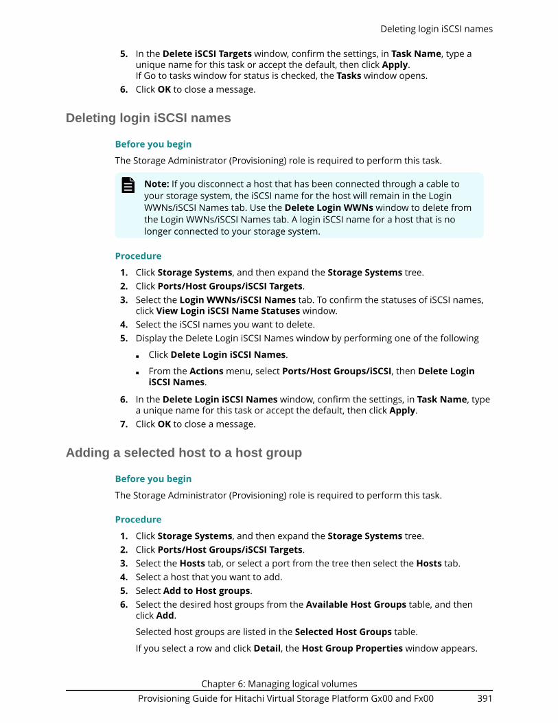
5. In the Delete iSCSI Targets window, confirm the settings, in Task Name, type aunique name for this task or accept the default, then click Apply.If Go to tasks window for status is checked, the Tasks window opens.
6. Click OK to close a message.
Deleting login iSCSI names
Before you begin
The Storage Administrator (Provisioning) role is required to perform this task.
Note: If you disconnect a host that has been connected through a cable toyour storage system, the iSCSI name for the host will remain in the LoginWWNs/iSCSI Names tab. Use the Delete Login WWNs window to delete fromthe Login WWNs/iSCSI Names tab. A login iSCSI name for a host that is nolonger connected to your storage system.
Procedure
1. Click Storage Systems, and then expand the Storage Systems tree.2. Click Ports/Host Groups/iSCSI Targets.3. Select the Login WWNs/iSCSI Names tab. To confirm the statuses of iSCSI names,
click View Login iSCSI Name Statuses window.4. Select the iSCSI names you want to delete.5. Display the Delete Login iSCSI Names window by performing one of the following
■ Click Delete Login iSCSI Names.
■ From the Actions menu, select Ports/Host Groups/iSCSI, then Delete LoginiSCSI Names.
6. In the Delete Login iSCSI Names window, confirm the settings, in Task Name, typea unique name for this task or accept the default, then click Apply.
7. Click OK to close a message.
Adding a selected host to a host group
Before you begin
The Storage Administrator (Provisioning) role is required to perform this task.
Procedure
1. Click Storage Systems, and then expand the Storage Systems tree.2. Click Ports/Host Groups/iSCSI Targets.3. Select the Hosts tab, or select a port from the tree then select the Hosts tab.4. Select a host that you want to add.5. Select Add to Host groups.6. Select the desired host groups from the Available Host Groups table, and then
click Add.
Selected host groups are listed in the Selected Host Groups table.
If you select a row and click Detail, the Host Group Properties window appears.
Deleting login iSCSI names
Chapter 6: Managing logical volumesProvisioning Guide for Hitachi Virtual Storage Platform Gx00 and Fx00 391

7. Click Finish.The Confirm window appears.
8. In the Add to Host groups window, confirm the settings, in Task Name type aunique name for this task or accept the default, and then click Apply.If Go to tasks window for status is checked, the Tasks window opens.
9. Click OK to close the message.
Adding a host to the selected host group
Before you begin
The Storage Administrator (Provisioning) role is required to perform this task.
Procedure
1. Click Storage Systems, and then expand the Storage Systems tree.2. Click Ports/Host Groups/iSCSI Targets.3. Select the Host Groups tab.4. Select the host group for the host you want to add.5. Select Add to Hosts.6. Select the desired host from the Available Hosts table, and then click Add.
Selected host groups are listed in the Selected Hosts table.
If the desired host has never been connected with a cable to any port in the storagesystem, perform the following steps:
a. Click Add New Host under the Available Hosts list.The Add New Host dialog box opens.
b. Enter the desired WWN in the HBA WWN box.c. If necessary, enter a nickname for the host bus adapter in the Host Name box.d. Click OK to close the Add New Host dialog box.e. Select the desired host bus adapter from the Available Hosts list.
7. Click Finish.The Confirm window appears.
8. In the Add to Host groups window, confirm the settings, in Task Name type aunique name for this task or accept the default, and then click Apply.If Go to tasks window for status is checked, the Tasks window opens.
9. Click OK to close the message.
Adding a host to the selected iSCSI target
Before you begin
The Storage Administrator (Provisioning) role is required to perform this task.
Procedure
1. Click Storage Systems, and then expand the Storage Systems tree.2. Click Ports/Host Groups/iSCSI Targets.3. Select the Host tab.4. Select the iSCSI target for the host you want to add.
Adding a host to the selected host group
Chapter 6: Managing logical volumesProvisioning Guide for Hitachi Virtual Storage Platform Gx00 and Fx00 392

5. Select Add to Hosts.6. Select the desired host from the Available Hosts table, and then click Add.
Selected iSCSI targets are listed in the Selected Hosts table.
If the desired host has never been connected with a cable to any port in the storagesystem, perform the following steps:
a. Click Add New Host under the Available Hosts list.The Add New Host dialog box opens.
b. Select the format from iqn or eui. Enter the desired HBA iSCSI name in theHBA iSCSI Name box.
c. If necessary, enter a nickname for the host bus adapter in the Host Name box.d. Click OK to close the Add New Host dialog box.e. Select the desired host bus adapter from the Available Hosts list.
7. Click Finish.The Confirm window appears.
8. In the Add to Host groups window, confirm the settings, in Task Name type aunique name for this task or accept the default, and then click Apply.If Go to tasks window for status is checked, the Tasks window opens.
9. Click OK to close the message.
Confirming communication status
Before you begin
The Storage Administrator (Provisioning) role is required to perform this task.
Procedure
1. From the Storage Navigator, click Actions, Ports/Host Groups/iSCSI, and thenAuthentication to open the Test Communication Statuses window.
2. Select the port ID from Local Port ID (From).3. In IP Address (To), select IPv4 or IPv6 then specify the IP address.4. Click Test.5. In the Communication Statuses table, confirm the result.6. Click Close.
Creating LDEVs used as system drives of NAS
To apply the settings of LDEVs used for system drives of NAS, you must add LU pathsbetween target LEVs and dedicated host groups.
Before you begin■ The Storage Administrator (Provisioning) role is required to perform this task.■ The NAS module must be installed in the storage system.■ LDEVs used as system drives of NAS must already be created.
Procedure
1. Click Storage Systems, and then expand the Storage Systems tree.
Confirming communication status
Chapter 6: Managing logical volumesProvisioning Guide for Hitachi Virtual Storage Platform Gx00 and Fx00 393

2. Click Ports/Host Groups/iSCSI Targets and select the target host group or iSCSItarget.
3. Click Add LUN Paths.4. In the Select LDEVs window, select target LDEVs from the Available LDEVs table,
then click Add.
Added LDEVs are listed in the Selected LDEVs table.
5. Click Next.6. In Selection Object, click NAS Platform (User LU).7. Dedicated host groups are listed in the Selected Host Groups table.
Note:
In the window, Available Host Groups, Add, and Remove are inactive.
If you select the check box of the row, and then click Detail, the Host GroupProperty window appears.
8. Click Next.9. Confirm the defined LU paths.
To change the LDEV name:
1. Select the check boxes of LDEV IDs that you want to change.2. Click Change LDEV Settings.3. In the Change LDEV Settings window, specify values in Prefix and Initial
Number.4. Click OK.
To change the LUN ID:
1. In the LUN ID column (Any number Sets of Paths), select the host groups (iSCSITargets) checkboxes.
2. Select the check box of the LDEV ID that you want to change.3. Click Change LUN IDs.4. In the Change LUN IDs window, specify the value in Initial LUN ID.5. Click OK.
10. Click Finish.The Confirm window appears.
11. In the Task Name text box, type a unique name for the task or accept the default.You can enter up to 32 ASCII characters and symbols, with the exception of: \ / : , ;* ? " < > |. The value "date-window name" is entered by default.
12. Click Apply.If the Go to tasks window for status check box is selected, the Tasks windowappears.
Setting the T10 PI mode on a port
Before you begin■ The Storage Administrator (Provisioning) role is required to perform this task.
Setting the T10 PI mode on a port
Chapter 6: Managing logical volumesProvisioning Guide for Hitachi Virtual Storage Platform Gx00 and Fx00 394

■ Access to the CHB(FC) Fibre Channel board port is required.■ The port speed must be 16 Gbps or 32 Gbps.
Caution:
If you change the T10 PI mode of one port, the T10 PI mode of the other portpaired with changed port also needs to be changed. You must verify themode of each port in the pair before changing the T10 PI mode. Make surethe ports in each pair are the same in the resource group. The followingshows pairs of port IDs.
If you change the setting on one of the ports in the pair, the setting on theother port in the pair will also be changed:■ Port IDs 1x and 3x (where x is a letter from A to R). For example, 1A and 3A
can be paired with each other.■ Port IDs 2x and 4x (where x is a letter from A to R). For example, 2B and 4B
can be paired with each other.■ If the T10 PI mode of the CHB port of the 4HF32R package, port IDs 1x, 3x,
5x, and 7x (where x is a letter from A to R) are collectively changed.
Note: If the T10 PI mode is enabled between the path of the target port andLDEV, you cannot disable the T10 PI mode of the port.
Procedure
1. Click Storage Systems, and then expand the Storage Systems tree.2. Click Ports/Host Groups/iSCSI Targets.3. Select the Ports tab.4. Select the desired port.
To collectively change the T10 PI mode of ports, do not intermix ports with enabledor disabled T10 PI modes.
5. Click Edit Ports.6. Click OK on the message window.7. Select Enable or Disable on the Edit T10 PI Mode window.8. Click Finish. The Confirm window appears.9. In the Confirm window, confirm the settings. In the Task Name, type a unique
name for this task or accept the default, then click Apply. If Go to tasks windowfor status is checked, the Tasks window opens.
Creating iSCSI targets and registering hosts in an iSCSItarget
Before you begin■ The Storage Administrator (Provisioning) role is required to perform this task.■ The Security Administrator (View and Modify) role is required to perform this task.
Creating iSCSI targets and registering hosts in an iSCSI target
Chapter 6: Managing logical volumesProvisioning Guide for Hitachi Virtual Storage Platform Gx00 and Fx00 395
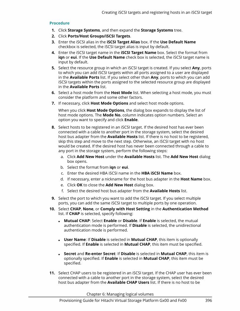
Procedure
1. Click Storage Systems, and then expand the Storage Systems tree.2. Click Ports/Host Groups/iSCSI Targets.3. Enter the iSCSI alias in the iSCSI Target Alias box. If the Use Default Name
checkbox is selected, the iSCSI target alias is input by default.4. Enter the iSCSI target name in the iSCSI Target Name box. Select the format from
iqn or eui. If the Use Default Name check box is selected, the iSCSI target name isinput by default.
5. Select the resource group in which an iSCSI target is created. If you select Any, portsto which you can add iSCSI targets within all ports assigned to a user are displayedin the Available Ports list. If you select other than Any, ports to which you can addiSCSI targets within the ports assigned to the selected resource group are displayedin the Available Ports list.
6. Select a host mode from the Host Mode list. When selecting a host mode, you mustconsider the platform and some other factors.
7. If necessary, click Host Mode Options and select host mode options.
When you click Host Mode Options, the dialog box expands to display the list ofhost mode options. The Mode No. column indicates option numbers. Select anoption you want to specify and click Enable.
8. Select hosts to be registered in an iSCSI target. If the desired host has ever beenconnected with a cable to another port in the storage system, select the desiredhost bus adapter from the Available Hosts list. If there is no host to be registered,skip this step and move to the next step. Otherwise, an iSCSI target with no hostwould be created. If the desired host has never been connected through a cable toany port in the storage system, perform the following steps:
a. Click Add New Host under the Available Hosts list. The Add New Host dialogbox opens.
b. Select the format from iqn or eui.c. Enter the desired HBA iSCSI name in the HBA iSCSI Name box.d. If necessary, enter a nickname for the host bus adapter in the Host Name box.e. Click OK to close the Add New Host dialog box.f. Select the desired host bus adapter from the Available Hosts list.
9. Select the port to which you want to add the iSCSI target. If you select multipleports, you can add the same iSCSI target to multiple ports by one operation.
10. Select CHAP, None, or Comply with Host Setting in the Authentication Methodlist. If CHAP is selected, specify following:
■ Mutual CHAP: Select Enable or Disable. If Enable is selected, the mutualauthentication mode is performed. If Disable is selected, the unidirectionalauthentication mode is performed.
■ User Name: If Disable is selected in Mutual CHAP, this item is optionallyspecified. If Enable is selected in Mutual CHAP, this item must be specified.
■ Secret and Re-enter Secret: If Disable is selected in Mutual CHAP, this item isoptionally specified. If Enable is selected in Mutual CHAP, this item must bespecified.
11. Select CHAP users to be registered in an iSCSI target. If the CHAP user has ever beenconnected with a cable to another port in the storage system, select the desiredhost bus adapter from the Available CHAP Users list. If there is no host to be
Creating iSCSI targets and registering hosts in an iSCSI target
Chapter 6: Managing logical volumesProvisioning Guide for Hitachi Virtual Storage Platform Gx00 and Fx00 396

registered, skip this step and move to the step 11. Otherwise, an iSCSI target with noCHAP user would be created. If the desired CHAP user has never been connectedthrough a cable to any port in the storage system, perform the following steps:
a. Click Add New CHAP User under the Available CHAP Users list. The Add NewCHAP User dialog box opens.
b. Specify an user name, and secret.c. Click OK to close the Add New CHAP User dialog box.d. Select the desired CHAP user from the Available CHAP Users list.
12. Click Add to add the iSCSI target. By repeating steps from 2 to 10, you can createmultiple iSCSI targets. If you select a row and click Detail, the iSCSI TargetProperties window appears. If you select a row and click Remove, a messageappears asking whether you want to remove the selected row or rows. To removethe row, click OK.
13. Click Finish to display the Confirm window. To continue to add LUN paths, clickNext.
14. Confirm the settings and enter the task name in the Task Name box. A task namecan consist of up to 32 ASCII characters (letters, numerals, and symbols). Tasknames are case-sensitive. (date) - (task name) is input by default. If you select a rowand click Detail, the iSCSI Target Properties window appears.
15. Click Apply in the Confirm window. If the Go to tasks window for status checkbox is selected, the Tasks window appears.
Editing iSCSI port settingsUse this procedure to edit the iSCSI port settings.
When the iSCSI virtual port mode is enabled for a port, the following items cannot be setusing Device Manager - Storage Navigator:■ IPv4 Settings■ IPv6 Mode■ IPv6 Settings■ TCP Port Number■ Selective ACK■ Delayed ACK■ Maximum Window Size■ Ethernet MTU Size■ Keep Alive Timer■ VLAN Tagging Mode■ iSNS Server
To edit iSCSI ports for which the virtual port mode is enabled, use Command ControlInterface. For details, see the Command Control Interface documentation.
Before you begin■ The Storage Administrator (System Resource Management and Provisioning) role is
required to perform this task.
Editing iSCSI port settings
Chapter 6: Managing logical volumesProvisioning Guide for Hitachi Virtual Storage Platform Gx00 and Fx00 397

■ The Security Administrator (View and Modify) role is required to perform this task.
Caution: It is best to enable LUN security on each port when configuring yourstorage system. Although you can enable LUN security on a port when hostI/O is in progress, I/O is rejected with a security guard after enabling.
Procedure
1. Click Storage Systems, and then expand the Storage Systems tree.2. Click Ports/Host Groups/iSCSI Targets, and select the Ports tab.3. Select the desired port, and click Edit Ports.4. Select the check box to change the option and specify values. Items that can be
changed are as follows:
■ IPv4 Settings: Specifies IP Address, Subnet Mask, or Default Gateway.
■ IPv6 Mode: Specifies enable or disable of this mode.
■ IPv6 Settings: Specifies Link Local Address, Global Address, Global Address 2,or Default Gateway if IPv6 Mode is selected to Enable.
■ Port Security: Specifies enable or disable.
■ Port Speed: Specifies the data transfer speed.
■ TCP Port Number: Specifies the TCP port number.
■ Selective ACK: Specifies enable or disable.
■ Delayed ACK: Specifies enable or disable.
■ Maximum Window Size: Specifies the size of the maximum window.
■ Ethernet MTU Size: Specifies the MTU size.
■ Keep Alive Timer: Specifies the keep alive timer.
■ VLAN Tagging Mode: Specifies enable or disable.
■ iSNS Server: Specifies enable or disable. If this option is selected to Enable,specify IP Address or TCP Port Number.
■ CHAP User Name: Specifies the CHAP user name.
■ Secret and Re-enter Secret: Specifies the secret which is used for hostauthentication.
5. Click Finish. A message appears, confirming whether to switch the LUN security.Clicking OK opens the Confirm window.
6. In the Confirm window, confirm the settings, in Task Name type a unique name forthis task or accept the default, then click Apply. If Go to tasks window for status ischecked, the Tasks window opens.
Adding CHAP users
Before you begin■ The Storage Administrator (Provisioning) role is required to perform this task.■ The Security Administrator (View and Modify) role is required to perform this task.
Adding CHAP users
Chapter 6: Managing logical volumesProvisioning Guide for Hitachi Virtual Storage Platform Gx00 and Fx00 398

Procedure
1. Click Storage Systems, and then expand the Storage Systems tree.2. Click Ports/Host Groups/iSCSI Targets.3. Select the iSCSI target to register CHAP users.4. Display the Add CHAP Users window by performing one of the following:
■ Click More Actions, select Add CHAP Users.
■ From the Actions menu, select Ports/Host Groups/iSCSI, Authentication, thenAdd CHAP Users.
5. In the Available CHAP Users table, select the CHAP user row. Click Add. Theselected CHAP user is registered in the Selected CHAP Users table. If the CHAP userdoes not exist, perform the following steps to register a new CHAP user:
a. Click Add New CHAP User under the Available CHAP Users table. The AddNew CHAP User dialog box opens.
b. Specify User Name and Secret.c. Click OK to close the Add New CHAP User dialog box.
6. Click Finish to display the Confirm window.7. Confirm the settings and enter the task name in the Task Name box. A task name
can consist of up to 32 ASCII characters (letters, numerals, and symbols). Tasknames are case-sensitive. (date) - (task name) is input by default.
8. Click Apply in the Confirm window. If the Go to tasks window for status checkbox is selected, the Tasks window appears.
Editing CHAP users
Before you begin■ The Storage Administrator (Provisioning) role is required to perform this task.■ The Security Administrator (View and Modify) role is required to perform this task.
Procedure
1. Click Storage Systems, and then expand the Storage Systems tree.2. Click Ports/Host Groups/iSCSI Targets.3. Select the CHAP users.4. Display the Edit CHAP Users window by performing one of the following:
■ Click Edit CHAP Users.
■ From the Actions menu, select Ports/Host Groups/iSCSI, Authentication, thenEdit CHAP Users.
5. Specify User Name and Secret.6. Click Finish to display the Confirm window.7. Confirm the settings and enter the task name in the Task Name box. A task name
can consist of up to 32 ASCII characters (letters, numerals, and symbols). Tasknames are case-sensitive. (date) - (task name) is input by default.
8. Click Apply in the Confirm window. If the Go to tasks window for status checkbox is selected, the Tasks window appears.
Editing CHAP users
Chapter 6: Managing logical volumesProvisioning Guide for Hitachi Virtual Storage Platform Gx00 and Fx00 399

Removing CHAP users
Before you begin■ The Storage Administrator (Provisioning) role is required to perform this task.■ The Security Administrator (View and Modify) role is required to perform this task.
Procedure
1. Click Storage Systems, and then expand the Storage Systems tree.2. Click Ports/Host Groups/iSCSI Targets.3. Select the CHAP users.4. Display the Remove CHAP Users window by performing one of the following:
■ Click Remove CHAP Users.
■ From the Actions menu, select Ports/Host Groups/iSCSI, Authentication, thenRemove CHAP Users.
5. Specify User Name and Secret.6. Click Finish to display the Remove CHAP Users window.7. Confirm the settings and enter the task name in the Task Name box. A task name
can consist of up to 32 ASCII characters (letters, numerals, and symbols). Tasknames are case-sensitive. (date) - (task name) is input by default.
8. Click Apply in the Confirm window. If the Go to tasks window for status checkbox is selected, the Tasks window appears.
Removing target CHAP users
Before you begin■ The Storage Administrator (Provisioning) role is required to perform this task.■ The Security Administrator (View and Modify) role is required to perform this task.
Procedure
1. Click Storage Systems, and then expand the Storage Systems tree.2. Click Ports/Host Groups/iSCSI Targets.3. Select the iSCSI target.4. Display the Remove Target CHAP Users window by performing one of the
following:
■ Click More Actions > Remove Target CHAP Users.
■ From the Actions menu, select Ports/Host Groups/iSCSI, Authentication, thenRemove Target CHAP Users.
5. Confirm the settings and enter the task name in the Task Name box. A task namecan consist of up to 32 ASCII characters (letters, numerals, and symbols). Tasknames are case-sensitive. (date) - (task name) is input by default.
6. Click Apply in the Confirm window. If the Go to tasks window for status checkbox is selected, the Tasks window appears.
Removing CHAP users
Chapter 6: Managing logical volumesProvisioning Guide for Hitachi Virtual Storage Platform Gx00 and Fx00 400

Removing port CHAP users
Before you begin■ The Storage Administrator (Provisioning) role is required to perform this task.■ The Security Administrator (View and Modify) role is required to perform this task.
Procedure
1. Click Storage Systems, and then expand the Storage Systems tree.2. Click Ports/Host Groups/iSCSI Targets.3. Select the port CHAP user port name to be removed.4. Display the Remove Port CHAP Users window by performing one of the following:
■ Click Remove Port CHAP Users.
■ From the Actions menu, select Ports/Host Groups, iSCSI, Authentication, thenRemove Port CHAP Users.
5. Confirm the settings and enter the task name in the Task Name box.A task name can consist of up to 32 ASCII characters (letters, numerals, andsymbols). Task names are case-sensitive. (date) - (task name) is input by default.
6. Click Apply in the Confirm window.If the Go to tasks window for status check box is selected, the Tasks windowappears.
Removing port CHAP users
Chapter 6: Managing logical volumesProvisioning Guide for Hitachi Virtual Storage Platform Gx00 and Fx00 401

Chapter 6: Managing logical volumesProvisioning Guide for Hitachi Virtual Storage Platform Gx00 and Fx00 402

Chapter 7: Working with ALUs and SLUs forvSphere VVOL
The storage systems can be integrated with a VMware® ESXi host or VMware® vCenterServer by Storage Provider for VMware vCenter, which provides support for vSphere APIsfor Storage Awareness (VASA). Snapshot and replication functions are used in storagesystems that are configured with Administrative Logical Units (ALUs) and SubsidiaryLogical Units (SLUs).
You can use Device Manager - Storage Navigator to create ALUs, view the ALUs and SLUson the storage system, and unbind SLUs from ALUs.
Do not perform operations on LDEVs with the SLU or ALU attribute from Device Manager- Storage Navigator or Command Control Interface (CCI). If you must perform operationson LDEVs with the SLU or ALU attribute, contact customer support.
Caution: If you must change the configuration of LDEVs with the SLU or ALUattribute using Device Manager - Storage Navigator or CCI, you must first shutdown the associated virtual machines. When the virtual machine is shutdown, LDEVs with the SLU or ALU attribute related to the virtual machine areunbound automatically.
If virtual machines cannot be shut down, unbind the LDEVs with the SLUattribute from LDEVs with the ALU attribute related to the virtual machinesusing Device Manager - Storage Navigator, and then perform theconfiguration change operation. For instructions, see Unbinding the SLUsfrom the ALUs (on page 405) . If you accidentally change the configurationwhile the virtual machine is running without first unbinding the LDEVs withthe SLU attribute, contact your storage administrator.
For information about setting up and operating VMware virtualization servers, see theHitachi Command Suite Administrator Guide.
For information about installing, deploying, and configuring Storage Provider for VMwarevCenter, see the Hitachi Storage Provider for VMware vCenter Deployment Guide.
Creating LDEVs with the ALU attributeUse this procedure to create LDEVs with the ALU attribute.
Before you begin
The Storage Administrator (Provisioning) role is required to perform this task.
Chapter 7: Working with ALUs and SLUs for vSphere VVOLProvisioning Guide for Hitachi Virtual Storage Platform Gx00 and Fx00 403

Procedure
1. In the Device Manager - Storage Navigator Explorer pane, click Storage Systems,expand the target storage system, and then click Logical Devices.
2. In the LDEVs tab, click Create LDEVs.3. In the Create LDEVs window, from the Provisioning Type list, select ALU.4. In Number of LDEVs, type the number of LDEVs to be created.5. In LDEV Name, specify a name for this LDEV.
a. In Prefix, type the characters that will become the fixed characters for thebeginning of the LDEV name. The characters are case sensitive.
b. In Initial Number, type the initial number that will follow the prefix name.
6. Click Options to show more options.7. In Initial LDEV ID, make sure that an LDEV ID is set. To confirm the used number
and unavailable number, click View LDEV IDs to open the View LDEV IDs window.a. In Initial LDEV ID in the Create LDEVs window, click View LDEV IDs.
In the View LDEV IDs window, the matrix vertical scale represents the second-to-last digit of the LDEV number, and the horizontal scale represents the lastdigit of the LDEV number. The LDEV IDs table shows the available, used, anddisabled LDEV IDs.
In the table, used LDEV numbers appear in blue, unavailable numbers appearin gray, and unused numbers appear in white. LDEV numbers that areunavailable may be already in use, or already assigned to another emulationgroup (group by 32 LDEV numbers).
b. Click Close
8. In the CLPR list, select the CLPR ID.
9. From the MP Unit list, select an MP unit to be used by the LDEVs.
■ If you assign a specific MP unit, select the ID of the MP unit.
■ If you can assign any MP unit, click Auto.
10. Click Add.
The created LDEVs are added to the Selected LDEVs table.
The Provisioning Type and Number of LDEVs must be set. If these required itemsare not registered, you cannot click Add.
11. If necessary, change the following LDEV settings:
■ Click Change LDEV Settings to open the Change LDEV Settings window.
12. If necessary, delete an LDEV from the Selected LDEVs table.
Select an LDEV to delete, and then click Remove.
13. Click Finish.
The Confirm window opens.
To continue setting the LU path and defining a logical unit, click Next.
14. In the Task Name text box, type a unique name for the task or accept the default.
You can enter up to 32 ASCII characters and symbols, with the exception of: \ / : , ;* ? " < > |. The value "date-window name" is entered by default.
Creating LDEVs with the ALU attribute
Chapter 7: Working with ALUs and SLUs for vSphere VVOLProvisioning Guide for Hitachi Virtual Storage Platform Gx00 and Fx00 404

15. Click Apply.
If the Go to tasks window for status check box is selected, the Tasks windowappears.
Viewing the ALUs and SLUs in the storage systemUse this procedure to the view the ALUs and SLUs in the storage system. You can alsoview the ALUs and SLUs on the ESXi host or vCenter Server.
Before you begin
The Storage Administrator (Provisioning) role is required to perform this task.
Procedure
1. Click Storage Systems, and then expand the Storage Systems tree.2. Click Logical Devices.3. In the LDEVs pane, click More Actions > View ALUs/SLUs.
The ALUs / SLUs window displays the ALU or SLU ID, LDEV ID, and LDEV name ofeach volume with the ALU or SLU attribute. For SLUs the provisioning type of eachvolume (DP-VOL or Thin Image volume) is also displayed.
Unbinding the SLUs from the ALUsUse this procedure to unbind the SLUs from one or more ALUs. You can also unbindSLUs by using the ESXi host or vCenter Server.
Viewing the ALUs and SLUs in the storage system
Chapter 7: Working with ALUs and SLUs for vSphere VVOLProvisioning Guide for Hitachi Virtual Storage Platform Gx00 and Fx00 405

Before you begin
The Storage Administrator (Provisioning) role is required to perform this task.
Procedure
1. Click Storage Systems, and then expand the Storage Systems tree.2. Click Logical Devices.3. In the LDEVs pane, select the ALUs for which you want to unbind the SLUs. The
ALUs have the value ALU in the Attribute column.4. Click More Actions > Unbind SLUs.5. Enter a task name or accept the default, and then click Apply.
If Go to tasks window for status is selected, the Tasks window appears.
Chapter 7: Working with ALUs and SLUs for vSphere VVOLProvisioning Guide for Hitachi Virtual Storage Platform Gx00 and Fx00 406

Chapter 8: Troubleshooting for provisioning
Troubleshooting for provisioning operations involves identifying the cause of the errorand resolving the problem. For information about the error messages displayed byDevice Manager - Storage Navigator, see Hitachi Device Manager - Storage NavigatorMessages. If you are unable to solve a problem, please contact customer support.
Troubleshooting Dynamic ProvisioningThe following table provides troubleshooting information for Dynamic Provisioning.
If you are unable to solve a problem, or if you encounter a problem not listed, pleasecontact customer support.
When an error occurs during operations, the error code and error message are displayedin the error message dialog box. For details about error messages, see Hitachi DeviceManager - Storage Navigator Messages.
Problem Causes and solutions
Cannot create a DP-VOL. Causes:■ Usage of the pool has reached to 100%.■ Something in the storage system is blocked.■ The available capacity of DP-VOL is restricted due to
the value of Subscription-Limit set for the pool.
Solutions:■ Add some pool-VOLs to the pool. See Expanding a
pool (on page 288) .■ Perform the operation to reclaim zero pages in order
to release pages in which zero data are stored. SeeAbout releasing pages in a DP-VOL (on page 299) .
■ Adjust the value of Subscription Limit for the pool. SeeChanging the pool subscription limit (on page 271) .
■ Ask customer support to solve the problem.
Chapter 8: Troubleshooting for provisioningProvisioning Guide for Hitachi Virtual Storage Platform Gx00 and Fx00 407
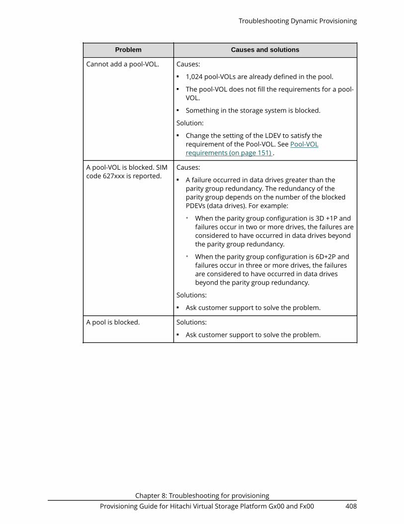
Problem Causes and solutions
Cannot add a pool-VOL. Causes:■ 1,024 pool-VOLs are already defined in the pool.■ The pool-VOL does not fill the requirements for a pool-
VOL.■ Something in the storage system is blocked.
Solution:■ Change the setting of the LDEV to satisfy the
requirement of the Pool-VOL. See Pool-VOLrequirements (on page 151) .
A pool-VOL is blocked. SIMcode 627xxx is reported.
Causes:■ A failure occurred in data drives greater than the
parity group redundancy. The redundancy of theparity group depends on the number of the blockedPDEVs (data drives). For example:● When the parity group configuration is 3D +1P and
failures occur in two or more drives, the failures areconsidered to have occurred in data drives beyondthe parity group redundancy.
● When the parity group configuration is 6D+2P andfailures occur in three or more drives, the failuresare considered to have occurred in data drivesbeyond the parity group redundancy.
Solutions:■ Ask customer support to solve the problem.
A pool is blocked. Solutions:■ Ask customer support to solve the problem.
Troubleshooting Dynamic Provisioning
Chapter 8: Troubleshooting for provisioningProvisioning Guide for Hitachi Virtual Storage Platform Gx00 and Fx00 408

Problem Causes and solutions
A pool cannot be restored. Causes:■ Processing takes time, because something in the
storage system is blocked.■ Usage of the pool has reached to 100%.
Solutions:■ Add some pool-VOLs to the pool to increase the
capacity of the pool. See Expanding a pool (onpage 288) .
■ Perform the operation to reclaim zero pages in orderto release pages in which zero data are stored. SeeAbout releasing pages in a DP-VOL (on page 299) .
■ Ask customer support to solve the problem.
A pool cannot be deleted. Causes:■ The pool usage is not 0.■ External volumes are removed from the pool before
you delete the pool.■ DP-VOLs have not been deleted.
Solutions:■ Confirm that the pool usage is 0 after the DP-VOLs are
deleted, and that you can delete the pool.■ Ask customer support to solve the problem.
A failure occurs to theapplication for monitoringthe volumes installed in ahost.
Causes:■ Free space of the pool is insufficient.■ Some areas in the storage system are blocked.
Solutions:■ Check the free space of the pool and increase the
capacity of the pool. See Expanding a pool (onpage 288) .
■ Perform the operation to reclaim zero pages in orderto release pages in which zero data are stored. SeeAbout releasing pages in a DP-VOL (on page 299) .
■ Ask customer support to solve the problem.
Troubleshooting Dynamic Provisioning
Chapter 8: Troubleshooting for provisioningProvisioning Guide for Hitachi Virtual Storage Platform Gx00 and Fx00 409

Problem Causes and solutions
When the host computertries to access the port,error occurs and the hostcannot access the port.
Causes:■ Free space of the pool is insufficient.■ Some areas in the storage system are blocked.
Solutions:■ Check the free space of the pool and increase the
capacity of the pool. See Expanding a pool (onpage 288) .
■ Perform the operation to reclaim zero pages in orderto release pages in which zero data are stored. SeeAbout releasing pages in a DP-VOL (on page 299) .
■ Ask customer support to solve the problem.
When you are operatingHitachi Device Manager -Storage Navigator, atimeout occurs frequently.
Causes:■ The load on the management client is too heavy, so
that it cannot respond to the SVP.■ The period of time until when time-out occurs is set
too short.
Solutions:■ Wait for a while, then try the operation again.
DP-VOL capacity cannot beincreased.
See Resolving errors when using CCI to perform DynamicProvisioning operations (SSB1: 0x2e31/0xb96d/0xb980)(on page 418) and identify the cause.
Solutions:■ After refreshing the display, confirm whether the
processing for increasing DP-VOL capacity meets theconditions described in Requirements for increasingDP-VOL capacity (on page 158) .
■ Retry the operation after 10 minutes or so.■ Ask customer support to solve the problem.
Cannot reclaim zero pagesin a DP-VOL.
Causes:■ Zero pages in the DP-VOL cannot be reclaimed from
Device Manager - Storage Navigator because the DP-VOL does not meet conditions for releasing pages in aDP-VOL.
Solutions:■ Make sure that the DP-VOL meets the conditions
described in Releasing pages in a DP-VOL (onpage 300) .
Troubleshooting Dynamic Provisioning
Chapter 8: Troubleshooting for provisioningProvisioning Guide for Hitachi Virtual Storage Platform Gx00 and Fx00 410

Problem Causes and solutions
The DP-VOL cannot bereleased if the process toreclaim zero pages in theDP-VOL is interrupted.
Causes:■ Pages of the DP-VOL are not released because the
process of reclaiming zero pages was interrupted.
Solutions:■ Make sure that the DP-VOL meets the conditions
described in Releasing pages in a DP-VOL (onpage 300) .
Cannot release the Protectattribute of the DP-VOLs.
Causes:■ The pool is full.■ The pool-VOL is blocked.■ The pool-VOL that is an external volume is blocked.
Solutions:■ Add pool-VOLs to the pool to increase the free space
in the pool. See Expanding a pool (on page 288) .■ Perform the reclaiming zero pages operation to
release pages in which zero data are stored. SeeReleasing pages in a DP-VOL (on page 300) .
■ Contact customer support to restore the pool-VOL.■ If the blocked pool-VOL is an external volume, verify
the status of the path blockade and the externalstorage system.
■ After performing above solutions, release the Protectattribute (Data Retention Utility) of the DP-VOL. Forinformation about Data Retention Utility, see theProvisioning Guide.
SIM code 622xxx wasissued.
Causes:■ Usage of the pool has reached 100%.
Solutions:■ Add pool-VOLs to the pool to increase the free space
in the pool. See Expanding a pool (on page 288) .■ Perform the operation to reclaim zero pages in order
to release pages in which zero data are stored. SeeReleasing pages in a DP-VOL (on page 300) .
The Protect attribute of Data Retention Utility can havebeen set to DP-VOLs. After performing above solutions,release the Protect attribute of the DP-VOLs.
Troubleshooting Dynamic Provisioning
Chapter 8: Troubleshooting for provisioningProvisioning Guide for Hitachi Virtual Storage Platform Gx00 and Fx00 411

Problem Causes and solutions
SIM code 624000 wasissued.
Causes:■ The pools and DP-VOLs configuration, of which the
size is more than the supported capacity, is created.
Solutions:■ Remove pools that are not used.■ Remove DP-VOLs that are not used.■ Remove Thin Image pairs that are not used.■ Shrink pools capacities.
Formatted pool capacitydisplayed in the View PoolManagement Statuswindow does not increase.
Causes:■ Another pool is being formatted.■ The pool usage level reaches up to the threshold.■ The pool is blocked.■ I/O loads to the storage system are high.■ The cache memory is blocked.■ Pool-VOLs are blocked.■ Pool-VOLs that are external volumes are blocked.
Solutions:■ Confirm the display again after waiting for a while.■ Add pool-VOLs to the pool to increase the free space
in the pool. See Expanding a pool (on page 288) .■ Perform the operation to reclaim zero pages in order
to release pages in which zero data are stored. SeeAbout releasing pages in a DP-VOL (on page 299) .
■ Confirm the display again after decreasing I/O loads ofthe storage system.
■ Contact customer support to restore the cachememory.
■ Contact customer support to restore the pool-VOL.■ If the blocked pool-VOL is an external volume, confirm
following:● Path blockage● Status of the storage system
Troubleshooting Dynamic Provisioning
Chapter 8: Troubleshooting for provisioningProvisioning Guide for Hitachi Virtual Storage Platform Gx00 and Fx00 412

Problem Causes and solutions
The shrink pool operationends abnormally.
Causes:■ Cache memory maintenance was performed while the
pool capacity was being decreased.■ Cache memory errors occurred while the pool capacity
was being decreased.■ The I/O load to DP-VOLs associated with the pool is
too high.■ DP-VOLs associated with the pool are being blocked.
Solution:■ Restore the cache memory, and then perform the
shrink pool operation again.■ Wait until the I/O load to DP-VOLs associated with the
pool is lower, and then perform the shrink pooloperation again.
■ Delete or format DP-VOLs associated with the pool,and then perform the shrink pool operation again.
The Assign DeduplicationSystem Data Volumeoption is set to Yes whencreating a pool, but thededuplication system datavolume is not created.
Cause:■ After creating a pool, errors occur when the
deduplication system data volume is created, andthen the processing aborts.
Solution:■ Resolve the causes of the errors, and then assign a
deduplication system data volume to the pool byusing the Edit Pools window.
A Deduplication-Availablepool cannot be deleted,and after the failed pooldeletion, the Deduplicationsetting is changed to NotAvailable.
Cause:■ After deleting a deduplication system data volume,
errors occur when a pool is deleted, and then theprocessing aborts.
Solution:■ Resolve the causes of the errors, and then delete the
pool by using the Delete Pools window.
Troubleshooting Dynamic Provisioning
Chapter 8: Troubleshooting for provisioningProvisioning Guide for Hitachi Virtual Storage Platform Gx00 and Fx00 413

Problem Causes and solutions
DP-VOLs whose capacitysaving setting isCompression orDeduplication andCompression are created,but the capacity savingsetting of the DP-VOLs isset to Disabled.
Cause:■ After creating DP-VOLs, errors occur when the capacity
saving setting changes to Compression orDeduplication and Compression, and then theprocessing aborts.
Solution:■ Resolve the causes of the errors, and then change the
capacity saving setting to Compression orDeduplication and Compression by using the EditLDEVs window.
The processing stops whenCapacity Saving Status isEnabling or Rehydrating.
Cause:■ Errors occur while the capacity saving status is
changing, and then the processing aborts. Afterrecovering from the errors, the resumed statuschange process fails.
Solution:■ For DP-VOLs, change Capacity Saving to Disabled, and
then retry the operation by using the Edit LDEVswindow.
A capacity saving statuswith DP-VOLs whoseDeduplication Data isDisabled changes to theFailed status.
Cause:■ The shared memory is volatilized and the storage
system is restarted.■ The pool is initialized.■ The pool volumes are formatted.■ The processing for deleting the DP-VOL failed.
Solution:■ Format the operation target DP-VOLs.
Troubleshooting Dynamic Provisioning
Chapter 8: Troubleshooting for provisioningProvisioning Guide for Hitachi Virtual Storage Platform Gx00 and Fx00 414

Problem Causes and solutions
A capacity saving statuswith DP-VOLs whoseDeduplication Data isEnabled changes to theFailed status.
Causes:■ The shared memory is volatilized and the storage
system is restarted.■ The pool is initialized.■ The pool volumes are formatted.■ The processing for deleting the DP-VOL failed.
Solution:
1. In the pool, back up all of the DP-VOLs whoseDeduplication Data status is Enabled.
2. Block the deduplication system data volume and allof the DP-VOLs whose Deduplication Data status isEnabled.
3. If a deduplication system data volume exists in thepool, the volume must be formatted. If you are usingDevice Manager - Storage Navigator, perform theFormat LDEVs operation on the deduplicationsystem data volume. If you are using CCI, specify thededuplication system data volume, and execute theraidcom initialize pool command.
4. Perform the Format LDEVs operation for all blockedDP-VOLs whose Deduplication Data status isEnabled.
Caution: Do not perform the restoreLDEV operation because these DP-VOLscannot be used again.
5. Restore the back-up data, or retry the delete LDEVoperation.
Note: If you format DP-VOLs for which the capacitysaving setting is disabled and Deduplication Data isEnabled, the capacity saving setting for the DP-VOLsmight become Compression. If you format thededuplication system data volume for a pool that has DP-VOLs for which the capacity saving setting is disabled andDeduplication Data is Enabled, the capacity saving settingfor the DP-VOLs might become Deduplication andcompression. Therefore, verify the capacity saving settingof DP-VOLs after the format operation completes.
Troubleshooting Dynamic Provisioning
Chapter 8: Troubleshooting for provisioningProvisioning Guide for Hitachi Virtual Storage Platform Gx00 and Fx00 415

Problem Causes and solutions
When the storage systemis restarted, one offollowing problems occur:
1. For the DP-VOLs,Capacity Saving Statusindicates DeletingVolume, and theprogress indicates ahyphen.
2. For the DP-VOLs,Capacity Saving Statusindicates Disabled.
Delete the DP-VOLs corresponding to 1 or 2 again.
Troubleshooting Dynamic Provisioning
Chapter 8: Troubleshooting for provisioningProvisioning Guide for Hitachi Virtual Storage Platform Gx00 and Fx00 416

Problem Causes and solutions
For a DP-VOL, the CapacitySaving Status indicatesRehydrating, but theprocessing progress doesnot increase.
Causes:■ The pool used capacity exceeded the depletion
threshold.■ The target DP-VOL is being blocked.■ The pool with which the target DP-VOL is associated is
being blocked, or the pool volumes are being blocked.■ The deduplication system data volume of the pool
with which the target DP-VOL is associated is beingblocked.
■ The SVP or a Device Manager - Storage Navigatorsecondary window is in Modify mode.
Solutions:
If the pool used capacity exceeded the depletionthreshold, take the following action:
1. Verify the free capacity of the pool, and then expandthe pool capacity for the capacity shortage.
2. Perform the operation to release pages in DP-VOLsto reclaim zero pages.
If the target DP-VOL is being blocked, take the followingaction:
1. Restore the blocked DP-VOL.
If the pool with which the target DP-VOL is associated isbeing blocked, or if the pool volumes are being blocked,take the following action:
1. Restore the pool or pool volumes.
If the deduplication system data volume of the pool withwhich the target DP-VOL is associated is being blocked,take the following action:
1. Restore the deduplication system data volume thatis being blocked.
If the SVP or a Device Manager - Storage Navigatorsecondary window is in Modify mode, change to Viewmode.
Troubleshooting Dynamic Provisioning
Chapter 8: Troubleshooting for provisioningProvisioning Guide for Hitachi Virtual Storage Platform Gx00 and Fx00 417

Problem Causes and solutions
For a DP-VOL, the CapacitySaving Status indicatesDeleting Volume, howeverthe processing progressdoes not increase.
Causes:■ The pool used capacity exceeded the depletion
threshold.■ The pool with which the target DP-VOL is associated is
being blocked, or the pool volumes are being blocked.■ The deduplication system data volume of the pool
with which the target DP-VOL is associated is beingblocked.
■ The SVP or a Device Manager - Storage Navigatorsecondary window is in Modify mode.
Solutions:
If the pool used capacity exceeded the depletionthreshold, take the following action:
1. Verify the free capacity of the pool, and then expandthe pool capacity for the capacity shortage.
2. Perform the operation to release pages in DP-VOLsto reclaim zero pages.
If the pool with which the target DP-VOL is associated isbeing blocked, or if the pool volumes are being blocked,take the following action:
1. Restore the pool or pool volumes.
If the deduplication system data volume of the pool withwhich the target DP-VOL is associated is being blocked,take the following action:
1. Restore the deduplication system data volume thatis being blocked.
If the SVP or a Device Manager - Storage Navigatorsecondary window is in Modify mode, change to Viewmode.
Resolving errors when using CCI to perform Dynamic Provisioningoperations (SSB1: 0x2e31/0xb96d/0xb980)
If an error occurs while using CCI to perform Dynamic Provisioning operations, you mightidentify the cause of the error by referring to the log appearing on the CCI window or theCCI operation log file.
The CCI operation log file is stored in the following directory.
/HORCM/log*/curlog/horcmlog_HOST/horcm.log
where
Resolving errors when using CCI to perform Dynamic Provisioning operations (SSB1: 0x2e31/0xb96d/0xb980)
Chapter 8: Troubleshooting for provisioningProvisioning Guide for Hitachi Virtual Storage Platform Gx00 and Fx00 418

■ * is the instance number.■ HOST is the host name.
The following is an example of a log entry in the CCI window.
The following table provides troubleshooting information for Dynamic Provisioningoperations performed using CCI.
Error code(SSB2) Error contents Solutions
0x0b27 The command cannot beexecuted because the virtualLDEV is not defined.
Define the virtual LDEV and thenexecute the command.
0x2c3a The operation was rejectedbecause the specified volume wasbeing enabled for the attribute ofthe data direct mapping.
Specify the volume of which theattribute of the data directmapping is disabled.
0x2c77 The operation was rejectedbecause the specified DP-VOLwas a deduplication system datavolume.
Specify a DP-VOL that is not adeduplication system datavolume.
0x2c78 The operation failed because thespecified DP-VOL is being deleted.
Specify a DP-VOL that is not beingdeleted.
0x9100 The command cannot beexecuted because userauthentication is not performed.
Perform user authentication.
0xb900/0xb901/0xaf28
Error occurred when increasingDP-VOL capacity operation.
Ask customer support to solvethe problem.
0xb902 The operation was rejectedbecause the configuration wasbeing changed by SVP or HitachiDevice Manager - StorageNavigator, or because the DP-VOLcapacity was going to beincreased by another instance ofthe CCI.
Increase the DP-VOL capacityafter finishing operations on yourstorage system, such as theVirtual LUN operation or amaintenance operation. SeeCaution in Requirements forincreasing DP-VOL capacity (onpage 158) .
0xb903 The operation cannot beperformed because the specifiedresource is contained inNAS_Platform_System_RSG.
Move the specified resource to aresource group other thanNAS_Platform_System_RSG.
Resolving errors when using CCI to perform Dynamic Provisioning operations (SSB1: 0x2e31/0xb96d/0xb980)
Chapter 8: Troubleshooting for provisioningProvisioning Guide for Hitachi Virtual Storage Platform Gx00 and Fx00 419

Error code(SSB2) Error contents Solutions
0xaf22 The operation was rejectedbecause the specified volume isplaced online with the OS whichdoes not support EAV (ExtendedAddress Volume).
Increase the DP-VOL capacityafter the specified volume isplaced online with the OS whichsupports EAV.
0xaf24 The operation was rejectedbecause the total DP-VOL capacityexceeded the pool reservationrate after the capacity wasincreased.
Specify a capacity so that the poolreservation rate will not beexceeded.
0xaf25 The operation to increasecapacity cannot be performed onthe specified DP-VOL.
Check the emulation type of thespecified DP-VOL.
0xaf26 The operation was rejectedbecause of lack of cachemanagement devices due toincreased capacity.
Specify a capacity so that themaximum number of cachemanagement devices will not beexceeded.
0xaf29 The operation was rejectedbecause the specified volume wasnot a DP-VOL.
Makes sure that the volume is aDP-VOL.
0xaf2a The operation was rejectedbecause the specified capacitiesare invalid or exceeded the valueimmediately below LDEV Capacityin the Expand Virtual Volumeswindow.
To increase capacity, specify thecorrect capacity that does notexceed the value immediatelybelow LDEV Capacity in theExpand Virtual Volumeswindow. See the conditions forincreasing DP-VOL capacity inRequirements for increasing DP-VOL capacity (on page 158) .
0xaf2b The operation was rejectedbecause the specified volumeoperation was not finished.
Re-execute the operation after abrief interval.
0xaf2c The operation was rejectedbecause the shared memorycapacity is not enough to increasethe specified capacity.
Confirm the value immediatelybelow LDEV Capacity in theExpand Virtual Volumeswindow.
Resolving errors when using CCI to perform Dynamic Provisioning operations (SSB1: 0x2e31/0xb96d/0xb980)
Chapter 8: Troubleshooting for provisioningProvisioning Guide for Hitachi Virtual Storage Platform Gx00 and Fx00 420

Error code(SSB2) Error contents Solutions
0xaf2e The operation was rejectedbecause the specified DP-VOLwas used by other software orwas being formatted.
Wait until formatting of thespecified volume is finished, orsee Using Dynamic Provisioningand Dynamic Tiering with othersoftware products (on page 163)and confirm whether the DP-VOLis used with software in whichthat the DP-VOL capacity cannotbe increased.
0xaf2f The specified DP-VOL capacitycannot be expanded because theconfiguration of journal volumesis being changed.
Re-execute the operation afterthe journal volume configurationis changed.
0x0b2b The operation was rejectedbecause the raidcom extendldev command was executedwith specifying the -cylinderoption to the DP-VOL for the opensystem.
Re-execute the raidcom extendldev command withoutspecifying the -cylinder option.
0xaf60 The operation was rejectedbecause the pool used capacityexceeds the depletion thresholdof the pool if the specifiedcapacity is reserved in the pool.
Expand the pool capacity, andthen retry the operation.
Troubleshooting Data Retention UtilityIf an error occurs with Data Retention Utility, the Error Detail dialog box appears. TheError Detail dialog box displays error locations and error messages.
The Error Detail dialog box does not display Hitachi Device Manager - Storage Navigatorerror messages. To find information about Hitachi Device Manager - Storage Navigatorerrors and solutions, see the Hitachi Device Manager - Storage Navigator Messages.
Troubleshooting for Data Retention Utility
The following table provides troubleshooting information for Data Retention Utility.
Troubleshooting Data Retention Utility
Chapter 8: Troubleshooting for provisioningProvisioning Guide for Hitachi Virtual Storage Platform Gx00 and Fx00 421

Problems Probable cause and solution
The Disable/ Enable or theEnable/Disable button onthe Data Retentionwindow is unavailable.Nothing happens when youclick the button.
You have been making changes in the Data Retentionwindow, but the changes have not been applied to thestorage system. Apply the changes first, and thenperform the extension lock operation.
You can find the changes by:■ Scrolling the current list up and down.■ Selecting another CU from the tree and then scrolling
the list up and down.
Open-systems hosts cannotread from or write to avolume.
■ The volume is protected by the read-only attribute.Write failure is reported as an error message.
■ The volume is protected by the Protect attribute.Read (or write) failure is reported as an errormessage.
The number of days inRetention Term does notdecrease
The number of days in Retention Term is calculatedbased on the operating time of the storage system.Therefore, the number of days in Retention Term mightnot decrease.
Resolving errors when using CCI to perform Data Retention Utilityoperations (SSB1:2E31/B9BF/B9BD)
If an error occurs while using CCI to perform Data Retention Utility operations, you mightidentify the cause of the error by referring to the log appearing on the CCI window or theCCI operation log file.
The CCI operation log file is stored in the following directory.
/HORCM/log*/curlog/horcmlog_HOST/horcm.log
where■ * is the instance number.■ HOST is the host name.
The following is an example of a log entry in the CCI window.
The following table provides troubleshooting information for Data Retention Utilityoperations performed using CCI.
Resolving errors when using CCI to perform Data Retention Utility operations (SSB1:2E31/B9BF/B9BD)
Chapter 8: Troubleshooting for provisioningProvisioning Guide for Hitachi Virtual Storage Platform Gx00 and Fx00 422

Error code(SSB2) Description
9100 The command cannot be executed because user authentication isnot performed.
B9BD The setting failed because the specified volume does not exist.
B9C2 The specified volume is a command device.
B9C4 The command was rejected due to one of the following reasons:■ The specified volume is a virtual volume.■ The specified volume is a pool volume.■ The specified volume is an secondary volume of Universal
Replicator.■ The specified volume is a journal volume.■ The specified volume is a primary volume or secondary volume of
ShadowImage.■ The consumed capacity exceeded the licensed capacity.■ The access attribute cannot be changed because the data
retention term is set.■ The specified volume is a command device.■ The specified volume is in the PAIR or COPY status.■ The specified volume does not exist.■ The S-VOL Disable attribute is set to the specified volume.■ The reserve function cannot be canceled using CCI.■ The specified volume is a quorum disk for global-active device, so
that the requested setting of Data Retention Utility cannot beperformed.
■ The specified volume is in an accelerated compression-enabledparity group.
■ The specified volume is a deduplication system data volume.
B9C7 Data Retention Utility is not installed.
B9C9 The consumed capacity exceeded the licensed capacity.
B9CA The command was rejected due to one of the following reasons:■ Fewer days are set as the data retention term.■ More than 60 years are set as the data retention term.■ An interface other than Java® updated the settings while Data
Retention Utility was in the process of changing them. A conflictoccurred between Java and the other interface.
Resolving errors when using CCI to perform Data Retention Utility operations (SSB1:2E31/B9BF/B9BD)
Chapter 8: Troubleshooting for provisioningProvisioning Guide for Hitachi Virtual Storage Platform Gx00 and Fx00 423

Error code(SSB2) Description
B9CB The retention term cannot be set because the access attribute isread/write.
Contacting customer supportIf you are unable to resolve an error condition in Device Manager - Storage Navigator,contact Hitachi Vantara customer support for assistance.
Before you contact customer support, please gather as much information about theproblem as possible, including the following:■ The circumstances surrounding the error or failure.■ The exact content of any error messages displayed on the host systems.■ The exact content of any error messages displayed by Device Manager - Storage
Navigator.■ The Device Manager - Storage Navigator configuration information. Use the Device
Manager - Storage Navigator Dump Tool to download the dump files andconfiguration information from the SVP.
■ The service information messages (SIMs), including reference codes and severitylevels, displayed by Device Manager - Storage Navigator.
The Hitachi Vantara customer support staff is available 24 hours a day, seven days aweek. To contact technical support, log on to Hitachi Vantara Support Connect forcontact information: https://support.hitachivantara.com/en_us/contact-us.html
Chapter 8: Troubleshooting for provisioningProvisioning Guide for Hitachi Virtual Storage Platform Gx00 and Fx00 424

Appendix A: CCI command reference forprovisioning
Provisioning tasks can be performed using Hitachi Device Manager - Storage Navigatorand Command Control Interface (CCI).
Provisioning tasks and CCI commandsThe following table lists the provisioning tasks that can be performed using HitachiDevice Manager - Storage Navigator (HDvM - SN) and provides the corresponding CCIcommand for each task.
Item Task name in HDvM - SN CCI command
Logical Device Create LDEVs raidcom add ldev
Delete LDEVs raidcom delete ldev
Edit LDEVs raidcom modify ldev
Format LDEVs raidcom initialize ldev
Block LDEVs raidcom modify ldev
Restore LDEVs raidcom modify ldev
Assign MP Unit raidcom modify ldev
Add LUN Paths raidcom add lun
Delete LUN Paths raidcom delete lun
Expand V-VOLs raidcom extend ldev
Reclaim Zero Pages raidcom modify ldev
Shredding raidcom initialize ldev
Port/Host Group/iSCSITarget (Fibre Channel)
Create Host Groups raidcom add host_grp
Delete Host Groups raidcom delete host_grp
Edit Host Groups raidcom modify host_grp
Add Hosts raidcom add hba_wwn
Appendix A: CCI command reference for provisioningProvisioning Guide for Hitachi Virtual Storage Platform Gx00 and Fx00 425

Item Task name in HDvM - SN CCI command
Add to Host Groups raidcom add hba_wwn
Remove Hosts raidcom delete hba_wwn
Edit Host raidcom add hba_wwn
Create Alternate LUN Paths raidcom add lun
Edit Ports raidcom modify port
Pool Create Pools raidcom add dp_pool
Expand Pool raidcom add dp_pool
Shrink pools raidcom delete pool
Delete Pools raidcom delete pool
Edit Pools raidcom modify pool
Monitor Pools raidcom monitor pool
Stop Monitoring Pools raidcom monitor pool
Start Tier Relocation raidcom reallocate pool
Stop Tier Relocation raidcom reallocate pool
Restore Pools raidcom modify pool
View Tier Properties raidcom get dp_pool
External Storage Disconnect ExternalVolumes
raidcom disconnectexternal_grp
Reconnect ExternalVolumes
raidcom check_ext_storage
Port/Host Group/iSCSI(iSCSI)
Create iSCSI Targets raidcom add host_grp
Delete iSCSI Targets raidcom delete host_grp
Edit iSCSI Targets raidcom modify host_grp
Add Hosts raidcom add hba_iscsi
Remove Hosts raidcom delete hba_iscsi
Edit Host raidcom set hba_iscsi
Add CHAP Users raidcom add chap_user
Remove CHAP Users raidcom delete chap_user
Edit CHAP User raidcom set chap_user
Provisioning tasks and CCI commands
Appendix A: CCI command reference for provisioningProvisioning Guide for Hitachi Virtual Storage Platform Gx00 and Fx00 426

Item Task name in HDvM - SN CCI command
Create Alternate LUN Paths raidcom add lun
Edit Ports raidcom modify port
Provisioning tasks and CCI commands
Appendix A: CCI command reference for provisioningProvisioning Guide for Hitachi Virtual Storage Platform Gx00 and Fx00 427

Appendix A: CCI command reference for provisioningProvisioning Guide for Hitachi Virtual Storage Platform Gx00 and Fx00 428

Appendix B: Guidelines for pools whenaccelerated compression is enabled
You must follow specific guidelines for sizing, creating, and maintaining a pool that usesLDEVs carved from parity groups with accelerated compression enabled.
Checking whether accelerated compression can be enabledBefore enabling accelerated compression on a parity group, check whether it can beused with the parity group. Accelerated compression cannot be used on an FMC paritygroup if the parity group meets any of the following conditions:■ Encryption is enabled on the parity group.■ The LDEV carved from the parity group is not used as a pool volume.■ The LDEVs carved from the parity group are used as pool volumes in multiple pools.■ The full allocation function is enabled for all or any single DP-VOL associated with the
pool containing the LDEV that is carved from the parity group.
If the DP-VOL that is associated with the pool containing the LDEV created from the FMCparity group is used as a journal volume of a Universal Replicator pair, we do notrecommend using accelerated compression on this parity group.
Estimating required FMC capacityTo create or expand a pool that uses LDEVs carved from accelerated compression-enabled parity groups, you must first estimate the required FMC capacity. The HitachiData Reduction Estimation Tool enables you to estimate the amount of FMC capacity toinstall for a new pool or when expanding an existing pool.
Hitachi Data Reduction Estimation Tool
The Hitachi Data Reduction Estimation Tool (hidr_estimator.exe) samples existing dataand estimates a data saving ratio.
By using the Data Reduction Estimation Tool before storing data to an FMC, you canestimate the saving percent, and the compressibility of your data. The tool samples datathat is in a file or volume that you specify and calculates a compression ratio using thesame compression algorithm as the storage system and FMC. By calculating a savingpercent for the actual data, you can confirm the effect of accelerated compression withhigh precision. The Data Reduction Estimation Tool must be installed on the server hostthat has access to the data you want to sample. For details about how to get or use theData Reduction Estimation Tool, contact customer support.
Appendix B: Guidelines for pools when accelerated compression is enabledProvisioning Guide for Hitachi Virtual Storage Platform Gx00 and Fx00 429

The following is an example of executing the Data Reduction Estimation Tool. Bestpractice is to use the value of Saving % (Except Zero data) in [HAFDC2 Compression].
■ Origin Bytes: The data size before compression. The value is approximately 23.4 MiBin the example.
■ Compressed Bytes: The data size after compression. The value is approximately 12.3MiB in the example.
■ Saving %: The data-size saving rate after compression. The value is 47.20% in theexample.
■ Saving % (Except Zero data): The data-size saving rate with all zero pages excludedfrom the data before compression. The value is 47.20% in the example.
■ Compression Ratio: The ratio of data size compression. In the example, the data sizeafter compression is assumed to be 1, and the ratio of data size compression is 1.9.
Estimating FMC capacity for a new pool
When you need to install FMC drives to create a new pool, use the following workflow toestimate the required capacity.
Note:
To estimate the FMC capacity to be used for an accelerated compression-enabled parity group, estimate a buffer capacity in addition to the main
Estimating FMC capacity for a new pool
Appendix B: Guidelines for pools when accelerated compression is enabledProvisioning Guide for Hitachi Virtual Storage Platform Gx00 and Fx00 430

capacity for storing data. Add approximately 20% of the required FMCcapacity as buffer capacity. Buffer capacity refers to the total expectedincrease in FMC capacity, which includes the following:■ Expected increase in capacity used to store management information of
the storage system■ Expected increase in capacity to offset degradation of the Saving %
compared with estimated values
1. Estimate the required pool capacity.
Estimate the pool capacity required for user data in the same way you estimatecapacity when creating a pool.
2. Estimate the Saving % using one of the following methods:
■ If data will be migrated to the FMC, use the Data Reduction Estimation Tool toestimate the Saving %. The tool reports a Saving % that can be used to determinethe capacity needed. If the estimate is less than 20%, best practice is to use aparity group with accelerated compression disabled, and to estimate the poolcapacity by the conventional method.
■ If new data will be stored on the FMC, or if the Data Reduction Estimation Toolcannot be executed in the environment, consider setting the Saving % to 0% andusing the conventional method to size capacity. With accelerated compressiondisabled for the parity group, you can monitor the Saving % through themanagement software and then decide to enable accelerated compression at alater time.
Note: If the 14-TB FMC is used and the Saving % that is estimated in thisstep exceeds 75%, apply 75% for "Saving %" in the formula of the nextstep.
3. Estimate the required FMC capacity to be purchased.
If there is data to migrate to the FMC, use the following formula to calculate therequired FMC capacity.
Required FMC capacity to be purchased = required-pool-capacity * (100% - (Saving % - 10%)) * 110%
The buffers in the above formula are as follows:
■ - 10%: Buffer representing expected increase in capacity because of degradationin Saving %
■ * 110%: Buffer representing expected increase in capacity because of additionalspace required to store management information of the storage system
Then, enable accelerated compression and create parity groups, LDEVs, and pools.
Note:
Estimating FMC capacity for a new pool
Appendix B: Guidelines for pools when accelerated compression is enabledProvisioning Guide for Hitachi Virtual Storage Platform Gx00 and Fx00 431

When using Dynamic Tiering or active flash, if the Tier 1 is configured ofFMC drives, use 1.2 times the calculated required pool capacity. Use thefollowing formula to calculate the value:
Required pool capacity = required-pool-capacity-estimated-in-Step-1 * 120%
To prevent the depletion of assured capacity for writing due to the tierrelocation, Dynamic Tiering or active flash uses a 20% buffer whencalculating the number of pages that can fit in the FMC tier. Ifaccelerated compression is disabled, Dynamic Tiering or active flash donot use the 20% buffer.
Therefore, if the same FMC (Tier 1) capacity is applied, the amount ofdata that can be stored with accelerated compression enabled is smallerthan the amount of data that can be stored with acceleratedcompression disabled.
Estimating FMC capacity to expand an existing pool
When you need to install additional FMC drives to expand an existing pool, use thefollowing workflow to estimate the required capacity.
Estimating FMC capacity to expand an existing pool
Appendix B: Guidelines for pools when accelerated compression is enabledProvisioning Guide for Hitachi Virtual Storage Platform Gx00 and Fx00 432

1. Estimate the pool capacity to be added.
Estimate the pool capacity required for user data in the same way you estimatedcapacity when creating a pool. If you are expanding a pool, also estimate theadditional capacity.
2. Check the Saving %.
The Saving % is displayed in the Pools window. View the Saving % by clicking Pools >FMC Pool Volumes Capacity > Saving (%).
Note: If the 14-TB FMC is used and the Saving % confirmed in this stepexceeds 75%, apply 75% for "Saving %" in the formula of the next step.
3. Estimate the required FMC capacity.
Use the following formula to calculate the required FMC capacity:
Required FMC capacity = Required pool capacity × [100% - (Saving % - 10%)]
The buffer in the above formula is as follows:
■ - 10%: Buffer representing expected increase in capacity because of degradationin Saving %
Estimate the additional FMC capacity to be purchased according to the requiredFMC capacity calculated using the above formula, and the free capacity assured forwriting.
4. Check the free capacity assured for writing.
In the Pools tab of the Pools window, check the value of FMC Pool VolumesCapacity. The free capacity reserved for writing is the difference between the Totaland Used values.
5. Estimate the additional FMC capacity to be purchased.
If the space calculated in step 4 is sufficient, this step is unnecessary. If the space isinsufficient, use the following formula to calculate the required FMC capacity:
Required FMC capacity to be purchased = (Required FMC capacity - free capacity assured for writing in step 4) × 110%
Creating parity groups, LDEVs, and pools with acceleratedcompression
After you have confirmed that the Saving % on used pool capacity is sufficient, you cancreate accelerated compression-enabled parity groups, LDEVs, and pools.
Use the following workflow to create accelerated compression-enabled parity groups,LDEVs, and pools
Creating parity groups, LDEVs, and pools with accelerated compression
Appendix B: Guidelines for pools when accelerated compression is enabledProvisioning Guide for Hitachi Virtual Storage Platform Gx00 and Fx00 433

Caution: When you create LDEVs in an accelerated compression-enabledFMC parity group, you must add all LDEVs you create to the same pool. If youdo not add an LDEV to the pool, data recovery for a drive failure might fail.Make sure that you register all LDEVs to the pool.
During data recovery, LDEVs that were not added to the pool will berecovered to the FMC drive that was replaced when a failure occurred. In thiscase, the size of data to be recovered becomes greater than the original size,and the following might occur:■ The pool reduction ratio might become very low.■ The capacity of the FMC drive to which data is copied runs out, and data
recovery might fail.■ The FMC drive capacity runs out, the write pending rate of cache remains
high, and access to the storage system might be lost.
After data recovery, if you continue operation without formatting thefollowing LDEVs, the FMC drive capacity remains consumed. As a result, theFMC capacity runs out, the write pending ratio of cache remains high, andaccess to the storage system might be lost:■ LDEVs used as normal volumes before the accelerated compression
function is enabled■ LDEVs deleted from the pool because of the reduction of the pool capacity
To use LDEVs that are not registered to a pool, you must format them before thedeletion. Quick format cannot be performed.
Creating parity groups, LDEVs, and pools with accelerated compression
Appendix B: Guidelines for pools when accelerated compression is enabledProvisioning Guide for Hitachi Virtual Storage Platform Gx00 and Fx00 434

1. Check whether FMC parity groups are already used.
If yes, go to step 2.
If no, go to step 3.
2. Enable the accelerated compression function for an existing parity group. Use theEdit Parity Groups window to enable accelerated compression.
3. Use the new FMC capacity to create accelerated compression-enabled paritygroups. Use the Create Parity Groups window to create parity groups.
4. Create LDEVs to be used as pool-VOLs. Use the Create LDEVs window to createLDEVs.
Best practice is to create 2.99-TB LDEVs because this is the maximum capacity of apool-VOL. Use the following formula to calculate the recommended value of thetotal LDEV capacity to be defined for one parity group:
Total LDEV capacity = FMC-capacity-of-the-parity-group / (100% - (Saving % - 10%)) / 110%
The buffers in the formula are as follows:
Creating parity groups, LDEVs, and pools with accelerated compression
Appendix B: Guidelines for pools when accelerated compression is enabledProvisioning Guide for Hitachi Virtual Storage Platform Gx00 and Fx00 435

■ - 10%: Buffer representing the expected increase in capacity used because ofdegradation in the Saving %
■ / 110%: Buffer representing the expected increase in capacity used to storemanagement information of the storage system
Note:
■ If the 14-TB FMC drive is used and the Saving % exceeds 75%, apply75% for "Saving %" in the formula for total LDEV capacity.
■ The total capacity of LDEVs that can be created from a parity group of14-TB FMC drives is equal to the total capacity of LDEVs that can becreated from a parity group of 7-TB FMC drives (for example, up to 8xexpansion for the 7-TB parity group but only 4x expansion for the 14-TB parity group). This is because the virtualized total capacity ofLDEVs that can be created from a 14-TB FMC parity group exceeds thecapacity of the Parity Group table.
For example, when the 3.2-TB FMC is used in a 3D+1P configuration and theestimated Saving % is 40%, the number of required LDEVs is calculated as follows:
■ Calculate the total capacity of the LDEVs to be created as follows:
Total LDEV capacity = 9.6 TB / (100% - (40% - 10%)) / 110% = 12.5 TB
■ Calculate the number of LDEVs as follows. The value enclosed in ceiling( ) mustbe rounded up to the nearest whole number.
ceiling(12.5 TB / 2.99 TB ) = 5
If the capacity of each LDEV is 2.99 TB, 5 LDEVs are required.
Note: If you use multiple parity groups, best practice is to configure thesame basic usable capacity expansion rate for each parity group. Use thefollowing formula to calculate the basic usable capacity expansion rateof the parity groups:
Basic usable capacity expansion rate of the parity groups = Total-capacity-of-the-LDEVs-created-from-the-parity-groups / FMC-capacity-of-the-parity-groups
5. Create or expand the pool, and then add all of the created LDEVs to the same pool.
Note: Add all of the LDEVs that were created from a single parity groupto the same pool.
Monitoring the pool capacityIf you are regularly monitoring pool capacity and notice that a pool has insufficientspace, or if insufficient space is reported in a related SIM report, you need to estimatethe capacity to be added.
Monitoring the pool capacity
Appendix B: Guidelines for pools when accelerated compression is enabledProvisioning Guide for Hitachi Virtual Storage Platform Gx00 and Fx00 436

Estimating FMC capacity when pool capacity is insufficientIf the pool capacity or physical pool capacity is insufficient, use the following workflow toestimate the capacity to be added.
Note: If the 14-TB FMC is used and the Saving % exceeds 75%, apply 75% for"Saving %" when calculating the required FMC capacity (third task in theworkflow).
Estimating FMC capacity when pool capacity is insufficient
Appendix B: Guidelines for pools when accelerated compression is enabledProvisioning Guide for Hitachi Virtual Storage Platform Gx00 and Fx00 437

Disabling accelerated compression on a parity groupUse the following workflow to disable accelerated compression on a parity group.
1. For the targeted pool, use the following formulas to determine whether the shrinkpool operation can be performed:
■ Pool capacity after shrinking =
(pool-capacity-before-shrinking) - (total-capacity-of-pool-VOLs-with-Expanded-Space-Used=Yes)
■ Decision formula:
(used-pool-capacity) < (pool-capacity-after-shrinking) × (depletion-threshold)
If the condition of the decision formula is met, you can delete pool-VOLs withExpanded Space Used = Yes. Go to step 3.
If the condition of the decision formula is not met, you cannot delete pool-VOLswith Expanded Space Used = Yes. Go to step 2.
2. Expand the pool.
Disabling accelerated compression on a parity group
Appendix B: Guidelines for pools when accelerated compression is enabledProvisioning Guide for Hitachi Virtual Storage Platform Gx00 and Fx00 438

For the LDEVs to be added as pool-VOLs, use LDEVs with Expanded Space Used =No. Add capacity that is larger than the total of pool-VOLs with Expanded SpaceUsed = Yes.
3. Shrink the pool so that all pool-VOLs in the pool are deleted.4. Format the LDEVs with Expanded Space Used = Yes.5. Delete the LDEVs with Expanded Space Used = Yes.
Disabling accelerated compression on a parity group
Appendix B: Guidelines for pools when accelerated compression is enabledProvisioning Guide for Hitachi Virtual Storage Platform Gx00 and Fx00 439

Appendix B: Guidelines for pools when accelerated compression is enabledProvisioning Guide for Hitachi Virtual Storage Platform Gx00 and Fx00 440

Appendix C: LDEV GUI reference
The Hitachi Device Manager - Storage Navigator windows display the logical device(LDEV) information for the storage system and allow you to configure and manageLDEVs.
For general information about the Device Manager - Storage Navigator GUI, see theSystem Administrator Guide.
Parity Groups windowUse this window to view information about parity groups. Only the parity groupsassigned to the logged-in user are available.
Appendix C: LDEV GUI referenceProvisioning Guide for Hitachi Virtual Storage Platform Gx00 and Fx00 441

Parity Groups window
Appendix C: LDEV GUI referenceProvisioning Guide for Hitachi Virtual Storage Platform Gx00 and Fx00 442

Summary
Item Description
Parity Group Capacity ■ Internal: Capacity of all of the parity groups in theinternal volume.● Free1: Free space capacity of the internal volume.
The expanded capacity appears when acceleratedcompression is enabled for an existing parity group.
● Total2: Total capacity of the internal volume. Theexpanded capacity appears when existing paritygroups with accelerated compression is enabled.
■ External: Capacity of all of the parity groups in theexternal volume.● Free1: Free space capacity of the external volume.● Total2: Total capacity of the external volume.
Number of Drives ■ SSD: Displays the number of SSDs.■ SAS: Displays the number of SAS drives.■ Total: Displays the total number of drives.
Format/Shredding TaskStatus
■ Formatting n %: Displays the progress of the formattask.
■ Preparing Quick Format n %: Displays the progress ofthe quick format preparing.
■ Verifying n % (x / y parity groups): Displays the progressof the verifying. n represents the progress of theverifying. x represents the number of parity groups thatare completed of verifying. y represents the number ofall parity groups that are to be verified.
■ Blank: States that the format, shredding, or verifying isnot being performed. If the configuration of thestorage system is being changed, this field is also blankbecause the information cannot be collected.
Notes:
1. The control information used by the storage system, such as control cylinders, isnot included in the Free capacity.
2. The total capacity of the LDEVs and the Free capacity is displayed in the Total.
Parity Groups window
Appendix C: LDEV GUI referenceProvisioning Guide for Hitachi Virtual Storage Platform Gx00 and Fx00 443

Parity Groups tab
Item Description
Parity Group ID Parity group identifier of the parity group in the storagesystem.
LDEV Status The following icons are used to indicate the status of eachLDEV in the parity group:■
Normal: Normal status.■
Blocked: Host cannot access a blocked volume.■
Warning: Problem occurs in the volume.■
Formatting: Volume is being formatted.■
Preparing Quick Format: Volume is being preparedfor quick formatting.
■ Quick Formatting: Volume is being quick-formatted.
■ Correction Access: Access attribute is being
corrected.■
Copying: Data in the volume is being copied.■
Read Only: Data cannot be written on a read-onlyvolume.
■ Shredding: Volume is being shredded.
■ - (hyphen): Any status other than the above.
RAID Level RAID level. An asterisk "*" indicates that the parity groupto which the LDEV belongs is interleaved (concatenated).Either RAID level of the parity group appears.
Base Emulation Type1 Emulation type of each parity group.
Capacity ■ Free: Capacity of the free space of each parity group.The expanded capacity appears when existing paritygroups with accelerated compression is enabled. Thecontrol information used by the storage system, suchas control cylinders, is not included in the Free capacity.
■ Total: The total capacity of the LDEVs and Free capacityis displayed in the Total. The expanded capacityappears when existing parity groups with acceleratedcompression is enabled.
Parity Groups window
Appendix C: LDEV GUI referenceProvisioning Guide for Hitachi Virtual Storage Platform Gx00 and Fx00 444

Item Description
Physical Capacity1 Capacity assured for writing data in the parity group.
Number of LDEVs ■ Unallocated: Number of unallocated LDEVs in eachparity group.
■ Total: Total number of LDEVs in each parity group.
Drive Type/RPM Drive type and rpm in use on this LDEV.
Encryption Encryption information:■ Enable: encrypted parity group■ Disable: non-encrypted parity group■ - (hyphen): parity group in which the encryption setting
is not defined
This item is not available with Virtual Storage PlatformG200.
Accelerated Compression1 Displays information about accelerated compression forthe parity group.■ Enabled: Accelerated compression for the parity group
is enabled.■ Disabled: Accelerated compression for the parity group
is disabled.■ - (hyphen): The parity group does not support
accelerated compression.
Expanded Space Used1 Displays whether the LDEV is allocated in the expandedarea or the physical area. If accelerated compression isenabled, LDEVs are initially allocated in the physical area,and then LDEVs are allocated in the expanded area.■ Yes: LDEV is allocated in the expanded area.■ No: LDEV is allocated in the physical area.
Attribute Displays the attribute of the parity group.
A hyphen (-) is displayed for a parity group in which theattribute is not defined.
Copy-Back Mode Displays the setting of the copy-back mode.■ Enable: Copy-back mode is set to parity groups.■ Disable: Copy-back mode is not set to parity groups.
Resource Group Name(ID)
Resource group name and ID of which this parity group isa member.
Parity Groups window
Appendix C: LDEV GUI referenceProvisioning Guide for Hitachi Virtual Storage Platform Gx00 and Fx00 445

Item Description
Virtual Storage Machine 1 Model type and serial number of the virtual storagemachine to which the parity group belongs.
Create Parity Groups Opens the Create Parity Groups window.
Create LDEVs Opens the Create LDEVs window.
Format Parity Groups Opens the Format Parity Groups window.
Format LDEVs2 Opens the Format LDEVs window.
Edit Encryption2 Opens the Edit Encryption window.
This item is not available with Virtual Storage PlatformG200.
Shred LDEVs2 Opens the Shred LDEVs window.
Edit Parity Groups2 Opens the Edit Parity Groups window.
Delete Parity Groups2 Opens the Delete Parity Groups window.
Block LDEVs2 Opens the Block LDEVs window.
Restore LDEVs2 Opens the Restore LDEVs window.
Interrupt Shredding Task2 Opens the Interrupt Shredding Task window.
Export2 Opens the window that enables you to export theconfiguration information listed in the table to a file thatcan be used for purposes such as analysis or reporting.
1 Does not appear by default. To display this item, click Column Settings.2 Available when you click More Actions.
Drives tab
Only drives assigned to the logged-on user are displayed.
Parity Groups window
Appendix C: LDEV GUI referenceProvisioning Guide for Hitachi Virtual Storage Platform Gx00 and Fx00 446

Item Description
Parity Group ID Displays the identifier of the parity group.
Drive Box Displays the identifier of the drive box.
Location Displays the location of the drive box.
Status Displays the status of the drive box
Drive Type/RPM/Capacity Displays the drive type, RPM, and capacity.As for SSD, a hyphen (-) appears on theRPM field.
Drive Type-Code Displays the drive type-code.
Usage Displays the usage status of the drive.■ Data: Data drive.■ Spare: Spare drive■ Free: Drive which is not used.
Create Parity Groups Displays the Create Parity Groupswindow.
Assign Spare Drives Displays the Assign Spare Drives window.
Parity Groups window
Appendix C: LDEV GUI referenceProvisioning Guide for Hitachi Virtual Storage Platform Gx00 and Fx00 447

Item Description
Export Displays the window for outputting tableinformation.
Parity Groups tab: Internal or external volumeUse this window to view information about the parity groups for internal or externalvolumes. Only the parity groups assigned to the logged-in user are displayed.
Parity Groups tab: Internal or external volume
Appendix C: LDEV GUI referenceProvisioning Guide for Hitachi Virtual Storage Platform Gx00 and Fx00 448

Summary
Item Description
Parity Group Capacity ■ Free: The free space capacity of the internal or externalvolume. The expanded capacity appears when existingparity groups with accelerated compression is enabled.The control information used by the storage system,such as control cylinders, is not included in the Freecapacity.
■ Total: The total capacity of the LDEVs and Free capacityis displayed in the Total. The expanded capacityappears when existing parity groups with acceleratedcompression is enabled.
Number of Drives ■ SSD: Displays the number of SSDs.■ SAS: Displays the number of SAS drives.■ Total: Displays the total number of drives.
Parity Groups tab
Item Description
Parity Group ID The parity group identifiers of the parity groups in thestorage system.
Parity Groups tab: Internal or external volume
Appendix C: LDEV GUI referenceProvisioning Guide for Hitachi Virtual Storage Platform Gx00 and Fx00 449

Item Description
LDEV Status The following icons are used to indicate the LDEV status:■
Normal: Normal status.■
Blocked: Host cannot access a blocked volume.■
Warning: Problem occurs in the volume.■
Formatting: Volume is being formatted.■
Preparing Quick Format: Volume is being preparedfor quick formatting.
■ Quick Formatting: Volume is being quick-formatted.
■ Correction Access: Access attribute is being
corrected.■
Copying: Data in the volume is being copied.■
Read Only: Data cannot be written on a read-onlyvolume.
■ Shredding: Volume is being shredded.
■ Hyphen (-): Any status other than the above.
RAID Level RAID level. An asterisk (*) indicates that the parity group towhich the LDEV belongs is interleaved (concatenated).Either RAID level of the parity group is displayed.
Capacity ■ Free: Capacity of the free space. The expanded capacityappears when existing parity groups with acceleratedcompression is enabled. The control information usedby the storage system such as control cylinders is notincluded in the displayed capacity.
■ Total: The total capacity of the LDEVs and the "Capacity- Free" capacity is displayed. The expanded capacityappears when existing parity groups with acceleratedcompression is enabled.
Physical Capacity1 Capacity assured for writing data in the parity group.
Number of LDEVs ■ Unallocated: Number of unallocated LDEVs.■ Total: Total number of LDEVs.
Drive Type/RPM Drive type and rpm in use on this LDEV.
Parity Groups tab: Internal or external volume
Appendix C: LDEV GUI referenceProvisioning Guide for Hitachi Virtual Storage Platform Gx00 and Fx00 450

Item Description
Encryption Encryption information:■ Enable: encrypted parity group■ Disable: non-encrypted parity group■ - (hyphen): parity group in which the encryption setting
is not defined
This item is not available with Virtual Storage PlatformG200.
Accelerated Compression1 Displays the information about the acceleratedcompression of the parity group.■ Enabled: The accelerated compression of the parity
group is enabled.■ Disabled: The accelerated compression of the parity
group is disabled.■ - (hyphen): The parity group with the accelerated
compression is not supported.
Expanded Space Used 1 Displays whether the LDEV is allocated in the expandedarea or the physical area. If accelerated compression isenabled, LDEVs are initially allocated in the physical area,and then LDEVs are allocated in the expanded area.■ Yes: LDEV is allocated in the expanded area.■ No: LDEV is allocated in the physical area.
Attribute Displays the attribute of the parity group.
- (hyphen): parity group in which the attribute is notdefined.
Copy-Back Mode Displays the setting of the copy-back mode.■ Enable: Copy-back mode is set to parity groups.■ Disable: Copy-back mode is not set to parity groups.
Resource Group Name(ID)
Resource group name and ID of which this parity group isa member.
Virtual Storage Machine1 Model type and serial number of the virtual storagemachine to which the parity group belongs.
Create ParityGroups(Internal)
Opens the Create Parity Groups window.
Create LDEVs Opens the Create LDEVs window.
Format Parity Groups Opens the Format Parity Groups window.
Parity Groups tab: Internal or external volume
Appendix C: LDEV GUI referenceProvisioning Guide for Hitachi Virtual Storage Platform Gx00 and Fx00 451
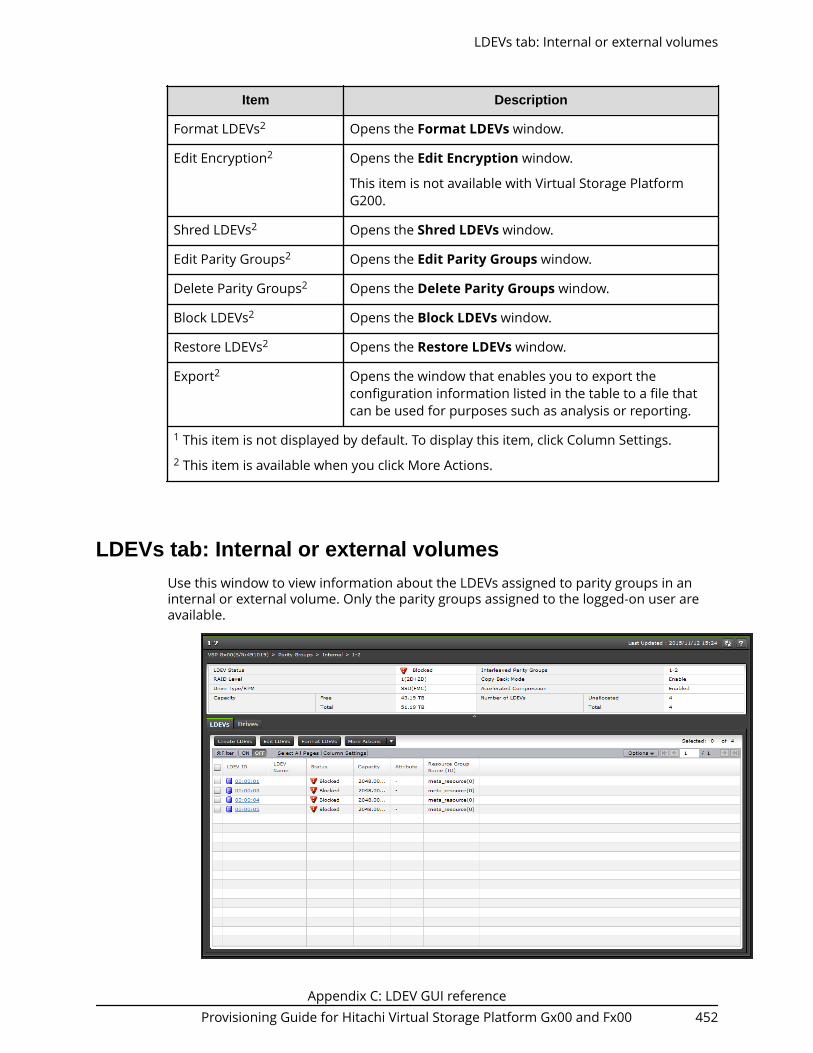
Item Description
Format LDEVs2 Opens the Format LDEVs window.
Edit Encryption2 Opens the Edit Encryption window.
This item is not available with Virtual Storage PlatformG200.
Shred LDEVs2 Opens the Shred LDEVs window.
Edit Parity Groups2 Opens the Edit Parity Groups window.
Delete Parity Groups2 Opens the Delete Parity Groups window.
Block LDEVs2 Opens the Block LDEVs window.
Restore LDEVs2 Opens the Restore LDEVs window.
Export2 Opens the window that enables you to export theconfiguration information listed in the table to a file thatcan be used for purposes such as analysis or reporting.
1 This item is not displayed by default. To display this item, click Column Settings.2 This item is available when you click More Actions.
LDEVs tab: Internal or external volumesUse this window to view information about the LDEVs assigned to parity groups in aninternal or external volume. Only the parity groups assigned to the logged-on user areavailable.
LDEVs tab: Internal or external volumes
Appendix C: LDEV GUI referenceProvisioning Guide for Hitachi Virtual Storage Platform Gx00 and Fx00 452

Summary
Item Description
LDEV Status Current status of the LDEV.
Normal: Normal status.
Blocked: Host cannot access a blocked volume.
Warning: Problem occurs in the volume.
Formatting: Volume is being formatted.
Preparing Quick Format: Volume is being prepared forquick formatting.
Quick Formatting: Volume is being quick-formatted.
Correction Access: Access attribute is being corrected.
Copying: Data in the volume is being copied.
Read Only: Data cannot be written on a read-onlyvolume.
Shredding: Volume is being shredded.
Hyphen (-): Any status other than the above.
RAID Level RAID level. An asterisk "*" indicates that the parity groupto which the LDEV belongs is interleaved (concatenated).
Capacity ■ Free: Capacity of the free space. The expanded capacityappears when existing parity groups with acceleratedcompression is enabled. The control information usedby the storage system, such as control cylinders, is notincluded in the Free capacity.
■ Total: The total capacity of the LDEVs and the "Capacity- Free" capacity is displayed in the Total. The expandedcapacity appears when existing parity groups withaccelerated compression is enabled.
Drive Type/RPM Drive type and rpm in use on this LDEV.
Interleaved Parity Groups Interleaved (concatenated) parity groups.
LDEVs tab: Internal or external volumes
Appendix C: LDEV GUI referenceProvisioning Guide for Hitachi Virtual Storage Platform Gx00 and Fx00 453

Item Description
Accelerated Compression Displays information about the accelerated compressionof the parity group that is created of LDEVs
Enabled: The accelerated compression of the parity groupis enabled.
Disabled: The accelerated compression of the parity groupis disabled.
Hyphen (-): The parity group with the acceleratedcompression is not supported.
Copy-Back Mode Displays the setting of the copy-back mode.■ Enable: Copy-back mode is enabled in the parity
groups.■ Disable: Copy-back mode is disabled in the parity group
Number of LDEVs ■ Unallocated: Number of unallocated LDEVs.■ Total: Total number of LDEVs.
LDEVs tab
Item Description
LDEV ID LDEV identifier, which is the combination of LDKC, CU, and LDEV.
LDEV Name LDEV name.
LDEVs tab: Internal or external volumes
Appendix C: LDEV GUI referenceProvisioning Guide for Hitachi Virtual Storage Platform Gx00 and Fx00 454

Item Description
Status LDEV status.
Normal: Normal status.
Blocked: Host cannot access a blocked volume.
Warning: Problem occurs in the volume.
Formatting: Volume is being formatted.
Preparing Quick Format: Volume is being prepared for quickformatting.
Quick Formatting: Volume is being quick-formatted.
Correction Access: Access attribute is being corrected.
Copying: Data in the volume is being copied.
Read Only: Data cannot be written on a read-only volume.
Shredding: Volume is being shredded.
Hyphen (-): Any status other than the above.
Capacity Capacity of the selected LDEV.
LDEVs tab: Internal or external volumes
Appendix C: LDEV GUI referenceProvisioning Guide for Hitachi Virtual Storage Platform Gx00 and Fx00 455

Item Description
Attribute Attribute of the volume indicating how the LDEV is being used.■ Command Device: The volume is a command device.■ Remote Command Device: The volume is a remote command
device.■ JNL VOL: The volume is a journal volume.■ Pool VOL: The volume is a pool volume. The number in the
parenthesis indicates the pool identifier.■ Quorum Disk: Quorum disk for global-active device.■ Data Direct Mapping: LDEV of the data direct mapping attribute.■ NAS Platform (User LU): LDEV used for storing the NAS user
data. This value appears if the NAS module is installed.
■ NAS Platform (System LU): LDEV used for storing the NASfirmware system data. This value appears if the NAS module isinstalled.
■ Deduplication System Data: Deduplication System Data volume.■ Hyphen (-): Volume in which the attribute is not defined
Resource GroupName (ID)
Resource group name and identifier of the LDEV.
Expanded SpaceUsed1
Displays the information that LDEV is allocated in the expandedarea or the physical area. If the accelerated compression isenabled, LDEVs are initially allocated in the physical area, thenLDEVs are allocated in the expanded area.
This item displays whether the LDEV area is allocated in theexpanded or physical area.
Yes: LDEV is allocated in the expanded area.
No: LDEV is allocated in the physical area.
LDEVs tab: Internal or external volumes
Appendix C: LDEV GUI referenceProvisioning Guide for Hitachi Virtual Storage Platform Gx00 and Fx00 456

Item Description
Virtual StorageMachine1
Information about the virtual storage machine.■ Model / Serial Number1: Model name and serial number of the
virtual storage machine that has LDEV.■ LDEV ID1: Virtual LDEV ID. If a Virtual LDEV ID is not assigned to
the LDEV, this column is blank.■ Device Name1: Virtual device name, which is a combination of
the virtual emulation type, virtual LUSE volume number, and thevirtual CVS attribute. Values of the virtual emulation type, virtualLUSE volume number, and virtual CVS attribute appear only foritems that have been set. This column is blank when the virtualemulation type, virtual LUSE volume number, and virtual CVSattribute are not set. If the virtual CVS attribute is set, CVS isattached as the suffix to the device name.
■ SSID1: Virtual SSID. If Virtual SSID is not set for LDEV, this columnis blank.
■ Attribute1: Virtual LDEV attribute. If the attribute is not set forLDEV, this column is blank.
Create LDEVs Opens the Create LDEVs window.
Edit LDEVs Opens the Edit LDEVs window.
Format LDEVs Opens the Format LDEVs window.
Delete LDEVs2 Opens the Delete LDEVs window.
Shred LDEVs2 Opens the Shred LDEVs window.
Block LDEVs2 Opens the Block LDEVs window.
Restore LDEVs2 Opens the Restore LDEVs window.
Export2 Opens a window where you can export configuration informationlisted in the table to a file that can be used for multiple purposes,such as backup or reporting.
Notes:
1. Does not appear by default. To display this item, change the Column Settings ofthe table option.
2. Available when you click More Actions.
LDEVs tab: Internal or external volumes
Appendix C: LDEV GUI referenceProvisioning Guide for Hitachi Virtual Storage Platform Gx00 and Fx00 457

Drives tab
Only drives assigned to the logged-on user are displayed.
Item Description
Drive Box Displays the drive box number.
Location Displays the location of the drive box.
Status Displays the status of the drive box.
Drive Type-Code Displays the drive type-code.
Drive Type/RPM/Capacity Displays the drive type, RPM, and capacity.As for SSD, a hyphen (-) appears on theRPM field.
Assign Spare Drives Displays the Assign Spare Drives window.
Export Displays the window for outputting tableinformation.
Logical Devices windowUse this window to view information about logical devices. Only the LDEVs assigned tothe logged-on user are available.
Logical Devices window
Appendix C: LDEV GUI referenceProvisioning Guide for Hitachi Virtual Storage Platform Gx00 and Fx00 458

Summary
Item Description
Volume Migration ■ View Migration Plans: Opens the View Migration Planswindow.
■ View Histories: Opens the View Histories window.
Number of LDEVs ■ Allocated: Number of allocated LDEVs.■ Unallocated: Number of unallocated LDEVs.■ Reserved: Number of reserved LDEVs.■ V-VOLs: Number of allocated V-VOLs.
Total Number of LDEVs Total number of LDEVs.
Logical Devices window
Appendix C: LDEV GUI referenceProvisioning Guide for Hitachi Virtual Storage Platform Gx00 and Fx00 459

Item Description
Format/Shredding TaskStatus
Formatting n %: Displays the percentage of the progressof formatting processing.
Preparing Quick Format n %: Displays the percentage ofthe progress of the preparing quick format processing.
Shredding n %: Displays the percentage of the progress ofthe shredding processing.
Verifying n % (x / y parity groups): Displays the progress ofthe verifying. n represents the progress of the verifying. xrepresents the number of parity groups that arecompleted of verifying. y represents the number of allparity groups that are to be verified
Blank: Displays a blank when formatting or shreddingdoes not perform. If the information cannot be obtained,for example being changed of the storage systemconfiguration, a blank is displayed.
LDEVs tab
Item Description
LDEV ID LDEV identifier, which is the combination of LDKC, CU, and LDEV.
LDEV Name LDEV name.
Logical Devices window
Appendix C: LDEV GUI referenceProvisioning Guide for Hitachi Virtual Storage Platform Gx00 and Fx00 460

Item Description
Status LDEV status:■
Normal: Normal status.■
Blocked: Hosts cannot access a blocked volume.■
Warning: Problem occurs in the volume.■
Formatting: Volume is being formatted.■
Preparing Quick Format: Volume is being prepared for quickformatting.
■ Quick Formatting: Volume is being quick-formatted.
■ Correction Access: Access attribute is being corrected.
■ Copying: Data in the volume is being copied.
■ Read Only: Data cannot be written on a read-only volume.
■ Shredding: Volume is being shredded.
■ - (hyphen): Any status other than the above.
PIN Status Displays the PIN status.
V-VOLManagementTask1
Displays the V-VOL management task being performed on aDynamic Provisioning, Dynamic Tiering, or a V-VOL.■ Reclaiming Zero Pages: The process is in progress.■ Waiting for Zero Page Reclaiming: The process has been waited.■ Blank: The V-VOL management task can be performed on the
volume, but the task is not currently in process.■ - (hyphen): The V-VOL management task cannot be performed
on the volume.
Capacity LDEV capacity.
Capacity Saving1 Capacity saving setting of the LDEV:■ Compression: The compression function is used.■ Deduplication and Compression: The deduplication and
compression functions are used.■ Disabled: The capacity saving function is not used.
Logical Devices window
Appendix C: LDEV GUI referenceProvisioning Guide for Hitachi Virtual Storage Platform Gx00 and Fx00 461

Item Description
Capacity SavingStatus1
Status of the capacity saving function:■ Enabling: The format for enabling the capacity saving function is
being performed.■ Rehydrating: The format for disabling the capacity saving
function is being performed.■ Deleting Volume: The deletion of DP-VOL whose capacity saving
function is Enabled is being performed.■ Enabled: The capacity saving function is enabled.■ Disabled: The capacity saving function is disabled.■ Failed: Data cannot be secured.■ - (hyphen): The LDEV does not support the capacity saving
function.
DeduplicationData1
Displays whether the deduplication function is applied to thevolume (DP-VOL).■ Enabled: The deduplication function is applied.■ Disabled: The deduplication function is not applied.■ - (hyphen): The LDEV is not a DP-VOL, or the firmware version
does not support deduplication.
If the capacity saving setting of a DP-VOL is Deduplication andCompression, Enabled is displayed even if the used capacity is 0.
When the capacity saving setting is Disabled and the disabling ofthe capacity saving setting is in process, Enabled is displayed forDeduplication Data while deduplicated data remains in the DP-VOL.When the disabling of the capacity saving setting is complete andno deduplicated data remains in the DP-VOL, Disabled is displayed.
Number of paths Number of paths set for the LDEV.
Provisioning Type Provisioning type to be assigned to the LDEV.■ Basic: Internal volume.■ DP: DP-VOL■ External: External volume.■ External MF: Migration volume.■ Snapshot: Thin Image volume.■ ALU: LDEV of the ALU attribution.
Logical Devices window
Appendix C: LDEV GUI referenceProvisioning Guide for Hitachi Virtual Storage Platform Gx00 and Fx00 462

Item Description
Attribute Attribute of the volume indicating how the LDEV is being used.■ Command Device: Volume is a command device.■ Remote Command Device: Volume is a remote command
device.■ JNL VOL: Volume is a journal volume.■ Pool VOL: Volume is a pool volume. The number in parentheses
shows the pool identifier.■ Quorum Disk: Quorum disk for global-active device.■ ALU: LDEV of the ALU attribution.■ SLU: LDEV of the SLU attribution.■ Data Direct Mapping: LDEV with the data direct mapping
attribute enabled.■ NAS Platform (User LU): LDEV used for storing the NAS user
data. This value appears if the NAS module is installed.
■ NAS Platform (System LU): LDEV used for storing the NASfirmware system data. This value appears if the NAS module isinstalled.
■ Deduplication System Data: Deduplication System Data volume.■ - (hyphen ): Volume other than the above.
Access Attribute1 Displays the access attribute of the LDEV.
Pool Name (ID) Pool name (pool identifier).
Parity Group ID Parity group identifier.
RAID Level RAID level. An asterisk (*) indicates that the parity group that theLDEV belong to is interleaved (concatenated).
MP Unit ID2 MP unit identifier.
Logical Devices window
Appendix C: LDEV GUI referenceProvisioning Guide for Hitachi Virtual Storage Platform Gx00 and Fx00 463
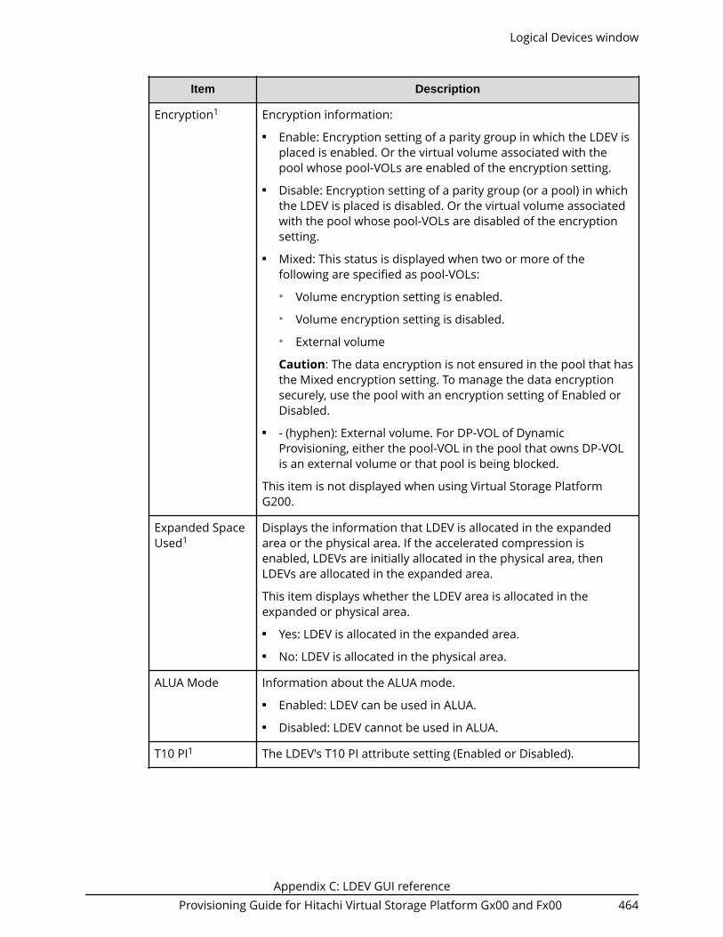
Item Description
Encryption1 Encryption information:■ Enable: Encryption setting of a parity group in which the LDEV is
placed is enabled. Or the virtual volume associated with thepool whose pool-VOLs are enabled of the encryption setting.
■ Disable: Encryption setting of a parity group (or a pool) in whichthe LDEV is placed is disabled. Or the virtual volume associatedwith the pool whose pool-VOLs are disabled of the encryptionsetting.
■ Mixed: This status is displayed when two or more of thefollowing are specified as pool-VOLs:● Volume encryption setting is enabled.● Volume encryption setting is disabled.● External volume
Caution: The data encryption is not ensured in the pool that hasthe Mixed encryption setting. To manage the data encryptionsecurely, use the pool with an encryption setting of Enabled orDisabled.
■ - (hyphen): External volume. For DP-VOL of DynamicProvisioning, either the pool-VOL in the pool that owns DP-VOLis an external volume or that pool is being blocked.
This item is not displayed when using Virtual Storage PlatformG200.
Expanded SpaceUsed1
Displays the information that LDEV is allocated in the expandedarea or the physical area. If the accelerated compression isenabled, LDEVs are initially allocated in the physical area, thenLDEVs are allocated in the expanded area.
This item displays whether the LDEV area is allocated in theexpanded or physical area.■ Yes: LDEV is allocated in the expanded area.■ No: LDEV is allocated in the physical area.
ALUA Mode Information about the ALUA mode.■ Enabled: LDEV can be used in ALUA.■ Disabled: LDEV cannot be used in ALUA.
T10 PI1 The LDEV's T10 PI attribute setting (Enabled or Disabled).
Logical Devices window
Appendix C: LDEV GUI referenceProvisioning Guide for Hitachi Virtual Storage Platform Gx00 and Fx00 464

Item Description
External StorageSystem1
Information about the external storage system.
If LDEV is the DP-VOL of the data direct mapping attribure, theinformation about the external storage system to which LDEV isbeing mapped appears.■ Vendor/Model/Serial Number: The information about these
items of the external storage system is displayed. A hyphen(-)appears if an external storage system is not mapped to LDEV.
■ Path Group ID: The information about this item of the externalstorage system is displayed. If the link of the path group id isclicked, the Mapped Volumes tab appears. A hyphen (-) appearsif an external storage system is not mapped to LDEV.
Data DirectMapping1
Information about the data direct mapping.■ LDEV ID: LDEV ID of the pool-VOL in the pool with data direct
mapping enabled, or LDEV ID of the DP-VOL with data directmapping enabled. If the link of LDEV ID is clicked, the LDEVProperties window appears. If data direct mapping is disabled, ahyphen (-) is displayed. If a DP-VOL with data direct mappingenabled is not created in the pool with data direct mappingenabled, this field is blank.
■ Parity Group ID: Parity Group ID of the pool-VOL in the pool withdata direct mapping enabled. If data direct mapping is disabled,a hyphen (-) is displayed.
Resource GroupName (ID)1
Name and ID of the resource group to which this LDEV belongs.
Virtual StorageMachine1
Information about the virtual storage machine.■ Model / Serial Number1: Model name and serial number of the
virtual storage machine that has the LDEV.■ LDEV ID1: Virtual LDEV ID. If a Virtual LDEV ID is not assigned to
LDEV, this column is blank.■ Device Name1: Virtual device name, which is a combination of
the virtual emulation type, virtual LUSE volume number, and thevirtual CVS attribute. Values of the virtual emulation type, virtualLUSE volume number, and virtual CVS attribute appear only foritems that have been set. This column is blank when the virtualemulation type, virtual LUSE volume number, and virtual CVSattribute are not set. If the virtual CVS attribute is set, CVS isattached as the suffix to the device name.
■ SSID1: Virtual SSID. If Virtual SSID is not set for LDEV, this columnis blank.
Create LDEVs Opens the Create LDEVs window.
Logical Devices window
Appendix C: LDEV GUI referenceProvisioning Guide for Hitachi Virtual Storage Platform Gx00 and Fx00 465

Item Description
Add LUN Paths Opens the LUN Paths window.
Edit LDEVs Opens the Edit LDEVs window.
Format LDEVs3 Opens the Format LDEVs window.
Delete LDEVs3 Opens the Delete LDEVs window.
Shred LDEVs3 Opens the Shred LDEVs window.
Delete LUNPaths3
Opens the Delete LUN Paths window.
Edit CommandDevice3
Opens the Edit Command Devices window
Block LDEVs3 Opens the Block LDEVs window.
Restore LDEVs3 Opens the Restore LDEVs window.
Assign MP Blade3 Opens the Assign MP Blade window.
Delete UUIDs3 Opens the Delete UUIDs window.
Reclaim ZeroPages3
Opens the Reclaim Zero Pages window.
Stop ReclaimingZero Pages3
Opens the Stop Reclaiming Zero Pages window.
Expand V-VOLs3 Opens the Expand V-VOLs window.
View TierProperties3
Opens the View Tier Properties window.
MigrateVolumes3
Opens the Migrate Volumes window.
Interrupt LDEVTask3
Select Interrupt Format Task to display the Interrupt FormattingTask window.
Select Interrupt Shredding Task to display the Interrupt ShreddingTask window.
Force DeletePairs3
■ TC Pairs: Opens the Force Delete Pairs (TC Pairs) window. Fordetails see the Hitachi TrueCopy® User Guide .
■ UR Pairs: Opens the Force Delete Pairs (UR Pairs) window. Fordetails see the Hitachi Universal Replicator User Guide.
■ GAD Pairs: Opens the Force Delete Pairs (GAD Pairs) window.For details see the Global-Active Device User Guide.
ALUs/SLUs3 Opens the ALUs / SLUs window.
Logical Devices window
Appendix C: LDEV GUI referenceProvisioning Guide for Hitachi Virtual Storage Platform Gx00 and Fx00 466
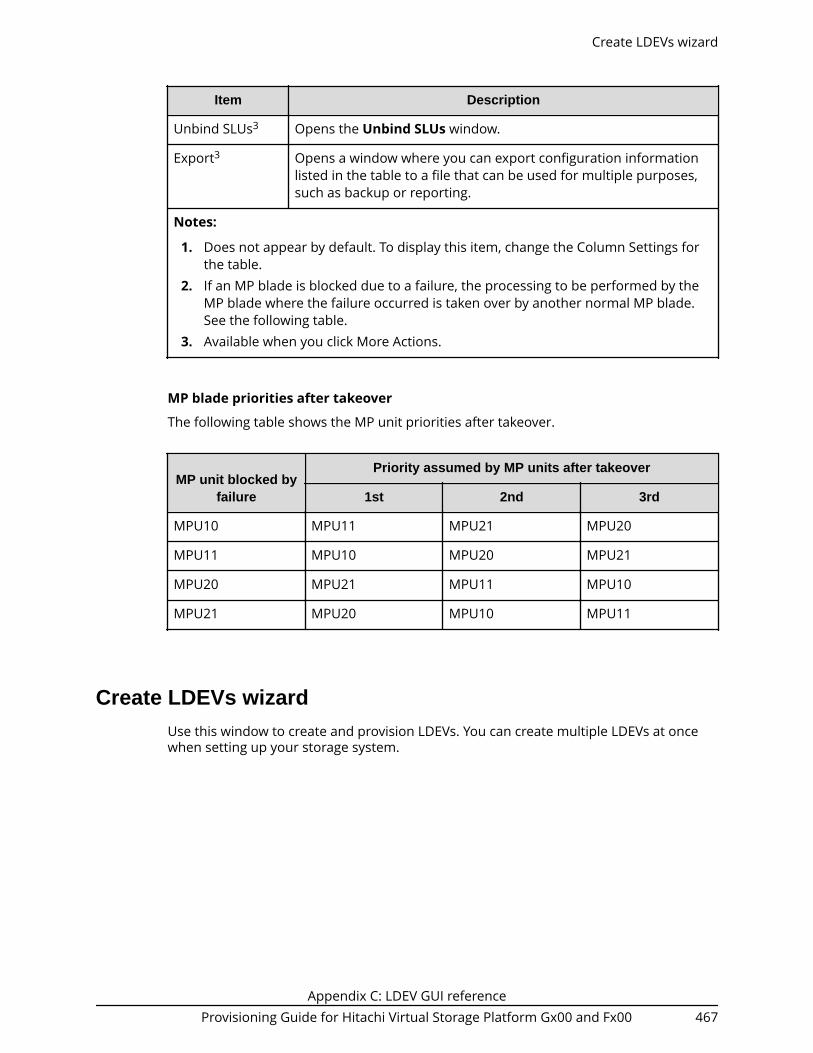
Item Description
Unbind SLUs3 Opens the Unbind SLUs window.
Export3 Opens a window where you can export configuration informationlisted in the table to a file that can be used for multiple purposes,such as backup or reporting.
Notes:
1. Does not appear by default. To display this item, change the Column Settings forthe table.
2. If an MP blade is blocked due to a failure, the processing to be performed by theMP blade where the failure occurred is taken over by another normal MP blade.See the following table.
3. Available when you click More Actions.
MP blade priorities after takeover
The following table shows the MP unit priorities after takeover.
MP unit blocked byfailure
Priority assumed by MP units after takeover
1st 2nd 3rd
MPU10 MPU11 MPU21 MPU20
MPU11 MPU10 MPU20 MPU21
MPU20 MPU21 MPU11 MPU10
MPU21 MPU20 MPU10 MPU11
Create LDEVs wizardUse this window to create and provision LDEVs. You can create multiple LDEVs at oncewhen setting up your storage system.
Create LDEVs wizard
Appendix C: LDEV GUI referenceProvisioning Guide for Hitachi Virtual Storage Platform Gx00 and Fx00 467

Create LDEVs window
Setting fields
Item Description
Provisioning Type Select the type of LDEV.■ Basic: Internal volume.■ Dynamic Provisioning: DP-VOL.■ External: External volume.■ Snapshot: Thin Image volume.■ ALU: LDEV of the ALU attribution.
Data Direct Mapping Select Enable or Disable for the data direct mappingattribute. This item can be selected if the ProvisioningType is Dynamic Provisioning or External. If theProvisioning Type is External and an external volumewith the data direct mapping attribute enabled doesnot exist, you cannot select Enable.■ Enable: The data direct mapping attribute is
enabled.■ Disable: The data direct mapping attribute is
disabled.
Create LDEVs window
Appendix C: LDEV GUI referenceProvisioning Guide for Hitachi Virtual Storage Platform Gx00 and Fx00 468

Item Description
Capacity Saving Select the option for the capacity saving functions:■ Compression: Select to use the compression
function.■ Deduplication and Compression: Select to use the
deduplication and compression functions. Thisoption cannot be selected if Disable is set forDeduplication in the target pool or if the LDEVstatus of the deduplication system data volume inthe target pool is other than Normal.
■ Disabled: Select to disable the capacity savingfunctions. Disabled is automatically selected whenany of the following conditions is satisfied:
- Enable is selected for Data Direct Mapping.
- The license for the capacity saving functions isnot installed.
- Enable is set for Multi-Tier Pool.
- The device emulation type is other than OPEN-V.
Multi-Tier Pool Select Enable or Disable if using Dynamic Tiering.■ Enable: The pool for Dynamic Tiering is displayed
in the Select Pool window.■ Disable: The pool for Dynamic Tieringis displayed
in the Select Pool window.
Active Flash Select to enable active flash. To select this item, all ofthe following conditions must be met:■ The Multi-Tier Pool option is enabled.■ Pool volumes whose drive type is SSD are installed.
Parity Group Selection, PoolSelection, or External VolumeSelection
Select the parity group to which the LDEV is assigned.■ Parity Group Selection: Displayed when you create
internal volumes.■ Pool Selection: Displayed when you create DP-
VOLs. If the Data Direct Mapping is set to Enable,this item is not displayed.
■ External Volume Selection: Displayed when youcreate external volumes.
Create LDEVs window
Appendix C: LDEV GUI referenceProvisioning Guide for Hitachi Virtual Storage Platform Gx00 and Fx00 469

Item Description
Drive Type/RPM Select the data drive type and RPM.■ Any: All types of drives that are supported by the
system.■ SSD(FMC): Flash module compression.
(Open systems) Specify when creating an LDEV in aparity group with accelerated compressionenabled.
■ SSD(FMD): Flash module drive.■ SSD(MLC): Multi-level-cell flash drive.■ SAS/RPM: SAS drive of the specified rotational
speed (RPM).
For VSP Fx00 models, SAS drives cannot bespecified.
■ External Storage: External storage system.■ Mixed: Mixed types of drives.
RAID Level Select the RAID level. When External Storage isselected from the Drive Type/RPM field, a hyphen (-) isdisplayed.
Select Free Spaces Displays the Select Free Spaces window.
Select Pool Displays the Select Pool window.
Total Selected Free Spaces Displays the number of the selected free spaces.
Total Selected Free SpaceCapacity
Displays the total capacity of the free spaces.
Selected Pool Name (ID) Displays the selected pool name and ID.
Selected Pool Capacity Displays the selected pool capacity.
Create LDEVs window
Appendix C: LDEV GUI referenceProvisioning Guide for Hitachi Virtual Storage Platform Gx00 and Fx00 470

Item Description
LDEV Capacity ■ Capacity Compatibility Mode (Offset boundary):● If you want to offset the specified LDEV capacity
by boundary, set the Capacity CompatibilityMode (Offset boundary) to ON.
■ Input area: Specify the LDEV capacity to create in afree space, a pool, or an external volume.
Detailed calculation of the LDEV capacity differsdepending on the specification of the unit. If the DataDirect Mapping is set to enable, this item is notdisplayed.
(Open systems) When creating of LDEVs carved fromaccelerated compression-enabled parity groups,estimate the LDEV capacity. For details, see Guidelinesfor pools when accelerated compression is enabled(on page 429) .
Number of LDEVs per FreeSpace, Number of LDEVs, orNumber of LDEVs per ExternalVolume
Specify the number of LDEVs to create in a free space,pool, or the external volume.
If the Provisioning Type is set to Dynamic Provisioningand the Data Direct Mapping is set to enable, thisitem is not displayed. If the Provisioning Type is set toExternal and the Data Direct Mapping is set to enable,1 is displayed in the Number of LDEVs per ExternalVolume.
(Open systems) When creating LDEVs in acceleratedcompression-enabled parity groups, estimate thenumber of LDEVs. For details, see Guidelines for poolswhen accelerated compression is enabled (onpage 429) .
Create LDEVs window
Appendix C: LDEV GUI referenceProvisioning Guide for Hitachi Virtual Storage Platform Gx00 and Fx00 471

Item Description
Available Volumes Select available volumes. This item is displayed whenthe Provisioning Type is Dynamic Provisioning anddata direct mapping is enabled. The following itemsare displayed:■ LDEV ID■ LDEV Name■ Parity Group ID■ Capacity: The capacity of LDEV■ Vender/Model/Serial Number■ Pool Name (ID)■ Subscription Current (%): The percentage of the
current subscription of the pool■ Subscription Limit (%): The percentage of the limit
subscription of the pool■ Capacity: The capacity of the pool
LDEV Name LDEV name. Specify the prefix characters and theinitial number.■ Prefix: A fixed character string.■ Initial Number: The initial number of the LDEV
name.
Specify the prefix characters and the initialnumber according to the examples below. You canspecify up to 32 characters total.
Example:■ 1: Up to 9 numbers are added (1, 2, 3... 9).■ 08: Up to 92 numbers are added (08, 09, 10...
99).■ 23: Up to 77 numbers are added (23, 24, 25...
99).■ 098: Up to 902 numbers are added (098, 099,
100... 999).
Create LDEVs window
Appendix C: LDEV GUI referenceProvisioning Guide for Hitachi Virtual Storage Platform Gx00 and Fx00 472

Item Description
Format Type Specify the format type. This is displayed when aninternal or external volume is used.■ Quick Format (default): You cannot select this
when the provisioning type is external volume orfor an LDEV in a parity group with acceleratedcompression enabled.
■ Normal Format: Normal formatting.■ Parity Group Format: Parity group is formatted.
This type can be selected if no LDEV exists in theparity group.
■ No Format: Volumes are not formatted.
Initial LDEV ID Specify the LDEV ID. LDKC is fixed to 00. Default of CUand DEV is 00:00.
For creating multiple LDEVs, select the interval of theassigned LDEV ID from the Interval list.
View LDEV IDs Displays the View LDEV IDs windows.
CLPR Cache logical partition number, displayed as ID:CLPR.
MP Unit ID Specify the MP unit you want to assign to the LDEV.
You can select an ID from MPB0 to MPB7. If automaticassignment is enabled for one or more MPs, you canalso select Auto.
If Auto is enabled, the default is Auto. If Auto isdisabled, the default is the lowest number of the MPunit.
Full Allocation Select Enable to reserve pages in a pool that isassociated with LDEVs.■ Enable: Full allocation is performed.■ Disable (default): Full allocation is not performed.
You can select Enable only when all of the followingconditions are satisfied:■ The sum of the mapped capacity and the reserved
capacity is same or less than the depletionthreshold.
■ The specified pool is not undergoing the shrinkprocessing.
■ The data direct mapping attribute is disabled.
Create LDEVs window
Appendix C: LDEV GUI referenceProvisioning Guide for Hitachi Virtual Storage Platform Gx00 and Fx00 473

Item Description
Tiering Policy Tiering Policy: All(0) is selected by default. You canchange a level from Level1(1) to Level5(5) or fromLevel6(6) to Level31(31). See Notes on tiering policysettings (on page 213) . From Level 6 (6) to Level 31(31), the names of tiering policies can also bechanged. If these names have changed, the newnames appear.
You can specify this function when the multi-tier pooloption is enabled.
New Page Assignment Tier Specify the new page assignment tier you want toassign to the LDEV. Middle is selected by default. Youcan select from the levels of High, Middle, and Low.See New page assignment tier (on page 215) .You canspecify this function when the multi-tier pool option isenabled.
Relocation Priority Specify this option if the LDEV is to be relocatedpreferentially. You can select Default or Prioritize.
You can specify this function when the Multi-Tier Poolis enabled.
T10 PI Specify the LDEV's T10 PI attribute (Enabled orDisabled).
This item can be specified only when the ProvisioningType is Basic, Dynamic Provisioning, or Snapshot.
Add Adds the LDEVs that have settings specified in thesetting field to the Selected LDEVs table.
The items that can be set in this window depend on the type of volume you are creating.The following table lists the items that can be set according to volume type.
ItemInternalvolume V-VOL
Externalvolume
Snapshotvolume
LDEV of theALU
attribution
Provisioning Type Required Required Required Required N/A
Data Direct Mapping N/A Optional Optional N/A N/A
Capacity Saving N/A Optional N/A N/A N/A
Multi-Tier Pool N/A Required N/A N/A N/A
Active Flash N/A Optional N/A N/A N/A
Create LDEVs window
Appendix C: LDEV GUI referenceProvisioning Guide for Hitachi Virtual Storage Platform Gx00 and Fx00 474

ItemInternalvolume V-VOL
Externalvolume
Snapshotvolume
LDEV of theALU
attribution
Drive Type/RPM Required Required Disabled N/A N/A
RAID Level Required Required Disabled N/A N/A
Select Free Spaces Required N/A Required N/A N/A
Select Pool N/A Required N/A N/A N/A
Capacity CompatibilityMode (Offset boundary)
Optional Optional Optional Optional N/A
LDEV Capacity Required Required Required Required N/A
Number of LDEVs perFree Space
Required N/A N/A N/A N/A
Number of LDEVs N/A Required N/A Required Required
Number of LDEVs perExternal Volume
N/A N/A Required N/A N/A
Available Volumes N/A Optional Optional N/A N/A
LDEV Name Optional Optional Optional Optional Optional
Format Type Required N/A Required N/A N/A
Initial LDEV ID Optional Optional Optional Optional Optional
View LDEV IDs Optional Optional Optional Optional Optional
CLPR N/A Optional N/A Optional Optional
MP Unit ID Optional Optional Optional Optional Optional
Full Allocation N/A Optional N/A N/A N/A
Tiering Policy N/A Optional N/A N/A N/A
New Page AssignmentTier
N/A Optional N/A N/A N/A
Relocation Priority N/A Optional N/A N/A N/A
T10 PI Optional Optional N/A Optional N/A
Create LDEVs window
Appendix C: LDEV GUI referenceProvisioning Guide for Hitachi Virtual Storage Platform Gx00 and Fx00 475

Selected LDEVs table
Item Description
LDEV ID LDEV identifier, which is the combination of LDKC, CU,and LDEV.
LDEV Name LDEV name, including the combination of prefixcharacters and the initial number.
Parity Group ID Parity group identifier.
Pool Name (ID) Pool name and pool identifier.
Data Direct Mapping Information about the data direct mapping.■ LDEV ID: LDEV ID of the pool-VOL in the pool with
data direct mapping enabled, or LDEV ID of the DP-VOL with data direct mapping enabled. If datadirect mapping is disabled, a hyphen (-) isdisplayed.
■ Parity Group ID: Parity Group ID of the pool-VOL inthe pool with data direct mapping enabled. If datadirect mapping is disabled, a hyphen (-) isdisplayed.
Drive Type/RPM Drive type and rpm in use on this LDEV.
RAID Level RAID level. An asterisk "*" indicates that the paritygroup to which the LDEV belongs is interleaved(concatenated).
Capacity LDEV capacity.
Format Type Format type.
CLPR Cache logical partition number, displayed as ID:CLPR.
For detailed information about CLPRs, see thePerformance Guide.
MP Unit ID MP unit identifier. If Auto is selected, the ID isautomatically assigned.
Multi-Tier Pool Indicates whether Dynamic Tiering is enabled ordisabled.■ Enabled: The LDEV is for Dynamic Tiering .■ Disabled: The LDEV is not for Dynamic Tiering .
Create LDEVs window
Appendix C: LDEV GUI referenceProvisioning Guide for Hitachi Virtual Storage Platform Gx00 and Fx00 476

Item Description
Full Allocation Displays the status of the setting for the full allocationin a pool associated with the V-VOL.■ Enable: Full allocation of all DP-VOL pages is
performed.■ Disable: Full allocation of all DP-VOL pages is not
performed.
Active Flash Indicates whether active flash is enabled or disabled.
Enabled: The LDEV is for active flash .
Disable: The LDEV is for Dynamic Tiering .
- (hyphen): The LDEV is for Dynamic Provisioning .
Tiering Policy The tiering policy name and ID for the LDEV.
New Page Assignment Tier Displays the new page assignment tier for the LDEV.
Relocation Priority Displays the relocation priority assigned to the LDEV.
Capacity Saving Displays the capacity saving setting:■ Compression: The compression function is used.■ Deduplication and Compression: The
deduplication and compression functions areused.
■ Disabled: The Capacity Saving function is not used.
Attribute Displays the attribute of the LDEV.■ ALU: LDEV of the ALU attribution■ Data Direct Mapping: LDEV with the data direct
mapping attribute enabled.■ - (hyphen): Volume for which the attribute is not
defined.
Create LDEVs window
Appendix C: LDEV GUI referenceProvisioning Guide for Hitachi Virtual Storage Platform Gx00 and Fx00 477

Item Description
Encryption Encryption information:■ Enable: Encryption setting of a parity group in
which the LDEV is placed is enabled. Or the virtualvolume associated with the pool whose pool-VOLsare enabled of the encryption setting.
■ Disable: Encryption setting of a parity group (or apool) in which the LDEV is placed is disabled. Orthe virtual volume associated with the pool whosepool-VOLs are disabled of the encryption setting.
■ Mixed: This status is displayed when two or moreof the following are specified as pool-VOLs:● Volume encryption setting is enabled.● Volume encryption setting is disabled.● External volume
Caution: The data encryption is not ensured in thepool that has the Mixed encryption setting. Tomanage the data encryption securely, use the poolwith an encryption setting of Enabled or Disabled.
■ - (hyphen): External volume or migration volume.As for DP-VOL of Dynamic Provisioning, the pool-VOL in the pool of which DP-VOL belongs is anexternal volume, or the pool of which DP-VOLbelongs is being blocked.
This item is not displayed when using Virtual StoragePlatform G200.
Accelerated Compression Displays information about the acceleratedcompression of the parity group that is created ofLDEVs
Enabled: The accelerated compression of the paritygroup is enabled.
Disabled: The accelerated compression of the paritygroup is disabled.
- (hyphen): The parity group with acceleratedcompression is not supported.
T10 PI Displays the LDEV's T10 PI attribute information(Enabled or Disabled).
Resource Group Name (ID) Resource group name and ID of which this LDEV is amember.
Create LDEVs window
Appendix C: LDEV GUI referenceProvisioning Guide for Hitachi Virtual Storage Platform Gx00 and Fx00 478

Item Description
Virtual Storage Machine Displays the information about the virtual storagemachine.■ Model / Serial Number: The model name and serial
number of the virtual storage machine having theLDEV.
■ Attribute: Virtual LDEV attribute. If the attribute isnot set for LDEV, this column is blank.
Change LDEV Settings Opens the Change LDEV Settings window.
Remove Removes the added LDEV.
Create LDEVs confirmation window
Note: If multiple tasks that are connected in one wizard are executed, thiswindow shows all configured items of tasks. To show information ofconfigured items other than this topic, click Back to display related settingwindows, and then click Help.
Selected LDEVs table
Item Description
LDEV ID LDEV identifier, which is the combination of LDKC, CU,and LDEV.
LDEV Name LDEV name, including the combination of prefixcharacters and the initial number.
Create LDEVs confirmation window
Appendix C: LDEV GUI referenceProvisioning Guide for Hitachi Virtual Storage Platform Gx00 and Fx00 479

Item Description
Data Direct Mapping Information about the data direct mapping.■ LDEV ID: LDEV ID of the pool-VOL in the pool with
data direct mapping enabled, or LDEV ID of the DP-VOL data direct mapping enabled. If the data directmapping attribute is disabled, a hyphen (-) isdisplayed.
■ Parity Group ID: Parity Group ID of the pool-VOL inthe pool with data direct mapping enabled. If thedata direct mapping attribute is disabled, a hyphen(-) is displayed.
Parity Group ID Parity group identifier.
Drive Type/RPM Drive type and rpm in use on this LDEV.
Pool Name (ID) Pool name (pool identifier).
RAID Level RAID level. An asterisk "*" indicates that the paritygroup to which the LDEV belongs is interleaved(concatenated).
Capacity LDEV capacity.
Provisioning Type Type of LDEV.■ Basic: Internal volume.■ DP: DP-VOL.■ External: External volume.■ Snapshot: Thin Image volume.■ ALU: LDEV of the ALU attribution.
Format Type Format type.
CLPR Cache logical partition number, in ID:CLPR format.
For detailed information about CLPRs, see thePerformance Guide.
MP Unit ID MP unit identifier. If Auto is selected, the ID isautomatically assigned.
Multi-Tier Pool Displays whether Dynamic Tiering is enabled ordisabled.
Enable: The LDEV for Dynamic Tiering .
Disable: The LDEV for Dynamic Provisioning .
Create LDEVs confirmation window
Appendix C: LDEV GUI referenceProvisioning Guide for Hitachi Virtual Storage Platform Gx00 and Fx00 480

Item Description
Active Flash Indicates whether active flash is enabled or disabled.
Enabled: The LDEV is for active flash.
Disable: The LDEV is for Dynamic Tiering.
Hyphen (-): The LDEV is for Dynamic Provisioning.
Full Allocation Displays the status of the setting for the full allocationin a pool associated with the V-VOL.■ Enable: Full allocation of all DP-VOL pages is
performed.■ Disable: Full allocation of all DP-VOL pages is not
performed.
Tiering Policy Displaying the tiering policy name and ID for theLDEV.
New Page Assignment Tier Displays the new page assignment tier for the LDEV.
Relocation Priority Relocation priority assigned to the LDEV.
Capacity Saving Displays the capacity saving setting:■ Compression: The compression function is used.■ Deduplication and Compression: The
deduplication and compression functions areused.
■ Disabled: The Capacity Saving function is not used.
Attribute Displays the attribute of the LDEV.
ALU: LDEV of the ALU attribution.
Data Direct Mapping: LDEV with the data directmapping attribute enabled.
Hyphen (-): Volume in which attribute is not defined.
Create LDEVs confirmation window
Appendix C: LDEV GUI referenceProvisioning Guide for Hitachi Virtual Storage Platform Gx00 and Fx00 481

Item Description
Encryption Encryption information:■ Enable: Encryption setting of a parity group in
which the LDEV is placed is enabled. Or the virtualvolume associated with the pool whose pool-VOLsare enabled of the encryption setting.
■ Disable: Encryption setting of a parity group (or apool) in which the LDEV is placed is disabled. Orthe virtual volume associated with the pool whosepool-VOLs are disabled of the encryption setting.
■ Mixed: This status is displayed when two or moreof the following are specified as pool-VOLs:● Volume encryption setting is enabled.● Volume encryption setting is disabled.● External volume
Caution: The data encryption is not ensured in thepool that has the Mixed encryption setting. Tomanage the data encryption securely, use the poolwith an encryption setting of Enabled or Disabled.
■ Hyphen(-): External volume or migration volume.As for DP-VOL of Dynamic Provisioning , the pool-VOL in the pool of which DP-VOL belongs is anexternal volume, or the pool of which DP-VOLbelongs is being blocked.
Accelerated Compression Displays information about the acceleratedcompression of the parity group that is created ofLDEVs.
Enabled: The accelerated compression of the paritygroup is enabled.
Disabled: The accelerated compression of the paritygroup is disabled.
Hyphen (-): The parity group with acceleratedcompression is not supported.
T10 PI Displays the LDEV's T10 PI attribute information(Enabled or Disabled).
Resource Group Name (ID) Resource group name and ID of which this LDEV is amember.
Create LDEVs confirmation window
Appendix C: LDEV GUI referenceProvisioning Guide for Hitachi Virtual Storage Platform Gx00 and Fx00 482
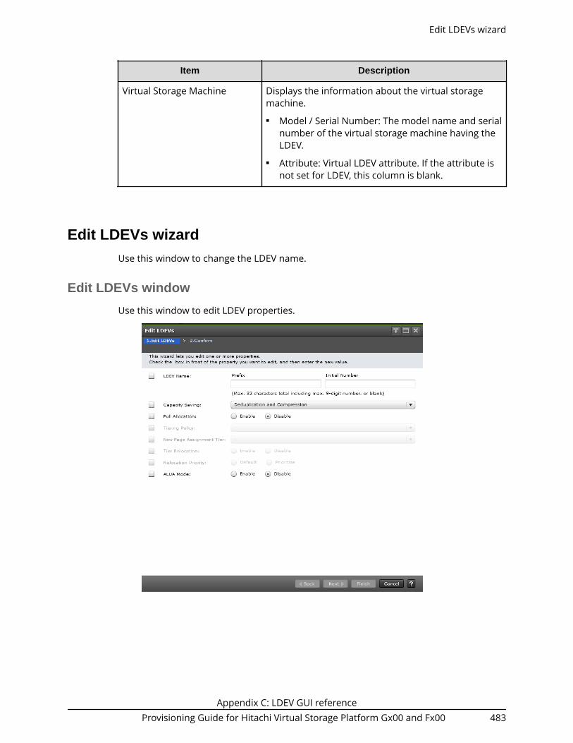
Item Description
Virtual Storage Machine Displays the information about the virtual storagemachine.■ Model / Serial Number: The model name and serial
number of the virtual storage machine having theLDEV.
■ Attribute: Virtual LDEV attribute. If the attribute isnot set for LDEV, this column is blank.
Edit LDEVs wizardUse this window to change the LDEV name.
Edit LDEVs window
Use this window to edit LDEV properties.
Edit LDEVs wizard
Appendix C: LDEV GUI referenceProvisioning Guide for Hitachi Virtual Storage Platform Gx00 and Fx00 483

Item Description
LDEV Name Specify the LDEV name, using up to 32 characters.■ Prefix: Fixed character string.■ Initial Number: Initial number.
Specify the prefix characters and the initial numberaccording to these examples.
Example:■ 1: Up to 9 numbers are added (1, 2, 3 ... 9).■ 08: Up to 92 numbers are added (08, 09, 10 ... 99).■ 23: Up to 77 numbers are added (23, 24, 25 ... 99).■ 098: Up to 902 numbers are added (098, 099, 100 ...
999).
Capacity Saving Select the option for the capacity saving function.■ Compression: Select this option to use the
compression function.■ Deduplication and Compression: Select this option to
use the deduplication and compression functions. IfDeduplication is disabled in the target pool, this optioncannot be selected.
■ Disabled: Select this option to disable the CapacitySaving function.
If any of the following conditions is satisfied, Disabled isset for Capacity Saving:■ Data Direct Mapping is enabled.■ The license for the capacity saving function is not
installed.■ Multi-Tier Pool is enabled.■ There are not enough cache management devices.■ A journal volume for Universal Replicator is selected.
Edit LDEVs window
Appendix C: LDEV GUI referenceProvisioning Guide for Hitachi Virtual Storage Platform Gx00 and Fx00 484
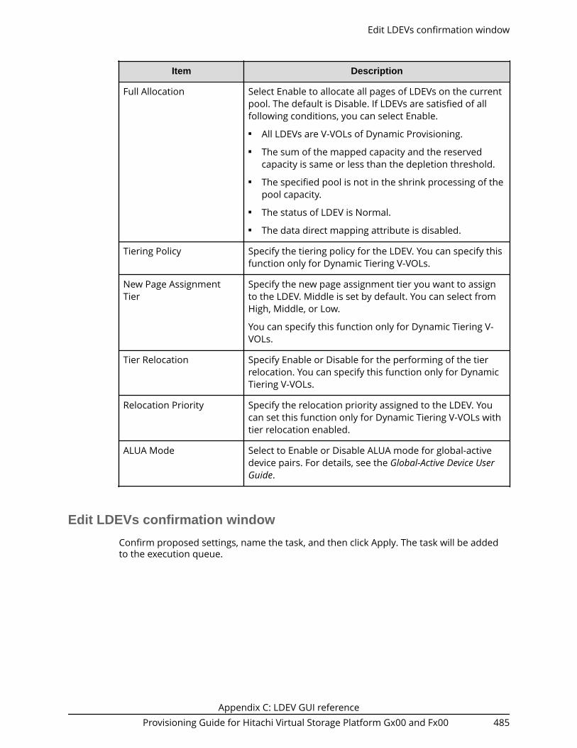
Item Description
Full Allocation Select Enable to allocate all pages of LDEVs on the currentpool. The default is Disable. If LDEVs are satisfied of allfollowing conditions, you can select Enable.■ All LDEVs are V-VOLs of Dynamic Provisioning.■ The sum of the mapped capacity and the reserved
capacity is same or less than the depletion threshold.■ The specified pool is not in the shrink processing of the
pool capacity.■ The status of LDEV is Normal.■ The data direct mapping attribute is disabled.
Tiering Policy Specify the tiering policy for the LDEV. You can specify thisfunction only for Dynamic Tiering V-VOLs.
New Page AssignmentTier
Specify the new page assignment tier you want to assignto the LDEV. Middle is set by default. You can select fromHigh, Middle, or Low.
You can specify this function only for Dynamic Tiering V-VOLs.
Tier Relocation Specify Enable or Disable for the performing of the tierrelocation. You can specify this function only for DynamicTiering V-VOLs.
Relocation Priority Specify the relocation priority assigned to the LDEV. Youcan set this function only for Dynamic Tiering V-VOLs withtier relocation enabled.
ALUA Mode Select to Enable or Disable ALUA mode for global-activedevice pairs. For details, see the Global-Active Device UserGuide.
Edit LDEVs confirmation window
Confirm proposed settings, name the task, and then click Apply. The task will be addedto the execution queue.
Edit LDEVs confirmation window
Appendix C: LDEV GUI referenceProvisioning Guide for Hitachi Virtual Storage Platform Gx00 and Fx00 485

Item Description
LDEV ID LDEV identifier, which is the combination of LDKC, CU,and LDEV.
LDEV Name LDEV name, including the combination of prefixcharacters and the initial number.
Parity Group ID Parity group identifier.
Pool Name (ID) Pool name and pool identifier.
Capacity LDEV capacity.
Provisioning Type Type of LDEV.■ Basic: Internal volume.■ DP: DP-VOL.■ External: External volume.■ Snapshot: Thin Image volume.■ ALU: LDEV with the ALU attribution.
Edit LDEVs confirmation window
Appendix C: LDEV GUI referenceProvisioning Guide for Hitachi Virtual Storage Platform Gx00 and Fx00 486

Item Description
Capacity Saving Displays the capacity saving setting of the LDEV.■ Compression: The compression function is used.■ Deduplication and Compression: The
deduplication and compression functions areused.
■ Disabled: The capacity saving function is not used.■ - (hyphen): The LDEV does not support the capacity
saving function.
Full Allocation Displays the status of the setting for the full allocationin a pool associated with the V-VOL.■ Enable: Full allocation is performed.■ Disable: Full allocation is not performed.■ - (hyphen): LDEVs other than V-VOLs for Dynamic
Provisioning.
Tiering Policy Tiering policy. A hyphen (-) is displayed for volumesother than Dynamic Tiering volumes.
New Page Assignment Tier Displays the new page assignment tier for the LDEV. Ahyphen (-) is displayed for volumes other thanDynamic Tiering volumes.
Tier Relocation Displays whether tier relocation is enabled ordisabled. A hyphen (-) is displayed for volumes otherthan Dynamic Tiering volumes.
Relocation Priority Displays the relocation priority assigned to the LDEV.A hyphen is displayed if the LDEV is the one offollowing:■ LDEV other than Dynamic Tiering.■ The tier relocation of LDEV is set to disabled.
ALUA Mode Information about the ALUA mode.■ Enabled: LDEV can be used in ALUA.■ Disabled: LDEV cannot be used in ALUA.
Change LDEV Settings windowUse this window to edit one or more LDEV properties.
Change LDEV Settings window
Appendix C: LDEV GUI referenceProvisioning Guide for Hitachi Virtual Storage Platform Gx00 and Fx00 487

Item Description
LDEV Name Specify the LDEV name, using up to 32 characters.■ Prefix: Fixed character string.■ Initial Number: Initial number.
Specify the initial number according to these examples.
Examples:■ 1: Up to 9 numbers are added (1, 2, 3 ... 9)■ 08: Up to 92 numbers are added (08, 09, 10 ... 99)■ 23: Up to 77 numbers are added (23, 24, 25 ... 99)■ 098: Up to 902 numbers are added (098, 099, 100 ...
999)
Initial LDEV ID Specify the LDEV identifier, which is the combination ofLDKC, CU, and LDEV. Assigns the ID at a certain intervalstarting with the ID you specify.■ LDKC: Specify the LDKC number. It is fixed to 00.■ CU: Specify the CU number.■ DEV: Specify the LDEV number.■ Interval: Specify the interval of the assigned LDEV ID.■ View LDEV IDs: Opens the View LDEV IDs window.
Change LDEV Settings window
Appendix C: LDEV GUI referenceProvisioning Guide for Hitachi Virtual Storage Platform Gx00 and Fx00 488

Item Description
MP Unit ID Select the MP unit ID you want to assign to the LDEV.
Select any ID or Auto.
Select an ID from MPB0 to MPB7. If automatic assignmentis enabled for one or more MPs, you can also select Auto.
T10 PI Specify the LDEV's T10 PI attribute (Enabled or Disabled).
This item can be specified if the Provisioning Type is Basic,Dynamic Provisioning, or Snapshot.
Select Free Spaces windowUse this window to view information about available free space slots in the parity group.Only the free spaces in the parity groups assigned to the logged-on user are available.
Item Description
Parity Group ID Parity group identifier.
Free Space No. Sequence number for identifying free space in the parity group.
RAID Level RAID level. An asterisk "*" indicates that the parity group to whichthe LDEV belongs is interleaved (concatenated).
Capacity Capacity of free space.
Drive Type/ RPM Drive type and rpm in use on this LDEV.
Select Free Spaces window
Appendix C: LDEV GUI referenceProvisioning Guide for Hitachi Virtual Storage Platform Gx00 and Fx00 489

Item Description
Encryption Encryption information.■ Enable: encrypted parity group■ Disable: non-encrypted parity group
If the parity group in which the encryption setting is not defined, ahyphen (-) is displayed.
This item is not available with Virtual Storage Platform G200.
AcceleratedCompression
Displays information about the accelerated compression of theparity group
Enabled: The accelerated compression of the parity group isenabled.
Disabled: The accelerated compression of the parity group isdisabled.
Hyphen (-): The parity group with the accelerated compression isnot supported.
View PhysicalLocation
Opens the View Physical Location window.
Select Pool window
Select Pool window
Appendix C: LDEV GUI referenceProvisioning Guide for Hitachi Virtual Storage Platform Gx00 and Fx00 490

Available Pools table
Item Description
Pool Name (ID) Displays the pool name and pool ID.
RAID Level Displays the RAID level.
Capacity Displays information about the pool capacity.■ Total: Total capacity of pool. As for a pool using pool
volumes assigned by accelerated compression-enabledparity groups, the writeable capacity might be smallerthan the displayed capacity.
■ Used: Sum of the mapped capacity and reservedcapacity.
The displayed value of Used might be larger than thedisplayed value of Total due to following reason:● Used displays the sum of the mapped capacity and
reserved capacity, which are rounded up on eachpage.
● If the emulation type is 3390-A, the mapped capacityof V-VOL includes the capacity of control cylinders (7Cyl is required per 1,113 Cyl).
● If the emulation type is 3390-A and the TSE attributeis enabled, the mapped capacity for DP-VOLcontains the management area capacity.
● The mapped capacity of DP-VOL includes thecapacity of the control information (uses amaximum of 168 MB per 3,145,548 MB).
● DP-VOL with data direct mapping attribute includesthe control information (168 MB is used per3,145,548 MB) and capacity for one page.
■ Used (%): Percentage of the sum of the mappedcapacity and the reserved capacity of a pool. The Used(%) field displays the value which is truncated after thedecimal point of the actual value.
Drive Type/RPM Displays the data drive type and RPM. When the volume isthe external volume, Drive Type displays External Storageand the value of the external LDEV tier rank.
Select Pool window
Appendix C: LDEV GUI referenceProvisioning Guide for Hitachi Virtual Storage Platform Gx00 and Fx00 491

Item Description
Encryption Encryption information:■ Enable: Encryption setting of a parity group in which
the LDEV is placed is enabled. Or the virtual volumeassociated with the pool whose pool-VOLs are enabledof the encryption setting.
■ Disable: Encryption setting of a parity group (or a pool)in which the LDEV is placed is disabled. Or the virtualvolume associated with the pool whose pool-VOLs aredisabled of the encryption setting.
■ Mixed: This status is displayed when two or more ofthe following are specified as pool-VOLs:● Volume encryption setting is enabled.● Volume encryption setting is disabled.● External volume
Caution: The data encryption is not ensured in thepool that has the Mixed encryption setting. To managethe data encryption securely, use the pool with anencryption setting of Enabled or Disabled.
■ - (hyphen): Pool is created by external volumes, or poolis being blocked.
This item is not available with Virtual Storage PlatformG200.
User-Defined Threshold(%)
Displays the pool threshold.■ Warning: Warning threshold is displayed.■ Depletion: Depletion threshold is displayed.
Tier Management Displays Auto or Manual according to the TierManagement setting when Dynamic Tiering is enabled.Displays Manual for pools other than Dynamic Tieringwhich are available for monitoring. For other pools, ahyphen (-) is displayed.
Subscription (%) Displays information about subscription of the pool.■ Current: Percentage of the total V-VOL capacity
assigned to the pool and the V-VOL capacity to becreated.
■ Limit: Percentage of the subscription limit of the pool.
Number of V-VOLs Displays the number of V-VOLs associated with the pool.
Number of Root VOLs Displays the number of root volumes of Thin Image pairsassociated with the pool.
Select Pool window
Appendix C: LDEV GUI referenceProvisioning Guide for Hitachi Virtual Storage Platform Gx00 and Fx00 492

Item Description
Detail Displays the Pool Properties window when selecting arow and clicking this button
View LDEV IDs windowUse this window to view available, used, and unavailable LDEV IDs in matrix format. Thevertical scale in the matrix indicates the second-to-last digit of the LDEV number, and thehorizontal scale indicates the last digit of the LDEV number.
In the matrix, used LDEV numbers are displayed in blue, unselectable LDEV numbers aredisplayed in gray, and unused LDEV numbers are displayed in white. The LDEV numberscorresponding to any one of the following conditions cannot be specified:■ The LDEV is already in use.■ The LDEV is already assigned to another emulation group (grouped every 32 LDEVs).■ The LDEV is not assigned to the user.
View LDEV IDs window
Appendix C: LDEV GUI referenceProvisioning Guide for Hitachi Virtual Storage Platform Gx00 and Fx00 493

Summary
Item Description
LDEV IDs LDEV identifier, which is the combination of LDKC, CU, andLDEV.
LDKC: Indicates the LDKC number.
CU: Indicates the CU number. The CU number range foreach storage system type is:■ VSP G800 or VSP F800: 00 to 3F■ VSP G400, G600 or VSP F400, F600: 00 to 0F■ VSP G200: 00 to 07
View Physical Location windowUse this window to view information about the physical location of where free spacesand LDEVs are assigned in a parity group.
View Physical Location window
Appendix C: LDEV GUI referenceProvisioning Guide for Hitachi Virtual Storage Platform Gx00 and Fx00 494

Parity Group Property table
Item Description
Parity Group ID Parity group identifier. For an interleaved parity group, allparity groups that are contained in the interleaved paritygroup are shown.
RAID Level RAID level. An asterisk "*" indicates that the parity groupto which the LDEV belongs is interleaved (concatenated).
Capacity (Free/Total) Free capacity and total capacity of the parity group. Thecontrol information used by the storage system, such ascontrol cylinders, is not included in the Free capacity. Thetotal capacity of the LDEVs and Free capacity is displayedin the Total.
Physical Capacity Capacity assured for writing data in the parity group.
Drive Type/ RPM Drive type and rpm in use on this LDEV.
Vendor/Model/SerialNumber
For external volumes, vendor name, model name, andserial number appear. For internal volumes, -/-/- appears.
Resource Group Name(ID)
Resource group name and ID of which this parity group isa member.
Physical Location table
Item Description
Physical Location No. Location where the free spaces and LDEVs are assigned.
Free Space No. Free space number. The hyphenation appears for volumesother than free spaces.
LDEV ID LDEV identifier. A hyphen (-) appears for other than LDEVIDs.
LDEV Name LDEV name. A hyphen (-) appears for volumes other thanLDEVs.
Capacity Capacity of the LDEV.
Number of Paths Number of paths set for the LDEV. A hyphen (-) appearsfor volumes other than LDEVs.
View Physical Location window
Appendix C: LDEV GUI referenceProvisioning Guide for Hitachi Virtual Storage Platform Gx00 and Fx00 495

Format LDEVs wizardUse this window to format LDEVs. LDEVs must be formatted before you can use thestorage space.
Format LDEVs window
Item Description
Format Type Select the type of formatting to be used on this LDEV.■ Quick Format (default): Select this to perform quick-
formatting. This option is available only for formattingan internal volume.
■ Normal Format: Select this to perform normal-formatting. This option is available for formatting aninternal volume, or an external volume whoseemulation type is OPEN.
Number of Selected ParityGroups
Number of selected parity groups.
Format LDEVs confirmation window
Confirm proposed settings, name the task, and then click Apply. The task will be addedto the execution queue.
Format LDEVs wizard
Appendix C: LDEV GUI referenceProvisioning Guide for Hitachi Virtual Storage Platform Gx00 and Fx00 496

Item Description
LDEV ID LDEV identifier, which is the combination of LDKC, CU,and LDEV.
LDEV Name LDEV name.
Parity Group ID Parity group identifier.
Pool Name (ID) Pool name and pool identifier.
Capacity LDEV capacity.
Provisioning Type Provisioning type to be assigned to the LDEV.■ Basic: Internal volume.■ DP: DP-VOL.■ External: External volume.■ Snapshot: Thin Image volume.■ ALU: LDEV with the ALU attribution.
Format LDEVs confirmation window
Appendix C: LDEV GUI referenceProvisioning Guide for Hitachi Virtual Storage Platform Gx00 and Fx00 497

Item Description
Attribute Displays the attribute of the LDEV.■ Command Device: CCI command device.■ TSE: TSE-VOL for Compatible FlashCopy® SE.■ ALU: LDEV with the ALU attribution.■ SLU: LDEV with the SLU attribution.■ Data Direct Mapping: LDEV with the data direct
mapping attribute.■ NAS Platform (User LU): LDEV used for storing the
NAS user data. This value appears if the NASmodule is installed.
■ NAS Platform (System LU): LDEV used for storingthe NAS firmware system data. This value appearsif the NAS module is installed.
■ Deduplication System Data Volume: LDEV used tomanage data deduplication.
■ Hyphen (-): LDEV for which the attribute is notdefined.
Format Type Type of formatting operation.■ Quick Format: Quick formatting is performed.■ Normal Format: Normal formatting is performed.
Restore LDEVs windowUse this window to recover blocked LDEVs.
Restore LDEVs window
Appendix C: LDEV GUI referenceProvisioning Guide for Hitachi Virtual Storage Platform Gx00 and Fx00 498

Item Description
LDEV ID LDEV identifier, which is the combination of LDKC, CU,and LDEV.
LDEV Name LDEV name.
Parity Group ID Parity group identifier.
Pool Name (ID) Pool name and pool identifier.
Capacity LDEV capacity.
Provisioning Type Provisioning type assigned to the LDEV.■ Basic: Internal volume.■ DP: DP-VOL.■ External: External volume.■ Snapshot: Thin Image volume.■ ALU: LDEV with the ALU attribution.
Restore LDEVs window
Appendix C: LDEV GUI referenceProvisioning Guide for Hitachi Virtual Storage Platform Gx00 and Fx00 499

Item Description
Attribute Displays the attribute of the LDEV.■ Command Device: CCI command device.■ Remote Command Device: Remote command
device for CCI.■ JNL VOL: Journal volume for Universal Replicator.■ Quorum Disk: Quorum disk for global-active
device.■ TSE: TSE-VOL for Compatible FlashCopy® SE.■ ALU: LDEV of the ALU attribution.■ SLU: LDEV of the SLU attribution.■ Data Direct Mapping: LDEV with the data direct
mapping attribute.■ NAS Platform (User LU): LDEV used for storing the
NAS user data. This value appears if the NASmodule is installed.
■ NAS Platform (System LU): LDEV used for storingthe NAS firmware system data. This value appearsif the NAS module is installed.
■ Deduplication System Data Volume: LDEV used tomanage data deduplication.
■ - (hyphen ): LDEV for which the attribute is notdefined.
Block LDEVs windowUse this window to block specific LDEVs. The data on the LDEV cannot be accessed whenthe LDEV is blocked.
Block LDEVs window
Appendix C: LDEV GUI referenceProvisioning Guide for Hitachi Virtual Storage Platform Gx00 and Fx00 500

Item Description
LDEV ID LDEV identifier, which is the combination of LDKC, CU,and LDEV.
LDEV Name LDEV name.
Parity Group ID Parity group identifier.
Pool Name (ID) Pool name and pool identifier.
Capacity LDEV capacity.
Provisioning Type Provisioning type assigned to the LDEV.■ Basic: Internal volume.■ DP: DP-VOL.■ External: External volume.■ Snapshot: Thin Image volume.■ ALU: LDEV with the ALU attribution.
Block LDEVs window
Appendix C: LDEV GUI referenceProvisioning Guide for Hitachi Virtual Storage Platform Gx00 and Fx00 501

Item Description
Attribute Displays the attribute of the LDEV.■ Command Device: CCI command device.■ Remote Command Device: Remote command
device for CCI.■ TSE: TSE-VOL for Compatible FlashCopy® SE.■ ALU: LDEV with the ALU attribution.■ SLU: LDEV with the SLU attribution.■ Data Direct Mapping: LDEV with the data direct
mapping attribute.■ NAS Platform (User LU): LDEV used for storing the
NAS user data. This value appears if the NASmodule is installed.
■ NAS Platform (System LU): LDEV used for storingthe NAS firmware system data. This value appearsif the NAS module is installed.
■ Deduplication System Data Volume: LDEV used tomanage data deduplication.
■ - (hyphen): LDEV for which the attribute is notdefined.
Delete LDEVs windowUse the window to delete an LDEV from a parity group.
Delete LDEVs window
Appendix C: LDEV GUI referenceProvisioning Guide for Hitachi Virtual Storage Platform Gx00 and Fx00 502

Item Description
LDEV ID LDEV identifier, which is the combination of LDKC, CU,and LDEV.
LDEV Name LDEV name.
Parity Group ID Parity group identifier.
Pool Name (ID) Pool name and pool identifier.
Capacity LDEV capacity.
Provisioning Type Provisioning type assigned to the LDEV.■ Basic: Internal volume.■ DP: DP-VOL.■ External: External volume.■ Snapshot: Thin Image volume.■ ALU: LDEV with the ALU attribution.
Attribute Displays the attribute of the LDEV.■ Command Device: CCI command device.■ TSE: TSE-VOL for Compatible FlashCopy® SE.■ ALU: LDEV with the ALU attribution.■ SLU: LDEV with the SLU attribution.■ Data Direct Mapping: LDEV with the data direct
mapping attribute.■ NAS Platform (User LU): LDEV used for storing the
NAS user data. This value appears if the NASmodule is installed.
■ NAS Platform (System LU): LDEV used for storingthe NAS firmware system data. This value appearsif the NAS module is installed.
■ Deduplication System Data Volume: LDEV used tomanage data deduplication.
■ - (hyphen): LDEV for which the attribute is notdefined.
Delete LDEVs window
Appendix C: LDEV GUI referenceProvisioning Guide for Hitachi Virtual Storage Platform Gx00 and Fx00 503
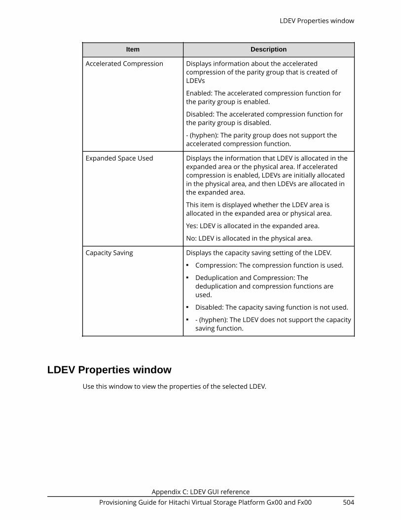
Item Description
Accelerated Compression Displays information about the acceleratedcompression of the parity group that is created ofLDEVs
Enabled: The accelerated compression function forthe parity group is enabled.
Disabled: The accelerated compression function forthe parity group is disabled.
- (hyphen): The parity group does not support theaccelerated compression function.
Expanded Space Used Displays the information that LDEV is allocated in theexpanded area or the physical area. If acceleratedcompression is enabled, LDEVs are initially allocatedin the physical area, and then LDEVs are allocated inthe expanded area.
This item is displayed whether the LDEV area isallocated in the expanded area or physical area.
Yes: LDEV is allocated in the expanded area.
No: LDEV is allocated in the physical area.
Capacity Saving Displays the capacity saving setting of the LDEV.■ Compression: The compression function is used.■ Deduplication and Compression: The
deduplication and compression functions areused.
■ Disabled: The capacity saving function is not used.■ - (hyphen): The LDEV does not support the capacity
saving function.
LDEV Properties windowUse this window to view the properties of the selected LDEV.
LDEV Properties window
Appendix C: LDEV GUI referenceProvisioning Guide for Hitachi Virtual Storage Platform Gx00 and Fx00 504

LDEV Properties table
Item Description
LDEV ID LDEV identifier, which is the combination of LDKC, CU,and LDEV.
LDEV Name Displays the LDEV name.
Capacity Displays the LDEV capacity.
LDEV Properties window
Appendix C: LDEV GUI referenceProvisioning Guide for Hitachi Virtual Storage Platform Gx00 and Fx00 505

Item Description
Virtual Storage Machine Information about the virtual storage machine.■ Model / Serial Number: Model name and serial
number of the virtual storage machine that hasLDEV.
■ LDEV ID: Virtual LDEV ID. If a Virtual LDEV ID is notassigned to LDEV, this column is blank.
■ Device Name: Virtual device name, which is acombination of the virtual emulation type, virtualLUSE volume number, and the virtual CVSattribute. Values of the virtual emulation type,virtual LUSE volume number, and virtual CVSattribute appear only for items that have been set.This column is blank when the virtual emulationtype, virtual LUSE volume number, and virtual CVSattribute are not set. If the virtual CVS attribute isset, CVS is attached as the suffix to the devicename.
■ SSID: Virtual SSID. If Virtual SSID is not set for LDEV,this column is blank.
Basic tab
LDEV basic information is displayed in the Basic Properties, LUNs, and Hosts.
LDEV Properties window
Appendix C: LDEV GUI referenceProvisioning Guide for Hitachi Virtual Storage Platform Gx00 and Fx00 506

Basic Properties table
Item Description
Parity Group ■ ID: Displays the parity group ID.■ Interleaved Parity Groups: Displays the interleaved
parity groups.■ RAID Level: Displays the RAID level of parity group.
The asterisk (*) indicates the parity group is theinterleaved parity group.
■ Drive Type/RPM: Displays the data drive type andRPM.
■ Encryption: Displays the encryption setting (enableor disable). If the parity group in which theencryption setting is not defined, a hyphen (-) isdisplayed.
■ Accelerated compression: Displays the acceleratedcompression setting (enable or disable). If theparity group with accelerated compression settingis not defined, a hyphen (-) is displayed.
Pool Name (ID): Displays the pool name and ID.
RAID Level: Displays the RAID level of pool.
Type: Displays the data drive type of pool.
Encryption: The encryption information of the pool.■ Enabled: Pool which is created by pool-VOLs
whose encryption settings are enabled.■ Disable: Pool which is created by pool-VOLs whose
encryption settings are disabled.■ Mixed: This status is displayed when two or more
of the following are specified as pool-VOLs:● Volume encryption setting is enabled.● Volume encryption setting is disabled.● External volume
Caution: The data encryption is not ensured in thepool that has the Mixed encryption setting. Tomanage the data encryption securely, use the poolwith an encryption setting of Enabled or Disabled.
■ Hyphen(-): Pool is created by external volumes. Orpool is being blocked.
This item is not displayed when using Virtual StoragePlatform G200
LDEV Properties window
Appendix C: LDEV GUI referenceProvisioning Guide for Hitachi Virtual Storage Platform Gx00 and Fx00 507

Item Description
Provisioning Type Display the type of LDEV.■ Basic: Internal volume.■ DP: DP-VOL.■ External: External volume.■ Snapshot: Thin Image volume.■ ALU: LDEV of the ALU attribution.
Status Displays the LDEV status.■ Normal: Normal status.■ Blocked: Host cannot access blocked volumes.■ Warning: Problem occurs in the volumes.■ Formatting: Volumes are being formatted.■ Preparing Quick Format: Volumes are being
prepared for quick formatting.■ Quick Formatting: Volumes are being quick-
formatted.■ Correction Access: Access attribute is being
corrected.■ Copying: Data in the volumes are being copied.■ Read Only: Data cannot be written on the Read
Only volumes.■ Shredding: Volumes are being shredded.
PIN status Displays the PIN status.
LDEV Properties window
Appendix C: LDEV GUI referenceProvisioning Guide for Hitachi Virtual Storage Platform Gx00 and Fx00 508

Item Description
Attribute Displays the attribute of the LDEV.■ Command Device: Command device.■ Remote Command Device: Remote command
device.■ JNL VOL: Journal volume.■ Pool VOL: Pool volume. The number in
parentheses shows the pool ID.■ Quorum Disk: Quorum disk for global-active
device.■ ALU: LDEV of the ALU attribution.■ SLU: LDEV of the SLU attribution.■ Data Direct Mapping: LDEV with the data direct
mapping attribute enabled.■ NAS Platform (User LU): LDEV used for storing the
NAS user data. This value appears if the NASmodule is installed.
■ NAS Platform (System LU): LDEV used for storingthe NAS firmware system data. This value appearsif the NAS module is installed.
■ Deduplication System Data: Deduplication systemdata volume
■ Hyphen (-): Volume in which the attribute is notdefined.
Command Device Attribute ■ Security: Displays the setting (Enable or Disable) ofCommand Device Security.
■ User Authentication: Displays the setting (Enableor Disable) of user authentication.
■ Device Group Definition: Displays the setting(Enable or Disable) of Device Group Definition.
Number of Paths Displays the number of paths of the selected LDEV.
UUID Displays the UUID.
CLPR Displays the ID and name of the CLPR in ID:CLPRformat.
Access Attribute Displays the access attribute of the LDEV.
SSID Displays the SSID.
LDEV Properties window
Appendix C: LDEV GUI referenceProvisioning Guide for Hitachi Virtual Storage Platform Gx00 and Fx00 509

Item Description
Cache Mode Displays the cache mode.
V-VOL Management Task Displays the V-VOL management task beingperformed on a Dynamic Provisioning,DynamicTiering, or a V-VOL.
Current MP Unit ID Displays the current MP unit ID.
Assigned MP Unit ID Displays the assigned MP unit ID.
ALUA Mode Information about the ALUA mode.
Enabled: LDEV can be used in ALUA.
Disabled: LDEV cannot be used in ALUA.
T10 PI Displays the LDEV's T10 PI attribute information(Enabled or Disabled).
External Storage System Information about the external storage system.
If LDEV is the DP-VOL of the data direct mappingattribure, the information about the external storagesystem to which LDEV is being mapped appears.■ Vendor/Model/Serial Number: The information
about these items of the external storage system isdisplayed. A hyphen(-) appears if an externalstorage system is not mapped to LDEV.
■ Path Group ID: The information about this item ofthe external storage system is displayed. If the linkof the path group id is clicked, the MappedVolumes tab appears. A hyphen(-) appears if anexternal storage system is not mapped to LDEV.
Data Direct Mapping Information about the data direct mapping.■ LDEV ID: LDEV ID of the pool-VOL in the pool with
data direct mapping enabled, or LDEV ID of the DP-VOL with data direct mapping enabled. If the linkof LDEV ID is clicked, the LDEV Properties windowappears. If the data direct mapping attribute isdisabled, a hyphen (-) is displayed. If a DP-VOL withdata direct mapping enabled is not created in thepool with data direct mapping enabled, this field isblank.
■ Parity Group ID: Parity Group ID of the pool-VOL inthe pool with data direct mapping enabled. If thedata direct mapping attribute is disabled, a hyphen(-) is displayed.
LDEV Properties window
Appendix C: LDEV GUI referenceProvisioning Guide for Hitachi Virtual Storage Platform Gx00 and Fx00 510

Item Description
Resource Group Name (ID) Displays the resource group name and ID of the LDEV.The ID is provided in parentheses.
Full Allocation Displays the status of the setting for the full allocationwith V-VOLs for Dynamic Provisioning.■ Enabled: Full allocation is performed.■ Disabled: Full allocation is not performed.■ Hyphen (-): LDEVs other than V-VOLs for Dynamic
Provisioning.
Tiering Policy Displays the tiering policy name and ID.
New page Assignment Tier Displays the new page assignment tier.
Tier Relocation Displays the tier relocation setting.
Relocation Priority Displays the relocation priority setting.
Expanded Space Used Displays the information that LDEV is allocated in theexpanded area or the physical area. If the acceleratedcompression is enabled, LDEVs are initially allocatedin the physical area, then LDEVs are allocated in theexpanded area.
This item displays whether the LDEV area is allocatedin the expanded or physical area.
Yes: LDEV is allocated in the expanded area.
No: LDEV is allocated in the physical area.
Capacity Saving Displays the capacity saving setting of the LDEV.■ Compression: The compression function is used.■ Deduplication and Compression: The
deduplication and compression functions areused.
■ Disabled: The capacity saving function is not used.■ - (hyphen): The LDEV does not support the capacity
saving function.
LDEV Properties window
Appendix C: LDEV GUI referenceProvisioning Guide for Hitachi Virtual Storage Platform Gx00 and Fx00 511

Item Description
Capacity Saving Status The status of the capacity saving function.■ Enabling: The format for enabling the capacity
saving function is being performed.■ Rehydrating: The format for disabling the capacity
saving function is being performed. The processingprogress is displayed as a percentage inparentheses.
■ Deleting Volume: The deletion of DP-VOL whosecapacity saving function is Enabled is beingperformed. The processing progress is displayedas a percentage in parentheses.
■ Enabled: The capacity saving function is enabled.■ Disabled: The capacity saving function is disabled.■ Failed: Data cannot be secured.■ - (hyphen): The LDEV does not support the capacity
saving function.
Deduplication Data Displays whether the deduplication function isapplied to the volume (DP-VOL).■ Enabled: The deduplication function is applied.■ Disabled: The deduplication function is not
applied.■ - (hyphen): The LDEV is not a DP-VOL, or the
firmware version does not support deduplication.
If the capacity saving setting of a DP-VOL isDeduplication and Compression, Enabled is displayedeven if the used capacity is 0.
When the capacity saving setting is Disabled and thedisabling of the capacity saving setting is in process,Enabled is displayed for Deduplication Data whilededuplicated data remains in the DP-VOL. When thedisabling of the capacity saving setting is completeand no deduplicated data remains in the DP-VOL,Disabled is displayed.
Virtual Attribute Displays the virtual LDEV attribute. If the attribute isnot set for LDEV, this column is blank.
LUNs table
This table is not displayed if the path is not set.
LDEV Properties window
Appendix C: LDEV GUI referenceProvisioning Guide for Hitachi Virtual Storage Platform Gx00 and Fx00 512

Item Description
Port ID Port name.
Type Types of ports■ Fibre: Fibre Channel ports.■ iSCSI: iSCSI ports.■ NAS Platform (User LU): LDEV used for storing the
NAS user data. This value appears if the NASmodule is installed.
■ NAS Platform (System LU): LDEV used for storingthe NAS firmware system data. This value appearsif the NAS module is installed.
Host Group Name / iSCSITarget Alias
Host group name or iSCSI target alias.
iSCSI Target Name iSCSI target name.
LUN ID Identifier of the logical unit.
Asymmetric Access States Asymmetric access states of the port. When usingiSCSI, a hyphen (-) is displayed.
Active/Optimized: Access from the host ispreferentially performed on this port.
Active/Non-Optimized: When the Active/Optimizedport is disabled, access from the host is performed onthis port.
Hosts table
This table provides information about the host that can view LDEVs. This table is notavailable if the WWN is not registered in the host to which the path is set.
LDEV Properties window
Appendix C: LDEV GUI referenceProvisioning Guide for Hitachi Virtual Storage Platform Gx00 and Fx00 513

Item Description
Type Types of ports:■ Fibre: Fibre Channel ports.■ iSCSI: iSCSI ports.■ NAS Platform (User LU): LDEV used for storing the
NAS user data. This value appears if the NASmodule is installed.
■ NAS Platform (System LU): LDEV used for storingthe NAS firmware system data. This value appearsif the NAS module is installed.
HBA WWN / iSCSI Name HBA WWN or iSCSI name.
Host Name Host name.
Replication Tab
Information about the volume of the local replication pair is displayed in the ReplicationProperties, SI Pairs, TI Pairs, TC Pairs, UR Pairs, and GAD Pairs tables.
For details about each item, see the following:■ Hitachi ShadowImage® User Guide■ Hitachi Thin Image User Guide■ Hitachi Compatible FlashCopy/FlashCopy SE User Guide■ Hitachi TrueCopy® User Guide■ Hitachi Universal Replicator User Guide■ Global-Active Device User Guide
Replication Properties table
Item Description
Local Replication ■ ShadowImage L1: Displays the status of theShadowImage L1 pair.
■ ShadowImage L2: Displays the status of theShadowImage L2 pair.
■ Thin Image: Displays the status of the Thin Imagepair.
Remote Replication ■ TrueCopy: Displays the status of the TrueCopy pair.■ Universal Replicator: Displays the status of the
Universal Replicator pair.
LDEV Properties window
Appendix C: LDEV GUI referenceProvisioning Guide for Hitachi Virtual Storage Platform Gx00 and Fx00 514

SI Pairs table
Item Description
Primary Volume ■ LDEV ID: Displays LDEV ID of the primary volume.■ LDEV Name: Displays LDEV name of the primary
volume.■ Emulation Type: Displays emulation type of the
primary volume.■ Capacity: Displays capacity of the primary volume.■ CLPR: Displays CLPR ID of the primary volume.
Copy Type Displays copy type of the pair.
Status Displays the pair status.
Secondary Volume ■ LDEV ID: Displays LDEV ID of the secondaryvolume.
■ LDEV Name: Displays LDEV name of the secondaryvolume.
■ Capacity: Displays capacity of the secondaryvolume.
■ CLPR: Displays CLPR ID of the secondary volume.
Copy Pace Displays the pace of copying of the pair.
CTG ID Displays the consistency group number of the pair.
Mirror Unit Displays the mirror unit number of the pair.
Detail Displays the View Pair Properties window.
HTI Pairs table
Item Description
Primary Volume ■ LDEV ID: Displays LDEV ID of the primary volume.■ LDEV Name: Displays LDEV name of the primary
volume.■ Capacity: Displays capacity of the primary volume.■ CLPR: Displays CLPR ID of the primary volume.
Snapshot Group Displays the snapshot group name.
Information is shown for this item only if you haveconfigured a snapshot group for the HTI pair.
LDEV Properties window
Appendix C: LDEV GUI referenceProvisioning Guide for Hitachi Virtual Storage Platform Gx00 and Fx00 515

Item Description
Status Displays the pair status.
Snapshot Date Displays the date and time when you created the pairto store snapshot.
Secondary Volume ■ LDEV ID: Displays LDEV ID of the secondaryvolume.
■ LDEV Name: Displays LDEV name of the secondaryvolume.
■ Capacity: Displays capacity of the secondaryvolume.
■ CLPR: Displays CLPR ID of the secondary volume.
Pool Name (ID) Displays pool name and identification number.
CTG ID Displays the consistency group identification number.
Mirror Unit Displays the mirror unit number of the pair.
Cascade Indicates whether a cascade pair can be created byusing the pair.■ Enabled: Cascade pair can be created.■ Disabled: Cascade pair cannot be created.
Type Displays the type of the pair.■ Snapshot: Pair with the snapshot attribute.
Topology ID Displays the topology ID of the pair. The topology IDindicates the layer of the pair location based on themirror unit. The topology ID consists of the LDEV ID ofthe root volume and the mirror unit.
Root Volume Displays the LDEV ID of the root volume of the pair.
Detail Displays the View Pair Properties window.
TC Pairs table
Item Description
Pair Position Displays whether the volume is a primary orsecondary volume.
Status Displays the pair status.
LDEV Properties window
Appendix C: LDEV GUI referenceProvisioning Guide for Hitachi Virtual Storage Platform Gx00 and Fx00 516

Item Description
Remote Storage System ■ Model / Serial Number: Displays the model andserial number of the remote storage system.
■ LDEV ID: Displays LDEV ID of the remote storagesystem.
■ Port ID: Displays Port ID of the remote storagesystem.
■ Host Group ID / iSCSI Target ID: Displays HostGroup ID or iSCSI Target ID of the remote storagesystem.
■ LUN ID: Displays LUN ID of the remote storagesystem.
Path Group ID Displays the path group ID.
Update Type Displays the update type.
CTG ID Displays the consistency group ID.
CTG Utilization Displays whether the consistency group is shared bymultiple local and remote storage systems.
Fence Level Displays the fence level.
Detail Displays the View Pair Properties window.
UR Pairs table
Item Description
Journal ID Displays the journal ID.
LDEV Properties window
Appendix C: LDEV GUI referenceProvisioning Guide for Hitachi Virtual Storage Platform Gx00 and Fx00 517

Item Description
Pair 1 Displays the pair 1 information.■ Pair Position: Displays whether the volume is a
primary or secondary volume.■ Mirror ID: Displays the mirror ID.■ Status: Displays the pair status.■ Remote Storage System: Displays the information
about the remote storage system.● Model / Serial Number: Displays the model and
serial number of the remote storage system.● LDEV ID: Displays LDEV ID of the remote
storage system.● Port ID: Displays Port ID of the remote storage
system.● Host Group ID / iSCSI Target ID: Displays Host
Group ID or iSCSI Target ID of the remotestorage system.
● LUN ID: Displays LUN ID of the remote storagesystem.
● Journal ID: Displays journal ID of the remotestorage system.
■ Path Group ID: Displays the path group ID.■ CTG ID: Displays the consistency group ID.■ Error Level: Displays the error level.
LDEV Properties window
Appendix C: LDEV GUI referenceProvisioning Guide for Hitachi Virtual Storage Platform Gx00 and Fx00 518

Item Description
Pair 2 Displays the pair 2 information.■ Pair Position: Displays whether the volume is a
primary or secondary volume.■ Mirror ID: Displays the mirror ID.■ Status: Displays the pair status.■ Remote Storage System: Displays the information
about the remote storage system.● Model / Serial Number: Displays the model and
serial number of the remote storage system.● LDEV ID: Displays LDEV ID of the remote
storage system.● Port ID: Displays Port ID of the remote storage
system.● Host Group ID / iSCSI Target ID: Displays Host
Group ID or iSCSI Target ID of the remotestorage system.
● LUN ID: Displays LUN ID of the remote storagesystem.
● Journal ID: Displays journal ID of the remotestorage system.
■ Path Group ID: Displays the path group ID.■ CTG ID: Displays the consistency group ID.■ Error Level: Displays the error level.
Detail Displays the View Pair Properties window.
GAD Pairs table
Item Description
Pair Position Displays whether the volume is a primary orsecondary volume.
Status Displays the pair status.
LDEV Properties window
Appendix C: LDEV GUI referenceProvisioning Guide for Hitachi Virtual Storage Platform Gx00 and Fx00 519

Item Description
Remote Storage System ■ Model / Serial Number: Displays the model andserial number of the remote storage system.
■ LDEV ID: Displays LDEV ID of the remote storagesystem.
■ Port ID: Displays Port ID of the remote storagesystem.
Path Group ID Displays the path group ID.
Quorum Disk ID Displays the quorum disk ID.
Mirror ID Displays the mirror ID.
Detail Displays the View Pair Properties window.
ALUs / SLUs windowUse this window to view the administrative logical units (ALUs) and subsidiary logicalunits (SLUs) in the storage system. To open this window, open the Logical Deviceswindow, and then in the LDEVs pane click More Actions > View ALUs/SLUs.
ALUs / SLUs window
Appendix C: LDEV GUI referenceProvisioning Guide for Hitachi Virtual Storage Platform Gx00 and Fx00 520

Administrative Logical Units tab
Item Description
ALU ID ALU attribution identifier of the LDEV. In the VASA environment,if the ALU ID is not assigned, a question mark (?) is displayed.
LDEV ID LDEV identifier, which consists of the LDKC, CU, and LDEV.
LDEV Name Name of the LDEV.
Subsidiary Logical Units tab
Item Description
SLU ID SLU attribution identifier of the LDEV. In the VASA environment,if the SLU ID is not assigned, a question mark (?) is displayed.
LDEV ID LDEV identifier, which consists of the LDKC, CU, and LDEV.
LDEV Name Name of the LDEV.
Provisioning Type Provisioning type of the LDEV:■ DP: DP-VOL■ Snapshot: Thin Image volume.
Unbind SLUs window
Unbind SLUs window
Appendix C: LDEV GUI referenceProvisioning Guide for Hitachi Virtual Storage Platform Gx00 and Fx00 521

Selected ALUs
Item Description
LDEV ID LDEV identifier, a combination of LDKC,CU, and LDEV.
ALU ID ALU attribution identifier of an LDEV.
LDEV Name Name of the LDEV.
Components windowUse this window to view information about the controller chassis components in thestorage system.
Summary
Item Description
Number of ControllerChassis
Number of controller chassis
Components window
Appendix C: LDEV GUI referenceProvisioning Guide for Hitachi Virtual Storage Platform Gx00 and Fx00 522

Item Description
Power Consumption Total power consumption of the controller chassis anddrive box. When the power information cannot beacquired because of a failure in the component ornetwork, the power information is not added to the powerconsumption information.
In the following cases, the power consumption valuemight temporarily displays lower:■ When starting the storage system■ After replacing a part of the storage system■ When updating the microcode or after updating the
microcode
View TemperatureMonitor
Opens the Temperature Monitor window
Components tab
Item Description
Chassis ID Chassis identifier of the storage system.
Chassis Type Chassis type.
Temperature (degrees C) Temperature of the cluster.■ Cluster 1: Temperature of the cluster 1.■ Cluster 2: Temperature of the cluster 2.
A question mark (?) appears when the temperatureinformation cannot be acquired because of a failure in thecomponent or network.
Export Opens a window where you can export configurationinformation listed in the table to a file that can be used formultiple purposes, such as backup or reporting.
DKC: Controller Boards & MP Units tabUse this window to view information about MP units in the storage system.
DKC: Controller Boards & MP Units tab
Appendix C: LDEV GUI referenceProvisioning Guide for Hitachi Virtual Storage Platform Gx00 and Fx00 523
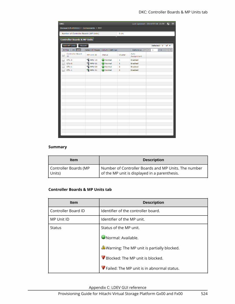
Summary
Item Description
Controller Boards (MPUnits)
Number of Controller Boards and MP Units. The numberof the MP unit is displayed in a parenthesis.
Controller Boards & MP Units tab
Item Description
Controller Board ID Identifier of the controller board.
MP Unit ID Identifier of the MP unit.
Status Status of the MP unit.
Normal: Available.
Warning: The MP unit is partially blocked.
Blocked: The MP unit is blocked.
Failed: The MP unit is in abnormal status.
DKC: Controller Boards & MP Units tab
Appendix C: LDEV GUI referenceProvisioning Guide for Hitachi Virtual Storage Platform Gx00 and Fx00 524

Item Description
Cluster Cluster number of the MP unit.
Auto Assignment Indicates whether the MP unit is automatically assigned toresources.
Enabled: The MP unit is automatically assigned toresources (logical devices, external volumes, and journalvolumes).
Disabled: The MP unit is not automatically assigned toresources.
Edit MP Units Opens the Edit MP Units window.
Export Opens a window where you can export configurationinformation listed in the table to a file that can be used formultiple purposes, such as backup or reporting.
Edit MP Units wizardUse this wizard to enable or disable the storage system to automatically assign the loadof resources controlled by the selected MP units.
Edit MP Units window
Edit MP Units wizard
Appendix C: LDEV GUI referenceProvisioning Guide for Hitachi Virtual Storage Platform Gx00 and Fx00 525

Item Description
Auto Assignment Specify whether to automatically assign an MP unit toresources (logical devices, external volumes, and journalvolumes).■ Enable: Resources will be automatically assigned to the
specified MP unit.■ Disable: Resources will not be automatically assigned
to the specified MP unit.
Edit MP Units confirmation window
Confirm proposed settings, name the task, and then click Apply. The task will be addedto the execution queue.
Item Description
MP Unit ID MP unit identifier.
Cluster Cluster number of the MP unit.
Auto Assignment Indicates whether automatic assignment of MP unitsis in use.■ Enabled: An MP unit is automatically assigned to
resources (logical devices, external volumes, andjournal volumes).
■ Disabled: An MP unit is not automatically assignedto resources.
Edit MP Units confirmation window
Appendix C: LDEV GUI referenceProvisioning Guide for Hitachi Virtual Storage Platform Gx00 and Fx00 526

Assign MP Unit wizardUse this wizard to assign an MP unit that will control selected resources.
Assign MP Unit window
Use this window to select an MP unit to assign to an LDEV.
Item Description
MP Unit ID Change the MP unit identifier assigned to the LDEV.
MP-unit ID: The selected MP unit identifier is assigned tothe LDEV.
Assign MP Unit confirmation window
Confirm proposed settings, name the task, and then click Apply. The task will be addedto the execution queue.
Assign MP Unit wizard
Appendix C: LDEV GUI referenceProvisioning Guide for Hitachi Virtual Storage Platform Gx00 and Fx00 527

Item Description
LDEV ID LDEV identifier, which is the combination of LDKC, CU,and LDEV.
LDEV Name LDEV name.
Parity Group ID Parity group identifier.
Pool Name (ID) Pool name and pool identifier.
Capacity LDEV capacity.
Provisioning Type Provisioning type to be assigned to the LDEV.■ Basic: Internal volume.■ DP: DP-VOL.■ External: External volume.■ Snapshot: Thin Image volume.
Assign MP Unit confirmation window
Appendix C: LDEV GUI referenceProvisioning Guide for Hitachi Virtual Storage Platform Gx00 and Fx00 528

Item Description
Attribute Displays the attribute of the LDEV.■ Command Device: Command device■ Remote Command Device: Remote command
device■ JNL VOL: Journal volume■ Pool VOL: Pool volume. The number in
parentheses shows the pool ID.■ Quorum Disk: Quorum disk for global-active device■ ALU: LDEV of the ALU attribution■ SLU: LDEV of the SLU attribution■ Data Direct Mapping: LDEV of the data direct
mapping attribute■ NAS Platform (User LU): LDEV used for storing the
NAS user data. This value appears if the NASmodule is installed.
■ NAS Platform (System LU): LDEV used for storingthe NAS firmware system data. This value appearsif the NAS module is installed.
■ Deduplication System Data: Deduplication SystemData volume (open systems)
■ Hyphen (-): Volume in which the attribute is notdefined
MP Unit ID MP unit identifier to be set.
View Management Resource Usage window
View Management Resource Usage window
Appendix C: LDEV GUI referenceProvisioning Guide for Hitachi Virtual Storage Platform Gx00 and Fx00 529

Management Resource Usage table
Item Description
Number of CacheManagement Devices
The current number and maximum allowed numberof cache management devices in the storage systemare displayed.
Create Parity Groups wizard
Create Parity Groups window
When selecting drives manually
Create Parity Groups wizard
Appendix C: LDEV GUI referenceProvisioning Guide for Hitachi Virtual Storage Platform Gx00 and Fx00 530

When selecting drives automatically
Setting Fields
Item Description
Drive Type/RPM/Capacity Select the type of the drive box.
RAID level Select the RAID level.
Drive Selection Select the mode of the drive selectionfrom Auto or Manual.
Number of Parity Groups Enter the number of parity groups. Thisitem appears when selected Auto as yourdrive selection.
Available Drives This item appears when selected Manualas your drive selection.
For drives to be incorporated to a paritygroup, set the check box of a row to ON.■ Location: Displays the location of the
drive box.■ Drive Box: Displays the name of the
drive box.■ Drive Box Type: Displays the type of
the drive box.■ Drive Type-Code: Displays the type
code of the drive box.
Create Parity Groups window
Appendix C: LDEV GUI referenceProvisioning Guide for Hitachi Virtual Storage Platform Gx00 and Fx00 531

Item Description
The number you have to select Displays the number of drives that youmust select. This item appears whenselected Manual as your drive selection.
Initial Parity Group ID Enter the parity group ID.
Text box on the left side: Enter thealphanumeric characters, which are fixedcharacters of the head of the parity groupnames. Characters are case-sensitive.
Text box on the right side: Enter the initialnumber following the prefix name.
Drive Box Type Select the type of drive box. This itemappears when selected Auto as your driveselection.
Initial Drive Box This item appears when selected Auto asyour drive selection.
The smallest available number is enteredin the text box as a default. No numberappears in the text box if no availableparity group ID exists. If you specify theparity group ID which is already used, theminimum parity group ID after that thespecified parity group ID is automaticallyset.
Drive Select Type This item appears when selected Auto asyour drive selection.
Select the method for the selecting ofdrives in a parity group.■ Disperse: Selected drives where are
located dispersedly.■ Linear: Selected drives where are
located linearly.
This item is not available with VirtualStorage Platform G200. If this storagesystem is used, only Linear is available.
Cache Partition Select a CLPR number which is displayedas ID:CLPR.
Create Parity Groups window
Appendix C: LDEV GUI referenceProvisioning Guide for Hitachi Virtual Storage Platform Gx00 and Fx00 532

Item Description
Encryption Specify if encrypted parity groups arecreated.■ Enable: Encrypted parity groups are
created.■ Disable: Non-encrypted parity groups
are created.
This item is not available with VirtualStorage Platform G200.
accelerated compression Displays the accelerated compressionsetting (enable or disable). If Enable isselected in the Encryption field, youcannot select Enable in the acceleratedcompression field. If the acceleratedcompression field is not defined, a hyphen(-) is displayed.
Copy-Back Mode Specify if the copy-back mode is set to aparity group.■ Enable: Copy-back mode is enabled in
a parity group.■ Disable: Copy-back mode is disabled in
a parity group
Add When you click Add, the configuredinformation is added to the right side ofthe Selected Parity Groups table.
Selected Parity Groups table
Item Description
Parity Group ID Displays a parity group ID.
Drive Type/RPM/Capacity Displays the drive type, RPM, and capacity.As for SSD, a hyphen (-) appears on theRPM field.
RAID Level Displays a RAID level.
CLPR Displays the CLPR ID and name that isdisplayed as ID:CLPR.
Create Parity Groups window
Appendix C: LDEV GUI referenceProvisioning Guide for Hitachi Virtual Storage Platform Gx00 and Fx00 533

Item Description
Encryption Displays the encryption information.■ Enable: Encrypted parity group.■ Disable: Non-encrypted parity group.
This item is not available with VirtualStorage Platform G200.
Accelerated Compression Displays the accelerated compressionsetting (enable or disable). If theaccelerated compression field is notdefined, a hyphen (-) is displayed.
Copy-Back Mode Displays the copy-back mode settinginformation.■ Enable: Copy-back mode is set to
enable in a parity group■ Disable: Copy-back mode is set to
disable in a parity group.
Drive Type-Code Displays the drive type-code.
Concatenate Creates a concatenated parity group byselecting multiple rows. When clicked thisbutton with selecting multiple rows, amessage asking whether a concatenatedparity group is created is displayed.
Change Settings Changes the setting of the parity group.When clicked this button with selecting arow, the Change Settings window isdisplayed.
Detail Displays the Parity Group Propertieswindow when a row is selected, andshows the error window when a row is notselected or multiple rows are selected.
Remove Deletes the parity group selected in theSelected Parity Groups window. Displaysthe error window when a row is notselected.
Next Task Option
Click Next to go to the task setting window, which is indicated in Task Next Option.
Create Parity Groups confirmation window
Create Parity Groups confirmation window
Appendix C: LDEV GUI referenceProvisioning Guide for Hitachi Virtual Storage Platform Gx00 and Fx00 534

Selected Parity Groups
Item Description
Parity Group ID Displays a parity group ID.
Drive Type/RPM/Capacity Displays the drive type, RPM, and capacity.As for SSD, a hyphen (-) appears on theRPM field.
RAID Level Displays a RAID level.
CLPR Displays the CLPR ID and name that isdisplayed as ID:CLPR.
Encryption Displays the encryption information.■ Enable: Encrypted parity group.■ Disable: Non-encrypted parity group.
This item is not available with VirtualStorage Platform G200.
Create Parity Groups confirmation window
Appendix C: LDEV GUI referenceProvisioning Guide for Hitachi Virtual Storage Platform Gx00 and Fx00 535

Item Description
Accelerated Compression Displays information about theaccelerated compression of the paritygroup.■ Enabled: The accelerated compression
of the parity group is enabled. .■ Disabled: The accelerated compression
of the parity group is disabled.■ Hyphen (-): accelerated compression is
not supported on the parity group.
Copy-Back Mode Displays the copy-back mode settinginformation.■ Enable: Copy-back mode is set to
enable in a parity group■ Disable: Copy-back mode is set to
disable in a parity group.
Drive Type-Code Displays the drive type-code.
Detail Displays the Parity Group Propertieswindow when a row is selected, andshows the error window when a row is notselected or multiple rows are selected.
Note:
If multiple tasks that are connected in one wizard are executed, this windowshows all configured items of tasks. To show information of configured itemsother than this topic, click Back to display related setting windows, then clickHelp.
Change Settings (Parity Group) window
Change Settings (Parity Group) window
Appendix C: LDEV GUI referenceProvisioning Guide for Hitachi Virtual Storage Platform Gx00 and Fx00 536

Item Description
Initial Parity Group ID Set the check box to ON and enter theparity group ID.■ Text box on the left side: Enter the
alphanumeric characters, which arefixed characters of the head of theparity group names. Characters arecase-sensitive.
■ Text box on the right side: Enter theinitial number following the prefixname.
Cache Partition Set the check box to ON and select a CLPRnumber which is displayed as ID:CLPR.
Encryption Set the check box to ON and specify ifencrypted parity groups are created. Youcannot specify the setting of thecombination where both Encryption andaccelerated compression are Enabled.■ Enable: Encrypted parity groups are
created.■ Disable: Non-encrypted parity groups
are created.
This item is not available with VirtualStorage Platform G200.
Change Settings (Parity Group) window
Appendix C: LDEV GUI referenceProvisioning Guide for Hitachi Virtual Storage Platform Gx00 and Fx00 537
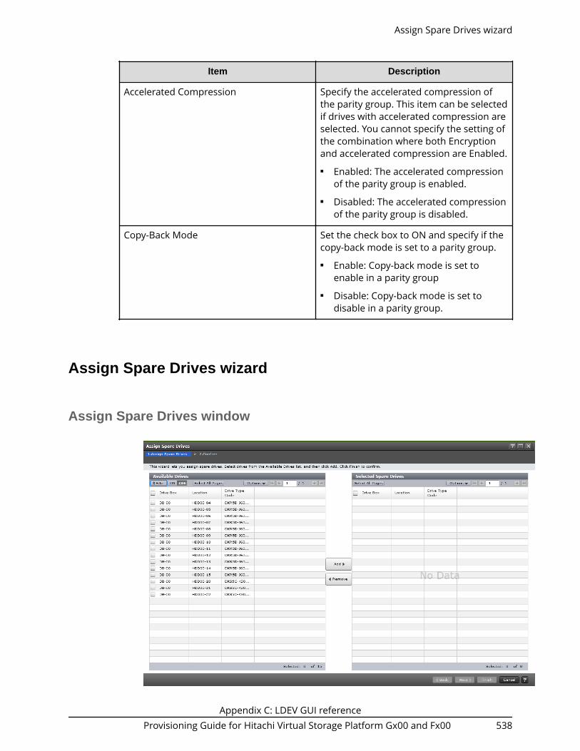
Item Description
Accelerated Compression Specify the accelerated compression ofthe parity group. This item can be selectedif drives with accelerated compression areselected. You cannot specify the setting ofthe combination where both Encryptionand accelerated compression are Enabled.■ Enabled: The accelerated compression
of the parity group is enabled.■ Disabled: The accelerated compression
of the parity group is disabled.
Copy-Back Mode Set the check box to ON and specify if thecopy-back mode is set to a parity group.■ Enable: Copy-back mode is set to
enable in a parity group■ Disable: Copy-back mode is set to
disable in a parity group.
Assign Spare Drives wizard
Assign Spare Drives window
Assign Spare Drives wizard
Appendix C: LDEV GUI referenceProvisioning Guide for Hitachi Virtual Storage Platform Gx00 and Fx00 538

Available Drives table
This table lists drives for spare drives. Only drives assigned to the logged-on user areavailable.
Item Description
Drive Box Displays the drive box number.
Location Displays the location of the drive box.
Drive Type-Code Displays the drive type code
Add Adds one or more drives selected in theAvailable Drives table to the SelectedSpare Drives table.
Remove Removes one or more selected drivesfrom the Selected Spare Drives table, andrelocates drives to the Available Drivestable.
Selected Spare Drives table
Item Description
Drive Box Displays the drive box number.
Location Displays the location of the drive box
Drive Type-Code Displays the drive type code.
Assign Spare Drives confirmation window
Assign Spare Drives confirmation window
Appendix C: LDEV GUI referenceProvisioning Guide for Hitachi Virtual Storage Platform Gx00 and Fx00 539

Assigned Spare Drives table or Released Spare Drives table
Item Description
Drive Box Displays the drive box number.
Location Displays the location of the drive box.
Drive Type-Code Displays the drive type code.
Note:
If multiple tasks that are connected in one wizard are executed, this windowshows all configured items of tasks. To show information of configured itemsother than this topic, click Back to display related setting windows, then clickHelp.
Edit Parity Groups wizardUse this wizard to edit parity groups.
Edit Parity Groups window
Use this window to edit the accelerated compression of selected parity groups.
Edit Parity Groups wizard
Appendix C: LDEV GUI referenceProvisioning Guide for Hitachi Virtual Storage Platform Gx00 and Fx00 540

Item Description
Accelerated Compression Specify the accelerated compression in a parity group. Ifthe parity group with accelerated compression is selected,this item can be specified.
Enabled: accelerated compression is enabled.
Disabled: accelerated compression is disabled.
Copy-Back Mode Specify the copy-back mode in a parity group.
Enable: Copy-back mode is enabled. This functionperforms when failure data-drives are replaced.
Disable: Copy-back function is disabled.
Edit Parity Groups confirmation window
Use this window to confirm the accelerated compression setting of selected paritygroups.
Edit Parity Groups confirmation window
Appendix C: LDEV GUI referenceProvisioning Guide for Hitachi Virtual Storage Platform Gx00 and Fx00 541

Item Description
Parity Group ID Displays the parity group ID.
RAID Level Displays the RAID level.
Drive Type-Code Displays the drive type code.
Drive Type/RPM Displays the drive type and RPM.
Accelerated Compression Displays the accelerated compression setting for theparity group.
Enabled: accelerated compression is enabled.
Disabled: accelerated compression is disabled.
Copy-Back Mode Displays the copy-back mode that is set for the paritygroup.
Enable: Copy-back mode is enabled.
Disable: Copy-back function is disabled.
Note: If multiple tasks that are connected in one wizard are executed, thiswindow shows all configured items of tasks. To show information of otherconfigured items, click Back to display related setting windows, then clickHelp.
Edit Parity Groups confirmation window
Appendix C: LDEV GUI referenceProvisioning Guide for Hitachi Virtual Storage Platform Gx00 and Fx00 542

Format Parity Groups window
Selected Parity Groups table
Item Description
Parity Group ID Displays the parity group ID.
RAID Level Displays the RAID level.
Capacity Displays the capacity of the parity group.
Drive Type/RPM Displays the drive type and RPM.
Delete Parity Groups window
Format Parity Groups window
Appendix C: LDEV GUI referenceProvisioning Guide for Hitachi Virtual Storage Platform Gx00 and Fx00 543

Selected Parity Groups table
Item Description
Parity Group ID Displays the parity group ID.
RAID Level Displays the RAID level.
Capacity Displays the capacity of the parity group.
Drive Type-Code Displays the drive type code.
Drive Type/RPM Displays the drive type and RPM.
Number of LDEVs Displays the number of LDEVs in theparity group.
Parity Group Properties window
Parity Group Properties window
Appendix C: LDEV GUI referenceProvisioning Guide for Hitachi Virtual Storage Platform Gx00 and Fx00 544

Parity Group Properties table
Item Description
Parity Group ID Displays the parity group ID.
Interleaved Parity Groups Displays interleaved (concatenated) paritygroups
Drive Type/RPM/Capacity Displays the drive type, RPM, and capacity.As for SSD, a hyphen (-) appears on theRPM field.
RAID Level Displays the RAID level. The asterisk (*)indicates the parity group is theinterleaved parity group.
CLPR Displays the identifier and name of theCLPR in ID:CLPR format.
Encryption Displays the encryption function which isset for the parity group. If the parity groupis encrypted, Enabled is displayed. If theparity group is not encrypted, Disabled isdisplayed.
This item is not available with VirtualStorage Platform G200.
Parity Group Properties window
Appendix C: LDEV GUI referenceProvisioning Guide for Hitachi Virtual Storage Platform Gx00 and Fx00 545

Item Description
Accelerated Compression Displays information about theaccelerated compression of the paritygroup created of LDEVs.■ Enabled: The accelerated compression
of the parity group is enabled.■ Disabled: The accelerated compression
of the parity group is disabled.■ Hyphen (-): accelerated compression is
not supported on the parity group.
Copy-Back Mode Displays the copy-back mode that is setfor the parity group. If the copy-backmode is enabled, Enabled is displayed. Ifthe period mode is not enabled, Disabledis displayed.
Drives table
Only drives assigned to the logged-on user are displayed.
Item Description
Location Displays the location of the drive box.
Drive Box Displays the drive box number.
Drive Box Type Displays the drive box type.
Drive Type-Code Displays the drive type code.
Appendix C: LDEV GUI referenceProvisioning Guide for Hitachi Virtual Storage Platform Gx00 and Fx00 546

Appendix D: Dynamic Provisioning, DynamicTiering, and active flash GUI reference
The Dynamic Provisioning and Dynamic Tiering windows in Hitachi Device Manager -Storage Navigator display the Dynamic Provisioning and Dynamic Tiering information forthe storage system and allow you to perform Dynamic Provisioning and Dynamic Tieringoperations.
For general information about the Device Manager - Storage Navigator GUI, see theSystem Administrator Guide.
Pools window
Appendix D: Dynamic Provisioning, Dynamic Tiering, and active flash GUI referenceProvisioning Guide for Hitachi Virtual Storage Platform Gx00 and Fx00 547

Summary
Item Description
Pool Capacity1 Displays information about the pool capacity.■ Used/Total
● Dynamic Provisioning(DP): Displays the pool capacity (thesum of the used capacity and the total pool capacity) ofDynamic Provisioning, Dynamic Tiering, and active flash.
● Thin Image(TI): Displays the pool capacity (used/total) ofThin Image.
For each value, if the Estimated Configurable capacity is
zero, is displayed in the cell.■ Estimated Configurable2
● Dynamic Provisioning(DP): Displays the estimated poolcapacity of Dynamic Provisioning, Dynamic Tiering, andactive flash.
● Thin Image(TI): Displays the remaining physical poolcapacity that is configurable for Thin Image.
V-VOL Capacity1 Displays information about the DP-VOL capacity.■ Allocated/Total
● Dynamic Provisioning(DP): In the Allocated field, totalcapacity of the Dynamic Provisioning, and activeflashDynamic Tiering DP-VOLs to which LU paths areallocated is displayed. In the Total field, total capacity ofthe Dynamic Provisioning, Dynamic Tiering, and activeflashDP-VOLs is displayed.
For each value, if the Estimated Configurable capacity is
zero, is displayed in the cell.■ Estimated Configurable2
● Dynamic Provisioning(DP): Displays the DP-VOL estimatedconfigurable capacity of Dynamic Provisioning, DynamicTiering, and active flash.
Pools window
Appendix D: Dynamic Provisioning, Dynamic Tiering, and active flash GUI referenceProvisioning Guide for Hitachi Virtual Storage Platform Gx00 and Fx00 548

Item Description
Licensed Capacity(Used / Licensed)
Displays information about available licensed capacity.■ Dynamic Provisioning(DP): Displays the licensed capacity of
Dynamic Provisioning. Used displays the total capacity ofpools for Dynamic Provisioning, Dynamic Tiering, and activeflash.
■ Thin Image(TI): Displays the licensed capacity of the ThinImage.
Caution: In the Licensed Capacity(Used/Licensed) field, thetotal capacity of the system is displayed. The total capacity ofthe system includes capacities of LDEVs assigned to each userand resources other than LDEVs. Therefore, the value displayedas the "Used" Licensed Capacity (Used/ Licensed) might differfrom the value of the "Total" Pool Capacity.
Number of Pools Displays the total number of pools for Dynamic Provisioning,Dynamic Tiering, active flash, and Thin Image.
Edit Tiering Policies Displays the Edit Tiering Policies window.
Notes:
1. The total value of the Total cells under Capacity of each pool type in the Pools tabwindow and the total Used capacity of the Pool Capacity in the Summary table arealmost same, but small differences might occur.
If the pool-VOL or DP-VOL for Dynamic Provisioning is created, the estimatedconfigurable pool capacity and estimated configurable V-VOL capacity forDynamic Provisioning(DP) change. The estimated capacity is calculated based onthe configuration of current pools and DP-VOL, and remaining capacity of theshared memory.
2. The estimated configurable capacity of Dynamic Provisioning is the estimate ofthe DP-VOL capacity or the pool capacity that can be created by using theremaining capacity of the shared memory after deduction of the capacity of theshared memory used by the current pool and DP-VOL. The values of theEstimated Configurable Pool Capacity and the Estimated Configurable V-VOLCapacity can be used only as a guide, but are not guaranteed to create pools andDP-VOLs having the estimated configurable capacity. If the pool-VOL or DP-VOLfor Dynamic Provisioning is created or deleted, the estimated configurable poolcapacity and estimated configurable V-VOL capacity for Dynamic Provisioningchange.
Pools window
Appendix D: Dynamic Provisioning, Dynamic Tiering, and active flash GUI referenceProvisioning Guide for Hitachi Virtual Storage Platform Gx00 and Fx00 549
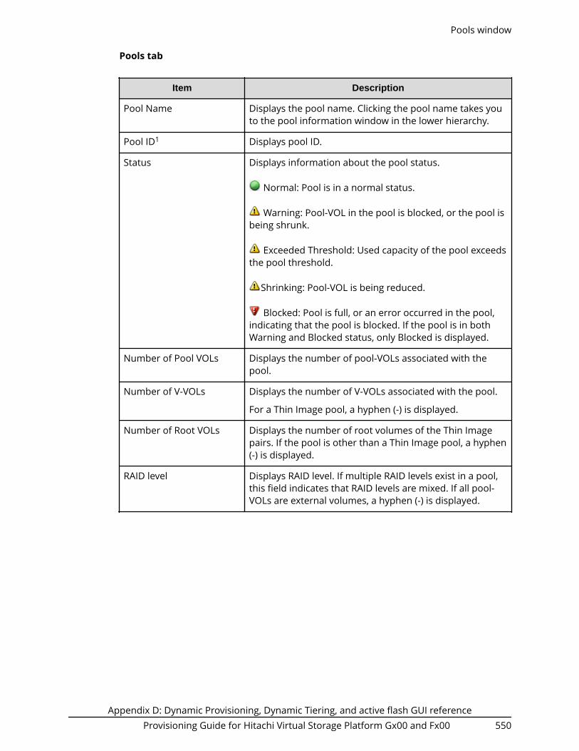
Pools tab
Item Description
Pool Name Displays the pool name. Clicking the pool name takes youto the pool information window in the lower hierarchy.
Pool ID1 Displays pool ID.
Status Displays information about the pool status.
Normal: Pool is in a normal status.
Warning: Pool-VOL in the pool is blocked, or the pool isbeing shrunk.
Exceeded Threshold: Used capacity of the pool exceedsthe pool threshold.
Shrinking: Pool-VOL is being reduced.
Blocked: Pool is full, or an error occurred in the pool,indicating that the pool is blocked. If the pool is in bothWarning and Blocked status, only Blocked is displayed.
Number of Pool VOLs Displays the number of pool-VOLs associated with thepool.
Number of V-VOLs Displays the number of V-VOLs associated with the pool.
For a Thin Image pool, a hyphen (-) is displayed.
Number of Root VOLs Displays the number of root volumes of the Thin Imagepairs. If the pool is other than a Thin Image pool, a hyphen(-) is displayed.
RAID level Displays RAID level. If multiple RAID levels exist in a pool,this field indicates that RAID levels are mixed. If all pool-VOLs are external volumes, a hyphen (-) is displayed.
Pools window
Appendix D: Dynamic Provisioning, Dynamic Tiering, and active flash GUI referenceProvisioning Guide for Hitachi Virtual Storage Platform Gx00 and Fx00 550

Item Description
Capacity Displays information about the pool capacity.■ Total: Total capacity of the pool. For a pool that
contains pool-volumes assigned to acceleratedcompression-enabled parity groups, the writeablecapacity might be smaller than the displayed capacity.
Click Option to select the desired capacity unit.● One block = 512 bytes● One page = 42 MB
■ Reserved: Displays the reserved page capacity of thepool.
The displayed value of Reserved might be larger thanthe displayed value of Total due to the followingreasons:■ Reserved displays reserved page capacity that is
rounded up on each page.■ The mapped capacity of DP-VOL includes the
capacity of the control information (requires amaximum of 168 MB per 3,145,548 MB).
■ Used: Sum of the mapped capacity and reservedcapacity.
The displayed value of Used might be larger than thedisplayed value of Total due to following reasons:■ Used displays the sum of the mapped capacity and
reserved capacity, which are rounded up on eachpage.
■ The mapped capacity of a DP-VOL includes thecapacity of the control information (uses amaximum of 168 MB per 3,145,548 MB).
■ A DP-VOL with data direct mapping attributeincludes the control information (168 MB is usedper 3,145,548 MB) and capacity for one page.
■ Used (%): On a pool capacity basis, percentages of thesum of the mapped capacity and the reserved pagecapacity (rounded down to the nearest integer).
For Dynamic Provisioning, Dynamic Tiering, and ThinImage pools, a hyphen (-) is displayed if the capacity unit ischanged to Cylinder.
Pools window
Appendix D: Dynamic Provisioning, Dynamic Tiering, and active flash GUI referenceProvisioning Guide for Hitachi Virtual Storage Platform Gx00 and Fx00 551

Item Description
Saving Effect1 The capacity saving rates and capacity that is reduced byaccelerated compression and the capacity saving function(compression and deduplication). A hyphen appears if thepool does not support accelerated compression or thecapacity saving function.■ Saving (%)1: Displays the ratio of the Saving capacity
with respect to the user data capacity. The total valueof Deduplication (%) and Compression (%).
■ Saving1: Displays the saved capacity for a pool. Thetotal value of the capacity expansion function and thecapacity saving function.
■ Deduplication (%)1: Displays the data capacity ratioreduced by the deduplication function in the user datacapacity.
■ Compression (%)1: Displays the data capacity ratioreduced by accelerated compression and thecompression function in the user data capacity
Physical Capacity1 For a pool containing pool volumes that supportaccelerated compression, this item displays the capacityassured for writing. If accelerated compression is notsupported, a hyphen (-) is displayed.■ Total: Displays the total pool capacity assured for
writing.■ Used: Displays the used capacity of the pool. The used
capacity is the capacity deducted from the free capacityassured for writing from the total pool capacity assuredfor writing. For a pool comprised of pool volumesassigned to accelerated compression-enabled paritygroups, the compressed data capacity is included in theused capacity.
■ Used (%): Displays the percentage of the used poolcapacity against the total capacity assured for writing
Capacity Expansion Rate(%)1
For a pool containing pool volumes that supportaccelerated compression, this item displays thepercentage of the total capacity with respect to thecapacity assured for writing. If accelerated compression isnot supported, a hyphen (-) is displayed.
Pools window
Appendix D: Dynamic Provisioning, Dynamic Tiering, and active flash GUI referenceProvisioning Guide for Hitachi Virtual Storage Platform Gx00 and Fx00 552

Item Description
Physical FMC PoolVolumes Capacity 1
For FMC pool volumes used in the pool, this item displaysthe capacity guaranteed for writing. If the pool does notinclude FMC pool volumes, a hyphen (-) is displayed.■ Total: Displays the total capacity of FMC pool volumes
for which writing is assured.■ Used: Displays the used capacity of FMC pool volumes
after they are compressed.
Pools window
Appendix D: Dynamic Provisioning, Dynamic Tiering, and active flash GUI referenceProvisioning Guide for Hitachi Virtual Storage Platform Gx00 and Fx00 553

Item Description
FMC Pool VolumesCapacity
Displays the capacity of FMC pool volumes used in thepool. If the pool does not include FMC pool volumes, ahyphen (-) is displayed.■ Total1: Displays the total capacity of FMC pool volumes.■ Used1: Displays the used capacity of FMC pool
volumes.■ Saving1: Displays the capacity reduced by the FMC data
compression function.■ Saving (%)1: Displays the ratio of the Saving (capacity)
with respect to the Used (capacity) for Pool VolumesCapacity. If the formatting progress percentage of thepool formatted capacity is less than 100%, because thenon-formatted data exists in FMC, the saving ratiomight be different from what you expect. For detailsabout the formatted pool capacity, see the item for
Pools window
Appendix D: Dynamic Provisioning, Dynamic Tiering, and active flash GUI referenceProvisioning Guide for Hitachi Virtual Storage Platform Gx00 and Fx00 554

Item Description
Free + Reserved in the section for View PoolManagement Status window (on page 652) .
■ Expansion Rate (%): Displays the percentage of thetotal capacity of FMC pool volumes with respect to thetotal capacity of FMC pool volumes assured for writing.If either the used pool capacity or the used physicalpool capacity exceeds 50% of the depletion threshold(the warning threshold for the Thin Image pool), anicon of one of following statuses appears:
: In all accelerated compression-enabled paritygroups, this status shows that the expansion rate andthe saving ratio are balanced.
: In one or more accelerated compression-enabledparity groups, this status shows that an excess of theunanticipated usage might occur. In this case, considerrevising the total capacity of LDEVs (pool volumes)carved from these parity groups. For details, seeGuidelines for pools when accelerated compression isenabled (on page 429) .
:
In one or more accelerated compression-enabledparity groups, this status shows that the acceleratedcompression function is not performed in the effectiveutilization. However, if there is a parity group with a status (see above) in the pool, then this icon does notappear. In this case, consider revising the total capacityof LDEVs (pool volumes) carved from these paritygroups. For details, see Guidelines for pools whenaccelerated compression is enabled (on page 429) .
Pool Saving (Post ProcessData)
The data capacity reduction provided by the capacitysaving function, which includes compression anddeduplication. A hyphen (-) is displayed if the capacitysaving function is not supported.■ Saving (%): Displays the capacity reduction (%) provided
by the capacity saving function, which is calculated asthe ratio of Saving to Pre Saving Used.
■ Saving: Displays the capacity reduction (bytes) providedby the capacity saving function.
■ Used (Pre Processed Data): Displays the data capacitybefore the reduction provided by the capacity savingfunction.
Pools window
Appendix D: Dynamic Provisioning, Dynamic Tiering, and active flash GUI referenceProvisioning Guide for Hitachi Virtual Storage Platform Gx00 and Fx00 555

Item Description
Snapshot Used Capacity The used capacity for snapshot data in a DynamicProvisioning pool that contains Thin Image pairs andsnapshot data.
User-Defined Threshold(%)
Displays information about the threshold of a pool.■ Warning: Warning threshold.■ Depletion: Depletion threshold.
For a Thin Image pool, a hyphen (-) is displayed forDepletion.
Suspend TI pairs whendepletion threshold isexceeded
Displays whether SIM code 62Exxx is output when thepool used capacity exceeds the depletion threshold.■ Yes: When the pool used capacity exceeds the
depletion threshold, SIM code 62Exxx is output, andThin Image pairs in the pool cannot be used.
■ No: When the pool used capacity exceeds the depletionthreshold, SIM code 62Exxx is not output, and ThinImage pairs in the pool can be used.
Subscription (%) Displays information about the subscription of the pool.■ Current: Percentage of the total V-VOL capacity
assigned to the pool.■ Limit: Percentage of the subscription limit of the pool.
For a Thin Image pool, a hyphen (-) is displayed for Currentand Limit.
Pool Type Displays the pool type.
For a Dynamic Provisioning pool, DP is displayed.
For a Dynamic Tiering pool, DT is displayed.
For a pool being used for active flash, DT(Active Flash) isdisplayed.
For a pool with data direct mapping enabled, DP (datadirect mapping) is displayed.
For a Thin Image pool, TI is displayed.
Drive Type/RPM Displays the data drive type and RPM of the pool. Ifmultiple drive types or RPMs exist in a pool, this fieldindicates that drive types or RPMs are mixed. When thevolume is the external volume, Drive Type displaysExternal Storage and the value of the external LDEV tierrank.
Pools window
Appendix D: Dynamic Provisioning, Dynamic Tiering, and active flash GUI referenceProvisioning Guide for Hitachi Virtual Storage Platform Gx00 and Fx00 556

Item Description
Encryption Encryption: The encryption information of the pool.■ Enabled: Pool which is created by pool-VOLs whose
encryption settings are enabled.■ Disable: Pool which is created by pool-VOLs whose
encryption settings are disabled.■ Mixed: This status is displayed when two or more of
the following are specified as pool-VOLs:● Volume encryption setting is enabled.● Volume encryption setting is disabled.● External volume
Caution: The data encryption is not ensured in thepool that has the Mixed encryption setting. To managethe data encryption securely, use the pool with anencryption setting of Enabled or Disabled.
■ Hyphen(-): Pool is created by external volumes. Or poolis being blocked.
This item is not displayed when using Virtual StoragePlatform G200.
Tier Management Displays whether Dynamic Tiering is enabled or disabled.If it is enabled Auto or Manual is displayed. If it is disabled,a hyphen (-) is displayed.
For a Thin Image pool, a hyphen (-) is displayed.
Shrinkable Displays whether the pool-VOL can be removed. While thepool is being shrunk, a hyphen (-) is displayed.
Monitoring Mode Displays the monitoring mode that is set for the pool. Ifthe continuous mode is enabled, Continuous Mode isdisplayed. If the period mode is enabled, Period Mode isdisplayed. If Dynamic Tiering is disabled, a hyphen (-) isdisplayed.
Monitoring Status Displays the status of pool monitoring.■ In Progress: The monitoring is being performed.■ During Computation: The calculating is being
processed.
Other than these cases, a hyphen (-) is displayed.
Pools window
Appendix D: Dynamic Provisioning, Dynamic Tiering, and active flash GUI referenceProvisioning Guide for Hitachi Virtual Storage Platform Gx00 and Fx00 557

Item Description
Recent Monitor Data Displays the latest monitoring data.■ If the monitoring data exists, the monitoring period of
time is displayed.
Example: 2010/11/15 00:00 - 2010/11/15 23:59■ If the monitoring data is being obtained, only the
starting time is displayed.
Example: 2010/11/15 00:00 -■ If the latest monitoring data does not exist, a hyphen (-)
is displayed.
Pool Management Task Displays the pool management task being performed tothe pool.■ Waiting for Rebalance: The rebalance process is being
waited.■ Rebalancing: The rebalance process is being
performed.■ Waiting for Relocation: The tier relocation process is
being waited.■ Relocating: The tier relocation process is being
performed.■ Waiting for Shrink: The pool shrinking process is being
waited.■ Shrinking: The pool shrinking process is being
performed.■ Blank: The pool management task is not being
performed to the pool.
For details about the tier relocation, see the tier relocationlog file.
Relocation Result Displays the status of the tier relocation processing.
In Progress: The status of Pool Management Task isWaiting for Relocation or Relocating.
Completed: The tier relocation operation is not inprogress, or the tier relocation is complete.
Uncompleted (n% relocated): The tier relocation issuspended at the indicated percentage progression.
Hyphen (-): The pool is not a Dynamic Tieringor activeflash pool.
Pools window
Appendix D: Dynamic Provisioning, Dynamic Tiering, and active flash GUI referenceProvisioning Guide for Hitachi Virtual Storage Platform Gx00 and Fx00 558

Item Description
Relocation Speed Displays the tier relocation speed: 1(Slowest), 2(Slower),3(Standard), 4(Faster), or 5(Fastest).
Protect V-VOLs when I/Ofails to Blocked Pool VOL
Displays whether the protect function for DP-VOL is beingenabled or disabled. If the setting is enabled, when thepool-VOL is blocked, DP-VOL is protected from readingand writing requests. And at the same instant, the accessattribute of the DP-VOL is changed to the Protectattribute.
A hyphen appears if the pool corresponds with one offollowing:■ Data Retention Utility is not installed.■ Pool type is other than DP or DT.
Protect V-VOLs when I/Ofails to Full Pool
Displays whether the protect function for DP-VOL is beingenabled or disabled. If the setting is enabled, when thepool usage reaches the full size, DP-VOL is protected fromreading and writing requests. And at the same instant, theaccess attribute of the DP-VOL is changed to the Protectattribute.
A hyphen appears if the pool corresponds with one offollowing:■ Data Retention Utility is not installed.■ Pool type is other than DP or DT.
Deduplication1 For a DP pool, the deduplication setting of the pool.■ Available: The deduplication setting for the pool is
enabled.■ Not Available: The deduplication setting for the pool is
disabled.
Create Pools Displays the Create Pools window.
Create LDEVs Displays the Create LDEVs window.
Expand Pool Displays the Expand Pool window.
Delete Pools2 Displays the Delete Pools window.
Restore Pools2 Displays the Restore Pools window.
Edit Pools2 Displays the Edit Pools window.
Monitor Pools2 Displays the Monitor Pools window.
Stop Monitoring Pools2 Displays the Stop Monitoring Pools window.
Pools window
Appendix D: Dynamic Provisioning, Dynamic Tiering, and active flash GUI referenceProvisioning Guide for Hitachi Virtual Storage Platform Gx00 and Fx00 559

Item Description
Start Tier Relocation2 Displays the Start Tier Relocation window.
Stop Tier Relocation2 Displays the Stop Tier Relocation window.
View Tier Properties2 Displays the View Tier Properties window. This windowcan be viewed only for the pools for which DynamicTiering is enabled.
View Pool ManagementStatus2
Displays the View Pool Management Status window.
Export Tier RelocationLog2
Displays the window to download the result of the tierrelocation.
Export2 Displays the window for outputting table information.
Notes:
1. Does not appear by default. To display this item, change the Column Settings ofthe table option.
2. Available when you click More Actions.
Pools window
Appendix D: Dynamic Provisioning, Dynamic Tiering, and active flash GUI referenceProvisioning Guide for Hitachi Virtual Storage Platform Gx00 and Fx00 560

Pools: Volume tabs
Pools: Volume tabs
Appendix D: Dynamic Provisioning, Dynamic Tiering, and active flash GUI referenceProvisioning Guide for Hitachi Virtual Storage Platform Gx00 and Fx00 561

Summary
Item Description
Status Displays information about the pool status.■
Normal: Pool is in a normal status.
■ Warning: Pool-VOL in the pool is blocked, or the
pool is being shrunk.
■ Exceeded Threshold: Percentages of the sum of the
mapped capacity of the pool and the reservedcapacity of the pool exceed the pool threshold.
■ Shrinking: Pool-VOL is being reduced.
■ Blocked: The pool is full, or an error occurred in the
pool, indicating that the pool is blocked. If the pool isin both Warning and Blocked status, only Blocked isdisplayed.
Pool Name (ID) Displays the pool name and pool ID.
Pool VOL with System Area(Name)
Displays the LDEV ID and LDEV name of the pool-VOLwhich includes the pool management area.
Pool Type Displays the pool type.■ For a Dynamic Provisioning pool, DP is displayed.■ For a Dynamic Tiering pool, DT is displayed.■ For a pool being used for active flash, DT(Active Flash)
is displayed.■ For a pool with the data direct mapping attribute
enabled, DT (data direct mapping) is displayed.■ For a Thin Image pool, TI is displayed.
RAID Level Displays RAID level. If multiple RAID levels exist in a pool,this field indicates that RAID levels are mixed. If all pool-VOLs are external volumes, a hyphen (-) is displayed.
Drive Type/RPM Displays the data drive type and RPM of the pool. Ifmultiple drive types or RPMs exist in a pool, this fieldindicates that drive types or RPMs are mixed. When thevolume is the external volume, Drive Type displaysExternal Storage and the value of the external LDEV tierrank.
Pools: Volume tabs
Appendix D: Dynamic Provisioning, Dynamic Tiering, and active flash GUI referenceProvisioning Guide for Hitachi Virtual Storage Platform Gx00 and Fx00 562

Item Description
Encryption Encryption: The encryption information of the pool.■ Enabled: Pool which is created by pool-VOLs whose
encryption settings are enabled.■ Disable: Pool which is created by pool-VOLs whose
encryption settings are disabled.■ Mixed: This status is displayed when two or more of
the following are specified as pool-VOLs:● Volume encryption setting is enabled.● Volume encryption setting is disabled.● External volume
Caution: Data encryption is not ensured in a pool thathas the Mixed encryption setting. To manage dataencryption securely, use a pool with the encryptionsetting of Enabled or Disabled.
■ - (hyphen): Pool is created by external volumes, orpool is being blocked.
This item is not displayed when using Virtual StoragePlatform G200.
Cache Mode For a configuration of external volumes, cache mode isdisplayed as enabled or disabled. For otherconfigurations, a hyphen (-) is displayed.
Deduplication The deduplication setting.■ Available: The deduplication setting is enabled on the
pool.■ Not Available: The deduplication setting is disabled on
the pool.■ - (hyphen): The pool type is other than DP.
Protect V-VOLs when I/Ofails to Blocked Pool VOL
Displays whether the protect function for DP-VOL is beingenabled or disabled. If the setting is enabled, when thepool-VOL is blocked, DP-VOL is protected from readingand writing requests. And at the same instant, the accessattribute of the DP-VOL is changed to the Protectattribute.
A hyphen is displayed if the pool corresponds with one offollowing:■ Data Retention Utility is not installed.■ The pool type is other than DP or DT.
Pools: Volume tabs
Appendix D: Dynamic Provisioning, Dynamic Tiering, and active flash GUI referenceProvisioning Guide for Hitachi Virtual Storage Platform Gx00 and Fx00 563

Item Description
Protect V-VOLs when I/Ofails to Full Pool
Displays whether the protect function for DP-VOL is beingenabled or disabled. If the setting is enabled, when thepool usage reaches the full size, DP-VOL is protectedfrom reading and writing requests. And at the sameinstant, the access attribute of the DP-VOL is changed tothe Protect attribute.
A hyphen appears if the pool corresponds with one offollowing:■ Data Retention Utility is not installed.■ Pool type is other than DP or DT.
Number of Pool VOLs Displays the number of pool-VOLs set for the pool, andthe maximum number of pool-VOLs that can be set forthe pool.
Number of V-VOLs Displays the number of V-VOLs associated with the pool,and the maximum number of V-VOLs that can beassociated with the pool.
As for the pool with the data direct mapping attribute, ahyphen (-) appears for the maximum number of V-VOLswhich can associate with the pool.
For a Thin Image, a hyphen (-) is displayed.
Number of Root VOLs Displays the number of root volumes of the Thin Imagepairs. When the applicable volume does not exist, ahyphen (-) is displayed.
Pool Capacity (Used/Total) Displays the sum of the mapped capacity and reservedcapacity for the pool, and the total capacity of the pool. Ifthe pool consists of multiple pool-VOLs, the sum of itscapacities is displayed in the Total field.
Physical Pool Capacity(Used/Total)
Used capacity assured for writing data in the pool andthe total capacity assured for writing data in the pool. Ifthe accelerated compression is not supported, ahyphen(-) is displayed.
As for a pool comprised of pool volumes assigned toaccelerated compression-enabled parity groups, thewritable capacity might be smaller than the displayedcapacity.
Saving Effect The data capacity saving rates provided by theaccelerated compression function and the capacity savingfunction, which includes the compression anddeduplication functions.
Pools: Volume tabs
Appendix D: Dynamic Provisioning, Dynamic Tiering, and active flash GUI referenceProvisioning Guide for Hitachi Virtual Storage Platform Gx00 and Fx00 564

Item Description
V-VOL Capacity (Used/Total)
Displays the sum of the mapped capacity and thereserved capacity for virtual volumes, and the totalcapacity of virtual volumes. For a Thin Image pool, ahyphen (-) is displayed along with the used and total V-VOL capacity.
Snapshot Used Capacity The used capacity for snapshot data in a DynamicProvisioning pool that contains Thin Image pairs andsnapshot data.
Subscription (Current/Limit)
Displays the subscription (Rate of total V-VOL capacityassociated with a pool to the pool capacity/Subscriptionthat is set).
For a Thin Image, a hyphen (-) is displayed for Current orLimit.
User-Defined Threshold(Warning/Depletion)
Displays the user-defined threshold (Warning/Depletion).
For a Thin Image, a hyphen (-) is displayed for Depletion.
Suspend TI pairs whendepletion threshold isexceeded
Displays whether SIM code 62Exxx is output when thepool used capacity exceeds the depletion threshold.■ Yes: When the pool used capacity exceeds the
depletion threshold, SIM code 62Exxx is output, andThin Image pairs in the pool cannot be used.
■ No: When the pool used capacity exceeds thedepletion threshold, SIM code 62Exxx is not output,and Thin Image pairs in the pool can be used.
Pools: Volume tabs
Appendix D: Dynamic Provisioning, Dynamic Tiering, and active flash GUI referenceProvisioning Guide for Hitachi Virtual Storage Platform Gx00 and Fx00 565

Item Description
FMC Pool VolumesCapacity
Displays the saving rate and expansion rate of FMC poolvolumes.■ Saving: Displays the percentage of the capacity
reduced by data compression with respect to the usedcapacity before the data compression. If theformatting progress percentage of the pool formattedcapacity is less than 100%, because the non-formatteddata exists in FMC, the saving ratio might be differentfrom what you expect. For details about the formattedpool capacity, see the item for Free + Reserved in thesection for View Pool Management Status window (onpage 652) .
■ Expansion Rate: Displays the percentage of the totalcapacity of FMC pool volumes with respect to the totalcapacity of FMC pool volumes assured for writing. Ifeither the used pool capacity or the used physical poolcapacity exceeds 50% of the depletion threshold (thewarning threshold for the Thin Image pool), an icon ofone of the following statuses appears:
: In all accelerated compression-enabled paritygroups, this status shows that the expansion rate andthe saving ratio are balanced.
: In one or more accelerated compression-enabledparity groups, this status show that an excess of theunanticipated usage might occur. In this case,consider revising the total capacity of LDEVs (poolvolumes) carved from these parity groups. For details,see Guidelines for pools when acceleratedcompression is enabled (on page 429) .
:
In one or more accelerated compression-enabledparity groups, this status shows that the acceleratedcompression function is not performed in the effectiveutilization. However, if there is a parity group with a status (see above) in the pool, then this icon does notappear. In this case, consider revising the totalcapacity of LDEVs (pool volumes) carved from theseparity groups. For details, see Guidelines for poolswhen accelerated compression is enabled (onpage 429) .
Pools: Volume tabs
Appendix D: Dynamic Provisioning, Dynamic Tiering, and active flash GUI referenceProvisioning Guide for Hitachi Virtual Storage Platform Gx00 and Fx00 566

Item Description
Tier Management If Dynamic Tiering is enabled, Auto or Manual isdisplayed. If Dynamic Tiering is disabled, a hyphen (-) isdisplayed.
For a Thin Image, a hyphen (-) is displayed.
Cycle Time Displays the cycle of performance monitoring and tierrelocation. If Dynamic Tiering is disabled, a hyphen (-) isdisplayed.
Monitoring Period Displays the time of starting and ending of performancemonitoring. If Dynamic Tiering is disabled, a hyphen (-) isdisplayed.
Monitoring Mode Displays the monitoring mode that is set for the pool. Ifthe continuous mode is enabled, Continuous Mode isdisplayed. If the period mode is enabled, Period Mode isdisplayed. If Dynamic Tiering is disabled, a hyphen (-) isdisplayed.
Monitoring Status Displays the status of pool monitoring.
If the monitoring is being performed, In Progress isdisplayed. A hyphen (-) is displayed other than this case.
Recent Monitor Data Displays the latest monitoring data.■ If the monitoring data exists, the monitoring period of
time is displayed.
Example: 2010/11/15 00:00 - 2010/11/15 23:59■ If the monitoring data is being obtained, only the
starting time is displayed.
Example: 2010/11/15 00:00 -■ If the latest monitoring data does not exist, a hyphen
(-) is displayed.
Pools: Volume tabs
Appendix D: Dynamic Provisioning, Dynamic Tiering, and active flash GUI referenceProvisioning Guide for Hitachi Virtual Storage Platform Gx00 and Fx00 567

Item Description
Pool Management Task Displays the pool management task being performed tothe pool.■ Waiting for Rebalance: The rebalance process is being
waited.■ Rebalancing: The rebalance process is being
performed.■ Waiting for Relocation: The tier relocation process is
being waited.■ Relocating: The tier relocation process is being
performed.■ Waiting for Shrink: The pool shrinking process is being
waited.■ Shrinking: The pool shrinking process is being
performed.■ Blank:The pool management task is not being
performed to the pool.
For details about the tier relocation, see the tierrelocation log file.
Relocation Result Displays the status of the tier relocation processing.
In Progress: The status of Pool Management Task isWaiting for Relocation or Relocating.
Completed: The tier relocation operation is not inprogress, or the tier relocation is complete.
Uncompleted (n% relocated): The tier relocation issuspended at the indicated percentage progression.
- (hyphen): The pool is not a Dynamic Tiering pool.
Relocation Speed Displays the tier relocation speed: 1(Slowest), 2(Slower),3(Standard), 4(Faster), or 5(Fastest).
Pool Volumes tab
Only the LDEVs assigned to the logged-on user are available.
Pools: Volume tabs
Appendix D: Dynamic Provisioning, Dynamic Tiering, and active flash GUI referenceProvisioning Guide for Hitachi Virtual Storage Platform Gx00 and Fx00 568

Item Description
LDEV ID LDEV identifier, which is the combination of LDKC, CU, andLDEV.
LDEV Name Displays the LDEV name.
Status Displays the following information about the pool-VOLstatus.■
Normal: Pool-VOL is in the normal status.
■ Shrinking: Pool-VOL is being reduced.
■ Blocked: Pool-VOL is blocked.
Parity Group ID Displays the parity group ID.
Capacity Displays the pool capacity.■ Usable: The usable capacity in the pool-VOL that is
offset on the basis of the page appears. For the pool-VOL with system area, the displayed capacity does notinclude the capacity of the management area.
■ Mapped: The mapped capacity in the pool-VOL that isoffset on the basis of the page appears.
For the pool of Dynamic Provisioning, Dynamic Tiering,active flash, and Thin Image, a hyphen (-) is displayed ifthe unit of capacity is changed to Cylinder.
RAID Level Displays the RAID level.
Drive Type/RPM Displays the data drive type and RPM. When the volume isthe external volume, Drive Type displays External Storageand the value of the external LDEV tier rank.
Tier ID Displays the tier ID. For a Dynamic Provisioning, or a ThinImage pool, a hyphen (-) is displayed.
Pools: Volume tabs
Appendix D: Dynamic Provisioning, Dynamic Tiering, and active flash GUI referenceProvisioning Guide for Hitachi Virtual Storage Platform Gx00 and Fx00 569

Item Description
Provisioning Type Displays the type of the LDEV.■ Basic: Internal volume.■ External: External volume.
Attribute Attribute of the volume indicating how the LDEV is beingused.■ Data Direct Mapping: LDEV with the data direct
mapping attribute enabled.■ NAS Platform (User LU): LDEV used for storing the NAS
user data. This value appears if the NAS module isinstalled.
■ NAS Platform (System LU): LDEV used for storing theNAS firmware system data. This value appears if theNAS module is installed.
■ - (hyphen): LDEV for which the attribute is not defined.
Cache Mode For the external volume, this item is displayed as enabledor disabled. If the LDEV is not an external volume, ahyphen (-) is displayed.
Shrinkable Displays whether the pool-VOL can be removed while thepool is being shrunk, a hyphen (-) is displayed.
Pools: Volume tabs
Appendix D: Dynamic Provisioning, Dynamic Tiering, and active flash GUI referenceProvisioning Guide for Hitachi Virtual Storage Platform Gx00 and Fx00 570

Item Description
Encryption1 Displays the information about parity group encryption.■ Enable: Encryption setting of a parity group in which
the LDEV is placed is enabled. Or the pool-VOL which isenabled of the encryption setting.
■ Disable: Encryption setting of a parity group (or a pool)in which the LDEV is placed is disabled. Or the pool-VOL which is enabled of the encryption setting.
■ Mixed: This status is displayed when two or more ofthe following are specified as pool-VOLs:● Volume encryption setting is enabled.● Volume encryption setting is disabled.● External volume
Caution: The data encryption is not ensured in thepool that has the Mixed encryption setting. To managethe data encryption securely, use the pool with anencryption setting of Enabled or Disabled.
■ - (hyphen): External volume.
This item is not displayed when using Virtual StoragePlatform G200.
Accelerated Compression1 Displays information about the accelerated compressionof the parity group comprised of LDEVs.
Enabled: The accelerated compression of the parity groupis enabled.
Disabled: The accelerated compression of the parity groupis disabled.
- (hyphen): The parity group with accelerated compressionis not supported.
Expanded Space Used1 Displays the information that LDEV is allocated in theexpanded area or the physical area. If the acceleratedcompression is enabled, LDEVs are initially allocated in thephysical area, then LDEVs are allocated in the expandedarea.
This item displays whether the LDEV area is allocated inthe expanded or physical area.
Yes: LDEV is allocated in the expanded area.
No: LDEV is allocated in the physical area.
Pools: Volume tabs
Appendix D: Dynamic Provisioning, Dynamic Tiering, and active flash GUI referenceProvisioning Guide for Hitachi Virtual Storage Platform Gx00 and Fx00 571

Item Description
Data Direct Mapped LDEV Displays LDEV ID of pool-VOL in the pool with data directmapping enabled. If the link of LDEV ID is clicked, the LDEVProperties window appears.
A hyphen (-) appears if data direct mapping is disabled. Ifa DP-VOL with data direct mapping enabled is not createdin the pool with data direct mapping enabled, this item isblank.
Resource Group Name(ID)
Displays the resource group names and IDs of the LDEV.The ID is provided in parentheses.
Physical Parity GroupCapacity Expansion Rate(%)
For accelerated compression-enabled parity groups ofwhich pool volumes are created, the capacity expansionrate appears. If either the used pool capacity or the usedphysical pool capacity exceeds 50% of the depletionthreshold (the warning threshold for the Thin Image pool),an icon of one of the following statuses appears:
: In all accelerated compression-enabled parity groups,this status shows that the expansion rate and the savingratio are balanced.
: In one or more accelerated compression-enabledparity groups, this status shows that an excess of theunanticipated usage might occur. In this case, considerrevising the total capacity of LDEVs (pool volumes) carvedfrom these parity groups. For details, see Guidelines forpools when accelerated compression is enabled (onpage 429) .
:
In one or more accelerated compression-enabled paritygroups, this status shows that the acceleratedcompression function is not performed in the effectiveutilization. However, if there is a parity group with a status (see above) in the pool, then this icon does notappear. In this case, consider revising the total capacity ofLDEVs (pool volumes) carved from these parity groups. Fordetails, see Guidelines for pools when acceleratedcompression is enabled (on page 429) .
Expand Pool Displays the Expand Pool window.
Shrink Pool Displays the Shrink Pool window.
Stop Shrinking Pools Displays the Stop Shrinking Pools window.
Pools: Volume tabs
Appendix D: Dynamic Provisioning, Dynamic Tiering, and active flash GUI referenceProvisioning Guide for Hitachi Virtual Storage Platform Gx00 and Fx00 572

Item Description
Edit External LDEV TierRank2
Displays the Edit External LDEV Tier Rank window. Youcannot operate the pool other than the pool of DynamicProvisioning, Dynamic Tiering, active flash, .
Edit External Volumes2 Displays the Edit External Volumes window. If the volumetype of the specified pool-VOL is other than the externalvolume, you cannot operate this button. For details, seeHitachi Universal Volume Manager User Guide.
Export2 Displays the window for outputting table information.
Notes:
1. This item does not appear in the window by default. To display this item, changethe Column Settings of the table option.
2. Appears when you click More Actions.
Virtual Volumes tab
When you select a Thin Image pool, this tab is not displayed.
Item Description
LDEV ID LDEV identifier, which is the combination of LDKC, CU, andLDEV.
LDEV Name Displays the LDEV name.
Pools: Volume tabs
Appendix D: Dynamic Provisioning, Dynamic Tiering, and active flash GUI referenceProvisioning Guide for Hitachi Virtual Storage Platform Gx00 and Fx00 573

Item Description
Status ■ Normal: Normal status.
■ Blocked: Host cannot access a blocked volume.
■ Warning: Problem occurs in the volume.
■ Formatting: Volume is being formatted.
■ Preparing Quick Format: Volume is being prepared
for quick formatting.
■ Quick Formatting: Volume is being quick-formatted.
■ Correction Access: Access attribute is being
corrected.
■ Copying: Data in the volume is being copied.
■ Read Only: Data cannot be written to a read-only
volume.
■ Shredding: Volume is being shredded.
■ - (hyphen): Any status other than the above.
Pools: Volume tabs
Appendix D: Dynamic Provisioning, Dynamic Tiering, and active flash GUI referenceProvisioning Guide for Hitachi Virtual Storage Platform Gx00 and Fx00 574

Item Description
Capacity Displays information about the V-VOL capacity.■ Total: Displays the V-VOL capacity.■ Reserved: Displays the reserved capacity of the V-VOL.
The displayed value of Reserved might be larger thanthe displayed value of Total due to following reasons:● Reserved displays the reserved capacity that is
rounded up on each page.● The mapped capacity of V-VOL for Dynamic
Provisioning includes the capacity of controlinformation (168 MB is required per 3,145,548 MB).
■ Used: Displays the sum of the mapped capacity andthe reserved capacity.
The displayed value of Used might be larger than thedisplayed value of Total due to following reasons:● Used displays the sum of the mapped capacity and
the reserved capacity that is rounded up on eachpage.
● The mapped capacity of DP-VOL includes thecapacity of the control information (uses amaximum of 168 MB per 3,145,548 MB).
● DP-VOL with data direct mapping enabled includesthe control information (168 MB is used per3,145,548 MB) and the capacity for one page.
If used capacity is referenced during I/O or copyprocessing by software such as ShadowImage orUniversal Replicator, the used capacity displayedmight be different from the actual capacity even ifthe full allocation is enabled on the V-VOL. This iscaused by a gap between the times that informationis gathered about the mapped capacity and thereserved capacity.
■ Used(%): For the entire capacity of V-VOL, this itemdisplays percentages of the sum of the mappedcapacity and the reserved capacity.
Pools: Volume tabs
Appendix D: Dynamic Provisioning, Dynamic Tiering, and active flash GUI referenceProvisioning Guide for Hitachi Virtual Storage Platform Gx00 and Fx00 575

Item Description
Used Capacity Displays information about the mapped capacity of a V-VOL.■ Tier1: Displays the used capacity of tier 1.
A hyphen (-) is displayed if the logical volume is a not aV-VOL of Dynamic Tieringor active flash.
■ Tier2: Displays the used capacity of tier 2.
A hyphen (-) is displayed if tier 2 does not exist or if thelogical volume is a not a V-VOL of Dynamic Tieringoractive flash.
■ Tier3: Displays the used capacity of tier 3.
A hyphen (-) is displayed if tier 3 does not exist or if thelogical volume is a not a V-VOL of Dynamic Tiering oractive flash.
The reserved page capacity is not included in the usedcapacity for each tier of the V-VOL. Therefore, the Usedvalue in the Capacity column might not correspond withthe Used Capacity value.
Capacity Saving The setting of the capacity saving function.■ Compression: The compression function is set.■ Deduplication and Compression: The deduplication
and compression function is set.■ Disabled: The capacity saving function is not set.■ - (hyphen): The LDEV does not support the capacity
saving function.
Capacity Saving Status The status of the capacity saving function.■ Enabling: The format operation for enabling the
capacity saving function is being performed.■ Rehydrating: The format operation for disabling the
capacity saving function is being performed.■ Deleting Volume: A DP-VOL with the capacity saving
function enabled is being deleted.■ Enabled: The capacity saving function is enabled.■ Disabled: The capacity saving function is disabled.■ Failed: Data cannot be secured.■ - (hyphen): The LDEV does not support the capacity
saving function.
Pools: Volume tabs
Appendix D: Dynamic Provisioning, Dynamic Tiering, and active flash GUI referenceProvisioning Guide for Hitachi Virtual Storage Platform Gx00 and Fx00 576

Item Description
Deduplication Data1 Displays whether the deduplication function is applied tothe volume (DP-VOL).■ Enabled: The deduplication function is applied.■ Disabled: The deduplication function is not applied.■ - (hyphen): The LDEV is not a DP-VOL, or the firmware
version does not support deduplication.
If the capacity saving setting of a DP-VOL is Deduplicationand Compression, Enabled is displayed even if the usedcapacity is 0.
When the capacity saving setting is Disabled and thedisabling of the capacity saving setting is in process,Enabled is displayed for Deduplication Data whilededuplicated data remains in the DP-VOL. When thedisabling of the capacity saving setting is complete and nodeduplicated data remains in the DP-VOL, Disabled isdisplayed.
Number of Paths Displays the number of alternate paths.
CLPR Displays the CLPR ID.
Full Allocation Displays the status of the setting for the full allocation in apool associated with the V-VOL.■ Enable: Pages are reserved.■ Disable: Pages are not reserved.
Tiering Policy Displays the tiering policy name and ID.■ All(0): The policy of which all tiers in the pool are used.■ Level1(1) - Level5(5): One of the policy from Level1 to
Level5 is set to V-VOL.■ Level6(6) - Level31(31): The tiering policy of the user
definition is set to V-VOL.
From Level 6 (6) to Level 31 (31), the names of tieringpolicies can be changed. If these names have changed,the new names appear.
■ - (hyphen): V-VOL is not the Dynamic Tieringor activeflash V-VOL.
Pools: Volume tabs
Appendix D: Dynamic Provisioning, Dynamic Tiering, and active flash GUI referenceProvisioning Guide for Hitachi Virtual Storage Platform Gx00 and Fx00 577

Item Description
New Page AssignmentTier
Displays the new page assignment tier.■ High: High is set to V-VOL.■ Middle: Middle is set to V-VOL.■ Low: Low is set to V-VOL.■ - (hyphen): V-VOL is not the Dynamic Tiering or active
flash V-VOL.
Tier Relocation Displays whether tier relocation is set to enabled ordisabled. If the Dynamic Tieringor active flash V-VOL is notused, a hyphen (-) is displayed.
Relocation Priority Displays the relocation priority.■ Prioritized: The priority is set to V-VOL.■ Blank: The priority is not set to V-VOL.■ - (hyphen): V-VOL is not the Dynamic Tiering or active
flash V-VOL or the tier relocation function is disabled.
Pool Management Task Displays the pool management task being performed tothe pool.■ Waiting for Rebalance: The rebalance process is being
waited.■ Rebalancing: The rebalance process is being
performed.■ Waiting for Relocation: The tier relocation process is
being waited.■ Relocating: The tier relocation process is being
performed.■ Waiting for Shrink: The pool shrinking process is being
waited.■ Shrinking: The pool shrinking process is being
performed.■ Blank:The pool management task is not being
performed to the pool.
Pools: Volume tabs
Appendix D: Dynamic Provisioning, Dynamic Tiering, and active flash GUI referenceProvisioning Guide for Hitachi Virtual Storage Platform Gx00 and Fx00 578

Item Description
V-VOL Management Task Displays the V-VOL management task being performed toV-VOL.■ Reclaiming Zero Pages: The zero page reclaiming
processing is being performed.■ Waiting for Zero Page Reclaiming: The zero page
reclaiming processing is being waited.■ Blank: The V-VOL management task is not being
performed to V-VOL.
Attribute Displays the attribute of the LDEV.■ Data Direct Mapping: LDEV with the data direct
mapping attribute enabled.■ - (hyphen): Volume in which the attribute is not
defined.
Access Attribute1 Displays the access attribute of the LDEV.
T10 PI1 Displays the LDEV's T10 PI attribute information (Enabledor Disabled).
Data Direct MappedLDEV1
Displays LDEV ID of pool-VOL in the pool with data directmapping enabled. If the link of LDEV ID is clicked, the LDEVProperties window appears.
A hyphen (-) appears if the data direct mapping attribute isdisabled.
Resource Group Name(ID)
Displays the resource group names and IDs of the LDEV.The ID is provided in parentheses.
Pools: Volume tabs
Appendix D: Dynamic Provisioning, Dynamic Tiering, and active flash GUI referenceProvisioning Guide for Hitachi Virtual Storage Platform Gx00 and Fx00 579

Item Description
Virtual Storage Machine1 Information about the virtual storage machine.■ Model / Serial Number1: Model name and serial
number of the virtual storage machine that has theLDEV.
■ LDEV ID1: Virtual LDEV ID. If a Virtual LDEV ID is notassigned to LDEV, this column is blank.
■ Device Name1: Virtual device name, which is acombination of the virtual emulation type, virtual LUSEvolume number, and the virtual CVS attribute. Valuesof the virtual emulation type, virtual LUSE volumenumber, and virtual CVS attribute appear only for itemsthat have been set. This column is blank when thevirtual emulation type, virtual LUSE volume number,and virtual CVS attribute are not set. If the virtual CVSattribute is set, CVS is attached as the suffix to thedevice name.
■ SSID1: Virtual SSID. If Virtual SSID is not set for LDEV,this column is blank.
■ Attribute1: Virtual LDEV attribute. If the attribute is notset for the LDEV, this column is blank.
Create LDEVs Displays the Create LDEV window.
Add LUN Paths Displays the Add LUN Paths window.
Expand V-VOLs Displays the Expand V-VOLs window.
Format LDEVs2 Displays the Format LDEVs window.
Delete LDEVs2 Displays the Delete LDEVs window.
Shred LDEVs2 Displays the Shred LDEVs window.
Delete LUN Paths2 Displays the Delete LUN Paths window.
Block LDEVs2 Displays the Block LDEVs window.
Restore LDEVs2 Displays the Restore LDEVs window.
Edit LDEVs2 Displays the Edit LDEVs window.
Reclaim Zero Pages2 Displays the Reclaim Zero Pages window.
Stop Reclaiming ZeroPages2
Displays the Stop Reclaiming Zero Pages window.
View Tier Properties2 Displays the View Tier Properties window. This windowcan open only for a pool for which Dynamic Tieringisenabled.
Pools: Volume tabs
Appendix D: Dynamic Provisioning, Dynamic Tiering, and active flash GUI referenceProvisioning Guide for Hitachi Virtual Storage Platform Gx00 and Fx00 580

Item Description
Edit Command Devices2 Opens the Edit Command Devices window.
Assign MP Unit2 Opens the Assign MP Unit window.
Delete UUIDs2 Opens the Delete UUIDs window.
Interrupt LDEV Task 2 Select Format to display the Interrupt Formatting Taskwindow.
Select Shred to display the Interrupt Shredding Taskwindow.
Force Delete Pairs2 ■ TC Pairs: Opens the Force Delete Pairs (TC Pairs)window. For details see the Hitachi TrueCopy® UserGuide .
■ UR Pairs: Opens the Force Delete Pairs (UR Pairs)window. For details see the Hitachi Universal ReplicatorUser Guide .
■ GAD Pairs: Opens the Force Delete Pairs (GAD Pairs)window. For details see the Global-Active Device UserGuide.
Force Delete Pairs (TCPairs)3
Opens the Force Delete Pairs (TC Pairs) window. Fordetails see the Hitachi TrueCopy® User Guide.
Force Delete Pairs (URPairs)3
Opens the Force Delete Pairs (UR Pairs) window. Fordetails see the Hitachi Universal Replicator User Guide.
Force Delete Pairs (GADPairs)3
Opens the Force Delete Pairs (GAD Pairs) window. Fordetails see the Global-Active Device User Guide.
View ALUs / SLUs3 Displays the ALUs / SLUs window.
Export3 Displays the window for outputting table information.
Notes:
1. Does not appear by default. To display this item, change the Column Settings ofthe table option.
2. Available when you click More Actions.3. Available when you click More Actions > more.
Root Volumes tab or TI Root Volumes tab■ When you select a Thin Image pool, the Root Volumes tab is displayed.■ When you select a Dynamic Provisioning pool, the TI Root Volumes tab is displayed.
Pools: Volume tabs
Appendix D: Dynamic Provisioning, Dynamic Tiering, and active flash GUI referenceProvisioning Guide for Hitachi Virtual Storage Platform Gx00 and Fx00 581

Item Description
LDEV ID Displays the combination of the LDKC, CU, and LDEV.
Clicking LDEV ID opens the LDEV Properties window.
LDEV Name Displays the LDEV name.
Status ■ Normal: Normal status.
■ Blocked: Host cannot access a blocked volume.
■ Warning: Problem occurs in the volume.
■ Formatting: Volume is being formatted.
■ Preparing Quick Format: Volume is being prepared
for quick formatting.
■ Quick Formatting: Volume is being quick-formatted.
■ Correction Access: Access attribute is being
corrected.
■ Copying: Data in the volume is being copied.
■ Read Only: Data cannot be written to a read-only
volume.
■ Shredding: Volume is being shredded.
■ - (hyphen): Any status other than the above.
Used Pool Capacity Displays the used pool capacity.
Pools: Volume tabs
Appendix D: Dynamic Provisioning, Dynamic Tiering, and active flash GUI referenceProvisioning Guide for Hitachi Virtual Storage Platform Gx00 and Fx00 582

Item Description
Pool Usage(%) Displays the pool usage level.
Number of Paths Displays the number of alternate paths.
CLPR Displays the CLPR. Displays in ID:CLPR form.
Pool Management Task Displays the pool management task being performed tothe pool.■ Waiting for Rebalance: The rebalance process is being
waited.■ Rebalancing: The rebalance process is being
performed.■ Waiting for Relocation: The tier relocation process is
being waited.■ Relocating: The tier relocation process is being
performed.■ Waiting for Shrink: The pool shrinking process is being
waited.■ Shrinking: The pool shrinking process is being
performed.■ Blank:The pool management task is not being
performed to the pool.
Pools: Volume tabs
Appendix D: Dynamic Provisioning, Dynamic Tiering, and active flash GUI referenceProvisioning Guide for Hitachi Virtual Storage Platform Gx00 and Fx00 583

Item Description
Encryption1 Displays the information about parity group encryption.■ Enable: Encryption setting of a parity group in which
the LDEV is placed is enabled. Or the pool-VOL which isenabled of the encryption setting.
■ Disable: Encryption setting of a parity group (or a pool)in which the LDEV is placed is disabled. Or the pool-VOL which is enabled of the encryption setting.
■ Mixed: This status is displayed when two or more ofthe following are specified as pool-VOLs:● Volume encryption setting is enabled.● Volume encryption setting is disabled.● External volume
Caution: The data encryption is not ensured in thepool that has the Mixed encryption setting. To managethe data encryption securely, use the pool with anencryption setting of Enabled or Disabled.
■ - (hyphen): External volume.
This item is not displayed when using Virtual StoragePlatform G200.
Virtual Storage Machine1 Information about the virtual storage machine.■ Model / Serial Number1: Model name and serial
number of the virtual storage machine that has theLDEV.
■ LDEV ID1: Virtual LDEV ID. If a Virtual LDEV ID is notassigned to LDEV, this column is blank.
■ Device Name1: Virtual device name, which is acombination of the virtual emulation type, virtual LUSEvolume number, and the virtual CVS attribute. Valuesof the virtual emulation type, virtual LUSE volumenumber, and virtual CVS attribute appear only for itemsthat have been set. This column is blank when thevirtual emulation type, virtual LUSE volume number,and virtual CVS attribute are not set. If the virtual CVSattribute is set, CVS is attached as the suffix to thedevice name.
■ SSID1: Virtual SSID. If Virtual SSID is not set for LDEV,this column is blank.
Export Displays the window for outputting table information.
Pools: Volume tabs
Appendix D: Dynamic Provisioning, Dynamic Tiering, and active flash GUI referenceProvisioning Guide for Hitachi Virtual Storage Platform Gx00 and Fx00 584
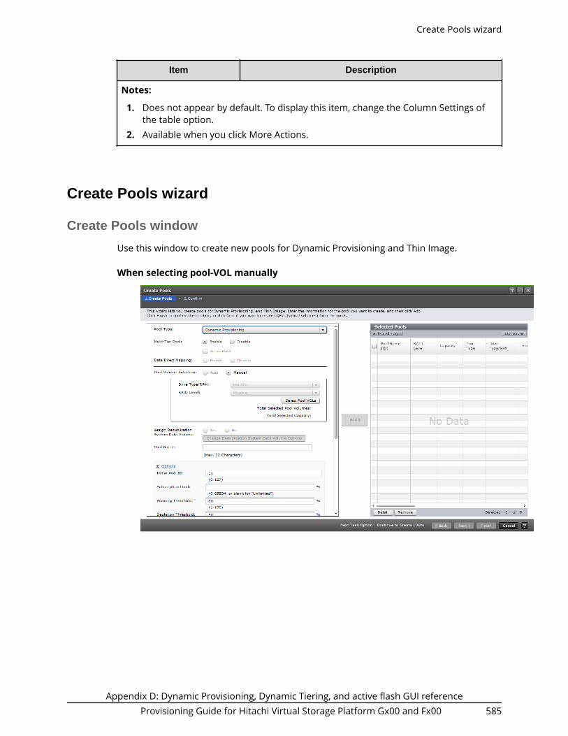
Item Description
Notes:
1. Does not appear by default. To display this item, change the Column Settings ofthe table option.
2. Available when you click More Actions.
Create Pools wizard
Create Pools window
Use this window to create new pools for Dynamic Provisioning and Thin Image.
When selecting pool-VOL manually
Create Pools wizard
Appendix D: Dynamic Provisioning, Dynamic Tiering, and active flash GUI referenceProvisioning Guide for Hitachi Virtual Storage Platform Gx00 and Fx00 585

When selecting pool-VOL automatically
Item Description
*Pool Type Select the pool type.
For Thin Image, select Thin Image.
For the following software, select Dynamic Provisioning.■ Dynamic Provisioning■ Dynamic Tiering■ active flash
*Multi-Tier Pool If Dynamic Tiering is enabled, Auto or Manual forperformance monitoring and tier relocation is displayed. IfDynamic Tiering is disabled, a hyphen (-) is displayed.
Active Flash When the following conditions are satisfied, this check boxcan be selected:■ Multi-Tier Pool is enabled.■ Pool volumes whose drive type is SSD are installed.
If this check box is selected, active flash can be used.
Create Pools window
Appendix D: Dynamic Provisioning, Dynamic Tiering, and active flash GUI referenceProvisioning Guide for Hitachi Virtual Storage Platform Gx00 and Fx00 586

Item Description
Data Direct Mapping Select Enable or Disable for the data direct mappingattribute. This item can be selected if following arespecified:■ Pool Type: Dynamic Provisioning■ Multi-Tier Pool: Disable
*Pool Volume Selection Select the mode of the pool-VOL setting from Auto orManual. If Enable is selected in Data Direct Mapping,Manual is selected automatically.
*Drive Type/RPM Select the data drive type and RPM of the pool-VOL. Whenthe volume is created by Dynamic Provisioning, DynamicTiering, or active flash, Mixable appears. When thevolume is the external volume, Drive Type displaysExternal Storage. This item is displayed when you selectManual as your Pool Volume Selection.
*RAID Level Select the RAID level of the pool-VOL. This item isdisplayed when you select Manual as your Pool VolumeSelection.
Mixable appears in the case of Dynamic Provisioning,Dynamic Tiering, or active flash. A hyphen (-) appearswhen External Storage is selected in the Drive Type/RPMlist.
*Select Pool VOLs Opens the Select Pool VOLs window. Selecting a pool-VOLis mandatory. This item is displayed when you selectManual as your Pool Volume Selection.
Total Selected PoolVolumes
Displays the total number of the selected pool-VOLs. Thisitem is displayed when you select Manual as your PoolVolume Selection.
Total Selected Capacity Displays the total capacity of the selected pool-VOLs. Thisitem is displayed when you select Manual as your PoolVolume Selection.
Resource Group This item is displayed when you select Auto as your PoolVolume Selection.
Select the resource group name of the pool.
Performance This item is displayed when you select Auto as your PoolVolume Selection.
Select the performance of the pool.
Create Pools window
Appendix D: Dynamic Provisioning, Dynamic Tiering, and active flash GUI referenceProvisioning Guide for Hitachi Virtual Storage Platform Gx00 and Fx00 587

Item Description
Total Capacity This item is displayed when you select Auto as your PoolVolume Selection.
Specify the total capacity of the pool.
Change PoolConfiguration
This item is displayed when you select Auto as your PoolVolume Selection.
Opens the Change Pool Configuration Pattern window.You can change the pool configuration that isautomatically selected. For details, see Change PoolConfiguration Pattern window (on page 666) .
Total Pool Volumes This item is displayed when you select Auto as your PoolVolume Selection.
Displays the total number of pool-VOLs.
Total Capacity This item is displayed when you select Auto as your PoolVolume Selection.
Displays the capacity of the pool created by the selectedpool configuration.
Assign DeduplicationSystem Data Volume
(Open systems)
Select Yes or No to enable or disable the deduplicationsetting. Deduplication cannot be enabled if any of thefollowing conditions exists:■ The license for the capacity saving function is not
installed.■ Data Direct Mapping is enabled.■ Multi-Tier Pool is enabled.■ Pool volumes are not selected.■ There are not enough available LDEV IDs.■ There are not enough available cache management
devices.
Change Deduplication System Data Volume Options:Opens the Change Deduplication System Data VolumeOptions window.
*Pool Name Set the pool name. You can enter up to 32 case-sensitiveand alphanumeric characters.
Initial Pool ID The smallest available number is entered in the text boxas a default. No number appears in the text box if noavailable pool ID exists.
If you specify the pool ID which is used already, theminimum pool ID after that the specified pool ID isautomatically set.
Create Pools window
Appendix D: Dynamic Provisioning, Dynamic Tiering, and active flash GUI referenceProvisioning Guide for Hitachi Virtual Storage Platform Gx00 and Fx00 588

Item Description
Subscription Limit Set the subscription limit of the pool from 0 to 65534 (%).
If this is blank, the subscription is set to unlimited.
When creating a Thin Image pool, this setting is notnecessary.
Warning Threshold Set the threshold between 1 and 100%. The default valueis 70%.
For Thin Image: Set the threshold between 20% and 95%.The default value is 80%. If Enable is selected in DataDirect Mapping, 100% is specified automatically.
Depletion Threshold Set the threshold between 1% and 100%. The defaultvalue is 80%.
When creating a Thin Image pool, this setting is notnecessary. If Enable is selected in Data Direct Mapping,100% is specified automatically.
Suspend TI pairs whendepletion threshold isexceeded
For a Dynamic Provisioning pool that contains Thin Imagepairs and snapshot data, specify whether SIM code 62Exxxis output when the pool used capacity exceeds thedepletion threshold (default = yes). If you attempt to splita Thin Image pair in the pool after SIM code 62Exxx isoutput, the operation fails and the pair is suspended byerror.■ Yes (default): When the pool used capacity exceeds the
depletion threshold, SIM code 62Exxx is output, andThin Image pairs in the pool cannot be split.
If Multi-Tier Pool or Data Direct Mapping is enabled forthe pool, Yes cannot be selected.
■ No: When the pool used capacity exceeds the depletionthreshold, SIM code 62Exxx is not output, and ThinImage pairs in the pool can be split.
Protect V-VOLs when I/Ofails to Blocked Pool VOL
You can set this item if the following conditions aresatisfied:■ Dynamic Provisioning is selected in Pool Type.■ Data Retention Utility is installed.
Select Yes or No in the protect function for DP-VOL. If thisfunction is enabled, when the pool-VOL is blocked, DP-VOLis protected from reading and writing requests, and, at thesame time, the access attribute of the DP-VOL is changedto the Protect attribute.
Create Pools window
Appendix D: Dynamic Provisioning, Dynamic Tiering, and active flash GUI referenceProvisioning Guide for Hitachi Virtual Storage Platform Gx00 and Fx00 589

Item Description
Protect V-VOLs when I/Ofails to Full Pool
You can set this item if the following conditions aresatisfied:■ Dynamic Provisioning is selected in Pool Type.■ Data Retention Utility is installed.
Select Yes or No in the protect function for DP-VOL. If thisfunction is enabled, when the pool usage reaches the fullsize, DP-VOL is protected from reading and writingrequests, and, at the same time, the access attribute ofthe DP-VOL is changed to the Protect attribute.
Tier Management Select Auto or Manual of performance monitoring and tierrelocation.■ Cycle Time
Select the cycle of performance monitoring and tierrelocation.
■ Monitoring Period
When 24 Hours is selected in the Cycle Time list, specifythe time zone from 00:00 to 23:59 (default value), inwhich performance monitoring is to be performed.Take one or more hours between the starting time andthe ending time. If you specify the starting time laterthan the ending time, the performance monitoringcontinues until the time when you specify as theending time on the next day.
This function can be set when the multi-tier pool isenabled.
Monitoring Mode Specifies the monitoring mode, If you perform the tierrelocation weighted to the past period monitoring result,select Continuous Mode. If you perform the tier relocationon the specified cycle, select Period Mode. You can specifythis function when the multi-tier pool feature is enabled.
Relocation speed Specifies the page relocation speed. You can set the speedto: 1(Slowest), 2(Slower), 3(Standard), 4(Faster), or5(Fastest). The default is 3(Standard). If the speedspecified is slower than 3(Standard), the data drive load islow when tier relocation is performed.
Create Pools window
Appendix D: Dynamic Provisioning, Dynamic Tiering, and active flash GUI referenceProvisioning Guide for Hitachi Virtual Storage Platform Gx00 and Fx00 590

Item Description
Buffer Space for Newpage assignment
You can set this function when the multi-tier pool featureis enabled.
Tier 1: Enter an integer value from 0 to 50 as thepercentage (%) to set for tier 1. A default value dependson the data drive type of pool-VOL in tier 1. The defaultvalue of SSD is 0%. The default value other than SSD is 8%.
Tier 2: Enter an integer value from 0 to 50 as thepercentage (%) to set for tier 2. A default value dependson the data drive type of pool-VOL in tier 2.
Tier 3: Enter an integer value from 0 to 50 as thepercentage (%) to set for tier 3. A default value dependson the data drive type of pool-VOL in tier 3.
Buffer Space for Tierrelocation
You can set this function when the multi-tier pool featureis enabled.
Tier 1: Enter an integer value from 2 to 40 as thepercentage (%) to set for tier 1. A default value is 2%.
Tier 2: Enter an integer value from 2 to 40 as thepercentage (%) to set for tier 2. A default value is 2%.
Tier 3: Enter an integer value from 2 to 40 as thepercentage (%) to set for tier 3. A default value is 2%.
Add When you click Add, the configured information is addedto the right side of the Selected Pools table.
*Items with asterisks require configuration.
Create Pools window
Appendix D: Dynamic Provisioning, Dynamic Tiering, and active flash GUI referenceProvisioning Guide for Hitachi Virtual Storage Platform Gx00 and Fx00 591

Selected Pools table
Item Description
Pool Name (ID) Displays the pool name and pool ID.
RAID Level Displays RAID level of the pool. If multiple RAID levels existin a pool, this field indicates that RAID levels are mixed. Ifall pool-VOLs are external volumes, a hyphen (-) isdisplayed.
Capacity Displays the total capacity of the created pool.
For open systems, the displayed capacity is approximately4.1 GB (capacity of the management area) less than thetotal capacity of the selected pool volumes.
As for a pool comprised of pool volumes assigned toaccelerated compression-enabled parity groups, thewritable capacity might be smaller than the displayedcapacity.
Create Pools window
Appendix D: Dynamic Provisioning, Dynamic Tiering, and active flash GUI referenceProvisioning Guide for Hitachi Virtual Storage Platform Gx00 and Fx00 592

Item Description
Pool Type Displays the pool type.
For a Dynamic Provisioning pool, DP is displayed.
For a Dynamic Tiering pool, DT is displayed.
For a pool being used for active flash, DT(Active Flash) isdisplayed.
For a pool with data direct mapping enabled, DP (datadirect mapping) is displayed.
For a Thin Image pool, TI is displayed.
Drive Type/RPM Displays the data drive type and RPM. If multiple drivetypes or RPMs exist in a pool, this field indicates Mixed.When the volume is the external volume, Drive Typedisplays External Storage and the value of the externalLDEV tier rank.
Encryption Encryption: The encryption information of the pool.■ Enabled: Pool which is created by pool-VOLs whose
encryption settings are enabled.■ Disable: Pool which is created by pool-VOLs whose
encryption settings are disabled.■ Mixed: This status is displayed when two or more of
the following are specified as pool-VOLs:● Volume encryption setting is enabled.● Volume encryption setting is disabled.● External volume
Caution: The data encryption is not ensured in thepool that has the Mixed encryption setting. To managethe data encryption securely, use the pool with anencryption setting of Enabled or Disabled.
■ Hyphen(-): Pool which is created by external volumes.
User-Defined Threshold(%)
Displays the pool threshold.■ Warning: Warning threshold is displayed.■ Depletion: Depletion threshold is displayed.
For a Thin Image pool, a hyphen (-) is displayed forDepletion.
Create Pools window
Appendix D: Dynamic Provisioning, Dynamic Tiering, and active flash GUI referenceProvisioning Guide for Hitachi Virtual Storage Platform Gx00 and Fx00 593

Item Description
Suspend TI pairs whendepletion threshold isexceeded
Displays the setting for outputting SIM code 62Exxx whenthe pool used capacity exceeds the depletion threshold.■ Yes: When the pool used capacity exceeds the
depletion threshold, SIM code 62Exxx is output.■ No: When the pool used capacity exceeds the depletion
threshold, SIM code 62Exxx is not output.
Subscription Limit (%) Displays subscription limit of the pool.
For Thin Image pool, a hyphen (-) is displayed.
Protect V-VOLs when I/Ofails to Blocked Pool VOL
Displays whether the protect function for DP-VOL is beingenabled or disabled. If the setting is enabled, when thepool-VOL is blocked, DP-VOL is protected from readingand writing requests. And at the same instant, the accessattribute of the DP-VOL is changed to the Protectattribute.
A hyphen appears if the pool corresponds with one offollowing:■ Data Retention Utility is not installed.■ Pool type is the type other than DP or DT.
Protect V-VOLs when I/Ofails to Full Pool
Displays whether the protect function for DP-VOL is beingenabled or disabled. If the setting is enabled, when thepool usage reaches the full size, DP-VOL is protected fromreading and writing requests. And at the same instant, theaccess attribute of the DP-VOL is changed to the Protectattribute.
A hyphen appears if the pool corresponds with one offollowing:■ Data Retention Utility is not installed.■ Pool type is the type other than DP or DT.
Number of Pool VOLs Displays the number of pool-VOLs.
Tier Management If Dynamic Tiering is enabled, Auto or Manual forperformance monitoring and tier relocation is displayed. IfDynamic Tiering is disabled, a hyphen (-) is displayed.
Cycle Time Displays the cycle of performance monitoring and tierrelocation. If Dynamic Tiering is disabled, a hyphen (-) isdisplayed.
Monitoring Period Displays the time zone of performance monitoring when24 Hours is selected as the Cycle Time. If Dynamic Tieringis disabled, a hyphen (-) is displayed.
Create Pools window
Appendix D: Dynamic Provisioning, Dynamic Tiering, and active flash GUI referenceProvisioning Guide for Hitachi Virtual Storage Platform Gx00 and Fx00 594

Item Description
Monitoring Mode If the continuous mode is enabled, Continuous Mode isdisplayed. If the period mode is enabled, Period Mode isdisplayed.
Relocation speed Displays the page relocation speed: 1(Slowest), 2(Slower),3(Standard), 4(Faster), or 5(Fastest). If Dynamic Tiering isdisabled, a hyphen (-) is displayed.
Buffer Space for Newpage assignment (%)
Displays the information of the buffer space for new pageassignment to each tier.
Tier 1: If you make the Dynamic Tiering function available,the buffer space for new page assignment to tier 1 isdisplayed. If you make the Dynamic Tiering functionunavailable, a hyphen (-) is displayed.
Tier 2: If you make the Dynamic Tiering function available,and tier 2 exists, the buffer space for new pageassignment to tier 2 is displayed. If you make the DynamicTiering function unavailable, or tier 2 does not exist, ahyphen (-) is displayed.
Tier 3: If you make the Dynamic Tiering function available,and tier 3 exists, the buffer space for new pageassignment to tier 3 is displayed. If you make the DynamicTiering function unavailable, or tier 3 does not exist, ahyphen (-) is displayed.
Buffer Space for Tierrelocation (%)
Displays the information of the buffer space for tierrelocation to each tier.
Tier 1: If you make the Dynamic Tiering function available,the buffer space for tier relocation to tier 1 is displayed. Ifyou make the Dynamic Tiering function unavailable, ahyphen (-) is displayed.
Tier 2: If you make the Dynamic Tiering function available,and tier 2 exists, the buffer space for tier relocation to tier2 is displayed. If you make the Dynamic Tiering functionunavailable, or tier 2 does not exist, a hyphen (-) isdisplayed.
Tier 3: If you make the Dynamic Tiering function available,and tier 3 exists, the buffer space for tier relocation to tier3 is displayed. If you make the Dynamic Tiering functionunavailable, or tier 3 does not exist, a hyphen (-) isdisplayed.
Deduplication
(Open systems)
If the pool type is DP, this item displays Available or NotAvailable for the deduplication setting. If the pool type isother than DP, a hyphen (-) is displayed.
Create Pools window
Appendix D: Dynamic Provisioning, Dynamic Tiering, and active flash GUI referenceProvisioning Guide for Hitachi Virtual Storage Platform Gx00 and Fx00 595

Item Description
Detail Displays the Pool Properties window when a row isselected, and shows the error window when a row is notselected or multiple rows are selected.
Remove Deletes the pool selected in the Selected Pools window.
Displays the error window when a row is not selected.
Next Task Option
Click Next to go to the task setting window.
Create Pools confirmation window
Confirm proposed settings, name the task, and then click Apply. The task will be addedto the execution queue.
Note: If multiple tasks that are connected in one wizard are executed, thiswindow shows all configured items of tasks. To show information ofconfigured items other than this topic, click Back to display related settingwindows, and then click Help.
Item Description
Pool Name (ID) Displays the pool name and pool ID.
RAID Level Displays the RAID level. If multiple RAID levels exist in apool, this field indicates that RAID levels are mixed. If allpool-VOLs are external volumes, a hyphen (-) is displayed.
Capacity Displays the pool capacity.
(Open systems) For a pool containing pool volumesassigned by accelerated compression-enabled paritygroups, the writable capacity may be smaller than thedisplayed capacity.
Create Pools confirmation window
Appendix D: Dynamic Provisioning, Dynamic Tiering, and active flash GUI referenceProvisioning Guide for Hitachi Virtual Storage Platform Gx00 and Fx00 596

Item Description
Pool Type Displays the pool type.
For a Dynamic Provisioning pool, DP is displayed.
For a Dynamic Tiering pool, DT is displayed.
For a pool being used for active flash, DT(Active Flash) isdisplayed.
For a pool with data direct mapping enabled, DP (datadirect mapping) is displayed.
For a Thin Image pool, TI is displayed.
Drive Type/RPM Displays the data drive type and RPM. If multiple drivetypes or RPMs exist in a pool, this field indicates that drivetypes or RPMs are mixed. When the volume is the externalvolume, Drive Type displays External Storage and thevalue of the external LDEV tier rank.
Encryption Encryption: The encryption information of the pool.■ Enabled: Pool which is created by pool-VOLs whose
encryption settings are enabled.■ Disable: Pool which is created by pool-VOLs whose
encryption settings are disabled.■ Mixed: This status is displayed when two or more of
the following are specified as pool-VOLs:● Volume encryption setting is enabled.● Volume encryption setting is disabled.● External volume
Caution: The data encryption is not ensured in thepool that has the Mixed encryption setting. To managethe data encryption securely, use the pool with anencryption setting of Enabled or Disabled.
■ Hyphen(-): Pool is created by external volumes.
This item is not displayed when using Virtual StoragePlatform G200.
User-Defined Threshold(%)
Displays the pool threshold.■ Warning: Warning threshold is displayed.■ Depletion: Depletion threshold is displayed.
For a Thin Image pool, a hyphen (-) is displayed forDepletion.
Create Pools confirmation window
Appendix D: Dynamic Provisioning, Dynamic Tiering, and active flash GUI referenceProvisioning Guide for Hitachi Virtual Storage Platform Gx00 and Fx00 597

Item Description
Suspend TI pairs whendepletion threshold isexceeded
Displays the setting for outputting SIM code 62Exxx whenthe pool used capacity exceeds the depletion threshold.■ Yes: When the pool used capacity exceeds the
depletion threshold, SIM code 62Exxx is output.■ No: When the pool used capacity exceeds the depletion
threshold, SIM code 62Exxx is not output.
Subscription Limit (%) Displays the subscription limit.
For Thin Image pool, a hyphen (-) is displayed.
Protect V-VOLs when I/Ofails to Blocked Pool VOL
Displays whether the protect function for DP-VOL is beingenabled or disabled. If the setting is enabled, when thepool-VOL is blocked, DP-VOL is protected from readingand writing requests. And at the same instant, the accessattribute of the DP-VOL is changed to the Protectattribute.
A hyphen is displayed if the pool corresponds with one ofthe following:■ Data Retention Utility is not installed.
Protect V-VOLs when I/Ofails to Full Pool
Displays whether the protect function for DP-VOL is beingenabled or disabled. If the setting is enabled when thepool usage reaches the full size, DP-VOL is protected fromreading and writing requests. At the same instant, theaccess attribute of the DP-VOL is changed to the Protectattribute.
A hyphen is displayed under these conditions:■ Data Retention Utility is not installed.
Number of Pool VOLs Displays the number of pool-VOLs.
Tier Management If Dynamic Tiering is enabled, Auto or Manual forperformance monitoring and tier relocation is displayed. IfDynamic Tieringis disabled, a hyphen (-) is displayed.
Cycle Time Displays the cycle of performance monitoring and tierrelocation. If Dynamic Tiering is disabled, a hyphen (-) isdisplayed.
Monitoring Period Displays the time zone of performance monitoring when24 Hours is selected as the Cycle Time. If Dynamic Tieringis disabled, a hyphen (-) is displayed.
Monitoring Mode If the continuous mode is enabled, Continuous Mode isdisplayed. If the period mode is enabled, Period Mode isdisplayed.
Create Pools confirmation window
Appendix D: Dynamic Provisioning, Dynamic Tiering, and active flash GUI referenceProvisioning Guide for Hitachi Virtual Storage Platform Gx00 and Fx00 598
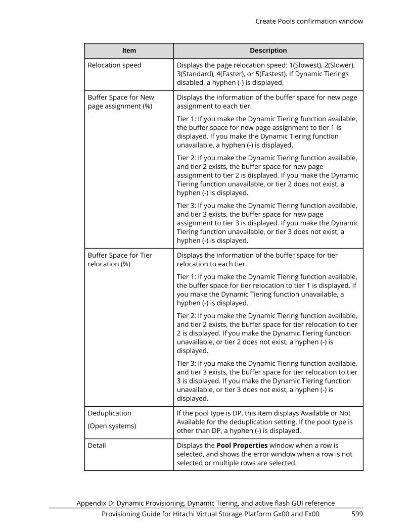
Item Description
Relocation speed Displays the page relocation speed: 1(Slowest), 2(Slower),3(Standard), 4(Faster), or 5(Fastest). If Dynamic Tieringsdisabled, a hyphen (-) is displayed.
Buffer Space for Newpage assignment (%)
Displays the information of the buffer space for new pageassignment to each tier.
Tier 1: If you make the Dynamic Tiering function available,the buffer space for new page assignment to tier 1 isdisplayed. If you make the Dynamic Tiering functionunavailable, a hyphen (-) is displayed.
Tier 2: If you make the Dynamic Tiering function available,and tier 2 exists, the buffer space for new pageassignment to tier 2 is displayed. If you make the DynamicTiering function unavailable, or tier 2 does not exist, ahyphen (-) is displayed.
Tier 3: If you make the Dynamic Tiering function available,and tier 3 exists, the buffer space for new pageassignment to tier 3 is displayed. If you make the DynamicTiering function unavailable, or tier 3 does not exist, ahyphen (-) is displayed.
Buffer Space for Tierrelocation (%)
Displays the information of the buffer space for tierrelocation to each tier.
Tier 1: If you make the Dynamic Tiering function available,the buffer space for tier relocation to tier 1 is displayed. Ifyou make the Dynamic Tiering function unavailable, ahyphen (-) is displayed.
Tier 2: If you make the Dynamic Tiering function available,and tier 2 exists, the buffer space for tier relocation to tier2 is displayed. If you make the Dynamic Tiering functionunavailable, or tier 2 does not exist, a hyphen (-) isdisplayed.
Tier 3: If you make the Dynamic Tiering function available,and tier 3 exists, the buffer space for tier relocation to tier3 is displayed. If you make the Dynamic Tiering functionunavailable, or tier 3 does not exist, a hyphen (-) isdisplayed.
Deduplication
(Open systems)
If the pool type is DP, this item displays Available or NotAvailable for the deduplication setting. If the pool type isother than DP, a hyphen (-) is displayed.
Detail Displays the Pool Properties window when a row isselected, and shows the error window when a row is notselected or multiple rows are selected.
Create Pools confirmation window
Appendix D: Dynamic Provisioning, Dynamic Tiering, and active flash GUI referenceProvisioning Guide for Hitachi Virtual Storage Platform Gx00 and Fx00 599

Selected deduplication system data volumes
This table is displayed only when a deduplication system data volume is selected.
Item Description
LDEV ID Displays the LDEV identifier, which is the combination ofLDKC, CU, and LDEV.
LDEV Name Displays the LDEV name.
Pool Name (ID) Displays the pool name, and the pool ID is displayed inparentheses.
Capacity Displays the LDEV capacity.
Provisioning Type Displays the type of the LDEV.
SSID Displays the SSID of the LDEV.
Resource Group Name(ID)
Displays the resource group names, and the IDs of theresource groups are displayed in parentheses.
Virtual Storage Machine Model name and serial number of the virtual storagemachine that has LDEV.
Expand Pool wizard
Expand Pool window
Use this window to add LDEVs to a pool to expand the pool to increase pool capacity.
Expand Pool wizard
Appendix D: Dynamic Provisioning, Dynamic Tiering, and active flash GUI referenceProvisioning Guide for Hitachi Virtual Storage Platform Gx00 and Fx00 600

Item Description
Drive Type/RPM The Drive Type/RPM of the selected pool or Mixable isdisplayed. When the volume is the external volume, DriveType displays External Storage.
RAID Level Set the RAID level of the selected pool. If the level is notset, Mixable appears. If External Storage is selected in theDrive Type/RPM field, a hyphen (-) is displayed.
Select Pool VOLs Opens the Select Pool VOLs window.
Total Selected PoolVolumes
Total number of the pool-VOLs selected for this pool.
Total Selected Capacity Total capacity of the pool-VOLs selected for this pool.
Expand Pool confirmation window
Confirm proposed settings, name the task, and then click Apply. The task will be addedto the execution queue.
Selected Pool table
Item Description
Pool Name (ID) Displays the pool name and pool ID.
Expand Pool confirmation window
Appendix D: Dynamic Provisioning, Dynamic Tiering, and active flash GUI referenceProvisioning Guide for Hitachi Virtual Storage Platform Gx00 and Fx00 601

Selected Pool Volumes table
Item Description
LDEV ID Displays LDEV identifier, which is the combination ofLDKC, CU, and LDEV.
LDEV Name Displays the LDEV name.
Capacity Displays the pool-VOL capacity.
Parity Group ID Displays the parity group ID.
RAID Level Displays RAID level. If a pool-VOL is an external volume, ahyphen (-) is displayed.
Drive Type/RPM Displays the data drive type and RPM. When the volume isthe external volume, Drive Type displays External Storageand the value of the external LDEV tier rank.
Cache Mode For an external volume, this item is displayed as enabledor disabled. If the LDEV is not an external volume, ahyphen (-) is displayed.
Attribute Attribute of the volume indicating how the LDEV is beingused.■ Data Direct Mapping: LDEV with the data direct
mapping attribute.■ Deduplication System Data Volume: LDEV used to
manage data deduplication.■ - (hyphen): Volume for which the attribute is not
defined.
Accelerated Compression Displays information about the accelerated compressionof the parity group that is created of LDEVs.
Enabled: The accelerated compression of the parity groupis enabled.
Disabled: The accelerated compression of the parity groupis disabled.
- (hyphen): The parity group with the acceleratedcompression is not supported.
Edit Pools wizard
Edit Pools window
Use this window to edit the settings of the selected pool.
Edit Pools wizard
Appendix D: Dynamic Provisioning, Dynamic Tiering, and active flash GUI referenceProvisioning Guide for Hitachi Virtual Storage Platform Gx00 and Fx00 602

Caution:■ If you need to perform two or more operations to edit several items in the
same pool, wait until the first task has been applied before performing thenext task. If the next task is performed while the first task is being applied,the first task is canceled and the next task is applied to the storage system,so the result might be different from what you expect.
■ If you modified pool parameters by using Command Control Interface andthen use Device Manager - Storage Navigator, click File > Refresh All todisplay the latest pool information before performing the next operationby using Device Manager - Storage Navigator. If you use Device Manager -Storage Navigator without refreshing the windows, the informationupdated by Command Control Interface might not yet be displayed on theDevice Manager - Storage Navigator windows, so if you perform anoperation the result might be different from what you expect.
Edit Pools window
Appendix D: Dynamic Provisioning, Dynamic Tiering, and active flash GUI referenceProvisioning Guide for Hitachi Virtual Storage Platform Gx00 and Fx00 603

Item Description
Multi-Tier Pool Select the check box, then Enable or Disable when usingor not using Dynamic Tiering.
In Thin Image, you cannot change the setting of thisfunction.
For a Dynamic Provisioning pool that contains Thin Imagepairs and snapshot data, you cannot change this settingfrom Disable to Enable.
Active Flash Select the check box if you are using active flash. If poolvolumes whose drive type is SSD are installed, this checkbox can be selected.
In Thin Image, you cannot change the setting of thisfunction.
Edit Pools window
Appendix D: Dynamic Provisioning, Dynamic Tiering, and active flash GUI referenceProvisioning Guide for Hitachi Virtual Storage Platform Gx00 and Fx00 604

Item Description
Options for Multi-Tier Pool Specifies the performance monitoring, tier relocation, editbuffer space for new page assignment, and buffer spacefor tier relocation if Multi-Tier Pool is set to Enable.
In Thin Image, you cannot change the setting of thisfunction.
Select the Tier Management check box, and then set thetier management, the cycle time, and the monitoringperiod.■ Tier Management: Select Auto or Manual.■ Cycle Time: When selecting Auto in the Tier
Management option, select the cycle of performancemonitoring and tier relocation from the Cycle Time list.
■ Monitoring Period: When selecting 24 Hours in theCycle Time list, specify the time of starting and endingof performance monitoring in 00:00 to 23:59 (defaultvalue). Take one or more hours between the startingtime and the ending time. If you specify the startingtime later than the ending time, the performance
Edit Pools window
Appendix D: Dynamic Provisioning, Dynamic Tiering, and active flash GUI referenceProvisioning Guide for Hitachi Virtual Storage Platform Gx00 and Fx00 605

Item Description
monitoring continues until the time when you specifyas the ending time on the next day.
Select the Monitoring Mode check box, and then set themonitoring mode.
Monitoring Mode: Specify the monitoring mode. If youperform the tier relocation weighted to the past periodmonitoring result, select Continuous Mode. If you performthe tier relocation on the specified cycle, select PeriodMode.
Select the Relocation Speed check box. Then set the tierrelocation speed.
Relocation Speed: Specify the page relocation speed whentier relocation is performed. You can set the speed to:1(Slowest), 2(Slower), 3(Standard), 4(Faster), or 5(Fastest).
Select the Buffer Space for New page assignment checkbox, and then set the buffer space for new pageassignment.
Buffer Space for New page assignment: Enter an integervalue from 0 to 50 as the percentage (%) to set for tier 1,tier 2, and tier 3. If there is no tier, you cannot set thisitem.
Select the Buffer Space for Tier relocation check box, andthen set the buffer space for tier relocation.
Buffer Space for Tier relocation: Enter an integer valuefrom 2 to 40 as the percentage (%) to set for tier 1, tier 2,and tier 3.
If the check box is not selected, you cannot set this item.You must set all items if you change the pool setting fromDynamic Provisioning to Dynamic Tieringor active flash.
If the check box is selected, you cannot collapse theOptions for Multi-Tier Pool field.
Edit Pools window
Appendix D: Dynamic Provisioning, Dynamic Tiering, and active flash GUI referenceProvisioning Guide for Hitachi Virtual Storage Platform Gx00 and Fx00 606

Item Description
Data Direct Mapping Select the check box, and then select Enable or Disable forthe data direct mapping attribute. This item can beenabled only when the pool type is Dynamic Provisioningand multi-tier pool is disabled.
Enable or Disable cannot be selected in the followingcases:■ You cannot select Enable or Disable if any of the
following conditions is satisfied:● Multi-Tier Pool is enabled.● A Thin Image pool is selected.
■ You cannot select Enable when the selected poolcontains a DP-VOL associated with an LDEV that doesnot have the data direct mapping attribute.
■ You cannot select Enable when the selected DynamicProvisioning pool contains Thin Image pairs andsnapshot data.
■ You cannot select Disable when the selected poolcontains an LDEV with the data direct mappingattribute.
Subscription Limit Select the Subscription Limit check box, and then enterthe subscription limit (%). In Thin Image, you cannotchange the setting of this function.■ If this field is blank, the subscription is set to be
unlimited.■ Use blank or a value in the following range:
(Total V-VOL capacity including the controlinformation / pool capacity) × 100(%) +1 to 65534(%)
■ When the current subscription setting is unlimited andthe value calculated by the following formula exceeds65534, you cannot configure the subscription limit.
((Total V-VOL capacity including the controlinformation / pool capacity) × 100)
■ If the check box is not selected, the subscription limit isdisabled.
Edit Pools window
Appendix D: Dynamic Provisioning, Dynamic Tiering, and active flash GUI referenceProvisioning Guide for Hitachi Virtual Storage Platform Gx00 and Fx00 607
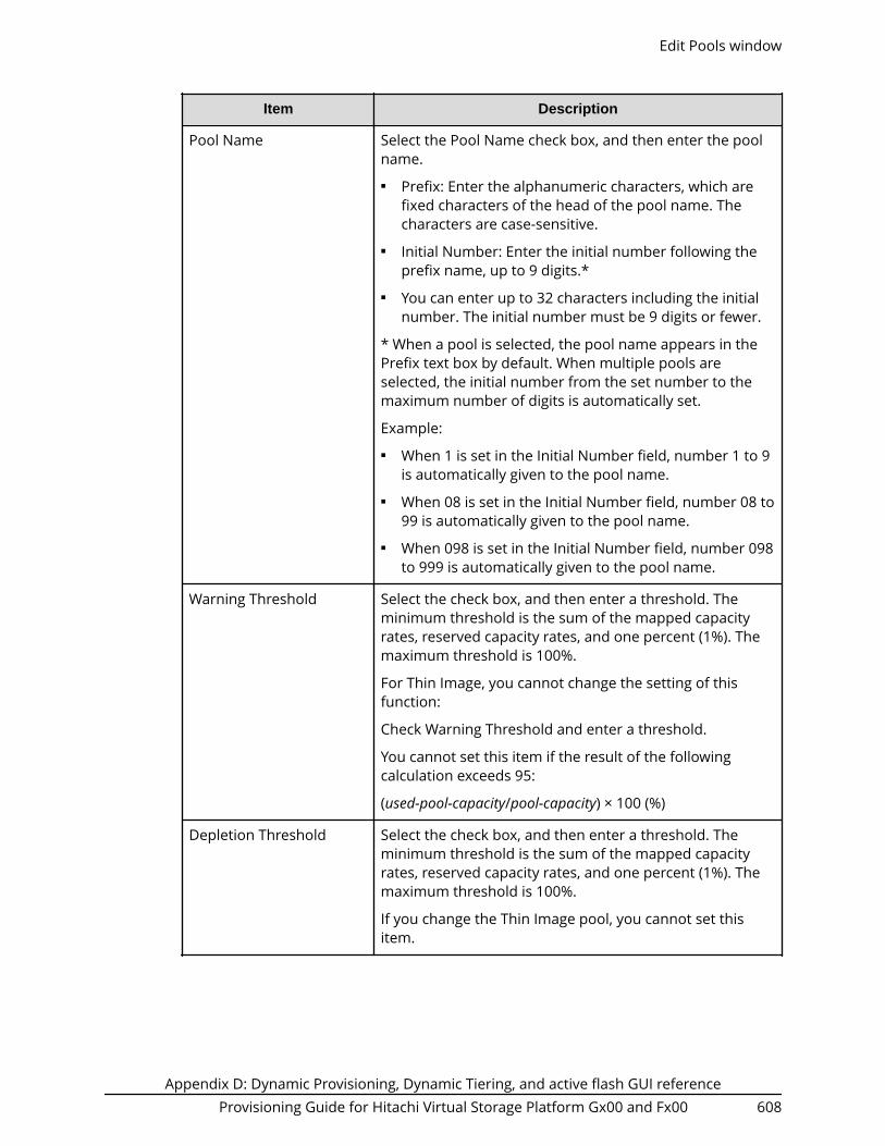
Item Description
Pool Name Select the Pool Name check box, and then enter the poolname.■ Prefix: Enter the alphanumeric characters, which are
fixed characters of the head of the pool name. Thecharacters are case-sensitive.
■ Initial Number: Enter the initial number following theprefix name, up to 9 digits.*
■ You can enter up to 32 characters including the initialnumber. The initial number must be 9 digits or fewer.
* When a pool is selected, the pool name appears in thePrefix text box by default. When multiple pools areselected, the initial number from the set number to themaximum number of digits is automatically set.
Example:■ When 1 is set in the Initial Number field, number 1 to 9
is automatically given to the pool name.■ When 08 is set in the Initial Number field, number 08 to
99 is automatically given to the pool name.■ When 098 is set in the Initial Number field, number 098
to 999 is automatically given to the pool name.
Warning Threshold Select the check box, and then enter a threshold. Theminimum threshold is the sum of the mapped capacityrates, reserved capacity rates, and one percent (1%). Themaximum threshold is 100%.
For Thin Image, you cannot change the setting of thisfunction:
Check Warning Threshold and enter a threshold.
You cannot set this item if the result of the followingcalculation exceeds 95:
(used-pool-capacity/pool-capacity) × 100 (%)
Depletion Threshold Select the check box, and then enter a threshold. Theminimum threshold is the sum of the mapped capacityrates, reserved capacity rates, and one percent (1%). Themaximum threshold is 100%.
If you change the Thin Image pool, you cannot set thisitem.
Edit Pools window
Appendix D: Dynamic Provisioning, Dynamic Tiering, and active flash GUI referenceProvisioning Guide for Hitachi Virtual Storage Platform Gx00 and Fx00 608

Item Description
Protect V-VOLs when I/Ofails to Blocked Pool VOL
Select the check box, and then select Yes or No in theprotect function for DP-VOL. If this function is enabled,when the pool-VOL is blocked, DP-VOL is protected fromreading and writing requests. And at the same instant, theaccess attribute of the DP-VOL is changed to the Protectattribute.
However, if Data Retention Utility is not installed, thischeck box goes inactive.
Suspend TI pairs whendepletion threshold isexceeded
For a Dynamic Provisioning pool that contains Thin Imagepairs and snapshot data, specify whether SIM code 62Exxxis output when the pool used capacity exceeds thedepletion threshold. If you attempt to split a Thin Imagepair in the pool after SIM code 62Exxx is output, theoperation fails and the pair is suspended by error.■ Yes: When the pool used capacity exceeds the
depletion threshold, SIM code 62Exxx is output, andThin Image pairs in the pool cannot be split.
If Multi-Tier Pool or Data Direct Mapping is enabled forthe pool, Yes cannot be selected.
■ No: When the pool used capacity exceeds the depletionthreshold, SIM code 62Exxx is not output, and ThinImage pairs in the pool can be split.
Protect V-VOLs when I/Ofails to Full Pool
Select the check box, and then select Yes or No in theprotect function for DP-VOL. If this function is enabled,when the pool usage reaches the full size, DP-VOL isprotected from reading and writing requests. And at thesame instant, the access attribute of the DP-VOL ischanged to the Protect attribute.
However, if Data Retention Utility is not installed, thischeck box goes inactive.
Edit Pools window
Appendix D: Dynamic Provisioning, Dynamic Tiering, and active flash GUI referenceProvisioning Guide for Hitachi Virtual Storage Platform Gx00 and Fx00 609

Item Description
Assign DeduplicationSystem Data Volume
(Open systems)
Select Yes or No to enable or disable the deduplicationsetting. Deduplication cannot be enabled if any of thefollowing conditions exists:■ The license for the capacity saving function is not
installed.■ Data Direct Mapping is enabled.■ Multi-Tier Pool is enabled.■ There are not enough available LDEV IDs.■ There are not enough available cache management
devices.
Deduplication cannot be disabled if the setting forDeduplication is being disabled.
Edit Pools confirmation window
Confirm proposed settings, name the task, and then click Apply. The task will be addedto the execution queue.
Item Description
Pool Name (ID) Displays the pool name and pool ID.
RAID Level Displays the RAID level. If multiple RAID levels exist in apool, this field indicates that RAID levels are mixed. If allpool-VOLs are external volumes, a hyphen (-) is displayed.
Capacity Displays the pool capacity.
Edit Pools confirmation window
Appendix D: Dynamic Provisioning, Dynamic Tiering, and active flash GUI referenceProvisioning Guide for Hitachi Virtual Storage Platform Gx00 and Fx00 610

Item Description
Pool Type Displays the pool type.
For a Dynamic Provisioning pool, DP is displayed.
For a Dynamic Tiering pool, DT is displayed.
For a pool being used for active flash, DT(Active Flash) isdisplayed.
For a pool with data direct mapping enabled, DP (datadirect mapping) is displayed.
For a Thin Image pool, TI is displayed.
Drive Type/RPM Displays the data drive type and RPMs. If multiple drivetypes or RPMs exist in a pool, this field indicates Mixed.When the volume is the external volume, Drive Typedisplays External Storage and the value of the externalLDEV tier rank. If all pool-VOLs are external volumes, ahyphen (-) is displayed.
User-Defined Threshold(%)
Displays the pool threshold.■ Warning: Warning threshold is displayed.■ Depletion: Depletion threshold is displayed.
For a Thin Image pool, a hyphen (-) is displayed forDepletion.
Suspend TI pairs whendepletion threshold isexceeded
Displays the setting for outputting SIM code 62Exxx whenthe pool used capacity exceeds the depletion threshold.■ Yes: When the pool used capacity exceeds the
depletion threshold, SIM code 62Exxx is output.■ No: When the pool used capacity exceeds the depletion
threshold, SIM code 62Exxx is not output.
Subscription Limit (%) Displays the subscription limit.
For Thin Image pool, a hyphen (-) is displayed.
Protect V-VOLs when I/Ofails to Blocked Pool VOL
Displays whether the protect function for DP-VOL is beingenabled or disabled. If the setting is enabled, when thepool-VOL is blocked, DP-VOL is protected from readingand writing requests. And at the same instant, the accessattribute of the DP-VOL is changed to the Protectattribute.
A hyphen appears if the pool corresponds with one of thefollowing:■ Data Retention Utility is not installed.■ Pool type is other than DP or DT.
Edit Pools confirmation window
Appendix D: Dynamic Provisioning, Dynamic Tiering, and active flash GUI referenceProvisioning Guide for Hitachi Virtual Storage Platform Gx00 and Fx00 611
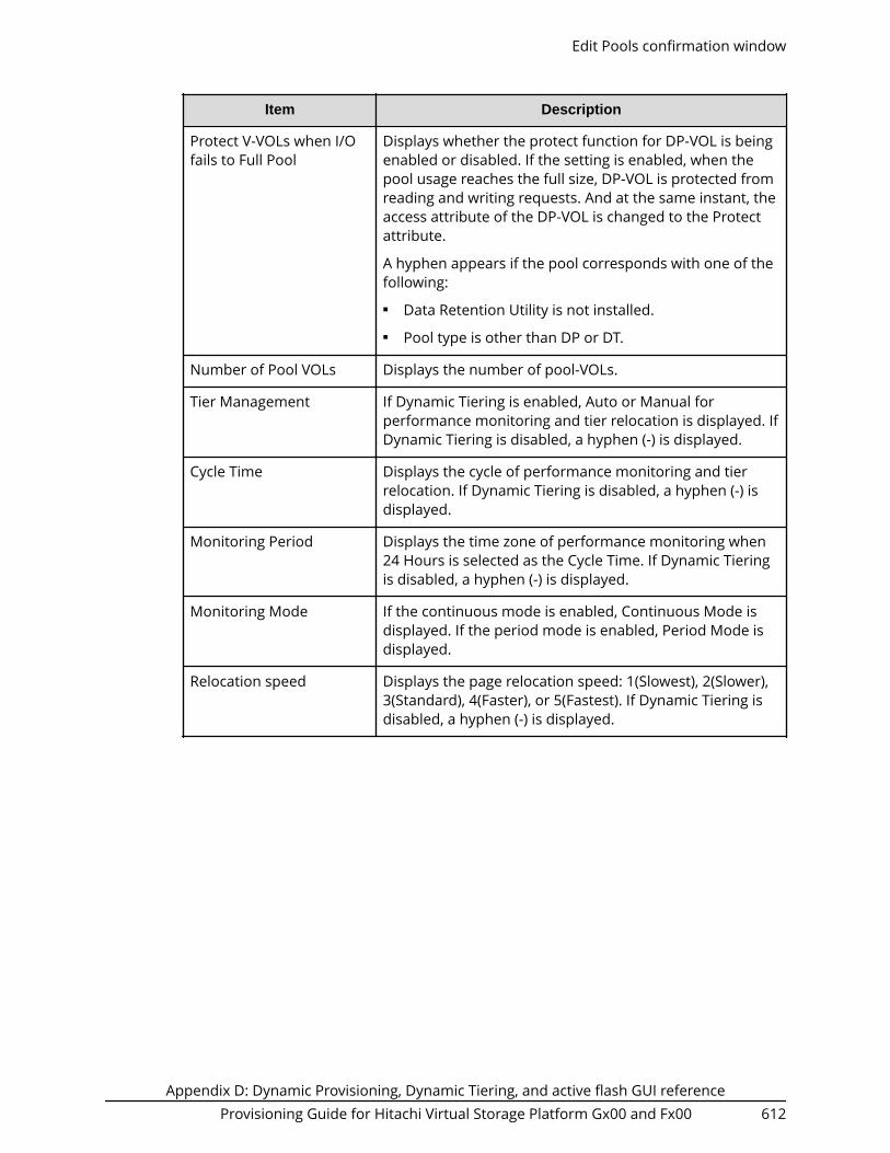
Item Description
Protect V-VOLs when I/Ofails to Full Pool
Displays whether the protect function for DP-VOL is beingenabled or disabled. If the setting is enabled, when thepool usage reaches the full size, DP-VOL is protected fromreading and writing requests. And at the same instant, theaccess attribute of the DP-VOL is changed to the Protectattribute.
A hyphen appears if the pool corresponds with one of thefollowing:■ Data Retention Utility is not installed.■ Pool type is other than DP or DT.
Number of Pool VOLs Displays the number of pool-VOLs.
Tier Management If Dynamic Tiering is enabled, Auto or Manual forperformance monitoring and tier relocation is displayed. IfDynamic Tiering is disabled, a hyphen (-) is displayed.
Cycle Time Displays the cycle of performance monitoring and tierrelocation. If Dynamic Tiering is disabled, a hyphen (-) isdisplayed.
Monitoring Period Displays the time zone of performance monitoring when24 Hours is selected as the Cycle Time. If Dynamic Tieringis disabled, a hyphen (-) is displayed.
Monitoring Mode If the continuous mode is enabled, Continuous Mode isdisplayed. If the period mode is enabled, Period Mode isdisplayed.
Relocation speed Displays the page relocation speed: 1(Slowest), 2(Slower),3(Standard), 4(Faster), or 5(Fastest). If Dynamic Tiering isdisabled, a hyphen (-) is displayed.
Edit Pools confirmation window
Appendix D: Dynamic Provisioning, Dynamic Tiering, and active flash GUI referenceProvisioning Guide for Hitachi Virtual Storage Platform Gx00 and Fx00 612

Item Description
Buffer Space for Newpage assignment (%)
Displays the information of the buffer space for new pageassignment to each tier.
Tier 1: If you make the Dynamic Tiering function available,the buffer space for new page assignment to tier 1 isdisplayed. If you make the Dynamic Tiering functionunavailable, a hyphen (-) is displayed.
Tier 2: If you make the Dynamic Tiering function available,and tier 2 exists, the buffer space for new pageassignment to tier 2 is displayed. If you make the DynamicTiering function unavailable, or tier 2 does not exist, ahyphen (-) is displayed.
Tier 3: If you make the Dynamic Tiering function available,and tier 3 exists, the buffer space for new pageassignment to tier 3 is displayed. If you make the DynamicTiering function unavailable, or tier 3 does not exist, ahyphen (-) is displayed.
Buffer Space for Tierrelocation (%)
Displays the information of the buffer space for tierrelocation to each tier.
Tier 1: If you make the Dynamic Tiering function available,the buffer space for tier relocation to tier 1 is displayed. Ifyou make the Dynamic Tiering function unavailable, ahyphen (-) is displayed.
Tier 2: If you make the Dynamic Tiering function available,and tier 2 exists, the buffer space for tier relocation to tier2 is displayed. If you make the Dynamic Tiering functionunavailable, or tier 2 does not exist, a hyphen (-) isdisplayed.
Tier 3: If you make the Dynamic Tiering function available,and tier 3 exists, the buffer space for tier relocation to tier3 is displayed. If you make the Dynamic Tiering functionunavailable, or tier 3 does not exist, a hyphen (-) isdisplayed.
Deduplication If the pool type is DP, this item displays Available or NotAvailable for the deduplication setting. If the pool typeother than DP, a hyphen (-) is displayed.
Added Deduplication System Data Volumes
This table is displayed only when Deduplication System Data volumes are being added.
Edit Pools confirmation window
Appendix D: Dynamic Provisioning, Dynamic Tiering, and active flash GUI referenceProvisioning Guide for Hitachi Virtual Storage Platform Gx00 and Fx00 613

Item Description
LDEV ID Displays the LDEV identifier, which is the combination ofLDKC, CU, and LDEV.
LDEV Name Displays the LDEV name.
Pool Name (ID) Displays the pool name, and the pool ID is displayed inparentheses.
Capacity Displays the LDEV capacity.
Provisioning Type Displays the type of the LDEV.
SSID Displays the SSID of the LDEV.
Resource Group Name(ID)
Displays the resource group names, and the IDs of theresource groups are displayed in parentheses.
Virtual Storage Machine Model name and serial number of the virtual storagemachine that has LDEV.
Removed Deduplication System Data Volumes
This table is displayed only when Deduplication System Data volumes are beingremoved.
Item Description
LDEV ID Displays the LDEV identifier, which is the combination ofLDKC, CU, and LDEV.
LDEV Name Displays the LDEV name.
Pool Name (ID) Displays the pool name, and the pool ID is displayed inparentheses.
Capacity Displays the LDEV capacity.
Provisioning Type Displays the type of the LDEV.
SSID Displays the SSID of the LDEV.
Resource Group Name(ID)
Displays the resource group names, and the IDs of theresource groups are displayed in parentheses.
Virtual Storage Machine Model name and serial number of the virtual storagemachine that has LDEV.
Edit Pools confirmation window
Appendix D: Dynamic Provisioning, Dynamic Tiering, and active flash GUI referenceProvisioning Guide for Hitachi Virtual Storage Platform Gx00 and Fx00 614

Delete Pools wizard
Delete Pools window
Item Description
Pool Name (ID) Displays the pool name and pool ID.
RAID Level Displays the RAID level.
If multiple RAID levels exist in a pool, this field indicatesthat RAID levels are mixed. If all pool-VOLs are externalvolumes, a hyphen (-) is displayed.
Capacity Displays the pool capacity.
Pool Type Displays the pool type.
For a Dynamic Provisioning pool, DP is displayed.
For a Dynamic Tiering pool, DT is displayed.
For a pool being used for active flash, DT(Active Flash) isdisplayed.
For a pool with data direct mapping enabled, DP (datadirect mapping) is displayed.
For a Thin Image pool, TI is displayed.
Delete Pools wizard
Appendix D: Dynamic Provisioning, Dynamic Tiering, and active flash GUI referenceProvisioning Guide for Hitachi Virtual Storage Platform Gx00 and Fx00 615

Item Description
Drive Type/RPM Displays the data drive type and RPM of the pool. Ifmultiple drive types or RPMs exist in a pool, this fieldindicates that drive types or RPMs are mixed. When thevolume is the external volume, Drive Type displaysExternal Storage and the value of the external LDEV tierrank.
User-Defined Threshold(%)
Displays the pool threshold.■ Warning: Warning threshold is displayed.■ Depletion: Depletion threshold is displayed.
For a Thin Image pool, a hyphen (-) is displayed forDepletion.
Number of Pool VOLs Displays the number of pool-VOLs.
Detail Displays the Pool Properties window when a row isselected, and shows the error window when a row is notselected or multiple rows are selected.
Next Task Option
Click Next to go to the task setting window.
Delete Pools confirmation window
Confirm proposed settings, name the task, and then click Apply. The task will be addedto the execution queue.
Note: If multiple tasks that are connected in one wizard are executed, thiswindow shows all configured items of tasks. To show information ofconfigured items other than this topic, click Back to display related settingwindows, and then click Help.
Delete Pools confirmation window
Appendix D: Dynamic Provisioning, Dynamic Tiering, and active flash GUI referenceProvisioning Guide for Hitachi Virtual Storage Platform Gx00 and Fx00 616

Item Description
Pool Name (ID) Displays the pool name and pool ID.
RAID Level Displays the RAID level.
If multiple RAID levels exist in a pool, this field indicatesthat RAID levels are mixed. If all pool-VOLs are externalvolumes, a hyphen (-) is displayed.
Capacity Displays the pool capacity.
Pool Type Displays the pool type.
For a Dynamic Provisioning pool, DP is displayed.
For a Dynamic Tiering pool, DT is displayed.
For a pool being used for active flash, DT(Active Flash) isdisplayed.
For a pool with data direct mapping enabled, DP (datadirect mapping) is displayed.
For a Thin Image pool, TI is displayed.
Drive Type/RPM Displays the data drive type and RPM. If multiple drivetypes or RPMs exist in a pool, this field indicates that drivetypes or RPMs are mixed. When the volume is the externalvolume, Drive Type displays External Storage and thevalue of the external LDEV tier rank.
Delete Pools confirmation window
Appendix D: Dynamic Provisioning, Dynamic Tiering, and active flash GUI referenceProvisioning Guide for Hitachi Virtual Storage Platform Gx00 and Fx00 617

Item Description
User-Defined Threshold(%)
Displays the pool threshold.■ Warning: Warning threshold is displayed.■ Depletion: Depletion threshold is displayed.
For a Thin Image pool, a hyphen (-) is displayed forDepletion.
Number of Pool VOLs Displays the number of pool-VOLs.
Detail Displays the Pool Properties window when a row isselected, and shows the error window when a row is notselected or multiple rows are selected.
Expand V-VOLs wizard
Expand V-VOLs window
Use this wizard to expand the V-VOLs to the defined final capacity of the virtual volumes.
Expand V-VOLs wizard
Appendix D: Dynamic Provisioning, Dynamic Tiering, and active flash GUI referenceProvisioning Guide for Hitachi Virtual Storage Platform Gx00 and Fx00 618

Item Description
Specify total capacity Select this check box when you specify the total capacityof V-VOL.
Specify additional capacity Select this check box when you specify the additionalcapacity of V-VOL.
Capacity CompatibilityMode (Offset boundary)
Select this check box if you want to offset the specifiedLDEV capacity by boundary.
Text Box Specify the V-VOL (LDEV) capacity within the range ofvalues indicated below the text box.
Expand V-VOLs confirmation window
Confirm proposed settings, name the task, and then click Apply. The task will be addedto the execution queue.
Item Description
LDEV ID LDEV identifier, which is the combination of LDKC, CU, andLDEV.
LDEV Name Displays the LDEV name.
Expand V-VOLs confirmation window
Appendix D: Dynamic Provisioning, Dynamic Tiering, and active flash GUI referenceProvisioning Guide for Hitachi Virtual Storage Platform Gx00 and Fx00 619

Item Description
Pool Name (ID) Displays the pool name and pool ID.
Capacity Displays the capacity of the LDEV.■ Current: Displays the capacity before expanding the
volume.■ Assigned: Displays the capacity that is derived by the
current value subtracted from the final value. The valuemight not be exact because the size is displayed withtwo decimal places.
■ Final: Displays the capacity after expanding the volume.
Provisioning Type Displays the LDEV type. In this case, DP is displayed.
Attribute Displays the attribute of the LDEV.■ Command Device: Command device of CCI.■ (Open systems) Deduplication System Data:
Deduplication system data volume■ - (hyphen): Volume in which the attribute is not
defined.
Full Allocation Displays the status of the setting for the full allocation in apool associated with the V-VOL.■ Enable: Full allocation of all DP-VOL pages is
performed.■ Disable: Full allocation of all DP-VOL pages is not
performed.
Restore Pools window
Restore Pools window
Appendix D: Dynamic Provisioning, Dynamic Tiering, and active flash GUI referenceProvisioning Guide for Hitachi Virtual Storage Platform Gx00 and Fx00 620

Item Description
Pool Name (ID) Displays the pool name and pool ID.
RAID Level Displays the RAID level.
If multiple RAID levels exist in a pool, this field indicatesthat RAID levels are mixed. If all pool-VOLs are externalvolumes, a hyphen (-) is displayed.
Capacity Displays the pool capacity. If the pool is blocked and pool-VOLs that belong to the pool cannot be identified, 0 isdisplayed.
Pool Type Displays the pool type.
For a Dynamic Provisioning pool, DP is displayed.
For a Dynamic Tiering pool, DT is displayed.
For a pool being used for active flash, DT(Active Flash) isdisplayed.
For a pool with data direct mapping enabled, DP (datadirect mapping) is displayed.
For a Thin Image pool, TI is displayed.
Drive Type/RPM Displays the data drive type and RPM. If multiple drivetypes or RPMs exist in a pool, this field indicates that drivetypes or RPMs are mixed. When the volume is the externalvolume, Drive Type displays External Storage and thevalue of the external LDEV tier rank.
User-Defined Threshold(%)
Displays the pool threshold.■ Warning: Warning threshold is displayed.■ Depletion: Depletion threshold is displayed.
For a Thin Image pool, a hyphen (-) is displayed forDepletion.
Number of Pool VOLs Displays the number of pool-VOLs.
If the pool is blocked and pool-VOLs that belong to thepool cannot be identified, 0 is displayed.
Restore Pools window
Appendix D: Dynamic Provisioning, Dynamic Tiering, and active flash GUI referenceProvisioning Guide for Hitachi Virtual Storage Platform Gx00 and Fx00 621

Shrink Pool window
Estimated Result of Shrinking table
Item Description
Pool Name (ID) Displays the pool name and pool ID.
User-Defined Threshold(%)
Displays the pool threshold.■ Warning: Warning threshold is displayed.■ Depletion: Depletion threshold is displayed.
For a Thin Image pool, a hyphen (-) is displayed forDepletion.
Shrink Pool window
Appendix D: Dynamic Provisioning, Dynamic Tiering, and active flash GUI referenceProvisioning Guide for Hitachi Virtual Storage Platform Gx00 and Fx00 622

Item Description
Capacity(Used/Total) Displays the capacity before and after shrinking.
As for the pool comprised of pool volumes assigned bythe accelerated compression-enabled parity groups, thewritable capacity may be smaller than the displayedcapacity.■ Before Shrinking: Displays the sum of the mapped
capacity and the reserved page capacity, the totalcapacity before shrinking the pool, and the pool usagerates.
■ After Shrinking: Displays the sum of the mappedcapacity and the reserved page capacity, the totalcapacity after shrinking the pool, and the pool usagerates.
Physical Capacity (Used/Total)
Displays the capacity before and after shrinking.■ Before Shrinking: For the pool of containing the pool-
VOL which supports the accelerated compression, thisitem displays the total capacity, the used capacity, andthe usage percentages. The capacity is the capacityreserved for writing data in the pool. If the acceleratedcompression is not supported, a hyphen (-) appears.
■ After Shrinking: For the pool comprised of poolvolumes supporting accelerated compression, this itemdisplays the total capacity, the used capacity, and theusage percentages. The capacity is the capacityreserved for writing data in the pool. If the acceleratedcompression is not supported, a hyphen (-) appears.
Selected Pool Volumes table
Item Description
LDEV ID LDEV identifier, which is the combination of LDKC, CU, andLDEV.
LDEV Name Displays the LDEV name.
Parity Group ID Displays the parity group ID.
Capacity Displays the pool-VOL capacity.
Shrink Pool window
Appendix D: Dynamic Provisioning, Dynamic Tiering, and active flash GUI referenceProvisioning Guide for Hitachi Virtual Storage Platform Gx00 and Fx00 623

Item Description
Attribute Attribute of the volume indicating how the LDEV is beingused.
Pool VOL: LDEV with pool-VOL
Data Direct Mapping: LDEV with data direct mappingattribute.
Hyphen (-): Volume in which the attribute is not defined.
Accelerated Compression Displays the information about the acceleratedcompression of the parity group comprised of LDEVs.
Enabled: The accelerated compression of the parity groupis enabled.
Disabled: The accelerated compression of the parity groupis disabled.
Hyphen (-): The parity group with accelerated compressionis not supported.
Expanded Space Used Displays the information that LDEV is allocated on theexpanded area or the physical area. If the acceleratedcompression is enabled, LDEVs are initially allocated onthe physical area, then LDEVs are allocated on theexpanded area.
This item displays whether the area of which LDEV isallocated is the expanded area or the physical area.
Yes: LDEV is allocated in the expanded area.
No: LDEV is allocated in the physical area.
Stop Shrinking Pools window
Stop Shrinking Pools window
Appendix D: Dynamic Provisioning, Dynamic Tiering, and active flash GUI referenceProvisioning Guide for Hitachi Virtual Storage Platform Gx00 and Fx00 624

Item Description
Pool Name (ID) Displays the pool name and pool ID.
RAID Level Displays the RAID level.
If multiple RAID levels exist in a pool, this field indicatesthat RAID levels are mixed. If all pool-VOLs are externalvolumes, a hyphen (-) is displayed.
Capacity Displays the pool capacity.
Pool Type Displays the pool type.
For a Dynamic Provisioning pool, DP is displayed.
For a Dynamic Tiering pool, DT is displayed.
For a pool being used for active flash, DT(Active Flash) isdisplayed.
For a pool with data direct mapping enabled, DP (datadirect mapping) is displayed.
For a Thin Image pool, TI is displayed.
Drive Type/RPM Displays the data drive type and RPM. If multiple drivetypes or RPMs exist in a pool, this field indicates that drivetypes or RPMs are mixed. When the volume is the externalvolume, Drive Type displays External Storage and thevalue of the external LDEV tier rank.
User-Defined Threshold(%)
Displays the pool threshold.■ Warning: Warning threshold is displayed.■ Depletion: Depletion threshold is displayed.
For a Thin Image pool, a hyphen (-) is displayed forDepletion.
Number of Pool VOLs Displays the number of pool-VOLs.
Detail Displays the Pool Properties window when a row isselected, and shows the error window when a row is notselected or multiple rows are selected.
Select Pool VOLs windowUse this window to add pool-VOLs to a pool. Only the LDEVs assigned to the logged-onuser are available.
Select Pool VOLs window
Appendix D: Dynamic Provisioning, Dynamic Tiering, and active flash GUI referenceProvisioning Guide for Hitachi Virtual Storage Platform Gx00 and Fx00 625

Available Pool Volumes table
Only the LDEVs assigned to the user are displayed.
Item Description
LDEV ID Displays the LDEV identifier, which is the combination ofLDKC, CU, and LDEV.
LDEV Name Displays the LDEV name.
Capacity Displays the pool-VOL capacity.
Parity Group ID Displays the parity group ID.
RAID Level Displays the RAID level. If an LDEV is an external volume, ahyphen (-) is displayed.
Drive Type/RPM Displays the data drive type and RPM. When the volume isthe external volume, Drive Type displays External Storage.
Provisioning Type Displays the type of the LDEV.
Basic: Internal volume.
External: External volume.
Attribute Attribute of the volume indicating how the LDEV is beingused.
Data Direct Mapping: LDEV of the data direct mappingattribute.
- (hyphen): Volume in which the attribute is not defined.
Select Pool VOLs window
Appendix D: Dynamic Provisioning, Dynamic Tiering, and active flash GUI referenceProvisioning Guide for Hitachi Virtual Storage Platform Gx00 and Fx00 626

Item Description
Cache Mode For the external volume, the item is displayed as enabledor disabled. If the LDEV is not an external volume, ahyphen (-) is displayed.
Encryption Displays the information about parity group encryption.■ Enable: Encryption setting of a parity group in which
the LDEV is placed is enabled. Or the pool-VOL which isenabled of the encryption setting.
■ Disable: Encryption setting of a parity group (or a pool)in which the LDEV is placed is disabled. Or the pool-VOL which is enabled of the encryption setting.
■ Mixed: This status is displayed when two or more ofthe following are specified as pool-VOLs:● Volume encryption setting is enabled.● Volume encryption setting is disabled.● External volume
Caution: The data encryption is not ensured in thepool that has the Mixed encryption setting. To managethe data encryption securely, use the pool with anencryption setting of Enabled or Disabled.
■ - (hyphen): External volume.
This item is not displayed when using Virtual StoragePlatform G200.
Accelerated Compression Displays information about the accelerated compressionof the parity group comprised of LDEVs.
Enabled: The accelerated compression of the parity groupis enabled.
Disabled: The accelerated compression of the parity groupis disabled.
- (hyphen): The parity group with accelerated compressionis not supported.
Resource Group Name(ID)
Displays the resource group names and IDs of the LDEV.The ID is provided in parentheses.
External LDEV Tier Rank
Specify the tier rank of the external volume. If there is no external volume in theAvailable Pool Volumes table or Selected Pool Volumes table, you cannot select thisoption.
Select Pool VOLs window
Appendix D: Dynamic Provisioning, Dynamic Tiering, and active flash GUI referenceProvisioning Guide for Hitachi Virtual Storage Platform Gx00 and Fx00 627

Add
When you select a row in the Available Pool Volumes table and click Add, the selectedpool-VOL is added to the Selected Pool Volumes table.
Note: Up to 1,024 volumes can be added including the volumes already in thepool.
When adding a volume to the pool for which Multi-Tier Pool is enabled, notethe following:
For a pool, you can add volumes whose Drive Type/RPM settings are thesame and whose RAID Levels are different. For example, you can add thefollowing volumes to the same pool:■ Volume whose Drive Type/RPM is SAS/15K and whose RAID Level is 5 (3D
+1P)■ Volume whose Drive Type/RPM is SAS/15K and whose RAID Level is 5 (7D
+1P)
Note:
For details about adding LDEVs carved from the accelerated compression-enabled parity groups, Guidelines for pools when accelerated compression isenabled (on page 429) .
Remove
When you select a row in Selected Pool Volumes table and click Remove, the selectedpool-VOL is removed from the Selected Pool Volumes table.
Selected Pool Volumes table
Item Description
LDEV ID Displays the LDEV identifier, which is the combination ofLDKC, CU, and LDEV.
LDEV Name Displays the LDEV name.
Capacity Displays the pool-VOL capacity.
Parity Group ID Displays the parity group ID.
RAID Level Displays the RAID level. If an LDEV is an external volume, ahyphen (-) is displayed.
Drive Type/RPM Displays the data drive type and RPM. When the volume isthe external volume, Drive Type displays External Storage.
External LDEV Tier Rank Displays the tier rank of the external volume. If thevolume is not an external volume, a hyphen(-) is displayed.
Select Pool VOLs window
Appendix D: Dynamic Provisioning, Dynamic Tiering, and active flash GUI referenceProvisioning Guide for Hitachi Virtual Storage Platform Gx00 and Fx00 628

Item Description
Provisioning Type Displays the type of the LDEV.
Basic: Internal volume.
External: External volume.
Attribute Attribute of the volume indicating how the LDEV is beingused.
Data Direct Mapping: LDEV of the data direct mappingattribute.
- (hyphen): Volume in which the attribute is not defined.
Cache Mode For the external volume, this item is displayed as enabledor disabled. If the LDEV is not an external volume, ahyphen (-) is displayed.
Encryption Displays the information about parity group encryption.■ Enable: Encryption setting of a parity group in which
the LDEV is placed is enabled. Or the pool-VOL which isenabled of the encryption setting.
■ Disable: Encryption setting of a parity group (or a pool)in which the LDEV is placed is disabled. Or the pool-VOL which is enabled of the encryption setting.
■ Mixed: This status is displayed when two or more ofthe following are specified as pool-VOLs:● Volume encryption setting is enabled.● Volume encryption setting is disabled.● External volume
Caution: The data encryption is not ensured in thepool that has the Mixed encryption setting. To managethe data encryption securely, use the pool with anencryption setting of Enabled or Disabled.
■ - (hyphen): External volume.
This item is not displayed when using Virtual StoragePlatform G200.
Select Pool VOLs window
Appendix D: Dynamic Provisioning, Dynamic Tiering, and active flash GUI referenceProvisioning Guide for Hitachi Virtual Storage Platform Gx00 and Fx00 629

Item Description
Accelerated Compression Displays information about the accelerated compressionof the parity group comprised of LDEVs.
Enabled: The accelerated compression of the parity groupis enabled.
Disabled: The accelerated compression of the parity groupis disabled.
- (hyphen): The parity group with accelerated compressionis not supported.
Resource Group Name(ID)
Displays the resource group names and IDs of the LDEV.The ID is provided in parentheses.
Reclaim Zero Pages window
Item Description
LDEV ID Displays the LDEV identifier, which is the combination ofLDKC, CU, and LDEV.
LDEV Name Displays the LDEV name.
Pool Name (ID) Displays the pool name and pool ID.
Capacity Displays the capacity.
Provisioning Type Displays the LDEV type. In this case, DP is displayed.
Reclaim Zero Pages window
Appendix D: Dynamic Provisioning, Dynamic Tiering, and active flash GUI referenceProvisioning Guide for Hitachi Virtual Storage Platform Gx00 and Fx00 630

Item Description
Attribute Displays the attribute of the LDEV.■ Command Device: Command device of CCI.■ Deduplication System Data: Deduplication System Data
volume■ - (hyphen): Volume in which the attribute is not
defined.
Stop Reclaiming Zero Pages window
Item Description
LDEV ID Displays the LDEV identifier, which is the combination ofLDKC, CU, and LDEV.
LDEV Name Displays the LDEV name.
Pool Name (ID) Displays the pool name and pool ID.
Capacity Displays the capacity.
Provisioning Type Displays the LDEV type. In this case, DP is displayed.
Stop Reclaiming Zero Pages window
Appendix D: Dynamic Provisioning, Dynamic Tiering, and active flash GUI referenceProvisioning Guide for Hitachi Virtual Storage Platform Gx00 and Fx00 631

Item Description
Attribute Displays the attribute of the LDEV.■ Command Device: Command device of CCI.■ Deduplication System Data: Deduplication System Data
volume■ - (hyphen): Volume in which the attribute is not
defined.
Pool Property windowUse this window to view and change pool properties. Only the LDEVs assigned to thelogged-on user are available.
Pool Properties table
Item Description
Pool Name (ID) Displays the pool name and pool ID.
Pool Property window
Appendix D: Dynamic Provisioning, Dynamic Tiering, and active flash GUI referenceProvisioning Guide for Hitachi Virtual Storage Platform Gx00 and Fx00 632

Item Description
Pool Type Displays the pool type.
For a Dynamic Provisioning pool, DP is displayed.
For a Dynamic Tiering pool, DT is displayed.
For a pool being used for active flash, DT(Active Flash) isdisplayed.
For a pool with data direct mapping enabled, DP (datadirect mapping) is displayed.
For a Thin Image pool, TI is displayed.
Capacity Displays the pool capacity.
As for the pool comprised of pool volumes assigned bythe accelerated compression-enabled parity groups, thewritable capacity may be smaller than the displayedcapacity.
User-Defined Threshold(Warning/Depletion)
Displays the user-defined threshold (Warning/Depletion).
Subscription Limit Displays the subscription limit.
For a Thin Image pool, a hyphen (-) is displayed for Currentor Limit.
RAID Level Displays the RAID level. If multiple RAID levels exist in apool, this field indicates that RAID levels are mixed. If allpool-VOLs are external volumes, a hyphen (-) is displayed.
Pool Property window
Appendix D: Dynamic Provisioning, Dynamic Tiering, and active flash GUI referenceProvisioning Guide for Hitachi Virtual Storage Platform Gx00 and Fx00 633

Item Description
Encryption Displays the encryption information of the pool:■ Enable: Pool comprised of pool volumes with
encryption settings are enabled.■ Disable: Pool comprised of pool volumes with
encryption settings are disabled.■ Mixed: This status is displayed when two or more of
the following are specified as pool-VOLs:● Volume encryption setting is enabled.● Volume encryption setting is disabled.● External volume
Caution: The data encryption is not ensured in thepool that has the Mixed encryption setting. To managethe data encryption securely, use the pool with anencryption setting of Enabled or Disabled.
■ - (hyphen): The pool is created by external volumes, orthe pool is being blocked.
This item is not displayed when using Virtual StoragePlatform G200.
Pool VOL with SystemArea (Name)
Displays LDEV ID and LDEV name of the pool-VOL whichincludes the system area. If you open this window fromthe Selected Pools table in the Create Pool window, ahyphen(-) is displayed.
Pool Volumes table
Only the LDEVs assigned to the user are displayed.
Item Description
LDEV ID Displays the LDEV identifier, which is the combination ofLDKC, CU, and LDEV.
LDEV Name Displays the LDEV name.
Capacity Displays the pool volumes capacity. If you open thiswindow from the Selected Pools table in the Create Poolwindow, the LDEV capacity selected in the Select PoolVOLs window is displayed.
Parity Group ID Displays the parity group ID.
RAID Level Displays the RAID level. If a pool-VOL is an externalvolume, a hyphen (-) is displayed.
Pool Property window
Appendix D: Dynamic Provisioning, Dynamic Tiering, and active flash GUI referenceProvisioning Guide for Hitachi Virtual Storage Platform Gx00 and Fx00 634

Item Description
Drive Type/RPM Displays the tier ID. A hyphen (-) is displayed whenselecting the pool for Dynamic Provisioning, or ThinImage.
Tier ID Displays the tier ID. A hyphen (-) is displayed when youselect a Dynamic Provisioning or Thin Image pool.
Provisioning Type Displays the type of the LDEV.
Basic: Internal volume.
External: External volume.
Attribute Attribute of the volume indicating how the LDEV is beingused.
Pool VOL: LDEV of the pool-VOL
Data Direct Mapping: LDEV with the data direct mappingattribute enabled.
- (hyphen): Volume in which the attribute is not defined.
Cache Mode For the external volume, this item is displayed as enabledor disabled. If the LDEV is not an external volume, ahyphen (-) is displayed.
Encryption Displays the information about parity group encryption:■ Enable: Encryption setting of a parity group in which
the LDEV is placed is enabled. Or the pool-VOL which isenabled of the encryption setting.
■ Disable: Encryption setting of a parity group (or a pool)in which the LDEV is placed is disabled. Or the pool-VOL which is enabled of the encryption setting.
■ Mixed: This status is displayed when two or more ofthe following are specified as pool-VOLs:● Volume encryption setting is enabled.● Volume encryption setting is disabled.● External volume
Caution: The data encryption is not ensured in thepool that has the Mixed encryption setting. To managethe data encryption securely, use the pool with anencryption setting of Enabled or Disabled.
■ - (hyphen): External volume.
This item is not displayed when using Virtual StoragePlatform G200.
Pool Property window
Appendix D: Dynamic Provisioning, Dynamic Tiering, and active flash GUI referenceProvisioning Guide for Hitachi Virtual Storage Platform Gx00 and Fx00 635
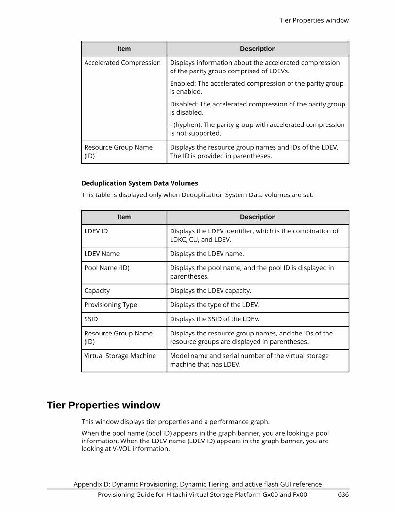
Item Description
Accelerated Compression Displays information about the accelerated compressionof the parity group comprised of LDEVs.
Enabled: The accelerated compression of the parity groupis enabled.
Disabled: The accelerated compression of the parity groupis disabled.
- (hyphen): The parity group with accelerated compressionis not supported.
Resource Group Name(ID)
Displays the resource group names and IDs of the LDEV.The ID is provided in parentheses.
Deduplication System Data Volumes
This table is displayed only when Deduplication System Data volumes are set.
Item Description
LDEV ID Displays the LDEV identifier, which is the combination ofLDKC, CU, and LDEV.
LDEV Name Displays the LDEV name.
Pool Name (ID) Displays the pool name, and the pool ID is displayed inparentheses.
Capacity Displays the LDEV capacity.
Provisioning Type Displays the type of the LDEV.
SSID Displays the SSID of the LDEV.
Resource Group Name(ID)
Displays the resource group names, and the IDs of theresource groups are displayed in parentheses.
Virtual Storage Machine Model name and serial number of the virtual storagemachine that has LDEV.
Tier Properties windowThis window displays tier properties and a performance graph.
When the pool name (pool ID) appears in the graph banner, you are looking a poolinformation. When the LDEV name (LDEV ID) appears in the graph banner, you arelooking at V-VOL information.
Tier Properties window
Appendix D: Dynamic Provisioning, Dynamic Tiering, and active flash GUI referenceProvisioning Guide for Hitachi Virtual Storage Platform Gx00 and Fx00 636

For pools
The following tables list the Tier Properties information.
When selecting Entire Pool or Tiering Policy
Item Description
Entire Pool or TieringPolicy
Select the following resource to display the performancegraph.■ Entire Pool: Displays the performance graph of the
entire pool.■ Tiering Policy: Displays the performance graph of the
tiering policy.
All(0), and from Level1(1)to Level31(31)
Select the Tiering Policy.
The performance graph that corresponds to the selectedtiering policy appears.
From Level 6 (6) to Level 31 (31), the names of tieringpolicies can be changed. If these names have changed, thenew names appear.
Tier Properties window
Appendix D: Dynamic Provisioning, Dynamic Tiering, and active flash GUI referenceProvisioning Guide for Hitachi Virtual Storage Platform Gx00 and Fx00 637

Tier Properties table
Item Description
Pool Name (ID) Displays the pool name and ID.
Tier name Displays the tier names: Tier1, Tier2, Tier3, and Total. Eachcolumn displays information about the tier.
Drive Type/RPM Displays the data drive type and RPM of tier.
If multiple types exist in a tier, Mixed is displayed. For anexternal volume, Drive Type displays External Storage withthe value of the external LDEV tier rank.
Buffer Space Displays the following buffer spaces.■ New page assignment: Buffer spaces for new page
assignment.■ Tier relocation: Buffer spaces for tier relocation.
Capacity Displays the capacity of the pool and each tier.■ Total: displays the total capacity of each tier and a pool.
As for the pool comprised of pool volumes assigned bythe accelerated compression-enabled parity groups,the writable capacity may be smaller than thedisplayed capacity.
■ Used [Used%]: Displays the percentage of the usedcapacity for the pool and each tier. The field is updatedasynchronously with the Recent Tier Utilization tableand when the View Tier Properties window is opened.The Used Capacity of each tier can differ from the sumof the used capacities of all tiers.
Tiering Policy: tiering policy name: Displays the usedcapacity size and percentage related to the tiering-policy of the pool and each tier. This item displayswhen you make a Tiering Policy selection.
■ Used (Pre Processed Data): Displays the data capacitybefore the reduction provided by the capacity savingfunction.
Physical Capacity This item appears when Entire Pool is selected. In the tier1 of containing the pool-VOL supporting acceleratedcompression, the capacity which is assured of the writingof data appears. Hyphens are displayed in Tier 2 column,Tier 3 column, and Total column.■ Total: Displays the total capacity of tier 1.■ Used [Used%]: Displays the used capacity and
percentage of the tier 1.
Tier Properties window
Appendix D: Dynamic Provisioning, Dynamic Tiering, and active flash GUI referenceProvisioning Guide for Hitachi Virtual Storage Platform Gx00 and Fx00 638

Item Description
Total Capacity Displays the total capacity of each tier and total capacity ofthe pool.
Used Capacity (Used %) Displays the percentage of the used capacity for the pooland each tier. The field is updated asynchronously withthe Recent Tier Utilization table and when the View TierProperties window is opened. The Used Capacity of eachtier can differ from the sum of the used capacities of alltiers.
Tiering Policy: tieringpolicy name
Displays the used capacity size and percentage related tothe tiering-policy of the pool and each tier. This itemdisplays when you make a Tiering Policy selection.
Current Average Numberof I/O(per Hour)
Displays the actual monitored average I/Os andpercentages of each tier and entire pool for the periodfrom the creating of the pool to the current state. Thisitem appears when selecting of Entire Pool. In addition,the number of I/Os is initialized in cases of following, andthen I/Os are counted again:■ When monitoring information collection is completed.
■ When the number of tiers in a pool changes.■ When a tier location of the pool VOL changes by adding
a pool VOL.■ When multi tier pools are enabled after being invalid.■ When the fixed monitoring information is calculated
again.
For details about cases that the fixed monitoringinformation is calculated again, see Tier relocationrules, restrictions, and guidelines (on page 182) .
Recent Tier Utilization (monitoring period) table
Item Description
Header area If an error occurs, a message appears.
Tier name Displays the tier names: Tier1, Tier2, Tier3, and Total. Eachcolumn displays information about the tier.
Performance Utilization Displays the percentage of progress in performanceutilization processing.
Tier Properties window
Appendix D: Dynamic Provisioning, Dynamic Tiering, and active flash GUI referenceProvisioning Guide for Hitachi Virtual Storage Platform Gx00 and Fx00 639

Item Description
Average Number of I/Os(per Hour)
Displays the average number of I/Os in a pool and eachtier.
Actual: Displays the actual monitored average I/Os andpercentages for each tier and a pool on an hourly basis.*This item appears when selecting the Entire Pool option.
Target: Displays the target average I/Os and percentagesfor each tier and a pool after the tier determinationcalculation.* This item appears when selecting the EntirePool option.
Tiering Policy: tiering policy name: Displays the averagenumber of I/Os for the pool and each tier that are relatedto the tiering-policy. This item displays when you make aTiering Policy selection.*
* This field is updated when performance monitoring information is collected,asynchronously with Used Capacity (Used %). If ? is displayed, take the actionsdisplayed in the header area of the Recent Tier Utilization table. If an error messageand countermeasure are not shown in the header area of the Recent Tier Utilizationtable, refresh the window. If ? continues to be displayed, call customer support.
Performance Graph
Item Description
Performance graph Displays the performance graph of the entire pool ortiering policy.
Pool If Entire Pool and the period mode of the monitoringmode are specified, this item appears. When this checkbox is selected, the performance graph appears. Thevertical scale of the performance graph indicates theaverage number of I/Os on an hourly basis. The horizontalscale of the performance graph indicates the capacity.
If there is no monitor data, this item does not appear.
Pool(Weighted average) If Entire Pool and the continuous mode of the monitoringmode are specified, this item appears. When this checkbox is selected, the performance graph appears. Thevertical scale indicates the average number of I/Os on anhourly basis. The number of I/Os is a weighted, averagedwith the monitoring data from the past cycle weightedagainst the monitoring data from the current cycle. Thehorizontal scale indicates the capacity.
If there is no monitor data, this item does not appear.
Tier Properties window
Appendix D: Dynamic Provisioning, Dynamic Tiering, and active flash GUI referenceProvisioning Guide for Hitachi Virtual Storage Platform Gx00 and Fx00 640

Item Description
Policy If Tiering Policy and the period mode of the monitoringmode are specified, this item appears. When the checkbox is selected, the performance graph appears. Thevertical scale of the performance graph indicates theaverage number of I/Os on an hourly basis. The horizontalscale of the performance graph indicates the capacity.
If there is no monitor data, this item does not appear.
Policy(Weighted average) If Tiering Policy and the continuous mode of themonitoring mode are specified, this item appears. Whenthe check box is selected, the performance graph appears.The vertical scale of the performance graph indicates theaverage number of I/Os on an hourly basis. The horizontalscale of the performance graph indicates the capacity.
If there is no monitor data, this item does not appear.
Tier1 Displays the performance graph of tier1. The vertical scaleindicates the average number of I/Os on an hourly basis.The horizontal scale indicates the capacity.
If there is no monitor data in tier1, this item does notappear.
Tier2 Displays the performance graph of tier2. The vertical scaleindicates the average number of I/Os on an hourly basis.The horizontal scale indicates the capacity.
If there is no monitor data in tier2, this item does notappear.
Tier3 Displays the performance graph of tier3. The vertical scaleindicates the average number of I/Os on an hourly basis.The horizontal scale indicates the capacity.
If there is no monitor data in tier3, this item does notappear.
Tier1 range Displays the range in tier1.
If there is no monitor data in tier1, this item does notappear.
Tier2 range Displays the range in tier2.
If there is no monitor data in tier2, this item does notappear.
The following describes how to read the performance graph when it contains poolinformation.
The vertical scale of the graph indicates an average number of I/Os by each hour and thehorizontal scale indicates capacity (GB) of the area where the I/Os are performed.
Tier Properties window
Appendix D: Dynamic Provisioning, Dynamic Tiering, and active flash GUI referenceProvisioning Guide for Hitachi Virtual Storage Platform Gx00 and Fx00 641
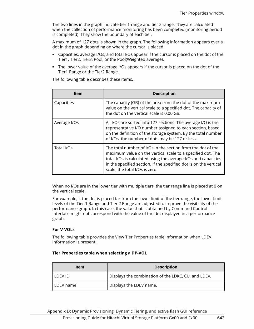
The two lines in the graph indicate tier 1 range and tier 2 range. They are calculatedwhen the collection of performance monitoring has been completed (monitoring periodis completed). They show the boundary of each tier.
A maximum of 127 dots is shown in the graph. The following information appears over adot in the graph depending on where the cursor is placed.■ Capacities, average I/Os, and total I/Os appear if the cursor is placed on the dot of the
Tier1, Tier2, Tier3, Pool, or the Pool(Weighted average).■ The lower value of the average I/Os appears if the cursor is placed on the dot of the
Tier1 Range or the Tier2 Range.
The following table describes these items.
Item Description
Capacities The capacity (GB) of the area from the dot of the maximumvalue on the vertical scale to a specified dot. The capacity ofthe dot on the vertical scale is 0.00 GB.
Average I/Os All I/Os are sorted into 127 sections. The average I/O is therepresentative I/O number assigned to each section, basedon the definition of the storage system. By the total numberof I/Os, the number of dots may be 127 or less.
Total I/Os The total number of I/Os in the section from the dot of themaximum value on the vertical scale to a specified dot. Thetotal I/Os is calculated using the average I/Os and capacitiesin the specified section. If the specified dot is on the verticalscale, the total I/Os is zero.
When no I/Os are in the lower tier with multiple tiers, the tier range line is placed at 0 onthe vertical scale.
For example, if the dot is placed far from the lower limit of the tier range, the lower limitlevels of the Tier 1 Range and Tier 2 Range are adjusted to improve the visibility of theperformance graph. In this case, the value that is obtained by Command ControlInterface might not correspond with the value of the dot displayed in a performancegraph.
For V-VOLs
The following table provides the View Tier Properties table information when LDEVinformation is present.
Tier Properties table when selecting a DP-VOL
Item Description
LDEV ID Displays the combination of the LDKC, CU, and LDEV.
LDEV name Displays the LDEV name.
Tier Properties window
Appendix D: Dynamic Provisioning, Dynamic Tiering, and active flash GUI referenceProvisioning Guide for Hitachi Virtual Storage Platform Gx00 and Fx00 642

Item Description
Tiering Policy Displays the tiering policy name and ID.
New Page AssignmentTier
Displays the new page assigned tier.
Tier Relocation Displays whether tier relocation is set to Enabled orDisabled.
Relocation Priority Displays the relocation priority.
Tier name Displays the tier names: Tier1, Tier2, Tier3, and Total. Eachcolumn displays information about the tier.
Drive Type/RPM Displays the data drive type and RPM of tier.
If multiple types exist in a tier, Mixed is displayed. For anexternal volume, Drive Type displays External Storage withthe value of the external LDEV tier rank.
Pool Capacity Displays the total capacity of each tier and total capacity ofthe pool.
Used Capacity (Used %) Displays the percentage of the used capacity for the pooland each tier. The field is updated asynchronously withthe Recent Tier Utilization table and when the View TierProperties window is opened. The Used Capacity of eachtier might differ from the sum of the used capacities of alltiers.
Current Average Numberof I/O(per Hour)
Displays the actual monitored average I/Os andpercentages of each tier and entire pool for the periodfrom the creating of the DP-VOL to the current state. Inaddition, the number of I/Os is initialized in cases offollowing, and then I/Os are counted again:■ When monitoring information collection is completed.
■ When the number of tiers in a pool changes.■ When a tier location of the pool VOL changes by adding
a pool VOL.■ When multi tier pools are enabled after being invalid.■ When the fixed monitoring information is calculated
again.
For details about cases that the fixed monitoringinformation is calculated again, see Tier relocationrules, restrictions, and guidelines (on page 182) .
Tier Properties window
Appendix D: Dynamic Provisioning, Dynamic Tiering, and active flash GUI referenceProvisioning Guide for Hitachi Virtual Storage Platform Gx00 and Fx00 643

Recent Tier Utilization (monitoring period) table
Item Description
Header area If a error occurs, a message appears.
Tier name Displays the tier names: Tier1, Tier2, Tier3, and Total. Eachcolumn displays information about the tier.
Average Number of I/O(per Hour)
■ Displays the actual monitored average I/Os andpercentages of each tier and a DP-VOL on an hourlybasis.*
■ Target: Displays the target average I/Os andpercentages of each tier and a DP-VOL after the tierdetermination calculation.
* This field is updated when performance monitoring information is collected,asynchronously with Used Capacity (Used %). If ? is displayed, take the actionsdisplayed in the header area of the Recent Tier Utilization table. If an error messageand countermeasure are not shown in the header area of the Recent Tier Utilizationtable, refresh the window. If ? continues to display, call the customer support.
Performance Graph
Item Description
Performance graph Displays the performance graph of the entire pool ortiering policy.
Volume If the period mode of the monitoring mode is specified,this item appears. When this check box is selected, theperformance graph appears. The vertical scale of theperformance graph indicates the average number of I/Oson an hourly basis. The horizontal scale of theperformance graph indicates the capacity.
If there is no monitor data, this item does not appear.
Volume(Weightedaverage)
If the continuous mode of the monitoring mode isspecified, this item appears. When this check box isselected, the performance graph appears. The verticalscale indicates the average number of I/Os on an hourlybasis. The number of I/Os is a weighted, averaged with themonitoring data from the past cycle weighted against themonitoring data from the current cycle. The horizontalscale indicates the capacity.
If there is no monitor data, this item does not appear.
Tier Properties window
Appendix D: Dynamic Provisioning, Dynamic Tiering, and active flash GUI referenceProvisioning Guide for Hitachi Virtual Storage Platform Gx00 and Fx00 644

Item Description
Tier1 Displays the performance graph of tier1. The vertical scaleindicates the average number of I/Os on an hourly basis.The horizontal scale indicates the capacity.
If there is no monitor data in tier1, this item does notappear.
Tier2 Displays the performance graph of tier2. The vertical scaleindicates the average number of I/Os on an hourly basis.The horizontal scale indicates the capacity.
If there is no monitor data in tier2, this item does notappear.
Tier3 Displays the performance graph of tier3. The vertical scaleindicates the average number of I/Os on an hourly basis.The horizontal scale indicates the capacity.
If there is no monitor data in tier3, this item does notappear.
Tier1 range Displays the range in tier1.
If there is no monitor data in tier1, this item does notappear.
Tier2 range Displays the range in tier2.
If there is no monitor data in tier2, this item does notappear.
The following describes how to read the performance graph when LDEV information ispresented.
The vertical scale of the graph indicates an average number of I/Os by each hour and thehorizontal scale indicates a capacity, in GB, of the area where the I/Os are performed.
The two lines in the graph indicate tier 1 range and tier 2 range. These ranges arecalculated when the collection of performance monitoring data is complete (monitoringperiod is completed). They show the boundary of each tier.
A maximum of 127 dots is shown in the graph. The following information appears over adot in the graph depending on where the cursor is placed.■ Capacities, average I/Os, and total I/Os appear if the cursor is placed on the dot of the
Tier1, Tier2, Tier3, Volume or the Volume(Weighted average).■ The lower value of the average I/Os appears if the cursor is placed on the dot of the
Tier1 Range or the Tier2 Range.
The following table describes these items.
Tier Properties window
Appendix D: Dynamic Provisioning, Dynamic Tiering, and active flash GUI referenceProvisioning Guide for Hitachi Virtual Storage Platform Gx00 and Fx00 645

Item Description
Capacities The capacity (GB) of the area from the dot of the maximumvalue on the vertical scale to a specified dot. The capacity ofthe dot on the vertical scale is 0.00 GB.
Average I/Os All I/Os are sorted into 127 sections. The average I/O is therepresentative I/O number assigned to each section, basedon the definition of the storage system. By the total numberof I/Os, the number of dots may be 127 or less.
Total I/Os The total number of I/Os in the section from the dot of themaximum value on the vertical scale to a specified dot. Thetotal I/Os is calculated using the average I/Os and capacitiesin the specified section. If the specified dot is on the verticalscale, the total I/Os is zero.
When no I/Os are in the lower tier with multiple tiers, the tier range line is placed at 0 onthe vertical scale.
Monitor Pools window
Selected Pools table
Item Description
Pool Name (ID) Displays the pool name and pool ID.
Number of Pool VOLs Displays the number of pool-VOLs in the selected pool.
Monitor Pools window
Appendix D: Dynamic Provisioning, Dynamic Tiering, and active flash GUI referenceProvisioning Guide for Hitachi Virtual Storage Platform Gx00 and Fx00 646

Item Description
Capacity Displays the information about the pool capacity.■ Total: Total capacity of pool.
Using Option, you can select unit of capacity.● One block equals 512 bytes and one page equals 42
megabytes in a pool capacity of DynamicProvisioning, Dynamic Tiering,active flash, or ThinImage.
■ Mapped: Page capacity of the pool in which user dataand control information is stored.
■ Mapped (%): Percentages of the page capacity of thepool that contains user data and control information.
Mapped (%) displays the value which is truncated afterthe decimal point of the actual value.
Recent Monitor Data Displays the period of monitoring time as follows:
start-time-end-time
If the monitoring data is being obtained, only the startingtime is displayed.
If the latest monitoring data does not exist, a hyphen (-) isdisplayed.
Stop Monitoring Pools window
Stop Monitoring Pools window
Appendix D: Dynamic Provisioning, Dynamic Tiering, and active flash GUI referenceProvisioning Guide for Hitachi Virtual Storage Platform Gx00 and Fx00 647

Selected Pools table
Item Description
Pool Name (ID) Displays the pool name and pool ID.
Number of Pool VOLs Displays the number of pool-VOLs in the selected pool.
Capacity Displays the information about the pool capacity.■ Total: Total capacity of pool.
Using Option, you can select unit of capacity.● One block equals 512 bytes and one page equals 42
megabytes in a pool capacity of DynamicProvisioning, Dynamic Tiering,active flash, or ThinImage.
■ Mapped: Page capacity of the pool in which user dataand control information is stored.
■ Mapped (%): Percentages of the page capacity of thepool that contains user data and control information.
Mapped (%) displays the value which is truncated afterthe decimal point of the actual value.
Recent Monitor Data Displays the period of monitoring time as follows:
start-time-end-time
If the monitoring data is being obtained, only the startingtime is displayed.
If the latest monitoring data does not exist, a hyphen (-) isdisplayed.
Stop Monitoring Pools window
Appendix D: Dynamic Provisioning, Dynamic Tiering, and active flash GUI referenceProvisioning Guide for Hitachi Virtual Storage Platform Gx00 and Fx00 648

Start Tier Relocation window
Selected Pools table
Item Description
Pool Name (ID) Displays the pool name and pool ID.
Number of Pool VOLs Displays the number of pool-VOLs in the selected pool.
Capacity Displays the information about the pool capacity.■ Total: Total capacity of pool.
Using Option, you can select unit of capacity.● One block equals 512 bytes and one page equals 42
megabytes in a pool capacity of DynamicProvisioning, Dynamic Tiering, active flash, or ThinImage.
■ Mapped: Page capacity of the pool in which user dataand control information is stored.
■ Mapped (%): Percentages of the page capacity of thepool that contains user data and control information.
Mapped (%) displays the value which is truncated afterthe decimal point of the actual value.
Start Tier Relocation window
Appendix D: Dynamic Provisioning, Dynamic Tiering, and active flash GUI referenceProvisioning Guide for Hitachi Virtual Storage Platform Gx00 and Fx00 649

Item Description
Recent Monitor Data Displays the period of monitoring time as follows:
start-time-end-time
If the monitoring data is being obtained, only the startingtime is displayed.
If the latest monitoring data does not exist, a hyphen (-) isdisplayed.
Relocation Speed Displays the tier relocation speed: 1(Slowest), 2(Slower),3(Standard), 4(Faster), or 5(Fastest)
Stop Tier Relocation window
Selected Pools table
Item Description
Pool Name (ID) Displays the pool name and pool ID.
Number of Pool VOLs Displays the number of pool-VOLs in the selected pool.
Stop Tier Relocation window
Appendix D: Dynamic Provisioning, Dynamic Tiering, and active flash GUI referenceProvisioning Guide for Hitachi Virtual Storage Platform Gx00 and Fx00 650

Item Description
Capacity Displays the information about the pool capacity.■ Total: Total capacity of pool.
Using Option, you can select unit of capacity.● One block equals 512 bytes and one page equals 42
megabytes in a pool capacity of DynamicProvisioning, Dynamic Tiering, active flash, or ThinImage.
■ Mapped: Page capacity of the pool in which user dataand control information is stored.
■ Mapped (%): Percentages of the page capacity of thepool that contains user data and control information.
Mapped (%) displays the value which is truncated afterthe decimal point of the actual value.
Recent Monitor Data Displays the period of monitoring time as follows:
start-time-end-time
If the monitoring data is being obtained, only the startingtime is displayed.
If the latest monitoring data does not exist, a hyphen (-) isdisplayed.
Relocation Progress(%) Displays the progress percentage of the tier relocation.
0 to 99: The relocation is performed at the indicatedpercentage progression.
100: The relocation operation is not in performed, or therelocation is complete.
For details about the tier relocation, see the tier relocationlog file.
Relocation Speed Displays the tier relocation speed: 1(Slowest), 2(Slower),3(Standard), 4(Faster), or 5(Fastest)
Stop Tier Relocation window
Appendix D: Dynamic Provisioning, Dynamic Tiering, and active flash GUI referenceProvisioning Guide for Hitachi Virtual Storage Platform Gx00 and Fx00 651
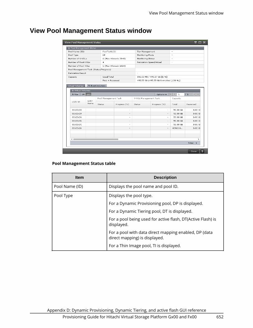
View Pool Management Status window
Pool Management Status table
Item Description
Pool Name (ID) Displays the pool name and pool ID.
Pool Type Displays the pool type.
For a Dynamic Provisioning pool, DP is displayed.
For a Dynamic Tiering pool, DT is displayed.
For a pool being used for active flash, DT(Active Flash) isdisplayed.
For a pool with data direct mapping enabled, DP (datadirect mapping) is displayed.
For a Thin Image pool, TI is displayed.
View Pool Management Status window
Appendix D: Dynamic Provisioning, Dynamic Tiering, and active flash GUI referenceProvisioning Guide for Hitachi Virtual Storage Platform Gx00 and Fx00 652

Item Description
Number of V-VOLs Displays the number of V-VOLs associated with the pool,and the maximum number of V-VOLs that can beassociated with the pool.
If you select a Dynamic Provisioning, Dynamic Tiering, oractive flash pool, this item appears.
If the pool with the data direct mapping attribute isselected, the number of the V-VOLs is displayed, then ahyphen appears for the maximum number of V-VOLswhich can associate with the pool.
Number of Root VOLs Displays the number of root volumes of Thin Image pairsthat are associated with the pool.
Number of Pool VOLs Displays the number of pool-VOLs set for the pool, andthe maximum number of pool-VOLs that can be set forthe pool.
Pool Management Task(Status/Progress)
Displays the status and progress ratio of the poolmanagement task being performed to the pool, andaverage progress ratio of each V-VOL in the pool.
Waiting for Rebalance: The rebalance process is beingwaited.
Rebalancing: The rebalance process is being performed.
Waiting for Relocation: The tier relocation process is beingwaited.
Relocating: The tier relocation process is being performed.
Waiting for Shrink: The pool shrinking process is beingwaited.
Shrinking: The pool shrinking process is being performed.
Blank:The pool management task is not being performedto the pool.
The following values that are displayed in the VirtualVolume table or in the Root Volumes table might notcorrespond with the value displayed for this item. This isbecause the progress of the pool management task iscalculated after the progress of each V-VOL displayed inthe Virtual Volume table or the Root Volumes table iscalculated.■ Pool Management Task - Status■ Pool Management Task - Progress(%)
For details about the tier relocation, see the tier relocationlog file.
View Pool Management Status window
Appendix D: Dynamic Provisioning, Dynamic Tiering, and active flash GUI referenceProvisioning Guide for Hitachi Virtual Storage Platform Gx00 and Fx00 653
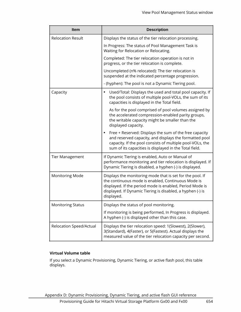
Item Description
Relocation Result Displays the status of the tier relocation processing.
In Progress: The status of Pool Management Task isWaiting for Relocation or Relocating.
Completed: The tier relocation operation is not inprogress, or the tier relocation is complete.
Uncompleted (n% relocated): The tier relocation issuspended at the indicated percentage progression.
- (hyphen): The pool is not a Dynamic Tiering pool.
Capacity ■ Used/Total: Displays the used and total pool capacity. Ifthe pool consists of multiple pool-VOLs, the sum of itscapacities is displayed in the Total field.
As for the pool comprised of pool volumes assigned bythe accelerated compression-enabled parity groups,the writable capacity might be smaller than thedisplayed capacity.
■ Free + Reserved: Displays the sum of the free capacityand reserved capacity, and displays the formatted poolcapacity. If the pool consists of multiple pool-VOLs, thesum of its capacities is displayed in the Total field.
Tier Management If Dynamic Tiering is enabled, Auto or Manual ofperformance monitoring and tier relocation is displayed. IfDynamic Tiering is disabled, a hyphen (-) is displayed.
Monitoring Mode Displays the monitoring mode that is set for the pool. Ifthe continuous mode is enabled, Continuous Mode isdisplayed. If the period mode is enabled, Period Mode isdisplayed. If Dynamic Tiering is disabled, a hyphen (-) isdisplayed.
Monitoring Status Displays the status of pool monitoring.
If monitoring is being performed, In Progress is displayed.A hyphen (-) is displayed other than this case.
Relocation Speed/Actual Displays the tier relocation speed: 1(Slowest), 2(Slower),3(Standard), 4(Faster), or 5(Fastest). Actual displays themeasured value of the tier relocation capacity per second.
Virtual Volume table
If you select a Dynamic Provisioning, Dynamic Tiering, or active flash pool, this tabledisplays.
View Pool Management Status window
Appendix D: Dynamic Provisioning, Dynamic Tiering, and active flash GUI referenceProvisioning Guide for Hitachi Virtual Storage Platform Gx00 and Fx00 654

Item Description
LDEV ID Displays the LDEV identifier, which is the combination ofLDKC, CU, and LDEV.
LDEV Name Displays the LDEV name.
Pool Management Task ■ Status: Displays the pool management task beingperformed to the pool.● Waiting for Rebalance: The rebalance process is
being waited.● Rebalancing: The rebalance process is being
performed.● Waiting for Relocation: The tier relocation process is
being waited.● Relocating: The tier relocation process is being
performed.● Waiting for Shrink: The pool shrinking process is
being waited.● Shrinking: The pool shrinking process is being
performed.● Blank: The pool management task is not being
performed to the pool.■ Progress(%): Displays V-VOL progress percentage (%) of
the pool management task being performed. A hyphen(-) is displayed when the pool management task is notperformed.
V-VOL Management Task ■ Status: Displays the V-VOL management task beingperformed to V-VOL.● Reclaiming Zero Pages: The zero page reclaim
processing that is being performed.● Waiting for Zero Page Reclaiming: The zero page
reclaim processing● Blank: The V-VOL management task is not being
performed to V-VOL.■ Progress(%): Displays the progress percentages (%) of
the V-VOL management task being performed. Ahyphen (-) is displayed when the V-VOL managementtask is not performed.
View Pool Management Status window
Appendix D: Dynamic Provisioning, Dynamic Tiering, and active flash GUI referenceProvisioning Guide for Hitachi Virtual Storage Platform Gx00 and Fx00 655

Item Description
Capacity Displays information about the V-VOL used capacity.■ Total: Displays the V-VOL capacity.■ Reserved: Displays the reserved page capacity of the V-
VOL.
The displayed value of Reserved might be larger thanthe displayed value of Total due to following reasons:● Reserved displays the sum of the used V-VOL
capacity and the reserved page capacity that isrounded up on each page.
● The mapped capacity of V-VOL for DynamicProvisioning includes the capacity of controlinformation (168 MB is required per 3,145,548 MB).
■ Used: Displays the sum of the mapped capacity andthe reserved page capacity.
The displayed value of Used might be larger than thedisplayed value of Total due to the following reasons:● Used displays the sum of the mapped capacity and
the reserved page capacity that is rounded up oneach page.
● The mapped capacity of DP-VOL includes thecapacity of the control information (uses amaximum of 168 MB per 3,145,548 MB).
● DP-VOL with data direct mapping enabled includesthe control information (168 MB is used per3,145,548 MB) and the capacity for one page.
If used capacity is referenced during I/O or copyprocessing by software such as ShadowImage orUniversal Replicator, the used capacity displayedmight be different from the actual capacity even ifthe full allocation is enabled on the V-VOL. This iscaused by a gap between the times that informationis gathered about the mapped capacity and thereserved capacity.
■ Used(%): For the entire capacity of V-VOL, this itemdisplays percentages of the sum of the mappedcapacity and the reserved capacity.
Full Allocation Displays the status of the setting for full allocation in apool that are associated with the V-VOL.■ Enable: Pages are reserved.■ Disable: Pages are not reserved.
View Pool Management Status window
Appendix D: Dynamic Provisioning, Dynamic Tiering, and active flash GUI referenceProvisioning Guide for Hitachi Virtual Storage Platform Gx00 and Fx00 656

Item Description
Tiering Policy Displays the tiering policy name and ID.■ All(0): Policy in which all tiers of the pool are used.■ Level1(1) - Level5(5):Policy selected from levels 1 to 5 is
set to the V-VOL.■ Level6(6) - Level31(31): Policy defined by the user and
set to the V-VOL. From Level 6 (6) to Level 31 (31), thenames of tiering policies can be changed. If thesenames have changed, the new names appear.
■ - (hyphen): V-VOL is not the V-VOL of Dynamic TieringV-VOL.
New Page AssignmentTier
Displays the new page assigned tier.■ High: High is set to V-VOL.■ Middle: Middle is set to V-VOL.■ Low: Low is set to V-VOL.■ - (hyphen): V-VOL is not the Dynamic Tieringor active
flash V-VOL.
Tier Relocation Displays whether tier relocation is set to enable or disable.If the Dynamic Tieringor active flash V-VOL is not used, ahyphen (-) is displayed.
Relocation Priority Displays the relocation priority.■ Prioritized: The priority is set to the V-VOL.■ Blank: The priority is not set to the V-VOL.■ - (hyphen): V-VOL is not the Dynamic Tiering or active
flash V-VOL or the tier relocation function is disabled.
View Pool Management Status window
Appendix D: Dynamic Provisioning, Dynamic Tiering, and active flash GUI referenceProvisioning Guide for Hitachi Virtual Storage Platform Gx00 and Fx00 657

Item Description
Attribute Displays the attribute of the LDEV.■ TSE: TSE-VOL for Compatible FlashCopy® SE.■ Data Direct Mapping: LDEV with the data direct
mapping attribute enabled.■ NAS Platform (User LU): LDEV used for storing the NAS
user data. This value appears if the NAS module isinstalled.
■ NAS Platform (System LU): LDEV used for storing theNAS firmware system data. This value appears if theNAS module is installed.
■ Deduplication System Data Volume: LDEV used tomanage data deduplication.
■ - (hyphen): Volume in which the attribute is notdefined.
Virtual Storage Machine Information about the virtual storage machine.■ Model / Serial Number: Model name and serial number
of the virtual storage machine to which the LDEVbelongs.
■ LDEV ID: Virtual LDEV ID. If a Virtual LDEV ID is notassigned to the LDEV, this column is blank.
■ Device Name: Virtual device name, which is acombination of the virtual emulation type, virtual LUSEvolume number, and the virtual CVS attribute. Valuesof the virtual emulation type, virtual LUSE volumenumber, and virtual CVS attribute appear only for itemsthat have been set. This column is blank when thevirtual emulation type, virtual LUSE volume number,and virtual CVS attribute are not set. If the virtual CVSattribute is set, CVS is attached as the suffix to thedevice name.
■ SSID: Virtual SSID. If a Virtual SSID is not set for theLDEV, this column is blank.
Root Volumes table or TI Root Volumes table■ When you select a Thin Image pool, the Root Volumes tab is displayed.■ When you select a Dynamic Provisioning pool, the TI Root Volumes tab is displayed.
View Pool Management Status window
Appendix D: Dynamic Provisioning, Dynamic Tiering, and active flash GUI referenceProvisioning Guide for Hitachi Virtual Storage Platform Gx00 and Fx00 658

Item Description
LDEV ID Displays the LDEV identifier which is the combination ofLDKC, CU, and LDEV.
LDEV Name Displays the LDEV name.
Pool Management Task --Status
Displays the pool management task being performed tothe pool.■ Waiting for Rebalance: The rebalance process is being
waited.■ Rebalancing: The rebalance process is being
performed.■ Waiting for Shrink: The pool shrinking process is being
waited.■ Shrinking: The pool shrinking process is being
performed.■ Blank: The pool management task is not being
performed to the pool.
Pool Management Task --Progress (%)
Displays a progress percentage (%) of a pool managementtask being performed on each primary volume. A hyphen(-) is displayed when the pool management task is notperformed.
Used Pool Capacity Displays the used pool capacity.
Pool Usage(%) Displays the pool usage ratio.
Virtual Storage Machine Information about the virtual storage machine.■ Model / Serial Number: Model name and serial number
of the virtual storage machine that has LDEV.■ LDEV ID: Virtual LDEV ID. If a Virtual LDEV ID is not
assigned to LDEV, this column is blank.■ Device Name: Virtual device name, which is a
combination of the virtual emulation type, virtual LUSEvolume number, and the virtual CVS attribute. Valuesof the virtual emulation type, virtual LUSE volumenumber, and virtual CVS attribute appear only for itemsthat have been set. This column is blank when thevirtual emulation type, virtual LUSE volume number,and virtual CVS attribute are not set. If the virtual CVSattribute is set, CVS is attached as the suffix to thedevice name.
■ SSID: Virtual SSID. If Virtual SSID is not set for LDEV, thiscolumn is blank.
View Pool Management Status window
Appendix D: Dynamic Provisioning, Dynamic Tiering, and active flash GUI referenceProvisioning Guide for Hitachi Virtual Storage Platform Gx00 and Fx00 659

Edit External LDEV Tier Rank wizard
Edit External LDEV Tier Rank window
Selected Pool Volumes table
Item Description
LDEV ID Displays the combination of the LDKC, CU, and LDEV.
LDEV Name Displays the LDEV name.
Parity Group ID Displays the parity group ID.
Usable Capacity The usable capacity in the pool-VOL that is offset on thebasis of the page appears. For the pool-VOL with systemarea, the displayed capacity does not include the capacityof the management area.
External LDEV Tier Rank Displays the tier rank of the external volume.
Change Changes the tier rank of the selected pool-VOL to High,Middle, or Low.
Edit External LDEV Tier Rank wizard
Appendix D: Dynamic Provisioning, Dynamic Tiering, and active flash GUI referenceProvisioning Guide for Hitachi Virtual Storage Platform Gx00 and Fx00 660

Edit External LDEV Tier Rank confirmation window
Selected Pool table
Item Description
Pool Name (ID) Displays the pool name and pool ID.
Selected Pool Volumes table
Item Description
LDEV ID Displays the combination of the LDKC, CU, and LDEV.
LDEV Name Displays the LDEV name.
Parity Group ID Displays the parity group ID.
Usable Capacity The usable capacity in the pool-VOL that is offset on thebasis of the page appears. For the pool-VOL with systemarea, the displayed capacity does not include the capacityof the management area.
External LDEV Tier Rank Displays the tier rank of the external volume.
Edit External LDEV Tier Rank confirmation window
Appendix D: Dynamic Provisioning, Dynamic Tiering, and active flash GUI referenceProvisioning Guide for Hitachi Virtual Storage Platform Gx00 and Fx00 661

Edit Tiering Policies wizard
Edit Tiering Policies window
Tiering Policies table
Item Description
ID Displays the ID of the tiering policy.
Tiering Policy Displays the name of the tiering policy.
Tier1 Max(%) Displays the maximum percentage that is allocated to tier1 in the total capacity to which tier relocation isperformed. For a policy with an ID from 0 to 5, a hyphen (-)is displayed.
Tier1 Min(%) Displays the minimum percentage that is allocated to tier1 in the total capacity to which tier relocation isperformed. For a policy whose ID is from 0 to 5, a hyphen(-) is displayed.
Tier3 Max(%) Displays the maximum percentage that is allocated to tier3 in the total capacity to which tier relocation isperformed. For a policy with an ID from 0 to 5, a hyphen (-)is displayed.
Edit Tiering Policies wizard
Appendix D: Dynamic Provisioning, Dynamic Tiering, and active flash GUI referenceProvisioning Guide for Hitachi Virtual Storage Platform Gx00 and Fx00 662

Item Description
Tier3 Min(%) Displays the minimum percentage that is allocated to tier3 in the total capacity to which tier relocation isperformed. For a policy whose ID is from 0 to 5, a hyphen(-) is displayed.
Number of V-VOLs Displays the number of V-VOLs to which the tiering policyis set.
Change Displays the Change Tiering Policy window when youselect the row and click this button.
A policy with an ID is from 0 to 6 cannot be changed.
Edit Tiering Policies confirmation window
Tiering Policies table
Item Description
ID Displays the ID of the tiering policy.
Tiering Policy Displays the name of the tiering policy.
Edit Tiering Policies confirmation window
Appendix D: Dynamic Provisioning, Dynamic Tiering, and active flash GUI referenceProvisioning Guide for Hitachi Virtual Storage Platform Gx00 and Fx00 663

Item Description
Tier1 Max(%) Displays the maximum percentage that is allocated to tier1 in the total capacity to which tier relocation isperformed. For a policy with an ID from 0 to 5, a hyphen (-)is displayed.
Tier1 Min(%) Displays the minimum percentage that is allocated to tier1 in the total capacity to which tier relocation isperformed. For a policy whose ID is from 0 to 5, a hyphen(-) is displayed.
Tier3 Max(%) Displays the maximum percentage that is allocated to tier3 in the total capacity to which tier relocation isperformed. For a policy with an ID from 0 to 5, a hyphen (-)is displayed.
Tier3 Min(%) Displays the minimum percentage that is allocated to tier3 in the total capacity to which tier relocation isperformed. For a policy whose ID is from 0 to 5, a hyphen(-) is displayed.
Number of V-VOLs Displays the number of V-VOLs to which the tiering policyis set.
Change Tiering Policy window
Item Description
ID Displays the ID of the tiering policy.
Change Tiering Policy window
Appendix D: Dynamic Provisioning, Dynamic Tiering, and active flash GUI referenceProvisioning Guide for Hitachi Virtual Storage Platform Gx00 and Fx00 664

Item Description
Tiering Policy Specify the tiering policy name. You can enter up to 32alphanumeric characters. The name is case-sensitive. Thefollowing symbols cannot be used in the name:
\ / : , ; * ? " < > |
Tier1 Max(%) Set the maximum percentage that is allocated to tier 1 inthe total capacity for the tier relocation from 0 (%) to 100(%). The setting value is needed to satisfy either one offollowing conditions:
Equal to Tier1 Min
Larger than Tier1 Min
Tier1 Min(%) Set the minimum percentage that is allocated to tier 1 inthe total capacity for the tier relocation from 0 (%) to 100(%). The setting value is needed to satisfy either one offollowing conditions:
Equal to Tier1 Max
Smaller than Tier1 Max
Tier3 Max(%) Set the maximum percentage that is allocated to tier 3 inthe total capacity for the tier relocation from 0 (%) to 100(%). The setting value is needed to satisfy either one offollowing conditions:
Equal to Tier1 Min
Larger than Tier1 Min
Tier3 Min(%) Set the minimum percentage that is allocated to tier 3 inthe total capacity for the tier relocation from 0 (%) to 100(%). The setting value is needed to satisfy either one offollowing conditions:
Equal to Tier1 Max
Smaller than Tier1 Max
Note: The total of Tier1 Min and Tier3 Min must be 100(%) or less.
Change Tiering Policy window
Appendix D: Dynamic Provisioning, Dynamic Tiering, and active flash GUI referenceProvisioning Guide for Hitachi Virtual Storage Platform Gx00 and Fx00 665

Change Pool Configuration Pattern window
For Dynamic Provisioning pools
When you create a Dynamic Provisioning pool, the following table displays.
Pool Configuration Patterns table
Item Description
Priority Displays the priority of the pool configuration.
Selected Displays whether the pool configuration is selected or not.
Total Capacity Displays the total capacity of the pool.
Drive Type/RPM Displays the data drive type and RPM of the pool.
RAID Level Displays the RAID level of the pool.
Select If the pool configuration is changed, select a row in thePool Configuration Patterns table. Then click this button.The selected pool configuration is reflected to the poolsetting.
Change Pool Configuration Pattern window
Appendix D: Dynamic Provisioning, Dynamic Tiering, and active flash GUI referenceProvisioning Guide for Hitachi Virtual Storage Platform Gx00 and Fx00 666

For Dynamic Tiering pools
When you create a Dynamic Tiering pool, the following table displays.
Pool Configuration Patterns table
Item Description
Priority Displays the priority of the pool configuration.
Selected Displays whether the pool configuration is selected or not.
Total Capacity Displays the total capacity of the pool
Tier 1 Displays the tier 1 information.
Drive Type/RPM: Displays the data drive type and RPM ofpool-VOLs.
RAID Level: Displays the RAID level of pool-VOLs.
Rate (%): Displays the percentage of the tier 1 against thetotal capacity of the pool.
Tier 2 Displays the tier 2 information.
Drive Type/RPM: Displays the data drive type and RPM ofpool-VOLs.
RAID Level: Displays the RAID level of pool-VOLs.
Rate (%): Displays the percentage of the tier 2 against thetotal capacity of the pool.
Change Pool Configuration Pattern window
Appendix D: Dynamic Provisioning, Dynamic Tiering, and active flash GUI referenceProvisioning Guide for Hitachi Virtual Storage Platform Gx00 and Fx00 667

Item Description
Tier 3 Displays the tier 3 information.
Drive Type/RPM: Displays the data drive type and RPM ofpool-VOLs.
RAID Level: Displays the RAID level of pool-VOLs.
Rate (%): Displays the percentage of the tier 3 against thetotal capacity of the pool.
Select If the pool configuration is changed, select a row in thePool Configuration Patterns table. Then click this button.The selected pool configuration is reflected to the poolsetting.
Change Deduplication System Data Volume Options windowUse this window to change the options for a deduplication system data volume for apool. To open this window, select the pool on the Pools window, click More Actions > EditPools to open the Edit Pools window, click Edit Deduplication System Data Volume toopen the Edit Deduplication System Data Volume window, select the deduplicationsystem data volume, and then click Change Deduplication System Data Volume Options.
Item Description
Provisioning Type Displays the provisioning type of the deduplication systemdata volume, which is Dynamic Provisioning.
Change Deduplication System Data Volume Options window
Appendix D: Dynamic Provisioning, Dynamic Tiering, and active flash GUI referenceProvisioning Guide for Hitachi Virtual Storage Platform Gx00 and Fx00 668

Item Description
Capacity Displays 40 TB for the capacity of the deduplicationsystem data volume.
LDEV Name Specify the LDEV name.■ Prefix: Fixed character string.■ Initial Number: Initial number.
Specify the initial number according to these examples.■ 1: Up to 9 numbers are added (1, 2, 3 ... 9).■ 08: Up to 92 numbers are added (08, 09, 10 ... 99).■ 23: Up to 77 numbers are added (23, 24, 25 ... 99).■ 098: Up to 902 numbers are added (098, 099, 100 ...
999).
Initial LDEV ID Specify the LDEV identifier, which is the combination ofLDKC, CU, and LDEV. Assigns the ID at a certain intervalstarting with the ID you specify.■ LDKC: Specify the LDKC number. It is fixed to 00.■ CU: Specify the CU number.■ DEV: Specify the LDEV number.■ Interval: Specify the interval of the assigned LDEV ID.■ View LDEV IDs: Opens the View LDEV IDs window.
Edit Deduplication System Data Volume windowUse this window to edit a deduplication system data volume for a pool. To open thiswindow, select the pool on the Pools window, click More Actions > Edit Pools to open theEdit Pools window, and then click Edit Deduplication System Data Volume.
Edit Deduplication System Data Volume window
Appendix D: Dynamic Provisioning, Dynamic Tiering, and active flash GUI referenceProvisioning Guide for Hitachi Virtual Storage Platform Gx00 and Fx00 669

Deduplication System Data Volume table
Item Description
LDEV ID Displays the LDEV identifier, which is the combination ofLDKC, CU, and LDEV.
LDEV Name Displays the LDEV name.
Pool Name (ID) Displays the pool name, and the pool ID is displayed inparentheses.
Capacity Displays the LDEV capacity.
Provisioning Type Displays the type of the LDEV.
Resource Group Name(ID)
Displays the resource group names, and the IDs of theresource groups are displayed in parentheses.
Virtual Storage Machine Model name and serial number of the virtual storagemachine that has LDEV.
Edit Deduplication System Data Volume window
Appendix D: Dynamic Provisioning, Dynamic Tiering, and active flash GUI referenceProvisioning Guide for Hitachi Virtual Storage Platform Gx00 and Fx00 670

Item Description
Change DeduplicationSystem Data VolumeOptions
Opens the Change Deduplication System Data VolumeOptions window for the selected deduplication systemdata volume.
Edit Deduplication System Data Volume window
Appendix D: Dynamic Provisioning, Dynamic Tiering, and active flash GUI referenceProvisioning Guide for Hitachi Virtual Storage Platform Gx00 and Fx00 671

Appendix D: Dynamic Provisioning, Dynamic Tiering, and active flash GUI referenceProvisioning Guide for Hitachi Virtual Storage Platform Gx00 and Fx00 672

Appendix E: Data Retention Utility GUI reference
The Data Retention Utility windows in Hitachi Device Manager - Storage Navigator displaythe Data Retention Utility information for the storage system and allow you to performData Retention Utility operations.
For general information about the Device Manager - Storage Navigator GUI, see theSystem Administrator Guide.
Data Retention windowUse the Data Retention window to assign an access attribute to open-system volumes.
Summary
Item Description
LDKC Select the LDKC which is displayed in the tree.
CU Group 00-3F: CUs from 00 to 3F appear in the tree.
Appendix E: Data Retention Utility GUI referenceProvisioning Guide for Hitachi Virtual Storage Platform Gx00 and Fx00 673

Item Description
Tree A list of CUs. Selecting a CU provides the selected CU informationin the volume list on the right of the tree.
This tree appears only the CUs that include volumes to whichaccess attributes can be actually set.
Volume list Lists information about the CU selected in the tree. See the tablebelow for details.
Expiration Lock Enables or disables enhanced volume protection.■ Disable > Enable: Indicates the expiration lock is disabled. You
can change an access attribute to read/write when theretention term is over.
■ Enable > Disable: Indicates the expiration lock is enabled. Youcannot change an access attribute to read/write even when theretention term is over.
Apply Applies settings to the storage system.
Cancel Discards setting changes.
Volume list
The volume list provides information about access attributes that are assigned tovolumes.
Item Description
LDEV LDEV number.■
: Read/write■
: Read-only■
: Protect
The symbol beside the LDEV number indicates:■ #: an external volume
■ A: LDEV of the ALU attribute.
■ S: LDEV of the SLU attribute.
■ V: a virtual volume
■ D: Deduplication System Data volume
■ X: a virtual volume used for Dynamic Provisioning
Data Retention window
Appendix E: Data Retention Utility GUI referenceProvisioning Guide for Hitachi Virtual Storage Platform Gx00 and Fx00 674

Item Description
Attribute Access attribute assigned to this volume. These attributes can beassigned using the Command Control Interface.■ Read/Write: Both read and writer operations are permitted on
the logical volume.■ Read-only: Read operations are permitted on the logical
volume.■ Protect: Neither read nor write operations are permitted.
Emulation Volume emulation types.
Capacity Capacity of each volume in GB to two decimal places.
S-VOL Indicates whether the volume can be specified as a secondaryvolume (S-VOL). You can also use the CCI to specify whether eachvolume can be used as an S-VOL.
Reserved Indicates the method that can be used to make LU path andcommand device settings.■ Hyphen (-): Both CCI and Hitachi Device Manager - Storage
Navigator can be used to make LU path and command devicesettings.
■ CCI: Only CCI can be used to make LU path and commanddevice settings. Hitachi Device Manager - Storage Navigatorcannot be used to do so.
Retention Term Period (in days) when you are prohibited from changing accessattribute to read/write. The retention term can be extended butcannot be shortened. During the retention term, you can changeread-only to protect, or vice versa.■ 500 days. Attempts to change access attribute to read/write are
prohibited in the next 500 days.■ Unlimited: The retention term is extended with no limits.■ 0 days: You can change access attribute to read/write.
Caution: In Data Retention Utility, you can increase the value forRetention Term, but cannot decrease the value.
Path Number of LU paths.
Data Retention window
Appendix E: Data Retention Utility GUI referenceProvisioning Guide for Hitachi Virtual Storage Platform Gx00 and Fx00 675

Item Description
Mode Indicates the mode that the CCI user assigns to the volume. Youcannot use Hitachi Device Manager - Storage Navigator to changemodes. You must use the CCI to change modes.■ Zer: Zero Read Cap mode is assigned to the volume. If the Read
Capacity command (which is a SCSI command) is issued to avolume in Zero Read Cap mode, it will be reported that thecapacity of the volume is zero.
■ Inv: Invisible mode is assigned to the volume. If the Inquirycommand (which is a SCSI command) is issued to a volume inInvisible mode, it will be reported that the volume does notexist. Therefore, the hosts will be unable to recognize thevolume.
■ Zer/Inv. Both Zero Read Cap mode and Invisible mode areassigned to the volume.
■ Hyphen (-): No mode is assigned by CCI to the volume.
Operation Target of the operation or the name of the operation. When nooperation is performed, No Operation appears.
Also shown are the volume icons and the total number of volumeswith each access attribute.
Error Detail dialog boxIf an error occurs with Data Retention Utility, the Error Detail dialog box appears. TheError Detail dialog box displays error locations and error messages.
Items Description
Location Location where the error occurred. If an error relating toa volume occurred, the LDKC number, CU number, andLDEV number (volume number) are shown.
Error Detail dialog box
Appendix E: Data Retention Utility GUI referenceProvisioning Guide for Hitachi Virtual Storage Platform Gx00 and Fx00 676

Items Description
Error Message Provides the full text of the error message. For detailsabout the solution, see the Hitachi Device Manager -Storage Navigator Messages.
Close Closes the Error Detail window.
Error Detail dialog box
Appendix E: Data Retention Utility GUI referenceProvisioning Guide for Hitachi Virtual Storage Platform Gx00 and Fx00 677

Appendix E: Data Retention Utility GUI referenceProvisioning Guide for Hitachi Virtual Storage Platform Gx00 and Fx00 678

Appendix F: LUN Manager GUI reference
The LUN Manager windows in Hitachi Device Manager - Storage Navigator display theLUN information for the storage system and allow you to configure and manage LUNs.
For general information about the Device Manager - Storage Navigator GUI, see theSystem Administrator Guide.
Ports/Host Groups/iSCSI Targets window
Summary
Item Description
Number of Ports Total number of ports.
Host Groups / iSCSI Targets tab
This tab provides information about the host groups and iSCSI targets that are assignedto the logged-on user.
Appendix F: LUN Manager GUI referenceProvisioning Guide for Hitachi Virtual Storage Platform Gx00 and Fx00 679

Item Description
Port ID Identifier of the port.
Clicking a port ID opens Port/Host Groups: Host Groupsand Hosts tabs.
Type Types of ports:■ Fibre: Fibre Channel ports■ iSCSI: iSCSI ports.■ NAS Platform (User LU): LDEV used for storing the NAS
user data. This value appears if the NAS module isinstalled.
■ NAS Platform (System LU): LDEV used for storing theNAS firmware system data. This value appears if theNAS module is installed.
Host Group Name / iSCSITarget Alias
Icons and names of the host group or iSCSI target alias.
Clicking a host group name or iSCSI target opens Port/Host Groups/iSCSI Targets: Hosts, LUNs, and Host ModeOptions tabs.
Host Group ID / iSCSITarget ID1
Host group ID or iSCSI Target ID.
iSCSI Target Name iSCSI Target name.
Host Mode Host mode of the host group or iSCSI target.
Port Security LUN security setting (Enabled or Disabled) on the port.
Number of Hosts Number of hosts set to the relevant port.
Number of LUNs Number of logical units.
Authentication Information about the authentication. If the port is a FibreChannel port, a hyphen appears.■ Method: Authentication method that is CHAP, None, or
Comply with Host Setting■ Mutual CHAP: Mutual CHAP setting that is Enabled or
Disabled■ User Name■ Number of Users
ALUA Used Usage condition of ALUA.
Yes: ALUA is used.
No: ALUA is not used.
Ports/Host Groups/iSCSI Targets window
Appendix F: LUN Manager GUI referenceProvisioning Guide for Hitachi Virtual Storage Platform Gx00 and Fx00 680

Item Description
Asymmetric Access States Asymmetric access states of the port. When using iSCSI, ahyphen (-) is displayed.
Active/Optimized: Access from the host is preferentiallyperformed on this port.
Active/Non-Optimized: When the Active/Optimized port isdisabled, access from the host is performed on this port.
T10 PI Mode T10 PI attribute setting (Enabled or Disabled) on the port.
Resource Group Name(ID)
Resource group name and identifier of the host groups.
Virtual Storage Machine1 Model name and serial number of the virtual storagemachine that has the port.
Create Host Groups Opens the Create Host Groups window.
Create iSCSI Targets Opens the Create iSCSI Targets window.
Add LUN Paths Opens the Add LUN Paths window.
Add Hosts2 Opens the Add Hosts window.
Delete Host Groups2 Opens the Delete Host Groups window.
Delete iSCSI Targets2 Opens the Delete iSCSI Targets window.
Edit Host Groups2 Opens the Edit Host Groups window.
Edit iSCSI Targets2 Opens the Edit iSCSI Targets window.
Create Alternative LUNPaths2
Opens the Create Alternative LUN Paths window.
Add CHAP Users2 Opens the Add CHAP Users window.
Edit Asymmetric AccessStates 2
Opens the Edit Asymmetric Access States window. Fordetails, see Global-Active Device User Guide.
Export2 Opens a window where you can export configurationinformation listed in the table to a file that can be used formultiple purposes, such as backup or reporting.
Notes:
1. Does not appear by default. To display this item, change the Column Settings ofthe table option.
2. Available when you click More Actions.
Ports/Host Groups/iSCSI Targets window
Appendix F: LUN Manager GUI referenceProvisioning Guide for Hitachi Virtual Storage Platform Gx00 and Fx00 681

Hosts tab
This tab provides information about the HBA WWNs that are registered to the hostgroups or iSCSI targets assigned to the logged-on user.
Item Description
Port ID Identifier of the port.
Clicking a port ID opens Port/Host Groups: Host Groupsand Hosts tabs.
Type Types of ports:■ Fibre: Fibre Channel ports■ iSCSI: iSCSI ports■ NAS Platform (User LU): LDEV used for storing the NAS
user data. This value appears if the NAS module isinstalled.
■ NAS Platform (System LU): LDEV used for storing theNAS firmware system data. This value appears if theNAS module is installed.
HBA WWN / iSCSI name HBA WWNs/ iSCSI names and their icons.
Ports/Host Groups/iSCSI Targets window
Appendix F: LUN Manager GUI referenceProvisioning Guide for Hitachi Virtual Storage Platform Gx00 and Fx00 682

Item Description
Host Name Name of hosts.
Host Group Name Name of the host group.
Number of iSCSI Targets Number of iSCSI targets.
Add to Host Groups Opens the Add to Host Groups window.
Edit Host Opens the Edit Host window.
View Host Properties(iSCSI)
Opens the Host Properties window.
Remove Hosts (Fibre)1 Opens the Remove Hosts window.
Remove Hosts (iSCSI)1 Opens the Remove Hosts window.
Export1 Opens a window where you can export configurationinformation listed in the table to a file that can be used formultiple purposes, such as backup or reporting.
Notes:
1. Available when you click More Actions.
Ports/Host Groups/iSCSI Targets window
Appendix F: LUN Manager GUI referenceProvisioning Guide for Hitachi Virtual Storage Platform Gx00 and Fx00 683

Ports tab
This tab provides information about the ports assigned to the logged-on user.
Item Description
Port ID Identifier of the port. Clicking a port ID opens Port/HostGroups: Host Groups and Hosts tabs.
Ports/Host Groups/iSCSI Targets window
Appendix F: LUN Manager GUI referenceProvisioning Guide for Hitachi Virtual Storage Platform Gx00 and Fx00 684

Item Description
Type Types of ports:■ Fibre: Fibre Channel ports.■ iSCSI: iSCSI ports.■ NAS Platform (User LU): LDEV used for storing the NAS
user data. This value appears if the NAS module isinstalled.
■ NAS Platform (System LU): LDEV used for storing theNAS firmware system data. This value appears if theNAS module is installed.
Adapter Type Adapter type of the port.
iSCSI Virtual Port Mode Information about the setting of the iSCSI virtual portmode:■ Enabled: The iSCSI virtual port mode is enabled for the
port.■ Disabled: The iSCSI virtual port mode is disabled for the
port.■ - (hyphen): The port does not support the iSCSI virtual
port mode.
WWN / iSCSI Name WWN or iSCSI initiator name of the port.
IPv4 Information about the setting for IPv4:■ IP Address: IP address for the port.■ Subnet Mask*: Subnet mask for the port.■ Default Gateway*: Default gateway for the port.■ - (hyphen): The iSCSI virtual port mode is enabled for
the port.
IPv6 Information about the setting for IPv6:■ Mode: IPv6 setting (Enabled or Disabled) for the port.■ Link Local Address: Link local address for the port.■ Global Address: Global address for the port.■ Global Address 2*: Global address for the port.■ Subnet Prefix*: Subnet prefix for the port address.■ Assigned Default Gateway*: Assigned default gateway
address for the port.■ - (hyphen): The iSCSI virtual port mode is enabled for
the port.
Ports/Host Groups/iSCSI Targets window
Appendix F: LUN Manager GUI referenceProvisioning Guide for Hitachi Virtual Storage Platform Gx00 and Fx00 685

Item Description
Speed Data transfer speed for the selected Fibre Channel port inGbps (gigabit per second).
Valid speeds are 1, 2, 4, 8, 10, 16, or 32 Gbps. If Auto is setfor the port speed, Auto (1, 2, 4, 8, 10, 16, or 32 Gbps) isdisplayed. The value enclosed in parentheses is defined bythe storage system. A hyphen (-) appears in theparentheses when the connection is not in the linkupstatus.
Security LUN security setting (Enabled or Disabled) on the port.
SFP Data Transfer Rate1 SFP data transfer rate.
A hyphen (-) is displayed for iSCSI ports.
Address (Loop ID) Address of the port.
Fabric Indicates whether a fabric switch is used.
Connection Type Topology of the port.
TCP Port Number1 TCP port number. A hyphen (-) is displayed if the iSCSIvirtual port mode is enabled for the port.
Ethernet MTU Size(Byte) MTU size on Ethernet.■ MTU: Specified MTU size■ Linked MTU: Present MTU size for the data transfer■ - (hyphen): The iSCSI virtual port mode is enabled for
the port.
MAC Address1 MAC address.
Keep Alive Timer(sec.)1 Keep alive timer setting. A hyphen (-) is displayed if theiSCSI virtual port mode is enabled for the port.
Selective ACK1 Selective ACK setting (Enabled or Disabled) for the port. Ahyphen (-) is displayed if the iSCSI virtual port mode isenabled for the port.
Delayed ACK1 Delayed ACK setting (Enabled or Disabled) for the port. Ahyphen (-) is displayed if the iSCSI virtual port mode isenabled for the port.
Maximum Window Size(KB)1
Maximum window size setting. A hyphen (-) is displayed ifthe iSCSI virtual port mode is enabled for the port.
Ports/Host Groups/iSCSI Targets window
Appendix F: LUN Manager GUI referenceProvisioning Guide for Hitachi Virtual Storage Platform Gx00 and Fx00 686

Item Description
iSNS Server1 Information about the iSNS server.■ Mode: iSNS server setting (Enabled or Disabled) for the
port.■ IP Address: IP address of the iSNS server.■ TCP Port Number: TCP port number of the iSNS server.
VLAN1 Information about VLAN.■ Tagging Mode: Tagging mode setting (Enabled or
Disabled) for the port.■ ID: VLAN identifier.■ - (hyphen): The iSCSI virtual port mode is enabled for
the port.
Authentication Information about authentication.■ CHAP User Name: CHAP user name of the port.■ Used: Shows whether the CHAP authentication is using
the CHAP user. If Yes appears, the CHAP user is used. IfNo appears, the CHAP user is not used.
T10 PI Mode T10 PI attribute setting (Enabled or Disabled) on the port.
If the T10 PI mode is not supported, a hyphen (-) isdisplayed.
Resource Group Name(ID)
Resource group names and IDS of the ports.
Virtual Storage Machine1 Model name and serial number of the virtual storagemachine that has the port.
Edit Ports Opens the Edit Ports window.
Remove Port CHAP User Opens the Remove Port CHAP User window.
Export Opens a window where you can export configurationinformation listed in the table to a file that can be used formultiple purposes, such as backup or reporting.
Notes:
1. This item does not appear by default. To display this item, change the ColumnSettings of the table option.
Ports/Host Groups/iSCSI Targets window
Appendix F: LUN Manager GUI referenceProvisioning Guide for Hitachi Virtual Storage Platform Gx00 and Fx00 687

Login WWNs / iSCSI Names tab
Item Description
Port ID Identifier of the port.
Clicking a port ID opens Port/Host Groups: Host Groupsand Hosts tabs.
Type Types of ports:■ Fibre: Fibre Channel ports.■ iSCSI: iSCSI ports.
HBA WWN / iSCSI Name HBA WWNs / iSCSI Names and their icons.
Host Name Name of the host.
Host Group Name Name of the host group.
Number of iSCSI Targets Number of iSCSI targets.
Add to Host Groups Opens the Add to Host Groups window.
Delete Login WWNs Opens the Delete Login WWNs window.
Delete Login iSCSI Names Opens the Delete Login iSCSI Names window.
Ports/Host Groups/iSCSI Targets window
Appendix F: LUN Manager GUI referenceProvisioning Guide for Hitachi Virtual Storage Platform Gx00 and Fx00 688

Item Description
View Login WWNStatuses1
Opens the View Login WWN Statuses window.
View Login iSCSI NameStatuses 1
Opens the View Login iSCSI Name Statuses window.
Export1 Opens a window where you can export configurationinformation listed in the table to a file that can be used formultiple purposes, such as backup or reporting.
Notes:
1. Available when you click More Actions.
CHAP Users tab
Item Description
Port ID Identifier of the port.
Clicking a port ID opens Port/iSCSI Targets: iSCSI Targets,Hosts and CHAP Users tabs.
Ports/Host Groups/iSCSI Targets window
Appendix F: LUN Manager GUI referenceProvisioning Guide for Hitachi Virtual Storage Platform Gx00 and Fx00 689

Item Description
User Name User name.
Clicking a user name opens the CHAP User Propertieswindow.
Number of iSCSI Targets Number of iSCSI Targets
Edit CHAP User Opens the Edit CHAP User window.
Remove CHAP Users Opens the Remove CHAP Users window.
Export Opens a window where you can export configurationinformation listed in the table to a file that can be used formultiple purposes, such as backup or reporting.
Port/Host Groups: Host Groups and Hosts tabs (FibreChannel)
Port/Host Groups: Host Groups and Hosts tabs (Fibre Channel)
Appendix F: LUN Manager GUI referenceProvisioning Guide for Hitachi Virtual Storage Platform Gx00 and Fx00 690

Summary
Item Description
WWN WWN of the port.
Speed Data transfer speed for the selected Fibre Channel port inthe unit of Gbps (Gigabit per second). Valid speeds are 2,4, 8, 10, 16, or 32 Gbps. If Auto is set for the port speed,Auto (2, 4, 8, 10, 16, or 32 Gbps) is displayed. The valueenclosed in parentheses is defined by the storage system.A hyphen (-) is displayed in the parentheses when theconnection is not in the linkup status.
SFP Data Transfer Rate SFP data transfer rate.
A hyphen (-) is displayed for iSCSI ports.
Security LUN security setting (Enabled or Disabled) on the port.
Address (Loop ID) Address of the selected port.
Fabric Indicates whether a fabric switch is used.
Connection Type Topology of the selected port.
Number of LUNs Total number of logical units set to the relevant port, andthe maximum number of logical units that can beregistered to the port.
Number of Hosts Total number of hosts set to the relevant port, and themaximum number of hosts that can be registered to theport.
Number of Host Groups Total number of host groups set to the relevant port, andthe maximum number of host groups that can beregistered to the port.
Host Groups tab
This tab provides information about the host groups assigned to the logged-on user.
Item Description
Port ID Identifier of the port.
Host Group Name Icons and names of host groups.
Clicking a host group name opens Port/Host Groups:Hosts, LUNs, and Host Mode Options tabs.
Host Group ID1 Host group ID
Host Mode Host mode of the host group.
Port/Host Groups: Host Groups and Hosts tabs (Fibre Channel)
Appendix F: LUN Manager GUI referenceProvisioning Guide for Hitachi Virtual Storage Platform Gx00 and Fx00 691

Item Description
Port Security LUN security setting (Enabled or Disabled) on the port.
Number of Hosts Number of hosts in the host group.
Number of LUNs Number of logical units in the host group.
ALUA Used 1 Usage condition of ALUA.
Yes: ALUA is used.
No: ALUA is not used.
Asymmetric AccessStates1
Asymmetric access states of the port. When using iSCSI, ahyphen (-) is displayed.
Active/Optimized: Access from the host is preferentiallyperformed on this port.
Active/Non-Optimized: When the Active/Optimized port isdisabled, access from the host is performed on this port.
Resource Group Name(ID)
Resource group name and identifier of the host group.
Virtual Storage Machine1 Model name and serial number of the virtual storagemachine that has the port.
Create Host Groups Opens the Create Host Groups window.
Add LUN Paths Opens the Add LUN Paths window.
Add Hosts Opens the Add Hosts window.
Delete Host Groups2 Opens the Delete Host Groups window.
Edit Host Groups2 Opens the Edit Host Groups window.
Create Alternative LUNPaths2
Opens the Create Alternative LUN Paths window.
Edit Asymmetric AccessStates2
Opens the Edit Asymmetric Access States window.
For details see Global-Active Device User Guide.
Export2 Opens a window where you can export configurationinformation listed in the table to a file that can be used formultiple purposes, such as backup or reporting.
Notes:
1. Does not appear by default. To display this item, change the Column Settings ofthe table option.
2. Available when you click More Actions.
Port/Host Groups: Host Groups and Hosts tabs (Fibre Channel)
Appendix F: LUN Manager GUI referenceProvisioning Guide for Hitachi Virtual Storage Platform Gx00 and Fx00 692

Hosts tab
This tab provides information about the HBA WWNs that are registered to the hostgroups assigned to the logged-on user.
Item Description
Port ID Identifier of the port.
HBA WWN HBA WWNs and their icons.
Host Name Name of the host.
Host Group Name Name of the host group.
Add to Host Groups Opens the Add to Host Groups window.
Edit Host Opens the Edit Host window.
Remove Hosts Opens the Remove Hosts window.
Export Opens a window where you can export configurationinformation listed in the table to a file that can be used formultiple purposes, such as backup or reporting.
Port/Host Groups: Host Groups and Hosts tabs (Fibre Channel)
Appendix F: LUN Manager GUI referenceProvisioning Guide for Hitachi Virtual Storage Platform Gx00 and Fx00 693

Ports / Host Groups / iSCSI Targets: Hosts, LUNs, Host ModeOptions, and CHAP Users tabs
Fibre Channel
The Ports/Host Groups/iSCSI Targets window displays the following information on theHosts, LUNs, and Host Mode Options tabs when a Fibre Channel port is selected.
Summary
Item Description
Volume Migration ■ View Migration Plans: Opens the View Migration Planswindow.
■ View Histories: Opens the View Histories window.
Host Group Name Name of the host group.
Port ID Identifier of the port.
Host Mode Host mode of the host group.
Port Security LUN security setting (Enabled or Disabled) on the port.
Ports / Host Groups / iSCSI Targets: Hosts, LUNs, Host Mode Options, and CHAP Users tabs
Appendix F: LUN Manager GUI referenceProvisioning Guide for Hitachi Virtual Storage Platform Gx00 and Fx00 694

Item Description
Virtual Storage Machine Model name and serial number of the virtual storagemachine that has a host group.
Asymmetric Access States Asymmetric access states of the port. When using iSCSI, ahyphen (-) is displayed.
Active/Optimized: Access from the host is preferentiallyperformed on this port.
Active/Non-Optimized: When the Active/Optimized port isdisabled, access from the host is performed on this port.
T10 PI Mode T10 PI attribute setting (Enabled or Disabled) on the port.
Hosts tab
Item Description
Port ID Identifier of the port.
HBA WWN HBA WWNs and their icons.
Host Name Name of the host.
Host Group Name Name of the host group.
Add to Host Groups Opens the Add to Host Groups window.
Add Hosts Opens the Add Hosts window
Edit Host Opens the Edit Host window.
Remove Hosts1 Opens the Remove Hosts window.
Export1 Opens a window where you can export configurationinformation listed in the table to a file that can be used formultiple purposes, such as backup or reporting.
Note:
1. Available when you click More Actions.
Ports / Host Groups / iSCSI Targets: Hosts, LUNs, Host Mode Options, and CHAP Users tabs
Appendix F: LUN Manager GUI referenceProvisioning Guide for Hitachi Virtual Storage Platform Gx00 and Fx00 695

LUNs tab
This tab provides information about the LU paths that correspond to the LDEV assignedto the logged-in user.
Item Description
Port ID Identifier of the port.
LUN ID Icons and identifiers of the logical unit. Clicking a LUN IDopens the LUN Properties window.
LDEV ID LDEV identifier, which is the combination of LDKC, CU, andLDEV.
Clicking an LDEV ID takes you to the LDEV Propertieswindow.
LDEV Name Name of each LDEV.
Pool Name (ID) Displays the pool name and pool ID. If the logical volumeis not the volume other than V-VOL, a hyphen (-) isdisplayed.
Ports / Host Groups / iSCSI Targets: Hosts, LUNs, Host Mode Options, and CHAP Users tabs
Appendix F: LUN Manager GUI referenceProvisioning Guide for Hitachi Virtual Storage Platform Gx00 and Fx00 696

Item Description
Capacity ■ Total: Displays the logical volume capacity.■ Reserved: Displays the reserved capacity of the V-VOL.
The displayed value of Reserved might be larger thanthe displayed value of Total due to following reasons:■ Reserved displays the reserved capacity that is
rounded up on each page.
■ The mapped capacity of V-VOL for DynamicProvisioning includes the capacity of controlinformation (168 MB is required per 3,145,548 MB).
If used capacity is referenced during I/O or copyprocessing by software such as ShadowImage orUniversal Replicator, the used capacity displayedmight be different from the actual capacity even ifthe full allocation is enabled on the V-VOL. This iscaused by a gap between the times that informationis gathered about the mapped capacity and thereserved capacity.
■ Used: Displays the sum of the mapped capacity andthe reserved capacity.
The Used value displayed might be larger than theTotal value displayed of due to following reasons:■ Used displays the sum of the mapped capacity and
the reserved capacity that is rounded up on eachpage.
■ The mapped capacity of DP-VOL includes thecapacity of the control information (Requires amaximum of 168 MB per 3,145,548 MB).
■ DP-VOL with data direct mapping enabled includesthe control information (168 MB is required per3,145,548 MB) and the capacity for one page.
■ Used(%): For the entire capacity of V-VOL, this itemdisplays percentages of the sum of the mappedcapacity and the reserved capacity. If the logical volumeis not the volume other than V-VOL, a hyphen (-) isdisplayed.
Ports / Host Groups / iSCSI Targets: Hosts, LUNs, Host Mode Options, and CHAP Users tabs
Appendix F: LUN Manager GUI referenceProvisioning Guide for Hitachi Virtual Storage Platform Gx00 and Fx00 697

Item Description
Used Capacity ■ Tier1: Displays the used capacity of tier 1. If the logicalvolume is not the volume other than V-VOL forDynamic Tiering or active flash, a hyphen (-) isdisplayed.
■ Tier2: Displays the used capacity of tier 2. If the logicalvolume is not the volume other than V-VOL forDynamic Tiering or active flash, or if tier 2 does notexist, a hyphen (-) is displayed.
■ Tier3: Displays the used capacity of tier 3. If the logicalvolume is not the volume other than V-VOL forDynamic Tiering or active flash, or if tier 3 does notexist, a hyphen (-) is displayed.
The reserved capacity is not included in the used capacityfor each tier of the V-VOL. Therefore, the Used value in theCapacity column may not correspond with the UsedCapacity value.
Capacity Saving Capacity saving setting of the LDEV:■ Compression: The compression function is used.■ Deduplication and Compression: The deduplication
and compression functions are used.■ Disabled: The capacity saving function is not used.
Capacity Saving Status Status of the capacity saving function:■ Enabling: The format for enabling the capacity saving
function is being performed.■ Rehydrating: The format for disabling the capacity
saving function is being performed.■ Deleting Volume: The deletion of DP-VOL whose
capacity saving function is Enabled is being performed.■ Enabled: The capacity saving function is enabled.■ Disabled: The capacity saving function is disabled.■ Failed: Data cannot be secured.■ - (hyphen): The LDEV does not support the capacity
saving function.
Ports / Host Groups / iSCSI Targets: Hosts, LUNs, Host Mode Options, and CHAP Users tabs
Appendix F: LUN Manager GUI referenceProvisioning Guide for Hitachi Virtual Storage Platform Gx00 and Fx00 698

Item Description
Deduplication Data1 Displays whether the deduplication function is applied tothe volume (DP-VOL).■ Enabled: The deduplication function is applied.■ Disabled: The deduplication function is not applied.■ - (hyphen): The LDEV is not a DP-VOL, or the firmware
version does not support deduplication.
If the capacity saving setting of a DP-VOL is Deduplicationand Compression, Enabled is displayed even if the usedcapacity is 0.
When the capacity saving setting is Disabled and thedisabling of the capacity saving setting is in process,Enabled is displayed for Deduplication Data whilededuplicated data remains in the DP-VOL. When thedisabling of the capacity saving setting is complete and nodeduplicated data remains in the DP-VOL, Disabled isdisplayed.
Provisioning Type Displays the type for each logical volume.■ Basic: Internal volume.■ External: External volume.■ DP: V-VOL of Dynamic Provisioning.■ Snapshot: Thin Image volume.
CLPR Cache logical partition number, displayed as ID:CLPR.
Full Allocation Displays the status of the full allocation setting in a poolthat is associated with the V-VOL.■ Enable: Pages are reserved.■ Disable: Pages are not reserved.
Tiering Policy Displays the tiering policy name and ID.■ All(0): Policy specified when all tiers in the pool are
used.■ Level1(1) to Level31(31): Policies selected from Level1
to Level31 are set to the V-VOL. From Level 6 (6) toLevel 31 (31), the names of tiering policies can bechanged. If these names have changed, the new namesappear.
■ - (hyphen): The logical volume is not the DynamicTiering or active flash V-VOL.
Ports / Host Groups / iSCSI Targets: Hosts, LUNs, Host Mode Options, and CHAP Users tabs
Appendix F: LUN Manager GUI referenceProvisioning Guide for Hitachi Virtual Storage Platform Gx00 and Fx00 699

Item Description
New Page AssignmentTier
Displays the new page assignment tier of the tieringpolicy.
- (hyphen): The logical volume is not the Dynamic Tieringor active flash V-VOL.
Tier Relocation Displays whether tier relocation is set to Enable orDisable. If the logical volume is not to the V-VOL ofDynamic Tiering or active flash, a hyphen (-) is displayed.
Attribute Displays the attribute of the LDEV.■ Command Device: Command device.■ Remote Command Device: Remote command device.■ Data Direct Mapping: LDEV with the data direct
mapping attribute enabled.■ NAS Platform (User LU): LDEV used for storing the NAS
user data. This value appears if the NAS module isinstalled.
■ NAS Platform (System LU): LDEV used for storing theNAS firmware system data. This value appears if theNAS module is installed.
■ - (hyphen): Volume for which the attribute is notdefined.
Access Attribute1 Displays the access attribute of the LDEV.
Ports / Host Groups / iSCSI Targets: Hosts, LUNs, Host Mode Options, and CHAP Users tabs
Appendix F: LUN Manager GUI referenceProvisioning Guide for Hitachi Virtual Storage Platform Gx00 and Fx00 700

Item Description
Encryption1 Displays the information about parity group encryption.■ Enable: Encryption setting of a parity group in which
the LDEV is placed is enabled. Or the virtual volumeassociated with the pool whose pool-VOLs are enabledof the encryption setting.
■ Encryption setting of a parity group (or a pool) in whichthe LDEV is placed is disabled. Or the virtual volumeassociated with the pool whose pool-VOLs are disabledof the encryption setting.
■ Mixed: This status is displayed when two or more ofthe following are specified as pool-VOLs:● Volume encryption setting is enabled.● Volume encryption setting is disabled.● External volume
Caution: The data encryption is not ensured in thepool that has the Mixed encryption setting. To managethe data encryption securely, use the pool with anencryption setting of Enabled or Disabled.
■ - (hyphen): External volume or migration volume. As forDP-VOL of Dynamic Provisioning , the pool-VOL in thepool of which DP-VOL belongs is an external volume, orthe pool of which DP-VOL belongs is being blocked.
This item is not displayed when using Virtual StoragePlatform G200.
Number of Paths Displays the total number of relevant paths andalternative paths.
ALUA Mode Information about the ALUA mode.
Enabled: LDEV can be used in ALUA.
Disabled: LDEV cannot be used in ALUA.
T10 PI1 Displays the LDEV's T10 PI attribute setting (Enabled orDisabled).
Data Direct Mapped LDEV Displays the LDEV ID of the pool-VOL in the pool with datadirect mapping enabled. Click the LDEV ID to open theLDEV Properties window.
A hyphen (-) is displayed if the data direct mappingattribute is disabled.
Ports / Host Groups / iSCSI Targets: Hosts, LUNs, Host Mode Options, and CHAP Users tabs
Appendix F: LUN Manager GUI referenceProvisioning Guide for Hitachi Virtual Storage Platform Gx00 and Fx00 701

Item Description
Virtual Storage Machine1 Information about the virtual storage machine.■ Model / Serial Number1: Model name and serial
number of the virtual storage machine that has theLDEV.
■ LDEV ID1: Virtual LDEV ID. If a Virtual LDEV ID is notassigned to LDEV, this column is blank.
■ Device Name1: Virtual device name, which is acombination of the virtual emulation type, virtual LUSEvolume number, and the virtual CVS attribute. Valuesof the virtual emulation type, virtual LUSE volumenumber, and virtual CVS attribute appear only for itemsthat have been set. This column is blank when thevirtual emulation type, virtual LUSE volume number,and virtual CVS attribute are not set. If the virtual CVSattribute is set, CVS is attached as the suffix to thedevice name.
■ SSID1: Virtual SSID. If Virtual SSID is not set for LDEV,this column is blank.
■ Attribute1: Virtual LDEV attribute. If the attribute is notset for the LDEV, this column is blank.
Add LUN Paths Opens the Add LUN Paths window.
Copy LUN Paths Opens the Copy LUN Path window.
Edit Command Devices Opens the Edit Command Devices window.
View Host-ReservedLUNs2
Displays the Host-Reserved LUNs window.
Delete LUN Paths2 Opens the Delete LUN Paths window.
Edit UUIDs2 Opens the Edit UUIDs window.
Delete UUIDs2 Opens the Delete UUIDs window.
Create LDEVs2 Opens the Create LDEVs window.
Edit LDEVs2 Opens the Edit LDEVs window.
Format LDEVs2 Opens the Format LDEVs window.
Shred LDEVs2 Opens the Shred LDEVs window. For details, see HitachiVolume Shredder User Guide.
Block LDEVs2 Opens the Block LDEVs window.
Restore LDEVs2 Opens the Restore LDEVs window.
Ports / Host Groups / iSCSI Targets: Hosts, LUNs, Host Mode Options, and CHAP Users tabs
Appendix F: LUN Manager GUI referenceProvisioning Guide for Hitachi Virtual Storage Platform Gx00 and Fx00 702

Item Description
Assign MP Blade2 Opens the Assign MP Blade window.
Reclaim Zero Pages2 Opens the Reclaim Zero Pages window.
Stop Reclaiming ZeroPages2
Opens the Stop Reclaiming Zero Pages window.
Expand V-VOLs2 Opens the Expand V-VOL window.
View Tier Properties2 Opens the View Tier Properties window.
Migrate Volumes2 Opens the Migrate Volumes window.
Interrupt LDEV Task 2 Select Format to display the Interrupt Formatting Taskwindow.
Select Shred to display the Interrupt Shredding Taskwindow.
Force Delete Pairs2 ■ TC Pairs: Opens the Force Delete Pairs (TC Pairs)window. For details see the Hitachi TrueCopy® UserGuide.
■ UR Pairs: Opens the Force Delete Pairs (UR Pairs)window. For details see the Hitachi Universal ReplicatorUser Guide.
■ GAD Pairs: Opens the Force Delete Pairs (GAD Pairs)window. For details see the Global-Active Device UserGuide.
View ALUs / SLUs 2 Open the ALUs / SLUs window.
Unbind SLUs2 Opens the Unbind SLUs window.
Export2 Opens a window where you can export configurationinformation listed in the table to a file that can be used formultiple purposes, such as backup or reporting.
Notes:
1. Does not appear by default. To display this item, change the Column Settings ofthe table option.
2. Available when you click More Actions.
Ports / Host Groups / iSCSI Targets: Hosts, LUNs, Host Mode Options, and CHAP Users tabs
Appendix F: LUN Manager GUI referenceProvisioning Guide for Hitachi Virtual Storage Platform Gx00 and Fx00 703

Host Mode Options tab
Item Description
Mode No. Number of the host mode option.
Option Description Description of the host mode option.
Status Setting (enable or disable) of the host mode option.
Edit Host Groups Opens the Edit Host Group window.
Export Opens a window where you can export configurationinformation listed in the table to a file that can be used formultiple purposes, such as backup or reporting.
iSCSI
The Ports/Host Groups/iSCSI Targets window displays the following information on theHosts, LUNs, Host Mode Options, and CHAP Users tabs when an iSCSI port is selected.
Ports / Host Groups / iSCSI Targets: Hosts, LUNs, Host Mode Options, and CHAP Users tabs
Appendix F: LUN Manager GUI referenceProvisioning Guide for Hitachi Virtual Storage Platform Gx00 and Fx00 704

Summary
Item Description
iSCSI Target Alias iSCSI target alias.
iSCSI Target Name iSCSI target name.
Port ID Identifier of the port.
Virtual Storage Machine Model name and serial number of the virtual storagemachine that has the port.
Host Mode Host mode of the iSCSI target.
Port Security LUN security setting (Enabled or Disabled) on the port.
Authentication Information about the authentication.■ Method: Authentication method that is CHAP, None, or
Comply with Host Setting■ Mutual CHAP: Mutual CHAP setting that is Enabled or
Disabled.■ User name
Ports / Host Groups / iSCSI Targets: Hosts, LUNs, Host Mode Options, and CHAP Users tabs
Appendix F: LUN Manager GUI referenceProvisioning Guide for Hitachi Virtual Storage Platform Gx00 and Fx00 705

Host tab
This tab provides information about the iSCSI Names that are registered to the iSCSItargets assigned to the logged-on user.
Item Description
Port ID Identifier of the port.
HBA iSCSI Name HBA iSCSI Names and their icons
Host Name Name of hosts.
iSCSI Target Alias iSCSI target alias.
iSCSI Target Name iSCSI target name.
Edit Host Opens the Edit Host window.
Add Hosts Opens the Add Hosts window.
Remove Hosts Opens the Remove Hosts window.
Export Opens a window where you can export configurationinformation listed in the table to a file that can be used formultiple purposes, such as backup or reporting.
LUNs tab
Ports / Host Groups / iSCSI Targets: Hosts, LUNs, Host Mode Options, and CHAP Users tabs
Appendix F: LUN Manager GUI referenceProvisioning Guide for Hitachi Virtual Storage Platform Gx00 and Fx00 706

This tab provides information about the LU paths that correspond to the LDEV assignedto the logged-in user.
Item Description
Port ID Identifier of the port.
LUN ID Icons and identifiers of the logical unit. Click a LUN ID toopen the LUN Properties window.
LDEV ID LDEV identifier, which is the combination of LDKC, CU, andLDEV.
Click an LDEV ID to open the LDEV Properties window.
LDEV Name Name of each LDEV.
Pool Name (ID) Displays the pool name and pool ID. If the logical volumeis not the volume other than V-VOL, a hyphen (-) isdisplayed.
Ports / Host Groups / iSCSI Targets: Hosts, LUNs, Host Mode Options, and CHAP Users tabs
Appendix F: LUN Manager GUI referenceProvisioning Guide for Hitachi Virtual Storage Platform Gx00 and Fx00 707
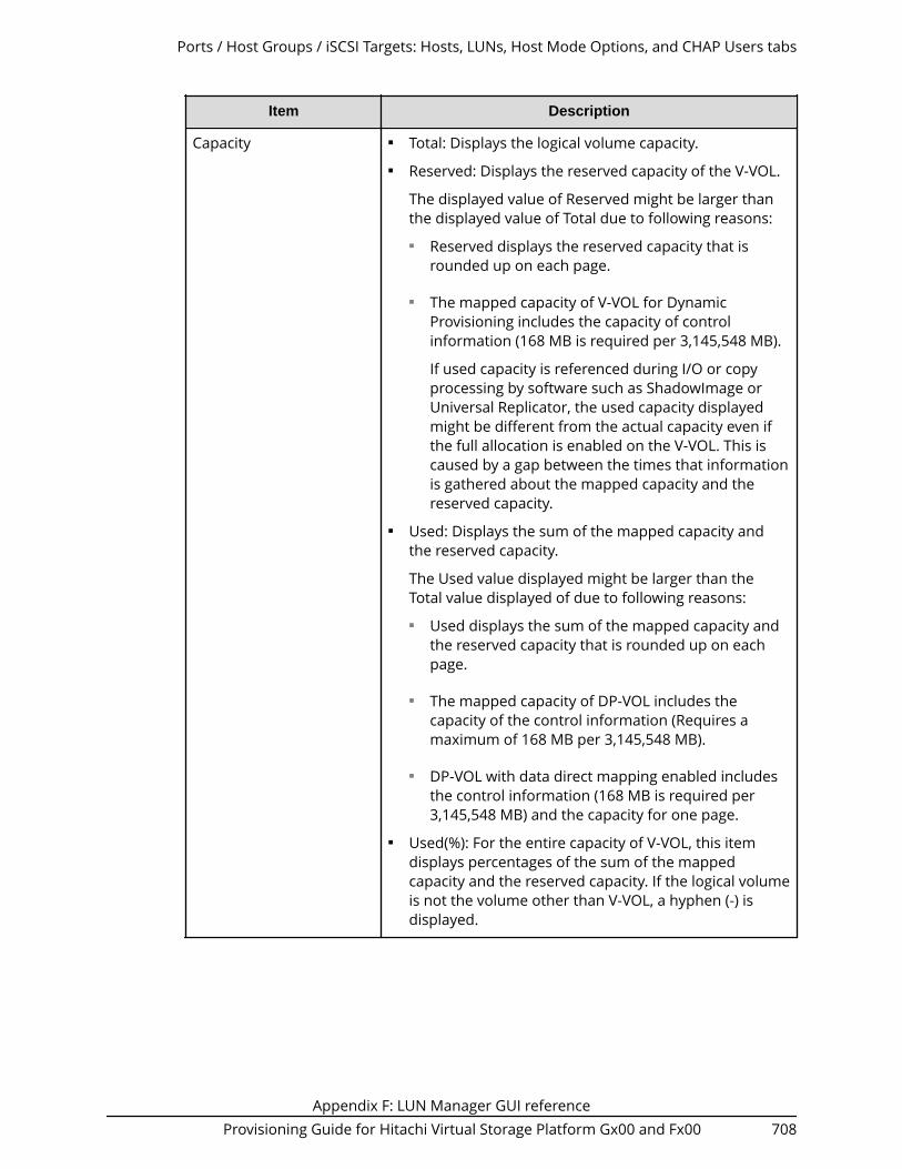
Item Description
Capacity ■ Total: Displays the logical volume capacity.■ Reserved: Displays the reserved capacity of the V-VOL.
The displayed value of Reserved might be larger thanthe displayed value of Total due to following reasons:■ Reserved displays the reserved capacity that is
rounded up on each page.
■ The mapped capacity of V-VOL for DynamicProvisioning includes the capacity of controlinformation (168 MB is required per 3,145,548 MB).
If used capacity is referenced during I/O or copyprocessing by software such as ShadowImage orUniversal Replicator, the used capacity displayedmight be different from the actual capacity even ifthe full allocation is enabled on the V-VOL. This iscaused by a gap between the times that informationis gathered about the mapped capacity and thereserved capacity.
■ Used: Displays the sum of the mapped capacity andthe reserved capacity.
The Used value displayed might be larger than theTotal value displayed of due to following reasons:■ Used displays the sum of the mapped capacity and
the reserved capacity that is rounded up on eachpage.
■ The mapped capacity of DP-VOL includes thecapacity of the control information (Requires amaximum of 168 MB per 3,145,548 MB).
■ DP-VOL with data direct mapping enabled includesthe control information (168 MB is required per3,145,548 MB) and the capacity for one page.
■ Used(%): For the entire capacity of V-VOL, this itemdisplays percentages of the sum of the mappedcapacity and the reserved capacity. If the logical volumeis not the volume other than V-VOL, a hyphen (-) isdisplayed.
Ports / Host Groups / iSCSI Targets: Hosts, LUNs, Host Mode Options, and CHAP Users tabs
Appendix F: LUN Manager GUI referenceProvisioning Guide for Hitachi Virtual Storage Platform Gx00 and Fx00 708
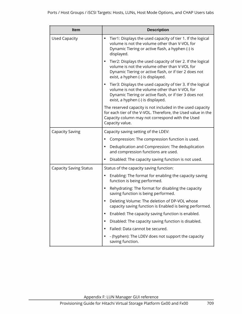
Item Description
Used Capacity ■ Tier1: Displays the used capacity of tier 1. If the logicalvolume is not the volume other than V-VOL forDynamic Tiering or active flash, a hyphen (-) isdisplayed.
■ Tier2: Displays the used capacity of tier 2. If the logicalvolume is not the volume other than V-VOL forDynamic Tiering or active flash, or if tier 2 does notexist, a hyphen (-) is displayed.
■ Tier3: Displays the used capacity of tier 3. If the logicalvolume is not the volume other than V-VOL forDynamic Tiering or active flash, or if tier 3 does notexist, a hyphen (-) is displayed.
The reserved capacity is not included in the used capacityfor each tier of the V-VOL. Therefore, the Used value in theCapacity column may not correspond with the UsedCapacity value.
Capacity Saving Capacity saving setting of the LDEV:■ Compression: The compression function is used.■ Deduplication and Compression: The deduplication
and compression functions are used.■ Disabled: The capacity saving function is not used.
Capacity Saving Status Status of the capacity saving function:■ Enabling: The format for enabling the capacity saving
function is being performed.■ Rehydrating: The format for disabling the capacity
saving function is being performed.■ Deleting Volume: The deletion of DP-VOL whose
capacity saving function is Enabled is being performed.■ Enabled: The capacity saving function is enabled.■ Disabled: The capacity saving function is disabled.■ Failed: Data cannot be secured.■ - (hyphen): The LDEV does not support the capacity
saving function.
Ports / Host Groups / iSCSI Targets: Hosts, LUNs, Host Mode Options, and CHAP Users tabs
Appendix F: LUN Manager GUI referenceProvisioning Guide for Hitachi Virtual Storage Platform Gx00 and Fx00 709

Item Description
Deduplication Data1 Displays whether the deduplication function is applied tothe volume (DP-VOL).■ Enabled: The deduplication function is applied.■ Disabled: The deduplication function is not applied.■ - (hyphen): The LDEV is not a DP-VOL, or the firmware
version does not support deduplication.
If the capacity saving setting of a DP-VOL is Deduplicationand Compression, Enabled is displayed even if the usedcapacity is 0.
When the capacity saving setting is Disabled and thedisabling of the capacity saving setting is in process,Enabled is displayed for Deduplication Data whilededuplicated data remains in the DP-VOL. When thedisabling of the capacity saving setting is complete and nodeduplicated data remains in the DP-VOL, Disabled isdisplayed.
Provisioning Type Displays the type for each logical volume.■ Basic: Internal volume.■ External: External volume.■ DP: V-VOL of Dynamic Provisioning.■ Snapshot: Thin Image volume.
CLPR Cache logical partition number, displayed as ID:CLPR.
Full Allocation Displays the status of the full allocation setting in a poolthat is associated with the V-VOL.■ Enable: Pages are reserved.■ Disable: Pages are not reserved.
Tiering Policy Displays the tiering policy name and ID.■ All(0): Policy specified when all tiers in the pool are
used.■ Level1(1) to Level31(31): Policies selected from Level1
to Level31 are set to the V-VOL.■ - (hyphen): The logical volume is not the Dynamic
Tiering or active flash V-VOL.
New Page AssignmentTier
Displays the new page assignment tier of the tieringpolicy.
- (hyphen): The logical volume is not the Dynamic Tieringor active flash V-VOL.
Ports / Host Groups / iSCSI Targets: Hosts, LUNs, Host Mode Options, and CHAP Users tabs
Appendix F: LUN Manager GUI referenceProvisioning Guide for Hitachi Virtual Storage Platform Gx00 and Fx00 710

Item Description
Tier Relocation Displays whether tier relocation is set to Enable orDisable. If the logical volume is not to the V-VOL ofDynamic Tiering or active flash, a hyphen (-) is displayed.
Attribute Displays the attribute of the LDEV.■ Command Device: Command device.■ Remote Command Device: Remote command device.■ Data Direct Mapping: LDEV with the data direct
mapping attribute enabled.■ - (hyphen): Volume in which the attribute is not
defined.
Access Attribute1 Displays the access attribute of the LDEV.
Encryption1 Displays the information about parity group encryption.■ Enable: Encryption setting of a parity group in which
the LDEV is placed is enabled. Or the virtual volumeassociated with the pool whose pool-VOLs are enabledof the encryption setting.
■ Encryption setting of a parity group (or a pool) in whichthe LDEV is placed is disabled. Or the virtual volumeassociated with the pool whose pool-VOLs are disabledof the encryption setting.
■ Mixed: This status is displayed when two or more ofthe following are specified as pool-VOLs:● Volume encryption setting is enabled.● Volume encryption setting is disabled.● External volume
Caution: The data encryption is not ensured in thepool that has the Mixed encryption setting. To managethe data encryption securely, use the pool with anencryption setting of Enabled or Disabled.
■ - (hyphen): External volume or migration volume. As forDP-VOL of Dynamic Provisioning , the pool-VOL in thepool of which DP-VOL belongs is an external volume, orthe pool of which DP-VOL belongs is being blocked.
This item is not displayed when using Virtual StoragePlatform G200.
Number of Paths Displays the total number of relevant paths andalternative paths.
Ports / Host Groups / iSCSI Targets: Hosts, LUNs, Host Mode Options, and CHAP Users tabs
Appendix F: LUN Manager GUI referenceProvisioning Guide for Hitachi Virtual Storage Platform Gx00 and Fx00 711

Item Description
ALUA Mode Information about the ALUA mode.
Enabled: The LDEV can be used in ALUA.
Disabled: The LDEV cannot be used in ALUA.
Data Direct Mapped LDEV Displays LDEV ID of pool-VOL in the pool with data directmapping enabled. Click the LDEV ID to open the LDEVProperties window.
A hyphen (-) is displayed if the data direct mappingattribute is disabled.
Virtual Storage Machine1 Information about the virtual storage machine.■ Model / Serial Number1: Model name and serial
number of the virtual storage machine that has theLDEV.
■ LDEV ID1: Virtual LDEV ID. If a Virtual LDEV ID is notassigned to LDEV, this column is blank.
■ Device Name1: Virtual device name, which is acombination of the virtual emulation type, virtual LUSEvolume number, and the virtual CVS attribute. Valuesof the virtual emulation type, virtual LUSE volumenumber, and virtual CVS attribute appear only for itemsthat have been set. This column is blank when thevirtual emulation type, virtual LUSE volume number,and virtual CVS attribute are not set. If the virtual CVSattribute is set, CVS is attached as the suffix to thedevice name.
■ SSID1: Virtual SSID. If Virtual SSID is not set for LDEV,this column is blank.
■ Attribute1: Virtual LDEV attribute. If the attribute is notset for the LDEV, this column is blank.
Add LUN Paths Opens the Add LUN Paths window.
Copy LUN Paths Opens the Copy LUN Path window.
Edit Command Devices Opens the Edit Command Devices window.
View Host-ReservedLUNs2
Displays the Host-Reserved LUNs window.
Delete LUN Paths2 Opens the Delete LUN Paths window.
Edit UUIDs2 Opens the Edit UUIDs window.
Delete UUIDs 2 Opens the Delete UUIDs window.
Create LDEVs2 Opens the Create LDEVs window.
Ports / Host Groups / iSCSI Targets: Hosts, LUNs, Host Mode Options, and CHAP Users tabs
Appendix F: LUN Manager GUI referenceProvisioning Guide for Hitachi Virtual Storage Platform Gx00 and Fx00 712

Item Description
Edit LDEVs2 Opens the Edit LDEVs window.
Format LDEVs2 Opens the Format LDEVs window.
Shred LDEVs 2 Opens the Shred LDEVs window. For details, see HitachiVolume Shredder User Guide.
Block LDEVs2 Opens the Block LDEVs window.
Restore LDEVs2 Opens the Restore LDEVs window.
Assign MP Blade2 Opens the Assign MP Blade window.
Reclaim Zero Pages2 Opens the Reclaim Zero Pages window.
Stop Reclaiming ZeroPages2
Opens the Stop Reclaiming Zero Pages window.
Expand V-VOLs2 Opens the Expand V-VOL window.
View Tier Properties2 Opens the View Tier Properties window.
Migrate Volumes2 Opens the Migrate Volumes window.
Interrupt LDEV Task2 Select Format to display the Interrupt Formatting Taskwindow.
Select Shred to display the Interrupt Shredding Taskwindow.
Force Delete Pairs2 ■ TC Pairs: Opens the Force Delete Pairs (TC Pairs)window. For details see the Hitachi TrueCopy® UserGuide.
■ UR Pairs: Opens the Force Delete Pairs (UR Pairs)window. For details see the Hitachi Universal ReplicatorUser Guide.
■ GAD Pairs: Opens the Force Delete Pairs (GAD Pairs)window. For details see the Global-Active Device UserGuide.
View ALUs / SLUs 2 Open the ALUs / SLUs window.
Unbind SLUs2 Opens the Unbind SLUs window.
Export2 Opens a window where you can export configurationinformation listed in the table to a file that can be used formultiple purposes, such as backup or reporting.
Ports / Host Groups / iSCSI Targets: Hosts, LUNs, Host Mode Options, and CHAP Users tabs
Appendix F: LUN Manager GUI referenceProvisioning Guide for Hitachi Virtual Storage Platform Gx00 and Fx00 713

Item Description
Notes:
1. Does not appear by default. To display this item, change the Column Settings ofthe table option.
2. Available when you click More Actions.
Host Mode Options tab
Item Description
Mode No. Number of the host mode option.
Option Description Description of the host mode option.
Status Setting (enable or disable) of the host mode option.
Edit iSCSI Targets Opens the Edit iSCSI Targets window.
Export Opens a window where you can export configurationinformation listed in the table to a file that can be used formultiple purposes, such as backup or reporting.
Ports / Host Groups / iSCSI Targets: Hosts, LUNs, Host Mode Options, and CHAP Users tabs
Appendix F: LUN Manager GUI referenceProvisioning Guide for Hitachi Virtual Storage Platform Gx00 and Fx00 714

CHAP Users tab
Item Description
Port ID Identifier of the port.
User Name User name. Click a user name to open theCHAP User Properties window.
Number of iSCSI Targets Number of iSCSI Targets
iSCSI Target Alias iSCSI target alias.
iSCSI Target Name iSCSI target name.
Edit CHAP User Opens the Edit CHAP User window.
Remove CHAP Users Opens the Remove CHAP Users window.
Export Opens a window where you can exportconfiguration information listed in thetable to a file that can be used for multiplepurposes, such as backup or reporting.
Ports / Host Groups / iSCSI Targets: Hosts, LUNs, Host Mode Options, and CHAP Users tabs
Appendix F: LUN Manager GUI referenceProvisioning Guide for Hitachi Virtual Storage Platform Gx00 and Fx00 715

Ports/iSCSI Targets: iSCSI Targets, Hosts, and CHAP Userstabs (iSCSI)
Ports/iSCSI Targets: iSCSI Targets, Hosts, and CHAP Users tabs (iSCSI)
Appendix F: LUN Manager GUI referenceProvisioning Guide for Hitachi Virtual Storage Platform Gx00 and Fx00 716

Summary
Item Description
IPv4 Information about the setting for IPv4:■ IP Address: IP address for the port.■ Subnet Mask: Subnet mask for the
port.■ Default Gateway: Default gateway for
the port.■ - (hyphen): The iSCSI virtual port mode
is enabled for the port.
IPv6 Information about the setting for IPv6:■ Mode: IPv6 setting (Enabled or
Disabled) for the port.■ Link Local Address: Link local address
for the port.■ Global Address: Global address for the
port.■ Global Address 2: Global address for
the port.■ Assigned Default Gateway: Assigned
default gateway address for the port.■ - (hyphen): The iSCSI virtual port mode
is enabled for the port.
iSCSI name iSCSI name of the port.
Speed Data transfer speed.
Valid speeds are 1 or 10 Gbps. If Auto isset for the port speed, Auto (1 or 10 Gbps)appears. The value enclosed inparentheses is defined by the storagesystem.
Security LUN security setting (Enabled or Disabled)for the port.
TCP Port Number TCP port number. A hyphen (-) isdisplayed if the iSCSI virtual port mode isenabled for the port.
Ethernet MTU Size MTU size on Ethernet. A hyphen (-) isdisplayed if the iSCSI virtual port mode isenabled for the port.
Ports/iSCSI Targets: iSCSI Targets, Hosts, and CHAP Users tabs (iSCSI)
Appendix F: LUN Manager GUI referenceProvisioning Guide for Hitachi Virtual Storage Platform Gx00 and Fx00 717

Item Description
MAC Address MAC address.
Keep Alive Timer Keep alive timer setting. A hyphen (-) isdisplayed if the iSCSI virtual port mode isenabled for the port.
Selective ACK Selective ACK setting (Enabled orDisabled) on the port. A hyphen (-) isdisplayed if the iSCSI virtual port mode isenabled for the port.
Delayed ACK Delayed ACK setting (Enabled or Disabled)on the port. A hyphen (-) is displayed if theiSCSI virtual port mode is enabled for theport.
Maximum Window Size Maximum window size setting. A hyphen(-) is displayed if the iSCSI virtual portmode is enabled for the port.
iSNS Server Information about the iSNS server.■ Mode: iSNS server setting (Enabled or
Disabled) for the port.■ IP Address: IP address of the iSNS
server.■ TCP Port Number: TCP port number of
the iSNS server.
VLAN Information about VLAN:■ Tagging Mode: Tagging mode setting
(Enabled or Disabled) for the port.
■ ID: VLAN identifier.■ - (hyphen): The iSCSI virtual port mode
is enabled for the port.
iSCSI Virtual Port Mode Information about the setting of the iSCSIvirtual port mode for a port:■ Enabled: The iSCSI virtual port mode is
enabled for the port.■ Disabled: The iSCSI virtual port mode is
enabled for the port.■ - (hyphen): The port does not support
the iSCSI virtual port mode.
CHAP User Name Information about the CHAP user name.
Ports/iSCSI Targets: iSCSI Targets, Hosts, and CHAP Users tabs (iSCSI)
Appendix F: LUN Manager GUI referenceProvisioning Guide for Hitachi Virtual Storage Platform Gx00 and Fx00 718

Item Description
Number of LUNs Total number of logical units set to therelevant port, and the maximum numberof logical units that can be registered tothe port.
Number of Hosts Total number of hosts set to the relevantport, and the maximum number of hoststhat can be registered to the port.
Number of iSCSI Targets Total number of iSCSI targets set to therelevant port, and the maximum numberof iSCSI targets that can be registered tothe port.
Number of CHAP Users Total number of CHAP users set to therelevant port, and the maximum numberof CHAP users that can be registered tothe port.
View Port Properties Opens the Port Properties window.
iSCSI Targets tab
This tab provides information about the host groups that are assigned to the logged-onuser.
Item Description
Port ID Identifier of the port.
iSCSI Target Alias Icons and names of the iSCSI target alias.
iSCSI Target ID1 iSCSI target ID.
iSCSI Target Name iSCSI target name.
Host Mode Host mode of the iSCSI target.
Port Security LUN security setting (Enabled or Disabled)on the port.
Number of Hosts Number of hosts set to the relevant port.
Number of LUNs Number of logical units.
Ports/iSCSI Targets: iSCSI Targets, Hosts, and CHAP Users tabs (iSCSI)
Appendix F: LUN Manager GUI referenceProvisioning Guide for Hitachi Virtual Storage Platform Gx00 and Fx00 719

Item Description
Authentication Information about the authentication.■ Method: Authentication method that is
CHAP, None, or Comply with HostSetting
■ Mutual CHAP: Mutual CHAP settingthat is Enabled or Disabled
■ User Name■ Number of Users
Resource Group Name (ID) Resource group name and identifier of theiSCSI target.
Virtual Storage Machine1 Model name and serial number of thevirtual storage machine that has the iSCSItarget.
Create iSCSI Targets Opens the Create iSCSI Targets window.
Add LUN Paths Opens the Add LUN Paths window.
Add Hosts Opens the Add Hosts window.
Delete iSCSI Targets2 Opens the Delete iSCSI Targets window.
Edit iSCSI Targets2 Opens the Edit iSCSI Targets window.
Create Alternative LUN Paths2 Opens the Create Alternative LUN Pathswindow.
Add CHAP Users2 Opens the Add CHAP Users window.
Remove Target CHAP Users2 Opens the Remove Target CHAP Userswindow.
Export2 Opens a window where you can exportconfiguration information listed in thetable to a file that can be used for multiplepurposes, such as backup or reporting.
Notes:1 Does not appear by default. To display this item, change the Column Settings of thetable option.2 Appears when you click More Actions.
Ports/iSCSI Targets: iSCSI Targets, Hosts, and CHAP Users tabs (iSCSI)
Appendix F: LUN Manager GUI referenceProvisioning Guide for Hitachi Virtual Storage Platform Gx00 and Fx00 720

Hosts tab
This tab provides information about the iSCSI Names that are registered to the iSCSItargets assigned to the logged-on user.
Item Description
Port ID Identifier of the port.
HBA iSCSI Name HBA iSCSI Names and their icons.
Host Name Name of hosts.
Number of iSCSI Targets Number of iSCSI targets.
Edit Host Opens the Edit Host window.
View Host Properties Opens the Host Properties window
Remove Hosts Opens the Remove Hosts window.
Export Opens a window where you can exportconfiguration information listed in thetable to a file that can be used for multiplepurposes, such as backup or reporting.
Ports/iSCSI Targets: iSCSI Targets, Hosts, and CHAP Users tabs (iSCSI)
Appendix F: LUN Manager GUI referenceProvisioning Guide for Hitachi Virtual Storage Platform Gx00 and Fx00 721
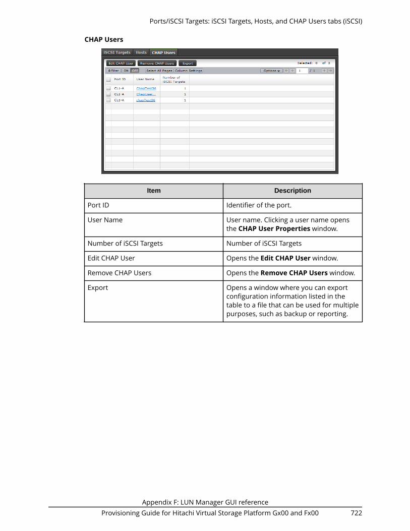
CHAP Users
Item Description
Port ID Identifier of the port.
User Name User name. Clicking a user name opensthe CHAP User Properties window.
Number of iSCSI Targets Number of iSCSI Targets
Edit CHAP User Opens the Edit CHAP User window.
Remove CHAP Users Opens the Remove CHAP Users window.
Export Opens a window where you can exportconfiguration information listed in thetable to a file that can be used for multiplepurposes, such as backup or reporting.
Ports/iSCSI Targets: iSCSI Targets, Hosts, and CHAP Users tabs (iSCSI)
Appendix F: LUN Manager GUI referenceProvisioning Guide for Hitachi Virtual Storage Platform Gx00 and Fx00 722

Add LUN Paths wizard
Select LDEVs window
Available LDEVs table
This table lists logical volumes for which LU paths can be established. Only the LDEVsavailable to the logged-on user are available.
Item Description
LDEV ID LDEV identifier, which is the combination of LDKC, CU,and LDEV.
LDEV Name Name of the LDEV.
Parity Group ID Identifier of the parity group.
Pool Name (ID) Pool name and pool identifier.
If the LDEV is not used as a pool-VOL, a hyphen (-)appears.
RAID Level Displays the RAID level. If multiple RAID levels exist in apool, Mixed appears in this field.
Capacity Size of each logical volume.
Add LUN Paths wizard
Appendix F: LUN Manager GUI referenceProvisioning Guide for Hitachi Virtual Storage Platform Gx00 and Fx00 723

Item Description
Provisioning Type Provisioning type for each logical volume.■ Basic: Internal volume.■ External: External volume.■ DP: V-VOL of Dynamic Provisioning.■ Snapshot: Thin Image volume.
Attribute Displays the attribute of the LDEV.■ Command Device: Command device.■ Remote Command Device: Remote command
device.■ Data Direct Mapping: LDEV of the data direct
mapping attribute.■ NAS Platform (User LU): LDEV used for storing the
NAS user data. This value appears if the NASmodule is installed.
■ NAS Platform (System LU): LDEV used for storingthe NAS firmware system data. This value appearsif the NAS module is installed.
■ Hyphen (-): Volume in which the attribute is notdefined.
Number of Paths Number of paths set for the LDEV.
ALUA Mode Information about the ALUA mode.
Enabled: LDEV can be used in ALUA.
Disabled: LDEV cannot be used in ALUA.
T10 PI The LDEV's T10 PI attribute setting (Enabled orDisabled).
Resource Group Name (ID) Resource group name and identifier of the LDEV.
Virtual Storage Machine Model name and serial number of the virtual storagemachine that has the LDEV.
Add Adds logical volumes selected from the AvailableLDEVs table to the Selected LDEVs table.
Remove Removes logical volumes from the Selected LDEVstable.
Select LDEVs window
Appendix F: LUN Manager GUI referenceProvisioning Guide for Hitachi Virtual Storage Platform Gx00 and Fx00 724

Selected LDEVs table
Item Description
LDEV ID LDEV identifier, which is the combination of LDKC, CU,and LDEV.
LDEV Name Name of the LDEV.
Parity Group ID Identifier of the parity group.
Pool Name (ID) Pool name and pool identifier.
If the LDEV is not used as a pool-VOL, a hyphen (-)appears.
Capacity Size of each logical volume.
Provisioning Type Provisioning type for each logical volume.■ Basic: Internal volume.■ External: External volume.■ DP: V-VOL of Dynamic Provisioning.■ Snapshot: Thin Image volume.
Attribute Displays the attribute of the LDEV.■ Command Device: Command device.■ Remote Command Device: Remote command
device.■ Data Direct Mapping: LDEV of the data direct
mapping attribute.■ NAS Platform (User LU): LDEV used for storing the
NAS user data. This value appears if the NASmodule is installed.
■ NAS Platform (System LU): LDEV used for storingthe NAS firmware system data. This value appearsif the NAS module is installed.
■ Hyphen (-): Volume in which the attribute is notdefined.
Number of Paths Number of paths set for the LDEV.
ALUA Mode Information about the ALUA mode.■ Enabled: LDEV can be used in ALUA.■ Disabled: LDEV cannot be used in ALUA.
T10 PI The LDEV's T10 PI attribute setting (Enabled orDisabled).
Select LDEVs window
Appendix F: LUN Manager GUI referenceProvisioning Guide for Hitachi Virtual Storage Platform Gx00 and Fx00 725

Item Description
Resource Group Name (ID) Resource group name and identifier of the LDEV.
Virtual Storage Machine Model name and serial number of the virtual storagemachine that has the LDEV.
Select Host Groups/iSCSI Targets window
Selection Object
Item Description
Selection Object ■ Fibre: Select to add LUN paths to host groups.■ iSCSI target: Select to add LUN paths to iSCSI
targets.■ NAS Platform (User LU): LDEV used for storing the
NAS user data. This value appears if the NASmodule is installed.
Available Host Groups table
This table lists host groups for which LU paths can be established. Only the host groupsassigned to the logged-on user are available. However, if NAS Platform (User LU) isselected in Selection Object, host groups do not appear in this table.
Select Host Groups/iSCSI Targets window
Appendix F: LUN Manager GUI referenceProvisioning Guide for Hitachi Virtual Storage Platform Gx00 and Fx00 726

Item Description
Port ID Identifier of the port.
Host Group Name Name of the host group.
Host Mode The host mode of the host group.
Port Security LUN security setting (Enabled or Disabled) on the port.
Number of Hosts Number of hosts registered in the host group.
Asymmetric Access States Asymmetric access states of the port. When usingiSCSI, a hyphen (-) is displayed.
Active/Optimized: Access from the host ispreferentially performed on this port.
Active/Non-Optimized: When the Active/Optimizedport is disabled, access from the host is performed onthis port.
T10 PI Mode The port's T10 PI Mode setting (Enabled or Disabled).
Resource Group Name (ID) Resource group name and identifier of the host group.
Virtual Storage Machine Model name and serial number of the virtual storagemachine that has the port.
Detail Details about the selected host group.
Add Adds host groups selected from the Available HostGroups table to the Selected Host Groups table.However, if NAS Platform (User LU) is selected inSelection Object, host groups do not appear in thistable.
Remove Removes the selected host groups from the SelectedHost Groups table. However, if NAS Platform (User LU)is selected in Selection Object, host groups do notappear in this table.
Selected Host Groups table
Item Description
Port ID Identifier of the port.
Host Group Name Name of the host group.
Host Mode The host mode of the host group.
Port Security LUN security setting (Enabled or Disabled) on the port.
Select Host Groups/iSCSI Targets window
Appendix F: LUN Manager GUI referenceProvisioning Guide for Hitachi Virtual Storage Platform Gx00 and Fx00 727

Item Description
Number of Hosts Number of hosts registered in the host group.
Asymmetric Access States Asymmetric access states of the port. When usingiSCSI, a hyphen (-) is displayed.
Active/Optimized: Access from the host ispreferentially performed on this port.
Active/Non-Optimized: When the Active/Optimizedport is disabled, access from the host is performed onthis port.
T10 PI Mode The port's T10 PI Mode setting (Enabled or Disabled).
Resource Group Name (ID) Resource group name and identifier of the host group.
Virtual Storage Machine Model name and serial number of the virtual storagemachine that has the port.
Detail Details about the selected host group.
iSCSI
Available iSCSI Targets table
This table lists iSCSI targets for which LU paths can be established. Only the iSCSI targetsassigned to the logged-on user are available.
Select Host Groups/iSCSI Targets window
Appendix F: LUN Manager GUI referenceProvisioning Guide for Hitachi Virtual Storage Platform Gx00 and Fx00 728

Item Description
Port ID Identifier of the port.
iSCSI Target Alias iSCSI target alias.
iSCSI Target ID iSCSI target ID.
iSCSI Target Name iSCSI target name.
Host Mode Host mode of the iSCSI target.
Port Security LUN security setting (Enabled or Disabled) on the port.
Number of Hosts Number of hosts set to the relevant port.
Resource Group Name (ID) Resource group name and identifier of the iSCSI target.
Detail Details about the selected iSCSI target.
Add Adds host groups selected from the Available iSCSITargets table to the Selected iSCSI Targets table.
Remove Removes the selected host groups from the SelectediSCSI Targets table.
Selected iSCSI Targets table
Item Description
Port ID Identifier of the port.
iSCSI Target Alias iSCSI target alias.
iSCSI Target ID iSCSI target ID.
iSCSI Target Name iSCSI target name.
Host Mode Host mode of the iSCSI target.
Port Security LUN security setting (Enabled or Disabled) on the port.
Number of Hosts Number of hosts set to the relevant port.
Resource Group Name (ID) Resource group name and identifier of the iSCSI target.
Add LUN Paths window
This window provides information about LUs that are already set. You can viewinformation about the LUN and change the LUN ID.
Add LUN Paths window
Appendix F: LUN Manager GUI referenceProvisioning Guide for Hitachi Virtual Storage Platform Gx00 and Fx00 729

Added LUNs table
Item Description
LDEV ID LDEV identifier, which is the combination of LDKC, CU,and LDEV.
LDEV Name Name of the LDEV.
Parity Group ID Identifier of the parity group.
Pool Name (ID) Pool names and pool identifiers.
If the LDEV is not used as a pool-VOL, a hyphen (-)appears.
Capacity Size of each logical volume.
Provisioning Type Provisioning type of the logical volume.■ Basic: Internal volume.■ External: External volume.■ DP: V-VOL of Dynamic Provisioning.■ Snapshot: Thin Image volume.
Add LUN Paths window
Appendix F: LUN Manager GUI referenceProvisioning Guide for Hitachi Virtual Storage Platform Gx00 and Fx00 730

Item Description
Attribute Displays the attribute of the LDEV.■ Command Device: Command device.■ Remote Command Device: Remote command
device.■ Data Direct Mapping: LDEV of the data direct
mapping attribute.■ NAS Platform (User LU): LDEV used for storing the
NAS user data. This value appears if the NASmodule is installed.
■ NAS Platform (System LU): LDEV used for storingthe NAS firmware system data. This value appearsif the NAS module is installed.
■ Hyphen (-): Volume in which the attribute is notdefined.
ALUA Mode Information about the ALUA mode.
Enabled: The LDEV can be used in ALUA.
Disabled: The LDEV cannot be used in ALUA.
Asymmetric Access States Asymmetric access states of the port. When usingiSCSI, a hyphen (-) is displayed.
Active/Optimized: Access from the host ispreferentially performed on this port.
Active/Non-Optimized: When the Active/Optimizedport is disabled, access from the host is performed onthis port.
T10 PI The LDEV's T10 PI attribute setting (Enabled orDisabled).
LUN ID ((number-of-LUNs) Setsof Paths)
Number of assigned LUNs.
port-ID/ host-group-name (oriSCSI target name)
Name of the port and the host group (or iSCSI targetname) of assigned LUNs. This item appears accordingto the number of assigned LUNs.
Change LDEV Settings To change the LDEV name setting, select an LDEV andthen click this button.
Change LUN IDs To change the LUN setting, select the check box in thetable column of port-ID/host-group-name, select thetarget LDEV, and then click this button.
Add LUN Paths window
Appendix F: LUN Manager GUI referenceProvisioning Guide for Hitachi Virtual Storage Platform Gx00 and Fx00 731

Add LUN Paths confirmation window
Confirm proposed settings, name the task, and then click Apply. The task will be addedto the execution queue.
Added LUNs table
Item Description
LDEV ID Identifier of the LDEV.
LDEV Name Name of the LDEV.
Parity Group ID Identifier of the parity group.
Pool Name (ID) Pool names and pool identifiers.
If the LDEV is not used as a pool-VOL, a hyphen (-)appears.
Capacity Size of each logical volume.
Provisioning Type Provisioning types for each logical volume.■ Basic: Internal volume.■ External: External volume.■ DP: V-VOL of Dynamic Provisioning.■ Snapshot: Thin Image volume.
Add LUN Paths confirmation window
Appendix F: LUN Manager GUI referenceProvisioning Guide for Hitachi Virtual Storage Platform Gx00 and Fx00 732

Item Description
Attribute Displays the attribute of the LDEV.■ Command Device: Command device.■ Remote Command Device: Remote command
device.■ Data Direct Mapping: LDEV of the data direct
mapping attribute.■ NAS Platform (User LU): LDEV used for storing the
NAS user data. This value appears if the NASmodule is installed.
■ NAS Platform (System LU): LDEV used for storingthe NAS firmware system data. This value appearsif the NAS module is installed.
■ Hyphen (-): Volume in which the attribute is notdefined.
ALUA Mode Information about the ALUA mode.
Enabled: LDEV can be used in ALUA.
Disabled: LDEV cannot be used in ALUA.
Asymmetric Access States Asymmetric access states of the port. When usingiSCSI, a hyphen (-) is displayed.
Active/Optimized: Access from the host ispreferentially performed on this port.
Active/Non-Optimized: When the Active/Optimizedport is disabled, access from the host is performed onthis port.
T10 PI The LDEV's T10 PI attribute setting (Enabled orDisabled).
LUN ID ((number-of-LUNs) Setsof Paths)
Number of assigned LUNs.
port-ID/ host-group-name (oriSCSI target name)
Name of the port and the host group (or iSCSI targetname) of assigned LUNs. This item appears accordingto the number of assigned LUNs.
Add LUN Paths confirmation window
Appendix F: LUN Manager GUI referenceProvisioning Guide for Hitachi Virtual Storage Platform Gx00 and Fx00 733

Create Host Groups wizard
Create Host Groups window
Item Description
Host Group Name Enter the name of the host group.
As a host group name, you can use single-byte ASCIIcharacters (alphanumeric characters and symbols) upto 64 characters. You cannot use the followingsymbols: \ / : , ; * ? " < > |
You cannot use blanks at the beginning or end of thehost group name.
Resource Group Name (ID) Select the resource group in which the host group iscreated. If Any is selected, among all ports beingallocated to the user, ports where the host group canbe add are available in the Available Ports table. Ifother than Any is selected, among ports assigned tothe selected resource group, ports where the hostgroup can be add are available in the Available Portstable.
Host Mode Select the host mode from the list.
Add Adds the settings to the Selected Host Groups table.
Create Host Groups wizard
Appendix F: LUN Manager GUI referenceProvisioning Guide for Hitachi Virtual Storage Platform Gx00 and Fx00 734

Available Hosts table
This table lists information about the registered hosts.
Item Description
Port ID Identifier of the port.
HBA WWN WWN of the port.
Host Name Name of the host.
Host Group Name Name of the host group.
New Host Indicates whether this is a new host.■ Yes: The host is newly added and has never been
connected via a cable to any port in the storagesystem.
■ No: The host has been connected via a cable toanother port.
Port Security LUN security setting (Enabled or Disabled) on the port.
Add New Host Adds a new host. Or, select host bus adapters andthen click this button to assign a nickname to the hostbus adapter.
Available Ports table
This table lists the registered ports.
Item Description
Port ID Identifier of the port.
Security LUN security setting (Enabled or Disabled) on the port.
T10 PI Mode The port's T10 PI Mode setting (Enabled or Disabled).
Host Mode Options table
Item Description
Mode No. The ID number of the host mode option.
Option Description The description of host mode option.
Status The setting status (Enabled or Disabled) of the hostmode option.
Create Host Groups window
Appendix F: LUN Manager GUI referenceProvisioning Guide for Hitachi Virtual Storage Platform Gx00 and Fx00 735

Item Description
Enabled Indicates that the host mode option is enabled.
Disabled Indicates that the host mode option is disabled.
Selected Host Groups table
Item Description
Port ID Identifier of the port.
Host Group Name Name of the host group.
Host Mode The host mode of the host group.
Port Security LUN security setting (Enabled or Disabled) on the port.
Number of Hosts Number of hosts registered in the host group.
T10 PI Mode The port's T10 PI Mode setting (Enabled or Disabled).
Resource Group Name (ID) Resource group name and identifier of the host group.
Virtual Storage Machine Model name and serial number of the virtual storagemachine that has the host group.
Detail Details about the selected host group.
Remove Removes the selected host groups from the SelectedHost Groups table.
Next Task Option
Click Next to go to the task setting window.
Create Host Groups confirmation window
Note: If multiple tasks that are connected in one wizard are executed, thiswindow shows all configured items of tasks. To show information ofconfigured items other than this topic, click Back to display related settingwindows, and then click Help.
Create Host Groups confirmation window
Appendix F: LUN Manager GUI referenceProvisioning Guide for Hitachi Virtual Storage Platform Gx00 and Fx00 736

Create Host Groups table
Item Description
Port ID Identifier of the port.
Host Group Name Name of the host group.
Host Mode The host mode of the host group.
Port Security LUN security setting (Enabled or Disabled) on the port.
Number of Hosts Number of hosts registered in the host group.
T10 PI Mode The port's T10 PI Mode setting (Enabled or Disabled).
Resource Group Name (ID) Resource group name and identifier of the host group.
Virtual Storage Machine Model name and serial number of the virtual storagemachine that has the host group.
Detail Details about the selected host group.
Edit Host Groups wizard
Edit Host Groups window
Use this window to edit host group properties for selected host groups. Propertiesinclude host group name, host mode, or host mode options.
When you select multiple host groups to which different host modes are defined, if thehost group assigned to an initiator port is included, you cannot finish the Edit HostGroups operation.
Edit Host Groups wizard
Appendix F: LUN Manager GUI referenceProvisioning Guide for Hitachi Virtual Storage Platform Gx00 and Fx00 737

Item Description
Host Group name Specify the name of the host group.
Host group name can be up to 64 single-byte ASCIIcharacters (alpha-numerals and symbols).
You cannot use the following symbols: \ / : , ; * ? " < > |
You cannot use blanks at the beginning or end of thehost group name.
Host Mode Select the host mode from the list.
If a host group assigned to an initiator port is includedin the specified host groups, this item is unavailable.
Host Mode Options table
To set the host mode option, select a host mode option, and then click Enable. If you donot need a host mode option, select an unnecessary host mode option, and then clickDisable.
Item Description
Mode No. Number identifier of the host mode option.
Option Description Description of the host mode option.
Edit Host Groups window
Appendix F: LUN Manager GUI referenceProvisioning Guide for Hitachi Virtual Storage Platform Gx00 and Fx00 738

Item Description
Status Indicates the current status setting (Enabled orDisabled) of the host mode option on this host group.
Enable Enables the host mode option.
Disable Disables the host mode option.
Edit Host Groups confirmation window
Confirm proposed settings, name the task, and then click Apply. The task will be addedto the execution queue.
Selected Host Groups table
Item Description
Port ID Identifier of the port.
Host Group Name Name of the host group.
Host Mode The host mode of the host group.
Port Security LUN security setting (Enabled or Disabled) on the port.
Number of Hosts Number of hosts registered in the host group.
T10 PI Mode The port's T10 PI Mode setting (Enabled or Disabled).
Detail Details about the selected host group.
Edit Host Groups confirmation window
Appendix F: LUN Manager GUI referenceProvisioning Guide for Hitachi Virtual Storage Platform Gx00 and Fx00 739

Add to Host Groups wizard (when specific host is selected)
Add to Host Groups window
Available Host Groups table
This table lists host groups in which selected hosts can be registered. Only the hostgroups assigned to the logged-on user are available.
Item Description
Port ID Identifier of the port.
Host Group Name Name of the host group.
Host Mode The host mode of the host group.
Port Security LUN security setting (Enabled or Disabled) on the port.
Number of Hosts Number of hosts registered in the host group.
T10 PI Mode The port's T10 PI Mode setting (Enabled or Disabled).
Detail Details about the selected host group.
Add Adds host groups selected from the Available HostGroups table to the Selected Host Groups table.
Remove Removes the selected host groups from the SelectedHost Groups table.
Selected Host Groups table
This table lists the selected host groups.
Add to Host Groups wizard (when specific host is selected)
Appendix F: LUN Manager GUI referenceProvisioning Guide for Hitachi Virtual Storage Platform Gx00 and Fx00 740

Item Description
Port ID Identifier of the port.
Host Group Name Name of the host group.
Host Mode The host mode of the host group.
Port Security LUN security setting (Enabled or Disabled) on the port.
Number of Hosts Number of hosts registered in the host group.
T10 PI Mode The port's T10 PI Mode setting (Enabled or Disabled).
Detail Details about the selected host group.
Add to Host Groups confirmation window
Confirm proposed settings, name the task, and then click Apply. The task will be addedto the execution queue.
Selected Hosts table
This table lists the hosts selected to be added to a host group.
Item Description
HBA WWN WWN of the port.
Host Name Name of the host.
Add to Host Groups confirmation window
Appendix F: LUN Manager GUI referenceProvisioning Guide for Hitachi Virtual Storage Platform Gx00 and Fx00 741

Selected Host Groups table
A list of host groups to which hosts are registered.
Item Description
Port ID Identifier of the port.
Host Group Name Name of the host group.
Host Mode The host mode of the host group.
Port Security LUN security setting (Enabled or Disabled) on the port.
Number of Hosts Number of hosts registered in the host group.
T10 PI Mode The port's T10 PI Mode setting (Enabled or Disabled).
Add Hosts wizard (when specific hosts group is selected)
Add Hosts window
The Add Hosts window displays the following information when a host group on a FibreChannel port is selected.
Available Hosts table (Fibre Channel)
This table lists the hosts that can be registered in the selected host group.
Add Hosts wizard (when specific hosts group is selected)
Appendix F: LUN Manager GUI referenceProvisioning Guide for Hitachi Virtual Storage Platform Gx00 and Fx00 742

Item Description
Port ID Identifier of the port.
HBA WWN WWN of the port.
Host Name Name of the host.
Host Group Name Name of the host group.
New Host Indicates whether this is a newly added host.■ Yes: The host is newly added and has never been
connected via a cable to any port in the storagesystem.
■ No: The host has been connected via a cable toanother port.
Add New Host Adds a new host. Note that Port ID and Host GroupName will be blank after a new host is added.
Add Adds hosts selected from the Available Hosts table tothe Selected Hosts table.
Remove Removes hosts from the Selected Hosts table.
Selected Hosts table (Fibre Channel)
This table lists hosts selected from the Available Hosts table.
Item Description
Port ID Identifier of the port. This field is blank for the hostcreated by clicking Add New Host.
HBA WWN WWN of the port.
Host Name Name of the host.
Host Group Name Name of the host group. Note that this field is blankfor the host created by clicking Add New Host.
New Host Indicates whether this is a newly added host.■ Yes: The host is newly added and has never been
connected via a cable to any port in the storagesystem.
■ No: The host has been connected via a cable toanother port.
The Add Hosts window displays the following information when a host group on an iSCSIport is selected.
Add Hosts window
Appendix F: LUN Manager GUI referenceProvisioning Guide for Hitachi Virtual Storage Platform Gx00 and Fx00 743

Available Hosts table (iSCSI)
This table lists the hosts that can be registered in the selected iSCSI target.
Item Description
Port ID Identifier of the port.
HBA iSCSI Name HBA iSCSI Name of the port.
Host Name Name of the host.
Number of iSCSI Targets Number of iSCSI Targets.
New Host Indicates whether this is a newly added host.■ Yes: The host is newly added and has never been
connected via a cable to any port in the storagesystem.
■ No: The host has been connected via a cable toanother port.
Add New Host Adds a new host. Note that Port ID and Host GroupName will be blank after a new host is added.
Add Adds hosts selected from the Available Hosts table tothe Selected Hosts table.
Remove Removes hosts from the Selected Hosts table.
Add Hosts window
Appendix F: LUN Manager GUI referenceProvisioning Guide for Hitachi Virtual Storage Platform Gx00 and Fx00 744

Selected Hosts table (iSCSI)
This table lists hosts selected from the Available Hosts table.
Item Description
Port ID Identifier of the port.
HBA iSCSI Name HBA iSCSI Name of the port.
Host Name Name of the host.
Number of iSCSI Targets Number of iSCSI Targets.
New Host Indicates whether this is a newly added host.■ Yes: The host is newly added and has never been
connected via a cable to any port in the storagesystem.
■ No: The host has been connected via a cable toanother port.
Add Hosts confirmation window
Confirm proposed settings, name the task, and then click Apply. The task will be addedto the execution queue.
Selected Host Groups table (Fibre Channel)
This table lists the selected hosts.
Add Hosts confirmation window
Appendix F: LUN Manager GUI referenceProvisioning Guide for Hitachi Virtual Storage Platform Gx00 and Fx00 745

Item Description
Port ID Identifier of the port.
Host Group Name Name of the host group.
Host Mode The host mode of the host group.
Port Security LUN security setting (Enabled or Disabled) on the port.
Number of Hosts Number of hosts registered in the host group.
T10 PI Mode The port's T10 PI Mode setting (Enabled or Disabled).
Selected Hosts table (Fibre Channel)
This table contains a list of added host groups.
Item Description
HBA WWN WWN of the port.
Host Name Name of the host.
Add Hosts confirmation window
Appendix F: LUN Manager GUI referenceProvisioning Guide for Hitachi Virtual Storage Platform Gx00 and Fx00 746

Selected iSCSI Targets table (iSCSI)
This table lists the selected iSCSI targets.
Item Description
Port ID Identifier of the port.
iSCSI Target Alias iSCSI target alias.
iSCSI Target Name iSCSI target name.
Host Mode
.
The host mode of the iSCSI target.
Port Security LUN security setting (Enabled or Disabled) on the port.
Number of Hosts Number of hosts registered in the host group.
Add Hosts confirmation window
Appendix F: LUN Manager GUI referenceProvisioning Guide for Hitachi Virtual Storage Platform Gx00 and Fx00 747

Item Description
Authentication Information about the authentication.■ Method: Authentication method that is CHAP, None,
or Comply with Host Setting■ Mutual CHAP: Mutual CHAP setting that is Enabled
or Disabled■ User name■ Number of users
Selected Hosts table (iSCSI)
This table contains a list of added host groups.
Item Description
HBA iSCSI Name HBA iSCSI name of the port.
Host Name Name of the host.
Port ID Port ID
iSCSI Target Alias iSCSI target alias
iSCSI target Name iSCSI target name
Delete LUN Paths wizard
Delete LUN Paths window
Delete LUN Paths wizard
Appendix F: LUN Manager GUI referenceProvisioning Guide for Hitachi Virtual Storage Platform Gx00 and Fx00 748

Selected LUN Paths table
This table provides information about the selected LUN paths.
Item Description
Port ID Identifier of the port.
LUN ID Identifier of the selected LUN paths.
LDEV ID LDEV identifier, which is the combination of LDKC, CU,and LDEV.
LDEV Name Name of the LDEV.
Host Group Name / iSCSITarget Alias
Name of the host group or iSCSI target alias.
iSCSI Target Name iSCSI target name.
Capacity Size of each logical volume.
Attribute Displays the attribute of the LDEV.■ Command Device: Command device.■ Remote Command Device: Remote command
device.■ Data Direct Mapping: LDEV of the data direct
mapping attribute.■ NAS Platform (User LU): LDEV used for storing the
NAS user data. This value appears if the NASmodule is installed.
■ NAS Platform (System LU): LDEV used for storingthe NAS firmware system data. This value appearsif the NAS module is installed.
■ Hyphen (-): Volume in which the attribute is notdefined.
Asymmetric Access States Asymmetric access states of the port. When usingiSCSI, a hyphen (-) is displayed.
Active/Optimized: Access from the host ispreferentially performed on this port.
Active/Non-Optimized: When the Active/Optimizedport is disabled, access from the host is performed onthis port.
T10 PI The LDEV's T10 PI attribute setting (Enabled orDisabled).
Delete LUN Paths window
Appendix F: LUN Manager GUI referenceProvisioning Guide for Hitachi Virtual Storage Platform Gx00 and Fx00 749

Item Description
Remove from Delete process Removes LUN paths from the Selected LUN Pathstable.
Delete all defined LUN pathsto above LDEVs
Removes LUN paths from the Selected LUN Pathstable.
When this check box is selected, the host groups of allthe alternate paths in the LDEV displayed in theSelected LUNs table must be assigned to the StorageAdministrator group permitted to manage them.
Next Task Option
Click Next to go to the task setting window.
Delete LUN Paths confirmation window
Confirm proposed settings, name the task, and then click Apply. The task will be addedto the execution queue.
Selected LUN Paths table
Item Description
Port ID Identifier of the port.
LUN ID Identifier of the selected LUN path.
LDEV ID LDEV identifier, which is the combination of LDKC, CU,and LDEV.
Delete LUN Paths confirmation window
Appendix F: LUN Manager GUI referenceProvisioning Guide for Hitachi Virtual Storage Platform Gx00 and Fx00 750

Item Description
LDEV Name Name of the LDEV.
Host Group Name / iSCSITarget Alias
Name of the host group iSCSI target alias .
iSCSI Target Name iSCSI target name
Capacity Size of each logical volume.
Attribute Displays the attribute of the LDEV.■ Command Device: Command device.■ Remote Command Device: Remote command
device.■ Data Direct Mapping: LDEV of the data direct
mapping attribute.■ NAS Platform (User LU): LDEV used for storing the
NAS user data. This value appears if the NASmodule is installed.
■ NAS Platform (System LU): LDEV used for storingthe NAS firmware system data. This value appearsif the NAS module is installed.
■ Hyphen (-): Volume in which the attribute is notdefined.
Asymmetric Access States Asymmetric access states of the port. When usingiSCSI, a hyphen (-) is displayed.
Active/Optimized: Access from the host ispreferentially performed on this port.
Active/Non-Optimized: When the Active/Optimizedport is disabled, access from the host is performed onthis port.
T10 PI The LDEV's T10 PI attribute setting (Enabled orDisabled).
Note: If multiple tasks that are connected in one wizard are executed, thiswindow shows all configured items of tasks. To show information ofconfigured items other than this topic, click Back to display related settingwindows, and then click Help.
Delete LUN Paths confirmation window
Appendix F: LUN Manager GUI referenceProvisioning Guide for Hitachi Virtual Storage Platform Gx00 and Fx00 751

Edit Host wizardUse this wizard to edit host parameters.
Caution: In one host, if the setting operations are performed with two timesor more to edit many setting items, wait until the primary task applies thenperform the secondary operation. If the secondary operation is performedwhile being applying of the primary task, the primary task is canceled and thesecondary task is applied to the storage system.
Edit Host window
For Fibre Channel Ports
Item Description
HBA WWN Specify the WWN of the port in 16 digits ofhexadecimal numbers.
Host Name Specify the host name.
Host name can be up to 64 single-byte ASCII characters(alpha-numerals and symbols).
You cannot use the following symbols: \ / : , ; * ? " < > |
You cannot use blanks at the beginning or end of thehost name. A host name is case-sensitive.
Apply same settings to theHBA WWN in all ports
If this check box is selected, the changes made in thisdialog box will also affect other ports.
Edit Host wizard
Appendix F: LUN Manager GUI referenceProvisioning Guide for Hitachi Virtual Storage Platform Gx00 and Fx00 752

For iSCSI Ports
Item Description
HBA iSCSI Name Specify the WWN of the port in 16 digits ofhexadecimal numbers.■ iqn or eui: Select the format of the iSCSI name.■ Text box: Specify the iSCSI name.
For the iqn format, an iSCSI name takes up to 219single-byte ASCII characters (alpha-numerals andsymbols). You cannot use the following symbols: ! "# $ % & ' ( ) * + , / ; < = > ? @ [ \ ] ^ _ ` { | } ~
For the eui format, an iSCSI name takes fixed to 16alpha-numerals.
Host Name Specify the host name.
Host name can be up to 32 single-byte ASCII characters(alpha-numerals and symbols).
You cannot use the following symbols: \ / : , ; * ? " < > |
You cannot use blanks at the beginning or end of thehost name. A host name is case-sensitive.
Apply same settings to theHBA iSCSI name in all ports.
If this check box is selected, the changes made in thisdialog box will also affect other ports.
Edit Host confirmation window
Confirm proposed settings, name the task, and then click Apply. The task will be addedto the execution queue.
Edit Host confirmation window
Appendix F: LUN Manager GUI referenceProvisioning Guide for Hitachi Virtual Storage Platform Gx00 and Fx00 753

Selected Hosts table (Fibre Channel)
Item Description
Port ID Identifier of the port.
HBA WWN WWN of the port.
Host Name Name of the host.
Selected Hosts table (iSCSI ports)
Item Description
Port ID Identifier of the port.
HBA iSCSI Name HBA iSCSI Name of the port.
Host Name Name of the host.
Edit Host confirmation window
Appendix F: LUN Manager GUI referenceProvisioning Guide for Hitachi Virtual Storage Platform Gx00 and Fx00 754

Item Description
Number of iSCSI Targets Number of iSCSI targets.
Detail Details about the selected host.
Edit Ports wizardUse this wizard to edit port parameters.
Caution: In one port, if the setting operations are performed with two timesor more to edit many setting items, wait until the primary task applies thenperform the secondary operation. If the secondary operation is performedwhile being applying of the primary task, the primary task is canceled and thesecondary task is applied to the storage system.
Edit Ports window
Fibre Channel
For Fibre Channel ports
Item Description
Port Security Select whether LUN security is Enabled or Disabled.
Edit Ports wizard
Appendix F: LUN Manager GUI referenceProvisioning Guide for Hitachi Virtual Storage Platform Gx00 and Fx00 755

Item Description
Port Speed Select the data transfer speed, in Gbps, for theselected Fibre Channel port.
If Auto is selected, the storage system automaticallysets the data transfer speed to 2, 4, 8, 10, or 16 Gbps.
Caution: If you are using 2-Gbps HBA and switch, setthe transfer speed of the CHF (Fibre Channel adapter)port for VSP G1000, VSP G1500, and VSP F1500, orCHB(FC) (Fibre Channel board) for as 2 Gbps. If you areusing 4-Gbps HBA and switch, set the transfer speed ofthe CHF or CHB(FC) port as 4 Gbps. If you are using 8-Gbps HBA and switch, set the transfer speed of theCHF or CHB(FC) port as 8 Gbps. If you are using 16-Gbps HBA and switch, set the transfer speed of theCHF or CHB(FC) port as 16-Gbps. If you are using a 32-Gbps HBA and switch, set the transfer speed of theCHB(FC) port to 32 Gbps. If the Auto Negotiationsetting is required, the linkup might become improperat server restart. Check a channel lamp, and if it isblinking, remove and re-insert the cable to perform thesignal synchronization and linkup.
When the transfer speed of the CHF port is set to Auto,the data might not be transferred at the maximumspeed depending on the connected device. Confirmthe transfer speed appearing in Speed in the Ports listwhen you start up the storage system, HBA, or switch.When the transfer speed is not the maximum speed,select the maximum speed from the list on the right orremove and reinsert the cable.
Only 10 Gbps can be specified for the FCoE port. Autocannot be specified for the FCoE port.
Address (Loop ID) Select the address of the selected port. .
Fabric Select whether a fabric switch is set to ON or OFF. .
Connection Type Select the topology:■ FC-AL: Fibre Channel arbitrated loop■ P-to-P (point-to-point).
Caution: Some fabric switches require that you specifypoint-to-point topology. If you enable a fabric switch,check the documentation for the fabric switch todetermine whether your switch requires point-to-pointtopology.
Edit Ports window
Appendix F: LUN Manager GUI referenceProvisioning Guide for Hitachi Virtual Storage Platform Gx00 and Fx00 756

For iSCSI ports
Item Description
IPv4 Settings Information about IPv4. If the iSCSI virtual port modeis enabled for the port, this item cannot be selected.■ IP Address: IP address of the port. If 2 or more
ports are selected, this information cannot bespecified.
■ Subnet Mask: Subnet mask of the port.■ Default Gateway: Default gateway of the port.
Edit Ports window
Appendix F: LUN Manager GUI referenceProvisioning Guide for Hitachi Virtual Storage Platform Gx00 and Fx00 757

Item Description
IPv6 Mode Specify this information if IPv6 is used or not used. Ifthe iSCSI virtual port mode is enabled for the port, thisitem cannot be selected.■ Enable: IPv6 mode is enabled. If Enable is selected,
the IPv6 Settings can be specified.■ Disable: IPv6 mode is disabled.
Port Security Specify whether to use LUN security on the port.■ Enable: Use LUN security on the port.■ Disable: Do not use LUN security on the port.
Port Speed Select the data transfer speed for the selected port: 1Gbps, 10 Gbps, or Auto.
TCP Port Number Specify the TCP port number. If the iSCSI virtual portmode is enabled for the port, this item cannot beselected.
Selective ACK Specify this information if the selective ACK is used ornot used. If the iSCSI virtual port mode is enabled forthe port, this item cannot be selected.■ Enable: The selective ACK is enabled.■ Disable: The selective ACK is disabled.
Delayed ACK Specify this information if the delayed ACK is used ornot used. If the iSCSI virtual port mode is enabled forthe port, this item cannot be selected.■ Enable: The delayed ACK is enabled.■ Disable: The delayed ACK is disabled.
Maximum Window Size Select the maximum window size from 64 KB, 128 KB,256 KB, 512 KB, or 1024 KB. If the iSCSI virtual portmode is enabled for the port, this item cannot beselected.
Ethernet MTU Size Select Ethernet MTU size from 1500 bytes, 4500 bytes,or 9000 bytes. If the iSCSI virtual port mode is enabledfor the port, this item cannot be selected.
Keep Alive Timer Specify the interval time to perform the keep alivetimer option. If the iSCSI virtual port mode is enabledfor the port, this item cannot be selected.
Edit Ports window
Appendix F: LUN Manager GUI referenceProvisioning Guide for Hitachi Virtual Storage Platform Gx00 and Fx00 758
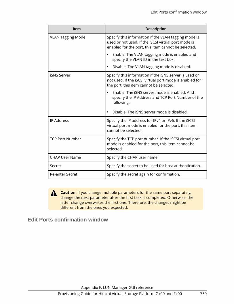
Item Description
VLAN Tagging Mode Specify this information if the VLAN tagging mode isused or not used. If the iSCSI virtual port mode isenabled for the port, this item cannot be selected.■ Enable: The VLAN tagging mode is enabled and
specify the VLAN ID in the text box.■ Disable: The VLAN tagging mode is disabled.
iSNS Server Specify this information if the iSNS server is used ornot used. If the iSCSI virtual port mode is enabled forthe port, this item cannot be selected.■ Enable: The iSNS server mode is enabled. And
specify the IP Address and TCP Port Number of thefollowing.
■ Disable: The iSNS server mode is disabled.
IP Address Specify the IP address for IPv4 or IPv6. If the iSCSIvirtual port mode is enabled for the port, this itemcannot be selected.
TCP Port Number Specify the TCP port number. If the iSCSI virtual portmode is enabled for the port, this item cannot beselected.
CHAP User Name Specify the CHAP user name.
Secret Specify the secret to be used for host authentication.
Re-enter Secret Specify the secret again for confirmation.
Caution: If you change multiple parameters for the same port separately,change the next parameter after the first task is completed. Otherwise, thelatter change overwrites the first one. Therefore, the changes might bedifferent from the ones you expected.
Edit Ports confirmation window
Edit Ports confirmation window
Appendix F: LUN Manager GUI referenceProvisioning Guide for Hitachi Virtual Storage Platform Gx00 and Fx00 759

Selected Ports table for Fibre Channel ports
Item Description
Port ID Identifier of the port.
Security LUN security setting (Enabled or Disabled) on the port.
Speed Data transfer speed for the selected Fibre Channelport in Gbps (Gigabits per second).
SFP Data Transfer Rate SFP data transfer rate of 8 Gbps, 16 Gbps, or 32 Gbps.
Address (Loop ID) Address of the selected port.
Fabric Status setting (ON or OFF) for a fabric switch.
Connection Type Topology of the selected port.■ FC-AL: Fibre Channel arbitrated loop■ P-to-P: Point-to-point
Edit Ports confirmation window
Appendix F: LUN Manager GUI referenceProvisioning Guide for Hitachi Virtual Storage Platform Gx00 and Fx00 760

Selected Ports table for iSCSI ports
Item Description
Port ID Identifier of the port.
IPv4 Information about IPv4.■ IP Address: IP address of the port.■ Subnet Mask: Subnet mask of the port.■ Default Gateway: Default gateway of the port.
IPv6 Information about IPv6.■ Mode: IPv6 setting (Enabled or Disabled) for the
port.■ Link Local Address: Link local address for the port.■ Global Address: Global address for the port.■ Global Address 2: Global address for the port.■ Default Gateway: Default gateway address for the
port.
Edit Ports confirmation window
Appendix F: LUN Manager GUI referenceProvisioning Guide for Hitachi Virtual Storage Platform Gx00 and Fx00 761

Item Description
Port Security Specify this information if the LUN security is used ornot used.■ Enable: The LUN security is enabled.■ Disable: The LUN security is disabled.
Port Speed Select the data transfer speed for the selected port. 1Gbps, 10 Gbps, or Auto can be selected.
TCP Port Number Specify the TCP port number.
Selective ACK Specify this information whether the selective ACK isused or not used.■ Enable: The selective ACK is enabled.■ Disable: The selective ACK is disabled.
Delayed ACK Appears with enabled or disabled for the delayed ACK.
Maximum Window Size Select the maximum window size from 64 KB, 128 KB,256 KB, 512 KB, or 1024 KB.
MTU Ethernet MTU size.
Keep Alive Timer Specify the interval time to perform the keep alivetimer option.
VLAN ■ Tagging Mode: Appears with enabled or disabledfor VLAN.
■ ID: Identifier of VLAN.
iSNS Server ■ Mode: iSNS server setting (Enabled or Disabled).■ IP Address: IP address of the iSNS server.■ TCP Port Number: TCP port number of the iSNS
server.
CHAP Authentication Information for the host authentication.■ User Name: User name appears.■ Secret: If the secret is specified, a character string of
six asterisks (*) appears.
Edit Ports confirmation window
Appendix F: LUN Manager GUI referenceProvisioning Guide for Hitachi Virtual Storage Platform Gx00 and Fx00 762

Create Alternative LUN Paths wizard
Create Alternative LUN Paths window
Item Description
Resource Group Name (ID) Select the resource group in which the host group iscreated. If Any is selected, among all ports beingallocated to the user, ports where the host group canbe add are available in the Available Ports table. Ifother than Any is selected, among ports assigned tothe selected resource group, ports where the hostgroup can be add are available in the Available Portstable.
Available Ports table
This table lists the ports for which alternate paths can be created.
Item Description
Port ID Identifier of the port.
Security LUN security setting (Enabled or Disabled) on the port.
Create Alternative LUN Paths wizard
Appendix F: LUN Manager GUI referenceProvisioning Guide for Hitachi Virtual Storage Platform Gx00 and Fx00 763

Item Description
Add Adds ports selected from the Available Ports table tothe Selected Ports table.
Remove Removes ports from the Selected Ports table.
Selected Ports table
Item Description
Port ID Identifier of the port.
Security LUN security setting (Enabled or Disabled) on the port.
Create Alternative LUN Paths confirmation window
Confirm proposed settings, name the task, and then click Apply. The task will be addedto the execution queue.
Selected Host Groups table for Fibre Channel ports
Item Description
Port ID Identifier of the port.
Host Group Name Name of the host group.
Create Alternative LUN Paths confirmation window
Appendix F: LUN Manager GUI referenceProvisioning Guide for Hitachi Virtual Storage Platform Gx00 and Fx00 764

Item Description
Host Mode The host mode of the host group.
Port Security LUN security setting (Enabled or Disabled) on the port.
Number of Hosts Number of hosts registered in the host group.
T10 PI Mode The port's T10 PI Mode setting (Enabled or Disabled).
Resource Group Name (ID) Resource group name and identifier of the resourcegroup containing the host groups.
Asymmetric Access States Asymmetric access states of the port. When usingiSCSI, a hyphen (-) is displayed.
Active/Optimized: Access from the host ispreferentially performed on this port.
Active/Non-Optimized: When the Active/Optimizedport is disabled, access from the host is performed onthis port.
Selected iSCSI Targets table for iSCSI ports
Item Description
Port ID Identifier of the port.
Create Alternative LUN Paths confirmation window
Appendix F: LUN Manager GUI referenceProvisioning Guide for Hitachi Virtual Storage Platform Gx00 and Fx00 765

Item Description
iSCSI Target Alias Alias of the iSCSI target.
iSCSI Target Name Name of the iSCSI target.
Host Mode The host mode of the iSCSI target.
Port Security LUN security setting (Enabled or Disabled) on the port.
Number of Hosts Number of hosts registered in the host group.
Resource Group Name (ID) Resource group name and identifier of the resourcegroup containing the host groups.
Added LUNs table
Item Description
LUN ID Identifier of the added logical unit.
LDEV ID Identifier of the LDEV.
LDEV Name LDEV identifier, which is the combination of LDKC, CU,and LDEV.
Capacity Size of each logical volume.
Parity Group ID Identifier of the parity group.
Number of Paths Number of paths set for the LDEV.
T10 PI Mode The port's T10 PI Mode setting (Enabled or Disabled).
Create Alternative LUN Paths confirmation window
Appendix F: LUN Manager GUI referenceProvisioning Guide for Hitachi Virtual Storage Platform Gx00 and Fx00 766

Copy LUN Paths wizard
Copy LUN Paths window
Selection Object
Item Description
Selection Object ■ Host Group: Select to copy LUN paths to hostgroups.
■ iSCSI target: Select to copy LUN paths to iSCSItargets.
Available Host Groups table
This table lists the host groups for which LU paths can be copied. Only the host groupassigned to the logged-on user are available.
Item Description
Port ID Identifier of the port.
Host Group Name Name of the host group.
Host Mode The host mode of the host group.
Port Security LUN security setting (Enabled or Disabled) on the port.
Number of Hosts Number of hosts registered in the host group.
Copy LUN Paths wizard
Appendix F: LUN Manager GUI referenceProvisioning Guide for Hitachi Virtual Storage Platform Gx00 and Fx00 767

Item Description
Asymmetric Access States Asymmetric access states of the port. When usingiSCSI, a hyphen (-) is displayed.
Active/Optimized: Access from the host ispreferentially performed on this port.
Active/Non-Optimized: When the Active/Optimizedport is disabled, access from the host is performed onthis port.
T10 PI Mode The port's T10 PI Mode setting (Enabled or Disabled).
Detail Details about the selected host group.
Add Adds host groups selected from the Available HostGroups table to the Selected Host Groups table.
Remove Removes the selected host groups from the SelectedHost Groups table.
Selected Host Groups table
Item Description
Port ID Identifier of the port.
Host Group Name Name of the host group.
Host Mode The host mode of the host group.
Port Security LUN security setting (Enabled or Disabled) on the port.
Number of Hosts Number of hosts registered in the host group.
Asymmetric Access States Asymmetric access states of the port. When usingiSCSI, a hyphen (-) is displayed.
Active/Optimized: Access from the host ispreferentially performed on this port.
Active/Non-Optimized: When the Active/Optimizedport is disabled, access from the host is performed onthis port.
T10 PI Mode The port's T10 PI Mode setting (Enabled or Disabled).
Detail Details about the selected host group.
Copy LUN Paths window
Appendix F: LUN Manager GUI referenceProvisioning Guide for Hitachi Virtual Storage Platform Gx00 and Fx00 768

Available Selected iSCSI Targets table
This table lists iSCSI targets for which LU paths can be copied. Only iSCSI targets assignedto the logged-on user are available.
Item Description
Port ID Identifier of the port.
iSCSI Target Alias iSCSI target alias.
iSCSI Target Name iSCSI target name.
Host Mode Host mode of the iSCSI target.
Port Security LUN security setting (Enabled or Disabled) on the port.
Number of Hosts Number of hosts set to the relevant port.
Detail Details about the selected iSCSI target.
Add Adds host groups selected from the Available iSCSITargets table to the Selected iSCSI Targets table.
Remove Removes the selected host groups from the SelectediSCSI Targets table.
Copy LUN Paths window
Appendix F: LUN Manager GUI referenceProvisioning Guide for Hitachi Virtual Storage Platform Gx00 and Fx00 769
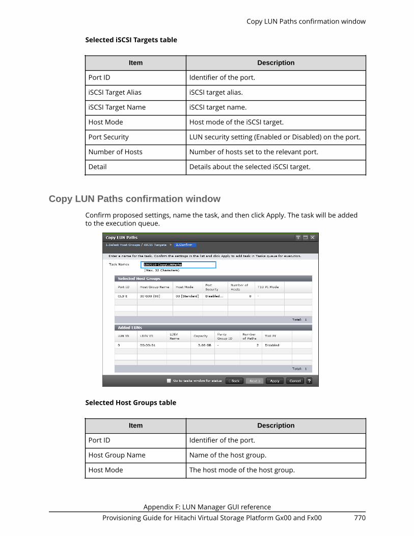
Selected iSCSI Targets table
Item Description
Port ID Identifier of the port.
iSCSI Target Alias iSCSI target alias.
iSCSI Target Name iSCSI target name.
Host Mode Host mode of the iSCSI target.
Port Security LUN security setting (Enabled or Disabled) on the port.
Number of Hosts Number of hosts set to the relevant port.
Detail Details about the selected iSCSI target.
Copy LUN Paths confirmation window
Confirm proposed settings, name the task, and then click Apply. The task will be addedto the execution queue.
Selected Host Groups table
Item Description
Port ID Identifier of the port.
Host Group Name Name of the host group.
Host Mode The host mode of the host group.
Copy LUN Paths confirmation window
Appendix F: LUN Manager GUI referenceProvisioning Guide for Hitachi Virtual Storage Platform Gx00 and Fx00 770

Item Description
Port Security LUN security setting (Enabled or Disabled) on the port.
Number of Hosts Number of hosts registered in the host group.
Asymmetric Access States Asymmetric access states of the port. When usingiSCSI, a hyphen (-) is displayed.
Active/Optimized: Access from the host ispreferentially performed on this port.
Active/Non-Optimized: When the Active/Optimizedport is disabled, access from the host is performed onthis port.
T10 PI Mode The port's T10 PI Mode setting (Enabled or Disabled).
Selected iSCSI Targets (iSCSI)
Item Description
Port ID Identifier of the port.
iSCSI Target Alias iSCSI target alias.
iSCSI Target Name iSCSI target name.
Host Mode Host mode of the iSCSI target.
Copy LUN Paths confirmation window
Appendix F: LUN Manager GUI referenceProvisioning Guide for Hitachi Virtual Storage Platform Gx00 and Fx00 771
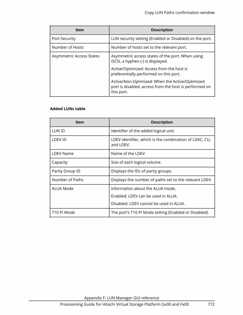
Item Description
Port Security LUN security setting (Enabled or Disabled) on the port.
Number of Hosts Number of hosts set to the relevant port.
Asymmetric Access States Asymmetric access states of the port. When usingiSCSI, a hyphen (-) is displayed.
Active/Optimized: Access from the host ispreferentially performed on this port.
Active/Non-Optimized: When the Active/Optimizedport is disabled, access from the host is performed onthis port.
Added LUNs table
Item Description
LUN ID Identifier of the added logical unit.
LDEV ID LDEV identifier, which is the combination of LDKC, CU,and LDEV.
LDEV Name Name of the LDEV.
Capacity Size of each logical volume.
Parity Group ID Displays the IDs of parity groups.
Number of Paths Displays the number of paths set to the relevant LDEV.
ALUA Mode Information about the ALUA mode.
Enabled: LDEV can be used in ALUA.
Disabled: LDEV cannot be used in ALUA.
T10 PI Mode The port's T10 PI Mode setting (Enabled or Disabled).
Copy LUN Paths confirmation window
Appendix F: LUN Manager GUI referenceProvisioning Guide for Hitachi Virtual Storage Platform Gx00 and Fx00 772

Remove Hosts wizard
Remove Hosts window
Selected Hosts table
Item Description
Port ID Identifier of the port.
HBA WWN WWN of the port.
Host Name Name of the host.
Host Group Name Name of the host group.
Remove selected hosts fromall host groups containing thehosts in the storage system
If this check box is selected, selected hosts areremoved from all host groups containing the hosts inthe storage system.
Remove Hosts confirmation window
Confirm proposed settings, name the task, and then click Apply. The task will be addedto the execution queue.
Remove Hosts wizard
Appendix F: LUN Manager GUI referenceProvisioning Guide for Hitachi Virtual Storage Platform Gx00 and Fx00 773

Selected Hosts table
Item Description
Port ID Identifier of the port.
HBA WWN WWN of the port.
Host Name Name of the host.
Host Group Name Name of the host group.
Edit UUIDs wizard
Edit UUIDs window
Edit UUIDs wizard
Appendix F: LUN Manager GUI referenceProvisioning Guide for Hitachi Virtual Storage Platform Gx00 and Fx00 774

Item Description
Prefix For an OpenVMS server host: The total length of thePrefix and the Initial Number cannot exceed 5characters. If the Prefix is 5 characters, you cannotspecify an Initial Number and vice versa.
For a server host other than OpenVMS: The totallength of the Prefix and the Initial Number cannotexceed 64 characters. If the Prefix is 64 characters, youcannot specify an Initial Number and vice versa.
The following rules apply to UUID:■ These characters cannot be used: \ / : , ; * ? " < > |■ A space character cannot be used for the first and
the last characters.■ UUIDs are case-sensitive. For example, Abc and abc
are different UUIDs.
Initial Number For an OpenVMS server host: The total length of thePrefix and the Initial Number cannot exceed 5characters. If the Prefix is 5 characters, you cannotspecify an Initial Number and vice versa.
For a server host other than OpenVMS: The totallength of the Prefix and the Initial Number cannotexceed 64 characters. If the Prefix is 64 characters, youcannot specify an Initial Number and vice versa.
The following rules apply to the initial number.
Example:■ 1: Up to 9 numbers are added (1, 2, 3 ... 9)■ 08: Up to 92 numbers are added (08, 09, 10 ... 99)
(If the host mode is OpenVMS, the numbers are: 8,9, 10 ... 99)
■ 23: Up to 77 numbers are added (23, 24, 25 ... 99)
Caution: If UUID is blank, the UUID setting is released.
Edit UUIDs confirmation window
Confirm proposed settings, name the task, and then click Apply. The task will be addedto the execution queue.
Edit UUIDs confirmation window
Appendix F: LUN Manager GUI referenceProvisioning Guide for Hitachi Virtual Storage Platform Gx00 and Fx00 775

Selected LUNs table
Item Description
Port ID Identifier of the port.
LUN ID Logical units whose UUID has been changed.
LDEV ID LDEV identifier, which is the combination of LDKC, CU,and LDEV.
LDEV Name Name of the LDEV.
UUID Identifies the set or changed UUID. A blank fieldindicates that the UUID is released.
Capacity Size of each logical volume.
Add New Host window
Add New Host window
Appendix F: LUN Manager GUI referenceProvisioning Guide for Hitachi Virtual Storage Platform Gx00 and Fx00 776

For Fibre Channel Ports
Item Description
HBA WWN Specify the WWN of the port in 16 digits ofhexadecimal numbers.
Host Name Specify the host name.
As a host name, you can use single-byte ASCIIcharacters (alpha-numerals and symbols) up to 64characters. You cannot use the following symbols:
\ / : , ; * ? " < > |
You cannot use blanks at the beginning or end of thehost name. A host name is case-sensitive.
For iSCSI ports
Item Description
HBA iSCSI Name Specify the WWN of the port in 16 digits ofhexadecimal numbers.■ iqn or eui: Select the format of the iSCSI name.■ Text box: Specify the iSCSI name.
For the iqn format, an iSCSI name takes up to 219single-byte ASCII characters (alpha-numerals andsymbols). You cannot use the following symbols:
! " # $ % & ' ( ) * + , / ; < = > ? @ [ \ ] ^ _ ` { | } ~
For the eui format, an iSCSI name takes fixed to 16alpha-numerals.
Add New Host window
Appendix F: LUN Manager GUI referenceProvisioning Guide for Hitachi Virtual Storage Platform Gx00 and Fx00 777

Item Description
Host Name Specify the host name.
As a host name, you can use single-byte ASCIIcharacters (alpha-numerals and symbols) up to 32characters. You cannot use the following symbols:
\ / : , ; * ? " < > |
You cannot use blanks at the beginning or end of thehost name. A host name is case-sensitive.
Change LUN IDs window
Setting field
Item Description
Initial LUN ID Specify the initial LUN ID. If multiple LUs are selected,LUN IDs are set consecutively from the specified LUNID.
Change LUN IDs window
Appendix F: LUN Manager GUI referenceProvisioning Guide for Hitachi Virtual Storage Platform Gx00 and Fx00 778
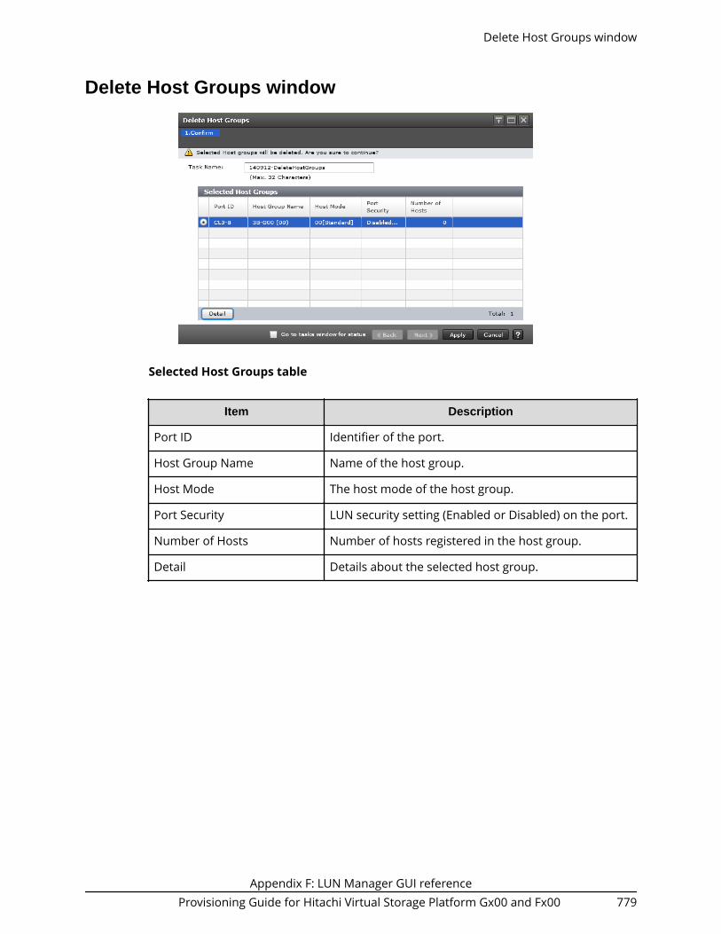
Delete Host Groups window
Selected Host Groups table
Item Description
Port ID Identifier of the port.
Host Group Name Name of the host group.
Host Mode The host mode of the host group.
Port Security LUN security setting (Enabled or Disabled) on the port.
Number of Hosts Number of hosts registered in the host group.
Detail Details about the selected host group.
Delete Host Groups window
Appendix F: LUN Manager GUI referenceProvisioning Guide for Hitachi Virtual Storage Platform Gx00 and Fx00 779

Delete Login WWNs window
Selected Login WWNs table
Item Description
Port ID Identifier of the port.
HBA WWN WWN of the port.
Host Name Name of the host.
Host Group Name Name of the host group.
Delete UUIDs window
Delete Login WWNs window
Appendix F: LUN Manager GUI referenceProvisioning Guide for Hitachi Virtual Storage Platform Gx00 and Fx00 780

Selected LDEVs table
Item Description
LDEV ID LDEV identifier, which is the combination of LDKC, CU,and LDEV.
LDEV Name Name of the LDEV.
UUID This field is blank because the UUID is to be deleted.
Capacity Size of each logical volume.
Host Group Properties windowUse this window to view properties about a selected host group.
Host Group Properties table
Item Description
Port ID Identifier of the port.
Host Group Name Name of the host group.
Host Mode The host mode of the host group.
Host Group Properties window
Appendix F: LUN Manager GUI referenceProvisioning Guide for Hitachi Virtual Storage Platform Gx00 and Fx00 781

Item Description
Host Mode Option The number of host mode options that are enabled.
T10 PI Mode The port's T10 PI Mode setting (Enabled or Disabled).
Resource Group Name (ID) Resource group names and IDs of host groups. The IDis provided in parentheses.
Hosts table
Item Description
HBA WWN WWN of the port.
Host Name Name of the host.
LUN Properties window
LUN Properties table
This table provides information about the selected LUN.
LUN Properties window
Appendix F: LUN Manager GUI referenceProvisioning Guide for Hitachi Virtual Storage Platform Gx00 and Fx00 782

Item Description
LUN ID Identifier of the selected logical unit.
LDEV ID LDEV identifier, which is the combination of LDKC, CU,and LDEV.
LDEV Name Name of the LDEV.
Host Group Name / iSCSITarget Alias
Name of the host group or iSCSI target alias.
iSCSI Target Name Name of the iSCSI target.
Host Mode The host mode of the host group.
Host Mode Option The number of host mode options that are enabled.
Port ID Identifier of the port on this volume.
Type Type of port:■ Fibre: Fibre Channel port.■ iSCSI: iSCSI port.■ NAS Platform (User LU): LDEV used for storing the
NAS user data. This value appears if the NASmodule is installed.
■ NAS Platform (System LU): LDEV used for storingthe NAS firmware system data. This value appearsif the NAS module is installed.
Emulation Type Emulation types for the logical volume (or logicaldevice).
Capacity Size of the logical volume.
Provisioning Type Provisioning type assigned to this logical volume.■ Basic: Internal volume.■ External: External volume.■ DP: V-VOL of Dynamic Provisioning.■ Snapshot: Thin Image volume.
LUN Properties window
Appendix F: LUN Manager GUI referenceProvisioning Guide for Hitachi Virtual Storage Platform Gx00 and Fx00 783

Item Description
LDEV Attribute Displays the attribute of the LDEV.■ Command Device: Command device.■ Remote Command Device: Remote command
device.■ Data Direct Mapping: LDEV with the data direct
mapping attribute enabled.■ NAS Platform (User LU): LDEV used for storing the
NAS user data. This value appears if the NASmodule is installed.
■ NAS Platform (System LU): LDEV used for storingthe NAS firmware system data. This value appearsif the NAS module is installed.
■ - (hyphen): Volume in which the attribute is notdefined.
Command Device Attributes If the logical volume is used as a command device,indicates the status of the attributes on this LDEV.■ Security: Indicates the status of command device
security is (enable or disable).■ User Authentication: Indicates the status of user
authentication (enable or disable).■ Device Group Definition: Indicates the status of
device group definition (enable or disable).
Access Attribute Access attribute assigned to this LDEV.■ Read/Write: Both read and write operations are
permitted on the logical volume.■ Read-only: Read operations are permitted on the
logical volume.■ Protect: Neither read nor write operations are
permitted.
Number of Paths Number of paths set for the LDEV.
UUID User-definable LUN identifier. This field is blank if theUUID is not set.
CLPR Cache logical partition numbers.
For detailed information about CLPRs, see thePerformance Guide.
LUN Properties window
Appendix F: LUN Manager GUI referenceProvisioning Guide for Hitachi Virtual Storage Platform Gx00 and Fx00 784

Item Description
Encryption Displays the information about parity groupencryption.■ Enable: Encryption setting of a parity group in
which the LDEV is placed is enabled. Or the virtualvolume associated with the pool whose pool-VOLsare enabled of the encryption setting.
■ Disable: Encryption setting of a parity group (or apool) in which the LDEV is placed is disabled. Or thevirtual volume associated with the pool whose pool-VOLs are disabled of the encryption setting.
■ Mixed: This status is displayed when two or more ofthe following are specified as pool-VOLs:● Volume encryption setting is enabled.● Volume encryption setting is disabled.● External volume
Caution: The data encryption is not ensured in thepool that has the Mixed encryption setting. Tomanage the data encryption securely, use the poolwith an encryption setting of Enabled or Disabled.
■ - (hyphen): External volume or migration volume. Asfor DP-VOL of Dynamic Provisioning, the pool-VOLin the pool of which DP-VOL belongs is an externalvolume, or the pool of which DP-VOL belongs isbeing blocked.
This item is not displayed when using Virtual StoragePlatform G200.
ALUA Mode Information about the ALUA mode.■ Enabled: LDEV can be used in ALUA.■ Disabled: LDEV cannot be used in ALUA.
Asymmetric Access States Asymmetric access states of the port. When usingiSCSI, a hyphen (-) is displayed.
Active/Optimized: Access from the host ispreferentially performed on this port.
Active/Non-Optimized: When the Active/Optimizedport is disabled, access from the host is performed onthis port.
T10 PI The LDEV's T10 PI attribute setting (Enabled orDisabled).
LUN Properties window
Appendix F: LUN Manager GUI referenceProvisioning Guide for Hitachi Virtual Storage Platform Gx00 and Fx00 785

Item Description
Data Direct Mapped LDEV Displays LDEV ID of pool-VOL in the pool with datadirect mapping enabled.
A hyphen (-) is displayed if the data direct mappingattribute is disabled.
Capacity Saving Capacity saving setting of the LDEV:■ Compression: The compression function is used.■ Deduplication and Compression: The deduplication
and compression functions are used.■ Disabled: The capacity saving function is not used.
Capacity Saving Status Status of the capacity saving function:■ Enabling: The format for enabling the capacity
saving function is being performed.■ Rehydrating: The format for disabling the capacity
saving function is being performed.■ Deleting Volume: The deletion of DP-VOL whose
capacity saving function is Enabled is beingperformed.
■ Enabled: The capacity saving function is enabled.■ Disabled: The capacity saving function is disabled.■ Failed: Data cannot be secured.■ - (hyphen): The LDEV does not support the capacity
saving function.
Deduplication Data Displays whether the deduplication function is appliedto the volume (DP-VOL).■ Enabled: The deduplication function is applied.■ Disabled: The deduplication function is not applied.■ - (hyphen): The LDEV is not a DP-VOL, or the
firmware version does not support deduplication.
If the capacity saving setting of a DP-VOL isDeduplication and Compression, Enabled is displayedeven if the used capacity is 0.
When the capacity saving setting is Disabled and thedisabling of the capacity saving setting is in process,Enabled is displayed for Deduplication Data whilededuplicated data remains in the DP-VOL. When thedisabling of the capacity saving setting is complete andno deduplicated data remains in the DP-VOL, Disabledis displayed.
LUN Properties window
Appendix F: LUN Manager GUI referenceProvisioning Guide for Hitachi Virtual Storage Platform Gx00 and Fx00 786

Item Description
Virtual Storage Machine Information about the virtual storage machine.■ Model / Serial Number: Model name and serial
number of the virtual storage machine that has theLDEV.
■ LDEV ID: Virtual LDEV ID. If a Virtual LDEV ID is notassigned to the LDEV, this column is blank.
■ Device Name: Virtual device name, which is acombination of the virtual emulation type, virtualLUSE volume number, and the virtual CVS attribute.Values of the virtual emulation type, virtual LUSEvolume number, and virtual CVS attribute appearonly for items that have been set. This column isblank when the virtual emulation type, virtual LUSEvolume number, and virtual CVS attribute are notset. If the virtual CVS attribute is set, CVS is attachedas the suffix to the device name.
■ SSID: Virtual SSID. If Virtual SSID is not set for anLDEV, this column is blank.
■ Attribute: Virtual LDEV attribute. If the attribute isnot set for LDEV, this column is blank.
LUNs table
This table provides information about the LUN ID registered for the selected LDEV.
Item Description
Port ID Identifier of the port.
Type Type of port:■ Fibre: Fibre Channel port.■ iSCSI: iSCSI port.■ NAS Platform (User LU): LDEV used for storing the
NAS user data. This value appears if the NASmodule is installed.
■ NAS Platform (System LU): LDEV used for storingthe NAS firmware system data. This value appearsif the NAS module is installed.
Host Group Name / iSCSITarget Alias
Name of the host group or iSCSI target alias.
LUN Properties window
Appendix F: LUN Manager GUI referenceProvisioning Guide for Hitachi Virtual Storage Platform Gx00 and Fx00 787

Item Description
iSCSI Target Name Name of the iSCSI target.
LUN ID Identifier of the logical unit.
Asymmetric Access States Asymmetric access states of the port. When usingiSCSI, a hyphen (-) is displayed.
Active/Optimized: Access from the host ispreferentially performed on this port.
Active/Non-Optimized: When the Active/Optimizedport is disabled, access from the host is performed onthis port.
Hosts table
Lists the hosts that belong to the host group in which the selected LUN ID is registered.
Item Description
Type Type of port:■ Fibre: Fibre Channel port.■ iSCSI: iSCSI port.■ NAS Platform (User LU): LDEV used for storing the
NAS user data. This value appears if the NASmodule is installed.
■ NAS Platform (System LU): LDEV used for storingthe NAS firmware system data. This value appearsif the NAS module is installed.
HBA WWN / iSCSI Name WWN of HBA or iSCSI name.
Host Name Name of the host.
Authentication window
Authentication window (Fibre Channel folder selected)
To display the Authentication window, the Hitachi Device Manager - Storage Navigatorsecondary windows must be usable in advance. If the user authentication settings areperformed, you must set the modify mode in the secondary window. The modify mode isan exclusive access control for operations of secondary windows. If you set the modifymode to ON, other users or programs cannot apply settings to a storage system. If youclose the secondary window, the modify mode is released. For more information about
Authentication window
Appendix F: LUN Manager GUI referenceProvisioning Guide for Hitachi Virtual Storage Platform Gx00 and Fx00 788

Hitachi Device Manager - Storage Navigator secondary windows and modify mode, seethe System Administrator Guide of your storage system.
On the menu bar, click Actions > Port/Host Group, Fibre > Authentication. TheAuthentication secondary window opens.
Port tree
The Port tree provides information about user authentication on each port.
Double-click the Fibre folder to show the Fibre Channel ports in the storage system.
If you select the Fibre folder, information about ports and fabric switches appears in thetable on the right of the tree. The Fibre folder is available only if the storage systemcontains a Fibre Channel board.
Item Description
CLX-YThis icon indicates a Fibre Channel port.
Port information list
Item Description
Port Name Fibre Channel port names.
Authentication window (Fibre Channel folder selected)
Appendix F: LUN Manager GUI referenceProvisioning Guide for Hitachi Virtual Storage Platform Gx00 and Fx00 789

Item Description
Time out The period of time between authentication sessions to thesame port. If the previous authentication session to a portfailed, the next authentication session starts after the specifiedperiod of time elapses. The unit is seconds.
Refusal Intvl. If authentication fails for the number of times specified inRefusal Freq., connection to the port fails. Refusal Intvl. showsthe interval (in minutes) from when connection to a port fails towhen the next authentication session starts.
Refusal Freq. Number of times that authentication is allowed for connectionto a port. If authentication fails for the specified number oftimes, connection to the port fails.
Fabric Switch information list
Item Description
Port Name Fibre Channel port name.
User Name User name of the fabric switch.
Mode Mode of authentication between ports and fabric switches.■ bidirectional: The authentication mode is mutual.■ unidirectional: The authentication mode is not mutual.
Authentication Indicates whether to perform authentication for the fabricswitch.■ Enable: The fabric switch is a target of user authentication.■ Disable: The fabric switch is not a target of user
authentication.
Authentication window (Fibre Channel port selected)
Hitachi Device Manager - Storage Navigator secondary windows must be defined for usein advance. When you select Modify from this window to make user authenticationsettings, other users or programs are prevented from changing storage system settings.When you close the secondary window, Modify mode is released. For more informationabout Hitachi Device Manager - Storage Navigator secondary windows and Modify mode,see the System Administrator Guide of your storage system.
On the menu bar, click Actions > Port/Host Group, Fibre > Authentication. TheAuthentication secondary window opens.
Authentication window (Fibre Channel port selected)
Appendix F: LUN Manager GUI referenceProvisioning Guide for Hitachi Virtual Storage Platform Gx00 and Fx00 790

Port tree
Use this tree to find information about user authentication on each port. When youselect a port from this tree, the Authentication Information (Target) list on the rightprovides user information of the hosts that are registered on the port. In addition, theAuthentication Information (Host) list below the Authentication Information (Target) listprovides the user information of the selected port.
Double-click the Fibre folder to view all Fibre Channel ports in the storage system. TheFibre folder is available only if the storage system contains a Fibre Channel board.Double-click the Fibre Channel ports to view host groups in that port. The host groupname appears beside the icon.
Item Description
CLX-YIndicates a Fibre Channel port.
host group nameIndicates that the host group performs authenticationof hosts.
host group name Indicates that the host group does not performauthentication of hosts.
Authentication information (target) list
The list on the right provides user information of the host groups that are allowed toconnect to the port or host group specified in the tree.
Authentication window (Fibre Channel port selected)
Appendix F: LUN Manager GUI referenceProvisioning Guide for Hitachi Virtual Storage Platform Gx00 and Fx00 791

Item Description
Group Name Names of the host group.
User Name User name of the host group. When the user name is not definedfor a host group, this column is blank.
Authentication Indicates whether to perform user authentication for the host.■ Enable: The host is a target of user authentication.■ Disable: The host is not a target of user authentication.
Authentication information (host) list
Below the User Information (Target) list appears a list that provides user information ofthe host selected in the port or host group in the tree. In this list, you can register up to64 user information items.
Item Description
Group Name Name of the host group.
User Name User name of the host. When the user name is not defined for ahost, this column is blank.
Protocol Indicates the protocol in use for user authentication. Always CHAP.
Add New User Information (Host) window
Item Description
Group Name Select the group name where the user will be registered.
User Name Specify the user name of the host. 16 hexadecimal characters canbe used. The user name is not case-sensitive.
Add New User Information (Host) window
Appendix F: LUN Manager GUI referenceProvisioning Guide for Hitachi Virtual Storage Platform Gx00 and Fx00 792

Item Description
Secret Specify the secret to be used for host authentication.
Use 12 to 32 characters, including alphanumerics, spaces, and thefollowing symbols: . - + @ _ = : / [ ] , ~
Re-enter Secret Specify the secret again for confirmation. An error occurs if youenter incorrect characters, and then click OK.
Protocol Protocol to be used for user authentication. This protocol is alwaysCHAP (Challenge-Handshake Authentication Protocol).
Change User Information (Host) window
Item Description
Group Name Group name where the user is registered.
User Name Specify the user name of the host. 16 hexadecimal characters canbe used. The user name is not case-sensitive.
Secret Specify the secret to be used for host authentication.
Use 12 to 32 characters, including alphanumerics, spaces, and thefollowing symbols: . - + @ _ = : / [ ] , ~
Re-enter Secret Specify the secret again for confirmation. An error occurs if youenter incorrect characters, and then click OK.
Protocol Protocol to be used for user authentication. This protocol is alwaysCHAP (Challenge-Handshake Authentication Protocol).
Change User Information (Host) window
Appendix F: LUN Manager GUI referenceProvisioning Guide for Hitachi Virtual Storage Platform Gx00 and Fx00 793

Clear Authentication information window
Item Description
No Item number.
Group Name Group name to be deleted.
User Name The name of the user to be deleted.
Clear Authentication information window
Appendix F: LUN Manager GUI referenceProvisioning Guide for Hitachi Virtual Storage Platform Gx00 and Fx00 794

Specify Authentication Information window
When selecting a port
When selecting a host group
Item Description
Port Name Port name where the authentication information is specified in thewindow that opens when you select a port.
Group Name Group name where the authentication information is specified inthe window that opens when you select a host group.
User Name Specify the user name of the host. 16 hexadecimal characters canbe used. The user name is not case-sensitive.
Secret Specify the secret to be used for host authentication.
Use 12 to 32 characters, including alphanumerics, spaces, and thefollowing symbols: . - + @ _ = : / [ ] , ~
Re-enter Secret Specify the secret again for confirmation. An error occurs if youenter incorrect characters, and then click OK.
Specify Authentication Information window
Appendix F: LUN Manager GUI referenceProvisioning Guide for Hitachi Virtual Storage Platform Gx00 and Fx00 795

Set Port Information
Item Description
Time out Specify the period of time from when authentication fails to whenthe next authentication session is ended. This period of time isbetween 15 to 60 seconds. The initial value is 45.
Refusal Interval Specify the interval from when connection to a port fails to whenthe next authentication session starts, with up to 60 minutes. Theinitial value is 3.
RefusalFrequency
Specify the number of times of authentication allowable forconnection to a port with up to 10 times. The initial value is 3.
Default Setting(User Name/Secret) window
Item Description
Port Name Fibre Channel port names.
User Name Specify the user name of the Fibre Channel switch with 16characters. You can use hexadecimal characters in a user name. Theuser name is not case-sensitive.
Secret Specify the secret (that is, a password used in CHAP authentication)between 12 to 32 characters. You can use alphanumeric characters,spaces, and the following symbols in a secret:
. - + @ _ = : / [ ] , ~
Set Port Information
Appendix F: LUN Manager GUI referenceProvisioning Guide for Hitachi Virtual Storage Platform Gx00 and Fx00 796

Item Description
Re-enter secret Specify the secret, again, for confirmation.
Edit Command Devices wizardThe system administrator can enter CCI commands from open-system hosts to performoperations such as TrueCopy or ShadowImage operations or both on logical devices. Forexample, CCI commands can be used to create and to split pairs. If you want to allow thesystem administrator to enter CCI commands from open-system hosts, you must specifyat least one logical device as the command device. If desired, you must also applycommand device security to other logical devices in the storage system.
Use the Edit Command Devices window to edit command devices.
Caution: The following volumes cannot be specified as a command device:■ Volume whose access attribute is other than read/write.■ TrueCopy pair volume.■ Global-active device pair volume.■ ShadowImage pair volume.■ Universal Replicator pair volume.■ Virtual volume (V-VOL) for Thin Image.■ Volume reserved by Data Retention Utility.■ Journal volume.■ Pool volume that includes a DP-VOL with the direct mapping attribute
enabled.■ Remote command device.■ LDEV of the ALU attribute.■ Quorum disk for global-active device.■ LDEV with ALUA mode enabled.■ LDEV with the T10 PI attribute enabled.■ LDEV with NAS Platform (User LU) enabled.■ LDEV with NAS Platform (System LU) enabled.
Procedure
1. Click Storage Systems, and then expand the Storage Systems tree.2. Click Logical Devices.3. Click More Actions > Edit Command Devices.
The Edit Command Devices window opens.
Edit Command Devices wizard
Appendix F: LUN Manager GUI referenceProvisioning Guide for Hitachi Virtual Storage Platform Gx00 and Fx00 797

Edit Command Devices window
If you want to enable command device security, user authentication, and device groupdefinition, you must enable the command device in this window.
If the command device is disabled, you cannot enable command device security, userauthentication, and device group definition.
Item Description
Command Device Select Enable to enable command devices. SelectDisable to release command devices.
Command Device Security Select Enable to apply command device security to alogical device in a storage system. Select Disable torelease command device security.
If you want to protect logical volumes from the use ofCCI commands, you must apply command devicesecurity to the logical volumes. If command devicesecurity is applied to a logical device, the logical devicewill not be affected by CCI commands issued viacommand devices from the hosts.1
User Authentication Select Enable to apply user authentication to acommand device. Select Disable to release userauthentication.1
Device Group Definition Select Enable to apply device group definition to acommand device. Select Disable to release devicegroup definition.1
Note:
1. For details about command device attribute settings, see the Command ControlInterface User and Reference Guide.
Edit Command Devices window
Appendix F: LUN Manager GUI referenceProvisioning Guide for Hitachi Virtual Storage Platform Gx00 and Fx00 798

Edit Command Devices confirmation window
Confirm proposed settings, name the task, and then click Apply. The task will be addedto the execution queue.
Selected LDEVs table
Item Description
LDEV ID LDEV identifier, which is the combination of LDKC, CU,and LDEV.
LDEV Name Name of the LDEV.
Parity Group ID Identifier of the parity group.
Capacity Size of each logical volume.
Provisioning Type Provisioning types for each logical volume.■ Basic: Internal volume.■ External: External volume.■ DP: V-VOL of Dynamic Provisioning.■ Snapshot: Thin Image volume.
Command Device Indicates whether the selected logical device is acommand device.■ Enabled: The command devices are enabled.■ Disabled: The logical device is not a command
device.
Edit Command Devices confirmation window
Appendix F: LUN Manager GUI referenceProvisioning Guide for Hitachi Virtual Storage Platform Gx00 and Fx00 799

Item Description
Command Device Security Indicates whether command device security is appliedto the selected command device.■ Enabled: Command device security is applied to the
command device.■ Disabled: Command device security is not applied
to the command device.
User Authentication Indicates whether user authentication is applied to theselected command device.■ Enabled: User authentication is applied to the
command device.■ Disabled: User authentication is not applied to the
command device.
Device Group Definition Indicates whether the device group definition isapplied to the selected command device.■ Enabled: Device group definition is applied to the
command device.■ Disabled: Device group definition is not applied to
the command device.
Edit Command Devices confirmation window
Appendix F: LUN Manager GUI referenceProvisioning Guide for Hitachi Virtual Storage Platform Gx00 and Fx00 800

Host-Reserved LUNs window
LUNs table
LUNs reserved by hosts are displayed.
Item Description
Port ID Displays names of ports.
LUN ID Displays IDs of the LUNs.
LDEV ID LDEV identifier, which is the combination of LDKC, CU,and LDEV.
LDEV Name Displays names of LDEVs.
Number of Paths Displays the number of paths set for the relevant LDEV.
Host-Reserved Status Displays the status of the host-reserved LUN.■ Open Reserved: LUN is reserved by the Open
Reserved command.■ Persistent Reserved: LUN is reserved by the
Persistent Group Reserve command.■ ACA Active: LUN is in the ACA active status.
Host-Reserved LUNs window
Appendix F: LUN Manager GUI referenceProvisioning Guide for Hitachi Virtual Storage Platform Gx00 and Fx00 801
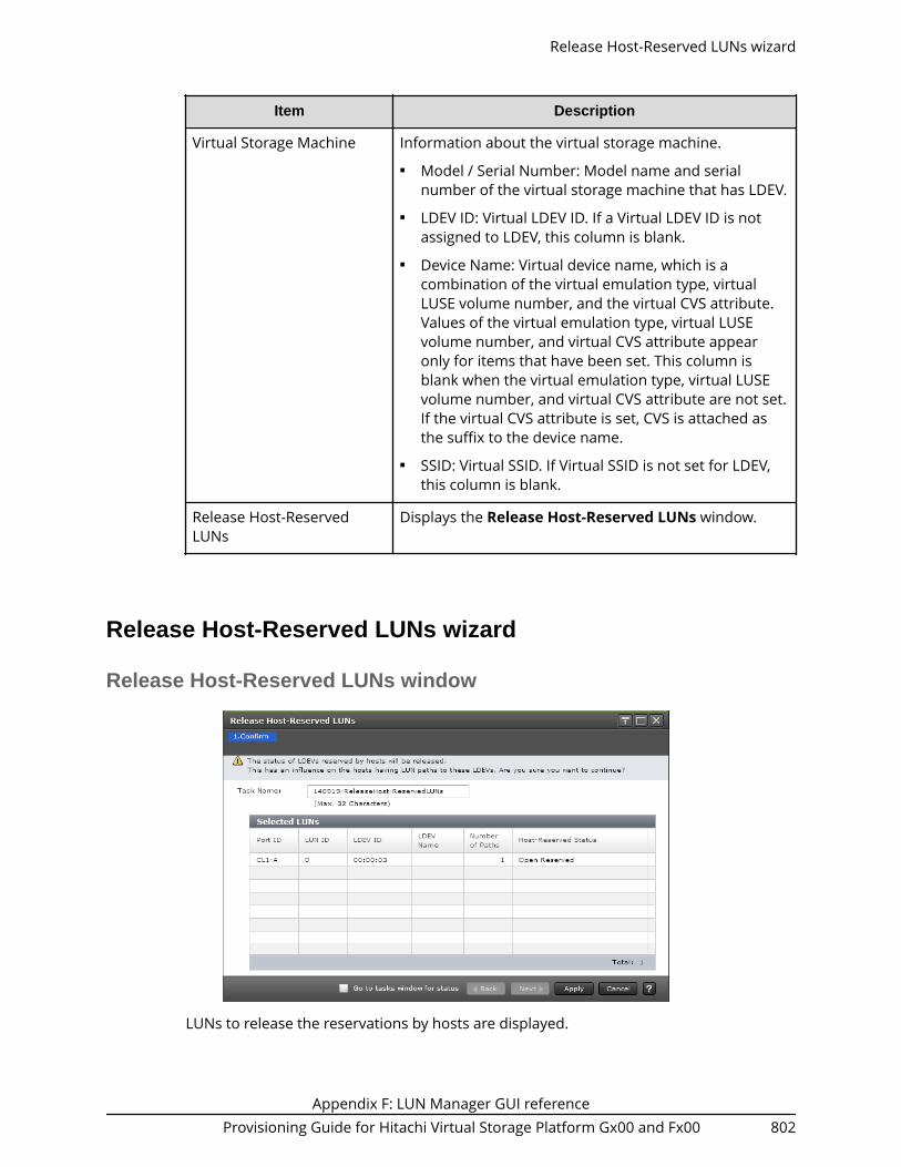
Item Description
Virtual Storage Machine Information about the virtual storage machine.■ Model / Serial Number: Model name and serial
number of the virtual storage machine that has LDEV.■ LDEV ID: Virtual LDEV ID. If a Virtual LDEV ID is not
assigned to LDEV, this column is blank.■ Device Name: Virtual device name, which is a
combination of the virtual emulation type, virtualLUSE volume number, and the virtual CVS attribute.Values of the virtual emulation type, virtual LUSEvolume number, and virtual CVS attribute appearonly for items that have been set. This column isblank when the virtual emulation type, virtual LUSEvolume number, and virtual CVS attribute are not set.If the virtual CVS attribute is set, CVS is attached asthe suffix to the device name.
■ SSID: Virtual SSID. If Virtual SSID is not set for LDEV,this column is blank.
Release Host-ReservedLUNs
Displays the Release Host-Reserved LUNs window.
Release Host-Reserved LUNs wizard
Release Host-Reserved LUNs window
LUNs to release the reservations by hosts are displayed.
Release Host-Reserved LUNs wizard
Appendix F: LUN Manager GUI referenceProvisioning Guide for Hitachi Virtual Storage Platform Gx00 and Fx00 802

Selected LUNs table
Item Description
Port ID Displays names of ports.
LUN ID Displays IDs of the LUNs.
LDEV ID LDEV identifier, which is the combination of LDKC, CU,and LDEV.
LDEV Name Displays names of LDEVs.
Number of Paths Displays the number of paths set for the relevant LDEV.
Host-Reserved Status Displays the status of the host-reserved LUN.■ Open Reserved: LUN is reserved by the Open
Reserved command.■ Persistent Reserved: LUN is reserved by the
Persistent Group Reserve command.■ ACA Active: LUN is in the ACA active status.
View Login WWN Statuses window
View Login WWN Statuses window
Appendix F: LUN Manager GUI referenceProvisioning Guide for Hitachi Virtual Storage Platform Gx00 and Fx00 803

Login WWNs table
Item Description
Port ID Displays names of ports.
HBA WWN Displays the HBA WWNs and their icons.
Host Name Displays the names of hosts.
Host Group Name Displays the names of host groups.
Status Displays the host login status (Logged In or Logged Out).
View Login iSCSI Name Statuses window
Login iSCSI Names table
Item Description
Port ID Identifier of the port.
HBA iSCSI Name HBA iSCSI name.
Host Name Host name.
iSCSI Target Alias iSCSI target alias.
View Login iSCSI Name Statuses window
Appendix F: LUN Manager GUI referenceProvisioning Guide for Hitachi Virtual Storage Platform Gx00 and Fx00 804

Item Description
iSCSI Target Name iSCSI target name.
Status Status of the login from the host. LoggedIn or Logged Out appears.
Port Properties window
Port Properties window
Appendix F: LUN Manager GUI referenceProvisioning Guide for Hitachi Virtual Storage Platform Gx00 and Fx00 805

Port Properties table
Item Description
Port ID Identifier of the port.
Type Type of the port.
iSCSI: iSCSI port.
IPv4 Information about IPv4. A hyphen (-) isdisplayed if the iSCSI virtual port mode isenabled for the port.■ IP Address: IP address of the port. If
two or more ports are selected, thisinformation cannot be specified.
■ Subnet Mask: Subnet mask of the port.■ Default Gateway: Default gateway of
the port.
IPv6 Information about IPv6. A hyphen (-) isdisplayed if the iSCSI virtual port mode isenabled for the port.■ Mode: IPv6 setting (Enabled or
Disabled) for the port.■ Link Local Address: Link local address
for the port.■ Link Local Address Status: Link local
address status for the port.■ Global Address: The first global
address for the port.■ Global Address Status: Status of the
first global address for the port.■ Global Address 2: The second global
address for the port.■ Global Address 2 Status: Status of the
second global address for the port.■ Subnet Prefix: Subnet prefix for the
port address.■ Assigned Default Gateway: Assigned
default gateway address for the port.■ Current Default Gateway: Current
default gateway address for the port.■ Default Gateway Status: Default
gateway status.
Port Properties window
Appendix F: LUN Manager GUI referenceProvisioning Guide for Hitachi Virtual Storage Platform Gx00 and Fx00 806

Item Description
Speed Data transfer speed for the selected port.
Security LUN security setting (Enabled or Disabled)on the port.
TCP Port Number TCP port number. A hyphen (-) isdisplayed if the iSCSI virtual port mode isenabled for the port.
Ethernet MTU Size MTU size on Ethernet. A hyphen (-) isdisplayed if the iSCSI virtual port mode isenabled for the port.■ MTU: Specified MTU size.■ Linked MTU: Present MTU size for the
data transfer.
MAC Address MAC address.
Keep Alive Timer Keep alive timer setting. A hyphen (-) isdisplayed if the iSCSI virtual port mode isenabled for the port.
Selective ACK Selective ACK setting (Enabled orDisabled) of the port. A hyphen (-) isdisplayed if the iSCSI virtual port mode isenabled for the port.
Delayed ACK Delayed ACK setting (Enabled or Disabled)of the port. A hyphen (-) is displayed if theiSCSI virtual port mode is enabled for theport.
Maximum Window Size Maximum window size setting. A hyphen(-) is displayed if the iSCSI virtual portmode is enabled for the port.
iSNS Server Information about the iSNS server.■ Mode: iSNS server setting (Enabled or
Disabled).■ IP Address: IP address of the iSNS
server.■ TCP Port Number: TCP port number of
the iSNS server.
Port Properties window
Appendix F: LUN Manager GUI referenceProvisioning Guide for Hitachi Virtual Storage Platform Gx00 and Fx00 807

Item Description
VLAN Information about VLAN. A hyphen (-) isdisplayed if the iSCSI virtual port mode isenabled for the port.■ Tagging Mode: Tagging mode setting
(Enabled or Disabled) for the port.■ ID: VLAN identifier.
iSCSI Virtual Port Mode Information about the setting of the iSCSIvirtual port mode for a port.■ Enabled: The iSCSI virtual port mode is
enabled for the port.■ Disabled: The iSCSI virtual port mode is
disabled for the port.■ - (hyphen): The port does not support
the iSCSI virtual port mode.
CHAP User Properties window
CHAP User Properties window
Appendix F: LUN Manager GUI referenceProvisioning Guide for Hitachi Virtual Storage Platform Gx00 and Fx00 808

CHAP User Properties table
Item Description
User Name User name.
Port ID Identifier of the port.
Number of iSCSI Targets Number of iSCSI targets.
iSCSI Targets table
Item Description
iSCSI Target Alias iSCSI target alias.
iSCSI Target Name iSCSI target name.
Authentication Information about the authentication.■ Method: Authentication method that is
CHAP, None, or Comply with HostSetting
■ Mutual CHAP: Mutual CHAP settingthat is Enabled or Disabled
■ User Name■ Number of Users
CHAP User Properties window
Appendix F: LUN Manager GUI referenceProvisioning Guide for Hitachi Virtual Storage Platform Gx00 and Fx00 809

Host Properties window
Host Properties table
Item Description
HBA iSCSI Name HBA iSCSI Names and their icons.
Host Name Name of hosts.
Port ID Identifier of the port.
Number of iSCSI Targets Number of iSCSI targets.
iSCSI Targets table
Item Description
iSCSI Target Alias iSCSI target alias.
iSCSI Target Name iSCSI target name.
Host Properties window
Appendix F: LUN Manager GUI referenceProvisioning Guide for Hitachi Virtual Storage Platform Gx00 and Fx00 810

Item Description
Host Mode Host mode of the host group.
Port Security LUN security setting (Enabled or Disabled)on the port.
Number of Hosts Number of hosts registered in the hostgroup.
Create iSCSI Targets wizard
Create iSCSI Targets window
Create iSCSI Targets wizard
Appendix F: LUN Manager GUI referenceProvisioning Guide for Hitachi Virtual Storage Platform Gx00 and Fx00 811

Setting field
Item Description
iSCSI Target Alias ■ Use Default Name: If this check box isselected, the iSCSI target alias is inputby default.
■ Text box: Specify the iSCSI target alias.
If Use Default Name is selected, thedefault value appears with thefollowing format:
Port-ID-GiSCSI-target-ID
For instance, 1A-G00 appears.
If Use Default Name is not selected, theblank field appears. You can enter upto 32 ASCII characters and symbols,with the exception of: \ / , ; * ? " < > |.
Create iSCSI Targets window
Appendix F: LUN Manager GUI referenceProvisioning Guide for Hitachi Virtual Storage Platform Gx00 and Fx00 812

Item Description
iSCSI Target Name ■ iqn or eui: Select the format which youwant to use.
■ Use Default Name: If this check box isselected, the iSCSI target name is inputby default.
■ Text box: Specify the iSCSI target name.
If Use Default Name is selected, thedefault value appears with thefollowing format:
For the iqn format: iqn.1994-04.jp.co.hitachi:rsd.Model-name.t.Serial-number.Port-identifieriSCSI-target-identifier
For instance, iqn.1994-04.jp.co.hitachi:rsd.r80.t.62507.1a000 appears.
For the eui format: eui.(6-digits-of-OUI)(Fixed-value-given-to-each-storage)(Serial-number)(Port-name)(iSCSI-target-identifier)
For instance,eui.02004567A425678Dappears.
If Use Default Name is not selected, thedefault value for the iqn format is asfollows:
For the iqn format: iqn.1994-04.jp.co.hitachi:rsd.Model-name.t.Serial-number.Port-identifieriSCSI-target-identifier
You can enter up to 219 ASCIIcharacters and symbols, with theexception of: \ / , ; * ? " < > |.
If Use Default Name is not selected, thedefault value for the eui format isblank. You can enter fixed to 16alphanumeric characters that are case-sensitive.
Create iSCSI Targets window
Appendix F: LUN Manager GUI referenceProvisioning Guide for Hitachi Virtual Storage Platform Gx00 and Fx00 813
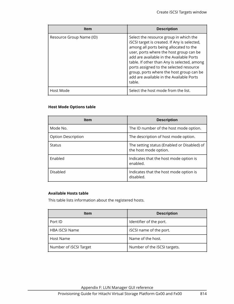
Item Description
Resource Group Name (ID) Select the resource group in which theiSCSI target is created. If Any is selected,among all ports being allocated to theuser, ports where the host group can beadd are available in the Available Portstable. If other than Any is selected, amongports assigned to the selected resourcegroup, ports where the host group can beadd are available in the Available Portstable.
Host Mode Select the host mode from the list.
Host Mode Options table
Item Description
Mode No. The ID number of the host mode option.
Option Description The description of host mode option.
Status The setting status (Enabled or Disabled) ofthe host mode option.
Enabled Indicates that the host mode option isenabled.
Disabled Indicates that the host mode option isdisabled.
Available Hosts table
This table lists information about the registered hosts.
Item Description
Port ID Identifier of the port.
HBA iSCSI Name iSCSI name of the port.
Host Name Name of the host.
Number of iSCSI Target Number of the iSCSI targets.
Create iSCSI Targets window
Appendix F: LUN Manager GUI referenceProvisioning Guide for Hitachi Virtual Storage Platform Gx00 and Fx00 814

Item Description
New Host Indicates whether the host is newlyconnected.■ Yes: The host is newly added and has
never been connected via a cable toany port in the storage system.
■ No: The host has been connected via acable to another port.
Port Security LUN security setting (Enabled or Disabled)on the port.
Add New Host Adds a new host. Or, select host busadapters then click to assign a nicknameto the host bus adapter.
Available Ports table
This table lists the registered ports.
Item Description
Port ID Identifier of the port.
Security LUN security setting (Enabled or Disabled)on the port.
Authentication Method
Select the CHAP Authentication setting from Enable, Disable, or Use Host Setting.
CHAP Authentication Options
Item Description
Mutual CHAP Select the mutual authentication mode toEnable or Disable. If Disable is selected,the unidirectional authentication mode isperformed
Create iSCSI Targets window
Appendix F: LUN Manager GUI referenceProvisioning Guide for Hitachi Virtual Storage Platform Gx00 and Fx00 815

Item Description
User Name Specify the user name. If Disable isselected in the Mutual CHAP, this item isoptionally specified. If Mutual is selected,this item must be specified. Specify theuser name between 1 to 223 characters.
You can use case-sensitive alphanumericcharacters, spaces, and the followingsymbols: . - + @ _ = : [ ] , ~
Secret Specify the secret which is used for hostauthentication. If Disable is selected in theMutual CHAP, this item is optionallyspecified. If Mutual is selected, this itemmust be specified. Specify the secret (thatis, a password used in CHAPauthentication) between 12 to 32characters.
You can use alphanumeric characters,spaces, and the following symbols in asecret: . - + @ _ = : [ ] ~
Re-enter Secret Specify the secret again for confirmation.If incorrect, an error message appearswhen clicking Add.
Available CHAP Users table
Item Description
Port ID Identifier of the port.
User Name Name of the user.
User Seq. No. User sequence identifier.
Number of iSCSI Target Number of the iSCSI targets.
New CHAP User Indicates whether the CHAP user is newlyadded or not.
Yes: New CHAP user added by using of theAdd New CHAP User window.
No: Existing CHAP user.
Port Security LUN security setting (Enabled or Disabled)on the port.
Create iSCSI Targets window
Appendix F: LUN Manager GUI referenceProvisioning Guide for Hitachi Virtual Storage Platform Gx00 and Fx00 816

Item Description
Add New CHAP User Click this button to add the new CHAPuser. If the new CHAP user is added, PortID is blank.
Add button
Adds the settings to the Selected iSCSI Targets table.
Selected iSCSI Targets table
Item Description
Port ID Identifier of the port.
iSCSI Target Alias iSCSI target alias.
iSCSI Target Name iSCSI target name.
Host Mode The host mode of the iSCSI target.
Port Security LUN security setting (Enabled or Disabled)on the port.
Number of Hosts Number of hosts registered in the iSCSItarget.
Authentication Information about the authentication.■ Method: Authentication method that is
CHAP, None, or Comply with HostSetting
■ Mutual CHAP: Mutual CHAP settingthat is Enabled or Disabled
■ User Name■ Number of Users
Resource Group Name (ID) Resource group name and identifier of theresource group containing the iSCSItarget.
Virtual Storage Machine Model name and serial number of thevirtual storage machine.
Detail Details about the selected iSCSI target.
Remove Removes the selected iSCSI targets fromthis table.
Create iSCSI Targets window
Appendix F: LUN Manager GUI referenceProvisioning Guide for Hitachi Virtual Storage Platform Gx00 and Fx00 817

Next Task Option
Click Next to go to the task setting window, which is indicated in Next Task Option.
Create iSCSI Targets Confirm window
Note: If multiple tasks that are connected in one wizard are executed, thiswindow shows all configured items of tasks. To show information ofconfigured items other than this topic, click Back to display related settingwindows, then click Help.
Selected iSCSI Targets table
Item Description
Port ID Identifier of the port.
iSCSI Target Alias iSCSI target alias.
iSCSI Target Name iSCSI target name.
Host Mode The host mode of the iSCSI target.
Port Security LUN security setting (Enabled or Disabled)on the port.
Number of Hosts Number of hosts registered in the iSCSItarget.
Create iSCSI Targets Confirm window
Appendix F: LUN Manager GUI referenceProvisioning Guide for Hitachi Virtual Storage Platform Gx00 and Fx00 818

Item Description
Authentication Information about the authentication.■ Method: Authentication method that is
CHAP, None, or Comply with HostSetting
■ Mutual CHAP: Mutual CHAP settingthat is Enabled or Disabled
■ User Name■ Secret: If the secret is specified, the
character string of six asterisks (*)appears.
■ Number of Users
Resource Group Name (ID) Resource group name and identifier of theresource group containing the iSCSItarget.
Virtual Storage Machine Model name and serial number of thevirtual storage machine.
Detail Details about the selected iSCSI target.
Edit iSCSI Targets wizard
Edit iSCSI Targets wizard
Appendix F: LUN Manager GUI referenceProvisioning Guide for Hitachi Virtual Storage Platform Gx00 and Fx00 819

Edit iSCSI Targets window
Item Description
iSCSI Target Alias Specify the iSCSI target alias.
Edit iSCSI Targets window
Appendix F: LUN Manager GUI referenceProvisioning Guide for Hitachi Virtual Storage Platform Gx00 and Fx00 820

Item Description
iSCSI Target Name ■ iqn or eui: Select the format which youwant to use.
■ Text box: Specify the iSCSI target name.
For the iqn format:
iqn.1994-04.jp.co.hitachi:rsd.Model-name.t.Serial-number .Port-identifieriSCSI-target-identifier
For instance, iqn.1994-04.jp.co.hitachi:rsd.r80.t.62507.1a000 appears.
You can enter up to 219 ASCIIcharacters and symbols, with theexception of: \ / , ; * ? " < > |.
For the eui format:
eui.(6-digits-of-OUI)(Fixed-value-given-to-each-storage)(Serial-number)(Port-name)(iSCSI-target-identifier)
For instance, eui.02004567A425678Dappears.
You can enter fixed to 16 alphanumericcharacters that are case-sensitive.
Host Mode Select the host mode from the list.
Host Mode Options table
To set the host mode option, select a host mode option, then click Enable. If you do notneed a host mode option, select an unnecessary host mode option, then click Disable.
Item Description
Mode No. Number identifier of the host modeoption.
Option Description Description of the host mode option.
Status Indicates the current status setting(Enabled or Disabled) of the host modeoption on this host group.
Enable Enables the host mode option.
Disable Disables the host mode option.
Edit iSCSI Targets window
Appendix F: LUN Manager GUI referenceProvisioning Guide for Hitachi Virtual Storage Platform Gx00 and Fx00 821

Item Description
Authentication Method Select the authentication setting fromCHAP, None or Comply with Host Setting.If CHAP is selected, following items can bespecified.
Mutual CHAP Select Enable or Disable. If Enable isselected, the mutual authentication modeis performed. If Disable is selected, theunidirectional authentication mode isperformed.
User Name Specify the user name between 1 to 223characters.
You can use case-sensitive alphanumericcharacters, spaces, and the followingsymbols: . - + @ _ = : [ ] , ~
Secret Specify the secret (that is, a passwordused in CHAP authentication) between 12to 32 characters.
You can use alphanumeric characters,spaces, and the following symbols in asecret: . - + @ _ = : [ ] ~
Re-enter Secret Specify the secret again for confirmation.If incorrect, an error message appearswhen clicking Finish.
Edit iSCSI Targets Confirm window
Note: If multiple tasks that are connected in one wizard are executed, thiswindow shows all configured items of tasks. To show information ofconfigured items other than this topic, click Back to display related settingwindows, then click Help.
Edit iSCSI Targets Confirm window
Appendix F: LUN Manager GUI referenceProvisioning Guide for Hitachi Virtual Storage Platform Gx00 and Fx00 822

Selected iSCSI Targets table
Item Description
Port ID Identifier of the port.
iSCSI Target Alias iSCSI target alias.
iSCSI Target Name iSCSI target name.
Host Mode The host mode of the iSCSI target.
Port Security LUN security setting (Enabled or Disabled)on the port.
Number of Hosts Number of hosts registered in the iSCSItarget.
Edit iSCSI Targets Confirm window
Appendix F: LUN Manager GUI referenceProvisioning Guide for Hitachi Virtual Storage Platform Gx00 and Fx00 823

Item Description
Authentication Information about the authentication.■ Method: Authentication method that is
CHAP, None, or Comply with HostSetting
■ Mutual CHAP: Mutual CHAP settingthat is Enabled or Disabled
■ User Name■ Secret: If the secret is specified, the
character string of six asterisks (*)appears.
■ Number of Users
Detail Details about the selected iSCSI target.
Add CHAP Users wizard when selected iSCSI target
Add CHAP Users window
Add CHAP Users wizard when selected iSCSI target
Appendix F: LUN Manager GUI referenceProvisioning Guide for Hitachi Virtual Storage Platform Gx00 and Fx00 824

Available CHAP Users table
This window lists CHAP users that can be registered to the selected iSCSI target
Item Description
Port ID Identifier of the port.
User Name Name of the user.
User Seq. No. User sequence identifier.
Number of iSCSI Target Number of the iSCSI targets.
New CHAP User Indicates whether the CHAP user is newlyadded or not.
Yes: New CHAP user added by using theAdd New CHAP User window.
No: Existing CHAP user.
Add New CHAP User Click this button to add the new CHAPuser. If the new CHAP user is added, PortID is blank.
Port Security LUN security setting (Enabled or Disabled)on the port.
Add Adds CHAP users selected from theAvailable LDEVs table to the SelectedLDEVs table.
Remove Removes logical volumes from theSelected LDEVs table.
Selected CHAP Users table
This table lists CHAP users that are selected from the Available CHAP Users table.
Item Description
Port ID Identifier of the port.
User Name Name of the user.
User Seq. No. User sequence identifier.
Number of iSCSI Target Number of the iSCSI targets.
Add CHAP Users window
Appendix F: LUN Manager GUI referenceProvisioning Guide for Hitachi Virtual Storage Platform Gx00 and Fx00 825

Item Description
New CHAP User Indicates whether the CHAP user is newlyadded or not.
Yes: New CHAP user added by using theAdd New CHAP User window.
No: Existing CHAP user.
Add CHAP Users Confirm window
Add CHAP Users table
This table lists added CHAP users.
Item Description
Port ID Identifier of the port.
User Name Name of the user.
Secret Secret: If the secret is specified, thecharacter string of six asterisks (*)appears.
Add CHAP Users Confirm window
Appendix F: LUN Manager GUI referenceProvisioning Guide for Hitachi Virtual Storage Platform Gx00 and Fx00 826

Item Description
iSCSI Target Alias iSCSI target alias.
iSCSI Target Name iSCSI target name.
Host Mode The host mode of the iSCSI target.
Port Security LUN security setting (Enabled or Disabled)on the port.
Number of Hosts Number of hosts registered in the iSCSItarget.
Authentication Information about the authentication.■ Method: Authentication method that is
CHAP, None, or Comply with HostSetting
■ Mutual CHAP: Mutual CHAP settingthat is Enabled or Disabled
Edit CHAP User wizard
Edit CHAP User wizard
Appendix F: LUN Manager GUI referenceProvisioning Guide for Hitachi Virtual Storage Platform Gx00 and Fx00 827

Edit CHAP User window
Edit CHAP User
Item Description
User Name Specify the user name between 1 to 223characters.
You can use case-sensitive alphanumericcharacters, spaces, and the followingsymbols: . - + @ _ = : [ ] , ~
Secret Specify the secret to be used for hostauthentication.
Use characters, including alphanumerics,spaces, and the following symbols: . - + @_ = : / [ ] ~
Re-enter Secret Specify the secret again for confirmation.If incorrect, an error message appearswhen clicking Finish.
Edit CHAP User window
Appendix F: LUN Manager GUI referenceProvisioning Guide for Hitachi Virtual Storage Platform Gx00 and Fx00 828

Edit CHAP User confirm window
Selected CHAP User table
Item Description
Port ID Identifier of the port.
User Name User name.
Secret Secret: If the secret is specified, thecharacter string of six asterisks (*)appears.
Number of iSCSI Targets Number of iSCSI targets.
Detail Details about the selected the CHAP user.
Edit CHAP User confirm window
Appendix F: LUN Manager GUI referenceProvisioning Guide for Hitachi Virtual Storage Platform Gx00 and Fx00 829

iSCSI Target Properties window
iSCSI Target Properties table
Item Description
Port ID Identifier of the port.
iSCSI Target Alias iSCSI target alias and identifier.
iSCSI Target Name iSCSI target name.
Host Mode The host mode of the iSCSI target.
Host Mode Option The number of host mode options thatare enabled.
Authentication Information about the authentication.■ Method: Authentication method that is
CHAP, None, or Comply with HostSetting
■ Mutual CHAP: Mutual CHAP settingthat is Enabled or Disabled
■ User Name
iSCSI Target Properties window
Appendix F: LUN Manager GUI referenceProvisioning Guide for Hitachi Virtual Storage Platform Gx00 and Fx00 830

Item Description
Resource Group Name (ID) Resource group name and identifier of theresource group containing the iSCSItarget.
Hosts table
Item Description
HBA iSCSI Name HBA iSCSI name.
Host Name Host name.
CHAP Users table
Item Description
User Name Name of the user.
User Seq. No. User sequence identifier.
Add New CHAP User window
Add New CHAP User window
Appendix F: LUN Manager GUI referenceProvisioning Guide for Hitachi Virtual Storage Platform Gx00 and Fx00 831

Setting field
Item Description
User Name Specify the user name between 1 to 223characters.
You can use case-sensitive alphanumericcharacters, spaces, and the followingsymbols: . - + @ _ = : [ ] , ~
Secret Specify the secret to be used for hostauthentication.
Use characters, including alphanumerics,spaces, and the following symbols: . - + @_ = : / [ ] ~
Re-enter Secret Specify the secret again for confirmation.If incorrect, the error message appearswhen clicking OK.
Delete iSCSI Targets window
Selected iSCSI Targets table
Item Description
Port ID Identifier of the port.
iSCSI Target Alias iSCSI target alias name and identifier.
Delete iSCSI Targets window
Appendix F: LUN Manager GUI referenceProvisioning Guide for Hitachi Virtual Storage Platform Gx00 and Fx00 832

Item Description
iSCSI Target Name iSCSI target name.
Host Mode The host mode of the iSCSI target.
Port Security LUN security setting (Enabled or Disabled)on the port.
Number of Hosts Number of hosts registered in the iSCSItarget.
Detail Details about the selected iSCSI target.
Delete Login iSCSI Names window
Selected Login iSCSI Names table
Item Description
Port ID Identifier of the port.
HBA iSCSI Name HBA iSCSI names and their icons.
Host Name Name of hosts.
Number of iSCSI Targets Number of iSCSI targets.
Delete Login iSCSI Names window
Appendix F: LUN Manager GUI referenceProvisioning Guide for Hitachi Virtual Storage Platform Gx00 and Fx00 833

Remove CHAP Users window
Selected CHAP Users table
Item Description
Port ID Identifier of the port.
User Name User name.
iSCSI Target Name iSCSI target name.
iSCSI Target Alias iSCSI target alias name and identifier.
Authentication Number of hosts registered in the iSCSItarget.
Detail Authentication setting information (CHAP,None, or Comply with Host Setting).
Remove CHAP Users window
Appendix F: LUN Manager GUI referenceProvisioning Guide for Hitachi Virtual Storage Platform Gx00 and Fx00 834

Remove Target CHAP Users window
Selected iSCSI Targets table
Item Description
Port ID Identifier of the port.
iSCSI Target Alias iSCSI target alias name and identifier.
iSCSI Target Name iSCSI target name.
Host Mode The host mode of the iSCSI target.
Port Security LUN security setting (Enabled or Disabled)on the port.
Number of Hosts Number of hosts registered in the iSCSItarget.
Authentication Information about the authentication.■ Method: Authentication method that is
CHAP, None, or Comply with HostSetting
■ Mutual CHAP: Mutual CHAP settingthat is Enabled or Disabled
■ User Name
Detail When clicking this button with selected arow, the iSCSI Target Properties windowis displayed.
Remove Target CHAP Users window
Appendix F: LUN Manager GUI referenceProvisioning Guide for Hitachi Virtual Storage Platform Gx00 and Fx00 835

Remove Port CHAP Users window
Selected Ports table
Item Description
Port ID Identifier of the port.
CHAP User Name The CHAP user name set to the port.
Remove Hosts window
Remove Port CHAP Users window
Appendix F: LUN Manager GUI referenceProvisioning Guide for Hitachi Virtual Storage Platform Gx00 and Fx00 836
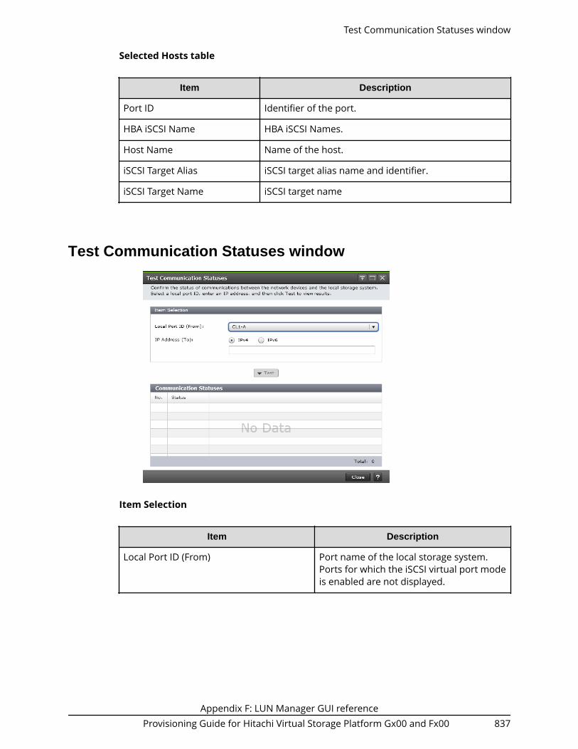
Selected Hosts table
Item Description
Port ID Identifier of the port.
HBA iSCSI Name HBA iSCSI Names.
Host Name Name of the host.
iSCSI Target Alias iSCSI target alias name and identifier.
iSCSI Target Name iSCSI target name
Test Communication Statuses window
Item Selection
Item Description
Local Port ID (From) Port name of the local storage system.Ports for which the iSCSI virtual port modeis enabled are not displayed.
Test Communication Statuses window
Appendix F: LUN Manager GUI referenceProvisioning Guide for Hitachi Virtual Storage Platform Gx00 and Fx00 837

Item Description
IP Address (To) Specify an IP address of a device of whichthe ping command is executed.■ IPv4: Select this item if the device is
adopted to IPv4. Specify the address ina text box.
■ IPv6: Select this item if the device isadopted to IPv6. Specify the address ina text box.
Test Click to execute the ping command.
No. Number of times of command executionsfrom 1 to 5.
Status Status of the result of the ping commandexecution.
Edit T10 PI Mode wizard
Edit T10 PI Mode window
Selected Ports table
Item Description
Port Name Port name.
Edit T10 PI Mode wizard
Appendix F: LUN Manager GUI referenceProvisioning Guide for Hitachi Virtual Storage Platform Gx00 and Fx00 838

Item Description
T10 PI Mode The port's T10 PI Mode setting (Enabled orDisabled).
Information setting area
Item Description
T10 PI Mode Select the T10 PI mode for the port.■ Enabled: T10 PI mode on the port is
enabled.■ Disabled: T10 PI mode on the port is
disabled.
Edit T10 PI Mode confirmation window
Selected Ports table
Item Description
Port Name Port name.
T10 PI Mode The port's T10 PI Mode setting (Enabled orDisabled).
Edit T10 PI Mode confirmation window
Appendix F: LUN Manager GUI referenceProvisioning Guide for Hitachi Virtual Storage Platform Gx00 and Fx00 839

Appendix F: LUN Manager GUI referenceProvisioning Guide for Hitachi Virtual Storage Platform Gx00 and Fx00 840

Appendix G: Notices
This software product includes the following redistributable software:
LZ4 LibraryThis software product includes LZ4 Library.
LZ4 Library
Copyright © 2011-2014, Yann Collet
All rights reserved.
Redistribution and use in source and binary forms, with or without modification, arepermitted provided that the following conditions are met:■ Redistributions of source code must retain the above copyright notice, this list of
conditions and the following disclaimer.■ Redistributions in binary form must reproduce the above copyright notice, this list of
conditions and the following disclaimer in the documentation and/or other materialsprovided with the distribution.
THIS SOFTWARE IS PROVIDED BY THE COPYRIGHT HOLDERS AND CONTRIBUTORS "AS IS"AND ANY EXPRESS OR IMPLIED WARRANTIES, INCLUDING, BUT NOT LIMITED TO, THEIMPLIED WARRANTIES OF MERCHANTABILITY AND FITNESS FOR A PARTICULAR PURPOSEARE DISCLAIMED. IN NO EVENT SHALL THE COPYRIGHT HOLDER OR CONTRIBUTORS BELIABLE FOR ANY DIRECT, INDIRECT, INCIDENTAL, SPECIAL, EXEMPLARY, ORCONSEQUENTIAL DAMAGES (INCLUDING, BUT NOT LIMITED TO, PROCUREMENT OFSUBSTITUTE GOODS OR SERVICES; LOSS OF USE, DATA, OR PROFITS; OR BUSINESSINTERRUPTION) HOWEVER CAUSED AND ON ANY THEORY OF LIABILITY, WHETHER INCONTRACT, STRICT LIABILITY, OR TORT (INCLUDING NEGLIGENCE OR OTHERWISE)ARISING IN ANY WAY OUT OF THE USE OF THIS SOFTWARE, EVEN IF ADVISED OF THEPOSSIBILITY OF SUCH DAMAGE.
Appendix G: NoticesProvisioning Guide for Hitachi Virtual Storage Platform Gx00 and Fx00 841

Appendix G: NoticesProvisioning Guide for Hitachi Virtual Storage Platform Gx00 and Fx00 842

Glossary
AALUA
See asymmetric logical unit access.
asymmetric access
A method of defining a preferred path for sending and receiving data when multiple alternate pathsare used between a server and storage systems, such as a cross-path configuration for global-activedevice. To use, ALUA must be enabled.
asymmetric logical unit access (ALUA)
Asymmetric logical unit access functionality of SCSI. When multiple alternate paths are used toconnect storage systems, or a server and one or more storage systems, you can define a preferredpath in a storage system, and issue I/O requests from the server to storage systems. If a failureoccurs in a preferred path, an alternate path is used. See also asymmetric access.
audit log
Files that store a history of the operations performed from Device Manager - Storage Navigator andthe commands that the storage system received from hosts, and data encryption operations.
Bback-end director (BED)
The hardware component that controls the transfer of data between the drives and cache. A BEDfeature consists of a pair of boards. A BED is also referred to as a disk board (DKB).
BED
See back-end director.
Ccache logical partition (CLPR)
Consists of virtual cache memory that is set up to be allocated to different hosts in contention forcache memory.
capacity
The amount of data storage space available on a physical storage device, usually measured in bytes(MB, GB, TB, and so on).
capacity saving
The data deduplication and data compression functions provided by the storage system controllers.
CCI
Command Control Interface
CLPR
See cache logical partition (CLPR).
cluster
Multiple-storage servers working together to respond to multiple read and write requests.
GlossaryProvisioning Guide for Hitachi Virtual Storage Platform Gx00 and Fx00 843

command device
A dedicated logical volume used only by Command Control Interface and Business ContinuityManager to interface with the storage system. Can be shared by several hosts.
controller
The component in a storage system that manages all storage functions. It is analogous to acomputer and contains a processors, I/O devices, RAM, power supplies, cooling fans, and other sub-components as needed to support the operation of the storage system.
copy pair
A pair of volumes in which one volume contains original data and the other volume contains thecopy of the original. Copy operations can be synchronous or asynchronous, and the volumes of thecopy pair can be located in the same storage system (local copy) or in different storage systems(remote copy).
A copy pair can also be called a volume pair, or just pair. A pair created by Compatible FlashCopy® iscalled a relationship.
custom volume (CV)
A custom-size volume whose size is defined by the user using Virtual LVI/Virtual LUN.
CV
See custom volume.
CVS
custom volume size
Ddata drive
A physical data storage device that can be either a hard disk drive (HDD) or a flash drive (also calleda solid-state device).
DC
data center
deduplication system data volume
The volume used to manage data duplication in a pool. The deduplication system data volume iscreated when you enable deduplication on a pool.
device
A physical or logical unit with a specific function.
disk array
Disk array, or just array, is a complete storage system, including the control and logic devices,storage devices (HDD, SSD), connecting cables, and racks
disk controller (DKC)
The hardware component that manages front-end and back-end storage operations. The term DKCcan refer to the entire storage system or to the controller components.
DKCSee disk controller (DKC).DKCMAINdisk controller main. Refers to the software for the storage system.
GlossaryProvisioning Guide for Hitachi Virtual Storage Platform Gx00 and Fx00 844
DSD volume
Used in Hitachi Command Suite to identify a deduplication system data volume.
dump
A collection of data that is saved to a file when an error or crash occurs. The data is used by supportpersonnel to determine the cause of the error or crash.
Dump tool
Downloads Device Manager - Storage Navigator configuration information onto recording media forbackup and troubleshooting purposes.
Dynamic Provisioning (HDP)
An approach to managing storage. Instead of "reserving" a fixed amount of storage, it removescapacity from the available pool when data is actually written to disk.
Eexternal volume
A logical volume whose data resides on drives that are physically located outside the Hitachi storagesystem.
FFC
Fibre Channel; FlashCopy
FC-AL
fibre-channel arbitrated loop
flash drive
A data drive that uses a solid-state memory device instead of a rotating hard disk.
flash module (FMD)
A high speed data storage device that includes a custom flash controller and several flash memorysub-modules on a single PCB.
HHBA
host bus adapter
HDD
hard disk drive
HDT
Hitachi Dynamic Tiering
host group
A group of hosts of the same operating system platform.
host mode
Operational modes that provide enhanced compatibility with supported host platforms. Used withfibre-channel ports on RAID storage systems.
host mode option
Additional options for fibre-channel ports on RAID storage systems. Provide enhanced functionalityfor host software and middleware.
GlossaryProvisioning Guide for Hitachi Virtual Storage Platform Gx00 and Fx00 845

Iinternal volume
A logical volume whose data resides on drives that are physically located within the storage system.See also external volume.
JJNL
journal
journal volume
A volume that records and stores a log of all events that take place in another volume. In the eventof a system crash, the journal volume logs are used to restore lost data and maintain data integrity.
In Universal Replicator, differential data is held in journal volumes on until it is copied to the S-VOL.
LLDEV
logical device
logical device (LDEV)
An individual logical data volume (on multiple drives in a RAID configuration) in the storage system.An LDEV may or may not contain any data and may or may not be defined to any hosts. Each LDEVhas a unique identifier or "address" within the storage system composed of the logical diskcontroller (LDKC) number, control unit (CU) number, and LDEV number. The LDEV IDs within astorage system do not change.An LDEV formatted for use by mainframe hosts is called a logicalvolume image (LVI). An LDEV formatted for use by open-system hosts is called a logical unit (LU).
logical disk controller (LDKC)
A group of 255 control unit (CU) images in the RAID storage system that is controlled by a virtual(logical) storage system within the single physical storage system. For example, the Hitachi UniversalStorage Platform V storage system supports two LDKCs, LDKC 00 and LDKC 01.
logical partition (LPAR)
A subset of a system's hardware resources that is virtualized as a separate system. For a storagesystem, logical partitioning can be applied to cache memory and/or storage capacity.
logical unit (LU)
A logical volume that is configured for use by open-systems hosts (for example, OPEN-V).
logical unit (LU) path
The path between an open-systems host and a logical unit.
logical volume (LV)
See volume.
LU
See logical unit (LU).
LUN
See logical unit number
LV
logical volume
GlossaryProvisioning Guide for Hitachi Virtual Storage Platform Gx00 and Fx00 846

OOPEN-V
A logical unit (LU) of user-defined size that is formatted for use by open-systems hosts.
OPEN-x
A logical unit (LU) of fixed size (for example, OPEN-3 or OPEN-9) that is used primarily for sharingdata between mainframe and open-systems hosts using Hitachi Cross-OS File Exchange.
PP-VOL
This term is used only in the earlier version of the Device Manager - Storage Navigator GUI (still inuse) for the primary volume. See primary volume.
pair
Two logical volumes in a replication relationship in which one volume contains original data to becopied and the other volume contains the copy of the original data. The copy operations can besynchronous or asynchronous, and the pair volumes can be located in the same storage system (in-system replication) or in different storage systems (remote replication).
parity group
See RAID group.
PDEV
physical device
PG
parity group. See RAID group.
physical device
See device.
pool
A set of volumes that are reserved for storing pool volumes (pool-VOL), and used by Thin Image,Dynamic Provisioning, Dynamic Tiering, or active flash data.
pool volume (pool-VOL)
A logical volume that is reserved for storing snapshot data for Thin Image operations or write datafor Dynamic Provisioning, Dynamic Tiering, or active flash.
port attribute
Indicates the type of fibre-channel port: target, RCU target, or initiator.
primary volume (P-VOL)
The volume in a copy pair that contains the original data to be replicated. The data on the P-VOL isduplicated synchronously or asynchronously on the secondary volume (S-VOL).
The following Hitachi products use the term P-VOL: Thin Image, Copy-on-Write Snapshot,ShadowImage, TrueCopy, Universal Replicator, Universal Replicator for Mainframe, and HighAvailability Manager.
See also secondary volume.
GlossaryProvisioning Guide for Hitachi Virtual Storage Platform Gx00 and Fx00 847

Qquick format
The quick format feature in Virtual LVI/Virtual LUN in which the formatting of the internal volumes isdone in the background. This allows system configuration (such as defining a path or creating aTrueCopy pair) before the formatting is completed. To execute quick formatting, the volumes mustbe in blocked status.
RRAID group
A set of RAID disks that have the same capacity and are treated as one group for data storage andrecovery. A RAID group contains both user data and parity information. This allows user data to beaccessed in the event that one or more of the drives within the RAID group are not available. TheRAID level of a RAID group determines the number of data drives and parity drives and how the datais "striped" across the drives. For RAID1, user data is duplicated within the RAID group, so there is noparity data for RAID1 RAID groups.
A RAID group can also be called an array group or a parity group.
RAID level
The type of RAID implementation. RAID levels include RAID0, RAID1, RAID2, RAID3, RAID4, RAID5 andRAID6.
RCU
See remote control unit.
RCU target port
A fibre-channel port that is configured to receive remote I/Os from an initiator port on anotherstorage system.
remote control unit (RCU)
A storage system at a secondary or remote site that is configured to receive remote I/Os from one ormore storage systems at the primary or main site.
resync
resynchronize.
SS-VOL
See secondary volume or source volume. When used for "secondary volume", "S-VOL" is only seen inthe earlier version of the Device Manager - Storage Navigator GUI (still in use).
secondary volume (S-VOL)
The volume in a copy pair that is the copy of the original data on the primary volume (P-VOL). Thefollowing Hitachi products use the term "secondary volume": Thin Image, Copy-on-Write Snapshot,ShadowImage, TrueCopy, Universal Replicator, Universal Replicator for Mainframe, and HighAvailability Manager.
See also primary volume.
service information message (SIM)
Messages generated by a RAID storage system when it detects an error or service requirement. SIMsare reported to hosts and displayed on Device Manager - Storage Navigator.
GlossaryProvisioning Guide for Hitachi Virtual Storage Platform Gx00 and Fx00 848

service processor
The computer in a storage system that hosts the Device Manager - Storage Navigator software and isused to configure and maintain the storage system.
severity level
Applies to service information messages (SIMs) and Device Manager - Storage Navigator error codes.
shredding
See volume shredding.
SI
Hitachi ShadowImage
SIM
See service information message.
size
Generally refers to the storage capacity of a memory module or cache. Not usually used for storageof data on disk or flash drives.
SM
shared memory
SN
Device Manager - Storage Navigator
snapshot
A point-in-time virtual copy of a Hitachi Thin Image primary volume (P-VOL). The snapshot ismaintained when the P-VOL is updated by storing pre-updated data (snapshot data) in a data pool.
SOM
See system option mode.
space
Generally refers to the data storage capacity of a disk drive or flash drive.
SSD
solid-state drive. Also called flash drive.
storage tiers
See tiered storage.
SVP
See service processor.
syslog
The file on the SVP that includes both syslog and audit log information, such as the date and time.
system option mode (SOM)
Additional operational parameters for the RAID storage systems that enable the storage system tobe tailored to unique customer operating requirements. SOMs are set on the service processor.
TT10 PI
See T10 Protection Information.
GlossaryProvisioning Guide for Hitachi Virtual Storage Platform Gx00 and Fx00 849

T10 Protection Information (T10 PI)
A code standard defined in SCSI. T10 PI adds 8-byte protection information at every 512 bytes tovalidate data. By combining T10 PI with Data Integrity Extension (DIX), which enables data protectioncovering application and operating system, data protection from application to disk drives can beprovided.
target port
A fibre-channel port that is configured to receive and process host I/Os.
TC
Hitachi TrueCopy
tiered storage
A layered structure of performance levels, or tiers, that matches data access requirements with theappropriate performance tiers. The tiers are:
Tier 1: Static content. Tier 1 is fully supported computing expected to be production quality.
Tier 2: Application logic. Tier 2 platforms are not supported by the security officer and releaseengineering teams. Tier 2 systems are targeted for Tier 1 support, but are still under development.
Tier 3: Database. Tier 3 platforms are architectures for which hardware is not or will not be availableor that are considered legacy systems unlikely to see broad future use.
Tier 4 systems are not supported.
total capacity
The aggregate amount of storage space in a data storage system.
UUR
Hitachi Universal Replicator
VV-VOL
virtual volume
VDEV
See virtual device.
virtual device (VDEV)
A group of logical devices (LDEVs) in a RAID group. A VDEV typically consists of some fixed volumes(FVs) and some free space. The number of fixed volumes is determined by the RAID level and deviceemulation type.
Virtual LVI/LUN
A custom-size volume whose size is defined by the user using Virtual LVI/LUN. Also called a customvolume (CV).
virtual volume (V-VOL)
A logical volume in a storage system. A V-VOL has no physical storage space.
Thin Image uses V-VOLs as secondary volumes of copy pairs.
In Dynamic Provisioning, Dynamic Tiering, and active flash, V-VOLs are called DP-VOLs.
GlossaryProvisioning Guide for Hitachi Virtual Storage Platform Gx00 and Fx00 850

VLUN
Hitachi Virtual LUN
VM
volume migration; volume manager
volume shredding
Deleting the user data on a volume by overwriting all data in the volume with dummy data.
GlossaryProvisioning Guide for Hitachi Virtual Storage Platform Gx00 and Fx00 851

GlossaryProvisioning Guide for Hitachi Virtual Storage Platform Gx00 and Fx00 852

Index
Aaccelerated compression
about pools 54disabling 124, 438enabling 123guidelines for pools 429workflow for creating parity groups, LDEVs, andpools 433
access attributechanging to read/write 321
access attributesassigning to a volume 319changing to read-only or protect 320expiration lock 322overview 317permitted operations 318requirements 318reserving volumes 323restrictions 318retention term 322workflow 319
active flash 59, 147, 226, 227, 229, 240active flash pool
creating by selecting pool-VOLs automatically 253creating by selecting pool-VOLs manually 250
Add 824adding 392Adding CHAP users 398alternate 356alternate LU paths 328ALU ID 405ALUs
unbinding the associated SLUs 405viewing 405
Assign Spare Drives confirmation window 539Assign Spare Drives window 538Assign Spare Drives wizard 538attribute 159, 310Attribute command 320authentication
configuring on Fibre Channel ports 376configuring on fibre channels 372fabric switch 369fibre channel 364host settings 365hosts and host groups 366mutual 364mutual of ports 372port settings 365
authentication (continued)users 364
auto assignment of MP units 143
Bbasic provisioning
overview 33workflow 36
blocking volumes 135boundary values 122buffer space 239
Ccapacity
decreasing pool capacity 292pool-VOLs 159
capacity expansionabout pools 54disabling 124enabling 123
capacity of a slot 123capacity of OPEN-V 118capacity saving
cautions and restrictions 53garbage collection 48inline mode 48metadata 157post-process mode 48
CCIvirtual storage machine operations 103
Change Settings (Parity Group) window 536CHAP authentication 364–367, 369, 371, 372, 375, 377,378CHAP User 827CHAP User Properties window 808CHAP Users 824checking 429Command Control Interface
access attributes restrictions 318command device
setting 350communication 837communication status 393compression
cautions and restrictions 53disabling on a DP-VOL 305
configuration 381Confirming 393
IndexProvisioning Guide for Hitachi Virtual Storage Platform Gx00 and Fx00 853

contacting customer support 424copy-back mode
setting 130copying 356, 357Copying selected 358correspondence table for defining devices 356create 811Create iSCSI Targets window 811Create Parity Groups confirmation window 534Create Parity Groups window 530Create Parity Groups wizard 530creating
active flash pool by selecting pool-VOLsautomatically 253active flash pool by selecting pool-VOLs manually250DP pool by selecting pool-VOLs automatically 247DP pool by selecting pool-VOLs manually 244DP-VOL with data direct mapping enabled 314Dynamic Tiering pool by selecting pool-VOLsautomatically 253Dynamic Tiering pool by selecting pool-VOLsmanually 250external volume with data direct mappingenabled 310host group 348iSCSI target 395LDEVs
overview 130procedure 130
parity group by selecting drives automatically 126parity group by selecting drives manually 125parity groups, LDEVs, and pools with acceleratedcompression 433pool 243pool with data direct mapping enabled 312virtual storage machine 106
Creating 310custom policies 206custom-sized provisioning
disadvantages 35overview 35when to use 35
customer support 424
Ddata direct mapping
disabling on a pool 315enabling on a pool 315
Data Retention window 673data transfer speed
Fibre Channel ports 331data-size 429data-transfer speeds 332decreasing pool capacity 292deduplication
cautions and restrictions 53disabling on a DP-VOL 305disabling on a pool 291enabling on a new pool 243enabling on an existing pool 290
deduplication system data volumerequirements 156
defined 356defining 353, 356Delete Parity Groups window 543deleting
all DP-VOLs with capacity saving enabled in a pool308DP-VOL 306login iSCSI names 391parity groups 128pools 296
Depletion Threshold for pools 268Device Manager - Storage Navigator
virtual storage machine operations 103devices
correspondence table 356disabling
virtualization management setting 113disabling accelerated compression 438disabling compression on DP-VOLs 305disabling deduplication on a pool 291disabling deduplication on DP-VOLs 305DP pool
creating by selecting pool-VOLs automatically 247creating by selecting pool-VOLs manually 244
DP-VOLactive flash 259changing the tiering policy level 222creating 259data direct mapping attribute 40deleting 306disabling compression 305disabling deduplication 305enabling capacity saving function 304enabling compression 304enabling deduplication 304full allocation 302protection function 257, 258
DP-VOL with capacity saving enableddeleting all in a pool 308
DP-VOL with data direct mapping enabledcreating 314
DP-VOLsinteroperability 163requirements 154requirements for increasing capacity 158
DSD volume 48Dynamic Provisioning
sharing a pool with Thin Image 39Dynamic Tiering pool
creating by selecting pool-VOLs automatically 253creating by selecting pool-VOLs manually 250
Eedit 540, 541, 819Edit 827, 838editing 111Editing CHAP users 399enabled 429enabling
IndexProvisioning Guide for Hitachi Virtual Storage Platform Gx00 and Fx00 854

enabling (continued)virtualization management setting 109
enabling capacity saving functions on DP-VOLs 304enabling compression on DP-VOLs 304enabling deduplication on a new pool 243enabling deduplication on an existing pool 290enabling deduplication on DP-VOLs 304Error Detail dialog box 421estimating 429Estimating 159estimating FMC capacity
for a new pool 430to expand an existing pool 432when pool capacity is insufficient 437
expanding a pool 288expiration lock
enabling/disabling 322external volume with data direct mapping enabled
creating 310
Ffabric switch
enabling or disabling authentication 380fabric topology 336FC-AL (Fibre Channel-Arbitrated Loop) topology 336Fibre Channel 353fibre channel authentication
setting 364fibre channel ports
configuring 331configuring authentication 372registering user information 377setting port information 376
Fibre Channel portsaddresses 334configuring 335configuring authentication 376data transfer speed 331
fibre channel switchauthentication settings and connection results371clearing user information 379registering user information 378setting authentication mode 379
Fibre Channel topologyoverview 336
Fibre security control function 327finding WWN
AIX 347HP-UX 347IRIX 347Sequent 347Solaris 346Windows 346
fixed-sized provisioningdisadvantages 33overview 33when to use 33
FMC capacityestimating 429estimating for a new pool 430
FMC capacity (continued)estimating to expand an existing pool 432estimating when pool capacity is insufficient 437
formattinga specific LDEV 139about formatting LDEVs 135parity groups 127Quick Format function 136
Ggarbage collection 48global storage virtualization
requirements and specifications 102global-active device 90, 101, 170
Hhafdc2_estimator 429HMOs 339host
registering in host group 348registering in iSCSI target 395
host authenticationdisabling in a host group 372enabling in a host group 372
host bus adapterschanging HBA iSCSI name 384changing WWNs 383deleting from host group 388
host groupcreating 348
host group 0initializing 388
host group function 327host groups
adding 391, 392authentication 366changing host mode 385changing host mode options 385changing name 385deleting 389deleting host bus adapters 388editing 385
host mode options 339host modes
listed and defined 337hosts
authentication 366changing host user information 374configuring 337configuring workflow 337deleting host user information 374managing 383registering host group user information 375registering host user information 372
Iimportant terms 31inline mode 48
IndexProvisioning Guide for Hitachi Virtual Storage Platform Gx00 and Fx00 855

interoperability of DP-VOLs and pool-VOLs 163iSCSI
changing 384iSCSI ports 397iSCSI security function 327iSCSI target
creating 395iSCSI target function 327iSCSI target properties 830iSCSI targets 387, 811iSCSI Targets
changing iSCSI target setting 386changing name 386
iSCSI virtual port mode 382
Kkey terms 31
LLDEVs
about LDEV formatting 135blocking 135deleting (converting to free space) 142editing name 142formatting a specific LDEV 139formatting in a parity group 140Quick Format function 136restoring blocked LDEVs 141stopping the LDEV format process 140
LDEVs with ALU attribute 403leap year 320license information
LZ4 841logical units
workflow for configuring 329logical volumes
managing 327login iSCSI names
deleting 391LU paths
configuration workflow 352, 353configuring 352configuring on Fibre Channel 328deleting 359managing 358rules, restrictions, and guidelines 329viewing settings 360
LUNdefined 328
LUN securityenabling on ports 362example of disabling 361example of enabling 361settings for authentication of hosts 365settings for authentication of ports 365
LUN security on portsdisabling 363
LZ4 license information 841
Mmanagement area capacity 122managing
hosts 383parity groups 125
managing logical volumesrules, restrictions, and guidelines 329
mapped capacity 221metadata 157migrating V-VOL data 263monitoring 436monitoring and tier relocation settings 237monitoring capacity 263monitoring pools 266MP unit
enabling/disabling auto assignment 143multi VLAN 382mutual authentication
ports 372, 375
NNetwork 381Network configuration for iSCSI 381nicknames
changing 383, 384nondisruptive migration 100
Ooperating system and file system capacity 161
Ppair operations
for virtual storage machine pairs 105parity group
creating by selecting drives automatically 126creating by selecting drives manually 125enabling accelerated compression 123formatting 127
Parity Group Properties window 544parity groups
configuring volumes 115deleting 128managing 125
parity groups confirmation window 541parity groups window 540performance
optimizing by setting data transfer speed for aFibre Channel port 331
Performance Monitorautomatic starting considerations 318
point-to-point topology 336pool
accelerated compression-enabled 54changing a Dynamic Provisioning pool to aDynamic Tiering pool 235creating 243
IndexProvisioning Guide for Hitachi Virtual Storage Platform Gx00 and Fx00 856

pool (continued)creating active flash pool by selecting pool-VOLsautomatically 253creating active flash pool by selecting pool-VOLsmanually 250creating DP pool by selecting pool-VOLsautomatically 247creating DP pool by selecting pool-VOLs manually244creating Dynamic Tiering pool by selecting pool-VOLs automatically 253creating Dynamic Tiering pool by selecting pool-VOLs manually 250disabling data direct mapping 315disabling deduplication 291enabling data direct mapping 315enabling deduplication 243, 290prerequisites for creating 243sharing with Dynamic Provisioning and ThinImage 39shrinking 294viewing capacity information 285
pool capacitydecreasing 292, 294increasing 288stop decreasing 295
pool capacity informationviewing 285
pool informationviewing 285
pool namechanging 289
pool subscription limitchanging 271
pool thresholdchanging 271
pool with data direct mapping enabledcreating 312
pool-VOLsinteroperability 163requirements 151
poolsdeleting 296managing 284recovering 291requirements 148utilization thresholds 268
portsmutual authentication 372rules, restrictions, and guidelines 329
Ports/Host Groups/iSCSI Targets window 679post-process mode 48protection function for DP-VOLs
enabling and disabling 258provisioning operations
for virtualized resources 104system requirements for 61
Qqueue depth 329Quick Format 136
RRAID levels 117reclaiming pages in a V-VOL 300remove port chap users window 836Removing 387Removing CHAP users 400, 401Removing target CHAP users 400requirements
shared memory 62reserved capacity 221reserving volumes with access attributes 323restoring blocked volumes 141retention term
changing access attributes 322root volume
viewing used pool capacity 286
SS-VOL disable attribute 323saving rate 429secret
in CHAP authentication 365selected 357service information messages (SIMs) 273setting
T10 PI mode on a port 394ShadowImage 171shared memory
requirements 62shrinking a pool 294SIMs
for HDP/HDT 273overview 273
slot capacity 123SLU ID 405SLUs
unbinding from ALUs 405viewing 405
software license informationLZ4 841
SOMs 63spare drives
assigning 129removing 129
statuses 837storing data 55subscription limit of a pool
changing 271System Area 159system option modes 63system requirements 61
TT10 PI mode
setting on a port 394T10 PI Mode 838technical support 424terms 31
IndexProvisioning Guide for Hitachi Virtual Storage Platform Gx00 and Fx00 857

test 837Thin Image
interoperability restrictions with DynamicProvisioning 173sharing a pool with Dynamic Provisioning 39
Thin Image pairscontrolling behavior in a depleted DP pool 272
Thin Image root volumeviewing used pool capacity 286
thin provisioningadvantages 38configuring 147overview 147work flow 44workflow 174
thin provisioning requirements 148tier capacity
reserving 210reserving example 211
tier rank 297tier relocation
rules, restrictions, and guidelines 182tier relocation log file 197tier relocation settings 237tiering
workflow 227tiering policy
changing execution modes example 214notes on using 213overview 205relationship with graphs 209relationship with tiers 208reserving tier capacity 210setting on a V-VOL 207
tiering policy levelchanging 222
tool 429topology
example of FC-AL and point-to-point 336troubleshooting
Dynamic Provisioning 407troubleshooting for Data Retention Utility 324, 421TrueCopy 169
Uunbind SLUs window 521unbinding SLUs from ALUs 405Universal Replicator 171used capacity 221user authentication 364UUID
clearing settings 360setting 354
VV-VOL
active flash 259creating 259
V-VOL full allocation 160
V-VOL page reservation requirement 160V-VOLs
changing name 299increasing capacity 298managing 284releasing pages 300requirements for increasing capacity 158stop releasing pages 302
VASA integration 403Viewing formatted pool capacity 286, 308–310Viewing rebalancing progress 287virtual LDEV ID
setting 111Virtual LUN
size calculations 119specifications 117
Virtual Partition Manager 174virtual port mode 382virtual storage machine pairs
pair operations for 105virtual storage machines
about 99creating 106operations supported by CCI and Device Manager- Storage Navigator 103pair operations 105provisioning operations for 104requirements and specifications 102
virtualization management settingdisabling 113enabling 109
virtualization management settings 111virtualized resources
about 99volume capacity 118Volume Migration
automatic starting considerations 318volumes
blocking 135boundary values 122restoring blocked volumes 141
vSphere VVOL 403VVOL 403
WWarning Threshold for pools 268WWN
changing 383deleting from WWN table 389deleting old WWNs 389finding on AIX, IRIX, or Sequent 347finding on different operating systems 345finding on HP-UX 347finding on Solaris 346finding on Windows 346
Zzero pages
reclaiming 299
IndexProvisioning Guide for Hitachi Virtual Storage Platform Gx00 and Fx00 858

Zero Read Cap mode 676
IndexProvisioning Guide for Hitachi Virtual Storage Platform Gx00 and Fx00 859

IndexProvisioning Guide for Hitachi Virtual Storage Platform Gx00 and Fx00 860


Hitachi Vantara
Corporate Headquarters2845 Lafayette StreetSanta Clara, CA 95050-2639 USAwww.HitachiVantara.com | community.HitachiVantara.com
Regional Contact InformationAmericas: +1 866 374 5822 or [email protected], Middle East, and Africa: +44 (0) 1753 618000 or info@[email protected] Pacific: + 852 3189 7900 or [email protected]