HITACHI - npcdn.net
38
Nominal Capacity Range R22: 116kW to 1,146kW 99,760kcal/h to 985,560kcal/h 33RT to 326 RT R407C: 110kW to 1,089kW 94,600kcal/h to 936,540kcal/h 31RT to 310 RT Technical Catalog I Design Information Model: R22 R407C RCU40AHYZ1 RCUG40AHYZ1 RCU50AHYZ1 RCUG50AHYZ1 RCU60AHYZ1 RCUG60AHYZ1 RCU75AHYZ1 RCUG75AHYZ1 RCU100AHYZ1 RCUG100AHYZ1 RCU120AHYZ1 RCUG120AHYZ1 RCU150AHYZ1 RCUG150AHYZ1 RCU180AHYZ1 RCUG180AHYZ1 RCU200AHYZ1 RCUG200AHYZ1 RCU240AHYZ1 RCUG240AHYZ1 RCU270AHYZ1 RCUG270AHYZ1 RCU300AHYZ1 RCUG300AHYZ1 RCU330AHYZ1 RCUG330AHYZ1 RCU350AHYZ1 RCUG350AHYZ1 RCU360AHYZ1 RCUG360AHYZ1 RCU380AHYZ1 RCUG380AHYZ1 RCU400AHYZ1 RCUG400AHYZ1 New Series !This series of HITACHI air-cooled water chillers up to 400HP has been developed for various requirements of air-conditioning systems and industrial chilled water systems, where these equipment are operated under high ambient temperatures of 43 ℃,Therefore, the units can be utilized under a wide temperature range. These water chillers are equipped with newly model-changed semi-hermetic HITACHI A-type screw compressors, featuring high reliability, low noise and low vibration, and highly efficient air-cooled condenser, resulting in compact design. The unit is composed of compressors, air-cooled condensers, shell-tube type water coolers, and other auxiliary and control devices, compactly packaged in a weather-proof cabinet which is constructed of galvanized steel plates processed with specially baked resin paint. HITACHI AIR-COOLED WATER CHILLERS – SCREW TYPE – HITACHI
-
Upload
khangminh22 -
Category
Documents
-
view
2 -
download
0
Transcript of HITACHI - npcdn.net

Nominal Capacity Range R22: 116kW to 1,146kW
99,760kcal/h to 985,560kcal/h 33RT to 326 RT
R407C: 110kW to 1,089kW 94,600kcal/h to 936,540kcal/h
31RT to 310 RT
Technical Catalog I Design Information
Model: R22 R407C
RCU40AHYZ1 RCUG40AHYZ1 RCU50AHYZ1 RCUG50AHYZ1 RCU60AHYZ1 RCUG60AHYZ1 RCU75AHYZ1 RCUG75AHYZ1
RCU100AHYZ1 RCUG100AHYZ1 RCU120AHYZ1 RCUG120AHYZ1 RCU150AHYZ1 RCUG150AHYZ1 RCU180AHYZ1 RCUG180AHYZ1 RCU200AHYZ1 RCUG200AHYZ1 RCU240AHYZ1 RCUG240AHYZ1 RCU270AHYZ1 RCUG270AHYZ1 RCU300AHYZ1 RCUG300AHYZ1 RCU330AHYZ1 RCUG330AHYZ1 RCU350AHYZ1 RCUG350AHYZ1 RCU360AHYZ1 RCUG360AHYZ1 RCU380AHYZ1 RCUG380AHYZ1 RCU400AHYZ1 RCUG400AHYZ1
New Series!This series of HITACHI air-cooled water chillers up to 400HP has been developed for various
requirements of air-conditioning systems and industrial chilled water systems, where these equipment are operated under high
ambient temperatures of 43 ℃,Therefore, the units can be utilized under a wide temperature range.
These water chillers are equipped with newly model-changed semi-hermetic HITACHI A-type screw compressors,
featuring high reliability, low noise and low vibration, and highly efficient air-cooled condenser, resulting in compact design.
The unit is composed of compressors, air-cooled condensers, shell-tube type water coolers, and other auxiliary and control
devices, compactly packaged in a weather-proof cabinet which is constructed of galvanized steel plates processed with
specially baked resin paint.
HITACHI AIR-COOLED WATER CHILLERS – SCREW TYPE –
HITACHI

1
NEW HITACHI AIR-COOLED WATER CHILLERS… THAT’S THE ACHIEVEMENT OF TOTAL HITACHI TECHNOLOGE… ● The most reliable semi-hermetic screw type compressor Adopting new profile screw rotors, HITACHI have developed the higher performance screw type compressor to obtain a higher reliability and durability of the unit operation.
●Highly Efficiency Operation The appropriate combination of the air side heat exchangers with high performance SLIT fins, highly efficient screw compressors and water side heat exchangers has achieved this high efficiency of operation.
●Smaller Vibration and Lower Operation Sound Due to the combination of the HITACHI semi-hermetic screw compressors and smooth-air-flow propeller fans for air side heat exchangers, smaller vibration and lower sound operation has been achieved, therefore, in most cases, special vibration absorbing curbs are not required by utilizing factory-supplied rubber mats.
In this new century when people pay more attention to the change of the environment, HITACHI semi-hermetic screw type compressors ,which use the R407C refrigerant directly, and reduce the refrigerant leak greatly, have been sold 140,000 in the world !
1. Efficiency is improved by using the highly precision rotors. 2. Separation efficiency is enhanced greatly by changing the oil separation mode.
Discharge Outlet
Motor for Compressor
Suction Inlet
Bearing
Slide Valve
Heat-Exchanger(AHYZ1)
1.Improve the air heat exchanger configuration. 2.Adopt high heat exchange efficiency inner thread tube 3.Improve air velocity
distribution to enhance efficiency .
Air side heat-exchanger using the converse
M-type distributing resulting in an equality
distribution of the air velocity, achieves highly
heat exchange efficiency.
FEATURE

2
Capacity Control
Continuous Capacity Control Chilled water outlet temperature can be controlled precisely within ±0.5 of the setting ℃
temperature. This control is performed by applying a micro-computer to the continuous capacity control type screw compressor.
This precise temperature control is not only suitable for air conditioning, but also for industrial use.
-Principle of Continuous Capacity Control- Continuous capacity control is performed by adjusting the slide valve position as shown below. The slide position can be changed freely between 100% and 15% in accordance with cooling load.
Load-up Load-down Hold
Pd: Discharge Pressure, Ps: Suction Pressure S1,2,3 :Solenoid Valve
Micro-Processor Control for Various Functions Alarm Indication for each cycle by 7-Segment Rotating control of compressor starting order Current limitation control Automatic start after instantaneous power failure
Complete Standard Accessory Water connection companion flange Vibration-proof Mat Foundation Bolt, Nut, Washer and Bushing Spreader bar for rigging Acoustic panel for compressor Protection net for condenser
Other Option The following specifications are available on order basis. Please contact local Hitachi’s distributors if required. RS485 physics connector High static pressure fan (Max. outside static pressure:150Pa)
Remote control box Liquid crystal touch panel with big screen(Independent Box)
HITACHI water chillers group control system
Lapsed time
4
6
8Neutral zonestandard
Stop temperature
Inlet water temperature
Start
Inlet water temperature
Stop
60sec.2sec.
Load-up signal
≈
≈
A given load status is maintained.
The inlet water temperature is detected at a stop, and it is restarted by a raise in inlet water temperature60sec.
2sec.
Load-down signal
standard
When there is a big difference between set temperature and actual temperature60sec.
12sec.
Load-up signal
Outlet water temperature
Outlet water temperature
(Set temperature:5℃)
Lapsed time
4
6
8Neutral zonestandard
Stop temperature
Inlet water temperature
Start
Inlet water temperature
Stop
60sec.2sec.
Load-up signal
≈
≈
A given load status is maintained.A given load status is maintained.
The inlet water temperature is detected at a stop, and it is restarted by a raise in inlet water temperature60sec.
2sec.
Load-down signal The inlet water temperature is detected at a stop, and it is restarted by a raise in inlet water temperature60sec.
2sec.
Load-down signal
standard
When there is a big difference between set temperature and actual temperature60sec.
12sec.
Load-up signal
Outlet water temperature
Outlet water temperature
(Set temperature:5℃)
FEATURE

3
General Data(R22 and R407C)
NOTE: 1. The nominal cooling capacities are based on GB/T
18430.1-2007(*1) Chilled Water Inlet/Outlet Temperature:12/7℃ Condenser Air Inlet Temperature:35℃(DB)
2. Applicable Power Supply Main Power Source(AC3φ)
Control Power Source(AC1φ)
380V,50HZ 415V,50HZ
220V,50HZ 240V,50HZ
3. The units greater than 240AHYZ1 including 240AHYZ1 consist of two modules and are separately shipped. (*3). The common chilled water piping (Filed-Supplied) between each water cooler shall be directly connected at site.
4. Water Flow 1) RCU(G)240,300,360,400AHYZ1 It is necessary to control the common water flow volume to
each cooler. 2) RCU(G)270,330,350,380AHYZ1 Because the chilled water flow rate is different between No.1
and No.2 units. It is necessary to control the water flow volume of each unit with adjusting valves (Filed-Supplied).
5. It is required to connect electrical control wires between No.1 and No.2 units for the unit greater than 240AHYZ1including 240AHYZ1.
6. ( ) marked with *2 is available by selection switch.
5~43℃
Item StandardChilled Water Outlet Temperature
Condenser Air Inlet Temperature(DB)5~15℃
Working Range
GENERAL DATA
R22 RCU40AHYZ1 RCU50AHYZ1 RCU60AHYZ1 RCU75AHYZ1 RCU100AHYZ1
RCU120AHYZ1
RCU150AHYZ1
RCU180AHYZ1
RCU200AHYZ1
R407C RCUG40AHYZ1
RCUG50AHYZ1
RCUG60AHYZ1
RCUG75AHYZ1
RCUG100AHYZ1
RCUG120AHYZ1
RCUG150AHYZ1
RCUG180AHYZ1
RCUG200AHYZ1
kW 116 143 179 191 286 358 382 537 573
kcal/h 99,760 122,980 153,940 164,260 245,960 307,880 328,520 461,820 492,780
RT 33 41 51 54 81 102 109 153 163
kW 110 136 170 181 272 340 363 510 544
kcal/h 94,600 116,960 146,200 155,660 233,920 292,400 312,180 438,600 467,840
RT 31 39 48 51 77 97 103 145 155
─
%
mm
mm
mm
kg 1,790 1,830 1,870 1,890 3,210 3,280 3,320 4,865 4,900
—
—
—
—
─
─ 40ASCC-Z 50ASCC-Z 60ASCC-Z 60ASCC-Z 50ASCC-Z 60ASCC-Z 60ASCC-Z 60ASCC-Z 60ASCC-Z
─
─
Condenser Fan ─
Power Input kW 1.1 1.1 1.1 1.1 1.1 1.1 1.1 1.1 1.1
Quantity ─ 4 4 4 4 8 8 8 12 12
Air Discharge m3/min 930 930 930 930 1,860 1,860 1,860 2,790 2,790
─
─
Main Power(square orifice) mm
Circuit mm
kg 2,000 2,040 2,080 2,100 3,610 3,680 3,720 5,500 5,535
mm 2,600 2,600 2,600 2,600 4,700 4,700 4,700 6,800 6,800
mm 2,190 2,190 2,190 2,190 2,190 2,190 2,190 2,190 2,190
mm 2,510 2,510 2,510 2,510 2,510 2,510 2,510 2,510 2,510
3×φ48;φ64;φ52;2×φ75
Semi-Hermetic Screw Type
1 2 3
R22
R407C
Thermal Expansion Valve
1 2 3
2,390 4,490 6,590
1,940
Nominal Cooling Capacity*1 R407C
Continuous Capacity Control
100~15,0 100~15(7.5)*2,0 100~15(5)*2,0
Piping Connections for Water-Side HeatExchanger(Inlet/Outlet) ─
Height
Connection Hole
Shipping Weight*3
ShippingDimension
Depth
Width
Model
Capacity Control
Compressor
Type
Model
Quantity
Net Weight
Refrigerant
Nominal Cooling Capacity*1 R22
Safety Devices
Heat-Exchanger
Condenser
Fan Motor
Evaporator
Standard
R407C
Flow Control
Number of Circuit
OuterDimension
Depth
Width
Height
1,940 1,940
2,170 2,170 2,170
3×φ48;2×φ75
Cross Fin Type
Direct drive Propeller Fan
Shell and Tube Type
Overcurrent Relay for Compressor , Internal Thermostat for Compressor, Reverse Phase Protection Device for Compressor,ThermalOvercurrent Relay for Fan Motor,High Pressure Switch, Low Pressure Control, Suction Gas Temperature Control,Freeze Protection
Thermistor control,Oil Heater, Discharge Gas Thermistor, Fusible Plug, Fuse for Control Circuit and Pressure Relief Valve
With φ90 Inner Diameter Companion Flange With φ142 Inner Diameter Companion Flange
233×140

4
General Data(R22 and R407C)
Working Range
5~43℃
Item StandardChilled Water Outlet Temperature
Condenser Air Inlet Temperature(DB)5~15℃
GENERAL DATA
R22 RCU240AHYZ1 RCU270AHYZ1 RCU300AHYZ1 RCU330AHYZ1 RCU350AHYZ1 RCU360AHYZ1 RCU380AHYZ1 RCU400AHYZ1
R407C RCUG240AHYZ1 RCUG270AHYZ1 RCUG300AHYZ1 RCUG330AHYZ1 RCUG350AHYZ1 RCUG360AHYZ1 RCUG380AHYZ1 RCUG400AHYZ1
kW 716 740 764 919 955 1,074 1,110 1,146
kcal/h 615,760 636,400 657,040 790,340 821,300 923,640 954,600 985,560
RT 204 210 217 261 272 305 316 326
kW 680 703 726 873 907 1,020 1,055 1,089
kcal/h 584,800 604,580 624,360 750,780 780,020 877,200 907,300 936,540
RT 193 200 206 248 258 290 300 310
─
%
mm
mm
mm
kg 2×3,280 3,320+3,280 2×3,320 4,865+3,320 4,900+3,320 2×4,865 4,900+4,865 2×4,900
—
—
—
—
─
─ 60ASCC-Z 60ASCC-Z 60ASCC-Z 60ASCC-Z 60ASCC-Z 60ASCC-Z 60ASCC-Z 60ASCC-Z
─
─
Condenser Fan ─
Power Input kW 1.1 1.1 1.1 1.1 1.1 1.1 1.1 1.1
Quantity ─ 2×8 8+8 2×8 12+8 12+8 2×12 12+12 2×12
Air Discharge m3/min 3,720 3,720 3,720 4,650 4,650 5,580 5,580 5,580
─
─
Main Power(square orifice)
mm
Circuit mm
kg 2×3,680 3,720+3,680 2×3,720 5,500+3,720 5,535+3,720 2×5,500 5,535+5,500 2×5,535
mm 2×4,700 2×4,700 2×4,700 6,800+4,700 6,800+4,700 2×6,800 2×6,800 2×6,800
mm 2,190 2,190 2,190 2,190 2,190 2,190 2,190 2190mm 2,510 2,510 2,510 2,510 2,510 2,510 2,510 2,510
OuterDimension
Depth
Width
Height
Standard
R407C
Flow Control
Number of Circuit
Safety Devices
Heat-Exchanger
Condenser
FanMotor
Evaporator
Model
Capacity Control
Cross Fin Type
Direct Drive Propeller Fan
Compressor
Type
Model
Quantity
Net Weight
Refrigerant
Piping Connections for Water-Side HeatExchanger(Inlet/Outlet) ─
Height
Connection Hole
Shipping Weight*3
ShippingDimension
Depth
Width
Nominal CoolingCapacity*1 R22
Nominal CoolingCapacity*1 R407C
Continuous Capacity Control
100~15(7.5)*2,0 100~15(6)*2
,0 100~15(7.5)*2,0
9,080(Minimum) 11,180(Minimum) 13,280(Minimum)
1,940 1,940 1,940
2,170 2,170 2,170
R22
R407C
Thermal Expansion Valve
4 5 6
Semi-Hermetic Screw Type
4 5 6
Shell and Tube Type
Overcurrent Relay for Compressor , Internal Thermostat for Compressor, Reverse Phase Protection Device for Compressor,Thermal Overcurrent Relay for Fan Motor,HighPressure Switch, Low Pressure Control, Suction Gas Temperature Control,Freeze Protection Thermistor control,Oil Heater, Discharge Gas Thermistor, Fusible Plug, Fuse for
Control Circuit and Pressure Relief Valve
With φ142 Inner Diameter Companion Flange
2×233×140
6×φ48;2×φ64;2×φ52;4×φ75
NOTE: 1. The nominal cooling capacities are based on GB/T
18430.1-2007(*1) Chilled Water Inlet/Outlet Temperature:12/7℃ Condenser Air Inlet Temperature:35℃(DB)
2. Applicable Power Supply Main Power Source(AC3φ)
Control Power Source(AC1φ)
380V,50HZ 415V,50HZ
220V,50HZ 240V,50HZ
3. The units greater than 240AHYZ1 including 240AHYZ1 consist of two modules and are separately shipped. (*3). The common chilled water piping (Filed-Supplied) between each water cooler shall be directly connected at site.
4. Water Flow 1) RCU(G)240,300,360,400AHYZ1 It is necessary to control the common water flow volume to
each cooler. 2) RCU(G)270,330,350,380AHYZ1 Because the chilled water flow rate is different between No.1
and No.2 units. It is necessary to control the water flow volume of each unit with adjusting valves (Filed-Supplied).
5. It is required to connect electrical control wires between No.1 and No.2 units for the unit greater than 240AHYZ1including 240AHYZ1.
6. ( ) marked with *2 is available by selection switch.

5
Unit Dimensions RCU(G)40AHYZ1, RCU(G)50AHYZ1, RCU(G)60AHYZ1,RCU(G)75AHYZ1 RCU(G)100AHYZ1, RCU(G)120AHYZ1 and RCU(G)150AHYZ1
DIMENSION DATA
NOTES:
2.Water connection flanges( 142mm inner diameter)are supplied by factory with the unit.
1.Surpport the water pipes with stay not to give the weight of water pipes directly to the unit.
Earth Connection Terminal Screw Type Compressor
Air Discharge
Air Inlet Air Inlet
Mounting Holes(6-φ26)
Rigging Holes(4-φ50)
Air Side Heat-Exchanger
Fanfor Power Supply
Wiring Hole
2.Water connection flanges( 90mm inner diameter )are supplied by factory with the unit.
NOTES:
Earth Connection Terminal Screw Type Compressor
Air Side Heat-Exchanger
Air Discharge
Air Inlet Air Inlet
Rigging holes(4-φ50)
Mounting Holes(4-φ26)
Fan 1.Surpport the water pipes with stay not to give the weight of water pipes directly to the unit.
for Power SupplyWiring Hole
6
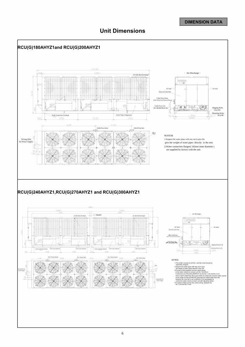
Unit Dimensions
RCU(G)180AHYZ1and RCU(G)200AHYZ1 RCU(G)240AHYZ1,RCU(G)270AHYZ1 and RCU(G)300AHYZ1
DIMENSION DATA
are supplied by factory with the unit.
NOTES:
2.Water connection flanges( 142mm inner diameter )
give the weight of water pipes directly to the unit.1.Surpport the water pipes with stay not to give the
Mounting Holes(8-φ26)
(4-φ50)Rigging Holes
Air Inlet
Air Discharge
Air Inlet
for Power SupplyWiring Hole
Fan
Earth Connection Terminal Screw Type Compressor
Air Side Heat-Exchanger
Power SupplyWiring Hole for
Power SupplyWiring Hole for
Mounting Holes(12-φ26)
Rigging Holes(8-φ50)
Air Inlet Air Inlet
Air Discharge
Fan
No.1 Water Outlet No.1 Water Inlet No.2 Water OutletNo.2 Water Inlet
Earth Connection Terminal Screw Type Compressor Screw Type Compressor Earth Connection Terminal Screw Type Compressor Screw Type Compressor
Minimum) Air Side Heat-ExchangerAir Side Heat-Exchanger
to the chiller;
No.1 unit and No. 2 unit.
have a same water flow rate,
between No.1and No.2 unit is different,
it just needs to control the common water volume
3.Provide a field-supplied common water piping at the water coolers to connect unit No.1 and No.2.
the weight of water pipes directly to the unit.2.Support the water pipes with stay not to give
NOTES:
separately shipped.1.This chiller consists of unit No.1 and No.2 and should be
control the water volume of each unit with adjusting valves.
for RCU270AHYZ1:because the chilled water flow rate
4.It needs to field-connect the control wiring between the
Furthermore,for RCU240,300AHYZ1:as the No.1 unit and No.2 unit
It is necessary to

7
Unit Dimensions
RCU(G)330AHYZ1 and RCU(G)350AHYZ1
RCU(G)360AHYZ1, RCU(G)380AHYZ1 and RCU(G)400AHYZ1
DIMENSION DATA
(Minimum)Air Side Heat-Exchanger Air Side Heat-Exchanger
Mounting Holes
Rigging Holes(8-φ50)
(14-φ26)
Air Inlet Air Inlet
Air Discharge
NOTES:
4.It needs to field-connect the control wiring between the
Furthermore,for RCU330,350AHYZ1,because the chilled water
control the water volume of each unit with adjusting valves.
1.This chiller consists of unit No.1 and No.2 and should be separately shipped.
2.Support the water pipes with stay not to give the weight of water pipes directly to the unit.
at the water coolers to connect unit No.1 and No.2. 3.Provide a field-supplied common water piping
flow rate between No.1and No.2 unit is different,
No.1 unit and No. 2 unit.5.The dimension of No.2 unit marked with P is 300mm.
Power SupplyWiring Hole for
Fan
P
it needs to
Power SupplyWiring Hole for
No.1Water Outlet No.1WaterInlet No.2Water Outlet No.2WaterInlet
Earth Connection Terminal Screw Type Compressor Earth Connection Terminal Screw Type Compressor Screw Type Compressor
Power SupplyWiring Hole for
Power SupplyWiring Hole for
Fan
No.1 Water Outlet No.1 Water Inlet No.2 Water Outlet No.2 Water Inlet
Earth Connection Terminal Screw Type Compressor Earth Connection Terminal Screw Type Compressor
Air Side Heat-Exchanger Air Side Heat-Exchanger
Air Inlet Air Inlet
Air Discharge
Furthermore,for RCU360,400AHYZ1:as the No.1 unit and No.2 unit
4.It needs to field-connect the control wiring between the
for RCU380AHYZ1:because the chilled water flow rate
control the water volume of each unit with adjusting valves.
1.This chiller consists of unit No.1 and No.2 and should be separately shipped.
NOTES:
2.Support the water pipes with stay not to give the weight of water pipes directly to the unit.
at the water coolers to connect unit No.1 and No.2. 3.Provide a field-supplied common water piping
it just needs to control the common water volume
between No.1and No.2 unit is different,
have a same water flow rate,
No.1 unit and No. 2 unit.
to the chiller; It is necessary to
安装孔(16-φ26)
起吊孔(8-φ50)
(Minimum)

8
Operation Space
Maximum Foundation Gradient
h1≤h2
Refer to C,D E F
Refer to C,D
Refer to C,D
G
30mmm
15mm
For Mode ls : RCU(G)240AHYZ1,RCU(G)270AHYZ1, RCU(G) 300AHYZ 1, RCU(G) 330A HYZ1 ,RCU(G) 350AHYZ 1, RCU(G) 360A HYZ1 ,R C U ( G ) 3 8 0 A H Y Z 1 , R C U ( G ) 4 0 0 A H Y Z 1
PREPARATION
h1≤h2
A B C D E F G
RCU(G)40AHYZ1 2,390 1,200 100 900 1,200 2,000 1,200
RCU(G)50AHYZ1 2,390 1,200 100 900 1,200 2,000 1,200
RCU(G)60AHYZ1 2,390 1,200 100 900 1,200 2,000 1,200
RCU(G)75AHYZ1 2,390 1,200 100 900 1,200 2,000 1,200
RCU(G)100AHYZ1 4,490 1,200 100 900 1,200 2,000 1,200
RCU(G)120AHYZ1 4,490 1,200 100 900 1,200 2,000 1,200
RCU(G)150AHYZ1 4,490 1,200 100 900 1,200 2,000 1,200
RCU(G)180AHYZ1 6,590 1,200 100 900 1,200 2,000 1,200
RCU(G)200AHYZ1 6,590 1,200 100 900 1,200 2,000 1,200
RCU(G)240AHYZ1 9,080(Minimum) 1,200 900 900 1,200 2,000 1,200
RCU(G)270AHYZ1 9,080(Minimum) 1,200 900 900 1,200 2,000 1,200
RCU(G)300AHYZ1 9,080(Minimum) 1,200 900 900 1,200 2,000 1,200
RCU(G)330AHYZ1 11,800(Minimum) 1,200 900 900 1,200 2,000 1,200
RCU(G)350AHYZ1 11,800 (Minimum) 1,200 900 900 1,200 2,000 1,200
RCU(G)360AHYZ1 13,280(Minimum) 1,200 900 900 1,200 2,000 1,200
RCU(G)380AHYZ1 13,280 (Minimum) 1,200 900 900 1,200 2,000 1,200
RCU(G)400AHYZ1 13,280 (Minimum) 1,200 900 900 1,200 2,000 1,200
Model Maintain Space (mm) Air Inlet Space (mm)
For Models: RCU(G)40AHYZ1, RCU(G)50AHYZ1,
RCU(G)60AHYZ1,RCU(G)75AHYZ1,
RCU(G)100AHYZ1,RCU(G)120AHYZ1,
RCU(G)150AHYZ1,RCU(G)180AHYZ1, RCU(G)200AHYZ1.

9
Center of Gravity Weight Balance
PREPARATION
1 2 3 4RCU(G)40AHYZ1 380 360 615 515RCU(G)50AHYZ1 385 365 625 525RCU(G)60AHYZ1 395 375 635 535RCU(G)75AHYZ1 400 380 640 540
1 2 3 4 5 6RCU(G)100AHYZ1 550 502 485 610 600 603RCU(G)120AHYZ1 560 520 495 620 610 615RCU(G)150AHYZ1 570 535 510 620 610 615RCU(G)240AHYZ1-1 560 520 495 620 610 615RCU(G)240AHYZ1-2 495 520 560 615 610 620RCU(G)270AHYZ1-1 570 535 510 620 610 615RCU(G)270AHYZ1-2 495 520 560 615 610 620RCU(G)300AHYZ1-1 570 535 510 620 610 615RCU(G)300AHYZ1-2 510 535 570 615 610 620
1 2 3 4 5 6 7 8RCU(G)180AHYZ1 538 556 557 553 708 720 728 715RCU(G)200AHYZ1 538 564 565 553 708 730 737 715RCU(G)330AHYZ1-1 538 556 557 553 708 720 728 715RCU(G)330AHYZ1-2 510 535 570 615 610 620RCU(G)350AHYZ1-1 538 564 565 553 708 730 737 715RCU(G)350AHYZ1-2 510 535 570 615 610 620RCU(G)360AHYZ1-1 538 556 557 553 708 720 728 715RCU(G)360AHYZ1-2 553 556 557 538 715 720 728 708RCU(G)380AHYZ1-1 538 564 565 553 708 730 737 715RCU(G)380AHYZ1-2 553 556 557 538 715 720 728 708RCU(G)400AHYZ1-1 538 564 565 553 708 730 737 715RCU(G)400AHYZ1-2 553 564 565 538 715 730 737 708
ModelWeight Destribution (kg)
Model Weight Destribution (kg)
ModelWeight Destribution (kg)
X Y X Y
RCU(G)40AHYZ1 1050 970 1870 RCU(G)270AHYZ1-2 2240 870 3420
RCU(G)50AHYZ1 1050 970 1900 RCU(G)300AHYZ1-1 2050 870 3460
RCU(G)60AHYZ1 1050 970 1940 RCU(G)300AHYZ1-2 2240 870 3460
RCU(G)75AHYZ1 1050 970 1960 RCU(G)330AHYZ1-1 3240 857 5075
RCU(G)100AHYZ1 2050 870 3350 RCU(G)330AHYZ1-2 2240 870 3460
RCU(G)120AHYZ1 2050 870 3420 RCU(G)350AHYZ1-1 3240 857 5110
RCU(G)150AHYZ1 2050 870 3460 RCU(G)350AHYZ1-2 2240 870 3460
RCU(G)180AHYZ1 3240 857 5075 RCU(G)360AHYZ1-1 3240 857 5075
RCU(G)200AHYZ1 3240 857 5110 RCU(G)360AHYZ1-2 3440 857 5075
RCU(G)240AHYZ1-1 2050 870 3420 RCU(G)380AHYZ1-1 3240 857 5110
RCU(G)240AHYZ1-2 2240 870 3420 RCU(G)380AHYZ1-2 3440 857 5075
RCU(G)400AHYZ1-1 3240 857 5110
RCU(G)400AHYZ1-2 3440 857 5110RCU(G)270AHYZ1-1 2050 870 3460
Center ofGravity Operation
Weight(kg)Model OperationWeight(kg)
Center ofGravity Model

10
Correction
Factor
Correction
Factor
NOTE: The flow rate of each model is not different; please refer to the chilled water flow rate on the pages 11 to 16.
Selection Example Determination the System Requirements: Condenser Air Inlet Temperature: 40℃ Chilled Water Outlet Temperature 7℃ Chilled Water Inlet Temperature 12℃ Cooling Load 453kW Power Source Frequency: 50Hz From the cooling capacity table, model RCU180AHYZ1 can be selected with the following performance: Cooling Capacity: 507.5kW Chilled Water Flow Rate: 87.3m3/h Water Cooler Pressure Drop: 69.7kPa Compressor Input Power: 173.2kW The water flow rate in the cooling capacity table is based on the 5 ℃ temperature difference between the chilled water inlet and outlet temperature, if the temperature difference is not 5 ℃ , correct the water flow rater of the water cooler utilizing follow formulas.
Corrected Flow = ×
Rate
The corrected chilled water flow rate must be confirmed to be within the working range described on pages 20
Cooling Capacity and Compressor Input When the fouling factor is different from 0.018m2.℃/kW, the cooling capacity or the compressor input will be corrected utilizing follow formulas:
= ×
and
= ×
Fouling
Factor
m2. ℃/kW
Cooling
Capacity
Compressor
Input
Water
Cooler
0.000
0.018
1.01
1.00
1.00
1.00
SELECTION DATA
5℃
Given Temperature
Difference (℃)
Flow Rate
From the Table (CFR)
Corrected
Cooling Capacity
Cooling Capacity
Indicated in Table
Corrected
Compressor
Input
Compressor Input
indicated in Table
Correction Factor for Cooling Capacity and Compressor Input Regarding Fouling Factor
Wat
er C
oole
r Pre
ssur
e D
rop(
kPa)
(Total Flow Rate /Number of Cooler)Chilled Water Flow Rate of Each Water Cooler(m /h)3
1、RCU(G)40AHYZ12、RCU(G)50AHYZ13、RCU(G)60AHYZ1 RCU(G)75AHYZ14、RCU(G)100AHYZ15、RCU(G)120AHYZ1 RCU(G)150AHYZ1 RCU(G)240AHYZ1-1 RCU(G)240AHYZ1-2 RCU(G)270AHYZ1-1 RCU(G)270AHYZ1-2 RCU(G)300AHYZ1-1 RCU(G)300AHYZ1-2 RCU(G)330AHYZ1-2 RCU(G)350AHYZ1-26、RCU(G)180AHYZ1 RCU(G)200AHYZ1 RCU(G)330AHYZ1-1 RCU(G)350AHYZ1-1 RCU(G)360AHYZ1-1 RCU(G)360AHYZ1-2 RCU(G)380AHYZ1-1 RCU(G)380AHYZ1-2 RCU(G)400AHYZ1-1 RCU(G)400AHYZ1-2

11
Cooling Capacities(R22) Conversion Multiplier:1kW=860kcal/h
=3412Btu/h -50Hz- 1kPa=0.102mAq
CCAP CFR CPD IPT CCAP CFR CPD IPT CCAP CFR CPD IPT CCAP CFR CPD IPT CCAP CFR CPD IPT
5 120.5 20.7 38.2 27.2 148.7 25.6 41.3 33.1 186.1 32.0 44.8 41.3 198.5 34.1 50.8 44.0 297.3 51.1 55.7 66.3
6 124.6 21.4 40.7 27.5 153.7 26.4 43.9 33.4 192.4 33.1 47.8 41.7 205.3 35.3 54.1 44.4 307.3 52.9 59.3 66.9
7 128.7 22.1 43.2 27.7 158.7 27.3 46.6 33.7 198.7 34.2 50.9 42.0 212.0 36.5 57.6 44.8 317.5 54.6 62.9 67.4
8 132.7 22.8 45.7 27.9 163.7 28.2 49.3 34.0 204.9 35.2 54.0 42.4 218.7 37.6 61.1 45.1 327.5 56.3 66.6 68.0
9 136.7 23.5 48.3 28.2 168.7 29.0 52.1 34.4 211.1 36.3 57.1 42.8 225.3 38.7 64.7 45.5 337.4 58.0 70.4 68.7
10 140.7 24.2 50.9 28.4 173.5 29.8 54.9 34.6 217.2 37.3 60.3 43.2 231.8 39.9 68.3 46.0 347.1 59.7 74.1 69.3
5 114.4 19.7 34.7 30.6 141.1 24.3 37.5 37.3 176.7 30.4 40.6 46.5 188.5 32.4 46.0 49.4 282.2 48.5 50.6 74.7
6 118.4 20.4 37.0 30.9 146.0 25.1 39.9 37.7 182.7 31.4 43.3 46.9 195.0 33.5 49.1 49.9 292.0 50.2 53.9 75.3
7 122.3 21.0 39.3 31.1 150.9 25.9 42.4 38.0 188.9 32.5 46.1 47.3 201.5 34.7 52.2 50.3 301.7 51.9 57.3 76.0
8 126.2 21.7 41.7 31.4 155.7 26.8 44.9 38.4 194.9 33.5 49.0 47.7 208.0 35.8 55.5 50.8 311.4 53.6 60.7 76.7
9 130.1 22.4 44.0 31.7 160.5 27.6 47.5 38.7 200.9 34.5 51.9 48.1 214.3 36.9 58.8 51.1 320.9 55.2 64.2 77.4
10 133.9 23.0 46.4 31.9 165.2 28.4 50.1 39.0 206.7 35.5 54.9 48.5 220.6 37.9 62.1 51.6 330.3 56.8 67.7 78.1
5 108.3 18.6 31.4 34.0 133.6 23.0 33.9 41.6 167.2 28.8 36.5 51.6 178.4 30.7 41.4 54.8 267.2 46.0 45.8 83.1
6 112.1 19.3 33.5 34.3 138.3 23.8 36.1 42.0 173.1 29.8 39.0 52.1 184.7 31.8 44.2 55.3 276.6 47.6 48.8 83.9
7 115.9 19.9 35.6 34.6 143.0 24.6 38.4 42.3 179.0 30.8 41.6 52.5 191.0 32.8 47.1 55.8 286.0 49.2 51.9 84.6
8 119.7 20.6 37.8 34.9 147.7 25.4 40.8 42.6 184.9 31.8 44.3 52.9 197.2 33.9 50.1 56.3 295.4 50.8 55.1 85.3
9 123.5 21.2 40.0 35.1 152.3 26.2 43.1 43.0 190.6 32.8 47.0 53.4 203.4 35.0 53.2 56.8 304.6 52.4 58.3 86.1
10 127.1 21.9 42.2 35.4 156.8 27.0 45.5 43.4 196.3 33.8 49.7 53.8 209.4 36.0 56.2 57.1 313.6 53.9 61.5 86.7
5 102.2 17.6 28.2 37.4 126.0 21.7 30.4 45.8 157.8 27.1 32.7 56.8 168.4 29.0 37.0 60.4 252.1 43.4 41.1 91.6
6 105.9 18.2 30.1 37.7 130.6 22.5 32.5 46.2 163.5 28.1 35.0 57.2 174.4 30.0 39.6 60.8 261.2 44.9 43.9 92.4
7 109.5 18.8 32.1 38.0 135.1 23.2 34.6 46.6 169.2 29.1 37.4 57.7 180.5 31.0 42.3 61.3 270.3 46.5 46.8 93.2
8 113.2 19.5 34.1 38.3 139.6 24.0 36.8 47.0 174.8 30.1 39.8 58.2 186.5 32.1 45.0 61.8 279.3 48.0 49.7 94.0
9 116.8 20.1 36.1 38.6 144.1 24.8 38.9 47.4 180.4 31.0 42.2 58.7 192.5 33.1 47.9 62.3 288.1 49.6 52.6 94.7
10 120.3 20.7 38.1 38.9 148.5 25.5 41.2 47.8 185.8 32.0 44.7 59.1 198.3 34.1 50.7 62.8 296.9 51.1 55.6 95.5
CCAP CFR CPD IPT CCAP CFR CPD IPT CCAP CFR CPD IPT CCAP CFR CPD IPT
5 372.1 64.0 66.2 82.6 397.0 68.3 75.6 88.0 558.2 96.0 83.6 123.9 595.5 102.4 94.7 132.0
6 384.8 66.2 70.9 83.4 410.6 70.6 81.0 88.7 577.2 99.3 89.2 125.1 615.9 105.9 101.1 133.1
7 397.4 68.3 75.7 84.1 424.0 72.9 86.5 89.5 596.1 102.5 94.9 126.1 636.0 109.4 107.5 134.3
8 409.9 70.5 80.7 84.9 437.4 75.2 92.2 90.3 614.8 105.7 100.7 127.3 656.1 112.8 114.1 135.4
9 422.2 72.6 85.8 85.6 450.6 77.5 98.1 91.0 633.3 108.9 106.6 128.4 675.9 116.2 120.8 136.5
10 434.4 74.7 90.9 86.4 463.6 79.7 104.0 92.0 651.6 112.0 112.6 129.6 695.4 119.6 127.6 138.0
5 353.3 60.8 59.5 93.0 377.0 64.8 68.0 98.8 530.0 91.1 75.7 139.5 565.5 97.2 85.8 148.3
6 365.5 62.9 63.8 93.8 390.0 67.1 72.9 99.8 548.2 94.3 80.8 140.6 585.0 100.6 91.5 149.7
7 377.7 65.0 68.2 94.5 403.0 69.3 77.9 100.6 566.6 97.4 86.1 141.8 604.5 104.0 97.5 150.8
8 389.8 67.0 72.8 95.4 416.0 71.5 83.2 101.5 584.7 100.5 91.4 143.1 624.0 107.3 103.6 152.3
9 401.7 69.1 77.4 96.2 428.6 73.7 88.5 102.3 602.6 103.6 96.9 144.3 642.9 110.6 109.8 153.4
10 413.4 71.1 82.2 97.0 441.2 75.9 93.9 103.2 620.2 106.6 102.4 145.4 661.8 113.8 116.0 154.8
5 334.5 57.5 53.1 103.3 356.8 61.4 60.7 109.7 501.7 86.3 68.1 154.9 535.2 92.0 77.1 164.5
6 346.2 59.5 57.0 104.1 369.4 63.5 65.2 110.6 519.3 89.3 72.8 156.2 554.1 95.3 82.5 166.0
7 358.0 61.6 61.1 105.0 382.0 65.7 69.8 111.6 537.0 92.3 77.6 157.5 573.0 98.5 88.0 167.4
8 369.7 63.6 65.3 105.9 394.4 67.8 74.6 112.6 554.6 95.4 82.6 158.8 591.6 101.7 93.5 168.8
9 381.2 65.6 69.5 106.7 406.8 70.0 79.5 113.5 571.8 98.3 87.6 160.1 610.2 104.9 99.3 170.3
10 392.6 67.5 73.9 107.6 418.8 72.0 84.4 114.3 588.9 101.3 92.7 161.4 628.2 108.0 105.0 171.4
5 315.6 54.3 47.1 113.6 336.8 57.9 53.9 120.7 473.4 81.4 60.9 170.4 505.2 86.9 69.0 181.1
6 327.0 56.2 50.7 114.5 348.8 60.0 57.9 121.7 490.5 84.3 65.2 171.7 523.2 90.0 73.9 182.5
7 338.4 58.2 54.4 115.5 361.0 62.1 62.2 122.6 507.5 87.3 69.7 173.2 541.5 93.1 78.9 184.0
8 349.6 60.1 58.2 116.3 373.0 64.1 66.5 123.6 524.5 90.2 74.2 174.5 559.5 96.2 84.0 185.4
9 360.7 62.0 62.1 117.3 385.0 66.2 71.0 124.6 541.1 93.0 78.8 176.0 577.5 99.3 89.3 186.8
10 371.7 63.9 66.0 118.3 396.6 68.2 75.4 125.5 557.5 95.9 83.4 177.4 594.9 102.3 94.5 188.3
RCU180AHYZ1 RCU200AHYZ1
25
30
ABTRCU150AHYZ1
RCU75AHYZ1 RCU100AHYZ1
25
30
ABTRCU50AHYZ1 RCU60AHYZ1
35
40
CLOTRCU120AHYZ1
35
40
CLOTRCU40AHYZ1
ABT:Condensate Air Inlet Temperature(℃) CLOT:Chilled Water Outlet Temperature(℃) CCAP:Cooling Capacity(kW) CFR:Chilled Water Flow Rate at 5℃ Difference Between Inlet and Outlet Temperature(m3/h)
CPD:Water Cooler Pressure Drop(kPa) IPT:Input Power for Compressor(kW)
SELECTION DATA

12
Cooling Capacities(R22) Conversion Multiplier:1kW=860kcal/h
=3412Btu/h -50Hz- 1kPa=0.102mAq
CCAP CFR1 CFR2 CPD1 CPD2 IPT CCAP CFR1 CFR2 CPD1 CPD2 IPT
5 744.2 64.0 64.0 66.2 66.2 165.2 769.1 68.3 64.0 75.6 66.2 170.6
6 769.6 66.2 66.2 70.9 70.9 166.8 795.4 70.6 66.2 81.0 70.9 172.1
7 794.8 68.3 68.3 75.7 75.7 168.2 821.4 72.9 68.3 86.5 75.7 173.6
8 819.7 70.5 70.5 80.7 80.7 169.7 847.3 75.2 70.5 92.2 80.7 175.1
9 844.4 72.6 72.6 85.8 85.8 171.3 872.8 77.5 72.6 98.1 85.8 176.7
10 868.7 74.7 74.7 90.9 90.9 172.8 898.0 79.7 74.7 104.0 90.9 178.4
5 706.7 60.8 60.8 59.5 59.5 186.0 730.3 64.8 60.8 68.0 59.5 191.8
6 731.0 62.9 62.9 63.8 63.8 187.5 755.5 67.1 62.9 72.9 63.8 193.6
7 755.5 65.0 65.0 68.2 68.2 189.1 780.7 69.3 65.0 77.9 68.2 195.1
8 779.6 67.0 67.0 72.8 72.8 190.8 805.8 71.5 67.0 83.2 72.8 196.9
9 803.4 69.1 69.1 77.4 77.4 192.4 830.3 73.7 69.1 88.5 77.4 198.5
10 826.9 71.1 71.1 82.2 82.2 193.9 854.6 75.9 71.1 93.9 82.2 200.2
5 668.9 57.5 57.5 53.1 53.1 206.5 691.3 61.4 57.5 60.7 53.1 213.0
6 692.4 59.5 59.5 57.0 57.0 208.3 715.6 63.5 59.5 65.2 57.0 214.8
7 716.0 61.6 61.6 61.1 61.1 210.0 740.0 65.7 61.6 69.8 61.1 216.6
8 739.4 63.6 63.6 65.3 65.3 211.7 764.1 67.8 63.6 74.6 65.3 218.4
9 762.4 65.6 65.6 69.5 69.5 213.5 788.0 70.0 65.6 79.5 69.5 220.2
10 785.2 67.5 67.5 73.9 73.9 215.2 811.4 72.0 67.5 84.4 73.9 221.9
5 631.2 54.3 54.3 47.1 47.1 227.2 652.4 57.9 54.3 53.9 47.1 234.4
6 653.9 56.2 56.2 50.7 50.7 229.0 675.8 60.0 56.2 57.9 50.7 236.2
7 676.7 58.2 58.2 54.4 54.4 230.9 699.4 62.1 58.2 62.2 54.4 238.1
8 699.3 60.1 60.1 58.2 58.2 232.7 722.6 64.1 60.1 66.5 58.2 239.9
9 721.4 62.0 62.0 62.1 62.1 234.6 745.7 66.2 62.0 71.0 62.1 241.9
10 743.3 63.9 63.9 66.0 66.0 236.5 768.3 68.2 63.9 75.4 66.0 243.8
CCAP CFR1 CFR2 CPD1 CPD2 IPT CCAP CFR1 CFR2 CPD1 CPD2 IPT
5 794.0 68.3 68.3 75.6 75.6 176.0 955.2 96.0 68.3 83.6 75.6 211.9
6 821.2 70.6 70.6 81.0 81.0 177.5 987.8 99.3 70.6 89.2 81.0 213.8
7 848.0 72.9 72.9 86.5 86.5 179.0 1020.1 102.5 72.9 94.9 86.5 215.6
8 874.8 75.2 75.2 92.2 92.2 180.5 1052.2 105.7 75.2 100.7 92.2 217.5
9 901.2 77.5 77.5 98.1 98.1 182.1 1083.9 108.9 77.5 106.6 98.1 219.5
10 927.2 79.7 79.7 104.0 104.0 184.0 1115.2 112.0 79.7 112.6 104.0 221.6
5 754.0 64.8 64.8 68.0 68.0 197.7 907.0 91.1 64.8 75.7 68.0 238.3
6 780.0 67.1 67.1 72.9 72.9 199.6 938.2 94.3 67.1 80.8 72.9 240.4
7 806.0 69.3 69.3 77.9 77.9 201.1 969.6 97.4 69.3 86.1 77.9 242.4
8 832.0 71.5 71.5 83.2 83.2 203.0 1000.7 100.5 71.5 91.4 83.2 244.6
9 857.2 73.7 73.7 88.5 88.5 204.5 1031.2 103.6 73.7 96.9 88.5 246.5
10 882.4 75.9 75.9 93.9 93.9 206.4 1061.4 106.6 75.9 102.4 93.9 248.7
5 713.6 61.4 61.4 60.7 60.7 219.4 858.5 86.3 61.4 68.1 60.7 264.6
6 738.8 63.5 63.5 65.2 65.2 221.3 888.7 89.3 63.5 72.8 65.2 266.8
7 764.0 65.7 65.7 69.8 69.8 223.2 919.0 92.3 65.7 77.6 69.8 269.1
8 788.8 67.8 67.8 74.6 74.6 225.1 949.0 95.4 67.8 82.6 74.6 271.4
9 813.6 70.0 70.0 79.5 79.5 227.0 978.6 98.3 70.0 87.6 79.5 273.6
10 837.6 72.0 72.0 84.4 84.4 228.5 1007.7 101.3 72.0 92.7 84.4 275.7
5 673.6 57.9 57.9 53.9 53.9 241.5 810.2 81.4 57.9 60.9 53.9 291.2
6 697.6 60.0 60.0 57.9 57.9 243.4 839.3 84.3 60.0 65.2 57.9 293.4
7 722.0 62.1 62.1 62.2 62.2 245.3 868.5 87.3 62.1 69.7 62.2 295.8
8 746.0 64.1 64.1 66.5 66.5 247.2 897.5 90.2 64.1 74.2 66.5 298.1
9 770.0 66.2 66.2 71.0 71.0 249.1 926.1 93.0 66.2 78.8 71.0 300.5
10 793.2 68.2 68.2 75.4 75.4 251.0 954.1 95.9 68.2 83.4 75.4 302.9
25
30
35
40
ABT CLOTRCU300AHYZ1 RCU330AHYZ1
25
30
35
40
ABT CLOTRCU240AHYZ1 RCU270AHYZ1
ABT:Condensate Air Inlet Temperature(℃) CLOT:Chilled Water Outlet Temperature(℃) CCAP:Cooling Capacity(kW) CFR1,CFR2:Chilled Water Flow Rate of No.1 Unit and No.2 Unit at 5 Difference Between Inlet and Outlet Temper℃ ature(m3/h).
CPD1,CPD2:Water Cooler Pressure Drop of No.1 Unit and No.2 Unit(kPa) IPT:Input Power for Compressor(kW)
SELECTION DATA

13
Cooling Capacities(R22) Conversion Multiplier:1kW=860kcal/h
=3412Btu/h -50Hz- 1kPa=0.102mAq
CCAP CFR1 CFR2 CPD1 CPD2 IPT CCAP CFR1 CFR2 CPD1 CPD2 IPT
5 992.5 102.4 68.3 94.7 75.6 220.0 1116.3 96.0 96.0 83.6 83.6 247.9
6 1026.5 105.9 70.6 101.1 81.0 221.9 1154.4 99.3 99.3 89.2 89.2 250.2
7 1060.0 109.4 72.9 107.5 86.5 223.8 1192.1 102.5 102.5 94.9 94.9 252.2
8 1093.5 112.8 75.2 114.1 92.2 225.7 1229.6 105.7 105.7 100.7 100.7 254.6
9 1126.5 116.2 77.5 120.8 98.1 227.6 1266.7 108.9 108.9 106.6 106.6 256.9
10 1159.0 119.6 79.7 127.6 104.0 230.0 1303.1 112.0 112.0 112.6 112.6 259.2
5 942.5 97.2 64.8 85.8 68.0 247.1 1060.0 91.1 91.1 75.7 75.7 279.0
6 975.0 100.6 67.1 91.5 72.9 249.5 1096.5 94.3 94.3 80.8 80.8 281.3
7 1007.5 104.0 69.3 97.5 77.9 251.4 1133.2 97.4 97.4 86.1 86.1 283.6
8 1040.0 107.3 71.5 103.6 83.2 253.8 1169.4 100.5 100.5 91.4 91.4 286.2
9 1071.5 110.6 73.7 109.8 88.5 255.7 1205.2 103.6 103.6 96.9 96.9 288.6
10 1103.0 113.8 75.9 116.0 93.9 258.1 1240.3 106.6 106.6 102.4 102.4 290.9
5 892.0 92.0 61.4 77.1 60.7 274.2 1003.4 86.3 86.3 68.1 68.1 309.8
6 923.5 95.3 63.5 82.5 65.2 276.6 1038.5 89.3 89.3 72.8 72.8 312.4
7 955.0 98.5 65.7 88.0 69.8 279.0 1074.0 92.3 92.3 77.6 77.6 315.0
8 986.0 101.7 67.8 93.5 74.6 281.4 1109.1 95.4 95.4 82.6 82.6 317.6
9 1017.0 104.9 70.0 99.3 79.5 283.8 1143.6 98.3 98.3 87.6 87.6 320.2
10 1047.0 108.0 72.0 105.0 84.4 285.7 1177.8 101.3 101.3 92.7 92.7 322.8
5 842.0 86.9 57.9 69.0 53.9 301.9 946.7 81.4 81.4 60.9 60.9 340.9
6 872.0 90.0 60.0 73.9 57.9 304.2 980.9 84.3 84.3 65.2 65.2 343.5
7 902.5 93.1 62.1 78.9 62.2 306.6 1015.1 87.3 87.3 69.7 69.7 346.4
8 932.5 96.2 64.1 84.0 66.5 309.0 1048.9 90.2 90.2 74.2 74.2 349.0
9 962.5 99.3 66.2 89.3 71.0 311.4 1082.1 93.0 93.0 78.8 78.8 351.9
10 991.5 102.3 68.2 94.5 75.4 313.8 1115.0 95.9 95.9 83.4 83.4 354.8
CCAP CFR1 CFR2 CPD1 CPD2 IPT CCAP CFR1 CFR2 CPD1 CPD2 IPT
5 1153.7 102.4 96.0 94.7 83.6 255.9 1191.0 102.4 102.4 94.7 94.7 264.0
6 1193.1 105.9 99.3 101.1 89.2 258.2 1231.8 105.9 105.9 101.1 101.1 266.2
7 1232.1 109.4 102.5 107.5 94.9 260.4 1272.0 109.4 109.4 107.5 107.5 268.5
8 1270.9 112.8 105.7 114.1 100.7 262.7 1312.2 112.8 112.8 114.1 114.1 270.8
9 1309.2 116.2 108.9 120.8 106.6 265.0 1351.8 116.2 116.2 120.8 120.8 273.1
10 1347.0 119.6 112.0 127.6 112.6 267.6 1390.8 119.6 119.6 127.6 127.6 276.0
5 1095.5 97.2 91.1 85.8 75.7 287.7 1131.0 97.2 97.2 85.8 85.8 296.5
6 1133.2 100.6 94.3 91.5 80.8 290.3 1170.0 100.6 100.6 91.5 91.5 299.4
7 1171.1 104.0 97.4 97.5 86.1 292.6 1209.0 104.0 104.0 97.5 97.5 301.7
8 1208.7 107.3 100.5 103.6 91.4 295.4 1248.0 107.3 107.3 103.6 103.6 304.5
9 1245.5 110.6 103.6 109.8 96.9 297.7 1285.8 110.6 110.6 109.8 109.8 306.8
10 1282.0 113.8 106.6 116.0 102.4 300.3 1323.6 113.8 113.8 116.0 116.0 309.7
5 1036.9 92.0 86.3 77.1 68.1 319.4 1070.4 92.0 92.0 77.1 77.1 329.1
6 1073.4 95.3 89.3 82.5 72.8 322.2 1108.2 95.3 95.3 82.5 82.5 331.9
7 1110.0 98.5 92.3 88.0 77.6 324.9 1146.0 98.5 98.5 88.0 88.0 334.8
8 1146.2 101.7 95.4 93.5 82.6 327.6 1183.2 101.7 101.7 93.5 93.5 337.7
9 1182.0 104.9 98.3 99.3 87.6 330.4 1220.4 104.9 104.9 99.3 99.3 340.5
10 1217.1 108.0 101.3 105.0 92.7 332.8 1256.4 108.0 108.0 105.0 105.0 342.8
5 978.6 86.9 81.4 69.0 60.9 351.5 1010.4 86.9 86.9 69.0 69.0 362.2
6 1013.7 90.0 84.3 73.9 65.2 354.3 1046.4 90.0 90.0 73.9 73.9 365.1
7 1049.0 93.1 87.3 78.9 69.7 357.2 1083.0 93.1 93.1 78.9 78.9 367.9
8 1084.0 96.2 90.2 84.0 74.2 359.9 1119.0 96.2 96.2 84.0 84.0 370.8
9 1118.6 99.3 93.0 89.3 78.8 362.8 1155.0 99.3 99.3 89.3 89.3 373.7
10 1152.4 102.3 95.9 94.5 83.4 365.7 1189.8 102.3 102.3 94.5 94.5 376.5
ABT CLOTRCU350AHYZ1 RCU360AHYZ1
25
30
35
40
ABT CLOTRCU380AHYZ1 RCU400AHYZ1
25
30
35
40
ABT:Condensate Air Inlet Temperature(℃) CLOT:Chilled Water Outlet Temperature(℃) CCAP:Cooling Capacity(kW) CFR1,CFR2:Chilled Water Flow Rate of No.1 Unit and No.2 Unit at 5 Difference Between Inlet and Outlet Temperature℃ (m3/h).
CPD1,CPD2:Water Cooler Pressure Drop of No.1 Unit and No.2 Unit(kPa) IPT:Input Power for Compressor(kW)
SELECTION DATA

14
Cooling Capacities (R407C) Conversion Multiplier:1kW=860kcal/h
=3412Btu/h -50Hz- 1kPa=0.102mAq
CCAP CFR CPD IPT CCAP CFR CPD IPT CCAP CFR CPD IPT CCAP CFR CPD IPT CCAP CFR CPD IPT
5 114.5 19.7 34.8 29.1 141.2 24.3 37.5 35.5 176.7 30.4 40.6 44.2 188.6 32.4 46.0 47.1 282.5 48.6 50.7 70.9
6 118.3 20.4 37.0 29.4 146.0 25.1 39.9 35.8 182.7 31.4 43.3 44.6 195.0 33.5 49.1 47.5 292.0 50.2 53.9 71.5
7 122.2 21.0 39.3 29.6 150.8 25.9 42.4 36.1 188.7 32.5 46.1 45.0 201.4 34.6 52.2 47.9 301.6 51.9 57.2 72.2
8 126.1 21.7 41.6 29.9 155.5 26.7 44.9 36.4 194.6 33.5 48.9 45.4 207.8 35.7 55.4 48.3 311.1 53.5 60.6 72.8
9 129.9 22.3 43.9 30.2 160.3 27.6 47.4 36.8 200.5 34.5 51.7 45.8 214.0 36.8 58.6 48.7 320.5 55.1 64.0 73.5
10 133.6 23.0 46.3 30.4 164.9 28.4 49.9 37.1 206.3 35.5 54.6 46.2 220.2 37.9 61.9 49.2 329.7 56.7 67.4 74.1
5 108.7 18.7 31.6 32.8 134.1 23.1 34.1 39.9 167.8 28.9 36.8 49.7 179.1 30.8 41.7 52.9 268.1 46.1 46.1 79.9
6 112.4 19.3 33.6 33.0 138.7 23.9 36.3 40.3 173.6 29.8 39.2 50.2 185.3 31.9 44.5 53.4 277.4 47.7 49.1 80.6
7 116.2 20.0 35.7 33.3 143.3 24.6 38.6 40.7 179.4 30.8 41.8 50.6 191.4 32.9 47.4 53.8 286.6 49.3 52.1 81.3
8 119.9 20.6 37.9 33.6 147.9 25.4 40.9 41.0 185.1 31.8 44.4 51.0 197.6 34.0 50.3 54.3 295.9 50.9 55.2 82.1
9 123.6 21.3 40.1 33.9 152.4 26.2 43.2 41.4 190.8 32.8 47.0 51.5 203.6 35.0 53.3 54.7 304.9 52.4 58.4 82.8
10 127.2 21.9 42.2 34.2 156.9 27.0 45.6 41.8 196.3 33.8 49.7 51.9 209.6 36.0 56.3 55.2 313.8 54.0 61.6 83.5
5 102.9 17.7 28.6 36.4 126.9 21.8 30.8 44.5 158.8 27.3 33.1 55.2 169.5 29.1 37.5 58.7 253.8 43.7 41.7 89.0
6 106.5 18.3 30.4 36.7 131.4 22.6 32.8 44.9 164.4 28.3 35.4 55.7 175.5 30.2 40.1 59.2 262.8 45.2 44.4 89.8
7 110.1 18.9 32.4 37.0 135.9 23.4 34.9 45.3 170.0 29.2 37.7 56.2 181.5 31.2 42.7 59.7 271.7 46.7 47.2 90.5
8 113.7 19.6 34.4 37.3 140.3 24.1 37.1 45.6 175.6 30.2 40.1 56.6 187.3 32.2 45.4 60.2 280.6 48.3 50.1 91.3
9 117.3 20.2 36.4 37.6 144.7 24.9 39.2 46.0 181.0 31.1 42.5 57.1 193.2 33.2 48.2 60.7 289.4 49.8 53.0 92.1
10 120.7 20.8 38.4 37.9 148.9 25.6 41.4 46.4 186.4 32.1 45.0 57.6 198.9 34.2 51.0 61.1 297.9 51.2 55.9 92.8
5 97.1 16.7 25.6 40.0 119.7 20.6 27.7 49.0 149.9 25.8 29.6 60.8 160.0 27.5 33.6 64.6 239.5 41.2 37.4 98.0
6 100.6 17.3 27.4 40.3 124.1 21.3 29.5 49.4 155.3 26.7 31.7 61.3 165.7 28.5 35.9 65.1 248.1 42.7 39.9 98.9
7 104.1 17.9 29.2 40.7 128.4 22.1 31.5 49.8 160.7 27.6 33.9 61.8 171.5 29.5 38.3 65.6 256.8 44.2 42.5 99.7
8 107.5 18.5 31.0 41.0 132.6 22.8 33.4 50.3 166.0 28.6 36.1 62.2 177.2 30.5 40.8 66.1 265.3 45.6 45.2 100.5
9 110.9 19.1 32.8 41.3 136.9 23.5 35.4 50.7 171.3 29.5 38.3 62.8 182.9 31.4 43.4 66.6 273.7 47.1 47.9 101.4
10 114.3 19.7 34.7 41.7 141.0 24.3 37.4 51.1 176.5 30.4 40.5 63.3 188.4 32.4 45.9 67.1 282.1 48.5 50.6 102.2
CCAP CFR CPD IPT CCAP CFR CPD IPT CCAP CFR CPD IPT CCAP CFR CPD IPT
5 353.4 60.8 59.5 88.4 377.2 64.9 68.0 94.1 530.1 91.2 75.7 132.6 565.7 97.3 85.8 141.2
6 365.4 62.8 63.7 89.2 390.1 67.1 72.9 95.0 548.2 94.3 80.8 133.9 585.1 100.6 91.6 142.4
7 377.4 64.9 68.1 90.0 402.8 69.3 77.9 95.8 566.1 97.4 85.9 134.9 604.2 103.9 97.4 143.7
8 389.2 66.9 72.6 90.8 415.5 71.5 83.0 96.6 583.9 100.4 91.2 136.2 623.3 107.2 103.4 144.9
9 401.0 69.0 77.2 91.6 428.1 73.6 88.2 97.4 601.5 103.4 96.6 137.4 642.1 110.4 109.5 146.1
10 412.5 70.9 81.8 92.5 440.4 75.7 93.6 98.4 618.8 106.4 102.0 138.7 660.6 113.6 115.6 147.6
5 335.6 57.7 53.5 99.5 358.2 61.6 61.2 105.8 503.4 86.6 68.6 149.2 537.2 92.4 77.7 158.6
6 347.1 59.7 57.3 100.3 370.5 63.7 65.6 106.8 520.7 89.5 73.2 150.5 555.8 95.6 82.9 160.2
7 358.8 61.7 61.4 101.2 382.9 65.8 70.1 107.6 538.1 92.5 78.0 151.7 574.3 98.8 88.3 161.4
8 370.2 63.7 65.5 102.1 395.2 68.0 74.9 108.6 555.3 95.5 82.8 153.1 592.8 101.9 93.9 162.9
9 381.5 65.6 69.6 102.9 407.2 70.0 79.6 109.4 572.3 98.4 87.7 154.4 610.8 105.0 99.4 164.1
10 392.6 67.5 73.9 103.7 419.1 72.1 84.5 110.4 589.0 101.3 92.7 155.6 628.7 108.1 105.1 165.7
5 317.6 54.6 47.8 110.5 339.0 58.3 54.6 117.4 476.5 81.9 61.7 165.7 508.4 87.4 69.9 176.1
6 328.8 56.5 51.3 111.4 350.9 60.3 58.7 118.4 493.2 84.8 65.9 167.1 526.4 90.5 74.7 177.6
7 340.0 58.5 55.0 112.4 362.9 62.4 62.8 119.4 510.0 87.7 70.3 168.5 544.4 93.6 79.7 179.1
8 351.1 60.4 58.7 113.3 374.7 64.4 67.1 120.4 526.7 90.6 74.8 169.9 562.0 96.7 84.7 180.6
9 362.0 62.3 62.5 114.2 386.5 66.5 71.5 121.4 543.1 93.4 79.3 171.3 579.7 99.7 89.9 182.2
10 372.9 64.1 66.4 115.1 397.9 68.4 75.9 122.3 559.3 96.2 84.0 172.7 596.8 102.6 95.1 183.4
5 299.7 51.5 42.4 121.6 320.0 55.0 48.5 129.2 449.6 77.3 55.2 182.4 479.9 82.5 62.6 193.8
6 310.5 53.4 45.6 122.5 331.4 57.0 52.1 130.2 465.8 80.1 59.1 183.8 497.0 85.5 66.9 195.3
7 321.4 55.3 48.9 123.5 343.0 59.0 55.9 131.2 482.0 82.9 63.1 185.3 514.4 88.5 71.5 196.8
8 332.1 57.1 52.4 124.5 354.4 60.9 59.8 132.2 498.1 85.7 67.2 186.7 531.5 91.4 76.1 198.4
9 342.6 58.9 55.8 125.5 365.8 62.9 63.9 133.3 513.9 88.4 71.3 188.3 548.6 94.3 80.9 199.9
10 353.0 60.7 59.4 126.5 376.8 64.8 67.9 134.3 529.5 91.1 75.6 189.8 565.2 97.2 85.7 201.4
35
40
RCUG180AHYZ1 RCUG200AHYZ1
25
30
CLOTRCUG120AHYZ1 RCUG150AHYZ1
30
35
40
ABT
RCUG60AHYZ1 RCUG75AHYZ1 RCUG100AHYZ1
25
ABT CLOTRCUG40AHYZ1 RCUG50AHYZ1
ABT:Condensate Air Inlet Temperature(℃) CLOT:Chilled Water Outlet Temperature(℃) CCAP:Cooling Capacity(kW) CFR:Chilled Water Flow Rate at 5 Difference Between Inlet and Outlet Temperature℃ (m3/h)
CPD:Water Cooler Pressure Drop(kPa) IPT:Input Power for Compressor(kW)
SELECTION DATA

15
Cooling Capacities (R407C) Conversion Multiplier:1kW=860kcal/h
=3412Btu/h -50Hz- 1kPa=0.102mAq
CCAP CFR1 CFR2 CPD1 CPD2 IPT CCAP CFR1 CFR2 CPD1 CPD2 IPT
5 706.8 60.8 60.8 59.5 59.5 176.8 730.5 64.9 60.8 68.0 59.5 182.6
6 730.9 62.8 62.8 63.7 63.7 178.5 755.5 67.1 62.8 72.9 63.7 184.2
7 754.8 64.9 64.9 68.1 68.1 179.9 780.2 69.3 64.9 77.9 68.1 185.7
8 778.5 66.9 66.9 72.6 72.6 181.6 804.8 71.5 66.9 83.0 72.6 187.4
9 802.0 69.0 69.0 77.2 77.2 183.2 829.1 73.6 69.0 88.2 77.2 189.0
10 825.1 70.9 70.9 81.8 81.8 184.9 853.0 75.7 70.9 93.6 81.8 190.9
5 671.1 57.7 57.7 53.5 53.5 199.0 693.7 61.6 57.7 61.2 53.5 205.3
6 694.2 59.7 59.7 57.3 57.3 200.7 717.6 63.7 59.7 65.6 57.3 207.1
7 717.5 61.7 61.7 61.4 61.4 202.3 741.6 65.8 61.7 70.1 61.4 208.7
8 740.4 63.7 63.7 65.5 65.5 204.2 765.4 68.0 63.7 74.9 65.5 210.7
9 763.0 65.6 65.6 69.6 69.6 205.8 788.7 70.0 65.6 79.6 69.6 212.3
10 785.3 67.5 67.5 73.9 73.9 207.5 811.8 72.1 67.5 84.5 73.9 214.2
5 635.3 54.6 54.6 47.8 47.8 221.0 656.6 58.3 54.6 54.6 47.8 227.9
6 657.5 56.5 56.5 51.3 51.3 222.8 679.7 60.3 56.5 58.7 51.3 229.8
7 680.0 58.5 58.5 55.0 55.0 224.7 702.9 62.4 58.5 62.8 55.0 231.8
8 702.3 60.4 60.4 58.7 58.7 226.6 725.8 64.4 60.4 67.1 58.7 233.7
9 724.1 62.3 62.3 62.5 62.5 228.4 748.5 66.5 62.3 71.5 62.5 235.7
10 745.7 64.1 64.1 66.4 66.4 230.3 770.7 68.4 64.1 75.9 66.4 237.4
5 599.4 51.5 51.5 42.4 42.4 243.1 619.7 55.0 51.5 48.5 42.4 250.8
6 621.1 53.4 53.4 45.6 45.6 245.0 641.9 57.0 53.4 52.1 45.6 252.7
7 642.7 55.3 55.3 48.9 48.9 247.1 664.3 59.0 55.3 55.9 48.9 254.8
8 664.1 57.1 57.1 52.4 52.4 249.0 686.4 60.9 57.1 59.8 52.4 256.7
9 685.2 58.9 58.9 55.8 55.8 251.0 708.3 62.9 58.9 63.9 55.8 258.8
10 706.0 60.7 60.7 59.4 59.4 253.1 729.8 64.8 60.7 67.9 59.4 260.8
CCAP CFR1 CFR2 CPD1 CPD2 IPT CCAP CFR1 CFR2 CPD1 CPD2 IPT
5 754.3 64.9 64.9 68.0 68.0 188.3 907.2 91.2 64.9 75.7 68.0 226.8
6 780.1 67.1 67.1 72.9 72.9 189.9 938.2 94.3 67.1 80.8 72.9 228.8
7 805.6 69.3 69.3 77.9 77.9 191.5 968.9 97.4 69.3 85.9 77.9 230.7
8 831.1 71.5 71.5 83.0 83.0 193.2 999.4 100.4 71.5 91.2 83.0 232.8
9 856.1 73.6 73.6 88.2 88.2 194.8 1029.6 103.4 73.6 96.6 88.2 234.8
10 880.8 75.7 75.7 93.6 93.6 196.8 1059.2 106.4 75.7 102.0 93.6 237.1
5 716.3 61.6 61.6 61.2 61.2 211.5 861.5 86.6 61.6 68.6 61.2 255.0
6 741.0 63.7 63.7 65.6 65.6 213.6 891.2 89.5 63.7 73.2 65.6 257.3
7 765.7 65.8 65.8 70.1 70.1 215.2 921.0 92.5 65.8 78.0 70.1 259.3
8 790.4 68.0 68.0 74.9 74.9 217.2 950.5 95.5 68.0 82.8 74.9 261.7
9 814.3 70.0 70.0 79.6 79.6 218.9 979.5 98.4 70.0 87.7 79.6 263.8
10 838.3 72.1 72.1 84.5 84.5 220.9 1008.1 101.3 72.1 92.7 84.5 266.1
5 677.9 58.3 58.3 54.6 54.6 234.7 815.4 81.9 58.3 61.7 54.6 283.1
6 701.9 60.3 60.3 58.7 58.7 236.8 844.1 84.8 60.3 65.9 58.7 285.5
7 725.8 62.4 62.4 62.8 62.8 238.8 872.9 87.7 62.4 70.3 62.8 287.9
8 749.4 64.4 64.4 67.1 67.1 240.9 901.4 90.6 64.4 74.8 67.1 290.4
9 772.9 66.5 66.5 71.5 71.5 242.9 929.5 93.4 66.5 79.3 71.5 292.8
10 795.7 68.4 68.4 75.9 75.9 244.5 957.2 96.2 68.4 84.0 75.9 295.0
5 639.9 55.0 55.0 48.5 48.5 258.4 769.5 77.3 55.0 55.2 48.5 311.6
6 662.7 57.0 57.0 52.1 52.1 260.4 797.2 80.1 57.0 59.1 52.1 314.0
7 685.9 59.0 59.0 55.9 55.9 262.5 825.0 82.9 59.0 63.1 55.9 316.5
8 708.7 60.9 60.9 59.8 59.8 264.5 852.5 85.7 60.9 67.2 59.8 319.0
9 731.5 62.9 62.9 63.9 63.9 266.5 879.6 88.4 62.9 71.3 63.9 321.5
10 753.5 64.8 64.8 67.9 67.9 268.6 906.2 91.1 64.8 75.6 67.9 324.1
ABT CLOTRCUG240AHYZ1 RCUG270AHYZ1
25
30
35
40
ABT CLOTRCUG300AHYZ1 RCUG330AHYZ1
25
30
35
40
ABT:Condensate Air Inlet Temperature(℃) CLOT:Chilled Water Outlet Temperature(℃) CCAP:Cooling Capacity(kW) CFR1,CFR2:Chilled Water Flow Rate of No.1 Unit and No.2 Unit at 5 Difference Between Inlet and Outlet Temperature℃ (m3/h).
CPD1,CPD2:Water Cooler Pressure Drop of No.1 Unit and No.2 Unit(kPa) IPT:Input Power for Compressor(kW)
SELECTION DATA

16
Cooling Capacities (R407C) Conversion Multiplier:1kW=860kcal/h
=3412Btu/h -50Hz- 1kPa=0.102mAq
ABT:Condensate Air Inlet Temperature(℃) CLOT:Chilled Water Outlet Temperature(℃) CCAP:Cooling Capacity(kW) CFR1,CFR2:Chilled Water Flow Rate of No.1 Unit and No.2 Unit at 5 Difference Between Inlet and Outlet Temperature℃ (m3/h).
CPD1,CPD2:Water Cooler Pressure Drop of No.1 Unit and No.2 Unit(kPa) IPT:Input Power for Compressor(kW)
CCAP CFR1 CFR2 CPD1 CPD2 IPT CCAP CFR1 CFR2 CPD1 CPD2 IPT
5 942.9 97.3 64.9 85.8 68.0 235.4 1060.2 91.2 91.2 75.7 75.7 265.2
6 975.2 100.6 67.1 91.6 72.9 237.4 1096.3 94.3 94.3 80.8 80.8 267.7
7 1007.0 103.9 69.3 97.4 77.9 239.4 1132.2 97.4 97.4 85.9 85.9 269.9
8 1038.8 107.2 71.5 103.4 83.0 241.5 1167.7 100.4 100.4 91.2 91.2 272.4
9 1070.2 110.4 73.6 109.5 88.2 243.5 1203.0 103.4 103.4 96.6 96.6 274.9
10 1101.1 113.6 75.7 115.6 93.6 246.1 1237.6 106.4 106.4 102.0 102.0 277.4
5 895.4 92.4 61.6 77.7 61.2 264.4 1006.7 86.6 86.6 68.6 68.6 298.5
6 926.3 95.6 63.7 82.9 65.6 266.9 1041.3 89.5 89.5 73.2 73.2 301.0
7 957.1 98.8 65.8 88.3 70.1 269.0 1076.3 92.5 92.5 78.0 78.0 303.5
8 988.0 101.9 68.0 93.9 74.9 271.5 1110.6 95.5 95.5 82.8 82.8 306.3
9 1017.9 105.0 70.0 99.4 79.6 273.6 1144.6 98.4 98.4 87.7 87.7 308.8
10 1047.9 108.1 72.1 105.1 84.5 276.1 1177.9 101.3 101.3 92.7 92.7 311.2
5 847.4 87.4 58.3 69.9 54.6 293.4 952.9 81.9 81.9 61.7 61.7 331.5
6 877.3 90.5 60.3 74.7 58.7 296.0 986.3 84.8 84.8 65.9 65.9 334.3
7 907.3 93.6 62.4 79.7 62.8 298.5 1020.0 87.7 87.7 70.3 70.3 337.1
8 936.7 96.7 64.4 84.7 67.1 301.1 1053.4 90.6 90.6 74.8 74.8 339.8
9 966.2 99.7 66.5 89.9 71.5 303.6 1086.1 93.4 93.4 79.3 79.3 342.6
10 994.7 102.6 68.4 95.1 75.9 305.7 1118.6 96.2 96.2 84.0 84.0 345.4
5 799.9 82.5 55.0 62.6 48.5 323.0 899.1 77.3 77.3 55.2 55.2 364.7
6 828.4 85.5 57.0 66.9 52.1 325.5 931.6 80.1 80.1 59.1 59.1 367.5
7 857.4 88.5 59.0 71.5 55.9 328.1 964.1 82.9 82.9 63.1 63.1 370.6
8 885.9 91.4 60.9 76.1 59.8 330.6 996.2 85.7 85.7 67.2 67.2 373.4
9 914.4 94.3 62.9 80.9 63.9 333.2 1027.7 88.4 88.4 71.3 71.3 376.5
10 941.9 97.2 64.8 85.7 67.9 335.7 1058.9 91.1 91.1 75.6 75.6 379.6
CCAP CFR1 CFR2 CPD1 CPD2 IPT CCAP CFR1 CFR2 CPD1 CPD2 IPT
5 1095.8 97.3 91.2 85.8 75.7 273.8 1131.5 97.3 97.3 85.8 85.8 282.4
6 1133.3 100.6 94.3 91.6 80.8 276.3 1170.2 100.6 100.6 91.6 91.6 284.9
7 1170.3 103.9 97.4 97.4 85.9 278.6 1208.4 103.9 103.9 97.4 97.4 287.3
8 1207.2 107.2 100.4 103.4 91.2 281.1 1246.6 107.2 107.2 103.4 103.4 289.8
9 1243.6 110.4 103.4 109.5 96.6 283.5 1284.2 110.4 110.4 109.5 109.5 292.2
10 1279.4 113.6 106.4 115.6 102.0 286.3 1321.3 113.6 113.6 115.6 115.6 295.3
5 1040.6 92.4 86.6 77.7 68.6 307.9 1074.5 92.4 92.4 77.7 77.7 317.3
6 1076.4 95.6 89.5 82.9 73.2 310.7 1111.5 95.6 95.6 82.9 82.9 320.3
7 1112.4 98.8 92.5 88.3 78.0 313.1 1148.6 98.8 98.8 88.3 88.3 322.8
8 1148.1 101.9 95.5 93.9 82.8 316.1 1185.6 101.9 101.9 93.9 93.9 325.8
9 1183.0 105.0 98.4 99.4 87.7 318.5 1221.5 105.0 105.0 99.4 99.4 328.3
10 1217.7 108.1 101.3 105.1 92.7 321.3 1257.4 108.1 108.1 105.1 105.1 331.3
5 984.9 87.4 81.9 69.9 61.7 341.8 1016.9 87.4 87.4 69.9 69.9 352.1
6 1019.5 90.5 84.8 74.7 65.9 344.7 1052.8 90.5 90.5 74.7 74.7 355.2
7 1054.4 93.6 87.7 79.7 70.3 347.6 1088.7 93.6 93.6 79.7 79.7 358.2
8 1088.7 96.7 90.6 84.7 74.8 350.6 1124.0 96.7 96.7 84.7 84.7 361.3
9 1122.8 99.7 93.4 89.9 79.3 353.5 1159.4 99.7 99.7 89.9 89.9 364.3
10 1156.1 102.6 96.2 95.1 84.0 356.1 1193.6 102.6 102.6 95.1 95.1 366.8
5 929.5 82.5 77.3 62.6 55.2 376.2 959.9 82.5 82.5 62.6 62.6 387.6
6 962.8 85.5 80.1 66.9 59.1 379.1 994.1 85.5 85.5 66.9 66.9 390.6
7 996.5 88.5 82.9 71.5 63.1 382.2 1028.9 88.5 88.5 71.5 71.5 393.7
8 1029.6 91.4 85.7 76.1 67.2 385.1 1063.1 91.4 91.4 76.1 76.1 396.7
9 1062.5 94.3 88.4 80.9 71.3 388.2 1097.3 94.3 94.3 80.9 80.9 399.8
10 1094.6 97.2 91.1 85.7 75.6 391.3 1130.3 97.2 97.2 85.7 85.7 402.9
ABT CLOTRCUG350AHYZ1 RCUG360AHYZ1
25
30
35
40
ABT CLOTRCUG380AHYZ1 RCUG400AHYZ1
25
30
35
40
SELECTION DATA

17
Electric Data (Voltage:380V) 1. These data are based on the same conditions as those for the cooling capacity; please refer to the notes for the Unit
General Data. 2. The starting current is indicated for each compressor. 3. The “Maximum Unit Current” is the total running current of the unit under the following conditions, which consume the
maximum current within the unit working range. Supplied Voltage: Rated Voltage×0.9
Condenser Air Inlet Temperature: 43 ℃ Chilled Water Outlet Temperature: 15℃ Capacity Control: 100%
Therefore, the size of wiring and fuses must be determined according to applicable national and local codes. 4. In addition to the conditions mentioned in the item 3, the compressor currents can be estimated as shown below.
One-Compressor
Maximum
Instantaneous
Current
STC
5. The unit power input can be estimated from that of the compressor in the Cooling Capacity Table and that of the condenser fan motor above.
SELECTION DATA
Voltage Hz Max. Min. RNC(A) IPT (kW)RCU40AHYZ1 114 58 34.6 4×2.7 4×1.1 96RCU50AHYZ1 148 75 42.3 4×2.7 4×1.1 129RCU60AHYZ1 178 95 52.5 4×2.7 4×1.1 162RCU75AHYZ1 178 100 55.8 4×2.7 4×1.1 173RCU100AHYZ1 148 2×75 2×42.3 8×2.7 8×1.1 258RCU120AHYZ1 178 2×95 2×52.5 8×2.7 8×1.1 324RCU150AHYZ1 178 2×100 2×55.8 8×2.7 8×1.1 346RCU180AHYZ1 178 3×95 3×52.5 12×2.7 12×1.1 486RCU200AHYZ1 178 3×100 3×55.8 12×2.7 12×1.1 519RCU240AHYZ1 178 4×95 4×52.5 16×2.7 16×1.1 648RCU270AHYZ1 178 2×100+2×95 2×55.8+2×52.5 16×2.7 16×1.1 670RCU300AHYZ1 178 4×100 4×55.8 16×2.7 16×1.1 692RCU330AHYZ1 178 3×95+2×100 3×52.5+2×55.8 20×2.7 20×1.1 832RCU350AHYZ1 178 5×100 5×55.8 20×2.7 20×1.1 865RCU360AHYZ1 178 6×95 6×52.5 24×2.7 24×1.1 972RCU380AHYZ1 178 3×100+3×95 3×55.8+3×52.5 24×2.7 24×1.1 1005RCU400AHYZ1 178 6×100 6×55.8 24×2.7 24×1.1 1038RCUG40AHYZ1 114 64 36.6 4×2.7 4×1.1 114RCUG50AHYZ1 148 81 45.3 4×2.7 4×1.1 138RCUG60AHYZ1 178 102 56.2 4×2.7 4×1.1 171RCUG75AHYZ1 178 107 59.7 4×2.7 4×1.1 181RCUG100AHYZ1 148 2×81 2×45.3 8×2.7 8×1.1 276RCUG120AHYZ1 178 2×10² 2×56.2 8×2.7 8×1.1 342RCUG150AHYZ1 178 2×10⁷ 2×59.7 8×2.7 8×1.1 362RCUG180AHYZ1 178 3×10² 3×56.2 12×2.7 12×1.1 513RCUG200AHYZ1 178 3×10⁷ 3×59.7 12×2.7 12×1.1 543RCUG240AHYZ1 178 4×10² 4×56.2 16×2.7 16×1.1 684RCUG270AHYZ1 178 2×10⁷+2×10² 2×59.7+2×56.2 16×2.7 16×1.1 704RCUG300AHYZ1 178 4×10⁷ 4×59.7 16×2.7 16×1.1 724RCUG330AHYZ1 178 3×10²+2×10⁷ 3×56.2+2×59.7 20×2.7 20×1.1 875RCUG350AHYZ1 178 5×10⁷ 5×59.7 20×2.7 20×1.1 905RCUG360AHYZ1 178 6×10² 6×56.2 24×2.7 24×1.1 1026RCUG380AHYZ1 178 3×10⁷+3×10² 3×59.7+3×56.2 24×2.7 24×1.1 1056RCUG400AHYZ1 178 6×10⁷ 6×59.7 24×2.7 24×1.1 1086
ModelUnit Main Power
ApplicationVoltage(V)
Compressor(Three Phases) Motor for CondenserFan Maximum Unit
Current(A)STC(A) RNC(A) IPT (kW)
380 50 418 342
RNC: Running Current IPT: Power Input

18
Electric Data (Voltage:415V)
1. These data are based on the same conditions as those for the cooling capacity; please refer to the notes for the Unit
General Data. 2. The starting current is indicated for each compressor. 3. The “Maximum Unit Current” is the total running current of the unit under the following conditions, which consume the
maximum current within the unit working range. Supplied Voltage: Rated Voltage×0.9
Condenser Air Inlet Temperature: 43℃ Chilled Water Outlet Temperature: 15℃ Capacity Control: 100%
Therefore, the size of wiring and fuses must be determined according to applicable national and local codes. 4. In addition to the conditions mentioned in the item 3, the compressor currents can be estimated as shown below.
One-Compressor
Maximum
Instantaneous
Current
STC
5. The unit power input can be estimated from that of the compressor in the Cooling Capacity Table and that of the condenser fan motor above.
SELECTION DATA
Voltage Hz Max. Min. RNC(A) IPT (kW)RCU40AHYZ1 125 53 34.6 4×2.7 4×1.1 88RCU50AHYZ1 161 69 42.3 4×2.7 4×1.1 118RCU60AHYZ1 195 87 52.5 4×2.7 4×1.1 148RCU75AHYZ1 195 92 55.8 4×2.7 4×1.1 158RCU100AHYZ1 161 2×69 2×42.3 8×2.7 8×1.1 236RCU120AHYZ1 195 2×87 2×52.5 8×2.7 8×1.1 297RCU150AHYZ1 195 2×92 2×55.8 8×2.7 8×1.1 317RCU180AHYZ1 195 3×87 3×52.5 12×2.7 12×1.1 445RCU200AHYZ1 195 3×92 3×55.8 12×2.7 12×1.1 475RCU240AHYZ1 195 4×87 4×52.5 16×2.7 16×1.1 593RCU270AHYZ1 195 2×92+2×87 2×55.8+2×52.5 16×2.7 16×1.1 613RCU300AHYZ1 195 4×92 4×55.8 16×2.7 16×1.1 634RCU330AHYZ1 195 3×87+2×92 3×52.5+2×55.8 20×2.7 20×1.1 762RCU350AHYZ1 195 5×92 5×55.8 20×2.7 20×1.1 792RCU360AHYZ1 195 6×87 6×52.5 24×2.7 24×1.1 890RCU380AHYZ1 195 3×92+3×87 3×55.8+3×52.5 24×2.7 24×1.1 920RCU400AHYZ1 195 6×92 6×55.8 24×2.7 24×1.1 950RCUG40AHYZ1 125 59 36.6 4×2.7 4×1.1 104RCUG50AHYZ1 161 74 45.3 4×2.7 4×1.1 126RCUG60AHYZ1 195 93 56.2 4×2.7 4×1.1 157RCUG75AHYZ1 195 98 59.7 4×2.7 4×1.1 166RCUG100AHYZ1 161 2×74 2×45.3 8×2.7 8×1.1 253RCUG120AHYZ1 195 2×93 2×56.2 8×2.7 8×1.1 313RCUG150AHYZ1 195 2×98 2×59.7 8×2.7 8×1.1 331RCUG180AHYZ1 195 3×93 3×56.2 12×2.7 12×1.1 470RCUG200AHYZ1 195 3×98 3×59.7 12×2.7 12×1.1 497RCUG240AHYZ1 195 4×93 4×56.2 16×2.7 16×1.1 626RCUG270AHYZ1 195 2×98+2×93 2×59.7+2×56.2 16×2.7 16×1.1 645RCUG300AHYZ1 195 4×98 4×59.7 16×2.7 16×1.1 663RCUG330AHYZ1 195 3×93+2×98 3×56.2+2×59.7 20×2.7 20×1.1 801RCUG350AHYZ1 195 5×98 5×59.7 20×2.7 20×1.1 829RCUG360AHYZ1 195 6×93 6×56.2 24×2.7 24×1.1 939RCUG380AHYZ1 195 3×98+3×93 3×59.7+3×56.2 24×2.7 24×1.1 967RCUG400AHYZ1 195 6×98 6×59.7 24×2.7 24×1.1 994
ModelUnit Main Power
ApplicationVoltage(V)
Compressor(Three Phases) Motor for Condenser Fan Maximum Unit
Current(A)STC(A) RNC(A) IPT (kW)
415 50 456 374
RNC: Running Current IPT: Power Input

19
Sound Data
SOUND DATA
45~90 90~180 180~355 355~710 710~1400 1400~2800 2800~5600 5600~11200 Overall
RCU40AHYZ1
RCUG40AHYZ1
RCU50AHYZ1
RCUG50AHYZ1
RCU60AHYZ1
RCUG60AHYZ1
RCU75AHYZ1
RCUG75AHYZ1
RCU100AHYZ1
RCUG100AHYZ1
RCU120AHYZ1
RCUG120AHYZ1
RCU150AHYZ1
RCUG150AHYZ1
RCU180AHYZ1
RCUG180AHYZ1
RCU200AHYZ1
RCUG200AHYZ1
RCU240AHYZ1
RCUG240AHYZ1
RCU270AHYZ1
RCUG270AHYZ1
RCU300AHYZ1
RCUG300AHYZ1
RCU330AHYZ1
RCUG330AHYZ1
RCU350AHYZ1
RCUG350AHYZ1
RCU360AHYZ1
RCUG360AHYZ1
RCU380AHYZ1
RCUG380AHYZ1
RCU400AHYZ1
RCUG400AHYZ1
Notes:
Model
Unit Power Frequency :50Hz
Frequency Band(Hz)
49.6 54.4 62.4 65.2 66.5 60.9 44.3 38.9 69.0
49.9 54.8 63.0 65.8 67.0 61.2 44.7 39.1 69.5
51.1 55.2 63.4 66.4 67.2 61.5 44.9 39.3 69.8
51.5 55.8 63.8 66.7 67.4 61.8 45.3 39.8 70.1
52.4 56.5 64.7 66.3 67.4 66.5 46.2 41.5 71.4
52.8 57.2 65.4 66.5 67.8 66.9 46.7 42.2 71.8
52.8 57.3 65.5 66.8 68.1 66.9 46.8 42.3 72.0
53.1 57.5 66.4 67.3 68.7 67.2 47.2 42.6 72.5
53.1 57.7 66.7 67.6 68.8 67.5 47.2 42.6 72.7
53.3 57.9 66.8 68.1 69.3 67.8 47.3 43.1 73.1
53.3 57.9 66.8 68.3 69.4 67.9 47.3 43.1 73.2
53.3 57.9 66.8 68.4 69.5 67.9 47.3 43.1 73.3
53.5 58.1 67.3 68.8 70.1 68.2 47.6 43.4 73.7
53.5 58.1 67.3 69.1 70.3 68.4 47.6 43.4 73.9
54.7 58.6 67.9 69.5 70.9 69.2 49.4 44.5 74.6
54.7 58.6 67.9 69.7 71.1 69.4 49.4 44.5 74.8
55.2 58.5 68.1 69.9 71.4 69.7 49.6 44.9 75.0
SPL-A: A Scale Sound Pressure Level (dB)
1. The measuring point is 1.0 meter from the center of the unit surface and 1.5 meter from the floor level.2. The units are operating under the standard working condition for cooling operation.
3. The above data was measured on a flat ground, Therefore, reflected sounds should be taken into consideration when the unit issurrounded by walls, etc.

20
Working Range
Power Supply: Working Voltage :90%-100% Rating Voltage Unbalanced Voltage :Within ±3% Deviation from Each Voltage at Compressor Terminals Start Voltage:Higher than 85% of the Rated Voltage Maximum Water Flow Rate and Minimum Water Flow Rate (m3/h)
Note: Minimum internal system water volume in the above table is setting according to the standard neutral zone temperature.
In case of changing the setting, minimum internal system water volume shall be increased as follows.
Water Neutral Zone Temperature Minimum Water Volume in System
2℃(Standard) 100% 1.5℃ 130% 1℃ 200%
Temperature Range The temperature range is given in the following table.
Item Standard Chilled Water Outlet Temperature 5~15℃
Condenser Air Inlet Temperature(DB) 5~43℃
WOKING RANGE
Model Max.Flow Rate(No.1)
Min.Flow Rate(No.1) Model Max.Flow Rate
(No.1/No.2)Min.Flow Rate
(No.1/No.2)
RCU40AHYZ1, RCUG40AHYZ1 41.0 12.8 RCU200AHYZ1, RCUG200AHYZ1 159.4 57.1RCU50AHYZ1, RCUG50AHYZ1 50.5 15.7 RCU240AHYZ1, RCUG240AHYZ1 98.3/98.3 35.2/35.2RCU60AHYZ1, RCUG60AHYZ1 63.3 19.7 RCU270AHYZ1, RCUG270AHYZ1 135/98.3 42/35.2RCU75AHYZ1, RCUG75AHYZ1 67.5 21.0 RCU300AHYZ1, RCUG300AHYZ1 135/135 42/42RCU100AHYZ1, RCUG100AHYZ1 76.4 28.6 RCU330AHYZ1, RCUG330AHYZ1 152.2/135 53.4/42RCU120AHYZ1, RCUG120AHYZ1 98.3 35.2 RCU350AHYZ1, RCUG350AHYZ1 159.4/135 57.1/42RCU150AHYZ1, RCUG150AHYZ1 135.0 42.0 RCU360AHYZ1, RCUG360AHYZ1 152.2/152.2 53.4/53.4
RCU380AHYZ1, RCUG380AHYZ1 159.4/152.2 57.1/53.4RCU400AHYZ1, RCUG400AHYZ1 159.4/159.4 57.1/57.1
RCU180AHYZ1, RCUG180AHYZ1 152.2 53.4
Internal Water Volume in Water Cooler (m3)Model Volume(No.1) Model Volume(No.1/No.2)
RCU40AHYZ1, RCUG40AHYZ1 0.08 RCU200AHYZ1, RCUG200AHYZ1 0.21RCU50AHYZ1, RCUG50AHYZ1 0.07 RCU240AHYZ1, RCUG240AHYZ1 0.14/0.14RCU60AHYZ1, RCUG60AHYZ1 0.07 RCU270AHYZ1, RCUG270AHYZ1 0.14/0.14RCU75AHYZ1, RCUG75AHYZ1 0.07 RCU300AHYZ1, RCUG300AHYZ1 0.14/0.14RCU100AHYZ1, RCUG100AHYZ1 0.14 RCU330AHYZ1, RCUG330AHYZ1 0.21/0.14RCU120AHYZ1, RCUG120AHYZ1 0.14 RCU350AHYZ1, RCUG350AHYZ1 0.21/0.14RCU150AHYZ1, RCUG150AHYZ1 0.14 RCU360AHYZ1, RCUG360AHYZ1 0.21/0.21
RCU380AHYZ1, RCUG380AHYZ1 0.21/0.21RCU400AHYZ1, RCUG400AHYZ1 0.21/0.21
RCU180AHYZ1, RCUG180AHYZ1 0.21
RCU40AHYZ1 RCU50AHYZ1 RCU60AHYZ1 RCU75AHYZ1 RCU100AHYZ1 RCU120AHYZ1 RCU150AHYZ1 RCU180AHYZ1 RCU200AHYZ1
RCUG40AHYZ1 RCUG50AHYZ1 RCUG60AHYZ1 RCUG75AHYZ1 RCUG100AHYZ1 RCUG120AHYZ1 RCUG150AHYZ1 RCUG180AHYZ1 RCUG200AHYZ1
RCU240AHYZ1 RCU270AHYZ1 RCU300AHYZ1 RCU330AHYZ1 RCU350AHYZ1 RCU360AHYZ1 RCU380AHYZ1 RCU400AHYZ1
RCUG240AHYZ1 RCUG270AHYZ1 RCUG300AHYZ1 RCUG330AHYZ1 RCUG350AHYZ1 RCUG360AHYZ1 RCUG380AHYZ1 RCUG400AHYZ1
2.57 3.85 3.98 4.112.65 2.74 3.29 3.42Volume(m3)
Model
1.370.64 0.68 1.02 1.28Volume(m3)
2.05
Model
0.42 0.51
Minimum Internal System Water Volume
1.92

21
Component Detailed Data(R22 and R407C) Compressor
Model — 40ASCC-Z 50ASCC-Z 60ASCC-Z
Compressor Type — Semi-Hermetic
Revolution 50Hz r/min 2,880 Displacement 50Hz m3/h 137.4 169.5 208.7
Capacity Control Continuous Control Type % 100~15, 0
Air Tight Pressure Discharge MPa 3.0
Suction MPa 2.0 Type — Special Squirrel Cage, Three-Phase Motor Starting Method — Star-Delta Starting Poles — 2
Motor
Insulation — F Name — ICEMATIC UX300 Oil Charge Liters 6
COMPONENT DATA
RCU40AHYZ1
RCU50AHYZ1
RCU60AHYZ1
RCU75AHYZ1
RCU100AHYZ1
RCU120AHYZ1
RCU150AHYZ1
RCU180AHYZ1
RCUG40AHYZ1
RCUG50AHYZ1
RCUG60AHYZ1
RCUG75AHYZ1
RCUG100AHYZ1
RCUG120AHYZ1
RCUG150AHYZ1
RCUG180AHYZ1
—
—
mm 9.53 9.53 9.53 9.53 9.53 9.53 9.53 9.53mm 0.4 0.4 0.4 0.4 0.4 0.4 0.4 0.4
—
MPa 3.0 3.0 3.0 3.0 3.0 3.0 3.0 3.0— 4 4 4 4 8 8 8 12
—
— 4 4 4 4 8 8 8 12mm 710 710 710 710 710 710 710 710
r/min 960 960 960 960 960 960 960 960
—
—
kW 0.9 0.9 0.9 0.9 0.9 0.9 0.9 0.9— 4 4 4 4 8 8 8 12— E E E E E E E E— 6 6 6 6 6 6 6 6
RCU200AHYZ1
RCU240AHYZ1
RCU270AHYZ1
RCU300AHYZ1
RCU330AHYZ1
RCU350AHYZ1
RCU360AHYZ1
RCU380AHYZ1
RCU400AHYZ1
RCUG200AHYZ1
RCUG240AHYZ1
RCUG270AHYZ1
RCUG300AHYZ1
RCUG330AHYZ1
RCUG350AHYZ1
RCUG360AHYZ1
RCUG380AHYZ1
RCUG400AHYZ1
——
mm 9.53 9.53 9.53 9.53 9.53 9.53 9.53 9.53 9.53mm 0.4 0.4 0.4 0.4 0.4 0.4 0.4 0.4 0.4—
MPa 3.0 3.0 3.0 3.0 3.0 3.0 3.0 3.0 3.0— 12 2×8 2×8 2×8 20 20 2×12 2×12 2×12—— 12 2×8 2×8 2×8 20 20 2×12 2×12 2×12
mm 710 710 710 710 710 710 710 710 710r/min 960 960 960 960 960 960 960 960 960
——kW 0.9 0.9 0.9 0.9 0.9 0.9 0.9 0.9 0.9— 12 2×8 2×8 2×8 20 20 2×12 2×12 2×12— E E E E E E E E E— 6 6 6 6 6 6 6 6 6
Drip-Proof Enclosure
Direct-On-Line Starting
Multi-Pass Cross Finned Tube
Copper Tube
Aluminum
Direct-Drive Propeller Fan
Condenser and Condenser Fan
ModelR22
R407C
Condenser Type
CondenserPiping
Material
Outer DiameterTube Thickness(mean)
Fin Material
Maximum Operation PressureNumber of Condenser/unit(s)
Condeser Fan
Type
Number/UnitOuter Diameter
Revolution
Condenser FanMotor
Type
Starting Method
Nominal OutputQuantity
Insulation ClassPoles
Model R22
R407C
Condenser Type Multi-Pass Cross Finned Tube
CondenserPiping
Material Copper TubeOuter Diameter
Tube Thickness(mean)Fin Material Aluminum
Maximum Operation PressureNumber of Condenser/unit(s)
Condeser Fan
Type Direct-Drive Propeller FanNumber/Unit
Outer DiameterRevolution
Condenser FanMotor
Type Drip-Proof EnclosureStarting Method Direct-On-Line StartingNominal Output
QuantityInsulation Class
Poles

22
Water Cooler
Note: the data above is indicated for each water cooler, as these units greater than 240AHYZ1 including
240AHYZ1 consist of two water coolers for two modules, in the case the data for the two water coolers are different,
it is showed as no.1water cooler data + no.2 water cooler data.
COMPONENT DATA
RCU(G)40AHYZ1
RCU(G)50AHYZ1
RCU(G)60AHYZ1
RCU(G)75AHYZ1
RCU(G)100AHYZ1
RCU(G)120AHYZ1
RCU(G)150AHYZ1
RCU(G)180AHYZ1
Shell Material
Outer Diameter 356.2 356.2 356.2 356.2 356.2 356.2 356.2 431.8Length 1,276 1,276 1,276 1,276 2,296 2,296 2,296 2,400
Shell Material
Outer Diameter 420 420 420 420 420 420 420 500
Length 101 101 101 101 101 101 101 101
Thickness 10 10 10 10 10 10 10 12
12.7 12.7 12.7 12.7 12.7 12.7 12.7 12.7220 272 310 310 272 310 310 4374 4 4 4 2 2 2 2
R22 1.3 1.3 1.3 1.3 1.3 1.3 1.3 1.3R407C 1.6 1.6 1.6 1.6 1.6 1.6 1.6 1.6
1.05 1.05 1.05 1.05 1.05 1.05 1.05 1.05
RCU(G)200AHYZ1
RCU(G)240AHYZ1
RCU(G)270AHYZ1
RCU(G)300AHYZ1
RCU(G)330AHYZ1
RCU(G)350AHYZ1
RCU(G)360AHYZ1
RCU(G)380AHYZ1
RCU(G)400AHYZ1
Shell Material
Outer Diameter 431.8 356.2 356.2 356.2 431.8+356.2 431.8+356.2 431.8 431.8 431.8
Length 2,400 2,296 2,296 2,296 2,400+2,296 2,400+2,296 2,400 2,400 2,400Shell Material
Outer Diameter 500 420 420 420 500+420 500+420 500 500 500Length 101 101 101 101 101 101 101 101 101
Thickness 12 10 10 10 12+10 12+10 12 12 12
12.7 12.7 12.7 12.7 12.7 12.7 12.7 12.7 12.7437 310 310 310 437+310 437+310 437 437 4372 2 2 2 2 2 2 2 2
R22 1.3 1.3 1.3 1.3 1.3 1.3 1.3 1.3 1.3R407C 1.6 1.6 1.6 1.6 1.6 1.6 1.6 1.6 1.6
1.05 1.05 1.05 1.05 1.05 1.05 1.05 1.05 1.05
RefrigerantSide
Polyethylene(25mm)
Copper
Steel
Steel
MaximumPemissable
Pressure
Material
Outer DiameterQuantity
Number of PassRefrigerant
Side
Shell
Water Side
Steel
RefrigerantSide
Model
Steel
Copper
MaximumPemissable
Pressure
Polyethylene(25mm)
QuantityNumber of PassRefrigerant
Side
Water Side
Insulation
Outer Diameter
Model
Water Side
Insulation
MaterialTube
Tube
Shell
Water Side

23
Refrigerant System
In addition to the basic air-cooled water chiller components (compressor, condenser, thermal expansion valves and water cooler), the following components are equipped in each refrigerant cycle: Stop Valve for Compressor Discharge Line and Liquid Line: These stop valves are equipped at the liquid line, and facilitate easy compressor service without appreciable
leakage of refrigerant.
Capacity Control All models are equipped with an unloading system for each compressor, in order to adjust the cooling capacity and provide precise temperature control for the chilled water, coupled with electric thermostat.
Electric Operation Control Electrical Operation Control advanced HITACHI Water Chillers are as follows. Control Panel ON switch, OFF switch, Power Supply Lamp, Operation Lamp, Alarm Lamp, Operation/Alarm Indicator for each refrigerant cycle and check switch are mounted in the Control Panel. The Control Panel is located at a position where easy access is available. Operation/Alarm indicator can display individual alarm codes such as High-Cut, Low-Cut etc. This function is very useful for detecting what alarm has occurred. Check switches are for checking chilled water temperature and alarm occurrence data. Chilled water temperature setting switches, ON/OFF Differential Setting Switches, Remote-Local Switch and so on are located at the rear side of Control Panel, in order not to access during operation. Operation Hour Meter This hour-meter indicates the sum of the compressor operation. Screw Compressor Cycling Protection Circuit The electric timer of the screw compressor cycling protection (CCP ) connected in the compressor control circuit delays the screw compressor restarting period for approximately three (3) minutes for No.1 compressor, four (4) minutes for No.2 compressor, five (5) minutes for No.3 compressor and six (6) minutes for No.4 compressor after the electronic thermostat calls for the cooling operation or automatic resetting of the protection devices, thereby preventing harmful screw compressor cycling operation. Electronic Thermostat Circuit The electronic thermostat senses chilled water temperatures at the water cooler outlet, and operates solenoid valves for HITACHI screw compressor capacity control. Screw Compressor Reversing Protection Circuit This circuit is composed of a reverse-phase protection devices, preventing reverse operation of the screw compressor, because the screw compressor definitely cannot be operated in the wrong direction as the misconnection of the main power phases. Rotation of Compressor Operation Rotation of compressor operation order is available in order to balance operation hours of compressors. This function extends machine life. Restart after Short Period Power-Failure In the case that a power failure shorter than 2 seconds occurred, compressors can be restarted automatically within 3 minutes after power supply.
CONTROL SYSTEM

24
Refrigerant Charge R22
Model RCU40AHYZ1
RCU50AHYZ1
RCU60AHYZ1
RCU75AHYZ1
RCU100AHYZ1
RCU120AHYZ1
RCU150AHYZ1
RCU180AHYZ1
Charge(kg) 38 44 48 50 2×42 2×43 2×47 3×43
Model RCU200AHYZ1
RCU240AHYZ1
RCU270AHYZ1
RCU300AHYZ1
RCU330AHYZ1
RCU350AHYZ1
RCU360AHYZ1
RCU380AHYZ1
RCU400AHYZ1
Charge(kg) 3×48 4×43 2×47+ 2×43 4×47 3×43+2x47 3×48+2×47 6×43 3×48+3×43 6×48
R407C
Model RCUG40AHYZ1
RCUG50AHYZ1
RCUG60AHYZ1
RCUG75AHYZ1
RCUG100AHYZ1
RCUG120AHYZ1
RCUG150AHYZ1
RCUG180AHYZ1
Charge(kg) 38 48 2×35 2×38 2×40 3×44
Model RCUG200AHYZ1
RCUG240AHYZ1
RCUG270AHYZ1
RCUG300AHYZ1
RCUG330AHYZ1
RCUG350AHYZ1
RCUG360AHYZ1
RCUG380AHYZ1
RCUG400AHYZ1
Charge(kg) 3×46 4×38 2×40+
2×38
4×40 3×44+2×40 3×46+2×40 6×44 3×46+3×44 6×46
Note: for the details of the blank places, please contact HITACHI or Hitachi’s distributors. Protection and Safety Control The safety and protective devices are equipped in the unit to ensure dependable and long life operation. Their functions should be carefully noted, and field adjustment is not recommended, if the setting is maintained at the point listed in the table. Compressor Protection
1、The high pressure switch and the low pressure control protect against excessive discharge pressure and
exceedingly low suction pressure. The switch and control cut out compressor operation when the discharge pressure exceeds the setting or when the suction pressure decrease below the setting.
2、Overcurrent relays equipped in the magnetic switch box cut out each compressor operation when the current to the compressor exceeds the setting.
3、The internal thermostat embedded in the compressor motor winding cuts out each operations, when the temperature of the motor winding exceeds the setting.
4、An oil heater in the compressor prevents from oil foaming during cold starting. Energize this heater to warm the oil, while the compressor is stopped.
Fan Motor Protection The thermal overcurrent relays for the condenser fan motors cut out fan operation and compressor operation, when the current to the fan motor exceeds the setting. Refrigerant Cycle 1、The fusible plug is equipped on the liquid line. When refrigerant temperature exceeds the melting point,
and the plug melts and purges the refrigerant gas, in order to avoid explosion of the condenser. 2、The freeze protection control, for which the sensor is located in the water outlet near the water cooler, cuts
out the compressor operation, when the water outlet temperature decreases below the setting.
CONTROL SYSTEM
25
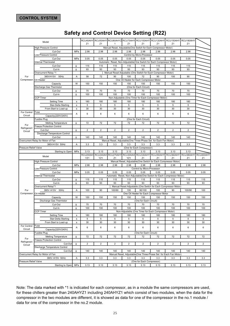
Safety and Control Device Setting (R22)
Note: The data marked with *1 is indicated for each compressor, as in a module the same compressors are used, for these chillers greater than 240AHYZ1 including 240AHYZ1 which consist of two modules, when the data for the compressor in the two modules are different, it is showed as data for one of the compressor in the no.1 module / data for one of the compressor in the no.2 module.
CONTROL SYSTEM
RCU40AHYZ1
RCU50AHYZ1
RCU60AHYZ1
RCU75AHYZ1
RCU100AHYZ1
RCU120AHYZ1
RCU150AHYZ1
RCU180AHYZ1
Cut-Out MPa 2.98 2.98 2.98 2.98 2.98 2.98 2.98 2.98
Cut-Out MPa 0.05 0.05 0.05 0.05 0.05 0.05 0.05 0.05
Cut-Out ℃ 115 115 115 115 115 115 115 115Cut-In ℃ 93 93 93 93 93 93 93 93
380V/415V 50Hz A 58 72 90 100 72 90 100 90
Capacity W 150 150 150 150 150 150 150 150
Cut-Out ℃ 70 70 70 70 70 70 70 70Cut-In ℃ 100 100 100 100 100 100 100 100
Setting Time s 180 180 180 180 180 180 180 180 Star-Delta Starting s 5 5 5 5 5 5 5 5
From Start to Load-up s 30 30 30 30 30 30 30 30
Capacity(220V/240V)
Melting Temperature ℃ 72 72 72 72 72 72 72 72
Cut-Out ℃ 2 2 2 2 2 2 2 2
Cut-Out ℃ 140 140 140 140 140 140 140 140
380V/415V 50Hz A 3.3 3.3 3.3 3.3 3.3 3.3 3.3 3.3
Starting to Open MPa 3.13 3.13 3.13 3.13 3.13 3.13 3.13 3.13RCU200AH
YZ1RCU240AH
YZ1RCU270AHY
Z1RCU300AH
YZ1RCU330AHY
Z1RCU350AHY
Z1RCU360AHY
Z1RCU380AHY
Z1RCU400AHY
Z1
Cut-Out MPa 2.98 2.98 2.98 2.98 2.98 2.98 2.98 2.98 2.98
Cut-Out MPa 0.05 0.05 0.05 0.05 0.05 0.05 0.05 0.05 0.05
Cut-Out ℃ 115 115 115 115 115 115 115 115 115Cut-In ℃ 93 93 93 93 93 93 93 93 93
380V /415V 50Hz A 100 90 100/90 100 90/100 100 90 100/90 100
Capacity W 150 150 150 150 150 150 150 150 150
Cut-Out ℃ 70 70 70 70 70 70 70 70 70Cut-In ℃ 100 100 100 100 100 100 100 100 100
Setting Time s 180 180 180 180 180 180 180 180 180 Star-Delta Starting s 5 5 5 5 5 5 5 5 5
From Start to Load-up s 30 30 30 30 30 30 30 30 30
Capacity(220V/240V)
Melting Temperature ℃ 72 72 72 72 72 72 72 72 72
Cut-Out ℃ 2 2 2 2 2 2 2 2 2
Cut-Out ℃ 140 140 140 140 140 140 140 140 140
380V /415V 50Hz A 3.3 3.3 3.3 3.3 3.3 3.3 3.3 3.3 3.3
Starting to Open MPa 3.13 3.13 3.13 3.13 3.13 3.13 3.13 3.13 3.13
Manual Reset Adjustable (One Switch for Each Compressor Motor)
Automatic Reset, Non-Adjustable(One Switch for Each Compressor Motor)
Control by Micro-Processor
Manual Reset, Adjustable(One Switch for Each Compressor Motor)
Model
ForCompressor
High Pressure Control
Low Pressure Control
Internal Thermostat
Overcurrent Relay *1
Oil Heater
Discharge Gas Thermistor
(One for Each Compressor)
Manual Reset, Adjustable(One Three-Phase Set for Each Fan Motor)
(One for Each Circuit)
Non-Adjustable (One Timer for Each Compressor Motor)
6 6 6 6
(One for Each Circuit)
One Oil Heater for Each Compressor Motor
CCP Timer
For ControlCircuit
FuseA 6 6 6 6
ForRefrigerant
Circuit
Fusible Plug
Freeze Protection Control
Discharge Temperature Control
Overcurrent Relay for Motor of Fan
Pressure Relief Valve
Model
ForCompressor
High Pressure Control
Overcurrent Relay*1
CCP Timer
Manual Reset, Adjustable(One Switch for Each Compressor Motor)
Low Pressure Control Control by Micro-Processor
Internal Thermostat Automatic Reset, Non-Adjustable(One Switch for Each Compressor Motor)
Manual Reset Adjustable (One Switch for Each Compressor Motor)
Oil Heater One Oil Heater for Each Compressor Motor
Discharge Gas Thermistor (One for Each Circuit)
Non-Adjustable (One Timer for Each Compressor Motor)
For ControlCircuit
FuseA 6 6 6 6 6 6 6 6 6
ForRefrigerant
Circuit
Fusible Plug (One for Each Circuit)
Freeze Protection Control
Discharge Temperature Control
Overcurrent Relay for Motor of Fan Manual Reset, Adjustable(One Three-Phase Set for Each Fan Motor)
Pressure Relief Valve (One for Each Compressor)

26
Safety and Control Device Setting (R407C)
Note: The data marked with *1 is indicated for each compressor, as in a module the same compressors are used, for these chillers greater than 240AHYZ1 including 240AHYZ1 which consist of two modules, when the data for the compressor in the two modules are different, it is showed as data for one of the compressor in the no.1 module / data for one of the compressor in the no.2 module.
CONTROL SYSTEM
RCUG40AHYZ1
RCUG50AHYZ1
RCUG60AHYZ1
RCUG75AHYZ1
RCUG100AHYZ1
RCUG120AHYZ1
RCUG150AHYZ1
RCUG180AHYZ1
Cut-Out MPa 2.98 2.98 2.98 2.98 2.98 2.98 2.98 2.98
Cut-Out MPa 0.05 0.05 0.05 0.05 0.05 0.05 0.05 0.05
Cut-Out ℃ 115 115 115 115 115 115 115 115Cut-In ℃ 93 93 93 93 93 93 93 93
380V/415V 50Hz A 64 80 100 100 80 100 100 100
W 150 150 150 150 150 150 150 150
Cut-Out ℃ 70 70 70 70 70 70 70 70Cut-In ℃ 100 100 100 100 100 100 100 100
Setting Time s 180 180 180 180 180 180 180 180Star-Delta Starting s 5 5 5 5 5 5 5 5
From Start to Load-up s 30 30 30 30 30 30 30 30
Capacity(220V/240V)
Melting Temperature ℃ 72 72 72 72 72 72 72 72
Cut-Out ℃ 2 2 2 2 2 2 2 2
Cut-Out ℃ 140 140 140 140 140 140 140 140
380V/415V 50Hz A 3.3 3.3 3.3 3.3 3.3 3.3 3.3 3.3
Starting to Open MPa 3.13 3.13 3.13 3.13 3.13 3.13 3.13 3.13RCUG200
AHYZ1RCUG240
AHYZ1RCUG270A
HYZ1RCUG300
AHYZ1RCUG330A
HYZ1RCUG350A
HYZ1RCUG360A
HYZ1RCUG380A
HYZ1RCUG400A
HYZ1
Cut-Out MPa 2.98 2.98 2.98 2.98 2.98 2.98 2.98 2.98 2.98
Cut-Out MPa 0.05 0.05 0.05 0.05 0.05 0.05 0.05 0.05 0.05
Cut-Out ℃ 115 115 115 115 115 115 115 115 115Cut-In ℃ 93 93 93 93 93 93 93 93 93
380V/415V 50Hz A 100 100 100 100 100 100 100 100 100
W 150 150 150 150 150 150 150 150 150
Cut-Out ℃ 70 70 70 70 70 70 70 70 70Cut-In ℃ 100 100 100 100 100 100 100 100 100
Setting Time s 180 180 180 180 180 180 180 180 180s 5 5 5 5 5 5 5 5 5
From Start to Load-up s 30 30 30 30 30 30 30 30 30
Capacity(220V/240V)
Melting Temperature ℃ 72 72 72 72 72 72 72 72 72
Cut-Out ℃ 2 2 2 2 2 2 2 2 2
Cut-Out ℃ 140 140 140 140 140 140 140 140 140
380V/415V 50Hz A 3.3 3.3 3.3 3.3 3.3 3.3 3.3 3.3 3.3
Starting to Open MPa 3.13 3.13 3.13 3.13 3.13 3.13 3.13 3.13 3.13
Manual Reset, Adjustable(One Three-Phase Set for Each Fan Motor)
(One for Each Compressor)
One Oil Heater for Each Compressor Motor
(One for Each Circuit)
Non-Adjustable (One Timer for Each Compressor Motor)
(One for Each Circuit)
Manual Reset, Adjustable(One Switch for Each Compressor Motor)
Control by Micro-Processor
Automatic Reset, Non-Adjustable(One Switch for Each Compressor Motor)
Manual Reset Adjustable (One Switch for Each Compressor Motor)
Manual Reset, Adjustable(One Three-Phase Set for Each Fan Motor)
(One for Each Compressor)
One Oil Heater for Each Compressor Motor
(One for Each Circuit)
Non-Adjustable (One Timer for Each Compressor Motor)
(One for Each Circuit)
6 6 6 6
Manual Reset, Adjustable(One Switch for Each Compressor Motor)
Control by Micro-Processor
Automatic Reset, Non-Adjustable(One Switch for Each Compressor Motor)
Manual Reset Adjustable (One Switch for Each Compressor Motor)
Model
ForCompressor
High Pressure Control
Low Pressure Control
Internal Thermostat
Overcurrent Relay *1
Oil HeaterCapacity
Discharge Gas Thermistor
CCP Timer
For ControlCircuit
FuseA 6 6 6 6
ForRefrigerant
Circuit
Fusible Plug
Freeze Protection Control
Discharge Temperature Control
Overcurrent Relay for Motor of Fan
Pressure Relief Valve
Model
ForCompressor
High Pressure Control
Low Pressure Control
Internal Thermostat
Overcurrent Relay*1
Oil HeaterCapacity
Discharge Gas Thermistor
CCP Timer
Star-Delta Starting
For ControlCircuit
Fuse6 6A 6 6 6
Overcurrent Relay for Motor of Fan
Pressure Relief Valve
6 6
ForRefrigerant
Circuit
Fusible Plug
Freeze Protection Control
Discharge Temperature Control
6 6

27
Recommended Concrete Curbs
RCU(G)40、50、60、75AHYZ1 RCU(G)100AHYZ1、RCU(G)120AHYZ1 and RCU(G)150AHYZ1
INSTALLATION DATA
Drain Ditch Concrete Mortar Cement
☆Nut☆Washer☆Bushing
☆Foundation Bolt
☆:Supplied by Factory
Steel Plate(1mm)☆Vibration Proof Rubber Mat
10-Vibration Proof Rubber Mat
Steel Plate(1mm) : Field Supply
Drain Ditch
Foundation Bolt(6-M20×300)
Drain Ditch
Steel Plate(1mm): Field Supply
Mortar CementConcreteDrain Ditch
[Compressor Side]
Foundation Bolt
6-Vibration Proof Rubber Mat
(4-M20×300)
☆Nut☆Washer☆Bushing
☆Foundation Bolt
☆:Supplied by Factory
Steel Plate(1mm)
☆Vibration Proof Rubber Mat
[Tubing Side]
3

28
Recommended Concrete Curbs
RCU(G)180AHYZ1 and RCU(G)200AHYZ1 RCU(G)240AHYZ1,RCU(G)270AHYZ1 and RCU(G)300AHYZ1
INSTALLATION DATA
Drain Ditch14-Vibration
Foundation Bolt
☆Nut☆Washer☆Bushing
☆Foundation Bolt
☆:Supplied by Factory
Steel Plate(1mm)☆Vibration Proof Rubber Mat
Proof Rubber Mat
Steel Plate(1mm) : Field Supply
Drain Ditch Concrete Mortar Cement
[Tubing Side]
Compressor Side
Drain Ditch
[Compressor Side]
[Tubing Side]
(6-M20×300)Foundation Bolt
Drain Ditch
Foundation Bolt(6-M20×300)
[Tubing Side]
Concrete Mortar Cement
☆Nut☆Washer☆Bushing
☆Foundation Bolt
☆:Supplied by Factory
Steel Plate(1mm)
☆Vibration Proof Rubber Mat
[Compressor Side]
Rubber Mat10-Vibration Proof 10-Vibration Proof
Rubber Mat
Steel Plate(1mm) : Field Supply
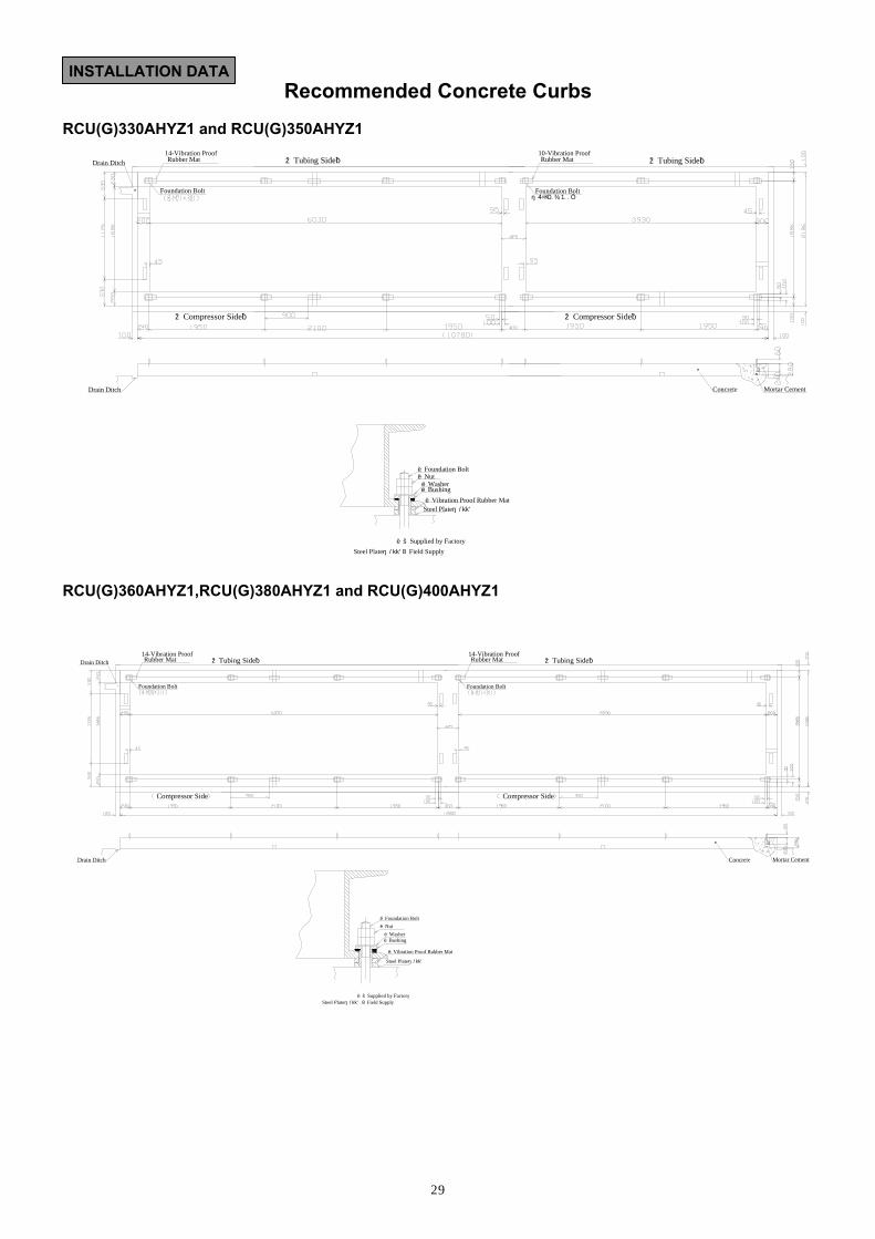
29
Recommended Concrete Curbs RCU(G)330AHYZ1 and RCU(G)350AHYZ1 RCU(G)360AHYZ1,RCU(G)380AHYZ1 and RCU(G)400AHYZ1
INSTALLATION DATA
Concrete Mortar Cement
Foundation Bolt
[Tubing Side]
Drain Ditch
Foundation Bolt(6-M20×300)
[Compressor Side]
☆Nut☆Washer☆Bushing
☆Foundation Bolt
☆:Supplied by Factory
Steel Plate(1mm)☆Vibration Proof Rubber Mat
Drain Ditch Rubber Mat [Tubing Side]
[Compressor Side]
10-Vibration Proof 14-Vibration Proof Rubber Mat
Steel Plate(1mm): Field Supply
Foundation Bolt
[Tubing Side]
Drain Ditch Concrete Mortar Cement
Foundation Bolt
Drain Ditch
Compressor Side
☆Nut☆Washer☆Bushing
☆Foundation Bolt
☆:Supplied by Factory
Steel Plate(1mm)
☆Vibration Proof Rubber Mat
Compressor Side
[Tubing Side]14-Vibration Proof Rubber Mat
14-Vibration Proof Rubber Mat
Steel Plate(1mm) : Field Supply

30
CONTROL SYSTEM
Electrical Wiring Diagram MODELS: RCU(G)40、50、60、75AHYZ1
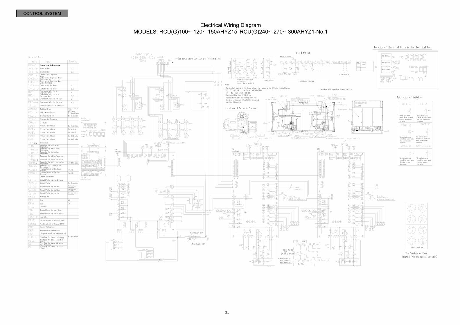
31
CONTROL SYSTEM
Electrical Wiring Diagram MODELS: RCU(G)100、120、150AHYZ1,RCU(G)240、270、300AHYZ1-No.1
Motor for Compressor
1,2,4
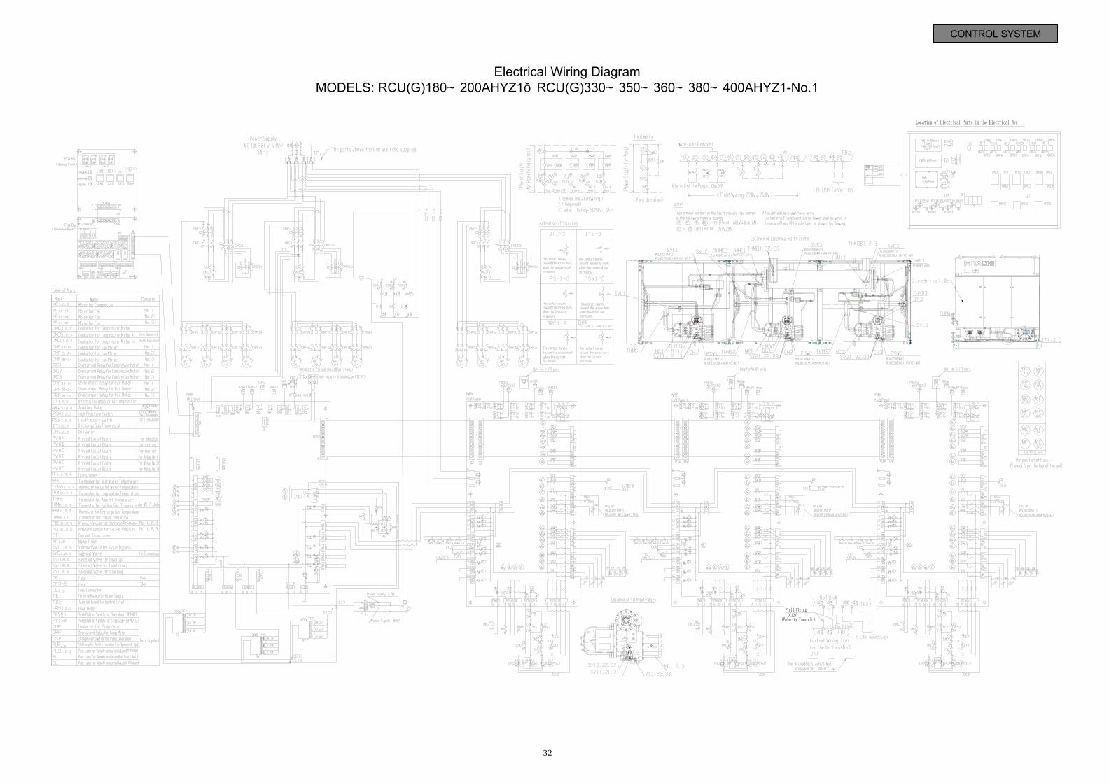
32
CONTROL SYSTEM
Electrical Wiring Diagram MODELS: RCU(G)180、200AHYZ1,RCU(G)330、350、360、380、400AHYZ1-No.1

33
CONTROL SYSTEM
Electrical Wiring Diagram MODELS: RCU(G)240、270、300、330、350AHYZ1-No.2
Motor for Compressor
1,2,4

34
CONTROL SYSTEM
Electrical Wiring Diagram MODELS: RCU(G)360、380、400AHYZ1-No.2

35
CONTROL SYSTEM
DIP SWITCH SETTING MODELS: RCU(G)40AHYZ1~RCU(G)400AHYZ1

36
Standard Specifications
Unit - The unit shall be an air-cooled screw type water chiller with R22 or R407C refrigerant, and shall be factory-completed with screw-type compressors, refrigeration cycle(s), air-cooled condensers, shell-and-tube water coolers, condenser fan motors, a star-delta starter, protective and safety devices, thermal expansion valves and compressor discharge stop valves, and shall be factory-assembled, piped, internal wired and charged with R22 or R407C refrigerant. The unit shall be completely weather-proofed for outdoor installation. The unit shall comply with Chinese Industrial Standards and other Chinese Industrial Standardization statutes, including safety codes. Capacity - The cooling capacity of the unit shall be kW or greater under the following conditions: m3/h chilled water flow rate, ℃chilled water inlet temperature, ℃chilled water outlet temperature, m2. /℃W fouling factor for the water-side heat exchanger or greater. The water-side heat exchanger pressure decrease shall not exceed kPa. The compressor power input shall not exceed kW under the prescribed conditions. Power Supply - The unit shall operate on V, ___Hz, three-phase current, and shall be capable to operate within maximum V and minimum V. Dimensions and Weight - The height of the unit shall be mm, the width shall be mm, and the depth shall be mm. The weight of the unit shall not exceed kg. Cabinet - The cabinet shall be constructed of galvanized steel, baked with synthetic resin paint. The service panels shall be easily removable for service access to the electrical components such as magnetic switches and electrical devices.
Compressor - The compressor shall be a semi-hermetic compressor from the same manufacturer. The compressor shall be serviceable type. The compressor protection system shall include an overcurrent relay, a pressure switch, a timer relays and an internal thermostat embedded in the motor winding. Water-Cooler-the water cooler shall be the dry expansion type with a horizontal welded steel construction shell, containing inside tubes. The refrigerant side of the water cooler shall be cleaned, dehydrated and tested for leakage at the maximum permissible working pressure of _ MPa.The water side of the water cooler shall be cleaned and performed water pressure test at_ MPa. Air-Side Heat Exchanger Fan and Fan Motor - The fan shall be the propeller type directly driven by a kW motor. The motor shall be thermally protected from overloaded conditions with a thermal overcurrent relay and shall be permanently lubricated, The winding and bearing of the condenser fan motor shall be weather-proof construction. Condenser-The condenser shall be the multi-pass, cross-finned tube type, equipped with aluminum slit fins, mechanically bonded to seamless, oxygen-free copper tubes. The condenser shall be cleaned, dehydrated and tested for leakage at the maximum permissible working pressure of MPa. Accessories-Standard accessories shall include vibration-proof mats, foundation bolts
SPECIFICATIONS

36
Hitachi Appliances , Inc.
Air Conditioning Division Specifications in this catalogue are subject to change without notice in order that HITACHI may bring the latest innovations to their customers.
Printed in china No:Z0011121-IX-B
URL: http://www.hitachiacs.co.jp
Distributed By: