Provisioning Guide for Mainframe Systems - Hitachi Vantara
528
Product Version Document Organization Getting Help FASTFIND LINKS Contents Hitachi Virtual Storage Platform Provisioning Guide for Mainframe Systems MK-90RD7021-16
-
Upload
khangminh22 -
Category
Documents
-
view
1 -
download
0
Transcript of Provisioning Guide for Mainframe Systems - Hitachi Vantara
Product Version
Document Organization
Getting Help
FASTFIND LINKS
Contents
Hitachi Virtual Storage PlatformProvisioning Guide for Mainframe Systems
MK-90RD7021-16
Hitachi Virtual Storage Platform Provisioning Guide for Mainframe Systems
ii
© 2010-2014 Hitachi, Ltd. All rights reserved.
Legal Disclaimer
No part of this publication may be reproduced or transmitted in any form or by any means, electronic or mechanical, including photocopying and recording, or stored in a database or retrieval system for any purpose without the express written permission of Hitachi, Ltd. (hereinafter referred to as "Hitachi") and Hitachi Data Systems Corporation (hereinafter referred to as "Hitachi Data Systems").
Hitachi, Ltd., reserves the right to make changes to this document at any time without notice and assumes no responsibility for its use. This document contains the most current information available at the time of publication. When new or revised information becomes available, this entire document will be updated and distributed to all registered users.
Some of the features described in this document might not be currently available. Refer to the most recent product announcement for information about feature and product availability, or contact Hitachi Data Systems Corporation at https://portal.hds.com.
Notice: Hitachi, Ltd., products and services can be ordered only under the terms and conditions of the applicable Hitachi Data Systems Corporation agreements. The use of Hitachi, Ltd., products is governed by the terms of your agreements with Hitachi Data Systems Corporation.
Notice on Export Controls: The technical data and technology inherent in this Document may be subject to U.S. export control laws, including the U.S. Export Administration Act and its associated regulations, and may be subject to export or import regulations in other countries. Reader agrees to comply strictly with all such regulations and acknowledges that Reader has the responsibility to obtain licenses to export, re-export, or import the Document and any Compliant Products.
Hitachi is a registered trademark of Hitachi, Ltd., in the United States and other countries. Hitachi Data Systems is a registered trademark and service mark of Hitachi, Ltd., in the United States and other countries.
Archivas, Essential NAS Platform, HiCommand, Hi-Track, ShadowImage, Tagmaserve, Tagmasoft, Tagmasolve, Tagmastore, TrueCopy, Universal Star Network, and Universal Storage Platform are registered trademarks of Hitachi Data Systems Corporation.
AIX, AS/400, DB2, Domino, DS6000, DS8000, Enterprise Storage Server, ESCON, FICON, FlashCopy, IBM, Lotus, MVS, OS/390, RS/6000, S/390, System z9, System z10, Tivoli, VM/ESA, z/OS, z9, z10, zSeries, z/VM, and z/VSE are registered trademarks or trademarks of International Business Machines Corporation.
All other trademarks, service marks, and company names in this document or website are properties of their respective owners.
Microsoft product screen shots are reprinted with permission from Microsoft Corporation.
Contents iiiHitachi Virtual Storage Platform Provisioning Guide for Mainframe Systems
Contents
Preface . . . . . . . . . . . . . . . . . . . . . . . . . . . . . . . . . . . . . . . . . . . . xiiiIntended audience. . . . . . . . . . . . . . . . . . . . . . . . . . . . . . . . . . . . . . . . . . . . .xivProduct version . . . . . . . . . . . . . . . . . . . . . . . . . . . . . . . . . . . . . . . . . . . . . . .xivDocument revision level . . . . . . . . . . . . . . . . . . . . . . . . . . . . . . . . . . . . . . . . .xivChanges made in this revision . . . . . . . . . . . . . . . . . . . . . . . . . . . . . . . . . . . . xvReferenced documents. . . . . . . . . . . . . . . . . . . . . . . . . . . . . . . . . . . . . . . . . . xvDocument organization . . . . . . . . . . . . . . . . . . . . . . . . . . . . . . . . . . . . . . . . .xviDocument conventions. . . . . . . . . . . . . . . . . . . . . . . . . . . . . . . . . . . . . . . . . .xviConvention for storage capacity values . . . . . . . . . . . . . . . . . . . . . . . . . . . . . xviiAccessing product documentation . . . . . . . . . . . . . . . . . . . . . . . . . . . . . . . . . xviiiGetting help . . . . . . . . . . . . . . . . . . . . . . . . . . . . . . . . . . . . . . . . . . . . . . . . xviiiComments . . . . . . . . . . . . . . . . . . . . . . . . . . . . . . . . . . . . . . . . . . . . . . . . . xviii
1 Introduction to provisioning . . . . . . . . . . . . . . . . . . . . . . . . . . . . 1-1About provisioning. . . . . . . . . . . . . . . . . . . . . . . . . . . . . . . . . . . . . . . . . . . . 1-3Basic provisioning . . . . . . . . . . . . . . . . . . . . . . . . . . . . . . . . . . . . . . . . . . . . 1-3Fixed-sized provisioning . . . . . . . . . . . . . . . . . . . . . . . . . . . . . . . . . . . . . . . . 1-3Disadvantages . . . . . . . . . . . . . . . . . . . . . . . . . . . . . . . . . . . . . . . . . . . . . . 1-3When to use fixed-sized provisioning. . . . . . . . . . . . . . . . . . . . . . . . . . . . . . . 1-4Custom-sized provisioning . . . . . . . . . . . . . . . . . . . . . . . . . . . . . . . . . . . . . . 1-4When to use custom-sized provisioning . . . . . . . . . . . . . . . . . . . . . . . . . . . . . 1-4Basic provisioning workflow . . . . . . . . . . . . . . . . . . . . . . . . . . . . . . . . . . . . . 1-4Dynamic Provisioning Overview. . . . . . . . . . . . . . . . . . . . . . . . . . . . . . . . . . . 1-5Dynamic Provisioning for Mainframe . . . . . . . . . . . . . . . . . . . . . . . . . . . . . . . 1-5Dynamic Provisioning for Mainframe concepts . . . . . . . . . . . . . . . . . . . . . . . . 1-6When to use Dynamic Provisioning for Mainframe. . . . . . . . . . . . . . . . . . . . . . 1-7Dynamic Provisioning for Mainframe advantages. . . . . . . . . . . . . . . . . . . . . . . 1-7Dynamic Provisioning for Mainframe advantage example . . . . . . . . . . . . . . . . . 1-8Dynamic Provisioning for Mainframe work flow. . . . . . . . . . . . . . . . . . . . . . . . 1-8Dynamic Tiering for Mainframe . . . . . . . . . . . . . . . . . . . . . . . . . . . . . . . . . . . 1-8Tiers concept . . . . . . . . . . . . . . . . . . . . . . . . . . . . . . . . . . . . . . . . . . . . . . 1-10When to use Dynamic Tiering for Mainframe . . . . . . . . . . . . . . . . . . . . . . . . 1-10
Hitachi Virtual Storage Platform Provisioning Guide for Mainframe Systems
iv Contents
Resource groups strategies . . . . . . . . . . . . . . . . . . . . . . . . . . . . . . . . . . . . 1-10Complimentary strategies. . . . . . . . . . . . . . . . . . . . . . . . . . . . . . . . . . . . . . 1-11Key terms. . . . . . . . . . . . . . . . . . . . . . . . . . . . . . . . . . . . . . . . . . . . . . . . . 1-11Before you begin. . . . . . . . . . . . . . . . . . . . . . . . . . . . . . . . . . . . . . . . . . . . 1-12About cache management devices . . . . . . . . . . . . . . . . . . . . . . . . . . . . . . . 1-13
Calculating the number of cache management devices required by a DP-VOL . . . . . . . . . . . . . . . . . . . . . . . . . . . . . . . . . . . . . . . . . . . . . . 1-13Maximum capacity of cache management device . . . . . . . . . . . . . . . . 1-13
Calculating the number of cache management devices required by a volume that is not a DP-VOL. . . . . . . . . . . . . . . . . . . . . . . . . . . . . . . . 1-14
Viewing the number of cache management devices . . . . . . . . . . . . . . . . 1-14
2 Configuring resource groups . . . . . . . . . . . . . . . . . . . . . . . . . . . . 2-1System configuration using resource groups . . . . . . . . . . . . . . . . . . . . . . . . . 2-3Resource groups examples. . . . . . . . . . . . . . . . . . . . . . . . . . . . . . . . . . . . . . 2-3
Example of resource groups sharing a port . . . . . . . . . . . . . . . . . . . . . . . 2-3Example of resource groups not sharing ports . . . . . . . . . . . . . . . . . . . . . 2-5
Meta_resource . . . . . . . . . . . . . . . . . . . . . . . . . . . . . . . . . . . . . . . . . . . . . . 2-7Resource lock . . . . . . . . . . . . . . . . . . . . . . . . . . . . . . . . . . . . . . . . . . . . . . . 2-7User groups . . . . . . . . . . . . . . . . . . . . . . . . . . . . . . . . . . . . . . . . . . . . . . . . 2-7Resource group assignments . . . . . . . . . . . . . . . . . . . . . . . . . . . . . . . . . . . . 2-7Resource group license requirements . . . . . . . . . . . . . . . . . . . . . . . . . . . . . . 2-8Resource group rules, restrictions, and guidelines . . . . . . . . . . . . . . . . . . . . . 2-8Creating a resource group . . . . . . . . . . . . . . . . . . . . . . . . . . . . . . . . . . . . . . 2-9Adding resources to a resource group . . . . . . . . . . . . . . . . . . . . . . . . . . . . . 2-10Removing resources from a resource group . . . . . . . . . . . . . . . . . . . . . . . . . 2-10Managing Resource Groups . . . . . . . . . . . . . . . . . . . . . . . . . . . . . . . . . . . . 2-11
Changing the name of a resource group . . . . . . . . . . . . . . . . . . . . . . . . 2-11Deleting a resource group . . . . . . . . . . . . . . . . . . . . . . . . . . . . . . . . . . 2-12
Using Resource Partition Manager and other VSP products . . . . . . . . . . . . . . 2-12Compatible PAV. . . . . . . . . . . . . . . . . . . . . . . . . . . . . . . . . . . . . . . . . . 2-13Dynamic Provisioning for Mainframe . . . . . . . . . . . . . . . . . . . . . . . . . . . 2-13Encryption License Key . . . . . . . . . . . . . . . . . . . . . . . . . . . . . . . . . . . . 2-13Performance Monitor . . . . . . . . . . . . . . . . . . . . . . . . . . . . . . . . . . . . . . 2-14ShadowImage for Mainframe . . . . . . . . . . . . . . . . . . . . . . . . . . . . . . . . 2-14TrueCopy for Mainframe. . . . . . . . . . . . . . . . . . . . . . . . . . . . . . . . . . . . 2-14Universal Replicator for Mainframe . . . . . . . . . . . . . . . . . . . . . . . . . . . . 2-15Universal Volume Manager . . . . . . . . . . . . . . . . . . . . . . . . . . . . . . . . . . 2-16Virtual LVI . . . . . . . . . . . . . . . . . . . . . . . . . . . . . . . . . . . . . . . . . . . . . 2-18Virtual Partition Manager . . . . . . . . . . . . . . . . . . . . . . . . . . . . . . . . . . . 2-19Volume Migration . . . . . . . . . . . . . . . . . . . . . . . . . . . . . . . . . . . . . . . . 2-19Volume Shredder. . . . . . . . . . . . . . . . . . . . . . . . . . . . . . . . . . . . . . . . . 2-19
3 Configuring custom-sized provisioning . . . . . . . . . . . . . . . . . . . . . 3-1Virtual LVI/Virtual LUN functions . . . . . . . . . . . . . . . . . . . . . . . . . . . . . . . . . . 3-3

Contents vHitachi Virtual Storage Platform Provisioning Guide for Mainframe Systems
VLL requirements . . . . . . . . . . . . . . . . . . . . . . . . . . . . . . . . . . . . . . . . . . . . 3-3VLL specifications . . . . . . . . . . . . . . . . . . . . . . . . . . . . . . . . . . . . . . . . . . . . 3-3
Virtual LVI specifications for mainframe systems. . . . . . . . . . . . . . . . . . . . 3-3CV capacity by emulation type for mainframe systems. . . . . . . . . . . . . . . . 3-4
SSID requirements . . . . . . . . . . . . . . . . . . . . . . . . . . . . . . . . . . . . . . . . . . . 3-5VLL size calculations . . . . . . . . . . . . . . . . . . . . . . . . . . . . . . . . . . . . . . . . . . 3-6
Calculating the size of a mainframe volume . . . . . . . . . . . . . . . . . . . . . . . 3-6Calculating the size of a CV using Enhanced mode on SATA drives . . . . . . . 3-7
Management area capacity of a mainframe volume. . . . . . . . . . . . . . . . 3-9Boundary values for RAID levels (Enhanced mode on SATA drives) . . . . . 3-9Boundary values for RAID levels (other than Enhanced mode on SATA drives) . . . . . . . . . . . . . . . . . . . . . . . . . . . . . . . . . . . . . . . . . . . . . . 3-9
Capacity of a slot . . . . . . . . . . . . . . . . . . . . . . . . . . . . . . . . . . . . . . . 3-10Calculated management area capacities (SATA-E drive) . . . . . . . . . . . . 3-10
Configuring volumes in a parity group . . . . . . . . . . . . . . . . . . . . . . . . . 3-10Create LDEV function. . . . . . . . . . . . . . . . . . . . . . . . . . . . . . . . . . . . . . . . . 3-11
Creating an LDEV . . . . . . . . . . . . . . . . . . . . . . . . . . . . . . . . . . . . . . . . 3-11Finding an LDEV ID . . . . . . . . . . . . . . . . . . . . . . . . . . . . . . . . . . . . . . . 3-15Finding an LDEV SSID . . . . . . . . . . . . . . . . . . . . . . . . . . . . . . . . . . . . . 3-15Editing an LDEV SSID . . . . . . . . . . . . . . . . . . . . . . . . . . . . . . . . . . . . . 3-15Changing LDEV settings . . . . . . . . . . . . . . . . . . . . . . . . . . . . . . . . . . . . 3-16Removing an LDEV to be registered. . . . . . . . . . . . . . . . . . . . . . . . . . . . 3-16
Blocking an LDEV . . . . . . . . . . . . . . . . . . . . . . . . . . . . . . . . . . . . . . . . . . . 3-17Restoring a blocked LDEV. . . . . . . . . . . . . . . . . . . . . . . . . . . . . . . . . . . . . . 3-17Editing an LDEV name . . . . . . . . . . . . . . . . . . . . . . . . . . . . . . . . . . . . . . . . 3-18Deleting an LDEV (converting to free space) . . . . . . . . . . . . . . . . . . . . . . . . 3-18Formatting LDEVs . . . . . . . . . . . . . . . . . . . . . . . . . . . . . . . . . . . . . . . . . . . 3-19
About formatting LDEVs . . . . . . . . . . . . . . . . . . . . . . . . . . . . . . . . . . . . 3-19Storage system operation when LDEVs are formatted . . . . . . . . . . . . . . . 3-20Quick Format function . . . . . . . . . . . . . . . . . . . . . . . . . . . . . . . . . . . . . 3-20
Quick Format specifications . . . . . . . . . . . . . . . . . . . . . . . . . . . . . . . 3-21Write to Control Blocks function . . . . . . . . . . . . . . . . . . . . . . . . . . . . . . 3-22Formatting a specific LDEV . . . . . . . . . . . . . . . . . . . . . . . . . . . . . . . . . . 3-23Formatting all LDEVs in a parity group . . . . . . . . . . . . . . . . . . . . . . . . . . 3-23
Making external mainframe system volumes usable . . . . . . . . . . . . . . . . . . . 3-24Registering external volumes . . . . . . . . . . . . . . . . . . . . . . . . . . . . . . . . 3-24Overwriting control blocks in specific external volumes . . . . . . . . . . . . . . 3-25
Assigning a processor blade . . . . . . . . . . . . . . . . . . . . . . . . . . . . . . . . . . . . 3-26Assigning a processor blade to a resource . . . . . . . . . . . . . . . . . . . . . . . 3-26Changing the processor blade assigned to an LDEV . . . . . . . . . . . . . . . . 3-26
Using a system disk . . . . . . . . . . . . . . . . . . . . . . . . . . . . . . . . . . . . . . . . . . 3-27System disk rules, restrictions, and guidelines . . . . . . . . . . . . . . . . . . . . 3-28
4 Configuring thin provisioning . . . . . . . . . . . . . . . . . . . . . . . . . . . 4-1Dynamic Provisioning for Mainframe overview . . . . . . . . . . . . . . . . . . . . . . . . 4-2Dynamic Tiering for Mainframe overview . . . . . . . . . . . . . . . . . . . . . . . . . . . . 4-2
Hitachi Virtual Storage Platform Provisioning Guide for Mainframe Systems
vi Contents
Thin provisioning requirements. . . . . . . . . . . . . . . . . . . . . . . . . . . . . . . . . . . 4-2License requirements. . . . . . . . . . . . . . . . . . . . . . . . . . . . . . . . . . . . . . . 4-2Pool requirements . . . . . . . . . . . . . . . . . . . . . . . . . . . . . . . . . . . . . . . . . 4-3Pool-VOL requirements . . . . . . . . . . . . . . . . . . . . . . . . . . . . . . . . . . . . . 4-4DP-VOL requirements . . . . . . . . . . . . . . . . . . . . . . . . . . . . . . . . . . . . . . 4-7Requirements for increasing DP-VOL capacity. . . . . . . . . . . . . . . . . . . . . . 4-7
Using Dynamic Provisioning for Mainframe or Dynamic Tiering for Mainframe with other VSP products . . . . . . . . . . . . . . . . . . . . . . . . . . . . . . . . . . . . . . 4-8
Interoperability of DP-VOLs and pool-VOLs . . . . . . . . . . . . . . . . . . . . . . . 4-8TrueCopy for Mainframe. . . . . . . . . . . . . . . . . . . . . . . . . . . . . . . . . . . . 4-10Universal Replicator for Mainframe . . . . . . . . . . . . . . . . . . . . . . . . . . . . 4-11ShadowImage for Mainframe . . . . . . . . . . . . . . . . . . . . . . . . . . . . . . . . 4-12Virtual Partition Manager CLPR setting. . . . . . . . . . . . . . . . . . . . . . . . . . 4-13Volume Migration . . . . . . . . . . . . . . . . . . . . . . . . . . . . . . . . . . . . . . . . 4-13Resource Partition Manager . . . . . . . . . . . . . . . . . . . . . . . . . . . . . . . . . 4-14
Dynamic Provisioning for Mainframe workflow . . . . . . . . . . . . . . . . . . . . . . . 4-14Dynamic Tiering for Mainframe. . . . . . . . . . . . . . . . . . . . . . . . . . . . . . . . . . 4-15
About tiered storage . . . . . . . . . . . . . . . . . . . . . . . . . . . . . . . . . . . . . . 4-15Tier monitoring and data relocation. . . . . . . . . . . . . . . . . . . . . . . . . . . . 4-15Multi-tier pool . . . . . . . . . . . . . . . . . . . . . . . . . . . . . . . . . . . . . . . . . . . 4-15Tier monitoring and relocation cycles . . . . . . . . . . . . . . . . . . . . . . . . . . 4-16Tier relocation flow . . . . . . . . . . . . . . . . . . . . . . . . . . . . . . . . . . . . . . . 4-21Tier relocation rules, restrictions, and guidelines. . . . . . . . . . . . . . . . . . . 4-24Buffer area of a tier . . . . . . . . . . . . . . . . . . . . . . . . . . . . . . . . . . . . . . . 4-29
Setting external volumes for each tier . . . . . . . . . . . . . . . . . . . . . . . . 4-29Dynamic Tiering for Mainframe cache specifications and requirements . . . 4-31Execution modes for tier relocation . . . . . . . . . . . . . . . . . . . . . . . . . . . . 4-31
Execution modes when using Hitachi Storage Navigator . . . . . . . . . . . 4-31Execution modes when using Command Control Interface . . . . . . . . . . 4-34
Monitoring modes . . . . . . . . . . . . . . . . . . . . . . . . . . . . . . . . . . . . . . . . 4-36Cautions when using monitoring modes. . . . . . . . . . . . . . . . . . . . . . . 4-37
Notes on performing monitoring . . . . . . . . . . . . . . . . . . . . . . . . . . . . . . 4-38Downloading the tier relocation log file . . . . . . . . . . . . . . . . . . . . . . . . . 4-38
Tier relocation log file contents . . . . . . . . . . . . . . . . . . . . . . . . . . . . . 4-38Tiering policy . . . . . . . . . . . . . . . . . . . . . . . . . . . . . . . . . . . . . . . . . . . 4-39
Tiering policy expansion. . . . . . . . . . . . . . . . . . . . . . . . . . . . . . . . . . 4-40Tiering policy examples . . . . . . . . . . . . . . . . . . . . . . . . . . . . . . . . . . 4-40Setting tiering policy on a DP-VOL. . . . . . . . . . . . . . . . . . . . . . . . . . . 4-42Tiering policy levels . . . . . . . . . . . . . . . . . . . . . . . . . . . . . . . . . . . . . 4-43Viewing the tiering policy in the performance graph . . . . . . . . . . . . . . 4-44Reserving tier capacity when setting a tiering policy . . . . . . . . . . . . . . 4-45Example of reserving tier capacity . . . . . . . . . . . . . . . . . . . . . . . . . . . 4-46Notes on tiering policy settings . . . . . . . . . . . . . . . . . . . . . . . . . . . . . 4-48New page assignment tier . . . . . . . . . . . . . . . . . . . . . . . . . . . . . . . . 4-50Relocation priority . . . . . . . . . . . . . . . . . . . . . . . . . . . . . . . . . . . . . . 4-52Assignment tier when pool-VOLs are deleted . . . . . . . . . . . . . . . . . . . 4-53Formatted pool capacity . . . . . . . . . . . . . . . . . . . . . . . . . . . . . . . . . . 4-54
Contents viiHitachi Virtual Storage Platform Provisioning Guide for Mainframe Systems
Rebalancing the usage level among pool-VOLs . . . . . . . . . . . . . . . . . . 4-54Execution mode settings and tiering policy . . . . . . . . . . . . . . . . . . . . . 4-55Changing the tiering policy level on a DP-VOL . . . . . . . . . . . . . . . . . . 4-56
Changing new page assignment tier of a V-VOL . . . . . . . . . . . . . . . . . . . 4-57Opening the Edit Tiering Policies window . . . . . . . . . . . . . . . . . . . . . . . . 4-57Changing a tiering policy . . . . . . . . . . . . . . . . . . . . . . . . . . . . . . . . . . . 4-58
To change the tiering policy . . . . . . . . . . . . . . . . . . . . . . . . . . . . . . . 4-58Changing relocation priority setting of a V-VOL . . . . . . . . . . . . . . . . . . . . 4-59Dynamic Tiering for Mainframe workflow . . . . . . . . . . . . . . . . . . . . . . . . 4-59Dynamic Tiering for Mainframe tasks and parameters . . . . . . . . . . . . . . . 4-61
Task and parameter settings . . . . . . . . . . . . . . . . . . . . . . . . . . . . . . . 4-62Display items: Setting parameters . . . . . . . . . . . . . . . . . . . . . . . . . . . 4-63Display items: Capacity usage for each tier . . . . . . . . . . . . . . . . . . . . 4-64Display items: Performance monitor statistics . . . . . . . . . . . . . . . . . . . 4-64Display items: Operation status of performance monitor/relocation. . . . 4-64
Managing Dynamic Tiering for Mainframe . . . . . . . . . . . . . . . . . . . . . . . 4-65Changing pool for Dynamic Provisioning for Mainframe to pool for Dynamic Tiering for Mainframe. . . . . . . . . . . . . . . . . . . . . . . . . . . . 4-65
Changing monitoring and tier relocation settings. . . . . . . . . . . . . . . . . 4-67Changing monitoring mode setting . . . . . . . . . . . . . . . . . . . . . . . . . . 4-68Changing buffer space for new page assignment setting . . . . . . . . . . . 4-68Changing buffer space for tier relocation setting . . . . . . . . . . . . . . . . . 4-69
Changing a pool for Dynamic Tiering for Mainframe to a pool for Dynamic Provisioning for Mainframe . . . . . . . . . . . . . . . . . . . . . . . . . . . . . . . . . . . . 4-69
Working with pools . . . . . . . . . . . . . . . . . . . . . . . . . . . . . . . . . . . . . . . . . . 4-70About pools. . . . . . . . . . . . . . . . . . . . . . . . . . . . . . . . . . . . . . . . . . . . . 4-70About pool-VOLs . . . . . . . . . . . . . . . . . . . . . . . . . . . . . . . . . . . . . . . . . 4-70Pool status . . . . . . . . . . . . . . . . . . . . . . . . . . . . . . . . . . . . . . . . . . . . . 4-71Creating a pool . . . . . . . . . . . . . . . . . . . . . . . . . . . . . . . . . . . . . . . . . . 4-71
Working with DP-VOLs . . . . . . . . . . . . . . . . . . . . . . . . . . . . . . . . . . . . . . . . 4-77About DP-VOLs . . . . . . . . . . . . . . . . . . . . . . . . . . . . . . . . . . . . . . . . . . 4-77Relationship between a pool and DP-VOLs . . . . . . . . . . . . . . . . . . . . . . . 4-77Creating V-VOLs . . . . . . . . . . . . . . . . . . . . . . . . . . . . . . . . . . . . . . . . . 4-77Editing a DP-VOL's SSID . . . . . . . . . . . . . . . . . . . . . . . . . . . . . . . . . . . . 4-81Changing DP-VOL settings . . . . . . . . . . . . . . . . . . . . . . . . . . . . . . . . . . 4-81Removing the DP-VOL to be registered . . . . . . . . . . . . . . . . . . . . . . . . . 4-82
Thresholds . . . . . . . . . . . . . . . . . . . . . . . . . . . . . . . . . . . . . . . . . . . . . . . . 4-82Pool utilization thresholds . . . . . . . . . . . . . . . . . . . . . . . . . . . . . . . . . . . 4-82Pool subscription limit . . . . . . . . . . . . . . . . . . . . . . . . . . . . . . . . . . . . . 4-83Changing pool thresholds . . . . . . . . . . . . . . . . . . . . . . . . . . . . . . . . . . . 4-84Changing the pool subscription limit . . . . . . . . . . . . . . . . . . . . . . . . . . . 4-85
Working with SIMs. . . . . . . . . . . . . . . . . . . . . . . . . . . . . . . . . . . . . . . . . . . 4-85About SIMs . . . . . . . . . . . . . . . . . . . . . . . . . . . . . . . . . . . . . . . . . . . . . 4-85SIM reference codes . . . . . . . . . . . . . . . . . . . . . . . . . . . . . . . . . . . . . . 4-86Automatic completion of a SIM . . . . . . . . . . . . . . . . . . . . . . . . . . . . . . 4-86Manually completing a SIM. . . . . . . . . . . . . . . . . . . . . . . . . . . . . . . . . . 4-87
Managing pools and DP-VOLs . . . . . . . . . . . . . . . . . . . . . . . . . . . . . . . . . . . 4-88
Hitachi Virtual Storage Platform Provisioning Guide for Mainframe Systems
viii Contents
Viewing pool information . . . . . . . . . . . . . . . . . . . . . . . . . . . . . . . . . . . 4-88Viewing used pool capacity. . . . . . . . . . . . . . . . . . . . . . . . . . . . . . . . . . 4-88Viewing formatted pool capacity . . . . . . . . . . . . . . . . . . . . . . . . . . . . . . 4-89Viewing the progress of rebalancing the usage level among pool-VOLs . . 4-90Increasing pool capacity. . . . . . . . . . . . . . . . . . . . . . . . . . . . . . . . . . . . 4-90Changing a pool name . . . . . . . . . . . . . . . . . . . . . . . . . . . . . . . . . . . . . 4-92Recovering a blocked pool . . . . . . . . . . . . . . . . . . . . . . . . . . . . . . . . . . 4-92Decrease pool capacity . . . . . . . . . . . . . . . . . . . . . . . . . . . . . . . . . . . . 4-93
About decreasing pool capacity. . . . . . . . . . . . . . . . . . . . . . . . . . . . . 4-93Decreasing pool capacity . . . . . . . . . . . . . . . . . . . . . . . . . . . . . . . . . 4-95Stopping the decrease of pool capacity . . . . . . . . . . . . . . . . . . . . . . . 4-95
Deleting a tier in a pool . . . . . . . . . . . . . . . . . . . . . . . . . . . . . . . . . . . . 4-95Deleting a pool . . . . . . . . . . . . . . . . . . . . . . . . . . . . . . . . . . . . . . . . . . 4-97Changing external LDEV tier rank . . . . . . . . . . . . . . . . . . . . . . . . . . . . . 4-97Increasing DP-VOL capacity . . . . . . . . . . . . . . . . . . . . . . . . . . . . . . . . . 4-98Changing the name of a DP-VOL. . . . . . . . . . . . . . . . . . . . . . . . . . . . . . 4-99About releasing pages in a DP-VOL . . . . . . . . . . . . . . . . . . . . . . . . . . . . 4-99
Releasing pages in a DP-VOL . . . . . . . . . . . . . . . . . . . . . . . . . . . . . .4-101Stopping the release of pages in a DP-VOL . . . . . . . . . . . . . . . . . . . .4-102
Enabling/disabling tier relocation of a DP-VOL . . . . . . . . . . . . . . . . . . . .4-102Deleting a DP-VOL. . . . . . . . . . . . . . . . . . . . . . . . . . . . . . . . . . . . . . . .4-103
5 Configuring access attributes. . . . . . . . . . . . . . . . . . . . . . . . . . . . 5-1Access attributes strategies . . . . . . . . . . . . . . . . . . . . . . . . . . . . . . . . . . . . . 5-2Volume Retention Manager requirements. . . . . . . . . . . . . . . . . . . . . . . . . . . . 5-2Access attribute restrictions . . . . . . . . . . . . . . . . . . . . . . . . . . . . . . . . . . . . . 5-2Keywords . . . . . . . . . . . . . . . . . . . . . . . . . . . . . . . . . . . . . . . . . . . . . . . . . . 5-3Assigning access attribute . . . . . . . . . . . . . . . . . . . . . . . . . . . . . . . . . . . . . . 5-4
Supported volume emulation types . . . . . . . . . . . . . . . . . . . . . . . . . . . . . 5-4Setting Access Attributes . . . . . . . . . . . . . . . . . . . . . . . . . . . . . . . . . . . . 5-4
Specifying the VTOC size . . . . . . . . . . . . . . . . . . . . . . . . . . . . . . . . . . . . . . . 5-5
6 Protecting volumes from I/O operations . . . . . . . . . . . . . . . . . . . . 6-1Overview of Volume Security . . . . . . . . . . . . . . . . . . . . . . . . . . . . . . . . . . . . 6-3Volume Security Requirements . . . . . . . . . . . . . . . . . . . . . . . . . . . . . . . . . . . 6-3Volume Security Functions . . . . . . . . . . . . . . . . . . . . . . . . . . . . . . . . . . . . . . 6-3Protecting Volumes from I/O Operations at Mainframe Hosts . . . . . . . . . . . . . . 6-4Warnings Regarding Volume Security . . . . . . . . . . . . . . . . . . . . . . . . . . . . . 6-12Supported Volume Emulation Types . . . . . . . . . . . . . . . . . . . . . . . . . . . . . . 6-14Maximum Number of Groups . . . . . . . . . . . . . . . . . . . . . . . . . . . . . . . . . . . 6-14Maximum Number of Hosts and Volumes. . . . . . . . . . . . . . . . . . . . . . . . . . . 6-14Launching Volume Security . . . . . . . . . . . . . . . . . . . . . . . . . . . . . . . . . . . . 6-14Viewing Security Settings . . . . . . . . . . . . . . . . . . . . . . . . . . . . . . . . . . . . . . 6-15
Locating Volumes in a Specified Security Group . . . . . . . . . . . . . . . . . . . 6-15Locating Security Groups that Contain a Specified Host . . . . . . . . . . . . . . 6-15
Contents ixHitachi Virtual Storage Platform Provisioning Guide for Mainframe Systems
Locating Volumes in a Security Group that Contains a Specified Host . . . . 6-16Locating Ports through Which Hosts Can Access Volumes . . . . . . . . . . . . 6-16Locating Security Groups that Contain a Specified Volume . . . . . . . . . . . . 6-17Locating Hosts in a Security Group that Contains a Specified Volume . . . . 6-17Locating Security Groups that Contain a Specified Host Group . . . . . . . . . 6-17Locating Security Groups that Contain a Specified LDEV Group . . . . . . . . 6-18
Limiting Host Access . . . . . . . . . . . . . . . . . . . . . . . . . . . . . . . . . . . . . . . . . 6-18Creating a Host Group . . . . . . . . . . . . . . . . . . . . . . . . . . . . . . . . . . . . . 6-18Registering Hosts in a Host Group . . . . . . . . . . . . . . . . . . . . . . . . . . . . . 6-19Registering Ports in a Host Group . . . . . . . . . . . . . . . . . . . . . . . . . . . . . 6-20Creating an LDEV Group. . . . . . . . . . . . . . . . . . . . . . . . . . . . . . . . . . . . 6-21Registering Volumes in an LDEV Group . . . . . . . . . . . . . . . . . . . . . . . . . 6-21Creating a Security Group for Use As an Access Group . . . . . . . . . . . . . . 6-22Registering a Host Group and an LDEV Group in a Security Group . . . . . . 6-23
Prohibiting Host Access . . . . . . . . . . . . . . . . . . . . . . . . . . . . . . . . . . . . . . . 6-23Creating an LDEV Group. . . . . . . . . . . . . . . . . . . . . . . . . . . . . . . . . . . . 6-24Registering Volumes in an LDEV Group . . . . . . . . . . . . . . . . . . . . . . . . . 6-25Creating a Security Group for Use As a Pool Group . . . . . . . . . . . . . . . . . 6-25Registering an LDEV Group in a Security Group . . . . . . . . . . . . . . . . . . . 6-26
Protecting Volumes from Copy Operations . . . . . . . . . . . . . . . . . . . . . . . . . . 6-27Disabling Volume Security . . . . . . . . . . . . . . . . . . . . . . . . . . . . . . . . . . . . . 6-27Editing Security Groups . . . . . . . . . . . . . . . . . . . . . . . . . . . . . . . . . . . . . . . 6-28
Unregistering a Host Group . . . . . . . . . . . . . . . . . . . . . . . . . . . . . . . . . 6-28Unregistering an LDEV Group . . . . . . . . . . . . . . . . . . . . . . . . . . . . . . . . 6-29Renaming a Security Group . . . . . . . . . . . . . . . . . . . . . . . . . . . . . . . . . 6-29Deleting a Security Group. . . . . . . . . . . . . . . . . . . . . . . . . . . . . . . . . . . 6-29
Editing Host Groups. . . . . . . . . . . . . . . . . . . . . . . . . . . . . . . . . . . . . . . . . . 6-30Registering Hosts to be Attached to the Storage System . . . . . . . . . . . . . 6-30Deleting Hosts from Host Groups . . . . . . . . . . . . . . . . . . . . . . . . . . . . . 6-31Deleting Ports from Host Groups . . . . . . . . . . . . . . . . . . . . . . . . . . . . . . 6-32Renaming Host Groups. . . . . . . . . . . . . . . . . . . . . . . . . . . . . . . . . . . . . 6-32Deleting Host Groups . . . . . . . . . . . . . . . . . . . . . . . . . . . . . . . . . . . . . . 6-33
Editing LDEV Groups . . . . . . . . . . . . . . . . . . . . . . . . . . . . . . . . . . . . . . . . . 6-33Deleting Volumes from an LDEV Groups. . . . . . . . . . . . . . . . . . . . . . . . . 6-33Renaming an LDEV Group . . . . . . . . . . . . . . . . . . . . . . . . . . . . . . . . . . 6-34Deleting an LDEV Group. . . . . . . . . . . . . . . . . . . . . . . . . . . . . . . . . . . . 6-34
7 Troubleshooting . . . . . . . . . . . . . . . . . . . . . . . . . . . . . . . . . . . . . 7-1Troubleshooting VLL . . . . . . . . . . . . . . . . . . . . . . . . . . . . . . . . . . . . . . . . . . 7-2Troubleshooting Dynamic Provisioning for Mainframe . . . . . . . . . . . . . . . . . . . 7-2Troubleshooting provisioning while using Command Control Interface. . . . . . . . 7-7
Errors when operating CCI (Dynamic Provisioning for Mainframe, SSB1: 0x2e31/0xb96d) . . . . . . . . . . . . . . . . . . . . . . . . . . . . . . . . . . . . . . . . . 7-8
Troubleshooting Volume Retention Manager. . . . . . . . . . . . . . . . . . . . . . . . . . 7-9Troubleshooting Volume Security. . . . . . . . . . . . . . . . . . . . . . . . . . . . . . . . . 7-10Calling the Hitachi Data Systems Support Center . . . . . . . . . . . . . . . . . . . . . 7-11
Hitachi Virtual Storage Platform Provisioning Guide for Mainframe Systems
x Contents
A CCI command reference . . . . . . . . . . . . . . . . . . . . . . . . . . . . . . . A-1 Storage Navigator tasks and CCI command list . . . . . . . . . . . . . . . . . . . . . . . A-2
B Resource Partition Manager GUI reference . . . . . . . . . . . . . . . . . . B-1Resource Groups window. . . . . . . . . . . . . . . . . . . . . . . . . . . . . . . . . . . . . . . B-2
Summary and buttons . . . . . . . . . . . . . . . . . . . . . . . . . . . . . . . . . . . . . . B-2Resource Groups tab . . . . . . . . . . . . . . . . . . . . . . . . . . . . . . . . . . . . . . . B-3
Window after selecting a resource group . . . . . . . . . . . . . . . . . . . . . . . . . . . . B-3Parity Groups tab . . . . . . . . . . . . . . . . . . . . . . . . . . . . . . . . . . . . . . . . . B-5LDEVs tab. . . . . . . . . . . . . . . . . . . . . . . . . . . . . . . . . . . . . . . . . . . . . . . B-6Ports tab . . . . . . . . . . . . . . . . . . . . . . . . . . . . . . . . . . . . . . . . . . . . . . . B-8Host Groups tab . . . . . . . . . . . . . . . . . . . . . . . . . . . . . . . . . . . . . . . . . B-10
Create Resource Groups wizard . . . . . . . . . . . . . . . . . . . . . . . . . . . . . . . . . B-11Create Resource Groups window. . . . . . . . . . . . . . . . . . . . . . . . . . . . . . B-11Select Parity Groups window. . . . . . . . . . . . . . . . . . . . . . . . . . . . . . . . . B-14Select LDEVs window. . . . . . . . . . . . . . . . . . . . . . . . . . . . . . . . . . . . . . B-15Select Ports window. . . . . . . . . . . . . . . . . . . . . . . . . . . . . . . . . . . . . . . B-18Select Host Groups window . . . . . . . . . . . . . . . . . . . . . . . . . . . . . . . . . B-20Create Resource Groups Confirm window. . . . . . . . . . . . . . . . . . . . . . . . B-21
Edit Resource Group wizard . . . . . . . . . . . . . . . . . . . . . . . . . . . . . . . . . . . . B-23Edit Resource Group window . . . . . . . . . . . . . . . . . . . . . . . . . . . . . . . . B-23Edit Resource Group Confirm window . . . . . . . . . . . . . . . . . . . . . . . . . . B-23
Add Resources wizard . . . . . . . . . . . . . . . . . . . . . . . . . . . . . . . . . . . . . . . . B-25Add Resources window . . . . . . . . . . . . . . . . . . . . . . . . . . . . . . . . . . . . B-25Add Resources Confirm window . . . . . . . . . . . . . . . . . . . . . . . . . . . . . . B-25
Remove Resources window . . . . . . . . . . . . . . . . . . . . . . . . . . . . . . . . . . . . B-29Delete Resource Groups window. . . . . . . . . . . . . . . . . . . . . . . . . . . . . . . . . B-31Resource Group Properties window . . . . . . . . . . . . . . . . . . . . . . . . . . . . . . . B-33
C LDEV GUI reference . . . . . . . . . . . . . . . . . . . . . . . . . . . . . . . . . . C-1Parity Groups window . . . . . . . . . . . . . . . . . . . . . . . . . . . . . . . . . . . . . . . . . C-3Parity Groups window after selecting Internal (or External) under Parity Groups C-5Window after selecting a parity group under Internal (or External) of Parity Groups . . . . . . . . . . . . . . . . . . . . . . . . . . . . . . . . . . . . . . . . . . . . . . . . . . . C-8
Window after selecting Logical Devices . . . . . . . . . . . . . . . . . . . . . . . . . . . . C-12Create LDEVs wizard . . . . . . . . . . . . . . . . . . . . . . . . . . . . . . . . . . . . . . . . . C-15
Create LDEVs window . . . . . . . . . . . . . . . . . . . . . . . . . . . . . . . . . . . . . C-15Create LDEVs Confirm window . . . . . . . . . . . . . . . . . . . . . . . . . . . . . . . C-23
Edit LDEVs wizard . . . . . . . . . . . . . . . . . . . . . . . . . . . . . . . . . . . . . . . . . . . C-24Edit LDEVs window . . . . . . . . . . . . . . . . . . . . . . . . . . . . . . . . . . . . . . . C-24Edit LDEVs Confirm window . . . . . . . . . . . . . . . . . . . . . . . . . . . . . . . . . C-26
Change LDEV Settings window . . . . . . . . . . . . . . . . . . . . . . . . . . . . . . . . . . C-28View SSIDs window. . . . . . . . . . . . . . . . . . . . . . . . . . . . . . . . . . . . . . . . . . C-29Select Free Spaces window . . . . . . . . . . . . . . . . . . . . . . . . . . . . . . . . . . . . C-30Select Pool window . . . . . . . . . . . . . . . . . . . . . . . . . . . . . . . . . . . . . . . . . . C-32
Contents xiHitachi Virtual Storage Platform Provisioning Guide for Mainframe Systems
View LDEV IDs window . . . . . . . . . . . . . . . . . . . . . . . . . . . . . . . . . . . . . . . C-33Emulation groups and types . . . . . . . . . . . . . . . . . . . . . . . . . . . . . . . . . C-34
View Physical Location window . . . . . . . . . . . . . . . . . . . . . . . . . . . . . . . . . . C-34Edit SSIDs window . . . . . . . . . . . . . . . . . . . . . . . . . . . . . . . . . . . . . . . . . . C-36Change SSIDs window . . . . . . . . . . . . . . . . . . . . . . . . . . . . . . . . . . . . . . . . C-37Format LDEVs wizard . . . . . . . . . . . . . . . . . . . . . . . . . . . . . . . . . . . . . . . . . C-37
Format LDEVs window . . . . . . . . . . . . . . . . . . . . . . . . . . . . . . . . . . . . . C-38Format LDEVs Confirm window . . . . . . . . . . . . . . . . . . . . . . . . . . . . . . . C-38
Restore LDEVs window. . . . . . . . . . . . . . . . . . . . . . . . . . . . . . . . . . . . . . . . C-40Block LDEVs window . . . . . . . . . . . . . . . . . . . . . . . . . . . . . . . . . . . . . . . . . C-41Delete LDEVs window . . . . . . . . . . . . . . . . . . . . . . . . . . . . . . . . . . . . . . . . C-42LDEV Properties window . . . . . . . . . . . . . . . . . . . . . . . . . . . . . . . . . . . . . . C-43Top window when selecting Components . . . . . . . . . . . . . . . . . . . . . . . . . . . C-48Top window when selecting controller chassis under Components . . . . . . . . . C-50Edit Processor Blades wizard . . . . . . . . . . . . . . . . . . . . . . . . . . . . . . . . . . . C-51
Edit Processor Blades window . . . . . . . . . . . . . . . . . . . . . . . . . . . . . . . . C-52Edit Processor Blades Confirm window. . . . . . . . . . . . . . . . . . . . . . . . . . C-52
Assign Processor Blade wizard . . . . . . . . . . . . . . . . . . . . . . . . . . . . . . . . . . C-53Assign Processor Blade window. . . . . . . . . . . . . . . . . . . . . . . . . . . . . . . C-53Assign Processor Blade Confirm window . . . . . . . . . . . . . . . . . . . . . . . . C-54
View Management Resource Usage window . . . . . . . . . . . . . . . . . . . . . . . . . C-56
D Dynamic Provisioning for Mainframe and Dynamic Tiering for Mainframe GUI reference . . . . . . . . . . . . . . . . . . . . . . . . . . . . . . . . . . . . . . . . . D-1
Pools window after selecting pool (Pools window). . . . . . . . . . . . . . . . . . . . . . D-3Top window when selecting a pool under Pools . . . . . . . . . . . . . . . . . . . . . . D-10Create Pools wizard . . . . . . . . . . . . . . . . . . . . . . . . . . . . . . . . . . . . . . . . . . D-18
Create Pools window . . . . . . . . . . . . . . . . . . . . . . . . . . . . . . . . . . . . . . D-18Create Pools Confirm window . . . . . . . . . . . . . . . . . . . . . . . . . . . . . . . . D-27
Expand Pool wizard . . . . . . . . . . . . . . . . . . . . . . . . . . . . . . . . . . . . . . . . . . D-30Expand Pool window . . . . . . . . . . . . . . . . . . . . . . . . . . . . . . . . . . . . . . D-30Expand Pool Confirm window . . . . . . . . . . . . . . . . . . . . . . . . . . . . . . . . D-32
Edit Pools wizard . . . . . . . . . . . . . . . . . . . . . . . . . . . . . . . . . . . . . . . . . . . . D-33Edit Pools window . . . . . . . . . . . . . . . . . . . . . . . . . . . . . . . . . . . . . . . . D-33Edit Pools Confirm window . . . . . . . . . . . . . . . . . . . . . . . . . . . . . . . . . . D-37
Delete Pools wizard . . . . . . . . . . . . . . . . . . . . . . . . . . . . . . . . . . . . . . . . . . D-41Delete Pools window . . . . . . . . . . . . . . . . . . . . . . . . . . . . . . . . . . . . . . D-41Delete Pools Confirm window . . . . . . . . . . . . . . . . . . . . . . . . . . . . . . . . D-42
Expand V-VOLs wizard . . . . . . . . . . . . . . . . . . . . . . . . . . . . . . . . . . . . . . . . D-44Expand V-VOLs window . . . . . . . . . . . . . . . . . . . . . . . . . . . . . . . . . . . . D-44Expand V-VOLs Confirm window . . . . . . . . . . . . . . . . . . . . . . . . . . . . . . D-45
Restore Pools window . . . . . . . . . . . . . . . . . . . . . . . . . . . . . . . . . . . . . . . . D-47Shrink Pool window . . . . . . . . . . . . . . . . . . . . . . . . . . . . . . . . . . . . . . . . . . D-48Stop Shrinking Pools window . . . . . . . . . . . . . . . . . . . . . . . . . . . . . . . . . . . D-49Complete SIMs window . . . . . . . . . . . . . . . . . . . . . . . . . . . . . . . . . . . . . . . D-51Select Pool VOLs window . . . . . . . . . . . . . . . . . . . . . . . . . . . . . . . . . . . . . . D-51

Hitachi Virtual Storage Platform Provisioning Guide for Mainframe Systems
xii Contents
Reclaim Zero Pages window . . . . . . . . . . . . . . . . . . . . . . . . . . . . . . . . . . . . D-56Stop Reclaiming Zero Pages window . . . . . . . . . . . . . . . . . . . . . . . . . . . . . . D-57Pool Property window . . . . . . . . . . . . . . . . . . . . . . . . . . . . . . . . . . . . . . . . D-57View Tier Properties window . . . . . . . . . . . . . . . . . . . . . . . . . . . . . . . . . . . D-59Monitor Pools window . . . . . . . . . . . . . . . . . . . . . . . . . . . . . . . . . . . . . . . . D-65Stop Monitoring Pools window . . . . . . . . . . . . . . . . . . . . . . . . . . . . . . . . . . D-67Start Tier Relocation window . . . . . . . . . . . . . . . . . . . . . . . . . . . . . . . . . . . D-68Stop Tier Relocation window . . . . . . . . . . . . . . . . . . . . . . . . . . . . . . . . . . . D-70View Pool Management Status window . . . . . . . . . . . . . . . . . . . . . . . . . . . . D-72Edit External LDEV Tier Rank wizard . . . . . . . . . . . . . . . . . . . . . . . . . . . . . . D-77
Edit External LDEV Tier Rank window . . . . . . . . . . . . . . . . . . . . . . . . . . D-77Edit External LDEV Tier Rank Confirm window . . . . . . . . . . . . . . . . . . . . D-78
Edit Tiering Policies wizard . . . . . . . . . . . . . . . . . . . . . . . . . . . . . . . . . . . . . D-79Edit Tiering Policies window . . . . . . . . . . . . . . . . . . . . . . . . . . . . . . . . . D-79Edit Tiering Policies Confirm window . . . . . . . . . . . . . . . . . . . . . . . . . . . D-81
Change Tiering Policy Window . . . . . . . . . . . . . . . . . . . . . . . . . . . . . . . . . . D-82
E Volume Retention Manager GUI reference . . . . . . . . . . . . . . . . . . E-1Volume Retention Manager window . . . . . . . . . . . . . . . . . . . . . . . . . . . . . . . E-2VTOC Area dialog box . . . . . . . . . . . . . . . . . . . . . . . . . . . . . . . . . . . . . . . . . E-3Error Detail Dialog Box. . . . . . . . . . . . . . . . . . . . . . . . . . . . . . . . . . . . . . . . . E-4
F Volume Security GUI reference. . . . . . . . . . . . . . . . . . . . . . . . . . F-1Volume Security window . . . . . . . . . . . . . . . . . . . . . . . . . . . . . . . . . . . . . . . F-2Add/Change Security Group Dialog Box . . . . . . . . . . . . . . . . . . . . . . . . . . . . . F-7Add/Change Host Group Dialog Box . . . . . . . . . . . . . . . . . . . . . . . . . . . . . . F-11Add/Change LDEV Group Dialog Box . . . . . . . . . . . . . . . . . . . . . . . . . . . . . . F-13
Add/Change Host Dialog Box . . . . . . . . . . . . . . . . . . . . . . . . . . . . . . . . F-15Select LDEV Dialog Box . . . . . . . . . . . . . . . . . . . . . . . . . . . . . . . . . . . . . . . F-18Select Port Dialog Box . . . . . . . . . . . . . . . . . . . . . . . . . . . . . . . . . . . . . . . . F-20Specify Security Group Dialog Box . . . . . . . . . . . . . . . . . . . . . . . . . . . . . . . F-22Host to Security Group Dialog Box . . . . . . . . . . . . . . . . . . . . . . . . . . . . . . . F-23Host to LDEV Dialog Box . . . . . . . . . . . . . . . . . . . . . . . . . . . . . . . . . . . . . . F-25Host Group to Security Group Dialog Box. . . . . . . . . . . . . . . . . . . . . . . . . . . F-27Host Group to Port Dialog Box . . . . . . . . . . . . . . . . . . . . . . . . . . . . . . . . . . F-29LDEV to Security Group Dialog Box . . . . . . . . . . . . . . . . . . . . . . . . . . . . . . . F-30LDEV to Host Dialog Box . . . . . . . . . . . . . . . . . . . . . . . . . . . . . . . . . . . . . . F-32LDEV Group to Security Group Dialog Box . . . . . . . . . . . . . . . . . . . . . . . . . . F-33Error Detail Dialog Box. . . . . . . . . . . . . . . . . . . . . . . . . . . . . . . . . . . . . . . . F-35
Glossary
Index

Preface xiiiHitachi Virtual Storage Platform Provisioning Guide for Mainframe Systems
Preface
This document describes and provides instructions for using the provisioning software to configure and perform its operations on the Hitachi Virtual Storage Platform storage system. Provisioning software includes Hitachi Dynamic Provisioning for Mainframe, Dynamic Tiering for Mainframe software, and Hitachi Virtual LVI.
Please read this document carefully to understand how to use these products, and maintain a copy for your reference.
□ Intended audience
□ Product version
□ Document revision level
□ Changes made in this revision
□ Referenced documents
□ Document organization
□ Document conventions
□ Convention for storage capacity values
□ Accessing product documentation
□ Getting help
□ Comments
Hitachi Virtual Storage Platform Provisioning Guide for Mainframe Systems
xiv Preface
Intended audienceThis document is intended for storage System Administrators, Hitachi Data Systems representatives, and authorized service providers who are involved in installing, configuring, and operating the Hitachi Virtual Storage Platform storage system.
Readers of this document should:
• Have a background in data processing and understand RAID storage systems and their basic functions.
• Be familiar with the VSP storage system, and you should have read the Hitachi Virtual Storage Platform User and Reference Guide.
• Be familiar with the Storage Navigator software for VSP, and you should have read the Hitachi Storage Navigator User Guide.
• Be familiar with the concepts and functionality of storage provisioning operations in the use of Hitachi Dynamic Provisioning for Mainframe, Dynamic Tiering for Mainframe software, and Hitachi Virtual LVI.
Product versionThis document revision applies to Hitachi VSP microcode 70-06-2x or later.
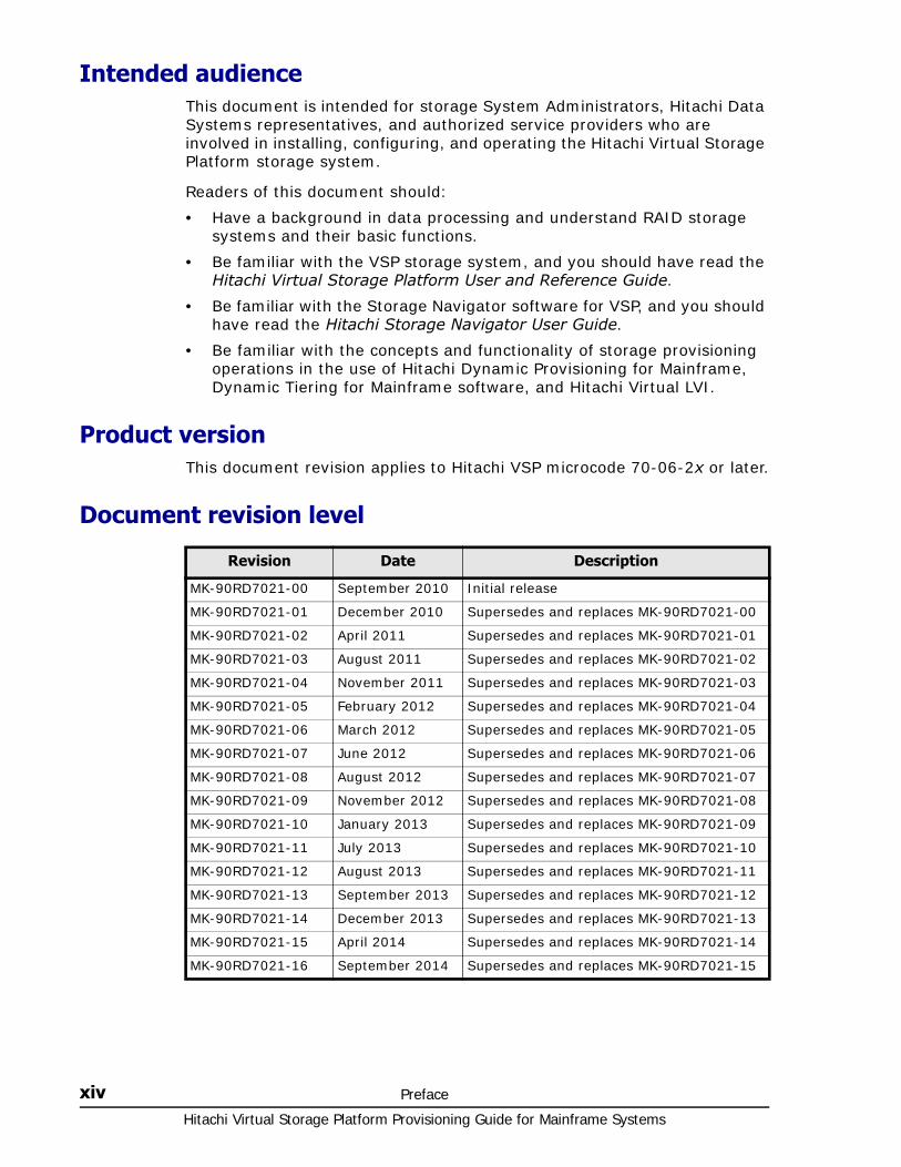
Document revision level
Revision Date Description
MK-90RD7021-00 September 2010 Initial release
MK-90RD7021-01 December 2010 Supersedes and replaces MK-90RD7021-00
MK-90RD7021-02 April 2011 Supersedes and replaces MK-90RD7021-01
MK-90RD7021-03 August 2011 Supersedes and replaces MK-90RD7021-02
MK-90RD7021-04 November 2011 Supersedes and replaces MK-90RD7021-03
MK-90RD7021-05 February 2012 Supersedes and replaces MK-90RD7021-04
MK-90RD7021-06 March 2012 Supersedes and replaces MK-90RD7021-05
MK-90RD7021-07 June 2012 Supersedes and replaces MK-90RD7021-06
MK-90RD7021-08 August 2012 Supersedes and replaces MK-90RD7021-07
MK-90RD7021-09 November 2012 Supersedes and replaces MK-90RD7021-08
MK-90RD7021-10 January 2013 Supersedes and replaces MK-90RD7021-09
MK-90RD7021-11 July 2013 Supersedes and replaces MK-90RD7021-10
MK-90RD7021-12 August 2013 Supersedes and replaces MK-90RD7021-11
MK-90RD7021-13 September 2013 Supersedes and replaces MK-90RD7021-12
MK-90RD7021-14 December 2013 Supersedes and replaces MK-90RD7021-13
MK-90RD7021-15 April 2014 Supersedes and replaces MK-90RD7021-14
MK-90RD7021-16 September 2014 Supersedes and replaces MK-90RD7021-15
Preface xvHitachi Virtual Storage Platform Provisioning Guide for Mainframe Systems
Changes made in this revision• Added troubleshooting information on the 0x0bf5 error code. See Errors
when operating CCI (Dynamic Provisioning for Mainframe, SSB1: 0x2e31/0xb96d) on page 7-8.
• Added notes about VRM. See Setting Access Attributes on page 5-4 and Troubleshooting Volume Retention Manager on page 7-9.
• Revised information about CPAV volumes. See Interoperability of DP-VOLs and pool-VOLs on page 4-8.
• Updated information related to SIM completion. See Working with SIMs on page 4-85 and Troubleshooting Dynamic Provisioning for Mainframe on page 7-2.
• Updated SSD-related information. See Pool-VOL requirements on page 4-4 and Create LDEVs window on page C-15.
• Added topic on used pool capacity. See Managing pools and DP-VOLs on page 4-88.
Referenced documentsHitachi Virtual Storage Platform documentation:
• Hitachi Audit Log User Guide, MK-90RD7007
• Hitachi Command Control Interface Command Reference, MK-90RD7009
• Hitachi Command Control Interface User and Reference Guide, MK-90RD7010
• Hitachi Compatible PAV User Guide, MK-90RD7012
• Hitachi Copy-on-Write Snapshot User Guide, MK-90RD7013
• Hitachi Compatible FlashCopy® User Guide, MK-90RD7017
• Hitachi High Availability Manager User Guide, MK-90RD7018
• Hitachi Virtual Storage Platform Performance Guide, MK-90RD7020
• Hitachi ShadowImage® for Mainframe User Guide, MK-90RD7023
• Hitachi SNMP Agent User Guide, MK-90RD7025
• Hitachi Storage Navigator User Guide, MK-90RD7027
• Hitachi Storage Navigator Messages, MK-90RD7028
• Hitachi TrueCopy® for Mainframe User Guide, MK-90RD7030
• Hitachi Universal Replicator for Mainframe User Guide, MK-90RD7031
• Hitachi Universal Volume Manager User Guide, MK-90RD7033
• Hitachi Volume Shredder User Guide, MK-90RD7035
• Hitachi Virtual Storage Platform User and Reference Guide, MK-90RD7042
• Hitachi Thin Image User Guide, MK-90RD7179
Hitachi Virtual Storage Platform Provisioning Guide for Mainframe Systems
xvi Preface
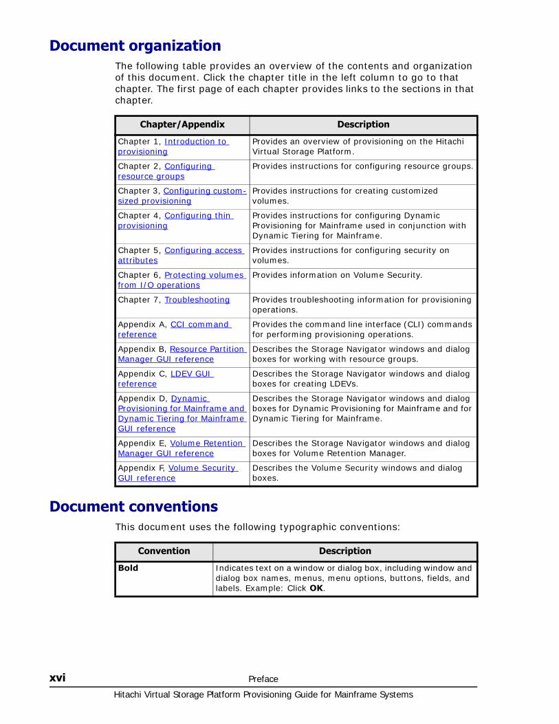
Document organizationThe following table provides an overview of the contents and organization of this document. Click the chapter title in the left column to go to that chapter. The first page of each chapter provides links to the sections in that chapter.
Document conventionsThis document uses the following typographic conventions:
Chapter/Appendix Description
Chapter 1, Introduction to provisioning
Provides an overview of provisioning on the Hitachi Virtual Storage Platform.
Chapter 2, Configuring resource groups
Provides instructions for configuring resource groups.
Chapter 3, Configuring custom-sized provisioning
Provides instructions for creating customized volumes.
Chapter 4, Configuring thin provisioning
Provides instructions for configuring Dynamic Provisioning for Mainframe used in conjunction with Dynamic Tiering for Mainframe.
Chapter 5, Configuring access attributes
Provides instructions for configuring security on volumes.
Chapter 6, Protecting volumes from I/O operations
Provides information on Volume Security.
Chapter 7, Troubleshooting Provides troubleshooting information for provisioning operations.
Appendix A, CCI command reference
Provides the command line interface (CLI) commands for performing provisioning operations.
Appendix B, Resource Partition Manager GUI reference
Describes the Storage Navigator windows and dialog boxes for working with resource groups.
Appendix C, LDEV GUI reference
Describes the Storage Navigator windows and dialog boxes for creating LDEVs.
Appendix D, Dynamic Provisioning for Mainframe and Dynamic Tiering for Mainframe GUI reference
Describes the Storage Navigator windows and dialog boxes for Dynamic Provisioning for Mainframe and for Dynamic Tiering for Mainframe.
Appendix E, Volume Retention Manager GUI reference
Describes the Storage Navigator windows and dialog boxes for Volume Retention Manager.
Appendix F, Volume Security GUI reference
Describes the Volume Security windows and dialog boxes.
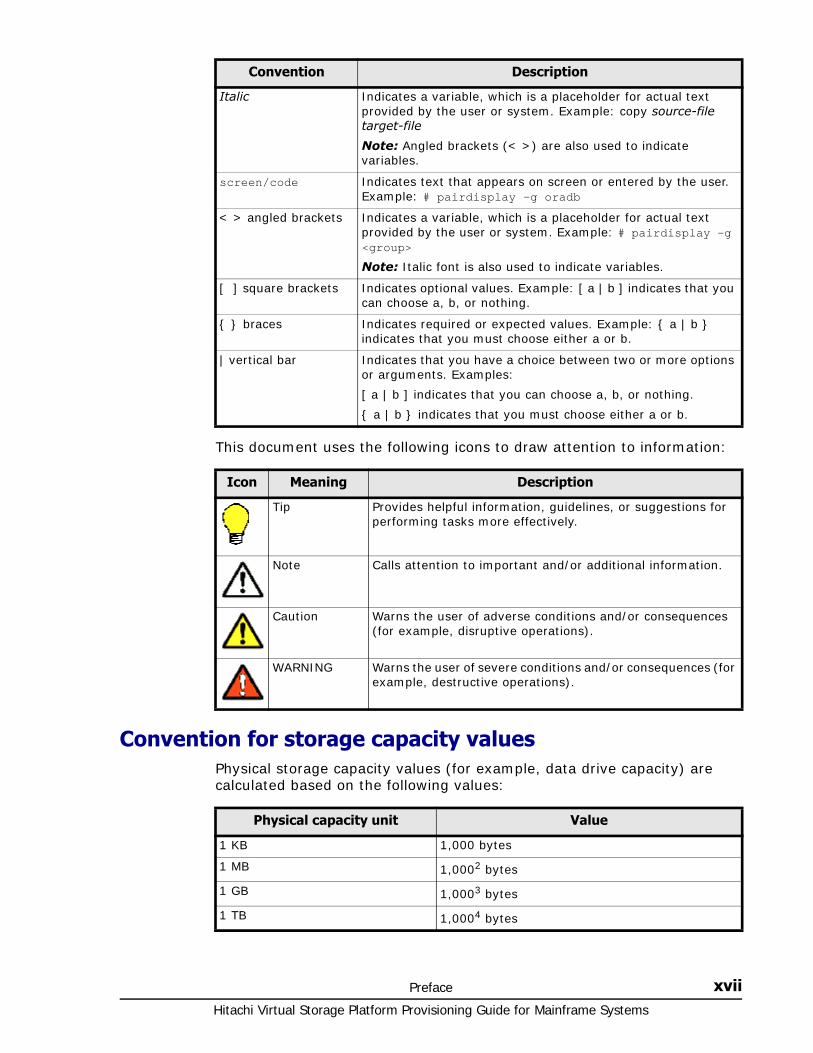
Convention Description
Bold Indicates text on a window or dialog box, including window and dialog box names, menus, menu options, buttons, fields, and labels. Example: Click OK.
Preface xviiHitachi Virtual Storage Platform Provisioning Guide for Mainframe Systems
This document uses the following icons to draw attention to information:
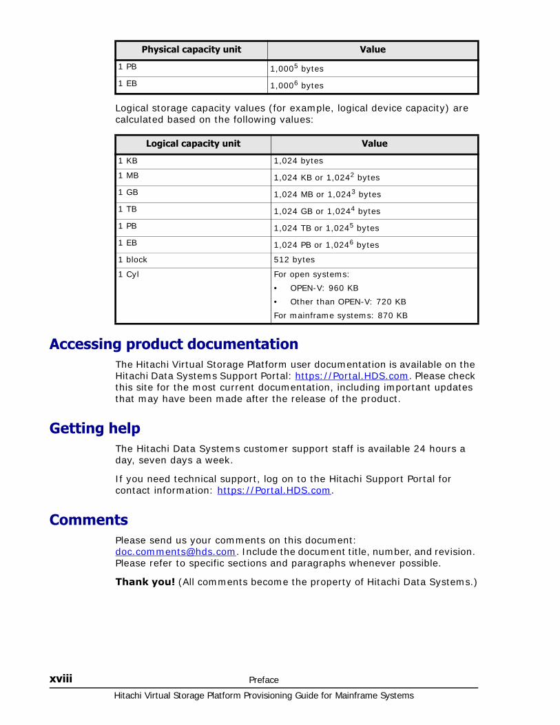
Convention for storage capacity valuesPhysical storage capacity values (for example, data drive capacity) are calculated based on the following values:
Italic Indicates a variable, which is a placeholder for actual text provided by the user or system. Example: copy source-file target-file
Note: Angled brackets (< >) are also used to indicate variables.
screen/code Indicates text that appears on screen or entered by the user. Example: # pairdisplay -g oradb
< > angled brackets Indicates a variable, which is a placeholder for actual text provided by the user or system. Example: # pairdisplay -g <group>
Note: Italic font is also used to indicate variables.
[ ] square brackets Indicates optional values. Example: [ a | b ] indicates that you can choose a, b, or nothing.
{ } braces Indicates required or expected values. Example: { a | b } indicates that you must choose either a or b.
| vertical bar Indicates that you have a choice between two or more options or arguments. Examples:
[ a | b ] indicates that you can choose a, b, or nothing.
{ a | b } indicates that you must choose either a or b.
Convention Description
Icon Meaning Description
Tip Provides helpful information, guidelines, or suggestions for performing tasks more effectively.
Note Calls attention to important and/or additional information.
Caution Warns the user of adverse conditions and/or consequences (for example, disruptive operations).
WARNING Warns the user of severe conditions and/or consequences (for example, destructive operations).
Physical capacity unit Value
1 KB 1,000 bytes
1 MB 1,0002 bytes
1 GB 1,0003 bytes
1 TB 1,0004 bytes
Hitachi Virtual Storage Platform Provisioning Guide for Mainframe Systems
xviii Preface
Logical storage capacity values (for example, logical device capacity) are calculated based on the following values:
Accessing product documentationThe Hitachi Virtual Storage Platform user documentation is available on the Hitachi Data Systems Support Portal: https://Portal.HDS.com. Please check this site for the most current documentation, including important updates that may have been made after the release of the product.
Getting helpThe Hitachi Data Systems customer support staff is available 24 hours a day, seven days a week.
If you need technical support, log on to the Hitachi Support Portal for contact information: https://Portal.HDS.com.
CommentsPlease send us your comments on this document: [email protected]. Include the document title, number, and revision. Please refer to specific sections and paragraphs whenever possible.
Thank you! (All comments become the property of Hitachi Data Systems.)
1 PB 1,0005 bytes
1 EB 1,0006 bytes
Physical capacity unit Value
Logical capacity unit Value
1 KB 1,024 bytes
1 MB 1,024 KB or 1,0242 bytes
1 GB 1,024 MB or 1,0243 bytes
1 TB 1,024 GB or 1,0244 bytes
1 PB 1,024 TB or 1,0245 bytes
1 EB 1,024 PB or 1,0246 bytes
1 block 512 bytes
1 Cyl For open systems:
• OPEN-V: 960 KB
• Other than OPEN-V: 720 KB
For mainframe systems: 870 KB

1
Introduction to provisioning 1–1Hitachi Virtual Storage Platform Provisioning Guide for Mainframe Systems
Introduction to provisioning
Provisioning a storage system requires balancing the costs of the solution with the benefits that the solution provides. The following is an overview of provisioning strategies that you can implement on the Hitachi Virtual Storage Platform to support your business.
□ About provisioning
□ Basic provisioning
□ Fixed-sized provisioning
□ Disadvantages
□ When to use fixed-sized provisioning
□ Custom-sized provisioning
□ When to use custom-sized provisioning
□ Basic provisioning workflow
□ Dynamic Provisioning Overview
□ Dynamic Provisioning for Mainframe
□ Dynamic Provisioning for Mainframe concepts
□ When to use Dynamic Provisioning for Mainframe
□ Dynamic Provisioning for Mainframe advantages
□ Dynamic Provisioning for Mainframe advantage example
Hitachi Virtual Storage Platform Provisioning Guide for Mainframe Systems
1–2 Introduction to provisioning
□ Dynamic Provisioning for Mainframe work flow
□ Dynamic Tiering for Mainframe
□ Tiers concept
□ When to use Dynamic Tiering for Mainframe
□ Resource groups strategies
□ Complimentary strategies
□ Key terms
□ Before you begin
□ About cache management devices
Introduction to provisioning 1–3Hitachi Virtual Storage Platform Provisioning Guide for Mainframe Systems
About provisioningProvisioning is a method of managing storage system devices or volumes. Some provisioning methods are host-based, while others use existing storage system capabilities such as concatenated array groups. Some provisioning methods are hardware-based, and others are software-based. Each technique has its particular use and benefit, for example, capacity, reliability, performance, or cost considerations, in a given storage environment. Used in the wrong scenario, each can be expensive, awkward, time consuming to configure and maintain, and can be potentially error prone. Your support representatives are available to help you configure the highest quality solution for your storage environment.
Provisioning strategies falls into two fundamental categories:
• Basic provisioning on page 1-3 (or traditional provisioning).
• Dynamic Provisioning Overview on page 1-5 (or virtual provisioning). Thin provisioning includes pooling physical storage and creating logical devices for hosts.
Basic provisioningSeveral basic provisioning techniques traditionally are used to manage storage volumes. These strategies are useful in specific scenarios based on user needs, such as whether you use open or mainframe storage systems, or you prefer manual or automated control of your storage resources.
Basic provisioning relies on carving up physical storage into smaller units. Custom sizing is possible, and requires using Virtual LVI software.
Basic provisioning includes:
• Fixed-sized provisioning on page 1-3
• Custom-sized provisioning on page 1-4
Fixed-sized provisioningFixed-sized provisioning is the logical choice for mainframe systems that need to be compatible with IBM systems. It is easy to define the storage system, and then get on with your business. Later, you can attach additional storage as the initial volumes fill up.
Fixed-sized provisioning is a good choice for mainframe systems.
Disadvantages Some disadvantages to using fixed-sized provisioning are:
• If you use only part of the entire capacity specified by an emulation type, the rest of the capacity is wasted.
• After creating fixed-sized volumes, typically some physical capacity will be wasted due to being less than the fixed-size capacity.
• In a fixed-sized environment, manual intervention can become a costly and tedious exercise when a larger volume size is required.
Hitachi Virtual Storage Platform Provisioning Guide for Mainframe Systems
1–4 Introduction to provisioning
When to use fixed-sized provisioningFixed-sized provisioning is a best fit in the following scenarios:
• In a mainframe environment in which the simplest form of provisioning can be sacrificed at the expense of some efficiency in capacity utilization.
Custom-sized provisioningCustom-sized (or variable-sized) provisioning has more flexibility than fixed-sized provisioning and is the traditional storage-based volume management strategy typically used to organize storage space.
To create custom-sized volumes on a storage system, an administrator creates volumes of the desired size from individual array groups. These volumes are then individually mapped to one or more host ports as a logical unit.
Following are three scenarios where custom-sized provisioning is an advantage:
• In fixed-sized provisioning, when several frequently accessed files are located on the same volume and one file is being accessed, users cannot access the other files because of logical device contention. If the custom-sized feature is used to divide the volume into several smaller volumes and I/O workload is balanced (each file is allocated to different volumes), then access contention is reduced and access performance is improved.
• In fixed-sized provisioning, not all of the capacity may be used. Unused capacity on the volume will remain inaccessible to other users. If the custom-sized feature is used, smaller volumes can be created that do not waste capacity.
• Applications that require the capacity of many fixed-sized volumes can instead be given fewer large volumes to relieve device addressing constraints.
To change the size of a volume already in use, you first create a new volume larger (if possible) than the old one, and move the contents of the old volume to the new one. The new volume must be defined in the IOGEN of the host as a different volume.
A disadvantage is that this manual intervention can become costly and tedious and this provisioning strategy is appropriate only in certain scenarios.
When to use custom-sized provisioningUse custom-sized provisioning when you want to manually control and monitor your storage resources and usage scenarios.
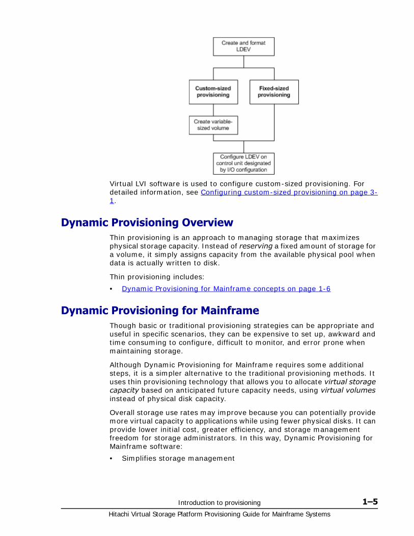
Basic provisioning workflowThe following illustrates the basic provisioning workflow:
Introduction to provisioning 1–5Hitachi Virtual Storage Platform Provisioning Guide for Mainframe Systems
Virtual LVI software is used to configure custom-sized provisioning. For detailed information, see Configuring custom-sized provisioning on page 3-1.
Dynamic Provisioning OverviewThin provisioning is an approach to managing storage that maximizes physical storage capacity. Instead of reserving a fixed amount of storage for a volume, it simply assigns capacity from the available physical pool when data is actually written to disk.
Thin provisioning includes:
• Dynamic Provisioning for Mainframe concepts on page 1-6
Dynamic Provisioning for MainframeThough basic or traditional provisioning strategies can be appropriate and useful in specific scenarios, they can be expensive to set up, awkward and time consuming to configure, difficult to monitor, and error prone when maintaining storage.
Although Dynamic Provisioning for Mainframe requires some additional steps, it is a simpler alternative to the traditional provisioning methods. It uses thin provisioning technology that allows you to allocate virtual storage capacity based on anticipated future capacity needs, using virtual volumes instead of physical disk capacity.
Overall storage use rates may improve because you can potentially provide more virtual capacity to applications while using fewer physical disks. It can provide lower initial cost, greater efficiency, and storage management freedom for storage administrators. In this way, Dynamic Provisioning for Mainframe software:
• Simplifies storage management
Hitachi Virtual Storage Platform Provisioning Guide for Mainframe Systems
1–6 Introduction to provisioning
• Provides balanced resources and more optimized performance by default without inordinate manual intervention.
• Maximizes physical disk usage
• May reduce device address requirements over traditional provisioning by providing larger volume sizes.
Dynamic Provisioning for Mainframe concepts Dynamic Provisioning for Mainframe is a volume management feature that allows storage managers and System Administrators to efficiently plan and allocate storage to users or applications. It provides a platform for the array to dynamically manage data and physical capacity without frequent manual involvement.
Dynamic Provisioning for Mainframe provides three important capabilities: thin provisioning of storage, enhanced volume performance, and larger volume sizes.
Dynamic Provisioning for Mainframe is more efficient than traditional provisioning strategies. It is implemented by creating one or more Dynamic Provisioning for Mainframe pools (DP pools) of physical storage space using multiple LDEVs. Then, you can establish virtual DP volumes (DP-VOLs) and connect them to the individual DP pools. In this way, capacity to support data can be randomly assigned on demand within the pool.
DP-VOLs are of a user-specified logical size without any corresponding physical space. Actual physical space (in 38-MB pool page units) is automatically assigned to a DP-VOL from the connected DP pool as that volume’s logical space is written to over time. A new volume does not have any pool pages assigned to it. The pages are loaned out from its connected pool to that DP volume until the volume is reformatted or deleted. At that point, all of that volume’s assigned pages are returned to the pool’s free page list. This handling of logical and physical capacity is called thin provisioning. In many cases, logical capacity will exceed physical capacity.
Dynamic Provisioning for Mainframe enhances volume performance. This is an automatic result of how DP-VOLs map capacity from individual DP pools. A pool is created using from one to 1024 LDEVs (pool volumes) of physical space. Each pool volume is sectioned into 38-MB pages. Each page is consecutively laid down on a number of RAID stripes from one pool volume. The pool’s 38-MB pool pages are assigned on demand to any of the DP-VOLs that are connected to that pool. Other pages assigned over time to that DP-VOL randomly originate from the next free page of some other pool volume in the pool.
DP-VOLs are defined as 3390-A volumes that can be larger than traditional volumes. This volume type was created to reduce device address requirements.
Setting up a Dynamic Provisioning for Mainframe environment requires a few extra steps. You still configure various array groups to a desired RAID level and create one or more 3390-V volumes (LDEVs) on each of them (see Creating an LDEV on page 3-11). Then set up a Dynamic Provisioning for Mainframe environment by creating one or more DP pools of physical
Introduction to provisioning 1–7Hitachi Virtual Storage Platform Provisioning Guide for Mainframe Systems
storage space that are each a collection of some of these 3390-V LDEVs (DP pool volumes). This pool structure supports creation of 3390-A Dynamic Provisioning for Mainframe virtual volumes (DP-VOLs), where 38-MB pages of data are randomly assigned on demand.
For detailed information, see Configuring thin provisioning on page 4-1.
When to use Dynamic Provisioning for MainframeDynamic Provisioning for Mainframe is a best fit in a mainframe environment in the following scenarios:
• Where the aggregation of storage pool capacity usage across many volumes provides the best opportunity for performance optimization.
• For stable environments and large consistently growing files or volumes.
• Where device addressing constraints are a concern.
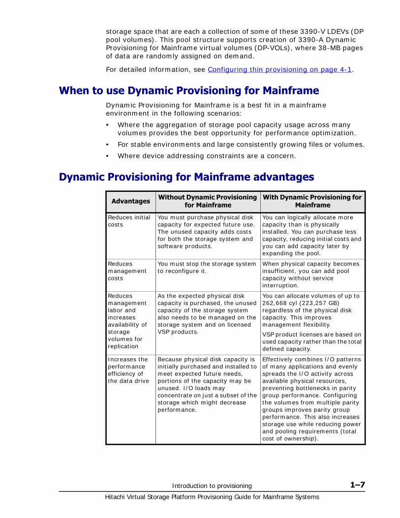
Dynamic Provisioning for Mainframe advantages
Advantages Without Dynamic Provisioning for Mainframe
With Dynamic Provisioning for Mainframe
Reduces initial costs
You must purchase physical disk capacity for expected future use. The unused capacity adds costs for both the storage system and software products.
You can logically allocate more capacity than is physically installed. You can purchase less capacity, reducing initial costs and you can add capacity later by expanding the pool.
Reduces management costs
You must stop the storage system to reconfigure it.
When physical capacity becomes insufficient, you can add pool capacity without service interruption.
Reduces management labor and increases availability of storage volumes for replication
As the expected physical disk capacity is purchased, the unused capacity of the storage system also needs to be managed on the storage system and on licensed VSP products.
You can allocate volumes of up to 262,668 cyl (223,257 GB) regardless of the physical disk capacity. This improves management flexibility.
VSP product licenses are based on used capacity rather than the total defined capacity.
Increases the performance efficiency of the data drive
Because physical disk capacity is initially purchased and installed to meet expected future needs, portions of the capacity may be unused. I/O loads may concentrate on just a subset of the storage which might decrease performance.
Effectively combines I/O patterns of many applications and evenly spreads the I/O activity across available physical resources, preventing bottlenecks in parity group performance. Configuring the volumes from multiple parity groups improves parity group performance. This also increases storage use while reducing power and pooling requirements (total cost of ownership).
Hitachi Virtual Storage Platform Provisioning Guide for Mainframe Systems
1–8 Introduction to provisioning
Dynamic Provisioning for Mainframe advantage exampleTo illustrate the merits of a Dynamic Provisioning for Mainframe environment, assume you have twelve 3390-V LDEVs from 12 RAID 1 (2D+2D) array groups assigned to a DP pool. All 48 disks contribute their IOPS and throughput power to all 3390-A DP volumes assigned to that pool. Instead, if more random read IOPS horsepower is desired for a pool, then it can be created with 3390-V 32 LDEVs from 32 RAID 5 (3D+1P) array groups, thus providing 128 disks of IOPS power to that pool. Up to 1024 LDEVs may be assigned to a single pool, providing a considerable amount of I/O capability to just a few DP volumes.
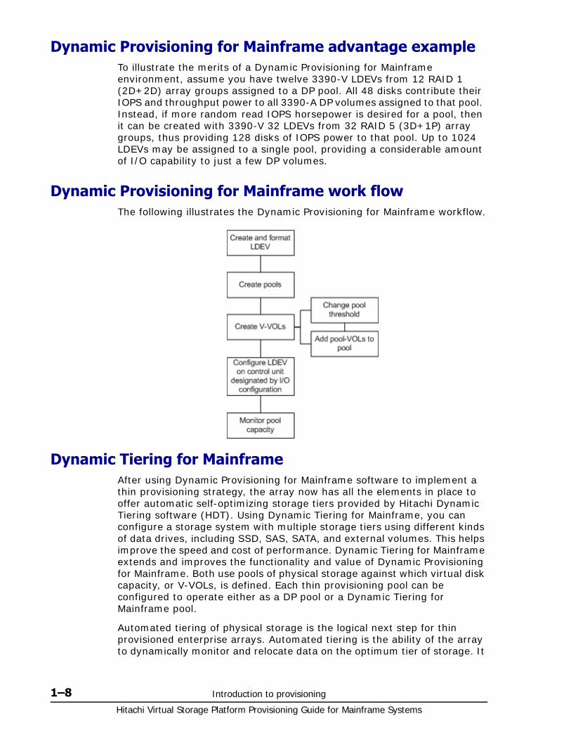
Dynamic Provisioning for Mainframe work flowThe following illustrates the Dynamic Provisioning for Mainframe workflow.
Dynamic Tiering for MainframeAfter using Dynamic Provisioning for Mainframe software to implement a thin provisioning strategy, the array now has all the elements in place to offer automatic self-optimizing storage tiers provided by Hitachi Dynamic Tiering software (HDT). Using Dynamic Tiering for Mainframe, you can configure a storage system with multiple storage tiers using different kinds of data drives, including SSD, SAS, SATA, and external volumes. This helps improve the speed and cost of performance. Dynamic Tiering for Mainframe extends and improves the functionality and value of Dynamic Provisioning for Mainframe. Both use pools of physical storage against which virtual disk capacity, or V-VOLs, is defined. Each thin provisioning pool can be configured to operate either as a DP pool or a Dynamic Tiering for Mainframe pool.
Automated tiering of physical storage is the logical next step for thin provisioned enterprise arrays. Automated tiering is the ability of the array to dynamically monitor and relocate data on the optimum tier of storage. It
Introduction to provisioning 1–9Hitachi Virtual Storage Platform Provisioning Guide for Mainframe Systems
focuses on data segments rather than entire volumes. The functionality is entirely within the array without any mandated host level involvement. Dynamic Tiering for Mainframe adds another layer to the thin provisioned environment.
Using Dynamic Tiering for Mainframe you can:
• Configure physical storage into tiers consisting of multiple kinds of data drives, including SSD, SAS, and SATA. Although host volumes are conventionally configured from a common pool, the pool is efficiently configured using multiple kinds of disk drives. Placing data that needs high performance while reducing storage costs by using high cost disks such as SSDs as efficiently as possible, resulting in data that is accessed infrequently being placed on lower cost physical storage.
• Automatically migrate small portions of host volumes to the most suitable data drive according to access frequency. Frequently accessed data is migrated to higher speed hard disk drives (for example, SSD). Infrequently accessed data is migrated to lower cost and lower speed hard disk drives (for example, SATA) to use the storage efficiently.
Dynamic Tiering for Mainframe simplifies storage administration by automating and eliminating the complexities of efficiently using tiered storage. It automatically moves data on pages in Dynamic Provisioning for Mainframe V-VOLs to the most appropriate storage media, according to workload, to maximize service levels and minimize total cost of storage.
Dynamic Tiering for Mainframe gives you:
• Improved storage resource usage
• Improved return on costly storage tiers
• Reduced storage management effort
• More automation
• Nondisruptive storage management
• Reduced costs
• Improved performance
Dynamic Tiering for Mainframe can be used by Storage Navigator, Command Control Interface, or Hitachi Tiered Storage Manager for Mainframe (HTSM for Mainframe).
If Storage Navigator or Command Control Interface is used, the following resources that are assigned to the storage administrator can be used:
• Tiers of pools
• Tiers of DP-VOLs
If HTSM for Mainframe is used, the following resources that are assigned to the mainframe administrator can be used:
• Tiers of storage groups
• Tiers of DP-VOLs that are assigned to a host
For details about Hitachi Tiered Storage Manager for Mainframe, see Hitachi Tiered Storage Manager for Mainframe User Guide.
Hitachi Virtual Storage Platform Provisioning Guide for Mainframe Systems
1–10 Introduction to provisioning
Tiers conceptWhen not using Dynamic Tiering for Mainframe, data is allocated to only one kind of drive (typically an expensive high-speed hard disk drive) without regard to the workload to the volumes because the volumes are configured with only one kind of data drive. When using Dynamic Tiering for Mainframe, the higher speed data drive is automatically allocated to the volumes of high workload, and the lower speed drive to the volumes of low workload,. This improves performance and reduces costs.
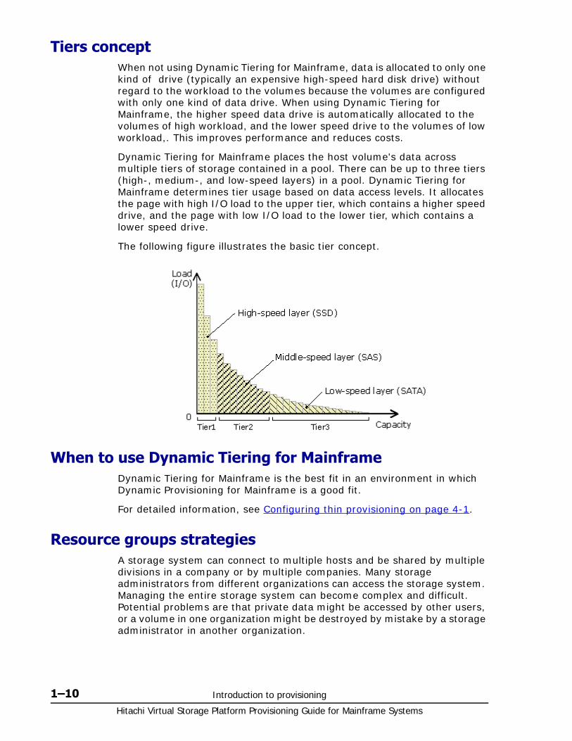
Dynamic Tiering for Mainframe places the host volume's data across multiple tiers of storage contained in a pool. There can be up to three tiers (high-, medium-, and low-speed layers) in a pool. Dynamic Tiering for Mainframe determines tier usage based on data access levels. It allocates the page with high I/O load to the upper tier, which contains a higher speed drive, and the page with low I/O load to the lower tier, which contains a lower speed drive.
The following figure illustrates the basic tier concept.
When to use Dynamic Tiering for MainframeDynamic Tiering for Mainframe is the best fit in an environment in which Dynamic Provisioning for Mainframe is a good fit.
For detailed information, see Configuring thin provisioning on page 4-1.
Resource groups strategiesA storage system can connect to multiple hosts and be shared by multiple divisions in a company or by multiple companies. Many storage administrators from different organizations can access the storage system. Managing the entire storage system can become complex and difficult. Potential problems are that private data might be accessed by other users, or a volume in one organization might be destroyed by mistake by a storage administrator in another organization.
Introduction to provisioning 1–11Hitachi Virtual Storage Platform Provisioning Guide for Mainframe Systems
To avoid such problems, use Hitachi Resource Partition Manager software to set up resource groups that allow you to manage one storage system as multiple virtual private storage systems. The storage administrator in each resource group can access only their assigned resources and cannot access other resources. Configuring resource groups prevents the risk of data leakage or data destruction by another storage administrator in another resource group.
The resources such as LDEVs, parity groups, external volumes or ports can be assigned to a resource group. These resources can be combined to flexibly compose a virtual private storage system.
Resource groups should be planned and created before creating volumes. For more information, see Configuring resource groups on page 2-1.
Complimentary strategies
Functions related to provisioning
For the following functions, see the appropriate manuals:
• Replication: ShadowImage for Mainframe, TrueCopy for Mainframe, Universal Replicator for Mainframe, Compatible XRC, Compatible FlashCopy® V2
• External storage: Universal Volume Manager
• Partitioning: Virtual Partition Manager (Performance Guide)
• TSE-VOL: Compatible Software for IBM® FlashCopy® SE
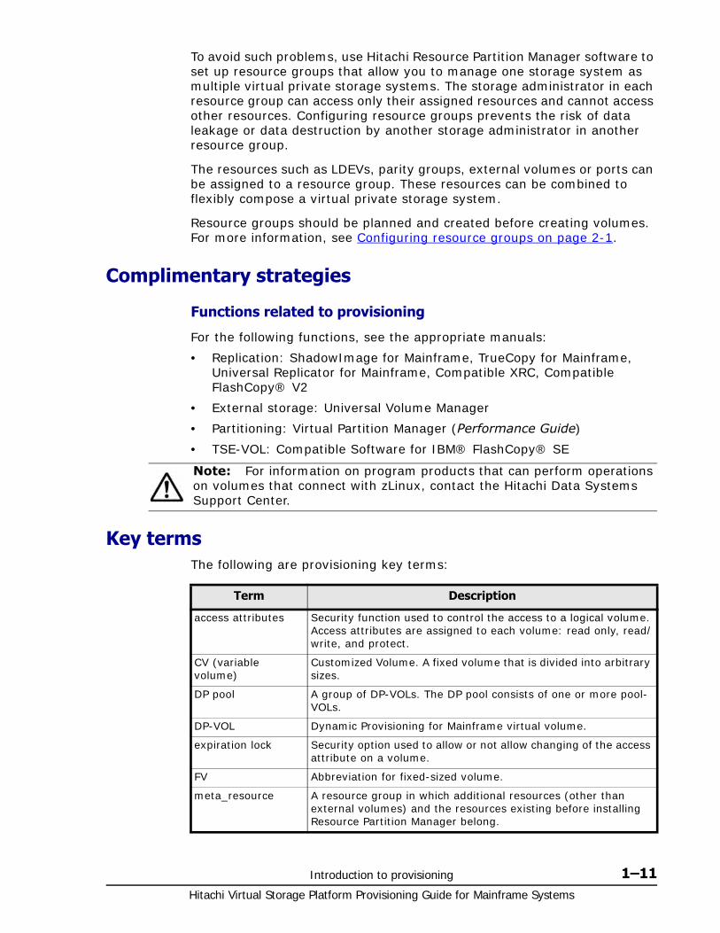
Key termsThe following are provisioning key terms:
Note: For information on program products that can perform operations on volumes that connect with zLinux, contact the Hitachi Data Systems Support Center.
Term Description
access attributes Security function used to control the access to a logical volume. Access attributes are assigned to each volume: read only, read/write, and protect.
CV (variable volume)
Customized Volume. A fixed volume that is divided into arbitrary sizes.
DP pool A group of DP-VOLs. The DP pool consists of one or more pool-VOLs.
DP-VOL Dynamic Provisioning for Mainframe virtual volume.
expiration lock Security option used to allow or not allow changing of the access attribute on a volume.
FV Abbreviation for fixed-sized volume.
meta_resource A resource group in which additional resources (other than external volumes) and the resources existing before installing Resource Partition Manager belong.
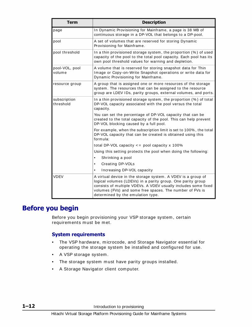
Hitachi Virtual Storage Platform Provisioning Guide for Mainframe Systems
1–12 Introduction to provisioning
Before you beginBefore you begin provisioning your VSP storage system, certain requirements must be met.
System requirements• The VSP hardware, microcode, and Storage Navigator essential for
operating the storage system be installed and configured for use.
• A VSP storage system.
• The storage system must have parity groups installed.
• A Storage Navigator client computer.
page In Dynamic Provisioning for Mainframe, a page is 38 MB of continuous storage in a DP-VOL that belongs to a DP-pool.
pool A set of volumes that are reserved for storing Dynamic Provisioning for Mainframe.
pool threshold In a thin provisioned storage system, the proportion (%) of used capacity of the pool to the total pool capacity. Each pool has its own pool threshold values for warning and depletion.
pool-VOL, pool volume
A volume that is reserved for storing snapshot data for Thin Image or Copy-on-Write Snapshot operations or write data for Dynamic Provisioning for Mainframe.
resource group A group that is assigned one or more resources of the storage system. The resources that can be assigned to the resource group are LDEV IDs, parity groups, external volumes, and ports.
subscription threshold
In a thin provisioned storage system, the proportion (%) of total DP-VOL capacity associated with the pool versus the total capacity.
You can set the percentage of DP-VOL capacity that can be created to the total capacity of the pool. This can help prevent DP-VOL blocking caused by a full pool.
For example, when the subscription limit is set to 100%, the total DP-VOL capacity that can be created is obtained using this formula:
total DP-VOL capacity <= pool capacity x 100%
Using this setting protects the pool when doing the following:
• Shrinking a pool
• Creating DP-VOLs
• Increasing DP-VOL capacity
VDEV A virtual device in the storage system. A VDEV is a group of logical volumes (LDEVs) in a parity group. One parity group consists of multiple VDEVs. A VDEV usually includes some fixed volumes (FVs) and some free spaces. The number of FVs is determined by the emulation type.
Term Description
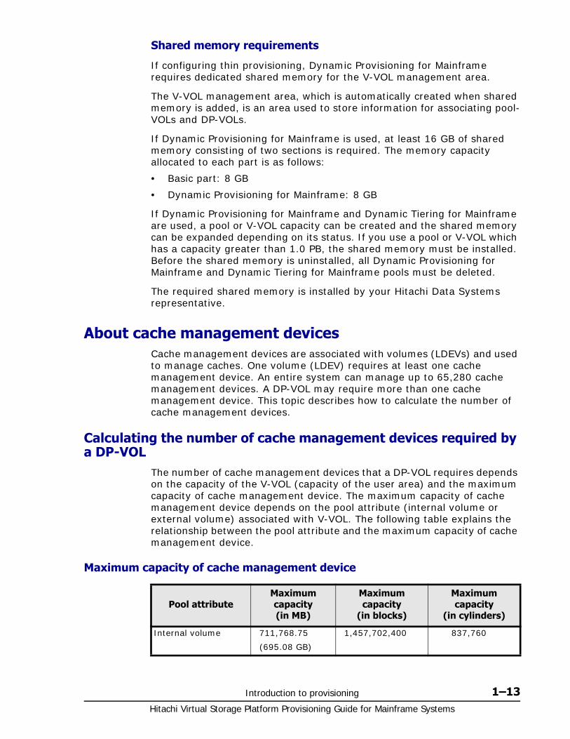
Introduction to provisioning 1–13Hitachi Virtual Storage Platform Provisioning Guide for Mainframe Systems
Shared memory requirements
If configuring thin provisioning, Dynamic Provisioning for Mainframe requires dedicated shared memory for the V-VOL management area.
The V-VOL management area, which is automatically created when shared memory is added, is an area used to store information for associating pool-VOLs and DP-VOLs.
If Dynamic Provisioning for Mainframe is used, at least 16 GB of shared memory consisting of two sections is required. The memory capacity allocated to each part is as follows:
• Basic part: 8 GB
• Dynamic Provisioning for Mainframe: 8 GB
If Dynamic Provisioning for Mainframe and Dynamic Tiering for Mainframe are used, a pool or V-VOL capacity can be created and the shared memory can be expanded depending on its status. If you use a pool or V-VOL which has a capacity greater than 1.0 PB, the shared memory must be installed. Before the shared memory is uninstalled, all Dynamic Provisioning for Mainframe and Dynamic Tiering for Mainframe pools must be deleted.
The required shared memory is installed by your Hitachi Data Systems representative.
About cache management devicesCache management devices are associated with volumes (LDEVs) and used to manage caches. One volume (LDEV) requires at least one cache management device. An entire system can manage up to 65,280 cache management devices. A DP-VOL may require more than one cache management device. This topic describes how to calculate the number of cache management devices.
Calculating the number of cache management devices required by a DP-VOL
The number of cache management devices that a DP-VOL requires depends on the capacity of the V-VOL (capacity of the user area) and the maximum capacity of cache management device. The maximum capacity of cache management device depends on the pool attribute (internal volume or external volume) associated with V-VOL. The following table explains the relationship between the pool attribute and the maximum capacity of cache management device.
Maximum capacity of cache management device
Pool attributeMaximum capacity (in MB)
Maximum capacity
(in blocks)
Maximum capacity
(in cylinders)
Internal volume 711,768.75
(695.08 GB)
1,457,702,400 837,760
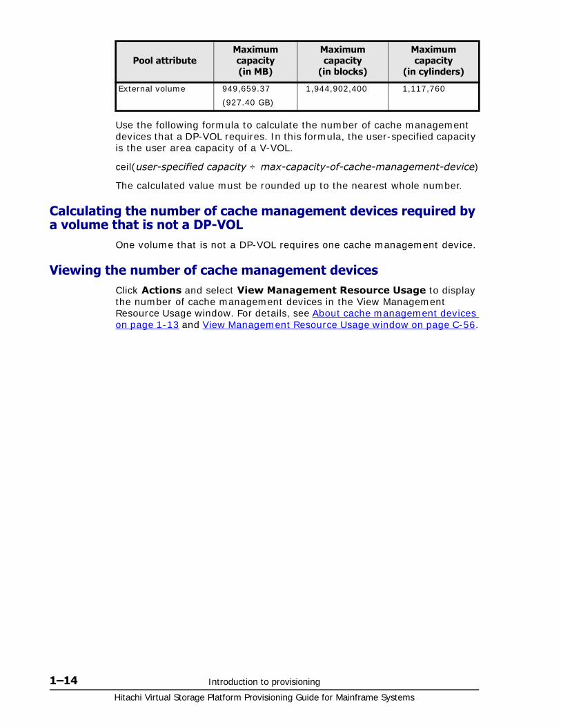
Hitachi Virtual Storage Platform Provisioning Guide for Mainframe Systems
1–14 Introduction to provisioning
Use the following formula to calculate the number of cache management devices that a DP-VOL requires. In this formula, the user-specified capacity is the user area capacity of a V-VOL.
ceil(user-specified capacity ÷ max-capacity-of-cache-management-device)
The calculated value must be rounded up to the nearest whole number.
Calculating the number of cache management devices required by a volume that is not a DP-VOL
One volume that is not a DP-VOL requires one cache management device.
Viewing the number of cache management devicesClick Actions and select View Management Resource Usage to display the number of cache management devices in the View Management Resource Usage window. For details, see About cache management devices on page 1-13 and View Management Resource Usage window on page C-56.
External volume 949,659.37
(927.40 GB)
1,944,902,400 1,117,760
Pool attributeMaximum capacity (in MB)
Maximum capacity
(in blocks)
Maximum capacity
(in cylinders)
2
Configuring resource groups 2–1Hitachi Virtual Storage Platform Provisioning Guide for Mainframe Systems
Configuring resource groups
The Storage Administrator can divide a provisioned storage system into resource groups that allow managing the storage system as multiple virtual private storage systems. Configuring resource groups involves creating resource groups, moving storage system resources into the resource groups, and assigning resource groups to user groups.
Resource groups can be set up on both open and mainframe systems. Resource Partition Manager software is required.
□ System configuration using resource groups
□ Resource groups examples
□ Meta_resource
□ Resource lock
□ User groups
□ Resource group assignments
□ Resource group license requirements
□ Resource group rules, restrictions, and guidelines
□ Creating a resource group
□ Adding resources to a resource group
□ Removing resources from a resource group
□ Managing Resource Groups
Hitachi Virtual Storage Platform Provisioning Guide for Mainframe Systems
2–2 Configuring resource groups
□ Using Resource Partition Manager and other VSP products
Configuring resource groups 2–3Hitachi Virtual Storage Platform Provisioning Guide for Mainframe Systems
System configuration using resource groupsConfiguring resource groups prevents the risk of data leakage or data destruction by another Storage Administrator in another resource group. The Storage Administrator considers and plans which resource should be managed by which user, and then the Security Administrator creates resource groups and assigns each resource to the resource groups.
A resource group is assigned one or more storage system resources. The following resources can be assigned to resource groups.
• LDEV IDs*
• Parity groups
• External volumes (VDEVs)
• Ports
* Before you create LDEVs, the LDEV IDs can be reserved and assigned to a resource group for future use.
The following tasks provide instructions for configuring resource groups.
• Creating a resource group on page 2-9
• Adding resources to a resource group on page 2-10
• Removing resources from a resource group on page 2-10
• Changing the name of a resource group on page 2-11
• Deleting a resource group on page 2-12
Resource groups examplesThe following examples illustrate how you can configure resource groups on your storage system:
• Example of resource groups sharing a port on page 2-3
• Example of resource groups not sharing ports on page 2-5
Example of resource groups sharing a portIf you have a limited number of ports, you can still operate a storage system effectively by sharing ports using resource groups.
The following example shows the system configuration of an in-house division providing virtual private storage system for two divisions. Divisions A and B each use their own assigned parity group, but share a port between the two divisions. The shared port is managed by the system division.
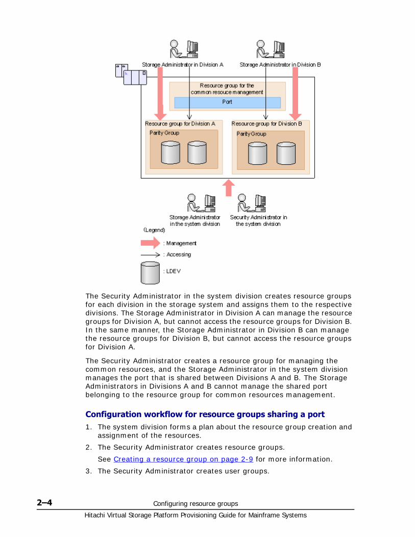
Hitachi Virtual Storage Platform Provisioning Guide for Mainframe Systems
2–4 Configuring resource groups
The Security Administrator in the system division creates resource groups for each division in the storage system and assigns them to the respective divisions. The Storage Administrator in Division A can manage the resource groups for Division A, but cannot access the resource groups for Division B. In the same manner, the Storage Administrator in Division B can manage the resource groups for Division B, but cannot access the resource groups for Division A.
The Security Administrator creates a resource group for managing the common resources, and the Storage Administrator in the system division manages the port that is shared between Divisions A and B. The Storage Administrators in Divisions A and B cannot manage the shared port belonging to the resource group for common resources management.
Configuration workflow for resource groups sharing a port1. The system division forms a plan about the resource group creation and
assignment of the resources.
2. The Security Administrator creates resource groups.
See Creating a resource group on page 2-9 for more information.
3. The Security Administrator creates user groups.

Configuring resource groups 2–5Hitachi Virtual Storage Platform Provisioning Guide for Mainframe Systems
See Hitachi Storage Navigator User Guide for more information.
4. The Security Administrator assigns the resource groups to user groups.
See Hitachi Storage Navigator User Guide for more information.
5. The Storage Administrator in the system division sets a port.
6. The Security Administrator assigns resources to the resource groups.
See Adding resources to a resource group on page 2-10 for more information.
7. The Security Administrator assigns each Storage Administrator to each user group.
See Hitachi Storage Navigator User Guide for more information.
After the above procedures, the Storage Administrators in A and B divisions can manage the resource groups assigned to their own division.
Example of resource groups not sharing portsIf you assign ports to each resource group without sharing, performance can be maintained on a different port even if the bulk of I/O is issued from one side port.
The following shows a system configuration example of an in-house system division providing the virtual private storage system for two divisions. Divisions A and B each use individual assigned ports and parity groups. In this example, they do not share a port.

Hitachi Virtual Storage Platform Provisioning Guide for Mainframe Systems
2–6 Configuring resource groups
The Security Administrator in the system division creates resource groups for each division in the storage system and assigns them to the respective divisions. The Storage Administrator in Division A can manage the resource groups for Division A, but cannot access the resource groups for Division B. In the same manner, the Storage Administrator in Division B can manage the resource groups for Division B, but cannot access the resource groups for Division A.
Configuration workflow for resource groups not sharing a port1. The system division forms a plan about creating resource groups and the
assigning resources to the groups.
2. The Security Administrator creates resource groups.
See Creating a resource group on page 2-9) for more information.
3. The Security Administrator creates user groups.
See Hitachi Storage Navigator User Guide for more information.
4. The Security Administrator assigns the resource groups to user groups.
See Hitachi Storage Navigator User Guide for more information.
5. The Storage Administrator in the system division sets ports.
6. The Security Administrator assigns resources to the resource groups.
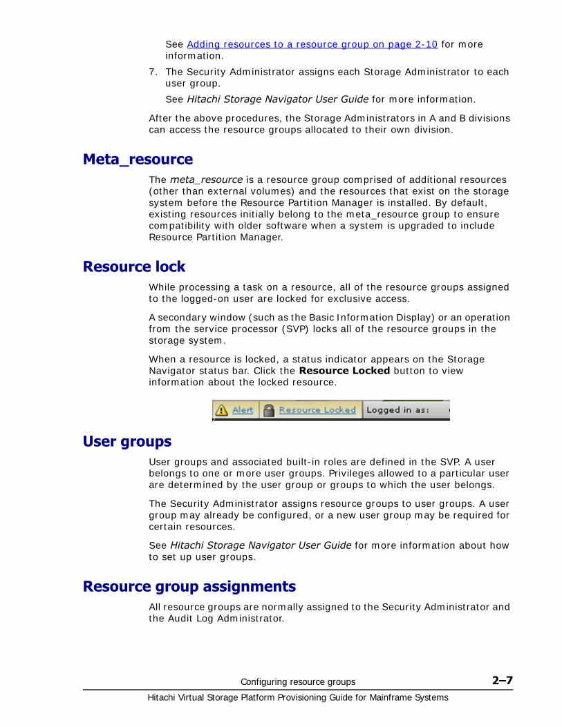
Configuring resource groups 2–7Hitachi Virtual Storage Platform Provisioning Guide for Mainframe Systems
See Adding resources to a resource group on page 2-10 for more information.
7. The Security Administrator assigns each Storage Administrator to each user group.
See Hitachi Storage Navigator User Guide for more information.
After the above procedures, the Storage Administrators in A and B divisions can access the resource groups allocated to their own division.
Meta_resourceThe meta_resource is a resource group comprised of additional resources (other than external volumes) and the resources that exist on the storage system before the Resource Partition Manager is installed. By default, existing resources initially belong to the meta_resource group to ensure compatibility with older software when a system is upgraded to include Resource Partition Manager.
Resource lockWhile processing a task on a resource, all of the resource groups assigned to the logged-on user are locked for exclusive access.
A secondary window (such as the Basic Information Display) or an operation from the service processor (SVP) locks all of the resource groups in the storage system.
When a resource is locked, a status indicator appears on the Storage Navigator status bar. Click the Resource Locked button to view information about the locked resource.
User groupsUser groups and associated built-in roles are defined in the SVP. A user belongs to one or more user groups. Privileges allowed to a particular user are determined by the user group or groups to which the user belongs.
The Security Administrator assigns resource groups to user groups. A user group may already be configured, or a new user group may be required for certain resources.
See Hitachi Storage Navigator User Guide for more information about how to set up user groups.
Resource group assignmentsAll resource groups are normally assigned to the Security Administrator and the Audit Log Administrator.
Hitachi Virtual Storage Platform Provisioning Guide for Mainframe Systems
2–8 Configuring resource groups
Each resource group has a designated Storage Administrator who can access only their assigned resources and cannot access other resources.
All resource groups to which all resources in the storage system belong can be assigned to a user group. Configure this in Storage Navigator by setting All Resource Groups Assigned to Yes.
A user who has All Resource Groups Assigned set to Yes can access all resources in the storage system. For example, if a user is a Security Administrator (with View & Modify privileges) and a Storage Administrator (with View and Modify privileges) and All Resource Groups Assigned is Yes on that user account, the user can edit the storage for all the resources.
If allowing this access becomes a problem with security on the storage system, then register the following two user accounts in Storage Navigator and use these different accounts for different purposes.
• A user account for a Security Administrator where All Resource Groups Assigned is set to Yes.
• A user account for a Storage Administrator who does not have all resource groups assigned and has only some of the resource groups assigned.
Resource group license requirementsUse of Resource Partition Manager on the VSP storage system requires the following:
• A license key on the Storage Navigator computer for Resource Partition Manager software. For details about the license key or product installation, see the Hitachi Storage Navigator User Guide.
Resource group rules, restrictions, and guidelines
Rules• The maximum number of resource groups that can be created on a
storage system is 1023.
• A Storage Administrator with the Security Administrator (View & Modify) role can create resource groups and assign resources to resource groups.
• Resources removed from a resource group are returned to meta_resource.
• Only a Storage Administrator (View & Modify) can manage the resources in assigned resource groups.
Restrictions• No new resources can be added to meta_resource.
• Resources cannot be deleted from meta_resource.
• An LDEV that has the same pool ID or the journal group ID cannot be added to multiple resource groups.
Configuring resource groups 2–9Hitachi Virtual Storage Platform Provisioning Guide for Mainframe Systems
In the case of adding LDEVs that are used as pool volumes or journal volumes, add all the LDEVs that have the same pool IDs or journal group IDs by using a function such as sort.
Guidelines• If you are providing a virtual private storage system to different
companies, you should not share parity groups, external volumes, or pools if you want to limit the capacity that can be used by each user. When parity groups, external volumes, or pools are shared between multiple users, and if one user uses too much capacity of the shared resource, the other users might not be able to create an LDEV.
Creating a resource groupWhen creating a resource group, observe the following:
• The maximum number of resource groups that can be created on a storage system is 1023.
• The name meta_resource cannot be set for a resource group name.
• Duplicate occurrences of the same name are not allowed.
• Resource group name can use alphanumeric characters, spaces, and the following symbols: ! # $ % & ' ( ) + - . = @ [ ] ^ _ ` { } ~
• Alphabets are case-sensitive.
• You must have Security Administrator (View & Modify) role to perform this task.
To create a resource group
1. In the Storage Navigator main window, in the Storage Systems tree, click Administration, and then Resource Groups.
2. Click Create Resource Groups in the Resource Groups tab.
3. Enter a resource group name in the Create Resource Groups window.
Select resources to be assigned to the resource group.a. Click the appropriate buttons select parity groups, LDEVs, ports, or
host groups.b. Select resources from the available parity groups, LDEVs, ports, or
host groups table.c. Click Add.
The selected resources move to the selected parity groups, LDEVs, ports, or host groups table.
If the selected resource is removed, select the row and click Remove.
d. Click OK.
The Create Resource Groups window appears.
4. Click Add.
Hitachi Virtual Storage Platform Provisioning Guide for Mainframe Systems
2–10 Configuring resource groups
The resource group is added to Selected Resource Groups table. If you select a row and click Detail, the Resource Group Properties window appears. If you select a row and click Remove, a message appears asking whether you want to remove the OK.
5. Click Finish.
6. In the Confirm window, confirm the settings, in Task Name type a unique name for this task or accept the default, and then click Apply.
If you select a row and click Detail, the Resource Group Properties window appears.
If Go to tasks window for status is checked, the Tasks window opens.
Adding resources to a resource groupBefore adding resources to a resource group, consider the following:
• You must have Security Administrator (View & Modify) role to perform this task.
• No resource can be added to meta_resource.
• Only resources allocated to meta_resource can be added to resource groups.
• An LDEV with the same pool ID or journal group ID cannot be added to multiple resource groups. For example, when two LDEVs belong to the same pool, you must allocate both to the same resource group. You cannot allocate them separately. Use the sort function to sort the LDEVs by pool ID or journal group ID, then select them and add them all at once.
To add resources to a resource group
1. In the Storage Navigator main window, in the Storage Systems tree, click Administration, and then Resource Groups.
2. Click a resource group to add in the Resource Groups tab.
3. Click Add Resources.
4. Select the type of resources to add in the resource group.
5. Select one or more resources to add to the resource group, and then click Add.
6. Click OK, and then click Finish.
7. In the Confirm window, confirm the settings, in Task Name type a unique name for this task or accept the default, and then click Apply.
If Go to tasks window for status is checked, the Tasks window opens.
Removing resources from a resource groupBefore removing remove resources from a resource group, consider the following:
Configuring resource groups 2–11Hitachi Virtual Storage Platform Provisioning Guide for Mainframe Systems
• The resources removed from a resource group are returned to meta_resource.
• Resources cannot be deleted from the meta_resource.
• An LDEV that has the same pool ID or journal group ID cannot be partially removed. For example, if two LDEVs belong to the same pool, you cannot remove only LDEV1 from the resource group and leave only LDEV2. Use the sort function to sort the LDEVs by pool ID or journal group ID, then select them and remove them all at once.
• You must have Security Administrator (View & Modify) role to perform this task.
To remove resources from a resource group
1. In the Storage Navigator main window, in the Storage Systems tree, click Administration, and then Resource Groups.
2. Click a resource group to remove in the Resource Groups tab.
3. Select one or more resources to remove from the resource group, and then click Remove Resources.
4. In the Confirm window, confirm the settings, in Task Name type a unique name for this task or accept the default, and then click Apply.
If Go to tasks window for status is checked, the Tasks window opens.
Managing Resource Groups
Changing the name of a resource groupWhen changing the name of a resource group, observe the following:
• The name meta_resource cannot be changed.
• Duplicate occurrences of the same name are not allowed.
• The name of meta_resource cannot be set for a resource group name.
• Resource group names can use alphanumeric characters, spaces, and the following symbols: ! # $ % & ' ( ) + - . = @ [ ] ^ _ ` { } ~
• Alphabets are case-sensitive.
• You must have Security Administrator (View & Modify) role to perform this task.
To change a resource group name
1. In the Storage Navigator main window, in the Storage Systems tree, click Administration, and then Resource Groups.
2. Click a resource group to change its name in the Resource Groups tab.
3. Click Edit Resource Group.
4. In the Edit Resource Group window, type a new resource group name, and then click Finish.
5. In the Confirm window, confirm the settings, in Task Name type a unique name for this task or accept the default, and then click Apply.
Hitachi Virtual Storage Platform Provisioning Guide for Mainframe Systems
2–12 Configuring resource groups
If you select a row and click Detail, the Resource Group Properties window appears.
If Go to tasks window for status is checked, the Tasks window opens.
Deleting a resource groupYou cannot delete the following:
• The meta_resource.
• A resource group that is assigned to a user group.
• A resource group that has resources assigned to it.
To delete a resource group
1. In the Storage Navigator main window, in the Storage Systems tree, click Administration, and then Resource Groups.
2. Click one or more resource groups to delete in the Resource Groups tab.
3. Click Delete Resource Groups.
4. In the Confirm window, confirm the settings, in Task Name type a unique name for this task or accept the default, and then click Apply.
If Go to tasks window for status is checked, the Tasks window opens.
Using Resource Partition Manager and other VSP productsTo use Resource Partition Manager with other VSP products, the resources that are required for the operation must satisfy specific conditions. The following topics provide information about the specific resource conditions that are required for using each VSP product.
• Compatible PAV on page 2-13
• Dynamic Provisioning for Mainframe on page 2-13
• Encryption License Key on page 2-13
• Performance Monitor on page 2-14
• ShadowImage for Mainframe on page 2-14
• TrueCopy for Mainframe on page 2-14
• Universal Replicator for Mainframe on page 2-15
• Universal Volume Manager on page 2-16
• Virtual LVI on page 2-18
• Virtual Partition Manager on page 2-19
• Volume Migration on page 2-19
• Volume Shredder on page 2-19
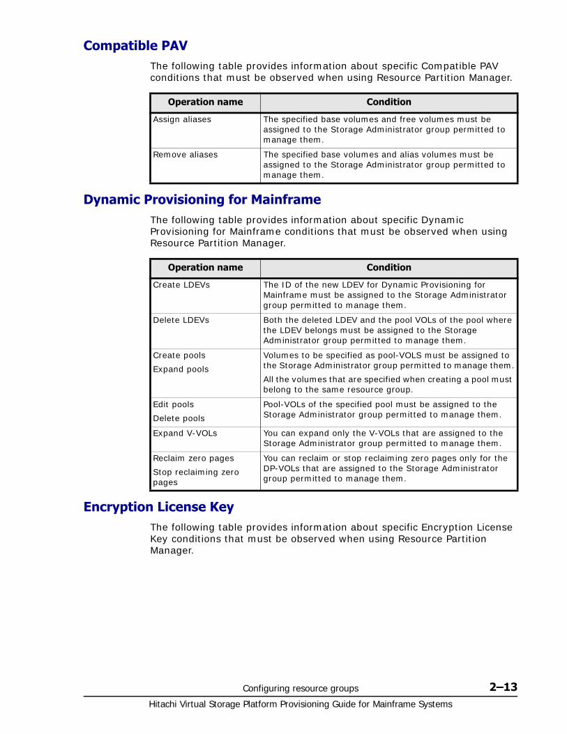
Configuring resource groups 2–13Hitachi Virtual Storage Platform Provisioning Guide for Mainframe Systems
Compatible PAVThe following table provides information about specific Compatible PAV conditions that must be observed when using Resource Partition Manager.
Dynamic Provisioning for MainframeThe following table provides information about specific Dynamic Provisioning for Mainframe conditions that must be observed when using Resource Partition Manager.
Encryption License KeyThe following table provides information about specific Encryption License Key conditions that must be observed when using Resource Partition Manager.
Operation name Condition
Assign aliases The specified base volumes and free volumes must be assigned to the Storage Administrator group permitted to manage them.
Remove aliases The specified base volumes and alias volumes must be assigned to the Storage Administrator group permitted to manage them.
Operation name Condition
Create LDEVs The ID of the new LDEV for Dynamic Provisioning for Mainframe must be assigned to the Storage Administrator group permitted to manage them.
Delete LDEVs Both the deleted LDEV and the pool VOLs of the pool where the LDEV belongs must be assigned to the Storage Administrator group permitted to manage them.
Create pools
Expand pools
Volumes to be specified as pool-VOLS must be assigned to the Storage Administrator group permitted to manage them.
All the volumes that are specified when creating a pool must belong to the same resource group.
Edit pools
Delete pools
Pool-VOLs of the specified pool must be assigned to the Storage Administrator group permitted to manage them.
Expand V-VOLs You can expand only the V-VOLs that are assigned to the Storage Administrator group permitted to manage them.
Reclaim zero pages
Stop reclaiming zero pages
You can reclaim or stop reclaiming zero pages only for the DP-VOLs that are assigned to the Storage Administrator group permitted to manage them.

Hitachi Virtual Storage Platform Provisioning Guide for Mainframe Systems
2–14 Configuring resource groups
Performance MonitorThe following table provides information about specific Performance Monitor conditions that must be observed when using Resource Partition Manager.
ShadowImage for MainframeThe following table provides information about specific ShadowImage for Mainframe conditions that must be observed when using Resource Partition Manager.
TrueCopy for MainframeThe following table provides information about specific TrueCopy for Mainframe conditions that must be observed when using Resource Partition Manager.
Operation name Condition
Edit encryption keys When you specify a parity group and open the Edit Encryption window, the specified parity group and LDEVs belonging to the parity group must be assigned to the Storage Administrator group permitted to manage them.
When you open the Edit Encryption window without specifying a parity group, more than one parity group and LDEVs belonging to the parity group must be assigned to the Storage Administrator group permitted to manage them.
Operation name Condition
Add to ports The specified ports must be assigned to the Storage Administrator group permitted to manage them.
Add new monitored WWNs
The specified ports must be assigned to the Storage Administrator group permitted to manage them.
Edit WWNs The specified ports must be assigned to the Storage Administrator group permitted to manage them.
Operation name Condition
Create pairs Both P-VOLs and S-VOLs must be assigned to the Storage Administrator group permitted to manage them.
Split pairs P-VOLs must be assigned to the Storage Administrator group permitted to manage them.Suspend pairs
Resynchronize pairs
Release pairs
Set reserve attributes
Remove reserve attributes
The specified LDEVs must be assigned to the Storage Administrator group permitted to manage them.
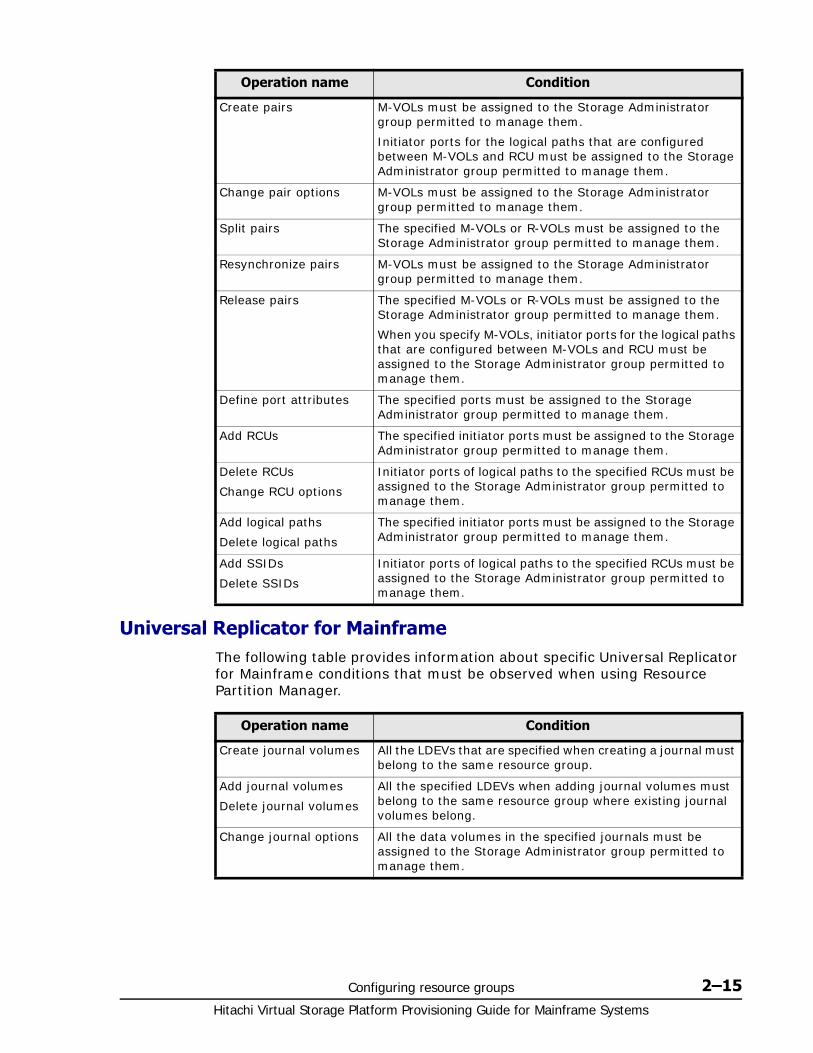
Configuring resource groups 2–15Hitachi Virtual Storage Platform Provisioning Guide for Mainframe Systems
Universal Replicator for MainframeThe following table provides information about specific Universal Replicator for Mainframe conditions that must be observed when using Resource Partition Manager.
Operation name Condition
Create pairs M-VOLs must be assigned to the Storage Administrator group permitted to manage them.
Initiator ports for the logical paths that are configured between M-VOLs and RCU must be assigned to the Storage Administrator group permitted to manage them.
Change pair options M-VOLs must be assigned to the Storage Administrator group permitted to manage them.
Split pairs The specified M-VOLs or R-VOLs must be assigned to the Storage Administrator group permitted to manage them.
Resynchronize pairs M-VOLs must be assigned to the Storage Administrator group permitted to manage them.
Release pairs The specified M-VOLs or R-VOLs must be assigned to the Storage Administrator group permitted to manage them.
When you specify M-VOLs, initiator ports for the logical paths that are configured between M-VOLs and RCU must be assigned to the Storage Administrator group permitted to manage them.
Define port attributes The specified ports must be assigned to the Storage Administrator group permitted to manage them.
Add RCUs The specified initiator ports must be assigned to the Storage Administrator group permitted to manage them.
Delete RCUs
Change RCU options
Initiator ports of logical paths to the specified RCUs must be assigned to the Storage Administrator group permitted to manage them.
Add logical paths
Delete logical paths
The specified initiator ports must be assigned to the Storage Administrator group permitted to manage them.
Add SSIDs
Delete SSIDs
Initiator ports of logical paths to the specified RCUs must be assigned to the Storage Administrator group permitted to manage them.
Operation name Condition
Create journal volumes All the LDEVs that are specified when creating a journal must belong to the same resource group.
Add journal volumes
Delete journal volumes
All the specified LDEVs when adding journal volumes must belong to the same resource group where existing journal volumes belong.
Change journal options All the data volumes in the specified journals must be assigned to the Storage Administrator group permitted to manage them.
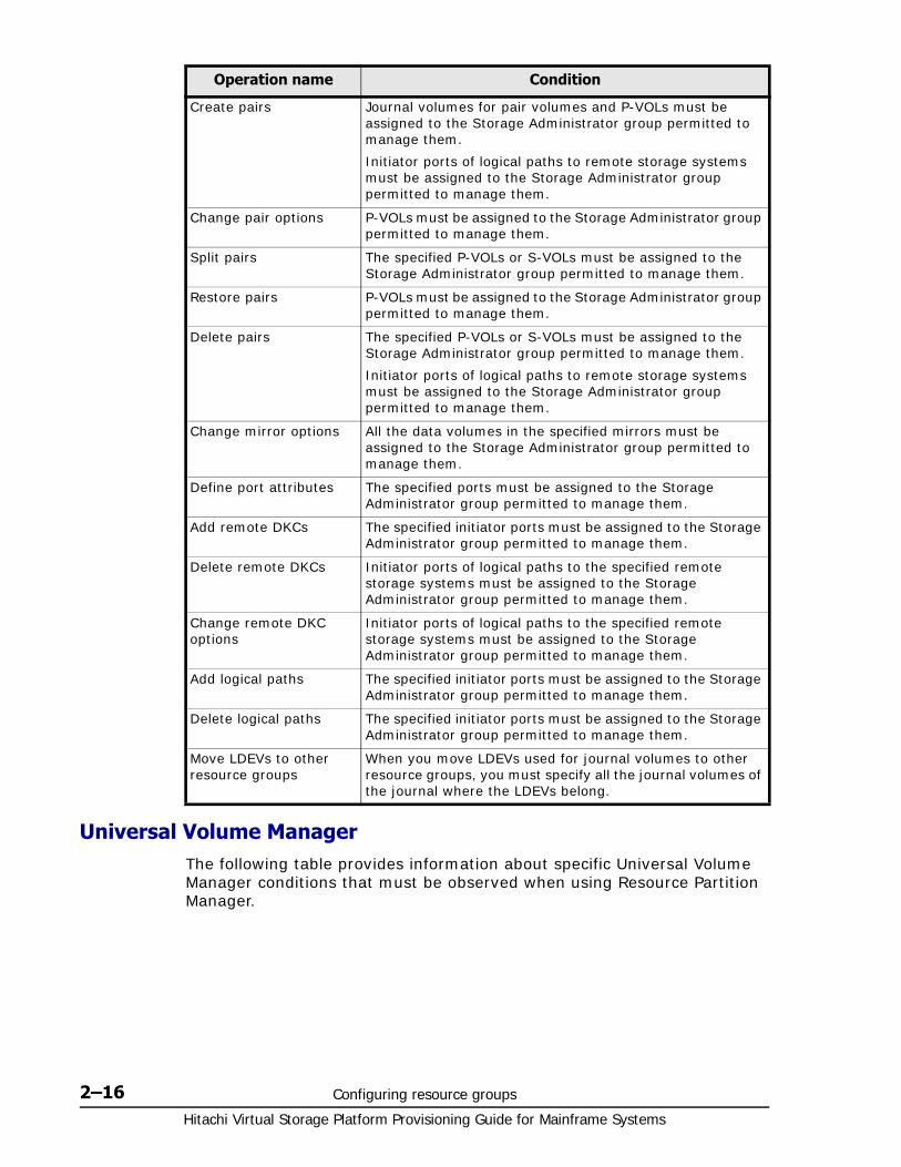
Hitachi Virtual Storage Platform Provisioning Guide for Mainframe Systems
2–16 Configuring resource groups
Universal Volume ManagerThe following table provides information about specific Universal Volume Manager conditions that must be observed when using Resource Partition Manager.
Create pairs Journal volumes for pair volumes and P-VOLs must be assigned to the Storage Administrator group permitted to manage them.
Initiator ports of logical paths to remote storage systems must be assigned to the Storage Administrator group permitted to manage them.
Change pair options P-VOLs must be assigned to the Storage Administrator group permitted to manage them.
Split pairs The specified P-VOLs or S-VOLs must be assigned to the Storage Administrator group permitted to manage them.
Restore pairs P-VOLs must be assigned to the Storage Administrator group permitted to manage them.
Delete pairs The specified P-VOLs or S-VOLs must be assigned to the Storage Administrator group permitted to manage them.
Initiator ports of logical paths to remote storage systems must be assigned to the Storage Administrator group permitted to manage them.
Change mirror options All the data volumes in the specified mirrors must be assigned to the Storage Administrator group permitted to manage them.
Define port attributes The specified ports must be assigned to the Storage Administrator group permitted to manage them.
Add remote DKCs The specified initiator ports must be assigned to the Storage Administrator group permitted to manage them.
Delete remote DKCs Initiator ports of logical paths to the specified remote storage systems must be assigned to the Storage Administrator group permitted to manage them.
Change remote DKC options
Initiator ports of logical paths to the specified remote storage systems must be assigned to the Storage Administrator group permitted to manage them.
Add logical paths The specified initiator ports must be assigned to the Storage Administrator group permitted to manage them.
Delete logical paths The specified initiator ports must be assigned to the Storage Administrator group permitted to manage them.
Move LDEVs to other resource groups
When you move LDEVs used for journal volumes to other resource groups, you must specify all the journal volumes of the journal where the LDEVs belong.
Operation name Condition
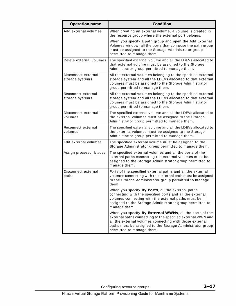
Configuring resource groups 2–17Hitachi Virtual Storage Platform Provisioning Guide for Mainframe Systems
Operation name Condition
Add external volumes When creating an external volume, a volume is created in the resource group where the external port belongs.
When you specify a path group and open the Add External Volumes window, all the ports that compose the path group must be assigned to the Storage Administrator group permitted to manage them.
Delete external volumes The specified external volume and all the LDEVs allocated to that external volume must be assigned to the Storage Administrator group permitted to manage them.
Disconnect external storage systems
All the external volumes belonging to the specified external storage system and all the LDEVs allocated to that external volumes must be assigned to the Storage Administrator group permitted to manage them.
Reconnect external storage systems
All the external volumes belonging to the specified external storage system and all the LDEVs allocated to that external volumes must be assigned to the Storage Administrator group permitted to manage them.
Disconnect external volumes
The specified external volume and all the LDEVs allocated to the external volumes must be assigned to the Storage Administrator group permitted to manage them.
Reconnect external volumes
The specified external volume and all the LDEVs allocated to the external volumes must be assigned to the Storage Administrator group permitted to manage them.
Edit external volumes The specified external volume must be assigned to the Storage Administrator group permitted to manage them.
Assign processor blades The specified external volumes and all the ports of the external paths connecting the external volumes must be assigned to the Storage Administrator group permitted to manage them.
Disconnect external paths
Ports of the specified external paths and all the external volumes connecting with the external path must be assigned to the Storage Administrator group permitted to manage them.
When you specify By Ports, all the external paths connecting with the specified ports and all the external volumes connecting with the external paths must be assigned to the Storage Administrator group permitted to manage them.
When you specify By External WWNs, all the ports of the external paths connecting to the specified external WWN and all the external volumes connecting with those external paths must be assigned to the Storage Administrator group permitted to manage them.
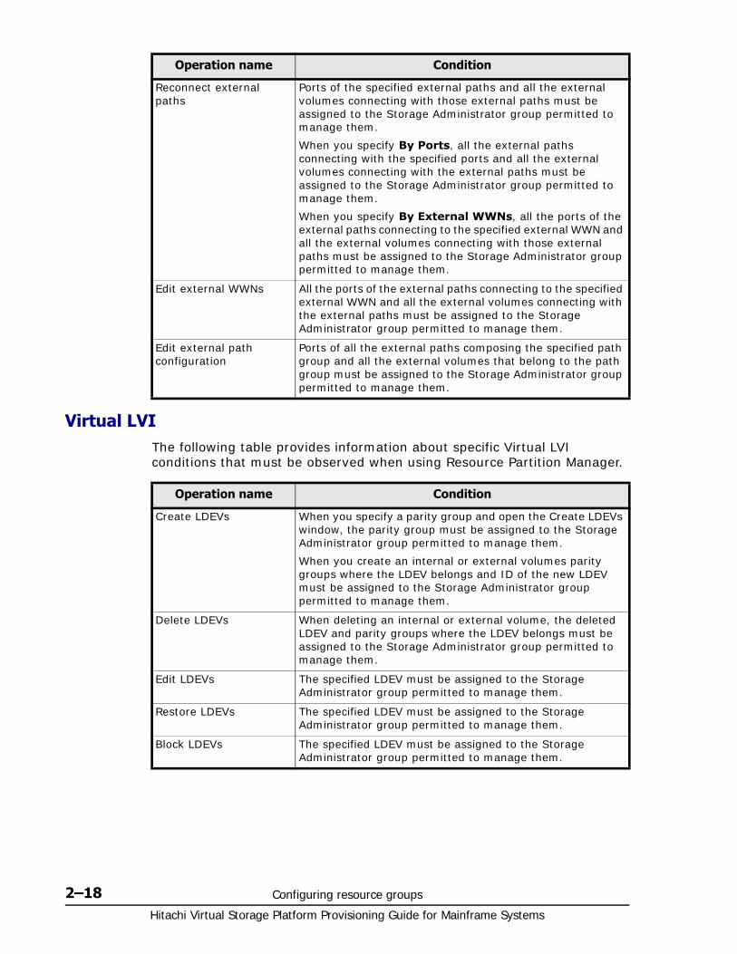
Hitachi Virtual Storage Platform Provisioning Guide for Mainframe Systems
2–18 Configuring resource groups
Virtual LVIThe following table provides information about specific Virtual LVI conditions that must be observed when using Resource Partition Manager.
Reconnect external paths
Ports of the specified external paths and all the external volumes connecting with those external paths must be assigned to the Storage Administrator group permitted to manage them.
When you specify By Ports, all the external paths connecting with the specified ports and all the external volumes connecting with the external paths must be assigned to the Storage Administrator group permitted to manage them.
When you specify By External WWNs, all the ports of the external paths connecting to the specified external WWN and all the external volumes connecting with those external paths must be assigned to the Storage Administrator group permitted to manage them.
Edit external WWNs All the ports of the external paths connecting to the specified external WWN and all the external volumes connecting with the external paths must be assigned to the Storage Administrator group permitted to manage them.
Edit external path configuration
Ports of all the external paths composing the specified path group and all the external volumes that belong to the path group must be assigned to the Storage Administrator group permitted to manage them.
Operation name Condition
Operation name Condition
Create LDEVs When you specify a parity group and open the Create LDEVs window, the parity group must be assigned to the Storage Administrator group permitted to manage them.
When you create an internal or external volumes parity groups where the LDEV belongs and ID of the new LDEV must be assigned to the Storage Administrator group permitted to manage them.
Delete LDEVs When deleting an internal or external volume, the deleted LDEV and parity groups where the LDEV belongs must be assigned to the Storage Administrator group permitted to manage them.
Edit LDEVs The specified LDEV must be assigned to the Storage Administrator group permitted to manage them.
Restore LDEVs The specified LDEV must be assigned to the Storage Administrator group permitted to manage them.
Block LDEVs The specified LDEV must be assigned to the Storage Administrator group permitted to manage them.
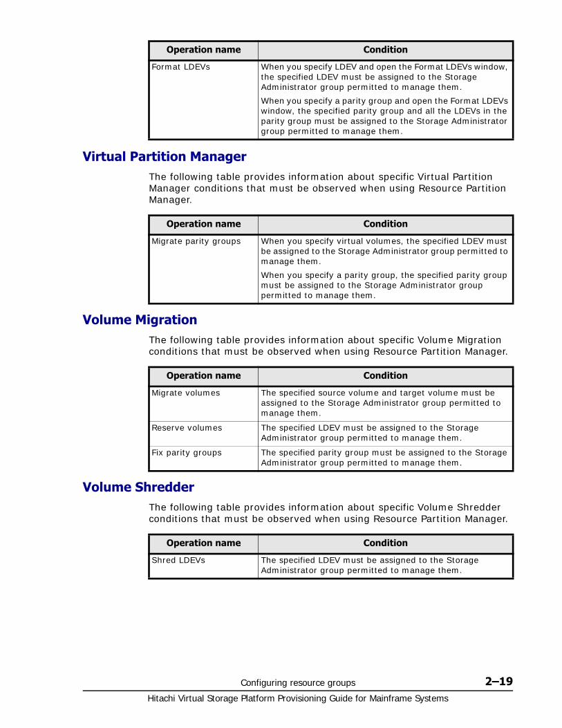
Configuring resource groups 2–19Hitachi Virtual Storage Platform Provisioning Guide for Mainframe Systems
Virtual Partition ManagerThe following table provides information about specific Virtual Partition Manager conditions that must be observed when using Resource Partition Manager.
Volume MigrationThe following table provides information about specific Volume Migration conditions that must be observed when using Resource Partition Manager.
Volume ShredderThe following table provides information about specific Volume Shredder conditions that must be observed when using Resource Partition Manager.
Format LDEVs When you specify LDEV and open the Format LDEVs window, the specified LDEV must be assigned to the Storage Administrator group permitted to manage them.
When you specify a parity group and open the Format LDEVs window, the specified parity group and all the LDEVs in the parity group must be assigned to the Storage Administrator group permitted to manage them.
Operation name Condition
Operation name Condition
Migrate parity groups When you specify virtual volumes, the specified LDEV must be assigned to the Storage Administrator group permitted to manage them.
When you specify a parity group, the specified parity group must be assigned to the Storage Administrator group permitted to manage them.
Operation name Condition
Migrate volumes The specified source volume and target volume must be assigned to the Storage Administrator group permitted to manage them.
Reserve volumes The specified LDEV must be assigned to the Storage Administrator group permitted to manage them.
Fix parity groups The specified parity group must be assigned to the Storage Administrator group permitted to manage them.
Operation name Condition
Shred LDEVs The specified LDEV must be assigned to the Storage Administrator group permitted to manage them.

Hitachi Virtual Storage Platform Provisioning Guide for Mainframe Systems
2–20 Configuring resource groups
3
Configuring custom-sized provisioning 3–1Hitachi Virtual Storage Platform Provisioning Guide for Mainframe Systems
Configuring custom-sized provisioning
Configuring custom-sized provisioning involves creating and configuring a customized volume (CV). A CV is a fixed-sized volume that is divided into arbitrary sizes.
This provisioning strategy is suitable for use on both open and mainframe systems. Virtual LVI or Virtual LUN software is required to configure variable-sized provisioning.
□ Virtual LVI/Virtual LUN functions
□ VLL requirements
□ VLL specifications
□ SSID requirements
□ VLL size calculations
□ Create LDEV function
□ Blocking an LDEV
□ Restoring a blocked LDEV
□ Editing an LDEV name
□ Deleting an LDEV (converting to free space)
□ Formatting LDEVs
□ Making external mainframe system volumes usable
□ Assigning a processor blade

Hitachi Virtual Storage Platform Provisioning Guide for Mainframe Systems
3–2 Configuring custom-sized provisioning
□ Using a system disk
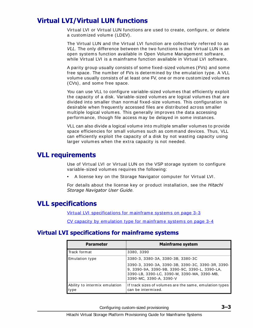
Configuring custom-sized provisioning 3–3Hitachi Virtual Storage Platform Provisioning Guide for Mainframe Systems
Virtual LVI/Virtual LUN functionsVirtual LVI or Virtual LUN functions are used to create, configure, or delete a customized volume (LDEV).
The Virtual LUN and the Virtual LVI function are collectively referred to as VLL. The only difference between the two functions is that Virtual LUN is an open systems function available in Open Volume Management software, while Virtual LVI is a mainframe function available in Virtual LVI software.
A parity group usually consists of some fixed-sized volumes (FVs) and some free space. The number of FVs is determined by the emulation type. A VLL volume usually consists of at least one FV, one or more customized volumes (CVs), and some free space.
You can use VLL to configure variable-sized volumes that efficiently exploit the capacity of a disk. Variable-sized volumes are logical volumes that are divided into smaller than normal fixed-size volumes. This configuration is desirable when frequently accessed files are distributed across smaller multiple logical volumes. This generally improves the data accessing performance, though file access may be delayed in some instances.
VLL can also divide a logical volume into multiple smaller volumes to provide space efficiencies for small volumes such as command devices. Thus, VLL can efficiently exploit the capacity of a disk by not wasting capacity using larger volumes when the extra capacity is not needed.
VLL requirementsUse of Virtual LVI or Virtual LUN on the VSP storage system to configure variable-sized volumes requires the following:
• A license key on the Storage Navigator computer for Virtual LVI.
For details about the license key or product installation, see the Hitachi Storage Navigator User Guide.
VLL specificationsVirtual LVI specifications for mainframe systems on page 3-3
CV capacity by emulation type for mainframe systems on page 3-4
Virtual LVI specifications for mainframe systems
Parameter Mainframe system
Track format 3380, 3390
Emulation type 3380-3, 3380-3A, 3380-3B, 3380-3C
3390-3, 3390-3A, 3390-3B, 3390-3C, 3390-3R, 3390-9, 3390-9A, 3390-9B, 3390-9C, 3390-L, 3390-LA, 3390-LB, 3390-LC, 3390-M, 3390-MA, 3390-MB, 3390-MC, 3390-A, 3390-V
Ability to intermix emulation type
If track sizes of volumes are the same, emulation types can be intermixed.
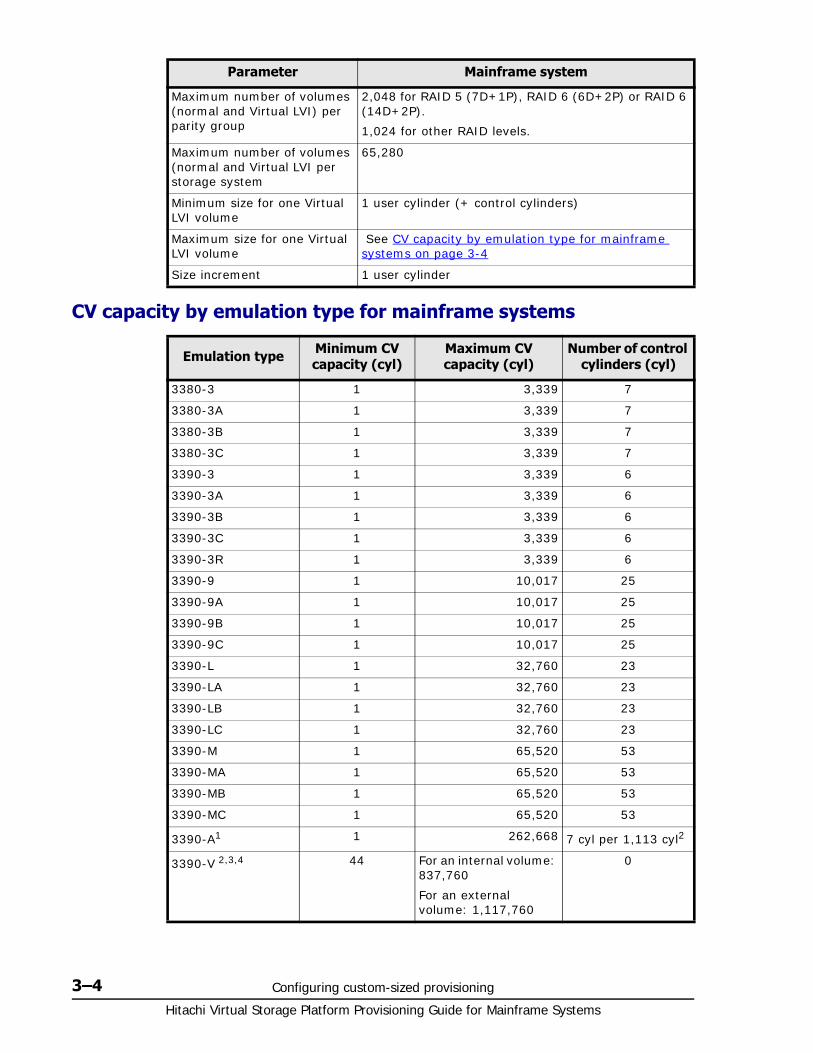
Hitachi Virtual Storage Platform Provisioning Guide for Mainframe Systems
3–4 Configuring custom-sized provisioning
CV capacity by emulation type for mainframe systems
Maximum number of volumes (normal and Virtual LVI) per parity group
2,048 for RAID 5 (7D+1P), RAID 6 (6D+2P) or RAID 6 (14D+2P).
1,024 for other RAID levels.
Maximum number of volumes (normal and Virtual LVI per storage system
65,280
Minimum size for one Virtual LVI volume
1 user cylinder (+ control cylinders)
Maximum size for one Virtual LVI volume
See CV capacity by emulation type for mainframe systems on page 3-4
Size increment 1 user cylinder
Emulation type Minimum CV capacity (cyl)
Maximum CV capacity (cyl)
Number of control cylinders (cyl)
3380-3 1 3,339 7
3380-3A 1 3,339 7
3380-3B 1 3,339 7
3380-3C 1 3,339 7
3390-3 1 3,339 6
3390-3A 1 3,339 6
3390-3B 1 3,339 6
3390-3C 1 3,339 6
3390-3R 1 3,339 6
3390-9 1 10,017 25
3390-9A 1 10,017 25
3390-9B 1 10,017 25
3390-9C 1 10,017 25
3390-L 1 32,760 23
3390-LA 1 32,760 23
3390-LB 1 32,760 23
3390-LC 1 32,760 23
3390-M 1 65,520 53
3390-MA 1 65,520 53
3390-MB 1 65,520 53
3390-MC 1 65,520 53
3390-A1 1 262,668 7 cyl per 1,113 cyl2
3390-V 2,3,4 44 For an internal volume: 837,760
For an external volume: 1,117,760
0
Parameter Mainframe system
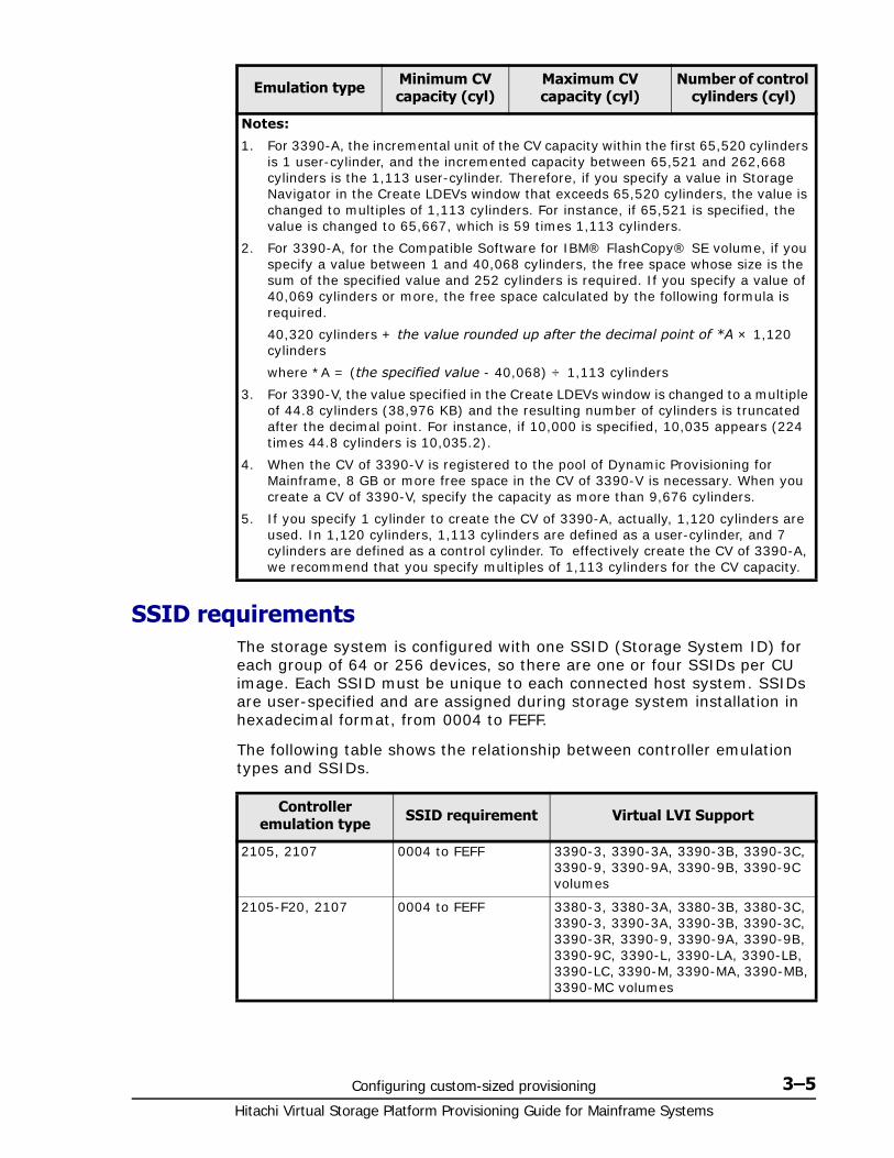
Configuring custom-sized provisioning 3–5Hitachi Virtual Storage Platform Provisioning Guide for Mainframe Systems
SSID requirements The storage system is configured with one SSID (Storage System ID) for each group of 64 or 256 devices, so there are one or four SSIDs per CU image. Each SSID must be unique to each connected host system. SSIDs are user-specified and are assigned during storage system installation in hexadecimal format, from 0004 to FEFF.
The following table shows the relationship between controller emulation types and SSIDs.
Notes:
1. For 3390-A, the incremental unit of the CV capacity within the first 65,520 cylinders is 1 user-cylinder, and the incremented capacity between 65,521 and 262,668 cylinders is the 1,113 user-cylinder. Therefore, if you specify a value in Storage Navigator in the Create LDEVs window that exceeds 65,520 cylinders, the value is changed to multiples of 1,113 cylinders. For instance, if 65,521 is specified, the value is changed to 65,667, which is 59 times 1,113 cylinders.
2. For 3390-A, for the Compatible Software for IBM® FlashCopy® SE volume, if you specify a value between 1 and 40,068 cylinders, the free space whose size is the sum of the specified value and 252 cylinders is required. If you specify a value of 40,069 cylinders or more, the free space calculated by the following formula is required.
40,320 cylinders + the value rounded up after the decimal point of *A × 1,120 cylinders
where *A = (the specified value - 40,068) ÷ 1,113 cylinders
3. For 3390-V, the value specified in the Create LDEVs window is changed to a multiple of 44.8 cylinders (38,976 KB) and the resulting number of cylinders is truncated after the decimal point. For instance, if 10,000 is specified, 10,035 appears (224 times 44.8 cylinders is 10,035.2).
4. When the CV of 3390-V is registered to the pool of Dynamic Provisioning for Mainframe, 8 GB or more free space in the CV of 3390-V is necessary. When you create a CV of 3390-V, specify the capacity as more than 9,676 cylinders.
5. If you specify 1 cylinder to create the CV of 3390-A, actually, 1,120 cylinders are used. In 1,120 cylinders, 1,113 cylinders are defined as a user-cylinder, and 7 cylinders are defined as a control cylinder. To effectively create the CV of 3390-A, we recommend that you specify multiples of 1,113 cylinders for the CV capacity.
Emulation type Minimum CV capacity (cyl)
Maximum CV capacity (cyl)
Number of control cylinders (cyl)
Controller emulation type SSID requirement Virtual LVI Support
2105, 2107 0004 to FEFF 3390-3, 3390-3A, 3390-3B, 3390-3C, 3390-9, 3390-9A, 3390-9B, 3390-9C volumes
2105-F20, 2107 0004 to FEFF 3380-3, 3380-3A, 3380-3B, 3380-3C, 3390-3, 3390-3A, 3390-3B, 3390-3C, 3390-3R, 3390-9, 3390-9A, 3390-9B, 3390-9C, 3390-L, 3390-LA, 3390-LB, 3390-LC, 3390-M, 3390-MA, 3390-MB, 3390-MC volumes
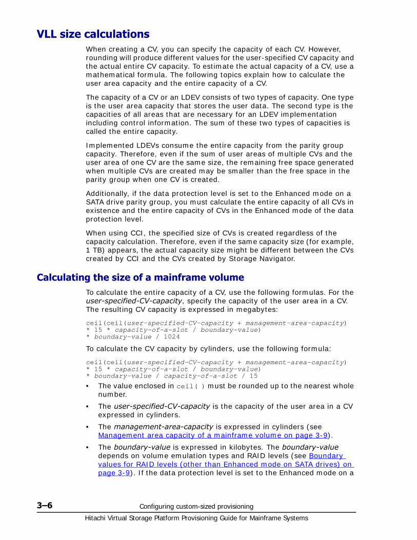
Hitachi Virtual Storage Platform Provisioning Guide for Mainframe Systems
3–6 Configuring custom-sized provisioning
VLL size calculationsWhen creating a CV, you can specify the capacity of each CV. However, rounding will produce different values for the user-specified CV capacity and the actual entire CV capacity. To estimate the actual capacity of a CV, use a mathematical formula. The following topics explain how to calculate the user area capacity and the entire capacity of a CV.
The capacity of a CV or an LDEV consists of two types of capacity. One type is the user area capacity that stores the user data. The second type is the capacities of all areas that are necessary for an LDEV implementation including control information. The sum of these two types of capacities is called the entire capacity.
Implemented LDEVs consume the entire capacity from the parity group capacity. Therefore, even if the sum of user areas of multiple CVs and the user area of one CV are the same size, the remaining free space generated when multiple CVs are created may be smaller than the free space in the parity group when one CV is created.
Additionally, if the data protection level is set to the Enhanced mode on a SATA drive parity group, you must calculate the entire capacity of all CVs in existence and the entire capacity of CVs in the Enhanced mode of the data protection level.
When using CCI, the specified size of CVs is created regardless of the capacity calculation. Therefore, even if the same capacity size (for example, 1 TB) appears, the actual capacity size might be different between the CVs created by CCI and the CVs created by Storage Navigator.
Calculating the size of a mainframe volumeTo calculate the entire capacity of a CV, use the following formulas. For the user-specified-CV-capacity, specify the capacity of the user area in a CV. The resulting CV capacity is expressed in megabytes:
ceil(ceil(user-specified-CV-capacity + management-area-capacity)* 15 * capacity-of-a-slot / boundary-value)* boundary-value / 1024
To calculate the CV capacity by cylinders, use the following formula:
ceil(ceil(user-specified-CV-capacity + management-area-capacity)* 15 * capacity-of-a-slot / boundary-value)* boundary-value / capacity-of-a-slot / 15
• The value enclosed in ceil( ) must be rounded up to the nearest whole number.
• The user-specified-CV-capacity is the capacity of the user area in a CV expressed in cylinders.
• The management-area-capacity is expressed in cylinders (see Management area capacity of a mainframe volume on page 3-9).
• The boundary-value is expressed in kilobytes. The boundary-value depends on volume emulation types and RAID levels (see Boundary values for RAID levels (other than Enhanced mode on SATA drives) on page 3-9). If the data protection level is set to the Enhanced mode on a
Configuring custom-sized provisioning 3–7Hitachi Virtual Storage Platform Provisioning Guide for Mainframe Systems
SATA drive, the boundary value depends on volume emulation types and RAID levels (see Boundary values for RAID levels (Enhanced mode on SATA drives) on page 3-9).
• The capacity-of-a-slot is expressed in kilobytes. The capacity of a slot value depends on volume emulation types (see Capacity of a slot on page 3-10).
When calculating the size of a mainframe volume, note the following:
• To calculate the capacity of the CV of 3390-A, apply the multiples of 1,113 cylinders to user-specified CV capacity in the upper formula. For instance, if you want to apply 1 cylinder to user-specified CV capacity, apply 1,113 cylinders. If you want to apply 1,114 cylinders to user-specified CV capacity, apply 2,226 cylinders.
To calculate the capacity of the CV of 3390-V, apply the multiples of 44.8 cylinders to user-specified CV capacity in the upper formula. For instance, if you want to apply 44 cylinder to user-specified CV capacity, apply 44.8 cylinders. If you want to apply 45 cylinders to user-specified CV capacity, apply 89.6 cylinders.
• In 3390-A, for the Compatible Software for IBM® FlashCopy® SE volume, if you specify a value between 1 and 40,068 cylinders, the space whose size is the sum of the specified value and 252 cylinders for the control cylinders is required. If you specify a value of 40,069 cylinders or more, the free space calculated by the following formula is required.
40,320 cylinders + the value rounded up after the decimal point of *A × 1,120 cylinders
where *A = (the specified value - 40,068) ÷ 1,113 cylinders
• In 3390-A, if a value is specified in Storage Navigator in the Create LDEVs window that exceeds 65,520 cylinders, the value is corrected to multiples of 1,113 cylinders. For instance, if 65,521 is specified, 65,667 which is 59 times 1,113 cylinders appears.
• In 3390-V, the value specified in the Create LDEVs window is corrected to multiples of 44.8 cylinders (38,976 KB) and rounded down to the nearest whole number of cylinders.
Calculating the size of a CV using Enhanced mode on SATA drivesIf the data protection level is set to Enhanced mode on a SATA drive, the entire capacity of a CV must be calculated based on the previously calculated entire capacity of a CV. The calculation methods vary depending on the unit for the capacity specified when creating the CV.
If the CV capacity unit is MB (megabytes):
To calculate the entire capacity of a CV whose capacity unit is defined as MB:
entire-capacity-of-a-CV * 1024 / capacity-of-a-slot
where
• capacity-of-a-slot is expressed in kilobytes. The capacity of a slot depends on volume emulation types (see Capacity of a slot on page 3-10).
Hitachi Virtual Storage Platform Provisioning Guide for Mainframe Systems
3–8 Configuring custom-sized provisioning
• The resulting entire capacity is expressed in slots.
To calculate the management area capacity:
ceil(entire-capacity-of-a-CV(slots) / calculated-management-area-capacity) * boundary-value
where
• the value enclosed in ceil( ) must be rounded up to the nearest whole number.
• The resulting entire capacity is expressed in slots.
To calculate the entire capacity of a CV if the data protection level is set to the Enhanced mode on the SATA drive:
ceil(entire-capacity-of-a-CV(slots) + calculated-management-area-capacity)
To convert the resulting entire capacity into megabytes:
calculated-entire-capacity-of-a-CV(slots) /1024 * capacity-of-a-slot
where
• calculated-entire-capacity-of-a-CV(slots) means the entire capacity of a CV if the data protection level is set to the Enhanced mode on the SATA drive.
If the CV capacity unit is block:
To calculate the entire capacity of a CV whose capacity unit is defined as block:
user-specified-a-CV-capacity / 2 / capacity-of-a-slot
where
• capacity-of-a-slot is expressed in kilobytes. The capacity of a slot depends on volume emulation types (see Capacity of a slot on page 3-10).
• The resulting entire capacity is expressed in slots.
To calculate the management area capacity:
ceil(entire-capacity-of-a-CV(slots) / calculated-management-area-capacity) * boundary-value
where
• the value enclosed in ceil( ) must be rounded up to the nearest whole number.
To calculate the entire capacity of a CV if the data protection level is set to the Enhanced mode on the SATA drive:
ceil(entire-capacity-of-a-CV(slots) + calculated-management-area-capacity)
To convert the resulting entire capacity into blocks:
calculated-entire-capacity-of-a-CV(slots) * capacity-of-a-slot * 2
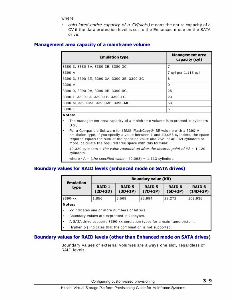
Configuring custom-sized provisioning 3–9Hitachi Virtual Storage Platform Provisioning Guide for Mainframe Systems
where
• calculated-entire-capacity-of-a-CV(slots) means the entire capacity of a CV if the data protection level is set to the Enhanced mode on the SATA drive.
Management area capacity of a mainframe volume
Boundary values for RAID levels (Enhanced mode on SATA drives)
Boundary values for RAID levels (other than Enhanced mode on SATA drives)
Boundary values of external volumes are always one slot, regardless of RAID levels.
Emulation type Management area capacity (cyl)
3380-3, 3380-3A, 3380-3B, 3380-3C, 7
3390-A 7 cyl per 1,113 cyl
3390-3, 3390-3R, 3390-3A, 3390-3B, 3390-3C 6
3390-V 0
3390-9, 3390-9A, 3390-9B, 3390-9C 25
3390-L, 3390-LA, 3390-LB, 3390-LC 23
3390-M, 3390-MA, 3390-MB, 3390-MC 53
3390-1 5
Notes:
• The management area capacity of a mainframe volume is expressed in cylinders (Cyl).
• For a Compatible Software for IBM® FlashCopy® SE volume with a 3390-A emulation type, if you specify a value between 1 and 40,068 cylinders, the space required equals the sum of the specified value and 252 of 40,069 cylinders or more, calculate the required free space with this formula:
40,320 cylinders + the value rounded up after the decimal point of *A × 1,120 cylinders
where *A = (the specified value - 40,068) ÷ 1,113 cylinders
Emulation type
Boundary value (KB)
RAID 1 (2D+2D)
RAID 5 (3D+1P)
RAID 5 (7D+1P)
RAID 6 (6D+2P)
RAID 6 (14D+2P)
3390-xx 1,856 5,568 25,984 22,272 103,936
Notes:
• xx indicates one or more numbers or letters.
• Boundary values are expressed in kilobytes.
• A SATA drive supports 3390-xx emulation types for a mainframe system.
• Hyphen (-) indicates that the combination is not supported.
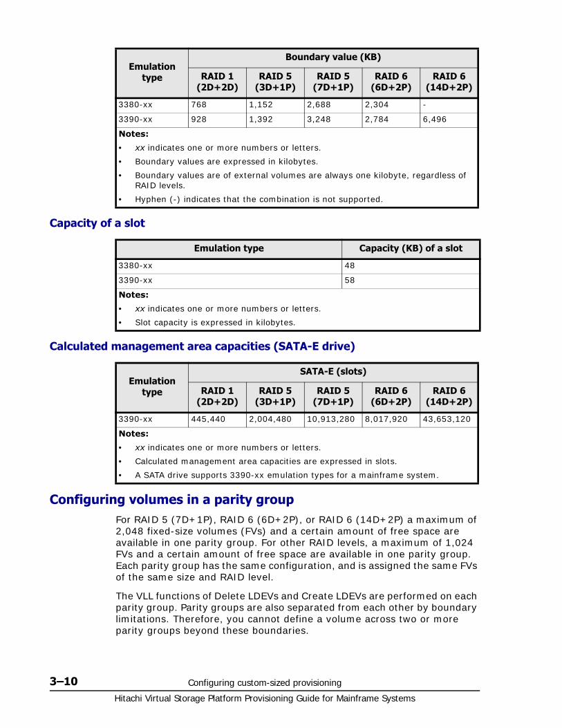
Hitachi Virtual Storage Platform Provisioning Guide for Mainframe Systems
3–10 Configuring custom-sized provisioning
Capacity of a slot
Calculated management area capacities (SATA-E drive)
Configuring volumes in a parity group For RAID 5 (7D+1P), RAID 6 (6D+2P), or RAID 6 (14D+2P) a maximum of 2,048 fixed-size volumes (FVs) and a certain amount of free space are available in one parity group. For other RAID levels, a maximum of 1,024 FVs and a certain amount of free space are available in one parity group. Each parity group has the same configuration, and is assigned the same FVs of the same size and RAID level.
The VLL functions of Delete LDEVs and Create LDEVs are performed on each parity group. Parity groups are also separated from each other by boundary limitations. Therefore, you cannot define a volume across two or more parity groups beyond these boundaries.
Emulation type
Boundary value (KB)
RAID 1 (2D+2D)
RAID 5 (3D+1P)
RAID 5 (7D+1P)
RAID 6 (6D+2P)
RAID 6 (14D+2P)
3380-xx 768 1,152 2,688 2,304 -
3390-xx 928 1,392 3,248 2,784 6,496
Notes:
• xx indicates one or more numbers or letters.
• Boundary values are expressed in kilobytes.
• Boundary values are of external volumes are always one kilobyte, regardless of RAID levels.
• Hyphen (-) indicates that the combination is not supported.
Emulation type Capacity (KB) of a slot
3380-xx 48
3390-xx 58
Notes:
• xx indicates one or more numbers or letters.
• Slot capacity is expressed in kilobytes.
Emulation type
SATA-E (slots)
RAID 1 (2D+2D)
RAID 5 (3D+1P)
RAID 5 (7D+1P)
RAID 6 (6D+2P)
RAID 6 (14D+2P)
3390-xx 445,440 2,004,480 10,913,280 8,017,920 43,653,120
Notes:
• xx indicates one or more numbers or letters.
• Calculated management area capacities are expressed in slots.
• A SATA drive supports 3390-xx emulation types for a mainframe system.
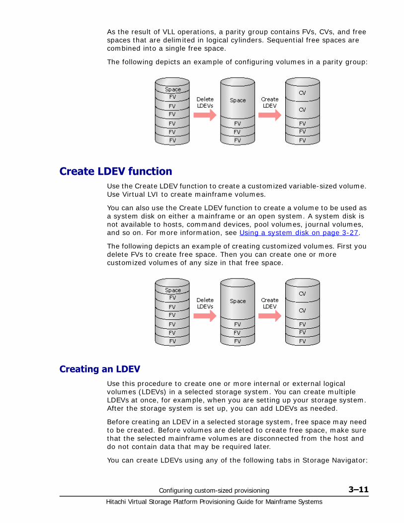
Configuring custom-sized provisioning 3–11Hitachi Virtual Storage Platform Provisioning Guide for Mainframe Systems
As the result of VLL operations, a parity group contains FVs, CVs, and free spaces that are delimited in logical cylinders. Sequential free spaces are combined into a single free space.
The following depicts an example of configuring volumes in a parity group:
Create LDEV functionUse the Create LDEV function to create a customized variable-sized volume. Use Virtual LVI to create mainframe volumes.
You can also use the Create LDEV function to create a volume to be used as a system disk on either a mainframe or an open system. A system disk is not available to hosts, command devices, pool volumes, journal volumes, and so on. For more information, see Using a system disk on page 3-27.
The following depicts an example of creating customized volumes. First you delete FVs to create free space. Then you can create one or more customized volumes of any size in that free space.
Creating an LDEVUse this procedure to create one or more internal or external logical volumes (LDEVs) in a selected storage system. You can create multiple LDEVs at once, for example, when you are setting up your storage system. After the storage system is set up, you can add LDEVs as needed.
Before creating an LDEV in a selected storage system, free space may need to be created. Before volumes are deleted to create free space, make sure that the selected mainframe volumes are disconnected from the host and do not contain data that may be required later.
You can create LDEVs using any of the following tabs in Storage Navigator:
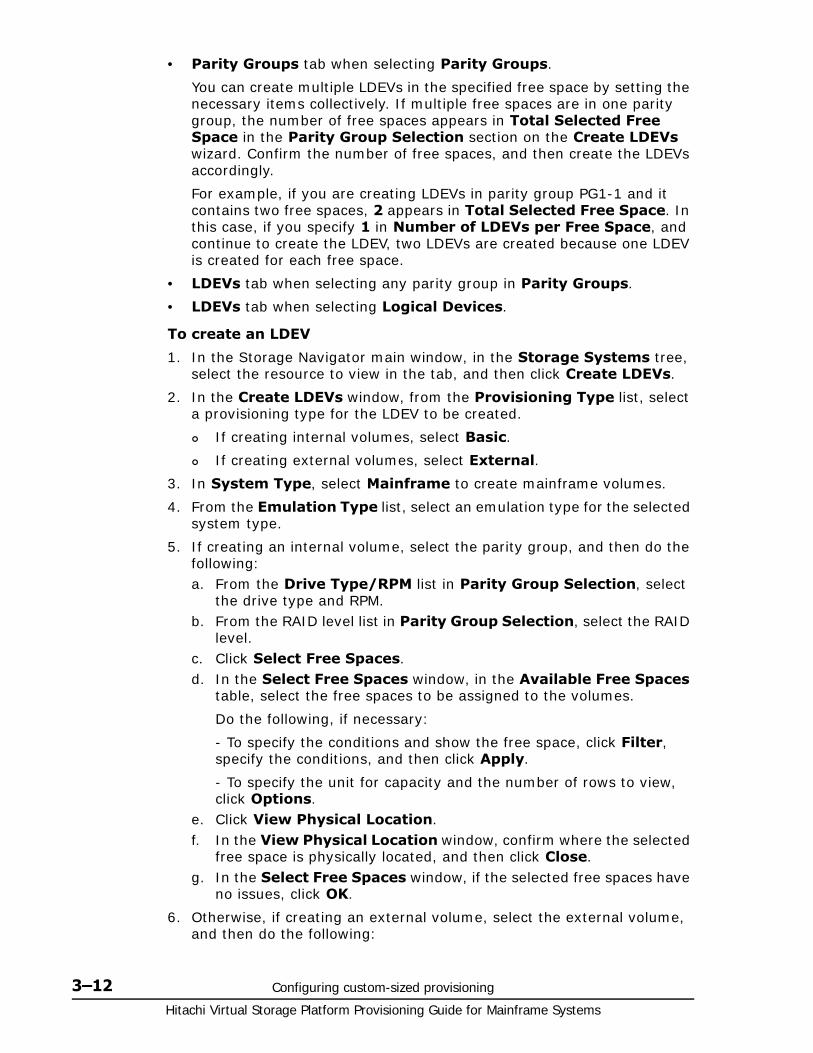
Hitachi Virtual Storage Platform Provisioning Guide for Mainframe Systems
3–12 Configuring custom-sized provisioning
• Parity Groups tab when selecting Parity Groups.
You can create multiple LDEVs in the specified free space by setting the necessary items collectively. If multiple free spaces are in one parity group, the number of free spaces appears in Total Selected Free Space in the Parity Group Selection section on the Create LDEVs wizard. Confirm the number of free spaces, and then create the LDEVs accordingly.
For example, if you are creating LDEVs in parity group PG1-1 and it contains two free spaces, 2 appears in Total Selected Free Space. In this case, if you specify 1 in Number of LDEVs per Free Space, and continue to create the LDEV, two LDEVs are created because one LDEV is created for each free space.
• LDEVs tab when selecting any parity group in Parity Groups.
• LDEVs tab when selecting Logical Devices.
To create an LDEV
1. In the Storage Navigator main window, in the Storage Systems tree, select the resource to view in the tab, and then click Create LDEVs.
2. In the Create LDEVs window, from the Provisioning Type list, select a provisioning type for the LDEV to be created.
If creating internal volumes, select Basic.
If creating external volumes, select External.
3. In System Type, select Mainframe to create mainframe volumes.
4. From the Emulation Type list, select an emulation type for the selected system type.
5. If creating an internal volume, select the parity group, and then do the following:a. From the Drive Type/RPM list in Parity Group Selection, select
the drive type and RPM.b. From the RAID level list in Parity Group Selection, select the RAID
level.c. Click Select Free Spaces.d. In the Select Free Spaces window, in the Available Free Spaces
table, select the free spaces to be assigned to the volumes.
Do the following, if necessary:
- To specify the conditions and show the free space, click Filter, specify the conditions, and then click Apply.
- To specify the unit for capacity and the number of rows to view, click Options.
e. Click View Physical Location.f. In the View Physical Location window, confirm where the selected
free space is physically located, and then click Close.g. In the Select Free Spaces window, if the selected free spaces have
no issues, click OK.
6. Otherwise, if creating an external volume, select the external volume, and then do the following:
Configuring custom-sized provisioning 3–13Hitachi Virtual Storage Platform Provisioning Guide for Mainframe Systems
a. Click Select Free Spaces.b. In the Select Free Spaces window, in the Available Free Spaces
table, select the free space to be assigned to the volumes.
Do the following, if necessary:
- To specify the conditions and show the free space, click Filter, specify the conditions, and then click Apply.
- To specify the unit for capacity and the number of rows to view, click Options.
c. Click View Physical Location.d. In the View Physical Location window, confirm where the selected
free space is physically located, and then click Close.e. In the Select Free Spaces window, if the selected free spaces have
no issues, click OK.
7. In LDEV Capacity, type the amount of LDEV capacity to be created and select a capacity unit from the list.
You can enter the capacity within the range of figures displayed below the text box. The capacity unit is fixed to Cyl.
8. In Number of LDEVs, type the number of LDEVs to be created.
For an internal volume, Number of LDEVs per Free Space appears.
For an external volume, Number of LDEVs per External Volume appears.
9. In LDEV Name, specify a name for this LDEV.a. In Prefix, type the characters that will become the fixed characters
for the beginning of the LDEV name. The characters are case-sensitive.
b. In Initial Number, type the initial number that will follow the prefix name.
10.In Format Type, select the format type for the LDEV from the list.
For an internal volume, you can select Normal Format, Quick Format, or No Format.
If No Format is selected, format the volume after creating LDEVs.
For an external volume, if you create the LDEV whose emulation type is the mainframe system, you can select Write to Control Blocks, Normal Format or No Format.
If No Format is selected, format the volume after creating the LDEVs.
If you select Quick Format, host I/Os might be affected when you perform the Quick Format operation. For details, see Quick Format function on page 3-20.
11.Click Options to show more options.
12.In Initial LDEV ID, make sure that an LDEV ID is set. To confirm the used number and unavailable number, click View LDEV IDs to open the View LDEV IDs window.
Hitachi Virtual Storage Platform Provisioning Guide for Mainframe Systems
3–14 Configuring custom-sized provisioning
a. In Initial LDEV ID in the Create LDEVs window, click View LDEV IDs.
In the View LDEV IDs window, the matrix vertical scale represents the second-to-last digit of the LDEV number, and the horizontal scale represents the last digit of the LDEV number. The LDEV IDs table shows the available, used, and disabled LDEV IDs.
In the table, used LDEV numbers appear in blue, unavailable numbers appear in gray, and unused numbers appear in white. LDEV numbers that are unavailable may be already in use, or already assigned to another emulation group (group by 32 LDEV numbers).
b. Click Close.
13.In the Create LDEVs window, in SSID, type four digits, in hexadecimal format (0004 to FEFF), for the SSID.
14.To confirm the created SSID, click View SSIDs to open the View SSIDs dialog box.a. In the Create LDEVs window, in Initial SSID, click View SSIDs.
In the SSIDs window, the SSIDs table shows the used SSIDs.b. Click Close.
15.In the Create LDEVs window, from the Processor Blade list, select a processor blade to be used by the LDEVs.
If you assign a specific processor blade, select the ID of the processor blade.
If you can assign any processor blade, click Auto.
16.If you are creating one more system disks, select Create LDEVs as System Disk.
17.Click Add.
The created LDEVs are added to the Selected LDEVs table.
The Provisioning Type, System Type, Emulation Type, Parity Group Selection, LDEV Capacity, and Number of LDEVs per Free Space or the Number of LDEVs per External Volume fields must be set. If these required items are not registered, you cannot click Add.
18.If necessary, change the following LDEV settings:
Click Edit SSIDs to open the SSIDs window. If a new LDEV is to be created in the CU, you can change the SSID to be allocated to the LDEV. For details about how to edit an SSID, see Editing an LDEV SSID on page 3-15.
Note: When you create a Compatible Software for IBM® FlashCopy® SE volume, if you select the pool and open the View LDEV IDs window, the window looks different depending on whether the selected pool ID is an odd number or an even number. If the selected pool ID is an odd number, all the LDEV IDs belonging to the CU whose ID is an even number are unavailable. If the selected pool ID is an even number, all the LDEV IDs belonging to the CU whose ID is an odd number are unavailable.
Configuring custom-sized provisioning 3–15Hitachi Virtual Storage Platform Provisioning Guide for Mainframe Systems
Click Change LDEV Settings to open the Change LDEV Settings window. For details about how to change the LDEV settings, see Changing LDEV settings on page 3-16.
19.If necessary, delete an LDEV from the Selected LDEVs table.
Select an LDEV to delete, and then click Remove. For details about how to remove an LDEV, see Removing an LDEV to be registered on page 3-16.
20.Click Finish.
The Confirm window opens.
21.In the Confirm window, confirm the settings, in Task Name type a unique name for this task or accept the default, and then click Apply.
If Go to tasks window for status is checked, the Tasks window opens.
Finding an LDEV IDWhen creating volumes, the LDEV ID (LDKC: CU: LDEV) must be specified. Use this procedure to determine the LDEV IDs in use in the storage system so you can specify the correct LDEV.
1. In Initial LDEV ID in the Create LDEVs window, click View LDEV IDs.
2. In the View LDEV IDs window, review the list to confirm the LDEV IDs. The LDEV IDs table shows the available, used, and disabled LDEV IDs.
The matrix vertical scale represents the second-to-last digit of the LDEV number, and the horizontal scale represents the last digit of the LDEV number.
In the table, used LDEV numbers appear in blue, unavailable LDEV numbers appear in gray, and unused LDEV IDs appear in white. LDEV numbers that are unavailable may be already in use, or already assigned to another emulation group (group by 32 LDEV numbers).
3. Click Close.
The Create LDEVs window opens.
Finding an LDEV SSID When creating volumes, the LDEV SSIDs must be specified. Use this procedure to determine the SSIDs in use in the storage system so you can specify the correct SSID.
1. In the Create LDEVs window, beside Initial SSID, click View SSIDs.
2. In the SSIDs window, review the list to confirm the LDEV SSIDs. The SSIDs table shows the SSIDs in use in the system.
3. Click Close. The Create LDEVs window opens.
Editing an LDEV SSID Before registering an LDEV, you may need to edit the LDEV SSID. If a CU is specified in which the first LDEV is created, the specified value of the SSID can be changed.
Hitachi Virtual Storage Platform Provisioning Guide for Mainframe Systems
3–16 Configuring custom-sized provisioning
1. In the Create LDEVs window, in the Selected LDEVs table, click Edit SSIDs.
2. In the Edit SSIDs window, review the SSIDs table showing the existing SSIDs and ones to be added.
3. If you change the SSID, select the appropriate LDEV, and then click Change SSIDs.
4. In the Change SSIDs window, type the new SSID, and then click OK.
5. In the Edit SSIDs window, click OK.
6. In the Create LDEVs window, click Finish.
7. In the Confirm window, click Apply.
The new SSID is registered.
If Go to tasks window for status is checked, the Tasks window opens.
Changing LDEV settingsBefore registering an LDEV, you may need to change the LDEV settings.
1. In the Create LDEVs window, in the Selected LDEVs table, select an LDEV, and then click Change LDEV Settings.
2. In the Change LDEV Settings window, you can change the setting of LDEV Name, Initial LDEV ID, or Processor Blade.
If you change LDEV Name, specify the prefix characters and the initial number for this LDEV.
If you change Initial LDEV ID, specify the number of LDKC, CU, DEV, and Interval. To confirm used LDEV IDs, click View LDEV IDs to confirm the used LDEV IDs in the View LDEV IDs window.
If you change Processor Blade, click the list and specify the processor blade ID. If the specific processor blade is specified, select the processor blade ID. If any processor blade is specified, click Auto.
3. Click OK.
4. In the Create LDEVs window, click Finish.
5. In the Confirm window, verify the settings, and then click Apply.
The settings are changed.
If Go to tasks window for status is checked, the Tasks window opens.
Removing an LDEV to be registeredIf you do not want to register an LDEV that is scheduled to be registered, you can remove it from the registering task.
1. In the Selected LDEVs table in the Create LDEVs window, select an LDEV, and then click Remove.
A message appears asking whether you want to remove the selected row or rows. If you want to remove the row, click OK.
Configuring custom-sized provisioning 3–17Hitachi Virtual Storage Platform Provisioning Guide for Mainframe Systems
2. Click Finish.
3. In the Confirm window, click Apply. The LDEV is removed from the registering task.
If Go to tasks window for status is checked, the Tasks window opens.
Blocking an LDEVBefore formatting or shredding a registered LDEV, the LDEV must be blocked. This procedure blocks both internal and external volumes.
You can block LDEVs from any of the following tabs:
• LDEVs tab when selecting any parity group in Parity Groups.
• LDEVs tab when selecting Logical Devices.
• Virtual Volumes tab when selecting any pool in Pool.
1. In the Storage Navigator main window, in the Storage Systems tree, select the resource to view in the tab.
2. Find the target LDEV in the table and confirm the LDEV status in the Status column.
If Blocked appears, the LDEV is blocked. You can skip the remaining steps.
If Blocked does not appear, the LDEV is not blocked. Block the LDEV using the following steps.
3. Select an LDEV, click More Actions, and select Block LDEVs.
You can select multiple LDEVs that are listed together or separately. For LDEVs that are listed together, select them while pressing the Shift key. For LDEVs that are listed separately, click each while pressing the Ctrl key.
4. In the Confirm window, confirm the settings, in Task Name type a unique name for this task or accept the default, and then click Apply.
If Go to tasks window for status is checked, the Tasks window opens.
Restoring a blocked LDEVYou can restore a blocked LDEV using any of the following tabs:
• LDEVs tab when selecting any parity group in Parity Groups.
• LDEVs tab when selecting Logical Devices.
• Virtual Volumes tab when selecting any pool in Pool.
1. In the Storage Navigator main window, in the Storage Systems tree, select the resource to view in the tab.
2. Find the target LDEV in the table and confirm the LDEV status in the Status column.
If Blocked appears, the LDEV is blocked. Restore a blocked LDEV using the following steps.
Hitachi Virtual Storage Platform Provisioning Guide for Mainframe Systems
3–18 Configuring custom-sized provisioning
If Blocked does not appear, the LDEV is not blocked.
3. Select the blocked LDEV, click More Actions, and select Restore.
You can select multiple LDEVs that are listed together or separately. For LDEVs that are listed together, select them while pressing the Shift key. For LDEVs that are listed separately, click each while pressing the Ctrl key.
4. In the Confirm window, confirm the settings, in Task Name type a unique name for this task or accept the default, and then click Apply.
If Go to tasks window for status is checked, the Tasks window opens.
Editing an LDEV nameYou can edit the name of a registered internal volume.
For information about editing a registered external volume, see Hitachi Universal Volume Manager User Guide.
1. Select the LDEV to be edited.
2. Click Edit LDEVs.
3. In Edit LDEVs window, edit LDEV Name.
4. Click Finish.
5. In the Confirm window, confirm the settings, in Task Name type a unique name for this task or accept the default, and then click Apply.
If Go to tasks window for status is checked, the Tasks window opens.
Deleting an LDEV (converting to free space)You can convert one or more of the LDEVs on a selected parity group into free space by deleting the LDEVs. That free space can be used to either create one or more variable-sized volumes (CVs) using the Create LDEVs function, or left as free space for future use. You can also delete a system disk if you no longer need it.
An LDEV cannot be deleted successfully if it is:
• In the defined path (including the pair volumes of TrueCopy for Mainframe and Hitachi Universal Replicator for Mainframe).
• A reserved volume of Volume Migration.
• A pool-VOL (including LUSE).
• A journal volume.
• An LDEV that has the Read/Write access attribute.
• An LDEV with the Volume Security setting.
WARNING: Deleting LDEVs will erase your data. Back up your data before deleting LDEVs.
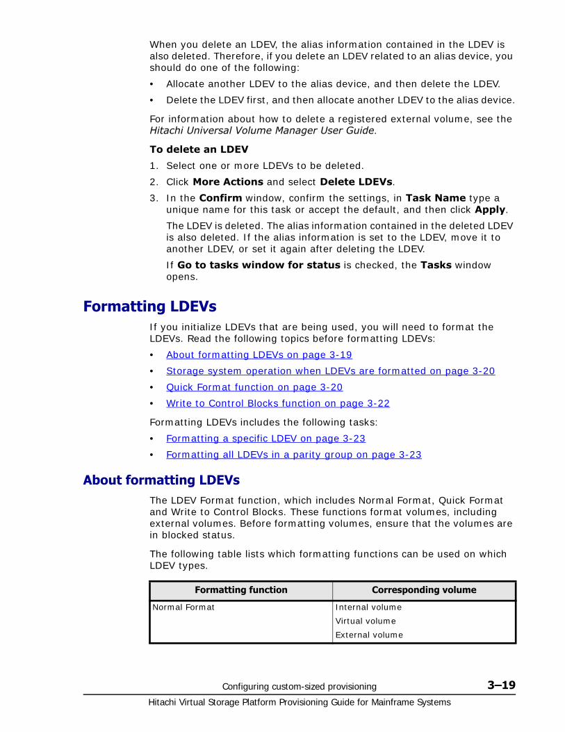
Configuring custom-sized provisioning 3–19Hitachi Virtual Storage Platform Provisioning Guide for Mainframe Systems
When you delete an LDEV, the alias information contained in the LDEV is also deleted. Therefore, if you delete an LDEV related to an alias device, you should do one of the following:
• Allocate another LDEV to the alias device, and then delete the LDEV.
• Delete the LDEV first, and then allocate another LDEV to the alias device.
For information about how to delete a registered external volume, see the Hitachi Universal Volume Manager User Guide.
To delete an LDEV
1. Select one or more LDEVs to be deleted.
2. Click More Actions and select Delete LDEVs.
3. In the Confirm window, confirm the settings, in Task Name type a unique name for this task or accept the default, and then click Apply.
The LDEV is deleted. The alias information contained in the deleted LDEV is also deleted. If the alias information is set to the LDEV, move it to another LDEV, or set it again after deleting the LDEV.
If Go to tasks window for status is checked, the Tasks window opens.
Formatting LDEVsIf you initialize LDEVs that are being used, you will need to format the LDEVs. Read the following topics before formatting LDEVs:
• About formatting LDEVs on page 3-19
• Storage system operation when LDEVs are formatted on page 3-20
• Quick Format function on page 3-20
• Write to Control Blocks function on page 3-22
Formatting LDEVs includes the following tasks:
• Formatting a specific LDEV on page 3-23
• Formatting all LDEVs in a parity group on page 3-23
About formatting LDEVsThe LDEV Format function, which includes Normal Format, Quick Format and Write to Control Blocks. These functions format volumes, including external volumes. Before formatting volumes, ensure that the volumes are in blocked status.
The following table lists which formatting functions can be used on which LDEV types.
Formatting function Corresponding volume
Normal Format Internal volume
Virtual volume
External volume
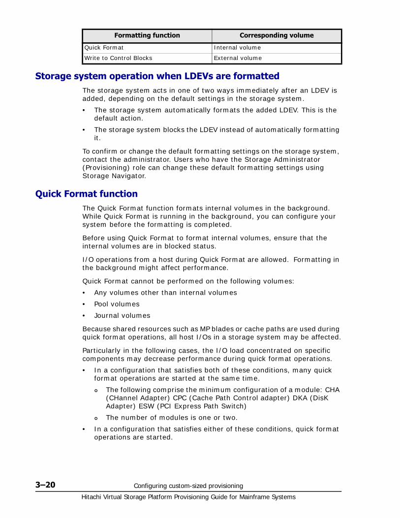
Hitachi Virtual Storage Platform Provisioning Guide for Mainframe Systems
3–20 Configuring custom-sized provisioning
Storage system operation when LDEVs are formattedThe storage system acts in one of two ways immediately after an LDEV is added, depending on the default settings in the storage system.
• The storage system automatically formats the added LDEV. This is the default action.
• The storage system blocks the LDEV instead of automatically formatting it.
To confirm or change the default formatting settings on the storage system, contact the administrator. Users who have the Storage Administrator (Provisioning) role can change these default formatting settings using Storage Navigator.
Quick Format functionThe Quick Format function formats internal volumes in the background. While Quick Format is running in the background, you can configure your system before the formatting is completed.
Before using Quick Format to format internal volumes, ensure that the internal volumes are in blocked status.
I/O operations from a host during Quick Format are allowed. Formatting in the background might affect performance.
Quick Format cannot be performed on the following volumes:
• Any volumes other than internal volumes
• Pool volumes
• Journal volumes
Because shared resources such as MP blades or cache paths are used during quick format operations, all host I/Os in a storage system may be affected.
Particularly in the following cases, the I/O load concentrated on specific components may decrease performance during quick format operations.
• In a configuration that satisfies both of these conditions, many quick format operations are started at the same time.
The following comprise the minimum configuration of a module: CHA (CHannel Adapter) CPC (Cache Path Control adapter) DKA (DisK Adapter) ESW (PCI Express Path Switch)
The number of modules is one or two.
• In a configuration that satisfies either of these conditions, quick format operations are started.
Quick Format Internal volume
Write to Control Blocks External volume
Formatting function Corresponding volume
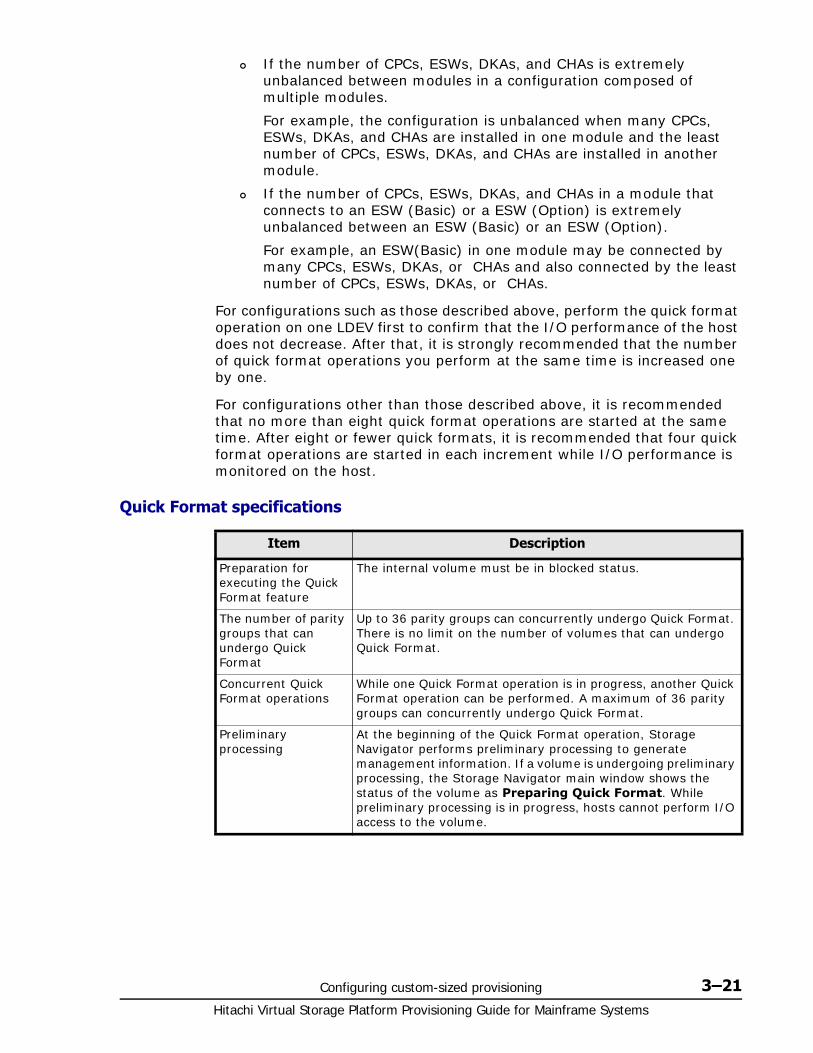
Configuring custom-sized provisioning 3–21Hitachi Virtual Storage Platform Provisioning Guide for Mainframe Systems
If the number of CPCs, ESWs, DKAs, and CHAs is extremely unbalanced between modules in a configuration composed of multiple modules.
For example, the configuration is unbalanced when many CPCs, ESWs, DKAs, and CHAs are installed in one module and the least number of CPCs, ESWs, DKAs, and CHAs are installed in another module.
If the number of CPCs, ESWs, DKAs, and CHAs in a module that connects to an ESW (Basic) or a ESW (Option) is extremely unbalanced between an ESW (Basic) or an ESW (Option).
For example, an ESW(Basic) in one module may be connected by many CPCs, ESWs, DKAs, or CHAs and also connected by the least number of CPCs, ESWs, DKAs, or CHAs.
For configurations such as those described above, perform the quick format operation on one LDEV first to confirm that the I/O performance of the host does not decrease. After that, it is strongly recommended that the number of quick format operations you perform at the same time is increased one by one.
For configurations other than those described above, it is recommended that no more than eight quick format operations are started at the same time. After eight or fewer quick formats, it is recommended that four quick format operations are started in each increment while I/O performance is monitored on the host.
Quick Format specifications
Item Description
Preparation for executing the Quick Format feature
The internal volume must be in blocked status.
The number of parity groups that can undergo Quick Format
Up to 36 parity groups can concurrently undergo Quick Format. There is no limit on the number of volumes that can undergo Quick Format.
Concurrent Quick Format operations
While one Quick Format operation is in progress, another Quick Format operation can be performed. A maximum of 36 parity groups can concurrently undergo Quick Format.
Preliminary processing
At the beginning of the Quick Format operation, Storage Navigator performs preliminary processing to generate management information. If a volume is undergoing preliminary processing, the Storage Navigator main window shows the status of the volume as Preparing Quick Format. While preliminary processing is in progress, hosts cannot perform I/O access to the volume.
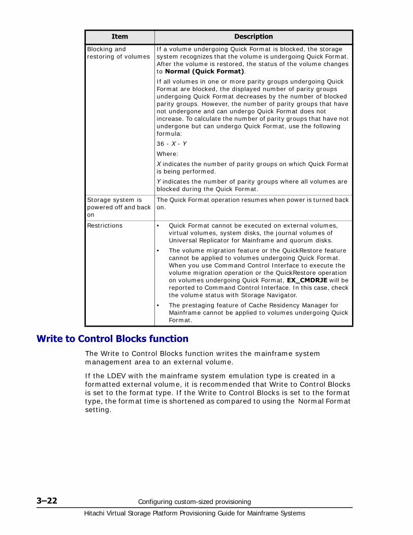
Hitachi Virtual Storage Platform Provisioning Guide for Mainframe Systems
3–22 Configuring custom-sized provisioning
Write to Control Blocks functionThe Write to Control Blocks function writes the mainframe system management area to an external volume.
If the LDEV with the mainframe system emulation type is created in a formatted external volume, it is recommended that Write to Control Blocks is set to the format type. If the Write to Control Blocks is set to the format type, the format time is shortened as compared to using the Normal Format setting.
Blocking and restoring of volumes
If a volume undergoing Quick Format is blocked, the storage system recognizes that the volume is undergoing Quick Format. After the volume is restored, the status of the volume changes to Normal (Quick Format).
If all volumes in one or more parity groups undergoing Quick Format are blocked, the displayed number of parity groups undergoing Quick Format decreases by the number of blocked parity groups. However, the number of parity groups that have not undergone and can undergo Quick Format does not increase. To calculate the number of parity groups that have not undergone but can undergo Quick Format, use the following formula:
36 - X - Y
Where:
X indicates the number of parity groups on which Quick Format is being performed.
Y indicates the number of parity groups where all volumes are blocked during the Quick Format.
Storage system is powered off and back on
The Quick Format operation resumes when power is turned back on.
Restrictions • Quick Format cannot be executed on external volumes, virtual volumes, system disks, the journal volumes of Universal Replicator for Mainframe and quorum disks.
• The volume migration feature or the QuickRestore feature cannot be applied to volumes undergoing Quick Format. When you use Command Control Interface to execute the volume migration operation or the QuickRestore operation on volumes undergoing Quick Format, EX_CMDRJE will be reported to Command Control Interface. In this case, check the volume status with Storage Navigator.
• The prestaging feature of Cache Residency Manager for Mainframe cannot be applied to volumes undergoing Quick Format.
Item Description
Configuring custom-sized provisioning 3–23Hitachi Virtual Storage Platform Provisioning Guide for Mainframe Systems
Before using this function, make sure that the external volumes have been formatted by the external storage system.
Formatting a specific LDEVThis procedure performs Normal formatting on the volume.
1. Select and block the LDEV to be formatted.
See Blocking an LDEV on page 3-17 for blocking an internal volume. See the Hitachi Universal Volume Manager User Guide for blocking an external volume.
2. To open the Format LDEVs window, click More Actions, then Format LDEVs from one of these tabs:
LDEVs tab, selected from the Logical Devices node of the Storage Systems tree.
Virtual Volumes tab, selected from a pool in the Pools node of the Storage Systems tree.
3. In the Format LDEVs window, select the format type from the Format Type list, and then click Finish.
4. In the Confirm window, click Apply.
If Go to tasks window for status is checked, the Tasks window opens.
Formatting all LDEVs in a parity groupThis procedure performs Normal formatting on the volume.
When formatting all LDEVs in a parity group, you will need to:
• Specify a parity group.
• Format the LDEV.
Before formatting all LDEVs in a parity group, make sure that all LDEVs under this parity group have been blocked.
See Blocking an LDEV on page 3-17 for blocking an internal volume. See the Hitachi Universal Volume Manager User Guide for blocking an external volume.
1. Select the parity group containing the LDEV to be formatted.
2. Click Format LDEVs.
3. In the Format LDEVs window, select the format type from the Format Type list, and then click Finish.
Caution: When it is uncertain whether the external LDEV has been formatted by an external storage system, select Normal Format to perform the format operation. If an option other than Normal Format is selected, the host may not have access to the formatted external LDEV.
To format the following LDEVs, select Normal Format as the format type:
• LDEV which was accessed by hosts
• LDEV on which the Write to Control Blocks function was performed
Hitachi Virtual Storage Platform Provisioning Guide for Mainframe Systems
3–24 Configuring custom-sized provisioning
In the Confirm window, click Next to go to the next operation.
4. Click Apply.
If Go to tasks window for status is checked, the Tasks window opens.
Making external mainframe system volumes usableTo use external mainframe volumes with a storage system, usually you must use Universal Volume Manager to perform external volume mapping, and then use the Format command of Virtual LVI to format the volumes. However, formatting the external mainframe system volumes in this way may take a lot of time.
If you want to make the external mainframe volumes usable more quickly, you can use an alternate method:
• Registering external volumes on page 3-24
• Overwriting control blocks in specific external volumes on page 3-25
Registering external volumesUsing this procedure, you can make the external mainframe system volumes usable more quickly.
When the external volume is disconnected, you cannot register the external volume.
1. Perform zero-formatting on the external mainframe system volumes.
Zero-formatting writes 0’s in the entire disk area, formatting the entire disk area. For information about how to perform zero-formatting, see the documentation for your mainframe system or external storage system.
2. Map the zero-formatted external volumes using Universal Volume Manager to register the volume in the external volume group. For more information, see the Hitachi Universal Volume Manager User Guide.
Non-zero-formatted external volumes must not be registered in the external groups. If the external volumes are registered, performing the next step (step 3) will block and disable the volumes to be read and written from the host. To make the non-zero-formatted external volumes usable with Virtual Storage Platform, use the Format command of Virtual LVI.
3. Specify the external volumes to overwrite the control blocks of the external volumes in the group (see Overwriting control blocks in specific external volumes on page 3-25). A control block, which is a kind of volume area, is used to store information other than the user's data. Only the storage administrator is authorized to overwrite the control blocks.
After overwriting completes, the external volumes are available for use in the storage system.
Configuring custom-sized provisioning 3–25Hitachi Virtual Storage Platform Provisioning Guide for Mainframe Systems
You can perform the following tasks while the LDEV is formatted, but only when the storage system is, by default, set to making the increased volumes blocked instead of formatting them automatically. For information about default settings of the storage system, see Overwriting control blocks in specific external volumes on page 3-25.
• Deleting LDEVs (converting LDEVs to the free space).
• Creating LDEVs.
Overwriting control blocks in specific external volumes1. Perform zero-formatting on the mainframe system volumes to register
them (see steps 1 and 2 in Registering external volumes on page 3-24).
2. In the Storage Systems tree, select External Storages.
The External Storage Systems tab appears.
3. Click the value of Vendor / Model / Serial Number of the external storage.
The External Path Groups tab appears.
4. Click the External Path Group ID.
The Mapped Volumes tab appears.
5. Select the row of the parity group that contains the external volume to be blocked, click More Actions and select Disconnect External Volumes.
For more details about the Disconnect External Volumes button, see the Hitachi Universal Volume Manager User Guide.
6. In the Storage Systems tree, click Parity Groups and External. Then select the parity group that contains the blocked external volume.
The LDEV tab appears. Confirm that Blocked appears in the Status column.
7. Select the target volumes from among the volumes with a status of Blocked and click Format LDEVs.
The Format LDEVs window appears.
8. From the Format Type list, select Write to Control Blocks, and click Finish.
9. In the Confirm window, click Apply.
If Go to tasks window for status is checked, the Tasks window opens.
10.When processing is complete, click OK.
11.Select the external volumes, then click More Actions and Reconnect External Volumes to restore them.
Normal displays in the Status column of the target volumes.
Hitachi Virtual Storage Platform Provisioning Guide for Mainframe Systems
3–26 Configuring custom-sized provisioning
Assigning a processor blade
Assigning a processor blade to a resourceYou can assign a processor blade to resources (logical devices, external volumes, and journal volumes).
1. In the Storage Navigator main window, in the Storage Systems tree, select Components.
2. In Components, select the name of the DKC for which you want to assign a processor blade.
Processor blades can be viewed in the Processor Blades tab.
3. Select a processor blade for which you want to change the settings, and then click Edit MP Blades.
4. In the Edit Processor Blades window, disable or enable Auto Assignment.
Select Enable if the processor blade can be automatically assigned. This is the default.
Select Disable if the processor blade cannot be automatically assigned.
5. Click Finish.
6. In the Confirm window, confirm the settings, in Task Name type a unique name for this task or accept the default, and then click Apply.
If Go to tasks window for status is checked, the Tasks window opens.
Changing the processor blade assigned to an LDEV1. In the Storage Navigator main window, in the Storage Systems tree,
select Logical Devices.
LDEVs are shown in the LDEVs tab.
2. Select the LDEV for which you want to change the processor blade.
3. Click More Actions, and then select Assign MP Blade.
4. In the Assign Processor Blade window, specify the processor blade in Processor Blade.
5. Click Finish.
6. In the Confirm window, confirm the settings, in Task Name type a unique name for this task or accept the default, and then click Apply.
Configuring custom-sized provisioning 3–27Hitachi Virtual Storage Platform Provisioning Guide for Mainframe Systems
If Go to tasks window for status is checked, the Tasks window opens.
Using a system diskA system disk is a special LDEV used in the storage system for specific purposes. A system disk is not required in a storage system, but is recommended for buffering of the audit log. A system disk should not be used for storing user data. After a system disk is created, the system knows what types of information the system disk is used for and all appropriate information is automatically sent to the system disk.
For example, when the system disk is used as an audit log buffer, you set parameters to enable the audit log buffer. The Audit Log feature recognizes the LDEV number of the system disk and then accesses it as a buffer. The system disk must have sufficient capacity to accommodate the audit log buffer. See the Hitachi Audit Log User Guide for more information about how to enable the audit log buffer.
To designate the system disk as the buffer area for audit logs, do one of the following:
• In the Audit Log Setting window, set Audit Log buffer to Enable.
• Set system option mode (SOM) 676 to ON.
You can create a system disk on either a mainframe or an open system. To create a system disk, you create an LDEV and then designate it as a system disk in the Create LDEVs wizard (see Creating an LDEV on page 3-11). The system disk designation prevents other storage system structures from accessing it. It is not available to hosts, or a command device, pool volume, journal, and so on. The system disk is part of one parity group. When an LDEV is defined as a system disk, the LDEV cannot be allocated to a port.
Caution:
• The processor blade assigned to the LDEV is used as a utility volume for Compatible XRC and can be changed only when the XRC session is suspended and the number of the side files of the target session is zero.
• Changes to the processor blade ID of an LDEV should be made during off-peak hours when the I/O load is as low as possible. Before and after changes are made, it is recommended that the cache write-pending rate (%) for all CLPRs is lower than 50%. Do not change the processor blade ID when the I/O load is high -- for example during an initial copy operation of ShadowImage for Mainframe, TrueCopy for Mainframe, or Universal Replicator for Mainframe.
• When you change the processor blade ID of an LDEV, you should use Performance Monitor before and after the change to check the load status of devices. Do not change several LDEV processor blade IDs during a short period of time. As a guideline, you can change 10% or less of the total number or the full workload of LDEV processor blade IDs assigned to the same processor blade ID at the same time.
• After you change the processor blade ID of an LDEV, wait more than 30 minutes before you try to change the ID again for the same LDEV.
Hitachi Virtual Storage Platform Provisioning Guide for Mainframe Systems
3–28 Configuring custom-sized provisioning
The buffering area capacity for the audit log buffer is: 130 MB, that is 185 cylinders if the track format is 3380-3 or NF80; 154 cylinders if the track format is 3390. Therefore, before using the audit log, make sure to prepare the system disk to have at minimum the above mentioned free capacity in the volume. The size of the system disk could be 1 GB if you want some spare capacity, or as large as 15 GB to accommodate the amount of system information that could be stored on it.
If you find you do not need a system disk, you can delete the system disk and convert the volume to free space (see Deleting an LDEV (converting to free space) on page 3-18).
System disk rules, restrictions, and guidelines
Rules• The minimum size of the system disk should be 130 MB in order to
accommodate audit log buffer information.
• When creating the system disk in the mainframe system volumes, assign the LDKC:CU:LDEV number that is not defined to the host's I/O generation.
• The LDKC:CU:LDEV number assigned to the system disk should be distinguishable from the one for a normal volume.
• Use the Delete LDEVs function to delete the system disk.
Restrictions• The system disk cannot be created on a DP-VOL.
• The system disk can be specified as any emulation type except 3390-V.
• A system disk cannot be used for any other function or connected to a port.
• Normal data cannot be stored on the system disk.
• The bind mode of Cache Residency Manager for Mainframe must not be set to the system disk.
• I/O cannot be issued from the host of the mainframe system. The device number is seen by the mainframe volume, but the device response is not operational. If an I/O is issued from a mainframe system host, a failure is reported as a CC=3 condition.
• The system disk should not be deleted or blocked while it is being used. Delete or block the system disk when it is not being used.
Guidelines• Although the system disk can be created in an external volume, it is best
to use only internal volumes.
• Although there can be up to 16 volumes of system disks created throughout the entire storage system, best practice is to have only one system disk per storage system.

Configuring custom-sized provisioning 3–29Hitachi Virtual Storage Platform Provisioning Guide for Mainframe Systems
• In a mixed configuration of open and mainframe system volumes in a storage system, it is best to select open volumes for the system disk.
• If you have more than one system disk on your storage system, and one of them is blocked, the unblocked system disks may not be usable. In this case, delete the blocked system disk, and then use the other normal system disks.

Hitachi Virtual Storage Platform Provisioning Guide for Mainframe Systems
3–30 Configuring custom-sized provisioning
4
Configuring thin provisioning 4–1Hitachi Virtual Storage Platform Provisioning Guide for Mainframe Systems
Configuring thin provisioning
Thin provisioning technology allows you to allocate virtual storage capacity based on anticipated future capacity needs, using virtual volumes instead of physical disks.
Thin provisioning is an optional provisioning strategy for both open and mainframe systems. Thin provisioning is implemented with Dynamic Provisioning for Mainframe by creating one or more Dynamic Provisioning for Mainframe pools (DP pools) of physical storage space.
□ Dynamic Provisioning for Mainframe overview
□ Dynamic Tiering for Mainframe overview
□ Thin provisioning requirements
□ Using Dynamic Provisioning for Mainframe or Dynamic Tiering for Mainframe with other VSP products
□ Dynamic Provisioning for Mainframe workflow
□ Dynamic Tiering for Mainframe
□ Changing a pool for Dynamic Tiering for Mainframe to a pool for Dynamic Provisioning for Mainframe
□ Working with pools
□ Working with DP-VOLs
□ Thresholds
□ Working with SIMs
□ Managing pools and DP-VOLs
Hitachi Virtual Storage Platform Provisioning Guide for Mainframe Systems
4–2 Configuring thin provisioning
Dynamic Provisioning for Mainframe overviewDynamic Provisioning for Mainframe is an advanced thin-provisioning software product that allows you to save money on storage purchases and reduce storage management expenses.
You can operate Dynamic Provisioning for Mainframe using both Storage Navigator software and the Command Control Interface.
Dynamic Tiering for Mainframe overviewDynamic Tiering for Mainframe is a software product that helps you reduce storage costs and increase storage performance by supporting a volume configured with different storage media of different cost and performance capabilities. This support allows you to allocate data areas with heavy I/O loads to higher-speed media and to allocate data areas with low I/O loads to lower-speed media. In this way, you can make the best use of the capabilities of installed storage media. Up to three storage tiers consisting of different types of data drives are supported in a single pool of storage.
Thin provisioning requirements
License requirementsBefore you operate Dynamic Provisioning for Mainframe, the Dynamic Provisioning and the Dynamic Provisioning for Mainframe program products must have been installed on the PC on which Storage Navigator has been installed. For this, you will need to purchase the Hitachi Basic Operating System Software (BOS) license.
Before you operate Dynamic Tiering for Mainframe, the Dynamic Provisioning, the Dynamic Provisioning for Mainframe, the Dynamic Tiering, and the Dynamic Tiering for Mainframe program products must have been installed. For this, you will need to purchase the Hitachi Dynamic Tiering software license and the Hitachi Basic Operating System Software (BOS) license.
You will need the Dynamic Tiering for Mainframe license for the total capacity of the pool for which the tier function is enabled.
If the V-VOL of Dynamic Provisioning for Mainframe or Dynamic Tiering for Mainframe are used for the P-VOLs and S-VOLs of ShadowImage for Mainframe, Compatible FlashCopy® V2, TrueCopy for Mainframe, or Universal Replicator for Mainframe, you will need the ShadowImage for Mainframe, TrueCopy for Mainframe, Compatible FlashCopy® V2, Universal Replicator for Mainframe license for the total pool capacity in use. In addition, if you assign a V-VOL of Dynamic Provisioning for Mainframe or Dynamic Tiering for Mainframe to the primary volume of Compatible XRC, you will need the Compatible XRC license for the total pool capacity in use by the related V-VOL.
If the DP-VOLs of Dynamic Provisioning for Mainframe or Dynamic Tiering for Mainframe are used for the P-VOLs and S-VOLs of ShadowImage for Mainframe, Compatible FlashCopy® V2, TrueCopy for Mainframe, or
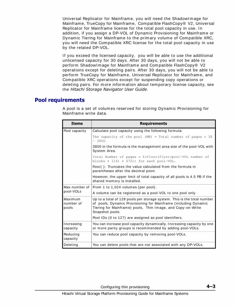
Configuring thin provisioning 4–3Hitachi Virtual Storage Platform Provisioning Guide for Mainframe Systems
Universal Replicator for Mainframe, you will need the ShadowImage for Mainframe, TrueCopy for Mainframe, Compatible FlashCopy® V2, Universal Replicator for Mainframe license for the total pool capacity in use. In addition, if you assign a DP-VOL of Dynamic Provisioning for Mainframe or Dynamic Tiering for Mainframe to the primary volume of Compatible XRC, you will need the Compatible XRC license for the total pool capacity in use by the related DP-VOL.
If you exceed the licensed capacity, you will be able to use the additional unlicensed capacity for 30 days. After 30 days, you will not be able to perform ShadowImage for Mainframe and Compatible FlashCopy® V2 operations except for deleting pairs. After 30 days, you will not be able to perform TrueCopy for Mainframe, Universal Replicator for Mainframe, and Compatible XRC operations except for suspending copy operations or deleting pairs. For more information about temporary license capacity, see the Hitachi Storage Navigator User Guide.
Pool requirementsA pool is a set of volumes reserved for storing Dynamic Provisioning for Mainframe write data.
Items Requirements
Pool capacity Calculate pool capacity using the following formula:
The capacity of the pool (MB) = Total number of pages × 38 - 3800.
3800 in the formula is the management area size of the pool-VOL with System Area.
Total Number of pages = Σ(floor(floor(pool-VOL number of blocks ÷ 116) ÷ 672)) for each pool-VOL.
floor( ): Truncates the value calculated from the formula in parentheses after the decimal point.
However, the upper limit of total capacity of all pools is 4.5 PB if the shared memory is installed.
Max number of pool-VOLs
From 1 to 1,024 volumes (per pool).
A volume can be registered as a pool-VOL to one pool only.
Maximum number of pools
Up to a total of 128 pools per storage system. This is the total number of pools, Dynamic Provisioning for Mainframe (including Dynamic Tiering for Mainframe) pools, Thin Image, and Copy-on-Write Snapshot pools.
Pool IDs (0 to 127) are assigned as pool identifiers.
Increasing capacity
You can increase pool capacity dynamically. Increasing capacity by one or more parity groups is recommended by adding pool-VOLs.
Reducing capacity
You can reduce pool capacity by removing pool-VOLs.
Deleting You can delete pools that are not associated with any DP-VOLs.
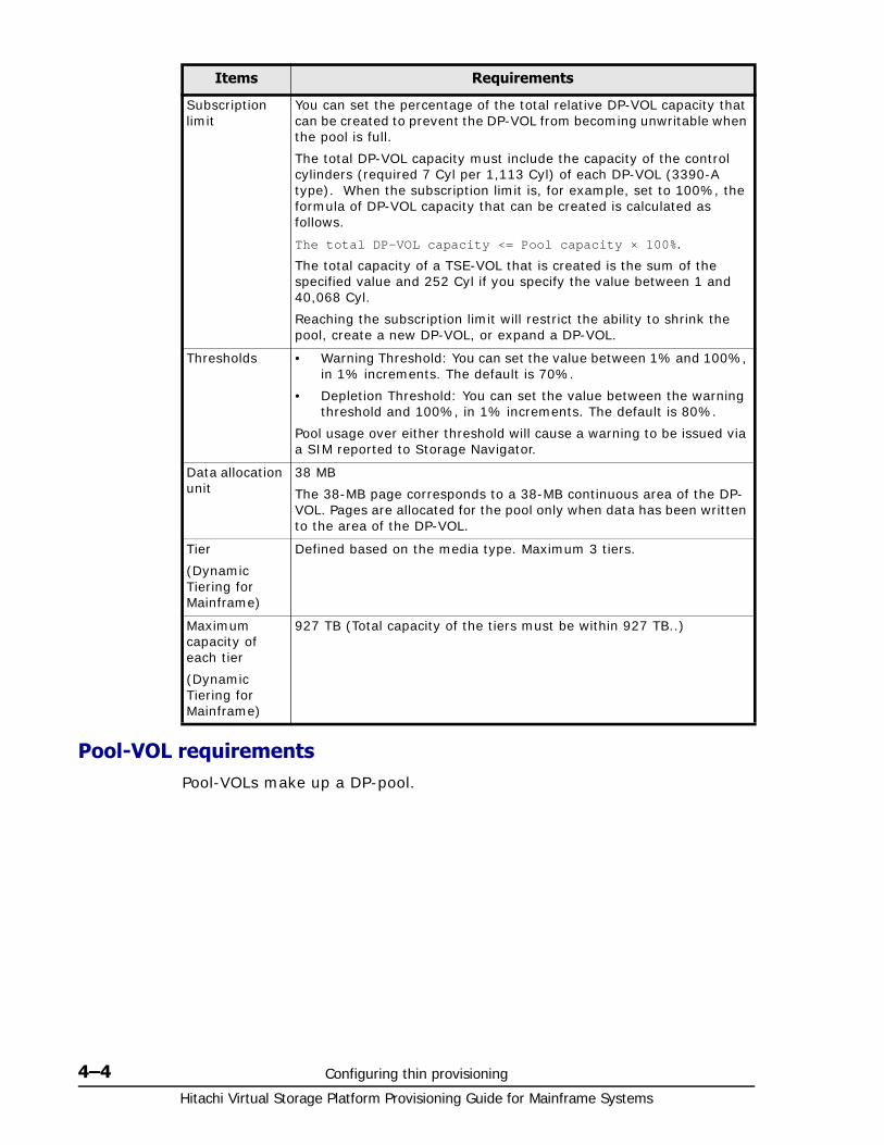
Hitachi Virtual Storage Platform Provisioning Guide for Mainframe Systems
4–4 Configuring thin provisioning
Pool-VOL requirementsPool-VOLs make up a DP-pool.
Subscription limit
You can set the percentage of the total relative DP-VOL capacity that can be created to prevent the DP-VOL from becoming unwritable when the pool is full.
The total DP-VOL capacity must include the capacity of the control cylinders (required 7 Cyl per 1,113 Cyl) of each DP-VOL (3390-A type). When the subscription limit is, for example, set to 100%, the formula of DP-VOL capacity that can be created is calculated as follows.
The total DP-VOL capacity <= Pool capacity × 100%.
The total capacity of a TSE-VOL that is created is the sum of the specified value and 252 Cyl if you specify the value between 1 and 40,068 Cyl.
Reaching the subscription limit will restrict the ability to shrink the pool, create a new DP-VOL, or expand a DP-VOL.
Thresholds • Warning Threshold: You can set the value between 1% and 100%, in 1% increments. The default is 70%.
• Depletion Threshold: You can set the value between the warning threshold and 100%, in 1% increments. The default is 80%.
Pool usage over either threshold will cause a warning to be issued via a SIM reported to Storage Navigator.
Data allocation unit
38 MB
The 38-MB page corresponds to a 38-MB continuous area of the DP-VOL. Pages are allocated for the pool only when data has been written to the area of the DP-VOL.
Tier
(Dynamic Tiering for Mainframe)
Defined based on the media type. Maximum 3 tiers.
Maximum capacity of each tier
(Dynamic Tiering for Mainframe)
927 TB (Total capacity of the tiers must be within 927 TB..)
Items Requirements
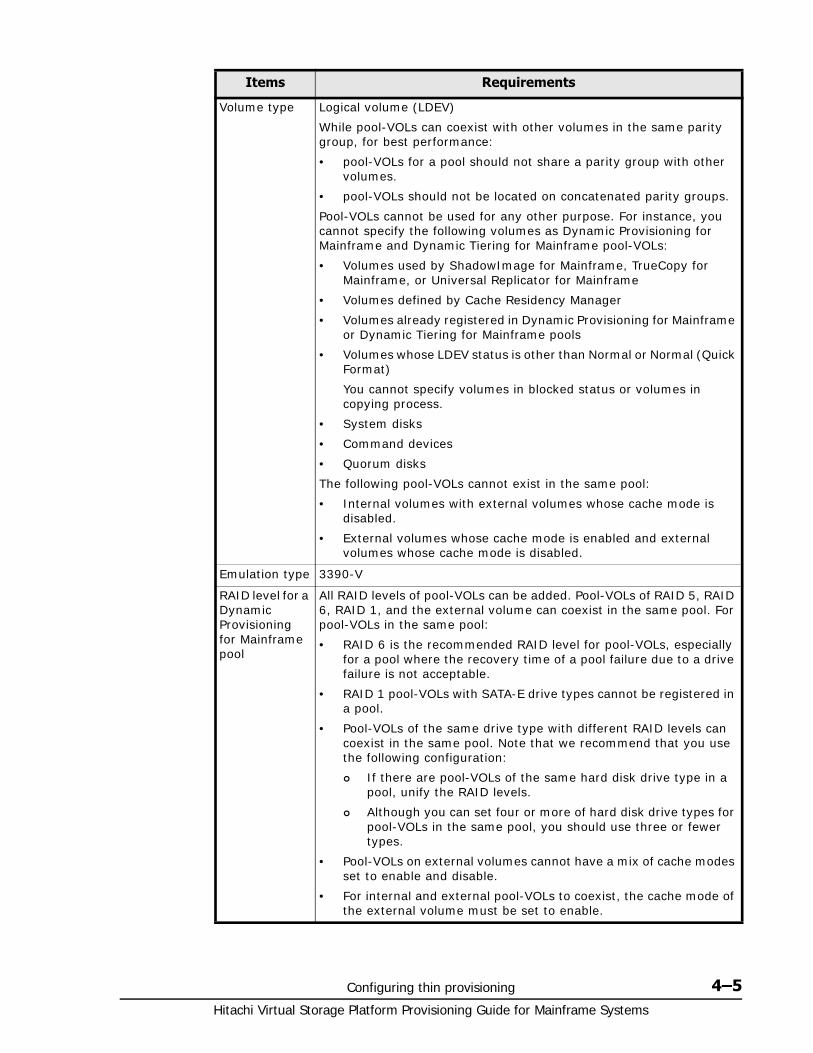
Configuring thin provisioning 4–5Hitachi Virtual Storage Platform Provisioning Guide for Mainframe Systems
Items Requirements
Volume type Logical volume (LDEV)
While pool-VOLs can coexist with other volumes in the same parity group, for best performance:
• pool-VOLs for a pool should not share a parity group with other volumes.
• pool-VOLs should not be located on concatenated parity groups.
Pool-VOLs cannot be used for any other purpose. For instance, you cannot specify the following volumes as Dynamic Provisioning for Mainframe and Dynamic Tiering for Mainframe pool-VOLs:
• Volumes used by ShadowImage for Mainframe, TrueCopy for Mainframe, or Universal Replicator for Mainframe
• Volumes defined by Cache Residency Manager
• Volumes already registered in Dynamic Provisioning for Mainframe or Dynamic Tiering for Mainframe pools
• Volumes whose LDEV status is other than Normal or Normal (Quick Format)
You cannot specify volumes in blocked status or volumes in copying process.
• System disks
• Command devices
• Quorum disks
The following pool-VOLs cannot exist in the same pool:
• Internal volumes with external volumes whose cache mode is disabled.
• External volumes whose cache mode is enabled and external volumes whose cache mode is disabled.
Emulation type 3390-V
RAID level for a Dynamic Provisioning for Mainframe pool
All RAID levels of pool-VOLs can be added. Pool-VOLs of RAID 5, RAID 6, RAID 1, and the external volume can coexist in the same pool. For pool-VOLs in the same pool:
• RAID 6 is the recommended RAID level for pool-VOLs, especially for a pool where the recovery time of a pool failure due to a drive failure is not acceptable.
• RAID 1 pool-VOLs with SATA-E drive types cannot be registered in a pool.
• Pool-VOLs of the same drive type with different RAID levels can coexist in the same pool. Note that we recommend that you use the following configuration:
If there are pool-VOLs of the same hard disk drive type in a pool, unify the RAID levels.
Although you can set four or more of hard disk drive types for pool-VOLs in the same pool, you should use three or fewer types.
• Pool-VOLs on external volumes cannot have a mix of cache modes set to enable and disable.
• For internal and external pool-VOLs to coexist, the cache mode of the external volume must be set to enable.
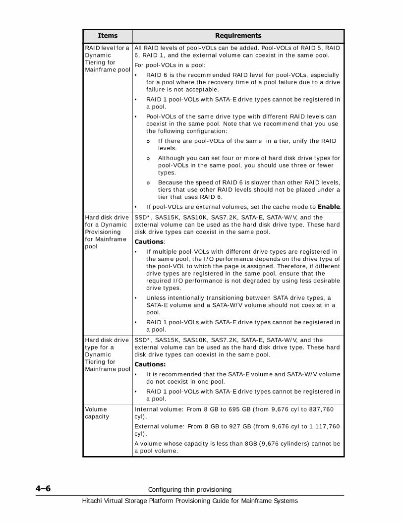
Hitachi Virtual Storage Platform Provisioning Guide for Mainframe Systems
4–6 Configuring thin provisioning
RAID level for a Dynamic Tiering for Mainframe pool
All RAID levels of pool-VOLs can be added. Pool-VOLs of RAID 5, RAID 6, RAID 1, and the external volume can coexist in the same pool.
For pool-VOLs in a pool:
• RAID 6 is the recommended RAID level for pool-VOLs, especially for a pool where the recovery time of a pool failure due to a drive failure is not acceptable.
• RAID 1 pool-VOLs with SATA-E drive types cannot be registered in a pool.
• Pool-VOLs of the same drive type with different RAID levels can coexist in the same pool. Note that we recommend that you use the following configuration:
If there are pool-VOLs of the same in a tier, unify the RAID levels.
Although you can set four or more of hard disk drive types for pool-VOLs in the same pool, you should use three or fewer types.
Because the speed of RAID 6 is slower than other RAID levels, tiers that use other RAID levels should not be placed under a tier that uses RAID 6.
• If pool-VOLs are external volumes, set the cache mode to Enable.
Hard disk drive for a Dynamic Provisioning for Mainframe pool
SSD*, SAS15K, SAS10K, SAS7.2K, SATA-E, SATA-W/V, and the external volume can be used as the hard disk drive type. These hard disk drive types can coexist in the same pool.
Cautions:
• If multiple pool-VOLs with different drive types are registered in the same pool, the I/O performance depends on the drive type of the pool-VOL to which the page is assigned. Therefore, if different drive types are registered in the same pool, ensure that the required I/O performance is not degraded by using less desirable drive types.
• Unless intentionally transitioning between SATA drive types, a SATA-E volume and a SATA-W/V volume should not coexist in a pool.
• RAID 1 pool-VOLs with SATA-E drive types cannot be registered in a pool.
Hard disk drive type for a Dynamic Tiering for Mainframe pool
SSD*, SAS15K, SAS10K, SAS7.2K, SATA-E, SATA-W/V, and the external volume can be used as the hard disk drive type. These hard disk drive types can coexist in the same pool.
Cautions:
• It is recommended that the SATA-E volume and SATA-W/V volume do not coexist in one pool.
• RAID 1 pool-VOLs with SATA-E drive types cannot be registered in a pool.
Volume capacity
Internal volume: From 8 GB to 695 GB (from 9,676 cyl to 837,760 cyl).
External volume: From 8 GB to 927 GB (from 9,676 cyl to 1,117,760 cyl).
A volume whose capacity is less than 8GB (9,676 cylinders) cannot be a pool volume.
Items Requirements
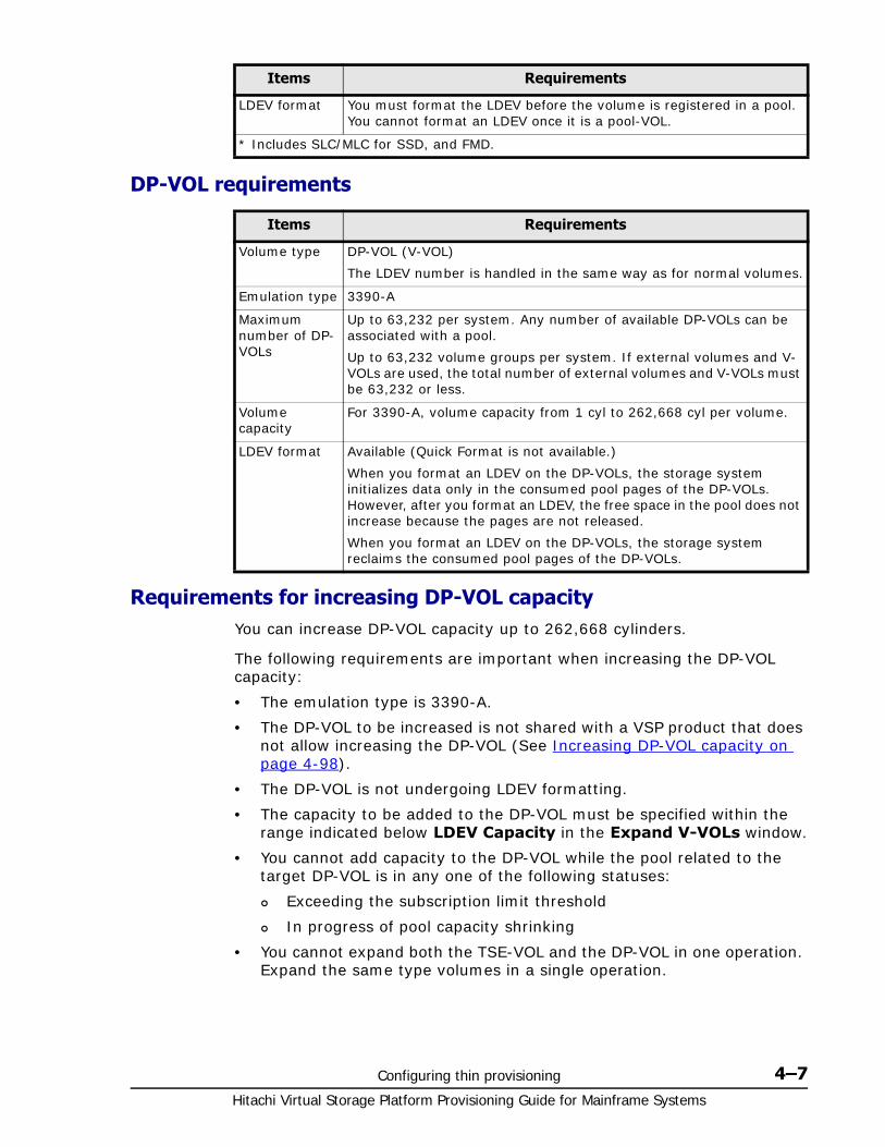
Configuring thin provisioning 4–7Hitachi Virtual Storage Platform Provisioning Guide for Mainframe Systems
DP-VOL requirements
Requirements for increasing DP-VOL capacityYou can increase DP-VOL capacity up to 262,668 cylinders.
The following requirements are important when increasing the DP-VOL capacity:
• The emulation type is 3390-A.
• The DP-VOL to be increased is not shared with a VSP product that does not allow increasing the DP-VOL (See Increasing DP-VOL capacity on page 4-98).
• The DP-VOL is not undergoing LDEV formatting.
• The capacity to be added to the DP-VOL must be specified within the range indicated below LDEV Capacity in the Expand V-VOLs window.
• You cannot add capacity to the DP-VOL while the pool related to the target DP-VOL is in any one of the following statuses:
Exceeding the subscription limit threshold
In progress of pool capacity shrinking
• You cannot expand both the TSE-VOL and the DP-VOL in one operation. Expand the same type volumes in a single operation.
LDEV format You must format the LDEV before the volume is registered in a pool. You cannot format an LDEV once it is a pool-VOL.
* Includes SLC/MLC for SSD, and FMD.
Items Requirements
Volume type DP-VOL (V-VOL)
The LDEV number is handled in the same way as for normal volumes.
Emulation type 3390-A
Maximum number of DP-VOLs
Up to 63,232 per system. Any number of available DP-VOLs can be associated with a pool.
Up to 63,232 volume groups per system. If external volumes and V-VOLs are used, the total number of external volumes and V-VOLs must be 63,232 or less.
Volume capacity
For 3390-A, volume capacity from 1 cyl to 262,668 cyl per volume.
LDEV format Available (Quick Format is not available.)
When you format an LDEV on the DP-VOLs, the storage system initializes data only in the consumed pool pages of the DP-VOLs. However, after you format an LDEV, the free space in the pool does not increase because the pages are not released.
When you format an LDEV on the DP-VOLs, the storage system reclaims the consumed pool pages of the DP-VOLs.
Items Requirements
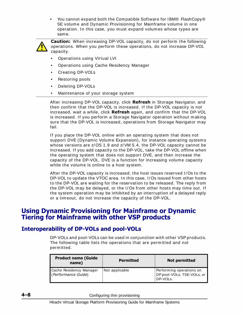
Hitachi Virtual Storage Platform Provisioning Guide for Mainframe Systems
4–8 Configuring thin provisioning
• You cannot expand both the Compatible Software for IBM® FlashCopy® SE volume and Dynamic Provisioning for Mainframe volume in one operation. In this case, you must expand volumes whose types are same.
After increasing DP-VOL capacity, click Refresh in Storage Navigator, and then confirm that the DP-VOL is increased. If the DP-VOL capacity is not increased, wait a while, click Refresh again, and confirm that the DP-VOL is increased. If you perform a Storage Navigator operation without making sure that the DP-VOL is increased, operations from Storage Navigator may fail.
If you place the DP-VOL online with an operating system that does not support DVE (Dynamic Volume Expansion), for instance operating systems whose versions are z/OS 1.9 and z/VM 5.4, the DP-VOL capacity cannot be increased. If you add capacity to the DP-VOL, take the DP-VOL offline when the operating system that does not support DVE, and then increase the capacity of the DP-VOL. DVE is a function for increasing volume capacity while the volume is online to a host system.
After the DP-VOL capacity is increased, the host issues reserved I/Os to the DP-VOL to update the VTOC area. In this case, I/Os issued from other hosts to the DP-VOL are waiting for the reservation to be released. The reply from the DP-VOL may be delayed, or the I/Os from other hosts may time out. If the system operation may be inhibited by an interruption of a delayed reply or a timeout, do not increase the capacity of the DP-VOL.
Using Dynamic Provisioning for Mainframe or Dynamic Tiering for Mainframe with other VSP products
Interoperability of DP-VOLs and pool-VOLsDP-VOLs and pool-VOLs can be used in conjunction with other VSP products. The following table lists the operations that are permitted and not permitted.
Caution: When increasing DP-VOL capacity, do not perform the following operations. When you perform these operations, do not increase DP-VOL capacity.
• Operations using Virtual LVI
• Operations using Cache Residency Manager
• Creating DP-VOLs
• Restoring pools
• Deleting DP-VOLs
• Maintenance of your storage system
Product name (Guide name) Permitted Not permitted
Cache Residency Manager (Performance Guide)
Not applicable Performing operations on DP pool-VOLs, TSE-VOLs, or DP-VOLs.
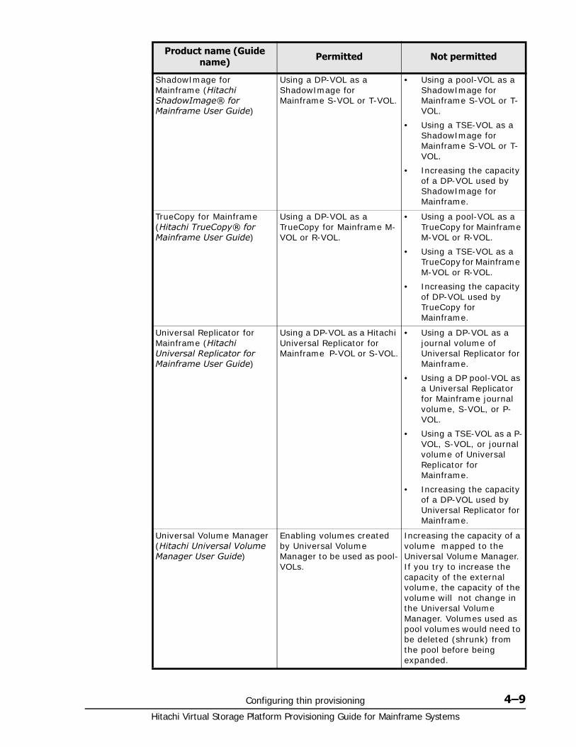
Configuring thin provisioning 4–9Hitachi Virtual Storage Platform Provisioning Guide for Mainframe Systems
ShadowImage for Mainframe (Hitachi ShadowImage® for Mainframe User Guide)
Using a DP-VOL as a ShadowImage for Mainframe S-VOL or T-VOL.
• Using a pool-VOL as a ShadowImage for Mainframe S-VOL or T-VOL.
• Using a TSE-VOL as a ShadowImage for Mainframe S-VOL or T-VOL.
• Increasing the capacity of a DP-VOL used by ShadowImage for Mainframe.
TrueCopy for Mainframe (Hitachi TrueCopy® for Mainframe User Guide)
Using a DP-VOL as a TrueCopy for Mainframe M-VOL or R-VOL.
• Using a pool-VOL as a TrueCopy for Mainframe M-VOL or R-VOL.
• Using a TSE-VOL as a TrueCopy for Mainframe M-VOL or R-VOL.
• Increasing the capacity of DP-VOL used by TrueCopy for Mainframe.
Universal Replicator for Mainframe (Hitachi Universal Replicator for Mainframe User Guide)
Using a DP-VOL as a Hitachi Universal Replicator for Mainframe P-VOL or S-VOL.
• Using a DP-VOL as a journal volume of Universal Replicator for Mainframe.
• Using a DP pool-VOL as a Universal Replicator for Mainframe journal volume, S-VOL, or P-VOL.
• Using a TSE-VOL as a P-VOL, S-VOL, or journal volume of Universal Replicator for Mainframe.
• Increasing the capacity of a DP-VOL used by Universal Replicator for Mainframe.
Universal Volume Manager (Hitachi Universal Volume Manager User Guide)
Enabling volumes created by Universal Volume Manager to be used as pool-VOLs.
Increasing the capacity of a volume mapped to the Universal Volume Manager. If you try to increase the capacity of the external volume, the capacity of the volume will not change in the Universal Volume Manager. Volumes used as pool volumes would need to be deleted (shrunk) from the pool before being expanded.
Product name (Guide name) Permitted Not permitted
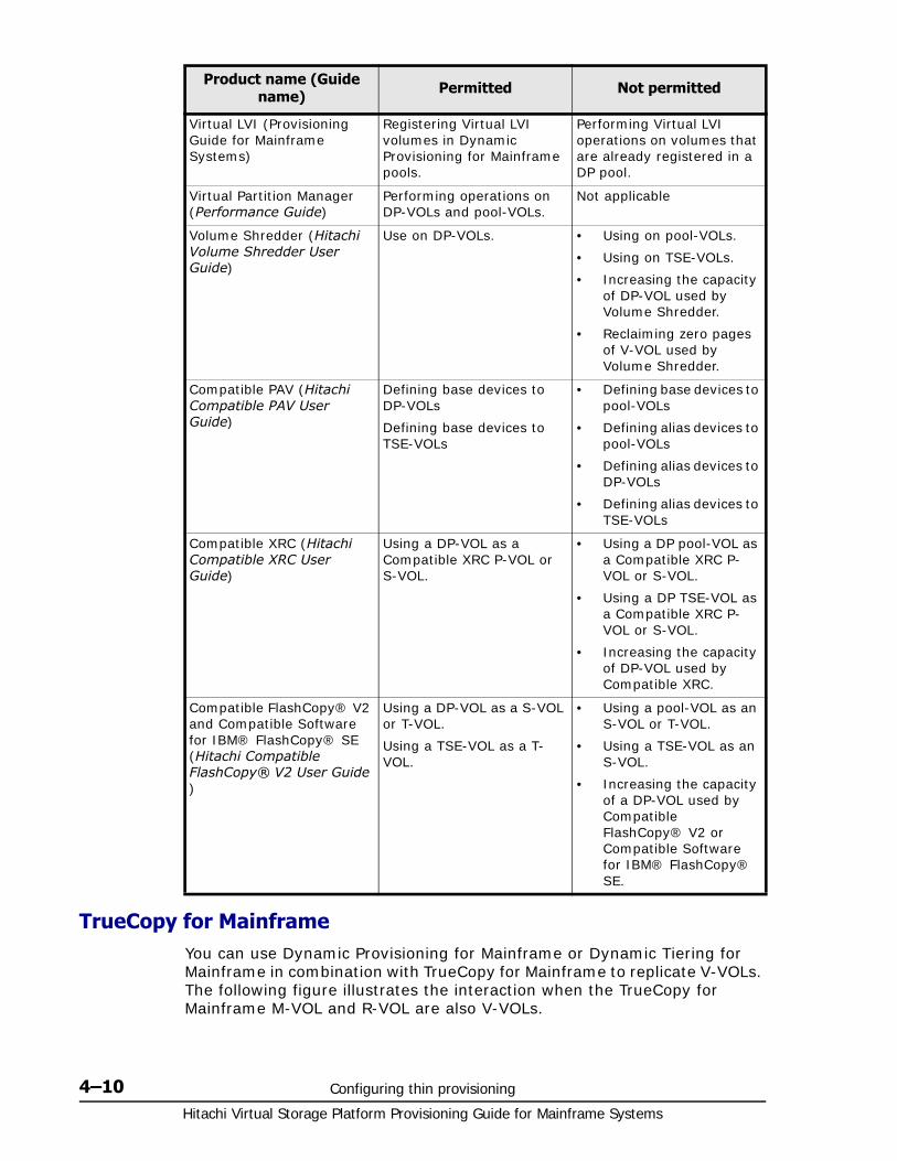
Hitachi Virtual Storage Platform Provisioning Guide for Mainframe Systems
4–10 Configuring thin provisioning
TrueCopy for MainframeYou can use Dynamic Provisioning for Mainframe or Dynamic Tiering for Mainframe in combination with TrueCopy for Mainframe to replicate V-VOLs. The following figure illustrates the interaction when the TrueCopy for Mainframe M-VOL and R-VOL are also V-VOLs.
Virtual LVI (Provisioning Guide for Mainframe Systems)
Registering Virtual LVI volumes in Dynamic Provisioning for Mainframe pools.
Performing Virtual LVI operations on volumes that are already registered in a DP pool.
Virtual Partition Manager (Performance Guide)
Performing operations on DP-VOLs and pool-VOLs.
Not applicable
Volume Shredder (Hitachi Volume Shredder User Guide)
Use on DP-VOLs. • Using on pool-VOLs.
• Using on TSE-VOLs.
• Increasing the capacity of DP-VOL used by Volume Shredder.
• Reclaiming zero pages of V-VOL used by Volume Shredder.
Compatible PAV (Hitachi Compatible PAV User Guide)
Defining base devices to DP-VOLs
Defining base devices to TSE-VOLs
• Defining base devices to pool-VOLs
• Defining alias devices to pool-VOLs
• Defining alias devices to DP-VOLs
• Defining alias devices to TSE-VOLs
Compatible XRC (Hitachi Compatible XRC User Guide)
Using a DP-VOL as a Compatible XRC P-VOL or S-VOL.
• Using a DP pool-VOL as a Compatible XRC P-VOL or S-VOL.
• Using a DP TSE-VOL as a Compatible XRC P-VOL or S-VOL.
• Increasing the capacity of DP-VOL used by Compatible XRC.
Compatible FlashCopy® V2 and Compatible Software for IBM® FlashCopy® SE (Hitachi Compatible FlashCopy® V2 User Guide )
Using a DP-VOL as a S-VOL or T-VOL.
Using a TSE-VOL as a T-VOL.
• Using a pool-VOL as an S-VOL or T-VOL.
• Using a TSE-VOL as an S-VOL.
• Increasing the capacity of a DP-VOL used by Compatible FlashCopy® V2 or Compatible Software for IBM® FlashCopy® SE.
Product name (Guide name) Permitted Not permitted
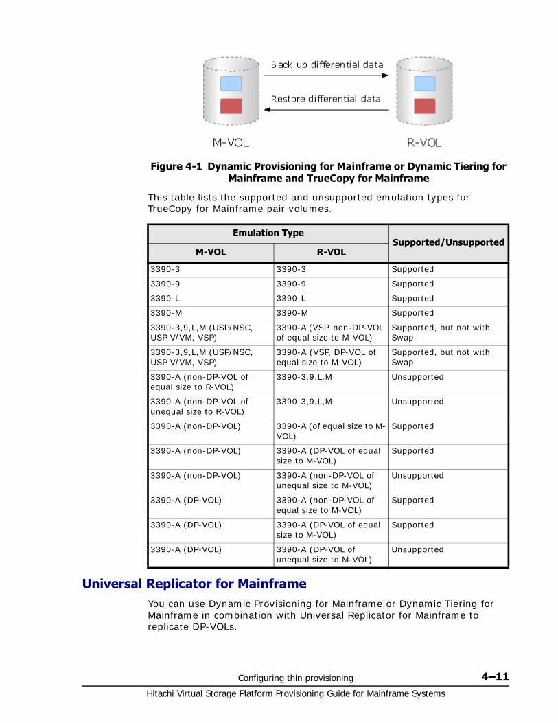
Configuring thin provisioning 4–11Hitachi Virtual Storage Platform Provisioning Guide for Mainframe Systems
This table lists the supported and unsupported emulation types for TrueCopy for Mainframe pair volumes.
Universal Replicator for MainframeYou can use Dynamic Provisioning for Mainframe or Dynamic Tiering for Mainframe in combination with Universal Replicator for Mainframe to replicate DP-VOLs.
Figure 4-1 Dynamic Provisioning for Mainframe or Dynamic Tiering for Mainframe and TrueCopy for Mainframe
Emulation TypeSupported/Unsupported
M-VOL R-VOL
3390-3 3390-3 Supported
3390-9 3390-9 Supported
3390-L 3390-L Supported
3390-M 3390-M Supported
3390-3,9,L,M (USP/NSC, USP V/VM, VSP)
3390-A (VSP, non-DP-VOL of equal size to M-VOL)
Supported, but not with Swap
3390-3,9,L,M (USP/NSC, USP V/VM, VSP)
3390-A (VSP, DP-VOL of equal size to M-VOL)
Supported, but not with Swap
3390-A (non-DP-VOL of equal size to R-VOL)
3390-3,9,L,M Unsupported
3390-A (non-DP-VOL of unequal size to R-VOL)
3390-3,9,L,M Unsupported
3390-A (non-DP-VOL) 3390-A (of equal size to M-VOL)
Supported
3390-A (non-DP-VOL) 3390-A (DP-VOL of equal size to M-VOL)
Supported
3390-A (non-DP-VOL) 3390-A (non-DP-VOL of unequal size to M-VOL)
Unsupported
3390-A (DP-VOL) 3390-A (non-DP-VOL of equal size to M-VOL)
Supported
3390-A (DP-VOL) 3390-A (DP-VOL of equal size to M-VOL)
Supported
3390-A (DP-VOL) 3390-A (DP-VOL of unequal size to M-VOL)
Unsupported
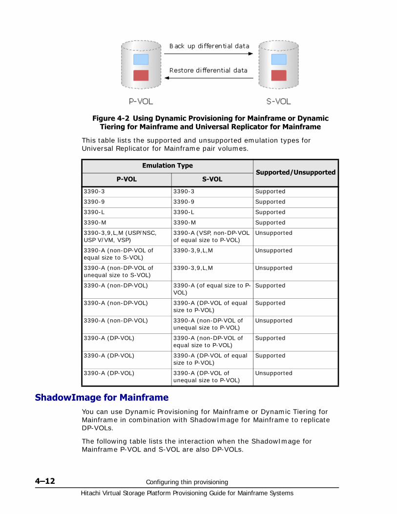
Hitachi Virtual Storage Platform Provisioning Guide for Mainframe Systems
4–12 Configuring thin provisioning
This table lists the supported and unsupported emulation types for Universal Replicator for Mainframe pair volumes.
ShadowImage for MainframeYou can use Dynamic Provisioning for Mainframe or Dynamic Tiering for Mainframe in combination with ShadowImage for Mainframe to replicate DP-VOLs.
The following table lists the interaction when the ShadowImage for Mainframe P-VOL and S-VOL are also DP-VOLs.
Figure 4-2 Using Dynamic Provisioning for Mainframe or Dynamic Tiering for Mainframe and Universal Replicator for Mainframe
Emulation TypeSupported/Unsupported
P-VOL S-VOL
3390-3 3390-3 Supported
3390-9 3390-9 Supported
3390-L 3390-L Supported
3390-M 3390-M Supported
3390-3,9,L,M (USP/NSC, USP V/VM, VSP)
3390-A (VSP, non-DP-VOL of equal size to P-VOL)
Unsupported
3390-A (non-DP-VOL of equal size to S-VOL)
3390-3,9,L,M Unsupported
3390-A (non-DP-VOL of unequal size to S-VOL)
3390-3,9,L,M Unsupported
3390-A (non-DP-VOL) 3390-A (of equal size to P-VOL)
Supported
3390-A (non-DP-VOL) 3390-A (DP-VOL of equal size to P-VOL)
Supported
3390-A (non-DP-VOL) 3390-A (non-DP-VOL of unequal size to P-VOL)
Unsupported
3390-A (DP-VOL) 3390-A (non-DP-VOL of equal size to P-VOL)
Supported
3390-A (DP-VOL) 3390-A (DP-VOL of equal size to P-VOL)
Supported
3390-A (DP-VOL) 3390-A (DP-VOL of unequal size to P-VOL)
Unsupported
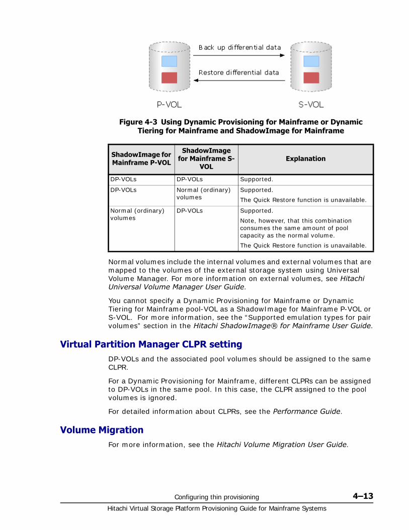
Configuring thin provisioning 4–13Hitachi Virtual Storage Platform Provisioning Guide for Mainframe Systems
Normal volumes include the internal volumes and external volumes that are mapped to the volumes of the external storage system using Universal Volume Manager. For more information on external volumes, see Hitachi Universal Volume Manager User Guide.
You cannot specify a Dynamic Provisioning for Mainframe or Dynamic Tiering for Mainframe pool-VOL as a ShadowImage for Mainframe P-VOL or S-VOL. For more information, see the “Supported emulation types for pair volumes” section in the Hitachi ShadowImage® for Mainframe User Guide.
Virtual Partition Manager CLPR settingDP-VOLs and the associated pool volumes should be assigned to the same CLPR.
For a Dynamic Provisioning for Mainframe, different CLPRs can be assigned to DP-VOLs in the same pool. In this case, the CLPR assigned to the pool volumes is ignored.
For detailed information about CLPRs, see the Performance Guide.
Volume MigrationFor more information, see the Hitachi Volume Migration User Guide.
Figure 4-3 Using Dynamic Provisioning for Mainframe or Dynamic Tiering for Mainframe and ShadowImage for Mainframe
ShadowImage for Mainframe P-VOL
ShadowImage for Mainframe S-
VOLExplanation
DP-VOLs DP-VOLs Supported.
DP-VOLs Normal (ordinary) volumes
Supported.
The Quick Restore function is unavailable.
Normal (ordinary) volumes
DP-VOLs Supported.
Note, however, that this combination consumes the same amount of pool capacity as the normal volume.
The Quick Restore function is unavailable.
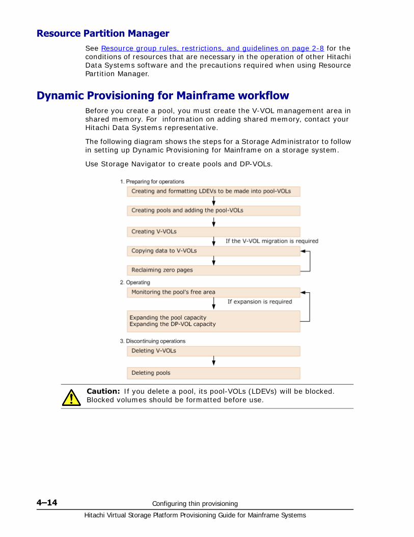
Hitachi Virtual Storage Platform Provisioning Guide for Mainframe Systems
4–14 Configuring thin provisioning
Resource Partition ManagerSee Resource group rules, restrictions, and guidelines on page 2-8 for the conditions of resources that are necessary in the operation of other Hitachi Data Systems software and the precautions required when using Resource Partition Manager.
Dynamic Provisioning for Mainframe workflowBefore you create a pool, you must create the V-VOL management area in shared memory. For information on adding shared memory, contact your Hitachi Data Systems representative.
The following diagram shows the steps for a Storage Administrator to follow in setting up Dynamic Provisioning for Mainframe on a storage system.
Use Storage Navigator to create pools and DP-VOLs.
Caution: If you delete a pool, its pool-VOLs (LDEVs) will be blocked. Blocked volumes should be formatted before use.
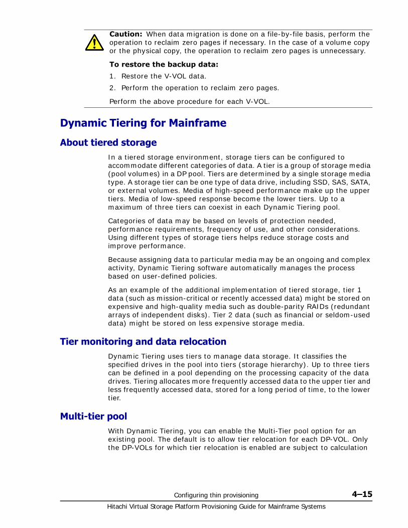
Configuring thin provisioning 4–15Hitachi Virtual Storage Platform Provisioning Guide for Mainframe Systems
Dynamic Tiering for Mainframe
About tiered storageIn a tiered storage environment, storage tiers can be configured to accommodate different categories of data. A tier is a group of storage media (pool volumes) in a DP pool. Tiers are determined by a single storage media type. A storage tier can be one type of data drive, including SSD, SAS, SATA, or external volumes. Media of high-speed performance make up the upper tiers. Media of low-speed response become the lower tiers. Up to a maximum of three tiers can coexist in each Dynamic Tiering pool.
Categories of data may be based on levels of protection needed, performance requirements, frequency of use, and other considerations. Using different types of storage tiers helps reduce storage costs and improve performance.
Because assigning data to particular media may be an ongoing and complex activity, Dynamic Tiering software automatically manages the process based on user-defined policies.
As an example of the additional implementation of tiered storage, tier 1 data (such as mission-critical or recently accessed data) might be stored on expensive and high-quality media such as double-parity RAIDs (redundant arrays of independent disks). Tier 2 data (such as financial or seldom-used data) might be stored on less expensive storage media.
Tier monitoring and data relocationDynamic Tiering uses tiers to manage data storage. It classifies the specified drives in the pool into tiers (storage hierarchy). Up to three tiers can be defined in a pool depending on the processing capacity of the data drives. Tiering allocates more frequently accessed data to the upper tier and less frequently accessed data, stored for a long period of time, to the lower tier.
Multi-tier poolWith Dynamic Tiering, you can enable the Multi-Tier pool option for an existing pool. The default is to allow tier relocation for each DP-VOL. Only the DP-VOLs for which tier relocation is enabled are subject to calculation
Caution: When data migration is done on a file-by-file basis, perform the operation to reclaim zero pages if necessary. In the case of a volume copy or the physical copy, the operation to reclaim zero pages is unnecessary.
To restore the backup data:
1. Restore the V-VOL data.
2. Perform the operation to reclaim zero pages.
Perform the above procedure for each V-VOL.
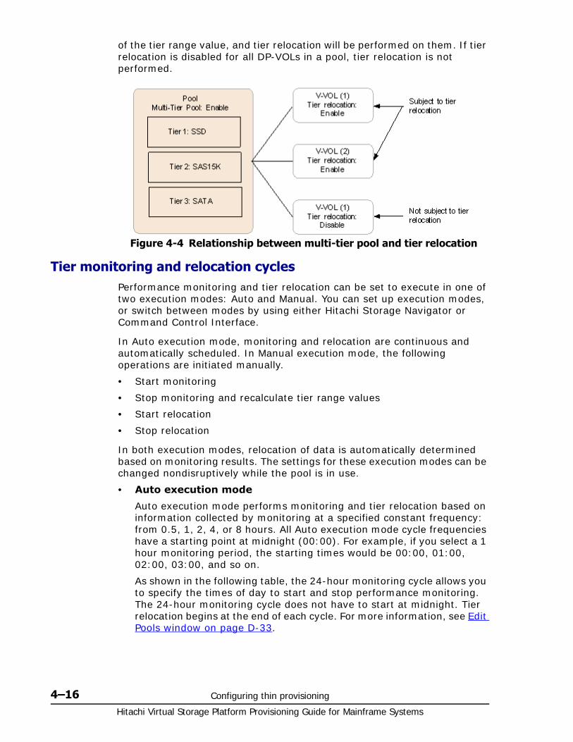
Hitachi Virtual Storage Platform Provisioning Guide for Mainframe Systems
4–16 Configuring thin provisioning
of the tier range value, and tier relocation will be performed on them. If tier relocation is disabled for all DP-VOLs in a pool, tier relocation is not performed.
Tier monitoring and relocation cyclesPerformance monitoring and tier relocation can be set to execute in one of two execution modes: Auto and Manual. You can set up execution modes, or switch between modes by using either Hitachi Storage Navigator or Command Control Interface.
In Auto execution mode, monitoring and relocation are continuous and automatically scheduled. In Manual execution mode, the following operations are initiated manually.
• Start monitoring
• Stop monitoring and recalculate tier range values
• Start relocation
• Stop relocation
In both execution modes, relocation of data is automatically determined based on monitoring results. The settings for these execution modes can be changed nondisruptively while the pool is in use.
• Auto execution mode
Auto execution mode performs monitoring and tier relocation based on information collected by monitoring at a specified constant frequency: from 0.5, 1, 2, 4, or 8 hours. All Auto execution mode cycle frequencies have a starting point at midnight (00:00). For example, if you select a 1 hour monitoring period, the starting times would be 00:00, 01:00, 02:00, 03:00, and so on.
As shown in the following table, the 24-hour monitoring cycle allows you to specify the times of day to start and stop performance monitoring. The 24-hour monitoring cycle does not have to start at midnight. Tier relocation begins at the end of each cycle. For more information, see Edit Pools window on page D-33.
Figure 4-4 Relationship between multi-tier pool and tier relocation
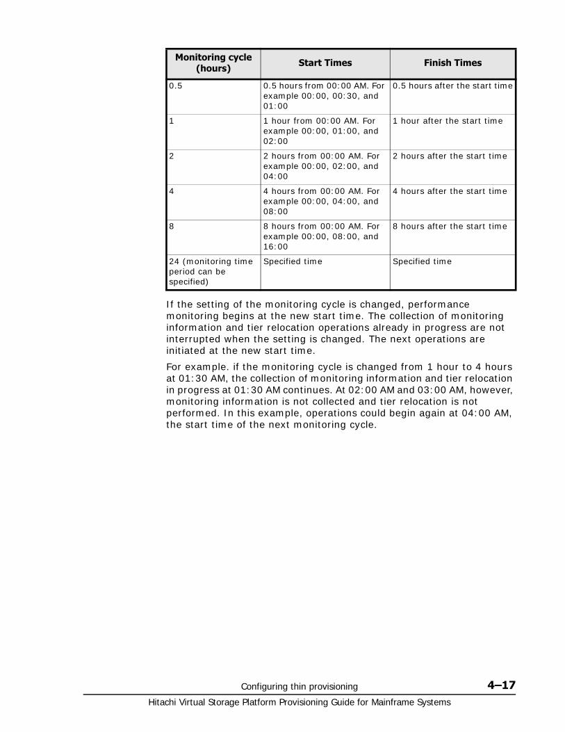
Configuring thin provisioning 4–17Hitachi Virtual Storage Platform Provisioning Guide for Mainframe Systems
If the setting of the monitoring cycle is changed, performance monitoring begins at the new start time. The collection of monitoring information and tier relocation operations already in progress are not interrupted when the setting is changed. The next operations are initiated at the new start time.
For example. if the monitoring cycle is changed from 1 hour to 4 hours at 01:30 AM, the collection of monitoring information and tier relocation in progress at 01:30 AM continues. At 02:00 AM and 03:00 AM, however, monitoring information is not collected and tier relocation is not performed. In this example, operations could begin again at 04:00 AM, the start time of the next monitoring cycle.
Monitoring cycle (hours) Start Times Finish Times
0.5 0.5 hours from 00:00 AM. For example 00:00, 00:30, and 01:00
0.5 hours after the start time
1 1 hour from 00:00 AM. For example 00:00, 01:00, and 02:00
1 hour after the start time
2 2 hours from 00:00 AM. For example 00:00, 02:00, and 04:00
2 hours after the start time
4 4 hours from 00:00 AM. For example 00:00, 04:00, and 08:00
4 hours after the start time
8 8 hours from 00:00 AM. For example 00:00, 08:00, and 16:00
8 hours after the start time
24 (monitoring time period can be specified)
Specified time Specified time
Hitachi Virtual Storage Platform Provisioning Guide for Mainframe Systems
4–18 Configuring thin provisioning
In auto execution mode, the collection of monitoring data and tier relocation operations are performed in parallel in the next cycle. Data from these parallel processes are stored in two separate fields.
• Data while monitoring is in progress in the next cycle.
• Fixed monitoring information used in tier reliocation.
• Manual execution mode
You can start and stop performance monitoring and tier relocation at any time. You should keep the duration of performance monitoring to less than 7 days (168 hours). If performance monitoring exceeds 7 days, then monitoring stops automatically.
Manual execution mode starts and ends monitoring and relocation at the time the command is issued from Storage Navigator or CCI. You can use scripts, which provide flexibility to control monitoring and relocation tasks based on a schedule for each day of the week.
In manual execution mode, the next monitoring cycle can be started with the collection of monitoring data and tier relocation operations performed in parallel. Data from these parallel processes are stored in two separate fields.
Data while monitoring is in progress in the next cycle.
Fixed monitoring information used in tier reliocation.
Figure 4-5 Collection of monitoring data to tier relocation workflow in auto execution mode
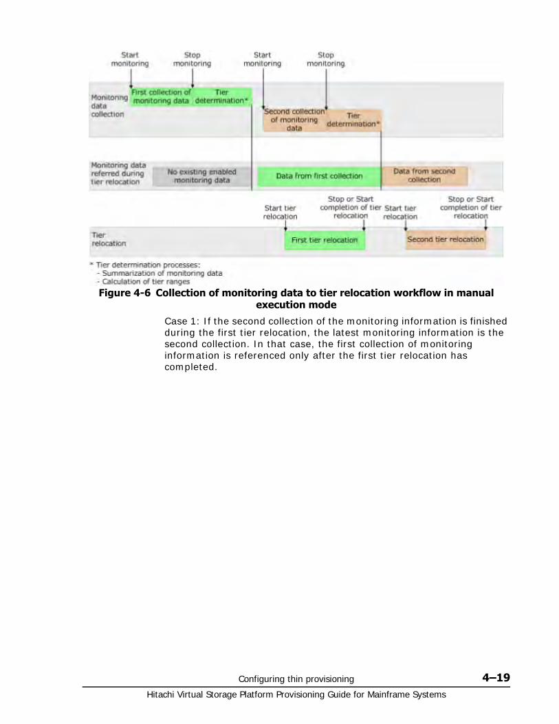
Configuring thin provisioning 4–19Hitachi Virtual Storage Platform Provisioning Guide for Mainframe Systems
Case 1: If the second collection of the monitoring information is finished during the first tier relocation, the latest monitoring information is the second collection. In that case, the first collection of monitoring information is referenced only after the first tier relocation has completed.
Figure 4-6 Collection of monitoring data to tier relocation workflow in manual execution mode
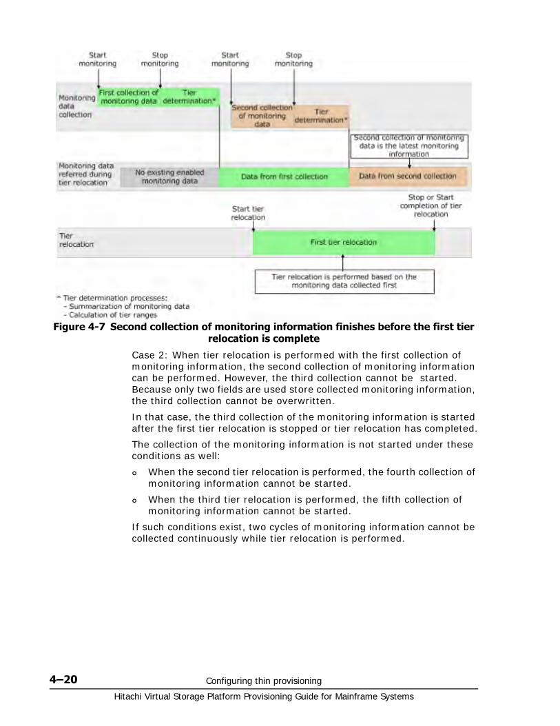
Hitachi Virtual Storage Platform Provisioning Guide for Mainframe Systems
4–20 Configuring thin provisioning
Case 2: When tier relocation is performed with the first collection of monitoring information, the second collection of monitoring information can be performed. However, the third collection cannot be started. Because only two fields are used store collected monitoring information, the third collection cannot be overwritten.
In that case, the third collection of the monitoring information is started after the first tier relocation is stopped or tier relocation has completed.
The collection of the monitoring information is not started under these conditions as well:
When the second tier relocation is performed, the fourth collection of monitoring information cannot be started.
When the third tier relocation is performed, the fifth collection of monitoring information cannot be started.
If such conditions exist, two cycles of monitoring information cannot be collected continuously while tier relocation is performed.
Figure 4-7 Second collection of monitoring information finishes before the first tier relocation is complete
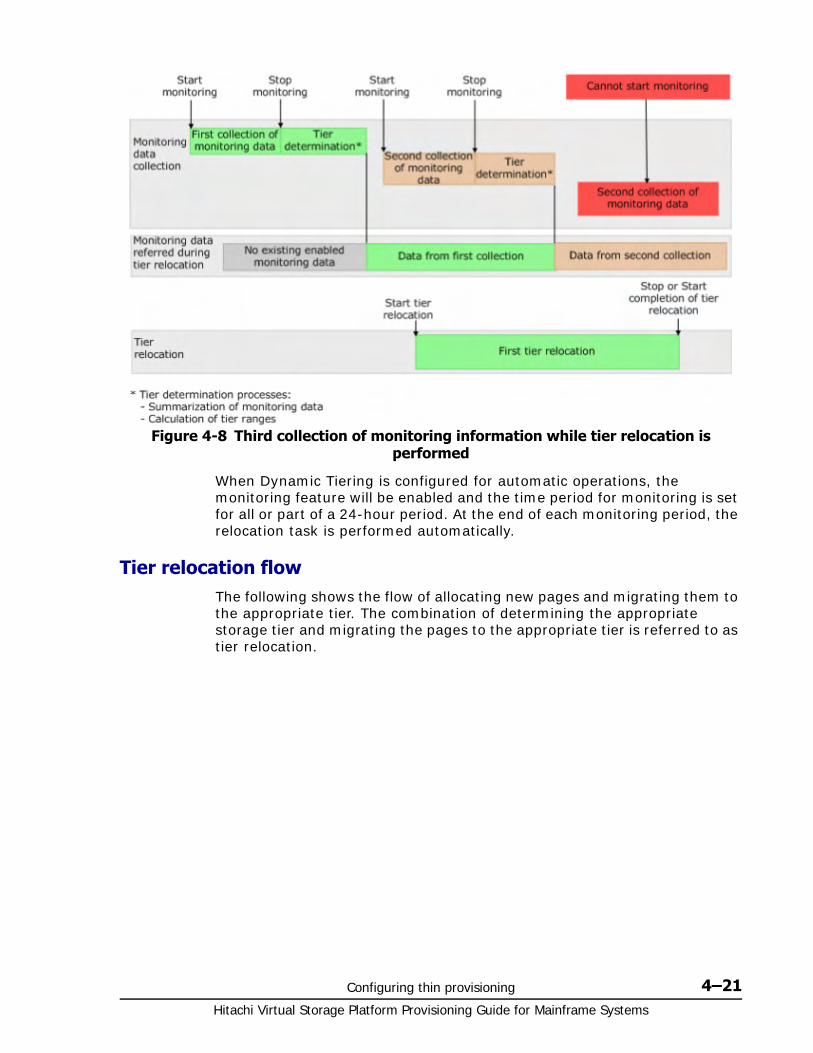
Configuring thin provisioning 4–21Hitachi Virtual Storage Platform Provisioning Guide for Mainframe Systems
When Dynamic Tiering is configured for automatic operations, the monitoring feature will be enabled and the time period for monitoring is set for all or part of a 24-hour period. At the end of each monitoring period, the relocation task is performed automatically.
Tier relocation flowThe following shows the flow of allocating new pages and migrating them to the appropriate tier. The combination of determining the appropriate storage tier and migrating the pages to the appropriate tier is referred to as tier relocation.
Figure 4-8 Third collection of monitoring information while tier relocation is performed
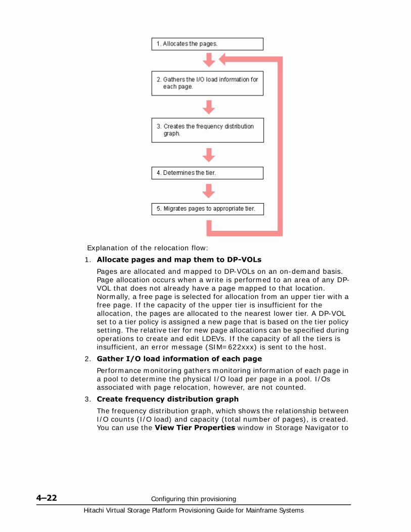
Hitachi Virtual Storage Platform Provisioning Guide for Mainframe Systems
4–22 Configuring thin provisioning
Explanation of the relocation flow:
1. Allocate pages and map them to DP-VOLs
Pages are allocated and mapped to DP-VOLs on an on-demand basis. Page allocation occurs when a write is performed to an area of any DP-VOL that does not already have a page mapped to that location. Normally, a free page is selected for allocation from an upper tier with a free page. If the capacity of the upper tier is insufficient for the allocation, the pages are allocated to the nearest lower tier. A DP-VOL set to a tier policy is assigned a new page that is based on the tier policy setting. The relative tier for new page allocations can be specified during operations to create and edit LDEVs. If the capacity of all the tiers is insufficient, an error message (SIM=622xxx) is sent to the host.
2. Gather I/O load information of each page
Performance monitoring gathers monitoring information of each page in a pool to determine the physical I/O load per page in a pool. I/Os associated with page relocation, however, are not counted.
3. Create frequency distribution graph
The frequency distribution graph, which shows the relationship between I/O counts (I/O load) and capacity (total number of pages), is created. You can use the View Tier Properties window in Storage Navigator to

Configuring thin provisioning 4–23Hitachi Virtual Storage Platform Provisioning Guide for Mainframe Systems
view this graph. The vertical scale of the graph indicates ranges of I/Os per hour and the horizontal scale indicates a capacity that received the I/O level. Note that the horizontal scale is accumulative.
The following is an example of a frequency distribution graph.
Monitoring mode settings (see Monitoring modes on page 4-36) of Period or Continuous influences the values shown on the performance graph. Period mode will report the most recent completed monitor cycle I/O data on the performance graph. Continuous mode will report a weighted average of I/O data that uses recent monitor cycle data, along with historical data on the performance graph.
4. Determine the tier range values
The page is allocated to the appropriate tier according to performance monitoring information. The tier is determined as follows.a. Determine the tier boundary
The tier range value of a tier is calculated using the frequency distribution graph. This acts as a boundary value that separates tiers
The pages of higher I/O load are allocated to the upper tier in sequence. Tier range is defined as the lowest I/Os per hour (IOPH) value at which the total number of stored pages matches the capacity of the target tier (less some buffer percentage) or the IOPH value that will reach the maximum I/O load that the tier should process. The maximum I/O load that should be targeted to a tier is the limit performance value, and the rate of I/O to the limit performance value of a tier is called the performance utilization percent. If the performance utilization percent shows 100%, this indicates that the target I/O load to a tier is beyond the forecasted limit performance value.
b. Determine the tier delta values
The tier range values are set as the lower limit boundary of each tier. The delta values are set above and below the tier boundaries (+10 to 20%) to prevent pages from being migrated unnecessarily. If all pages subject to tier relocation can be contained in the upper tier, both the tier range value (lower limit) and the delta value will be zero.
Caution: When the number of I/Os is counted, the number of I/Os satisfied by cache hits are not counted. Therefore, the number of I/Os counted by Performance Monitoring is different from the number of I/Os from the host. The number of I/Os per hour is shown in the graph. If the monitoring time is less than an hour, the number of I/Os shown in the graph might be higher than the actual number of I/Os.
Caution: The limit performance value is proportional to the capacity of the pool volumes used in the tier. The total capacity of the parity group should be used for a pool to further improve the limit performance.
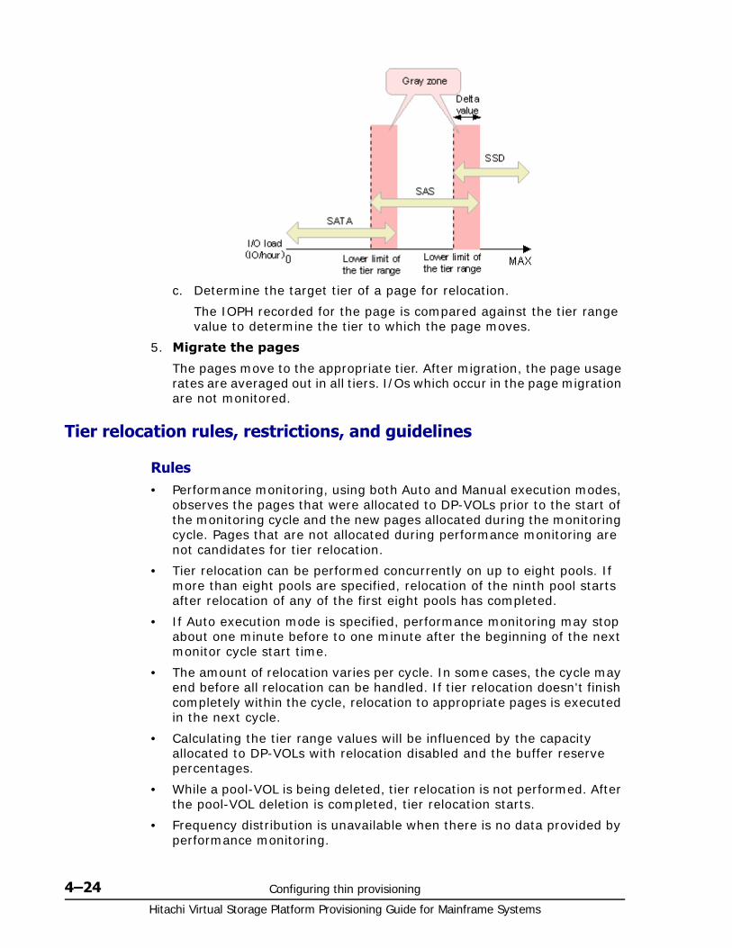
Hitachi Virtual Storage Platform Provisioning Guide for Mainframe Systems
4–24 Configuring thin provisioning
c. Determine the target tier of a page for relocation.
The IOPH recorded for the page is compared against the tier range value to determine the tier to which the page moves.
5. Migrate the pages
The pages move to the appropriate tier. After migration, the page usage rates are averaged out in all tiers. I/Os which occur in the page migration are not monitored.
Tier relocation rules, restrictions, and guidelines
Rules• Performance monitoring, using both Auto and Manual execution modes,
observes the pages that were allocated to DP-VOLs prior to the start of the monitoring cycle and the new pages allocated during the monitoring cycle. Pages that are not allocated during performance monitoring are not candidates for tier relocation.
• Tier relocation can be performed concurrently on up to eight pools. If more than eight pools are specified, relocation of the ninth pool starts after relocation of any of the first eight pools has completed.
• If Auto execution mode is specified, performance monitoring may stop about one minute before to one minute after the beginning of the next monitor cycle start time.
• The amount of relocation varies per cycle. In some cases, the cycle may end before all relocation can be handled. If tier relocation doesn't finish completely within the cycle, relocation to appropriate pages is executed in the next cycle.
• Calculating the tier range values will be influenced by the capacity allocated to DP-VOLs with relocation disabled and the buffer reserve percentages.
• While a pool-VOL is being deleted, tier relocation is not performed. After the pool-VOL deletion is completed, tier relocation starts.
• Frequency distribution is unavailable when there is no data provided by performance monitoring.

Configuring thin provisioning 4–25Hitachi Virtual Storage Platform Provisioning Guide for Mainframe Systems
• While the frequency distribution graph is being created or the tier range values are being calculated, the frequency distribution graph is not available. The time required for determining the tier range values varies depending on the number of DP-VOLs and total capacity. The maximum time is about 20 minutes.
• To balance the usage levels of all pool-VOLs, rebalancing may be performed after several tier relocation operations. If rebalancing is in progress, the next cycle of tier relocation might be delayed.
For details on rebalancing, see Rebalancing the usage level among pool-VOLs on page 4-54.
The status of data collection, fixed monitoring, and tier relocation operations are described in the following table. The latest fixed monitoring information is referenced when tiers are relocated.
Monitoring information or execution conditions
Status of data
collection in progress
Status of fixed monitoring information used in tier relocation
Tier relocation operations
Solutions
Unallocated pages.
Pages are not monitored.
No monitoring information on pages.
Tiers of the pages are not relocated.
Unnecessary. After the pages are allocated, monitoring and relocation are performed automatically.
Zero data is discarded during data monitoring.
Monitoring on pages is reset.
Only monitoring information on pages is invalid.
Tiers of the pages are not relocated.
Unnecessary. After the pages are allocated, monitoring and relocation are performed automatically.
V-VOL settings do not allow tier relocation.
Volume is monitored.
Monitoring information on the volume is valid.
Tiers of the pages are not relocated.
N/A
When V-VOLs are deleted
Volume is not monitored.
Only monitoring information on the volume is invalid.
Tier relocation of the volume is suspended.
N/A
When execution mode is changed to Manual from Auto or vice versa.
Suspended. Monitoring information collected before suspension is valid.
Suspended.1 Collect the monitoring information again if necessary.2
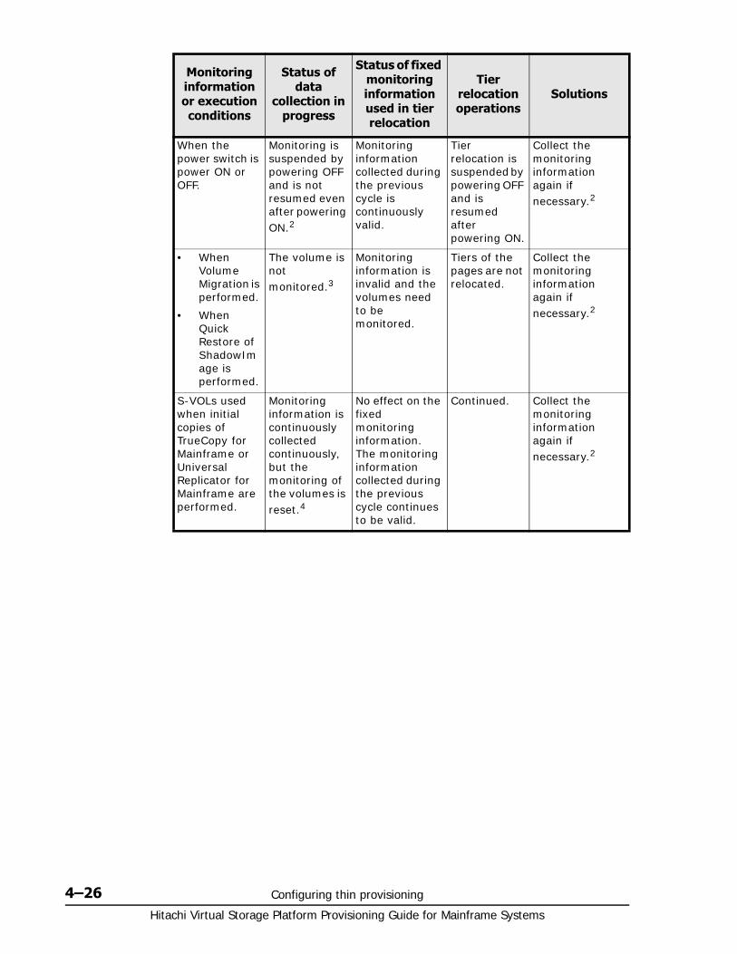
Hitachi Virtual Storage Platform Provisioning Guide for Mainframe Systems
4–26 Configuring thin provisioning
When the power switch is power ON or OFF.
Monitoring is suspended by powering OFF and is not resumed even after powering ON.2
Monitoring information collected during the previous cycle is continuously valid.
Tier relocation is suspended by powering OFF and is resumed after powering ON.
Collect the monitoring information again if necessary.2
• When Volume Migration is performed.
• When Quick Restore of ShadowImage is performed.
The volume is not monitored.3
Monitoring information is invalid and the volumes need to be monitored.
Tiers of the pages are not relocated.
Collect the monitoring information again if necessary.2
S-VOLs used when initial copies of TrueCopy for Mainframe or Universal Replicator for Mainframe are performed.
Monitoring information is continuously collected continuously, but the monitoring of the volumes is reset.4
No effect on the fixed monitoring information. The monitoring information collected during the previous cycle continues to be valid.
Continued. Collect the monitoring information again if necessary.2
Monitoring information or execution conditions
Status of data
collection in progress
Status of fixed monitoring information used in tier relocation
Tier relocation operations
Solutions
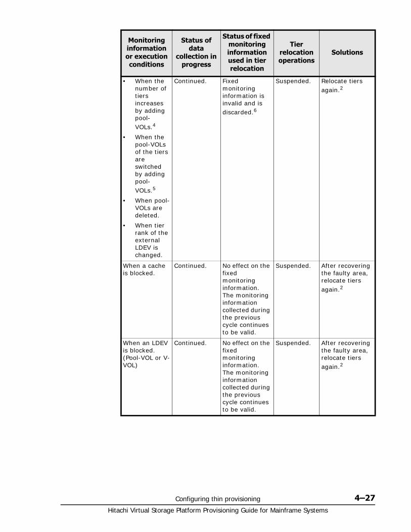
Configuring thin provisioning 4–27Hitachi Virtual Storage Platform Provisioning Guide for Mainframe Systems
• When the number of tiers increases by adding pool-VOLs.4
• When the pool-VOLs of the tiers are switched by adding pool-VOLs.5
• When pool-VOLs are deleted.
• When tier rank of the external LDEV is changed.
Continued. Fixed monitoring information is invalid and is discarded.6
Suspended. Relocate tiers again.2
When a cache is blocked.
Continued. No effect on the fixed monitoring information. The monitoring information collected during the previous cycle continues to be valid.
Suspended. After recovering the faulty area, relocate tiers again.2
When an LDEV is blocked. (Pool-VOL or V-VOL)
Continued. No effect on the fixed monitoring information. The monitoring information collected during the previous cycle continues to be valid.
Suspended. After recovering the faulty area, relocate tiers again.2
Monitoring information or execution conditions
Status of data
collection in progress
Status of fixed monitoring information used in tier relocation
Tier relocation operations
Solutions
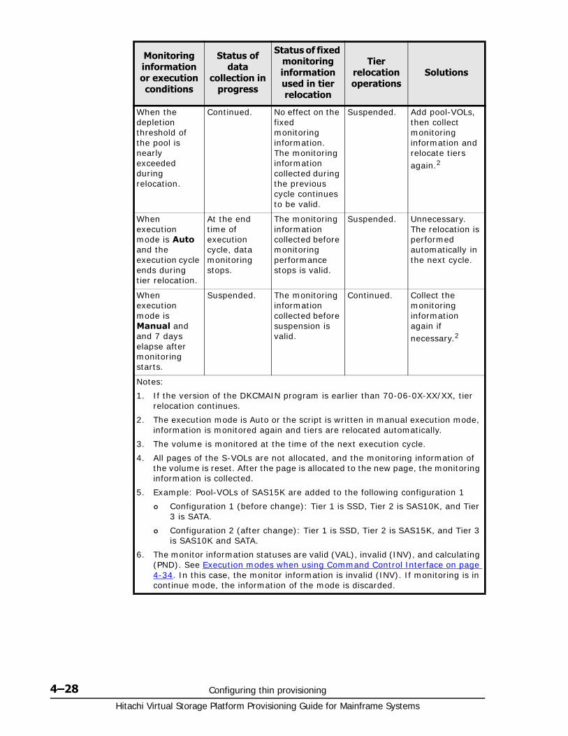
Hitachi Virtual Storage Platform Provisioning Guide for Mainframe Systems
4–28 Configuring thin provisioning
When the depletion threshold of the pool is nearly exceeded during relocation.
Continued. No effect on the fixed monitoring information. The monitoring information collected during the previous cycle continues to be valid.
Suspended. Add pool-VOLs, then collect monitoring information and relocate tiers again.2
When execution mode is Auto and the execution cycle ends during tier relocation.
At the end time of execution cycle, data monitoring stops.
The monitoring information collected before monitoring performance stops is valid.
Suspended. Unnecessary. The relocation is performed automatically in the next cycle.
When execution mode is Manual and and 7 days elapse after monitoring starts.
Suspended. The monitoring information collected before suspension is valid.
Continued. Collect the monitoring information again if necessary.2
Notes:
1. If the version of the DKCMAIN program is earlier than 70-06-0X-XX/XX, tier relocation continues.
2. The execution mode is Auto or the script is written in manual execution mode, information is monitored again and tiers are relocated automatically.
3. The volume is monitored at the time of the next execution cycle.
4. All pages of the S-VOLs are not allocated, and the monitoring information of the volume is reset. After the page is allocated to the new page, the monitoring information is collected.
5. Example: Pool-VOLs of SAS15K are added to the following configuration 1
Configuration 1 (before change): Tier 1 is SSD, Tier 2 is SAS10K, and Tier 3 is SATA.
Configuration 2 (after change): Tier 1 is SSD, Tier 2 is SAS15K, and Tier 3 is SAS10K and SATA.
6. The monitor information statuses are valid (VAL), invalid (INV), and calculating (PND). See Execution modes when using Command Control Interface on page 4-34. In this case, the monitor information is invalid (INV). If monitoring is in continue mode, the information of the mode is discarded.
Monitoring information or execution conditions
Status of data
collection in progress
Status of fixed monitoring information used in tier relocation
Tier relocation operations
Solutions
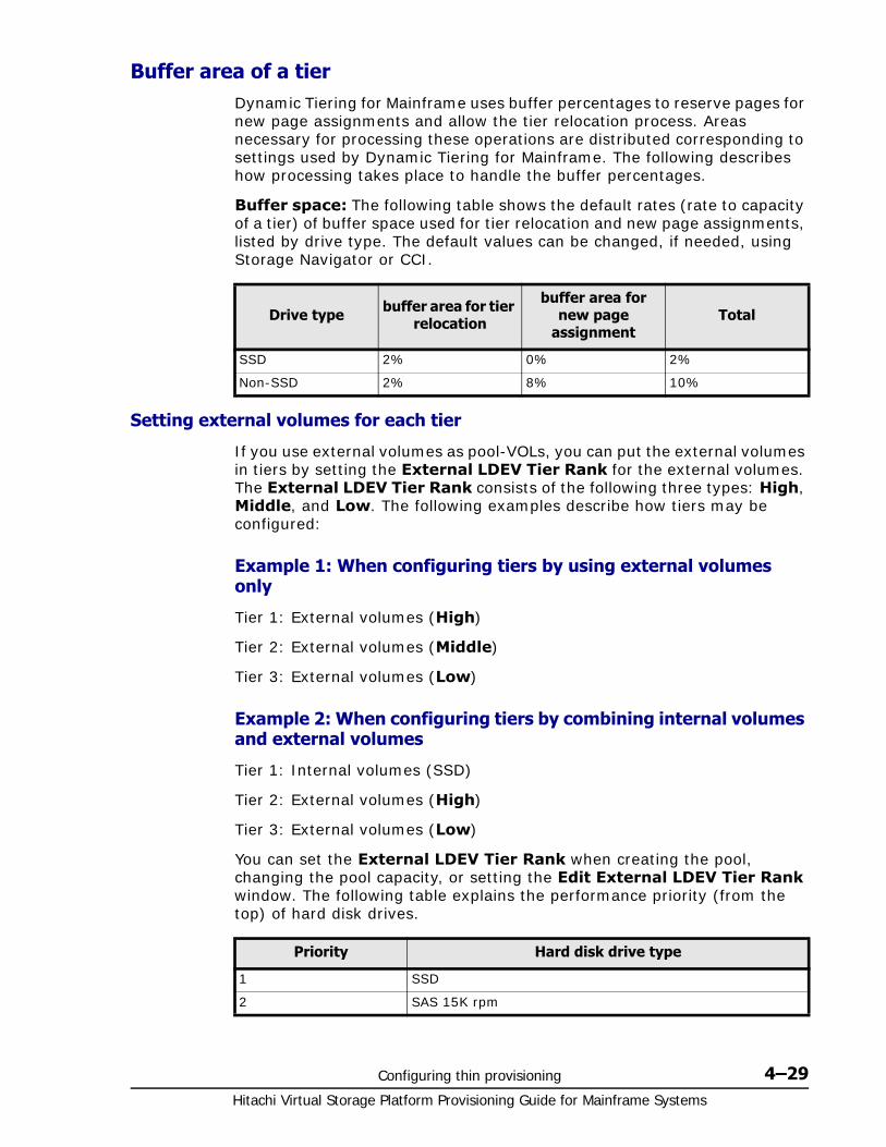
Configuring thin provisioning 4–29Hitachi Virtual Storage Platform Provisioning Guide for Mainframe Systems
Buffer area of a tierDynamic Tiering for Mainframe uses buffer percentages to reserve pages for new page assignments and allow the tier relocation process. Areas necessary for processing these operations are distributed corresponding to settings used by Dynamic Tiering for Mainframe. The following describes how processing takes place to handle the buffer percentages.
Buffer space: The following table shows the default rates (rate to capacity of a tier) of buffer space used for tier relocation and new page assignments, listed by drive type. The default values can be changed, if needed, using Storage Navigator or CCI.
Setting external volumes for each tier
If you use external volumes as pool-VOLs, you can put the external volumes in tiers by setting the External LDEV Tier Rank for the external volumes. The External LDEV Tier Rank consists of the following three types: High, Middle, and Low. The following examples describe how tiers may be configured:
Example 1: When configuring tiers by using external volumes only
Tier 1: External volumes (High)
Tier 2: External volumes (Middle)
Tier 3: External volumes (Low)
Example 2: When configuring tiers by combining internal volumes and external volumes
Tier 1: Internal volumes (SSD)
Tier 2: External volumes (High)
Tier 3: External volumes (Low)
You can set the External LDEV Tier Rank when creating the pool, changing the pool capacity, or setting the Edit External LDEV Tier Rank window. The following table explains the performance priority (from the top) of hard disk drives.
Drive type buffer area for tier relocation
buffer area for new page
assignmentTotal
SSD 2% 0% 2%
Non-SSD 2% 8% 10%
Priority Hard disk drive type
1 SSD
2 SAS 15K rpm
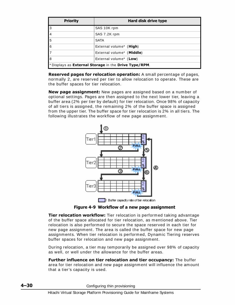
Hitachi Virtual Storage Platform Provisioning Guide for Mainframe Systems
4–30 Configuring thin provisioning
Reserved pages for relocation operation: A small percentage of pages, normally 2, are reserved per tier to allow relocation to operate. These are the buffer spaces for tier relocation.
New page assignment: New pages are assigned based on a number of optional settings. Pages are then assigned to the next lower tier, leaving a buffer area (2% per tier by default) for tier relocation. Once 98% of capacity of all tiers is assigned, the remaining 2% of the buffer space is assigned from the upper tier. The buffer space for tier relocation is 2% in all tiers. The following illustrates the workflow of new page assignment.
Tier relocation workflow: Tier relocation is performed taking advantage of the buffer space allocated for tier relocation, as mentioned above. Tier relocation is also performed to secure the space reserved in each tier for new page assignment. The area is called the buffer space for new page assignments. When tier relocation is performed, Dynamic Tiering reserves buffer spaces for relocation and new page assignment.
During relocation, a tier may temporarily be assigned over 98% of capacity as well, or well under the allowance for the buffer areas.
Further influence on tier relocation and tier occupancy: The buffer area for tier relocation and new page assignment will influence the amount that a tier’s capacity is used.
3 SAS 10K rpm
4 SAS 7.2K rpm
5 SATA
6 External volume* (High)
7 External volume* (Middle)
8 External volume* (Low)
*Displays as External Storage in the Drive Type/RPM.
Priority Hard disk drive type
Figure 4-9 Workflow of a new page assignment
Configuring thin provisioning 4–31Hitachi Virtual Storage Platform Provisioning Guide for Mainframe Systems
If the relocation cycle’s duration is not long enough for the allocation moves to all complete, then the amount of tier capacity used may not fully represent the desired target levels. Subsequent relocations should eventually reach the target levels.
Dynamic Tiering for Mainframe cache specifications and requirements
The following cache capacity is required when the total capacity is 128 TB:
• Recommended capacity of cache memory for data: 28 GB
• Required capacity of cache memory for control information for using Dynamic Provisioning for Mainframe: 8 GB
• Required capacity of cache memory for Dynamic Tiering for Mainframe: 4 GB
• Therefore, in this example 40 GB of capacity of cache memory is required.
Note that cache memory is installed in pairs. Therefore, actual capacity is twice the cache memory capacity. For example, if required controlling information is 8 GB, then actual installed capacity is 16 GB.
To decrease the capacity of the cache memory for Dynamic Tiering for Mainframe, you have to remove Dynamic Tiering for Mainframe.
Execution modes for tier relocation
Execution modes when using Hitachi Storage Navigator
Dynamic Tiering for Mainframe performs tier relocations using one of two execution modes: Auto and Manual. You can switch between modes by using Hitachi Storage Navigator.
Auto execution mode
In Auto execution mode, the system automatically and periodically collects monitoring data and performs tier relocation. You can select an Auto execution cycle of 0.5, 1, 2, 4, or 8 hours, or a specified time. You can specify the settings for the auto execution mode with Hitachi Storage Navigator.
The following illustrates tier relocation processing in a 2-hour Auto execution mode:

Hitachi Virtual Storage Platform Provisioning Guide for Mainframe Systems
4–32 Configuring thin provisioning
Manual execution mode
In Manual execution mode, you can manually collect monitoring data and relocate a tier. You can issue commands to manually:
1. Start monitoring.
2. Stop monitoring.
3. Perform tier relocation.
The following illustrates tier relocation processing in Manual execution mode:
Configuring thin provisioning 4–33Hitachi Virtual Storage Platform Provisioning Guide for Mainframe Systems
Notes on performing monitoring• You can collect the monitoring data even while performing the
relocation.
• After stopping the monitoring, the tier range is automatically calculated.
• The latest available monitoring information, which is collected just before the relocation is performed, is used for the relocation processing.
• When the relocation is performed, the status of the monitor information must be valid.
Viewing monitor and tier relocation information:
Information is displayed on the following items in the GUI windows:
• Monitoring Status on Pools window after selecting pool (Pools window) on page D-3, Top window when selecting a pool under Pools on page D-10, and View Pool Management Status window on page D-72.
Displays the status of pool monitoring.
In Progress: The monitoring is being performed.
During Computation: The calculating is being processed.
Other than these cases, a hyphen (-) is displayed.
• Recent Monitor Data on Pools window after selecting pool (Pools window) on page D-3 and Top window when selecting a pool under Pools on page D-10
Displays the latest monitoring data.
If the monitoring data exists, the monitoring period of time is displayed.
Example: 2010/11/15 00:00 - 2010/11/15 23:59
If the monitoring data is being obtained, only the starting time is displayed.
Example: 2010/11/15 00:00 -
If the latest monitoring data does not exist, a hyphen (-) is displayed.
• Pool Management Task on Pools window after selecting pool (Pools window) on page D-3 and Top window when selecting a pool under Pools on page D-10
Displays the pool management task being performed to the pool.
Waiting for Relocation: The tier relocation process is being waited.
Relocating: The tier relocation process is being performed.
For details about the relocation progress rate, check the tier relocation log. For more information about the table item for the tier relocation log file, see Tier relocation log file contents on page 4-38.
• Pool Management Task (Status/Progress) on View Pool Management Status window on page D-72.
Displays the status of the pool management task being performed, each V-VOL progress ratio in the pool and its average.
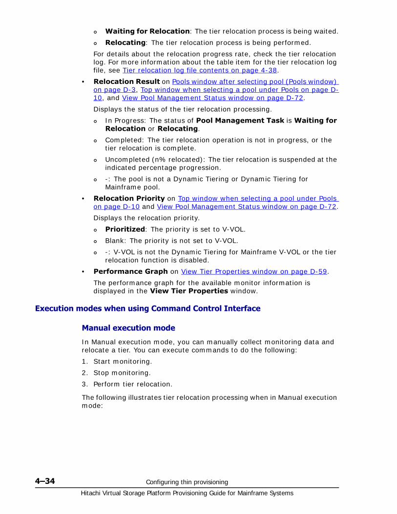
Hitachi Virtual Storage Platform Provisioning Guide for Mainframe Systems
4–34 Configuring thin provisioning
Waiting for Relocation: The tier relocation process is being waited.
Relocating: The tier relocation process is being performed.
For details about the relocation progress rate, check the tier relocation log. For more information about the table item for the tier relocation log file, see Tier relocation log file contents on page 4-38.
• Relocation Result on Pools window after selecting pool (Pools window) on page D-3, Top window when selecting a pool under Pools on page D-10, and View Pool Management Status window on page D-72.
Displays the status of the tier relocation processing.
In Progress: The status of Pool Management Task is Waiting for Relocation or Relocating.
Completed: The tier relocation operation is not in progress, or the tier relocation is complete.
Uncompleted (n% relocated): The tier relocation is suspended at the indicated percentage progression.
-: The pool is not a Dynamic Tiering or Dynamic Tiering for Mainframe pool.
• Relocation Priority on Top window when selecting a pool under Pools on page D-10 and View Pool Management Status window on page D-72.
Displays the relocation priority.
Prioritized: The priority is set to V-VOL.
Blank: The priority is not set to V-VOL.
-: V-VOL is not the Dynamic Tiering for Mainframe V-VOL or the tier relocation function is disabled.
• Performance Graph on View Tier Properties window on page D-59.
The performance graph for the available monitor information is displayed in the View Tier Properties window.
Execution modes when using Command Control Interface
Manual execution mode
In Manual execution mode, you can manually collect monitoring data and relocate a tier. You can execute commands to do the following:
1. Start monitoring.
2. Stop monitoring.
3. Perform tier relocation.
The following illustrates tier relocation processing when in Manual execution mode:
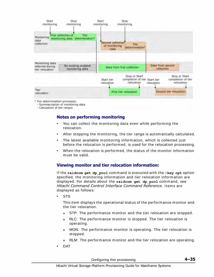
Configuring thin provisioning 4–35Hitachi Virtual Storage Platform Provisioning Guide for Mainframe Systems
Notes on performing monitoring• You can collect the monitoring data even while performing the
relocation.
• After stopping the monitoring, the tier range is automatically calculated.
• The latest available monitoring information, which is collected just before the relocation is performed, is used for the relocation processing.
• When the relocation is performed, the status of the monitor information must be valid.
Viewing monitor and tier relocation information:
If the raidcom get dp_pool command is executed with the -key opt option specified, the monitoring information and tier relocation information are displayed. For details about the raidcom get dp_pool command, see Hitachi Command Control Interface Command Reference. Items are displayed as follows:
• STS
This item displays the operational status of the performance monitor and the tier relocation.
STP: The performance monitor and the tier relocation are stopped.
RLC: The performance monitor is stopped. The tier relocation is operating.
MON: The performance monitor is operating. The tier relocation is stopped.
RLM: The performance monitor and the tier relocation are operating.
• DAT
Hitachi Virtual Storage Platform Provisioning Guide for Mainframe Systems
4–36 Configuring thin provisioning
This item displays the status of the monitor information.
VAL: Valid.
INV: Invalid.
PND: Being calculated.
• R(%)
This item displays the progress percentage of tier relocation.
0 to 99: Shows one of the following statuses.
When the value of STS is RLC or RLM: Relocation is in progress.
When the value of STS is STP or MON: Relocation is suspended at the indicated percentage progression.
100: Shows if the relocation operation is not in progress, or the relocation is complete.
Monitoring modesWhen you create or edit a pool, specify the Dynamic Tiering for Mainframe monitoring mode. The monitoring mode is either the period mode or the continuous mode. If you change the mode from the one to the other while performing the monitoring, the changed setting becomes effective when the next monitoring will starts.
Period mode
Period mode is the default setting. If Period mode is enabled, tier range values and page relocations are determined based solely on the monitoring data from the last complete cycle. Relocation is performed according to any changes in I/O loads. However, if the I/O loads vary greatly, relocation may not finish in one cycle.
Continuous mode
If Continuous Mode is enabled, by weighting the latest monitoring information and the collected monitoring information in the past cycles, the weighted average efficiency is calculated. By performing the tier relocation based on the weighted average efficiency, even if a temporary decrease or an increase of the I/O load occurs, unnecessary relocation can be avoided.
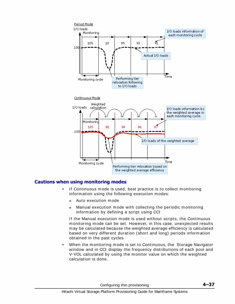
Configuring thin provisioning 4–37Hitachi Virtual Storage Platform Provisioning Guide for Mainframe Systems
Cautions when using monitoring modes• If Continuous mode is used, best practice is to collect monitoring
information using the following execution modes:
Auto execution mode
Manual execution mode with collecting the periodic monitoring information by defining a script using CCI
If the Manual execution mode is used without scripts, the Continuous monitoring mode can be set. However, in this case, unexpected results may be calculated because the weighted average efficiency is calculated based on very different duration (short and long) periods information obtained in the past cycles.
• When the monitoring mode is set to Continuous, the Storage Navigator window and in CCI display the frequency distributions of each pool and V-VOL calculated by using the monitor value on which the weighted calculation is done.

Hitachi Virtual Storage Platform Provisioning Guide for Mainframe Systems
4–38 Configuring thin provisioning
These calculated values are the predictive values for the next cycle after successfully relocating all pages. Therefore, these values may differ from an actual monitoring result when they appear.
In Performance Utilization of each tier, regardless of the type of the monitoring mode setting, the Storage Navigator window and CCI display the monitor values which were already collected in the current cycle.
If you switch the monitoring mode from Period to Continuous or from Continuous to Period, the current cycle’s monitoring data that is being collected is not discarded. However, the data calculated by using past monitor cycle information on which the weighted calculation is done will be reset.
Notes on performing monitoring• You can collect a new cycle of monitoring data while performing
relocation.
• After monitoring stops, the tier range is automatically calculated.
• The latest available monitoring information, collected just before the relocation is performed, is used for relocation processing.
• When relocation is performed, the status of the monitor information must be valid (VAL).
Downloading the tier relocation log fileYou can download the log file that contains the results of past tier relocations. See Tier relocation log file contents on page 4-38 for information about the contents of the log.
1. Using Storage Navigator, in the Storage Systems tree select Pool.
2. In the Pool window, click More Actions > Tier Relocation Log.
3. In the progress dialog box, click OK.
4. A dialog box opens allowing you to select where to download the file. Specify the folder in which to download the file, and then click Save.
If you change the file name from the default, make sure the file name contains the .tsv extension before saving a renamed file.
Tier relocation log file contents
Item Description
Pool ID Displays the pool ID.
Start Relocation Time Displays the time and date when the performing the relocation function starts.
End Relocation Time Displays the time and date when the performing the relocation function ends.
Result Displays the section where the relocation result is shown.
Status Displays the execution results that are Normal or Cancel.

Configuring thin provisioning 4–39Hitachi Virtual Storage Platform Provisioning Guide for Mainframe Systems
Tiering policyThe tiering policy function is used to assign a specific storage tier to a specific DP-VOL. A tiering policy specifies subset of tiers that is available to a given set of DP-VOLs.
Tier relocation changes the location of previously stored data. It is performed in conformance to the tiering policy. If a DP-VOL is initially allocated to a low-speed tier and the tiering policy is changed to a high-speed tier, relocation is performed in the next cycle.
For example, if you set the tiering policy level on a V-VOL(DP-VOL) to a tier with a high I/O speed, the data is always stored on the high-speed tier when relocating tiers. When you use that V-VOL(DP-VOL), regardless of the actual size of the I/O load, you can always get high-speed responses. See Tiering policy expansion on page 4-40.
When you create the DP-VOL, you can designate one of six existing tiering policies and define up to 26 new tiering policies. See Tiering policy expansion on page 4-40 and Setting tiering policy on a DP-VOL on page 4-42.
Use the Edit LDEVs window to change the tiering policy settings. When tier relocation occurs, the related tiering policy set for the DP-VOL is used to relocate data to the desired tier or tiers.
Detail Displays the following causes of cancellation. A hyphen (-) is displayed when the execution status is Normal.
• It was interrupted by annulling the monitor data. Monitoring information with a status of valid or calculating is discarded under certain conditions.
• It was interrupted by not completing within the cycle of relocation.
• The tier relocation was interrupted because the threshold reached the vicinity of the upper limit. The information appears when the pool usage level reaches the depletion threshold of the pool.
• It was interrupted by a user instruction.
Move Page Num Displays the number of pages that are moved between tiers.
Tier1->Tier2 Displays the number of pages that are moved from tier1 to tier2.
Tier1->Tier3 Displays the number of pages that are moved from tier1 to tier3.
Tier2->Tier1 Displays the number of pages that are moved from tier2 to tier1.
Tier2->Tier3 Displays the number of pages that are moved from tier2 to tier3.
Tier3->Tier1 Displays the number of pages that are moved from tier3 to tier1.
Tier3->Tier2 Displays the number of pages that are moved from tier3 to tier2.
Item Description
Hitachi Virtual Storage Platform Provisioning Guide for Mainframe Systems
4–40 Configuring thin provisioning
The tiering policy does not own pool capacity. Rather, pool capacity is shared among tiers. Pages are allocated in order of priority from upper to lower tiers in a tiering policy. When you specify a new allocation tier, pages are allocated starting from the tier that you specify.
The tier range, frequency distribution, and used capacity are displayed per tiering policy: existing tier level All(0), Level1(1) through Level5(5) and Level6(6) to Level31(31).
Tiering policy expansion
In the current release, the tiering policy concept has been expanded to provide new options:
• Custom policies. You can define up to 26 new policies (Level6(6) - Level31(31)) in addition to the existing six (All(0), Level1(1), Level2(2), Level3(3), Level4(4), and Level5(5)). See Setting tiering policy on a DP-VOL on page 4-42.
A custom policy can be set for a DP-VOL when it is created and changed, if necessary, after creation.
• Dynamic Tiering for Mainframe performs relocation while calculating page allocation based on the tiering policy setting of all DP-VOLs that have the same tiering policy in each pool.
• Max(%) and Min(%) parameters. When a tiering policy is created, 4 types of parameters can be set: Tier1 Max and Tier 1 Min, Tier 3 Max and Tier 3 Min. Each parameter setting is a ratio that corresponds to the total capacity of the allocated area of DP-VOLs that have the same tiering policy set for a pool. See Tiering policy examples on page 4-40.
Tier1 and Tier3 parameter settings can also limit the capacity for all volumes in a configuration that contain multiple DP-VOLs that have the same intended use. These settings can prevent conditions such as the following from occurring.
Excess allocation of SSD capacity for unimportant applications.
Degradation in average response time for high performance operations.
Tiering policy examples
The following figure shows the parameter settings Tier1 Max=40%, Tier1 Min=20%, Tier3 Max=40%, and Tier3 Min=20% for a DP-VOL with a Level6(6) setting when the initial allocated capacity of is 100GB.
Note: Custom policies cannot be renamed.

Configuring thin provisioning 4–41Hitachi Virtual Storage Platform Provisioning Guide for Mainframe Systems
The following figure shows an example of data allocation when the default tiering policy level All(0) is specified. Pages in the DP-VOL are relocated to any tier.
The following figure shows an example of data allocation when setting the tiering policy to Level1(1) (see Level1(1) in Tiering policy levels on page 4-43). In this case, pages in the DP-VOL are relocated to tier 1, and are not relocated to other tiers.
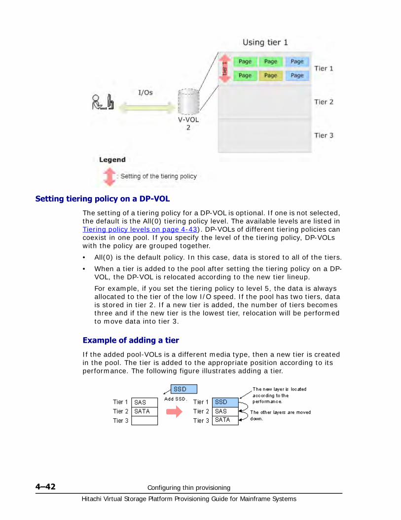
Hitachi Virtual Storage Platform Provisioning Guide for Mainframe Systems
4–42 Configuring thin provisioning
Setting tiering policy on a DP-VOL
The setting of a tiering policy for a DP-VOL is optional. If one is not selected, the default is the All(0) tiering policy level. The available levels are listed in Tiering policy levels on page 4-43). DP-VOLs of different tiering policies can coexist in one pool. If you specify the level of the tiering policy, DP-VOLs with the policy are grouped together.
• All(0) is the default policy. In this case, data is stored to all of the tiers.
• When a tier is added to the pool after setting the tiering policy on a DP-VOL, the DP-VOL is relocated according to the new tier lineup.
For example, if you set the tiering policy to level 5, the data is always allocated to the tier of the low I/O speed. If the pool has two tiers, data is stored in tier 2. If a new tier is added, the number of tiers becomes three and if the new tier is the lowest tier, relocation will be performed to move data into tier 3.
Example of adding a tier
If the added pool-VOLs is a different media type, then a new tier is created in the pool. The tier is added to the appropriate position according to its performance. The following figure illustrates adding a tier.
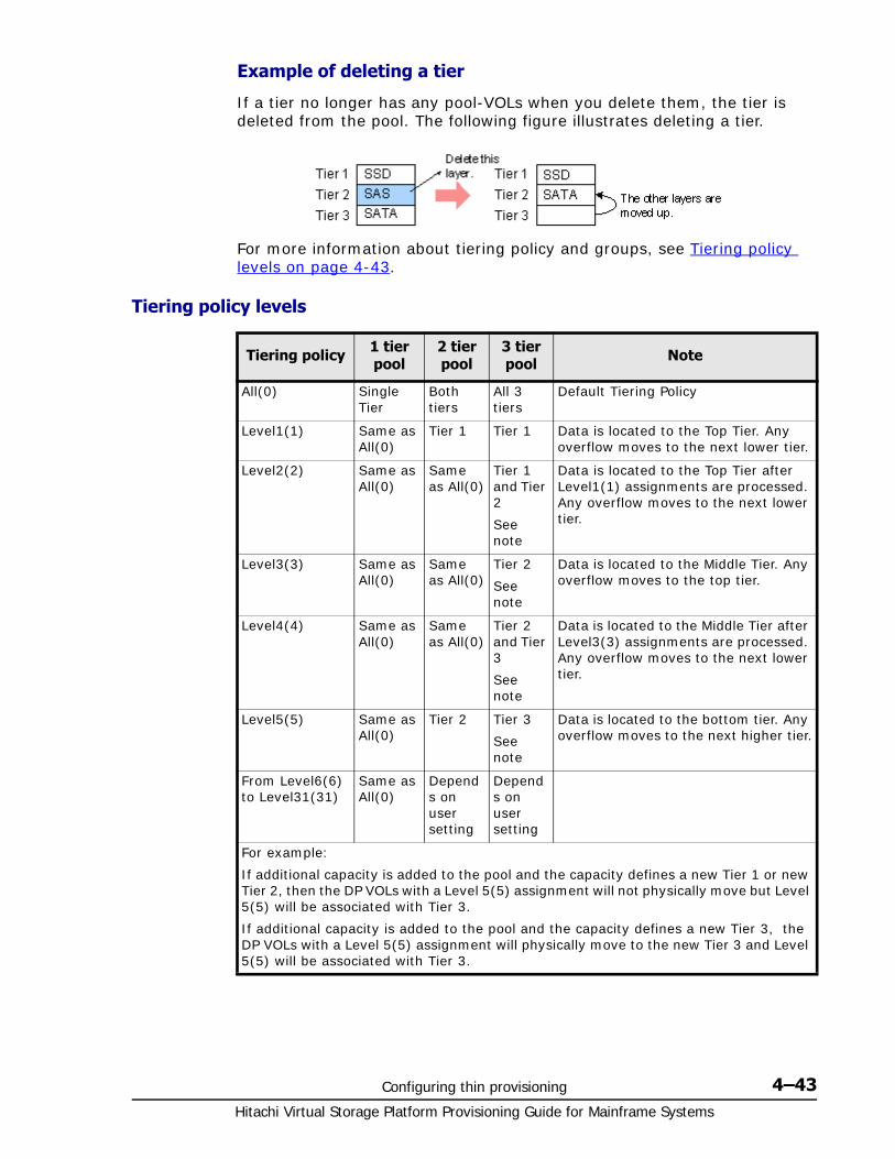
Configuring thin provisioning 4–43Hitachi Virtual Storage Platform Provisioning Guide for Mainframe Systems
Example of deleting a tier
If a tier no longer has any pool-VOLs when you delete them, the tier is deleted from the pool. The following figure illustrates deleting a tier.
For more information about tiering policy and groups, see Tiering policy levels on page 4-43.
Tiering policy levels
Tiering policy 1 tier pool
2 tier pool
3 tier pool Note
All(0) Single Tier
Both tiers
All 3 tiers
Default Tiering Policy
Level1(1) Same as All(0)
Tier 1 Tier 1 Data is located to the Top Tier. Any overflow moves to the next lower tier.
Level2(2) Same as All(0)
Same as All(0)
Tier 1 and Tier 2
See note
Data is located to the Top Tier after Level1(1) assignments are processed. Any overflow moves to the next lower tier.
Level3(3) Same as All(0)
Same as All(0)
Tier 2
See note
Data is located to the Middle Tier. Any overflow moves to the top tier.
Level4(4) Same as All(0)
Same as All(0)
Tier 2 and Tier 3
See note
Data is located to the Middle Tier after Level3(3) assignments are processed. Any overflow moves to the next lower tier.
Level5(5) Same as All(0)
Tier 2 Tier 3
See note
Data is located to the bottom tier. Any overflow moves to the next higher tier.
From Level6(6) to Level31(31)
Same as All(0)
Depends on user setting
Depends on user setting
For example:
If additional capacity is added to the pool and the capacity defines a new Tier 1 or new Tier 2, then the DP VOLs with a Level 5(5) assignment will not physically move but Level 5(5) will be associated with Tier 3.
If additional capacity is added to the pool and the capacity defines a new Tier 3, the DP VOLs with a Level 5(5) assignment will physically move to the new Tier 3 and Level 5(5) will be associated with Tier 3.
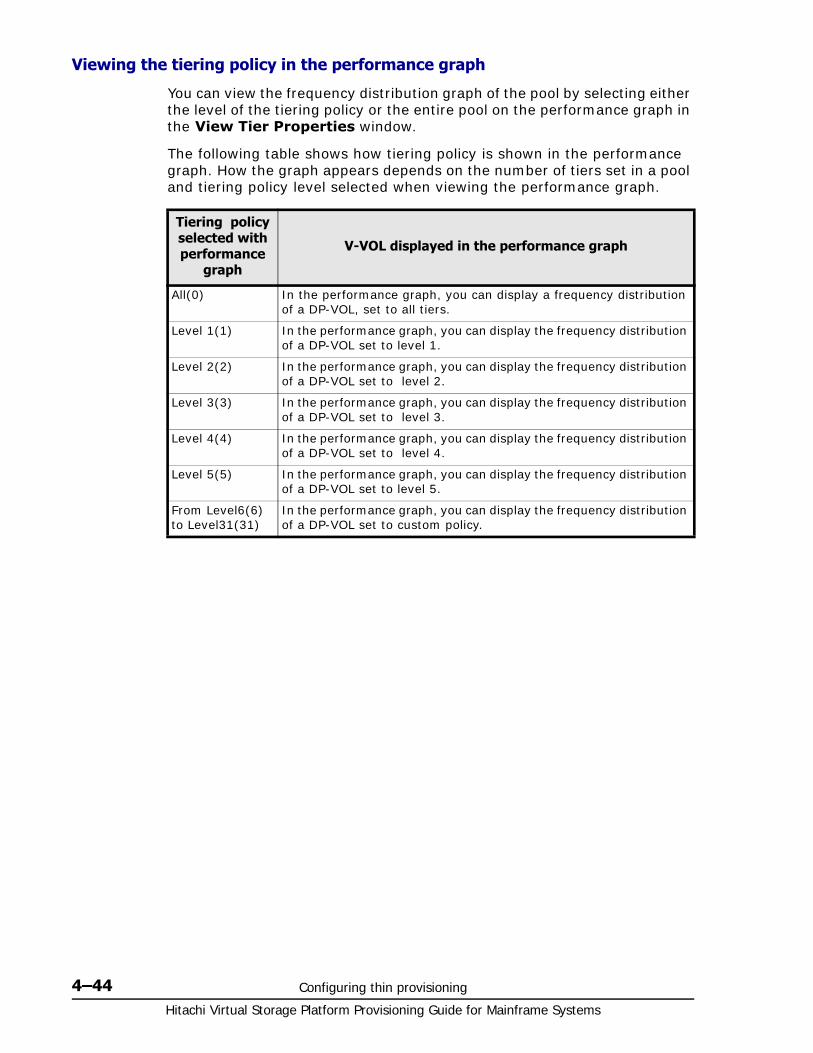
Hitachi Virtual Storage Platform Provisioning Guide for Mainframe Systems
4–44 Configuring thin provisioning
Viewing the tiering policy in the performance graph
You can view the frequency distribution graph of the pool by selecting either the level of the tiering policy or the entire pool on the performance graph in the View Tier Properties window.
The following table shows how tiering policy is shown in the performance graph. How the graph appears depends on the number of tiers set in a pool and tiering policy level selected when viewing the performance graph.
Tiering policy selected with performance
graph
V-VOL displayed in the performance graph
All(0) In the performance graph, you can display a frequency distribution of a DP-VOL, set to all tiers.
Level 1(1) In the performance graph, you can display the frequency distribution of a DP-VOL set to level 1.
Level 2(2) In the performance graph, you can display the frequency distribution of a DP-VOL set to level 2.
Level 3(3) In the performance graph, you can display the frequency distribution of a DP-VOL set to level 3.
Level 4(4) In the performance graph, you can display the frequency distribution of a DP-VOL set to level 4.
Level 5(5) In the performance graph, you can display the frequency distribution of a DP-VOL set to level 5.
From Level6(6) to Level31(31)
In the performance graph, you can display the frequency distribution of a DP-VOL set to custom policy.
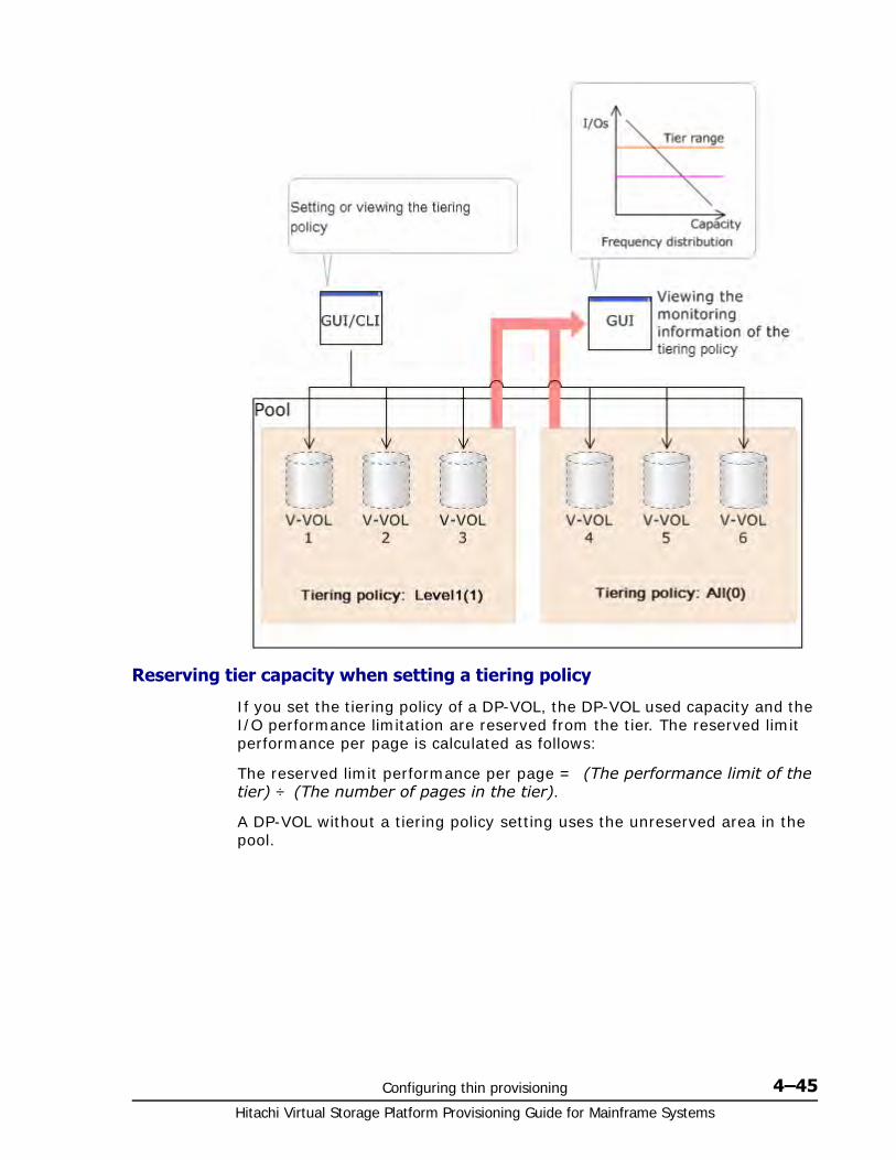
Configuring thin provisioning 4–45Hitachi Virtual Storage Platform Provisioning Guide for Mainframe Systems
Reserving tier capacity when setting a tiering policy
If you set the tiering policy of a DP-VOL, the DP-VOL used capacity and the I/O performance limitation are reserved from the tier. The reserved limit performance per page is calculated as follows:
The reserved limit performance per page = (The performance limit of the tier) ÷ (The number of pages in the tier).
A DP-VOL without a tiering policy setting uses the unreserved area in the pool.

Hitachi Virtual Storage Platform Provisioning Guide for Mainframe Systems
4–46 Configuring thin provisioning
Example of reserving tier capacity
The reservation priority depends on the level of tiering policy. The following figure illustrates the reservation priority. Tiers are reserved in order of priority from (1) to (7) in the figure. If the pool-VOL capacity is deficient when you reserve a tier, the nearest tier of your specified tier is allocated. If you specify two tiers like level 2 or level 4 of the tiering policy, first of all the upper tier is reserved. At this time, if the capacity of the pool-VOL assigned to the upper tier is deficient, the lower tier defined by the tiering policy is reserved automatically. For example, in case of level 2 in the diagram below, tier 1 is reserved first. If the capacity of tier 1 is deficient at this point, tier 2 is reserved automatically. For details, see Notes on tiering policy settings on page 4-48.
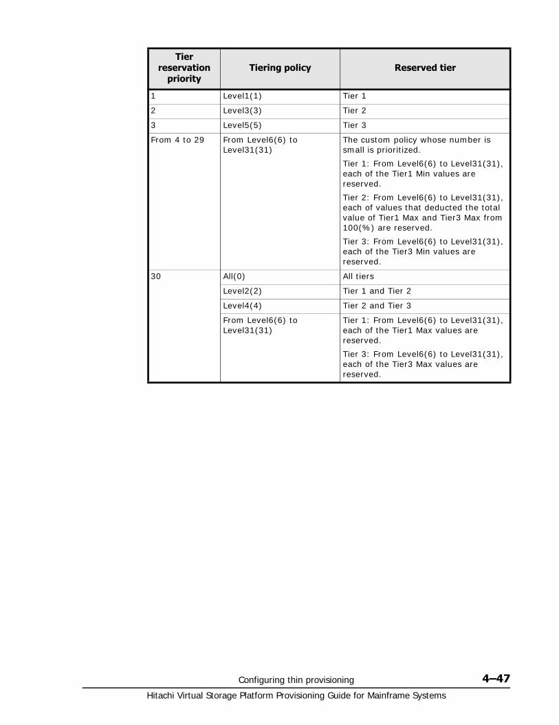
Configuring thin provisioning 4–47Hitachi Virtual Storage Platform Provisioning Guide for Mainframe Systems
Tier reservation
priorityTiering policy Reserved tier
1 Level1(1) Tier 1
2 Level3(3) Tier 2
3 Level5(5) Tier 3
From 4 to 29 From Level6(6) to Level31(31)
The custom policy whose number is small is prioritized.
Tier 1: From Level6(6) to Level31(31), each of the Tier1 Min values are reserved.
Tier 2: From Level6(6) to Level31(31), each of values that deducted the total value of Tier1 Max and Tier3 Max from 100(%) are reserved.
Tier 3: From Level6(6) to Level31(31), each of the Tier3 Min values are reserved.
30 All(0) All tiers
Level2(2) Tier 1 and Tier 2
Level4(4) Tier 2 and Tier 3
From Level6(6) to Level31(31)
Tier 1: From Level6(6) to Level31(31), each of the Tier1 Max values are reserved.
Tier 3: From Level6(6) to Level31(31), each of the Tier3 Max values are reserved.

Hitachi Virtual Storage Platform Provisioning Guide for Mainframe Systems
4–48 Configuring thin provisioning
Notes on tiering policy settings• If Auto is set as the execution mode, tier relocation is performed based
on the monitoring cycle. Therefore, when the tiering policy setting is changed, tier relocation will automatically implement the tiering policy at the end of the current monitoring cycle. See Example 1 in Execution mode settings and tiering policy on page 4-55.
• If Manual is set as the execution mode, you must manually perform monitoring, issue a monitor stop, and then start relocation (see Example 2, Case 1, in Execution mode settings and tiering policy on page 4-55). If you change the tiering policy settings while obtaining monitoring data, the monitoring data is used for the next tier relocation (see Example 2, Case 2, in Execution mode settings and tiering policy on page 4-55). Therefore, you do not need to perform new monitoring.

Configuring thin provisioning 4–49Hitachi Virtual Storage Platform Provisioning Guide for Mainframe Systems
• If a capacity shortage exists in the tier being set, a message may appear in the View Tier Property window that the page allocation cannot be completed according to the tiering policy specified for the V-VOL. Should that occur, the page allocation in the entire pool -- including the tier that defines the tiering policy -- might not be optimized.
When a capacity shortage exists in a tier, you can revise the setting of the tiering policy or the configuration of tiers. If the capacity of one tier is fully exhausted, the migrating pages are assigned to the next tier according to the tiering policy.
Level1(1): When tier 1 is full, the remaining pages are allocated to tier 2. If tier 2 is full, the remaining pages are allocated to tier 3.
Level3(3): When tier 2 is full, the remaining pages are allocated to tier 1. If tier 1 is full, the remaining pages are allocated to tier 3.
Level5(5): When tier 3 is full, the remaining pages are allocated to tier 2. If tier 2 is full, the remaining pages are allocated to tier 1.
Level2(2), Level4(4), and from Level6(6) to Level31(31): When the specified tier is full, the unallocated pages are kept in the prior tier.
• If a performance shortage exists in the tier being set, pages may not be allocated in conformance to the tiering policy specified for the V-VOL. In that case, pages are allocated according to the performance ratio of each tier.
As shown in the following table, allocation capacity considerations are based on the tiering policy.
Note: The message that page allocation cannot be completed according to the tiering policy does not appear when these tiering policies are set:
• All(0)
• In a 2-tier configuration, Level2(2), Level3(3), or Level4(4) which is equivalent to All(0)
Tiering Policy Allocation capacity considerations
All(0), Level2(2), or Level4(4)
Tier range and I/O performance
Level1(1), Level3(3), or Level5(5)
Tier range
From Level6(6) to Level31(31)
First phase: Tier range.
Allocation capacities in each tier.
• Tier1: The setting value(%) in Tier1 Min.
• Tier2: The value deducted Tier1 Max(%) and Tier3 Max(%) from 100(%).
• Tier3: The setting value(%) in Tier3 Min.
Second phase: Tier range and I/O performance.
Capacities deducted from the allocated capacities of the first phase from the total used capacity, are allocated to each tier.
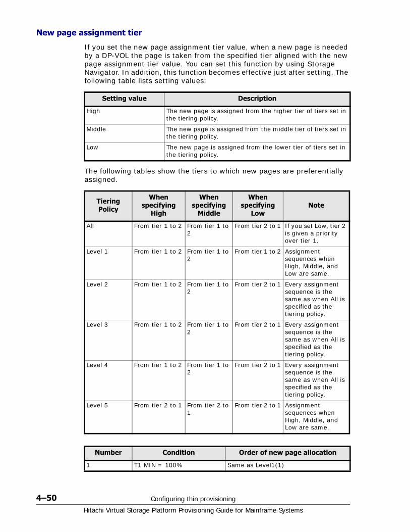
Hitachi Virtual Storage Platform Provisioning Guide for Mainframe Systems
4–50 Configuring thin provisioning
New page assignment tier
If you set the new page assignment tier value, when a new page is needed by a DP-VOL the page is taken from the specified tier aligned with the new page assignment tier value. You can set this function by using Storage Navigator. In addition, this function becomes effective just after setting. The following table lists setting values:
The following tables show the tiers to which new pages are preferentially assigned.
Setting value Description
High The new page is assigned from the higher tier of tiers set in the tiering policy.
Middle The new page is assigned from the middle tier of tiers set in the tiering policy.
Low The new page is assigned from the lower tier of tiers set in the tiering policy.
Tiering Policy
When specifying
High
When specifying
Middle
When specifying
LowNote
All From tier 1 to 2 From tier 1 to 2
From tier 2 to 1 If you set Low, tier 2 is given a priority over tier 1.
Level 1 From tier 1 to 2 From tier 1 to 2
From tier 1 to 2 Assignment sequences when High, Middle, and Low are same.
Level 2 From tier 1 to 2 From tier 1 to 2
From tier 2 to 1 Every assignment sequence is the same as when All is specified as the tiering policy.
Level 3 From tier 1 to 2 From tier 1 to 2
From tier 2 to 1 Every assignment sequence is the same as when All is specified as the tiering policy.
Level 4 From tier 1 to 2 From tier 1 to 2
From tier 2 to 1 Every assignment sequence is the same as when All is specified as the tiering policy.
Level 5 From tier 2 to 1 From tier 2 to 1
From tier 2 to 1 Assignment sequences when High, Middle, and Low are same.
Number Condition Order of new page allocation
1 T1 MIN = 100% Same as Level1(1)
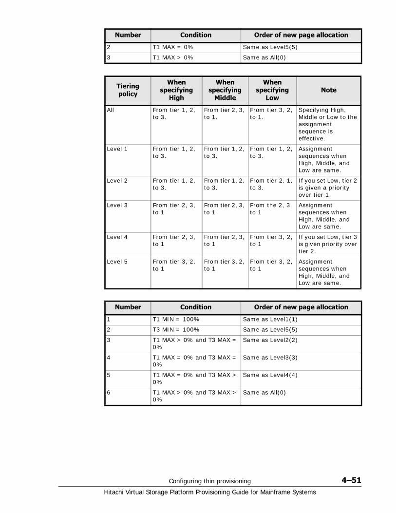
Configuring thin provisioning 4–51Hitachi Virtual Storage Platform Provisioning Guide for Mainframe Systems
2 T1 MAX = 0% Same as Level5(5)
3 T1 MAX > 0% Same as All(0)
Tiering policy
When specifying
High
When specifying
Middle
When specifying
LowNote
All From tier 1, 2, to 3.
From tier 2, 3, to 1.
From tier 3, 2, to 1.
Specifying High, Middle or Low to the assignment sequence is effective.
Level 1 From tier 1, 2, to 3.
From tier 1, 2, to 3.
From tier 1, 2, to 3.
Assignment sequences when High, Middle, and Low are same.
Level 2 From tier 1, 2, to 3.
From tier 1, 2, to 3.
From tier 2, 1, to 3.
If you set Low, tier 2 is given a priority over tier 1.
Level 3 From tier 2, 3, to 1
From tier 2, 3, to 1
From the 2, 3, to 1
Assignment sequences when High, Middle, and Low are same.
Level 4 From tier 2, 3, to 1
From tier 2, 3, to 1
From tier 3, 2, to 1
If you set Low, tier 3 is given priority over tier 2.
Level 5 From tier 3, 2, to 1
From tier 3, 2, to 1
From tier 3, 2, to 1
Assignment sequences when High, Middle, and Low are same.
Number Condition Order of new page allocation
1 T1 MIN = 100% Same as Level1(1)
2 T3 MIN = 100% Same as Level5(5)
3 T1 MAX > 0% and T3 MAX = 0%
Same as Level2(2)
4 T1 MAX = 0% and T3 MAX = 0%
Same as Level3(3)
5 T1 MAX = 0% and T3 MAX > 0%
Same as Level4(4)
6 T1 MAX > 0% and T3 MAX > 0%
Same as All(0)
Number Condition Order of new page allocation
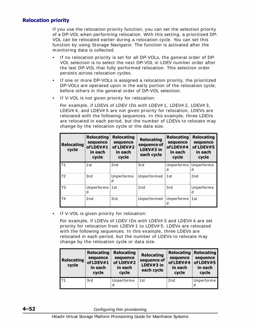
Hitachi Virtual Storage Platform Provisioning Guide for Mainframe Systems
4–52 Configuring thin provisioning
Relocation priority
If you use the relocation priority function, you can set the selection priority of a DP-VOL when performing relocation. With this setting, a prioritized DP-VOL can be relocated earlier during a relocation cycle. You can set this function by using Storage Navigator. The function is activated after the monitoring data is collected.
• If no relocation priority is set for all DP-VOLs, the general order of DP-VOL selection is to select the next DP-VOL in LDEV number order after the last DP-VOL that fully performed relocation. This selection order persists across relocation cycles.
• If one or more DP-VOLs is assigned a relocation priority, the prioritized DP-VOLs are operated upon in the early portion of the relocation cycle, before others in the general order of DP-VOL selection.
• If V-VOL is not given priority for relocation:
For example, if LDEVs of LDEV IDs with LDEV#1, LDEV#2, LDEV#3, LDEV#4, and LDEV#5 are not given priority for relocation, LDEVs are relocated with the following sequences. In this example, three LDEVs are relocated in each period, but the number of LDEVs to relocate may change by the relocation cycle or the data size.
• If V-VOL is given priority for relocation:
For example, if LDEVs of LDEV IDs with LDEV#3 and LDEV#4 are set priority for relocation from LDEV#1 to LDEV#5, LDEVs are relocated with the following sequences. In this example, three LDEVs are relocated in each period, but the number of LDEVs to relocate may change by the relocation cycle or data size.
Relocating cycle
Relocating sequence
of LDEV#1 in each cycle
Relocating sequence
of LDEV#2 in each cycle
Relocating sequence of LDEV#3 in each cycle
Relocating sequence
of LDEV#4 in each cycle
Relocating sequence
of LDEV#5 in each cycle
T1 1st 2nd 3rd Unperformed
Unperformed
T2 3rd Unperformed
Unperformed 1st 2nd
T3 Unperformed
1st 2nd 3rd Unperformed
T4 2nd 3rd Unperformed Unperformed
1st
Relocating cycle
Relocating sequence
of LDEV#1 in each cycle
Relocating sequence
of LDEV#2 in each cycle
Relocating sequence of LDEV#3 in each cycle
Relocating sequence
of LDEV#4 in each cycle
Relocating sequence
of LDEV#5 in each cycle
T1 3rd Unperformed
1st 2nd Unperformed
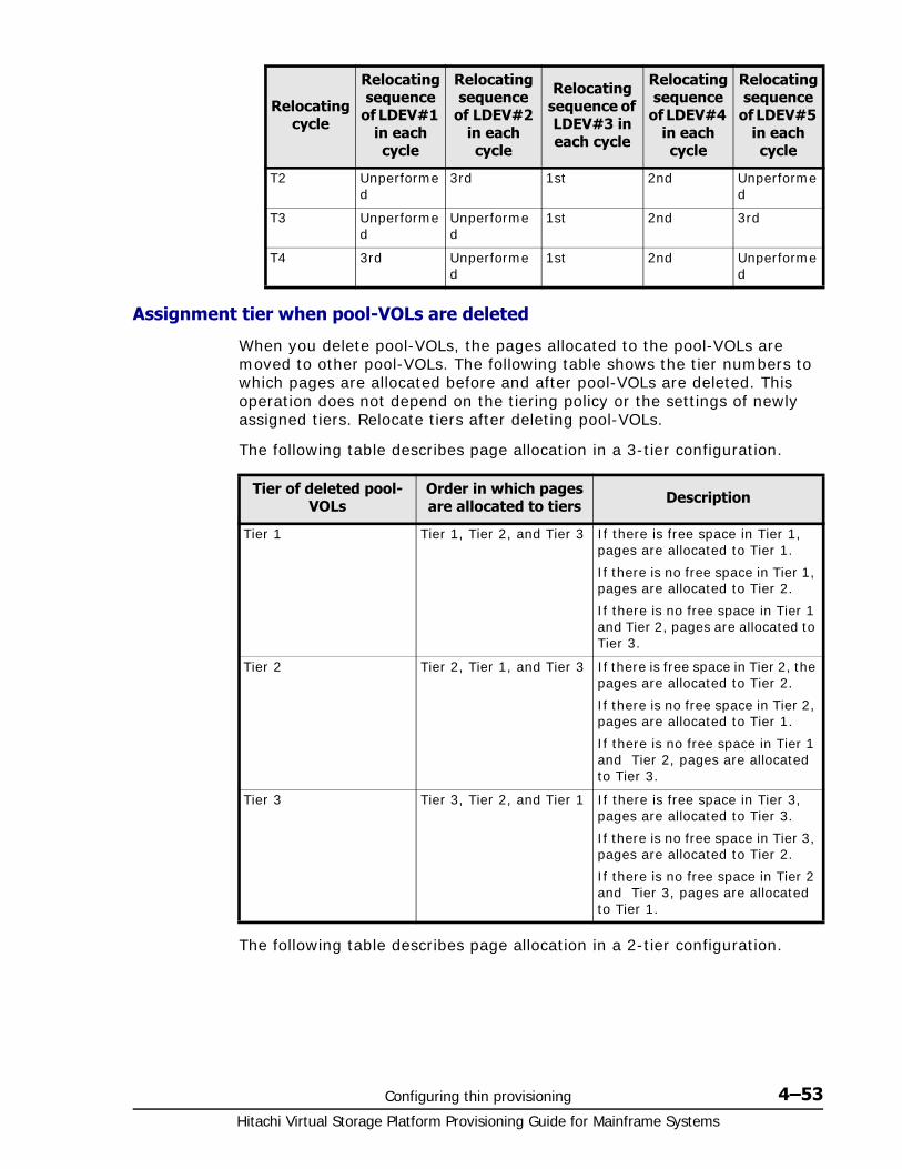
Configuring thin provisioning 4–53Hitachi Virtual Storage Platform Provisioning Guide for Mainframe Systems
Assignment tier when pool-VOLs are deleted
When you delete pool-VOLs, the pages allocated to the pool-VOLs are moved to other pool-VOLs. The following table shows the tier numbers to which pages are allocated before and after pool-VOLs are deleted. This operation does not depend on the tiering policy or the settings of newly assigned tiers. Relocate tiers after deleting pool-VOLs.
The following table describes page allocation in a 3-tier configuration.
The following table describes page allocation in a 2-tier configuration.
T2 Unperformed
3rd 1st 2nd Unperformed
T3 Unperformed
Unperformed
1st 2nd 3rd
T4 3rd Unperformed
1st 2nd Unperformed
Relocating cycle
Relocating sequence
of LDEV#1 in each cycle
Relocating sequence
of LDEV#2 in each cycle
Relocating sequence of LDEV#3 in each cycle
Relocating sequence
of LDEV#4 in each cycle
Relocating sequence
of LDEV#5 in each cycle
Tier of deleted pool-VOLs
Order in which pages are allocated to tiers Description
Tier 1 Tier 1, Tier 2, and Tier 3 If there is free space in Tier 1, pages are allocated to Tier 1.
If there is no free space in Tier 1, pages are allocated to Tier 2.
If there is no free space in Tier 1 and Tier 2, pages are allocated to Tier 3.
Tier 2 Tier 2, Tier 1, and Tier 3 If there is free space in Tier 2, the pages are allocated to Tier 2.
If there is no free space in Tier 2, pages are allocated to Tier 1.
If there is no free space in Tier 1 and Tier 2, pages are allocated to Tier 3.
Tier 3 Tier 3, Tier 2, and Tier 1 If there is free space in Tier 3, pages are allocated to Tier 3.
If there is no free space in Tier 3, pages are allocated to Tier 2.
If there is no free space in Tier 2 and Tier 3, pages are allocated to Tier 1.
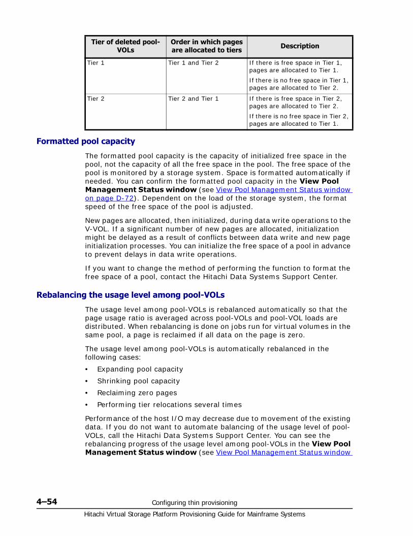
Hitachi Virtual Storage Platform Provisioning Guide for Mainframe Systems
4–54 Configuring thin provisioning
Formatted pool capacity
The formatted pool capacity is the capacity of initialized free space in the pool, not the capacity of all the free space in the pool. The free space of the pool is monitored by a storage system. Space is formatted automatically if needed. You can confirm the formatted pool capacity in the View Pool Management Status window (see View Pool Management Status window on page D-72). Dependent on the load of the storage system, the format speed of the free space of the pool is adjusted.
New pages are allocated, then initialized, during data write operations to the V-VOL. If a significant number of new pages are allocated, initialization might be delayed as a result of conflicts between data write and new page initialization processes. You can initialize the free space of a pool in advance to prevent delays in data write operations.
If you want to change the method of performing the function to format the free space of a pool, contact the Hitachi Data Systems Support Center.
Rebalancing the usage level among pool-VOLs
The usage level among pool-VOLs is rebalanced automatically so that the page usage ratio is averaged across pool-VOLs and pool-VOL loads are distributed. When rebalancing is done on jobs run for virtual volumes in the same pool, a page is reclaimed if all data on the page is zero.
The usage level among pool-VOLs is automatically rebalanced in the following cases:
• Expanding pool capacity
• Shrinking pool capacity
• Reclaiming zero pages
• Performing tier relocations several times
Performance of the host I/O may decrease due to movement of the existing data. If you do not want to automate balancing of the usage level of pool-VOLs, call the Hitachi Data Systems Support Center. You can see the rebalancing progress of the usage level among pool-VOLs in the View Pool Management Status window (see View Pool Management Status window
Tier of deleted pool-VOLs
Order in which pages are allocated to tiers Description
Tier 1 Tier 1 and Tier 2 If there is free space in Tier 1, pages are allocated to Tier 1.
If there is no free space in Tier 1, pages are allocated to Tier 2.
Tier 2 Tier 2 and Tier 1 If there is free space in Tier 2, pages are allocated to Tier 2.
If there is no free space in Tier 2, pages are allocated to Tier 1.
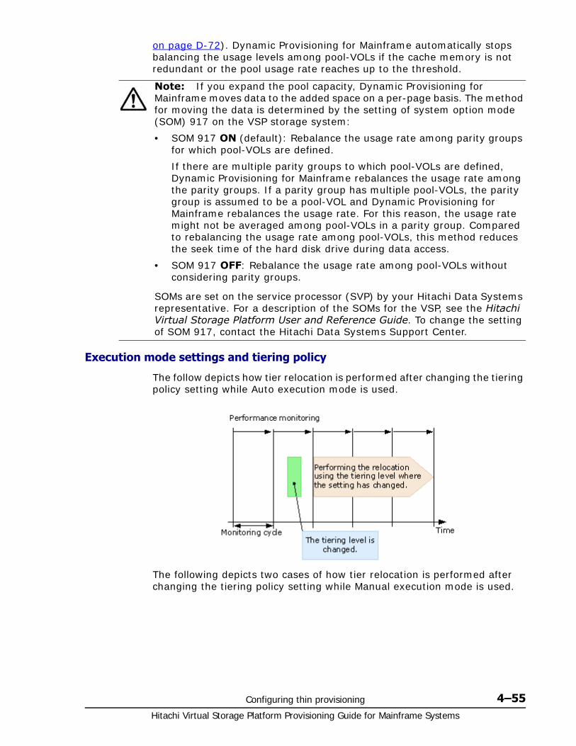
Configuring thin provisioning 4–55Hitachi Virtual Storage Platform Provisioning Guide for Mainframe Systems
on page D-72). Dynamic Provisioning for Mainframe automatically stops balancing the usage levels among pool-VOLs if the cache memory is not redundant or the pool usage rate reaches up to the threshold.
Execution mode settings and tiering policy
The follow depicts how tier relocation is performed after changing the tiering policy setting while Auto execution mode is used.
The following depicts two cases of how tier relocation is performed after changing the tiering policy setting while Manual execution mode is used.
Note: If you expand the pool capacity, Dynamic Provisioning for Mainframe moves data to the added space on a per-page basis. The method for moving the data is determined by the setting of system option mode (SOM) 917 on the VSP storage system:
• SOM 917 ON (default): Rebalance the usage rate among parity groups for which pool-VOLs are defined.
If there are multiple parity groups to which pool-VOLs are defined, Dynamic Provisioning for Mainframe rebalances the usage rate among the parity groups. If a parity group has multiple pool-VOLs, the parity group is assumed to be a pool-VOL and Dynamic Provisioning for Mainframe rebalances the usage rate. For this reason, the usage rate might not be averaged among pool-VOLs in a parity group. Compared to rebalancing the usage rate among pool-VOLs, this method reduces the seek time of the hard disk drive during data access.
• SOM 917 OFF: Rebalance the usage rate among pool-VOLs without considering parity groups.
SOMs are set on the service processor (SVP) by your Hitachi Data Systems representative. For a description of the SOMs for the VSP, see the Hitachi Virtual Storage Platform User and Reference Guide. To change the setting of SOM 917, contact the Hitachi Data Systems Support Center.

Hitachi Virtual Storage Platform Provisioning Guide for Mainframe Systems
4–56 Configuring thin provisioning
Changing the tiering policy level on a DP-VOL1. In the Storage Navigator main window, in the Storage Systems tree,
select Logical Devices.
The following is another way to select LDEVs.a. In the Storage Navigator main window, in the Storage Systems
tree, select Pool.b. Select the pool associated with the DP-VOL that has the tiering policy
level you want to change.c. Click the Virtual Volumes tab.
2. From the table, select the row with the DP-VOL that has the tiering policy level you want to change.
To select consecutive rows, highlight all of the rows to be selected and press the Shift key. To select separate rows, click each row while pressing the Ctrl key.
3. Click More Actions, and then select Edit LDEVs.
Configuring thin provisioning 4–57Hitachi Virtual Storage Platform Provisioning Guide for Mainframe Systems
4. In the Edit LDEVs window, select Tiering Policy, and select the tiering policy.
5. Click Finish.
6. In the Confirm window, confirm the settings, in Task Name type a unique name for this task or accept the default, and then click Apply.
If Go to tasks window for status is checked, the Tasks window opens.
Changing new page assignment tier of a V-VOL1. In the Storage Systems tree on the left pane of the top window, select
Logical Devices.
The following shows an example of the other operations to select LDEVs.a. In the Storage Systems tree on the left pane of the top window,
select Pool.
The pool name appears below Pool.b. Click the pool associated with the V-VOL that has new page
assignment tier you want to change.c. Click the Virtual Volumes tab on the right pane.
2. From the table, click the row that has the V-VOL with the new page assignment tier that you want to change.
To select consecutive rows, highlight all of the rows to be selected and press the Shift key. To select separate rows, click each row pressing the Ctrl key.
3. Click More Actions to select Edit LDEVs.
The Edit LDEVs window appears.
4. Click the New Page Assignment Tier check box and select the new page assignment tier you want to use.
5. Click Finish.
The Confirm window appears.
6. In the Task Name text box, type a unique name for the task or accept the default.
You can enter up to 32 ASCII characters and symbols, with the exception of: \ / : , ; * ? " < > |. The value "date-window name" is entered by default.
7. Click Apply.
If the Go to tasks window for status check box is selected, the Tasks window appears.
Opening the Edit Tiering Policies window1. In the Storage Systems tree, select Pool.
The pool information is displayed on the right pane of the window.
2. Click the Edit Tiering Policies button.
The Edit Tiering Policies window appears.

Hitachi Virtual Storage Platform Provisioning Guide for Mainframe Systems
4–58 Configuring thin provisioning
Changing a tiering policyYou must have the Storage Administrator (system resource management) role to perform this task.
To change the tiering policy1. In the Storage Systems tree, select Pool.
The pool information is displayed on the right pane of the window.
2. Click the Edit Tiering Policies button.
The Edit Tiering Policies window appears.
3. Select the tiering policy that you want to change and click the Change button.
The Change Tiering Policies window appears. The policies which have an ID numbered 0 to 5 cannot be changed.
4. Change the tiering policy, and click OK .
After clicking OK, the Edit Tiering Policies window appears again. Note that each tiering policy value is needed in order to meet the conditions described in the following table.
5. Click Finish.
The Confirm window appears.
6. In the Task Name text box, type a unique name for the task or accept the default.
7. Click Apply.
If the Go to tasks window for status check box is selected, the Tasks window appears.
Item Explanation
Tier1 Max One of these conditions must be met:
Equal to Tier1 Min
Bigger than Tier1 Min
Tier1 Min* One of these conditions must be met:
Equal to Tier1 Max
Smaller than Tier1 Max
Tier3 Max One of these conditions must be met:
Equal to Tier3 Min
Bigger than Tier3 Min
Tier3 Min* One of these conditions must be met:
Equal to Tier3 Max
Smaller than Tier3 Max
* The sum of Tier1 Min and Tier3 Min must be 100 (%) or less.
Configuring thin provisioning 4–59Hitachi Virtual Storage Platform Provisioning Guide for Mainframe Systems
Changing relocation priority setting of a V-VOL1. In the Storage Systems tree on the left pane of the top window, select
Logical Devices.
The following is another way to select LDEVs.a. In the Storage Systems tree on the left pane of the top window,
select Pool.
The pool name appears below Pool.b. Click the pool associated with the V-VOL that has the relocation
priority you want to change.c. Click the Virtual Volumes tab on the right pane.
2. From the table, click the row that has the V-VOL with the relocation priority you want to change.
To select consecutive rows, highlight all of the rows to be selected and press the Shift key. To select separate rows, click each row pressing the Ctrl key.
3. Click More Actions to select Edit LDEVs.
The Edit LDEVs window appears.
4. Select the Relocation Priority check box and click Default or Prioritize. If you choose Prioritize, LDEV is relocated preferentially.
5. Click Finish.
The Confirm window appears.
6. In the Task Name text box, enter the task name.
You can enter up to 32 ASCII characters and symbols, with the exception of: \ / : , ; * ? " < > |. The value "date-window name" is entered by default.
7. Click Apply.
If the Go to tasks window for status check box is selected, the Tasks window appears.
Dynamic Tiering for Mainframe workflowThe following diagram shows the flow of work for a Storage Administrator to set up Dynamic Tiering for Mainframe on the storage system.
As shown in the diagram, Storage Navigator and Command Control Interface have different workflows. The details about how to set up Dynamic Tiering using Storage Navigator are covered in subsequent topics. For details about how to set up Dynamic Tiering for Mainframe using Command Control Interface, see the Hitachi Command Control Interface Command Reference and Hitachi Command Control Interface User and Reference Guide. Use Storage Navigator to create pools and DP-VOLs.
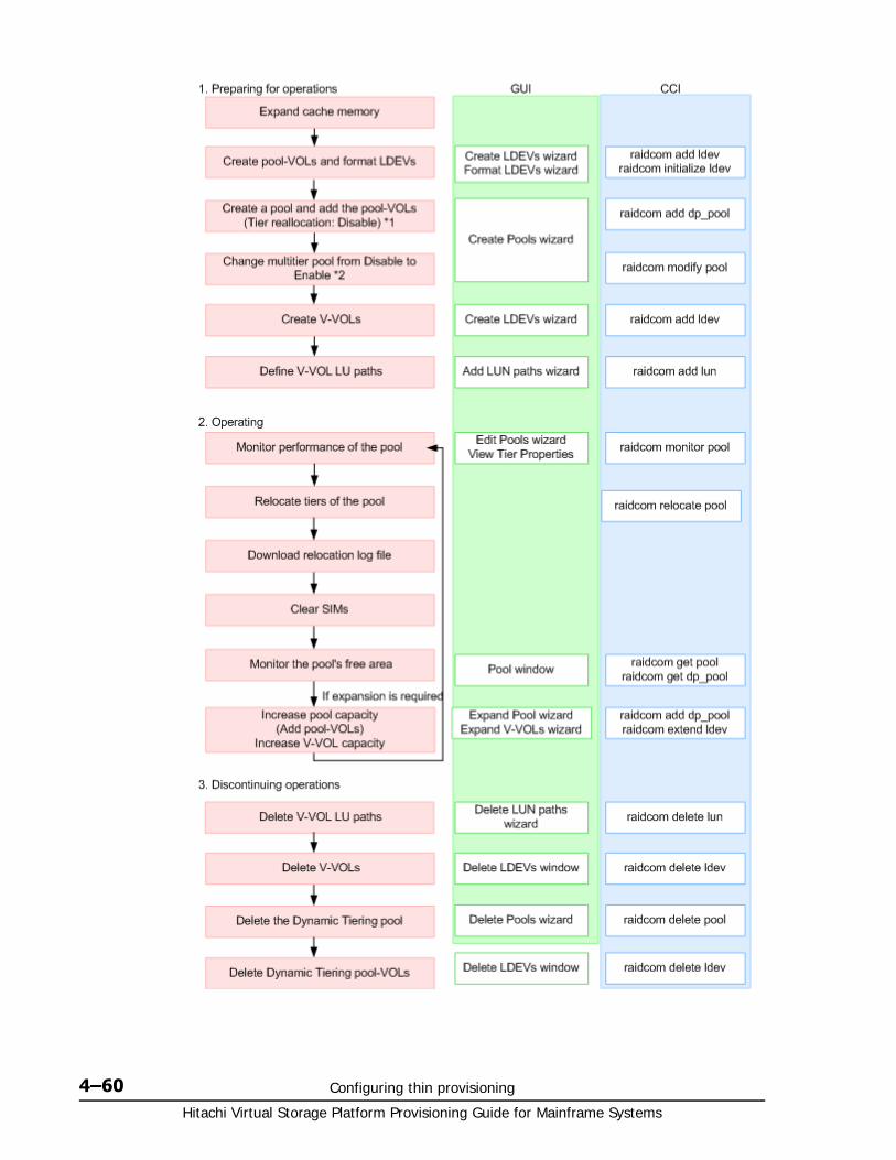
Hitachi Virtual Storage Platform Provisioning Guide for Mainframe Systems
4–60 Configuring thin provisioning
Configuring thin provisioning 4–61Hitachi Virtual Storage Platform Provisioning Guide for Mainframe Systems
• Before creating a pool, you need a DP-VOL management area in shared memory. When shared memory is added, the DP-VOL management area is automatically created. For adding shared memory, contact your Hitachi Data Systems representative.
• In Command Control Interface, when creating a pool, you cannot enable Multi-Tier Pool and cannot register multiple media as pool-VOLs. Before making tiers, enable Multi-Tier Pool.
• Enabling Multi-Tier Pool from Command Control Interface automatically sets Tier Management to Manual. To change Tier Management to Auto, you must do this in Storage Navigator.
• If you delete a pool, its pool-VOLs (LDEVs) will be blocked. If they are blocked, format them before using them.
Dynamic Tiering for Mainframe tasks and parametersThe following topics list the Dynamic Tiering for Mainframe tasks and parameter settings and indicate whether the tasks can be performed or the parameters can be set in Storage Navigator (GUI) or Command Control Interface, or both.
For functions that can be used by Hitachi Tiered Storage Manager for Mainframe, see Hitachi Tiered Storage Manager for Mainframe User Guide.
• Task and parameter settings on page 4-62
• Display items: Setting parameters on page 4-63
• Display items: Capacity usage for each tier on page 4-64
• Display items: Performance monitor statistics on page 4-64
• Display items: Operation status of performance monitor/relocation on page 4-64
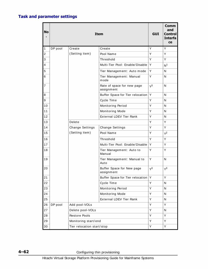
Hitachi Virtual Storage Platform Provisioning Guide for Mainframe Systems
4–62 Configuring thin provisioning
Task and parameter settings
No. Item GUI
Command
Control Interfa
ce
1 DP pool Create
(Setting item)
Create Y Y
2 Pool Name Y Y
3 Threshold Y Y
4 Multi-Tier Pool: Enable/Disable Y N1
5 Tier Management: Auto mode Y N
6 Tier Management: Manual mode
Y N
7 Rate of space for new page assignment
Y3 N
8 Buffer Space for Tier relocation Y N
9 Cycle Time Y N
10 Monitoring Period Y N
11 Monitoring Mode Y N
12 External LDEV Tier Rank Y N
13 Delete Y Y
14 Change Settings
(Setting item)
Change Settings Y Y
15 Pool Name Y Y2
16 Threshold Y Y
17 Multi-Tier Pool: Enable/Disable Y Y
18 Tier Management: Auto to Manual
Y Y
19 Tier Management: Manual to Auto
Y N
20 Buffer Space for New page assignment
Y3 Y3
21 Buffer Space for Tier relocation Y Y
22 Cycle Time Y N
23 Monitoring Period Y N
24 Monitoring Mode Y N
25 External LDEV Tier Rank Y N
26 DP pool Add pool-VOLs Y Y
27 Delete pool-VOLs Y N
28 Restore Pools Y Y
29 Monitoring start/end Y Y
30 Tier relocation start/stop Y Y
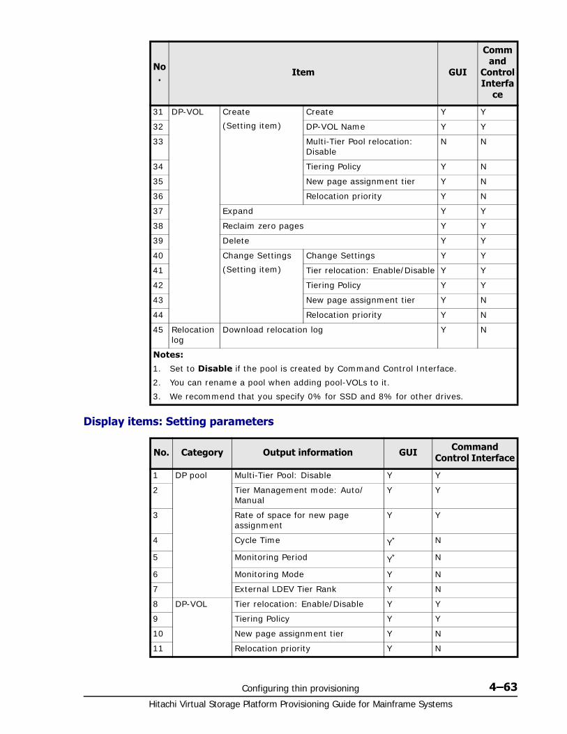
Configuring thin provisioning 4–63Hitachi Virtual Storage Platform Provisioning Guide for Mainframe Systems
Display items: Setting parameters
31 DP-VOL Create
(Setting item)
Create Y Y
32 DP-VOL Name Y Y
33 Multi-Tier Pool relocation: Disable
N N
34 Tiering Policy Y N
35 New page assignment tier Y N
36 Relocation priority Y N
37 Expand Y Y
38 Reclaim zero pages Y Y
39 Delete Y Y
40 Change Settings
(Setting item)
Change Settings Y Y
41 Tier relocation: Enable/Disable Y Y
42 Tiering Policy Y Y
43 New page assignment tier Y N
44 Relocation priority Y N
45 Relocation log
Download relocation log Y N
Notes:
1. Set to Disable if the pool is created by Command Control Interface.
2. You can rename a pool when adding pool-VOLs to it.
3. We recommend that you specify 0% for SSD and 8% for other drives.
No. Category Output information GUI Command Control Interface
1 DP pool Multi-Tier Pool: Disable Y Y
2 Tier Management mode: Auto/Manual
Y Y
3 Rate of space for new page assignment
Y Y
4 Cycle Time Y* N
5 Monitoring Period Y* N
6 Monitoring Mode Y N
7 External LDEV Tier Rank Y N
8 DP-VOL Tier relocation: Enable/Disable Y Y
9 Tiering Policy Y Y
10 New page assignment tier Y N
11 Relocation priority Y N
No. Item GUI
Command
Control Interfa
ce
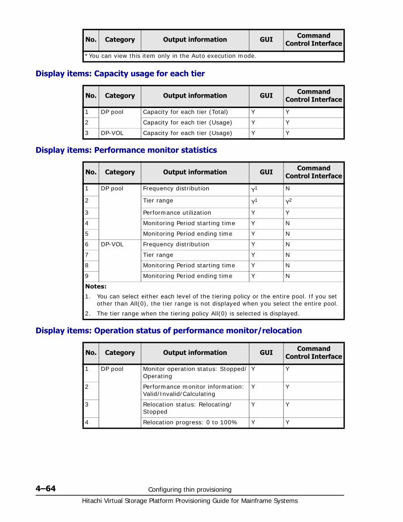
Hitachi Virtual Storage Platform Provisioning Guide for Mainframe Systems
4–64 Configuring thin provisioning
Display items: Capacity usage for each tier
Display items: Performance monitor statistics
Display items: Operation status of performance monitor/relocation
*You can view this item only in the Auto execution mode.
No. Category Output information GUI Command Control Interface
1 DP pool Capacity for each tier (Total) Y Y
2 Capacity for each tier (Usage) Y Y
3 DP-VOL Capacity for each tier (Usage) Y Y
No. Category Output information GUI Command Control Interface
1 DP pool Frequency distribution Y1 N
2 Tier range Y1 Y2
3 Performance utilization Y Y
4 Monitoring Period starting time Y N
5 Monitoring Period ending time Y N
6 DP-VOL Frequency distribution Y N
7 Tier range Y N
8 Monitoring Period starting time Y N
9 Monitoring Period ending time Y N
Notes:
1. You can select either each level of the tiering policy or the entire pool. If you set other than All(0), the tier range is not displayed when you select the entire pool.
2. The tier range when the tiering policy All(0) is selected is displayed.
No. Category Output information GUI Command Control Interface
1 DP pool Monitor operation status: Stopped/Operating
Y Y
2 Performance monitor information: Valid/Invalid/Calculating
Y Y
3 Relocation status: Relocating/Stopped
Y Y
4 Relocation progress: 0 to 100% Y Y
No. Category Output information GUI Command Control Interface
Configuring thin provisioning 4–65Hitachi Virtual Storage Platform Provisioning Guide for Mainframe Systems
Managing Dynamic Tiering for Mainframe
Changing pool for Dynamic Provisioning for Mainframe to pool for Dynamic Tiering for Mainframe
To change a pool for Dynamic Provisioning for Mainframe to a pool for Dynamic Tiering for Mainframe:1. In the Storage Systems tree on the left pane of the top window, select
Pool.
2. From the Pools table on right, click the row of a pool you want to change to the Dynamic Tiering for Mainframe setting.
To select consecutive rows, highlight all of the rows to be selected and press the Shift key. To select separate rows, click each row pressing the Ctrl key.
3. Click More Actions and select Edit Pools.
The Edit Pools window appears.
4. Check Multi-Tier Pool.
5. Select Enable from the Multi-Tier Pool field.
If TSE-VOL is assigned to the selected pool, you cannot select Enable.
6. To configure Dynamic Tiering for Mainframe:a. Select the Tier Management check box.b. From the Tier Management field, select Auto or Manual.
Normally Auto should be set.
When you select Auto, monitoring and tier relocation can automatically executed.
When you select Manual, monitoring and tier relocation can be executed with the Command Control Interface commands or the Pools window of Storage Navigator.
When you change the setting of Auto to Manual while monitoring and tier relocation is executing, it is cancelled.
Hitachi Virtual Storage Platform Provisioning Guide for Mainframe Systems
4–66 Configuring thin provisioning
c. From the Cycle Time list, select the cycle of performance monitoring and tier relocation.
d. Select the Monitoring Mode check box.e. From the Monitoring Mode option, select Period Mode or
Continuous Mode.
If you want to perform tier relocation using the monitor results from the prior cycle, select Period Mode. If you want to perform tier relocation weighted to the past period monitoring result, select Continuous Mode.
f. Select the Buffer Space for New page assignment check box.g. In the Buffer Space for New page assignment text box, enter an
integer value from 0 to 50 as the percentage (%) to set for each tier. h. Select the Buffer Space for Tier relocation check box.i. In the Buffer Space for Tier relocation text box, enter an integer
value from 2 to 40 as the percentage (%) to set for each tier.
7. Click Finish.
The Confirm window appears.
8. In the Task Name text box, enter the task name.
You can enter up to 32 ASCII characters and symbols in all, except for \ / : , ; * ? " < > |. The value "date-window name" is entered by default.
9. In the Confirm window, click Apply to register the setting in the task.
Note:
• When you change the Cycle Time while performance monitoring and tier relocation are being executed, the setting becomes effective for the next cycle after the current cycle is complete.
When you select 24 Hours (default):
Monitoring and tier relocation is performed once a day. In the Monitoring Period field, specify the time of starting and ending of monitoring in 00:00 to 23:59 (default value).
• If you specify the starting time later than the ending time, the monitoring continues until the time when you specify as the ending time on the next day. Anytime that is not in the specified range of the monitor period is not monitored.
• You can view the information gathered by monitoring with Storage Navigator and Command Control Interface.
• When you change the time range of performance monitoring, the setting becomes effective from the next cycle after the cycle that is executing is complete.
When you select any of 0.5 Hours, 1 Hour, 2 Hours, 4 Hours or 8 Hours:
Performance monitoring is performed every duration you selected starting at 00:00.
You cannot specify the monitoring period.
Configuring thin provisioning 4–67Hitachi Virtual Storage Platform Provisioning Guide for Mainframe Systems
If the Go to tasks window for status check box is selected, the Tasks window appears.
Changing monitoring and tier relocation settings
This topic describes how to change the following pool settings of Dynamic Tiering for Mainframe:
• Automatic or manual execution of monitoring and tier relocation
• Cycle time of monitoring and tier relocation
• Time period of monitoring
To change monitoring and tier relocation settings:1. In the Storage Systems tree on the left pane of the top window, select
Pool.
2. From the Pools table on the right, click the row of the pool with the Dynamic Tiering for Mainframe setting you want to change.
To select consecutive rows, highlight all of the rows to be selected and press the Shift key. To select separate rows, click each row while pressing the Ctrl key.
3. Click More Actions and select Edit Pools.
The Edit Pools window appears.
4. Check Tier Management.
5. From the Tier Management field, select Auto or Manual.
Normally Auto should be set.
When you select Auto, monitoring and tier relocation can automatically executed.
When you select Manual, monitoring and tier relocation can be executed with the Command Control Interface commands or the Pools window of Storage Navigator.
When you change the setting of Auto to Manual while performance monitoring and tier relocation is executing, it is cancelled and is not performed since then.
6. If Auto is selected from the Cycle Time list, select the cycle of performance monitoring and tier relocation.
7. Click Finish.
The Confirm window appears.
8. In the Task Name text box, enter the task name.
You can enter up to 32 ASCII characters and symbols in all, except for \ / : , ; * ? " < > |. The value "date-window name" is entered by default.
9. In the Confirm window, click Apply to register the setting in the task.
If the Go to tasks window for status check box is selected, the Tasks window appears.
Hitachi Virtual Storage Platform Provisioning Guide for Mainframe Systems
4–68 Configuring thin provisioning
Changing monitoring mode setting
To change monitoring mode setting:1. In the Storage Systems tree on the left pane of the top window, select
Pool.
2. From the Pools table on the right, click the row of the pool with the Dynamic Tiering for Mainframe setting you want to change.
To select consecutive rows, highlight all of the rows to be selected and press the Shift key. To select separate rows, click each row while pressing the Ctrl key.
3. Click More Actions and select Edit Pools.
The Edit Pools window appears.
4. Check Monitoring Mode.
5. From the Monitoring Mode option, select Period Mode or Continuous Mode.
If you want to perform tier relocation using the monitor results from the prior cycle, select Period Mode. If you want to perform tier relocation weighted to the past period monitoring result, select Continuous Mode.
6. Click Finish.
The Confirm window appears.
7. In the Task Name text box, enter the task name.
You can enter up to 32 ASCII characters and symbols in all, except for \ / : , ; * ? " < > |. The value "date-window name" is entered by default.
8. In the Confirm window, click Apply to register the setting in the task.
If the Go to tasks window for status check box is selected, the Tasks window appears.
Changing buffer space for new page assignment setting
To change buffer space for new page assignment setting:1. In the Storage Systems tree on the left pane of the top window, select
Pool.
2. From the Pools table on the right, click the row of a pool with the Dynamic Tiering for Mainframe setting you want to change.
To select consecutive rows, highlight all of the rows to be selected and press the Shift key. To select separate rows, click each row while pressing the Ctrl key.
3. Click More Actions and select Edit Pools.
The Edit Pools window appears.
4. Select the Buffer Space for New page assignment check box.
5. In the Buffer Space for New page assignment text box, enter an integer value from 0 to 50 as the percentage (%) to set for each tier.
Configuring thin provisioning 4–69Hitachi Virtual Storage Platform Provisioning Guide for Mainframe Systems
6. Click Finish.
The Confirm window appears.
7. In the Task Name text box, enter the task name.
You can enter up to 32 ASCII characters and symbols in all, except for \ / : , ; * ? " < > |. The value "date-window name" is entered by default.
8. In the Confirm window, click Apply to register the setting in the task.
If the Go to tasks window for status check box is selected, the Tasks window appears.
Changing buffer space for tier relocation setting
To change buffer space for tier relocation setting:1. In the Storage Systems tree on the left pane of the top window, select
Pool.
2. From the Pools table on the right, click the row of a pool with the Dynamic Tiering for Mainframe setting you want to change.
To select consecutive rows, highlight all of the rows to be selected and press the Shift key. To select separate rows, click each row while pressing the Ctrl key.
3. Click More Actions and select Edit Pools.
The Edit Pools window appears.
4. Select the Buffer Space for Tier relocation check box.
5. In the Buffer Space for Tier relocation text box, enter an integer value from 2 to 40 as the percentage (%) to set for each tier.
6. Click Finish.
The Confirm window appears.
7. In the Task Name text box, enter the task name.
You can enter up to 32 ASCII characters and symbols in all, except for \ / : , ; * ? " < > |. The value "date-window name" is entered by default.
8. In the Confirm window, click Apply to register the setting in the task.
If the Go to tasks window for status check box is selected, the Tasks window appears.
Changing a pool for Dynamic Tiering for Mainframe to a pool for Dynamic Provisioning for Mainframe
You can change a Dynamic Tiering for Mainframe pool to a Dynamic Provisioning for Mainframe pool. However, you cannot change the pool status of Dynamic Tiering for Mainframe to disable in the following cases:
• Tier relocation is being executed manually.
• Pool-VOLs are being deleted.
• Zero pages are being reclaimed.
Hitachi Virtual Storage Platform Provisioning Guide for Mainframe Systems
4–70 Configuring thin provisioning
1. In the Storage Systems tree on the left pane of the top window, select Pool.
The pool name appears below Pool.
2. Select a pool that is changed from a pool for Dynamic Tiering for Mainframe to a pool for Dynamic Provisioning for Mainframe.
The pool information appears.
3. Click More Actions to select Edit Pool.
The Edit Pool window appears.
4. Check Multi-Tier Pool and select Disable from the Multi-Tier Pool option.
5. Click Finish.
The Confirm window appears.
6. In the Task Name text box, enter the task name.
You can enter up to 32 ASCII characters and symbols in all, except for \ / : , ; * ? " < > |. The value "date-window name" is entered by default.
7. In the Confirm window, click Apply to register the setting in the task.
If the Go to tasks window for status check box is selected, the Tasks window appears.
Working with pools
About poolsDynamic Provisioning for Mainframe requires the use of pools. A pool consists of more than one pool-VOL. A storage system supports up to 128 pools, each of which can contain up to 1024 pool-VOLs and 63,232 DP-VOLs per pool. The pool for Dynamic Provisioning for Mainframe or Copy-on-Write Snapshot cannot be used in conjunction with other pools.
A pool number must be assigned to a pool. Multiple DP-VOLs can be related to one pool.
• capacity of the pool (MB) = total number of pages × 38 - 3800
3800 in the formula is the management area size of the pool-VOL with System Area.
• total number of pages = Σ(floor(floor(pool-VOL number of blocks ÷ 116) ÷ 672)) for each pool-VOL
• 1 cylinder - 1740 blocks
• floor( ) means to truncate the part of the formula within the parentheses after the decimal point.
About pool-VOLsPool-VOLs are grouped together to create a pool. When a new pool is created, the available pool-VOLs are selected in the Select Pool VOLs window and added to the Selected Pool Volumes table. Every pool must have a pool-VOL with System Area.
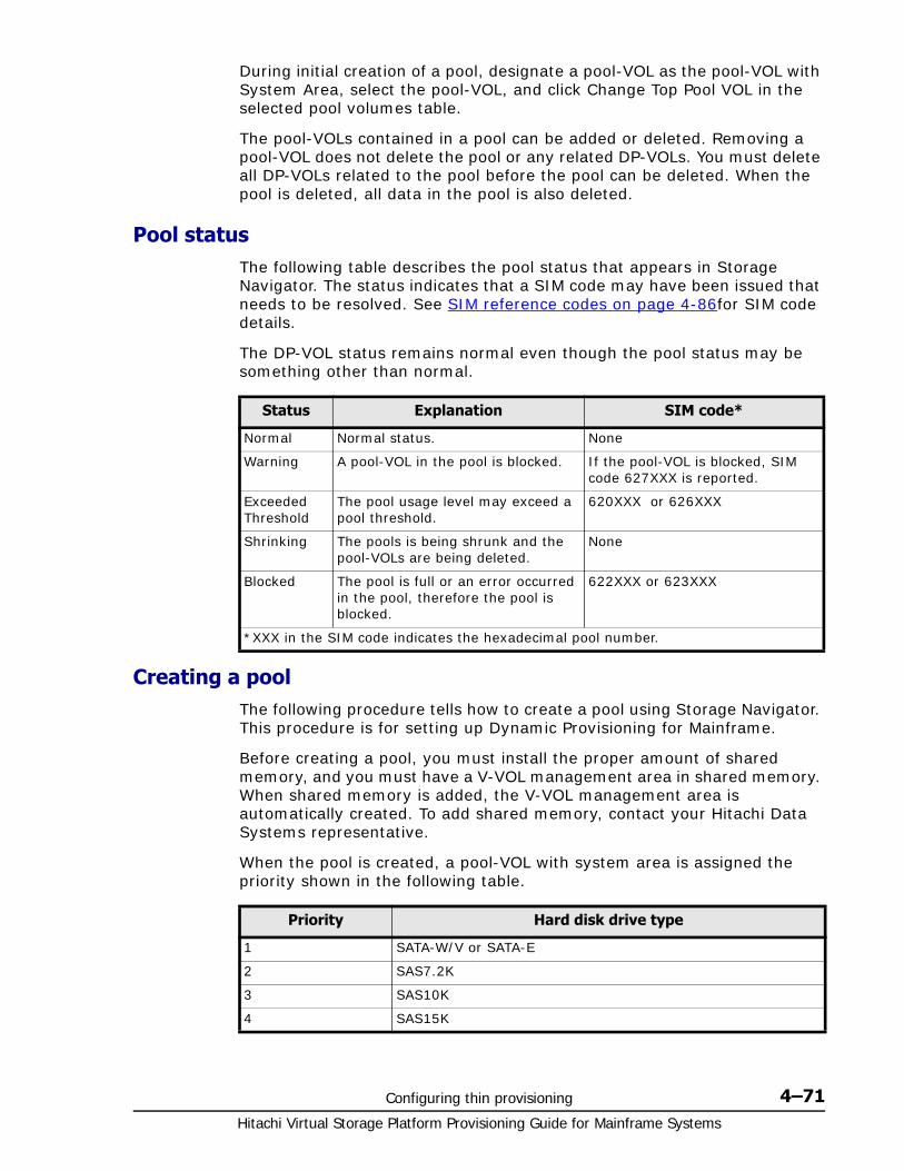
Configuring thin provisioning 4–71Hitachi Virtual Storage Platform Provisioning Guide for Mainframe Systems
During initial creation of a pool, designate a pool-VOL as the pool-VOL with System Area, select the pool-VOL, and click Change Top Pool VOL in the selected pool volumes table.
The pool-VOLs contained in a pool can be added or deleted. Removing a pool-VOL does not delete the pool or any related DP-VOLs. You must delete all DP-VOLs related to the pool before the pool can be deleted. When the pool is deleted, all data in the pool is also deleted.
Pool statusThe following table describes the pool status that appears in Storage Navigator. The status indicates that a SIM code may have been issued that needs to be resolved. See SIM reference codes on page 4-86for SIM code details.
The DP-VOL status remains normal even though the pool status may be something other than normal.
Creating a poolThe following procedure tells how to create a pool using Storage Navigator. This procedure is for setting up Dynamic Provisioning for Mainframe.
Before creating a pool, you must install the proper amount of shared memory, and you must have a V-VOL management area in shared memory. When shared memory is added, the V-VOL management area is automatically created. To add shared memory, contact your Hitachi Data Systems representative.
When the pool is created, a pool-VOL with system area is assigned the priority shown in the following table.
Status Explanation SIM code*
Normal Normal status. None
Warning A pool-VOL in the pool is blocked. If the pool-VOL is blocked, SIM code 627XXX is reported.
Exceeded Threshold
The pool usage level may exceed a pool threshold.
620XXX or 626XXX
Shrinking The pools is being shrunk and the pool-VOLs are being deleted.
None
Blocked The pool is full or an error occurred in the pool, therefore the pool is blocked.
622XXX or 623XXX
*XXX in the SIM code indicates the hexadecimal pool number.
Priority Hard disk drive type
1 SATA-W/V or SATA-E
2 SAS7.2K
3 SAS10K
4 SAS15K
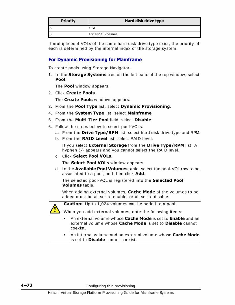
Hitachi Virtual Storage Platform Provisioning Guide for Mainframe Systems
4–72 Configuring thin provisioning
If multiple pool-VOLs of the same hard disk drive type exist, the priority of each is determined by the internal index of the storage system.
For Dynamic Provisioning for Mainframe
To create pools using Storage Navigator:
1. In the Storage Systems tree on the left pane of the top window, select Pool.
The Pool window appears.
2. Click Create Pools.
The Create Pools windows appears.
3. From the Pool Type list, select Dynamic Provisioning.
4. From the System Type list, select Mainframe.
5. From the Multi-Tier Pool field, select Disable.
6. Follow the steps below to select pool-VOLs.a. From the Drive Type/RPM list, select hard disk drive type and RPM.b. From the RAID Level list, select RAID level.
If you select External Storage from the Drive Type/RPM list, A hyphen (-) appears and you cannot select the RAID level.
c. Click Select Pool VOLs.
The Select Pool VOLs window appears.d. In the Available Pool Volumes table, select the pool-VOL row to be
associated to a pool, and then click Add.
The selected pool-VOL is registered into the Selected Pool Volumes table.
When adding external volumes, Cache Mode of the volumes to be added must be all set to enable, or all set to disable.
5 SSD
6 External volume
Priority Hard disk drive type
Caution: Up to 1,024 volumes can be added to a pool.
When you add external volumes, note the following items:
• An external volume whose Cache Mode is set to Enable and an external volume whose Cache Mode is set to Disable cannot coexist.
• An internal volume and an external volume whose Cache Mode is set to Disable cannot coexist.
Configuring thin provisioning 4–73Hitachi Virtual Storage Platform Provisioning Guide for Mainframe Systems
e. Click OK.
The information in the Selected Pool Volumes table is applied to Total Selected Pool Volumes and Total Selected Capacity.
7. In the Pool Name text box, enter the pool name as follows:
In the Prefix text box, enter the alphanumeric characters, which are fixed characters of the head of the pool name. The characters are case-sensitive.
In the Initial Number text box, type the initial number following the prefix name, which can be up to 9 digits.
You can enter up to 32 characters, including the initial number.
8. Click Options.
9. In the Initial Pool ID text box, type the number of the initial pool ID, from 0 to 127.
The smallest available number is displayed in the text box as a default. No number, however, appears in the text box, if no available pool ID exists. When the registered pool ID is entered, the smallest available pool ID is registered automatically among the subsequent pool IDs that were entered.
10.In the Subscription Limit text box, enter an integer value from 0 to 65534 as the subscription rate (%) for the pool.
If it is blank, the subscription rate is set to unlimited.
11.In the Warning Threshold text box, enter an integer value from 1 to 100 as the rate (%) for the pool. The default value is 70%.
12.In the Depletion Threshold text box, enter an integer value from 1 to 100 as the rate (%) for the pool. The default value is 80%.
Enter a value more than the value of Warning Threshold.
13.Click Add.
The created pool is added to the right Selected Pools table. If the invalid values are set, an error message appears.
If even one item that must be set is not entered or selected, you cannot click Add.
The items that have to be set include Pool Type, Pool Volume Selection, and Pool Name.
Note: Perform the following if necessary:
• Click Filter to open the menu, specify the filtering, and then Apply.
• Click Select All Pages to select all pool-VOLs in the table. To cancel the selection, click Select All Pages again.
• Click Options to specify the unit of volumes or the number of rows to be displayed.
• To set the tier rank of an external volume to a value other than Middle, select a tier rank from External LDEV Tier Rank, and click Add.
Hitachi Virtual Storage Platform Provisioning Guide for Mainframe Systems
4–74 Configuring thin provisioning
If you select a row and click Detail, the Pool Properties window appears. If you select a row and click Remove, a message appears asking whether you want to remove the selected row or rows. If you want to remove the row, click OK.
14.Click Next.
The Create LDEVs window appears. Go to Creating V-VOLs on page 4-77 to create LDEVs.
If Subscription Limit for all the created pool is set to 0%, the Create LDEVs window does not appear.
To finish the wizard, click Finish. The Confirm window appears.
15.In the Confirm window, click Apply to register the setting in the task.
If you select a row and click Detail, the Pool Properties window appears.
If the Go to tasks window for status check box is selected, the Tasks window appears.
For Dynamic Tiering for Mainframe
To create pools using Storage Navigator:
1. In the Storage Systems tree on the left pane of the top window, select Pool.
The Pool window appears.
2. Click Create Pools.
The Create Pools windows appears.
3. From the Pool Type list, select Dynamic Provisioning.
4. From the System Type list, select Mainframe.
5. From the Multi-Tier Pool field, select Enable.
6. Follow these steps below to select pool-VOLs:a. In the Drive Type/RPM list, make sure that Mixable is selected.b. From the RAID Level list, make sure that Mixable is selected.c. Click Select Pool VOLs.
The Select Pool VOLs window appears.d. In the Available Pool Volumes table, select the pool-VOL row to be
associated to a pool, and then click Add.
The selected pool-VOL is registered into the Selected Pool Volumes table.
Caution: You cannot select Enable if the storage system has only external volumes with the Cache Mode set to Disable.
Caution: Up to 1,024 volumes can be added to a pool.

Configuring thin provisioning 4–75Hitachi Virtual Storage Platform Provisioning Guide for Mainframe Systems
e. Click OK.
The information in the Selected Pool Volumes table is applied to Total Selected Pool Volumes and Total Selected Capacity.
7. In the Pool Name text box, enter the pool name as follows:
In the Prefix text box, enter the alphanumeric characters, which are the fixed characters of the head of the pool name. The characters are case-sensitive.
In the Initial Number text box, type the initial number following the prefix name, which can be up to 9 digits.
You can enter up to 32 characters, including the initial number.
8. Click Options.
The setting fields following Initial Pool ID appear.
9. In the Initial Pool ID text box, enter the number of the initial pool ID from 0 to 127.
The smallest available number is displayed in the text box as a default. No number, however, appears in the text box, if no available pool ID exists. When the registered pool ID is entered, the smallest available pool ID is registered automatically among the subsequent pool IDs that were entered.
10.In the Subscription Limit text box, enter an integer value from 0 to 65534 as the subscription rate (%).
If no figure is entered, the subscription is unlimitedly set.
11.In the Warning Threshold text box, enter an integer value from 1 to 100 as the rate (%) for the pool. The default value is 70%.
12.In the Depletion Threshold text box, enter an integer value from 1 to 100 as the rate (%) for the pool. The default value is 80%.
Enter a value more than the value of Warning Threshold.
Note: Perform the following if necessary:
• Click Filter to open the menu, specify the filtering, and then Apply.
• Click Select All Pages to select all pool-VOLs in the table. To cancel the selection, click Select All Pages again.
• Click Options to specify the unit of volumes or the number of rows to be displayed.
• To set the tier rank of an external volume to a value other than Middle, select a tier rank from External LDEV Tier Rank, and then click Add.
• For a pool, you can add volumes whose Drive Type/RPM settings are the same and whose RAID Levels are different. For example, you can add the following volumes to the same pool:
Volume whose Drive Type/RPM is SAS/15K and whose RAID Level is 5 (3D+1P)
Volume whose Drive Type/RPM is SAS/15K and whose RAID Level is 5 (7D+1P)
Hitachi Virtual Storage Platform Provisioning Guide for Mainframe Systems
4–76 Configuring thin provisioning
13.Configure Dynamic Tiering for Mainframe as follows:a. From the Tier Management option, select Auto or Manual.
Normally you select Auto.
If you select Auto, performance monitoring and tier relocation are automatically performed.
If you select Manual, you can manually perform performance monitoring and tier relocation with the Command Control Interface commands or Storage Navigator.
b. From Cycle Time list, select the cycle of performance monitoring and tier relocation.
When you select 24 Hours (default value):
Performance monitoring and tier relocation is performed once a day.
In the Monitoring Period field, specify the time of starting and ending of performance monitoring in 00:00 to 23:59 (default value).
Take one or more hours between the starting time and the ending time. If you specify the starting time later than the ending time, the performance monitoring continues until the time when you specify as the ending time on the next day.
You can view the information gathered by performance monitoring with Storage Navigator and Command Control Interface.
When you select any of 0.5 Hours, 1 Hour, 2 Hours, 4 Hours or 8 Hours:
Performance monitoring is performed every hour you selected starting at 00:00.
You cannot specify the time of performance monitoring.
Caution: When Auto is set, all the V-VOL pages may not be completed migrating by one cycle. At the next cycle, the last processed V-VOL will start being migrated with the updated information. However, the performance monitoring information is switched.
14.From the Monitoring Mode option, select Period Mode or Continuous Mode.
If you perform the tier relocation with the specified cycle or you do not need to specify the Monitoring Mode option, select Period Mode. If you perform the tier relocation weighted to the past period monitoring result, select Continuous Mode.
15.In the Buffer Space for New page assignment text box, enter an integer value from 0 to 50 as the percentage (%) to set for each tier.
A default value depends on the hard disk drive type of pool-VOL in each tier. The default value of SSD is 0%. The default value of the type other than SSD is 8%.
16.In the Buffer Space for Tier relocation text box, enter an integer value from 2 to 40 as the percentage (%) to set for each tier.
A default value is 2%.
17.Click Add.
Configuring thin provisioning 4–77Hitachi Virtual Storage Platform Provisioning Guide for Mainframe Systems
The created pool is added to the right Selected Pools table. If invalid values are set, an error message appears.
The Pool Type, Multi-Tier Pool, Pool Volume Selection and Pool Name field must be set. If these required items are not registered, you cannot click Add.
If you select a row and click Detail, the Pool Properties window appears. If you select a row and click Remove, a message appears asking whether you want to remove the selected row or rows. If you want to remove the row, click OK.
18.Click Next.
The Create LDEVs window appears. Go to Creating V-VOLs on page 4-77 to create LDEVs.
If Subscription Limit for all the created pool is set to 0%, the Create LDEVs window does not appear.
To finish the wizard, click Finish. The Confirm window appears.
19.In the Confirm window, click Apply to register the setting in the task.
If you select a row and click Detail, the Pool Properties window appears.
If the Go to tasks window for status check box is selected, the Tasks window appears.
Working with DP-VOLs
About DP-VOLsDynamic Provisioning for Mainframe requires the use of DP-VOLs, which are virtual volumes with no physical memory space. In Dynamic Provisioning for Mainframe, multiple DP-VOLs can be created.
A DP-VOL is a volume in a thin provisioning storage system. It is the virtual volume from a DP pool. Data in the DP pool is used via a DP-VOL. A DP-VOL is a virtual LU to some hosts.
On mainframe systems, 3390-A is the supported emulation type on a DP-VOL.
Relationship between a pool and DP-VOLsBefore you can use Dynamic Provisioning for Mainframe, a DP-VOL and a pool are required. Dynamic Provisioning for Mainframe uses the pool volumes in a pool through the DP-VOLs.
Creating V-VOLsYou can create a DP-VOL from any of the following tabs:
• The LDEVs tab, which appears when Logical Devices is selected.
• The Pools tab, which appears when Pools is selected.
Hitachi Virtual Storage Platform Provisioning Guide for Mainframe Systems
4–78 Configuring thin provisioning
• The Virtual Volumes tab, which appears when a pool in Pools is selected.
1. You can create LDEVs from the following tab windows:
The LDEVs tab, which appears when Logical Devices is selected.
The Pools tab, which appears when Pools is selected.
The Virtual Volumes tab, which appears when a pool in Pools is selected.
2. Click Create LDEVs.
The Create LDEVs window appears.
3. From the Provisioning Type list, confirm Dynamic Provisioning is selected.
If not, select Dynamic Provisioning from the list.
4. In the System Type option, select a system type.
To create mainframe volumes, select Mainframe.
5. From the Emulation Type list, confirm 3390-A is selected.
6. From the Multi-Tier Pool field, select Enable when you create the V-VOL for Dynamic Tiering for Mainframe, and select Disable when you do not create one.
If no pool is set to Enable in Dynamic Tiering for Mainframe, Disable is fixed.
7. If you create TSE-VOL, select Enable in the TSE Attribute option. If not created, select Disable.
If you do not have the license of Compatible Software for IBM® FlashCopy® SE, you can select only Disable in TSE Attribute. In addition, if there is no LDEV IDs that can be used as TSE-VOL, you can select only Disable in TSE Attribute.
8. Select the pool according to the following steps.a. From the Drive Type/RPM list in Pool Selection, select the hard
disk drive type and RPM.b. From the RAID level list, select the RAID level.c. Click Select Pool.
The Select Pool window appears.
Note:
• You can specify the TSE Attribute function only when selecting Mainframe in the System Type option.
• You can specify the TSE Attribute function only when selecting Disable in the Multi-Tier Pool field.
• For TSE-VOL, if the relating pool ID is the odd number, the odd number is automatically assigned as the CU number for the LDEV to create. If the relating pool ID is the even number, the even number is automatically assigned as the CU number for the LDEV to create.
Configuring thin provisioning 4–79Hitachi Virtual Storage Platform Provisioning Guide for Mainframe Systems
d. In the Available Pools table, select a pool.
e. Click OK.
The Select Pool window closes. The selected pool name appears in Selected Pool Name (ID), and the total capacity of the selected pool appears in Selected Pool Capacity.
9. In the LDEV Capacity text box, enter the DP-VOL capacity to be created.
You can enter the capacity within the range of figures displayed below the text box. The capacity unit is fixed to Cyl.
10.In the Number of LDEVs text box, enter the number of LDEVs to be created.
You can enter the number of LDEVs within a range of the figures displayed below the text box.
11.In the LDEV Name text box, enter the DP-VOL name.
In the Prefix text box, enter the alphanumeric characters, which are fixed characters of the head of the DP-VOL name. The characters are case-sensitive.
In the Initial Number text box, type the initial number following the prefix name, which can be up to 9 digits.
You can enter up to 32 characters including the initial number.
12.Click Options.
13.In the Initial LDEV ID field, make sure that LDEV ID is set.
Note: You can specify a pool when creating DP-VOLs if the pool has a status of one of the following:
• Normal status
• Exceeded Threshold status
• In progress of pool capacity shrinking
You can select only one pool. When Enable is selected in step 6, the Dynamic Tiering for Mainframe-pools appear, and when Disable is selected, only the non-Dynamic Tiering for Mainframe-pools appear.
Perform the following if necessary:
• Click Filter to open the menu, specify the filtering, and then Apply.
• Click Options to specify the units of pools or the number of rows to be displayed.
Hitachi Virtual Storage Platform Provisioning Guide for Mainframe Systems
4–80 Configuring thin provisioning
To confirm the used number and unavailable number, click View LDEV IDs to display the View LDEV IDs window.
14.In the Initial SSID text box, type the 4-digit SSID of a hexadecimal number (0004 to FFFE).
To confirm the created SSID, click View SSID to display the View SSID windows.
15.From the Cache Partition list, select CLPR.
16.From the Processor Blade list, select a processor blade.
Select a processor blade to be used by the LDEVs. If you assign a specific processor blade, select the ID of the processor blade. If you can assign any processor blade, click Auto.
17.From the Tiering Policy field, select the tiering policy to be used by the LDEVs. If you assign a specific tiering policy, select any policy. All(0) is selected by default. You can change a level from Level1(1) to Level5(5) or from Level6(6) to Level31(31). You can specify the function when the Multi-Tier Pool is enabled.
18.From the New Page Assignment Tier list, select a new page assignment tier. You can select from levels High, Middle, and Low.
You can specify the function when the Multi-Tier Pool is enabled.
19.In the Relocation Priority option, select a priority.
To relocate the LDEV preferentially, set Prioritize. You can select Default or Prioritize. You can specify this function when the Multi-Tier Pool is enabled.
20.If necessary, change the settings of the V-VOLs.
You can change the following settings:
Editing SSID
Click Edit SSIDs to open the Edit SSIDs window.
Changing the LDEV settings
Click Change LDEV Settings to open the Change LDEV Settings window.
21.If necessary, delete a row from the Selected LDEVs table.
Select a row to be deleted, and then click Remove.
22.Click Add.
The created V-VOLs are added to the right Selected LDEVs table. If invalid values are set, an error message appears.
Note: When you create TSE-VOL if you select the pool and display the View LDEV IDs window, the displaying when the selected pool ID is an odd number is different from the displaying when the selected pool ID is an even number. If the selected pool ID is an odd number, all the LDEV IDs belonging to the CU whose ID is an even number are displayed as disabled (the cell color is gray). If the selected pool ID is an even number, all the LDEV IDs belonging to the CU whose ID is an odd number are displayed as disabled (the cell color is gray).
Configuring thin provisioning 4–81Hitachi Virtual Storage Platform Provisioning Guide for Mainframe Systems
The Provisioning Type, System Type, Emulation Type, Pool Selection, Drive Type/RPM, RAID Level, LDEV Capacity, and Number of LDEVs field must be set. If these required items are not registered, you cannot click Add.
23.Click Finish.
The Confirm window appears.
24.In the Task Name in the text box, enter the task name.
You can enter up to 32 ASCII characters and symbols in all, except for \ / : , ; * ? " < > |. "yymmdd-window name" is entered as a default.
25.Click Apply.
If the Go to tasks window for status check box is selected, the Tasks window appears.
Editing a DP-VOL's SSIDBefore registering a DP-VOL, you may need to edit the DP-VOL's SSID. The SSID is a hexadecimal value.
1. In the Selected LDEVs table in the Create LDEVs window, click Edit SSIDs.
The Edit SSIDs window opens. The SSIDs table shows the SSID existing and to be added.
2. If you want to change the SSID, select the appropriate LDEV, and then click Change SSIDs.
3. In the Change SSIDs window, type the new SSID in hexadecimal format, and then click OK
4. In the Edit SSIDs window, click OK.
5. In the Create LDEVs window, click Finish.
6. In the Confirm window, confirm the settings, and then click Apply.
If Go to tasks window for status is checked, the Tasks window opens.
Changing DP-VOL settingsBefore registering a DP-VOL, you may need to change the DP-VOL settings.
1. In the Selected LDEVs table in the Create LDEVs window, select an LDEV, and then click Change LDEV Settings.
2. In the Change LDEV Settings window, you can change the setting of LDEV Name, Initial LDEV ID, or Processor Blade.
If you change LDEV Name, specify the prefix characters and the initial number for this LDEV.
Hitachi Virtual Storage Platform Provisioning Guide for Mainframe Systems
4–82 Configuring thin provisioning
If you change Initial LDEV ID, specify the number of LDKC, CU, DEV, and Interval. To check used LDEVs, click View LDEV IDs to confirm the used LDEVs. The View LDEV IDs window opens.
If you change Processor Blade, click the list and specify the processor blade ID. If the specific processor blade is specified, select the processor blade ID. If any processor blade is specified, click Auto.
3. Change the settings, and then click OK.
4. In the Create LDEVs window, click Finish.
5. In the Confirm window, click Apply.
The setting is changed.
If Go to tasks window for status is checked, the Tasks window opens.
Removing the DP-VOL to be registeredIf you do not want to register the DP-VOL, you can remove it from the registering task.
1. In the Selected LDEVs table in the Create LDEVs window, select the LDEV, and then click Remove. A message appears asking whether you want to remove the selected row or rows. If you want to remove the row, click OK.
2. Click Finish.
3. In the Confirm window, click Apply.
The LDEV is removed.
If Go to tasks window for status is checked, the Tasks window opens.
Thresholds
Pool utilization thresholdsDynamic Provisioning for Mainframe monitors pool capacity using thresholds. A threshold is the proportion (%) of used capacity of the pool to the total pool capacity. Each pool has its own pool threshold values.
• Warning Threshold: Set the value between 1% and 100%, in 1% increments. The default is 70%.
• Depletion Threshold: Set the value between 1% and 100%, in 1% increments. The default is 80%. The depletion threshold must be higher than the Warning threshold
Caution: You cannot change the LDEV ID when you select a TSE-VOL in one of the following conditions:
• Selecting TSE-VOLs and other volumes at the same time.
• Selecting together the TSE-VOL related to the pool whose ID is the odd number and the TSE-VOL related to the pool whose ID is the even number.
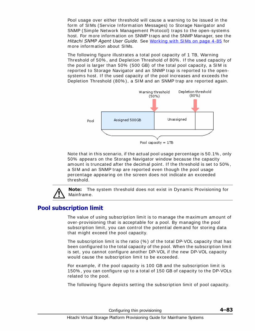
Configuring thin provisioning 4–83Hitachi Virtual Storage Platform Provisioning Guide for Mainframe Systems
Pool usage over either threshold will cause a warning to be issued in the form of SIMs (Service Information Messages) to Storage Navigator and SNMP (Simple Network Management Protocol) traps to the open-systems host. For more information on SNMP traps and the SNMP Manager, see the Hitachi SNMP Agent User Guide. See Working with SIMs on page 4-85 for more information about SIMs.
The following figure illustrates a total pool capacity of 1 TB, Warning Threshold of 50%, and Depletion Threshold of 80%. If the used capacity of the pool is larger than 50% (500 GB) of the total pool capacity, a SIM is reported to Storage Navigator and an SNMP trap is reported to the open-systems host. If the used capacity of the pool increases and exceeds the Depletion Threshold (80%), a SIM and an SNMP trap are reported again.
Note that in this scenario, if the actual pool usage percentage is 50.1%, only 50% appears on the Storage Navigator window because the capacity amount is truncated after the decimal point. If the threshold is set to 50%, a SIM and an SNMP trap are reported even though the pool usage percentage appearing on the screen does not indicate an exceeded threshold.
Pool subscription limitThe value of using subscription limit is to manage the maximum amount of over-provisioning that is acceptable for a pool. By managing the pool subscription limit, you can control the potential demand for storing data that might exceed the pool capacity.
The subscription limit is the ratio (%) of the total DP-VOL capacity that has been configured to the total capacity of the pool. When the subscription limit is set, you cannot configure another DP-VOL if the new DP-VOL capacity would cause the subscription limit to be exceeded.
For example, if the pool capacity is 100 GB and the subscription limit is 150%, you can configure up to a total of 150 GB of capacity to the DP-VOLs related to the pool.
The following figure depicts setting the subscription limit of pool capacity.
Note: The system threshold does not exist in Dynamic Provisioning for Mainframe.
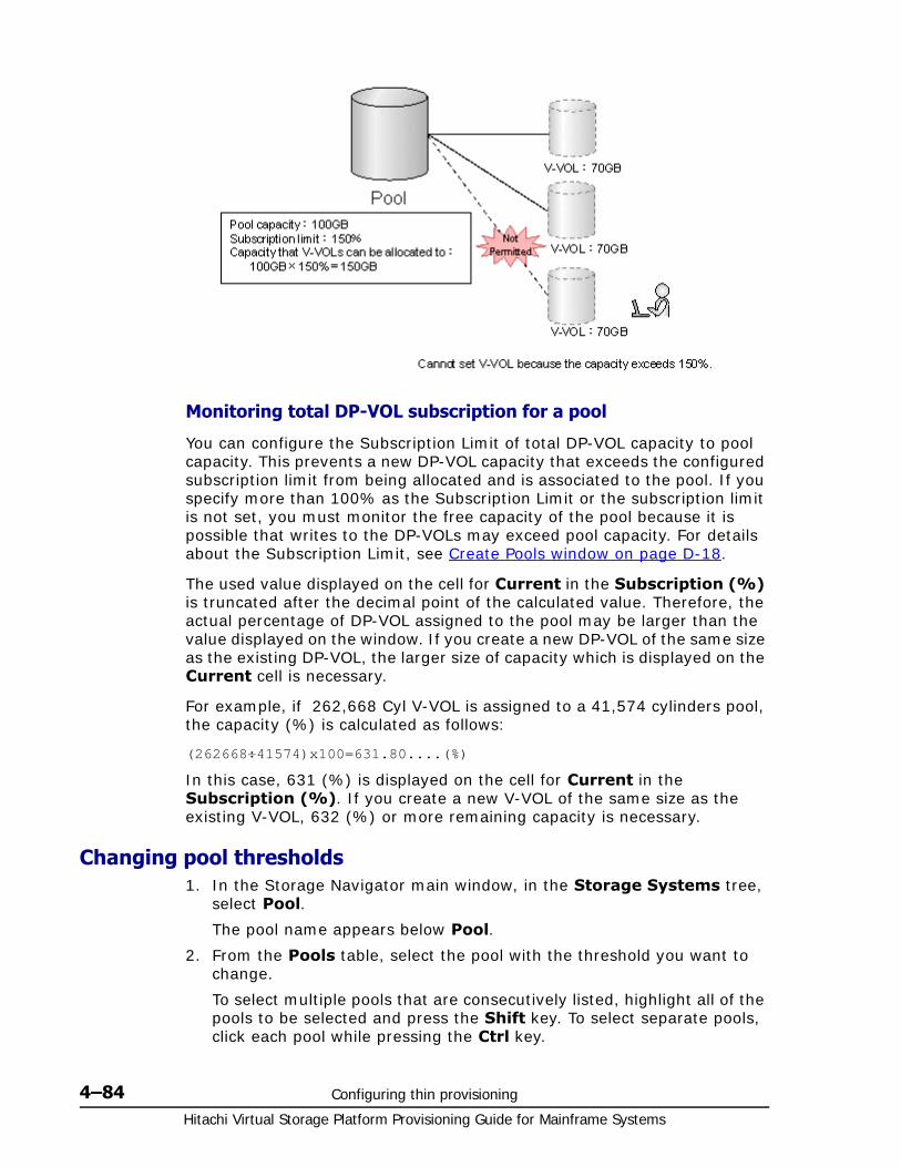
Hitachi Virtual Storage Platform Provisioning Guide for Mainframe Systems
4–84 Configuring thin provisioning
Monitoring total DP-VOL subscription for a pool
You can configure the Subscription Limit of total DP-VOL capacity to pool capacity. This prevents a new DP-VOL capacity that exceeds the configured subscription limit from being allocated and is associated to the pool. If you specify more than 100% as the Subscription Limit or the subscription limit is not set, you must monitor the free capacity of the pool because it is possible that writes to the DP-VOLs may exceed pool capacity. For details about the Subscription Limit, see Create Pools window on page D-18.
The used value displayed on the cell for Current in the Subscription (%) is truncated after the decimal point of the calculated value. Therefore, the actual percentage of DP-VOL assigned to the pool may be larger than the value displayed on the window. If you create a new DP-VOL of the same size as the existing DP-VOL, the larger size of capacity which is displayed on the Current cell is necessary.
For example, if 262,668 Cyl V-VOL is assigned to a 41,574 cylinders pool, the capacity (%) is calculated as follows:
(262668÷41574)x100=631.80....(%)
In this case, 631 (%) is displayed on the cell for Current in the Subscription (%). If you create a new V-VOL of the same size as the existing V-VOL, 632 (%) or more remaining capacity is necessary.
Changing pool thresholds1. In the Storage Navigator main window, in the Storage Systems tree,
select Pool.
The pool name appears below Pool.
2. From the Pools table, select the pool with the threshold you want to change.
To select multiple pools that are consecutively listed, highlight all of the pools to be selected and press the Shift key. To select separate pools, click each pool while pressing the Ctrl key.
Configuring thin provisioning 4–85Hitachi Virtual Storage Platform Provisioning Guide for Mainframe Systems
3. Click More Actions, and then select Edit Pools.
4. In the Edit Pools window, check Warning Threshold or Depletion Threshold.
5. Type the threshold values in the text box.
The threshold value can be within the range of values indicated below the text box. The Depletion Threshold value can be equal to or greater than the Warning Threshold.
6. Click Finish.
7. In the Confirm window, confirm the settings, in Task Name type a unique name for this task or accept the default, and then click Apply.
If Go to tasks window for status is checked, the Tasks window opens.
Changing the pool subscription limit1. In the Storage Navigator main window, in the Storage Systems tree,
select Pool.
2. From the Pools table, select the pool with the subscription limit you want to change.
To select multiple pools that are consecutively listed, highlight all of the pools to be selected and press the Shift key. To select separate pools, click each pool while pressing the Ctrl key.
3. Click More Actions, and then select Edit Pools.
4. In the Edit Pools window, check Subscription Limit, and then type the subscription limit percentage.
If the subscription limit is blank, then it is disabled, and any amount of DP-VOLs can be created regardless of the pool free capacity.
5. Click Finish.
6. In the Confirm window, confirm the settings, in Task Name type a unique name for this task or accept the default, and then click Apply.
If Go to tasks window for status is checked, the Tasks window opens.
Working with SIMs
About SIMsDynamic Provisioning for Mainframe provide Service Information Messages (SIMs) to report the status of the DP-VOLs and pools. The SIM level is Moderate. If an event associated with a pool occurs, a SIM is output to Storage Navigator to alert the user, and an SNMP trap is reported to the open-systems host.
Note: A SIM code is reported when the pool usage capacity exceeds the threshold changes.
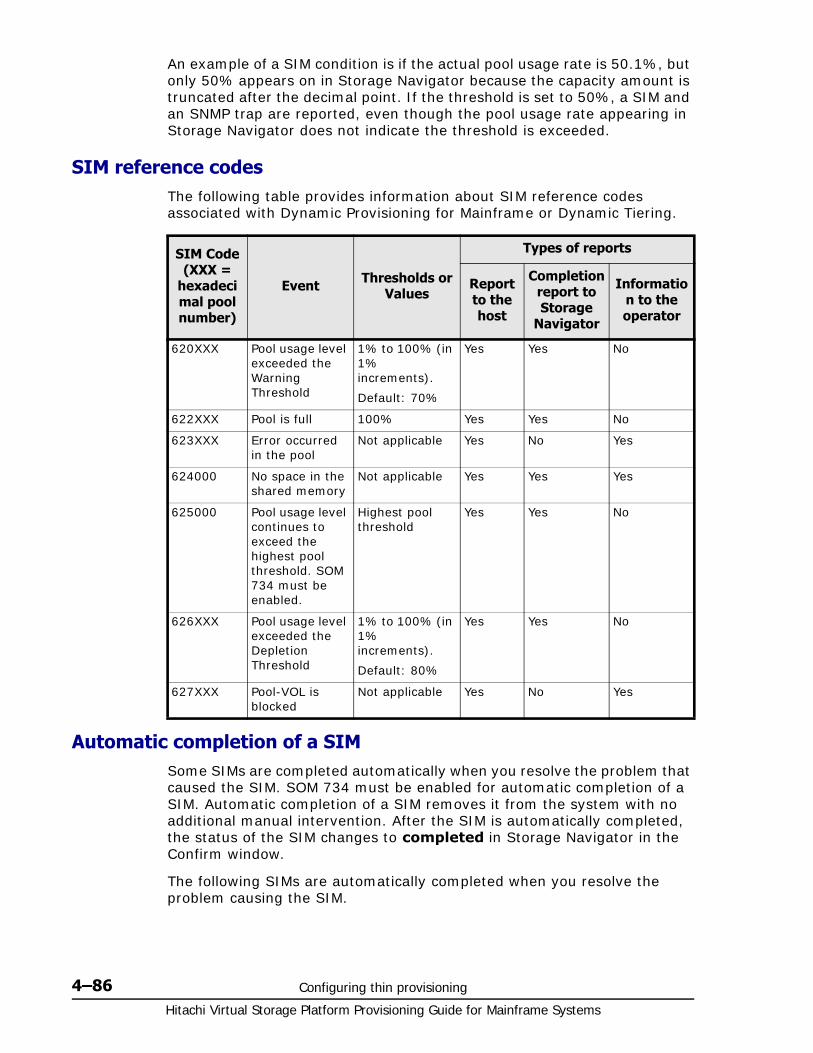
Hitachi Virtual Storage Platform Provisioning Guide for Mainframe Systems
4–86 Configuring thin provisioning
An example of a SIM condition is if the actual pool usage rate is 50.1%, but only 50% appears on in Storage Navigator because the capacity amount is truncated after the decimal point. If the threshold is set to 50%, a SIM and an SNMP trap are reported, even though the pool usage rate appearing in Storage Navigator does not indicate the threshold is exceeded.
SIM reference codesThe following table provides information about SIM reference codes associated with Dynamic Provisioning for Mainframe or Dynamic Tiering.
Automatic completion of a SIM Some SIMs are completed automatically when you resolve the problem that caused the SIM. SOM 734 must be enabled for automatic completion of a SIM. Automatic completion of a SIM removes it from the system with no additional manual intervention. After the SIM is automatically completed, the status of the SIM changes to completed in Storage Navigator in the Confirm window.
The following SIMs are automatically completed when you resolve the problem causing the SIM.
SIM Code (XXX =
hexadecimal pool number)
Event Thresholds or Values
Types of reports
Report to the host
Completion report to Storage
Navigator
Information to the operator
620XXX Pool usage level exceeded the Warning Threshold
1% to 100% (in 1% increments).
Default: 70%
Yes Yes No
622XXX Pool is full 100% Yes Yes No
623XXX Error occurred in the pool
Not applicable Yes No Yes
624000 No space in the shared memory
Not applicable Yes Yes Yes
625000 Pool usage level continues to exceed the highest pool threshold. SOM 734 must be enabled.
Highest pool threshold
Yes Yes No
626XXX Pool usage level exceeded the Depletion Threshold
1% to 100% (in 1% increments).
Default: 80%
Yes Yes No
627XXX Pool-VOL is blocked
Not applicable Yes No Yes
Configuring thin provisioning 4–87Hitachi Virtual Storage Platform Provisioning Guide for Mainframe Systems
• SIMs 620XXX, 625000, and 626XXX are automatically completed if you increase pool capacity by adding pool-VOLs because the condition that caused the SIM removed.
• SIMs are automatically completed in the following cases:
SIM 620XXX
If the DP pool number XXX usage level falls below both of two effective thresholds, SIM is automatically completed.
SIM 625000
In all pools in the storage system, if every DP pool’s usage level falls below the higher of two effective thresholds, SIM is automatically completed.
SIM 626XXX
If the DP pool number XXX, usage level falls below both of the two effective thresholds, SIM is automatically completed.
Manually completing a SIMSome SIMs must be manually completed to clear them from the system.
After the trouble that caused the SIM is solved, you can manually complete the SIM. After manually completing a SIM, the status of the SIM changes to completed. If you complete the SIM before the underlying cause is solved, the SIM may reoccur.
1. Perform the troubleshooting associated with the issued SIM. For information on troubleshooting, see Troubleshooting Dynamic Provisioning for Mainframe on page 7-2.
2. In the Storage Navigator main window, in the Storage Systems tree, select Pool.
The pool name appears below Pool.
3. Click More Actions, and then select Complete SIMs.
OR
From Pool in the Actions menu, select Complete SIMs.
The Complete SIMs window opens.
4. In the Confirm window, confirm the settings, in Task Name type a unique name for this task or accept the default, and then click Apply.
It takes time if many SIMs need to be completed.
If Go to tasks window for status is checked, the Tasks window opens.
You can check whether a SIM completes successfully in the Storage Navigator main window. For details, see the Hitachi Storage Navigator User Guide.

Hitachi Virtual Storage Platform Provisioning Guide for Mainframe Systems
4–88 Configuring thin provisioning
Managing pools and DP-VOLs
Viewing pool information1. In the Storage Navigator main window, in the Storage Systems tree,
select Pools.
2. View the pool information.
For details about the window for pool information, see Pools window after selecting pool (Pools window) on page D-3 and Top window when selecting a pool under Pools on page D-10.
Viewing used pool capacity
Viewing the used capacity of each pool1. In the Storage Systems tree on the left pane of the top window, select
Pools.
2. The used pool capacity of pools appears on the Used column in the Pools tab.
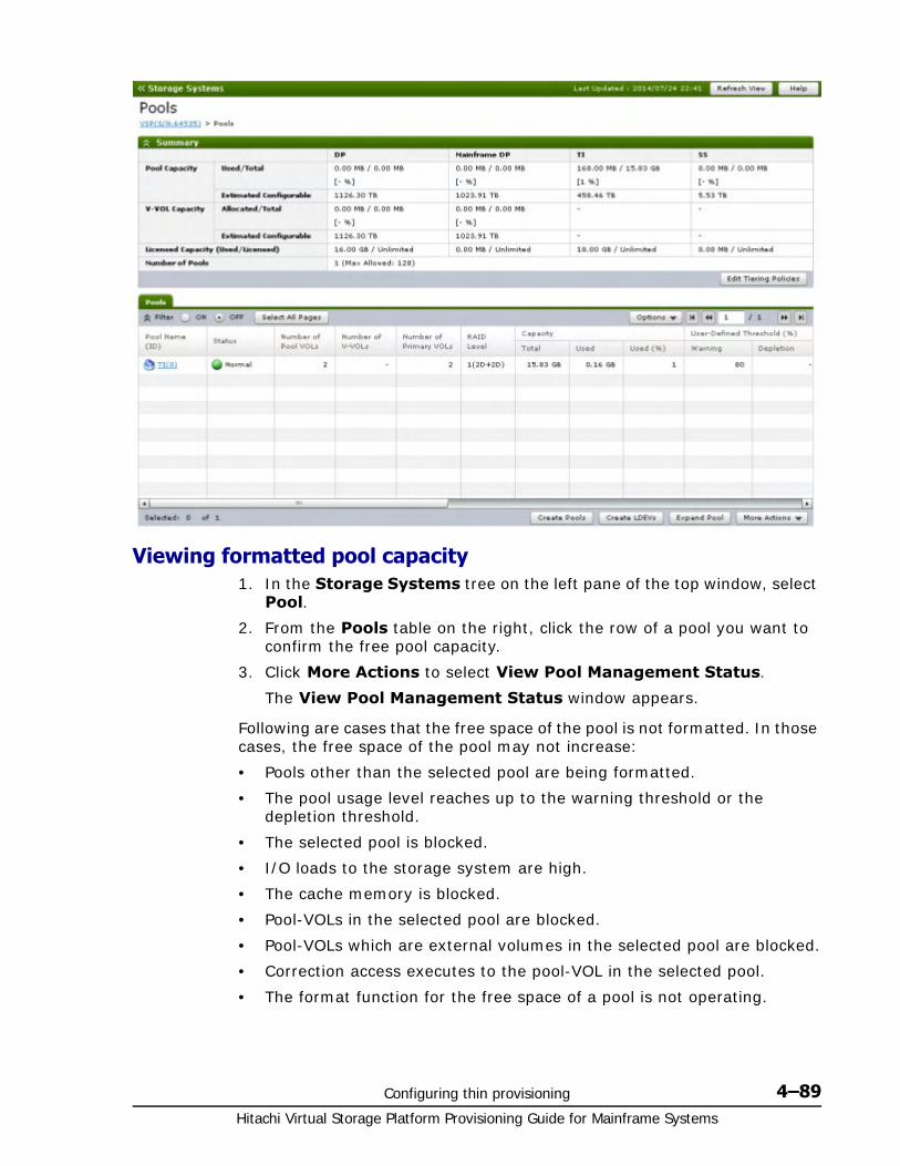
Configuring thin provisioning 4–89Hitachi Virtual Storage Platform Provisioning Guide for Mainframe Systems
Viewing formatted pool capacity1. In the Storage Systems tree on the left pane of the top window, select
Pool.
2. From the Pools table on the right, click the row of a pool you want to confirm the free pool capacity.
3. Click More Actions to select View Pool Management Status.
The View Pool Management Status window appears.
Following are cases that the free space of the pool is not formatted. In those cases, the free space of the pool may not increase:
• Pools other than the selected pool are being formatted.
• The pool usage level reaches up to the warning threshold or the depletion threshold.
• The selected pool is blocked.
• I/O loads to the storage system are high.
• The cache memory is blocked.
• Pool-VOLs in the selected pool are blocked.
• Pool-VOLs which are external volumes in the selected pool are blocked.
• Correction access executes to the pool-VOL in the selected pool.
• The format function for the free space of a pool is not operating.
Hitachi Virtual Storage Platform Provisioning Guide for Mainframe Systems
4–90 Configuring thin provisioning
If you want to change the method of performing the function to format the free space of a pool, contact the Hitachi Data Systems Support Center.
Viewing the progress of rebalancing the usage level among pool-VOLs
1. In the Storage Systems tree on the left pane of the top window, select Pool.
2. From the Pools table on the right, click the row of a pool you want to confirm the progress of rebalancing the usage level among pool-VOLs.
3. Click More Actions to select View Pool Management Status.
The View Pool Management Status window appears.
Following are cases that the progress ratio may not increase:
• The usage level is being rebalanced among the pool-VOLs in pools other than the selected pool.
• Tier relocation is performed.
Increasing pool capacityAdding the pool-VOL to the pool created for Dynamic Provisioning for Mainframe or Dynamic Tiering for Mainframe increases the pool capacity. The amount of pool capacity registered in the pool represents the pool capacity. You need to check the pool free capacity to determine if additional pool capacity is required. You cannot increase the pool capacity while it is being shrunk.
Notes on using Dynamic Provisioning for Mainframe
Notes on adding the pool-VOL to the pool are as follows:
• The internal volume, and the external volume whose Cache Mode is set to Disable cannot coexist.
• The external volume whose Cache Mode is set to Enable, and the external volume whose Cache Mode is set to Disable cannot coexist.
Notes on using Dynamic Tiering for Mainframe• When pool-VOLs with the available monitoring information are added in
a pool, tier relocation is performed. When pool-VOLs with no available monitoring information are added in a pool, the page usage rate is averaged out in a tier.
• If the pool-VOL is the external volume, set Enable for Cache Mode.
Note: Following are cases that the formatted pool capacity may decrease:
• New pages are being allocated.
• LDEV format is being performed on the pool-VOL.
• Correction copy is being executed.
Configuring thin provisioning 4–91Hitachi Virtual Storage Platform Provisioning Guide for Mainframe Systems
• If the pool-VOLs are added, the tier relocation being performed stops.
To increase pool capacity
1. In the Storage Navigator main window, in the Storage Systems tree, select Pool.
2. From the Pools table, select the pool for which you want to increase the capacity. You cannot increase pool capacity for multiple pools.
3. Click Expand Pool.
4. In the Expand Pool window, select the pool-VOL.a. Click Select Pool VOLs.b. In the Select Pool VOLs window, from the Available Pool
Volumes table, select the pool-VOL you want to assign, and then click Add.
The selected pool-VOLs are registered in the Selected Pool Volumes table.
Up to 1024 volumes can be added including the volumes already in the pool.
c. Click OK.
The Select Pool VOLs window closes. The number of the selected pool volumes appears in Total Selected Pool Volumes, and the total capacity of the selected pool-VOL appears in Total Selected Capacity.
5. Click Finish.
6. In the Confirm window, confirm the settings, in Task Name type a unique name for this task or accept the default, and then click Apply.
If Go to tasks window for status is checked, the Tasks window opens.
Note: If necessary, perform the following steps:
• From Filter option, select ON to filter the rows.
• Click Select All Pages to select pool-VOLs in the table. To cancel the selection, click Select All Pages again.
• Click Options to specify the unit of volumes or the number of rows to be viewed.
• To set the tier rank of an external volume to a value other than Middle, select a tier rank from External LDEV Tier Rank, and then click Add.
• For a pool, you can add volumes whose Drive Type/RPM settings are the same and whose RAID Levels are different. For example, you can add the following volumes to the same pool:
Volume whose Drive Type/RPM is SAS/15K and whose RAID Level is 5 (3D+1P)
Volume whose Drive Type/RPM is SAS/15K and whose RAID Level is 5 (7D+1P)
Hitachi Virtual Storage Platform Provisioning Guide for Mainframe Systems
4–92 Configuring thin provisioning
Changing a pool name1. In the Storage Navigator main window, in the Storage Systems tree,
select Pool.
2. From the Pools table, select the pool with the name you want to change.
To select multiple pools that are consecutively listed, highlight all of the pools to be selected and press the Shift key. To select separate pools, click each pool while pressing the Ctrl key.
3. Click More Actions, and then select Edit Pools.
4. In the Edit Pools window, in Pool Name, specify a name for this pool.a. In Prefix, type the characters that will become the fixed characters
for the beginning of the pool name. The characters are case-sensitive.
b. In Initial Number, type the initial number that will follow the prefix name.
5. Click Finish.
6. In the Confirm window, confirm the settings, in Task Name type a unique name for this task or accept the default, and then click Apply.
If Go to tasks window for status is checked, the Tasks window opens.
Recovering a blocked poolThis procedure is for failure recovery of a blocked pool. Ordinarily, you should not need to use this procedure. A recovered pool can be used, but the former data is lost.
1. In the Storage Navigator main window, in the Storage Systems tree, select Pool.
The pool name appears below Pool.
2. From the Pool table, select the pool to be recovered.
To select multiple pools that are consecutively listed, highlight all of the pools to be selected and press the Shift key. To select separate pools, click each pool while pressing the Ctrl key.
3. Click More Actions, and then select Restore Pools.
4. In the Confirm window, confirm the settings, in Task Name type a unique name for this task or accept the default, and then click Apply.
If Go to tasks window for status is checked, the Tasks window opens.
The recovery time for pools varies depending on pool usage or DP-VOL usage. Allow roughly 20 minutes of recovery time for every 100 TB of pool or DP-VOL usage. Recovery time may vary depending on the workload of the storage system at the time of recovery.

Configuring thin provisioning 4–93Hitachi Virtual Storage Platform Provisioning Guide for Mainframe Systems
Decrease pool capacity
About decreasing pool capacity
You can decrease pool capacity by deleting pool-VOLs.
When a pool-VOL is removed from a pool, all the used pages in the pool-VOL are moved to other pool-VOLs.
When you delete a pool or decrease the pool capacity, the released pool-VOLs (LDEVs) will be blocked. If they are blocked, format them before using them. If the blocked pool-VOL is an external volume, use Normal Format when formatting the volume.
You can decrease pool capacity for up to eight tasks at the same time. Do not execute a Command Control Interface command to also decrease the capacity of the pool whose capacity is already in the process of being decreased.
You cannot decrease pool capacity while doing any of the following to a pool.
• Creating the pool.
• Deleting the pool.
• Increasing the pool.
• Decreasing the pool.
• Recovering the pool.
• Stopping decreasing the pool.
• Changing the threshold.
• Reclaiming zero pages.
• Creating DP-VOLs.
• Increasing DP-VOL capacity.
While the pool capacity is being decreased, if maintenance of cache memory is performed, if the cache memory fails, or if the I/O load to the DP-VOL related to the pool is high, decreasing the pool capacity process might fail. In this case, check the Tasks window to determine whether processing has abnormally ended.
If the processing has ended abnormally, restore the cache memory, and then try decreasing the pool capacity again.
Note: You cannot perform the following operations on a pool while the pool volume capacity is in the process of shrinking. Wait until shrinking completes or stop the shrinking process.
• Expand Pool
• Shrink Pools
• Edit Pools
• Restore Pools
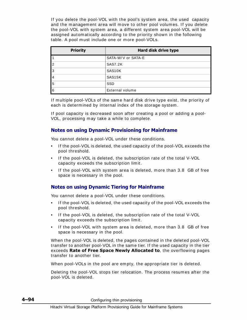
Hitachi Virtual Storage Platform Provisioning Guide for Mainframe Systems
4–94 Configuring thin provisioning
If you delete the pool-VOL with the pool’s system area, the used capacity and the management area will move to other pool volumes. If you delete the pool-VOL with system area, a different system area pool-VOL will be assigned automatically according to the priority shown in the following table. A pool must include one or more pool-VOLs.
If multiple pool-VOLs of the same hard disk drive type exist, the priority of each is determined by internal index of the storage system.
If pool capacity is decreased soon after creating a pool or adding a pool-VOL, processing may take a while to complete.
Notes on using Dynamic Provisioning for Mainframe
You cannot delete a pool-VOL under these conditions.
• If the pool-VOL is deleted, the used capacity of the pool-VOL exceeds the pool threshold.
• If the pool-VOL is deleted, the subscription rate of the total V-VOL capacity exceeds the subscription limit.
• If the pool-VOL with system area is deleted, more than 3.8 GB of free space is necessary in the pool.
Notes on using Dynamic Tiering for Mainframe
You cannot delete a pool-VOL under these conditions.
• If the pool-VOL is deleted, the used capacity of the pool-VOL exceeds the pool threshold.
• If the pool-VOL is deleted, the subscription rate of the total V-VOL capacity exceeds the subscription limit.
• If the pool-VOL with system area is deleted, more than 3.8 GB of free space is necessary in the pool.
When the pool-VOL is deleted, the pages contained in the deleted pool-VOL transfer to another pool-VOL in the same tier. If the used capacity in the tier exceeds Rate of Free Space Newly Allocated to, the overflowing pages transfer to another tier.
When pool-VOLs in the pool are empty, the appropriate tier is deleted.
Deleting the pool-VOL stops tier relocation. The process resumes after the pool-VOL is deleted.
Priority Hard disk drive type
1 SATA-W/V or SATA-E
2 SAS7.2K
3 SAS10K
4 SAS15K
5 SSD
6 External volume
Configuring thin provisioning 4–95Hitachi Virtual Storage Platform Provisioning Guide for Mainframe Systems
Decreasing pool capacity1. In the Storage Navigator main window, in the Storage Systems tree,
select Pool.
The pool name appears below Pool.
2. Select the pool that contains the pool-VOLs to be deleted.
3. From the Pool volumes, select the pool-VOL to be deleted.
To select multiple pool-VOLs that are consecutively listed, highlight all of the pool-VOLs to be selected and press the Shift key. To select separate pool-VOLs, click each pool-VOL while pressing the Ctrl key.
You cannot delete pool-VOLs unless Shrinkable is applied.
4. Click Shrink Pool.
The Shrink Pool window opens.
The details of Before Shrinking and After Shrinking, including the pool capacity, the used pool capacity and the free pool capacity, appears in Prediction Result of Shrinking.
5. In the Confirm window, confirm the settings, in Task Name type a unique name for this task or accept the default, and then click Apply.
If Go to tasks window for status is checked, the Tasks window opens.
Stopping the decrease of pool capacity1. In the Storage Navigator main window, in the Storage Systems tree,
select Pool.
2. From the Pools, select the pool for which you want to stop decreasing pool capacity.
To select multiple pools that are consecutively listed, highlight all of the pools to be selected and press the Shift key. To select separate pools, click each pool while pressing the Ctrl key.
3. Click Stop Shrinking Pools.
The Stop Shrinking Pools window opens.
4. In the Confirm window, confirm the settings, in Task Name type a unique name for this task or accept the default, and then click Apply.
If Go to tasks window for status is checked, the Tasks window opens.
Deleting a tier in a poolTo delete a tier in a pool, you must delete all the pool-VOLs in the tier to be deleted.
If you delete a pool, its pool-VOLs (LDEVs) will be blocked. If they are blocked, format them before using them.
You cannot delete the pool-VOL when:
• Creating the pool.
Hitachi Virtual Storage Platform Provisioning Guide for Mainframe Systems
4–96 Configuring thin provisioning
• Deleting the pool.
• Increasing the pool capacity.
• Decreasing the pool capacity.
• Restoring the pool.
• Stopping decreasing the pool capacity.
• Changing the threshold.
• Initializing the pool capacity.
• Changing the external LDEV tier rank
Notes on deleting a tier in a pool
You cannot delete a pool-VOL under these conditions.
• If the pool-VOL is deleted, the used capacity of the pool-VOL exceeds the pool threshold.
• If the pool-VOL is deleted, the subscription rate of the total V-VOL capacity exceeds the subscription limit.
• If the pool-VOL with system area has less than 3.8 GB of free space. There must be 3.8 GB of free space in the pool in order to delete the pool-VOL with system area.
Deleting the pool-VOL stops the tier relocation. The process resumes after the pool-VOL is deleted.
To delete a tier in a pool
1. In the Storage Navigator main window, in the Storage Systems tree, select Pool.
The pool name appears below Pool.
2. Select the pool that contains the pool-VOLs to be deleted.
The pool information appears on the right.
3. Select the Pool volumes tab and select all the pool-VOLs contained in the tier to be deleted.
To select multiple pool-VOLs that are consecutively listed, highlight all of the pool-VOLs to be selected and press the Shift key. To select separate pool-VOLs, click each pool-VOL while pressing the Ctrl key.
You cannot delete a pool-VOL unless Shrinkable has been applied.
4. Click Shrink Pool.
5. In the Shrink Pool window, verify the changes.
The details of Before Shrinking and After Shrinking, including the pool capacity, the used pool capacity and the free pool capacity, appears in Prediction Result of Shrinking.
6. In the Confirm window, confirm the settings, in Task Name type a unique name for this task or accept the default, and then click Apply.
If Go to tasks window for status is checked, the Tasks window opens.
Configuring thin provisioning 4–97Hitachi Virtual Storage Platform Provisioning Guide for Mainframe Systems
Deleting a poolWhen you delete a pool, its pool-VOLs (LDEVs) are blocked. If the pool-VOLs are blocked, they must be formatted before they can be reused. If the blocked pool-VOL is an external volume, select Normal Format when formatting the volume. You can delete a pool only when all of the DP-VOLs have been deleted.
1. In the Storage Systems tree on the left pane of the top window, select Pool.
2. From the Pools table on the right, select the pool to be deleted.
You can select multiple pools with the Shift key if the LDEV IDs are listed consecutively. If the pools are not in consecutive order, click the LDEV ID of each pool that you want to delete while pressing the Ctrl key.
3. Click More Actions, and then select Delete Pools.
The Delete Pools window opens.
You cannot delete a pool whose usage is not 0%, or a pool for which DP-VOLs are assigned.
4. Click Finish.
The Confirm window opens.
To continue with the shredding operation and delete volume data, click Next. For details about the shredding operation, see Hitachi Volume Shredder User Guide.
If the pool is blocked, you might not be able to perform shredding operations.
5. In the Confirm window, confirm the settings, in Task Name type a unique name for this task or accept the default, and then click Apply.
If Go to tasks window for status is checked, the Tasks window opens.
Changing external LDEV tier rank
1. In the Storage Systems tree on the left pane of the top window, select Pool.
The pool name appears below Pool.
2. From the Pool volumes table in the right pane, select the pool-VOL that has the external LDEV tier rank you want to change.
You cannot change the external LDEV tier rank of a pool-VOL if External Volume is not displayed in the Drive Type/RPM column.
Note: When the pool-VOLs of a pool are empty, the appropriate tier is deleted.
Note: When using Dynamic Tiering for Mainframe, if all pool-VOLs are deleted, the tier is also deleted.

Hitachi Virtual Storage Platform Provisioning Guide for Mainframe Systems
4–98 Configuring thin provisioning
To select multiple pool-VOLs that are consecutively listed, highlight all of the pool-VOLs to be selected and press the Shift key. To select separate pool-VOLs, click each pool-VOL while pressing the Ctrl key.
3. Click More Actions and select Edit External LDEV Tier Rank.
The Edit External LDEV Tier Rank window appears.
4. From the Selected Pool volumes table, select the pool-VOL with the external LDEV tier rank you want to change.
To select multiple pool-VOLs that are consecutively listed, highlight all of the pool-VOLs to be selected and press the Shift key. To select separate pool-VOLs, click each pool-VOL while pressing the Ctrl key.
5. Click Change and select the tier rank.
6. Click Finish.
The Confirm window appears.
7. In the Task Name text box, enter the task name.
You can enter up to 32 ASCII characters and symbols in all, except for \ / : , ; * ? " < > |. "date-window name" is entered by default.
8. In the Confirm window, click Apply to register the setting in the task.
If the Go to tasks window for status check box is selected, the Tasks window appears.
Increasing DP-VOL capacity1. In the Storage Navigator main window, in the Storage Systems tree,
select Logical Devices.
The following is another way to select LDEVs.a. In the Storage Navigator main window, in the Storage Systems
tree, select Pool.
The pool name appears below Pool.b. Select the pool associated with the DP-VOL that has the capacity
that you want to increase.c. Select the Virtual Volumes tab.
2. From the table, select the DP-VOL with the capacity you want to increase.
To select multiple DP-VOLs that are consecutively listed, highlight all of the DP-VOLs to be selected and press the Shift key. To select separate DP-VOLs, click each DP-VOL while pressing the Ctrl key.
3. Click Expand V-VOLs.
The Expand V-VOLs window opens. If the DP-VOL is selected from the LDEV table in the Logical Devices window, click More Actions, and then click Expand V-VOLs.
4. In Capacity, type the capacity amount.
You can enter the LDEV capacity to two decimal places within the range of values indicated below the text box.
5. Click Finish.
Configuring thin provisioning 4–99Hitachi Virtual Storage Platform Provisioning Guide for Mainframe Systems
The Confirm window opens.
6. In the Confirm window, confirm the settings, in Task Name type a unique name for this task or accept the default, and then click Apply.
If Go to tasks window for status is checked, the Tasks window opens.
Changing the name of a DP-VOL1. In the Storage Navigator main window, in the Storage Systems tree,
select Logical Devices.
The following is another way to select LDEVs.a. In the Storage Navigator main window, in the Storage Systems
tree, select Pool.
The pool name appears below Pool.b. Select the pool associated with the DP-VOL you want to rename.c. Select the Virtual Volumes tab.
2. From the table, select the DP-VOL you want to rename.
To select multiple DP-VOLs that are consecutively listed, highlight all of the DP-VOLs to be selected and press the Shift key. To select separate DP-VOLs, click each DP-VOL while pressing the Ctrl key.
3. Click Edit LDEVs.
When you selected DP-VOLs from the Virtual Volumes table, click More Actions, and then Edit LDEVs.
The Edit LDEVs window opens.
4. Check LDEV Name and change the LDEV name, if necessary.a. In Prefix, type the characters that will become the fixed characters
for the beginning of the LDEV name. The characters are case-sensitive.
b. In Initial Number, type the initial number that will follow the prefix name.
5. Click Finish.
6. In the Confirm window, confirm the settings, in Task Name type a unique name for this task or accept the default, and then click Apply.
If Go to tasks window for status is checked, the Tasks window opens.
About releasing pages in a DP-VOLYou can reclaim zero pages and release the appropriate pages if the status of all data in the pages in the V-VOL reads no logical records (referred to as zero page). The free capacity of a pool increases after the pages are released. You can perform the operation to reclaim zero pages on each V-VOL and monitor progress in Storage Navigator. For details, see View Pool Management Status window on page D-72. If you stop the operation to reclaim zero pages, the zero pages that have been reclaimed cannot be restored.
Hitachi Virtual Storage Platform Provisioning Guide for Mainframe Systems
4–100 Configuring thin provisioning
Logically, there is no difference between a page with just zero data and the area of a DP-VOL without a page allotted. Both are effectively identical. However, the former uses pool capacity and the latter does not.
Zero pages can be reclaimed when all the following conditions are satisfied:
• The DP-VOL is not used in conjunction with another VSP product which does not support reclaiming zero pages.
See Using Dynamic Provisioning for Mainframe or Dynamic Tiering for Mainframe with other VSP products on page 4-8.
• LDEV formatting is not being performed on the DP-VOL.
• The DP-VOL is not blocked.
• The DP-VOL is associated with a pool.
• The pool associated with the DP-VOL is not blocked, or is full and blocked.
• The DP-VOL is not TSE-VOL.
Pages that include control cylinders are not processed when releasing pages in a DP-VOL.
While releasing pages from a DP-VOL, performance of the host I/O to the DP-VOL may temporarily decrease due to scanning for non-zero data.
If you stop an operation to reclaim zero pages in mid-stream, the pages that have been released will remain as free pool capacity.
After an operation to reclaim zero pages, Dynamic Provisioning for Mainframe automatically balances usage levels among pool-VOLs in the pool. This rebalancing is performed on all of the DP-VOLs and pool-VOLs in the pool. If you do not want automatic balancing of the usage levels of pool-VOLs, call the Hitachi Data Systems Support Center to change your configuration.
Dynamic Provisioning for Mainframe does not automatically balance the usage levels among pool-VOLs if the cache memory is not redundant or if the pool usage reaches up to the threshold.
If all the tracks that belong to a page assigned to a DP-VOL have no records written, you can reclaim the page and return it to the pool's available capacity.
If you have started an operation to reclaim zero pages, and the storage system loses power, the shared memory is disrupted. The operation does not automatically continue after the storage system restarts.
In the following cases, an operation reclaim zero pages stops and DP-VOL pages are not released.
• LDEV formatting is performed while the operation to reclaim zero pages is in progress.
• The pool-VOL accessed by the target DP-VOL is blocked.
• The pool associated with the target DP-VOL is blocked while the operation to reclaim zero pages is in progress.
Configuring thin provisioning 4–101Hitachi Virtual Storage Platform Provisioning Guide for Mainframe Systems
• Cache memory failure occurs the operation to reclaim zero pages is in progress.
• The DP-VOL is released when the operation to reclaim zero pages is in progress.
• The initial copy operation between TrueCopy for Mainframe pair, Universal Replicator for Mainframe, ShadowImage pair is performed on the DP-VOL in which the zero pages are reclaimed.
Releasing pages in a DP-VOL
You can reclaim pages in a DP-VOL to free pool capacity. If a page assigned to a DP-VOL contains no logical records, you can reclaim the page. Before releasing pages in a DP-VOL, see About releasing pages in a DP-VOL on page 4-99).
To release pages in a DP-VOL
1. In the Storage Navigator main window, in the Storage Systems tree, select Logical Devices.
The following is another way to select LDEVs.a. In the Storage Navigator main window, in the Storage Systems
tree, select Pool.
The pool name appears below Pool.b. Select the pool associated with the DP-VOL that has pages you want
to release.c. Select the Virtual Volumes tab.
2. From the table, select the DP-VOL that has pages you want to release.
To select multiple DP-VOLs that are consecutively listed, highlight all of the DP-VOLs to be selected and press the Shift key. To select separate DP-VOLs, click each DP-VOL while pressing the Ctrl key.
3. Click More Actions, and then select Reclaim Zero Pages.
The Reclaim Zero Pages window opens.
You cannot release pages in a DP-VOL when the DP-VOL is not in a normal status or the DP-VOL is in the process of reclaiming zero pages.
4. In Task Name type a unique name for this task or accept the default, and then click Apply.
If Go to tasks window for status is checked, the Tasks window opens.
After the operation to reclaim zero pages is complete, click Refresh in Storage Navigator to update the Page Status. If the Page Status is not immediately updated, wait a while, and then click Refresh again. Completed status is displayed when no pages can be reclaimed.
If you have started the reclaiming zero pages operation, and the storage system is powered off the reclaiming zero pages operation will not automatically continue after the storage system restarts.
In any of the following cases, the reclaiming zero pages will stop, and DP-VOL pages will not be released:
Hitachi Virtual Storage Platform Provisioning Guide for Mainframe Systems
4–102 Configuring thin provisioning
• LDEV formatting was performed while reclaiming zero pages.
• The pool-VOL that is being accessed by the target DP-VOL was blocked.
• The pool associated with the target DP-VOL was blocked while reclaiming zero pages.
• Cache memory failure occurred while reclaiming zero pages.
• The DP-VOL was deleted when zero pages were reclaimed.
• The initial copy operation between the TrueCopy for Mainframe pair or the Universal Replicator for Mainframe pair was performed on the DP-VOL in which zero pages were being reclaimed.
Stopping the release of pages in a DP-VOL1. In the Storage Navigator main window, in the Storage Systems tree,
select Logical Devices.
The following is another way to select LDEVs.a. In the Storage Navigator main window, in the Storage Systems
tree, select Pool.
The pool name appears below Pool.b. Select the pool associated with the DP-VOL that has pages you want
to release.c. Select the Virtual Volumes tab.
2. From the table, select the DP-VOL that you want to stop from releasing pages.
To select multiple DP-VOLs that are consecutively listed, highlight all of the DP-VOLs to be selected and press the Shift key. To select separate DP-VOLs, click each DP-VOL while pressing the Ctrl key.
3. Click More Actions, and then select Stop Reclaiming Zero Pages.
The Stop Reclaiming Zero Pages window opens.
You cannot stop releasing the pages in a DP-VOL where zero pages are not being reclaimed.
4. In the Confirm window, confirm the settings, in Task Name type a unique name for this task or accept the default, and then click Apply.
If Go to tasks window for status is checked, the Tasks window opens.
Enabling/disabling tier relocation of a DP-VOLYou can enable or disable tier relocation of individual DP-VOLs or on all DP-VOLs.
DP-VOLs on which tier relocation is disabled are excluded from the targets for the tier range calculation, and are not reflected in the performance information of pools. If tier relocation is disabled on all DP-VOLs in a pool, performance information of a pool is unavailable in the View Tier Properties window.
1. In the Storage Navigator main window, in the Storage Systems tree, select Logical Devices.
Configuring thin provisioning 4–103Hitachi Virtual Storage Platform Provisioning Guide for Mainframe Systems
The following is another way to select LDEVs.a. In the Storage Navigator main window, in the Storage Systems
tree, select Pool.b. Select the pool associated with the DP-VOL for which tier relocation
is to be enabled or disabled.c. Click the Virtual Volumes tab.
2. From the table, select the DP-VOL for which tier relocation is to be enabled or disabled.
To select multiple DP-VOLs that are consecutively listed, highlight all of the DP-VOLs to be selected and press the Shift key. To select separate DP-VOLs, click each DP-VOL while pressing the Ctrl key.
Select multiple DP-VOLs using the Shift key (if the DP-VOLs are adjacent), or using the Ctrl key (if the DP-VOLs are not adjacent).
3. Click More Actions, and then select Edit LDEVs.
4. In the Edit LDEVs window, check tier relocation and select Enable or Disable.
Enable allows tier relocation to be performed to the DP-VOL.
Disable do not allow tier relocation to be performed on the DP-VOL in the case of both automatic and manual tier relocation.
5. Click Finish.
6. In the Confirm window, confirm the settings, in Task Name type a unique name for this task or accept the default, and then click Apply.
If Go to tasks window for status is checked, the Tasks window opens.
Deleting a DP-VOLYou cannot delete a DP-VOL if the status is online.
1. In the Storage Navigator main window, in the Storage Systems tree, select Logical Devices.
The following is another way to select LDEVs.a. In the Storage Navigator main window, in the Storage Systems
tree, select Pool. The pool name appears below Pool.b. Select the pool associated with the DP-VOLs to be deleted.c. Click the Virtual Volumes tab.
2. From the table, select the DP-VOL to be deleted.
To select multiple DP-VOLs that are consecutively listed, highlight all of the DP-VOLs to be selected and press the Shift key. To select separate DP-VOLs, click each DP-VOL while pressing the Ctrl key.
Do the following, if necessary.
In the Filter option, select ON to filter the rows.
Click Select All Pages to select all DP-VOLs in the list.
Click Options to specify the unit of volumes or the number of rows to view.
Hitachi Virtual Storage Platform Provisioning Guide for Mainframe Systems
4–104 Configuring thin provisioning
3. Click More Actions, and then select Delete LDEVs.
The Delete LDEVs window opens.
4. In the Confirm window, confirm the settings, in Task Name type a unique name for this task or accept the default, and then click Apply.
If Go to tasks window for status is checked, the Tasks window opens.
5
Configuring access attributes 5–1Hitachi Virtual Storage Platform Provisioning Guide for Mainframe Systems
Configuring access attributes
Hitachi Volume Retention Manager is required to assign access attributes to volumes.
□ Access attributes strategies
□ Volume Retention Manager requirements
□ Access attribute restrictions
□ Keywords
□ Assigning access attribute
□ Specifying the VTOC size

Hitachi Virtual Storage Platform Provisioning Guide for Mainframe Systems
5–2 Configuring access attributes
Access attributes strategiesBy default, all the volumes are subject to read and write operations by hosts. With Volume Retention Manager, you can assign access attributes to volumes that restrict read and/or write operations as needed. By properly setting these attributes, you can prevent unauthorized access to data and avoid the possibility of data being damaged, lost, or leaked.
Volume Retention Manager requirementsBefore using Volume Retention Manager, confirm that the following program products have been installed in Storage Navigator.
• Volume Retention Manager
• JAVA API
The storage system must be configured to conform to all hardware devices, microcode, and the Storage Navigator requirements. In addition, the Volume Retention Manager license key of must be installed in the Storage Navigator. Volume Retention Manager software contains license keys for Volume Retention Manager and Volume Retention Manager program products. For more information on license keys or the program product installation, see the Hitachi Storage Navigator User Guide.
Access attribute restrictionsNotes on using Volume Retention Manager with other program products follow.
Performance Monitor and Volume Migration
Some program products may be set to start automatically at a certain time. For example, if an automatic start time is set in Performance Monitor or Volume Migration, monitoring begins at the specified time. If another product has been set to start automatically, you must take one of these actions.
• Perform Volume Retention Manager operations when the other program is not running.
• Reset the specified start time of the other product.
TrueCopy for Mainframe and Universal Replicator for Mainframe• It is not recommended to assign an access attribute to a volume that is
in use by TrueCopy for Mainframe or Universal Replicator for Mainframe. If you assign an access attribute to such a volume, the job may end abnormally. If you still want to assign an access attribute to such a volume, you must assign the same access attribute to both the main volume (M-VOL) and the remote volume (R-VOL).
• When creating a TrueCopy for Mainframe or Universal Replicator for Mainframe pair and using a read-only volume as the M-VOL, use an R-VOL on a storage system on which Volume Retention Manager is enabled.
Configuring access attributes 5–3Hitachi Virtual Storage Platform Provisioning Guide for Mainframe Systems
If the R-VOL must be on a storage system on which Volume Retention Manager is not enabled, you must do either of the following:
Change the access attribute of the M-VOL to Read/Write.
Disable Volume Retention Manager on the main site.
• If you use TrueCopy for Mainframe or Universal Replicator for Mainframe to create a pair, the M-VOL and the R-VOL will have the same access attribute. Even if you suspend or delete the pair, access attribute for these volumes will not change.
• If a remote copy pair is suspended during a TrueCopy for Mainframe or Universal Replicator for Mainframe copy operation and you want to enable the R-VOL read option on the RCU (mode 20), you must ensure that the access attribute of the R-VOL is Read/Write before you enable the R-VOL read option. If the access attribute of the R-VOL is Read-Only, mode 20 will be disabled. Also, operations such as REFORMAT and REFVTOC cannot be performed for overwriting volume serial numbers.
• If a volume has the Protect attribute, the volume can neither be used as an M-VOL nor an R-VOL.
If the Protect attribute is set to the volume which is being used by TrueCopy for Mainframe, the pair might be suspended.
If the Protect attribute is set to the volume which is being used by Universal Replicator for Mainframe, the remote copy processing might not be continued.
ShadowImage for Mainframe, Compatible FlashCopy(R) V2, and Compatible Software for IBM(R) FlashCopy(R) SE
If a volume has the Protect attribute, the volume cannot be used as a primary volume (P-VOL) or secondary volume (S-VOL) for ShadowImage for Mainframe; nor can it be used as a source volume (S-VOL) or target volume (T-VOL) for Compatible FlashCopy(R) V2 or Compatible Software for IBM(R) FlashCopy(R) SE.
Volume Security• If a logical volume is secured by Volume Security, you must set the
Read/Write attribute on the volume. If you want to assign another access attribute to the logical volume, you must use Volume Security to remove security from the logical volume.
• If a logical volume has the Read Only attribute or the Protect attribute set, you must not use Volume Security to secure the logical volume. If you still want to use Volume Security to secure the logical volume, you must assign the Read/Write attribute to the logical volume.
KeywordsTo control the access to a volume, assign an access attribute to each volume. One of the following access attributes can be assigned to each logical volume:
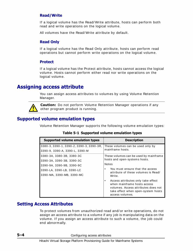
Hitachi Virtual Storage Platform Provisioning Guide for Mainframe Systems
5–4 Configuring access attributes
Read/Write
If a logical volume has the Read/Write attribute, hosts can perform both read and write operations on the logical volume.
All volumes have the Read/Write attribute by default.
Read Only
If a logical volume has the Read Only attribute, hosts can perform read operations but cannot perform write operations on the logical volume.
Protect
If a logical volume has the Protect attribute, hosts cannot access the logical volume. Hosts cannot perform either read nor write operations on the logical volume.
Assigning access attributeYou can assign access attributes to volumes by using Volume Retention Manager.
Supported volume emulation typesVolume Retention Manager supports the following volume emulation types:
Table 5-1 Supported volume emulation types
Setting Access AttributesTo protect volumes from unauthorized read and/or write operations, do not assign an access attribute to a volume if any job is manipulating data on the volume. If you assign an access attribute to such a volume, the job could end abnormally.
Caution: Do not perform Volume Retention Manager operations if any other program product is running.
Supported volume emulation types Description
3380-3, 3390-1, 3390-2, 3390-3, 3390-3R,
3390-9, 3390-A, 3390-L, 3390-M
These volumes can be used only by mainframe hosts.
3380-3A, 3380-3B, 3380-3C
3390-3A, 3390-3B, 3390-3C
3390-9A, 3390-9B, 3390-9C
3390-LA, 3390-LB, 3390-LC
3390-MA, 3390-MB, 3390-MC
These volumes can be used by mainframe hosts and open-systems hosts.
Notes
• You must ensure that the access attribute of these volumes is Read/Write.
• Access attributes only take effect when mainframe hosts access volumes. Access attributes does not take effect when open-system hosts access volumes.
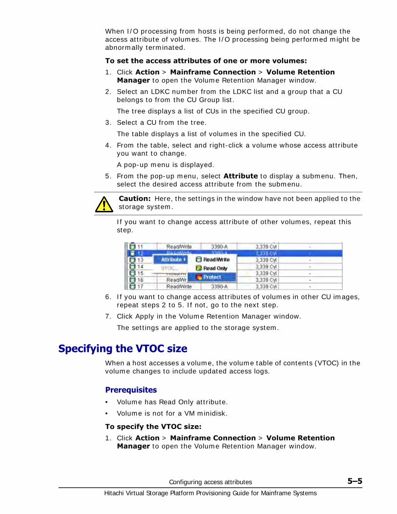
Configuring access attributes 5–5Hitachi Virtual Storage Platform Provisioning Guide for Mainframe Systems
When I/O processing from hosts is being performed, do not change the access attribute of volumes. The I/O processing being performed might be abnormally terminated.
To set the access attributes of one or more volumes:
1. Click Action > Mainframe Connection > Volume Retention Manager to open the Volume Retention Manager window.
2. Select an LDKC number from the LDKC list and a group that a CU belongs to from the CU Group list.
The tree displays a list of CUs in the specified CU group.
3. Select a CU from the tree.
The table displays a list of volumes in the specified CU.
4. From the table, select and right-click a volume whose access attribute you want to change.
A pop-up menu is displayed.
5. From the pop-up menu, select Attribute to display a submenu. Then, select the desired access attribute from the submenu.
If you want to change access attribute of other volumes, repeat this step.
6. If you want to change access attributes of volumes in other CU images, repeat steps 2 to 5. If not, go to the next step.
7. Click Apply in the Volume Retention Manager window.
The settings are applied to the storage system.
Specifying the VTOC sizeWhen a host accesses a volume, the volume table of contents (VTOC) in the volume changes to include updated access logs.
Prerequisites• Volume has Read Only attribute.
• Volume is not for a VM minidisk.
To specify the VTOC size:
1. Click Action > Mainframe Connection > Volume Retention Manager to open the Volume Retention Manager window.
Caution: Here, the settings in the window have not been applied to the storage system.
Hitachi Virtual Storage Platform Provisioning Guide for Mainframe Systems
5–6 Configuring access attributes
2. Select an LDKC number from the LDKC list and a group that a CU belongs to from the CU Group list.
The tree displays a list of CUs in the specified CU group.
3. Select a CU from the tree.
The table displays a list of volumes in the specified CU.
4. From the table, select one or more volumes that have Read Only attributes and right-click the selection.
A pop-up menu is displayed.
5. From the pop-up menu, select VTOC.
The VTOC Area dialog box appears.
6. Use the End (CC:HH) text boxes to specify the ending position of the VTOC. The text box on the left enables you to enter the cylinder number. The text box on the right enables you to enter the head number. The starting position of the VTOC is always 0:1 to indicate the cylinder number 0 and the head number 1. This number cannot be changed.
7. Click OK to close the VTOC Area dialog box.
8. Click Apply in the Volume Retention Manager window.
The settings are now applied to the storage system.
Caution: At this point, the change to the VTOC size has not been applied to the storage system.
6
Protecting volumes from I/O operations 6–1Hitachi Virtual Storage Platform Provisioning Guide for Mainframe Systems
Protecting volumes from I/Ooperations
Sections in this chapter provide information on Volume Security operations.
□ Overview of Volume Security
□ Volume Security Requirements
□ Volume Security Functions
□ Protecting Volumes from I/O Operations at Mainframe Hosts
□ Warnings Regarding Volume Security
□ Supported Volume Emulation Types
□ Maximum Number of Groups
□ Maximum Number of Hosts and Volumes
□ Launching Volume Security
□ Viewing Security Settings
□ Limiting Host Access
□ Prohibiting Host Access
□ Protecting Volumes from Copy Operations
□ Disabling Volume Security
Hitachi Virtual Storage Platform Provisioning Guide for Mainframe Systems
6–2 Protecting volumes from I/O operations
□ Editing Security Groups
□ Editing Host Groups
□ Editing LDEV Groups
Protecting volumes from I/O operations 6–3Hitachi Virtual Storage Platform Provisioning Guide for Mainframe Systems
Overview of Volume SecurityHitachi Volume Security protects data on your Virtual Storage Platform (VSP) from I/O operations performed at mainframe hosts. Security can be applied to logical volumes to prohibit read/write operations from specified mainframe hosts to specified logical volumes. With Volume Security, you can protect data on logical volumes from being accidentally overwritten by erroneous local or remote copy operations.
Volume Security can be used in conjunction with the Volume Security Port Option. This optional program is used to specify VSP ports through which hosts can access logical volumes.
Using Volume Security you can manipulate up to 64 hosts and 65,280 logical volumes for one VSP. Volume Security also enables you to create up to 64 security groups, 64 host groups, and 64 volume groups for one VSP.
Volume Security operations are performed using the licensed Storage Navigator software. The Storage Navigator software communicates directly with the VSP via a local-area network (LAN). Storage Navigator displays detailed Volume Security information and allows you to configure and perform Volume Security operations for the mainframe systems data stored on the VSP. For further details, refer to the Hitachi Storage Navigator User Guide.
Volume Security RequirementsBefore using the Volume Security, confirm that the following program products have been installed in Storage Navigator.
• Volume Security
• JAVA API
The storage system must be configured to conform to all hardware devices, microcode, and the Storage Navigator requirements. In addition, the Volume Security license key of must be installed in the Storage Navigator. To apply port-level security, you must install Volume Security Port Option with Volume Security. For more information on license keys or the program product installation, see the Hitachi Storage Navigator User Guide.
Volume Security FunctionsThe Volume Security feature protects data in your storage system from I/O operations performed at mainframe hosts. Volume Security enables you to apply security to volumes so that the specified mainframe hosts will be unable to read from and write to the specified volumes. Volume Security also enables you to prevent data on volumes from being overwritten by erroneous copy operations.
Volume Security can be used in conjunction with an optional program Volume Security Port Option. This optional program can be used to specify VSP ports through which hosts can access logical volumes.

Hitachi Virtual Storage Platform Provisioning Guide for Mainframe Systems
6–4 Protecting volumes from I/O operations
In the VSP documentation, volumes are sometimes referred to as logical devices or LDEVs. The term LDEV security is used at times to refer to the security policy enabled by Volume Security that you can apply to volumes.
Protecting Volumes from I/O Operations at Mainframe Hosts
Volume Security enables you to protect volumes from unauthorized access by mainframe hosts. To protect volumes from unauthorized access, you must create security groups and register mainframe hosts and volumes in security groups. Security groups are classified in access groups or pool groups. If you want to allow some but not all mainframe hosts to access volumes, you must classify the security group as an access group. If you want to exclude all mainframe hosts from access volumes, you must classify the security group as a pool group.
Enabling Only the Specified Hosts to Access Volumes
If you want to allow some but not all mainframe hosts in your network to access volumes, you must register the mainframe hosts and the volumes in an access group. For example, if you register two hosts (host_A and host_B) and two volumes (vol_C and vol_D) in an access group, only the two hosts will be able to access vol_C and vol_D. No other hosts will able to access vol_C and vol_D.
If mainframe hosts are registered in an access group, the hosts will be able to access volumes in the same access group, but will be unable to access other volumes. For example, if you register two hosts (host_A and host_B) and two volumes (vol_C and vol_D) in an access group, the two hosts can access vol_C and vol_D, but no other volumes.
To register hosts in an access group, you must create a host group, register the hosts in the host group, and then register the host group in the desired access group. To register volumes in an access group, you must create an LDEV group, register the volumes in the LDEV group, and then register the LDEV group in the desired access group. Any access group may contain only one host group and one LDEV group.
In security example shown in the next figure, six mainframe hosts are attached to a storage system. Two access groups are created and the following security settings are applied:
• The ldev1 and ldev2 volumes are accessible from only host1, host2, and host3 because the two volumes and the three hosts are registered to the same access group.
• The ldev4 volume is accessible from only host4 because ldev4 and host4 are registered to the same access group.
• The ldev5 volume does not belong to any access group. For this reason, hosts that belong to access groups cannot access ldev5. The ldev5 volume is accessible from only host5 and host6, which are not registered to access groups.
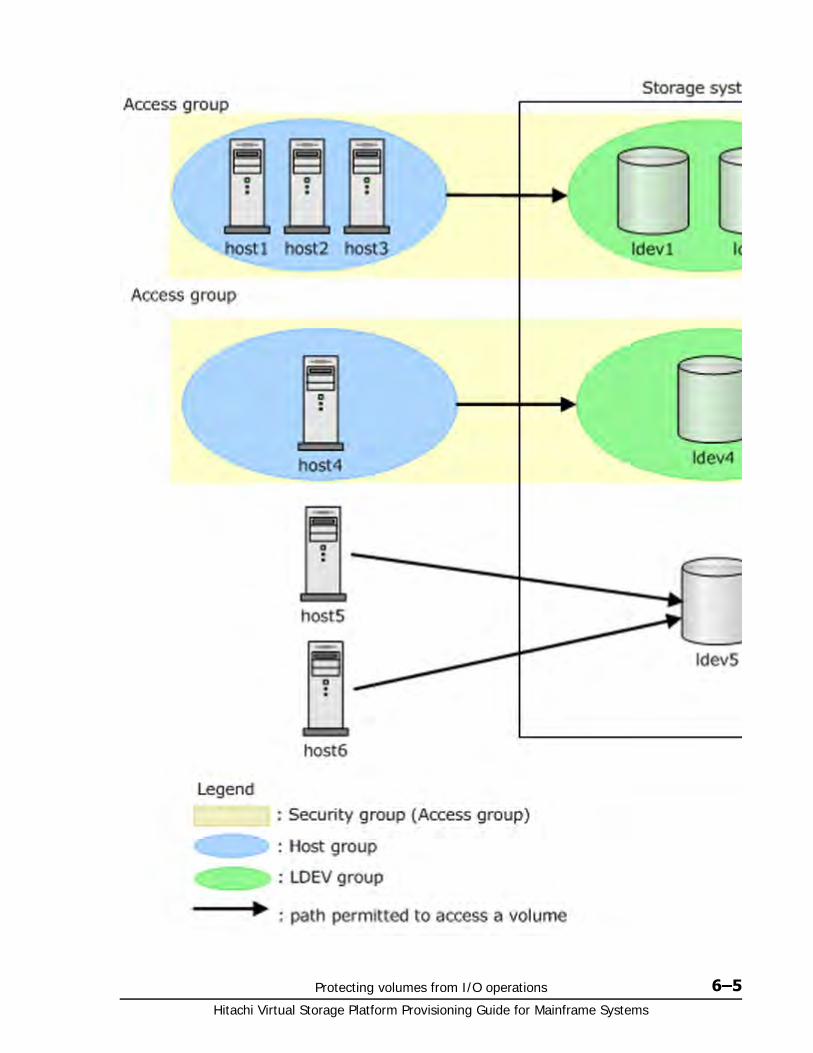
Protecting volumes from I/O operations 6–5Hitachi Virtual Storage Platform Provisioning Guide for Mainframe Systems
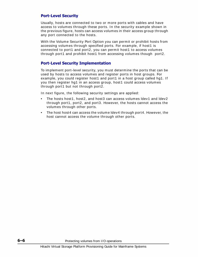
Hitachi Virtual Storage Platform Provisioning Guide for Mainframe Systems
6–6 Protecting volumes from I/O operations
Port-Level Security
Usually, hosts are connected to two or more ports with cables and have access to volumes through these ports. In the security example shown in the previous figure, hosts can access volumes in their access group through any port connected to the hosts.
With the Volume Security Port Option you can permit or prohibit hosts from accessing volumes through specified ports. For example, if host1 is connected to port1 and port2, you can permit host1 to access volumes through port1 and prohibit host1 from accessing volumes though port2.
Port-Level Security Implementation
To implement port-level security, you must determine the ports that can be used by hosts to access volumes and register ports in host groups. For example, you could register host1 and port1 in a host group called hg1. If you then register hg1 in an access group, host1 could access volumes through port1 but not through port2.
In next figure, the following security settings are applied:
• The hosts host1, host2, and host3 can access volumes ldev1 and ldev2 through port1, port2, and port3. However, the hosts cannot access the volumes through other ports.
• The host host4 can access the volume ldev4 through port4. However, the host cannot access the volume through other ports.

Protecting volumes from I/O operations 6–7Hitachi Virtual Storage Platform Provisioning Guide for Mainframe Systems
Hitachi Virtual Storage Platform Provisioning Guide for Mainframe Systems
6–8 Protecting volumes from I/O operations
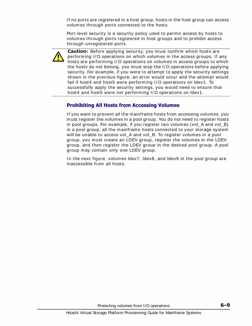
Protecting volumes from I/O operations 6–9Hitachi Virtual Storage Platform Provisioning Guide for Mainframe Systems
If no ports are registered in a host group, hosts in the host group can access volumes through ports connected to the hosts.
Port-level security is a security policy used to permit access by hosts to volumes through ports registered in host groups and to prohibit access through unregistered ports.
Prohibiting All Hosts from Accessing Volumes
If you want to prevent all the mainframe hosts from accessing volumes, you must register the volumes in a pool group. You do not need to register hosts in pool groups. For example, if you register two volumes (vol_A and vol_B) in a pool group, all the mainframe hosts connected to your storage system will be unable to access vol_A and vol_B. To register volumes in a pool group, you must create an LDEV group, register the volumes in the LDEV group, and then register the LDEV group in the desired pool group. A pool group may contain only one LDEV group.
In the next figure, volumes ldev7, ldev8, and ldev9 in the pool group are inaccessible from all hosts:
Caution: Before applying security, you must confirm which hosts are performing I/O operations on which volumes in the access groups. If any hosts are performing I/O operations on volumes in access groups to which the hosts do not belong, you must stop the I/O operations before applying security. For example, if you were to attempt to apply the security settings shown in the previous figure, an error would occur and the attempt would fail if host4 and host5 were performing I/O operations on ldev1. To successfully apply the security settings, you would need to ensure that host4 and host5 were not performing I/O operations on ldev1.

Hitachi Virtual Storage Platform Provisioning Guide for Mainframe Systems
6–10 Protecting volumes from I/O operations
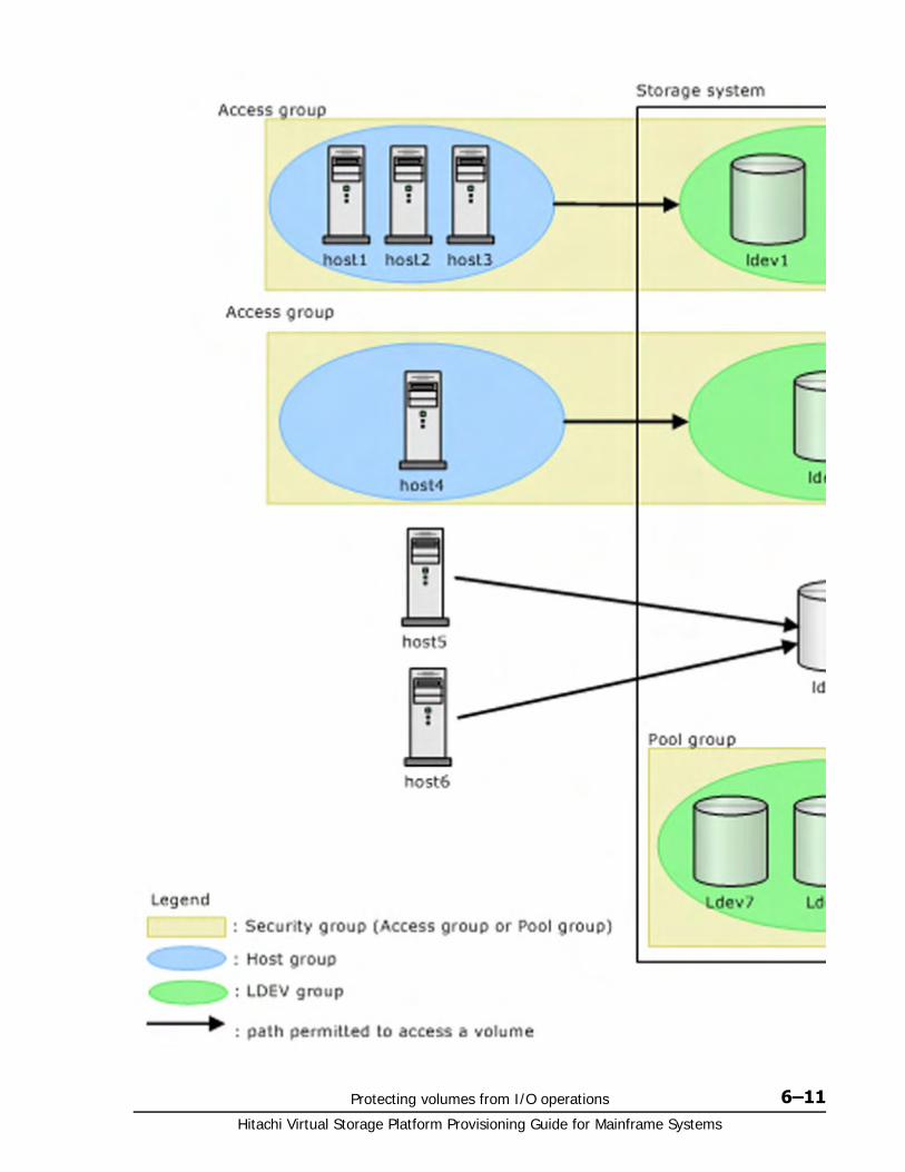
Protecting volumes from I/O operations 6–11Hitachi Virtual Storage Platform Provisioning Guide for Mainframe Systems

Hitachi Virtual Storage Platform Provisioning Guide for Mainframe Systems
6–12 Protecting volumes from I/O operations
Protecting Volumes from Erroneous Copy Operations
When VSP copy software (TrueCopy for Mainframe (TCz), Universal Replicator for Mainframe (URz), ShadowImage for Mainframe (SIz), Compatible FlashCopy® V2, or FICON(R) Data Migration is used to perform copy operations, data is overwritten on the secondary volumes, the copy destination volumes. If a volume that contains important data is specified as a secondary volume by mistake, VSP copy software operations could overwrite important data on the volume, causing data loss.
With Volume Security you can prevent a volume from being used as a secondary volume to avoid data loss.
Secondary volumes, referred to as TrueCopy remote volumes or R-VOLs ShadowImage target volumes or T-VOLs See Hitachi TrueCopy® for Mainframe User Guide and Hitachi ShadowImage® for Mainframe User Guide.
Warnings Regarding Volume SecurityThis section provides specific warnings and advice related to security settings.
When making security settings, it is important to be aware of these admonitions.
• If you are using VSP copy software (TrueCopy for Mainframe (TCz), Universal Replicator for Mainframe (URz), ShadowImage for Mainframe (SIz), and Compatible FlashCopy® or Compatible FlashCopy® V2): When you use Volume Security to make security settings, you must register the primary volume, the copy source, and the secondary volume, copy destination volume, in the same LDEV group. For details on how to register volumes in LDEV groups, see Registering Volumes in an LDEV Group on page 6-21. If you apply security to a primary volume and a secondary volume of a pair of Volume Security copy software, some or all mainframe hosts might be unable to read from and write to
WARNING:
1. Do not apply security to volumes on which any job is running. If you apply security to such a volume, the job may end abnormally.
2. When applying security, make sure that your security settings are correct. If incorrect security settings are made, the system will be difficult or impossible to control.
3. If the CPU of a mainframe host is upgraded after you apply security settings, you must execute the system command "D M=CPU" at the mainframe host to obtain the latest information about the host. Next, you must use the latest information to update host information in the Add/Change Host dialog box. If you do not update host information, the system will be impossible to control.
4. If the port level security is applied to a configuration that has alternate paths, set the port level security to all ports including alternate paths. If the port level security is not set to alternate paths, jobs end abnormally on alternate paths.
Protecting volumes from I/O operations 6–13Hitachi Virtual Storage Platform Provisioning Guide for Mainframe Systems
the primary volume and a secondary volume. However, the copy operation will be performed normally and the data will be copied from the primary volume to the secondary volume.
If you register a primary volume or secondary volume in a security group and then make a setting for preventing the volume from being used as a secondary volume, this setting will take effect after the pair is split.
Mainframe hosts cannot access volumes in pool groups. If a volume in a pool group is specified as a primary volume, the pair creation command might fail.
In the Hitachi TrueCopy® for Mainframe User Guide, primary volumes (copy source volumes) are often referred to as M-VOLs or main volumes. Also, secondary volumes (copy destination volumes) are often referred to as R-VOLs or remote volumes.
In the Hitachi ShadowImage® for Mainframe User Guide, primary volumes (copy source volumes) are often referred to as S-VOLs or source volumes. Also, secondary volumes (copy destination volumes) are often referred to as T-VOLs or target volumes.
• When the license key for the Volume Security program product expires, the volume setting that cannot be used for a secondary volume (copy target volume) becomes invalid. After that, the volume can be used as a secondary volume in TrueCopy for Mainframe and Universal Replicator for Mainframe.
• When security is applied to the volume for a command device, copying from a primary volume to a secondary volume is performed normally. However, when the port level security is applied to the volume for a command device, a copy operation that uses the Business Continuity Manager command can be performed only from a port for which access was permitted.
• If you are using Virtual LVI/LUN (VLL) volumes: If you apply security to a VLL volume, you will be unable to change the VLL settings on the volume. If you want to change the VLL settings, you must use Volume Security to disable security on the VLL volume.
• If you are using Compatible PAV: If you apply security to a Compatible PAV base volume, the security settings will also apply to the corresponding alias volume.
• To ensure normal system operation, take care in making security settings on the base-volume with alias volume access. For the Linux host: If a Linux host is registered to a host group, connect a storage system to a Linux host. Then register the Linux host to the host group.
• Removing secured volumes: If you apply security to a volume, you will be unable to remove the volume. If you want to remove the volume, you must disable security on the volume.
• Removing PCBs with secured ports: If port-level security is applied to your storage system, you cannot remove the PCBs (printed circuit boards) that include secured ports. If you want to remove PCBs that include secured ports, you must use Volume Security Port Option to disable security on the ports.
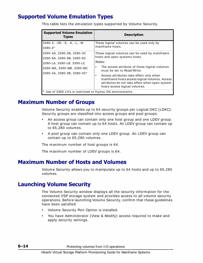
Hitachi Virtual Storage Platform Provisioning Guide for Mainframe Systems
6–14 Protecting volumes from I/O operations
Supported Volume Emulation TypesThis table lists the emulation types supported by Volume Security.
Maximum Number of GroupsVolume Security enables up to 64 security groups per Logical DKC (LDKC). Security groups are classified into access groups and pool groups:
• An access group can contain only one host group and one LDEV group. A host group can contain up to 64 hosts. An LDEV group can contain up to 65,280 volumes.
• A pool group can contain only one LDEV group. An LDEV group can contain up to 65,280 volumes.
The maximum number of host groups is 64.
The maximum number of LDEV groups is 64.
Maximum Number of Hosts and VolumesVolume Security allows you to manipulate up to 64 hosts and up to 65,280 volumes.
Launching Volume SecurityThe Volume Security window displays all the security information for the connected VSP storage system and provides access to all volume security operations. Before launching Volume Security, confirm that these guidelines have been satisfied:
• Volume Security Port Option is installed.
• You have Administrator (View & Modify) access required to make and apply security settings.
Supported Volume Emulation Types Description
3390-3, -3R, -9, -A, -L, -M
3380-3*
These logical volumes can be used only by mainframe hosts.
3390-3A, 3390-3B, 3390-3C
3390-9A, 3390-9B, 3390-9C
3390-LA, 3390-LB, 3390-LC
3390-MA, 3390-MB, 3390-MC
3380-3A, 3380-3B, 3380-3C*
These logical volumes can be used by mainframe hosts and open-systems hosts.
Notes:
• The access attribute of these logical volumes must be set to Read/Write.
• Access attributes take effect only when mainframe hosts access logical volumes. Access attributes do not take effect when open-system hosts access logical volumes.
* Use of 3380 LVIs is restricted to Fujitsu OS environments.
Protecting volumes from I/O operations 6–15Hitachi Virtual Storage Platform Provisioning Guide for Mainframe Systems
To start Volume Security
1. Open the Storage Navigator main window. For details, refer to Hitachi Storage Navigator User Guide.
2. Click Action > Mainframe Connection > Volume Security to open the Volume Security window.
Viewing Security SettingsThese sections describe how to view security settings.
• Locating Volumes in a Specified Security Group on page 6-15
• Locating Security Groups that Contain a Specified Host on page 6-15
• Locating Volumes in a Security Group that Contains a Specified Host on page 6-16
• Locating Ports through Which Hosts Can Access Volumes on page 6-16
• Locating Security Groups that Contain a Specified Volume on page 6-17
• Locating Hosts in a Security Group that Contains a Specified Volume on page 6-17
• Locating Security Groups that Contain a Specified Host Group on page 6-17
• Locating Security Groups that Contain a Specified LDEV Group on page 6-18
Locating Volumes in a Specified Security GroupTo search a security group for volumes, select the security group in the tree view of the Volume Security window. You can find the volumes listed in the lower-right table.
Locating Security Groups that Contain a Specified HostUse one of these procedures to specify a host and find the security groups in which the host is registered.
If the host appears in the upper-right table:
1. Right-click the host in the table
2. From the pop-up menu, select Host to Security Group. The Host to Security Group dialog box opens with a list of security groups.
If the host does not appear in the upper-right table:
1. In the tree view of the Volume Security window, right-click an item other than a host group or LDEV group that appears immediately below a security group.
2. From the pop-up menu, select List then Host to Security Group. The Host to Security Group dialog box opens.
3. From the Host list, select the desired host. The table lists associated security groups.
Hitachi Virtual Storage Platform Provisioning Guide for Mainframe Systems
6–16 Protecting volumes from I/O operations
Locating Volumes in a Security Group that Contains a Specified Host
If a security group is classified as an access group, the security group contains both host and volumes. Use one of these procedures to find volumes in the security group in which the specified host is registered.
If the host appears in the upper-right table:
1. Right-click the host in the table
2. From the pop-up menu, select Host to LDEV. The Host to LDEV dialog box opens with a list of volumes.
3. Right-click an arrow at the right end of the CU list to see how many CU image numbers appear.
If just one CU image number appears, the table in the dialog box displays all the volumes that you want.
If two or more CU image numbers appear, the table in the dialog box displays some of the volumes that you want. Select each CU image number to find volumes in the CU image.
If the host does not appear in the upper-right table:
1. In the tree view of the Volume Security window, right-click an item other than a host group or LDEV group that appears immediately below a security group.
2. From the pop-up menu, select List then Host to LDEV. The Host to LDEV dialog box opens.
3. From the Host list, select the desired host.
4. Right-click an arrow at the right end of the CU list to see how many CU image numbers appear.
If just one CU image number appears, the table in the dialog box displays all the volumes that you want.
If two or more CU image numbers appear, the table in the dialog box displays some of the volumes that you want. Select each CU image number to find volumes in the CU image.
Locating Ports through Which Hosts Can Access VolumesTo find ports through which a host can access volumes, follow this procedure to confirm that the Volume Security Port Option is installed.
To find ports that a host can use to access volumes:
1. In the Volume Security window, right-click an item in the tree view, then select List then Host Group to Port from the pop-up menu. The Host Group to Port dialog box opens
2. Select a group from the Host Group list.
3. Select a host from the Host list. The Port list shows ports that can be used by a specified host to access volumes.
4. Click OK to close the Host Group to Port dialog box and return to the Volume Security window
Protecting volumes from I/O operations 6–17Hitachi Virtual Storage Platform Provisioning Guide for Mainframe Systems
Locating Security Groups that Contain a Specified VolumeUse one of these procedures to specify a volume and find security groups in which the volume is registered.
If the volume appears in the lower-right table:
1. Right-click the volume in the table.
2. From the pop-up menu, select LDEV to Security Group. The LDEV to Security Group dialog box opens with a list of security groups.
If the volume does not appear in the lower-right table:
1. In the tree view of the Volume Security window, right-click an item other than a host group or LDEV group that appears immediately below a security group.
2. From the pop-up menu, select List then LDEV to Security Group. The LDEV to Security Group dialog box opens.
3. Select a CU image number from the CU list, then select an LDEV number from the lower-left table. The table on the right lists the security groups that you want.
Locating Hosts in a Security Group that Contains a Specified Volume
Use one of these procedures to specify a volume and find hosts in security groups in which the volume is registered.
If the volume appears in the lower-right table:
1. Right-click the volume in the table.
2. From the pop-up menu, select LDEV to Host. The LDEV to Host dialog box opens with a list of hosts.
If the volume does not appear in the lower-right table:
1. In the tree view of the Volume Security window, right-click an item other than a host group or LDEV group that appears immediately below a security group.
2. From the pop-up menu, select List then LDEV to Host. The LDEV to Host dialog box opens.
3. Select a CU image number from the CU list, then select an LDEV number from the lower-left table. The table on the right lists the security groups that you want.
Locating Security Groups that Contain a Specified Host GroupUse this procedure to specify a host group and find security groups in which the specified host group is registered.
1. In the tree view of the Volume Security window, right-click an item other than a host group or LDEV group that appears immediately below a security group.
2. From the pop-up menu, select List then Host Group to Security Group. The Host Group dialog box opens.
Hitachi Virtual Storage Platform Provisioning Guide for Mainframe Systems
6–18 Protecting volumes from I/O operations
3. Select a host group from the Host Group list. The table lists the security groups that you want.
Locating Security Groups that Contain a Specified LDEV GroupUse this procedure to specify an LDEV group and find security groups in which the specified LDEV group is registered.
1. In the tree view of the Volume Security window, right-click an item other than a host group or LDEV group that appears immediately below a security group.
2. From the pop-up menu, select List then LDEV Group to Security Group. The LDEV Group to Security Group dialog box opens.
3. Select an LDEV group from the Host Group list. The table lists the security groups that you want.
Limiting Host AccessUse the procedures in this section to enable some hosts to access certain volumes and to prevent other hosts from accessing the same volumes.
• Creating a Host Group on page 6-18
• Registering Hosts in a Host Group on page 6-19
• Registering Ports in a Host Group on page 6-20
• Creating an LDEV Group on page 6-21
• Registering Volumes in an LDEV Group on page 6-21
• Creating a Security Group for Use As an Access Group on page 6-22
• Registering a Host Group and an LDEV Group in a Security Group on page 6-23
Creating a Host GroupTo specify hosts that can access specific volumes, create a host group and register the hosts in the host group.
The following is the procedure for creating a host group. For details on how to register hosts in a host group, see Registering Hosts in a Host Group on page 6-19.
To create a host group
1. Confirm that you are in Modify mode.
2. In the Volume Security window, double-click an LDKC number.
3. Right-click Host Group. A pop-up menu appears.
Caution: When creating a host group, it is strongly recommended that you click Apply in the Volume Security window, as described in the last step of the following procedure. If you forget to click Apply, the host group can be lost if you encounter an error in registering the host group and the LDEV group.
Protecting volumes from I/O operations 6–19Hitachi Virtual Storage Platform Provisioning Guide for Mainframe Systems
4. Select Add/Change from the pop-up menu. The Add/Change Host Group dialog box opens.
5. In the Enter Host Group box, enter the name of the host group that you want to create, and click Add.
Names can be up to eight characters and are case-sensitive. A space cannot be used as the first or last character of a name. The following characters are not allowed in names:
\ , / : ; * ? " < > |
6. Confirm that the new host group is displayed in Host Group List, and click OK. At this point, the settings in the window have not been applied to the storage system.
7. Click Apply in the Volume Security window. A message appears asking whether to apply the settings to the storage system.
8. Click Yes. The settings are applied to the storage system.
Registering Hosts in a Host GroupAfter creating a host group, the next step is to register hosts in the host group.
To register a host in a host group
1. Confirm that you are in Modify mode.
2. In the Volume Security window, double-click an LDKC number.
3. Right-click a host group. A pop-up menu appears.
4. Select Specify, then Host, from the pop-up menu. The Add/Change Host dialog box opens with a list of hosts.
5. Select and right-click one or more hosts that you want to register.
If a host is indicated by the icon or , the host is registered already in the specified host group. For details on the meaning of icons, see Add/Change Host Dialog Box on page F-15.
If ports are registered in the displayed host group, you can register only the hosts that do not belong to any other host group. You cannot register hosts that belong to any other host group.
If no ports are registered in the displayed host group, you can register the following hosts:
hosts that do not belong to any host group
hosts belonging to host groups in which no ports are registered.
However, you cannot register hosts that belong to host groups in which ports are registered.
Caution: When registering hosts into a host group, it is strongly recommended that you click Apply in the Volume Security window, as described in the last step of the following procedure. If you forget to click Apply, you might lose the host group when you encounter an error registering the host group and the LDEV group.

Hitachi Virtual Storage Platform Provisioning Guide for Mainframe Systems
6–20 Protecting volumes from I/O operations
6. Select Registration and then Register Host in Host Group from the pop-up menu. The specified hosts are displayed in blue and indicated by
the icon or the icon .
7. Click OK in the Add/Change Host dialog box. At this point, the settings in the window have not been applied to the storage system.
8. Click Apply in the Volume Security window. A message appears asking whether to apply the settings to the storage system.
9. Click Yes. The settings are applied to the storage system.
Registering Ports in a Host GroupAfter registering ports in a host group, you can register ports in the host group to implement port-level security.
If you want to register ports in a host group, you must ensure that Volume Security Port Option is installed.
If you do not want to implement port-level security, you do not need to register ports in host groups. If no ports are registered in a host group, hosts in the host group can access volumes through every port to which the hosts are connected.
To register ports in a host group
1. Confirm that you are in Modify mode.
2. In the Volume Security window, double-click an LDKC number.
3. Right-click a host group. A pop-up menu appears.
4. Select Specify, then Port, from the pop-up menu. The Select Port dialog box opens with a list of hosts.
5. From the Port list in the Unregistered port box, select one or more ports on the hosts in the host group to enable their accessing these volumes. Next, click Regist. The specified ports are displayed in blue in the Port list in the Registered port box.
To select all the ports in the Port list in the Unregistered port box, click Select All.
If hosts registered in the host group are also registered in another host group, you cannot register ports in the Port list in the Registered port box or implement port-level security.
6. Click OK in the Select Port dialog box. The Select Port dialog box closes and you are returned to the Volume Security window. At this point, the settings in the window have not been applied to the storage system.
7. Click Apply in the Volume Security window. A message appears asking whether to apply the settings to the storage system.
Caution: When registering ports into a host group, it is strongly recommended that you click Apply in the Volume Security window, as described in the last step of the following procedure. If you forget to click Apply, port registration could be cancelled when registering a the host group and an LDEV group. See Registering a Host Group and an LDEV Group in a Security Group.
Protecting volumes from I/O operations 6–21Hitachi Virtual Storage Platform Provisioning Guide for Mainframe Systems
8. Click Yes. The settings are applied to the storage system.
Creating an LDEV GroupTo specify volumes to be secured, you must create an LDEV group and register the volumes in the LDEV group.
The following procedure explains how to create an LDEV group. For details on how to register volumes in an LDEV group, see Registering Volumes in an LDEV Group.
To create an LDEV group
1. Confirm that you are in Modify mode.
2. In the Volume Security window, double-click an LDKC number.
3. Right-click a LDEV Group. A pop-up menu appears.
4. Select Add/Change from the pop-up menu. The Add/Change LDEV Group dialog box opens.
5. In the Enter LDEV Group box, enter the name of the LDEV group that you want to create, and click Add.
Names can be up to eight characters and are case-sensitive. A space cannot be used as the first or last character of a name. The following characters are not allowed in names:
\ , / : ; * ? " < > |
6. Confirm that the new LDEV group is displayed in LDEV Group List, and click OK. At this point, the settings in the window have not been applied to the storage system.
7. Click Apply in the Volume Security window. A message appears asking whether to apply the settings to the storage system.
8. Click Yes. The settings are applied to the storage system.
Registering Volumes in an LDEV GroupAfter creating an LDEV group, the next step is to register volumes in the LDEV group.
Caution: When creating an LDEV group, it is strongly recommended that you click Apply in the Volume Security window, as described in the last step of the following procedure. If you forget to click Apply, you might lose the LDEV group when you encounter an error in registering the host group and the LDEV group. See Registering a Host Group and an LDEV Group in a Security Group.
Caution: When registering volumes in an LDEV group, it is strongly recommended that you click Apply in the Volume Security window, as described in the last step of the following procedure. If you forget to click Apply, the volumes might be unregistered when you encounter an error registering the host group and the LDEV group. See Registering a Host Group and an LDEV Group in a Security Group.
Hitachi Virtual Storage Platform Provisioning Guide for Mainframe Systems
6–22 Protecting volumes from I/O operations
To register volumes in the LDEV group
1. Confirm that you are in Modify mode.
2. In the Volume Security window, double-click an LDKC number.
3. Right-click an LDEV group. A pop-up menu appears.
4. Select Specify, then LDEV, from the pop-up menu. The Select LDEV dialog box opens with a list of hosts.
5. Use the CU list to specify a CU image. The two boxes beneath the list show volumes in the specified CU image.
The Registered in LDEV group box displays volumes registered in the LDEV group.
The Not Registered in LDEV group box displays volumes that are not registered in the LDEV group.
6. In the Not Registered in LDEV group box, select volumes that you want to register. Then, click Regist. The selected volumes move to the Registered in LDEV group box.
7. If you want to register volumes in other CU images, return to step 5.
8. Click OK. At this point, the settings in the window have not been applied to the storage system.
9. Click Apply in the Volume Security window. A message appears asking whether to apply the settings to the storage system.
10.Click Yes. The settings are applied to the storage system.
Creating a Security Group for Use As an Access GroupTo make security settings, you must create security groups. Security groups can be classified as access groups or pool groups. You must classify a security group as an access group if you want to allow volumes to be accessed only by specified hosts.
To create a security group and classify the group as an access group
1. Confirm that you are in Modify mode.
2. In the Volume Security window, double-click an LDKC number.
3. Right-click a LDEV Group. A pop-up menu appears.
4. Select Add/Change from the pop-up menu. The Add/Change Security Group dialog box opens.
5. In the Enter Security Group box, enter the name of the security group that you want to create, and click Add.
Names can be up to eight characters and are case-sensitive. A space cannot be used as the first or last character of a name. The following characters are not allowed in names:
\ , / : ; * ? " < > |
6. In the Security box, select Enable.
7. In the Group Status box, select Access.
8. In the T-VOL/R-VOL box, select Enable or Disable.
Protecting volumes from I/O operations 6–23Hitachi Virtual Storage Platform Provisioning Guide for Mainframe Systems
Select Enable if you want make volumes in the security group usable as secondary volumes (copy destination volumes) for copy operations.
Select Disable if you want make volumes in the security group unusable as secondary volumes (copy destination volumes) for copy operations.
9. Click Add. Information about the new security group is added to the Security Group List table and is displayed in blue.
10.Click OK. At this point, the settings in the window have not been applied to the storage system.
11.Click Apply in the Volume Security window. A message appears asking whether to apply the settings to the storage system.
12.Click Yes. The settings are applied to the storage system.
Registering a Host Group and an LDEV Group in a Security GroupAfter classifying a security group as an access group, the next (and the last) task is to register the host group and LDEV group into the security group. When you finish registration, the volumes in the LDEV group are secured and can be accessed only by hosts in the host group. Other hosts cannot access the volumes
To register a host group and an LDEV group into a security group
1. Confirm that you are in Modify mode.
2. In the Volume Security window, double-click an LDKC number.
3. Right-click an LDEV group. A pop-up menu appears.
4. Select Specify, then Security Group, from the pop-up menu. The Select Security Group dialog box opens with a list of hosts.
5. Use the Select Security Group list to select the security group in which you want to register a host group and an LDEV group.
6. Use the Host Group list to select the host group that you want to register in a security group.
7. Use the LDEV Group list to select the LDEV group that you want to register in a security group.
8. Click Apply in the Volume Security window. A message appears asking whether to apply the settings to the storage system.
9. Click Yes. The settings are applied to the storage system.
Prohibiting Host AccessUse the procedures in this section to prohibit all the hosts from accessing specified volumes.
Caution: Before applying security, confirm which hosts are performing I/O operations on volumes in access groups. If there are hosts are performing I/O operations on volumes in access groups to which the hosts do not belong, you must stop the I/O operations before applying security.
Hitachi Virtual Storage Platform Provisioning Guide for Mainframe Systems
6–24 Protecting volumes from I/O operations
• Creating an LDEV Group on page 6-24
• Registering Volumes in an LDEV Group on page 6-25
• Creating a Security Group for Use As a Pool Group on page 6-25
• Registering an LDEV Group in a Security Group on page 6-26
Creating an LDEV GroupTo specify volumes to be secured, you must create an LDEV group and register the volumes in the LDEV group.
The following procedure explains how to create an LDEV group. For details on how to register volumes in an LDEV group, see Registering Volumes in an LDEV Group.
To create an LDEV group
1. Confirm that you are in Modify mode.
2. In the Volume Security window, double-click an LDKC number.
3. Right-click a LDEV Group. A pop-up menu appears.
4. Select Add/Change from the pop-up menu. The Add/Change LDEV Group dialog box opens.
5. In the Enter LDEV Group box, enter the name of the LDEV group that you want to create, and click Add.
Names can be up to eight characters and are case-sensitive. A space cannot be used as the first or last character of a name. The following characters are not allowed in names:
\ , / : ; * ? " < > |
6. Confirm that the new LDEV group is displayed in LDEV Group List, and click OK. At this point, the settings in the window have not been applied to the storage system.
7. Click Apply in the Volume Security window. A message appears asking whether to apply the settings to the storage system.
8. Click Yes. The settings are applied to the storage system.
Caution: When creating an LDEV group, it is strongly recommended that you click Apply in the Volume Security window, as described in the last step of the following procedure. If you forget to click Apply, you might lose the LDEV group when you encounter an error in registering the LDEV group. See Registering a Host Group and an LDEV Group in a Security Group.
Protecting volumes from I/O operations 6–25Hitachi Virtual Storage Platform Provisioning Guide for Mainframe Systems
Registering Volumes in an LDEV GroupAfter creating an LDEV group, the next step is to register volumes in the LDEV group.
To register volumes in the LDEV group
1. Confirm that you are in Modify mode.
2. In the Volume Securitywindow, double-click an LDKC number.
3. Right-click an LDEV group. A pop-up menu appears.
4. Select Specify, then LDEV, from the pop-up menu. The Select LDEV dialog box opens with a list of hosts.
5. Use the CU list to specify a CU image. The two boxes beneath the list show volumes in the specified CU image.
The Registered in LDEV group box displays volumes registered in the LDEV group.
The Not Registered in LDEV group box displays volumes that are not registered in the LDEV group.
6. In the Not Registered in LDEV group box, select volumes that you want to register. Then, click Regist. The selected volumes move to the Registered in LDEV group box.
7. If you want to register volumes in other CU images, return to step 5.
8. Click OK. At this point, the settings in the window have not been applied to the storage system.
9. Click Apply in the Volume Security window. A message appears asking whether to apply the settings to the storage system.
10.Click Yes. The settings are applied to the storage system.
Creating a Security Group for Use As a Pool GroupTo make security settings, you must create security groups. Security groups can be classified as access groups or pool groups. You must classify a security group as a pool group if you want to prohibit all the hosts from accessing volumes.
To create a security group and classify the group as an access group
1. Confirm that you are in Modify mode.
2. In the Volume Security window, double-click an LDKC number.
3. Right-click a Security Group. A pop-up menu appears.
4. Select Add/Change from the pop-up menu. The Add/Change Security Group dialog box opens.
Caution: When registering volumes in an LDEV group, it is strongly recommended that you click Apply in the Volume Securitywindow, as described in the last step of the following procedure. If you forget to click Apply, the volumes might be unregistered when you encounter an error registering the LDEV group. See Registering a Host Group and an LDEV Group in a Security Group.
Hitachi Virtual Storage Platform Provisioning Guide for Mainframe Systems
6–26 Protecting volumes from I/O operations
5. In the Enter Security Group box, enter the name of the security group that you want to create, and click Add.
Names can be up to eight characters and are case-sensitive. A space cannot be used as the first or last character of a name. The following characters are not allowed in names:
\ , / : ; * ? " < > |
6. In the Security box, select Enable.
7. In the Group Status box, select Pool.
8. In the T-VOL/R-VOL box, select Enable or Disable.
Select Enable if you want make volumes in the security group usable as secondary volumes (copy destination volumes) for copy operations.
Select Disable if you want make volumes in the security group unusable as secondary volumes (copy destination volumes) for copy operations.
9. Click Add. Information about the new security group is added to the Security Group List table and is displayed in blue.
10.Click OK. At this point, the settings in the window have not been applied to the storage system.
11.Click Apply in the Volume Security window. A message appears asking whether to apply the settings to the storage system.
12.Click Yes. The settings are applied to the storage system.
Registering an LDEV Group in a Security GroupAfter classifying a security group as pool group, the next (and the last) task is to register the host group and LDEV group into the security group. When you finish registration, the volumes in the LDEV group are secured and inaccessible from any hosts.
To register a host group and an LDEV group into a security group
1. Confirm that you are in Modify mode.
2. In the Volume Security window, double-click an LDKC number.
3. Right-click an LDEV group. A pop-up menu appears.
4. Select Specify, then Security Group, from the pop-up menu. The Select Security Group dialog box opens with a list of hosts.
5. Use the Select Security Group list to select the security group in which you want to register a host group and an LDEV group.
6. Use the Host Group list to select the host group that you want to register in a security group.
7. Use the LDEV Group list to select the LDEV group that you want to register in a security group.
Caution: Before applying security, confirm which hosts are performing I/O operations on volumes in access groups. If there are hosts are performing I/O operations on volumes in access groups to which the hosts do not belong, you must stop the I/O operations before applying security.

Protecting volumes from I/O operations 6–27Hitachi Virtual Storage Platform Provisioning Guide for Mainframe Systems
8. Click Apply in the Volume Security window. A message appears asking whether to apply the settings to the storage system.
9. Click Yes. The settings are applied to the storage system.
Protecting Volumes from Copy OperationsThe procedure in this section makes volumes in a security group unusable as secondary volumes (copy destination volumes) to protect data in volumes from being overwritten in copy operations.
To make volumes in a security group unusable as secondary volumes
1. Confirm that you are in Modify mode.
2. In the Volume Security window, double-click an LDKC number.
3. Right-click a Security Group or the desired security group. A pop-up menu appears.
4. Select Add/Change from the pop-up menu. The Add/Change Security Group dialog box opens.
5. Confirm that the desired security group is selected in the Security Group list table.
6. Select Disable in the T-VOL/R-VOL box.
7. Select Change. The change is reflected in the dialog box.
8. Click OK. At this point, the settings in the window have not been applied to the storage system.
9. Click Apply in the Volume Security window. A message appears asking whether to apply the settings to the storage system.
10.Click Yes. The settings are applied to the storage system.
Disabling Volume SecurityYou can use the procedure in this section to manipulate a security group and disable security on volumes in the security group. If security is disabled, volumes in the security group are accessible from all hosts and are usable as secondary volumes (copy destination volumes) for copy operations, regardless of whether the security group is an access group or a pool group. You can restore security in a simple operation.
If you will not need to restore security, you can delete your security group to disable security. For details on how to delete security groups, see Deleting Security Groups.
To disable security on volumes
1. Confirm that you are in Modify mode.
Tip: To make volumes in your security group usable as secondary volumes (copy destination volumes) for copy operations, select the security group in the Add/Change Security Group dialog box. Then select Enable in the T-VOL/R-VOL box. Next, click Change, then OK. Finally, click Apply in the Volume Security window.
Hitachi Virtual Storage Platform Provisioning Guide for Mainframe Systems
6–28 Protecting volumes from I/O operations
2. In the Volume Security window, double-click an LDKC number.
3. Right-click a Security Group the security group in which the desired volumes are registered. A pop-up menu appears.
4. Select Add/Change from the pop-up menu. The Add/Change Security Group dialog box opens.
5. Confirm that the desired security group is selected in the Security Group list table.
6. Select Disable in the Security box.
7. Select Change. The change is reflected in the dialog box.
8. Click OK. At this point, the settings in the window have not been applied to the storage system.
9. Click Apply in the Volume Security window. A message appears asking whether to apply the settings to the storage system.
10.Click Yes. The settings are applied to the storage system.
Editing Security GroupsUse the procedures in this section to edit your security groups.
• Unregistering a Host Group on page 6-28
• Unregistering an LDEV Group on page 6-29
• Renaming a Security Group on page 6-29
• Deleting a Security Group on page 6-29
Unregistering a Host GroupTo unregister a host group from a security group
1. Confirm that you are in Modify mode.
2. In the Volume Security window, double-click an LDKC number.
3. Locate and double-click a security group. The tree view displays the host group in the specified security group.
4. Right-click the host groups and select Delete from the pop-up menu. A message appears asking whether to unregister the specified host group.
5. Click Yes to close the message. At this point, the settings in the window have not been applied to the storage system.
6. Click Apply in the Volume Security window. A message appears asking whether to apply the settings to the storage system.
7. Click Yes. The settings are applied to the storage system.
Tip: To restore security, select the security group in the Add/Change Security Group dialog box. Then select Enable in the Security box. Next, click Change, then OK. Finally, click Apply in the Volume Security window.
Protecting volumes from I/O operations 6–29Hitachi Virtual Storage Platform Provisioning Guide for Mainframe Systems
Unregistering an LDEV GroupTo unregister an LDEV group from a security group
1. Confirm that you are in Modify mode.
2. In the Volume Security window, double-click an LDKC number.
3. Locate and double-click a security group. The tree view displays the host group in the specified security group.
4. Right-click the LDEV group and select Delete from the pop-up menu. A message appears asking whether to unregister the specified LDEV group.
5. Click Yes to close the message. At this point, the settings in the window have not been applied to the storage system.
6. Click Apply in the Volume Security window. A message appears asking whether to apply the settings to the storage system.
7. Click Yes. The settings are applied to the storage system.
Renaming a Security GroupTo rename a security group
1. Confirm that you are in Modify mode.
2. In the Volume Security window, double-click an LDKC number.
3. Right-click Security Group or a security group. A pop-up menu appears.
4. Select Add/Change from the pop-up menu. The Add/Change Security Group dialog box opens.
5. Confirm that the desired security group is selected in the Security Group List table
6. In the Enter Security Group box, enter the new name for the security group that you want to create, and click Add.
Names can be up to eight characters and are case-sensitive. A space cannot be used as the first or last character of a name. The following characters are not allowed in names:
\ , / : ; * ? " < > |
7. Click Change. The change is reflected in the dialog box.
8. Click OK. At this point, the settings in the window have not been applied to the storage system.
9. Click Apply in the Volume Security window. A message appears asking whether to apply the settings to the storage system.
10.Click Yes. The settings are applied to the storage system.
Deleting a Security GroupTo delete a security group
1. Confirm that you are in Modify mode.
2. In the Volume Security window, double-click an LDKC number.
Hitachi Virtual Storage Platform Provisioning Guide for Mainframe Systems
6–30 Protecting volumes from I/O operations
3. Do one of the following:
Right-click a security group in the tree view.
Right-click Security Group, then select Add/Change from the pop-up menu. In the Add/Change Security Group dialog box, select one or more security groups in the Security Group List table and right-click the selection.
4. Select Delete from the pop-up menu. A message appears asking whether you want to delete the specified security groups.
5. Click Yes to close the message. If the Add/Change Security Group dialog box still remains displayed, click OK to close the dialog box. At this point, the settings in the window have not been applied to the storage system.
6. Click Apply in the Volume Security window. A message appears asking whether to apply the settings to the storage system.
7. Click Yes. The change is applied to the storage system.
Editing Host GroupsUse the procedures in this section to edit your host groups.
• Registering Hosts to be Attached to the Storage System on page 6-30
• Deleting Hosts from Host Groups on page 6-31
• Deleting Ports from Host Groups on page 6-32
• Renaming Host Groups on page 6-32
• Deleting Host Groups on page 6-33
Registering Hosts to be Attached to the Storage SystemIf your organization is planning to attach new mainframe hosts to the storage system, you will possibly need to revise security settings on volumes. For example, if you do not want to allow the new hosts to access some volumes, you might need to register the new hosts in the host group in an existing access group. Volume Security enables you to register new hosts in host groups before the new hosts are attached with cables to the storage system.
To register a mainframe host to be attached into a host group
1. Execute the following system command at the mainframe host:
D M=CPU
This command displays the type, the model number, the node ID, and the logical partition number of the host. Record this information.
For more information on this command, refer to the documentation on system commands.
2. Confirm that you are in Modify mode.
3. In the Volume Security window, double-click an LDKC number.
4. Right-click Host Groups to display a list of host groups.
Protecting volumes from I/O operations 6–31Hitachi Virtual Storage Platform Provisioning Guide for Mainframe Systems
5. Right-click the host group in which you want to register the host. Select Specify and then Host from the pop-up menu. The Add/Change Host dialog box opens
6. Use the text boxes and the drop-down list to specify information you obtained in the first step about the host you want to register.
7. Click Add. The specified host is added to the table and is indicated by
the icon .
8. Click OK. At this point, the settings in the window have not been applied to the storage system.
9. Click Apply in the Volume Security window. A message appears asking whether to apply the settings to the storage system.
10.Click Yes. The settings are applied to the storage system.
Deleting Hosts from Host GroupsTo delete hosts from host groups
1. Confirm that you are in Modify mode.
2. In the Volume Security window, double-click an LDKC number.
3. Right-click a host group. A pop-up menu appears.
4. Select Specify, then Host, from the pop-up menu. The Add/Change Host dialog box opens with a list of hosts.
The icons and indicate hosts that are registered specified host groups.
5. Select and right-click one or more hosts, indicated by or , that you want to delete.
6. Select Registration, then Unregister Host in Host Group from the pop-up menu. The specified hosts are displayed in blue. The icons
disappear or change to or the icon , to indicate that the host is registered in another host group.
7. Click OK in the Add/Change Host dialog box. At this point, the settings in the window have not been applied to the storage system.
8. Click Apply in the Volume Security window. A message appears asking whether to apply the settings to the storage system.
Tip: If you registered a host in an incorrect host group, follow the above procedure to register the host in the correct host group. Then, follow the procedure in the Deleting Hosts from Host Groups section to remove the host from the incorrect host group.
You can modify information about hosts indicated by in the Add/Change Host dialog box. To modify information, select the desired host in the table, then use text boxes and drop-down lists to change information. Click Change, then OK. Finally, click Apply in the Volume Security window.
To delete a host indicated by from the Add/Change Host dialog box, select and right-click the host. Then select Delete from the pop-up menu, and click OK. Finally, click Apply in the Volume Security window.

Hitachi Virtual Storage Platform Provisioning Guide for Mainframe Systems
6–32 Protecting volumes from I/O operations
9. Click Yes. The settings are applied to the storage system.
Deleting Ports from Host GroupsIf you want to delete ports from host groups, you must confirm that Volume Security Port Option is installed.
To delete ports from host groups
1. Confirm that you are in Modify mode.
2. In the Volume Security window, double-click an LDKC number.
3. Right-click a host group. A pop-up menu appears.
4. Select Specify, then Port from the pop-up menu. The Select Port dialog box opens.
5. In the Port list in the Registered port box, select one or more ports that you want to delete. Click Unregist.
The specified ports are displayed in blue in the Port list in the Unregist port box.
If you want to select all ports in the Port list in the Regist port box, click Select All.
6. Click OK in the Select Port dialog box. The Select Port dialog box closes and you are returned to the Volume Security window. At this point, the settings in the window have not been applied to the storage system.
7. Click Apply in the Volume Security window. A message appears asking whether to apply the settings to the storage system.
8. Click Yes. The settings are applied to the storage system.
Renaming Host GroupsTo rename a host group
1. Confirm that you are in Modify mode.
2. In the Volume Security window, double-click an LDKC number.
3. Right-click Host Group or a security group. A pop-up menu appears.
4. Select Add/Change from the pop-up menu. The Add/Change Host Group dialog box opens.
5. Confirm that the desired host group is selected in the Host Group List table
6. In the Enter Host Group box, enter the new name for the host group that you want to create.
Names can be up to eight characters and are case-sensitive. A space cannot be used as the first or last character of a name. The following characters are not allowed in names:
\ , / : ; * ? " < > |
7. Click Change. The change is reflected in the dialog box.
8. Click OK. At this point, the settings in the window have not been applied to the storage system.
Protecting volumes from I/O operations 6–33Hitachi Virtual Storage Platform Provisioning Guide for Mainframe Systems
9. Click Apply in the Volume Security window. A message appears asking whether to apply the settings to the storage system.
10.Click Yes. The settings are applied to the storage system.
Deleting Host GroupsTo delete a host group:
1. Confirm that you are in Modify mode.
2. In the Volume Security window, double-click an LDKC number.
3. Do one of the following:
Right-click a host group in the tree view.
Right-click Host Group in the tree view, then select Add/Change from the pop-up menu. In the Add/Change Host Group dialog box, select one or more host groups in the Host Group List table and right-click the selection.
4. Select Delete from the pop-up menu. A message appears asking whether you want to delete the specified host groups.
5. Click Yes to close the message. If the Add/Change Security Group dialog box still remains displayed, click OK to close the dialog box. At this point, the settings in the window have not been applied to the storage system.
6. Click Apply in the Volume Security window. A message appears asking whether to apply the settings to the storage system.
7. Click Yes. The change is applied to the storage system.
Editing LDEV GroupsUse the procedures in this section to edit your LDEV groups.
• Deleting Volumes from an LDEV Groups on page 6-33
• Renaming an LDEV Group on page 6-34
• Deleting an LDEV Group on page 6-34
Deleting Volumes from an LDEV GroupsTo delete hosts from an LDEV group
1. Confirm that you are in Modify mode.
2. In the Volume Security window, double-click an LDKC number.
3. Right-click a host group. A pop-up menu appears.
4. Select Specify, then LDEV, from the pop-up menu. The Select LDEV dialog box opens.
5. Use the CU list to specify a CU image. The two boxes beneath the list show volumes in the specified CU image.
The Registered in LDEV group box displays volumes registered in the LDEV group.
The Not Registered in LDEV group box displays volumes that are not registered in the LDEV group.
Hitachi Virtual Storage Platform Provisioning Guide for Mainframe Systems
6–34 Protecting volumes from I/O operations
6. In the Registered in LDEV group box, select volumes that you want to delete. Then, click Not Regist. The selected volumes move to the Not Registered in LDEV group box.
7. If you want to delete volumes in other CU images, return to step 5.
8. Click OK in the Add/Change Host dialog box. At this point, the settings in the window have not been applied to the storage system.
9. Click Apply in the Volume Security window. A message appears asking whether to apply the settings to the storage system.
10.Click Yes. The settings are applied to the storage system.
Renaming an LDEV GroupTo rename an LDEV group
1. Confirm that you are in Modify mode.
2. In the Volume Security window, double-click an LDKC number.
3. Right-click LDEV Group. A pop-up menu appears.
4. Select Add/Change from the pop-up menu. The Add/Change LDEV Group dialog box opens.
5. Confirm that the desired LDEV group is selected in the LDEV Group List table
6. In the Enter LDEV Group box, enter the new name for the host group that you want to create.
Names can be up to eight characters and are case-sensitive. A space cannot be used as the first or last character of a name. The following characters are not allowed in names:
\ , / : ; * ? " < > |
7. Click Change. The change is reflected in the dialog box.
8. Click OK. At this point, the settings in the window have not been applied to the storage system.
9. Click Apply in the Volume Security window. A message appears asking whether to apply the settings to the storage system.
10.Click Yes. The settings are applied to the storage system.
Deleting an LDEV GroupTo delete an LDEV group:
1. Confirm that you are in Modify mode.
2. In the Volume Security window, double-click an LDKC number.
3. Do one of the following:
Right-click a host group in the tree view.
Right-click LDEV Group in the tree view, then select Add/Change from the pop-up menu. In the Add/Change LDEV Group dialog box, select one or more host groups in the LDEV Group List table and right-click the selection.
Protecting volumes from I/O operations 6–35Hitachi Virtual Storage Platform Provisioning Guide for Mainframe Systems
4. Select Delete from the pop-up menu. A message appears asking whether you want to delete the specified LDEV groups.
5. Click Yes to close the message. If the Add/Change Security Group dialog box still remains displayed, click OK to close the dialog box. At this point, the settings in the window have not been applied to the storage system.
6. Click Apply in the Volume Security window. A message appears asking whether to apply the settings to the storage system.
7. Click Yes. The change is applied to the storage system.

Hitachi Virtual Storage Platform Provisioning Guide for Mainframe Systems
6–36 Protecting volumes from I/O operations
7
Troubleshooting 7–1Hitachi Virtual Storage Platform Provisioning Guide for Mainframe Systems
Troubleshooting
The information in this chapter can help you troubleshoot problems when provisioning a storage system.
□ Troubleshooting VLL
□ Troubleshooting Dynamic Provisioning for Mainframe
□ Troubleshooting provisioning while using Command Control Interface
□ Troubleshooting Volume Retention Manager
□ Troubleshooting Volume Security
□ Calling the Hitachi Data Systems Support Center
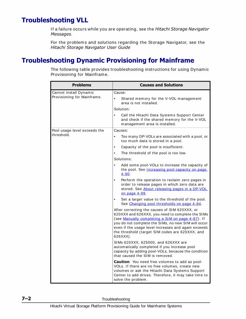
Hitachi Virtual Storage Platform Provisioning Guide for Mainframe Systems
7–2 Troubleshooting
Troubleshooting VLLIf a failure occurs while you are operating, see the Hitachi Storage Navigator Messages.
For the problems and solutions regarding the Storage Navigator, see the Hitachi Storage Navigator User Guide
Troubleshooting Dynamic Provisioning for MainframeThe following table provides troubleshooting instructions for using Dynamic Provisioning for Mainframe.
Problems Causes and Solutions
Cannot install Dynamic Provisioning for Mainframe.
Cause:
• Shared memory for the V-VOL management area is not installed.
Solution:
• Call the Hitachi Data Systems Support Center and check if the shared memory for the V-VOL management area is installed.
Pool usage level exceeds the threshold.
Causes:
• Too many DP-VOLs are associated with a pool, or too much data is stored in a pool.
• Capacity of the pool is insufficient.
• The threshold of the pool is too low.
Solutions:
• Add some pool-VOLs to increase the capacity of the pool. See Increasing pool capacity on page 4-90.
• Perform the operation to reclaim zero pages in order to release pages in which zero data are stored. See About releasing pages in a DP-VOL on page 4-99.
• Set a larger value to the threshold of the pool. See Changing pool thresholds on page 4-84.
After correcting the causes of SIM 620XXX, or 620XXX and 626XXX, you need to complete the SIMs (see Manually completing a SIM on page 4-87). If you do not complete the SIMs, no new SIM will occur even if the usage level increases and again exceeds the threshold (target SIM codes are 620XXX, and 626XXX).
SIMs 620XXX, 625000, and 626XXX are automatically completed if you increase pool capacity by adding pool-VOLs, because the condition that caused the SIM is removed.
Caution: You need free volumes to add as pool-VOLs. If there are no free volumes, create new volumes or ask the Hitachi Data Systems Support Center to add drives. Therefore, it may take time to solve the problem.
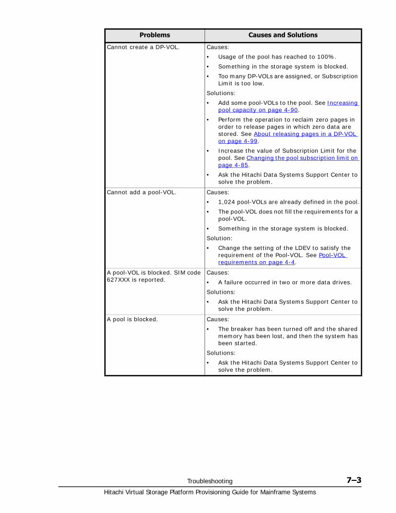
Troubleshooting 7–3Hitachi Virtual Storage Platform Provisioning Guide for Mainframe Systems
Cannot create a DP-VOL. Causes:
• Usage of the pool has reached to 100%.
• Something in the storage system is blocked.
• Too many DP-VOLs are assigned, or Subscription Limit is too low.
Solutions:
• Add some pool-VOLs to the pool. See Increasing pool capacity on page 4-90.
• Perform the operation to reclaim zero pages in order to release pages in which zero data are stored. See About releasing pages in a DP-VOL on page 4-99.
• Increase the value of Subscription Limit for the pool. See Changing the pool subscription limit on page 4-85.
• Ask the Hitachi Data Systems Support Center to solve the problem.
Cannot add a pool-VOL. Causes:
• 1,024 pool-VOLs are already defined in the pool.
• The pool-VOL does not fill the requirements for a pool-VOL.
• Something in the storage system is blocked.
Solution:
• Change the setting of the LDEV to satisfy the requirement of the Pool-VOL. See Pool-VOL requirements on page 4-4.
A pool-VOL is blocked. SIM code 627XXX is reported.
Causes:
• A failure occurred in two or more data drives.
Solutions:
• Ask the Hitachi Data Systems Support Center to solve the problem.
A pool is blocked. Causes:
• The breaker has been turned off and the shared memory has been lost, and then the system has been started.
Solutions:
• Ask the Hitachi Data Systems Support Center to solve the problem.
Problems Causes and Solutions
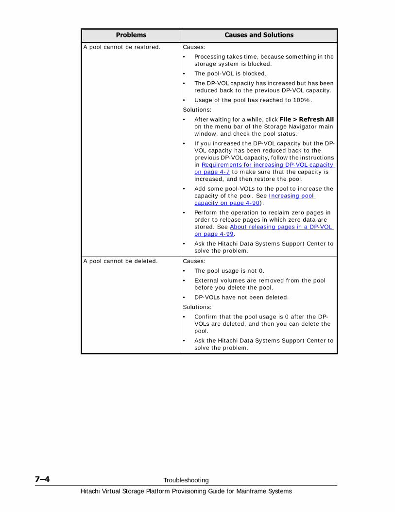
Hitachi Virtual Storage Platform Provisioning Guide for Mainframe Systems
7–4 Troubleshooting
A pool cannot be restored. Causes:
• Processing takes time, because something in the storage system is blocked.
• The pool-VOL is blocked.
• The DP-VOL capacity has increased but has been reduced back to the previous DP-VOL capacity.
• Usage of the pool has reached to 100%.
Solutions:
• After waiting for a while, click File > Refresh All on the menu bar of the Storage Navigator main window, and check the pool status.
• If you increased the DP-VOL capacity but the DP-VOL capacity has been reduced back to the previous DP-VOL capacity, follow the instructions in Requirements for increasing DP-VOL capacity on page 4-7 to make sure that the capacity is increased, and then restore the pool.
• Add some pool-VOLs to the pool to increase the capacity of the pool. See Increasing pool capacity on page 4-90).
• Perform the operation to reclaim zero pages in order to release pages in which zero data are stored. See About releasing pages in a DP-VOL on page 4-99.
• Ask the Hitachi Data Systems Support Center to solve the problem.
A pool cannot be deleted. Causes:
• The pool usage is not 0.
• External volumes are removed from the pool before you delete the pool.
• DP-VOLs have not been deleted.
Solutions:
• Confirm that the pool usage is 0 after the DP-VOLs are deleted, and then you can delete the pool.
• Ask the Hitachi Data Systems Support Center to solve the problem.
Problems Causes and Solutions
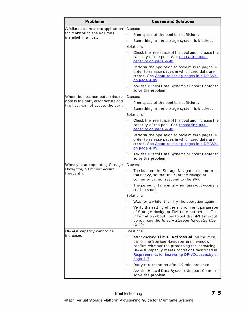
Troubleshooting 7–5Hitachi Virtual Storage Platform Provisioning Guide for Mainframe Systems
A failure occurs to the application for monitoring the volumes installed in a host.
Causes:
• Free space of the pool is insufficient.
• Something in the storage system is blocked.
Solutions:
• Check the free space of the pool and increase the capacity of the pool. See Increasing pool capacity on page 4-90).
• Perform the operation to reclaim zero pages in order to release pages in which zero data are stored. See About releasing pages in a DP-VOL on page 4-99.
• Ask the Hitachi Data Systems Support Center to solve the problem.
When the host computer tries to access the port, error occurs and the host cannot access the port.
Causes:
• Free space of the pool is insufficient.
• Something in the storage system is blocked.
Solutions:
• Check the free space of the pool and increase the capacity of the pool. See Increasing pool capacity on page 4-90.
• Perform the operation to reclaim zero pages in order to release pages in which zero data are stored. See About releasing pages in a DP-VOL on page 4-99.
• Ask the Hitachi Data Systems Support Center to solve the problem.
When you are operating Storage Navigator, a timeout occurs frequently.
Causes:
• The load on the Storage Navigator computer is too heavy, so that the Storage Navigator computer cannot respond to the SVP.
• The period of time until when time-out occurs is set too short.
Solutions:
• Wait for a while, then try the operation again.
• Verify the setting of the environment parameter of Storage Navigator RMI time-out period. For information about how to set the RMI time-out period, see the Hitachi Storage Navigator User Guide.
DP-VOL capacity cannot be increased.
Solutions:
• After clicking File > Refresh All on the menu bar of the Storage Navigator main window, confirm whether the processing for increasing DP-VOL capacity meets conditions described in Requirements for increasing DP-VOL capacity on page 4-7.
• Retry the operation after 10 minutes or so.
• Ask the Hitachi Data Systems Support Center to solve the problem.
Problems Causes and Solutions
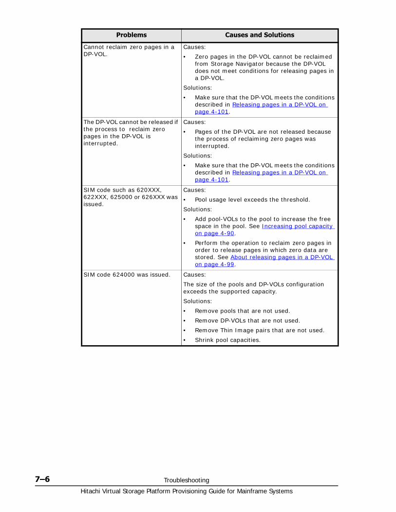
Hitachi Virtual Storage Platform Provisioning Guide for Mainframe Systems
7–6 Troubleshooting
Cannot reclaim zero pages in a DP-VOL.
Causes:
• Zero pages in the DP-VOL cannot be reclaimed from Storage Navigator because the DP-VOL does not meet conditions for releasing pages in a DP-VOL.
Solutions:
• Make sure that the DP-VOL meets the conditions described in Releasing pages in a DP-VOL on page 4-101.
The DP-VOL cannot be released if the process to reclaim zero pages in the DP-VOL is interrupted.
Causes:
• Pages of the DP-VOL are not released because the process of reclaiming zero pages was interrupted.
Solutions:
• Make sure that the DP-VOL meets the conditions described in Releasing pages in a DP-VOL on page 4-101.
SIM code such as 620XXX, 622XXX, 625000 or 626XXX was issued.
Causes:
• Pool usage level exceeds the threshold.
Solutions:
• Add pool-VOLs to the pool to increase the free space in the pool. See Increasing pool capacity on page 4-90.
• Perform the operation to reclaim zero pages in order to release pages in which zero data are stored. See About releasing pages in a DP-VOL on page 4-99.
SIM code 624000 was issued. Causes:
The size of the pools and DP-VOLs configuration exceeds the supported capacity.
Solutions:
• Remove pools that are not used.
• Remove DP-VOLs that are not used.
• Remove Thin Image pairs that are not used.
• Shrink pool capacities.
Problems Causes and Solutions
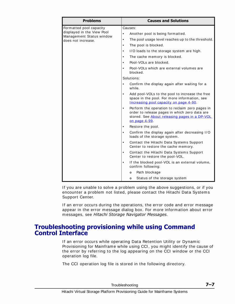
Troubleshooting 7–7Hitachi Virtual Storage Platform Provisioning Guide for Mainframe Systems
If you are unable to solve a problem using the above suggestions, or if you encounter a problem not listed, please contact the Hitachi Data Systems Support Center.
If an error occurs during the operations, the error code and error message appear in the error message dialog box. For more information about error messages, see Hitachi Storage Navigator Messages.
Troubleshooting provisioning while using Command Control Interface
If an error occurs while operating Data Retention Utility or Dynamic Provisioning for Mainframe while using CCI, you might identify the cause of the error by referring to the log appearing on the CCI window or the CCI operation log file.
The CCI operation log file is stored in the following directory.
Formatted pool capacity displayed in the View Pool Management Status window does not increase.
Causes:
• Another pool is being formatted.
• The pool usage level reaches up to the threshold.
• The pool is blocked.
• I/O loads to the storage system are high.
• The cache memory is blocked.
• Pool-VOLs are blocked.
• Pool-VOLs which are external volumes are blocked.
Solutions:
• Confirm the display again after waiting for a while.
• Add pool-VOLs to the pool to increase the free space in the pool. For more information, see Increasing pool capacity on page 4-90.
• Perform the operation to reclaim zero pages in order to release pages in which zero data are stored. See About releasing pages in a DP-VOL on page 4-99.
• Restore the pool.
• Confirm the display again after decreasing I/O loads of the storage system.
• Contact the Hitachi Data Systems Support Center to restore the cache memory.
• Contact the Hitachi Data Systems Support Center to restore the pool-VOL.
• If the blocked pool-VOL is an external volume, confirm following:
Path blockage
Status of the storage system
Problems Causes and Solutions
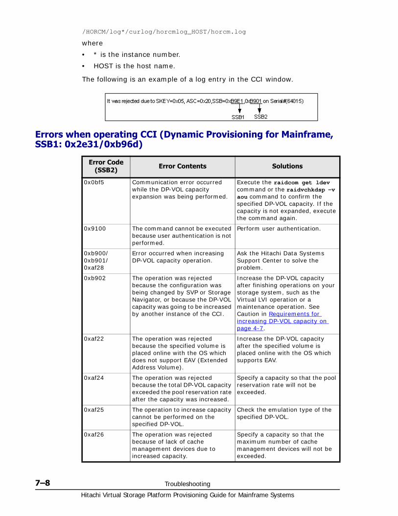
Hitachi Virtual Storage Platform Provisioning Guide for Mainframe Systems
7–8 Troubleshooting
/HORCM/log*/curlog/horcmlog_HOST/horcm.log
where
• * is the instance number.
• HOST is the host name.
The following is an example of a log entry in the CCI window.
Errors when operating CCI (Dynamic Provisioning for Mainframe, SSB1: 0x2e31/0xb96d)
Error Code (SSB2) Error Contents Solutions
0x0bf5 Communication error occurred while the DP-VOL capacity expansion was being performed.
Execute the raidcom get ldev command or the raidvchkdsp -v aou command to confirm the specified DP-VOL capacity. If the capacity is not expanded, execute the command again.
0x9100 The command cannot be executed because user authentication is not performed.
Perform user authentication.
0xb900/ 0xb901/ 0xaf28
Error occurred when increasing DP-VOL capacity operation.
Ask the Hitachi Data Systems Support Center to solve the problem.
0xb902 The operation was rejected because the configuration was being changed by SVP or Storage Navigator, or because the DP-VOL capacity was going to be increased by another instance of the CCI.
Increase the DP-VOL capacity after finishing operations on your storage system, such as the Virtual LVI operation or a maintenance operation. See Caution in Requirements for increasing DP-VOL capacity on page 4-7.
0xaf22 The operation was rejected because the specified volume is placed online with the OS which does not support EAV (Extended Address Volume).
Increase the DP-VOL capacity after the specified volume is placed online with the OS which supports EAV.
0xaf24 The operation was rejected because the total DP-VOL capacity exceeded the pool reservation rate after the capacity was increased.
Specify a capacity so that the pool reservation rate will not be exceeded.
0xaf25 The operation to increase capacity cannot be performed on the specified DP-VOL.
Check the emulation type of the specified DP-VOL.
0xaf26 The operation was rejected because of lack of cache management devices due to increased capacity.
Specify a capacity so that the maximum number of cache management devices will not be exceeded.
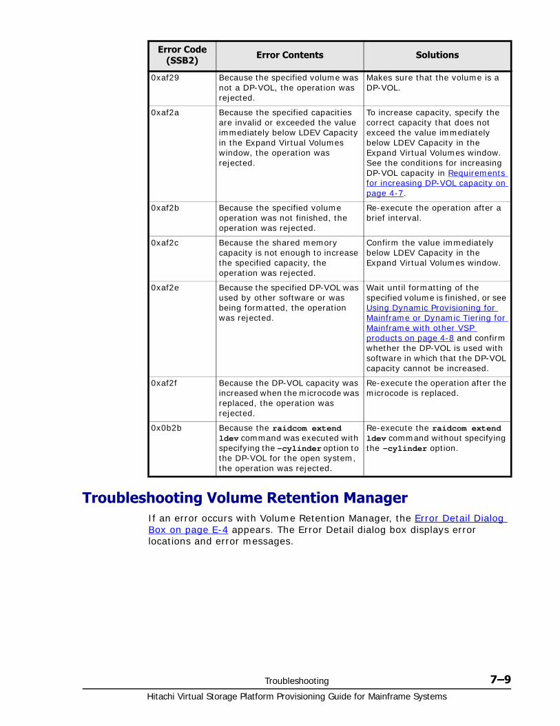
Troubleshooting 7–9Hitachi Virtual Storage Platform Provisioning Guide for Mainframe Systems
Troubleshooting Volume Retention ManagerIf an error occurs with Volume Retention Manager, the Error Detail Dialog Box on page E-4 appears. The Error Detail dialog box displays error locations and error messages.
0xaf29 Because the specified volume was not a DP-VOL, the operation was rejected.
Makes sure that the volume is a DP-VOL.
0xaf2a Because the specified capacities are invalid or exceeded the value immediately below LDEV Capacity in the Expand Virtual Volumes window, the operation was rejected.
To increase capacity, specify the correct capacity that does not exceed the value immediately below LDEV Capacity in the Expand Virtual Volumes window. See the conditions for increasing DP-VOL capacity in Requirements for increasing DP-VOL capacity on page 4-7.
0xaf2b Because the specified volume operation was not finished, the operation was rejected.
Re-execute the operation after a brief interval.
0xaf2c Because the shared memory capacity is not enough to increase the specified capacity, the operation was rejected.
Confirm the value immediately below LDEV Capacity in the Expand Virtual Volumes window.
0xaf2e Because the specified DP-VOL was used by other software or was being formatted, the operation was rejected.
Wait until formatting of the specified volume is finished, or see Using Dynamic Provisioning for Mainframe or Dynamic Tiering for Mainframe with other VSP products on page 4-8 and confirm whether the DP-VOL is used with software in which that the DP-VOL capacity cannot be increased.
0xaf2f Because the DP-VOL capacity was increased when the microcode was replaced, the operation was rejected.
Re-execute the operation after the microcode is replaced.
0x0b2b Because the raidcom extend ldev command was executed with specifying the -cylinder option to the DP-VOL for the open system, the operation was rejected.
Re-execute the raidcom extend ldev command without specifying the -cylinder option.
Error Code (SSB2) Error Contents Solutions
Hitachi Virtual Storage Platform Provisioning Guide for Mainframe Systems
7–10 Troubleshooting
The Error Detail dialog box does not display Storage Navigator error messages. To find information about Storage Navigator errors and solutions, see the Hitachi Storage Navigator User Guide.
Troubleshooting Volume SecurityIf an error occurs when you attempt to apply security settings with Volume Security, the Error Detail Dialog Box on page F-35 appears. The probable causes of the error are:
• Hosts in one security group are accessing volumes in another security group.
• Hosts that do not belong to any security group are accessing volumes in a security group
To remove this error, you must find the hosts and the volumes that caused the error. Use the following procedure to find the hosts and the volumes that caused the error:
1. In the Error Detail dialog box, click the arrow button at the right end of the Host list
If the list shows only one entry, only one host is causing the error.
If the list shows two or more entries, two or more hosts are causing the error.
2. Select a host from the Host list.
3. Right-click the arrow button at the right end of the CU list, and then check how many CU images are displayed in the list.
If the list shows only one entry, the table displays all the volumes that are causing the error
Caution: Read and/or write operations may fail under these conditions.
• If a host computer attempts to write data to a read-only volume, the write operation fails and the host receives a Write Inhibit report that the host cannot write data because of the access attribute.
• If a host computer attempts to read data from or write data to a volume that has the Protect attribute, the attempted access is rejected and an intervention request is reported to the host.
• If the DVE function of a host computer may attempt to change the capacity of a volume with a Read-Only or Protect access attribute, release the access attribute in advance. If the capacity is changed without releasing the access attribute, the modified volume will become unusable and a Write Inhibit or an intervention request will be reported to the host.
• When jobs that manipulate data on a volume are in progress, do not assign an access attribute to the volume. The jobs in progress might be abnormally terminated.
• When I/O processing from hosts is being performed, do not change the access attribute of volumes. The I/O processing being performed might be abnormally terminated.
Troubleshooting 7–11Hitachi Virtual Storage Platform Provisioning Guide for Mainframe Systems
If the list shows two or more entries, some of the error-causing volumes are displayed in the table. To view other error-causing volumes, use the CU list to specify another CU image
4. If two or more hosts are causing the error, please repeat steps 2 and 3.
If error-causing hosts and volumes are detected, do either of the following to remove the error:
• Vary the error-causing volume offline from the error-causing host. For detailed information about varying the volume offline, refer to the documentation for host commands
• Find the security group that contains the error-causing hosts and the error-causing volumes. Next, disable the security settings of the security group. See Disabling Volume Security.
The Error Detail dialog box does not display Storage Navigator error messages. To find information about Storage Navigator errors and solutions, see the Hitachi Storage Navigator User Guide.
Calling the Hitachi Data Systems Support CenterIf you need to call the Hitachi Data Systems Support Center, make sure you can provide as much information about the problem as possible. Include the circumstances surrounding the error or failure, the Storage Navigator configuration information saved by the Dump Tool, the exact content of messages appearing on the Storage Navigator, and severity levels and reference codes appearing on the Status tab of the Storage Navigator main window (see the Hitachi Storage Navigator Messages).
The Hitachi Data Systems customer support staff is available 24 hours a day, seven days a week. If you need technical support, log on to the Hitachi Data Systems Portal for contact information: https://portal.hds.com
Caution: These conditions could prevent mainframe host access.
• If the mainframe host does not have appropriate permission and attempts to access (read or write) a volume that has the security setting, the access is rejected and an intervention request or CC=3 is reported to the host.
• If the mainframe host has the security setting and attempts to access (read or write) a volume for which access is not permitted, access is rejected and an intervention request or CC=3 is reported to the host.
• If the mainframe host has access permission but cannot access (read or write) a volume that has the security setting, host recognition might have failed on the storage system. Should this error occur, confirm the setting information, then reconnect the host and the storage system.

Hitachi Virtual Storage Platform Provisioning Guide for Mainframe Systems
7–12 Troubleshooting
A
CCI command reference A–1Hitachi Virtual Storage Platform Provisioning Guide for Mainframe Systems
CCI command reference
This appendix provides information on Storage Navigator tasks and corresponding Command Control Interface commands used in provisioning.
□ Storage Navigator tasks and CCI command list

Hitachi Virtual Storage Platform Provisioning Guide for Mainframe Systems
A–2 CCI command reference
Storage Navigator tasks and CCI command listThe following lists actions (tasks) that can be performed in the Storage Navigator GUI, and the corresponding commands that can be issued in CCI.
Item Action name CCI command
Logical Device Create LDEVs raidcom add ldev
Delete LDEVs raidcom delete ldev
Edit LDEVs raidcom modify ldev
Format LDEVs raidcom initialize ldev
Block LDEVs raidcom modify ldev
Restore LDEVs raidcom modify ldev
Assign MP Blade raidcom modify ldev
Add LUN Paths raidcom add lun
Delete LUN Paths raidcom delete lun
Expand V-VOLs raidcom extend ldev
Reclaim Zero Pages raidcom modify ldev
Shredding raidcom initialize ldev
Port/Host Group Create Host Groups raidcom add host_grp
Delete Host Groups raidcom delete host_grp
Edit Host Groups raidcom modify host_grp
Add Hosts raidcom add hba_wwn
Add to Host Groups raidcom add hba_wwn
Remove Hosts raidcom delete hba_wwn
Edit Host raidcom add hba_wwn
Create Alternate LUN Paths raidcom add lun
Edit Ports raidcom modify port
Pool Create Pools raidcom add dp_pool
Expand Pool raidcom add dp_pool
Shrink pools raidcom delete pool
Delete Pools raidcom delete pool
Edit Pools raidcom modify pool
Monitor Pools raidcom monitor pool
Stop Monitoring Pools raidcom monitor pool
Start Tier Relocation raidcom reallocate pool
Stop Tier Relocation raidcom reallocate pool
Restore Pools raidcom modify pool
View Tier Properties raidcom get dp_pool
External Storage Disconnect External Volumes raidcom disconnect external_grp
Reconnect External Volumes raidcom check_ext_storage
B
Resource Partition Manager GUI reference B–1Hitachi Virtual Storage Platform Provisioning Guide for Mainframe Systems
Resource Partition Manager GUIreference
Sections in this appendix describe the windows, wizards, and dialog boxes of the Resource Partition Manager used in configuring resource groups.
For information about common Storage Navigator operations, such as using navigation buttons and creating tasks, see the Hitachi Storage Navigator User Guide.
□ Resource Groups window
□ Window after selecting a resource group
□ Create Resource Groups wizard
□ Edit Resource Group wizard
□ Add Resources wizard
□ Remove Resources window
□ Delete Resource Groups window
□ Resource Group Properties window
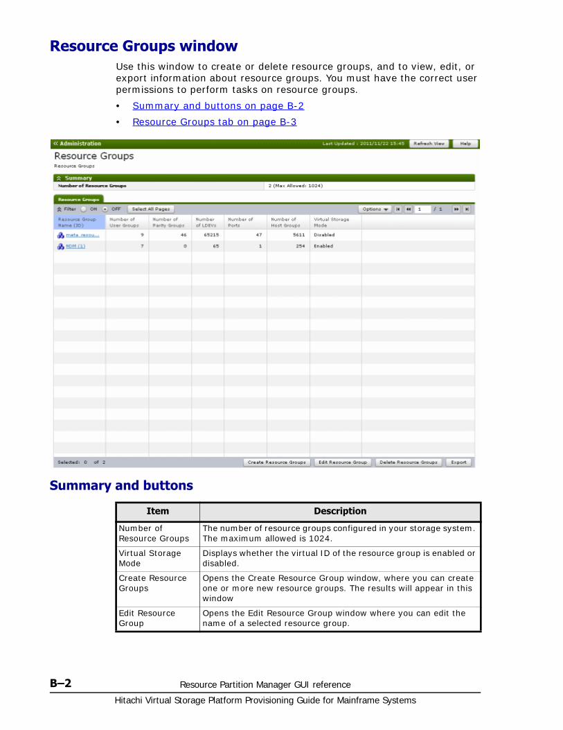
Hitachi Virtual Storage Platform Provisioning Guide for Mainframe Systems
B–2 Resource Partition Manager GUI reference
Resource Groups windowUse this window to create or delete resource groups, and to view, edit, or export information about resource groups. You must have the correct user permissions to perform tasks on resource groups.
• Summary and buttons on page B-2
• Resource Groups tab on page B-3
Summary and buttons
Item Description
Number of Resource Groups
The number of resource groups configured in your storage system. The maximum allowed is 1024.
Virtual Storage Mode
Displays whether the virtual ID of the resource group is enabled or disabled.
Create Resource Groups
Opens the Create Resource Group window, where you can create one or more new resource groups. The results will appear in this window
Edit Resource Group
Opens the Edit Resource Group window where you can edit the name of a selected resource group.
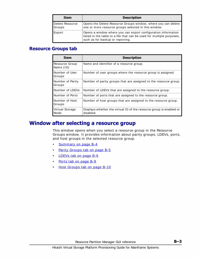
Resource Partition Manager GUI reference B–3Hitachi Virtual Storage Platform Provisioning Guide for Mainframe Systems
Resource Groups tab
Window after selecting a resource groupThis window opens when you select a resource group in the Resource Groups window. It provides information about parity groups, LDEVs, ports, and host groups in the selected resource group.
• Summary on page B-4
• Parity Groups tab on page B-5
• LDEVs tab on page B-6
• Ports tab on page B-8
• Host Groups tab on page B-10
Delete Resource Groups
Opens the Delete Resource Groups window, where you can delete one or more resource groups selected in this window.
Export Opens a window where you can export configuration information listed in the table to a file that can be used for multiple purposes, such as for backup or reporting.
Item Description
Resource Group Name (ID)
Name and identifier of a resource group.
Number of User Groups
Number of user groups where the resource group is assigned.
Number of Parity Groups
Number of parity groups that are assigned to the resource group.
Number of LDEVs Number of LDEVs that are assigned to the resource group.
Number of Ports Number of ports that are assigned to the resource group.
Number of Host Groups
Number of host groups that are assigned to the resource group.
Virtual Storage Mode
Displays whether the virtual ID of the resource group is enabled or disabled.
Item Description
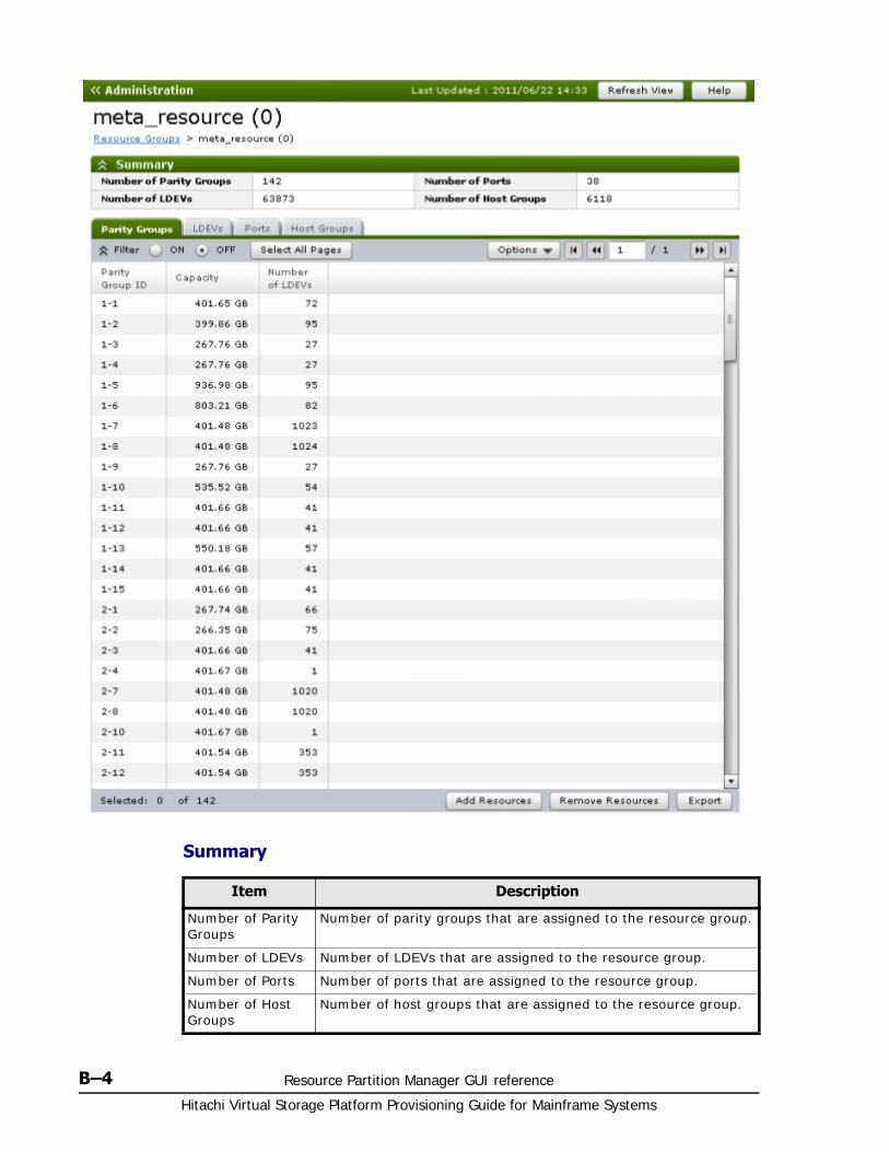
Hitachi Virtual Storage Platform Provisioning Guide for Mainframe Systems
B–4 Resource Partition Manager GUI reference
Summary
Item Description
Number of Parity Groups
Number of parity groups that are assigned to the resource group.
Number of LDEVs Number of LDEVs that are assigned to the resource group.
Number of Ports Number of ports that are assigned to the resource group.
Number of Host Groups
Number of host groups that are assigned to the resource group.
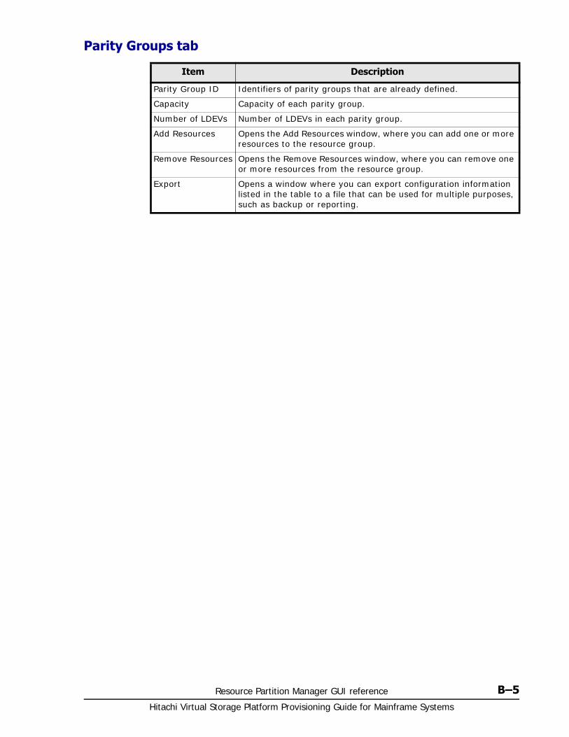
Resource Partition Manager GUI reference B–5Hitachi Virtual Storage Platform Provisioning Guide for Mainframe Systems
Parity Groups tab
Item Description
Parity Group ID Identifiers of parity groups that are already defined.
Capacity Capacity of each parity group.
Number of LDEVs Number of LDEVs in each parity group.
Add Resources Opens the Add Resources window, where you can add one or more resources to the resource group.
Remove Resources Opens the Remove Resources window, where you can remove one or more resources from the resource group.
Export Opens a window where you can export configuration information listed in the table to a file that can be used for multiple purposes, such as backup or reporting.
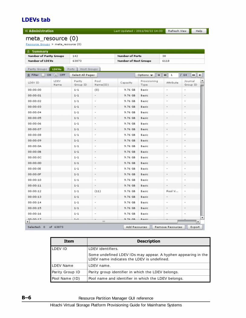
Hitachi Virtual Storage Platform Provisioning Guide for Mainframe Systems
B–6 Resource Partition Manager GUI reference
LDEVs tab
Item Description
LDEV ID LDEV identifiers.
Some undefined LDEV IDs may appear. A hyphen appearing in the LDEV name indicates the LDEV is undefined.
LDEV Name LDEV name.
Parity Group ID Parity group identifier in which the LDEV belongs.
Pool Name (ID) Pool name and identifier in which the LDEV belongs.
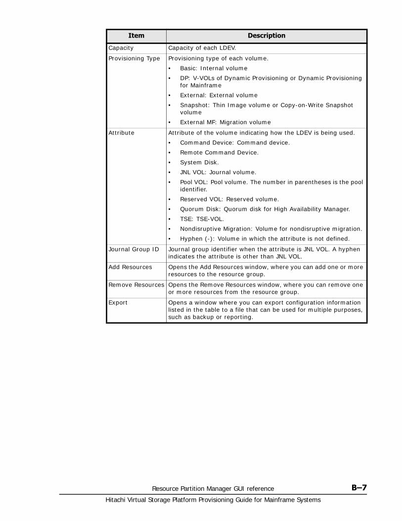
Resource Partition Manager GUI reference B–7Hitachi Virtual Storage Platform Provisioning Guide for Mainframe Systems
Capacity Capacity of each LDEV.
Provisioning Type Provisioning type of each volume.
• Basic: Internal volume
• DP: V-VOLs of Dynamic Provisioning or Dynamic Provisioning for Mainframe
• External: External volume
• Snapshot: Thin Image volume or Copy-on-Write Snapshot volume
• External MF: Migration volume
Attribute Attribute of the volume indicating how the LDEV is being used.
• Command Device: Command device.
• Remote Command Device.
• System Disk.
• JNL VOL: Journal volume.
• Pool VOL: Pool volume. The number in parentheses is the pool identifier.
• Reserved VOL: Reserved volume.
• Quorum Disk: Quorum disk for High Availability Manager.
• TSE: TSE-VOL.
• Nondisruptive Migration: Volume for nondisruptive migration.
• Hyphen (-): Volume in which the attribute is not defined.
Journal Group ID Journal group identifier when the attribute is JNL VOL. A hyphen indicates the attribute is other than JNL VOL.
Add Resources Opens the Add Resources window, where you can add one or more resources to the resource group.
Remove Resources Opens the Remove Resources window, where you can remove one or more resources from the resource group.
Export Opens a window where you can export configuration information listed in the table to a file that can be used for multiple purposes, such as backup or reporting.
Item Description
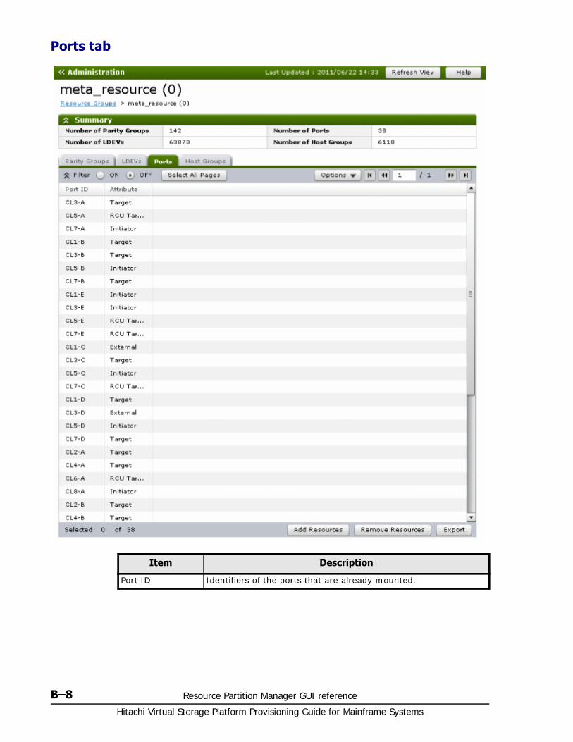
Hitachi Virtual Storage Platform Provisioning Guide for Mainframe Systems
B–8 Resource Partition Manager GUI reference
Ports tab
Item Description
Port ID Identifiers of the ports that are already mounted.
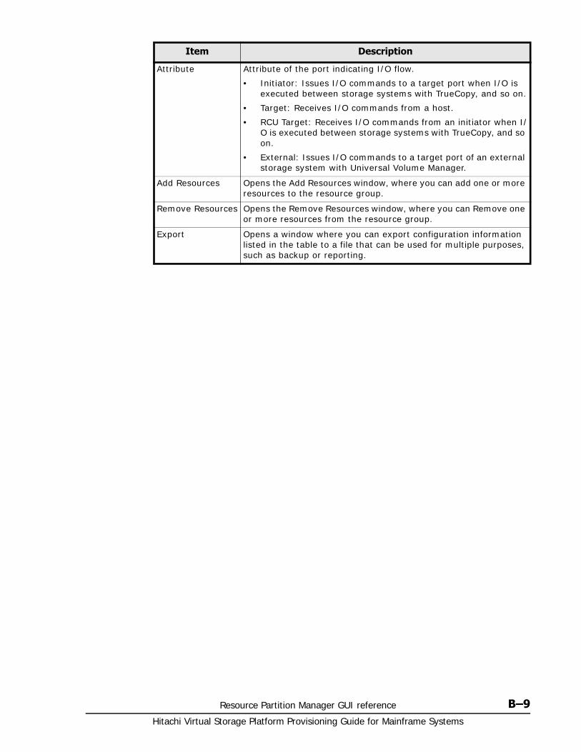
Resource Partition Manager GUI reference B–9Hitachi Virtual Storage Platform Provisioning Guide for Mainframe Systems
Attribute Attribute of the port indicating I/O flow.
• Initiator: Issues I/O commands to a target port when I/O is executed between storage systems with TrueCopy, and so on.
• Target: Receives I/O commands from a host.
• RCU Target: Receives I/O commands from an initiator when I/O is executed between storage systems with TrueCopy, and so on.
• External: Issues I/O commands to a target port of an external storage system with Universal Volume Manager.
Add Resources Opens the Add Resources window, where you can add one or more resources to the resource group.
Remove Resources Opens the Remove Resources window, where you can Remove one or more resources from the resource group.
Export Opens a window where you can export configuration information listed in the table to a file that can be used for multiple purposes, such as backup or reporting.
Item Description
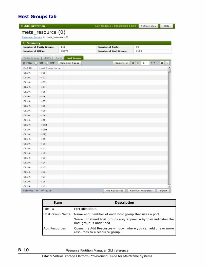
Hitachi Virtual Storage Platform Provisioning Guide for Mainframe Systems
B–10 Resource Partition Manager GUI reference
Host Groups tab
Item Description
Port ID Port identifiers.
Host Group Name Name and identifier of each host group that uses a port.
Some undefined host groups may appear. A hyphen indicates the host group is undefined.
Add Resources Opens the Add Resources window, where you can add one or more resources to a resource group.
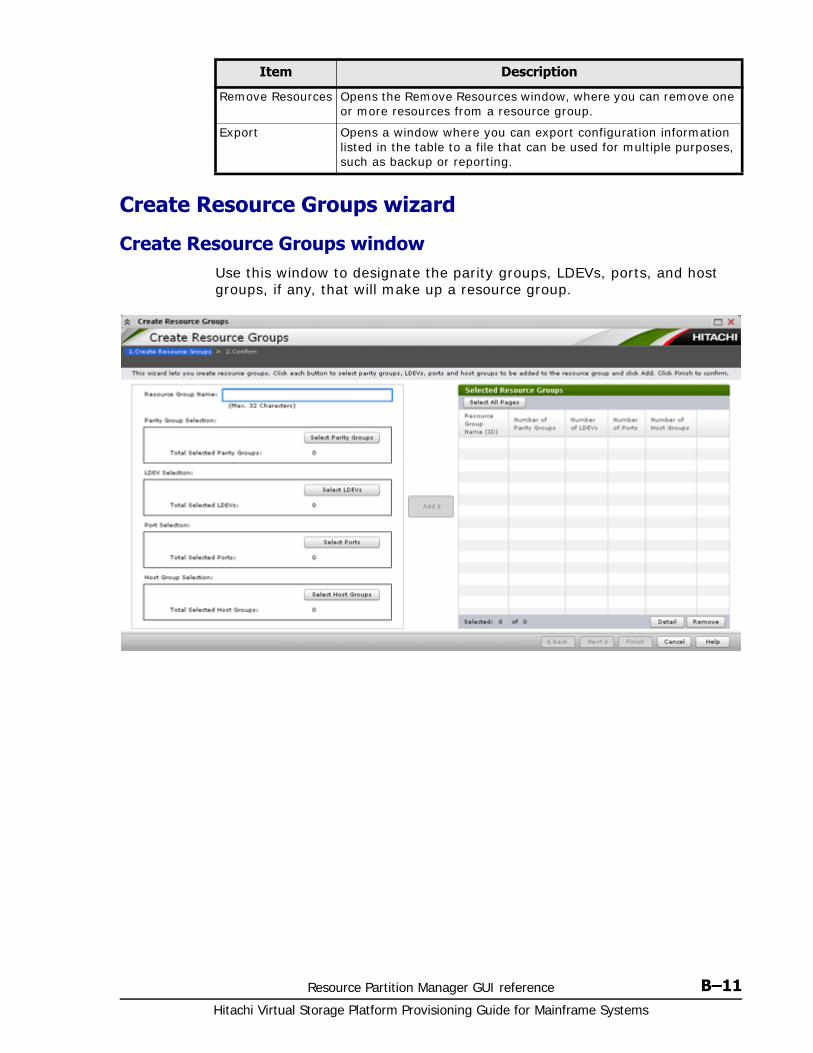
Resource Partition Manager GUI reference B–11Hitachi Virtual Storage Platform Provisioning Guide for Mainframe Systems
Create Resource Groups wizard
Create Resource Groups windowUse this window to designate the parity groups, LDEVs, ports, and host groups, if any, that will make up a resource group.
Remove Resources Opens the Remove Resources window, where you can remove one or more resources from a resource group.
Export Opens a window where you can export configuration information listed in the table to a file that can be used for multiple purposes, such as backup or reporting.
Item Description
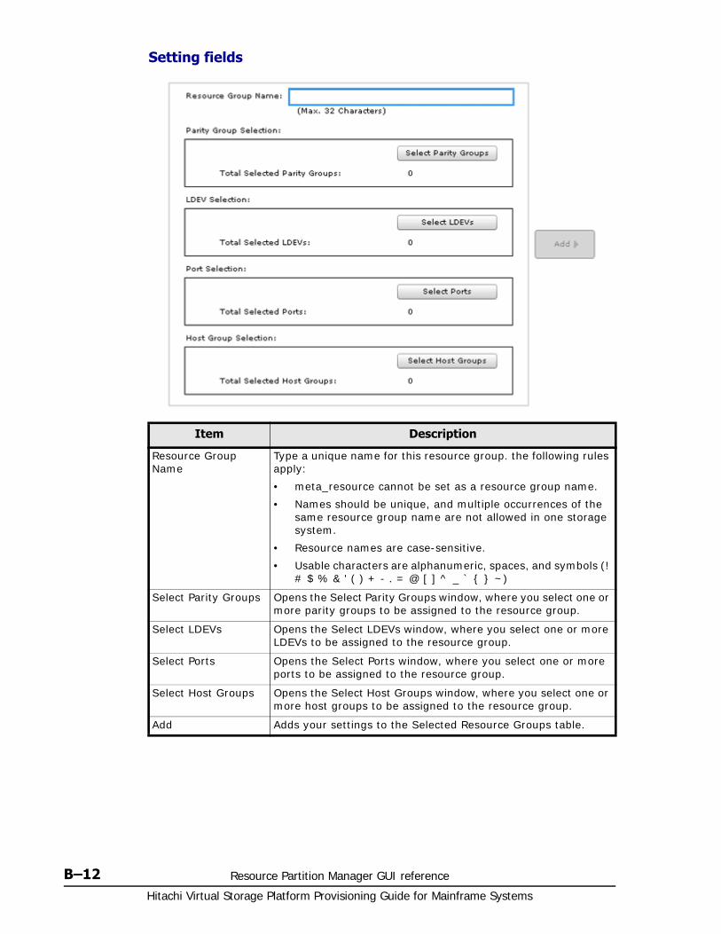
Hitachi Virtual Storage Platform Provisioning Guide for Mainframe Systems
B–12 Resource Partition Manager GUI reference
Setting fields
Item Description
Resource Group Name
Type a unique name for this resource group. the following rules apply:
• meta_resource cannot be set as a resource group name.
• Names should be unique, and multiple occurrences of the same resource group name are not allowed in one storage system.
• Resource names are case-sensitive.
• Usable characters are alphanumeric, spaces, and symbols (! # $ % & ' ( ) + - . = @ [ ] ^ _ ` { } ~)
Select Parity Groups Opens the Select Parity Groups window, where you select one or more parity groups to be assigned to the resource group.
Select LDEVs Opens the Select LDEVs window, where you select one or more LDEVs to be assigned to the resource group.
Select Ports Opens the Select Ports window, where you select one or more ports to be assigned to the resource group.
Select Host Groups Opens the Select Host Groups window, where you select one or more host groups to be assigned to the resource group.
Add Adds your settings to the Selected Resource Groups table.
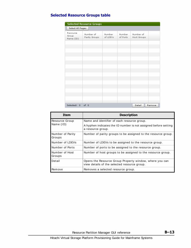
Resource Partition Manager GUI reference B–13Hitachi Virtual Storage Platform Provisioning Guide for Mainframe Systems
Selected Resource Groups table
Item Description
Resource Group Name (ID)
Name and identifier of each resource group.
A hyphen indicates the ID number is not assigned before setting a resource group.
Number of Parity Groups
Number of parity groups to be assigned to the resource group.
Number of LDEVs Number of LDEVs to be assigned to the resource group.
Number of Ports Number of ports to be assigned to the resource group.
Number of Host Groups
Number of host groups to be assigned to the resource group.
Detail Opens the Resource Group Property window, where you can view details of the selected resource group.
Remove Removes a selected resource group.
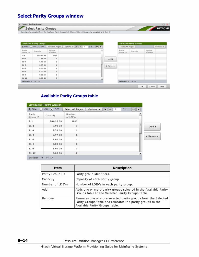
Hitachi Virtual Storage Platform Provisioning Guide for Mainframe Systems
B–14 Resource Partition Manager GUI reference
Select Parity Groups window
Available Parity Groups table
Item Description
Parity Group ID Parity group identifiers.
Capacity Capacity of each parity group.
Number of LDEVs Number of LDEVs in each parity group.
Add Adds one or more parity groups selected in the Available Parity Groups table to the Selected Parity Groups table.
Remove Removes one or more selected parity groups from the Selected Parity Groups table and relocates the parity groups to the Available Parity Groups table.
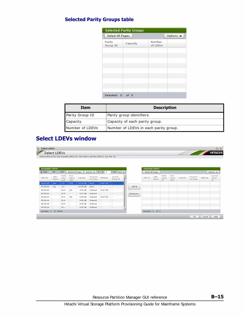
Resource Partition Manager GUI reference B–15Hitachi Virtual Storage Platform Provisioning Guide for Mainframe Systems
Selected Parity Groups table
Select LDEVs window
Item Description
Parity Group ID Parity group identifiers.
Capacity Capacity of each parity group.
Number of LDEVs Number of LDEVs in each parity group.
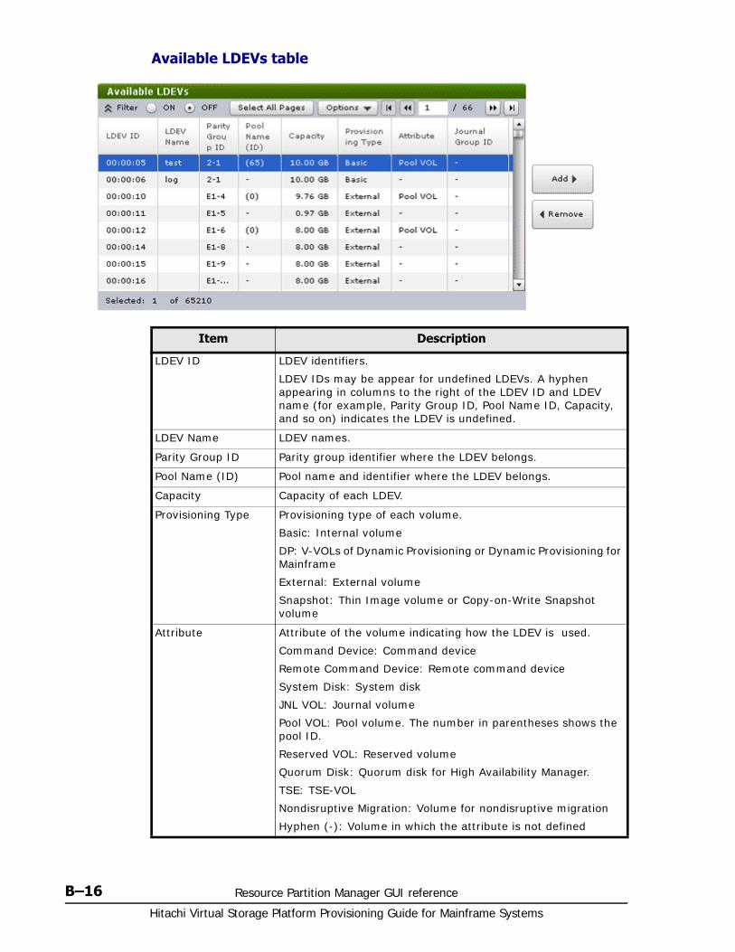
Hitachi Virtual Storage Platform Provisioning Guide for Mainframe Systems
B–16 Resource Partition Manager GUI reference
Available LDEVs table
Item Description
LDEV ID LDEV identifiers.
LDEV IDs may be appear for undefined LDEVs. A hyphen appearing in columns to the right of the LDEV ID and LDEV name (for example, Parity Group ID, Pool Name ID, Capacity, and so on) indicates the LDEV is undefined.
LDEV Name LDEV names.
Parity Group ID Parity group identifier where the LDEV belongs.
Pool Name (ID) Pool name and identifier where the LDEV belongs.
Capacity Capacity of each LDEV.
Provisioning Type Provisioning type of each volume.
Basic: Internal volume
DP: V-VOLs of Dynamic Provisioning or Dynamic Provisioning for Mainframe
External: External volume
Snapshot: Thin Image volume or Copy-on-Write Snapshot volume
Attribute Attribute of the volume indicating how the LDEV is used.
Command Device: Command device
Remote Command Device: Remote command device
System Disk: System disk
JNL VOL: Journal volume
Pool VOL: Pool volume. The number in parentheses shows the pool ID.
Reserved VOL: Reserved volume
Quorum Disk: Quorum disk for High Availability Manager.
TSE: TSE-VOL
Nondisruptive Migration: Volume for nondisruptive migration
Hyphen (-): Volume in which the attribute is not defined
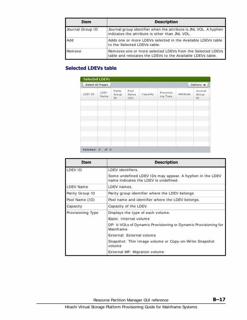
Resource Partition Manager GUI reference B–17Hitachi Virtual Storage Platform Provisioning Guide for Mainframe Systems
Selected LDEVs table
Journal Group ID Journal group identifier when the attribute is JNL VOL. A hyphen indicates the attribute is other than JNL VOL.
Add Adds one or more LDEVs selected in the Available LDEVs table to the Selected LDEVs table.
Remove Removes one or more selected LDEVs from the Selected LDEVs table and relocates the LDEVs to the Available LDEVs table.
Item Description
Item Description
LDEV ID LDEV identifiers.
Some undefined LDEV IDs may appear. A hyphen in the LDEV name indicates the LDEV is undefined.
LDEV Name LDEV names.
Parity Group ID Parity group identifier where the LDEV belongs.
Pool Name (ID) Pool name and identifier where the LDEV belongs.
Capacity Capacity of the LDEV.
Provisioning Type Displays the type of each volume.
Basic: Internal volume
DP: V-VOLs of Dynamic Provisioning or Dynamic Provisioning for Mainframe
External: External volume
Snapshot: Thin Image volume or Copy-on-Write Snapshot volume
External MF: Migration volume
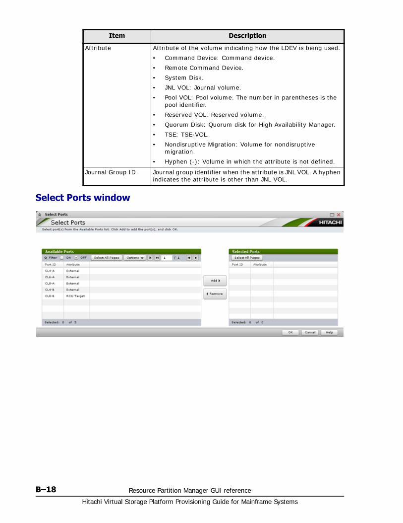
Hitachi Virtual Storage Platform Provisioning Guide for Mainframe Systems
B–18 Resource Partition Manager GUI reference
Select Ports window
Attribute Attribute of the volume indicating how the LDEV is being used.
• Command Device: Command device.
• Remote Command Device.
• System Disk.
• JNL VOL: Journal volume.
• Pool VOL: Pool volume. The number in parentheses is the pool identifier.
• Reserved VOL: Reserved volume.
• Quorum Disk: Quorum disk for High Availability Manager.
• TSE: TSE-VOL.
• Nondisruptive Migration: Volume for nondisruptive migration.
• Hyphen (-): Volume in which the attribute is not defined.
Journal Group ID Journal group identifier when the attribute is JNL VOL. A hyphen indicates the attribute is other than JNL VOL.
Item Description
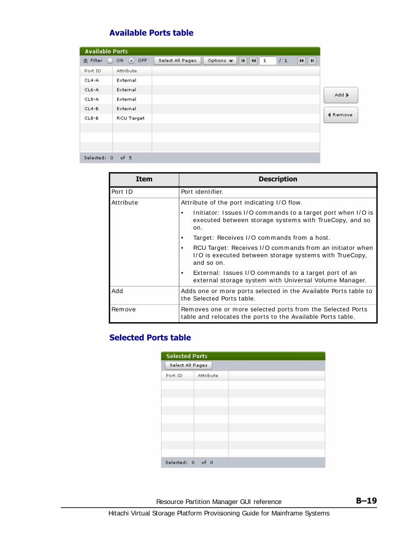
Resource Partition Manager GUI reference B–19Hitachi Virtual Storage Platform Provisioning Guide for Mainframe Systems
Available Ports table
Selected Ports table
Item Description
Port ID Port identifier.
Attribute Attribute of the port indicating I/O flow.
• Initiator: Issues I/O commands to a target port when I/O is executed between storage systems with TrueCopy, and so on.
• Target: Receives I/O commands from a host.
• RCU Target: Receives I/O commands from an initiator when I/O is executed between storage systems with TrueCopy, and so on.
• External: Issues I/O commands to a target port of an external storage system with Universal Volume Manager.
Add Adds one or more ports selected in the Available Ports table to the Selected Ports table.
Remove Removes one or more selected ports from the Selected Ports table and relocates the ports to the Available Ports table.
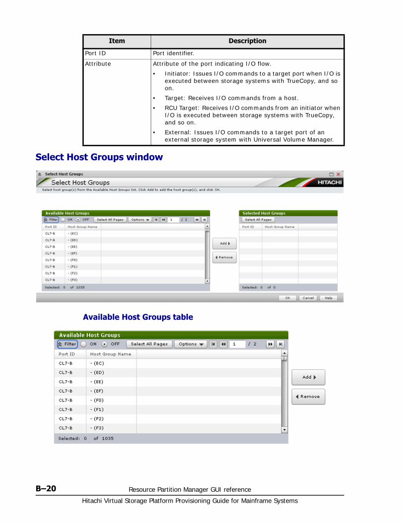
Hitachi Virtual Storage Platform Provisioning Guide for Mainframe Systems
B–20 Resource Partition Manager GUI reference
Select Host Groups window
Available Host Groups table
Item Description
Port ID Port identifier.
Attribute Attribute of the port indicating I/O flow.
• Initiator: Issues I/O commands to a target port when I/O is executed between storage systems with TrueCopy, and so on.
• Target: Receives I/O commands from a host.
• RCU Target: Receives I/O commands from an initiator when I/O is executed between storage systems with TrueCopy, and so on.
• External: Issues I/O commands to a target port of an external storage system with Universal Volume Manager.
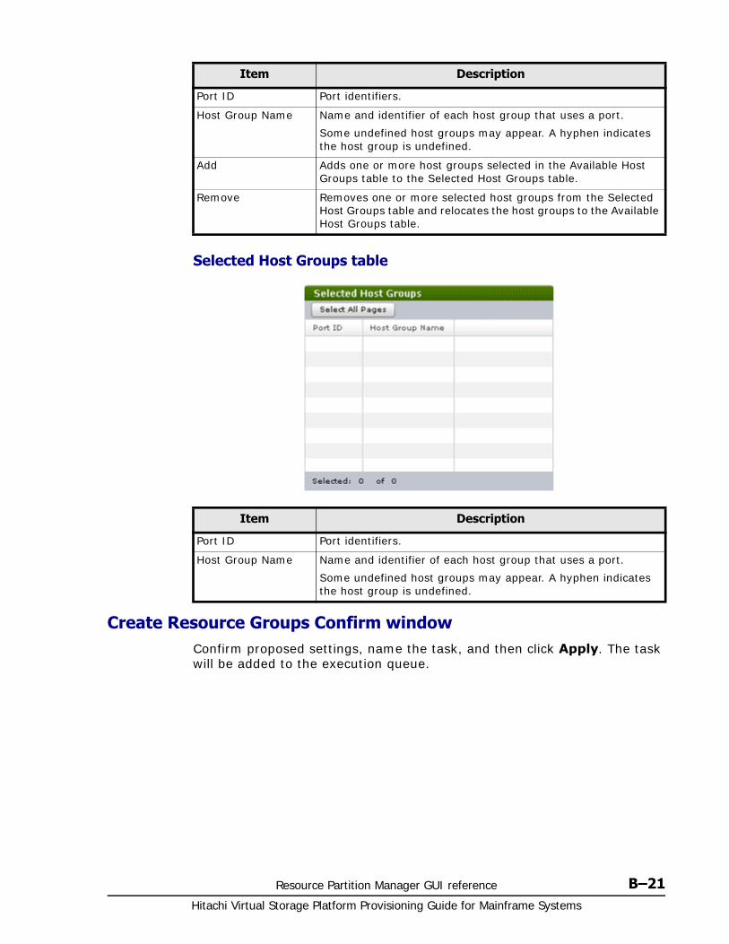
Resource Partition Manager GUI reference B–21Hitachi Virtual Storage Platform Provisioning Guide for Mainframe Systems
Selected Host Groups table
Create Resource Groups Confirm windowConfirm proposed settings, name the task, and then click Apply. The task will be added to the execution queue.
Item Description
Port ID Port identifiers.
Host Group Name Name and identifier of each host group that uses a port.
Some undefined host groups may appear. A hyphen indicates the host group is undefined.
Add Adds one or more host groups selected in the Available Host Groups table to the Selected Host Groups table.
Remove Removes one or more selected host groups from the Selected Host Groups table and relocates the host groups to the Available Host Groups table.
Item Description
Port ID Port identifiers.
Host Group Name Name and identifier of each host group that uses a port.
Some undefined host groups may appear. A hyphen indicates the host group is undefined.
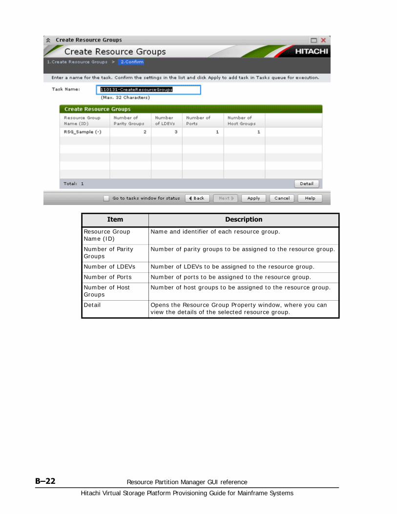
Hitachi Virtual Storage Platform Provisioning Guide for Mainframe Systems
B–22 Resource Partition Manager GUI reference
Item Description
Resource Group Name (ID)
Name and identifier of each resource group.
Number of Parity Groups
Number of parity groups to be assigned to the resource group.
Number of LDEVs Number of LDEVs to be assigned to the resource group.
Number of Ports Number of ports to be assigned to the resource group.
Number of Host Groups
Number of host groups to be assigned to the resource group.
Detail Opens the Resource Group Property window, where you can view the details of the selected resource group.

Resource Partition Manager GUI reference B–23Hitachi Virtual Storage Platform Provisioning Guide for Mainframe Systems
Edit Resource Group wizard
Edit Resource Group window
Edit Resource Group Confirm windowConfirm proposed settings, name the task, and then click Apply. The task will be added to the execution queue.
Item Description
Resource Group Name
Type the name of the resource group after editing.
• meta_resource cannot be set as a name.
• Duplicate occurrences of the same resource group name are not allowed in one storage system.
• Names are case-sensitive.
• Usable characters are alphanumeric, spaces, and symbols (! # $ % & ' ( ) + - . = @ [ ] ^ _ ` { } ~)
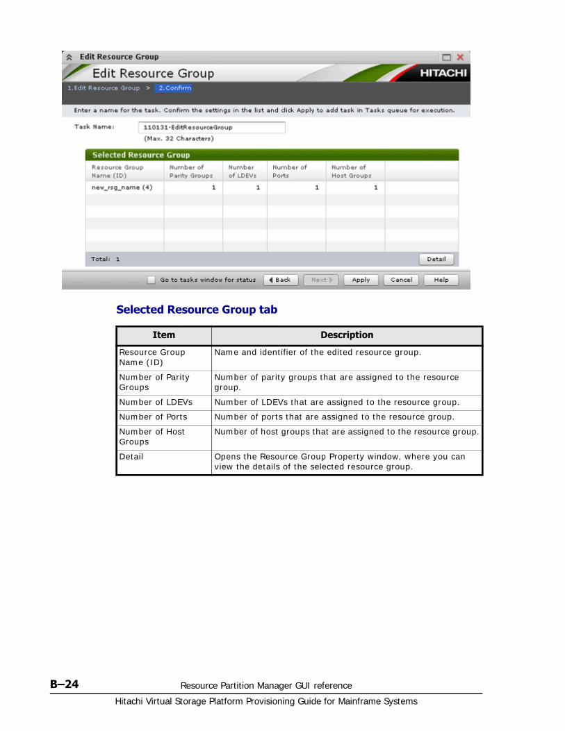
Hitachi Virtual Storage Platform Provisioning Guide for Mainframe Systems
B–24 Resource Partition Manager GUI reference
Selected Resource Group tab
Item Description
Resource Group Name (ID)
Name and identifier of the edited resource group.
Number of Parity Groups
Number of parity groups that are assigned to the resource group.
Number of LDEVs Number of LDEVs that are assigned to the resource group.
Number of Ports Number of ports that are assigned to the resource group.
Number of Host Groups
Number of host groups that are assigned to the resource group.
Detail Opens the Resource Group Property window, where you can view the details of the selected resource group.
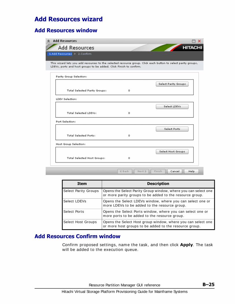
Resource Partition Manager GUI reference B–25Hitachi Virtual Storage Platform Provisioning Guide for Mainframe Systems
Add Resources wizard
Add Resources window
Add Resources Confirm windowConfirm proposed settings, name the task, and then click Apply. The task will be added to the execution queue.
Item Description
Select Parity Groups Opens the Select Parity Group window, where you can select one or more parity groups to be added to the resource group.
Select LDEVs Opens the Select LDEVs window, where you can select one or more LDEVs to be added to the resource group.
Select Ports Opens the Select Ports window, where you can select one or more ports to be added to the resource group.
Select Host Groups Opens the Select Host group window, where you can select one or more host groups to be added to the resource group.
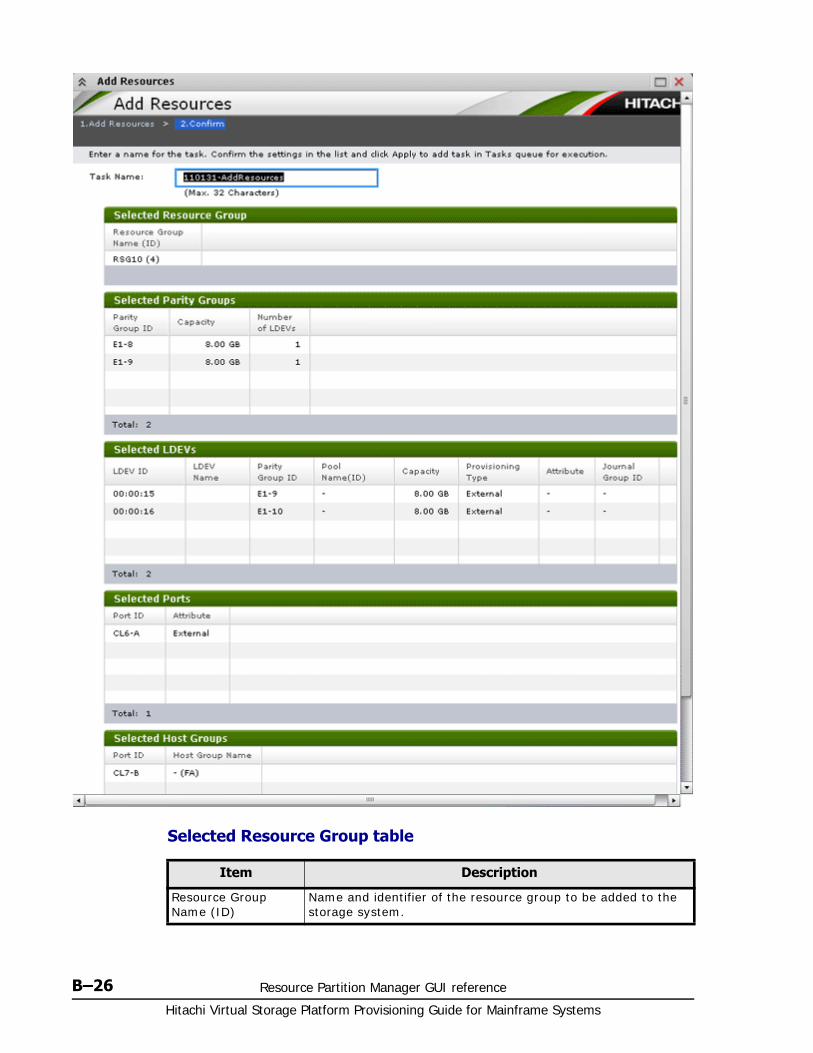
Hitachi Virtual Storage Platform Provisioning Guide for Mainframe Systems
B–26 Resource Partition Manager GUI reference
Selected Resource Group table
Item Description
Resource Group Name (ID)
Name and identifier of the resource group to be added to the storage system.
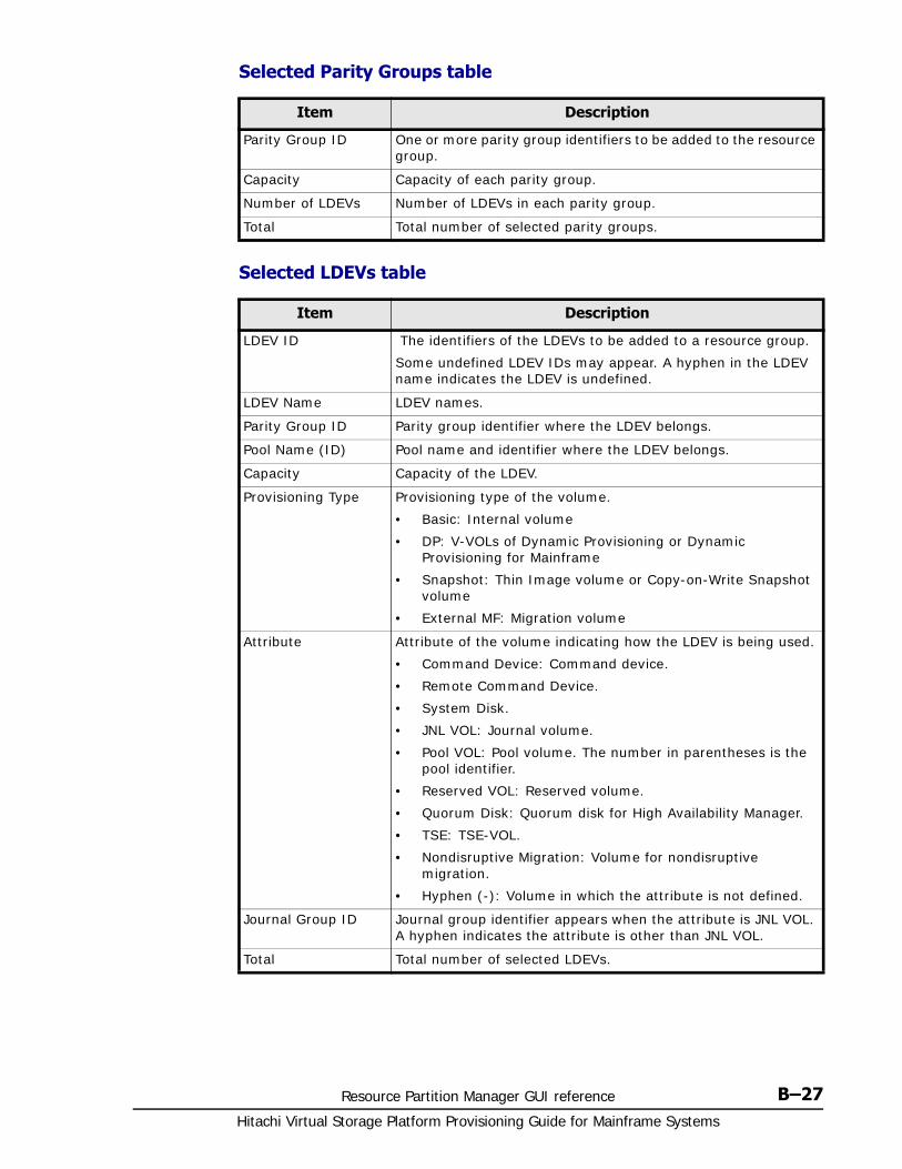
Resource Partition Manager GUI reference B–27Hitachi Virtual Storage Platform Provisioning Guide for Mainframe Systems
Selected Parity Groups table
Selected LDEVs table
Item Description
Parity Group ID One or more parity group identifiers to be added to the resource group.
Capacity Capacity of each parity group.
Number of LDEVs Number of LDEVs in each parity group.
Total Total number of selected parity groups.
Item Description
LDEV ID The identifiers of the LDEVs to be added to a resource group.
Some undefined LDEV IDs may appear. A hyphen in the LDEV name indicates the LDEV is undefined.
LDEV Name LDEV names.
Parity Group ID Parity group identifier where the LDEV belongs.
Pool Name (ID) Pool name and identifier where the LDEV belongs.
Capacity Capacity of the LDEV.
Provisioning Type Provisioning type of the volume.
• Basic: Internal volume
• DP: V-VOLs of Dynamic Provisioning or Dynamic Provisioning for Mainframe
• Snapshot: Thin Image volume or Copy-on-Write Snapshot volume
• External MF: Migration volume
Attribute Attribute of the volume indicating how the LDEV is being used.
• Command Device: Command device.
• Remote Command Device.
• System Disk.
• JNL VOL: Journal volume.
• Pool VOL: Pool volume. The number in parentheses is the pool identifier.
• Reserved VOL: Reserved volume.
• Quorum Disk: Quorum disk for High Availability Manager.
• TSE: TSE-VOL.
• Nondisruptive Migration: Volume for nondisruptive migration.
• Hyphen (-): Volume in which the attribute is not defined.
Journal Group ID Journal group identifier appears when the attribute is JNL VOL. A hyphen indicates the attribute is other than JNL VOL.
Total Total number of selected LDEVs.
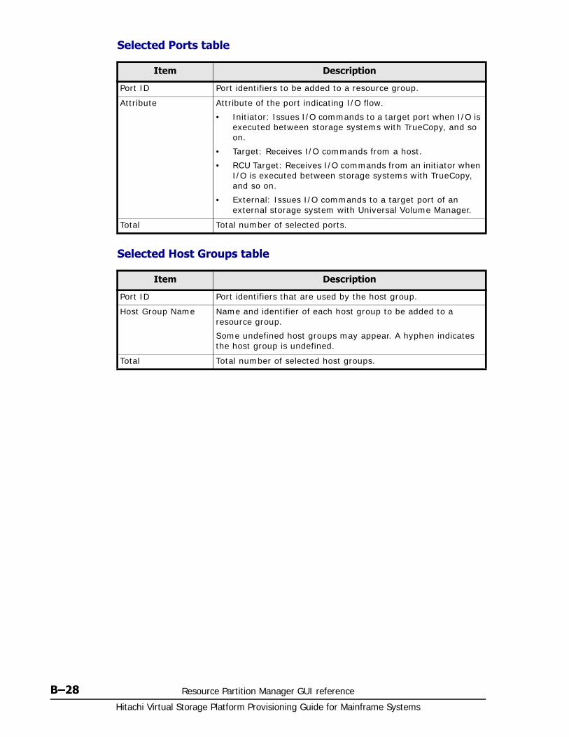
Hitachi Virtual Storage Platform Provisioning Guide for Mainframe Systems
B–28 Resource Partition Manager GUI reference
Selected Ports table
Selected Host Groups table
Item Description
Port ID Port identifiers to be added to a resource group.
Attribute Attribute of the port indicating I/O flow.
• Initiator: Issues I/O commands to a target port when I/O is executed between storage systems with TrueCopy, and so on.
• Target: Receives I/O commands from a host.
• RCU Target: Receives I/O commands from an initiator when I/O is executed between storage systems with TrueCopy, and so on.
• External: Issues I/O commands to a target port of an external storage system with Universal Volume Manager.
Total Total number of selected ports.
Item Description
Port ID Port identifiers that are used by the host group.
Host Group Name Name and identifier of each host group to be added to a resource group.
Some undefined host groups may appear. A hyphen indicates the host group is undefined.
Total Total number of selected host groups.

Resource Partition Manager GUI reference B–29Hitachi Virtual Storage Platform Provisioning Guide for Mainframe Systems
Remove Resources window
Selected Resource Group table
Selected Parity Groups table (when deleting parity groups)
Item Description
Resource Group Name (ID)
Name and identifier of each resource group whose resources are deleted.
Item Description
Parity Group ID Identifier of each parity group to be deleted from the resource group.
Capacity Capacity of each parity group.
Number of LDEVs Number of LDEVs in the parity group.
Total Total number of parity groups.
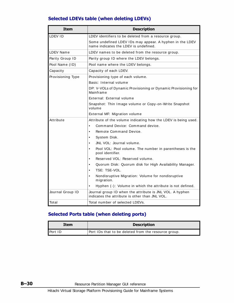
Hitachi Virtual Storage Platform Provisioning Guide for Mainframe Systems
B–30 Resource Partition Manager GUI reference
Selected LDEVs table (when deleting LDEVs)
Selected Ports table (when deleting ports)
Item Description
LDEV ID LDEV identifiers to be deleted from a resource group.
Some undefined LDEV IDs may appear. A hyphen in the LDEV name indicates the LDEV is undefined.
LDEV Name LDEV names to be deleted from the resource group.
Parity Group ID Parity group ID where the LDEV belongs.
Pool Name (ID) Pool name where the LDEV belongs.
Capacity Capacity of each LDEV.
Provisioning Type Provisioning type of each volume.
Basic: Internal volume
DP: V-VOLs of Dynamic Provisioning or Dynamic Provisioning for Mainframe
External: External volume
Snapshot: Thin Image volume or Copy-on-Write Snapshot volume
External MF: Migration volume
Attribute Attribute of the volume indicating how the LDEV is being used.
• Command Device: Command device.
• Remote Command Device.
• System Disk.
• JNL VOL: Journal volume.
• Pool VOL: Pool volume. The number in parentheses is the pool identifier.
• Reserved VOL: Reserved volume.
• Quorum Disk: Quorum disk for High Availability Manager.
• TSE: TSE-VOL.
• Nondisruptive Migration: Volume for nondisruptive migration.
• Hyphen (-): Volume in which the attribute is not defined.
Journal Group ID Journal group ID when the attribute is JNL VOL. A hyphen indicates the attribute is other than JNL VOL.
Total Total number of selected LDEVs.
Item Description
Port ID Port IDs that to be deleted from the resource group.
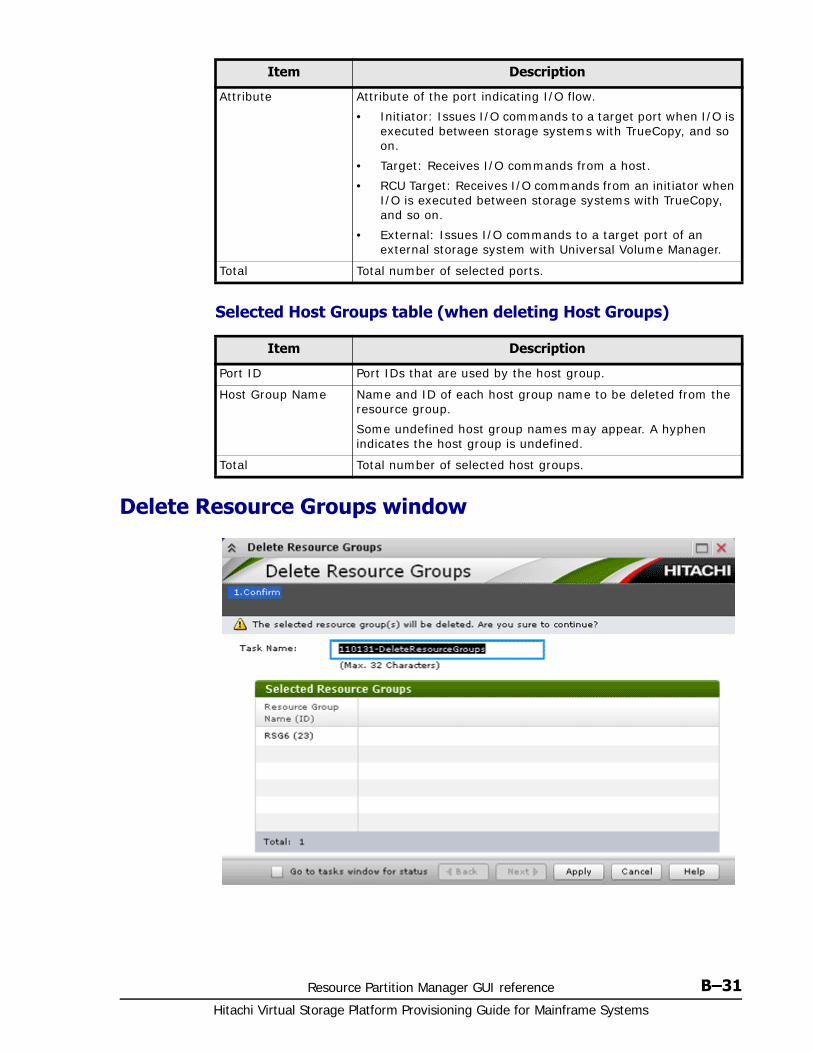
Resource Partition Manager GUI reference B–31Hitachi Virtual Storage Platform Provisioning Guide for Mainframe Systems
Selected Host Groups table (when deleting Host Groups)
Delete Resource Groups window
Attribute Attribute of the port indicating I/O flow.
• Initiator: Issues I/O commands to a target port when I/O is executed between storage systems with TrueCopy, and so on.
• Target: Receives I/O commands from a host.
• RCU Target: Receives I/O commands from an initiator when I/O is executed between storage systems with TrueCopy, and so on.
• External: Issues I/O commands to a target port of an external storage system with Universal Volume Manager.
Total Total number of selected ports.
Item Description
Item Description
Port ID Port IDs that are used by the host group.
Host Group Name Name and ID of each host group name to be deleted from the resource group.
Some undefined host group names may appear. A hyphen indicates the host group is undefined.
Total Total number of selected host groups.
Hitachi Virtual Storage Platform Provisioning Guide for Mainframe Systems
B–32 Resource Partition Manager GUI reference
Selected Resource Groups table
Item Description
Resource Group Name (ID)
Name and ID of each resource group name to be deleted.
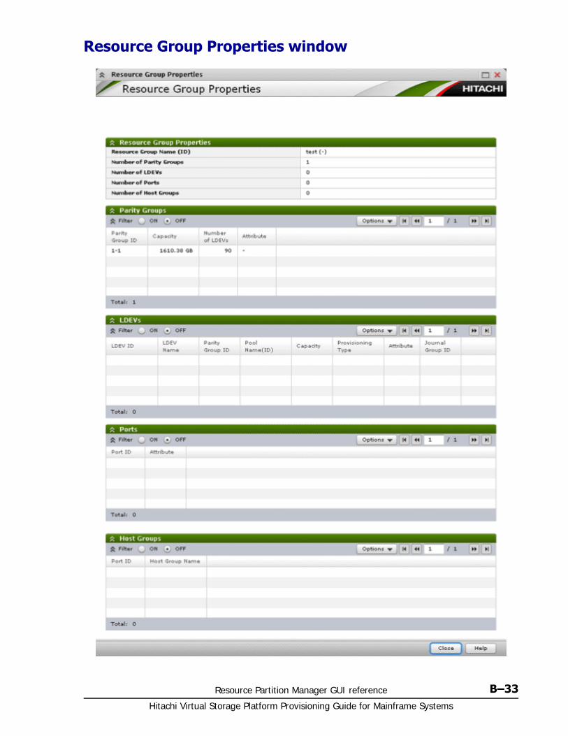
Resource Partition Manager GUI reference B–33Hitachi Virtual Storage Platform Provisioning Guide for Mainframe Systems
Resource Group Properties window

Hitachi Virtual Storage Platform Provisioning Guide for Mainframe Systems
B–34 Resource Partition Manager GUI reference
Resource Group Properties table
Parity Groups table
LDEVs table
Item Description
Resource Group Name (ID)
Name and ID of a resource group name.
Number of Parity Groups
Number of parity groups that are assigned to the resource group.
Number of LDEVs Number of LDEVs that are assigned to the resource group.
Number of Ports Number of ports that are assigned to the resource group.
Number of Host Groups
Number of host groups that are assigned to the resource group.
Item Description
Parity Group ID Parity group IDs.
Capacity Capacity of each parity group.
Number of LDEVs Number of LDEVs in each parity group.
Attribute Displays the attribute of the parity group.
Nondisruptive Migration: Parity group for nondisruptive migration.
-: Parity group in which the attribute is not defined.
Total Total number of selected parity groups.
Item Description
LDEV ID LDEV IDs.
Some undefined LDEV IDs may appear. A hyphen in the LDEV name indicates the LDEV is undefined.
LDEV Name LDEV names.
Parity Group ID Parity group ID where the LDEV belongs.
Pool Name (ID) Pool name and ID where the LDEV belongs.
Capacity Capacity of each LDEV.
Provisioning Type Provisioning type of a volume.
• Basic: Internal volume
• DP: V-VOLs of Dynamic Provisioning or Dynamic Provisioning for Mainframe
• Snapshot: Thin Image volume or Copy-on-Write Snapshot volume
• External: External volume
• External MF: External volume
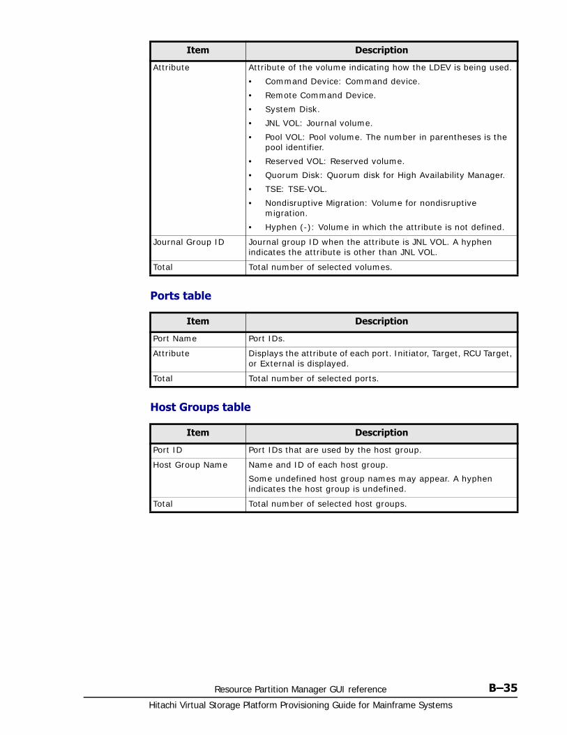
Resource Partition Manager GUI reference B–35Hitachi Virtual Storage Platform Provisioning Guide for Mainframe Systems
Ports table
Host Groups table
Attribute Attribute of the volume indicating how the LDEV is being used.
• Command Device: Command device.
• Remote Command Device.
• System Disk.
• JNL VOL: Journal volume.
• Pool VOL: Pool volume. The number in parentheses is the pool identifier.
• Reserved VOL: Reserved volume.
• Quorum Disk: Quorum disk for High Availability Manager.
• TSE: TSE-VOL.
• Nondisruptive Migration: Volume for nondisruptive migration.
• Hyphen (-): Volume in which the attribute is not defined.
Journal Group ID Journal group ID when the attribute is JNL VOL. A hyphen indicates the attribute is other than JNL VOL.
Total Total number of selected volumes.
Item Description
Item Description
Port Name Port IDs.
Attribute Displays the attribute of each port. Initiator, Target, RCU Target, or External is displayed.
Total Total number of selected ports.
Item Description
Port ID Port IDs that are used by the host group.
Host Group Name Name and ID of each host group.
Some undefined host group names may appear. A hyphen indicates the host group is undefined.
Total Total number of selected host groups.

Hitachi Virtual Storage Platform Provisioning Guide for Mainframe Systems
B–36 Resource Partition Manager GUI reference
C
LDEV GUI reference C–1Hitachi Virtual Storage Platform Provisioning Guide for Mainframe Systems
LDEV GUI reference
Sections in this appendix describe the windows, wizards, and dialog boxes used in creating LDEVs.
For information about common Storage Navigator operations, such as using navigation buttons and creating tasks, see the Hitachi Storage Navigator User Guide.
□ Parity Groups window
□ Parity Groups window after selecting Internal (or External) under Parity Groups
□ Window after selecting a parity group under Internal (or External) of Parity Groups
□ Window after selecting Logical Devices
□ Create LDEVs wizard
□ Edit LDEVs wizard
□ Change LDEV Settings window
□ View SSIDs window
□ Select Free Spaces window
□ Select Pool window
□ View LDEV IDs window
□ View Physical Location window
Hitachi Virtual Storage Platform Provisioning Guide for Mainframe Systems
C–2 LDEV GUI reference
□ Edit SSIDs window
□ Change SSIDs window
□ Format LDEVs wizard
□ Restore LDEVs window
□ Block LDEVs window
□ Delete LDEVs window
□ LDEV Properties window
□ Top window when selecting Components
□ Top window when selecting controller chassis under Components
□ Edit Processor Blades wizard
□ Assign Processor Blade wizard
□ View Management Resource Usage window
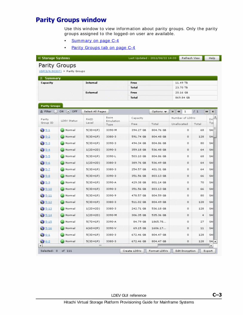
LDEV GUI reference C–3Hitachi Virtual Storage Platform Provisioning Guide for Mainframe Systems
Parity Groups windowUse this window to view information about parity groups. Only the parity groups assigned to the logged-on user are available.
• Summary on page C-4
• Parity Groups tab on page C-4
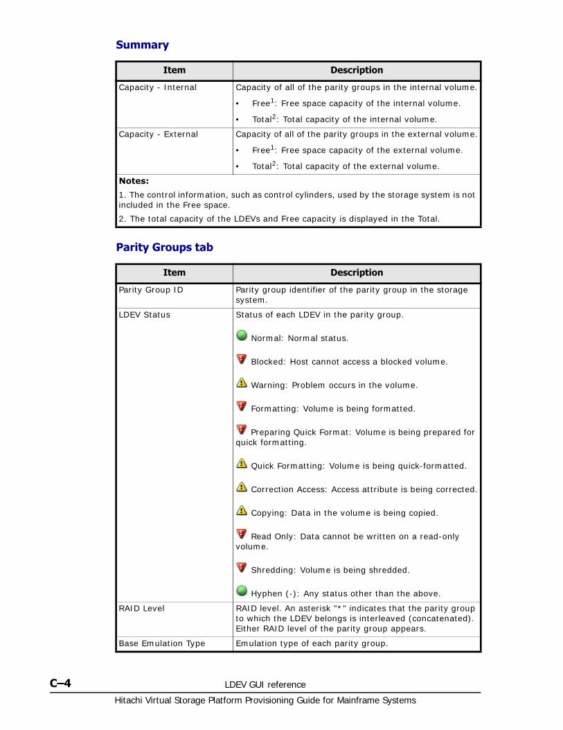
Hitachi Virtual Storage Platform Provisioning Guide for Mainframe Systems
C–4 LDEV GUI reference
Summary
Parity Groups tab
Item Description
Capacity - Internal Capacity of all of the parity groups in the internal volume.
• Free1: Free space capacity of the internal volume.
• Total2: Total capacity of the internal volume.
Capacity - External Capacity of all of the parity groups in the external volume.
• Free1: Free space capacity of the external volume.
• Total2: Total capacity of the external volume.
Notes:
1. The control information, such as control cylinders, used by the storage system is not included in the Free space.
2. The total capacity of the LDEVs and Free capacity is displayed in the Total.
Item Description
Parity Group ID Parity group identifier of the parity group in the storage system.
LDEV Status Status of each LDEV in the parity group.
Normal: Normal status.
Blocked: Host cannot access a blocked volume.
Warning: Problem occurs in the volume.
Formatting: Volume is being formatted.
Preparing Quick Format: Volume is being prepared for quick formatting.
Quick Formatting: Volume is being quick-formatted.
Correction Access: Access attribute is being corrected.
Copying: Data in the volume is being copied.
Read Only: Data cannot be written on a read-only volume.
Shredding: Volume is being shredded.
Hyphen (-): Any status other than the above.
RAID Level RAID level. An asterisk "*" indicates that the parity group to which the LDEV belongs is interleaved (concatenated). Either RAID level of the parity group appears.
Base Emulation Type Emulation type of each parity group.
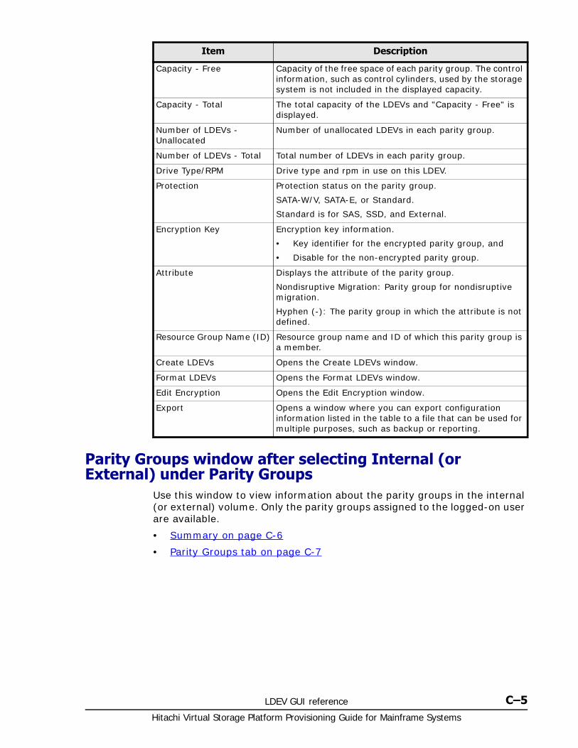
LDEV GUI reference C–5Hitachi Virtual Storage Platform Provisioning Guide for Mainframe Systems
Parity Groups window after selecting Internal (or External) under Parity Groups
Use this window to view information about the parity groups in the internal (or external) volume. Only the parity groups assigned to the logged-on user are available.
• Summary on page C-6
• Parity Groups tab on page C-7
Capacity - Free Capacity of the free space of each parity group. The control information, such as control cylinders, used by the storage system is not included in the displayed capacity.
Capacity - Total The total capacity of the LDEVs and "Capacity - Free" is displayed.
Number of LDEVs - Unallocated
Number of unallocated LDEVs in each parity group.
Number of LDEVs - Total Total number of LDEVs in each parity group.
Drive Type/RPM Drive type and rpm in use on this LDEV.
Protection Protection status on the parity group.
SATA-W/V, SATA-E, or Standard.
Standard is for SAS, SSD, and External.
Encryption Key Encryption key information.
• Key identifier for the encrypted parity group, and
• Disable for the non-encrypted parity group.
Attribute Displays the attribute of the parity group.
Nondisruptive Migration: Parity group for nondisruptive migration.
Hyphen (-): The parity group in which the attribute is not defined.
Resource Group Name (ID) Resource group name and ID of which this parity group is a member.
Create LDEVs Opens the Create LDEVs window.
Format LDEVs Opens the Format LDEVs window.
Edit Encryption Opens the Edit Encryption window.
Export Opens a window where you can export configuration information listed in the table to a file that can be used for multiple purposes, such as backup or reporting.
Item Description

Hitachi Virtual Storage Platform Provisioning Guide for Mainframe Systems
C–6 LDEV GUI reference
Summary
Item Description
Capacity - Free The free space capacity of the internal (or external) volume. The control information, such as control cylinders, used by the storage system is not included in the displayed capacity.
Capacity - Total The total capacity of the LDEVs and "Capacity - Free" is displayed.
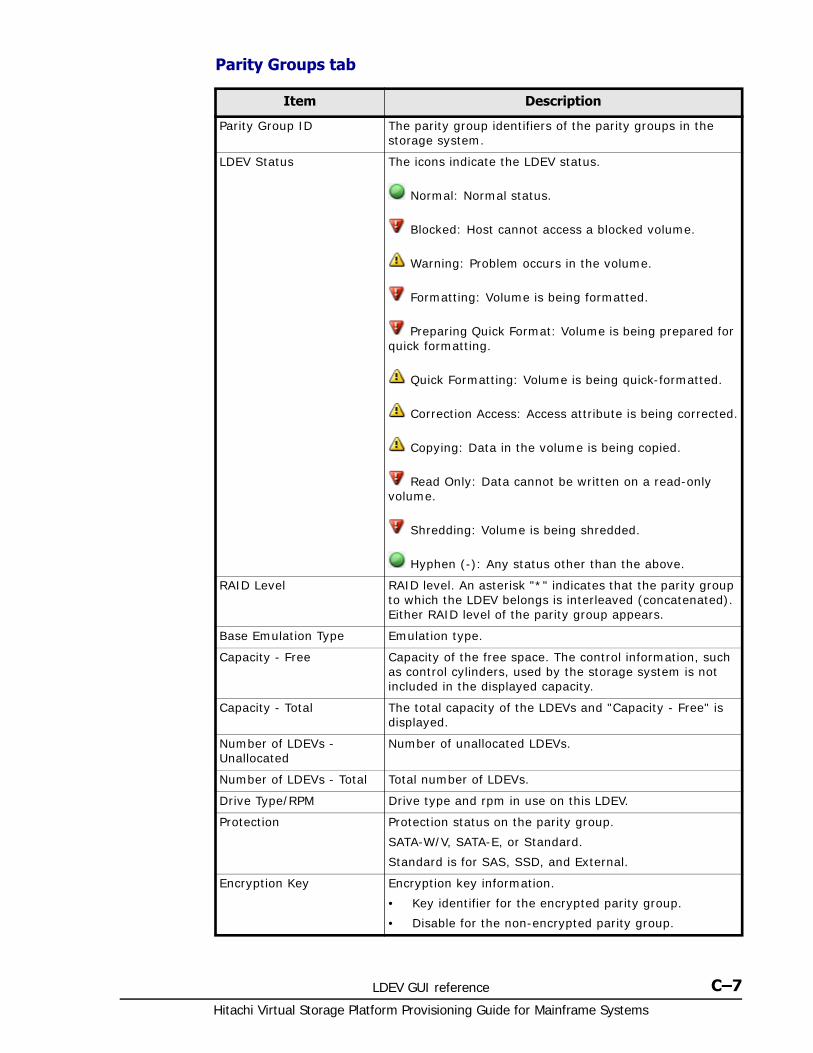
LDEV GUI reference C–7Hitachi Virtual Storage Platform Provisioning Guide for Mainframe Systems
Parity Groups tab
Item Description
Parity Group ID The parity group identifiers of the parity groups in the storage system.
LDEV Status The icons indicate the LDEV status.
Normal: Normal status.
Blocked: Host cannot access a blocked volume.
Warning: Problem occurs in the volume.
Formatting: Volume is being formatted.
Preparing Quick Format: Volume is being prepared for quick formatting.
Quick Formatting: Volume is being quick-formatted.
Correction Access: Access attribute is being corrected.
Copying: Data in the volume is being copied.
Read Only: Data cannot be written on a read-only volume.
Shredding: Volume is being shredded.
Hyphen (-): Any status other than the above.
RAID Level RAID level. An asterisk "*" indicates that the parity group to which the LDEV belongs is interleaved (concatenated). Either RAID level of the parity group appears.
Base Emulation Type Emulation type.
Capacity - Free Capacity of the free space. The control information, such as control cylinders, used by the storage system is not included in the displayed capacity.
Capacity - Total The total capacity of the LDEVs and "Capacity - Free" is displayed.
Number of LDEVs - Unallocated
Number of unallocated LDEVs.
Number of LDEVs - Total Total number of LDEVs.
Drive Type/RPM Drive type and rpm in use on this LDEV.
Protection Protection status on the parity group.
SATA-W/V, SATA-E, or Standard.
Standard is for SAS, SSD, and External.
Encryption Key Encryption key information.
• Key identifier for the encrypted parity group.
• Disable for the non-encrypted parity group.
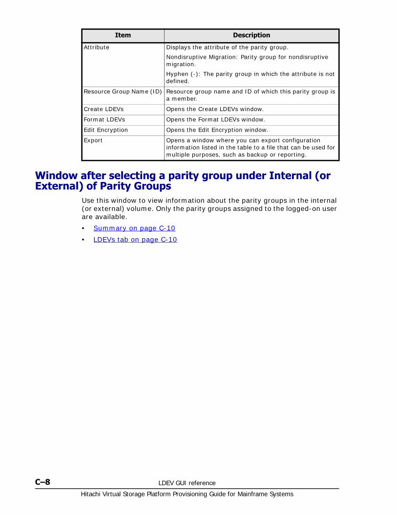
Hitachi Virtual Storage Platform Provisioning Guide for Mainframe Systems
C–8 LDEV GUI reference
Window after selecting a parity group under Internal (or External) of Parity Groups
Use this window to view information about the parity groups in the internal (or external) volume. Only the parity groups assigned to the logged-on user are available.
• Summary on page C-10
• LDEVs tab on page C-10
Attribute Displays the attribute of the parity group.
Nondisruptive Migration: Parity group for nondisruptive migration.
Hyphen (-): The parity group in which the attribute is not defined.
Resource Group Name (ID) Resource group name and ID of which this parity group is a member.
Create LDEVs Opens the Create LDEVs window.
Format LDEVs Opens the Format LDEVs window.
Edit Encryption Opens the Edit Encryption window.
Export Opens a window where you can export configuration information listed in the table to a file that can be used for multiple purposes, such as backup or reporting.
Item Description
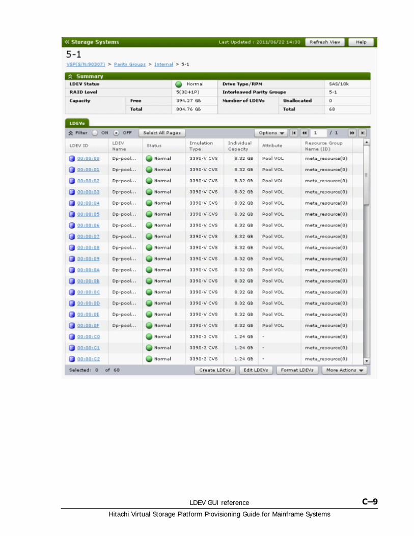
LDEV GUI reference C–9Hitachi Virtual Storage Platform Provisioning Guide for Mainframe Systems
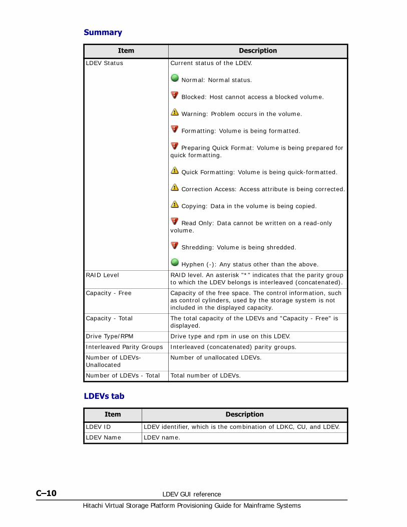
Hitachi Virtual Storage Platform Provisioning Guide for Mainframe Systems
C–10 LDEV GUI reference
Summary
LDEVs tab
Item Description
LDEV Status Current status of the LDEV.
Normal: Normal status.
Blocked: Host cannot access a blocked volume.
Warning: Problem occurs in the volume.
Formatting: Volume is being formatted.
Preparing Quick Format: Volume is being prepared for quick formatting.
Quick Formatting: Volume is being quick-formatted.
Correction Access: Access attribute is being corrected.
Copying: Data in the volume is being copied.
Read Only: Data cannot be written on a read-only volume.
Shredding: Volume is being shredded.
Hyphen (-): Any status other than the above.
RAID Level RAID level. An asterisk "*" indicates that the parity group to which the LDEV belongs is interleaved (concatenated).
Capacity - Free Capacity of the free space. The control information, such as control cylinders, used by the storage system is not included in the displayed capacity.
Capacity - Total The total capacity of the LDEVs and "Capacity - Free" is displayed.
Drive Type/RPM Drive type and rpm in use on this LDEV.
Interleaved Parity Groups Interleaved (concatenated) parity groups.
Number of LDEVs- Unallocated
Number of unallocated LDEVs.
Number of LDEVs - Total Total number of LDEVs.
Item Description
LDEV ID LDEV identifier, which is the combination of LDKC, CU, and LDEV.
LDEV Name LDEV name.
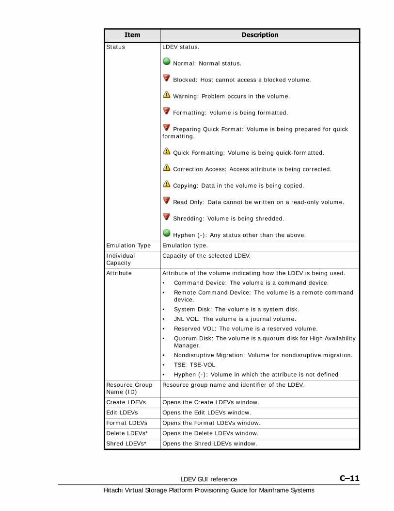
LDEV GUI reference C–11Hitachi Virtual Storage Platform Provisioning Guide for Mainframe Systems
Status LDEV status.
Normal: Normal status.
Blocked: Host cannot access a blocked volume.
Warning: Problem occurs in the volume.
Formatting: Volume is being formatted.
Preparing Quick Format: Volume is being prepared for quick formatting.
Quick Formatting: Volume is being quick-formatted.
Correction Access: Access attribute is being corrected.
Copying: Data in the volume is being copied.
Read Only: Data cannot be written on a read-only volume.
Shredding: Volume is being shredded.
Hyphen (-): Any status other than the above.
Emulation Type Emulation type.
Individual Capacity
Capacity of the selected LDEV.
Attribute Attribute of the volume indicating how the LDEV is being used.
• Command Device: The volume is a command device.
• Remote Command Device: The volume is a remote command device.
• System Disk: The volume is a system disk.
• JNL VOL: The volume is a journal volume.
• Reserved VOL: The volume is a reserved volume.
• Quorum Disk: The volume is a quorum disk for High Availability Manager.
• Nondisruptive Migration: Volume for nondisruptive migration.
• TSE: TSE-VOL
• Hyphen (-): Volume in which the attribute is not defined
Resource Group Name (ID)
Resource group name and identifier of the LDEV.
Create LDEVs Opens the Create LDEVs window.
Edit LDEVs Opens the Edit LDEVs window.
Format LDEVs Opens the Format LDEVs window.
Delete LDEVs* Opens the Delete LDEVs window.
Shred LDEVs* Opens the Shred LDEVs window.
Item Description
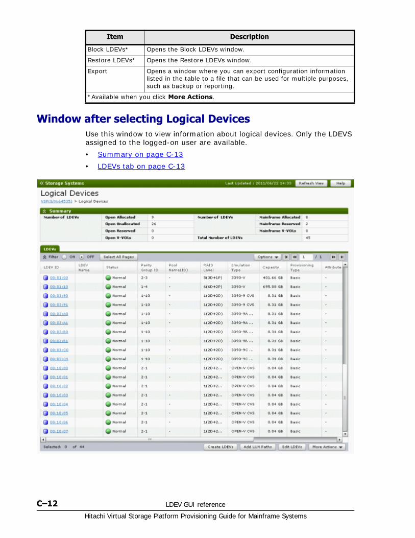
Hitachi Virtual Storage Platform Provisioning Guide for Mainframe Systems
C–12 LDEV GUI reference
Window after selecting Logical DevicesUse this window to view information about logical devices. Only the LDEVS assigned to the logged-on user are available.
• Summary on page C-13
• LDEVs tab on page C-13
Block LDEVs* Opens the Block LDEVs window.
Restore LDEVs* Opens the Restore LDEVs window.
Export Opens a window where you can export configuration information listed in the table to a file that can be used for multiple purposes, such as backup or reporting.
*Available when you click More Actions.
Item Description
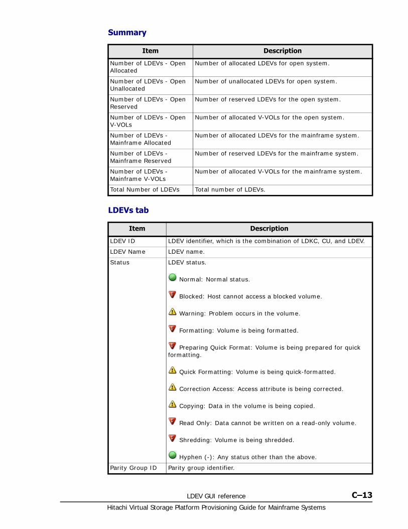
LDEV GUI reference C–13Hitachi Virtual Storage Platform Provisioning Guide for Mainframe Systems
Summary
LDEVs tab
Item Description
Number of LDEVs - Open Allocated
Number of allocated LDEVs for open system.
Number of LDEVs - Open Unallocated
Number of unallocated LDEVs for open system.
Number of LDEVs - Open Reserved
Number of reserved LDEVs for the open system.
Number of LDEVs - Open V-VOLs
Number of allocated V-VOLs for the open system.
Number of LDEVs - Mainframe Allocated
Number of allocated LDEVs for the mainframe system.
Number of LDEVs - Mainframe Reserved
Number of reserved LDEVs for the mainframe system.
Number of LDEVs - Mainframe V-VOLs
Number of allocated V-VOLs for the mainframe system.
Total Number of LDEVs Total number of LDEVs.
Item Description
LDEV ID LDEV identifier, which is the combination of LDKC, CU, and LDEV.
LDEV Name LDEV name.
Status LDEV status.
Normal: Normal status.
Blocked: Host cannot access a blocked volume.
Warning: Problem occurs in the volume.
Formatting: Volume is being formatted.
Preparing Quick Format: Volume is being prepared for quick formatting.
Quick Formatting: Volume is being quick-formatted.
Correction Access: Access attribute is being corrected.
Copying: Data in the volume is being copied.
Read Only: Data cannot be written on a read-only volume.
Shredding: Volume is being shredded.
Hyphen (-): Any status other than the above.
Parity Group ID Parity group identifier.
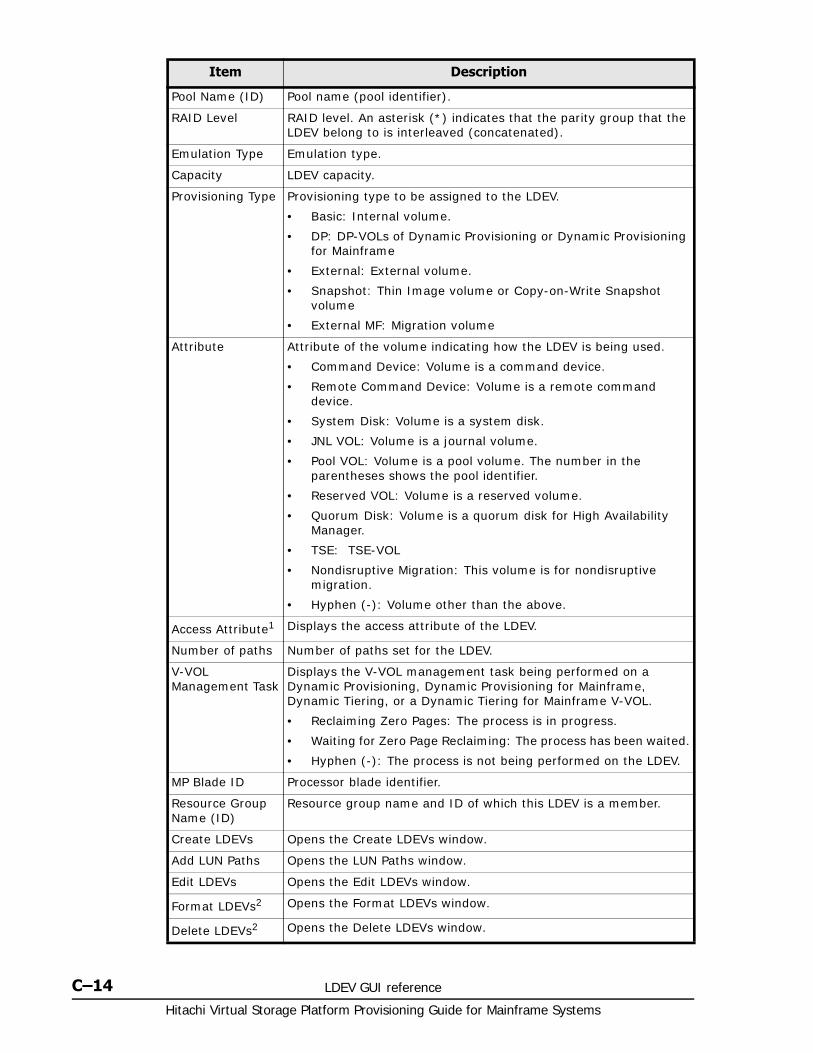
Hitachi Virtual Storage Platform Provisioning Guide for Mainframe Systems
C–14 LDEV GUI reference
Pool Name (ID) Pool name (pool identifier).
RAID Level RAID level. An asterisk (*) indicates that the parity group that the LDEV belong to is interleaved (concatenated).
Emulation Type Emulation type.
Capacity LDEV capacity.
Provisioning Type Provisioning type to be assigned to the LDEV.
• Basic: Internal volume.
• DP: DP-VOLs of Dynamic Provisioning or Dynamic Provisioning for Mainframe
• External: External volume.
• Snapshot: Thin Image volume or Copy-on-Write Snapshot volume
• External MF: Migration volume
Attribute Attribute of the volume indicating how the LDEV is being used.
• Command Device: Volume is a command device.
• Remote Command Device: Volume is a remote command device.
• System Disk: Volume is a system disk.
• JNL VOL: Volume is a journal volume.
• Pool VOL: Volume is a pool volume. The number in the parentheses shows the pool identifier.
• Reserved VOL: Volume is a reserved volume.
• Quorum Disk: Volume is a quorum disk for High Availability Manager.
• TSE: TSE-VOL
• Nondisruptive Migration: This volume is for nondisruptive migration.
• Hyphen (-): Volume other than the above.
Access Attribute1 Displays the access attribute of the LDEV.
Number of paths Number of paths set for the LDEV.
V-VOL Management Task
Displays the V-VOL management task being performed on a Dynamic Provisioning, Dynamic Provisioning for Mainframe, Dynamic Tiering, or a Dynamic Tiering for Mainframe V-VOL.
• Reclaiming Zero Pages: The process is in progress.
• Waiting for Zero Page Reclaiming: The process has been waited.
• Hyphen (-): The process is not being performed on the LDEV.
MP Blade ID Processor blade identifier.
Resource Group Name (ID)
Resource group name and ID of which this LDEV is a member.
Create LDEVs Opens the Create LDEVs window.
Add LUN Paths Opens the LUN Paths window.
Edit LDEVs Opens the Edit LDEVs window.
Format LDEVs2 Opens the Format LDEVs window.
Delete LDEVs2 Opens the Delete LDEVs window.
Item Description
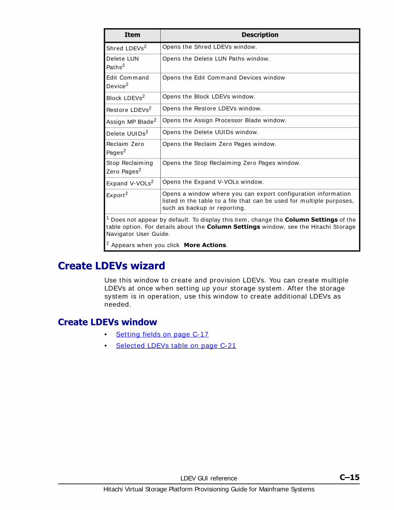
LDEV GUI reference C–15Hitachi Virtual Storage Platform Provisioning Guide for Mainframe Systems
Create LDEVs wizardUse this window to create and provision LDEVs. You can create multiple LDEVs at once when setting up your storage system. After the storage system is in operation, use this window to create additional LDEVs as needed.
Create LDEVs window• Setting fields on page C-17
• Selected LDEVs table on page C-21
Shred LDEVs2 Opens the Shred LDEVs window.
Delete LUN Paths2
Opens the Delete LUN Paths window.
Edit Command Device2
Opens the Edit Command Devices window
Block LDEVs2 Opens the Block LDEVs window.
Restore LDEVs2 Opens the Restore LDEVs window.
Assign MP Blade2 Opens the Assign Processor Blade window.
Delete UUIDs2 Opens the Delete UUIDs window.
Reclaim Zero Pages2
Opens the Reclaim Zero Pages window.
Stop Reclaiming Zero Pages2
Opens the Stop Reclaiming Zero Pages window.
Expand V-VOLs2 Opens the Expand V-VOLs window.
Export2 Opens a window where you can export configuration information listed in the table to a file that can be used for multiple purposes, such as backup or reporting.
1 Does not appear by default. To display this item, change the Column Settings of the table option. For details about the Column Settings window, see the Hitachi Storage Navigator User Guide.
2 Appears when you click More Actions.
Item Description
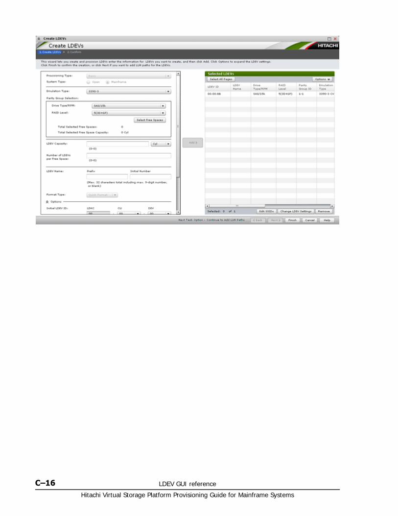
Hitachi Virtual Storage Platform Provisioning Guide for Mainframe Systems
C–16 LDEV GUI reference
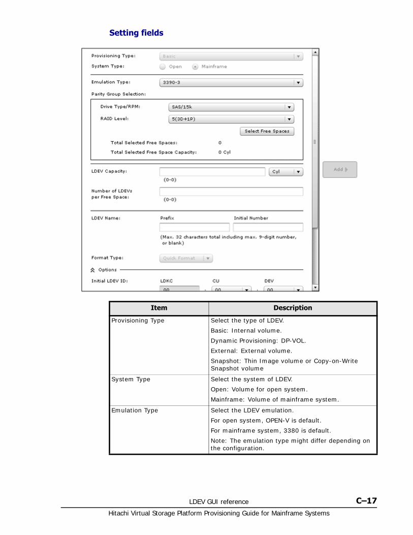
LDEV GUI reference C–17Hitachi Virtual Storage Platform Provisioning Guide for Mainframe Systems
Setting fields
Item Description
Provisioning Type Select the type of LDEV.
Basic: Internal volume.
Dynamic Provisioning: DP-VOL.
External: External volume.
Snapshot: Thin Image volume or Copy-on-Write Snapshot volume
System Type Select the system of LDEV.
Open: Volume for open system.
Mainframe: Volume of mainframe system.
Emulation Type Select the LDEV emulation.
For open system, OPEN-V is default.
For mainframe system, 3380 is default.
Note: The emulation type might differ depending on the configuration.
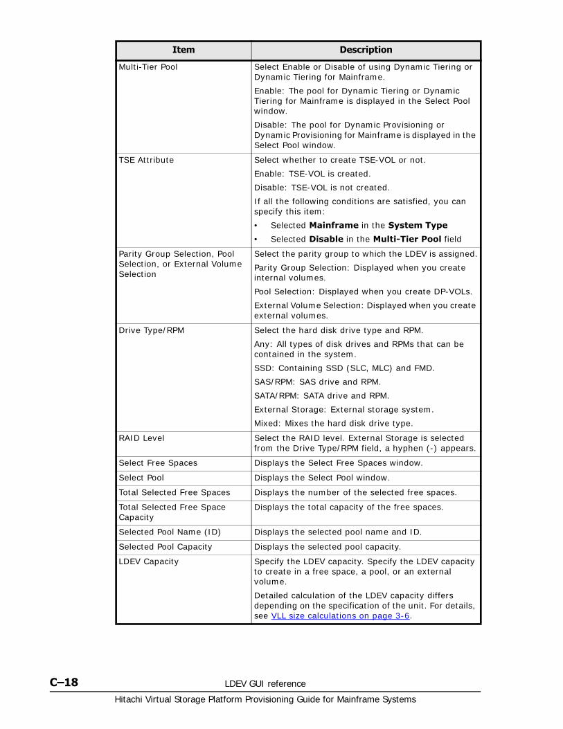
Hitachi Virtual Storage Platform Provisioning Guide for Mainframe Systems
C–18 LDEV GUI reference
Multi-Tier Pool Select Enable or Disable of using Dynamic Tiering or Dynamic Tiering for Mainframe.
Enable: The pool for Dynamic Tiering or Dynamic Tiering for Mainframe is displayed in the Select Pool window.
Disable: The pool for Dynamic Provisioning or Dynamic Provisioning for Mainframe is displayed in the Select Pool window.
TSE Attribute Select whether to create TSE-VOL or not.
Enable: TSE-VOL is created.
Disable: TSE-VOL is not created.
If all the following conditions are satisfied, you can specify this item:
• Selected Mainframe in the System Type
• Selected Disable in the Multi-Tier Pool field
Parity Group Selection, Pool Selection, or External Volume Selection
Select the parity group to which the LDEV is assigned.
Parity Group Selection: Displayed when you create internal volumes.
Pool Selection: Displayed when you create DP-VOLs.
External Volume Selection: Displayed when you create external volumes.
Drive Type/RPM Select the hard disk drive type and RPM.
Any: All types of disk drives and RPMs that can be contained in the system.
SSD: Containing SSD (SLC, MLC) and FMD.
SAS/RPM: SAS drive and RPM.
SATA/RPM: SATA drive and RPM.
External Storage: External storage system.
Mixed: Mixes the hard disk drive type.
RAID Level Select the RAID level. External Storage is selected from the Drive Type/RPM field, a hyphen (-) appears.
Select Free Spaces Displays the Select Free Spaces window.
Select Pool Displays the Select Pool window.
Total Selected Free Spaces Displays the number of the selected free spaces.
Total Selected Free Space Capacity
Displays the total capacity of the free spaces.
Selected Pool Name (ID) Displays the selected pool name and ID.
Selected Pool Capacity Displays the selected pool capacity.
LDEV Capacity Specify the LDEV capacity. Specify the LDEV capacity to create in a free space, a pool, or an external volume.
Detailed calculation of the LDEV capacity differs depending on the specification of the unit. For details, see VLL size calculations on page 3-6.
Item Description
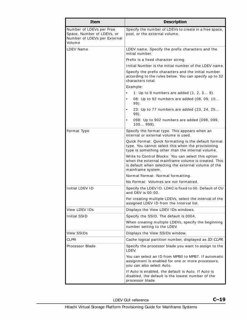
LDEV GUI reference C–19Hitachi Virtual Storage Platform Provisioning Guide for Mainframe Systems
Number of LDEVs per Free Space, Number of LDEVs, or Number of LDEVs per External Volume
Specify the number of LDEVs to create in a free space, pool, or the external volume.
LDEV Name LDEV name. Specify the prefix characters and the initial number.
Prefix is a fixed character string.
Initial Number is the initial number of the LDEV name.
Specify the prefix characters and the initial number according to the rules below. You can specify up to 32 characters total.
Example:
• 1: Up to 9 numbers are added (1, 2, 3... 9).
• 08: Up to 92 numbers are added (08, 09, 10... 99).
• 23: Up to 77 numbers are added (23, 24, 25... 99).
• 098: Up to 902 numbers are added (098, 099, 100... 999).
Format Type Specify the format type. This appears when an internal or external volume is used.
Quick Format: Quick formatting is the default format type. You cannot select this when the provisioning type is something other than the internal volume.
Write to Control Blocks: You can select this option when the external mainframe volume is created. This is default when selecting the external volume of the mainframe system.
Normal Format: Normal formatting.
No Format: Volumes are not formatted.
Initial LDEV ID Specify the LDEV ID. LDKC is fixed to 00. Default of CU and DEV is 00:00.
For creating multiple LDEVs, select the interval of the assigned LDEV ID from the Interval list.
View LDEV IDs Displays the View LDEV IDs windows.
Initial SSID Specify the SSID. The default is 0004.
When creating multiple LDEVs, specify the beginning number setting to the LDEV.
View SSIDs Displays the View SSIDs window.
CLPR Cache logical partition number, displayed as ID:CLPR.
Processor Blade Specify the processor blade you want to assign to the LDEV.
You can select an ID from MPB0 to MPB7. If automatic assignment is enabled for one or more processors, you can also select Auto.
If Auto is enabled, the default is Auto. If Auto is disabled, the default is the lowest number of the processor blade.
Item Description
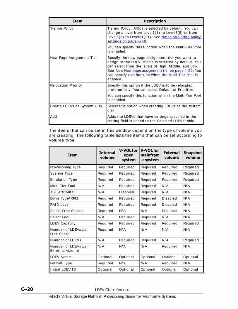
Hitachi Virtual Storage Platform Provisioning Guide for Mainframe Systems
C–20 LDEV GUI reference
The items that can be set in this window depend on the type of volume you are creating. The following table lists the items that can be set according to volume type.
Tiering Policy Tiering Policy: All(0) is selected by default. You can change a level from Level1(1) to Level5(5) or from Level6(6) to Level31(31). See Notes on tiering policy settings on page 4-48.
You can specify this function when the Multi-Tier Pool is enabled.
New Page Assignment Tier Specify the new page assignment tier you want to assign to the LDEV. Middle is selected by default. You can select from the levels of High, Middle, and Low. See New New page assignment tier on page 4-50. You can specify this function when the Multi-Tier Pool is enabled.
Relocation Priority Specify this option if the LDEV is to be relocated preferentially. You can select Default or Prioritize.
You can specify this function when the Multi-Tier Pool is enabled.
Create LDEVs as System Disk Select this option when creating LDEVs as the system disk.
Add Adds the LDEVs that have settings specified in the setting field is added to the Selected LDEVs table.
Item Description
Item Internal volume
V-VOL for open
system
V-VOL for mainframe system
External volume
Snapshot volume
Provisioning Type Required Required Required Required Required
System Type Required Required Required Required Required
Emulation Type Required Required Required Required Required
Multi-Tier Pool N/A Required Required N/A N/A
TSE Attribute N/A Disabled Required N/A N/A
Drive Type/RPM Required Required Required Disabled N/A
RAID Level Required Required Required Disabled N/A
Select Free Spaces Required N/A N/A Required N/A
Select Pool N/A Required Required N/A N/A
LDEV Capacity Required Required Required Required Required
Number of LDEVs per Free Space
Required N/A N/A N/A N/A
Number of LDEVs N/A Required Required N/A Required
Number of LDEVs per External Volume
N/A N/A N/A Required N/A
LDEV Name Optional Optional Optional Optional Optional
Format Type Required N/A N/A Required N/A
Initial LDEV ID Optional Optional Optional Optional Optional
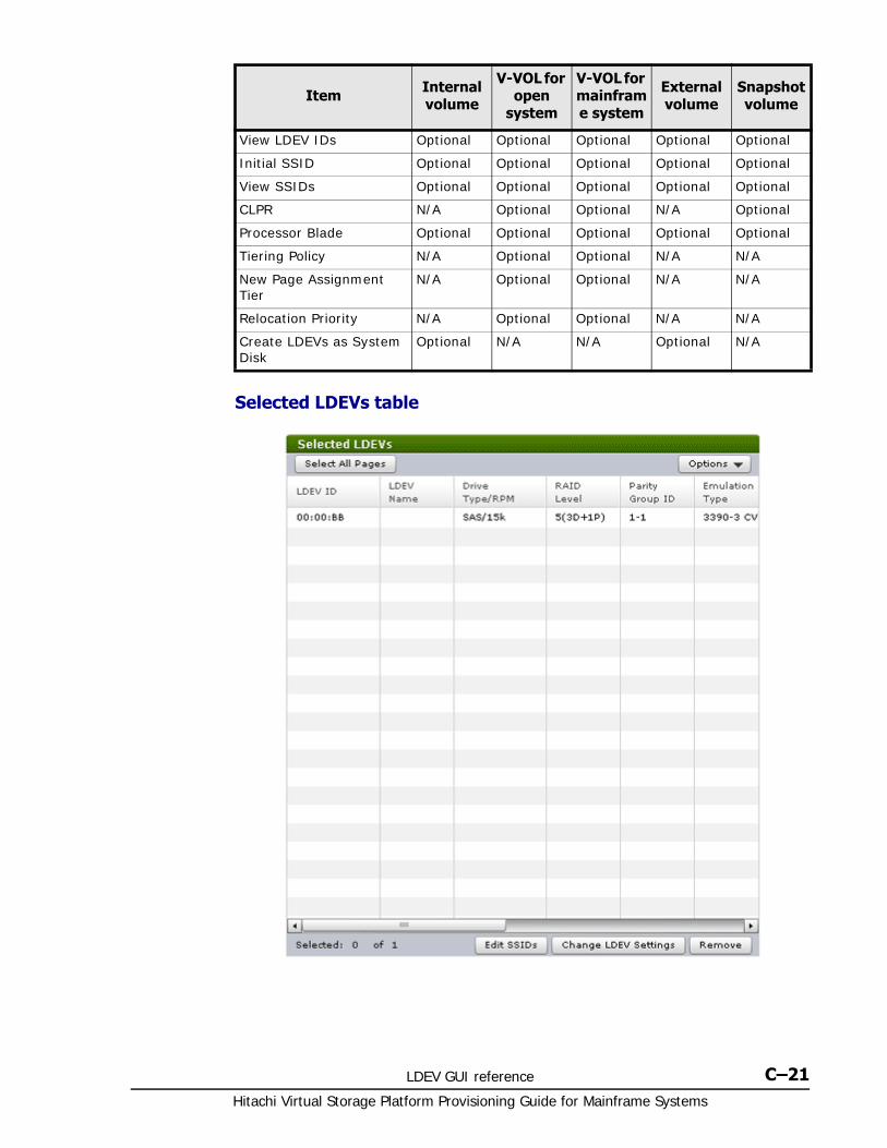
LDEV GUI reference C–21Hitachi Virtual Storage Platform Provisioning Guide for Mainframe Systems
Selected LDEVs table
View LDEV IDs Optional Optional Optional Optional Optional
Initial SSID Optional Optional Optional Optional Optional
View SSIDs Optional Optional Optional Optional Optional
CLPR N/A Optional Optional N/A Optional
Processor Blade Optional Optional Optional Optional Optional
Tiering Policy N/A Optional Optional N/A N/A
New Page Assignment Tier
N/A Optional Optional N/A N/A
Relocation Priority N/A Optional Optional N/A N/A
Create LDEVs as System Disk
Optional N/A N/A Optional N/A
Item Internal volume
V-VOL for open
system
V-VOL for mainframe system
External volume
Snapshot volume

Hitachi Virtual Storage Platform Provisioning Guide for Mainframe Systems
C–22 LDEV GUI reference
Item Description
LDEV ID LDEV identifier, which is the combination of LDKC, CU, and LDEV.
LDEV Name LDEV name, including the combination of prefix characters and the initial number.
Parity Group ID Parity group identifier.
Pool Name (ID) Pool name and pool identifier.
Drive Type/RPM Drive type and rpm in use on this LDEV.
RAID Level RAID level. An asterisk "*" indicates that the parity group to which the LDEV belongs is interleaved (concatenated).
Emulation Type Emulation type.
Capacity LDEV capacity.
Format Type Format type.
SSID Storage system identifier in hexadecimal format.
CLPR Cache logical partition number, displayed as ID:CLPR.
For detailed information about CLPRs, see the Performance Guide.
MP Blade ID Processor blade identifier. If Auto is selected, the ID is automatically assigned.
System Disk Indicates whether the LDEV is being used as the system disk.
• Yes: System disk.
• No: Not system disk.
Multi-Tier Pool Indicates whether Dynamic Tiering or Dynamic Tiering for Mainframe is enabled or disabled.
• Enable: The LDEV is for Dynamic Tiering or Dynamic Tiering for Mainframe.
• Disable: The LDEV is for Dynamic Tiering or Dynamic Tiering for Mainframe.
Tiering Policy The tiering policy name and ID for the LDEV.
New Page Assignment Tier Displays the new page assignment tier for the LDEV.
Relocation Priority Displays the relocation priority assigned to the LDEV.
Attribute Displays the attribute of the LDEV.
TSE: TSE-VOL
Hyphen (-): Volume in which attribute is not defined.
Resource Group Name (ID) Resource group name and ID of which this LDEV is a member.
Edit SSIDs Opens the Edit SSIDs window.
Change LDEV Settings Opens the Change LDEV Settings window.
Remove Removes the added LDEV.
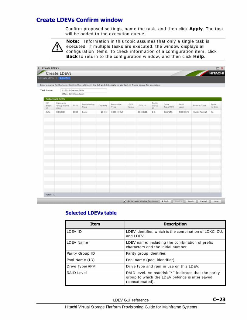
LDEV GUI reference C–23Hitachi Virtual Storage Platform Provisioning Guide for Mainframe Systems
Create LDEVs Confirm windowConfirm proposed settings, name the task, and then click Apply. The task will be added to the execution queue.
Selected LDEVs table
Note: Information in this topic assumes that only a single task is executed. If multiple tasks are executed, the window displays all configuration items. To check information of a configuration item, click Back to return to the configuration window, and then click Help.
Item Description
LDEV ID LDEV identifier, which is the combination of LDKC, CU, and LDEV.
LDEV Name LDEV name, including the combination of prefix characters and the initial number.
Parity Group ID Parity group identifier.
Pool Name (ID) Pool name (pool identifier).
Drive Type/RPM Drive type and rpm in use on this LDEV.
RAID Level RAID level. An asterisk "*" indicates that the parity group to which the LDEV belongs is interleaved (concatenated).
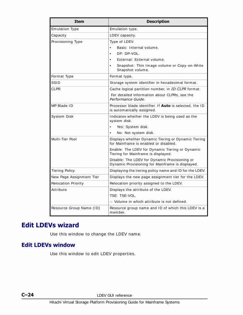
Hitachi Virtual Storage Platform Provisioning Guide for Mainframe Systems
C–24 LDEV GUI reference
Edit LDEVs wizardUse this window to change the LDEV name.
Edit LDEVs windowUse this window to edit LDEV properties.
Emulation Type Emulation type.
Capacity LDEV capacity.
Provisioning Type Type of LDEV.
• Basic: Internal volume.
• DP: DP-VOL.
• External: External volume.
• Snapshot: Thin Image volume or Copy-on-Write Snapshot volume.
Format Type Format type.
SSID Storage system identifier in hexadecimal format.
CLPR Cache logical partition number, in ID:CLPR format.
For detailed information about CLPRs, see the Performance Guide.
MP Blade ID Processor blade identifier. If Auto is selected, the ID is automatically assigned.
System Disk Indicates whether the LDEV is being used as the system disk.
• Yes: System disk.
• No: Not system disk.
Multi-Tier Pool Displays whether Dynamic Tiering or Dynamic Tiering for Mainframe is enabled or disabled.
Enable: The LDEV for Dynamic Tiering or Dynamic Tiering for Mainframe is displayed.
Disable: The LDEV for Dynamic Provisioning or Dynamic Provisioning for Mainframe is displayed.
Tiering Policy Displaying the tiering policy name and ID for the LDEV.
New Page Assignment Tier Displays the new page assignment tier for the LDEV.
Relocation Priority Relocation priority assigned to the LDEV.
Attribute Displays the attribute of the LDEV.
TSE: TSE-VOL.
-: Volume in which attribute is not defined.
Resource Group Name (ID) Resource group name and ID of which this LDEV is a member.
Item Description

LDEV GUI reference C–25Hitachi Virtual Storage Platform Provisioning Guide for Mainframe Systems
Item Description
LDEV Name Specify the LDEV name, using up to 32 characters.
• Prefix: Fixed character string.
• Initial Number: Initial number.
Specify the prefix characters and the initial number according to these rules.
• 1: Up to 9 numbers are added (1, 2, 3 ... 9)
• 08: Up to 92 numbers are added (08, 09, 10 ... 99)
• 23: Up to 77 numbers are added (23, 24, 25 ... 99)
• 098: Up to 902 numbers are added (098, 099, 100 ... 999)
Tiering Policy Specify the tiering policy for the LDEV. For details about the setting. You can specify this function only when the V-VOLs using Dynamic Tiering or Dynamic Tiering for Mainframe are available. See Notes on tiering policy settings on page 4-48
Hitachi Virtual Storage Platform Provisioning Guide for Mainframe Systems
C–26 LDEV GUI reference
Edit LDEVs Confirm windowConfirm proposed settings, name the task, and then click Apply. The task will be added to the execution queue.
New Page Assignment Tier Specify the new page assignment tier you want to assign to the LDEV. Middle is set by default. You can select from High, Middle, or Low. See New page assignment tier on page 4-50.
You can specify this function only when the V-VOLs that use Dynamic Tiering or Dynamic Tiering for Mainframe are available.
Tier Relocation Specify Enable or Disable for the performing of the tier relocation. You can specify this function only when the V-VOLs using Dynamic Tiering or Dynamic Tiering for Mainframe are available.
Relocation Priority Specify the relocation priority assigned to the LDEV. You can set this function under the following conditions:
• When there are V-VOLs where Dynamic Tiering or Dynamic Tiering for Mainframe is enabled.
• When the tier relocation is enabled.
Item Description
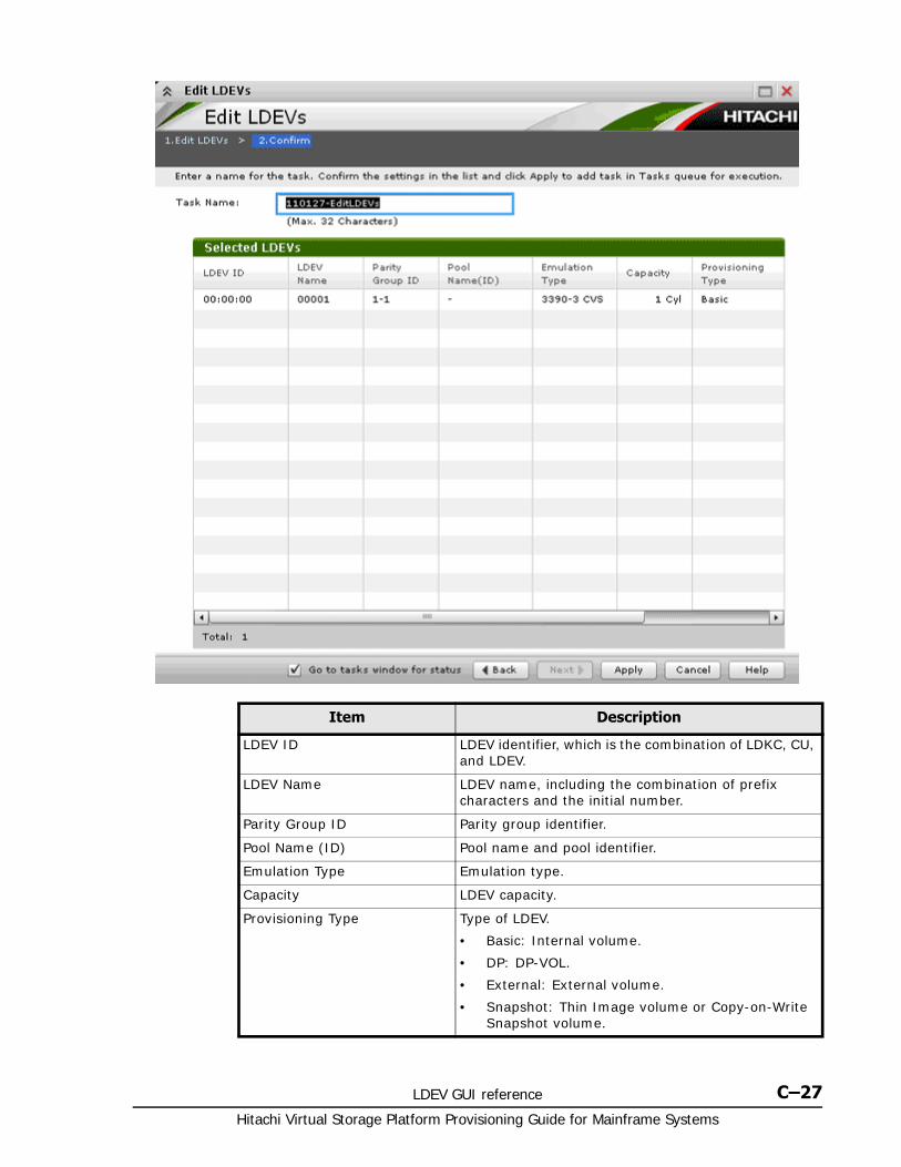
LDEV GUI reference C–27Hitachi Virtual Storage Platform Provisioning Guide for Mainframe Systems
Item Description
LDEV ID LDEV identifier, which is the combination of LDKC, CU, and LDEV.
LDEV Name LDEV name, including the combination of prefix characters and the initial number.
Parity Group ID Parity group identifier.
Pool Name (ID) Pool name and pool identifier.
Emulation Type Emulation type.
Capacity LDEV capacity.
Provisioning Type Type of LDEV.
• Basic: Internal volume.
• DP: DP-VOL.
• External: External volume.
• Snapshot: Thin Image volume or Copy-on-Write Snapshot volume.
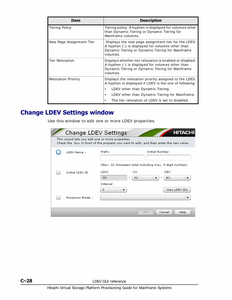
Hitachi Virtual Storage Platform Provisioning Guide for Mainframe Systems
C–28 LDEV GUI reference
Change LDEV Settings windowUse this window to edit one or more LDEV properties.
Tiering Policy Tiering policy. A hyphen is displayed for volumes other than Dynamic Tiering or Dynamic Tiering for Mainframe volumes.
New Page Assignment Tier Displays the new page assignment tier for the LDEV. A hyphen (-) is displayed for volumes other than Dynamic Tiering or Dynamic Tiering for Mainframe volumes.
Tier Relocation Displays whether tier relocation is enabled or disabled. A hyphen (-) is displayed for volumes other than Dynamic Tiering or Dynamic Tiering for Mainframe volumes.
Relocation Priority Displays the relocation priority assigned to the LDEV. A hyphen is displayed if LDEV is the one of following:
• LDEV other than Dynamic Tiering.
• LDEV other than Dynamic Tiering for Mainframe.
• The tier relocation of LDEV is set to disabled.
Item Description

LDEV GUI reference C–29Hitachi Virtual Storage Platform Provisioning Guide for Mainframe Systems
View SSIDs windowUse this window to view storage system identifier information.
Item Description
LDEV Name Specify the LDEV name, using up to 32 characters.
Prefix: Fixed character string.
Initial Number: Initial number.
Specify the prefix character and the initial number according to these rules.
• 1: Up to 9 numbers are added (1, 2, 3 ... 9)
• 08: Up to 92 numbers are added (08, 09, 10 ... 99)
• 23: Up to 77 numbers are added (23, 24, 25 ... 99)
• 098: Up to 902 numbers are added (098, 099, 100 ... 999)
Initial LDEV ID Specify the LDEV identifier, which is the combination of LDKC, CU, and LDEV. Assigns the ID at a certain interval starting with the ID you specify.
LDKC Specify the LDKC number. It is fixed to 00.
CU Specify the CU number.
DEV Specify the LDEV number.
Interval Specify the interval of the assigned LDEV ID.
View LDEV IDs Opens the View LDEV IDs window.
Processor Blade Select the processor blade you want to assign to the LDEV.
Select any ID or Auto.
Select an ID from MPB0 to MPB7. If automatic assignment is enabled for one or more processors, you can also select Auto.
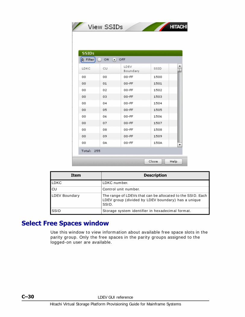
Hitachi Virtual Storage Platform Provisioning Guide for Mainframe Systems
C–30 LDEV GUI reference
Select Free Spaces windowUse this window to view information about available free space slots in the parity group. Only the free spaces in the parity groups assigned to the logged-on user are available.
Item Description
LDKC LDKC number.
CU Control unit number.
LDEV Boundary The range of LDEVs that can be allocated to the SSID. Each LDEV group (divided by LDEV boundary) has a unique SSID.
SSID Storage system identifier in hexadecimal format.
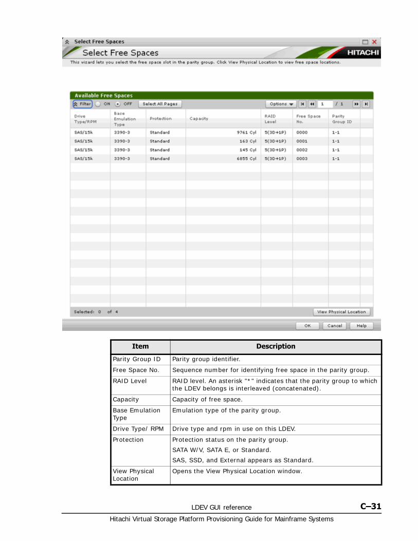
LDEV GUI reference C–31Hitachi Virtual Storage Platform Provisioning Guide for Mainframe Systems
Item Description
Parity Group ID Parity group identifier.
Free Space No. Sequence number for identifying free space in the parity group.
RAID Level RAID level. An asterisk "*" indicates that the parity group to which the LDEV belongs is interleaved (concatenated).
Capacity Capacity of free space.
Base Emulation Type
Emulation type of the parity group.
Drive Type/ RPM Drive type and rpm in use on this LDEV.
Protection Protection status on the parity group.
SATA W/V, SATA E, or Standard.
SAS, SSD, and External appears as Standard.
View Physical Location
Opens the View Physical Location window.
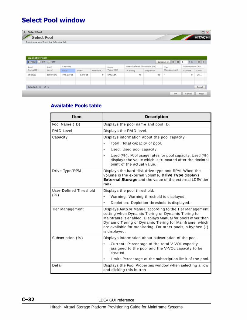
Hitachi Virtual Storage Platform Provisioning Guide for Mainframe Systems
C–32 LDEV GUI reference
Select Pool window
Available Pools table
Item Description
Pool Name (ID) Displays the pool name and pool ID.
RAID Level Displays the RAID level.
Capacity Displays information about the pool capacity.
• Total: Total capacity of pool.
• Used: Used pool capacity.
• Used (%): Pool usage rates for pool capacity. Used (%) displays the value which is truncated after the decimal point of the actual value.
Drive Type/RPM Displays the hard disk drive type and RPM. When the volume is the external volume, Drive Type displays External Storage and the value of the external LDEV tier rank.
User-Defined Threshold (%)
Displays the pool threshold.
• Warning: Warning threshold is displayed.
• Depletion: Depletion threshold is displayed.
Tier Management Displays Auto or Manual according to the Tier Management setting when Dynamic Tiering or Dynamic Tiering for Mainframe is enabled. Displays Manual for pools other than Dynamic Tiering or Dynamic Tiering for Mainframe which are available for monitoring. For other pools, a hyphen (-) is displayed.
Subscription (%) Displays information about subscription of the pool.
• Current: Percentage of the total V-VOL capacity assigned to the pool and the V-VOL capacity to be created.
• Limit: Percentage of the subscription limit of the pool.
Detail Displays the Pool Properties window when selecting a row and clicking this button
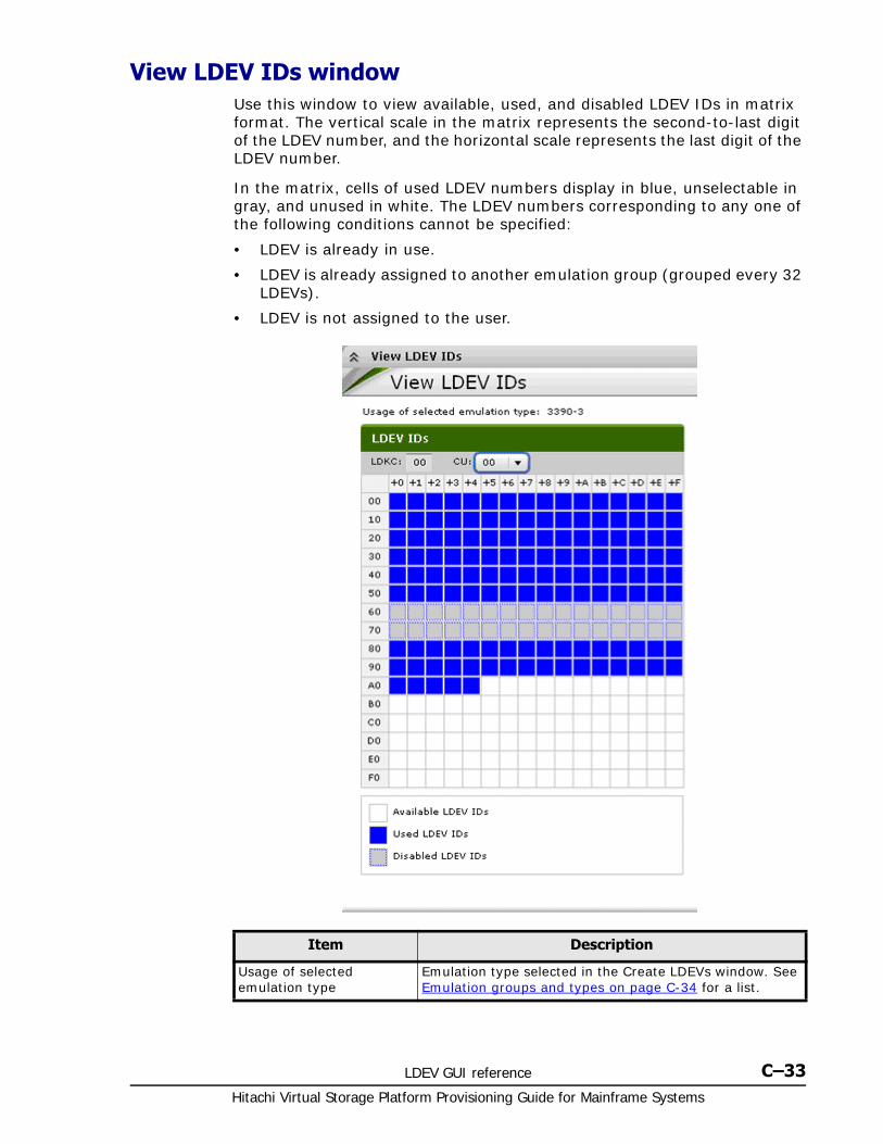
LDEV GUI reference C–33Hitachi Virtual Storage Platform Provisioning Guide for Mainframe Systems
View LDEV IDs windowUse this window to view available, used, and disabled LDEV IDs in matrix format. The vertical scale in the matrix represents the second-to-last digit of the LDEV number, and the horizontal scale represents the last digit of the LDEV number.
In the matrix, cells of used LDEV numbers display in blue, unselectable in gray, and unused in white. The LDEV numbers corresponding to any one of the following conditions cannot be specified:
• LDEV is already in use.
• LDEV is already assigned to another emulation group (grouped every 32 LDEVs).
• LDEV is not assigned to the user.
Item Description
Usage of selected emulation type
Emulation type selected in the Create LDEVs window. See Emulation groups and types on page C-34 for a list.
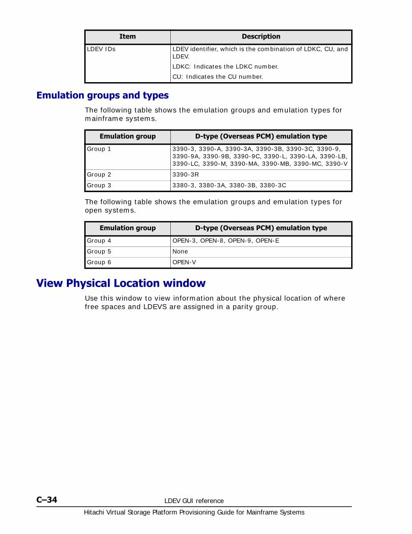
Hitachi Virtual Storage Platform Provisioning Guide for Mainframe Systems
C–34 LDEV GUI reference
Emulation groups and typesThe following table shows the emulation groups and emulation types for mainframe systems.
The following table shows the emulation groups and emulation types for open systems.
View Physical Location windowUse this window to view information about the physical location of where free spaces and LDEVS are assigned in a parity group.
LDEV IDs LDEV identifier, which is the combination of LDKC, CU, and LDEV.
LDKC: Indicates the LDKC number.
CU: Indicates the CU number.
Item Description
Emulation group D-type (Overseas PCM) emulation type
Group 1 3390-3, 3390-A, 3390-3A, 3390-3B, 3390-3C, 3390-9, 3390-9A, 3390-9B, 3390-9C, 3390-L, 3390-LA, 3390-LB, 3390-LC, 3390-M, 3390-MA, 3390-MB, 3390-MC, 3390-V
Group 2 3390-3R
Group 3 3380-3, 3380-3A, 3380-3B, 3380-3C
Emulation group D-type (Overseas PCM) emulation type
Group 4 OPEN-3, OPEN-8, OPEN-9, OPEN-E
Group 5 None
Group 6 OPEN-V
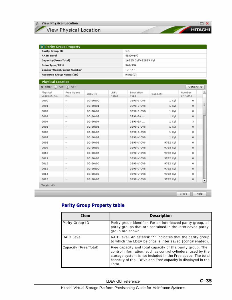
LDEV GUI reference C–35Hitachi Virtual Storage Platform Provisioning Guide for Mainframe Systems
Parity Group Property table
Item Description
Parity Group ID Parity group identifier. For an interleaved parity group, all parity groups that are contained in the interleaved parity group are shown.
RAID Level RAID level. An asterisk "*" indicates that the parity group to which the LDEV belongs is interleaved (concatenated).
Capacity (Free/Total) Free capacity and total capacity of the parity group. The control information, such as control cylinders, used by the storage system is not included in the Free space. The total capacity of the LDEVs and Free capacity is displayed in the Total.

Hitachi Virtual Storage Platform Provisioning Guide for Mainframe Systems
C–36 LDEV GUI reference
Physical Location table
Edit SSIDs windowUse this window to select a storage system identifier whose properties can be changed.
Drive Type/ RPM Drive type and rpm in use on this LDEV.
Vendor/Model/Serial Number
For external volumes, vendor name, model name, and serial number appear. For internal volumes, -/-/- appears.
Resource Group Name (ID) Resource group name and ID of which this parity group is a member.
Item Description
Item Description
Physical Location No. Location where the free spaces and LDEVs are assigned.
Free Space No. Free space number. The hyphenation appears for volumes other than free spaces.
LDEV ID LDEV identifier. A hyphen (-) appears for other than LDEV IDs.
LDEV Name LDEV name. A hyphen (-) appears for volumes other than LDEVs.
Emulation Type Emulation type. A hyphen (-) appears for volumes other than LDEVs.
Capacity Capacity of the LDEV.
Number of Paths Number of paths set for the LDEV. A hyphen (-) appears for volumes other than LDEVs.
Item Description
LDKC LDKC number.
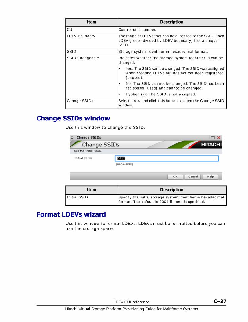
LDEV GUI reference C–37Hitachi Virtual Storage Platform Provisioning Guide for Mainframe Systems
Change SSIDs windowUse this window to change the SSID.
Format LDEVs wizardUse this window to format LDEVs. LDEVs must be formatted before you can use the storage space.
CU Control unit number.
LDEV Boundary The range of LDEVs that can be allocated to the SSID. Each LDEV group (divided by LDEV boundary) has a unique SSID.
SSID Storage system identifier in hexadecimal format.
SSID Changeable Indicates whether the storage system identifier is can be changed.
• Yes: The SSID can be changed. The SSID was assigned when creating LDEVs but has not yet been registered (unused).
• No: The SSID can not be changed. The SSID has been registered (used) and cannot be changed.
• Hyphen (-): The SSID is not assigned.
Change SSIDs Select a row and click this button to open the Change SSID window.
Item Description
Item Description
Initial SSID Specify the initial storage system identifier in hexadecimal format. The default is 0004 if none is specified.
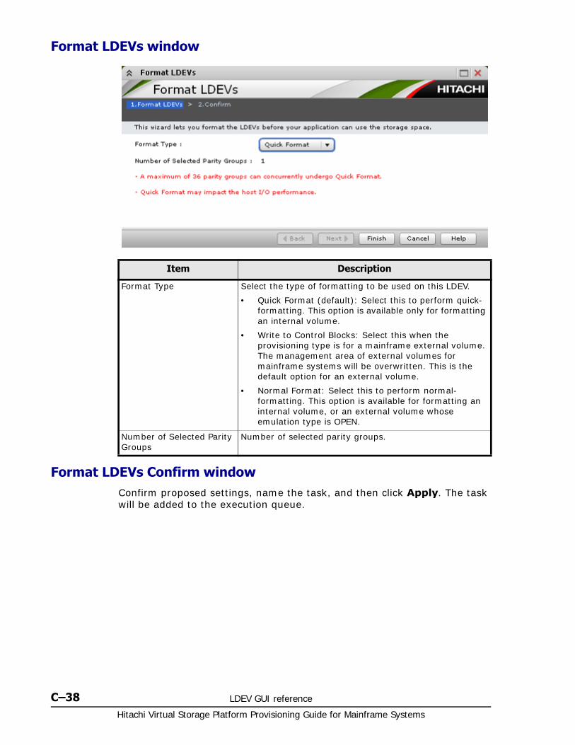
Hitachi Virtual Storage Platform Provisioning Guide for Mainframe Systems
C–38 LDEV GUI reference
Format LDEVs window
Format LDEVs Confirm windowConfirm proposed settings, name the task, and then click Apply. The task will be added to the execution queue.
Item Description
Format Type Select the type of formatting to be used on this LDEV.
• Quick Format (default): Select this to perform quick-formatting. This option is available only for formatting an internal volume.
• Write to Control Blocks: Select this when the provisioning type is for a mainframe external volume. The management area of external volumes for mainframe systems will be overwritten. This is the default option for an external volume.
• Normal Format: Select this to perform normal-formatting. This option is available for formatting an internal volume, or an external volume whose emulation type is OPEN.
Number of Selected Parity Groups
Number of selected parity groups.
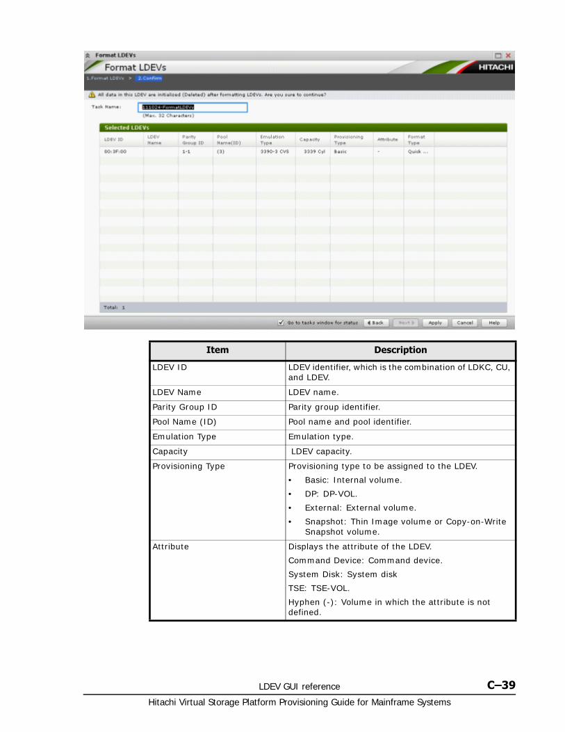
LDEV GUI reference C–39Hitachi Virtual Storage Platform Provisioning Guide for Mainframe Systems
Item Description
LDEV ID LDEV identifier, which is the combination of LDKC, CU, and LDEV.
LDEV Name LDEV name.
Parity Group ID Parity group identifier.
Pool Name (ID) Pool name and pool identifier.
Emulation Type Emulation type.
Capacity LDEV capacity.
Provisioning Type Provisioning type to be assigned to the LDEV.
• Basic: Internal volume.
• DP: DP-VOL.
• External: External volume.
• Snapshot: Thin Image volume or Copy-on-Write Snapshot volume.
Attribute Displays the attribute of the LDEV.
Command Device: Command device.
System Disk: System disk
TSE: TSE-VOL.
Hyphen (-): Volume in which the attribute is not defined.
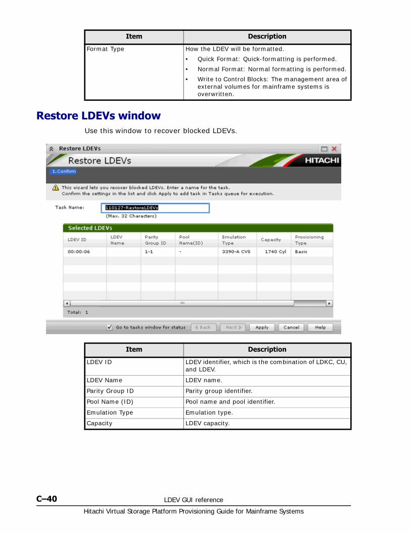
Hitachi Virtual Storage Platform Provisioning Guide for Mainframe Systems
C–40 LDEV GUI reference
Restore LDEVs windowUse this window to recover blocked LDEVs.
Format Type How the LDEV will be formatted.
• Quick Format: Quick-formatting is performed.
• Normal Format: Normal formatting is performed.
• Write to Control Blocks: The management area of external volumes for mainframe systems is overwritten.
Item Description
Item Description
LDEV ID LDEV identifier, which is the combination of LDKC, CU, and LDEV.
LDEV Name LDEV name.
Parity Group ID Parity group identifier.
Pool Name (ID) Pool name and pool identifier.
Emulation Type Emulation type.
Capacity LDEV capacity.
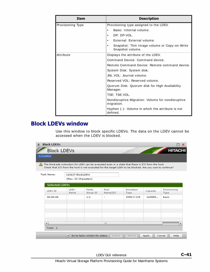
LDEV GUI reference C–41Hitachi Virtual Storage Platform Provisioning Guide for Mainframe Systems
Block LDEVs windowUse this window to block specific LDEVs. The data on the LDEV cannot be accessed when the LDEV is blocked.
Provisioning Type Provisioning type assigned to the LDEV.
• Basic: Internal volume.
• DP: DP-VOL.
• External: External volume.
• Snapshot: Thin Image volume or Copy-on-Write Snapshot volume.
Attribute Displays the attribute of the LDEV.
Command Device: Command device.
Remote Command Device: Remote command device.
System Disk: System disk.
JNL VOL: Journal volume.
Reserved VOL: Reserved volume.
Quorum Disk: Quorum disk for High Availability Manager.
TSE: TSE-VOL.
Nondisruptive Migration: Volume for nondisruptive migration.
Hyphen (-): Volume in which the attribute is not defined.
Item Description
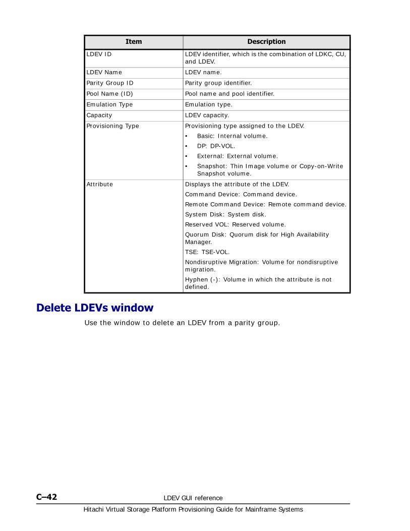
Hitachi Virtual Storage Platform Provisioning Guide for Mainframe Systems
C–42 LDEV GUI reference
Delete LDEVs windowUse the window to delete an LDEV from a parity group.
Item Description
LDEV ID LDEV identifier, which is the combination of LDKC, CU, and LDEV.
LDEV Name LDEV name.
Parity Group ID Parity group identifier.
Pool Name (ID) Pool name and pool identifier.
Emulation Type Emulation type.
Capacity LDEV capacity.
Provisioning Type Provisioning type assigned to the LDEV.
• Basic: Internal volume.
• DP: DP-VOL.
• External: External volume.
• Snapshot: Thin Image volume or Copy-on-Write Snapshot volume.
Attribute Displays the attribute of the LDEV.
Command Device: Command device.
Remote Command Device: Remote command device.
System Disk: System disk.
Reserved VOL: Reserved volume.
Quorum Disk: Quorum disk for High Availability Manager.
TSE: TSE-VOL.
Nondisruptive Migration: Volume for nondisruptive migration.
Hyphen (-): Volume in which the attribute is not defined.
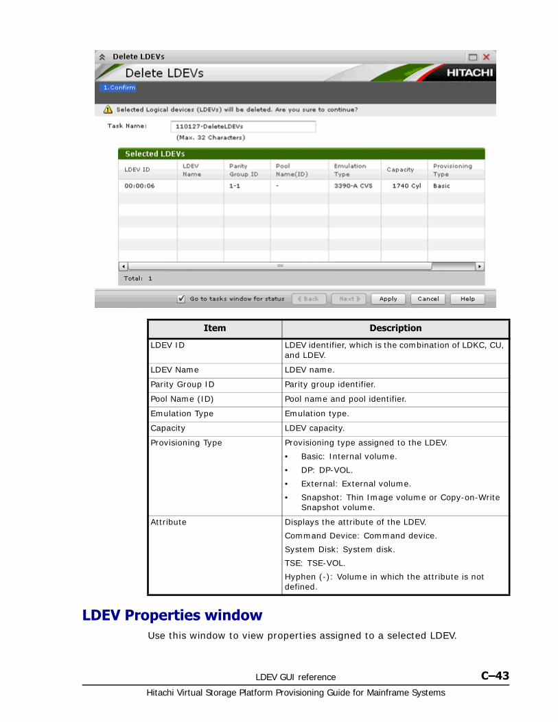
LDEV GUI reference C–43Hitachi Virtual Storage Platform Provisioning Guide for Mainframe Systems
LDEV Properties windowUse this window to view properties assigned to a selected LDEV.
Item Description
LDEV ID LDEV identifier, which is the combination of LDKC, CU, and LDEV.
LDEV Name LDEV name.
Parity Group ID Parity group identifier.
Pool Name (ID) Pool name and pool identifier.
Emulation Type Emulation type.
Capacity LDEV capacity.
Provisioning Type Provisioning type assigned to the LDEV.
• Basic: Internal volume.
• DP: DP-VOL.
• External: External volume.
• Snapshot: Thin Image volume or Copy-on-Write Snapshot volume.
Attribute Displays the attribute of the LDEV.
Command Device: Command device.
System Disk: System disk.
TSE: TSE-VOL.
Hyphen (-): Volume in which the attribute is not defined.

Hitachi Virtual Storage Platform Provisioning Guide for Mainframe Systems
C–44 LDEV GUI reference
• LDEV Properties table on page C-44
• Basic tab on page C-45
• Local Replication Tab on page C-47
LDEV Properties table
Item Description
LDEV ID LDEV identifier, which is the combination of LDKC, CU, and LDEV.
LDEV Name Displays the LDEV name.
Emulation Type Displays the emulation type.
Capacity Displays the LDEV capacity.
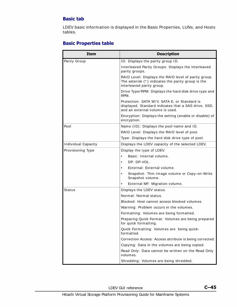
LDEV GUI reference C–45Hitachi Virtual Storage Platform Provisioning Guide for Mainframe Systems
Basic tab
LDEV basic information is displayed in the Basic Properties, LUNs, and Hosts tables.
Basic Properties table
Item Description
Parity Group ID: Displays the parity group ID.
Interleaved Parity Groups: Displays the interleaved parity groups.
RAID Level: Displays the RAID level of parity group. The asterisk (*) indicates the parity group is the interleaved parity group.
Drive Type/RPM: Displays the hard disk drive type and RPM.
Protection: SATA W/V, SATA E, or Standard is displayed. Standard indicates that a SAS drive, SSD, and an external volume is used.
Encryption: Displays the setting (enable or disable) of encryption.
Pool Name (ID): Displays the pool name and ID.
RAID Level: Displays the RAID level of pool.
Type: Displays the hard disk drive type of pool.
Individual Capacity Displays the LDEV capacity of the selected LDEV.
Provisioning Type Display the type of LDEV.
• Basic: Internal volume.
• DP: DP-VOL.
• External: External volume.
• Snapshot: Thin Image volume or Copy-on-Write Snapshot volume.
• External MF: Migration volume.
Status Displays the LDEV status.
Normal: Normal status.
Blocked: Host cannot access blocked volumes.
Warning: Problem occurs in the volumes.
Formatting: Volumes are being formatted.
Preparing Quick Format: Volumes are being prepared for quick formatting.
Quick Formatting: Volumes are being quick-formatted.
Correction Access: Access attribute is being corrected.
Copying: Data in the volumes are being copied.
Read Only: Data cannot be written on the Read Only volumes.
Shredding: Volumes are being shredded.
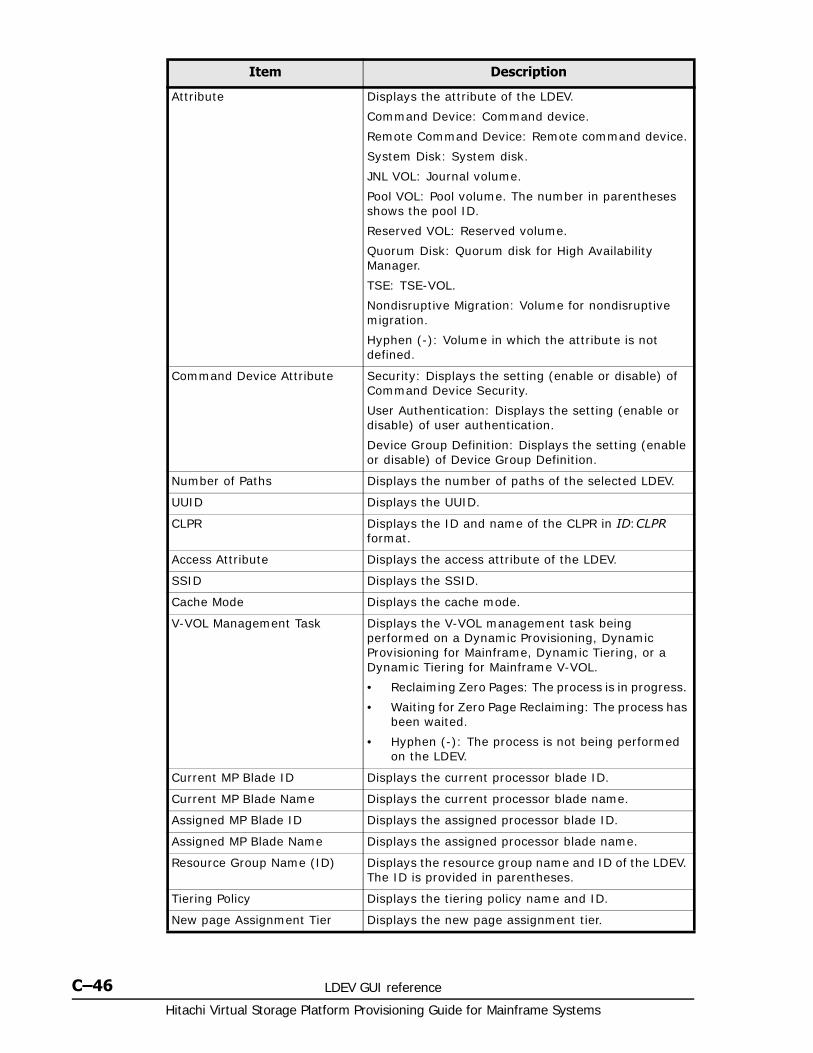
Hitachi Virtual Storage Platform Provisioning Guide for Mainframe Systems
C–46 LDEV GUI reference
Attribute Displays the attribute of the LDEV.
Command Device: Command device.
Remote Command Device: Remote command device.
System Disk: System disk.
JNL VOL: Journal volume.
Pool VOL: Pool volume. The number in parentheses shows the pool ID.
Reserved VOL: Reserved volume.
Quorum Disk: Quorum disk for High Availability Manager.
TSE: TSE-VOL.
Nondisruptive Migration: Volume for nondisruptive migration.
Hyphen (-): Volume in which the attribute is not defined.
Command Device Attribute Security: Displays the setting (enable or disable) of Command Device Security.
User Authentication: Displays the setting (enable or disable) of user authentication.
Device Group Definition: Displays the setting (enable or disable) of Device Group Definition.
Number of Paths Displays the number of paths of the selected LDEV.
UUID Displays the UUID.
CLPR Displays the ID and name of the CLPR in ID:CLPR format.
Access Attribute Displays the access attribute of the LDEV.
SSID Displays the SSID.
Cache Mode Displays the cache mode.
V-VOL Management Task Displays the V-VOL management task being performed on a Dynamic Provisioning, Dynamic Provisioning for Mainframe, Dynamic Tiering, or a Dynamic Tiering for Mainframe V-VOL.
• Reclaiming Zero Pages: The process is in progress.
• Waiting for Zero Page Reclaiming: The process has been waited.
• Hyphen (-): The process is not being performed on the LDEV.
Current MP Blade ID Displays the current processor blade ID.
Current MP Blade Name Displays the current processor blade name.
Assigned MP Blade ID Displays the assigned processor blade ID.
Assigned MP Blade Name Displays the assigned processor blade name.
Resource Group Name (ID) Displays the resource group name and ID of the LDEV. The ID is provided in parentheses.
Tiering Policy Displays the tiering policy name and ID.
New page Assignment Tier Displays the new page assignment tier.
Item Description
LDEV GUI reference C–47Hitachi Virtual Storage Platform Provisioning Guide for Mainframe Systems
LUNs table
This table is not displayed if the path is not set.
Hosts table
This table provides information about the host that can view LDEVs. This table is not available if the WWN is not registered in the host to which the path is set.
Local Replication Tab
Information about the volume of the local replication pair is displayed in the Replication Properties, and Pairs tables.
For details about each item, see Hitachi ShadowImage® User Guide, Hitachi ShadowImage® for Mainframe User Guide, Hitachi Thin Image User Guide, Hitachi Copy-on-Write Snapshot User Guide, or Hitachi Compatible FlashCopy® User Guide.
Replication Properties table
Tier Relocation Displays the tier relocation setting.
Relocation Priority Displays the relocation priority setting.
Item Description
Item Description
Port ID Port name.
Host Group Name Host group name.
LUN ID Identifier of the logical unit.
Item Description
HBA WWN WWN of the host that can view LDEVs.
Host Name Host name.
Item Description
ShadowImage L1 Displays the status of the ShadowImage L1 pair.
ShadowImage L2 Displays the status of the ShadowImage L2 pair.
COW Snapshot Displays the status of the Copy-on-Write Snapshot pair.
Thin Image Displays the status of the Thin Image pair.
ShadowImage for Mainframe Displays the status of the ShadowImage for Mainframe pair.
Compatible FlashCopy® V2 Displays the status of the Compatible FlashCopy® V2 relationship.
Compatible Software for IBM® FlashCopy® SE
Displays the status of the Compatible Software for IBM® FlashCopy® SE relationship.
Hitachi Virtual Storage Platform Provisioning Guide for Mainframe Systems
C–48 LDEV GUI reference
Pairs table
Top window when selecting ComponentsUse this window to view information about the controller chassis components in the storage system.
Reserve Volume If the volume is the reserved volume for the pair, Yes is displayed. If the volume other than the reserved volume is specified, No is displayed.
Item Description
Item Description
Primary Volume Displays LDEV ID, LDEV Name, Emulation type, Capacity, CLPR ID, and CLPR name of the primary volume.
Copy Type Displays the copy type of the pair.
Snapshot group Displays the snapshot group name
Status Displays the pair status.
Secondary Volume Displays LDEV ID, LDEV Name, Emulation type, Capacity, CLPR ID, and CLPR name of the secondary volume.
Snapshot Date A hyphen (-) is displayed.
Pool Name(ID) A hyphen (-) is displayed.
Copy Pace Displays the pace of copying of the pair.
CTG ID Displays the consistency group number of the pair.
Mirror Unit Displays the mirror unit number of the pair.
Detail Displays the View Pair Properties.
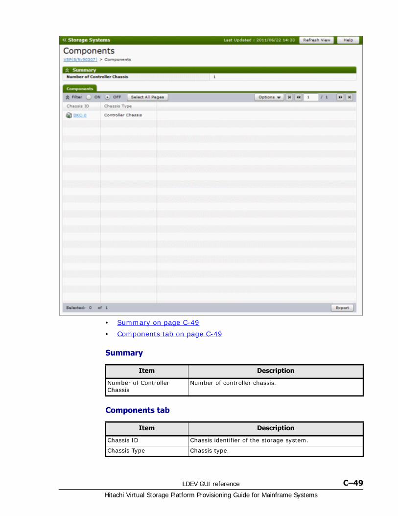
LDEV GUI reference C–49Hitachi Virtual Storage Platform Provisioning Guide for Mainframe Systems
• Summary on page C-49
• Components tab on page C-49
Summary
Components tab
Item Description
Number of Controller Chassis
Number of controller chassis.
Item Description
Chassis ID Chassis identifier of the storage system.
Chassis Type Chassis type.
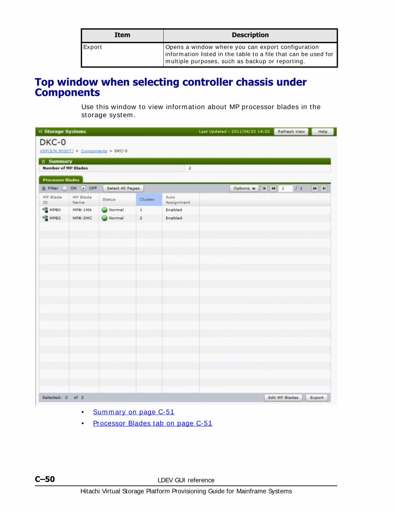
Hitachi Virtual Storage Platform Provisioning Guide for Mainframe Systems
C–50 LDEV GUI reference
Top window when selecting controller chassis under Components
Use this window to view information about MP processor blades in the storage system.
• Summary on page C-51
• Processor Blades tab on page C-51
Export Opens a window where you can export configuration information listed in the table to a file that can be used for multiple purposes, such as backup or reporting.
Item Description
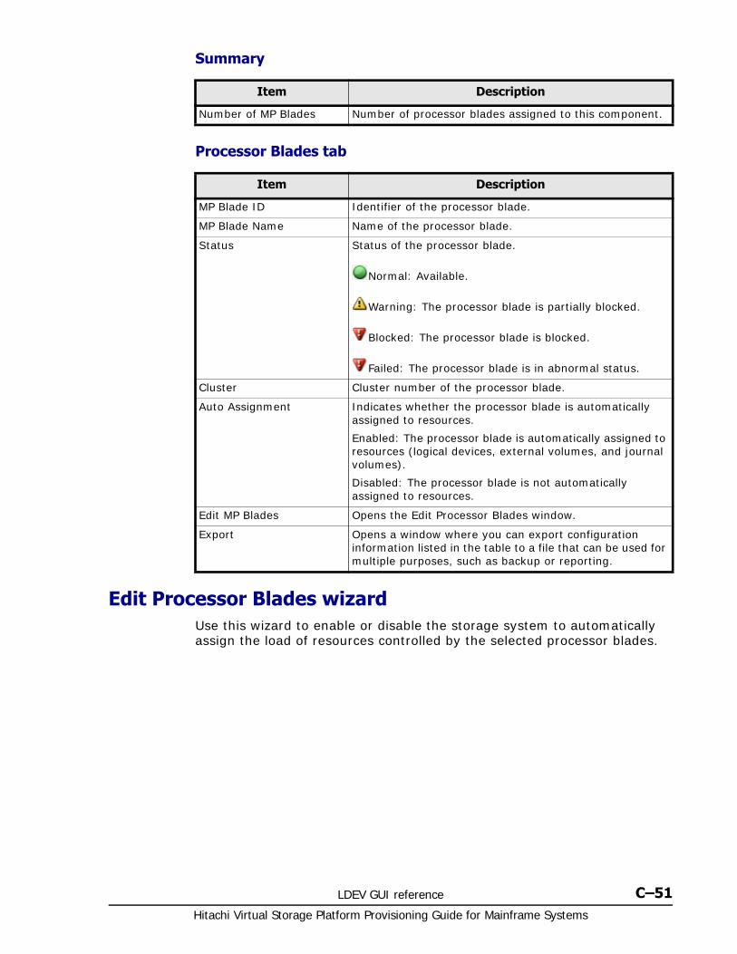
LDEV GUI reference C–51Hitachi Virtual Storage Platform Provisioning Guide for Mainframe Systems
Summary
Processor Blades tab
Edit Processor Blades wizardUse this wizard to enable or disable the storage system to automatically assign the load of resources controlled by the selected processor blades.
Item Description
Number of MP Blades Number of processor blades assigned to this component.
Item Description
MP Blade ID Identifier of the processor blade.
MP Blade Name Name of the processor blade.
Status Status of the processor blade.
Normal: Available.
Warning: The processor blade is partially blocked.
Blocked: The processor blade is blocked.
Failed: The processor blade is in abnormal status.
Cluster Cluster number of the processor blade.
Auto Assignment Indicates whether the processor blade is automatically assigned to resources.
Enabled: The processor blade is automatically assigned to resources (logical devices, external volumes, and journal volumes).
Disabled: The processor blade is not automatically assigned to resources.
Edit MP Blades Opens the Edit Processor Blades window.
Export Opens a window where you can export configuration information listed in the table to a file that can be used for multiple purposes, such as backup or reporting.
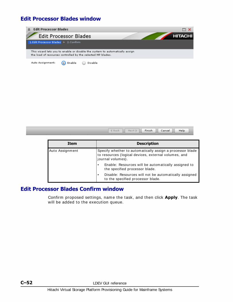
Hitachi Virtual Storage Platform Provisioning Guide for Mainframe Systems
C–52 LDEV GUI reference
Edit Processor Blades window
Edit Processor Blades Confirm windowConfirm proposed settings, name the task, and then click Apply. The task will be added to the execution queue.
Item Description
Auto Assignment Specify whether to automatically assign a processor blade to resources (logical devices, external volumes, and journal volumes).
• Enable: Resources will be automatically assigned to the specified processor blade.
• Disable: Resources will not be automatically assigned to the specified processor blade.
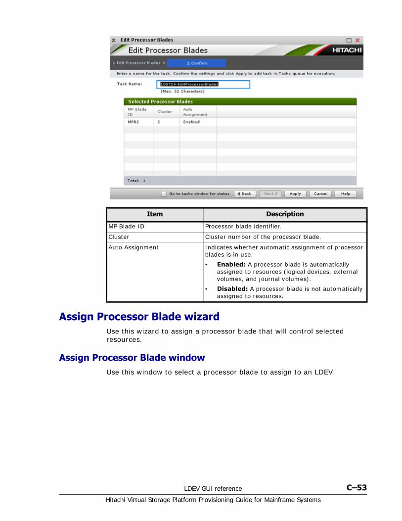
LDEV GUI reference C–53Hitachi Virtual Storage Platform Provisioning Guide for Mainframe Systems
Assign Processor Blade wizardUse this wizard to assign a processor blade that will control selected resources.
Assign Processor Blade windowUse this window to select a processor blade to assign to an LDEV.
Item Description
MP Blade ID Processor blade identifier.
Cluster Cluster number of the processor blade.
Auto Assignment Indicates whether automatic assignment of processor blades is in use.
• Enabled: A processor blade is automatically assigned to resources (logical devices, external volumes, and journal volumes).
• Disabled: A processor blade is not automatically assigned to resources.
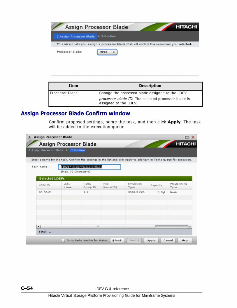
Hitachi Virtual Storage Platform Provisioning Guide for Mainframe Systems
C–54 LDEV GUI reference
Assign Processor Blade Confirm windowConfirm proposed settings, name the task, and then click Apply. The task will be added to the execution queue.
Item Description
Processor Blade Change the processor blade assigned to the LDEV.
processor blade ID: The selected processor blade is assigned to the LDEV.
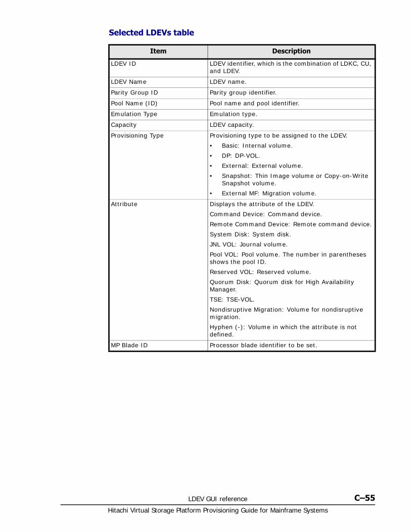
LDEV GUI reference C–55Hitachi Virtual Storage Platform Provisioning Guide for Mainframe Systems
Selected LDEVs table
Item Description
LDEV ID LDEV identifier, which is the combination of LDKC, CU, and LDEV.
LDEV Name LDEV name.
Parity Group ID Parity group identifier.
Pool Name (ID) Pool name and pool identifier.
Emulation Type Emulation type.
Capacity LDEV capacity.
Provisioning Type Provisioning type to be assigned to the LDEV.
• Basic: Internal volume.
• DP: DP-VOL.
• External: External volume.
• Snapshot: Thin Image volume or Copy-on-Write Snapshot volume.
• External MF: Migration volume.
Attribute Displays the attribute of the LDEV.
Command Device: Command device.
Remote Command Device: Remote command device.
System Disk: System disk.
JNL VOL: Journal volume.
Pool VOL: Pool volume. The number in parentheses shows the pool ID.
Reserved VOL: Reserved volume.
Quorum Disk: Quorum disk for High Availability Manager.
TSE: TSE-VOL.
Nondisruptive Migration: Volume for nondisruptive migration.
Hyphen (-): Volume in which the attribute is not defined.
MP Blade ID Processor blade identifier to be set.
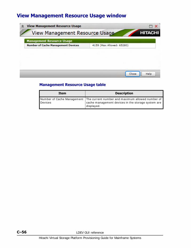
Hitachi Virtual Storage Platform Provisioning Guide for Mainframe Systems
C–56 LDEV GUI reference
View Management Resource Usage window
Management Resource Usage table
Item Description
Number of Cache Management Devices
The current number and maximum allowed number of cache management devices in the storage system are displayed.

D
Dynamic Provisioning for Mainframe and Dynamic Tiering for Mainframe GUI reference D–1
Hitachi Virtual Storage Platform Provisioning Guide for Mainframe Systems
Dynamic Provisioning for Mainframeand Dynamic Tiering for Mainframe
GUI reference
The Dynamic Provisioning for Mainframe and Dynamic Tiering for Mainframe windows, wizards, and dialog boxes are described in the following topics.
For information about common Storage Navigator operations such as using navigation buttons and creating tasks, see the Hitachi Storage Navigator User Guide.
□ Pools window after selecting pool (Pools window)
□ Top window when selecting a pool under Pools
□ Create Pools wizard
□ Expand Pool wizard
□ Edit Pools wizard
□ Delete Pools wizard
□ Expand V-VOLs wizard
□ Restore Pools window
□ Shrink Pool window
□ Stop Shrinking Pools window
□ Complete SIMs window
Hitachi Virtual Storage Platform Provisioning Guide for Mainframe Systems
D–2Dynamic Provisioning for Mainframe and Dynamic Tiering for Mainframe GUI
reference
□ Select Pool VOLs window
□ Reclaim Zero Pages window
□ Stop Reclaiming Zero Pages window
□ Pool Property window
□ View Tier Properties window
□ Monitor Pools window
□ Stop Monitoring Pools window
□ Start Tier Relocation window
□ Stop Tier Relocation window
□ View Pool Management Status window
□ Edit External LDEV Tier Rank wizard
□ Edit Tiering Policies wizard
□ Change Tiering Policy Window

Dynamic Provisioning for Mainframe and Dynamic Tiering for Mainframe GUI reference D–3
Hitachi Virtual Storage Platform Provisioning Guide for Mainframe Systems
Pools window after selecting pool (Pools window)
• Summary on page D-4
• Pools tab on page D-5
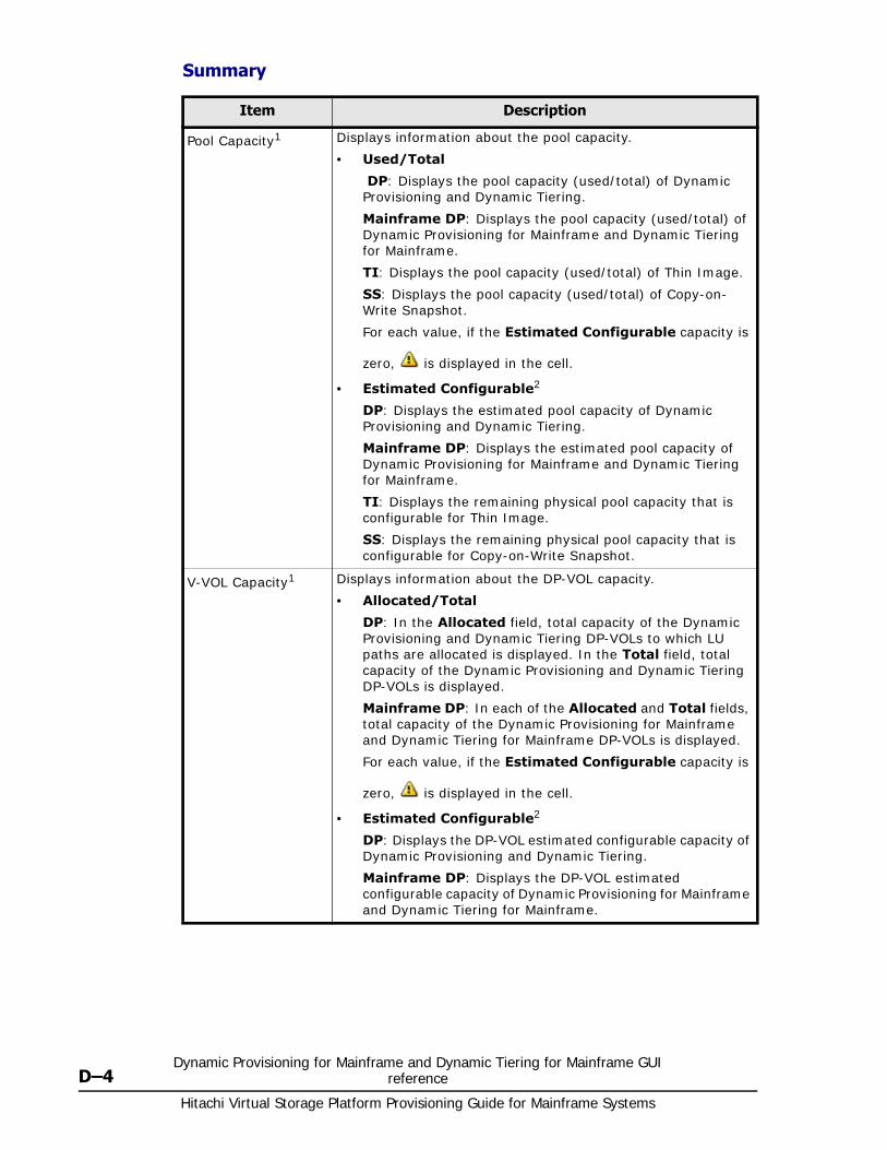
Hitachi Virtual Storage Platform Provisioning Guide for Mainframe Systems
D–4Dynamic Provisioning for Mainframe and Dynamic Tiering for Mainframe GUI
reference
Summary
Item Description
Pool Capacity1 Displays information about the pool capacity.
• Used/Total
DP: Displays the pool capacity (used/total) of Dynamic Provisioning and Dynamic Tiering.
Mainframe DP: Displays the pool capacity (used/total) of Dynamic Provisioning for Mainframe and Dynamic Tiering for Mainframe.
TI: Displays the pool capacity (used/total) of Thin Image.
SS: Displays the pool capacity (used/total) of Copy-on-Write Snapshot.
For each value, if the Estimated Configurable capacity is
zero, is displayed in the cell.
• Estimated Configurable2
DP: Displays the estimated pool capacity of Dynamic Provisioning and Dynamic Tiering.
Mainframe DP: Displays the estimated pool capacity of Dynamic Provisioning for Mainframe and Dynamic Tiering for Mainframe.
TI: Displays the remaining physical pool capacity that is configurable for Thin Image.
SS: Displays the remaining physical pool capacity that is configurable for Copy-on-Write Snapshot.
V-VOL Capacity1 Displays information about the DP-VOL capacity.
• Allocated/Total
DP: In the Allocated field, total capacity of the Dynamic Provisioning and Dynamic Tiering DP-VOLs to which LU paths are allocated is displayed. In the Total field, total capacity of the Dynamic Provisioning and Dynamic Tiering DP-VOLs is displayed.
Mainframe DP: In each of the Allocated and Total fields, total capacity of the Dynamic Provisioning for Mainframe and Dynamic Tiering for Mainframe DP-VOLs is displayed.
For each value, if the Estimated Configurable capacity is
zero, is displayed in the cell.
• Estimated Configurable2
DP: Displays the DP-VOL estimated configurable capacity of Dynamic Provisioning and Dynamic Tiering.
Mainframe DP: Displays the DP-VOL estimated configurable capacity of Dynamic Provisioning for Mainframe and Dynamic Tiering for Mainframe.
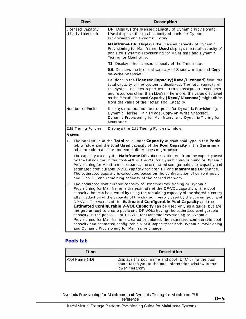
Dynamic Provisioning for Mainframe and Dynamic Tiering for Mainframe GUI reference D–5
Hitachi Virtual Storage Platform Provisioning Guide for Mainframe Systems
Pools tab
Licensed Capacity (Used / Licensed)
DP: Displays the licensed capacity of Dynamic Provisioning. Used displays the total capacity of pools for Dynamic Provisioning and Dynamic Tiering,
Mainframe DP: Displays the licensed capacity of Dynamic Provisioning for Mainframe. Used displays the total capacity of pools for Dynamic Provisioning for Mainframe and Dynamic Tiering for Mainframe.
TI: Displays the licensed capacity of the Thin Image.
SS: Displays the licensed capacity of ShadowImage and Copy-on-Write Snapshot.
Caution: In the Licensed Capacity(Used/Licensed) field, the total capacity of the system is displayed. The total capacity of the system includes capacities of LDEVs assigned to each user and resources other than LDEVs. Therefore, the value displayed as the "Used" Licensed Capacity (Used/ Licensed) might differ from the value of the "Total" Pool Capacity.
Number of Pools Displays the total number of pools for Dynamic Provisioning, Dynamic Tiering, Thin Image, Copy-on-Write Snapshot, Dynamic Provisioning for Mainframe, and Dynamic Tiering for Mainframe.
Edit Tiering Policies Displays the Edit Tiering Policies window.
Notes:
1. The total value of the Total cells under Capacity of each pool type in the Pools tab window and the total Used capacity of the Pool Capacity in the Summary table are almost same, but small differences might occur.
The capacity used by the Mainframe DP volume is different from the capacity used by the DP volume. If the pool-VOL or DP-VOL for Dynamic Provisioning or Dynamic Provisioning for Mainframe is created, the estimated configurable pool capacity and estimated configurable V-VOL capacity for both DP and Mainframe DP change. The estimated capacity is calculated based on the configuration of current pools and DP-VOL, and remaining capacity of the shared memory.
2. The estimated configurable capacity of Dynamic Provisioning or Dynamic Provisioning for Mainframe is the estimate of the DP-VOL capacity or the pool capacity that can be created by using the remaining capacity of the shared memory after deduction of the capacity of the shared memory used by the current pool and DP-VOL. The values of the Estimated Configurable Pool Capacity and the Estimated Configurable V-VOL Capacity can be used only as a guide, but are not guaranteed to create pools and DP-VOLs having the estimated configurable capacity. If the pool-VOL or DP-VOL for Dynamic Provisioning or Dynamic Provisioning for Mainframe is created or deleted, the estimated configurable pool capacity and estimated configurable V-VOL capacity for both Dynamic Provisioning and Dynamic Provisioning for Mainframe change.
Item Description
Item Description
Pool Name (ID) Displays the pool name and pool ID. Clicking the pool name takes you to the pool information window in the lower hierarchy.
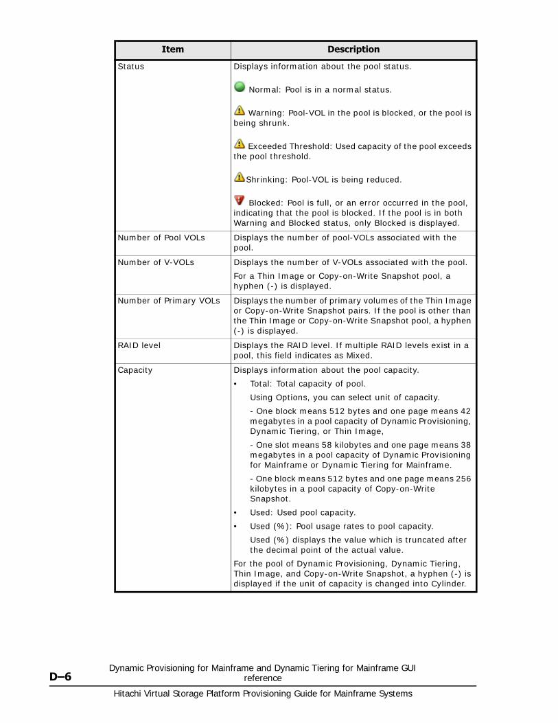
Hitachi Virtual Storage Platform Provisioning Guide for Mainframe Systems
D–6Dynamic Provisioning for Mainframe and Dynamic Tiering for Mainframe GUI
reference
Status Displays information about the pool status.
Normal: Pool is in a normal status.
Warning: Pool-VOL in the pool is blocked, or the pool is being shrunk.
Exceeded Threshold: Used capacity of the pool exceeds the pool threshold.
Shrinking: Pool-VOL is being reduced.
Blocked: Pool is full, or an error occurred in the pool, indicating that the pool is blocked. If the pool is in both Warning and Blocked status, only Blocked is displayed.
Number of Pool VOLs Displays the number of pool-VOLs associated with the pool.
Number of V-VOLs Displays the number of V-VOLs associated with the pool.
For a Thin Image or Copy-on-Write Snapshot pool, a hyphen (-) is displayed.
Number of Primary VOLs Displays the number of primary volumes of the Thin Image or Copy-on-Write Snapshot pairs. If the pool is other than the Thin Image or Copy-on-Write Snapshot pool, a hyphen (-) is displayed.
RAID level Displays the RAID level. If multiple RAID levels exist in a pool, this field indicates as Mixed.
Capacity Displays information about the pool capacity.
• Total: Total capacity of pool.
Using Options, you can select unit of capacity.
- One block means 512 bytes and one page means 42 megabytes in a pool capacity of Dynamic Provisioning, Dynamic Tiering, or Thin Image,
- One slot means 58 kilobytes and one page means 38 megabytes in a pool capacity of Dynamic Provisioning for Mainframe or Dynamic Tiering for Mainframe.
- One block means 512 bytes and one page means 256 kilobytes in a pool capacity of Copy-on-Write Snapshot.
• Used: Used pool capacity.
• Used (%): Pool usage rates to pool capacity.
Used (%) displays the value which is truncated after the decimal point of the actual value.
For the pool of Dynamic Provisioning, Dynamic Tiering, Thin Image, and Copy-on-Write Snapshot, a hyphen (-) is displayed if the unit of capacity is changed into Cylinder.
Item Description
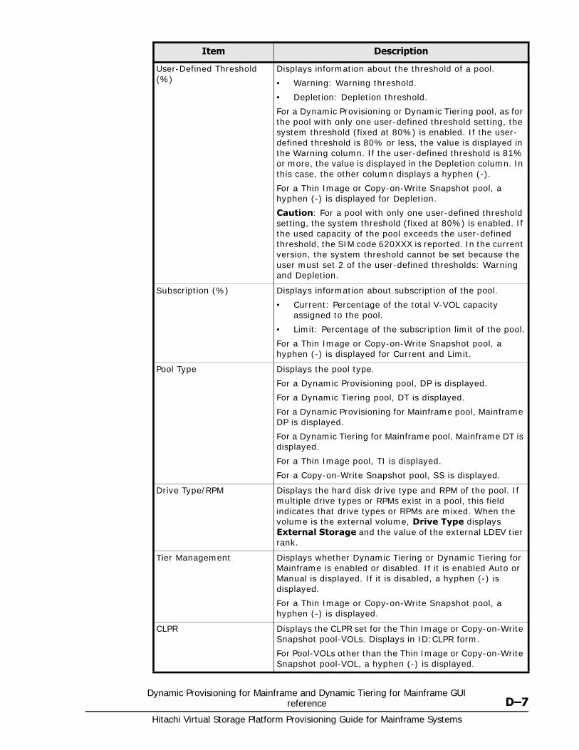
Dynamic Provisioning for Mainframe and Dynamic Tiering for Mainframe GUI reference D–7
Hitachi Virtual Storage Platform Provisioning Guide for Mainframe Systems
User-Defined Threshold (%)
Displays information about the threshold of a pool.
• Warning: Warning threshold.
• Depletion: Depletion threshold.
For a Dynamic Provisioning or Dynamic Tiering pool, as for the pool with only one user-defined threshold setting, the system threshold (fixed at 80%) is enabled. If the user-defined threshold is 80% or less, the value is displayed in the Warning column. If the user-defined threshold is 81% or more, the value is displayed in the Depletion column. In this case, the other column displays a hyphen (-).
For a Thin Image or Copy-on-Write Snapshot pool, a hyphen (-) is displayed for Depletion.
Caution: For a pool with only one user-defined threshold setting, the system threshold (fixed at 80%) is enabled. If the used capacity of the pool exceeds the user-defined threshold, the SIM code 620XXX is reported. In the current version, the system threshold cannot be set because the user must set 2 of the user-defined thresholds: Warning and Depletion.
Subscription (%) Displays information about subscription of the pool.
• Current: Percentage of the total V-VOL capacity assigned to the pool.
• Limit: Percentage of the subscription limit of the pool.
For a Thin Image or Copy-on-Write Snapshot pool, a hyphen (-) is displayed for Current and Limit.
Pool Type Displays the pool type.
For a Dynamic Provisioning pool, DP is displayed.
For a Dynamic Tiering pool, DT is displayed.
For a Dynamic Provisioning for Mainframe pool, Mainframe DP is displayed.
For a Dynamic Tiering for Mainframe pool, Mainframe DT is displayed.
For a Thin Image pool, TI is displayed.
For a Copy-on-Write Snapshot pool, SS is displayed.
Drive Type/RPM Displays the hard disk drive type and RPM of the pool. If multiple drive types or RPMs exist in a pool, this field indicates that drive types or RPMs are mixed. When the volume is the external volume, Drive Type displays External Storage and the value of the external LDEV tier rank.
Tier Management Displays whether Dynamic Tiering or Dynamic Tiering for Mainframe is enabled or disabled. If it is enabled Auto or Manual is displayed. If it is disabled, a hyphen (-) is displayed.
For a Thin Image or Copy-on-Write Snapshot pool, a hyphen (-) is displayed.
CLPR Displays the CLPR set for the Thin Image or Copy-on-Write Snapshot pool-VOLs. Displays in ID:CLPR form.
For Pool-VOLs other than the Thin Image or Copy-on-Write Snapshot pool-VOL, a hyphen (-) is displayed.
Item Description
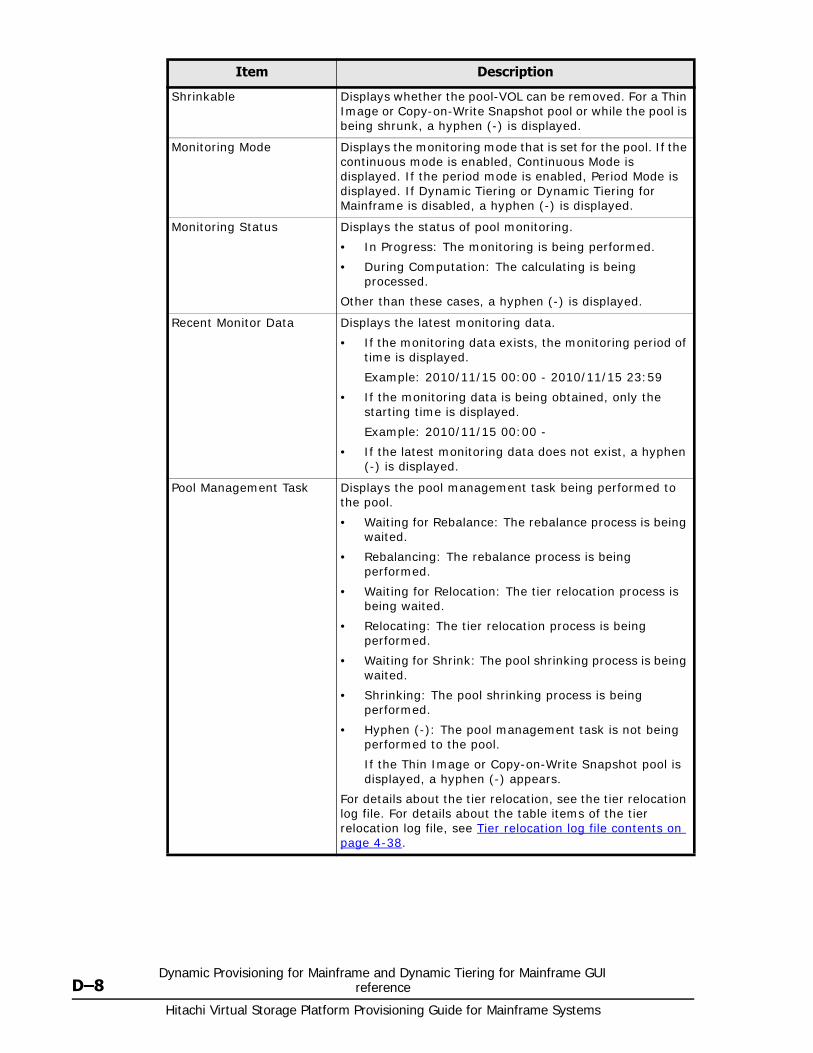
Hitachi Virtual Storage Platform Provisioning Guide for Mainframe Systems
D–8Dynamic Provisioning for Mainframe and Dynamic Tiering for Mainframe GUI
reference
Shrinkable Displays whether the pool-VOL can be removed. For a Thin Image or Copy-on-Write Snapshot pool or while the pool is being shrunk, a hyphen (-) is displayed.
Monitoring Mode Displays the monitoring mode that is set for the pool. If the continuous mode is enabled, Continuous Mode is displayed. If the period mode is enabled, Period Mode is displayed. If Dynamic Tiering or Dynamic Tiering for Mainframe is disabled, a hyphen (-) is displayed.
Monitoring Status Displays the status of pool monitoring.
• In Progress: The monitoring is being performed.
• During Computation: The calculating is being processed.
Other than these cases, a hyphen (-) is displayed.
Recent Monitor Data Displays the latest monitoring data.
• If the monitoring data exists, the monitoring period of time is displayed.
Example: 2010/11/15 00:00 - 2010/11/15 23:59
• If the monitoring data is being obtained, only the starting time is displayed.
Example: 2010/11/15 00:00 -
• If the latest monitoring data does not exist, a hyphen (-) is displayed.
Pool Management Task Displays the pool management task being performed to the pool.
• Waiting for Rebalance: The rebalance process is being waited.
• Rebalancing: The rebalance process is being performed.
• Waiting for Relocation: The tier relocation process is being waited.
• Relocating: The tier relocation process is being performed.
• Waiting for Shrink: The pool shrinking process is being waited.
• Shrinking: The pool shrinking process is being performed.
• Hyphen (-): The pool management task is not being performed to the pool.
If the Thin Image or Copy-on-Write Snapshot pool is displayed, a hyphen (-) appears.
For details about the tier relocation, see the tier relocation log file. For details about the table items of the tier relocation log file, see Tier relocation log file contents on page 4-38.
Item Description

Dynamic Provisioning for Mainframe and Dynamic Tiering for Mainframe GUI reference D–9
Hitachi Virtual Storage Platform Provisioning Guide for Mainframe Systems
Relocation Result Displays the status of the tier relocation processing.
In Progress: The status of Pool Management Task is Waiting for Relocation or Relocating.
Completed: The tier relocation operation is not in progress, or the tier relocation is complete.
Uncompleted (n% relocated): The tier relocation is suspended at the indicated percentage progression.
Hyphen (-): The pool is not a Dynamic Tiering or Dynamic Tiering for Mainframe pool.
Mixable1 Indicates whether pool-VOLs of different RAID levels can coexist in a pool.
Enabled: Pool-VOLs of different RAID levels can coexist in the pool. For details about the requirements, see Pool-VOL requirements on page 4-4.
Disabled: Pool-VOLs of different RAID levels cannot coexist in the pool.
Hyphen (-): The pool is a Thin Image or Copy-on-Write Snapshot pool.
Create Pools Displays the Create Pools window.
Create LDEVs Displays the Create LDEVs window.
Expand Pool Displays the Expand Pool window.
Delete Pools2 Displays the Delete Pools window.
Restore Pools2 Displays the Restore Pools window.
Edit Pools2 Displays the Edit Pools window.
Monitor Pools2 Displays the Monitor Pools window.
Stop Monitoring Pools2 Displays the Stop Monitoring Pools window.
Start Tier Relocation2 Displays the Start Tier Relocation window.
Stop Tier Relocation2 Displays the Stop Tier Relocation window.
Complete SIMs2 Displays the Complete SIMs window.
View Tier Properties2 Displays the View Tier Properties window. This window can be viewed only for the pools for which Dynamic Tiering or Dynamic Tiering for Mainframe is enabled.
View Pool Management Status2
Displays the View Pool Management Status window.
Export2 Displays the window for outputting table information.
Tier Relocation Log2 Displays the window to download the result of the tier relocation. For more information about the table item of the tier relocation file, see Tier relocation log file contents on page 4-38.
Notes:
1. Does not appear by default. To display this item, change settings in the Column Settings window of the table option. For details about the Column Settings window, see the Hitachi Storage Navigator User Guide.
2. Appears when you click More Actions.
Item Description
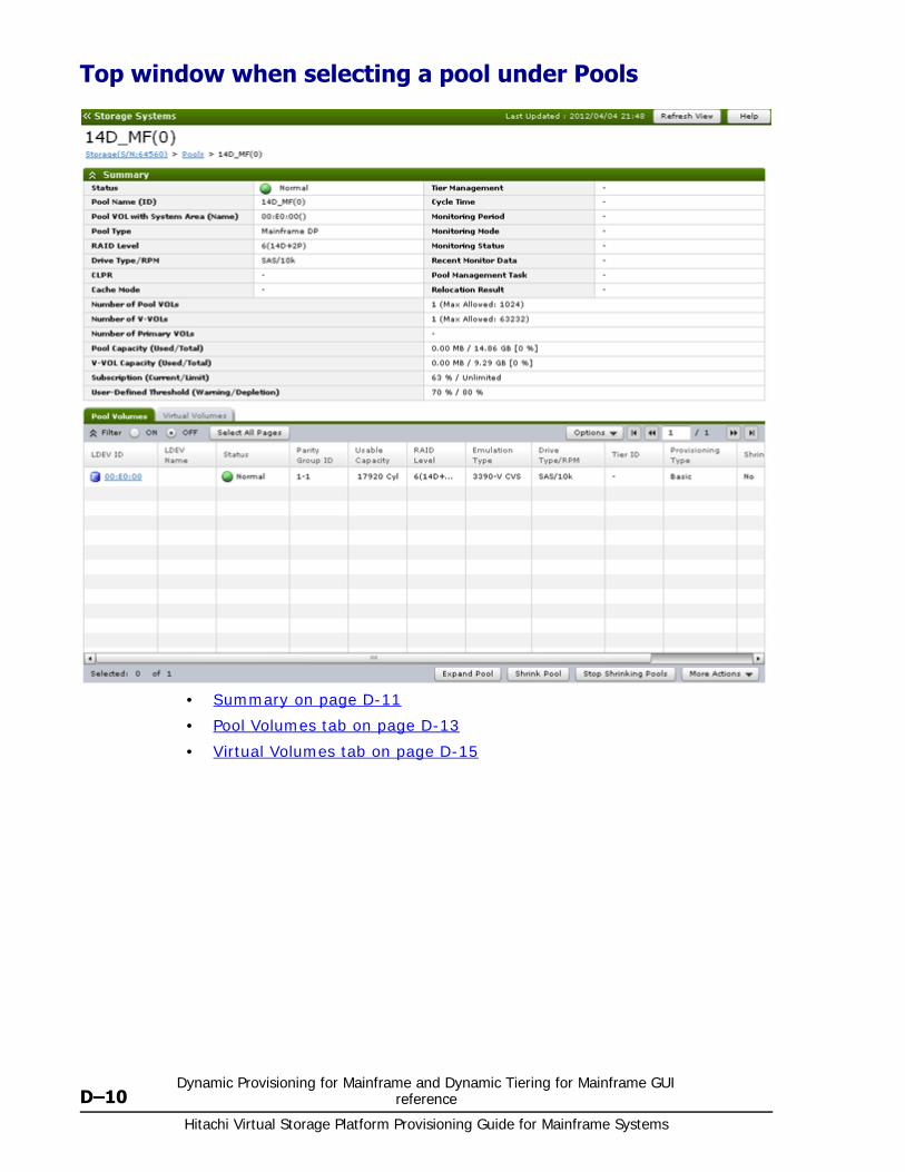
Hitachi Virtual Storage Platform Provisioning Guide for Mainframe Systems
D–10Dynamic Provisioning for Mainframe and Dynamic Tiering for Mainframe GUI
reference
Top window when selecting a pool under Pools
• Summary on page D-11
• Pool Volumes tab on page D-13
• Virtual Volumes tab on page D-15
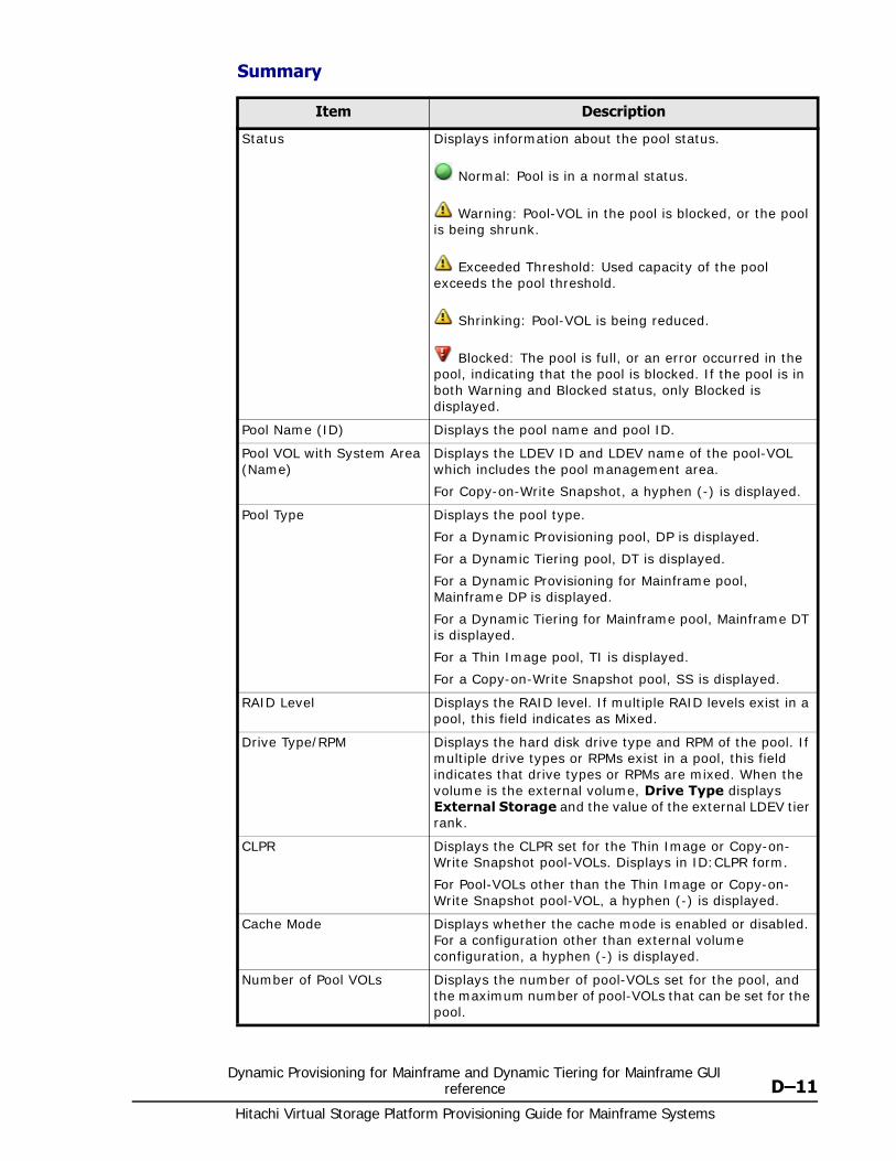
Dynamic Provisioning for Mainframe and Dynamic Tiering for Mainframe GUI reference D–11
Hitachi Virtual Storage Platform Provisioning Guide for Mainframe Systems
Summary
Item Description
Status Displays information about the pool status.
Normal: Pool is in a normal status.
Warning: Pool-VOL in the pool is blocked, or the pool is being shrunk.
Exceeded Threshold: Used capacity of the pool exceeds the pool threshold.
Shrinking: Pool-VOL is being reduced.
Blocked: The pool is full, or an error occurred in the pool, indicating that the pool is blocked. If the pool is in both Warning and Blocked status, only Blocked is displayed.
Pool Name (ID) Displays the pool name and pool ID.
Pool VOL with System Area (Name)
Displays the LDEV ID and LDEV name of the pool-VOL which includes the pool management area.
For Copy-on-Write Snapshot, a hyphen (-) is displayed.
Pool Type Displays the pool type.
For a Dynamic Provisioning pool, DP is displayed.
For a Dynamic Tiering pool, DT is displayed.
For a Dynamic Provisioning for Mainframe pool, Mainframe DP is displayed.
For a Dynamic Tiering for Mainframe pool, Mainframe DT is displayed.
For a Thin Image pool, TI is displayed.
For a Copy-on-Write Snapshot pool, SS is displayed.
RAID Level Displays the RAID level. If multiple RAID levels exist in a pool, this field indicates as Mixed.
Drive Type/RPM Displays the hard disk drive type and RPM of the pool. If multiple drive types or RPMs exist in a pool, this field indicates that drive types or RPMs are mixed. When the volume is the external volume, Drive Type displays External Storage and the value of the external LDEV tier rank.
CLPR Displays the CLPR set for the Thin Image or Copy-on-Write Snapshot pool-VOLs. Displays in ID:CLPR form.
For Pool-VOLs other than the Thin Image or Copy-on-Write Snapshot pool-VOL, a hyphen (-) is displayed.
Cache Mode Displays whether the cache mode is enabled or disabled. For a configuration other than external volume configuration, a hyphen (-) is displayed.
Number of Pool VOLs Displays the number of pool-VOLs set for the pool, and the maximum number of pool-VOLs that can be set for the pool.
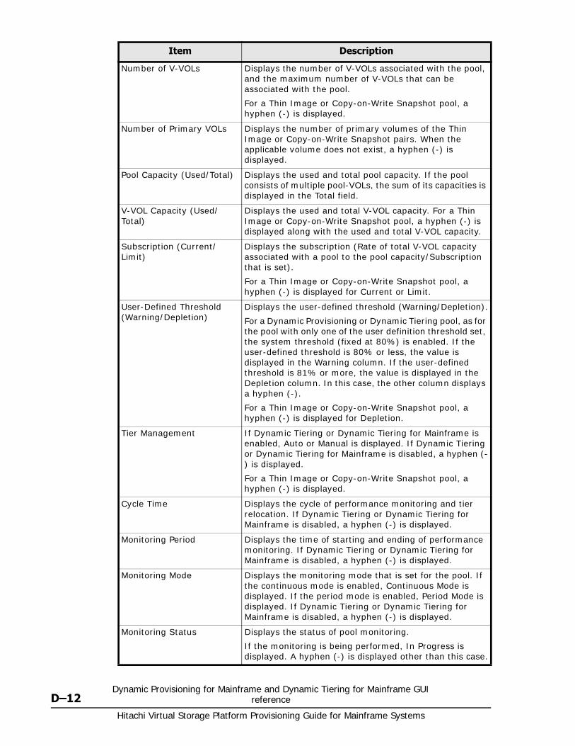
Hitachi Virtual Storage Platform Provisioning Guide for Mainframe Systems
D–12Dynamic Provisioning for Mainframe and Dynamic Tiering for Mainframe GUI
reference
Number of V-VOLs Displays the number of V-VOLs associated with the pool, and the maximum number of V-VOLs that can be associated with the pool.
For a Thin Image or Copy-on-Write Snapshot pool, a hyphen (-) is displayed.
Number of Primary VOLs Displays the number of primary volumes of the Thin Image or Copy-on-Write Snapshot pairs. When the applicable volume does not exist, a hyphen (-) is displayed.
Pool Capacity (Used/Total) Displays the used and total pool capacity. If the pool consists of multiple pool-VOLs, the sum of its capacities is displayed in the Total field.
V-VOL Capacity (Used/Total)
Displays the used and total V-VOL capacity. For a Thin Image or Copy-on-Write Snapshot pool, a hyphen (-) is displayed along with the used and total V-VOL capacity.
Subscription (Current/Limit)
Displays the subscription (Rate of total V-VOL capacity associated with a pool to the pool capacity/Subscription that is set).
For a Thin Image or Copy-on-Write Snapshot pool, a hyphen (-) is displayed for Current or Limit.
User-Defined Threshold (Warning/Depletion)
Displays the user-defined threshold (Warning/Depletion).
For a Dynamic Provisioning or Dynamic Tiering pool, as for the pool with only one of the user definition threshold set, the system threshold (fixed at 80%) is enabled. If the user-defined threshold is 80% or less, the value is displayed in the Warning column. If the user-defined threshold is 81% or more, the value is displayed in the Depletion column. In this case, the other column displays a hyphen (-).
For a Thin Image or Copy-on-Write Snapshot pool, a hyphen (-) is displayed for Depletion.
Tier Management If Dynamic Tiering or Dynamic Tiering for Mainframe is enabled, Auto or Manual is displayed. If Dynamic Tiering or Dynamic Tiering for Mainframe is disabled, a hyphen (-) is displayed.
For a Thin Image or Copy-on-Write Snapshot pool, a hyphen (-) is displayed.
Cycle Time Displays the cycle of performance monitoring and tier relocation. If Dynamic Tiering or Dynamic Tiering for Mainframe is disabled, a hyphen (-) is displayed.
Monitoring Period Displays the time of starting and ending of performance monitoring. If Dynamic Tiering or Dynamic Tiering for Mainframe is disabled, a hyphen (-) is displayed.
Monitoring Mode Displays the monitoring mode that is set for the pool. If the continuous mode is enabled, Continuous Mode is displayed. If the period mode is enabled, Period Mode is displayed. If Dynamic Tiering or Dynamic Tiering for Mainframe is disabled, a hyphen (-) is displayed.
Monitoring Status Displays the status of pool monitoring.
If the monitoring is being performed, In Progress is displayed. A hyphen (-) is displayed other than this case.
Item Description

Dynamic Provisioning for Mainframe and Dynamic Tiering for Mainframe GUI reference D–13
Hitachi Virtual Storage Platform Provisioning Guide for Mainframe Systems
Pool Volumes tab
Only the LDEVs assigned to the logged-on user are available.
Recent Monitor Data Displays the latest monitoring data.
• If the monitoring data exists, the monitoring period of time is displayed.
Example: 2010/11/15 00:00 - 2010/11/15 23:59
• If the monitoring data is being obtained, only the starting time is displayed.
Example: 2010/11/15 00:00 -
• If the latest monitoring data does not exist, a hyphen (-) is displayed.
Pool Management Task Displays the pool management task being performed to the pool.
• Waiting for Rebalance: The rebalance process is being waited.
• Rebalancing: The rebalance process is being performed.
• Waiting for Relocation: The tier relocation process is being waited.
• Relocating: The tier relocation process is being performed.
• Waiting for Shrink: The pool shrinking process is being waited.
• Shrinking: The pool shrinking process is being performed.
• Hyphen (-): The pool management task is not being performed to the pool.
If the Thin Image or Copy-on-Write Snapshot pool is displayed, a hyphen (-) appears.
For details about the tier relocation, see the tier relocation log file. For details about the table items of the tier relocation log file, see Tier relocation log file contents on page 4-38.
Relocation Result Displays the status of the tier relocation processing.
In Progress: The status of Pool Management Task is Waiting for Relocation or Relocating.
Completed: The tier relocation operation is not in progress, or the tier relocation is complete.
Uncompleted (n% relocated): The tier relocation is suspended at the indicated percentage progression.
Hyphen (-): The pool is not a Dynamic Tiering or Dynamic Tiering for Mainframe pool.
Item Description
Item Description
LDEV ID LDEV identifier, which is the combination of LDKC, CU, and LDEV.
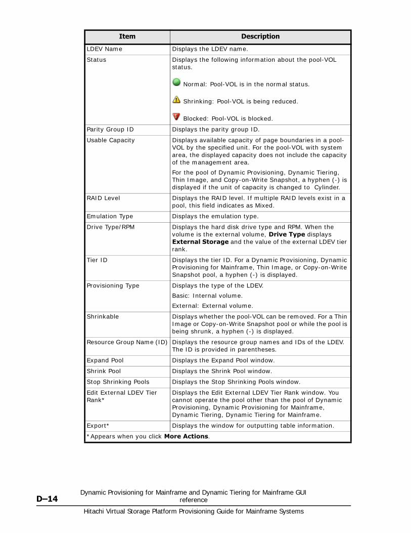
Hitachi Virtual Storage Platform Provisioning Guide for Mainframe Systems
D–14Dynamic Provisioning for Mainframe and Dynamic Tiering for Mainframe GUI
reference
LDEV Name Displays the LDEV name.
Status Displays the following information about the pool-VOL status.
Normal: Pool-VOL is in the normal status.
Shrinking: Pool-VOL is being reduced.
Blocked: Pool-VOL is blocked.
Parity Group ID Displays the parity group ID.
Usable Capacity Displays available capacity of page boundaries in a pool-VOL by the specified unit. For the pool-VOL with system area, the displayed capacity does not include the capacity of the management area.
For the pool of Dynamic Provisioning, Dynamic Tiering, Thin Image, and Copy-on-Write Snapshot, a hyphen (-) is displayed if the unit of capacity is changed to Cylinder.
RAID Level Displays the RAID level. If multiple RAID levels exist in a pool, this field indicates as Mixed.
Emulation Type Displays the emulation type.
Drive Type/RPM Displays the hard disk drive type and RPM. When the volume is the external volume, Drive Type displays External Storage and the value of the external LDEV tier rank.
Tier ID Displays the tier ID. For a Dynamic Provisioning, Dynamic Provisioning for Mainframe, Thin Image, or Copy-on-Write Snapshot pool, a hyphen (-) is displayed.
Provisioning Type Displays the type of the LDEV.
Basic: Internal volume.
External: External volume.
Shrinkable Displays whether the pool-VOL can be removed. For a Thin Image or Copy-on-Write Snapshot pool or while the pool is being shrunk, a hyphen (-) is displayed.
Resource Group Name (ID) Displays the resource group names and IDs of the LDEV. The ID is provided in parentheses.
Expand Pool Displays the Expand Pool window.
Shrink Pool Displays the Shrink Pool window.
Stop Shrinking Pools Displays the Stop Shrinking Pools window.
Edit External LDEV Tier Rank*
Displays the Edit External LDEV Tier Rank window. You cannot operate the pool other than the pool of Dynamic Provisioning, Dynamic Provisioning for Mainframe, Dynamic Tiering, Dynamic Tiering for Mainframe.
Export* Displays the window for outputting table information.
*Appears when you click More Actions.
Item Description

Dynamic Provisioning for Mainframe and Dynamic Tiering for Mainframe GUI reference D–15
Hitachi Virtual Storage Platform Provisioning Guide for Mainframe Systems
Virtual Volumes tab
This tab is displayed unless you select a Thin Image or Copy-on-Write Snapshot pool.
Item Description
LDEV ID LDEV identifier, which is the combination of LDKC, CU, and LDEV.
LDEV Name Displays the LDEV name.
Status Normal: Normal status.
Blocked: Host cannot access a blocked volume.
Warning: Problem occurs in the volume.
Formatting: Volume is being formatted.
Preparing Quick Format: Volume is being prepared for quick formatting.
Quick Formatting: Volume is being quick-formatted.
Correction Access: Access attribute is being corrected.
Copying: Data in the volume is being copied.
Read Only: Data cannot be written to a read-only volume.
Shredding: Volume is being shredded.
Hyphen (-): Any status other than the above.
Emulation Type Displays the emulation type.
Capacity - Total Displays the V-VOL capacity.
Capacity - Used Displays the V-VOL used capacity.
The displayed value on Total might be larger than the displayed value on Used due to following reasons:
• Used displays the used V-VOL capacity which is rounded up on each page.
• If the emulation type is 3390-A, the used capacity of V-VOL includes the capacity of control cylinders (7 Cyl is required per 1,113 Cyl).
Capacity - Used(%) Displays the V-VOL usage level.
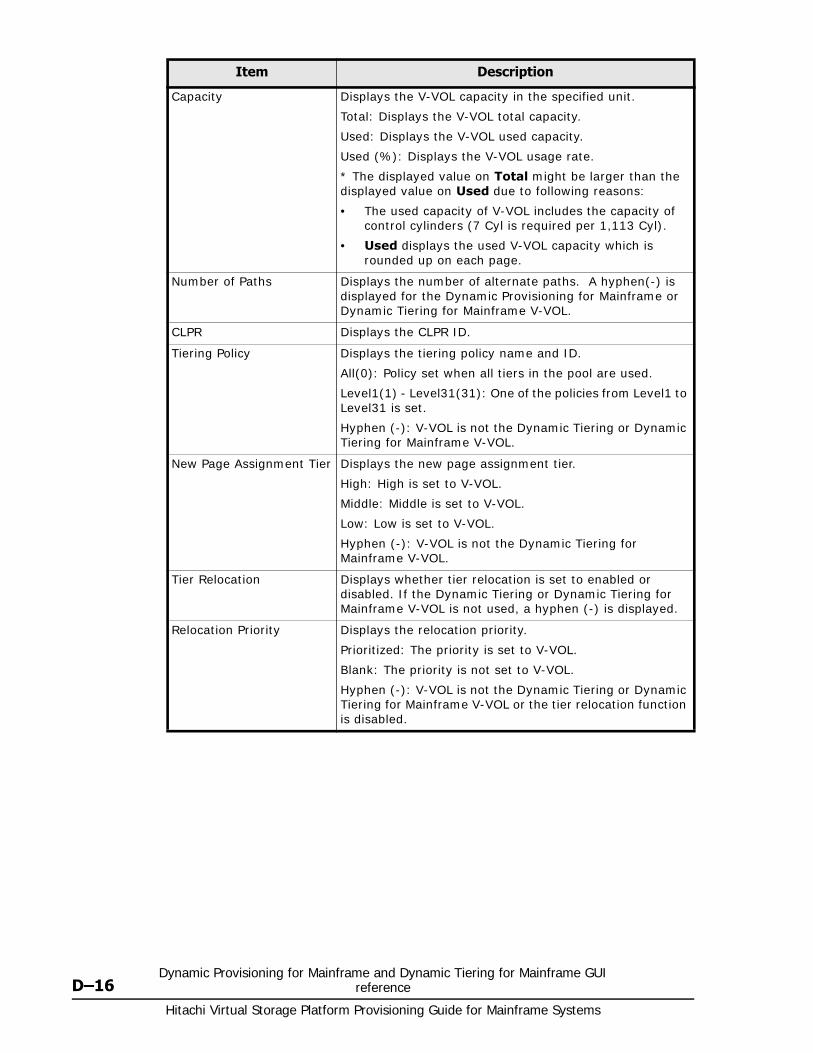
Hitachi Virtual Storage Platform Provisioning Guide for Mainframe Systems
D–16Dynamic Provisioning for Mainframe and Dynamic Tiering for Mainframe GUI
reference
Capacity Displays the V-VOL capacity in the specified unit.
Total: Displays the V-VOL total capacity.
Used: Displays the V-VOL used capacity.
Used (%): Displays the V-VOL usage rate.
* The displayed value on Total might be larger than the displayed value on Used due to following reasons:
• The used capacity of V-VOL includes the capacity of control cylinders (7 Cyl is required per 1,113 Cyl).
• Used displays the used V-VOL capacity which is rounded up on each page.
Number of Paths Displays the number of alternate paths. A hyphen(-) is displayed for the Dynamic Provisioning for Mainframe or Dynamic Tiering for Mainframe V-VOL.
CLPR Displays the CLPR ID.
Tiering Policy Displays the tiering policy name and ID.
All(0): Policy set when all tiers in the pool are used.
Level1(1) - Level31(31): One of the policies from Level1 to Level31 is set.
Hyphen (-): V-VOL is not the Dynamic Tiering or Dynamic Tiering for Mainframe V-VOL.
New Page Assignment Tier Displays the new page assignment tier.
High: High is set to V-VOL.
Middle: Middle is set to V-VOL.
Low: Low is set to V-VOL.
Hyphen (-): V-VOL is not the Dynamic Tiering for Mainframe V-VOL.
Tier Relocation Displays whether tier relocation is set to enabled or disabled. If the Dynamic Tiering or Dynamic Tiering for Mainframe V-VOL is not used, a hyphen (-) is displayed.
Relocation Priority Displays the relocation priority.
Prioritized: The priority is set to V-VOL.
Blank: The priority is not set to V-VOL.
Hyphen (-): V-VOL is not the Dynamic Tiering or Dynamic Tiering for Mainframe V-VOL or the tier relocation function is disabled.
Item Description
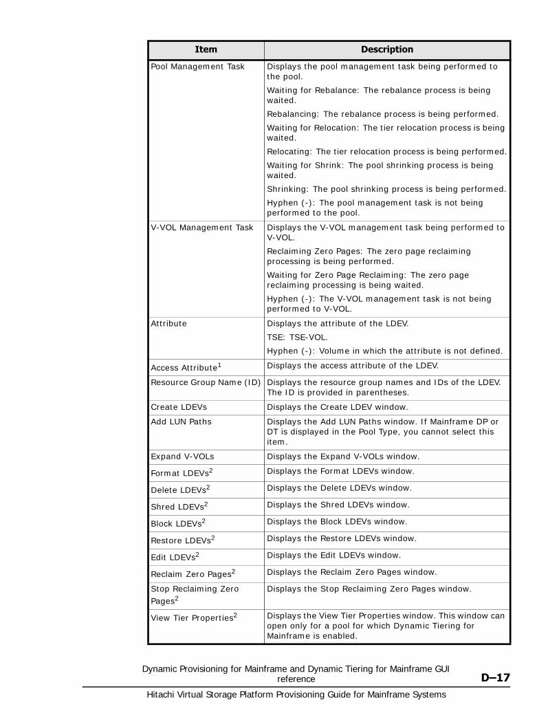
Dynamic Provisioning for Mainframe and Dynamic Tiering for Mainframe GUI reference D–17
Hitachi Virtual Storage Platform Provisioning Guide for Mainframe Systems
Pool Management Task Displays the pool management task being performed to the pool.
Waiting for Rebalance: The rebalance process is being waited.
Rebalancing: The rebalance process is being performed.
Waiting for Relocation: The tier relocation process is being waited.
Relocating: The tier relocation process is being performed.
Waiting for Shrink: The pool shrinking process is being waited.
Shrinking: The pool shrinking process is being performed.
Hyphen (-): The pool management task is not being performed to the pool.
V-VOL Management Task Displays the V-VOL management task being performed to V-VOL.
Reclaiming Zero Pages: The zero page reclaiming processing is being performed.
Waiting for Zero Page Reclaiming: The zero page reclaiming processing is being waited.
Hyphen (-): The V-VOL management task is not being performed to V-VOL.
Attribute Displays the attribute of the LDEV.
TSE: TSE-VOL.
Hyphen (-): Volume in which the attribute is not defined.
Access Attribute1 Displays the access attribute of the LDEV.
Resource Group Name (ID) Displays the resource group names and IDs of the LDEV. The ID is provided in parentheses.
Create LDEVs Displays the Create LDEV window.
Add LUN Paths Displays the Add LUN Paths window. If Mainframe DP or DT is displayed in the Pool Type, you cannot select this item.
Expand V-VOLs Displays the Expand V-VOLs window.
Format LDEVs2 Displays the Format LDEVs window.
Delete LDEVs2 Displays the Delete LDEVs window.
Shred LDEVs2 Displays the Shred LDEVs window.
Block LDEVs2 Displays the Block LDEVs window.
Restore LDEVs2 Displays the Restore LDEVs window.
Edit LDEVs2 Displays the Edit LDEVs window.
Reclaim Zero Pages2 Displays the Reclaim Zero Pages window.
Stop Reclaiming Zero Pages2
Displays the Stop Reclaiming Zero Pages window.
View Tier Properties2 Displays the View Tier Properties window. This window can open only for a pool for which Dynamic Tiering for Mainframe is enabled.
Item Description
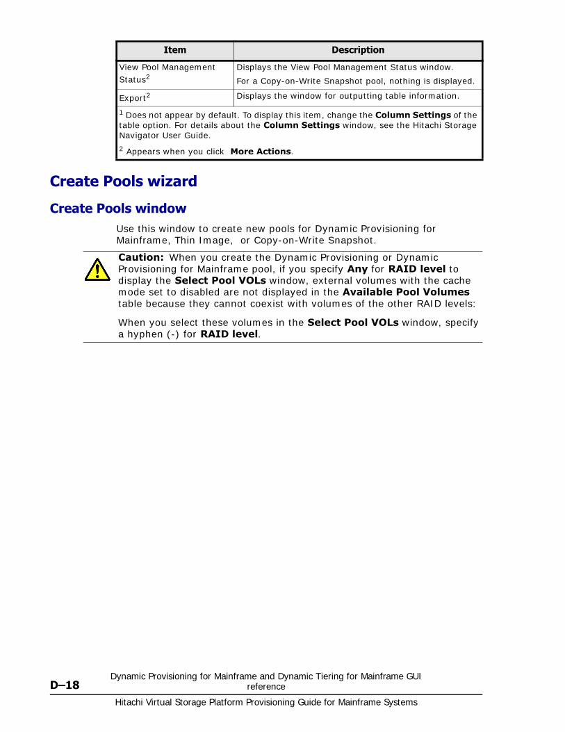
Hitachi Virtual Storage Platform Provisioning Guide for Mainframe Systems
D–18Dynamic Provisioning for Mainframe and Dynamic Tiering for Mainframe GUI
reference
Create Pools wizard
Create Pools windowUse this window to create new pools for Dynamic Provisioning for Mainframe, Thin Image, or Copy-on-Write Snapshot.
View Pool Management Status2
Displays the View Pool Management Status window.
For a Copy-on-Write Snapshot pool, nothing is displayed.
Export2 Displays the window for outputting table information.
1 Does not appear by default. To display this item, change the Column Settings of the table option. For details about the Column Settings window, see the Hitachi Storage Navigator User Guide.
2 Appears when you click More Actions.
Item Description
Caution: When you create the Dynamic Provisioning or Dynamic Provisioning for Mainframe pool, if you specify Any for RAID level to display the Select Pool VOLs window, external volumes with the cache mode set to disabled are not displayed in the Available Pool Volumes table because they cannot coexist with volumes of the other RAID levels:
When you select these volumes in the Select Pool VOLs window, specify a hyphen (-) for RAID level.
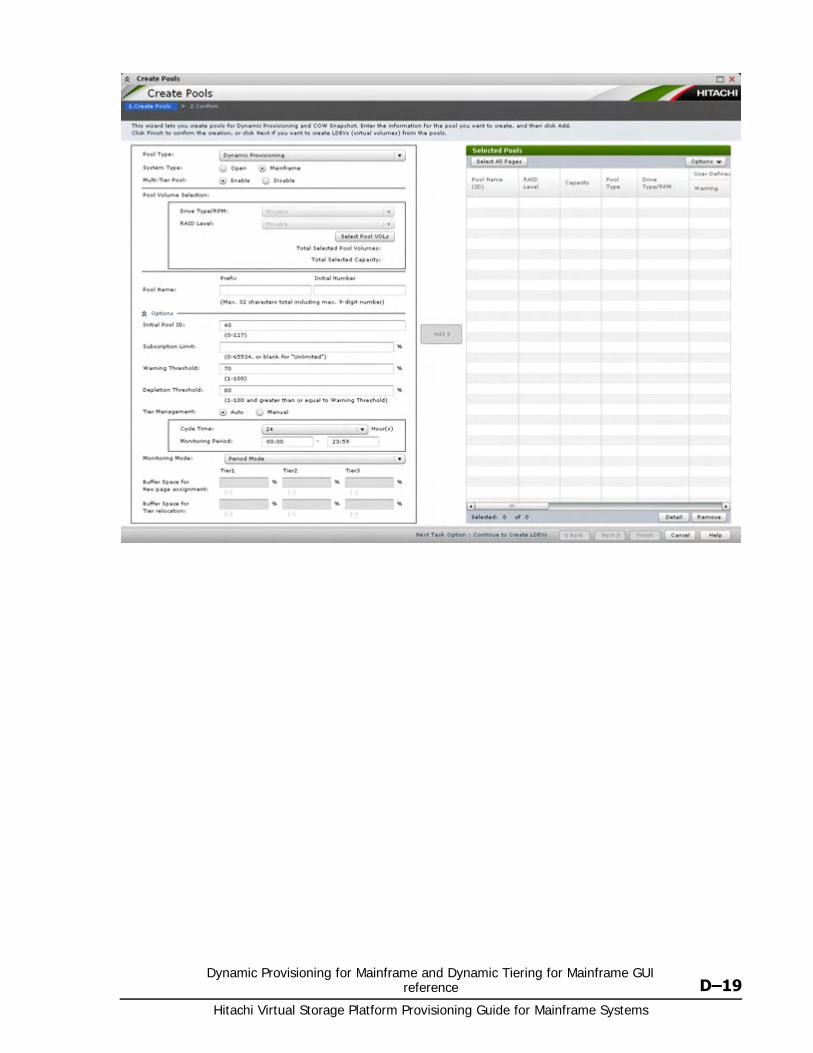
Dynamic Provisioning for Mainframe and Dynamic Tiering for Mainframe GUI reference D–19
Hitachi Virtual Storage Platform Provisioning Guide for Mainframe Systems
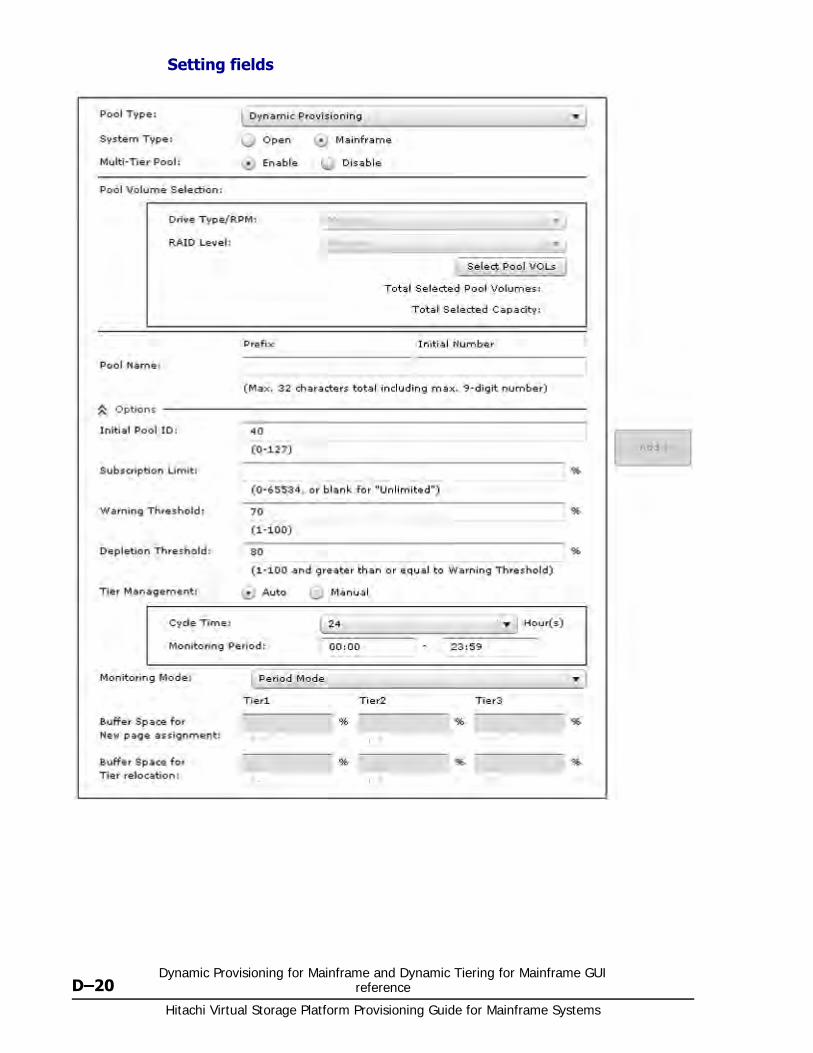
Hitachi Virtual Storage Platform Provisioning Guide for Mainframe Systems
D–20Dynamic Provisioning for Mainframe and Dynamic Tiering for Mainframe GUI
reference
Setting fields
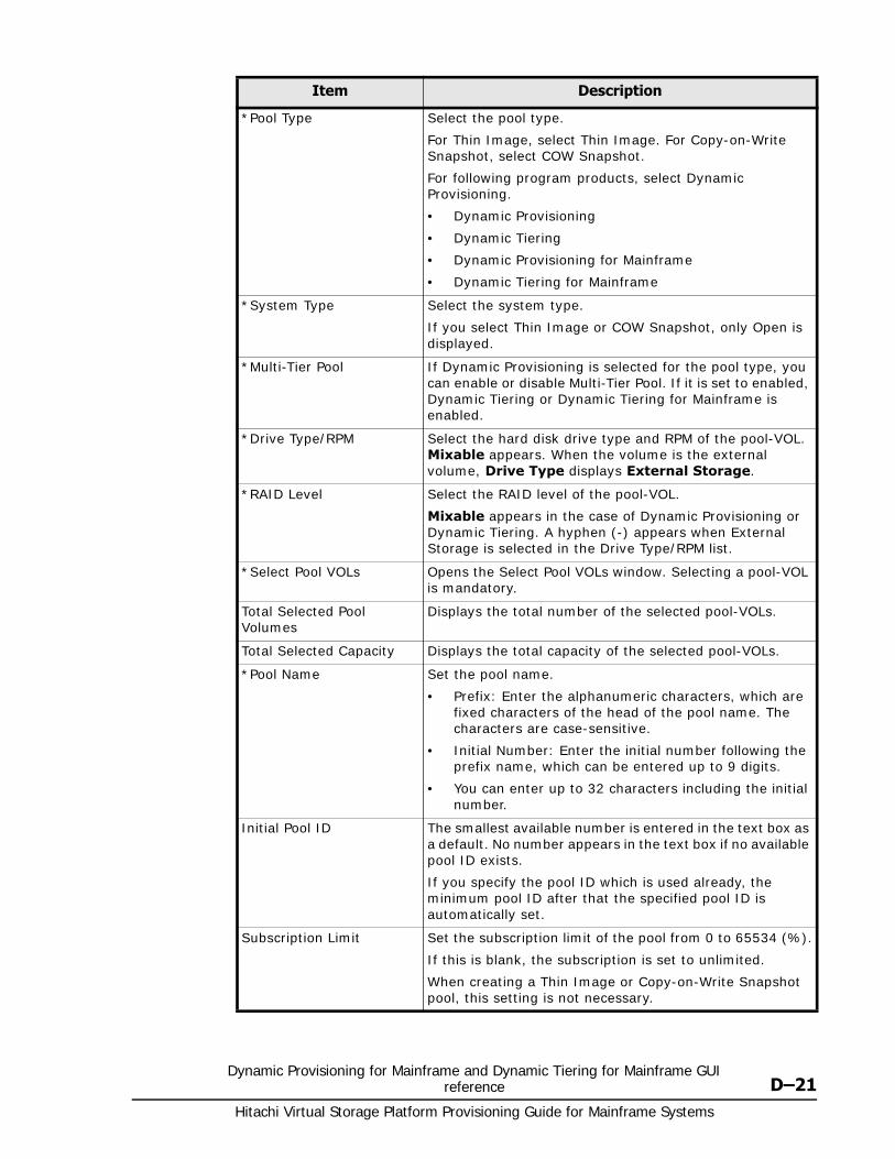
Dynamic Provisioning for Mainframe and Dynamic Tiering for Mainframe GUI reference D–21
Hitachi Virtual Storage Platform Provisioning Guide for Mainframe Systems
Item Description
*Pool Type Select the pool type.
For Thin Image, select Thin Image. For Copy-on-Write Snapshot, select COW Snapshot.
For following program products, select Dynamic Provisioning.
• Dynamic Provisioning
• Dynamic Tiering
• Dynamic Provisioning for Mainframe
• Dynamic Tiering for Mainframe
*System Type Select the system type.
If you select Thin Image or COW Snapshot, only Open is displayed.
*Multi-Tier Pool If Dynamic Provisioning is selected for the pool type, you can enable or disable Multi-Tier Pool. If it is set to enabled, Dynamic Tiering or Dynamic Tiering for Mainframe is enabled.
*Drive Type/RPM Select the hard disk drive type and RPM of the pool-VOL. Mixable appears. When the volume is the external volume, Drive Type displays External Storage.
*RAID Level Select the RAID level of the pool-VOL.
Mixable appears in the case of Dynamic Provisioning or Dynamic Tiering. A hyphen (-) appears when External Storage is selected in the Drive Type/RPM list.
*Select Pool VOLs Opens the Select Pool VOLs window. Selecting a pool-VOL is mandatory.
Total Selected Pool Volumes
Displays the total number of the selected pool-VOLs.
Total Selected Capacity Displays the total capacity of the selected pool-VOLs.
*Pool Name Set the pool name.
• Prefix: Enter the alphanumeric characters, which are fixed characters of the head of the pool name. The characters are case-sensitive.
• Initial Number: Enter the initial number following the prefix name, which can be entered up to 9 digits.
• You can enter up to 32 characters including the initial number.
Initial Pool ID The smallest available number is entered in the text box as a default. No number appears in the text box if no available pool ID exists.
If you specify the pool ID which is used already, the minimum pool ID after that the specified pool ID is automatically set.
Subscription Limit Set the subscription limit of the pool from 0 to 65534 (%).
If this is blank, the subscription is set to unlimited.
When creating a Thin Image or Copy-on-Write Snapshot pool, this setting is not necessary.
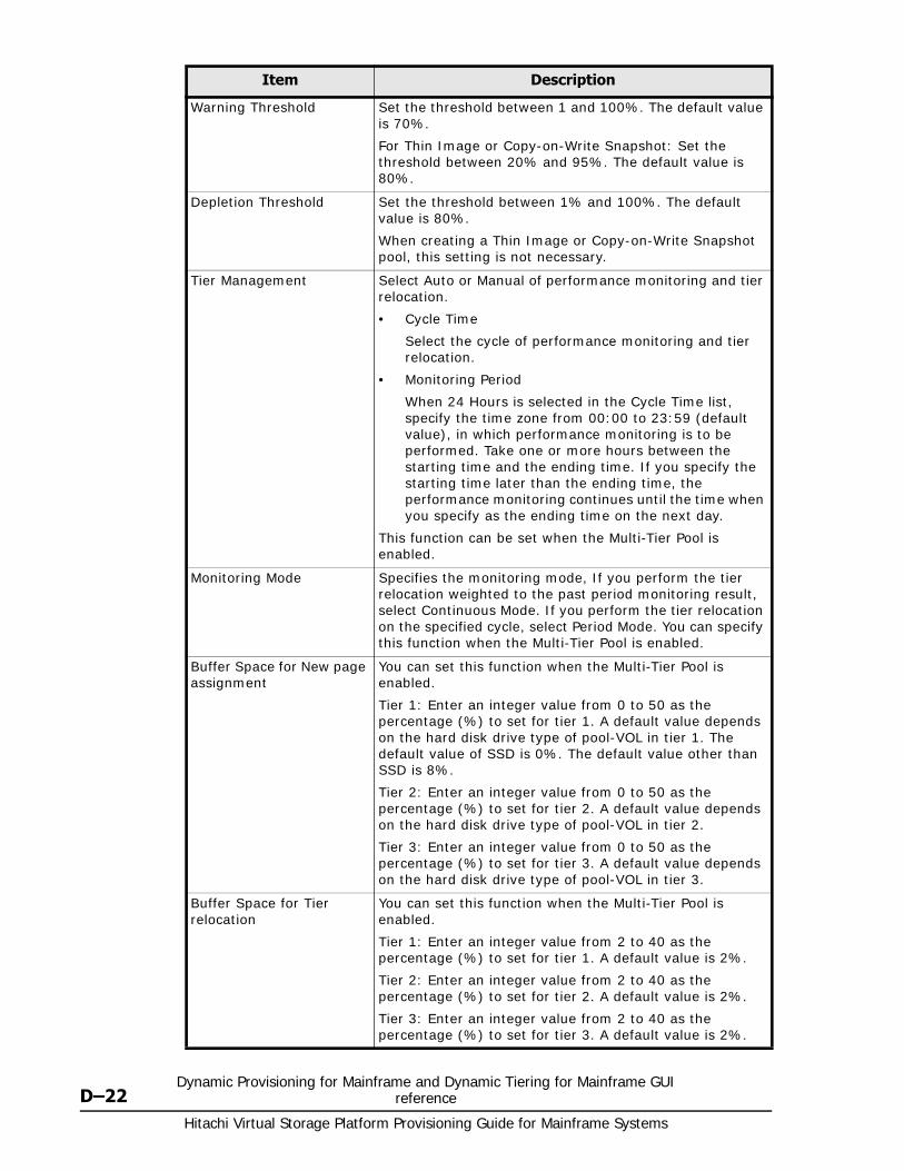
Hitachi Virtual Storage Platform Provisioning Guide for Mainframe Systems
D–22Dynamic Provisioning for Mainframe and Dynamic Tiering for Mainframe GUI
reference
Warning Threshold Set the threshold between 1 and 100%. The default value is 70%.
For Thin Image or Copy-on-Write Snapshot: Set the threshold between 20% and 95%. The default value is 80%.
Depletion Threshold Set the threshold between 1% and 100%. The default value is 80%.
When creating a Thin Image or Copy-on-Write Snapshot pool, this setting is not necessary.
Tier Management Select Auto or Manual of performance monitoring and tier relocation.
• Cycle Time
Select the cycle of performance monitoring and tier relocation.
• Monitoring Period
When 24 Hours is selected in the Cycle Time list, specify the time zone from 00:00 to 23:59 (default value), in which performance monitoring is to be performed. Take one or more hours between the starting time and the ending time. If you specify the starting time later than the ending time, the performance monitoring continues until the time when you specify as the ending time on the next day.
This function can be set when the Multi-Tier Pool is enabled.
Monitoring Mode Specifies the monitoring mode, If you perform the tier relocation weighted to the past period monitoring result, select Continuous Mode. If you perform the tier relocation on the specified cycle, select Period Mode. You can specify this function when the Multi-Tier Pool is enabled.
Buffer Space for New page assignment
You can set this function when the Multi-Tier Pool is enabled.
Tier 1: Enter an integer value from 0 to 50 as the percentage (%) to set for tier 1. A default value depends on the hard disk drive type of pool-VOL in tier 1. The default value of SSD is 0%. The default value other than SSD is 8%.
Tier 2: Enter an integer value from 0 to 50 as the percentage (%) to set for tier 2. A default value depends on the hard disk drive type of pool-VOL in tier 2.
Tier 3: Enter an integer value from 0 to 50 as the percentage (%) to set for tier 3. A default value depends on the hard disk drive type of pool-VOL in tier 3.
Buffer Space for Tier relocation
You can set this function when the Multi-Tier Pool is enabled.
Tier 1: Enter an integer value from 2 to 40 as the percentage (%) to set for tier 1. A default value is 2%.
Tier 2: Enter an integer value from 2 to 40 as the percentage (%) to set for tier 2. A default value is 2%.
Tier 3: Enter an integer value from 2 to 40 as the percentage (%) to set for tier 3. A default value is 2%.
Item Description
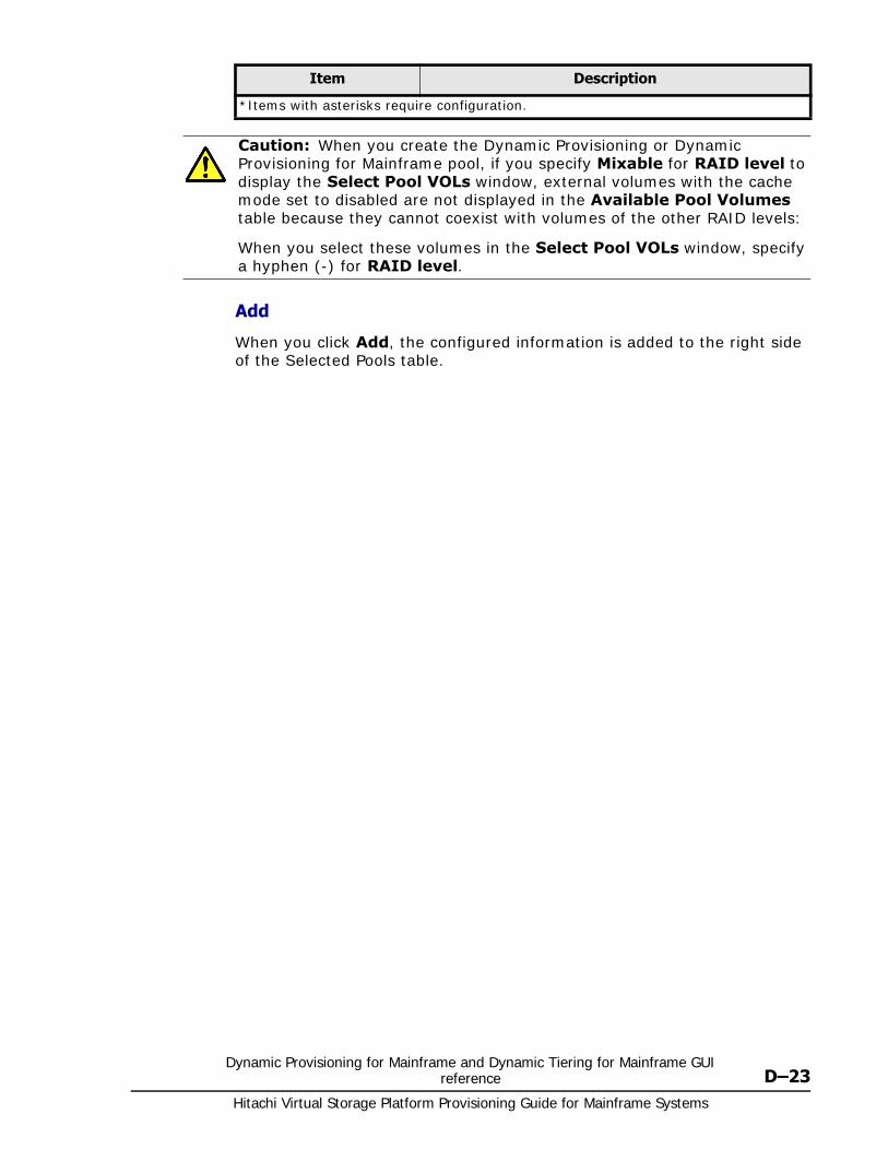
Dynamic Provisioning for Mainframe and Dynamic Tiering for Mainframe GUI reference D–23
Hitachi Virtual Storage Platform Provisioning Guide for Mainframe Systems
Add
When you click Add, the configured information is added to the right side of the Selected Pools table.
*Items with asterisks require configuration.
Caution: When you create the Dynamic Provisioning or Dynamic Provisioning for Mainframe pool, if you specify Mixable for RAID level to display the Select Pool VOLs window, external volumes with the cache mode set to disabled are not displayed in the Available Pool Volumes table because they cannot coexist with volumes of the other RAID levels:
When you select these volumes in the Select Pool VOLs window, specify a hyphen (-) for RAID level.
Item Description
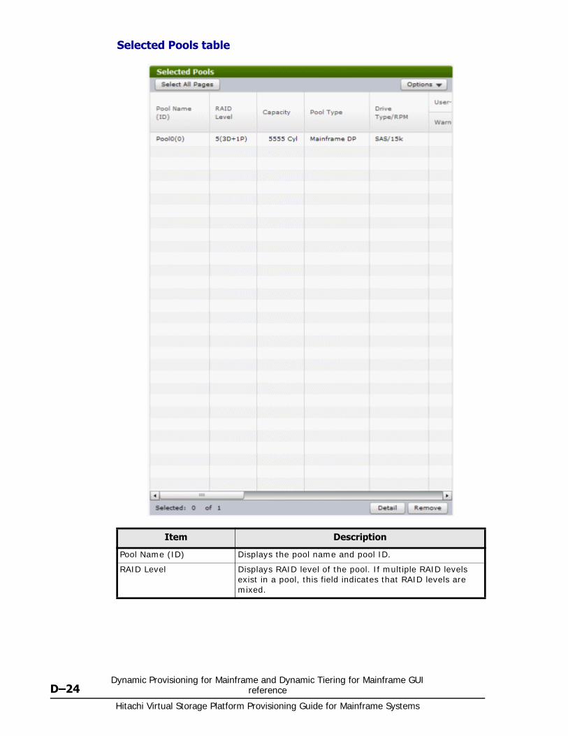
Hitachi Virtual Storage Platform Provisioning Guide for Mainframe Systems
D–24Dynamic Provisioning for Mainframe and Dynamic Tiering for Mainframe GUI
reference
Selected Pools table
Item Description
Pool Name (ID) Displays the pool name and pool ID.
RAID Level Displays RAID level of the pool. If multiple RAID levels exist in a pool, this field indicates that RAID levels are mixed.
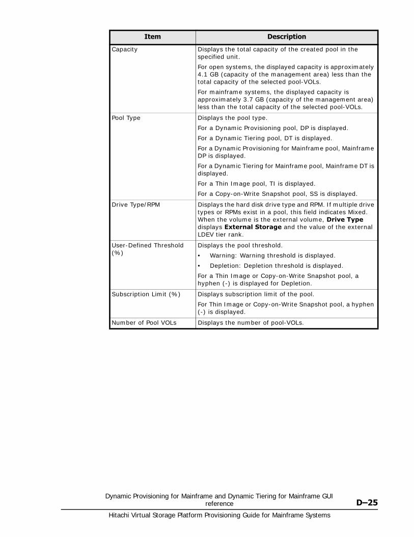
Dynamic Provisioning for Mainframe and Dynamic Tiering for Mainframe GUI reference D–25
Hitachi Virtual Storage Platform Provisioning Guide for Mainframe Systems
Capacity Displays the total capacity of the created pool in the specified unit.
For open systems, the displayed capacity is approximately 4.1 GB (capacity of the management area) less than the total capacity of the selected pool-VOLs.
For mainframe systems, the displayed capacity is approximately 3.7 GB (capacity of the management area) less than the total capacity of the selected pool-VOLs.
Pool Type Displays the pool type.
For a Dynamic Provisioning pool, DP is displayed.
For a Dynamic Tiering pool, DT is displayed.
For a Dynamic Provisioning for Mainframe pool, Mainframe DP is displayed.
For a Dynamic Tiering for Mainframe pool, Mainframe DT is displayed.
For a Thin Image pool, TI is displayed.
For a Copy-on-Write Snapshot pool, SS is displayed.
Drive Type/RPM Displays the hard disk drive type and RPM. If multiple drive types or RPMs exist in a pool, this field indicates Mixed. When the volume is the external volume, Drive Type displays External Storage and the value of the external LDEV tier rank.
User-Defined Threshold (%)
Displays the pool threshold.
• Warning: Warning threshold is displayed.
• Depletion: Depletion threshold is displayed.
For a Thin Image or Copy-on-Write Snapshot pool, a hyphen (-) is displayed for Depletion.
Subscription Limit (%) Displays subscription limit of the pool.
For Thin Image or Copy-on-Write Snapshot pool, a hyphen (-) is displayed.
Number of Pool VOLs Displays the number of pool-VOLs.
Item Description

Hitachi Virtual Storage Platform Provisioning Guide for Mainframe Systems
D–26Dynamic Provisioning for Mainframe and Dynamic Tiering for Mainframe GUI
reference
Multi-Tier Pool Displays the Dynamic Tiering or Dynamic Tiering for Mainframe information.
• Monitoring Mode
If the continuous mode is enabled, Continuous Mode is displayed. If the period mode is enabled, Period Mode is displayed.
• Tier Management
If Dynamic Tiering or Dynamic Tiering for Mainframe is enabled, Auto or Manual of performance monitoring and tier relocation is displayed. If Dynamic Tiering or Dynamic Tiering for Mainframe is disabled, a hyphen (-) is displayed.
• Cycle Time
Displays the cycle of performance monitoring and tier relocation. If Dynamic Tiering or Dynamic Tiering for Mainframe is disabled, a hyphen (-) is displayed.
• Monitoring Period
Displays the time zone of performance monitoring when 24 Hours is selected in the Cycle Time list. If Dynamic Tiering or Dynamic Tiering for Mainframe is disabled, a hyphen (-) is displayed.
Buffer Space for New page assignment (%)
Displays the information of the buffer space for new page assignment to each tier.
Tier 1: If you make the Dynamic Tiering or Dynamic Tiering for Mainframe function available, the buffer space for new page assignment to tier 1 is displayed. If you make the Dynamic Tiering or Dynamic Tiering for Mainframe function unavailable, a hyphen (-) is displayed.
Tier 2: If you make the Dynamic Tiering or Dynamic Tiering for Mainframe function available, and tier 2 exists, the buffer space for new page assignment to tier 2 is displayed. If you make the Dynamic Tiering or Dynamic Tiering for Mainframe function unavailable, or tier 2 does not exist, a hyphen (-) is displayed.
Tier 3: If you make the Dynamic Tiering or Dynamic Tiering for Mainframe function available, and tier 3 exists, the buffer space for new page assignment to tier 3 is displayed. If you make the Dynamic Tiering or Dynamic Tiering for Mainframe function unavailable, or tier 3 does not exist, a hyphen (-) is displayed.
Item Description
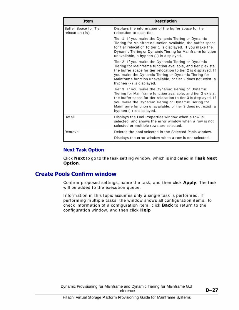
Dynamic Provisioning for Mainframe and Dynamic Tiering for Mainframe GUI reference D–27
Hitachi Virtual Storage Platform Provisioning Guide for Mainframe Systems
Next Task Option
Click Next to go to the task setting window, which is indicated in Task Next Option.
Create Pools Confirm windowConfirm proposed settings, name the task, and then click Apply. The task will be added to the execution queue.
Information in this topic assumes only a single task is performed. If performing multiple tasks, the window shows all configuration items. To check information of a configuration item, click Back to return to the configuration window, and then click Help
Buffer Space for Tier relocation (%)
Displays the information of the buffer space for tier relocation to each tier.
Tier 1: If you make the Dynamic Tiering or Dynamic Tiering for Mainframe function available, the buffer space for tier relocation to tier 1 is displayed. If you make the Dynamic Tiering or Dynamic Tiering for Mainframe function unavailable, a hyphen (-) is displayed.
Tier 2: If you make the Dynamic Tiering or Dynamic Tiering for Mainframe function available, and tier 2 exists, the buffer space for tier relocation to tier 2 is displayed. If you make the Dynamic Tiering or Dynamic Tiering for Mainframe function unavailable, or tier 2 does not exist, a hyphen (-) is displayed.
Tier 3: If you make the Dynamic Tiering or Dynamic Tiering for Mainframe function available, and tier 3 exists, the buffer space for tier relocation to tier 3 is displayed. If you make the Dynamic Tiering or Dynamic Tiering for Mainframe function unavailable, or tier 3 does not exist, a hyphen (-) is displayed.
Detail Displays the Pool Properties window when a row is selected, and shows the error window when a row is not selected or multiple rows are selected.
Remove Deletes the pool selected in the Selected Pools window.
Displays the error window when a row is not selected.
Item Description
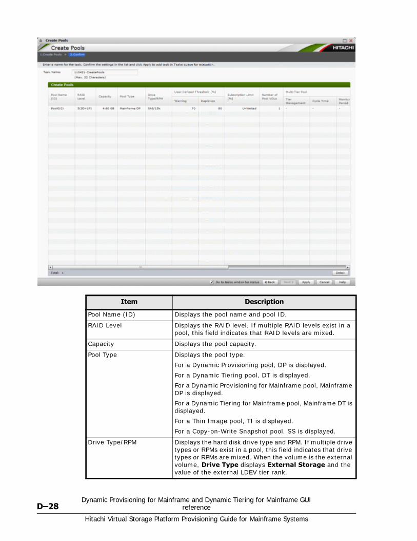
Hitachi Virtual Storage Platform Provisioning Guide for Mainframe Systems
D–28Dynamic Provisioning for Mainframe and Dynamic Tiering for Mainframe GUI
reference
Item Description
Pool Name (ID) Displays the pool name and pool ID.
RAID Level Displays the RAID level. If multiple RAID levels exist in a pool, this field indicates that RAID levels are mixed.
Capacity Displays the pool capacity.
Pool Type Displays the pool type.
For a Dynamic Provisioning pool, DP is displayed.
For a Dynamic Tiering pool, DT is displayed.
For a Dynamic Provisioning for Mainframe pool, Mainframe DP is displayed.
For a Dynamic Tiering for Mainframe pool, Mainframe DT is displayed.
For a Thin Image pool, TI is displayed.
For a Copy-on-Write Snapshot pool, SS is displayed.
Drive Type/RPM Displays the hard disk drive type and RPM. If multiple drive types or RPMs exist in a pool, this field indicates that drive types or RPMs are mixed. When the volume is the external volume, Drive Type displays External Storage and the value of the external LDEV tier rank.
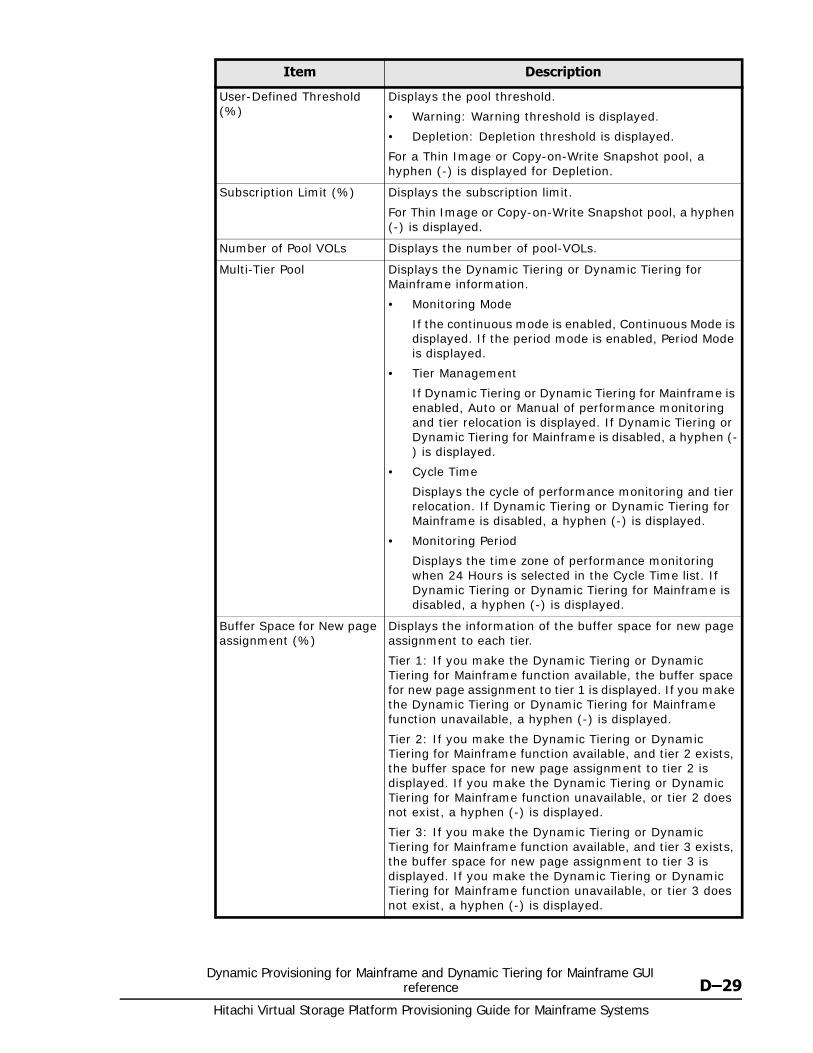
Dynamic Provisioning for Mainframe and Dynamic Tiering for Mainframe GUI reference D–29
Hitachi Virtual Storage Platform Provisioning Guide for Mainframe Systems
User-Defined Threshold (%)
Displays the pool threshold.
• Warning: Warning threshold is displayed.
• Depletion: Depletion threshold is displayed.
For a Thin Image or Copy-on-Write Snapshot pool, a hyphen (-) is displayed for Depletion.
Subscription Limit (%) Displays the subscription limit.
For Thin Image or Copy-on-Write Snapshot pool, a hyphen (-) is displayed.
Number of Pool VOLs Displays the number of pool-VOLs.
Multi-Tier Pool Displays the Dynamic Tiering or Dynamic Tiering for Mainframe information.
• Monitoring Mode
If the continuous mode is enabled, Continuous Mode is displayed. If the period mode is enabled, Period Mode is displayed.
• Tier Management
If Dynamic Tiering or Dynamic Tiering for Mainframe is enabled, Auto or Manual of performance monitoring and tier relocation is displayed. If Dynamic Tiering or Dynamic Tiering for Mainframe is disabled, a hyphen (-) is displayed.
• Cycle Time
Displays the cycle of performance monitoring and tier relocation. If Dynamic Tiering or Dynamic Tiering for Mainframe is disabled, a hyphen (-) is displayed.
• Monitoring Period
Displays the time zone of performance monitoring when 24 Hours is selected in the Cycle Time list. If Dynamic Tiering or Dynamic Tiering for Mainframe is disabled, a hyphen (-) is displayed.
Buffer Space for New page assignment (%)
Displays the information of the buffer space for new page assignment to each tier.
Tier 1: If you make the Dynamic Tiering or Dynamic Tiering for Mainframe function available, the buffer space for new page assignment to tier 1 is displayed. If you make the Dynamic Tiering or Dynamic Tiering for Mainframe function unavailable, a hyphen (-) is displayed.
Tier 2: If you make the Dynamic Tiering or Dynamic Tiering for Mainframe function available, and tier 2 exists, the buffer space for new page assignment to tier 2 is displayed. If you make the Dynamic Tiering or Dynamic Tiering for Mainframe function unavailable, or tier 2 does not exist, a hyphen (-) is displayed.
Tier 3: If you make the Dynamic Tiering or Dynamic Tiering for Mainframe function available, and tier 3 exists, the buffer space for new page assignment to tier 3 is displayed. If you make the Dynamic Tiering or Dynamic Tiering for Mainframe function unavailable, or tier 3 does not exist, a hyphen (-) is displayed.
Item Description
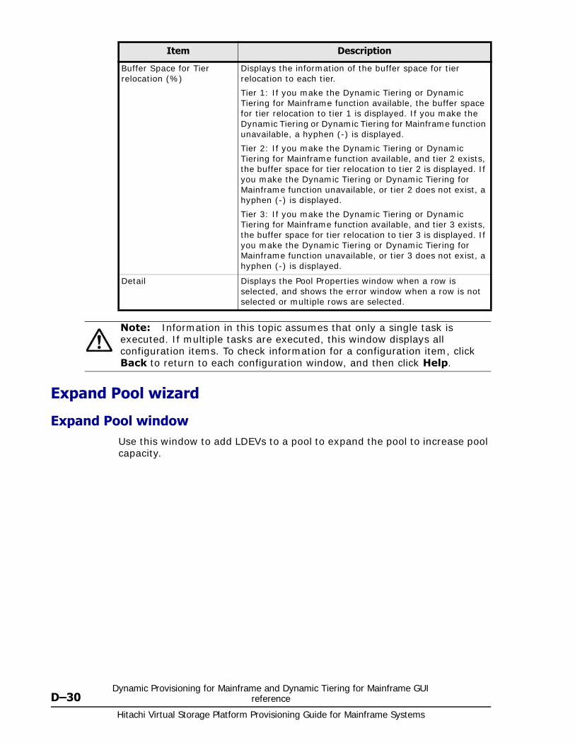
Hitachi Virtual Storage Platform Provisioning Guide for Mainframe Systems
D–30Dynamic Provisioning for Mainframe and Dynamic Tiering for Mainframe GUI
reference
Expand Pool wizard
Expand Pool windowUse this window to add LDEVs to a pool to expand the pool to increase pool capacity.
Buffer Space for Tier relocation (%)
Displays the information of the buffer space for tier relocation to each tier.
Tier 1: If you make the Dynamic Tiering or Dynamic Tiering for Mainframe function available, the buffer space for tier relocation to tier 1 is displayed. If you make the Dynamic Tiering or Dynamic Tiering for Mainframe function unavailable, a hyphen (-) is displayed.
Tier 2: If you make the Dynamic Tiering or Dynamic Tiering for Mainframe function available, and tier 2 exists, the buffer space for tier relocation to tier 2 is displayed. If you make the Dynamic Tiering or Dynamic Tiering for Mainframe function unavailable, or tier 2 does not exist, a hyphen (-) is displayed.
Tier 3: If you make the Dynamic Tiering or Dynamic Tiering for Mainframe function available, and tier 3 exists, the buffer space for tier relocation to tier 3 is displayed. If you make the Dynamic Tiering or Dynamic Tiering for Mainframe function unavailable, or tier 3 does not exist, a hyphen (-) is displayed.
Detail Displays the Pool Properties window when a row is selected, and shows the error window when a row is not selected or multiple rows are selected.
Note: Information in this topic assumes that only a single task is executed. If multiple tasks are executed, this window displays all configuration items. To check information for a configuration item, click Back to return to each configuration window, and then click Help.
Item Description
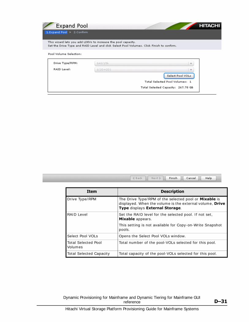
Dynamic Provisioning for Mainframe and Dynamic Tiering for Mainframe GUI reference D–31
Hitachi Virtual Storage Platform Provisioning Guide for Mainframe Systems
Item Description
Drive Type/RPM The Drive Type/RPM of the selected pool or Mixable is displayed. When the volume is the external volume, Drive Type displays External Storage.
RAID Level Set the RAID level for the selected pool. If not set, Mixable appears.
This setting is not available for Copy-on-Write Snapshot pools.
Select Pool VOLs Opens the Select Pool VOLs window.
Total Selected Pool Volumes
Total number of the pool-VOLs selected for this pool.
Total Selected Capacity Total capacity of the pool-VOLs selected for this pool.
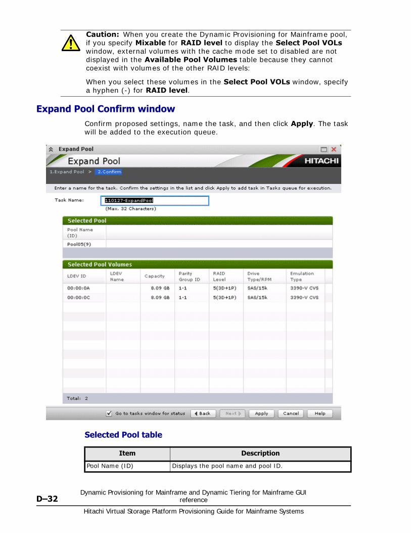
Hitachi Virtual Storage Platform Provisioning Guide for Mainframe Systems
D–32Dynamic Provisioning for Mainframe and Dynamic Tiering for Mainframe GUI
reference
Expand Pool Confirm windowConfirm proposed settings, name the task, and then click Apply. The task will be added to the execution queue.
Selected Pool table
Caution: When you create the Dynamic Provisioning for Mainframe pool, if you specify Mixable for RAID level to display the Select Pool VOLs window, external volumes with the cache mode set to disabled are not displayed in the Available Pool Volumes table because they cannot coexist with volumes of the other RAID levels:
When you select these volumes in the Select Pool VOLs window, specify a hyphen (-) for RAID level.
Item Description
Pool Name (ID) Displays the pool name and pool ID.
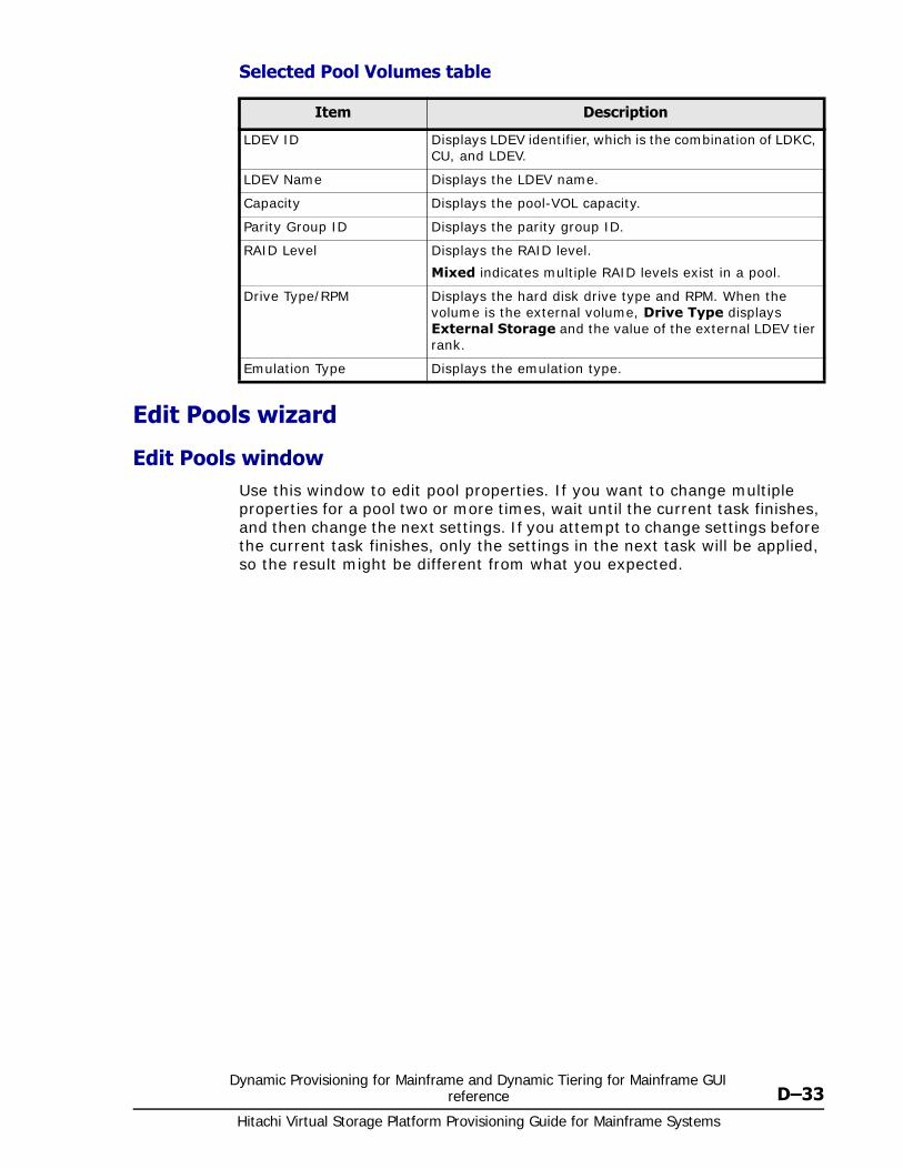
Dynamic Provisioning for Mainframe and Dynamic Tiering for Mainframe GUI reference D–33
Hitachi Virtual Storage Platform Provisioning Guide for Mainframe Systems
Selected Pool Volumes table
Edit Pools wizard
Edit Pools windowUse this window to edit pool properties. If you want to change multiple properties for a pool two or more times, wait until the current task finishes, and then change the next settings. If you attempt to change settings before the current task finishes, only the settings in the next task will be applied, so the result might be different from what you expected.
Item Description
LDEV ID Displays LDEV identifier, which is the combination of LDKC, CU, and LDEV.
LDEV Name Displays the LDEV name.
Capacity Displays the pool-VOL capacity.
Parity Group ID Displays the parity group ID.
RAID Level Displays the RAID level.
Mixed indicates multiple RAID levels exist in a pool.
Drive Type/RPM Displays the hard disk drive type and RPM. When the volume is the external volume, Drive Type displays External Storage and the value of the external LDEV tier rank.
Emulation Type Displays the emulation type.
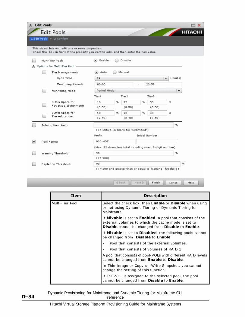
Hitachi Virtual Storage Platform Provisioning Guide for Mainframe Systems
D–34Dynamic Provisioning for Mainframe and Dynamic Tiering for Mainframe GUI
reference
Item Description
Multi-Tier Pool Select the check box, then Enable or Disable when using or not using Dynamic Tiering or Dynamic Tiering for Mainframe.
If Mixable is set to Enabled, a pool that consists of the external volumes to which the cache mode is set to Disable cannot be changed from Disable to Enable.
If Mixable is set to Disabled, the following pools cannot be changed from Disable to Enable.
• Pool that consists of the external volumes.
• Pool that consists of volumes of RAID 1.
A pool that consists of pool-VOLs with different RAID levels cannot be changed from Enable to Disable.
In Thin Image or Copy-on-Write Snapshot, you cannot change the setting of this function.
If TSE-VOL is assigned to the selected pool, the pool cannot be changed from Disable to Enable.
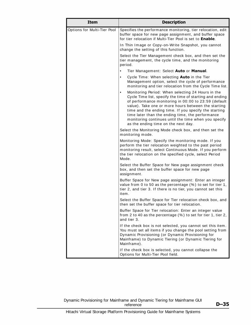
Dynamic Provisioning for Mainframe and Dynamic Tiering for Mainframe GUI reference D–35
Hitachi Virtual Storage Platform Provisioning Guide for Mainframe Systems
Options for Multi-Tier Pool Specifies the performance monitoring, tier relocation, edit buffer space for new page assignment, and buffer space for tier relocation if Multi-Tier Pool is set to Enable.
In Thin Image or Copy-on-Write Snapshot, you cannot change the setting of this function.
Select the Tier Management check box, and then set the tier management, the cycle time, and the monitoring period.
• Tier Management: Select Auto or Manual.
• Cycle Time: When selecting Auto in the Tier Management option, select the cycle of performance monitoring and tier relocation from the Cycle Time list.
• Monitoring Period: When selecting 24 Hours in the Cycle Time list, specify the time of starting and ending of performance monitoring in 00:00 to 23:59 (default value). Take one or more hours between the starting time and the ending time. If you specify the starting time later than the ending time, the performance monitoring continues until the time when you specify as the ending time on the next day.
Select the Monitoring Mode check box, and then set the monitoring mode.
Monitoring Mode: Specify the monitoring mode. If you perform the tier relocation weighted to the past period monitoring result, select Continuous Mode. If you perform the tier relocation on the specified cycle, select Period Mode.
Select the Buffer Space for New page assignment check box, and then set the buffer space for new page assignment.
Buffer Space for New page assignment: Enter an integer value from 0 to 50 as the percentage (%) to set for tier 1, tier 2, and tier 3. If there is no tier, you cannot set this item.
Select the Buffer Space for Tier relocation check box, and then set the buffer space for tier relocation.
Buffer Space for Tier relocation: Enter an integer value from 2 to 40 as the percentage (%) to set for tier 1, tier 2, and tier 3.
If the check box is not selected, you cannot set this item. You must set all items if you change the pool setting from Dynamic Provisioning (or Dynamic Provisioning for Mainframe) to Dynamic Tiering (or Dynamic Tiering for Mainframe).
If the check box is selected, you cannot collapse the Options for Multi-Tier Pool field.
Item Description
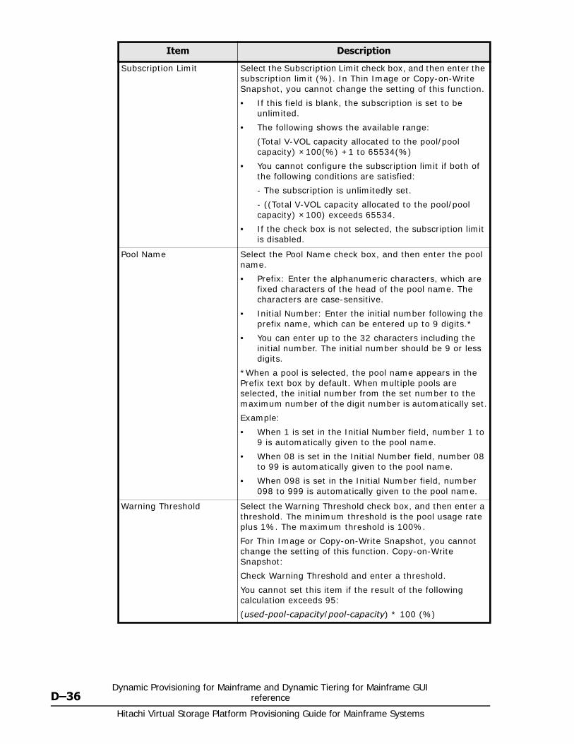
Hitachi Virtual Storage Platform Provisioning Guide for Mainframe Systems
D–36Dynamic Provisioning for Mainframe and Dynamic Tiering for Mainframe GUI
reference
Subscription Limit Select the Subscription Limit check box, and then enter the subscription limit (%). In Thin Image or Copy-on-Write Snapshot, you cannot change the setting of this function.
• If this field is blank, the subscription is set to be unlimited.
• The following shows the available range:
(Total V-VOL capacity allocated to the pool/pool capacity) ×100(%) +1 to 65534(%)
• You cannot configure the subscription limit if both of the following conditions are satisfied:
- The subscription is unlimitedly set.
- ((Total V-VOL capacity allocated to the pool/pool capacity) ×100) exceeds 65534.
• If the check box is not selected, the subscription limit is disabled.
Pool Name Select the Pool Name check box, and then enter the pool name.
• Prefix: Enter the alphanumeric characters, which are fixed characters of the head of the pool name. The characters are case-sensitive.
• Initial Number: Enter the initial number following the prefix name, which can be entered up to 9 digits.*
• You can enter up to the 32 characters including the initial number. The initial number should be 9 or less digits.
*When a pool is selected, the pool name appears in the Prefix text box by default. When multiple pools are selected, the initial number from the set number to the maximum number of the digit number is automatically set.
Example:
• When 1 is set in the Initial Number field, number 1 to 9 is automatically given to the pool name.
• When 08 is set in the Initial Number field, number 08 to 99 is automatically given to the pool name.
• When 098 is set in the Initial Number field, number 098 to 999 is automatically given to the pool name.
Warning Threshold Select the Warning Threshold check box, and then enter a threshold. The minimum threshold is the pool usage rate plus 1%. The maximum threshold is 100%.
For Thin Image or Copy-on-Write Snapshot, you cannot change the setting of this function. Copy-on-Write Snapshot:
Check Warning Threshold and enter a threshold.
You cannot set this item if the result of the following calculation exceeds 95:
(used-pool-capacity/pool-capacity) * 100 (%)
Item Description
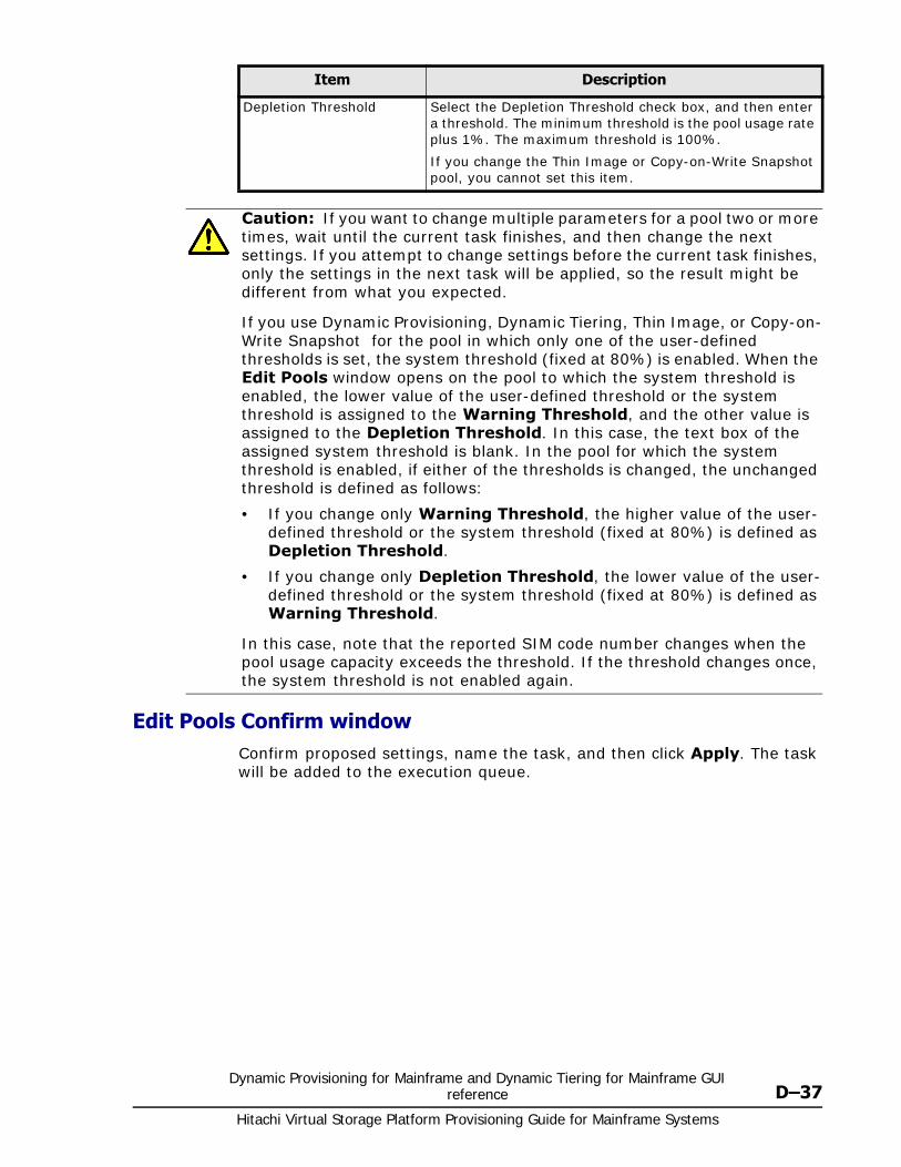
Dynamic Provisioning for Mainframe and Dynamic Tiering for Mainframe GUI reference D–37
Hitachi Virtual Storage Platform Provisioning Guide for Mainframe Systems
Edit Pools Confirm windowConfirm proposed settings, name the task, and then click Apply. The task will be added to the execution queue.
Depletion Threshold Select the Depletion Threshold check box, and then enter a threshold. The minimum threshold is the pool usage rate plus 1%. The maximum threshold is 100%.
If you change the Thin Image or Copy-on-Write Snapshot pool, you cannot set this item.
Caution: If you want to change multiple parameters for a pool two or more times, wait until the current task finishes, and then change the next settings. If you attempt to change settings before the current task finishes, only the settings in the next task will be applied, so the result might be different from what you expected.
If you use Dynamic Provisioning, Dynamic Tiering, Thin Image, or Copy-on-Write Snapshot for the pool in which only one of the user-defined thresholds is set, the system threshold (fixed at 80%) is enabled. When the Edit Pools window opens on the pool to which the system threshold is enabled, the lower value of the user-defined threshold or the system threshold is assigned to the Warning Threshold, and the other value is assigned to the Depletion Threshold. In this case, the text box of the assigned system threshold is blank. In the pool for which the system threshold is enabled, if either of the thresholds is changed, the unchanged threshold is defined as follows:
• If you change only Warning Threshold, the higher value of the user-defined threshold or the system threshold (fixed at 80%) is defined as Depletion Threshold.
• If you change only Depletion Threshold, the lower value of the user-defined threshold or the system threshold (fixed at 80%) is defined as Warning Threshold.
In this case, note that the reported SIM code number changes when the pool usage capacity exceeds the threshold. If the threshold changes once, the system threshold is not enabled again.
Item Description

Hitachi Virtual Storage Platform Provisioning Guide for Mainframe Systems
D–38Dynamic Provisioning for Mainframe and Dynamic Tiering for Mainframe GUI
reference
Item Description
Pool Name (ID) Displays the pool name and pool ID.
RAID Level Displays the RAID level. If multiple RAID levels exist in a pool, this field indicates that RAID levels are mixed.
Capacity Displays the pool capacity.
Pool Type Displays the pool type.
For a Dynamic Provisioning pool, DP is displayed.
For a Dynamic Tiering pool, DT is displayed.
For a Dynamic Provisioning for Mainframe pool, Mainframe DP is displayed.
For a Dynamic Tiering for Mainframe pool, Mainframe DT is displayed.
For a Thin Image pool, TI is displayed.
For a Copy-on-Write Snapshot pool, SS is displayed.
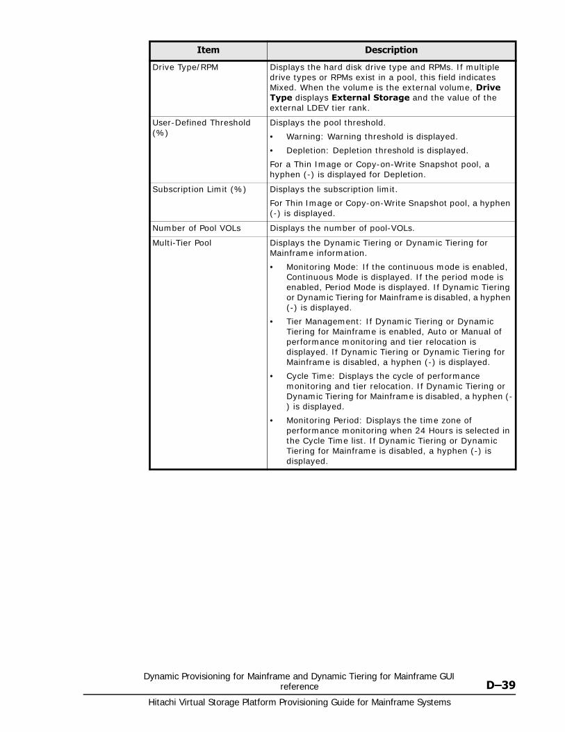
Dynamic Provisioning for Mainframe and Dynamic Tiering for Mainframe GUI reference D–39
Hitachi Virtual Storage Platform Provisioning Guide for Mainframe Systems
Drive Type/RPM Displays the hard disk drive type and RPMs. If multiple drive types or RPMs exist in a pool, this field indicates Mixed. When the volume is the external volume, Drive Type displays External Storage and the value of the external LDEV tier rank.
User-Defined Threshold (%)
Displays the pool threshold.
• Warning: Warning threshold is displayed.
• Depletion: Depletion threshold is displayed.
For a Thin Image or Copy-on-Write Snapshot pool, a hyphen (-) is displayed for Depletion.
Subscription Limit (%) Displays the subscription limit.
For Thin Image or Copy-on-Write Snapshot pool, a hyphen (-) is displayed.
Number of Pool VOLs Displays the number of pool-VOLs.
Multi-Tier Pool Displays the Dynamic Tiering or Dynamic Tiering for Mainframe information.
• Monitoring Mode: If the continuous mode is enabled, Continuous Mode is displayed. If the period mode is enabled, Period Mode is displayed. If Dynamic Tiering or Dynamic Tiering for Mainframe is disabled, a hyphen (-) is displayed.
• Tier Management: If Dynamic Tiering or Dynamic Tiering for Mainframe is enabled, Auto or Manual of performance monitoring and tier relocation is displayed. If Dynamic Tiering or Dynamic Tiering for Mainframe is disabled, a hyphen (-) is displayed.
• Cycle Time: Displays the cycle of performance monitoring and tier relocation. If Dynamic Tiering or Dynamic Tiering for Mainframe is disabled, a hyphen (-) is displayed.
• Monitoring Period: Displays the time zone of performance monitoring when 24 Hours is selected in the Cycle Time list. If Dynamic Tiering or Dynamic Tiering for Mainframe is disabled, a hyphen (-) is displayed.
Item Description
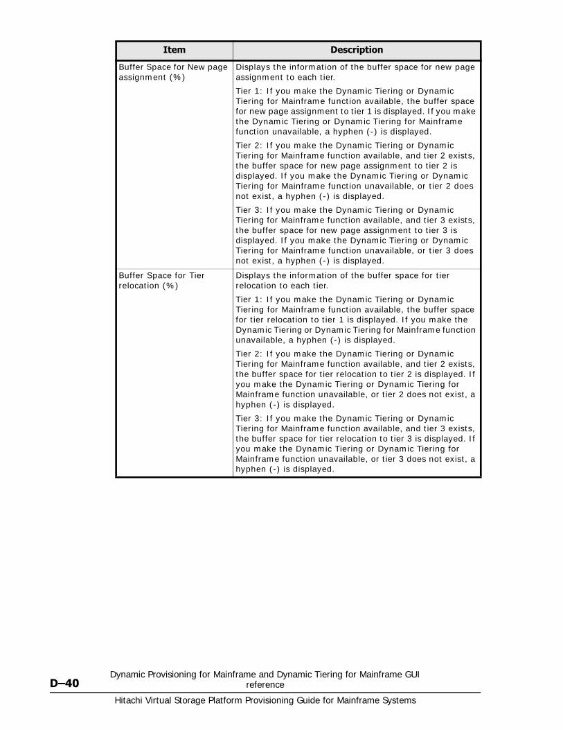
Hitachi Virtual Storage Platform Provisioning Guide for Mainframe Systems
D–40Dynamic Provisioning for Mainframe and Dynamic Tiering for Mainframe GUI
reference
Buffer Space for New page assignment (%)
Displays the information of the buffer space for new page assignment to each tier.
Tier 1: If you make the Dynamic Tiering or Dynamic Tiering for Mainframe function available, the buffer space for new page assignment to tier 1 is displayed. If you make the Dynamic Tiering or Dynamic Tiering for Mainframe function unavailable, a hyphen (-) is displayed.
Tier 2: If you make the Dynamic Tiering or Dynamic Tiering for Mainframe function available, and tier 2 exists, the buffer space for new page assignment to tier 2 is displayed. If you make the Dynamic Tiering or Dynamic Tiering for Mainframe function unavailable, or tier 2 does not exist, a hyphen (-) is displayed.
Tier 3: If you make the Dynamic Tiering or Dynamic Tiering for Mainframe function available, and tier 3 exists, the buffer space for new page assignment to tier 3 is displayed. If you make the Dynamic Tiering or Dynamic Tiering for Mainframe function unavailable, or tier 3 does not exist, a hyphen (-) is displayed.
Buffer Space for Tier relocation (%)
Displays the information of the buffer space for tier relocation to each tier.
Tier 1: If you make the Dynamic Tiering or Dynamic Tiering for Mainframe function available, the buffer space for tier relocation to tier 1 is displayed. If you make the Dynamic Tiering or Dynamic Tiering for Mainframe function unavailable, a hyphen (-) is displayed.
Tier 2: If you make the Dynamic Tiering or Dynamic Tiering for Mainframe function available, and tier 2 exists, the buffer space for tier relocation to tier 2 is displayed. If you make the Dynamic Tiering or Dynamic Tiering for Mainframe function unavailable, or tier 2 does not exist, a hyphen (-) is displayed.
Tier 3: If you make the Dynamic Tiering or Dynamic Tiering for Mainframe function available, and tier 3 exists, the buffer space for tier relocation to tier 3 is displayed. If you make the Dynamic Tiering or Dynamic Tiering for Mainframe function unavailable, or tier 3 does not exist, a hyphen (-) is displayed.
Item Description
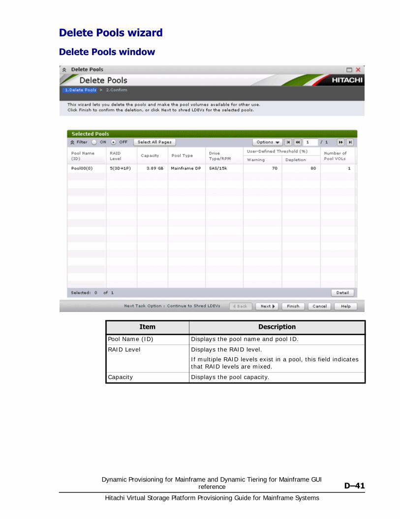
Dynamic Provisioning for Mainframe and Dynamic Tiering for Mainframe GUI reference D–41
Hitachi Virtual Storage Platform Provisioning Guide for Mainframe Systems
Delete Pools wizard
Delete Pools window
Item Description
Pool Name (ID) Displays the pool name and pool ID.
RAID Level Displays the RAID level.
If multiple RAID levels exist in a pool, this field indicates that RAID levels are mixed.
Capacity Displays the pool capacity.
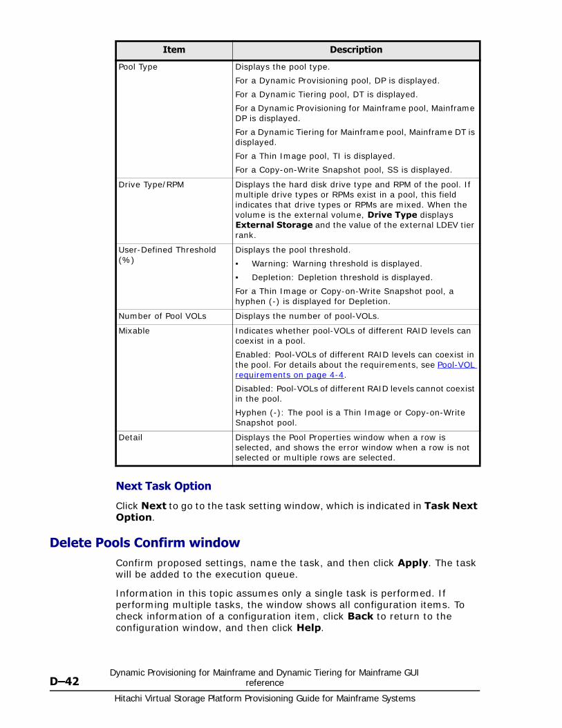
Hitachi Virtual Storage Platform Provisioning Guide for Mainframe Systems
D–42Dynamic Provisioning for Mainframe and Dynamic Tiering for Mainframe GUI
reference
Next Task Option
Click Next to go to the task setting window, which is indicated in Task Next Option.
Delete Pools Confirm windowConfirm proposed settings, name the task, and then click Apply. The task will be added to the execution queue.
Information in this topic assumes only a single task is performed. If performing multiple tasks, the window shows all configuration items. To check information of a configuration item, click Back to return to the configuration window, and then click Help.
Pool Type Displays the pool type.
For a Dynamic Provisioning pool, DP is displayed.
For a Dynamic Tiering pool, DT is displayed.
For a Dynamic Provisioning for Mainframe pool, Mainframe DP is displayed.
For a Dynamic Tiering for Mainframe pool, Mainframe DT is displayed.
For a Thin Image pool, TI is displayed.
For a Copy-on-Write Snapshot pool, SS is displayed.
Drive Type/RPM Displays the hard disk drive type and RPM of the pool. If multiple drive types or RPMs exist in a pool, this field indicates that drive types or RPMs are mixed. When the volume is the external volume, Drive Type displays External Storage and the value of the external LDEV tier rank.
User-Defined Threshold (%)
Displays the pool threshold.
• Warning: Warning threshold is displayed.
• Depletion: Depletion threshold is displayed.
For a Thin Image or Copy-on-Write Snapshot pool, a hyphen (-) is displayed for Depletion.
Number of Pool VOLs Displays the number of pool-VOLs.
Mixable Indicates whether pool-VOLs of different RAID levels can coexist in a pool.
Enabled: Pool-VOLs of different RAID levels can coexist in the pool. For details about the requirements, see Pool-VOL requirements on page 4-4.
Disabled: Pool-VOLs of different RAID levels cannot coexist in the pool.
Hyphen (-): The pool is a Thin Image or Copy-on-Write Snapshot pool.
Detail Displays the Pool Properties window when a row is selected, and shows the error window when a row is not selected or multiple rows are selected.
Item Description
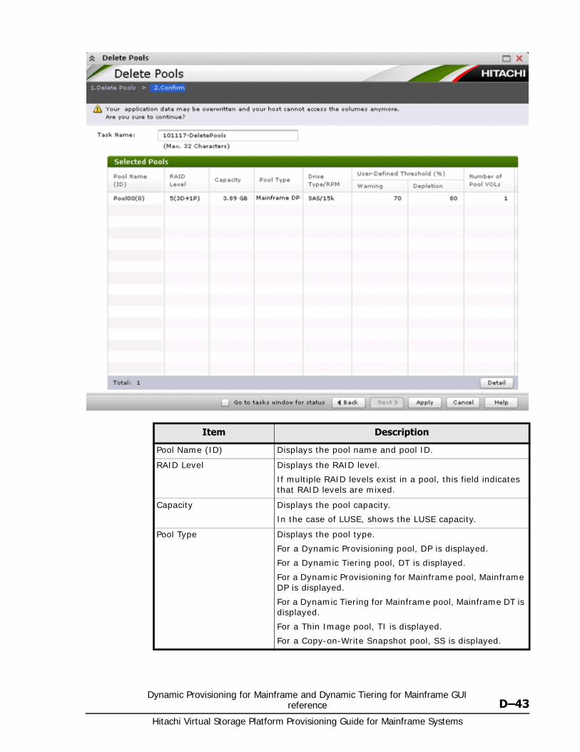
Dynamic Provisioning for Mainframe and Dynamic Tiering for Mainframe GUI reference D–43
Hitachi Virtual Storage Platform Provisioning Guide for Mainframe Systems
Item Description
Pool Name (ID) Displays the pool name and pool ID.
RAID Level Displays the RAID level.
If multiple RAID levels exist in a pool, this field indicates that RAID levels are mixed.
Capacity Displays the pool capacity.
In the case of LUSE, shows the LUSE capacity.
Pool Type Displays the pool type.
For a Dynamic Provisioning pool, DP is displayed.
For a Dynamic Tiering pool, DT is displayed.
For a Dynamic Provisioning for Mainframe pool, Mainframe DP is displayed.
For a Dynamic Tiering for Mainframe pool, Mainframe DT is displayed.
For a Thin Image pool, TI is displayed.
For a Copy-on-Write Snapshot pool, SS is displayed.

Hitachi Virtual Storage Platform Provisioning Guide for Mainframe Systems
D–44Dynamic Provisioning for Mainframe and Dynamic Tiering for Mainframe GUI
reference
Expand V-VOLs wizard
Expand V-VOLs windowUse this wizard to expand the V-VOLs to the defined final capacity of the virtual volumes.
Drive Type/RPM Displays the hard disk drive type and RPM. If multiple drive types or RPMs exist in a pool, this field indicates that drive types or RPMs are mixed. When the volume is the external volume, Drive Type displays External Storage and the value of the external LDEV tier rank.
User-Defined Threshold (%)
Displays the pool threshold.
• Warning: Warning threshold is displayed.
• Depletion: Depletion threshold is displayed.
For a Thin Image or Copy-on-Write Snapshot pool, a hyphen (-) is displayed for Depletion.
Number of Pool VOLs Displays the number of pool-VOLs.
Mixable Indicates whether pool-VOLs of different RAID levels can coexist in a pool.
Enabled: Pool-VOLs of different RAID levels can coexist in the pool. For details about the requirements, see Pool-VOL requirements on page 4-4.
Disabled: Pool-VOLs of different RAID levels cannot coexist in the pool.
Hyphen (-): The pool is a Thin Image or Copy-on-Write Snapshot pool.
Detail Displays the Pool Properties window when a row is selected, and shows the error window when a row is not selected or multiple rows are selected.
Note: Information in this topic assumes that only a single task is executed. If multiple tasks are executed, this window displays all configuration items. To check information of a configuration item, click Back to return to each configuration window, and then click Help.
Item Description
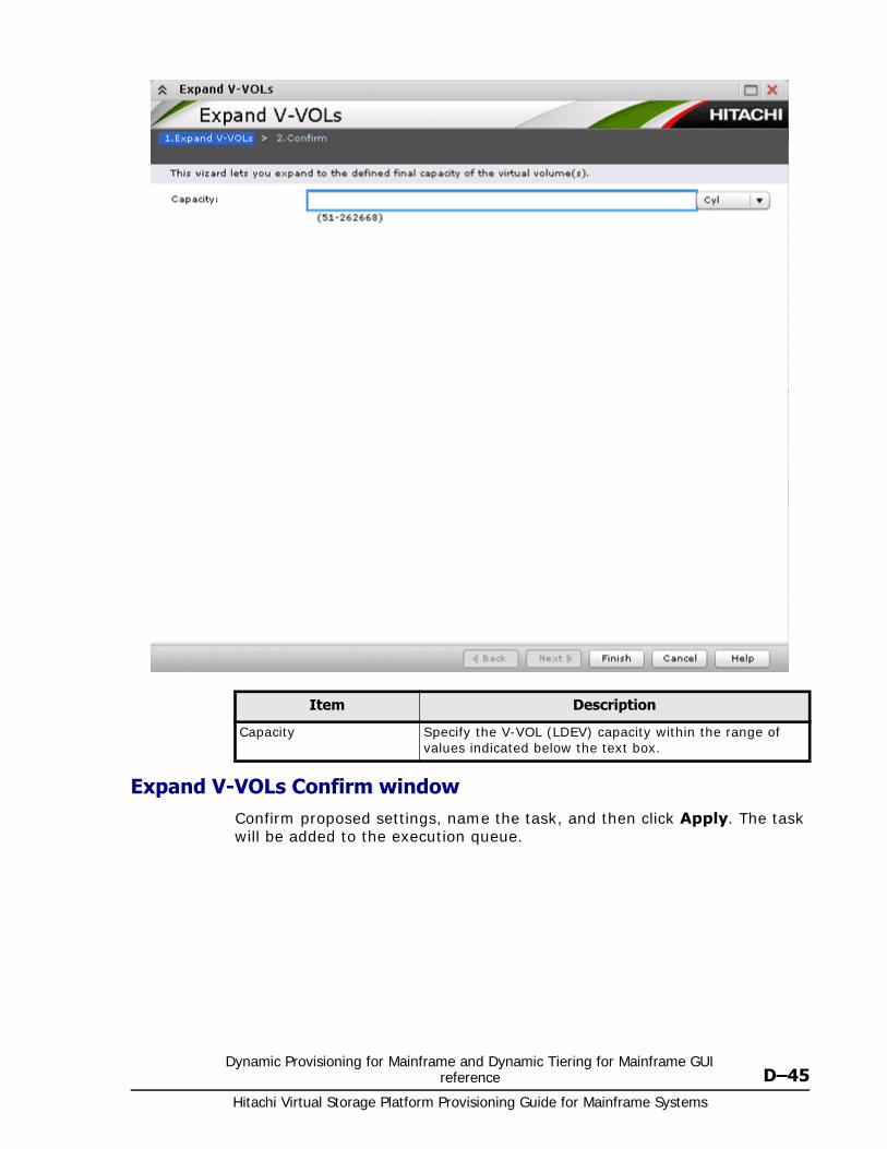
Dynamic Provisioning for Mainframe and Dynamic Tiering for Mainframe GUI reference D–45
Hitachi Virtual Storage Platform Provisioning Guide for Mainframe Systems
Expand V-VOLs Confirm windowConfirm proposed settings, name the task, and then click Apply. The task will be added to the execution queue.
Item Description
Capacity Specify the V-VOL (LDEV) capacity within the range of values indicated below the text box.
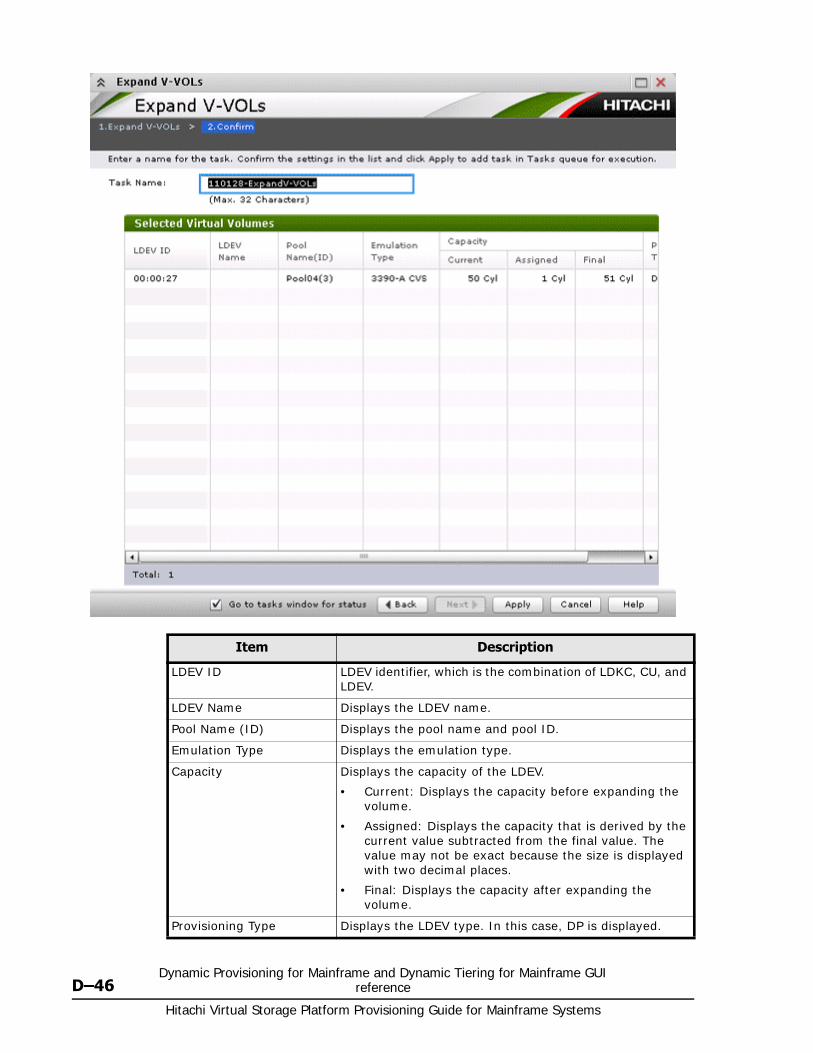
Hitachi Virtual Storage Platform Provisioning Guide for Mainframe Systems
D–46Dynamic Provisioning for Mainframe and Dynamic Tiering for Mainframe GUI
reference
Item Description
LDEV ID LDEV identifier, which is the combination of LDKC, CU, and LDEV.
LDEV Name Displays the LDEV name.
Pool Name (ID) Displays the pool name and pool ID.
Emulation Type Displays the emulation type.
Capacity Displays the capacity of the LDEV.
• Current: Displays the capacity before expanding the volume.
• Assigned: Displays the capacity that is derived by the current value subtracted from the final value. The value may not be exact because the size is displayed with two decimal places.
• Final: Displays the capacity after expanding the volume.
Provisioning Type Displays the LDEV type. In this case, DP is displayed.

Dynamic Provisioning for Mainframe and Dynamic Tiering for Mainframe GUI reference D–47
Hitachi Virtual Storage Platform Provisioning Guide for Mainframe Systems
Restore Pools window
Attribute Displays the attribute of the LDEV.
Command Device: Command device.
TSE: TSE-VOL.
Hyphen (-): Volume in which the attribute is not defined.
Item Description
Pool Name (ID) Displays the pool name and pool ID.
RAID Level Displays the RAID level.
If multiple RAID levels exist in a pool, this field indicates that RAID levels are mixed.
Capacity Displays the pool capacity. If the pool is blocked and pool-VOLs that belong to the pool cannot be identified, 0 is displayed.
Item Description
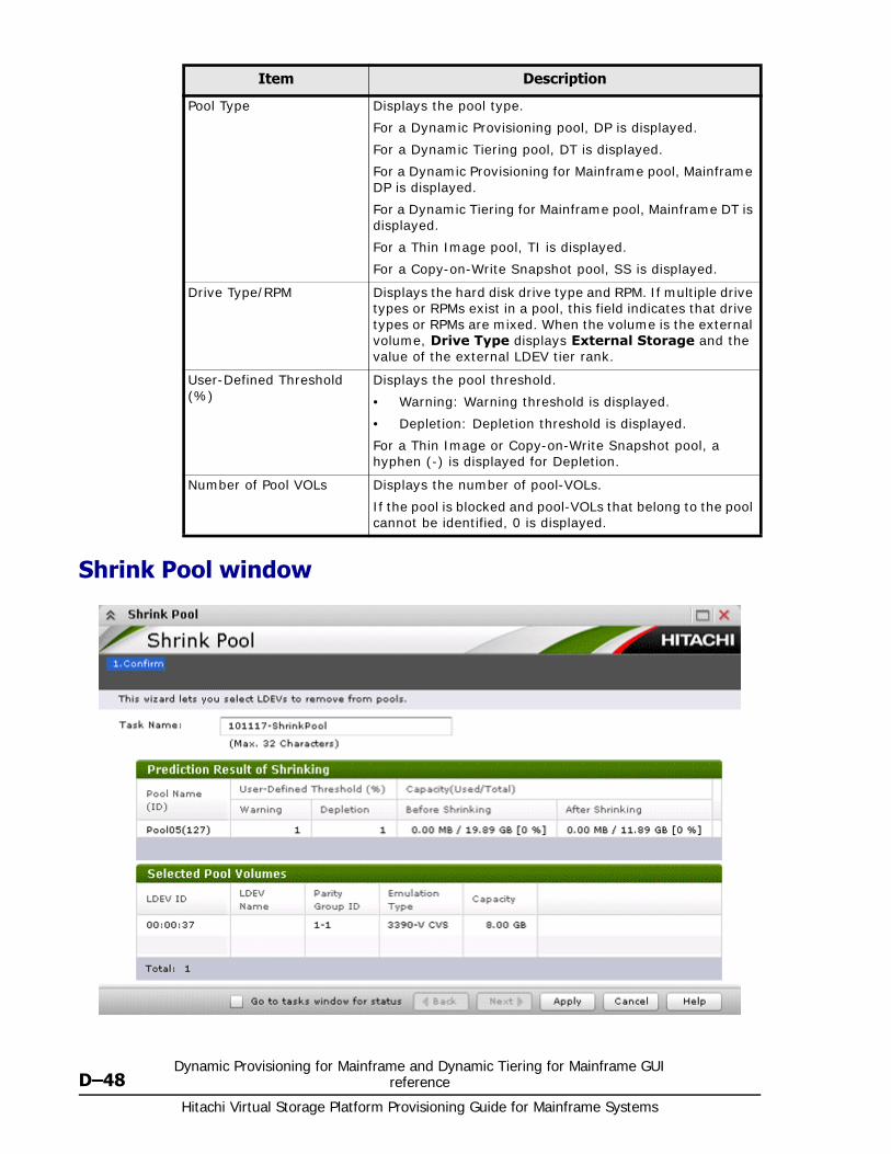
Hitachi Virtual Storage Platform Provisioning Guide for Mainframe Systems
D–48Dynamic Provisioning for Mainframe and Dynamic Tiering for Mainframe GUI
reference
Shrink Pool window
Pool Type Displays the pool type.
For a Dynamic Provisioning pool, DP is displayed.
For a Dynamic Tiering pool, DT is displayed.
For a Dynamic Provisioning for Mainframe pool, Mainframe DP is displayed.
For a Dynamic Tiering for Mainframe pool, Mainframe DT is displayed.
For a Thin Image pool, TI is displayed.
For a Copy-on-Write Snapshot pool, SS is displayed.
Drive Type/RPM Displays the hard disk drive type and RPM. If multiple drive types or RPMs exist in a pool, this field indicates that drive types or RPMs are mixed. When the volume is the external volume, Drive Type displays External Storage and the value of the external LDEV tier rank.
User-Defined Threshold (%)
Displays the pool threshold.
• Warning: Warning threshold is displayed.
• Depletion: Depletion threshold is displayed.
For a Thin Image or Copy-on-Write Snapshot pool, a hyphen (-) is displayed for Depletion.
Number of Pool VOLs Displays the number of pool-VOLs.
If the pool is blocked and pool-VOLs that belong to the pool cannot be identified, 0 is displayed.
Item Description

Dynamic Provisioning for Mainframe and Dynamic Tiering for Mainframe GUI reference D–49
Hitachi Virtual Storage Platform Provisioning Guide for Mainframe Systems
Prediction Result of Shrinking table
Selected Pool Volumes table
Stop Shrinking Pools window
Item Description
Pool Name (ID) Displays the pool name and pool ID.
User-Defined Threshold (%)
Displays the pool threshold.
• Warning: Warning threshold is displayed.
• Depletion: Depletion threshold is displayed.
For a Thin Image or Copy-on-Write Snapshot pool, a hyphen (-) is displayed for Depletion.
Capacity(Used/Total) Displays the capacity before and after shrinking.
• Before Shrinking: Displays the used capacity, total capacity before shrinking and the usage rates.
• After Shrinking: Displays the used capacity, total capacity after shrinking and the usage rates.
Item Description
LDEV ID LDEV identifier, which is the combination of LDKC, CU, and LDEV.
LDEV Name Displays the LDEV name.
Parity Group ID Displays the parity group ID.
Emulation Type Displays the emulation type.
Capacity Displays the pool-VOL capacity.
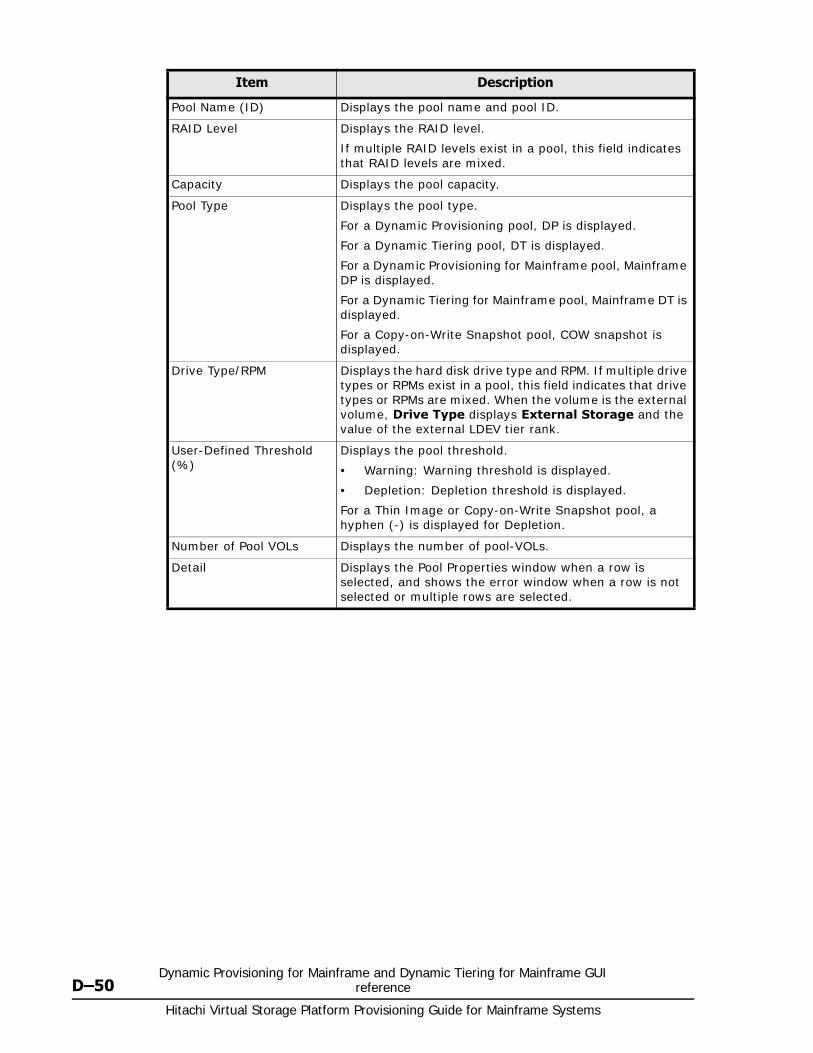
Hitachi Virtual Storage Platform Provisioning Guide for Mainframe Systems
D–50Dynamic Provisioning for Mainframe and Dynamic Tiering for Mainframe GUI
reference
Item Description
Pool Name (ID) Displays the pool name and pool ID.
RAID Level Displays the RAID level.
If multiple RAID levels exist in a pool, this field indicates that RAID levels are mixed.
Capacity Displays the pool capacity.
Pool Type Displays the pool type.
For a Dynamic Provisioning pool, DP is displayed.
For a Dynamic Tiering pool, DT is displayed.
For a Dynamic Provisioning for Mainframe pool, Mainframe DP is displayed.
For a Dynamic Tiering for Mainframe pool, Mainframe DT is displayed.
For a Copy-on-Write Snapshot pool, COW snapshot is displayed.
Drive Type/RPM Displays the hard disk drive type and RPM. If multiple drive types or RPMs exist in a pool, this field indicates that drive types or RPMs are mixed. When the volume is the external volume, Drive Type displays External Storage and the value of the external LDEV tier rank.
User-Defined Threshold (%)
Displays the pool threshold.
• Warning: Warning threshold is displayed.
• Depletion: Depletion threshold is displayed.
For a Thin Image or Copy-on-Write Snapshot pool, a hyphen (-) is displayed for Depletion.
Number of Pool VOLs Displays the number of pool-VOLs.
Detail Displays the Pool Properties window when a row is selected, and shows the error window when a row is not selected or multiple rows are selected.
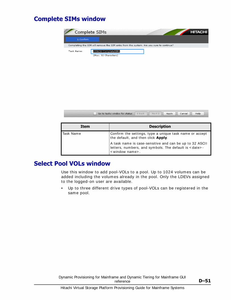
Dynamic Provisioning for Mainframe and Dynamic Tiering for Mainframe GUI reference D–51
Hitachi Virtual Storage Platform Provisioning Guide for Mainframe Systems
Complete SIMs window
Select Pool VOLs windowUse this window to add pool-VOLs to a pool. Up to 1024 volumes can be added including the volumes already in the pool. Only the LDEVs assigned to the logged-on user are available.
• Up to three different drive types of pool-VOLs can be registered in the same pool.
Item Description
Task Name Confirm the settings, type a unique task name or accept the default, and then click Apply.
A task name is case-sensitive and can be up to 32 ASCII letters, numbers, and symbols. The default is <date>-<window name>.
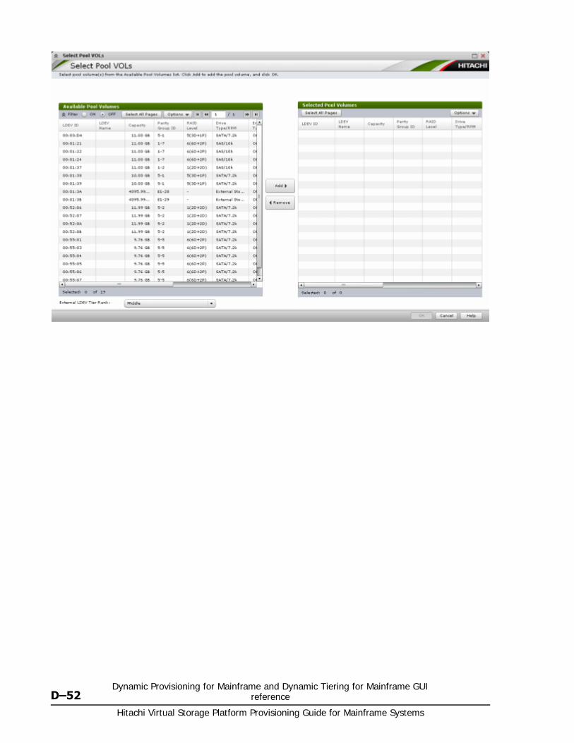
Hitachi Virtual Storage Platform Provisioning Guide for Mainframe Systems
D–52Dynamic Provisioning for Mainframe and Dynamic Tiering for Mainframe GUI
reference
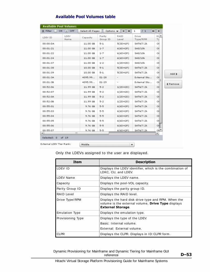
Dynamic Provisioning for Mainframe and Dynamic Tiering for Mainframe GUI reference D–53
Hitachi Virtual Storage Platform Provisioning Guide for Mainframe Systems
Available Pool Volumes table
Only the LDEVs assigned to the user are displayed.
Item Description
LDEV ID Displays the LDEV identifier, which is the combination of LDKC, CU, and LDEV.
LDEV Name Displays the LDEV name.
Capacity Displays the pool-VOL capacity.
Parity Group ID Displays the parity group ID.
RAID Level Displays the RAID level.
Drive Type/RPM Displays the hard disk drive type and RPM. When the volume is the external volume, Drive Type displays External Storage.
Emulation Type Displays the emulation type.
Provisioning Type Displays the type of the LDEV.
Basic: Internal volume.
External: External volume.
CLPR Displays the CLPR. Displays in ID:CLPR form.
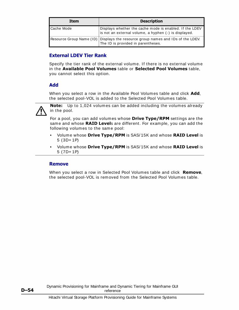
Hitachi Virtual Storage Platform Provisioning Guide for Mainframe Systems
D–54Dynamic Provisioning for Mainframe and Dynamic Tiering for Mainframe GUI
reference
External LDEV Tier Rank
Specify the tier rank of the external volume. If there is no external volume in the Available Pool Volumes table or Selected Pool Volumes table, you cannot select this option.
Add
When you select a row in the Available Pool Volumes table and click Add, the selected pool-VOL is added to the Selected Pool Volumes table.
Remove
When you select a row in Selected Pool Volumes table and click Remove, the selected pool-VOL is removed from the Selected Pool Volumes table.
Cache Mode Displays whether the cache mode is enabled. If the LDEV is not an external volume, a hyphen (-) is displayed.
Resource Group Name (ID) Displays the resource group names and IDs of the LDEV. The ID is provided in parentheses.
Item Description
Note: Up to 1,024 volumes can be added including the volumes already in the pool.
For a pool, you can add volumes whose Drive Type/RPM settings are the same and whose RAID Levels are different. For example, you can add the following volumes to the same pool:
• Volume whose Drive Type/RPM is SAS/15K and whose RAID Level is 5 (3D+1P)
• Volume whose Drive Type/RPM is SAS/15K and whose RAID Level is 5 (7D+1P)
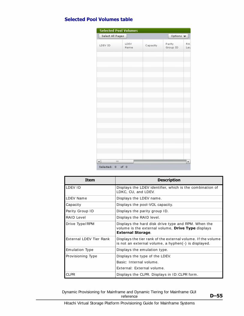
Dynamic Provisioning for Mainframe and Dynamic Tiering for Mainframe GUI reference D–55
Hitachi Virtual Storage Platform Provisioning Guide for Mainframe Systems
Selected Pool Volumes table
Item Description
LDEV ID Displays the LDEV identifier, which is the combination of LDKC, CU, and LDEV.
LDEV Name Displays the LDEV name.
Capacity Displays the pool-VOL capacity.
Parity Group ID Displays the parity group ID.
RAID Level Displays the RAID level.
Drive Type/RPM Displays the hard disk drive type and RPM. When the volume is the external volume, Drive Type displays External Storage.
External LDEV Tier Rank Displays the tier rank of the external volume. If the volume is not an external volume, a hyphen(-) is displayed.
Emulation Type Displays the emulation type.
Provisioning Type Displays the type of the LDEV.
Basic: Internal volume.
External: External volume.
CLPR Displays the CLPR. Displays in ID:CLPR form.
Hitachi Virtual Storage Platform Provisioning Guide for Mainframe Systems
D–56Dynamic Provisioning for Mainframe and Dynamic Tiering for Mainframe GUI
reference
Reclaim Zero Pages window
Cache Mode Displays whether the cache mode is enabled. If the LDEV is not an external volume, a hyphen (-) is displayed.
Resource Group Name (ID) Displays the resource group names and IDs of the LDEV. The ID is provided in parentheses.
Item Description
LDEV ID Displays the LDEV identifier, which is the combination of LDKC, CU, and LDEV.
LDEV Name Displays the LDEV name.
Pool Name (ID) Displays the pool name and pool ID.
Emulation Type Displays the emulation type.
Capacity Displays the capacity.
Provisioning Type Displays the LDEV type. In this case, DP is displayed.
Attribute Displays the attribute of the LDEV.
Command Device: Command device.
Hyphen (-): Volume in which the attribute is not defined.
Item Description

Dynamic Provisioning for Mainframe and Dynamic Tiering for Mainframe GUI reference D–57
Hitachi Virtual Storage Platform Provisioning Guide for Mainframe Systems
Stop Reclaiming Zero Pages window
Pool Property windowUse this window to view and change pool properties. Only the LDEVS assigned to the logged-on user are available.
Item Description
LDEV ID Displays the LDEV identifier, which is the combination of LDKC, CU, and LDEV.
LDEV Name Displays the LDEV name.
Pool Name (ID) Displays the pool name and pool ID.
Emulation Type Displays the emulation type.
Capacity Displays the capacity.
Provisioning Type Displays the LDEV type. In this case, DP is displayed.
Attribute Displays the attribute of the LDEV.
Command Device: Command device.
Hyphen (-): Volume in which the attribute is not defined.
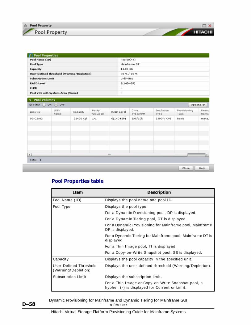
Hitachi Virtual Storage Platform Provisioning Guide for Mainframe Systems
D–58Dynamic Provisioning for Mainframe and Dynamic Tiering for Mainframe GUI
reference
Pool Properties table
Item Description
Pool Name (ID) Displays the pool name and pool ID.
Pool Type Displays the pool type.
For a Dynamic Provisioning pool, DP is displayed.
For a Dynamic Tiering pool, DT is displayed.
For a Dynamic Provisioning for Mainframe pool, Mainframe DP is displayed.
For a Dynamic Tiering for Mainframe pool, Mainframe DT is displayed.
For a Thin Image pool, TI is displayed.
For a Copy-on-Write Snapshot pool, SS is displayed.
Capacity Displays the pool capacity in the specified unit.
User-Defined Threshold (Warning/Depletion)
Displays the user-defined threshold (Warning/Depletion).
Subscription Limit Displays the subscription limit.
For a Thin Image or Copy-on-Write Snapshot pool, a hyphen (-) is displayed for Current or Limit.
Dynamic Provisioning for Mainframe and Dynamic Tiering for Mainframe GUI reference D–59
Hitachi Virtual Storage Platform Provisioning Guide for Mainframe Systems
Pool Volumes table
Only the LDEVs assigned to the user are displayed.
View Tier Properties windowThis window shows tier properties and a performance graph:
• For pools on page D-60
• For V-VOLs on page D-63
When the pool name (pool ID) appears in the graph banner, you are looking a pool information. When the LDEV name (LDEV ID) appears in the graph banner, you are looking at V-VOL information.
RAID Level Displays the RAID level. If multiple RAID levels exist in a pool, this field indicates that RAID levels are mixed.
CLPR Displays the CLPR set for the Thin Image or Copy-on-Write Snapshot pool-VOLs. Displays in ID:CLPR form.
For Pool-VOLs other than the Thin Image or Copy-on-Write Snapshot pool-VOL, a hyphen (-) is displayed.
Pool VOL with System Area (Name)
Displays LDEV ID and LDEV name of the pool-VOL which includes the system area. If you open this window from the Selected Pools table in the Create Pool window, a hyphen(-) is displayed.
For a Copy-on-Write Snapshot pool, a hyphen (-) is displayed for Current or Limit.
Item Description
Item Description
LDEV ID Displays the LDEV identifier, which is the combination of LDKC, CU, and LDEV.
LDEV Name Displays the LDEV name.
Capacity Displays the pool volumes capacity in the specified unit. If you open this window from the Selected Pools table in the Create Pool window, the LDEV capacity selected in the Select Pool VOLs window is displayed.
Parity Group ID Displays the parity group ID.
RAID Level Displays the RAID level.
Drive Type/RPM Displays the hard disk drive type and RPM. When the volume is the external volume, Drive Type displays External Storage and the value of the external LDEV tier rank.
Emulation Type Displays the emulation type.
Provisioning Type Displays the type of the LDEV.
Basic: Internal volume.
External: External volume.
Resource Group Name (ID) Displays the resource group names and IDs of the LDEV. The ID is provided in parentheses.
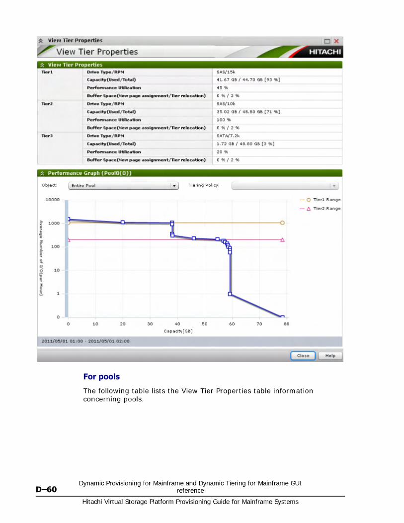
Hitachi Virtual Storage Platform Provisioning Guide for Mainframe Systems
D–60Dynamic Provisioning for Mainframe and Dynamic Tiering for Mainframe GUI
reference
For pools
The following table lists the View Tier Properties table information concerning pools.
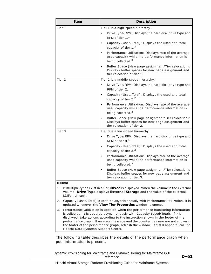
Dynamic Provisioning for Mainframe and Dynamic Tiering for Mainframe GUI reference D–61
Hitachi Virtual Storage Platform Provisioning Guide for Mainframe Systems
The following table describes the details of the performance graph when pool information is present.
Item Description
Tier 1 Tier 1 is a high-speed hierarchy.
• Drive Type/RPM: Displays the hard disk drive type and RPM of tier 1.1
• Capacity (Used/Total): Displays the used and total capacity of tier 1.2
• Performance Utilization: Displays rate of the average used capacity while the performance information is being collected.3
• Buffer Space (New page assignment/Tier relocation): Displays buffer spaces for new page assignment and tier relocation of tier 1.
Tier 2 Tier 2 is a middle-speed hierarchy.
• Drive Type/RPM: Displays the hard disk drive type and RPM of tier 2.1
• Capacity (Used/Total): Displays the used and total capacity of tier 2.2
• Performance Utilization: Displays rate of the average used capacity while the performance information is being collected.3
• Buffer Space (New page assignment/Tier relocation): Displays buffer spaces for new page assignment and tier relocation of tier 2.
Tier 3 Tier 3 is a low-speed hierarchy.
• Drive Type/RPM: Displays the hard disk drive type and RPM of tier 3.1
• Capacity (Used/Total): Displays the used and total capacity of tier 3.2
• Performance Utilization: Displays rate of the average used capacity while the performance information is being collected.3
• Buffer Space (New page assignment/Tier relocation): Displays buffer spaces for new page assignment and tier relocation of tier 3.
Notes:
1. If multiple types exist in a tier, Mixed is displayed. When the volume is the external volume, Drive Type displays External Storage and the value of the external LDEV tier rank.
2. Capacity (Used/Total) is updated asynchronously with Performance Utilization. It is updated whenever the View Tier Properties window is opened.
3. Performance Utilization is updated when the performance monitoring information is collected. It is updated asynchronously with Capacity (Used/Total). If ? is displayed, take actions according to the instruction shown in the footer of the performance graph. If an error message and the countermeasure are not shown in the footer of the performance graph, refresh the window. If ? still appears, call the Hitachi Data Systems Support Center.
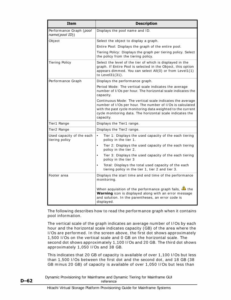
Hitachi Virtual Storage Platform Provisioning Guide for Mainframe Systems
D–62Dynamic Provisioning for Mainframe and Dynamic Tiering for Mainframe GUI
reference
The following describes how to read the performance graph when it contains pool information.
The vertical scale of the graph indicates an average number of I/Os by each hour and the horizontal scale indicates capacity (GB) of the area where the I/Os are performed. In the screen above, the first dot shows approximately 1,500 I/Os on the vertical scale and 0 GB on the horizontal scale. The second dot shows approximately 1,100 I/Os and 20 GB. The third dot shows approximately 1,050 I/Os and 38 GB.
This indicates that 20 GB of capacity is available of over 1,100 I/Os but less than 1,500 I/Os between the first dot and the second dot, and 18 GB (38 GB minus 20 GB) of capacity is available of over 1,050 I/Os but less than
Item Description
Performance Graph (pool name(pool ID))
Displays the pool name and ID.
Object Select the object to display a graph.
Entire Pool: Displays the graph of the entire pool.
Tiering Policy: Displays the graph per tiering policy. Select the policy from the tiering policy.
Tiering Policy Select the level of the tier of which is displayed in the graph. If Entire Pool is selected in the Object, this option appears dimmed. You can select All(0) or from Level1(1) to Level31(31).
Performance Graph Displays the performance graph.
Period Mode: The vertical scale indicates the average number of I/Os per hour. The horizontal scale indicates the capacity.
Continuous Mode: The vertical scale indicates the average number of I/Os per hour. The number of I/Os is calculated with the past cycle monitoring data weighted to the current cycle monitoring data. The horizontal scale indicates the capacity.
Tier1 Range Displays the Tier1 range.
Tier2 Range Displays the Tier2 range.
Used capacity of the each tiering policy
• Tier 1: Displays the used capacity of the each tiering policy in the tier 1.
• Tier 2: Displays the used capacity of the each tiering policy in the tier 2.
• Tier 3: Displays the used capacity of the each tiering policy in the tier 3
• Total: Displays the total used capacity of the each tiering policy in the tier 1, tier 2 and tier 3.
Footer area Displays the start time and end time of the performance monitoring.
When acquisition of the performance graph fails, the Warning icon is displayed along with an error message and solution. In the parentheses, an error code is displayed.
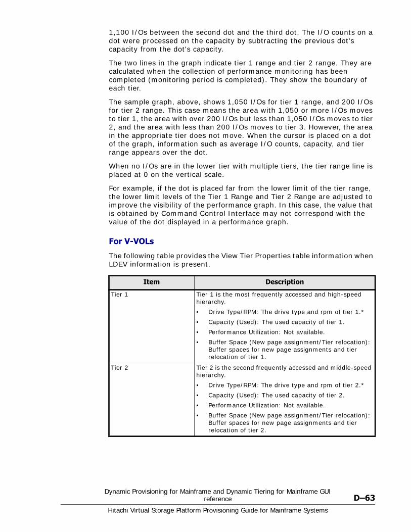
Dynamic Provisioning for Mainframe and Dynamic Tiering for Mainframe GUI reference D–63
Hitachi Virtual Storage Platform Provisioning Guide for Mainframe Systems
1,100 I/Os between the second dot and the third dot. The I/O counts on a dot were processed on the capacity by subtracting the previous dot's capacity from the dot's capacity.
The two lines in the graph indicate tier 1 range and tier 2 range. They are calculated when the collection of performance monitoring has been completed (monitoring period is completed). They show the boundary of each tier.
The sample graph, above, shows 1,050 I/Os for tier 1 range, and 200 I/Os for tier 2 range. This case means the area with 1,050 or more I/Os moves to tier 1, the area with over 200 I/Os but less than 1,050 I/Os moves to tier 2, and the area with less than 200 I/Os moves to tier 3. However, the area in the appropriate tier does not move. When the cursor is placed on a dot of the graph, information such as average I/O counts, capacity, and tier range appears over the dot.
When no I/Os are in the lower tier with multiple tiers, the tier range line is placed at 0 on the vertical scale.
For example, if the dot is placed far from the lower limit of the tier range, the lower limit levels of the Tier 1 Range and Tier 2 Range are adjusted to improve the visibility of the performance graph. In this case, the value that is obtained by Command Control Interface may not correspond with the value of the dot displayed in a performance graph.
For V-VOLs
The following table provides the View Tier Properties table information when LDEV information is present.
Item Description
Tier 1 Tier 1 is the most frequently accessed and high-speed hierarchy.
• Drive Type/RPM: The drive type and rpm of tier 1.*
• Capacity (Used): The used capacity of tier 1.
• Performance Utilization: Not available.
• Buffer Space (New page assignment/Tier relocation): Buffer spaces for new page assignments and tier relocation of tier 1.
Tier 2 Tier 2 is the second frequently accessed and middle-speed hierarchy.
• Drive Type/RPM: The drive type and rpm of tier 2.*
• Capacity (Used): The used capacity of tier 2.
• Performance Utilization: Not available.
• Buffer Space (New page assignment/Tier relocation): Buffer spaces for new page assignments and tier relocation of tier 2.
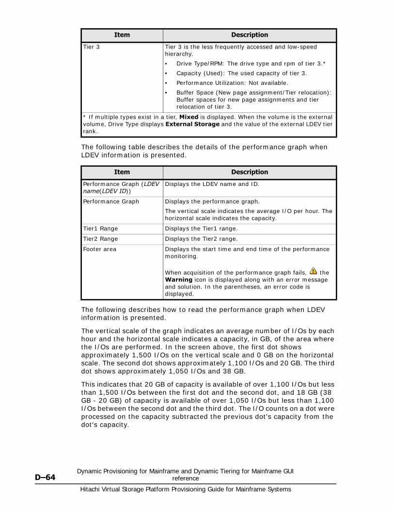
Hitachi Virtual Storage Platform Provisioning Guide for Mainframe Systems
D–64Dynamic Provisioning for Mainframe and Dynamic Tiering for Mainframe GUI
reference
The following table describes the details of the performance graph when LDEV information is presented.
The following describes how to read the performance graph when LDEV information is presented.
The vertical scale of the graph indicates an average number of I/Os by each hour and the horizontal scale indicates a capacity, in GB, of the area where the I/Os are performed. In the screen above, the first dot shows approximately 1,500 I/Os on the vertical scale and 0 GB on the horizontal scale. The second dot shows approximately 1,100 I/Os and 20 GB. The third dot shows approximately 1,050 I/Os and 38 GB.
This indicates that 20 GB of capacity is available of over 1,100 I/Os but less than 1,500 I/Os between the first dot and the second dot, and 18 GB (38 GB - 20 GB) of capacity is available of over 1,050 I/Os but less than 1,100 I/Os between the second dot and the third dot. The I/O counts on a dot were processed on the capacity subtracted the previous dot's capacity from the dot's capacity.
Tier 3 Tier 3 is the less frequently accessed and low-speed hierarchy.
• Drive Type/RPM: The drive type and rpm of tier 3.*
• Capacity (Used): The used capacity of tier 3.
• Performance Utilization: Not available.
• Buffer Space (New page assignment/Tier relocation): Buffer spaces for new page assignments and tier relocation of tier 3.
* If multiple types exist in a tier, Mixed is displayed. When the volume is the external volume, Drive Type displays External Storage and the value of the external LDEV tier rank.
Item Description
Item Description
Performance Graph (LDEV name(LDEV ID))
Displays the LDEV name and ID.
Performance Graph Displays the performance graph.
The vertical scale indicates the average I/O per hour. The horizontal scale indicates the capacity.
Tier1 Range Displays the Tier1 range.
Tier2 Range Displays the Tier2 range.
Footer area Displays the start time and end time of the performance monitoring.
When acquisition of the performance graph fails, the Warning icon is displayed along with an error message and solution. In the parentheses, an error code is displayed.
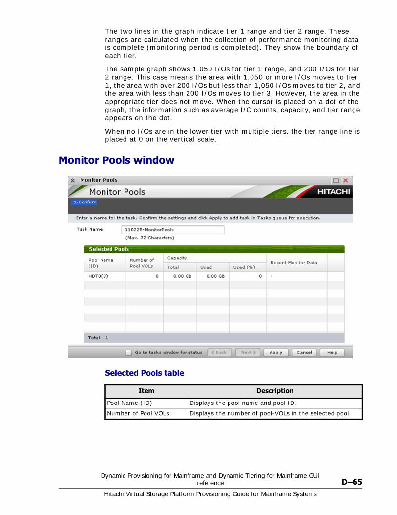
Dynamic Provisioning for Mainframe and Dynamic Tiering for Mainframe GUI reference D–65
Hitachi Virtual Storage Platform Provisioning Guide for Mainframe Systems
The two lines in the graph indicate tier 1 range and tier 2 range. These ranges are calculated when the collection of performance monitoring data is complete (monitoring period is completed). They show the boundary of each tier.
The sample graph shows 1,050 I/Os for tier 1 range, and 200 I/Os for tier 2 range. This case means the area with 1,050 or more I/Os moves to tier 1, the area with over 200 I/Os but less than 1,050 I/Os moves to tier 2, and the area with less than 200 I/Os moves to tier 3. However, the area in the appropriate tier does not move. When the cursor is placed on a dot of the graph, the information such as average I/O counts, capacity, and tier range appears on the dot.
When no I/Os are in the lower tier with multiple tiers, the tier range line is placed at 0 on the vertical scale.
Monitor Pools window
Selected Pools table
Item Description
Pool Name (ID) Displays the pool name and pool ID.
Number of Pool VOLs Displays the number of pool-VOLs in the selected pool.
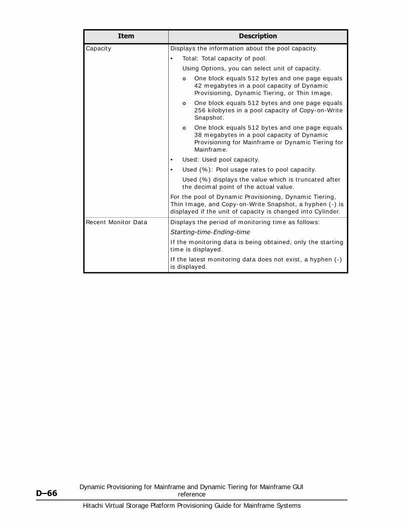
Hitachi Virtual Storage Platform Provisioning Guide for Mainframe Systems
D–66Dynamic Provisioning for Mainframe and Dynamic Tiering for Mainframe GUI
reference
Capacity Displays the information about the pool capacity.
• Total: Total capacity of pool.
Using Options, you can select unit of capacity.
One block equals 512 bytes and one page equals 42 megabytes in a pool capacity of Dynamic Provisioning, Dynamic Tiering, or Thin Image.
One block equals 512 bytes and one page equals 256 kilobytes in a pool capacity of Copy-on-Write Snapshot.
One block equals 512 bytes and one page equals 38 megabytes in a pool capacity of Dynamic Provisioning for Mainframe or Dynamic Tiering for Mainframe.
• Used: Used pool capacity.
• Used (%): Pool usage rates to pool capacity.
Used (%) displays the value which is truncated after the decimal point of the actual value.
For the pool of Dynamic Provisioning, Dynamic Tiering, Thin Image, and Copy-on-Write Snapshot, a hyphen (-) is displayed if the unit of capacity is changed into Cylinder.
Recent Monitor Data Displays the period of monitoring time as follows:
Starting-time-Ending-time
If the monitoring data is being obtained, only the starting time is displayed.
If the latest monitoring data does not exist, a hyphen (-) is displayed.
Item Description
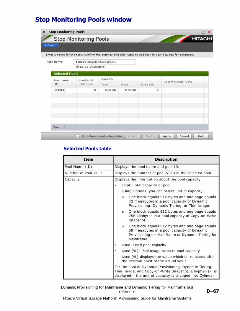
Dynamic Provisioning for Mainframe and Dynamic Tiering for Mainframe GUI reference D–67
Hitachi Virtual Storage Platform Provisioning Guide for Mainframe Systems
Stop Monitoring Pools window
Selected Pools table
Item Description
Pool Name (ID) Displays the pool name and pool ID.
Number of Pool VOLs Displays the number of pool-VOLs in the selected pool.
Capacity Displays the information about the pool capacity.
• Total: Total capacity of pool.
Using Options, you can select unit of capacity.
One block equals 512 bytes and one page equals 42 megabytes in a pool capacity of Dynamic Provisioning, Dynamic Tiering, or Thin Image.
One block equals 512 bytes and one page equals 256 kilobytes in a pool capacity of Copy-on-Write Snapshot.
One block equals 512 bytes and one page equals 38 megabytes in a pool capacity of Dynamic Provisioning for Mainframe or Dynamic Tiering for Mainframe.
• Used: Used pool capacity.
• Used (%): Pool usage rates to pool capacity.
Used (%) displays the value which is truncated after the decimal point of the actual value.
For the pool of Dynamic Provisioning, Dynamic Tiering, Thin Image, and Copy-on-Write Snapshot, a hyphen (-) is displayed if the unit of capacity is changed into Cylinder.
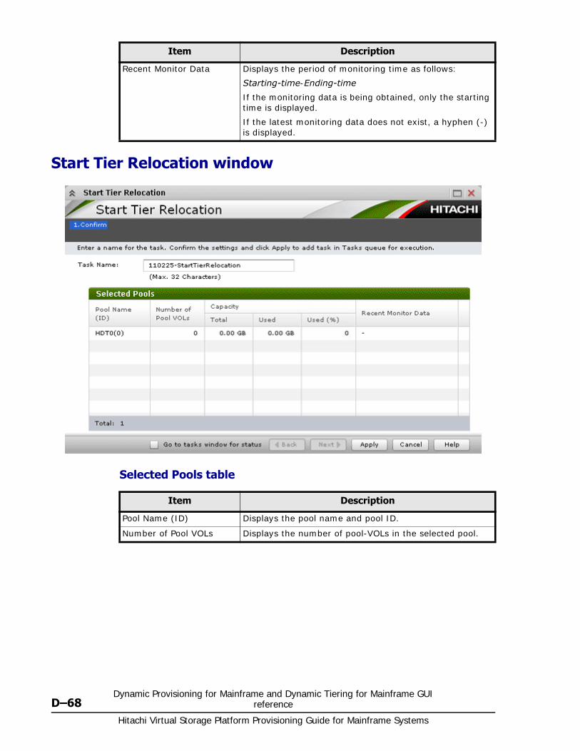
Hitachi Virtual Storage Platform Provisioning Guide for Mainframe Systems
D–68Dynamic Provisioning for Mainframe and Dynamic Tiering for Mainframe GUI
reference
Start Tier Relocation window
Selected Pools table
Recent Monitor Data Displays the period of monitoring time as follows:
Starting-time-Ending-time
If the monitoring data is being obtained, only the starting time is displayed.
If the latest monitoring data does not exist, a hyphen (-) is displayed.
Item Description
Item Description
Pool Name (ID) Displays the pool name and pool ID.
Number of Pool VOLs Displays the number of pool-VOLs in the selected pool.
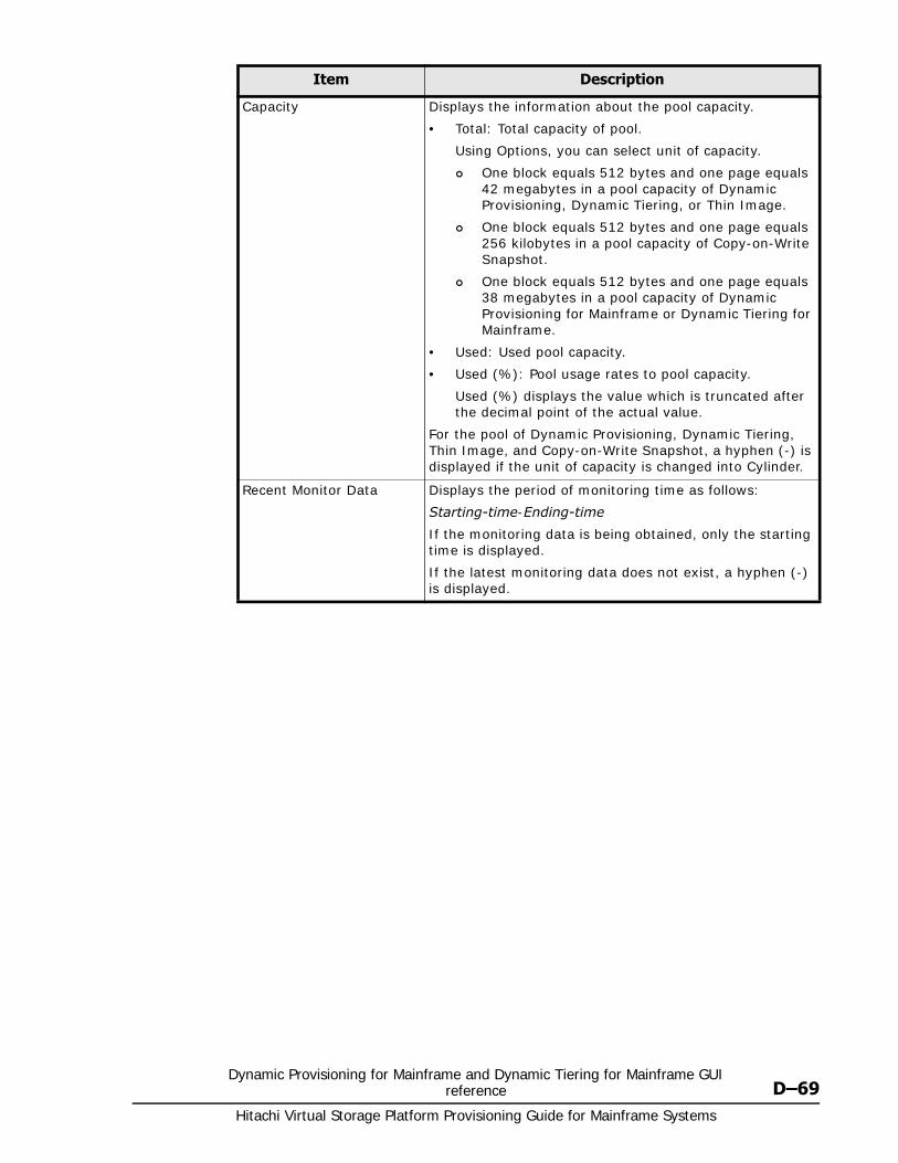
Dynamic Provisioning for Mainframe and Dynamic Tiering for Mainframe GUI reference D–69
Hitachi Virtual Storage Platform Provisioning Guide for Mainframe Systems
Capacity Displays the information about the pool capacity.
• Total: Total capacity of pool.
Using Options, you can select unit of capacity.
One block equals 512 bytes and one page equals 42 megabytes in a pool capacity of Dynamic Provisioning, Dynamic Tiering, or Thin Image.
One block equals 512 bytes and one page equals 256 kilobytes in a pool capacity of Copy-on-Write Snapshot.
One block equals 512 bytes and one page equals 38 megabytes in a pool capacity of Dynamic Provisioning for Mainframe or Dynamic Tiering for Mainframe.
• Used: Used pool capacity.
• Used (%): Pool usage rates to pool capacity.
Used (%) displays the value which is truncated after the decimal point of the actual value.
For the pool of Dynamic Provisioning, Dynamic Tiering, Thin Image, and Copy-on-Write Snapshot, a hyphen (-) is displayed if the unit of capacity is changed into Cylinder.
Recent Monitor Data Displays the period of monitoring time as follows:
Starting-time-Ending-time
If the monitoring data is being obtained, only the starting time is displayed.
If the latest monitoring data does not exist, a hyphen (-) is displayed.
Item Description
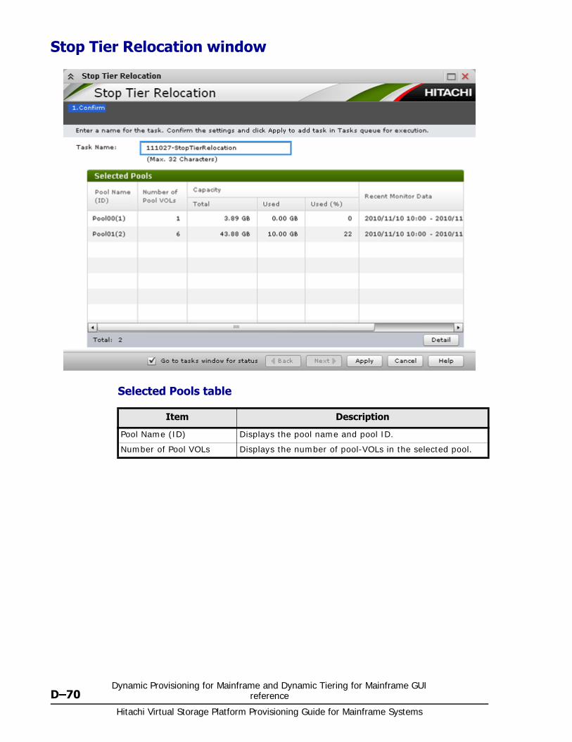
Hitachi Virtual Storage Platform Provisioning Guide for Mainframe Systems
D–70Dynamic Provisioning for Mainframe and Dynamic Tiering for Mainframe GUI
reference
Stop Tier Relocation window
Selected Pools table
Item Description
Pool Name (ID) Displays the pool name and pool ID.
Number of Pool VOLs Displays the number of pool-VOLs in the selected pool.
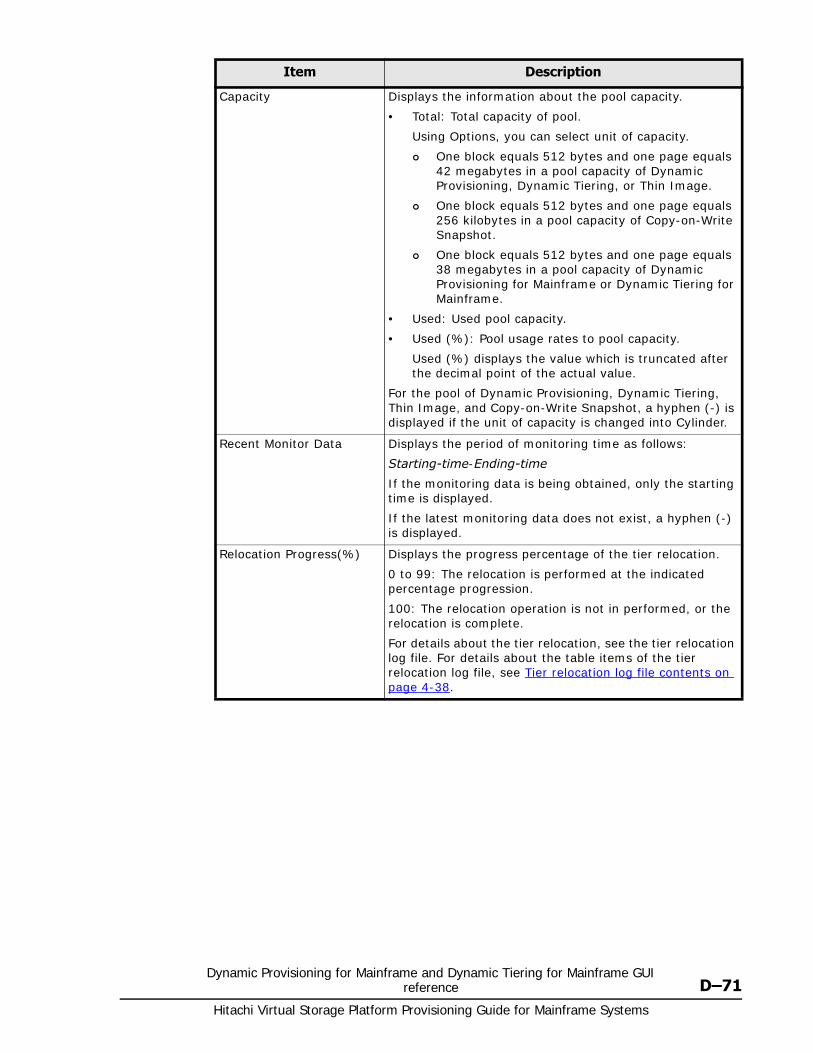
Dynamic Provisioning for Mainframe and Dynamic Tiering for Mainframe GUI reference D–71
Hitachi Virtual Storage Platform Provisioning Guide for Mainframe Systems
Capacity Displays the information about the pool capacity.
• Total: Total capacity of pool.
Using Options, you can select unit of capacity.
One block equals 512 bytes and one page equals 42 megabytes in a pool capacity of Dynamic Provisioning, Dynamic Tiering, or Thin Image.
One block equals 512 bytes and one page equals 256 kilobytes in a pool capacity of Copy-on-Write Snapshot.
One block equals 512 bytes and one page equals 38 megabytes in a pool capacity of Dynamic Provisioning for Mainframe or Dynamic Tiering for Mainframe.
• Used: Used pool capacity.
• Used (%): Pool usage rates to pool capacity.
Used (%) displays the value which is truncated after the decimal point of the actual value.
For the pool of Dynamic Provisioning, Dynamic Tiering, Thin Image, and Copy-on-Write Snapshot, a hyphen (-) is displayed if the unit of capacity is changed into Cylinder.
Recent Monitor Data Displays the period of monitoring time as follows:
Starting-time-Ending-time
If the monitoring data is being obtained, only the starting time is displayed.
If the latest monitoring data does not exist, a hyphen (-) is displayed.
Relocation Progress(%) Displays the progress percentage of the tier relocation.
0 to 99: The relocation is performed at the indicated percentage progression.
100: The relocation operation is not in performed, or the relocation is complete.
For details about the tier relocation, see the tier relocation log file. For details about the table items of the tier relocation log file, see Tier relocation log file contents on page 4-38.
Item Description
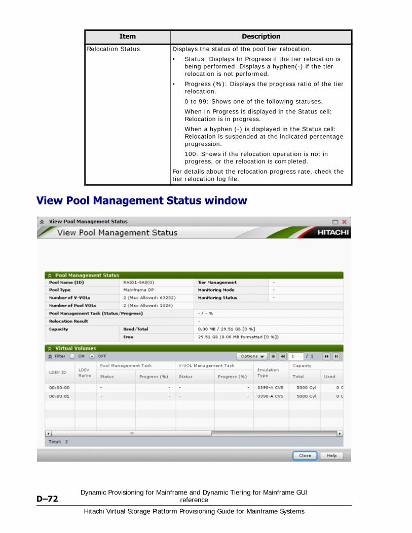
Hitachi Virtual Storage Platform Provisioning Guide for Mainframe Systems
D–72Dynamic Provisioning for Mainframe and Dynamic Tiering for Mainframe GUI
reference
View Pool Management Status window
Relocation Status Displays the status of the pool tier relocation.
• Status: Displays In Progress if the tier relocation is being performed. Displays a hyphen(-) if the tier relocation is not performed.
• Progress (%): Displays the progress ratio of the tier relocation.
0 to 99: Shows one of the following statuses.
When In Progress is displayed in the Status cell: Relocation is in progress.
When a hyphen (-) is displayed in the Status cell: Relocation is suspended at the indicated percentage progression.
100: Shows if the relocation operation is not in progress, or the relocation is completed.
For details about the relocation progress rate, check the tier relocation log file.
Item Description
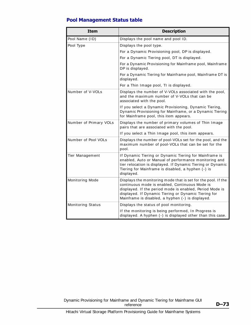
Dynamic Provisioning for Mainframe and Dynamic Tiering for Mainframe GUI reference D–73
Hitachi Virtual Storage Platform Provisioning Guide for Mainframe Systems
Pool Management Status table
Item Description
Pool Name (ID) Displays the pool name and pool ID.
Pool Type Displays the pool type.
For a Dynamic Provisioning pool, DP is displayed.
For a Dynamic Tiering pool, DT is displayed.
For a Dynamic Provisioning for Mainframe pool, Mainframe DP is displayed.
For a Dynamic Tiering for Mainframe pool, Mainframe DT is displayed.
For a Thin Image pool, TI is displayed.
Number of V-VOLs Displays the number of V-VOLs associated with the pool, and the maximum number of V-VOLs that can be associated with the pool.
If you select a Dynamic Provisioning, Dynamic Tiering, Dynamic Provisioning for Mainframe, or a Dynamic Tiering for Mainframe pool, this item appears.
Number of Primary VOLs Displays the number of primary volumes of Thin Image pairs that are associated with the pool.
If you select a Thin Image pool, this item appears.
Number of Pool VOLs Displays the number of pool-VOLs set for the pool, and the maximum number of pool-VOLs that can be set for the pool.
Tier Management If Dynamic Tiering or Dynamic Tiering for Mainframe is enabled, Auto or Manual of performance monitoring and tier relocation is displayed. If Dynamic Tiering or Dynamic Tiering for Mainframe is disabled, a hyphen (-) is displayed.
Monitoring Mode Displays the monitoring mode that is set for the pool. If the continuous mode is enabled, Continuous Mode is displayed. If the period mode is enabled, Period Mode is displayed. If Dynamic Tiering or Dynamic Tiering for Mainframe is disabled, a hyphen (-) is displayed.
Monitoring Status Displays the status of pool monitoring.
If the monitoring is being performed, In Progress is displayed. A hyphen (-) is displayed other than this case.
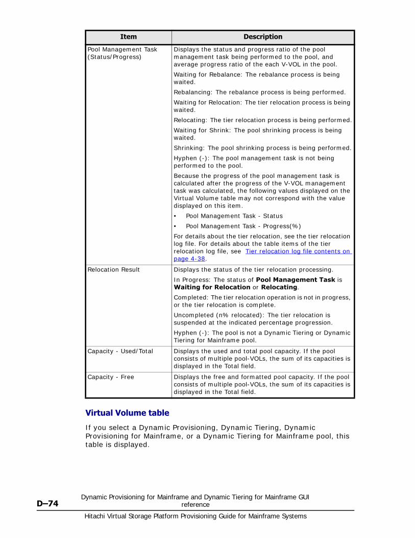
Hitachi Virtual Storage Platform Provisioning Guide for Mainframe Systems
D–74Dynamic Provisioning for Mainframe and Dynamic Tiering for Mainframe GUI
reference
Virtual Volume table
If you select a Dynamic Provisioning, Dynamic Tiering, Dynamic Provisioning for Mainframe, or a Dynamic Tiering for Mainframe pool, this table is displayed.
Pool Management Task (Status/Progress)
Displays the status and progress ratio of the pool management task being performed to the pool, and average progress ratio of the each V-VOL in the pool.
Waiting for Rebalance: The rebalance process is being waited.
Rebalancing: The rebalance process is being performed.
Waiting for Relocation: The tier relocation process is being waited.
Relocating: The tier relocation process is being performed.
Waiting for Shrink: The pool shrinking process is being waited.
Shrinking: The pool shrinking process is being performed.
Hyphen (-): The pool management task is not being performed to the pool.
Because the progress of the pool management task is calculated after the progress of the V-VOL management task was calculated, the following values displayed on the Virtual Volume table may not correspond with the value displayed on this item.
• Pool Management Task - Status
• Pool Management Task - Progress(%)
For details about the tier relocation, see the tier relocation log file. For details about the table items of the tier relocation log file, see Tier relocation log file contents on page 4-38.
Relocation Result Displays the status of the tier relocation processing.
In Progress: The status of Pool Management Task is Waiting for Relocation or Relocating.
Completed: The tier relocation operation is not in progress, or the tier relocation is complete.
Uncompleted (n% relocated): The tier relocation is suspended at the indicated percentage progression.
Hyphen (-): The pool is not a Dynamic Tiering or Dynamic Tiering for Mainframe pool.
Capacity - Used/Total Displays the used and total pool capacity. If the pool consists of multiple pool-VOLs, the sum of its capacities is displayed in the Total field.
Capacity - Free Displays the free and formatted pool capacity. If the pool consists of multiple pool-VOLs, the sum of its capacities is displayed in the Total field.
Item Description
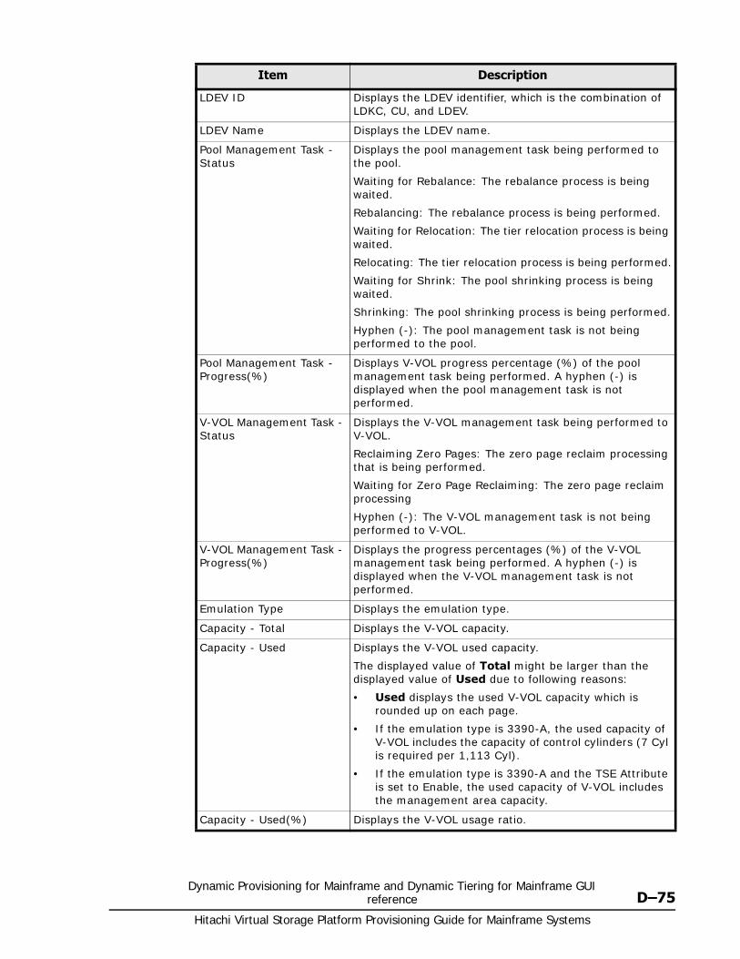
Dynamic Provisioning for Mainframe and Dynamic Tiering for Mainframe GUI reference D–75
Hitachi Virtual Storage Platform Provisioning Guide for Mainframe Systems
Item Description
LDEV ID Displays the LDEV identifier, which is the combination of LDKC, CU, and LDEV.
LDEV Name Displays the LDEV name.
Pool Management Task - Status
Displays the pool management task being performed to the pool.
Waiting for Rebalance: The rebalance process is being waited.
Rebalancing: The rebalance process is being performed.
Waiting for Relocation: The tier relocation process is being waited.
Relocating: The tier relocation process is being performed.
Waiting for Shrink: The pool shrinking process is being waited.
Shrinking: The pool shrinking process is being performed.
Hyphen (-): The pool management task is not being performed to the pool.
Pool Management Task - Progress(%)
Displays V-VOL progress percentage (%) of the pool management task being performed. A hyphen (-) is displayed when the pool management task is not performed.
V-VOL Management Task - Status
Displays the V-VOL management task being performed to V-VOL.
Reclaiming Zero Pages: The zero page reclaim processing that is being performed.
Waiting for Zero Page Reclaiming: The zero page reclaim processing
Hyphen (-): The V-VOL management task is not being performed to V-VOL.
V-VOL Management Task - Progress(%)
Displays the progress percentages (%) of the V-VOL management task being performed. A hyphen (-) is displayed when the V-VOL management task is not performed.
Emulation Type Displays the emulation type.
Capacity - Total Displays the V-VOL capacity.
Capacity - Used Displays the V-VOL used capacity.
The displayed value of Total might be larger than the displayed value of Used due to following reasons:
• Used displays the used V-VOL capacity which is rounded up on each page.
• If the emulation type is 3390-A, the used capacity of V-VOL includes the capacity of control cylinders (7 Cyl is required per 1,113 Cyl).
• If the emulation type is 3390-A and the TSE Attribute is set to Enable, the used capacity of V-VOL includes the management area capacity.
Capacity - Used(%) Displays the V-VOL usage ratio.
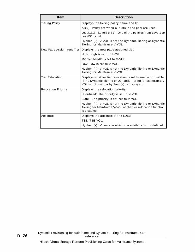
Hitachi Virtual Storage Platform Provisioning Guide for Mainframe Systems
D–76Dynamic Provisioning for Mainframe and Dynamic Tiering for Mainframe GUI
reference
Tiering Policy Displays the tiering policy name and ID.
All(0): Policy set when all tiers in the pool are used.
Level1(1) - Level31(31): One of the policies from Level1 to Level31 is set.
Hyphen (-): V-VOL is not the Dynamic Tiering or Dynamic Tiering for Mainframe V-VOL.
New Page Assignment Tier Displays the new page assigned tier.
High: High is set to V-VOL.
Middle: Middle is set to V-VOL.
Low: Low is set to V-VOL.
Hyphen (-): V-VOL is not the Dynamic Tiering or Dynamic Tiering for Mainframe V-VOL.
Tier Relocation Displays whether tier relocation is set to enable or disable. If the Dynamic Tiering or Dynamic Tiering for Mainframe V-VOL is not used, a hyphen (-) is displayed.
Relocation Priority Displays the relocation priority.
Prioritized: The priority is set to V-VOL.
Blank: The priority is not set to V-VOL.
Hyphen (-): V-VOL is not the Dynamic Tiering or Dynamic Tiering for Mainframe V-VOL or the tier relocation function is disabled.
Attribute Displays the attribute of the LDEV.
TSE: TSE-VOL.
Hyphen (-): Volume in which the attribute is not defined.
Item Description
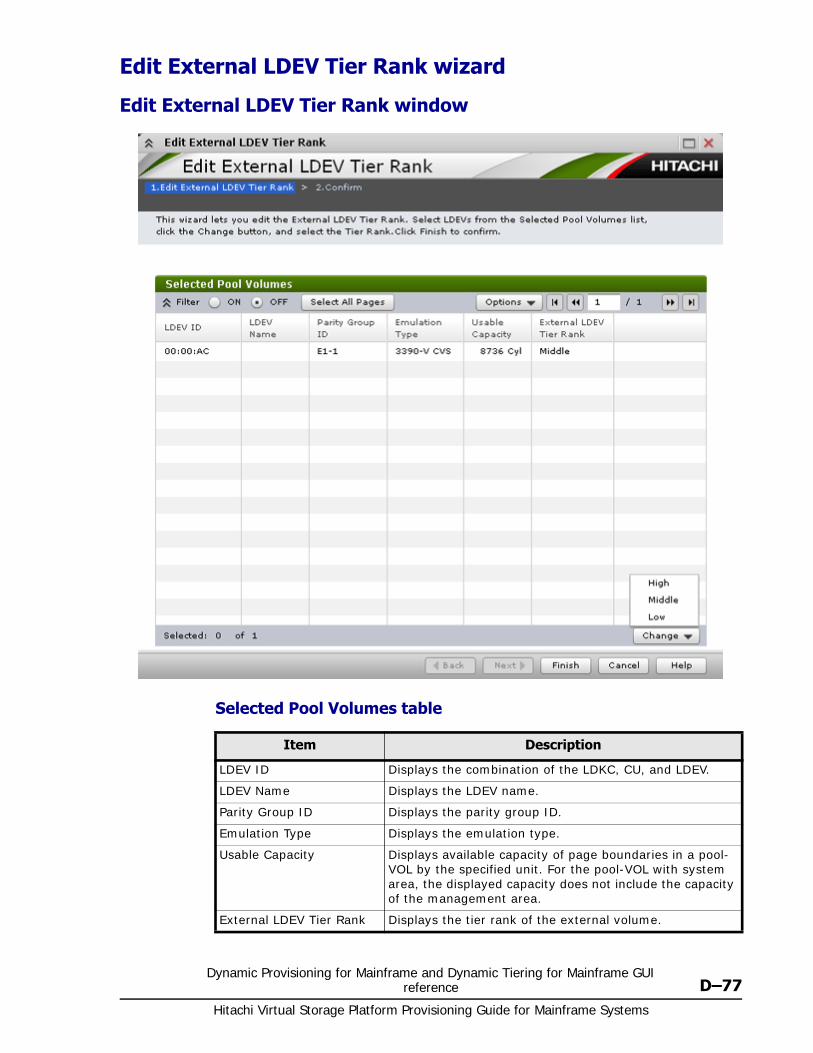
Dynamic Provisioning for Mainframe and Dynamic Tiering for Mainframe GUI reference D–77
Hitachi Virtual Storage Platform Provisioning Guide for Mainframe Systems
Edit External LDEV Tier Rank wizard
Edit External LDEV Tier Rank window
Selected Pool Volumes table
Item Description
LDEV ID Displays the combination of the LDKC, CU, and LDEV.
LDEV Name Displays the LDEV name.
Parity Group ID Displays the parity group ID.
Emulation Type Displays the emulation type.
Usable Capacity Displays available capacity of page boundaries in a pool-VOL by the specified unit. For the pool-VOL with system area, the displayed capacity does not include the capacity of the management area.
External LDEV Tier Rank Displays the tier rank of the external volume.
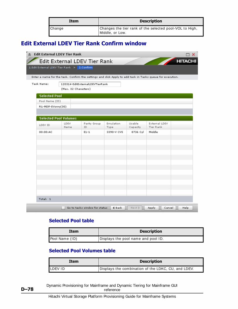
Hitachi Virtual Storage Platform Provisioning Guide for Mainframe Systems
D–78Dynamic Provisioning for Mainframe and Dynamic Tiering for Mainframe GUI
reference
Edit External LDEV Tier Rank Confirm window
Selected Pool table
Selected Pool Volumes table
Change Changes the tier rank of the selected pool-VOL to High, Middle, or Low.
Item Description
Item Description
Pool Name (ID) Displays the pool name and pool ID.
Item Description
LDEV ID Displays the combination of the LDKC, CU, and LDEV.
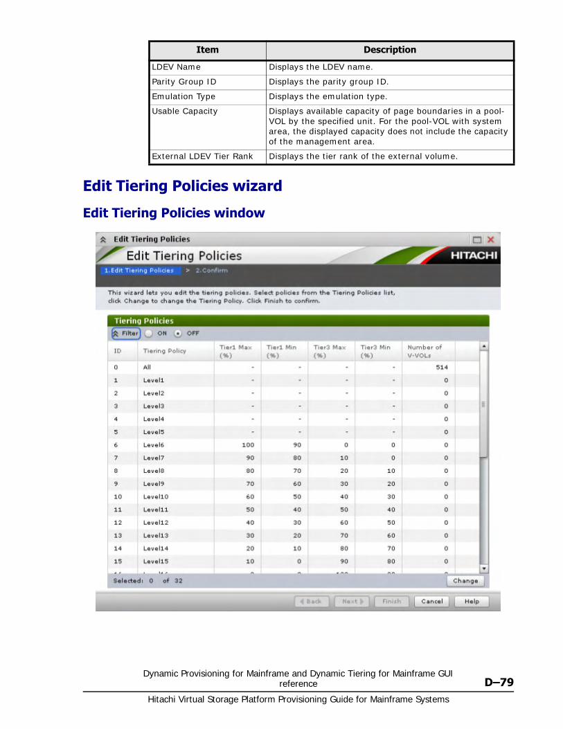
Dynamic Provisioning for Mainframe and Dynamic Tiering for Mainframe GUI reference D–79
Hitachi Virtual Storage Platform Provisioning Guide for Mainframe Systems
Edit Tiering Policies wizard
Edit Tiering Policies window
LDEV Name Displays the LDEV name.
Parity Group ID Displays the parity group ID.
Emulation Type Displays the emulation type.
Usable Capacity Displays available capacity of page boundaries in a pool-VOL by the specified unit. For the pool-VOL with system area, the displayed capacity does not include the capacity of the management area.
External LDEV Tier Rank Displays the tier rank of the external volume.
Item Description
Hitachi Virtual Storage Platform Provisioning Guide for Mainframe Systems
D–80Dynamic Provisioning for Mainframe and Dynamic Tiering for Mainframe GUI
reference
Tiering Policies table
Item Description
ID Displays the ID of the tiering policy.
Tiering Policy Displays the name of the tiering policy.
Tier1 Max(%) Displays the maximum percentage that is allocated to tier 1 in the total capacity to which tier relocation is performed. For a policy with an ID from 0 to 5, a hyphen (-) is displayed.
Tier1 Min(%) Displays the minimum percentage that is allocated to tier 1 in the total capacity to which tier relocation is performed. For a policy whose ID is from 0 to 5, a hyphen (-) is displayed.
Tier3 Max(%) Displays the maximum percentage that is allocated to tier 3 in the total capacity to which tier relocation is performed. For a policy with an ID from 0 to 5, a hyphen (-) is displayed.
Tier3 Min(%) Displays the minimum percentage that is allocated to tier 3 in the total capacity to which tier relocation is performed. For a policy whose ID is from 0 to 5, a hyphen (-) is displayed.
Number of V-VOLs Displays the number of V-VOLs to which the tiering policy is set.
Change Displays the Change Tiering Policy window when you select the row and click this button.
A policy with an ID is from 0 to 5 cannot be changed.
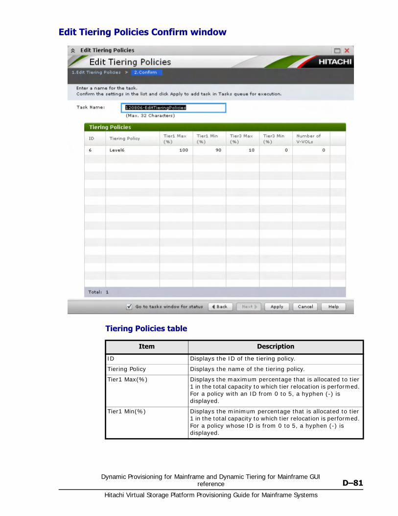
Dynamic Provisioning for Mainframe and Dynamic Tiering for Mainframe GUI reference D–81
Hitachi Virtual Storage Platform Provisioning Guide for Mainframe Systems
Edit Tiering Policies Confirm window
Tiering Policies table
Item Description
ID Displays the ID of the tiering policy.
Tiering Policy Displays the name of the tiering policy.
Tier1 Max(%) Displays the maximum percentage that is allocated to tier 1 in the total capacity to which tier relocation is performed. For a policy with an ID from 0 to 5, a hyphen (-) is displayed.
Tier1 Min(%) Displays the minimum percentage that is allocated to tier 1 in the total capacity to which tier relocation is performed. For a policy whose ID is from 0 to 5, a hyphen (-) is displayed.
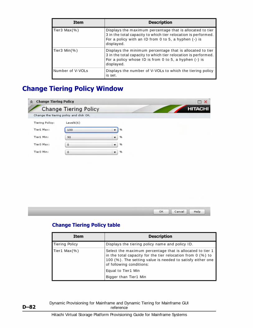
Hitachi Virtual Storage Platform Provisioning Guide for Mainframe Systems
D–82Dynamic Provisioning for Mainframe and Dynamic Tiering for Mainframe GUI
reference
Change Tiering Policy Window
Change Tiering Policy table
Tier3 Max(%) Displays the maximum percentage that is allocated to tier 3 in the total capacity to which tier relocation is performed. For a policy with an ID from 0 to 5, a hyphen (-) is displayed.
Tier3 Min(%) Displays the minimum percentage that is allocated to tier 3 in the total capacity to which tier relocation is performed. For a policy whose ID is from 0 to 5, a hyphen (-) is displayed.
Number of V-VOLs Displays the number of V-VOLs to which the tiering policy is set.
Item Description
Item Description
Tiering Policy Displays the tiering policy name and policy ID.
Tier1 Max(%) Select the maximum percentage that is allocated to tier 1 in the total capacity for the tier relocation from 0 (%) to 100 (%). The setting value is needed to satisfy either one of following conditions:
Equal to Tier1 Min
Bigger than Tier1 Min
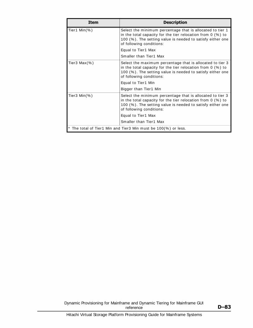
Dynamic Provisioning for Mainframe and Dynamic Tiering for Mainframe GUI reference D–83
Hitachi Virtual Storage Platform Provisioning Guide for Mainframe Systems
Tier1 Min(%) Select the minimum percentage that is allocated to tier 1 in the total capacity for the tier relocation from 0 (%) to 100 (%). The setting value is needed to satisfy either one of following conditions:
Equal to Tier1 Max
Smaller than Tier1 Max
Tier3 Max(%) Select the maximum percentage that is allocated to tier 3 in the total capacity for the tier relocation from 0 (%) to 100 (%). The setting value is needed to satisfy either one of following conditions:
Equal to Tier1 Min
Bigger than Tier1 Min
Tier3 Min(%) Select the minimum percentage that is allocated to tier 3 in the total capacity for the tier relocation from 0 (%) to 100 (%). The setting value is needed to satisfy either one of following conditions:
Equal to Tier1 Max
Smaller than Tier1 Max
* The total of Tier1 Min and Tier3 Min must be 100(%) or less.
Item Description

Hitachi Virtual Storage Platform Provisioning Guide for Mainframe Systems
D–84Dynamic Provisioning for Mainframe and Dynamic Tiering for Mainframe GUI
reference
E
Volume Retention Manager GUI reference E–1Hitachi Virtual Storage Platform Provisioning Guide for Mainframe Systems
Volume Retention Manager GUIreference
Sections in this appendix describe the windows, wizards, and dialog boxes of the Volume Retention Manager.
□ Volume Retention Manager window
□ VTOC Area dialog box
□ Error Detail Dialog Box
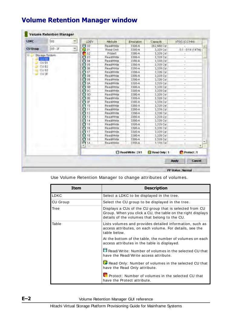
Hitachi Virtual Storage Platform Provisioning Guide for Mainframe Systems
E–2 Volume Retention Manager GUI reference
Volume Retention Manager window
Use Volume Retention Manager to change attributes of volumes.
Item Description
LDKC Select a LDKC to be displayed in the tree.
CU Group Select the CU group to be displayed in the tree.
Tree Displays a CUs of the CU group that is selected from CU Group. When you click a CU, the table on the right displays details of the volumes that belong to the CU.
Table Lists volumes and provides detailed information, such as access attributes, on each volume. For details, see the table below.
At the bottom of the table, the number of volumes on each access attributes in the table is displayed.
Read/Write: Number of volumes in the selected CU that have the Read/Write access attribute.
Read Only: Number of volumes in the selected CU that have the Read Only attribute.
Protect: Number of volumes in the selected CU that have the Protect attribute.
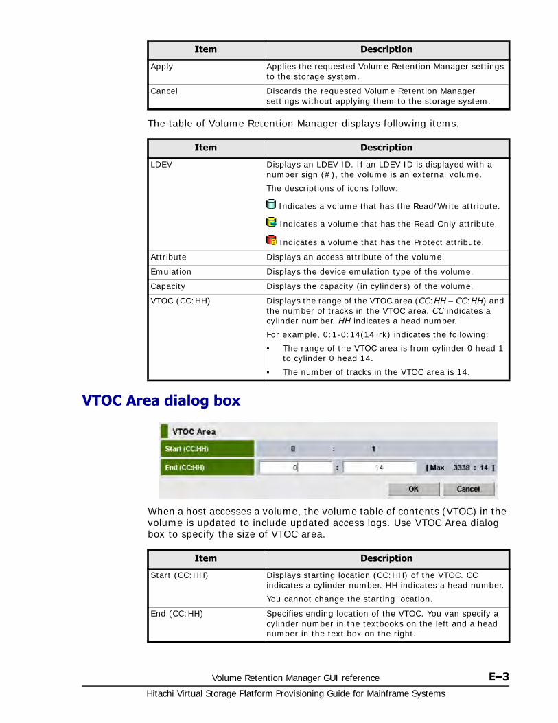
Volume Retention Manager GUI reference E–3Hitachi Virtual Storage Platform Provisioning Guide for Mainframe Systems
The table of Volume Retention Manager displays following items.
VTOC Area dialog box
When a host accesses a volume, the volume table of contents (VTOC) in the volume is updated to include updated access logs. Use VTOC Area dialog box to specify the size of VTOC area.
Apply Applies the requested Volume Retention Manager settings to the storage system.
Cancel Discards the requested Volume Retention Manager settings without applying them to the storage system.
Item Description
Item Description
LDEV Displays an LDEV ID. If an LDEV ID is displayed with a number sign (#), the volume is an external volume.
The descriptions of icons follow:
Indicates a volume that has the Read/Write attribute.
Indicates a volume that has the Read Only attribute.
Indicates a volume that has the Protect attribute.
Attribute Displays an access attribute of the volume.
Emulation Displays the device emulation type of the volume.
Capacity Displays the capacity (in cylinders) of the volume.
VTOC (CC:HH) Displays the range of the VTOC area (CC:HH – CC:HH) and the number of tracks in the VTOC area. CC indicates a cylinder number. HH indicates a head number.
For example, 0:1-0:14(14Trk) indicates the following:
• The range of the VTOC area is from cylinder 0 head 1 to cylinder 0 head 14.
• The number of tracks in the VTOC area is 14.
Item Description
Start (CC:HH) Displays starting location (CC:HH) of the VTOC. CC indicates a cylinder number. HH indicates a head number.
You cannot change the starting location.
End (CC:HH) Specifies ending location of the VTOC. You van specify a cylinder number in the textbooks on the left and a head number in the text box on the right.
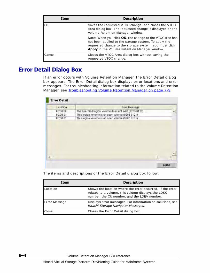
Hitachi Virtual Storage Platform Provisioning Guide for Mainframe Systems
E–4 Volume Retention Manager GUI reference
Error Detail Dialog BoxIf an error occurs with Volume Retention Manager, the Error Detail dialog box appears. The Error Detail dialog box displays error locations and error messages. For troubleshooting information related to the Volume Retention Manager, see Troubleshooting Volume Retention Manager on page 7-9.
The items and descriptions of the Error Detail dialog box follow.
OK Saves the requested VTOC change, and closes the VTOC Area dialog box. The requested change is displayed on the Volume Retention Manager window.
Note: When you click OK, the change to the VTOC size has not been applied to the storage system. To apply the requested change to the storage system, you must click Apply in the Volume Retention Manager window.
Cancel Closes the VTOC Area dialog box without saving the requested VTOC change.
Item Description
Item Description
Location Shows the location where the error occurred. If the error relates to a volume, this column displays the LDKC number, the CU number, and the LDEV number.
Error Message Displays error messages. For information on solutions, see Hitachi Storage Navigator Messages.
Close Closes the Error Detail dialog box.
F
Volume Security GUI reference F–1Hitachi Virtual Storage Platform Provisioning Guide for Mainframe Systems
Volume Security GUI reference
Sections in this appendix describe the Volume Security windows, wizards, and dialog boxes.
□ Volume Security window
□ Add/Change Security Group Dialog Box
□ Add/Change Host Group Dialog Box
□ Add/Change LDEV Group Dialog Box
□ Select LDEV Dialog Box
□ Select Port Dialog Box
□ Specify Security Group Dialog Box
□ Host to Security Group Dialog Box
□ Host to LDEV Dialog Box
□ Host Group to Security Group Dialog Box
□ Host Group to Port Dialog Box
□ LDEV to Security Group Dialog Box
□ LDEV to Host Dialog Box
□ LDEV Group to Security Group Dialog Box
□ Error Detail Dialog Box
Hitachi Virtual Storage Platform Provisioning Guide for Mainframe Systems
F–2 Volume Security GUI reference
Volume Security windowThe Volume Security window displays all the security information for the connected VSP storage system and provides access to all volume security operations. Before starting Volume Security, confirm that these guidelines have been satisfied:
• Volume Security Port Option is installed.
• You have the Administrator (View & Modify) access required to make and apply security settings.
To open the Volume Security click Action > Mainframe Connection > Volume Security in the Storage Navigator main window.
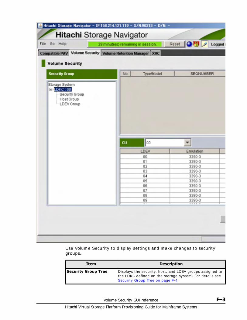
Volume Security GUI reference F–3Hitachi Virtual Storage Platform Provisioning Guide for Mainframe Systems
Use Volume Security to display settings and make changes to security groups.
Item Description
Security Group Tree Displays the security, host, and LDEV groups assigned to the LDKC defined on the storage system. For details see Security Group Tree on page F-4.
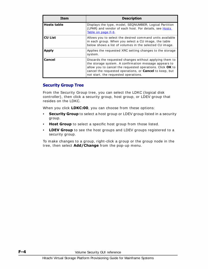
Hitachi Virtual Storage Platform Provisioning Guide for Mainframe Systems
F–4 Volume Security GUI reference
Security Group Tree
From the Security Group tree, you can select the LDKC (logical disk controller), then click a security group, host group, or LDEV group that resides on the LDKC.
When you click LDKC:00, you can choose from these options:
• Security Group to select a host group or LDEV group listed in a security group.
• Host Group to select a specific host group from those listed.
• LDEV Group to see the host groups and LDEV groups registered to a security group.
To make changes to a group, right-click a group or the group node in the tree, then select Add/Change from the pop-up menu.
Hosts table Displays the type, model, SEQNUMBER, Logical Partition (LPAR) and vendor of each host. For details, see Hosts Table on page F-6.
CU List Allows you to select the desired command units available in each group. When you select a CU image, the table below shows a list of volumes in the selected CU image.
Apply Applies the requested XRC setting changes to the storage system.
Cancel Discards the requested changes without applying them to the storage system. A confirmation message appears to allow you to cancel the requested operations. Click OK to cancel the requested operations, or Cancel to keep, but not start, the requested operations.
Item Description
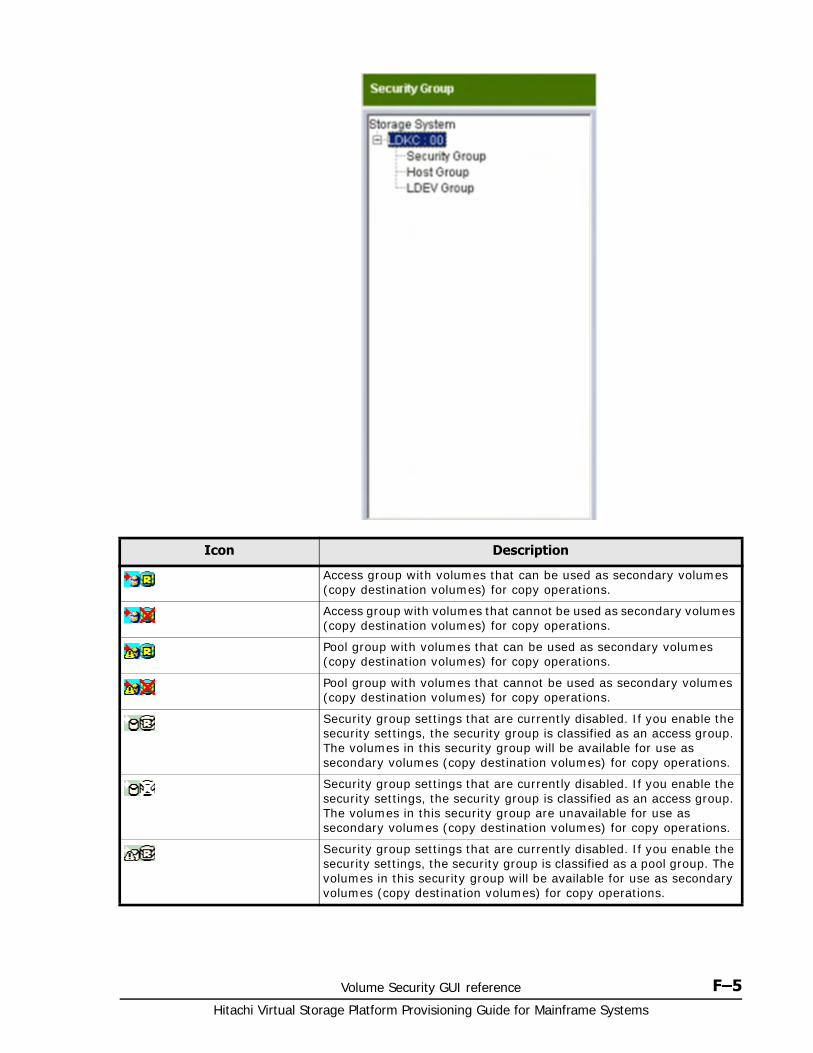
Volume Security GUI reference F–5Hitachi Virtual Storage Platform Provisioning Guide for Mainframe Systems
Icon Description
Access group with volumes that can be used as secondary volumes (copy destination volumes) for copy operations.
Access group with volumes that cannot be used as secondary volumes (copy destination volumes) for copy operations.
Pool group with volumes that can be used as secondary volumes (copy destination volumes) for copy operations.
Pool group with volumes that cannot be used as secondary volumes (copy destination volumes) for copy operations.
Security group settings that are currently disabled. If you enable the security settings, the security group is classified as an access group. The volumes in this security group will be available for use as secondary volumes (copy destination volumes) for copy operations.
Security group settings that are currently disabled. If you enable the security settings, the security group is classified as an access group. The volumes in this security group are unavailable for use as secondary volumes (copy destination volumes) for copy operations.
Security group settings that are currently disabled. If you enable the security settings, the security group is classified as a pool group. The volumes in this security group will be available for use as secondary volumes (copy destination volumes) for copy operations.
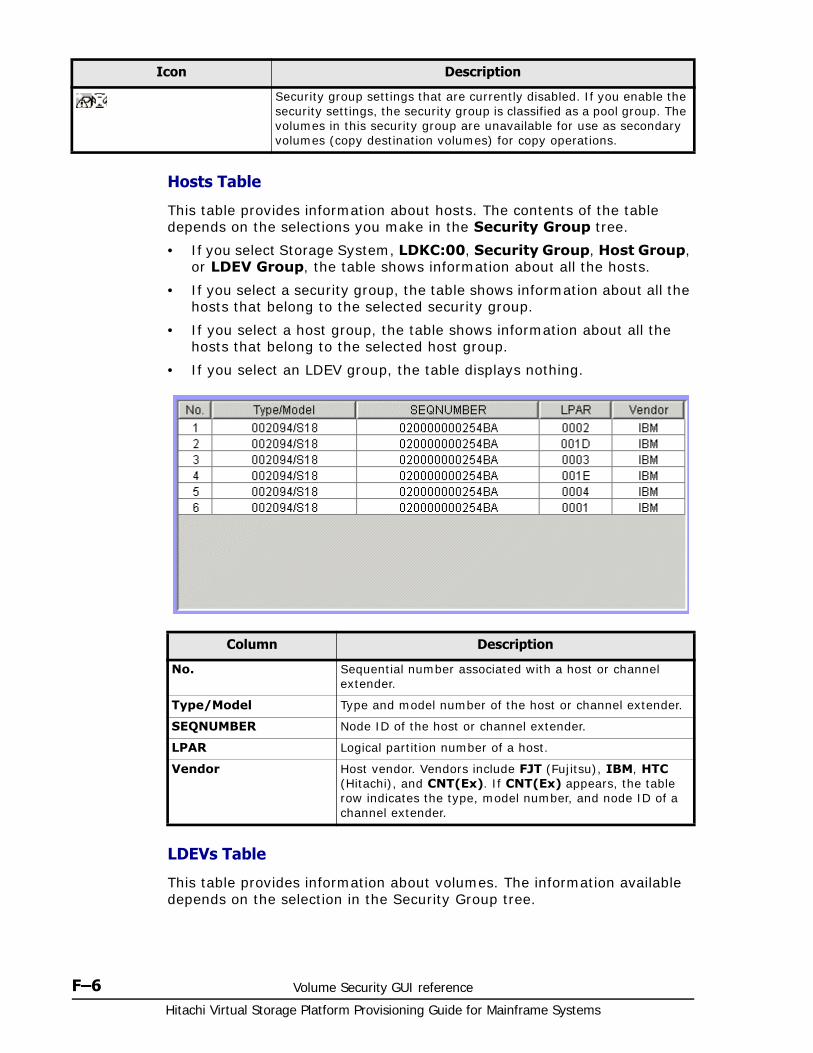
Hitachi Virtual Storage Platform Provisioning Guide for Mainframe Systems
F–6 Volume Security GUI reference
Hosts Table
This table provides information about hosts. The contents of the table depends on the selections you make in the Security Group tree.
• If you select Storage System, LDKC:00, Security Group, Host Group, or LDEV Group, the table shows information about all the hosts.
• If you select a security group, the table shows information about all the hosts that belong to the selected security group.
• If you select a host group, the table shows information about all the hosts that belong to the selected host group.
• If you select an LDEV group, the table displays nothing.
LDEVs Table
This table provides information about volumes. The information available depends on the selection in the Security Group tree.
Security group settings that are currently disabled. If you enable the security settings, the security group is classified as a pool group. The volumes in this security group are unavailable for use as secondary volumes (copy destination volumes) for copy operations.
Icon Description
Column Description
No. Sequential number associated with a host or channel extender.
Type/Model Type and model number of the host or channel extender.
SEQNUMBER Node ID of the host or channel extender.
LPAR Logical partition number of a host.
Vendor Host vendor. Vendors include FJT (Fujitsu), IBM, HTC (Hitachi), and CNT(Ex). If CNT(Ex) appears, the table row indicates the type, model number, and node ID of a channel extender.
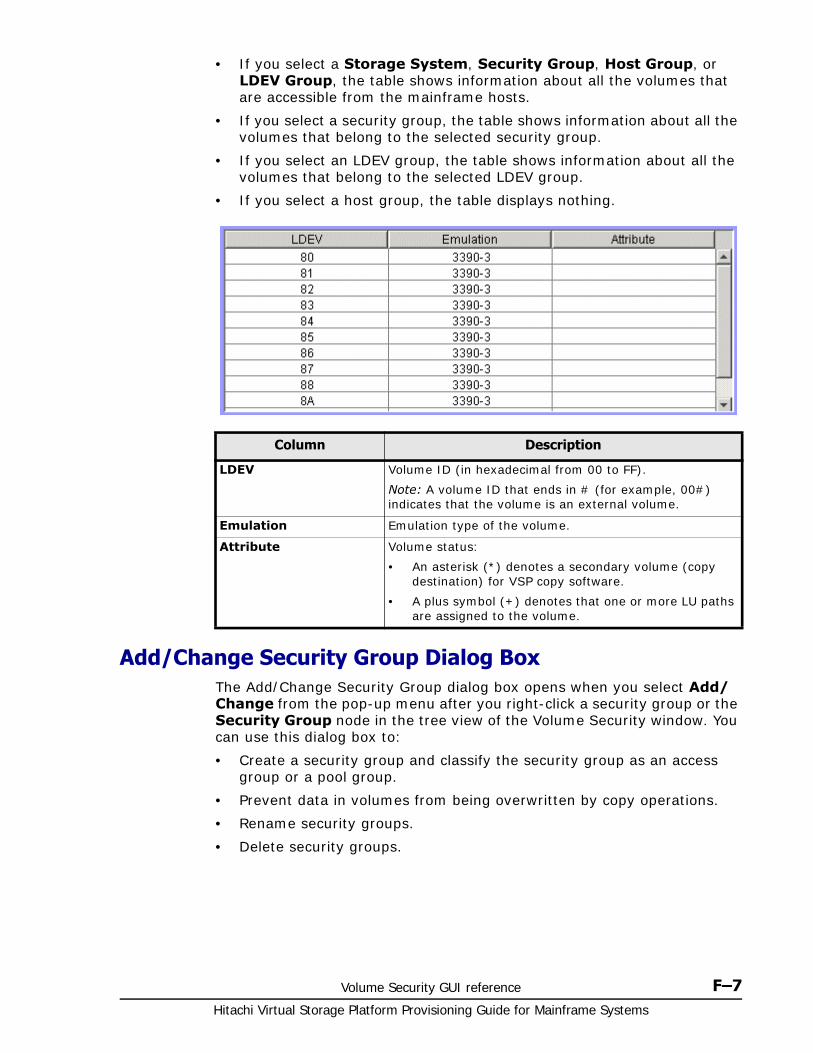
Volume Security GUI reference F–7Hitachi Virtual Storage Platform Provisioning Guide for Mainframe Systems
• If you select a Storage System, Security Group, Host Group, or LDEV Group, the table shows information about all the volumes that are accessible from the mainframe hosts.
• If you select a security group, the table shows information about all the volumes that belong to the selected security group.
• If you select an LDEV group, the table shows information about all the volumes that belong to the selected LDEV group.
• If you select a host group, the table displays nothing.
Add/Change Security Group Dialog BoxThe Add/Change Security Group dialog box opens when you select Add/Change from the pop-up menu after you right-click a security group or the Security Group node in the tree view of the Volume Security window. You can use this dialog box to:
• Create a security group and classify the security group as an access group or a pool group.
• Prevent data in volumes from being overwritten by copy operations.
• Rename security groups.
• Delete security groups.
Column Description
LDEV Volume ID (in hexadecimal from 00 to FF).
Note: A volume ID that ends in # (for example, 00#) indicates that the volume is an external volume.
Emulation Emulation type of the volume.
Attribute Volume status:
• An asterisk (*) denotes a secondary volume (copy destination) for VSP copy software.
• A plus symbol (+) denotes that one or more LU paths are assigned to the volume.
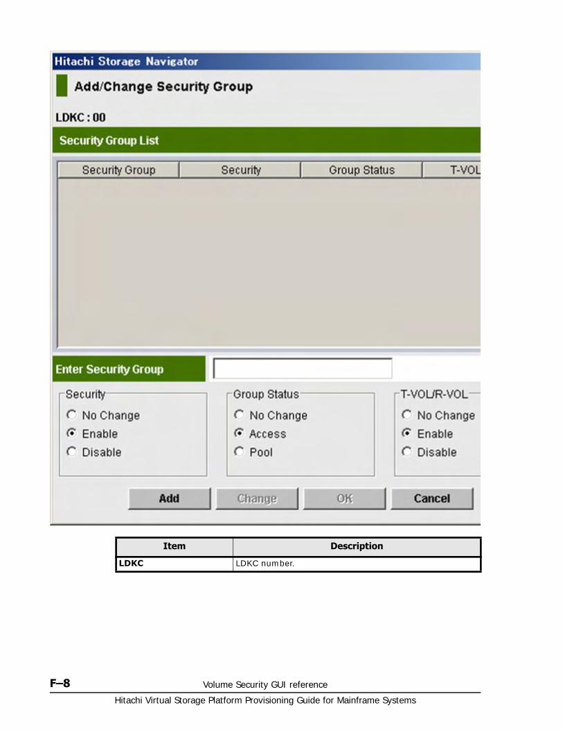
Hitachi Virtual Storage Platform Provisioning Guide for Mainframe Systems
F–8 Volume Security GUI reference
Item Description
LDKC LDKC number.
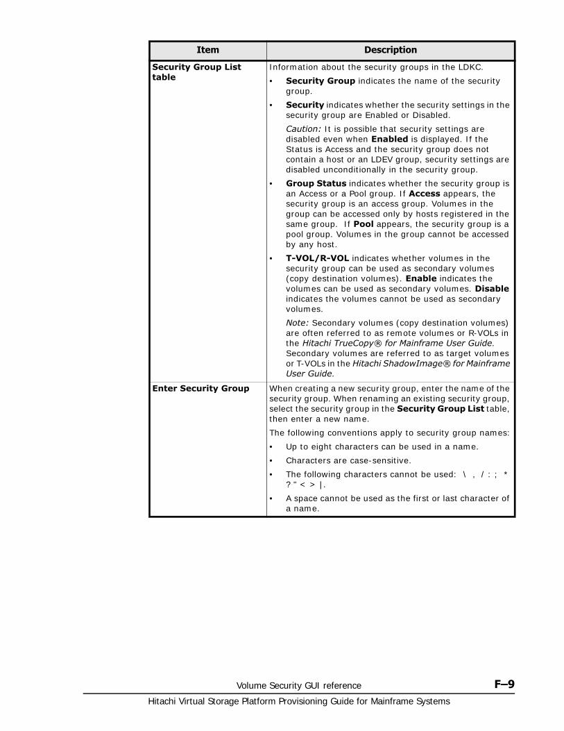
Volume Security GUI reference F–9Hitachi Virtual Storage Platform Provisioning Guide for Mainframe Systems
Security Group List table
Information about the security groups in the LDKC.
• Security Group indicates the name of the security group.
• Security indicates whether the security settings in the security group are Enabled or Disabled.
Caution: It is possible that security settings are disabled even when Enabled is displayed. If the Status is Access and the security group does not contain a host or an LDEV group, security settings are disabled unconditionally in the security group.
• Group Status indicates whether the security group is an Access or a Pool group. If Access appears, the security group is an access group. Volumes in the group can be accessed only by hosts registered in the same group. If Pool appears, the security group is a pool group. Volumes in the group cannot be accessed by any host.
• T-VOL/R-VOL indicates whether volumes in the security group can be used as secondary volumes (copy destination volumes). Enable indicates the volumes can be used as secondary volumes. Disable indicates the volumes cannot be used as secondary volumes.
Note: Secondary volumes (copy destination volumes) are often referred to as remote volumes or R-VOLs in the Hitachi TrueCopy® for Mainframe User Guide. Secondary volumes are referred to as target volumes or T-VOLs in the Hitachi ShadowImage® for Mainframe User Guide.
Enter Security Group When creating a new security group, enter the name of the security group. When renaming an existing security group, select the security group in the Security Group List table, then enter a new name.
The following conventions apply to security group names:
• Up to eight characters can be used in a name.
• Characters are case-sensitive.
• The following characters cannot be used: \ , / : ; * ? " < > |.
• A space cannot be used as the first or last character of a name.
Item Description
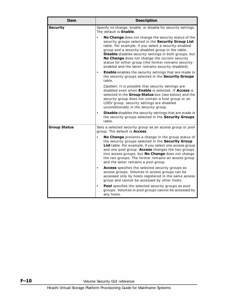
Hitachi Virtual Storage Platform Provisioning Guide for Mainframe Systems
F–10 Volume Security GUI reference
Security Specify no change, enable, or disable for security settings. The default is Enable.
• No Change does not change the security status of the security groups selected in the Security Group List table. For example, if you select a security-enabled group and a security-disabled group in the table, Disable disables security settings in both groups, but No Change does not change the current security status for either group (the former remains security-enabled and the latter remains security-disabled).
• Enable enables the security settings that are made in the security groups selected in the Security Groups table.
Caution: It is possible that security settings are disabled even when Enable is selected. If Access is selected in the Group Status box (see below) and the security group does not contain a host group or an LDEV group, security settings are disabled unconditionally in the security group.
• Disable disables the security settings that are made in the security groups selected in the Security Groups table.
Group Status Sets a selected security group as an access group or pool group. The default is Access.
• No Change prevents a change in the group status of the security groups selected in the Security Group List table. For example, if you select one access group and one pool group, Access changes the two groups into access groups, but No Change does not change the two groups. The former remains an access group and the latter remains a pool group.
• Access specifies the selected security groups as access groups. Volumes in access groups can be accessed only by hosts registered in the same access group and cannot be accessed by other hosts.
• Pool specifies the selected security groups as pool groups. Volumes in pool groups cannot be accessed by any hosts.
Item Description
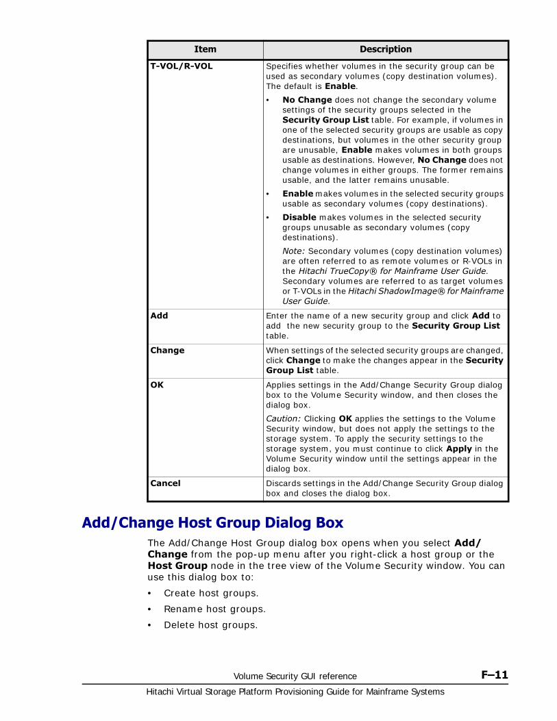
Volume Security GUI reference F–11Hitachi Virtual Storage Platform Provisioning Guide for Mainframe Systems
Add/Change Host Group Dialog BoxThe Add/Change Host Group dialog box opens when you select Add/Change from the pop-up menu after you right-click a host group or the Host Group node in the tree view of the Volume Security window. You can use this dialog box to:
• Create host groups.
• Rename host groups.
• Delete host groups.
T-VOL/R-VOL Specifies whether volumes in the security group can be used as secondary volumes (copy destination volumes). The default is Enable.
• No Change does not change the secondary volume settings of the security groups selected in the Security Group List table. For example, if volumes in one of the selected security groups are usable as copy destinations, but volumes in the other security group are unusable, Enable makes volumes in both groups usable as destinations. However, No Change does not change volumes in either groups. The former remains usable, and the latter remains unusable.
• Enable makes volumes in the selected security groups usable as secondary volumes (copy destinations).
• Disable makes volumes in the selected security groups unusable as secondary volumes (copy destinations).
Note: Secondary volumes (copy destination volumes) are often referred to as remote volumes or R-VOLs in the Hitachi TrueCopy® for Mainframe User Guide. Secondary volumes are referred to as target volumes or T-VOLs in the Hitachi ShadowImage® for Mainframe User Guide.
Add Enter the name of a new security group and click Add to add the new security group to the Security Group List table.
Change When settings of the selected security groups are changed, click Change to make the changes appear in the Security Group List table.
OK Applies settings in the Add/Change Security Group dialog box to the Volume Security window, and then closes the dialog box.
Caution: Clicking OK applies the settings to the Volume Security window, but does not apply the settings to the storage system. To apply the security settings to the storage system, you must continue to click Apply in the Volume Security window until the settings appear in the dialog box.
Cancel Discards settings in the Add/Change Security Group dialog box and closes the dialog box.
Item Description
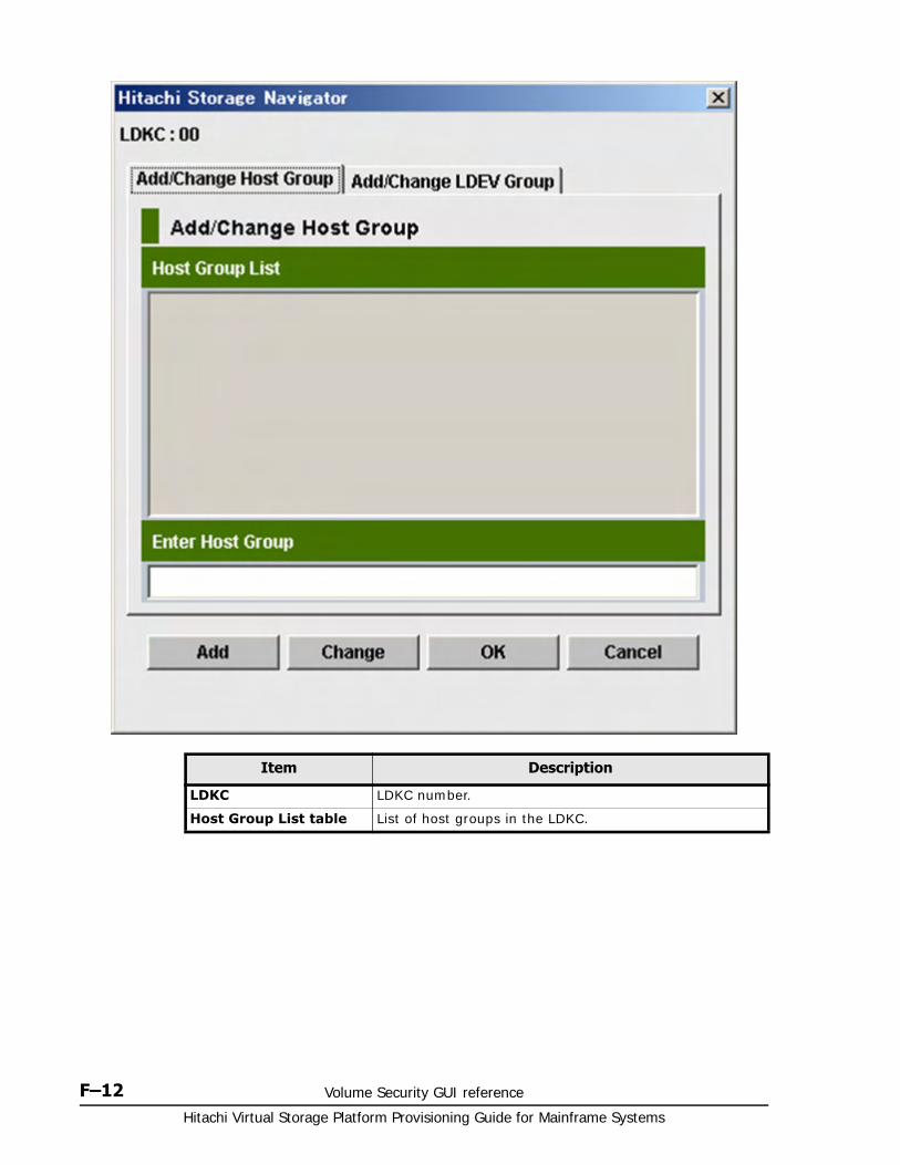
Hitachi Virtual Storage Platform Provisioning Guide for Mainframe Systems
F–12 Volume Security GUI reference
Item Description
LDKC LDKC number.
Host Group List table List of host groups in the LDKC.
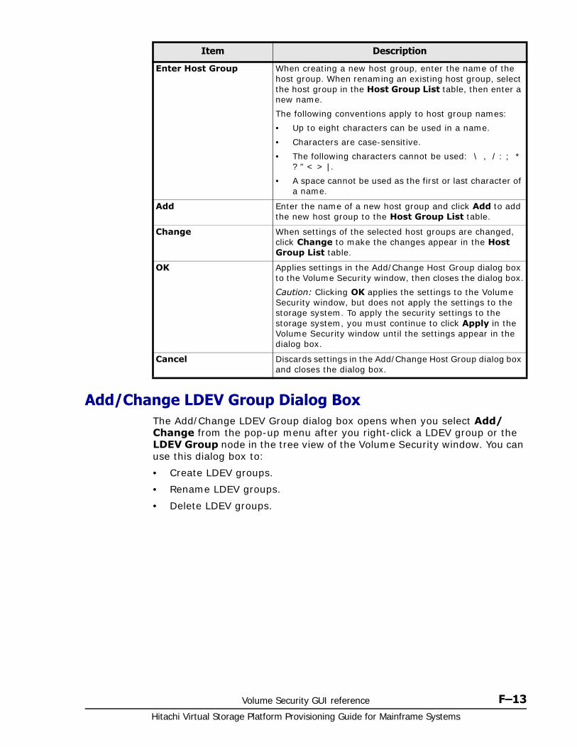
Volume Security GUI reference F–13Hitachi Virtual Storage Platform Provisioning Guide for Mainframe Systems
Add/Change LDEV Group Dialog BoxThe Add/Change LDEV Group dialog box opens when you select Add/Change from the pop-up menu after you right-click a LDEV group or the LDEV Group node in the tree view of the Volume Security window. You can use this dialog box to:
• Create LDEV groups.
• Rename LDEV groups.
• Delete LDEV groups.
Enter Host Group When creating a new host group, enter the name of the host group. When renaming an existing host group, select the host group in the Host Group List table, then enter a new name.
The following conventions apply to host group names:
• Up to eight characters can be used in a name.
• Characters are case-sensitive.
• The following characters cannot be used: \ , / : ; * ? " < > |.
• A space cannot be used as the first or last character of a name.
Add Enter the name of a new host group and click Add to add the new host group to the Host Group List table.
Change When settings of the selected host groups are changed, click Change to make the changes appear in the Host Group List table.
OK Applies settings in the Add/Change Host Group dialog box to the Volume Security window, then closes the dialog box.
Caution: Clicking OK applies the settings to the Volume Security window, but does not apply the settings to the storage system. To apply the security settings to the storage system, you must continue to click Apply in the Volume Security window until the settings appear in the dialog box.
Cancel Discards settings in the Add/Change Host Group dialog box and closes the dialog box.
Item Description
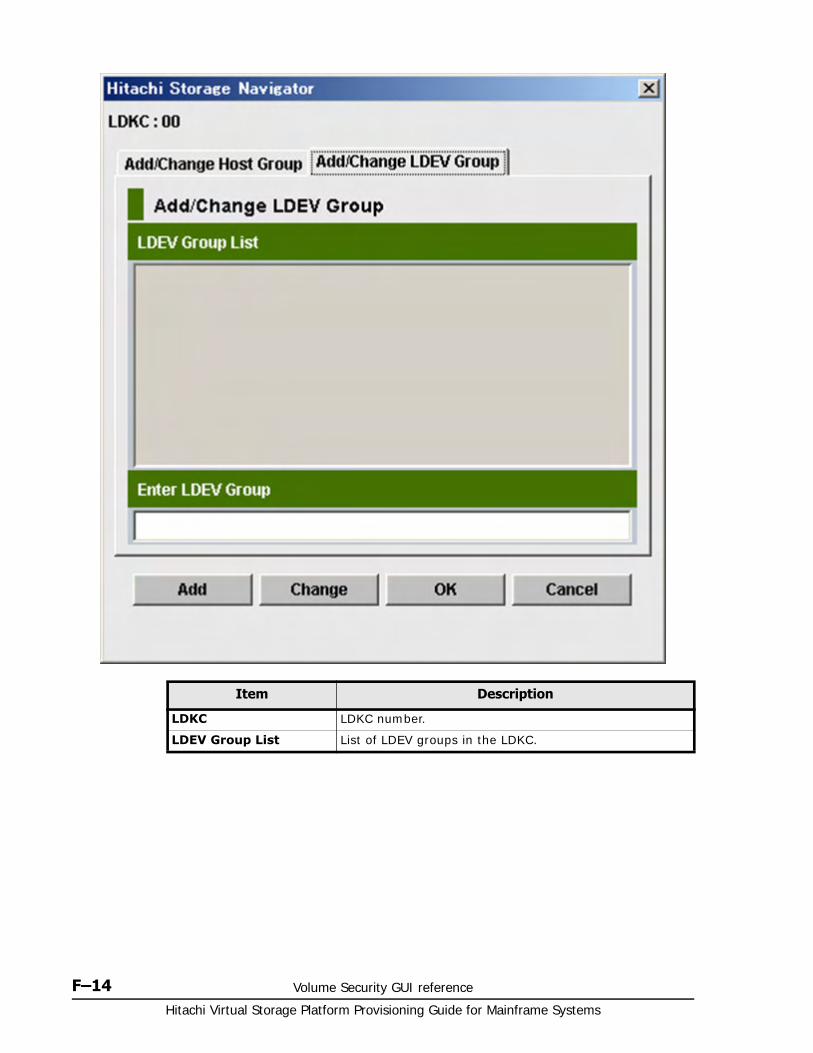
Hitachi Virtual Storage Platform Provisioning Guide for Mainframe Systems
F–14 Volume Security GUI reference
Item Description
LDKC LDKC number.
LDEV Group List List of LDEV groups in the LDKC.
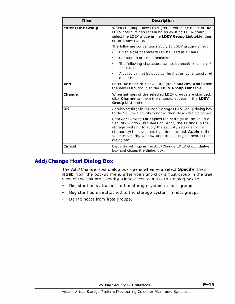
Volume Security GUI reference F–15Hitachi Virtual Storage Platform Provisioning Guide for Mainframe Systems
Add/Change Host Dialog BoxThe Add/Change Host dialog box opens when you select Specify, then Host, from the pop-up menu after you right-click a host group in the tree view of the Volume Security window. You can use this dialog box to:
• Register hosts attached to the storage system in host groups.
• Register hosts unattached to the storage system in host groups.
• Delete hosts from host groups.
Enter LDEV Group When creating a new LDEV group, enter the name of the LDEV group. When renaming an existing LDEV group, select the LDEV group in the LDEV Group List table, then enter a new name.
The following conventions apply to LDEV group names:
• Up to eight characters can be used in a name.
• Characters are case-sensitive.
• The following characters cannot be used: \ , / : ; * ? " < > |.
• A space cannot be used as the first or last character of a name.
Add Enter the name of a new LDEV group and click Add to add the new LDEV group to the LDEV Group List table.
Change When settings of the selected LDEV groups are changed, click Change to make the changes appear in the LDEV Group List table.
OK Applies settings in the Add/Change LDEV Group dialog box to the Volume Security window, then closes the dialog box.
Caution: Clicking OK applies the settings to the Volume Security window, but does not apply the settings to the storage system. To apply the security settings to the storage system, you must continue to click Apply in the Volume Security window until the settings appear in the dialog box.
Cancel Discards settings in the Add/Change LDEV Group dialog box and closes the dialog box.
Item Description
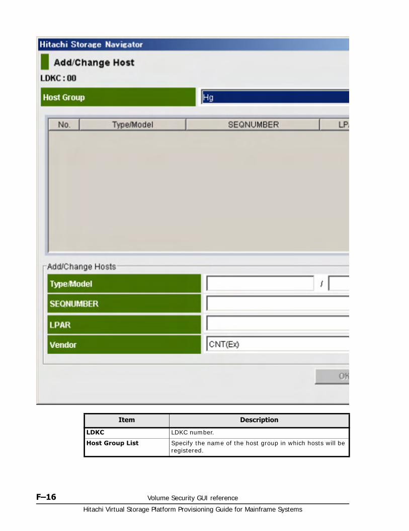
Hitachi Virtual Storage Platform Provisioning Guide for Mainframe Systems
F–16 Volume Security GUI reference
Item Description
LDKC LDKC number.
Host Group List Specify the name of the host group in which hosts will be registered.

Volume Security GUI reference F–17Hitachi Virtual Storage Platform Provisioning Guide for Mainframe Systems
Host table Host information.
• No. indicates a sequential number associated with a host.
Note: Each table row usually shows information about a host. However, if a host is attached to the storage system through a channel extender, the table row shows information about the channel extender
• Type/Model indicates the type and the model number of a host or a channel extender. The Type appears on the left of the slash (/) and the Model on the right. An icon indicates the registration status of the host:
The host is registered in the current host displayed above the table, and is attached to the storage system with a cable.
The host is registered in the current host group, and is not attached to the storage system.
The host is registered in another host group or the current host group. The host is attached to the storage system with a cable.
The host is registered in another host group or the current host group. The host is not attached to the storage system.
No icon The host is not registered in any host group. The host is attached to the storage system with a cable.
• SEQNUMBER indicates the node ID of a host or a channel extender.
• LPAR indicates the logical partition number of a host. Logical partitions are virtual systems created by sectioning a computer's memory into separate units.
• Vendor indicates the vendor of a host. Vendors include FJT (Fujitsu), IBM, HTC (Hitachi), and CNT(Ex) for channel extender. For CNT(Ex), the Type/Model and SEQNUMBER indicate the node ID of the channel extender.
Add/Change Hosts table
Host group information.
• Type/Model indicates the type and the model number of a host or a channel extender.
• SEQNUMBER indicates the node ID of a host or a channel extender.
• LPAR indicates the logical partition number of a host.
• Vendor indicates the vendor of a host. Vendors include FJT (Fujitsu), IBM, HTC (Hitachi), and CNT(Ex) for channel extender.
Item Description
Hitachi Virtual Storage Platform Provisioning Guide for Mainframe Systems
F–18 Volume Security GUI reference
Select LDEV Dialog BoxThe Select LDEV dialog box opens when you right-click a LDEV group in the tree view of the Volume Security window and select Specify, then LDEV, from the pop-up menu. You can use this dialog box to:
• Register volumes (LDEVs) in an LDEV group.
• Delete volumes from an LDEV group.
OK Applies settings in the Add/Change Host dialog box to the Volume Security window, then closes the dialog box.
Caution: Clicking OK applies the settings to the Volume Security window, but does not apply the settings to the storage system. To apply the security settings to the storage system, you must continue to click Apply in the Volume Security window until the settings appear in the dialog box.
Cancel Discards settings in the Add/Change Host dialog box and closes the dialog box.
Item Description
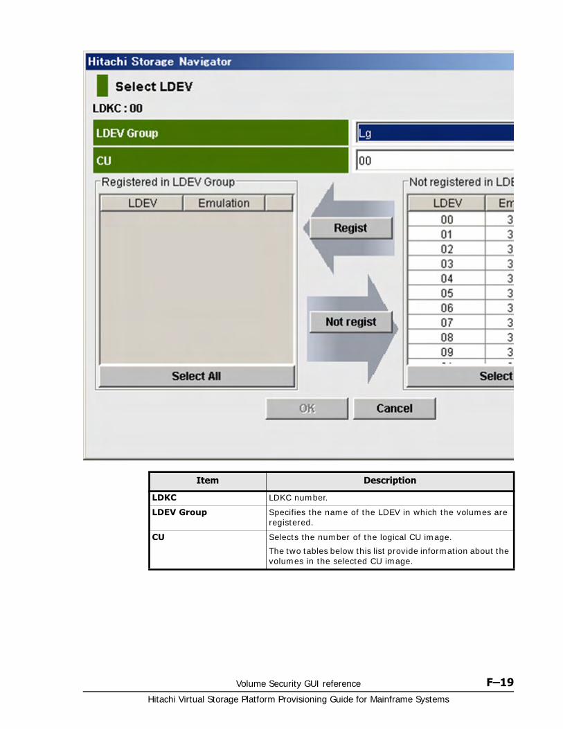
Volume Security GUI reference F–19Hitachi Virtual Storage Platform Provisioning Guide for Mainframe Systems
Item Description
LDKC LDKC number.
LDEV Group Specifies the name of the LDEV in which the volumes are registered.
CU Selects the number of the logical CU image.
The two tables below this list provide information about the volumes in the selected CU image.
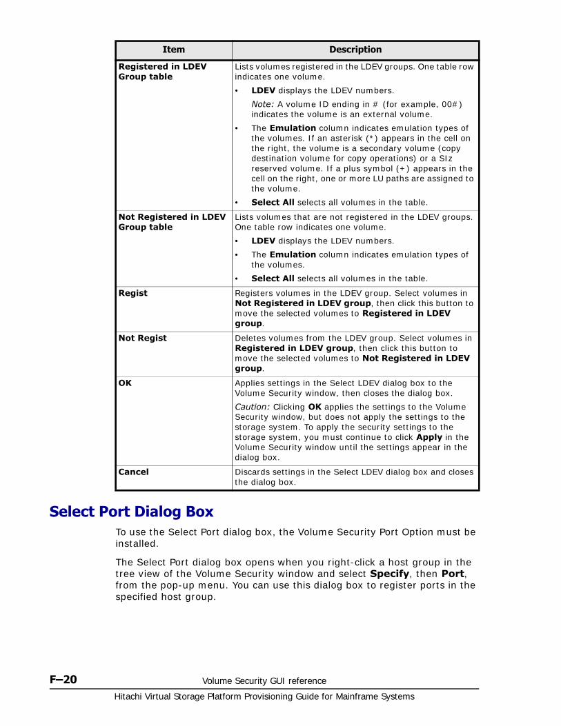
Hitachi Virtual Storage Platform Provisioning Guide for Mainframe Systems
F–20 Volume Security GUI reference
Select Port Dialog BoxTo use the Select Port dialog box, the Volume Security Port Option must be installed.
The Select Port dialog box opens when you right-click a host group in the tree view of the Volume Security window and select Specify, then Port, from the pop-up menu. You can use this dialog box to register ports in the specified host group.
Registered in LDEV Group table
Lists volumes registered in the LDEV groups. One table row indicates one volume.
• LDEV displays the LDEV numbers.
Note: A volume ID ending in # (for example, 00#) indicates the volume is an external volume.
• The Emulation column indicates emulation types of the volumes. If an asterisk (*) appears in the cell on the right, the volume is a secondary volume (copy destination volume for copy operations) or a SIz reserved volume. If a plus symbol (+) appears in the cell on the right, one or more LU paths are assigned to the volume.
• Select All selects all volumes in the table.
Not Registered in LDEV Group table
Lists volumes that are not registered in the LDEV groups. One table row indicates one volume.
• LDEV displays the LDEV numbers.
• The Emulation column indicates emulation types of the volumes.
• Select All selects all volumes in the table.
Regist Registers volumes in the LDEV group. Select volumes in Not Registered in LDEV group, then click this button to move the selected volumes to Registered in LDEV group.
Not Regist Deletes volumes from the LDEV group. Select volumes in Registered in LDEV group, then click this button to move the selected volumes to Not Registered in LDEV group.
OK Applies settings in the Select LDEV dialog box to the Volume Security window, then closes the dialog box.
Caution: Clicking OK applies the settings to the Volume Security window, but does not apply the settings to the storage system. To apply the security settings to the storage system, you must continue to click Apply in the Volume Security window until the settings appear in the dialog box.
Cancel Discards settings in the Select LDEV dialog box and closes the dialog box.
Item Description
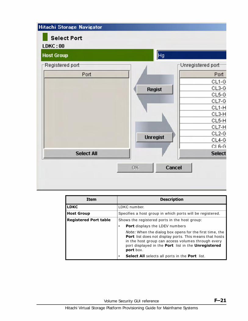
Volume Security GUI reference F–21Hitachi Virtual Storage Platform Provisioning Guide for Mainframe Systems
Item Description
LDKC LDKC number.
Host Group Specifies a host group in which ports will be registered.
Registered Port table Shows the registered ports in the host group:
• Port displays the LDEV numbers
Note: When the dialog box opens for the first time, the Port list does not display ports. This means that hosts in the host group can access volumes through every port displayed in the Port list in the Unregistered port box.
• Select All selects all ports in the Port list.
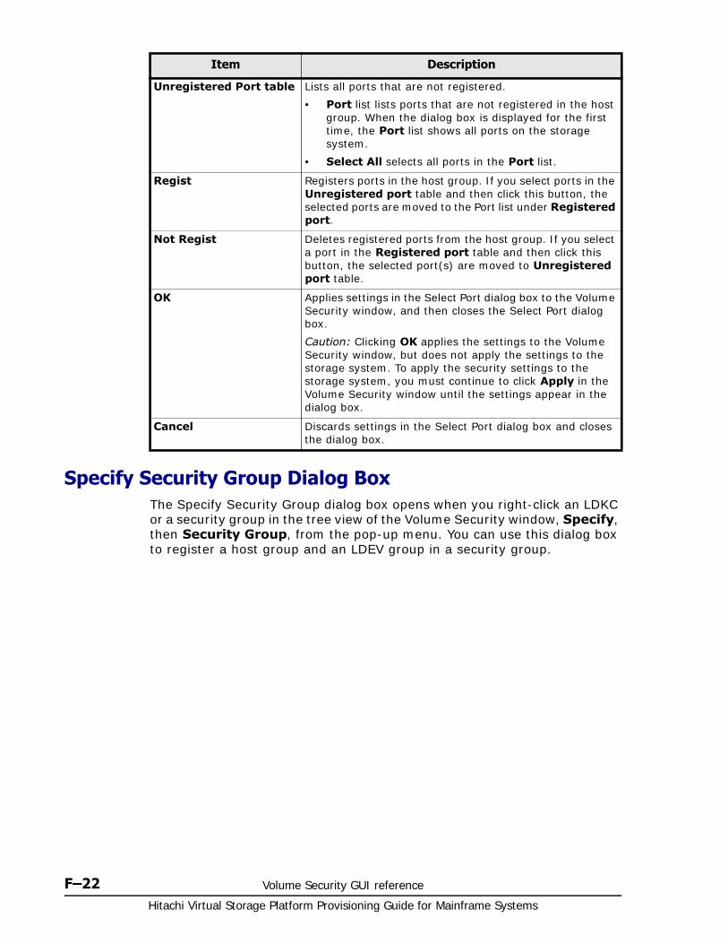
Hitachi Virtual Storage Platform Provisioning Guide for Mainframe Systems
F–22 Volume Security GUI reference
Specify Security Group Dialog BoxThe Specify Security Group dialog box opens when you right-click an LDKC or a security group in the tree view of the Volume Security window, Specify, then Security Group, from the pop-up menu. You can use this dialog box to register a host group and an LDEV group in a security group.
Unregistered Port table Lists all ports that are not registered.
• Port list lists ports that are not registered in the host group. When the dialog box is displayed for the first time, the Port list shows all ports on the storage system.
• Select All selects all ports in the Port list.
Regist Registers ports in the host group. If you select ports in the Unregistered port table and then click this button, the selected ports are moved to the Port list under Registered port.
Not Regist Deletes registered ports from the host group. If you select a port in the Registered port table and then click this button, the selected port(s) are moved to Unregistered port table.
OK Applies settings in the Select Port dialog box to the Volume Security window, and then closes the Select Port dialog box.
Caution: Clicking OK applies the settings to the Volume Security window, but does not apply the settings to the storage system. To apply the security settings to the storage system, you must continue to click Apply in the Volume Security window until the settings appear in the dialog box.
Cancel Discards settings in the Select Port dialog box and closes the dialog box.
Item Description
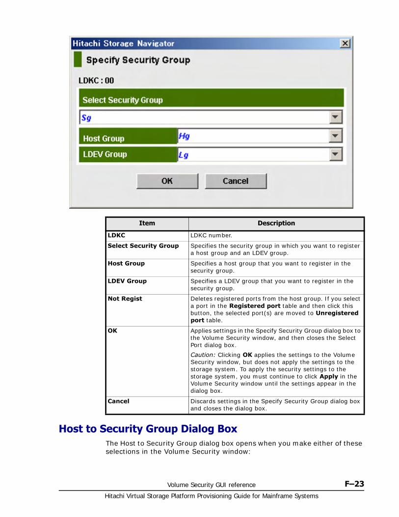
Volume Security GUI reference F–23Hitachi Virtual Storage Platform Provisioning Guide for Mainframe Systems
Host to Security Group Dialog BoxThe Host to Security Group dialog box opens when you make either of these selections in the Volume Security window:
Item Description
LDKC LDKC number.
Select Security Group Specifies the security group in which you want to register a host group and an LDEV group.
Host Group Specifies a host group that you want to register in the security group.
LDEV Group Specifies a LDEV group that you want to register in the security group.
Not Regist Deletes registered ports from the host group. If you select a port in the Registered port table and then click this button, the selected port(s) are moved to Unregistered port table.
OK Applies settings in the Specify Security Group dialog box to the Volume Security window, and then closes the Select Port dialog box.
Caution: Clicking OK applies the settings to the Volume Security window, but does not apply the settings to the storage system. To apply the security settings to the storage system, you must continue to click Apply in the Volume Security window until the settings appear in the dialog box.
Cancel Discards settings in the Specify Security Group dialog box and closes the dialog box.
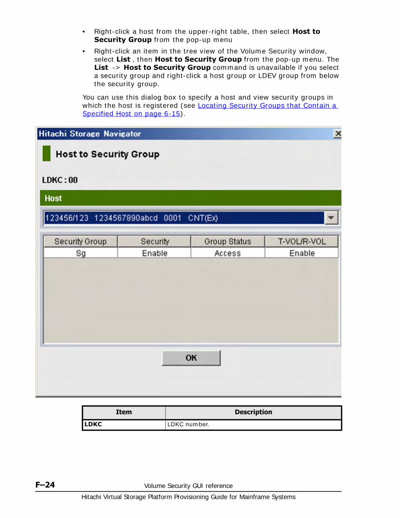
Hitachi Virtual Storage Platform Provisioning Guide for Mainframe Systems
F–24 Volume Security GUI reference
• Right-click a host from the upper-right table, then select Host to Security Group from the pop-up menu
• Right-click an item in the tree view of the Volume Security window, select List , then Host to Security Group from the pop-up menu. The List -> Host to Security Group command is unavailable if you select a security group and right-click a host group or LDEV group from below the security group.
You can use this dialog box to specify a host and view security groups in which the host is registered (see Locating Security Groups that Contain a Specified Host on page 6-15).
Item Description
LDKC LDKC number.
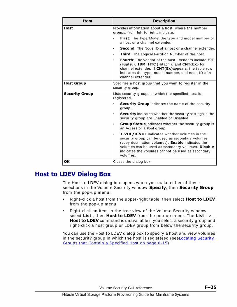
Volume Security GUI reference F–25Hitachi Virtual Storage Platform Provisioning Guide for Mainframe Systems
Host to LDEV Dialog BoxThe Host to LDEV dialog box opens when you make either of these selections in the Volume Security window:Specify, then Security Group, from the pop-up menu.
• Right-click a host from the upper-right table, then select Host to LDEV from the pop-up menu
• Right-click an item in the tree view of the Volume Security window, select List , then Host to LDEV from the pop-up menu. The List -> Host to LDEV command is unavailable if you select a security group and right-click a host group or LDEV group from below the security group.
You can use the Host to LDEV dialog box to specify a host and view volumes in the security group in which the host is registered (seeLocating Security Groups that Contain a Specified Host on page 6-15).
Host Provides information about a host, where the number groups, from left to right, indicate:
• First: The Type/Model the type and model number of a host or a channel extender.
• Second: The Node ID of a host or a channel extender.
• Third: The Logical Partition Number of the host.
• Fourth: The vendor of the host. Vendors include FJT (Fujitsu), IBM, HTC (Hitachi), and CNT(Ex) for channel extender. If CNT(Ex)appears, the table row indicates the type, model number, and node ID of a channel extender.
Host Group Specifies a host group that you want to register in the security group.
Security Group Lists security groups in which the specified host is registered.
• Security Group indicates the name of the security group.
• Security indicates whether the security settings in the security group are Enabled or Disabled.
• Group Status indicates whether the security group is an Access or a Pool group.
• T-VOL/R-VOL indicates whether volumes in the security group can be used as secondary volumes (copy destination volumes). Enable indicates the volumes can be used as secondary volumes. Disable indicates the volumes cannot be used as secondary volumes.
OK Closes the dialog box.
Item Description
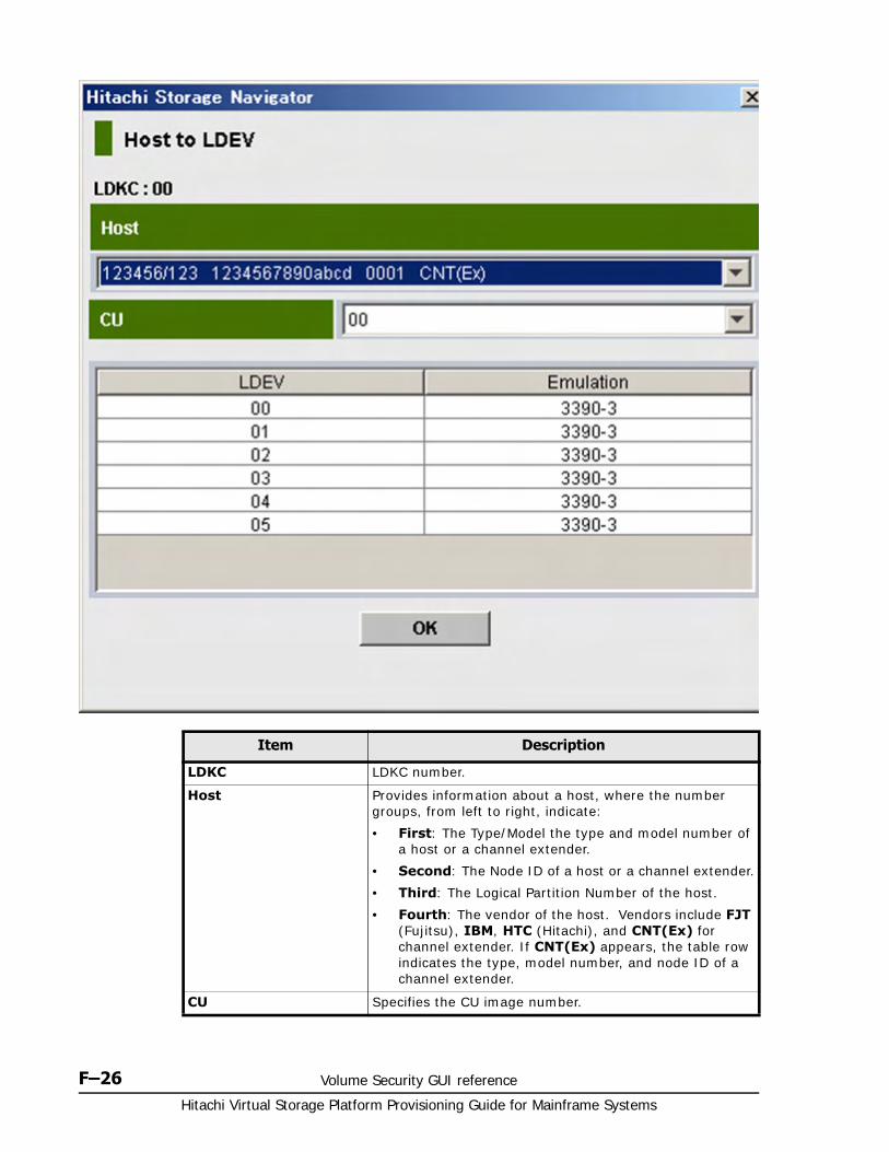
Hitachi Virtual Storage Platform Provisioning Guide for Mainframe Systems
F–26 Volume Security GUI reference
Item Description
LDKC LDKC number.
Host Provides information about a host, where the number groups, from left to right, indicate:
• First: The Type/Model the type and model number of a host or a channel extender.
• Second: The Node ID of a host or a channel extender.
• Third: The Logical Partition Number of the host.
• Fourth: The vendor of the host. Vendors include FJT (Fujitsu), IBM, HTC (Hitachi), and CNT(Ex) for channel extender. If CNT(Ex) appears, the table row indicates the type, model number, and node ID of a channel extender.
CU Specifies the CU image number.
Volume Security GUI reference F–27Hitachi Virtual Storage Platform Provisioning Guide for Mainframe Systems
Host Group to Security Group Dialog BoxThe Host Group to Security Group dialog box opens when you right-click an item in the tree view of the Volume Security window, select List , then Host Group to Security Group from the pop-up menu. The List -> Host Group to Security Group command is unavailable if you select a security group and right-click a host group or LDEV group from below the security group.
You can use the Host Group to Security Group dialog box to specify a host group and view security groups in which the specified host group is registered (see Locating Security Groups that Contain a Specified Host on page 6-15).
LDEV table Lists host groups in which the CU is registered.
• LDEV indicates the name of an LDEV. A volume ID ending in # (for example, 00#) indicates the volume is an external volume.
• Emulation indicates the emulation types of the volumes.
OK Closes the dialog box.
Item Description

Hitachi Virtual Storage Platform Provisioning Guide for Mainframe Systems
F–28 Volume Security GUI reference
Item Description
LDKC LDKC number.
Host Group Specifies a host group.
Security Group Lists information about security groups in which the specified host is registered.
• Security Group indicates the name of the security group.
• Security indicates whether the security settings in the security group are Enabled or Disabled.
• Group Status indicates whether the security group is an Access or a Pool group.
• T-VOL/R-VOL indicates whether volumes in the security group can be used as secondary volumes (copy destination volumes). Enable indicates the volumes can be used as secondary volumes. Disable indicates the volumes cannot be used as secondary volumes.
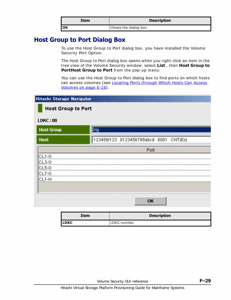
Volume Security GUI reference F–29Hitachi Virtual Storage Platform Provisioning Guide for Mainframe Systems
Host Group to Port Dialog BoxTo use the Host Group to Port dialog box, you have installed the Volume Security Port Option.
The Host Group to Port dialog box opens when you right-click an item in the tree view of the Volume Security window, select List , then Host Group to PortHost Group to Port from the pop-up menu.
You can use the Host Group to Port dialog box to find ports on which hosts can access volumes (see Locating Ports through Which Hosts Can Access Volumes on page 6-16).
OK Closes the dialog box.
Item Description
Item Description
LDKC LDKC number.
Hitachi Virtual Storage Platform Provisioning Guide for Mainframe Systems
F–30 Volume Security GUI reference
LDEV to Security Group Dialog BoxThe LDEV to Security Group dialog box opens when you make either of these selections in the Volume Security window:
• Right-click a host from the upper-right table, then select LDEV to Security Group from the pop-up menu
• Right-click an item in the tree view of the Volume Security window, select List , then LDEV to Security Group from the pop-up menu. The List -> LDEV to Security Group command is unavailable if you select a security group and right-click a host group or LDEV group from below the security group.
You can use this dialog box to specify a volume and view security groups in which the volume is registered (see Locating Security Groups that Contain a Specified Volume on page 6-17).
Host Group Provides information about a host group, where the number groups, from left to right, indicate:
• First: The Type/Model the type and model number of a host or a channel extender.
• Second: The Node ID of a host or a channel extender.
• Third: The Logical Partition Number of the host.
• Fourth: The vendor of the host. Vendors include FJT (Fujitsu), IBM, HTC (Hitachi), and CNT(Ex) for channel extender. If CNT(Ex) appears, the table row indicates the type, model number, and node ID of a channel extender.
Port table Lists ports that are available and registered.
OK Closes the dialog box.
Item Description
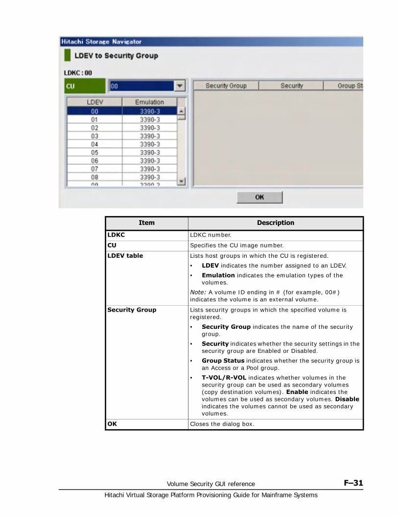
Volume Security GUI reference F–31Hitachi Virtual Storage Platform Provisioning Guide for Mainframe Systems
Item Description
LDKC LDKC number.
CU Specifies the CU image number.
LDEV table Lists host groups in which the CU is registered.
• LDEV indicates the number assigned to an LDEV.
• Emulation indicates the emulation types of the volumes.
Note: A volume ID ending in # (for example, 00#) indicates the volume is an external volume.
Security Group Lists security groups in which the specified volume is registered.
• Security Group indicates the name of the security group.
• Security indicates whether the security settings in the security group are Enabled or Disabled.
• Group Status indicates whether the security group is an Access or a Pool group.
• T-VOL/R-VOL indicates whether volumes in the security group can be used as secondary volumes (copy destination volumes). Enable indicates the volumes can be used as secondary volumes. Disable indicates the volumes cannot be used as secondary volumes.
OK Closes the dialog box.

Hitachi Virtual Storage Platform Provisioning Guide for Mainframe Systems
F–32 Volume Security GUI reference
LDEV to Host Dialog BoxThe LDEV to Host dialog box opens when you make either of these selections in the Volume Security window:
• Right-click a host from the upper-right table, then select LDEV to Host from the pop-up menu
• Right-click an item in the tree view of the Volume Security window, select List , then LDEV to Host from the pop-up menu. The List -> LDEV to Host command is unavailable if you select a security group and right-click a host group or LDEV group from below the security group.
You can use this dialog box to specify a volume and view hosts in which the specified volume is registered (see Locating Hosts in a Security Group that Contains a Specified Volume on page 6-17).
Item Description
LDKC LDKC number.
CU Specifies the CU image number.
LDEV table Lists host groups in which the CU is registered.
• LDEV indicates the number assigned to an LDEV.
• Emulation indicates the emulation types of the volumes.
Note: A volume ID ending in # (for example, 00#) indicates the volume is an external volume.
Volume Security GUI reference F–33Hitachi Virtual Storage Platform Provisioning Guide for Mainframe Systems
LDEV Group to Security Group Dialog BoxThe LDEV Group to Security Group dialog box opens when you right-click an item in the tree view of the Volume Security window, select List , then LDEV Group to Security Group from the pop-up menu. The List -> LDEV Group to Security Group command is unavailable if you select a security group and right-click a host group or LDEV group from below the security group.
You can use this dialog box to specify a LDEV group and view security groups in which the specified LDEV group is registered (see Locating Security Groups that Contain a Specified LDEV Group on page 6-18).
Host table Host information.
• No. indicates a sequential number associated with a host.
Note: Each table row usually shows information about a host. However, if a host is attached to the storage system through a channel extender, the table row shows information about the channel extender
• Type/Model indicates the type and the model number of a host or a channel extender. The Type appears on the left of the slash (/) and the Model on the right. An icon indicates the registration status of the host:
• SEQNUMBER indicates the node ID of a host or a channel extender.
• LPAR indicates the logical partition number of a host. Logical partitions are virtual systems created by sectioning a computer's memory into separate units.
• Vendor indicates the vendor of a host. Vendors include FJT (Fujitsu), IBM, HTC (Hitachi), and CNT(Ex) for channel extender. If CNT(Ex) appears, the Type/Model column indicates the type and model number of a channel extender. The SEQNUMBER column indicates the node ID of the channel extender.
OK Closes the dialog box.
Item Description
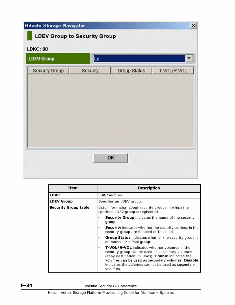
Hitachi Virtual Storage Platform Provisioning Guide for Mainframe Systems
F–34 Volume Security GUI reference
Item Description
LDKC LDKC number.
LDEV Group Specifies an LDEV group.
Security Group table Lists information about security groups in which the specified LDEV group is registered.
• Security Group indicates the name of the security group.
• Security indicates whether the security settings in the security group are Enabled or Disabled.
• Group Status indicates whether the security group is an Access or a Pool group.
• T-VOL/R-VOL indicates whether volumes in the security group can be used as secondary volumes (copy destination volumes). Enable indicates the volumes can be used as secondary volumes. Disable indicates the volumes cannot be used as secondary volumes.
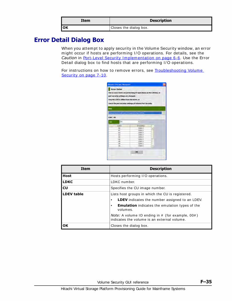
Volume Security GUI reference F–35Hitachi Virtual Storage Platform Provisioning Guide for Mainframe Systems
Error Detail Dialog BoxWhen you attempt to apply security in the Volume Security window, an error might occur if hosts are performing I/O operations. For details, see the Caution in Port-Level Security Implementation on page 6-6. Use the Error Detail dialog box to find hosts that are performing I/O operations.
For instructions on how to remove errors, see Troubleshooting Volume Security on page 7-10.
OK Closes the dialog box.
Item Description
Item Description
Host Hosts performing I/O operations.
LDKC LDKC number.
CU Specifies the CU image number.
LDEV table Lists host groups in which the CU is registered.
• LDEV indicates the number assigned to an LDEV.
• Emulation indicates the emulation types of the volumes.
Note: A volume ID ending in # (for example, 00#) indicates the volume is an external volume.
OK Closes the dialog box.

Hitachi Virtual Storage Platform Provisioning Guide for Mainframe Systems
F–36 Volume Security GUI reference
CA KD E F G H I J L M N O P Q R S T U V W X Y# B Z# A B C D E F G H I J K L M N O P Q R S T U V W X Z
Glossary–1Hitachi Virtual Storage Platform Provisioning Guide for Mainframe Systems
Glossary
This glossary defines the special terms used in this document. Click the letter links below to navigate.
#
2DC
two-data-center. Refers to the local and remote sites, or data centers, in which TrueCopy (TC) and Universal Replicator (UR) combine to form a remote replication configuration.
In a 2DC configuration, data is copied from a TC primary volume at the local site to the UR master journal volume at an intermediate site, then replicated to the UR secondary volume at the remote site. Since this configuration side-steps the TC secondary volume at the intermediate site, the intermediate site is not considered a data center.
3DC
three-data-center. Refers to the local, intermediate, and remote sites, or data centers, in which TrueCopy (TC) and Universal Replicator (UR) combine to form a remote replication configuration.
In a 3DC configuration, data is copied from a local site to an intermediate site and then to a remote site (3DC cascade configuration), or from a local site to two separate remote sites (3DC multi-target configuration).
A
access attribute
The setting on a logical volume (mainframe or open-systems) that determines whether hosts can read and/or write to the volume.
ACE
Advanced Cluster Environment
CA KD E F G H I J L M N O P Q R S T U V W X Y# B Z# A B C D E F G H I J K L M N O P Q R S T U V W X Z
Hitachi Virtual Storage Platform Provisioning Guide for Mainframe Systems
Glossary–2
ACP
array control processor. Another name for a back-end director (BED).
Adr
address
AdvFS
advanced file system
AES
Advanced Encryption Standard
AL
arbitrated loop
alias device
A formatted but unused mainframe logical device (LDEV) whose address can be used as an alias for a Parallel Access Volume (PAV) base device. See also base device.
allocated volume
A logical device (LDEV) for which one or more host paths are defined.
AL-PA
arbitrated-loop physical address
alternate path
A secondary path (port, target ID, LUN) to a logical volume, in addition to the primary path, that is used as a backup in case the primary path fails.
AMS
Hitachi Adaptable Modular Storage
ANSI
American National Standards Institute
AOU
allocation on use. Another name for Hitachi Dynamic Provisioning.
APAR
Authorized Problem Analysis Report
CA KD E F G H I J L M N O P Q R S T U V W X Y# B Z# A B C D E F G H I J K L M N O P Q R S T U V W X Z
Glossary–3Hitachi Virtual Storage Platform Provisioning Guide for Mainframe Systems
API
application program interface
APLB
active path load balancing
array
Another name for a RAID storage system.
array domain
All functions, paths, and drives controlled by one back-end director (BED) feature (pair of boards). An array domain can contain a mix of mainframe and open-systems volume types. RAID-level intermix (all RAID types) is also allowed within an array domain.
array frame
One of the additional cabinets that can be added to the controller frame of the floor model and that contains primarily data drives.
array group
See RAID group.
ASCII
American National Standard Code for Information Interchange
ASL
Array Support Library
ASTM
American Society for Testing and Materials
async
asynchronous
at-time split
Operation that allows multiple pairsplit operations to be performed at a pre-determined time.
ATA
Advanced Technology Attachment
ATM
asynchronous transfer mode
CA KD E F G H I J L M N O P Q R S T U V W X Y# B Z# A B C D E F G H I J K L M N O P Q R S T U V W X Z
Hitachi Virtual Storage Platform Provisioning Guide for Mainframe Systems
Glossary–4
audit log
Files that store a history of the operations performed from Storage Navigator and the service processor (SVP), commands that the storage system received from hosts, and data encryption operations.
ave, avg
average
B
b
bit
B
byte
b/sec, bps
bits per second
B/sec, Bps
bytes per second
back-end director (BED)
The hardware component that controls the transfer of data between the drives and cache. A BED feature consists of a pair of boards. A BED is also referred to as a disk adapter (DKA).
base device
A formatted mainframe logical device (LDEV) that contains user data and can be accessed via alias devices using IBM Parallel Access Volume (PAV) host software. A base device must be defined to the host as a "B" device type (for example, 3390B-9). See also alias device.
base emulation type
Emulation type that is set when drives are installed. Determines the device emulation types that can be set in the RAID group.
BBC
buffer-to-buffer credit
BC
business continuity
CA KD E F G H I J L M N O P Q R S T U V W X Y# B Z# A B C D E F G H I J K L M N O P Q R S T U V W X Z
Glossary–5Hitachi Virtual Storage Platform Provisioning Guide for Mainframe Systems
BCM
Business Continuity Manager
BED
See back-end director (BED).
bind mode
In bind mode the Cache Residency Manager extents are used to hold read and write data for specific extents on volumes. Data written to the Cache Residency Manager bind area is not destaged to the drives. For bind mode, all targeted read and write data is transferred at host data transfer speed.
BIOS
basic input/output system
BL
block length
blade
A computer module, generally a single circuit board, used mostly in servers.
BLK, blk
block
bmp
bitmap
BS
basic (power) supply
BSA
bus adapter
BTU
British thermal unit
C
C/T
See consistency time (C/T).
CA KD E F G H I J L M N O P Q R S T U V W X Y# B Z# A B C D E F G H I J K L M N O P Q R S T U V W X Z
Hitachi Virtual Storage Platform Provisioning Guide for Mainframe Systems
Glossary–6
ca
cache
cache blade
A circuit board containing random-access memory (RAM) that is a component in the Virtual Storage Platform controller.
cache logical partition (CLPR)
Consists of virtual cache memory that is set up to be allocated to different hosts in contention for cache memory.
capacity
The amount of data storage space available on a physical storage device, usually measured in bytes (MB, GB, TB, etc.).
cascade configuration
In a 3DC cascade configuration for remote replication, data is copied from a local site to an intermediate site and then to a remote site using TrueCopy and Universal Replicator. See also 3DC.
In a ShadowImage cascade configuration, two layers of secondary volumes can be defined for a single primary volume. Pairs created in the first and second layer are called cascaded pairs.
cascade function
A ShadowImage function that allows a primary volume (P-VOL) to have up to nine secondary volumes (S-VOLs) in a layered configuration. The first cascade layer (L1) is the original ShadowImage pair with one P-VOL and up to three S-VOLs. The second cascade layer (L2) contains ShadowImage pairs in which the L1 S-VOLs are functioning as the P-VOLs of layer-2 ShadowImage pairs that can have up to two S-VOLs for each P-VOL.
See also root volume, node volume, leaf volume, layer-1 (L1) pair, and layer-2 (L2) pair.
cascaded pair
A ShadowImage pair in a cascade configuration. See cascade function.
CC
Concurrent Copy; channel command; cylinder-cylinder
CCA
channel connection address
CCHH
cylinder-cylinder, head-head
CA KD E F G H I J L M N O P Q R S T U V W X Y# B Z# A B C D E F G H I J K L M N O P Q R S T U V W X Z
Glossary–7Hitachi Virtual Storage Platform Provisioning Guide for Mainframe Systems
CCI
Hitachi Command Control Interface software
CCW
channel command word
CDB
control data block
CEC
Canadian Electroacoustic Community
C-field
count-field
CFL
Configuration File Loader. A Storage Navigator function for validating and running scripted spreadsheets.
CFW
cache fast write
CG
See consistency group (CTG).
CH
channel
CHA
channel adapter. Another name for a front-end director (FED).
channel adapter (CHA)
Another name for a front-end director. See front-end director (FED).
channel path
The communication path between a channel and a control unit. A channel path consists of the physical channel path and the logical path.
CHAP
challenge handshake authentication protocol
CHIP
client-host interface processor. Another name for a front-end director.
CA KD E F G H I J L M N O P Q R S T U V W X Y# B Z# A B C D E F G H I J K L M N O P Q R S T U V W X Z
Hitachi Virtual Storage Platform Provisioning Guide for Mainframe Systems
Glossary–8
CHL
channel
CHP
channel path; channel processor. The channel processors are the microprocessors on the front-end director features of the Universal Storage Platform V/VM.
CHPID
channel path ID
CIFS
common internet file system
CKD
count-key data
CL
cluster
CLI
command line interface
CLPR
cache logical partition
cluster
Multiple-storage servers working together to respond to multiple read and write requests.
CM
control memory
CMA
cache memory adapter
CMM
cache memory module
command device
A dedicated logical volume used only by Command Control Interface to interface with the storage system. Can be shared by several hosts.
CA KD E F G H I J L M N O P Q R S T U V W X Y# B Z# A B C D E F G H I J K L M N O P Q R S T U V W X Z
Glossary–9Hitachi Virtual Storage Platform Provisioning Guide for Mainframe Systems
concatenated parity group
A configuration where the VDEVs corresponding to a pair of RAID 10 (2D+2D) or RAID 5 (7D+1P) parity groups, or four RAID 5 (7D+1P) parity groups, are interleaved on a RAID stripe level on a round-robin basis. A logical RAID stripe line is created as a concatenation of the individual RAID stripe lines. This has the effect of dispersing I/O activity over twice or four times the number of disks, but it does not change the number, names, or size of VDEVs, and hence it doesn't make it possible to assign larger LDEVs to them. Note that we often refer to RAID 10 (4D+4D), but this is actually two RAID 10 (2D+2D) parity groups interleaved together.
configuration definition file
A text file that defines the configuration, parameters, and options of Command Control Interface (CCI) operations. It also defines the connected hosts and the volumes and groups known to the Command Control Interface instance.
consistency group (CG, CTG)
A group of pairs on which copy operations are performed simultaneously; the pairs' status changes at the same time. See also extended consistency group (EXCTG).
consistency time (C/T)
Shows a time stamp to indicate how close the target volume is to the source volume. C/T also shows the time stamp of a journal group and extended consistency group.
control chassis
The hardware component that houses the controller components of the Virtual Storage Platform storage system, including the front-end directors, virtual storage directors, cache and shared memory, switches, and back-end directors. The Virtual Storage Platform storage system can be configured with one or two control chassis.
controller
The component in a storage system that manages all storage functions. It is analogous to a computer and contains a processors, I/O devices, RAM, power supplies, cooling fans, and other sub-components as needed to support the operation of the storage system.
controller frame
The cabinet (floor model) that contains the controller components of the RAID storage system.
CA KD E F G H I J L M N O P Q R S T U V W X Y# B Z# A B C D E F G H I J K L M N O P Q R S T U V W X Z
Hitachi Virtual Storage Platform Provisioning Guide for Mainframe Systems
Glossary–10
copy-on-write
Point-in-time snapshot copy of any data volume within a storage system. Copy-on-Write Snapshot stores only changed data blocks. Therefore, the amount of storage capacity required for each copy is substantially smaller than the source volume.
copy pair
A pair of volumes in which one volume contains original data and the other volume contains the copy of the original. Copy operations can be synchronous or asynchronous, and the volumes of the copy pair can be located in the same storage system (local copy) or in different storage systems (remote copy).
A copy pair can also be called a volume pair, or just pair.
COW
copy-on-write
COW Snapshot
Hitachi Copy-on-Write Snapshot software
PAV
Hitachi Compatible PAV
CPPL
command processor parameter list
CPC
cache path control adapter
CPU
central processing unit
CRC
cyclical redundancy checking
CRM
Hitachi Cache Residency Manager
CSA
Canadian Standards Association
CT, C/T
See consistency time (C/T).
CA KD E F G H I J L M N O P Q R S T U V W X Y# B Z# A B C D E F G H I J K L M N O P Q R S T U V W X Z
Glossary–11Hitachi Virtual Storage Platform Provisioning Guide for Mainframe Systems
CTG
See consistency group (CTG).
CTL
controller
CTQ
command tag queuing
CTRLID
controller ID
CU
control unit
currency of data
The synchronization of the volumes in a copy pair. When the data on the secondary volume (S-VOL) is identical to the data on the primary volume (P-VOL), the data on the S-VOL is current. When the data on the S-VOL is not identical to the data on the P-VOL, the data on the S-VOL is not current.
custom volume (CV)
A customized (variable-sized) volume whose size is defined by the user using Virtual LVI/Virtual LUN.
CV
See custom volume (CV).
CVS
custom volume size
CXFS
clustered version of XFS file system
CYL, cyl
cylinder
cylinder bitmap
Indicates the differential data (updated by write I/Os) in a volume of a split or suspended copy pair. The primary and secondary volumes each have their own cylinder bitmap. When the pair is resynchronized, the cylinder bitmaps are merged, and the differential data is copied to the secondary volume.
CA KD E F G H I J L M N O P Q R S T U V W X Y# B Z# A B C D E F G H I J K L M N O P Q R S T U V W X Z
Hitachi Virtual Storage Platform Provisioning Guide for Mainframe Systems
Glossary–12
D
D
delimiter
DAM
direct-access method
DASD
direct-access storage device
data consistency
When the data on the secondary volume is identical to the data on the primary volume.
data drive
A physical data storage device that can be either a hard disk drive (HDD) or a flash drive (also called a solid-state device).
data lifecyle management (DLM)
The policies, processes, practices, services, and tools used to align the business value of data with the most appropriate and cost-effective storage infrastructure from the time data is created through its final disposition.
data path
The physical paths used by primary storage systems to communicate with secondary storage systems in a remote replication environment.
data pool
One or more logical volumes designated to temporarily store original data. When a snapshot is taken of a primary volume, the data pool is used if a data block in the primary volume is to be updated. The original snapshot of the volume is maintained by storing the to-be-changed data blocks in the data pool.
DB
database
dB(A)
decibel (A-weighted)
DB2
DATABASE 2
CA KD E F G H I J L M N O P Q R S T U V W X Y# B Z# A B C D E F G H I J K L M N O P Q R S T U V W X Z
Glossary–13Hitachi Virtual Storage Platform Provisioning Guide for Mainframe Systems
DBMS
database management system
DBV
Hitachi Database Validator
DC
data center
DCR
Dynamic Cache Residency
delta resync
A disaster recovery solution in which TrueCopy and Universal Replicator systems are configured to provide a quick recovery using only differential data stored at an intermediate site.
DEV, dev
device
device
A physical or logical unit with a specific function.
device emulation
Indicates the type of logical volume. Mainframe device emulation types provide logical volumes of fixed size, called logical volume images (LVIs), which contain EBCDIC data in CKD format. Typical mainframe device emulation types include 3390-9 and 3390-M. Open-systems device emulation types provide logical volumes of variable size, called logical units (LUs), that contain ASCII data in FBA format. The typical open-systems device emulation type is OPEN-V.
DEVN
device number
DF600
The factory model name for the Hitachi Thunder 9500V storage system.
DF700
The factory model name for the Hitachi TagmaStore® Adaptable Modular Storage and Workgroup Modular Storage arrays.
DF800
The factory model name for the Hitachi Adaptable Modular Storage 2000 storage system.
CA KD E F G H I J L M N O P Q R S T U V W X Y# B Z# A B C D E F G H I J K L M N O P Q R S T U V W X Z
Hitachi Virtual Storage Platform Provisioning Guide for Mainframe Systems
Glossary–14
DFDSS
Data Facility Dataset Services
DFSMS
Data Facility System Managed Storage
DFW
DASD fast write
DHCP
dynamic host configuration protocol
differential data
Changed data in the primary volume not yet reflected in the secondary volume of a copy pair.
differential table
Used to manage differential data between pairs’ primary volumes and secondary volumes. In Volume Migration, it is used during volume transfer to manage differential data between a source and target volume. Used by ShadowImage, ShadowImage for Mainframe, Copy-on-Write Snapshot, Compatible FlashCopy® V2, Compatible Software for IBM® FlashCopy® SE, and Volume Migration.
differential management logical unit (DM-LU)
An exclusive volume for storing replication data when the storage system is powered down. The DM-LU is hidden from the host.
disaster recovery
A set of procedures to recover critical application data and processing after a disaster or other failure.
disk adapter (DKA)
Another name for back-end director. See back-end director (BED).
disk array
Disk array, or just array, is another name for a RAID storage system.
disk controller (DKC)
The hardware component that manages front-end and back-end storage operations. The term DKC is also used to refer to the entire RAID storage system.
disk unit (DKU)
See drive chassis.
CA KD E F G H I J L M N O P Q R S T U V W X Y# B Z# A B C D E F G H I J K L M N O P Q R S T U V W X Z
Glossary–15Hitachi Virtual Storage Platform Provisioning Guide for Mainframe Systems
DKA
disk adapter. Another name for a back-end director (BED).
DKC
disk controller. DKC can refer to the RAID storage system or the controller components.
DKCMAIN
disk controller main. Refers to the microcode for the RAID storage system.
DKP
disk processor. Refers to the microprocessors on the back-end director features of the Universal Storage Platform V/VM.
DKU
disk unit. See drive chassis.
DL
data length
DLM
See data lifecyle management (DLM).
DM-LU
See differential management logical unit (DM-LU).
DMP
Dynamic Multi Pathing
DO
dataset organization
DNS
domain name system
DVE
dynamic volume expansion
DP
Hitachi Dynamic Provisioning
CA KD E F G H I J L M N O P Q R S T U V W X Y# B Z# A B C D E F G H I J K L M N O P Q R S T U V W X Z
Hitachi Virtual Storage Platform Provisioning Guide for Mainframe Systems
Glossary–16
DP-VOL
Dynamic Provisioning-virtual volume. A virtual volume with no memory space used by Dynamic Provisioning.
drive chassis
The hardware component of the Virtual Storage Platform storage system that contains data drives and no controller components. A drive chassis can also be called a disk unit (DKU).
DRR
data recovery and reconstruction
DRU
Hitachi Data Retention Utility
DS
DEVSERV
DSF
Device Support Facilities
DSR
Hitachi Dataset Replication for IBM® z/OS®
DTDS+
Disaster Tolerant Storage System Plus
dump
A collection of data that is saved to a file when an error or crash occurs. The data is used by support personnel to determine the cause of the error or crash.
DWL
duplex write line
dynamic provisioning
An approach to managing storage. Instead of "reserving" a fixed amount of storage, it removes capacity from the available pool when data is actually written to disk. Dynamic provisioning is also referred to as thin provisioning.

CA KD E F G H I J L M N O P Q R S T U V W X Y# B Z# A B C D E F G H I J K L M N O P Q R S T U V W X Z
Glossary–17Hitachi Virtual Storage Platform Provisioning Guide for Mainframe Systems
E
EB
exabyte
EBCDIC
extended binary-coded decimal interchange code
EBED
encrypting back-end director
EC
error code
ECB
entry control block; Electronic Code Book.
ECKD
extended count-key data
EDD
element data definition
EFS
extent file system (used in SGI IRIX systems)
ELB
extended long busy
DAR
Encryption License Key
EMI
electromagnetic interference
Emp
empty file option
EMT64T
Extended Memory 64 Technology
CA KD E F G H I J L M N O P Q R S T U V W X Y# B Z# A B C D E F G H I J K L M N O P Q R S T U V W X Z
Hitachi Virtual Storage Platform Provisioning Guide for Mainframe Systems
Glossary–18
emulation
The operation of the Hitachi RAID storage system to emulate the characteristics of a different storage system. For device emulation the mainframe host "sees" the logical devices on the RAID storage system as 3390-x devices. For controller emulation the mainframe host "sees" the control units (CUs) on the RAID storage system as 2105 or 2107 controllers.
RAID storage system operates the same as the storage system being emulated.
emulation group
A set of device emulation types that can be intermixed within a RAID group and treated as a group.
env.
environment
EOF
end of file; end of field
EOU
ease of use
EPO
emergency power-off
ERC
error reporting communications
EREP
Error Reporting
ERP
error recovery procedure
ESA
Enterprise Systems Architecture
ESCD
extended system configuration data; ESCON director
ESCON
Enterprise System Connection
CA KD E F G H I J L M N O P Q R S T U V W X Y# B Z# A B C D E F G H I J K L M N O P Q R S T U V W X Z
Glossary–19Hitachi Virtual Storage Platform Provisioning Guide for Mainframe Systems
ESD
electrostatic discharge
ESDS
entry-sequenced dataset
ESS
Enterprise Storage Server
ESW
PCI express path switch
EXCTG
See extended consistency group (EXCTG).
EXG
external volume group
ExSA
Extended Serial Adapter. Another name for an ESCON front-end director.
ext.
external
extended consistency group (EXCTG)
A set of Universal Replicator for Mainframe journal groups in which data consistency is guaranteed. When performing copy operations between multiple primary and secondary systems, the journal groups must be registered in an EXCTG.
external application
A software module that is used by a storage system but runs on a separate platform.
external port
A fibre-channel port that is configured to be connected to an external storage system for Universal Volume Manager operations.
external volume
A logical volume whose data resides on drives that are physically located outside the Hitachi RAID storage system.
CA KD E F G H I J L M N O P Q R S T U V W X Y# B Z# A B C D E F G H I J K L M N O P Q R S T U V W X Z
Hitachi Virtual Storage Platform Provisioning Guide for Mainframe Systems
Glossary–20
F
F
fixed length and de- blocking
F/M
format/message
f/w
firmware
failback
The process of switching operations from the secondary path or host back to the primary path or host, after the primary path or host has recovered from failure. See also failover.
failover
The process of switching operations from the primary path or host to a secondary path or host when the primary path or host fails.
FAL
File Access Library
FAL/FCU
File Access Library/File Conversion Utility
FB
fixed length and blocking
FBA
fixed-block architecture
FC
fibre channel; FlashCopy
FCA
fibre-channel adapter
FC-AL
fibre-channel arbitrated loop
FCC
Federal Communications Commission
CA KD E F G H I J L M N O P Q R S T U V W X Y# B Z# A B C D E F G H I J K L M N O P Q R S T U V W X Z
Glossary–21Hitachi Virtual Storage Platform Provisioning Guide for Mainframe Systems
FCIP
fibre-channel internet protocol
FCP
fibre-channel protocol
FCSP
fibre-channel security protocol
FCU
File Conversion Utility
FD
floppy disk
FD Dump Tool
Downloads Storage Navigator configuration information onto a floppy disk or hard disk for backup and troubleshooting purposes.
FDR
Fast Dump/Restore
FED
See front-end director (FED).
FIBARC
Fibre Connection Architecture
FICON
Fibre Connectivity
FIFO
first in, first out
flash drive
A data drive that is a solid-state memory device instead of a rotating hard disk drive. A flash drive can also be called a solid-state drive (SSD).
frame
A hardware cabinet (floor model) that contains RAID storage system hardware components. The two frame types are controller frame and array frame.
CA KD E F G H I J L M N O P Q R S T U V W X Y# B Z# A B C D E F G H I J K L M N O P Q R S T U V W X Z
Hitachi Virtual Storage Platform Provisioning Guide for Mainframe Systems
Glossary–22
free capacity
The amount of storage space (in bytes) that is available for use by the host systems.
front-end director (FED)
The hardware component that processes channel commands from hosts and manages host access to cache. A FED is also referred to as a channel adapter (CHA).
FTP
file-transfer protocol
FV
fixed-size volume
FWD
fast-wide differential
FX
Hitachi Cross-OS File Exchange
fx
IRIX disk utility
FXmto
Hitachi Cross-OS File Exchange – mainframe to open
FXotm
Hitachi Cross-OS File Exchange – open to mainframe
FXoto
Hitachi Cross-OS File Exchange – open to open
G
Gb
gigabit
GB
gigabyte
Gb/sec, Gbps
gigabits per second
CA KD E F G H I J L M N O P Q R S T U V W X Y# B Z# A B C D E F G H I J K L M N O P Q R S T U V W X Z
Glossary–23Hitachi Virtual Storage Platform Provisioning Guide for Mainframe Systems
GB/sec, GBps
gigabytes per second
GbE
gigabit Ethernet
GDG
generation data group
GDS
generation dataset
GHz
gigahertz
GID
group ID
GLM
gigabit link module
GLPR
global logical partition
GT
Hitachi Graph-Track
GUI
graphical user interface
H
H.A.R.D
Hardware Assisted Resilient Data
h/w
hardware
HA
high availability
HACMP
High Availability Cluster Multi-Processing
CA KD E F G H I J L M N O P Q R S T U V W X Y# B Z# A B C D E F G H I J K L M N O P Q R S T U V W X Z
Hitachi Virtual Storage Platform Provisioning Guide for Mainframe Systems
Glossary–24
HAM
Hitachi High Availability Manager software
HBA
host bus adapter
HCD
Hardware Configuration Definition
HCS
Hitachi Command Suite (previously called Hitachi Storage Command Suite)
HD
head
HDD
hard disk drive
HDLM
Hitachi Dynamic Link Manager
HDP
Hitachi Dynamic Provisioning
HDS
Hitachi Data Systems
HDT
Hitachi Dynamic Tiering software
HDU
hard disk unit
HDvM
Hitachi Device Manager software
head LDEV
See top LDEV.
HGLAM
Hitachi Global Link Availability Manager
CA KD E F G H I J L M N O P Q R S T U V W X Y# B Z# A B C D E F G H I J K L M N O P Q R S T U V W X Z
Glossary–25Hitachi Virtual Storage Platform Provisioning Guide for Mainframe Systems
HH
head-head
high-speed mode
An operational mode of a fibre-channel port that improves data transfer rate but limits port usage to just one on the front-end director board.
HIHSM
Hitachi Hierarchical Storage Manager. Another name for Volume Migration.
Hi-Star
Hierarchical Star Network
HLDE
hold-error
HLQ
high-level qualifier
H-LUN
host logical unit
HMC
Hardware Management Console
HMDE
Hitachi Multiplatform Data Exchange. Another name for Hitachi Cross-OS File Exchange.
HMRCF
Hitachi Multi-RAID Coupling Feature. Another name for Hitachi ShadowImage® for Mainframe.
HODM
Hitachi Online Data Migration
HOMRCF
Hitachi Open Multi-RAID Coupling Feature. Another name for Hitachi ShadowImage®.
HORC
Hitachi Open Remote Copy. Another name for Hitachi TrueCopy®.
CA KD E F G H I J L M N O P Q R S T U V W X Y# B Z# A B C D E F G H I J K L M N O P Q R S T U V W X Z
Hitachi Virtual Storage Platform Provisioning Guide for Mainframe Systems
Glossary–26
HORCM
Hitachi Open Remote Copy Manager. Another name for Command Control Interface.
host failover
The process of switching operations from one host to another host when the primary host fails.
host group
A group of hosts of the same operating system platform.
host mode
Operational modes that provide enhanced compatibility with supported host platforms. Used with fibre-channel ports on RAID storage systems.
host mode option
Additional options for fibre-channel ports on RAID storage systems. Provide enhanced functionality for host software and middleware.
HPAV
Hitachi Parallel Access Volume. Another name for Hitachi Compatible PAV.
HPF
High-Performance FICON
HPtM
Hitachi Protection Manager
HPvM
Hitachi Provisioning Manager
HRC
Hitachi Remote Copy. Another name for Hitachi TrueCopy® for Mainframe.
HRCA
Hitachi Remote Copy Asynchronous
HRpM
Hitachi Replication Manager software
CA KD E F G H I J L M N O P Q R S T U V W X Y# B Z# A B C D E F G H I J K L M N O P Q R S T U V W X Z
Glossary–27Hitachi Virtual Storage Platform Provisioning Guide for Mainframe Systems
HRX
Hitachi RapidXchange. Another name for Hitachi Cross-OS File Exchange.
HSCS
Hitachi Storage Command Suite. This suite of products is now called the Hitachi Command Suite.
HSD
host storage domain. See host group.
HSN
Hierarchical Star Network
HTM
Hitachi Tuning Manager
HTnM
Hitachi Tuning Manager
HTSM
Hitachi Tiered Storage Manager
HUR
Hitachi Universal Replicator
HVR
Hitachi Volume Relocation
HWM
high-water mark
HXRC
Hitachi Extended Remote Copy. Another name for Hitachi Compatible Replication for IBM® XRC.
Hz
Hertz
I
IBM
International Business Machines Corporation
CA KD E F G H I J L M N O P Q R S T U V W X Y# B Z# A B C D E F G H I J K L M N O P Q R S T U V W X Z
Hitachi Virtual Storage Platform Provisioning Guide for Mainframe Systems
Glossary–28
ICF
integrated catalog facility
ICKDSF
Device Support Facility (DSF) program for media maintenance
ICP
interval control program
IDCAMS
access method services (a component of Data Facility Product)
IDE
integrated drive electronics
IEC
International Electrotechnical Commission
IEFBR14
Information Engineering Facility branch register 14
IETF
Internet Engineering Task Force
iFCP
internet fibre-channel protocol
IIS
internet information service
IML
initial microcode load; initial microprogram load
IMPL
initial microprogram load
IMS
Information Management System
in.
inch
CA KD E F G H I J L M N O P Q R S T U V W X Y# B Z# A B C D E F G H I J K L M N O P Q R S T U V W X Z
Glossary–29Hitachi Virtual Storage Platform Provisioning Guide for Mainframe Systems
int.
interval
initial copy
An initial copy operation is performed when a copy pair is created. Data on the primary volume is copied to the secondary volume.
initiator port
A fibre-channel port configured to send remote I/Os to an RCU target port on another storage system. See also RCU target port and target port.
in-system replication
The original data volume and its copy are located in the same storage system. ShadowImage in-system replication provides duplication of logical volumes; Copy-on-Write Snapshot in-system replication provides "snapshots" of logical volumes that are stored and managed as virtual volumes (V-VOLs).
See also remote replication.
inter-control chassis cable
The hardware option that connects two control chassis. Two sets of this option are required for the high-performance model.
intermediate site (I-site)
A site that functions as both a TrueCopy Synchronous secondary site and a Universal Replicator primary site in a 3-data-center (3DC) cascading configuration.
internal volume
A logical volume whose data resides on drives that are physically located within the storage system. See also external volume.
IO
input/output
IOCDS
I/O Configuration Dataset
IOCP
I/O configuration program
IODF
I/O definition file
CA KD E F G H I J L M N O P Q R S T U V W X Y# B Z# A B C D E F G H I J K L M N O P Q R S T U V W X Z
Hitachi Virtual Storage Platform Provisioning Guide for Mainframe Systems
Glossary–30
IOPS
I/Os per second
IOS
internetwork operating system
IP
internet protocol
IPv4
Internet Protocol, Version 4
IPv6
Internet Protocol, Version 6
IPL
initial program load
ISAM
index sequential-access method
I-site
See intermediate site (I-site).
ISL
inter-switch link
iSNS
internet storage name service
ISPF/PDF
Interactive System Productivity Facility/Program Development Facility
IZPIOCP
inter-zone path (IZP) version of IOCP
J
JCL
job control language
JFS
Journaled File System
CA KD E F G H I J L M N O P Q R S T U V W X Y# B Z# A B C D E F G H I J K L M N O P Q R S T U V W X Z
Glossary–31Hitachi Virtual Storage Platform Provisioning Guide for Mainframe Systems
JNL
journal
JNLG
journal group
journal group (JNLG)
In a Universal Replicator system, journal groups manage data consistency between multiple primary volumes and secondary volumes. See also consistency group (CG, CTG).
journal volume
A volume that records and stores a log of all events that take place in another volume. In the event of a system crash, the journal volume logs are used to restore lost data and maintain data integrity.
In Universal Replicator, differential data is held in journal volumes on until it is copied to the S-VOL.
JRE
Java Runtime Environment
JVM
Java Virtual Machine
JWS
Java Web Start
K
kb, Kb
kilobit
KB
kilobyte
Kb/sec, Kbps
kilobits per second
KB/sec, KBps
kilobytes per second
keypair
Two mathematically-related cryptographic keys: a private key and its associated public key.
CA KD E F G H I J L M N O P Q R S T U V W X Y# B Z# A B C D E F G H I J K L M N O P Q R S T U V W X Z
Hitachi Virtual Storage Platform Provisioning Guide for Mainframe Systems
Glossary–32
kHz
kilohertz
KL
key length
km
kilometer
KSDS
key sequential dataset
kVA
kilovolt-ampere
kW
kilowatt
L
L1 pair
See layer-1 (L1) pair.
L2 pair
See layer-2 (L2) pair.
LAN
local-area network
layer-1 (L1) pair
In a ShadowImage cascade configuration, a layer-1 pair consists of a primary volume and secondary volume in the first cascade layer. An L1 primary volume can be paired with up to three L1 secondary volumes. See also cascade configuration.
layer-2 (L2) pair
In a ShadowImage cascade configuration, a layer-2 (L2) pair consists of a primary volume and secondary volume in the second cascade layer. An L2 primary volume can be paired with up to two L2 secondary volumes. See also cascade configuration.
LBA
logical block address
CA KD E F G H I J L M N O P Q R S T U V W X Y# B Z# A B C D E F G H I J K L M N O P Q R S T U V W X Z
Glossary–33Hitachi Virtual Storage Platform Provisioning Guide for Mainframe Systems
LCP
link control processor
LCU
logical control unit
LD
local directory; logical device
LDAP
lightweight directory access protocol
LDEV
logical device
LDKC
See logical disk controller (LDKC).
LDM
Logical Disk Manager
LDS
linear dataset
leaf volume
A level-2 secondary volume in a ShadowImage cascade configuration. The primary volume of a layer-2 pair is called a node volume. See also cascade configuration.
LED
light-emitting diode
LF
line feed
license key
A specific set of characters that unlocks an application and allows it to be used.
LIFO
last in, first out
LIP
loop initialization primitive
CA KD E F G H I J L M N O P Q R S T U V W X Y# B Z# A B C D E F G H I J K L M N O P Q R S T U V W X Z
Hitachi Virtual Storage Platform Provisioning Guide for Mainframe Systems
Glossary–34
LM
local memory
loc.
location
local control port (LCP)
A serial-channel (ESCON) port configured to receive I/Os from a host or remote I/Os from a TrueCopy main control unit (MCU).
local copy
See in-system replication.
local site
See primary site.
logical device (LDEV)
An individual logical data volume (on multiple drives in a RAID configuration) in the storage system. An LDEV may or may not contain any data and may or may not be defined to any hosts. Each LDEV has a unique identifier or "address" within the storage system composed of the logical disk controller (LDKC) number, control unit (CU) number, and LDEV number. The LDEV IDs within a storage system do not change. An LDEV formatted for use by mainframe hosts is called a logical volume image (LVI). An LDEV formatted for use by open-system hosts is called a logical unit (LU).
logical disk controller (LDKC)
A group of 255 control unit (CU) images in the RAID storage system that is controlled by a virtual (logical) storage system within the single physical storage system. For example, the Universal Storage Platform V/VM storage system supports two LDKCs, LDKC 00 and LDKC 01.
logical partition (LPAR)
A subset of a system's hardware resources that is virtualized as a separate system. For a storage system, logical partitioning can be applied to cache memory and/or storage capacity.
logical unit (LU)
A logical volume that is configured for use by open-systems hosts (for example, OPEN-V).
logical unit (LU) path
The path between an open-systems host and a logical unit.
CA KD E F G H I J L M N O P Q R S T U V W X Y# B Z# A B C D E F G H I J K L M N O P Q R S T U V W X Z
Glossary–35Hitachi Virtual Storage Platform Provisioning Guide for Mainframe Systems
logical volume
See volume.
logical volume image (LVI)
A logical volume that is configured for use by mainframe hosts (for example, 3390-9).
LPAR
logical partition
LRU
least recently used
LSM
Logical Storage Manager
LSS
logical subsystem
LU
logical unit
LUN
logical unit number
LUNM
Hitachi LUN Manager
LUSE
Hitachi LUN Expansion; Hitachi LU Size Expansion
LV
logical volume
LVD
Hitachi Logical Volume Divider
LVI
See logical volume image (LVI).
LVM
Logical Volume Manager; logical volume management
CA KD E F G H I J L M N O P Q R S T U V W X Y# B Z# A B C D E F G H I J K L M N O P Q R S T U V W X Z
Hitachi Virtual Storage Platform Provisioning Guide for Mainframe Systems
Glossary–36
LW
long wavelength
M
main control unit (MCU)
A storage system at a primary or main site that contains primary volumes of TrueCopy for Mainframe remote replication pairs. The MCU is configured to send remote I/Os to one or more storage systems at the secondary or remote site, called remote control units (RCUs), that contain the secondary volumes of the remote replication pairs. See also remote control unit (RCU).
main site
See primary site.
main volume (M-VOL)
A primary volume on the main storage system in a TrueCopy for Mainframe copy pair. The M-VOL contains the original data that is duplicated on the remote volume (R-VOL). See also remote volume (R-VOL).
master journal (M-JNL)
Holds differential data on the primary Universal Replicator system until it is copied to the restore journal (R-JNL) on the secondary system. See also restore journal (R-JNL).
max.
maximum
MB
megabyte
Mb/sec, Mbps
megabits per second
MB/sec, MBps
megabytes per second
MBU
Hitachi Multiplatform Backup
MCU
See main control unit (MCU).
CA KD E F G H I J L M N O P Q R S T U V W X Y# B Z# A B C D E F G H I J K L M N O P Q R S T U V W X Z
Glossary–37Hitachi Virtual Storage Platform Provisioning Guide for Mainframe Systems
MDB
master directory block
MF, M/F
mainframe
MHz
megahertz
MIB
message information block
mig.
migration
min.
minute; minimum
MIH
missing interrupt handler
mirror
In Universal Replicator, each pair relationship in and between journal groups is called a "mirror". Each pair is assigned a mirror ID when it is created. The mirror ID identifies individual pair relationships between journal groups.
M-JNL
main journal
mm
millimeter
MM
Maintenance Manual
modify mode
The mode of operation of Storage Navigator that allows changes to the storage system configuration. See also view mode.
MP
microprocessor
CA KD E F G H I J L M N O P Q R S T U V W X Y# B Z# A B C D E F G H I J K L M N O P Q R S T U V W X Z
Hitachi Virtual Storage Platform Provisioning Guide for Mainframe Systems
Glossary–38
MPE
maximum physical extents
MPLF
Multi-Path Locking Facility
MPSD
multiple path storage director
MR
magnetoresistive
MRCF
Multi-RAID Coupling Feature. Another name for ShadowImage.
ms, msec
millisecond
MSCS
Microsoft Cluster Server
MTBF
mean time between failures
mto, MTO
mainframe-to-open
MU
mirror unit
multi-pathing
A performance and fault-tolerant technique that uses more than one physical connection between the storage system and host system. Also called multipath I/O.
M-VOL
main volume
MVS
Multiple Virtual Storage
MVS/ESA
Multiple Virtual Storage/Enterprise Systems Architecture
CA KD E F G H I J L M N O P Q R S T U V W X Y# B Z# A B C D E F G H I J K L M N O P Q R S T U V W X Z
Glossary–39Hitachi Virtual Storage Platform Provisioning Guide for Mainframe Systems
MVS/XA
Multiple Virtual Storage/Extended Architecture
N
NAS
network-attached storage
NBU
NetBackup
NDMP
network data management protocol
NEC
National Electrical Code
NFS
network file system
NIC
network interface card
NIS
Network Information Service
NNC
network node controller
no.
number
node volume
A level-2 primary volume in a ShadowImage cascade configuration. The secondary volume of a layer-2 pair is called a leaf volume. See also cascade configuration.
non-prioritized
A port on which the processing has low priority. Non-prioritized ports are connected to low-priority host bus adapters.
NSC
Hitachi TagmaStore® Network Storage Controller

CA KD E F G H I J L M N O P Q R S T U V W X Y# B Z# A B C D E F G H I J K L M N O P Q R S T U V W X Z
Hitachi Virtual Storage Platform Provisioning Guide for Mainframe Systems
Glossary–40
NTP
network time protocol
NUM
number
NVS
nonvolatile storage
O
OBID
(data) object ID
OCI
Oracle call interface
OCO
object code only
ODM
Object Data Manager
OEM
original equipment manufacturer
OFC
open fibre control
OLTR
online transaction processing
OPEN-V
A logical unit (LU) of user-defined size that is formatted for use by open-systems hosts.
OPEN-x
A logical unit (LU) of fixed size (for example, OPEN-3 or OPEN-9) that is used primarily for sharing data between mainframe and open-systems hosts using Hitachi Cross-OS File Exchange.
OPS
Oracle Parallel Server

CA KD E F G H I J L M N O P Q R S T U V W X Y# B Z# A B C D E F G H I J K L M N O P Q R S T U V W X Z
Glossary–41Hitachi Virtual Storage Platform Provisioning Guide for Mainframe Systems
ORM
online read margin
OS
operating system
OS/390
Operating System/390
OSI
open-systems interconnection
OSW
Optimized Storage Workload. Optimized Storage Workload is another name for Hitachi High Availability Manager software.
otm, OTM
open-to-mainframe
oto, OTO
open-to-open
P
PA
physical address
pair
Two logical volumes in a replication relationship in which one volume contains original data to be copied and the other volume contains the copy of the original data. The copy operations can be synchronous or asynchronous, and the pair volumes can be located in the same storage system (in-system replication) or in different storage systems (remote replication).
pair status
Indicates the condition of a copy pair. A pair must have a specific status for specific operations. When an operation completes, the status of the pair changes to the new status.
PAM
partitioned access method
CA KD E F G H I J L M N O P Q R S T U V W X Y# B Z# A B C D E F G H I J K L M N O P Q R S T U V W X Z
Hitachi Virtual Storage Platform Provisioning Guide for Mainframe Systems
Glossary–42
parity group
See RAID group.
path failover
The ability of a host to switch from using the primary path to a logical volume to the secondary path to the volume when the primary path fails. Path failover ensures continuous host access to the volume in the event the primary path fails.
See also alternate path and failback.
PAV
Parallel Access Volume
PB
petabyte
PC
personal computer system
PCB
printed circuit board
PCI
power control interface; peripheral component interconnect.
P/DAS
PPRC/dynamic address switching
PDB
power distribution box
PDEV
physical device
PDL
Product Documentation Library
PDP
power distribution panel
PDS
partitioned dataset
CA KD E F G H I J L M N O P Q R S T U V W X Y# B Z# A B C D E F G H I J K L M N O P Q R S T U V W X Z
Glossary–43Hitachi Virtual Storage Platform Provisioning Guide for Mainframe Systems
PDU
power distribution unit; protocol data unit
PG
parity group. See RAID group.
PFM
Hitachi Performance Monitor
physical device
See device.
PiT
point-in-time
point-in-time (PiT) copy
A copy or snapshot of a volume or set of volumes at a specific point in time. A point-in-time copy can be used for backup or mirroring application to run concurrently with the system.
pool
A set of volumes that are reserved for storing Copy-on-Write Snapshot data or Dynamic Provisioning write data.
pool volume (pool-VOL)
A logical volume that is reserved for storing snapshot data for Copy-on-Write Snapshot operations or write data for Dynamic Provisioning.
port attribute
Indicates the type of fibre-channel port: target, RCU target, or initiator.
port block
A group of four fibre-channel ports that have the same port mode.
port mode
The operational mode of a fibre-channel port. The three port modes for fibre-channel ports on the Hitachi RAID storage systems are standard, high-speed, and initiator/external MIX.
POSIX
portable operating system interface for UNIX
PP
program product; physical partition
CA KD E F G H I J L M N O P Q R S T U V W X Y# B Z# A B C D E F G H I J K L M N O P Q R S T U V W X Z
Hitachi Virtual Storage Platform Provisioning Guide for Mainframe Systems
Glossary–44
P-P
point-to-point
PPC
Hitachi Prioritized Port Control
PPCgrp
Prioritized Port Control group
PPRC
Peer-to-Peer Remote Copy
Preview list
The list of requested operations on Hitachi Storage Navigator.
primary site
The physical location of the storage system that contains the original data to be replicated and that is connected to one or more storage systems at the remote or secondary site via remote copy connections. A primary site can also be called a "main site" or "local site".
The term "primary site" is also used for host failover operations. In that case, the primary site is the host computer where the production applications are running, and the secondary site is where the backup applications run when the applications at the primary site fail, or where the primary site itself fails.
primary volume (P-VOL)
The volume in a copy pair that contains the original data to be replicated. The data in the primary volume is duplicated synchronously or asynchronously on the secondary volume.
The following Hitachi products use the term P-VOL: Copy-on-Write Snapshot, ShadowImage, ShadowImage for Mainframe, TrueCopy, Universal Replicator, Universal Replicator for Mainframe, and High Availability Manager.
See also secondary volume.
prio
priority mode. Used in Cache Residency Manager.
prioritized port
A port on which processing has high priority. Prioritized ports are connected to high priority host bus adapters.
CA KD E F G H I J L M N O P Q R S T U V W X Y# B Z# A B C D E F G H I J K L M N O P Q R S T U V W X Z
Glossary–45Hitachi Virtual Storage Platform Provisioning Guide for Mainframe Systems
PS
power supply
PSID
(data) pageset ID
P-site
primary site
PTF
program temporary fix
PV
physical volume
P-VOL
Term used for the primary volume in the earlier version of the Storage Navigator GUI (still in use). See primary volume.
Q
QSA
Query Security Attributes
quick format
The quick format feature in Virtual LVI/LUN in which the formatting of the internal volumes is done in the background. This allows system configuration (such as defining a path or creating a TrueCopy pair) before the formatting is completed. To execute quick formatting, the volumes must be in blocked status.
quick restore
A reverse resynchronization in which no data is actually copied: the primary and secondary volumes are swapped.
quick split
A split operation in which the pair becomes split immediately before the differential data is copied to the secondary volume (S-VOL). Any remaining differential data is copied to the S-VOL in the background. The benefit is that the S-VOL becomes immediately available for read and write I/O.
CA KD E F G H I J L M N O P Q R S T U V W X Y# B Z# A B C D E F G H I J K L M N O P Q R S T U V W X Z
Hitachi Virtual Storage Platform Provisioning Guide for Mainframe Systems
Glossary–46
R
R/W, r/w
read/write
R0
record 0
RAB
RAID Advisory Board
RAID
redundant array of inexpensive disks
RAID400
Factory model name for the Hitachi Lightning 9900storage system.
RAID450
Factory model name for the Hitachi Lightning 9900V storage system
RAID500
Factory model name for the Hitachi TagmaStore® Universal Storage Platform and Hitachi TagmaStore® Network Storage Controller storage systems.
RAID600
Factory model name for the Hitachi Universal Storage Platform V/VM storage system.
RAID group
A redundant array of inexpensive drives (RAID) that have the same capacity and are treated as one group for data storage and recovery. A RAID group contains both user data and parity information, which allows the user data to be accessed in the event that one or more of the drives within the RAID group are not available. The RAID level of a RAID group determines the number of data drives and parity drives and how the data is "striped" across the drives. For RAID1, user data is duplicated within the RAID group, so there is no parity data for RAID1 RAID groups.
A RAID group can also be called an array group or a parity group.
RAID level
The type of RAID implementation. RAID levels include RAID0, RAID1, RAID2, RAID3, RAID4, RAID5 and RAID6.
CA KD E F G H I J L M N O P Q R S T U V W X Y# B Z# A B C D E F G H I J K L M N O P Q R S T U V W X Z
Glossary–47Hitachi Virtual Storage Platform Provisioning Guide for Mainframe Systems
RAIN
redundant array of independent nodes
RAM
random-access memory
RBAC
role-based access control
RC
reference code (of a service information message)
RCP
remote control port
RCU
See remote control unit (RCU).
RD
read
RDC
remote dual copy
RDW
record description word
RECFM
record format
RCU target port
A fibre-channel port that is configured to receive remote I/Os from an initiator port on another storage system.
remote console PC
A previous term for the personal computer (PC) system that is LAN-connected to a RAID storage system. The current term is Storage Navigator PC.
remote control port (RCP)
A serial-channel (ESCON) port on a TrueCopy main control unit (MCU) that is configured to send remote I/Os to a TrueCopy remote control unit (RCU).
CA KD E F G H I J L M N O P Q R S T U V W X Y# B Z# A B C D E F G H I J K L M N O P Q R S T U V W X Z
Hitachi Virtual Storage Platform Provisioning Guide for Mainframe Systems
Glossary–48
remote control unit (RCU)
A storage system at a secondary or remote site that is configured to receive remote I/Os from one or more storage systems at the primary or main site.
remote copy
See remote replication.
remote copy connections
The physical paths that connect a storage system at the primary site to a storage system at the secondary site. Also called data path.
remote replication
Data replication configuration in which the storage system that contains the original data is at a local site and the storage system that contains the copy of the original data is at a remote site. TrueCopy and Universal Replicator provide remote replication. See also in-system replication.
remote site
See secondary site.
remote volume (R-VOL)
In TrueCopy for Mainframe, a volume at the remote site that contains a copy of the original data on the main volume (M-VOL) at the main site.
reserve volume
A volume reserved either as a secondary volume for ShadowImage or ShadowImage, or as a migration destination for a Volume Migration migration plan.
restore journal (R-JNL)
Holds differential data on the secondary Universal Replicator system until it is copied to the secondary volume.
resync
resynchronize
RF
record format
RIO
remote I/O
R-JNL
restore journal
CA KD E F G H I J L M N O P Q R S T U V W X Y# B Z# A B C D E F G H I J K L M N O P Q R S T U V W X Z
Glossary–49Hitachi Virtual Storage Platform Provisioning Guide for Mainframe Systems
RL
record length
RM
RAID Manager. Another name for Command Control Interface.
RMI
Remote Method Invocation
rnd
random
root volume
A level-1 primary volume in a ShadowImage cascade configuration. The secondary volume of a layer-1 pair is called a node volume. See also cascade configuration.
RPO
recovery point objective
RRDS
relative record dataset
RSCN
registered state-change notification
R-SIM
remote service information message
R-site
remote site (used for Universal Replicator)
RSV
reserved
RTC
real-time clock
RTO
recovery time objective
R-VOL
See remote volume (R-VOL).
CA KD E F G H I J L M N O P Q R S T U V W X Y# B Z# A B C D E F G H I J K L M N O P Q R S T U V W X Z
Hitachi Virtual Storage Platform Provisioning Guide for Mainframe Systems
Glossary–50
R/W
read/write
S
S#
serial number
S/390
System/390
S/N
serial number
s/w
software
SAID
system adapter ID
SAM
sequential access method; System Administration Manager
SAN
storage-area network
SAS
serial-attached SCSI
SATA
serial Advanced Technology Attachment
SC
storage control
SCDS
source control dataset
SCI
state change interrupt
SCN
state-change notification
CA KD E F G H I J L M N O P Q R S T U V W X Y# B Z# A B C D E F G H I J K L M N O P Q R S T U V W X Z
Glossary–51Hitachi Virtual Storage Platform Provisioning Guide for Mainframe Systems
SCP
state change pending
scripting
The use of command line scripts, or spreadsheets downloaded by Configuration File Loader, to automate storage management operations.
SCSI
small computer system interface
SDA
symbolic device address
SDEVN
source device number
SDM
System Data Mover
sec.
second
secondary site
The physical location of the storage system that contains the primary volumes of remote replication pairs at the main or primary site. The storage system at the secondary site is connected to the storage system at the main or primary site via remote copy connections. The secondary site can also be called the "remote site". See also primary site.
secondary volume
The volume in a copy pair that is the copy. The following Hitachi products use the term "secondary volume": Storage Navigator, ShadowImage, ShadowImage for Mainframe, TrueCopy, Universal Replicator, Universal Replicator for Mainframe, and High Availability Manager.
See also primary volume.
seq.
sequential
Server Priority Manager (SPM) group
A set of host bus adapters (HBAs) managed as a group. All HBAs in an SPM group must be of the same priority. Prioritized WWNs (that is, high priority HBAs) and non prioritized WWNs (that is, low priority HBAs) cannot be mixed in the same group.
CA KD E F G H I J L M N O P Q R S T U V W X Y# B Z# A B C D E F G H I J K L M N O P Q R S T U V W X Z
Hitachi Virtual Storage Platform Provisioning Guide for Mainframe Systems
Glossary–52
service information message (SIM)
SIMs are generated by a RAID storage system when it detects an error or service requirement. SIMs are reported to hosts and displayed on Storage Navigator.
service processor (SVP)
The computer inside a RAID storage system that hosts the Storage Navigator software and is used by service personnel for configuration and maintenance of the storage system.
severity level
Applies to service information messages (SIMs) and Storage Navigator error codes.
SFP
small form-factor pluggable
SGI
Silicon Graphics, Inc.
SGMP
simple gateway management protocol
shared volume
A volume that is being used by more than one replication function. For example, a volume that is the primary volume of a TrueCopy pair and the primary volume of a ShadowImage pair is a shared volume.
SHRED
Volume Shredder
shredding
See volume shredding.
SI
Hitachi ShadowImage®
sidefile
An area of cache memory that is used to store updated data for later integration into the copied data.
SIM
service information message
CA KD E F G H I J L M N O P Q R S T U V W X Y# B Z# A B C D E F G H I J K L M N O P Q R S T U V W X Z
Glossary–53Hitachi Virtual Storage Platform Provisioning Guide for Mainframe Systems
SIz
Hitachi ShadowImage® for Mainframe
size
Generally refers to the storage capacity of a memory module or cache. Not usually used for storage of data on disk or flash drives.
SLCU
source logical control unit
SLES
SuSE Linux Enterprise Server
SLP
sleep
SLPR
storage logical partition; streaming line printer
SM
shared memory
SMA
shared memory adapter
SMB
server message block
SMIT
System Management Information Tool
SMS
System Managed Storage; Storage Management Subsystem
SMTP
simple mail transfer protocol
SN
serial number; Storage Navigator
snapshot
A point-in-time virtual copy of a Copy-on-Write Snapshot primary volume (P-VOL). The snapshot is maintained when the P-VOL is updated by storing pre-updated data (snapshot data) in a data pool.
CA KD E F G H I J L M N O P Q R S T U V W X Y# B Z# A B C D E F G H I J K L M N O P Q R S T U V W X Z
Hitachi Virtual Storage Platform Provisioning Guide for Mainframe Systems
Glossary–54
SNMP
simple network management protocol
SOM
system option mode
SONET
synchronous optical network
source volume (S-VOL)
The volume in a copy pair containing the original data. The term is used only in the earlier version of the Storage Navigator GUI (still in use), for the following Hitachi products: ShadowImage for Mainframe, Dataset Replication, Compatible FlashCopy® V2.
space
Generally refers to the data storage capacity of a disk drive or flash drive.
SPM
Hitachi Server Priority Manager
SPUFI
SQL processor using file input
SQL
structured query language
SRA
Hitachi Storage Replication Adapter
SRM
Storage Replication Manager
SS
Hitachi Copy-on-Write Snapshot software; snapshot
SSB
sense byte
SSCH
start subchannel
CA KD E F G H I J L M N O P Q R S T U V W X Y# B Z# A B C D E F G H I J K L M N O P Q R S T U V W X Z
Glossary–55Hitachi Virtual Storage Platform Provisioning Guide for Mainframe Systems
SSD
solid-state drive. Another name for a flash drive. In this guide, single level cell (SLC), multi level cell (MLC), and flash module drive (FMD) are collectively referred to as an SSD.
SSER
source serial number
SSID
storage subsystem ID. SSIDs are used for reporting information from the CU to the mainframe operating system. Each group of 64 or 256 volumes requires one SSID, so there are one or four SSIDs per CU image. The user-specified SSIDs are assigned during storage system installation and must be unique to all connected host operating environments.
SSL
secure socket layer
steady split
In ShadowImage, a typical pair split operation in which any remaining differential data from the P-VOL is copied to the S-VOL and then the pair is split.
storage cluster
See cluster.
storage tiers
See tiered storage.
S-VOL
See secondary volume or source volume (S-VOL). When used for "secondary volume", "S-VOL" is only seen in the earlier version of the Storage Navigator GUI (still in use).
SVP
See service processor (SVP).
SVPV
service processor for Microsoft Vista applications
SVS
Storage Virtualization System
CA KD E F G H I J L M N O P Q R S T U V W X Y# B Z# A B C D E F G H I J K L M N O P Q R S T U V W X Z
Hitachi Virtual Storage Platform Provisioning Guide for Mainframe Systems
Glossary–56
SW, sw
switch; short wavelength
sync
synchronize; synchronous
syslog
The file on the SVP that includes both syslog and audit log information, such as the date, time, and
system disk
The volume from which an open-systems host boots.
system option mode (SOM)
Additional operational parameters for the RAID storage systems that enable the storage system to be tailored to unique customer operating requirements. SOMs are set on the service processor.
T
target port
A fibre-channel port that is configured to receive and process host I/Os.
target volume (T-VOL)
The volume in a mainframe copy pair that is the copy. The term is used only in the earlier version of the Storage Navigator GUI (still in use), for the following Hitachi products: ShadowImage for Mainframe, Dataset Replication, Compatible FlashCopy® V2.
See also source volume (S-VOL).
TB
terabyte
TC
Hitachi TrueCopy®
TCz
Hitachi TrueCopy® for Mainframe
TDEVN
target device number
TGT
target; target port
CA KD E F G H I J L M N O P Q R S T U V W X Y# B Z# A B C D E F G H I J K L M N O P Q R S T U V W X Z
Glossary–57Hitachi Virtual Storage Platform Provisioning Guide for Mainframe Systems
THD
threshold
TID
target ID
TL
tape library
tiered storage
A layered structure of performance levels, or tiers, that match data access requirements with the appropriate performance tiers.
TLCU
target logical control unit
top LDEV
The logical device in a LUSE volume that has the lowest LDEV ID and that is used to identify the LUSE volume. For example, the top LDEV in the LUSE volume that includes LDEVs 00:00:01, 00:00:02, 00:00:03, and 00:00:04 is 00:00:01, so this LUSE volume is identified by the LDEV ID 00:00:01.
total capacity
The aggregate amount of storage space in a data storage system.
TPF
Transaction Processing Facility
TPOF
tolerable point of failure
TRK
track
TSER
target serial number
TSO
Time Sharing Option
TSV
tab-separated values
CA KD E F G H I J L M N O P Q R S T U V W X Y# B Z# A B C D E F G H I J K L M N O P Q R S T U V W X Z
Hitachi Virtual Storage Platform Provisioning Guide for Mainframe Systems
Glossary–58
T-VOL
See target volume (T-VOL).
U
UA
unit address
UCB
unit control block
UDP
user datagram protocol
UFS
UNIX file system
UL
Underwriters' Laboratories
UIM
unit information module
unallocated volume
An LDEV for which no host paths are assigned.
update copy
An operation that copies differential data on the primary volume of a copy pair to the secondary volume. Update copy operations are performed in response to write I/Os on the primary volume after the initial copy operation is completed.
UPS
uninterruptible power supply
UR
Hitachi Universal Replicator
URL
uniform resource locator
URz
Hitachi Universal Replicator for Mainframe

CA KD E F G H I J L M N O P Q R S T U V W X Y# B Z# A B C D E F G H I J K L M N O P Q R S T U V W X Z
Glossary–59Hitachi Virtual Storage Platform Provisioning Guide for Mainframe Systems
TagmaStore USP
Hitachi TagmaStore® Universal Storage Platform
USP/NSC
Hitachi TagmaStore® Universal Storage Platform and Hitachi TagmaStore® Network Storage Controller
USP V/VM
Hitachi Universal Storage Platform V/VM
USP VM
Hitachi Universal Storage Platform VM
USP V/VM
Hitachi Universal Storage Platform V/VM
UT
Universal Time
UTC
Universal Time-coordinated
UVM
Hitachi Universal Volume Manager
V
V
version; variable length and de-blocking (mainframe record format)
VA
volt-ampere
VAC
volts-AC
VB
variable length and blocking (mainframe record format)
VCS
VERITAS Cluster Server
CA KD E F G H I J L M N O P Q R S T U V W X Y# B Z# A B C D E F G H I J K L M N O P Q R S T U V W X Z
Hitachi Virtual Storage Platform Provisioning Guide for Mainframe Systems
Glossary–60
VDE
Verband Deutscher Elektrotechniker
VDEV
See virtual device (VDEV).
VFA
virtual file access
VIB
volume information block
view mode
The mode of operation of Storage Navigator that allows viewing only of the storage system configuration. The two Storage Navigator modes are view mode and modify mode.
virtual device (VDEV)
A group of logical devices (LDEVs) in a RAID group. A VDEV typically consists of some fixed volumes (FVs) and some free space. The number of fixed volumes is determined by the RAID level and device emulation type.
Virtual LVI/LUN volume
A custom-size volume whose size is defined by the user using Virtual LVI/LUN. Also called a custom volume (CV).
virtual storage director
The virtual storage directors of the Virtual Storage Platform storage system control the front-end directors and manage front-end access to cache memory.
virtual volume (V-VOL)
The secondary volume in a Copy-on-Write Snapshot pair. When in PAIR status, the V-VOL is an up-to-date virtual copy of the primary volume (P-VOL). When in SPLIT status, the V-VOL points to data in the P-VOL and to replaced data in the pool, maintaining the point-in-time copy of the P-VOL at the time of the split operation.
When a V-VOL is used with Dynamic Provisioning, it is called a DP-VOL.
VLAN
virtual local-area network
VLL
Hitachi Virtual LVI/LUN
CA KD E F G H I J L M N O P Q R S T U V W X Y# B Z# A B C D E F G H I J K L M N O P Q R S T U V W X Z
Glossary–61Hitachi Virtual Storage Platform Provisioning Guide for Mainframe Systems
VLUN
Hitachi Virtual LUN
LVI
Hitachi Virtual LVI
VM
volume migration; volume manager
VMA
volume management area
VM/ESA
Virtual Machine/Enterprise Systems Architecture
VOL, vol
volume
VOLID
volume ID
VolSec, VOLSec
Volume Security
volser
volume serial number
volume
A logical device (LDEV), or a set of concatenated LDEVs in the case of LUSE, that has been defined to one or more hosts as a single data storage unit. A mainframe volume is called a logical volume image (LVI), and an open-systems volume is called a logical unit. (LU).
volume pair
See copy pair.
volume shredding
Deleting the user data on a volume by overwriting all data in the volume with dummy data.
VOS3
Virtual Storage Operating System 3
CA KD E F G H I J L M N O P Q R S T U V W X Y# B Z# A B C D E F G H I J K L M N O P Q R S T U V W X Z
Hitachi Virtual Storage Platform Provisioning Guide for Mainframe Systems
Glossary–62
VPG
virtual parity group
VPM
Hitachi Virtual Partition Manager
VRM
Hitachi Volume Retention Manager
VSAM
virtual storage access method
VSE
Virtual Storage Extension
VSEC
Hitachi Volume Security software
VSN
volume serial number
VSP
Hitachi Virtual Storage Platform
VSS
Microsoft Volume Shadow Copy Service
VTOC
volume table of contents
VTOCIX
volume table of contents index
V-VOL
See virtual volume (V-VOL).
V-VOL management area
Contains the pool management block and pool association information for Copy-on-Write Snapshot operations. The V-VOL management area is created automatically when additional shared memory is installed and is required for Copy-on-Write Snapshot operations.
VxVM
VERITAS Volume Manager
CA KD E F G H I J L M N O P Q R S T U V W X Y# B Z# A B C D E F G H I J K L M N O P Q R S T U V W X Z
Glossary–63Hitachi Virtual Storage Platform Provisioning Guide for Mainframe Systems
W
WAN
wide-area network
WDM
wavelength division multiplexing
WMS
Hitachi Workgroup Modular Storage
WORM
write once, read many
WR
write
write order
The order of write I/Os to the primary volume of a copy pair. The data on the S-VOL is updated in the same order as on the P-VOL, particularly when there are multiple write operations in one update cycle. This feature maintains data consistency at the secondary volume. Update records are sorted in the cache at the remote system to ensure proper write sequencing.
WS
workstation
WSSN
World Standards Services Network
WWN
worldwide name
WWPN
worldwide port name
X
XA
Extended Architecture
XDF
Extended Distance Feature
CA KD E F G H I J L M N O P Q R S T U V W X Y# B Z# A B C D E F G H I J K L M N O P Q R S T U V W X Z
Hitachi Virtual Storage Platform Provisioning Guide for Mainframe Systems
Glossary–64
XFS
IRIX extended file system
XLV
extended logical volume manager
XML
extensible markup language
XRC
Extended Remote Copy
Z
zero data
The number 0 (zero). A zero-formatting operation is one that writes zero data to the entire data drive area.
zero formatting
A formatting operation that writes zero data to the entire data drive area.
z/VM
z/Virtual Machine
z/VSE
z/Virtual Storage Extension
zHPF
High-Performance FICON for System z
Index–1Hitachi Virtual Storage Platform Provisioning Guide for Mainframe Systems
Index
Bbasic provisioning
overview 1–3workflow 1–4
boundary values for RAID levels 3–9enhanced data protection on SATA drive 3–9
Ccapacity of a slot 3–10Changing External LDEV Capacity 4–97Create LDEV function 3–11custom-sized provisioning
overview 1–4
DDP-VOLs
requirements 4–7
Eemulation types 6–14Error Detail dialog box 7–9, 7–10, E–4, F–35
Ffixed-sized provisioning
overview 1–3
Hhost group
creating 6–4, 6–9maximum number 6–14registering 6–19
LLDEV Group
registering in a security group 6–26LDEV group
creating 6–21, 6–24maximum number 6–14registering 6–28
registering volumes 6–21, 6–25LDEVs
blocking 3–17changing settings 3–16confirming SSID 3–15creating 3–11deleting (converting to free space) 3–18editing name 3–18editing SSID 3–15formatting 3–19, 3–23formatting in a parity group 3–23removing from registering task 3–16restoring if blocked 3–17
Mmanagement area capacity
calculated 3–10mainframe volume 3–9
meta_resource 2–7
Pparity groups
configuring volumes 3–10pool capacity
decreasing 4–93increasing 4–90stop decreasing 4–95
pool informationviewing 4–88
pool namechanging 4–92
pool subscription limitchanging 4–85
pool thresholdchanging 4–84
pool-VOLsrequirements 4–4
poolscreating 4–71deleting 4–97managing 4–88recovering 4–92
Hitachi Virtual Storage Platform Provisioning Guide for Mainframe Systems
Index–2
requirements 4–3Protect 5–4provisioning key terms 1–11
QQuick Format function 3–20
RR-VOLs 6–12RAID levels
boundary values 3–9boundary values (enhanced data protection
on SATA drive) 3–9Read Only 5–4Read/Write 5–4reclaiming pages in a V-VOL 4–101resource groups
adding resources to 2–10assignments 2–7changing name 2–11creating 2–9deleting 2–12example not sharing a port 2–5example sharing a port 2–3license requirements 2–8meta_resource 2–7overview 2–1removing resources from 2–10resource lock 2–7rules, restrictions, and guidelines 2–8strategies 1–10system configuration 2–3user groups 2–7
resource lock 2–7
Ssecondary volumes 6–12security
enabling host access 6–18example 6–4, 6–6, 6–9prohibiting host access 6–23protecting volumes 6–27
security groupcreating 6–22maximum number 6–14registering 6–28
shared memory requirements for provisioning 1–13
SIM reference codeslisted 4–86
SIMscompleting automatically 4–86completing manually 4–87overview 4–85
slot capacity 3–10SSID
confirming 3–15editing 3–15
requirements 3–5subscription limit of a pool
changing 4–85system disk
rules, restrictions, and guidelines 3–28system requirements for provisioning 1–12
TT-VOLs 6–12Technical Support Center 7–11thin provisioning
advantages 1–7configuring 4–1example 1–8overview 1–5, 4–2requirements 4–2work flow 1–8workflow 4–14
tier capacityreserving 4–45reserving example 4–46
tier relocationdisabling 4–102enabling 4–102rules, restrictions, and guidelines 4–24
tieringworkflow 4–59
tiering policy 4–42changing execution modes example 4–55notes on using 4–48overview 4–39relationship with graphs 4–44relationship with tiers 4–43reserving tier capacity 4–45setting on a V-VOL 4–42
troubleshooting 7–1provisioning while using CCI 7–7thin provisioning 7–2
UUniversal Replicator 4–11
VV-VOLs
changing name 4–99creating 4–77deleting 4–103increasing capacity 4–98managing 4–88releasing pages 4–101requirements for increasing capacity 4–7stop releasing pages 4–102
Viewing formatted pool capacity 4–89Viewing rebalancing progress 4–90Virtual LVI/LUN specifications 3–3Virtual Partition Manager 4–13VLL size calculations 3–6volume emulation types 6–14
Index–3Hitachi Virtual Storage Platform Provisioning Guide for Mainframe Systems
Volume Securitydisabling 6–27emulation types 6–14maximum hosts, volumes, groups 6–3starting 6–14
WWrite-to-control Blocks function 3–22
Zzero formatting 3–24zero pages
reclaiming 4–100

Hitachi Virtual Storage Platform Provisioning Guide for Mainframe Systems
Index–4

Hitachi Virtual Storage Platform Provisioning Guide for Mainframe Systems
MK-90RD7021-16
Hitachi Data Systems
Corporate Headquarters2845 Lafayette StreetSanta Clara, California 95050-2639U.S.A.www.hds.com
Regional Contact Information
Americas+1 408 970 [email protected]
Europe, Middle East, and Africa+44 (0)1753 [email protected]
Asia Pacific+852 3189 [email protected]