
Hitachi Compute Blade 2000 Software Guide
462
MK-99BDS2K002-14 Hitachi Compute Blade 2000 Software Guide
-
Upload
khangminh22 -
Category
Documents
-
view
0 -
download
0
Transcript of Hitachi Compute Blade 2000 Software Guide

MK-99BDS2K002-14
Hitachi Compute Blade 2000 Software Guide

ii
Hitachi Compute Blade 2000 Software Guide
© 2011 - 2015 Hitachi, Ltd. All rights reserved.
No part of this publication may be reproduced or transmitted in any form or by any means, electronic or mechanical, including photocopying and recording, or stored in a
database or retrieval system for any purpose without the express written permission of
Hitachi, Ltd.
Hitachi, Ltd., reserves the right to make changes to this document at any time without notice and assumes no responsibility for its use. This document contains the most current
information available at the time of publication. When new or revised information
becomes available, this entire document will be updated and distributed to all registered
users.
Some of the features described in this document might not be currently available. Refer to the most recent product announcement for information about feature and product
availability, or contact Hitachi Data Systems Corporation at https://portal.hds.com.
Notice: Hitachi, Ltd., products and services can be ordered only under the terms and
conditions of the applicable Hitachi Data Systems Corporation agreements. The use of Hitachi, Ltd., products is governed by the terms of your agreements with Hitachi Data
Systems Corporation.
Hitachi is a registered trademark of Hitachi, Ltd., in the United States and other countries.
Hitachi Data Systems is a registered trademark and service mark of Hitachi, Ltd., in the United States and other countries.
Archivas, Essential NAS Platform, HiCommand, Hi-Track, ShadowImage, Tagmaserve,
Tagmasoft, Tagmasolve, Tagmastore, TrueCopy, Universal Star Network, and Universal
Storage Platform are registered trademarks of Hitachi Data Systems Corporation.
AIX, AS/400, DB2, Domino, DS8000, Enterprise Storage Server, ESCON, FICON,
FlashCopy, IBM, Lotus, OS/390, RS6000, S/390, System z9, System z10, Tivoli, VM/ESA,
z/OS, z9, zSeries, z/VM, z/VSE are registered trademarks and DS6000, MVS, and z10 are
trademarks of International Business Machines Corporation.
All other trademarks, service marks, and company names in this document or website are
properties of their respective owners.
Microsoft product screen shots are reprinted with permission from Microsoft Corporation.

iii
Introduction
Important Note This product includes codes licensed from RSA Data Security.
Introduction Thank you for purchasing Hitachi system equipment. This manual describes how to use and install Microsoft® Windows Server® 2008 R2, Microsoft® Windows Server® 2008, Microsoft® Windows Server® 2003 R2, and Microsoft® Windows Server® 2003; Red Hat Enterprise Linux 5. The BladeSymphony server name has been changed to Hitachi Compute Blade. If you are using BladeSymphony based server products, substitute references to Hitachi Compute Blade with BladeSymphony. The Hitachi Virtualization Manager (HVM) name has been changed to Hitachi logical partitioning manager (LPAR manager, or LP). If you are using HVM based logical partitioning feature, substitute references to Hitachi logical partitioning manager (LPAR manager, or LP) with HVM.
Notations used in the Manual
Descriptions on Symbols The following explains the symbols used in this manual.
This indicates notes not directly related to injury or severe damage to the equipment.
This indicates an advice for helping make the most use of the equipment.
Tip
! Note

iv
Introduction
Abbreviations for Operating Systems (OS) In this manual, the following abbreviations are used for OS name.
Microsoft® Windows Server® 2008 R2 Standard (Hereinafter, referred to as Windows Server 2008 R2 Standard)
Microsoft® Windows Server® 2008 R2 Enterprise (Hereinafter, referred to as Windows Server 2008 R2 Enterprise)
Microsoft® Windows Server® 2008 R2 Datacenter (Hereinafter, referred to as Windows Server 2008 R2 Datacenter)
Microsoft® Windows Server® 2008 Standard (Hereinafter, referred to as Windows Server 2008 Standard)
Microsoft® Windows Server® 2008 Enterprise (Hereinafter, referred to as Windows Server 2008 Enterprise)
Microsoft® Windows Server® 2008 Datacenter (Hereinafter, referred to as Windows Server 2008 Datacenter)
Microsoft® Windows Server® 2008 Standard without Hyper-VTM (Hereinafter, referred to as Windows Server 2008 Standard without Hyper-V)
Microsoft® Windows Server® 2008 Enterprise without Hyper-VTM (Hereinafter, referred to as Windows Server 2008 Enterprise without Hyper-V)
Microsoft® Windows Server® 2008 Datacenter without Hyper-VTM (Hereinafter, referred to as Windows Server 2008 Datacenter without Hyper-V)
Microsoft® Windows Server® 2008 Standard 32-bit (Hereinafter, referred to as Windows Server 2008 Standard 32-bit)
Microsoft® Windows Server® 2008 Enterprise 32-bit (Hereinafter, referred to as Windows Server 2008 Enterprise 32-bit)
Microsoft® Windows Server® 2008 Datacenter 32-bit (Hereinafter, referred to as Windows Server 2008 Datacenter 32-bit)
Microsoft® Windows Server® 2008 Standard without Hyper-VTM 32-bit (Hereinafter, referred to as Windows Server 2008 Standard without Hyper-V 32-bit)
Microsoft® Windows Server® 2008 Enterprise without Hyper-VTM 32-bit (Hereinafter, referred to as Windows Server 2008 Enterprise without Hyper-V 32-bit)
Microsoft® Windows Server® 2008 Datacenter without Hyper-VTM 32-bit (Hereinafter, referred to as Windows Server 2008 Datacenter without Hyper-V 32-bit)
Microsoft® Windows Server® 2003 R2, Standard x64 Edition (Hereinafter, referred to as Windows Server 2003 R2, Standard x64 Edition)
Microsoft® Windows Server® 2003 R2, Enterprise x64 Edition (Hereinafter, referred to as Windows Server 2003 R2, Enterprise x64 Edition)
Microsoft® Windows Server® 2003 R2, Standard Edition (Hereinafter, referred to as Windows Server 2003 R2, Standard Edition)
Microsoft® Windows Server® 2003 R2, Enterprise Edition (Hereinafter, referred to as Windows Server 2003 R2, Enterprise Edition)
Microsoft® Windows Server® 2003, Standard x64 Edition (Hereinafter, referred to as Windows Server 2003, Standard x64 Edition)
Microsoft® Windows Server® 2003, Enterprise x64 Edition (Hereinafter, referred to as Windows Server 2003, Enterprise x64 Edition)

v
Introduction
Microsoft® Windows Server® 2003, Standard Edition (Hereinafter, referred to as Windows Server 2003, Standard Edition)
Microsoft® Windows Server® 2003, Enterprise Edition (Hereinafter, referred to as Windows Server 2003, Enterprise Edition)
Microsoft® Windows Server® 2000 Server Operating System (Hereinafter, referred to as Windows 2000 Server)
Microsoft® Windows Server® 2000 Advanced Server Operating System (Hereinafter, referred to as Windows 2000 Advanced Server)
The following abbreviated OS name stands for all or part of the related OS.
OS name in this manual Related OS Windows Server 2008 R2 Windows Server 2008 R2 Standard
Windows Server 2008 R2 Enterprise Windows Server 2008 R2 Datacenter
Windows Server 2008 Windows Server 2008 Standard Windows Server 2008 Enterprise Windows Server 2008 Datacenter Windows Server 2008 Standard without Hyper-V Windows Server 2008 Enterprise without Hyper-V Windows Server 2008 Datacenter without Hyper-V Windows Server 2008 Standard 32-bit Windows Server 2008 Enterprise 32-bit Windows Server 2008 Datacenter 32-bit Windows Server 2008 Standard without Hyper-V 32-bit Windows Server 2008 Enterprise without Hyper-V 32-bit Windows Server 2008 Datacenter without Hyper-V 32-bit
Windows Server 2008 64-bit Windows Server 2008 Standard Windows Server 2008 Enterprise Windows Server 2008 Datacenter Windows Server 2008 Standard without Hyper-V Windows Server 2008 Enterprise without Hyper-V Windows Server 2008 Datacenter without Hyper-V
Windows Server 2008 32-bit Windows Server 2008 Standard 32-bit Windows Server 2008 Enterprise 32-bit Windows Server 2008 Datacenter 32-bit Windows Server 2008 Standard without Hyper-V 32-bit Windows Server 2008 Enterprise without Hyper-V 32-bit Windows Server 2008 Datacenter without Hyper-V 32-bit
Windows Server 2003 R2 Windows Server 2003 R2, Standard x64 Edition Windows Server 2003 R2, Enterprise x64 Edition Windows Server 2003 R2, Standard Edition Windows Server 2003 R2, Enterprise Edition
Windows Server 2003 R2 (x64) Windows Server 2003 R2, Standard x64 Edition Windows Server 2003 R2, Enterprise x64 Edition
Windows Server 2003 R2 (32-bit)
Windows Server 2003 R2, Standard Edition Windows Server 2003 R2, Enterprise Edition
Windows Server 2003 Windows Server 2003, Standard x64 Edition Windows Server 2003, Enterprise x64 Edition Windows Server 2003, Standard Edition Windows Server 2003, Enterprise Edition
Windows Server 2003 (x64) Windows Server 2003, Standard x64 Edition

vi
Introduction
OS name in this manual Related OS Windows Server 2003, Enterprise x64 Edit
Windows Server 2003 (32-bit) Windows Server 2003, Standard Edition Windows Server 2003, Enterprise Edition
Windows 2000 Windows 2000 Server Windows 2000 Advanced Server
Service Pack is abbreviated as SP.

vii
Introduction
Contents of the Manual Each chapter explains the procedures for turning off power and booting each server blade, and for software setup.
Windows Server 2008 R2 on High-performance/Standard Server Blade
Windows Server 2008 on High-performance/Standard Server Blade
Windows Server 2003/R2 on Standard Server Blade
Red Hat Enterprise Linux Version 5.3 / 5.4 / 5.6 / 5.7 / 5.9 on High-performance/Standard Server Blade
Red Hat Enterprise Linux Version 6 on High-performance/Standard Server Blade
Windows Server 2008/R2 with logical partitioning manager
Windows Server 2003/R2 with logical partitioning manager
Red Hat Enterprise Linux Version 5.3 / 5.4 / 5.6 / 5.7 / 5.9 with logical partitioning manager
Red Hat Enterprise Linux Version 6 with logical partitioning manager
When You Need Help
1 Refer to the manual. Refer to other printed manuals provided with the product.
2 Inquiry.
Contact the reseller from which you have purchased the product.

viii
C
ontents
Contents Important Note ........................................................................................................iii
Introduction .................................................................................................................... iii Notations used in the Manual ................................................................................ iii Contents of the Manual ......................................................................................... vii When You Need Help ........................................................................................... vii
Contents ........................................................................................................................ viii
Precautions for Safe Use .............................................................................................. xiii How to Use the Manuals ....................................................................................... xv
1 Windows Server 2008 R2 on High-performance/Standard Server Blade .......................................... 1
Turning on/off Power ....................................................................................................... 2 Turning off Power .................................................................................................... 2 Turning on Power .................................................................................................... 3 Terminating Application/System Forcibly ................................................................ 4
Basic Operations/How to Change Settings of Windows Server 2008 R2 ....................... 5 How to Use Help ..................................................................................................... 5
How to Use Supplied Software ....................................................................................... 7 MegaRAID Storage Manager .................................................................................. 7 Intel(R) PROSet ...................................................................................................... 7 Broadcom Advanced Control Suite 4 ...................................................................... 7
Use of Software ............................................................................................................... 8 Restrictions on Use of Windows Server 2008 R2 ................................................... 8 Restrictions on Use of Windows Server 2008 R2 SP1 ......................................... 26
Windows Server 2008 R2 Setup ................................................................................... 28 Windows Server 2008 R2 Setup ........................................................................... 29 Details of Windows Server 2008 R2 Setup ........................................................... 31 Driver/Utility Setup ................................................................................................ 42
Windows Hypervisor 2.0 ............................................................................................... 52 Hyper-V 2.0 Overview ........................................................................................... 52 Further Information on Hyper-V 2.0 ...................................................................... 52
System Configuration for Hyper-V 2.0 .......................................................................... 53 Server Blade for Hyper-V 2.0 ................................................................................ 53 Software Configuration ......................................................................................... 53 Physical Hardware Configuration ......................................................................... 53 Virtual Machine Configuration ............................................................................... 55
Hyper-V 2.0 Setup ......................................................................................................... 58 Management OS Setup ........................................................................................ 58 Hyper-V 2.0 Setup ................................................................................................ 58 Virtual Hard Disk Setup ......................................................................................... 59 Virtual Machine Setup ........................................................................................... 59 Guest OS Setup .................................................................................................... 60
Restrictions on Hyper-V 2.0 .......................................................................................... 61 General Restrictions ............................................................................................. 61 Restrictions only on Management OS .................................................................. 64

ix
C
ontents
Restrictions only on Guest OS .............................................................................. 65
2 Windows Server 2008 on High-performance/Standard Server Blade ........................................ 67
Turning on/off Power ..................................................................................................... 68 Turning off Power .................................................................................................. 68 Turning on Power for Regular Use ....................................................................... 69 Plugging off the Power Cable ............................................................................... 70 Terminating Application/System Forcibly .............................................................. 70
Basic Operations/How to Change Settings of Windows Server 2008 .......................... 71 How to Use Help ................................................................................................... 71
How to Use Supplied Software ..................................................................................... 73 MegaRAID Storage Manager ................................................................................ 73 Intel® PROSet ...................................................................................................... 73 Broadcom Advanced Control Suite 4 .................................................................... 73
Use of Software ............................................................................................................. 74 Restrictions on Use of Windows Server 2008 ...................................................... 74 Restrictions on Windows Server 2008 SP2 .......................................................... 90
Windows Server 2008 Setup ........................................................................................ 92 Windows Server 2008 Setup ................................................................................ 93 Details of Windows Server 2008 Setup ................................................................ 95 Driver/Utility Setup .............................................................................................. 106
Windows Server 2008 SP2 Setup ............................................................................... 118
Windows Hypervisor ................................................................................................... 119 Hyper-V Overview ............................................................................................... 119 Further Information on Hyper-V .......................................................................... 119
System Configuration for Hyper-V .............................................................................. 120 System Equipment for Hyper-V .......................................................................... 120 Software Configuration ....................................................................................... 120 Physical Hardware Configuration ....................................................................... 121 Virtual Machine Configuration ............................................................................. 122
Hyper-V Setup ............................................................................................................. 124 Management OS Setup ...................................................................................... 124 Hyper-V Setup .................................................................................................... 124 Virtual Hard Disk Setup ....................................................................................... 127 Virtual Machine Setup ......................................................................................... 127 Guest OS Setup .................................................................................................. 128
Restrictions on Hyper-V .............................................................................................. 130 General Restrictions ........................................................................................... 130 Restrictions only on Management OS ................................................................ 132 Restrictions only on Guest OS ............................................................................ 133
3 Windows Server 2003/R2 on Standard Server Blade .......................................................................... 135 Turning on/off Power ................................................................................................... 136
Turning off Power ................................................................................................ 136 Turning on Power for Regular Use ..................................................................... 137
Reboot the System Equipment (Reset) ...................................................................... 138

x
C
ontents
Forcibly Terminate Application............................................................................ 138 Forcibly Reboot the System Equipment ............................................................. 138
Basic Operations/How to Change Settings of Windows Server 2003 R2 ................... 139 Display [Control panel] ........................................................................................ 139 How to Use Help ................................................................................................. 140
How to Use Supplied Software ................................................................................... 141 MegaRAID Storage Manager .............................................................................. 141 Intel(R) PROSet .................................................................................................. 141
Use of Software ........................................................................................................... 142 Restrictions on Use of Windows Server 2003/R2 SP2 ....................................... 142
Windows Server 2003/R2 Setup ................................................................................. 154 Flow Chart of Windows Server 2003 R2 Setup .................................................. 155 Check the BIOS Setting ...................................................................................... 156 Details of Windows Server 2003 R2 Setup ......................................................... 156
4 Red Hat Enterprise Linux Version 5.3 / 5.4 / 5.6 / 5.7 / 5.9 on High-performance/Standard Server Blade ............................... 171 Note ............................................................................................................................. 173
How to Install Red Hat Enterprise Linux 5.3/5.4 ......................................................... 174 Kernel Update .....................................................................................................185
How to Update the Driver ............................................................................................ 188 How to Update the igb Driver (Intel® Gigabit Ethernet Network Driver) ............. 188 How to Update the ixgbe driver (Intel® 10 Gigabit PCI Express Network Driver) ................................................. 195
How to Install Red Hat Enterprise Linux 5.6/5.7/5.8/5.9 ............................................. 198Red Hat Enterprise Linux 5.6/5.7/5.8/5.9 Setup with the Driver CD ................... 199 Settings after Installation ..................................................................................... 207
5 Red Hat Enterprise Linux Version 6 on High-performance/Standard Server Blade ................................ 215 How to Install Red Hat Enterprise Linux 6 .................................................................. 216
Red Hat Enterprise Linux 6 Setup with the Driver CD ........................................ 217 Settings after Installation ..................................................................................... 222
Utilities ......................................................................................................................... 225 MegaRAID Storage Manager .............................................................................. 225 Internal storage monitor ...................................................................................... 225 Hitachi Fibre Channel Adapter Linux Utility ........................................................ 226 OneCommand Manager ..................................................................................... 226 Installing Utilities with Utility CD .......................................................................... 227 Fail Messages ..................................................................................................... 229
Restriction on Red Hat Enterprise Linux 6 .................................................................. 230
6 Windows Server 2008/R2 with logical partitioning manager ............................................................ 233 Use of Windows Server 2008/R2 with LPAR manager ............................................... 234
Activate and Reset LPAR ................................................................................... 234 Basic Operations/How to Change Settings of Windows Server 2008/R2 .......... 234 How to Use Supplied Software ........................................................................... 235

xi
C
ontents
Restrictions on Windows ............................................................................................. 236 Restrictions on Windows Server 2008/R2 .......................................................... 236
Windows Server 2008/R2 Setup ................................................................................. 241 How to Setup ...................................................................................................... 241 OS Setup ............................................................................................................. 241 Driver/Utility Setup .............................................................................................. 244
7 Windows Server 2003/R2 with logical partitioning manager ............................................................ 251 Use of Windows Server 2003/R2 with LPAR manager ............................................... 252
Activate and Reset LPAR ................................................................................... 252 Basic Operations/How to Change Settings of Windows Server 2003/R2 .......... 253 How to Use Supplied Software ........................................................................... 253
Restrictions on Windows ............................................................................................. 254 Restrictions on Windows Server 2003/R2 .......................................................... 254
Windows Server 2003/R2 Setup ................................................................................. 258 How to Setup ...................................................................................................... 258 Windows Server 2003/R2 Setup ......................................................................... 259
8 Red Hat Enterprise Linux Version 5.3 / Version 5.4 / Version 5.6 / Version 5.7 / Version 5.9 with logical partitioning manager..................................................................................................................... 263 How to Install Red Hat Enterprise Linux 5.3/5.4 ......................................................... 264
Prerequisites to install ......................................................................................... 264 Procedure to install ............................................................................................. 265
Red Hat Enterprise Linux 5.6/5.7/5.9 using the Driver CD ......................................... 285 Prerequisites for Setup ....................................................................................... 285 Notes and Restrictions on Linux 5.6/5.7/5.9 ....................................................... 286 Setting up Red Hat Enterprise Linux 5.6/5.7/5.9 ................................................ 294
Appendix ..................................................................................................................... 307
9 Red Hat Enterprise Linux Version 6 with logical partitioning manager ............................................................................................................... 309 Using Red Hat Enterprise Linux 6 with LPAR manager ............................................. 310
Prerequisites for Setup ....................................................................................... 310
Notes and Restrictions on Linux 6 .............................................................................. 311
Setting up Red Hat Enterprise Linux 6 ........................................................................ 319 Required Setups ................................................................................................. 319 Setup Flowchart .................................................................................................. 319 Linux Settings for Operation on the LPAR .......................................................... 321
Utility............................................................................................................................ 329
Appendix ..................................................................................................................... 330
Appendix I: Compute Blade Windows Server 2008 / Windows Server 2003/R2 LAN Advanced Function Manual for Intel

xii
C
ontents
Appendix II: Compute Blade Windows Server 2008 R2 LAN Advanced Function Manual for Intel
Appendix III: Compute Blade Windows Server 2008 / Windows Server 2008 R2 LAN Advanced Function Manual for Broadcom
Appendix IV: Compute Blade Windows Server 2012 LAN Driver Update

xiii
P
recautions for Safe Use
Precautions for Safe Use Items of precautions for safe use are indicated with safety alert symbols and headings, “WARNING”, “CAUTION”, and “NOTICE” as shown below.
This is a safety alert symbol. It calls attention to a potential safety hazard to humans. In order to avoid possible injury or death, follow the message provided after this symbol.
WARNING This symbol indicates the presence of a potential risk that might cause death or severe injury.
CAUTION This symbol indicates the presence of a potential risk that might cause relatively mild or moderate injury.
NOTICE This symbol indicates the presence of a potential risk that might cause severe damage to the equipment and/or damage to surrounding properties.
[Example 1: hazard identification] The equilateral triangle filled in with yellow indicates a precaution. A safety alert symbol inside the triangle indicates the type of hazard, such as “an electric shock hazard”.
[Example 2: prohibition] The red circle with a red diagonal bar indicates an action that you must not take. The red diagonal bar is placed over a figure that depicts the “must-not” item involved, such as a screwdriver to disassemble a device. The red circle with a red diagonal bar without a symbol indicates the general prohibition.
[Example 3: mandatory action] The circle filled in with blue indicates an action to take. A white figure inside the circle shows the action to take, such as unplugging the power cable from the outlet. The same circle with an exclamation mark
indicates generally should-take actions.
Common precautions concerning safety Please carefully read through these safety instructions to follow: When operating the equipment, follow the instructions and procedures provided in the
manual. Be sure to follow notes, cautionary statements and advice indicated on the equipment or in
the manual. Referring to manuals attached to other products which you install in or connect to the
equipment, follow the instructions described in those manuals.
Failure to follow those instructions can cause injury, fire or damage to property including the equipment.

xiv
P
recautions for Safe Use
Precautions for Safe Use
Operations and actions to perform Do not perform operations or actions other than those described in the manual. Should you find any problem with the equipment, turn off the power, unplug the power cable from the electrical outlet, and then contact your reseller or call for maintenance personnel. Pay attention The equipment and the manual carry notes, cautionary statements and advice that have been fully examined and reviewed. However, unforeseeable situations may occur. When operating the equipment, always stay alert as well as follow instructions.
Warning Sign in the Manual
NOTICE
Shut down the power Shut down an OS to turn off the power. If you abruptly press the power button to turn off the power, data may fail or the OS may not boot.
Refer to Chapter 1, Chapter 2, and Chapter 3: “Turning off Power”.
Backup data before the reset Re-setup causes the hard disk data to disappear. Back up data that you need in advance.
Refer to Chapter 1: “Windows Server 2008 R2” and “Setup Steps”; Chapter 2: “Windows Server 2008” and “Setup Steps.

xv
H
ow to U
se the Guide
How to Use the Manuals The User's Guide and Software Guide are available as electronic manuals. Refer to the User’s Guide for usage of the electronic manuals. Depending on the configuration of the system equipment, additional manuals may be provided. Read these manuals if necessary.

xvi
H
ow to U
se the Guide

1
1 Windows Server 2008 R2 on High-performance/Standard Server Blade
This section explains the setup and operation for Windows Server 2008 R2. Each model supports the following OS.
Turning on/off power ............................................................................................... 2
Basic operations/how to change settings of Windows Server 2008 R2 .................. 5
How to use supplied software ................................................................................. 7
Use of software ....................................................................................................... 8
Windows Server 2008 R2 setup ............................................................................ 28
Windows Hypervisor 2.0........................................................................................ 52
System configuration for Hyper-V 2.0 ................................................................... 53
Hyper-V 2.0 setup ................................................................................................. 58
Restrictions on Hyper-V 2.0 .................................................................................. 61
Model Name Windows Server 2008 R2 Windows Server 2008 R2 SP1 X55A1 X55A2 X57A1 X57A2
X55R3/X55S3 -

2
1 W
indows S
erver 2008 R2 on H
igh-performance/Standard Server B
lade
Turning on/off power This section explains how to turn on the system and start the OS, how to turn off the system by the OS shutdown, and how to forcibly terminate the applications and system. For information about turning on or turning off power, see the Hitachi Compute Blade 2000 User’s Guide.
Turning off power Follow the steps below after completing all tasks on the system equipment to turn off power.
NOTICE Shut down an OS to turn off power. If you abruptly press the power button to turn off power, data may fail or the OS may not boot.
1 Click Start and select Shutdown.

3
1 W
indows S
erver 2008 R2 on H
igh-performance/Standard Server B
lade
2 Select a reason for the shutdown from Option in Shutdown Event Tracker.
When the reason for shutdown is classified as Other, a Comment: should be given.
3 Click OK.
The system equipment is powered off. Turn off the server blade, and then turn off the peripheral equipment.
Turning on power This section describes the procedure for turning on power. After setup, you can operate the system equipment immediately after turning on power.
1 Turn on power to the peripheral equipment.
2 Press the POWER switch at the front of the system.
The Start Logon appears. Do not press the keys repeatedly when booting the system because an error message may appear. The system executes POST after power on. It may take about 10 minutes for some systems to display the Start Logon screen.

4
1 W
indows S
erver 2008 R2 on H
igh-performance/Standard Server B
lade
3 Press and hold Ctrl + Alt and press Delete.
The Logon Information appears.
4 Enter the user name and password, and click Enter. Windows boots itself and the Desktop window appears.
Terminating application/system forcibly When the system equipment function fails while processing applications, terminating the applications forcibly or rebooting the system equipment forcibly might enable the system to resume normal operation.
Forcibly terminate application Right-click the task bar and click Task Manager of the shortcut menu. Click the Application tab, select the application you want to terminate, and click End Task. The OS or application may not operate correctly, or data may not be secured after the forcible termination. In that case, reset the OS or application, or restore data from the backup.
Forcibly reboot the system equipment (reset) When Windows functions abnormally or the normal shutdown cannot be executed, keep the POWER switch pressed to turn off the power. The OS or application may not operate correctly, or data may not be secured after reset. In that case, reset the OS or application, or restore data from the backup. Do not press the POWER switch again until the Windows reboot is complete unless an emergency occurs because doing so may cause Windows to fail to boot. When resetting, be sure to boot and terminate Windows properly, and then reboot it a second time. Otherwise, Windows may not operate correctly.

5
1 W
indows S
erver 2008 R2 on H
igh-performance/Standard Server B
lade
Basic operations/how to change settings of Windows Server 2008 R2 This section explains basic operations and how to change the settings of Windows Server 2008 R2.
How to use Help Windows Help is available from Windows.
Start Help and Support. Click Start and then select Help and Support. The Windows Help and Support Center boots itself.
Check Desired Operations
1 Enter a keyword related to the target topic into the search box in Windows
Help and Support, and then click . Search starts and the result will appear in a few moments.

6
1 W
indows S
erver 2008 R2 on H
igh-performance/Standard Server B
lade
2 Click the target topic when it displays.
The topic appears.
3 Read the help text. Use the buttons displayed.
4 To exit help, click [] at the upper right of the window.

7
1 W
indows S
erver 2008 R2 on H
igh-performance/Standard Server B
lade
How to use supplied software This section explains the software included in this system.
MegaRAID Storage Manager This software monitors disk array devices. Be sure to install it when using HDDs in the server blade. If the software is not installed, a double-failure might be caused because of non-detection of the hard disk failure, and the failure analysis might be difficult. See the file MegaRAID Storage Manager Instruction Manual in the DriverKit 12-13 or later versions for details of the usage. Where d: is the DVD drive name. GVX-CA2SRD2X1/GV-CA2SRD2X1-Y
d:\MANUAL\MSM\MSManager.pdf GVX-CA2SRD4X1/GV-CA2SRD4X1-Y only for X55A2 model
d:\MANUAL\MSM2\MSManager.pdf X55R3 model
d:\MANUAL\MSM3\MSManager.pdf
Intel(R) PROSet For X55A1/X55A2/X55R3*/X55S3*/X57A1/X57A2: The Intel PROSet utility provides advanced functions such as dual Local Area Network (LAN) redundancy and VLAN. See Appendix II: Compute Blade Windows Server 2008 R2 LAN Advanced Function Manual for Intel for details. *X55R3 and X55S3 models require LAN expansion cards to use this software.
Broadcom Advanced Control Suite 4 For X55R3/X55S3: The Broadcom Advanced Control Suite 4 utility provides advanced functions such as dual LAN redundancy and VLAN. See Appendix III: Compute Blade Windows Server 2008/R2 LAN Advanced Function Manual for Broadcom for details.

8
1 W
indows S
erver 2008 R2 on H
igh-performance/Standard Server B
lade
Use of software This section explains the Windows Server 2008 R2 restrictions.
Restrictions on use of Windows Server 2008 R2
Number of processors recognized by OS Windows Server 2008 R2 recognizes the number of processors shown in the following table.
The numbers in the table are included in the OS specifications.
Server Core
Do not install Server Core because it is not supported.
Datacenter There are some usage restrictions on Windows Server 2008 R2 Datacenter. The following functions for advanced availability are not supported: Hot Replace Memory Hot Add Processors Hot Replace Processors
Windows Server shutdown If you shut down Windows during the boot procedure, it may not shut down normally. Be sure to allow a time interval of at least five minutes after booting Windows.
Restore the computer Step 4 in the Setup procedure might not displayed in some OS installation media. When that happens, “Repair your computer” on the step 4 screen in Setup steps is not displayed, so that Windows Recovery Environment (hereinafter, referred to as Windows RE) cannot be started. For details, see:
http://support.microsoft.com/kb/951495
Edition Maximum number of sockets (Total number of physical
processors)
Maximum number of logical processors
(Total of multi-core and HT) Standard 4 256
Enterprise 8 256
Datacenter 64 256

9
1 W
indows S
erver 2008 R2 on H
igh-performance/Standard Server B
lade
When a multipath (access route) is assigned to a logical unit (LU) of an external disk array where the OS is installed, change it to a single path before starting Windows RE because data on the disk may be destroyed.
Start Windows RE, if necessary.
1. In the Select OS to install window, press and hold the Shift key and press the F10 key.
A command prompt is displayed.
2. Enter the following command in the command prompt to execute recenv.exe.
> cd /d %SystemDrive%\source\recovery
> RecEnv.exe
3. Windows RE will start.
Fault tolerant Back up data regularly. Span volume, Stripe volume, RAID-5 volume, and Mirror volume are not supported.
Backup Windows Server Backup does not support backing up to tape media. When backing up data to a tape device, purchase the backup software.
Backing up to DVD media is also not supported.
Screen display After switching the screen display to change a task, the previous display may remain depending on the timing. In such a case, redraw the point in question to display properly.
Depending on the status of use, the message box may be hidden behind other windows.
To change the display color, terminate the application first. Otherwise, it can cause a distorted screen of the application. In such a case, redraw by switching the screen settings for proper display.
Some monitors cannot display a screen with a refresh rate. When changing refresh rates, confirm that your monitor can display a screen properly. A screen may freeze with some applications, like video files. When this happens, switch screens, such as maximize another window.

10
1 W
indows S
erver 2008 R2 on H
igh-performance/Standard Server B
lade
Power saving function Do not select System Standby, Hybrid Sleep, and Hibernate. These three are not supported.
Among power supply options, you can only change the time-out period before the display shutdown.
If you fail to observe the two restrictions above, the monitor may not operate properly.
Setting recovery operation at system shutdown It is recommended that the Automatically restart checkbox should be unchecked. 1. Select Start > Administrative Tools, and open Server Manager. 2. Select Change System Property, and open System Property. 3. Select the Advanced tab, and then click Settings in Start and Recovery. Start
and Recovery will open. 4. Remove the check mark from Automatically restart, and click OK.
When you return to Start and Recovery, click OK.
Device Manager Device Manager is displayed as Intel(R) 82567LF-2 Gigabit Network Connection and is invalid. Leave it as invalid, because this device is not available.
USB device connection in operation Configure Universal Serial Bus (USB) devices to the minimum requirement when a blade server is operating. It is recommended that USB devices not required for the operation should be detached.
Getting complete memory dump in physical memory exceeding 2 GB When Windows is set on the system equipment with 2 GB or larger memory, Complete Memory Dump cannot be selected from Write Debug Information in Start and Recovery. Perform the following procedure when getting Complete Memory Dump in an environment where 2 GB or larger Physical Memory is used.
1 Insert the Driver Kit DVD-ROM, version 12-11 or later, into the DVD drive.
2 Select Run from the Start menu, Enter following file name and click OK. Where d: is the DVD drive name.
X55A1 Model: d:\X55x1\Win2008\Tools\Dump\PMDE.bat X55A2 Model: d:\X55x2\Win2008\Tools\Dump\PMDE.bat X55R3/X55S3 Model: d:\X55x3\Win2008\Tools\Dump\PMDE.BAT

11
1 W
indows S
erver 2008 R2 on H
igh-performance/Standard Server B
lade
X57A1 Model: d:\X57x1\Win2008\Tools\Dump\PMDE.bat X57A2 Model: d:\X57x2\Win2008\Tools\Dump\PMDE.bat
The batch file above is common to Windows Server 2008.
3 Press any key when the following message appears.
"Change the setting to get Complete Memory Dump. Press any key to continue the operation. Press the Ctrl + C keys to cancel."
4 Set the Virtual memory size. See Setting virtual memory size.
Setting virtual memory size When setting Virtual Memory to get the complete memory dump, set the virtual memory file to a size larger than the capacity of the physical memory. If you try to set the file size of the virtual memory smaller than the physical memory, a warning message "If the paging file is disabled or the virtual memory's initial page size: is smaller than xxx MB, a system error can occur and useful information to identify the problem cannot be saved. Do you like to continue?" appears. If you select this xxx MB, the complete memory dump may not be obtained correctly. Set the file size larger than xxx +400 MB.
When setting Virtual Memory to get the kernel memory dump, set enough size for the virtual memory. Otherwise, the kernel memory dump may not be properly collected.
For details, see:
http://support.microsoft.com/kb/949052/en-us
1 Select Start > Administrative Tools > Server manager, and then Server Manager will open.
2 Select Change System Property, and System Property will open.
3 Select the Advanced tab, click Setting in Performance then Performance Option will open.
4 From the same Advanced tab, click Change in Virtual Memory and then Virtual Memory will open.
5 Remove the check mark from Automatically manage paging file size for all drives.
6 Select Custom Size. Enter the value xxx+400 MB or over to Initial and Maximum size, and then click Set. Click OK after the setting.
The Maximum size must be larger than Initial size.
7 Reboot the system equipment.

12
1 W
indows S
erver 2008 R2 on H
igh-performance/Standard Server B
lade
System event viewer The following errors might be recorded in the System event log.
Event category
Event ID
Event source Explanation Effects Remarks
Error 10 VDS Dynamic Provider
The provider failed while storing notifications from the driver. The virtual Disk Service should be restarted. Hr=xxxxxxx
See the following URL and restart the Virtual Disk service if necessary. http://support.microsoft.com/kb/948275/en-us
Error 49 volmgr Configuring the Page file for crash dump failed. Make sure there is a page file on the boot partition and that it is large enough to contain all physical memory.
Recommended file size by Windows is different depending on the physical memory. When the C-drive capacity or space cannot satisfy the recommended size, this event is recorded. No problem in the usual OS operation. But complete memory dump cannot be obtained. When large physical memory is required, set the C: drive to a larger size.
It may happen immediately after the OS setup. Setting the C: drive to a larger size is recommended before installing physical memory with larger capacity.
Error 4202 Microsoft-Windows-Iphlpsvc
The IP address on Isatap interface isatap.{8E208284-65BF--43D8-92DD-89FFAAF47DF0} could not be updated. Update type: 0; Error code: 0x57. A figure in {} a globally unique identifier (GUID) may be different depending on the environment.
Ignore this event.
Error 7026 Service Control Manager Eventlog provider
The following boot-start or system-start driver(s) failed to load:cdrom
Ignore this event if recorded in the environment where a CD-ROM or DVD-ROM drive is connected via USB.
Error 7030 Service Control Manager
The RAID Monitor service is marked as an interactive service. However, the system is configured to not allow interactive services. This service may not function properly.
Ignore this event.

13
1 W
indows S
erver 2008 R2 on H
igh-performance/Standard Server B
lade
TCP/IP checksum offload function of the network adapter The onboard LAN adapter and the expanded LAN board have the Transmission Control Protocol/Internet Protocol (TCP/IP) protocol checksum calculation function that is executed on the LAN controller. We recommend using the TCP/IP checksum calculation function that the OS provides rather than to use this function. You can construct a more high reliability system if the calculation function of the OS side is made available, because the correspondence confirmation of the packet data received from the network will be performed in the last phase of the OS protocol processing. Change the setting of the LAN adapter to turn off the checksum function by the LAN controller off, as follows. Onboard LAN mezzanine cards in X55R3/X55S3 model Click Device Manager > Properties for each network adapter > Advanced tab, and set each item as shown below: IPv4 Checksum Offload: None TCP/UDP Checksum Offload (IPv4): None TCP/UDP Checksum Offload (IPv6): None Large Send Offload (IPv4): Disable Large Send Offload v2 (IPv4): Disable Large Send Offload v2 (IPv6): Disable Receive Side Scaling: Disable Other LAN mezzanine cards Click Device Manager > Properties for each network adapter > Advanced tab, and set each item shown below to “off. IPv4 Checksum Offload TCP Checksum Offload (IPv4) TCP Checksum Offload (lpv6) UDP Checksum Offload (lpv4) UDP Checksum Offload (lpv6) Receive Side Scaling Large send offload (LSO) (IPv4) Large send offload (LSO) (IPv6) Large send offload (LSO) v2 (IPv4) Large send offload (LSO) v2 (IPv6) Restart the system equipment after changing the settings.

14
1 W
indows S
erver 2008 R2 on H
igh-performance/Standard Server B
lade
Some items may not be displayed depending on the type of a network adapter. Set items displayed with your adapter. With 10 Gbps expansion LAN adapter: Intel(R) Ethernet Server Adapter X520-2, have the LAN controller function calculate the checksum of TCP/IP protocol. If you have the OS do it, data transmission may be less than expected due to the heavy load on the CPU. The default value of newly installed adapters is all “Enabled.” To enable the checksum functions for the LAN controller, click Device manager > Properties of each LAN adapter > Advanced tab, and specify the setting items shown below to Receive/Send: Enabled or On. With Intel(R) PROSet installed, you may find some items by clicking the Advanced tab > TCP/IP Offload option > Properties to check each box as shown below.
lPv4 Checksum Offload: Enabled for Receive/Send
TCP Checksum Offload (lPv4): Enabled for Receive/Send
TCP Checksum Offload (lPv6): Enabled for Receive/Send
UDP Checksum Offload (lPv4): Enabled for Receive/Send
UDP Checksum Offload (lPv6): Enabled for Receive/Send
Large Send Offload (IPv4): On
Large Send Offload (IPv6): On
Restriction on changing the network adapter parameter When the network adapter setting has been changed, communication may be disconnected through all adapters, or a certain error may be recorded in the OS error logs. Check that the network adapter with the new setting works properly before using it. Communication may not be done properly through the network adapter with the new settings. Check the adapter with the new setting in the device manager. If “!” is displayed, right-click the indicated adapter, disable it, and enable it again. Then the adapter will be used.

15
1 W
indows S
erver 2008 R2 on H
igh-performance/Standard Server B
lade
WOL function in LAN device For X55A1/X55A2/X57A1/X57A2 models: The Wake On LAN (WOL) function of the LAN device may not be used in the default settings. Open LAN adapter properties to use WOL from Device Manager, and change the following items under the Advanced tab or the Power Management tab from the default value. Intel(R) 82576 Gigabit Dual Port Server Network connection
1 Intel PROSet: not installed Set the values under the Advanced tab as follows:
Select Enabled for Enable PME. Select Disabled for Wake On Magic Packet. Select Disabled for Wake on Pattern.

16
1 W
indows S
erver 2008 R2 on H
igh-performance/Standard Server B
lade
2 Intel PROSet: installed Set the values under the Power Management tab, as follows:
Remove the checkmark from Wake On Magic Packet. Check Wake On Magic Packet from power off state. Remove the checkmark from Wake On Pattern Match.
To check the version of your Intel PROSet, select Control Panel > Programs > Programs and Features. To check LAN devices, See Local area connection.
Local area connection Select Control Panel > Network and Internet > Network and Sharing Center > Network Connection Manager from Task. Network connection in the name of "local area connection x" (where x is a number) and is displayed. The number accompanying the local area connection and the LAN device number that is indicated in the device name are independent respectively, and they are not necessarily identical to each other. The relationship between the number accompanying the local area connection and the LAN switch module’s service LAN port on the back of the chassis of Compute Blade is also independent. If a server blade is compared with another server blade, local area connections with the same number do not necessarily connect to the same LAN switch module.
Be sure to check correspondence between the local area connection, the LAN device, and the connected LAN switch module before configuring the network for the first time. Since the name of local area connection can be changed, it is recommended to assign a recognizable name in the environment after checking.

17
1 W
indows S
erver 2008 R2 on H
igh-performance/Standard Server B
lade
Checking the LAN Device Built in Server Blade
1 From the Start menu, go to Control Panel > Network and Internet > Network and Sharing Center, and select Network Connection Manager from the task bar. Network Connection Manager will open.
2 On Local Area Connections, right-click the local area connection you want to check, and select Properties.
3 On the Networking tab, click Configure….

18
1 W
indows S
erver 2008 R2 on H
igh-performance/Standard Server B
lade
4 In the same General tab displayed in the properties of the LAN device, check Location:
Check which LAN switch module is connected to a device.
X55A1 server blade with extensible firmware interface (EFI) Firmware Version 01-xx/02-xx
X55A1/X55A2 server blade with EFI Firmware Version 03-xx/04-xx
Location Connected LAN switch module Peripheral components interconnect (PCI) bus 1, device 0, function 0
Switch module slot #0
PCI bus 1, device 0, function 1 Switch module slot #1
PCI bus 98, device 0, function 0 Switch module slot #2
PCI bus 98, device 0, function 1 Switch module slot #3
PCI bus 100, device 0, function 0 Switch module slot #2
PCI bus 100, device 0, function 1 Switch module slot #3
PCI bus 112, device 0, function 0 Switch module slot #4
PCI bus 112, device 0, function 1 Switch module slot #5
PCI bus 114, device 0, function 0 Switch module slot #4
PCI bus 114, device 0, function 1 Switch module slot #5
Location Connected LAN switch module PCI bus 1, device 0, function 0 Switch module slot #0
PCI bus 1, device 0, function 1 Switch module slot #1
PCI bus 91, device 0, function 0 Switch module slot #2
PCI bus 91, device 0, function 1 Switch module slot #3
PCI bus 92, device 0, function 0 Switch module slot #2
PCI bus 92, device 0, function 1 Switch module slot #3
PCI bus 105, device 0, function 0 Switch module slot #4
PCI bus 105, device 0, function 1 Switch module slot #5
PCI bus 106, device 0, function 0 Switch module slot #4
PCI bus 106, device 0, function 1 Switch module slot #5

19
1 W
indows S
erver 2008 R2 on H
igh-performance/Standard Server B
lade
X55R3/X55S3 server blade
X57A1/X57A2 server blade (1) Without SMP connection between server blades
X57A1/X57A2 server blade
(2) With SMP connection between 2 server blades
See Table (1) above and (2) below.
Location Connected LAN switch module PCI bus 92, device 0, function 0 Switch module slot #2
PCI bus 92, device 0, function 1 Switch module slot #3
PCI bus 93, device 0, function 0 Switch module slot #2
PCI bus 93, device 0, function 1 Switch module slot #3
PCI bus 105, device 0, function 0 Switch module slot #4
PCI bus 105, device 0, function 1 Switch module slot #5
PCI bus 106, device 0, function 0 Switch module slot #4
PCI bus 106, device 0, function 1 Switch module slot #5
PCI bus 117, device 0, function 0 Switch module slot #0
PCI bus 117, device 0, function 1 Switch module slot #1
Location Connected LAN switch module PCI bus 1, device 0, function 0 Switch module slot #0
PCI bus 1, device 0, function 1 Switch module slot #1
PCI bus 51, device 0, function 0 Switch module slot #2
PCI bus 51, device 0, function 1 Switch module slot #3
PCI bus 52, device 0, function 0 Switch module slot #2
PCI bus 52, device 0, function 1 Switch module slot #3
PCI bus 55, device 0, function 0 Switch module slot #4
PCI bus 55, device 0, function 1 Switch module slot #5
PCI bus 56, device 0, function 0 Switch module slot #4
PCI bus 56, device 0, function 1 Switch module slot #5
Location Connected LAN switch module PCI bus 65, device 0, function 0 Switch module slot #0
PCI bus 65, device 0, function 1 Switch module slot #1
PCI bus 115, device 0, function 0 Switch module slot #2
PCI bus 115, device 0, function 1 Switch module slot #3
PCI bus 116, device 0, function 0 Switch module slot #2
PCI bus 116, device 0, function 1 Switch module slot #3
PCI bus 119, device 0, function 0 Switch module slot #4
PCI bus 119, device 0, function 1 Switch module slot #5
PCI bus 120, device 0, function 0 Switch module slot #4
PCI bus 120, device 0, function 1 Switch module slot #5

20
1 W
indows S
erver 2008 R2 on H
igh-performance/Standard Server B
lade
X57A1/X57A2 server blade
(3) With SMP connection among 4 server blades
See Table (1) and (2) above, and (3) below.
A LAN device displaying a location not included in the table above is installed in the expansion card slot. The LAN Intel(R) 82567LF-2 Gigabit Network Connection cannot be used. Make sure to disable that LAN with the Device Manager.
Event log on network adapter \DEVICE {354C76B6-E426-4CEB-8015-BF991BA8D75F} instead of a network adapter name such as Intel(R) 82576 Gigabit Dual Port Network Connection may be displayed in the event log explanation of the network adapter. This occurs due to the specification, which will not affect the operation. The network adapter name and the number in brackets (GUID) may be different depending on your environment.
Location Connected LAN switch module PCI bus 129, device 0, function 0 Switch module slot #0
PCI bus 129, device 0, function 1 Switch module slot #1
PCI bus 179, device 0, function 0 Switch module slot #2
PCI bus 179, device 0, function 1 Switch module slot #3
PCI bus 180, device 0, function 0 Switch module slot #2
PCI bus 180, device 0, function 1 Switch module slot #3
PCI bus 183, device 0, function 0 Switch module slot #4
PCI bus 183, device 0, function 1 Switch module slot #5
PCI bus 184, device 0, function 0 Switch module slot #4
PCI bus 184, device 0, function 1 Switch module slot #5
PCI bus 193, device 0, function 0 Switch module slot #0
PCI bus 193, device 0, function 1 Switch module slot #1
PCI bus 243, device 0, function 0 Switch module slot #2
PCI bus 243, device 0, function 1 Switch module slot #3
PCI bus 244, device 0, function 0 Switch module slot #2
PCI bus 244, device 0, function 1 Switch module slot #3
PCI bus 247, device 0, function 0 Switch module slot #4
PCI bus 247, device 0, function 1 Switch module slot #5
PCI bus 248, device 0, function 0 Switch module slot #4
PCI bus 248, device 0, function 1 Switch module slot #5

21
1 W
indows S
erver 2008 R2 on H
igh-performance/Standard Server B
lade
Display of network adapter connection Network Connection or task tray status may not be quickly updated at the network adapter linkup. To find the status, press the Alt key in Network Connections. Then select View > Refresh to update the connection from the displayed toolbar.
Network adapter event log at OS boot An error event may occur in the network adapter during system boot. The network adapter may be linked down. Confirm that the targeted network adapter is connected in Network Connections. A linkup event may be recorded during system boot in whatever status the network adapter is linked. Check the connection status of the targeted network adapter in Network Connection.
External disk array When you use an external disk array device with Windows Server 2008 R2, it may be necessary for the disk array to update the firmware or change the settings for Windows Server 2008 R2. See the instructions of the disk array to be used for details.
File properties Details of File Properties by Explorer may not display the File Version, Product Information, or Product Version. Not-displayed items may appear by rebooting the OS or changing resolution/color bits.
SAN storage manager A disk array device that supports VDS (Virtual Disk Service) is necessary when using SAN storage manager. Check the instructions of your disk array device to find if the disk array device supports VDS.
Physical memory capacity Microsoft recommends that Windows Server 2008 R2 should have 2 GB memory. If the memory is insufficient, processing may not be completed by the time expected or may be interrupted due to resource shortage overload.

22
1 W
indows S
erver 2008 R2 on H
igh-performance/Standard Server B
lade
Windows RE (recovery environment) With Windows Server 2008 R2, when the system equipment restarts due to failure during the OS startup, a message appears, indicating that the computer failed to start and that Windows will attempt to repair it. With no operation, Windows RE (Recovery Environment) instead of Windows Server 2008 R2 starts in 30 seconds. When Windows RE starts, the user needs to start Windows Server 2008 R2. If you operate the system with this setting, which automatically restarts the system to start Windows Server 2008 R2, it can be troublesome. It is recommended that you disable the setting because features provided by Windows RE are only available using the installation medium. For the disable procedure, see “Setting Change in Windows RE.” An OS standard command reagentc.exe can be used to enable or disable the setting. For details, log on as Administrator, perform reagentc.exe/?, and view the help.
USB memory Only the optional USB memory, FK802 GB/804 GB is supported. Operation with other USB memory devices are not guaranteed. With the USB memory connected, do not power on the system equipment or perform reboot-up. Boot the OS and then connect the USB memory. After that, confirm that drive letters of other drives are not changed.
BitLocker drive encryption BitLocker Drive Encryption is supported only when TPM (Trusted Platform Module) is used with X55R3 or X55S3 server blade model. This feature encrypts drives. Some applications and middleware may not support the feature or have restrictions. Consult your reseller before using it. Make sure to turn off BitLocker Drive Encryption before hardware maintenance or expansion work starts. To temporarily suspend BitLocker Drive Encryption, click Suspend Protection on the OS. After maintenance or expansion is done, turn on BitLocker Drive Encryption. To turn on BitLocker, click Resume BitLocker on the OS. If Resume BitLocker does not work due to a problem of the TPM installed on the system, recovering work using the recovery password is required. Make sure to keep the recovery password in a safe place. If you lose the recovery password, you cannot perform the recovery work, which results in problems with the OS startup, data access, and hardware maintenance or expansion work. Turning on BitLocker Drive Encryption causes overhead due to encrypting and decrypting. When this feature is used with a database requiring high performance or under virtual environment, the disk performance may be lower than expected. Therefore, test it beforehand.
Required time for OS boot The time required for OS boot depends on the number of installed processors, memory size, and the number of installed devices. Check the required time for booting the OS in advance and then schedule the operation, including the required time for OS boot and maintenance.

23
1 W
indows S
erver 2008 R2 on H
igh-performance/Standard Server B
lade
OS setup in a device with 1-TB memory When installing Windows Server 2008 R2 in the environment with 1-TB memory, perform the following procedure. If not, the OS may hang up. When using the OS installation media with Service Pack 1 applied, ignore the following procedure and just set up the OS. Prerequisites
Follow the steps described below.
Turn off the target server blade before performing the prerequisite tasks. 1 Open the server blade Web console with the Web browser, and log in as
Administrator.
See Chapter 5, Hitachi Compute Blade 2000 User’s Guide for more details about the server blade Web console.
2 Select the Server Operation tab > Server Configuration and Reduction. 3 Move to the list: CPU/DIMM Planned Reduction Settings.
Select Deconfigured for all selectable items from the following on Modify Next Planned Reduction Settings, and click Modify. Non-primary blade1/CPU0 DIMM Non-primary blade1/CPU1 DIMM Non-primary blade2/CPU0 DIMM Non-primary blade2/CPU1 DIMM Non-primary blade3/CPU0 DIMM Non-primary blade3/CPU1 DIMM
4 Check that all values you have changed are set to Deconfigured, and click Confirm.
5 Check that the settings have changed to the new settings in CPU/DIMM Planned Reduction Settings in Server Configuration and Reduction.
OS setup
When the prerequisite has been completed, set up the OS according to the Windows Server 2008 R2 setup.

24
1 W
indows S
erver 2008 R2 on H
igh-performance/Standard Server B
lade
Applying Quick fix Engineering (QFE) When the OS setup has been completed, download KB980598 from the following website, and apply the hotfix. http://support.microsoft.com/kb/980598
When you have applied QFE above, a popup that asks to reboot is displayed. Reboot the OS following the directions in Windows. When the OS is rebooted, QFE will be completely applied.
Cancelling the reduction settings.
Cancel the reduction settings following the steps below. 1 When QFE is completely applied, turn off the target server blade. 2 Open the server blade Web console with the Web browser, and log in as
Administrator. 3 Select the Server Operation tab > Server Configuration and Reduction. 4 Move to the list: CPU/DIMM Planned Reduction Settings.
Select Configured for all selectable items from the following on Modify Next Planned Reduction Settings and click Modify. Non-primary blade1/CPU0 DIMM Non-primary blade1/CPU1 DIMM Non-primary blade2/CPU0 DIMM Non-primary blade2/CPU1 DIMM Non-primary blade3/CPU0 DIMM Non-primary blade3/CPU1 DIMM
5 Check that all values you changed are set to Configured, and click Confirm. 6 Check that the settings have changed to the new settings in CPU/DIMM
Planned Reduction Settings in Server Configuration and Reduction. 7 Boot the target server blade.
Multipath When a multipath (access route) is assigned to a LU of an external disk array for the OS installation, change it to a single path before installing the OS. With multiple paths assigned to the LU, the installation fails. Install the OS with a single path, then install multipath software, and release the single-path routing. When a multipath (access route) is assigned to a LU of an external disk array where the OS has been installed, change it to a single-path routing before restoring the OS from the backup files. With multiple paths assigned to the LU, the restoration may fail. Check notes on the backup software referring to the manual beforehand. It is common to change a multipath to a single-path routing from the management utility of an external disk array. See the manual of the external disk array device.
25
1 W
indows S
erver 2008 R2 on H
igh-performance/Standard Server B
lade
OS setup for 4-Blade SMP with X57A2 model When setting up Windows Server 2008 R2 in a 4-blade SMP with X57A2 model server blades, perform the following steps. If not, a STOP error may occur. When using the OS installation media with Service Pack 1 applied, ignore the following procedure and just set up the OS. Prerequisites
Perform the following steps for prerequisites. 1 Power on the server blade and enter the EFI Setup screen.
See the Hitachi Compute Blade 2000 User’s Guide > Chapter 5: Server Blade Setup for details of the EFI Setup screen.
2 Click the Advanced tab > CPU Configuration. 3 On the CPU Configuration screen, select xAPIC from ACPI Mode. 4 Save the setting, and exit from the EFI Setup screen.
OS setup
When the prerequisite has been completed, set up the OS according to Windows Server 2008 R2 setup.
Applying QFE When the OS setup has been completed, download KB2398906 and KB2303458 from the following website, and apply the hotfix. http://support.microsoft.com/kb/2398906 http://support.microsoft.com/kb/2303458
When you have applied the quick fix engineering (QFE) above, a popup that asks to reboot is displayed. Reboot the OS according to the directions in windows. When the OS is rebooted, QFE will be completely applied.
Cancelling the prerequisites.
Perform the following steps after applying QFE. 1 Power on the server blade and enter the EFI Setup screen. 2 Click the Advanced tab > CPU Configuration. 3 On the CPU Configuration screen, select Auto from ACPI Mode. 4 Save the setting and exit from the EFI Setup screen.
Rebooting may be requested when you boot Windows the first time after changing the ACPI mode setting. If so, follow the request to reboot Windows.

26
1 W
indows S
erver 2008 R2 on H
igh-performance/Standard Server B
lade
OS boot from OS setup media in 4-Blade SMP with X57A2 model When you boot the OS from the OS setup media in a 4-blade SMP environment with X57A2 model server blades to use some functions such as Windows RE, perform the prerequisites described in OS setup for 4-Blade SMP with X57A2 model before booting Windows from the OS media. When using the OS installation media with Service Pack 1 applied, ignore the prerequisite procedure.
Restrictions on use of Windows Server 2008 R2 SP1
Read through “Restrictions on Use of Windows Server 2008 R2” first and see the following when you apply Windows Server 2008 R2 SP1. See the following Microsoft website for information on Windows Server 2008 R2 SP1. http://technet.microsoft.com/en-us/library/ff817647(WS.10).aspx
System event viewer The following errors might be recorded in the System event log when SP1 is being applied.
Event category
Event ID
Event source Explanation Effects Remarks
Error 10128 Microsoft-Windows-WinRM
The WinRM service is not listening for HTTP requests because there was a failure binding to the URL (http://+:47001/wsman/) in HTTP.SYS. No remote requests will be serviced on that URL. User Action Please use "netsh http" to check if ACL for URL (http://+:47001/wsman/) is set to Network Service. Additional Data The error code received from HTTP.sys is 5: %%5
Ignore this event. The event may be recorded while SP1 is being applied.
Error 10 Microsoft-Windows-WMI
Event filter with query "SELECT * FROM __InstanceModificationEv
WMI: Windows Management Instrumentation

27
1 W
indows S
erver 2008 R2 on H
igh-performance/Standard Server B
lade
Event category
Event ID
Event source Explanation Effects Remarks
ent WITHIN 60 WHERE TargetInstance ISA "Win32_Processor" AND TargetInstance.LoadPercentage > 99" could not be reactivated in namespace "//./root/CIMV2" because of error 0x80041003. Events cannot be delivered through this filter until the problem is corrected.
The event may be recorded every OS boot, if the OS is set up with the media with SP1 applied. When this error occurs, see the following Microsoft website to solve the problem. http://support.microsoft.com/kb/950375
Before installing SP1 Apply KB2487426 before installing SP1. If not, an application error occurs in x86-based applications. See the following Microsoft website. http://support.microsoft.com/kb/2487426

28
1 W
indows S
erver 2008 R2 on H
igh-performance/Standard Server B
lade
Windows Server 2008 R2 setup This section explains the setup for Windows Server 2008 R2. For the expansion board driver installation procedure, see the expansion board manual.
When installing Windows, drivers, or utilities, use the DriverKit 12-11, or later. Ask your reseller for the latest version. Use the specified driver in the procedure. Otherwise, the application will not work properly. For X55A1, EFI 01-47, a later version is required to install Windows Server 2008 R2. With other versions, installation may fail. When setting up Windows Server 2008 R2 in a device with 1-TB memory, follow the procedures in OS setup in a device with 1-TB memory. If you do not follow the procedures, the OS may hang up. Error logs in a PCI Express, PCI Express board module, or PCI Express expander without failure in the server blade hardware, may be recorded in the management module at Windows Server 2008 R2 setup. When the error log is recorded, only during setup, there is no problem.
NOTICE
Re-setup causes the hard disk data to disappear. Back up data that you need in advance.

29
1 W
indows S
erver 2008 R2 on H
igh-performance/Standard Server B
lade
Windows Server 2008 R2 setup Make sure to install both OS Setup and Driver/Utility Setup. After the OS setup, make sure to install the Driver/Utility Setup. Windows 2008 R2 cannot operate properly with only the OS setup. The following Setup DVD-ROMs are described in this manual: Windows Server 2008 R2 Standard
Windows Server 2008 R2 Enterprise
Windows Server 2008 R2 Datacenter Standard DVD drive names are next to the hard disk. Check the DVD drive name in advance.
Printed Name Official Name Setup DVD DVD-ROM for Microsoft Windows Server 2008
R2 Standard, Retail Edition or Volume License
Printed Name Official Name Setup DVD DVD-ROM for Microsoft Windows Server 2008
R2 Enterprise, Retail Edition or Volume License
Printed Name Official Name Setup DVD DVD-ROM for Microsoft Windows Server 2008
R2 Datacenter, Retail Edition or Volume License

30
1 W
indows S
erver 2008 R2 on H
igh-performance/Standard Server B
lade
Setup flowchart Setup with Compute Systems Installer Setup without Compute Systems Installer
Back up necessary files. (Use backup program.) Set partition to the disk array. (Carry out as necessary.) Initialize BIOS settings. (As necessary)
Before Setup
Install the OS completely.
OS Setup
Component/Utility Installation
Update the OS using Windows Update. Set up each component and utility. Set up other applications as necessary.
Update/Setting/Application Installation
Install drivers: Chipset Driver / LAN driver / Display driver
Install MegaRAID Storage Manager as necessary.
Install Intel(R) PROSet as necessary.
Other option board utility: may be different depending on the type or configuration of the option board.
Update the Registry.
Setup with Compute Systems Installer

31
1 W
indows S
erver 2008 R2 on H
igh-performance/Standard Server B
lade
Details of Windows Server 2008 R2 setup
This section describes how to set up Windows Server 2008 R2.
Restrictions on setup Required time for OS setup
The time required for OS setup depends on the numbers of installed processors, memory, and devices. When recognizing a device, the required time will take longer depending on the size of installation. If it seems to hang up due to no change in the window during the setup, do not reset or turn off the power. It might take up to several hours, especially with a lot of I/O adapters.
Connect to a server blade using a remote console application for setup. It is recommended that you connect your DVD-ROM drive to the USB port on the front panel of the server blade.
Remote keyboard, video, and mouse (KVM)
See Chapter 3: Connecting the System Equipment and Powering on, in the Hitachi Compute Blade 2000 User’s Guide for information on how to use the remote KVM in advance.
Make sure to operate the keyboard and mouse with the remote KVM during setup.
When using a remote floppy disk (FD) and remote CD/DVD, connect the remote FD and remote CD/DVD before turning on power to the server blade. If they are connected after starting the OS setup, they may not be recognized correctly.
If the OS installer cannot find the remote FD or CD/DVD, disconnect the remote FD and CD/DVD, then reconnect them and have the OS installer browse them again. For the procedure of reconnecting the remote FD and CD/DVD, see Procedure 2 of 7.5 Recovery Procedure for Remote FD and Remote CD/DVD in the Compute Blade 2000 Remote Console Application Users Guide.
Installing the OS into the external disk array device Set one path to the target LU of the external disk array device before installing
the OS. If several paths are set to the target LU, the installation fails. Generally, use the management utility of the external disk array device to set one path. See the external disk array device’s manual for details. Install multiple path software after the OS installation, and cancel the one-path setting.
When installing the OS, allow the OS only to view the target LU for installation, and do not allow the OS to view any other LU than the target one temporarily. Check if you can mask the other LUs or remove them from the LU group temporarily in the external disk array device setting. When you set up the OS while viewing multiple LUs, multiple disks for installation are displayed. Displayed disk numbers, and the order, are unstable and always change. Therefore, set to block multiple disks from being displayed on the screen beforehand. When you set up the OS with multiple disks displayed, select the target disk by size, not by the disk number or the order.

32
1 W
indows S
erver 2008 R2 on H
igh-performance/Standard Server B
lade
If you select a wrong disk, the data will be lost. For details, see the following Microsoft website. http://support.microsoft.com/kb/937251/en
Set an external device to use LUN0 for the OS. Press the F2 key to display the basic input/output system (BIOS) menu when booting the server blade. Then, confirm that Boot Priority of the target LU is the first priority at the System Boot menu.
Setting partition (drive)
The partition (drive) to which the OS is installed Install the OS in the first partition of the HDD to boot. All programs and data in that partition will be deleted.
Write cache setting
When installing the OS in the internal disk array of the server blade, confirm that the write cache of a disk for setup is invalid, Write Through mode, before setting up Windows. If it is valid, Write Back mode, change it to Write Through mode, invalid. For information about how to change the setting, see the Hitachi Compute Blade 2000 User’s Guide.
MegaRAID Storage Manager Instruction Manual See the following file in the DriverKit DVD-ROM 12-11 or later to find the MegaRAID Storage Manager Instruction Manual. Where d: is the DVD drive name. GVX-CA2SRD2X1/GV-CA2SRD2X1-Y
d:\MANUAL\MSM\MSManager.pdf GVX-CA2SRD4X1/GV-CA2SRD4X1-Y only for X55A2
d:\MANUAL\MSM2\MSManager.pdf X55R3 model
d:\MANUAL\MSM3\MSManager.pdf
DVD drive Windows Server 2008 R2 setup needs a DVD-ROM drive (hereinafter referred to as DVD drive).
DVD-ROM ejection Press the eject button of the DVD drive only when changing DVD-ROM media. Otherwise the OS setup must be reinstalled.
With multiple disks and partitions (drives) When multiple disks and partitions (drives) are in the system equipment, multiple disks are displayed as the target for installation. The disk number and the order of disks, however, always changes: they are not fixed. When performing the setup with multiple disks displayed, determine the target disk for installation by its size, not by the order or its number. This is why we recommend that you configure different capacity of disk arrays and hard disks mounted on the system per drive.

33
1 W
indows S
erver 2008 R2 on H
igh-performance/Standard Server B
lade
In case you select a wrong disk or partition as the target, existing partitions, or existing data may be deleted. For further details, see the following Microsoft website. http://support.microsoft.com/kb/937251 You can find disk capacity in MegaRAID WebBIOS or system BIOS. For details, see Chapter 5 Server Blade Setup in the Hitachi Compute Blade 2000 User's Guide.
You need to install the LAN driver as well as the boot device driver when installing the OS. Install the driver following the procedure.
If the LAN driver has not been installed during the OS installation, the OS installation may fail. When the OS installation has been completed without installing the LAN driver, there is no problem. Then install the necessary components including the LAN driver.
Settings for a server blade in OS setup Configure the server blade Web console EFI setting to PCI Error Handling Mode: PCIe Error Isolation before installing the OS. Without the setting above, a hang-up might occur during OS installation, or the installation may fail. If the OS has been successfully installed, there is no problem. After the setup, return the setting of PCI Error Handling Mode to your usual setting. See Chapter 5: Server Blade Setup, in the Hitachi Compute Blade 2000 User's Guide for details.
Setup steps
When an external disk array device is connected, turn off the device power or change the device setting for disks not viewed from the server blade temporarily before starting the setup. When disks other than the target can be viewed, the installation destination may not be recognized correctly.
1 Turn on the server blade, and quickly insert the Setup DVD to the DVD drive.
2 If the message "Press any key to boot from CD or DVD" appears, press any key.
NOTICE
Re-setup causes the hard disk data to disappear. Back up data that you need in advance.

34
1 W
indows S
erver 2008 R2 on H
igh-performance/Standard Server B
lade
If you press the key late, the existing OS starts instead of the DVD-ROM. In that case, go back to step 1. If you press the key more than once, Windows Boot Manager may start. In that case, select Windows > Setup EMS Enabled, and continue the setup.
3 A message “Windows is loading files” is displayed, and then the Install Windows screen is displayed. Customize it as necessary, and click Next.
4 When the following screen is displayed, select Install now.
When Windows RE needs to start, see Restore the computer.
5 When the message “Select the operating system you want to install” is displayed, select the edition you need to install, and click Next.
Do not select “Server Core Install”, which is not supported.
6 A message “Please read the license terms” is displayed. Read the contents, check the box I accept the license terms if you accept the license terms, and click Next.
7 When the message “Which type of installation do you want?” displays, select Custom.
If this screen is not displayed, go on to step 8 without making a selection.
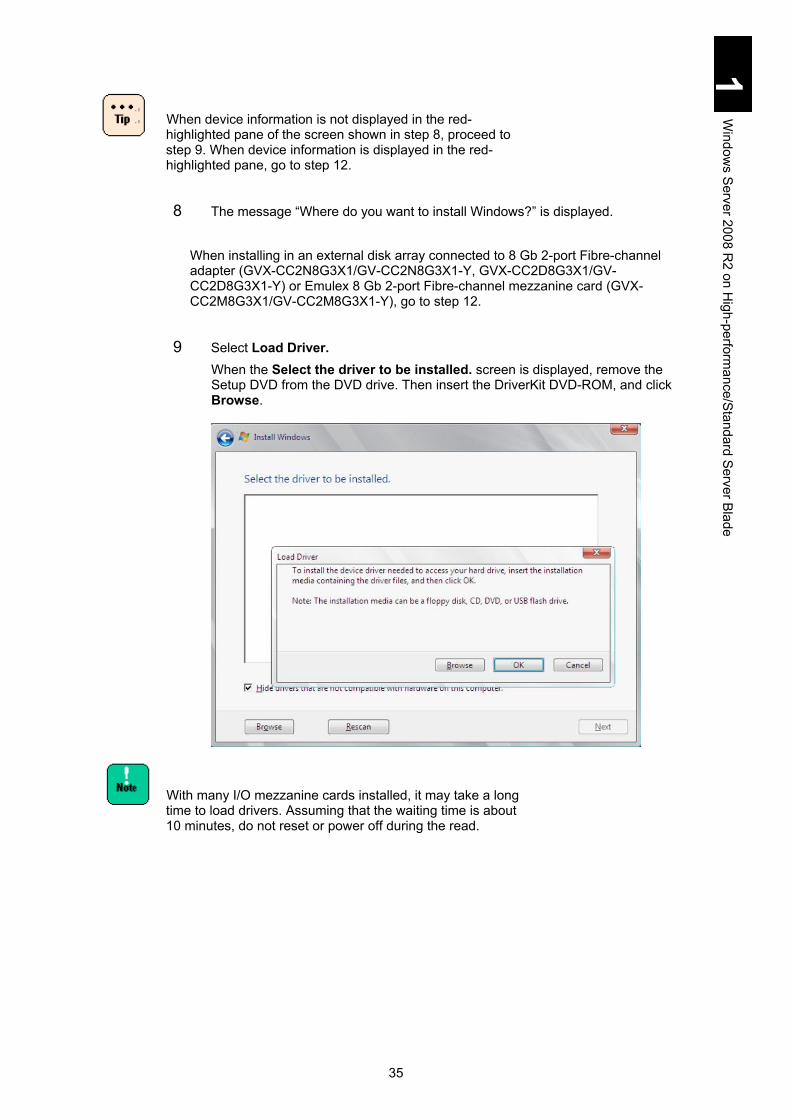
35
1 W
indows S
erver 2008 R2 on H
igh-performance/Standard Server B
lade
When device information is not displayed in the red-highlighted pane of the screen shown in step 8, proceed to step 9. When device information is displayed in the red-highlighted pane, go to step 12.
8 The message “Where do you want to install Windows?” is displayed. When installing in an external disk array connected to 8 Gb 2-port Fibre-channel adapter (GVX-CC2N8G3X1/GV-CC2N8G3X1-Y, GVX-CC2D8G3X1/GV-CC2D8G3X1-Y) or Emulex 8 Gb 2-port Fibre-channel mezzanine card (GVX-CC2M8G3X1/GV-CC2M8G3X1-Y), go to step 12.
9 Select Load Driver. When the Select the driver to be installed. screen is displayed, remove the Setup DVD from the DVD drive. Then insert the DriverKit DVD-ROM, and click Browse.
With many I/O mezzanine cards installed, it may take a long time to load drivers. Assuming that the waiting time is about 10 minutes, do not reset or power off during the read.

36
1 W
indows S
erver 2008 R2 on H
igh-performance/Standard Server B
lade
10 In the Browse for Folder screen, select a location according to the following description, and click OK (Where d: is the DVD drive name).
(1) With X55A1/X55A2/X55R3 server blade model, installing in the internal
disk array connected to LSI Logic MegaRAID SAS PCI Express SAS Internal RAID board: GVX-CA2SRD2X1/GV-CA2SRD2X1-Y X55A1 Model: (d:\X55x1\Win2008R2\Drivers\RAID\MegaSAS_01\x64) X55A2 Model: (d:\X55x2\Win2008R2\Drivers\RAID\MegaSAS_01\x64) SAS Internal RAID board: GVX-CA2SRD4X1/GV-CA2SRD4X1-Y X55A2 Model: (d:\X55x2\Win2008R2\Drivers\RAID\MegaSAS_02\x64) SAS RAID on Motherboard X55R3 Model: (d:\X55x3\Win2008R2\Drivers\RAID\MegaSAS_01\x64)
(2) With X55A1 server blade model, installing in the external disk array connected to Hitachi 4 Gb 2-port Fibre-channel adapter (GVX-CC2N4G1X1) or Hitachi 4 Gb 2-port Fibre-channel mezzanine card (GVX-CC2M4G1X1). (d:\X55x1\Win2008R2\Drivers\FibreChannel\HFC_01\x64)
(3) Installing in the external disk array connected to Hitachi 8 Gb Fibre-channel adapter (GVX-CC2N8G1X1/GV-CC2N8G1X1-Y, GVX-CC2N8G2X1/GV-CC2N8G2X1-Y, GVX-CC2D8G1X1/GV-CC2D8G1X1-Y, GVX-CC2D8G2X1/GV-CC2D8G2X1-Y) or Hitachi 8 Gb Fibre-channel mezzanine card (GVX-CC2M8G1X1/GV-CC2MD8G1X1-Y, GVX-CC2M8G2X1/GV-CC2M8G2X1-Y) X55A1 Model : (d:\X55x1\Win2008R2\Drivers\FibreChannel\HFC_01\x64) X55A2 Model : (d:\X55x2\Win2008R2\Drivers\FibreChannel\HFC_01\x64) X55S3/X55R3 Model: (d:\X55x3\Win2008R2\Drivers\FibreChannel\HFC_01\x64) X57A1 Model : (d:\X57x1\Win2008R2\Drivers\FibreChannel\HFC_01\x64) X57A2 Model : (d:\X57x2\Win2008R2\Drivers\FibreChannel\HFC_01\x64)

37
1 W
indows S
erver 2008 R2 on H
igh-performance/Standard Server B
lade
11 In the Select the driver to be installed. screen, select a driver based on the following description, and click Next (Where d: is the DVD drive name.).
(1) With the X55A1/X55A2/X55R3 server blade model, installing in the internal disk array connected to LSI Logic MegaRAID SAS PCI Express SAS internal RAID board: GVX-CA2SRD2X1/GV-CA2SRD2X1-Y. X55A1 Model: (d:\X55x1\Win2008R2\Drivers\RAID\MegaSAS_01\x64\oemsetup.inf) X55A2 Model: (d:\X55x2\Win2008R2\Drivers\RAID\MegaSAS_01\x64\oemsetup.inf) SAS Internal RAID board: GVX-CA2SRD4X1/GV-CA2SRD4X1-Y X55A2 Model: (d:\X55x2\Win2008R2\Drivers\RAID\MegaSAS_02\x64\oemsetup.inf) SAS RAID on Motherboard X55R3 Model: (d:\X55x3\Win2008R2\Drivers\RAID\MegaSAS_01\x64\megasas2.inf)
(2) With the X55A1 server blade model, installing in the external disk array connected to Hitachi 4 Gb 2-port Fibre-channel adapter (GVX-CC2N4G1X1) or Hitachi 4 Gb 2-port Fibre-channel mezzanine card (GVX-CC2M4G1X1). (d:\X55x1\Win2008R2\Drivers\FibreChannel\HFC_01\x64\hfcwdd.inf)
(3) Installing in the external disk array connected to Hitachi 8 Gb Fibre-channel adapter (GVX-CC2N8G1X1/GV-CC2N8G1X1-Y, GVX-CC2N8G2X1/GV-CC2N8G2X1-Y, GVX-CC2D8G1X1/GV-CC2D8G1X1-Y, GVX-CC2D8G2X1/GV-CC2D8G2X1-Y) or Hitachi 8Gb Fibre-channel mezzanine card (GVX-CC2M8G1X1/GV-CC2M8G1X1-Y, GVX-CC2M8G2X1/GV-CC2M8G2X1-Y) X55A1 Model: (d:\X55x1\Win2008R2\Drivers\FibreChannel\HFC_01\x64\hfcwdd.inf) X55A2 Model: (d:\X55x2\Win2008R2\Drivers\FibreChannel\HFC_01\x64\hfcwdd.inf) X55R3/X55S3 Model: (d:\X55x3\Win2008R2\Drivers\FibreChannel\HFC_01\x64\hfcwdd.inf) X57A1 Model: (d:\X57x1\Win2008R2\Drivers\FibreChannel\HFC_01\x64\hfcwdd.inf) X57A2 Model: (d:\X57x2\Win2008R2\Drivers\FibreChannel\HFC_01\x64\hfcwdd.inf)

38
1 W
indows S
erver 2008 R2 on H
igh-performance/Standard Server B
lade
12 The message “Where do you want to install Windows?” is displayed. When using the X55R3 or X55S3 model with no LAN mezzanine card (GVX-CN2M1G1X1/GV-CN2M1G1X1-Y, GVX-CN2N1G1X1/GV-CN2N1G1X1-Y, GVX-CN2N1G3X1/GV-CN2N1G3X1-Y, GVX-CN2D1G1X1/GV-CN2D1G1X1-Y, GVX-CN2D1G3X1/GV-CN2D1G3X1-Y) installed, go to step 20
When installing Windows Server 2008 R2 on an LPAR, check whether or not the dedicated network interface card (NIC) is assigned to the LPAR. If no dedicated NIC is assigned and only a virtual or shared NIC is assigned to it, go to Step 18. See Chapter 5: Windows Server 2008/R2 with LPAR manager before starting the installation.
13 Select Load Driver. In the Load Driver screen, confirm that the Driver Kit DVD 12-13 or a later version is in the DVD drive, and click Browse.
Install the LAN driver using the following procedure. If not, the OS installation may fail. When the OS installation has been completed without installing the LAN driver, there is no problem. Then, install the necessary components including the LAN driver.
14 When Browse for folders is displayed, select the following directory, and click OK. X55A1 Model: Intel(R) 82576 Gigabit Dual Port Server Network Connection (d:\X55x1\Win2008R2\Drivers\LAN\INTEL_01\x64) X55A2 Model: Intel(R) 82576 Gigabit Dual Port Server Network Connection (d:\X55x2\Win2008R2\Drivers\LAN\INTEL_01\x64) X55R3/X55S3 Model: (d:\X55x3\Win2008R2\Drivers\LAN\INTEL_01\x64) X57A1 Model: Intel(R) 82576 Gigabit Dual Port Server Network Connection (d:\X57x1\Win2008R2\Drivers\LAN\INTEL_01\x64) X57A2 Model: Intel(R) 82576 Gigabit Dual Port Server Network Connection (d:\X57x2\Win2008R2\Drivers\LAN\INTEL_01\x64) Where d: is the DVD drive name.

39
1 W
indows S
erver 2008 R2 on H
igh-performance/Standard Server B
lade
15 When Select the driver to be installed is displayed, select one of the following drivers and click Next. Intel(R) 82576 Gigabit Dual Port Server Network Connection Path specified in step 12: \e1q62x64.inf Intel(R) Gigabit ET Dual Port Server Adapter Path specified in step 12: \e1q62x64.inf Intel(R) Gigabit ET Quad Port Server Adapter Path specified in step 12: \e1q62x64.inf Intel(R) ET Qua Port Server Adapter Path specified in step 12: \e1q62x64.inf
The adapter above may not be displayed on an LPAR of LPAR manager.
16 The message “Where do you want to install Windows?” is displayed. When using the X55R3/X55S3 model, go to step 20.
17 Click Load Driver.
18 Browse for folders is displayed. Select the following location and click OK. X55A1 Model: Intel(R) 82576 Gigabit Dual Port Server Network Connection (d:\X55x1\Win2008R2\Drivers\LAN\INTEL_01\x64) X55A2 Model: Intel(R) 82576 Gigabit Dual Port Server Network Connection (d:\X55x2\Win2008R2\Drivers\LAN\INTEL_01\x64) X57A1 Model: Intel(R) 82576 Gigabit Dual Port Server Network Connection (d:\X57x1\Win2008R2\Drivers\LAN\INTEL_01\x64) X57A2 Model: Intel(R) 82576 Gigabit Network Connection (d:\X57x2\Win2008R2\Drivers\LAN\INTEL_01\x64) Where d: is the DVD drive name.
19 When Select the driver to be installed is displayed, select the following driver and click Next. Intel(R) 82576LF-2 Gigabit Network Connection Path specified in step 18: \e1y62x64.inf
The adapter above is not displayed on an LPAR of LPAR manager.
20 The message “Where do you want to install Windows?” is displayed. Remove the Driver Kit DVD-ROM from the DVD drive, insert the Setup DVD, and click Refresh.

40
1 W
indows S
erver 2008 R2 on H
igh-performance/Standard Server B
lade
If you do not change the media, the message “Unable to install Windows in the disk” is displayed on the bottom of the screen. Then you cannot continue the setup.
21 Select a partition from the screen, and click Next.
When multiple disks are displayed, the disk order and the number of each disk is not always the same. Select the target disk for installation by size and not by the order or the disk number. Another way to select the target disk is to set the disk device to only view the target disk beforehand. See Restrictions on setup in advance. If you select a wrong disk or partition, the existing partition (data) may be deleted. For details, see the following website.
http://support.microsoft.com/kb/937251
You can find disk capacity in “MegaRAID WebBIOS” or system BIOS. For details, see Chapter 5 “Server Blade Setup.”
If there are some disks with the same size, follow the steps below to find a target disk.
1. Press and hold Shift and press the F10 key to display the command prompt.
2. Enter the following command in the command line to start “diskpart”.
>diskpart
3. Perform the following command in “diskpart”.
>selectdisk=system
(*) stands for a space.
A message like “Diskn is selected.” is displayed.
4. Install the OS in an appropriate partition in the “diskn” displayed in step 3.
The Delete button cannot be used to a partition in the
dynamic disk. See the following URL for the details.
http://support.microsoft.com/kb/926190 When Drive Option is used to create a partition,
installing the OS in a partition with less than 32 GB, memory might fail. Therefore, we recommend that a 40 GB partition, or larger, be created for the OS installation.
If you select a wrong disk or partition, the existing partition (data) may be deleted.
When the target disk has not partition 1, “Unallocated Space” is displayed as Name. On the target disk, select Drive Option > New and create a partition for OS installation.

41
1 W
indows S
erver 2008 R2 on H
igh-performance/Standard Server B
lade
To specify the capacity of the partition for installation, click Drive options (Advanced). If you select a disk not specifying the partition capacity and click Next, or if you click OK when a message like “Another partition may be created for the system file to have all Windows functions work properly.” is displayed in configuring the installation partition, another partition of 100 MB will be created, which is called a system partition. For details, see the following Website.
http://technet.microsoft.com/en-us/library/dd799232(WS.10).aspx
When a target disk for installation is not recognized even if the boot device driver has been applied, apply the driver again. Then, if the target disk is recognized, there is no problem. If the target disk is not recognized by the second attempt, check settings for the target disk and connection.
22 The message “Installing Windows…” is displayed. After several reboots, the OS setup will be completed.
When several I/O expansion cards are installed, it may take a long time for installation. Because installation might take an hour, do not reset or power off during installation
23 When booting the OS for the first time after the setup, the message “The user’s password must be changed before logging on the first time.” is displayed. Click OK.
24 Enter the administrator’s password into the New password and Confirm password fields, and click .
A password is required to satisfy the following conditions: Combine at least 3 characters among the followings:
English capital letters (A to Z); English lower case (a to z); numbers (1 to 9); comma, period
Do not use 3 or more consecutive letters from the user name or full name.
25 When the message “Your password has been changed” appears, click OK. OS Setup has been completed. Go to Driver/Utility setup.

42
1 W
indows S
erver 2008 R2 on H
igh-performance/Standard Server B
lade
Driver/Utility setup This section describes how to setup Driver/Utility for Windows Server 2008 R2. You can set up drivers and utilities with or without Compute Systems Installer. We usually recommend the setup with Compute Systems Installer.
Setup with Compute Systems Installer The Compute Systems Installer, which is included in Driver Kit 12-11 or later, enables you to easily install drivers and utilities required for the system operation.
Compute Systems Installer can be used to install only the English version OS. If many I/O adapters are installed, it may take a while to install the drivers.
Assuming that it might take up to an hour, do not reset or turn off the power during installation.
The following or later versions of Compute Systems Installer support Windows Server 2008 R2. Check the DVD label beforehand.
Setting up Compute Systems Installer
Follow the procedure described below to set up Compute Systems Installer before installing drivers/utilities. 1 Power on the system equipment, start Windows, and log on as Administrator. 2 Insert the Driver Kit DVD into the DVD drive. 3 Click Start > Run.
Check the DVD version referring to the table above. 4 Enter the following and click OK.
d: \HInstall.exe Where d: is the DVD drive name. The Compute Systems Installer Installation window is displayed.
5 Click Yes. The Compute Systems Installer will start automatically after installation.
6 Click OK. A window will be displayed, where you can select which component to install.
Go on to Setting up Drivers/Utilities.
Model Name Driver Kit for Windows Server 2008 R2
X55A1 - X55A2 12-10
X55R3/X55S3 12-13 X57A1 12-10 X57A2 12-11

43
1 W
indows S
erver 2008 R2 on H
igh-performance/Standard Server B
lade
Setting up Drivers/Utilities
Set up drivers and utilities with Compute Systems Installer. When you have installed Compute Systems Installer provided in Setting up Compute Systems Installer, Compute Systems Installer will start automatically. When you start the Compute Systems Installer with the Found New Hardware dialog box open, the installer may not proceed. Therefore, click Cancel to remove it.
1 When installing all components, click default installation. When selecting
components to install, click Custom installation, select components following the directions in the window, and click Next.
We usually recommend the Default installation.
2 Click Next. Preparation for installation will start. Follow the instructions on the windows to proceed. You may have to change DVDs during installation. A setup completion window will be displayed at the end. When reboot is required, go to step 3; when reboot is not required, go to step 6.
You may be asked to type something while setting up utilities. See the manual of each utility for details about setup procedures. See How to use supplied software for the location of each manual.
3 Check Reboot Now, and remove the DVD from the drive. 4 Click OK.
The server blade will be rebooted. 5 Log on as Administrator after reboot.
The Compute Systems Installer automatically reboots to continue processing. Repeat step 2 through step 5 as necessary.
6 Click Done. If you want to remove the Compute Systems Installer, go to Removing Compute Systems Installer without clicking Done. The Compute Systems Installer will be finished.
44
1 W
indows S
erver 2008 R2 on H
igh-performance/Standard Server B
lade
Removing Compute Systems Installer
When drivers and utilities have been set up, remove the Compute Systems Installer. Reboot is required for removing the Compute Systems Installer. 1 In the finish window for the Compute Systems Installer, check Never launch the
program on startup and then check Uninstall this program. The Compute Systems Installer Deletion window is displayed.
2 Click Yes. 3 Click Done.
The Compute Systems Installer will be removed.
Checking Driver Updates
With some adapters or devices, their drivers may not be installed with the Compute Systems Installer. The latest drivers are in the attached CDs or can be downloaded from websites. Apply the latest drivers referring to the manual of your adapters. When applying the new driver, the Compute Systems Installer might not recognize the driver installation status correctly. If you update the driver manually, remove the Compute Systems Installer in advance.
Applying Patches
Apply Windows update patches such as the security patch as necessary. Some server blades and adapters may have prerequisite patches. Visit each website or contact your reseller for patches they recommended to apply.

45
1 W
indows S
erver 2008 R2 on H
igh-performance/Standard Server B
lade
Setup without Compute Systems Installer When setting up the driver/utility without the Compute Systems Installer, make sure to install the following drivers, utilities, and register update respectively. Registry Update (1) Driver
Display driver Chipset driver LAN driver
Utility MegaRAID Storage Manager (X55A1, X55A2, and E55R3 with onboard
MegaRAID models) Intel(R) PROSet (X55A1, X55A2, X55R3 and X55S3 with LAN expansion
cards, X57A1, and X57A2 models) Broadcom Advanced Control Suite 4 (X55R3 and X55S3 models)
Driver/Utility for expansion cards Registry Update (2) Windows Recovery Environment (RE) Update Information Check
Check information on driver update Apply patch files
To install drivers
Registry Update (1)
Insert the Driver Kit DVD-ROM 12-11 or later into the DVD drive, and execute the following steps. Where d: is the DVD drive name. Set dumps to be collected when a non-maskable interrupt (NMI) is issued.
1 Click Start, and select Run…. 2 Input the following, and click OK.
X55A1 Model: d:\X55x1\Win2008\Tools\NMIDump\NMID.bat X55A2 Model: d:\X55x2\Win2008\Tools\NMIDump\NMID.bat X55R3/X55S3 Model: d: \X55x3\Win2008\Tools\NMIDump\NMID.bat X57A1 Model: d:\X57x1\Win2008\Tools\NMIDump\NMID.bat X57A2 Model: d:\X57x2\Win2008\Tools\NMIDump\NMID.bat

46
1 W
indows S
erver 2008 R2 on H
igh-performance/Standard Server B
lade
Set the PCI driver.
1 Click Start, and select Run…. 2 Input the following, and click OK.
X55A1 Model: d:\X55x1\Win2008\Tools\avoidD3\avoidD3.bat X55A2 Model: d:\X55x2\Win2008\Tools\avoidD3\avoidD3.bat X55R3/X55S3 Model: d:\X55x3\Win2008\Tools\avoidD3\avoidD3.bat X57A1 Model: d:\X57x1\Win2008\Tools\avoidD3\avoidD3.bat X57A2 Model: d:\X57x2\Win2008\Tools\avoidD3\avoidD3.bat
The batch file above is common to Windows Server 2008.
Reboot the OS after applying the batch to reflect the setting items.
Display driver
Install the Display driver using the following procedure. With the LPAR manager (Hitachi Virtualization Manager) environment, you need not install the display driver because LPAR manager uses the virtual graphic device. If you do, the display driver installation will fail.
1 Turn on the system power, boot Windows, and log on as Administrator. 2 Insert the Driver Kit DVD-ROM 12-11 or later into the DVD drive. 3 Click Start, and select Run…. 4 Input the following, and click OK.
X55A1 Model: d:\X55x1\Win2008R2\Drivers\SVGA\Matrox_01\install.bat X55A2 Model: d:\X55x2\Win2008R2\Drivers\SVGA\Matrox_01\install.bat X55R3/X55S3 Model: d:\X55x3\Win2008R2\Drivers\SVGA\Matrox_01\install.bat X57A1 Model: d:\X57x1\Win2008R2\Drivers\SVGA\Matrox_01\install.bat X57A2 Model: d:\X57x2\Win2008R2\Drivers\SVGA\Matrox_01\install.bat Where d: is the DVD drive name.

47
1 W
indows S
erver 2008 R2 on H
igh-performance/Standard Server B
lade
Execute install.bat using the procedure described above. With other procedures, the setup fails.
5 Remove the DVD-ROM from the drive, and then reboot the system equipment. 6 Change the resolution for the display specification.
When High (24 bits) is selected as a display color, the screen may not display.
Select Max (32 bits or Medium (16 bits)
Chipset Driver
Install the chipset driver following the steps below: 1 Power on the server blade, boot Windows, and log on as Administrator. 2 Insert the Driver Kit DVD-ROM 12-11 or later into the DVD drive. 3 Click Start and then select Run…. 4 Input the following, and click OK.
X55A1 Model: d:\X55x1\Win2008R2\Drivers\Chipset\INTEL_01\infinst_autol.exe X55A2 Model: d:\X55x2\Win2008R2\Drivers\Chipset\INTEL_01\infinst_autol.exe X55R3/X55S3 Model: d:\X55x3\Win2008R2\Drivers\Chipset\INTEL_01\Setup.exe X57A1 Model: d:\X57x1\Win2008R2\Drivers\Chipset\INTEL_01\infinst_autol.exe X57A2 Model: d:\X57x2\Win2008R2\Drivers\Chipset\INTEL_01\infinst_autol.exe (Where d: is the DVD drive name.) The Setup screen is displayed.
5 Click Next. “License Agreement Terms“ is displayed.
6 Read the license agreement, and then click Yes if you agree. Install the chipset driver following the on screen instructions. “Setup completed” is displayed in the end.
7 Click Complete, and quickly remove the DriverKit from the drive. The server blade will be rebooted.

48
1 W
indows S
erver 2008 R2 on H
igh-performance/Standard Server B
lade
LAN driver
X55A1/X555A2/X57A1/X57A2 Install the LAN driver using the following procedure.
1 Select Start > Administrative Tools, and open Server Manager. Server Manager appears.
2 Select Diagnostics and then Device Manager. Device Manager appears
3 Right-click Intel(R) 82567LF-2 Gigabit Network Connection that is displayed in Network adapter of the Device Manager, and click Disabled.
Make sure to disable the LAN device “Intel(R) 82567LF-2 Gigabit Network Connection.” Do not use this LAN device.
There is no problem if an error or warning event logs appear concerning the “Intel(R) 82567LF-2 Gigabit Network Connection,” which indicates that the link rate is inconsistent with the connected point, or that the IP address is busy. Confirm that no error or warning log was recorded in the event log after disabling the adapter. Check that no warning or error is registered after disabling the adapter.
The adapter above is not displayed on an LPAR. A message “This hardware cannot be started.”
might be displayed during driver setup. In this case, reboot the server blade, and it will operate properly. Confirm using the device manager that the device runs correctly.
An error event log may occur in the network adapter each time the system is booted. The network adapter may link down. Check if that network adapter is connected using Network connection. To check the status when Intel(R) PROSet is installed, right-click the target network adapter in Device Manager, click Properties > the Link Speed tab to find the Link Status. The Link Speed tab may be displayed as the Link tab depending on the version on Intel PROSet version.
Network properties or network status in the task tray may not update quickly during linkup. Select Display and then Update the latest on the Network connection screen to update the network status.
49
1 W
indows S
erver 2008 R2 on H
igh-performance/Standard Server B
lade
X55R3/X55S3 Install the LAN driver using the following procedure.
1 Power on the system equipment, start Windows, and log on as Administrator. 2 Insert Driver Kit 12-13 into the DVD drive. 3 Select Start > Administrative Tools, and open Server Manager.
Server Manager appears. 4 Select Diagnostics > Device Manager. 5 Right-click a network adapter without any driver applied, and click Update
driver software. Update driver software wizard appears.
6 Click Browse my computer for driver software. 7 Enter the following to Browse for driver software on your computer, and
click Next. d:\X55x3\Win2008R2\Drivers\LAN\BROAD_01\x64 Where d: is the DVD drive name.
8 Confirm that “Windows has successfully updated your driver software.” is shown, and click Close.
9 Remove the Driver Kit, and restart the system equipment.
To install utilities
MegaRAID Storage Manager
For details, see MegaRAID Storage Manager.
Intel PROSet
For details, see Intel(R) PROSet.
Broadcom Advanced Control Suite 4 (X55R3/X55S3 model)
For details, see Broadcom Advanced Control Suite 4.
Driver/Utility for expansion board
There may be some drivers/utilities to be installed by using the expansion boards installed. See the expansion board user’s manual for details, and install components as necessary.

50
1 W
indows S
erver 2008 R2 on H
igh-performance/Standard Server B
lade
Registry update (2)
With the DriverKit DVD-ROM 12-11 in the DVD drive, execute the following. Where d: is the DVD drive name. Install the driver for an expansion card, and then execute the tool to set the value of TimeOut.
1 Click Start and select Run…. 2 Input the following, and click OK.
X55A1 Model: d:\X55x1\Win2008\Tools\TimeOutValue\TimeOutValue.bat X55A2 Model: d:\X55x2\Win2008\Tools\TimeOutValue\TimeOutValue.bat X55R3/X55S3 Model: d:\X55x3\Win2008\Tools\TimeOutValue\TimeOutValue.bat X57A1 Model: d:\X57x1\Win2008\Tools\TimeOutValue\TimeOutValue.bat X57A2 Model: d:\X57x2\Win2008\Tools\TimeOutValue\TimeOutValue.bat Reboot the OS after applying the batch to enable the setting of the item.
Change the LAN device interrupt setting. With the X55A1 model, skip this setting.
1 Click Start, and select Run…. 2 Input the following, and click OK.
X55A2 Model: d:\X55x2\Win2008\Tools\MSIXDIS\MSIXDIS.bat X55R3/X55S3 Model: d:\X55x3\Win2008\Tools\MSIXDIS\MSIXDIS.bat X57A1 Model: d:\X57x1\Win2008\Tools\MSIXDIS\MSIXDIS.bat X57A2 Model: d:\X57x2\Win2008\Tools\MSIXDIS\MSIXDIS.bat Reboot the OS after applying the batch to enable the setting of the item.
Whenever you add a new LAN device or update the LAN driver, execute this setting.

51
1 W
indows S
erver 2008 R2 on H
igh-performance/Standard Server B
lade
Windows Recovery Environment (RE)
With the Driver Kit DVD-ROM 12-11 or later in the DVD drive, execute the following. Where d: is the DVD drive name. With the X55A1 model, skip this setting.
1 Click Start, and select Run…. 2 Input the following, and click OK.
X55A2 Model: d:\X55x2\Win2008R2\Tools\WinRE\WinRE.cmd X55R3/X55S3 Model: d:\X55x3\Win2008R2\Tools\WinRE\WinRE.cmd X57A1 Model: d:\X57x1\Win2008R2\Tools\WinRE\WinRE.cmd X57A2 Model: d:\X57x2\Win2008R2\Tools\WinRE\WinRE.cmd
Without the Driver Kit, perform the following. 1 Log in to the OS as Administrator. 2 Click Start > Run. 3 Enter the following and click OK.
cmd 4 Enter the following in command prompt.
reagentc.exe/disable
Check information on driver update
Some expansion cards or devices have CD-ROMs that includes the latest driver, or you can download the latest driver from the website. Apply the latest driver referring to the expansion card manual.
Apply patches
Apply Windows patches, such as the security patch, as necessary. Some server blade or expansion cards can have prerequisite patches. See your distributor for information about patches.

52
1 W
indows S
erver 2008 R2 on H
igh-performance/Standard Server B
lade
Windows Hypervisor 2.0 Windows Hypervisor 2.0 (Hyper-V 2.0) is a virtualization function provided as a part of Windows Server 2008 R2. Hyper-V 2.0 allows multiple Windows operating systems to run on the single physical hardware, which can improve efficient use of physical hardware and reduce IT costs.
Hyper-V 2.0 overview Hyper-V 2.0 adopts the hypervisor-based virtualization architecture. Hypervisor is a software layer between hardware and the OS.
Terms used in this manual are defined as follows: Physical hardware Virtual machine:
virtual hardware that operates on physical hardware Management OS:
Operating system installed in physical hardware for managing Hyper-V 2.0
Guest OS: Operating systems installed in a virtual machine
Further information on Hyper-V 2.0 Access the following URL for further details of Hyper-V. http://www.microsoft.com/windowsserver2008/en/us/hyperv-main.aspx
Physical Hardware
Windows Hypervisor
Manage-ment
OS
Virtual Machine
Guest OS
Virtual Machine
Guest OS
Virtual Machine
Guest OS
Compute Blade
Manage- ment
Tip
53
1 W
indows S
erver 2008 R2 on H
igh-performance/Standard Server B
lade
System configuration for Hyper-V 2.0 This section describes system configuration for using Hyper-V 2.0.
Server blade for Hyper-V 2.0 Server blades that support Windows Server 2008 R2.
Software configuration The following software requirements should be satisfied before configuring Hyper-V 2.0.
Software requirements
Windows Server 2008 R2 Standard/Enterprise/Datacenter for the management OS Windows Server 2008 R2 SP1 Standard/Enterprise/Datacenter for the
management OS
Physical hardware configuration In addition to the system requirements for Windows Server 2008 R2, the following hardware requirements should be satisfied before using Hyper-V 2.0. See the following URL for the system requirements for Windows Server 2008 R2. http://www.microsoft.com/windowsserver2008/en/us/system-requirements.aspx
Hardware requirements
Data Execute Prevention (DEP) DEP settings of the server blade are all enabled by default. Use it as it is.
Intel 64 (x64-based processor) All CPUs mounted in the server blade support Intel x64 features. Use it as is.
Intel Virtualization Technology (Intel VT) Intel VT settings of the server blade are all enabled by default. Use it as is.
It is recommended that the server blade use the physical hardware that satisfies the minimum requirements shown below or more for configuration. See Virtual Machine configuration.

54
1 W
indows S
erver 2008 R2 on H
igh-performance/Standard Server B
lade
CPU core: In addition to the total number of CPUs to be assigned to each guest OS running simultaneously, at least one CPU for the management OS is required.
Memory: In addition to the total capacity of the memory, which is recommended by Microsoft to each OS running simultaneously, at least another 2 GB for the management OS is required.
Partitions: Separate partitions are required for the management OS and the virtual hard disk file (.vhd) of a virtual machine.
Recommendations above are just general standards and do not guarantee that the system will work well under any condition. They may be insufficient depending on an application to run on the guest OS. Give the system a test run and check if it works properly beforehand. Recommendations above are just general standards. When using the system for a specific purpose such as a test environment, it may not necessarily satisfy the recommended requirements. Examine the configuration depending on your needs.

55
1 W
indows S
erver 2008 R2 on H
igh-performance/Standard Server B
lade
Virtual Machine configuration Hitachi confirmed that the following guest OSs ran properly on the server blade. Windows 2000 Server with Service Pack 4 Windows 2000 Advanced Server with Service Pack 4 Windows Server 2003, Standard Edition with Service Pack 2 (including R2) Windows Server 2003, Enterprise Edition with Service Pack 2 (including R2) Windows Server 2003, x64 Standard Edition with Service Pack 2 (including R2) Windows Server 2003, x64 Enterprise Edition with Service Pack 2 (including R2) Windows Server 2008 Standard 32-bit Windows Server 2008 Enterprise 32-bit Windows Server 2008 Datacenter 32-bit Windows Server 2008 Standard 64-bit Windows Server 2008 Enterprise 64-bit Windows Server 2008 Datacenter 64-bit Windows Server 2008 Standard 32-bit with Service Pack 2 Windows Server 2008 Enterprise 32-bit with Service Pack 2 Windows Server 2008 Datacenter 32-bit with Service Pack 2 Windows Server 2008 Standard 64-bit with Service Pack 2 Windows Server 2008 Enterprise 64-bit with Service Pack 2 Windows Server 2008 Datacenter 64-bit with Service Pack 2 Windows Server 2008 R2 Standard Windows Server 2008 R2 Enterprise Windows Server 2008 R2 Datacenter Windows Server 2008 R2 Standard with Service Pack 1 Windows Server 2008 R2 Enterprise with Service Pack 1 Windows Server 2008 R2 Datacenter with Service Pack 1 Windows XP Professional x86 Edition with Service Pack 3 Windows Vista Business x86 Edition with Service Pack 2 Windows Vista Enterprise x86 Edition with Service Pack 2 Windows Vista Ultimate x86 Edition with Service Pack 2 Windows 7 Professional x86 Edition Windows 7 Enterprise x86 Edition Windows 7 Ultimate x86 Edition Windows 7 Professional x64 Edition Windows 7 Enterprise x64 Edition Windows 7 Ultimate x64 Edition Windows 7 Professional x86 Edition with Service Pack 1 Windows 7 Enterprise x86 Edition with Service Pack 1 Windows 7 Ultimate x86 Edition with Service Pack 1 Windows 7 Professional x64 Edition with Service Pack 1

56
1 W
indows S
erver 2008 R2 on H
igh-performance/Standard Server B
lade
Windows 7 Enterprise x64 Edition with Service Pack 1 Windows 7 Ultimate x64 Edition with Service Pack 1 Guest OSs, not included in the list above and supported by Microsoft, can be installed in the server blade. The installation and operation, however, are not supported. It is recommended that virtual machines should be configured with the server blade beyond what is recommended for a guest OS by Microsoft. The virtual hard disk file (.vhd) has 3 forms such as fixed-
size, variable-size, and differentiating vhds. In the Variable-size or differentiating vhds, the file size of the virtual hard disk file on the physical disk expands dynamically according to the amount that the virtual machine is using. If the size cannot be expanded due to the capacity shortage of the physical disk, the virtual machine will halt. Always make sure that the capacity of the physical disk is sufficient in the actual operation. Otherwise, the virtual machine may stop unexpectedly. Therefore, it is recommended that the virtual hard disk should be configured with the fixed-size in the actual operation.
There are 2 types of virtual network adapters such as the network adapter and the legacy network adapter. Select the network adapter for the blade server. When setting up the integrated service in Windows 2000 described in Patch programs for Windows 2000 or a certain application specifies the legacy network adapter, use it only 0for that purpose.
See the following URLs for the system requirements for each OS recommended by Microsoft. Windows Server 2008 R2
http://www.microsoft.com/windowsserver2008/en/us/system-requirements.aspx
Windows Server 2008
http://www.microsoft.com/windowsserver2008/en/us/WS08-system-requirements.aspx
Windows Server 2003 (See Windows Server 2003 R2.)
http://www.microsoft.com/Windowsserver2003/sbs/evaluation/sysreqs/default.mspx
Windows 2000 Server
http://support.microsoft.com/kb/304297
Windows 2000 Advanced Server
http://support.microsoft.com/kb/304297 Windows 7
http://windows.microsoft.com/en-US/windows7/products/system-requirements

57
1 W
indows S
erver 2008 R2 on H
igh-performance/Standard Server B
lade
Windows Vista
http://windows.microsoft.com/en-US/windows-vista/products/system-requirements
Windows XP
http://support.microsoft.com/kb/314865
The maximum number of processors that can be assigned depends on a guest OS.
One (1) processor at a maximum can be assigned to Windows Server 2000; two (2) at a maximum to Windows Server 2003 R2, Windows Server 2003, Windows Vista, and Windows XP SP3; four (4) at a maximum to Windows Server 2008 R2, Windows Server 2008, and Windows 7.

58
1 W
indows S
erver 2008 R2 on H
igh-performance/Standard Server B
lade
Hyper-V 2.0 setup This section describes how to set up Hyper-V 2.0.
Always log in to the management OS with the account that has the administrator’s privilege. See Server blade for Hyper-V 2.0 before the setup. For details on how to use the Hyper-V 2.0 manager, see the management OS help.
Management OS setup Only Windows Server 2008 R2 64-bit can be used for the management OS. See Software configuration for details.
Hyper-V 2.0 setup Follow the steps shown below to set up Hyper-V 2.0. 1 Boot the server manager on the management OS.
Click Start and then Server Manager.
2 Add the Hyper-V role. In Server Manager, click Roles > Roles Summary > Add Roles to boot the Add Roles Wizard. Select Hyper-V in Server Roles, and proceed to the completion of the wizard following the instructions in the screens.
The following event is recorded in the system event when you add Hyper-V roles. However, no problem occurs. Event ID: 6004 Source: Winlogon Event Level: Warning Description: The Winlogon notification subscriber <TrustedInstaller> failed a critical notification event.

59
1 W
indows S
erver 2008 R2 on H
igh-performance/Standard Server B
lade
3 Reboot per instructions to complete the setup. After completing the setup, apply required update modules to the OS before using Hyper-V 2.0. Some update modules cannot be applied before enabling Hyper-V.
Virtual hard disk setup Set up the virtual hardware following the steps shown below. 1 Click Start > Administrative Tools > Hyper-V Manager to boot the Hyper-V
Manager.
2 Click Action > New > Hard Disk in the Hyper-V Manager to open the New Virtual Hard Disk Wizard.
3 Create a new virtual hard disk by following the wizard. It is recommended that the virtual hard disk should be configured with the fixed-size in the actual operation. See Virtual Machine configuration for further details.
Virtual machine setup Set up a virtual machine following the steps shown below. 1 Click Start > Administrative Tools > Hyper-V Manager to boot the Hyper-V
Manager.
2 Click Action > New > Virtual Machines in the Hyper-V Manager to open the New Virtual Machine Wizard.
3 Create a new virtual machine by following the wizard. In the Connect Virtual Hard Disk, select Use an existing virtual hard disk and then select the hard disk created in Virtual hard disk setup.
For the recommended virtual machine configuration for the server blade, see Virtual Machine configuration. 4 When completing the wizard, add hardware if needed.
For details, such as the procedure, see the management OS help.

60
1 W
indows S
erver 2008 R2 on H
igh-performance/Standard Server B
lade
Guest OS setup Install a guest OS in the virtual machine created in Virtual machine setup by following the steps shown below. There are restrictions on OS media to be used as a guest OS. See Restrictions only on guest OS for further details. 1 In the Virtual Machines section of Hyper-V Manager right-click a virtual machine
name to install a guest OS. Select Connect from the menu to open Virtual Machine Connection.
2 Insert the OS setup disk into the DVD drive that is configured in the virtual machine to install the guest OS.
If a DVD drive is not included in the virtual machine, configure a DVD drive in the virtual machine. For the specific procedure, see the Management OS help. To configure it, for example, select Media > DVD Drive > D: Capture in Virtual Machine Connection. *D: DVD drive character on the management OS 3 Select Action > Start to start the virtual machine.
4 Boot up from the OS setup medium, then set up the guest OS following the
instructions in the screens. 5 After completing the guest OS setup, select Action > Insert Integration Services
Setup Disk via the Virtual Machine Connection when the guest OS is running. Referring to Patch programs for Windows 2000, apply the required programs, if necessary, before setting up the integrate service. For Windows 2000 Server, execute step 5 after setting up Service Pack 4. For Windows Server 2003 including R2, execute step 5 after setting up Service Pack 2. 6 Set up the integrated service following the screen instructions.
See Help for details on how to set up the integrated service.

61
1 W
indows S
erver 2008 R2 on H
igh-performance/Standard Server B
lade
Restrictions on Hyper-V 2.0 This section describes restrictions when using Hyper-V 2.0 on the server blade.
General restrictions Maintenance
While advancing the integration using the virtual environment, multiple tasks and environments run on a single machine. Therefore, it is important to plan the machine operation including spare time for maintenance work. Maintenance tasks include applying security patches, updating application and drivers, and installing service packs. Make a plan for the system in advance taking into account the time required for maintenance including the guest OS, and use it accordingly.
Number of Processors Used by Hyper-V2.0 The number of processors available for Windows Server 2008 R2 Hyper-V is limited to the following.
The numbers in the table are included in the OS specifications. Memory available for Hyper-V
The memory capacity available for Windows Server 2008 R2 Hyper-V is limited to the following. The capacities in the table are included in the OS specifications.
Server Core Installation of Windows Server 2008 R2/Windows Server 2008 Server Core is not supported.
Application Some application or middleware may create a notice when using Hyper-V 2.0. See the application distributor where you bought it for details.
Cluster When configuring a cluster using Hyper-V 2.0, it is recommended that you
configure Windows Failover Cluster (WSFC) between management OSs. See the management OS Help for information about how to configure a cluster between management OSs.
Edition Max number of sockets (Total number of physical
processors)
Max number of logical processors
(Total of multi-core and HT) Standard 4 64
Enterprise 8 64
Datacenter 64 64
Edition Max memory Standard 32 GB
Enterprise 1 TB
Datacenter 1 TB

62
1 W
indows S
erver 2008 R2 on H
igh-performance/Standard Server B
lade
Cluster configuration between a guest OS and a physical machine is not supported. Cluster configuration between guest OSs requires a storage device via internet small computer system interface (iSCSI). When guest OSs include Windows 2000 Server/Windows Server 2003, cluster configuration between guest OSs is not supported.
Cluster failover is executed when the connection between the management OS and a shared disk fails due to an Fibre channel (FC) cable break. For example, cluster failover service may fail when the guest OS adds too much access load to the shared disk and the quorum fails during failover.
Live Migration When a series of Live Migrations are used in a short period, they may fail. Use
a series of Live Migrations at intervals of a few minutes. When setting a virtual LAN ID (VLAN ID) for a virtual machine which is
performing live migration, select the target virtual machine for Services and Applications in Failover Cluster Manager, right-click Virtual machine xxxxx in Overview of xxxxx, and select Settings to open a window for the virtual machine setting then configure the virtual LAN ID (VLAN ID). xxxxx is the target virtual machine name. If you set virtual LAN IDs (VLAN ID) with each Hyper-V Manager, those virtual LAN ID (VLAN ID) settings might disappear after Live Migration, which might cause communication to not be available.
When using a virtual LAN ID (VLAN ID) in Hyper-V, ensure that you read Appendix-II: Compute Blade Windows Server 2008 R2 LAN Advanced Function Manual.
Intel PROSet
When you install Intel(R) PROSet in the management OS for use, see Appendix-II Compute Blade Windows Server 2008 R2 LAN Advanced Function Manual for Intel. Do not install Intel(R) PROSet in any guest OS.
Event related to Physical Hardware Monitor events related to the physical hardware on the management OS, not on the guest OS.
OS Reboot and Shutdown It is recommended that all guest OSs are shut down before rebooting and shutting down the management OS. When multiple guest OSs are running, shutting down the management OS at the same time puts a high load on the CPU. This can create problems such as taking too much time to shutdown or improper shutdown.
Trouble with virtual machine boot-up When a LAN device installed in a server blade has more than 10 ports, the device manager displays an exclamation mark “!” for the virtual machine bus or virtual infrastructure driver and the virtual machine created with Hyper-V did not start, which has been reported. Check if you performed the setting change tool of the LAN device described in Registry update (2). Perform the tool again as necessary.
4-Blade SMP with X57A2 Model With 4-blade SMP using four of the X57A2 model, perform the following steps before setting up Hyper-V2.0. If not, a STOP error may occur.

63
1 W
indows S
erver 2008 R2 on H
igh-performance/Standard Server B
lade
1 Power on the server blade and go to the EFI Setup screen. See the Hitachi Compute Blade 2000 User’s Guide > Chapter 5: Server Blade Setup for details about the EFI Setup screen
2 Click the Advanced tab > CPU Configuration. 3 On the CPU Configuration screen, select xAPIC from ACPI Mode. 4 Save the setting and exit from the EFI Setup screen. 5 Boot Windows and set up Hpyer-V2.0 following the procedure described in
Hyper-V 2.0 setup.
Do not change ACPI Mode from xAPIC after setting up Hyper-V2.0. If you do, the OS may not boot properly.
Rebooting may be requested when you boot Windows the first time after changing the ACPI mode setting. If so, follow the request to reboot Windows.
Dynamic Memory
When SP1 or later is installed on the management OS, Dynamic Memory is available. We confirm that the following OSs have operated on the server blade. - Windows Server 2003, Standard Edition with Service Pack 2 (including R2) - Windows Server 2003, Enterprise Edition with Service Pack 2 (including R2) - Windows Server 2003, x64 Standard Edition with Service Pack 2 (including R2) - Windows Server 2003, x64 Enterprise Edition with Service Pack 2 (including
R2) - Windows Server 2008 Standard 32-bit with Service Pack 2 - Windows Server 2008 Enterprise 32-bit with Service Pack 2 - Windows Server 2008 Datacenter 32-bit with Service Pack 2 - Windows Server 2008 Standard 64-bit with Service Pack 2 - Windows Server 2008 Enterprise 64-bit with Service Pack 2 - Windows Server 2008 Datacenter 64-bit with Service Pack 2 - Windows Server 2008 R2 Standard with Service Pack 1 - Windows Server 2008 R2 Enterprise with Service Pack 1 - Windows Server 2008 R2 Datacenter with Service Pack 1 - Windows Vista Enterprise x86 Edition with Service Pack 2 - Windows Vista Ultimate x86 Edition with Service Pack 2 - Windows 7 Enterprise x86 Edition with Service Pack 1 - Windows 7 Ultimate x86 Edition with Service Pack 1 - Windows 7 Enterprise x64 Edition with Service Pack 1 - Windows 7 Ultimate x64 Edition with Service Pack 1

64
1 W
indows S
erver 2008 R2 on H
igh-performance/Standard Server B
lade
When using Windows Server 2008 Standard 32-bit with Service Pack 2/Windows Server 2008 Standard 64-bit with Service Pack 2 as a guest OS, apply the following update module before enabling Dynamic Memory. http://support.microsoft.com/kb/2230887
RemoteFX RemoteFX is not supported.
Other restrictions Search in the following URL “Microsoft Help and Support” using “Hyper-V” as a keyword. http://support.microsoft.com/
Restrictions only on Management OS Software on the management OS
It is recommended that task application (middleware) such as a database or application server should not be installed on the management OS with Hyper-V enabled.
Role It is recommended that any role except Hyper-V in Windows Server 2008 R2 should be disabled on the management OS with Hyper-V enabled.

65
1 W
indows S
erver 2008 R2 on H
igh-performance/Standard Server B
lade
Restrictions only on guest OS Saving VM
When selecting Action > Save in the management screen of the virtual machine, the virtual machine status is saved and the virtual machine halts. To restart the virtual machine from the halting point, select Action > Start. This operation, however, is different from the guest OS shutdown and reboot. Applications communicating with the outside may register an error.
Notes for Active Directory on the guest OS Microsoft Help and Support provides “Considerations when hosting Active Directory domain controller in virtual hosting environments” in the following URL. Access the following URL and read it in advance. http://support.microsoft.com/kb/888794/en-us
Network Load Balancing (NLB) configuration on the guest OS Configuring NLB cluster on the guest OS is not supported. It is recommended that tasks requiring NLB should be done on the physical machine.
OS installation media When using Windows Server 2003 32-bit with Service Pack 2 as a guest OS, use the OS medium to which Service Pack 1 or 2 has been applied. Otherwise, the guest OS may show the “STOP” error and halt during installation.
Snapshot It is recommended that the snapshot should not be used in the actual environment. If using the snapshot, performance reduction may occur, or consistency may be destroyed in the system where multiple servers combine. It is also recommended that snapshot should not be used in the guest OS where Active Directory is configured. If using the snapshot, inconsistency in the database might occur.
Virtual Hard Disk File (.vhd) When multiple virtual hard disk files (.vhd) are on a single physical hard disk, IO bottlenecks may occur depending on processing on the guest OS. This may affect the entire OS processing. When using multiple guest OSs in the actual environment, execute careful test runs in advance. You might as well deploy virtual hard disk files (.vhd) on a separate physical disk if necessary.
Virtual SCSI controller A guest OS cannot be installed in a virtual hard disk connected to a virtual SCSI controller. With Windows 2000 Server as a guest OS, the SCSI controller connected to a virtual machine is not available. Connect all virtual hard disks to the virtual Integrated Drive Electronics (IDE) controller with Windows 2000 Server as a guest OS.
Patch programs for Windows 2000 When using Windows 2000 with service pack 4 as a guest OS, in which the integrated service has been set up, and applying the following patch programs to the guest OS, 0xCE is displayed and the guest OS may halt. KB891861
http://support.microsoft.com/kb/891861/ KB905590
http://support.microsoft.com/kb/905590/

66
1 W
indows S
erver 2008 R2 on H
igh-performance/Standard Server B
lade
KB922582 http://support.microsoft.com/kb/922582/
Apply these programs if necessary before setting up the integrated service. Since programs KB891861/KB922582 are prioritized in the Windows update programs, perform Windows Update before the integrated service. When programs KB891861/KB922582 have been applied, there is no problem if you perform the integrated service and then Windows Update. Use the legacy network adapter as a virtual network adapter on a virtual machine before setting up the integrated service. After setting up the integrated service, delete the legacy network adapter from the virtual machine, and use a network adapter. If trouble occurs, the guest OS may have to be set up again.
Sound playback with a guest OS When playing back sounds with a guest OS, you cannot play them on Hyper-V manager. If you need to play a sound, connect to the guest OS using an application such as a remote desktop client from a PC with a sound device to play the sound.
When no physical sound device is installed in a terminal or a remote application that cannot replay a sound, you cannot play a sound even though using remote connection. See your application manual for details.

67
2 Windows Server 2008 on high-performance/standard server blade
This section explains the setup and operation for Windows Server 2008. Each model supports the following OS.
Turning on/off power ............................................................................................. 68
Basic operations/how to change settings of Windows Server 2008 ...................... 71
How to use supplied software ............................................................................... 73
Use of software ..................................................................................................... 74
Windows Server 2008 setup ................................................................................. 92
Windows Server 2008 SP2 setup ........................................................................ 118
Windows Hypervisor ........................................................................................... 119
System configuration for Hyper-V ....................................................................... 120
Hyper-V setup ..................................................................................................... 124
Restrictions on Hyper-V ...................................................................................... 130
Model Name Windows Server 2008 32-bit/64-bit without SP (=SP1)
Windows Server 2008 32-bit/64-bit with SP2
X55A1 X55A2
X55R3/X55S3 - X57A1 - X57A2 -

68
2 W
indows S
erver 2008 on High-perform
ance/Standard Server Blade
Turning on/off power This section explains how to turn on the system and start the OS, how to turn off the system by the OS shutdown, and how to forcibly terminate the applications and system. See “Turning on/off Power” in the Hitachi Compute Blade 2000 User's Guide for power operation.
Turning off power Follow the steps below after completing all tasks on the system equipment to turn off power.
NOTICE Shut down an OS to turn off power. If you abruptly press the power button to turn off power, data might fail or the OS might not boot.
1 Click Start and select Shutdown.
The Shutdown window appears.

69
2 W
indows S
erver 2008 on High-perform
ance/Standard Server Blade
2 Select a reason for shutdown from Option in Shutdown Event Tracker.
When the reason for shutdown is classified as Other, a comment should be given in the Comment box.
3 Click OK.
The system equipment is powered off.
4 Turn off the power of the peripheral equipment.
Turning on power for regular use This section describes the procedure for turning on power After the setup, you can operate the system equipment immediately after turning on power.
1 Turn on power of the peripheral equipment.
2 Press the POWER switch on the system front.
Start Logon appears. Do not press the keys repeatedly when booting the system because an error message may appear.
Some types of monitors may take time before the display appears.
The system executes POST after the power on. It may take up to 10 minutes for some systems to display the Start Logon screen.

70
2 W
indows S
erver 2008 on High-perform
ance/Standard Server Blade
3 Press and hold Ctrl + Alt and press Delete. The logon information appears.
4 Enter the user name and password, and click Enter. Windows boots itself and the Desktop window appears.
Unplugging the power cable Electricity is supplied to some circuits even if the system equipment is turned off. For safety reasons unplug the power cord from the outlet when the following occurs: when you find abnormal heat, smoke, abnormal noise, and unusual odor. Unplug power cables when you do not use the system equipment for a long period of
time.
Terminating application/system forcibly When the system equipment function fails while processing applications, terminating the applications forcibly or rebooting the system equipment forcibly might enable the system to resume normal operation.
Forcibly terminate application Right-click the task bar and click Task Manager on the shortcut menu. Click the Application tab, select the application you want to terminate, and click End Task. The OS or application may not operate correctly, or data may not be secured after the forcible termination. In that case, reset the OS or application, or restore data from the backup.
Forcibly reboot the system equipment (reset) When Windows functions abnormally or the normal shutdown cannot be executed, press and hold the POWER switch to turn off power. The OS or application might not operate correctly, or data may not be secured after the reset. In that case, reset the OS or application, or restore data from the backup. Do not press the POWER switch again until the Windows reboot completely unless an emergency occurs because doing so may cause Windows to fail to boot.
When resetting, be sure to boot and terminate Windows properly, and then reboot it a second time because Windows might not operate correctly.
71
2 W
indows S
erver 2008 on High-perform
ance/Standard Server Blade
Basic operations/how to change settings of Windows Server 2008 This section explains basic operations and how to change settings of Windows Server 2008.
How to use Help Windows Help is available from Windows.
Start Help and Support.
1 Click Start and then select Help and Support. Windows Help and Support Center boots itself.
A pop up message “Do you need to get the latest help contents when searching Help?” might be displayed at the first boot. If selecting “Yes”, the latest content is obtained from Windows Online Help when connecting to the Internet. Select “Yes” if necessary.
If the pop up message is not displayed after the first setup or at the first boot, you can change the setting by selecting Option and then Settings.

72
2 W
indows S
erver 2008 on High-perform
ance/Standard Server Blade
Check desired operations 1 Enter a keyword related to the target topic into the search box in the
Windows Help and Support window, and then click . Search starts and the result will appear in a few moments.
2 When the target topic is found, click it. The topic appears.
3 Read the help text. Use the following buttons. : Returns to the previous window. Option: Changes the character size to be displayed and the change
search options.
4 To exit Help, click [] at the upper right of the window.

73
2 W
indows S
erver 2008 on High-perform
ance/Standard Server Blade
How to use supplied software This section explains the software included in this system.
MegaRAID Storage Manager This software is a utility to monitor disk array devices. Be sure to install it when using the HDDs installed in the server blade. If it is not installed, a double-failure might be caused because of non-detection of the hard disk failure, and the failure analysis becomes more difficult. See the MegaRAID Storage Manager User’s Guide in the Driver Kit 12-13 or later versions for usage details. d: is a DVD drive name. GVX-CA2SRD2X1/GV-CA2SRD2X1-Y
d:\MANUAL\MSM\MSManager.pdf GVX-CA2SRD4X1/GV-CA2SRD4X1-Y only for X55A2
model d:\MANUAL\MSM2\MSManager.pdf
X55R3 model d:\MANUAL\MSM3\MSManager.pdf
Intel® PROSet For X55A1/X55A2/X55R3 with onboard LAN card/X55S3 with onboard LAN card: Intel PROSet is a utility to provide expansion functions such as Dual LAN Redundancy. See Appendix-I: Compute Blade Windows Server 2008 / Windows Server 2003/R2 LAN Advanced Function Manual for Intel for details.
Broadcom Advanced Control Suite 4 For X55R3/X55S3: Broadcom Advanced Control Suite 4 is a utility to provide advanced functions such as dual LAN redundancy and VLAN. See Appendix-III: Compute Blade Windows Server 2008/R2 LAN Advanced Function Manual for Broadcom for details.

74
2 W
indows S
erver 2008 on High-perform
ance/Standard Server Blade
Use of software This section explains the restrictions on the use of Windows Server 2008.
Restrictions on use of Windows Server 2008
Number of Processors Recognized by OS Windows Server 2008 can recognize the number of processors in the table below.
Those numbers in the table are included in the OS specifications.
Server Core
Do not install Server Core because it is not supported.
Hyper-V Windows Server® 2008 Standard and Windows Server® 2008 Enterprise contain Hypervisor-based virtualization technology, Hyper-V Bata version. The official edition of this technology will be released soon, which can be downloaded using Windows Update.
Windows Server shutdown If you shut down Windows while the service registered to start at the boot is still activated, it might not shut down normally. Be sure to allow a time interval of at least five minutes after booting Windows.
Edition Maximum number of sockets (Total number of physical
processors)
Maximum number of logical processors
(Total of multi-core and HT) Standard 32-bit 4 32
Standard 64-bit 4 64
Enterprise 32-bit 8 32
Enterprise 64-bit 8 64
Datacenter 32-bit 32 32
Datacenter 64-bit 64 64

75
2 W
indows S
erver 2008 on High-perform
ance/Standard Server Blade
Restore the computer Step 4 in the setup procedure may not be displayed in some OS installation media. When that happens, “Repair your computer” on the step 4 screen in Setup steps is not displayed, and the Windows Recovery Environment (hereinafter, referred to as Windows RE) cannot be started.
http://support.microsoft.com/kb/951495
Start Windows RE as follows, if necessary.
Change the multipath configuration to single path before booting from the OS media. Otherwise, data contained in the disk may be destroyed.
1. In the Select OS to install window, press and hold the Shift key and press the F10 key.
A command prompt is displayed.
2. Enter the following command in the command prompt to execute recenv.exe.
> cd /d %SystemDrive%\source\recovery
> RecEnv.exe
3. Windows RE will start.
Fault tolerant Backup your data regularly. Span volume, Stripe volume, RAID-5 volume and Mirror volume are not supported.
Backup Windows Server Backup does not support backing up to tape media. When backing up data to a tape device, purchase the backup software.
Backing up to DVD media is also not supported.
Screen display After switching the screen display to change a task, the previous display may remain depending on the timing. In such a case, do a screen refresh to update the current display.
Depending on the usage status, the message box may be hidden behind other windows.
To change the display color, terminate the application. Otherwise, it can cause strange display effects. In such a case, refresh by switching the screen for proper display.

76
2 W
indows S
erver 2008 on High-perform
ance/Standard Server Blade
Some monitors cannot display a screen with a refresh rate. When changing refresh rates, confirm that your monitor can display a screen properly. A screen may remain displayed after stopping the process with some applications that play animated files. When this happens, change screens, such as maximize another window. When selecting High (24-bit) for the display color, the screen may not display. Select Max (32-bit) or Mid (16-bit).
Power saving function Do not select System Standby, Hybrid Sleep, and Hibernate because these three functions are not supported.
Among power supply options, you can only change the time-out period before the display shutdown.
If you fail to observe the two restrictions above, the monitor may not operate properly.
Setting recovery operation at system shutdown It is recommended that the Automatically restart checkbox be unchecked. 1. Select Start - Management Tool, and open Server Manager. 2. Select Change System Property, and open System Property. 3. Select the Details Setting tab, and then click Set in Start and Recovery. Start
and Recovery will open. 4. Remove the check mark from Automatically restart, and click OK.
Device Manager The Device Manager is displayed as “Intel(R) 82567LF-2 Gigabit Network Connection,” and is invalid. Leave it as it is, invalid, because this device is not available.
USB device connection in operation Configure USB devices to the minimum requirement when a blade server is operating. It is recommended that USB devices not required for the operation be detached.
Physical memory capacity Microsoft recommends 2 GB or more as memory capacity installed in Windows Server 2008. Without enough memory capacity, a process might not complete by the expected time, or a process may halt due to resource shortages when the load is high.
77
2 W
indows S
erver 2008 on High-perform
ance/Standard Server Blade
Getting complete memory dump in physical memory exceeding 2 GB When Windows is set on the system equipment installed with 2 GB or larger memory, Complete Memory Dump cannot be selected from Write Debug Information in Start and Recovery. Perform the following procedure when getting Complete Memory Dump in an environment where 2 GB or larger Physical Memory is used. See the following URL for details, where Windows Server 2003 should be translated to Windows Server 2008. http://support.microsoft.com/kb/274598/en-us
1 Insert the Driver Kit 12-11 or later into the DVD drive.
2 Select Run from the Start menu, and enter the following file name and click OK. Where d: is the DVD drive name.
X55A1 Model: d:\X55x1\Win2008\Tools\Dump\PMDE.bat X55A2 Model: d:\X55x2\Win2008\Tools\Dump\PMDE.bat X55R3/X55S3 Model: \X55x3\Win2008\Tools\Dump\PMDE.BAT X57A1 Model: d:\X57x1\Win2008\Tools\Dump\PMDE.bat X57A2 Model: d:\X57x2\Win2008\Tools\Dump\PMDE.bat
3 Press any key when the following message appears.
"Change the setting to get Complete Memory Dump. Press any key to continue the operation. Press the Ctrl + C keys for stopping."
4 Set the Virtual memory size. See Setting Virtual Memory size.
When starting Startup and Recovery after step 2 and clicking OK, the dump format will be changed to the one selected in Write Debug Information. If you clicked OK, repeat step 2.

78
2 W
indows S
erver 2008 on High-perform
ance/Standard Server Blade
Setting Virtual Memory size When setting Virtual Memory to get the complete memory dump, set the virtual memory file to a size larger than the capacity of the physical memory. If you try to set the file size of the virtual memory smaller than the physical memory, a warning message "If the paging file is disabled or the virtual memory's initial page size: is smaller than xxx MB, a system error can occur and useful information to identify the problem cannot be saved. Do you like to continue?" appears. If you select this xxx MB, the complete memory dump may not be obtained correctly. Set the file size larger than xxx +400 MB.
When setting Virtual Memory to get the kernel memory dump, set enough size for the virtual memory. Otherwise, the kernel memory dump may not be properly collected. For details see:
http://support.microsoft.com/kb/949052/en-us
1 Select Start > Administrative Tool > Server Manager. Server Manager will open.
2 Select Change System Property, and System Property will open. 3 Select the Advanced tab, and click Settings in Performance. Performance
Option will open. 4 From the same Advanced tab, click Settings in Virtual Memory. Virtual
Memory will open. 5 Remove the check mark from Manage automatically all the drive paging
file sizes. 6 Select Custom Size, and enter the value xxx+400 MB or over to Initial and
Maximum size.
The Maximum size must be larger than Initial size.
7 Reboot the system equipment.
PAE: Physical Address Extension PAE in Windows Server 2008 32-bit is supported. See the following URL for PAE.
http://www.microsoft.com/us

79
2 W
indows S
erver 2008 on High-perform
ance/Standard Server Blade
System Event viewer The following errors might be recorded in the system event log.
Event category
Event ID
Event source Explanation Effects Remarks
Warning 63 Microsoft-Windows-WMI
A Provider “WmiPerfClass” has been registered in the root\cimv2 name space, Windows Management Instrumentation to use the LocalSystem account. This account is privileged and the provider may cause a security violation if it does not correctly impersonate user requests.
There is no problem if recorded only once immediately after the OS setup.
It may happen immediately after the OS setup.
Warning 263 PlugPlayManager
ShellHWDetection might not have cancelled the record of device event notice.
There is no problem if recorded only once immediately after the OS setup.
It may happen immediately after the OS setup.
Error 15016 Microsoft-Windows-HttpEvent
Unable to initialize the security package, Kerberos for server side authentication. The data field contains the error number.
Ignore this event.
Warning 5 Storflt The Virtual Storage Filter Driver is disabled through the registry. It is inactive for all disk drives.
When Hyper-V is not running, ignore this event.
For details, see the following web site. http://support.microsoft.com/kb/951007
Error 7026 Service Control Manager Eventlog provider
The following boot-start or system-start driver(s) failed to load:cdrom
Ignore this event if recorded in the environment without connecting to a CD-ROM or DVD-ROM driver.
Error 10 VDS Dynamic Provider
The provider failed while storing notifications from the driver. The virtual Disk Service should be restarted. Hr=xxxxxxx
See the following URL and restart the Virtual Disk service if necessary. http://support.microsoft.com/kb/948275
Error 49 volmgr Configuring the Page file for crash dump failed. Make sure there is a page file on the boot partition and that it is large enough to contain all physical memory.
Recommended file size by Windows is different depending on the physical memory. When the C-drive capacity or space cannot satisfy the recommended size, this event is recorded. No problem in the usual OS operation.
It may happen immediately after the OS setup. Setting the C: drive to a larger size is recommended before installing physical memory with large capacity.

80
2 W
indows S
erver 2008 on High-perform
ance/Standard Server Blade
Event category
Event ID
Event source Explanation Effects Remarks
But complete memory dump cannot be obtained.
Error 10009 DistributedCOM
DCOM was unable to communicate with the computer –ilc using any of the configured protocols.
There is no problem if recorded immediately after the OS setup.
Information
30 E1G60 Event ID30 description from E1G60 is not found. The local component to create this event may not be connected to the local computer or the installation fails. Install the component in the local computer or restore the component.
Although the correct explanation is not displayed, there is no problem in operation.
When the rpm setting is not the same as the destination for connection, this event may be registered. Check the rpm setting.
Warning 6005 Microsoft-Windows-Winlogon
The winlogon notification subscriber <GPClient> is taking a long time to handle the notification event (CreateSession).
There is no problem if recorded at the system boot.
Confirm that the following event ID 6006 is recorded after a while.
Warning 6006 Microsoft-Windows-Winlogon
The winlogon notification subscriber <GPClient> took xx seconds to handle the notification event (CreateSession).
xx (seconds) differs depending on the environment. The following event ID 4311 may be recorded when the LAN device configuration is changed.
Error 4311 NetBT Initialization failed because the driver device could not be created. Use the string “macaddress” to identify the interface for which initialization failed. It represents the MAC address of the failed interface or the Globally Unique Interface identifier (GUID) if NetBT was unable to map from GUID to MAC address. If neither the MAC address nor the GUID were available, the string represents a cluster device name.
There is no problem if recorded after the LAN device configuration was changed.
Reboot the system, and then confirm that this event will not be recorded.

81
2 W
indows S
erver 2008 on High-perform
ance/Standard Server Blade
TCP/IP checksum offload function of the network adapter The onboard LAN adapter and the expanded LAN board have the TCP/IP protocol checksum calculation function that is executed on the LAN controller. We recommend using the TCP/IP checksum calculation function that OS provides as standard, rather than using this function. You can construct a higher reliability system if the calculation function of the OS side is made available. This is because the correspondence confirmation of the packet data received from the network will be performed in the last phase of the OS protocol processing. Change the setting of the LAN adapter to turn the checksum function by the LAN controller off, as follows. X55R3/X55S3 with onboard LAN mezzanine card Click Device Manager > Properties for each adapter > Advanced tab, set each item shown below to the value in brackets: None or Disable. IPv4 Checksum Offload: [None] TCP/UDP Checksum Offload (IPv4): [None] TCP/UDP Checksum Offload (IPv6): [None] Large Send Offload (IPv4): [Disable] Large Send Offload v2 (IPv4): [Disable] Large Send Offload v2 (IPv6): [Disable] Receive Side Scaling: [Disable] Other LAN mezzanine cards Click Device Manager > Properties for each adapter > Advanced tab, set each item shown below to the value in brackets: None or Disable. IPv4 Checksum Offload TCP Checksum Offload (IPv4) TCP Checksum Offload (lPv6) UDP Checksum Offload (lPv4) UDP Checksum Offload (lPv6) Receive Side Scaling Large send offload (LSO) (IPv4) Large send offload (LSO) (IPv6) Large send offload (LSO) v2 (IPv4) Large send offload (LSO) v2 (IPv6) Restart the system equipment after the setting change.
When the following adapters are used, communication might not be available with established setting values. Intel(R) 82576 Gigabit Dual Port Server Network
Connection Intel(R) Gigabit Et Dual Port Server Adapter

82
2 W
indows S
erver 2008 on High-perform
ance/Standard Server Blade
Make sure to set the following settings to Off. Large Send Off-load (LSO) v2 (IPv4) Large Send Off-load (LSO) v2 (IPv6)
Reboot the system equipment after changing the setting.
Some items may not be displayed depending on the type of network adapter. Set the items displayed with your adapter.
Disable the following items:
With 10 Gbps expansion LAN adapter: Intel(R) Ethernet Server Adapter X520-2, have the LAN controller function calculate the checksum of TCP/IP protocol. If you have the OS do it, data transmission might be less than expected due to the heavy load on the CPU. The default value of newly installed adapters is Enabled.
To enable the checksum functions for the LAN controller, click Device manager > Properties of each LAN adapter > Advanced tab, and specify the setting items shown below to Receive/Send: Enabled or On. With Intel(R) PROSet installed, you may find some items by clicking Advanced tab > TCP/IP Offload option > Properties to check each box, as shown below.
lPv4 Checksum Offload: Enabled for Receive/Send
TCP Checksum Offload (lPv4): Enabled for Receive/Send
TCP Checksum Offload (lPv6): Enabled for Receive/Send
UDP Checksum Offload (lPv4): Enabled for Receive/Send
UDP Checksum Offload (lPv6): Enabled for Receive/Send
Large Send Offload (IPv4): On
Large Send Offload (IPv6): On
Restriction on changing the network adapter parameter When the network adapter setting has been changed, communication may not be done properly via the said adapter. Check the network adapter with the changed setting in the device manager. If “!” is displayed, right-click the said adapter, disable it, and enable it again. Then the adapter will be used.

83
2 W
indows S
erver 2008 on High-perform
ance/Standard Server Blade
WOL (Wake On Lan) function in LAN device For X55A1/X55A2/X57A1/X57A2 models: The WOL function of the LAN device may not be used in the standard state. Open LAN adapter properties to use WOL from Device Manager, and change the following items under the Advanced tab or the Power Management tab from the provided value. Intel®82576 Gigabit Dual Port Server Network connection (X55A1/X55A2/X57A1/X57A2 model) Set the value under the Advanced tab Select Enabled for (Enable PME)
When Intel PROSet is installed, the procedure is different. See Appendix-I: Compute Blade Windows Server 2008 / Windows Server 2003/R2 LAN Advanced Function Manual for Intel. To check LAN devices, see Local area connection.
Local area connection Select Control Panel – Network and Sharing Center – Network Connection Manager from Task. Network connection in the name of local area connection x (x is a number) is displayed. The number accompanying the local area connection and the LAN device number that is indicated in the device name are independent respectively, and they are not necessarily identical to each other. The relationship between the number accompanying the local area connection and the LAN switch module’s service LAN port on the back of the chassis of Compute Blade is also independent. If a server blade is compared with another server blade, local area connections with the same number are not necessarily connected to the same LAN switch module.
Be sure to check correspondence between local area connection and LAN device and the connected LAN switch module before configuring the network for the first time. Since the name of local area connection can be changed, it is recommended to assign a recognizable name in the environment after checking.

84
2 W
indows S
erver 2008 on High-perform
ance/Standard Server Blade
Checking the LAN Device Built into Server Blade
1 From the Start menu, go to Control Panel – Network and Sharing Center, and select Network Connection Manager from the task bar. The Network Connection Manager window will open.
2 On the Network Connection window, right-click the Local Area Connection you want to check, and select Properties from the displayed menu to open Properties.
3 Click Configure under the Networking tab.
Select the LAN adapter configuration that you would like to check
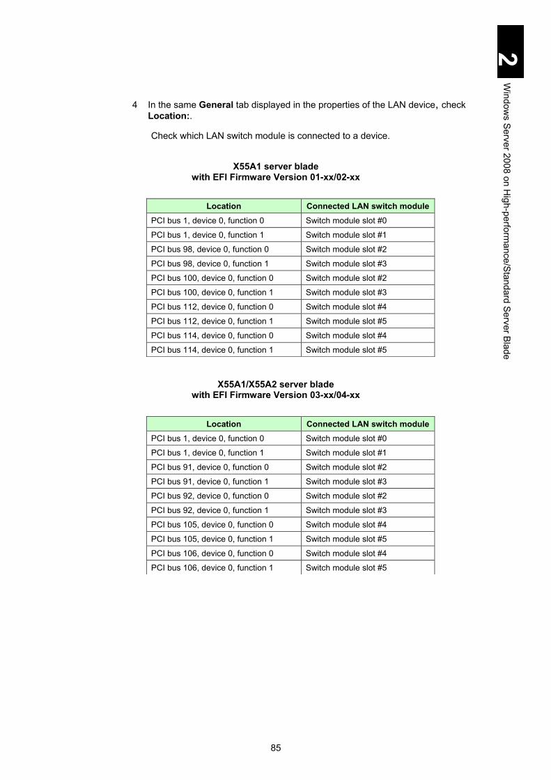
85
2 W
indows S
erver 2008 on High-perform
ance/Standard Server Blade
4 In the same General tab displayed in the properties of the LAN device, check Location:.
Check which LAN switch module is connected to a device.
X55A1 server blade with EFI Firmware Version 01-xx/02-xx
X55A1/X55A2 server blade with EFI Firmware Version 03-xx/04-xx
Location Connected LAN switch module PCI bus 1, device 0, function 0 Switch module slot #0
PCI bus 1, device 0, function 1 Switch module slot #1
PCI bus 98, device 0, function 0 Switch module slot #2
PCI bus 98, device 0, function 1 Switch module slot #3
PCI bus 100, device 0, function 0 Switch module slot #2
PCI bus 100, device 0, function 1 Switch module slot #3
PCI bus 112, device 0, function 0 Switch module slot #4
PCI bus 112, device 0, function 1 Switch module slot #5
PCI bus 114, device 0, function 0 Switch module slot #4
PCI bus 114, device 0, function 1 Switch module slot #5
Location Connected LAN switch module PCI bus 1, device 0, function 0 Switch module slot #0
PCI bus 1, device 0, function 1 Switch module slot #1
PCI bus 91, device 0, function 0 Switch module slot #2
PCI bus 91, device 0, function 1 Switch module slot #3
PCI bus 92, device 0, function 0 Switch module slot #2
PCI bus 92, device 0, function 1 Switch module slot #3
PCI bus 105, device 0, function 0 Switch module slot #4
PCI bus 105, device 0, function 1 Switch module slot #5
PCI bus 106, device 0, function 0 Switch module slot #4
PCI bus 106, device 0, function 1 Switch module slot #5

86
2 W
indows S
erver 2008 on High-perform
ance/Standard Server Blade
X55R3/X55S3 server blade
X57A1/X57A2 server blade (1) With No SMP connection between server blades
X57A1/X57A2 server blade
(2) With SMP connection between 2 server blades
See Table (1) above and (2) below.
Location Connected LAN switch module PCI bus 92, device 0, function 0 Switch module slot #2
PCI bus 92, device 0, function 1 Switch module slot #3
PCI bus 93, device 0, function 0 Switch module slot #2
PCI bus 93, device 0, function 1 Switch module slot #3
PCI bus 105, device 0, function 0 Switch module slot #4
PCI bus 105, device 0, function 1 Switch module slot #5
PCI bus 106, device 0, function 0 Switch module slot #4
PCI bus 106, device 0, function 1 Switch module slot #5
PCI bus 117, device 0, function 0 Switch module slot #0
PCI bus 117, device 0, function 1 Switch module slot #1
Location Connected LAN switch module PCI bus 1, device 0, function 0 Switch module slot #0
PCI bus 1, device 0, function 1 Switch module slot #1
PCI bus 51, device 0, function 0 Switch module slot #2
PCI bus 51, device 0, function 1 Switch module slot #3
PCI bus 52, device 0, function 0 Switch module slot #2
PCI bus 52, device 0, function 1 Switch module slot #3
PCI bus 55, device 0, function 0 Switch module slot #4
PCI bus 55, device 0, function 1 Switch module slot #5
PCI bus 56, device 0, function 0 Switch module slot #4
PCI bus 56, device 0, function 1 Switch module slot #5
Location Connected LAN switch module PCI bus 65, device 0, function 0 Switch module slot #0
PCI bus 65, device 0, function 1 Switch module slot #1
PCI bus 115, device 0, function 0 Switch module slot #2
PCI bus 115, device 0, function 1 Switch module slot #3
PCI bus 116, device 0, function 0 Switch module slot #2
PCI bus 116, device 0, function 1 Switch module slot #3
PCI bus 119, device 0, function 0 Switch module slot #4
PCI bus 119, device 0, function 1 Switch module slot #5
PCI bus 120, device 0, function 0 Switch module slot #4
PCI bus 120, device 0, function 1 Switch module slot #5

87
2 W
indows S
erver 2008 on High-perform
ance/Standard Server Blade
X57A1/X57A2 server blade (3) With SMP connection among 4 server blades
See Table (1) (2) above and (3) below.
A LAN device displaying a location not included in the table above is installed in the expansion card slot.
The LAN Intel®82567LF-2 Gigabit Network Connection cannot be used. Make sure to enable that LAN with the Device Manager.
External disk array When using an external disk array device with Windows Server 2008, it may be necessary for the disk array to update the firmware or change the settings for Windows Server 2008. See the instructions of the disk array to be used for details.
Location Connected LAN switch module PCI bus 129, device 0, function 0 Switch module slot #0
PCI bus 129, device 0, function 1 Switch module slot #1
PCI bus 179, device 0, function 0 Switch module slot #2
PCI bus 179, device 0, function 1 Switch module slot #3
PCI bus 180, device 0, function 0 Switch module slot #2
PCI bus 180, device 0, function 1 Switch module slot #3
PCI bus 183, device 0, function 0 Switch module slot #4
PCI bus 183, device 0, function 1 Switch module slot #5
PCI bus 184, device 0, function 0 Switch module slot #4
PCI bus 184, device 0, function 1 Switch module slot #5
PCI bus 193, device 0, function 0 Switch module slot #0
PCI bus 193, device 0, function 1 Switch module slot #1
PCI bus 243, device 0, function 0 Switch module slot #2
PCI bus 243, device 0, function 1 Switch module slot #3
PCI bus 244, device 0, function 0 Switch module slot #2
PCI bus 244, device 0, function 1 Switch module slot #3
PCI bus 247, device 0, function 0 Switch module slot #4
PCI bus 247, device 0, function 1 Switch module slot #5
PCI bus 248, device 0, function 0 Switch module slot #4
PCI bus 248, device 0, function 1 Switch module slot #5

88
2 W
indows S
erver 2008 on High-perform
ance/Standard Server Blade
SAN storage manager A disk array device that supports VDS (Virtual Disk Service) is necessary to use SAN storage manager. Check the instructions of your disk array device to see if the disk array device supports VDS.
File properties Details of File Properties by Explorer may not display File Version, Product Information or Product Version. Non-displayed items might appear by rebooting the OS or changing resolution/color bits.
Event log on network adapter \DEVICE {354C76B6-E426-4CEB-8015-BF991BA8D75F} instead of a network adapter name such as Intel® 82566DC-2 Gigabit Network Connection may be displayed in the event log explanation of the network adapter. This occurs due to the specification, which will not affect the operation. The network adapter name and the number in brackets (GUID) might be different depending on your environment.
Display of network adapter connection Network Connection or task tray status may not be quickly updated at the network adapter linkup. To find the status, select View in Network Connections. then select Latest Update to update the connection.
Network adapter event log during OS boot An error event might occur in the network adapter during system boot. The network adapter might be linked down. Confirm that the targeted network adapter is connected in Network Connections. A linkup event might be recorded during system boot in whatever status the network adapter is linked. Check the connection status of the targeted network adapter in Network Connection.
Link rate setting for LAN adapter When using Intel® 82576 Gigabit Dual Port Server Network Connection (X55A1 model), you can specify Link rate and Duplex among 10 Mbps, 100 Mbps, and 1.0 Gbps in Advanced of the LAN device properties. If the setting is changed, the link rate is unchangeable and remains as 1.0 Gps/full duplex. Use the provided Auto negotiation as it is.

89
2 W
indows S
erver 2008 on High-perform
ance/Standard Server Blade
USB memory Only the optional USB memory, FK802 GB/804 GB G is supported and operation with other USB memory devices are not be guaranteed. With the USB memory connected, do not power on the system equipment, or perform reboot-up. Boot the OS and then connect the USB memory. After that, confirm that the drive letters of other drives are not changed. In the setup with Compute System Installer, do not connect a USB memory to the system unit unless otherwise specified in this manual.
BitLocker drive encryption The BitLocker drive encryption feature is not supported.
OS setup for 4-Blade SMP with X57A2 model When setting up Windows Server 2008 in 4-blade SMP with X57A2 model server blades, perform the following steps. If not, a STOP error might occur. Prerequisites
1 Power on the server blade and enter the EFI Setup screen.
See the Hitachi Compute Blade 2000 User’s Guide, Chapter 5: Server Blade Setup for details of the EFI Setup screen.
2 Click the Advanced tab > CPU Configuration. 3 On the CPU Configuration screen, select xAPIC from ACPI Mode. 4 Save the setting and exit from the EFI Setup screen.
OS setup
When the prerequisite has been completed, set up the OS according to the Windows Server 2008 setup.
Do not change ACPI Mode from xAPIC because the OS may not boot properly.
Required time for OS boot It takes longer time to boot the OS in proportion to the amount of processors, memory, and devices that are installed. It may take several tens of minutes if the amount is big. When you install many processors, several hundreds of memory modules, or several tens of I/O expansion cards, check the required time for booting the OS in advance and then schedule the operation, including the required time for OS boot and maintenance.

90
2 W
indows S
erver 2008 on High-perform
ance/Standard Server Blade
Multipath When a multipath (access route) is assigned to the LU of an external disk array for install the OS, change it to a single path before installing the OS. With multiple paths assigned to the LU, the installation fails. Install the OS with a single path, then install multipath software, and release the single-path routing. When a multipath (access route) is assigned to the LU of an external disk array where the OS has been installed, change it to a single-path routing before restoring the OS from the backup files. With multiple paths assigned to the LU, the restoration might fail. Check notes on the backup software referring to the manual beforehand. It is common to change a multipath to a single-path routing from the management utility of an external disk array. See the manual of the external disk array device.
Restrictions on Windows Server 2008 SP2
Read through Restrictions on use of Windows Server 2008, and then see this subsection.
See the Microsoft Website for information on Windows Server 2008 SP2.
http://www.microsoft.com/windowsserver2008/en/us/SP2.aspx
Event viewer Much of the following event is recorded in the system event log at the OS boot after applying Windows Server 2008 SP2. There is, however, no problem.
Event ID: 4374 Event source: Microsoft-Windows-Servicing Event Level: Warning Description: Windows Servicing identified that package KB905866 (Update) is not applicable for this sys.
The following event is recorded in the system event log during OS boot after applying Windows Server 2008 SP2. There is, however, no problem.
Event ID: 7026 Event source: Service Control Manager Event Level: Error Description: The following boot-start or system-start driver(s) failed to load: storflt
See the following Website for further details. http://support.microsoft.com/kb/971527

91
2 W
indows S
erver 2008 on High-perform
ance/Standard Server Blade
Microsoft Multipath I/O (MPIO) When configuring multipath environment with Multipath I/O enabled, a standard function to the OS, without installing Windows Server 2008 SP2, apply the following update module: KB967752 before installing SP2. If you install Windows Server 2008 SP2 without applying the update module and uninstall it, access to the multi-path disk might not be available, and the OS might not be able to boot up. See the following Website for further details. http://support.microsoft.com/kb/967752
Device Manager A device, which is disabled in Device Manager without installing Windows Server 2008 SP2, has automatically been Enabled after installing Windows Server 2008 SP2. Check Disabled devices in Device Manager before installing Windows Server 2008 SP, and disable them again if they are enabled after installing Windows Server 2008 SP. With X55A1/X55A2/X57A1/X57A2 models, some devices should be disabled during normal use. Check with Device Manager if Intel(R) 82567LF-2 Gigabit Network Connection is enabled. If so, configure it to disabled again. See step 10 in LAN driver for the procedure.
Local Area Connection Local Area Connection, which is disabled in network Connection in Control Panel without installing Windows Server 2008 SP2, has automatically been enabled after installing Windows Server 2008 SP2. Check each Local Area Connection before installing Windows Server 2008 S2, and disable it again if it is enabled after installing Windows Server 2008 SP2.

92
2 W
indows S
erver 2008 on High-perform
ance/Standard Server Blade
Windows Server 2008 setup This section explains the setup for Windows Server 2008.
For the installation procedure of the driver for the expansion board, see the expansion board manual.
When installing the Windows driver utility, use Driver Kit version 12-11 or later. Ask your reseller for the latest version. Do not use other versions for Windows Server 2008 setup.
Use the specified driver in the procedure. Otherwise, the application does not work properly.
Error logs in a PCI Express, PCI Express board module, or PCI Express expander without failure in the server blade hardware, may be recorded in the management module during Windows Server 2008 setup. When the error log is recorded only during setup and not afterwards, there is no problem.
NOTICE
Re-setup causes the hard disk data to be deleted. Back up data that you need in advance.

93
2 W
indows S
erver 2008 on High-perform
ance/Standard Server Blade
Windows Server 2008 setup Make sure to install both OS Setup and Driver/Utility Setup.
After the OS setup, make sure to install the Driver/Utility Setup. Windows 2008 cannot operate properly with only the OS setup.
The following setup DVD-ROMs are described in this manual: Windows Server 2008 Standard
Windows Server 2008 Standard, without Hyper-V
Windows Server 2008 Enterprise
Windows Server 2008 Enterprise, without Hyper-V
Windows Server 2008 Standard 32-bit (not including Hyper-V)
Windows Server 2008 Enterprise 32-bit (not including Hyper-V)
Standard DVD drive names are next to the hard disk. Check the DVD drive name in advance.
Printed Name Official Name Setup DVD DVD-ROM for Microsoft Windows Server 2008
Standard, Retail Edition
Printed Name Official Name Setup DVD DVD-ROM for Microsoft Windows Server 2008
Standard without Hyper-V, Retail Edition
Printed Name Official Name Setup DVD DVD-ROM for Microsoft Windows Server 2008
Enterprise, Retail Edition
Printed Name Official Name Setup DVD DVD-ROM for Microsoft Windows Server 2008
Enterprise without Hyper-V, Retail Edition
Printed Name Official Name Setup DVD DVD-ROM for Microsoft Windows Server 2008
Standard 32-bit, Retail Edition
Printed Name Official Name Setup DVD DVD-ROM for Microsoft Windows Server 2008
Enterprise 32-bit, Retail Edition

94
2 W
indows S
erver 2008 on High-perform
ance/Standard Server Blade
Setup flowchart Setup with Compute Systems Installer Setup without Compute Systems Installer
Back up necessary files. (Use backup program.) Set partition to the disk array. (Carry out as necessary.) Initialize BIOS settings. (as necessary)
Before Setup
Install the OS completely.
OS Setup
Component/Utility Installation
Update the OS using Windows Update. Set up each component and utility. Set up other applications as necessary.
Update/Setting/Application Installation
Setup with Compute Systems Installer
Install drivers: Chipset Driver / LAN driver / Display driver
Install MegaRAID Storage Manager as necessary.
Install Intel PROSet as necessary.
Other option board utility: may be different depending on the type or configuration of the option board.
Update the Registry.
95
2 W
indows S
erver 2008 on High-perform
ance/Standard Server Blade
Details of Windows Server 2008 setup This section describes how to setup Windows Server 2008.
Setup restrictions Required time for OS setup
Time required for OS setup will extend as the amount of installed processors, memory, and devices get larger. Especially in recognizing a device, required time will take longer by hours depending on the size of installation. If it seems to hang up due to no change in the window during the setup, do not reset or turn off the power. It is expected to take minutes or some hours, especially with a lot of I/O adapters. It can be time consuming.
Remote KVM See Chapter 3: Connecting the System Equipment and Powering on, in the
Hitachi Compute Blade 2000 User’s Guide for information about how to use the remote KVM in advance.
Make sure to operate the keyboard and mouse with the remote KVM during setup.
When using a remote FD and remote CD/DVD, connect the remote FD and remote CD/DVD before turning on power to the server blade. If they are connected after starting the OS setup, they may not be recognized correctly.
Installing OS into the external disk array device. Set 'one path' to the target LU of the external disk array device before
installing the OS. If several paths are set to the target LU, the installation fails. In general, use the management utility of the external disk array device for setting ‘one path’. See the external disk array device’s manual for details. Install multiple path software after the OS installation, and cancel the one-path setting.
Set an external device to use LUN0 for the OS. Press the F2 key to display the BIOS menu when booting the server blade. Then, confirm that Boot Priority of the target LU is the first priority at the System Boot menu.
While reinstalling the OS, it is recommended that a non-target LU should be hidden temporarily for safety. Check whether it is possible to temporarily mask a non-target LU during the setting of the external RAID device, or to be able to remove them from the LU group.
Setting partition (drive)
The partition (drive) to which the OS is installed Install the OS in the first partition of the HDD. All programs and data in that partition will be deleted.
Write cache setting
When installing the OS in the internal disk array of the server blade, confirm that the write cache of a disk for setup is invalid (Write Through mode) before setting up Windows. If it is valid (Write Back mode), change it to Write Through mode (invalid).

96
2 W
indows S
erver 2008 on High-perform
ance/Standard Server Blade
For information on how to change the setting, see the Hitachi Compute Blade 2000 User’s Guide.
MegaRAID Storage Manager Instruction Manual See the following file in the DriverKit DVD-ROM 12-11 or later to find the MegaRAID Storage Manager Instruction Manual. Where d: is a DVD drive name. GVX-CA2SRD2X1/GV-CA2SRD2X1-Y
d:\MANUAL\MSM\MSManager.pdf GVX-CA2SRD4X1/GV-CA2SRD4X1-Y only for X55A2
d:\MANUAL\MSM2\MSManager.pdf X55R3 model
d:\MANUAL\MSM3\MSManager.pdf
DVD drive Windows Server 2008 setup needs a DVD-ROM drive (hereinafter referred to as DVD drive).
DVD-ROM ejection Press the eject button of the DVD drive only when changing DVD-ROM media. Otherwise, the OS setup must be reinstalled.
With multiple disks and partitions (drives) When multiple disks and partitions (drives) are in the system equipment, multiple disks are displayed as the target for installation. The number of a disk and the order of disks, however, always changes: are not fixed. When performing the setup with multiple disks displayed, determine the target disk for installation by its size, not by the order or its number. This is why we recommend that you should configure different capacity of disk arrays and hard disks mounted on the system per drive. In case you select a wrong disk or partition as the target, existent partitions or existent data may be removed. For further details, see the following Microsoft website. http://support.microsoft.com/kb/937251 You can find disk capacity in MegaRAID WebBIOS or system BIOS. For details, see Chapter 5 “Server Blade Setup”.
Settings for a server blade in OS setup Configure the server blade Web console EFI setting to: PCI Error Handling Mode: PCIe Error Isolation before installing the OS. Without the setting above, a hang-up may occur during OS installation or the installation might fail. If the OS has been successfully installed, there is no problem. After the setup, return the setting of PCI Error Handling Mode to your usual setting. See Chapter 5: Server Blade Setup, in the Hitachi Compute Blade 2000 User’s Guide for details.

97
2 W
indows S
erver 2008 on High-perform
ance/Standard Server Blade
Setup steps
When an external disk array device or SCSI device is connected, turn off the device power before starting the setup. Otherwise, the installing destination might not be recognized correctly.
1 Turn on the system equipment, and quickly insert the Setup DVD to the DVD drive.
2 If a message "Press any key to boot from CD or DVD" appears, press any key
immediately.
When the key is not pressed immediately, the existing OS starts instead of the DVD-ROM. In that case, go back to step 1.
When pressing the key more than once, Windows Boot Manager may start. In that case, select Windows Setup [EMS Enabled] and continue the setup.
3 A message “Windows is loading files” is displayed, and then Install Windows is
displayed. Customize it as necessary, and click Next.
NOTICE
Re-setup causes the hard disk data to disappear. Back up data that you need in advance.

98
2 W
indows S
erver 2008 on High-perform
ance/Standard Server Blade
. 4 When the following screen is displayed, click Install now.
When Windows RE needs to start, see Restore the computer.
5 When the Product Key to License Authentication screen is displayed, enter the product key applicable to the Setup DVD and click Next.
6 When the message “Select the OS system” is displayed, select the edition you need to install, and check the Windows edition Selected box. Click Next.
The check box of Windows edition selected may not be displayed. In that case, it is not necessary to check it.
Do not select Server Core Install, because it is not supported.
7 The message “Please read the license terms” is displayed. Read the contents,
check the box next to “I accept the license terms” if you accept the license terms, and click Next.
8 When a message “Which type of installation do you want?” is displayed, select Custom.
When this screen is not displayed, go to step 9 without making a selection.
When device information is not displayed in the red-encircled rectangular pane of the screen shown in step 9, go to step 10. When device information is displayed in the red rectangular pane, go to step 14.
9 A message “Where do you want to install Windows?” is displayed.
When installing in an external disk array connected to 8 Gb 2-port Fibre-channel adapter (GVX-CC2N8G3X1/GV-CC2N8G3X1-Y, GVX-CC2D8G3X1/GV-CC2D8G3X1-Y), the disk for installation may be shown. Go to step 10.

99
2 W
indows S
erver 2008 on High-perform
ance/Standard Server Blade
10 Select Load Driver. When the Load Driver screen is displayed, remove the Setup DVD from the DVD drive. Insert the DriverKit DVD-ROM 12-11 or a later version, and click Browse.
With many I/O mezzanine cards installed, it may take a long time for loading drivers. Assuming that the waiting time is about 10 minutes, do not reset or power off during the read.
11 The Browse for Folder screen is displayed. Select a location according to the
following description, and click OK. Where d: is the DVD drive name.
(1) With X55A1/X55A2/X55R3 server blade model, install to the internal disk array it is connected to. LSI Logic MegaRAID SAS PCI Express. Windows Server 2008
SAS Internal RAID board: GVX-CA2SRD2X1/GV-CA2SRD2X1-Y X55A1 Model : (d:\X55x1\Win2008\Drivers\RAID\MegaSAS_01\x64) X55A2 Model : (d:\X55x2\Win2008\Drivers\RAID\MegaSAS_01\x64) SAS Internal RAID board: GVX-CA2SRD4X1/GV-CA2SRD4X1-Y X55A2 Model: (d:\X55x2\Win2008R2\Drivers\RAID\MegaSAS_02\x64) SAS RAID on Motherboard X55R3 Model: (d:\X55x3\Win2008\Drivers\RAID\MegaSAS_01\x64)
Windows Server 2008 32-bit SAS Internal RAID board: GVX-CA2SRD2X1/GV-CA2SRD2X1-Y X55A1 Model : (d:\X55x1\Win2008\Drivers\RAID\MegaSAS_01\x86)

100
2 W
indows S
erver 2008 on High-perform
ance/Standard Server Blade
X55A2 Model : (d:\X55x2\Win2008\Drivers\RAID\MegaSAS_01\x86) SAS Internal RAID board: GVX-CA2SRD4X1/GV-CA2SRD4X1-Y X55A2 Model : (d:\X55x2\Win2008\Drivers\RAID\MegaSAS_02\x86) SAS RAID on Motherboard X55R3 Model: (d:\X55x3\Win2008\Drivers\RAID\MegaSAS_01\x86)
(2) With X55A1 server blade model, install in the external disk array connected to the Hitachi 4 Gb 2-port Fibre-channel adapter (GVX-CC2N4G1X1) or Hitachi 4 Gb 2-port Fibre-channel mezzanine card (GVX-CC2M4G1X1). Windows Server 2008
X55A1 Model : (d:\X55x1\Win2008\Drivers\FibreChannel\HFC_01\x64)
Windows Server 2008 32-bit X55A1 Model: (d:\X55x1\Win2008\Drivers\FibreChannel\HFC_01\x86)
(3) Installing in the external disk array connected to the Hitachi 8 Gb Fibre-channel adapter (GVX-CC2N8G1X1/GV-CC2N8G1X1-Y, GVX-CC2N8G2X1/GV-CC2N8G2X1-Y, GVX-CC2D8G1X1/GV-CC2D8G1X1-Y, GVX-CC2D8G2X1/GV-CC2D8G2X1-Y) or Hitachi 8 Gb Fibre-channel mezzanine card (GVX-CC2M8G1X1/GV-CC2M8G1X1-Y, GVX-CC2M8G2X1/GV-CC2M8G2X1-Y) Windows Server 2008
X55A1 Model : (d:\X55x1\Win2008\Drivers\FibreChannel\HFC_01\x64) X55A2 Model : (d:\X55x2\Win2008\Drivers\FibreChannel\HFC_01\x64) X55R3/X55S3 Model: (d:\X55x3\Win2008\Drivers\FibreChannel\HFC_01\x64) X57A1 Model : (d:\X57x1\Win2008\Drivers\FibreChannel\HFC_01\x64) X57A2 Model : (d:\X57x2\Win2008\Drivers\FibreChannel\HFC_01\x64)
Windows Server 2008 32-bit X55A1 Model : (d:\X55x1\Win2008\Drivers\FibreChannel\HFC_01\x86) X55A2 Model : (d:\X55x2\Win2008\Drivers\FibreChannel\HFC_01\x86) X55R3/X55S3 Model: (d:\X55x3\Win2008\Drivers\FibreChannel\HFC_01\x86) X57A1 Model : (d:\X57x1\Win2008\Drivers\FibreChannel\HFC_01\x86) X57A2 Model : (d:\X57x2\Win2008\Drivers\FibreChannel\HFC_01\x86)
(4) Installing in the external disk array connected to an Emulex 8 Gb 2-port Fibre-channel mezzanine card (GVX-CC2M8G3X1/GV-CC2M8G3X1-Y, GVX-CC2N8G3X1/GV-CC2N8G3X1-Y, GVX-CC2D8G3X1/GV-CC2D8G3X1-Y).

101
2 W
indows S
erver 2008 on High-perform
ance/Standard Server Blade
Windows Server 2008 X55A1 Model: (d:\X55x1\Win2008\Drivers\FibreChannel\Emulex_01\x64 Drivers\Storport\x64\HBA) X55A2 Model: (d:\X55x2\Win2008\Drivers\FibreChannel\Emulex_01\x64 Drivers\Storport\x64\HBA) X55R3/X55S3 Model: (d:\X55x3\Win2008\Drivers\FibreChannel\Emulex_01\x64 Drivers\Storport\x64\HBA) X57A1 Model: (d:\X57x1\Win2008\Drivers\FibreChannel\Emulex_01\x64 Drivers\Storport\x64\HBA) X57A2 Model: (d:\X57x2\Win2008\Drivers\FibreChannel\Emulex_01\x64 Drivers\Storport\x64\HBA)
Windows Server 2008 32-bit X55A1 Model: (d:\X55x1\Win2008\Drivers\FibreChannel\Emulex_01\x86\Drivers\Storport\x86\HBA) X55A2 Model: (d:\X55x2\Win2008\Drivers\FibreChannel\Emulex_01\x86\Drivers\Storport\x86\HBA) X55R3/X55S3 Model: (d:\X55x3\Win2008\Drivers\FibreChannel\Emulex_01\x86\Drivers\Storport\x86\HBA) X57A1 Model: (d:\X57x1\Win2008\Drivers\FibreChannel\Emulex_01\x86\Drivers\Storport\x86\HBA) X57A2 Model: (d:\X57x2\Win2008\Drivers\FibreChannel\Emulex_01\x86\Drivers\Storport\x86\HBA)

102
2 W
indows S
erver 2008 on High-perform
ance/Standard Server Blade
12 The driver path on the CD/DVD you selected in the previous step will be indicated on the screen. Confirm it, and then click Next.
There might be some location names that are the same. If you select the location, select from any one of them.
(1) With X55A1/X55A2/X55R3 server blade model, installing in the internal
disk array connected to LSI Logic MegaRAID SAS PCI Express Windows Server 2008
SAS Internal RAID board: GVX-CA2SRD2X1/GV-CA2SRD2X1-Y X55A1 Model: (d:\X55x1\Win2008\Drivers\RAID\MegaSAS_01\x64\oemsetup.inf) X55A2 Model: (d:\X55x2\Win2008\Drivers\RAID\MegaSAS_01\x64\oemsetup.inf) SAS Internal RAID board: GVX-CA2SRD4X1/GV-CA2SRD4X1-Y X55A2 Model: (d:\X55x2\Win2008\Drivers\RAID\MegaSAS_02\x64\oemsetup.inf) SAS RAID on Motherboard X55R3 Model: (d:\X55x3\Win2008\Drivers\RAID\MegaSAS_01\x64\ megasas2.inf)
Windows Server 2008 32-bit SAS Internal RAID board: GVX-CA2SRD2X1/GV-CA2SRD2X1-Y X55A1 Model: (d:\X55x1\Win2008\Drivers\RAID\MegaSAS_01\x86\oemsetup.inf) X55A2 Model: (d:\X55x2\Win2008\Drivers\RAID\MegaSAS_01\x86\oemsetup.inf) SAS Internal RAID board: GVX-CA2SRD4X1/GV-CA2SRD4X1-Y X55A2 Model: (d:\X55x2\Win2008\Drivers\RAID\MegaSAS_02\x86\oemsetup.inf) SAS RAID on Motherboard X55R3 Model: (d:\X55x3\Win2008\Drivers\RAID\MegaSAS_01\x86\ megasas2.inf)
(2) With X55A1 server blade model, installing in the external disk array connected to the Hitachi 4 Gb 2-port Fibre-channel adapter (GVX-CC2N4G1X1) or Hitachi 4 Gb 2-port Fibre-channel mezzanine card (GVX-CC2M4G1X1). Windows Server 2008
X55A1 Model: (d:\X55x1\Win2008\Drivers\FibreChannel\HFC_01\x64\hfcwdd.inf)
Windows Server 2008 32-bit X55A1 Model: (d:\X55x1\Win2008\Drivers\FibreChannel\HFC_01\x86\hfcwdd.inf)

103
2 W
indows S
erver 2008 on High-perform
ance/Standard Server Blade
(3) Installing in the external disk array connected to a Hitachi 8 Gb Fibre-channel adapter (GVX-CC2N8G1X1/GV-CC2N8G1X1-Y, GVX-CC2N8G2X1/GV-CC2N8G2X1-Y, GVX-CC2D8G1X1/GV-CC2D8G1X1-Y, GVX-CC2D8G2X1/GV-CC2D8G2X1-Y) or Hitachi 8 Gb Fibre-channel mezzanine card (GVX-CC2M8G1X1/GV-CC2M8G1X1-Y, GVX-CC2M8G2X1/GV-CC2M8G2X1-Y) Windows Server 2008
X55A1 Model: (d:\X55x1\Win2008\Drivers\FibreChannel\HFC_01\x64\hfcwdd.inf) X55A2 Model: (d:\X55x2\Win2008\Drivers\FibreChannel\HFC_01\x64\hfcwdd.inf) X55R3/X55S3 Model: X55R3/X3\Win2008\Drivers\FibreChannel\HFC_01\x64\hfcwdd.inf) X57A1 Model : (d:\X57x1\Win2008\Drivers\FibreChannel\HFC_01\x64\hfcwdd.inf) X57A2 Model : (d:\X57x2\Win2008\Drivers\FibreChannel\HFC_01\x64\hfcwdd.inf)
Windows Server 2008 32-bit X55A1 Model : (d:\X55x1\Win2008\Drivers\FibreChannel\HFC_01\x86\hfcwdd.inf) X55A2 Model : (d:\X55x2\Win2008\Drivers\FibreChannel\HFC_01\x86\hfcwdd.inf) X55R3/X55S3 Model: (d:\X55x3\Win2008\Drivers\FibreChannel\HFC_01\x86\hfcwdd.inf) X57A1 Model : (d:\X57x1\Win2008\Drivers\FibreChannel\HFC_01\x86\hfcwdd.inf) X57A2 Model : (d:\X57x2\Win2008\Drivers\FibreChannel\HFC_01\x86\hfcwdd.inf)

104
2 W
indows S
erver 2008 on High-perform
ance/Standard Server Blade
(4) Installing in the external disk array connected to an Emulex 8 Gb 2-port Fibre-channel mezzanine card (GVX-CC2M8G3X1/GV-CC2M8G3X1-Y, GVX-CC2N8G3X1/GV-CC2N8G3X1-Y, GVX-CC2D8G3X1/GV-CC2D8G3X1-Y). Windows Server 2008
X55A1 Model: (d:\X55x1\Win2008\Drivers\FibreChannel\Emulex_01\x64 Drivers\Storport\x64\HBA\oemsetup.inf) X55A2 Model: (d:\X55x2\Win2008\Drivers\FibreChannel\Emulex_01\x64 Drivers\Storport\x64\HBA\oemsetup.inf) X55R3/X55S3 Model: (d:\X55x3\Win2008\Drivers\FibreChannel\Emulex_01\x64 Drivers\Storport\x64\HBA\oemsetup.inf) X57A1 Model: (d:\X57x1\Win2008\Drivers\FibreChannel\Emulex_01\x64 Drivers\Storport\x64\HBA\oemsetup.inf) X57A2 Model: (d:\X57x2\Win2008\Drivers\FibreChannel\Emulex_01\x64 Drivers\Storport\x64\HBA\oemsetup.inf)
Windows Server 2008 32-bit X55A1 Model: (d:\X55x1\Win2008\Drivers\FibreChannel\Emulex_01\x86\Drivers\Storport\x86\HBA\oemsetup.inf) X55A2 Model: (d:\X55x2\Win2008\Drivers\FibreChannel\Emulex_01\x86\Drivers\Storport\x86\HBA\oemsetup.inf) X55R3/X55S3 Model: (d:\X55x3\Win2008\Drivers\FibreChannel\Emulex_01\x86\Drivers\Storport\x86\HBA\oemsetup.inf) X57A1 Model: (d:\X57x1\Win2008\Drivers\FibreChannel\Emulex_01\x86\Drivers\Storport\x86\HBA\oemsetup.inf) X57A2 Model: (d:\X57x2\Win2008\Drivers\FibreChannel\Emulex_01\x86\Drivers\Storport\x86\HBA\oemsetup.inf)
13 A message “Where do you want to install Windows?” is displayed. Remove the Driver Kit DVD-ROM from the DVD drive, and insert the Setup DVD.
14 Select a partition from the screen, and click Next.
Delete cannot be used to a partition in the dynamic disk. See the following URL for the details.
http://support.microsoft.com/kb/926190 When Drive Option is used to create a partition,
installing the OS in the 10 GB partition may fail. Therefore, we strongly recommend making a partition larger than 40 GB for the OS installation.

105
2 W
indows S
erver 2008 on High-perform
ance/Standard Server Blade
When multiple disks are displayed, the number of a disk and the order is not fixed. Determine the target disk for installation by its size, not by the order or its number. In case a wrong disk or partition is selected as the target, existing partitions or existing data may be removed. For further details, see the following Microsoft website. http://support.microsoft.com/kb/937251 You can find disk capacity in MegaRAID WebBIOS or system BIOS. For details, see Chapter 5 “Server Blade Setup.” This is why we recommend that you configure different capacity of disk arrays and hard disks mounted on the system per drive.
To specify the capacity of the partition for installation, click Drive options (Advanced).
When a target disk for installation is not recognized even if the boot device driver has been applied, apply the driver again. Then, if the target disk is recognized, there is no problem. If the target disk is not recognized by the second attempt, check the settings for the target disk and connection.
15 A message “Installing Windows…” is displayed. After several reboots, the OS setup will be completed.
16 When booting the OS for the first time after setup, a message “The user’s password must be changed before logging on the first time.” is displayed. Click OK.
When many I/O expansion cards are installed, installation might take up to an hour. Do not reset or power off during installation
17 Enter the Administrator password into New password and Confirm password,
and click .
The following conditions are required for a password. Combine at least 3 characters among the followings:
English capital letters (A to Z); English lower case (a to z); numbers (1 to 9); comma, period
Does not contain 3 or more consecutive letters from the user name or full name.
18 When the message “Your password has been changed” is displayed, click OK.
The OS Setup has been completed. Go to Driver/Utility setup.

106
2 W
indows S
erver 2008 on High-perform
ance/Standard Server Blade
Driver/Utility setup This section describes how to setup Driver/Utility for Windows Server 2008 using the Setup DVD. You can set up drivers and utilities with or without the Compute Systems Installer. We usually recommend the setup with Compute Systems Installer.
Setup with Compute Systems Installer Compute Systems Installer, which is included in Driver Kit 12-11 or later, enables you to easily install drivers and utilities required for the system operation.
Compute Systems Installer can be used to install only the English version OS and
not any other language version OSs such as Japanese, multi-language. With many I/O adapters installed, it might take up to an hour to install drivers. Do
not reset or turn off the power during installation. The following or later versions of Compute Systems Installer support Windows
Server 2008. Check the DVD label beforehand.
Setting up Compute Systems Installer
The following procedure describes how to set up Compute Systems Installer before installing drivers/utilities. 1 Power on the system equipment, start Windows, and log on as Administrator. 2 Insert the Driver Kit DVD into the DVD drive. 3 Click Start and select Run. 4 Enter the following and click OK.
d: \HInstall.exe Where d: is the DVD drive name. The Compute Systems Installer Installation window is displayed.
5 Click Yes. The Compute Systems Installer will start automatically after installation.
6 Click OK. A window will be displayed where you can select which component to install.
Go to Setting up drivers/utilities.
Model Name Driver Kit for Windows Server 2008 (SP1/SP2)
X55A1 - X55A2 12-10
X55R3/X55S3 12-13 X57A1 12-10 X57A1 12-11

107
2 W
indows S
erver 2008 on High-perform
ance/Standard Server Blade
Setting up drivers/utilities
Set up drivers and utilities with Compute Systems Installer. When you have installed Compute Systems Installer in Setting up Compute Systems Installer, Compute Systems Installer will start automatically.
1 When installing all components, click default installation. When selecting
components to install, click Custom installation, and select components following the directions in the window, and click Next.
We usually recommend the default installation.
2 Click Next. Preparation for installation will start. Follow the instructions on the windows to proceed. You may have to change DVDs during installation. A setup completion window will be displayed at the end. When reboot is required, go to step 3. When reboot is not required, go to step 6.
You may be asked to type something while setting up utilities. See the manual of each utility for details about the setup procedures. See How to use supplied software for the location of each manual.
3 Check Reboot Now, and remove the DVD from the drive. 4 Click OK.
The server blade will be rebooted. 5 Log on as Administrator after reboot.
Compute Systems Installer automatically reboots to continue processing. Repeat step 2 through step 5 as necessary.
6 Click Done. If you want to remove the Compute Systems Installer, go to Removing Compute Systems Installer without clicking Done. Compute Systems Installer will be finished.

108
2 W
indows S
erver 2008 on High-perform
ance/Standard Server Blade
Removing Compute Systems Installer
When drivers and utilities have been set up, remove Compute Systems Installer. Reboot is required for removing Compute Systems Installer. 1 In the finish window for Compute Systems Installer, check Never launch the
program on startup and then check Uninstall this program. Compute Systems Installer Deletion window is displayed.
2 Click Yes. 3 Click Done.
Compute Systems Installer will be removed.
Checking driver updates
With some adapters or devices, their drivers may not be installed with Compute Systems Installer. The latest drivers can be available in attached CDs or can be downloaded from Websites. Apply the latest drivers referring to the manual of your adapters.
When applying the new driver, Compute Systems Installer may not recognize the driver installation status correctly. If you update the driver manually, remove Compute Systems Installer in advance.
Applying patches
Apply Windows update patches such as the security patch as necessary. Some server blades and adapters may have prerequisite patches. Visit each website or contact your reseller for the recommended patches to apply.

109
2 W
indows S
erver 2008 on High-perform
ance/Standard Server Blade
Setup without Compute Systems Installer When setting up driver/utility without Compute Systems Installer, make sure to install the following drivers, utilities, and register update respectively. Registry Update (1) Driver
Display driver Chipset driver LAN driver
Utility MegaRAID Storage Manager (x55A1/X55A2/E55R3 with onboard
MegaRAID model) Intel® PROSet(X55A1/X55A2/X55R3 with onboard LAN mezzanine
card/X55S3 with onboard LAN mezzanine card/X57A1/X57A2 model Driver/Utility for an option board Registry Update (2) Update Information Check
Check information on driver update Apply batches
After having installed drivers/utilities above, install an expansion board driver. See the expansion board manual for the installation procedure.
Then update the registry after having installed the expansion board driver.

110
2 W
indows S
erver 2008 on High-perform
ance/Standard Server Blade
Registry Update (1)
Insert the Driver kit DVD-ROM 12-11 or later into the DVD drive, and execute the following steps. * where d represents the drive name of DVD. Set dumps to be collected when NMI is issued.
1 Click Start and select Run…. 2 Input the following, and click OK.
X55A1 Model: d:\X55x1\Win2008\Tools\NMIDump\NMID.bat X55A2 Model: d:\X55x2\Win2008\Tools\NMIDump\NMID.bat X55R3/X55S3 Model: d: \X55x3\Win2008\Tools\NMIDump\NMID.bat X57A1 Model: d:\X57x1\Win2008\Tools\NMIDump\NMID.bat X57A2 Model: d:\X57x2\Win2008\Tools\NMIDump\NMID.bat
Set the PCI driver. 1 Click Start and select Run…. 2 Input the following, and click OK.
X55A1 Model: d:\X55x1\Win2008\Tools\avoidD3\avoidD3.bat X55A2 Model: d:\X55x2\Win2008\Tools\avoidD3\avoidD3.bat X55R3/X55S3 Model: d:\X55x3\Win2008\Tools\avoidD3\avoidD3.bat X57A1 Model: d:\X57x1\Win2008\Tools\avoidD3\avoidD3.bat X57A2 Model: d:\X57x2\Win2008\Tools\avoidD3\avoidD3.bat
Reboot the OS after applying the batch to reflect the item settings.

111
2 W
indows S
erver 2008 on High-perform
ance/Standard Server Blade
To install drivers
Display driver
Install the display driver in the following procedure.
With LPAR manager environment, you do not need to install the display driver.
Do not execute the procedure for the display driver installation.
1 Turn on the system equipment power, boot Windows, and log on as Administrator.
2 Insert the Driver kit 12-11 or later into the DVD drive. 3 Click Start and select Run. 4 Input the following, and click OK.
X55A1 Model: d:\X55x1\Win2008\Drivers\SVGA\Matrox_01\install.bat X55A2 Model: d:\X55x2\Win2008\Drivers\SVGA\Matrox_01\install.bat X55R3/X55S3 Model: d:\X55x3\Win2008R2\Drivers\SVGA\Matrox_01\install.bat X57A1 Model: d:\X57x1\Win2008\Drivers\SVGA\Matrox_01\install.bat X57A2 Model: d:\X57x2\Win2008\Drivers\SVGA\Matrox_01\install.bat Where d: is the DVD driver name.
Execute install.bat using the procedure described above. With some procedures, the setup fails.
5 Remove the DVD-ROM from the drive, and then reboot the system equipment. 6 Change the resolution for the display specification.
When High (24 bits) is selected as a display color, the screen may not be displayed.
Select Max (32 bits) or Medium (16 bits).

112
2 W
indows S
erver 2008 on High-perform
ance/Standard Server Blade
Chipset driver
Install the chipset driver following the steps below: 1 Power on the system equipment, boot Windows, and log on as Administrator. 2 Insert the DriverKit DVD-ROM version 12-11 or later into the DVD drive. 3 Click Start and select Run…. 4 Input the following, and click OK.
X55A1 Model: d:\X55x1\Win2008\Drivers\Chipset\INTEL_01\infinst_autol.exe X55A2 Model: d:\X55x2\Win2008\Drivers\Chipset\INTEL_01\infinst_autol.exe X55R3/X55S3 Model: d:\X55x3\Win2008\Drivers\Chipset\INTEL_01\infinst_autol.exe X57A1Model: d:\X57x1\Win2008\Drivers\Chipset\INTEL_01\infinst_autol.exe (d: is the DVD drive name.) X57A2Model: d:\X57x2\Win2008\Drivers\Chipset\INTEL_01\infinst_autol.exe (Where d: is the DVD drive name.)
The Setup screen is displayed. 5 Click Next.
“License Agreement Terms“ is displayed. 6 Read the license agreement, and then click Yes if you agree.
Install the chipset driver following the instructions on the screens. “Setup completed” is displayed in the end.
7 Select Yes, reboot the computer now and click Complete. Quickly remove the DVD-ROM from the drive. The system equipment will be rebooted.

113
2 W
indows S
erver 2008 on High-perform
ance/Standard Server Blade
LAN driver
Install the LAN driver using the following procedure. For the driver for an expanded LAN board driver, see the manual of the expanded LAN board.
1 Turn on the system equipment power, boot Windows, and log on as Administrator.
2 Insert the Driver kit DVD-ROM version 12-11 or later into the DVD drive. 3 Click Start and select Server Manager.
Server Manager appears. 4 Select Diagnostics and then Device Manager.
Device Manager appears 5 Right-click the network adapter whose driver has not been updated and click
Update Driver Software…. Update Wizard appears.
6 Select Browse my computer for driver software. 7 Select Search for Driver Software in this location and input the following.
Then click Next. (1) Driver for 10 Gb 2-port LAN adapter (GVX-CN2NXG2X1/GV-CN2NXG2X1-Y, GVX-CN2DXG2X1 GV-CN2DXG2X1-Y
Windows Server 2008: X55A2 Model: d:\X55x2\Win2008\Drivers\LAN\INTELXG_01\x64 X55R3/X55S3 Model: d:\X55x3\Win2008\Drivers\LAN\INTELXG_01\x64 X57A1 Model: d:\X57x1\Win2008\Drivers\LAN\INTELXG_01\x64 X57A2 Model: d:\X57x1\Win2008\Drivers\LAN\INTELXG_01\x64
Windows Server 2008 32-bit X55A2 Model: d:\X55x2\Win2008\Drivers\LAN\INTELXG_01\x86 X55R3/X55S3 Model: d:\X55x3\Win2008\Drivers\LAN\INTELXG_01\x86 X57A1Model: d:\X57x1\Win2008\Drivers\LAN\INTELXG_01\x86 X57A2Model: d:\X57x2\Win2008\Drivers\LAN\INTELXG_01\x86
(2) Driver for LAN devices other than (1) 10 Gb 2-port LAN adapter Windows Server 2008:
X55A1 Model: d:\X55x1\Win2008\Drivers\LAN\INTEL_01\x64 X55A2 Model: d:\X55x2\Win2008\Drivers\LAN\INTEL_01\x64 X55R3/X55S3 Model: d:\X55x3\Win2008\Drivers\LAN\INTEL_01\x64 X57A1 Model: d:\X57x1\Win2008\Drivers\LAN\INTEL_01\x64

114
2 W
indows S
erver 2008 on High-perform
ance/Standard Server Blade
X57A2 Model: d:\X57x2\Win2008\Drivers\LAN\INTEL_01\x64
Windows Server 2008 32-bit X55A1 Model: d:\X55x1\Win2008\Drivers\LAN\INTEL_01\x86 X55A2 Model: d:\X55x2\Win2008\Drivers\LAN\INTEL_01\x86 X55R3/X55S3 Model: d:\X55x3\Win2008\Drivers\LAN\INTEL_01\x86 X57A1Model: d:\X57x1\Win2008\Drivers\LAN\INTEL_01\x86 X57A2Model: d:\X57x2\Win2008\Drivers\LAN\INTEL_01\x86
(3) Driver for Broadcom for X55R3/X55S3 Model Windows Server 2008:
d:\X55x3\Win2008\Drivers\LAN\BROAD_01\x64 Windows Server 2008 32-bit
d:\X55x3\Win2008\Drivers\LAN\BROAD_01\x86 Where d: is the DVD drive name. Remove the check mark from Search the subfolder.
8 Confirm that “Driver software updated correctly.” is displayed, and then click Close.
9 If there remain network adapters whose LAN drivers have not been updated, repeat steps 5 through 8 above for each network adapters. With X55R3/X55S3 model, go to step 11.
10 Right-click Intel® 82567LF-2 Gigabit Network Connection that is displayed in Network adapter of the Device Manager, and click Disabled from the menu.
The adapter mentioned above is not displayed on LPARs.
11 Remove the DVD-ROM from the drive, and reboot the system equipment.
Make sure to set Disabled to the LAN device Intel®82567LF-2 Gigabit Network Connection. Do not use this LAN device.
There is no problem if some errors or warnings appear about Intel® 82567LF-2 Gigabit Network Connection, which indicates the link rate is inconsistent with the connected point or that the IP address is busy.
115
2 W
indows S
erver 2008 on High-perform
ance/Standard Server Blade
A message “This hardware cannot be started.” may
be displayed during driver setup. In this case, reboot the system equipment, and it will operate properly. Confirm using the Device Manager that the device is running correctly.
An error event log may occur in the network adapter each time the system is booted. The network adapter may link down. Check if that network adapter is connected using Network connection.
Network properties or network status in the task tray may not be quickly updated during linkup. Select Display and then Update the latest on the Network connection screen to update the network status.
To install utilities
MegaRAID Storage Manager
For details, see MegaRAID Storage Manager.
Intel PROSet
For details, see Intel® PROSet.
Broadcom Advanced Control Suite 4 (X55R3/X55S3 model)
For details, see Broadcom Advanced Control Suite 4.
Driver/Utility for expansion board
There may be some drivers/utilities to be installed for use by the installed expansion boards installed. See the expansion board user’s manual for details, and install components as necessary. For drivers for expansion boards contained in the Driver Kit, see readme.html in the Driver Kit DVD-ROM.

116
2 W
indows S
erver 2008 on High-perform
ance/Standard Server Blade
Registry Update (2)
With the Driver Kit DVD-ROM version 12-11 or later in the DVD drive, execute the following. Where d: is the DVD drive name. Change the LAN driver setting.
1 Click Start and select Run…. 2 Input the following, and click OK.
X55A1 Model: d:\X55x1\Win2008\Tools\SNPDS\SNPDSW08.bat X55A2 Model: d:\X55x2\Win2008\Tools\SNPDS\SNPDSW08.bat X55R3/X55S3 Model: d:\X55x3\Win2008\Tools\SNPDS\SNPDSW08.bat X57A1 Model: d:\X57x1\Win2008\Tools\SNPDS\SNPDSW08.bat X57A2 Model: d:\X57x2\Win2008\Tools\SNPDS\SNPDSW08.bat
When this batch is applied, some settings are restored to the default values as the following URL shows.
http://support.microsoft.com/kb/967224
When you apply the batch while installing Windows Server 2008 according to the procedure in this manual, no problem occurs. If you apply the batch after completing installation, values changed after the installation are restored to the default ones. See the URL shown above in this Note for details.
Install the driver for an expansion card, and then execute the tool to set the value of Timeout.
1 Click Start and select Run…. 2 Input the following, and click OK.
X55A1 Model: d:\X55x1\Win2008\Tools\TimeOutValue\TimeOutValue.bat X55A2 Model: d:\X55x2\Win2008\Tools\TimeOutValue\TimeOutValue.bat X55R3/X55S3 Model: d:\X55x3\Win2008\Tools\TimeOutValue\TimeOutValue.bat X57A1 Model: d:\X57x1\Win2008\Tools\TimeOutValue\TimeOutValue.bat X57A2 Model: d:\X57x2\Win2008\Tools\TimeOutValue\TimeOutValue.bat
Reboot the OS after applying the batch to enable the settings.

117
2 W
indows S
erver 2008 on High-perform
ance/Standard Server Blade
Change the LAN device interrupt setting.
With X55A1 model, or with X55A2/X57A1 model for Windows Server 2008 32-bit, skip this setting.
1 Click Start and select Run…. 2 Input the following, and click OK.
X55A2 Model: d:\X55x2\Win2008\Tools\MSIXDIS\MSIXDIS.bat X55R3/X55S3 Model: d:\X55x3\Win2008\Tools\MSIXDIS\MSIXDIS.bat X57A1 Model: d:\X57x1\Win2008\Tools\MSIXDIS\MSIXDIS.bat X57A2 Model: d:\X57x2\Win2008\Tools\MSIXDIS\MSIXDIS.bat
Reboot the OS after applying the batch to enable the settings.
Whenever you add a new LAN device or update the LAN driver, execute this setting.
Check information on driver update
Some expansion cards or devices have a CD-ROM that includes the latest driver, or you can download the latest driver from the website. Apply the latest driver referring to the expansion card manual.
Apply the patch
Apply Windows patches, such as the security patch, as necessary. Some server blade or expansion cards can have prerequisite patches. Please ask your distributor about patch information.

118
2 W
indows S
erver 2008 on High-perform
ance/Standard Server Blade
Windows Server 2008 SP2 setup You need to download SP2 from the Microsoft web site.
Confirm that all software programs support Windows Server 2008 SP2 before installation.
Setup procedures 1 Power on the system equipment, boot Windows, and log on as Administrator. 2 Insert the Service Pack DVD into the DVD drive. 3 Click Start and select Run…. 4 Type the following and click OK.
d:\setup.exe Where d: is the DVD drive name. “Welcome to Windows Server® Service pack 2” is displayed.
5 Click Next. “Please read the license terms” is displayed.
6 Read the license terms, place a checkmark next to I accept the license terms if you agree them. Install Windows Server® Service Pack 2 is displayed.
7 Remove the checkmark from Reboot my computer automatically, if necessary, and click Install. SP2 will be installed. The system equipment will be rebooted. After the logon, “Windows Server® Service Pack 2 has been installed” is displayed.
8 Click Close, and then close the screen after “Windows Server® Service Pack 2 has been installed” is displayed.
9 Confirm that “Intel(R) 82567LF-2 Gigabit Network Connection” displayed in Network adapter of the Device Manager is Disabled. If not, right-click the device and then click Disabled from the menu.
This is the end of SP2 installation.
Apply the patches Apply Windows patches, such as the security patch, as necessary. Some server blades or expansion cards may have prerequisite patches. Consult your reseller for more details.

119
2 W
indows S
erver 2008 on High-perform
ance/Standard Server Blade
Windows Hypervisor Windows Hypervisor (Hyper-V) is a virtualization function provided as a part of Windows Server 2008. Hyper-V allows multiple operating systems to run on the single physical hardware
Hyper-V overview Hyper-V adopts the hypervisor-based virtualization architecture. Hypervisor is a software layer between the hardware and OS.
Terms used in this manual are defined as follows: Physical hardware Virtual machine:
virtual hardware that operates on physical hardware Management OS:
Operating system installed in physical hardware for managing Hyper-V
Guest OS: Operating systems installed in a virtual machine
Further information on Hyper-V See the following URL for further details of Hyper-V. http://www.microsoft.com/windowsserver2008/en/us/hyperv.aspx
Physical Hardware
Windows Hypervisor
Manage-ment
OS
Virtual Machine
Guest OS
Virtual Machine
Guest OS
Virtual Machine
Guest OS
Compute Blade
Manage- ment

120
2 W
indows S
erver 2008 on High-perform
ance/Standard Server Blade
System configuration for Hyper-V This section describes the system configuration for using Hyper-V.
System equipment for Hyper-V Server blades should support Windows Server 2008 x64.
Software configuration The following software is required to configure Hyper-V.
Requirements for Software
Windows Server 2008 Standard/Enterprise x64 edition for the management OS If the edition is “Without Hyper-V”, the hyper-V function is not provided.
RTM (Release To Manufacturing) update for Hyper-V: only when SP2 is not applied. Since a beta version of Hyper-V was included with Windows Server 2008, obtain and apply Hyper-V Update for Windows Server 2008 x64 to the beta version. There is also Hyper-V Update for Windows Server 2008 x32 because the management tool is included in Windows Server 2008 x32. Hyper-V, however, can run only on Windows Server 2008 x64. See the following URL for the RTM update for Hyper-V. http://www.microsoft.com/downloads/details.aspx?FamilyId=6F69D661-5B91-4E5E-A6C0-210E629E1C42&displaylang=en
Since SP2 and later versions include RTM update for Hyper-V, you do not need to apply it.
Server install DVD-ROM version 1.0:
This server install DVD-ROM does not contain RTM update for Hyper-V.
http://www.microsoft.com/downloads/details.aspx?FamilyID=f3ab3d4b-63c8-4424-a738-baded34d24ed&DisplayLang=en

121
2 W
indows S
erver 2008 on High-perform
ance/Standard Server Blade
Physical hardware configuration In addition to the system requirements for Windows Server 2008, the following hardware requirements should be satisfied to use Hyper-V.
See the following URL for the system requirements for Windows Server 2008. http://msdn.microsoft.com/en-us/windowsserver/cc196364.aspx
Hardware requirements
Data Execute Prevention (DEP) DEP settings are all enabled by default in the Compute Blade system equipment. Use it as is.
Intel 64 (x64-based processor) All CPUs mounted in the Compute Blade system equipment support Intel x64 features. Use it as is.
Intel Virtualization Technology (Intel VT) Intel VT settings are all enabled by default in the Compute Blade system equipment. Use it as is.
It is recommended that the system equipment should use the physical hardware that satisfies the requirements shown below, or greater, for configuration. See Virtual Machine configuration as well. CPU core: In addition to the total number of CPUs to be assigned to each guest OS
running simultaneously, at least one CPU for the management OS is required. Memory: In addition to the total capacity of the memory, which is recommended by
Microsoft for each OS running simultaneously, at least another 2 GB for the management OS is required.
Partitions: Separate partitions are required for the management OS and the virtual hard disk file of a virtual machine.
Recommendations above are just general standards and do not guarantee that the system will work well under any condition. They may be insufficient depending on an application to be run on the guest OS. Give the system a test run and check if it will work properly beforehand.
Recommendations above are just general standards. When using the system for a specific purpose such as a test environment, it may not necessarily satisfy the recommended requirements. Examine the configuration depending on your needs.

122
2 W
indows S
erver 2008 on High-perform
ance/Standard Server Blade
Virtual Machine configuration Hitachi confirmed that the following guest OSs ran properly. Windows 2000 Server with Service Pack 4 Windows 2000 Advanced Server with Service Pack 4 Windows Server 2003, Standard Edition with Service Pack 2 (including R2) Windows Server 2003, Enterprise Edition with Service Pack 2 (including R2) Windows Server 2003, x64 Standard Edition with Service Pack 2 (including R2) Windows Server 2003, x64 Enterprise Edition with Service Pack 2 (including R2) Windows Server 2008 Standard 32-bit Windows Server 2008 Enterprise 32-bit Windows Server 2008 Datacenter 32-bit Windows Server 2008 Standard 64-bit Windows Server 2008 Enterprise 64-bit Windows Server 2008 Datacenter 64-bit Windows Server 2008 Standard 32-bit with Service Pack 2 Windows Server 2008 Enterprise 32-bit with Service Pack 2 Windows Server 2008 Datacenter 32bit with Service Pack 2 Windows Server 2008 Standard 64bit with Service Pack 2 Windows Server 2008 Enterprise 64bit with Service Pack 2 Windows Server 2008 Datacenter 64bit with Service Pack
Guest OSs, not included in the list above and supported by Microsoft, can be installed in the Compute Blade system equipment. The installation and operation, however, are not supported. It is recommended that virtual machines be configured with the system requirements greater than what is recommended to a guest OS by Microsoft.
Recommendations above are just general standards and
do not guarantee that the system will work well under all conditions. They may be insufficient depending on an application to be run on the guest OS. Give the system a test run and check if it will work properly beforehand.
The virtual hard disk file (.vhd) has 3 forms such as fixed-size, variable-size, and differentiating vhds. In the variable-size or differentiating vhds, the file size of the virtual hard disk file on the physical disk expands dynamically according to the amount that the virtual machine is using. If the size cannot be expanded due to the capacity shortage of the physical disk, the virtual machine will halt. Always make sure that the capacity of the physical disk is sufficient in the actual operation. Otherwise, the virtual machine might stop unexpectedly. Therefore, it is

123
2 W
indows S
erver 2008 on High-perform
ance/Standard Server Blade
recommended that the virtual hard disk should be configured with the fixed-size in the actual operation.
There are two types of virtual network adapters such as the network adapter and the legacy network adapter. Select the network adapter for the Compute Blade system equipment. If using the legacy network adapter, the communication may experience problems.
Some applications may require legacy network adapter.
When using it, follow notes for the application. For requirements of each OS recommended by
Microsoft.com, see the following site.
Windows Server 2008 R2:
http://www.microsoft.com/windowsserver2008/en/us/system-requirements.aspx
Windows Server 2008:
http://www.microsoft.com/windowsserver2008/en/us/WS08-system-requirements.aspx
Windows Server 2003:
http://www.microsoft.com/windowsserver2003/evaluation/sysreqs/default_old.mspx
Windows 2000 Server; Windows 2000 Advanced Server:
http://www.microsoft.com/hk/windows2000/faq.htm The maximum number of processors assigned by a guest
OS depends on each OS. Up to two processors can be assigned to Windows Server 2003 R2/Windows Server 2003; up to four processors to Windows Server 2008. Access each OS site for details.

124
2 W
indows S
erver 2008 on High-perform
ance/Standard Server Blade
Hyper-V setup This section describes how to set up Hyper-V.
Always log in to the management OS with the account that has the manager’s privilege.
See System configuration for Hyper-V before the setup.
For details about how to use the Hyper-V manager, see the management OS help.
Management OS setup See the Software Guide attached to the Compute Blade system equipment for information about how to set up the management OS.
Only Windows Server 2008 64-bit can be used for the management OS. See Software configuration for details.
Hyper-V setup The following steps describe how to set up Hyper-V.
BIOS setting is required before the Hyper-V role is added to the host OS. If not setting BIOS, the host OS will not boot after the Hyper-V role is added. If the host OS does not boot, power off the server blade, execute the procedure described below, and then reboot the OS.
1 With X55A1/X55A2 model, power on the server blade, and press the F2 key on
the BIOS initial screen to enter the BIOS setting screen. With other models, go to step 5.
2 Select CPU Configuration in the Advanced tab.

125
2 W
indows S
erver 2008 on High-perform
ance/Standard Server Blade
3 Set Disabled to CPU C3 Report.
4 Press the Esc key to return to the initial screen. Select Save Changes and Exit in
the Save & Exit tab to save the setting and to exit.
See the procedures provided in the following URL by Microsoft before performing setup. http://technet.microsoft.com/en-us/library/cc732470.aspx
5 Download the update program Windows6.0-KB950050-x86.msu, and execute it on
the management OS. Then start the setup following the instructions on the screen. When the setup is completed, reboot the management OS.
See Software configuration for information about how to download the update program.
Hyper-V can run only on Windows Server 2008 x64. There is, however, a Hyper-V Update for Windows Server 2008 x32. See Software configuration for more details.
The following event is registered a couple of times during the update program set up. Event ID: 4374 Source: Microsoft-Windows-Servicing Event Level: Warning Description: PackageKB950050 (Update) could not be applied to your system. If the following system event is registered when the OS is rebooted after setup, the update program has been properly setup without a problem.

126
2 W
indows S
erver 2008 on High-perform
ance/Standard Server Blade
Event ID: 19 Source: Microsoft-Windows-WindowsUpdateClient Event Level: Information Description: Installation Successful: Windows successfully installed the following update: Windows update program KB950050.
6 Boot the server manager on the management OS.
Select Start and then Server Manager.
7 Add the Hyper-V role. In Server Manager, click Roles > Roles Summary > Add Roles to boot the Add Roles Wizard. Select Hyper-V in Server Roles, and proceed to the completion of the wizard following the instructions on the screens.
The following events are recorded in the system event when adding the Hyper-V role. However, no problem occurs.
Event ID: 4376 Source: Servicing Event Level: Warning Description: Servicing has required reboot to complete the operation of setting package KB950050 (Update) into the permanent state. Event ID: 4376 Source: Servicing Event Level: Warning Description: Servicing has required reboot to complete the operation of setting package [package name] into the installed state. Event ID: 1 Source: VMSMP Event Level: Warning Description: Failed to open handle to switch list configuration store key due to error C0000034. Persistent Virtual Switches and Ports are not restored.
The following events are registered in the application event when adding the Hyper-V role. However, no problem occurs.
Event ID: 6004 Source: Winlogon Event Level: Warning Description: The Winlogon notification subscriber <TrustedInstaller> failed a critical notification event.

127
2 W
indows S
erver 2008 on High-perform
ance/Standard Server Blade
8 Reboot according to instructions to complete the setup. After completing the setup, apply required update modules to the OS before using Hyper-V. Some update modules cannot be applied before enabling Hyper-V.
Virtual hard disk setup Set up the virtual hardware following the steps shown below. 1 Click Start > Administrative Tools > Hyper-V Manager to boot the Hyper-V
Manager.
2 Click Action > New > Hard Disk in the Hyper-V Manager to open the New Virtual Hard Disk Wizard.
3 Create a new virtual hard disk by following the wizard. It is recommended that the virtual hard disk should be configured with the fixed-size in the actual operation.
See Virtual Machine configuration for further details.
Virtual Machine setup Set up the virtual machine by following the steps shown below. See the procedures provided in the following URL by Microsoft before the setup. http://technet.microsoft.com/en-us/library/cc732470.aspx
1 Click Start - Administrative Tools > Hyper-V Manager to boot the Hyper-V
Manager.
2 Click Action > New > Virtual Machines in the Hyper-V Manager to open the New Virtual Machine Wizard.
3 Create a new virtual machine by following the wizard. In the Connect Virtual Hard Disk, select Use an existing virtual hard disk and then select the hard disk created in Virtual hard disk setup.

128
2 W
indows S
erver 2008 on High-perform
ance/Standard Server Blade
For the recommended virtual machine configuration for the Compute Blade system equipment, see Virtual Machine configuration. 4 When completing the wizard, add hardware if needed.
For the procedure details, see the management OS help.
Guest OS setup Install the guest OS in the virtual machine created in Virtual Machine setup by following the steps shown below. There are restrictions on OS media to be used as a guest OS. See Restrictions only on guest OS for further details.
1 In Virtual Machines of Hyper-V Manager, right-click a virtual machine name to
install a guest OS. Select Connect from the menu to open Virtual Machine Connection.
2 Insert the OS setup medium into the DVD drive that is configured in the virtual machine to install the guest OS.
If a DVD drive is not included in the virtual machine, configure a DVD drive in the virtual machine. For the specific procedure, see the Management OS help. To configure it, for example, select Media > DVD Drive > D: Capture in Virtual Machine Connection.
*D: DVD drive character on the management OS
3 Select Action > Start to start the virtual machine.
4 Boot up from the OS setup medium, and proceed to set up the guest OS by
following the instructions on the screen.
When the guest OS boots up before the integrated service setup, the following events may be registered in the system event. Since there is no problem, set up the integrated service according to the procedures. Event ID: 26
Source: VMSMP Event Level: Error Description: NIC driver [Any virtual machine name] cannot load because it is incompatible with the server virtualization stack. Server version 2.0; Client version 1 (virtual machine…)

129
2 W
indows S
erver 2008 on High-perform
ance/Standard Server Blade
When the guest OS boots up before the integrated service setup, the following event may be registered in the Hyper-V-Worker event. Since there is no problem, set up the integrated service according to the procedures. Event ID: 23012
Source: Hyper-V-Worker Event Level: Error Description: Device [any virtual machine name] Microsoft Synthetic Mouse cannot load because it is incompatible with the virtual stack. Server version 2.0; Client version 1 (virtual machine…)
5 After completing the guest OS setup, select Action > Insert Integration Services Setup Disk via the Virtual Machine Connection when the guest OS is running.
For Windows Server 2003 including R2, execute step 5 after completing the Service Pack 2 setup.
6 Set up the integrated service by following the on-screen instructions.
See Help for details on how to set up the integrated service.

130
2 W
indows S
erver 2008 on High-perform
ance/Standard Server Blade
Restrictions on Hyper-V This section describes restrictions when using Hyper-V on the Compute Blade system equipment.
General restrictions Maintenance
Using the virtual environment, multiple tasks and environments run on a single machine. Therefore, it is important to plan the machine operation including spare time for maintenance work. Maintenance tasks include applying security patches, updating application and drivers, and installing service packs. Make a plan for the system in advance taking into account the time required for maintenance including the guest OS, and use it accordingly.
Number of Processors Used by Hyper-V The number of processors available for Windows Server 2008 Hyper-V is limited to the following.
.
You need to apply Windows Server 2008 SP2 or the update package KB956710 to the management OS. We recommend that you apply SP2 Those numbers in the table are included in the OS specifications.
Server Core Installation of Windows Server 2008 Server Core is not supported.
Application Some application or middleware may create a notice when using Hyper-V. See the application distributor from which you have bought it for further details.
Cluster When configuring a cluster using Hyper-V, configure Windows Failover Cluster
(WSFC) between management OSs. See the management OS Help for information about how to configure a cluster between management OSs. In the failover cluster, failover is executed per LUN. Therefore, if multiple virtual machines are deployed to a single LUN, they always transfer by the LUN and cannot transfer by the virtual machine.
Cluster configuration between guest OSs or a guest OS and a physical machine is not supported.
Microsoft provides a tool for failover cluster. Look up the following URL if necessary to obtain the tool. http://support.microsoft.com/kb/951308/en-us
Edition Maximum number of sockets
(Total number of physical processors)
Maximum number of logical processors
(Total of multi-core and HT)
Standard 64-bit 4 24*
Enterprise 64-bit 8 24*
Datacenter 64-bit 64 24*

131
2 W
indows S
erver 2008 on High-perform
ance/Standard Server Blade
In the cluster configuration with the management OS, do not select No Majority: Disk Only. It is recommended that the management OS should adopt the operation with dual connections to shared disks against path failure. Cluster failover is executed when a connection between the management OS and a shared disk fails due to FC cable break, for example. Cluster failover service itself may fail, however, when the guest OS adds so much access loads to the shared disk that the quorum fails during the failover.
Hyper-V Management Tool Microsoft provides the Hyper-V management tool that can be available for a client. But the OS must be Windows Vista Service Pack1 or later versions. Therefore, Windows XP cannot be used. http://support.microsoft.com/kb/952627/en-us
Event related to Physical Hardware Monitor events related to the physical hardware on the management OS, not on the guest OS.
OS Reboot and Shutdown It is recommended to shut down all guest OSs before rebooting and shutting down the management OS. Especially when multiple guest OSs are running, shutting down the management OS at the same time puts a high load on the CPU. This can cause problems such as too much time to shutdown or improper shutdown.
Intel PROSet If Intel PROSet is installed in the management OS, communication may become unavailable. Do not assign physical and/or virtual network adapters included in the team or VLAN using Intel PROSet to the Hyper-V virtual machine.
Trouble with virtual machine boot-up When a LAN device installed in a server blade has more than 32 ports, the device manager displays an exclamation mark “!” for the virtual machine bus or virtual infrastructure driver and the virtual machine created with Hyper-V did not start, which has been reported. The number of logical processors available for Hyper-V is 24, as shown in Number of Processors Used by Hyper-V. If more than 24 processors are installed, they cannot be used in Hyper-v. Put restrictions on the number of physical processors, which the OS can recognize, to 32 or less by disabling Hyper-threading in the BIOS setting.
Other restrictions Search in the following URL “Microsoft Help and Support” using “Hyper-V” as a keyword. http://support.microsoft.com/
132
2 W
indows S
erver 2008 on High-perform
ance/Standard Server Blade
Restrictions only on Management OS Software on the management OS
It is recommended that task application (middleware) such as a database or application server should not be installed on the management OS with Hyper-V enabled.
Role It is recommended that any role but Hyper-V in Windows Server 2008 be disabled on the management OS with Hyper-V enabled.
The number of logical processors With Hyper-V Update for Windows Server 2008 x64, you can use up to 16 logical processors. Applying Hotfix KB956710 allows you to use 24 logical processors in Hyper-V. For further information, visit the following website. http://support.microsoft.com/kb/956710/en-us

133
2 W
indows S
erver 2008 on High-perform
ance/Standard Server Blade
Restrictions only on guest OS Saving VM
When selecting Action > Save in the management screen of the virtual machine, the virtual machine status is saved and the virtual machine halts. To restart the virtual machine from the halting point, select Action > Start. This operation, however, is different from the guest OS shutdown and reboot. Applications communicating with the outside may register an error.
Notes for Active Directory on the guest OS Microsoft Help and Support provides “Considerations when hosting Active Directory domain controller in virtual hosting environments” in the following URL. Access the following URL and read it in advance. http://support.microsoft.com/kb/888794/en-us
Network Load Balancing (NLB) configuration on the guest OS Configuring NLB cluster on the guest OS is not supported. We recommend that tasks that require NLB should be done on the physical machine.
OS installation media When using Windows Server 2003 x32 Service Pack 2 as a guest OS, use the OS medium to which Service Pack 1 or 2 has been applied. Otherwise, the guest OS may show the STOP error and halt during installation.
Snapshot It is recommended that the snapshot should not be used in the actual environment. If using the snapshot, overhead may occur in performance, or consistency may be destroyed in the system where multiple servers combine. It is recommended that snapshot should not be used in the guest OS where Active Directory is configured. If using the snapshot, inconsistency in the database may occur.
Virtual Hard Disk File (.vhd) When multiple virtual hard disk files (.vhd) are on a single physical hard disk, an IO bottleneck may occur depending on processing on the guest OS. This may affect the entire OS processing. When using multiple guest OSs in the actual environment, execute careful test runs in advance. You might as well deploy virtual hard disk files (.vhd) on a separate physical disk if necessary.
iSCSI Using iSCSI on a guest OS is not supported.
Virtual SCSI controller Any guest OS cannot be installed in the virtual hard disk connected to a virtual SCSI controller. When Windows 2000 is used as a guest OS, the virtual SCSI controller connected to a virtual machine is not available. With Windows 2000 as a guest OS, connect all virtual hard disks to the virtual IDE controller.

134
2 W
indows S
erver 2008 on High-perform
ance/Standard Server Blade

135
3 Windows Server 2003/R2 on standard server blade
This section explains Windows Server 2003 and Windows Server 2003 R2 on the Standard Server Blade. Each model supports the following OS.
Windows Server 2003
Model name Windows Server 2003 32-bit without SP
Windows Server 2003 32-bit SP1
Windows Server 2003 x64
Windows Server 2003 32-bit SP2
Windows Server 2003 x64 SP2
X55A1 - - -
X55A2 - - -
Windows Server 2003 R2
Model name
Windows Server 2003 R2 32-bit
Windows Server 2003 R2 x64
Windows Server 2003 R2 32-bit SP2
Windows Server 2003 R2 x64 SP2
X55A1 -
X55A2 -
Turning on/off power ........................................................................................... 136
Reboot the system equipment (reset) ................................................................. 138
Basic operations/how to change settings of Windows Server 2003 R2 ............... 139
How to use supplied software ............................................................................. 141
Use of software ................................................................................................... 142
Windows Server 2003/R2 setup .......................................................................... 154

136
3 W
indows S
erver 2003/R2 on Standard S
erver Blade
Turning on/off power This section explains how to turn on the system and start the OS, how to turn off the system by the OS shutdown, and how to forcibly terminate the applications and system. See Turning on/off Power” in the Hitachi Compute Blade 2000 User’s Guide for power operation.
Turning off power Follow the steps below after completing all tasks on the system equipment to turn off power.
NOTICE
Shut down the OS to turn off the power. If you abruptly press the power button to turn off the power without shutting down the OS first, data failure might occur or the OS might not boot.
1 Click Start and click Shutdown.
Shutdown Windows appears.
2 Select Shutdown, and select the reason for the shutdown from Option: in Shutdown Event Tracker.

137
3 W
indows S
erver 2003/R2 on Standard S
erver Blade
When the reason for shutdown is classified as Other, a Comment: should be given.
3 Click OK.
The system equipment is powered off.
4 Turn off power to peripheral equipment, such as the display.
Turning on power for regular use This section describes the procedure for turning on power. After setup, you can operate the system equipment immediately after turning on power.
1 Turn on power to peripheral equipment, such as the display.
2 Press the POWER switch on the front of the system. Start Logon appears.
Do not press the keys repeatedly when booting the system because an error message might appear.
Some monitors might take time before the display appears.
3 Use the Ctrl - Alt - Delete keys combination. Logon Information appears.
4 Enter the user name and password, and press Enter. Windows boots itself and the Desktop window appears.

138
3 W
indows S
erver 2003/R2 on Standard S
erver Blade
Reboot the system equipment (reset) When the system equipment fails while processing applications, terminating the applications forcibly or rebooting the system equipment forcefully might allow normal operation to resume.
Forcibly terminate application Right-click the task bar and click Task Manager from the shortcut menu. Click the Application tab, select the application you want to terminate, and click End Task.
Forcibly reboot the system equipment When Windows functions abnormally, press and hold the POWER switch for four seconds or more to turn off power. However, the system equipment might not be of use unless the HDD is reformatted. Do not press the POWER switch again until the Windows reboot is completed, except in an emergency. When resetting, be sure to reboot Windows after once booting and properly terminating it.

139
3 W
indows S
erver 2003/R2 on Standard S
erver Blade
Basic operations/how to change settings of Windows Server 2003 R2 This section explains basic operations and how to change the settings of Windows Server 2003 R2.
Display Control panel Clicking icons on Control Panel enables you to configure easy-to-use system equipment. 1 Click Start and select Control Panel.
Control Panel appears.
2 Click the icon appropriate to the settings you want to make.
Display icon: Enables you to change screen resolution and desktop images.
System icon: Enables you to check the version of Windows, environmental variables, and user profiles.
Add or Remove Programs icon: Enables you to install a new application on the system equipment or delete applications.

140
3 W
indows S
erver 2003/R2 on Standard S
erver Blade
How to use Help Help is available from Windows, in which Windows functionality is described.
Start Help and Support. Click Start and then click Help and Support.
Help and Support Center boots itself.
Check desired operations. 1 Search the topic under which the desired operation is described. Enter a keyword
related to the target topic into Search in the upper left corner of Help and Support Center, and then click .
Search starts and the result will appear in a few moments. 2 When the target topic is found, click it.
The topic appears. 3 Read the Help text.
Back: Returns to the previous window.
Option: Changes the character size to be displayed and changes the search option.
4 To exit Help, click [] at the upper right of the window.

141
3 W
indows S
erver 2003/R2 on Standard S
erver Blade
How to use supplied software This section explains the software included with this system.
MegaRAID Storage Manager This item includes the following two types: GVX-CA2SRD2X1/GV-CA2SRD2X1-Y GVX-CA2SRD4X1/GV-CA2SRD4X1-Y only for X55A2 Model This software is necessary to manage the disk array devices. Be sure to install it when the HDD is installed in the server blade. If the software is not installed, a double-failure might be caused because of non-detection of the hard disk failure, and the failure analysis becomes more difficult. See the file MegaRAID Storage Manager manual in the DriverKit for usage details. GVX-CA2SRD2X1/GV-CA2SRD2X1-Y
d: \MANUAL\MSM\MSManager.pdf GVX-CA2SRD4X1/GV-CA2SRD4X1-Y only for X55A2
d: \MANUAL\MSM2\MSManager.pdf
Intel(R) PROSet
Intel(R) PROSet is a LAN device configuration program. This system equipment supports the following extensions that can be configured with Intel PROSet.
See Appendix-I: Compute Blade Windows Server 2008 / Windows Server 2003/R2 LAN Advanced Function Manual for Intel for more information.

142
3 W
indows S
erver 2003/R2 on Standard S
erver Blade
Use of software This section explains the software restrictions.
Restrictions on use of Windows Server 2003/R2 SP2
Number of Processors Recognized by OS Windows Server 2003 can recognize the number of processors in the table below.
Those numbers in the table are included in the OS specifications.
New Hardware Wizard after Logon The New Hardware Wizard may be displayed after you log on to Windows. To avoid displaying this wizard at the next logon, perform the following procedure. 1 New hardware Searching Wizard is displayed.
If you are asked “Can Windows connect to Windows Update to search for software?”, select No, not this time, and click Next.
2 The message “This wizard installs software required for the following hardware” dialog box is displayed.
When “Unknown” and “Select an install type” is displayed, select Install software automatically (Recommended) and click Next.
If not “Unknown”, apply a proper driver referring to the manual of the optional devices.
3 The “Cannot install this hardware dialog box” is displayed.
Confirm that Not displayed confirmation of software installation is checked, and click Finish.
After performing the procedure above, open Device Manager and confirm that “?Unknown Device” to which a driver is not applied, is “ACPI\IPI0001\0”. For details, see Device Manager. If the device is other than “ACPI\IPI0001\0”, install a proper driver referring to the manual of the optional devices.
Edition Maximum number of sockets (Total number of physical
processors)
Maximum number of logical processors
(Total of multi-core and HT) Standard 32-bit 4 32
Standard 64-bit 4 64
Enterprise 32-bit 8 32
Enterprise 64-bit 8 64

143
3 W
indows S
erver 2003/R2 on Standard S
erver Blade
Windows Server 2003 shutdown If you shut down Windows while the service registered to start at the boot is still activated, it might not shut down normally. Be sure to allow a time interval of at least five minutes after booting Windows.
Disk management When creating a FAT16 partition (it will be displayed as FAT in Manages disks), note that the maximum capacity is 4,094 MB.
For dynamic volume, start Help and Support from the Start menu –and open the following windows: Disks and Data – Managing Disks and Volumes – Disk Management – How To – Manage Dynamic Volumes.
If a new hard disk is added or a hard disk is physically formatted, the Upgrade Disk and Signature Wizard dialog box appears when Disk Management is started. Follow instructions in the dialog box, and write a disk signature.
Fault tolerant To set up mirror configuration on the HDD installed in the server blade, use the onboard RAID expansion card rather than the Windows fault-tolerant function.
Backup Tape cannot be used concurrently by backup of System Tool and backup function of other applications such as SQL Server.
The volume of bytes of the processed file output to the log at the time of backup differs from that of at the time of restore. However, it presents no problem if a message is displayed indicating that backup and restore processes have been completed successfully.
Do not use a backup device with a changer for the backup tool that comes standard on the OS. To use the Linear Tape-Open (LTO) changer, etc., use a commercially available backup application.

144
3 W
indows S
erver 2003/R2 on Standard S
erver Blade
When using removable disk A disk may not be ejected even by pressing Eject of the removable drive while Windows is booted. In such a case, use My Computer or Explorer. Right click the device, and then click Eject on the menu. Members who are not registered in the Administrators group are not allowed to perform this operation. If you are a member other than the Administrators group, change the policy to eject the disk by following the steps below.
1 From the Start menu, select All Programs* > Administrative Tools > Local Security Policy.
* If changed to the classic Start menu, Program will appear.
2 Click Local Policies > Security Options.
3 Double-click Devices: Allowed to format and eject removable media.
4 Change Administrators to Administrators and Interactive Users and click OK.
Restrictions on the use of Internet Explorer Some application might not be able to display the screen normally. If so, temporarily minimize the application and refresh the screen.
Screen display After switching the screen display to change a task, the previous display may remain depending on the timing. In such a case, refresh that part to display it properly.
Depending on the status of use, the message box may be hidden behind other windows.
To change the display color, terminate the application. Otherwise, it can cause a strange display for the application. In such a case, refresh by switching the screen for a proper display.
Some displays cannot show a certain refresh rate correctly. When changing a refresh rate, check if the refresh rate is displayed correctly. With some applications that play back animations, the screen still remains even if the playback is halted. In this case, switch windows such as maximizing another application screen.
When an animation is displayed in full screen with media player, the screen might not be displayed correctly. In this case, select File > Properties > Advanced tab in media player; select Video Renderer and then click Properties. Select the Performance tab, and place a check mark next to Display mode fixed in full screen. Restart it, and you can play back the animation properly.
When High (24 bits) is selected as the display color, the screen may not be displayed. Select Max (32 bits) or Medium (16 bits).
Power saving function System Standby, Turn off Hard Disk, and Hibernate are not available. Leave them set to None.

145
3 W
indows S
erver 2003/R2 on Standard S
erver Blade
Setting recovery operation at system shutdown It is recommended that you uncheck the Automatically restart checkbox. For recovery operation setup steps and other restrictions, see Online Help by selecting Start > Help and Support.
Connecting USB device in operation Configure USB devices in the minimum requirement when a blade server is operating. It is recommended that USB devices not required for the operation should be detached.
Getting complete memory dump in physical memory exceeding 2 GB When Windows is set on the system equipment installed with 2 GB or larger memory, Complete Memory Dump cannot be selected from Write Debug Information. Perform the following procedure when getting Complete Memory Dump in an environment where 2 GB or larger Physical Memory is used. 1 Insert Driver Kit 12-11 or later into the DVD drive. 2 Select Run from the Start menu, enter following file name, and click OK.
X55A1 Model: d:\X55x1\Win2003R2\Tools\Dump\PMED.bat X55A2 Model: d:\X55x2\Win2003R2\Tools\Dump\PMED.bat
3 Press any key when the following message appears. "Change the setting to get Complete Memory Dump. Press any key to continue the operation. Press the Ctrl + C keys for stopping."
4 Select Control Panel > System, and click Settings from the Advanced tab > Performance.
5 Click Change from the Advanced tab > Virtual memory. 6 Change the initial size to the recommended file size, and click Set and then click
OK.
When starting Startup and Recovery and clicking OK after executing step 2, the dump format will be changed to that selected in Write Debug Information. If you clicked OK unintentionally, repeat step 2.
Installing physical memory exceeding 4 GB Even if a memory board exceeding 4 GB is installed on Windows Server 2003 Standard Edition, memory can be used up to 4 GB only. To collect complete memory dump in an environment where 4 GB or larger Physical Memory is used, see Getting complete memory dump in physical memory exceeding 2 GB.

146
3 W
indows S
erver 2003/R2 on Standard S
erver Blade
Setting Virtual Memory size When setting to get the complete memory dump, the file of the virtual memory must be set to a size larger than the capacity of the physical memory. If you try to set the file size of the virtual memory smaller than the physical memory, a warning message "If the virtual memory's initial page size of Volume c: is smaller than xxx MB, a STOP error can occur to the system, disabling it to create the debug information file. Do you like to continue?" appears if you select this xxx MB, the complete memory dump may not be obtained correctly. Set the file size larger than xxx +11 MB.
/3GB switch Do not set the /3GB switch, a switch option in the boot.ini file. If you reboot the system after setting the /3GB switch, Windows may not boot.
In case Windows cannot boot, boot Windows in safe mode and delete the /3 GB switch parameter.
Device Manager The message “?Other device” - "?Unknown device" might be displayed on the
device manager. Open Properties of that device in the device manager and check the device instance ID under the Details tab. If it is “ACPI\IPI0001\0”, there is no problem. Use it as it is.
When you use X55A1/X55A2 model with any Windows Server 2003 R2, Device Manager is displayed as “Intel(R) 82567LF-2 Gigabit Network Connection” and is invalid. Leave it as it is (invalid) because this device is not available.
USB floppy drive When setting up Windows with a USB floppy drive connected to the system, the following event may be registered in the system event log.
Source: Sfloppy Type: Warning Event ID: 51 Description: An error was detected on device <device path> during a paging operation.
If this warning is not displayed after the setup, there is no problem.

147
3 W
indows S
erver 2003/R2 on Standard S
erver Blade
When using Wake On LAN (WOL) in a LAN device The WOL function of a LAN device may not be used in the standard state. Open LAN adapter properties to use WOL from Device Manager, and change the following items under the Advanced tab or the Power Management tab from the provided value. Intel®82576 Gigabit Dual Port Server Network connection (X55A1/X55A2 model) Select the value Enabled for Enable PME from the property window under the
Advanced tab.
When Intel PROSet is installed, the procedure is different. See Appendix-I: Compute Blade Windows Server 2008 / Windows Server 2003/R2 LAN Advanced Function Manual for Intel. To check LAN devices, see Local area connection.
Local area connection Opening Control Panel – Network Connections displays network connections in the name of "local area connection x" (where x is a number). The number accompanying the local area connection and the LAN device number that is indicated in the device name are independent respectively, and they do not necessarily agree with each other. The relationship between the number accompanying the local area connection and the Switch/Path-through Module’s service LAN port on the back of the chassis of Compute Blade is also independent. For example, local area connection (without number) does not necessarily correspond to the service LAN port of the Switch/Path-through Module located on the right side when viewed from the back of the chassis.
Be sure to check correspondence between local area connection and the LAN device and service LAN port of SVP module before configuring the network for the first time. Since the name of local area connection can be changed, it is recommended to assign a recognizable name in the environment after checking.

148
3 W
indows S
erver 2003/R2 on Standard S
erver Blade
Checking LAN Device Built into Server Blade
1 From the Start menu, select Control Panel > Network Connections, select Open from the menu that appears by right clicking, and open Network Connections.
2 On the Network Connection window, right-click the Local Area Connection you want to check and select Properties from the displayed menu to open Properties.
3 Press Configure under the General tab.
Select the LAN adapter that you would like to check the configuration

149
3 W
indows S
erver 2003/R2 on Standard S
erver Blade
4 Check Function of Location: displayed in the properties of the LAN device. Check which LAN switch module is connected to a device.
X55A1 server blade with EFI Firmware Version 01-xx/02-xx
Location Connected LAN switch module PCI bus 1, device 0, function 0 Switch module slot #0
PCI bus 1, device 0, function 1 Switch module slot #1
PCI bus 98, device 0, function 0 Switch module slot #2
PCI bus 98, device 0, function 1 Switch module slot #3
PCI bus 100, device 0, function 0 Switch module slot #2
PCI bus 100, device 0, function 1 Switch module slot #3
PCI bus 112, device 0, function 0 Switch module slot #4
PCI bus 112, device 0 function 1 Switch module slot #5
PCI bus 114, device 0, function 0 Switch module slot #4
PCI bus 114, device 0, function 1 Switch module slot #5

150
3 W
indows S
erver 2003/R2 on Standard S
erver Blade
X55A1/X55A2 server blade with EFI Firmware Version 03-xx/04-xx
A LAN device displaying a location not included in the table above is installed in the expansion card slot.
When you use the X55A1/X55A2 model with any Windows Server 2003 R2, the LAN Intel®82567LF-2 Gigabit Network Connection cannot be used. Make sure to disable that LAN with the device manager.
About TCP/IP checksum offload function of the network adapter The onboard LAN adapter and the extended LAN board have the TCP/IP protocol checksum calculation function that is executed on the LAN controller. It is recommended to use the TCP/IP checksum calculation function that the OS provides as standard, rather than using this function. You can construct a higher reliability system if the calculation function of the OS side is set available because the correspondence confirmation of the packet data received from the network will be performed in the last phase of the OS protocol processing. Change the setting of the LAN adapter to turn the checksum function by the LAN controller off, as follows.
When you use the LAN extended function of Intel PROSet adapter fault tolerance (AFT)/adaptive load balancing (ALB)/ switch fault tolerance (SFT)/tag delete the LAN extended function once, change the setting, and configure the LAN extended function again after the setting change.
Location Connected LAN switch module PCI bus 1, device 0, function 0 Switch module slot #0
PCI bus 1, device 0, function 1 Switch module slot #1
PCI bus 91, device 0, function 0 Switch module slot #2
PCI bus 91, device 0, function 1 Switch module slot #3
PCI bus 92, device 0, function 0 Switch module slot #2
PCI bus 92, device 0, function 1 Switch module slot #3
PCI bus 105, device 0, function 0 Switch module slot #4
PCI bus 105, device 0, function 1 Switch module slot #5
PCI bus 106, device 0, function 0 Switch module slot #4
PCI bus 106, device 0, function 1 Switch module slot #5
151
3 W
indows S
erver 2003/R2 on Standard S
erver Blade
Open the property of each LAN adapter from the device manager, and make the setting of the following items under the Detail settings tab Off. Restart the system device after the setting change. - Off-load of lpv4 checksum - Off-load of TCP checksum (lpv4) - Off-load of UDP checksum (lpv4) - Off-load of TCP Segmentation - Scaling on the Receive side
Some items may not be displayed depending on the type of network adapter. Set items displayed with your adapter.
With 10 Gbps expansion LAN adapter: Intel(R) Ethernet Server Adapter X520-2, have the LAN controller function calculate the checksum of TCP/IP protocol. If you have the OS do it, data transmission may be less than expected due to a heavier load on the CPU. The default value of newly installed adapters is all Enabled.
To enable the checksum functions for the LAN controller, follow click Device manager > Properties of each LAN adapter >, Advanced tab. Specify the setting items shown below to Receive/Send: Enabled or On. With Intel(R) PROSet installed, you might find some items by clicking Advanced tab > TCP/IP Offload option > Properties to check each box as shown below.
lPv4 Checksum Offload: Enabled for Receive/Send
TCP Segmentation Offload: On
TCP Checksum Offload (lPv4): Enabled for Receive/Send
UDP Checksum Offload (lPv4): Enabled for Receive/Send
System Event viewer When you apply a LAN driver to the X55A1/X55A2 model with any Windows Server 2003 R2, the following event may be recorded.
Source: e1yexpress Type: Warning Event ID: 30 Description: Intel®82567LF-2 Gigabit Network Connection auto-negotiation is set. The link partner, however, is not set to auto-negotiation. Inconsistency in duplex may occur.
Event log on network adapter \DEVICE {354C76B6-E426-4CEB-8015-BF991BA8D75F} instead of a network adapter name, such as Intel® 82566DC-2 Gigabit Network Connection, might be displayed in the event log explanation of the network adapter.
152
3 W
indows S
erver 2003/R2 on Standard S
erver Blade
This occurs due to the specification, which will not affect the operation. The network adapter name and the number in brackets (GUID) may be different depending on your environment.
Display of network adapter connection Network Connection or task tray status may not be quickly updated during network adapter linkup. To find the status, select View in Network Connections. Then select Latest Update to update the connection.
PAE: Physical Address Extension PAE is used, as a standard, in the system with a CPU that supports NX (No Execute: Execute Disabled Bit or Data deterrence function). See the user guide of the system equipment for information on whether or not to support NX.
When you use MSCS (cluster) (Enterprise edition only) When the option board (HITACHI Gigabit Fibre-channel adapter) is installed, and
MSCS (cluster service) is used, it is necessary to enable the MSCS mode with the parameter setting tool. See Chapter 12, Setting of the GIGABIT FIBRE-CHANNEL Adapter in the option board manual Hitachi Gigabit Fibre-channel Adapter User's Guide, and set the MSCS mode to enable by using the parameter setting tool (hfcutil.exe). This setting is unnecessary in the system where Hitachi Dynamic Link Manager is installed. To apply this setting, the driver version 1.0.1.50, or later, is required.
When MSCS is used, the use of a standard firewall function is not recommended, though the firewall function was installed as a standard in Service Pack 1 and Windows Server 2003 R2. Confirm that the Windows Firewall/Internet Connection Sharing (ICS) service has been stopped and that Startup Kind is "Invalid" or "Manual" on Management tool > Service, when MSCS is assembled, and you do not need the firewall function.
Windows Firewall/Internet Connection Sharing (ICS service does not stop even if you set "Invalid" to firewall from Control Panel > Windows firewall. Be sure to stop serving from Management Tool > Service when you stop the firewall.
The restriction of the SAN storage manager The storage subsystem corresponding to the VDS (Virtual Disk Service) 1.1 of the Microsoft Corporation is necessary to use SAN storage manager that is an additional component of Windows Server 2003 R2.
Note on network using SP2 After SPS is installed, it has been confirmed that communication using the protocol in TCP layer might not available. Details are found on the following Microsoft website: http://support.microsoft.com/kb/936594/en

153
3 W
indows S
erver 2003/R2 on Standard S
erver Blade
Network adapter event log at OS boot An error event may occur in the network adapter during system boot. The network adapter may be linked down. Confirm that the targeted network adapter is connected in Network Connections. A linkup event may be recorded during system boot in whatever status the network adapter is linked. Check the connection status of the targeted network adapter in Network Connection.
Link rate setting for LAN adapter When using Intel® 82576 Gigabit Dual Port Server Network Connection (X55A1 model), you can specify Link rate and Duplex among 10 Mbps, 100 Mbps, and 1.0 Gbps in Advanced of the LAN device properties. If the setting is changed, the link rate is unchangeable and remains as 1.0 Gps/full duplex. Use the provided Auto negotiation as is.
USB memory Only the optional USB memory, FK802 GB/FK804 GB is supported and operation with other USB memory devices is not guaranteed. With the USB memory connected, do not power on the system equipment or perform reboot-up. Boot the OS and then connect the USB memory. After that, check that drive letters of other drives are not changed.
Required time for OS boot The time required to boot the OS is proportional to the number of processors, memory sizes, and the number of installed devices. When you install multiple processors, I/O expansion cards, or large amounts of memory, check the required time for booting the OS in advance, and then schedule the operation including the required time for OS boot and maintenance.
Multipath When a multipath (access route) is assigned to a LU of an external disk array where the OS is to be installed, change it to a single path before installing the OS. With multiple paths assigned to the LU, the installation fails. Install the OS with a single path, then install multipath software, and release the single-path routing.
Functions requiring floppy disk drive The following functions require a floppy disk drive. You cannot use them without a USB floppy disk drive. Automatic System Recovery (ASR) Windows Recovery Console OS setup with the Setup CD Other functions that need a floppy disk drive

154
3 W
indows S
erver 2003/R2 on Standard S
erver Blade
Windows Server 2003/R2 setup This section explains how to redo setting after completion of the initial settings of Windows Server 2003 R2 model. To set up Windows 2003 R2 for server blade without the OS, follow the same steps. For the installation procedure of the expansion board driver, see the expansion board manual.
The description below shows the Windows setup for the internal HDD module or HDD module connected to the option board.
When configuring the SAN boot environment using a disk array connected to a SAN, consult the reseller from which you purchased the product regarding news and updates for the SAN environment configuration.
Error logs in a PCI Express, PCI Express board module, or PCI Express expander without failure in the server blade hardware, may be recorded in the management module during Windows Server 2003/R2 setup. When the error log is recorded only during setup and not afterwards, there is no problem.

155
3 W
indows S
erver 2003/R2 on Standard S
erver Blade
Flowchart of Windows Server 2003 R2 setup
Redoing setup deletes the contents of the HDD. Back up necessary files beforehand.
To redo setup, see Restrictions on setup.
For partition setting, see Online Help in Computer Management on Windows Server 2003 R2.
Back up necessary files.
: Carry out as necessary.
Set partition.
Initialize BIOS settings
Setup Windows Server 2003. Use the following approach. Setup using Setup CD alone.
Check driver update and settings on the option board.
Apply the necessary fix patch for Windows or similar.
Use backup program.

156
3 W
indows S
erver 2003/R2 on Standard S
erver Blade
Check the BIOS setting Check the BIOS setting according to the configuration of the device you use. It is not necessary to check them when you redo setup of the OS, unless there are changes to the hardware configuration. See the Hitachi Compute Blade 2000 User's Guide for details of the BIOS setting items.
Details of Windows Server 2003 R2 setup
Setup based on setup CD alone This section explains how to set up using Windows Server 2003 R2 Setup CD. While performing setup using the Setup CD, the following steps must be individually executed. For the overall flow for the setup, see the Flow of Windows Server 2003 R2 setup .
*1 This procedure is necessary in some cases, and depends on the kind of connected device of the HDD that Windows has been installed to.
After initializing BIOS settings, proceed with the setup operation. Do not mount an expansion board.
The driver for the expansion board is installed after the setup of Windows is completed. See the expansion board manual for the procedure.
Check driver update and settings on the option board.
Apply the necessary service pack and fix patch for Windows or similar.
Windows Server 2003 (Setup of disk array driver) Set up *1
Driver installation for on-board devices
Each utilities installation
157
3 W
indows S
erver 2003/R2 on Standard S
erver Blade
Restrictions on setup
Required time for OS setup The time required for OS setup will be proportional to the number of installed processors, memory sizes, and the number installed devices and can take several hours especially with a lot of I/O adapters. If it seems to hang up, do not reset or turn off power.
Remote KVM See Chapter 3: Connecting the System Equipment and Powering on in the
Hitachi Compute Blade 2000 User’s Guide for information on how to use the remote KVM before using it.
Make sure to operate the keyboard and mouse during setup. When setting up the OS, connect to one device: a remotely connected FD or
CD/DVD drive, or USB FD or DVD-ROM drive connected to the system. Otherwise, the OS setup fails.
When using a remote FD or remote CD/DVD drive, connect the drive before powering on the server blade. The drive may not be recognized if the drive is connected after the setup starts.
OS media The first edition of Windows Server 2003 (32-bit) is not available for setting up Windows Server 2003 (32-bit). Make sure to use OS media with SP1 or with SP2. Windows Server 2003 R2 (32-bit) media are equivalent to OS media with SP1.
Setting partition (drive) Partition to be installed (drive) Install the OS to the first partition of the HDD.
Installing the OS into the external disk array device. Set one path to the target LU before installing the OS in an external disk array
device instead of the internal disk in the blade. If several paths are set to the target LU, the installation fails. Generally, use the management utility of the external disk array device for setting ‘one path.’ See the external disk array device’s manual for details.
Set the external disk array device to use LUN0 for the OS. Press the F2 key to enter the system BIOS menu when booting the server blade, and confirm that Boot Priority of the target LU is the first priority at System Boot menu.
During reinstallation of the OS, a non-target LU should be hidden temporarily for safety. Check whether you can temporarily mask the non-target LU while setting the external disk array device, or to be able to remove them from Group.

158
3 W
indows S
erver 2003/R2 on Standard S
erver Blade
Setup steps
When an external disk array device or SCSI device is connected, turn off the device power before starting the setup.
1 Create a boot driver FD on another working PC before starting installation. Prepare one brand new and formatted FD, and create a Driver FD using the batch file in the DriverKit DVD-ROM.
(1) When installing in the HDD connected to LSI SAS internal RAID board: SAS Internal RAID board: GVX-CA2SRD2X1/GV-CA2SRD2X1-Y X55A1 Model: Windows Server 2003/R2 x64 Edition: d:\X55x1\Win2003R2\Drivers\RAID\MegaSAS_01\x64 Windows Server 2003/R2 (32-bit): d:\X55x1\Win2003R2\Drivers\RAID\MegaSAS_01\x86 X55A2 Model: Windows Server 2003/R2 x64 Edition: d:\X55x2\Win2003R2\Drivers\RAID\MegaSAS_01\x64 Windows Server 2003/R2 (32-bit): d:\X55x2\Win2003R2\Drivers\RAID\MegaSAS_01\x86 SAS Internal RAID board: GVX-CA2SRD4X1/GV-CA2SRD4X1-Y X55A2 Model: Windows Server 2003/R2 x64 Edition: d:\X55x2\Win2003R2\Drivers\RAID\MegaSAS_02\x64 Windows Server 2003/R2 (32-bit): d:\X55x2\Win2003R2\Drivers\RAID\MegaSAS_02\x86
(2) With X55A1 server blade, when installing in the external disk array device connected to Hitachi 4 Gb 2-port Fibre-channel adapter (GVX-CC2N4G1X1), or Hitachi 4 Gb 2-port Fibre-channel mezzanine card (GVX-CC2M4G1X1). Windows Server 2003/R2 x64 Edition: d:\X55x1\Win2003R2\Drivers\FibreChannel\HFC_01\x64 Windows Server 2003/R2 (32-bit): d:\X55x1\Win2003R2\Drivers\FibreChannel\HFC_01\x86
(3) When installing in the external disk array device connected to Hitachi 8 Gb Fibre-channel adapter (GVX-CC2N8G1X1/GV-CC2N8G1X1-Y, GVX-CC2N8G2X1/GV-CC2N8G2X1-Y, GVX-CC2D8G1X1/GV-CC2D8G1X1-Y, GVXCC2D8G2X1/GV-CC2D8G2X1-Y) or Hitachi 8Gb Fibre-channel mezzanine card (GVX-CC2M8G1X1/GV-CC2M8G1X1-Y, GVX-CC2M8G2X1/GVCC2M8G2X1-Y). X55A1 Model: Windows Server 2003/R2 x64 Edition d:\X55x1\Win2003R2\Drivers\FibreChannel\HFC_01\x64 Windows Server 2003/R2 (32-bit) d:\X55x1\Win2003R2\Drivers\FibreChannel\HFC_01\x86 X55A2 Model: Windows Server 2003/R2 x64 Edition d:\X55x2\Win2003R2\Drivers\FibreChannel\HFC_01\x64

159
3 W
indows S
erver 2003/R2 on Standard S
erver Blade
Windows Server 2003/R2 (32-bit) d:\X55x2\Win2003R2\Drivers\FibreChannel\HFC_01\x86
(4) When installing in the external disk array device connected to Emulex 8 Gb 2-port Fibre-channel adapter (GVX-CC2N8G3X1/GV-CC2N8G3X1-Y, GVX-CC2D8G3X1/GVCC2D8G3X1-Y) or Emulex 8 Gb 2-port Fibre-channel mezzanine card (GVX-CC2M8G3X1/GV-CC2M8G3X1-Y) X55A1 Model :. Windows Server 2003/R2 x64 Edition d:\X55x1\Win2003R2\Drivers\FibreChannel\Emulex_01\x64 Windows Server 2003/R2 (32-bit) d:\X55x1\Win2003R2\Drivers\FibreChannel\Emulex_01\x86 X55A2 Model :. Windows Server 2003/R2 x64 Edition d:\X55x2\Win2003R2\Drivers\FibreChannel\Emulex_01\x64 Windows Server 2003/R2 (32-bit) d:\X55x2\Win2003R2\Drivers\FibreChannel\Emulex_01\x86
2 Connect an FD drive to the PC.
3 Turn on the system equipment, and quickly insert the Server Installation CD-ROM or Microsoft® Windows Server 2003 CD-ROM into the DVD drive.
4 If the message "Press any key to boot from CD" appears, press any key without
delay. When pressing the key is delayed, an OS already installed starts booting instead of starting from the CD-ROM. In such a case, repeat the operation from step 3.
5 When the message "Press the F6 key if you need to install a third party SCSI or
RAID driver..." appears: Press the F5 and F6 keys, if driver FD has been created at step 1. Otherwise, press the F5 key. When the file is read, various lists of computers are displayed as follows.

160
3 W
indows S
erver 2003/R2 on Standard S
erver Blade
6 Select one of the following using the and keys, and press Enter. Windows Server 2003/R2 x64 Edition: ACPI Multiprocessor x64 Windows Server 2003/R2 (32-bit): ACPI Multiprocessor PC
If you did not create a driver FD at step 1, go to step 11.
7 After a while, the following screen appears. Press the S key.
8 Insert the driver FD created beforehand into Drive A (USB FD drive) and then press Enter.

161
3 W
indows S
erver 2003/R2 on Standard S
erver Blade
9 Select the following driver name, and press Enter. (1) When installing in the HDD connected to LSI SAS internal RAID board (GVX-
CA2SRD2X1/ GV-CA2SRD2X1-Y; GVX-CA2SRD4X1/GV-CA2SRD4X1-Y). Windows Server 2003/R2 x64 Edition:
LSI MegaRAID SAS RAID Controller Driver Windows Server 2003/R2 (32-bit):
LSI MegaRAID SAS RAID Controller Driver (2) With X55A1 sever blade, when installing in the external disk array device
connected to a Hitachi 4 Gb 2-port Fibre-channel adapter (GVX-CC2N4G1X1) or Hitachi 4 Gb 2-port Fibre-channel mezzanine card (GVX-CC2M4G1X1). Windows Server 2003/R2 x64 Edition:
Hitachi PCI Fibre-channel Adapter Windows Server 2003/R2 (32-bit):
Hitachi PCI Fibre-channel Adapter (3) When installing in the external disk array device connected to Hitachi 8 Gb
Fibre-channel adapter (GVX-CC2N8G1X1/GV-CC2N8G1X1-Y, GVX-CC2N8G2X1/GV-CC2N8G2X1-Y, GVX-CC2D8G1X1/GV-CC2D8G1X1-Y, GVXCC2D8G2X1/GV-CC2D8G2X1-Y) or Hitachi 8 Gb Fibre-channel mezzanine card (GVX-CC2M8G1X1/GV-CC2M8G1X1-Y, GVX-CC2M8G2X1/GVCC2M8G2X1-Y). Windows Server 2003/R2 x64 Edition:
Hitachi PCI Fibre-channel Adapter Windows Server 2003/R2 (32-bit):
Hitachi PCI Fibre-channel Adapter (4) When installing in the external disk array device connected to Emulex 8 Gb 2-
port Fibre-channel adapter (GVX-CC2N8G3X1/GV-CC2N8G3X1-Y, GVX-CC2D8G3X1/GVCC2D8G3X1-Y) or Emulex 8 Gb 2-port Fibre-channel mezzanine card (GVX-CC2M8G3X1/GV-CC2M8G3X1-Y). Windows Server 2003/R2 x64 Edition:
Emulex LPX000 PCI Fibre-channel HBA Windows Server 2003/R2 (32-bit):
Emulex LPX000 PCI Fibre-channel HBA .
10 If the following screen appears, press the S key.
Windows Setup
The driver you provided seems to be older than the Windows
default driver.
Windows already has a driver that you can use for
“XXXXXXXXXXXXXXXXXXXXXXXXXXXXXXXXXX”
Unless the device manufacture prefers that you use the driver on the
Floppy disc, you should use the driver in Windows.
S=Use the driver on floppy Enter=Use the default Windows driver

162
3 W
indows S
erver 2003/R2 on Standard S
erver Blade
11 When the screen returns to the step 6 screen, press Enter. 12 After a while, "Welcome to Setup" appears. Press Enter.
Windows License Agreement appears.
13 Check the contents and press the F8 key. Press the Esc key when the following screen appears.
14 Specify the partition to be installed following the instructions provided on the screen.
When the file copy is completed, the server blade reboots.
When the size of FAT format exceeding 2,047 MB is created, FAT32 will be selected for the partition configuration. 15 If the driver FD is in the A drive, remove the driver FD.
Installing Windows continues, and soon Regional and Language Options will appear.
While installing Windows, Security Alert-Driver Installation, Software Installation, or Hardware Installation might appear.
Click Yes to continue.
16 Customize as necessary and click Next.
The Personalize Your Software window appears. 17 Enter your name and enter the name of your organization as necessary. 18 Click Next. 19 When the Product Key window appears, enter the product key corresponding to
your media, and click Next. License Mode appears.
20 Select the license mode you use and click Next.
Windows Server 2003, Standard Edition Setup
If one of the following windows installations is damaged,
Setup can try to repair it.
Use the UP and DOWN ARROW keys to select an Installations.
・ To repair the selected windows installations,
press R.
・ To continue installing a fresh copy of windows
without repairing, press ESC.
F3=Quit R=Repair ESC=Don’t Repair
C:\WINDOWS ”Windows Server 2003, Standard Edition”
163
3 W
indows S
erver 2003/R2 on Standard S
erver Blade
The Computer Name and Administrator Password window appears. Windows Server 2003/Windows Server 2003 R2 contain the following client licenses: Windows Server 2003/Windows Server 2003 R2,
Standard Edition: 5 licenses Windows Server 2003/Windows Server 2003 R2,
Enterprise Edition: 25 licenses 21 Enter the computer name and Administrator password, and click Next.
Date and Time Settings appears.
The computer name has already been entered. Make changes as necessary.
The computer name and the Administrator password can be changed even after completion of initial settings.
If you forget the set password, you cannot log on to Windows on the next boot-up. In such a case, you need to reinstall Windows.
If you don't specify the Administrator's password, a warning popup message appears. When you do not specify the password, click Yes to go to further steps. 22 Check the displayed date and time (change it as necessary), and click Next.
Network installation starts, and then Network Setting will appear.
Network Setting may not be displayed with some hardware configuration.
23 Place a check mark for Standard or Custom, and click Next.
24 When Custom is selected, Network Component will appear. Install and configure
necessary components, and click Next. Work group or Domain name is displayed.
Network group or Domain name may not be displayed with some hardware configuration.
25 Configure Work group or Domain name for your server environment, and click
Next. The installation process starts, and the system equipment is rebooted at the end.
26 After the system equipment is rebooted, log on to Windows. Windows Server 2003 is set up:
Server role and management is displayed. Go to step 29.
Windows Server 2003/R2 is set up:

164
3 W
indows S
erver 2003/R2 on Standard S
erver Blade
The following screen is displayed.
27 Put Setup CD 2 into the DVD-ROM drive, and click OK. Windows Server 2003 R2 Setup Wizard is displayed.
28 Set it up according to the wizard 29 Restart the server after the setup completion.
Without rebooting after setup, the screens still displayed as Windows Server 2003 instead of Windows Server 2003 R2.
30 After installing drivers and utilities that may require additional steps or change, configure them in accordance with the environment where they are used.
When performing the server configuration change, such as addition of a service or protocol, the CD-ROM of Windows Server 2003/Windows Server 2003 R2 might be requested.
31 Set the display resolution for the display specifications.
See Screen display for instructions.
Display driver Install the Display driver in the following procedure.
Do not install the display driver in the LPAR environment in LPAR manager. Therefore, skip the following steps. 1 Turn on power to the system equipment, boot Windows, and log on as
Administrator. 2 Insert Driver Kit 12-11 or later into the DVD drive. 3 Click Start and select Run….

165
3 W
indows S
erver 2003/R2 on Standard S
erver Blade
4 At the command prompt, enter the following, and click OK. cmd
5 Go to the following directory. X55A1 model
d:\X55x1\Win2003R2\Drivers\SVGA\Matrox_01 X55A2 model
d:\X55x2\Win2003R2\Drivers\SVGA\Matrox_01 Where d: stands for the DVD drive name.
6 Execute install. bat.
If do not use the above procedure to execute install.bat , the setup might fail.
7 Remove the DVD-ROM from the drive, and then reboot the system equipment. 8 Change the resolution for the display specification.
When High (24 bits) is selected as a display color, the screen might not be displayed.
Select Max (32 bits) or Medium (16 bits).
Registry Update (1)
Insert Driver Kit 12-11 or later into the DVD drive, and execute the following steps. Where d: stands for the DVD drive name. Enable the dump function.
X55A1 model d:\X55x1\Win2003R2\Tools\NMIDump\NMID.BAT X55A2 model d:\X55x2\Win2003R2\Tools\NMIDump\NMID.BAT
Set the PCI driver. X55A1 model d:\X55x1\Win2003R2\Tools\avoidD3\avoidD3.bat X55A2 model d:\X55x2\Win2003R2\Tools\avoidD3\avoidD3.bat

166
3 W
indows S
erver 2003/R2 on Standard S
erver Blade
Chip set driver Install the chip set driver using the following procedure. Check if Service pack 2 is applied to the OS before
installing the chipset driver. If not, apply Service Pack 2 before the chipset driver.
See Service pack 2 (SP2).
When you install the chipset driver before Service Pack 2, the keyboard or mouse might not work properly after rebooting the OS. If so, you need to re-setup Windows.
When the OS is installed in the LPAR manager environment, you need to see Windows Server 2003/R2 with LPAR manager > Windows Server 2003/R2 Setup > Restrictions on setup to see notes on the Fibre-channel adapter assigned to LPARs before installing the chipset driver.
1 Turn on power to the system equipment, boot Windows, and log on as
Administrator. 2 Insert Driver Kit 12-11 or later into the DVD drive. 3 Click Start and select Run…. 4 Enter the following, and click OK.
X55A1 model d:\X55x1\Win2003R2\Drivers\Chipset\INTEL_01\infinst_autol.exe
X55A2 model d:\X55x2\Win2003R2\Drivers\Chipset\INTEL_01\infinst_autol.exe
Where d: stands for the DVD drive name. Setup appears.
5 Click Next. License Agreement appears.
6 Read the contents of License Agreement, and click Yes if you accept it. Continue your setup according to the screen instructions. Finally, InstallShield(R) wizard has been finished appears.
7 Remove the DVD-ROM from the drive, select Restart Later and click Finish. 8 Select Shutdown from the start menu to shut down the OS.
LAN driver Install the LAN driver in the following procedure. For the expansion board driver, see the expansion board manual.
1 Turn on power to the system equipment, boot Windows, and log on as Administrator.
2 Insert Driver Kit 12-11 or later into the DVD drive. 3 Select Start > Control Panel > System.
System Properties appears. 4 Click Device Manager under the Hardware tab.

167
3 W
indows S
erver 2003/R2 on Standard S
erver Blade
Device Manager appears. 5 Right-click the network adapter whose driver has not been updated, and click
Update Driver. Hardware Update Wizard appears.
6 If you are asked "Can Windows connect to Windows Update to search for software?", select No, not this time., and click Next.
7 Select Install from a list or specific location, and click Next. 8 Select Include this location in the search:, enter the following and then click
Next. (1) Driver for 10 Gb 2-port LAN adapter (GVX-CN2NXG2X1 / GV-CN2NXG2X1-Y, GVX-CN2DXG2X1 / GV-CN2DXG2X1-Y) Windows Server 2003/R2 x64 Edition:
X55A2 Model: d:\X55x2\Win2003R2\Drivers\LAN\INTELXG_01\x64
Windows Server 2003/R2 (32-bit): X55A2 Model: d:\X55x2\Win2003R2\Drivers\LAN\INTELXG_01\x86
(2) Driver for LAN devices other than (1) 10 Gb 2-port LAN adapter Windows Server 2003/R2 x64 Edition:
X55A1 Model: d:\X55x1\Win2003R2\Drivers\LAN\INTEL_01\x64 X55A2 Model: d:\X55x2\Win2003R2\Drivers\LAN\INTEL_01\x64
Windows Server 2003/R2 (32-bit): X55A1 Model: d:\X55x1\Win2003R2\Drivers\LAN\INTEL_01\x86 X55A2 Model: d:\X55x2\Win2003R2\Drivers\LAN\INTEL_01\x86
Where d: stands for the DVD drive name.
File Copy starts. When it is completed, "Completing the Hardware Update Wizard" appears.
The Hardware Installation screen may appear while installing the driver. Click Continue to continue the installation.
When SP2 is installed in the system, make sure to execute the Scalable Networking Pack (SNP) Blocker tool referring to Service pack 2 (SP2).
9 Click Finish.
Device Manager reappears. 10 If there remain network adapters whose LAN driver has not been updated, repeat
step 6 through step 9 for each network adapter. 11 When you use X55A1/X55A2 with any Windows Server 2003 R2, right-click
Intel®82567LF-2 Gigabit Network Connection displayed in Network Adapter of the device manager, and click Disabled.

168
3 W
indows S
erver 2003/R2 on Standard S
erver Blade
When you use X55A1/X55A2 with any Windows Server
2003 R2, do not use the LAN device Intel®82567LF-2 Gigabit Network Connection. Make sure to set it to Disabled.
When you use X55A1/X55A2 with any Windows Server 2003 R2, there is no problem if some errors or warnings occur about Intel®82567LF-2 Gigabit Network Connection, which indicates that the link rate is inconsistent with the connected point or that the IP address is busy.
12 Remove the DVD-ROM from the drive, and reboot the system. A message “This hardware cannot be started.” may be
displayed during the driver setup. In this case, reboot the system equipment, and it will operate properly. Confirm using the Device Manager that the device is running correctly.
An error event log might occur in the network adapter each time the system is booted. The network adapter might link down. Check if that network adapter is connected using Network connection.
Network properties or network status in the task tray may not be quickly updated during linkup. Select Display and then Update the latest on the Network connection screen to update the network status.
MegaRAID Storage Manager MegaRAID Storage Manager is a utility used to monitor a disk array device. When using the HDD connected to a LSI SAS internal RAID board (GVX-CA2SRD2X1/GV-CA2SRD2X1-Y; GVX-CA2SRD4X1/GV-CA2SRD4X1-Y1only for X55A2 Model) in a server blade, make sure to install this utility. If you do not install this utility, a double fault would occur because hard disk failure could not be detected, and a failure could not be analyzed correctly. See MegaRAID Storage Manager Instruction Manual in the DriverKit DVD-ROM 12-11 or later for details about the setup. Where d: is a DVD drive name GVX-CA2SRD2X1/GV-CA2SRD2X1-Y
D:\MANUAL\MSM\MSManager.pdf GVX-CA2SRD4X1/GV-CA2SRD4X1
D:\MANUAL\MSM2\MSManager.pdf
169
3 W
indows S
erver 2003/R2 on Standard S
erver Blade
Intel PROSet
Intel PROSet is a setup program for LAN devices. For installation details, see the Appendix in this manual.
Update and configure option board drivers Some drivers for option boards, such as the Hitachi Gigabit Fibre-channel adapter, or other devices, may not be included in the Driver Kit DVD-ROM. A CD including the latest driver may be supplied, or the latest driver may be downloaded from the Internet. Use the latest driver by consulting the option board user's manual.
Service pack 2 (SP2) Note on Network with SP2 applied: After SP2 is installed, it has been confirmed that communication using the protocol in TCP layer may not available. Details are available at the following Microsoft website: http://support.microsoft.com/kb/936594/en Apply the service pack 2, insert the Driver Kit 12-11 or later into the drive, and execute the following steps. 1 Execute the SNP Blocker Tool.
X55A1 Model: d:\X55x1\Win2003R2\Tools\SNPDS\SNPDIS.BAT X55A2 Model: d:\X55x2\Win2003R2\Tools\SNPDS\SNPDIS.BAT
Where d: stands for the DVD drive name. 2 When the setting is complete, reboot the server blade.
Emulex Fibre-channel adapter driver update When you have installed an Emulex 8 Gb 2-port Fibre-channel adapter (GVX-CC2N8G3X1/GV-CC2N8G3X1-Y, GVX-CC2D8G3X1/GVCC2D8G3X1-Y) or Emulex 8 Gb 2-port Fibre-channel mezzanine card (GVX-CC2M8G3X1/GV-CC2M8G3X1-Y), update the driver by following the steps below. Make sure to update the driver. If not, unexpected
problems might occur. Apply Service Pack 2 before updating the driver. If you
update the driver before applying Service Pack 2 and recommended update patches, the driver update might fail.
1 Turn on power to the system equipment, boot Windows, and log on as
Administrator. 2 Insert Driver Kit 12-11 or later into the DVD drive. 3 Click Start, and select Run….

170
3 W
indows S
erver 2003/R2 on Standard S
erver Blade
4 Input the following, and click OK. Windows Server 2003/R2 x64 Edition:
X55A1 Model: d:\X55x1\Win2003R2\Drivers\FibreChannel\Emulex_01\x64\APInstall.exe X55A2 Model: d:\X55x2\Win2003R2\Drivers\FibreChannel\Emulex_01\x64\APInstall.exe
Windows Server 2003/R2 (32-bit): X55A1 Model: d:\X55x1\Win2003R2\Drivers\FibreChannel\Emulex_01\x86\APInstall.exe X55A2 Model: d:\X55x2\Win2003R2\Drivers\FibreChannel\Emulex_01\x86\APInstall.exe
Registry update (2) With the Driver Kit 12-11 or later in the DVD drive, execute the following. Where d: is the DVD drive name. Install the driver for a mezzanine card, and then execute the tool to set the value of Timeout. 1 Click Start, and select Run…. 2 Input the following, and click OK.
X55A1 Model: d:\X55x1\Win2003R2\Tools\TimeOutValue\TimeOutValue.bat X55A2 Model: d:\X55x2\Win2003R2\Tools\TimeOutValue\TimeOutValue.bat
Reboot the OS after applying the batch to enable the setting.
Apply fix patch Apply Windows patches, such as the security patch, as necessary. Some server blade or expansion cards can have prerequisite patches. Please ask your distributor about information about patches.

171
4 Red Hat Enterprise Linux version 5.3 / version 5.4 / version 5.6 / version 5.7 / version 5.8 / Version 5.9 on high-performance/standard server blade
This chapter explains the installation procedure for Xeon Processor Server Blade Red Hat Enterprise Linux 5.3 / 5.4 / 5.6 / 5.7 / 5.8 / 5.9 for Compute Blade. Please note that this chapter might be updated without notice.
Note .................................................................................................................... 173
How to install Red Hat Enterprise Linux 5.3/5.4 .................................................. 174
Kernel update ........................................................................................................ 185
How to update the driver ..................................................................................... 188
How to update the igb driver (Intel® gigabit Ethernet network driver) ................... 188
How to update the ixgbe driver (Intel® 10 gigabit PCI Express network driver) ... 195
How to install Red Hat Enterprise Linux 5.6/5.7/5.8/5.9 ...................................... 198
Red Hat Enterprise Linux 5.6 / 5.7 / 5.8 / 5.9 setup with the driver CD ................ 199
Settings after installation ....................................................................................... 207

172
4 R
ed Hat E
nterprise Linux Version 5.3 / V
ersion 5.4 / Version 5.6 / V
ersion 5.7 / Version 5.8 / V
ersion 5.9 on High-perform
ance/Standard Server B
lade
Each model supports the OS versions shown below:
Version Model
RHEL 5.3 RHEL 5.4 RHEL 5.6 RHEL 5.7 RHEL 5.8 RHEL 5.9
X86 X86 _64 X86 X86
_64 X86 X86 _64 X86 X86
_64 X86 X86 _64 X86 X86
_64
X55A1 - -
X55A2 - -
X55R3 - - - - - -
X55S3 - - - - - -
X55R4 - - - - - - - - - - - -
X57A1 - -
X57A2 - - - -

173
4 R
ed Hat E
nterprise Linux Version 5.3 / V
ersion 5.4 / Version 5.6 / V
ersion 5.7 / Version 5.8 / V
ersion 5.9 on High-perform
ance/Standard Server B
lade
Note Check the target of the Linux installation and perform the installation for Linux according to the instructions. A DVD drive is necessary for installation. There are two ways for the installation: one is the local connection using USB, and the other is the remote connection using the remote CD/DVD function of the remote KVM. See Chapter 3: Connecting the System Equipment and Powering on, in the Hitachi Compute Blade 2000 User’s Guide for installation details.
Backup necessary files before installing an OS, which deletes all the data on the disk. The settings described in this manual show some
examples. For further settings, visit the following Red Hat website.
http://www.redhat.com/docs/manuals/enterprise/ If you use the Hitachi FC adapter:
When you install the FC adapter driver for Linux, use the Gigabit Fibre-channel Adapter Drivers for Windows/Linux/VMware CD, which is attached to the product. For the installation procedure, see the Hitachi Gigabit Fibre-channel Adapter User's Guide, which is in the attached CD.
When having completely installed RHEL 5.4 x86/x64, go to Kernel update.
Confirm that System Date in the server blade EFI Setup menu is the current day: today before starting the OS setup. If the System Date is earlier than today, installing specific packages might fail. See “Server Blade Setup”, Chapter 5, in the Hitachi Compute Blade 2000 User’s Guide.

174
4 R
ed Hat E
nterprise Linux Version 5.3 / V
ersion 5.4 / Version 5.6 / V
ersion 5.7 / Version 5.8 / V
ersion 5.9 on High-perform
ance/Standard Server B
lade
How to install Red Hat Enterprise Linux 5.3/5.4
1 Connect a USB CD-ROM drive or USB DVD-ROM drive to the system device.
Connect a USB CD-ROM drive or USB DVD-ROM drive according to the Hitachi Compute Blade 2000 User’s Guide. Performing the installation using a USB drive not supported by the system device cannot be guaranteed.
You cannot use the Alt + Tab keys in the remote console environment. See the Remote Console Application User’s
Guide Compute Blade 2000 “6.1 Restrictions on the Keyboard” for other restrictions.
2 Insert Installation Media Disk1 of Red Hat Enterprise Linux 5.3/ 5.4 into the USB-CD ROM or USB-DVD ROM.
3 Turn the system device on. 4 Boot the system from USB CD-ROM or USB-DVD ROM. 5 The following screen appears.
When installing RHEL 5.4, select a boot option for your system from below, type it, and press Enter. Otherwise, press Enter.
! Note
! Note

175
4 R
ed Hat E
nterprise Linux Version 5.3 / V
ersion 5.4 / Version 5.6 / V
ersion 5.7 / Version 5.8 / V
ersion 5.9 on High-perform
ance/Standard Server B
lade
X55A1/X55A2 linux xdriver=vesa
X57A1 (a) With both 33 or more logical CPUs and 768 GB or more main memory (b) With both less than 33 logical CPUs and 768 GB or more main memory (c) With both 33 or more logical CPUs and less than 768 GB main memory
You can check the number of logical CPUs using the DF command of SVP. For information about how to use the DF command, see Chapter 6: Management Module Settings, System Console Command Reference in the Hitachi
Compute Blade 2000 User’s Guide.
linux xdriver=vesa hashdist=1 mem= mem=1024G maxcpus=1
linux xdriver=vesa hashdist=1 mem= mem=1024G
linux xdriver=vesa maxcpus=1

176
4 R
ed Hat E
nterprise Linux Version 5.3 / V
ersion 5.4 / Version 5.6 / V
ersion 5.7 / Version 5.8 / V
ersion 5.9 on High-perform
ance/Standard Server B
lade
6 When the following screen appears, select Skip and press Enter.
7 When the following screen is displayed, click Next.
Follow the wizard to continue the installation.

177
4 R
ed Hat E
nterprise Linux Version 5.3 / V
ersion 5.4 / Version 5.6 / V
ersion 5.7 / Version 5.8 / V
ersion 5.9 on High-perform
ance/Standard Server B
lade
When the message “Please click into the map to choose a region” is displayed, select the time-zone for your environment. Do not select System clock uses UTC.
On a window to select an installation package, do not select Virtualization.
With an X57A1 model (4-blade SMP configuration), perform step 8 to step 12. If not using the X57A1 model (4-blade SMP configuration), follow the wizard.

178
4 R
ed Hat E
nterprise Linux Version 5.3 / V
ersion 5.4 / Version 5.6 / V
ersion 5.7 / Version 5.8 / V
ersion 5.9 on High-perform
ance/Standard Server B
lade
8 When the following GRand Unified Bootloader (GRUB) booting screen is
displayed, press any key to go to the next screen for selecting a kernel. A remaining time available for this operation is displayed in the screen. Three seconds remain in the following screen.
You might fail to reboot the OS without performing this step. In that case, reboot again, and then proceed. Perform this step for every OS reboot until completing step 52.
9 When the following screen for selecting a kernel is displayed, select a kernel to boot with cursor keys, and press the e key to go to the next screen for editing the commands.
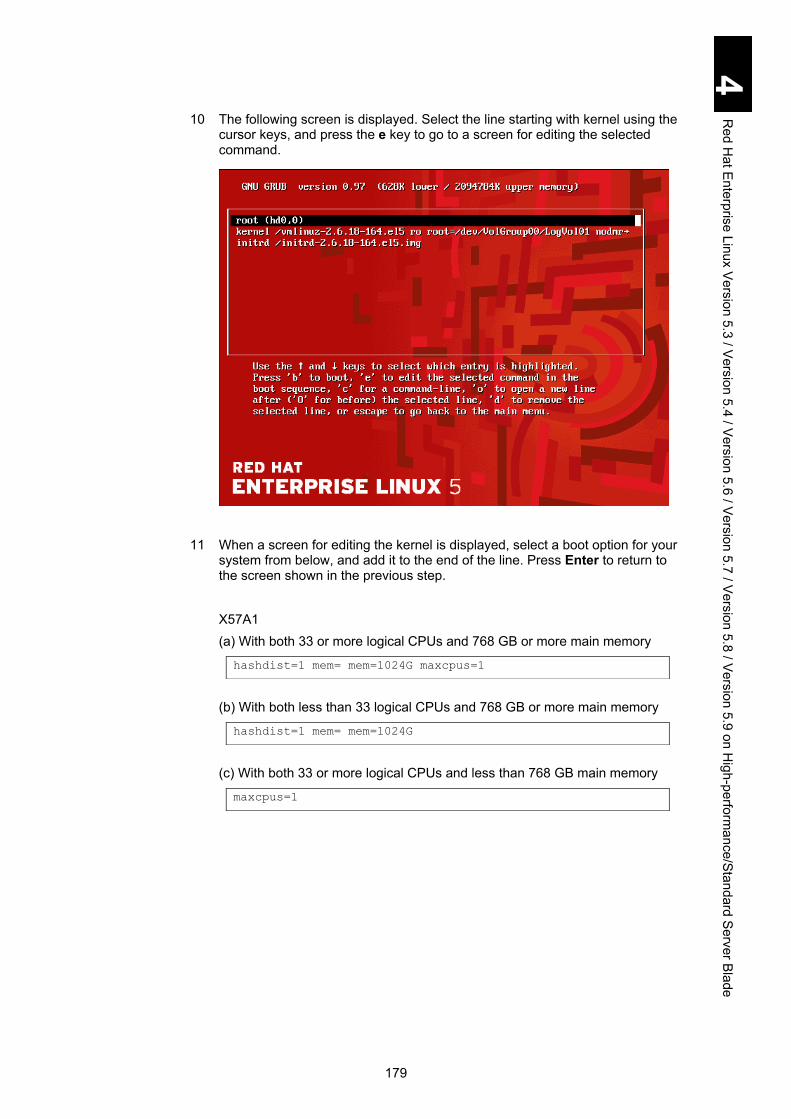
179
4 R
ed Hat E
nterprise Linux Version 5.3 / V
ersion 5.4 / Version 5.6 / V
ersion 5.7 / Version 5.8 / V
ersion 5.9 on High-perform
ance/Standard Server B
lade
10 The following screen is displayed. Select the line starting with kernel using the cursor keys, and press the e key to go to a screen for editing the selected command.
11 When a screen for editing the kernel is displayed, select a boot option for your system from below, and add it to the end of the line. Press Enter to return to the screen shown in the previous step. X57A1 (a) With both 33 or more logical CPUs and 768 GB or more main memory (b) With both less than 33 logical CPUs and 768 GB or more main memory (c) With both 33 or more logical CPUs and less than 768 GB main memory
hashdist=1 mem= mem=1024G maxcpus=1
hashdist=1 mem= mem=1024G
maxcpus=1

180
4 R
ed Hat E
nterprise Linux Version 5.3 / V
ersion 5.4 / Version 5.6 / V
ersion 5.7 / Version 5.8 / V
ersion 5.9 on High-perform
ance/Standard Server B
lade
12 When you return to the following screen, press the b key to boot the kernel. Follow the wizard to continue installation.
Then, the installation is completed. In the next boot, Linux is booted automatically.
With an X57A1 model (4-blade SMP configuration), perform step 13 to step 19. If not using the X57A1 model (4-blade SMP configuration), go to step 18.

181
4 R
ed Hat E
nterprise Linux Version 5.3 / V
ersion 5.4 / Version 5.6 / V
ersion 5.7 / Version 5.8 / V
ersion 5.9 on High-perform
ance/Standard Server B
lade
13 When the following GRUB booting screen is displayed, press any key to go to the next screen for selecting a kernel. A remaining time available for this operation is displayed in the screen. Three seconds remains in the following screen.
You might fail to reboot the OS without performing this step. In that case, reboot again, and then proceed. Perform this step for every OS reboot until completing step 52.
14 When the following screen for selecting a kernel is displayed, select a kernel to boot with cursor keys, and press the e key to go to the next screen for editing the commands.

182
4 R
ed Hat E
nterprise Linux Version 5.3 / V
ersion 5.4 / Version 5.6 / V
ersion 5.7 / Version 5.8 / V
ersion 5.9 on High-perform
ance/Standard Server B
lade
15 The following screen is displayed. Select the line starting with kernel using the cursor keys, and press the e key to go to a screen for editing the selected command.
16 When a screen for editing the kernel is displayed, select a boot option for your system from below, and add it at the end of the line. Press Enter to return to the screen shown in the previous step. X57A1 (a) With both 33 or more logical CPUs and 768 GB or more main memory (b) With both less than 33 logical CPUs and 768 GB or more main memory (c) With both 33 or more logical CPUs and less than 768 GB main memory
hashdist=1 mem= mem=1024G maxcpus=1
hashdist=1 mem= mem=1024G
maxcpus=1

183
4 R
ed Hat E
nterprise Linux Version 5.3 / V
ersion 5.4 / Version 5.6 / V
ersion 5.7 / Version 5.8 / V
ersion 5.9 on High-perform
ance/Standard Server B
lade
17 When you return to the following screen, press the b key to boot the kernel.
18 When the following screen is displayed, log in with the root privilege.
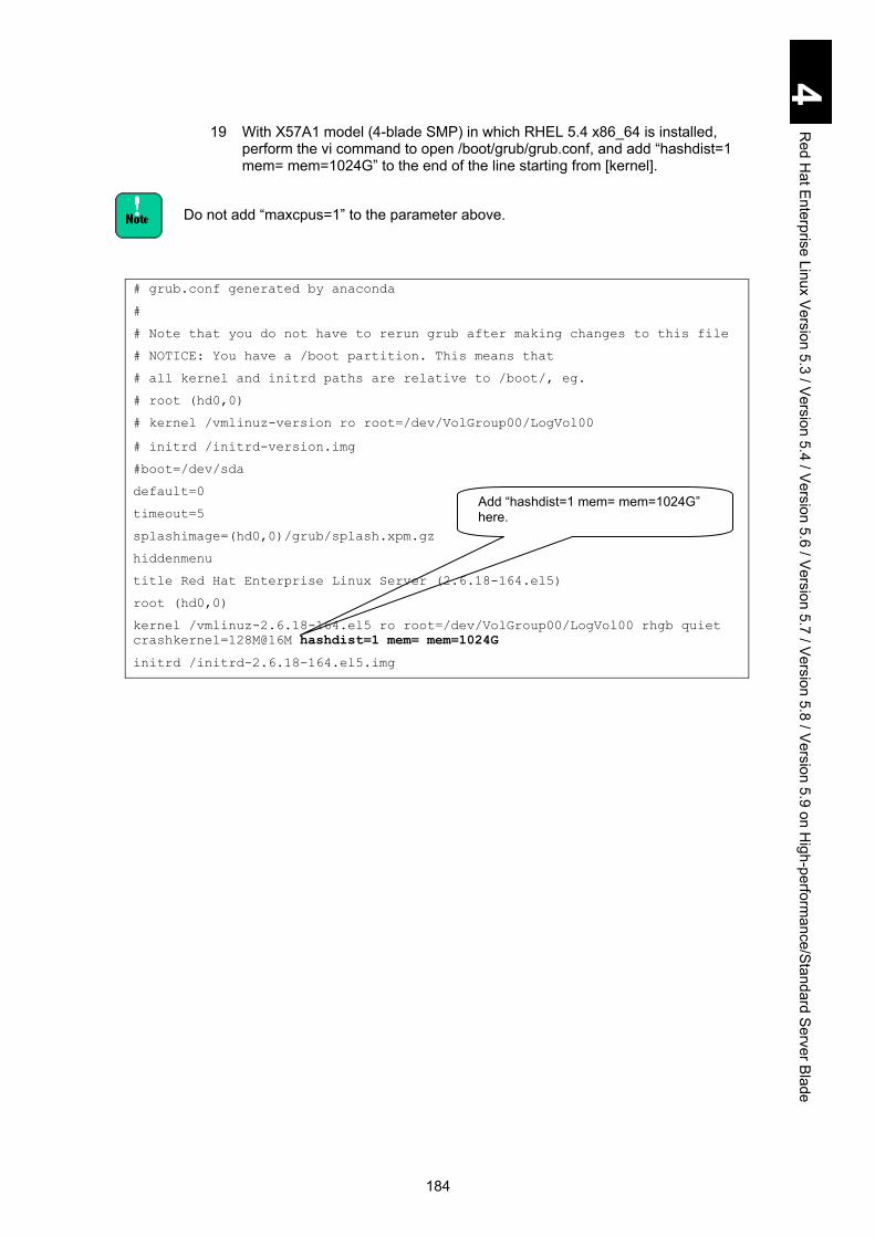
184
4 R
ed Hat E
nterprise Linux Version 5.3 / V
ersion 5.4 / Version 5.6 / V
ersion 5.7 / Version 5.8 / V
ersion 5.9 on High-perform
ance/Standard Server B
lade
19 With X57A1 model (4-blade SMP) in which RHEL 5.4 x86_64 is installed, perform the vi command to open /boot/grub/grub.conf, and add “hashdist=1 mem= mem=1024G” to the end of the line starting from [kernel].
Do not add “maxcpus=1” to the parameter above.
# grub.conf generated by anaconda
#
# Note that you do not have to rerun grub after making changes to this file
# NOTICE: You have a /boot partition. This means that
# all kernel and initrd paths are relative to /boot/, eg.
# root (hd0,0)
# kernel /vmlinuz-version ro root=/dev/VolGroup00/LogVol00
# initrd /initrd-version.img
#boot=/dev/sda
default=0
timeout=5
splashimage=(hd0,0)/grub/splash.xpm.gz
hiddenmenu
title Red Hat Enterprise Linux Server (2.6.18-164.el5)
root (hd0,0)
kernel /vmlinuz-2.6.18-164.el5 ro root=/dev/VolGroup00/LogVol00 rhgb quiet
crashkernel=128M@16M hashdist=1 mem= mem=1024G
initrd /initrd-2.6.18-164.el5.img
Add “hashdist=1 mem= mem=1024G” here.
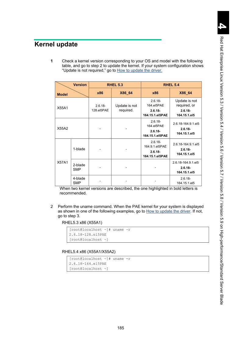
185
4 R
ed Hat E
nterprise Linux Version 5.3 / V
ersion 5.4 / Version 5.6 / V
ersion 5.7 / Version 5.8 / V
ersion 5.9 on High-perform
ance/Standard Server B
lade
Kernel update
1 Check a kernel version corresponding to your OS and model with the following table, and go to step 2 to update the kernel. If your system configuration shows “Update is not required,” go to How to update the driver.
Version Model
RHEL 5.3 RHEL 5.4
x86 X86_64 x86 X86_64
X55A1 2.6.18-128.el5PAE
Update is not required.
2.6.18-164.el5PAE
2.6.18-164.15.1.el5PAE
Update is not required, or
2.6.18-164.15.1.el5
X55A2 - -
2.6.18-164.el5PAE
2.6.18-164.15.1.el5PAE
2.6.18-164.9.1.el5 2.6.18-
164.15.1.el5
X57A1
1-blade - -
2.6.18-164.9.1.el5PAE
2.6.18-164.15.1.el5PAE
2.6.18-164.9.1.el5 2.6.18-
164.15.1.el5
2-blade SMP - - -
2.6.18-164.9.1.el5 2.6.18-
164.15.1.el5
4-blade SMP - - -
2.6.18-164.15.1.el5
When two kernel versions are described, the one highlighted in bold letters is recommended.
2 Perform the uname command. When the PAE kernel for your system is displayed
as shown in one of the following examples, go to How to update the driver. If not, go to step 3.
RHEL5.3 x86 (X55A1) [root@localhost ~]# uname -r
2.6.18-128.el5PAE
[root@localhost ~]
RHEL5.4 x86 (X55A1/X55A2)
[root@localhost ~]# uname -r
2.6.18-164.el5PAE
[root@localhost ~]

186
4 R
ed Hat E
nterprise Linux Version 5.3 / V
ersion 5.4 / Version 5.6 / V
ersion 5.7 / Version 5.8 / V
ersion 5.9 on High-perform
ance/Standard Server B
lade
3 Obtain the file to update to the kernel version confirmed in step 1, and copy it in /tmp.
No. Kernel version Where to obtain File name
1 2.6.18-128.el5PAE
Obtain files described in the column [File name] on the right from the following directory in Red hat Enterprise Linux 5.3 (x86) Install Disc 1. These examples show those files are mounted in /media. CD: /media/RHEL-5.3 i386 Disc 1/Server DVD: /media/RHEL-5.3 i386 DVD/Server
kernel-PAE-2.6.18-128.el5.i686.rpm kernel-PAE-devel-2.6.18-128.el5.i686.rpm
2 2.6.18-164.el5PAE
Obtain files described in the column [File name] on the right from the following directory in Red hat Enterprise Linux 5.4 (x86) Install Disc 1. These examples show those files are mounted in /media. CD: /media/RHEL-5.4i386 Disc 1/Server DVD: /media/RHEL-5.4 i386 DVD/Server
kernel-PAE-2.6.18-164.el5.i686.rpm kernel-PAE-devel-2.6.18-164.el5.i686.rpm
3 2.6.18-164.9.1.el5PAE
Obtain the file described in the column [File name] on the right from Red Hat, Inc.
kernel-PAE-2.6.18-164.9.1.el5.i686.rpm kernel-PAE-devel-2.6.18-164.9.1.el5.i686.rpm
4 2.6.18-164.15.1.el5PAE
Obtain the file described in the column [File name] on the right from Red Hat, Inc.
kernel-PAE-2.6.18-164.15.1.el5.i686.rpm kernel-PAE-devel-2.6.18-164.15.1.el5.i686.rpm
5 2.6.18-164.9.1.el5 Obtain files described in the column [File name] on the right from Red Hat, Inc.
kernel-2.6.18-164.9.1.el5. x86_64.rpm kernel-devel-2.6.18-164.9.1.el5.x86_64.rpm
6 2.6.18-164.15.1.el5 Obtain files described in the column [File name] on the right from Red Hat, Inc.
kernel-2.6.18-164.15.1.el5.x86_64.rpm kernel-devel-2.6.18-164.15.1.el5.x86_64.rpm
4 Go to the /tmp directory as described below, and open the file copied in /tmp in step 3. (Although the example below shows the file name in two lines, the example is displayed in one line on the screen.) 2.6.18-128.el5PAE/2.6.18-164.el5PAE/2.6.18-164.9.1.el5PAE/2.6.18-164.15.1.el5PAE [root@localhost ~]# cd /tmp
[root@localhost tmp]# rpm -ivh kernel-PAE-2.6.18-xxx.el5.i686.rpm
kernel-PAE-devel-2.6.18-xxx.el5.i686.rpm
2.6.18-164.9.1.el5/2.6.18-164.15.1.el5
[root@localhost ~]# cd /tmp
[root@localhost tmp]# rpm -ivh kernel-2.6.18-xxx.el5.x86_64.rpm
kernel-devel-2.6.18-xxx.el5.x86_64.rpm

187
4 R
ed Hat E
nterprise Linux Version 5.3 / V
ersion 5.4 / Version 5.6 / V
ersion 5.7 / Version 5.8 / V
ersion 5.9 on High-perform
ance/Standard Server B
lade
5 Perform the vi command to open “/boot/grub/grub.conf”, and change the default kernel to the Update kernel. With X57A1 model (4-blade SMP), add “hashdist=1 mem= mem=1024G” to the end of the line starting from [kernel]. If “hashdist=1 mem= mem=1024G” is already described in the line, you need not to add it.
<Kernel Version> is the version you have selected in step 3.
# grub.conf generated by anaconda
#
# Note that you do not have to rerun grub after making changes to
this file
# NOTICE: You have a /boot partition. This means that
# all kernel and initrd paths are relative to /boot/, eg.
# root (hd0,0)
# kernel /vmlinuz-version ro root=/dev/VolGroup00/LogVol00
# initrd /initrd-version.img
#boot=/dev/sda
default=0
timeout=5
splashimage=(hd0,0)/grub/splash.xpm.gz
hiddenmenu
title Red Hat Enterprise Linux Server (<Kernel Version>)
root (hd0,0)
kernel /vmlinuz-<Kernel Version> ro root=/dev/VolGroup00/LogVol00
rhgb quiet crashkernel=128M@16M hashdist=1 mem= mem=1024G
initrd /initrd-<Kernel Version>.img
title Red Hat Enterprise Linux Server (2.6.18-164.el5)
root (hd0,0)
kernel /vmlinuz-2.6.18-164.el5 ro root=/dev/VolGroup00/LogVol00 rhgb
quiet crashkernel=128M@16M hashdist=1 mem= mem=1024G
initrd /initrd-2.6.18-164.el5.img
6 Restart the OS, and log on with the root privilege.
7 Perform the kernel in the same way as shown below.
<Kernel Version> is the version you have selected in step 3.
[root@localhost ~]# uname -r
<Kernel Version>
w[root@localhost ~]#
Go to How to update the igb driver (Intel® gigabit Ethernet network
Type the title line number of lowest ”title Red Hat Enterprise Linux Server (<Kernel Version>)” . In this example, it is zero (0).
With X57A1 model (4-blade SMP), add “hashdist=1 mem= mem=1024G” here. If this is already here, nothing is required to be added.

188
4 R
ed Hat E
nterprise Linux Version 5.3 / V
ersion 5.4 / Version 5.6 / V
ersion 5.7 / Version 5.8 / V
ersion 5.9 on High-perform
ance/Standard Server B
lade
How to update the driver
How to update the igb driver (Intel® gigabit Ethernet network driver) Applicable OS
Version Model
RHEL 5.3 RHEL 5.4
x86 x86_64 x86 x86_64
X55A1 2.6.18-128.el5PAE 2.6.18-128.el5
2.6.18-164.el5PAE 2.6.18-
164.15.1.el5PAE
2.6.18-164.el5 2.6.18-
164.15.1.el5
X55A2 - - 2.6.18-164.el5PAE
2.6.18-164.15.1.el5PAE
2.6.18-164.9.1.el5 2.6.18-
164.15.1.el5
X57A1
1-blade - -
2.6.18-164.9.1.el5PAE
2.6.18-164.15.1.el5PAE
2.6.18-164.9.1.el5 2.6.18-
164.15.1.el5
2-blade SMP - - -
2.6.18-164.9.1.el5 2.6.18-
164.15.1.el5
4-blade SMP - - - 2.6.18-
164.15.1.el5
File Configuration of the DriverKit DVD 12-10 or later versions. [X55A1]
|+---RHEL5
|+---Drivers
|+---LAN
|+---INTEL_01
|+---x64
| |+---igb-1.3.19.3-h7-RHEL5.3-x86_64.tar.gz
| |+---igb-1.3.19.3-h18-RHEL5.4-x86_64.tar.gz
| |+---igb-1.3.19.3-h18-RHEL5.4SA-x86_64.tar.gz
|+---x86
| |+---igb-1.3.19.3-h7-RHEL5.3-x86.tar.gz
| |+---igb-1.3.19.3-h18-RHEL5.4-x86.tar.gz
| |+---igb-1.3.19.3-h18-RHEL5.4SA-x86.tar.gz
[X55A2]
|+---RHEL5
|+---Drivers
|+---LAN
|+---INTEL_01
|+---x64
| |+---igb-1.3.19.3-h18-RHEL5.4.3-x86_64.tar.gz
| |+---igb-1.3.19.3-h18-RHEL5.4SA-x86_64.tar.gz
|+---x86
| |+---igb-1.3.19.3-h18-RHEL5.4-x86.tar.gz

189
4 R
ed Hat E
nterprise Linux Version 5.3 / V
ersion 5.4 / Version 5.6 / V
ersion 5.7 / Version 5.8 / V
ersion 5.9 on High-perform
ance/Standard Server B
lade
| |+---igb-1.3.19.3-h18-RHEL5.4SA-x86.tar.gz
[X57A1]
|+---RHEL5
|+---Drivers
|+---LAN
|+---INTEL_01
|+---x64
| |+---igb-1.3.19.3-h18-RHEL5.4.3-x86_64.tar.gz
| |+---igb-1.3.19.3-h18-RHEL5.4SA-x86_64.tar.gz
|+---x86
| |+---igb-1.3.19.3-h18-RHEL5.4.3-x86.tar.gz
| |+---igb-1.3.19.3-h18-RHEL5.4SA-x86.tar.gz
In the actual directory structure, each model has directories and files required only for the model.
Updating the igb driver version to 1.3.19.3 Update the igb driver to version 1.3.19.3 using the following the procedure. 1 Check the igb driver.
Execute the following command to find the igb driver. RHEL 5.3
RHEL 5.4/RHEL5.4.3/RHEL5.4SA
If the igb driver version is 1.3.19.3, the following work is unnecessary. If the igb driver version is not 1.3.19.3 or is not displayed, perform the following steps to update the driver.
dmesg | grep 1.3.19.3-h7
Intel(R) Gigabit Ethernet Network Driver – version 1.3.19.3-h7
dmesg | grep 1.3.19.3-h18
Intel(R) Gigabit Ethernet Network Driver – version 1.3.19.3-h18

190
4 R
ed Hat E
nterprise Linux Version 5.3 / V
ersion 5.4 / Version 5.6 / V
ersion 5.7 / Version 5.8 / V
ersion 5.9 on High-perform
ance/Standard Server B
lade
2 The igb driver installation 2-1 Copy the igb archive file onto /tmp directory.
The archive file names are as follows:
Version Model
RHEL 5.3 RHEL 5.4
x86 x86_64 x86 x86_64
X55A1 igb-1.3.19.3-h7-
RHEL5.3-x86.tar.gz
igb-1.3.19.3-h7-RHEL5.3-
x86_64.tar.gz
igb-1.3.19.3-h18-RHEL5.4-x86.tar.gz igb-1.3.19.3-h18-RHEL5.4SA-x86.tar.gz
igb-1.3.19.3-h18-RHEL5.4-x86_64.tar.gz igb-1.3.19.3-h18-RHEL5.4SA-x86_64.tar.gz
X55A2 - -
igb-1.3.19.3-h18-RHEL5.4-x86.tar.gz igb-1.3.19.3-h18-RHEL5.4SA-x86.tar.gz
igb-1.3.19.3-h18-RHEL5.4.3-x86_64.tar.gz igb-1.3.19.3-h18-RHEL5.4SA-x86_64.tar.gz
X57A1
1-blade - -
igb-1.3.19.3-h18-RHEL5.4.3-x86.tar.gz igb-1.3.19.3-h18-RHEL5.4SA-x86.tar.gz
igb-1.3.19.3-h18-RHEL5.4.3-x86_64.tar.gz igb-1.3.19.3-h18-RHEL5.4SA-x86_64.tar.gz
2-blade SMP - - -
igb-1.3.19.3-h18-RHEL5.4.3-x86_64.tar.gz igb-1.3.19.3-h18-RHEL5.4SA-x86_64.tar.gz
4-blade SMP - - -
igb-1.3.19.3-h18-RHEL5.4SA-x86_64.tar.gz
2-2 Back up the current driver.
Note: If the igb.ko file does not exist in the updates directory, go to step (2).
(1) The igb.ko file exists.
cd /lib/modules/<Kernel version>/updates
mv igb.ko igb_ko.old
cd /lib/modules/<Kernel version>/kernel/drivers/net/igb
mv igb.ko igb_bandle_ko.old

191
4 R
ed Hat E
nterprise Linux Version 5.3 / V
ersion 5.4 / Version 5.6 / V
ersion 5.7 / Version 5.8 / V
ersion 5.9 on High-perform
ance/Standard Server B
lade
(2) The igb.ko file does not exist.
cd /lib/modules/<Kernel version>/kernel/drivers/net/igb
mv igb.ko igb_ko.old
<Kernel version> is as follows:
Version Model
RHEL 5.3 RHEL 5.4
x86 x86_64 x86 x86_64
X55A1 2.6.18-128.el5PAE 2.6.18-128.el5
2.6.18-164.el5PAE 2.6.18-
164.15.1.el5PAE
2.6.18-164.el5 2.6.18-
164.15.1.el5
X55A2 - - 2.6.18-164.el5PAE
2.6.18-164.15.1.el5PAE
2.6.18-164.9.1.el5
2.6.18-164.15.1.el5
X57A1
1-blade - - 2.6.18-164.9.1.el5
2.6.18-164.15.1.el5
2.6.18-164.9.1.el5
2.6.18-164.15.1.el5
2-blade SMP - - -
2.6.18-164.9.1.el5
2.6.18-164.15.1.el5
4-blade SMP - - - 2.6.18-
164.15.1.el5
2-3 Extract the igb driver < igb archive file name >: See Step 2-1.
tar -C / -zxvpf /tmp/< igb archive file name >
2-4 Execute the following command for RHEL5.3/5.4.
depmod -a
(*)The command can be executed at any directory.
2-5 Reboot the system.
reboot
3 Confirm the installed igb driver version.
Execute the following command and confirm that the driver version is updated as 1.3.19.3.

192
4 R
ed Hat E
nterprise Linux Version 5.3 / V
ersion 5.4 / Version 5.6 / V
ersion 5.7 / Version 5.8 / V
ersion 5.9 on High-perform
ance/Standard Server B
lade
RHEL 5.3
RHEL 5.4/RHEL5.4.3/RHEL5.4SA
4 Open “/etc/modprobe.conf” using the vi command. Add “#“ to the head of the line that includes ”e1000e” and save the file.
dmesg | grep 1.3.19.3-h7
Intel(R) Gigabit Ethernet Network Driver – version 1.3.19.3-h7
alias eth0 igb
alias eth1 igb
alias eth2 igb
alias eth3 igb
alias eth4 igb
alias eth5 igb
alias eth6 igb
alias eth7 igb
alias eth8 igb
alias eth9 igb
#alias eth10 e1000e
alias scsi_hostadapter hfcldd
alias scsi_hostadapter1 ata_piix
alias scsi_hostadapter2 usb-storage
Add “#” to the head of the line.
dmesg | grep 1.3.19.3-h18
Intel(R) Gigabit Ethernet Network Driver – version 1.3.19.3-h18

193
4 R
ed Hat E
nterprise Linux Version 5.3 / V
ersion 5.4 / Version 5.6 / V
ersion 5.7 / Version 5.8 / V
ersion 5.9 on High-perform
ance/Standard Server B
lade
5 Open “ /etc/modprobe.d/blacklist” using the vi command. Add ”blacklist e1000e” at the bottom, and save the file.
6 Reboot the system.
#
# Listing a module here prevents the hotplug scripts from
loading it.
# Usually that'd be so that some other driver will bind it
instead,
# no matter which driver happens to get probed first.
Sometimes user
# mode tools can also control driver binding.
#
# Syntax: driver name alone (without any spaces) on a line.
Other
# lines are ignored.
#
# watchdog drivers
blacklist i8xx_tco
# framebuffer drivers
blacklist aty128fb
blacklist atyfb
blacklist radeonfb
blacklist i810fb
blacklist cirrusfb
blacklist intelfb
blacklist kyrofb
blacklist i2c-matroxfb
blacklist hgafb
blacklist nvidiafb
blacklist rivafb
blacklist savagefb
blacklist sstfb
blacklist neofb
blacklist tridentfb
blacklist tdfxfb
blacklist virgefb
blacklist vga16fb
# ISDN - see bugs 154799, 159068
blacklist hisax
blacklist hisax_fcpcipnp
blacklist e1000e
Add “blacklist e1000e” at the bottom.

194
4 R
ed Hat E
nterprise Linux Version 5.3 / V
ersion 5.4 / Version 5.6 / V
ersion 5.7 / Version 5.8 / V
ersion 5.9 on High-perform
ance/Standard Server B
lade
7 Execute the “lsmod | grep e1000e” command, and confirm that no message is output.
Make sure to configure HWADDR of “/etc/sysconfig/network-scripts/ifcfg-eth*”.
[root@localhost ~]# lsmod | grep e1000e [root@localhost ~]#
! Note

195
4 R
ed Hat E
nterprise Linux Version 5.3 / V
ersion 5.4 / Version 5.6 / V
ersion 5.7 / Version 5.8 / V
ersion 5.9 on High-perform
ance/Standard Server B
lade
How to update the ixgbe driver (Intel® 10 gigabit PCI Express network driver) Applicable OS
Version
Model
RHEL 5.4
x86 x86_64
X55A1 - -
X55A2 2.6.18-164.el5PAE 2.6.18-164.15.1.el5PAE
2.6.18-164.9.1.el5 2.6.18-164.15.1.el5
X57A1
1-blade 2.6.18-164.el5PAE 2.6.18-164.15.1.el5PAE
2.6.18-164.9.1.el5 2.6.18-164.15.1.el5
2-blade SMP - 2.6.18-164.9.1.el5
2.6.18-164.15.1.el5
4-blade SMP - 2.6.18-164.15.1.el5
File Configuration of the DriverKit DVD 12-10 or later versions.
[X55A2]
|+---RHEL5
|+---Drivers
|+---LAN
|+---INTELXG_01
|+---x64
| |+---ixgbe-2.0.75.7-h2-NAPI-RHEL5.4-x86_64.tar.gz
| |+---ixgbe-2.0.75.7-h2-NAPI-RHEL5.4SA-x86_64.tar.gz
|+---x86
| |+---ixgbe-2.0.75.7-h2-NAPI-RHEL5.4.3-x86.tar.gz
| |+---ixgbe-2.0.75.7-h2-NAPI-RHEL5.4SA-x86.tar.gz
[X57A1]
|+---RHEL5
|+---Drivers
|+---LAN
|+---INTEL_01
|+---x64
| |+---ixgbe-2.0.75.7-h2-NAPI-RHEL5.4.3-x86_64.tar.gz
| |+---ixgbe-2.0.75.7-h2-NAPI-RHEL5.4SA-x86_64.tar.gz
|+---x86
| |+---ixgbe-2.0.75.7-h2-NAPI-RHEL5.4.3-x86.tar.gz
| |+---ixgbe-2.0.75.7-h2-NAPI-RHEL5.4SA-x86.tar.gz

196
4 R
ed Hat E
nterprise Linux Version 5.3 / V
ersion 5.4 / Version 5.6 / V
ersion 5.7 / Version 5.8 / V
ersion 5.9 on High-perform
ance/Standard Server B
lade
Update the ixgbe driver to 2.0.75.7 according to the following procedure
1 Check the ixgbe driver. Execute the following command to find the ixgbe driver. RHEL 5.4/RHEL5.4.3/RHEL5.4SA (X55A2/X57A1 models)
If the ixgbe driver’s version is 2.0.75.7 then the following work is unnecessary. If the ixgbe driver’s version is not 2.0.75.7, perform the following steps to update the driver.
2 The ixgbe driver installation.
2-1 Copy the ixgbe archive file into the /tmp directory. The archive file names are as follows:
Version
Model
RHEL 5.4
x86 x86_64
X55A1 - -
X55A2
ixgbe-2.0.75.7-h2-RHEL5.4-x86.tar.gz ixgbe-2.0.75.7-h2-RHEL5.4SA-x86.tar.gz
ixgbe-2.0.75.7-h2-RHEL5.4.3-el5-x86_64.tar.gz ixgbe-2.0.75.7-h2-RHEL5.4SA-el5-x86_64.tar.gz
X57A1
1-blade
ixgbe-2.0.75.7-h2-RHEL5.4-x86.tar.gz ixgbe-2.0.75.7-h2-RHEL5.4SA-x86.tar.gz
ixgbe-2.0.75.7-h2-RHEL5.4.3-el5-x86_64.tar.gz ixgbe-2.0.75.7-h2-RHEL5.4SA-el5-x86_64.tar.gz
2-blade SMP -
ixgbe-2.0.75.7-h2-RHEL5.4.3-el5-x86_64.tar.gz ixgbe-2.0.75.7-h2-RHEL5.4SA-el5-x86_64.tar.gz
4-blade SMP - ixgbe-2.0.75.7-h2-RHEL5.4SA-
el5-x86_64.tar.gz
2-2 Backup the current driver.
Note: If the ixgbe.ko file did not exist in updates directory, perform only step (2).
(1) The ixgbe.ko file exists. cd /lib/modules/<Kernel version>/updates
mv ixgbe.ko ixgbe_ko.old
cd /lib/modules/<Kernel version>/kernel/drivers/net/ixgbe
mv ixgbe.ko ixgbe_bandle_ko.old
dmesg | grep 2.0.75.7-h2
ixgbe: Intel(R) 10 Gigabit PCI Express Network Driver
- version 2.0.75.7-h2-NAPI
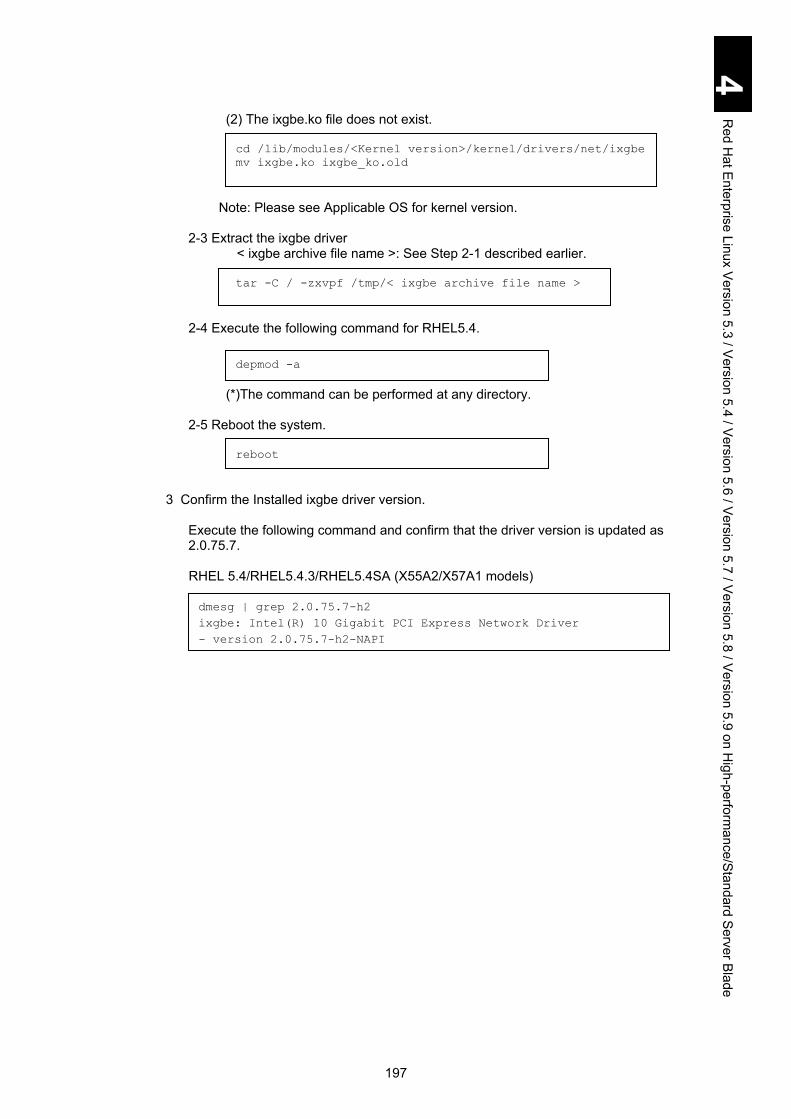
197
4 R
ed Hat E
nterprise Linux Version 5.3 / V
ersion 5.4 / Version 5.6 / V
ersion 5.7 / Version 5.8 / V
ersion 5.9 on High-perform
ance/Standard Server B
lade
(2) The ixgbe.ko file does not exist.
cd /lib/modules/<Kernel version>/kernel/drivers/net/ixgbe
mv ixgbe.ko ixgbe_ko.old
Note: Please see Applicable OS for kernel version.
2-3 Extract the ixgbe driver < ixgbe archive file name >: See Step 2-1 described earlier.
tar -C / -zxvpf /tmp/< ixgbe archive file name >
2-4 Execute the following command for RHEL5.4.
depmod -a
(*)The command can be performed at any directory.
2-5 Reboot the system.
reboot
3 Confirm the Installed ixgbe driver version.
Execute the following command and confirm that the driver version is updated as 2.0.75.7.
RHEL 5.4/RHEL5.4.3/RHEL5.4SA (X55A2/X57A1 models)
dmesg | grep 2.0.75.7-h2
ixgbe: Intel(R) 10 Gigabit PCI Express Network Driver
- version 2.0.75.7-h2-NAPI

198
4 R
ed Hat E
nterprise Linux Version 5.3 / V
ersion 5.4 / Version 5.6 / V
ersion 5.7 / Version 5.8 / V
ersion 5.9 on High-perform
ance/Standard Server B
lade
How to install Red Hat Enterprise Linux 5.6/5.7/5.8/5.9 This section describes the procedure to install Red Hat Enterprise Linux 5.6 / 5.7 / 5.8 / 5.9 with the driver CD.
Driver CD 0560-xx contains drivers for RHEL 5.6, which is available for the RHEL 5.6 setup driver CD.
Driver & Utility CD 0570-xx contains drivers for RHEL 5.7 and utilities for RHEL 5.6/5.7, which is available for RHEL 5.7 setup driver CD.
Driver & Utility CD 0580-xx contains drivers and utilities for RHEL 5.8, which is available for the RHEL 5.8 setup driver CD.
Driver & Utility CD 0590-xx contains drivers and utilities for RHEL 5.9, which is available for the RHEL 5.9 setup driver CD.
The setup procedure described in this manual is an example. See the following Red Hat website for details.
http://docs.redhat.com/docs/en-US/Red_Hat_Enterprise_Linux/index.html
Update the kernel after installing RHEL 5.6/5.7/5.8/5.9. See Settings after installation for details.
Make sure to check that System Date for the server blade EFI Setup menu is set to the current day, month, and year before installing the OS. If it is set to a date older than the current date, some package may fail to be installed. See Chapter 5: Server Blade Setup in Hitachi Compute Blade 2000 User’s Guide.

199
4 R
ed Hat E
nterprise Linux Version 5.3 / V
ersion 5.4 / Version 5.6 / V
ersion 5.7 / Version 5.8 / V
ersion 5.9 on High-perform
ance/Standard Server B
lade
Red Hat Enterprise Linux 5.6 / 5.7 / 5.8 / 5.9 setup with the driver CD
1 Perform Remote CD/DVD from the remote console, or connect a USB CD-ROM drive or USB DVD-ROM drive directly to the server blade.
See Chapter 3: Connecting the System Equipment and Powering on, in the Hitachi Compute Blade 2000 User’s
Guide for details about the remote console. Screens for RHEL 5.6 setup are shown in the procedure below. 2 Insert the first CD for RHEL 5.6 / 5.7 / 5.8 installation or the installation DVD into
the CD/DVD drive, and power on the server blade. 3 On the EFI starting screen, press the F2 key or Delete to enter the EFI Setup
menu. Click the Save & Exit tab, find Boot Override to select the CD/DVD drive, and press Enter.

200
4 R
ed Hat E
nterprise Linux Version 5.3 / V
ersion 5.4 / Version 5.6 / V
ersion 5.7 / Version 5.8 / V
ersion 5.9 on High-perform
ance/Standard Server B
lade
4 Type the following depending on the model you use and the system configuration, and press Enter.
Installing in a standard server blade: X55A1/X55A2
Installing in a high-performance server blade: X57A1/X57A2/X55R3/X55S3 The boot option depends on the hardware resources you use. Type the appropriate option referring to the following.
(1) Installing Red hat Enterprise Linux 5.6 / 5.7 / 5.8 / 5.9 (X86)
(2) Installing Red hat Enterprise Linux 5.6 / 5.7 / 5.8 / 5.9 (X86_ 64) The boot option depends on the memory capacity. Check the system memory capacity, specify either (a) or (b) shown below. (a) system memory capacity: less than 768 GB (b) System memory capacity: 768 GB or larger
boot : linux xdriver=vesa dd avoid_smi
boot : linux xdriver=vesa dd avoid_smi
boot : linux xdriver=vesa dd avoid_smi
boot : linux xdriver=vesa hashdist=1 mem= mem=1024G dd avoid_smi

201
4 R
ed Hat E
nterprise Linux Version 5.3 / V
ersion 5.4 / Version 5.6 / V
ersion 5.7 / Version 5.8 / V
ersion 5.9 on High-perform
ance/Standard Server B
lade
5 Select Yes when “Do you have a driver disk?” is displayed.
6 Remove the first CD for installation or the installation DVD from the drive, insert the driver CD into the drive, and click OK.

202
4 R
ed Hat E
nterprise Linux Version 5.3 / V
ersion 5.4 / Version 5.6 / V
ersion 5.7 / Version 5.8 / V
ersion 5.9 on High-perform
ance/Standard Server B
lade
7 When the following screen appears, remove the driver CD from the drive, insert the first CD for installation or the installation DVD into the drive, and select No.
Follow the wizard to continue the installation.
Do not configure a network for the device using e1000e driver, Intel Corporation 82567LF-2, which must be disabled after the installation.

203
4 R
ed Hat E
nterprise Linux Version 5.3 / V
ersion 5.4 / Version 5.6 / V
ersion 5.7 / Version 5.8 / V
ersion 5.9 on High-perform
ance/Standard Server B
lade
When Gateway and DNS fields are blank, the following error message is displayed. Check that there is no problem if Gateway and DNS fields are blank, and click Continue.
Do not select Virtualization when Hitachi Fibre channel adapter GVX-CC2*4G1X1/GV-CC2*4G1X1-Y, GVX-CC2*8G1X/GV-CC2*8G1X*-Y, GVX-CC2*8G2X1/GV-CC2*8G2X*-Y is installed.
Select a time zone, uncheck System clock uses UTC, and click Next.
When using a high-performance server blade, X57A1/X57A2, perform step 8 to step 12. When using a standard server blade, X55A1/X55A2/X55R3/X55S3, follow the wizard.

204
4 R
ed Hat E
nterprise Linux Version 5.3 / V
ersion 5.4 / Version 5.6 / V
ersion 5.7 / Version 5.8 / V
ersion 5.9 on High-perform
ance/Standard Server B
lade
8 When the GRUB booting screen appears, press any key within three seconds.
9 When the following screen appears, press the e key.

205
4 R
ed Hat E
nterprise Linux Version 5.3 / V
ersion 5.4 / Version 5.6 / V
ersion 5.7 / Version 5.8 / V
ersion 5.9 on High-perform
ance/Standard Server B
lade
10 When the following screen appears, select the line that includes kernel, and press the e key.
11 Type the following depending on the model you use and the system configuration, and press Enter. The boot command depends on the hardware resources you use. Type the appropriate option referring to the following.

206
4 R
ed Hat E
nterprise Linux Version 5.3 / V
ersion 5.4 / Version 5.6 / V
ersion 5.7 / Version 5.8 / V
ersion 5.9 on High-perform
ance/Standard Server B
lade
(1) Installing Red hat Enterprise Linux 5.6 / 5.7 / 5.8 /5.9 (X86)
avoid_smi
(2) Installing Red hat Enterprise Linux 5.6 / 5.7 / 5.8 /5.9 (X86_64)
The boot option depends on the memory capacity. Check the system memory capacity, and specify either (a) or (b), shown below. (a) system memory capacity: less than 768 GB avoid_smi
(b) system memory capacity: 768 GB or larger hashdist=1 mem= mem=1024G avoid_smi
12 When you return to the following screen, press the b key.
Follow the wizard to continue the installation.
After rebooting the system, you need to edit the boot menu depending on the model you use and the system configuration. When using a high-performance server blade: X57A1/X57A2
Perform step 24 through step 28 and reboot the system. Read through those steps beforehand. Perform Settings after installation when the reboot is completed.
When using a standard server blade: X55A2/X55A2/X55R3/X55S3 The installation is completed. Perform Settings after installation.

207
4 R
ed Hat E
nterprise Linux Version 5.3 / V
ersion 5.4 / Version 5.6 / V
ersion 5.7 / Version 5.8 / V
ersion 5.9 on High-perform
ance/Standard Server B
lade
Settings after installation This subsection describes the settings after Red Hat Enterprise Linux 5.6 / 5.7 / 5.8 / 5.9 have been installed with the driver CD.
For Red Hat Enterprise Linux 5.8 For Red Hat Enterprise Linux 5.8, install tg3 driver using the following steps before proceeding to For Red Hat Enterprise Linux 5.6 / 5.7 / 5.8 / 5.9. 1 Copy tg3 archive file to /tmp directory.
The following archive files are contained in the CD. EM64T:\hitachi_utilities/tg3-RHEL5.8/EM64T/tg3-3.124c-RHEL5.8-el5-x86_64.tar.gz x86:\hitachi_utilities/tg3-RHEL5.8/x86/tg3-3.124c-RHEL5.8-el5-x86.tar.gz x86PAE:\hitachi_utilities/tg3-RHEL5.8/x86PAE/tg3-3.124c-RHEL5.8-el5PAE-x86.tar.gz
2 Back up the current driver. # cd /lib/modules/<kernel version>/kernel/drivers/net
# mv tg3.ko tg3_ko.old
3 Decompress tg3 driver. # tar -C / -zxvpf /tmp/<tg3 archive file>
4 Perform the following command. # depmod -a
5 Reboot the OS. # reboot
6 Perform the following command to check that the driver version is updated to 3.124c.
# modinfo -F version tg3
Example: 3.124c

208
4 R
ed Hat E
nterprise Linux Version 5.3 / V
ersion 5.4 / Version 5.6 / V
ersion 5.7 / Version 5.8 / V
ersion 5.9 on High-perform
ance/Standard Server B
lade
For Red Hat Enterprise Linux 5.6 / 5.7 / 5.8 / 5.9 1 Disabling TCP Checksum Offload
TCP Checksum Offload is a function that checks TCP packets in the LAN controller. If TCP Checksum Offload is enabled, packet data may be destroyed when the LAN controller fails. Targeted drivers - igb driver - tg3 driver Values: off or on (off: disabled; on: enabled) Perform the ethtool command to disable TCP Checksum Offload for both receive and transmit. Add the same number of ethtool commands as that of LAN controllers to /sbin/ifup-pre-local as shown below, and reboot the OS. The new settings are automatically configured during the OS boot. Example: To disable two LAN controllers Add the following line to /sbin//ifup-pre-local on condition that the OS recognizes them as network devices eht0 and eth1.
If there is no /sbin/ifup-pre-local file, create a new file with the file privilege 755 and add the setting above. When the file exists, add the setting above to the file. Then reboot the OS or the network device with the new setting, which makes the new setting take effect. When enabling TCP Checksum Offload, replace each value to tx/rx parameter “off” with “on”.
if [ "${1}" == "ifcfg-eth0" ]; then
/sbin/ethtool -K eth0 rx off
/sbin/ethtool -K eth0 tx off
fi
if [ "${1}" == "ifcfg-eth1" ]; then
/sbin/ethtool -K eth1 rx off
/sbin/ethtool -K eth1 tx off
fi

209
4 R
ed Hat E
nterprise Linux Version 5.3 / V
ersion 5.4 / Version 5.6 / V
ersion 5.7 / Version 5.8 / V
ersion 5.9 on High-perform
ance/Standard Server B
lade
2 Customizing /etc/sysctl.conf Enable the magic SysRq key to collect information when a problem occurs. Edit or add the following line. Add a setting to start kernel panic when NMI occurs, with which you can quickly detect a failure in hardware and drivers. Edit or add the following line.
3 Customizing /boot/grub/grub.conrf Editing depends on the hardware resources you use. Add an appropriate kernel option while referring to the following.
(1) Installing Red hat Enterprise Linux 5.6 / 5.7 / 5.8 / 5.9 (X86)
(2) Installing Red hat Enterprise Linux 5.6 / 5.7 / 5.8 / 5.9 (X86_ 64) The boot option depends on the memory capacity. Check the system memory capacity, specify either (a) or (b) shown below. (a) system memory capacity: less than 768 GB (b) System memory capacity: 768 GB or larger
Adding the kernel option above configures the following settings. - Disables nmi_watchdog to use a parameter that stops the system when
hardware fails. - A setting for avoiding an error in detecting CPU clock frequency when SMI
occurs at the OS boot - A setting for dealing with the problem in which the OS cannot be booted
when a large memory is installed.
kernel.sysrq = 1
kernel.unknown_nmi_panic = 0
kernel.panic_on_unrecovered_nmi = 1
nmi_watchdog=0 avoid_smi
nmi_watchdog=0 mem= mem=1024G hashdist=1 avoid_smi
avoid_smi

210
4 R
ed Hat E
nterprise Linux Version 5.3 / V
ersion 5.4 / Version 5.6 / V
ersion 5.7 / Version 5.8 / V
ersion 5.9 on High-perform
ance/Standard Server B
lade
4 Customizing /etc/modprobe.conf This setting blocks loading drivers to prevent unnecessary devices from being detected. Add # to the head of a line that includes the following e1000e, which comments out the line.
5 Customizing /etc/modprobe.d/blacklist.conf This setting blocks loading drivers to prevent unnecessary devices from being detected. Add the following at the last line.
6 Reflecting the new settings
Reboot the OS to reflect the settings configured from step 1 through step 5. For RHEL 5.6 / 5.7, go on to step 7. For RHEL 5.8, the setting after installation is complete in this step 6.
7 Copying the driver Make sure to copy the driver before updating a kernel in step 8. Follow the procedure described below to copy the driver from the driver CD. (1) Perform the following command to check the architecture.
# uname –m
Performing the command above will display the following results depending on the architecture: i686: i686 x86_64: x86_64
Some of the steps described below depend on the architecture. (2) Insert the driver CD into the CD/DVD-ROM drive. (3) Perform the following command to mount the driver CD.
# mount /dev/cdrom /media/
alias eth0 igb
alias eth1 igb
alias eth2 igb
alias eth3 igb
alias eth4 igb
alias eth5 igb
#alias ethx e1000e
alias scsi_hostadapter hradrv
alias scsi_hostadapter1 ata_piix
alias scsi_hostadapter2 usb-storage
blacklist e1000e
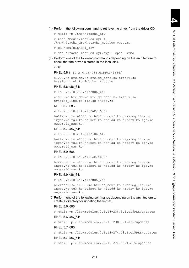
211
4 R
ed Hat E
nterprise Linux Version 5.3 / V
ersion 5.4 / Version 5.6 / V
ersion 5.7 / Version 5.8 / V
ersion 5.9 on High-perform
ance/Standard Server B
lade
(4) Perform the following command to retrieve the driver from the driver CD. # mkdir -p /tmp/hitachi_drv
# zcat /media/modules.cgz >
/tmp/hitachi_drv/hitachi_modules.cgz.tmp
# cd /tmp/hitachi_drv
# cat hitachi_modules.cgz.tmp | cpio -iumd
(5) Perform one of the following commands depending on the architecture to check that the driver is stored in the local disk. i686:
RHEL 5.6 # ls 2.6.18-238.el5PAE/i686/ e1000.ko hfcldd.ko hfcldd_conf.ko hradrv.ko
hraslog_link.ko igb.ko ixgbe.ko
RHEL 5.6 x86_64: # ls 2.6.18-238.el5/x86_64/
e1000.ko hfcldd.ko hfcldd_conf.ko hradrv.ko
hraslog_link.ko igb.ko ixgbe.ko
RHEL 5.7 i686: # ls 2.6.18-274.el5PAE/i686/
be2iscsi.ko e1000.ko hfcldd_conf.ko hraslog_link.ko
ixgbe.ko tg3.ko be2net.ko hfcldd.ko hradrv.ko igb.ko
megaraid_sas.ko
RHEL 5.7 x86_64: # ls 2.6.18-274.el5/x86_64/
be2iscsi.ko e1000.ko hfcldd_conf.ko hraslog_link.ko
ixgbe.ko tg3.ko be2net.ko hfcldd.ko hradrv.ko igb.ko
megaraid_sas.ko
RHEL 5.9 i686: # ls 2.6.18-348.el5PAE/i686/
be2iscsi.ko e1000.ko hfcldd_conf.ko hraslog_link.ko
ixgbe.ko tg3.ko be2net.ko hfcldd.ko hradrv.ko igb.ko
megaraid_sas.ko
RHEL 5.9 x86_64: # ls 2.6.18-348.el5/x86_64/
be2iscsi.ko e1000.ko hfcldd_conf.ko hraslog_link.ko
ixgbe.ko tg3.ko be2net.ko hfcldd.ko hradrv.ko igb.ko
megaraid_sas.ko
(6) Perform one of the following commands depending on the architecture to create a directory for updating the kernel. RHEL 5.6 i686: # mkdir –p /lib/modules/2.6.18-238.9.1.el5PAE/updates
RHEL 5.6 x86_64: # mkdir –p /lib/modules/2.6.18-238.9.1.el5/updates
RHEL 5.7 i686: # mkdir –p /lib/modules/2.6.18-274.18.1.el5PAE/updates
RHEL 5.7 x86_64: # mkdir –p /lib/modules/2.6.18-274.18.1.el5/updates

212
4 R
ed Hat E
nterprise Linux Version 5.3 / V
ersion 5.4 / Version 5.6 / V
ersion 5.7 / Version 5.8 / V
ersion 5.9 on High-perform
ance/Standard Server B
lade
RHEL 5.9 i686: # mkdir –p /lib/modules/2.6.18-348.6.1.el5PAE/updates
RHEL 5.9 x86_64: # mkdir –p /lib/modules/2.6.18-348.6.1.el5/updates
(7) Perform one of the following commands depending on the architecture to copy the driver. RHEL 5.6 i686: # cp –a 2.6.18-238.el5PAE/i686/* /lib/modules/2.6.18-
238.9.1.el5PAE/updates/.
# ls /lib/modules/2.6.18-238.9.1.el5PAE/updates/
e1000.ko hfcldd.ko hfcldd_conf.ko hradrv.ko
hraslog_link.ko igb.ko ixgbe.ko
RHEL 5.6 x86_64: # cp –a 2.6.18-238.el5/x86_64/* /lib/modules/2.6.18-
238.9.1.el5/updates/.
# ls /lib/modules/2.6.18-238.9.1.el5/updates/
e1000.ko hfcldd.ko hfcldd_conf.ko hradrv.ko
hraslog_link.ko igb.ko ixgbe.ko
RHEL 5.7 i686: # cp –a 2.6.18-274.el5PAE/i686/* /lib/modules/2.6.18-
274.18.1.el5PAE/updates/.
# ls /lib/modules/2.6.18-274.18.1.el5PAE/updates/
e1000.ko hfcldd.ko hfcldd_conf.ko hradrv.ko tg3.ko
hraslog_link.ko igb.ko ixgbe.ko be2net.ko be2iscsi.ko
RHEL 5.7 x86_64: # cp –a 2.6.18-274.el5/x86_64/* /lib/modules/2.6.18-
274.18.1.el5/updates/.
# ls /lib/modules/2.6.18-274.18.1.el5/updates/
e1000.ko hfcldd.ko hfcldd_conf.ko hradrv.ko tg3.ko
hraslog_link.ko igb.ko ixgbe.ko be2net.ko be2isiscsi.ko
RHEL 5.9 i686: # cp –a 2.6.18-348.el5PAE/i686/* /lib/modules/2.6.18-
348.6.1.el5PAE/updates/.
# ls /lib/modules/2.6.18-348.6.1.el5PAE/updates/
e1000.ko hfcldd.ko hfcldd_conf.ko hradrv.ko tg3.ko
hraslog_link.ko igb.ko ixgbe.ko be2net.ko be2iscsi.ko
RHEL 5.9 x86_64: # cp –a 2.6.18-348.el5/x86_64/* /lib/modules/2.6.18-
348.6.1.el5/updates/.
# ls /lib/modules/2.6.18-348.6.1.el5/updates/
e1000.ko hfcldd.ko hfcldd_conf.ko hradrv.ko tg3.ko
hraslog_link.ko igb.ko ixgbe.ko be2net.ko be2isiscsi.ko
(8) Perform the following command to unmount the driver CD. # umount /media/
(9) Perform the following command to delete the working directory. # cd /tmp
# rm –rf /tmp/hitachi_drv
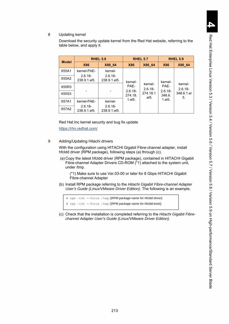
213
4 R
ed Hat E
nterprise Linux Version 5.3 / V
ersion 5.4 / Version 5.6 / V
ersion 5.7 / Version 5.8 / V
ersion 5.9 on High-perform
ance/Standard Server B
lade
8 Updating kernel Download the security update kernel from the Red Hat website, referring to the table below, and apply it.
Model RHEL 5.6 RHEL 5.7 RHEL 5.9
X86 X86_64 X86 X86_64 X86 X86_64 X55A1 kernel-PAE-
2.6.18-238.9.1.el5.
kernel- 2.6.18-
238.9.1.el5. kernel-PAE-
2.6.18-274.18.1.el5.
kernel- 2.6.18-
274.18.1.el5.
kernel-PAE-
2.6.18-348.6.1.el5.
kernel- 2.6.18-
348.6.1.el5.
X55A2
X55R3 - -
X55S3
X57A1 kernel-PAE- 2.6.18-
238.9.1.el5.
kernel- 2.6.18-
238.9.1.el5. X57A2
Red Hat.Inc kernel security and bug fix update https://rhn.redhat.com/
9 Adding/Updating Hitachi drivers With the configuration using HITACHI Gigabit Fibre-channel adapter, install hfcldd driver (RPM package), following steps (a) through (c). (a) Copy the latest hfcldd driver (RPM package), contained in HITACHI Gigabit
Fibre-channel Adapter Drivers CD-ROM (*1) attached to the system unit, under /tmp.
(*1) Make sure to use Ver.03-00 or later for 8 Gbps HITACHI Gigabit Fibre-channel Adapter
(b) Install RPM package referring to the Hitachi Gigabit Fibre-channel Adapter User’s Guide (Linux/VMware Driver Edition). The following is an example.
(c) Check that the installation is completed referring to the Hitachi Gigabit Fibre-
channel Adapter User’s Guide (Linux/VMware Driver Edition).
# rpm -ivh --force /tmp/[RPM package name for hfcldd driver]
# rpm -ivh --force /tmp/[RPM package name for hfcldd-tools]

214
4 R
ed Hat E
nterprise Linux Version 5.3 / V
ersion 5.4 / Version 5.6 / V
ersion 5.7 / Version 5.8 / V
ersion 5.9 on High-perform
ance/Standard Server B
lade

215
5 Red Hat Enterprise Linux version 6.1 / version 6.2 / version 6.4 on high-performance/standard server blade
This chapter explains the installation procedure for Xeon Processor Server Blade Red Hat Enterprise Linux 6.1/6.2/6.4 for Compute Blade. Please note that this chapter may be updated without notice.
How to install Red Hat Enterprise Linux 6.1/6.2/6.4 ............................................ 216
Red Hat Enterprise Linux 6.1/6.2/6.4 setup with the driver CD ............................ 217
Settings after installation ....................................................................................... 222
Utilities ................................................................................................................ 225
MegaRAID Storage Manager ................................................................................ 225
Internal storage monitor........................................................................................ 225
Hitachi Fibre-channel adapter Linux utility ............................................................ 226
OneCommand manager ........................................................................................ 226
Installing utilities with utility CD ............................................................................. 227
Fail Messages ....................................................................................................... 229
Restriction on Red Hat Enterprise Linux 6.1/6.2/6.4 ........................................... 230 Each model supports the OS versions shown below:
Version Model
RHEL 6.1 RHEL 6.2 RHEL 6.4
X86 X86_64 X86 X86_64 X86 X86_64
X55A1
X55A2
X55R3/X55S3 - -
X55R4 - - - -
X57A1 * *
X57A2
* Configuration with 2-TB or more memory on high-performance server blade
Westmere-EX model (X57A2) is supported by RHEL 6.2 or later.

216
5 R
ed Hat E
nterprise Linux version 6.1 / version 6.2 / version 6.4 on high-performance/standard server blade
How to install Red Hat Enterprise Linux 6.1/6.2/6.4 This section describes how to install Red Hat Enterprise Linux 6.1/6.2/6.4 with the driver CD.
Back up data you required before resetting, which deletes data on the hard disk.
Driver CD 0610-xx contains drivers for RHEL 6.1, which is available for RHEL 6.1 setup driver CD.
Driver & Utility CD C2K-DUX-0620-xx contains drivers for RHEL 6.2 and utilities for RHEL 6.1/6.2, which is available for RHEL 6.2 setup driver CD. It is also available for RHEL 6.1/6.2 utility CD.
Driver &Utility CD 0640-xx contains drivers and utilities for RHEL 6.4, which is available for RHEL 6.4 setup driver CD. It is also available for RHEL 6.4 utility CD. iso image for Driver & Utility CD 0640-xx depends on the model. Volume label indicates a model for which you can use the iso image as the following examples.
- For CB 2000 X55A1/X55A2/X55R3/X55S3/X57A1/X57A2 model when the volume label shows **-00-DUX-0640-xx
- For CB 2000 X55R4 model when the volume label shows **-01-DUX-0640-xx
The setup procedure described in this manual is an example. See the following Red Hat website for details.
http://docs.redhat.com/docs/en-US/Red_Hat_Enterprise_Linux/index.html

217
5 R
ed Hat E
nterprise Linux version 6.1 / version 6.2 / version 6.4 on high-performance/standard server blade
Red Hat Enterprise Linux 6.1/6.2/6.4 setup with the driver CD
1 Perform Remote CD/DVD from the remote console, or connect a USB CD-ROM drive or USB DVD-ROM drive directly to the server blade.
See Chapter 3: Connecting the System Equipment and Powering on, in the Hitachi Compute Blade 2000 User’s
Guide for details about the remote console. The following steps describe the RHEL 6.1 setup. 2 Insert the first CD for RHEL 6.1/6.2/6.4 installation or the installation DVD into
the CD/DVD drive, and power on the server blade. 3 On the EFI starting screen, press the F2 key or Delete to enter the EFI Setup
menu. Click the Save & Exit tab, find Boot Override to select the CD/DVD drive, and press Enter. Do not select a device that starts from UEFI.

218
5 R
ed Hat E
nterprise Linux version 6.1 / version 6.2 / version 6.4 on high-performance/standard server blade
4 Select Install system with basic video driver, and press the Tab key.
Press the Tab key to display options, and enter dd.

219
5 R
ed Hat E
nterprise Linux version 6.1 / version 6.2 / version 6.4 on high-performance/standard server blade
5 Select Yes when “Do you have a driver disk?” appears.
6 Remove the first CD for installation or the installation DVD from the drive, insert the driver CD into the drive, and click OK.

220
5 R
ed Hat E
nterprise Linux version 6.1 / version 6.2 / version 6.4 on high-performance/standard server blade
7 When the following screen appears, remove the driver CD from the drive; insert the first CD for installation or the installation DVD into the drive, and select No.
Follow the wizard to continue the installation. Do not configure network settings for a device using the e1000e driver* which needs to be disabled after the installation.
*: Intel Corporation 82567LF-2
The device with the last one of the three consecutive MAC addresses.
When the message “Please select the nearest city in your time zone” is displayed, select a time zone, and uncheck System clock uses UTC.
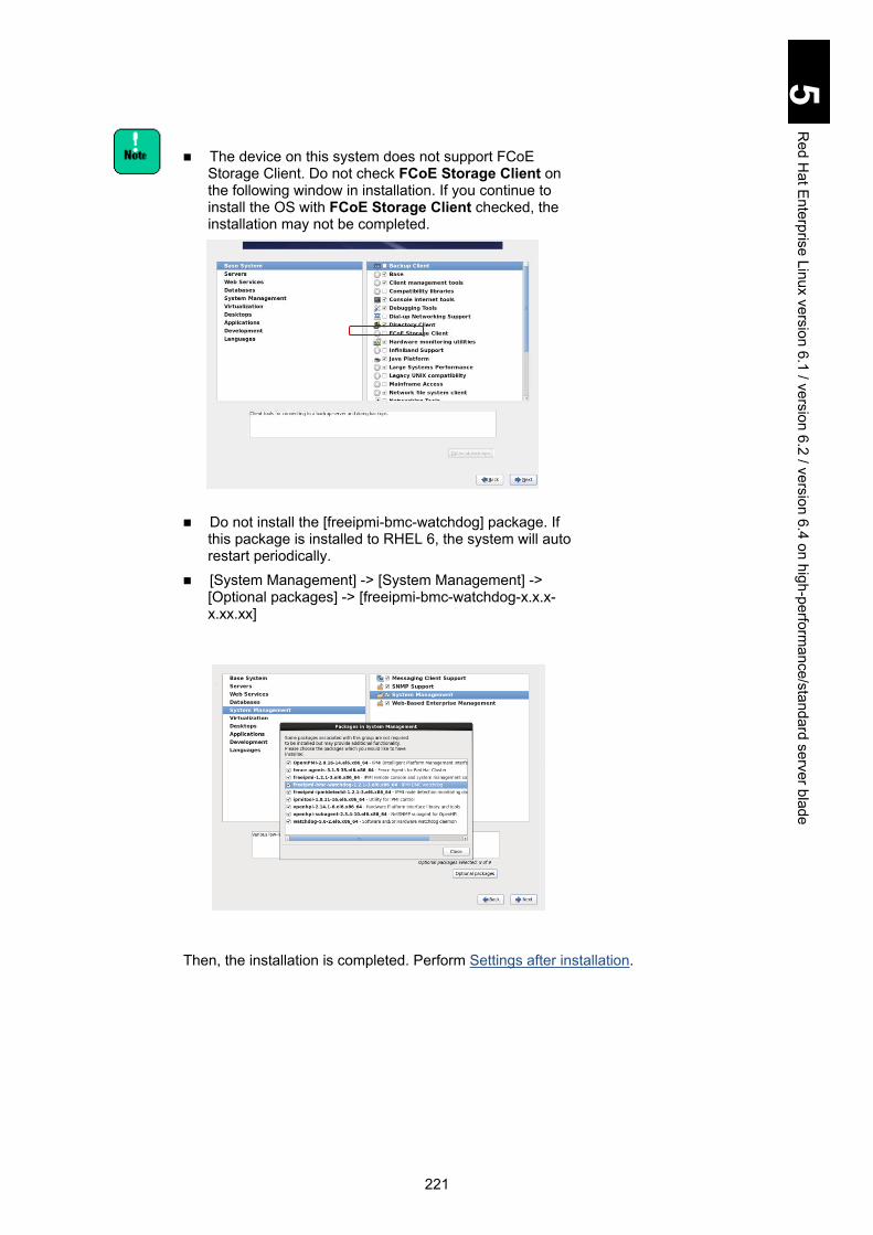
221
5 R
ed Hat E
nterprise Linux version 6.1 / version 6.2 / version 6.4 on high-performance/standard server blade
The device on this system does not support FCoE
Storage Client. Do not check FCoE Storage Client on the following window in installation. If you continue to install the OS with FCoE Storage Client checked, the installation may not be completed.
Do not install the [freeipmi-bmc-watchdog] package. If
this package is installed to RHEL 6, the system will auto restart periodically.
[System Management] -> [System Management] -> [Optional packages] -> [freeipmi-bmc-watchdog-x.x.x-x.xx.xx]
Then, the installation is completed. Perform Settings after installation.

222
5 R
ed Hat E
nterprise Linux version 6.1 / version 6.2 / version 6.4 on high-performance/standard server blade
Settings after installation This subsection describes the settings after Red Hat Enterprise Linux 6.1/6.2/6.4 has been installed with the driver CD. 1 Disabling TCP Checksum Offload
TCP Checksum Offload is a function that checks TCP packets in the LAN controller. If TCP Checksum Offload is enabled, packet data may be destroyed when the LAN controller fails. Targeted drivers - igb driver and tg3 driver Values: off or on (off: disabled; on: enabled) Perform the ethtool command to disable TCP Checksum Offload for both receive and transmit. Add the same number of ethtool commands as that of LAN controllers to /sbin/ifup-pre-local, as shown below, and reboot the OS. The new settings are automatically configured at the OS boot. Example: To disable two LAN controllers Add the following line to /sbin//ifup-pre-local on condition that the OS recognizes them as network devices eht0 and eth1.
If there is no /sbin/ifup-pre-local file, create a new file with the file privilege 755 and add the setting above. When the file exists, add the setting above to the file. Then, reboot the OS or the network device with the new setting, which makes the new setting take effect.
When enabling TCP Checksum Offload, replace each value to tx/rx parameter “off” with “on”.
2 Disabling NetworkManager service
Do not use NetworkManager service. It has been shown that the following problem occurred when NetworkManager service was started. DNS server information registered in /etc/resolv.conf may be deleted. Perform the following commands to set NetworkManager service to off. (1) Stop NetworkManager service.
if [ "${1}" == "ifcfg-eth0" ]; then
/sbin/ethtool -K eth0 rx off
/sbin/ethtool -K eth0 tx off
fi
if [ "${1}" == "ifcfg-eth1" ]; then
/sbin/ethtool -K eth1 rx off
/sbin/ethtool -K eth1 tx off
fi
# service NetworkManager stop

223
5 R
ed Hat E
nterprise Linux version 6.1 / version 6.2 / version 6.4 on high-performance/standard server blade
(2) Disable NetworkManager service. (3) Check that NetworkManager service is off.
3 Customizing /etc/sysctl.conf
Enable the magic SysRq key to collect information when a problem occurs. Edit or add the following line. Add a setting to start kernel panic when NMI occurs, with which you can quickly detect a failure in hardware and drivers. Edit or add the following line.
4 Customizing /boot/grub/grub.conf Add the following kernel option.
Adding the kernel option above configures the following settings. - Disabling nmi_watchdog to use a parameter that stops the system when
hardware fails - A setting of kernel panic for avoiding the OS malfunction when MCA
interrupts occur - A setting for avoiding Aero from working If selecting tboot package in RHEL installation, delete the following option to disable the TXT function.
5 Customizing /etc/modprobe.d/blacklist.conf This setting blocks loading drivers to prevent unnecessary devices from being detected. Add the following to the last line.
6 Reflecting the new settings
Reboot the OS to reflect the settings configured from step 1 through step 4.
7 Updating drivers/utilities
blacklist e1000e
# chkconfig NetworkManager off
# chkconfig | grep NetworkManager
NetworkManager 0:off 1:off 2:off 3:off 4:off 5:off 6:off
kernel.sysrq = 1
kernel.unknown_nmi_panic = 0
kernel.panic_on_unrecovered_nmi = 1
kernel.panic_on_io_nmi = 1
nmi_watchdog=0 mce=0 pci=noaer
intel_iommu=on

224
5 R
ed Hat E
nterprise Linux version 6.1 / version 6.2 / version 6.4 on high-performance/standard server blade
Obtain and install the latest drivers and utilities. Consult your reseller for details about them.
8 Additional setting before updating kernel When using Red Hat Enterprise Linux 6.2 with Emulex 10 Gbps LAN adapter or CNA installed, you need to configure the following additional setting before updating the kernel in step 8.
Make sure to perform the following procedure before updating kernel. If you do not, the correct driver is not installed.
Target device drivers: be2net driver; be2iscsi driver Check if be2net driver or be2iscsi driver is used by performing commands shown below.
#lsmod | grep be2net
be2net xxxxxxx 0
or # lsmod | grep be2iscsi
be2iscsi xxxxxxx 0
When the be2net or be2iscsi driver is shown by the commands above, perform the additional setting to the driver. (a) For be2net driver
# echo "override be2net 2.6.32-* weak-updates/be2net" >
/etc/depmod.d/be2net.conf
# chmod 644 /etc/depmod.d/be2net.conf
(b) For be2iscsi driver # echo "override be2iscsi 2.6.32-* weak-updates/be2iscsi" >
/etc/depmod.d/be2iscsi.conf
# chmod 644 /etc/depmod.d/be2iscsi.conf
9 Updating the kernel
When using Red Hat Enterprise Linux 6.2/6.4, download the security update kernel from the Red Had website referring to the table below and apply it.
Supported OS Supported kernel
32-bit x86 64-bit x86_64 Red Hat Enterprise Linux 6.2 2.6.32-220.4.2.el6
Red Hat Enterprise Linux 6.4 2.6.32-358.23.2.el6 Red Hat, Inc. http://www.redhat.com/

225
5 R
ed Hat E
nterprise Linux version 6.1 / version 6.2 / version 6.4 on high-performance/standard server blade
Utilities This section describes main utilities and its installation.
MegaRAID Storage Manager This utility monitors internal disk arrays. Be sure to install it when using the HDDs installed in the server blade. If the software is not installed, a double-failure might occur because of non-detection of the hard disk failure, and the failure analysis might be difficult. See the file MegaRAID Storage Manager Version xxx Instruction Manual in Driver CD. MegaRAID SAS 2108 (GVX-CA2SRD4X1/GV-CA2SRD4X1-Y)
MegaRAID Storage Manager Version 8.31-01 Instruction Manual MegaRAID SAS 2208 (X55R3 model)
MegaRAID Storage Manager Version 11.08.03-02 Instruction Manual
Internal storage monitor Internal storage monitor is a utility to monitor the internal disk array of server blade/storage expansion blade. When using the internal disk array of server blade/storage expansion blade, you must install this utility. If this utility is not installed, double fault may occur because the hard disk failure cannot be detected, and also the failure cannot be analyzed correctly. See the Server installation and monitoring tool User's Guide internal storage monitoring functions.
When using this utility, make sure to uninstall MegaRAID Storage Manager (MSM) before installing internal storage monitor.
RAID controller type varies with the form factor. For the RAID controller names of internal storage monitor, see RAID controller name view in the Server installation and monitoring
tool User's Guide internal storage monitoring functions.

226
5 R
ed Hat E
nterprise Linux version 6.1 / version 6.2 / version 6.4 on high-performance/standard server blade
Hitachi Fibre-channel adapter Linux utility
This utility manages Hitachi Gigabit Fibre-channel adapters. Consult your resellers for details.
OneCommand manager This utility manages Emulex Fibre Channel adapters. Consult your resellers for details.

227
5 R
ed Hat E
nterprise Linux version 6.1 / version 6.2 / version 6.4 on high-performance/standard server blade
Installing utilities with utility CD Install packages (library) required for each utility before installing the utility by referring to the manual shown in Utilities. Terminal size 80*24 and root privilege are required for installing utilities with the Utility CD.
Install script for utilities in Driver & Utility CD 0640-xx:
The install script is available only for the first installation. For the second or later installation or uninstallation, follow the manual for a specific utility to install or uninstall. 1 Mount the Utility CD in a directory.
# mkdir -p /mnt/SNV
# mount /dev/cdrom /mnt/SNV
2 Perform the following command.
Driver & Utility CD 0620-xx
Driver & Utility CD 0640-xx
3 Select a utility to install. When the following installation screen is displayed, type the number of unnecessary utilities and press Enter to remove them. Confirm that an asterisk is added to only utilities to install. The following screen is an example.
# cd /mnt/SNV/hitachi_utilities
# ./hitachi_utilities_install.sh
# cd /mnt/SNV/RHEL6.4/Utility/hitachi_utilities
# ./hitachi_utilities_install.sh
========================= Select Utilities To Install =========================
<No> <Name> <Version>
0 [*] System Info Collect Tool(systoru) ¦01-02
1 [*] JP1/ServerConductor/Agent ¦09-50
2 [*] JP1/ServerConductor/Advanced Agent ¦09-50
3 [*] MegaRAID Storage Manager ¦8.31-01
4 [*] Hitachi Hardware Maintenance Agent ¦V09-00
5 [*] OneCommand Manager ¦6.0.8.2-1
6 [*] Hitachi Fibre-channel Adapter Linux Utility ¦1.6.17.2019
7 [*] Hitachi RAID Adapter Linux Utility ¦2.5.0.10
===========================================================================
[*] Utilities will be installed.
Input a number to select utility or 'run' to start installation
[0-7,run,exit]:

228
5 R
ed Hat E
nterprise Linux version 6.1 / version 6.2 / version 6.4 on high-performance/standard server blade
For Driver & Utility CD 0640-xx, the screen is different from that of other CDs. Utility versions are not displayed and essential utilities cannot be unchecked.
4 Perform installation. Enter run and press Enter to perform the installation.
5 Check the installation results. When an installation result is shown, as in the following screen, confirm that selected utilities result in success. If a failure occurs, see the error code. The following screen is an example.
========================= Installation Result =========================
No.0 System Info Collect Tool(systoru): SUCCESS
No.1 JP1/ServerConductor/Agent: FAIL
- This utility is already installed.
No.2 JP1/ServerConductor/Advanced Agent: FAIL
- This utility is already installed.
No.3 MegaRAID Storage Manager: FAIL
- This utility is already installed.
No.4 Hitachi Hardware Maintenance Agent: SUCCESS
No.5 OneCommand Manager: SUCCESS
No.6 Hitachi Fibre-channel Adapter Linux Utility: SUCCESS
No.7 Hitachi RAID Adapter Linux Utility: FAIL
- The error occurred during utility installation.
======================================================================
For Driver & Utility CD 0640-xx, Reboot message shown in step 6 will not be displayed if the result of even a single selected utility shows FAIL. If FAIL is displayed, see Fail Messages.
6 Perform the reboot.
When the utility installation is complete, you need to reboot. When the following message is shown, type Yes or No, and press Enter. When you type No, make sure to perform the reboot.
Input a number to select utility or 'run' to start installation
[0-7,run,exit]: run
Reboot now? (Yes/No)
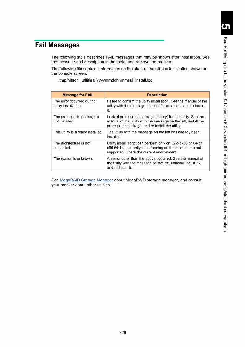
229
5 R
ed Hat E
nterprise Linux version 6.1 / version 6.2 / version 6.4 on high-performance/standard server blade
Fail Messages The following table describes FAIL messages that may be shown after installation. See the message and description in the table, and remove the problem. The following file contains information on the state of the utilities installation shown on the console screen.
/tmp/hitachi_utilities/[yyyymmddhhmmss]_install.log
Message for FAIL Description The error occurred during utility installation.
Failed to confirm the utility installation. See the manual of the utility with the message on the left, uninstall it, and re-install it.
The prerequisite package is not installed.
Lack of prerequisite package (library) for the utility. See the manual of the utility with the message on the left, install the prerequisite package, and re-install the utility.
This utility is already installed. The utility with the message on the left has already been installed.
The architecture is not supported.
Utility install script can perform only on 32-bit x86 or 64-bit x86 64, but currently is performing on the architecture not supported. Check the current environment.
The reason is unknown. An error other than the above occurred. See the manual of the utility with the message on the left, uninstall the utility, and re-install it.
See MegaRAID Storage Manager about MegaRAID storage manager, and consult your reseller about other utilities.

230
5 R
ed Hat E
nterprise Linux version 6.1 / version 6.2 / version 6.4 on high-performance/standard server blade
Restriction on Red Hat Enterprise Linux 6.1/6.2/6.4
This section describes the restrictions when you use Red Hat Enterprise Linux 6.1/6.2/6.4.
Time Required for X Logout With X logout, it may take about 5 to 10 minutes to complete the logout, which has no effect on the system behavior.
MTU Setting for ixgbe driver on 32-bit x86 kernel When using the ixgbe driver on 32-bit x86 kernel, use the default value: 1500 for MTU (maximum transmission unit). If MTU is more than 1500, a kernel panic might occur.
System Log Messages related to mcelog The following messages might be dumped in the system log (/var/log/messages). They do not affect the behavior. mcelog: failed to prefill DIMM database from DMI data mcelog: mcelog read: No such device
Disabling Large Receive Offload (LRO) only for RHEL 6.4 Kernel panic may occur when a system configuration satisfies the following two conditions. macvtap module is loaded. Intel 10 Gbps NIC is mounted. To check both of conditions, execute the following command, and check if the result includes the following. macvtap ixgbe Example of a configuration with macvtap and ixgbe loaded
# lsmod ¦ grep -E "ixgbe ¦ macvtap"
macvtap XXXXX X vhost_net
ixgbe XXXXX X
If one of them is not included, you do not need to change the setting. When both of them are included as shown in the example above, execute the following procedure.

231
5 R
ed Hat E
nterprise Linux version 6.1 / version 6.2 / version 6.4 on high-performance/standard server blade
To disable LRO: 1. Execute the following command to check that LRO is “on”.
# ethtool -k eth0 ¦ grep large-receive-offload
large-receive-offload: on <<< check the shaded setting.
2. When “on” is shown as above, execute the following command to disable LRO.
The following is an example with eth0 as a network interface. # ethtool -K eth0 lro off
3. Execute the command shown above again to check that LRO is “off”. To make this
setting value take effect at every system boot, add a line for the network interface to disable LRO to the sbin/ifup-pre-local file. :
if [ "${1}" == "ifcfg-eth0" ]; then
/sbin/ethtool -K eth0 lro off
fi
:
Notes: If the sbin/ifup-pre-local file does not exist, create one with file privilege 755, and add the setting shown above to the file. After that, reboot the system or the network device to which the setting is added to make it take effect.
Disabling fcoe and lldpad HotPlug and PCIe Error isolation may not work properly with the following LAN devices. 10 Gbps PCI LAN adapter: GV-CN2NXG2X1-Y I/O slot expansion unit 10 Gbps PCI LAN board: GV-CN2DXG2X1-Y How to disable fcoe and lldpad services
Checking: Check that fcoe and lldpad are enabled shown in step 2 below. When off is displayed for all setting items or nothing is displayed, no setting change is required. Setting: 1. Execute the following command to disable fcoe and lldpad services.
# chkconfig fcoe off # chkconfig lldpad off
2. Execute the following command to check that fcoe and lldpad are disabled:
setting values are changed to off. # chkconfig | grep fcoe
fcoe 0:off 1:off 2:off 3:off 4:off 5:off 6:off
# chkconfig | grep lldpad
lldpad 0:off 1:off 2:off 3:off 4:off 5:off 6:off
3. Execute the following command to reboot the OS
# reboot

232
5 R
ed Hat E
nterprise Linux version 6.1 / version 6.2 / version 6.4 on high-performance/standard server blade
ACPI Warning shown in the dmesg file The following message may be dumped by the dmesg command and in the system log (/var/log/dmesg). They do not affect the behavior.
“ACPI Warning: FADT (revision 5) is longer than ACPI 2.0 version, truncating length 0x10C to 0xF4 (20090903/tbfadt-288)”
Intel(R)I/OAT shown in the dmesg file The following message may be dumped by the dmesg command depending on the system configuration.
“Intel(R) I/OAT DMA Engine init failed” To avoid this problem, add the following kernel option to /boot/grub/grub.conf.
Using Kdump When using Kdump on Red Hat Enterprise Linux, you may not be able to use the dump function because of OS limitations if specifying the following devices to store the dump file.
Hitachi 16 Gb 1-port Fibre Channel adapter (GV-CC2N161X1-Y) Hitachi 16 Gb 2-port Fibre Channel adapter (GV-CC2N162X1-Y) Emulex 16 Gb 2-port Fibre Channel adapter (GV-CC2N163X1-Y)
If without an I/O slot expansion unit connected, you can avoid this problem by the following OS setting.
Add “blacklist igb” to the last line of /etc/kdump.conf file.
apic=bigsmp

233
6 0BWindows Server 2008/R2 with logical partitioning manager
This chapter explains the use of Windows Server 2008/R2 on logical partitioning manager (LPAR manager).
0B
1BUse of Windows Server 2008/R2 with LPAR manager ....................................... 234
2BRestrictions on Windows ..................................................................................... 236
3BWindows Server 2008/R2 setup .......................................................................... 241

234
6 W
indows S
erver 2008/R2 w
ith logical partitioning manager
1BUse of Windows Server 2008/R2 with LPAR manager You can install and use Windows Server 2008/R2 on an LPAR (Logical PARtition; hereinafter referred to as LPAR), a virtual environment created by LPAR manager. This section describes the instructions to use Windows Server 2008/R2 on the LPAR.
LPAR manager LPAR supports the following operation systems only: Any other OS or earlier SP versions are not supported:
- Windows Server 2008 (32-bit) with Service Pack 2 or later versions
- Windows Server 2008 (64-bit) with Service Pack 2 or later versions
- Windows Server 2008 R2 When Emulex 10 Gb LAN mezzanine card is used as a
dedicated NIC, see the 10 Gb Converged Network Production Instruction Manual to check the supported OS. Multi-channel, iSCSI, and FCoE are not available.
For configuration preconditions and general information of LPAR manager operations, such as how to configure an LPAR, see the Hitachi Compute Blade 2000 User’s Guide, Chapter 12 “Logical partitioning manager.”
4BActivate and reset LPAR Because LPARs are virtual environments, the physical buttons on the front panel of a server blade, such as “power,” “reset,” and “dump”, are not available. Always operate LPARs from the LPAR manager management screen. Make sure not to use physical buttons when operating LPARs. Otherwise, it affects all the LPARs operating on the server blade. For the configuration and the general information of LPAR manager operations, such as how to configure an LPAR, see the Hitachi Compute Blade 2000 User’s Guide, Chapter 12 “Logical partitioning manager.”
5BBasic operations/how to change settings of Windows Server 2008/R2
After Windows is started on the LPAR in the Xeon-version LPAR manager, basic operations and setup changes are performed on the desktop through remote desktop connection. For basic operation, see "Basic Operations and Setup Change Procedures
Tip

235
6 W
indows S
erver 2008/R2 w
ith logical partitioning manager
for Windows Server 2008 R2” in Chapter 1 or "Basic Operations and Setup Change Procedures for Windows Server 2008” in Chapter 2.
6BHow to use supplied software You can use Intel(R) PROSet on LPAR. For descriptions and setup procedures, see the following section for each OS.
-“How to Use Supplied Software” in Chapter 1: Windows Server 2008 R2 on High-performance/Standard Server Blade, or in Chapter 2: Windows Server 2008 on High-performance/Standard Server Blade

236
6 W
indows S
erver 2008/R2 w
ith logical partitioning manager
2BRestrictions on Windows This section describes restrictions when using Windows Server 2008/R2.
7BRestrictions on Windows Server 2008/R2 See Use of Windows Server 2008 R2 in Chapter 1: Windows Server 2008 R2 on High-performance/Standard Server Blade or Use of Windows Server 2008 in Chapter 2: Windows Server 2008 on High-performance/Standard Server Blade in advance. Restrictions on LPAR are described below. If both have the same kind of restrictions on LPAR, prioritize the contents described below.
Hyper-V Hyper-V is not available on LPAR.
Network-related precautions When ALB is used, it is recommended that the team should be composed of
dedicated NICs. With teaming, shared NIC and virtual NIC and dedicated NIC cannot be included in
the same team. You can distinguish between shared NIC and virtual NICs and physical NICs
(network adapters assigned to LPAR in dedicated mode) by using the following procedures.
Use the PCI bus number of the device: 1 Select Control Panel > System, and click Device Manager shown on the left. 2 Click + in Network Adapter. LAN devices are displayed. 3 Right-click a LAN device, and click Properties from the menu. 4 Check the location in the General tab.
An adapter with the PCI bus of 127 is a shared NIC or virtual NIC. A shared NIC or virtual NIC number in LPAR is the same value as a subtracted one (1) from the device value. Any other PCI bus than 127 is a physical NIC. When PCI bus is 125 with X55R3 or X55S3 model, the adapter is a virtual NIC.
Use the MAC address 1 View the MAC address used for a shared NIC and virtual NIC in the LPAR
manager virtual network card (VNIC) Assignment screen. Write down the MAC address of the target shared NIC and virtual NIC.
2 Boot Windows, and then enter the following command in the command prompt. ipconfg /all When information on all LAN adapters is displayed, search the target shared NIC and virtual NIC using the MAC address as a key.
When composing a team from the shared NIC and virtual NIC, set the following items in the Advanced tab, Properties of the adapter consisting of teams.

237
6 W
indows S
erver 2008/R2 w
ith logical partitioning manager
When composing a team from the virtual NIC and shared NIC, set the following items in the Advanced tab, Properties of the adapter consisting of teams. Activation delay: 60 (the recommended value) Probe: invalid
If the shared NIC and virtual NIC and shared NIC form an AFT, SFT, or ALB team, a lot of team switch events may be registered in the event viewer. It is recommended that the Probe consisting of teams should be disabled. Link-down is the only trigger to switch teams. See Appendix I “Compute Blade Windows Server 2008 / Windows Server 2003/R2 LAN Advanced Function Manual for Intel” or Appendix II “Compute Blade Windows Server 2008 R2 LAN Advanced Function Manual for Intel” for information about how to disable Probes.
For the Intel(R) PROSet functionality, such as AFT, SFT, and ALB, and working conditions, See Appendix I “Compute Blade Windows Server 2008 / Windows Server 2003/R2 LAN Advanced Function Manual for Intel” or Appendix II “Compute Blade Windows Server 2008 R2 LAN Advanced Function Manual for Intel”.
Identifying the Shared NIC Adapter If you use the shared NIC adapter in an environment with Intel® PROSet installed, you cannot identify the adapter by using the Identify Adapter function on the Link tab for the properties of the extended network adapter "Intel PRO/1000 MF Dual Port Network Connection."
MTU value When Jumbo Frame is used in the virtual NIC and shared NIC, the following MTU (maximum transfer unit) sizes are supported by LPAR manager. Up to 16 KB for NIC1 (PRO/1000) Up to 9 KB for NIC 2 (Intel 82576)
When NIC2 (Intel 82576) is set as VNIC Device Type on the Virtual NIC Assignment screen, you need to note the following precautions for setting items in Device Manager. On the Link Speed tab, Speed and Diagnostics are not available. If you have
changed Link Speed, its value 1 Gbps remains unchanged. Also if you try to click the Diagnostics button, an Error is shown.
On the Advanced tab, set each recommended value for TCP/IP Offload Options and Large Send Offload (LSO) shown in Note below. Only Jumbo Packet can be changed. For other setting items, use each default value.
On the Power Management tab, use default values for all setting items. If you change any setting on the Power Management tab, behavior of shared NICs and virtual NICs will not be affected.
When you configure a cluster, it is recommended that a dedicated NIC should be assigned for heartbeat.
TCP/IP Checksum Offload function of the network adapter The onboard LAN adapter and the expanded LAN board have the TCP/IP protocol checksum calculation function that is executed on the LAN controller. It is recommended, however, that the TCP/IP checksum calculation function provided by the OS as standard should be used rather than this function. You can construct a more highly reliable system if the calculation function of OS side is set available. This is because the consistency check of the packet data received from the network will be performed in the last phase of the OS protocol processing. Change the setting of the LAN adapter to turn the checksum function by the LAN controller off, as described below. Set off-load both NICs before teaming and a teaming interface while teaming.

238
6 W
indows S
erver 2008/R2 w
ith logical partitioning manager
When you configure a cluster, it is recommended that a dedicated NIC should be assigned for heartbeat.
When using the advanced functions for LAN of Intel PROSet, such as AFT, ALB, SFT, or Tag VLAN, delete the advanced functions before changing the setting. Re-configure the advanced functions for LAN after changing the setting. (A) 1 Gbps LAN expansion card for shared NICs and virtual NICs
On the Virtual NIC Assignment screen, you can set NIC1 (PRO/1000)/NIC2 (Intel 82576) for VNIC Device Type. If VNIC Device Type does not appear, depending on the LPAR manager firmware version, set NIC1 (PRO/1000) following (a) shown below. Reboot the system after changing settings. (a) NIC1 (PRO/1000) Communication may not be properly performed with default settings. Click Device Manager > Properties of each LAN adapter > Advanced tab. On the Advanced tab, make sure to set values to Off or Enable as shown below. Some items may not be shown depending on the type of a network adapter. Set items shown for your adapter. lpv4 Checksum Offload: Off TCP Checksum Offload (lPv4): Off UDP Checksum Offload (lPv4): Off Large Send Offload (LSO) (IPv4): Off (b) NIC2 (Intel 82576) IPv4 Checksum Offload: Off TCP Checksum Offload (lPv4): Off TCP Checksum Offload (lPv6): Off UDP Checksum Offload (lPv4): Off UDP Checksum Offload (lPv6): Off Large Send Offload (LSO) (IPv4): Off Large Send Offload (LSO) (IPv6): Off
(B) 1 Gbps LAN expansion card for dedicated NICs Click Device Manager > Properties of each LAN adapter > Advanced tab. On the Advanced tab, set values. With Windows Server 2008 R2, see Chapter 1 > Restrictions on Use of Windows Server 2008 R2 > TCP/IP Checksum Offload function of the network adapter for details. With Windows Server 2008, see Chapter 2 > Restrictions on Use of Windows Server 2008 > TCP/IP Checksum Offload function of the network adapter for details. Reboot the system after changing settings. Some items may not be shown depending on the type of network adapter. Set items shown for your adpater.
(C) 10 Gbps LAN expansion card: Intel(R) Ethernet Server Adapter X520-2 for dedicated NICs
Click Device Manager > Properties of each LAN adapter > Advanced tab. On the Advanced tab, set values. With Windows Server 2008 R2, see Chapter 1 > Restrictions on Use of Windows Server 2008 R2 > TCP/IP Checksum Offload function of the network adapter for details. With Windows Server 2008, see Chapter 2 > Restrictions on Use of Windows Server 2008 > TCP/IP Checksum Offload function of the network adapter for details.

239
6 W
indows S
erver 2008/R2 w
ith logical partitioning manager
Reboot the system after changing settings. Some items may not be shown depending on the type of network adapter. Set items shown for your adapter.
Precautions on Fibre-channel driver On LPAR manager LPAR, you should use the following driver for FC switch
modules.
# OS Version Driver Version Recommended storport driver
1 Windows Server 2008 (32bit) hfcwdd.sys 1.1.6.670 or later -
2 Windows Server 2008 (x64) hfcwdd.sys 4.1.6.670 or later -
3 Windows Server 2008 R2 hfcwdd.sys 4.2.6.670 or later -
When using the 8G FC mezzanine card, make sure to install the latest driver. HBA BIOS Setting
When you use the shared FC as a boot device, the boot may not finish properly depending on the number of LPARs assigned to the shared FC. Extending LOGIN DELAY TIME that is the operation parametor of the Fibre-channel adapter can avoid this symptom.
For more details, see “Option Setting Procedure” in the Gigabit Fibre-channel Adapter User’s Guide.
Serial Console When using the virtual COM console, configure the serial console. Execute the following command at the command prompt on Windows and restart the OS. bcdedit /ems ON bcdedit /emssettings EMSPORT:1 EMSBAUDRATE:115200 Then, the serial console is available on a guest screen. You can move from the LPAR manager screen to a guest screen only on the active LPAR. See the Hitachi Compute Blade 2000 User’s Guide > Logical partitioning manager > LPAR manager Screen Operations.
How to use Remote Console Use the remote desktop connection for usual operations. Remote Console should
be used for operation only when the remote destop connection is not available, such as OS setup or booting into safe mode.
Do not use Remote Console for full-screen. With Logical video graphics array (VGA), boot the command prompt and switch to the full-screen using Alt + Enter.The display becomes distorted. In this case, enter Alt + Enter again to return the screen to regular from full-screen. Do not use Alt + Tab to switch to another screen after booting command.com and switching to full-screen, which causes an error: Windows NT Virtual DOS Machine (NTVDM) to occur and command.com to terminate.
Unavailable functions The following functions are not available on a guest OS for LPAR manager. Hyper-V/VMware/Xen Hot Add Memory Hot Add Processors
240
6 W
indows S
erver 2008/R2 w
ith logical partitioning manager
Hot Replace Memory Hot ReplaceProcessors Power Options
Configuration change in LPAR When you boot after changing LPAR configuration from uni-processor to multi-processor, a message asking to reboot your computer may appear. If so, follow the directions in the message to reboot the computer, which allows you to use the multi-processor configuration. When hardware configuration is changed, re-authenticating Windows license may be asked for Windows license management. If so, perform Windows license authentication once more. See the OS Help or documents for details.
OS system time lag When you operate an application using the multimedia timer, such as Media Player, with LPAR manager firmware version 58-12 or later, which the power saving function is added to: support for C6 state, OS system time lag can get larger. If this happens, perform the following to prevent the problem from happening frequently. Disable LPAR manager power saving functions Change the processor scheduling mode to shared mode.

241
6 W
indows S
erver 2008/R2 w
ith logical partitioning manager
3BWindows Server 2008/R2 setup This section explains the setup for Windows Server 2008/R2. For the installation procedure of the driver for expansion boards, see the expansion board manuals.
When installing Windows, driver, or utility, use the Driver Kit 12-11 or later version DVD-ROM. Ask your reseller for the latest version. Do not use other versions for Windows Server 2008/R2 setup.
Some recommended patch modules or the latest drivers may be required for Windows Server 2008/R2. Check the Microsoft website to obtain required modules and drivers in advance.
8BHow to setup This section describes how to setup Windows Server 2008/R2 on LPAR manager LPAR. Follow Windows Server 2008 R2 Setup in Chapter 1 or Windows Server 2008 Setup in Chapter 2. Instructions and restrictions on LPAR manager LPAR are described below. Read this chapter, and then proceed to Windows Server 2008 R2 Setup in Chapter 1 or Windows Server 2008 Setup in Chapter 2.
9BOS setup This section describes instructions and restrictions on setting up Windows Server 2008/R2 on LPAR manager LPAR. Follow the instructions and restrictions on the server blade. If some of them overlap, prioritize the description below.
NOTICE
Re-setup causes the hard disk data to disappear. Back up data that you need in advance.
Tip

242
6 W
indows S
erver 2008/R2 w
ith logical partitioning manager
Setup procedure Setup procedure is equivalent to the description in Windows Server 2008 R2 on High-performance/Standard Server Blade, Chapter 1, or Windows Server 2008 on High-performance/Standard Server Blade, Chapter 2. Prerequisites before the setup are as follows: Assign a USB device to an LPAR for OS setup. Operate the setup through the logical VGA screen. See “Logical partitioning manager in the Hitachi Compute Blade 2000 User’s Guide for information about how to assign a USB device, and how to view or operate the Logical VGA screen. Set to boot the OS from the DVD-ROM drive connected via USB on the logical EFI of LPAR. See Logical partitioning manager in the Hitachi Compute Blade 2000 User’s Guide. Set the FC switch module before performing the OS setup. When setting on the LPAR, operate the logical EFI Shell of LPAR. See Logical partitioning manager in the Hitachi Compute Blade 2000 User’s Guide for information about how to enter the logical EFI Shell. See EFI Driver in the Hitachi Gigabit Fibre-channel Adapter User’s Guide for details about the adapter setting. For setup procedures, see Details of Windows Server 2008 R2 Setup in Chapter 1 or Details of Windows Server 2008 Setup in Chapter 2.
Setup Flowchart The following flowchart includes three types of boxes: procedure for system console shown in double-framed box filled in with light blue; that for remote console shown in single box filled with light green; that for common shown in double-framed box filled with white.
Prerequisites Set TeraTerm: See Hitachi Compute Blade 2000 USER’S GUIDE > Chapter 12: Logical partitioning manager for prerequisites.
LP settings Set LP if not set it: See Hitachi Compute Blade 2000 USER’S GUIDE > Chapter 12: Logical partitioning manager for LPAR manager boot-up. If you have already set LP, go on to the next step LPAR configuration.
LPAR configuration
Configure LPARs if not configured them: See Hitachi Compute Blade 2000 USER’S GUIDE > Chapter 12: Logical partitioning manager for LPAR configuration. If you have already configured LPARs, go on to the next step OS setup.
OS setup Configure environment for setup using one of the following: Perform “Remote CD/DVD” from the remote console, and have the server blade recognize the DVD image file for installation to start the LPAR. Or Connect a USB CD/DVD drive direct to the server blade, and insert the installation DVD to the CD/DVD drive to start the LPAR.

243
6 W
indows S
erver 2008/R2 w
ith logical partitioning manager
EFI driver : See Hitachi Compute Blade 2000 USER’S GUIDE > Chapter 12: Logical partitioning manager for EFI driver settings.
Boot option: See Hitachi Compute Blade 2000 USER’S GUIDE > Chapter 12: Logical partitioning manager for boot option settings.
Boot order: See Hitachi Compute Blade 2000 USER’S GUIDE > Chapter 12: Logical partitioning manager for changing boot orders.
OS setup: For setting up Windows Server 2008 R2, see chapter 1 > Windows Server 2008 R2 Setup to perform the procedures. For setting up Windows Server 2008, see chapter 2 > Windows Server 2008 Setup to perform the procedures. For Service Pack, see Windows Server 2008 SP2 Setup. Note: Operations depend on the blade model.
Option settings
Checksum Offload: See XURestrictions on Windows Server 2008/R2UX > Network-related Precautions > TCP/IP Checksum of the network adapter for details.
Driver/Utility setup
Driver/Utility: See XUDriver/Utility SetupUX for details.
SNP disabled SNP disabled:
Disable SNP (Scalable Networking Pack) following steps below. 1. Start the registry editor with regedit, and set the following
registry value to 0 (zero). If there is not the registry, create an entry and set the registry value to 0 (zero). HKEY_LOCAL_MACHINE\SYSTEM\CurrentControlSet\Servic
es\Tcpip\Parameters Name: EnableTCPA Type: Reg_DWORD Value: 0 (zero)
2. Perform the following netsh command at the command prompt. netsh int tcp set global chimney=disabled
netsh int tcp set global rss=disabled 3. Reboot the OS after setting those values.
Finish

244
6 W
indows S
erver 2008/R2 w
ith logical partitioning manager
Restrictions on setup Boot Device
Only FC expansion cards are available as a boot device. Read the installation procedure referring to instructions on FC expansion cards.
Remote console Use the remote console only for OS installation. Use the remote desktop after OS installation.
Configure an LPAR to set up Windows before the setup referring to Logical partitioning manager in the Hitachi Compute Blade 2000 User’s Guide. The recommended LPAR configuration for Windows Server 2008/R2 is as follows Adjust resources to assign to the LPAR for the purpose or environment. When configuring an LPAR by assigning two processors to it with model X55R3/X55S3, set up OS, drivers, and utilities on the LPAR with one processor assigned. Then change the assignment to two processors after completing the setup. Memory: 2.0 GB or larger Disk: 40 GB or larger for a partition to set up OS Disk: At least one virtual NIC for the remote desktop connection
The shared NIC and virtual NIC may not be recognized as a network device at the first OS boot after the setup. Reboot the OS, and it will be recognized correctly.
When a USB port, different from the port used when the boot option is registered, is used, the USB DVD-ROM drive may not be recognized. In that case, re-register the boot option.
An LPAR in LPAR manager is a virtual environment. When a product key is demanded at the OS setup, type the key for the virtual environment.
10BDriver/Utility setup This section describes instructions and restrictions on setting up drivers and utilities for Windows Server 2008/R2 on LPAR manager. Follow the instructions and restrictions on the server blade. If some of them overlap, prioritize the description below.

245
6 W
indows S
erver 2008/R2 w
ith logical partitioning manager
Setup procedure See Driver/Utility Setup in Chapter 1 or 2 for the specific setup procedures. Using NICs in an environment different from the one at installation, LAN driver
installation may be required.
Device name and LAN driver used with Windows
NIC Scheduling mode Device name LAN driver
Shared NIC/Virtual NIC NIC1 Intel(R)PRO/1000
Ethernet e1000 LAN driver
NIC2 Intel(R)82576 Ethernet igb LAN driver
Dedicated NIC(*)
Intel(R)82576 Ethernet igb LAN driver
Intel(R) 82599 Ethernet Ixgbe LAN driver
Broadcom 1Gbps Ethernet
Tg3 LAN driver
Emulex 10Gbps Ethernet Be2net LAN driver (*): A device and LAN driver for Windows depend on the NIC installed in the
server blade.
Whether or not to update LAN drivers When executing the following, you may need to update the LAN driver.
Changed Logical Partitionings. Changed NIC scheduling modes. Changed VNIC Device Types
Find an intersecting cell for your conditions from the following table and click the number to see details about LAN drivers for each device. For intersecting cells without a number shown, you need not update the LAN driver for those conditions. Update the LAN driver for a destination device.
To:
Logical Partitioning Enabled Disabled
Scheduling mode
Shared NIC/Virtual NIC Dedicated NIC NIC1 NIC2
From: Enabled Shared NIC/ Virtual NIC
NIC1 HU- UH HU5UH HU3UH HU1UH
NIC2 HU5UH H- HU3UH HU1UH
Dedicated NIC HU4UH HU4UH - -
Disabled HU2UH HU2UH - -
VNIC Device Type: If VNIC Device Type is not included, see NIC1 (PRO/1000). Some LPAR manager firmware versions do not support VNIC Device Types. See Logical partitioning manager, Chapter 12, in the Hitachi Compute Blade 2000 User’s Guide for details.

246
6 W
indows S
erver 2008/R2 w
ith logical partitioning manager
1 Changing the Logical Partitioning from Enabled (Shared NIC/ Virtual NIC) to Disabled: When changing modes from Enabled (Shared NIC/ Virtual NIC) to Disabled, you may need to update the LAN driver. Update the driver referring to the following table.
Table 1: Drivers to update when changing from Enabled to Disabled
To:
Logical Partitioning Disabled
Scheduling mode
Device
name
VNIC
device type
Intel(R) 82576
Ethernet
Intel(R) 82599
Ethernet
Broadcom 1Gbps
Ethernet
Emulex 10Gbps Ethernet
From: Enabled Shared NIC/ Virtual NIC
NIC1 Update Update Update Update
NIC2 - Update Update Update
Update: Updating the driver is required. -: Updating the driver is Not required.
2 Changing the Logical Partitioning from Disabled to Enabled (Shared NIC/ Virtual NIC) When changing modes from Disabled to Enabled (Shared NIC/ Virtual NIC), you might need to update the LAN driver. Update the driver referring to the following table.
Table 2: Drivers to update when changing from Disabled to Enabled
To:
Logical Partitioning Enabled
Scheduling mode Shared NIC/ Virtual NIC
VNIC Device Type
Device name NIC1 NIC2
From: Disabled Intel(R) 82576 Ethernet Update -
Intel(R) 82599 Ethernet Update Update
Broadcom 1Gbps Ethernet Update Update
Emulex 10Gbps Ethernet Update Update
Update: Updating the driver is required. -: Updating the driver is Not required.

247
6 W
indows S
erver 2008/R2 w
ith logical partitioning manager
3 Changing the scheduling mode from LPAR manager (Shared NIC/Virtual NIC) to LPAR manager (Dedicated NIC)
When changing scheduling modes from LPAR manager (Shared NIC/Virtual NIC) to LPAR manager (Dedicated NIC), you may need to update the LAN driver. Update the driver referring to the following table.
Table 3: Drivers to update
when changing from LPAR manager (shared NIC/virtual NIC) to LPAR manager (dedicated NIC)
To:
Scheduling mode Dedicated NIC
Device
VNIC name Device Type
Intel(R) 82576
Ethernet
Intel(R) 82599
Ethernet
Broadcom 1Gbps
Ethernet
Emulex 10Gbps Ethernet
From: Shared NIC/ Virtual NIC
NIC1 Update Update Update Update
NIC2 - Update Update Update
Update: Updating the driver is required. -: Updating the driver is Not required.
4 Changing the scheduling mode from LPAR manager (Dedicated NIC) to LPAR manager (Shared NIC/Virtual NIC)
When changing scheduling modes from LPAR manager (Dedicated NIC) to LPAR manager (Shared NIC/Virtual NIC), you may need to update the LAN driver. Update the driver referring to the following table.
Table 4: Drivers to update when changing from LPAR manager (dedicated NIC)
to LPAR manager (shared NIC/virtual NIC)
To:
Scheduling mode Shared NIC/ Virtual NIC
VNIC device type
Device name NIC1 NIC2
From: Dedicated NIC
Intel(R) 82576 Ethernet Update -
Intel(R) 82599 Ethernet Update Update
Broadcom 1Gbps Ethernet Update Update
Emulex 10Gbps Ethernet Update Update
Update: Updating the driver is required. -: Updating the driver is Not required.

248
6 W
indows S
erver 2008/R2 w
ith logical partitioning manager
5 Changing LPAR manager (Shared NIC/Virtual NIC) device types When changing LPAR manager (Shared NIC/Virtual NIC) device types, you may
need to update the LAN driver. Update the driver referring to the following table.
Table 5: Drivers to update when changing device types for LPAR manager (shared NIC/virtual NIC)
To:
Scheduling mode Shared NIC/ Virtual NIC
VNIC Device Type NIC1 NIC2
From: Shared NIC/ Virtual NIC
NIC1 - Update
NIC2 Update -
Update: Updating the driver is required.
-: Updating the driver is Not required.
Installing the LAN driver Install the LAN driver contained in the Compute Systems Installer. When using the latest driver, contact your reseller.
Restrictions on setup
Display driver See Display Driver in Chapter 1 or 2 for the specific procedure. It is not necessary to install the display driver on LPAR.
LAN driver (Only for Windows Server 2008 R2) Drivers for the Shared NIC/Virtual NIC are stored in the separate folders. When installing LAN Driver referring to the procedure in Chapter 1, install the driver using the following folder. With NIC1 (PRO/1000) for VNIC Device Type of virtual NIC and shared NIC
X55A1 Model : d:\X55x1\Win2008R2\Drivers\LAN\INTEL_02\x64 X55A2 Model : d:\X55x2\Win2008R2\Drivers\LAN\INTEL_02\x64 X55R3/X55S3 Model: d:\X55x3\Win2008R2\Drivers\LAN\INTEL_02\x64 X57A1 Model : d:\X57x1\Win2008R2\Drivers\LAN\INTEL_02\x64 X57A2 Model : d:\X57x2\Win2008R2\Drivers\LAN\INTEL_02\x64 Where d: is a DVD drive name.
With NIC2 (Intel 82576) for VNIC Device Type of virtual NIC and shared NIC X55A1 Model: d:\X55x1\Win2008R2\Drivers\LAN\INTEL_01\x64

249
6 W
indows S
erver 2008/R2 w
ith logical partitioning manager
X55A2 Model: d:\X55x2\Win2008R2\Drivers\LAN\INTEL_01\x64 X55R3/X55S3 Model: d:\X55x3\Win2008R2\Drivers\LAN\INTEL_01\x64 X57A1 Model: d:\X57x1\Win2008R2\Drivers\LAN\INTEL_01\x64 X57A2 Model: d:\X57x2\Win2008R2\Drivers\LAN\INTEL_01\x64
When a dedicated NIC, such as the Broadcom NetXtreme Gigabit Ethernet, is assigned with X55R3/ X55S3 model, make sure to check or change the LAN driver parameters following the procedure shown below after completing setup of drivers and utilities.
1. For Windows Server 2008, select Start > Control Panel > System, and open Device Manager. For Windows Server 2008 R2, select Start > Control Panel > System and Security > System, and open Device Manager.
2. Right-click Broadcom NetXtremeGigabit Ethernet xx under Network adapters, and click Properties.
3. Click the Advanced tab on the Properties window, and check or change the following setting values. - IPv4 Checksum Offload: None - TCP/UDP Checksum Offload (IPv4): None - TCP/UDP Checksum Offload (IPv6): None - Large Send Offload (IPv4): Disable - Large Send Offload v2 (IPv4): Disable - Large Send Offload v2 (IPv6): Disable - Receive Side Scaling: Disable
4. Repeat step 2 and step 3 for every Broadcom NetXtremeGigabit Ethernet xx. 5. Reboot the OS.

250
6 W
indows S
erver 2008/R2 w
ith logical partitioning manager

251
7 Windows Server 2003/R2 with logical partitioning manager
This chapter explains the use of Windows Server 2003 on logical partitioning manager (LPAR manager).
Use of Windows Server 2003/R2 with LPAR manager ....................................... 252
Restrictions on Windows ..................................................................................... 254
Windows Server 2003/R2 setup .......................................................................... 258

252
7 W
indows S
erver 2003/R2 w
ith logical partitioning manager
Use of Windows Server 2003/R2 with LPAR manager You can install and use Windows Server 2003/R2 on an LPAR (Logical PARtition: hereinafter referred to as LPAR), a virtual environment created by LPAR manager. This section describes the instructions for using Windows Server 2003/R2 on the LPAR.
The LPAR in the Xeon-version LPAR manager supports only the following Windows versions with SP among Windows 2003/R2.
- Windows Server 2003/R2 (32-bit) with Service Pack 2 or a later version
- Windows Server 2003/R2 x64 Editions with Service Pack 2 or a later version
Other Windows Server 2003/R2 and the earlier version Service Pack are not supported.
For the precondition of the configuration and the general information of LPAR manager operations, such as how to configure an LPAR, see the Hitachi Compute Blade
2000 User’s Guide, Chapter 12 “Logical Partitioning Manager.”
In addition to the above, other settings are required. See the Hitachi Compute Blade 2000 User’s Guide, Chapter 12 “Logical partitioning manager” for details.
Activate and reset LPAR Because LPARs are virtual environments, the physical buttons on the front panel of a server blade, such as power, reset, and dump, are not available. Always operate LPARs from the LPAR manager management screen. Make sure not to use physical buttons when operating LPARs because it affects all the LPARs operating on the server blade. For the configuration and the general information of LPAR manager operations, such as how to configure an LPAR, see the Hitachi Compute Blade 2000 User’s Guide, Chapter 12 “Logical partitioning manager.”
Tip
! Note

253
7 W
indows S
erver 2003/R2 w
ith logical partitioning manager
Basic operations/how to change settings of Windows Server 2003/R2
After Windows is started on the LPAR in the Xeon-version LPAR manager, basic operations and setup changes are performed on the desktop through a remote desktop connection. For basic operation, see Chapter 3 Basic Operations / How to Change Settings of Windows Server 2003/R2 for a server blade model you use. When executing the remote desktop connection of Windows Server 2003, start the application Remote Desktop Connection on Windows of the operation terminal. Start the application using the following command line with /console option or admin option without fail, not from the short cut in the start menu.
mstsc.exe /console (or mstsc.exe /admin) If starting the application Remote Desktop Connection
using another method such as the icon in the start menu, not the command ‘mstsc.exe /console’ or mstsc.exe /admin, a certain function of Windows may not be available. Make sure to execute a command, ‘mstsc.exe /console’ or mstsc.exe /admin, to start Remote Desktop Connection.
A command used is different depending on a Remote Desktop Connection (mstsc.exe) version. /console: earlier versions than v61. /admin: v6.1 or later versions
How to use supplied software You can use Intel PROSet even on LPAR. For descriptions and setup procedures, see the following for a server blade model you use:
“Windows Server 2003/R2 on Standard Server Blade.” > “How to Use Supplied Software”
Tip

254
7 W
indows S
erver 2003/R2 w
ith logical partitioning manager
Restrictions on Windows This section describes restrictions when using Windows Server 2003/R2.
Restrictions on Windows Server 2003/R2 See Use of Windows Server 2003/R2 in “Chapter 3: Windows Server 2003/R2 on Standard Server Blade” for a server blade model you use, in advance. Instructions and restrictions on LPAR are described below. If both have the same kind of restrictions on LPAR, prioritize the contents described below.
Use of software Prerequisites and restrictions for Windows Server 2003/R2 in the LPAR environment are equivalent to those for a server blade you use in its basic environment. See ”Use of Software“ in Chapter 3 ”Windows Server 2003/R2 on High-performance/Standard Server Blade” beforehand. See the Hitachi Compute Blade 2000 User’s Guide, Chapter 12 “Logical partitioning manager” for configurations and instructions on LPAR manager. Additional instructions on LPAR are described below.
Serial Console When using the virtual COM console, configure the serial console. Execute the following command at the command prompt on Windows and restart the OS. bootcfg /ems EDIT /port COM1 bootcfg /ems ON /baud 115200 /id 1 Then, the serial console is available on a guest screen. You can move from the LPAR manager screen to a guest screen only on the active LPAR. See the Hitachi Compute Blade 2000 User’s Guide > Logical partitioning manager > LPAR manager Screen Operations.
Network-related precautions When ALB is used, it is recommended that the team should be composed of
dedicated NICs. With teaming, a shared NIC and virtual NIC and dedicated NIC cannot be included
in the same team. You can distinguish between shared NIC, virtual NIC, and dedicated NIC (network
adapters assigned to LPAR in dedicated mode) by using the following procedures. Use the PCI bus number of the device: 1 Select Control Panel > System, and click Hardware tab > Device Manager
in Device Manager: 2 Click + in the Network Adapter. LAN devices are displayed. 3 Right-click a LAN device, and click Properties from the menu. 4 Check the location in the General tab.

255
7 W
indows S
erver 2003/R2 w
ith logical partitioning manager
An adapter with the PCI bus of 127 is a shared NIC or virtual NIC. A shared NIC or virtual NIC number in LPAR is the same value as a subtracted one from the device value. Any other PCI bus than 127 is a dedicated NIC.
Use the MAC address 1 View the MAC address used for a shared NIC and virtual NIC in the LPAR
manager VNIC Assignment screen. Write down the MAC address of the target shared NIC and virtual NIC.
2 Boot Windows, and then enter the following command in the command prompt. Ipconfg /all When information on all LAN adapters is displayed, search the target shared NIC and virtual NIC using the MAC address as a key.
When composing a team from the shared NIC and virtual NIC, set the following items in the Advanced tab, Properties of the adapter consisting of teams. Activation delay: 60 (the recommended value) Probe: invalid
If the shared NIC and virtual NIC form an AFT, SFT, or ALB team, a lot of team switch events may be registered in the event viewer. It is recommended that the probe consisting of teams should be disabled. Link-down is the only trigger to switch teams. See Appendix-I: Compute Blade Windows Server 2008 / Windows Server 2003/R2 LAN Advanced Function Manual for Intel for information about how to disable Probe.
When the internal LAN device of the server blade is used for teaming, SFT configuration is recommended: AFT/ALB are not available as Xeon-version server blade. For the Intel(R) PROSet functionality, such as AFT, SFT, and ALB, and working conditions, see Appendix-I: Compute Blade Windows Server 2008 / Windows Server 2003/R2 LAN Advanced Function Manual for Intel.
Identifying the Shared NIC Adapter If you use the shared NIC adapter in an environment with Intel(R) PROSet installed, you cannot identify the adapter by using the Identify Adapter function on the Link tab for the properties of the extended network adapter Intel(R) PRO/1000 MF Dual Port Network Connection.
MTU value When Jumbo Frame is used in the virtual NIC and shared NIC, the following MTU (maximum transfer unit) sizes are supported by LPAR manager. Up to 16 KB for NIC1 (PRO/1000) NIC2 (Intel 82576) is not supported by Windows Server 2003/R2.
NIC2 (Intel 82576) for VNIC Device Type on the Virtual NIC Assignment screen This is not supported by Windows Server 2003/R2.
When you configure a cluster, it is recommended that a dedicated NIC should be assigned for heartbeat.
TCP/IP Checksum Offload function of the network adapter The onboard LAN adapter and the expansion LAN board have the TCP/IP protocol checksum calculation function that is executed on the LAN controller. It is recommended, however, that the TCP/IP checksum calculation function provided by the OS as standard should be used rather than this function. You can construct a more highly reliable system if the calculation function of the OS side is set available. This is because the consistency check of the packet data

256
7 W
indows S
erver 2003/R2 w
ith logical partitioning manager
received from the network will be performed in the last phase of the OS protocol processing. Change the setting of the LAN adapter to turn the checksum function by the LAN controller off, as described below. Set off-load both NICs before teaming and a teaming interface while teaming.
When you configure a cluster, it is recommended that a dedicated NIC should be assigned for heartbeat.
When using the advanced functions for LAN of Intel(R) PROSet, such as AFT, ALB, SFT, or Tag VLAN, delete the advanced functions before performing the following setting changes. Re-configure the advanced functions for LAN after the change. (A) 1 Gbps LAN expansion card for Shared NIC/Virtual NIC
On the Virtual NIC Assignment screen, you can set NIC1 (PRO/1000)/NIC2 (Intel 82576) can be set for VNIC Device Type. NIC2 (Intel 82576) is not supported by Windows Server 2003/R2. If VNIC Device Type does not appear depending on the LPAR manager firmware version, set NIC1 (PRO/1000) following (a) shown below. Reboot the system after changing settings. NIC1 (PRO/1000) Communication may not be properly performed with default settings. Click Device Manager > Properties of each LAN adapter > Advanced tab. On the Advanced tab, make sure to set items to Off or Enable as shown below. Receive IP Checksum Offload: Off Receive TCP Checksum Offload: Off Send IP Checksum Offload: Off Send TCP Checksum Offload: Off TCP Segmentation Offload: Off Some items may not be shown depending on the type of a network adapter. Set items shown for your adapter.
(B) 1 Gbps LAN expansion card for dedicated NICs Click Device Manager > Properties of each LAN adapter > Advanced tab. On the Advanced tab, set values. Then restart the system. See Chapter 3 > Restrictions on Use of Windows Server 2003/R2 > TCP/IP Checksum Offload function of the network adapter for details. Some items may not be shown depending on the type of a network adapter. Set items shown for your adapter.
(C) 10 Gbps LAN expansion card: Intel(R) Ethernet Server Adapter X520-2 for dedicated NICs
Click Device Manager > Properties of each LAN adapter > Advanced tab. On the Advanced tab, and set the necessary items. See Chapter 3 > Restrictions on Use of Windows Server 2003/R2 > TCP/IP Checksum Offload function of the network adapter for details. Some items may not be shown depending on the type of a network adapter. Set items shown for your adapter.

257
7 W
indows S
erver 2003/R2 w
ith logical partitioning manager
Precautions on Fibre-channel driver On LPAR using the Xeon-version LPAR manager, you should use the following as
the driver for the Hitachi Gigabit Fibre-channel adapter.
# OS Version Driver Version Recommended storport driver
1 Windows Server 2003/R2 (32bit) SP2 hfcwdd.sys 1.0.6.670 or later KB932755
2 Windows Server 2003/R2 x64 Editions SP2 hfcwdd.sys 4.0.6.670 or later KB932755
When using the 8G FC mezzanine card, make sure to install the latest driver. Ask your reseller about the latest driver. You can obtain a recommended support driver on the following web site. Make sure to apply it with Service Pack 2. http://support.microsoft.com/kb/932755 HBA BIOS Setting
When you use the shared FC as a boot device, the boot may not finish properly depending on the number of LPARs assigned to the shared FC. Extending LOGIN DELAY TIME that is the operation parameter of the Fibre-channel adapter can avoid this symptom.
For the details, see “Option Setting Procedure” in the Gigabit Fibre-channel Adapter User’s Guide.
How to use Remote Console Use the remote desktop connection for usual operations. Remote Console should
be used for operation only when the remote destop connection is not available, such as OS setup or booting the safe mode.
Do not use Remote Console for full-screen. With Logical VGA, boot the command prompt and switch to the full-screen using Alt + Enter ; the display becomes distorted. In this case, enter Alt + Enter again, which returns the screen to regular from full-screen. Do not use the Alt + Tab to switch to another screen after booting command.com and switching to full-screen, which causes an error:NTVDM to occur and command.com to terminate
Configuration change in LPAR When you reboot after changing LPAR configuration from uni-processor to multi-processor, a message indicating to reboot your computer may appear. If so, follow the direction in the message to reboot the computer, which allows you to use the multi-processor configuration.
Others See Restrictions on Server Blade.

258
7 W
indows S
erver 2003/R2 w
ith logical partitioning manager
Windows Server 2003/R2 setup This section explains the setup for Windows Server 2003/R2. For the installation procedure of the driver for expansion boards, see the expansion board manual.
Windows Server 2003 may have the recommended fix patch or the latest driver to apply.
How to setup This section describes how to setup Windows Server 2003/R2 on LPAR manager LPAR. Basically, follow Windows Server 2003/R2 Setup in Chapter 3. Instructions and restrictions on LPAR manager LPAR environment are described below. Read this chapter, and then proceed to Windows Server 2003/R2 setup.
NOTICE
Re-setup causes the hard disk data to disappear. Back up data that you need in advance.
Tip

259
7 W
indows S
erver 2003/R2 w
ith logical partitioning manager
Windows Server 2003/R2 setup This section describes instructions and restrictions on setting up Windows Server 2003/R2 on LPAR manager LPAR. Basically, follow the instructions and restrictions on the server blade. If some of them overlap, prioritize the description below.
Setup procedure The setup procedure is equivalent to the description in Windows Server 2003/R2 on Standard Server Blade, in Chapter 3. Prerequisites before the setup are as follows: Assign a USB device to an LPAR for the OS setup. Operate the setup through the logical VGA screen. See Logical partitioning manager in the Hitachi Compute Blade 2000 User’s Guide for information about how to assign a USB device, and how to view or operate the Logical VGA screen. Set to boot the OS from the DVD-ROM drive connected via USB on the logical EFI of LPAR. See Logical partitioning manager in the Hitachi Compute Blade 2000 User’s Guide. Set the Hitachi Gigabit Fibre-channel adapter before the OS setup. When performing settings on the LPAR, operate the logical EFI Shell of LPAR. See Logical partitioning manager in the Hitachi Compute Blade 2000 User’s Guide for information about how to enter the logical EFI Shell. See EFI Driver in the Hitachi Gigabit Fibre-channel Adapter User’s Guide for details about the adapter setting. For actual setup procedures, see Details of Windows Server 2003/R2 Setup in Chapter 3.
Setup flowchart The following flowchart includes three types of boxes: procedure for system console shown in a light blue double-framed box; remote console shown in a light green single box; and common shown in a white double-framed box.
Prerequisites Set TeraTerm: See the Hitachi Compute Blade 2000 User’s Guide > Chapter 12: Logical partitioning manager for prerequisites.
LP settings Set LP if not set: See the Hitachi Compute Blade 2000 User’s Guide > Chapter 12: Logical partitioning manager for LPAR manager boot-up. If you have already set HVM, go on to the next step LPAR configuration.
LPAR configuration
Configure LPARs if not configured: See the Hitachi Compute Blade 2000 User’s Guide > Chapter 12: Logical partitioning manager for LPAR manager boot-up. If you have already configured LPARs, go to the next step in the OS setup.
OS setup Configure environment for setup using one of the following: Perform Remote CD/DVD from the remote console, and have the server blade recognize the DVD image file for installation to start the LPAR.

260
7 W
indows S
erver 2003/R2 w
ith logical partitioning manager
Or Connect a USB CD/DVD drive direct to the server blade, and insert the installation DVD to the CD/DVD drive to start the LPAR.
EFI driver : See the Hitachi Compute Blade 2000 User’s Guide > Chapter 12: LPAR manager (Hitachi Virtualization Management) for EFI driver settings.
Boot option: See the Hitachi Compute Blade 2000 User’s Guide > Chapter 12: LPAR manager (Hitachi Virtualization Management) for boot option settings.
Boot order: See the Hitachi Compute Blade 2000 User’s Guide > Chapter 12: LPAR manager (Hitachi Virtualization Management) for changing boot orders.
OS setup: For setting up Windows Server 2003/R2, see chapter 3 > Windows Server 2003/R2 Setup > Setup Steps, and perform the setup steps to the end, shown as “Your password has been changed.” Note: Operations depend on the blade model.
Option settings
Checksum Offload: See Restrictions on Windows Server 2003/R2 > Network-related Precautions > TCP/IP Checksum of the network adapter for details.
Driver/Utility setup
Driver/Utility: See Chapter 3 > Windows Server 2003/R2 Setup > Details of Windows Server 2003/R2 for details about the following drivers. - Registry Update (1) - Chipset Driver - MdgaRAID Storage Manager - Intel® PROSet - Update and Configure Board Drivers - Service Pack 2 (SP2) - Emulex Fibre-channel Adapter Driver Update - Registry Update (2) - Apply fix Patch
Finish

261
7 W
indows S
erver 2003/R2 w
ith logical partitioning manager
Restrictions on setup Boot Device
Only Fibre-channel mezzanine cards are available as a boot device. Read the installation procedure referring to instructions on the Fibre-channel mezzanine cards.
Assign a single Fibre-channel mezzanine card to an LPAR during setup. If another Fibre-channel mezzanine card exists, the LPAR may reboot during the chipset driver installation and then the chipset driver may not be properly installed. When you use multiple Fibre-channel mezzanine cards on an LPAR, install the chipset driver before adding Fiber channel mezzanine cards to the LPAR.
Remote console Use the remote console only for OS installation. Use the remote desktop after OS installation. Remote FD/Remote DVD function of Remote console is not available. Connect a USB FD drive or USB DVD drive to the server blade, and assign the drive using the USB shared function of LPAR.
Configure an LPAR to setup Windows before setup referring to Logical partitioning manager in the Hitachi Compute Blade 2000 User’s Guide. The recommended LPAR configuration for Windows Server 2003/R2 is as follows Adjust resources to assign to the LPAR for the purpose or environment. Processor: Two or more Memory: 768 MB or larger Disk: 10 GB or larger for the partition on which the OS is set up. Network: At least one virtual NIC for the remote desktop connection
The LPAR in the Xeon-version LPAR manager supports only the following Windows versions with SP among Windows 2003/R2: Windows Server 2003/R2 with Service Pack 2 or a later version. Other Windows Server 2003/R2 and the earlier version Service Pack are not supported.
Make sure to use OS media with SP1 or SP2 for setting up Windows Server 2003 (32-bit). Windows Server 2003 first edition is not available. Windows Server 2003 R2 media are equivalent to Windows Server 2003 with SP1. Make sure to apply SP2 after setting up the OS.
Use installation media for Windows Server 2003 with SP2 when installing Windows Server 2003 32-bit.
The device driver to use is that of a server blade model you use in its basic environment.
The shared NIC and virtual NIC may not be recognized as a network device at the first OS boot after the setup. Reboot the OS, and it will be recognized correctly.
The USB DVD-ROM drive may not be recognized if you use a different USB port from the USB port used when registering the boot option. In that case, re-register the boot option.
Display driver Skip the procedure of Display Driver in Chapter 3. Installing a display driver is not necessary on LPAR.
LAN driver installation Step 11 in the LAN driver setup, described in Chapter 3, is not necessary because the device does not exist.

262
7 W
indows S
erver 2003/R2 w
ith logical partitioning manager
After the OS setup, set the resolution and the number of colors: click Control Panel to open Screen, and set those items in the Setting tab. With 16-color (4-bit) mode, part of the window may not be displayed properly.

263
8 Red Hat Enterprise Linux version 5.3 / version 5.4 / version 5.6 / version 5.7 / version 5.9 with logical partitioning manager
This chapter explains the use of Red Hat Enterprise Linux Version 5.3 / 5.4 / 5.6 / 5.7 / 5/9 (Xeon) on logical partitioning manager (LPAR manager). Please note that this chapter may be updated without notice.
How to install Red Hat Enterprise Linux 5.3/5.4 .................................................. 264
Red Hat Enterprise Linux 5.6/5.7/5.9 using the driver CD ................................... 285
Appendix ............................................................................................................. 307

264
8 R
ed Hat E
nterprise Linux Version 5.3 / V
ersion 5.4 / Version 5.6 / V
ersion 5.7 / Version 5.9 w
ith logical partitioning manager
How to install Red Hat Enterprise Linux 5.3/5.4
Prerequisites to install Prerequisites before the installation are as follows: Assign a USB device to an LPAR for the OS installation. Operate the install through the logical VGA screen. See “Logical partitioning manager” in the Hitachi Compute Blade 2000 User’s Guide for information about how to assign a USB device, and how to view or operate the Logical VGA screen. Set to boot the OS from the DVD-ROM drive connected via USB on the logical EFI of LPAR. See “Logical partitioning manager” in the Hitachi Compute Blade 2000 User’s Guide. Set the Hitachi Gigabit Fibre-channel adapter before the OS install. When setting up on the LPAR, operate the logical EFI Shell of LPAR. See “Logical partitioning manager” in the Hitachi Compute Blade 2000 User’s Guide for information about how to enter the logical EFI Shell. See “EFI Driver” in the Hitachi Gigabit Fibre-channel Adapter User’s Guide for details about the adapter setting. The hfcldd driver media is necessary for OS installation. See “Appendix A” in the Hitachi Gigabit Fibre-channel Adapter User’s Guide for information about how to create the hfcldd driver media.

265
8 R
ed Hat E
nterprise Linux Version 5.3 / V
ersion 5.4 / Version 5.6 / V
ersion 5.7 / Version 5.9 w
ith logical partitioning manager
Installation procedure 1 Connect a USB CD-ROM or USB DVD-ROM drive to the system device.
Connect a USB CD-ROM drive or a USB DVD-ROM drive according to the Hitachi Compute Blade 2000 User’s Guide.
Installation using a USB drive not supported by the system device is not guaranteed.
The remote CD/DVD function of the remote console is not available.
2 Insert Installation Media Disk 1 of Red Hat Enterprise Linux 5.3/5.4 into the USB-CD ROM or USB-DVD ROM.
3 Activate an LPAR, and connect to the LPAR via the remote console. 4 Boot the system from the USB CD-ROM or USB-DVD ROM. 5 When the following screen appears, enter linux dd at the boot: prompt, and
press Enter.
! Note

266
8 R
ed Hat E
nterprise Linux Version 5.3 / V
ersion 5.4 / Version 5.6 / V
ersion 5.7 / Version 5.9 w
ith logical partitioning manager
6 When the following screen appears, click Yes and press Enter.
7 When the following screen appears, change the installation media to the hfcldd driver media in the USB CD-ROM or USB DVD-ROM drive. Click OK, and press Enter.
8 When the following screen appears, change the media to Installation Media Disk 1 in the USB CD-ROM or USB DVD-ROM drive. Click No, and press Enter.

267
8 R
ed Hat E
nterprise Linux Version 5.3 / V
ersion 5.4 / Version 5.6 / V
ersion 5.7 / Version 5.9 w
ith logical partitioning manager
9 When the following screen appears, Click Skip, and press Enter.
10 Perform the installation according to the Red Hat Enterprise Linux 5.3 /5.4 Installer.
11 When the following screen is displayed, click Next, and press Enter.

268
8 R
ed Hat E
nterprise Linux Version 5.3 / V
ersion 5.4 / Version 5.6 / V
ersion 5.7 / Version 5.9 w
ith logical partitioning manager
12 When the following screen is displayed, select your language. Then click Next, and press Enter.
13 When the following screen is displayed, select your keyboard type. Then click Next, and press Enter.

269
8 R
ed Hat E
nterprise Linux Version 5.3 / V
ersion 5.4 / Version 5.6 / V
ersion 5.7 / Version 5.9 w
ith logical partitioning manager
14 When the following screen is displayed, input the Installation Number. Then
click OK, and press Enter.
15 When a Warning screen is displayed, click Yes, and press Enter.

270
8 R
ed Hat E
nterprise Linux Version 5.3 / V
ersion 5.4 / Version 5.6 / V
ersion 5.7 / Version 5.9 w
ith logical partitioning manager
16 When the following screen is displayed, select “Remove all partitions on selected drives and create default layout” and “Review and modify partitioning layout”. Then click Next, and press Enter.
17 When a Warning screen is displayed, click Yes, and press Enter.

271
8 R
ed Hat E
nterprise Linux Version 5.3 / V
ersion 5.4 / Version 5.6 / V
ersion 5.7 / Version 5.9 w
ith logical partitioning manager
18 When the following screen is displayed, click Next, and press Enter.
19 When the following screen is displayed, click Next, and press Enter.

272
8 R
ed Hat E
nterprise Linux Version 5.3 / V
ersion 5.4 / Version 5.6 / V
ersion 5.7 / Version 5.9 w
ith logical partitioning manager
20 When the following screen is displayed, click Edit, and press Enter.
21 When the following screen is displayed, remove the check mark from “Enable IPv6 support.” Then click OK, and press Enter. This configuration is necessary for each network port. (eth0, eth1, -- ethn).

273
8 R
ed Hat E
nterprise Linux Version 5.3 / V
ersion 5.4 / Version 5.6 / V
ersion 5.7 / Version 5.9 w
ith logical partitioning manager
22 When the following screen is displayed, select time-zone as your environment, and press Enter. Note: Do not select “System clock uses UTC”
23 When the following screen is displayed, input a root password you like. Then click Next, and press Enter.

274
8 R
ed Hat E
nterprise Linux Version 5.3 / V
ersion 5.4 / Version 5.6 / V
ersion 5.7 / Version 5.9 w
ith logical partitioning manager
24 When the following screen is displayed, remove the check mark from “Virtualization”.
25 When the following screen is displayed, set configuration for your environment.

275
8 R
ed Hat E
nterprise Linux Version 5.3 / V
ersion 5.4 / Version 5.6 / V
ersion 5.7 / Version 5.9 w
ith logical partitioning manager
26 When the following screen is displayed, set the configuration for your environment.
27 When the following screen is displayed, click Next, and press Enter.

276
8 R
ed Hat E
nterprise Linux Version 5.3 / V
ersion 5.4 / Version 5.6 / V
ersion 5.7 / Version 5.9 w
ith logical partitioning manager
28 When the following screen is displayed, click Continue, and press Enter. Note: Required Install Media may be different according to the configuration set in step 23.
29 When the following screen is displayed, insert the dsc* according to the directions.

277
8 R
ed Hat E
nterprise Linux Version 5.3 / V
ersion 5.4 / Version 5.6 / V
ersion 5.7 / Version 5.9 w
ith logical partitioning manager
30 When the following screen is displayed, click Reboot, and press Enter.
31 When the following screen is displayed, click Forward, and press Enter.

278
8 R
ed Hat E
nterprise Linux Version 5.3 / V
ersion 5.4 / Version 5.6 / V
ersion 5.7 / Version 5.9 w
ith logical partitioning manager
32 When the following screen is displayed, read the License Agreement carefully. If you agree with the content, click “Yes, I agree to the License Agreement”, and press Enter.
33 When the following screen is displayed, select Disabled. Then select Forward, and press Enter.

279
8 R
ed Hat E
nterprise Linux Version 5.3 / V
ersion 5.4 / Version 5.6 / V
ersion 5.7 / Version 5.9 w
ith logical partitioning manager
34 When the following screen is displayed, click Yes, and press Enter.
35 When the following screen is displayed, click Forward, and press Enter.

280
8 R
ed Hat E
nterprise Linux Version 5.3 / V
ersion 5.4 / Version 5.6 / V
ersion 5.7 / Version 5.9 w
ith logical partitioning manager
36 When the following screen is displayed, select Enable kdump, and press Enter.
37 When the following screen is displayed, click Yes, and press Enter.

281
8 R
ed Hat E
nterprise Linux Version 5.3 / V
ersion 5.4 / Version 5.6 / V
ersion 5.7 / Version 5.9 w
ith logical partitioning manager
38 When the following screen is displayed, enter the Hour, Minute, and Second. Then click Forward, and press Enter.
39 When the following screen is displayed, set the configuration for your environment.

282
8 R
ed Hat E
nterprise Linux Version 5.3 / V
ersion 5.4 / Version 5.6 / V
ersion 5.7 / Version 5.9 w
ith logical partitioning manager
40 When the following screen is displayed, fill in the blank cell for each item on the screen. Then click Forward, and press Enter.
41 When the following screen is displayed, click Forward, and press Enter.

283
8 R
ed Hat E
nterprise Linux Version 5.3 / V
ersion 5.4 / Version 5.6 / V
ersion 5.7 / Version 5.9 w
ith logical partitioning manager
42 When the following screen is displayed, click Finish, and press Enter.
43 When the following screen is displayed, click OK, and press Enter.
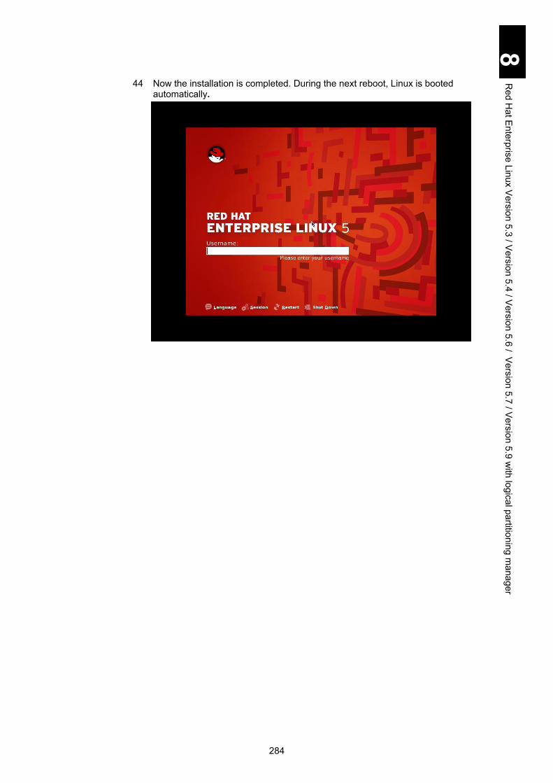
284
8 R
ed Hat E
nterprise Linux Version 5.3 / V
ersion 5.4 / Version 5.6 / V
ersion 5.7 / Version 5.9 w
ith logical partitioning manager
44 Now the installation is completed. During the next reboot, Linux is booted automatically.

285
8 R
ed Hat E
nterprise Linux Version 5.3 / V
ersion 5.4 / Version 5.6 / V
ersion 5.7 / Version 5.9 w
ith logical partitioning manager
Red Hat Enterprise Linux 5.6/5.7/5.9 using the driver CD Red Hat Enterprise Linux 5.6/5.7/5.9 can be installed on a virtual environment provided by LPAR manager, which is called LPAR.
Prerequisites for setup The procedure described later uses Red Hat Enterprise Linux 5.6/5.7/5.9 installation CD and the Hitachi driver. If you use a recovery CD provided by Linux support service, see the user’s guide given by that support service. Make sure to use media for Red Hat Enterprise Linux 5.6/5.7/5 for the setup. Never use any other media. Make sure to use the media for Red Hat Enterprise Linux 5.7 for the setup. Never use any other media. Make sure to use the media for Red Hat Enterprise Linux 5.9 for the setup. Never use any other media. Make sure also to use the driver specified for Red Hat Enterprise Linux 5.6/5.7/5.9 for the setup. Never use any other driver. If you use a driver not corresponding to the version, the OS will not work properly. LPAR manager LPAR supports the following OSs.
- Red Hat Enterprise Linux 5.6/5.7/5.9 (X86)
- Red Hat Enterprise Linux 5.6/5.7/5.9 (X86_64) Red Hat Enterprise Linux 5.9 is supported by LPAR
manager firmware version 59-51/79-51 or higher. When Emulex 10 Gb LAN mezzanine card is used as a
dedicated NIC, see “10 Gb Converged Network Production Instruction Manual” to check supported OS. Multi-channel, iSCSI, and FCoE are not available.
The following kernel versions are supported.
Red Hat Enterprise Linux 5.6
- X86: 2.6.18-238.9.1.el5PAE or later
- AMD/Intel 64: 2.6.18-238.9.1.el5 or later Red Hat Enterprise Linux 5.7
- X86: 2.6.18-274.18.1.el5PAE or later
- AMD/Intel 64: 2.6.18-274.18.1.el5 or later Red Hat Enterprise Linux 5.9
- X86: 2.6.18-348.6.1.el5PAE or higher
- AMD/Intel 64: 2.6.18-348.6.1.el5 or higher
Contact your reseller about the latest recommended driver version for Red Hat Enterprise Linux 5.6/5.7/5.9, and download it.

286
8 R
ed Hat E
nterprise Linux Version 5.3 / V
ersion 5.4 / Version 5.6 / V
ersion 5.7 / Version 5.9 w
ith logical partitioning manager
Notes and restrictions on Linux 5.6/5.7/5.9
This section describes restrictions and notes when you use Red Hat Enterprise Linux 5.6/5.7/5.9 on the LPAR.
Notes on the network
hbonding/bonding cannot bond dedicated NICs and physical NICs. When using virtual NICs and shared NICs with RHEL 5.6, set NIC1 (PRO/1000)
as VNIC Device Type. When using virtual NICs and shared NICs with RHEL 5.7/5.9, set NIC1
(PRO/1000) or NIC2 (Intel 82576) as VNIC Device Type, You can set VNIC Device Type on the Virtual NIC Assignment screen. VNIC Device Type might not be displayed depending on the LPAR manager firmware version. If so, VNIC Device Type is equivalent to NIC1 (PRO/1000).
Some items may not be displayed depending on the type of network adapter. Configure settings for the items displayed with the adapter you use.
Notes on the Fibre-channel driver Use the latest gigabit Fibre-channel adapter on LPAR manager LPAR.
Restrictions during setup The following table shows the recommended LPAR configuration for using
Red Hat Enterprise Linux 5.6/5.7/5.9. Adjust resources to assign to an LPAR for the system environment.
Setting item Recommended value Processor 2 or more
Memory 2.0 GB or larger (4.0 GB or larger only for X86 *1)
Disk Partition to install the OS: 40 GB or larger
Network At least one virtual NIC
*1 Physical address extension (PAE) is an extension function for X86 processors, with which a 32-bit system can use memory of more than 4 GB. If memory assigned to an LPAR is less than 4 GB on LPAR manager, make sure to apply PAE kernel. Only PAE kernel for Red Hat Enterprise Linux (X86) is supported. Install PAE kernel with one of the following methods. - Assign memory of 4 GB or larger to an LPAR during the OS installation. After the OS has been installed, you can change the memory assignment to less than 4 GB. - Install the OS, and then install PAE kernel to apply.
A virtual NIC may not be recognized as a network device at the first OS boot after the setup. Reboot the OS to recognize the shared NIC or virtual NIC properly.
When you use a USB port different from the USB port used in registering the boot option, the USB DVD drive may not be recognized. If so, re-register the boot option.

287
8 R
ed Hat E
nterprise Linux Version 5.3 / V
ersion 5.4 / Version 5.6 / V
ersion 5.7 / Version 5.9 w
ith logical partitioning manager
Boot device You can use a Fibre-channel mezzanine card or Fibre-channel adapter as a boot device. See the Gigabit Fibre-channel Adapter User’s Guide for the setup procedure.
Boot command option Do not use the mem boot command to prevent problems, such as repetitive reboots.
When using Red Hat Enterprise Linux 5 (X86) and changing the real-time clock (RTC) with the hwclock command, a message 'select() to /dev/rtc to wait for clock tick timeout' may be displayed. When changing RTC using the hwclock command, an option “--directisa” should be added, as shown below. If it failed once, executing the command with the option will not show this message. # hwclock –directisa
MTU setting The following table shows the supported firmware version and the maximum MTU size when MTU is used with shared NIC or virtual NIC.
LPAR manager firmware version
MTU size
59-00/79-00 or later 9000 bytes
Using NICs in an environment different from the one during installation, LAN driver installation may be required. (1) LAN drivers used with Linux
NIC Device name LAN driver
Shared NIC/ Virtual NIC
NIC1 Intel(R) PRO/1000 Ethernet e1000 LAN driver
NIC2 Intel(R) 82576 Ethernet igb LAN driver
Dedicated NIC *1
Intel(R) 82576 Ethernet igb LAN driver
Intel(R) 82599 Ethernet Ixgbe LAN driver
Broadcom 1 Gbps Ethernet Tg3 LAN driver
Emulex 10 Gbps Ethernet Be2net LAN driver *1: A supported device and LAN driver depend on the NIC installed in the server
blade.
(2) Whether or not to update LAN drivers
When executing the following, you may need to update the LAN driver. - Changed Logical Partitionings. - Changed NIC scheduling modes. - Changed VNIC Device Types

288
8 R
ed Hat E
nterprise Linux Version 5.3 / V
ersion 5.4 / Version 5.6 / V
ersion 5.7 / Version 5.9 w
ith logical partitioning manager
Find an intersecting cell for your conditions from the following table and click the number to see details about LAN drivers for each device. For intersecting cells without a number shown, you need not update the LAN driver for those conditions. Update the LAN driver for a destination device.
To:
Logical Partitioning Enabled Disabled
Scheduling mode
Shared NIC/Virtual NIC Dedicated NIC NIC1 NIC2
From: Enabled Shared NIC/ Virtual NIC
NIC1 - 5 3 1
NIC2 5 - 3 1
Dedicated NIC 4 4 - -
Disabled 2 2 - -
VNIC Device Type: If VNIC Device Type is not included, see NIC1 (PRO/1000). Some LPAR manager firmware versions do not support VNIC Device Type. See Chapter 12, “Logical partitioning manager” in the Hitachi Compute Blade 2000 User’s Guide for details.
1 Changing Logical Partitioning from Enabled (Shared NIC/Virtual NIC) to Disabled:
When changing modes from Enabled (Shared NIC/Virtual NIC) to Disabled, you may need to update the LAN driver. Update the driver referring to the following table.
Table 1: Drivers to update when changing from Enabled to Disabled
To:
Logical Partitioning Disabled
Scheduling mode
Device
name
VNIC
device type
Intel(R) 82576
Ethernet
Intel(R) 82599
Ethernet
Broadcom 1Gbps
Ethernet
Emulex 10Gbps Ethernet
From: Enabled Shared NIC/ Virtual NIC
NIC1 Update Update Update Update
NIC2 - Update Update Update
Update: Updating the driver is required. -: Updating the driver is not required.

289
8 R
ed Hat E
nterprise Linux Version 5.3 / V
ersion 5.4 / Version 5.6 / V
ersion 5.7 / Version 5.9 w
ith logical partitioning manager
2 Changing the Logical Partitioning from Disabled to Enabled (Shared NIC/Virtual NIC): When changing Logical Partitioning from Disabled to Enabled (Shared NIC/Virtual NIC), you may need to update the LAN driver. Update the driver referring to the following table.
Table 2: Drivers to update when changing from Disabled to LPAR Enabled
To:
Logical Partitioning Enabled
Scheduling mode Shared NIC/Virtual NIC
VNIC Device Type
Device name NIC1 NIC2
From: Disabled Intel(R) 82576 Ethernet Update -
Intel(R) 82599 Ethernet Update Update
Broadcom 1Gbps Ethernet Update Update
Emulex 10Gbps Ethernet Update Update
Update: Updating the driver is required.
-: Updating the driver is not required.
3 Changing the scheduling mode from LPAR manager (Shared NIC/Virtual NIC) to
LPAR manager (Dedicated NIC) When changing scheduling modes from LPAR manager (Shared NIC/Virtual NIC) to LPAR manager (Dedicated NIC), you may need to update the LAN driver. Update the driver referring to the following table.
Table 3: Drivers to update when changing from LPAR manager (shared NIC/virtual NIC)
to LPAR manager (dedicated NIC)
To:
Scheduling mode Dedicated NIC
Device VNIC name
Device Type
Intel(R) 82576
Ethernet
Intel(R) 82599
Ethernet
Broadcom 1Gbps
Ethernet
Emulex 10Gbps Ethernet
From: Shared NIC/ Virtual NIC
NIC1 Update Update Update Update
NIC2 - Update Update Update
Update: Updating the driver is required.
-: Updating the driver is not required.

290
8 R
ed Hat E
nterprise Linux Version 5.3 / V
ersion 5.4 / Version 5.6 / V
ersion 5.7 / Version 5.9 w
ith logical partitioning manager
4 Changing the scheduling mode from LPAR manager (Dedicated NIC) to LPAR
manager (Shared NIC/Virtual NIC) When changing scheduling modes from LPAR manager (Dedicated NIC) to LPAR manager (Shared NIC/Virtual NIC), you may need to update the LAN driver. Update the driver referring to the following table.
Table 4: Drivers to update when changing from LPAR manager (dedicated NIC)
to LPAR manager (shared NIC/virtual NIC)
To:
Scheduling mode Shared NIC/Virtual NIC
VNIC device type
Device name NIC1 NIC2
From: Dedicated NIC
Intel(R) 82576 Ethernet Update -
Intel(R) 82599 Ethernet Update Update
Broadcom 1Gbps Ethernet Update Update
Emulex 10Gbps Ethernet Update Update
Update: Updating the driver is required.
-: Updating the driver is not required.
5 Changing LPAR manager (Shared NIC/Virtual NIC) device types
When changing LPAR manager (Shared NIC/Virtual NIC) device types, you may need to update the LAN driver. Update the driver referring to the following table.
Table 5: Drivers to update when changing device types
for LPAR manager (Shared NIC/Virtual NIC)
To:
Scheduling mode Virtual NIC/Shared NIC
VNIC Device Type NIC1 NIC2
From: Shared NIC/ Virtual NIC
NIC1 - Update
NIC2 Update -
Update: Updating the driver is required.
-: Updating the driver is not required.
(3) LAN driver installation Obtain and install the LAN driver appropriate for your system.

291
8 R
ed Hat E
nterprise Linux Version 5.3 / V
ersion 5.4 / Version 5.6 / V
ersion 5.7 / Version 5.9 w
ith logical partitioning manager
When the dedicated NIC and shared NIC are simultaneously used on the following condition, the assignment between network devices and network interface (ethN) may be unstable. - An OS is installed in an LPAR to which both dedicated and shared NICs are assigned. - After a NIC is added to an LPAR, an OS is booted in the environment where both dedicated and shared NIC are assigned. Initialize the network device assignment by following the steps described below. In this procedure, assign the same order as PCI device recognition to network interfaces (ethN): starting from the onboard NIC in shared mode and going to the I/O board in dedicated mode (LAN board), LAN expansion card in dedicated mode, and then NIC in shared mode.
(1) Halt the network service.
# service network stop
(2) Unload the network driver. # rmmod e1000 # rmmod igb
(3) Save the current network setting file in a directory. The following example
shows that the file is saved in or under \tmp directory. # mv \etc\sysconfig\network-scripts\ifcfg-eth* \tmp
(4) Save the current hardware information file in a directory. The following
example shows that the file is in or under \tmp directory. No file may exist immediately after the installation. If not, go to step (5). # ls \etc\sysconfig\hwconf \etc\sysconfig\hwconf This means that no file exists, and go to step (5). # mv \etc\sysconfig\hwconf \tmp
(5) Load the igb driver.
# modprobe igb
(6) Confirm that the igb driver is loaded. # lsmod | grep igb igb 67600 0

292
8 R
ed Hat E
nterprise Linux Version 5.3 / V
ersion 5.4 / Version 5.6 / V
ersion 5.7 / Version 5.9 w
ith logical partitioning manager
(7) Load the e1000 driver. # modprobe e1000
(8) Confirm that the e1000 driver is loaded.
# lsmod | grep e1000 e1000 200460 0
(9) Create the setting file for the shared NIC using the kudzu command.
# kudzu
(10) Confirm that NIC setting files are created by the same number as assigned network devices.
# ls \etc\sysconfig\network-scripts\ifcfg-eth*
(11) Find out the setting files with the same MAC address (HWADDR) among files saved in step (3) and confirmed in step (10), and reflect the contents of the saved file on the files in step (10) without changing device parameters.
Example: Find out the setting file of MAC address [00:00:87:62:5F:08], and then add parameters with an arrow in the saved setting file to the newly created setting file. In this example, interface “eht2” is a saved file and interface “eth3” is a newly created file. - Saved setting file: /tmp/ifcfg-eth2 # Intel Corporation 82546GB Gigabit Ethernet Controller DEVICE=eth2 BOOTPROTO=static BROADCAST=10.208.179.255 HWADDR=00:00:87:62:5F:08 IPADDR=10.208.179.22 NETMASK=255.255.255.0 NETWORK=10.208.179.0 ONBOOT=yes - Newly created setting file: /etc/sysconfig/network-scripts/ifcfg-eth3 (before change) # Intel Corporation 82546GB Gigabit Ethernet Controller DEVICE=eth3 BOOTPROTO=dhcp HWADDR=00:00:87:62:5F:08 ONBOOT=yes (after change) # Intel Corporation 82546GB Gigabit Ethernet Controller DEVICE=eth3 BOOTPROTO=static BROADCAST=10.208.179.255 HWADDR=00:00:87:62:5F:08

293
8 R
ed Hat E
nterprise Linux Version 5.3 / V
ersion 5.4 / Version 5.6 / V
ersion 5.7 / Version 5.9 w
ith logical partitioning manager
IPADDR=10.208.179.22 NETMASK=255.255.255.0 NETWORK=10.208.179.0 ONBOOT=yes
(12) When adding a NIC, configure the TCP/IP offload option in the NIC.
(13) Delete the files saved in step (3) and step (4).
(14) This is the end of initialization for the network device assignment.
If you use Tag VLAN for Linux and enable the TCP segmentation offload
function, communication performance may be the same as that used when the TCP segmentation offload function is disabled.
When pasting characters to the guest screen, if a large volume of data is pasted, some characters may not be pasted. Especially for Linux because Linux may hang up, or an unexpected screen operation may occur. Up to 16 characters can be pasted. Hitachi recommends pasting characters from a virtual COM console or a terminal remotely connected to the server.
The following message may be output in the system log 8var/log/messages). This, however, does not affect operation.
Message
Warning; many lost ticks.
mtrr: type mismatch for ef200000,100000 old: write-back new: write-combining
Basic operations and setting change Basic operations and setting changes can be performed using SSH or terminal software, after Red Hat Enterprise Linux 5.6 / 5.7 / 5.9 is booted on the LPAR manager LPAR.
Booting and resetting LPARs Since the LPAR is a virtual environment, physical buttons, including power and reset on the front panel of a server blade, and the dump command from a management module, are not available for LPAR operation. Make sure to operate an LPAR from the LPAR manager management screen. If you use a physical button, all LPARs running on the server blade may be affected, which may destroy the OS. Never use physical buttons when any LPAR is booted.
Setting the HBA BIOS When a shared Fibre-channel is used as a boot device, the boot may not be properly completed depending on the number of LPARs assigned to the shared Fibre-channel. This problem may be avoided by extending LOGIN DELAY TIME, which is an operation parameter for a gigabit Fibre-channel adapter. See the “Option setting procedure” in the Gigabit Fibre-channel Adapter User’s Guide.

294
8 R
ed Hat E
nterprise Linux Version 5.3 / V
ersion 5.4 / Version 5.6 / V
ersion 5.7 / Version 5.9 w
ith logical partitioning manager
Using the remote console Use the remote console only for setting up the OS. Use terminal software for normal operations.
For information on how to use the remote console, see Chapter 3 “Connecting the system equipment and powering on” in the Hitachi Compute Blade 2000 User’s Guide.
Setting up Red Hat Enterprise Linux 5.6/5.7 / 5.9
This section describes the setup procedure for Red Hat Enterprise Linux 5.6/5.7.
Required setups Some setups are required including LPAR configuration, OS setup, Linux settings for operation on LPARs, and Driver/kernel setup. If each setup has not been completed, the OS may not operate properly. Make sure to set up the OS completely because the OS may not operate properly.
Setup flowchart The following flowchart includes three types of boxes: procedure for system console is shown in a light blue double-framed box; remote console is shown in a light green single box; and common is shown in a white double-framed box.
Prerequisites Set TeraTerm: See the Hitachi Compute Blade 2000 User’s Guide > Chapter 12: Logical partitioning manager for prerequisites.
LP settings Set LP if not set it: See the Hitachi Compute Blade 2000 User’s Guide > Chapter 12: Logical partitioning manager for HVM for LPAR manager boot-up. If you have already set LP, go on to the next step LPAR configuration.
LPAR configuration
Configure LPARs if not configured them: See the Hitachi Compute Blade 2000 User’s Guide > Chapter 12: Logical partitioning manager for LPAR configuration. If you have already configured LPARs, go on to the next step OS setup.
OS setup Configure environment for setup using one of the following: Perform “Remote CD/DVD” from the remote console, and have the server blade recognize the DVD image file for installation to start the LPAR.
NOTICE
Re-setup causes the hard disk data to disappear. Back up data that you need in advance.

295
8 R
ed Hat E
nterprise Linux Version 5.3 / V
ersion 5.4 / Version 5.6 / V
ersion 5.7 / Version 5.9 w
ith logical partitioning manager
Or Connect a USB CD/DVD drive direct to the server blade, and insert the installation DVD to the CD/DVD drive to start the LPAR.
EFI driver : See the Hitachi Compute Blade 2000 User’s Guide > Chapter 12: Logical partitioning manager for EFI driver settings.
Boot option: See the Hitachi Compute Blade 2000 User’s Guide > Chapter 12: Logical partitioning manager for boot option settings.
Boot order: See the Hitachi Compute Blade 2000 User’s Guide > Chapter 12: Logical partitioning manager for changing boot orders.
OS setup: For setting up the OS, see Chapter 4 > How to Install Red hat Enterprise Linux 5.6/5.7/5.9 > Red Hat Enterprise Linux 5.6/5.7/5.9 setup with the driver CD, and perform the setup steps to the end re-login test. Note: Operations depend on the blade model.
Option settings Required settings: See Setting up Red Hat Enterprise Linux 5.6/5.7/5.9 > Linux settings for operation on the LPAR > for details.
Driver/Kernel setup
Driver/Kernel: See Driver/Kernel setup for details.
Finish

296
8 R
ed Hat E
nterprise Linux Version 5.3 / V
ersion 5.4 / Version 5.6 / V
ersion 5.7 / Version 5.9 w
ith logical partitioning manager
Linux settings for operation on the LPAR This subsection describes the setting of items required for using Red Hat Enterprise Linux 5.6/5.7/5.9, and how to configure them. If you have configured all those settings correctly, skip this subsection. If the settings are different from the following description, however, the OS might not operate properly. 1 Setting and saving the “/etc/inittab” file.
Open the “/etc/inittab” file, change “id:5:initdefault:” on the file to “id:3:initdefault:” and save it.
Reboot the LPAR.
2 Setting /boot/grub/grub.conf
Configure the following settings in grub.conf. - Comment out “splashimage=(hd0,0)/grub/splash.xpm.gz.” - For RHEL 5.6, add “serial --unit=0 --speed= 115200 --word=8 --parity=no --
stop=1.” - For RHEL 5.7/5.9, add “serial --unit=0 --speed= 115200.” - Add “terminal --timeout=10 serial console.” - Remove “quiet rhgb” from the kernel line. - Add the following string at the end of the kernel line.
[X86]
Add “vga=792” if LPAR manager version is 59-41/79-41 or higher. [AMD/Intel64]
Add “vga=792” if LPAR manager version is 59-41/79-41 or higher.
# Default runlevel. The runlevels used by RHS are:
# 0 - halt (Do NOT set initdefault to this)
# 1 - Single user mode
# 2 - Multiuser, without NFS (The same as 3, if you do not have
networking)
# 3 - Full multiuser mode
# 4 - unused
# 5 - X11
# 6 - reboot (Do NOT set initdefault to this)
#
id:5:initdefault: >>> change to id:3:initdefault:
nmi_watchdog=0 lpj=[Frequency of the currently working processor
(KHz)] console=tty0 console=ttyS0,115200
nmi_watchdog=0 clock=tsccount lpj=[Frequency of the currently
working processor (KHz)] console=tty0 console=ttyS0,115200
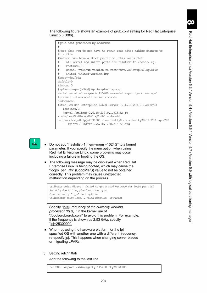
297
8 R
ed Hat E
nterprise Linux Version 5.3 / V
ersion 5.4 / Version 5.6 / V
ersion 5.7 / Version 5.9 w
ith logical partitioning manager
The following figure shows an example of grub.conf setting for Red Hat Enterprise Linux 5.6 (X86).
Do not add “hashdist=1 mem=mem =1024G” to a kernel
parameter. If you specify the mem option when using Red Hat Enterprise Linux, some problems may occur including a failure in booting the OS.
The following message may be displayed when Red Hat Enterprise Linux is being booted, which may cause the “loops_per_jiffy” (BogoMIPS) value to not be obtained correctly. This problem may cause unexpected malfunction depending on the process.
Specify “lpj=[Frequency of the currently working
processor (KHz)]” in the kernel line of “/boot/grub/grub.conf” to avoid this problem. For example, if the frequency is shown as 2.53 GHz, specify “lpj=2530000”.
When replacing the hardware platform for the lpj-specified OS with another one with a different frequency, re-specify jpj. This happens when changing server blades or migrating LPARs.
3 Setting /etc/inittab
Add the following to the last line.
calibrate_delay_direct() failed to get a good estimate for loops_per_jiff
Probably due to long platform interrupts.
Consider using "lpj=" boot option.
Calibrating delay loop... XX.XX BogoMIPS (lpj=XXXX)
co:2345:respawn:/sbin/agetty 115200 ttyS0 vt100
#grub.conf generated by anaconda
#
#Note that you do not have to rerun grub after making changes to
this file
#Notice: You have a /boot partition. this means that
# all kernel and initrd paths are relative to /boot/, eg.
# root(hd0,0)
# kernel /vmlinuz-version ro root=/dev/VolGroup00/LogVol00
# initrd /initrd-version.img
#boot=/dev/sda
default=0
timeout=5
#splashimage=(hd0,0)/grub/splash.xpm.gz
serial --unit=0 --speed= 115200 --word=8 --parity=no --stop=1
terminal --timeout=10 serial console
hiddenmenu
title Red Hat Enterprise Linux Server (2.6.18-238.9.1.el5PAE)
root(hd0,0)
kernel /vmlinuz-2.6.18-238.9.1.el5PAE ro
root=/dev/VolGroup00/LogVol00 nodmraid
nmi_watchdog=0 lpj=2530000 console=tty0 console=ttyS0,115200 vga=792
initrd / initrd-2.6.18.-238.el5PAE.img

298
8 R
ed Hat E
nterprise Linux Version 5.3 / V
ersion 5.4 / Version 5.6 / V
ersion 5.7 / Version 5.9 w
ith logical partitioning manager
4 Setting /etc/sysconfig/kudzu
Change “SAFE=no” to the following.
5 Setting /etc/securetty Add the following to the last line.
6 Setting /etc/sysconfig/init
Change “BOOTUP=color” to the following. 7 Customizing TCP Checksum Offload
The following table shows offload option setting items and values.
NIC scheduling
mode Device name
Offload setting value (essential)
rx tx tso sg gro
Shared NIC and virtual NIC
Intel® PRO/1000 Ethernet (NIC1) off on on on off
Intel® 82576 Ethernet (NIC2) Dedicated NIC
Intel® 82576 Ethernet off off off off off
Broadcom 1Gbps Ethernet
Intel® 82599 Ethernet on on on on off
Emulex 10Gbps Ethernet on on on on on
If TCP Checksum Offload is enabled in a LAN controller, packet data may be destroyed due to failure in the LAN controller.
SAFE=yes
ttySO
BOOTUP=serial

299
8 R
ed Hat E
nterprise Linux Version 5.3 / V
ersion 5.4 / Version 5.6 / V
ersion 5.7 / Version 5.9 w
ith logical partitioning manager
Examples: (a) Using shared NIC and virtual NIC
Perform the ethtool command to disable TCP Checksum Offload for receive. Add the same number of ethtool commands as that of LAN controllers to /sbin/ifup-pre-local as shown below, and reboot the OS. The new settings are automatically configured at the OS boot. Example: To disable two LAN controllers Add the following line to /sbin//ifup-pre-local on condition that the OS recognizes them as network devices eht0 and eth1.
When rx is set to off, gro is automatically set to off. If there is no /sbin/ifup-pre-local file, create a new file with the file privilege 755 and add the setting above. When the file exists, add the setting above to the file. Then reboot the OS or the network device with the new setting, which makes the new setting take effect.
(b) Using Intel® 82576 Ethernet or Broadcom 1Gbps Ethernet as dedicated NIC Perform the ethtool command to disable TCP Checksum Offload for both receive and transmit. Add the same number of ethtool commands as that of LAN controllers to /sbin/ifup-pre-local, as shown below, and reboot the OS. The new settings are automatically configured during the OS boot. Example: To disable two LAN controllers Add the following line to /sbin//ifup-pre-local on condition that the OS recognizes them as network devices eht0 and eth1.
When rx is set to off, gro is automatically set to off. When tx is set to off, tso and sg are automatically set to off. If there is no /sbin/ifup-pre-local file, create a new file with the file privilege 755 and add the setting above. When the file exists, add the setting above to the file. Then reboot the OS or the network device with the new setting, which makes the new setting take effect.
if [ "${1}" == "ifcfg-eth0" ]; then
/sbin/ethtool -K eth0 rx off
fi
if [ "${1}" == "ifcfg-eth1" ]; then
/sbin/ethtool -K eth1 rx off
fi
if [ "${1}" == "ifcfg-eth0" ]; then
/sbin/ethtool -K eth0 rx off
/sbin/ethtool -K eth0 tx off
fi
if [ "${1}" == "ifcfg-eth1" ]; then
/sbin/ethtool -K eth1 rx off
/sbin/ethtool -K eth1 tx off
fi

300
8 R
ed Hat E
nterprise Linux Version 5.3 / V
ersion 5.4 / Version 5.6 / V
ersion 5.7 / Version 5.9 w
ith logical partitioning manager
(c) Using Intel® 82599 Ethernet as dedicated NIC Perform the ethtool command to disable generic-receive-offload. Add the same number of ethtool commands as that of LAN controllers to /sbin/ifup-pre-local as shown below, and reboot the OS. The new settings are automatically configured at the OS boot. Example: To enable two LAN controllers Add the following line to /sbin//ifup-pre-local on condition that the OS recognizes them as network devices eht0 and eth1.
If there is no /sbin/ifup-pre-local file, create a new file with the file privilege 755 and add the setting above. When the file exists, add the setting above to the file. Then reboot the OS or the network device with the new setting, which makes the new setting take effect.
8 Setting /etc/modprobe.conf
This setting blocks loading drivers to prevent unnecessary devices from being detected. Add # to the head of the line that includes e1000e, which comments out the line.
9 Setting /etc/modprobe.d/blacklist.conf Add the following at the last line. This setting blocks loading drivers to prevent unnecessary devices from being detected.
10 Setting /etc/sysctl.conf Perform settings (1) through (3) for customizing /etc/sysctl.conf. (1) Setting the log level to 3
Add the following line.
alias eth0 igb
alias eth1 igb
alias eth2 igb
alias eth3 igb
alias eth4 igb
alias eth5 igb
#alias ethx e1000e
alias scsi_hostadapter hradrv
alias scsi_hostadapter1 ata_piix
alias scsi_hostadapter2 usb-storage
blacklist e1000e
kernel.printk = 3 4 1 7
if [ "${1}" == "ifcfg-eth0" ]; then
/sbin/ethtool -K eth0 gro off
fi
if [ "${1}" == "ifcfg-eth1" ]; then
/sbin/ethtool -K eth0 gro off
fi

301
8 R
ed Hat E
nterprise Linux Version 5.3 / V
ersion 5.4 / Version 5.6 / V
ersion 5.7 / Version 5.9 w
ith logical partitioning manager
When the OS console log level is set by default in Linux, a large amount of data may output on the guest screen, which may lead to significant performance degradation or Linux hang-up. Set the console log level to 3 as shown above, so that you can obtain OS console logs reliably using the guest screen.
(2) Enabling the magic SysRq key Edit or add the following line.
This setting is required for information to be obtained when a problem occurs. (3) Enabling NMI
Edit or add the following line.
This setting causes a kernel panic to occur when NMI is generated to quickly detect failures in hardware or drivers.
11 Setting /etc/sysconfig/syslog Change KLOGD_OPTIONS=”-x” to the following.
When using Red Hat Enterprise Linux 5.6/5.7/5.9 (X86), set the following item 12. When using Red Hat Enterprise Linux 5.6/5.7/5.9 (X86_64), jump to item 13. 12 Setting /etc/sysconfig/clock
Add the following at the last line.
The OS system time with Red Hat Enterprise Linux 5.6/5.7 (X86) may delay by the time zone at the OS boot and shutdown. This setting is required for avoiding that problem.
13 Rebooting the system Type the following, and press Enter to reboot the system.
14 Checking the log level Enter the following after booting the system, and press Enter to check the log level.
kernel.sysrq = 1
kernel.unknown_nmi_panic=0
kernel.panic_on_unrecovered_nmi=1
KLOGD_OPTIONS="-x -c 3"
ZONE="Asia/Tokyo"
UTC=false
ARC=false
CLOCKFLAGS="--directisa"
# reboot
# cat /proc/sys/kernel/printk
3 4 1 7 <<< the result of the command above

302
8 R
ed Hat E
nterprise Linux Version 5.3 / V
ersion 5.4 / Version 5.6 / V
ersion 5.7 / Version 5.9 w
ith logical partitioning manager
15 Checking the NMI setting Type the following after booting the system and press Enter to check the NMI setting.
See Notes and restrictions on Linux 5.6/5.7/5.9. When the settings above have been completed, perform Driver/Kernel setup.
# /sbin/sysctl -n kernel.unknown_nmi_panic
0 <<< the result of the command above
# /sbin/sysctl -n kernel.panic_on_unrecovered_nmi
1 <<< the result of the command above

303
8 R
ed Hat E
nterprise Linux Version 5.3 / V
ersion 5.4 / Version 5.6 / V
ersion 5.7 / Version 5.9 w
ith logical partitioning manager
Driver/Kernel setup This subsection describes the procedure for setting up drivers/kernels.
1 Copy the driver for your kernel before updating the kernel.
(1) Perform the following command to check your architecture.
# uname –m
Performing the command above will display the following results depending on the architecture: X86 (i686): i686 AMD/Intel64 (x86_64): x86_64
Some steps described below depend on the architecture. (2) Insert the driver CD into the CD/DVD-ROM drive. (3) Perform the following command to mount the driver CD.
(4) Perform the following command to retrieve the driver from the driver CD. (5) Perform one of the following commands depending on the architecture to check
that the driver is stored in the local disk. RHEL 5.6
x86 (i686): # ls 2.6.18-238.el5PAE/i686/
e1000.ko hfcldd.ko hfcldd_conf.ko igb.ko ixgbe.ko
AMD/Intel64 (x86_64): # ls 2.6.18-238.el5/x86_64/
e1000.ko hfcldd.ko hfcldd_conf.ko igb.ko ixgbe.ko
RHEL 5.7 x86 (i686): # ls 2.6.18-274.el5PAE/i686/
e1000.ko hfcldd.ko hfcldd_conf.ko igb.ko ixgbe.ko
tg3.ko be2net.ko
AMD/Intel64 (x86_64): # ls 2.6.18-274.el5/x86_64/
e1000.ko hfcldd.ko hfcldd_conf.ko igb.ko ixgbe.ko
tg3.ko be2net.ko
# mount /dev/cdrom /media/
# mkdir -p /tmp/hitachi_drv
# zcat /media/modules.cgz >
/tmp/hitachi_drv/hitachi_modules.cgz.tmp
# cd /tmp/hitachi_drv
# cat hitachi_modules.cgz.tmp | cpio -iumd

304
8 R
ed Hat E
nterprise Linux Version 5.3 / V
ersion 5.4 / Version 5.6 / V
ersion 5.7 / Version 5.9 w
ith logical partitioning manager
RHEL 5.9 x86 (i686): # ls 2.6.18-348.el5PAE/i686/
e1000.ko hfcldd.ko hfcldd_conf.ko igb.ko ixgbe.ko
tg3.ko be2net.ko
AMD/Intel64 (x86_64): # ls 2.6.18-348.el5/x86_64/
e1000.ko hfcldd.ko hfcldd_conf.ko igb.ko ixgbe.ko
tg3.ko be2net.ko
(6) Perform one of the following commands depending on the architecture to create a directory for updating the kernel. RHEL 5.6
x86 (i686): # mkdir –p /lib/modules/2.6.18-238.9.1.el5PAE/updates
AMD/Intel64 (x86_64): # mkdir –p /lib/modules/2.6.18-238.9.1.el5/updates
RHEL 5.7 x86 (i686): # mkdir -p /lib/modules/2.6.18-274.18.1.el5PAE/updates
AMD/Intel64 (x86_64): # mkdir -p /lib/modules/2.6.18-274.18.1.el5/updates
RHEL 5.9 x86 (i686): # mkdir -p /lib/modules/2.6.18-348.6.1.el5PAE/updates
AMD/Intel64 (x86_64): # mkdir -p /lib/modules/2.6.18-348.6.1.el5/updates
(7) Perform one of the following commands depending on the architecture to copy the driver. RHEL 5.6
x86 (i686): # cp –a 2.6.18-238.el5PAE/i686/* /lib/modules/2.6.18-
238.9.1.el5PAE/updates/.
# ls /lib/modules/2.6.18-238.9.1.el5PAE/updates/
e1000.ko hfcldd.ko hfcldd_conf.ko hradrv.ko
hraslog_link.ko igb.ko ixgbe.ko
AMD/Intel64 (x86_64): # cp –a 2.6.18-238.el5/x86_64/* /lib/modules/2.6.18-
238.9.1.el5/updates/.
# ls /lib/modules/2.6.18-238.9.1.el5/updates/
e1000.ko hfcldd.ko hfcldd_conf.ko hradrv.ko
hraslog_link.ko igb.ko ixgbe.ko
RHEL 5.7 x86 (i686): # cp -a 2.6.18-274.el5PAE/i686/* /lib/modules/2.6.18-
274.18.1.el5PAE/updates/.
# ls /lib/modules/2.6.18-274.18.1.el5PAE/updates/

305
8 R
ed Hat E
nterprise Linux Version 5.3 / V
ersion 5.4 / Version 5.6 / V
ersion 5.7 / Version 5.9 w
ith logical partitioning manager
e1000.ko hfcldd.ko hfcldd_conf.ko igb.ko ixgbe.ko tg3.ko
be2net.ko
AMD/Intel64 (x86_64): # cp -a 2.6.18-274.el5/x86_64/* /lib/modules/2.6.18-
274.18.1.el5/updates/.
# ls /lib/modules/2.6.18-274.18.1.el5/updates/
e1000.ko hfcldd.ko hfcldd_conf.ko igb.ko ixgbe.ko tg3.ko
be2net.ko
RHEL 5.9 x86 (i686): # cp -a 2.6.18-348.el5PAE/i686/* /lib/modules/2.6.18-
348.6.1.el5PAE/updates/.
# ls /lib/modules/2.6.18-348.6.1.el5PAE/updates/
e1000.ko hfcldd.ko hfcldd_conf.ko igb.ko ixgbe.ko
tg3.ko be2net.ko
AMD/Intel64 (x86_64): # cp -a 2.6.18-348.el5/x86_64/* /lib/modules/2.6.18-
348.6.1.el5/updates/.
# ls /lib/modules/2.6.18-348.6.1.el5/updates/
e1000.ko hfcldd.ko hfcldd_conf.ko igb.ko ixgbe.ko
tg3.ko be2net.ko
(8) Perform the following command to unmount the driver CD. # umount /media/
(9) Perform the following command to delete the working directory. # cd /tmp
# rm –rf /tmp/hitachi_drv
2 Add settings before updating the security kernel.
With an Emulex 10 Gbps LAN adapter installed, you need to add settings for the driver before updating the security kernel in Step 3.
Make sure to execute the following procedure before updating the kernel. If not, a proper driver might not be applied.
Target device driver
be2net driver
Type the following to check if be2net driver is used. # lsmod ¦ grep be2net
be2net xxxxxxx 0
When be2net driver is displayed by the above, add the following setting to the driver. # echo "override be2net 2.6.32-* weak-updates/be2net" >
/etc/depmod.d/be2net.conf
# chmod 644 /etc/depmod.d/be2net.conf

306
8 R
ed Hat E
nterprise Linux Version 5.3 / V
ersion 5.4 / Version 5.6 / V
ersion 5.7 / Version 5.9 w
ith logical partitioning manager
3 Update the security kernel. Download the security update kernel from the Red Hat website referring to the table below and apply it.
Model/OS version
Standard server blade:
High-performance server blade
X55A1/ X55A2
X55R3/X55S3
X57A1/X57A2
RHEL 5.6
X86 kernel-PAE-2.6.18- 238.9.1.el5.i686.rpm
Update - Update
AMD/ Intel64
kernel-2.6.18-238.9.1.el5.x86_64.rpm Update - Update
RHEL 5.7
X86 kernel-PAE-2.6.18- 274.18.1.el5.i686.rpm
Update Update Update
AMD/ Intel64
kernel-2.6.18-274.18. 1.el5.x86_64.rpm Update Update Update
RHEL 5.9
X86 kernel-PAE-2.6.18- 348.6.1.el5.i686.rpm
Update Update Update
AMD/ Intel64
kernel-2.6.18-348.6. 1.el5.x86_64.rpm Update Update Update
Update: Download the update kernel to apply.
- : Update is not required.
Red Hat Inc. kernel security and bug fix update https://rhn.redhat.com
4 Update the Hitachi Fibre-channel driver. With the configuration using the Hitachi Gigabit Fibre-channel adapter, install hfcldd driver (RPM package) following step (a) through step (c). (a) Copy the latest hfcldd driver (RPM package), contained in HITACHI Gigabit
Fibre-channel Adapter Drivers CD-ROM (*1) attached to the system unit, under /tmp. (*1) Make sure to use Ver.03-00 or later for 8 Gbps Hitachi Gigabit Fibre-channel Adapter.
(b) Install RPM package referring to the Hitachi Gigabit Fibre-channel Adapter User’s Guide (Linux/VMware Driver Edition). The following is an example.
(c) Check that the installation is completed, referring to the Hitachi Gigabit Fibre-channel Adapter User’s Guide (Linux/VMware Driver Edition).
# rpm -ivh --force /tmp/[RPM package name for hfcldd driver]
# rpm -ivh --force /tmp/[RPM package name for hfcldd-tools]

307
8 R
ed Hat E
nterprise Linux Version 5.3 / V
ersion 5.4 / Version 5.6 / V
ersion 5.7 / Version 5.9 w
ith logical partitioning manager
Appendix Table 1: Values for Red hat Enterprise Linux on LPAR
Setting item (Setting file) Setting value (Essential)
Guest OS Red Hat Enterprise Linux 5 Red Hat Enterprise Linux 6
Architecture x86 x64 X86 x64
Offload option settings See Table 2: Values for offload options.
kernel line of /boot/grub/grub.conf
Linux 5.3 clocksource=hp
et added
Linux 5.3 notsc added
mce 0 pci=noaer no_timer_check added
Linux 5.4/5.6/5.7/5.9
No setting required. *1
Linux 5.4/5.6/5.7/5.9 clock=tsccount
added *2 nmi_watchdog=0 added
rhgb (and) quiet removed vga=792*3
- No setting required.
- No setting required.
/etc/sysctl.conf kernel.unknown_nmi_panic=0 added
kernel.panic_on_unrecoverd_nmi=1 added
kernel.unknown_nmi_panic=0 added
kernel.panic_on_unrecoverd_nmi=1 added
kernel.panic_on_io_nmi=1 added kernel.printk = 3 4 1 7 added
/etc/sysconfig/syslog Change KLOGD_OPTIONS (before changed)
KLOGD_OPTIONS="-x" (after changed)
KLOGD_OPTIONS="-x -c 3"
- No setting required.
/etc/sysconfig/clock CLOCKFLAGS="--directisa"
added
- No setting required.
- No setting required.
Serial console
/boot/grub/grub.conf Comment out the line of splashimage=(hd0,0)/grub/splash.xpm.gz (before changed) splashimage=(hd0,0)/grub/splash.xpm.gz (after changed) #splashimage=(hd0,0)/grub/splash.xpm.gz
Add the following 2 lines between lines of hiddenmenu and title. Linux 5.6 serial --unit=0 --speed=115200 --word=8 --parity=no --stop=1
Linux 5.7 or higher serial --unit=0 --speed=115200 terminal --timeout=10 serial console
Add the following at the end of the kernel line.
console=tty0 console=ttyS0,115200
Add the following at the end of the kernel line.
console=ttyS0,115200
/etc/sysconfig/init Change BOOTUP. (before changed) BOOTUP=color (after changed) BOOTUP=serial
/etcsysconfig/kudzu Change SAFE. (before changed) SAFE=no (after changed) SAFE=yes
- No setting required.
/etc/inittab Add co:2345:respawn:/sbin/agetty 115200 ttyS0 vt100 to the bottom
line.
- No setting required.

308
8 R
ed Hat E
nterprise Linux Version 5.3 / V
ersion 5.4 / Version 5.6 / V
ersion 5.7 / Version 5.9 w
ith logical partitioning manager
Setting item (Setting file) Setting value (Essential)
Guest OS Red Hat Enterprise Linux 5 Red Hat Enterprise Linux 6
Architecture x86 x64 X86 x64
/etc/securetty Add ttyS0 to the bottom line. - No setting required.
*1 If the kernel parameter (clocksource=hpet) is added when you install Linux, delete the parameter.
*2 If the kernel parameter (notsc) is added when you install Linux, delete the parameter and add clock=tsccount..
*3 Add this parameter if LPAR manager version is 59-41/79-41 or higher.
Table 2: Values for offload options
NIC scheduling
mode Device name
Offload setting value (essential)
rx tx tso sg gro
Shared NIC and virtual NIC
Intel® PRO/1000 Ethernet (NIC1) off on on on off
Intel® 82576 Ethernet (NIC2) Dedicated NIC
Intel® 82576 Ethernet off off off off off
Broadcom 1Gbps Ethernet
Intel® 82599 Ethernet on on on on off
Emulex 10Gbps Ethernet on on on on on
309
9 Red Hat Enterprise Linux Version 6 with logical partitioning manager
This chapter explains the use of Red Hat Enterprise Linux Version 6.1 / 6.2 / 6.4 on logical partitioning manager (LPAR manager) using the driver CD. Please note that this chapter may be updated without notice.
Using Red Hat Enterprise Linux 6.1/6.2/6.4 with LPAR manager ....................... 310
Notes and restrictions on Linux 6.1/6.2/6.4 ......................................................... 311
Setting up Red Hat Enterprise Linux 6.1/6.2/6.4 ................................................. 319
Utility ................................................................................................................... 329
Appendix ............................................................................................................. 330

310
9 R
ed Hat E
nterprise Linux Version 6 w
ith logical partitioning manager
Using Red Hat Enterprise Linux 6.1/6.2/6.4 with LPAR manager Red Hat Enterprise Linux 6.1/6.2/6.4 can be installed on a virtual environment provided by LPAR manager, which is called LPAR.
Prerequisites for setup The procedure described later uses Red Hat Enterprise Linux 6.1/6.2/6.4 installation DVD and Hitachi driver. If you use a setup CD provided by Linux support service, see the user’s guide given by that support service. Make sure to use media for Red Hat Enterprise Linux 6.1/6.2/6.4 for the respective setup. Never use any other media. Make sure also to use the driver specified for Red Hat Enterprise Linux 6.1/6.2/6.4 for the respective setup. Never use any other driver. If you use a driver not corresponding to the version, the OS will not work properly. LPAR manager LPAR supports the following operating
systems.
- Red Hat Enterprise Linux 6.1/6.2/6.4 (X86)
- Red Hat Enterprise Linux 6.1/6.2/6.4 (X86_64) When Emulex 10 Gb LAN mezzanine card is used as a
dedicated NIC, see the 10 Gb Converged Network Production Instruction Manual to check supported operating systems. Multi-channel, iSCSI, and FCoE are not available.
The following kernel versions are supported.
For Red Hat Enterprise Linux 6.1:
32-bit X86: 2.6.32-131.0.15.el6 or later 64 bit X86_64: 2.6.32-131.0.15.el6 or later For Red Hat Enterprise Linux 6.2: 32-bit X86: 2.6.32-220.4.2.el6 or later 64 bit X86_64: 2.6.32-220.4.2.el6 or later For Red Hat Enterprise Linux 6.4 32-bit X86: 2.6.32-358.23.2.el6 or later 64-bit X86_64: 2.6.32-358.23.2.el6 or later For Red Hat Enterprise Linux 6.5 32-bit X86: 2.6.32-431.5.1.el6 or later 64-bit X86_64: 2.6.32-431.5.1.el6 or later Contact your reseller about the latest recommended driver version for Red Hat Enterprise Linux 6.1/6.2/6.4 and download it.

311
9 R
ed Hat E
nterprise Linux Version 6 w
ith logical partitioning manager
Notes and restrictions on Linux 6.1/6.2/6.4 This subsection describes notes and restrictions about using Red hat Enterprise Linux 6.1/6.2/6.4 with an LPAR.
Notes on the network hbonding/bonding cannot bond virtual NICs and dedicated NICs. When using virtual NICs and shared NICs with RHEL 6.1, set NIC1
(PRO/1000) as VNIC Device Type on the Virtual NIC Assignment screen. When using virtual NICs and shared NICs with RHEL 6.2/6.4, set NIC2 (Intel
82576) as VNIC Device Type on the Virtual NIC Assignment screen.
Some items may not be displayed depending on the type of network adapter. Configure settings for the items displayed with the adapter you use.
Notes on the Fibre-channel driver Use the latest gigabit Fibre-channel adapter on LPAR manager LPAR.
Restrictions during setup The following table shows the recommended LPAR configuration for using
Red Hat Enterprise Linux 6.1/6.2/6.4. Adjust resources to assign to an LPAR for the system environment.
Setting item Recommended value Processor 2 or more *1
Memory 2.0 GB *2
Disk Partition to install the OS: 40 GB or larger *3
Network At least 1 (one) virtual NIC
USB 1 *1 Minimum value is 1.
*2 Minimum value is 1.0 GB
*3 Minimum value is 23 GB.
A Shared NIC/Virtual NIC may not be recognized as a network device at the first OS boot after the setup. Reboot the OS to recognize the virtual NIC properly.
When you use a USB port different from the USB port used in registering the boot option, the USB DVD drive may not be recognized. If so, re-register the boot option.
Boot device You can use a Fibre-channel mezzanine card or Fibre-channel adapter as a boot device. See the Gigabit Fibre-channel Adapter User’s Guide for the setup procedure.
Time Required for X Logout With X logout, it may take about 5 to 10 minutes to complete the logout which has no effect on the system behavior.
MTU Setting for ixgbe driver on 32-bit x86 kernel
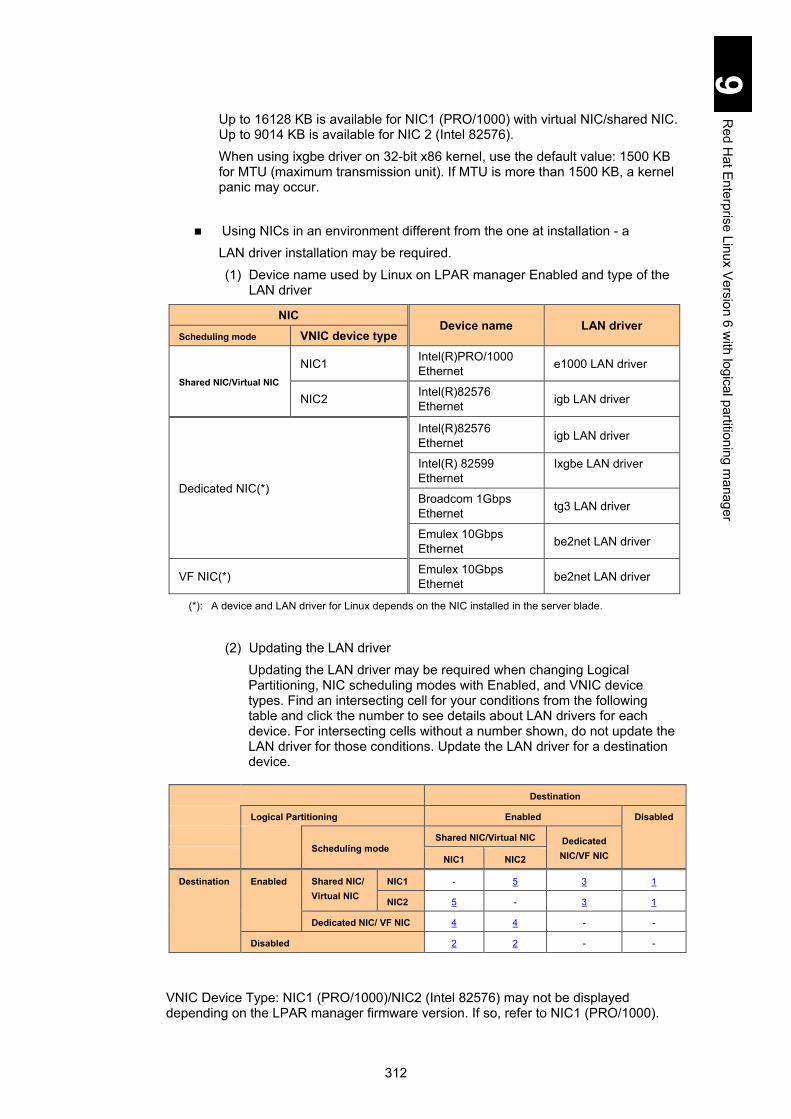
312
9 R
ed Hat E
nterprise Linux Version 6 w
ith logical partitioning manager
Up to 16128 KB is available for NIC1 (PRO/1000) with virtual NIC/shared NIC. Up to 9014 KB is available for NIC 2 (Intel 82576). When using ixgbe driver on 32-bit x86 kernel, use the default value: 1500 KB for MTU (maximum transmission unit). If MTU is more than 1500 KB, a kernel panic may occur.
Using NICs in an environment different from the one at installation - a LAN driver installation may be required. (1) Device name used by Linux on LPAR manager Enabled and type of the
LAN driver
NIC Device name LAN driver
Scheduling mode VNIC device type
Shared NIC/Virtual NIC
NIC1 Intel(R)PRO/1000 Ethernet e1000 LAN driver
NIC2 Intel(R)82576 Ethernet igb LAN driver
Dedicated NIC(*)
Intel(R)82576 Ethernet igb LAN driver
Intel(R) 82599 Ethernet
Ixgbe LAN driver
Broadcom 1Gbps Ethernet tg3 LAN driver
Emulex 10Gbps Ethernet be2net LAN driver
VF NIC(*) Emulex 10Gbps Ethernet be2net LAN driver
(*): A device and LAN driver for Linux depends on the NIC installed in the server blade.
(2) Updating the LAN driver
Updating the LAN driver may be required when changing Logical Partitioning, NIC scheduling modes with Enabled, and VNIC device types. Find an intersecting cell for your conditions from the following table and click the number to see details about LAN drivers for each device. For intersecting cells without a number shown, do not update the LAN driver for those conditions. Update the LAN driver for a destination device.
Destination
Logical Partitioning Enabled Disabled
Scheduling mode
Shared NIC/Virtual NIC Dedicated NIC/VF NIC NIC1 NIC2
Destination Enabled Shared NIC/ Virtual NIC
NIC1 - 5 3 1
NIC2 5 - 3 1
Dedicated NIC/ VF NIC 4 4 - -
Disabled 2 2 - -
VNIC Device Type: NIC1 (PRO/1000)/NIC2 (Intel 82576) may not be displayed depending on the LPAR manager firmware version. If so, refer to NIC1 (PRO/1000).

313
9 R
ed Hat E
nterprise Linux Version 6 w
ith logical partitioning manager
1 Changing the Logical Partitioning from Enabled (Shared NIC/Virtual NIC) to Disabled: When changing modes from Enabled (Shared NIC/Virtual NIC) to Disabled, you may need to update the LAN driver. Update the driver referring to the following table.
Destination
Logical Partitioning Disabled
Scheduling mode
Device
name
VNIC
device type
Intel(R) 82576
Ethernet
Intel(R) 82599
Ethernet
Broadcom 1Gbps
Ethernet
Emulex 10Gbps Ethernet
Desti-nation
Enabled
Shared NIC/ Virtual NIC
NIC1 Update Update Update Update
NIC2 - Update Update Update
Update: Updating the driver is required. -: Updating the driver is not required.
2 Changing the Logical Partitioning from Disabled to Enabled (Shared NIC/Virtual NIC) When changing Logical Partitioning from Disabled to Enabled (Shared NIC/Virtual NIC), you may need to update the LAN driver. Update the driver referring to the following table.
Destination
Logical Partitioning Enabled
Shared NIC/Virtual NIC
Virtual NIC/Shared NIC
VNIC Device Type
Device name NIC1 NIC2
Destination Disabled Intel(R) 82576 Ethernet Update -
Intel(R) 82599 Ethernet Update Update
Broadcom 1Gbps Ethernet Update Update
Emulex 10Gbps Ethernet Update Update
Update: Updating the driver is required.
-: Updating the driver is Not required.
3 Changing the scheduling mode from LPAR manager (Shared NIC/Virtual NIC) to LPAR manager (Dedicated NIC/VF NIC)
When changing scheduling modes from LPAR manager (Shared NIC/Virtual NIC) to LPAR manager (Dedicated NIC/VF NIC), you may need to update the LAN driver. Update the driver referring to the following table.
Destination
Scheduling mode Dedicated NIC/VF NIC
Device VNIC name Device Type
Intel(R) 82576
Ethernet
Intel(R) 82599
Ethernet
Broadcom 1Gbps
Ethernet
Emulex 10Gbps Ethernet
Destination Shared NIC/ Virtual NIC
NIC1 Update Update Update Update
NIC2 - Update Update Update
Update: Updating the driver is required. -: Updating the driver is not required.

314
9 R
ed Hat E
nterprise Linux Version 6 w
ith logical partitioning manager
4 Changing the scheduling mode from LPAR manager (Dedicated NIC/VF NIC) to
LPAR manager (Shared NIC/Virtual NIC) When changing scheduling modes from LPAR manager (Dedicated NIC/VF NIC) to
LPAR manager (Shared NIC/Virtual NIC), you may need to update the LAN driver. Update the driver referring to the following table.
Destination
Scheduling mode Shared NIC/Virtual NIC
VNIC device type
Device name NIC1 NIC2
Destination Dedicated NIC/VF NIC
Intel(R) 82576 Ethernet Update -
Intel(R) 82599 Ethernet Update Update
Broadcom 1Gbps Ethernet Update Update
Emulex 10Gbps Ethernet Update Update
Update: Updating the driver is required.
-: Updating the driver is not required.
5 Changing LPAR manager (Shared NIC/Virtual NIC) device types When changing LPAR manager (Shared NIC/Virtual NIC C) device types, you may
need to update the LAN driver. Update the driver referring to the following table.
Destination
Scheduling mode Shared NIC/Virtual NIC
VNIC Device Type NIC1 NIC2
Destination Shared NIC/ Virtual NIC
NIC1 - Update
NIC2 Update -
Update: Updating the driver is required.
-: Updating the driver is not required.
(3) LAN driver installation Install the LAN driver contained in the Compute Systems Installer. When using the latest driver, contact your reseller.
(4) Check the updating status
[How to check e1000 LAN driver] Execute the following command to check that e1000 LAN driver is updated. #modinfo -F version e1000 Displayed example: 7.5.5-NAPI When the applied driver version is displayed, e1000 LAN driver has been applied.

315
9 R
ed Hat E
nterprise Linux Version 6 w
ith logical partitioning manager
[How to check the igb LAN driver] Execute the following command to check that the igb LAN driver is updated. #modinfo -F version igb Displayed example: 1.3.8.6-h1 When the applied driver version is displayed, the igb LAN driver has been applied. [How to check the tg3 LAN driver] Execute the following command to check that the tg3 LAN driver is updated. #modinfo -F version tg3 Displayed example: 3.122g When the applied driver version is displayed, the tg3 LAN driver has been applied. [How to check the be2net LAN driver] Execute the following command to check that the be2net LAN driver is updated. #modinfo -F version be2net Displayed example: 4.1.334.18 When the applied driver version is displayed, the be2net LAN driver has been applied.
When the dedicated NIC and shared NIC are simultaneously used on the following condition, the assignment between network devices and network interface (ethN) may be unstable. - An OS is installed in the LPAR where both dedicated and shared NICs are assigned. - After a NIC is added to an LPAR, an OS is booted in the environment where both dedicated and shared NICs are assigned. Initialize the network device assignment by following the steps described below. In this procedure, assign the same order as PCI device recognition to network interfaces (ethN): starting from the onboard NIC in shared mode and going to the I/O board (LAN board in dedicated mode), LAN expansion card in dedicated mode, and then NIC in shared mode. The following initialization procedure is an example including one igb LAN driver in dedicated mode and one e1000 LAN driver in shared mode.
(1) Halt the network service.
# service network stop
(2) Unload the network driver. # rmmod e1000 # rmmod igb
(3) Save the current network setting file in a directory. The following example
shows that the file is saved in or under \tmp directory. # mv \etc\sysconfig\network-scripts\ifcfg-eth* \tmp

316
9 R
ed Hat E
nterprise Linux Version 6 w
ith logical partitioning manager
(4) Save the current hardware information file in a directory. The following
example shows that the file is in or under \tmp directory. No file may exist immediately after the installation. If not, go to step (5). # ls \etc\sysconfig\hwconf \etc\sysconfig\hwconf This means that no file exists and go on to step (5). # mv \etc\sysconfig\hwconf \tmp
(5) Load the igb driver.
# modprobe igb
(6) Confirm that the igb driver is loaded. # lsmod | grep igb igb 67600 0
(7) Load the e1000 driver.
# modprobe e1000
(8) Confirm that the e1000 driver is loaded. # lsmod | grep e1000 e1000 200460 0
(9) Create the setting file for the shared NIC using the kudzu command.
# kudzu
(10) Confirm that NIC setting files are created by the same number as assigned network devices.
# ls \etc\sysconfig\network-scripts\ifcfg-eth*
(11) Find out setting files with the same MAC address (HWADDR) among files saved in step (3) and confirmed in step (10), and reflect the contents of the saved file on the files in step (10) without changing device parameters.
Example: Find out the setting file of MAC address [00:00:87:62:5F:08], and then add parameters with an arrow in the saved setting file to the newly created setting file. In this example, interface “eht2” is a saved file and interface “eth3” is a newly created file. - Saved setting file: /tmp/ifcfg-eth2 # Intel Corporation 82546GB Gigabit Ethernet Controller DEVICE=eth2 BOOTPROTO=static BROADCAST=10.208.179.255 HWADDR=00:00:87:62:5F:08 IPADDR=10.208.179.22 NETMASK=255.255.255.0
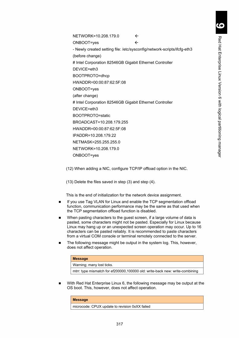
317
9 R
ed Hat E
nterprise Linux Version 6 w
ith logical partitioning manager
NETWORK=10.208.179.0 ONBOOT=yes - Newly created setting file: /etc/sysconfig/network-scripts/ifcfg-eth3 (before change) # Intel Corporation 82546GB Gigabit Ethernet Controller DEVICE=eth3 BOOTPROTO=dhcp HWADDR=00:00:87:62:5F:08 ONBOOT=yes (after change) # Intel Corporation 82546GB Gigabit Ethernet Controller DEVICE=eth3 BOOTPROTO=static BROADCAST=10.208.179.255 HWADDR=00:00:87:62:5F:08 IPADDR=10.208.179.22 NETMASK=255.255.255.0 NETWORK=10.208.179.0 ONBOOT=yes
(12) When adding a NIC, configure TCP/IP offload option in the NIC.
(13) Delete the files saved in step (3) and step (4).
This is the end of initialization for the network device assignment.
If you use Tag VLAN for Linux and enable the TCP segmentation offload function, communication performance may be the same as that used when the TCP segmentation offload function is disabled.
When pasting characters to the guest screen, if a large volume of data is pasted, some characters might not be pasted. Especially for Linux because Linux may hang up or an unexpected screen operation may occur. Up to 16 characters can be pasted reliably. It is recommended to paste characters from a virtual COM console or terminal remotely connected to the server.
The following message might be output in the system log. This, however, does not affect operation.
Message
Warning; many lost ticks.
mtrr: type mismatch for ef200000,100000 old: write-back new: write-combining
With Red Hat Enterprise Linux 6, the following message may be output at the OS boot. This, however, does not affect operation.
Message
microcode: CPUX update to revision 0xXX failed

318
9 R
ed Hat E
nterprise Linux Version 6 w
ith logical partitioning manager
With Red Hat Enterprise Linux 6, the following message may be output when the number of logical processors assigned to each LPAR is more than that of physical processors installed in the server blade. This, however, does not affect operation.
Message
hrtimer: interrupt took XXXXXXX ns
When tboot package is installed on Red Hat Enterprise Linux 6, the following message may be output at the OS boot. This, however, does not affect operation.
Message
TBOOT: Error: write TPM error: 0xX.
Basic operations and setting change Basic operations and setting change can be performed using Secure SHell (SSH) or terminal software, after Red Hat Enterprise Linux 6.1/6.2/6.4 is booted on the LPAR manager LPAR.
Booting and resetting LPARs Since the LPAR is a virtual environment, physical buttons including power and reset on the front panel of a server blade and the dump command from a management module are not available for LPAR operation. Make sure to operate an LPAR from the LPAR manager management screen. If you use a physical button, all LPARs running on the server blade may be affected, which may destroy the OS. Never use physical buttons when any LPAR is booted.
Setting the HBA BIOS When a shared Fibre-channel is used as a boot device, the boot may not complete properly depending on the number of LPARs assigned to the shared Fibre-channel. This problem may be avoided by extendin0g LOGIN DELAY TIME, which is an operation parameter for a gigabit Fibre-channel adapter. See the “Option setting procedure” in the Gigabit Fibre-channel Adapter User’s Guide.
Using the remote console Use the remote console only for setting up the OS. Use terminal software for normal operations.
For information on how to use the remote console, see Chapter 3, “Connecting the System Equipment and Powering on” in the Hitachi Compute Blade 2000 User’s Guide.

319
9 R
ed Hat E
nterprise Linux Version 6 w
ith logical partitioning manager
Setting up Red Hat Enterprise Linux 6.1/6.2/6.4 This section describes the setup procedure using the Red Hat Enterprise Linux 6.1/6.2/6.4 installation DVD and the Driver CD.
Required setups Some setups are required including LPAR configuration, OS setup, Linux settings for operation on LPARs, and Driver/kernel setup If each setup has not been completed, the OS might not operate properly.
Setup flowchart The following flowchart includes three types of boxes: procedure for system console shown in double-framed box filled in with light blue; that for remote console shown in single box filled with light green; that for common shown in double-framed box filled with white.
Prerequisites Set TeraTerm: See Hitachi Compute Blade 2000 USER’S GUIDE > Chapter 12: LPAR manager (Hitachi Virtualization Management) for prerequisites.
LP settings Set LP if not set it: See Hitachi Compute Blade 2000 USER’S GUIDE > Chapter 12: LPAR manager (Hitachi Virtualization Management) for LPAR manager boot-up. If you have already set LP, go on to the next step LPAR configuration.
LPAR configuration
Configure LPARs if not configured them: See Hitachi Compute Blade 2000 USER’S GUIDE > Chapter 12: LPAR manager (Hitachi Virtualization Management) for LPAR configuration. If you have already configured LPARs, go on to the next step OS setup.
OS setup Configure environment for setup using one of the following: Perform “Remote CD/DVD” from the remote console, and have the server blade recognize the DVD image file for installation to start the LPAR. Or Connect a USB CD/DVD drive direct to the server blade, and insert the installation DVD to the CD/DVD drive to start the LPAR.
Notice
Re-setup causes the hard disk data to disappear. Back up data that you need in advance.

320
9 R
ed Hat E
nterprise Linux Version 6 w
ith logical partitioning manager
EFI driver : See Hitachi Compute Blade 2000 USER’S GUIDE > Chapter 12: LPAR manager (Hitachi Virtualization Management) for EFI driver settings.
Boot option: See Hitachi Compute Blade 2000 USER’S GUIDE > Chapter 12: LPAR manager (Hitachi Virtualization Management) for boot option settings.
Boot order: See Hitachi Compute Blade 2000 USER’S GUIDE > Chapter 12: LPAR manager (Hitachi Virtualization Management) for changing boot orders.
OS setup: For setting up the OS, see Chapter 5 > How to Install Red Hat Enterprise Linux 6 > Red Hat Enterprise Linux 6 Setup with the Driver CD to perform the procedures. Note: Operations depend on the blade model.
Option settings Required settings: See Setting up Red Hat Enterprise Linux 6.1/6.2/6.4 > Linux settings for operation on the LPAR > for details.
Utility setup Driver/Kernel: See Utility for details.
Finish

321
9 R
ed Hat E
nterprise Linux Version 6 w
ith logical partitioning manager
Linux settings for operation on the LPAR
This section describes setting the items required for using Red Hat Enterprise Linux 6.1/6.2/6.4 and how to configure them. If you have configured all those settings correctly, skip this section. If the settings are different from the following description, however, the OS might not operate properly. 1 Setting the “/etc/inittab” file.
Open the “/etc/inittab” file, change “id:5:initdefault:” on the file to “id:3:initdefault:” and save it.
Reboot the LPAR.
2 Setting /boot/grub/grub.conf. Configure the following settings in grub.conf. - Comment out “splashimage=(hd0,0)/grub/splash.xpm.gz.” - Add “serial --unit=0 --speed= 115200”. - Add “terminal --timeout=10 serial console”. - Remove “quiet rhgb” from the kernel line. - Add the following string at the end of the kernel line.
Add “vga=792” as well if LPAR manager version is 59-41/79-41 or
higher.
# Default runlevel. The runlevels used by RHS are:
# 0 - halt (Do NOT set initdefault to this)
# 1 - Single user mode
# 2 - Multiuser, without NFS (The same as 3, if you do not have
networking)
# 3 - Full multiuser mode
# 4 - unused
# 5 - X11
# 6 - reboot (Do NOT set initdefault to this)
#
id:5:initdefault: >>> change to id:3:initdefault:
nmi_watchdog=0 mce=0 pci=noaer no_timer_check console=ttyS0,115200

322
9 R
ed Hat E
nterprise Linux Version 6 w
ith logical partitioning manager
The following figure shows an example of grub.conf setting for Red Hat Enterprise Linux 6.1 (X86/x86_64).
Installing tboot package is not recommendable because TPM is not available. If you install tboot package on your environment, set the following in grub.conf. Comment out “kernel /tboot.gz logging=vga,serial,memory”. Change the first “module” to “kernel” in the line starting with “module
/vmlinuz”. Delete “intel_iommu=on amd_iommu=on”. Change the first “module” to “initrd” in the line starting with “module /initramfs”. The following text contains settings above.
title Red Hat Enterprise Linux (2.6.32-431.el6.x86_64)
root (hd0,0)
# kernel /tboot.gz logging=vga,serial,memory
kernel /vmlinuz-2.6.32-431.el6.x86_64 ro
root=/dev/mapper/VolGroup00-lv_root rd_NO_LUKS rd_NO_MD nodmraid
rd_LVM_LV=VolGroup00/lv_root crashkernel=auto KEYBOARDTYPE=pc
KEYTABLE=jp106 nompath LANG=ja_JP.UTF-8 rd_LVM_LV=VolGroup00/lv_swap
rd_NO_DM nmi_watchdog=0 pci=noaer scsi_mod.scan=sync pcie_aspm=off
edd=off mce=0 no_timer_check console=ttyS1,115200 vga=792
initrd /initramfs-2.6.32-431.el6.x86_64.img
#grub.conf generated by anaconda
#
#Note that you do not have to rerun grub after making changes to
this file
#Notice: You have a /boot partition. this means that
# all kernel and initrd paths are relative to /boot/, eg.
# root(hd0,0)
# kernel /vmlinuz-version ro root=/dev/VolGroup00/LogVol00
# initrd /initrd-version.img
#boot=/dev/sda
default=0
timeout=5
#splashimage=(hd0,0)/grub/splash.xpm.gz
serial --unit=0 --speed= 115200
terminal --timeout=10 serial console
hiddenmenu
title Red Hat Enterprise Linux (2.6.32-131.0.15.el6.i686)
root(hd0,0)
kernel /vmlinuz-2.6.32-131.0.15.el6.i686 ro
root=/dev/mapper/VolGroup-lv_root rd_LVM_LV=VolGroup/lv_root
rd_LVM_LV=VolGroup/lv_swap rd_NO_LUKS rd_NO_MD rd_NO_DM LANG=ja_JP.UTF-8 KEYBOARDTYPE=pc KEYTABLE=jp106 crashkernel=auto
nmi_watchdog=0 mce=0 pci=noaer no_timer_check console=ttyS0,115200
vga=792 initrd /initramfs-2.6.32-131.0.15.el6.i686.img

323
9 R
ed Hat E
nterprise Linux Version 6 w
ith logical partitioning manager
3 Setting /etc/sysconfig/init. Change “BOOTUP=color” to the following.
4 Customizing TCP Checksum Offload.
The following table shows offload option setting items and values.
NIC scheduling
mode Device name
Offload setting value (essential)
rx tx tso sg ufo gso gro lro
Shared NIC and virtual NIC
Intel® PRO/1000 Ethernet (NIC1)
off on on on off on on*2
off Intel® 82576 Ethernet (NIC2)
Dedicated NIC
Intel® 82576 Ethernet
off off off off off on on*2
off Broadcom 1Gbps Ethernet
Intel® 82599 Ethernet on on on on off on off off
Emulex 10Gbps Ethernet on on on on off on on off
VF NIC*1 Emulex 10Gbps Ethernet on on on on off on on off
Notes:
1 A NIC for which the SR-IOV functionality is enabled
2 The default value is “on”, but “off” might be automatically set depending on the environment. However, even if this value remains “off”, no problems exist with operations.
If TCP Checksum Offload is enabled in a LAN controller, packet data may be destroyed due to failure in the LAN controller.
The following shows examples (a) Using shared NIC and virtual NIC
Perform the ethtool command to disable TCP Checksum Offload for receive. Add the same number of ethtool commands as that of LAN controllers to /sbin/ifup-pre-local as shown below, and reboot the OS. The new settings are automatically configured at the OS boot. Example: To disable two LAN controllers Add the following line to /sbin//ifup-pre-local on condition that the OS recognizes them as network devices eht0 and eth1.
BOOTUP=serial
if [ "${1}" == "ifcfg-eth0" ]; then
/sbin/ethtool -K eth0 rx off
fi
if [ "${1}" == "ifcfg-eth1" ]; then
/sbin/ethtool -K eth1 rx off
fi

324
9 R
ed Hat E
nterprise Linux Version 6 w
ith logical partitioning manager
When rx is set to off, gro is automatically set to off. If there is no /sbin/ifup-pre-local file, create a new file with the file privilege 755 and add the setting above. When the file exists, add the setting above to the file. Then reboot the OS or the network device with the new setting, which makes the new setting take effect.
(b) Using Intel® 82576 Ethernet or Broadcom 1Gbps Ethernet as dedicated NIC Perform the ethtool command to disable TCP Checksum Offload for both receive and transmit. Add the same number of ethtool commands as that of LAN controllers to /sbin/ifup-pre-local as shown below, and reboot the OS. The new settings are automatically configured at the OS boot. Example: To disable two LAN controllers Add the following line to /sbin//ifup-pre-local on condition that the OS recognizes them as network devices eht0 and eth1.
When rx is set to off, gro is automatically set to off. When tx is set to off, tso and sg are automatically set to off. If there is no /sbin/ifup-pre-local file, create a new file with the file privilege 755 and add the setting above. When the file exists, add the setting above to the file. Then reboot the OS or the network device with the new setting, which makes the new setting take effect.
(c) Using Intel® 82599 Ethernet as dedicated NIC When the macvtap module is loaded on RHEL 6.4, kernel panic may occur. Execute the following command. If macvtap and ixgbe are included in the output result, disable large-receive-offload.
if [ "${1}" == "ifcfg-eth0" ]; then
/sbin/ethtool -K eth0 rx off
/sbin/ethtool -K eth0 tx off
fi
if [ "${1}" == "ifcfg-eth1" ]; then
/sbin/ethtool -K eth1 rx off
/sbin/ethtool -K eth1 tx off
fi
# lsmod | grep -E "ixgbe | macvtap"
macvtap XXXXX X vhost_net
ixgbe XXXXX X
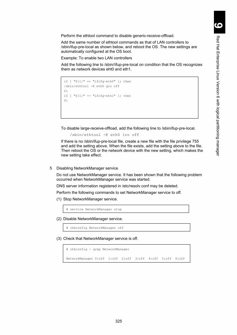
325
9 R
ed Hat E
nterprise Linux Version 6 w
ith logical partitioning manager
Perform the ethtool command to disable generic-receive-offload. Add the same number of ethtool commands as that of LAN controllers to /sbin/ifup-pre-local as shown below, and reboot the OS. The new settings are automatically configured at the OS boot. Example: To enable two LAN controllers Add the following line to /sbin//ifup-pre-local on condition that the OS recognizes them as network devices eht0 and eth1.
To disable large-receive-offload, add the following line to /sbin/ifup-pre-local. /sbin/ethtool -K eth0 lro off
If there is no /sbin/ifup-pre-local file, create a new file with the file privilege 755 and add the setting above. When the file exists, add the setting above to the file. Then reboot the OS or the network device with the new setting, which makes the new setting take effect.
5 Disabling NetworkManager service Do not use NetworkManager service. It has been shown that the following problem occurred when NetworkManager service was started. DNS server information registered in /etc/resolv.conf may be deleted. Perform the following commands to set NetworkManager service to off. (1) Stop NetworkManager service.
(2) Disable NetworkManager service.
(3) Check that NetworkManager service is off.
# service NetworkManager stop
# chkconfig NetworkManager off
# chkconfig | grep NetworkManager
NetworkManager 0:off 1:off 2:off 3:off 4:off 5:off 6:off
if [ "${1}" == "ifcfg-eth0" ]; then
/sbin/ethtool -K eth0 gro off
fi
if [ "${1}" == "ifcfg-eth1" ]; then
fi
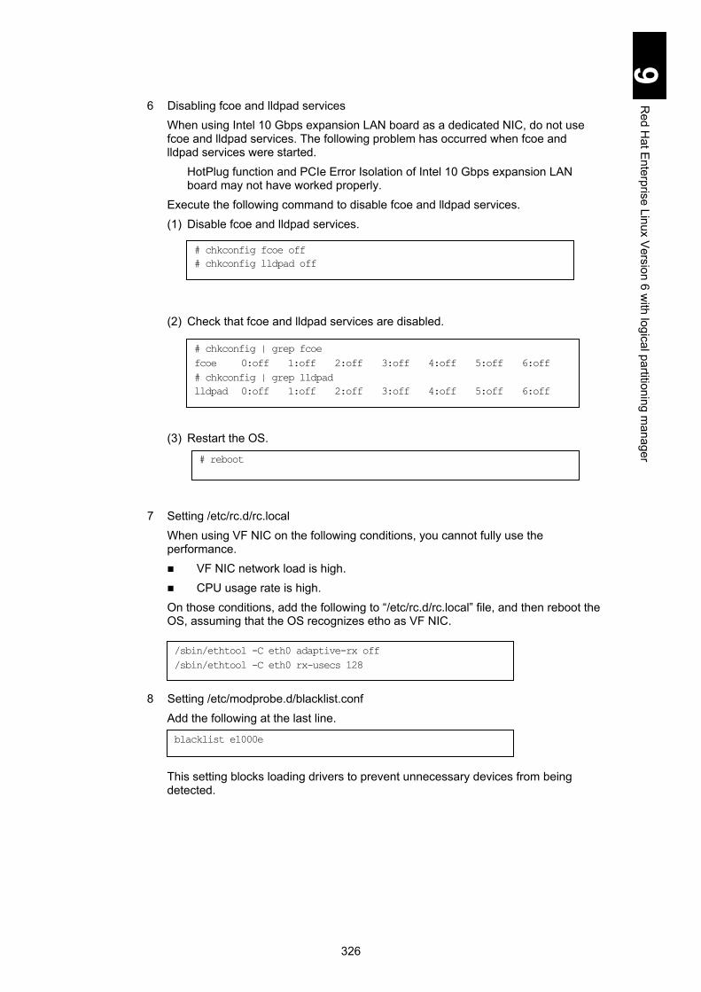
326
9 R
ed Hat E
nterprise Linux Version 6 w
ith logical partitioning manager
6 Disabling fcoe and lldpad services When using Intel 10 Gbps expansion LAN board as a dedicated NIC, do not use fcoe and lldpad services. The following problem has occurred when fcoe and lldpad services were started.
HotPlug function and PCIe Error Isolation of Intel 10 Gbps expansion LAN board may not have worked properly.
Execute the following command to disable fcoe and lldpad services. (1) Disable fcoe and lldpad services.
(2) Check that fcoe and lldpad services are disabled. (3) Restart the OS.
7 Setting /etc/rc.d/rc.local When using VF NIC on the following conditions, you cannot fully use the performance. VF NIC network load is high. CPU usage rate is high. On those conditions, add the following to “/etc/rc.d/rc.local” file, and then reboot the OS, assuming that the OS recognizes etho as VF NIC.
8 Setting /etc/modprobe.d/blacklist.conf
Add the following at the last line. This setting blocks loading drivers to prevent unnecessary devices from being detected.
blacklist e1000e
# chkconfig fcoe off
# chkconfig lldpad off
# chkconfig | grep fcoe
fcoe 0:off 1:off 2:off 3:off 4:off 5:off 6:off
# chkconfig | grep lldpad
lldpad 0:off 1:off 2:off 3:off 4:off 5:off 6:off
# reboot
/sbin/ethtool -C eth0 adaptive-rx off
/sbin/ethtool -C eth0 rx-usecs 128

327
9 R
ed Hat E
nterprise Linux Version 6 w
ith logical partitioning manager
9 Setting /etc/sysctl.conf.
Perform settings (1) through (3) for customizing /etc/sysctl.conf. (1) Setting the log level to 3.
Add the following line.
When the OS console log level is set by default in Linux, a large amount of data might output on the guest screen, which might lead to significant performance degradation, or Linux hang-up. Then, set the console log level to 3 as shown above, so that you can obtain OS console logs reliably using the guest screen.
(2) Enabling the magic SysRq key. Edit or add the following line.
This setting is required for information to be obtained when a problem occurs. (3) Enabling NMI.
Edit or add the following line.
This setting causes a kernel panic to occur when NMI is generated to quickly detect failures in hardware or drivers.
10 Rebooting the system. Type the following and press Enter to reboot the system.
11 Checking the log level. Type the following after booting the system and press Enter to check the log level.
kernel.printk = 3 4 1 7
kernel.sysrq = 1
kernel.unknown_nmi_panic=0
kernel.panic_on_unrecovered_nmi=1
kernel.panic_on_io_nmi=1
# reboot
# cat /proc/sys/kernel/printk
3 4 1 7 <<< the result of the command above

328
9 R
ed Hat E
nterprise Linux Version 6 w
ith logical partitioning manager
12 Checking the NMI setting. Type the following after booting the system and press Enter to check the NMI setting.
13 When updating the Hitachi Fibre-channel adapter, perform the following command.
14 Additional settings before kernel update. When a server blade has an Emulex 10 Gbps LAN adapter onboard and uses the dedicated NIC, perform the following, and then go to step 13 for kernel update.
Make sure to perform the following procedure before kernel update. If not, the proper driver will not be applied.
[Target device driver] be2net driver To find whether or not be2net driver is used, perform the following command. # lsmod | grep be2net be2net xxxxxxx 0 When the command above detects be2net driver, perform the following command to add settings to the driver. # echo "override be2net 2.6.32-* weak-updates/be2net" > /etc/depmod.d/be2net.conf # chmod 644 /etc/depmod.d/be2net.conf
# /sbin/sysctl -n kernel.unknown_nmi_panic
0 <<< the result of the command above
# /sbin/sysctl -n kernel.panic_on_unrecovered_nmi
1 <<< the result of the command above
# /sbin/sysctl -n kernel.panic_on_io_nmi
1 <<< the result of the command above
# rpm -ivh --force /tmp/[RPM package name for hfcldd driver]
# rpm -ivh --force /tmp/[RPM package name for hfcldd-tools]

329
9 R
ed Hat E
nterprise Linux Version 6 w
ith logical partitioning manager
15 Update the security kernel. When using Red Hat Enterprise Linux 6.2/6.4/6.5, download the security update kernel from the Red Hat website, referring to the table below, and apply it.
Model Supported kernel
X86 X86_64 Red Hat Enterprise Linux 6.2 2.6.32-220.4.2.el6
Red Hat Enterprise Linux 6.4 2.6.32-358.23.2.el6
Red Hat.Inc https://rhn.redhat.com/
See Notes and restrictions on Linux 6.1/6.2/6.4. See the Hitachi Compute Blade User’s Guide and this Hitachi Compute Blade SOFTWARE GUIDE for update information. When the settings above have been completed, see Utility.
Utility See Chapter 5 > Installing Utilities with Driver & Utility CD for utilities.
MegaRAID Storage Manager is not supported in the LPAR environment. Uncheck MegaRAID Storage Manager when installing utilities. If installing with MegaRAID Storage Manager checked, a FAIL message will appear after installation.

330
9 R
ed Hat E
nterprise Linux Version 6 w
ith logical partitioning manager
Appendix Table 1: Values for Red hat Enterprise Linux on LPAR
Setting item (Setting file) Setting value (Essential)
Guest OS Red Hat Enterprise Linux 5 Red Hat Enterprise Linux 6
Architecture x86 x64 x86 x64
Offload option settings See Table 2: Values for Offload Options.
kernel line of /boot/grub/grub.conf
Linux 5.3 clocksource=hp
et added
Linux 5.3 notsc added
mce 0 pci=noaer no_timer_check added
Linux 5.4/5.6/5.7/5.9
No setting required. *1
Linux 5.4/5.6/5.7/5.9 clock=tsccount
added *2
nmi_watchdog=0 added rhgb (and) quiet removed
vga=792 *3
lpj=<frequency (KHz) of the
currently activated processor> added
- No setting required.
/etc/sysctl.conf kernel.unknown_nmi_panic=0 added
kernel.panic_on_unrecoverd_nmi=1 added
kernel.unknown_nmi_panic=0 added
kernel.panic_on_unrecoverd_nmi=1 added
kernel.panic_on_io_nmi=1 added
kernel.printk = 3 4 1 7 added
/etc/sysconfig/syslog Change KLOGD_OPTIONS (before changed)
KLOGD_OPTIONS="-x" (after changed)
KLOGD_OPTIONS="-x -c 3"
- No setting is required.
/etc/sysconfig/clock CLOCKFLAGS="--directisa"
added
- No setting required.
- No setting is required.
Serial console
/boot/grub/grub.conf Comment out the line of splashimage=(hd0,0)/grub/splash.xpm.gz (before changed) splashimage=(hd0,0)/grub/splash.xpm.gz (after changed) #splashimage=(hd0,0)/grub/splash.xpm.gz
Add the following two lines between lines of hiddenmenu and title.
Linux 5.6 serial --unit=0 --speed=115200 --word=8 --parity=no --stop=1 Linux 5.7 or higher serial --unit=0 --speed=115200
terminal --timeout=10 serial console
Add the following at the end of the kernel line.
console=tty0 console=ttyS0,115200
Add the following at the end of the kernel line.
console=ttyS0,115200
/etc/sysconfig/init Change BOOTUP. (before changed) BOOTUP=color (after changed) BOOTUP=serial
/etcsysconfig/kudzu Change SAFE. (before changed) SAFE=no (after changed) SAFE=yes
- No setting is required.
/etc/inittab Add co:2345:respawn:/sbin/agetty 115200 ttyS0 vt100 to the bottom
line.
- No setting is required.

331
9 R
ed Hat E
nterprise Linux Version 6 w
ith logical partitioning manager
Setting item (Setting file) Setting value (Essential)
Guest OS Red Hat Enterprise Linux 5 Red Hat Enterprise Linux 6
Architecture x86 x64 x86 x64
/etc/securetty Add ttyS0 to the bottom line. - No setting is required.
*1 If the kernel parameter (clocksource=hpet) is added when you install Linux, delete the parameter.
*2 If the kernel parameter (notsc) is added when you install Linux, delete the parameter and add clock=tsccount.
*3 Add this parameter if LPAR manager version is 59-41/79-41 or higher.
Table 2: Values for Offload Options
NIC scheduling
mode Device name
Offload setting value (essential)
rx tx tso sg ufo gso gro lro
Shared NIC and virtual NIC
Intel® PRO/1000 Ethernet (NIC1)
off on on on off on on *2
off Intel® 82576 Ethernet (NIC2)
Dedicated NIC
Intel® 82576 Ethernet
off off off off off on on *2
off Broadcom 1Gbps Ethernet
Intel® 82599 Ethernet on on on on off on off off
Emulex 10Gbps Ethernet on on on on off on on off
VF NIC*1 Emulex 10Gbps Ethernet on on on on off on on off
Note
1 A NIC for which the SR-IOV functionality is enabled
2 The default value is “on”, but “off” might be automatically set depending on the environment. However, even if this value remains “off”, no problems exist with operations.

332
9 R
ed Hat E
nterprise Linux Version 6 w
ith logical partitioning manager
1
Appendix-I Compute Blade Windows Server 2008 / Windows Server 2003/R2 LAN advanced function manual for Intel
This appendix explains advanced functions for LAN in Windows Server 2003/R2 and Windows Server 2008.
How to set advanced LAN functions ....................................................................... 2 Installing Intel(R) PROSet ....................................................................................... 3 Setting of advanced LAN functions ......................................................................... 5
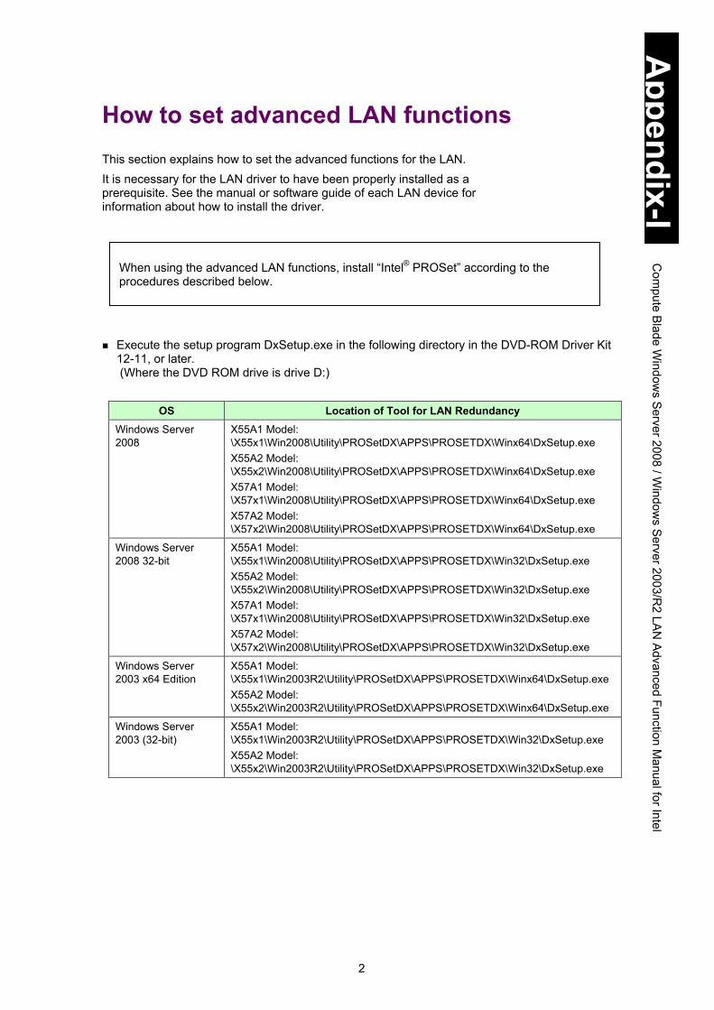
2
Appendix-I
Com
pute Blade W
indows S
erver 2008 / Window
s Server 2003/R
2 LAN
Advanced Function Manual for Intel
How to set advanced LAN functions This section explains how to set the advanced functions for the LAN. It is necessary for the LAN driver to have been properly installed as a prerequisite. See the manual or software guide of each LAN device for information about how to install the driver.
Execute the setup program DxSetup.exe in the following directory in the DVD-ROM Driver Kit
12-11, or later. (Where the DVD ROM drive is drive D:)
OS Location of Tool for LAN Redundancy Windows Server 2008
X55A1 Model: \X55x1\Win2008\Utility\PROSetDX\APPS\PROSETDX\Winx64\DxSetup.exe X55A2 Model: \X55x2\Win2008\Utility\PROSetDX\APPS\PROSETDX\Winx64\DxSetup.exe X57A1 Model: \X57x1\Win2008\Utility\PROSetDX\APPS\PROSETDX\Winx64\DxSetup.exe X57A2 Model: \X57x2\Win2008\Utility\PROSetDX\APPS\PROSETDX\Winx64\DxSetup.exe
Windows Server 2008 32-bit
X55A1 Model: \X55x1\Win2008\Utility\PROSetDX\APPS\PROSETDX\Win32\DxSetup.exe X55A2 Model: \X55x2\Win2008\Utility\PROSetDX\APPS\PROSETDX\Win32\DxSetup.exe X57A1 Model: \X57x1\Win2008\Utility\PROSetDX\APPS\PROSETDX\Win32\DxSetup.exe X57A2 Model: \X57x2\Win2008\Utility\PROSetDX\APPS\PROSETDX\Win32\DxSetup.exe
Windows Server 2003 x64 Edition
X55A1 Model: \X55x1\Win2003R2\Utility\PROSetDX\APPS\PROSETDX\Winx64\DxSetup.exe X55A2 Model: \X55x2\Win2003R2\Utility\PROSetDX\APPS\PROSETDX\Winx64\DxSetup.exe
Windows Server 2003 (32-bit)
X55A1 Model: \X55x1\Win2003R2\Utility\PROSetDX\APPS\PROSETDX\Win32\DxSetup.exe X55A2 Model: \X55x2\Win2003R2\Utility\PROSetDX\APPS\PROSETDX\Win32\DxSetup.exe
When using the advanced LAN functions, install “Intel® PROSet” according to the procedures described below.

3
Appendix-I
Com
pute Blade W
indows S
erver 2008 / Window
s Server 2003/R
2 LAN
Advanced Function Manual for Intel
Installing Intel(R) PROSet
Close all windows before starting installation. When installing Intel (R) PROSet, log in as an administrator account. 1 When the following screen appears, click Next.
2 Read the License Agreement Terms. Check I accept the terms in the license
agreement when you agree to the terms and click Next.

4
Appendix-I
Com
pute Blade W
indows S
erver 2008 / Window
s Server 2003/R
2 LAN
Advanced Function Manual for Intel
3 The Setup Option screen appears. Check the boxes of Intel(R) PROSet for Windows Device Manager and Advanced Network Services, and click Next.
Do not check the boxes of FCoE using Data Center Bridging, iSCSI using Data Center Bridging, and Intel(R) Network Connections SNMP Agent.
4 Click Install. The installation starts.
5 Click Finish and then reboot the system.
There is no problem if a warning message “WMI” is registered in the event log after installing Intel PROSet.
! Note
Tip
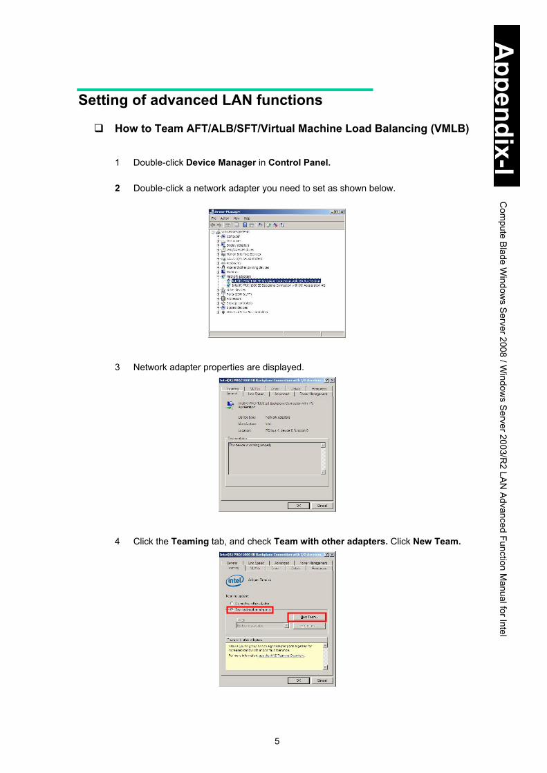
5
Appendix-I
Com
pute Blade W
indows S
erver 2008 / Window
s Server 2003/R
2 LAN
Advanced Function Manual for Intel
Setting of advanced LAN functions
How to Team AFT/ALB/SFT/Virtual Machine Load Balancing (VMLB) 1 Double-click Device Manager in Control Panel.
2 Double-click a network adapter you need to set as shown below.
3 Network adapter properties are displayed.
4 Click the Teaming tab, and check Team with other adapters. Click New Team.

6
Appendix-I
Com
pute Blade W
indows S
erver 2008 / Window
s Server 2003/R
2 LAN
Advanced Function Manual for Intel
5 The New Team Wizard screen is displayed.
Give a name to a team. For example, “Team #x (where x stands for a number.)” is the default setting.
6 In the following screen, check the box of a network adapter for teaming and click
Next.
7 The following screen appears. Select a function you need to set, and click Next.
Tip
To set Fault Tolerance, select Adapter Fault Tolerance. To set Load Balancing, select Adaptive Load Balancing. To set Switch Fault Tolerance, select Switch Fault Tolerance. To set Virtual Machine Load Balancing, select Virtual Machine Load Balancing.

7
Appendix-I
Com
pute Blade W
indows S
erver 2008 / Window
s Server 2003/R
2 LAN
Advanced Function Manual for Intel
Load Balancing/Virtual Machine Load Balancing functions contains Fault Tolerance on condition that Load Balancing is set to a team consisting of LAN devices with the same speed. Virtual Machine Load Balancing is displayed only when Hyper-V is installed in Windows Server 2008 x64.
When composing a team of Fault Tolerance or Switch Fault Tolerance, select two LAN devices.
For Load Balancing, up to two LAN devices can form a team in this system equipment.
It may take a bit longer until the setting is completed.
When selecting three or more LAN devices to team up, Switch Fault Tolerance is not displayed.
Intel PROSet is used to improve reliability of communication by creating redundancy to LAN devices. In some environments (network structure or application), however, it may take from a dozen seconds to a couple of minutes to restore communication at switching links.
Since incoming data is processed by a single LAN device, the bandwidth does not change while it is receiving data. ALB is a function to improve the actual throughput with the load balancing function. In some operation environments such as CPU loading or contents of communication, however, it may not improve performance due to overhead on the load balance processing.
LAN devices used in this system equipment support only five functions: Adapter Fault Tolerance, Adaptive Load Balancing, Virtual Machine Load Balancing, and Switch Fault Tolerance. Therefore, do not select other functions except those five.
Tip
Tip
Tip
Tip
! Note
! Note
Tip
! Note
Tip
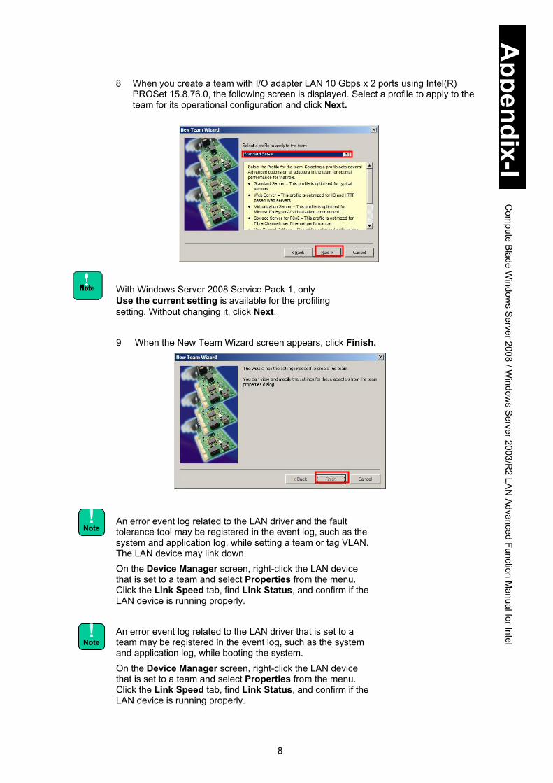
8
Appendix-I
Com
pute Blade W
indows S
erver 2008 / Window
s Server 2003/R
2 LAN
Advanced Function Manual for Intel
8 When you create a team with I/O adapter LAN 10 Gbps x 2 ports using Intel(R) PROSet 15.8.76.0, the following screen is displayed. Select a profile to apply to the team for its operational configuration and click Next.
With Windows Server 2008 Service Pack 1, only Use the current setting is available for the profiling setting. Without changing it, click Next.
9 When the New Team Wizard screen appears, click Finish.
An error event log related to the LAN driver and the fault tolerance tool may be registered in the event log, such as the system and application log, while setting a team or tag VLAN. The LAN device may link down. On the Device Manager screen, right-click the LAN device that is set to a team and select Properties from the menu. Click the Link Speed tab, find Link Status, and confirm if the LAN device is running properly. An error event log related to the LAN driver that is set to a team may be registered in the event log, such as the system and application log, while booting the system. On the Device Manager screen, right-click the LAN device that is set to a team and select Properties from the menu. Click the Link Speed tab, find Link Status, and confirm if the LAN device is running properly.
! Note
! Note

9
Appendix-I
Com
pute Blade W
indows S
erver 2008 / Window
s Server 2003/R
2 LAN
Advanced Function Manual for Intel
A team is added to the Device Manager screen as shown in the following figure.
After setting advanced LAN functions, double-click Networking and Sharing Center from Control Panel. Browse Network Connection Management. Confirm that one Local area Connection is added. After setting teams, such as AFT, ALB, and SFT, on a network adapter, communication cannot be executed properly with the adapter whose settings are changed. Find the network adapter with Device Manager. If ! is added to the network adapter, reboot the OS to use it. Two of the same team names may be displayed in the Network Connection screen immediately after the setting. Update the display after a while, and it will be properly displayed. 10 When setting priorities, follow the procedure described in How to set LAN device
priorities: primary/secondary to set the Primary LAN device.
When a VMLB team is set, priority setting for LAN devices is not supported.
11 When setting an ALB team, disable Receive Load Balancing by following the
procedure described in How to disable Receive Load Balancing.
12 When setting AFT/ALB/SFT teams, follow the procedure in How to change Activation Delay to change the activation delay setting.
13 When you need the Address Resolution Protocol (ARP) monitoring in setting an SFT team with Intel(R) PROSet 15.8.76.0, follow How to set Connection Monitoring to enable the monitoring.
14 When creating another team, repeat step 3 through step 13.
Tip
Tip
! Note

10
Appendix-I
Com
pute Blade W
indows S
erver 2008 / Window
s Server 2003/R
2 LAN
Advanced Function Manual for Intel
On the Network Connection screen, Local Area Connection icons are displayed. Those include an equivalent number of icons to the LAN devices and also of teams set in the LAN advanced function settings. A setting value of Local Area Connection added while setting the advanced LAN function is enabled as an IP address. To change the IP address, from Properties in Local Area Connection, select Network Protocol (TCP/IP) and then Properties.
Only for Windows Server 2008
When IPv6 address is set in a team with Intel(R) PROSet 15.8.76.0, communication may not be available with the following error message displayed and Error displayed in Event Properties. Do not use IPv6 address to an ALB team.
15 Check the IP address value. The default setting is Get Automatically. When using
the fixed IP address, change the setting. When changing IP address values, make sure to reboot the OS and check the connection.

11
Appendix-I
Com
pute Blade W
indows S
erver 2008 / Window
s Server 2003/R
2 LAN
Advanced Function Manual for Intel
16 Reboot the OS to enable LAN advanced functions. You can check the status of the LAN devices in a team using the system log in the event viewer.
When changing LAN devices during maintenance work, delete the team setting before making the change. New hardware is automatically recognized during the OS boot. Set teaming to LAN advanced functions again.
When you compose a team of different LAN adapters, values to those LAN adapters to join the team may be changed to the optimal ones.
! Note
! Note
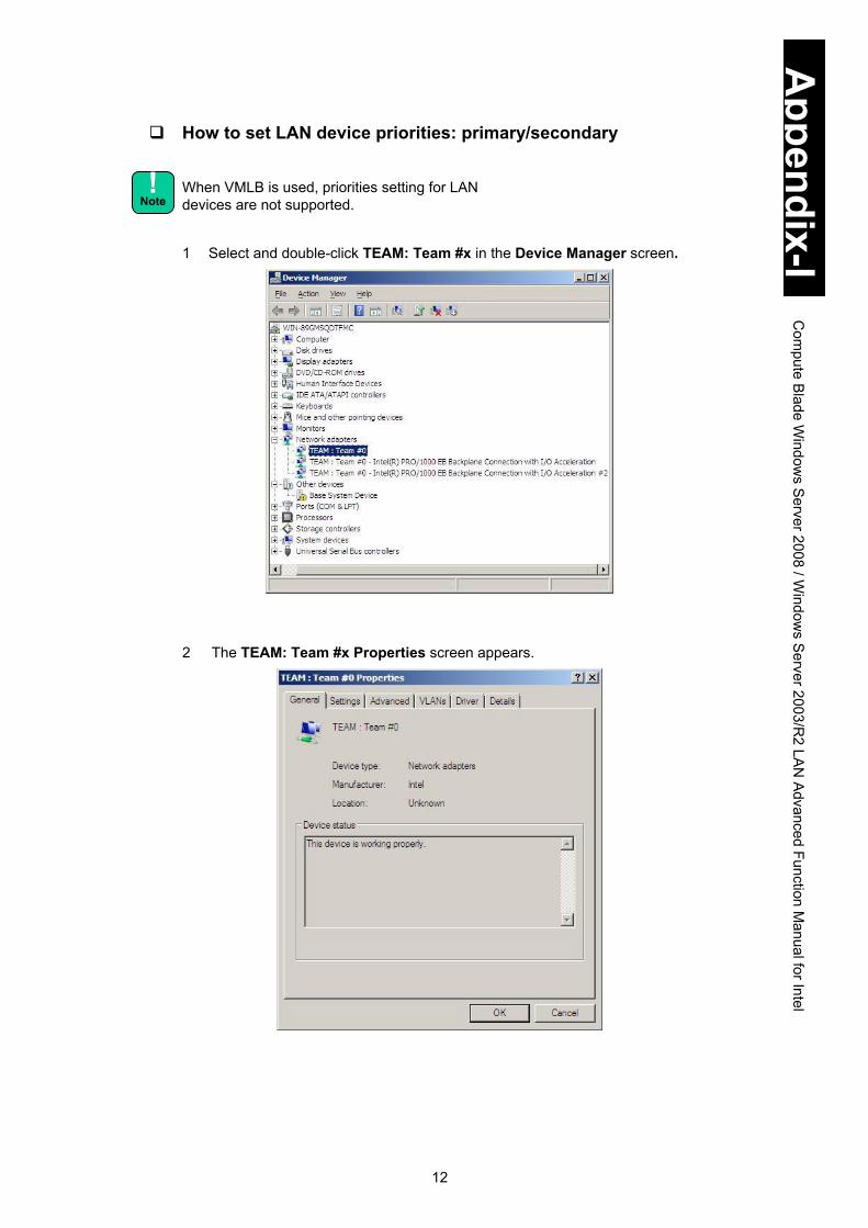
12
Appendix-I
Com
pute Blade W
indows S
erver 2008 / Window
s Server 2003/R
2 LAN
Advanced Function Manual for Intel
How to set LAN device priorities: primary/secondary
When VMLB is used, priorities setting for LAN devices are not supported. 1 Select and double-click TEAM: Team #x in the Device Manager screen.
2 The TEAM: Team #x Properties screen appears.
! Note
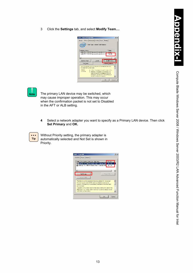
13
Appendix-I
Com
pute Blade W
indows S
erver 2008 / Window
s Server 2003/R
2 LAN
Advanced Function Manual for Intel
3 Click the Settings tab, and select Modify Team....
The primary LAN device may be switched, which may cause improper operation. This may occur when the confirmation packet is not set to Disabled in the AFT or ALB setting.
4 Select a network adapter you want to specify as a Primary LAN device. Then click
Set Primary and OK.
Without Priority setting, the primary adapter is automatically selected and Not Set is shown in Priority.
! Note
Tip

14
Appendix-I
Com
pute Blade W
indows S
erver 2008 / Window
s Server 2003/R
2 LAN
Advanced Function Manual for Intel
5 The Primary description is added to the network adapter in Adapters in Team as shown below.
6 Click OK.
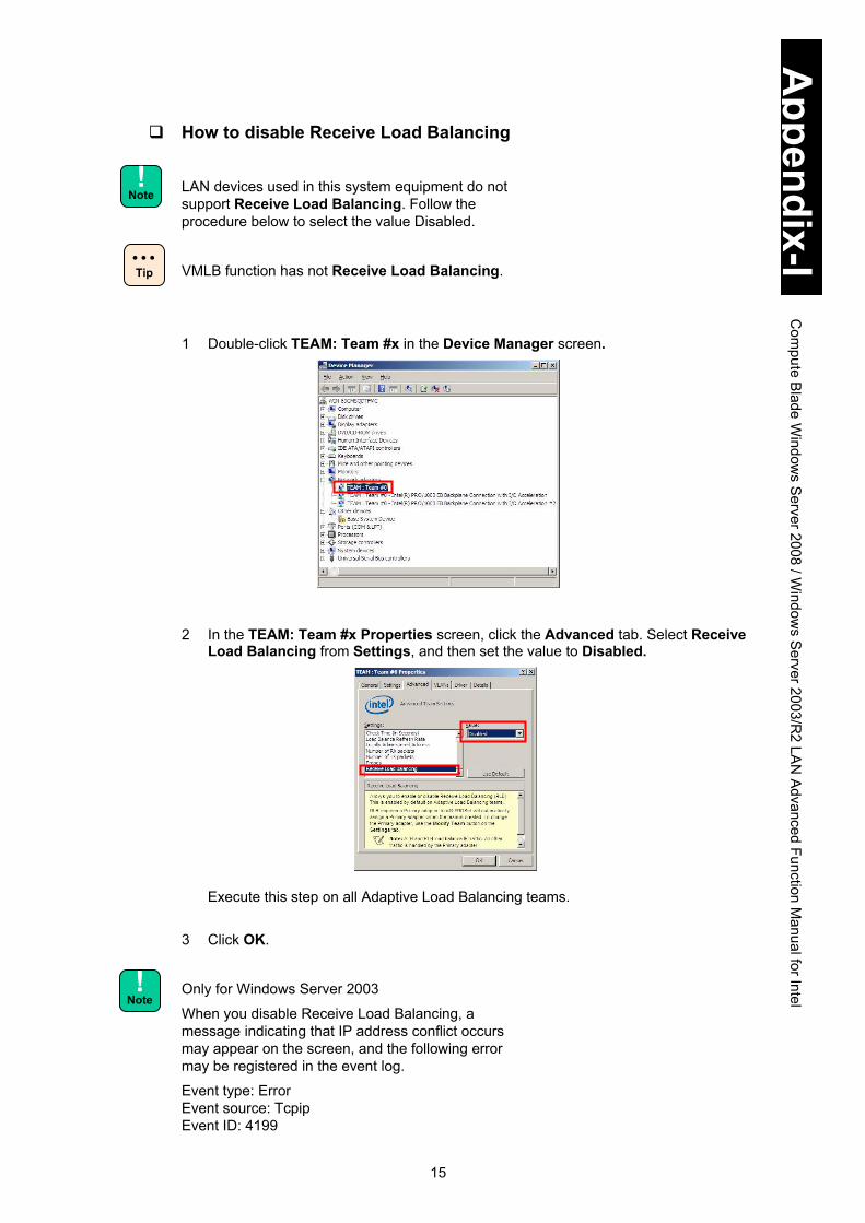
15
Appendix-I
Com
pute Blade W
indows S
erver 2008 / Window
s Server 2003/R
2 LAN
Advanced Function Manual for Intel
How to disable Receive Load Balancing
LAN devices used in this system equipment do not support Receive Load Balancing. Follow the procedure below to select the value Disabled.
VMLB function has not Receive Load Balancing.
1 Double-click TEAM: Team #x in the Device Manager screen.
2 In the TEAM: Team #x Properties screen, click the Advanced tab. Select Receive
Load Balancing from Settings, and then set the value to Disabled.
Execute this step on all Adaptive Load Balancing teams.
3 Click OK.
Only for Windows Server 2003
When you disable Receive Load Balancing, a message indicating that IP address conflict occurs may appear on the screen, and the following error may be registered in the event log.
Event type: Error Event source: Tcpip Event ID: 4199
! Note
! Note
Tip
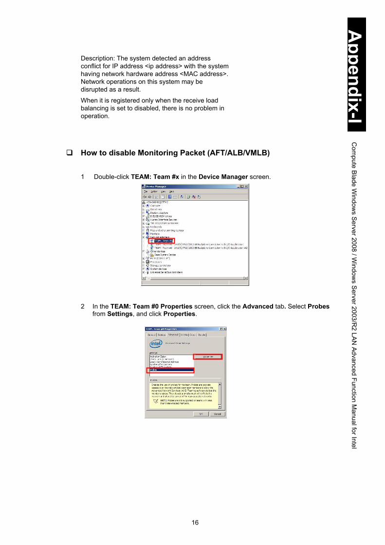
16
Appendix-I
Com
pute Blade W
indows S
erver 2008 / Window
s Server 2003/R
2 LAN
Advanced Function Manual for Intel
Description: The system detected an address conflict for IP address <ip address> with the system having network hardware address <MAC address>. Network operations on this system may be disrupted as a result.
When it is registered only when the receive load balancing is set to disabled, there is no problem in operation.
How to disable Monitoring Packet (AFT/ALB/VMLB) 1 Double-click TEAM: Team #x in the Device Manager screen.
2 In the TEAM: Team #0 Properties screen, click the Advanced tab. Select Probes
from Settings, and click Properties.

17
Appendix-I
Com
pute Blade W
indows S
erver 2008 / Window
s Server 2003/R
2 LAN
Advanced Function Manual for Intel
3 Remove the check mark from Send probes and click OK.
4 Click OK to return to the TEAM: Team#0 Properties screen.

18
Appendix-I
Com
pute Blade W
indows S
erver 2008 / Window
s Server 2003/R
2 LAN
Advanced Function Manual for Intel
How to change Activation Delay
When making a team: AFT, ALB, SFT, set Activation Delay to 3 seconds or more seconds. 1 Double-click TEAM: Team #x in the Device Manager screen. 2 In the TEAM: Team #x Properties screen, click the Advanced tab, select
Activation Delay from Settings and then set the value to 3 or more seconds.
For SFT team, there is no problem if the setting is the default value: 60 seconds. 3 Click OK.
! Note
Tip

19
Appendix-I
Com
pute Blade W
indows S
erver 2008 / Window
s Server 2003/R
2 LAN
Advanced Function Manual for Intel
How to set Connection Monitoring When monitoring redundancy with ARP monitoring in setting a SFT team, enable Connection Monitoring. 1 Double-click TEAM: Team #x in the Device Manager screen. 2 In the TEAM: Team # Properties screen, click the Advanced tab, select
Connection Monitoring from the Settings pane, and click Properties. 3 When the Connection Monitoring screen is displayed, check Enable Connection
Monitoring.

20
Appendix-I
Com
pute Blade W
indows S
erver 2008 / Window
s Server 2003/R
2 LAN
Advanced Function Manual for Intel
4 Enter the IP address of the target PC for ARP monitoring in the Add New IP field, and click Add. The IP address will be added to the Target IP pane.
5 To delete a target IP, select the target IP to remove, and click Remove. 6 When the settings you need are completed, click OK.
7 Click OK to return to the TEAM: Team # Properties screen.

21
Appendix-I
Com
pute Blade W
indows S
erver 2008 / Window
s Server 2003/R
2 LAN
Advanced Function Manual for Intel
How to remove Team 1 Double-click TEAM: Team #x in the Device Manager screen.
2 Click the Settings tab, and then click Remove Team.
3 When the following screen appears, click Yes.
4 Make sure to reboot the OS.
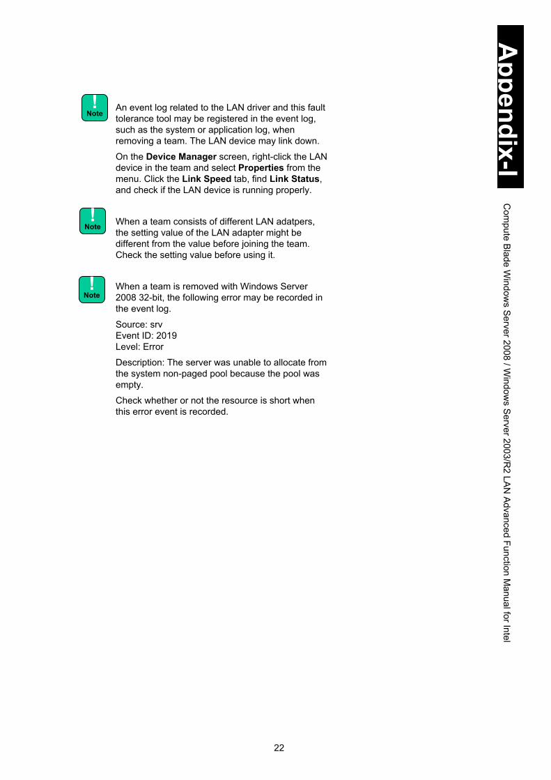
22
Appendix-I
Com
pute Blade W
indows S
erver 2008 / Window
s Server 2003/R
2 LAN
Advanced Function Manual for Intel
An event log related to the LAN driver and this fault tolerance tool may be registered in the event log, such as the system or application log, when removing a team. The LAN device may link down.
On the Device Manager screen, right-click the LAN device in the team and select Properties from the menu. Click the Link Speed tab, find Link Status, and check if the LAN device is running properly.
When a team consists of different LAN adatpers, the setting value of the LAN adapter might be different from the value before joining the team. Check the setting value before using it.
When a team is removed with Windows Server 2008 32-bit, the following error may be recorded in the event log.
Source: srv Event ID: 2019 Level: Error
Description: The server was unable to allocate from the system non-paged pool because the pool was empty.
Check whether or not the resource is short when this error event is recorded.
! Note
! Note
! Note

23
Appendix-I
Com
pute Blade W
indows S
erver 2008 / Window
s Server 2003/R
2 LAN
Advanced Function Manual for Intel
How to set Tag VLAN
When using a Tag VLAN with the Hyper-V virtual network to which VMLB is assigned, make sure to set both the tag VLAN of Intel(R) PROSet and the virtual LAN ID of each virtual machine with Hyper-V. 1 Double-click Device Manager in Control Panel.
2 Select and double-click a network adapter for which you want to set VLAN.
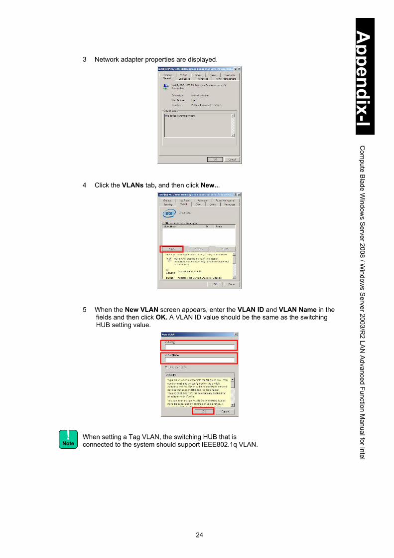
24
Appendix-I
Com
pute Blade W
indows S
erver 2008 / Window
s Server 2003/R
2 LAN
Advanced Function Manual for Intel
3 Network adapter properties are displayed.
4 Click the VLANs tab, and then click New...
5 When the New VLAN screen appears, enter the VLAN ID and VLAN Name in the fields and then click OK. A VLAN ID value should be the same as the switching HUB setting value.
When setting a Tag VLAN, the switching HUB that is connected to the system should support IEEE802.1q VLAN.
! Note

25
Appendix-I
Com
pute Blade W
indows S
erver 2008 / Window
s Server 2003/R
2 LAN
Advanced Function Manual for Intel
6 The screen returns to Properties. It may take about 10 seconds for the Tag VLAN setting.
Tag VLAN can set to 10 groups (IDs) per device. Only TCP/IP is supported as a protocol. If you set 11 or more groups or any other protocol but TCP/IP, the system equipment may be unstable. When configuring the Tag VLAN, the Properties screen may terminate improperly and “Application Error” generated in the application mmc.exe may be recorded in application logs. Check that the Tag VLAN is configured and that communication can be properly done. If the Tag VLAN is not configured, return to step 3 and set it again through step 6. Check that communication can be done properly. A Tag VLAN team is added to the Device Manager screen.
You may not communicate properly using the adapter with the setting changed after setting VLAN on the network adapter. If ! is added to the network adapter whose setting is changed with the device manager, reboot the OS to use the adapter.
7 Repeat step 3 to step 6 as many times as the number of network adapters to set
VLAN to.
8 Reboot the system, and the Tag VLAN function is enabled.
You can find the status of the LAN device, in which Tag VLAN has been configured, in the system logs of the event viewer.
Tip
! Note
! Note
! Note

26
Appendix-I
Com
pute Blade W
indows S
erver 2008 / Window
s Server 2003/R
2 LAN
Advanced Function Manual for Intel
On the Network Connection screen, Local Area Connection icons that include an equivalent number of icons to the LAN devices, and an equivalent number of Local Area Connection icons to Tag VLANs, are set in the Advanced LAN settings.
The IP address, the setting value of Local Area Connection added by the tab VLAN setting, is enabled. To change the IP address, from Properties in Local Area Connection, select Network Protocol (TCP/IP), and then Properties.
Intel(R)xxxxx – VLAN: VLANx is shown in How to connect:.
Two of the same team names may be displayed in the Network Connection screen immediately after setting VLAN. Update the display after a while, so that it is properly displayed.
An error event log related to the LAN driver or this fault tolerance tool may be registered in the event log, such as the system or application log, while setting the tag VLAN. The LAN device may link down. On the Device Manager screen, right-click the LAN device in which Tag VLAN has been configured, and select Properties from the menu. Click the Link Speed tab, find Link Status, and then check if the LAN device is running properly.
When changing LAN devices during maintenance work, remove the Tag VLAN settings before making the change. New hardware is automatically recognized at the OS boot. Set Tag VLAN once more.
Tip
! Note
! Note
! Note

27
Appendix-I
Com
pute Blade W
indows S
erver 2008 / Window
s Server 2003/R
2 LAN
Advanced Function Manual for Intel
When using a team (AFT, ALB, SFT, VMLB) that the Tag VLAN is set to, link connection to the team is not displayed as if the team is not connected. There is no problem in operation. Check if LAN devices in the team that Tag VLAN is configured operate properly.
How to remove Tag VLAN 1 Double-click VLAN: VLANx in the Device Manager screen.
2 Click the Settings tab and then click Remove VLAN.
3 When the following screen appears, click Yes.
4 Make sure to reboot the OS.

28
Appendix-I
Com
pute Blade W
indows S
erver 2008 / Window
s Server 2003/R
2 LAN
Advanced Function Manual for Intel
When removing Tag VLAN, error events related to the LAN driver and this fault tolerance tool may be recorded in the event log, such as system and application logs. The LAN device may link down.
On the Device Manager screen, right-click the LAN device in which Tag VLAN has been configured, and select Properties from the menu. Click the Link Speed tab, find Link Status, and check if the LAN device is running properly. When removing Tag VLAN, the following screen indicating NCS2Prov Module has stopped working may appear and “Application Error” generated in NCS2Prov.exe may be recorded in application logs. When the screen appears, click Close. Confirm that the Tag VLAN is removed in Device Manager and check that communication can be properly done via the adapter that Tag VLAN was set to. If the Tag VLAN is not removed, return to step 1 through step 4 and remove it again. Then check that communication can be done properly via the LAN adapter that Tag VLAN was set to.
When a team is removed with Windows Server 2008 32-bit, the following error may be recorded in the event log.
Source: srv Event ID: 2019 Level: Error
Description: The server was unable to allocate from the system non-paged pool because the pool was empty.
Check whether or not the resource is short when this error event is recorded.
! Note
! Note

29
Appendix-I
Com
pute Blade W
indows S
erver 2008 / Window
s Server 2003/R
2 LAN
Advanced Function Manual for Intel
Extra setting for WOL (Wake On LAN)
When using the internal onboard LAN, make sure to configure the settings described below. Without it, the OS may not properly shut down and reboot when the standard internal onboard LAN IP address receives data during the OS shutdown.
LAN driver and LAN device for this setting
No. Network adapter Displayed on Device Manager
1 Internal onboard LAN Intel(R) 82576EB Gigabit Dual Port
Server Network Connection
How to configure the setting Click Device Manager > Network adapters, open Properties of the LAN adapter to use WOL. Click the Advanced and Power Management tabs to open, and change values as follows when the following items do not have the same values as shown below. (1) When not using Wake On LAN:
(1-1) Intel(R) PROSet: Not installed Advanced tab: Select Disabled for Enable PME. Advanced tab: Select Disabled for Wake on Settings.
(1-2) Intel(R) PROSet: Installed Power Management tab: Uncheck Wake On Magic Packet from power off state. Power Management tab: Uncheck Wake On Magic Packet. Power Management tab: Uncheck Wake On Directed Packet.
(2) When using Wake On LAN: (2-1) Intel(R) PROSet: Not installed
Advanced tab: Select Enabled for Enable PME. Advanced tab: Select Disabled for Wake on Settings.
(2-2) Intel(R) PROSet: Installed Power Management tab: Check Wake On Magic Packet from power off state. Power Management tab: Uncheck Wake On Magic Packet. Power Management tab: Uncheck Wake On Directed Packet.
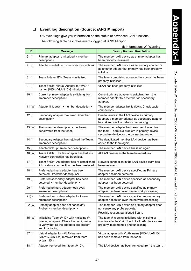
30
Appendix-I
Com
pute Blade W
indows S
erver 2008 / Window
s Server 2003/R
2 LAN
Advanced Function Manual for Intel
Event log description (Source: iANS Miniport) OS event logs give you information on the status of advanced LAN functions. The following table describes events logged at iANS Miniport.
(I: Information; W: Warning) ID Message Description and Resolution
6 (I) Primary adapter is initialized: <member description>
The member LAN device as primary adapter has been properly initialized.
7 (I) Adapter is initialized: <member description> The member LAN device as secondary adapter or as another adapter but primary has been properly initialized.
8 (I) Team #<team ID>: Team is initialized. The team comprising advanced functions has been properly initialized.
9 (I) Team #<ID>: Virtual Adapter for <VLAN name> [VID=<VLAN ID>] initialized.
VLAN has been properly initialized.
10 (I) Current primary adapter is switching from: <member description>
Current primary adapter is switching from the member adapter to a member as secondary adapter.
11 (W) Adapter link down: <member description> The member adapter link is down. Check cable connections.
12 (I) Secondary adapter took over: <member description>
Due to failure in the LAN device as primary adapter, a member adapter as secondary adapter has taken over the network processing.
13 (W) The <member description> has been deactivated from the team.
The member adapter has been deactivated from the team. There is a problem in primary device, secondary device, or the connecting route.
14 (I) Secondary Adapter has rejoined the Team: <member description>
The deactivated member LAN device has been added to the team again.
15 (I) Adapter link up: <member description> The member LAN device link is up again.
16 (W) Team #<ID>: The last adapter has lost link. Network connection has been lost.
All LAN devices in the team have lost link.
17 (I) Team #<ID>: An adapter has re-established link. Network connection has been restored.
Network connection in the LAN device team has been restored.
18 (I) Preferred primary adapter has been detected: <member description>
The member LAN device specified as Primary adapter has been detected.
19 (I) Preferred secondary adapter has been detected: <member description>
The member LAN device specified as secondary adapter has been detected.
20 (I) Preferred primary adapter took over: <member description>
The member LAN device specified as primary adapter has taken over the network processing.
21(I) Preferred secondary adapter took over: <member description>
The member LAN device specified as secondary adapter has taken over the network processing.
22 (W) Primary adapter does not sense any Probes: <member description>
The member LAN device as primary adapter does not sense any probe packets. Possible reason: partitioned Team.
35 (W) Initializing Team #<ID> with <missing #> missing adapters. Check the configuration to verify that all the adapters are present and functioning.
The team # is being initialized with missing or inactive adapters’ #. Check if all LAN devices are properly implemented and functioning.
37 (I) Virtual adapter for <VLAN name> [VID=<VLAN ID>] removed from team #<team ID>.
Virtual adapter with VLAN name [VID=VLAN ID] has been removed from the team.
38 (I) Adapter removed from team #<ID>. The LAN device has been removed from the team.

31
Appendix-I
Com
pute Blade W
indows S
erver 2008 / Window
s Server 2003/R
2 LAN
Advanced Function Manual for Intel
Example of operating Advanced Function Prerequisites A fault tolerance team is comprised of LAN Device A (Intel(R) PRO/1000 A Network Connection) and LAN Device B (Intel(R) PRO/1000 B Network Connection). Do not set preference values such as primary and secondary to both devices, and LAN Device A is automatically set to the primary. (See “How to set Primary LAN Device” for setting preference.)
Operation Suppose LAN Device A link is down when the network function is running. Fault tolerance function makes LAN Device B take over the process. Even if LAN Device A restores the linkup after a while, LAN Device B keeps processing.
OS Event Log to be recorded: System Log (Source: iANS Miniport) 1 When System Boots
Event ID 7: Information Adapter is initialized: Intel PRO/1000 A Network Connection
Event ID 7: Information Adapter is initialized: Intel PRO/1000 B Network Connection
Event ID 15: Information Adapter link up: Intel PRO/1000 A Network Connection
Event ID 15: Information Adapter link up: Intel PRO/1000 B Network Connection
Event ID 8: Information Team #<team ID>: Team is initialized.
Immediately after the system boots in setting Fault Tolerance, “Event ID 11: Adapter link down: <member description>” may be generated. Since no hardware failure occurs, use it as is. 2 When Link Connection is down
Event ID 11: Warning Adapter link down: <member description>: Intel PRO/1000 A Network Connection
Event ID 10: Information Current Primary Adapter is switching from: <member description>: Intel PRO/1000 A Network Connection
Event ID 12: Information Secondary Adapter took over: <member description>: Intel PRO/1000 B Network Connection
3 When Link Connection is restored
Event ID 15: Information Adapter link up: Intel PRO/1000 A Network Connection
Event ID 14: Information Secondary Adapter has rejoined the Team: <member description>: Intel PRO/1000 A Network Connection
Without setting a preference, LAN Device A remains Secondary even if restored.
Tip

32
Appendix-I
Com
pute Blade W
indows S
erver 2008 / Window
s Server 2003/R
2 LAN
Advanced Function Manual for Intel
Restrictions When integrating advanced functions mentioned above with Microsoft NLB/WLBS, use
these functions in the multicast mode, not in the unicast mode.
Do not configure the teaming among advanced functions for LAN, in the LAN for inter-cluster communication in the cluster server.
Diagnostic function in LAN devices When Intel PROSet is installed, do not perform the diagnostic test by clicking Diagnostics under the Link Speed tab in the LAN device Properties. If you performed the diagnostic test, linkdown could not be detected. If you have performed the diagnostic test, be sure to reboot the OS.
Be sure to disable monitoring packets when setting a team. See How to disable Monitoring Packet (AFT/ALB/VMLB) for details. If monitoring packets are not disabled at AFT/ALB setting, the LAN device for primary connection may be switched to another, which may lead to improper operation
When the network is under heavy load conditions, the LAN driver may rarely detect a temporary linkdown. It will be linked up in a second or two after detecting the linkdown. With a redundancy configuration using a team, LAN devices will be switched.

1
Appendix-II Compute Blade Windows Server 2008 R2 LAN Advanced Function Manual for Intel
This appendix explains advanced functions for LAN in Windows Server 2008 R2.
How to set Advanced LAN Functions in Windows Server 2008 R2 ........................ 2 Installing Intel(R) PROSet (Windows Server 2008 R2) .......................................... 2 Setting of Advanced LAN Functions ....................................................................... 4

2
Appendix-II
Com
pute Blade W
indows S
erver 2008 R2 LA
N Advanced Function M
anual for Intel
How to set Advanced LAN Functions in Windows Server 2008 R2 This section explains how to set the advanced function for LAN in the Windows Server 2008 R2 environment. A prerequisite for setting and using the Advanced LAN functions is a properly installed LAN driver for Windows Server 2008 R2. See the manual or software guide of each LAN device for information about how to install the driver.
Make sure to install Intel(R) PROSet when using advanced functions for LAN in the Windows 2008 R2 environment. Follow the procedure for installing the Intel PROSet described below.
Execute the setup program DxSetup.exe in the following directory in the DVD-ROM Driver Kit
12-11 or later supporting Windows Server 2008 R2. (Where the DVD ROM drive is Drive D:)
OS Location of Tool for LAN Redundancy
Windows Server 2008 R2
X55A1 Model: \X55x1\Win2008R2\Utility\PROSetDX\APPS\PROSETDX\Winx64\DxSetup.exe X55A2 Model: \X55x2\Win2008\Utility\PROSetDX\APPS\PROSETDX\Winx64\DxSetup.exe X57A1 Model: \X57x1\Win2008\Utility\PROSetDX\APPS\PROSETDX\Winx64\DxSetup.exe X57A2 Model: \X57x2\Win2008\Utility\PROSetDX\APPS\PROSETDX\Winx64\DxSetup.exe
Installing Intel(R) PROSet (Windows Server 2008 R2)
Close all windows before starting installation. When installing the Intel PROSet, log in as an administrator account.
1. When the following screen appears, click Next.
! Note

3
Appendix-II
Com
pute Blade W
indows S
erver 2008 R2 LA
N Advanced Function M
anual for Intel
2. Read the License Agreement. Select “I accept the terms in the license agreement”
when you agree to the terms and click Next.
3. The Setup Options screen appears. Check the boxes Intel(R) PROSet for
Windows* Device Manager and Advanced Network Services, and click Next.
Do not check the boxes FCoE using Data Center Bridging, iSCSI using Data Center Bridging, and “Intel(R) Network Connections SNMP Agent.
4. Select Install, and installation starts.
5. Select Finish, and then reboot the OS.
There is no problem if a warning message “WMI” is recorded in the event log after installing Intel PROSet.
! Note
Tip

4
Appendix-II
Com
pute Blade W
indows S
erver 2008 R2 LA
N Advanced Function M
anual for Intel
Setting of Advanced LAN Functions
When setting advanced LAN functions, log in as an administrator account.
How to team (AFT/ALB/SFT/VMLB)
1. Click Hardware in Control Panel.
2. Click Device Manager in Device and Printer.
3. Double-click a network adapter that you need to set, as shown below.
4. The Network Connection Properties are displayed.
! Note

5
Appendix-II
Com
pute Blade W
indows S
erver 2008 R2 LA
N Advanced Function M
anual for Intel
5. Click the Teaming tab, and check Team this adapter with other adapters. Click
New Team.
6. The New Team Wizard screen is displayed. Click Next.
Give a name to a team as you like. “Team #x (x stands for a number.)” is the default setting. 7. In the following screen, check the box of a network adapter for teaming. Click Next.
Tip

6
Appendix-II
Com
pute Blade W
indows S
erver 2008 R2 LA
N Advanced Function M
anual for Intel
8. The following screen appears. Select a function you need to set, and click Next.
To set Fault Tolerance, select Adapter Fault Tolerance. To set Load Balancing, select Adaptive Load Balancing. To set Switch Fault Tolerance, select Switch Fault Tolerance. To set Virtual Machine Load Balancing, select Virtual Machine Load
Balancing.
Load Balancing and Virtual Machine Load Balancing include Fault Tolerance. Load Balancing, however, requires that the team consist of LAN devices with the same speed.
Virtual Machine Load Balancing is displayed in the pane only when Hyper-V is installed.
When composing a team of Fault Tolerance or Switch Fault Tolerance, select two LAN devices.
For Load Balancing and Virtual Machine Load Balancing, up to two LAN devices can compose a team in this server blade.
It may take a bit longer until the setting is completed. When selecting three or more LAN devices to team up, Switch Fault Tolerance is not displayed. Intel PROSet is used to improve reliability in communication by giving redundancy to LAN devices. In some environments (network structure or application), however, it may take several minutes to restore communication while switching links.

7
Appendix-II
Com
pute Blade W
indows S
erver 2008 R2 LA
N Advanced Function M
anual for Intel
Since incoming data are processed by a single LAN device, the bandwidth does not change when receiving data. ALB is a function used to improve the actual throughput with the load balancing function. In some operation environments such as CPU loading or contents of communication, it may not improve performance due to overhead on the load balance processing. LAN devices used in this server blade support four functions only: Adapter Fault Tolerance, Adaptive Load Balancing, Virtual Machine Load Balancing, and Switch Fault Tolerance. Therefore, do not select other functions except those four. 9. When you create a team with I/O adapter LAN 10 Gbps x 2 ports using Intel(R)
PROSet 15.8.76.0, the following screen is displayed. Select a profile to apply to the team for its operational configuration and then click Next.
10. When the following screen appears, click Finish.
An error event log related to the LAN driver and redundancy tools may be generated in the system or application logs when setting a team or tab VLAN. In this case, the LAN device might link down. On the Device Manager screen, right-click the LAN device that is set to a team and select Properties from the menu. Click the Link Speed tab, find Link Status, and check if the LAN device is running properly.

8
Appendix-II
Com
pute Blade W
indows S
erver 2008 R2 LA
N Advanced Function M
anual for Intel
An error event log related to the LAN driver may be recorded in the event log (system/application log). On the Device Manager screen, right-click the LAN device that is set to a team and select Properties from the menu. Click the Link Speed tab, find Link Status, and check if the LAN device is running properly. A team is added to Device Manager as shown in the followigng figure.
After setting advanced LAN functions, click Control Panel > Network and Internet > View network status and tasks to display Networking and Sharing Center. In Networking and Sharing Center, click Change adapter settings to open Network Connections. Check if one Local area Connection is added.
11. When setting priorities, see How to set priority to LAN device: primary/secondary.
When VMLB is operated, priority setting for LAN devices is not supported.
12. When setting an ALB team, disable Receive Load Balancing and see How to
disable Receive Load Balancing.
13. When setting AFT/ALB/SFT teams, see How to change Activation Delay to change settings.
14. When you need the ARP monitoring in setting an SFT team with Intel(R) PROSet 15.8.76.0, perform How to set Connection Monitoring.
15. When creating another team, repeat step 3 through step 15
16. Make sure to reboot the OS.

9
Appendix-II
Com
pute Blade W
indows S
erver 2008 R2 LA
N Advanced Function M
anual for Intel
When you have set a team (AFT/ALB/SFT/VMLB) on a network adapter, the adapter settings might not allow proper communication. Check the network adapter with the changed setting using the device manager. If [!] is displayed, reboot the OS to use the adapter.
Two same team names may be displayed in the Network Connection screen immediately after making the setting. Update the display after a while, and it is properly displayed.
On Network Connection, Local Area Connection icons are displayed. Those include an equivalent number of icons to the LAN devices and also of teams set in the LAN advanced function settings. A setting value of Local Area Connection added while setting the advanced LAN function is enabled as an IP address. To change the IP address, from Properties in Local Area Connection, select Network Protocol (TCP/IP) and then Properties.
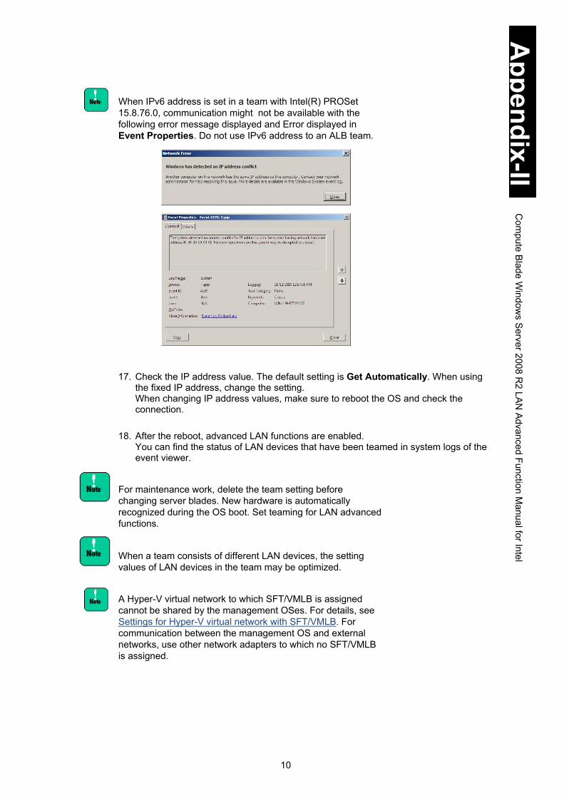
10
Appendix-II
Com
pute Blade W
indows S
erver 2008 R2 LA
N Advanced Function M
anual for Intel
When IPv6 address is set in a team with Intel(R) PROSet 15.8.76.0, communication might not be available with the following error message displayed and Error displayed in Event Properties. Do not use IPv6 address to an ALB team.
17. Check the IP address value. The default setting is Get Automatically. When using
the fixed IP address, change the setting. When changing IP address values, make sure to reboot the OS and check the connection.
18. After the reboot, advanced LAN functions are enabled. You can find the status of LAN devices that have been teamed in system logs of the event viewer.
For maintenance work, delete the team setting before changing server blades. New hardware is automatically recognized during the OS boot. Set teaming for LAN advanced functions.
When a team consists of different LAN devices, the setting values of LAN devices in the team may be optimized.
A Hyper-V virtual network to which SFT/VMLB is assigned cannot be shared by the management OSes. For details, see Settings for Hyper-V virtual network with SFT/VMLB. For communication between the management OS and external networks, use other network adapters to which no SFT/VMLB is assigned.

11
Appendix-II
Com
pute Blade W
indows S
erver 2008 R2 LA
N Advanced Function M
anual for Intel
Using the virtual machine load balancing (VMLB) with Hyper-V
Follow the steps described below, and open the properties of Local Area Connection xx to be newly created after SFT/VMLB is created. Remove check marks from all protocol icons ( ), and assign them to the virtual network in the Hyper-V environment. 1. Click Control Panel > Network and Internet > View network status and tasks. 2. When Network and Sharing Center is displayed, click Change adapter settings. 3. In the Network Connection screen, right-click on Local Area Connection xx that is
newly added by setting the VMLB to show a menu. On the menu, select Properties from the dropdown menu.
4. Remove check marks from all protocol icons displayed in the This connection uses the following items. field.
5. Click OK.
When using the SFT team with Hyper-V virtual network, apply Microsoft update patch: KB977357, which can be downloaded from the following URL, and also Registry setting tool for Windows Server 2008 R2 Hyper-V SFT, which is included in Driver Kit DVD-ROM 12-10 or later, to set the registry. Make sure to reboot the OS after applying the patch and tool.
Mircrosoft KB977357: http://support.microsoft.com/kb/977357/en
Registry setting tool for Windows Server 2008 R2 Hyper-V SFT:
d: \X55x1\Win2008R2\Tools\HYPVSFT\HVSFTEN.bat d: \X55x2\Win2008R2\Tools\HYPVSFT\HVSFTEN.bat d: \X57x1\Win2008R2\Tools\HYPVSFT\HVSFTEN.bat d: \X57x2\Win2008R2\Tools\HYPVSFT\HVSFTEN.bat (When the drive of DVD-RAM is d:)
When discharging the SFT team from Hyper-V virtual network, discharge the registry using the following Registry discharge tool for Windows Server 2008 R2 Hyper-V SFT: After applying the tool, make sure to reboot the OS.
Registry discharge tool for Windows Server 2008 R2 Hyper-V SFT
d: \X55x1\Win2008R2\Tools\HYPVSFT\HVSFTDIS.bat d: \X55x2\Win2008R2\Tools\HYPVSFT\HVSFTDIS.bat d: \X57x1\Win2008R2\Tools\HYPVSFT\HVSFTDIS.bat d: \X57x2\Win2008R2\Tools\HYPVSFT\HVSFTDIS.bat (When the drive of DVD-RAM is d:)

12
Appendix-II
Com
pute Blade W
indows S
erver 2008 R2 LA
N Advanced Function M
anual for Intel
How to set priority to LAN device: primary/secondary
When MVLB is running, the primary setting of the LAN device is not supported. 1. Double-click TEAM: Team #x in the Device Manager screen.
2. The TEAM: Team #x Properties screen appears.

13
Appendix-II
Com
pute Blade W
indows S
erver 2008 R2 LA
N Advanced Function M
anual for Intel
3. Click the Settings tab, and select Modify Team....
4. Select a network adapter you want to specify as a Primary LAN device. Click Set
Primary and then click OK.
If the primary setting is not set, it is automatically decided and displayed as Not Set.
5. Primary description is added to the network adapter in Adapters in Team as shown below.
6. Click OK.

14
Appendix-II
Com
pute Blade W
indows S
erver 2008 R2 LA
N Advanced Function M
anual for Intel
How to disable Receive Load Balancing
LAN devices used in this server blade do not support Receive Load Balancing. Disable the value following the procedure below.
The virtual machine load balancing (VMLB) does not include Receive Load Balancing.
1. Double-click TEAM: Team #x in the Device Manager screen.
2. In the TEAM: Team #0 Properties screen, click the Advanced tab. Select Receive
Load Balancing from Settings, and then set the value to Disabled.
Execute this step on all Adaptive Load Balancing teams.
3. Click OK.

15
Appendix-II
Com
pute Blade W
indows S
erver 2008 R2 LA
N Advanced Function M
anual for Intel
How to disable Monitoring Packet 1. Double-click TEAM: Team #x in the Device Manager screen.
2. In the TEAM: Team #x Properties screen, click the Advanced tab. Select Probes
from Settings and then Properties.
3. Remove the check mark from Send Probes, and click OK.
4. Click OK to return to the TEAM: Team #0 Properties screen.

16
Appendix-II
Com
pute Blade W
indows S
erver 2008 R2 LA
N Advanced Function M
anual for Intel
How to change Activation Delay
When making a team: AFT, ALB, SFT, set Activation Delay to three seconds or more. 1. Double-click TEAM: Team #x in the Device Manager screen. 2. In the TEAM: Team #0 Properties screen, select the Advanced tab > Settings >
Activation Delay and then set the value to 3 or more seconds.
For SFT team, there is no problem if the setting is the default value: 60 seconds. 3. Click OK.

17
Appendix-II
Com
pute Blade W
indows S
erver 2008 R2 LA
N Advanced Function M
anual for Intel
How to set Connection Monitoring When monitoring redundancy with ARP monitoring in setting an SFT team, enable Connection Monitoring. 1. Double-click TEAM: Team #x in the Device Manager screen. 2. In the TEAM: Team # Properties screen, click the Advanced tab, select
Connection Monitoring in the Settings pane, and click Properties. 3. When the Connection Monitoring screen is displayed, check Enable Connection
Monitoring.

18
Appendix-II
Com
pute Blade W
indows S
erver 2008 R2 LA
N Advanced Function M
anual for Intel
4. Type the IP address of the target PC for ARP monitoring in the Add New IP field, and click Add, then the IP address will be added to the Target IP pane.
5. To delete a target IP, select a target IP to remove, and click Remove. 6 When the settings you need are completed, click OK.
7 Click OK to return to the TEAM: Team # Properties screen.

19
Appendix-II
Com
pute Blade W
indows S
erver 2008 R2 LA
N Advanced Function M
anual for Intel
How to remove Team 1. Double-click TEAM: Team #0 in the Device Manager screen.
2. Click the Settings tab, and then click Remove Team.
3. When the following screen appears, click Yes.
4. Make sure to reboot the OS.

20
Appendix-II
Com
pute Blade W
indows S
erver 2008 R2 LA
N Advanced Function M
anual for Intel
An event log related to the LAN driver and redundancy tools may be generated in the system and application logs when removing a team. The LAN device may link down.
On the Device Manager screen, right-click the LAN device in the team and select Properties from the menu. Click the Link Speed tab, find Link Status, and check if the LAN device is running properly.
When a team consists of different LAN devices, the setting values of the LAN device may be different from the values before the team is created. Check the values before use.
When a team is set as a network device to use in another application, make sure to remove the team from the application settings.
! Note
! Note
! Note
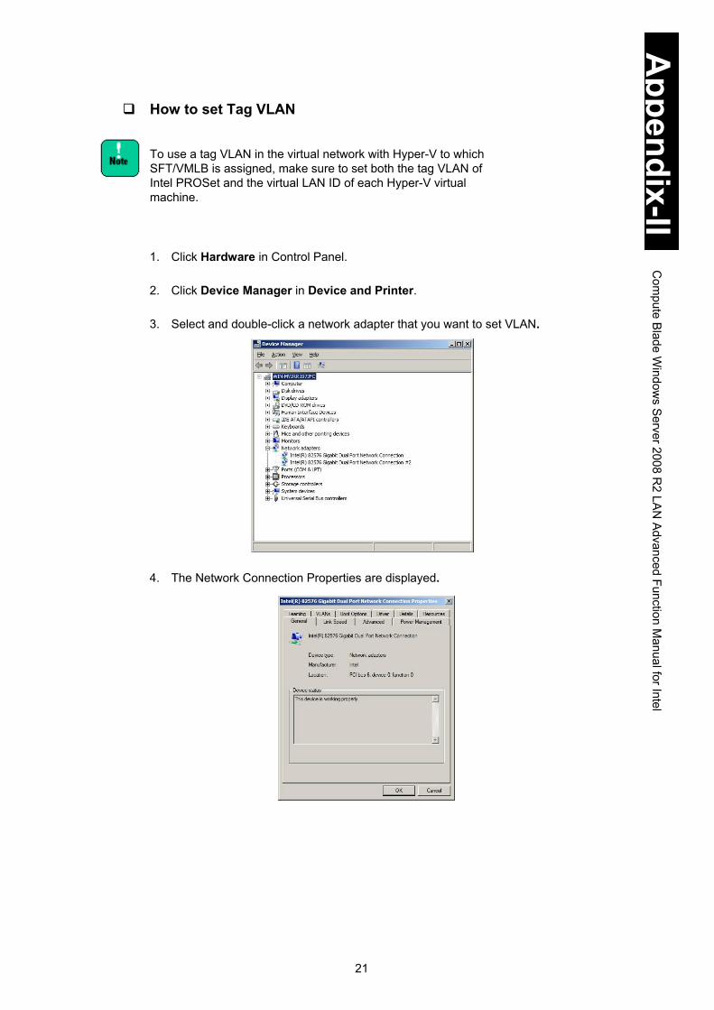
21
Appendix-II
Com
pute Blade W
indows S
erver 2008 R2 LA
N Advanced Function M
anual for Intel
How to set Tag VLAN
To use a tag VLAN in the virtual network with Hyper-V to which SFT/VMLB is assigned, make sure to set both the tag VLAN of Intel PROSet and the virtual LAN ID of each Hyper-V virtual machine. 1. Click Hardware in Control Panel.
2. Click Device Manager in Device and Printer.
3. Select and double-click a network adapter that you want to set VLAN.
4. The Network Connection Properties are displayed.

22
Appendix-II
Com
pute Blade W
indows S
erver 2008 R2 LA
N Advanced Function M
anual for Intel
5. Click the VLANs tab, and then click New...
6. When the New VLAN screen appears, type in VLAN ID and VLAN Name fields and then click OK. The VLAN ID should be the same as the switching HUB setting value.
When setting Tag VLAN, the switching HUB that connected to the system should support IEEE802.1q VLAN. 7. The screen returns to Properties.
It may take several seconds for the Tag VLAN setting to take effect. Tag VLAN can be set up to 10 groups (IDs) per server blade. Only TCP/IP is supported as a protocol. If it is set to more than 10 groups, or if any other protocol but TCP/IP is used, the server blade may be unstable.
! Note
! Note

23
Appendix-II
Com
pute Blade W
indows S
erver 2008 R2 LA
N Advanced Function M
anual for Intel
A Tag VLAN team is added to the Device Manager screen as shown below.
When you have set Tag VLAN on a network adapter, you may not properly communicate using the adapter which the settings have been changed. Check the network adapter with the changed setting using the device manager. If [!] is displayed, reboot the OS to use the adapter.
8. Repeat step 4 to step 7 to set all necessary VLANs.
9. Make sure to reboot the OS.
10. Select Control Panel > Network and Internet > View network status and tasks.
When the Network and Sharing Center screen is displayed, click Change adapter settings to view Network Connection.
On the Network Connection screen, Local Area Connection icons are displayed. Those include equivalent numbers of icons for the LAN devices and also to teams that the Tag VLAN has been set to. The IP address, the value of Local Area Connection added in Tag VLAN settings, is enabled.To change the IP address, from Properties in Local Area Connection, select Network Protocol (TCP/IP) and then Properties.
Tip
Tip
! Note

24
Appendix-II
Com
pute Blade W
indows S
erver 2008 R2 LA
N Advanced Function M
anual for Intel
“Intel(R)xxxxx – VLAN: VLANx” is shown in This connection uses the following items:.
Two same team names may be displayed in the Network Connection screen immediately after setting VLAN. Update the display after a while, then it displays properly. 11. Check the IP address value. The default setting is Get Automatically. When using
the fixed IP address, change the setting. When changing IP address values, make sure to check the connection.
12. Repeat step 11 to step 12, to set all necessary Tag VLANs.
13. Make sure to reboot the OS.
14. The Tag VLAN function is Enabled. You can find the status of a LAN device in which Tag VLAN has been configured, in system logs of the event viewer.
An error event log related to the LAN driver and this redundancy tools may be generated in the system or application logs when setting tag VLANs. The LAN device may link down.
On the Device Manager screen, right-click the LAN device in which Tag VLAN has been configured, and select Properties from the menu. Click the Link Speed tab, find Link Status, and check if the LAN device is running properly.
Remove Tag VLAN settings before changing server blades. New hardware is automatically recognized during the OS boot. Set Tag VLAN once more.
! Note
! Note
! Note

25
Appendix-II
Com
pute Blade W
indows S
erver 2008 R2 LA
N Advanced Function M
anual for Intel
When using a team (AFT, ALB, SFT) that the Tag VLAN is set to, the link connection to the team is not displayed as if the team is not connected. There is no problem in operation. Check if LAN devices in the team where Tag VLAN is configured operate properly.
How to remove Tag VLAN 1. Double-click VLAN: VLANx in the Device Manager screen.
2. Click the Setting tab and then Remove VLAN.
Tip

26
Appendix-II
Com
pute Blade W
indows S
erver 2008 R2 LA
N Advanced Function M
anual for Intel
3. When the following screen appears, click Yes.
4. Make sure to reboot the OS.
When Tag VLAN is configured in another application setting as a network device to use, make sure to cancel the Tag VLAN from the application settings, and remove it.
An error event log related to the LAN driver and redundancy tools may be generated in the system and application logs when removing the Tag VLAN. LAN devices might link down. On the Device Manager screen, right-click the LAN device that Tag VLAN is set to and select Properties from the menu. Click the Link Speed tab, find Link Status, and check if the LAN device is running properly.
! Note
! Note
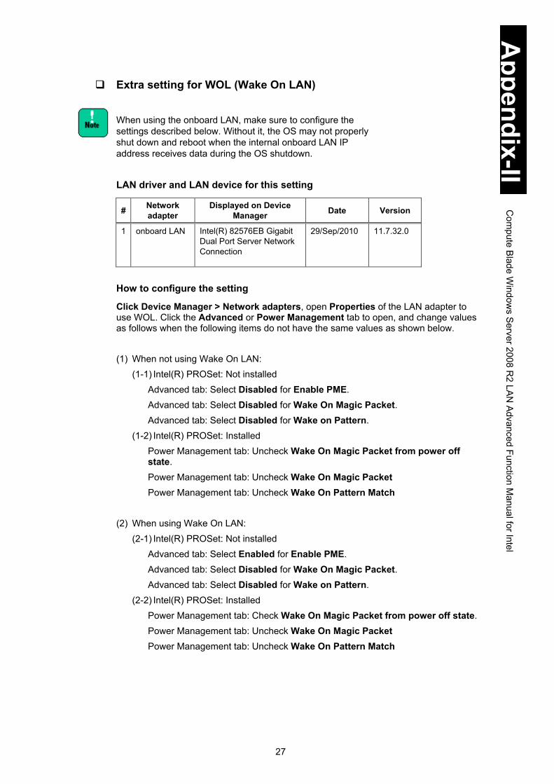
27
Appendix-II
Com
pute Blade W
indows S
erver 2008 R2 LA
N Advanced Function M
anual for Intel
Extra setting for WOL (Wake On LAN)
When using the onboard LAN, make sure to configure the settings described below. Without it, the OS may not properly shut down and reboot when the internal onboard LAN IP address receives data during the OS shutdown.
LAN driver and LAN device for this setting
# Network adapter
Displayed on Device Manager Date Version
1 onboard LAN Intel(R) 82576EB Gigabit Dual Port Server Network Connection
29/Sep/2010 11.7.32.0
How to configure the setting
Click Device Manager > Network adapters, open Properties of the LAN adapter to use WOL. Click the Advanced or Power Management tab to open, and change values as follows when the following items do not have the same values as shown below. (1) When not using Wake On LAN:
(1-1) Intel(R) PROSet: Not installed Advanced tab: Select Disabled for Enable PME. Advanced tab: Select Disabled for Wake On Magic Packet. Advanced tab: Select Disabled for Wake on Pattern.
(1-2) Intel(R) PROSet: Installed Power Management tab: Uncheck Wake On Magic Packet from power off state. Power Management tab: Uncheck Wake On Magic Packet Power Management tab: Uncheck Wake On Pattern Match
(2) When using Wake On LAN: (2-1) Intel(R) PROSet: Not installed
Advanced tab: Select Enabled for Enable PME. Advanced tab: Select Disabled for Wake On Magic Packet. Advanced tab: Select Disabled for Wake on Pattern.
(2-2) Intel(R) PROSet: Installed Power Management tab: Check Wake On Magic Packet from power off state. Power Management tab: Uncheck Wake On Magic Packet Power Management tab: Uncheck Wake On Pattern Match

28
Appendix-II
Com
pute Blade W
indows S
erver 2008 R2 LA
N Advanced Function M
anual for Intel
Settings for Hyper-V virtual network with SFT/VMLB Do not share Hyper-V virtual network, to which SFT/VMLB are assigned, between management OSs. 1 Click Start > Administrative Tools > Hyper-V Manager to start Hyper-V Manager. 2 On Hyper-V Manager, click Operation > Virtual Network Manager to open. 3 Select the Hyper-V virtual network to which SFT/VMLB are assigned. 4 Uncheck Allow management operating system to share this network adapter. 5 Click OK to close this screen.
Use another network adapter with no SFT/VMLB assigned to communicate between the management OS and external network.

29
Appendix-II
Com
pute Blade W
indows S
erver 2008 R2 LA
N Advanced Function M
anual for Intel
When a SFT team with VLAN is used on Hyper-V virtual network, a single VLAN is available. If a SFT team with two VLANs is used on Hyper-V virtual network, LAN devices cannot be switched properly in failure, which may cause a communication error.
When using a tag VLAN on Hyper-V virtual network, to which SFT/VMLB are assigned, make sure to set both the tag VLAN of Intel PROSet and virtual LAN ID of the Hyper-V machine.
1 Click the virtual machine, and then click Settings in the pane on the right.
2 When Setting for New Virtual Machine is displayed, click ADD Hardware in the left pane, and select a network adapter.
3 Check Enable virtual LAN Identification, and type the same ID as the tag VLAN ID set to the SFT/VMLB team to VLAN ID field.

30
Appendix-II
Com
pute Blade W
indows S
erver 2008 R2 LA
N Advanced Function M
anual for Intel
Event log description (Source: iANS Miniport) OS event logs give you information on the status of advanced LAN functions. The following table describes events logged at iANS Miniport.
(I: Information; W: Warning) ID Message Description and Resolution
6 (I) Primary adapter is initialized: <member description>
The member LAN device as Primary Adapter has been properly initialized.
7 (I) Adapter is initialized: <member description> The member LAN device as Secondary Adapter or as another adapter but Primary has been properly initialized.
8 (I) Team #<team ID>: Team is initialized. The team comprising of advanced functions has been properly initialized.
9 (I) Team #<ID>: Virtual Adapter for <VLAN name> [VID=<VLAN ID>] initialized.
VLAN has been properly initialized.
10 (I) Current Primary Adapter is switching from: <member description>
Current Primary Adapter is switching from the member adapter to a member as Secondary Adapter.
11 (W) Adapter link down: <member description> The member adapter link is down. Check cable connections.
12 (I) Secondary Adapter took over: <member description>
Due to failure in the LAN device as Primary Adapter, a member adapter as Secondary Adapter has taken over the network processing.
13 (W) The <member description> has been deactivated from the team.
The member adapter has been deactivated from the team. There is a problem in Primary device, Secondary device, or the connecting route.
14 (I) Secondary Adapter has rejoined the Team: <member description>
The deactivated member LAN device has been added to the team again.
15 (I) Adapter link up: <member description> The member LAN device link is up again.
16 (W) Team #<ID>: The last adapter has lost link. Network connection has been lost.
All LAN devices in the team have lost link.
17 (W) Team #<ID>: An adapter has re-established link. Network connection has been restored.
Network connection in the LAN device team has been restored.
18 (I) Preferred primary adapter has been detected: <member description>
The member LAN device specified as Primary Adapter has been detected.
19 (I) Preferred Secondary Adapter has been detected: <member description>
The member LAN device specified as Secondary Adapter has been detected.
20 (I) Preferred primary adapter took over: <member description>
The member LAN device specified as Primary Adapter has taken over the network processing.
21(I) Preferred secondary adapter took over: <member description>
The member LAN device specified as Secondary Adapter has taken over the network processing.
22 (W) Primary Adapter does not sense any Probes: <member description>
The member LAN device as Primary Adapter does not sense any probe packets. Possible reason: partitioned Team.
35 (W) Initializing Team #<ID> with <missing #> missing adapters. Check the configuration to verify that all the adapters are present and functioning.
The team # is being initialized with missing or inactive adapters' #. Check if all LAN devices are properly implemented and functioning.
37 (I) Virtual adapter for <VLAN name> [VID=<VLAN ID>] removed from team #<team ID>.
Virtual adapter with VLAN name [VID=VLAN ID] has been removed from the team.
38 (I) Adapter removed from team #<ID>. The LAN device has been removed from the team.

31
Appendix-II
Com
pute Blade W
indows S
erver 2008 R2 LA
N Advanced Function M
anual for Intel
Example of operating advanced function Prerequisites
A fault tolerance team is comprised of LAN Device A (Intel PRO/1000 A Network Connection) and LAN Device B (Intel(R) PRO/1000 B Network Connection). Do not set preference values such as primary and secondary to both devices, and when LAN Device A is automatically set to the Primary. (See How to set priority to LAN device: primary/secondary for the setting.)
Operation
Suppose LAN Device A link is down when the network function is running. Fault tolerance function makes LAN Device B take over the process. Even if LAN Device A restores the linkup after a while, LAN Device B keeps processing.
OS Event Log to be recorded: System Log (Source: iANS Miniport)
1. When a server blade boots up Event ID 7: Information
Adapter is initialized: Intel PRO/1000 A Network Connection Event ID 7: Information
Adapter is initialized: Intel PRO/1000 B Network Connection Event ID 15: Information
Adapter link up: Intel PRO/1000 A Network Connection Event ID 15: Information
Adapter link up: Intel PRO/1000 B Network Connection Event ID 8: Information
Team #<team ID>: Team is initialized.
Immediately after a server blade boots in setting Fault Tolerance, “Event ID 11: Adapter link down: <member description>” might be generated in the event log. Since no hardware failure occurs, use it as it is. 2. When Link Connection is down
Event ID 11: Warning Adapter link down: Intel PRO/1000 A Network Connection
Event ID 10: Information Current Primary Adapter is switching from: Intel PRO/1000 A Network Connection
Event ID 12: Information Secondary Adapter took over: Intel PRO/1000 B Network Connection
3. When Link Connection is restored
Event ID 15: Information Adapter link up: Intel PRO/1000 A Network Connection
Event ID 14: Information Secondary Adapter has rejoined the Team: <member description>: Intel PRO/1000 A Network Connection
Without setting preference, LAN Device A remains Secondary even if restored.
Tip

32
Appendix-II
Com
pute Blade W
indows S
erver 2008 R2 LA
N Advanced Function M
anual for Intel
Restrictions Settings for advanced LAN functions, such as AFT, ALB, VMLB, SFT, and VLAN are
not available in the environment with the network load balancing (NLB) installed. If you set those functions, you may not be able to communicate properly using the virtual LAN device that you have created or the LAN device for which you have cancelled the setting.
Do not use the team function of the advanced LAN functions as a LAN for internal cluster communication within cluster servers.
When the network is under heavy load conditions, the LAN driver may rarely detect a temporary linkdown. It will be linked up in a second or two after detecting the linkdown. With a redundancy configuration using a team, LAN devices will be switched.
1
Appendix-III Compute Blade Windows Server 2008/R2 LAN Advanced Function Manual for Broadcom
This appendix explains advanced functions for LAN in Windows Server 2008 and Windows Server 2008 R2.
How to set advanced LAN Functions ...................................................................... 2 Installing BACS4 ..................................................................................................... 3 Setting up Smart Load Balancing and failover ........................................................ 6 Status indicated in the event log (Source: Blfm) .................................................. 26 Example of setting up a Hyper-V virtual network with SLB .................................. 28 TCP Checksum Offload function........................................................................... 29 Restrictions ........................................................................................................... 30

2
Appendix-III
Com
pute Blade W
indows S
erver 2008/R2 LA
N Advanced Function M
anual for Broadcom
How to set advanced LAN Functions To install Broadcom BACS4, log in to the system with administrative permission. A prerequisite for setting advanced LAN functions is a properly installed LAN driver. See the manual or software guide of each LAN device for information about how to install the driver.
Run the setup program in the following directory of Drivers Kit CD-ROM. (Where the DVD ROM drive is drive D:)
OS Location of Tool for LAN Redundancy Windows Server 2008 R2
X55R3/S3 Model: d: \X55x3\Win2008\Utility\BACS4\MgmtApps\x64\setup.exe
Windows Server 2008 32-bit
X55R3/S3 Model: d: \X55x3\Win2008\Utility\BACS4\MgmtApps\IA32\setup.exe
Windows Server 2008 x64 Edition
X55R3/S3 Model: d: \X55x3\Win2008\Utility\BACS4\MgmtApps\x64\setup.exe
Supported operating systems are different depending on the system unit. Always check which operating systems are supported by the system unit.
You need to install BACS4 to use the LAN extension functions.

3
Appendix-III
Com
pute Blade W
indows S
erver 2008/R2 LA
N Advanced Function M
anual for Broadcom
Installing BACS4 1 Log on as a user with privileges (Administrator or others).
2 Install the following OS standard feature. Accept the license agreement when you
agree to the terms and click Next.
3 Double-click the exe file and click Next.
4 Read the LICENSE AGREEMENT, and check I accept the terms in the License Agreement to confirm you agree with the terms, and click Next. The Custom Setup dialog box is displayed. Click Next.

4
Appendix-III
Com
pute Blade W
indows S
erver 2008/R2 LA
N Advanced Function M
anual for Broadcom
5 The Custom Setup dialog box is displayed. Click Next.
Do not select the SNMP checkbox.
6 Click Install. Installation starts. 7 Click OK. 8 Click Finish and restart the OS.
! Note

5
Appendix-III
Com
pute Blade W
indows S
erver 2008/R2 LA
N Advanced Function M
anual for Broadcom
If you do not install the correct BACS4 corresponding to the OS you use, the warning message will be displayed. Example: If you try to install a 32-bit version of BACS to a 64-bit OS, the following warning message will be displayed:
After you uninstalled BACS4, make sure you restart the system. If you reinstall BACS4 without restarting the system, BACS4 might not work properly. If you want to uninstall BACS4, uninstall Broadcom Management Programs in Control Panel.
The following warning event is recorded when you install BACS4. This is not a problem. Level: Warning Source: WinMgmt Event ID: 63 Description: A provider, BnxWmiProvider, has been registered in the WMI namespace, Root\BrcmBnxNS, to use the LocalSystem account. This account is privileged and the provider may cause a security violation if it does not correctly impersonate user requests.
Tip
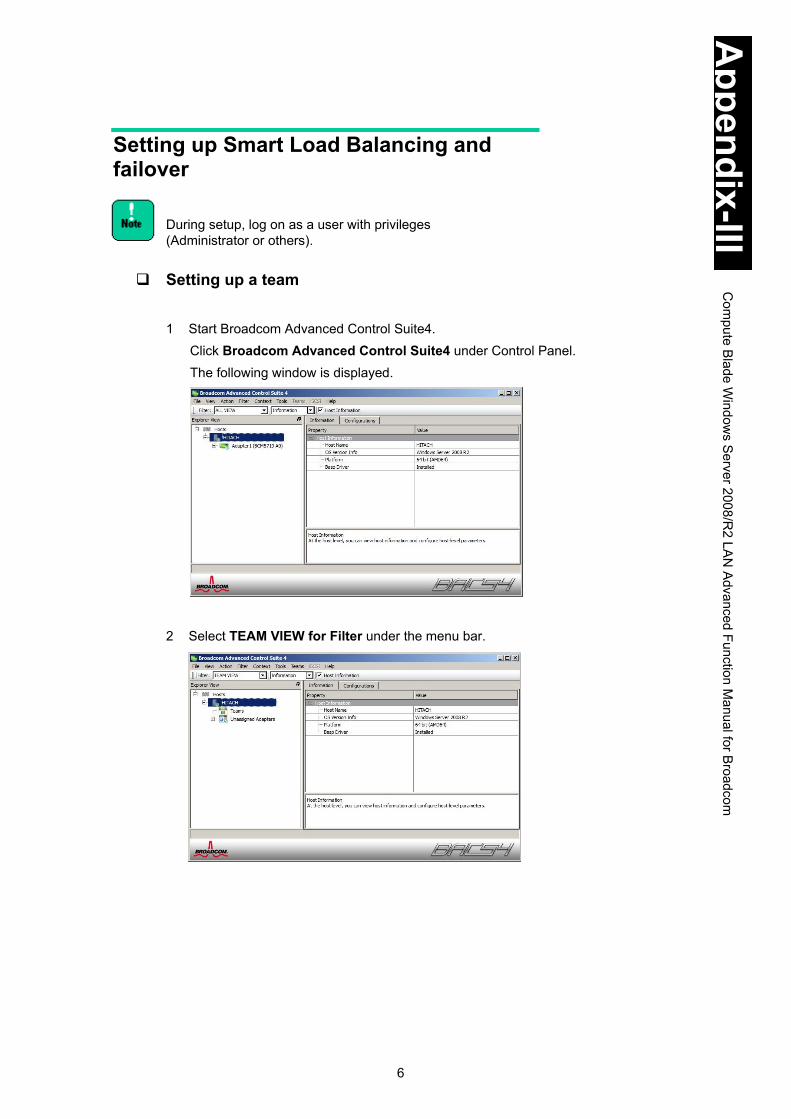
6
Appendix-III
Com
pute Blade W
indows S
erver 2008/R2 LA
N Advanced Function M
anual for Broadcom
Setting up Smart Load Balancing and failover
During setup, log on as a user with privileges (Administrator or others).
Setting up a team
1 Start Broadcom Advanced Control Suite4.
Click Broadcom Advanced Control Suite4 under Control Panel. The following window is displayed.
2 Select TEAM VIEW for Filter under the menu bar.

7
Appendix-III
Com
pute Blade W
indows S
erver 2008/R2 LA
N Advanced Function M
anual for Broadcom
3 Select a load balance member from LAN devices, right-click the load balance member, and select Create Team.
4 Click Next.
Expert Mode is not supported.
In rare cases, the dialog box may not be displayed properly.

8
Appendix-III
Com
pute Blade W
indows S
erver 2008/R2 LA
N Advanced Function M
anual for Broadcom
5 Type the team name as shown in the dialog below, and click Next. (Team 1 in the dialog).
You can choose the team name arbitrarily. 6 Check Team Type. Select Smart Load Balancing and Failover (SLB), and click
Next.
LAN devices used in the system unit only support Smart Load Balancing and Failover (SLB). Do not select other radio buttons. 7 Select one member for the team from Available Adapters, and click Add.
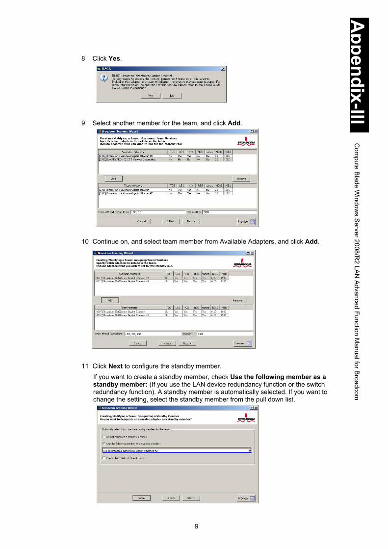
9
Appendix-III
Com
pute Blade W
indows S
erver 2008/R2 LA
N Advanced Function M
anual for Broadcom
8 Click Yes. 9 Select another member for the team, and click Add. 10 Continue on, and select team member from Available Adapters, and click Add.
11 Click Next to configure the standby member.
If you want to create a standby member, check Use the following member as a standby member: (If you use the LAN device redundancy function or the switch redundancy function). A standby member is automatically selected. If you want to change the setting, select the standby member from the pull down list.

10
Appendix-III
Com
pute Blade W
indows S
erver 2008/R2 LA
N Advanced Function M
anual for Broadcom
If you do not create a standby member, check Do not configure a standby member. (If you use the LAN device load balancing function).
If you check Enable Auto-Fallback Disable mode when failover to the standby member occurs due to failure in the load balance member and then the load balance member recovers, failback to the load balance member does not occur automatically. If you want failback to the load balance member to occur automatically, do not select the box
After you finish configuring teaming function, connect the two LAN devices to the same HUB if you use the LAN device redundancy function or the LAN device load balancing function. Connect the two LAN devices to the different HUBs if you use the switch redundancy function.
Teaming type Load balance member Standby member Network
configuration
LAN device redundancy function
LAN1 LAN2
LAN device load balancing function
LAN1 LAN2
-
Switch redundancy function
LAN1 LAN2

11
Appendix-III
Com
pute Blade W
indows S
erver 2008/R2 LA
N Advanced Function M
anual for Broadcom
12 In the following dialog box, click Next.
Do not select Yes for Configure LiveLink. The LiveLink function is not supported.
13 In the following dialog box, check Skip Manage VLAN and click Next. Then click
Finish.
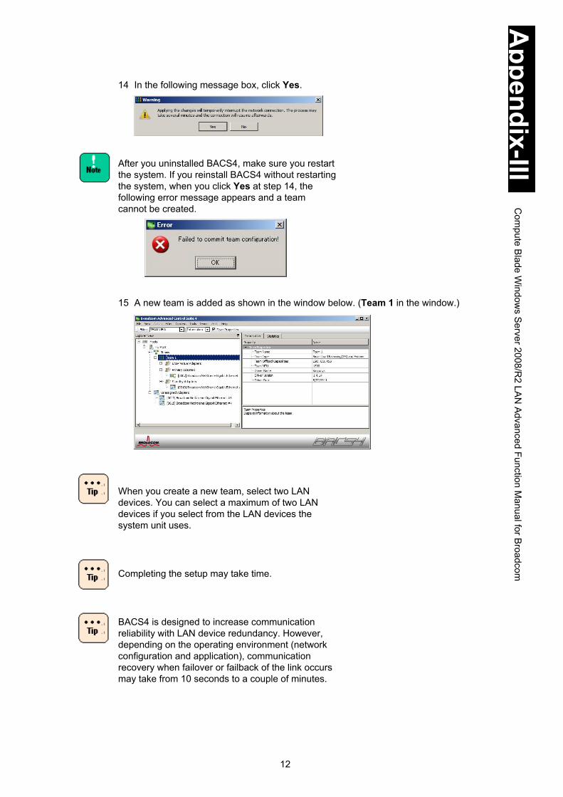
12
Appendix-III
Com
pute Blade W
indows S
erver 2008/R2 LA
N Advanced Function M
anual for Broadcom
14 In the following message box, click Yes. After you uninstalled BACS4, make sure you restart the system. If you reinstall BACS4 without restarting the system, when you click Yes at step 14, the following error message appears and a team cannot be created.
15 A new team is added as shown in the window below. (Team 1 in the window.)
When you create a new team, select two LAN devices. You can select a maximum of two LAN devices if you select from the LAN devices the system unit uses.
Completing the setup may take time.
BACS4 is designed to increase communication reliability with LAN device redundancy. However, depending on the operating environment (network configuration and application), communication recovery when failover or failback of the link occurs may take from 10 seconds to a couple of minutes.

13
Appendix-III
Com
pute Blade W
indows S
erver 2008/R2 LA
N Advanced Function M
anual for Broadcom
Receive data is processed by one LAN device. That means the bandwidth for receive data does not increase. Teaming is designed to increase the effective throughput of LAN communication by load balancing processing. However, depending on the operating environment (CPU load, communication data, and so on), the performance may not be improved due to the overhead of load balancing processing itself.
When teaming or VLAN tagging is set up, error events for the LAN driver or BACS4e are recorded in the event log (system or application). The LAN device might be linked down. Select ALL VIEW for Filter under the menu bar on the Broadcom Advanced Control Suite 4 window. Select Portxx (xx can be any number) corresponding to the LAN device set as a member of the team. Confirm the value of Link State is UP.
Type: Error Event: 4191 Source: TCP/IP Description: IP could not open the registry key for adapter TCPIP\Parameters\Adapters\NDISWANIP. Interfaces on this adapter will not be initialized.
Error events regarding the LAN drivers for the LAN device that has set the team setting may be recorded in the event log (system or application) regularly when the system starts up. Select ALL VIEW for Filter under the menu bar in the Broadcom Advanced Control Suite 4 window. Select Portxx (xx can be any number) corresponding to the LAN device set as a member of the team. Confirm the value of Link State is UP.

14
Appendix-III
Com
pute Blade W
indows S
erver 2008/R2 LA
N Advanced Function M
anual for Broadcom
After you set up teaming, Click Control Panel > Network and Internet > View network status and tasks. The Network and Sharing Center window is displayed. Click Change adapter settings. In the Network Connections window, confirm a new Local Area Connection is added.
In the Network Connections window, for each LAN device and for each team configured on the LAN extension functions, a Local Area Connection icon is displayed. For the IP address, the IP address value specified in Local Area Connection created for the team (not in the ones created for the LAN devices) is used. If you want to change the IP address, on Properties of Local Area Connection, select Properties of Internet Protocol (TCP/IP).
After you set up teaming on a network adapter, in some cases, the adapter may not be able to communicate normally. Go to the Device Manager and check the network adapter. If you see the ! at the side of the network adapter, you can resolve the issue by restarting the OS.
Immediately after you set up teaming, the team created on the Network Connection window may be displayed as two identical icons. Wait for a while and refresh the window, which should resolve the issue.

15
Appendix-III
Com
pute Blade W
indows S
erver 2008/R2 LA
N Advanced Function M
anual for Broadcom
16 Confirm the IP address setting. The initial setting for the IP address is Obtain an IP address automatically. When you use a fixed IP address, you need to change the setting of the IP address. After you change the setting, confirm the network connection is OK.
17 Repeat step 3 through step 16 for each team you want to create. 18 Restart the OS. After you restart the OS, the LAN extension functions become
effective. You can check the status of LAN devices configured as members of the team in the System log of the Event Viewer.
When you replace some parts in the system unit for maintenance, delete the team settings before the replacement. When the OS starts, new hardware is automatically detected. After that, reconfigure the team settings of the LAN extension functions.
If a different LAN device is used as a team member, the settings for the new LAN device may be adjusted to fit the device.
Deleting a team 1 Start Broadcom Advanced Control Suite4.
Click Broadcom Advanced Control Suite4 under Control Panel. The following window is displayed.

16
Appendix-III
Com
pute Blade W
indows S
erver 2008/R2 LA
N Advanced Function M
anual for Broadcom
2 Select TEAM VIEW for Filter just under the menu bar. Right-click the team name and select Delete Team. (Team 1 in the window.)
3 In the following message box, click Yes. 4 If you want to delete other teams, repeat step 1 through step 3. 5 Make sure you restart the OS. When you delete a team, error events for the LAN driver or the BACS4 might be recorded in the event log (system or application). If error events are recorded, the LAN device may be linked down. Select ALL VIEW for Filter located under the menu bar on the Broadcom Advanced Control Suite 4 window. Select Portxx (xx can be any number) corresponding to the LAN device set as a member of the team. Confirm the value of Link State is UP.
Type: Error
Event: 4191
Source: TCP/IP
Description: IP could not open the registry key for adapter
TCPIP\Parameters\Adapters\NDISWANIP. Interfaces on this adapter will not be initialized.

17
Appendix-III
Com
pute Blade W
indows S
erver 2008/R2 LA
N Advanced Function M
anual for Broadcom
Setting up a tagged VLAN
If you want to use VLAN tagging on the Hyper-V virtual network with teaming function, do not configure VLAN tagging for the team using Broadcom Advanced Control Suite 4 (BACS4). Configure virtual LAN IDs only on Hyper-V virtual machines.
If you use VLAN tagging, disable the Checksum function. For information about how to set this up, see Steps to set up.
If you add a tagged VLAN to a team, do not specify a fixed IPv6 address for the team before adding a tagged VLAN. Specify a fixed IPv6 address for the team after adding a tagged VLAN. If you specify a fixed IPv6 address for the team before adding a tagged VLAN, specify DHCP for the IPv6 address setting of the team temporarily to fix the issue.
1 Start Broadcom Advanced Control Suite4. Click Broadcom Advanced Control Suite4 under Control Panel.
2 Select a LAN device you want to add a tagged VLAN to, right-click the LAN device,
and select Create a VLAN.

18
Appendix-III
Com
pute Blade W
indows S
erver 2008/R2 LA
N Advanced Function M
anual for Broadcom
3 Click Next. Expert Mode is not supported.
4 Type the team name as shown in the following window and click Next. (Team 1 in
the window.) You can choose the team name arbitrarily.
5 Type the VLAN name as shown in the following window, and click Next. (VLAN1 in
the window.)

19
Appendix-III
Com
pute Blade W
indows S
erver 2008/R2 LA
N Advanced Function M
anual for Broadcom
6 Check Tagged and click Next. 7 The windows for setting up the VLAN ID are displayed. Enter the VLAN ID, and click
Next and then click Finish. If you use VLAN tagging, connect to a switching HUB that supports IEEE802.1q VLAN tagging.
You cannot change the VLAN ID or VLAN name for a VLAN already created. For information about how to change those settings, see Deleting a tagged VLAN.

20
Appendix-III
Com
pute Blade W
indows S
erver 2008/R2 LA
N Advanced Function M
anual for Broadcom
8 In the following message box, click Yes. The maximum number of tagged VLAN groups (IDs) you can use per system unit is 10. TCP/IP is the only supported protocol. If you create 11 or more groups or if you specify a protocol other than TCP/IP, the system unit might become unstable.
As in the window below, a new tagged VLAN team is added on the Broadcom Advanced Control Suite 4 window.
After you set up a tagged VLAN, click Control Panel > Network and Internet > View network status and tasks. The Network and Sharing Center window is displayed. Click Change adapter settings. In the Network Connections window, confirm a new Local Area Connection is added.
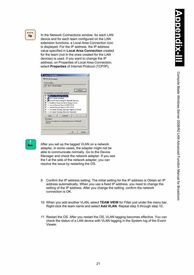
21
Appendix-III
Com
pute Blade W
indows S
erver 2008/R2 LA
N Advanced Function M
anual for Broadcom
In the Network Connections window, for each LAN device and for each team configured on the LAN extension functions, a Local Area Connection icon is displayed. For the IP address, the IP address value specified in Local Area Connection created for the team (not in the ones created for the LAN devices) is used. If you want to change the IP address, on Properties of Local Area Connection, select Properties of Internet Protocol (TCP/IP).
After you set up the tagged VLAN on a network adapter, in some cases, the adapter might not be able to communicate normally. Go to the Device Manager and check the network adapter. If you see the ! at the side of the network adapter, you can resolve the issue by restarting the OS.
9 Confirm the IP address setting. The initial setting for the IP address is Obtain an IP address automatically. When you use a fixed IP address, you need to change the setting of the IP address. After you change the setting, confirm the network connection is OK.
10 When you add another VLAN, select TEAM VIEW for Filter just under the menu bar.
Right-click the team name and select Add VLAN. Repeat step 5 through step 10. 11 Restart the OS. After you restart the OS, VLAN tagging becomes effective. You can
check the status of a LAN device with VLAN tagging in the System log of the Event Viewer.

22
Appendix-III
Com
pute Blade W
indows S
erver 2008/R2 LA
N Advanced Function M
anual for Broadcom
When you create a tagged VLAN, error events for the LAN driver or BACS4 may be recorded in the event log (system or application). If error events are recorded, the LAN device may be linked down. Select ALL VIEW for Filter located under the menu bar in the Broadcom Advanced Control Suite 4 window. Select Portxx (xx can be any number) corresponding to the LAN device set as a member of the team. Confirm the value of Link State is UP.
Level: Error
Event: 4191
Source: TCP/IP
Description: IP could not open the registry key for adapter
TCPIP\Parameters\Adapters\NDISWANIP. Interfaces on this adapter will not be initialized.
If you create a tagged VLAN on a team, Blfm Warning ID:8 will be recorded in the event log.
Level: Warning Event: 8 Source: Blfm Description: Could not bind to adapter \DEVICE\{adapter name }.
Level: Information Event: 9 Source: Blfm Description: Successfully bind to adapter \DEVICE\{adapter name }.
When you replace some parts in the system unit for maintenance, delete the tagged VLAN settings before the replacement. When the OS starts, new hardware is automatically detected. After that, reconfigure the tagged VLAN settings.

23
Appendix-III
Com
pute Blade W
indows S
erver 2008/R2 LA
N Advanced Function M
anual for Broadcom
Adding a tagged VLAN to an already existing team.
(1) Start Broadcom Advanced Control Suite4. Click Broadcom Advanced Control Suite4 under Control Panel. The following window is displayed.
(2) Select TEAM VIEW for Filter under the menu bar. Right-click the team name and select Add VLAN. (Team 1 in the window.)
(3) Click Next.
(4) Follow previous step 5 through step 11.

24
Appendix-III
Com
pute Blade W
indows S
erver 2008/R2 LA
N Advanced Function M
anual for Broadcom
Deleting a tagged VLAN 1 Start Broadcom Advanced Control Suite4. Click Broadcom Advanced Control
Suite4 under Control Panel. The following window is displayed. 2 Select TEAM VIEW for Filter under the menu bar. Right-click the team name, and
select Delete Team. (Team 1 in the window.) Team 1 and all VLAN IDs assigned to Team 1 are deleted.
If you want to delete only some of the VLAN IDs assigned to a team, right-click the VLAN name and select Remove VLAN. (VLAN 1 in the window.)
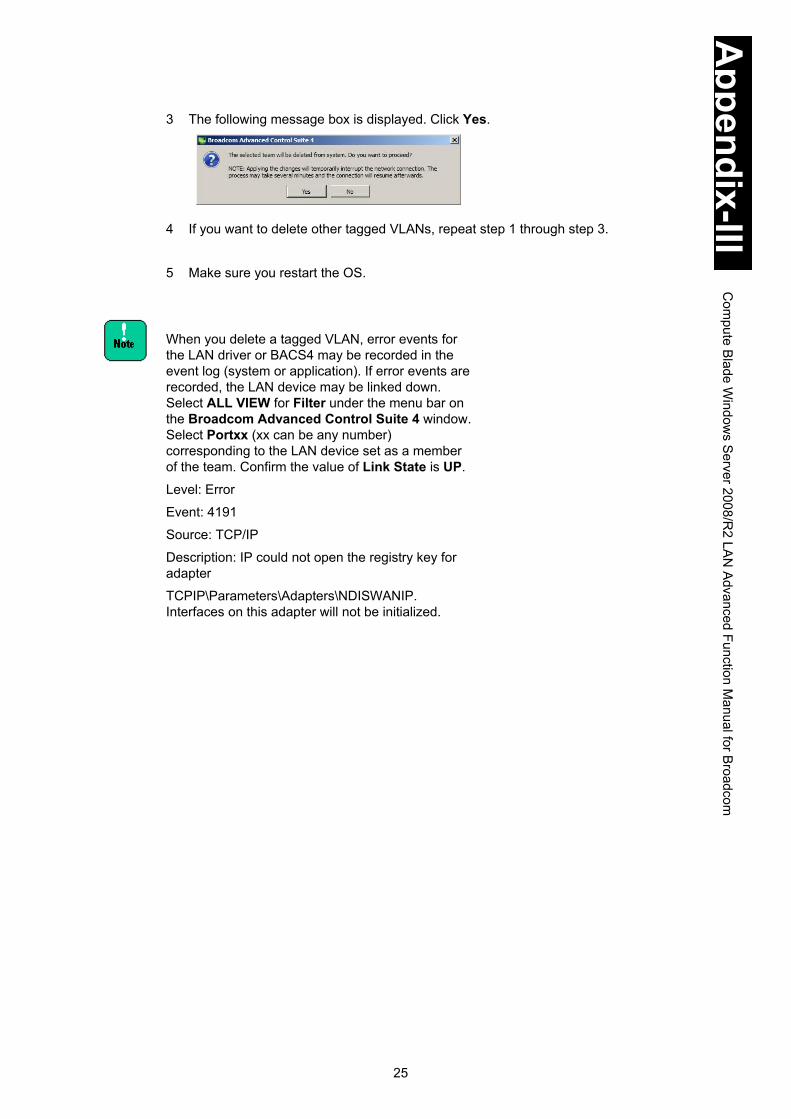
25
Appendix-III
Com
pute Blade W
indows S
erver 2008/R2 LA
N Advanced Function M
anual for Broadcom
3 The following message box is displayed. Click Yes. 4 If you want to delete other tagged VLANs, repeat step 1 through step 3. 5 Make sure you restart the OS. When you delete a tagged VLAN, error events for the LAN driver or BACS4 may be recorded in the event log (system or application). If error events are recorded, the LAN device may be linked down. Select ALL VIEW for Filter under the menu bar on the Broadcom Advanced Control Suite 4 window. Select Portxx (xx can be any number) corresponding to the LAN device set as a member of the team. Confirm the value of Link State is UP.
Level: Error
Event: 4191
Source: TCP/IP
Description: IP could not open the registry key for adapter
TCPIP\Parameters\Adapters\NDISWANIP. Interfaces on this adapter will not be initialized.

26
Appendix-III
Com
pute Blade W
indows S
erver 2008/R2 LA
N Advanced Function M
anual for Broadcom
Status indicated in the event log (Source: Blfm)
You can check the operating status of the LAN extension functions in the OS event log. The following table is a list of events recorded for Source: Blfm.
ID (Type) Description Meaning and corrective action
1 (Information)
Event logging enabled for Broadcom Advanced Server Program Driver.
Events are now recorded.
2 (Error)
Unable to register with NDIS. The driver cannot register with the NDIS interface.
Unload other NDIS drivers.
3 (Error)
Unable to create an instance of the management interface.
The driver cannot create a device instance.
Reboot the operating system.
4 (Error)
Unable to create symbolic link for the management interface.
Another driver has created a conflicting device name.
Unload the conflicting device driver that uses the name Blf.
5 (Information)
Broadcom Advanced Server Program Driver has started.
The driver has started.
6 (Information)
Broadcom Advanced Server Program Driver has stopped.
The driver has stopped.
7 (Error)
Could not allocate memory for internal data structures.
The driver cannot allocate memory from the operating system.
Close running applications to free memory.
8 (Warning)
Could not bind to adapter [Adapter Name].
The driver could not open one of the team physical adapters.
Unload and reload the physical adapter driver, install an updated physical adapter driver, or replace the physical adapter.
9 (Information)
Successfully bind to adapter [Adapter Name].
The driver successfully opened the physical adapter.
10 (Warning)
Network adapter [Adapter Name] is disconnected.
The physical adapter is not connected to the network (it has not established link).
Check that the network cable is connected, verify that the network cable is the right type, and verify that the link partner (switch or hub) is working correctly.
11 (Information)
Network adapter [Adapter Name] is connected.
The physical adapter is connected to the network (it has established link).
12 (Error)
Broadcom Advanced Program Features Driver is NOT designed to run on this version of Operating System.
The driver does not support the operating system on which it is installed.
Consult the driver release notes and install the driver on a supported operating system or update the driver.
14 (Information)
Network adapter [Adapter Name] does not support Advanced Failover.
The physical adapter does not support the Broadcom NIC Extension.
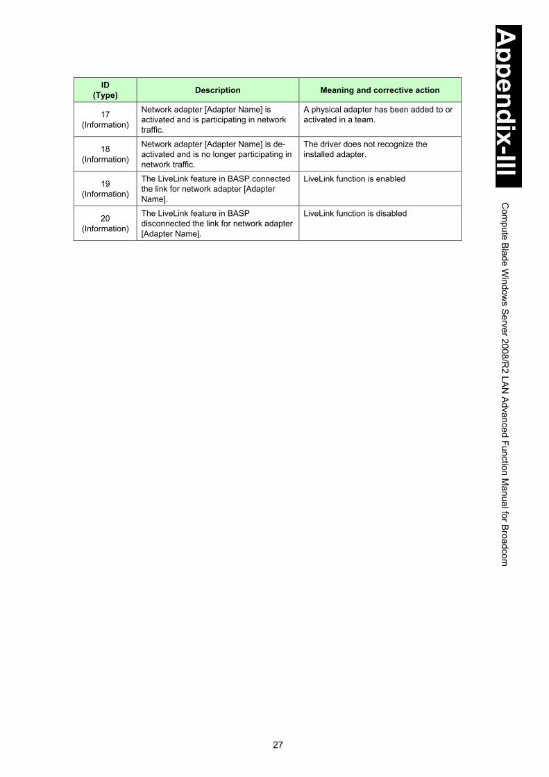
27
Appendix-III
Com
pute Blade W
indows S
erver 2008/R2 LA
N Advanced Function M
anual for Broadcom
ID (Type) Description Meaning and corrective action
17 (Information)
Network adapter [Adapter Name] is activated and is participating in network traffic.
A physical adapter has been added to or activated in a team.
18 (Information)
Network adapter [Adapter Name] is de-activated and is no longer participating in network traffic.
The driver does not recognize the installed adapter.
19 (Information)
The LiveLink feature in BASP connected the link for network adapter [Adapter Name].
LiveLink function is enabled
20 (Information)
The LiveLink feature in BASP disconnected the link for network adapter [Adapter Name].
LiveLink function is disabled
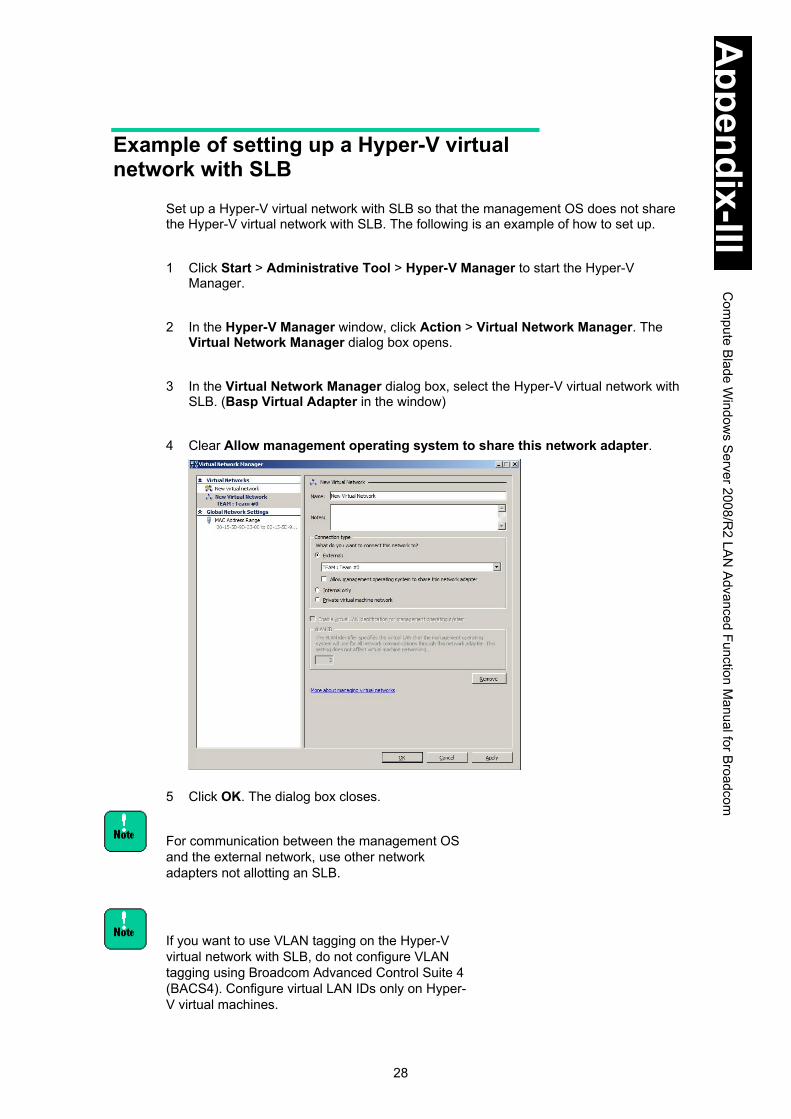
28
Appendix-III
Com
pute Blade W
indows S
erver 2008/R2 LA
N Advanced Function M
anual for Broadcom
Example of setting up a Hyper-V virtual network with SLB
Set up a Hyper-V virtual network with SLB so that the management OS does not share the Hyper-V virtual network with SLB. The following is an example of how to set up.
1 Click Start > Administrative Tool > Hyper-V Manager to start the Hyper-V
Manager. 2 In the Hyper-V Manager window, click Action > Virtual Network Manager. The
Virtual Network Manager dialog box opens. 3 In the Virtual Network Manager dialog box, select the Hyper-V virtual network with
SLB. (Basp Virtual Adapter in the window) 4 Clear Allow management operating system to share this network adapter. 5 Click OK. The dialog box closes.
For communication between the management OS and the external network, use other network adapters not allotting an SLB.
If you want to use VLAN tagging on the Hyper-V virtual network with SLB, do not configure VLAN tagging using Broadcom Advanced Control Suite 4 (BACS4). Configure virtual LAN IDs only on Hyper-V virtual machines.

29
Appendix-III
Com
pute Blade W
indows S
erver 2008/R2 LA
N Advanced Function M
anual for Broadcom
TCP Checksum Offload function The LAN cards on the system unit can calculate the checksums for the TCP/IP protocol inside the LAN controllers. However, we recommend not using this function but using the OS standard function to calculate the TCP/IP checksums. If the OS is configured to calculate the checksums, integrity check of received packet data is performed at the last stage of the protocol processing by the OS, which means higher reliability is established.
Steps to set up In Control Panel, double-click Device Manager. In the Properties dialog box for each LAN adapter under Network Adapters, click the Advanced tab. Configure each setting as shown in the following table.
Setting item Value
Broadcom Advanced Control Suite 4 not installed
Broadcom Advanced Control Suite 4 installed
IPv4 Checksum Offload Rx & Tx EnabledDisable Rx & Tx EnabledDisable
TCP/UDP Checksum Offload
(IPv4)
Rx & Tx EnabledDisable Rx & Tx EnabledDisable
TCP/UDP Checksum Offload
(IPv6)
Rx & Tx EnabledDisable Rx & Tx EnabledDisable
Large Send Offload (IPv4) EnableDisable EnableDisable
Large Send Offload v2
(IPv4)
EnableDisable EnableDisable
Large Send Offload v2
(IPv6)
EnableDisable EnableDisable
Receive Side Scaling EnableDisable EnableDisable
After you configure all the items, click OK to restart the OS.

30
Appendix-III
Com
pute Blade W
indows S
erver 2008/R2 LA
N Advanced Function M
anual for Broadcom
Restrictions Network protocol
Use TCP/IP for the protocol. Switching between LAN devices.
When, for example, the link to the load balance member is disconnected, the network traffic is switched to the standby member. Note that this switching process takes time. You need to check the event viewer and confirm that the network connection has been successfully switched before using the network.
Replacing a LAN device when failure occurs. If all LAN devices in the team have hardware failure, network connection is lost. When one of the LAN devices failed, replace the failed LAN device as soon as possible. After you replace the LAN device, reconfigure the extension functions according to this setup guide.
When the system unit starts up, the following event (warning) may be recorded for a LAN device on the system unit. LAN device name: The network link is down.
When the system starts up, error events may be recorded in the event log for the LAN device. The LAN device may be linked down. Check Network Connections to see if the reported LAN device is connected.
You cannot enable SLB if Network Load Balancing (NLB) is installed. If you do, network communication may not work properly for created virtual LAN devices or for LAN devices after disabling SLB.
Do not use LAN extension functions for a LAN used for internal communication within a cluster server.
Temporary communication disruption when a team or a tagged VLAN is created. When a team or a tagged VLAN is created, all teams or tagged VLANs in the system unit may not be able to communicate temporarily. You need to confirm all teams or tagged VLANs can communicate before using the network.
Temporary communication disruption when links in the team switches. Switching links takes a couple of seconds. Depending on applications in use, network connection may be disconnected temporarily.

1
Appendix-IV Compute Blade Windows Server 2012/2012 R2 LAN Driver Update
This appendix explains LAN driver update on Windows Server 2012/Windows Server 2012 R2.
Installing Drivers ...................................................................................................... 2 On Windows Server 2012/2012 R2 ........................................................................ 2
Additional Information on LAN Adapter ................................................................. 15 TCP Checksum Offload Function ......................................................................... 15 Setting TCP Checksum Offload on the OS ........................................................... 15 For Wake On LAN with the LAN Device ............................................................... 16 LAN Advanced Functions ..................................................................................... 16

2
Appendix-IV
Com
pute Blade W
indows S
erver 2012/2012 R2 LA
N D
river Update
Installing Drivers This section describes how to update the LAN driver on Windows Server 2012/2012 R2.
Supported operating systems are different depending on the system unit. Always check which operating systems are supported by the system unit.
On Windows Server 2012/2012 R2 If the latest LAN driver is installed at shipment, you do not
need to update the LAN driver unless otherwise instructed. For Windows Server 2012 R2, you do not need to install
drivers.
How to install the LAN drivers on Windows Server 2012 for 1 Gb LAN device
LAN device LAN device name on Device Manager Standard internal LAN 1 to 2 Intel(R) 82576 Gigabit Dual Port Server Network Connection
GVX-CN2M1G1X1EX Intel(R) 82576 Gigabit Dual Port Server Network Connection
GVX-CN2N1G2X1BX GVX-CN2D1G2X1EX
Intel(R) Gigabit ET Quad Port Server Adapter
GVX-CN2N1G3X1BX GVX-CN2D1G3X1EX
Intel(R) Gigabit ET2 Quad Port Server Adapter
GVX-CN2N1G1X1BX GVX-CN2D1G1X1EX
Intel(R) Gigabit ET Dual Port Server Adapter
It is assumed that Windows Server 2012 has been installed before starting this procedure. This section describes how to install Intel(R) Gigabit ET2 Quad Port Server Adapter as an example.
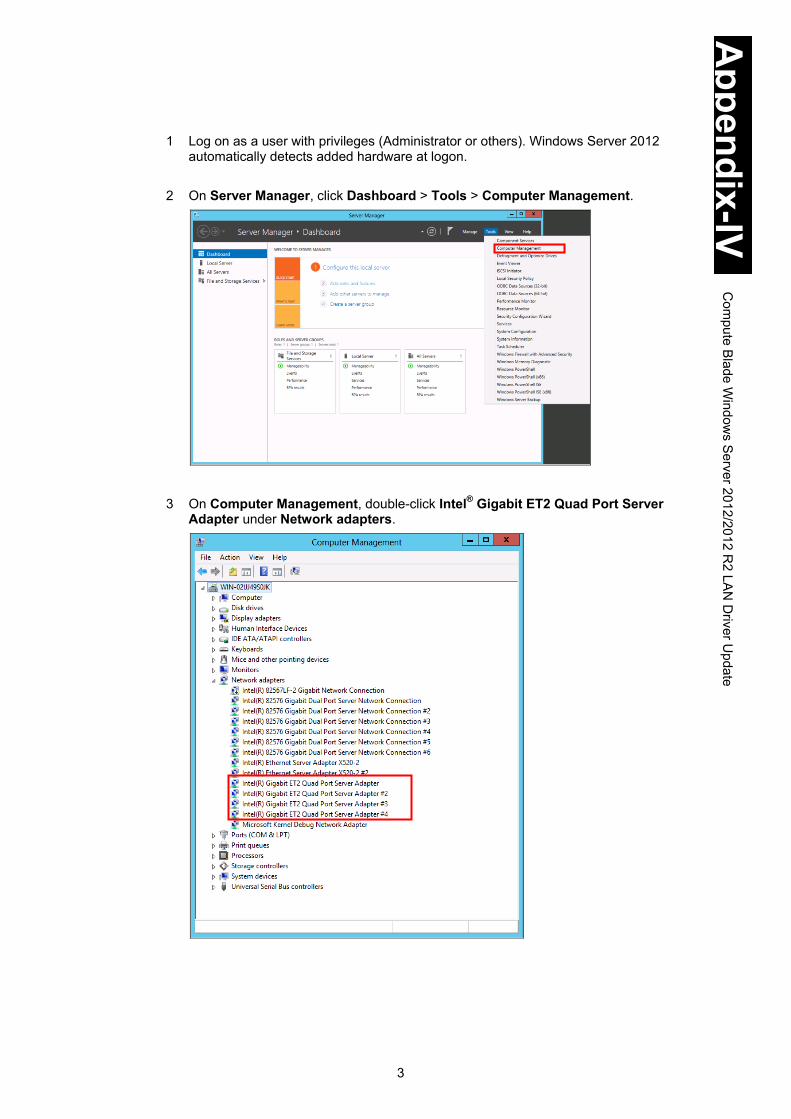
3
Appendix-IV
Com
pute Blade W
indows S
erver 2012/2012 R2 LA
N D
river Update
1 Log on as a user with privileges (Administrator or others). Windows Server 2012
automatically detects added hardware at logon.
2 On Server Manager, click Dashboard > Tools > Computer Management.
3 On Computer Management, double-click Intel® Gigabit ET2 Quad Port Server Adapter under Network adapters.

4
Appendix-IV
Com
pute Blade W
indows S
erver 2012/2012 R2 LA
N D
river Update
4 When the Properties dialog box appears, click the Driver tab > Update Driver.
5 When the following window appears, click Browse my computer for driver software.
Insert the Server installation and monitoring tool DVD into the DVD-ROM drive or DVD-RAM drive and enter the following directory. Click Next. (Where D is the drive name)
OS Location of LAN driver Windows Server 2012 D:\WinSrv2012\Drivers\NIC\IntelNIC_05\X64

5
Appendix-IV
Com
pute Blade W
indows S
erver 2012/2012 R2 LA
N D
river Update
6 Intel Gigabit ET2 Quad Port Server Adapter is detected, and the required driver will be installed to the system equipment from the Server installation and monitoring tool DVD. “Windows has finished installing the driver software for this device: Intel Gigabit ET2 Quad Port Server Adapter” is displayed. Click Close.
If the latest LAN driver has been installed, the following window appears. Click Close.

6
Appendix-IV
Com
pute Blade W
indows S
erver 2012/2012 R2 LA
N D
river Update
7 When the window returns to Properties, click Close. 8 Right-click the network adapter whose LAN driver has been updated, and select
Uninstall. When “You are about to uninstall this device from your system.” is displayed, click OK.
Select Uninstall, and Conform Device Uninstall software for this device. 9 The window returns to Device Manager. Repeat step from 2 through step 8 for
devices to update. 10 When having updated the LAN driver to all network adapters and uninstalled those
adapters, click a device on Device Manager, and click Action > Scan for Hardware Changes. All network adapters are automatically detected and the LAN driver is applied.
11. Check the value of IP address. Obtain an IP address automatically is checked by
default. When using a fixed IP address, you need to change the setting. After changing the setting, check that the LAN cable is properly connected to the counterpart such as a hub and restart the OS.
“Cannot Start this Hardware” may be displayed during
driver setup. If so, reboot the OS to operate properly. Check the device on Device Manager.
Restriction on changing parameters for network adapters
You may not be able to properly communicate with the adapter whose setting has been changed. Check the adapter on Device Manager. If the “!” is added to the adapter, right-click the adapter, disable it, and then enable it again to use it.
For the default setting, transfer speed, 10 Mbps, 100 Mbps, and 1000 Mbps, are automatically recognized. Correct transfer speed may not be automatically recognized depending on the network environment. If so, set the transfer speed fixed by following How to fix the transfer speed.

7
Appendix-IV
Com
pute Blade W
indows S
erver 2012/2012 R2 LA
N D
river Update
How to fix the transfer speed 1 Click Control Panel > Hardware, and double-click Device Manager. On Device
Manager, double-click Other Devices or Intel Gigabit ET2 Quad Port Server Adapter under Network adapters.
2 On Properties, click Advanced tab > Speed and Duplex. Auto Negotiation is set by
default. 3 Select a value of transfer speed, and then click OK.
4 Restart the OS. Do not change any other properties than Speed & Duplex. Restriction on 10/100 M bps half-duplex for network
adapters
When using this LAN adapter with 10 M half-duplex or 100 M half-duplex for transfer speed, disable Large Send Offload V2 (IPv4) and Large Send Offload V2 (IPv6). See Setting TCP Checksum Offload on the OS.

8
Appendix-IV
Com
pute Blade W
indows S
erver 2012/2012 R2 LA
N D
river Update
Click Server Manager > Local Server. On PROPERTIES, right-click Ethernet to open the Ethernet Properties. To change IP address, select Internet Protocol Versionx (TCP/IPxx) on Ethernet Properties. To find the LAN adapter location, click Configure.
When multiple of this LAN adapters are onboard, set a
unique network ID, which is part masked by Subnet Mask, to the IP address of each LAN adapter. If the same network ID is set to multiple IP address, the system equipment may not work properly.
See the manual of Windows Server 2012, Windows Server 2012 R2, and Server installation and monitoring tool OS Setup Guide for driver installation.

9
Appendix-IV
Com
pute Blade W
indows S
erver 2012/2012 R2 LA
N D
river Update
How to install the LAN drivers on Windows Server 2012/2012 R2 for 10 Gb LAN device
LAN device LAN device name on Device Manager GVX-CN2N1G2X1BX GVX-CN2D1G2X1EX
Intel(R) Ethernet Server Adapter X520-2
It is assumed that Windows Server 2012/Windows Server 2012 R2 has been installed before this procedure. This section describes how to install the driver for the LAN adapters shown above. 1 Log on as a user with privileges (Administrator or others). Windows Server
2012/Windows Server 2012 R2 automatically detects added hardware at logon.
2 On Server Manager, click Dashboard > Tools > Computer Management.

10
Appendix-IV
Com
pute Blade W
indows S
erver 2012/2012 R2 LA
N D
river Update
3 On Computer Management, double-click Intel Ethernet Server Adapter X520-2 under Network adapters.
4 When Properties appears, click Driver tab > Update Driver.
5 When the following window appears, click Browse my computer for driver software.

11
Appendix-IV
Com
pute Blade W
indows S
erver 2012/2012 R2 LA
N D
river Update
Insert the Server installation and monitoring tool DVD into the DVD-ROM drive or DVD-RAM drive and enter the following directory. Click Next. (Where D is the drive name)
OS Location of LAN driver Windows Server 2012 D:\WinSrv2012\Drivers\NIC\INTELXG_02\X64
Windows Server 2012 R2 WinSrv2012R2\Drivers\NIC\INTELXG_02\X64
6 Intel® Ethernet Server Adapter X520-2 is detected, and the required driver will be installed to the system equipment from the Server installation and monitoring tool DVD. “Windows has finished installing the driver software for this device: Intel Gigabit ET2 Quad Port Server Adapter” is displayed, click Close.
If the latest LAN driver has been installed, “Windows has determined the driver software for your device is up to date.” is displayed. Click Close.

12
Appendix-IV
Com
pute Blade W
indows S
erver 2012/2012 R2 LA
N D
river Update
7 When the window returns to Properties, click Close. 8 Right-click the network adapter whose LAN driver has been updated, and select
Uninstall. When “You are about to uninstall this device from your system.” is displayed, click OK.
Select Uninstall, and the following confirmation window appears. Do not check “Delete the driver software for this device.”
9 The window returns to Device Manager. Repeat step from 2 through step 8 for
devices to update. Check that the same numbers of Intel Ethernet Server Adapter X520-2 are displayed as that of LAN adapters onboard, and then close the window.
10 When having updated the LAN driver to all network adapters and uninstalled those
adapters, click a device on Device Manager, and click Action > Scan for Hardware Changes. All network adapters are automatically detected and the LAN driver is applied.
11. Check the value of IP address. Obtain an IP address automatically is set by
default. When using a fixed IP address, you need to change the setting. After changing the setting, check that the LAN cable is properly connected to the counterpart such as a hub and restart the OS.
Restriction on changing parameters for network adapters
You may not be able to communicate properly with the adapter whose setting has been changed. Check the adapter on Device Manager. If “!” is added to the adapter, right-click the adapter, disable it, and then enable it again to use it.
For the default setting, transfer speed, 10 Gbps and 1 Gbps, are automatically recognized. Correct transfer speed may not be automatically recognized depending on the network environment. If so, set the transfer speed fixed by following the procedure below.
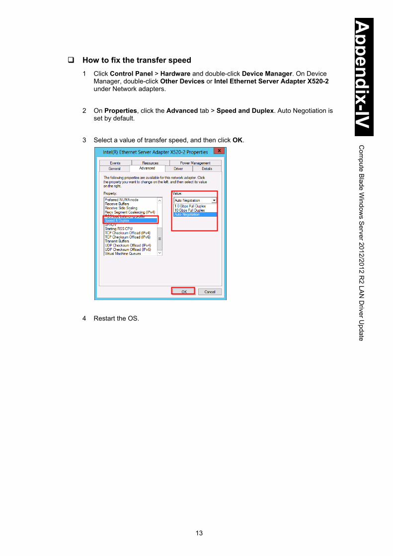
13
Appendix-IV
Com
pute Blade W
indows S
erver 2012/2012 R2 LA
N D
river Update
How to fix the transfer speed 1 Click Control Panel > Hardware and double-click Device Manager. On Device
Manager, double-click Other Devices or Intel Ethernet Server Adapter X520-2 under Network adapters.
2 On Properties, click the Advanced tab > Speed and Duplex. Auto Negotiation is
set by default. 3 Select a value of transfer speed, and then click OK.
4 Restart the OS.

14
Appendix-IV
Com
pute Blade W
indows S
erver 2012/2012 R2 LA
N D
river Update
Click Server Manager > Local Server. On PROPERTIES, right-click Ethernet to open the Ethernet Properties. To change IP address, select Internet Protocol Versionx (TCP/IPxx) on Ethernet Properties. To find the LAN adapter location, click Configure.
When multiple of this LAN adapters are onboard, set a
unique network ID, which is part masked by Subnet Mask, to the IP address of each LAN adapter. If the same network ID is set to multiple IP address, the system equipment may not work properly.
See the manual of Windows 2012, Windows Server 2012 R2, and Server installation and monitoring tool – OS Setup Guide for driver installation.
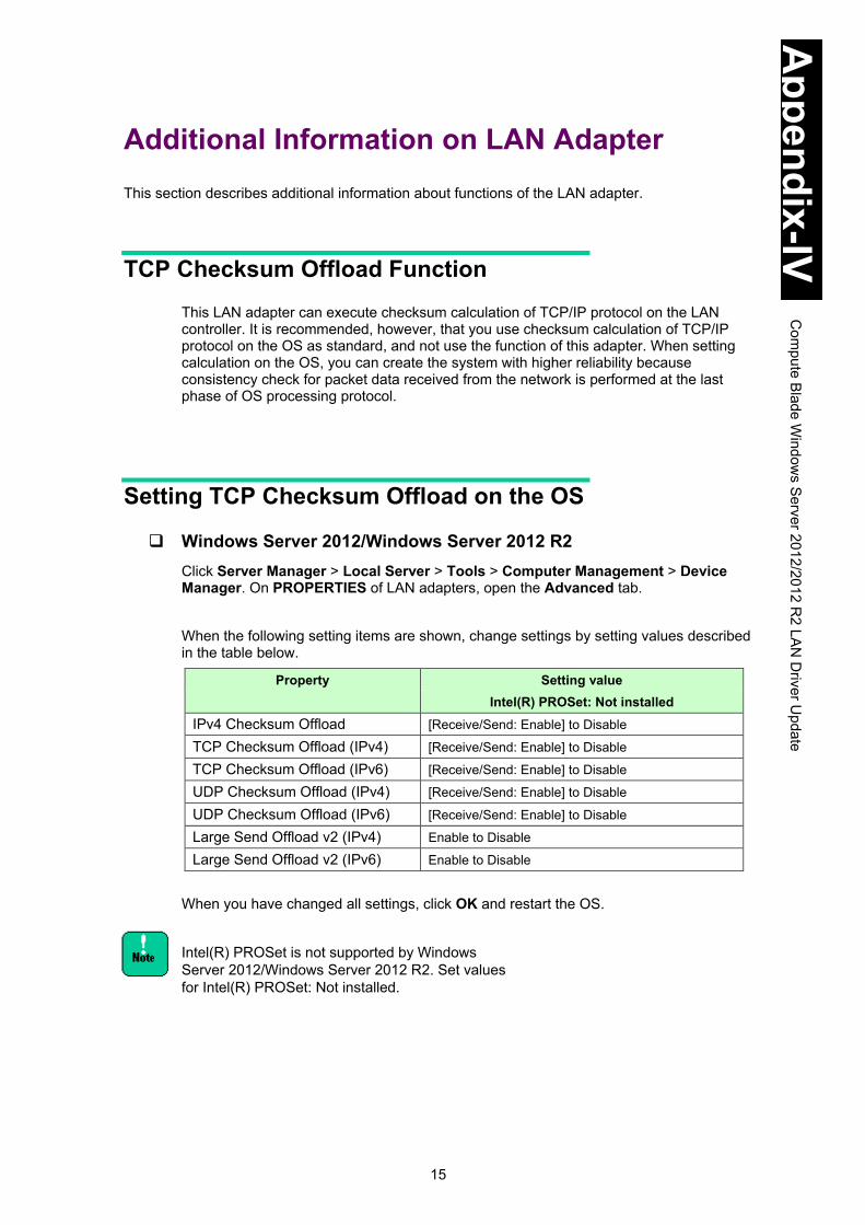
15
Appendix-IV
Com
pute Blade W
indows S
erver 2012/2012 R2 LA
N D
river Update
Additional Information on LAN Adapter This section describes additional information about functions of the LAN adapter.
TCP Checksum Offload Function This LAN adapter can execute checksum calculation of TCP/IP protocol on the LAN controller. It is recommended, however, that you use checksum calculation of TCP/IP protocol on the OS as standard, and not use the function of this adapter. When setting calculation on the OS, you can create the system with higher reliability because consistency check for packet data received from the network is performed at the last phase of OS processing protocol.
Setting TCP Checksum Offload on the OS
Windows Server 2012/Windows Server 2012 R2 Click Server Manager > Local Server > Tools > Computer Management > Device Manager. On PROPERTIES of LAN adapters, open the Advanced tab. When the following setting items are shown, change settings by setting values described in the table below.
Property Setting value Intel(R) PROSet: Not installed
IPv4 Checksum Offload [Receive/Send: Enable] to Disable
TCP Checksum Offload (IPv4) [Receive/Send: Enable] to Disable
TCP Checksum Offload (IPv6) [Receive/Send: Enable] to Disable
UDP Checksum Offload (IPv4) [Receive/Send: Enable] to Disable
UDP Checksum Offload (IPv6) [Receive/Send: Enable] to Disable
Large Send Offload v2 (IPv4) Enable to Disable
Large Send Offload v2 (IPv6) Enable to Disable When you have changed all settings, click OK and restart the OS.
Intel(R) PROSet is not supported by Windows Server 2012/Windows Server 2012 R2. Set values for Intel(R) PROSet: Not installed.
16
Appendix-IV
Com
pute Blade W
indows S
erver 2012/2012 R2 LA
N D
river Update
For Wake On LAN with the LAN Device The Wake On LAN function may not be worked on the LAN mezzanine card installed in Compute Blade 2000 as standard. Open properties of LAN adapter to use WOL on Device Manager, change the setting value in the Advanced tab if each value is not shown below. Wake On Magic Packet: Enable Wake On Pattern Match: Disable. LAN device name on Device Manager For LAN device installed as standard in Compute Blade 2000 standard/high-performance model: Intel(R) 82576 Gigabit Dual Port Server Network Connection
Wake On LAN is not supported by Windows Server 2012 R2.
You can find the version of Intel(R) PROSet by clicking Control Panel > Programs and Features.
LAN Advanced Functions LAN Advanced Functions using Intel(R) PROSet are not supported by Windows Server 2012/Windows Server 2012 R2. Use standard functions of the OS for LAN Advanced Functions.

17
Appendix-IV
Com
pute Blade W
indows S
erver 2012/2012 R2 LA
N D
river Update
Event log description (Source: iANS Miniport) OS event logs give you information on the status of advanced LAN functions. The following table describes events logged at iANS Miniport.
(I: Information; W: Warning) ID Message Description and Resolution
6 (I) Primary adapter is initialized: <member description>
The member LAN device as Primary Adapter has been properly initialized.
7 (I) Adapter is initialized: <member description> The member LAN device as Secondary Adapter or as another adapter but Primary has been properly initialized.
8 (I) Team #<team ID>: Team is initialized. The team comprising advanced functions has been properly initialized.
9 (I) Team #<ID>: Virtual Adapter for <VLAN name> [VID=<VLAN ID>] initialized.
VLAN has been properly initialized.
10 (I) Current Primary Adapter is switching from: <member description>
Current Primary Adapter is switching from the member adapter to a member as Secondary Adapter.
11 (W) Adapter link down: <member description> The member adapter link is down. Check cable connections.
12 (I) Secondary Adapter took over: <member description>
Due to failure in the LAN device as Primary Adapter, a member adapter as Secondary Adapter has taken over the network processing.
13 (W) The <member description> has been deactivated from the team.
The member adapter has been deactivated from the team. There is a problem in Primary device, Secondary device, or the connecting route.
14 (I) Secondary Adapter has rejoined the Team: <member description>
The deactivated member LAN device has been added to the team again.
15 (I) Adapter link up: <member description> The member LAN device link is up again.
16 (W) Team #<ID>: The last adapter has lost link. Network connection has been lost.
All LAN devices in the team have lost link.
17 (W) Team #<ID>: An adapter has re-established link. Network connection has been restored.
Network connection in the LAN device team has been restored.
18 (I) Preferred primary adapter has been detected: <member description>
The member LAN device specified as Primary adapter has been detected.
19 (I) Preferred Secondary Adapter has been detected: <member description>
The member LAN device as specified Secondary adapter has been detected.
20 (I) Preferred primary adapter took over: <member description>
The member LAN device specified as Primary adapter has taken over the network processing.
21(I) Preferred secondary adapter took over: <member description>
The member LAN device specified as Secondary adapter has taken over the network processing.
22 (W) Primary Adapter does not sense any Probes: <member description>
The member LAN device as Primary Adapter does not sense any probe packets. Possible reason: partitioned Team.
35 (W) Initializing Team #<ID> with <missing #> missing adapters. Check the configuration to verify that all the adapters are present and functioning.
The team # is being initialized with missing or inactive adapters#. Check if all LAN devices are properly implemented and functioning.
37 (I) Virtual adapter for <VLAN name> [VID=<VLAN ID>] removed from team #<team ID>.
Virtual adapter with VLAN name [VID=VLAN ID] has been removed from the team.
38 (I) Adapter removed from team #<ID>. The LAN device has been removed from the team.

18
Appendix-IV
Com
pute Blade W
indows S
erver 2012/2012 R2 LA
N D
river Update

Hitachi Compute Blade 2000 Software Guide

MK-99BDS2K002-14
Hitachi Data Systems
Corporate Headquarters 2845 Lafayette Street
Santa Clara, California 95050-2639 U.S.A. www.hds.com
Regional Contact Information
Americas
+1 408 970 1000
Europe, Middle East, and Africa
+44 (0) 1753 618000 [email protected]
Asia Pacific
+852 3189 7900 [email protected]