ACTIVA SERIES ROOF TOP Air Conditioners 100/175 - Bulclima
67
ACTIVA SERIES ROOF TOP Air Conditioners 100/175 Installation manual Ref.: N-40428_EN 0413
-
Upload
khangminh22 -
Category
Documents
-
view
1 -
download
0
Transcript of ACTIVA SERIES ROOF TOP Air Conditioners 100/175 - Bulclima

ACTIVA SERIES ROOF TOP AirConditioners 100/175
Installation manual
Ref.: N-40428_EN 0413

Index
1 Installation manual...................................................................................................................1
1.1 Safety instructions....................................................................................................................21.2 Icons used in this document.....................................................................................................21.3 Instructions for storage, transport and handling of the unit......................................................31.3.1 Disposal of packaging..............................................................................................................31.3.2 Hoisting points..........................................................................................................................41.3.3 Centre of gravity.......................................................................................................................51.4 Technical data..........................................................................................................................61.4.1 ARC technical and physical data (Only cooling)......................................................................61.4.2 ARH technical and physical data (Heat pump).........................................................................71.4.3 Unit sound pressure data.........................................................................................................81.4.4 Weight options and accessories...............................................................................................81.5 ARC / ARH units with auxiliary heating element......................................................................91.6 Limits of use.............................................................................................................................91.7 Measurements, clearances and accesses.............................................................................101.7.1 Dimensions of the duct connections.......................................................................................101.7.2 Connections for supply and return ducts................................................................................121.7.3 General measurements and accesses...................................................................................131.8 ARC output.............................................................................................................................151.8.1 ARC - 100 cooling capacities.................................................................................................151.8.2 ARC - 125 cooling capacities.................................................................................................151.8.3 ARC - 150 cooling capacities.................................................................................................161.8.4 ARC - 175 cooling capacities.................................................................................................161.9 ARH output.............................................................................................................................171.9.1 ARH - 100 cooling capacities.................................................................................................171.9.2 ARH - 125 cooling capacities.................................................................................................171.9.3 ARH - 150 cooling capacities.................................................................................................181.9.4 ARH - 175 cooling capacities.................................................................................................181.9.5 ARH - 100 thermodynamic heating capacities.......................................................................191.9.6 ARH - 125 thermodynamic heating capacities.......................................................................191.9.7 ARH - 150 thermodynamic heating capacities.......................................................................201.9.8 ARH - 175 thermodynamic heating capacities.......................................................................201.10 Indoor fan...............................................................................................................................211.10.1 Features table........................................................................................................................211.10.2 Indoor fan output tables..........................................................................................................211.11 Pressure drop in options/accessories....................................................................................271.12 Instructions for installation and connection of the unit...........................................................271.12.1 Characteristics of the location................................................................................................271.12.2 Characteristics of the facility where the unit will be installed..................................................281.12.3 Specifications for the foundation or anchoring of the unit......................................................291.12.4 Characteristics of utility provider connections........................................................................291.12.5 Connection and preparation of the various connections........................................................29
Index
i

1.13 Instructions for starting up the unit.........................................................................................321.13.1 Electrical checks.....................................................................................................................321.14 Unblocking the unit safely in case of breakdown................................................................... 331.15 Regular maintenance tasks performed by specialised personnel..........................................331.15.1 Planned Maintenance Schedule.............................................................................................341.15.2 Maintenance tasks performed by specialised personnel........................................................34
2 Options and accessories........................................................................................................37
2.1 DPC-1 Programmable digital thermostat with communication...............................................392.1.1 HVAC modes..........................................................................................................................392.1.2 Button functions......................................................................................................................422.2 Economiser, modulating, temperature control....................................................................... 432.3 Enthalpy probes..................................................................................................................... 442.4 Indoor air quality probe.......................................................................................................... 442.5 Barometric excess pressure damper..................................................................................... 442.6 Exhaust fan............................................................................................................................ 452.7 Fixed outdoor air damper.......................................................................................................462.8 Low temperature control (low ambient)..................................................................................462.9 Air filters F6 and F7................................................................................................................462.10 Dirty filter pressure switches.................................................................................................. 462.11 Smoke detector......................................................................................................................462.12 Fire detection thermostat....................................................................................................... 472.13 Hot water coil......................................................................................................................... 472.14 Heating element.....................................................................................................................472.15 Outdoor coil protection...........................................................................................................472.16 Anti-vibration kit......................................................................................................................472.17 Copper fin coils...................................................................................................................... 472.18 Roofcurb mounting base, fixed type.......................................................................................472.19 Roofcurb mounting base, adjustable type..............................................................................48
3 Unit installation data...............................................................................................................50
3.1 List of tests for unit start-up....................................................................................................513.2 Start-up data.......................................................................................................................... 52
4 Wiring diagrams..................................................................................................................... 54
4.1 Micro switch configuration......................................................................................................554.2 Fault table.............................................................................................................................. 564.3 Incidents.................................................................................................................................574.3.1 Test button............................................................................................................................. 584.4 DPC-1 thermostat.................................................................................................................. 584.5 ARC/ARH 100 – 125 wiring diagrams....................................................................................594.6 ARC/ARH 150 – 175 wiring diagrams....................................................................................62
Index
ii

1
Installation manual

1.1 Safety instructionsThis document contains the necessary information for the safe and efficient transportation, assemblyand installation of the air conditioning unit. This guarantees the condition of the unit and its operatingsafety.
Only an authorised company may assemble the air conditioning unit.
A T T E N T I O NOnly authorised companies with the appropriate technical resources and suitably trained personnel mayinstall the air conditioning unit.
C A U T I O NThe specialists responsible for installing the air conditioning unit must make sure they have all of theinformation and knowledge required to correctly install, test and deliver the unit. Johnson Controls Inc.shall not be considered responsible for any damage caused by installation of the unit that is no consistentwith that described in this document or others specifically provided with the unit.
During regular equipment installation, the fitter must pay special attention to certain situations in orderto prevent injuries or damage to the unit.
Situations that could jeopardise the safety of the fitter or that of others nearby or that could put the unititself at risk are clearly indicated in this manual.
A series of special symbols are used to clearly identify these situations.
Pay careful attention to these symbols and to the messages following them, as your safety and the safetyof others depends on it.
1.2 Icons used in this document
D A N G E R• The text following this symbol contains information and instructions relating directly to your safety
and physical well-being.• Not taking these instructions into account could lead to serious, very serious or even fatal injuries to
you and others in the proximities of the unit.
Information can also be found on safe procedures during unit handling. This will help reduce the risk ofaccidents.
C A U T I O N• The text following this symbol contains information and instructions relating directly to your safety
and physical well-being.• Not taking these instructions into account could lead to minor injuries to you and others in the
proximities of the unit.• Not taking these instructions into account could lead to unit damage.
Information can also be found on safe procedures during unit handling. This will help reduce the risk ofaccidents.
N O T E• The text following this symbol contains information or instructions that may be of use or that is worthy
of a more thorough explanation.• Instructions regarding inspections to be made on unit parts or systems may also be included.
1 Installation manual1.1 Safety instructions
2

1.3 Instructions for storage, transport and handling of the unitDelivery inspection
The unit should be carefully inspected for visible damage or abnormalities as soon as it is received.
Any abnormalities or damage to the unit should be communicated to both the transportation andinsurance company in writing.
Storage instructions
The unit should be stored in a place suitable to the purpose (warehouse or similar), protected from theweather, water, humidity and dust.
Cover the unit with a canvas of a suitable size.
The unit should be appropriately protected from knocks and dust, ensuring the protective parts it wassupplied with remain in place. Where these are not in place, establish the necessary protections and/orbarriers to keep vehicles or fork-lift trucks away.
Transport and handling of the unit
The units should only be handled by personnel from the company responsible for their installation.
Transport of the unit should be in such a manner that no damage is caused by faulty or inadequatemooring to the bed or body of the vehicle.
Where necessary, protect all of the edges of the unit against knocks and scratches and moor it to thebed or body of the vehicle using suitable textile belts or slings to keep it perfectly still.
A T T E N T I O NDo not use fork lifts in operations to load and unload the unit.
Loading and unloading the unit from a truck or trailer should be on flat, solid ground using a crane withsufficient capacity.
1.3.1 Disposal of packagingThe packaging is recyclable. Dispose of it in the appropriate place or take it to an appropriate collectioncentre. Respect the regulations in force for this type of waste in the country where the unit is beinginstalled.
Packaging remains must be correctly disposed of. Improper disposal of packaging generatesenvironmental problems that affect human life.
Installation manual 1Instructions for storage, transport and handling of the unit 1.3
3
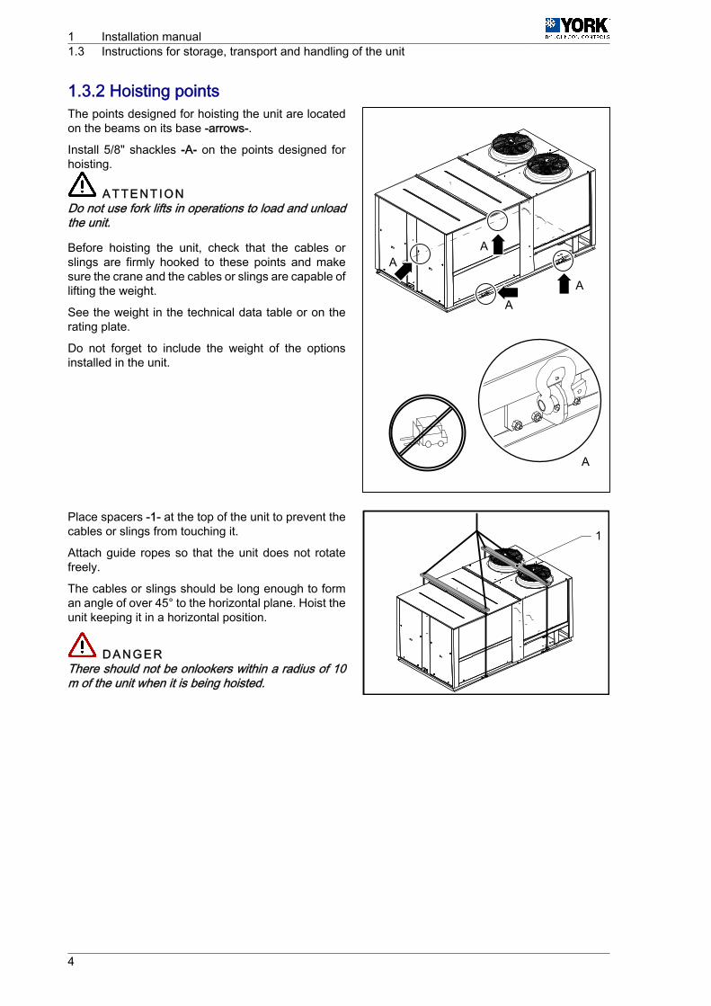
1.3.2 Hoisting pointsThe points designed for hoisting the unit are locatedon the beams on its base -arrows-.
Install 5/8" shackles -A- on the points designed forhoisting.
A T T E N T I O NDo not use fork lifts in operations to load and unloadthe unit.
Before hoisting the unit, check that the cables orslings are firmly hooked to these points and makesure the crane and the cables or slings are capable oflifting the weight.
See the weight in the technical data table or on therating plate.
Do not forget to include the weight of the optionsinstalled in the unit.
Place spacers -1- at the top of the unit to prevent thecables or slings from touching it.
Attach guide ropes so that the unit does not rotatefreely.
The cables or slings should be long enough to forman angle of over 45° to the horizontal plane. Hoist theunit keeping it in a horizontal position.
D A N G E RThere should not be onlookers within a radius of 10m of the unit when it is being hoisted.
AA
AA
A
1
1 Installation manual1.3 Instructions for storage, transport and handling of the unit
4
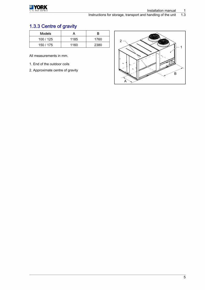
1.3.3 Centre of gravityModels A B
100 / 125 1185 1760150 / 175 1160 2380
All measurements in mm.
1. End of the outdoor coils
2. Approximate centre of gravity
A
B
1
2
Installation manual 1Instructions for storage, transport and handling of the unit 1.3
5

1.4 Technical data1.4.1 ARC technical and physical data (Only cooling)
ARC/ARG models 100 125 150 175
Cooling capacity (1)
Net cooling capacity kW 108 122 149 169
Rated absorbed power kW 34 41 59 64
Net EER 3,46 3,21 3,13 2,91
Heating Optional heating element heating capacity (400 V) (2) kW 37 ‑ 50 37 ‑ 50 ‑ 60
Circuits No. 2 2
Compressors
Rated/start-up current A 4 x 13 / 111 4 x 15 / 118 4 x 20 / 140 4 x 24 / 198
Type and quantity (per circuit) Scroll x 2 (1 Tándem)
Degree of protection IP21
Coolant (R-410A) Charge (per circuit) kg 20 20 25 25,5
Power supply V/ph/Hz 400 / 3 / 50
Indoor fan (3)
Rated air flow m3/h 19000 21000 27000 30000
Rated static pressure / maximum with rated flow Pa
Maximum flow rate m3/h 22000 25000 32000 35000
Minimum flow rate m3/h 16000 18000 22000 25000
Motor (IP55) Maximum power / Quantity kW 5,5 / 1 4 / 2
Maximum current A 12,5 12,5 9,5 x 2 9,5 x 2
Indoor coil (evaporator)
Number of elements No. 4
Distance between fins mm 1,81 1,81
Front surface m2 3,5 5,2
Air filters (G4)Quantity per unit No. 6
Dimensions mm 823 x 730 x 48 823 x 880 x 48
Outdoor fan(Data per circuit)
Diameter/number mm 800 / 1 800 / 2
Total rated flow m3/h 18000 36000
Motor (IP54) kW 1,9 1,9 (x 2)
Rated current A 3,3 3,3 (x 2)
Outdoor coil (condenser)(Data per circuit)
Number of elements No. 3 (x 2) 3 (x 2)
Distance between fins mm 2,11 2,11
Front area m2 1,86 (x 2) 2,62 (x 2)
Net dimensions (4)
Height mm 1862 + 280 ventilador
Length mm 4036 5085
Width mm 2250 2250
Net weight (basic unit withoutaccessories) (4) kg
Electrical features of the unit
Total rated power kW 34 41 59 64
Total rated current A 65 75 110 125
Total maximum power kW 49 57 74 85
Total maximum current A 88 101 137 157
Circuit breaker (K Curve) (5) A 100 125 160 200
Minimum cable section (6) mm2 3 x 35 3 x 50 3 x 50 3 x 70
(1) Data in compliance with Eurovent conditions, summer: indoor 27 °C TS/19 °C TH ‑ outdoor TS 35 °C. Winter: Indoor TS 20 °C, outdoor TS 7 °C / TH 6 °C (TS Dry-bulb thermometer; TH Wet-bulb thermometer), with vertical ducts, rated air flow and pressure.
Net EER = Net cooling capacity / Total absorbed power (according to Eurovent).
(2) Add the inside motor consumption to find the total calorific capacity.
(3) See Indoor fan, see on page 21.
(4) Consider the additional weight of options and accessories. To do so, see Weight options and accessories, see on page 8.
(5) and(6)
Circuit breaker with K curve, according to DIN, VDE 0660-104. Section of cables for the power supply line based on copper conductors, 105 °C. The circuit breaker and the section of powersupply cables indicated are for guidance. They should be adjusted based on the requirements of each installation, distance between units, fall in planned voltage and on the application of thecurrent regulations with respect to the country where the unit is being installed.
1 Installation manual1.4 Technical data
6

1.4.2 ARH technical and physical data (Heat pump)ARH/ARD models 100 125 150 175
Cooling capacity (1)
Net cooling capacity kW 108 122 149 169
Rated absorbed power kW 34 41 59 64
Net EER 3,46 3,21 3,13 2,91
Heat capacity (1)
Net heating capacity kW 105 118 147 167
Rated absorbed power kW 33 37 53 61
Net COP 3,48 3,44 3,20 2,96
Optional heating element heating capacity(400 V) (ARH) (2) kW 37 ‑ 50 37 ‑ 50 ‑ 60
Circuits No. 2
Compressors
Rated/start-up current A 4 x 13 / 111 4 x 15 / 118 4 x 20 / 140 4 x 24 / 198
Type and quantity (per circuit) Scroll x 2 (1 Tándem)
Degree of protection IP21
Coolant(R-410A) Charge (per circuit) kg 20 20 25,5 26
Power supply V/ph/Hz 400 / 3 / 50
Indoor fan (3)
Rated air flow m3/h 19000 21000 27000 30000
Rated static pressure / maximum with ratedflow Pa
Maximum flowrate m3/h 22000 25000 32000 35000
Minimum flowrate m3/h 16000 18000 22000 25000
Motor (IP55) Maximum power/ quantity kW 5,5 / 1 4 / 2
Maximum current A
Indoor coil (evaporator)
Number of elements No. 4
Distance between fins mm 1,81 1,81
Front surface m2 3,5 5,2
Air filters (G4)Quantity per unit No. 6
Dimensions mm 823 x 730 x 48 823 x 880 x 48
Outdoor fan(data per circuit)
Diameter/number mm 800 / 1 800 / 2
Total rated flow m3/h 18000 36000
Motor (IP54) kW 1,9 1,9 (x 2)
Rated current A 3,3 3,3 (x 2)
Outdoor coil (condenser)(data per circuit)
Number of elements No. 3 (x 2) 3 (x 2)
Distance between fins mm 2,11 2,11
Front area m2 1,86 (x 2) 2,62 (x 2)
Net dimensions (4)
Height mm 1862 + 280 ventilador
Length mm 4036 5085
Width mm 2250 2250
Net weight (basic unit without acces‐sories) (4) kg
Electrical features of the unit
Total rated power kW 34 41 59 64
Total rated current A 65 75 110 125
Total maximum power kW 49 57 74 85
Total maximum current A 88 101 137 157
Circuit breaker (K Curve) (5) A 100 125 160 200
Minimum cable section (6) mm2 3 x 35 3 x 50 3 x 50 3 x 70
(1) Data in compliance with Eurovent conditions, summer: indoor 27 °C TS/19 °C TH ‑ outdoor TS 35 °C. Winter: Indoor TS 20 °C, outdoor TS 7 °C / TH 6 °C (TS Dry-bulb thermometer; TH Wet-bulb thermometer), with vertical ducts, rated air flow and pressure.
Net EER = Net cooling capacity / Total absorbed power (according to Eurovent).
Net COP = Net heating capacity / Total absorbed power (according to Eurovent).
(2) Add the inside motor consumption to find the total calorific capacity.
(3) See Indoor fan, see on page 21
(4) Consider the additional weight of options and accessories. To do so, see Weight options and accessories, see on page 8.
(5) and(6)
Circuit breaker with K curve, according to DIN, VDE 0660-104. Section of cables for the power supply line based on copper conductors, 105 °C. The circuit breaker and the section of powersupply cables indicated are for guidance. They should be adjusted based on the requirements of each installation, distance between units, fall in planned voltage and on the application of thecurrent regulations with respect to the country where the unit is being installed.
Installation manual 1Technical data 1.4
7
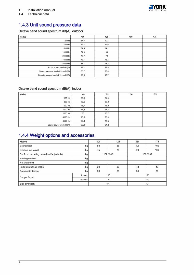
1.4.3 Unit sound pressure dataOctave band sound spectrum dB(A), outdoor
Models 100 125 150 175
125 Hz 87,3 90,1
250 Hz 85,4 86,6
500 Hz 84,5 84,2
1000 Hz 84,9 84
2000 Hz 79,7 79
4000 Hz 73,4 75,5
8000 Hz 68,4 73,2
Sound power level dB (A) 88,4 88,5
Sound pressure level at 5 m dB (A) 63,7 63,8
Sound pressure level at 10 m dB (A) 57,6 57,7
Octave band sound spectrum dB(A), indoorModels 100 125 150 175
125 Hz 89,8 94,4
250 Hz 77,5 83,2
500 Hz 75,7 76,9
1000 Hz 75,6 76,4
2000 Hz 75 75,7
4000 Hz 73,8 76,4
8000 Hz 70,3 74,5
Sound power level dB (A) 83,3 84,2
1.4.4 Weight options and accessoriesModels 100 125 150 175
Economiser kg 88 88 100 100
Exhaust fan (axial) kg 75 75 106 106
Roofcurb mounting base (fixed/adjustable) kg 152 / 248 186 / 302
Heating element kg
Hot water coil kg
Fixed outdoor air intake kg 39 39 43 43
Barometric damper kg 28 28 36 36
Copper fin coilindoor 105 160
outdoor 144 204
Side air supply 11 13
1 Installation manual1.4 Technical data
8

1.5 ARC / ARH units with auxiliary heating elementThe power supply to the heating resistor must be independent to the general power supply to the unitand must be fitted with its own circuit breaker according to the table:
ARC ModelPowersupply
V/Ph/Hz
Heating elementMaximum circuit breaker
(K Curve) (1)Minimum cable cross-section
(mm2) (2)Power(kW) Stages (No.) Current
(A)
100 400/3/5037 2 54 63 16
50 2 72 80 25
125 400/3/5037 2 54 63 16
50 2 72 80 25
150 400/3/50
37 2 54 63 16
50 2 72 80 25
60 2 87 100 35
175 400/3/50
37 2 54 63 16
50 2 72 80 25
60 2 87 100 35
(1) K Curve (DIN, VDE 0660-104).
(2) Based on copper conductors 105 °C.
1.6 Limits of useModel 100 125 150 175
Voltage limits Min./Max V 342/457
ARC
Temperature of air inlet in indoor coilWB °C Min./Max. 15/23 15/23 15/23 15/23
DB °C Min/Max 20/32 20/32 20/32 20/32
Outdoor temperature (without condensa‐tion control) TS °C Min. 10 10 7 7
Maximum outdoor tempera‐ture (1)
At fullload TS °C 46 46 46 46
At partialload TS °C 52 52 52 52
ARH
Summercycle
Temperature of air inlet in indoor coilWB °C Min./Max. 15/23 15/23 15/23 14/23
DB °C Min/Max 20/32 20/32 20/32 20/32
Outdoor temperature (without condensa‐tion control) TS °C Min. 10 10 7 7
Maximum outdoor tempera‐ture (1)
At fullload TS °C 46 46 46 46
At partialload TS °C 52 52 52 52
Wintercycle
Temperature of air inlet in indoor coil DB °C Min/Max 10/25 10/25 10/25 10/25
Outdoor temperature DB °C Min/Max -10/20 -10/20 -10/20 -10/20
1. Direct sunlight on the unit should be prevented when temperatures are higher than 43 °C. If placed under some kind of protective cover, the cover should not interferewith the flow of outdoor ventilation.
2. The gas heating units (ARG/ARD) are only appropriate for use with gas. In LPG (Liquefied Petroleum Gas, propane) installations, it must be ensured that in no caseshould gasoline in liquid form reach the gas group.
DB: Dry-bulb Thermometer; TH: Wet-bulb thermometer.
Installation manual 1ARC / ARH units with auxiliary heating element 1.5
9

1.7 Measurements, clearances and accesses1.7.1 Dimensions of the duct connectionsModels 100 / 175, side ducts (horizontal)
N O T EFloor plan without the top panel
S1 Lateral supplyR1 Lateral return
ModelARC /ARH
A B C D L1 H1 L2 H2
100 / 125 135 365 212 192 1380 575 1720 570150 / 175 135 390 212 192 1830 645 2170 570
1 Installation manual1.7 Measurements, clearances and accesses
10

Models 100 / 175, lower ducts (vertical)
L4 GJ
H4
H3
FL3 E
S2
R2
N O T EFloor plan without the top panel
S2 Bottom supplyR2 Lower return
ModelARC /ARH
E F G J L3 H3 L4 H4
100 / 125 145 135 163 125 1465 750 1755 510150 / 175 368 135 163 120 1690 750 2205 400
Installation manual 1Measurements, clearances and accesses 1.7
11

1.7.2 Connections for supply and return ductsUnits are shipped with the openings for the connection of the return duct covered.
For applications with downward discharge ducts1. The return compartment is accessed by removing
the access panel -B2-.
N O T EFor the supply duct -S1-, it is not necessary toremove any cover or access panel.
2. Remove and dispose of the lower cover of the duct-R2- (return). In order to do this, loosen the threebolts -D- that fix the cover to the base.
3. After removing the lower cover, reattach the sidepanel, ensuring that the seal is hermetic.
For applications with sideways discharge ducts
N O T EFor the supply duct -S2-, it is not necessary to removeany cover or access panel.1. Access the return compartment via the access
panel -B2- and loosen the bolts -E- from the inside.2. Remove and dispose of the side cover -A2-.3. After removing the side cover, reattach the side
panel, ensuring that the seal is hermetic.
R2
B2
D
A2
B2
E
E
1 Installation manual1.7 Measurements, clearances and accesses
12

1.7.3 General measurements and accessesMinimum clearance above the unit
The unit is designed to be installed outdoors.
In ground level installations, the building eaves must not be at a vertical distance of less than 3000 mmfrom the top of the unit.
Installation manual 1Measurements, clearances and accesses 1.7
13

Models ARC/ARH ‑ 100 / 175
A5C3
2000
4
C2
1500
2000
D
A1A4 A3
1 3 2
A1A2
C1
A5
5
100/125 : x 2
150/175 : x 4
3000
Model A B C D100 / 125 4036 1957 1123 2300150 / 175 5085 2557 1473 2750
A1. Access to indoor fanA2. Access to electrical boxA3. Access to return/economiser/filtersA4. Access to heating/supply optionsA5. Access to cooling circuitC1. Supply side coverC2. Return side cover / air exhaust optionsC3. Outdoor air inlet cover, optional1. Drain connection ∅ 41 x 35 Long2. Main switch3. Side inlet for power (PG48) and control (PG21) cables4. Instructions for minimum free space around the unit5. Inlet in the base for power (PG48) and control (PG21) cables
1 Installation manual1.7 Measurements, clearances and accesses
14

1.8 ARC output1.8.1 ARC ‑ 100 cooling capacities
Return air Outdoor coil air temperature (TS)
Flow rate
m3/hWB°C
27 °C 35 °C 46 °C
PTkW
PCkW
Sensible power kWPTkW
PCkW
Sensible power kWPTkW
PCkW
Sensible power kW
TS inlet temp. in indoor coil TS inlet temp. in indoor coil TS inlet temp. in indoor coil
22 24 27 30 22 24 27 30 22 24 27 30
(Mini‐mum)16000
23 122 25,4 — 42 58 74 116 27,8 — 40 56 72 105 30,7 — 36 52 68
19 111 24,6 55 66 82 98 105 26,7 53 63 79 95 94 28,8 49 60 75 91
17 105 24 70 76 93 105 96 26,4 65 74 89 96 86 28,6 59 69 85 86
15 94 23,8 76 86 94 94 90 25,9 74 84 90 90 81 28,3 70 81 81 81
(Nominal)19000
23 126 25,7 — 44 62 81 119 28,2 — 41 60 79 108 31,2 — 38 56 75
19 114 24,9 59 71 90 108 108 27,1 56 69 87 106 97 29,3 52 65 83 97
17 108 24,4 77 85 103 108 99 26,8 71 81 99 99 89 29 64 77 89 89
15 97 24,1 83 95 97 97 93 26,3 81 93 93 93 83 28,7 77 83 83 83
(Maxi‐mum)22000
23 129 26,1 — 49 66 87 123 28,6 — 42 64 85 111 31,6 — 39 60 82
19 117 25,3 62 76 97 117 111 27,5 59 74 99 111 99 29,7 56 70 91 91
17 110 24,8 84 92 110 110 102 27,2 77 88 102 102 91 29,4 69 83 91 91
15 99 24,5 90 99 99 99 95 26,7 88 95 95 95 85 29,2 84 85 85 85
* Data in accordance with Eurovent Rooftop program certification conditions
PT: Total Power; PC: Power absorbed by the compressor
WB: Wet-bulb temperature; TS: Dry bulb temperature.
1.8.2 ARC ‑ 125 cooling capacitiesReturn air Outdoor coil air temperature (TS)
Flow rate
m3/hWB°C
27 °C 35 °C 46 °C
PTkW
PCkW
Sensible power kWPTkW
PCkW
Sensible power kWPTkW
PCkW
Sensible power kW
TS inlet temp. in indoor coil TS inlet temp. in indoor coil TS inlet temp. in indoor coil
22 24 27 30 22 24 27 30 22 24 27 30
(Mini‐mum)18000
23 138 30,8 — 48 66 83 131 33,7 — 45 63 81 118 37,3 — 41 59 76
19 126 29,8 63 74 92 110 118 32,4 60 71 89 107 107 35 55 67 85 102
17 118 29,2 80 87 105 118 109 32,1 73 83 100 109 97 34,7 66 78 96 97
15 107 28,8 85 97 107 107 102 31,4 83 94 102 102 91 34,3 78 90 91 91
(Nominal)21000
23 143 31,2 — 49 70 90 135 34,1 — 47 67 88 122 37,7 — 43 63 83
19 129 30,2 66 80 100 120 122 32,8 63 77 97 117 110 35,4 59 72 93 110
17 122 29,5 87 94 115 122 112 32,5 79 90 110 112 100 35,1 72 85 100 100
15 110 29,2 93 106 110 110 105 31,8 90 103 105 105 94 34,8 86 94 94 94
(Maxi‐mum)25000
23 146 31,6 — 51 75 99 138 34,6 — 48 72 96 125 38,3 — 44 68 92
19 133 30,6 70 86 110 133 125 33,3 67 83 107 125 113 36 63 79 103 103
17 125 30 97 103 125 125 115 33 87 99 115 115 103 35,6 78 94 103 103
15 113 29,6 102 113 113 113 108 32,3 99 108 108 108 96 35,3 94 96 96 96
* Data in accordance with Eurovent Rooftop program certification conditions
PT: Total Power; PC: Power absorbed by the compressor
WB: Wet-bulb temperature; TS: Dry bulb temperature.
Installation manual 1ARC output 1.8
15

1.8.3 ARC ‑ 150 cooling capacitiesReturn air Outdoor coil air temperature (TS)
Flow rate
m3/hWB°C
27 °C 35 °C 46 °C
PTkW
PCkW
Sensible power kWPTkW
PCkW
Sensible power kWPTkW
PCkW
Sensible power kW
TS inlet temp. in indoor coil TS inlet temp. in indoor coil TS inlet temp. in indoor coil
22 24 27 30 22 24 27 30 22 24 27 30
(Mini‐mum)22000
23 168 35,2 — 58 80 101 159 38,6 — 55 77 98 143 42,7 — 50 72 93
19 152 34,1 76 91 112 134 143 37,1 73 87 109 131 129 40,1 67 82 104 125
17 143 33,4 95 106 128 143 132 36,7 88 101 123 132 117 39,7 81 95 117 117
15 129 33 104 118 129 129 123 36 101 116 123 123 110 39,3 96 110 110 110
(Nominal)27000
23 174 35,9 — 60 87 113 165 39,3 — 57 84 110 149 43,5 — 52 79 105
19 158 34,8 82 99 126 152 149 37,8 78 96 122 149 134 40,8 73 91 117 134
17 149 34 107 118 145 149 137 37,4 99 113 137 137 122 40,4 90 107 122 122
15 134 33,6 116 134 134 134 128 36,7 113 128 128 128 115 40,1 108 115 115 115
(Maxi‐mum)32000
23 178 36,4 — 62 93 124 169 39,8 — 59 90 121 152 44 — 54 85 116
19 162 35,2 87 107 138 162 153 38,3 83 104 135 153 137 41,4 78 99 130 137
17 153 34,5 119 130 153 153 140 37,9 108 124 140 140 125 41 98 119 125 125
15 137 34,1 128 137 137 137 131 37,2 124 131 131 131 117 40,6 117 117 117 117
* Data in accordance with Eurovent Rooftop program certification conditions
PT: Total Power; PC: Power absorbed by the compressor
WB: Wet-bulb temperature; TS: Dry bulb temperature.
1.8.4 ARC ‑ 175 cooling capacitiesReturn air Outdoor coil air temperature (TS)
Flow rate
m3/hWB°C
27 °C 35 °C 46 °C
PTkW
PCkW
Sensible power kWPTkW
PCkW
Sensible power kWPTkW
PCkW
Sensible power kW
TS inlet temp. in indoor coil TS inlet temp. in indoor coil TS inlet temp. in indoor coil
22 24 27 30 22 24 27 30 22 24 27 30
(Mini‐mum)25000
23 191 43,3 — 66 90 115 181 47,4 — 62 87 112 163 52,4 — 57 81 106
19 173 42 86 103 127 152 163 45,6 83 99 123 148 147 49,2 76 93 117 142
17 163 41 109 121 145 163 150 45,1 101 115 139 150 134 48,8 92 108 132 134
15 147 40,6 118 134 147 147 140 44,2 115 131 140 140 126 48,3 108 124 126 126
(Nominal)30000
23 198 44,1 — 68 97 127 187 48,3 — 65 94 123 169 53,4 — 59 88 118
19 179 42,7 92 112 141 170 169 46,4 88 108 137 166 152 50,1 82 102 131 152
17 169 41,8 122 133 162 169 155 45,9 111 127 155 155 139 49,6 101 120 139 139
15 152 41,3 130 150 152 152 145 45 127 145 145 145 130 49,2 120 130 130 130
(Maxi‐mum)35000
23 202 44,7 — 70 104 138 192 48,9 — 67 101 134 173 54,1 — 61 95 129
19 183 43,2 97 120 154 183 173 47 93 116 150 173 156 50,8 87 110 144 156
17 173 42,3 134 144 173 173 159 46,5 121 138 159 159 142 50,3 109 131 142 142
15 156 41,8 142 156 156 156 148 45,6 138 148 148 148 133 49,8 132 133 133 133
* Data in accordance with Eurovent Rooftop program certification conditions
PT: Total Power; PC: Power absorbed by the compressor
WB: Wet-bulb temperature; TS: Dry bulb temperature.
1 Installation manual1.8 ARC output
16

1.9 ARH output1.9.1 ARH ‑ 100 cooling capacities
Return air Outdoor coil air temperature (TS)
Flow rate
m3/hWB°C
27 °C 35 °C 46 °C
PTkW
PCkW
Sensible power kWPTkW
PCkW
Sensible power kWPTkW
PCkW
Sensible power kW
TS inlet temp. in indoor coil TS inlet temp. in indoor coil TS inlet temp. in indoor coil
22 24 27 30 22 24 27 30 22 24 27 30
(Mini‐mum)16000
23 122 25,4 — 42 58 74 116 27,8 — 40 56 72 105 30,7 — 36 52 68
19 111 24,6 55 66 82 98 105 26,7 53 63 79 95 94 28,8 49 60 75 91
17 105 24 70 76 93 105 96 26,4 65 74 89 96 86 28,6 59 69 85 86
15 94 23,8 76 86 94 94 90 25,9 74 84 90 90 81 28,3 70 81 81 81
(Nominal)19000
23 126 25,7 — 44 62 81 119 28,2 — 41 60 79 108 31,2 — 38 56 75
19 114 24,9 59 71 90 108 108 27,1 56 69 87 106 97 29,3 52 65 83 97
17 108 24,4 77 85 103 108 99 26,8 71 81 99 99 89 29 64 77 89 89
15 97 24,1 83 95 97 97 93 26,3 81 93 93 93 83 28,7 77 83 83 83
(Maxi‐mum)22000
23 129 26,1 — 49 66 87 123 28,6 — 42 64 85 111 31,6 — 39 60 82
19 117 25,3 62 76 97 117 111 27,5 59 74 99 111 99 29,7 56 70 91 91
17 110 24,8 84 92 110 110 102 27,2 77 88 102 102 91 29,4 69 83 91 91
15 99 24,5 90 99 99 99 95 26,7 88 95 95 95 85 29,2 84 85 85 85
* Data in accordance with Eurovent Rooftop program certification conditions
PT: Total Power; PC: Power absorbed by the compressor
WB: Wet-bulb temperature; TS: Dry bulb temperature.
1.9.2 ARH ‑ 125 cooling capacitiesReturn air Outdoor coil air temperature (TS)
Flow rate
m3/hWB°C
27 °C 35 °C 46 °C
PTkW
PCkW
Sensible power kWPTkW
PCkW
Sensible power kWPTkW
PCkW
Sensible power kW
TS inlet temp. in indoor coil TS inlet temp. in indoor coil TS inlet temp. in indoor coil
22 24 27 30 22 24 27 30 22 24 27 30
(Mini‐mum)18000
23 138 30,8 — 48 66 83 131 33,7 — 45 63 81 118 37,3 — 41 59 76
19 126 29,8 63 74 92 110 118 32,4 60 71 89 107 107 35 55 67 85 102
17 118 29,2 80 87 105 118 109 32,1 73 83 100 109 97 34,7 66 78 96 97
15 107 28,8 85 97 107 107 102 31,4 83 94 102 102 91 34,3 78 90 91 91
(Nominal)21000
23 143 31,2 — 49 70 90 135 34,1 — 47 67 88 122 37,7 — 43 63 83
19 129 30,2 66 80 100 120 122 32,8 63 77 97 117 110 35,4 59 72 93 110
17 122 29,5 87 94 115 122 112 32,5 79 90 110 112 100 35,1 72 85 100 100
15 110 29,2 93 106 110 110 105 31,8 90 103 105 105 94 34,8 86 94 94 94
(Maxi‐mum)25000
23 146 31,6 — 51 75 99 138 34,6 — 48 72 96 125 38,3 — 44 68 92
19 133 30,6 70 86 110 133 125 33,3 67 83 107 125 113 36 63 79 103 103
17 125 30 97 103 125 125 115 33 87 99 115 115 103 35,6 78 94 103 103
15 113 29,6 102 113 113 113 108 32,3 99 108 108 108 96 35,3 94 96 96 96
* Data in accordance with Eurovent Rooftop program certification conditions
PT: Total Power; PC: Power absorbed by the compressor
WB: Wet-bulb temperature; TS: Dry bulb temperature.
Installation manual 1ARH output 1.9
17

1.9.3 ARH ‑ 150 cooling capacitiesReturn air Outdoor coil air temperature (TS)
Flow rate
m3/hWB°C
27 °C 35 °C 46 °C
PTkW
PCkW
Sensible power kWPTkW
PCkW
Sensible power kWPTkW
PCkW
Sensible power kW
TS inlet temp. in indoor coil TS inlet temp. in indoor coil TS inlet temp. in indoor coil
22 24 27 30 22 24 27 30 22 24 27 30
(Mini‐mum)22000
23 168 35,2 — 58 80 101 159 38,6 — 55 77 98 143 42,7 — 50 72 93
19 152 34,1 76 91 112 134 143 37,1 73 87 109 131 129 40,1 67 82 104 125
17 143 33,4 95 106 128 143 132 36,7 88 101 123 132 117 39,7 81 95 117 117
15 129 33 104 118 129 129 123 36 101 116 123 123 110 39,3 96 110 110 110
(Nominal)27000
23 174 35,9 — 60 87 113 165 39,3 — 57 84 110 149 43,5 — 52 79 105
19 158 34,8 82 99 126 152 149 37,8 78 96 122 149 134 40,8 73 91 117 134
17 149 34 107 118 145 149 137 37,4 99 113 137 137 122 40,4 90 107 122 122
15 134 33,6 116 134 134 134 128 36,7 113 128 128 128 115 40,1 108 115 115 115
(Maxi‐mum)32000
23 178 36,4 — 62 93 124 169 39,8 — 59 90 121 152 44 — 54 85 116
19 162 35,2 87 107 138 162 153 38,3 83 104 135 153 137 41,4 78 99 130 137
17 153 34,5 119 130 153 153 140 37,9 108 124 140 140 125 41 98 119 125 125
15 137 34,1 128 137 137 137 131 37,2 124 131 131 131 117 40,6 117 117 117 117
* Data in accordance with Eurovent Rooftop program certification conditions
PT: Total Power; PC: Power absorbed by the compressor
WB: Wet-bulb temperature; TS: Dry bulb temperature.
1.9.4 ARH ‑ 175 cooling capacitiesReturn air Outdoor coil air temperature (TS)
Flow rate
m3/hWB°C
27 °C 35 °C 46 °C
PTkW
PCkW
Sensible power kWPTkW
PCkW
Sensible power kWPTkW
PCkW
Sensible power kW
TS inlet temp. in indoor coil TS inlet temp. in indoor coil TS inlet temp. in indoor coil
22 24 27 30 22 24 27 30 22 24 27 30
(Mini‐mum)25000
23 191 43,3 — 66 90 115 181 47,4 — 62 87 112 163 52,4 — 57 81 106
19 173 42 86 103 127 152 163 45,6 83 99 123 148 147 49,2 76 93 117 142
17 163 41 109 121 145 163 150 45,1 101 115 139 150 134 48,8 92 108 132 134
15 147 40,6 118 134 147 147 140 44,2 115 131 140 140 126 48,3 108 124 126 126
(Nominal)30000
23 198 44,1 — 68 97 127 187 48,3 — 65 94 123 169 53,4 — 59 88 118
19 179 42,7 92 112 141 170 169 46,4 88 108 137 166 152 50,1 82 102 131 152
17 169 41,8 122 133 162 169 155 45,9 111 127 155 155 139 49,6 101 120 139 139
15 152 41,3 130 150 152 152 145 45 127 145 145 145 130 49,2 120 130 130 130
(Maxi‐mum)35000
23 202 44,7 — 70 104 138 192 48,9 — 67 101 134 173 54,1 — 61 95 129
19 183 43,2 97 120 154 183 173 47 93 116 150 173 156 50,8 87 110 144 156
17 173 42,3 134 144 173 173 159 46,5 121 138 159 159 142 50,3 109 131 142 142
15 156 41,8 142 156 156 156 148 45,6 138 148 148 148 133 49,8 132 133 133 133
* Data in accordance with Eurovent Rooftop program certification conditions
PT: Total Power; PC: Power absorbed by the compressor
WB: Wet-bulb temperature; TS: Dry bulb temperature.
1 Installation manual1.9 ARH output
18

1.9.5 ARH ‑ 100 thermodynamic heating capacitiesFlow rate
m3/h
Returnair TS
°C
Outdoor air temperature TS °C
-10 -5 0 5 7 10 15 20
PT PC PT PC PT PC PT PC PT PC PT PC PT PC PT PC
(Minimum)16000
14 72 20,1 81 20,9 92 21,9 103 22,3 108 23,4 116 24,2 130 26,0 145 26,9
17 71 21,8 80 22,7 91 23,7 102 24,2 107 25,3 115 26,2 129 28,1 143 29,1
20 70 22,3 79 23,2 89 24,2 101 24,7 106 25,9 113 26,8 127 28,7 142 29,8
23 69 23,8 78 24,8 88 25,9 100 26,5 104 27,7 112 28,7 125 30,8 140 31,9
25 69 24,5 77 25,5 88 26,6 99 27,2 104 28,5 111 29,5 125 31,6 139 32,8
(Nominal)19000
14 72 19,6 82 20,4 93 21,3 105 21,7 110 22,8 117 23,6 132 25,2 147 26,2
17 72 21,2 81 22,1 92 23,0 103 23,5 108 24,6 116 25,5 130 27,3 145 28,3
20 71 21,7 80 22,6 91 23,6 102 24,1 107 25,2 115 26,1 129 28,0 143 29,0
23 70 23,2 79 24,1 89 25,2 101 25,8 106 27,0 113 27,9 127 29,9 142 31,0
25 69 23,8 78 24,8 89 25,9 100 26,5 105 27,7 113 28,7 126 30,8 141 31,9
(Maxi‐mum)22000
14 73 18,9 83 19,7 94 20,6 105 21,0 111 22,0 119 22,8 133 24,4 148 25,3
17 72 20,4 81 21,3 92 22,2 104 22,7 109 23,8 117 24,6 131 26,4 146 27,3
20 71 21,0 81 21,8 91 22,8 103 23,3 108 24,4 116 25,2 130 27,0 145 28,0
23 70 22,4 80 23,3 90 24,4 102 24,9 107 26,1 114 27,0 128 28,9 143 30,0
25 70 23,1 79 24,0 90 25,1 101 25,6 106 26,8 114 27,7 127 29,7 142 30,8
* Data in accordance with Eurovent Rooftop program certification conditions
PT: Total Power; PC: Power absorbed by the compressor
WB: Wet-bulb temperature; TS: Dry bulb temperature.
1.9.6 ARH ‑ 125 thermodynamic heating capacitiesFlow rate
m3/h
Returnair TS
°C
Outdoor air temperature TS °C
-10 -5 0 5 7 10 15 20
PT PC PT PC PT PC PT PC PT PC PT PC PT PC PT PC
(Minimum)18000
14 79 23,6 89 24,6 101 25,7 114 26,2 119 27,5 128 28,4 143 30,5 159 31,6
17 78 25,6 88 26,6 100 27,8 112 28,4 118 29,7 126 30,8 141 33,0 158 34,2
20 77 26,1 87 27,2 98 28,4 111 29,0 116 30,4 125 31,5 140 33,7 156 35,0
23 76 28,0 86 29,1 97 30,4 109 31,1 115 32,5 123 33,7 138 36,1 154 37,4
25 75 28,8 85 29,9 96 31,3 109 31,9 114 33,4 122 34,6 137 37,1 153 38,5
(Nominal)21000
14 80 22,8 90 23,8 102 24,8 115 25,4 121 26,5 130 27,5 145 29,5 162 30,5
17 79 24,7 89 25,7 101 26,9 114 27,5 119 28,8 128 29,8 144 31,9 160 33,1
20 78 25,3 88 26,3 100 27,5 113 28,1 118 29,4 126 30,4 142 32,6 158 33,8
23 77 27,1 87 28,2 99 29,4 111 30,0 116 31,5 125 32,6 140 34,9 156 36,2
25 77 27,8 86 28,9 98 30,2 110 30,9 116 32,3 124 33,5 139 35,9 155 37,2
(Maxi‐mum)25000
14 81 22,3 91 23,2 103 24,2 116 24,7 122 25,9 131 26,8 147 28,7 164 29,8
17 80 24,0 90 25,0 102 26,1 115 26,7 120 27,9 129 28,9 145 31,0 161 32,1
20 79 24,7 89 25,7 101 26,8 114 27,4 119 28,7 128 29,7 143 31,8 160 33,0
23 78 26,4 88 27,5 100 28,7 112 29,3 118 30,7 126 31,7 141 34,0 158 35,3
25 77 27,1 87 28,2 99 29,5 112 30,1 117 31,5 125 32,6 141 35,0 157 36,3
* Data in accordance with Eurovent Rooftop program certification conditions
PT: Total Power; PC: Power absorbed by the compressor
WB: Wet-bulb temperature; TS: Dry bulb temperature.
Installation manual 1ARH output 1.9
19

1.9.7 ARH ‑ 150 thermodynamic heating capacitiesFlow rate
m3/h
Returnair TS
°C
Outdoor air temperature TS °C
-10 -5 0 5 7 10 15 20
PT PC PT PC PT PC PT PC PT PC PT PC PT PC PT PC
(Minimum)22000
14 98 28,9 111 30,1 125 31,4 141 32,1 148 33,6 159 34,8 178 37,3 199 38,7
17 97 31,3 109 32,6 124 34,0 140 34,8 147 36,4 157 37,7 176 40,4 196 41,9
20 96 32,0 108 33,3 122 34,8 138 35,5 145 37,2 155 38,5 174 41,3 194 42,8
23 94 34,3 107 35,6 121 37,2 136 38,0 143 39,8 153 41,2 172 44,2 192 45,8
25 94 35,2 106 36,6 120 38,3 136 39,1 142 40,9 152 42,4 171 45,4 190 47,1
(Nominal)27000
14 99 28,0 112 29,1 127 30,4 144 31,0 151 32,5 161 33,6 181 36,1 202 37,4
17 98 30,3 111 31,5 126 32,9 142 33,6 149 35,2 159 36,4 179 39,1 199 40,5
20 97 31,0 110 32,2 124 33,7 140 34,4 147 36,0 158 37,3 177 39,9 197 41,4
23 96 33,1 108 34,5 123 36,0 138 36,8 145 38,5 156 39,9 174 42,7 194 44,3
25 95 34,1 108 35,4 122 37,0 138 37,8 144 39,6 155 41,0 173 43,9 193 45,5
(Maxi‐mum)32000
14 100 27,3 114 28,4 129 29,6 145 30,3 152 31,7 163 32,8 183 35,2 204 36,4
17 99 29,4 112 30,6 127 32,0 143 32,7 150 34,2 161 35,4 180 38,0 201 39,4
20 98 30,2 111 31,4 126 32,8 142 33,5 148 35,1 159 36,3 178 38,9 199 40,4
23 97 32,3 109 33,6 124 35,1 140 35,9 147 37,6 157 38,9 176 41,7 196 43,2
25 96 33,2 109 34,6 123 36,1 139 36,9 146 38,6 156 40,0 175 42,8 195 44,4
* Data in accordance with Eurovent Rooftop program certification conditions
PT: Total Power; PC: Power absorbed by the compressor
WB: Wet-bulb temperature; TS: Dry bulb temperature.
1.9.8 ARH ‑ 175 thermodynamic heating capacitiesFlow rate
m3/h
Returnair TS
°C
Outdoor air temperature TS °C
-10 -5 0 5 7 10 15 20
PT PC PT PC PT PC PT PC PT PC PT PC PT PC PT PC
(Minimum)25000
14 112 34,2 126 35,6 143 37,2 161 38,0 169 39,8 181 41,2 203 44,2 226 45,8
17 110 37,1 125 38,6 141 40,3 159 41,2 167 43,1 179 44,6 201 47,8 224 49,6
20 109 37,9 123 39,5 139 41,2 157 42,1 165 44,1 177 45,6 198 48,9 221 50,7
23 108 40,6 122 42,2 138 44,1 155 45,0 163 47,2 174 48,8 196 52,3 218 54,2
25 107 41,7 121 43,4 137 45,3 154 46,3 162 48,5 173 50,2 194 53,8 217 55,8
(Nominal)30000
14 113 33,2 128 34,6 145 36,1 163 36,9 171 38,6 183 40,0 206 42,9 229 44,4
17 112 36,0 126 37,5 143 39,1 161 40,0 169 41,9 181 43,3 203 46,4 226 48,1
20 110 36,8 125 38,3 141 40,0 159 40,9 167 42,8 179 44,3 201 47,5 224 49,2
23 109 39,4 123 41,0 139 42,8 157 43,7 165 45,8 177 47,4 198 50,8 221 52,7
25 108 40,5 122 42,1 139 44,0 156 45,0 164 47,1 176 48,7 197 52,2 220 54,1
(Maxi‐mum)35000
14 114 32,2 129 33,6 146 35,1 165 35,8 173 37,5 185 38,8 207 41,6 231 43,1
17 112 34,8 127 36,2 144 37,8 162 38,7 170 40,5 182 41,9 205 44,9 228 46,5
20 111 35,7 126 37,2 143 38,8 161 39,6 169 41,5 181 43,0 203 46,1 226 47,7
23 110 38,2 124 39,8 141 41,5 159 42,4 166 44,4 178 46,0 200 49,3 223 51,1
25 109 39,3 123 40,9 140 42,7 158 43,6 165 45,7 177 47,3 199 50,7 222 52,5
* Data in accordance with Eurovent Rooftop program certification conditions
PT: Total Power; PC: Power absorbed by the compressor
WB: Wet-bulb temperature; TS: Dry bulb temperature.
1 Installation manual1.9 ARH output
20

1.10 Indoor fanCentrifugal fan with forward-curved blades.
• 100/125 models: A double-turbine fan with a shared shaft, driven by a single motor.• 150/175 models: Two independent fans, each with their motor.
Both cases have BX-type pulley and belt transmission. The motor pulley has a diameter that can beadjusted in ½-turn intervals.
Motor protection rating IP55 and insulation class F.
1.10.1 Features table
Model Fan kitMotor (1) Motor pulley
(adjustable)
Fanpulley(fixed)
Belt
kW Type ofcasing
∅ pulley(mm)
∅ shaft(mm)
∅ pulley(mm)
∅ shaft(mm)
Length(mm) Ref. Qty.
100Standard
125Standard
150Standard
175Standard
1.10.2 Indoor fan output tablesFor units with 0% outdoor air and 100% return air, dry indoor coil, and standard G4 filters.
C A U T I O NBefore consulting the tables, add secure drops to the pressure required for the installation due to:• Accessories included in the unit, when appropriate. See Pressure drop in options/accessories, see
on page 27
The motor pulley comes adjusted to an opening of four turns. See Regular maintenance tasks performedby specialised personnel, see on page 33for the belt adjustment and tightening procedure.
C A U T I O N• Before commissioning the installation, but after balancing the air distribution in the building, the supply
air flow should be checked.• With clean filters the indoor fan should not exceed a 200 Pa suction vacuum.
Installation manual 1Indoor fan 1.10
21

ARC / ARH-100, standard driveFlow rate Motor pulley opening adjustment (no. of turns)
m3/h 0 1 2 3 4 5 6
16000SPA kW
17000SPA kW
18000SPA kW
19000SPA kW
20000SPA kW
21000SPA kW
22000SPA kW
ASP = Available static pressure.
ARC / ARH-100, HPD optional driveFlow rate Motor pulley opening adjustment (no. of turns)
m3/h 0 1 2 3 4 5 6
16000SPA kW
17000SPA kW
18000SPA kW
19000SPA kW
20000SPA kW
21000SPA kW
22000SPA kW
ASP = Available static pressure.
1 Installation manual1.10 Indoor fan
22

ARC / ARH-125 standard driveFlow rate Motor pulley opening adjustment (no. of turns)
m3/h 0 1 2 3 4 5 6
18000SPA kW
19000SPA kW
20000SPA kW
21000SPA kW
22000SPA kW
23000SPA kW
24000SPA kW
25000SPA kW
ASP = Available static pressure.
ARC / ARH-125 HPD optional driveFlow rate Motor pulley opening adjustment (no. of turns)
m3/h 0 1 2 3 4 5 6
18000SPA kW
19000SPA kW
20000SPA kW
21000SPA kW
22000SPA kW
23000SPA kW
24000SPA kW
25000SPA kW
ASP = Available static pressure.
Installation manual 1Indoor fan 1.10
23

ARC / ARH-150 standard driveFlow rate Motor pulley opening adjustment (no. of turns)
m3/h 0 1 2 3 4 5 6
22000SPA kW
23000SPA kW
24000SPA kW
25000SPA kW
26000SPA kW
27000SPA kW
28000SPA kW
29000SPA kW
30000SPA kW
31000SPA kW
32000SPA kW
ASP = Available static pressure.
1 Installation manual1.10 Indoor fan
24

ARC / ARH-150 HPD optional driveFlow rate Motor pulley opening adjustment (no. of turns)
m3/h 0 1 2 3 4 5 6
22000SPA kW
23000SPA kW
24000SPA kW
25000SPA kW
26000SPA kW
27000SPA kW
28000SPA kW
29000SPA kW
30000SPA kW
31000SPA kW
32000SPA kW
ASP = Available static pressure.
Installation manual 1Indoor fan 1.10
25

ARC / ARH-175 standard driveFlow rate Motor pulley opening adjustment (no. of turns)
m3/h 0 1 2 3 4 5 6
25000SPA kW
26000SPA kW
27000SPA kW
28000SPA kW
29000SPA kW
30000SPA kW
31000SPA kW
32000SPA kW
33000SPA kW
34000SPA kW
35000SPA kW
ASP = Available static pressure.
1 Installation manual1.10 Indoor fan
26
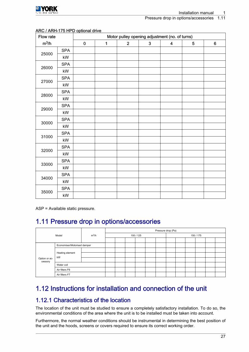
ARC / ARH-175 HPD optional driveFlow rate Motor pulley opening adjustment (no. of turns)
m3/h 0 1 2 3 4 5 6
25000SPA kW
26000SPA kW
27000SPA kW
28000SPA kW
29000SPA kW
30000SPA kW
31000SPA kW
32000SPA kW
33000SPA kW
34000SPA kW
35000SPA kW
ASP = Available static pressure.
1.11 Pressure drop in options/accessories
Model m3/h
Pressure drop (Pa)
100 / 125 150 / 175
Option or ac‐cessory
Economiser/Motorised damper
Heating element
kW
Water coil
Air filters F6
Air filters F7
1.12 Instructions for installation and connection of the unit1.12.1 Characteristics of the locationThe location of the unit must be studied to ensure a completely satisfactory installation. To do so, theenvironmental conditions of the area where the unit is to be installed must be taken into account.
Furthermore, the normal weather conditions should be instrumental in determining the best position ofthe unit and the hoods, screens or covers required to ensure its correct working order.
Installation manual 1Pressure drop in options/accessories 1.11
27

If possible, in warm zones like the southern Europe, the unit should be located on the north or east sideof the building or property.
The location chosen for the unit must provide the condenser with an unlimited air supply.
As well as the technical data given in this document and any others that are applicable, please bear inmind that the unit has been designed for outdoors installation only.
Where the unit is to be installed at ground level, refer to section Specifications for the foundation oranchoring of the unit, see on page 29.
Where the unit is to be installed on the roof of a building or property, make sure that the roof structurecan support the weight of the unit plus that of any optional equipment and/or accessories to be fitted.The unit must be installed on a specific mounting base or on a frame of appropriate steel angles. Thereare optional mounting bases available (RoofCurb).
Regardless, keep the level tolerance at maximum 10 mm all along the length and width of the unit.
If the unit is to be installed on a base or on a special angle frame that is not the standard RoofCurb,gaskets should be applied to all surfaces that are touching the bottom of the unit. Leave passages freefor the evacuation, towards the outdoors, of rainwater or condensation in the base of the compressorsection, next to the outdoor battery.
Special instructions for locations where there is regular snowfall or with ambient temperatures of closeto 0 °C or less
In areas where there is regular or sporadic snow, the unit should be elevated above the ground or roofwhere it is installed. The height should be enough to prevent the unit, the condenser and evaporator airinlets and the access to the unit panels from becoming blocked by accumulated snow.
Protection against ice
In areas where the temperature can drop below 0 °C, there must be some kind of additional protectionto prevent the water in the condensate drain pipe from freezing.
Use a wire heating element in the drain trap as well as in the drain, where applicable.
In heat pumps, also use wire heating elements in the support tray of the outdoor coil to prevent any icefrom accumulating.
Special instruction for locations with high ambient temperatures
In areas where the ambient temperature is over 43 °C, the unit must not be located in direct sunlight and,therefore a specific cover will be required.
The installation of a special sunshade over the unit must not affect the air flow required by the unit towork correctly. Check the minimum clearance required General measurements and accesses, see onpage 13.
1.12.2 Characteristics of the facility where the unit will be installedThe air duct installation where the unit is to be installed must be formed by a closed return duct system.The additional installation of economisers or outdoor air intakes is not excluded.
To reduce operating noise, the supply and return air duct connections on the unit must be made usingflexible joints.
The supply and return air duct systems must be designed for the air flow requirements of the installation.The ducts should not be sized based on the supply and return air connection sizes of the unit.
Duct covers
Units are shipped with side and lower duct openings covered. See sectionDimensions of the ductconnections, see on page 10 and Connections for supply and return ducts, see on page 12.
1 Installation manual1.12 Instructions for installation and connection of the unit
28

1.12.3 Specifications for the foundation or anchoring of the unitWhere the unit is to be installed at ground level, the characteristics of the ground it will sit on must betaken into account.
Characteristics, such as acceptable surface firmness, must be suitable for the foundation the unitrequires.
The unit should be placed on a level concrete slab at least 100 mm thick.
The length and width of the slab must be at least 150 mm more than the base rails on the unit.
C A U T I O NDo not attach the unit to the foundations of the building.
1.12.4 Characteristics of utility provider connectionsIn general, the different connections required by the unit are made following the shortest route possible.Under no circumstances may any local or national regulations be contravened when performing thepreparatory work for service connections.
N O T EFor further information on this subject, always keep the current regulations for the country where the unitis being installed at hand.
C A U T I O N• Before the connection work, possible losses of flow, temperature and voltage drops, etc. that might
affect the distances between planned connection points and the unit must be taken into account.• As a result, each connection must be sized accordingly.
1.12.5 Connection and preparation of the various connectionsElectricity. Power and controlPOWER LINE
Power must be supplied to the unit through a specific power supply line with an exclusive power controland differential breaker, installed in line with national and local regulations.
N O T EFor further information on this subject, always keep the current regulations for the country where the unitis being installed at hand.
Make sure that the electricity supply line has enough capacity to power the unit. Its length, the cablediameter and their protection (cover or jacket) should be appropriate for the unit.
Use a multimeter to check that the supply voltage stays within the accepted limits, ARC technical andphysical data (Only cooling), see on page 6, or ARH technical and physical data (Heat pump), see onpage 7.
Installation manual 1Instructions for installation and connection of the unit 1.12
29

To install the power cable, loosen the closures -1- by1/4 turn and remove the electrical board panel.
Bringing the power and control cables through the side of the unit.Remove the lower panel -4-
The side panel of the electrical box has PG48 packingglands -5- for the power cable and PG21 packingglands -6- for the control cable.
Pass the cables through them and to the inside of theelectrical box for steps -7- and -8-.
Once the cables have been passed, seal the packingglands with silicone in order to ensure they are airtight.
Reattach the panels that were removed, ensuring thatthey are hermetically sealed.
Bringing the power and control cables directly from the RoofcurbRemove the lower panel -4-.
The unit base beneath the electrical box has PG48packing glands -5- for the power cable and PG21packing glands -6- for the control cable.
Pass the cables through them and to the inside of theelectrical box for steps -7- and -8-.
Once the cables have been passed, seal the packingglands with silicone in order to ensure they are airtight.
Reattach the panels that were removed, ensuring thatthey are hermetically sealed.
1
7
4
5
6
8
5
4
7
8
6
1 Installation manual1.12 Instructions for installation and connection of the unit
30

CONTROL LINEConnect the cable to the terminals indicated andfirmly tighten the securing bolts. Also consult theWiring Diagrams.
N O T EThe complete wiring diagram for the unit is attachedto the inside of the electrical panel.
Indoor coil condensate drain
A T T E N T I O NThe installation of pipes should be adjusted to local regulations.Install a condensate drain line from the unitconnection to a nearby drain.
Ø 41
Installation manual 1Instructions for installation and connection of the unit 1.12
31

Apply a moderate amount of sealing paste to thethreads of the male part of the joint.
The drain line must have a siphon in order to facilitateproper drainage.
If it is not a siphon made of flexible material, it isrecommended that it has a stopper -1- for its drainageand cleaning.
N O T EThe condensate drain pipe should be at a minimum gradient of 2% (2 cm of drop for each metre in length).Protection against iceIn areas where the temperature can reach 0 °C or less, there should be some kind of additional protectionto prevent the water contained in the condensate drain pipe from freezing.
An heating element (wire heater) should be installed in the drain trap and in the condensate drain pipe.
For units with heat pumps, heating elements must also be installed in the support tray of the outdoor coilto prevent possible ice accumulation.
1.13 Instructions for starting up the unit1.13.1 Electrical checks
D A N G E R• All side panels of the unit must be fitted, closed and secured with their corresponding locks before
turning the general switch on the unit.• The unit has a remote control, which means that the fan turbine may start unexpectedly.
C A U T I O NLoose connection terminals produce overheating of cables and terminals. The unit will work incorrectlyand there is a risk of fire.
Check that the cables are firmly secured to their connection terminals.
C A U T I O NDo not turn on the general switch on the unit or start the unit until all installation work has been completed.
Initial connection of the unit
The general switch on the unit -Q3- must be turnedon once all of the planned accessories are installedand before starting the unit.
Press the "Test" button for two seconds so that theunit recognises the installed accessories. When therecognition process is complete, the red pilot lightswitches off.
50 m
m
75 m
m
1
Q3
1 Installation manual1.13 Instructions for starting up the unit
32

Rotating direction of the Scroll compressorsThe scroll compressors and the fans only operate correctly if they rotate in the correct direction. All ofthe motors and compressors in the unit are connected so that they rotate correctly.
If the compressors are not connected correctly and are rotating in the wrong direction:• The compressor will not compress.• Operating noise will be abnormal.• Electricity consumption (A) will be low.• They overheat.
1.14 Unblocking the unit safely in case of breakdown
D A N G E R• All side panels except for that of the electrical box, must be fitted, closed and secured with their
corresponding locks before turning the general switch on the unit.• The unit has a remote control, which means that the fan turbine may start unexpectedly.
To unlock the unit, see "Restarting the HVAC unit in case of fault" in the User Manual.
Where the thermostat screen continues to display theindicator -1- and any fault code or if the HVAC unitdoes not start, contact a Johnson Controls Inc.Authorised Technical Assistance Service.
1.15 Regular maintenance tasks performed by specialisedpersonnelLike any other machine, the unit requires regular maintenance, as the wear to which some of its partsare subjected can affect its mechanical reliability, electrical consumption and working life.
In order to keep the unit in similar working order to when it was installed and commissioned, a series ofmaintenance tasks must be performed every so often.
Furthermore, all maintenance and servicing tasks required by local and national regulations must becarried out.
D A N G E ROnly a Johnson Controls Inc. Authorised Technical Assistance Service with the appropriate technicalresources and suitably trained personnel may perform the unit maintenance tasks.
C A U T I O NJohnson Controls Inc. shall not be considered responsible for any damage caused by inappropriate useor maintenance of the unit that is in any way inconsistent with that described in this document or othersspecifically provided with the platform.
AUTOAUTO
ºC
1
2
Installation manual 1Unblocking the unit safely in case of breakdown 1.14
33
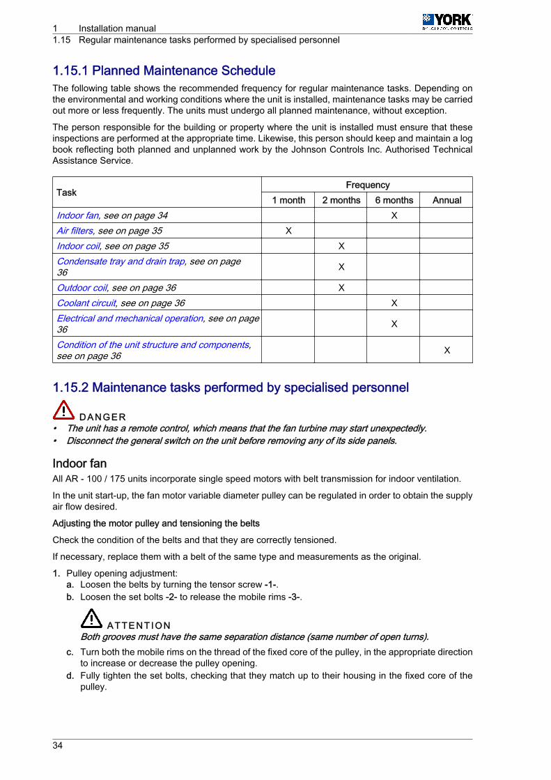
1.15.1 Planned Maintenance ScheduleThe following table shows the recommended frequency for regular maintenance tasks. Depending onthe environmental and working conditions where the unit is installed, maintenance tasks may be carriedout more or less frequently. The units must undergo all planned maintenance, without exception.
The person responsible for the building or property where the unit is installed must ensure that theseinspections are performed at the appropriate time. Likewise, this person should keep and maintain a logbook reflecting both planned and unplanned work by the Johnson Controls Inc. Authorised TechnicalAssistance Service.
TaskFrequency
1 month 2 months 6 months AnnualIndoor fan, see on page 34 X Air filters, see on page 35 X Indoor coil, see on page 35 X Condensate tray and drain trap, see on page36 X
Outdoor coil, see on page 36 X Coolant circuit, see on page 36 X Electrical and mechanical operation, see on page36 X
Condition of the unit structure and components,see on page 36 X
1.15.2 Maintenance tasks performed by specialised personnel
D A N G E R• The unit has a remote control, which means that the fan turbine may start unexpectedly.• Disconnect the general switch on the unit before removing any of its side panels.
Indoor fanAll AR ‑ 100 / 175 units incorporate single speed motors with belt transmission for indoor ventilation.
In the unit start-up, the fan motor variable diameter pulley can be regulated in order to obtain the supplyair flow desired.
Adjusting the motor pulley and tensioning the belts
Check the condition of the belts and that they are correctly tensioned.
If necessary, replace them with a belt of the same type and measurements as the original.
1. Pulley opening adjustment:a. Loosen the belts by turning the tensor screw -1-.b. Loosen the set bolts -2- to release the mobile rims -3-.
A T T E N T I O NBoth grooves must have the same separation distance (same number of open turns).
c. Turn both the mobile rims on the thread of the fixed core of the pulley, in the appropriate directionto increase or decrease the pulley opening.
d. Fully tighten the set bolts, checking that they match up to their housing in the fixed core of thepulley.
1 Installation manual1.15 Regular maintenance tasks performed by specialised personnel
34

2. Belt tightening:
a. Tighten the belts by turning the tensor screw -1-.b. Measure the tightness of the belts. In the event that you do not have a tension gauge, use the
following practical method:• Apply a 5kg force on the middle of the cord, perpendicular to it.• With this force the belt must be displaced by between 12 and 14mm.
3. It is recommended to check the tension of the belts twice during the first 24 hours of operations.
D.P
3
D.P
12 - 14 mm
F=5 Kg
AA
A-A
22 1
Air filtersThe air filters should be replaced by new ones of the same type and size, as required.
Slide the unit filters out on their guides to replace them.
Indoor coilVisually inspect the indoor coil when performing air filter maintenance.
The complete surface of the fins must be kept clean. If they need to be cleaned, use a soft brush or avacuum cleaner, taking special care not to damage the fins.
D A N G E RNever use a water hose to clean the indoor coil compartment.
Installation manual 1Regular maintenance tasks performed by specialised personnel 1.15
35

Condensate tray and drain trapLoosen the four bolts -1- and extract away from thetray -2-.
Remove all dirt and residue accumulated in thecondensate tray.
Check that neither the condensation outlet nor thedrain trap is blocked.
Check that the condensate (water) has been correctlyreleased to the outside.
Fill the drain trap with water if required (prime it).
Ensure that the four bolts are sealed hermetically -1-.
Outdoor coilThe complete surface of the fins must be kept clean. If they need to be cleaned, use a soft brush or avacuum cleaner, taking special care not to damage the fins.
Given that they are exposed to the outdoors, the fins can accumulate a lot of dirt and grime. To cleanthe fins more thoroughly, use water with a neutral detergent (e.g. washing-up liquid). Clean from theinside out and from top to bottom.
Coolant circuitBefore the start of each season when the unit is in use, a thorough check of the coolant circuit must bemade, including operating pressures, controls and temperature rises, etc.
Electrical and mechanical operationBefore the start of each season when the unit is in use, check the consumption (in amps) of all motors,the condition of the electrical connections and the correct working order of the safety and protectionsystems.
The motor bearings for both the indoor and outdoor fans are permanently lubricated and do not needadditional lubricant during maintenance.
If the unit has an economiser, motorised damper, outdoor air intake or barometricrelief damper (accessories):Check that the air dampers and their drive motors work correctly.
Check the condition of the aluminium mesh filters in the outdoor air inlet protection. Clean or replacethem when necessary.
If the unit has an exhaust fan (accessory):Check the condition of the fan and the operating control.
Condition of the unit structure and componentsCheck the correct condition of the unit structure and outdoor components for knocks, dents, scratchedpaint or rust. Check that bolts are properly secured and the condition of leak-proof seals and panel locksand make sure they close properly.
Hot water coil (accessory)Before the start of each season of operation, check the level of water in the system, that air has beenpurged from the coils, and the operation of control components.
Depending on the climate where the unit is installed, the mix of antifreeze and water must be checked.
2
1
1
1 Installation manual1.15 Regular maintenance tasks performed by specialised personnel
36

2
Options and accessories

An “OPTION” (O) includes those factory-fitted and supplied installed in the unit and ready for use.
An “ACCESSORY” (A) is defined as those that are fully or partially fitted on site.
A T T E N T I O NThe ECONOMISER is considered an “OPTION”, despite the fact that the rain protection must be installedon site for transportation reasons.
Name Option AccessoryDPC-1 thermostat AEconomiser, modulating, temperature control O Enthalpy probes for economiser O Air quality probe (IAQ) O Barometric damper AExhaust fan AFixed outdoor air damper AHigh-pressure ventilation drive O Lateral supply O Low temperature control (Low Ambient) O Air filters F6 O Air filters F7 O Dirty filter pressure switch O Smoke detector O Fire detection thermostat O Hot water coil O Heating element O Outdoor coil protection O Anti-vibration kit ACopper fin coils O Fixed Roofcurb AAdjustable Roofcurb A
2 Options and accessories
38

2.1 DPC-1 Programmable digital thermostat with communicationInterior appearance of the thermostat
N O T EWith the lid lifted, showing the central panel
The lid is only lifted to access the controls.
A B CD E
F
1
2 3 4 5 7 8 10 11
12
13
14
15
G
916
618
19
17
9
1 HVAC mode 11 Battery flat2 Comfort (day) 12 Keys blocked3 Economy (night) 13 Dirty filters4 Unoccupied 14 Outdoor temperature5 Heat 15 Warning or incident6 Cold 16 Time profile7 Timer activated 17 Day of the week8 Temperature setting 18 Hour9 Room temperature 19 Fan
10 Relative humidity
2.1.1 HVAC modesThe different HVAC modes can be selected by pressing the MODE key -A- successively.
Options and accessories 2DPC-1 Programmable digital thermostat with communication 2.1
39

OffThe HVAC system is switched off in this mode. Thescreen displays OFF-7-.
ColdThe screen displays COOL-4-.• Icon -8- flashes if there is demand.• Icon -8- remains static if not.
HeatThe screen displays HEAT-5-.• The sides of icon -9- flash if there is demand.• The sides of icon -9- remain static if not.
A B CD E
F
7
G
A B CD E
FG
4
8
A B CD E
FG
5
9
2 Options and accessories2.1 DPC-1 Programmable digital thermostat with communication
40

AutoThe screen displays AUTO-3-. The heating and thecooling functions of the system are enabled.• Icons -8- and -9- flash if there is demand.• Icons -8- and -9- remain static if not.
ProgrammedThe screen displays PROG-2- and AUTO-3-.Programmed mode involves the aforementionedAUTO mode, but also includes the time profile -10-.
This option is not displayed if microswitch pin 2 isOFF (see the microswitch configuration).
Emergency heatThe screen displays HEAT-5- and EMERG-6-.• Icon -9- flashes if the unit is running.• Icon -9- remains static without the sides if not.
A B CD E
F
3
G
9 8
A B CD E
F
3
G
2
10
A B CD E
FG
6
5
9
Options and accessories 2DPC-1 Programmable digital thermostat with communication 2.1
41

Ventilation onlyThis is accessed in OFF-7- mode and button -B- ispressed to select the fan speed.
This means that the HVAC system is stopped andonly the fan is running.
2.1.2 Button functions
A B CD E
F
1
2 3 4 5 7 8 10 11
12
13
14
15
G
916
618
19
17
9
HVAC mode button -A-
By pressing this button (in Normal mode) the current HVAC mode will be modified (OFF, COOL, HEAT,AUTO, AUTO PROG, EMERG HEAT).
Fan button -B-
By pressing this button it will enter Adjustment mode, which lasts for 5 seconds. In this mode, the fanflashes and the configured speed is displayed, together with whether it is in Auto or Fixed mode.
Outside temperature button -C-
By pressing this button (in Normal mode) the outdoor temperature is displayed for 5 seconds.
A B CD E
FG
7
2 Options and accessories2.1 DPC-1 Programmable digital thermostat with communication
42
Programming button -D-
By pressing this button (in Normal mode) it will enter Programming mode, which enables the selectionof one of the following options:
-2- Programming of the set temperatures for heat and cold in Occupied, Comfort or Day sta‐tus.
-3- Programming of the set temperatures for heat and cold in Standby, Economy or Nightstatus.
-4- Programming of the set temperatures for heat and cold in Unoccupied status.-7- Setting of the clock (day of the week, hours and minutes).
-16- Programming of the time profiles. A time profile only permits Comfort and Economy (Dayand Night) status.
-19- Fan programming.
Occupancy status button -E-
By pressing this button (in Normal mode) the current occupancy or comfort (Day / Night) status changesand the set temperature is displayed next to the flashing icon -8-. If you press the button again whilst stillin Adjustment mode, it will switch from one status to another in a sequential and cyclical manner.
If button -E- remains pressed down for more than one second, it switches to Unoccupied mode. If noother action is taken in this mode, the unoccupied status will remain indefinitely.
If button -D- is pressed, the setting disappears and the no. 0 is displayed in its place to indicate thenumber of days for which the unoccupied status must last. Buttons -F- and -G- increase or decrease thedays during which the status is to be unoccupied (with a maximum of 99 days). Icon -7- is displayed.
More -F- and less -G- buttons.
By pressing one of the two buttons (in Normal mode) it will switch to Adjustment mode, displaying thecurrent temperature setting, which is indicated by the flashing icon -8-.
If it remains pressed down for more than one second or it is released and then pressed again whilst stillin Adjustment mode, the temperature setting will be increased by 0.5 °C or 1 °F.
If the two button are pressed at the same time, it switches from °C to °F and vice versa.
2.2 Economiser, modulating, temperature controlThis consists of one damper located on the unit return and another located on the outdoor air inlet.
The control compares the outdoor air and return air temperature values and sets the opening of bothdampers proportionally using the 0 ‑ 10 V modulating actuator with return spring.
To guarantee a good comfort level, the supply temperature is limited to 12 °C.
The dampers are factory-set for a minimum volume of outdoor air of approximately 10%.
The outdoor air damper has rain protection, which is supplied separately, ready for installation on theoutdoor air inlet opening on the side of the unit.
Where necessary, enthalpy probe control options can be added to the economiser (see section Enthalpyprobes, see on page 44) as well as an exhaust system for excess air when the design of the installationrequires as such (see sections Barometric excess pressure damper, see on page 44 and Exhaustfan, see on page 45).
Options and accessories 2Economiser, modulating, temperature control 2.2
43
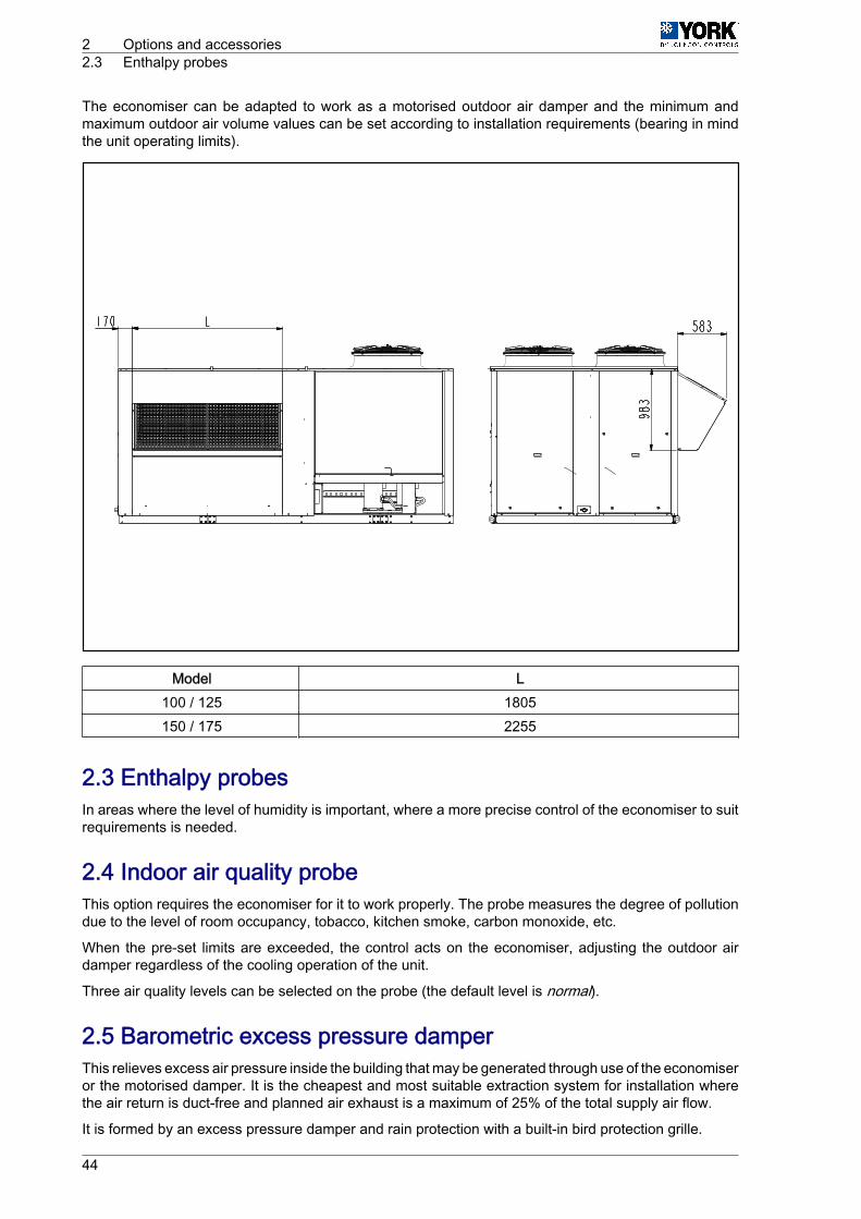
The economiser can be adapted to work as a motorised outdoor air damper and the minimum andmaximum outdoor air volume values can be set according to installation requirements (bearing in mindthe unit operating limits).
Model L100 / 125 1805150 / 175 2255
2.3 Enthalpy probesIn areas where the level of humidity is important, where a more precise control of the economiser to suitrequirements is needed.
2.4 Indoor air quality probeThis option requires the economiser for it to work properly. The probe measures the degree of pollutiondue to the level of room occupancy, tobacco, kitchen smoke, carbon monoxide, etc.
When the pre-set limits are exceeded, the control acts on the economiser, adjusting the outdoor airdamper regardless of the cooling operation of the unit.
Three air quality levels can be selected on the probe (the default level is normal).
2.5 Barometric excess pressure damperThis relieves excess air pressure inside the building that may be generated through use of the economiseror the motorised damper. It is the cheapest and most suitable extraction system for installation wherethe air return is duct-free and planned air exhaust is a maximum of 25% of the total supply air flow.
It is formed by an excess pressure damper and rain protection with a built-in bird protection grille.
2 Options and accessories2.3 Enthalpy probes
44

When the outdoor air inlet opens and the return air flow is closed proportionally, the pressure inside thebuilding increases. When the pressure is greater than atmospheric pressure, the damper is opened torelease any excess pressure directly outdoors.
Where the return duct connection to the unit is at the bottom, the barometric damper assembly and rainprotection are installed on the side of the unit.
Where the return duct connection to the unit is on the side, the barometric damper assembly and rainprotection are installed as close to the unit as possible, directly on the front of the return duct.
The barometric damper is supplied installed on the side panel of the unit.
The rain protection is supplied separately, for on-site installation.
B
A
A Rainhood EconomiserB Rainhood Barometric damper or Exhaust fan
Model L100 / 125 1805150 / 175 2255
2.6 Exhaust fanThis is the most suitable extraction system for installations using an economiser or motorised damper,where the air return is ducted and planned air exhaust is above 25% of the total supply air flow. Thesystem is formed of a group of axial fans (two units in the models 100 / 125 and three units in the models150 / 175), an excess pressure damper and the rain protection, which is the same as the barometricdamper. To consult the dimensions, see section Barometric excess pressure damper, see on page 44.
Options and accessories 2Exhaust fan 2.6
45

Up to approximately 30% of outdoor air inlet opening, operating as a barometric damper. The fans areenabled at this point and the air is discharged directly outdoors.
Where the return duct connection to the unit is at the bottom, the fans, the barometric damper assemblyand rain protection are installed on the side of the unit.
If the return duct connection to the unit is on the side, the fans, the barometric damper assembly andrain protection are installed as close to the unit as possible, directly on the front of the return duct. Thefans and the barometric damper are supplied installed on the side panel of the unit.
The rain protection is supplied separately for on-site installation. A cable is supplied for connection ofthe fan to the electric box.
2.7 Fixed outdoor air damperThis consists of one damper located at the outdoor air inlet, including the same rain protection andaluminium mesh filters as in the case of the economiser.
To consult the dimensions, see section Economiser, modulating, temperature control, see on page 43The damper has a manual opening device and mechanical fixing to ensure its position once the correctpercentage of outdoor air in the installation is achieved, always in accordance with the unit operatinglimits.
The damper is supplied installed on the side panel of the unit. The rain protection is supplied separatelyfor on-site installation.
2.8 Low temperature control (low ambient)This option is included in the "Premium Kit".
Rooftop units are designed to work in cold mode to a minimum outdoor temperature of 7 °C or 10 °C.With this option, they can operate correctly to a minimum outdoor temperature of ‑18 °C.
2.9 Air filters F6 and F7These are high-performance air filters (according to Standard EN-779). The unit is fitted with guides fortheir installation behind the standard filters G4, in line with the requirements of the strictest regulationson indoor air quality in buildings.
They have a galvanised steel frame and minipleat-type filtering.
2.10 Dirty filter pressure switchesThese provide a dry contact when the air filters are blocked to indicate that maintenance or replacementis required. The filter icon is indicated on the display connected to the thermostat DPC-1.
2.11 Smoke detectorThe detector is fitted in the return air area of the unit. If particles of smoke are detected, the unit stopsand switches to "lock out" mode, in which case it must be manually reset before it can be restarted.
A T T E N T I O NThe smoke detector is fitted to protect the unit. It must not be used as a protection system for the buildingor other facilities. Its use is subject to compliance with local regulations involving unit installation (relatingto ventilation systems, fire prevention, etc.).
Depending on the regulations involving the unit, this option may require the use of an economiser ormotorised damper.
2 Options and accessories2.7 Fixed outdoor air damper
46

2.12 Fire detection thermostatAs standard, the unit is fitted with an air supply probe that stops at 80 °C and switches to "lock out" mode,in which case the control must be manually reset.
Using this option, a set temperature probe and manual reset are located in the unit supply area. If theselected temperature is reached in this area, the unit stops and switches to "lock out" mode, in whichcase where the probe and control must be manually reset before it can be restarted.
A T T E N T I O NThe fire detection thermostat is fitted to protect the unit. It must not be used as a protection system forthe building or other facilities. Its use is subject to compliance with local regulations involving unitinstallation (relating to ventilation systems, fire prevention, etc.).
Depending on the regulations involving the unit, this option may require the use of an economiser ormotorised damper.
2.13 Hot water coilThis includes all of the hydraulic and control components required for operating, such as the 0-10 Vproportional actuator mixer valve and the antifreeze probe.
2.14 Heating elementAvailable for ARC cold-only models and the ARH heat pump at powers of 37, 50 and 60 kW.
The power supply to the heating resistor must be independent to the general power supply to the unitand must be fitted with its own circuit breaker (not supplied). See sections ARC / ARH units with auxiliaryheating element, see on page 9.
2.15 Outdoor coil protection50 x 50 electro-welded rod mesh painted the same colour as the unit panels. Easy to remove and fit touse for maintenance purposes.
2.16 Anti-vibration kitThis is formed by the shock absorbers and the necessary nuts and bolts for on-site assembly when fittingthe unit.
2.17 Copper fin coilsCopper fin coils to give the best corrosion protection for installations in coastal areas, maintaining fullefficiency. This is applied to the condensers (outdoor units) and evaporators (indoor units). See sectionWeight options and accessories, see on page 8 for the increase in weight in relation to standard.
2.18 Roofcurb mounting base, fixed typeFor installation on flat and levelled building roofs.
Structure made of galvanised sheet steel supplied in kit form for on-site assembly and installation.
Allows for installation of the ducts directly from inside the building following fitting of the rooftop unit andprovides a seal connection between it and the building roof.
The roofcurb assembly consists of a closed frame that fits below the base of the unit to provide a sealedconnection.
Options and accessories 2Fire detection thermostat 2.12
47

The roofcurb must be attached to the supporting structure of the building roof. To do so, use the nutsand bolts supplied or use welding.
To prevent humidity or condensation from filtering into the building, all of the outer perimeter must beinsulated and sealed with an extension of the same material used for the roofing finish.
A
C
B
F
E
D
282
300
415 50
2120
50
50
50
SOLO EN150/175
Model A B C D E F100 / 0125 3237 2085 1542 784 601 535150 / 175 4287 2535 1990 784 716 420
2.19 Roofcurb mounting base, adjustable typeFor installing on sloping building roofs at gradients of up to 5° (9%) in a lengthways direction to the unitand up to 7° (12%) in a transverse direction (models 100 / 125) or 10° (18%) (models 150 / 175).
2 Options and accessories2.19 Roofcurb mounting base, adjustable type
48
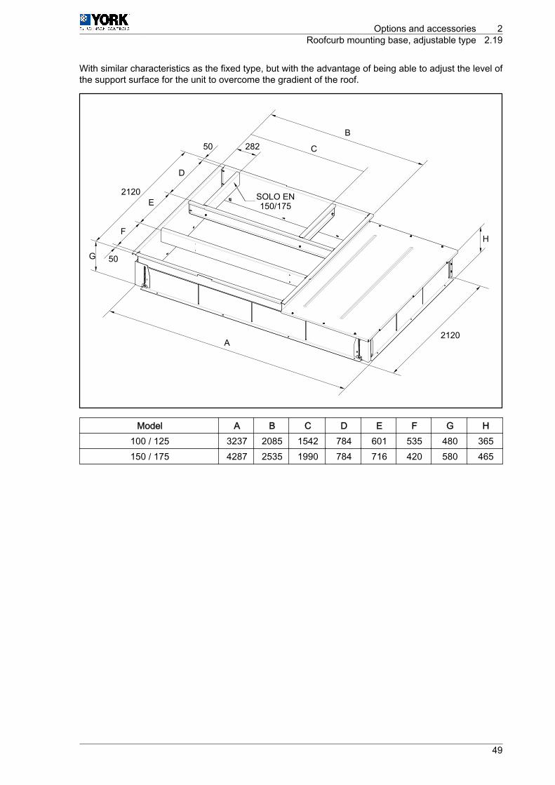
With similar characteristics as the fixed type, but with the advantage of being able to adjust the level ofthe support surface for the unit to overcome the gradient of the roof.
A
C
B
F
E
D
G 50
50
2120
282
H
2120
SOLO EN150/175
Model A B C D E F G H100 / 125 3237 2085 1542 784 601 535 480 365150 / 175 4287 2535 1990 784 716 420 580 465
Options and accessories 2Roofcurb mounting base, adjustable type 2.19
49

3
Unit installation data

3.1 List of tests for unit start-upPlease complete the following forms to register the full details of the installation and the start-upinspection.
Complete the blank fields or mark the appropriate box, as applicable.
Company performing installation:
Installing technician:
Name / project number:
Location of the unit:
Address of the unit location:
Person in charge of the building orproperty where the unit is installed:
Installation work start date: Unit model number: Unit serial number: Plate and version: Thermostat, model and version:
General inspection of the unit Visual appearance Levelling of the unit Check the unit for transport, loading and unloading damage Unit installed with sufficient clearance Check the circuit for the presence of oil (large coolant leaks). Terminals and connections correctly secured in the control panel and accessories Air filters installed Condensate drain pipe and drain trap installed correctly Thermostat and connection cabling installed correctly Air duct installation complete and correct Accessories and planned options installed (if applicable)
Inspection of the air supply fan Verification of direction of rotation
Inspection of compressors Verification that direction of rotation is correct
Unit installation data 3List of tests for unit start-up 3.1
51

3.2 Start-up dataElectrical data
Ratingplate Actual
Power supply
Check specifica‐tions in the Installa‐
tion Manual
Control voltage Fan consumption (A) Consumption of condenser fan 1 (A) Consumption of condenser fan 2 (A) Consumption of compressor 1 (A) Consumption of compressor 2 (A) Consumption of supply fan (A) Heating element 1 (Optional) Heating element 2 (Optional)
Cool and heat modes
Coolant circuitMode Value
Subcooling (min. 8 K, max. 18 K) °CLiquid pressure: _____ barLiquid temperature: _____ °C
Superheat (min. 4 K, max. 10 K) °CSuction pressure: _____ barSuction temperature: _____ °C
Complete liquid line checked in sight glass Correct oil level checked in sight glass
Supply air flow rate values
m3/hDesign Measured
Air temperature
Mode (cool or heat): Temperature (°C)Outdoor air: Supply air: Return air: Indoor air mix (if economiser is fitted):
3 Unit installation data3.2 Start-up data
52

OPTIONS
Heating mode (hot water coil)
Air temperatureCapacity: _____ (kW) Temperature (°C)Supply air (at 100 %) Return air
Hydraulic circuit Temperature (°C) Pressure (bar)Water inlet Water outlet
Others
Outdoor fan 1Type or model
Surge protection adjusted
Outdoor fan 2Type or model
Surge protection adjusted
Indoor fanType or model
Surge protection adjusted
Notes and observations:____________________________________________________________________________________
____________________________________________________________________________________
____________________________________________________________________________________
____________________________________________________________________________________
____________________________________________________________________________________
____________________________________________________________________________________
____________________________________________________________________________________
____________________________________________________________________________________
____________________________________________________________________________________
____________________________________________________________________________________
____________________________________________________________________________________
____________________________________________________________________________________
____________________________________________________________________________________
Installed by:Name
Date and signature
Unit installation data 3Start-up data 3.2
53

4
Wiring diagrams

4.1 Micro switch configurationThe micro switches are used to establish the following configurations:
A T T E N T I O NIn order to update the new configuration of the micro switches the power supply has to be shut off
MICRO SWITCH CONFIGURATION
Number Status Description
1 / 2
OFF/OFF Defrosting time 0'ON/OFF Defrosting time 30'OFF/ON Defrosting time 60'ON/ON Defrosting time 90'
3ON Crossed coilsOFF Independent coils
4ON Selection of 2 compressors (tandem) ‑ 1 circuitOFF Selection of 1 compressor ‑ 1 circuit
5ON Cold selectionOFF Heat pump selection
6ON 4-way valve active in heatOFF 4-way valve active in cold
7ON Receives signal B from thermostat (active in heat)OFF Receives signal O from thermostat (active in cold)
8ON Fan enabled during defrostOFF Fan disabled during defrost
Wiring diagrams 4Micro switch configuration 4.1
55

4.2 Fault tableThe red LED on the YKNOpen electronic board is responsible for showing the state of faults on the unit:• When the red LED remains off there are no faults in the unit.• If the red LED does two series of flashes in a constant sequence, there is a fault which must be
checked in the following table:
FAULT TABLE (RED LED)
Red LED flashesDescription
1st Series 2nd Series
1, 2 or 3
1 Discharge temperature exceeded
2 High-pressure switch, outdoor fan thermal switch or com‐pressor module thermal switch
3 Low-pressure switch4 Indoor fan thermal switch5 Repeated cold start-up or suction temperature < ‑25 °C
4
1 Gas control 1 or heating element 1 fault2 Gas control 2 or heating element 2 fault3 Heating element 3 stage fault4 Heating element 4 stage fault
5 Fault in economiser or hot water coil (outdoor supply probe,water return)
6 Smoke or high temperature detection (accessory) or supplytemperature > 80 °C
4 Wiring diagrams4.2 Fault table
56

4.3 IncidentsThe green LED on the YKNOpen electronic board is responsible for showing the state of incidents onthe unit:• If the green LED flashes in a constant sequence, there are no incidents in the unit.• If the green LED does three series of flashes in a constant sequence, there is an incident which must
be checked in the following table:
N O T EThe first series indicates the affected circuit: one flash for the first compressor, two for the second,three for the third and four for miscellaneous incidents. A short pause follows. The second and thirdseries specify the direct cause of the incident.
INCIDENT TABLE (GREEN LED)
Green Led flashes Description1st Ser‐
ies2nd
Series3rd
Series Type Incident
1, 2 or 31
1Probes
Discharge probe open or short circuited2 Liquid probe open or short circuited3 Suction probe open or short circuited
21
TemperatureRepeated defrosting
2 The discharge temperature is not recovered
4
1
1
Probes
Supply probe open or short circuited2 Return probe open or short circuited3 Outdoor probe open or short circuited4 Water probe open or short circuited5 Fault in the enthalpy probes
2
1
Thermostat
Signal Y1 or Y2 without signal G2 Signal W without signal B3 Signal W without signal G4 Signal Y2 without signal Y1
3
1
Auxiliary heat
Heating element thermal switch 12 Heating element thermal switch 23 Heating element thermal switch 34 Heating element thermal switch 4
4
1
Temperature
The water coil temperature is not recovered2 Outdoor temperature too low3 Water coil performing antifreeze operation4 Supply temperature above 55 °C5 Supply temperature < 25 °C with gas
5
1
Others
Transceiver ID unknown2 There is at least one accessory not found3 Air quality demand4 Dirty filters5 Presence sensor is unoccupied6 Suction temperature < 0 °C, economiser
Wiring diagrams 4Incidents 4.3
57

4.3.1 Test button• If the test button is pressed until the green led is activated, certain times are shortened.• If the test button is pressed until the orange led is activated, any fault that has been detected is reset.• If the test button is pressed until the red led is activated, the optional accessories and probes
connected to the board are identified.
4.4 DPC-1 thermostatWhen a fault occurs and there is communication between the unit and the thermostat, the thermostatalternately displays the time and the fault produced according to the unit fault table.
It also displays other faults related to the thermostat.
MICRO SWITCH CONFIGURATION
Type Thermostat numbers Description
Thermostat
9 1 Ambient probe open or short circuited9 2 Internal probe not calibrated9 3 Communication error9 4 Fault with AL terminal connected9 5 S5 digital probe not detected9 6 S6 digital probe not detected9 7 S7 digital probe not detected9 8 S8 digital probe not detected9 9 Digital outdoor probe not detected
4 Wiring diagrams4.4 DPC-1 thermostat
58

4.5 ARC/ARH 100 – 125 wiring diagrams
I-2649a (1/4)ARH: 100 y 125ARC: 100 y 125
(01) (02) (03) (04) (05) (07) (09)(00)
(*) 7
KM7
7
a
b
(13)
9
9
(21)
(14)
(14) (18) (22) (23) (15) (17)
KM9
(25)
A
B
Model Q2[A] B F1 [A] F2 [A] F3 [A] F4 [A] F5 [A]
REG.F7 [A]REG.
F9 [A]REG.
100 100 3 x 35 20 20 20 20 12,5 5,8 5,8125 125 3 x 50 25 25 25 25 12,5 5,8 5,8
( * ) If the unit has power and the green LED V2 on board A1 is off, check that the sequence ofphases L1, L2, L3 is correct.
AOn-site installation. These compo‐nents are not supplied by the manufac‐turer
FC Phase control
B Cross-section B [mm2]
Wiring diagrams 4ARC/ARH 100 – 125 wiring diagrams 4.5
59

I-2649a (2/4)ARH: 100 y 125ARC: 100 y 125
1 2 3 4 5 6 7
(14) (18) (22) (23)
X1/..
X1/..d
c
b
a
T1
1200 VA
230V400V
a b c d e
DEF
C
J K L M N O P
B
GA
HI
a b c
I-2649a (3/4)ARH: 100 y 125ARC: 100 y 125
X1/..
X1/..d
c
ARCARH
121110 13 14 15 181716 19 20 21 22 23 24 258 9
B8
F13
F5
F5 F7
10A
150 VA
(05)
F7
KM5
KM7 KM2
HP11
LP1
(07)
ARH ARHF9
F9
(09)
(09)(03)
(04)
(5)(6)
(07)(05)
HP21LP2
KM3
KM4 KM9
(01)
(3)
4 Wiring diagrams4.5 ARC/ARH 100 – 125 wiring diagrams
60
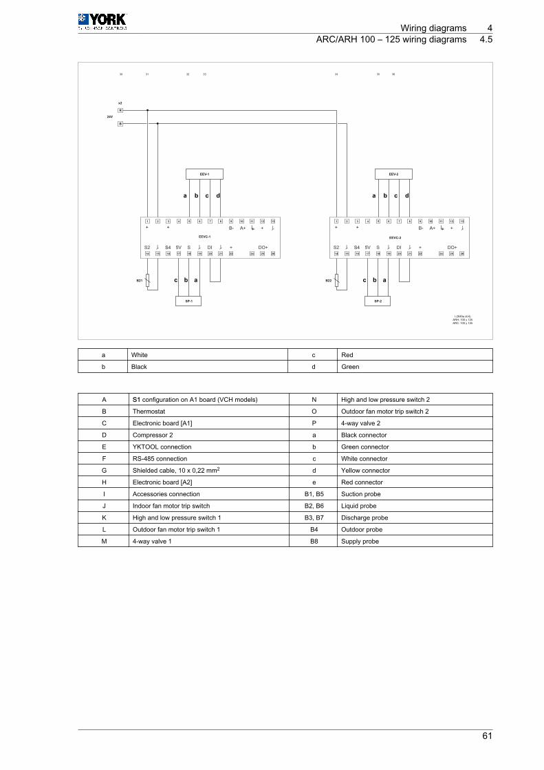
I-2649a (4/4)ARH: 100 y 125ARC: 100 y 125
SP-1
B21
1 2 3 4 5 6 7 8 9 10 11 12 13
14 15 16
S4
+ + + +
S417 18 19 20 21 22 24 25 26
EEV-1
EEVC-1 EEVC-2
SP-2
B22
1 2 3 4 5 6 7 8 9 10 11 12 13
14 15 16 17 18 19 20 21 22 24 25 26
EEV-2
R
x2
24V
B
33 34 35 3630 31 32
a b c d a b
b acb ac
c d
a White c Red
b Black d Green
A S1 configuration on A1 board (VCH models) N High and low pressure switch 2
B Thermostat O Outdoor fan motor trip switch 2
C Electronic board [A1] P 4-way valve 2
D Compressor 2 a Black connector
E YKTOOL connection b Green connector
F RS-485 connection c White connector
G Shielded cable, 10 x 0,22 mm2 d Yellow connector
H Electronic board [A2] e Red connector
I Accessories connection B1, B5 Suction probe
J Indoor fan motor trip switch B2, B6 Liquid probe
K High and low pressure switch 1 B3, B7 Discharge probe
L Outdoor fan motor trip switch 1 B4 Outdoor probe
M 4-way valve 1 B8 Supply probe
Wiring diagrams 4ARC/ARH 100 – 125 wiring diagrams 4.5
61

4.6 ARC/ARH 150 – 175 wiring diagrams
I-2650a (1/4)ARH 150 y 175ARC 150 y 175
(01) (02) (03) (04) (05) (06) (08) (09) (10)(07)(00)
(*) 7
KM7
7
(13)
8
8
(13)
9
9
(21)
10
10
(21)
(14)
(14) (18) (22) (23) (15) (15) (17)
KM8
(17)
KM9
(25)
KM10
ab
(25)
A
B
Model Q2[A] B F1 [A] F2 [A] F3 [A] F4 [A] F5 [A]
REG.F6 [A]REG.
F7, F8[A]
REG.
F9, F10[A]
REG.150 160 3 x 50 32 32 32 32 9,5 9,5 4,2 4,2175 200 3 x 70 32 32 32 32 9,5 9,5 4,2 4,2
( * ) If the unit has power and the green LED V2 on board A1 is off, check that the sequence ofphases L1, L2, L3 is correct.
AOn-site installation. These compo‐nents are not supplied by the manufac‐turer
FC Phase control
B Cross-section B [mm2]
4 Wiring diagrams4.6 ARC/ARH 150 – 175 wiring diagrams
62

I-2650a (2/4)ARH 150 y 175ARC 150 y 175
1 2 3 4 5 6 7
(14) (18) (22) (23)
X1/..
X1/..d
c
b
a
T1
1200 VA
230V400V
I-2650a (3/4)ARH 150 y 175ARC 150 y 175
X1/..
X1/..d
c
ARCARH
121110 13 14 15 181716 19 20 21 22 23 24 258 9
B8
F13
F5
F5
F7
10A
250 VA
(05)
F6
(06)
F7
KM5KM8
KM6
KM7
KM2
K8HP12
HP11
LP1
K8
(07)
14
11
F8
(08)
ARH
ARH
ARHF9
F9
(09)F10
(010)
(09)(03)
(04)
(5)(6)
(10)
(07)
(17)(08)
(05)(06) 14
1211
HP21LP2
KM3
KM4 KM9
K10 KM10
K10HP22 14
11
ARH
(01)
(3)
(25)14
1211
a b c d e
DEF
C
J K L M N O P
B
GA
HI
a b c
Wiring diagrams 4ARC/ARH 150 – 175 wiring diagrams 4.6
63
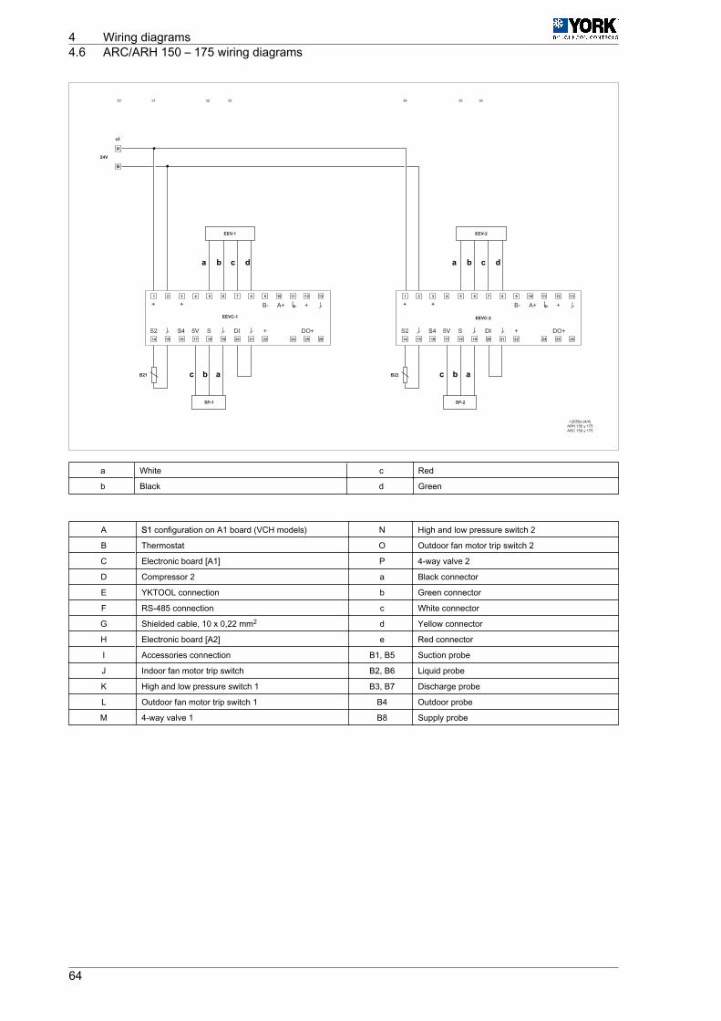
I-2650a (4/4)ARH 150 y 175ARC 150 y 175
SP-1
B21
1 2 3 4 5 6 7 8 9 10 11 12 13
14 15 16
S4
+ + + +
S417 18 19 20 21 22 24 25 26
EEV-1
EEVC-1 EEVC-2
SP-2
B22
1 2 3 4 5 6 7 8 9 10 11 12 13
14 15 16 17 18 19 20 21 22 24 25 26
EEV-2
R
x2
24V
B
33 34 35 3630 31 32
a b c d a b
b acb ac
c d
a White c Red
b Black d Green
A S1 configuration on A1 board (VCH models) N High and low pressure switch 2
B Thermostat O Outdoor fan motor trip switch 2
C Electronic board [A1] P 4-way valve 2
D Compressor 2 a Black connector
E YKTOOL connection b Green connector
F RS-485 connection c White connector
G Shielded cable, 10 x 0,22 mm2 d Yellow connector
H Electronic board [A2] e Red connector
I Accessories connection B1, B5 Suction probe
J Indoor fan motor trip switch B2, B6 Liquid probe
K High and low pressure switch 1 B3, B7 Discharge probe
L Outdoor fan motor trip switch 1 B4 Outdoor probe
M 4-way valve 1 B8 Supply probe
4 Wiring diagrams4.6 ARC/ARH 150 – 175 wiring diagrams
64