
MODELS 135 • 150 • 175 • 200
638
MODELS United States 0G960500 and Above . . . . . . With Serial Numbers SERVICE MANUAL 135 • 150 • 175 • 200 Printed in U.S.A. 2000, Mercury Marine 90-878079 JANUARY 2000
-
Upload
khangminh22 -
Category
Documents
-
view
0 -
download
0
Transcript of MODELS 135 • 150 • 175 • 200
MODELS
United States 0G960500 and Above. . . . . .
With Serial Numbers
SERVICE
MANUAL
135 • 150 • 175 • 200
Printed in U.S.A. 2000, Mercury Marine 90-878079 JANUARY 2000
90-878079 JANUARY 2000 Page i
Notice
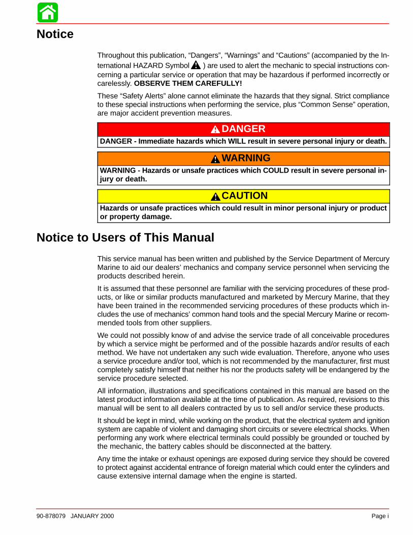
Throughout this publication, “Dangers”, “Warnings” and “Cautions” (accompanied by the In-ternational HAZARD Symbol ) are used to alert the mechanic to special instructions con-cerning a particular service or operation that may be hazardous if performed incorrectly orcarelessly. OBSERVE THEM CAREFULLY!
These “Safety Alerts” alone cannot eliminate the hazards that they signal. Strict complianceto these special instructions when performing the service, plus “Common Sense” operation,are major accident prevention measures.
DANGERDANGER - Imm ediate hazards which WILL result in severe personal injury or death.
WARNINGWARNING - Hazards or unsafe practices which COULD result in severe personal in-jury or death.
CAUTIONHazards or unsafe practices which could result in minor personal injury or productor property damage.
Notice to Users of This Manual
This service manual has been written and published by the Service Department of MercuryMarine to aid our dealers’ mechanics and company service personnel when servicing theproducts described herein.
It is assumed that these personnel are familiar with the servicing procedures of these prod-ucts, or like or similar products manufactured and marketed by Mercury Marine, that theyhave been trained in the recommended servicing procedures of these products which in-cludes the use of mechanics’ common hand tools and the special Mercury Marine or recom-mended tools from other suppliers.
We could not possibly know of and advise the service trade of all conceivable proceduresby which a service might be performed and of the possible hazards and/or results of eachmethod. We have not undertaken any such wide evaluation. Therefore, anyone who usesa service procedure and/or tool, which is not recommended by the manufacturer, first mustcompletely satisfy himself that neither his nor the products safety will be endangered by theservice procedure selected.
All information, illustrations and specifications contained in this manual are based on thelatest product information available at the time of publication. As required, revisions to thismanual will be sent to all dealers contracted by us to sell and/or service these products.
It should be kept in mind, while working on the product, that the electrical system and ignitionsystem are capable of violent and damaging short circuits or severe electrical shocks. Whenperforming any work where electrical terminals could possibly be grounded or touched bythe mechanic, the battery cables should be disconnected at the battery.
Any time the intake or exhaust openings are exposed during service they should be coveredto protect against accidental entrance of foreign material which could enter the cylinders andcause extensive internal damage when the engine is started.
Page ii 90-878079 JANUARY 2000
It is important to note, during any maintenance procedure replacement fasteners must havethe same measurements and strength as those removed. Numbers on the heads of the met-ric bolts and on the surfaces of metric nuts indicate their strength. American bolts use radiallines for this purpose, while most American nuts do not have strength markings. Mis-matched or incorrect fasteners can result in damage or malfunction, or possibly personalinjury. Therefore, fasteners removed should be saved for reuse in the same locations when-ever possible. Where the fasteners are not satisfactory for re-use, care should be taken toselect a replacement that matches the original.
Cleanliness and Care of Outboard Motor
A marine power product is a combination of many machined, honed, polished and lappedsurfaces with tolerances that are measured in the ten thousands of an inch/mm. When anyproduct component is serviced, care and cleanliness are important. Throughout this manu-al, it should be understood that proper cleaning, and protection of machined surfaces andfriction areas is a part of the repair procedure. This is considered standard shop practiceeven if not specifically stated.
Whenever components are removed for service, they should be retained in order. At thetime of installation, they should be installed in the same locations and with the same matingsurfaces as when removed.
Personnel should not work on or under an outboard which is suspended. Outboards shouldbe attached to work stands, or lowered to ground as soon as possible.
We reserve the right to make changes to this manual without prior notification.
Refer to dealer service bulletins for other pertinent information concerning the products de-scribed in this manual.
Page Numbering
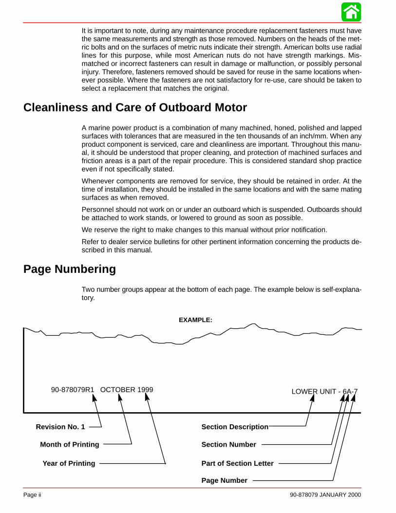
Two number groups appear at the bottom of each page. The example below is self-explana-tory.
EXAMPLE:
90-878079R1 OCTOBER 1999 LOWER UNIT - 6A-7
Revision No. 1
Month of Printing
Year of Printing
Section Description
Section Number
Part of Section Letter
Page Number

1
2
3
4
5
6
7
General Information& Specifications
Ignition System
Fuel System
Powerhead
Mid-Section
Gear Housing
Attachment/Control Linkage
8Color Diagrams
90-878079 JANUARY 2000 Page iii
Service Manual Outline
Section 1 - General Information & SpecificationsA - SpecificationsB - MaintenanceC - General InformationD - Outboard Installation
Section 2 - ElectricalA - IgnitionB - Charging & Starting SystemC - Timing, Synchronizing & AdjustingD - Wiring Diagrams
Section 3 - Fuel SystemA - Fuel PumpB - CarburetionC - Fuel InjectionD - Oil InjectionE - Emissions
Section 4 - PowerheadA - PowerheadB - Cooling
Section 5 - Mid-SectionA - Clamp/Swivel Brackets & Drive Shaft HousingB - Power Trim
Section 6 - Gear HousingA - Right Hand Non-RatchetingB - Left Hand Non-Ratcheting
Section 7 - Attachments/Control LinkageSection 8 - Color Diagrams
1A
SPECIFICATIONS
90-878079 JANUARY 2000 Page 1A-1
IMPORTANT INFORMATIONSection 1A - Specifications
Table of Contents
Specifications 1A-1. . . . . . . . . . . . . . . . . . . . . . . . . . .
Specifications
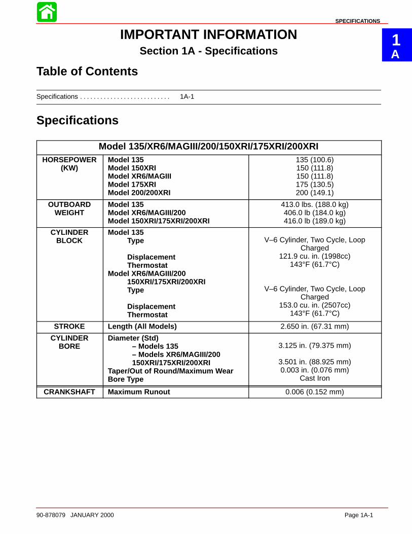
Model 135/XR6/MAGIII/200/150XRI/175XRI/200XRIHORSEPOWER
(KW)Model 135Model 150XRIModel XR6/MAGIIIModel 175XRIModel 200/200XRI
135 (100.6)150 (111.8)150 (111.8)175 (130.5)200 (149.1)
OUTBOARDWEIGHT
Model 135Model XR6/MAGIII/200Model 150XRI/175XRI/200XRI
413.0 lbs. (188.0 kg)406.0 lb (184.0 kg)416.0 lb (189.0 kg)
CYLINDERBLOCK
Model 135Type
DisplacementThermostat
Model XR6/MAGIII/200150XRI/175XRI/200XRIType
Displacement Thermostat
V–6 Cylinder, Two Cycle, LoopCharged
121.9 cu. in. (1998cc)143°F (61.7°C)
V–6 Cylinder, Two Cycle, LoopCharged
153.0 cu. in. (2507cc)143°F (61.7°C)
STROKE Length (All Models) 2.650 in. (67.31 mm)
CYLINDERBORE
Diameter (Std)– Models 135– Models XR6/MAGIII/200150XRI/175XRI/200XRI
Taper/Out of Round/Maximum WearBore Type
3.125 in. (79.375 mm)
3.501 in. (88.925 mm)0.003 in. (0.076 mm)
Cast Iron
CRANKSHAFT Maximum Runout 0.006 (0.152 mm)
SPECIFICATIONS
Page 1A-2 90-878079 JANUARY 2000
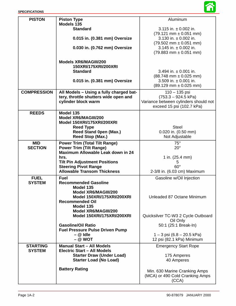
PISTON Piston TypeModels 135
Standard
0.015 in. (0.381 mm) Oversize
0.030 in. (0.762 mm) Oversize
Models XR6/MAGIII/200150XRI/175XRI/200XRIStandard
0.015 in. (0.381 mm) Oversize
Aluminum
3.115 in. ± 0.002 in. (79.121 mm ± 0.051 mm)
3.130 in. ± 0.002 in. (79.502 mm ± 0.051 mm)
3.145 in. ± 0.002 in. (79.883 mm ± 0.051 mm)
3.494 in. ± 0.001 in. (88.748 mm ± 0.025 mm)
3.509 in. ± 0.001 in. (89.129 mm ± 0.025 mm)
COMPRESSION All Models – Using a fully charged bat-tery, throttle shutters wide open andcylinder block warm
110 – 135 psi(753.3 – 924.5 kPa)
Variance between cylinders should notexceed 15 psi (102.7 kPa)
REEDS Model 135Model XR6/MAGIII/200Model 150XRI/175XRI/200XRI
Reed TypeReed Stand 0pen (Max.)Reed Stop (Max.)
Steel0.020 in. (0.50 mm)
Not Adjustable
MID SECTION
Power Trim ( Total Tilt Range)Power Trim ( Tilt Range)Maximum Allowable Leak down in 24hrs.Tilt Pin Adjustment PositionsSteering Pivot RangeAllowable Transom Thickness
75°20°
1 in. (25.4 mm)5
60°2-3/8 in. (6.03 cm) Maximum
FUELSYSTEM
FuelRecommended Gasoline
Model 135Model XR6/MAGIII/200Model 150XRI/175XRI/200XRI
Recommended OilModel 135Model XR6/MAGIII/200Model 150XRI/175XRI/200XRI
Gasoline/Oil RatioFuel Pressure Pulse Driven Pump
– @ Idle – @ WOT
Gasoline w/Oil Injection
Unleaded 87 Octane Minimum
Quicksilver TC-W3 2 Cycle OutboardOil Only
50:1 (25:1 Break-In)
1 – 3 psi (6.8 – 20.5 kPa)12 psi (82.1 kPa) Minimum
STARTINGSYSTEM
Manual Start – All ModelsElectric Start – All Models
Starter Draw (Under Load)Starter Load (No Load)
Battery Rating
Emergency Start Rope
175 Amperes40 Amperes
Min. 630 Marine Cranking Amps(MCA) or 490 Cold Cranking Amps
(CCA)

SPECIFICATIONS
90-878079 JANUARY 2000 Page 1A-3
IGNITIONSYSTEM
TypeSpark Plug Type Spark Plug GapFiring Order
Capacitor DischargeNGK BPZ8HS-100.040 in. (1.0 mm)
1-2-3-4-5-6
CHARGINGSYSTEM
Alternator Output (Regulated) Voltage Regulator Draw with IgnitionKey in the Off Position
40 Amperes @ 5000 rpm0 – 4 Milliamperes Each
(0 – 8 Milliamperes total system draw)
TIMING Idle Speed/Pickup Timing– 135 Carb Models– XR6/MAG III– 200 Carb– 150XRI/175 XRI Models– 200 XRI Model
Maximum BTDC– Model 135@ Cranking Speed@ WOT RPM
– XR6/MAG III Carb/175 XRI@ Cranking Speed@ WOT RPM
– Model 150 XRI@ Cranking Speed@ WOT RPM
– Model 200 Carb@ Cranking Speed@ WOT RPM
– Model 200XRI@ Cranking Speed@ WOT RPM
0° – 9° ATDC
25° BTDC19° BTDC
26° BTDC20° BTDC
22° BTDC16° BTDC
20° BTDC18° BTDC
24° BTDC18° BTDC
*NOTE: Timing specifications listed are for 2000 model year engines. Refer to timing decal on engine forprevious model year timing specifications.
SPECIFICATIONS
Page 1A-4 90-878079 JANUARY 2000
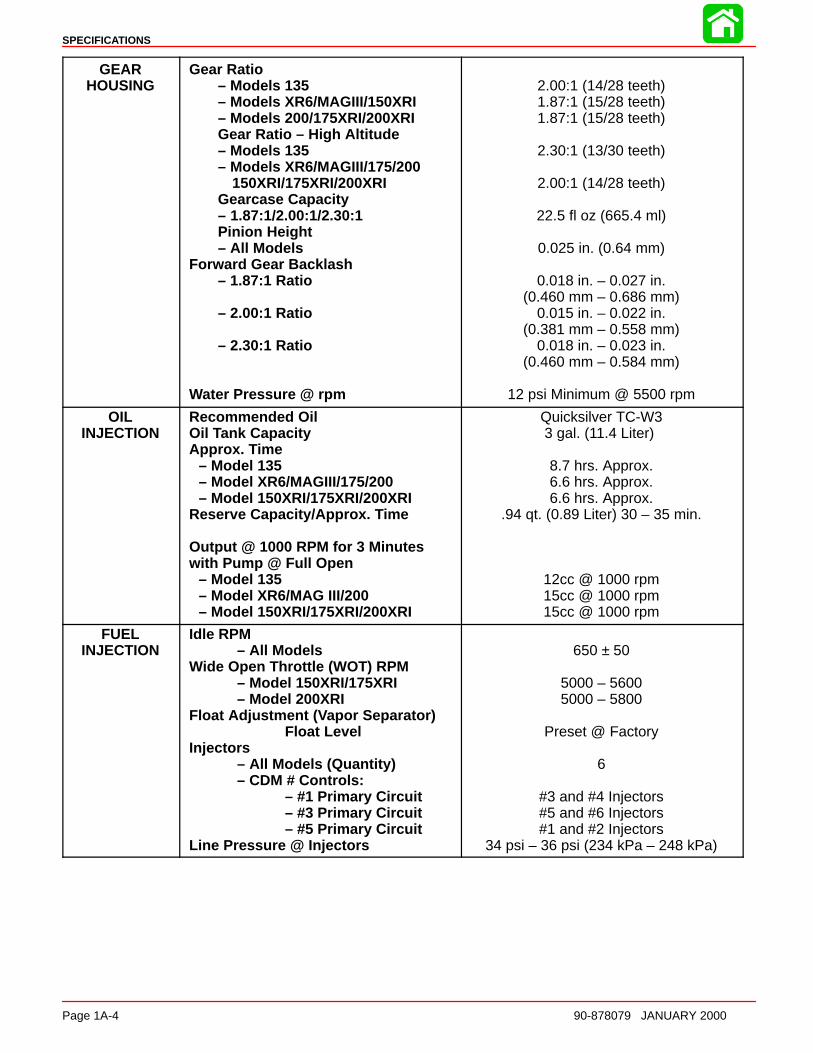
GEARHOUSING
Gear Ratio– Models 135– Models XR6/MAGIII/150XRI– Models 200/175XRI/200XRIGear Ratio – High Altitude– Models 135– Models XR6/MAGIII/175/200
150XRI/175XRI/200XRIGearcase Capacity– 1.87:1/2.00:1/2.30:1Pinion Height– All Models
Forward Gear Backlash– 1.87:1 Ratio
– 2.00:1 Ratio
– 2.30:1 Ratio
Water Pressure @ rpm
2.00:1 (14/28 teeth)1.87:1 (15/28 teeth)1.87:1 (15/28 teeth)
2.30:1 (13/30 teeth)
2.00:1 (14/28 teeth)
22.5 fl oz (665.4 ml)
0.025 in. (0.64 mm)
0.018 in. – 0.027 in.(0.460 mm – 0.686 mm)
0.015 in. – 0.022 in.(0.381 mm – 0.558 mm)
0.018 in. – 0.023 in.(0.460 mm – 0.584 mm)
12 psi Minimum @ 5500 rpm
OILINJECTION
Recommended OilOil Tank CapacityApprox. Time
– Model 135– Model XR6/MAGIII/175/200– Model 150XRI/175XRI/200XRI
Reserve Capacity/Approx. Time
Output @ 1000 RPM for 3 Minuteswith Pump @ Full Open
– Model 135– Model XR6/MAG III/200– Model 150XRI/175XRI/200XRI
Quicksilver TC-W33 gal. (11.4 Liter)
8.7 hrs. Approx.6.6 hrs. Approx.6.6 hrs. Approx.
.94 qt. (0.89 Liter) 30 – 35 min.
12cc @ 1000 rpm15cc @ 1000 rpm15cc @ 1000 rpm
FUELINJECTION
Idle RPM– All Models
Wide Open Throttle (WOT) RPM– Model 150XRI/175XRI– Model 200XRI
Float Adjustment ( Vapor Separator)Float Level
Injectors– All Models (Quantity)– CDM # Controls:
– #1 Primary Circuit– #3 Primary Circuit– #5 Primary Circuit
Line Pressure @ Injectors
650 ± 50
5000 – 56005000 – 5800
Preset @ Factory
6
#3 and #4 Injectors#5 and #6 Injectors#1 and #2 Injectors
34 psi – 36 psi (234 kPa – 248 kPa)

SPECIFICATIONS
90-878079 JANUARY 2000 Page 1A-5
CARBURETOR Idle RPM– Model 135/200– Model XR6/MAGIII
Wide Open Throttle (WOT) RPM– Model 135/200– Model XR6/MAGIII
Idle Mixture Screw Adjustment(Preset - Turns Out)
– Carburetor Model 135– Carburetor Models 150/200– All EFI Models
Float AdjustmentFloat Level
650 ± 50675 ± 50
5000 – 55005000 – 5500
1-1/2 ± 1/81-1/4 ± 1/8
Not Adjustable
Float Even with Bowl Edge w/BowlInverted
CARBURETOR WMV Carburetor Jets
– Model 135 (WMV 15)– Main Jet– Idle Air Jet
– Vent Jet
– Model XR6/MAGIII (WMV 16)– Main Jet– Idle Air Jet
– Vent Jet
– Model 200 (WMV 18)– Main Jet
– Idle Air Jet
– Vent Jet
.072 (all cylinders)Cyl. 2,4 – .040Cyl. 1 – .036Cyl. 3 - .030Cyl. 6 - .048Cyl. 5 - .038
.086 (all cylinders)
.074 (all cylinders)Cyl. 1,2,3,4,5 – .044
Cyl. 6 – .048.082 (all cylinders)
Cyl 2,3 – .082Cyl. 1,4 – .080Cyl. 5 – .084Cyl. 6 – .078Cyl. 2 – .038Cyl. 1 – .042
Cyl. 3,4,5,6 – .028.086 (all cylinders)
1B
MAINTENANCE
90-878079 JANUARY 2000 Page 1B-1
IMPORTANT INFORMATIONSection 1B - Maintenance
Table of Contents
Specifications 1B-1. . . . . . . . . . . . . . . . . . . . . . . . . . . . . . . . Gear Case Lubricant Capacity 1B-1. . . . . . . . . . . . . .
Special Tools 1B-2. . . . . . . . . . . . . . . . . . . . . . . . . . . . . . . . Quicksilver Lubricant/Sealant 1B-2. . . . . . . . . . . . . . . . . . Inspection and Maintenance Schedule 1B-4. . . . . . . . . .
Before Each Use 1B-4. . . . . . . . . . . . . . . . . . . . . . . . . . After Each Use 1B-4. . . . . . . . . . . . . . . . . . . . . . . . . . . . Every 100 Hours of Use or Once Yearly,Whichever Occurs First 1B-4. . . . . . . . . . . . . . . . . . . .
Flushing Engine 1B-5. . . . . . . . . . . . . . . . . . . . . . . . . . . . . . Flushing Cooling System –Using Cowl Flush Plug 1B-5. . . . . . . . . . . . . . . . . . . . . Flushing Cooling System – Using FlushingAttachment 44357A2 1B-5. . . . . . . . . . . . . . . . . . . . . .
Fuel System 1B-6. . . . . . . . . . . . . . . . . . . . . . . . . . . . . . . . . Fuel Line Inspection 1B-6. . . . . . . . . . . . . . . . . . . . . . . Fuel Line Filter (Models With Carburetors) 1B-6. . . . Water Separating Fuel Filter – EFI Models 1B-7. . . .
Corrosion Control Anode 1B-7. . . . . . . . . . . . . . . . . . . . . . Spark Plug Inspection 1B-8. . . . . . . . . . . . . . . . . . . . . . . . . Battery Inspection 1B-8. . . . . . . . . . . . . . . . . . . . . . . . . . . . Fuse Replacement 1B-9. . . . . . . . . . . . . . . . . . . . . . . . . . . Lubrication Points 1B-9. . . . . . . . . . . . . . . . . . . . . . . . . . . . Checking Power Trim Fluid 1B-11. . . . . . . . . . . . . . . . . . . Gear Case Lubrication 1B-12. . . . . . . . . . . . . . . . . . . . . . . Storage Preparation 1B-13. . . . . . . . . . . . . . . . . . . . . . . . .
Specifications
Gear Case Lubricant Capacity
Gear Case Ratio Capacity1.87:1 22.5 fl. oz. (717 ml)
2.00:1 22.5 fl. oz. (717 ml)
2.30:1 22.5 fl. oz. (717 ml)

MAINTENANCE
Page 1B-2 90-878079 JANUARY 2000
Special Tools
1. Grease Gun 91-37299A1
2. Flushing Attachment 44357A2
Quicksilver Lubricant/Sealant
1. Gear Lubricant - Premium Blend 92-850737A1
2. Anti-Corrosion Grease 92-850735A1
MAINTENANCE
90-878079 JANUARY 2000 Page 1B-3
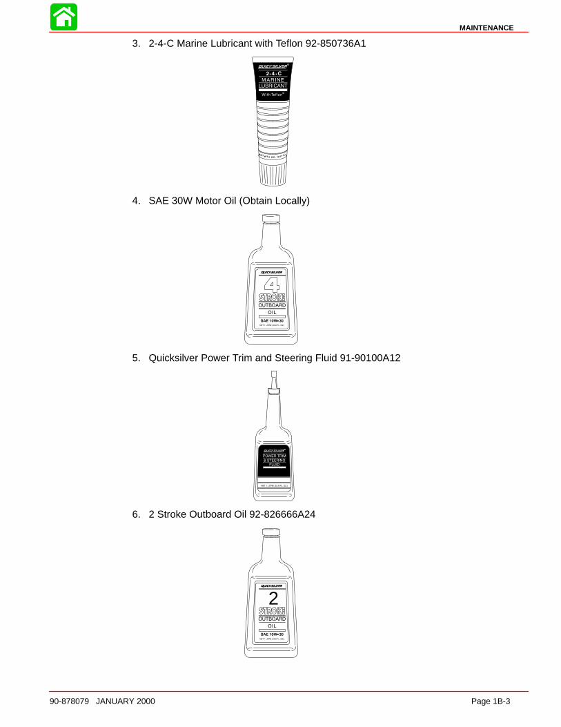
3. 2-4-C Marine Lubricant with Teflon 92-850736A1
4. SAE 30W Motor Oil (Obtain Locally)
5. Quicksilver Power Trim and Steering Fluid 91-90100A12
6. 2 Stroke Outboard Oil 92-826666A24
2
MAINTENANCE
Page 1B-4 90-878079 JANUARY 2000
Inspection and Maintenance Schedule
Before Each Use1. Check that lanyard stop switch stops the engine.
2. Visually inspect the fuel system for deterioration or leaks.
3. Check outboard for tightness on transom.
4. Check steering system for binding or loose components.
5. Visually check steering link rod fasteners for proper tightness.
6. Check propeller blades for damage.
After Each Use1. Flush out the outboard cooling system if operating in salt or polluted water.
2. Wash off all salt deposits and flush out the exhaust outlet of the propeller and gearcase with fresh water if operating in salt water.
Every 100 Hours of Use or Once Yearly, Whichever Occurs First1. Lubricate all lubrication points. Lubricate more frequently when used in salt water.
2. Inspect and clean spark plugs.
3. Check engine fuel filter for contaminants – Carburetor models.
4. Replace water separating fuel filter – EFI models.
5. Replace compressor air intake filter.
6. Check corrosion control anodes. Check more frequently when used in salt water.
7. Drain and replace gear case lubricant.
8. Lubricate splines on the drive shaft and shift shaft.∗9. Check power trim fluid.
10. Inspect battery.
11. Check control cable adjustments.∗12. Check tightness of bolts, nuts, and other fasteners.
13. Replace water pump impeller (more often if overheating occurs or reduced waterpressure is noted).∗
∗ These items should be serviced by an authorized dealer.
MAINTENANCE
90-878079 JANUARY 2000 Page 1B-5
Flushing Engine
Flushing Cooling System – Using Cowl Flush PlugFlush the internal water passages of the outboard with fresh water after each use in salt,polluted or muddy water. This will help prevent a buildup of deposits from clogging theinternal water passages.
NOTE: Engine can be stopped or running at idle speed when flushing the cooling system.Do not flush engine using a water system that exceeds 45 psi.
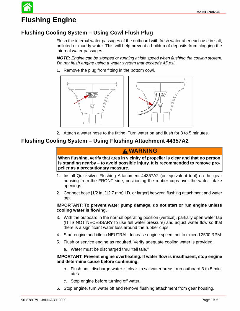
1. Remove the plug from fitting in the bottom cowl.
2. Attach a water hose to the fitting. Turn water on and flush for 3 to 5 minutes.
Flushing Cooling System – Using Flushing Attachment 44357A2
WARNINGWhen flushing, verify that area in vicinity of propeller is clear and that no personis standing nearby – to avoid possible injur y. It is recommended to remove pro-peller as a precautionary measure.
1. Install Quicksilver Flushing Attachment 44357A2 (or equivalent tool) on the gearhousing from the FRONT side, positioning the rubber cups over the water intakeopenings.
2. Connect hose [1/2 in. (12.7 mm) I.D. or larger] between flushing attachment and watertap.
IMPORTANT: To prevent water pump damage, do not start or run engine unlesscooling water is flowing.
3. With the outboard in the normal operating position (vertical), partially open water tap(IT IS NOT NECESSARY to use full water pressure) and adjust water flow so thatthere is a significant water loss around the rubber cups.
4. Start engine and idle in NEUTRAL. Increase engine speed, not to exceed 2500 RPM.
5. Flush or service engine as required. Verify adequate cooling water is provided.
a. Water must be discharged thru “tell tale.”
IMPORTANT: Prevent engine overheating. If water flow is insufficient, stop engineand determine cause before continuing.
b. Flush until discharge water is clear. In saltwater areas, run outboard 3 to 5 min-utes.
c. Stop engine before turning off water.
6. Stop engine, turn water off and remove flushing attachment from gear housing.
MAINTENANCE
Page 1B-6 90-878079 JANUARY 2000
IMPORTANT: While and after flushing, keep outboard in upright position until allwater has drained from drive shaft housing to prevent water from entering the pow-erhead via drive shaft housing and exhaust ports.
Fuel System
WARNINGAvoid serious injury or death from gasoline fire or explosion. Carefully follow allfuel system service instructions. Always stop the engine and DO NOT smoke orallow open flames or sparks in the area while servicing any part of the fuel sys-tem.
Before servicing any part of the fuel system, stop engine and disconnect the battery. Drainthe fuel system completely. Use an approved container to collect and store fuel. Wipe upany spillage immediately. Material used to contain spillage must be disposed of in an ap-proved receptacle. Any fuel system service must be performed in a well ventilated area.Inspect any completed service work for sign of fuel leakage.
Fuel Line InspectionVisually inspect the fuel line and primer bulb for cracks, swelling, leaks, hardness, or othersigns of deterioration or damage. If any of these conditions is found, the fuel line or primerbulb must be replaced.
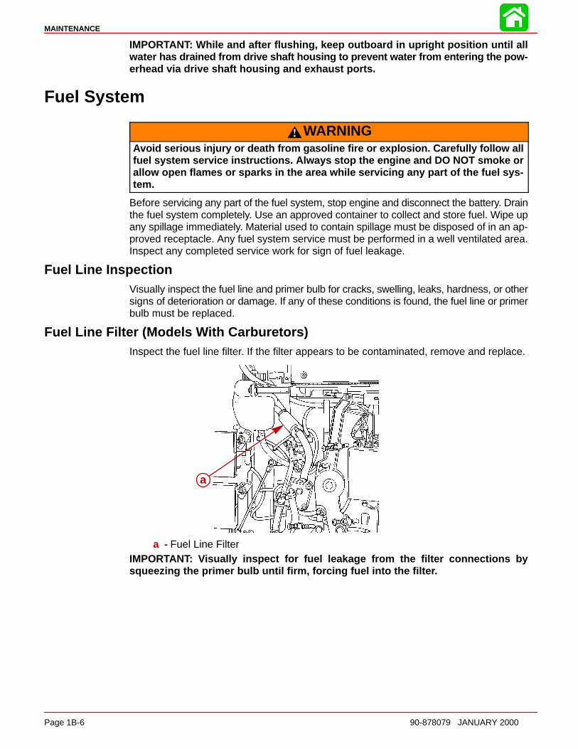
Fuel Line Filter (Models With Carburetors)Inspect the fuel line filter. If the filter appears to be contaminated, remove and replace.
a
a - Fuel Line FilterIMPORTANT: Visually inspect for fuel leakage from the filter connections bysqueezing the primer bulb until firm, forcing fuel into the filte r.
MAINTENANCE
90-878079 JANUARY 2000 Page 1B-7
Water Separating Fuel Filter – EFI ModelsNOTE: The warning system will turn on when water in the fuel filter reaches the full level.
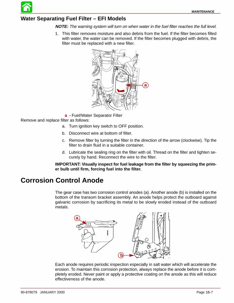
1. This filter removes moisture and also debris from the fuel. If the filter becomes filledwith water, the water can be removed. If the filter becomes plugged with debris, thefilter must be replaced with a new filter.
a
a - Fuel/Water Separator FilterRemove and replace filter as follows:
a. Turn ignition key switch to OFF position.
b. Disconnect wire at bottom of filter.
c. Remove filter by turning the filter in the direction of the arrow (clockwise). Tip thefilter to drain fluid in a suitable container.
d. Lubricate the sealing ring on the filter with oil. Thread on the filter and tighten se-curely by hand. Reconnect the wire to the filter.
IMPORTANT: Visually inspect for fuel leakage from the filter by squeezing the prim-er bulb until firm, forcing fuel into the filte r.
Corrosion Control Anode
The gear case has two corrosion control anodes (a). Another anode (b) is installed on thebottom of the transom bracket assembly. An anode helps protect the outboard againstgalvanic corrosion by sacrificing its metal to be slowly eroded instead of the outboardmetals.
a
b
Each anode requires periodic inspection especially in salt water which will accelerate theerosion. To maintain this corrosion protection, always replace the anode before it is com-pletely eroded. Never paint or apply a protective coating on the anode as this will reduceeffectiveness of the anode.
MAINTENANCE
Page 1B-8 90-878079 JANUARY 2000
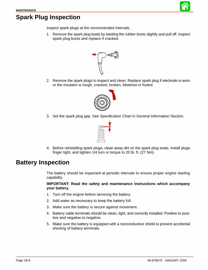
Spark Plug Inspection
Inspect spark plugs at the recommended intervals.
1. Remove the spark plug leads by twisting the rubber boots slightly and pull off. Inspectspark plug boots and replace if cracked.
2. Remove the spark plugs to inspect and clean. Replace spark plug if electrode is wornor the insulator is rough, cracked, broken, blistered or fouled.
3. Set the spark plug gap. See Specification Chart in General Information Section.
4. Before reinstalling spark plugs, clean away dirt on the spark plug seats. Install plugsfinger tight, and tighten 1/4 turn or torque to 20 lb. ft. (27 Nm).
Battery Inspection
The battery should be inspected at periodic intervals to ensure proper engine startingcapability.
IMPORTANT: Read the safety and maintenance instructions which accompanyyour batter y.
1. Turn off the engine before servicing the battery.
2. Add water as necessary to keep the battery full.
3. Make sure the battery is secure against movement.
4. Battery cable terminals should be clean, tight, and correctly installed. Positive to posi-tive and negative to negative.
5. Make sure the battery is equipped with a nonconductive shield to prevent accidentalshorting of battery terminals.

MAINTENANCE
90-878079 JANUARY 2000 Page 1B-9
Fuse Replacement
IMPORTANT: Always carry spare SFE 20 AMP fuses.
The electrical wiring circuits on the outboard are protected from overload by fuses in thewiring. If a fuse is blown, try to locate and correct the cause of the overload. If the causeis not found, the fuse may blow again.
1. Open the fuse holder and look at the silver colored band inside the fuse. If band isbroken, replace the fuse. Replace fuse with a new fuse with the same rating.
2. The fuses and circuits are identified as follows:
a. Accessories and Starting Circuit – 20 AMP Fuse.
b. Upper Voltage Regulator – 20 AMP Fuse.
c. Lower Voltage Regulator – 20 AMP Fuse.
c
b
a
Lubrication Points
Lubricate Point 1 with Quicksilver Special Lubricant 101.
1. Trim Rod Ball Ends – Turn the ball ends to work the lubricant into the ball sockets.
11
MAINTENANCE
Page 1B-10 90-878079 JANUARY 2000
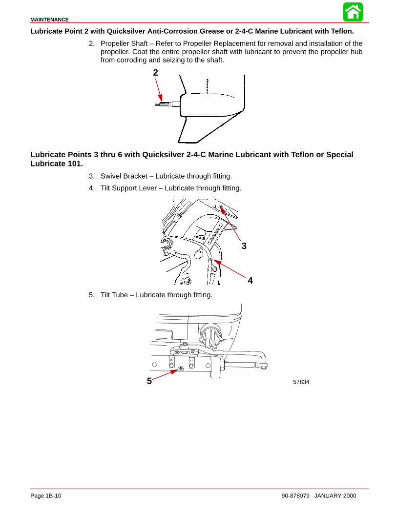
Lubricate Point 2 with Quicksilver Anti-Corrosion Grease or 2-4-C Marine Lubricant with Teflon.
2. Propeller Shaft – Refer to Propeller Replacement for removal and installation of thepropeller. Coat the entire propeller shaft with lubricant to prevent the propeller hubfrom corroding and seizing to the shaft.
2
Lubricate Points 3 thru 6 with Quicksilver 2-4-C Marine Lubricant with Teflon or SpecialLubricate 101.
3. Swivel Bracket – Lubricate through fitting.
4. Tilt Support Lever – Lubricate through fitting.
3
4
5. Tilt Tube – Lubricate through fitting.
578345
MAINTENANCE
90-878079 JANUARY 2000 Page 1B-11
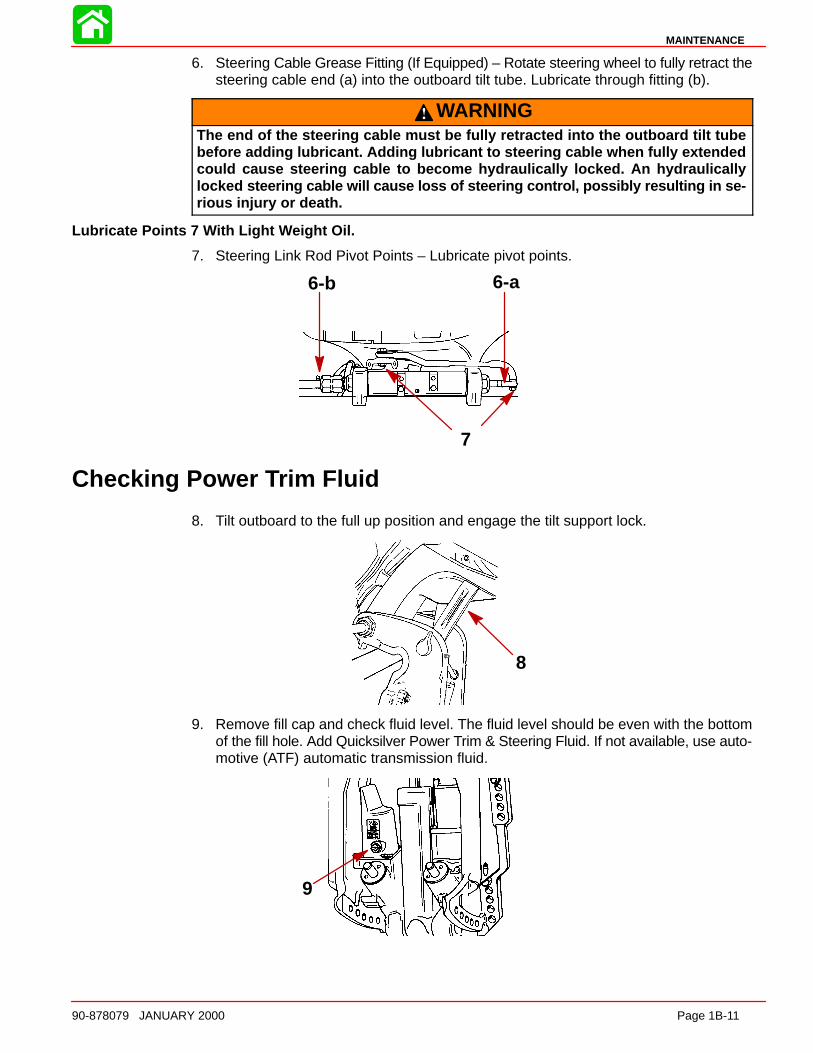
6. Steering Cable Grease Fitting (If Equipped) – Rotate steering wheel to fully retract thesteering cable end (a) into the outboard tilt tube. Lubricate through fitting (b).
WARNINGThe end of the steering cable must be fully retracted into the outboard tilt tubebefore adding lubricant. Adding lubricant to steering cable when fully extendedcould cause steering cable to become hydraulically locked. An hydraulicallylocked steering cable will cause loss of steering control, possibly resulting in se-rious injury or death.
Lubricate Points 7 With Light Weight Oil.
7. Steering Link Rod Pivot Points – Lubricate pivot points.
7
6-b 6-a
Checking Power Trim Fluid
8. Tilt outboard to the full up position and engage the tilt support lock.
8
9. Remove fill cap and check fluid level. The fluid level should be even with the bottomof the fill hole. Add Quicksilver Power Trim & Steering Fluid. If not available, use auto-motive (ATF) automatic transmission fluid.
9

MAINTENANCE
Page 1B-12 90-878079 JANUARY 2000
Gear Case Lubrication
When adding or changing gear case lubricant, visually check for the presence of waterin the lubricant. If water is present, it may have settled to the bottom and will drain out priorto the lubricant, or it may be mixed with the lubricant, giving it a milky colored appearance.If water is noticed, have the gear case checked by your dealer.Water in the lubricant mayresult in premature bearing failure or, in freezing temperatures, will turn to ice and damagethe gear case.
DRAINING GEAR CASE
NOTE: Some models may have the vent and fill/drain plugs on the opposite side.
1. Place outboard in a vertical operating position.
2. Place drain pan below outboard.
3. Remove vent plug and fill/drain plug and drain lubricant.
3
2 1
GEAR CASE LUBRICANT CA PACITY
Gear case lubricant capacity is approximately 22.5 fl. oz. (665 ml).
MAINTENANCE
90-878079 JANUARY 2000 Page 1B-13
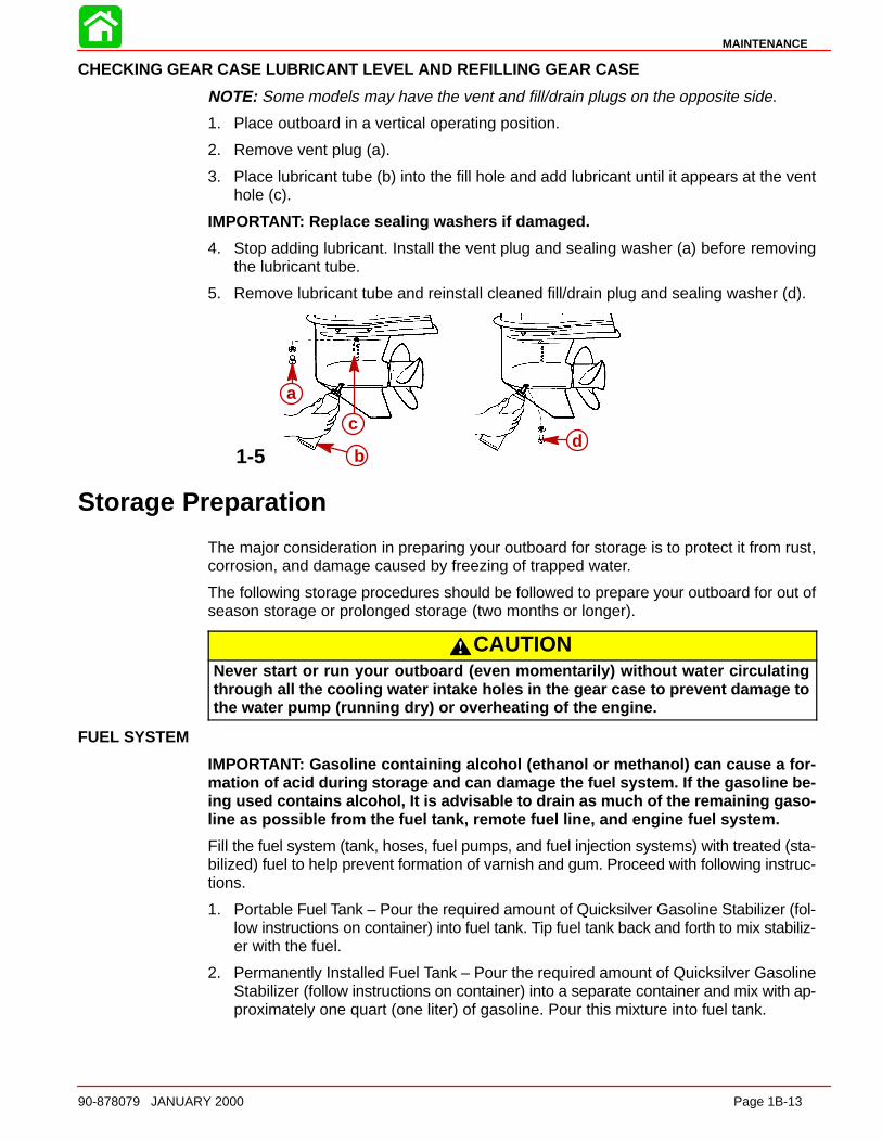
CHECKING GEAR CASE LUBRICANT LEVEL AND REFILLING GEAR CASE
NOTE: Some models may have the vent and fill/drain plugs on the opposite side.
1. Place outboard in a vertical operating position.
2. Remove vent plug (a).
3. Place lubricant tube (b) into the fill hole and add lubricant until it appears at the venthole (c).
IMPORTANT: Replace sealing washers if damaged.
4. Stop adding lubricant. Install the vent plug and sealing washer (a) before removingthe lubricant tube.
5. Remove lubricant tube and reinstall cleaned fill/drain plug and sealing washer (d).
1-5
a
b
cd
Storage Preparation
The major consideration in preparing your outboard for storage is to protect it from rust,corrosion, and damage caused by freezing of trapped water.
The following storage procedures should be followed to prepare your outboard for out ofseason storage or prolonged storage (two months or longer).
CAUTIONNever start or run your outboard (even momentarily) without water circulatingthrough all the cooling water intake holes in the gear case to prevent damage tothe water pump (running dry) or overheating of the engine.
FUEL SYSTEM
IMPORTANT: Gasoline containing alcohol (ethanol or methanol) can cause a for-mation of acid during storage and can damage the fuel system. If the gasoline be-ing used contains alcohol, It is advisable to drain as much of the remaining gaso-line as possible from the fuel tank, remote fuel line, and engine fuel system.
Fill the fuel system (tank, hoses, fuel pumps, and fuel injection systems) with treated (sta-bilized) fuel to help prevent formation of varnish and gum. Proceed with following instruc-tions.
1. Portable Fuel Tank – Pour the required amount of Quicksilver Gasoline Stabilizer (fol-low instructions on container) into fuel tank. Tip fuel tank back and forth to mix stabiliz-er with the fuel.
2. Permanently Installed Fuel Tank – Pour the required amount of Quicksilver GasolineStabilizer (follow instructions on container) into a separate container and mix with ap-proximately one quart (one liter) of gasoline. Pour this mixture into fuel tank.
MAINTENANCE
Page 1B-14 90-878079 JANUARY 2000
3. Place the outboard in water or connect flushing attachment for circulating coolingwater. Run the engine at 2000 rpm for 10 minutes to allow treated fuel to fill the fuelsystem.
PROTECTING INTERNAL ENGINE COMPONENTS
NOTE: Make sure the fuel system has been prepared for storage.Carburetor Models
1. Remove carburetor cover.
2. Place the outboard in water or connect flushing attachment for circulating cooling wa-ter. Start the engine and let it run in neutral to warm up.
3. With engine running at fast idle, stop the fuel flow by kinking the remote fuel line andrun engine until it stops, draining the fuel system. When engine begins to stall, quicklyspray Mercury Precision or Quicksilver Storage Seal into carburetors until enginestops from lack of fuel.
4. Remove the spark plugs and pour in 1 oz. (295 ml) of outboard oil around the insideof each cylinder.
5. Rotate the flywheel manually several times to distribute the oil in the cylinders. Rein-stall spark plugs.
Electronic Fuel Injection (EFI) ModelsNOTE: Make sure the fuel system has been prepared for storage.
1. Remove the spark plugs and add approximately one ounce (30ml) of engine oil intoeach spark plug hole. Rotate the flywheel manually several times to distribute the oilin the cylinders. Reinstall spark plugs.
2. Remove the water separating fuel filter and empty contents into a suitable container.Refer to Maintenance Section for removal and installation of filter. Replace fuel filterannually, or every 100 Hours of operation, or if large amount of fuel contamination ispresent.
PROTECTING EXTERNAL OUTBOARD COMPONENTS
1. Lubricate all outboard components listed in the Inspection and Maintenance Sched-ule.
2. Touch up any paint nicks. See your dealer for touch-up paint.
3. Spray Quicksilver Corrosion Guard on external metal surfaces (except corrosion con-trol anodes).
GEAR CASE
Drain and refill the gear case lubricant (refer to maintenance procedure).
POSITIONING OUTBOARD FOR STORAGE
Store outboard in an upright (vertical) position to allow water to drain out of outboard.
CAUTIONIf outboard is stored tilted up in freezing temperature, trapped cooling water orrain water that may have entered the propeller exhaust outlet in the gear casecould freeze and cause damage to the outboard.
MAINTENANCE
90-878079 JANUARY 2000 Page 1B-15
BATTERY STORAGE
1. Follow the battery manufacturers instructions for storage and recharging.
2. Remove the battery from the boat and check water level. Recharge if necessary.
3. Store the battery in a cool, dry place.
4. Periodically check the water level and recharge the battery during storage.

1C
GENERAL INFORMATION
90-878079 JANUARY 2000 Page 1C-1
IMPORTANT INFORMATIONSection 1C - General Information
Table of Contents
Serial Number Location 1C-1. . . . . . . . . . . . . . . . . . . . . . . Conditions Affecting Performance 1C-1. . . . . . . . . . . . . .
Weather 1C-1. . . . . . . . . . . . . . . . . . . . . . . . . . . . . . . . . . Boat 1C-2. . . . . . . . . . . . . . . . . . . . . . . . . . . . . . . . . . . . . Trim 1C-3. . . . . . . . . . . . . . . . . . . . . . . . . . . . . . . . . . . . . Engine 1C-5. . . . . . . . . . . . . . . . . . . . . . . . . . . . . . . . . . . Engine Compression 1C-5. . . . . . . . . . . . . . . . . . . . . . .
Following Complete Submersion 1C-6. . . . . . . . . . . . . . . Salt Water Submersion 1C-6. . . . . . . . . . . . . . . . . . . . . Submerged While Running 1C-6. . . . . . . . . . . . . . . . .
Model 135/150/200 Powerhead Front View 1C-8. . . . . . Model 135/150/200 Powerhead Starboard View 1C-9. . Model 135/150/200 Powerhead Port View 1C-10. . . . . Model 135/150/200 Powerhead Top View 1C-11. . . . . . . Model 135/150/200 Powerhead Aft View 1C-12. . . . . .
Model 150 XRI/175 XRI/200 XRIPowerhead Front View 1C-13. . . . . . . . . . . . . . . . . . . . . . Model 150 XRI/175 XRI/200 XRIPowerhead Starboard View 1C-14. . . . . . . . . . . . . . . . . . Model 150 XRI/175 XRI/200 XRIPowerhead Port View 1C-15. . . . . . . . . . . . . . . . . . . . . . . Model 150 XRI/175 XRI/200 XRIPowerhead Top View 1C-16. . . . . . . . . . . . . . . . . . . . . . . Model 150 XRI/175 XRI/200 XRIPowerhead Aft View 1C-17. . . . . . . . . . . . . . . . . . . . . . . . Painting Procedures 1C-18. . . . . . . . . . . . . . . . . . . . . . . .
Cleaning & Painting Aluminum Propellers& Gear Housings 1C-18. . . . . . . . . . . . . . . . . . . . . . . .
Decal Application 1C-19. . . . . . . . . . . . . . . . . . . . . . . . . . . Decal Removal 1C-19. . . . . . . . . . . . . . . . . . . . . . . . . . Instructions for “Wet” Application 1C-19. . . . . . . . . .
Serial Number Location
The engine serial number is located on the top of the engine block. A serial number is alsolocated on the starboard side of the swivel bracket.
19XX
XX
OGXXXXXX
XXXX
a
ed
cb
a - Serial Numberb - Model Yearc - Model Descriptiond - Year Manufacturede - Certified Europe Insignia
GENERAL INFORMATION
Page 1C-2 90-878079 JANUARY 2000
Conditions Affecting Performance
Weather
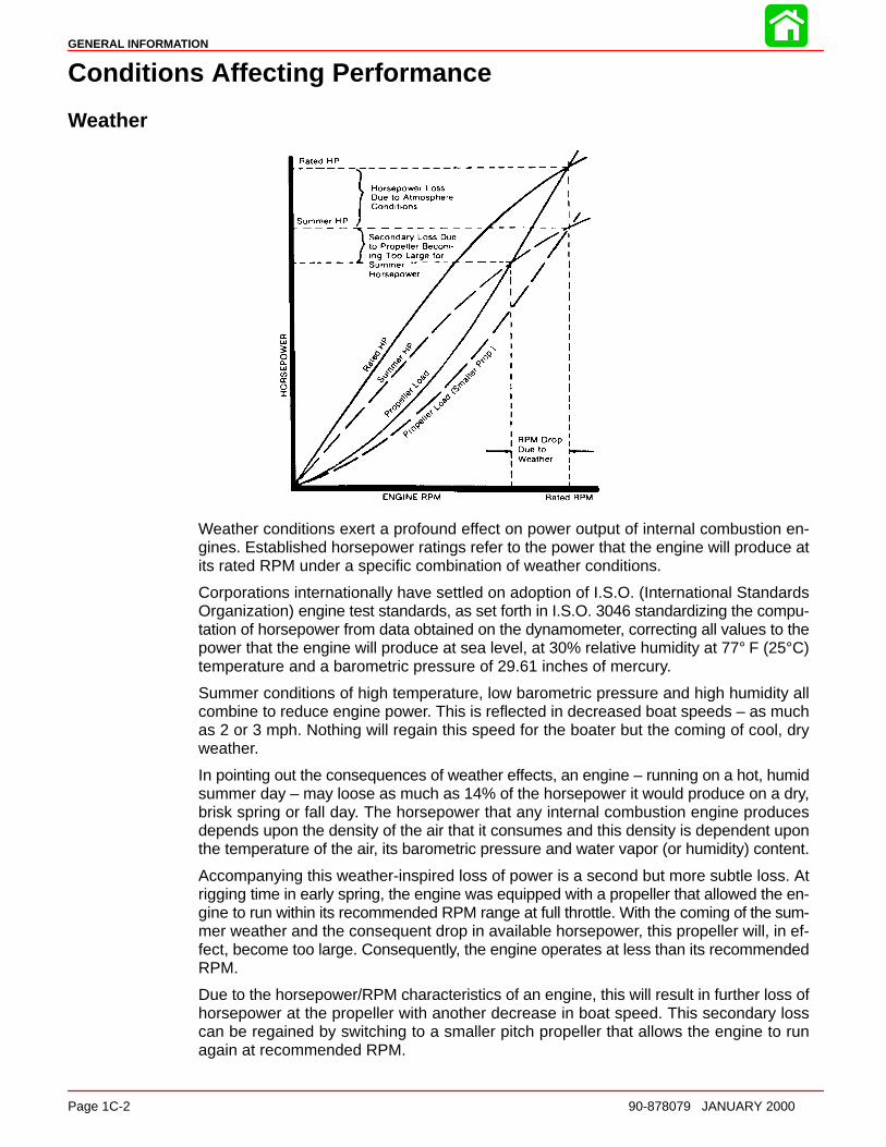
Weather conditions exert a profound effect on power output of internal combustion en-gines. Established horsepower ratings refer to the power that the engine will produce atits rated RPM under a specific combination of weather conditions.
Corporations internationally have settled on adoption of I.S.O. (International StandardsOrganization) engine test standards, as set forth in I.S.O. 3046 standardizing the compu-tation of horsepower from data obtained on the dynamometer, correcting all values to thepower that the engine will produce at sea level, at 30% relative humidity at 77° F (25°C)temperature and a barometric pressure of 29.61 inches of mercury.
Summer conditions of high temperature, low barometric pressure and high humidity allcombine to reduce engine power. This is reflected in decreased boat speeds – as muchas 2 or 3 mph. Nothing will regain this speed for the boater but the coming of cool, dryweather.
In pointing out the consequences of weather effects, an engine – running on a hot, humidsummer day – may loose as much as 14% of the horsepower it would produce on a dry,brisk spring or fall day. The horsepower that any internal combustion engine producesdepends upon the density of the air that it consumes and this density is dependent uponthe temperature of the air, its barometric pressure and water vapor (or humidity) content.
Accompanying this weather-inspired loss of power is a second but more subtle loss. Atrigging time in early spring, the engine was equipped with a propeller that allowed the en-gine to run within its recommended RPM range at full throttle. With the coming of the sum-mer weather and the consequent drop in available horsepower, this propeller will, in ef-fect, become too large. Consequently, the engine operates at less than its recommendedRPM.
Due to the horsepower/RPM characteristics of an engine, this will result in further loss ofhorsepower at the propeller with another decrease in boat speed. This secondary losscan be regained by switching to a smaller pitch propeller that allows the engine to runagain at recommended RPM.
GENERAL INFORMATION
90-878079 JANUARY 2000 Page 1C-3
To obtain optimum engine performance under changing weather conditions, the engineMUST be propped to allow it to operate at or near the top end of the recommended maxi-mum RPM range at wide-open-throttle with a normal boat load.
This will allow the engine to develop full power while operating in an RPM range that dis-courages damaging detonation.
BoatWEIGHT DISTRIBUTION
1. Proper positioning of the weight inside the boat (persons and gear) has a significanteffect on the boat’s performance, for example:
a. Shifting weight to the rear (stern)
(1.)Generally increases top speed.
(2.) If in excess, can cause the boat to porpoise.
(3.)Can make the bow bounce excessively in choppy water.
(4.)Will increase the danger of the following wave splashing into the boat whencoming off plane.
b. Shifting weight to the front (bow)
(1.) Improves ease of planing off.
(2.)Generally improves rough water ride.
(3.) If excessive, can make the boat veer back-and-forth (bow steer).
BOTTOM
1. Boat Bottom: For maximum speed, a boat bottom should be nearly a flat plane whereit contacts the water and particularly straight and smooth in fore-and-aft direction.
a. Hook: Exists when bottom is concave in fore-and -aft direction when viewed fromthe side. When boat is planing, “hook” causes more lift on bottom near transomand allows bow to drop, thus greatly increasing wetted surface and reducing boatspeed. “Hook” frequently is caused by supporting boat too far ahead of transomwhile hauling on a trailer or during storage.
b. Rocker: The reverse of hook and much less common. “Rocker” exists if bottomis convex in fore-and-aft direction when viewed from the side, and boat has strongtendency to porpoise.
c. Surfac e Roughness: Moss, barnacles, etc., on boat or corrosion of motor’s gearhousing increase skin friction and cause speed loss. Clean surfaces when neces-sary.
d. Gear Housing: If unit is left in the water, marine vegetation may accumulate overa period of time. This growth MUST be removed from unit before operation, as itmay clog the water inlet holes in the gear housing and cause the engine to over-heat.
GENERAL INFORMATION
Page 1C-4 90-878079 JANUARY 2000
TrimTRIMMING OUTBOARD “OUT” (“UP”)
WARNINGExcessive trim “out” also may reduce the stability of some high speed hulls. Tocorrec t instability at high speed, reduce the power GRADUAL LY and trim the out-board “in” slightly before resuming high speed operation. (Rapid reduction inpower will cause a sudden change of steering torque and may cause additionalmomentary boat instabilit y.)
1. Will lift bow of boat, generally increasing top speed.
2. Transfers steering torque harder to left on single outboard installations below 23 in.(584mm) transom height.
3. Increases clearance over submerged objects.
4. In excess, can cause porpoising and/or ventilation.
5. If trimmed out beyond the water pickup, reduced water supply can cause overheatingresulting in engine damage.
TRIMMING OUTBOARD “IN” (“DOWN”) CHARACTERISTICS
WARNINGExcessive speed at minimum trim “in” may cause undesirable and/or unsafesteering conditions. Each boat should be tested for handling characteristics afterany adjustment is made to the angle (trim adjustment bolt relocation.)
1. Will help planing off, particularly with a heavy load.
2. Usually improves ride in choppy water.
3. In excess, can cause boat to veer to the left or right (bow steer).
4. Transfers steering torque harder to right (or less to the left) on single outboard installa-tions.
5. Improves planing speed acceleration (by moving trim adjustment bolt one hole closerto transom).
WATER ABSORPTION
It is imperative that all through hull fasteners be coated with a quality marine sealer at timeof installation. Water intrusion into the transom core and/or inner hull will result in addition-al boat weight (reduced boat performance), hull decay and eventual structural failure.
CAVITATION
Cavitation is caused by water vapor bubbles forming either from a sharp edge or angleon the gear case or from an irregularity in the propeller blade itself. These vapor bubblesflow back and collapse when striking the surface of the propeller blade resulting in the ero-sion of the propeller blade surface. If allowed to continue, eventual blade failure (break-age) will occur.
VENTILATION
Ventilation occurs when air is drawn from the water’s surface (excessive trim out angle)or from the engine exhaust flow (wrong propeller/propeller hardware installed or gearcase labyrinth seal worn) into the propeller blades. These air bubbles strike the propellerblade surface and cause erosion of the blade surface. If allowed to continue, eventualblade failure (breakage) will occur.

GENERAL INFORMATION
90-878079 JANUARY 2000 Page 1C-5
EngineDETONATION
Detonation in a 2-cycle engine resembles the “pinging” heard in an automobile engine.It can be otherwise described as a tin-like “rattling” or “plinking” sound.
Detonation is an explosion of an unburned portion of the fuel/air charge after the sparkplug has fired. Detonation creates severe shock waves in the engine, and these shockwaves often find or create a weakness: The dome of a piston, cylinder head/gasket, pistonrings or piston ring lands, piston pin and roller bearings.
A few of the most common causes of detonation in a marine 2-cycle application are asfollows:
• Over-advanced ignition timing.
• Use of low octane gasoline.
• Propeller pitch too high (engine RPM below recommended maximum range).
• Lean fuel mixture at or near wide-open-throttle.
• Spark plugs (heat range too hot – incorrect reach – cross-firing).
• Inadequate engine cooling (deteriorated cooling system).
Detonation usually can be prevented if:
1. The engine is correctly set up.
2. Diligent maintenance is applied to combat the detonation causes.
51115
Engine CompressionEngine compression should be checked with engine block warm, throttle shutter wideopen, all spark plugs removed and using a fully charged battery. Normal compression forall cylinders should be 110 to 130 psi (758.5 to 896.4 kPa). Cylinders should not vary morethan 15 psi (103.4 kPa) between one another. A variance of more than 15 psi would indi-cate the need for a power head inspection/disassembly.
GENERAL INFORMATION
Page 1C-6 90-878079 JANUARY 2000
Following Complete Submersion
Salt Water SubmersionDue to the corrosive effect of salt water on internal engine components, complete disas-sembly is necessary before any attempt is made to start the engine.
Submerged While RunningWhen an engine is submerged while running, the possibility of internal engine damageis greatly increased. If, after engine is recovered and with spark plugs removed, enginefails to turn over freely when turning flywheel, the possibility of internal damage (bent con-necting rod and/or bent crankshaft) exists. If this is the case, the powerhead must be dis-assembled.
SUBMERGED ENGINE (FRESH WATER)
IMPORTANT: Engine should be run within 2 hours after recover y, or serious inter-nal damage may occu r. If unable to start engine in this period, disassemble engineand clean all parts. Apply oil as soon as possible.
NOTE: If sand has entered the air intake on the engine, do not attempt to the start theengine. Sand will cause internal engine damage. disassembly is required to clean all in-ternal engine components of sand.
1. Recover engine from water as quickly as possible.
2. Remove cowling.
3. Clean the exterior of the outboard with fresh water.
4. Dry all wiring and electrical components using compressed air.
5. Drain water from fuel system as follows:
a. Disconnect remote fuel hose from engine.
b. EFI Models – Remove drain plug from vapor separator and drain fuel/water. Rein-stall plug after draining.
c. EFI Models – Remove the water separating fuel filter and empty contents.
6. Remove spark plugs and get as much water as possible out of powerhead. Most watercan be eliminated by placing engine in a horizontal position (with spark plug holesdown) and rotating flywheel.
7. Pour alcohol into carburetor throats (alcohol will absorbed water). Again rotate fly-wheel.
8. Turn engine over (place spark plug openings down) and pour engine oil into throat ofcarburetors while rotating flywheel to distribute oil throughout crankcase.
9. Again turn engine over and pour approximately one teaspoon of engine oil into eachspark plug opening. Again rotate flywheel to distribute oil in cylinders.
10. Remove and clean carburetors and fuel pump assembly.
11. Dry all wiring and electrical components using compressed air.
12. Disassemble the engine starter motor and dry the brush contacts, armature and othercorrodible parts.
13. Reinstall spark plugs, carburetors and fuel pump.
14. Drain water from the oil injection system as follows:

GENERAL INFORMATION
90-878079 JANUARY 2000 Page 1C-7
a. Remove remote oil hose (black without blue stripe) from pulse fitting on starboardside of engine.
b. Drain any water from hose and reconnect.
c. If water was present in hose, check for water in the remote oil tank. Drain tank ifwater is present.
15. Attempt to start engine, using a fresh fuel source. If engine starts, it should be run forat least one hour to eliminate any water in engine.
16. If engine fails to start, determine cause (fuel, electrical or mechanical). Engine shouldbe run within 2 hours after recovery of outboard from water, or serious internal dam-age may occur. If unable to start engine in this period, disassemble engine and cleanall parts. Apply oil as soon as possible.
GENERAL INFORMATION
Page 1C-8 90-878079 JANUARY 2000
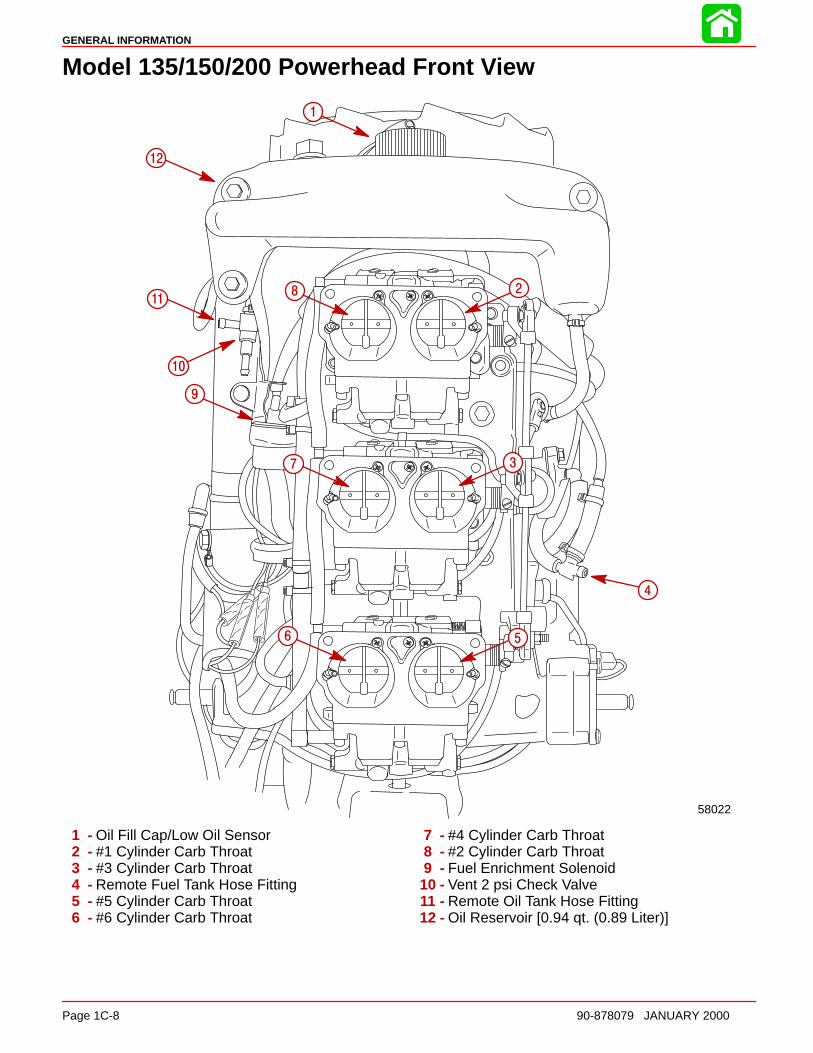
Model 135/150/200 Powerhead Front View
58022
1
2
3
4
56
7
8
9
10
11
12
1 - Oil Fill Cap/Low Oil Sensor2 - #1 Cylinder Carb Throat3 - #3 Cylinder Carb Throat4 - Remote Fuel Tank Hose Fitting5 - #5 Cylinder Carb Throat6 - #6 Cylinder Carb Throat
7 - #4 Cylinder Carb Throat8 - #2 Cylinder Carb Throat9 - Fuel Enrichment Solenoid
10 - Vent 2 psi Check Valve11 - Remote Oil Tank Hose Fitting12 - Oil Reservoir [0.94 qt. (0.89 Liter)]
GENERAL INFORMATION
90-878079 JANUARY 2000 Page 1C-9
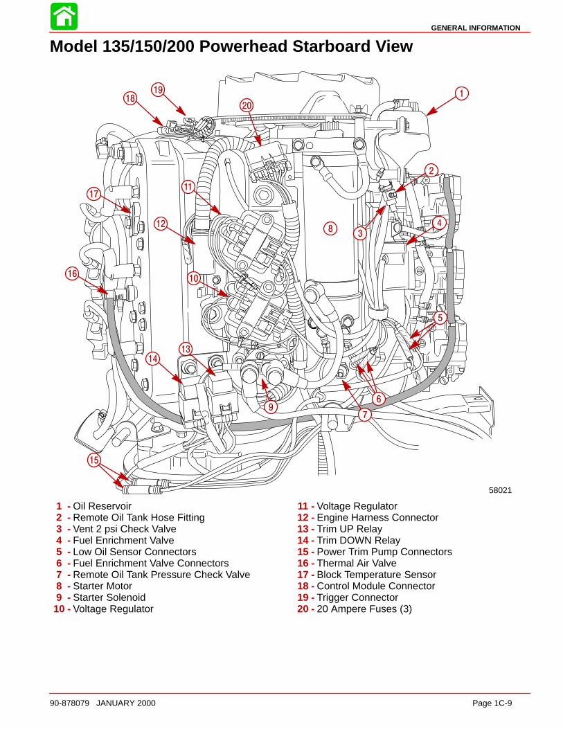
Model 135/150/200 Powerhead Starboard View
58021
17
12
11
1819
20
1
2
83
4
5
6
79
13
14
15
1610
1 - Oil Reservoir2 - Remote Oil Tank Hose Fitting3 - Vent 2 psi Check Valve4 - Fuel Enrichment Valve5 - Low Oil Sensor Connectors6 - Fuel Enrichment Valve Connectors7 - Remote Oil Tank Pressure Check Valve8 - Starter Motor9 - Starter Solenoid
10 - Voltage Regulator
11 - Voltage Regulator12 - Engine Harness Connector13 - Trim UP Relay14 - Trim DOWN Relay15 - Power Trim Pump Connectors16 - Thermal Air Valve17 - Block Temperature Sensor18 - Control Module Connector19 - Trigger Connector20 - 20 Ampere Fuses (3)
GENERAL INFORMATION
Page 1C-10 90-878079 JANUARY 2000
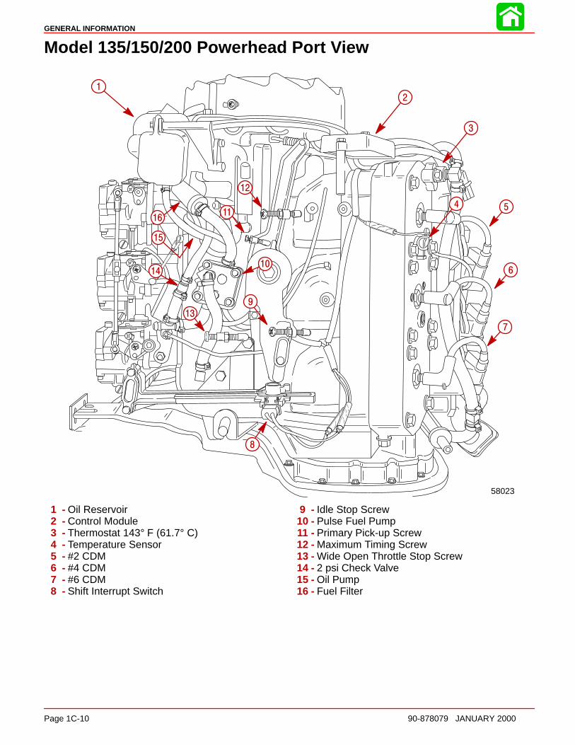
Model 135/150/200 Powerhead Port View
58023
1
2
3
4 5
6
7
8
9
10
11
12
13
15
16
14
1 - Oil Reservoir2 - Control Module3 - Thermostat 143° F (61.7° C)4 - Temperature Sensor5 - #2 CDM6 - #4 CDM7 - #6 CDM8 - Shift Interrupt Switch
9 - Idle Stop Screw10 - Pulse Fuel Pump11 - Primary Pick-up Screw12 - Maximum Timing Screw13 - Wide Open Throttle Stop Screw14 - 2 psi Check Valve15 - Oil Pump16 - Fuel Filter

GENERAL INFORMATION
90-878079 JANUARY 2000 Page 1C-11
Model 135/150/200 Powerhead Top View
58020
4
3
6
7
8
9
1
2
5
1 - Low Oil Sensor2 - Starter Motor3 - Trigger Harness Connector4 - Control Module Harness Connector5 - Starboard Thermostat (143°F (61.7°C)6 - Water By-Pass Hose7 - Port Thermostat (143°F (61.7°C)8 - Control Module (RPM Limiter, Bias Control,Shift Stabilizer, Idle Stabilizer, and Low Oil Warning9 - Oil Reservoir [0.94 qt. (0.89 Liter)]

GENERAL INFORMATION
Page 1C-12 90-878079 JANUARY 2000
Model 135/150/200 Powerhead Aft View
58024
1
2
3
4
5
6 7
8
9
10
11
12
13
14
15
16
12
17
1 - Port Thermostat [143°F (61.7°C)]2 - Temperature Sensor (Temperature Gauge)3 - #2 CDM4 - #4 CDM5 - #6 CDM6 - Thermostat Outlet Hose to Adaptor Plate7 - Cylinder Block Flush Hose8 - Tell–Tale Hose9 - #5 CDM
10 - #3 CDM11 - #1 CDM12 - Water By-Pass Hose to Poppet Valve Cover13 - Starboard Thermostat [143°F (61.7°C)]14 - Temperature Sensor (Engine Overheat)15 - Thermal Air Valve16 - Thermal Air Hose to Carburetors17 - Trim Motor Bullet Connectors
GENERAL INFORMATION
90-878079 JANUARY 2000 Page 1C-13
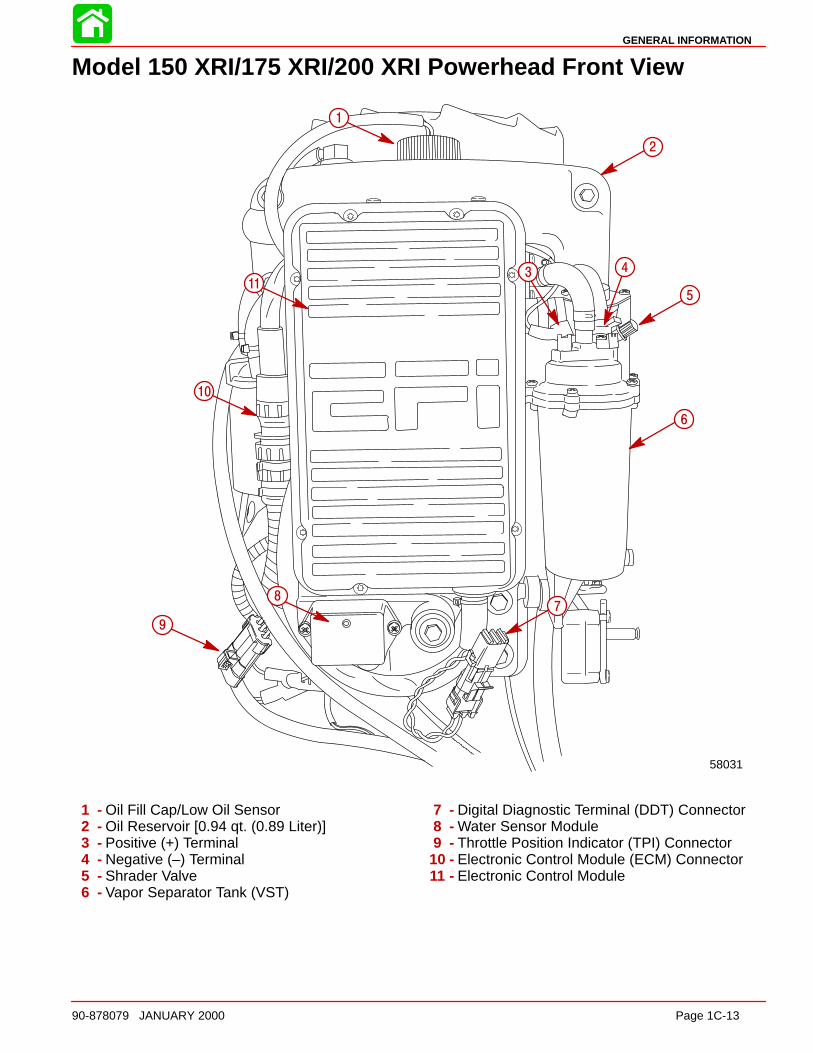
Model 150 XRI/175 XRI/200 XRI Powerhead Front View
58031
1
2
3 4
5
6
78
9
10
11
1 - Oil Fill Cap/Low Oil Sensor2 - Oil Reservoir [0.94 qt. (0.89 Liter)]3 - Positive (+) Terminal4 - Negative (–) Terminal5 - Shrader Valve6 - Vapor Separator Tank (VST)
7 - Digital Diagnostic Terminal (DDT) Connector8 - Water Sensor Module9 - Throttle Position Indicator (TPI) Connector
10 - Electronic Control Module (ECM) Connector11 - Electronic Control Module
GENERAL INFORMATION
Page 1C-14 90-878079 JANUARY 2000
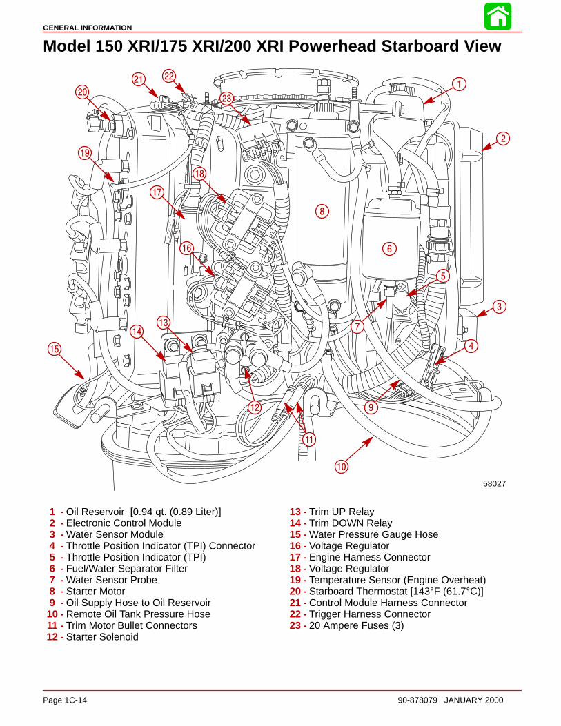
Model 150 XRI/175 XRI/200 XRI Powerhead Starboard View
58027
1
4
5
6
7
8
2
3
9
10
11
12
1314
15
16
17
18
19
20
21 22
23
1 - Oil Reservoir [0.94 qt. (0.89 Liter)]2 - Electronic Control Module3 - Water Sensor Module4 - Throttle Position Indicator (TPI) Connector5 - Throttle Position Indicator (TPI)6 - Fuel/Water Separator Filter7 - Water Sensor Probe8 - Starter Motor9 - Oil Supply Hose to Oil Reservoir
10 - Remote Oil Tank Pressure Hose11 - Trim Motor Bullet Connectors12 - Starter Solenoid
13 - Trim UP Relay14 - Trim DOWN Relay15 - Water Pressure Gauge Hose16 - Voltage Regulator17 - Engine Harness Connector18 - Voltage Regulator19 - Temperature Sensor (Engine Overheat)20 - Starboard Thermostat [143°F (61.7°C)]21 - Control Module Harness Connector22 - Trigger Harness Connector23 - 20 Ampere Fuses (3)
GENERAL INFORMATION
90-878079 JANUARY 2000 Page 1C-15
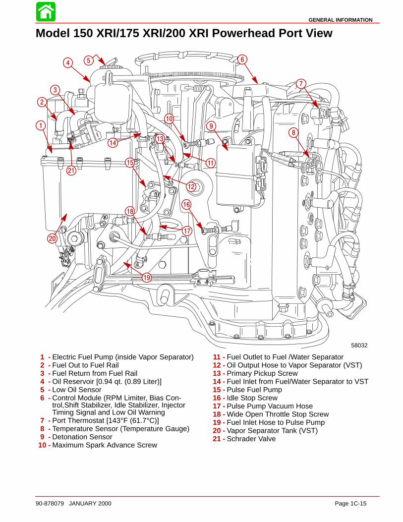
Model 150 XRI/175 XRI/200 XRI Powerhead Port View
58032
1
2
4 5 6
7
89
10
1314
15
12
11
16
17
18
19
20
21
3
1 - Electric Fuel Pump (inside Vapor Separator)2 - Fuel Out to Fuel Rail3 - Fuel Return from Fuel Rail4 - Oil Reservoir [0.94 qt. (0.89 Liter)]5 - Low Oil Sensor6 - Control Module (RPM Limiter, Bias Con-
trol,Shift Stabilizer, Idle Stabilizer, InjectorTiming Signal and Low Oil Warning
7 - Port Thermostat [143°F (61.7°C)]8 - Temperature Sensor (Temperature Gauge)9 - Detonation Sensor
10 - Maximum Spark Advance Screw
11 - Fuel Outlet to Fuel /Water Separator12 - Oil Output Hose to Vapor Separator (VST)13 - Primary Pickup Screw14 - Fuel Inlet from Fuel/Water Separator to VST15 - Pulse Fuel Pump16 - Idle Stop Screw17 - Pulse Pump Vacuum Hose18 - Wide Open Throttle Stop Screw19 - Fuel Inlet Hose to Pulse Pump20 - Vapor Separator Tank (VST)21 - Schrader Valve
GENERAL INFORMATION
Page 1C-16 90-878079 JANUARY 2000
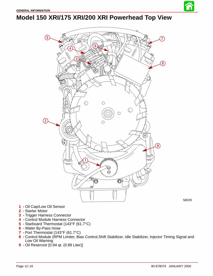
Model 150 XRI/175 XRI/200 XRI Powerhead Top View
58029
1
2
3
4
5
6
7
8
9
1 - Oil Cap/Low Oil Sensor2 - Starter Motor3 - Trigger Harness Connector4 - Control Module Harness Connector5 - Starboard Thermostat (143°F (61.7°C)6 - Water By-Pass Hose7 - Port Thermostat (143°F (61.7°C)8 - Control Module (RPM Limiter, Bias Control,Shift Stabilizer, Idle Stabilizer, Injector Timing Signal and
Low Oil Warning9 - Oil Reservoir [0.94 qt. (0.89 Liter)]

GENERAL INFORMATION
90-878079 JANUARY 2000 Page 1C-17
Model 150 XRI/175 XRI/200 XRI Powerhead Aft View
1
2
3
4
5
9
10
11
12
13
14
12
8
76
15
16
58030
17
1 - Port Thermostat [143°F (61.7°C)]2 - Temperature Sensor (Temperature Gauge)3 - #2 CDM4 - #4 CDM5 - #6 CDM6 - Thermostat Outlet Hose to Adaptor Plate7 - Cylinder Block Flush Hose8 - Tell–Tale Hose9 - #5 CDM
10 - #3 CDM11 - #1 CDM12 - Water By-Pass Hose to Poppet Valve Cover13 - Starboard Thermostat [143°F (61.7°C)]14 - Temperature Sensor (Engine Overheat)15 - Water Pressure Gauge Hose16 - Trim Motor Bullet Connectors17 - Detonation Sensor
GENERAL INFORMATION
Page 1C-18 90-878079 JANUARY 2000
Painting Procedures
Cleaning & Painting Aluminum Propellers & Gear Housings
WARNINGAvoid serious injury from flying debris. Avoid serious injury from airborne par-ticles. Use eye and breathing protection with proper ventilation.
PROPELLERS
1. Sand the entire area to be painted with 3M 120 Regalite Polycut or coarse Scotch-Brite, disc or belts.
2. Feather edges of all broken paint edges. Try not to sand through the primer.
3. Clean the surface to be painted using PPG Industries DX330 Wax and Grease Re-mover or equivalent (Xylene or M.E.K.).
4. If bare metal has been exposed, use Quicksilver’s Light Gray Primer.
5. Allow a minimum of 1 hour dry time and no more than 1 week before applying the finishcoat.
6. Apply the finish coat using Quicksilver’s EDP Propeller Black.
GEAR HOUSINGS
The following procedures should be used in refinishing gear housings. This procedure willprovide the most durable paint system available in the field. The materials recommendedare of high quality and approximate marine requirements. The following procedure willprovide a repaint job that compares with a properly applied factory paint finish. It is recom-mended that the listed materials be purchased from a local Ditzler Automotive Finish Sup-ply Outlet. The minimum package quantity of each material shown following is sufficientto refinish several gear housings.
Procedure:
1. Wash gear housing with a muriatic acid base cleaner to remove any type of marinegrowth, and rinse with water, if necessary.
2. Wash gear housing with soap and water, then rinse.
3. Sand blistered area with 3M 180 grit sandpaper or P180 Gold Film Disc to removepaint blisters only. Feather edge all broken paint edges.
4. Clean gear housing thoroughly with (DX-330) wax and grease remover.
5. Spot repair surfaces where bare metal is exposed with (DX-503) alodine treatment.
IMPORTANT: Do not use any type of aerosol spray paints as the paint will not prop-erly adhere to the surface nor will the coating be sufficiently thick to resist futurepaint blistering.
6. Mix epoxy chromate primer (DP-40) with equal part catalyst (DP-401) per manufac-turers instructions, allowing proper induction period for permeation of the epoxy prim-er and catalyst.
7. Allow a minimum of one hour drying time and no more than one week before top coat-ing assemblies.
8. Use Ditzler Urethane DU9000 for Mercury Black, DU34334 for Mariner Grey, andDU35466 for Force Charcoal, and DU33414M for Sea Ray White. Catalyze all fourcolors with Ditzler DU5 catalyst mixed 1:1 ratio. Reduce with solvents per Ditzler label.
GENERAL INFORMATION
90-878079 JANUARY 2000 Page 1C-19
CAUTIONBe sure to comply with instructions on the label for ventilation and respirators.Using a spray gun, apply one half to one mil even film thickness. Let dr y, flash offfor five minutes and apply another even coat of one half to one mil film thickness.This urethane paint will dry to the touch in a matter of hours, but will remain sensi-tive to scratches and abrasions for a few days.
9. The type of spray gun used will determine the proper reduction ratio of the paint.
IMPORTANT: Do not paint sacrificial zinc trim tab or zinc anode.
10. Cut out a cardboard “plug” for trim tab pocket to keep paint off of mating surface tomaintain good continuity circuitry between trim tab and gear housing.
Decal Application
Decal Removal1. Mark decal location before removal to assure proper alignment of new decal.
2. Carefully soften decal and decal adhesive with a heat gun or heat blower while remov-ing old decal.
3. Clean decal contact area with a 1:1 mixture of isopropyl alcohol and water.
4. Thoroughly dry decal contact area and check for a completely cleaned surface.
Instructions for “ Wet” ApplicationNOTE: The following decal installation instructions are provided for a “Wet” installation.All decals should be applied wet.
TOOLS REQUIRED
1. Plastic Squeegee*
2. Stick Pin
3. Dish Washing Liquid/Detergent without ammonia** “Joy” and “Drift” are known tobe compatible for this process.
** Automotive Body Filler Squeegee
** Do not use a soap that contains petroleum based solvents.
SERVICE TIP: Placement of decals using the “ Wet” application will allow time toposition decal. Read entire installation instructions on this technique before pro-ceeding.
TEMPERATURE
IMPORTANT: Installation of vinyl decals should not be attempted while in directsunlight. Air and surface temperature should be between 60 °F (15°C) and 100°F(38°C) for best application.
SURFACE PREPARATION
IMPORTANT: Do not use a soap or any petroleum based solvents to clean applica-tion surface.
Clean entire application surface with mild dish washing liquid and water. Rinse surfacethoroughly with clean water.
GENERAL INFORMATION
Page 1C-20 90-878079 JANUARY 2000
DECAL APPLIC ATION
1. Mix 1/2 ounce (16 ml) of dish washing liquid in one gallon (4 l) of cool water to use aswetting solution.
NOTE: Leave protective masking, if present, on the face of decal until final steps of decalinstallation. This will ensure that the vinyl decal keeps it’s shape during installation.
2. Place the decal face down on a clean work surface and remove the paper backingfrom “adhesive side” of decal.
3. Using a spray bottle, flood the entire “adhesive side” of the decal with the pre-mixedwetting solution.
4. Flood area where the decal will be positioned with wetting solution.
5. Position pre-wetted decal on wetted surface and slide into position.
6. Starting at the center of the decal, “lightly ” squeegee out the air bubbles and wettingsolution with overlapping strokes to the outer edge of the decal. Continue going overthe decal surface until all wrinkles are gone and adhesive bonds to the cowl surface.
7. Wipe decal surface with soft paper towel or cloth.
8. Wait 10 - 15 minutes.
9. Starting at one corner, “carefully and slowly” pull the masking off the decal surface ata 180° angle.
NOTE: To remove any remaining bubbles, pierce the decal at one end of the bubble withstick pin and press out the entrapped air or wetting solution with your thumb (moving to-ward the puncture).

1D
OUTBOARD MOTOR INSTALLATION
90-878079 JANUARY 2000 Page 1D-1
IMPORTANT INFORMATIONSection 1D - Outboard Motor Installation
Table of Contents
Installation Specifications 1D-1. . . . . . . . . . . . . . . . . . . . . . Lifting Outboard 1D-1. . . . . . . . . . . . . . . . . . . . . . . . . . . . . . Installing Outboard to Boat Transom 1D-2. . . . . . . . . . . .
Determining Recommended Outboard MountingHeight 1D-2. . . . . . . . . . . . . . . . . . . . . . . . . . . . . . . . . . .
Installing Outboard 1D-3. . . . . . . . . . . . . . . . . . . . . . . . . . . Drilling Outboard Mounting Holes 1D-3. . . . . . . . . . . . Securing Outboard To Boat Transom 1D-4. . . . . . . . .
Steering Cable 1D-4. . . . . . . . . . . . . . . . . . . . . . . . . . . . . . . Steering Link Rod 1D-5. . . . . . . . . . . . . . . . . . . . . . . . . . . . Electrical, Hoses and Control Cables 1D-6. . . . . . . . . . .
Installation Note 1D-6. . . . . . . . . . . . . . . . . . . . . . . . . . . Remote Wiring Harness 1D-6. . . . . . . . . . . . . . . . . . . . Battery Cables 1D-7. . . . . . . . . . . . . . . . . . . . . . . . . . . . Fuel Hose Connection 1D-8. . . . . . . . . . . . . . . . . . . . . Oil Hose Connections 1D-8. . . . . . . . . . . . . . . . . . . . . . Speedometer Tubing Connection(Models without SmartCraft Gauges) 1D-8. . . . . . . . . Water Pressure Tubing Connection(Models without SmartCraft Gauges) 1D-8. . . . . . . . .
Shift Cable 1D-9. . . . . . . . . . . . . . . . . . . . . . . . . . . . . . . . . . Counter Rotation Outboards 1D-9. . . . . . . . . . . . . . . . Installation 1D-10. . . . . . . . . . . . . . . . . . . . . . . . . . . . . .
Throttle Cable 1D-12. . . . . . . . . . . . . . . . . . . . . . . . . . . . . Installation 1D-12. . . . . . . . . . . . . . . . . . . . . . . . . . . . . . Front Clamp Reassembly 1D-13. . . . . . . . . . . . . . . . .
Filling the Oil Injection System 1D-14. . . . . . . . . . . . . . . Filling 1D-14. . . . . . . . . . . . . . . . . . . . . . . . . . . . . . . . . .
Bleeding Air from Oil Injection Pump andOil Injection Outlet Hose 1D-15. . . . . . . . . . . . . . . . . . . .
Bleeding Air from Oil Injection Pump 1D-15. . . . . . . Bleeding Air from Oil Injection Outlet Hose 1D-15. .
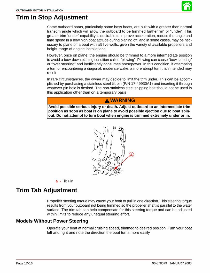
Adjusting the Oil Injection Pump 1D-15. . . . . . . . . . . . . . Trim In Stop Adjustment 1D-16. . . . . . . . . . . . . . . . . . . . . Trim Tab Adjustment 1D-16. . . . . . . . . . . . . . . . . . . . . . . .
Models Without Power Steering 1D-16. . . . . . . . . . . Models With Power Steering 1D-17. . . . . . . . . . . . . .
Installation Specifications
ba
a
a – Transom Opening – Minimum Single Engine – 33-3/8 in. (848 mm)Dual Engines – 59-3/4 in. (1518 mm)
b – Engine Center Line For Dual Engine26 in. (660mm) Minimum
Lifting Outboard
Electric Start Models – Remove plastic cap from flywheel hub. Thread lifting ring intoflywheel a minimum of 5 turns. Replace plastic cap after installation.
50048
OUTBOARD MOTOR INSTALLATION
Page 1D-2 90-878079 JANUARY 2000
Installing Outboard to Boat Transom
Determining Recommended Outboard Mounting Height
20 in.
21 in.
22 in.
23 in.
24 in.
25 in.
26 in.
19 in.
10 20 30 40 50 60 70 80
Maximum Boat Speed Anticipated
NOTE: Add 5 in. (127mm) for XL mod-els and 10 in. (254mm) for XXL modelsto listed outboard mounting height.
(660mm)
(635mm)
(609mm)
(584mm)
(560mm)
(533mm)
(508mm)
(482mm)
e
e
a
c
d
b
b
OutboardMountingHeight (SeeNOTE Below)
NOTICE TO INSTALLER:
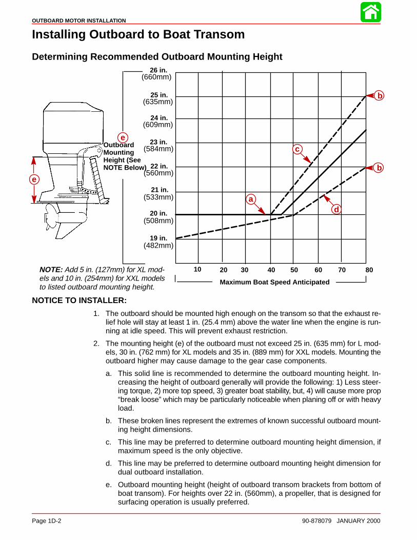
1. The outboard should be mounted high enough on the transom so that the exhaust re-lief hole will stay at least 1 in. (25.4 mm) above the water line when the engine is run-ning at idle speed. This will prevent exhaust restriction.
2. The mounting height (e) of the outboard must not exceed 25 in. (635 mm) for L mod-els, 30 in. (762 mm) for XL models and 35 in. (889 mm) for XXL models. Mounting theoutboard higher may cause damage to the gear case components.
a. This solid line is recommended to determine the outboard mounting height. In-creasing the height of outboard generally will provide the following: 1) Less steer-ing torque, 2) more top speed, 3) greater boat stability, but, 4) will cause more prop“break loose” which may be particularly noticeable when planing off or with heavyload.
b. These broken lines represent the extremes of known successful outboard mount-ing height dimensions.
c. This line may be preferred to determine outboard mounting height dimension, ifmaximum speed is the only objective.
d. This line may be preferred to determine outboard mounting height dimension fordual outboard installation.
e. Outboard mounting height (height of outboard transom brackets from bottom ofboat transom). For heights over 22 in. (560mm), a propeller, that is designed forsurfacing operation is usually preferred.
OUTBOARD MOTOR INSTALLATION
90-878079 JANUARY 2000 Page 1D-3
Installing Outboard
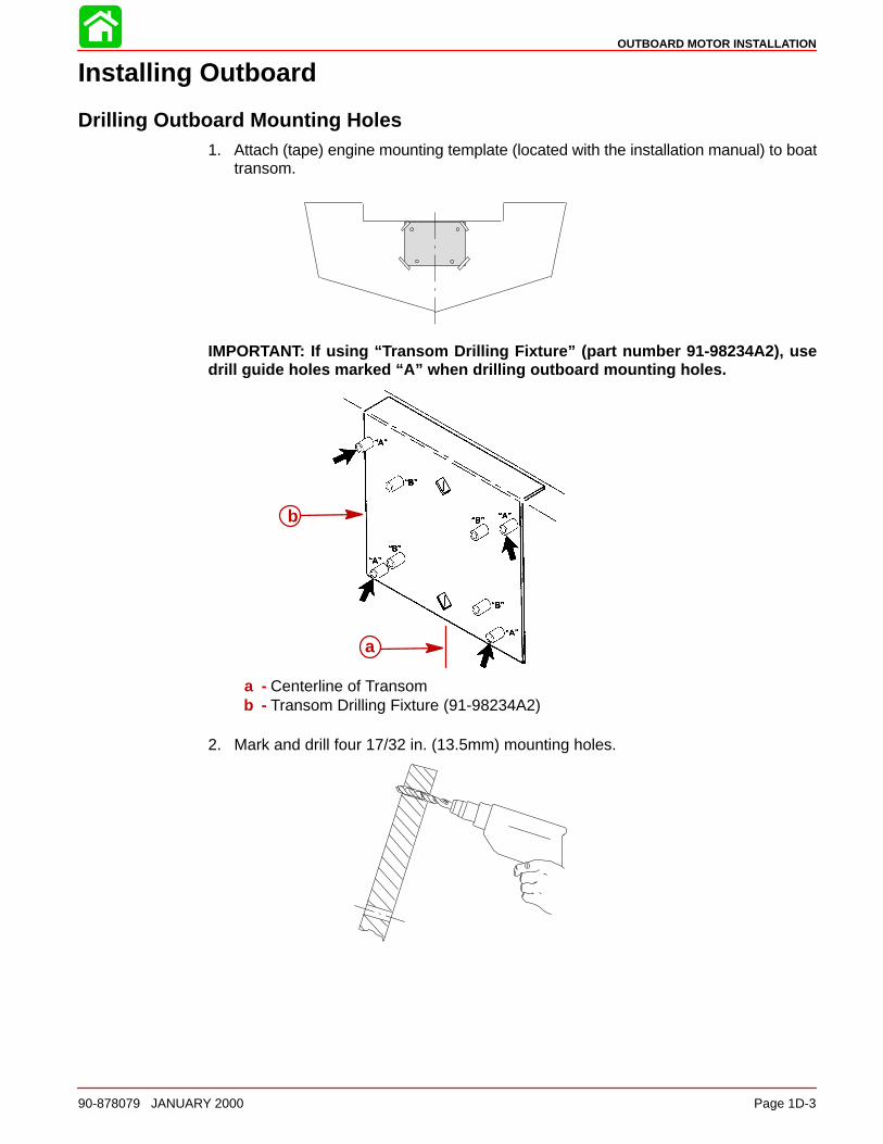
Drilling Outboard Mounting Holes1. Attach (tape) engine mounting template (located with the installation manual) to boat
transom.
IMPORTANT: If using “Transom Drilling Fixture” (part number 91-98234A2), usedrill guide holes marked “A” when drilling outboard mounting holes.
b
a
a - Centerline of Transomb - Transom Drilling Fixture (91-98234A2)
2. Mark and drill four 17/32 in. (13.5mm) mounting holes.

OUTBOARD MOTOR INSTALLATION
Page 1D-4 90-878079 JANUARY 2000
Securing Outboard To Boat Transom1. Refer to “Determining Recommended Outboard Motor Mounting Height”, preceding
and Install outboard to the nearest recommended mounting height.
2. Fasten outboard with provided mounting hardware shown.
c
a
e
bd
a - 1/2 in. Diameter Bolts(4)
b - Flat Washers(4)c - Locknuts (4)
d - Flat Washers(4)e - Marine Sealer - Apply to
Shanks of Bolts, NotThreads
Steering Cable
STARBOARD SIDE ROUTED CABLE
1. Lubricate O-ring seal and entire cable end.
95
95 2-4-C With Teflon (92-825407A12)

OUTBOARD MOTOR INSTALLATION
90-878079 JANUARY 2000 Page 1D-5
2. Insert steering cable into tilt tube.
57832
3. Torque nut to 35 lb. ft. (47.5 N·m).
57833
Steering Link Rod
1. Install steering link rod per illustration.
d
c
a
b 57834
a - Special Bolt (10-90041) Torque to 20 lb-ft (27 N·m)b - Nylon Insert Locknut (11-34863) Torque to 20 lb-ft (27 N·m)c - Flat Washer (2)d - Nylon Insert Locknut (11-34863) Tighten Locknut Until it Seats, Then Back
Nut Off 1/4 Turn
IMPORTANT: The steering link rod that connects the steering cable to the enginemust be fastened using special washer head bolt (“a” – Part Number 10-14000) andself locking nuts (“b” & “c” – Part Number 11-34863). These locknuts must neverbe replaced with common nuts (non locking) as they will work loose and vibrateoff freeing the link rod to disengage
WARNINGDisengagement of a steering link rod can result in the boat taking a full, sudden,sharp turn. This potentially violent action can cause occupants to be thrownoverboard exposing them to serious injury or death.
OUTBOARD MOTOR INSTALLATION
Page 1D-6 90-878079 JANUARY 2000
Electrical, Hoses and Control Cables
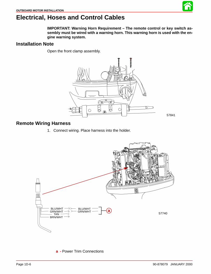
IMPORTANT: Warning Horn Requirement – The remote control or key switch as-sembly must be wired with a warning horn. This warning horn is used with the en-gine warning system.
Installation NoteOpen the front clamp assembly.
57841
Remote Wiring Harness1. Connect wiring. Place harness into the holder.
GRN/WHTBLU/WHT
BRN/WHTTAN
BLU/WHTGRN/WHT a
57740
a - Power Trim Connections

OUTBOARD MOTOR INSTALLATION
90-878079 JANUARY 2000 Page 1D-7
Battery CablesSINGLE OUTBOARD
(+)
(–)
a
b
c
a - RED Sleeve (Positive)b - BLACK Sleeve (Negative)c - Starting Battery
DUAL OUTBOARD
Connect a common ground cable (wire size same as engine battery cables) betweenNEGATIVE (–) terminals on starting batteries.
(–)
(–)
d
d - Common Ground Cable

OUTBOARD MOTOR INSTALLATION
Page 1D-8 90-878079 JANUARY 2000
Fuel Hose ConnectionFuel Hose Size – Minimum fuel line inside diameter (I.D.) is 5/16 in. (8mm), with separatefuel line/fuel tank pickup for each engine.
Fasten remote fuel hose to fitting with hose clamp.
Oil Hose ConnectionsConnect the remote oil hoses to the engine hose connections as shown. Fasten hose con-nections with sta-straps.
Speedometer Tubing ConnectionThis outboard has a speedometer water pick-up located in the leading edge of the gearcase. If you want to use this water pickup for the speedometer, connect the water tubingas shown.
Water Pressure Tubing ConnectionIf the boat is equipped with a water pressure gauge, make the water connection to thistubing as shown.
ab
cd ef
g
h
ij
kl
a - Remote Fuel Hoseb - Hose Clamp – Secure Remote Fuel Hosec - Oil Hoses with Blue Stripe - Secure With Sta-Strapd - Oil Hoses without Blue Stripe - Secure With Sta-Strape - Sta-Strap (2) - Secure Oil Hosesf - Speedometer Water Pickup Tubing (Black Color)g - Water Pressure Tubing (Gray Color)h - Coupler – Push In on End of Coupler to Disconnect Plug or Tubingi - Plug – Remove when Making Coupler Connectionj - Barb Hose Fitting (2) Provided with Outboard – Install this fitting into Coupler, if
a Rubber Hose Connection is Requiredk - Speedometer Hose – Insert the barb hose fitting (j) into Coupler and Connect
Hosel - Water Pressure Tube – Insert into coupler, pull on tube to verify that it is locked
OUTBOARD MOTOR INSTALLATION
90-878079 JANUARY 2000 Page 1D-9
Shift Cable
Install cables into the remote control following the instructions provided with the remotecontrol.
NOTE: Install the shift cable to the engine first. The shift cable is the first cable to movewhen the remote control handle is moved out of neutral.
COUNTER ROTATION OUTBOARDS
Counter rotating (left hand) gear cases can be identified by a “L” stamped into the end ofthe propeller shaft.
The Quicksilver Dual Engine Console Mount Control, P/N 88688A22 or 88688A52, is re-quired to shift the counter rotation outboard. The installation instructions shipped with thecontrol explain the procedure required to connect this control to a counter rotation out-board.
IMPORTANT: If the counter rotation outboard is rigged similar to a standard rota-tion outboard OR if a standard rotation outboard is rigged similar to a counter rota-tion outboard, the reverse gear and bearing in the gear case must function as for-ward gear. THE REVERSE GEAR/BEARING ARE NOT DESIGNED TO CARRY THESUSTAINED LOADS THAT ARE GENERATED WHEN RUNNING UNDER CONSTANTHIGH RPM AND THRUST CONDITIONS.
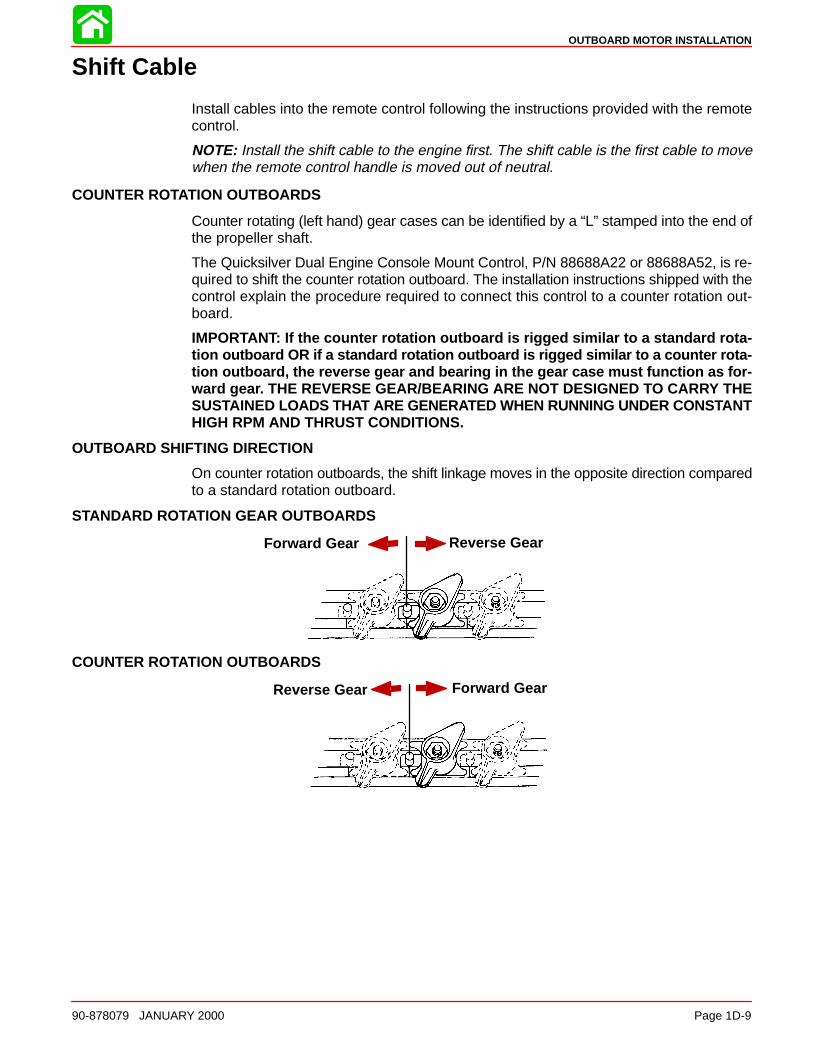
OUTBOARD SHIFTING DIRECTION
On counter rotation outboards, the shift linkage moves in the opposite direction comparedto a standard rotation outboard.
STANDARD ROTATION GEAR OUTBOARDS
Forward Gear Reverse Gear
COUNTER ROTATION OUTBOARDS
Forward GearReverse Gear
OUTBOARD MOTOR INSTALLATION
Page 1D-10 90-878079 JANUARY 2000
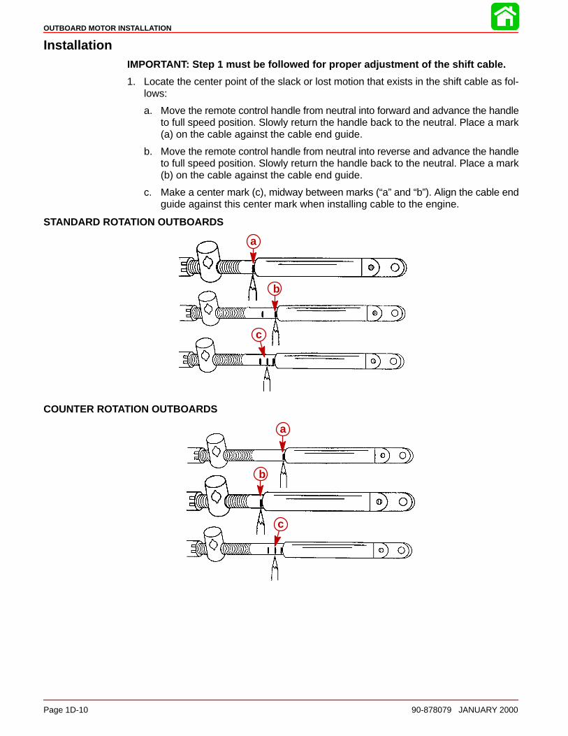
InstallationIMPORTANT: Step 1 must be followed for proper adjustment of the shift cable.
1. Locate the center point of the slack or lost motion that exists in the shift cable as fol-lows:
a. Move the remote control handle from neutral into forward and advance the handleto full speed position. Slowly return the handle back to the neutral. Place a mark(a) on the cable against the cable end guide.
b. Move the remote control handle from neutral into reverse and advance the handleto full speed position. Slowly return the handle back to the neutral. Place a mark(b) on the cable against the cable end guide.
c. Make a center mark (c), midway between marks (“a” and “b”). Align the cable endguide against this center mark when installing cable to the engine.
STANDARD ROTATION OUTBOARDS
a
b
c
COUNTER ROTATION OUTBOARDS
b
a
c

OUTBOARD MOTOR INSTALLATION
90-878079 JANUARY 2000 Page 1D-11
2. Position remote control and outboard into neutral.
N
3. Slide the shift cable retainer forward until resistance is felt, then slide cable anchortoward rear until resistance is felt. Center the anchor pin between resistance points.
b
a
a - Shift Cable Retainerb - Anchor Pin
4. Align the shift cable end guide with the center mark as instructed in Step 1.
5. Place shift cable on anchor pin. Adjust cable barrel so it slips freely into the barrelholder.
6. Secure shift cable with shift cable retainer.
b
aa - Cable Barrelb - Shift Cable Retainer
7. Check shift cable adjustments as follows:
a. With remote control in forward, the propshaft should lock solidly in gear. If it doesnot, adjust cable barrel closer to cable end guide.
b. Shift remote control into neutral. The propshaft should turn freely without drag. Ifnot, adjust barrel away from cable end guide. Repeat steps a and b.
c. Shift remote control into reverse while turning propeller. The propshaft shouldlock solidly in gear. If not, adjust barrel away from cable end guide. Repeat stepsa thru c.
OUTBOARD MOTOR INSTALLATION
Page 1D-12 90-878079 JANUARY 2000
d. Return remote control handle to neutral. The propeller should turn freely withoutdrag. If not, adjust barrel closer to cable end guide. Repeat steps a thru d.
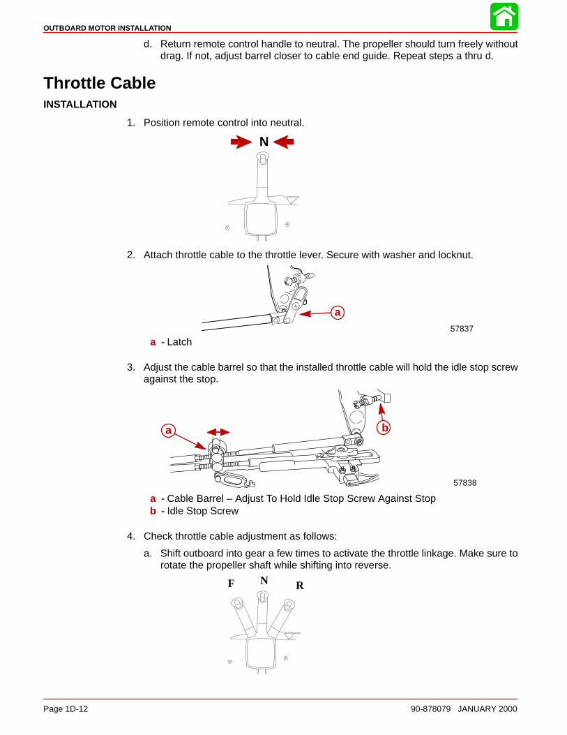
Throttle CableINSTALLATION
1. Position remote control into neutral.
N
2. Attach throttle cable to the throttle lever. Secure with washer and locknut.
57837
a
a - Latch
3. Adjust the cable barrel so that the installed throttle cable will hold the idle stop screwagainst the stop.
a b
57838
a - Cable Barrel – Adjust To Hold Idle Stop Screw Against Stopb - Idle Stop Screw
4. Check throttle cable adjustment as follows:
a. Shift outboard into gear a few times to activate the throttle linkage. Make sure torotate the propeller shaft while shifting into reverse.
N RF
OUTBOARD MOTOR INSTALLATION
90-878079 JANUARY 2000 Page 1D-13
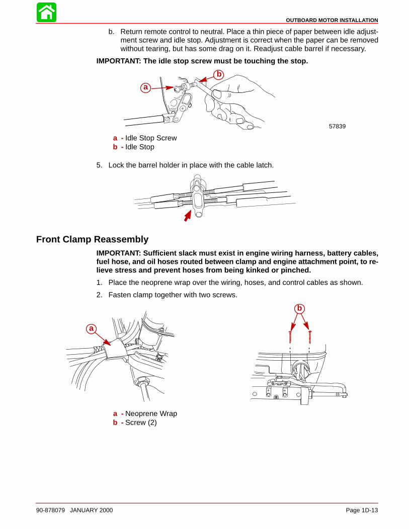
b. Return remote control to neutral. Place a thin piece of paper between idle adjust-ment screw and idle stop. Adjustment is correct when the paper can be removedwithout tearing, but has some drag on it. Readjust cable barrel if necessary.
IMPORTANT: The idle stop screw must be touching the stop.
a
b
57839
a - Idle Stop Screwb - Idle Stop
5. Lock the barrel holder in place with the cable latch.
Front Clamp ReassemblyIMPORTANT: Sufficient slack must exist in engine wiring harness, battery cables,fuel hose, and oil hoses routed between clamp and engine attachment point, to re-lieve stress and prevent hoses from being kinked or pinched.
1. Place the neoprene wrap over the wiring, hoses, and control cables as shown.
2. Fasten clamp together with two screws.
a
b
a - Neoprene Wrapb - Screw (2)
OUTBOARD MOTOR INSTALLATION
Page 1D-14 90-878079 JANUARY 2000
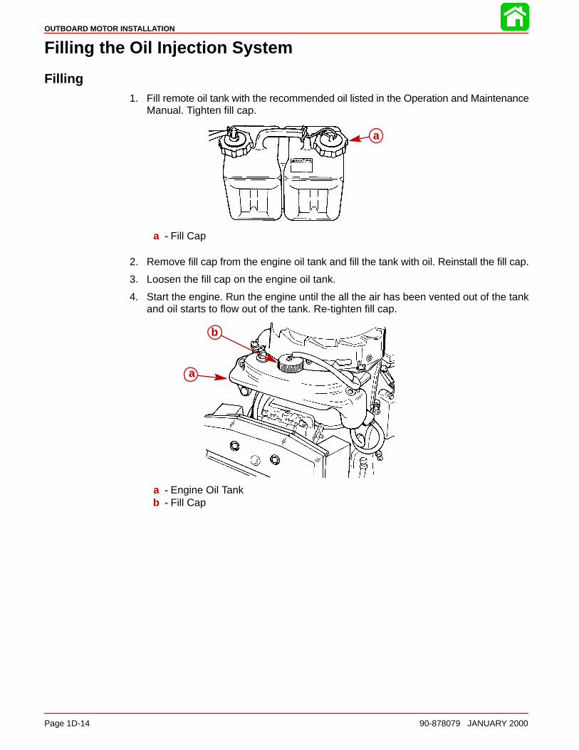
Filling the Oil Injection System
Filling1. Fill remote oil tank with the recommended oil listed in the Operation and Maintenance
Manual. Tighten fill cap.
a
a - Fill Cap
2. Remove fill cap from the engine oil tank and fill the tank with oil. Reinstall the fill cap.
3. Loosen the fill cap on the engine oil tank.
4. Start the engine. Run the engine until the all the air has been vented out of the tankand oil starts to flow out of the tank. Re-tighten fill cap.
a
b
a - Engine Oil Tankb - Fill Cap

OUTBOARD MOTOR INSTALLATION
90-878079 JANUARY 2000 Page 1D-15
Bleeding Air from Oil Injection Pump and Oil InjectionOutlet Hose
Bleeding Air from Oil Injection PumpWith engine not running, place a shop towel below the oil injection pump. Loosen bleedscrew three to four turns and allow oil to flow from bleed hole. Re-tighten bleed screw. Thisprocedure allows the pump to fill with oil.
Bleeding Air from Oil Injection Outlet HoseAny air bubbles in outlet hose in most cases will be purged out of the system during opera-tion of the engine.
NOTE: If air bubbles persist, they can be purged out of the hose by removing link rod androtating the pump arm full clockwise while operating engine at 1000 to 1500 RPM: If nec-essary, gently pinch the fuel line between the remote fuel line connector and the oil injec-tion pump “Tee” fitting. This will cause the fuel pump to provide a partial vacuum whichwill aid in removal of the air. Reinstall link rod.
a
b
c
d
a - Bleed Screwb - Outlet Hosec - Link Rodd - Pump Arm
Adjusting the Oil Injection Pump
When throttle linkage is at idle position, alignment mark on oil injection arm should bein-line with mark on casting as shown. If necessary, adjust link rod.
a
b c
a - Link Rodb - Alignment Markc - Casting Mark
OUTBOARD MOTOR INSTALLATION
Page 1D-16 90-878079 JANUARY 2000
Trim In Stop AdjustmentSome outboard boats, particularly some bass boats, are built with a greater than normaltransom angle which will allow the outboard to be trimmed further “in” or “under”. Thisgreater trim “under” capability is desirable to improve acceleration, reduce the angle andtime spend in a bow high boat attitude during planing off, and in some cases, may be nec-essary to plane off a boat with aft live wells, given the variety of available propellers andheight range of engine installations.
However, once on plane, the engine should be trimmed to a more intermediate positionto avoid a bow-down planing condition called “plowing”. Plowing can cause “bow steering”or “over steering” and inefficiently consumes horsepower. In this condition, if attemptinga turn or encountering a diagonal, moderate wake, a more abrupt turn than intended mayresult.
In rare circumstances, the owner may decide to limit the trim under. This can be accom-plished by purchasing a stainless steel tilt pin (P/N 17-49930A1) and inserting it throughwhatever pin hole is desired. The non-stainless steel shipping bolt should not be used inthis application other than on a temporary basis.
WARNINGAvoid possible serious injury or death. Adjust outboard to an intermediate trimposition as soon as boat is on plane to avoid possible ejection due to boat spin-out. Do not attempt to turn boat when engine is trimmed extremely under or in.
a
a - Tilt Pin
Trim Tab Adjustment
Propeller steering torque may cause your boat to pull in one direction. This steering torqueresults from your outboard not being trimmed so the propeller shaft is parallel to the watersurface. The trim tab can help compensate for this steering torque and can be adjustedwithin limits to reduce any unequal steering effort.
Models Without Power SteeringOperate your boat at normal cruising speed, trimmed to desired position. Turn your boatleft and right and note the direction the boat turns more easily.
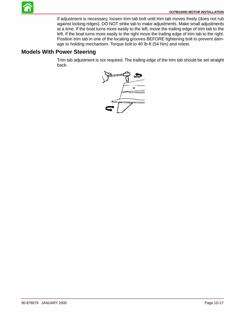
OUTBOARD MOTOR INSTALLATION
90-878079 JANUARY 2000 Page 1D-17
If adjustment is necessary, loosen trim tab bolt until trim tab moves freely (does not rubagainst locking ridges). DO NOT strike tab to make adjustments. Make small adjustmentsat a time. If the boat turns more easily to the left, move the trailing edge of trim tab to theleft. If the boat turns more easily to the right move the trailing edge of trim tab to the right.Position trim tab in one of the locating grooves BEFORE tightening bolt to prevent dam-age to holding mechanism. Torque bolt to 40 lb-ft (54 Nm) and retest.
Models With Power SteeringTrim tab adjustment is not required. The trailing edge of the trim tab should be set straightback.

2A
IGNITION
90-878079 JANUARY 2000 Page 2A-1
ELECTRICALSection 2A - Ignition
Table of Contents
Specifications 2A-2. . . . . . . . . . . . . . . . . . . . . . . . . . . Special Tools 2A-4. . . . . . . . . . . . . . . . . . . . . . . . . . . Flywheel/Starter Motor 2A-6. . . . . . . . . . . . . . . . . . . CDM Mounting 2A-8. . . . . . . . . . . . . . . . . . . . . . . . . . Solenoid Mounting 2A-10. . . . . . . . . . . . . . . . . . . . . . Theory of Operation 2A-12. . . . . . . . . . . . . . . . . . . . . V-6 2.0/2.5L CDM Ignition 2A-13. . . . . . . . . . . . . . . .
Capacitor Charging #1, #2, & #3 CDMs 2A-14. Capacitor Charging #4, #5 & #6 CDMs 2A-14. . #1 Cylinder Trigger Circuit 2A-14. . . . . . . . . . . . . Ignition Coil Circuit 2A-14. . . . . . . . . . . . . . . . . . . Stop Circuit 2A-14. . . . . . . . . . . . . . . . . . . . . . . . . .
Ignition Component Description 2A-15. . . . . . . . . . . Capacitor Discharge Module (CDM) 2A-15. . . . Trigger Coil 2A-15. . . . . . . . . . . . . . . . . . . . . . . . . . Control Module 2A-15. . . . . . . . . . . . . . . . . . . . . . .
Ignition Component Description 2A-16. . . . . . . . . . . Stator Assembly 2A-16. . . . . . . . . . . . . . . . . . . . . . Flywheel 2A-16. . . . . . . . . . . . . . . . . . . . . . . . . . . .
CDM (P/N 827509) Trouble ShootingFlowchart 2A-17. . . . . . . . . . . . . . . . . . . . . . . . . . . . . .
CDM (P/N 827509) 2A-17. . . . . . . . . . . . . . . . . . . CDM Stop Diode Trouble Shooting 2A-18. . . . . CDM Trouble Shooting Flowchart 2A-20. . . . . . . Direct Voltage Adaptor (DVA) 2A-25. . . . . . . . . .
Troubleshooting Tips 2A-25. . . . . . . . . . . . . . . . . . Ignition Test Procedures 2A-26. . . . . . . . . . . . . . . . . .
Direct Voltage Adaptor (DVA) Test 2A-26. . . . . . Resistance Tests 2A-30. . . . . . . . . . . . . . . . . . . . .
Bias Circuit 2A-30. . . . . . . . . . . . . . . . . . . . . . . . . . . . . Shift Stabilizer Circuit 2A-31. . . . . . . . . . . . . . . . . . . . Idle Stabilizer Description 2A-31. . . . . . . . . . . . . . . . Rev-Limit Circuit 2A-31. . . . . . . . . . . . . . . . . . . . . . . . EFI Injector Timing Signal Test 2A-32. . . . . . . . . . . . EFI Detonation Control System 2A-32. . . . . . . . . . .
Detonation Circuit Test 2A-32. . . . . . . . . . . . . . . . Ignition Component Removal 2A-33. . . . . . . . . . . . .
Flywheel Removal 2A-33. . . . . . . . . . . . . . . . . . . . Flywheel Installation 2A-33. . . . . . . . . . . . . . . . . . Stator Removal 2A-34. . . . . . . . . . . . . . . . . . . . . . Stator Installation 2A-35. . . . . . . . . . . . . . . . . . . . . Trigger Removal 2A-36. . . . . . . . . . . . . . . . . . . . . Trigger Installation 2A-37. . . . . . . . . . . . . . . . . . . . CDM Removal 2A-38. . . . . . . . . . . . . . . . . . . . . . . CDM Installation 2A-38. . . . . . . . . . . . . . . . . . . . . Control Module Removal 2A-38. . . . . . . . . . . . . . Control Module Installation 2A-38. . . . . . . . . . . . Detonation Module Removal 2A-39. . . . . . . . . . . Detonation Module Installation 2A-39. . . . . . . . .

IGNITION
Page 2A-2 90-878079 JANUARY 2000
Specifications
IGNITIONSYSTEM
TypeSpark Plug Type Spark Plug Gap
Capacitor DischargeNGK BPZ8HS-100.040 in. (1.0 mm)
CAPACITOR DISCHARGE MODULE
Circuit TestConnect Negative
(–)Meter Lead To:
Connect Positive(+)
Meter Lead To:
OhmsScale Results:
Stop Diode Forward Bias
Green (D) / orGreen test harness
lead
Black/Yellow (B) /or Black/Yellow test
harness lead
R x 100Diode Reading*
Continuity
Stop DiodeReverse Bias
Black/Yellow (B) /or Black/Yellow test
harness lead
Green (D) / orGreen test harness
lead
R x 100Diode Reading*
No Continuity
Return GroundPath Diode,
Reverse Bias
Green (D) / orGreen test harness
lead
Ground Pin (A) orBlack test harness
lead
R x 100Diode Reading*
No Continuity
Return GroundPath Diode,
Forward Bias
Ground Pin (A) / orBlack test harness
lead
Green (D) / orGreen test harness
lead
R x 100Diode Reading*
Continuity
CDM Trigger InputResistance
Ground Pin (A) / orBlack test harness
lead
White (C) / or Whitetest harness lead
R x 100 1000 - 1250Ohms
Coil SecondaryImpedance
Ground Pin (A) orBlack test harness
lead
Spark PlugTerminal
(At Spark PlugBoot)
R x 100 900 - 1200Ohms
*Diode Readings: Due to the differences in test meters, results other than specified maybe obtained. In such a case, reverse meter leads and re-test. If test results then read asspecified CDM is O.K. The diode measurements above will be opposite if using a Flukeequivalent multimeter.

IGNITION
90-878079 JANUARY 2000 Page 2A-3
Stator Output Test 400 DVA Scale
Positive Meter Lead (+) Negative Meter Lead (–) DVA Reading @ Cranking to2500 RPM
Connect to Green Test HarnessLead
Connect to Black Test HarnessLead 160 - 320
CDM Trigger Input Test 2 DVA Scale
Positive Meter Lead (+) Negative Meter Lead (–) DVA Reading @ Cranking
White Test Harness Lead Black Test Harness Lead 0.2 - 2.0
CDM Trigger Input Test 20 DVA Scale
Positive Meter Lead (+) Negative Meter Lead (–) DVA Reading @ Idle to 2500RPM
White Test Harness Lead Black Test Harness Lead 2 - 8 Volts
Bias Circuit Test (All Models Except 200 EFI) 40 DVA Scale @2500 RPM
Positive Meter Lead (+) Negative Meter Lead (–) DVA Reading
Engine Ground Black/White Shift Switch Wire 25 - 40 Volts
Bias Circuit Test (200 EFI) 40 DVA Scale @ 2500 RPM
Positive Meter Lead (+) Negative Meter Lead (–) DVA Reading
Engine Ground Disconnect 4 wire DetonationControl Module connector. Insertbent paper clip into Black/White
terminal.
25 - 40 Volts
Trigger Assembly Test
Test Leads to Resistance Ohms Scale Reading
Between Brown Trigger Leadand Yellow Trigger Lead
1100-1400 R x 100
Between White Trigger Lead andRed Trigger Lead
1100-1400 R x 100
Between Purple Trigger Leadand Blue Trigger Lead
1100-1400 R x 100
Stator Resistance TestR x 1 Ohms Scale
Positive Meter Lead (+) Negative Meter Lead (–)R x 1 Ohms Scale
Connect to White/Green stator lead Connect to Green/White stator lead380-430
Connect to White/Green stator lead Connect to engine groundNo continuity
Connect to Green/White stator lead Connect to engine groundNo continuity
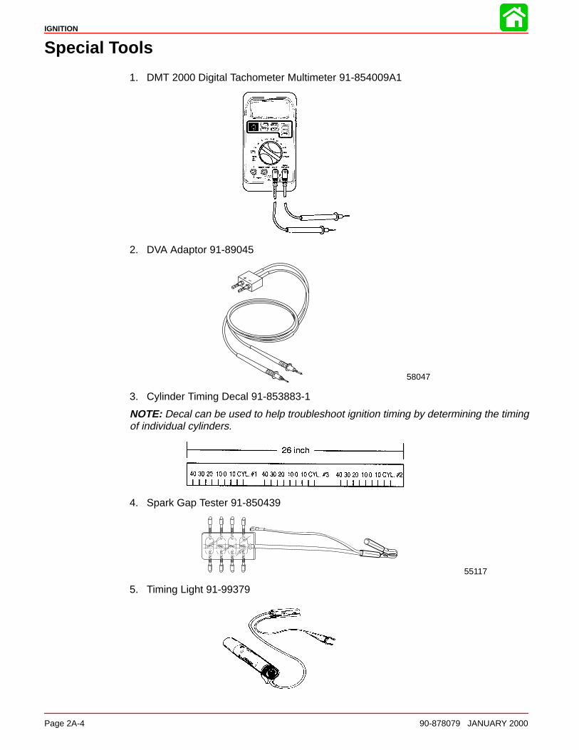
IGNITION
Page 2A-4 90-878079 JANUARY 2000
Special Tools
1. DMT 2000 Digital Tachometer Multimeter 91-854009A1
2. DVA Adaptor 91-89045
58047
3. Cylinder Timing Decal 91-853883-1
NOTE: Decal can be used to help troubleshoot ignition timing by determining the timingof individual cylinders.
4. Spark Gap Tester 91-850439
55117
5. Timing Light 91-99379
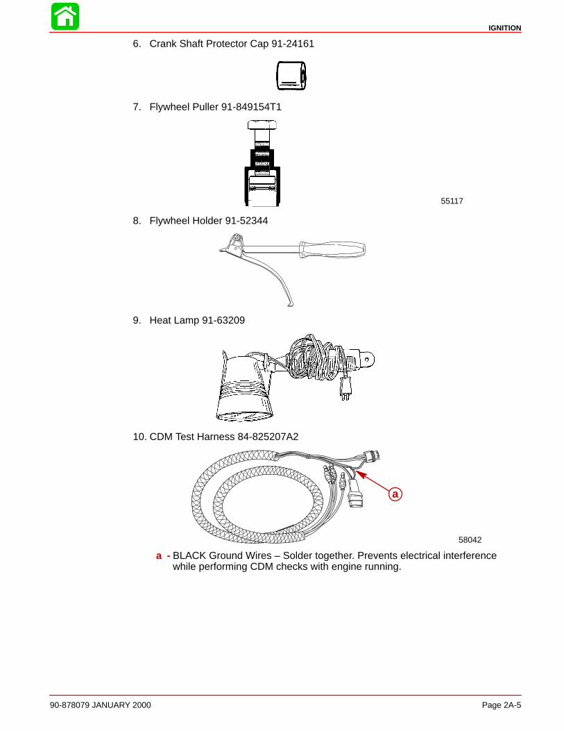
IGNITION
90-878079 JANUARY 2000 Page 2A-5
6. Crank Shaft Protector Cap 91-24161
7. Flywheel Puller 91-849154T1
55117
8. Flywheel Holder 91-52344
9. Heat Lamp 91-63209
10. CDM Test Harness 84-825207A2
58042
a
a - BLACK Ground Wires – Solder together. Prevents electrical interferencewhile performing CDM checks with engine running.
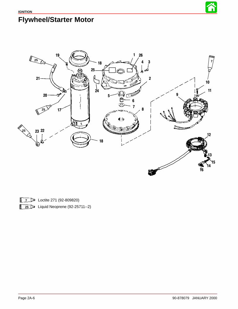
IGNITION
Page 2A-6 90-878079 JANUARY 2000
Flywheel/Starter Motor
1
2
34
5
6
78
9
10
11
12
17
18
19
20
21
2223
18
725
25
25
24
25
26
13
1415
16
Liquid Neoprene (92-25711--2)
7 Loctite 271 (92-809820)
25
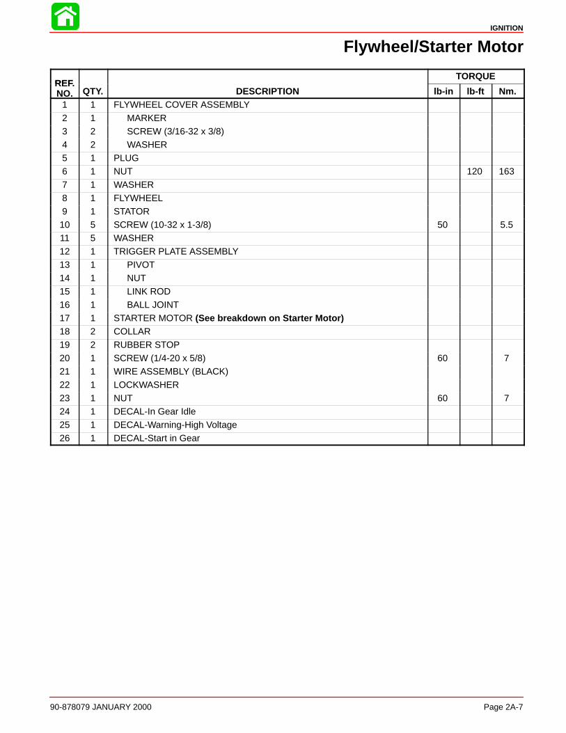
IGNITION
90-878079 JANUARY 2000 Page 2A-7
Flywheel/Starter Motor
REFTORQUE
REF.NO. QTY. DESCRIPTION lb-in lb-ft Nm.
1 1 FLYWHEEL COVER ASSEMBLY
2 1 MARKER3 2 SCREW (3/16-32 x 3/8)4 2 WASHER5 1 PLUG6 1 NUT 120 1637 1 WASHER
8 1 FLYWHEEL9 1 STATOR10 5 SCREW (10-32 x 1-3/8) 50 5.511 5 WASHER12 1 TRIGGER PLATE ASSEMBLY13 1 PIVOT14 1 NUT
15 1 LINK ROD16 1 BALL JOINT17 1 STARTER MOTOR (See breakdown on Starter Motor)18 2 COLLAR19 2 RUBBER STOP20 1 SCREW (1/4-20 x 5/8) 60 721 1 WIRE ASSEMBLY (BLACK)
22 1 LOCKWASHER23 1 NUT 60 724 1 DECAL-In Gear Idle25 1 DECAL-Warning-High Voltage26 1 DECAL-Start in Gear
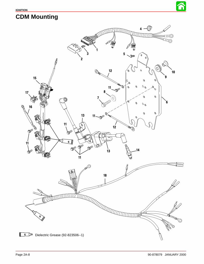
IGNITION
Page 2A-8 90-878079 JANUARY 2000
CDM Mounting
1
2
3
18
6
13
15
11
1012
8
4
5
17
7
9
1413
11
11
11
12
16
11
Dielectric Grease (92-823506--1)6
6
6

IGNITION
90-878079 JANUARY 2000 Page 2A-9
CDM Mounting
REFTORQUE
REF.NO. QTY. DESCRIPTION lb-in lb-ft Nm.
1 1 POWER HARNESS
2 1 COVER3 3 FUSE4 3 STA STRAP5 2 CLIP6 1 CDM MOUNTING PLATE7 4 SCREW (.312-18 x 1-1/4) 20 27
8 4 WASHER9 4 GROMMET10 4 BUSHING11 15 SCREW (M6 x 16) 70 812 2 CABLE13 6 CDM14 6 SPARK PLUG (NGK#BPZ8HS10) 20 27
15 1 CDM HARNESS16 1 CABLE17 1 CLIP18 1 ENGINE HARNESS
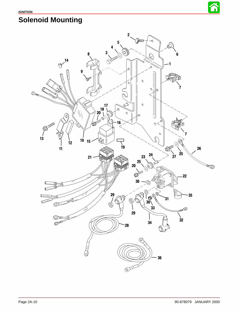
IGNITION
Page 2A-10 90-878079 JANUARY 2000
Solenoid Mounting
1
5
6
10
11
12
13
8
9
22
2324
20
25
28
3031
32
33
34
35
7
26
27
3
15
16
17
19
21
14
36
29
2
4
18
7
25
30
29
20
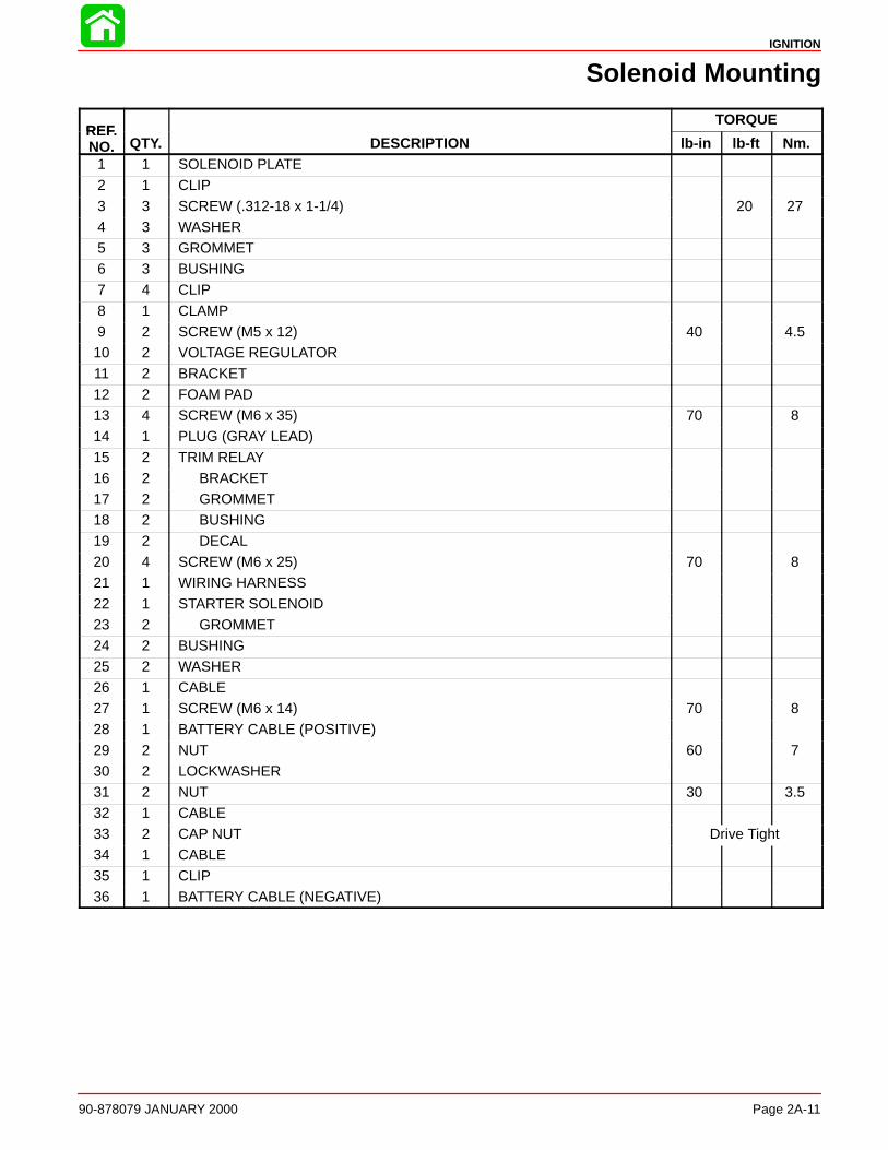
IGNITION
90-878079 JANUARY 2000 Page 2A-11
Solenoid Mounting
REFTORQUE
REF.NO. QTY. DESCRIPTION lb-in lb-ft Nm.
1 1 SOLENOID PLATE
2 1 CLIP3 3 SCREW (.312-18 x 1-1/4) 20 274 3 WASHER5 3 GROMMET6 3 BUSHING7 4 CLIP
8 1 CLAMP9 2 SCREW (M5 x 12) 40 4.510 2 VOLTAGE REGULATOR11 2 BRACKET12 2 FOAM PAD13 4 SCREW (M6 x 35) 70 814 1 PLUG (GRAY LEAD)
15 2 TRIM RELAY16 2 BRACKET17 2 GROMMET18 2 BUSHING19 2 DECAL20 4 SCREW (M6 x 25) 70 821 1 WIRING HARNESS
22 1 STARTER SOLENOID23 2 GROMMET24 2 BUSHING25 2 WASHER26 1 CABLE27 1 SCREW (M6 x 14) 70 828 1 BATTERY CABLE (POSITIVE)
29 2 NUT 60 730 2 LOCKWASHER31 2 NUT 30 3.532 1 CABLE33 2 CAP NUT Drive Tight34 1 CABLE35 1 CLIP
36 1 BATTERY CABLE (NEGATIVE)
IGNITION
Page 2A-12 90-878079 JANUARY 2000
Theory of Operation
The V-6 outboard CDM ignition system is alternator-driven with distributor-less capacitordischarge. Major components of the system are the flywheel, stator assembly, trigger as-sembly, control module, 6 CDM assemblies and 6 spark plugs.
The stator assembly is mounted below the flywheel and has 3 capacitor charging coils.The flywheel is fitted with permanent magnets inside the outer rim. As the flywheel ro-tates, the permanent magnets pass the capacitor charging coils producing AC voltage.The AC voltage is conducted to the CDMs where it is rectified, regulated to 300 volts, andstored in capacitors.
The trigger assembly (also mounted under the flywheel) has 3 coils. Each coil controlsthe spark to 2 cylinders - one on each bank. The flywheel also has a second set of perma-nent magnets located around the center hub. As the flywheel rotates, the magnets passthe trigger coils producing AC voltage. The AC voltage is conducted to the control module,which shapes the signal before sending it to the electronic switch (SCR) inside the ap-propriate CDM. The switch discharges the capacitor voltage into the primary side of theignition coil (inside the CDM).
As this voltage goes to ground through the primary circuit of the coil, it induces a voltagerise in the secondary side of the ignition coil. This voltage can increase to approximately40000 volts before bridging the spark plug gap and returning to ground.
The preceding sequence occurs once per engine revolution for each cylinder.
Spark timing is advanced or retarded by the movement of the trigger assembly attachedto the throttle/spark arm.
The control module provides rev-limit (carb models), bias control, shift stabilizer, idle sta-bilizer, injector timing signal (EFI models), and low oil warning.
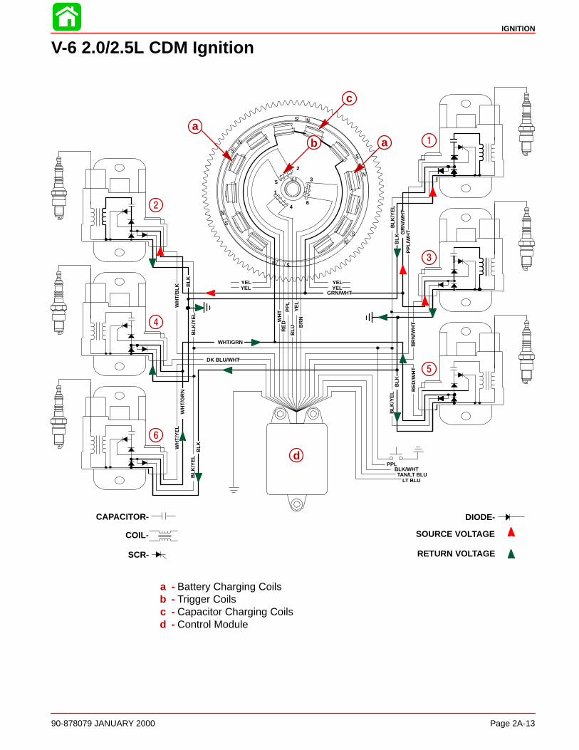
IGNITION
90-878079 JANUARY 2000 Page 2A-13
V-6 2.0/2.5L CDM Ignition
d
WHT/GRN
N
BLK
N
S
S
S
S
S
S N
N
N
N
N
S
GRN/WHT
YELYEL
PP
L
WH
T
WH
T/G
RN
BLK
BLK
/YE
LB
LK/Y
EL
BLK
WH
T/B
LK
BLK
BLK
/YE
LB
LK/Y
EL
GR
N/W
HT
PPLBLK/WHT
LT BLUTAN/LT BLU
PP
L/W
HT
RE
D/W
HT
BR
N/W
HT
WH
T/Y
EL
DK BLU/WHT
BR
NY
EL
RE
D
BLU
1
4
5
2
3
6
YELYEL
SCR-
CAPACITOR-
COIL-
DIODE-
SOURCE VOLTAGE
RETURN VOLTAGE
aa
b
c
1
2
3
4
5
6
a - Battery Charging Coilsb - Trigger Coilsc - Capacitor Charging Coilsd - Control Module
IGNITION
Page 2A-14 90-878079 JANUARY 2000
Capacitor Charging #1, #2, & #3 CDMsThe STATOR assembly is mounted to the block below the flywheel and has 3 CAPACI-TOR CHARGING COILS connected in series. The FLYWHEEL is fitted with 6 permanentmagnets inside the outer rim. The flywheel rotates the permanent magnets past the ca-pacitor charging coils causing the coils to produce AC voltage (260-320 volts). The ACvoltage is then conducted to the CAPACITOR DISCHARGE MODULES (CDM), whereit is rectified (DC) and stored in a capacitor. The stator voltage return path is through theground wire of one of the other CDMs and back through that CDM’s charging coil wire tothe capacitor charging coils.
NOTE: The CDM contains a zener diode (not shown for clarity). The zener diode regu-lates the capacitor voltage to 300 volts, preventing overcharging of the capacitor (andpossible failure) if the SCR does not receive a trigger pulse.
Capacitor Charging #4, #5 & #6 CDMsThe flywheel rotates the permanent magnets past the capacitor charging coils causingthe coils to produce AC voltage (260-320 volts). The opposite voltage pulse is then con-ducted to the CAPACITOR DISCHARGE MODULES (CDM), where it is rectified (DC) andstored in a capacitor. The stator voltage return path is through the ground wire of one ofthe other CDMs and back through that CDM’s charging coil wire to the capacitor chargingcoils.
NOTE: The CDM contains a zener diode (not shown for clarity). The zener diode regu-lates the capacitor voltage to 300 volts, preventing overcharging of the capacitor (andpossible failure) if the SCR does not receive a trigger pulse.
#1 Cylinder Trigger CircuitThe TRIGGER assembly (also mounted under the flywheel) has three coils, one for twocylinders - one on each bank. These coils are mounted adjacent to the flywheel centerhub. The center hub of the flywheel contains a permanent magnet with two north-southtransitions.
As the flywheel rotates, the magnet north-south transitions pass the trigger coils. Thiscauses the trigger coils to produce a voltage pulse which is sent to the control module.The control module shapes the signal before sending it onto the capacitor discharge mod-ule (CDM). A positive voltage pulse will activate the electronic switch (SCR) inside thecapacitor discharge module (CDM). The switch discharges the capacitor voltage throughthe coil primary windings. The return voltage pulse exits the CDM through the ground wireand returns through the control module.
Spark timing is advanced or retarded by the movement of the trigger assembly attachedto the throttle/spark arm.
Ignition Coil CircuitAs the capacitor voltage flows through the primary windings of the ignition coil, a voltageis induced into the ignition coil secondary windings. This secondary voltage rises to thelevel required to jump the spark plug gap and return to ground. This secondary voltagecan, if necessary, reach approximately 40,000 volts. To complete the secondary voltagepath, the released voltage enters the ground circuit of CDM module.
Stop CircuitTo stop the engine, the stop switch is closed allowing the capacitor charge current fromthe stator to drain directly to ground.
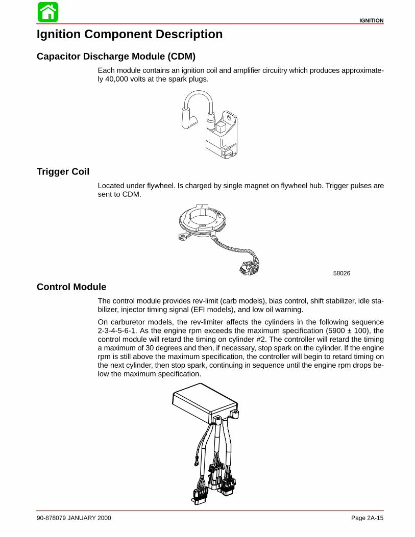
IGNITION
90-878079 JANUARY 2000 Page 2A-15
Ignition Component Description
Capacitor Discharge Module (CDM)Each module contains an ignition coil and amplifier circuitry which produces approximate-ly 40,000 volts at the spark plugs.
Trigger CoilLocated under flywheel. Is charged by single magnet on flywheel hub. Trigger pulses aresent to CDM.
58026
Control ModuleThe control module provides rev-limit (carb models), bias control, shift stabilizer, idle sta-bilizer, injector timing signal (EFI models), and low oil warning.
On carburetor models, the rev-limiter affects the cylinders in the following sequence2-3-4-5-6-1. As the engine rpm exceeds the maximum specification (5900 ± 100), thecontrol module will retard the timing on cylinder #2. The controller will retard the timinga maximum of 30 degrees and then, if necessary, stop spark on the cylinder. If the enginerpm is still above the maximum specification, the controller will begin to retard timing onthe next cylinder, then stop spark, continuing in sequence until the engine rpm drops be-low the maximum specification.

IGNITION
Page 2A-16 90-878079 JANUARY 2000
Ignition Component Description
Stator AssemblyLocated under the flywheel in the stator assembly are 12 coils; 3 ignition charge coils and9 auxiliary power coils wound in series that provide voltage to the CDM’s and battery/aux-iliary circuits respectively.
58025
FlywheelContains 6 magnets (12 pole) around circumference. Flywheel has 2 magnets on innerhub for trigger. Outer magnets are for battery charge coils and ignition charge coils. Theseouter magnets are covered by a thin stainless steel retaining ring bonded onto the insidediameter.
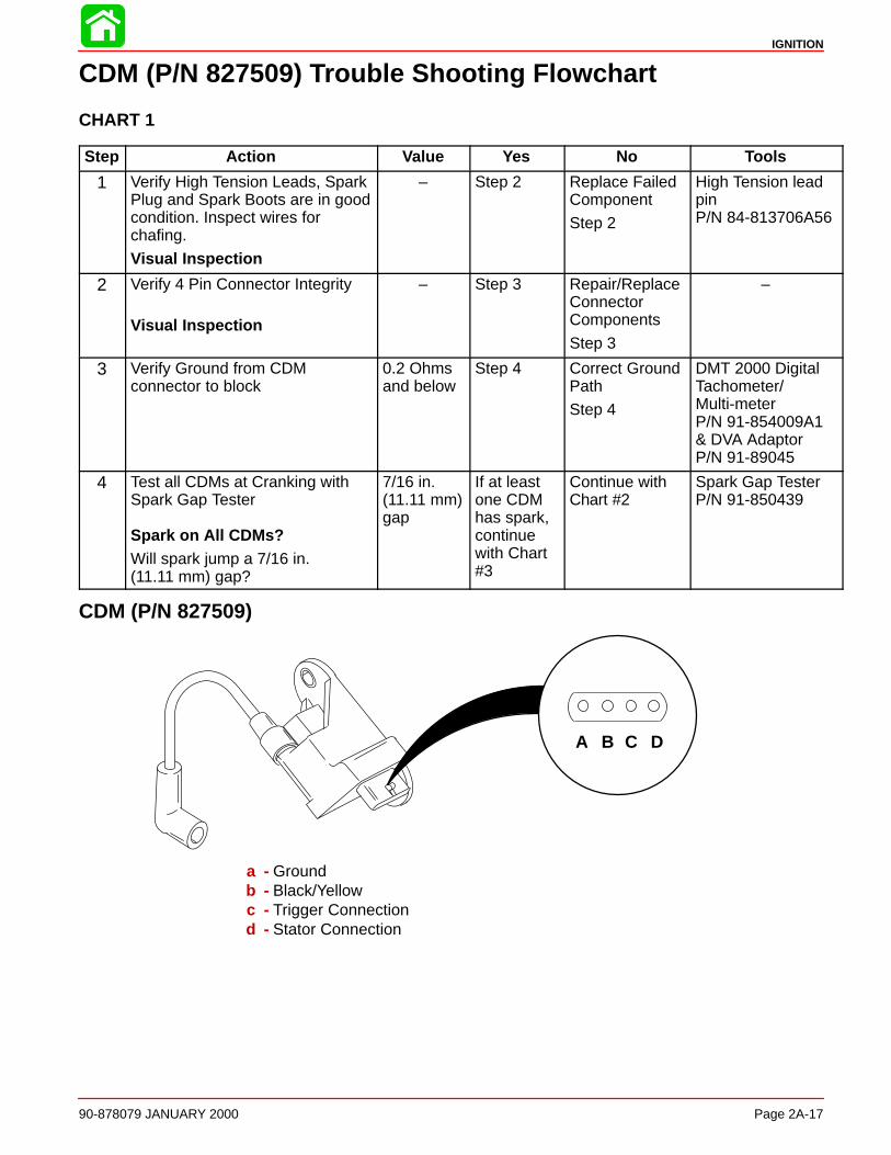
IGNITION
90-878079 JANUARY 2000 Page 2A-17
CDM (P/N 827509) Trouble Shooting Flowchart
CHART 1
Step Action Value Yes No Tools
1 Verify High Tension Leads, SparkPlug and Spark Boots are in goodcondition. Inspect wires forchafing.
Visual Inspection
– Step 2 Replace FailedComponent
Step 2
High Tension leadpin P/N 84-813706A56
2 Verify 4 Pin Connector Integrity
Visual Inspection
– Step 3 Repair/ReplaceConnectorComponents
Step 3
–
3 Verify Ground from CDMconnector to block
0.2 Ohmsand below
Step 4 Correct GroundPath
Step 4
DMT 2000 DigitalTachometer/Multi-meterP/N 91-854009A1& DVA AdaptorP/N 91-89045
4 Test all CDMs at Cranking withSpark Gap Tester
Spark on All CDMs?Will spark jump a 7/16 in. (11.11 mm) gap?
7/16 in.(11.11 mm)gap
If at leastone CDMhas spark,continuewith Chart#3
Continue withChart #2
Spark Gap TesterP/N 91-850439
CDM (P/N 827509)
A B C D
a - Groundb - Black/Yellowc - Trigger Connectiond - Stator Connection
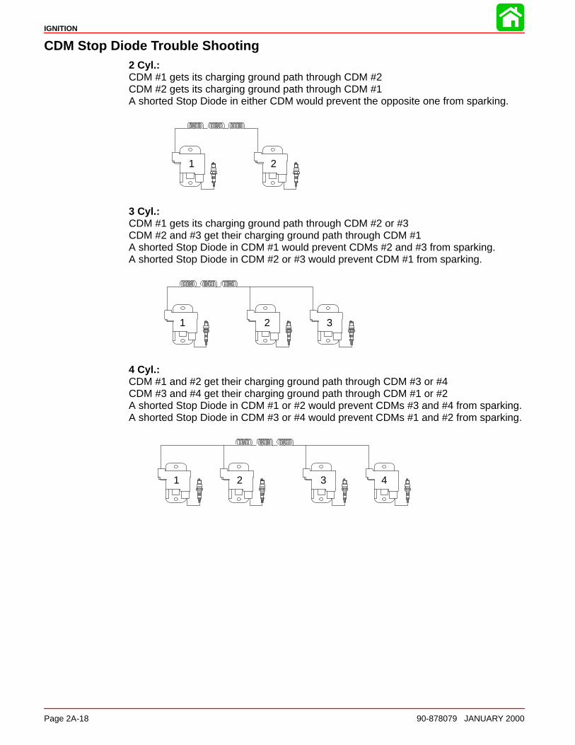
IGNITION
Page 2A-18 90-878079 JANUARY 2000
CDM Stop Diode Trouble Shooting2 Cyl.: CDM #1 gets its charging ground path through CDM #2CDM #2 gets its charging ground path through CDM #1A shorted Stop Diode in either CDM would prevent the opposite one from sparking.
1 2
3 Cyl.: CDM #1 gets its charging ground path through CDM #2 or #3CDM #2 and #3 get their charging ground path through CDM #1A shorted Stop Diode in CDM #1 would prevent CDMs #2 and #3 from sparking.A shorted Stop Diode in CDM #2 or #3 would prevent CDM #1 from sparking.
1 2 3
4 Cyl.: CDM #1 and #2 get their charging ground path through CDM #3 or #4CDM #3 and #4 get their charging ground path through CDM #1 or #2A shorted Stop Diode in CDM #1 or #2 would prevent CDMs #3 and #4 from sparking.A shorted Stop Diode in CDM #3 or #4 would prevent CDMs #1 and #2 from sparking.
1 2 3 4
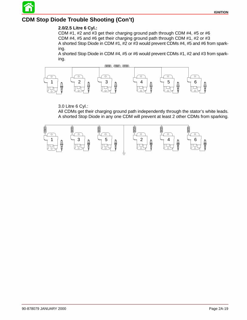
IGNITION
90-878079 JANUARY 2000 Page 2A-19
CDM Stop Diode Trouble Shooting (Con’t)2.0/2.5 Litre 6 Cyl.: CDM #1, #2 and #3 get their charging ground path through CDM #4, #5 or #6CDM #4, #5 and #6 get their charging ground path through CDM #1, #2 or #3A shorted Stop Diode in CDM #1, #2 or #3 would prevent CDMs #4, #5 and #6 from spark-ing.A shorted Stop Diode in CDM #4, #5 or #6 would prevent CDMs #1, #2 and #3 from spark-ing.
2 41 3 5 6
3.0 Litre 6 Cyl.: All CDMs get their charging ground path independently through the stator’s white leads.A shorted Stop Diode in any one CDM will prevent at least 2 other CDMs from sparking.
1 3 5 2 4 6
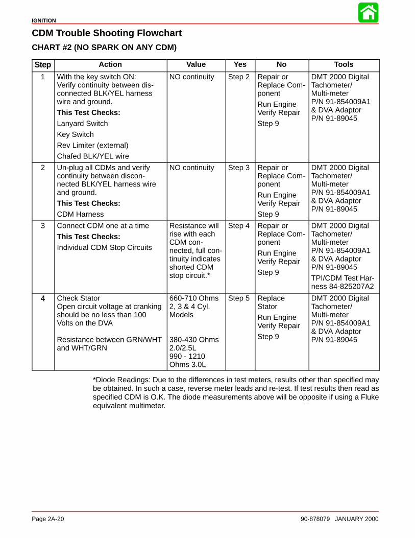
IGNITION
Page 2A-20 90-878079 JANUARY 2000
CDM Trouble Shooting FlowchartCHART #2 (NO SPARK ON ANY CDM)
Step Action Value Yes No Tools
1 With the key switch ON:Verify continuity between dis-connected BLK/YEL harnesswire and ground.
This Test Checks:Lanyard Switch
Key Switch
Rev Limiter (external)
Chafed BLK/YEL wire
NO continuity Step 2 Repair or Replace Com-ponent
Run EngineVerify Repair
Step 9
DMT 2000 DigitalTachometer/Multi-meterP/N 91-854009A1& DVA AdaptorP/N 91-89045
2 Un-plug all CDMs and verifycontinuity between discon-nected BLK/YEL harness wireand ground.
This Test Checks:CDM Harness
NO continuity Step 3 Repair or Replace Com-ponent
Run EngineVerify Repair
Step 9
DMT 2000 DigitalTachometer/Multi-meterP/N 91-854009A1& DVA AdaptorP/N 91-89045
3 Connect CDM one at a time
This Test Checks:Individual CDM Stop Circuits
Resistance willrise with eachCDM con-nected, full con-tinuity indicatesshorted CDMstop circuit.*
Step 4 Repair or Replace Com-ponent
Run EngineVerify Repair
Step 9
DMT 2000 DigitalTachometer/Multi-meterP/N 91-854009A1& DVA AdaptorP/N 91-89045
TPI/CDM Test Har-ness 84-825207A2
4 Check StatorOpen circuit voltage at crankingshould be no less than 100Volts on the DVA
Resistance between GRN/WHTand WHT/GRN
660-710 Ohms2, 3 & 4 Cyl.Models
380-430 Ohms2.0/2.5L990 - 1210Ohms 3.0L
Step 5 Replace Stator
Run EngineVerify Repair
Step 9
DMT 2000 DigitalTachometer/Multi-meterP/N 91-854009A1& DVA AdaptorP/N 91-89045
*Diode Readings: Due to the differences in test meters, results other than specified maybe obtained. In such a case, reverse meter leads and re-test. If test results then read asspecified CDM is O.K. The diode measurements above will be opposite if using a Flukeequivalent multimeter.
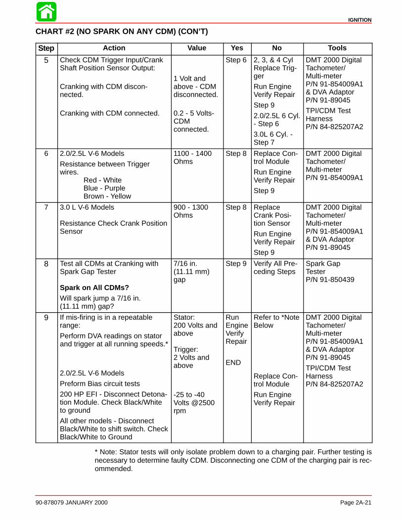
IGNITION
90-878079 JANUARY 2000 Page 2A-21
CHART #2 (NO SPARK ON ANY CDM) (CON’T)
Step Action Value Yes No Tools
5 Check CDM Trigger Input/CrankShaft Position Sensor Output:
Cranking with CDM discon-nected.
Cranking with CDM connected.
1 Volt andabove - CDMdisconnected.
0.2 - 5 Volts-CDM connected.
Step 6 2, 3, & 4 CylReplace Trig-ger
Run EngineVerify Repair
Step 9
2.0/2.5L 6 Cyl.- Step 6
3.0L 6 Cyl. -Step 7
DMT 2000 DigitalTachometer/Multi-meterP/N 91-854009A1& DVA AdaptorP/N 91-89045
TPI/CDM TestHarnessP/N 84-825207A2
6 2.0/2.5L V-6 Models
Resistance between Triggerwires.
Red - WhiteBlue - PurpleBrown - Yellow
1100 - 1400Ohms
Step 8 Replace Con-trol Module
Run EngineVerify Repair
Step 9
DMT 2000 DigitalTachometer/Multi-meterP/N 91-854009A1
7 3.0 L V-6 Models
Resistance Check Crank PositionSensor
900 - 1300Ohms
Step 8 ReplaceCrank Posi-tion Sensor
Run EngineVerify Repair
Step 9
DMT 2000 DigitalTachometer/Multi-meterP/N 91-854009A1& DVA AdaptorP/N 91-89045
8 Test all CDMs at Cranking withSpark Gap Tester
Spark on All CDMs?Will spark jump a 7/16 in. (11.11 mm) gap?
7/16 in. (11.11 mm)gap
Step 9 Verify All Pre-ceding Steps
Spark Gap Tester P/N 91-850439
9 If mis-firing is in a repeatablerange:
Perform DVA readings on statorand trigger at all running speeds.*
2.0/2.5L V-6 Models
Preform Bias circuit tests
200 HP EFI - Disconnect Detona-tion Module. Check Black/Whiteto ground
All other models - DisconnectBlack/White to shift switch. CheckBlack/White to Ground
Stator: 200 Volts andabove
Trigger:2 Volts andabove
-25 to -40Volts @2500rpm
RunEngineVerifyRepair
END
Refer to *NoteBelow
Replace Con-trol Module
Run EngineVerify Repair
DMT 2000 DigitalTachometer/Multi-meterP/N 91-854009A1& DVA AdaptorP/N 91-89045
TPI/CDM TestHarnessP/N 84-825207A2
* Note: Stator tests will only isolate problem down to a charging pair. Further testing isnecessary to determine faulty CDM. Disconnecting one CDM of the charging pair is rec-ommended.
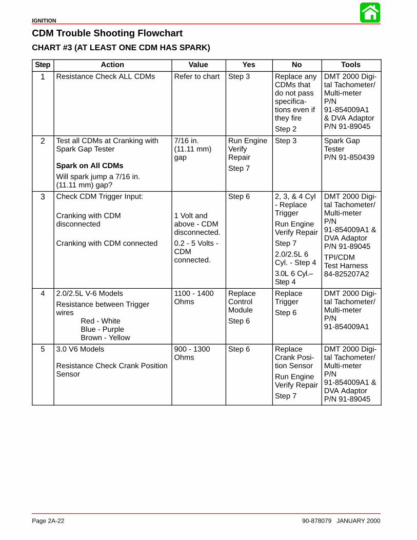
IGNITION
Page 2A-22 90-878079 JANUARY 2000
CDM Trouble Shooting FlowchartCHART #3 (AT LEAST ONE CDM HAS SPARK)
Step Action Value Yes No Tools
1 Resistance Check ALL CDMs Refer to chart Step 3 Replace anyCDMs thatdo not passspecifica-tions even ifthey fire
Step 2
DMT 2000 Digi-tal Tachometer/Multi-meterP/N91-854009A1& DVA AdaptorP/N 91-89045
2 Test all CDMs at Cranking withSpark Gap Tester
Spark on All CDMsWill spark jump a 7/16 in. (11.11 mm) gap?
7/16 in. (11.11 mm)gap
Run EngineVerifyRepair
Step 7
Step 3 Spark Gap Tester P/N 91-850439
3 Check CDM Trigger Input:
Cranking with CDMdisconnected
Cranking with CDM connected
1 Volt andabove - CDM disconnected.
0.2 - 5 Volts -CDM connected.
Step 6 2, 3, & 4 Cyl- ReplaceTrigger
Run EngineVerify Repair
Step 7
2.0/2.5L 6Cyl. - Step 4
3.0L 6 Cyl.–Step 4
DMT 2000 Digi-tal Tachometer/Multi-meterP/N91-854009A1 &DVA AdaptorP/N 91-89045
TPI/CDMTest Harness84-825207A2
4 2.0/2.5L V-6 Models
Resistance between Triggerwires
Red - WhiteBlue - PurpleBrown - Yellow
1100 - 1400Ohms
ReplaceControlModule
Step 6
ReplaceTrigger
Step 6
DMT 2000 Digi-tal Tachometer/Multi-meterP/N91-854009A1
5 3.0 V6 Models
Resistance Check Crank PositionSensor
900 - 1300Ohms
Step 6 ReplaceCrank Posi-tion Sensor
Run EngineVerify Repair
Step 7
DMT 2000 Digi-tal Tachometer/Multi-meterP/N91-854009A1 &DVA AdaptorP/N 91-89045

IGNITION
90-878079 JANUARY 2000 Page 2A-23
CHART #3 (AT LEAST ONE CDM HAS SPARK) (CON’T)
Step Action Value Yes No Tools
6 Test all CDMs at Cranking withSpark Gap Tester
Spark on All CDMs?Will spark jump a 7/16 in. (11.11 mm) gap?
7/16 in. (11.11 mm)gap
Run EngineVerify Repair
Step 7
Replace anynon-firingCDMs
Step 7
Spark Gap Tester P/N 91-850439
7 If mis-firing is in a repeatablerange:
Perform DVA readings on statorand trigger at all running speeds.*
2.0/2.5L V-6 Models
Preform Bias circuit tests
200 HP EFI - Disconnect Detona-tion Module. Check Black/White toground
All other models - DisconnectBlack/White to shift switch. CheckBlack/White to Ground
Stator: 200 Voltsand above
Trigger:2 Volts andabove
-25 to -40Volts @2500rpm
Run EngineVerify Repair
END
Refer to*Note Below
ReplaceControlModule
Run EngineVerify Repair
DMT 2000 Dig-ital Tachome-ter/Multi-meterP/N91-854009A1& DVA AdaptorP/N 91-89045
TPI/CDM TestHarness84-825207A2
6 Pin Connec-tor
* Note: Stator tests will only isolate problem down to a charging pair. Further testing isnecessary to determine faulty CDM. Disconnecting one CDM of the charging pair is rec-ommended.
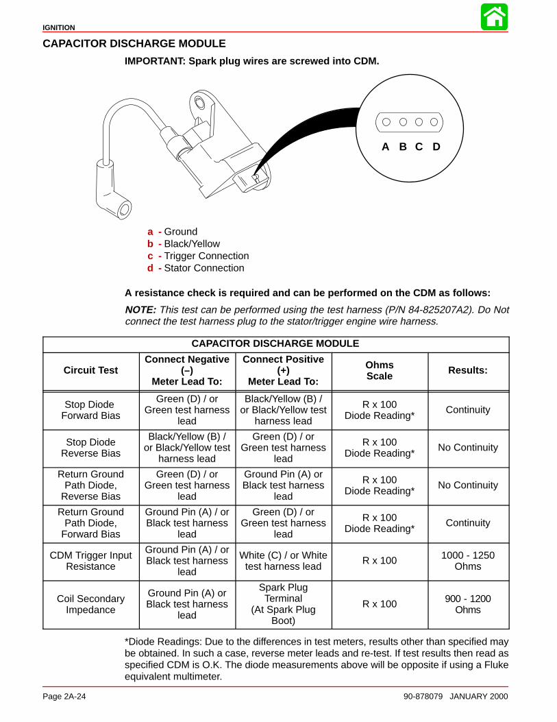
IGNITION
Page 2A-24 90-878079 JANUARY 2000
CAPACITOR DISCHARGE MODULE
IMPORTANT: Spark plug wires are screwed into CDM.
A B C D
a - Groundb - Black/Yellowc - Trigger Connectiond - Stator Connection
A resistance check is required and can be performed on the CDM as follows:
NOTE: This test can be performed using the test harness (P/N 84-825207A2). Do Notconnect the test harness plug to the stator/trigger engine wire harness.
CAPACITOR DISCHARGE MODULE
Circuit TestConnect Negative
(–)Meter Lead To:
Connect Positive(+)
Meter Lead To:
OhmsScale Results:
Stop Diode Forward Bias
Green (D) / orGreen test harness
lead
Black/Yellow (B) /or Black/Yellow test
harness lead
R x 100Diode Reading*
Continuity
Stop DiodeReverse Bias
Black/Yellow (B) /or Black/Yellow test
harness lead
Green (D) / orGreen test harness
lead
R x 100Diode Reading*
No Continuity
Return GroundPath Diode,
Reverse Bias
Green (D) / orGreen test harness
lead
Ground Pin (A) orBlack test harness
lead
R x 100Diode Reading*
No Continuity
Return GroundPath Diode,
Forward Bias
Ground Pin (A) / orBlack test harness
lead
Green (D) / orGreen test harness
lead
R x 100Diode Reading*
Continuity
CDM Trigger InputResistance
Ground Pin (A) / orBlack test harness
lead
White (C) / or Whitetest harness lead
R x 100 1000 - 1250Ohms
Coil SecondaryImpedance
Ground Pin (A) orBlack test harness
lead
Spark PlugTerminal
(At Spark PlugBoot)
R x 100 900 - 1200Ohms
*Diode Readings: Due to the differences in test meters, results other than specified maybe obtained. In such a case, reverse meter leads and re-test. If test results then read asspecified CDM is O.K. The diode measurements above will be opposite if using a Flukeequivalent multimeter.
IGNITION
90-878079 JANUARY 2000 Page 2A-25
Direct Voltage Adaptor (DVA)The DVA can be used with Quicksilver DMT 854009A1, VOA Meter 91-99750A1, Quick-silver Volt/Ohm meter 91-93572, or an equivalent volt meter (capable of measuring 400volts DC or higher) to check primary ignition voltage on Alternator Driven Ignition (ADI)systems. (Models are specified in Test Charts, following.)
CAUTIONTo protect against meter and/or component damage, observe the following pre-cautions:
-- MAKE CERTAIN that Positive (+) lead/terminal of DVA is connected to Positive(+) receptacle of meter.
-- 400 VDC test position (or higher) MUST BE used for all tests, except “TriggerOhms” test.
-- DO NOT CHANGE meter selector switch position while engine is running and/or“cranked.”
WARNINGDANGER - HIGH VOLTAGE/SHOCK HAZARD! Do Not t ouch ignition componentsand/or metal test probes while engine is running and/or “cranked.”
Test procedures and specifications are provided for checking primary ignition voltagewhile the engine is running and/or being “cranked.”
Troubleshooting Tips1. Intermittent, weak or no spark output at any one spark plug (single cylinder) usually
is a bad CDM or control module.
2. Intermittent, weak or no spark output at two spark plugs (one plug from each bank ofthree cylinders) usually is caused by a bad TRIGGER.
3. Intermittent, weak or no spark output at three spark plugs (1,2, & 3 or 4, 5, & 6) usuallyis caused by a bad CDM.
4. No spark output on any spark plug (six cylinders) usually is a bad stop circuit, statoror control module.
5. Erratic timing or an engine that will not idle down usually has a failure in the bias circuitinside the control module.

IGNITION
Page 2A-26 90-878079 JANUARY 2000
Ignition Test Procedures
Direct Voltage Adaptor (DVA) Test
CAUTIONDVA checks can be made while cranking engine with starter motor. To preventengine from starting while being cranked, all spark plugs must be removed.
CAUTIONTo protect against meter and/or component damage, observe the following pre-cautions:
• INSURE that the Positive (+) meter lead is connected to the DVA receptacle onthe meter.
• DO NOT CHANGE meter selector switch position while engine is running and/orbeing “cranked”.
• DO NOT reverse battery cable connections. The battery negative cable is (–)ground.
• DO NOT “spark” battery terminals with battery cable connections to check po-larity.
• DO NOT disconnect battery cables while engine is running.
A process of elimination must be used when checking the ignition system without a volt-meter (capable of measuring 400 volts DC, or higher) and Direct Voltage Adaptor(91-89045), as the control module cannot be thoroughly checked with conventional testequipment.
All other components can be tested with an ohmmeter. Before troubleshooting the ignitionsystem, check the following:
1. Make sure that electrical harness and ignition switch are not the source of the prob-lem.
2. Check that plug-in connectors are fully engaged and terminals are free of corrosion.
3. Make sure that wire connections are tight and free of corrosion.
4. Check all electrical components, that are grounded directly to engine, and all groundwires to see that they are grounded to engine.
5. Check for disconnected wires and short and open circuits.

IGNITION
90-878079 JANUARY 2000 Page 2A-27
NOTE: Each CDM is grounded through the engine wiring harness via the connector plug.It is not necessary to have the CDM mounted on the ignition plate for testing.
1. Remove all spark plugs.
2. Insert spark gap tool (P/N 91-63998A1) into each spark plug boot and attach alligatorclips to a good engine ground.
3. Disconnect remote fuel line from engine.
4. Make sure all CDMs are plugged in.
5. Test Stator and Trigger voltage to CDM:
a. Install test harness (84-825207A2) between ignition harness and CDM.
a bc
a - Stator/Trigger Harnessb - Test Harness (84-825207A2)c - Capacitor Discharge Module
b. Test each CDM.
Stator Output Test 400 DVA Scale
Positive Meter Lead (+) NegativeMeter Lead (–)
DVAReading
Connect to Green TestHarness Lead
Connect to Black TestHarness Lead 160 - 320
If only one CDM stator reading is below specifications, replace that CDM. If all CDM statorvoltage readings are low, go to “Testing Stator Resistance”.
58049
Test each CDM.

IGNITION
Page 2A-28 90-878079 JANUARY 2000
CDM Trigger Input Test 2 DVA Scale
Positive Meter Lead (+) NegativeMeter Lead (–)
DVAReading @ Cranking
White Test Harness Lead Black Test Harness Lead 0.2 - 2.0
If reading is below specifications, test trigger resistance. If reading is above specifica-tions, check CDM and ground connections.
58049
IGNITION
90-878079 JANUARY 2000 Page 2A-29
ENGINE RUNNING AT 2500 RPM
It is not necessary to perform this test if the voltage output was tested in the previous step.
Stator Output Test 400 DVA Scale
Positive Meter Lead (+) NegativeMeter Lead (–)
DVAReading
Connect to Green TestHarness Lead
Connect to Black Test Har-ness Lead 160 - 320
If stator output is low, go to “Testing Stator Resistance”.
CDM Trigger Input Test 20 DVA Scale
Positive Meter Lead (+) NegativeMeter Lead (–)
DVAReading @ Idle to 2500
RPM
White Test Harness Lead Black Test Harness Lead 2 - 8 Volts
If reading is below specifications, go to “Testing Trigger Resistance”. If reading is abovespecifications, check CDM and ground connections.
2.0/2.5L V-6 Models Only - Check control module bias circuit
Bias Circuit Test (All Models Except 200 EFI) 40 DVA Scale@2500 RPM
Positive Meter Lead (+) NegativeMeter Lead (–)
DVAReading
Engine Ground Black/White Shift SwitchWire 25 - 40 Volts
Bias Circuit Test (200 EFI) 40 DVA Scale@2500 RPM
Positive Meter Lead (+) NegativeMeter Lead (–)
DVAReading
Engine Ground Disconnect 4 wire Detona-tion Control Module con-nector. Insert bent paperclip into Black/White termi-nal.
25 - 40 Volts
If reading is below specifications, replace control module.

IGNITION
Page 2A-30 90-878079 JANUARY 2000
Resistance TestsTRIGGER ASSEMBLY TEST
1. Disconnect all trigger leads from control module.
2. Use an ohmmeter and perform the following checks:
TestLeads to
ResistanceOhms
ScaleReading
Between BROWN Trigger Leadand YELLOW Trigger Lead
1100-1400 R x 100
Between WHITE Trigger Leadand RED Trigger Lead
1100-1400 R x 100
Between PURPLE Trigger Leadand BLUE Trigger Lead
1100-1400 R x 100
3. If meter readings are not as specified, replace trigger assembly.
STATOR
1. Disconnect stator leads.
NOTE: Resistance varies greatly with temperature. Measurements should be taken withthe stator temperature range of 65° to 85° F. The ignition bobbin resistance may rise to1.5 times the room temperature resistance value after the engine has been running andengine block temperature has stabilized.
Stator Resistance TestR 1 Oh S lPositive Meter Lead (+) Negative
Meter Lead (–)
R x 1 Ohms Scale
Connect to White/Green sta-tor lead
Connect to Green/White sta-tor lead 380-430
Connect to White/Green sta-tor lead
Connect to engine groundNo continuity
Connect to Green/White sta-tor lead
Connect to engine groundNo continuity
IMPORTANT: If all CDM stator output voltage is low and stator resistance tests arewithin specifications, then each CDM (one at a time) must be replaced with a CDMknown to be good until stator output voltage returns to proper levels. This processof elimination will reveal a defective CDM.
Bias Circuit
Bias voltage is NEGATIVE (-) voltage applied to the ignition system to raise the triggerfiring threshold as engine rpm is increased, thus stabilizing ignition timing and preventingrandom ignition firing.
Refer to Bias Circuit Test page 2A-29 to check bias circuit on carburetor and EFI modeloutboards.
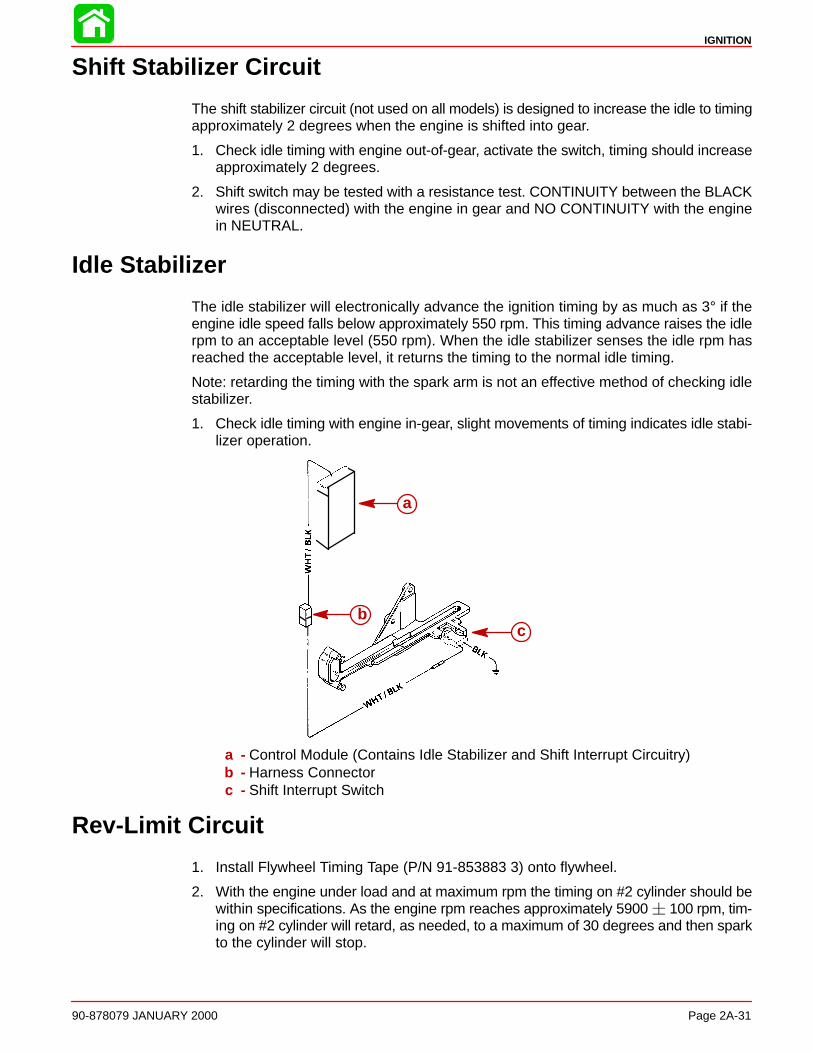
IGNITION
90-878079 JANUARY 2000 Page 2A-31
Shift Stabilizer Circuit
The shift stabilizer circuit (not used on all models) is designed to increase the idle to timingapproximately 2 degrees when the engine is shifted into gear.
1. Check idle timing with engine out-of-gear, activate the switch, timing should increaseapproximately 2 degrees.
2. Shift switch may be tested with a resistance test. CONTINUITY between the BLACKwires (disconnected) with the engine in gear and NO CONTINUITY with the enginein NEUTRAL.
Idle Stabilizer
The idle stabilizer will electronically advance the ignition timing by as much as 3° if theengine idle speed falls below approximately 550 rpm. This timing advance raises the idlerpm to an acceptable level (550 rpm). When the idle stabilizer senses the idle rpm hasreached the acceptable level, it returns the timing to the normal idle timing.
Note: retarding the timing with the spark arm is not an effective method of checking idlestabilizer.
1. Check idle timing with engine in-gear, slight movements of timing indicates idle stabi-lizer operation.
a
bc
a - Control Module (Contains Idle Stabilizer and Shift Interrupt Circuitry)b - Harness Connectorc - Shift Interrupt Switch
Rev-Limit Circuit
1. Install Flywheel Timing Tape (P/N 91-853883 3) onto flywheel.
2. With the engine under load and at maximum rpm the timing on #2 cylinder should bewithin specifications. As the engine rpm reaches approximately 5900 100 rpm, tim-ing on #2 cylinder will retard, as needed, to a maximum of 30 degrees and then sparkto the cylinder will stop.
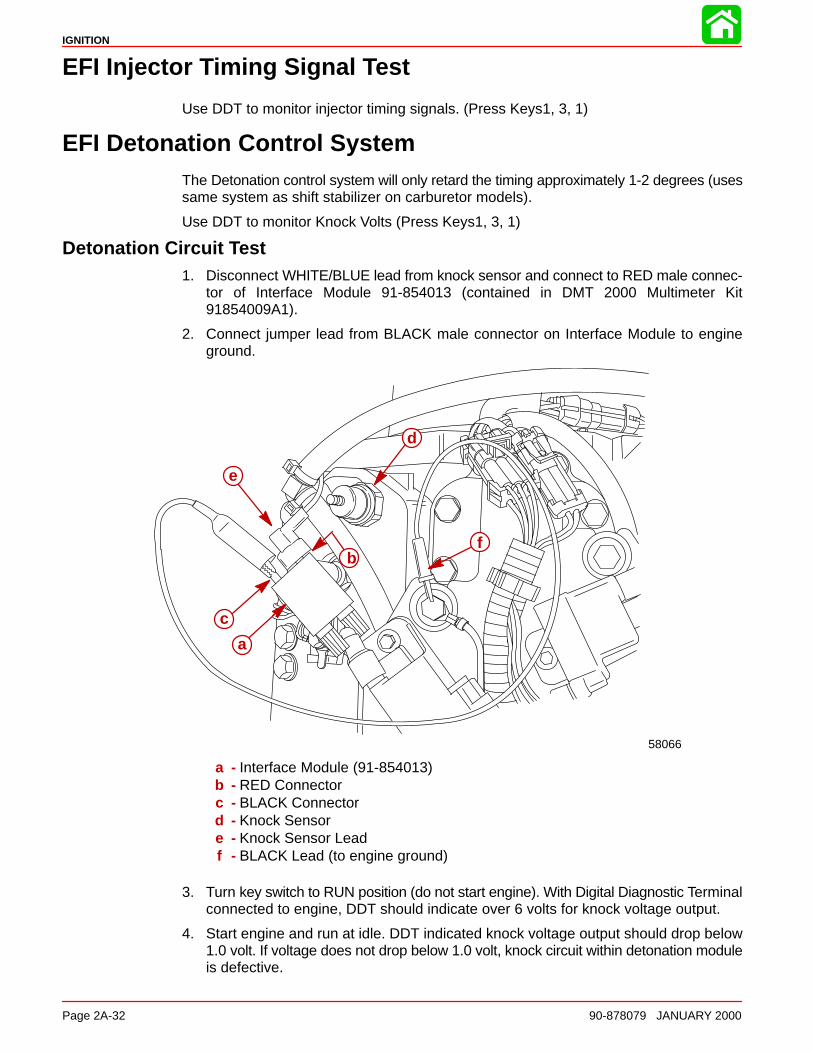
IGNITION
Page 2A-32 90-878079 JANUARY 2000
EFI Injector Timing Signal Test
Use DDT to monitor injector timing signals. (Press Keys1, 3, 1)
EFI Detonation Control SystemThe Detonation control system will only retard the timing approximately 1-2 degrees (usessame system as shift stabilizer on carburetor models).
Use DDT to monitor Knock Volts (Press Keys1, 3, 1)
Detonation Circuit Test1. Disconnect WHITE/BLUE lead from knock sensor and connect to RED male connec-
tor of Interface Module 91-854013 (contained in DMT 2000 Multimeter Kit91854009A1).
2. Connect jumper lead from BLACK male connector on Interface Module to engineground.
58066
a
b
c
d
e
f
a - Interface Module (91-854013)b - RED Connectorc - BLACK Connectord - Knock Sensore - Knock Sensor Leadf - BLACK Lead (to engine ground)
3. Turn key switch to RUN position (do not start engine). With Digital Diagnostic Terminalconnected to engine, DDT should indicate over 6 volts for knock voltage output.
4. Start engine and run at idle. DDT indicated knock voltage output should drop below1.0 volt. If voltage does not drop below 1.0 volt, knock circuit within detonation moduleis defective.
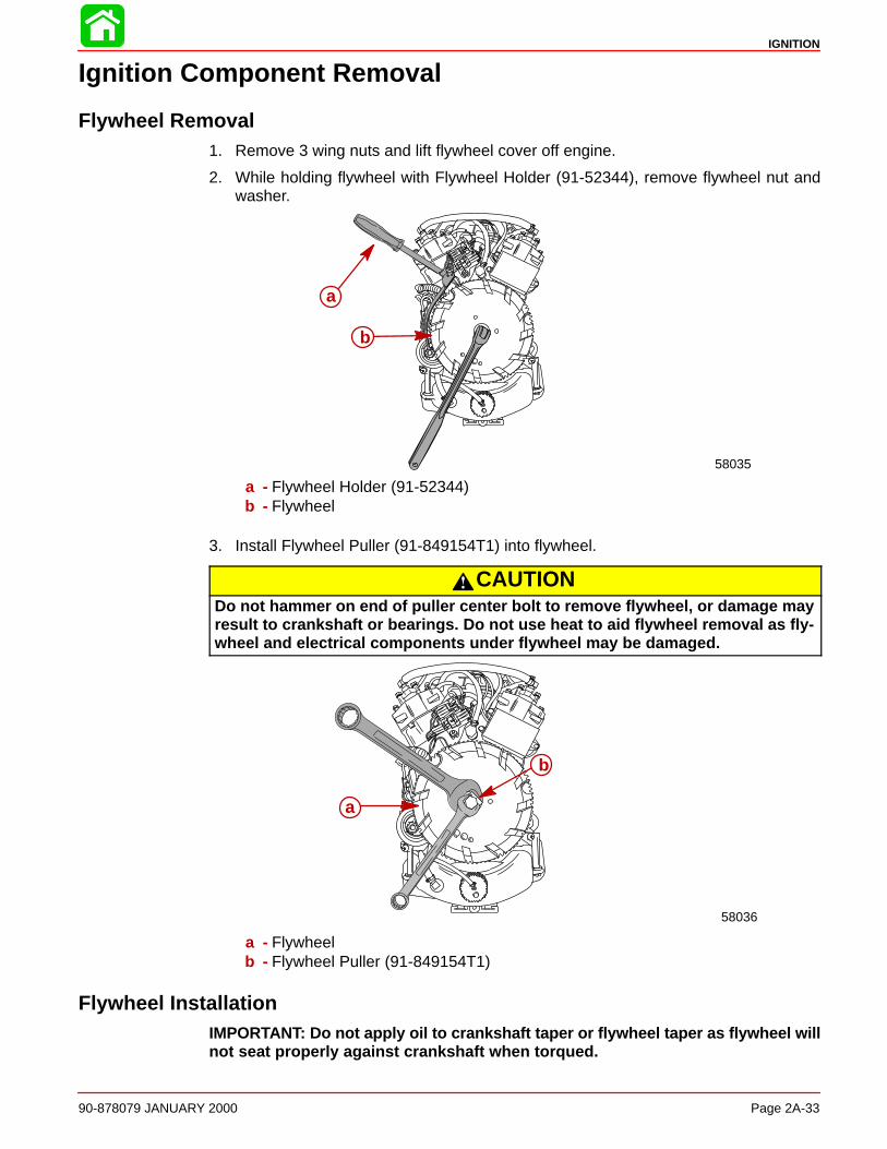
IGNITION
90-878079 JANUARY 2000 Page 2A-33
Ignition Component Removal
Flywheel Removal1. Remove 3 wing nuts and lift flywheel cover off engine.
2. While holding flywheel with Flywheel Holder (91-52344), remove flywheel nut andwasher.
58035
a
b
a - Flywheel Holder (91-52344)b - Flywheel
3. Install Flywheel Puller (91-849154T1) into flywheel.
CAUTIONDo not hammer on end of puller center bolt to remove flywheel, or damage mayresult to crankshaft or bearings. Do not use heat to aid flywheel removal as fly-wheel and electrical components under flywheel may be damaged.
58036
a
b
a - Flywheelb - Flywheel Puller (91-849154T1)
Flywheel InstallationIMPORTANT: Do not apply oil to crankshaft taper or flywheel taper as flywheel willnot seat properly against crankshaft when torqued.
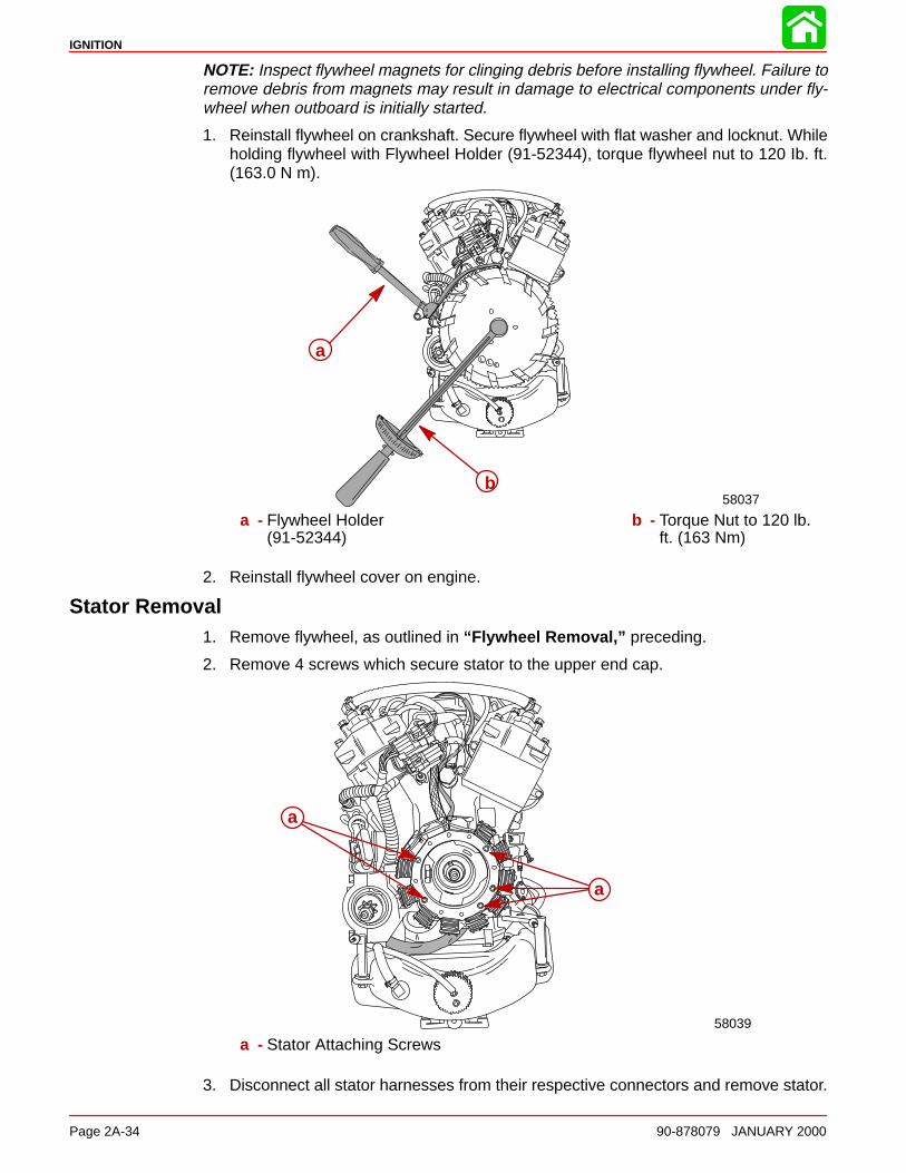
IGNITION
Page 2A-34 90-878079 JANUARY 2000
NOTE: Inspect flywheel magnets for clinging debris before installing flywheel. Failure toremove debris from magnets may result in damage to electrical components under fly-wheel when outboard is initially started.
1. Reinstall flywheel on crankshaft. Secure flywheel with flat washer and locknut. Whileholding flywheel with Flywheel Holder (91-52344), torque flywheel nut to 120 Ib. ft.(163.0 N m).
58037b
a
a - Flywheel Holder(91-52344)
b - Torque Nut to 120 lb.ft. (163 Nm)
2. Reinstall flywheel cover on engine.
Stator Removal1. Remove flywheel, as outlined in “Flywheel Removal,” preceding.
2. Remove 4 screws which secure stator to the upper end cap.
a
a
58039
a - Stator Attaching Screws
3. Disconnect all stator harnesses from their respective connectors and remove stator.
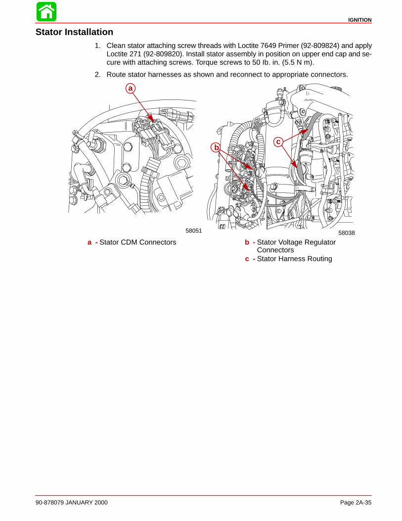
IGNITION
90-878079 JANUARY 2000 Page 2A-35
Stator Installation1. Clean stator attaching screw threads with Loctite 7649 Primer (92-809824) and apply
Loctite 271 (92-809820). Install stator assembly in position on upper end cap and se-cure with attaching screws. Torque screws to 50 Ib. in. (5.5 N m).
2. Route stator harnesses as shown and reconnect to appropriate connectors.
58038
bc
58051
a
a - Stator CDM Connectors b - Stator Voltage Regulator Connectors
c - Stator Harness Routing
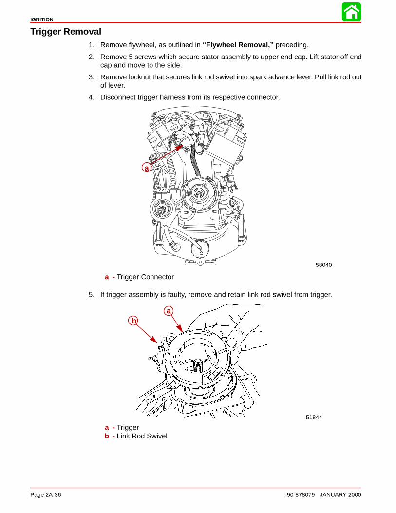
IGNITION
Page 2A-36 90-878079 JANUARY 2000
Trigger Removal1. Remove flywheel, as outlined in “Flywheel Removal,” preceding.
2. Remove 5 screws which secure stator assembly to upper end cap. Lift stator off endcap and move to the side.
3. Remove locknut that secures link rod swivel into spark advance lever. Pull link rod outof lever.
4. Disconnect trigger harness from its respective connector.
58040
a
a - Trigger Connector
5. If trigger assembly is faulty, remove and retain link rod swivel from trigger.
51844
ba
a - Triggerb - Link Rod Swivel
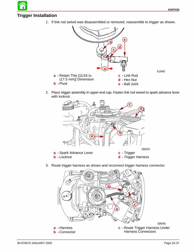
IGNITION
90-878079 JANUARY 2000 Page 2A-37
Trigger Installation1. If link rod swivel was disassembled or removed, reassemble to trigger as shown.
51840
e
dc
b
a
a - Retain This [11/16 in.(17.5 mm)] Dimension
b - Pivot
c - Link Rodd - Hex Nute - Ball Joint
2. Place trigger assembly in upper end cap. Fasten link rod swivel to spark advance leverwith locknut.
58203
ba
cd
a - Spark Advance Leverb - Locknut
c - Triggerd - Trigger Harness
3. Route trigger harness as shown and reconnect trigger harness connector.
58040
b
ca
a - Harnessb - Connector
c - Route Trigger Harness Under Harness Connectors
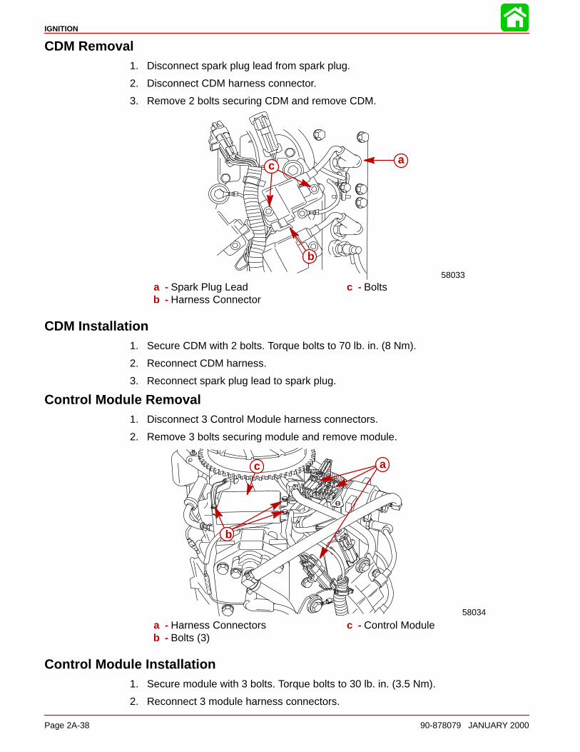
IGNITION
Page 2A-38 90-878079 JANUARY 2000
CDM Removal1. Disconnect spark plug lead from spark plug.
2. Disconnect CDM harness connector.
3. Remove 2 bolts securing CDM and remove CDM.
58033
a
b
c
a - Spark Plug Leadb - Harness Connector
c - Bolts
CDM Installation1. Secure CDM with 2 bolts. Torque bolts to 70 lb. in. (8 Nm).
2. Reconnect CDM harness.
3. Reconnect spark plug lead to spark plug.
Control Module Removal1. Disconnect 3 Control Module harness connectors.
2. Remove 3 bolts securing module and remove module.
58034
a
b
c
a - Harness Connectorsb - Bolts (3)
c - Control Module
Control Module Installation1. Secure module with 3 bolts. Torque bolts to 30 lb. in. (3.5 Nm).
2. Reconnect 3 module harness connectors.
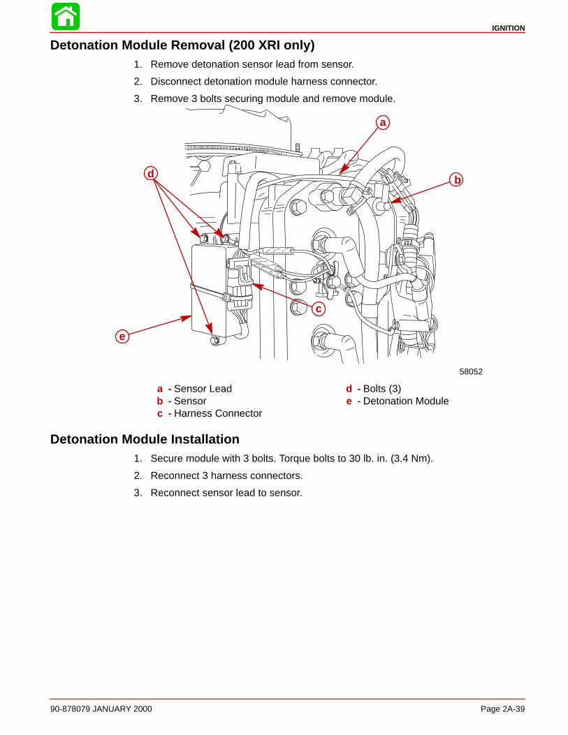
IGNITION
90-878079 JANUARY 2000 Page 2A-39
Detonation Module Removal (200 XRI only)1. Remove detonation sensor lead from sensor.
2. Disconnect detonation module harness connector.
3. Remove 3 bolts securing module and remove module.
58052
a
bd
c
e
a - Sensor Leadb - Sensorc - Harness Connector
d - Bolts (3)e - Detonation Module
Detonation Module Installation1. Secure module with 3 bolts. Torque bolts to 30 lb. in. (3.4 Nm).
2. Reconnect 3 harness connectors.
3. Reconnect sensor lead to sensor.
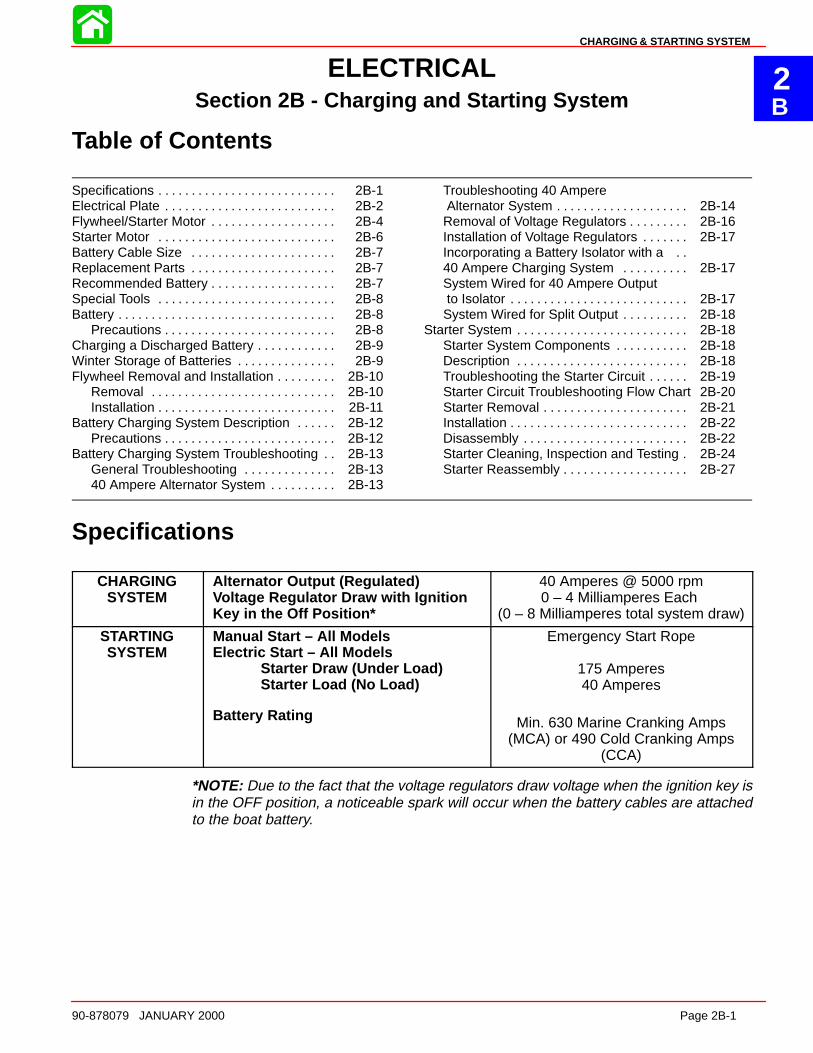
2B
CHARGING & STARTING SYSTEM
90-878079 JANUARY 2000 Page 2B-1
ELECTRICALSection 2B - Charging and Starting System
Table of Contents
Specifications 2B-1. . . . . . . . . . . . . . . . . . . . . . . . . . . Electrical Plate 2B-2. . . . . . . . . . . . . . . . . . . . . . . . . . Flywheel/Starter Motor 2B-4. . . . . . . . . . . . . . . . . . . Starter Motor 2B-6. . . . . . . . . . . . . . . . . . . . . . . . . . . Battery Cable Size 2B-7. . . . . . . . . . . . . . . . . . . . . . Replacement Parts 2B-7. . . . . . . . . . . . . . . . . . . . . . Recommended Battery 2B-7. . . . . . . . . . . . . . . . . . . Special Tools 2B-8. . . . . . . . . . . . . . . . . . . . . . . . . . . Battery 2B-8. . . . . . . . . . . . . . . . . . . . . . . . . . . . . . . . .
Precautions 2B-8. . . . . . . . . . . . . . . . . . . . . . . . . . Charging a Discharged Battery 2B-9. . . . . . . . . . . . Winter Storage of Batteries 2B-9. . . . . . . . . . . . . . . Flywheel Removal and Installation 2B-10. . . . . . . . .
Removal 2B-10. . . . . . . . . . . . . . . . . . . . . . . . . . . . Installation 2B-11. . . . . . . . . . . . . . . . . . . . . . . . . . .
Battery Charging System Description 2B-12. . . . . . Precautions 2B-12. . . . . . . . . . . . . . . . . . . . . . . . . .
Battery Charging System Troubleshooting 2B-13. . General Troubleshooting 2B-13. . . . . . . . . . . . . . 40 Ampere Alternator System 2B-13. . . . . . . . . .
Troubleshooting 40 Ampere Alternator System 2B-14. . . . . . . . . . . . . . . . . . . . Removal of Voltage Regulators 2B-16. . . . . . . . . Installation of Voltage Regulators 2B-17. . . . . . . Incorporating a Battery Isolator with a . . 40 Ampere Charging System 2B-17. . . . . . . . . . System Wired for 40 Ampere Output to Isolator 2B-17. . . . . . . . . . . . . . . . . . . . . . . . . . . System Wired for Split Output 2B-18. . . . . . . . . .
Starter System 2B-18. . . . . . . . . . . . . . . . . . . . . . . . . . Starter System Components 2B-18. . . . . . . . . . . Description 2B-18. . . . . . . . . . . . . . . . . . . . . . . . . . Troubleshooting the Starter Circuit 2B-19. . . . . . Starter Circuit Troubleshooting Flow Chart 2B-20Starter Removal 2B-21. . . . . . . . . . . . . . . . . . . . . . Installation 2B-22. . . . . . . . . . . . . . . . . . . . . . . . . . . Disassembly 2B-22. . . . . . . . . . . . . . . . . . . . . . . . . Starter Cleaning, Inspection and Testing 2B-24. Starter Reassembly 2B-27. . . . . . . . . . . . . . . . . . .
Specifications
CHARGINGSYSTEM
Alternator Output (Regulated) Voltage Regulator Draw with IgnitionKey in the Off Position*
40 Amperes @ 5000 rpm0 – 4 Milliamperes Each
(0 – 8 Milliamperes total system draw)
STARTINGSYSTEM
Manual Start – All ModelsElectric Start – All Models
Starter Draw (Under Load)Starter Load (No Load)
Battery Rating
Emergency Start Rope
175 Amperes40 Amperes
Min. 630 Marine Cranking Amps(MCA) or 490 Cold Cranking Amps
(CCA)
*NOTE: Due to the fact that the voltage regulators draw voltage when the ignition key isin the OFF position, a noticeable spark will occur when the battery cables are attachedto the boat battery.
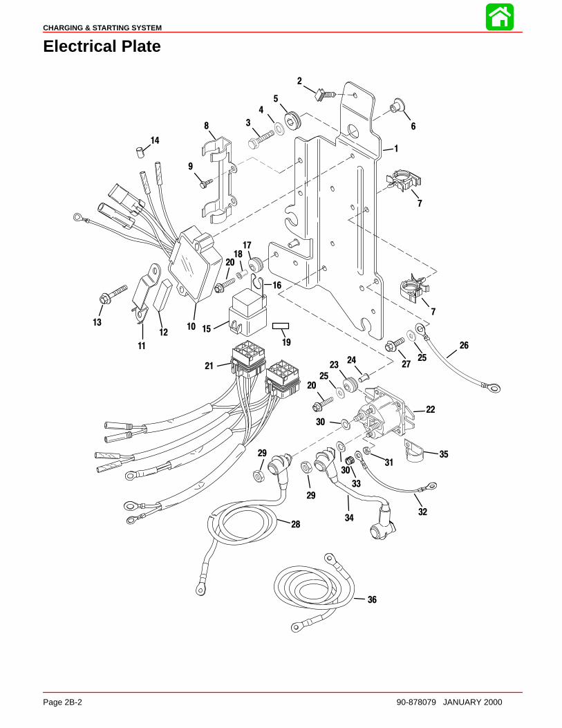
CHARGING & STARTING SYSTEM
Page 2B-2 90-878079 JANUARY 2000
Electrical Plate
1
5
6
10
11
12
13
8
9
22
2324
20
25
28
3031
32
33
34
35
7
26
27
3
15
16
17
19
21
14
36
29
2
4
18
7
25
30
29
20

CHARGING & STARTING SYSTEM
90-878079 JANUARY 2000 Page 2B-3
Electrical Plate
REFTORQUE
REF.NO. QTY. DESCRIPTION lb-in lb-ft Nm.
1 1 SOLENOID PLATE
2 1 CLIP3 3 SCREW (.312-18 x 1-1/4) 20 274 3 WASHER5 3 GROMMET6 3 BUSHING7 4 CLIP
8 1 CLAMP9 2 SCREW (M5 x 12) 40 4.510 2 VOLTAGE REGULATOR11 2 BRACKET12 2 FOAM PAD13 4 SCREW (M6 x 35) 70 814 1 PLUG (GRAY LEAD)
15 2 TRIM RELAY16 2 BRACKET17 2 GROMMET18 2 BUSHING19 2 DECAL20 4 SCREW (M6 x 25) 70 821 1 WIRING HARNESS
22 1 STARTER SOLENOID23 2 GROMMET24 2 BUSHING25 2 WASHER26 1 CABLE27 1 SCREW (M6 x 14) 70 828 1 BATTERY CABLE (POSITIVE)
29 2 NUT 60 730 2 LOCKWASHER31 2 NUT 30 3.532 1 CABLE33 2 CAP NUT Drive Tight34 1 CABLE35 1 CLIP
36 1 BATTERY CABLE (NEGATIVE)

CHARGING & STARTING SYSTEM
Page 2B-4 90-878079 JANUARY 2000
Flywheel/Starter Motor
1
2
34
5
6
78
9
10
11
12
17
18
19
20
21
2223
18
725
25
25
24
25
26
13
1415
16
7 Loctite 271 (92-809820)
Liquid Neoprene (92-25711--2)25
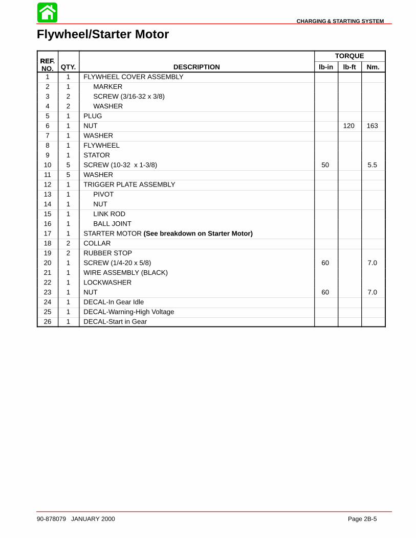
CHARGING & STARTING SYSTEM
90-878079 JANUARY 2000 Page 2B-5
Flywheel/Starter Motor
REFTORQUE
REF.NO. QTY. DESCRIPTION lb-in lb-ft Nm.
1 1 FLYWHEEL COVER ASSEMBLY
2 1 MARKER3 2 SCREW (3/16-32 x 3/8)4 2 WASHER5 1 PLUG6 1 NUT 120 1637 1 WASHER
8 1 FLYWHEEL9 1 STATOR10 5 SCREW (10-32 x 1-3/8) 50 5.511 5 WASHER12 1 TRIGGER PLATE ASSEMBLY13 1 PIVOT14 1 NUT
15 1 LINK ROD16 1 BALL JOINT17 1 STARTER MOTOR (See breakdown on Starter Motor)18 2 COLLAR19 2 RUBBER STOP20 1 SCREW (1/4-20 x 5/8) 60 7.021 1 WIRE ASSEMBLY (BLACK)
22 1 LOCKWASHER23 1 NUT 60 7.024 1 DECAL-In Gear Idle25 1 DECAL-Warning-High Voltage26 1 DECAL-Start in Gear
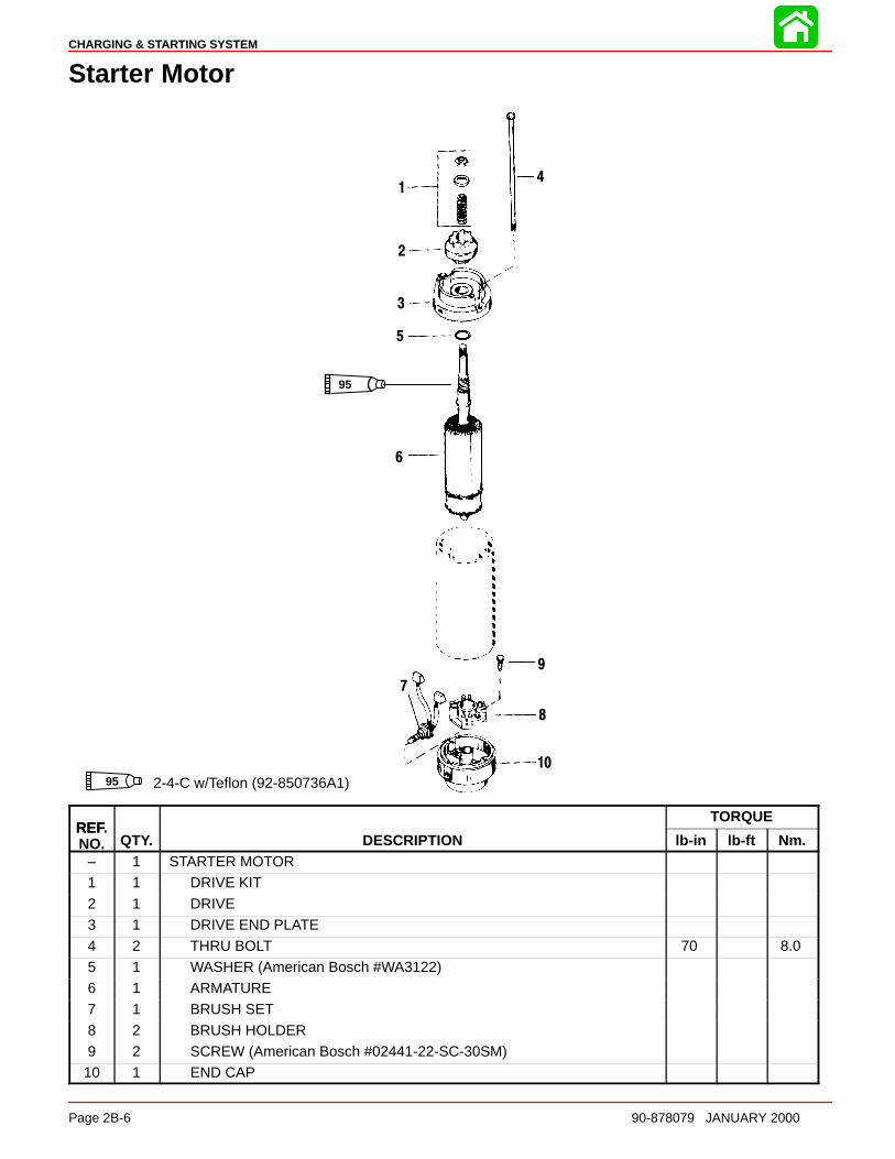
CHARGING & STARTING SYSTEM
Page 2B-6 90-878079 JANUARY 2000
Starter Motor
95
95 2-4-C w/Teflon (92-850736A1)
1
2
3
4
5
6
7
8
9
10
REFTORQUE
REF.NO. QTY. DESCRIPTION lb-in lb-ft Nm.
– 1 STARTER MOTOR1 1 DRIVE KIT
2 1 DRIVE3 1 DRIVE END PLATE4 2 THRU BOLT 70 8.05 1 WASHER (American Bosch #WA3122)6 1 ARMATURE7 1 BRUSH SET
8 2 BRUSH HOLDER9 2 SCREW (American Bosch #02441-22-SC-30SM)10 1 END CAP

CHARGING & STARTING SYSTEM
90-878079 JANUARY 2000 Page 2B-7
Battery Cable Size
If standard (original) battery cables are replaced with longer cables, the wire gauge size must increase. Seechart below for correct wire gauge size.
Battery Cable Length
ÎÎÎÎ
Wire Gage Size
Battery Cable Wire Gage SizeMercury/Mariner Outboards
Battery Cable Length
8 ft.2.4m
9 ft.2.7m
10ft.3.0m
11ft.3.4m
12ft.3.7m
13ft.4.0m
14ft.4.3m
15ft.4.6m
16ft.4.9m
17ft.5.2m
18ft.5.5m
19ft.5.8m
20ft.6.1m
21ft.6.4m
22ft.6.7m
23ft.7.0m
24ft.7.3m
Models Wire Gage Size No. SAE
6-25 Hp #8* #8 #6 #6 #6 #6 #4 #4 #4 #4 #4 #4 #4 #4 #2 #2 #2
30-115Hp
#6* #4 #4 #4 #4 #4 #2 #2 #2 #2 #2 #2 #2 #2 #0 #0 #0
125-250Hp (ex-
ceptDFI)
#6* #6 #4 #4 #4 #4 #4 #4 #2 #2 #2 #2 #2 #2 #2
DFIModels
#4* #2 #2 #2 #2 #2 #2 #2 #2 #2 #0 #0 #0
* = Standard (original) Cable Length and wire gage size.
Replacement Parts
WARNINGElectrical, ignition and fuel system components on your Mercury/Mariner out-board are designed and manufactured to comply with U. S. Coast Guard Rulesand Regulations to minimize risks of fire and explosions. Use of replacementelectrical, ignition or fuel system components, which do not comply with theserules and regulations, could result in a fire or explosion hazard and should beavoided.
Recommended Battery
A 12 volt marine battery with a minimum Cold Cranking amperage rating of 490 amperesor 630 (minimum) Marine Cranking amperes should be used.

CHARGING & STARTING SYSTEM
Page 2B-8 90-878079 JANUARY 2000
Special Tools
1. Volt/Ohm Meter 91-99750A1or DMT 2000 Digital Tachometer Multimeter91-854009A1
a b
a - Volt/Ohm Meter 91-99750A1b - DMT 2000 Digital Tachometer Multimeter 91-854009A1
2. Ammeter (60 Ampere minimum) (Obtain locally)
3. Flywheel Holder 91-52344
549644. Protector Cap 91-24161
5. Flywheel Puller 91-849154T1
55117
Battery
Precautions
CAUTIONIf battery acid comes in contact with skin or eyes, wash skin immediately with amild soap. Flush eyes with water immediately and see a docto r.

CHARGING & STARTING SYSTEM
90-878079 JANUARY 2000 Page 2B-9
When charging batteries, an explosive gas mixture forms in each cell. Part of this gas es-capes through holes in vent plugs and may form an explosive atmosphere around batteryif ventilation is poor. This explosive gas may remain in or around battery for several hoursafter it has been charged. Sparks or flames can ignite this gas and cause an internal ex-plosion which may shatter the battery.
The following precautions should be observed to prevent an explosion.
1. DO NOT smoke near batteries being charged or which have been charged very re-cently.
2. DO NOT break live circuits at terminals of batteries because a spark usually occursat the point where a live circuit is broken. Always be careful when connecting or dis-connecting cable clamps on chargers. Poor connections are a common cause of elec-trical arcs which cause explosions.
3. DO NOT reverse polarity of battery terminal to cable connections.
Charging a Discharged Battery
WARNINGHydrogen and oxygen gases are produced during normal battery operation orcharging. Sparks or flame can cause this mixture to ignite and explode, if they arebrought near the vent openings. Sulphuric acid in battery can cause seriousburns, if spilled on skin or in eyes. Flush or wash away immediately with clear wa-ter.
The following basic rule applies to any battery charging situation:
1. Any battery may be charged at any rate (in amperes) or as long as spewing of electro-lyte (from violent gassing) does not occur and for as long as electrolyte temperaturedoes not exceed 125° F (52° C). If spewing of electrolyte occurs, or if electrolyte tem-perature exceeds 125° F, charging rate (in amperes) must be reduced or temporarilyhalted to avoid damage to the battery.
2. Battery is fully charged when, over a 2-hour period at a low charging rate (in amperes),all cells are gassing freely (not spewing liquid electrolyte), and no change in specificgravity occurs. Full charge specific gravity is 1.260-1.275, corrected for electrolytetemperature with electrolyte level at 3/16 in. (4.8 mm) over plate, unless electrolyteloss has occurred (from age or over-filling) in which case specific gravity reading willbe lower. For most satisfactory charging, lower charging rates in amperes are recom-mended.
3. If, after prolonged charging, specific gravity of at least 1.230 on all cells cannot bereached, battery is not in optimum condition and will not provide optimum perform-ance; however, it may continue to provide additional service, if it has performed satis-factorily in the past.
4. To check battery voltage while cranking engine with electric starting motor, place RED(+) lead of tester on POSITIVE (+) battery terminal and BLACK (–) lead of tester onNEGATIVE (–) battery terminal. If the voltage drops below 9-1/2 volts while cranking,the battery is weak and should be recharged or replaced.
Winter Storage of Batteries
Battery companies are not responsible for battery damage either in winter storage or indealer stock if the following instructions are not observed:

CHARGING & STARTING SYSTEM
Page 2B-10 90-878079 JANUARY 2000
1. Remove battery from its installation as soon as possible and remove all grease, sul-fate and dirt from top surface by running water over top of battery. Be sure, however,that vent caps are tight beforehand, and blow off all excess water thoroughly with com-pressed air. Check water level, making sure that plates are covered.
2. When adding distilled water to battery, be extremely careful not to fill more than 3/16in. (4.8 mm) above perforated baffles inside battery. Battery solution or electrolyte ex-pands from heat caused by charging. Overfilling battery will cause electrolyte to over-flow (if filled beyond 3/16″ above baffles).
3. Grease terminal bolts well with 2-4-C Marine Lubricant and store battery in a COOL-DRY place. Remove battery from storage every 30-45 days, check water level andput on charge for 5 or 6 hours at 6 amperes. DO NOT FAST CHARGE.
4. If specific gravity drops below 1.240, check battery for reason and recharge. Whengravity reaches 1.260, discontinue charging. To check specific gravity, use a hydrom-eter, which can be purchased locally.
5. Repeat preceding charging procedure every 30-45 days, as long as battery is in stor-age, for best possible maintenance during inactive periods to ensure a good service-able battery in spring. When ready to place battery back in service, remove excessgrease from terminals (a small amount is desirable on terminals at all times), rechargeagain as necessary and reinstall battery.
Flywheel Removal and Installation
Removal1. Remove flywheel cover from engine.
WARNINGEngine could possibly start when turning flywheel during removal and installa-tion; therefore, disconnect (and isolate) spark plug leads from spark plugs to pre-vent engine from starting.
2. Disconnect spark plug leads from spark plugs.
3. While holding flywheel with Flywheel Holder (91-52344), remove flywheel nut andwasher.
58035
a
a - Flywheel Holder (91-52344)

CHARGING & STARTING SYSTEM
90-878079 JANUARY 2000 Page 2B-11
4. Install Flywheel Puller (91-849154T1) into flywheel.
5. Hold flywheel tool with wrench while tightening bolt down. Tighten bolt until flywheelcomes free.
58036
a
a - Flywheel Puller (91-849154T1)*NOTE: Neither heat or hammer should be used on flywheel to aid in removal as damageto flywheel or electrical components may result.
6. Remove flywheel. Inspect flywheel for cracks or damage.
InstallationIMPORTANT: Inspect flywheel magnets for clinging debris. Failure to remove de-bris before installing flywheel may result in damage to flywheel or electrical com-ponents under flywheel when outboard is initially started.
IMPORTANT: Do not apply any greases, oils or lubricants to flywheel/crankshaft ta-per surfaces. Clean flywheel/crankshaft taper with solvent and assemble dr y.
1. Install flywheel.
2. Install flywheel washer and nut.
3. Hold flywheel with Flywheel Holder (91-52344). Torque nut to 120 lb. ft. (163 Nm).
58037
a
a - Flywheel Holder (91-52344)
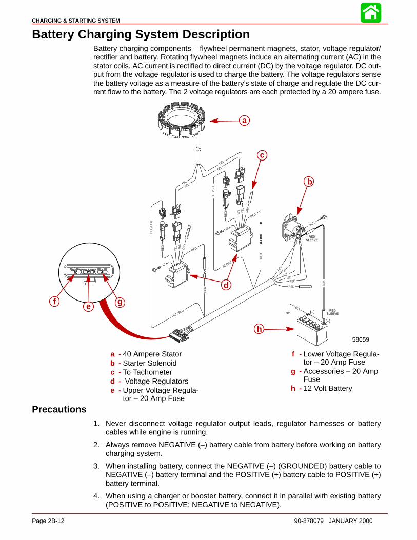
CHARGING & STARTING SYSTEM
Page 2B-12 90-878079 JANUARY 2000
Battery Charging System DescriptionBattery charging components – flywheel permanent magnets, stator, voltage regulator/rectifier and battery. Rotating flywheel magnets induce an alternating current (AC) in thestator coils. AC current is rectified to direct current (DC) by the voltage regulator. DC out-put from the voltage regulator is used to charge the battery. The voltage regulators sensethe battery voltage as a measure of the battery’s state of charge and regulate the DC cur-rent flow to the battery. The 2 voltage regulators are each protected by a 20 ampere fuse.
58059
a
b
c
d
h
gf e
a - 40 Ampere Statorb - Starter Solenoidc - To Tachometerd - Voltage Regulatorse - Upper Voltage Regula-
tor – 20 Amp Fuse
f - Lower Voltage Regula-tor – 20 Amp Fuse
g - Accessories – 20 AmpFuse
h - 12 Volt Battery
Precautions1. Never disconnect voltage regulator output leads, regulator harnesses or battery
cables while engine is running.
2. Always remove NEGATIVE (–) battery cable from battery before working on batterycharging system.
3. When installing battery, connect the NEGATIVE (–) (GROUNDED) battery cable toNEGATIVE (–) battery terminal and the POSITIVE (+) battery cable to POSITIVE (+)battery terminal.
4. When using a charger or booster battery, connect it in parallel with existing battery(POSITIVE to POSITIVE; NEGATIVE to NEGATIVE).

CHARGING & STARTING SYSTEM
90-878079 JANUARY 2000 Page 2B-13
Battery Charging System Troubleshooting
General TroubleshootingA fault in the battery charging system will usually cause the battery to become UNDER-CHARGED. A defective voltage regulator or a stator winding shorted to ground may alsoallow the system to OVERCHARGE the battery.
If a problem exists in the charging system, visually check the following:
1. Check for correct battery polarity [RED cable to (+) POSITIVE battery terminal].
*NOTE: 40 AMP CHARGING SYSTEM voltage regulator/rectifier is protected internallyagainst incorrectly installed battery cables.
2. Check for loose or corroded battery terminals.
3. Check condition of the battery.
4. Visually inspect all wiring between stator and battery for cuts, chafing and discon-nected, loose or corroded connections.
5. Excessive electrical load (from too many accessories) will cause battery to run down,even if the system is operating correctly.
If the system is still OVERCHARGING the battery, disconnect the YELLOW wire connec-tor from the regulator(s). Check for continuity between either YELLOW wire and groundwhich would indicate a shorted stator winding. A short to ground in the stator bypassesthe regulation circuit of the voltage regulator resulting in overcharging of the battery. If theYELLOW wires are not shorted to ground, the voltage regulator is most likely defectiveand should be replaced.
If the battery is undercharged, proceed with regulator, stator, and rectifier tests, following.
40 Ampere Alternator System40 AMP STATOR TEST (ALTERNATOR COILS ONLY)
*NOTE: Stator can be tested without removing from engine.
1. Disconnect YELLOW stator leads from voltage regulator connectors on starboardside of engine.
2. Use an ohmmeter and perform the following test:
Test Leads To- Resistance(Ohms)
ScaleReading
Connect test leads between 2YELLOW stator leads at each volt-age regulator connector.
0.18-.45* R x 1
RED test lead to 1 YELLOW statorlead (voltage regulator connector),and BLACK test lead to engineground if stator is mounted or tosteel frame of stator (if off engine)
NoContinuity
R x 1000
*NOTE: Resistance of these windings is less than one ohm. Copper wire is an excellentconductor but will have noticeable differences from cold to hot. Reasonable variation fromspecified reading is acceptable.
3. If meter readings are other than specified, replace stator assembly. Refer to stator as-sembly replacement in Section 2A.
CHARGING & STARTING SYSTEM
Page 2B-14 90-878079 JANUARY 2000
TROUBLESHOOTING 40 AMP A LTERNATOR SYSTEM
WARNINGBefore connecting or disconnecting any electrical connection, battery cablesMUST BE REMOVED from battery to prevent possible personal injury or damageto equipment.
IMPORTANT: The charging system may be connected to one or more batteries dur-ing these tests. Howeve r, these batteries MUST BE fully charged. These batteriesMUST NOT BE connected to any other charging source.
IMPORTANT: Check that all connections are tight prior to starting tests. Ensure thatthe battery posts and terminals are clean and making good contact. Verify with testequipment that wiring harnesses are not at fault.
DETERMINING CAUSE OF PROBLEM
1. Connect outboard battery leads to battery(s) that are known to be in good conditionand are fully charged.
2. Check voltage at battery(s) with an analog voltmeter. Digital voltmeters are not recom-mended as they may be inaccurate due to interference from outboard ignition system.
3. Start outboard and run at 1000 RPM. Voltage at battery should rise to and stabilizeat approximately 14.5 volts if system is operating properly. If voltage does not increasefrom previously checked battery voltage values, refer to “NO OUTPU T,” following, fortroubleshooting procedures. If voltage exceeds 16 volts and DOES NOT return downto and stabilize at 14.5 volts, refer to “CONS TANT HIGH OUTPUT,” following for trou-bleshooting procedures.
PROBLEM: CONS TANT HIGH OUTPUT
CAUTIONEngine must be shut off when performing the following tests. Disconnecting theYELLOW stator lead connectors at the voltage regulators while the engine is run-ning will result in voltage regulator failure.
1. Stator Test – Place RED ohmmeter lead in YELLOW stator lead connector. PlaceBLACK ohmmeter lead to ground. There should be no continuity between any YEL-LOW stator lead and ground. If there is continuity, stator is shorted and must be re-placed.
2. Voltage Regulator SCR Test – Place RED ohmmeter lead in YELLOW voltage regula-tor lead connector. Place BLACK ohmmeter lead to ground. There should be no conti-nuity. If there is continuity, SCR in voltage regulator is defective and regulator mustbe replaced.
3. Voltage Regulator Regulation Circuit Test* – Check voltage at battery (battery shouldbe fully charged). After engine initially starts, voltage will rise to 15.5 – 16.5 volts andthen drop below 15 volts where it should stabilize. If the voltage does not stabilize be-low 15 volts, voltage regulation circuit is defective. Replace voltage regulator.
*NOTE: If a digital voltmeter is used for this reading, measure voltage at the battery andkeep meter as far away from engine as possible. This will reduce the possibility of erro-neous readings from ignition noise.
CHARGING & STARTING SYSTEM
90-878079 JANUARY 2000 Page 2B-15
PROBLEM: NO OUTPUT
IMPORTANT: Regulators MUST have a good ground. Verify a clean contact surfaceexists between regulator case, powerhead and attaching hardware.
1. Check voltage on either RED wire to regulator(s) (bullet connectors). These leadsmust indicate battery voltage. If battery voltage is NOT present, wiring between thetest point and battery terminals is defective. Refer to WIRING DIAGRAMS, SECTION2D.
2. Connect an AC voltmeter to either YELLOW lead connectors on the regulators. If theAC voltage at idle or above is greater than 16 VAC, the regulator is defective.
*NOTE: The tachometer signal is provided by either regulator. It is possible to still havean accurate tachometer signal with a defective regulator.
REGULATION VOLTAGE CHECK
*NOTE: Battery must be fully charged before testing regulation voltage. A low battery willnot allow an accurate reading of regulation voltage.
1. Turn on all electrical accessories and crank engine for 20 seconds with the ignitionlanyard switch turned off. This will discharge battery slightly.
2. Start engine and observe battery voltage. Voltage should slowly rise to approximately14 to 16 volts. If voltage does not rise, repeat previous tests for stator and regulator.
*NOTE: If a digital voltmeter is used for this reading, measure voltage at the battery andkeep meter as far away from engine as possible. This will reduce the possibility of erro-neous readings from ignition noise.
VOLTAGE REGULATOR TEST (USING ANALOG METER)
*NOTE: Verify meter is zeroed before making any measurements.
IMPORTANT: The following regulator tests should be performed as soon as possi-ble after suspected regulator failure. A “cold” regulator may test “GOOD” when infact it is defective when “warm”.
Disconnect all voltage regulator wires.
Using analog meter, perform each ohms test listed below:
Test Leads To- Resistance(Ohms)
Scale
Diode Check: Connect NEGATIVE (–) ohm lead to eitherYELLOW lead. Connect POSITIVE (+) test lead to thickRED lead.
100-400 R x 10
Diode Check: Connect NEGATIVE (–) ohm lead to thickRED lead. Connect POSITIVE (+) ohm lead to either YEL-LOW lead.
20000 to ∞ R x 1K
SCR Checks: Connect NEGATIVE (–) ohm lead to eitherYELLOW lead. Connect POSITIVE (+) ohm lead to caseground.
8000 – 15000 R x 1K
Tachometer Circuit Check: Connect NEGATIVE (–) ohmlead to case ground. Connect POSITIVE (+) ohm lead toGRAY lead.
10000 – 50000 R x 1K
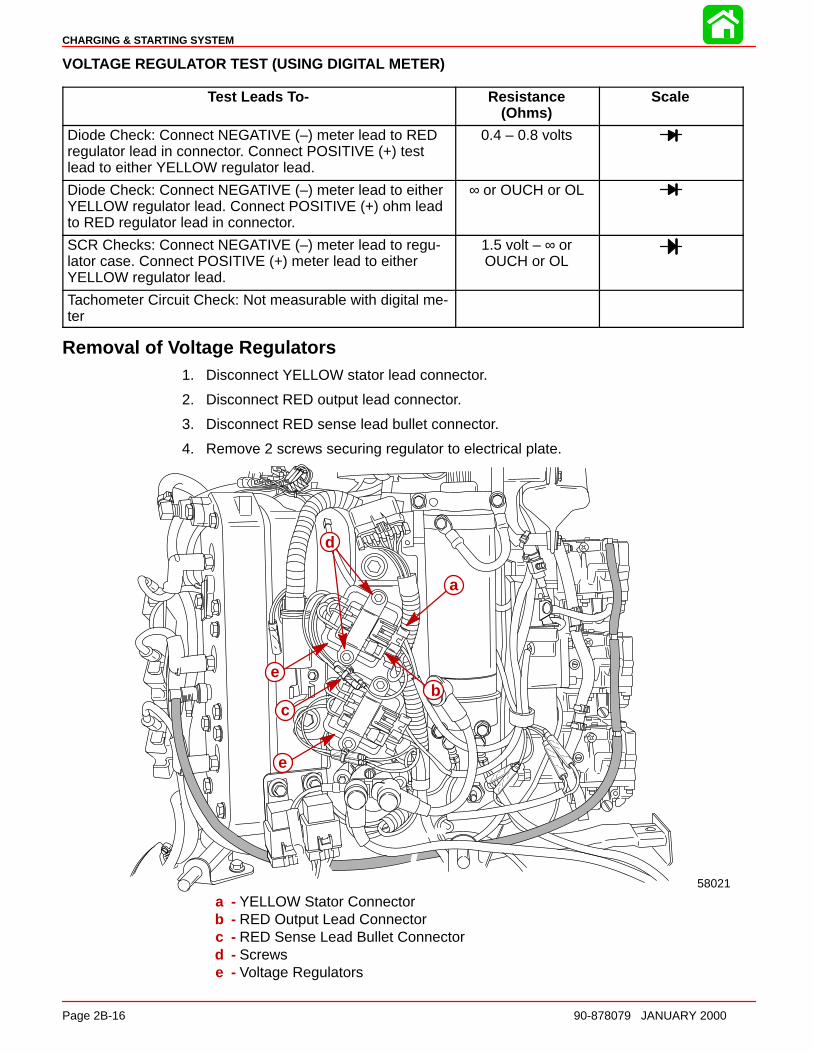
CHARGING & STARTING SYSTEM
Page 2B-16 90-878079 JANUARY 2000
VOLTAGE REGULATOR TEST (USING DIGITAL METER)
Test Leads To- Resistance(Ohms)
Scale
Diode Check: Connect NEGATIVE (–) meter lead to REDregulator lead in connector. Connect POSITIVE (+) testlead to either YELLOW regulator lead.
0.4 – 0.8 volts
Diode Check: Connect NEGATIVE (–) meter lead to eitherYELLOW regulator lead. Connect POSITIVE (+) ohm leadto RED regulator lead in connector.
∞ or OUCH or OL
SCR Checks: Connect NEGATIVE (–) meter lead to regu-lator case. Connect POSITIVE (+) meter lead to eitherYELLOW regulator lead.
1.5 volt – ∞ orOUCH or OL
Tachometer Circuit Check: Not measurable with digital me-ter
Removal of Voltage Regulators1. Disconnect YELLOW stator lead connector.
2. Disconnect RED output lead connector.
3. Disconnect RED sense lead bullet connector.
4. Remove 2 screws securing regulator to electrical plate.
58021
a
bc
d
e
e
a - YELLOW Stator Connectorb - RED Output Lead Connectorc - RED Sense Lead Bullet Connectord - Screwse - Voltage Regulators
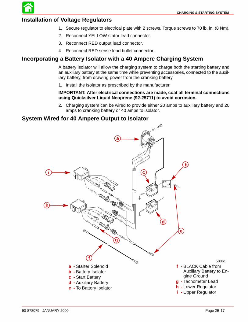
CHARGING & STARTING SYSTEM
90-878079 JANUARY 2000 Page 2B-17
Installation of Voltage Regulators1. Secure regulator to electrical plate with 2 screws. Torque screws to 70 lb. in. (8 Nm).
2. Reconnect YELLOW stator lead connector.
3. Reconnect RED output lead connector.
4. Reconnect RED sense lead bullet connector.
Incorporating a Battery Isolator with a 40 Ampere Charging SystemA battery isolator will allow the charging system to charge both the starting battery andan auxiliary battery at the same time while preventing accessories, connected to the auxil-iary battery, from drawing power from the cranking battery.
1. Install the isolator as prescribed by the manufacturer.
IMPORTANT: After electrical connections are made, coat all terminal connectionsusing Quicksilver Liquid Neoprene (92-257 11) to avoid corrosion.
2. Charging system can be wired to provide either 20 amps to auxiliary battery and 20amps to cranking battery or 40 amps to isolator.
System Wired for 40 Ampere Output to Isolator
58061
a
b
c
d
f
g
h
i
e
a - Starter Solenoidb - Battery Isolatorc - Start Batteryd - Auxiliary Batterye - To Battery Isolator
f - BLACK Cable fromAuxiliary Battery to En-gine Ground
g - Tachometer Leadh - Lower Regulatori - Upper Regulator
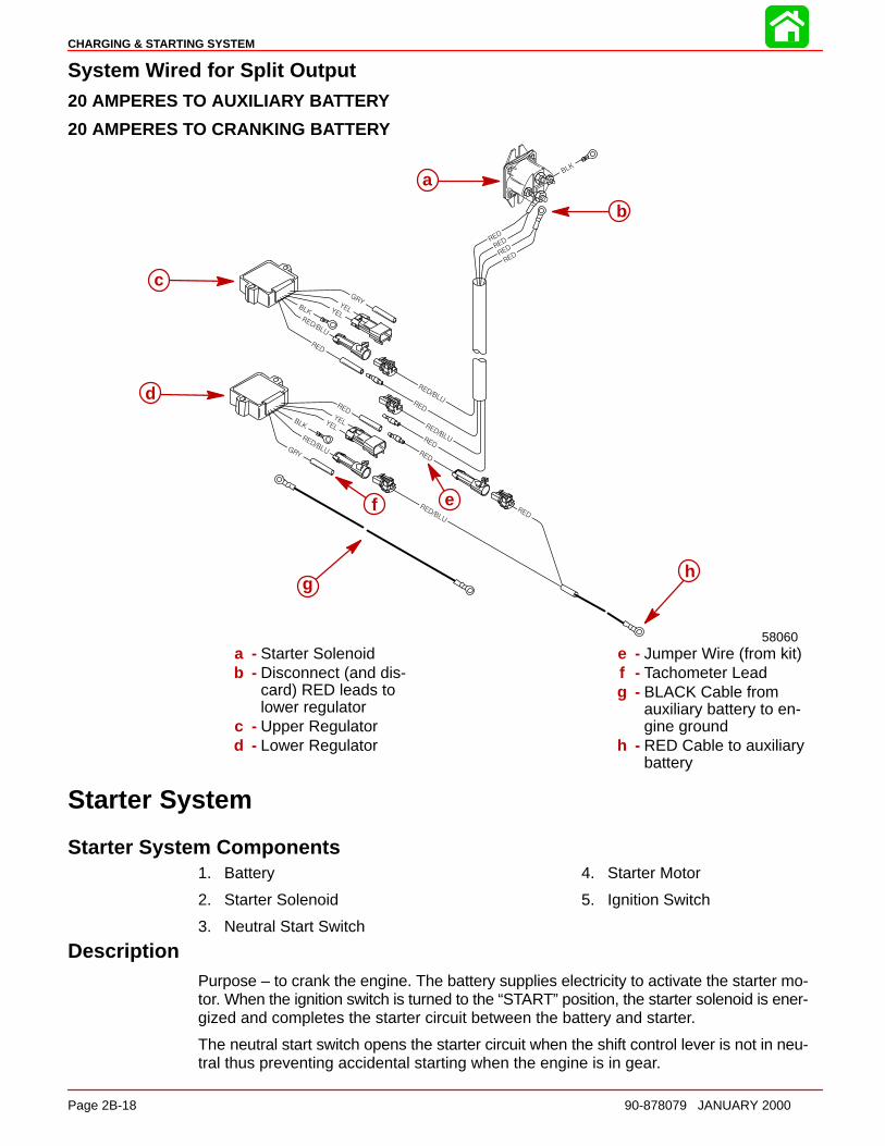
CHARGING & STARTING SYSTEM
Page 2B-18 90-878079 JANUARY 2000
System Wired for Split Output20 AMPERES TO AUXILIA RY BATTERY
20 AMPERES TO CRANKING B ATTERY
58060
a
b
c
d
ef
gh
a - Starter Solenoidb - Disconnect (and dis-
card) RED leads tolower regulator
c - Upper Regulatord - Lower Regulator
e - Jumper Wire (from kit)f - Tachometer Leadg - BLACK Cable from
auxiliary battery to en-gine ground
h - RED Cable to auxiliarybattery
Starter System
Starter System Components1. Battery
2. Starter Solenoid
3. Neutral Start Switch
4. Starter Motor
5. Ignition Switch
DescriptionPurpose – to crank the engine. The battery supplies electricity to activate the starter mo-tor. When the ignition switch is turned to the “START” position, the starter solenoid is ener-gized and completes the starter circuit between the battery and starter.
The neutral start switch opens the starter circuit when the shift control lever is not in neu-tral thus preventing accidental starting when the engine is in gear.
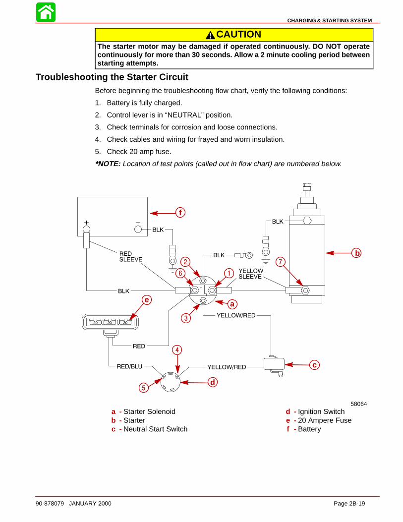
CHARGING & STARTING SYSTEM
90-878079 JANUARY 2000 Page 2B-19
CAUTIONThe starter motor may be damaged if operated continuousl y. DO NOT operatecontinuously for more than 30 seconds. Allow a 2 minute cooling period betweenstarting attempts.
Troubleshooting the Starter CircuitBefore beginning the troubleshooting flow chart, verify the following conditions:
1. Battery is fully charged.
2. Control lever is in “NEUTRAL” position.
3. Check terminals for corrosion and loose connections.
4. Check cables and wiring for frayed and worn insulation.
5. Check 20 amp fuse.
*NOTE: Location of test points (called out in flow chart) are numbered below.
b
f
58064
6
2
1
7
3
c
5
4
d
ae
a - Starter Solenoidb - Starterc - Neutral Start Switch
d - Ignition Switche - 20 Ampere Fusef - Battery
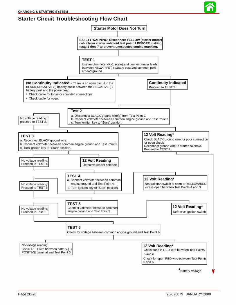
CHARGING & STARTING SYSTEM
Page 2B-20 90-878079 JANUARY 2000
Starter Circuit Troubleshooting Flow Chart
Starter Motor Does Not Turn
SAFETY WARNING: Disconnect YELLOW (starter motor)cable from starter solenoid test point 1 BEFORE makingtests 1-thru-7 to prevent unexpected engine cranking.
TEST 1Use an ohmmeter (Rx1 scale) and connect meter leadsbetween NEGATIVE (-) battery post and common pow-erhead ground.
No Continuity Indicated - There is an open circuit in the BLACK NEGATIVE (-) battery cable between the NEGATIVE (-) battery post and the powerhead.• Check cable for loose or corroded connections.• Check cable for open.
Continuity IndicatedProceed to TEST 2
Test 2a. Disconnect BLACK ground wire(s) from Test Point 2. b. Connect voltmeter between common engine ground and Test Point 2.c. Turn ignition key to “Start” position.
No voltage reading:proceed to TEST 3.
TEST 3a. Reconnect BLACK ground wire.b. Connect voltmeter between common engine ground and Test Point 3.c. Turn ignition key to “Start” position.
12 Volt Reading*Check BLACK ground wire for poor connectionor open circuit.Reconnect ground wire to starter solenoid.Proceed to TEST 7.
No voltage reading:Proceed to TEST 4
12 Volt ReadingDefective starter solenoid
TEST 4a. Connect voltmeter between common
engine ground and Test Point 4.b. Turn ignition key to “Start” position.
No voltage reading:Proceed to TEST 5
12 Volt Reading*Neutral start switch is open or YELLOW/REDwire is open between Test Points 4 and 3.
TEST 5Connect voltmeter between common engine ground and Test Point 5
No voltage reading:Proceed to Test 6.
12 Volt Reading*Defective ignition switch.
TEST 6Check for voltage between common engine ground and Test Point 6.
No voltage reading:Check RED wire between battery (+)POSITIVE terminal and Test Point 6.
12 Volt Reading*Check fuse in RED wire between Test Points5 and 6.Check for open RED wire between Test Points5 and 6.
*Battery Voltage
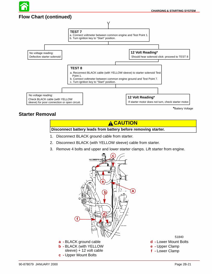
CHARGING & STARTING SYSTEM
90-878079 JANUARY 2000 Page 2B-21
Flow Chart (continued)
TEST 7a. Connect voltmeter between common engine and Test Point 1.b. Turn ignition key to “Start” position.
No voltage reading:Defective starter solenoid
12 Volt Reading*Should hear solenoid click: proceed to TEST 8
TEST 8a. Reconnect BLACK cable (with YELLOW sleeve) to starter solenoid Test Point 1.b. Connect voltmeter between common engine ground and Test Point 7.c. Turn ignition key to “Start” position.
No voltage reading:
Check BLACK cable (with YELLOWsleeve) for poor connection or open circuit.
12 Volt Reading*If starter motor does not turn, check starter motor.
*Battery Voltage
Starter Removal
CAUTIONDisconnect battery leads from battery before removing starte r.
1. Disconnect BLACK ground cable from starter.
2. Disconnect BLACK (with YELLOW sleeve) cable from starter.
3. Remove 4 bolts and upper and lower starter clamps. Lift starter from engine.
51840
df
b
c
e
a
a - BLACK ground cableb - BLACK (with YELLOW
sleeve) + 12 volt cablec - Upper Mount Bolts
d - Lower Mount Boltse - Upper Clampf - Lower Clamp
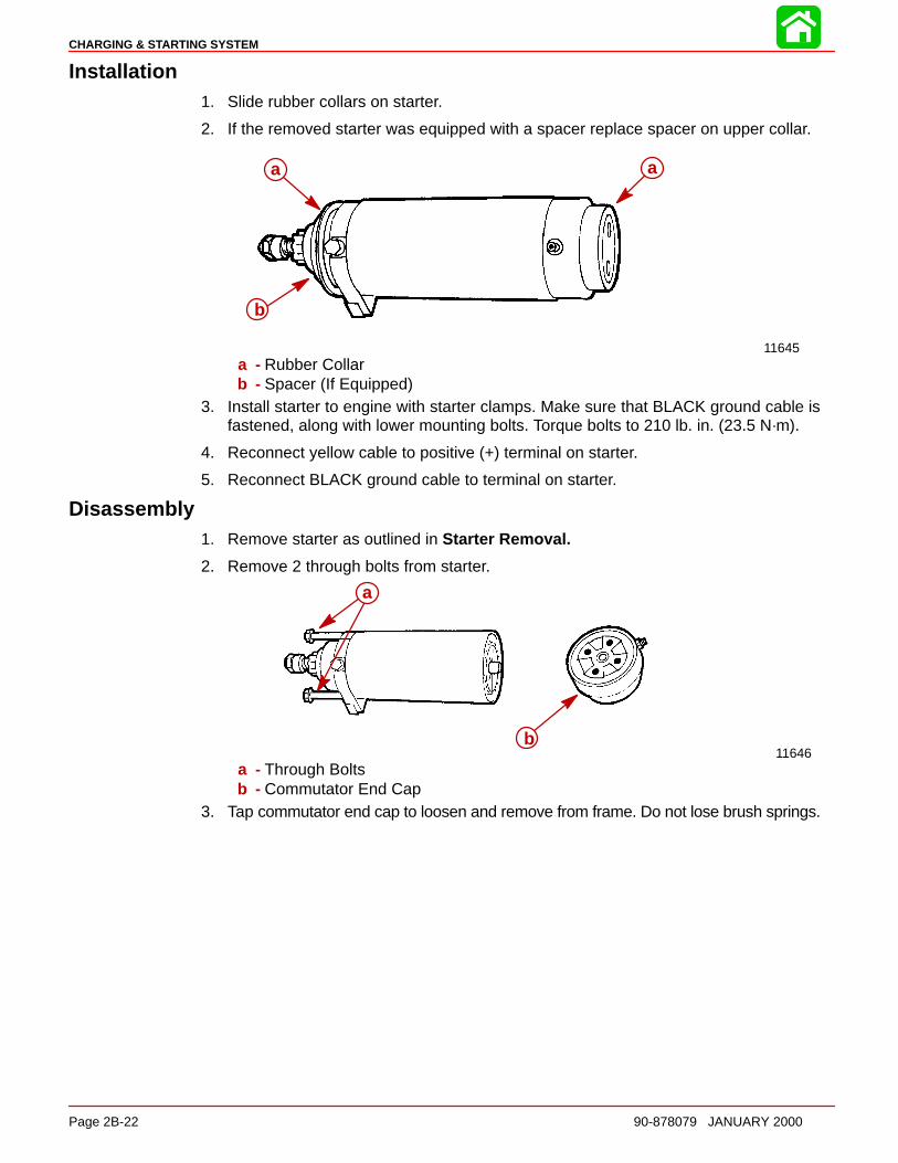
CHARGING & STARTING SYSTEM
Page 2B-22 90-878079 JANUARY 2000
Installation1. Slide rubber collars on starter.
2. If the removed starter was equipped with a spacer replace spacer on upper collar.
11645
aa
b
a - Rubber Collarb - Spacer (If Equipped)
3. Install starter to engine with starter clamps. Make sure that BLACK ground cable isfastened, along with lower mounting bolts. Torque bolts to 210 lb. in. (23.5 N·m).
4. Reconnect yellow cable to positive (+) terminal on starter.
5. Reconnect BLACK ground cable to terminal on starter.
Disassembly1. Remove starter as outlined in Starter Removal.
2. Remove 2 through bolts from starter.
11646b
a
a - Through Boltsb - Commutator End Cap
3. Tap commutator end cap to loosen and remove from frame. Do not lose brush springs.
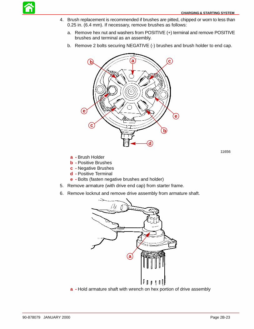
CHARGING & STARTING SYSTEM
90-878079 JANUARY 2000 Page 2B-23
4. Brush replacement is recommended if brushes are pitted, chipped or worn to less than0.25 in. (6.4 mm). If necessary, remove brushes as follows:
a. Remove hex nut and washers from POSITIVE (+) terminal and remove POSITIVEbrushes and terminal as an assembly.
b. Remove 2 bolts securing NEGATIVE (-) brushes and brush holder to end cap.
11656
c
e
b
d
c
e
b a
a - Brush Holderb - Positive Brushesc - Negative Brushesd - Positive Terminale - Bolts (fasten negative brushes and holder)
5. Remove armature (with drive end cap) from starter frame.
6. Remove locknut and remove drive assembly from armature shaft.
a
a - Hold armature shaft with wrench on hex portion of drive assembly
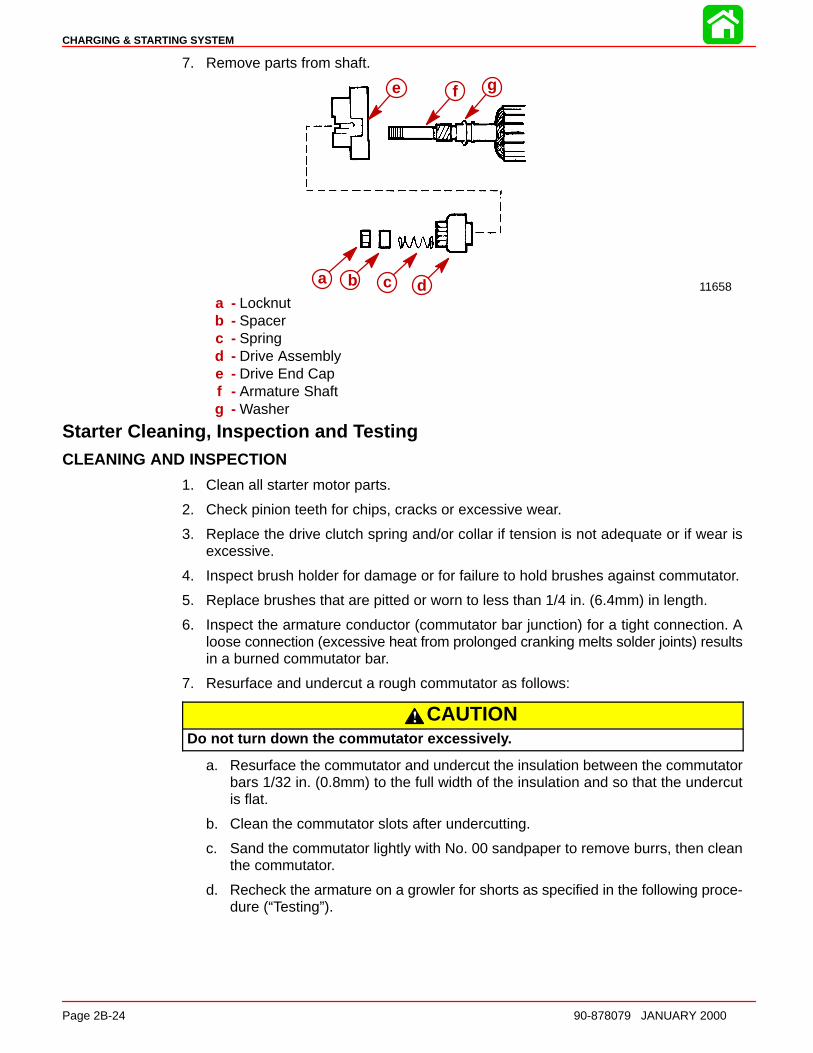
CHARGING & STARTING SYSTEM
Page 2B-24 90-878079 JANUARY 2000
7. Remove parts from shaft.
11658
fe
a b c d
g
a - Locknutb - Spacerc - Springd - Drive Assemblye - Drive End Capf - Armature Shaftg - Washer
Starter Cleaning, Inspection and TestingCLEANING AND INSPECTION
1. Clean all starter motor parts.
2. Check pinion teeth for chips, cracks or excessive wear.
3. Replace the drive clutch spring and/or collar if tension is not adequate or if wear isexcessive.
4. Inspect brush holder for damage or for failure to hold brushes against commutator.
5. Replace brushes that are pitted or worn to less than 1/4 in. (6.4mm) in length.
6. Inspect the armature conductor (commutator bar junction) for a tight connection. Aloose connection (excessive heat from prolonged cranking melts solder joints) resultsin a burned commutator bar.
7. Resurface and undercut a rough commutator as follows:
CAUTIONDo not turn down the commutator excessivel y.
a. Resurface the commutator and undercut the insulation between the commutatorbars 1/32 in. (0.8mm) to the full width of the insulation and so that the undercutis flat.
b. Clean the commutator slots after undercutting.
c. Sand the commutator lightly with No. 00 sandpaper to remove burrs, then cleanthe commutator.
d. Recheck the armature on a growler for shorts as specified in the following proce-dure (“Testing”).

CHARGING & STARTING SYSTEM
90-878079 JANUARY 2000 Page 2B-25
8. Open-circuited armatures often can be repaired. The most likely place for an open cir-cuit is at the commutator bars, as a result of long cranking periods. Long cranking peri-ods overheat the starter motor so that solder in the connections melts and is thrownout. The resulting poor connections then cause arcing and burning of the commutatorbars.
9. Repair bars, that are not excessively burned, by resoldering the leads in bars (usingrosin flux solder) and turning down the commutator in a lathe to remove burned mate-rial, then undercut the mica.
10. Clean out the copper or brush dust from slots between the commutator bars.
11. Check the armature for ground. See the following procedure (“Testing”).
TESTING
Armature Test for Shorts
Check armature for short circuits by placing on growler and holding hack saw blade overarmature core while armature is rotated. If saw blade vibrates, armature is shorted. Re-check after cleaning between commutator bars. If saw blade still vibrates, replace arma-ture.
11669
Armature Test for Ground
1. Set ohmmeter to (R x 1 scale). Place one lead of ohmmeter on armature core or shaftand other lead on commutator.
2. If meter indicates continuity, armature is grounded and must be replaced.
11675
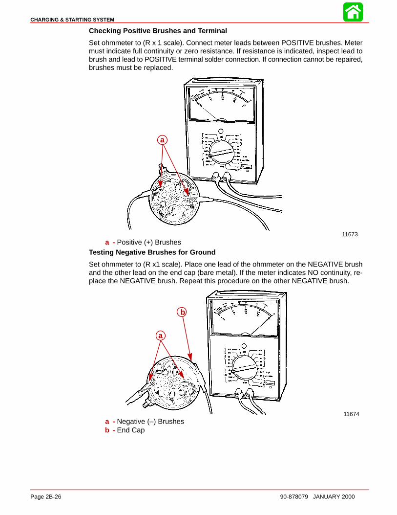
CHARGING & STARTING SYSTEM
Page 2B-26 90-878079 JANUARY 2000
Checking Positive Brushes and Terminal
Set ohmmeter to (R x 1 scale). Connect meter leads between POSITIVE brushes. Metermust indicate full continuity or zero resistance. If resistance is indicated, inspect lead tobrush and lead to POSITIVE terminal solder connection. If connection cannot be repaired,brushes must be replaced.
11673
a
a - Positive (+) BrushesTesting Negative Brushes for Ground
Set ohmmeter to (R x1 scale). Place one lead of the ohmmeter on the NEGATIVE brushand the other lead on the end cap (bare metal). If the meter indicates NO continuity, re-place the NEGATIVE brush. Repeat this procedure on the other NEGATIVE brush.
11674
a
b
a - Negative (–) Brushesb - End Cap
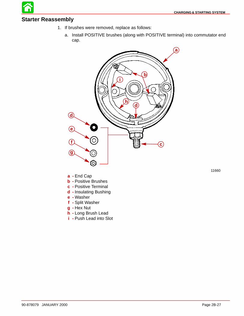
CHARGING & STARTING SYSTEM
90-878079 JANUARY 2000 Page 2B-27
Starter Reassembly1. If brushes were removed, replace as follows:
a. Install POSITIVE brushes (along with POSITIVE terminal) into commutator endcap.
11660
a
c
b
dh
i
e
f
g
d
a - End Capb - Positive Brushesc - Positive Terminald - Insulating Bushinge - Washerf - Split Washerg - Hex Nuth - Long Brush Leadi - Push Lead into Slot

CHARGING & STARTING SYSTEM
Page 2B-28 90-878079 JANUARY 2000
b. Install NEGATIVE brushes (along with brush holder).
11656
b
d
a
b
d
ac
a - Positive (+) Brushesb - Negative (–) Brushesc - Brush Holderd - Bolts (fasten negative brushes and holder)
2. If removed, reinstall parts on armature shaft. Use a new locknut and tighten securelyon end of shaft.
11658
gfe
a b c da - Locknutb - Spacerc - Springd - Drive Assemblye - Drive End Capf - Armature Shaftg - Washer
3. Lubricate helix threads on armature shaft with a drop of SAE 10W oil.
4. Lubricate bushing in drive end plate with a drop of SAE 10W oil.
5. Position armature into starter frame.
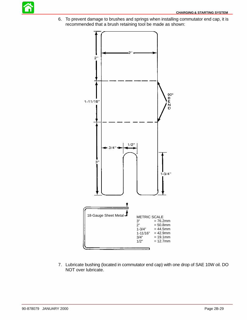
CHARGING & STARTING SYSTEM
90-878079 JANUARY 2000 Page 2B-29
6. To prevent damage to brushes and springs when installing commutator end cap, it isrecommended that a brush retaining tool be made as shown:
METRIC SCALE3”2”1-3/4”1-11/16”3/4”1/2”
= 76.2mm= 50.8mm= 44.5mm= 42.9mm= 19.1mm= 12.7mm
18-Gauge Sheet Metal
7. Lubricate bushing (located in commutator end cap) with one drop of SAE 10W oil. DONOT over lubricate.
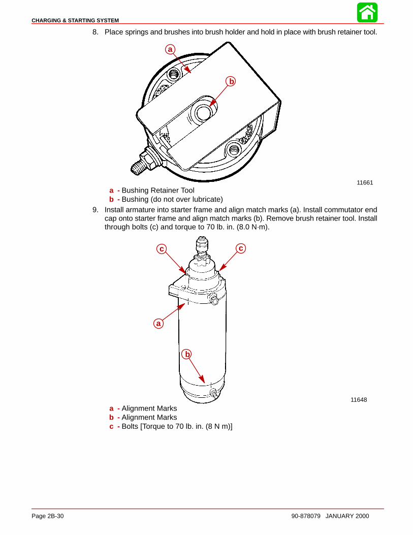
CHARGING & STARTING SYSTEM
Page 2B-30 90-878079 JANUARY 2000
8. Place springs and brushes into brush holder and hold in place with brush retainer tool.
11661
a
b
a - Bushing Retainer Toolb - Bushing (do not over lubricate)
9. Install armature into starter frame and align match marks (a). Install commutator endcap onto starter frame and align match marks (b). Remove brush retainer tool. Installthrough bolts (c) and torque to 70 lb. in. (8.0 N·m).
11648
cc
a
b
a - Alignment Marksb - Alignment Marksc - Bolts [Torque to 70 lb. in. (8 N m)]
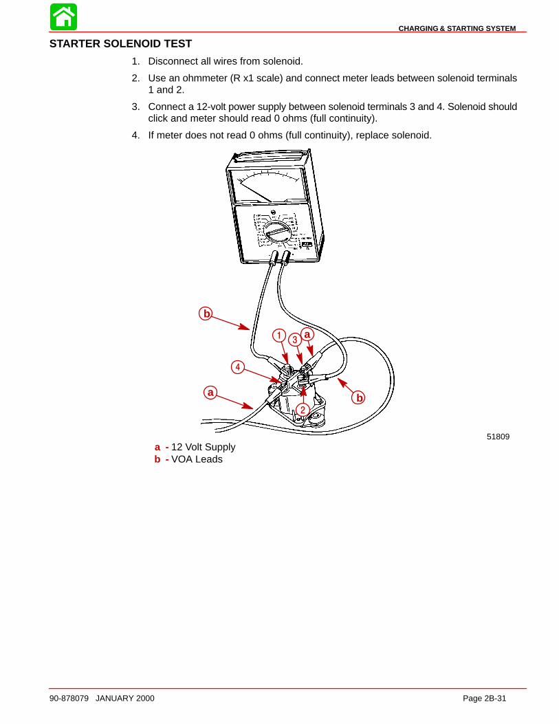
CHARGING & STARTING SYSTEM
90-878079 JANUARY 2000 Page 2B-31
STARTER SOLENOID TEST
1. Disconnect all wires from solenoid.
2. Use an ohmmeter (R x1 scale) and connect meter leads between solenoid terminals1 and 2.
3. Connect a 12-volt power supply between solenoid terminals 3 and 4. Solenoid shouldclick and meter should read 0 ohms (full continuity).
4. If meter does not read 0 ohms (full continuity), replace solenoid.
51809
b
13
a
b2
4
a
a - 12 Volt Supplyb - VOA Leads
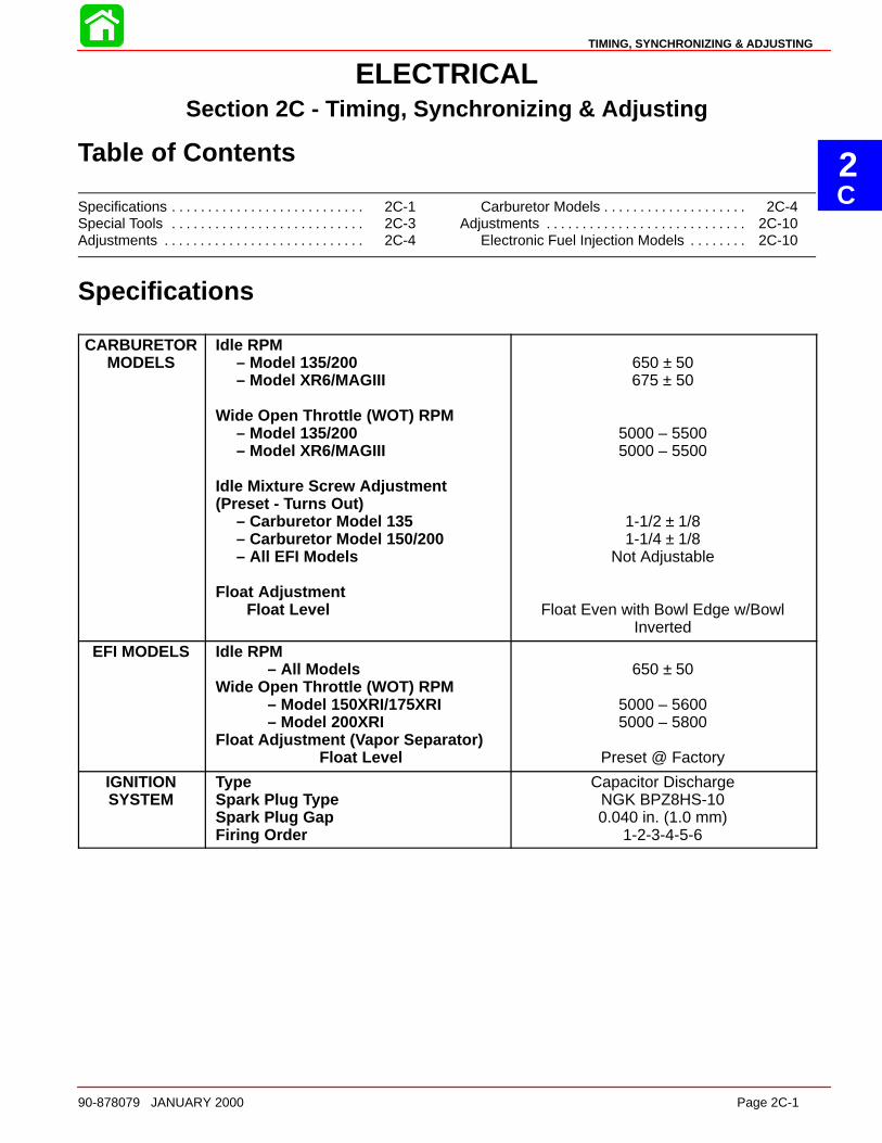
2C
TIMING, SYNCHRONIZING & ADJUSTING
90-878079 JANUARY 2000 Page 2C-1
ELECTRICALSection 2C - Timing, Synchronizing & Adjusting
Table of Contents
Specifications 2C-1. . . . . . . . . . . . . . . . . . . . . . . . . . . Special Tools 2C-3. . . . . . . . . . . . . . . . . . . . . . . . . . . Adjustments 2C-4. . . . . . . . . . . . . . . . . . . . . . . . . . . .
Carburetor Models 2C-4. . . . . . . . . . . . . . . . . . . . Adjustments 2C-10. . . . . . . . . . . . . . . . . . . . . . . . . . . .
Electronic Fuel Injection Models 2C-10. . . . . . . .
Specifications
CARBURETORMODELS
Idle RPM– Model 135/200– Model XR6/MAGIII
Wide Open Throttle (WOT) RPM– Model 135/200– Model XR6/MAGIII
Idle Mixture Screw Adjustment(Preset - Turns Out)
– Carburetor Model 135– Carburetor Model 150/200– All EFI Models
Float AdjustmentFloat Level
650 ± 50675 ± 50
5000 – 55005000 – 5500
1-1/2 ± 1/81-1/4 ± 1/8
Not Adjustable
Float Even with Bowl Edge w/BowlInverted
EFI MODELS Idle RPM– All Models
Wide Open Throttle (WOT) RPM– Model 150XRI/175XRI– Model 200XRI
Float Adjustment ( Vapor Separator)Float Level
650 ± 50
5000 – 56005000 – 5800
Preset @ Factory
IGNITIONSYSTEM
TypeSpark Plug Type Spark Plug GapFiring Order
Capacitor DischargeNGK BPZ8HS-100.040 in. (1.0 mm)
1-2-3-4-5-6
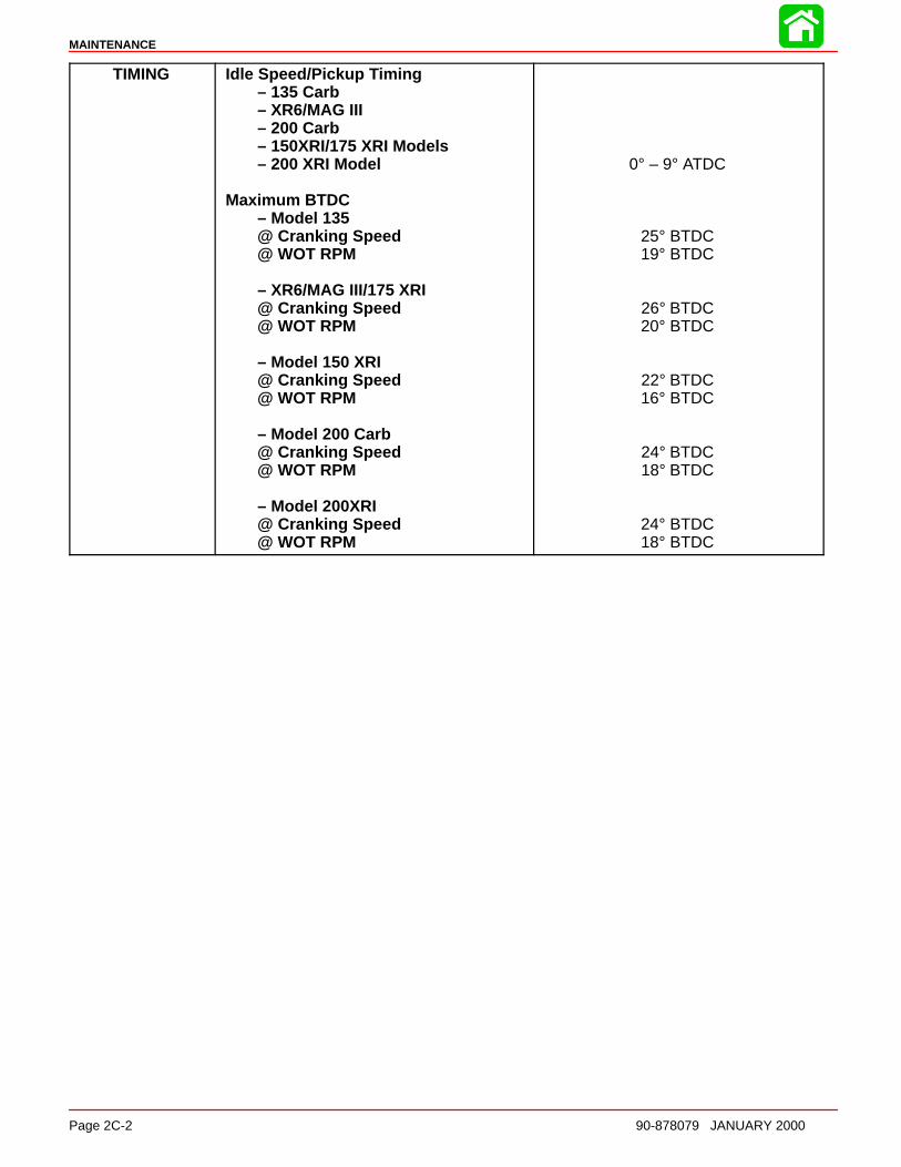
MAINTENANCE
Page 2C-2 90-878079 JANUARY 2000
TIMING Idle Speed/Pickup Timing– 135 Carb– XR6/MAG III– 200 Carb– 150XRI/175 XRI Models– 200 XRI Model
Maximum BTDC– Model 135@ Cranking Speed@ WOT RPM
– XR6/MAG III/175 XRI@ Cranking Speed@ WOT RPM
– Model 150 XRI@ Cranking Speed@ WOT RPM
– Model 200 Carb@ Cranking Speed@ WOT RPM
– Model 200XRI@ Cranking Speed@ WOT RPM
0° – 9° ATDC
25° BTDC19° BTDC
26° BTDC20° BTDC
22° BTDC16° BTDC
24° BTDC18° BTDC
24° BTDC18° BTDC
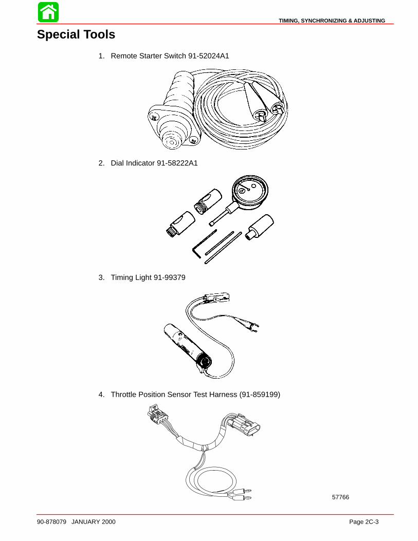
TIMING, SYNCHRONIZING & ADJUSTING
90-878079 JANUARY 2000 Page 2C-3
Special Tools
1. Remote Starter Switch 91-52024A1
2. Dial Indicator 91-58222A1
3. Timing Light 91-99379
4. Throttle Position Sensor Test Harness (91-859199)
57766

MAINTENANCE
Page 2C-4 90-878079 JANUARY 2000
Adjustments
Carburetor ModelsTIMING POINTER ADJUSTMENT
WARNINGEngine could start when turning flywheel to check timing pointer adjustment. Re-move all spark plugs from engine to prevent engine from starting.
1. Remove all spark plugs and install Dial Indicator (91-58222A1) into No. 1 cylinder (topcylinder, starboard bank).
58046
2. Turn flywheel in a clockwise direction until No. 1 piston is at top dead center (TDC).Set dial indicator at “O” (zero) and tighten indicator set screw.
3. Turn flywheel counterclockwise until dial indicator needle is approximately 1/4-turnbeyond 0.462 in., then turn flywheel clockwise so that dial indicator reads 0.462 in.(11.7mm) exactly.
4. Reposition timing pointer so that timing pointer is aligned with 0.462 in. mark on timingdecal. Retighten pointer attaching screws 20 lb. in. (2.3 Nm)
5. Remove dial indicator from cylinder.
b
a
c
a - Timing Pointerb - Attaching Screwsc - 0.462 in. Mark
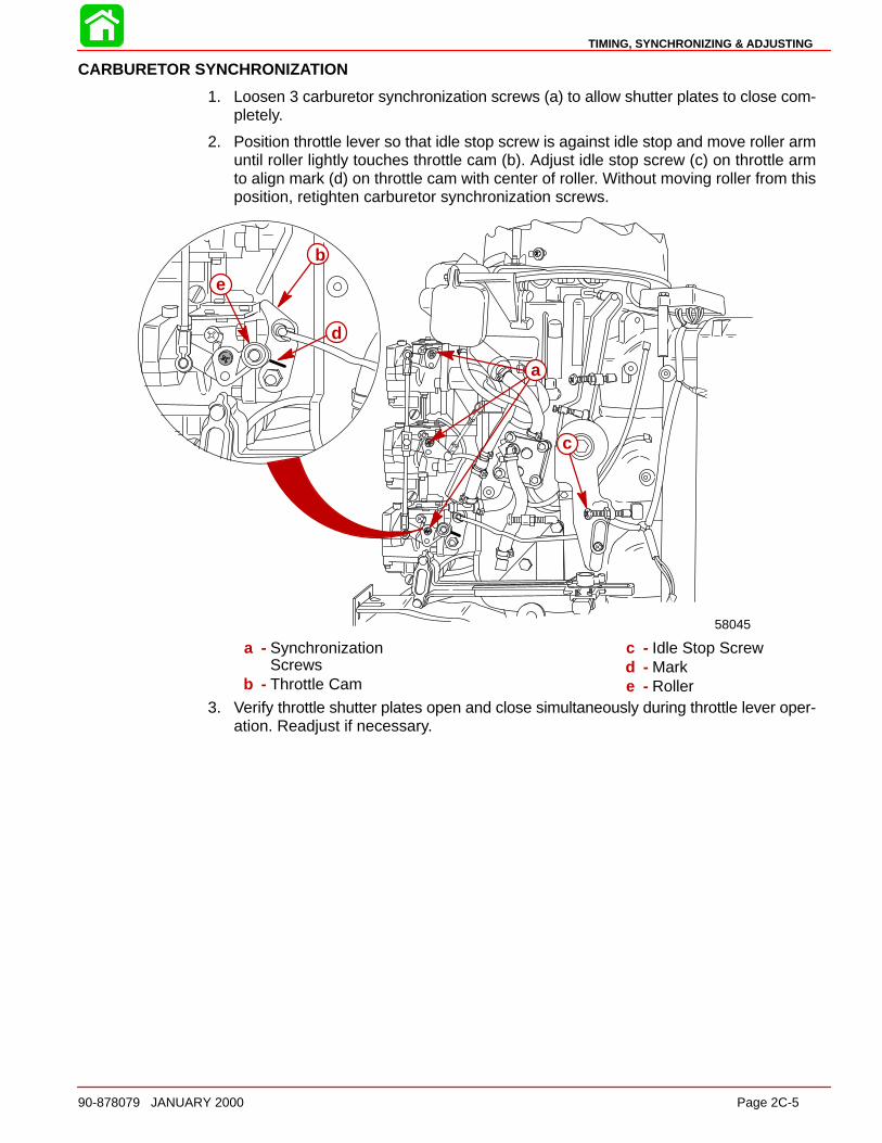
TIMING, SYNCHRONIZING & ADJUSTING
90-878079 JANUARY 2000 Page 2C-5
CARBURETOR SYNCHRONIZATION
1. Loosen 3 carburetor synchronization screws (a) to allow shutter plates to close com-pletely.
2. Position throttle lever so that idle stop screw is against idle stop and move roller armuntil roller lightly touches throttle cam (b). Adjust idle stop screw (c) on throttle armto align mark (d) on throttle cam with center of roller. Without moving roller from thisposition, retighten carburetor synchronization screws.
58045
a
c
b
d
e
a - SynchronizationScrews
b - Throttle Cam
c - Idle Stop Screwd - Marke - Roller
3. Verify throttle shutter plates open and close simultaneously during throttle lever oper-ation. Readjust if necessary.
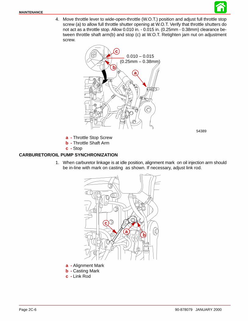
MAINTENANCE
Page 2C-6 90-878079 JANUARY 2000
4. Move throttle lever to wide-open-throttle (W.O.T.) position and adjust full throttle stopscrew (a) to allow full throttle shutter opening at W.O.T. Verify that throttle shutters donot act as a throttle stop. Allow 0.010 in. - 0.015 in. (0.25mm - 0.38mm) clearance be-tween throttle shaft arm(b) and stop (c) at W.O.T. Retighten jam nut on adjustmentscrew.
0.010 – 0.015(0.25mm – 0.38mm)
54389
b
c
a
a - Throttle Stop Screwb - Throttle Shaft Armc - Stop
CARBURETOR/OIL PUMP SYNCHRONIZATION
1. When carburetor linkage is at idle position, alignment mark on oil injection arm shouldbe in-line with mark on casting as shown. If necessary, adjust link rod.
ba
c
a - Alignment Markb - Casting Markc - Link Rod
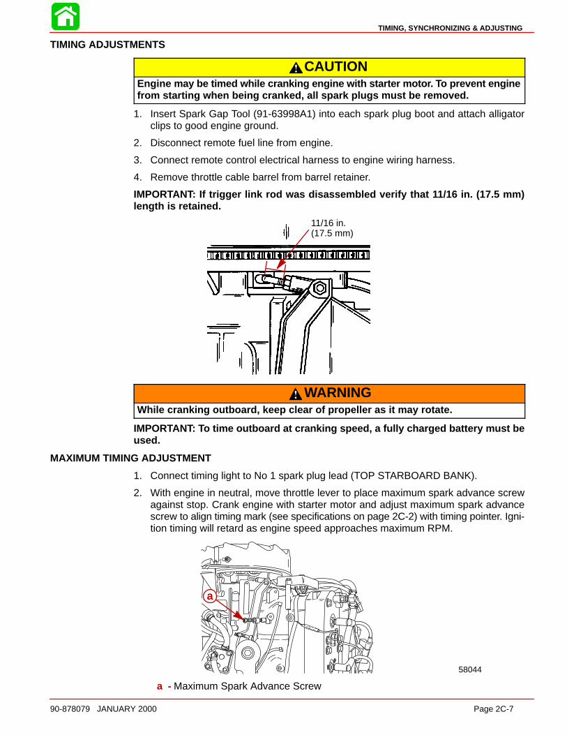
TIMING, SYNCHRONIZING & ADJUSTING
90-878079 JANUARY 2000 Page 2C-7
TIMING ADJUSTMENTS
CAUTIONEngine may be timed while cranking engine with starter moto r. To prevent enginefrom starting when being cranked, all spark plugs must be removed.
1. Insert Spark Gap Tool (91-63998A1) into each spark plug boot and attach alligatorclips to good engine ground.
2. Disconnect remote fuel line from engine.
3. Connect remote control electrical harness to engine wiring harness.
4. Remove throttle cable barrel from barrel retainer.
IMPORTANT: If trigger link rod was disassembled verify that 11/16 in. (17.5 mm)length is retained.
11/16 in.(17.5 mm)
WARNINGWhile cranking outboard, keep clear of propeller as it may rotate.
IMPORTANT: To time outboard at cranking speed, a fully charged battery must beused.
MAXIMUM TIMING ADJUSTMENT
1. Connect timing light to No 1 spark plug lead (TOP STARBOARD BANK).
2. With engine in neutral, move throttle lever to place maximum spark advance screwagainst stop. Crank engine with starter motor and adjust maximum spark advancescrew to align timing mark (see specifications on page 2C-2) with timing pointer. Igni-tion timing will retard as engine speed approaches maximum RPM.
58044
a
a - Maximum Spark Advance Screw
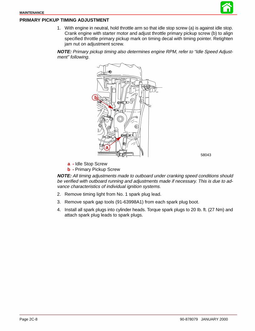
MAINTENANCE
Page 2C-8 90-878079 JANUARY 2000
PRIMARY PICKUP TIMING ADJUSTMENT
1. With engine in neutral, hold throttle arm so that idle stop screw (a) is against idle stop.Crank engine with starter motor and adjust throttle primary pickup screw (b) to alignspecified throttle primary pickup mark on timing decal with timing pointer. Retightenjam nut on adjustment screw.
NOTE: Primary pickup timing also determines engine RPM, refer to “Idle Speed Adjust-ment” following.
58043
a
b
a - Idle Stop Screwb - Primary Pickup Screw
NOTE: All timing adjustments made to outboard under cranking speed conditions shouldbe verified with outboard running and adjustments made if necessary. This is due to ad-vance characteristics of individual ignition systems.
2. Remove timing light from No. 1 spark plug lead.
3. Remove spark gap tools (91-63998A1) from each spark plug boot.
4. Install all spark plugs into cylinder heads. Torque spark plugs to 20 Ib. ft. (27 Nm) andattach spark plug leads to spark plugs.
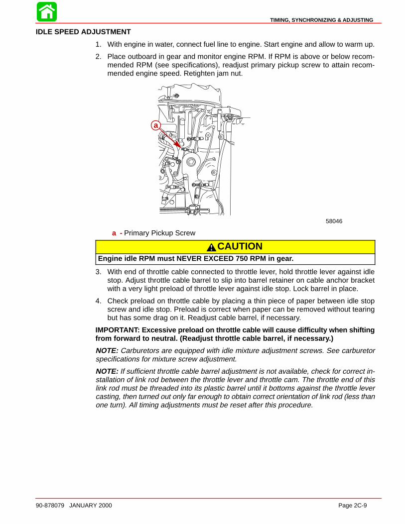
TIMING, SYNCHRONIZING & ADJUSTING
90-878079 JANUARY 2000 Page 2C-9
IDLE SPEED ADJUSTMENT
1. With engine in water, connect fuel line to engine. Start engine and allow to warm up.
2. Place outboard in gear and monitor engine RPM. If RPM is above or below recom-mended RPM (see specifications), readjust primary pickup screw to attain recom-mended engine speed. Retighten jam nut.
58046
a
a - Primary Pickup Screw
CAUTIONEngine idle RPM must NEVER EXCEED 750 RPM in gea r.
3. With end of throttle cable connected to throttle lever, hold throttle lever against idlestop. Adjust throttle cable barrel to slip into barrel retainer on cable anchor bracketwith a very light preload of throttle lever against idle stop. Lock barrel in place.
4. Check preload on throttle cable by placing a thin piece of paper between idle stopscrew and idle stop. Preload is correct when paper can be removed without tearingbut has some drag on it. Readjust cable barrel, if necessary.
IMPORTANT: Excessive preload on throttle cable will cause difficulty when shiftingfrom forward to neutral. (Readjust throttle cable barrel, if necessar y.)
NOTE: Carburetors are equipped with idle mixture adjustment screws. See carburetorspecifications for mixture screw adjustment.
NOTE: If sufficient throttle cable barrel adjustment is not available, check for correct in-stallation of link rod between the throttle lever and throttle cam. The throttle end of thislink rod must be threaded into its plastic barrel until it bottoms against the throttle levercasting, then turned out only far enough to obtain correct orientation of link rod (less thanone turn). All timing adjustments must be reset after this procedure.
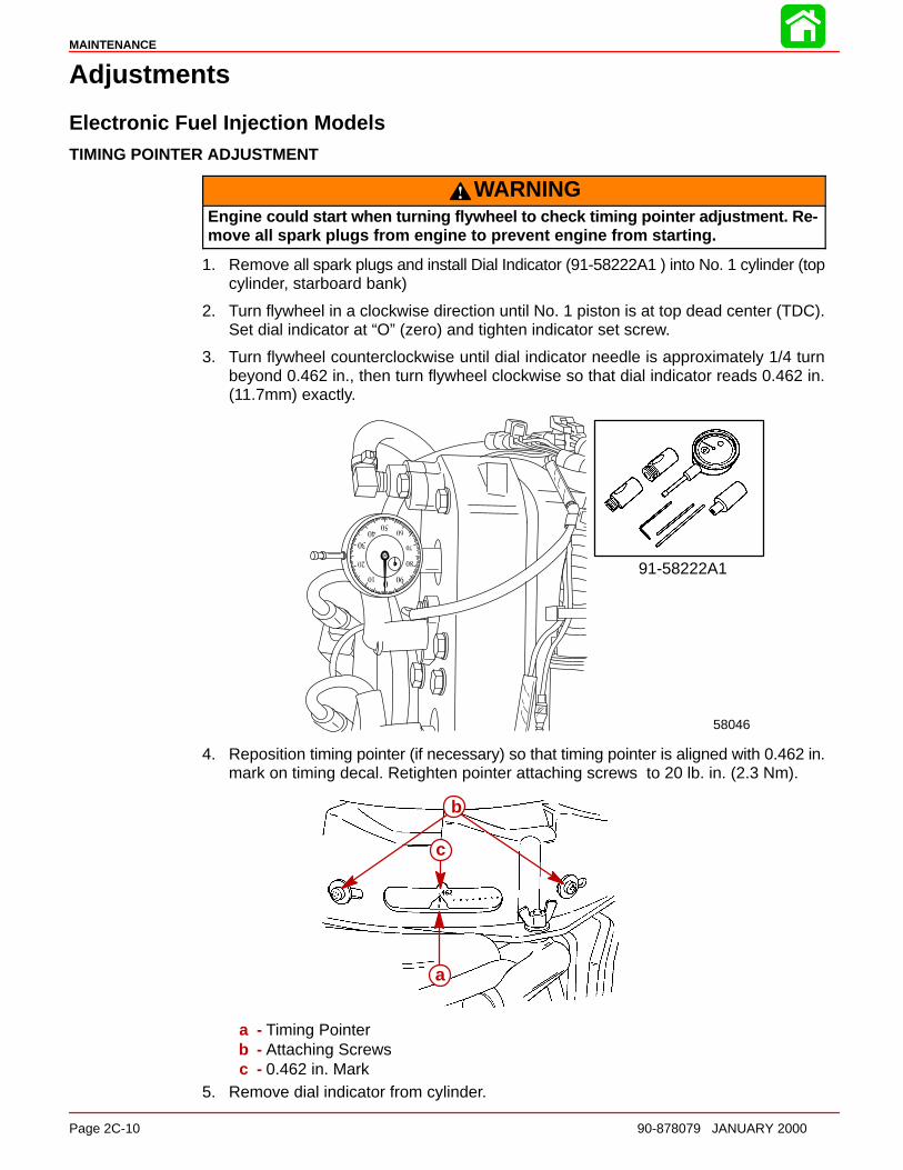
MAINTENANCE
Page 2C-10 90-878079 JANUARY 2000
Adjustments
Electronic Fuel Injection ModelsTIMING POINTER ADJUSTMENT
WARNINGEngine could start when turning flywheel to check timing pointer adjustment. Re-move all spark plugs from engine to prevent engine from starting.
1. Remove all spark plugs and install Dial Indicator (91-58222A1 ) into No. 1 cylinder (topcylinder, starboard bank)
2. Turn flywheel in a clockwise direction until No. 1 piston is at top dead center (TDC).Set dial indicator at “O” (zero) and tighten indicator set screw.
3. Turn flywheel counterclockwise until dial indicator needle is approximately 1/4 turnbeyond 0.462 in., then turn flywheel clockwise so that dial indicator reads 0.462 in.(11.7mm) exactly.
58046
91-58222A1
4. Reposition timing pointer (if necessary) so that timing pointer is aligned with 0.462 in.mark on timing decal. Retighten pointer attaching screws to 20 lb. in. (2.3 Nm).
b
a
c
a - Timing Pointerb - Attaching Screwsc - 0.462 in. Mark
5. Remove dial indicator from cylinder.
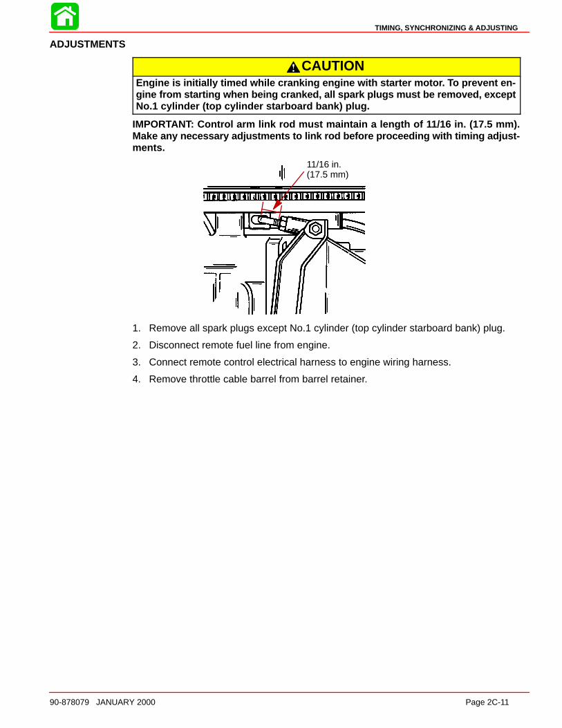
TIMING, SYNCHRONIZING & ADJUSTING
90-878079 JANUARY 2000 Page 2C-11
ADJUSTMENTS
CAUTIONEngine is initially timed while cranking engine with starter moto r. To prevent en-gine from starting when being cranked, all spark plugs must be removed, exceptNo.1 cylinder (top cylinder starboard bank) plug.
IMPORTANT: Control arm link rod must maintain a length of 11/16 in. (17.5 mm).Make any necessary adjustments to link rod before proceeding with timing adjust-ments.
11/16 in.(17.5 mm)
1. Remove all spark plugs except No.1 cylinder (top cylinder starboard bank) plug.
2. Disconnect remote fuel line from engine.
3. Connect remote control electrical harness to engine wiring harness.
4. Remove throttle cable barrel from barrel retainer.
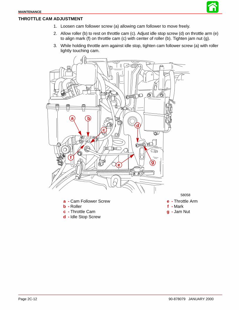
MAINTENANCE
Page 2C-12 90-878079 JANUARY 2000
THROTTLE CAM ADJUSTMENT
1. Loosen cam follower screw (a) allowing cam follower to move freely.
2. Allow roller (b) to rest on throttle cam (c). Adjust idle stop screw (d) on throttle arm (e)to align mark (f) on throttle cam (c) with center of roller (b). Tighten jam nut (g).
3. While holding throttle arm against idle stop, tighten cam follower screw (a) with rollerlightly touching cam.
58058
a b
cd
e
fg
a - Cam Follower Screwb - Rollerc - Throttle Camd - Idle Stop Screw
e - Throttle Armf - Markg - Jam Nut
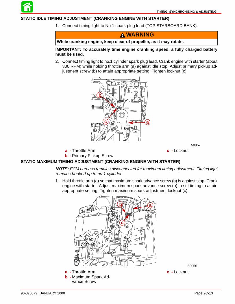
TIMING, SYNCHRONIZING & ADJUSTING
90-878079 JANUARY 2000 Page 2C-13
STATIC IDLE TIMING ADJUSTMENT (CRANKING ENGINE WITH S TARTER)
1. Connect timing light to No 1 spark plug lead (TOP STARBOARD BANK).
WARNINGWhile cranking engine, keep clear of propelle r, as it may rotate.
IMPORTANT: To accurately time engine cranking speed, a fully charged batterymust be used.
2. Connect timing light to no.1 cylinder spark plug lead. Crank engine with starter (about300 RPM) while holding throttle arm (a) against idle stop. Adjust primary pickup ad-justment screw (b) to attain appropriate setting. Tighten locknut (c).
58057
ac
b
a - Throttle Armb - Primary Pickup Screw
c - Locknut
STATIC MAXIMUM TIMING ADJUSTMENT (CRANKING ENGINE WITH S TARTER)
NOTE: ECM harness remains disconnected for maximum timing adjustment. Timing lightremains hooked up to no.1 cylinder.
1. Hold throttle arm (a) so that maximum spark advance screw (b) is against stop. Crankengine with starter. Adjust maximum spark advance screw (b) to set timing to attainappropriate setting. Tighten maximum spark adjustment locknut (c).
58056
b
c
a
a - Throttle Armb - Maximum Spark Ad-
vance Screw
c - Locknut
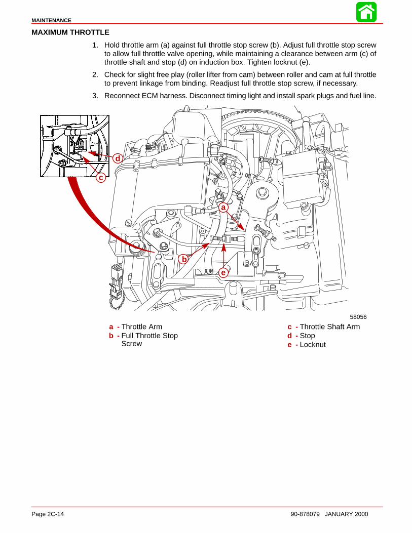
MAINTENANCE
Page 2C-14 90-878079 JANUARY 2000
MAXIMUM THROTTLE
1. Hold throttle arm (a) against full throttle stop screw (b). Adjust full throttle stop screwto allow full throttle valve opening, while maintaining a clearance between arm (c) ofthrottle shaft and stop (d) on induction box. Tighten locknut (e).
2. Check for slight free play (roller lifter from cam) between roller and cam at full throttleto prevent linkage from binding. Readjust full throttle stop screw, if necessary.
3. Reconnect ECM harness. Disconnect timing light and install spark plugs and fuel line.
a
b
c
d
e
58056
a - Throttle Armb - Full Throttle Stop
Screw
c - Throttle Shaft Armd - Stope - Locknut
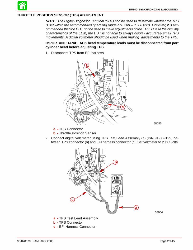
TIMING, SYNCHRONIZING & ADJUSTING
90-878079 JANUARY 2000 Page 2C-15
THROTTLE POSITION SENSOR (TPS) ADJUSTMENT
NOTE: The Digital Diagnostic Terminal (DDT) can be used to determine whether the TPSis set within the recommended operating range of 0.200 – 0.300 volts. However, it is rec-ommended that the DDT not be used to make adjustments of the TPS. Due to the circuitrycharacteristics of the ECM, the DDT is not able to always display accurately small TPSmovements. A digital voltmeter should be used when making adjustments to the TPS.
IMPORTANT: TAN/BLACK head temperature leads must be disconnected from portcylinder head before adjusting TPS.
1. Disconnect TPS from EFI harness.
58055
a
b
a - TPS Connectorb - Throttle Position Sensor
2. Connect digital volt meter using TPS Test Lead Assembly (a) (P/N 91-859199) be-tween TPS connector (b) and EFI harness connector (c). Set voltmeter to 2 DC volts.
58054
a
b
c
a - TPS Test Lead Assemblyb - TPS Connectorc - EFI Harness Connector
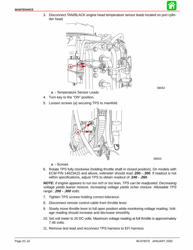
MAINTENANCE
Page 2C-16 90-878079 JANUARY 2000
3. Disconnect TAN/BLACK engine head temperature sensor leads located on port cylin-der head.
58052
a
a - Temperature Sensor Leads4. Turn key to the “ON” position.
5. Loosen screws (a) securing TPS to manifold.
58053
a
a - Screws6. Rotate TPS fully clockwise (holding throttle shaft in closed position). On models with
ECM P/N 14623A15 and above, voltmeter should read .200 - .300. If readout is notwithin specifications, adjust TPS to obtain readout of .240 - .260.
NOTE: If engine appears to run too rich or too lean, TPS can be readjusted. Decreasingvoltage yields leaner mixture. Increasing voltage yields richer mixture. Allowable TPSrange: .200 - .300 volts.
7. Tighten TPS screws holding correct tolerance.
8. Disconnect remote control cable from throttle lever.
9. Slowly move throttle lever to full open position while monitoring voltage reading. Volt-age reading should increase and decrease smoothly.
10. Set volt meter to 20 DC volts. Maximum voltage reading at full throttle is approximately7.46 volts.
11. Remove test lead and reconnect TPS harness to EFI harness.
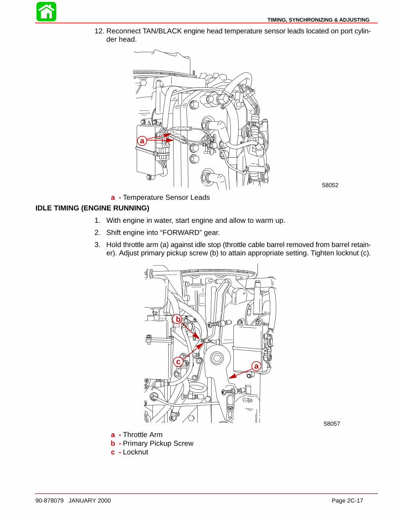
TIMING, SYNCHRONIZING & ADJUSTING
90-878079 JANUARY 2000 Page 2C-17
12. Reconnect TAN/BLACK engine head temperature sensor leads located on port cylin-der head.
58052
a
a - Temperature Sensor Leads
IDLE TIMING (ENGINE RUNNING)
1. With engine in water, start engine and allow to warm up.
2. Shift engine into “FORWARD” gear.
3. Hold throttle arm (a) against idle stop (throttle cable barrel removed from barrel retain-er). Adjust primary pickup screw (b) to attain appropriate setting. Tighten locknut (c).
58057
b
c a
a - Throttle Armb - Primary Pickup Screwc - Locknut

MAINTENANCE
Page 2C-18 90-878079 JANUARY 2000
IDLE ADJUSTMENT
1. With outboard in water, start and allow to warm up.
2. Loosen cam follower screw (a), allowing free movement of cam. Hold throttle armagainst idle stop. Adjust idle speed screw (b) by increasing or decreasing air valveopening to attain appropriate setting.
a
b
a - Cam Follower Screwb - Idle Speed Screw
THROTTLE VALVE/OIL PUMP SYNCHRONIZATION
1. While holding throttle arm against idle stop, adjust length of link rod (a) so thatstamped mark (b) of oil pump lever aligns with stamped mark (c) of oil pump body.
58058
a
c
b
a - Link Rodb - Stamped Mark on Leverc - Stamped Mark on Body
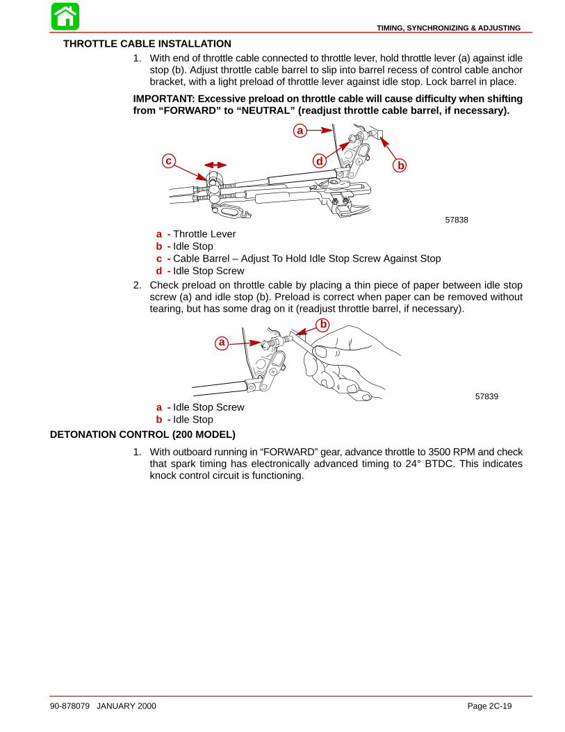
TIMING, SYNCHRONIZING & ADJUSTING
90-878079 JANUARY 2000 Page 2C-19
THROTTLE CABLE INS TALL ATION1. With end of throttle cable connected to throttle lever, hold throttle lever (a) against idle
stop (b). Adjust throttle cable barrel to slip into barrel recess of control cable anchorbracket, with a light preload of throttle lever against idle stop. Lock barrel in place.
IMPORTANT: Excessive preload on throttle cable will cause difficulty when shiftingfrom “FO RWARD” to “NEUTRAL” (readjust throttle cable barrel, if necessary).
57838
b
a
c d
a - Throttle Leverb - Idle Stopc - Cable Barrel – Adjust To Hold Idle Stop Screw Against Stopd - Idle Stop Screw
2. Check preload on throttle cable by placing a thin piece of paper between idle stopscrew (a) and idle stop (b). Preload is correct when paper can be removed withouttearing, but has some drag on it (readjust throttle barrel, if necessary).
a
b
57839a - Idle Stop Screwb - Idle Stop
DETONATION CONTROL (200 MODEL)
1. With outboard running in “FORWARD” gear, advance throttle to 3500 RPM and checkthat spark timing has electronically advanced timing to 24° BTDC. This indicatesknock control circuit is functioning.
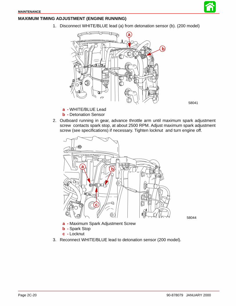
MAINTENANCE
Page 2C-20 90-878079 JANUARY 2000
MAXIMUM TIMING ADJUSTMENT (ENGINE RUNNING)
1. Disconnect WHITE/BLUE lead (a) from detonation sensor (b). (200 model)
58041
a
b
a - WHITE/BLUE Leadb - Detonation Sensor
2. Outboard running in gear, advance throttle arm until maximum spark adjustmentscrew contacts spark stop, at about 2500 RPM. Adjust maximum spark adjustmentscrew (see specifications) if necessary. Tighten locknut and turn engine off.
58044
a b
c
a - Maximum Spark Adjustment Screwb - Spark Stopc - Locknut
3. Reconnect WHITE/BLUE lead to detonation sensor (200 model).
2D
WIRING DIAGRAMS
90-878079 JANUARY 2000 Page 2D-1
ELECTRICALSection 2D – Wiring Diagrams
Table of Contents
Power Trim Wiring Diagram 2D-2. . . . . . . . . . . . . . Instrument Wiring Connections 2D-3. . . . . . . . . . . . Commander 3000 Classic Panel RemoteControl 2D-4. . . . . . . . . . . . . . . . . . . . . . . . . . . . . . . . . Commander 3000 Panel Remote Control 2D-5. . . Instrument/Lanyard Stop SwitchWiring Diagram 2D-6. . . . . . . . . . . . . . . . . . . . . . . . . Oil Level Gauge Wiring Diagram 2D-7. . . . . . . . . . Instrument/Lanyard Stop SwitchWiring Diagram (Dual Outboard) 2D-8. . . . . . . . . . Panel Mount Remote ControlWiring Installation 2D-10. . . . . . . . . . . . . . . . . . . . . . . QSI Gauge Wiring Diagrams 2D-11. . . . . . . . . . . . . .
Tachometer Wiring Diagram 2D-11. . . . . . . . . . .
Water Temperature Gauge 2D-12. . . . . . . . . . . . Oil Level Gauge Wiring 2D-13. . . . . . . . . . . . . . . . Engine Synchronizer Wiring Diagram 2D-15. . .
Maintenance 2D-16. . . . . . . . . . . . . . . . . . . . . . . . . . . . Multi-Function Gauge 2D-17. . . . . . . . . . . . . . . . . . . .
Dip Switch Setting/Testing 2D-17. . . . . . . . . . . . . Outboard Multi-Function Gauge Setting 2D-18.
2.5 Litre V-6 Carburetor Wiring Diagram 2000 Models 2D-19. . . . . . . . . . . . 2.5 Litre V-6 150/175 EFI Carburetor Wiring Diagram 2000 Models 2D-20. . . . . . . . . . . . 2.5 Litre V-6 200 EFI Carburetor Wiring Diagram 2000 Models 2D-21. . . . . . . . . . . .

WIRING DIAGRAMS
Page 2D-2 90-878079 JANUARY 2000
Power Trim Wiring Diagram
c
d
e
f
g
hj
m
n
a bc
d
e
f
g
hij
k
l
m
n
a - Tach. Connectorb - Key Switch Assemblyc - Trim Switchd - Trim Sendere - Start Solenoidf - To Batteryg - To Alternator
h - Trim Pump and Motori - DOWN Solenoidj - UP Solenoidk - Bottom Cowl Switchl - 20 Ampere Fuse
m - Engine Harnessn - Remote Control Harness
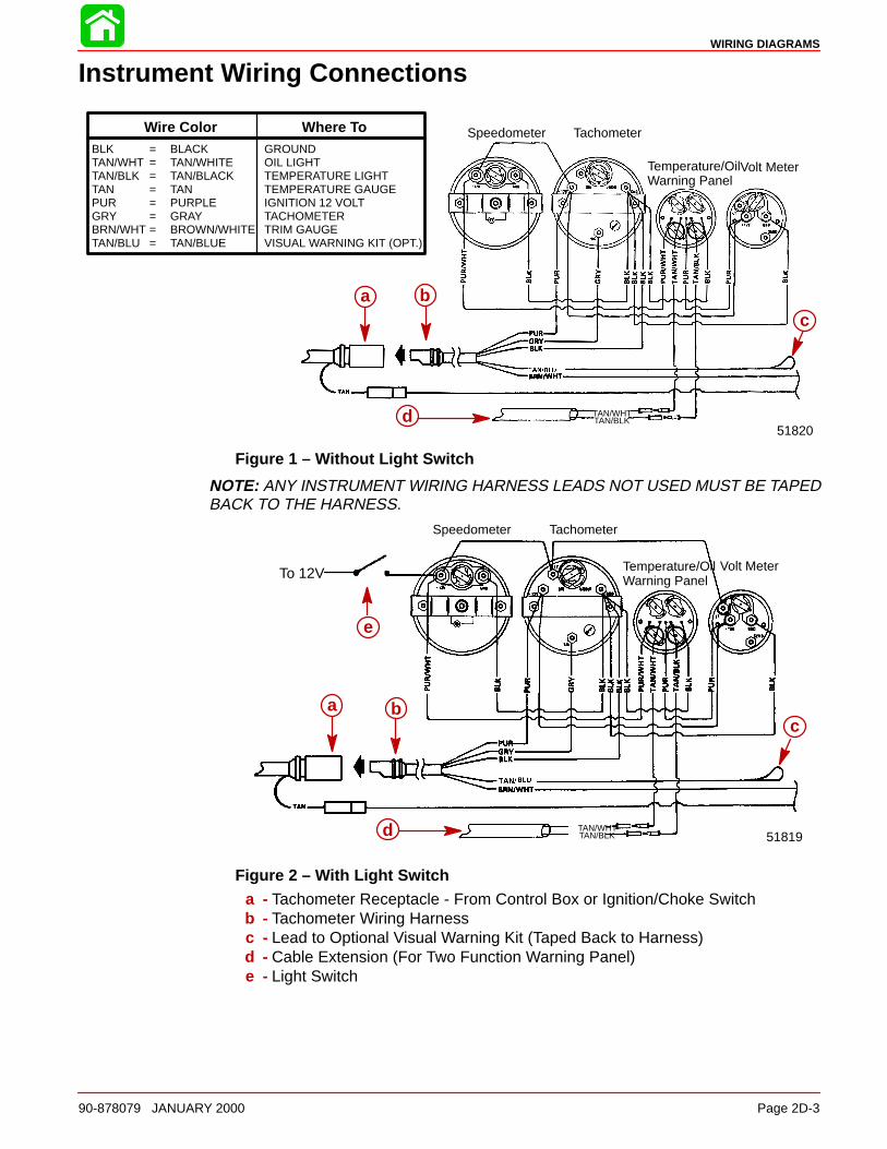
WIRING DIAGRAMS
90-878079 JANUARY 2000 Page 2D-3
Instrument Wiring Connections
Speedometer Tachometer
Temperature/Oil Warning Panel
Volt Meter
TAN/WHTTAN/BLK
51820
a b
d
c
BLK = BLACK GROUNDTAN/WHT = TAN/WHITE OIL LIGHTTAN/BLK = TAN/BLACK TEMPERATURE LIGHTTAN = TAN TEMPERATURE GAUGEPUR = PURPLE IGNITION 12 VOLTGRY = GRAY TACHOMETERBRN/WHT = BROWN/WHITE TRIM GAUGETAN/BLU = TAN/BLUE VISUAL WARNING KIT (OPT.)
Wire Color Where To
a bc
d
Figure 1 – Without Light Switch
NOTE: ANY INSTRUMENT WIRING HARNESS LEADS NOT USED MUST BE TAPEDBACK TO THE HARNESS.
TAN/WHTTAN/BLK
Speedometer Tachometer
Temperature/Oil Warning Panel
Volt Meter
51819
To 12V
e
a b
d
ca b
c
d
e
Figure 2 – With Light Switch
a - Tachometer Receptacle - From Control Box or Ignition/Choke Switchb - Tachometer Wiring Harnessc - Lead to Optional Visual Warning Kit (Taped Back to Harness)d - Cable Extension (For Two Function Warning Panel)e - Light Switch

WIRING DIAGRAMS
Page 2D-4 90-878079 JANUARY 2000
Commander 3000 Classic Panel Remote Control
F R< >
RED
PURPLE
GREEN
BLK = BlackBLU = BlueBRN = BrownGRY = GrayGRN = GreenORN = OrangePNK = PinkPUR = PurpleRED = RedTan = Tan
WHT = WhiteYEL = YellowLIT = Light
DRK = Dark
aa
a - Neutral Interlock Switch
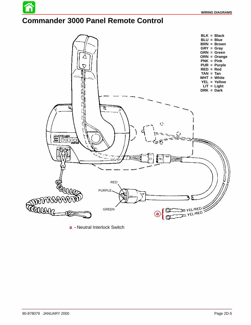
WIRING DIAGRAMS
90-878079 JANUARY 2000 Page 2D-5
Commander 3000 Panel Remote Control
RED
PURPLE
GREEN
BLK = BlackBLU = BlueBRN = BrownGRY = GrayGRN = GreenORN = OrangePNK = PinkPUR = PurpleRED = RedTAN = Tan
WHT = WhiteYEL = YellowLIT = Light
DRK = Dark
aa
a - Neutral Interlock Switch

WIRING DIAGRAMS
Page 2D-6 90-878079 JANUARY 2000
Instrument/Lanyard Stop Switch Wiring Diagram
BLK=BLACKBLU=BLUEBRN=BROWNGRN=GREENGRY=GRAYPUR=PURPLERED=REDTAN=TANWHT=WHITEYEL=YELLOW
52204
d
abc
j
i
k
j
h
fg
abc
d
e
hi
j
k
j
a - Ignition/Choke Switchb - Lanyard Stop Switchc - Lead Not Used on Outboard Installationsd - Retainere - Tachometerf - Trim Indicator Gauge (Optional)g - Temperature Gaugeh - Remote Controli - Power Trim Harness Connectorj - Connect Wires Together w/Screw and Nut (2 Places); Apply Liquid Neoprene
to Connections and Slide Rubber Sleeve over each Connection.k - Lead to Optional Visual Warning Kit
IMPORTANT: On installations where gauge options will not be used, tape back anyunused wiring harness leads.
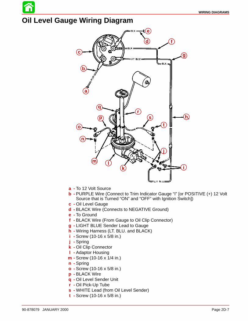
WIRING DIAGRAMS
90-878079 JANUARY 2000 Page 2D-7
Oil Level Gauge Wiring Diagram
a
b
c
i
o
m
n
j
kl
h
g
f
p
qr
s
t
e
d
a
b
c
d
e
f
g
h
i
j
klm
n
o
p
qr
s
t
a - To 12 Volt Sourceb - PURPLE Wire (Connect to Trim Indicator Gauge “I” [or POSITIVE (+) 12 Volt
Source that is Turned “ON” and “OFF” with Ignition Switch])c - Oil Level Gauged - BLACK Wire (Connects to NEGATIVE Ground)e - To Groundf - BLACK Wire (From Gauge to Oil Clip Connector)g - LIGHT BLUE Sender Lead to Gaugeh - Wiring Harness (LT. BLU. and BLACK)i - Screw (10-16 x 5/8 in.)j - Springk - Oil Clip Connectorl - Adaptor Housing
m - Screw (10-16 x 1/4 in.)n - Springo - Screw (10-16 x 5/8 in.)p - BLACK Wireq - Oil Level Sender Unitr - Oil Pick-Up Tubes - WHITE Lead (from Oil Level Sender)t - Screw (10-16 x 5/8 in.)

WIRING DIAGRAMS
Page 2D-8 90-878079 JANUARY 2000
Instrument/Lanyard Stop Switch Wiring Diagram (DualOutboard)
BLK=BLACKBLU=BLUEBRN=BROWNGRN=GREENGRY=GRAYPUR=PURPLERED=REDTAN=TANWHT=WHITEYEL=YELLOW
52205
g
a
d k d
bc
ld
f
nh
o
BATT GND
SENDER
PORT INSTALLATION
a
g
d k d
c b
ld
e
f
n
nh
o
a - Ignition/Choke Switchb - Lanyard Stop Switchc - Lead not used on Outboard Installationsd - Retainere - Tachometerf - Trim Indicator Gaugeg - Temperature Gaugeh - Remote Control
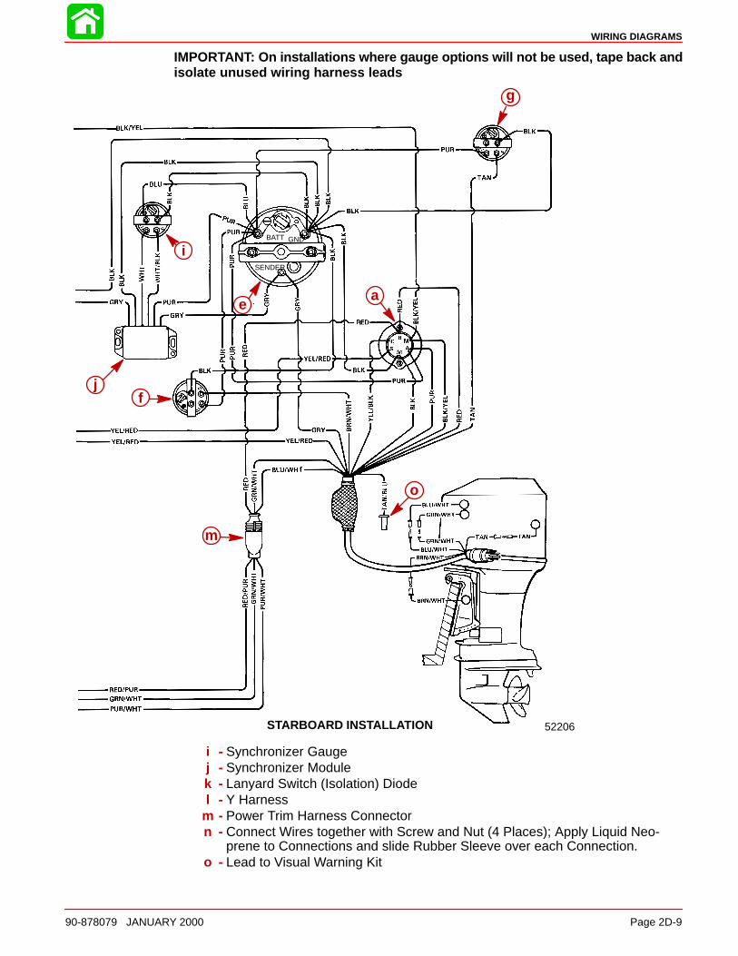
WIRING DIAGRAMS
90-878079 JANUARY 2000 Page 2D-9
IMPORTANT: On installations where gauge options will not be used, tape back andisolate unused wiring harness leads
52206
g
ae
jf
o
STARBOARD INSTALLATION
BATT GND
SENDER
g
i
jf
m
o
ae
i - Synchronizer Gaugej - Synchronizer Modulek - Lanyard Switch (Isolation) Diodel - Y Harness
m - Power Trim Harness Connectorn - Connect Wires together with Screw and Nut (4 Places); Apply Liquid Neo-
prene to Connections and slide Rubber Sleeve over each Connection.o - Lead to Visual Warning Kit
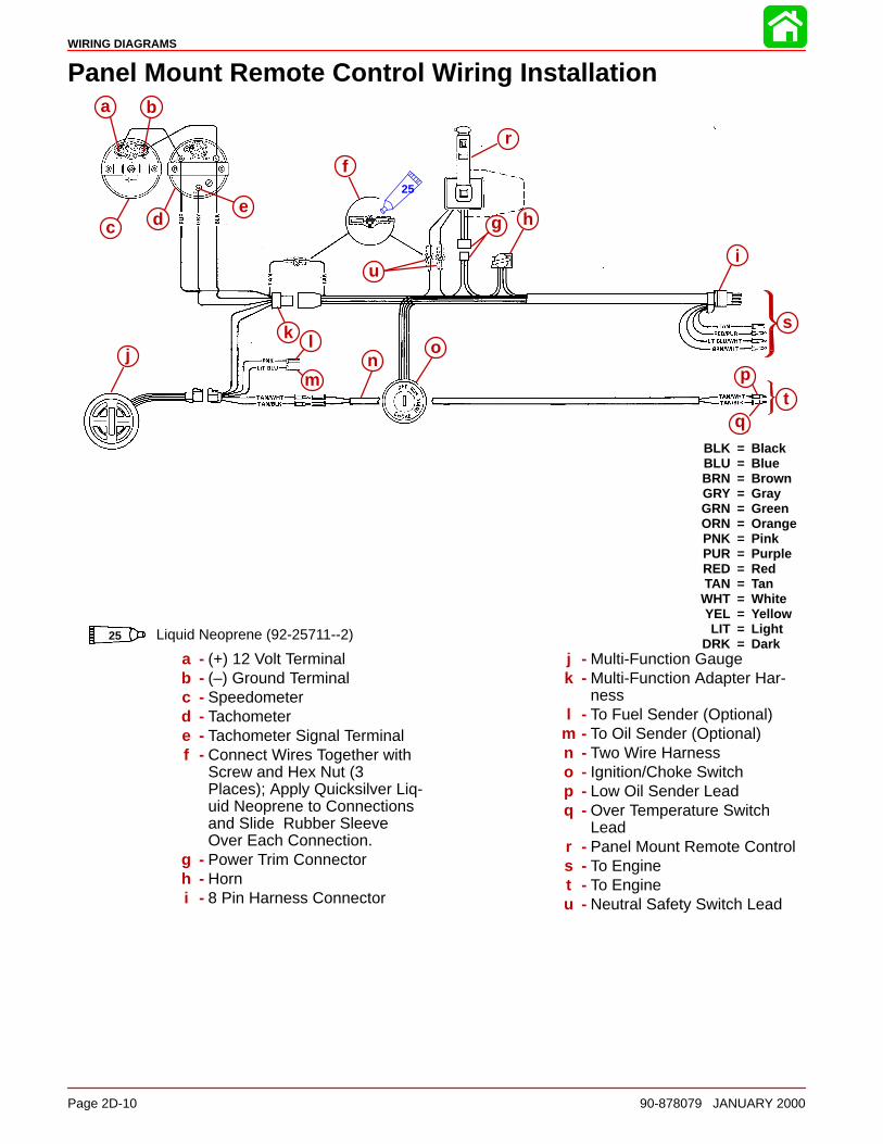
WIRING DIAGRAMS
Page 2D-10 90-878079 JANUARY 2000
Panel Mount Remote Control Wiring Installation
BLK = BlackBLU = BlueBRN = BrownGRY = GrayGRN = GreenORN = OrangePNK = PinkPUR = PurpleRED = RedTAN = Tan
WHT = WhiteYEL = YellowLIT = Light
DRK = Dark
a b
c d
f
g h
r
ui
s
tp
q
on
lkj
e25
a b
c de
f
g h
i
jk l
mn
o
p
q
r
s
t
u
Liquid Neoprene (92-25711--2)25
a - (+) 12 Volt Terminalb - (–) Ground Terminalc - Speedometerd - Tachometere - Tachometer Signal Terminalf - Connect Wires Together with
Screw and Hex Nut (3Places); Apply Quicksilver Liq-uid Neoprene to Connectionsand Slide Rubber SleeveOver Each Connection.
g - Power Trim Connectorh - Horni - 8 Pin Harness Connector
j - Multi-Function Gaugek - Multi-Function Adapter Har-
nessl - To Fuel Sender (Optional)
m - To Oil Sender (Optional)n - Two Wire Harnesso - Ignition/Choke Switchp - Low Oil Sender Leadq - Over Temperature Switch
Leadr - Panel Mount Remote Controls - To Enginet - To Engineu - Neutral Safety Switch Lead
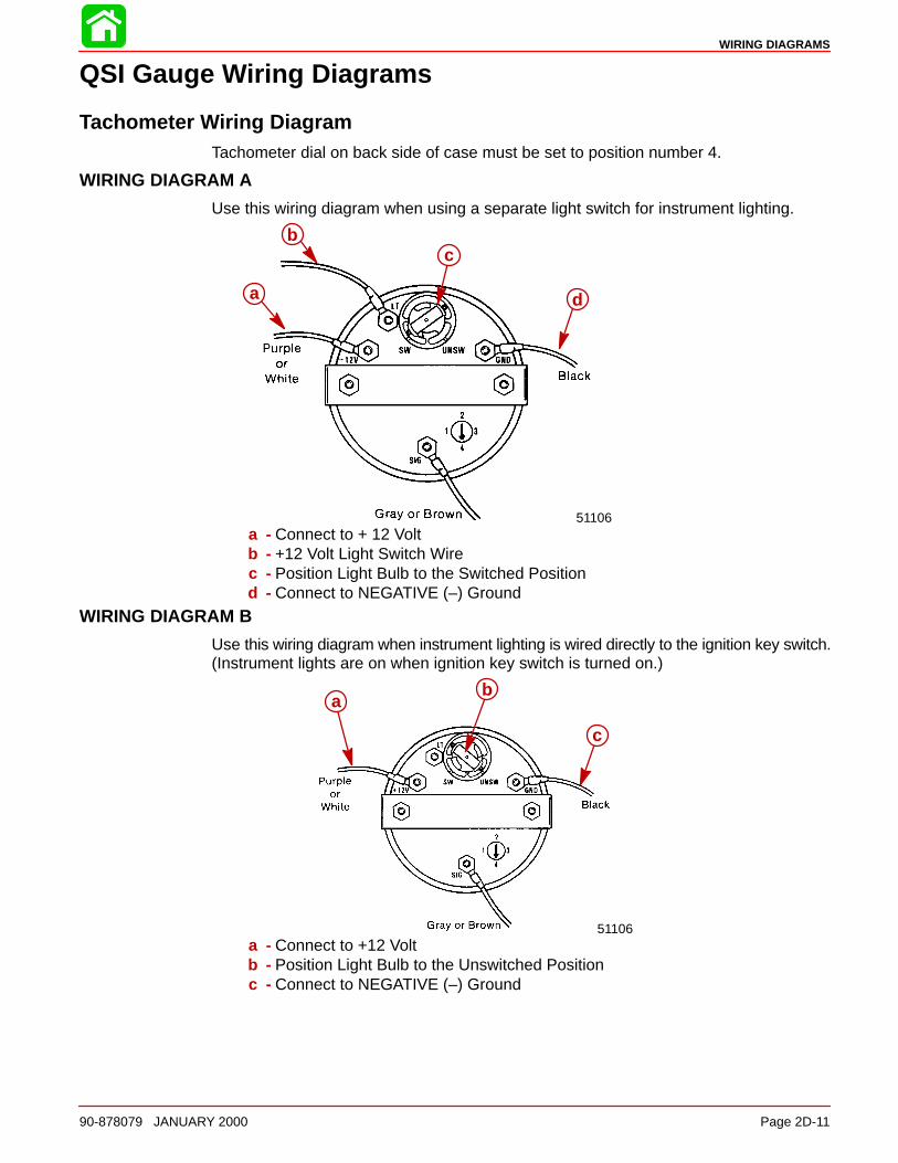
WIRING DIAGRAMS
90-878079 JANUARY 2000 Page 2D-11
QSI Gauge Wiring Diagrams
Tachometer Wiring DiagramTachometer dial on back side of case must be set to position number 4.
WIRING DIAGRAM A
Use this wiring diagram when using a separate light switch for instrument lighting.
51106
a
bc
d
a - Connect to + 12 Voltb - +12 Volt Light Switch Wirec - Position Light Bulb to the Switched Positiond - Connect to NEGATIVE (–) Ground
WIRING DIAGRAM B
Use this wiring diagram when instrument lighting is wired directly to the ignition key switch.(Instrument lights are on when ignition key switch is turned on.)
51106
ab
c
a - Connect to +12 Voltb - Position Light Bulb to the Unswitched Positionc - Connect to NEGATIVE (–) Ground

WIRING DIAGRAMS
Page 2D-12 90-878079 JANUARY 2000
Water Temperature GaugeWIRING DIAGRAM A
Use this wiring diagram when using a separate light switch for instrument lighting.
SEND
a
b c
d
e
a - Connect to + 12 Voltb - +12 Volt Light Switch Wirec - Position Light Bulb to the Switched Positiond - Connect to NEGATIVE (–) Grounde - Connect to TAN Lead located at the Tachometer Receptacle on Commander
Side Mount Remote Control or TAN Lead coming from Accessory Ignition/Choke Assembly.
WIRING DIAGRAM B
Use this wiring diagram when instrument lighting is wired directly to the ignition key switch.(Instrument lights are on when ignition key is turned on.)
51105
SEND
a
b
c
da - Connect to +12 Voltb - Position Light Bulb to the Unswitched Positionc - Connect to NEGATIVE (–) Groundd - Connect to TAN Lead located at the Tachometer Receptacle on Commander
Side Mount Remote Control or TAN Lead coming from Accessory Ignition/Choke Assembly
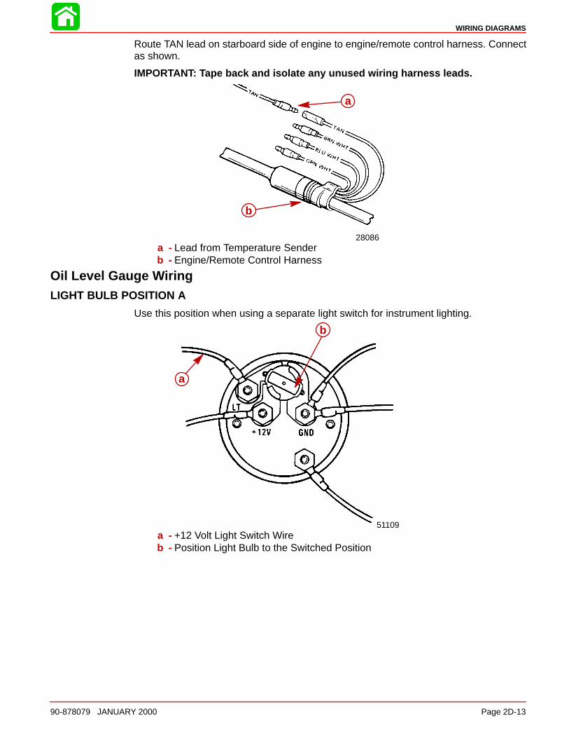
WIRING DIAGRAMS
90-878079 JANUARY 2000 Page 2D-13
Route TAN lead on starboard side of engine to engine/remote control harness. Connectas shown.
IMPORTANT: Tape back and isolate any unused wiring harness leads.
28086
a
b
a - Lead from Temperature Senderb - Engine/Remote Control Harness
Oil Level Gauge WiringLIGHT BULB POSITION A
Use this position when using a separate light switch for instrument lighting.
51109
a
b
a - +12 Volt Light Switch Wireb - Position Light Bulb to the Switched Position
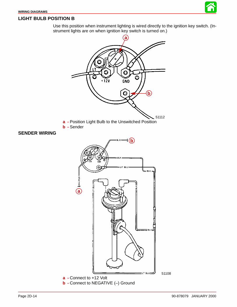
WIRING DIAGRAMS
Page 2D-14 90-878079 JANUARY 2000
LIGHT BULB POSITION B
Use this position when instrument lighting is wired directly to the ignition key switch. (In-strument lights are on when ignition key switch is turned on.)
51112
a
b
a - Position Light Bulb to the Unswitched Positionb - Sender
SENDER WIRING
51108
a
b
a - Connect to +12 Voltb - Connect to NEGATIVE (–) Ground
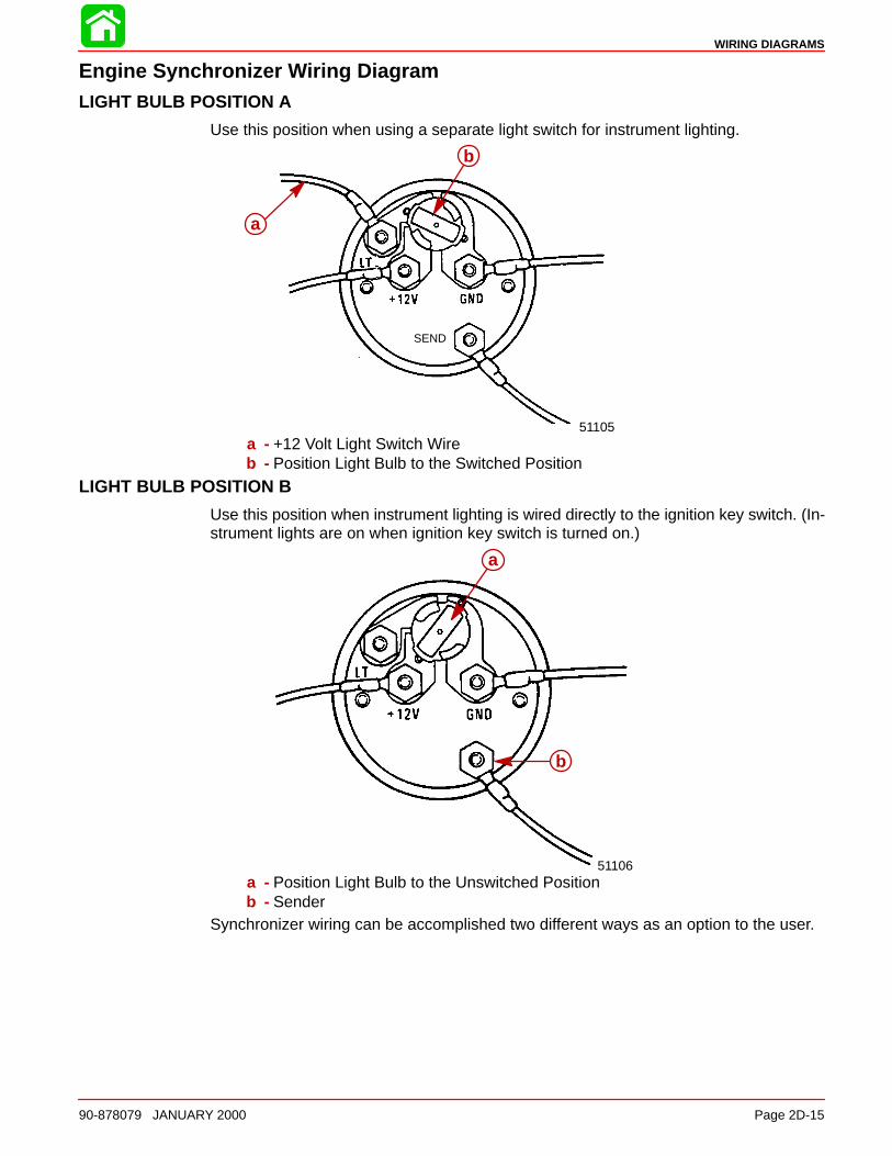
WIRING DIAGRAMS
90-878079 JANUARY 2000 Page 2D-15
Engine Synchronizer Wiring DiagramLIGHT BULB POSITION A
Use this position when using a separate light switch for instrument lighting.
SEND
51105
a
b
a - +12 Volt Light Switch Wireb - Position Light Bulb to the Switched Position
LIGHT BULB POSITION B
Use this position when instrument lighting is wired directly to the ignition key switch. (In-strument lights are on when ignition key switch is turned on.)
51106
a
b
a - Position Light Bulb to the Unswitched Positionb - Sender
Synchronizer wiring can be accomplished two different ways as an option to the user.
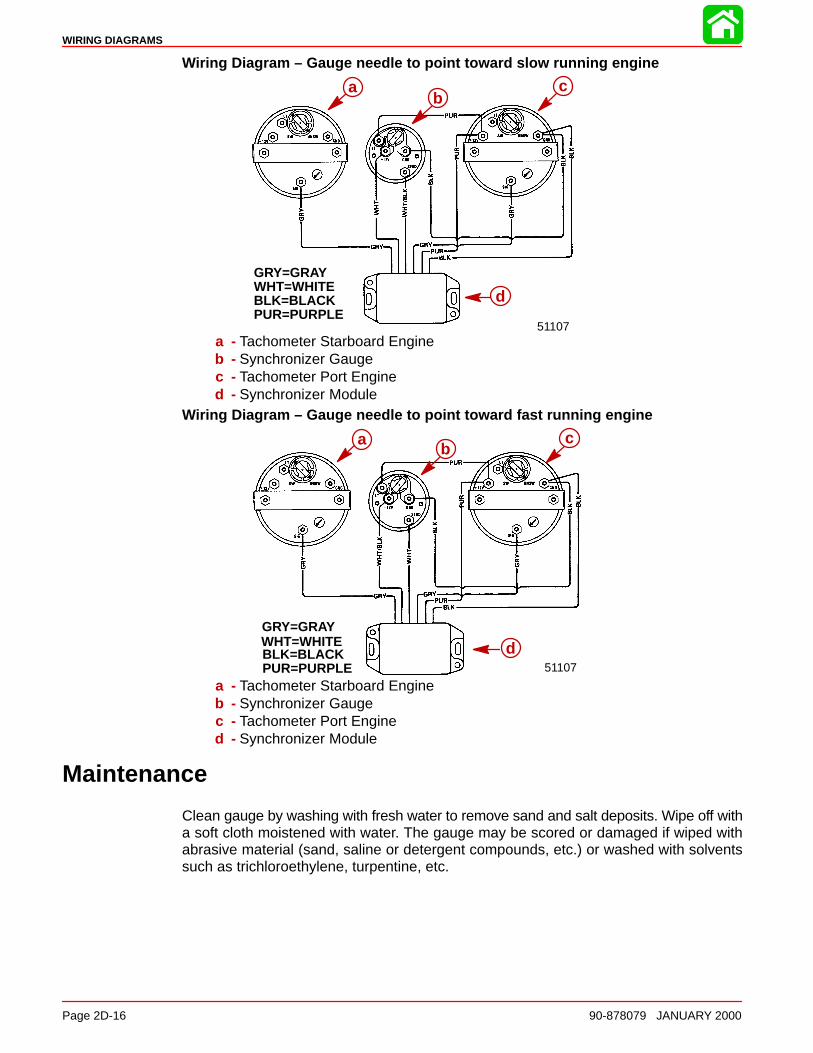
WIRING DIAGRAMS
Page 2D-16 90-878079 JANUARY 2000
Wiring Diagram – Gauge needle to point toward slow running engine
GRY=GRAYWHT=WHITEBLK=BLACKPUR=PURPLE
51107
bc
d
ab
c
d
a - Tachometer Starboard Engineb - Synchronizer Gaugec - Tachometer Port Engined - Synchronizer Module
Wiring Diagram – Gauge needle to point toward fast running engine
GRY=GRAYWHT=WHITEBLK=BLACKPUR=PURPLE
bc
d51107
ab
c
d
a - Tachometer Starboard Engineb - Synchronizer Gaugec - Tachometer Port Engined - Synchronizer Module
Maintenance
Clean gauge by washing with fresh water to remove sand and salt deposits. Wipe off witha soft cloth moistened with water. The gauge may be scored or damaged if wiped withabrasive material (sand, saline or detergent compounds, etc.) or washed with solventssuch as trichloroethylene, turpentine, etc.
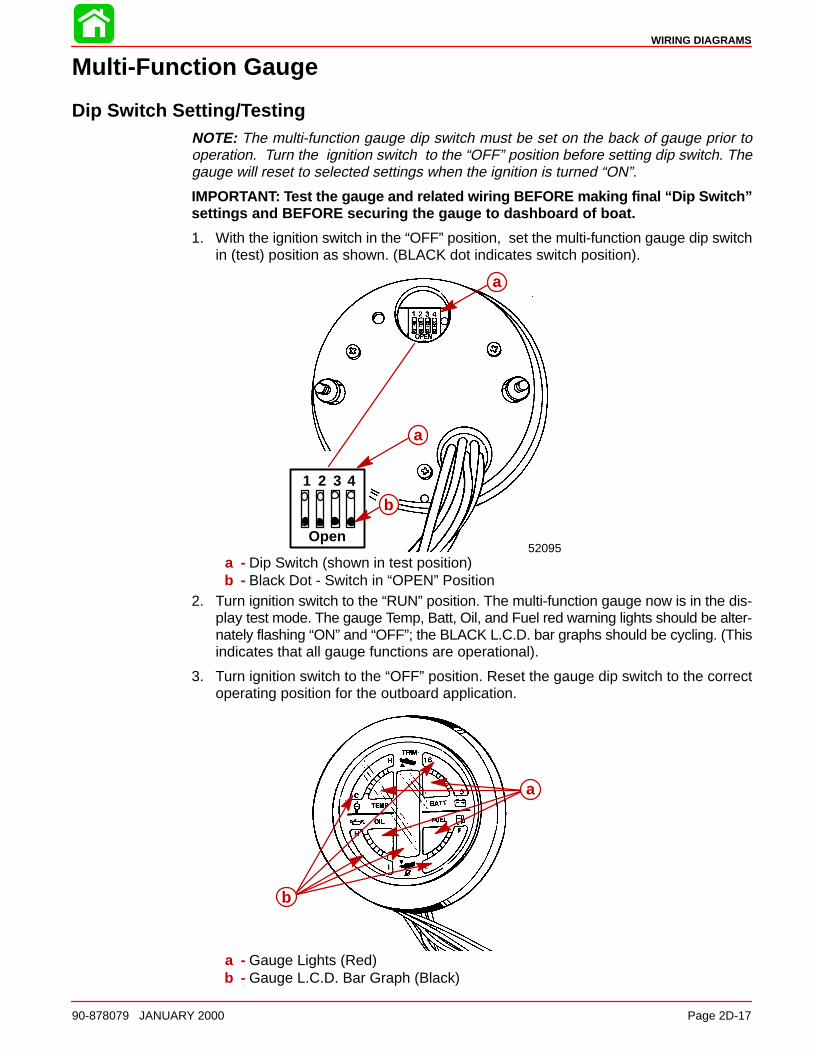
WIRING DIAGRAMS
90-878079 JANUARY 2000 Page 2D-17
Multi-Function Gauge
Dip Switch Setting/TestingNOTE: The multi-function gauge dip switch must be set on the back of gauge prior tooperation. Turn the ignition switch to the “OFF” position before setting dip switch. Thegauge will reset to selected settings when the ignition is turned “ON”.
IMPORTANT: Test the gauge and related wiring BEFORE making final “Dip Switch”settings and BEFORE securing the gauge to dashboard of boat.
1. With the ignition switch in the “OFF” position, set the multi-function gauge dip switchin (test) position as shown. (BLACK dot indicates switch position).
a
b
52095Open
1 2 3 4
a
a
b
a - Dip Switch (shown in test position)b - Black Dot - Switch in “OPEN” Position
2. Turn ignition switch to the “RUN” position. The multi-function gauge now is in the dis-play test mode. The gauge Temp, Batt, Oil, and Fuel red warning lights should be alter-nately flashing “ON” and “OFF”; the BLACK L.C.D. bar graphs should be cycling. (Thisindicates that all gauge functions are operational).
3. Turn ignition switch to the “OFF” position. Reset the gauge dip switch to the correctoperating position for the outboard application.
b
aa
b
a - Gauge Lights (Red)b - Gauge L.C.D. Bar Graph (Black)
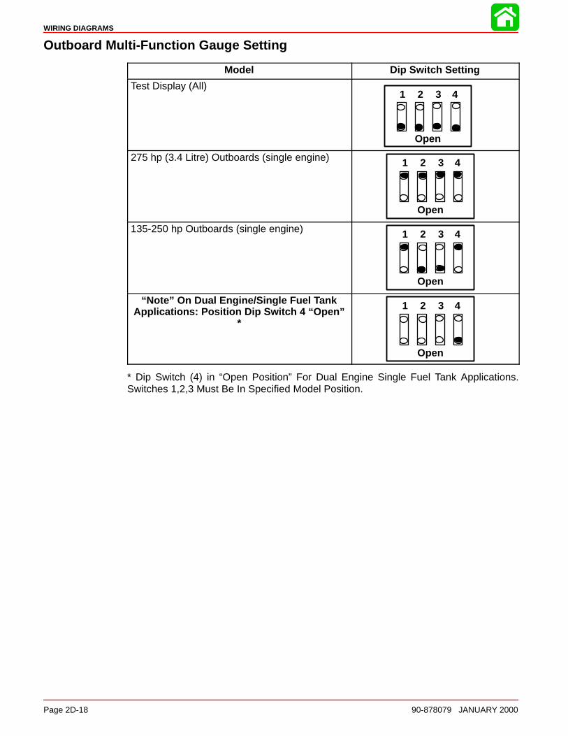
WIRING DIAGRAMS
Page 2D-18 90-878079 JANUARY 2000
Outboard Multi-Function Gauge Setting
Model Dip Switch Setting
Test Display (All)
Open
1 2 3 4
275 hp (3.4 Litre) Outboards (single engine)
Open
1 2 3 4
135-250 hp Outboards (single engine)
Open
1 2 3 4
“Note” On Dual Engine/Single Fuel TankApplications: Position Dip Switch 4 “Open”
*
Open
1 2 3 4
* Dip Switch (4) in “Open Position” For Dual Engine Single Fuel Tank Applications.Switches 1,2,3 Must Be In Specified Model Position.
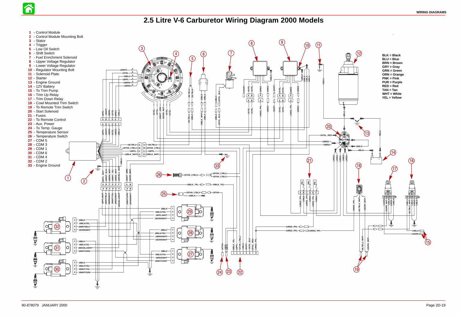
18LT
BLU
_WH
T
16R
ED
_PP
L
18LT
BLU
_WH
T
14B
LK
14B
LK
14B
LK
14B
LK
14B
LU
14G
RN
16G
RN
_WH
T
16LT
BLU
_WH
T
14R
ED
14R
ED
18G
RN
_WH
T
18G
RN
_WH
T
18Y
EL_
RE
D
14R
ED
_PP
L
18YEL_RED
14R
ED
14R
ED
14BLU
14GRN
8BLK
8BLK
8BLK
18P
PL_
WH
T
18W
HT
_BLK
18B
RN
_WH
T
18W
HT
_YE
L
18R
ED
_WH
T
18D
KB
LU_W
HT
18B
LU
18R
ED
18Y
EL
18B
RN
18W
HT
18P
PL
18BLK_YEL
18B
LK
18RED
18BRN
18PPL
18BLU
18YEL
18WHT
18R
ED
18B
RN
18P
PL
18B
LU
18Y
EL
18W
HT
18W
HT
_GR
N
18G
RN
_WH
T
18W
HT
_GR
N
18G
RN
_WH
T
18BLK_YEL
18B
LK_Y
EL
18TA
N_L
TB
LU
18BLK
18TAN18TAN_LTBLU
16TAN_LTBLU
16G
RY
16Y
EL
16Y
EL
16R
ED
16B
LK
16R
ED
16G
RY
16Y
EL
16Y
EL
16R
ED
16B
LK
16R
ED
16Y
EL
16Y
EL
16Y
EL
18G
RY
14B
LK
18Y
EL_
BLK
18B
LK
18B
LK
18Y
EL_
BLK
18BLK
10B
LK
18TAN_LTBLU
18LTBLU
16Y
EL
16Y
EL
16Y
EL
18B
LK
18B
LK
18BLK_WHT
18B
LK
18B
LK_W
HT
18LT
BLU
18TA
N
14B
LK
18G
RY
18Y
EL_
BLK
18P
PL
18PPL
18P
PL
18P
PL
18TAN_LTBLU
18TAN_LTBLU
18B
LK
18B
LK
14RED_PPL
14RED_PPL
14R
ED
_PP
L
14R
ED
14R
ED
14R
ED
14R
ED
14R
ED
16Y
EL
14R
ED
_PP
L
14R
ED
_PP
L
14R
ED
_PP
L
14R
ED
_PP
L
18R
ED
18R
ED
18RED
18RED
20a
20a
20a
18B
LK
16RED_PPL
14R
ED
16Y
EL
18LTBLU
18TAN_LTBLU
18PPL
18BLK_WHT
–+
87654321
DNUP
30858687 87A 30 8586 87 87A
A B C D E F
FEDCBA
1
3
5
S S
#12
#1 #2
#3
#4
#5
#6
#7#8
#9
#10
N
N
6
4
22
6
4
1
3
5
FEDCBA
BA
D
C
B
A
A B C D E F
A B A BA A
BA A BA A
A
B
C
D
BLK = BlackBLU = BlueBRN = BrownGRY = GrayGRN = GreenORN = OrangePNK = PinkPUR = PurpleRED = RedTAN = TanWHT = WhiteYEL = Yellow
2
3
4
5
6 7
8 910 11
12
13
14
16
1718
21
222324
25
26
33
19
15
27
28
29
30
31
32
1
20
18DKBLU/WHT
18WHT/YEL
18WHT/BLK
18RED/WHT
18BRN/WHT
18PPL/WHT
18BLK
18BLK
18BLK
18BLK
18BLK
18BLK18WHT/GRN
18WHT/GRN
18W
HT
/GR
N
18GRN/WHT
18G
RN
/WH
T
18GRN/WHT
18GRN/WHT
18BLK/YEL
18BLK/YEL
18BLK/YEL
18BLK/YEL
18BLK/YEL
18BLK/YEL
18P
PL/
WH
T
18B
RN
/WH
T
18R
ED
/WH
T
18W
HT
/BLK
18W
HT
/YE
L
18D
KB
LU/W
HT
18WHT/GRN
4
3
2
1
4
3
2
1
4
3
2
1
1
2
3
4
1
2
3
4
1
2
3
4
A B C D E F A B
18LT
BLU
18LT
BLU
WIRING DIAGRAMS
Page 2D-1990-878079 JANUARY 2000
2.5 Litre V-6 Carburetor Wiring Diagram 2000 Models
1 - Control Module2 - Control Module Mounting Bolt3 - Stator4 - Trigger5 - Low Oil Switch6 - Shift Switch7 - Fuel Enrichment Solenoid8 - Upper Voltage Regulator9 - Lower Voltage Regulator
10 - Regulator Mounting Bolt11 - Solenoid Plate12 - Starter13 - Engine Ground14 - 12V Battery15 - To Trim Pump16 - Trim Up Relay17 - Trim Down Relay18 - Cowl Mounted Trim Switch19 - To Remote Trim Switch20 - Start Solenoid21 - Fuses22 - To Remote Control23 - Aux. Power24 - To Temp. Gauge25 - Temperature Sensor26 - Temperature Switch27 - CDM 528 - CDM 329 - CDM 130 - CDM 631 - CDM 432 - CDM 233 - Engine Ground

18LT
BLU
18B
LK
16LT
BLU
_WH
T
18LT
BLU
_WH
T
16R
ED
_PP
L
18LT
BLU
_WH
T
14B
LK
14B
LK
14B
LK
14B
LK
14B
LU
14G
RN
16G
RN
_WH
T
14R
ED
14R
ED
18G
RN
_WH
T18
GR
N_W
HT
18Y
EL_
RE
D14
RE
D_P
PL
18YEL_RED
14R
ED
14R
ED
14BLU14GRN
8BLK
8BLK
8BLK
18P
PL_
WH
T18
WH
T_B
LK18
BR
N_W
HT
18W
HT
_YE
L18
RE
D_W
HT
18D
KB
LU_W
HT
18B
LU18
RE
D18
YE
L18
BR
N18
WH
T18
PP
L
18BLK_YEL
18B
LK
18RED18BRN18PPL18BLU18YEL
18WHT
18R
ED
18B
RN
18P
PL
18B
LU
18Y
EL
18W
HT
18W
HT
_GR
N18
GR
N_W
HT
18W
HT
_GR
N18
GR
N_W
HT
18BLK_YEL
18B
LK_Y
EL
18T
AN
_LT
BLU
18T
AN
16TAN_LTBLU
16G
RY
16Y
EL
16Y
EL
16R
ED
16B
LK
16R
ED
16G
RY
16Y
EL
16Y
EL
16R
ED
16B
LK
16R
ED
16Y
EL
16Y
EL
16Y
EL
18G
RY
14B
LK
18BLK
10B
LK
16Y
EL
16Y
EL
16Y
EL
18BLK
18BLK
18BLK
18T
AN
14B
LK18
GR
Y
18P
PL
18TAN_LTBLU
18B
LK
14RED_PPL
14RED_PPL
14R
ED
_PP
L14
RE
D
14R
ED
14R
ED
14RED14RED
16Y
EL
14R
ED
_PP
L
14R
ED
_PP
L
14R
ED
_PP
L
14R
ED
_PP
L
18R
ED
18R
ED
18RED18RED
20a
20a
16RED_PPL
14R
ED
16Y
EL
18LTBLU18TAN_LTBLU
18PPL
18BLK_WHT
18WHT18BLK_RED18DKBLU18GRY_WHT18YEL18RED18PPL18GRN_RED18GRN18GRN_WHT18YEL_RED18BRN18ORG18TAN_BLK18LTBLU18BLK
18RED
18RED
18RED
18RED
18RED
18RED
18WHT
18WHT
18BLU
18BLU
18YEL
18YEL
18YEL
18BLU
18RED
18WHT
18Y
EL
18R
ED
18B
LU18
WH
T
18LT
BLU
18LTBLU
18LT
BLU
18LT
BLU
18TAN_LTBLU
18GRN_RED18GRN
18GRN_WHT
18BLK_RED
18GRY_WHT
18PPL
18GRN_RED
18GRN18GRN_WHT
18YEL_RED
18B
RN
18B
RN
18BRN
18O
RG
18ORG18TAN_BLK
18LTBLU
18T
AN
_BLK
18LT
BLU
18LT
BLU
18P
PL
18P
PL
18B
LK
18B
LK
18B
LK
18R
ED
18G
RN
18GRN
18BLK_WHT
18O
RG
18T
AN
_BLK
18T
AN
_BLK
18T
AN
_BLK
18T
AN
_BLK
18T
AN
_BLK
18B
LK
18B
LK
18T
AN
_LT
BLU
18T
AN
18G
RY
_WH
T
18LT
BLU
18B
LK_W
HT
18P
PL
18P
PL
18PPL
18B
LK18
BR
N
18GRN–RED
18GRN_WHT18YEL_RED
18BLK
18B
LK_R
ED
18TAN_LTBLU
18G
RY
_WH
T18
BLK
_WH
T
18R
ED
–+
87654321
DNUP
30858687 87A
A B C D E F
1
3
5
S S
#12
#1 #2
#3
#4
#5
#6#7#8
#9
#10
N
N
6
4
2264135
FEDCBA
1 2 3 4 5 6
1 2 1 21 1
BA A BA A
ABCDEFGH H
GFEDCBA
12345678910111213141516 16
151413121110987654321
12344 3 2 1
ABCC B A
1 2 3321
AB
AB
AB
AB
AB
AB
DCBAA B C D
BLK = BlackBLU = BlueBRN = BrownGRY = GrayGRN = GreenORN = OrangePNK = PinkPUR = PurpleRED = RedTAN = TanWHT = WhiteYEL = Yellow
3 4 5
67
8
9
10
12
38
1415
16
17
18
19
20
21
22
23
24
25
26
27
28
36
2937
39
40
4243
44
13
41
2
1
20a
30858687 87A
18LT
BLU
_WH
T
18G
RN
_WH
T
FEDCBA BA
32
31
30
33
34
35
18DKBLU/WHT
18WHT/YEL
18WHT/BLK
18RED/WHT
18BRN/WHT
18PPL/WHT
18BLK
18BLK
18BLK
18BLK
18BLK
18BLK18WHT/GRN
18WHT/GRN
18W
HT
/GR
N
18GRN/WHT
18G
RN
/WH
T
18GRN/WHT
18GRN/WHT
18BLK/YEL
18BLK/YEL
18BLK/YEL
18BLK/YEL
18BLK/YEL
18BLK/YEL
18P
PL/
WH
T
18B
RN
/WH
T
18R
ED
/WH
T
18W
HT
/BLK
18W
HT
/YE
L
18D
KB
LU/W
HT
18WHT/GRN
4321
4321
4321
1234
1234
1234
A B C D E F A B
11
18LT
BLU
WIRING DIAGRAMS
Page 2D-20 90-878079 JANUARY 2000
2.5 Litre V-6 150/175 EFI Wiring Diagram 2000 Models
1 - Control Module2 - Control Module Mounting Bolt3 - Stator4 - Trigger5 - Low Oil Switch6 - Upper Voltage Regulator7 - Lower Voltage Regulator8 - Regulator Mounting Bolt9 - Solenoid Plate
10 - Starter11 - Engine Ground12 - 12V Battery13 - Air Temperature Sensor14 - Head Temp. Sensor15 - Water Sensor Module16 - Water Sensor17 - Fuel Injector #118 - Fuel Injector #219 - Fuel Injector #320 - Fuel Injector #421 - Fuel Injector #522 - Fuel Injector #623 - ECM24 - Fuel Pump25 - Engine Ground26 - Shift Switch27 - To Trim Pump28 - Throttle Position Sensor29 - Trim Up Relay30 - CDM 531 - CDM 332 - CDM 133 - CDM 634 - CDM 435 - CDM236 - Start Solenoid37 - Trim Down Relay38 - Cowl Mounted Trim Switch39 - To Remote Trim Switch40 - Fuses41 - To Remote Control42 - Aux. Power43 - To Temp. Gauge44 - Temp. Switch
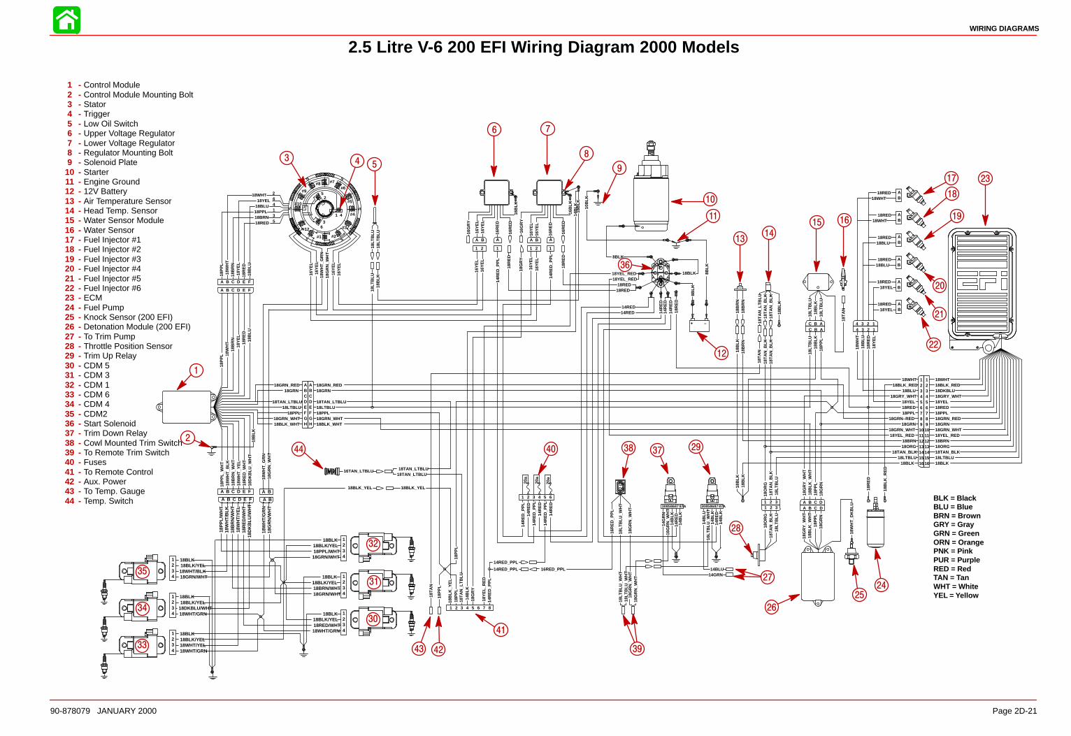
18B
LK
16LT
BLU
_WH
T
18LT
BLU
_WH
T
16R
ED
_PP
L
18LT
BLU
_WH
T
14B
LK
14B
LK
14B
LK
14B
LK
14B
LU
14G
RN
16G
RN
_WH
T
14R
ED
14R
ED
18G
RN
_WH
T18
GR
N_W
HT
18Y
EL_
RE
D14
RE
D_P
PL
18YEL_RED
14R
ED
14R
ED
14BLU14GRN
8BLK
8BLK
8BLK
18P
PL_
WH
T18
WH
T_B
LK18
BR
N_W
HT
18W
HT
_YE
L18
RE
D_W
HT
18D
KB
LU_W
HT
18B
LU18
RE
D18
YE
L18
BR
N18
WH
T18
PP
L
18BLK_YEL
18B
LK
18RED18BRN18PPL18BLU18YEL
18WHT
18R
ED
18B
RN
18P
PL
18B
LU
18Y
EL
18W
HT
18W
HT
_GR
N18
GR
N_W
HT
18W
HT
_GR
N18
GR
N_W
HT
18BLK_YEL
18B
LK_Y
EL
18T
AN
_LT
BLU
18T
AN
16TAN_LTBLU16
GR
Y
16Y
EL
16Y
EL
16R
ED
16B
LK
16R
ED
16G
RY
16Y
EL
16Y
EL
16R
ED
16B
LK
16R
ED
16Y
EL
16Y
EL
16Y
EL
18G
RY
14B
LK
18BLK
10B
LK
16Y
EL
16Y
EL
16Y
EL
18T
AN
14B
LK18
GR
Y
18P
PL
18TAN_LTBLU
18B
LK
14RED_PPL
14RED_PPL
14R
ED
_PP
L14
RE
D
14R
ED
14R
ED
14RED14RED
16Y
EL
14R
ED
_PP
L
14R
ED
_PP
L
14R
ED
_PP
L
14R
ED
_PP
L
18R
ED
18R
ED
18RED18RED
20a
20a
16RED_PPL
14R
ED
16Y
EL
18LTBLU18TAN_LTBLU
18PPL
18BLK_WHT
18WHT18BLK_RED18DKBLU18GRY_WHT18YEL18RED18PPL18GRN_RED18GRN18GRN_WHT18YEL_RED18BRN18ORG18TAN_BLK18LTBLU18BLK
18RED
18RED
18RED
18RED
18RED
18RED
18WHT
18WHT
18BLU
18BLU
18YEL
18YEL
18YEL
18BLU
18RED
18WHT
18Y
EL
18R
ED
18B
LU18
WH
T
18LT
BLU
18LTBLU
18LT
BLU
18LT
BLU
18TAN_LTBLU
18GRN_RED18GRN
18GRN_WHT
18BLK_RED
18GRY_WHT
18PPL
18GRN_RED
18GRN18GRN_WHT
18YEL_RED
18B
RN
18B
RN
18BRN
18O
RG
18ORG18TAN_BLK
18LTBLU
18T
AN
_BLK
18LT
BLU
18LT
BLU
18P
PL
18P
PL
18B
LK
18B
LK
18B
LK
18R
ED
18G
RN
18GRN
18BLK_WHT
18O
RG
18T
AN
_BLK
18T
AN
_BLK
18T
AN
_BLK
18T
AN
_BLK
18T
AN
_BLK
18B
LK
18B
LK
18T
AN
_LT
BLU
18T
AN
18G
RY
_WH
T
18LT
BLU
18B
LK_W
HT
18P
PL
18P
PL
18PPL
18B
LK18
BR
N
18GRN–RED
18GRN_WHT18YEL_RED
18BLK
18B
LK_R
ED
18TAN_LTBLU
18W
HT
_DK
BLU
18G
RY
_WH
T
18G
RN
18P
PL
18B
LK_W
HT
18R
ED
–+
87654321
DNUP
30858687 87A
A B C D E F
1
3
5
S S
#12
#1 #2
#3
#4
#5
#6#7#8
#9
#10
N
N
6
4
2264135
FEDCBA
1 2 3 4 5 6
1 2 1 21 1
BA A BA A
ABCDEFGH H
GFEDCBA
12345678910111213141516 16
151413121110987654321
12344 3 2 1
ABCC B A
1 2 3321
AB
AB
AB
AB
AB
AB
DCBAA B C D
BLK = BlackBLU = BlueBRN = BrownGRY = GrayGRN = GreenORN = OrangePNK = PinkPUR = PurpleRED = RedTAN = TanWHT = WhiteYEL = Yellow
3 4 5
6 7
8
9
10
11
12
36
14
15 16
17
18
19
20
21
22
23
24
25
26
27
28
29373840
41
4243
44
13
39
2
1
20a
30858687 87A
18LT
BLU
_WH
T
18G
RN
_WH
T
FEDCBA BA
32
31
30
33
34
35
18DKBLU/WHT
18WHT/YEL
18WHT/BLK
18RED/WHT
18BRN/WHT
18PPL/WHT
18BLK
18BLK
18BLK
18BLK
18BLK
18BLK18WHT/GRN
18WHT/GRN
18W
HT
/GR
N
18GRN/WHT
18G
RN
/WH
T
18GRN/WHT
18GRN/WHT
18BLK/YEL
18BLK/YEL
18BLK/YEL
18BLK/YEL
18BLK/YEL
18BLK/YEL
18P
PL/
WH
T
18B
RN
/WH
T
18R
ED
/WH
T
18W
HT
/BLK
18W
HT
/YE
L
18D
KB
LU/W
HT
18WHT/GRN
4321
4321
4321
1234
1234
1234
A B C D E F A B
18LT
BLU
18LT
BLU
WIRING DIAGRAMS
Page 2D-2190-878079 JANUARY 2000
2.5 Litre V-6 200 EFI Wiring Diagram 2000 Models
1 - Control Module2 - Control Module Mounting Bolt3 - Stator4 - Trigger5 - Low Oil Switch6 - Upper Voltage Regulator7 - Lower Voltage Regulator8 - Regulator Mounting Bolt9 - Solenoid Plate
10 - Starter11 - Engine Ground12 - 12V Battery13 - Air Temperature Sensor14 - Head Temp. Sensor15 - Water Sensor Module16 - Water Sensor17 - Fuel Injector #118 - Fuel Injector #219 - Fuel Injector #320 - Fuel Injector #421 - Fuel Injector #522 - Fuel Injector #623 - ECM24 - Fuel Pump25 - Knock Sensor (200 EFI)26 - Detonation Module (200 EFI)27 - To Trim Pump28 - Throttle Position Sensor29 - Trim Up Relay30 - CDM 531 - CDM 332 - CDM 133 - CDM 634 - CDM 435 - CDM236 - Start Solenoid37 - Trim Down Relay38 - Cowl Mounted Trim Switch39 - To Remote Trim Switch40 - Fuses41 - To Remote Control42 - Aux. Power43 - To Temp. Gauge44 - Temp. Switch
3A
FUEL PUMP
90-878079 JANUARY 2000 Page 3A-1
FUEL SYSTEMSection 3A - Fuel Pump
Table of Contents
Specifications 3A-2. . . . . . . . . . . . . . . . . . . . . . . . . . . Fuel Pump Pressure @ W.O.T. 3A-2. . . . . . . . . Fuel Pump Pressure @ Idle 3A-2. . . . . . . . . . .
Special Tools 3A-2. . . . . . . . . . . . . . . . . . . . . . . . . . . Fuel Pump Assembly 3A-4. . . . . . . . . . . . . . . . . . . . Fuel Pump Description/Operation 3A-6. . . . . . . . . Checking for Restricted Fuel Flow Caused by Anti-siphon Valves 3A-6. . . . . . . . . . . . . . . . . . . . . . .
Checking Fuel Pump Lift (Vacuum) 3A-7. . . . . . . . Vacuum Test Troubleshooting 3A-7. . . . . . . . . . Testing Fuel Pump 3A-8. . . . . . . . . . . . . . . . . . . . Fuel Pump Removal/Disassembly 3A-9. . . . . . Cleaning/Inspection 3A-10. . . . . . . . . . . . . . . . . . . Reassembly/lnstallation 3A-10. . . . . . . . . . . . . . .
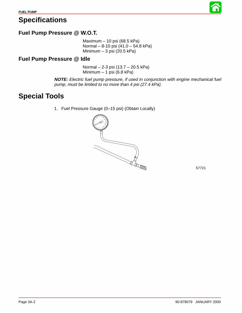
FUEL PUMP
Page 3A-2 90-878079 JANUARY 2000
Specifications
Fuel Pump Pressure @ W.O.T.Maximum – 10 psi (68.5 kPa)Normal – 8-10 psi (41.0 – 54.8 kPa)Minimum – 3 psi (20.5 kPa)
Fuel Pump Pressure @ IdleNormal – 2-3 psi (13.7 – 20.5 kPa) Minimum – 1 psi (6.8 kPa)
NOTE: Electric fuel pump pressure, if used in conjunction with engine mechanical fuelpump, must be limited to no more than 4 psi (27.4 kPa).
Special Tools
1. Fuel Pressure Gauge (0–15 psi) (Obtain Locally)
57721

FUEL PUMP
90-878079 JANUARY 2000 Page 3A-3
Notes:
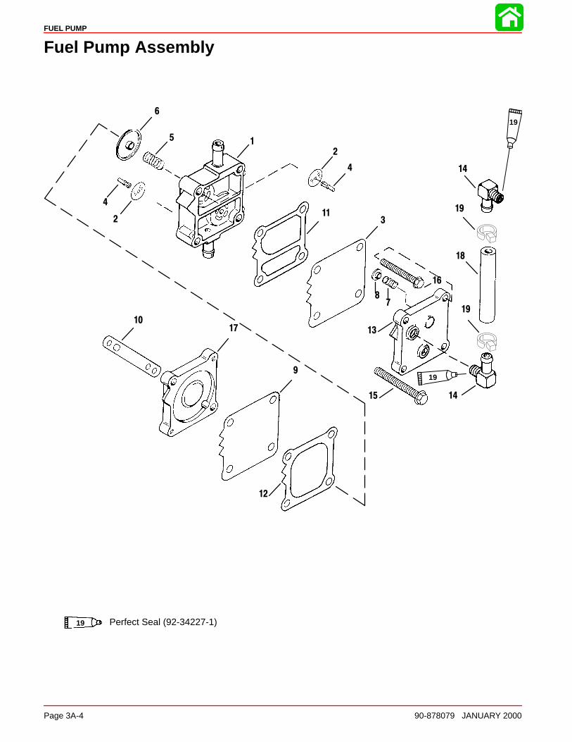
FUEL PUMP
Page 3A-4 90-878079 JANUARY 2000
Fuel Pump Assembly
1
2
3
4
5
6
78
9
11
12
1017 13
18
15
16
4
14
19
19
19
19
2
14
Perfect Seal (92-34227-1)19

FUEL PUMP
90-878079 JANUARY 2000 Page 3A-5
Fuel Pump Assembly
REFTORQUE
REF.NO. QTY. DESCRIPTION lb-in lb-ft Nm.
– 1 FUEL PUMP ASSEMBLY
1 1 FUEL PUMP ASSEMBLY2 1 DIAPHRAGM KIT3 1 DIAPHRAGM4 2 RETAINER5 1 SPRING6 1 CAP
7 1 SPRING8 1 CAP9 1 DIAPHRAGM10 1 GASKET–base11 1 GASKET-Boost12 1 GASKET-Pulse13 1 PLATE–fuel pump
14 2 ELBOW15 2 SCREW–pump to crankcase (M6 x 50) 55 6.016 2 SCREW–fuel pump (M5 x 40) 55 6.017 1 BASE–fuel pump18 1 FUEL LINE (6 IN.)19 2 STA STRAP
FUEL PUMP
Page 3A-6 90-878079 JANUARY 2000
Fuel Pump Description/Operation
The fuel pump is a crankcase-pressure-operated, diaphragm-type pump. Crankcase pul-sating pressure (created by the up-and-down movement of piston) is transferred to fuelpump by way of a passage (hole) between crankcase and fuel pump.
When piston is in an upward motion, a vacuum is created in the crankcase, thus pullingin on the fuel pump diaphragm. The inlet check valve (in fuel pump) is opened and fuel(from fuel tank) is drawn into fuel pump.
Downward motion of the piston forces the air mixture out of the crankcase into the cylin-der. This motion also forces out on the fuel pump diaphragm, which, in turn, closes theinlet check valve (to keep fuel from returning to fuel tank) and opens the outlet checkvalve, thus forcing fuel to the VST(EFI models) or carburetors.
Checking for Restricted Fuel Flow Caused by Anti-SiphonValves
While anti-siphon valves may be helpful from a safety stand-point, they clog with debris,they may be too small, or they may have too heavy a spring. Summarizing, the pressuredrop across these valves can, and often does, create operational problems and/or pow-er-head damage by restricting fuel to the fuel pump and VST. Some symptoms of re-stricted (lean) fuel flow, which could be caused by use of an anti-siphon valve, are:
1 - Loss of fuel pump pressure 2 - Loss of power 3 - High speed surging 4 - Preignition/detonation (piston dome erosion)5 - Outboard cuts out or hesitates upon acceleration 6 - Outboard runs rough7 - Outboard quits and cannot be restarted 8 - Outboard will not start 9 - Vapor lock
Since any type of anti-siphon device must be located between the outboard fuel inlet andfuel tank outlet, a simple method of checking [if such a device (or bad fuel) is a problemsource] is to operate the outboard with a separate fuel supply which is known to be good,such as a remote fuel tank.
If, after using a separate fuel supply, it is found that the anti-siphon valve is the cause ofthe problem, there are 2 solutions to the problem; either 1) replace the anti-siphon valvewith one that has lighter spring tension or 2) replace it with a solenoid-operated fuel shutoff valve.
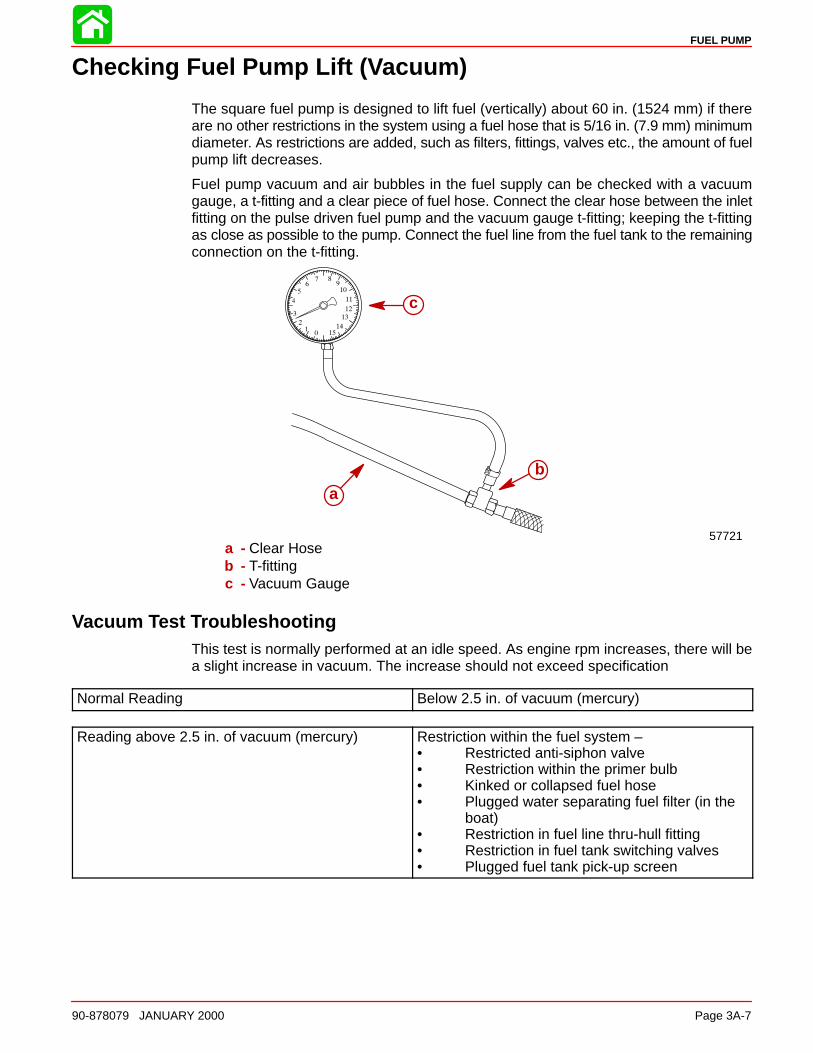
FUEL PUMP
90-878079 JANUARY 2000 Page 3A-7
Checking Fuel Pump Lift (Vacuum)
The square fuel pump is designed to lift fuel (vertically) about 60 in. (1524 mm) if thereare no other restrictions in the system using a fuel hose that is 5/16 in. (7.9 mm) minimumdiameter. As restrictions are added, such as filters, fittings, valves etc., the amount of fuelpump lift decreases.
Fuel pump vacuum and air bubbles in the fuel supply can be checked with a vacuumgauge, a t-fitting and a clear piece of fuel hose. Connect the clear hose between the inletfitting on the pulse driven fuel pump and the vacuum gauge t-fitting; keeping the t-fittingas close as possible to the pump. Connect the fuel line from the fuel tank to the remainingconnection on the t-fitting.
57721
a
b
c
a - Clear Hoseb - T-fittingc - Vacuum Gauge
Vacuum Test TroubleshootingThis test is normally performed at an idle speed. As engine rpm increases, there will bea slight increase in vacuum. The increase should not exceed specification
Normal Reading Below 2.5 in. of vacuum (mercury)
Reading above 2.5 in. of vacuum (mercury) Restriction within the fuel system – • Restricted anti-siphon valve• Restriction within the primer bulb• Kinked or collapsed fuel hose• Plugged water separating fuel filter (in the
boat)• Restriction in fuel line thru-hull fitting• Restriction in fuel tank switching valves• Plugged fuel tank pick-up screen
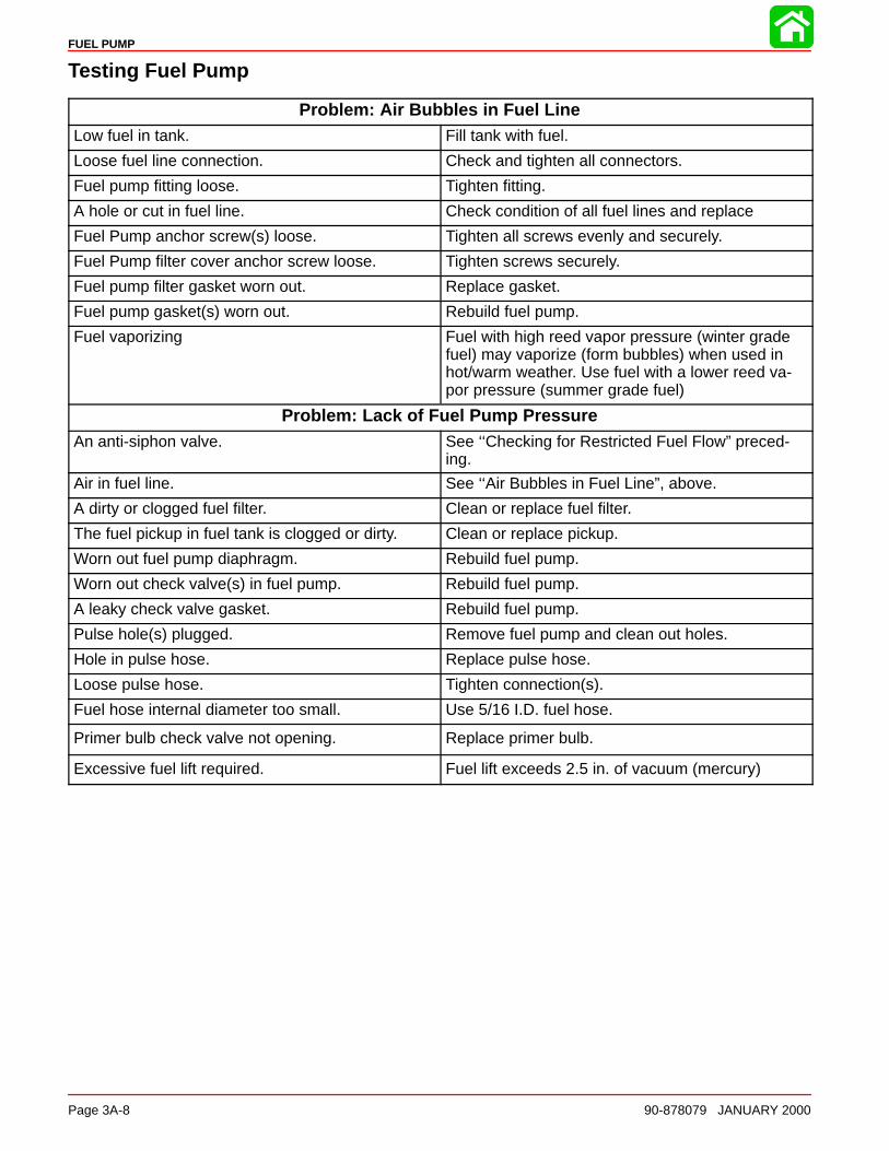
FUEL PUMP
Page 3A-8 90-878079 JANUARY 2000
Testing Fuel Pump
Problem: Air Bubbles in Fuel LineLow fuel in tank. Fill tank with fuel.
Loose fuel line connection. Check and tighten all connectors.
Fuel pump fitting loose. Tighten fitting.
A hole or cut in fuel line. Check condition of all fuel lines and replace
Fuel Pump anchor screw(s) loose. Tighten all screws evenly and securely.
Fuel Pump filter cover anchor screw loose. Tighten screws securely.
Fuel pump filter gasket worn out. Replace gasket.
Fuel pump gasket(s) worn out. Rebuild fuel pump.
Fuel vaporizing Fuel with high reed vapor pressure (winter gradefuel) may vaporize (form bubbles) when used inhot/warm weather. Use fuel with a lower reed va-por pressure (summer grade fuel)
Problem: Lack of Fuel Pump PressureAn anti-siphon valve. See ‘‘Checking for Restricted Fuel Flow” preced-
ing.
Air in fuel line. See ‘‘Air Bubbles in Fuel Line”, above.
A dirty or clogged fuel filter. Clean or replace fuel filter.
The fuel pickup in fuel tank is clogged or dirty. Clean or replace pickup.
Worn out fuel pump diaphragm. Rebuild fuel pump.
Worn out check valve(s) in fuel pump. Rebuild fuel pump.
A leaky check valve gasket. Rebuild fuel pump.
Pulse hole(s) plugged. Remove fuel pump and clean out holes.
Hole in pulse hose. Replace pulse hose.
Loose pulse hose. Tighten connection(s).
Fuel hose internal diameter too small. Use 5/16 I.D. fuel hose.
Primer bulb check valve not opening. Replace primer bulb.
Excessive fuel lift required. Fuel lift exceeds 2.5 in. of vacuum (mercury)
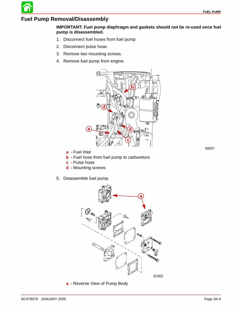
FUEL PUMP
90-878079 JANUARY 2000 Page 3A-9
Fuel Pump Removal/DisassemblyIMPORTANT: Fuel pump diaphragm and gaskets should not be re-used once fuelpump is disassembled.
1. Disconnect fuel hoses from fuel pump.
2. Disconnect pulse hose.
3. Remove two mounting screws.
4. Remove fuel pump from engine.
58057
d
d
b
a
c
a - Fuel Inletb - Fuel hose from fuel pump to carburetorsc - Pulse hosed - Mounting screws
5. Disassemble fuel pump.
52362
a
a - Reverse View of Pump Body
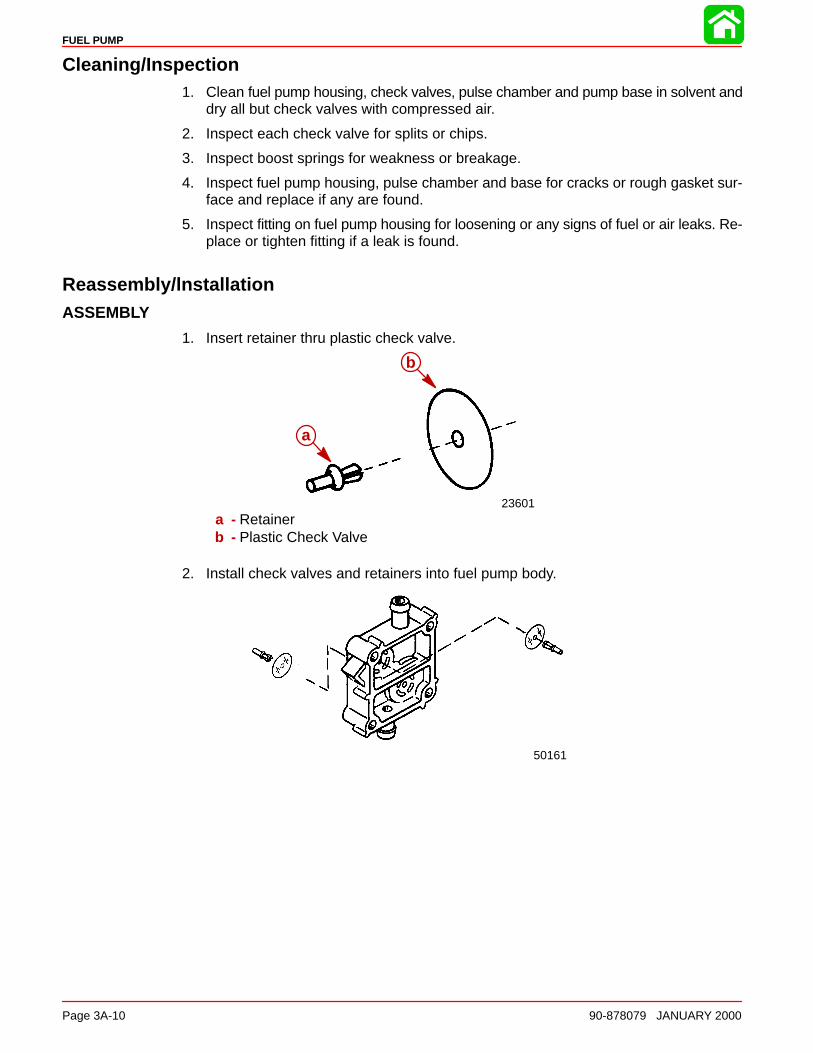
FUEL PUMP
Page 3A-10 90-878079 JANUARY 2000
Cleaning/Inspection1. Clean fuel pump housing, check valves, pulse chamber and pump base in solvent and
dry all but check valves with compressed air.
2. Inspect each check valve for splits or chips.
3. Inspect boost springs for weakness or breakage.
4. Inspect fuel pump housing, pulse chamber and base for cracks or rough gasket sur-face and replace if any are found.
5. Inspect fitting on fuel pump housing for loosening or any signs of fuel or air leaks. Re-place or tighten fitting if a leak is found.
Reassembly/lnstallationASSEMBLY
1. Insert retainer thru plastic check valve.
23601
a
b
a - Retainerb - Plastic Check Valve
2. Install check valves and retainers into fuel pump body.
50161
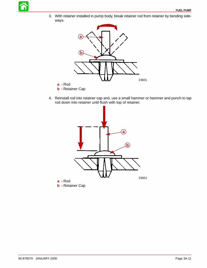
FUEL PUMP
90-878079 JANUARY 2000 Page 3A-11
3. With retainer installed in pump body, break retainer rod from retainer by bending side-ways.
23601
a
b
a - Rodb - Retainer Cap
4. Reinstall rod into retainer cap and, use a small hammer or hammer and punch to taprod down into retainer until flush with top of retainer.
23601
a
b
a - Rodb - Retainer Cap

FUEL PUMP
Page 3A-12 90-878079 JANUARY 2000
5. Place boost spring into pump body and place cap onto boost spring.
50161
a
b
c
a - Boost Springb - Pump Bodyc - Cap
6. Assemble remainder of components as shown and install retaining screws thru toalign.
52362
a
a - Reverse View of Pump Body
INSTALLATION
1. Install pump onto engine. Torque to 55 Ib. in. (6 N·m).
2. Install hoses onto proper fittings and secure with sta-straps.
3. Run engine and check for leaks.
3B
CARBURETORS
90-878079 JANUARY 2000 Page 3B-1
FUEL SYSTEMSection 3B - Carburetors
Table of Contents
Attenuator And Carb Throttle Levers 3B-2. . . . . . . Fuel Lines 3B-4. . . . . . . . . . . . . . . . . . . . . . . . . . . . . . Carburetor 3B-6. . . . . . . . . . . . . . . . . . . . . . . . . . . . . Fuel System - Troubleshooting 3B-10. . . . . . . . . . . .
General Information 3B-10. . . . . . . . . . . . . . . . . . Reed Valve Leak Test 3B-12. . . . . . . . . . . . . . . . . . . . Thermal Air Valve Circuit Description 3B-13. . . . . . Enrichener System Description 3B-14. . . . . . . . . . . .
Manual Operation of Enrichener Valve 3B-14. . Enrichener Valve Test 3B-15. . . . . . . . . . . . . . . . .
Carburetor 3B-16. . . . . . . . . . . . . . . . . . . . . . . . . . . . . Carburetor Fuel Circuits 3B-17. . . . . . . . . . . . . . . . . .
Float Bowl Circuit 3B-17. . . . . . . . . . . . . . . . . . . . . Idle Circuit 3B-18. . . . . . . . . . . . . . . . . . . . . . . . . . . Cold Start Circuit 3B-19. . . . . . . . . . . . . . . . . . . . .
Off-Idle Circuit 3B-19. . . . . . . . . . . . . . . . . . . . . . . Main Circuit 3B-20. . . . . . . . . . . . . . . . . . . . . . . . . . Back Draft Circuit 3B-21. . . . . . . . . . . . . . . . . . . . . Carburetor Specifications 3B-22. . . . . . . . . . . . . . Carburetor Placement and Jet Location forEach Cylinder 3B-23. . . . . . . . . . . . . . . . . . . . . . . . Carburetor Jet Placement 3B-24. . . . . . . . . . . . . High Altitude Recommendations 3B-25. . . . . . . . Jet Part Number Chart 3B-25. . . . . . . . . . . . . . . . High Altitude Jet Chart 3B-26. . . . . . . . . . . . . . . .
Removing Carburetor(s) from Engine 3B-27. . . . . . Throttle Shaft Screws 3B-28. . . . . . . . . . . . . . . . . Float Adjustment 3B-28. . . . . . . . . . . . . . . . . . . . . Installing Carburetor(s) to Engine 3B-29. . . . . . .
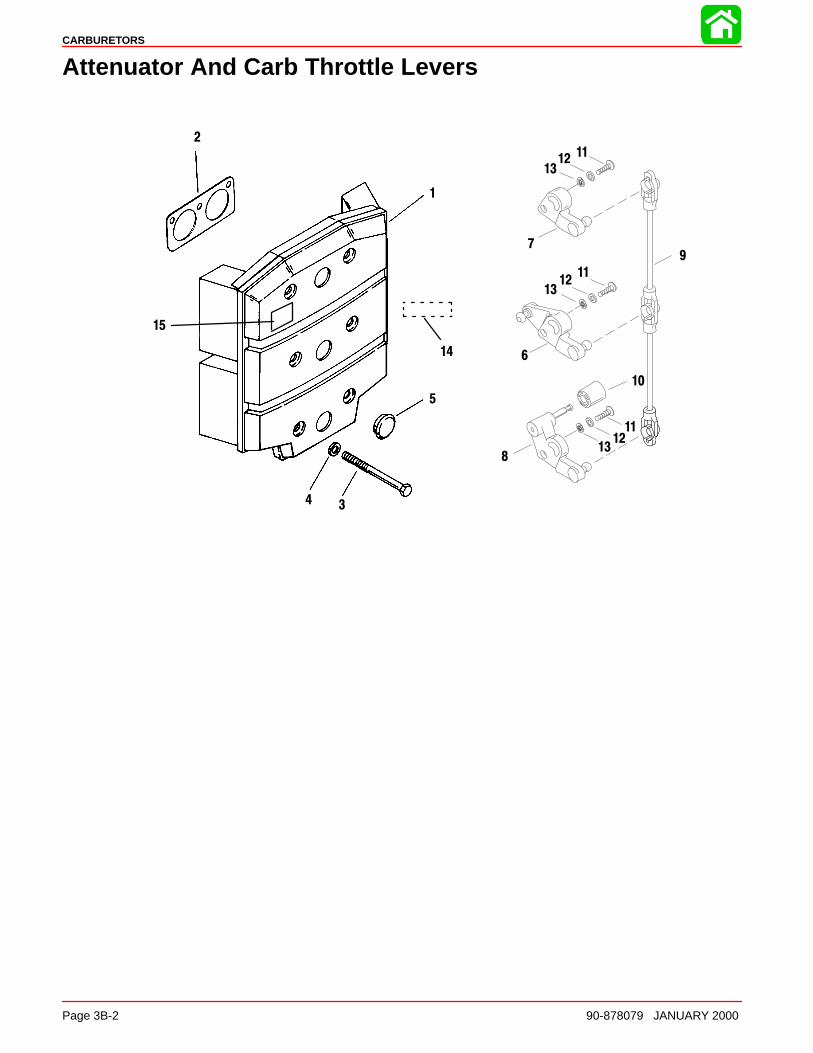
CARBURETORS
Page 3B-2 90-878079 JANUARY 2000
Attenuator And Carb Throttle Levers
1
2
34
5
6
10
11
1213
11
11
13
13
12
12
7
8
9
15
14

CARBURETORS
90-878079 JANUARY 2000 Page 3B-3
REFTORQUE
REF.NO. QTY. DESCRIPTION lb-in lb-ft Nm.
1 1 SOUND ATTENUATOR PLATE2 3 GASKET3 6 SCREW (1/4-28 x 2-1/2) 60 7.04 6 WASHER5 3 CAP PLUG6 1 THROTTLE LEVER KIT7 1 THROTTLE LEVER
8 1 THROTTLE LEVER9 1 THROTTLE LINK10 1 ROLLER11 3 SCREW (10-32 x 3/4)12 3 WASHER13 3 LOCKWASHER
141 DECAL-EPA INFO (2000)(135)(SEE NOTE)
141 DECAL-EPA INFO (2000)(150/XR6/MAG. III/200) (SEE NOTE)
15 1 DECAL– Caution Air Box
NOTE: THE EPA LABEL HAS IMPORTANT INFORMATION ON EPA EMISSION REGULATIONS. REPLACE ANYMISSING OR UNREADABLE EPA LABEL.
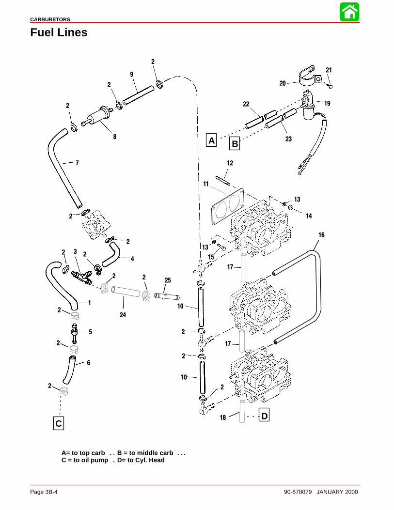
CARBURETORS
Page 3B-4 90-878079 JANUARY 2000
Fuel Lines
A
CD
A= to top carb B = to middle carb. . . . . C = to oil pump D= to Cyl. Head.
1
2
3
4
5
6
7
8
11
12
13
14
15
19
20
21
22
2
2
2
2
2 2
2
2
2
2
10
13
16
9
17
23
2
2
10
17
18
25
24
2 2
B
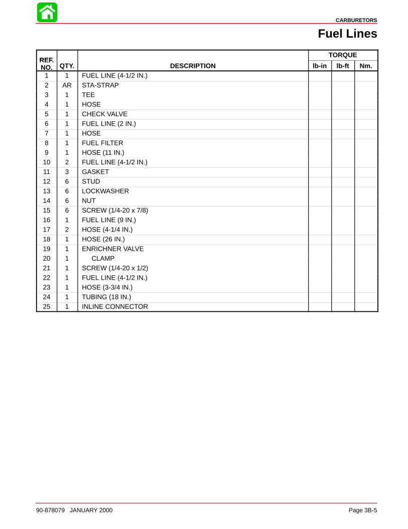
CARBURETORS
90-878079 JANUARY 2000 Page 3B-5
Fuel Lines
REFTORQUE
REF.NO. QTY. DESCRIPTION lb-in lb-ft Nm.
1 1 FUEL LINE (4-1/2 IN.)
2 AR STA-STRAP3 1 TEE4 1 HOSE5 1 CHECK VALVE6 1 FUEL LINE (2 IN.)7 1 HOSE
8 1 FUEL FILTER9 1 HOSE (11 IN.)10 2 FUEL LINE (4-1/2 IN.)11 3 GASKET12 6 STUD13 6 LOCKWASHER14 6 NUT
15 6 SCREW (1/4-20 x 7/8)16 1 FUEL LINE (9 IN.)17 2 HOSE (4-1/4 IN.)18 1 HOSE (26 IN.)19 1 ENRICHNER VALVE20 1 CLAMP21 1 SCREW (1/4-20 x 1/2)
22 1 FUEL LINE (4-1/2 IN.)23 1 HOSE (3-3/4 IN.)24 1 TUBING (18 IN.)25 1 INLINE CONNECTOR
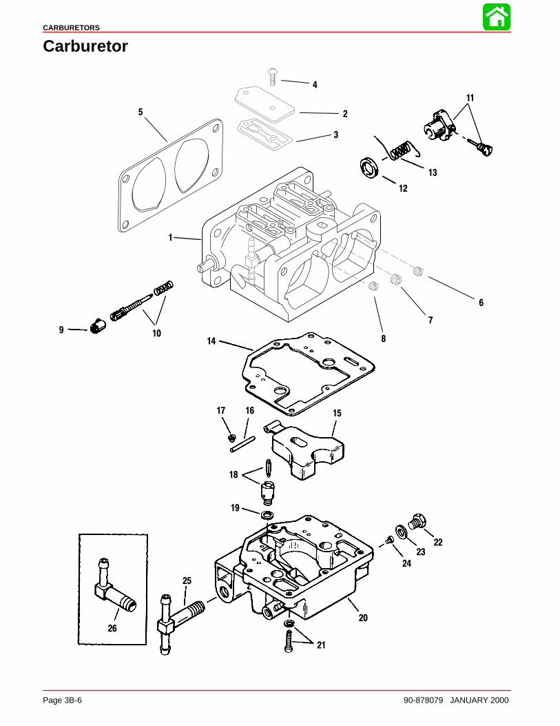
CARBURETORS
Page 3B-6 90-878079 JANUARY 2000
Carburetor
1
25
22
23
4
6
7
151617
18
19
20
24
21
25
26
3
14
9 10
11
12
13
8

CARBURETORS
90-878079 JANUARY 2000 Page 3B-7
Carburetor
REFTORQUE
REF.NO. QTY. DESCRIPTION lb-in lb-ft Nm.
1 TOP CARBURETOR1 CENTER CARBURETOR 135 - WMV-151 BOTTOM CARBURETOR1 TOP CARBURETOR
1 1 CENTER CARBURETOR 150/XR6/MAGNUM III1 BOTTOM CARBURETOR WMV-161 TOP CARBURETOR
1 CENTER CARBURETOR 200 - WMV-181 BOTTOM CARBURETOR
2 6 COVER3 6 GASKET4 12 SCREW 18 2.05 3 GASKET
2 JET–idle air vent (.040-Top/Center)(135) 14 1.5
1 JET–idle air vent (.048 - Bottom)(135) 14 1.52 JET–idle air vent (.044-Top/Center)(150/XR6/Magnum III) 14 1.5
6 1 JET–idle air vent (.048-Bottom)(150/XR6/Magnum III) 14 1.51 JET–idle air vent (.038-Top)(200) PORT 14 1.51 JET–idle air vent (.028-Center)(200) 14 1.51 JET–idle air vent (.032-Bottom)(200) 14 1.5
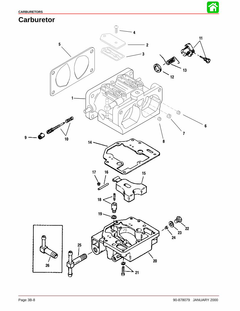
CARBURETORS
Page 3B-8 90-878079 JANUARY 2000
Carburetor
1
25
22
23
4
6
7
151617
18
19
20
24
21
25
26
3
14
9 10
11
12
13
8

CARBURETORS
90-878079 JANUARY 2000 Page 3B-9
Carburetor
REFTORQUE
REF.NO. QTY. DESCRIPTION lb-in lb-ft Nm.
73 JET–bowl vent (.086)(135/200)
7 3 JET–bowl vent (.082)(150/XR6/Magnum III)1 JET–idle air vent (.036-Top)(135)1 JET–idle air vent (.030-Center)(135)
81 JET–idle air vent (.038-Bottom)(135) STARBOARD
83 JET–idle air vent (.044)(150/XR6/Magnum III)1 JET–idle air vent (.038-Top)(200)2 JET–idle air vent (.028-Center/Bottom)(200)
9 6 LIMITER CAP10 6 IDLE MIXTURE SCREW/SPRING11 3 LEVER KIT12 3 SPACER13 3 SPRING14 3 GASKET–fuel bowl
15 3 FLOAT16 3 FLOAT SHAFT17 3 SCREW–float 10 1.018 3 VALVE SEAT KIT19 3 GASKET–valve seat
201 FUEL BOWL (TOP)
202 FUEL BOWL (CENTER/BOTTOM)
21 18 SCREW–fuel bowl 26 3.022 6 PLUG KIT 33 3.523 2 GASKET (Consists of 4 gaskets)
6 JET–main fuel (.072)(135) 14 1.56 JET–main fuel(.074)(150/XR6/Magnum III) 14 1.5
242 JET–main fuel (.080)(200-Top-Stbd/Center-Port) 14 1.5
242 JET–main fuel (.082)(200-Top-Port)/Center-Stbd) 14 1.5
1 JET-main fuel (.078)(200-Bottom-Port) 14 1.51 JET-main fuel (.084)(200-Bottom-Stbd) 14 1.5
25 2 TEE FITTING (TOP/CENTER)26 1 ELBOW (BOTTOM)
CARBURETORS
Page 3B-10 90-878079 JANUARY 2000
Fuel System - Troubleshooting
General InformationProblems, that are thought to be caused by the fuel system, may be, in reality, somethingcompletely different. Items, that are shown in the list on the left, could give the impressionthat there is a problem in the fuel system.
1. Impeller
2. Spark plugs
3. Ignition timing
4. Ignition spark voltage
5. Cylinder compression
6. Reed valves
Problem: Engine Turns Over But Will Not Start Or Starts Hard When Cold
Possible Cause Corrective Action
Improper starting procedure used. Check proper starting procedure, as outlined in“Operation and Maintenance Manual.”
Fuel tank empty or too low. Improperly mixed fuel.Contaminants (water, dirt, etc.) in fuel
Check fuel in fuel tank and replace or add which-ever is necessary.
Fuel tank air vent closed or restricted. Check air vent on fuel tank. Air vent must be openall-the-way and free from any contaminants.
A pinched, cut or restricted fuel line. Also loosefuel line connection.
Check all fuel lines and replace as needed. Checkand tighten all fuel line connections.
Dirty or restricted fuel filter. Check and replace or clean all fuel filters.
Low fuel pump pressure. Refer to Section 3A.
An anti-siphon valve. Refer to “Checking for Restricted Fuel Flow” inSection 3A.
Choke solenoid, or enrichment valve not operat-ing.
Check choke solenoid or valve, and electrical wir-ing to solenoid or valve. Replace if necessary.
A needle and seat (in carburetor) that is eitherstuck open or closed. Open=Flooding -Closed=Starving
Refer to “Carburetor Disassembly” in this section.
Improper carburetor jets, restricted jet or idle mix-ture screw out of adjustment.
Refer to “Carburetor Adjustments” in this section.
Improper carburetor float level. Refer to “Carburetor Adjustments” in this section.
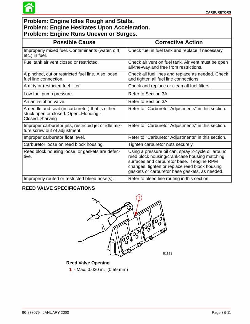
CARBURETORS
90-878079 JANUARY 2000 Page 3B-11
Problem: Engine Idles Rough and Stalls.Problem: Engine Hesitates Upon Acceleration.Problem: Engine Runs Uneven or Surges.
Possible Cause Corrective ActionImproperly mixed fuel. Contaminants (water, dirt,etc.) in fuel.
Check fuel in fuel tank and replace if necessary.
Fuel tank air vent closed or restricted. Check air vent on fuel tank. Air vent must be openall-the-way and free from restrictions.
A pinched, cut or restricted fuel line. Also loosefuel line connection.
Check all fuel lines and replace as needed. Checkand tighten all fuel line connections.
A dirty or restricted fuel filter. Check and replace or clean all fuel filters.
Low fuel pump pressure. Refer to Section 3A.
An anti-siphon valve. Refer to Section 3A.
A needle and seat (in carburetor) that is eitherstuck open or closed. Open=Flooding -Closed=Starving
Refer to ‘‘Carburetor Adjustments” in this section.
Improper carburetor jets, restricted jet or idle mix-ture screw out of adjustment.
Refer to ‘‘Carburetor Adjustments” in this section.
Improper carburetor float level. Refer to ‘‘Carburetor Adjustments” in this section.
Carburetor loose on reed block housing. Tighten carburetor nuts securely.
Reed block housing loose, or gaskets are defec-tive.
Using a pressure oil can, spray 2-cycle oil aroundreed block housing/crankcase housing matchingsurfaces and carburetor base. If engine RPMchanges, tighten or replace reed block housinggaskets or carburetor base gaskets, as needed.
Improperly routed or restricted bleed hose(s). Refer to bleed line routing in this section.
REED VALVE SPECIFICATIONS
1
51851
Reed Valve Opening1 - Max. 0.020 in. (0.59 mm)
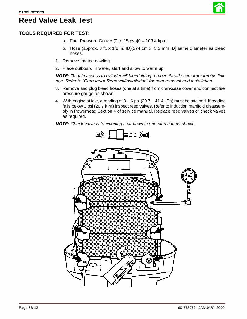
CARBURETORS
Page 3B-12 90-878079 JANUARY 2000
Reed Valve Leak Test
TOOLS REQUIRED FOR TEST:
a. Fuel Pressure Gauge (0 to 15 psi)[0 – 103.4 kpa]
b. Hose (approx. 3 ft. x 1/8 in. ID)[274 cm x 3.2 mm ID] same diameter as bleedhoses.
1. Remove engine cowling.
2. Place outboard in water, start and allow to warm up.
NOTE: To gain access to cylinder #5 bleed fitting remove throttle cam from throttle link-age. Refer to “Carburetor Removal/lnstallation” for cam removal and installation.
3. Remove and plug bleed hoses (one at a time) from crankcase cover and connect fuelpressure gauge as shown.
4. With engine at idle, a reading of 3 – 6 psi (20.7 – 41.4 kPa) must be attained. If readingfalls below 3 psi (20.7 kPa) inspect reed valves. Refer to induction manifold disassem-bly in Powerhead Section 4 of service manual. Replace reed valves or check valvesas required.
NOTE: Check valve is functioning if air flows in one direction as shown.

CARBURETORS
90-878079 JANUARY 2000 Page 3B-13
Thermal Air Valve Circuit Description
51863
a
a - Thermal Air Valve
The thermal air valve circuit functions as an air restrictor for the idle circuit which is con-trolled by a thermal open/close valve monitoring engine temperature. The valve is locatedon the starboard cylinder head below no. 3 spark plug. When the engine temperature isbelow 100° F (38° C) the thermal air valve is closed. When a cold engine is running, thethermal air valve restricts air to the idle circuit causing the fuel mixture to be richer. Whenthe engine warms sufficiently, the thermal valve opens allowing required fuel/air mixturefor efficient operation.
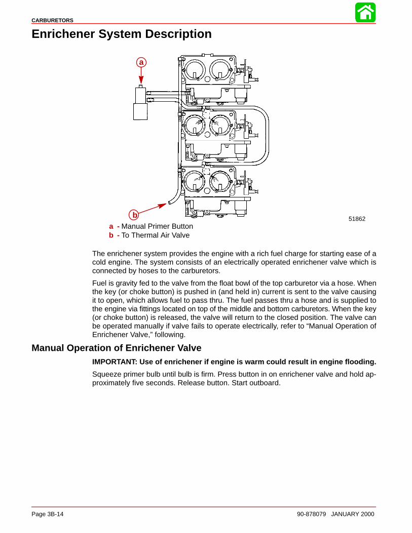
CARBURETORS
Page 3B-14 90-878079 JANUARY 2000
Enrichener System Description
51862
a
ba - Manual Primer Buttonb - To Thermal Air Valve
The enrichener system provides the engine with a rich fuel charge for starting ease of acold engine. The system consists of an electrically operated enrichener valve which isconnected by hoses to the carburetors.
Fuel is gravity fed to the valve from the float bowl of the top carburetor via a hose. Whenthe key (or choke button) is pushed in (and held in) current is sent to the valve causingit to open, which allows fuel to pass thru. The fuel passes thru a hose and is supplied tothe engine via fittings located on top of the middle and bottom carburetors. When the key(or choke button) is released, the valve will return to the closed position. The valve canbe operated manually if valve fails to operate electrically, refer to “Manual Operation ofEnrichener Valve,” following.
Manual Operation of Enrichener ValveIMPORTANT: Use of enrichener if engine is warm could result in engine flooding.
Squeeze primer bulb until bulb is firm. Press button in on enrichener valve and hold ap-proximately five seconds. Release button. Start outboard.
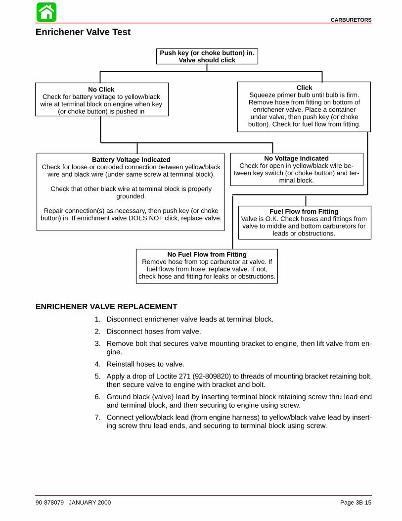
CARBURETORS
90-878079 JANUARY 2000 Page 3B-15
Enrichener Valve Test
Push key (or choke button) in.Valve should click
No ClickCheck for battery voltage to yellow/black
wire at terminal block on engine when key(or choke button) is pushed in
ClickSqueeze primer bulb until bulb is firm.Remove hose from fitting on bottom of
enrichener valve. Place a containerunder valve, then push key (or choke
button). Check for fuel flow from fitting.
Battery Voltage IndicatedCheck for loose or corroded connection between yellow/black
wire and black wire (under same screw at terminal block).
Check that other black wire at terminal block is properlygrounded.
Repair connection(s) as necessary, then push key (or chokebutton) in. If enrichment valve DOES NOT click, replace valve.
No Voltage IndicatedCheck for open in yellow/black wire be-
tween key switch (or choke button) and ter-minal block.
Fuel Flow from FittingValve is O.K. Check hoses and fittings fromvalve to middle and bottom carburetors for
leads or obstructions.
No Fuel Flow from FittingRemove hose from top carburetor at valve. If
fuel flows from hose, replace valve. If not,check hose and fitting for leaks or obstructions.
ENRICHENER VALVE REPLACEMENT
1. Disconnect enrichener valve leads at terminal block.
2. Disconnect hoses from valve.
3. Remove bolt that secures valve mounting bracket to engine, then lift valve from en-gine.
4. Reinstall hoses to valve.
5. Apply a drop of Loctite 271 (92-809820) to threads of mounting bracket retaining bolt,then secure valve to engine with bracket and bolt.
6. Ground black (valve) lead by inserting terminal block retaining screw thru lead endand terminal block, and then securing to engine using screw.
7. Connect yellow/black lead (from engine harness) to yellow/black valve lead by insert-ing screw thru lead ends, and securing to terminal block using screw.
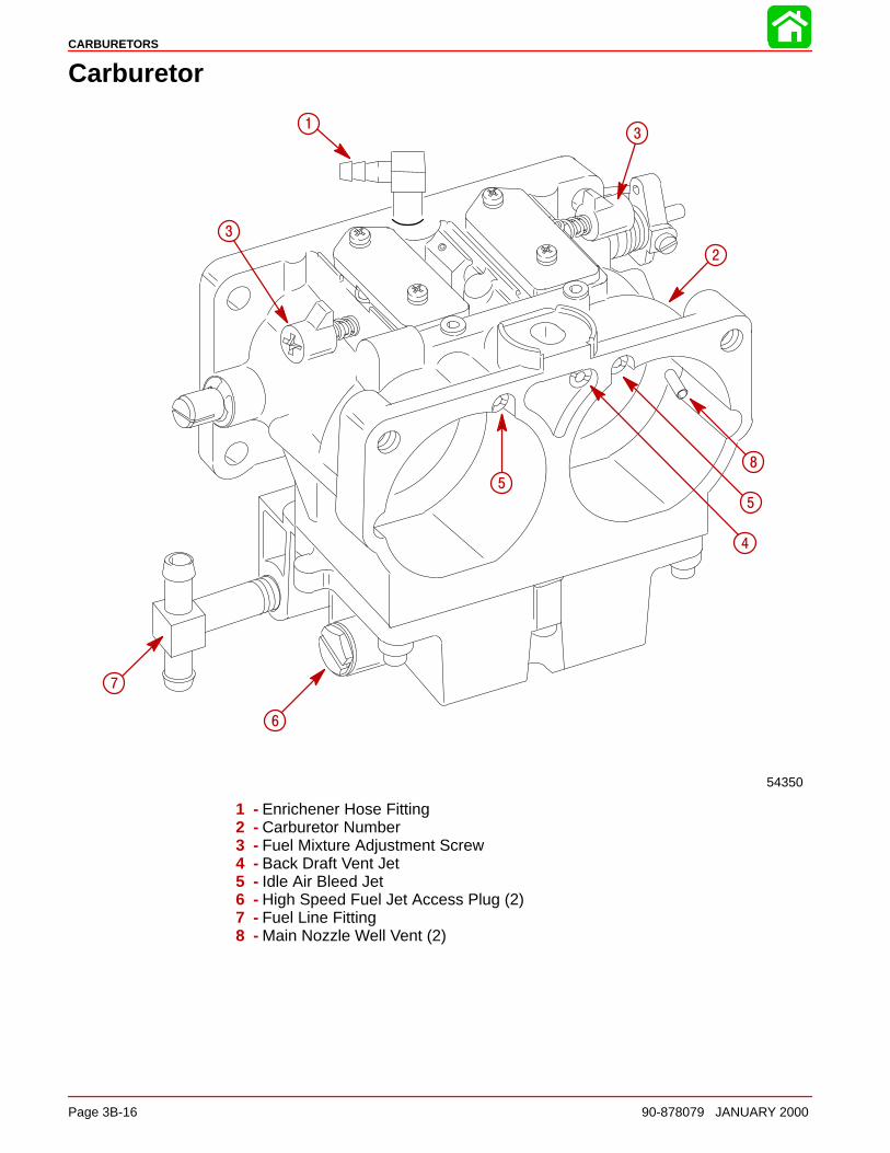
CARBURETORS
Page 3B-16 90-878079 JANUARY 2000
Carburetor
54350
1
2
3
3
4
5
8
5
6
7
1 - Enrichener Hose Fitting2 - Carburetor Number3 - Fuel Mixture Adjustment Screw4 - Back Draft Vent Jet5 - Idle Air Bleed Jet6 - High Speed Fuel Jet Access Plug (2)7 - Fuel Line Fitting8 - Main Nozzle Well Vent (2)
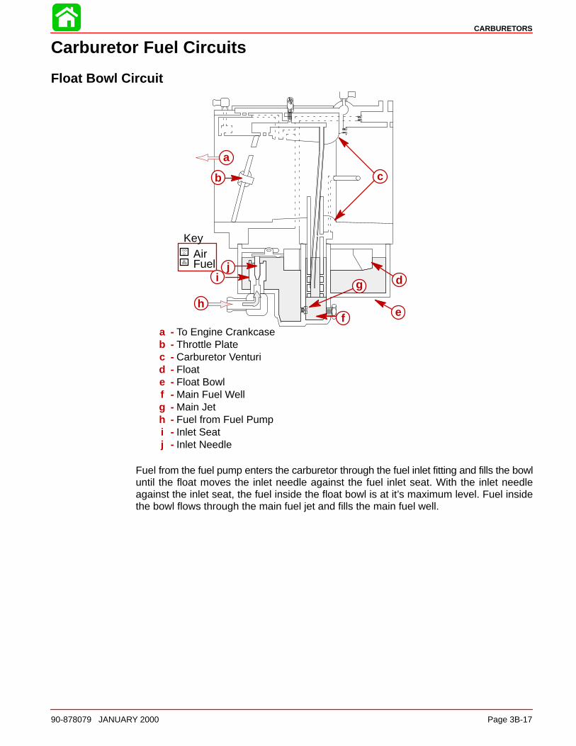
CARBURETORS
90-878079 JANUARY 2000 Page 3B-17
Carburetor Fuel Circuits
Float Bowl Circuit
AirFuel
Key
a
b c
d
ef
g
h
ij
a - To Engine Crankcaseb - Throttle Platec - Carburetor Venturid - Floate - Float Bowlf - Main Fuel Wellg - Main Jeth - Fuel from Fuel Pumpi - Inlet Seatj - Inlet Needle
Fuel from the fuel pump enters the carburetor through the fuel inlet fitting and fills the bowluntil the float moves the inlet needle against the fuel inlet seat. With the inlet needleagainst the inlet seat, the fuel inside the float bowl is at it’s maximum level. Fuel insidethe bowl flows through the main fuel jet and fills the main fuel well.
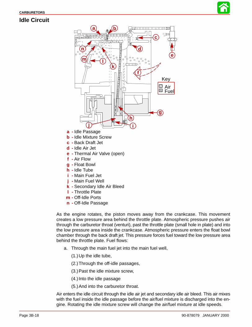
CARBURETORS
Page 3B-18 90-878079 JANUARY 2000
Idle Circuit
AirFuel
Key
a b
c
de
f
gh
ij
klm
n
a - Idle Passageb - Idle Mixture Screwc - Back Draft Jetd - Idle Air Jete - Thermal Air Valve (open)f - Air Flowg - Float Bowlh - Idle Tubei - Main Fuel Jetj - Main Fuel Wellk - Secondary Idle Air Bleedl - Throttle Plate
m - Off-Idle Portsn - Off-Idle Passage
As the engine rotates, the piston moves away from the crankcase. This movementcreates a low pressure area behind the throttle plate. Atmospheric pressure pushes airthrough the carburetor throat (venturi), past the throttle plate (small hole in plate) and intothe low pressure area inside the crankcase. Atmospheric pressure enters the float bowlchamber through the back draft jet. This pressure forces fuel toward the low pressure areabehind the throttle plate. Fuel flows:
a. Through the main fuel jet into the main fuel well,
(1.)Up the idle tube,
(2.)Through the off-idle passages,
(3.)Past the idle mixture screw,
(4.) Into the idle passage
(5.)And into the carburetor throat.
Air enters the idle circuit through the idle air jet and secondary idle air bleed. This air mixeswith the fuel inside the idle passage before the air/fuel mixture is discharged into the en-gine. Rotating the idle mixture screw will change the air/fuel mixture at idle speeds.
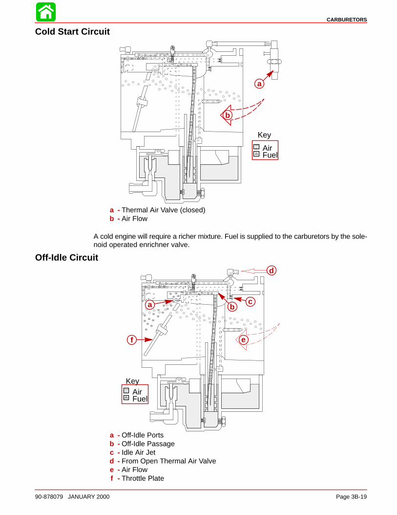
CARBURETORS
90-878079 JANUARY 2000 Page 3B-19
Cold Start Circuit
AirFuel
Key
b
a
a - Thermal Air Valve (closed)b - Air Flow
A cold engine will require a richer mixture. Fuel is supplied to the carburetors by the sole-noid operated enrichner valve.
Off-Idle Circuit
AirFuel
Key
a bc
d
ef
a - Off-Idle Portsb - Off-Idle Passagec - Idle Air Jetd - From Open Thermal Air Valvee - Air Flowf - Throttle Plate

CARBURETORS
Page 3B-20 90-878079 JANUARY 2000
As the throttle plates rotate past the off-idle ports, the ports are exposed to the low pres-sure area behind the throttle plate. Additional fuel flows through the off-idle passage;through the rear port; and as the throttle plate continues to rotate, through the forwardport.
Main Circuit
AirFuel
Key
a
b
c
d
e
f
g
hi
a - From Open Thermal Air Valveb - Air Flowc - Venturid - Main Discharge Air Inlet Tubee - Cross Holesf - Main Fuel Wellg - Main Fuel Jeth - Main Discharge Nozzlei - Throttle Plate
As the throttle plate rotates past the off-idle ports, the low pressure area extends to themain discharge nozzle. In addition, the increased air flow through the carburetor borecreates a low pressure area inside the venturi. These combined forces create a strongsuction over the main discharge tube. Fuel flows:
1. Through the main fuel jet into the main fuel well,
2. Up the main discharge nozzle,
3. Into the venturi.
Air is mixed with the fuel to make it lighter, air enters the main fuel well through the maindischarge air inlet tube. Cross holes are drilled in the main discharge tube, allowing theair to mix with the fuel inside the main well. As the throttle plate continues to open, addi-tional fuel is drawn out of the main discharge tube, exposing additional cross holes. At fullthrottle, the fuel mixture is controlled by the size of the main fuel jet.
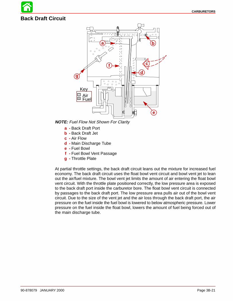
CARBURETORS
90-878079 JANUARY 2000 Page 3B-21
Back Draft Circuit
AirFuel
Key
a b
c
d
e
f
g
NOTE: Fuel Flow Not Shown For Clarity
a - Back Draft Portb - Back Draft Jetc - Air Flowd - Main Discharge Tubee - Fuel Bowlf - Fuel Bowl Vent Passageg - Throttle Plate
At partial throttle settings, the back draft circuit leans out the mixture for increased fueleconomy. The back draft circuit uses the float bowl vent circuit and bowl vent jet to leanout the air/fuel mixture. The bowl vent jet limits the amount of air entering the float bowlvent circuit. With the throttle plate positioned correctly, the low pressure area is exposedto the back draft port inside the carburetor bore. The float bowl vent circuit is connectedby passages to the back draft port. The low pressure area pulls air out of the bowl ventcircuit. Due to the size of the vent jet and the air loss through the back draft port, the airpressure on the fuel inside the fuel bowl is lowered to below atmospheric pressure. Lowerpressure on the fuel inside the float bowl, lowers the amount of fuel being forced out ofthe main discharge tube.
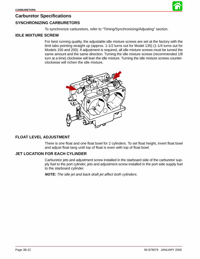
CARBURETORS
Page 3B-22 90-878079 JANUARY 2000
Carburetor SpecificationsSYNCHRONIZING CARBURETORS
To synchronize carburetors, refer to “Timing/Synchronizing/Adjusting” section.
IDLE MIXTURE SCREW
For best running quality, the adjustable idle mixture screws are set at the factory with thelimit tabs pointing straight up (approx. 1-1/2 turns out for Model 135) (1-1/4 turns out forModels 150 and 200). If adjustment is required, all idle mixture screws must be turned thesame amount and the same direction. Turning the idle mixture screws (recommended 1/8turn at a time) clockwise will lean the idle mixture. Turning the idle mixture screws counter-clockwise will richen the idle mixture.
FLOAT LEVEL ADJUSTMENT
There is one float and one float bowl for 2 cylinders. To set float height, invert float bowland adjust float tang until top of float is even with top of float bowl.
JET LOCATION FOR EACH CYLINDER
Carburetor jets and adjustment screw installed in the starboard side of the carburetor sup-ply fuel to the port cylinder, jets and adjustment screw installed in the port side supply fuelto the starboard cylinder.
NOTE: The idle jet and back draft jet affect both cylinders.
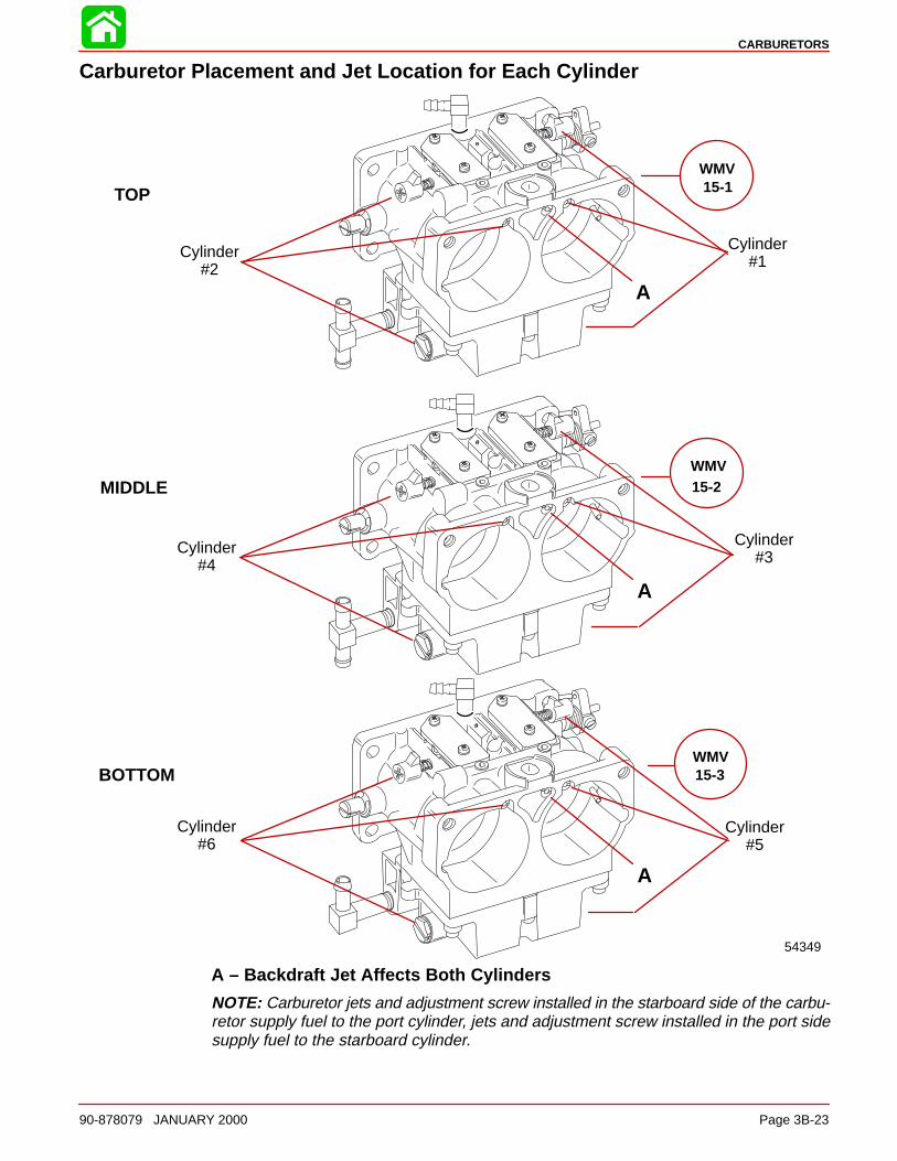
CARBURETORS
90-878079 JANUARY 2000 Page 3B-23
Carburetor Placement and Jet Location for Each Cylinder
Cylinder#2
Cylinder#4
Cylinder#6
Cylinder#1
Cylinder#3
Cylinder#5
54349
WMV15-1
WMV15-2
WMV15-3
TOP
MIDDLE
BOTTOM
A
A
A
A – Backdraft Jet Affects Both Cylinders
NOTE: Carburetor jets and adjustment screw installed in the starboard side of the carbu-retor supply fuel to the port cylinder, jets and adjustment screw installed in the port sidesupply fuel to the starboard cylinder.
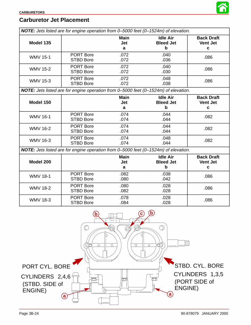
STBD. CYL. BOREPORT CYL. BORECYLINDERS 1,3,5(PORT SIDE ofENGINE)
CYLINDERS 2,4,6(STBD. SIDE ofENGINE)
a a
bcb
CARBURETORS
Page 3B-24 90-878079 JANUARY 2000
Carburetor Jet Placement
NOTE: Jets listed are for engine operation from 0–5000 feet (0–1524m) of elevation.
Model 135MainJeta
Idle AirBleed Jet
b
Back DraftVent Jet
c
WMV 15-1 PORT BoreSTBD Bore
.072
.072.040.036
.086
WMV 15-2 PORT BoreSTBD Bore
.072
.072.040.030
.086
WMV 15-3 PORT BoreSTBD Bore
.072
.072.048.038
.086
NOTE: Jets listed are for engine operation from 0–5000 feet (0–1524m) of elevation.
Model 150MainJeta
Idle AirBleed Jet
b
Back DraftVent Jet
c
WMV 16-1 PORT BoreSTBD Bore
.074
.074.044.044
.082
WMV 16-2 PORT BoreSTBD Bore
.074
.074.044.044
.082
WMV 16-3 PORT BoreSTBD Bore
.074
.074.048.044
.082
NOTE: Jets listed are for engine operation from 0–5000 feet (0–1524m) of elevation.
Model 200MainJeta
Idle AirBleed Jet
b
Back DraftVent Jet
c
WMV 18-1 PORT BoreSTBD Bore
.082
.080.038.042
.086
WMV 18-2 PORT BoreSTBD Bore
.080
.082.028.028
.086
WMV 18-3 PORT BoreSTBD Bore
.078
.084.028.028
.086
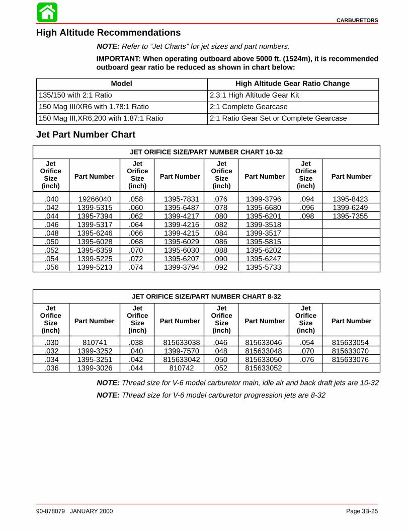
CARBURETORS
90-878079 JANUARY 2000 Page 3B-25
High Altitude RecommendationsNOTE: Refer to “Jet Charts” for jet sizes and part numbers.
IMPORTANT: When operating outboard above 5000 ft. (1524m), it is recommendedoutboard gear ratio be reduced as shown in chart below:
Model High Altitude Gear Ratio Change
135/150 with 2:1 Ratio 2.3:1 High Altitude Gear Kit
150 Mag III/XR6 with 1.78:1 Ratio 2:1 Complete Gearcase
150 Mag III,XR6,200 with 1.87:1 Ratio 2:1 Ratio Gear Set or Complete Gearcase
Jet Part Number Chart
JET ORIFICE SIZE/PART NUMBER CHART 10-32
.040 19266040 .058 1395-7831 .076 1399-3796 .094 1395-8423
.042 1399-5315 .060 1395-6487 .078 1395-6680 .096 1399-6249
.044 1395-7394 .062 1399-4217 .080 1395-6201 .098 1395-7355
.046 1399-5317 .064 1399-4216 .082 1399-3518
.048 1395-6246 .066 1399-4215 .084 1399-3517
.050 1395-6028 .068 1395-6029 .086 1395-5815
.052 1395-6359 .070 1395-6030 .088 1395-6202
.054 1399-5225 .072 1395-6207 .090 1395-6247
.056 1399-5213 .074 1399-3794 .092 1395-5733
JetOrifice
Size(inch)
Part Number Part Number Part Number Part Number
JetOrifice
Size(inch)
JetOrifice
Size(inch)
JetOrifice
Size(inch)
JET ORIFICE SIZE/PART NUMBER CHART 8-32
JetOrifice
Size(inch)
Part Number Part Number Part Number Part Number
JetOrifice
Size(inch)
JetOrifice
Size(inch)
JetOrifice
Size(inch)
.030 810741 .038 815633038 .046 815633046 .054 815633054
.032 1399-3252 .040 1399-7570 .048 815633048 .070 815633070
.034 1395-3251 .042 815633042 .050 815633050 .076 815633076
.036 1399-3026 .044 810742 .052 815633052
NOTE: Thread size for V-6 model carburetor main, idle air and back draft jets are 10-32
NOTE: Thread size for V-6 model carburetor progression jets are 8-32
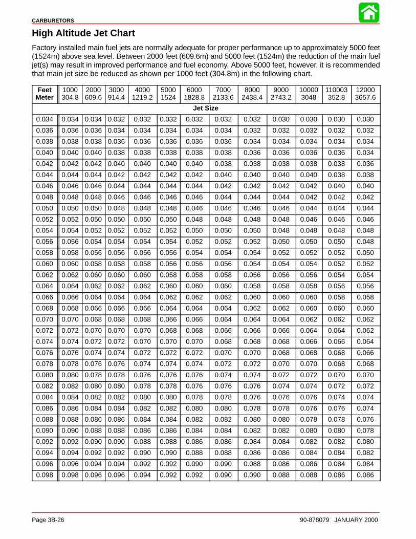
CARBURETORS
Page 3B-26 90-878079 JANUARY 2000
High Altitude Jet ChartFactory installed main fuel jets are normally adequate for proper performance up to approximately 5000 feet(1524m) above sea level. Between 2000 feet (609.6m) and 5000 feet (1524m) the reduction of the main fueljet(s) may result in improved performance and fuel economy. Above 5000 feet, however, it is recommendedthat main jet size be reduced as shown per 1000 feet (304.8m) in the following chart.
FeetMeter
1000304.8
2000609.6
3000914.4
40001219.2
50001524
60001828.8
70002133.6
80002438.4
90002743.2
100003048
110003352.8
120003657.6
Jet Size
0.034 0.034 0.034 0.032 0.032 0.032 0.032 0.032 0.032 0.030 0.030 0.030 0.030
0.036 0.036 0.036 0.034 0.034 0.034 0.034 0.034 0.032 0.032 0.032 0.032 0.032
0.038 0.038 0.038 0.036 0.036 0.036 0.036 0.036 0.034 0.034 0.034 0.034 0.034
0.040 0.040 0.040 0.038 0.038 0.038 0.038 0.038 0.036 0.036 0.036 0.036 0.034
0.042 0.042 0.042 0.040 0.040 0.040 0.040 0.038 0.038 0.038 0.038 0.038 0.036
0.044 0.044 0.044 0.042 0.042 0.042 0.042 0.040 0.040 0.040 0.040 0.038 0.038
0.046 0.046 0.046 0.044 0.044 0.044 0.044 0.042 0.042 0.042 0.042 0.040 0.040
0.048 0.048 0.048 0.046 0.046 0.046 0.046 0.044 0.044 0.044 0.042 0.042 0.042
0.050 0.050 0.050 0.048 0.048 0.048 0.046 0.046 0.046 0.046 0.044 0.044 0.044
0.052 0.052 0.050 0.050 0.050 0.050 0.048 0.048 0.048 0.048 0.046 0.046 0.046
0.054 0.054 0.052 0.052 0.052 0.052 0.050 0.050 0.050 0.048 0.048 0.048 0.048
0.056 0.056 0.054 0.054 0.054 0.054 0.052 0.052 0.052 0.050 0.050 0.050 0.048
0.058 0.058 0.056 0.056 0.056 0.056 0.054 0.054 0.054 0.052 0.052 0.052 0.050
0.060 0.060 0.058 0.058 0.058 0.056 0.056 0.056 0.054 0.054 0.054 0.052 0.052
0.062 0.062 0.060 0.060 0.060 0.058 0.058 0.058 0.056 0.056 0.056 0.054 0.054
0.064 0.064 0.062 0.062 0.062 0.060 0.060 0.060 0.058 0.058 0.058 0.056 0.056
0.066 0.066 0.064 0.064 0.064 0.062 0.062 0.062 0.060 0.060 0.060 0.058 0.058
0.068 0.068 0.066 0.066 0.066 0.064 0.064 0.064 0.062 0.062 0.060 0.060 0.060
0.070 0.070 0.068 0.068 0.068 0.066 0.066 0.064 0.064 0.064 0.062 0.062 0.062
0.072 0.072 0.070 0.070 0.070 0.068 0.068 0.066 0.066 0.066 0.064 0.064 0.062
0.074 0.074 0.072 0.072 0.070 0.070 0.070 0.068 0.068 0.068 0.066 0.066 0.064
0.076 0.076 0.074 0.074 0.072 0.072 0.072 0.070 0.070 0.068 0.068 0.068 0.066
0.078 0.078 0.076 0.076 0.074 0.074 0.074 0.072 0.072 0.070 0.070 0.068 0.068
0.080 0.080 0.078 0.078 0.076 0.076 0.076 0.074 0.074 0.072 0.072 0.070 0.070
0.082 0.082 0.080 0.080 0.078 0.078 0.076 0.076 0.076 0.074 0.074 0.072 0.072
0.084 0.084 0.082 0.082 0.080 0.080 0.078 0.078 0.076 0.076 0.076 0.074 0.074
0.086 0.086 0.084 0.084 0.082 0.082 0.080 0.080 0.078 0.078 0.076 0.076 0.074
0.088 0.088 0.086 0.086 0.084 0.084 0.082 0.082 0.080 0.080 0.078 0.078 0.076
0.090 0.090 0.088 0.088 0.086 0.086 0.084 0.084 0.082 0.082 0.080 0.080 0.078
0.092 0.092 0.090 0.090 0.088 0.088 0.086 0.086 0.084 0.084 0.082 0.082 0.080
0.094 0.094 0.092 0.092 0.090 0.090 0.088 0.088 0.086 0.086 0.084 0.084 0.082
0.096 0.096 0.094 0.094 0.092 0.092 0.090 0.090 0.088 0.086 0.086 0.084 0.084
0.098 0.098 0.096 0.096 0.094 0.092 0.092 0.090 0.090 0.088 0.088 0.086 0.086
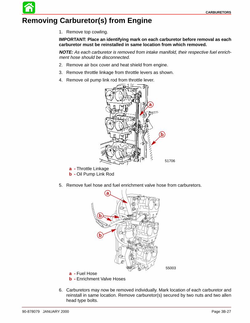
CARBURETORS
90-878079 JANUARY 2000 Page 3B-27
Removing Carburetor(s) from Engine1. Remove top cowling.
IMPORTANT: Place an identifying mark on each carburetor before removal as eachcarburetor must be reinstalled in same location from which removed.
NOTE: As each carburetor is removed from intake manifold, their respective fuel enrich-ment hose should be disconnected.
2. Remove air box cover and heat shield from engine.
3. Remove throttle linkage from throttle levers as shown.
4. Remove oil pump link rod from throttle lever.
51706
a
b
a - Throttle Linkageb - Oil Pump Link Rod
5. Remove fuel hose and fuel enrichment valve hose from carburetors.
55003
a
b
b
a - Fuel Hoseb - Enrichment Valve Hoses
6. Carburetors may now be removed individually. Mark location of each carburetor andreinstall in same location. Remove carburetor(s) secured by two nuts and two allenhead type bolts.
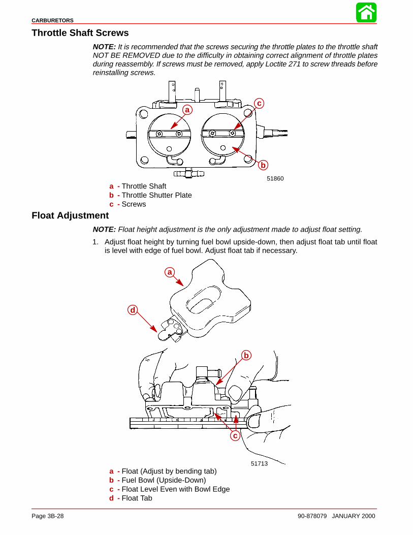
CARBURETORS
Page 3B-28 90-878079 JANUARY 2000
Throttle Shaft ScrewsNOTE: It is recommended that the screws securing the throttle plates to the throttle shaftNOT BE REMOVED due to the difficulty in obtaining correct alignment of throttle platesduring reassembly. If screws must be removed, apply Loctite 271 to screw threads beforereinstalling screws.
51860
a
b
c
a - Throttle Shaftb - Throttle Shutter Platec - Screws
Float AdjustmentNOTE: Float height adjustment is the only adjustment made to adjust float setting.
1. Adjust float height by turning fuel bowl upside-down, then adjust float tab until floatis level with edge of fuel bowl. Adjust float tab if necessary.
51713
a
b
c
d
a - Float (Adjust by bending tab)b - Fuel Bowl (Upside-Down)c - Float Level Even with Bowl Edged - Float Tab

CARBURETORS
90-878079 JANUARY 2000 Page 3B-29
Installing Carburetor(s) to Engine1. Place new carburetor gaskets onto carburetor mounting studs on intake manifold.
2. Install carburetors (in respective locations) onto mounting studs and secure in placewith nuts and allen type bolts.
3. Connect enrichment hoses and fuel hoses. Secure hoses in place using sta-straps.
55003
a
b
b
a - Fuel Hoseb - Enrichment Valve Hose
4. Attach throttle linkage and oil pump link rod to carburetors as shown.
51706
a
b
a - Throttle Linkageb - Oil Pump Link Rod
5. Re-synchronize carburetors following carburetor installation. Refer to “Timing/Syn-chronizing/Adjusting” Section 2C.
IMPORTANT: Inspect all fuel hose connections, and carburetor float bowl split linesfor fuel leaks with engine running. Also inspect each carburetor throat, with out-board r unning at low RPM, for fuel dribbling out of vent tube which would be indica-tive of a float and/or needle and seat assembly not functioning properly.
IMPORTANT: Engine should not be operated above 3000 RPM with air box coverremoved as engine will run too lean and internal damage could result.
3C
FUEL INJECTION
90-878079 JANUARY 2000 Page 3C-1
FUEL SYSTEMSection 3C - Fuel Injection
Table of Contents
Specifications 3C-2. . . . . . . . . . . . . . . . . . . . . . . . . . . Special Tools 3C-3. . . . . . . . . . . . . . . . . . . . . . . . . . . Ignition Controller and Detonation Module 3C-6. . ECM Assembly 3C-8. . . . . . . . . . . . . . . . . . . . . . . . . Fuel Management System 3C-10. . . . . . . . . . . . . . . . Fuel Pump 3C-14. . . . . . . . . . . . . . . . . . . . . . . . . . . . . Electronic Fuel Injection (EFl) System 3C-16. . . . . .
Introduction 3C-16. . . . . . . . . . . . . . . . . . . . . . . . . . Using the Test Procedures 3C-16. . . . . . . . . . . . . EFI System Tests 3C-16. . . . . . . . . . . . . . . . . . . . . Safety Precautions 3C-16. . . . . . . . . . . . . . . . . . . Fuel Injection System Function 3C-17. . . . . . . . .
Preliminary Checks 3C-17. . . . . . . . . . . . . . . . . . . . . . Ignition Spark Check 3C-17. . . . . . . . . . . . . . . . . . Electronic Fuel Injection Set Up 3C-18. . . . . . . . Fresh Quality Fuel 3C-18. . . . . . . . . . . . . . . . . . . . Low Battery Voltage 3C-18. . . . . . . . . . . . . . . . . .
Fuel Flow Diagram 3C-19. . . . . . . . . . . . . . . . . . . . . . Fuel Flow Component Description 3C-20. . . . . . . . .
EFI Electrical Components 3C-21. . . . . . . . . . . . EFI Fuel Management(Low Pressure Fuel Route) 3C-24. . . . . . . . . . . . . . . EFI Fuel Management(High Pressure Fuel Route) 3C-25. . . . . . . . . . . . . . . Fuel Rail Electrical/Fuel Determination 3C-26. . . . . EFI System Test Procedures 3C-27. . . . . . . . . . . . . .
Fuel Gauge Connection/Pressure Test 3C-27. . Vapor Separator Fuel Delivery Test 3C-28. . . . . Vapor Separator Float Test 3C-29. . . . . . . . . . . . Water Separating Filter Flow Test 3C-30. . . . . . . Pulse Fuel Pump Delivery Test 3C-31. . . . . . . . . Final Filter Check and De-PressurizingEFI System Procedures 3C-32. . . . . . . . . . . . . . . Pressure Regulator Test 3C-34. . . . . . . . . . . . . . . Electric Fuel Pump Voltage Test 3C-36. . . . . . . . Injector Electrical Harness Test 3C-39. . . . . . . . . ECM Injector Driver Test 3C-40. . . . . . . . . . . . . . Injector Fuel Delivery Test 3C-40. . . . . . . . . . . . . Injector Operation Test(Manifold Cover Removed) 3C-40. . . . . . . . . . . . Induction Manifold Leak Check(Manifold Cover Removed) 3C-43. . . . . . . . . . . . Air Temperature Sensor Test 3C-45. . . . . . . . . . . Engine Head Temperature Sensor Test 3C-46. . Detonation Control System Test(200 Models Only) 3C-46. . . . . . . . . . . . . . . . . . . . Detonation Sensor Check 3C-47. . . . . . . . . . . . . Detonation Control Module Check 3C-48. . . . . .
Throttle Position Sensor Test 3C-48. . . . . . . . . . . Map Sensor Test 3C-49. . . . . . . . . . . . . . . . . . . . . Problem Diagnosis 3C-50. . . . . . . . . . . . . . . . . . .
Engine Head Temperature Sensor Removal 3C-53EFI Induction Manifold Removal 3C-54. . . . . . . . . . .
Water Separating Filter AssemblyRemoval 3C-55. . . . . . . . . . . . . . . . . . . . . . . . . . . . Water Separating Filter AssemblyInstallation 3C-56. . . . . . . . . . . . . . . . . . . . . . . . . . . Throttle Position Sensor and TemperatureSensor Fuel Injector HarnessDisconnections 3C-56. . . . . . . . . . . . . . . . . . . . . . . Oil Reservoir Removal 3C-58. . . . . . . . . . . . . . . . Fuel Pressure Regulator Removal 3C-59. . . . . . Fuel Pressure Regulator Disassembly 3C-60. . Fuel Pressure Regulator Reassembly 3C-60. . . Vapor Separator Removal 3C-61. . . . . . . . . . . . . Vapor Separator Disassembly 3C-63. . . . . . . . . . Installing Vapor Separator Assembly toInduction Manifold 3C-69. . . . . . . . . . . . . . . . . . . . Manifold Removal 3C-72. . . . . . . . . . . . . . . . . . . .
EFI Induction Manifold Disassembly 3C-74. . . . . . . Air Temperature Sensor Removal 3C-74. . . . . . Throttle Position Sensor Removal 3C-75. . . . . . Fuel Rail Removal 3C-76. . . . . . . . . . . . . . . . . . . . Fuel Rail Disassembly 3C-78. . . . . . . . . . . . . . . . Fuel Injector Removal and Disassembly 3C-78. Injector Harness Removal 3C-80. . . . . . . . . . . . . Throttle Linkage Removed 3C-81. . . . . . . . . . . . .
EFI System Cleaning and Inspection 3C-82. . . . . . . Cleaning 3C-82. . . . . . . . . . . . . . . . . . . . . . . . . . . . Inspection 3C-82. . . . . . . . . . . . . . . . . . . . . . . . . . .
Induction Manifold Assembly 3C-83. . . . . . . . . . . . . . Injector Harness Installation 3C-83. . . . . . . . . . . Fuel Injector Assembly and Installation 3C-84. . Fuel Rail Assembly 3C-86. . . . . . . . . . . . . . . . . . . Fuel Rail Installation 3C-86. . . . . . . . . . . . . . . . . . Throttle Position Sensor Installation 3C-88. . . . . Air Temperature Sensor Installation 3C-89. . . . .
EFI Induction Manifold Installation 3C-91. . . . . . . . . Oil Reservoir Installation 3C-93. . . . . . . . . . . . . . Vapor Separator Installation 3C-94. . . . . . . . . . . Throttle Position Sensor, Air TemperatureSensor and Fuel Injector HarnessConnections 3C-96. . . . . . . . . . . . . . . . . . . . . . . . . ECM Installation 3C-98. . . . . . . . . . . . . . . . . . . . . . Engine Head Temperature SensorInstallation 3C-99. . . . . . . . . . . . . . . . . . . . . . . . . . .
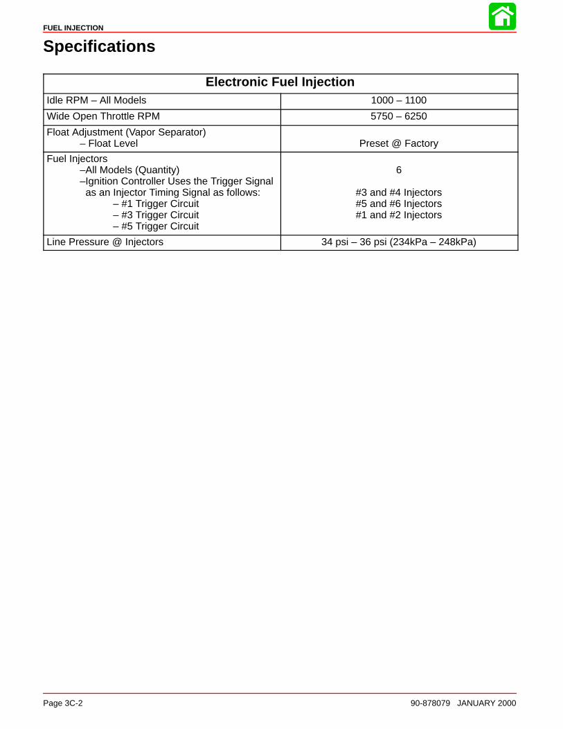
FUEL INJECTION
Page 3C-2 90-878079 JANUARY 2000
Specifications
Electronic Fuel InjectionIdle RPM – All Models 1000 – 1100
Wide Open Throttle RPM 5750 – 6250
Float Adjustment (Vapor Separator)– Float Level Preset @ Factory
Fuel Injectors–All Models (Quantity)–Ignition Controller Uses the Trigger Signal as an Injector Timing Signal as follows:
– #1 Trigger Circuit– #3 Trigger Circuit– #5 Trigger Circuit
6
#3 and #4 Injectors#5 and #6 Injectors#1 and #2 Injectors
Line Pressure @ Injectors 34 psi – 36 psi (234kPa – 248kPa)
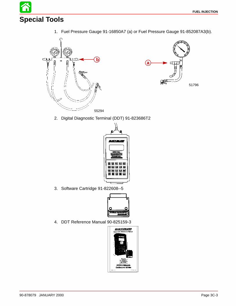
FUEL INJECTION
90-878079 JANUARY 2000 Page 3C-3
Special Tools
1. Fuel Pressure Gauge 91-16850A7 (a) or Fuel Pressure Gauge 91-852087A3(b).
51796
55294
ab
2. Digital Diagnostic Terminal (DDT) 91-823686T2
3. Software Cartridge 91-822608--5
4. DDT Reference Manual 90-825159-3
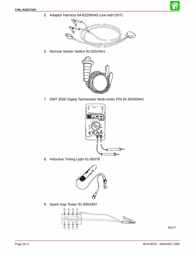
FUEL INJECTION
Page 3C-4 90-878079 JANUARY 2000
5. Adaptor Harness 84-822560A5 (use with DDT)
6. Remote Starter Switch 91-52024A1
7. DMT 2000 Digital Tachometer Multi-meter P/N 91-854009A1
8. Inductive Timing Light 91-99379
9. Spark Gap Tester 91-850439T
55117

FUEL INJECTION
90-878079 JANUARY 2000 Page 3C-5
10. Injector Test Harness 91-833169A1. Can be used to verify that the ECM is supplyingoperating voltage to the injectors. Harness is connected between the injector harnessand the engine harness. Harness is used in conjunction with DVA meter 91-99750A1.Harness will also serve as a convenient way to connect the injector harness to performinjector resistance test.
a b
c d e f
a - To Injector Manifoldb - To Engine Harnessc - RED
d - WHITEe - BLUEf - YELLOW
11. Strap Wrench 91-24937A1
12. Throttle Position Sensor Test Harness (91-859199)
57766

FUEL INJECTION
Page 3C-6 90-878079 JANUARY 2000
Ignition Controller and Detonation Module
4
3
2
1
5
6
7
8
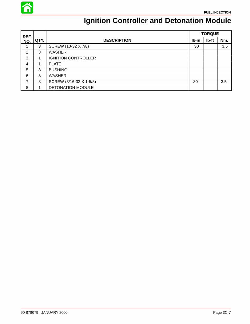
FUEL INJECTION
90-878079 JANUARY 2000 Page 3C-7
Ignition Controller and Detonation Module
REFTORQUE
REF.NO. QTY. DESCRIPTION lb-in lb-ft Nm.
1 3 SCREW (10-32 X 7/8) 30 3.5
2 3 WASHER3 1 IGNITION CONTROLLER4 1 PLATE5 3 BUSHING6 3 WASHER7 3 SCREW (3/16-32 X 1-5/8) 30 3.5
8 1 DETONATION MODULE
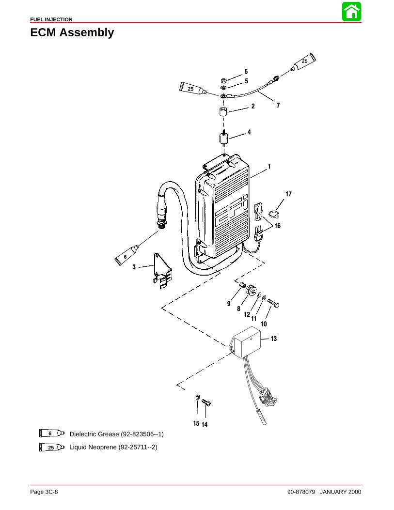
FUEL INJECTION
Page 3C-8 90-878079 JANUARY 2000
ECM Assembly
Dielectric Grease (92-823506--1)6
Liquid Neoprene (92-25711--2)
1
2
3
4
5
6
7
89
1011
12
13
1415
16
17
6
25
25
25
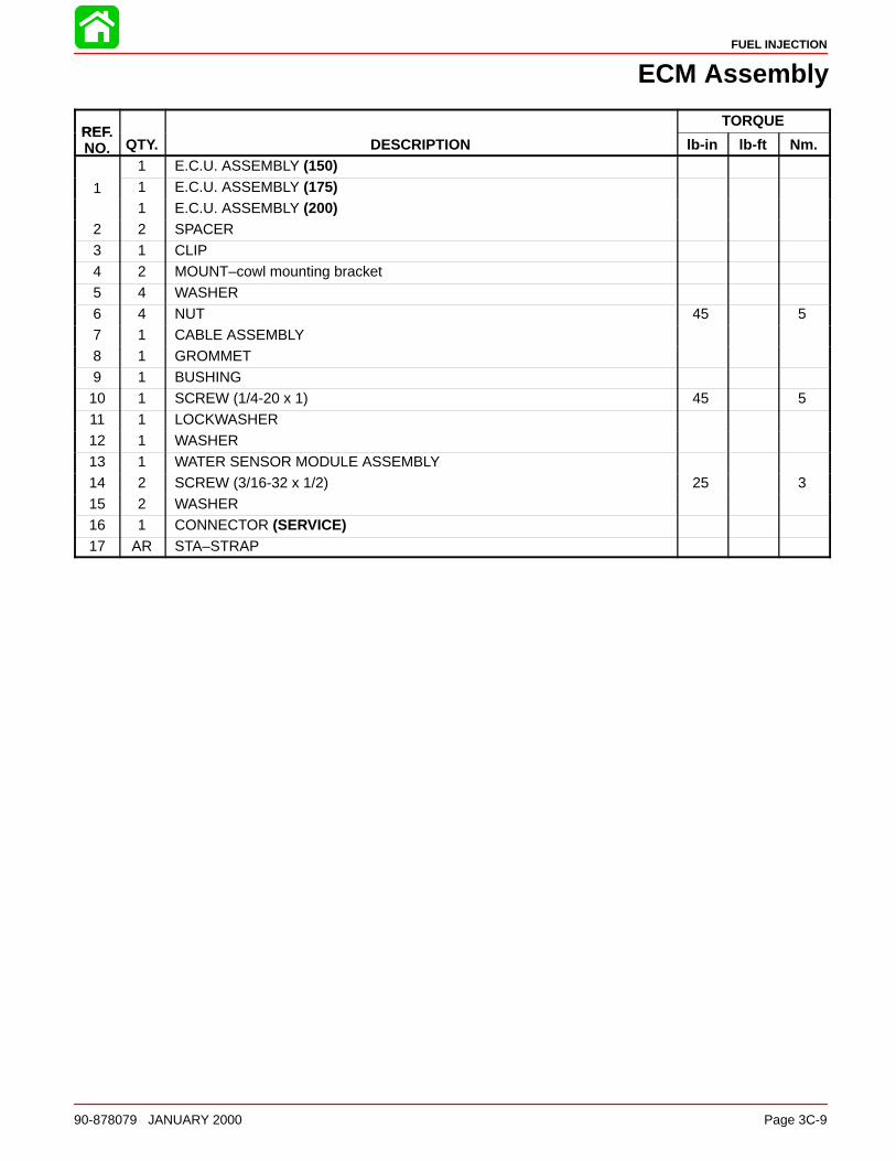
FUEL INJECTION
90-878079 JANUARY 2000 Page 3C-9
ECM Assembly
REFTORQUE
REF.NO. QTY. DESCRIPTION lb-in lb-ft Nm.
1 E.C.U. ASSEMBLY (150)
1 1 E.C.U. ASSEMBLY (175)1 E.C.U. ASSEMBLY (200)
2 2 SPACER3 1 CLIP4 2 MOUNT–cowl mounting bracket5 4 WASHER
6 4 NUT 45 57 1 CABLE ASSEMBLY8 1 GROMMET9 1 BUSHING10 1 SCREW (1/4-20 x 1) 45 511 1 LOCKWASHER12 1 WASHER
13 1 WATER SENSOR MODULE ASSEMBLY14 2 SCREW (3/16-32 x 1/2) 25 315 2 WASHER16 1 CONNECTOR (SERVICE)17 AR STA–STRAP

FUEL INJECTION
Page 3C-10 90-878079 JANUARY 2000
Fuel Management System
2
4
5
6
7
8
9
10
11
1213
14
1516
17
18
4
18
18
16
1716
13
22
23
24
25
26
2728 29
30
31
13
19
20
21

FUEL INJECTION
90-878079 JANUARY 2000 Page 3C-11
Fuel Management System
REFTORQUE
REF.NO. QTY. DESCRIPTION lb-in lb-ft Nm.
– 1 FUEL MANAGEMENT ASSEMBLY
1 1 COVER2 1 HARNESS KIT3 1 SEAL4 1 O RING/SEAL KIT5 1 FUEL RAIL6 1 FUEL INJECTOR
7 1 FILTER8 1 RETAINING KIT9 1 THROTTLE BODY10 1 JOINT KIT11 1 LINK12 1 LINK LEVER KIT13 1 STOP SCREW KIT
14 1 SCREW KIT 45 515 1 ELBOW KIT16 1 SCHRADER VALVE KIT17 1 FMA JOINT KIT18 1 HOSE KIT19 1 ROLLER20 12 SCREW (1/4-20 x 4 IN.) 90 10
21 10 WASHER22 1 TEMPERATURE SENSOR ASSEMBLY23 1 O-RING24 3 SCREW (8-32 x 3/8) Drive Tight25 3 LOCKWASHER26 1 INDICATOR–throttle position27 2 SCREW (8-32 x 5/8) 20 2
28 1 LOCKWASHER29 2 WASHER30 1 SLEEVE31 2 PLATE
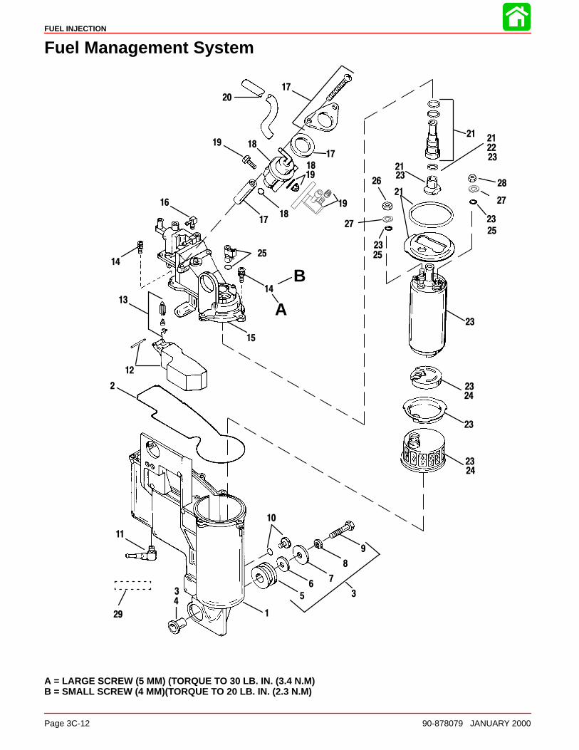
FUEL INJECTION
Page 3C-12 90-878079 JANUARY 2000
Fuel Management System
1
2
45
67
8
9
11
12
13
14
15
16
1718
1921
22
23
24
25
26 28
14
18
1819
19
17
17
21
21
23
23
23
23
23
2324
25
20
21
23
3 3
25
27
27
A
B
29
10
A = LARGE SCREW (5 MM) (TORQUE TO 30 LB. IN. (3.4 N.M)B = SMALL SCREW (4 MM)(TORQUE TO 20 LB. IN. (2.3 N.M)
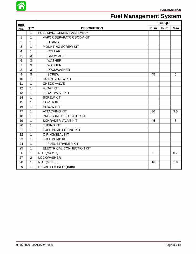
FUEL INJECTION
90-878079 JANUARY 2000 Page 3C-13
Fuel Management SystemREF
TORQUEREF.NO. QTY. DESCRIPTION lb. in. lb. ft. N·m
– 1 FUEL MANAGEMENT ASSEMBLY1 1 VAPOR SEPARATOR BODY KIT2 1 O RING3 1 MOUNTING SCREW KIT4 1 COLLAR
5 3 GROMMET6 3 WASHER7 3 WASHER8 3 LOCKWASHER9 3 SCREW 45 510 1 DRAIN SCREW KIT11 1 CHECK VALVE
12 1 FLOAT KIT13 1 FLOAT VALVE KIT14 1 SCREW KIT15 1 COVER KIT16 1 ELBOW KIT17 1 ATTACHING KIT 30 3.5
18 1 PRESSURE REGULATOR KIT19 1 SCHRADER VALVE KIT 45 520 1 TUBING KIT21 1 FUEL PUMP FITTING KIT22 1 O RING/SEAL KIT23 1 FUEL PUMP KIT24 1 FUEL STRAINER KIT
25 1 ELECTRICAL CONNECTION KIT26 1 NUT (M4 x .7) 6 0.727 2 LOCKWASHER28 1 NUT (M5 x .8) 16 1.829 1 DECAL-EPA INFO (1998)
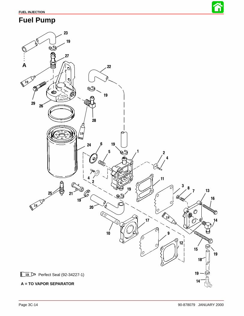
FUEL INJECTION
Page 3C-14 90-878079 JANUARY 2000
Fuel Pump
A
Perfect Seal (92-34227-1)19
1 2
3
4
5
6
78
910
11
12
13
14
15
16
17
18
19
20
21
22
23
24
25
26
27
28
29
19
19
19
19
42
14
19
19
19
19
19
19
A = TO VAPOR SEPARATOR
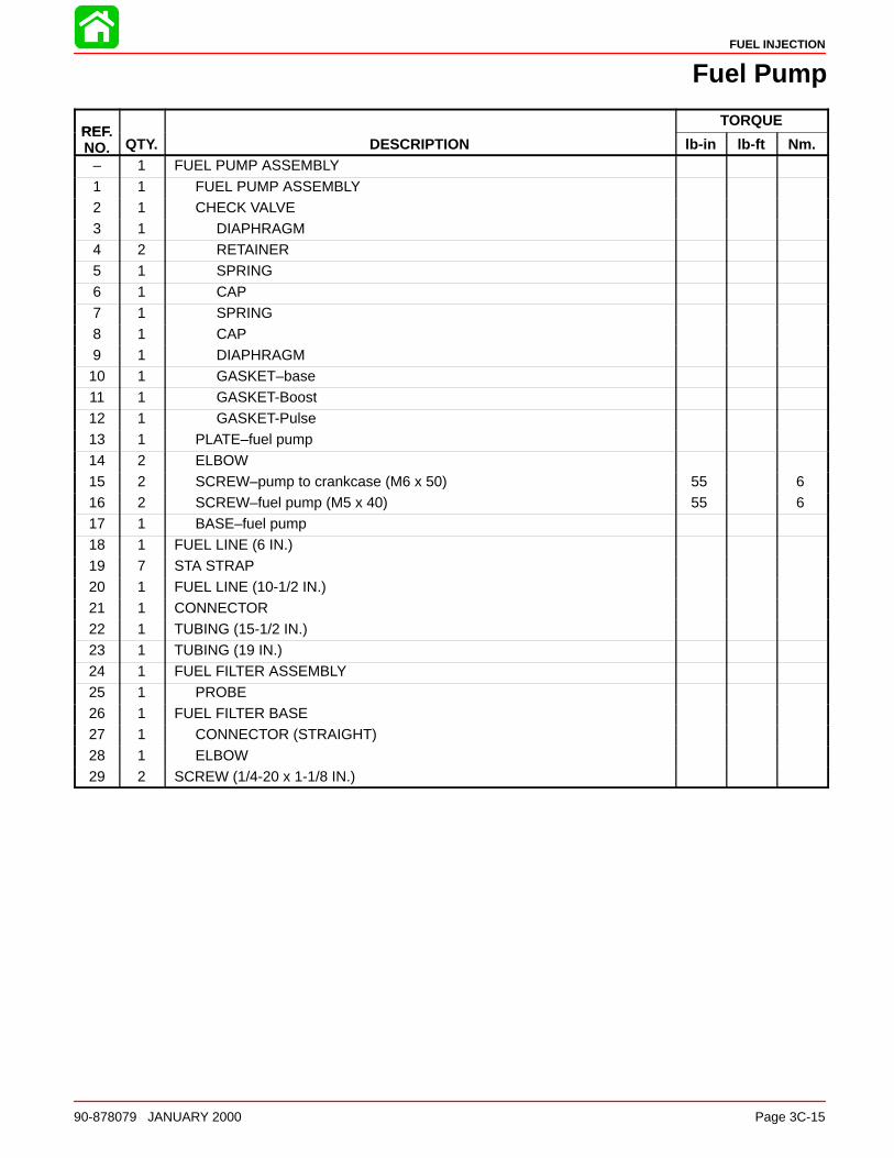
FUEL INJECTION
90-878079 JANUARY 2000 Page 3C-15
Fuel Pump
REFTORQUE
REF.NO. QTY. DESCRIPTION lb-in lb-ft Nm.
– 1 FUEL PUMP ASSEMBLY
1 1 FUEL PUMP ASSEMBLY2 1 CHECK VALVE3 1 DIAPHRAGM4 2 RETAINER5 1 SPRING6 1 CAP
7 1 SPRING8 1 CAP9 1 DIAPHRAGM10 1 GASKET–base11 1 GASKET-Boost12 1 GASKET-Pulse13 1 PLATE–fuel pump
14 2 ELBOW15 2 SCREW–pump to crankcase (M6 x 50) 55 616 2 SCREW–fuel pump (M5 x 40) 55 617 1 BASE–fuel pump18 1 FUEL LINE (6 IN.)19 7 STA STRAP20 1 FUEL LINE (10-1/2 IN.)
21 1 CONNECTOR22 1 TUBING (15-1/2 IN.)23 1 TUBING (19 IN.)24 1 FUEL FILTER ASSEMBLY25 1 PROBE26 1 FUEL FILTER BASE27 1 CONNECTOR (STRAIGHT)
28 1 ELBOW29 2 SCREW (1/4-20 x 1-1/8 IN.)

FUEL INJECTION
Page 3C-16 90-878079 JANUARY 2000
Electronic Fuel Injection (EFl) System
IntroductionThe troubleshooting information provided here consists of preliminary checks (checks tobe followed before proceeding with EFI tests), diagrams (fuel flow and electrical wiring),component description (from diagrams), flow charts (low pressure fuel delivery, high pres-sure fuel delivery, fuel delivery vs. electrical delivery), problem diagnosis, and a series oftest and check procedures that will help isolate problems associated with the fuel injectionsystem. Each test/check (listed) can be completed without major fuel system disassembly.
Using the Test ProceduresRead the entire test before beginning to perform outlined procedures. Study the RESULTSmaterial prior to testing. This will help in determining that each test is providing desiredresults.
EFI System Tests• EFI Electrical System and ECM Check
• Fuel Gauge Connection/Pressure Test
• Vapor Separator Fuel Delivery Test
• Vapor Separator Float Test
• Water Separating Filter Flow Test
• Pulse Fuel Pump Delivery Test
• Final Filter Check
• Fuel Pressure Regulator Test
• Electric Fuel Pump Test
• Injector Electrical Test
• Injector Fuel Delivery Test
• Injector Operating Test (Manifold Cover Removed)
• Induction Manifold Leak Check (Manifold Cover Removed)
• Sensor Tests
Safety Precautions
CAUTIONAlways use approved safety glasses or goggles when working on pressurized fuelsystems.
DANGERMotor fuels are extremely flammable. Do not show open sparks or flames whenworking near fuel systems.
WARNINGTo avoid potential fire hazards, use extreme caution when connecting and discon-necting fuel line connections and test adaptors. Do not allow fuel to spill on hotengine parts or on live electrical connections.
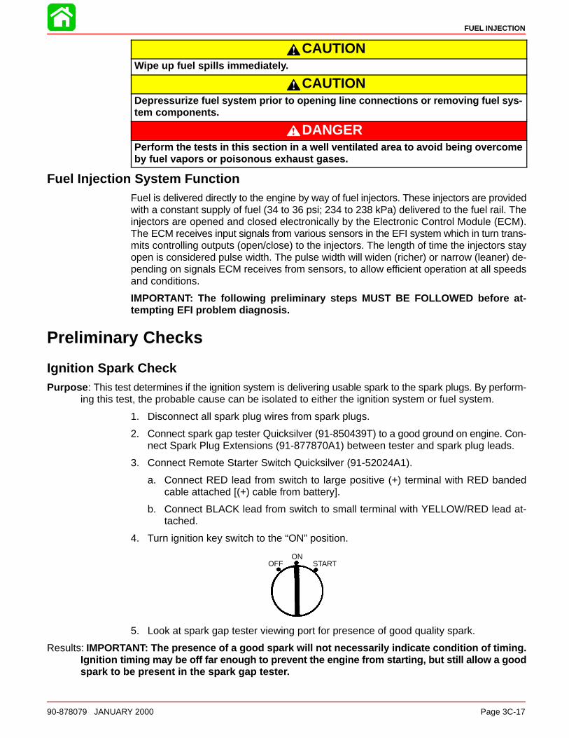
FUEL INJECTION
90-878079 JANUARY 2000 Page 3C-17
CAUTIONWipe up fuel spills immediately.
CAUTIONDepressurize fuel system prior to opening line connections or removing fuel sys-tem components.
DANGERPerform the tests in this section in a well ventilated area to avoid being overcomeby fuel vapors or poisonous exhaust gases.
Fuel Injection System FunctionFuel is delivered directly to the engine by way of fuel injectors. These injectors are providedwith a constant supply of fuel (34 to 36 psi; 234 to 238 kPa) delivered to the fuel rail. Theinjectors are opened and closed electronically by the Electronic Control Module (ECM).The ECM receives input signals from various sensors in the EFI system which in turn trans-mits controlling outputs (open/close) to the injectors. The length of time the injectors stayopen is considered pulse width. The pulse width will widen (richer) or narrow (leaner) de-pending on signals ECM receives from sensors, to allow efficient operation at all speedsand conditions.
IMPORTANT: The following preliminary steps MUST BE FOLLOWED before at-tempting EFI problem diagnosis.
Preliminary Checks
Ignition Spark CheckPurpose : This test determines if the ignition system is delivering usable spark to the spark plugs. By perform-
ing this test, the probable cause can be isolated to either the ignition system or fuel system.
1. Disconnect all spark plug wires from spark plugs.
2. Connect spark gap tester Quicksilver (91-850439T) to a good ground on engine. Con-nect Spark Plug Extensions (91-877870A1) between tester and spark plug leads.
3. Connect Remote Starter Switch Quicksilver (91-52024A1).
a. Connect RED lead from switch to large positive (+) terminal with RED bandedcable attached [(+) cable from battery].
b. Connect BLACK lead from switch to small terminal with YELLOW/RED lead at-tached.
4. Turn ignition key switch to the “ON” position.
OFFON
START
5. Look at spark gap tester viewing port for presence of good quality spark.
Results: IMPORTANT: The presence of a good spark will not necessarily indicate condition of timing.Ignition timing may be off far enough to prevent the engine from starting, but still allow a goodspark to be present in the spark gap tester.

FUEL INJECTION
Page 3C-18 90-878079 JANUARY 2000
A steady, blue spark should be present at each spark plug wire. If a good spark is present,problem may not be ignition related. If good spark is not present, problem may be ignitionrelated. Trouble shoot ignition system or make sure engine timing is set correctly. Referto appropriate ignition section in this service manual.
Ignition system failure (trigger, control module, wiring, etc.) can cause fuel delivery prob-lems. Injectors are triggered in pairs by one, three, five trigger inputs.
No. 1 Triggers input No. 3 & 4 InjectorsNo. 3 Triggers input No. 5 & 6 InjectorsNo. 5 Triggers input No. 1 & 2 Injectors
Failure in one or more of these primary circuits will cause no spark and no fuel to respectivecylinders (above). Check spark and spark plugs on all cylinders before attempting EFItests.
Electronic Fuel Injection Set UpIMPORTANT: Follow EFI Timing/Synchronizing/Adjustment section 2C before at-tempting tests on EFI system.
EFI set up procedures must be followed before tests on system are performed (refer toSection 2C). Improper set up can result in poor engine performance (i.e. uncontrollableidle speeds, lean sneezing, low power during acceleration or engine will simply not run.)Failure to properly set up the EFI system can lead to misdirections in solving simple prob-lems in the EFI system.
Fresh Quality Fuel
Using a remote fuel tank containing a major brand of premium unleaded gasoline, test runthe outboard to eliminate any problems related to restricted fuel supply (clogged lines, mal-functioning anti-siphon valve, etc.) and/or marginal gasoline.
Low Battery VoltageLow battery voltage can cause EFI system to deliver fuel in an inconsistent manner.
Inspect battery connections and charging system, refer to Section 2B. The EFI system re-quires a substantial amount of voltage to function properly. Operating engine at a low RPMfor an extended period of time can cause low voltage.
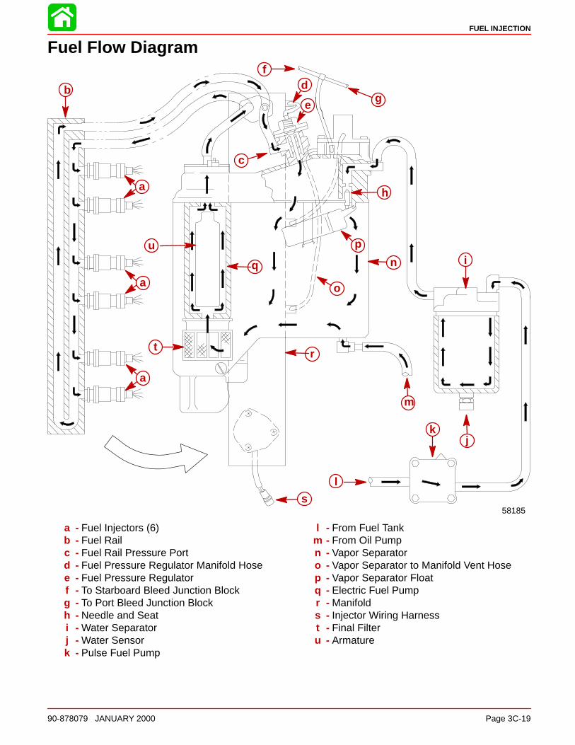
FUEL INJECTION
90-878079 JANUARY 2000 Page 3C-19
Fuel Flow Diagram
58185
b
a
a
a
u
c
f
ge
h
q
o
pi
d
j
n
m
tr
s
k
l
a - Fuel Injectors (6)b - Fuel Railc - Fuel Rail Pressure Portd - Fuel Pressure Regulator Manifold Hosee - Fuel Pressure Regulatorf - To Starboard Bleed Junction Blockg - To Port Bleed Junction Blockh - Needle and Seati - Water Separatorj - Water Sensork - Pulse Fuel Pump
l - From Fuel Tankm - From Oil Pumpn - Vapor Separatoro - Vapor Separator to Manifold Vent Hosep - Vapor Separator Floatq - Electric Fuel Pumpr - Manifolds - Injector Wiring Harnesst - Final Filteru - Armature
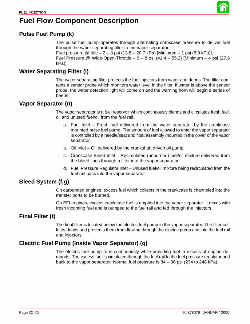
FUEL INJECTION
Page 3C-20 90-878079 JANUARY 2000
Fuel Flow Component Description
Pulse Fuel Pump (k)The pulse fuel pump operates through alternating crankcase pressure to deliver fuelthrough the water separating filter to the vapor separator.Fuel pressure @ Idle – 2 – 3 psi (13.8 – 20.7 kPa) [Minimum – 1 psi (6.9 kPa)].Fuel Pressure @ Wide-Open-Throttle – 6 – 8 psi (41.4 – 55.2) [Minimum – 4 psi (27.6kPa)].
Water Separating Filter (i)The water separating filter protects the fuel injectors from water and debris. The filter con-tains a sensor probe which monitors water level in the filter. If water is above the sensorprobe, the water detection light will come on and the warning horn will begin a series ofbeeps.
Vapor Separator (n)The vapor separator is a fuel reservoir which continuously blends and circulates fresh fuel,oil and unused fuel/oil from the fuel rail.
a. Fuel Inlet – Fresh fuel delivered from the water separator by the crankcasemounted pulse fuel pump. The amount of fuel allowed to enter the vapor separatoris controlled by a needle/seat and float assembly mounted in the cover of the vaporseparator.
b. Oil Inlet – Oil delivered by the crankshaft driven oil pump.
c. Crankcase Bleed Inlet – Recirculated (unburned) fuel/oil mixture delivered fromthe bleed lines through a filter into the vapor separator.
d. Fuel Pressure Regulator Inlet – Unused fuel/oil mixture being recirculated from thefuel rail back into the vapor separator.
Bleed System (f,g)On carbureted engines, excess fuel which collects in the crankcase is channeled into thetransfer ports to be burned.
On EFI engines, excess crankcase fuel is emptied into the vapor separator. It mixes withfresh incoming fuel and is pumped to the fuel rail and fed through the injectors.
Final Filter (t)The final filter is located below the electric fuel pump in the vapor separator. The filter col-lects debris and prevents them from flowing through the electric pump and into the fuel railand injectors.
Electric Fuel Pump (Inside Vapor Separator) (q)The electric fuel pump runs continuously while providing fuel in excess of engine de-mands. The excess fuel is circulated through the fuel rail to the fuel pressure regulator andback to the vapor separator. Normal fuel pressure is 34 – 36 psi (234 to 248 kPa).
FUEL INJECTION
90-878079 JANUARY 2000 Page 3C-21
Fuel Injectors (a)The fuel injectors are located inside the induction manifold on the fuel rail. The injectorvalve body consists of a solenoid actuated needle and seat assembly. The injector re-ceives signals from the EFI Electronic Control Module. These signals determine how longthe needle is lifted from the seat (pulse width) allowing a measured fuel flow. The pulsewidth will widen (richer) or narrow (leaner) depending on various signals received fromsensors connected to the EFI ECM. The ECM receives signals from the primary ignitioncircuit of cylinders #1, #3 and #5 to fire each pair of injectors accordingly.
A four wire harness connects the fuel injectors to the ECM. The RED wire is at 12 voltsand connects to all injectors. The BLUE, YELLOW and WHITE wires each go to a pair ofinjectors and are normally at 12 volts for a zero differential. To fire the injectors this voltageis brought down to near ground creating a potential across the injectors.
Induction Manifold (r)The induction manifold is a common plenum chamber for accurate pressure measure-ment. It contains 4 throttle shutters on 2 throttle shafts. The shutter opening (idle air open-ing) can be adjusted during EFI set-up procedure. The manifold contains the fuel rail, injec-tors, throttle position sensor and air temperature sensor. A fuel rail pressure port is locatedon the fuel pressure regulator.
Fuel Pressure Regulator (e)The fuel pressure regulator is located on top of the vapor separator and is continuouslyregulating fuel pressure produced by the electric fuel pump. The electric pump is capableof producing 90 psi (621 kPa) of fuel pressure. The pressure regulator limits fuel pressureat the injectors to 34 to 36 psi (234 to 248 kPa).
EFI Electrical ComponentsELECTRONIC CONTROL MODULE (ECM)
The ECM is continually monitoring various engine conditions (engine temperature, enginedetonation control, engine throttle opening) and climate conditions (induction air tempera-ture, barometric pressure and altitude level) needed to calculate fuel delivery (pulse widthlength) of injectors. The pulse width is constantly adjusted (rich/lean conditions) to com-pensate for operating conditions, such as cranking, cold starting, climate conditions, alti-tude, acceleration and deceleration, allowing the outboard to operate efficiently at all en-gine speeds.
12 Volt Battery - The 12 volt battery provides power to the ECM even with the ignitionswitch in the “OFF” position.
IMPORTANT: When disassembling EFI System DISCONNECT BATTERY CABLES.
Starter Sol enoid - Provides 12 volt signal when key is in the “start” position. In the “start”position, injector pulse widths are tripled when engine head temperature is below 90° F(32.2° C) to provide adequate fuel for quick start up. When key is returned to the run posi-tion or engine head temperature is above 90° F (32.2° C), pulse widths return to normalvalue.
Fuel Injectors - A four wire harness connects the fuel injectors to the ECM. The red wireis at 12 volts and connects to all injectors. The blue, yellow and white wires each go to apair of injectors and are normally at 12 volts for a zero differential. To fire the injectors thisvoltage is brought down to near ground creating a potential across the injectors.
FUEL INJECTION
Page 3C-22 90-878079 JANUARY 2000
Electric Fuel Pump - The ECM contains a fuel pump driver circuit that provides power tothe electric fuel pump. The fuel pump does not have its negative terminal (–) “BLACK/REDwire” grounded to the pump housing. The fuel pump positive terminal (+) “RED wire” andthe negative terminal (–) are at 12 volts with the ignition switch in the off position for a zerodifferential. When the pump is on, the negative terminal is brought down to near ground(i.e. 1.5 volts).
SENSOR INTERACTION WITH THE ECM
IMPORTANT: DO NOT run engine for extended periods of time with sensors discon-nected or bypassed (shorted). Serious engine damage may result.
AIR TEMPERATURE SENSOR
The air temperature sensor transmits manifold absolute air temperature, through full RPMrange, to the ECM. As air temperature increases “sensor” resistance decreases causingthe ECM to decrease fuel flow (leaner mixture). Disconnecting the air temp sensor (opencircuit) will increase fuel flow (richen mixture) by 10%. Bypassing air temp sensor (shortin circuit) will cause fuel flow to decrease 10%.The air temperature sensor circuit can betested using the EFI tester. The air temperature sensor can be tested following air temper-ature sensor test on page 3C-45.
MANIFOLD ABSOLUTE PRESSURE (MAP) SENSOR
The map sensor is a non-serviceable sensor mounted in the ECM box. The MAP sensoris used to sense changes in manifold absolute pressure and is connected to the intakemanifold by the way of a vacuum hose. The MAP sensor is functioning through the full RPMrange and is continually signaling induction manifold pressure readings to the ECM. TheECM in turn determines fuel flow as signals are received. Drawing a vacuum on the MAPsensor hose will create a lean fuel condition altering engine operation. If no change occurswhen drawing vacuum, MAP sensor is not functioning properly.
MAP sensor can be tested with the DDT tester, page 3C-50.
ENGINE HEAD TEMPERATURE SENSOR (PORT CYLINDER HEAD)
The Engine Head Temperature Sensor provides the ECM signals related to engine tem-perature to determine level of fuel enrichment during engine warm up. The ECM is receiv-ing information at all engine temperatures but stops fuel enrichment at an engine tempera-ture of 90° F (32° C). An open circuit on the temperature sensor will increase fuel flow upto 40% but will not be affected at wide open throttle. If no change occurs when sensor isdisconnected, sensor may not be functioning properly. The engine head temperature sen-sor can be tested following Engine Head Temperature Sensor Test on page 3C-46.
NOTE: If sensor does not make clean contact with cylinder head a rich condition may exist.
THROTTLE POSITION SENSOR (TPS)
The TPS transmits information to the ECM during low speed and mid range operation, re-lated to throttle angle under various load conditions. TPS adjustment is a critical step inengine set up (Section 2C). Disconnecting the TPS will increase fuel flow 40% at idle butdoes not effect WOT. The TPS can be tested following the Throttle Position Sensor Teston page 3C-49.
NOTE: The higher the voltage, the richer the fuel flow. Refer to TPS Adjustment (Section2C).

FUEL INJECTION
90-878079 JANUARY 2000 Page 3C-23
WATER SENSING SYSTEM
The system consists of a water separating fuel filter (starboard side powerhead), sensingprobe (bottom of filter) and a water sensing module (below ECM box). The water sensingmodule has four wires:
PURPLE - Connects to 12 volt power supply.
LIGHT BLUE - Connects to lube alert, which sounds the warning horn when activated.
TAN - Connects to sensing probe.
BLACK - Connects to ground.
WATER SENSING SYSTEM FUNCTION
1. The filter separates the accumulated water from the fuel.
2. A voltage is always present at sensing probe. When water reaches top of probe it com-pletes the circuit to ground.
3. The completed circuit activates the warning. The warning has a 5-10 second delay,then the module’s red light illuminates and warning horn intermittently sounds.
The system can be tested by disconnecting the TAN wire from sensor probe and holdingto a good engine ground connection for 10 seconds.
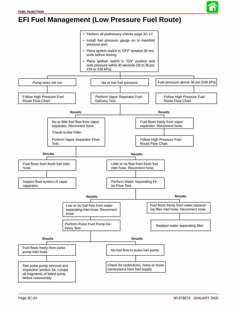
FUEL INJECTION
Page 3C-24 90-878079 JANUARY 2000
EFI Fuel Management (Low Pressure Fuel Route)
• Perform all preliminary checks page 3C-17.
• Install fuel pressure gauge on to manifoldpressure port.
• Place ignition switch in “OFF” position 30 sec-onds before testing.
• Place ignition switch in “ON” position andnote pressure within 30 seconds (34 to 36 psi;234 to 248 kPa).
No or low fuel pressurePump does not run Fuel pressure above 36 psi (248 kPa)
Perform Vapor Separator FuelDelivery Test .
Follow High Pressure FuelRoute Flow Chart.
Follow High Pressure FuelRoute Flow Chart.
No or little fuel flow from vaporseparator. Reconnect hose.
Fuel flows freely from vaporseparator. Reconnect hose.
Perform Vapor Separator FloatTest .
Follow High Pressure FuelRoute Flow Chart.
Fuel flows from fresh fuel inlet hose.
Little or no flow from fresh fuelinlet hose. Reconnect hose.
Inspect float system of vaporseparator.
Perform Water Separating Fil-ter Flow Test.
Low or no fuel flow from waterseparating inlet hose. Reconnecthose.
Fuel flows freely from water separat-ing filter inlet hose. Reconnect hose.
Perform Pulse Fuel Pump De-livery Test.
Replace water separating filter.
Fuel flows freely from pulsepump inlet hose. No fuel flow to pulse fuel pump.
See pulse pump removal andinspection section 3A. Locateall fragments of failed pumpbefore reassembly.
Check for restrictions, holes or looseconnections from fuel supply.
Results Results
ResultsResults
Results Results
ResultsResults
Check in-line Filter

FUEL INJECTION
90-878079 JANUARY 2000 Page 3C-25
EFI Fuel Management (High Pressure Fuel Route)
• Perform low pressure checks before performingchecks on high pressure route.
• Install fuel pressure gauge (P/N 91-16850A2) on tomanifold pressure port.
• Place ignition switch in “OFF” position 30 secondsbefore testing.
• Place ignition switch in “ON” position and note pres-sure within 30 seconds (34 to 36 psi; 234 to 248 kPa).
No or low fuel pressure Pump does not runFuel pressure above 36 psi (248 kPa)
Perform Final Filter CheckClogged or faulty fuel pressureregulator remove and replace.
Perform Electric Fuel Pump Volt-age Test .
Final filter OK. Final filter clogged.
Perform Fuel Pressure Regula-tor Test .
Clean or replace final filter.
Steady stream of fuel (pres-sure still below 34 psi).
Low or no fuel flow.
Replace fuel regulator.Perform Electric Fuel PumpVoltage Test .
Voltage from ECM driver circuit OK. Low or inconsistent voltagefrom ECM driver circuit.
Replace fuel pump. Replace ECM.
Results Results
ResultsResults
Results Results

FUEL INJECTION
Page 3C-26 90-878079 JANUARY 2000
Fuel Rail Electrical/Fuel Determination
• Perform all preliminary checks page 3C-17.
• Adequate fuel pressure (34 to 36 psi; 234 to248 kPa) follow Low/High Fuel Route FlowCharts.
• Place sport jet in water and run engine be-tween 2000 and 2500 RPM.
No RPM change on cylinder(s),indicating problem in cylinder(s).
RPM decreases (on each cylinder).
Perform Injector Electrical Har-ness Test .
Fuel delivery OK.
Broken circuit to injector. Injector circuit tests OK.
Perform Induction ManifoldDisassembly and inspection .
Perform Injector Fuel DeliveryTest.
RPM increase occurs. No RPM change.
Perform induction manifold dis-assembly. Inspect injector andfilter.
Perform compression check onproblem cylinder.
Low or no compression on cylinder. Compression OK.
Inspect cylinder bore. Refer toSection 4 for disassembly.
NOTE: Injector filters must beinspected prior to reassembly.
Check:1) Damaged reeds2) End cap seals3) Crankcase split line leak4) Crankshaft sealing rings
Results Results
ResultsResults
Results Results
ResultsResults
With engine running (2000-2500 RPM) re-move spark plug leads one at a time usinginsulated pliers.
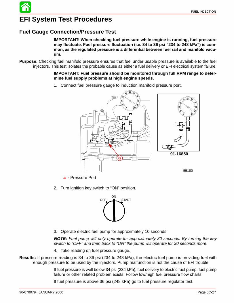
FUEL INJECTION
90-878079 JANUARY 2000 Page 3C-27
EFI System Test Procedures
Fuel Gauge Connection/Pressure TestIMPORTANT: When checking fuel pressure while engine is running, fuel pressuremay fluctuate. Fuel pressure fluctuation (i.e. 34 to 36 psi “234 to 248 kPa”) is com-mon, as the regulated pressure is a differential between fuel rail and manifold vacu-um.
Purpose: Checking fuel manifold pressure ensures that fuel under usable pressure is available to the fuelinjectors. This test isolates the probable cause as either a fuel delivery or EFI electrical system failure.
IMPORTANT: Fuel pressure should be monitored through full RPM range to deter-mine fuel supply problems at high engine speeds.
1. Connect fuel pressure gauge to induction manifold pressure port.
91-16850
55180
a
a - Pressure Port
2. Turn ignition key switch to “ON” position.
OFFON
START
3. Operate electric fuel pump for approximately 10 seconds.
NOTE: Fuel pump will only operate for approximately 30 seconds. By turning the keyswitch to “OFF” and then back to “ON” the pump will operate for 30 seconds more.
4. Take reading on fuel pressure gauge.
Results: If pressure reading is 34 to 36 psi (234 to 248 kPa), the electric fuel pump is providing fuel withenough pressure to be used by the injectors. Pump malfunction is not the cause of EFI trouble.
If fuel pressure is well below 34 psi (234 kPa), fuel delivery to electric fuel pump, fuel pumpfailure or other related problem exists. Follow low/high fuel pressure flow charts.
If fuel pressure is above 36 psi (248 kPa) go to fuel pressure regulator test.
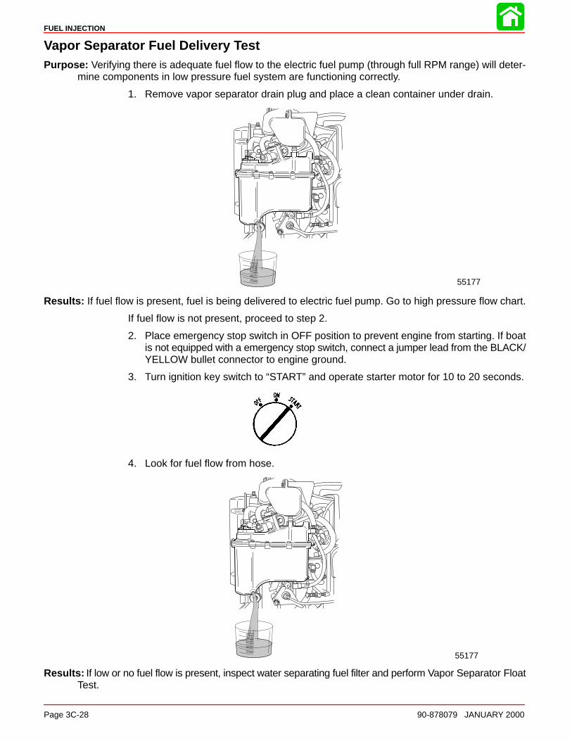
FUEL INJECTION
Page 3C-28 90-878079 JANUARY 2000
Vapor Separator Fuel Delivery TestPurpose: Verifying there is adequate fuel flow to the electric fuel pump (through full RPM range) will deter-
mine components in low pressure fuel system are functioning correctly.
1. Remove vapor separator drain plug and place a clean container under drain.
55177
Results: If fuel flow is present, fuel is being delivered to electric fuel pump. Go to high pressure flow chart.
If fuel flow is not present, proceed to step 2.
2. Place emergency stop switch in OFF position to prevent engine from starting. If boatis not equipped with a emergency stop switch, connect a jumper lead from the BLACK/YELLOW bullet connector to engine ground.
3. Turn ignition key switch to “START” and operate starter motor for 10 to 20 seconds.
4. Look for fuel flow from hose.
55177
Results: If low or no fuel flow is present, inspect water separating fuel filter and perform Vapor Separator FloatTest.

FUEL INJECTION
90-878079 JANUARY 2000 Page 3C-29
Vapor Separator Float TestPurpose: This test will indicate if float is stuck in the up position.
NOTE: If float is stuck down, vapor separator will over flow causing a rich condition.
1. Remove fuel inlet hose from vapor separator and put end of hose in clean container.
2. Remove all spark plugs from engine to prevent engine from starting.
3. Turn ignition key switch to “START” position and operate starter motor for 15 to 20 sec-onds.
OFFON
START
4. Look for fuel flow from hose.
55178
Results: If fuel flow is present at hose, remove, disassemble and inspect float assembly. See vapor separatordisassembly.
If fuel flow is low or not present, perform Water Separating Filter Flow Test.
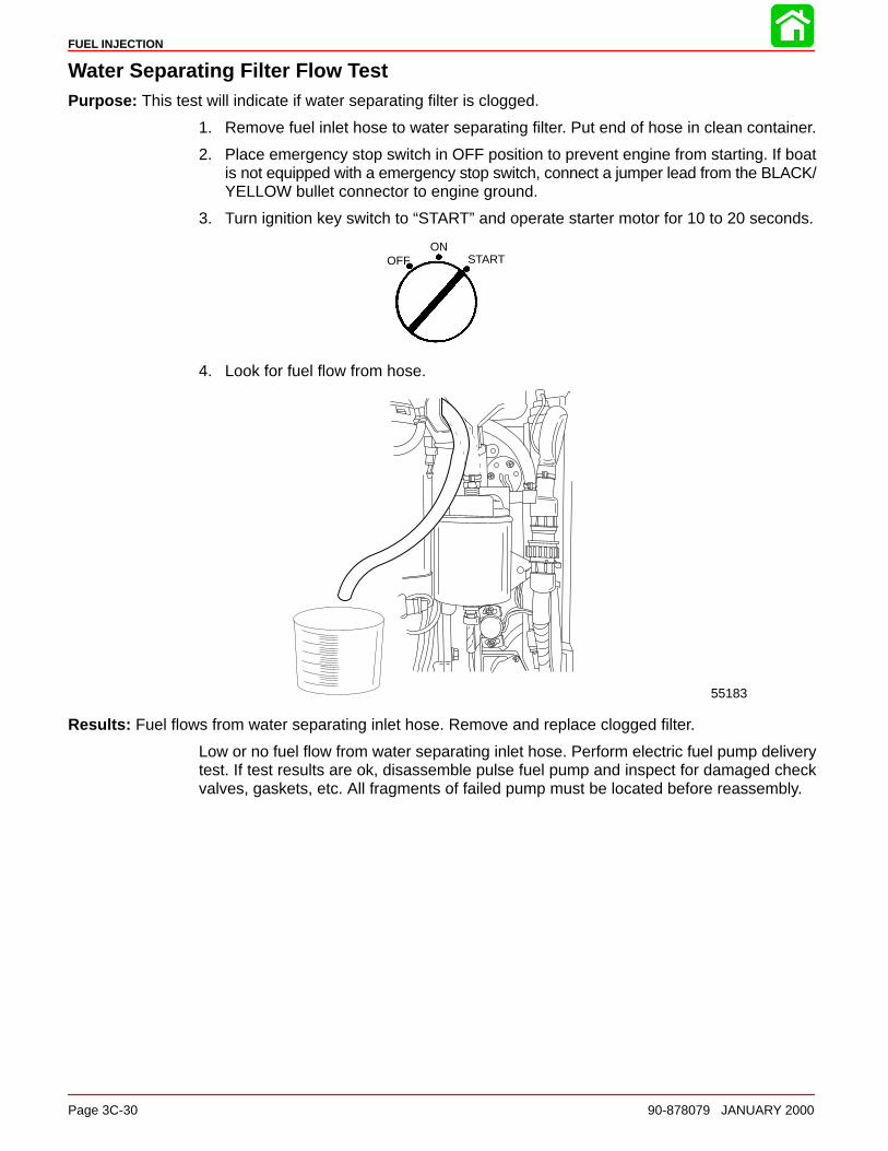
FUEL INJECTION
Page 3C-30 90-878079 JANUARY 2000
Water Separating Filter Flow TestPurpose: This test will indicate if water separating filter is clogged.
1. Remove fuel inlet hose to water separating filter. Put end of hose in clean container.
2. Place emergency stop switch in OFF position to prevent engine from starting. If boatis not equipped with a emergency stop switch, connect a jumper lead from the BLACK/YELLOW bullet connector to engine ground.
3. Turn ignition key switch to “START” and operate starter motor for 10 to 20 seconds.
OFFON
START
4. Look for fuel flow from hose.
55183
Results: Fuel flows from water separating inlet hose. Remove and replace clogged filter.
Low or no fuel flow from water separating inlet hose. Perform electric fuel pump deliverytest. If test results are ok, disassemble pulse fuel pump and inspect for damaged checkvalves, gaskets, etc. All fragments of failed pump must be located before reassembly.
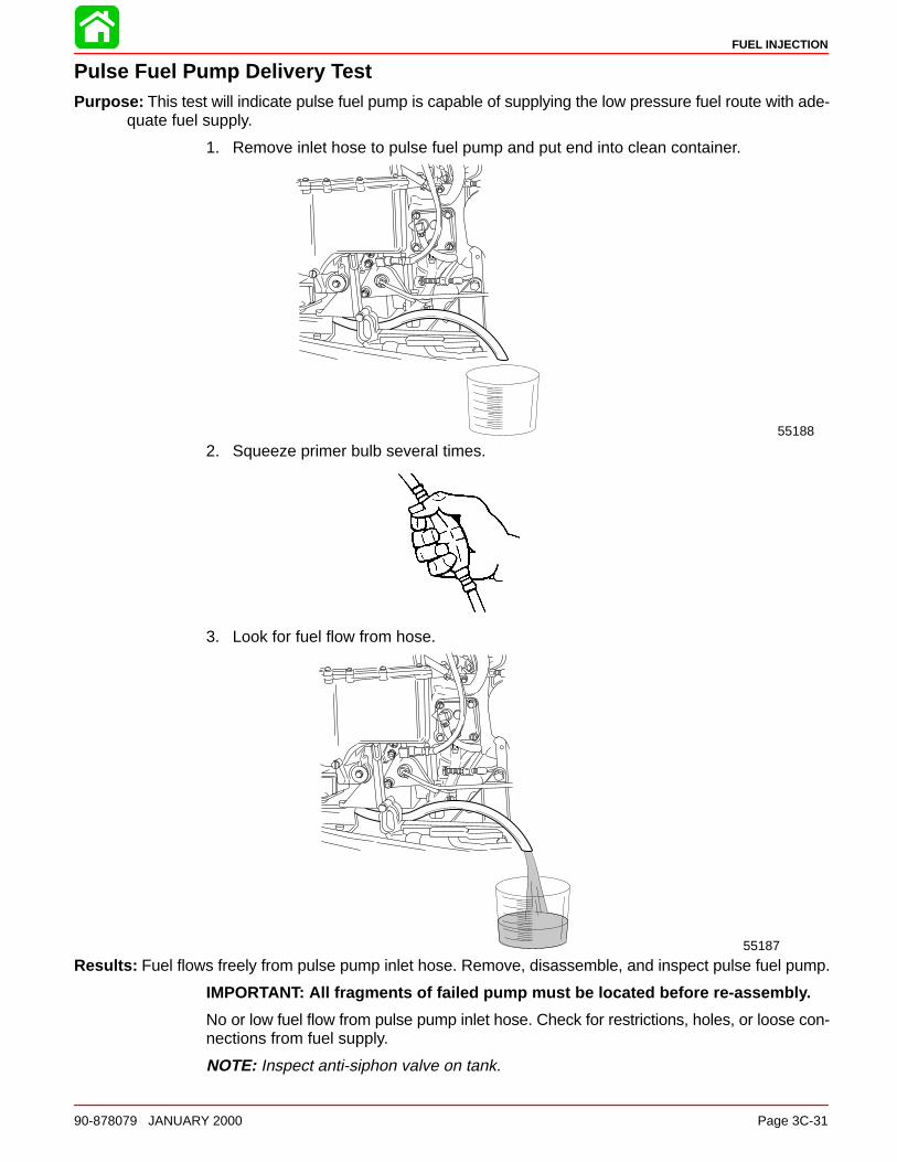
FUEL INJECTION
90-878079 JANUARY 2000 Page 3C-31
Pulse Fuel Pump Delivery TestPurpose: This test will indicate pulse fuel pump is capable of supplying the low pressure fuel route with ade-
quate fuel supply.
1. Remove inlet hose to pulse fuel pump and put end into clean container.
55188
2. Squeeze primer bulb several times.
3. Look for fuel flow from hose.
55187
Results: Fuel flows freely from pulse pump inlet hose. Remove, disassemble, and inspect pulse fuel pump.
IMPORTANT: All fragments of failed pump must be located before re-assembly.
No or low fuel flow from pulse pump inlet hose. Check for restrictions, holes, or loose con-nections from fuel supply.
NOTE: Inspect anti-siphon valve on tank.
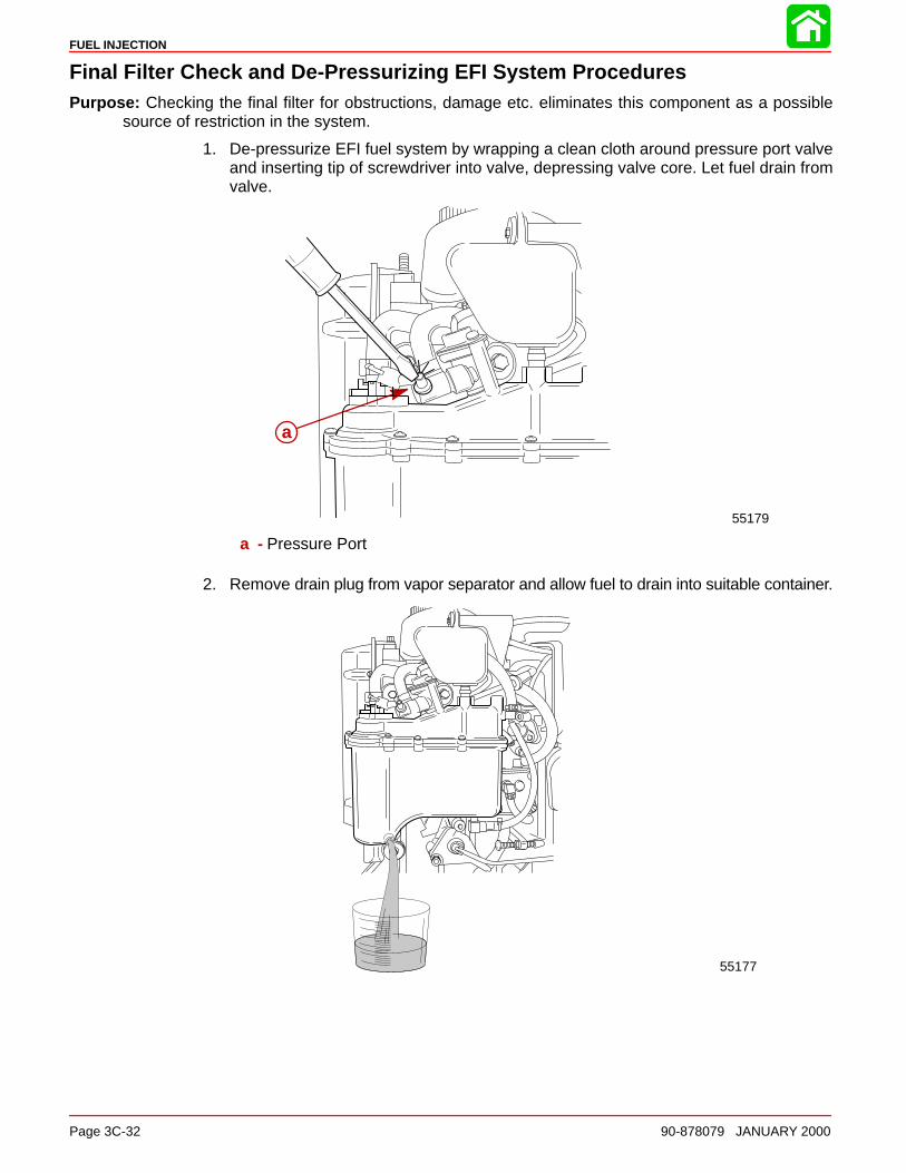
FUEL INJECTION
Page 3C-32 90-878079 JANUARY 2000
Final Filter Check and De-Pressurizing EFI System ProceduresPurpose: Checking the final filter for obstructions, damage etc. eliminates this component as a possible
source of restriction in the system.
1. De-pressurize EFI fuel system by wrapping a clean cloth around pressure port valveand inserting tip of screwdriver into valve, depressing valve core. Let fuel drain fromvalve.
55179
a
a - Pressure Port
2. Remove drain plug from vapor separator and allow fuel to drain into suitable container.
55177
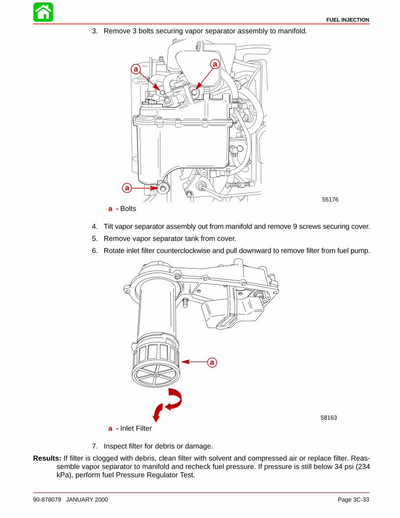
FUEL INJECTION
90-878079 JANUARY 2000 Page 3C-33
3. Remove 3 bolts securing vapor separator assembly to manifold.
55176
a
aa
a - Bolts
4. Tilt vapor separator assembly out from manifold and remove 9 screws securing cover.
5. Remove vapor separator tank from cover.
6. Rotate inlet filter counterclockwise and pull downward to remove filter from fuel pump.
58163
a
a - Inlet Filter
7. Inspect filter for debris or damage.
Results: If filter is clogged with debris, clean filter with solvent and compressed air or replace filter. Reas-semble vapor separator to manifold and recheck fuel pressure. If pressure is still below 34 psi (234kPa), perform fuel Pressure Regulator Test.
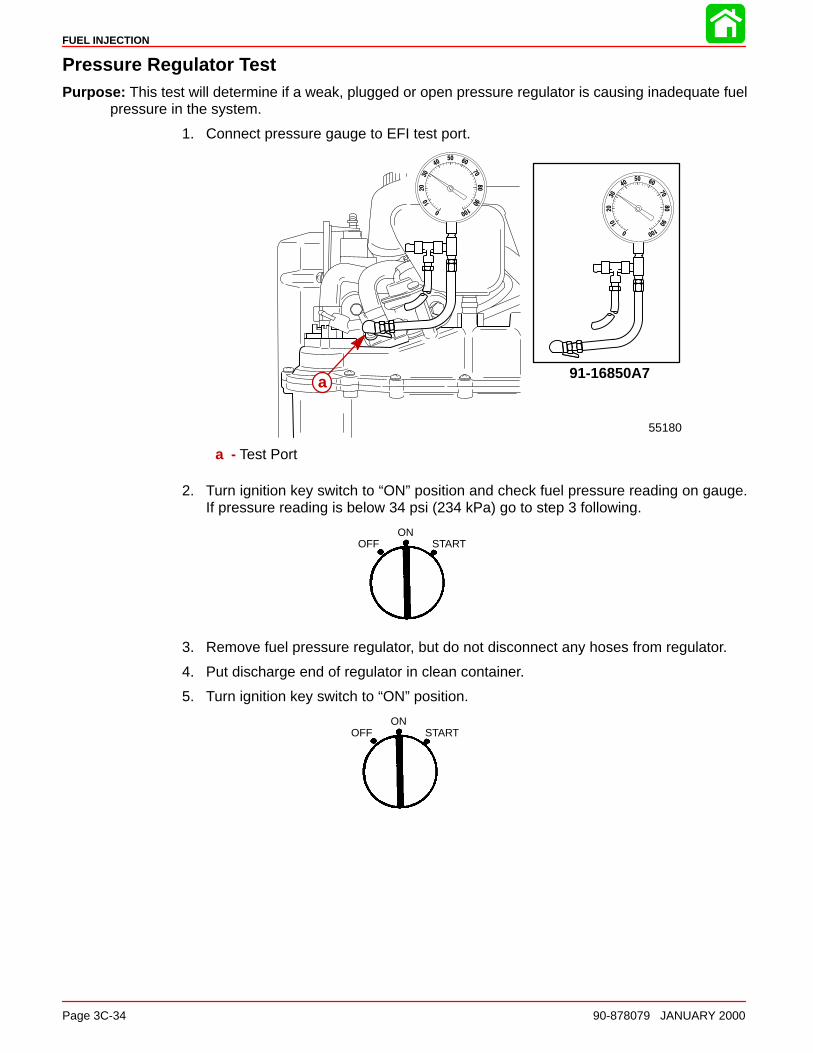
FUEL INJECTION
Page 3C-34 90-878079 JANUARY 2000
Pressure Regulator TestPurpose: This test will determine if a weak, plugged or open pressure regulator is causing inadequate fuel
pressure in the system.
1. Connect pressure gauge to EFI test port.
91-16850A7
55180
a
a - Test Port
2. Turn ignition key switch to “ON” position and check fuel pressure reading on gauge.If pressure reading is below 34 psi (234 kPa) go to step 3 following.
OFFON
START
3. Remove fuel pressure regulator, but do not disconnect any hoses from regulator.
4. Put discharge end of regulator in clean container.
5. Turn ignition key switch to “ON” position.
OFFON
START
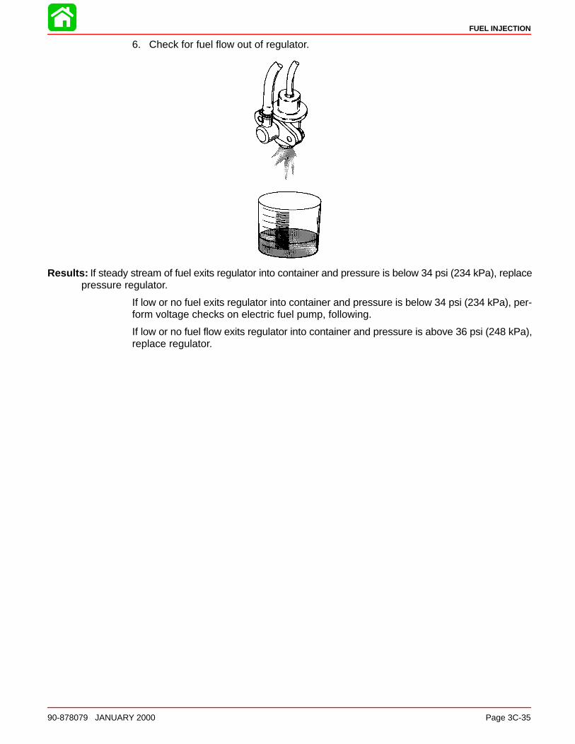
FUEL INJECTION
90-878079 JANUARY 2000 Page 3C-35
6. Check for fuel flow out of regulator.
Results: If steady stream of fuel exits regulator into container and pressure is below 34 psi (234 kPa), replacepressure regulator.
If low or no fuel exits regulator into container and pressure is below 34 psi (234 kPa), per-form voltage checks on electric fuel pump, following.
If low or no fuel flow exits regulator into container and pressure is above 36 psi (248 kPa),replace regulator.
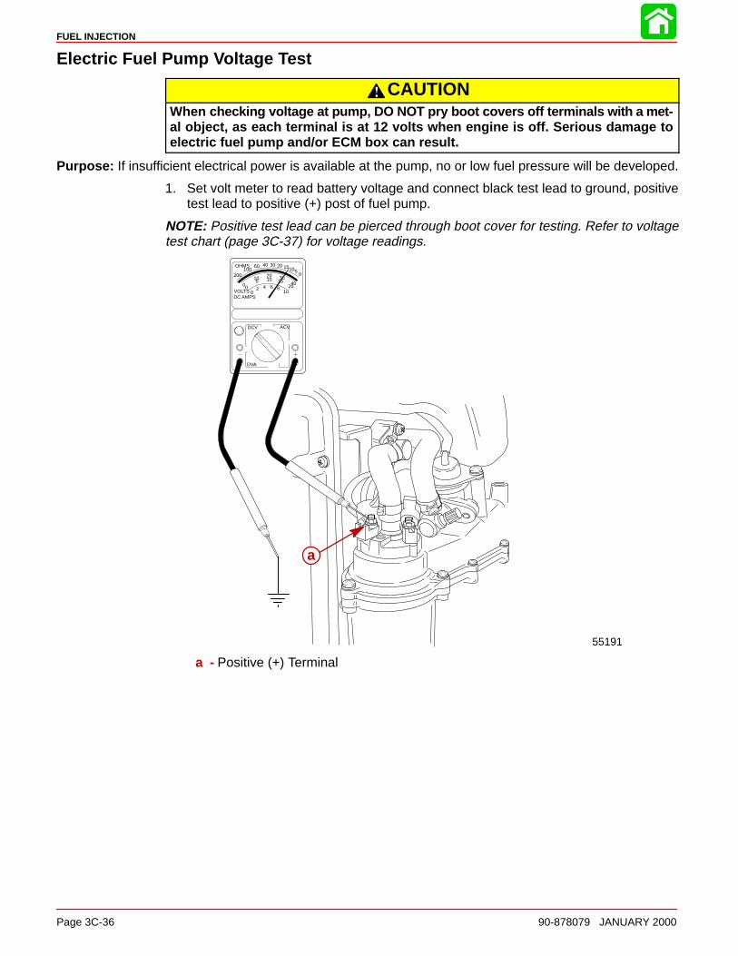
FUEL INJECTION
Page 3C-36 90-878079 JANUARY 2000
Electric Fuel Pump Voltage Test
CAUTIONWhen checking voltage at pump, DO NOT pry boot covers off terminals with a met-al object, as each terminal is at 12 volts when engine is off. Serious damage toelectric fuel pump and/or ECM box can result.
Purpose: If insufficient electrical power is available at the pump, no or low fuel pressure will be developed.
1. Set volt meter to read battery voltage and connect black test lead to ground, positivetest lead to positive (+) post of fuel pump.
NOTE: Positive test lead can be pierced through boot cover for testing. Refer to voltagetest chart (page 3C-37) for voltage readings.
VOLTSDC AMPS
OHMS
02 4 6 8
10
DCV ACV
DVA
005
10 2010 30
15 4020
05101520304060
100200
55191
a
a - Positive (+) Terminal

FUEL INJECTION
90-878079 JANUARY 2000 Page 3C-37
2. Set volt meter to read battery voltage and connect BLACK test lead to ground, POS-ITIVE test lead to NEGATIVE (–) post of fuel pump.
Negative Test Terminal
VOLTSDC AMPS
OHMS
02 4 6 8
10
DCV ACV
DVA
00510 20
10 3015 4020
05101520304060100
200
55192
a
a - Negative (–) Terminal
3. Perform voltage tests below.
VOLTAGE TEST CHART
Engine Mode BLACK Meter Lead toEngine Ground; RED
Meter Lead to:
Approximate VoltageReading
If Approximate Voltageis not obtained, this in-
dicates:
1. All models (+) terminal of fuel pump 12 – 13.5 volts If reading is below 12volts, the battery is bad,discharged or has badconnection(s). If readingis higher than 13.5 volts,the battery is over-charged
2. Ignition key in “OFF” position.
(–) terminal of fuelpump.
Same reading should beobtained as reading incheck No. 1 (above)
If reading is lower thanin test 1, the ECM is bador there is an open cir-cuit in fuel pump.
3. Ignition key in “ON” position and engine NOT running.
(–) terminal of fuelpump.
1.5 volt or less (voltageshould rise to 12 – 13.5volts after approximately30 seconds.
Bad ECM or bad fuelpump*.
4. Engine being cranked.
(–) terminal of fuelpump.
1.5 volt or less. Bad ECM or bad fuelpump.*
*Check for proper electrical operation of electric fuel pump. (Step 4)

FUEL INJECTION
Page 3C-38 90-878079 JANUARY 2000
4. Disconnect BLACK/RED wire to negative terminal on electric fuel pump. Connect aground jumper wire from negative pump terminal to a good engine ground.
a
a - Negative Terminal
Results: Pump does not operate. Replace electric fuel pump.
Pump operates. But, pressure reading does not change when performing electric fuelpump pressure test. Replace electric fuel pump.
Pump operates. Check BLACK/RED (–) lead and harness for good continuity.
NOTE: BLACK/RED lead is connected to pin 2 of EFI harness.
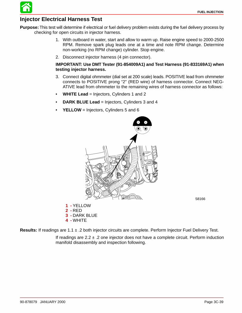
FUEL INJECTION
90-878079 JANUARY 2000 Page 3C-39
Injector Electrical Harness TestPurpose: This test will determine if electrical or fuel delivery problem exists during the fuel delivery process by
checking for open circuits in injector harness.
1. With outboard in water, start and allow to warm up. Raise engine speed to 2000-2500RPM. Remove spark plug leads one at a time and note RPM change. Determinenon-working (no RPM change) cylinder. Stop engine.
2. Disconnect injector harness (4 pin connector).
IMPORTANT: Use DMT Tester (91-854009A1) and Test Harness (91-833169A1) whentesting injector harness.
3. Connect digital ohmmeter (dial set at 200 scale) leads. POSITIVE lead from ohmmeterconnects to POSITIVE prong “2” (RED wire) of harness connector. Connect NEG-ATIVE lead from ohmmeter to the remaining wires of harness connector as follows:
• WHITE Lead = Injectors, Cylinders 1 and 2
• DARK BLUE Lead = Injectors, Cylinders 3 and 4
• YELLOW = Injectors, Cylinders 5 and 6
58166
1 - YELLOW2 - RED3 - DARK BLUE4 - WHITE
Results: If readings are 1.1 ± .2 both injector circuits are complete. Perform Injector Fuel Delivery Test.
If readings are 2.2 ± .2 one injector does not have a complete circuit. Perform inductionmanifold disassembly and inspection following.

FUEL INJECTION
Page 3C-40 90-878079 JANUARY 2000
ECM Injector Driver TestTo verify that the ECM is operating the injector pairs, connect test harness between man-ifold connector and engine harness. Start engine.
Use DVA meter (91-99750) or DMT (91-854009T1). Set meter to 200 scale. ConnectBLACK meter lead to engine ground and RED test lead to each BLUE, WHITE or YELLOWfemale bullet connector
Normal voltage for a 2.5L engine will be 25 to 60 volts. Voltage will vary with RPM.
Injector Fuel Delivery TestPurpose: This test will determine if injector is delivering fuel when signal is received.
NOTE: It is recommended that the Digital Diagnostic Terminal 91-823686A2 be utilizedfollowing the procedure listed with its’ instruction manual.
Injector Operation Test (Manifold Cover Removed)Purpose: This test determines if the injectors are actually injecting fuel into the engine at a normal rate.
WARNINGDo not start engine with induction manifold cover removed. Disable ignition sys-tem prior to doing this test.
1. Remove induction manifold cover using procedures outlined under “lnduction ManifoldRemoval.”

FUEL INJECTION
90-878079 JANUARY 2000 Page 3C-41
2. Re-attach induction manifold to engine using 1/4-20 x 2-3/4″ screws.
3. Connect a jumper wire between the ECU metal case and a good engine ground.
4. Disconnect all spark plug wires from spark plugs and seal leads with electrical tape toprevent sparking.
5. Put ignition key switch in “START” position.
OFFON
START
6. Look at injector spray pattern using an explosive proof flashlight.
Results A: If fuel spray is not present in all injectors or spray pattern is extremely weak, check wiring harnessto injector connectors, or injector filters for plugging.
If spray patterns are available in most of the injectors, but not all, perform Procedure B.
7. Connect EFI tester. Steps outlined in electrical system and ECM check.

FUEL INJECTION
Page 3C-42 90-878079 JANUARY 2000
8. Connect remote starter Quicksilver (91-52024A1) to NEGATIVE terminal of electricfuel pump and a good engine ground. Depress remote start switch, pump will operateas long as switch is depressed.
WARNINGDo not operate pump for more than 20 seconds continuously.
55197
a
a - Negative Terminal
9. Perform fuel injector test procedures (outlined) while depressing remote starter switch.
Results B: If fuel spray is present using EFI tester, but not present while cranking, perform switch box DVAtests Section 2A (1, 3, 5 switch box failure).
If fuel spray pattern is equal on all injectors, system is functioning normally.
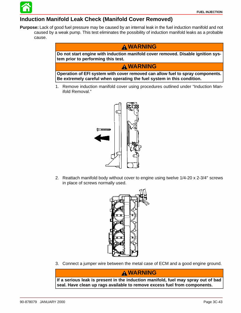
FUEL INJECTION
90-878079 JANUARY 2000 Page 3C-43
Induction Manifold Leak Check (Manifold Cover Removed)Purpose: Lack of good fuel pressure may be caused by an internal leak in the fuel induction manifold and not
caused by a weak pump. This test eliminates the possibility of induction manifold leaks as a probablecause.
WARNINGDo not start engine with induction manifold cover removed. Disable ignition sys-tem prior to performing this test.
WARNINGOperation of EFI system with cover removed can allow fuel to spray components.Be extremely careful when operating the fuel system in this condition.
1. Remove induction manifold cover using procedures outlined under “Induction Man-ifold Removal.”
2. Reattach manifold body without cover to engine using twelve 1/4-20 x 2-3/4″ screwsin place of screws normally used.
3. Connect a jumper wire between the metal case of ECM and a good engine ground.
WARNINGIf a serious leak is present in the induction manifold, fuel may spray out of badseal. Have clean up rags available to remove excess fuel from components.
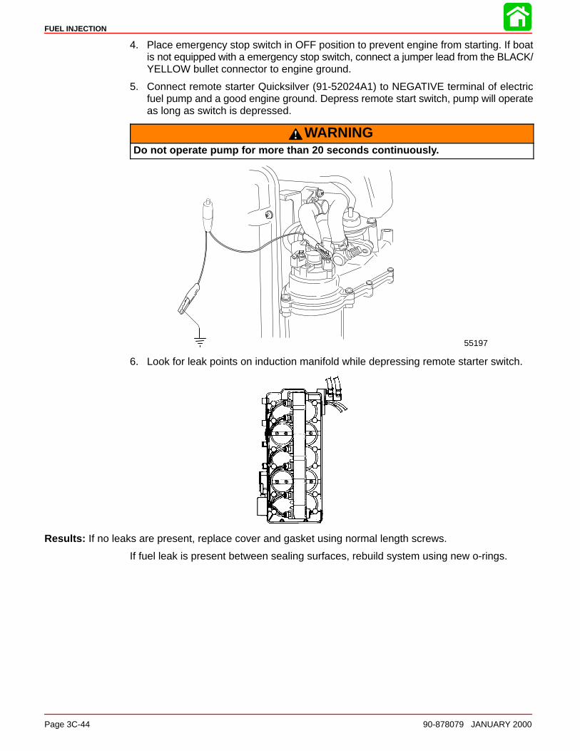
FUEL INJECTION
Page 3C-44 90-878079 JANUARY 2000
4. Place emergency stop switch in OFF position to prevent engine from starting. If boatis not equipped with a emergency stop switch, connect a jumper lead from the BLACK/YELLOW bullet connector to engine ground.
5. Connect remote starter Quicksilver (91-52024A1) to NEGATIVE terminal of electricfuel pump and a good engine ground. Depress remote start switch, pump will operateas long as switch is depressed.
WARNINGDo not operate pump for more than 20 seconds continuously.
55197
6. Look for leak points on induction manifold while depressing remote starter switch.
Results: If no leaks are present, replace cover and gasket using normal length screws.
If fuel leak is present between sealing surfaces, rebuild system using new o-rings.

FUEL INJECTION
90-878079 JANUARY 2000 Page 3C-45
Air Temperature Sensor TestPurpose: This test eliminates possibilities of improper fuel delivery related to air temperature sensor.
1. Disconnect and remove Air Temperature Sensor from induction manifold.
2. Connect DMT (91-854009T1) to leads of sensor.
3. Place sensor in ice water while monitoring meter reading. Use graph (below) for refer-ence.
NOTE: Temperature/resistance reading may differ slightly from graph curve.SENSOR RESISTANCE VS. AIR TEMPERATURE
AIR
TE
MP.
SE
NS
OR
RE
SIS
TAN
CE
(K
OH
MS
)
Results: Resistance does not change inversely with temperature change. Replace defective Air Tempera-ture Sensor.
Resistance changes inversely with temperature change. Air Temperature Sensor OK.
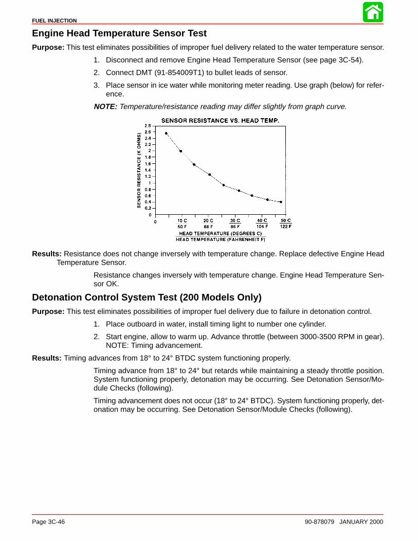
FUEL INJECTION
Page 3C-46 90-878079 JANUARY 2000
Engine Head Temperature Sensor TestPurpose: This test eliminates possibilities of improper fuel delivery related to the water temperature sensor.
1. Disconnect and remove Engine Head Temperature Sensor (see page 3C-54).
2. Connect DMT (91-854009T1) to bullet leads of sensor.
3. Place sensor in ice water while monitoring meter reading. Use graph (below) for refer-ence.
NOTE: Temperature/resistance reading may differ slightly from graph curve.
Results: Resistance does not change inversely with temperature change. Replace defective Engine HeadTemperature Sensor.
Resistance changes inversely with temperature change. Engine Head Temperature Sen-sor OK.
Detonation Control System Test (200 Models Only)Purpose: This test eliminates possibilities of improper fuel delivery due to failure in detonation control.
1. Place outboard in water, install timing light to number one cylinder.
2. Start engine, allow to warm up. Advance throttle (between 3000-3500 RPM in gear).NOTE: Timing advancement.
Results: Timing advances from 18° to 24° BTDC system functioning properly.
Timing advance from 18° to 24° but retards while maintaining a steady throttle position.System functioning properly, detonation may be occurring. See Detonation Sensor/Mo-dule Checks (following).
Timing advancement does not occur (18° to 24° BTDC). System functioning properly, det-onation may be occurring. See Detonation Sensor/Module Checks (following).

FUEL INJECTION
90-878079 JANUARY 2000 Page 3C-47
Detonation Sensor CheckIMPORTANT: When testing detonation control system keep all test leads away fromhigh tension leads (i.e. spark plug lead, electrical wiring etc.) to avoid false read-ings.
Purpose: This check will determine if sensor is correctly signaling control module.
1. Connect DMT 2000 Digital Tachometer Multi-Meter (91-854009A1) to detonation sen-sor as shown. RED “V-Ω” test lead to sensor terminal, BLACK “com” test lead to sensorhousing (ground).
58067
a
a - Detonation Sensor
2. Turn meter dial to 200 MV volts, AC position and power switch in ON position. Placeoutboard in water.
3. Start and operate engine at idle speed.
4. Check meter reading. A typical reading of 0.075 to 0.120 volts AC should be present.
NOTE: As RPM increases, volt readings will increase.
Results: If voltage reading is not within 0.075 to 0.120 volts AC replace detonation sensor. Torque sensor to144 Ib. in. (16.0 N·m).
If voltage reading is within 0.075 to 0.120 volts AC perform check on detonation controlmodule.
IMPORTANT: Handle detonation sensor with care when testing or replacing. Roughhandling could cause undetectable internal damage causing false readings to betransmitted to detonation module.
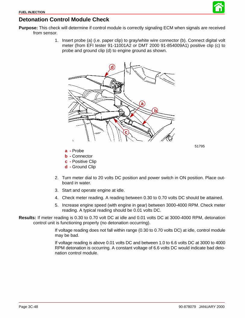
FUEL INJECTION
Page 3C-48 90-878079 JANUARY 2000
Detonation Control Module CheckPurpose: This check will determine if control module is correctly signaling ECM when signals are received
from sensor.
1. Insert probe (a) (i.e. paper clip) to gray/white wire connector (b). Connect digital voltmeter (from EFI tester 91-11001A2 or DMT 2000 91-854009A1) positive clip (c) toprobe and ground clip (d) to engine ground as shown.
51795
d
a
b
c
a - Probeb - Connectorc - Positive Clipd - Ground Clip
2. Turn meter dial to 20 volts DC position and power switch in ON position. Place out-board in water.
3. Start and operate engine at idle.
4. Check meter reading. A reading between 0.30 to 0.70 volts DC should be attained.
5. Increase engine speed (with engine in gear) between 3000-4000 RPM. Check meterreading. A typical reading should be 0.01 volts DC.
Results: If meter reading is 0.30 to 0.70 volt DC at idle and 0.01 volts DC at 3000-4000 RPM, detonationcontrol unit is functioning properly (no detonation occurring).
If voltage reading does not fall within range (0.30 to 0.70 volts DC) at idle, control modulemay be bad.
If voltage reading is above 0.01 volts DC and between 1.0 to 6.6 volts DC at 3000 to 4000RPM detonation is occurring. A constant voltage of 6.6 volts DC would indicate bad deto-nation control module.
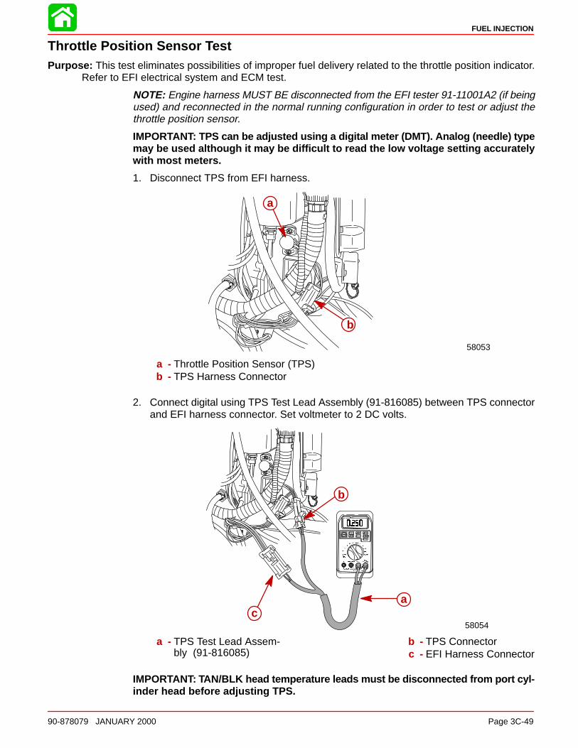
FUEL INJECTION
90-878079 JANUARY 2000 Page 3C-49
Throttle Position Sensor TestPurpose: This test eliminates possibilities of improper fuel delivery related to the throttle position indicator.
Refer to EFI electrical system and ECM test.
NOTE: Engine harness MUST BE disconnected from the EFI tester 91-11001A2 (if beingused) and reconnected in the normal running configuration in order to test or adjust thethrottle position sensor.
IMPORTANT: TPS can be adjusted using a digital meter (DMT). Analog (needle) typemay be used although it may be difficult to read the low voltage setting accuratelywith most meters.
1. Disconnect TPS from EFI harness.
58053
a
b
a - Throttle Position Sensor (TPS)b - TPS Harness Connector
2. Connect digital using TPS Test Lead Assembly (91-816085) between TPS connectorand EFI harness connector. Set voltmeter to 2 DC volts.
58054
b
ca
a - TPS Test Lead Assem-bly (91-816085)
b - TPS Connectorc - EFI Harness Connector
IMPORTANT: TAN/BLK head temperature leads must be disconnected from port cyl-inder head before adjusting TPS.
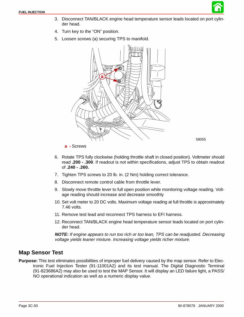
FUEL INJECTION
Page 3C-50 90-878079 JANUARY 2000
3. Disconnect TAN/BLACK engine head temperature sensor leads located on port cylin-der head.
4. Turn key to the “ON” position.
5. Loosen screws (a) securing TPS to manifold.
58055
a
a - Screws
6. Rotate TPS fully clockwise (holding throttle shaft in closed position). Voltmeter shouldread .200 - .300. If readout is not within specifications, adjust TPS to obtain readoutof .240 - .260.
7. Tighten TPS screws to 20 lb. in. (2 Nm) holding correct tolerance.
8. Disconnect remote control cable from throttle lever.
9. Slowly move throttle lever to full open position while monitoring voltage reading. Volt-age reading should increase and decrease smoothly
10. Set volt meter to 20 DC volts. Maximum voltage reading at full throttle is approximately7.46 volts.
11. Remove test lead and reconnect TPS harness to EFI harness.
12. Reconnect TAN/BLACK engine head temperature sensor leads located on port cylin-der head.
NOTE: If engine appears to run too rich or too lean, TPS can be readjusted. Decreasingvoltage yields leaner mixture. Increasing voltage yields richer mixture.
Map Sensor TestPurpose: This test eliminates possibilities of improper fuel delivery caused by the map sensor. Refer to Elec-
tronic Fuel Injection Tester (91-11001A2) and its test manual. The Digital Diagnostic Terminal(91-823686A2) may also be used to test the MAP Sensor. It will display an LED failure light, a PASS/NO operational indication as well as a numeric display value.
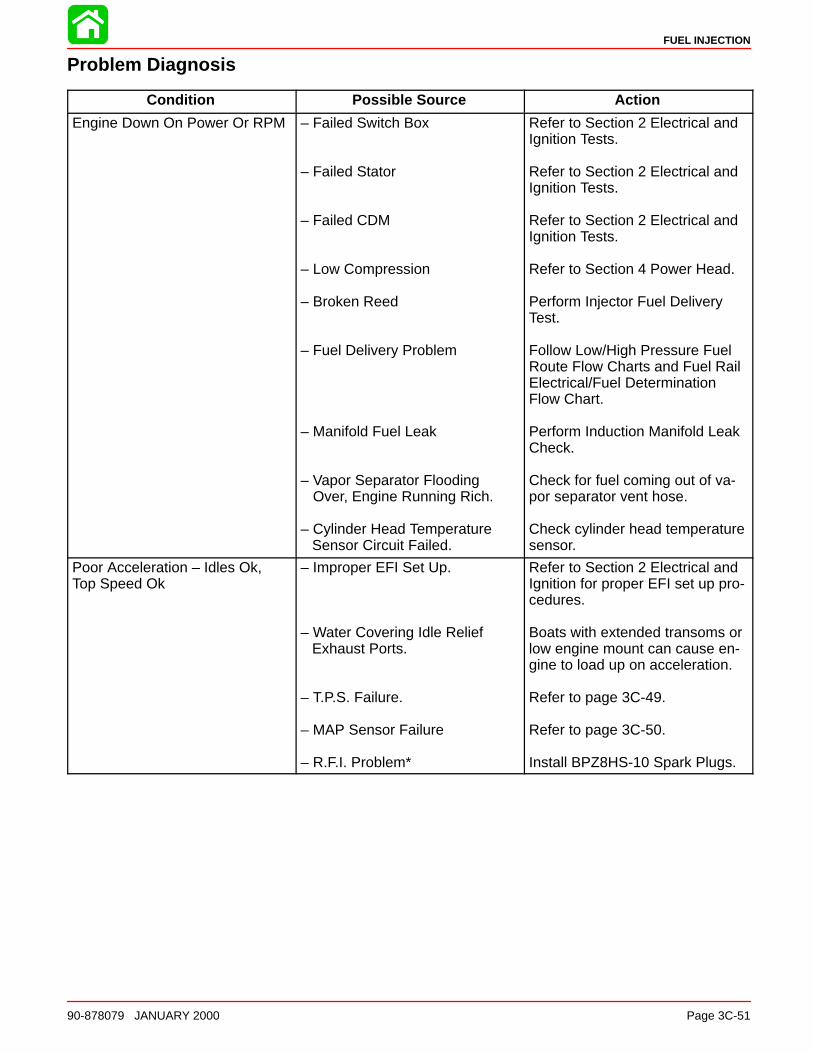
FUEL INJECTION
90-878079 JANUARY 2000 Page 3C-51
Problem Diagnosis
Condition Possible Source Action
Engine Down On Power Or RPM – Failed Switch Box
– Failed Stator
– Failed CDM
– Low Compression
– Broken Reed
– Fuel Delivery Problem
– Manifold Fuel Leak
– Vapor Separator Flooding Over, Engine Running Rich.
– Cylinder Head Temperature Sensor Circuit Failed.
Refer to Section 2 Electrical andIgnition Tests.
Refer to Section 2 Electrical andIgnition Tests.
Refer to Section 2 Electrical andIgnition Tests.
Refer to Section 4 Power Head.
Perform Injector Fuel DeliveryTest.
Follow Low/High Pressure FuelRoute Flow Charts and Fuel RailElectrical/Fuel DeterminationFlow Chart.
Perform Induction Manifold LeakCheck.
Check for fuel coming out of va-por separator vent hose.
Check cylinder head temperaturesensor.
Poor Acceleration – Idles Ok,Top Speed Ok
– Improper EFI Set Up.
– Water Covering Idle Relief Exhaust Ports.
– T.P.S. Failure.
– MAP Sensor Failure
– R.F.I. Problem*
Refer to Section 2 Electrical andIgnition for proper EFI set up pro-cedures.
Boats with extended transoms orlow engine mount can cause en-gine to load up on acceleration.
Refer to page 3C-49.
Refer to page 3C-50.
Install BPZ8HS-10 Spark Plugs.
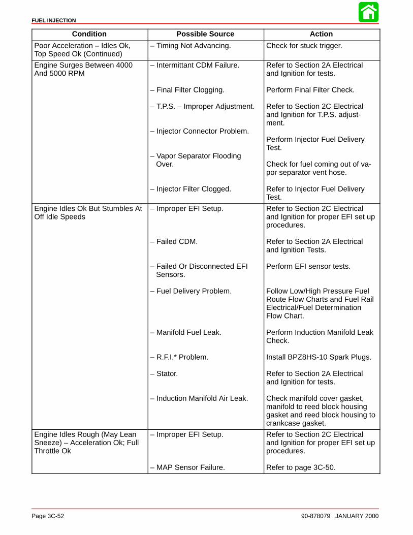
FUEL INJECTION
Page 3C-52 90-878079 JANUARY 2000
Condition Possible Source Action
Poor Acceleration – Idles Ok,Top Speed Ok (Continued)
– Timing Not Advancing. Check for stuck trigger.
Engine Surges Between 4000And 5000 RPM
– Intermittant CDM Failure.
– Final Filter Clogging.
– T.P.S. – Improper Adjustment.
– Injector Connector Problem.
– Vapor Separator Flooding Over.
– Injector Filter Clogged.
Refer to Section 2A Electricaland Ignition for tests.
Perform Final Filter Check.
Refer to Section 2C Electricaland Ignition for T.P.S. adjust-ment.
Perform Injector Fuel DeliveryTest.
Check for fuel coming out of va-por separator vent hose.
Refer to Injector Fuel DeliveryTest.
Engine Idles Ok But Stumbles AtOff Idle Speeds
– Improper EFI Setup.
– Failed CDM.
– Failed Or Disconnected EFI Sensors.
– Fuel Delivery Problem.
– Manifold Fuel Leak.
– R.F.I.* Problem.
– Stator.
– Induction Manifold Air Leak.
Refer to Section 2C Electricaland Ignition for proper EFI set upprocedures.
Refer to Section 2A Electricaland Ignition Tests.
Perform EFI sensor tests.
Follow Low/High Pressure FuelRoute Flow Charts and Fuel RailElectrical/Fuel DeterminationFlow Chart.
Perform Induction Manifold LeakCheck.
Install BPZ8HS-10 Spark Plugs.
Refer to Section 2A Electricaland Ignition for tests.
Check manifold cover gasket,manifold to reed block housinggasket and reed block housing tocrankcase gasket.
Engine Idles Rough (May LeanSneeze) – Acceleration Ok; FullThrottle Ok
– Improper EFI Setup.
– MAP Sensor Failure.
Refer to Section 2C Electricaland Ignition for proper EFI set upprocedures.
Refer to page 3C-50.
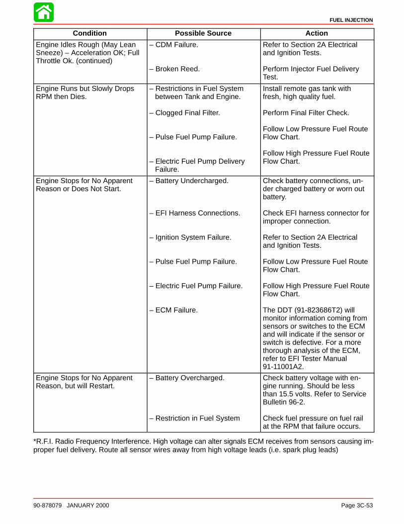
FUEL INJECTION
90-878079 JANUARY 2000 Page 3C-53
Condition Possible Source Action
Engine Idles Rough (May LeanSneeze) – Acceleration OK; FullThrottle Ok. (continued)
– CDM Failure.
– Broken Reed.
Refer to Section 2A Electricaland Ignition Tests.
Perform Injector Fuel DeliveryTest.
Engine Runs but Slowly DropsRPM then Dies.
– Restrictions in Fuel System between Tank and Engine.
– Clogged Final Filter.
– Pulse Fuel Pump Failure.
– Electric Fuel Pump Delivery Failure.
Install remote gas tank withfresh, high quality fuel.
Perform Final Filter Check.
Follow Low Pressure Fuel RouteFlow Chart.
Follow High Pressure Fuel RouteFlow Chart.
Engine Stops for No ApparentReason or Does Not Start.
– Battery Undercharged.
– EFI Harness Connections.
– Ignition System Failure.
– Pulse Fuel Pump Failure.
– Electric Fuel Pump Failure.
– ECM Failure.
Check battery connections, un-der charged battery or worn outbattery.
Check EFI harness connector forimproper connection.
Refer to Section 2A Electricaland Ignition Tests.
Follow Low Pressure Fuel RouteFlow Chart.
Follow High Pressure Fuel RouteFlow Chart.
The DDT (91-823686T2) willmonitor information coming fromsensors or switches to the ECMand will indicate if the sensor orswitch is defective. For a morethorough analysis of the ECM,refer to EFI Tester Manual91-11001A2.
Engine Stops for No ApparentReason, but will Restart.
– Battery Overcharged.
– Restriction in Fuel System
Check battery voltage with en-gine running. Should be lessthan 15.5 volts. Refer to ServiceBulletin 96-2.
Check fuel pressure on fuel railat the RPM that failure occurs.
*R.F.I. Radio Frequency Interference. High voltage can alter signals ECM receives from sensors causing im-proper fuel delivery. Route all sensor wires away from high voltage leads (i.e. spark plug leads)

FUEL INJECTION
Page 3C-54 90-878079 JANUARY 2000
Engine Head Temperature Sensor Removal
1. Remove screw and retaining plate.
2. Disconnect wires and remove sensor.
58052
a
b
c
d
a - Wiresb - Sensorc - Retainerd - Screw
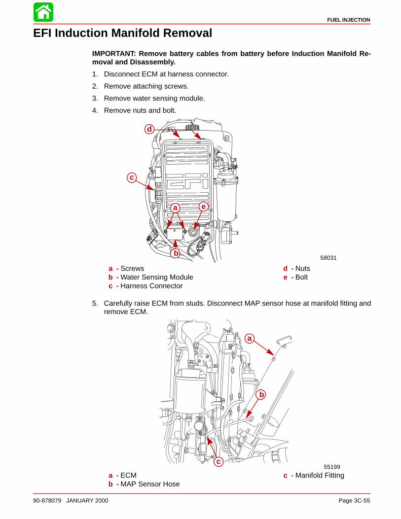
FUEL INJECTION
90-878079 JANUARY 2000 Page 3C-55
EFI Induction Manifold Removal
IMPORTANT: Remove battery cables from battery before Induction Manifold Re-moval and Disassembly.
1. Disconnect ECM at harness connector.
2. Remove attaching screws.
3. Remove water sensing module.
4. Remove nuts and bolt.
58031
a
b
c
d
e
a - Screwsb - Water Sensing Modulec - Harness Connector
d - Nutse - Bolt
5. Carefully raise ECM from studs. Disconnect MAP sensor hose at manifold fitting andremove ECM.
55199
a
b
c
a - ECMb - MAP Sensor Hose
c - Manifold Fitting
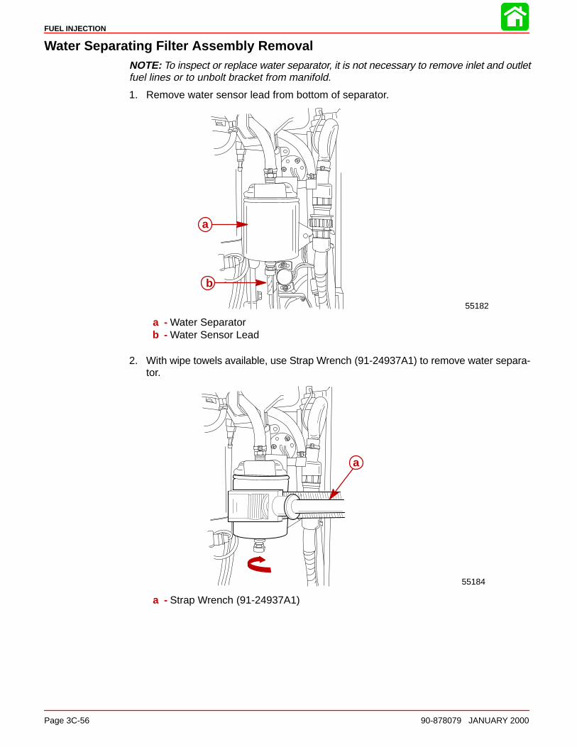
FUEL INJECTION
Page 3C-56 90-878079 JANUARY 2000
Water Separating Filter Assembly RemovalNOTE: To inspect or replace water separator, it is not necessary to remove inlet and outletfuel lines or to unbolt bracket from manifold.
1. Remove water sensor lead from bottom of separator.
55182
a
b
a - Water Separatorb - Water Sensor Lead
2. With wipe towels available, use Strap Wrench (91-24937A1) to remove water separa-tor.
55184
a
a - Strap Wrench (91-24937A1)

FUEL INJECTION
90-878079 JANUARY 2000 Page 3C-57
Water Separating Filter Assembly InstallationIMPORTANT: Apply a light coat of outboard oil to the rectangular sealing ring on thewater separator before installation.
1. After applying oil to sealing ring of water separator, install separator onto bracket.
2. HAND TIGHTEN SEPARATOR. DO NOT use strap wrench or other tool to tighten sep-arator.
3. Reconnect water sensor lead to bottom of separator.
55185
a
a - Sealing Ring
Throttle Position Sensor and Temperature Sensor Fuel Injector HarnessDisconnections
1. Disconnect throttle position sensor at 3 pin connector.
a
b
58055
a - Throttle Position Sensorb - 3 Pin Connector
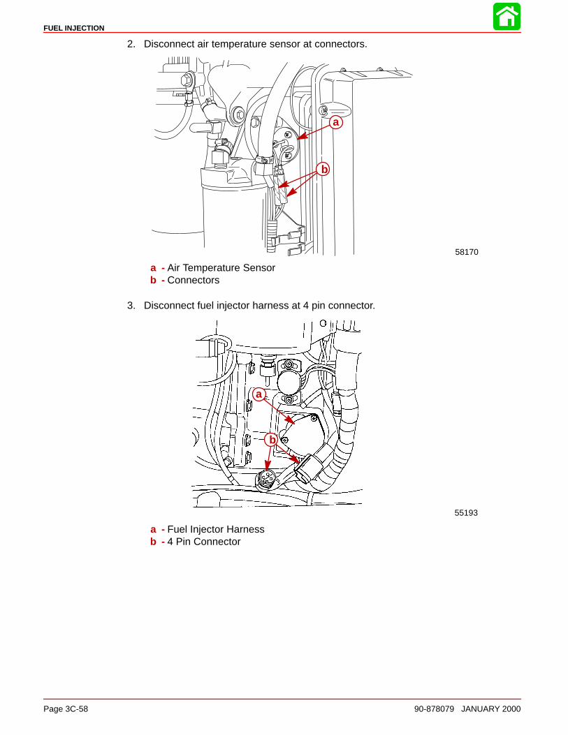
FUEL INJECTION
Page 3C-58 90-878079 JANUARY 2000
2. Disconnect air temperature sensor at connectors.
b
a
58170
a - Air Temperature Sensorb - Connectors
3. Disconnect fuel injector harness at 4 pin connector.
55193
a
b
a - Fuel Injector Harnessb - 4 Pin Connector
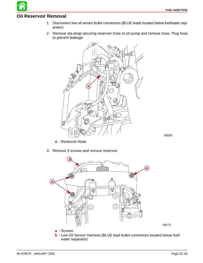
FUEL INJECTION
90-878079 JANUARY 2000 Page 3C-59
Oil Reservoir Removal1. Disconnect low oil sensor bullet connectors (BLUE leads located below fuel/water sep-
arator)
2. Remove sta-strap securing reservoir hose to oil pump and remove hose. Plug hoseto prevent leakage.
58050
a
a - Reservoir Hose
3. Remove 3 screws and remove reservoir.
a
a
58172
b
a - Screwsb - Low Oil Sensor Harness (BLUE lead bullet connectors located below fuel/
water separator)
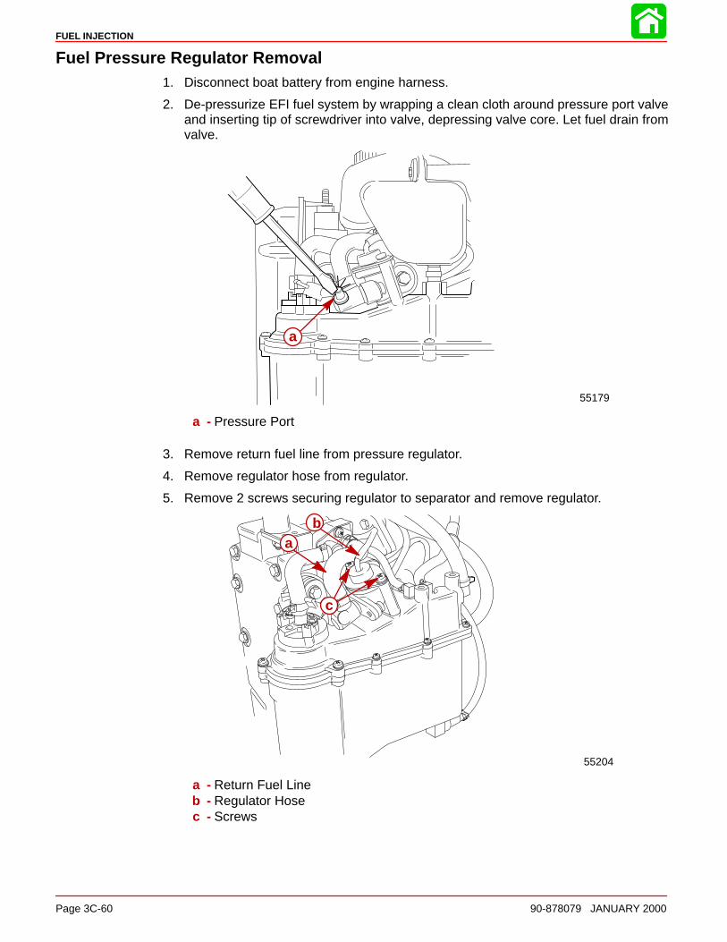
FUEL INJECTION
Page 3C-60 90-878079 JANUARY 2000
Fuel Pressure Regulator Removal1. Disconnect boat battery from engine harness.
2. De-pressurize EFI fuel system by wrapping a clean cloth around pressure port valveand inserting tip of screwdriver into valve, depressing valve core. Let fuel drain fromvalve.
55179
a
a - Pressure Port
3. Remove return fuel line from pressure regulator.
4. Remove regulator hose from regulator.
5. Remove 2 screws securing regulator to separator and remove regulator.
55204
ba
c
a - Return Fuel Lineb - Regulator Hosec - Screws

FUEL INJECTION
90-878079 JANUARY 2000 Page 3C-61
Fuel Pressure Regulator Disassembly1. Inspect O-rings for cuts and abraisions. Replace as required.
2. Inspect fuel filter for debris. Clean with solvent as required.
b
a
a - O-Ringsb - Filter
Fuel Pressure Regulator Reassembly
b
a
a - Screw (2) [Torque to 30 lb. in. (3.5 Nm)]b - Screw (2) [Torque to 45 lb. in. (5 Nm)]
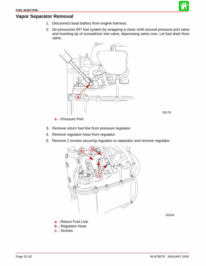
FUEL INJECTION
Page 3C-62 90-878079 JANUARY 2000
Vapor Separator Removal1. Disconnect boat battery from engine harness.
2. De-pressurize EFI fuel system by wrapping a clean cloth around pressure port valveand inserting tip of screwdriver into valve, depressing valve core. Let fuel drain fromvalve.
55179
a
a - Pressure Port
3. Remove return fuel line from pressure regulator.
4. Remove regulator hose from regulator.
5. Remove 2 screws securing regulator to separator and remove regulator.
55204
a b
c
a - Return Fuel Lineb - Regulator Hosec - Screws
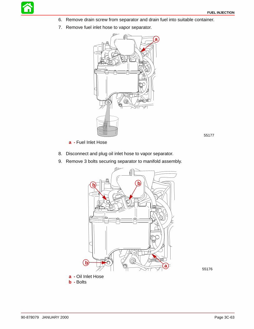
FUEL INJECTION
90-878079 JANUARY 2000 Page 3C-63
6. Remove drain screw from separator and drain fuel into suitable container.
7. Remove fuel inlet hose to vapor separator.
55177
a
a - Fuel Inlet Hose
8. Disconnect and plug oil inlet hose to vapor separator.
9. Remove 3 bolts securing separator to manifold assembly.
55176
bb
b a
a - Oil Inlet Hoseb - Bolts
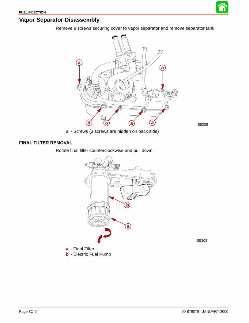
FUEL INJECTION
Page 3C-64 90-878079 JANUARY 2000
Vapor Separator DisassemblyRemove 9 screws securing cover to vapor separator and remove separator tank.
55209
aa
a a a a
a - Screws (3 screws are hidden on back side)
FINAL FILTER REMOVAL
Rotate final filter counterclockwise and pull down.
55205
a
b
a - Final Filterb - Electric Fuel Pump

FUEL INJECTION
90-878079 JANUARY 2000 Page 3C-65
ELECTRIC FUEL PUMP REMOVAL
NOTE: There are no individually replaceable parts within the electric pump. If brushes orarmature fails, entire pump must be replaced.
1. Remove 2 nuts on POSITIVE and NEGATIVE terminals. Remove pump from separa-tor cover.
55206
aa
b
a - Nutsb - Pump
2. Inspect pump O-rings for cuts or abraisions. Replace O-rings as required.
53702
a
a
a a
a
a - O-rings
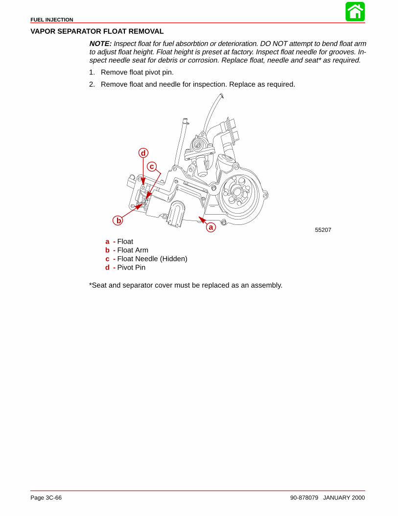
FUEL INJECTION
Page 3C-66 90-878079 JANUARY 2000
VAPOR SEPARATOR FLOAT REMOVAL
NOTE: Inspect float for fuel absorbtion or deterioration. DO NOT attempt to bend float armto adjust float height. Float height is preset at factory. Inspect float needle for grooves. In-spect needle seat for debris or corrosion. Replace float, needle and seat* as required.
1. Remove float pivot pin.
2. Remove float and needle for inspection. Replace as required.
55207
d
b
c
a
a - Floatb - Float Armc - Float Needle (Hidden)d - Pivot Pin
*Seat and separator cover must be replaced as an assembly.
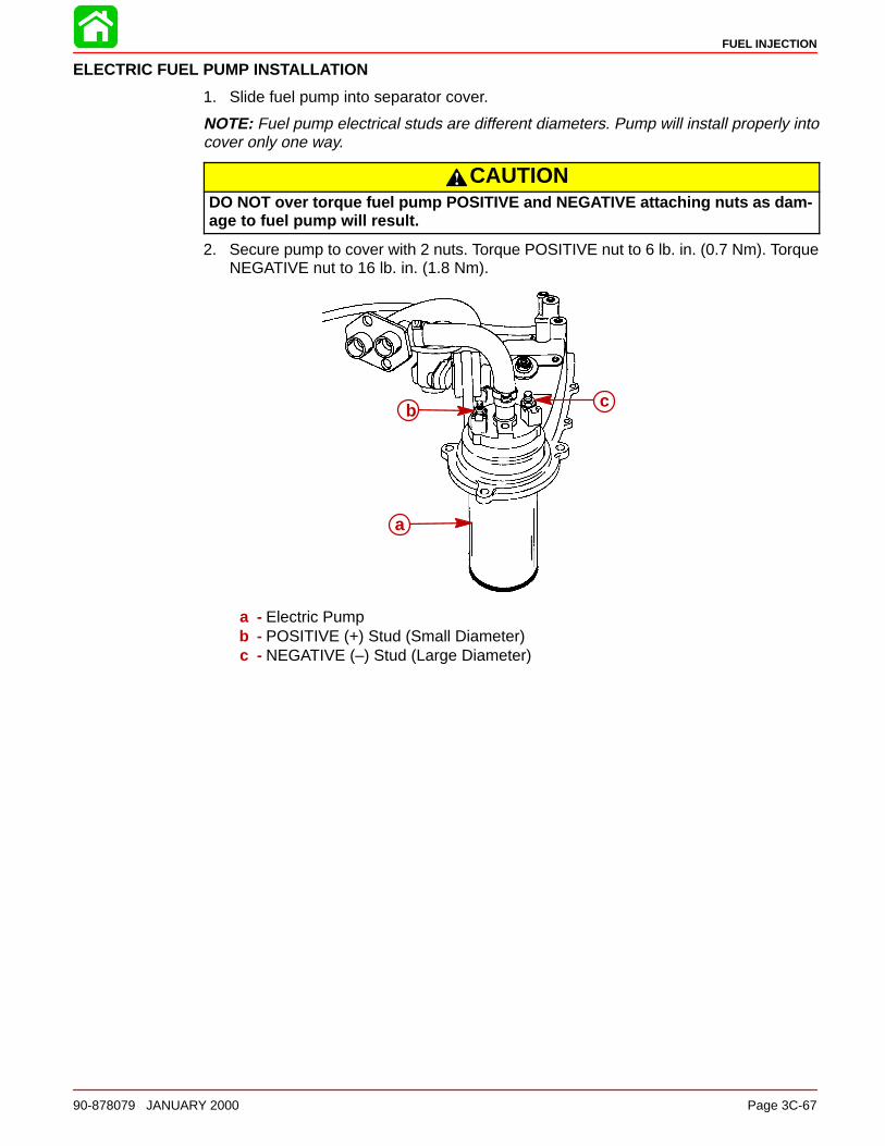
FUEL INJECTION
90-878079 JANUARY 2000 Page 3C-67
ELECTRIC FUEL PUMP INSTALLATION
1. Slide fuel pump into separator cover.
NOTE: Fuel pump electrical studs are different diameters. Pump will install properly intocover only one way.
CAUTIONDO NOT over torque fuel pump POSITIVE and NEGATIVE attaching nuts as dam-age to fuel pump will result.
2. Secure pump to cover with 2 nuts. Torque POSITIVE nut to 6 lb. in. (0.7 Nm). TorqueNEGATIVE nut to 16 lb. in. (1.8 Nm).
b
a
c
a - Electric Pumpb - POSITIVE (+) Stud (Small Diameter)c - NEGATIVE (–) Stud (Large Diameter)

FUEL INJECTION
Page 3C-68 90-878079 JANUARY 2000
3. Install rubber pad on bottom of pump.
NOTE: Rubber pad is molded to fit flush on bottom of pump on one side only.
4. Install pump support ring.
NOTE: Pump support ring fits over pad onto pump properly only one way (Tabs face up).
5. Install final filter into pump bottom. Rotate filter clockwise to lock filter onto pump.
ca
b
d
a - Rubber Padb - Support Ring
c - Tabs (face up)d - Final Filter
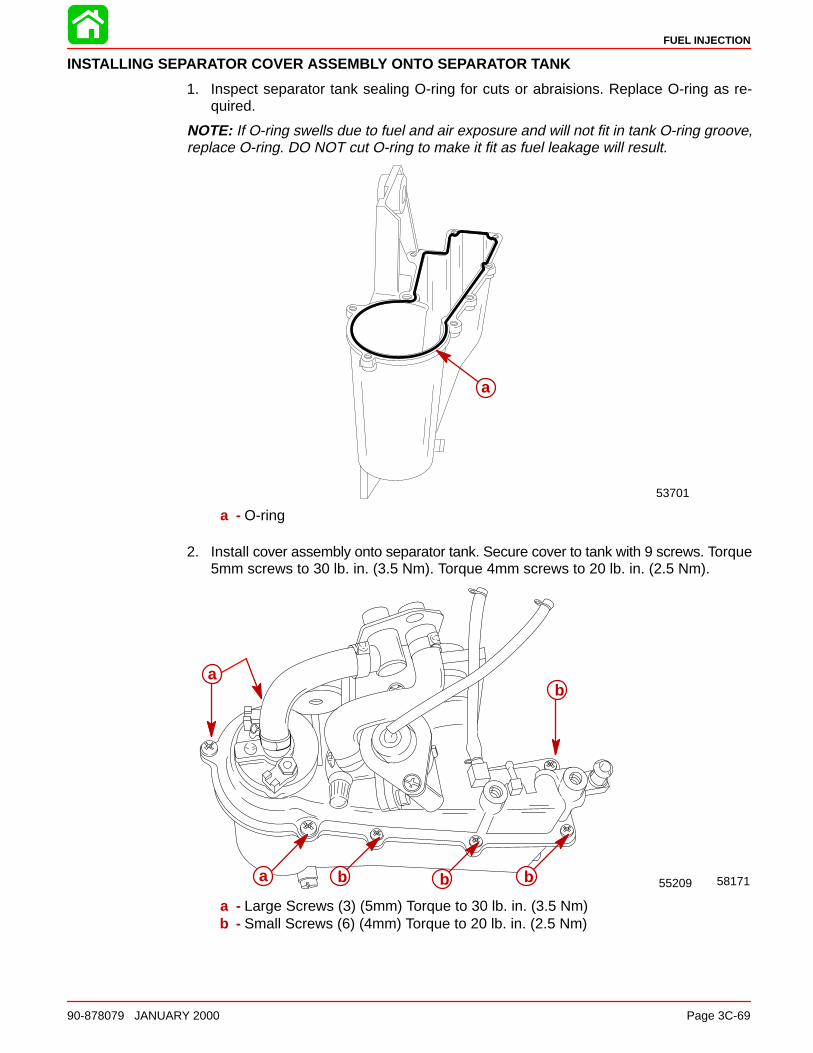
FUEL INJECTION
90-878079 JANUARY 2000 Page 3C-69
INSTALLING SEPARATOR COVER ASSEMBLY ONTO SEPARATOR TANK
1. Inspect separator tank sealing O-ring for cuts or abraisions. Replace O-ring as re-quired.
NOTE: If O-ring swells due to fuel and air exposure and will not fit in tank O-ring groove,replace O-ring. DO NOT cut O-ring to make it fit as fuel leakage will result.
53701
a
a - O-ring
2. Install cover assembly onto separator tank. Secure cover to tank with 9 screws. Torque5mm screws to 30 lb. in. (3.5 Nm). Torque 4mm screws to 20 lb. in. (2.5 Nm).
5817155209
a
a b b b
b
a - Large Screws (3) (5mm) Torque to 30 lb. in. (3.5 Nm)b - Small Screws (6) (4mm) Torque to 20 lb. in. (2.5 Nm)
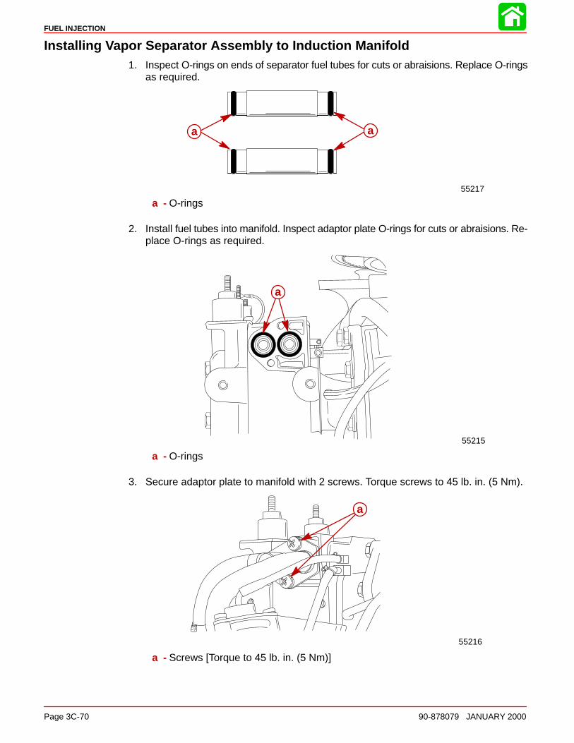
FUEL INJECTION
Page 3C-70 90-878079 JANUARY 2000
Installing Vapor Separator Assembly to Induction Manifold1. Inspect O-rings on ends of separator fuel tubes for cuts or abraisions. Replace O-rings
as required.
55217
a a
a - O-rings
2. Install fuel tubes into manifold. Inspect adaptor plate O-rings for cuts or abraisions. Re-place O-rings as required.
55215
a
a - O-rings
3. Secure adaptor plate to manifold with 2 screws. Torque screws to 45 lb. in. (5 Nm).
55216
a
a - Screws [Torque to 45 lb. in. (5 Nm)]
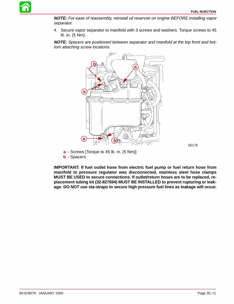
FUEL INJECTION
90-878079 JANUARY 2000 Page 3C-71
NOTE: For ease of reassembly, reinstall oil reservoir on engine BEFORE installing vaporseparator.
4. Secure vapor separator to manifold with 3 screws and washers. Torque screws to 45lb. in. (5 Nm).
NOTE: Spacers are positioned between separator and manifold at the top front and bot-tom attaching screw locations.
55176
a
a
b
a b
a - Screws [Torque to 45 lb. in. (5 Nm)]b - Spacers
IMPORTANT: If fuel outlet hose from electric fuel pump or fuel return hose frommanifold to pressure regulator was disconnected, stainless steel hose clampsMUST BE USED to secure connections. If outlet/return hoses are to be replaced, re-placement tubing kit (32-827694) MUST BE INSTALLED to prevent rupturing or leak-age. DO NOT use sta-straps to secure high pressure fuel lines as leakage will occur.
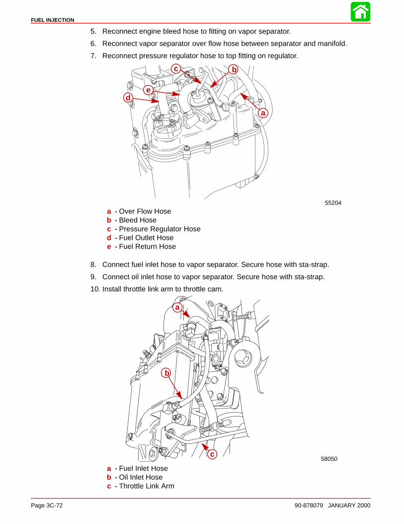
FUEL INJECTION
Page 3C-72 90-878079 JANUARY 2000
5. Reconnect engine bleed hose to fitting on vapor separator.
6. Reconnect vapor separator over flow hose between separator and manifold.
7. Reconnect pressure regulator hose to top fitting on regulator.
55204
c b
a
de
a - Over Flow Hoseb - Bleed Hosec - Pressure Regulator Hosed - Fuel Outlet Hosee - Fuel Return Hose
8. Connect fuel inlet hose to vapor separator. Secure hose with sta-strap.
9. Connect oil inlet hose to vapor separator. Secure hose with sta-strap.
10. Install throttle link arm to throttle cam.
58050
a
b
c
a - Fuel Inlet Hoseb - Oil Inlet Hosec - Throttle Link Arm

FUEL INJECTION
90-878079 JANUARY 2000 Page 3C-73
11. Connect RED (POSITIVE) lead to STARBOARD terminal of electric fuel pump andBLACK/RED (NEGATIVE) lead to PORT terminal of fuel pump. Torque POSITIVE nutto 6 lb. in. (0.7 Nm) and the NEGATIVE nut to 16 lb. in. (1.8 Nm).
55204
b
a
a - RED (+) Terminal [Torque nut to 6 lb. in. (0.7 Nm)]b - BLACK/RED (–) Terminal [Torque nut to 16 lb. in. (1.8 Nm)]
Manifold Removal1. Disconnect throttle link rod from throttle cam.
2. Disconnect oil injection link rod from injector arm.
55213ab
c d
a - Throttle Link Rodb - Throttle Camc - Oil Injection Link Rodd - Injector Arm
3. Identify location of 2 ground wires for reassembly purposes.
4. Remove12 screws securing manifold cover to manifold.

FUEL INJECTION
Page 3C-74 90-878079 JANUARY 2000
5. Remove manifold cover.
a
a
b
c
58176
a - Ground Wiresb - Screws (12)c - Manifold Cover
6. Disconnect bleed line hoses from manifold fittings.
7. Remove manifold assembly and place on clean work surface.
51795
a
a - Bleed Hoses

FUEL INJECTION
90-878079 JANUARY 2000 Page 3C-75
EFI Induction Manifold Disassembly
1. Remove manifold cover seal from manifold.
51785
b
a
a - Manifold Cover Sealb - Manifold
Air Temperature Sensor Removal1. Remove screws and sensor.
51790
a
a
b
a - Screwsb - Sensor

FUEL INJECTION
Page 3C-76 90-878079 JANUARY 2000
2. Remove O-ring from sensor.
51791
ab
a - O-ringb - Sensor
Throttle Position Sensor RemovalIMPORTANT: Sensor position will need to be set after induction manifold assemblyhas been installed.
1. Remove throttle position sensor screws.
a
58053
a - Screws
2. Remove sensor and sleeve from throttle shaft.
51788
c
a
b
a - Sensorb - Sleevec - Throttle Shaft
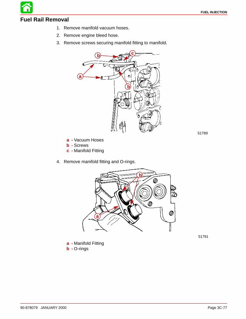
FUEL INJECTION
90-878079 JANUARY 2000 Page 3C-77
Fuel Rail Removal1. Remove manifold vacuum hoses.
2. Remove engine bleed hose.
3. Remove screws securing manifold fitting to manifold.
51789
a
b
b c
a - Vacuum Hosesb - Screwsc - Manifold Fitting
4. Remove manifold fitting and O-rings.
51791
b
a
a - Manifold Fittingb - O-rings
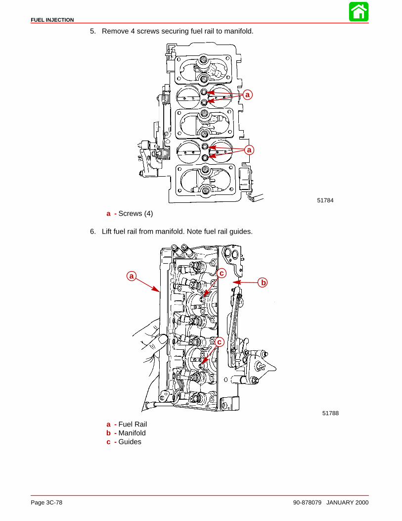
FUEL INJECTION
Page 3C-78 90-878079 JANUARY 2000
5. Remove 4 screws securing fuel rail to manifold.
51784
a
a
a - Screws (4)
6. Lift fuel rail from manifold. Note fuel rail guides.
51788
ab
c
c
a - Fuel Railb - Manifoldc - Guides
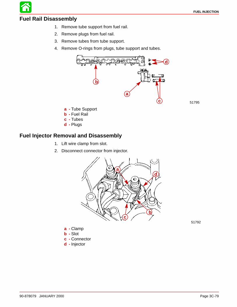
FUEL INJECTION
90-878079 JANUARY 2000 Page 3C-79
Fuel Rail Disassembly1. Remove tube support from fuel rail.
2. Remove plugs from fuel rail.
3. Remove tubes from tube support.
4. Remove O-rings from plugs, tube support and tubes.
51795
b
d
c
a
a - Tube Supportb - Fuel Railc - Tubesd - Plugs
Fuel Injector Removal and Disassembly1. Lift wire clamp from slot.
2. Disconnect connector from injector.
51792
ad
bc
a - Clampb - Slotc - Connectord - Injector

FUEL INJECTION
Page 3C-80 90-878079 JANUARY 2000
3. Remove injector from manifold.
51789
a
a - Injector
4. Place injector on clean work surface. Remove seals, O-ring and injector filter.
51789
b
d
c
a
a - Injectorb - Sealsc - O-Ringd - Filter
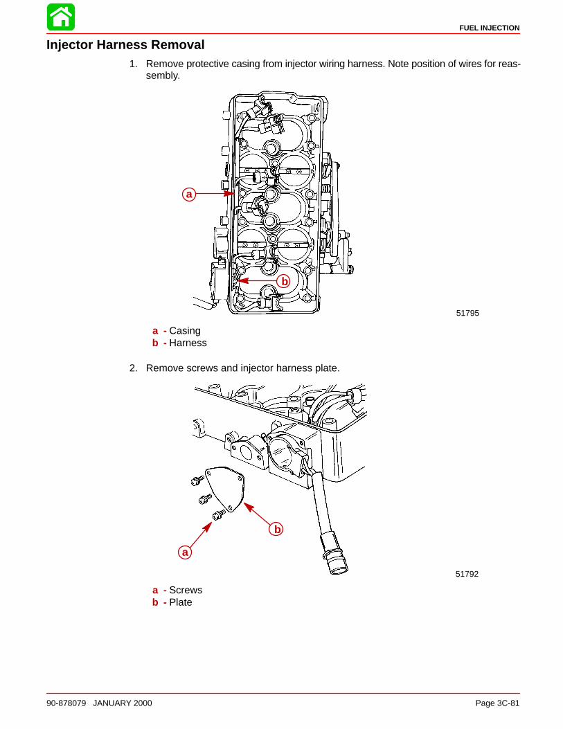
FUEL INJECTION
90-878079 JANUARY 2000 Page 3C-81
Injector Harness Removal1. Remove protective casing from injector wiring harness. Note position of wires for reas-
sembly.
51795
a
b
a - Casingb - Harness
2. Remove screws and injector harness plate.
51792
a
b
a - Screwsb - Plate
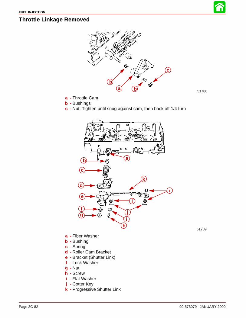
FUEL INJECTION
Page 3C-82 90-878079 JANUARY 2000
Throttle Linkage Removed
51786
ba b
c
a - Throttle Camb - Bushingsc - Nut; Tighten until snug against cam, then back off 1/4 turn
51789
ab
c
d
e
fg
k
i
i
j
ih
a - Fiber Washerb - Bushingc - Springd - Roller Cam Brackete - Bracket (Shutter Link)f - Lock Washerg - Nuth - Screwi - Flat Washerj - Cotter Keyk - Progressive Shutter Link
FUEL INJECTION
90-878079 JANUARY 2000 Page 3C-83
EFI System Cleaning and Inspection
Cleaning1. Clean all non-electrical metal parts using a good grade solvent.
2. Use a soft bristle brush for removing large accumulations of dirt or grease and oil.
3. Varnish type coating of induction manifold parts may be removed using carburetorcleaner.
4. Wiring harnesses can be wiped down with a slightly solvent dampened rag.
5. Clean all fuel passages in induction manifold.
6. Dry all components using clean lint free cloths that are free of abrasives such as metalshavings or dirt.
7. Compressed air may be used to dry parts if the air used is free of moisture and un-lubri-cated.
Inspection1. Look at entire system for signs of an obvious problem such as poor condition of wire
insulation, leaking fitting, cracked or loose hoses and lines.
2. Look for fuel or oil leaks wherever these fluids are used (i.e. fuel filter cap, fuel pump,vapor separator cap, etc.).
3. Check for signs of tampering or abuse such as modifications to wiring or hose routing.
4. Look at main connector between engine harness and ECM box for missing, corrodedor bent contact pins and socket. Check for dislodged grommet in ECM where harnessenters box.
5. Look at all sensors (throttle position, air temperature and water temperature) connec-tors and harnesses for bad connections or poor insulation conditions such as fraying,stripping, cracks or signs of abrasion wear.
6. Look for loose, missing or damaged mounting hardware such as stripped threads onscrews.
7. Look at sensors for signs of wear or damage such as cracks, chips, etc.
8. Look at filter housing for cracks, holes or other damage. Check for secure mounting.
9. Look at vapor separator for leaks, cracks, pitting or other damage.
10. Check all rubber mounting grommets for swelling tears, cracks or other conditions thatwould render parts unserviceable.
11. Check vapor separator float for signs of fuel entry in the float. Look at needle for wearof point.
12. Look at injectors for signs of plugging or looseness in fit with induction manifold.
13. Look at throttle linkage for bends, kinking or binding. Check spring for kinks.
14. Inspect all rubber seals and gaskets for swelling, cracks or slices that would cause im-proper sealing.
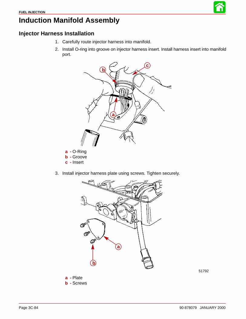
FUEL INJECTION
Page 3C-84 90-878079 JANUARY 2000
Induction Manifold Assembly
Injector Harness Installation1. Carefully route injector harness into manifold.
2. Install O-ring into groove on injector harness insert. Install harness insert into manifoldport.
b
a
c
a - O-Ringb - Groovec - Insert
3. Install injector harness plate using screws. Tighten securely.
51792
a
b
a - Plateb - Screws

FUEL INJECTION
90-878079 JANUARY 2000 Page 3C-85
4. Install protective casing over positioned injector wiring harness and insert into man-ifold.
51795
a
b
a - Casingb - Harness
Fuel Injector Assembly and Installation1. Install inspected seals, O-ring and injector filter to injector.
51789
a
c
b
d
a - Sealsb - O-Ringc - Filterd - Injector

FUEL INJECTION
Page 3C-86 90-878079 JANUARY 2000
2. Install injector into manifold.
51789
a
a - Injector
3. Install wire clamp into slot on injector connector.
4. Connect to injector.
51792
a
d
bc
a - Clampb - Slotc - Connectord - Injector
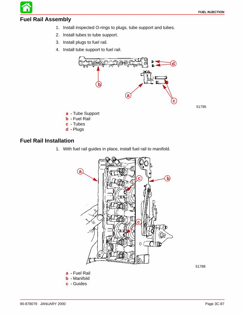
FUEL INJECTION
90-878079 JANUARY 2000 Page 3C-87
Fuel Rail Assembly1. Install inspected O-rings to plugs. tube support and tubes.
2. Install tubes to tube support.
3. Install plugs to fuel rail.
4. Install tube support to fuel rail.
51795
b
a
d
c
a - Tube Supportb - Fuel Railc - Tubesd - Plugs
Fuel Rail Installation1. With fuel rail guides in place, install fuel rail to manifold.
51788
ac b
c
a - Fuel Railb - Manifoldc - Guides
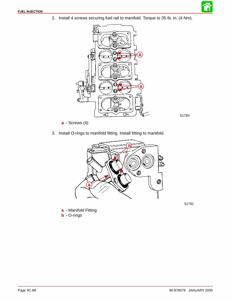
FUEL INJECTION
Page 3C-88 90-878079 JANUARY 2000
2. Install 4 screws securing fuel rail to manifold. Torque to 35 Ib. in. (4 Nm).
51784
a
a
a - Screws (4)
3. Install O-rings to manifold fitting. Install fitting to manifold.
51791
b
a
a - Manifold Fittingb - O-rings
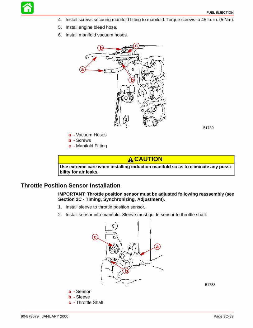
FUEL INJECTION
90-878079 JANUARY 2000 Page 3C-89
4. Install screws securing manifold fitting to manifold. Torque screws to 45 lb. in. (5 Nm).
5. Install engine bleed hose.
6. Install manifold vacuum hoses.
51789
a
b
b c
a - Vacuum Hosesb - Screwsc - Manifold Fitting
CAUTIONUse extreme care when installing induction manifold so as to eliminate any possi-bility for air leaks.
Throttle Position Sensor InstallationIMPORTANT: Throttle position sensor must be adjusted following reassembly (seeSection 2C - Timing, Synchronizing, Adjustment).
1. Install sleeve to throttle position sensor.
2. Install sensor into manifold. Sleeve must guide sensor to throttle shaft.
51788
c
a
b
a - Sensorb - Sleevec - Throttle Shaft

FUEL INJECTION
Page 3C-90 90-878079 JANUARY 2000
3. Tighten screws after induction manifold installation and throttle position sensor adjust-ments are completed. Torque screws to 20 lb. in. (2 Nm).
51790
a
a - Screws
Air Temperature Sensor Installation1. Install O-ring to air temperature sensor.
51791
ab
a - O-ringb - Sensor
2. Install air temperature sensor and secure with screws. Tighten screws securely.
51790
a
a
b
a - Screwsb - Sensor
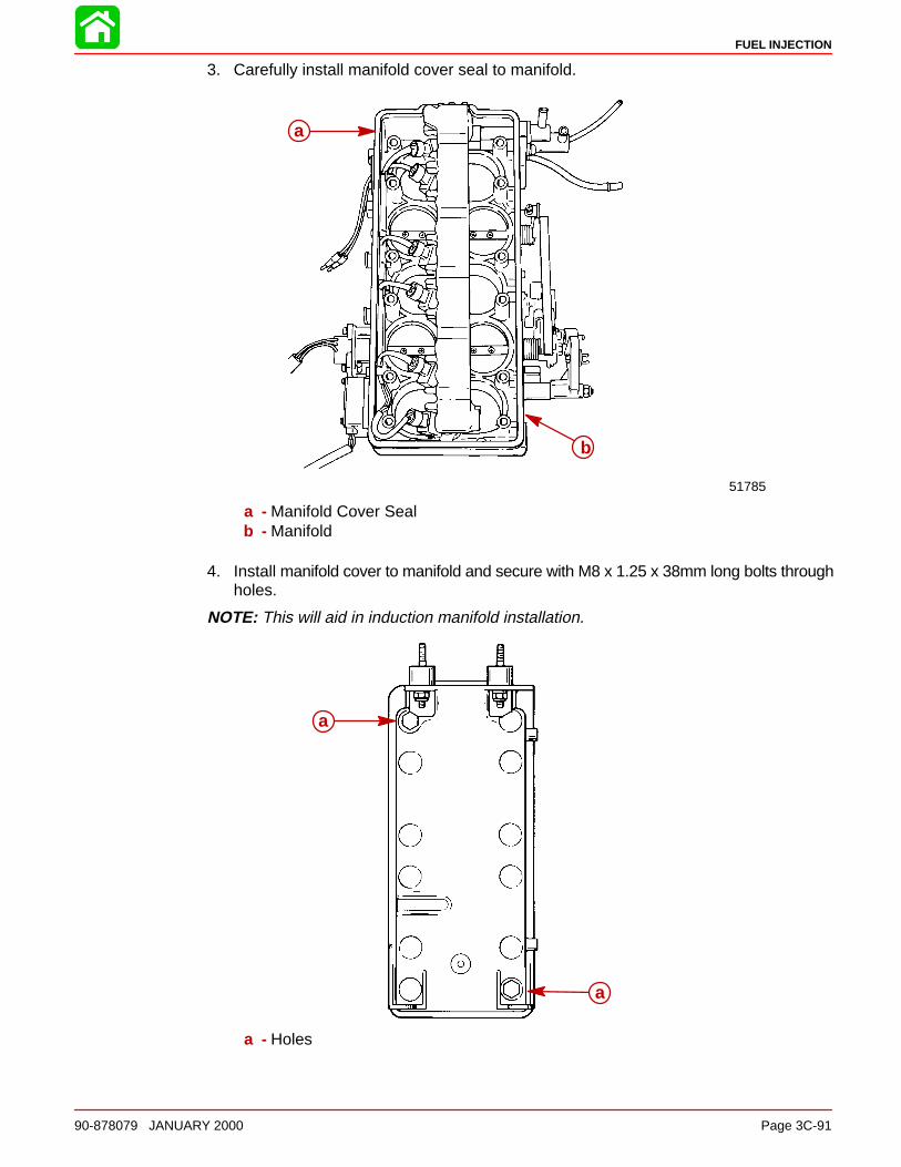
FUEL INJECTION
90-878079 JANUARY 2000 Page 3C-91
3. Carefully install manifold cover seal to manifold.
51785
b
a
a - Manifold Cover Sealb - Manifold
4. Install manifold cover to manifold and secure with M8 x 1.25 x 38mm long bolts throughholes.
NOTE: This will aid in induction manifold installation.
a
a
a - Holes
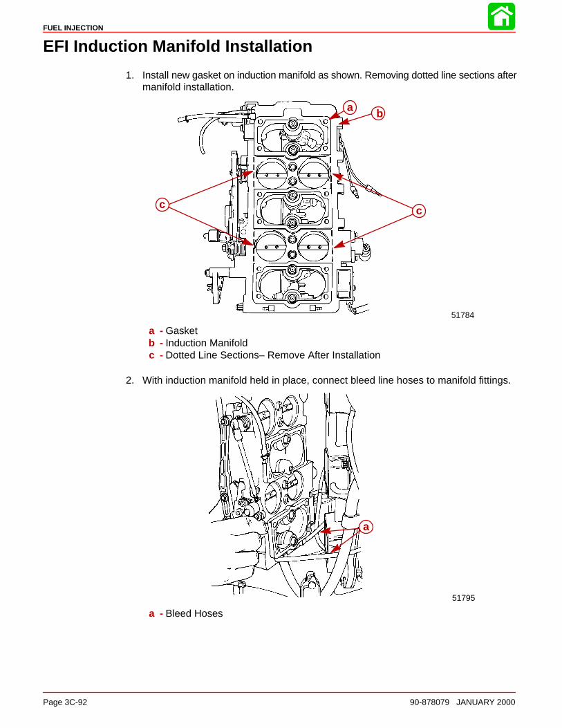
FUEL INJECTION
Page 3C-92 90-878079 JANUARY 2000
EFI Induction Manifold Installation
1. Install new gasket on induction manifold as shown. Removing dotted line sections aftermanifold installation.
51784
ba
c c
a - Gasketb - Induction Manifoldc - Dotted Line Sections– Remove After Installation
2. With induction manifold held in place, connect bleed line hoses to manifold fittings.
51795
a
a - Bleed Hoses
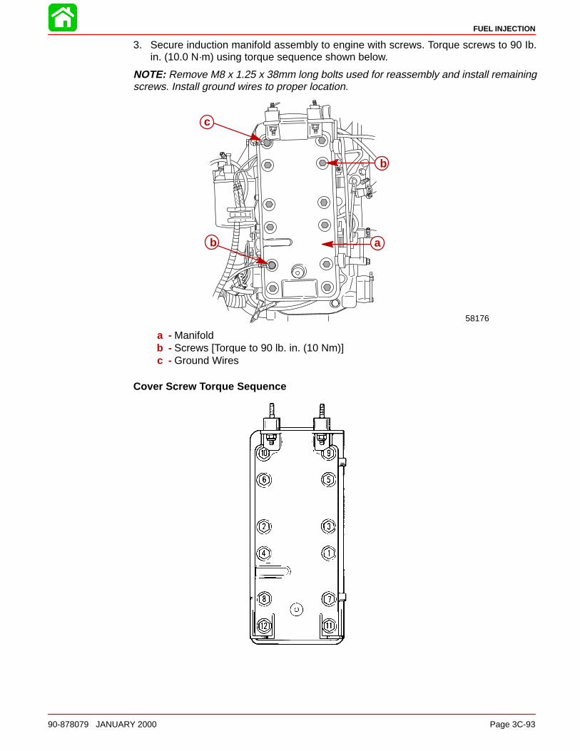
FUEL INJECTION
90-878079 JANUARY 2000 Page 3C-93
3. Secure induction manifold assembly to engine with screws. Torque screws to 90 Ib.in. (10.0 N·m) using torque sequence shown below.
NOTE: Remove M8 x 1.25 x 38mm long bolts used for reassembly and install remainingscrews. Install ground wires to proper location.
b
c
58176
ab
a - Manifoldb - Screws [Torque to 90 lb. in. (10 Nm)]c - Ground Wires
Cover Screw Torque Sequence
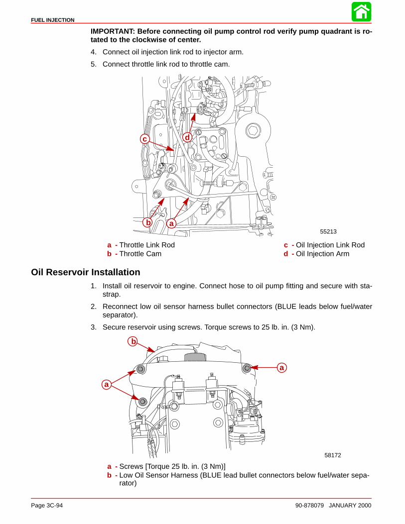
FUEL INJECTION
Page 3C-94 90-878079 JANUARY 2000
IMPORTANT: Before connecting oil pump control rod verify pump quadrant is ro-tated to the clockwise of center.
4. Connect oil injection link rod to injector arm.
5. Connect throttle link rod to throttle cam.
55213ab
c d
a - Throttle Link Rodb - Throttle Cam
c - Oil Injection Link Rodd - Oil Injection Arm
Oil Reservoir Installation1. Install oil reservoir to engine. Connect hose to oil pump fitting and secure with sta-
strap.
2. Reconnect low oil sensor harness bullet connectors (BLUE leads below fuel/waterseparator).
3. Secure reservoir using screws. Torque screws to 25 lb. in. (3 Nm).
58172
b
a
a
a - Screws [Torque 25 lb. in. (3 Nm)]b - Low Oil Sensor Harness (BLUE lead bullet connectors below fuel/water sepa-
rator)
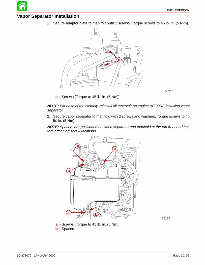
FUEL INJECTION
90-878079 JANUARY 2000 Page 3C-95
Vapor Separator Installation1. Secure adaptor plate to manifold with 2 screws. Torque screws to 45 lb. in. (5 N·m).
55216
a
a - Screws [Torque to 45 lb. in. (5 Nm)]
NOTE: For ease of reassembly, reinstall oil reservoir on engine BEFORE installing vaporseparator.
2. Secure vapor separator to manifold with 3 screws and washers. Torque screws to 45lb. in. (5 Nm).
NOTE: Spacers are positioned between separator and manifold at the top front and bot-tom attaching screw locations.
55176
a
a
b
a b
a - Screws [Torque to 45 lb. in. (5 Nm)]b - Spacers
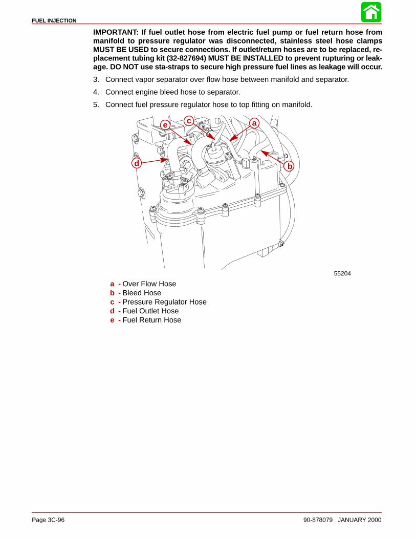
FUEL INJECTION
Page 3C-96 90-878079 JANUARY 2000
IMPORTANT: If fuel outlet hose from electric fuel pump or fuel return hose frommanifold to pressure regulator was disconnected, stainless steel hose clampsMUST BE USED to secure connections. If outlet/return hoses are to be replaced, re-placement tubing kit (32-827694) MUST BE INSTALLED to prevent rupturing or leak-age. DO NOT use sta-straps to secure high pressure fuel lines as leakage will occur.
3. Connect vapor separator over flow hose between manifold and separator.
4. Connect engine bleed hose to separator.
5. Connect fuel pressure regulator hose to top fitting on manifold.
55204
a
b
ce
d
a - Over Flow Hoseb - Bleed Hosec - Pressure Regulator Hosed - Fuel Outlet Hosee - Fuel Return Hose

FUEL INJECTION
90-878079 JANUARY 2000 Page 3C-97
Throttle Position Sensor, Air Temperature Sensor and Fuel Injector HarnessConnections
1. Connect fuel injector harness at 4 pin connector.
55193
a
b
a - Fuel Injector Harnessb - 4 Pin Connector
2. Connect air temperature sensor leads to bullet connectors.
b
a
58170
a - Air Temperature Sensorb - Connectors
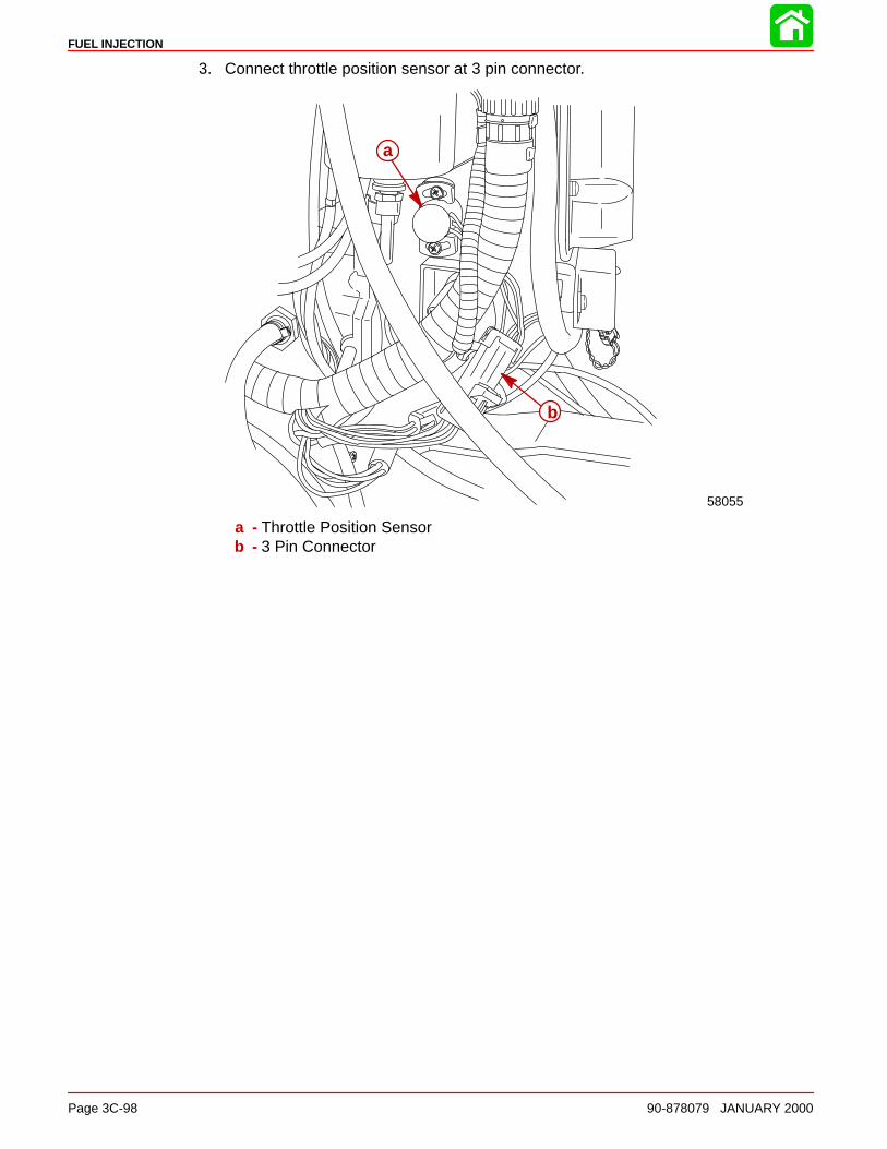
FUEL INJECTION
Page 3C-98 90-878079 JANUARY 2000
3. Connect throttle position sensor at 3 pin connector.
58055
a
b
a - Throttle Position Sensorb - 3 Pin Connector
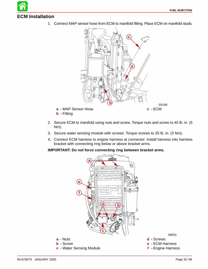
FUEL INJECTION
90-878079 JANUARY 2000 Page 3C-99
ECM Installation1. Connect MAP sensor hose from ECM to manifold fitting. Place ECM on manifold studs.
55199b
a
c
a - MAP Sensor Hoseb - Fitting
c - ECM
2. Secure ECM to manifold using nuts and screw. Torque nuts and screw to 45 lb. in. (5Nm).
3. Secure water sensing module with screws. Torque screws to 25 lb. in. (3 Nm).
4. Connect ECM harness to engine harness at connector. Install harness into harnessbracket with connecting ring below or above bracket arms.
IMPORTANT: Do not force connecting ring between bracket arms.
58031
a
b
c
d
e
f
a - Nutsb - Screwc - Water Sensing Module
d - Screwse - ECM Harnessf - Engine Harness
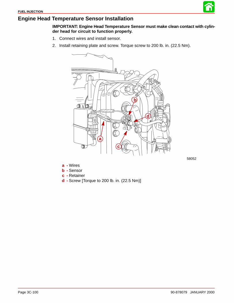
FUEL INJECTION
Page 3C-100 90-878079 JANUARY 2000
Engine Head Temperature Sensor InstallationIMPORTANT: Engine Head Tem perature Sensor must make clean contact with cylin-der head for circuit to function properly.
1. Connect wires and install sensor.
2. Install retaining plate and screw. Torque screw to 200 lb. in. (22.5 Nm).
58052
a
b
c
d
a - Wiresb - Sensorc - Retainerd - Screw [Torque to 200 lb. in. (22.5 Nm)]
3D
OIL INJECTION
90-878079 JANUARY 2000 Page 3D-1
FUEL SYSTEMSection 3D - Oil Injection
Table of Contents
Operation of the Oil Injection System 3D-2. . . . . . Final Checks Before Operation of Engine 3D-2Checking Operation of the Oil InjectionSystem (Engine Running) 3D-3. . . . . . . . . . . . .
Oil Injection Components 3D-4. . . . . . . . . . . . . . . . . Oil Injection Flow System 3D-7. . . . . . . . . . . . . . . . . Pump Drive Assembly 3D-8. . . . . . . . . . . . . . . . . . . Pump Drive System 3D-8. . . . . . . . . . . . . . . . . . . . .
Set Up Instructions for Oil InjectionSystem 3D-9. . . . . . . . . . . . . . . . . . . . . . . . . . . . . Bleeding Air from Oil Injection Pumpand Oil Injection Outlet Hose 3D-11. . . . . . . . . . . Adjusting Oil Injection Pump 3D-12. . . . . . . . . . .
Oil Injection Pump 3D-13. . . . . . . . . . . . . . . . . . . . . . . Oil Pump Removal 3D-13. . . . . . . . . . . . . . . . . . .
Worm Bushing 3D-14. . . . . . . . . . . . . . . . . . . . . . . . . . Worm Bushing Removal 3D-14. . . . . . . . . . . . . . . Worm Bushing Installation 3D-14. . . . . . . . . . . . . Oil Injection Pump Installation 3D-15. . . . . . . . . . Installing Drive Gear (for Oil Injection Pump)Onto Crankshaft 3D-15. . . . . . . . . . . . . . . . . . . . . . Oil Injection System Trouble ShootingChart 3D-16. . . . . . . . . . . . . . . . . . . . . . . . . . . . . . .
Oil Pump Volume (Flow) Test 3D-18. . . . . . . . . . . . . Engine Mounted Oil Reservoir 3D-19. . . . . . . . .
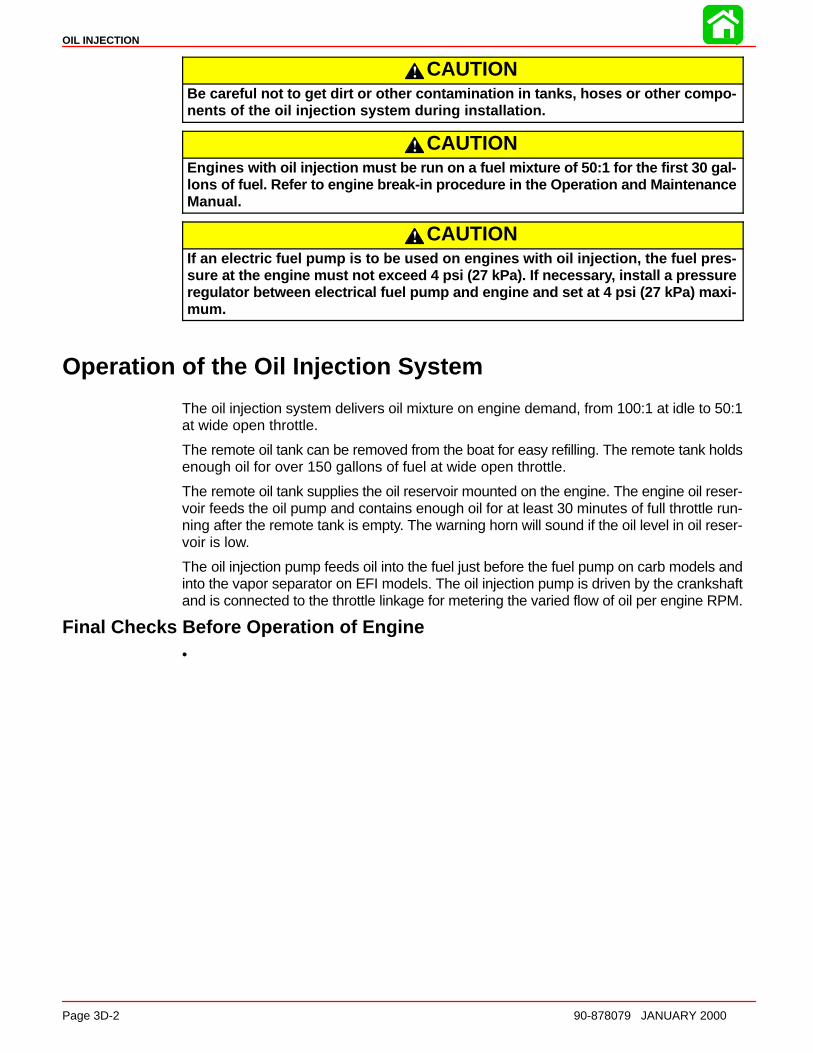
OIL INJECTION
Page 3D-2 90-878079 JANUARY 2000
CAUTIONBe careful not to get dirt or other contamination in tanks, hoses or other compo-nents of the oil injection system during installation.
CAUTIONEngines with oil injection must be run on a fuel mixture of 50:1 for the first 30 gal-lons of fuel. Refer to engine break-in procedure in the Operation and MaintenanceManual.
CAUTIONIf an electric fuel pump is to be used on engines with oil injection, the fuel pres-sure at the engine must not exceed 4 psi (27 kPa). If necessar y, install a pressureregulator between electrical fuel pump and engine and set at 4 psi (27 kPa) maxi-mum.
Operation of the Oil Injection System
The oil injection system delivers oil mixture on engine demand, from 100:1 at idle to 50:1at wide open throttle.
The remote oil tank can be removed from the boat for easy refilling. The remote tank holdsenough oil for over 150 gallons of fuel at wide open throttle.
The remote oil tank supplies the oil reservoir mounted on the engine. The engine oil reser-voir feeds the oil pump and contains enough oil for at least 30 minutes of full throttle run-ning after the remote tank is empty. The warning horn will sound if the oil level in oil reser-voir is low.
The oil injection pump feeds oil into the fuel just before the fuel pump on carb models andinto the vapor separator on EFI models. The oil injection pump is driven by the crankshaftand is connected to the throttle linkage for metering the varied flow of oil per engine RPM.
Final Checks Before Operation of Engine• Make sure fill cap gaskets are in place and caps are tight on engine oil reservoir
and remote oil tank.
• Mix a gasoline and oil mixture of 50:1 in the remote fuel tank during the initialbreak-in of the engine.
• Be certain the warning horn is installed and is operational. Refer to Instrument andWarning Horn Installation.
• Each time the key switch is turned from the “OFF” to “ON” position (engine notrunning); the warning horn will sound momentarily. This tells you the warning sys-tem for the oil injection system is functional and the warning horn is operational. Ifwarning horn does not sound or horn stays on when key is turned to the “ON” po-sition, refer to oil injection system troubleshooting chart following to correct theproblem.

OIL INJECTION
90-878079 JANUARY 2000 Page 3D-3
Checking Operation of the Oil Injection System (Engine Running)1. Operate engine following the break-in procedure outlined in the Operation and Main-
tenance Manual. If warning horn should sound an intermittent “beep,” “beep,” “beep”during operation, this indicates low oil level in the engine mounted oil reservoir. Referto troubleshooting following, to correct the problem.
2. After engine has been run for a short time, check that no oil is leaking out of engineoil reservoir fill cap.

OIL INJECTION
Page 3D-4 90-878079 JANUARY 2000
Oil Injection Components
34
35
9
10
1
5
6
3
4
7
8
11
12
13
15
16
17
18
21
22
2324
2526
27
28
29
30
3132
20 33
14
19
2
14
A
A = TO CHECK VALVE ON BLOCK
28
28
28
36
7 Loctite 271 (92-809820)
14 2 Cycle Outboard Oil (92-13249A24)
51 Loctite 222 (92-809818)
51
7
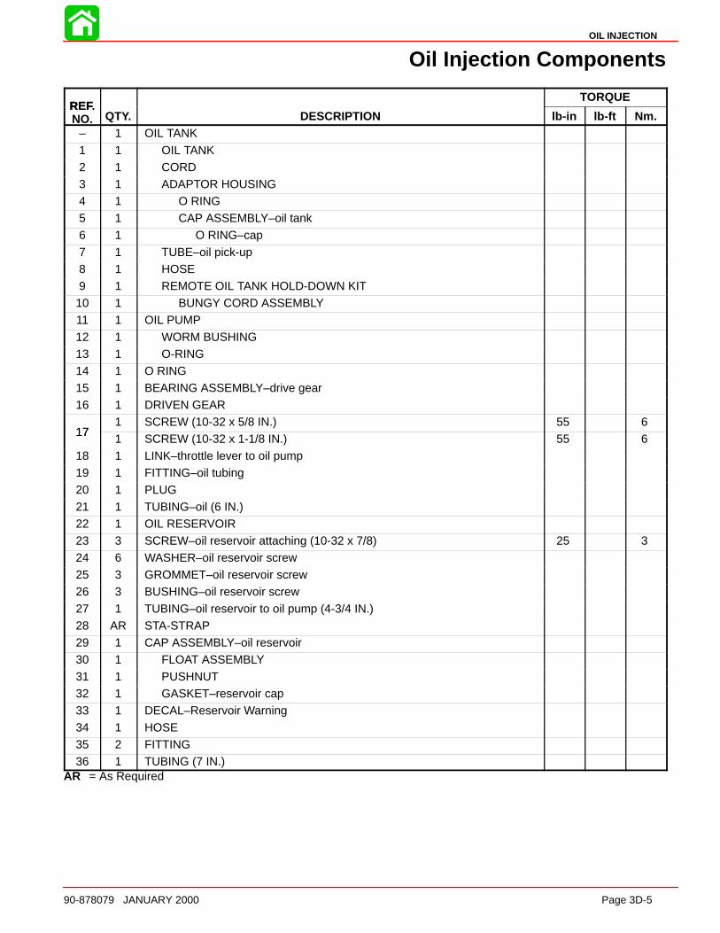
OIL INJECTION
90-878079 JANUARY 2000 Page 3D-5
Oil Injection Components
REFTORQUE
REF.NO. QTY. DESCRIPTION lb-in lb-ft Nm.
– 1 OIL TANK
1 1 OIL TANK2 1 CORD3 1 ADAPTOR HOUSING4 1 O RING5 1 CAP ASSEMBLY–oil tank6 1 O RING–cap
7 1 TUBE–oil pick-up8 1 HOSE9 1 REMOTE OIL TANK HOLD-DOWN KIT10 1 BUNGY CORD ASSEMBLY11 1 OIL PUMP 12 1 WORM BUSHING13 1 O-RING
14 1 O RING15 1 BEARING ASSEMBLY–drive gear16 1 DRIVEN GEAR
171 SCREW (10-32 x 5/8 IN.) 55 6
171 SCREW (10-32 x 1-1/8 IN.) 55 6
18 1 LINK–throttle lever to oil pump19 1 FITTING–oil tubing
20 1 PLUG21 1 TUBING–oil (6 IN.)22 1 OIL RESERVOIR23 3 SCREW–oil reservoir attaching (10-32 x 7/8) 25 324 6 WASHER–oil reservoir screw25 3 GROMMET–oil reservoir screw26 3 BUSHING–oil reservoir screw
27 1 TUBING–oil reservoir to oil pump (4-3/4 IN.)28 AR STA-STRAP29 1 CAP ASSEMBLY–oil reservoir30 1 FLOAT ASSEMBLY31 1 PUSHNUT32 1 GASKET–reservoir cap33 1 DECAL–Reservoir Warning
34 1 HOSE35 2 FITTING36 1 TUBING (7 IN.)
AR = As Required
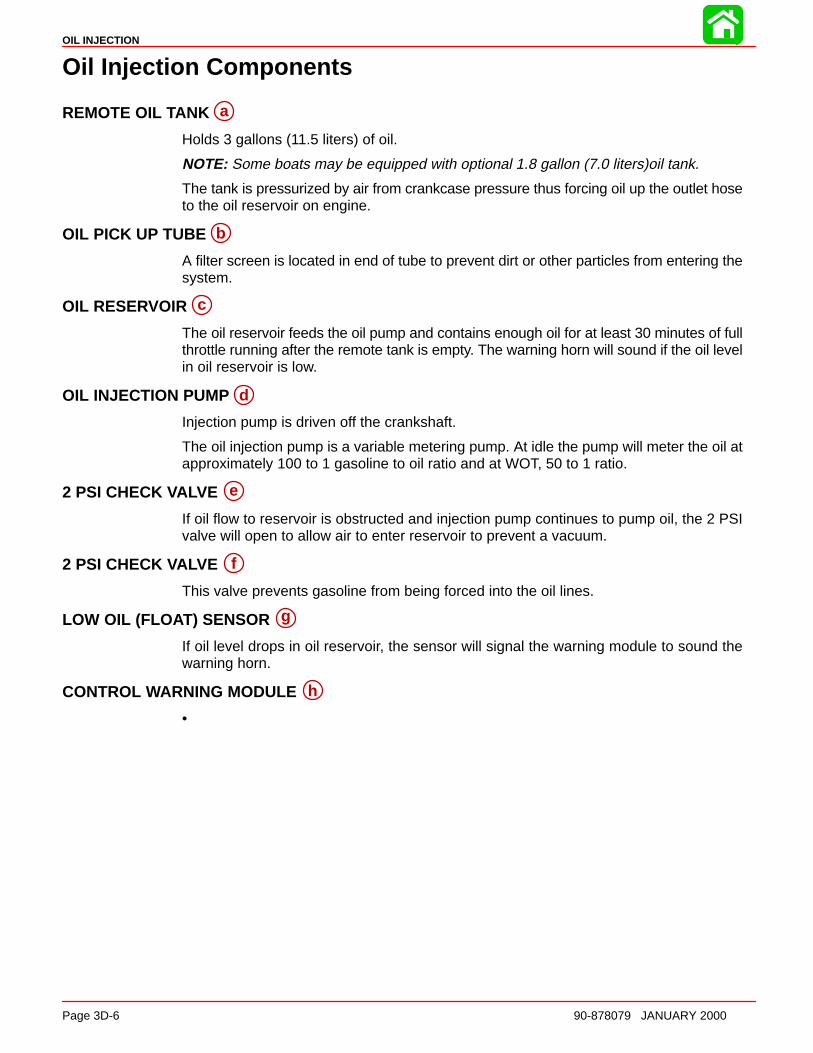
OIL INJECTION
Page 3D-6 90-878079 JANUARY 2000
Oil Injection Components
REMOTE OIL TANK a
Holds 3 gallons (11.5 liters) of oil.
NOTE: Some boats may be equipped with optional 1.8 gallon (7.0 liters)oil tank.
The tank is pressurized by air from crankcase pressure thus forcing oil up the outlet hoseto the oil reservoir on engine.
OIL PICK UP TUBE b
A filter screen is located in end of tube to prevent dirt or other particles from entering thesystem.
OIL RESERVOIR c
The oil reservoir feeds the oil pump and contains enough oil for at least 30 minutes of fullthrottle running after the remote tank is empty. The warning horn will sound if the oil levelin oil reservoir is low.
OIL INJECTION PUMP d
Injection pump is driven off the crankshaft.
The oil injection pump is a variable metering pump. At idle the pump will meter the oil atapproximately 100 to 1 gasoline to oil ratio and at WOT, 50 to 1 ratio.
2 PSI CHECK VALVE e
If oil flow to reservoir is obstructed and injection pump continues to pump oil, the 2 PSIvalve will open to allow air to enter reservoir to prevent a vacuum.
2 PSI CHECK VALVE f
This valve prevents gasoline from being forced into the oil lines.
LOW OIL (FLO AT) SENSOR g
If oil level drops in oil reservoir, the sensor will signal the warning module to sound thewarning horn.
CONTROL WARNING MODULE h
• Sounds the warning horn briefly when key switch is turned on, to indicate that thesystem is operational.
• If oil level drops in the engine oil reservoir, the low oil (float) sensor will signal themodule to sound the warning horn.
• On 200 EFI model, retards timing and widens pulse width of fuel injectors in theevent detonation is detected.
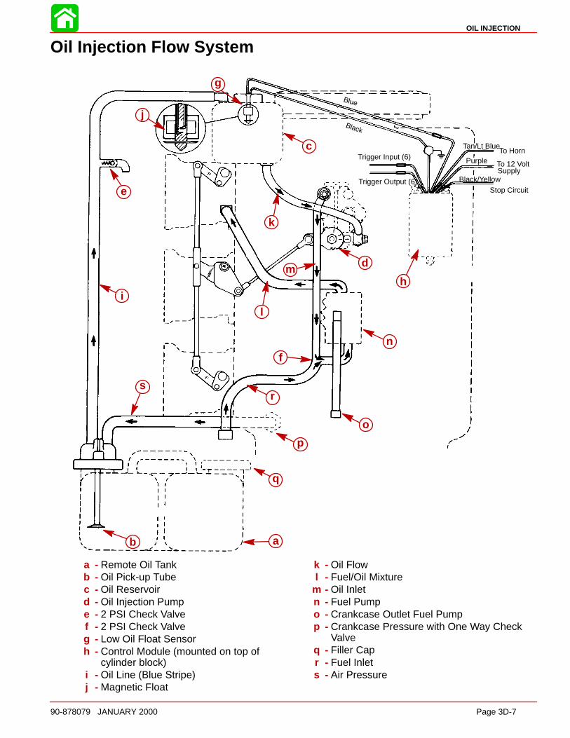
OIL INJECTION
90-878079 JANUARY 2000 Page 3D-7
Oil Injection Flow System
a
c
g
i
j
n
o
p
q
d
b
sr
e
l
mh
k
f
Tan/Lt BlueTo Horn
To 12 VoltSupply
Trigger Input (6)
Stop Circuit
Purple
Black/YellowTrigger Output (6)
a - Remote Oil Tankb - Oil Pick-up Tubec - Oil Reservoird - Oil Injection Pumpe - 2 PSI Check Valvef - 2 PSI Check Valveg - Low Oil Float Sensorh - Control Module (mounted on top of
cylinder block)i - Oil Line (Blue Stripe)j - Magnetic Float
k - Oil Flowl - Fuel/Oil Mixture
m - Oil Inletn - Fuel Pumpo - Crankcase Outlet Fuel Pumpp - Crankcase Pressure with One Way Check
Valveq - Filler Capr - Fuel Inlets - Air Pressure
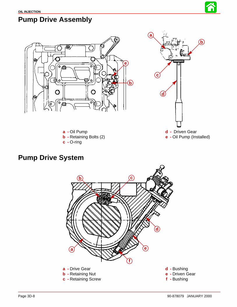
OIL INJECTION
Page 3D-8 90-878079 JANUARY 2000
Pump Drive Assembly
e
b
c
a
b
d
a - Oil Pumpb - Retaining Bolts (2)c - O-ring
d - Driven Geare - Oil Pump (Installed)
Pump Drive System
a
b c
d
e
f
a - Drive Gearb - Retaining Nutc - Retaining Screw
d - Bushinge - Driven Gearf - Bushing
OIL INJECTION
90-878079 JANUARY 2000 Page 3D-9
Set Up Instructions for Oil Injection System
CAUTIONBe careful not to get dirt or other contamination in tanks, hoses or other compo-nents of the oil injection system during installation.
CAUTIONOil injected engines additionall y, must be run on a 50:1 gasoline/oil mixture in thefuel tank for the first 30 gallons of fuel. Refer to engine break-in procedures in theOperation & Maintenance Manual.
CAUTIONIf an electric fuel pump is to be used on engines with oil injection, the fuel pres-sure at the engine must not exceed 4 psi (27 kPa). If necessar y, install a pressureregulator between electrical fuel pump and engine and set at 4 psi (27 kPa) maxi-mum.
INSTALLING REMOTE OIL TANK
1. The remote oil tank should be installed in an area in the boat where there is accessfor refilling.
The tank should be restrained to keep it from moving around, causing possible damage.
An acceptable means of restraining the tank would be the use of eye bolts and an elasticretaining strap about the mid-section of the tank taking care that any metal hooks do notpuncture the tank.
Keep in mind, when installing in tight areas, that this tank will be under pressure when theengine is operating and will expand slightly.
2. Oil hoses when routed thru engine well, must be able to extend to the hose fittings onengine.
3. Oil hoses must be arranged so they cannot become pinched, kinked, sharply bent orstretched during operation of the engine.
INSTALLING OIL HOSES TO ENGINE
Route remote oil tank hoses to starboard side of engine.
4. Remove (and discard) the shipping cap from hose fitting (a).
5. Connect oil hose from remote oil tank (hose with blue stripe) to fitting (a). Secure withsta-strap.
NOTE: Fitting barb (b) is a vent and does not get connected to a hose.
6. Remove (and discard) shipping cap from pulse fitting (c).
7. Connect the second oil hose from remote oil tank to pulse fitting. Secure with sta-strap.
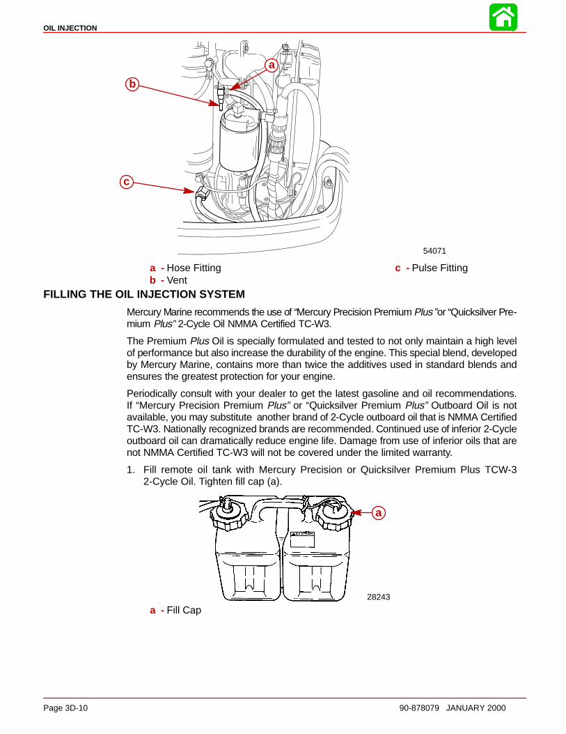
OIL INJECTION
Page 3D-10 90-878079 JANUARY 2000
c
b
a
54071
a - Hose Fittingb - Vent
c - Pulse Fitting
FILLING THE OIL INJECTION SYSTEM
Mercury Marine recommends the use of “Mercury Precision Premium Plus ”or “Quicksilver Pre-mium Plus” 2-Cycle Oil NMMA Certified TC-W3.
The Premium Plus Oil is specially formulated and tested to not only maintain a high levelof performance but also increase the durability of the engine. This special blend, developedby Mercury Marine, contains more than twice the additives used in standard blends andensures the greatest protection for your engine.
Periodically consult with your dealer to get the latest gasoline and oil recommendations.If “Mercury Precision Premium Plus” or “Quicksilver Premium Plus” Outboard Oil is notavailable, you may substitute another brand of 2-Cycle outboard oil that is NMMA CertifiedTC-W3. Nationally recognized brands are recommended. Continued use of inferior 2-Cycleoutboard oil can dramatically reduce engine life. Damage from use of inferior oils that arenot NMMA Certified TC-W3 will not be covered under the limited warranty.
1. Fill remote oil tank with Mercury Precision or Quicksilver Premium Plus TCW-32-Cycle Oil. Tighten fill cap (a).
a
28243
a - Fill Cap
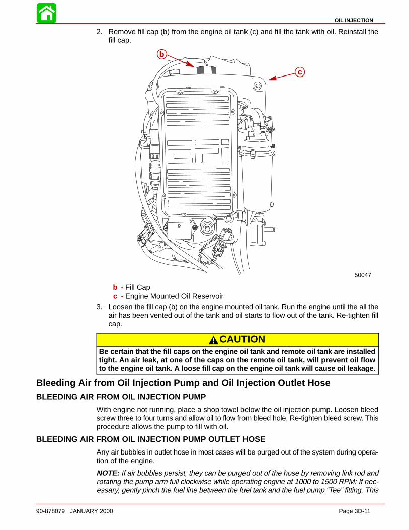
OIL INJECTION
90-878079 JANUARY 2000 Page 3D-11
2. Remove fill cap (b) from the engine oil tank (c) and fill the tank with oil. Reinstall thefill cap.
50047
b
c
b - Fill Capc - Engine Mounted Oil Reservoir
3. Loosen the fill cap (b) on the engine mounted oil tank. Run the engine until the all theair has been vented out of the tank and oil starts to flow out of the tank. Re-tighten fillcap.
CAUTIONBe certain that the fill caps on the engine oil tank and remote oil tank are installedtight. An air leak, at one of the caps on the remote oil tank, will prevent oil flowto the engine oil tank. A loose fill cap on the engine oil tank will cause oil leakage .
Bleeding Air from Oil Injection Pump and Oil Injection Outlet HoseBLEEDING AIR FROM OIL INJECTION PUMP
With engine not running, place a shop towel below the oil injection pump. Loosen bleedscrew three to four turns and allow oil to flow from bleed hole. Re-tighten bleed screw. Thisprocedure allows the pump to fill with oil.
BLEEDING AIR FROM OIL INJECTION PUMP OUTLET HOSE
Any air bubbles in outlet hose in most cases will be purged out of the system during opera-tion of the engine.
NOTE: If air bubbles persist, they can be purged out of the hose by removing link rod androtating the pump arm full clockwise while operating engine at 1000 to 1500 RPM: If nec-essary, gently pinch the fuel line between the fuel tank and the fuel pump “Tee” fitting. This
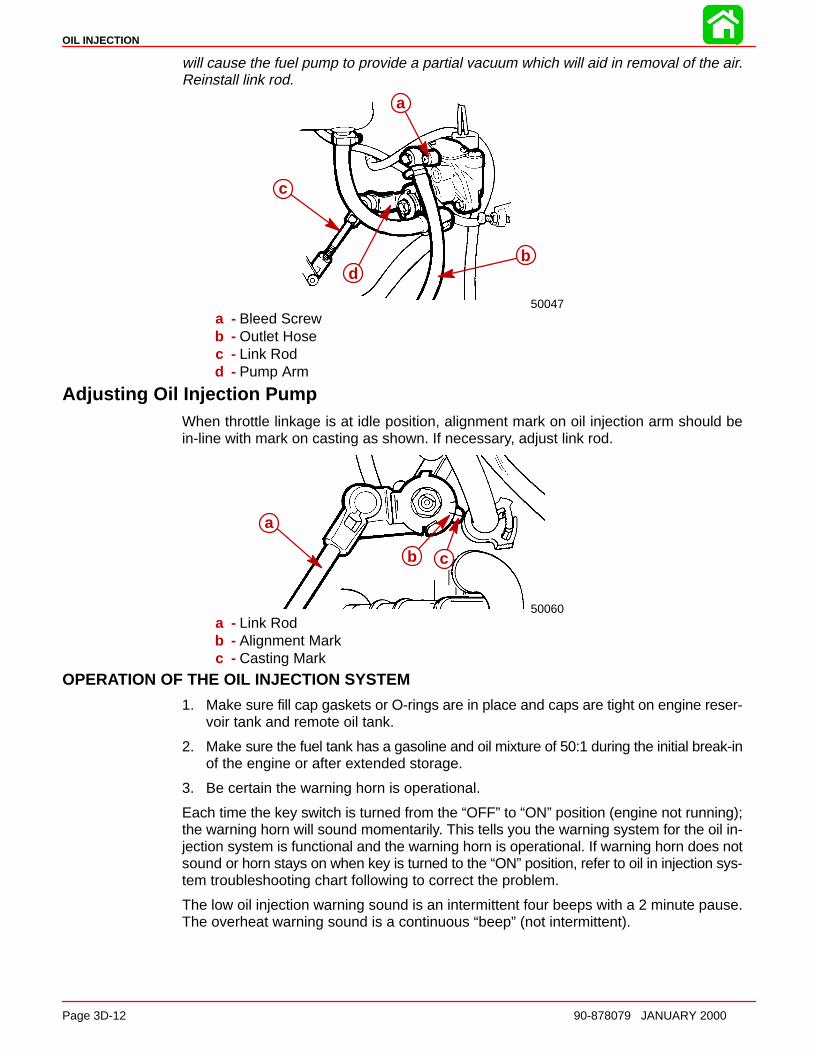
OIL INJECTION
Page 3D-12 90-878079 JANUARY 2000
will cause the fuel pump to provide a partial vacuum which will aid in removal of the air.Reinstall link rod.
b
c
d
a
b
c
d
50047a - Bleed Screwb - Outlet Hosec - Link Rodd - Pump Arm
Adjusting Oil Injection PumpWhen throttle linkage is at idle position, alignment mark on oil injection arm should bein-line with mark on casting as shown. If necessary, adjust link rod.
a
c
a
b c
50060a - Link Rodb - Alignment Markc - Casting Mark
OPERATION OF THE OIL INJECTION SYSTEM
1. Make sure fill cap gaskets or O-rings are in place and caps are tight on engine reser-voir tank and remote oil tank.
2. Make sure the fuel tank has a gasoline and oil mixture of 50:1 during the initial break-inof the engine or after extended storage.
3. Be certain the warning horn is operational.
Each time the key switch is turned from the “OFF” to “ON” position (engine not running);the warning horn will sound momentarily. This tells you the warning system for the oil in-jection system is functional and the warning horn is operational. If warning horn does notsound or horn stays on when key is turned to the “ON” position, refer to oil in injection sys-tem troubleshooting chart following to correct the problem.
The low oil injection warning sound is an intermittent four beeps with a 2 minute pause.The overheat warning sound is a continuous “beep” (not intermittent).
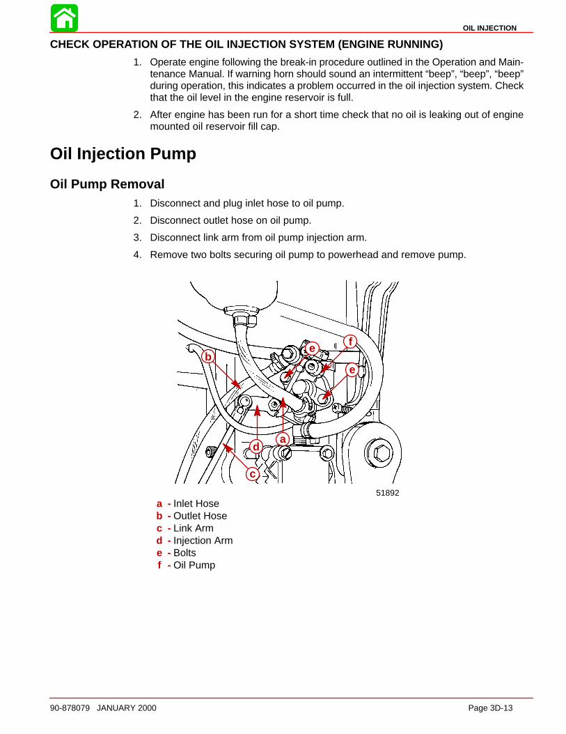
OIL INJECTION
90-878079 JANUARY 2000 Page 3D-13
CHECK OPERATION OF THE OIL INJECTION SYSTEM (ENGINE RUNNING)
1. Operate engine following the break-in procedure outlined in the Operation and Main-tenance Manual. If warning horn should sound an intermittent “beep”, “beep”, “beep”during operation, this indicates a problem occurred in the oil injection system. Checkthat the oil level in the engine reservoir is full.
2. After engine has been run for a short time check that no oil is leaking out of enginemounted oil reservoir fill cap.
Oil Injection Pump
Oil Pump Removal1. Disconnect and plug inlet hose to oil pump.
2. Disconnect outlet hose on oil pump.
3. Disconnect link arm from oil pump injection arm.
4. Remove two bolts securing oil pump to powerhead and remove pump.
a
b
c
d
e
e
f
51892a - Inlet Hoseb - Outlet Hosec - Link Armd - Injection Arme - Boltsf - Oil Pump
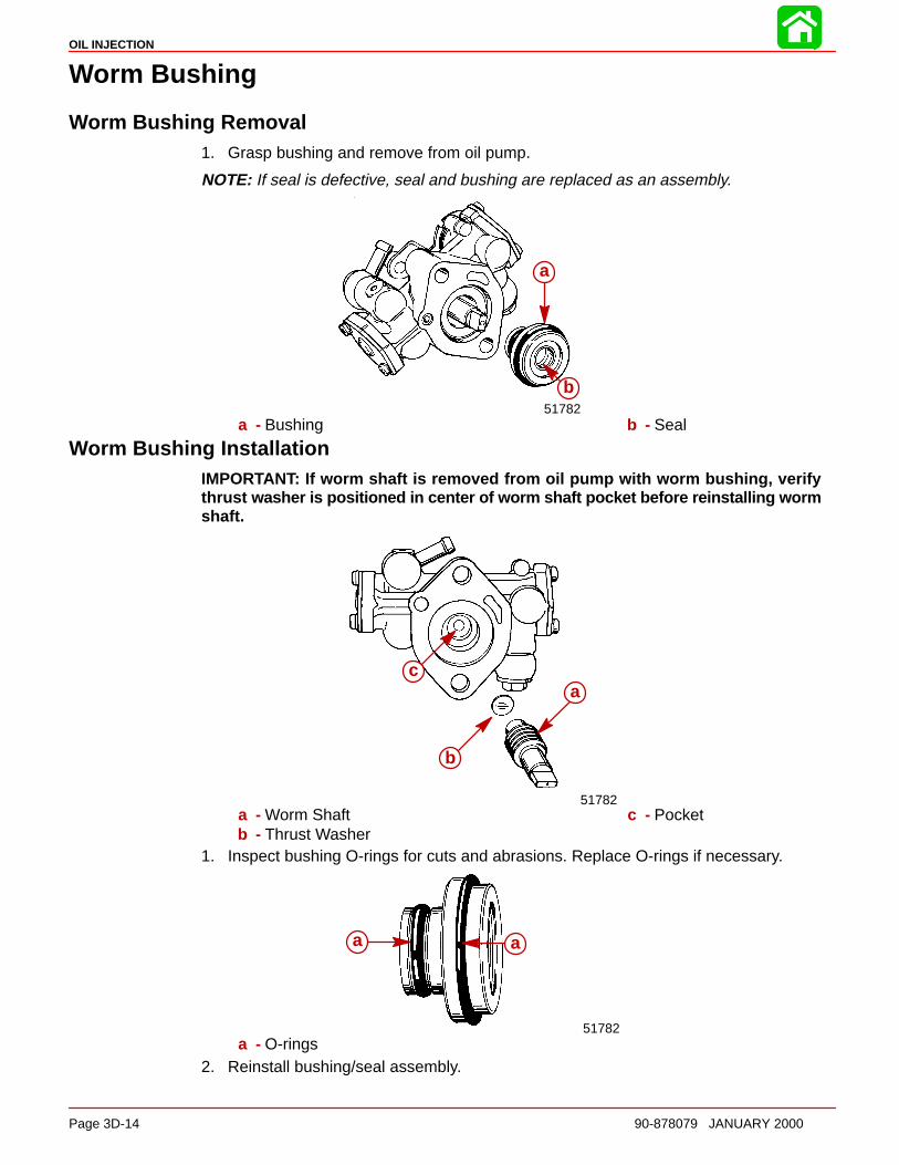
OIL INJECTION
Page 3D-14 90-878079 JANUARY 2000
Worm Bushing
Worm Bushing Removal1. Grasp bushing and remove from oil pump.
NOTE: If seal is defective, seal and bushing are replaced as an assembly.
a
b51782
a - Bushing b - Seal
Worm Bushing InstallationIMPORTANT: If worm shaft is removed from oil pump with worm bushing, verifythrust washer is positioned in center of worm shaft pocket before reinstalling wormshaft.
a
b
c
51782a - Worm Shaftb - Thrust Washer
c - Pocket
1. Inspect bushing O-rings for cuts and abrasions. Replace O-rings if necessary.
a a
51782a - O-rings
2. Reinstall bushing/seal assembly.

OIL INJECTION
90-878079 JANUARY 2000 Page 3D-15
Oil Injection Pump Installation1. Align oil pump worm shaft with end of driven gear in powerhead.
a
b
51782a - Worm Shaft b - Driven Gear
2. Apply Loctite 271 to threads of attaching bolts and secure oil pump to powerhead.Torque bolts to 55 Ib. in. (6 N·m).
3. Connect inlet and outlet hoses to oil pump. Secure hoses with clamps.
4. Connect link arm to oil pump arm.
5. Prior to starting engine, refer to “BLEEDING AIR FROM OIL INJECTION PUMP ” and“ADJUSTING OIL INJECTION PUM P,” SECTION 1D, for proper procedures.
Installing Drive Gear (for Oil Injection Pump) onto CrankshaftIMPORTANT: Oil pump drive gear retaining screws ARE S TAKED after installation.DO NOT remove drive gear from crankshaft unless gear is damaged or shows signsof excessive wea r.
REMOVAL OF DRIVE GEAR
1. Rotate crankshaft to gain access to two drive gear retaining allen screws.
2. Remove two screws and remove drive gear from crankshaft. DO NOT reuse retainingscrews as screw threads may be damaged by factory staking process.
a
b
c
51892a - Retaining Nutb - Allen Screw
c - Center Main Bearing(Hidden)
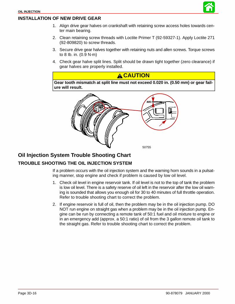
OIL INJECTION
Page 3D-16 90-878079 JANUARY 2000
INSTALL ATION OF NEW DRIVE GEAR
1. Align drive gear halves on crankshaft with retaining screw access holes towards cen-ter main bearing.
2. Clean retaining screw threads with Loctite Primer T (92-59327-1). Apply Loctite 271(92-809820) to screw threads.
3. Secure drive gear halves together with retaining nuts and allen screws. Torque screwsto 8 Ib. in. (0.9 N·m)
4. Check gear halve split lines. Split should be drawn tight together (zero clearance) ifgear halves are properly installed.
CAUTIONGear tooth mismatch at split line must not exceed 0.020 in. (0.50 mm) or gear fail-ure will result.
50755
Oil Injection System Trouble Shooting ChartTROUBLE SHOOTING THE OIL INJECTION SYSTEM
If a problem occurs with the oil injection system and the warning horn sounds in a pulsat-ing manner, stop engine and check if problem is caused by low oil level.
1. Check oil level in engine reservoir tank. If oil level is not to the top of tank the problemis low oil level. There is a safety reserve of oil left in the reservoir after the low oil warn-ing is sounded that allows you enough oil for 30 to 40 minutes of full throttle operation.Refer to trouble shooting chart to correct the problem.
2. If engine reservoir is full of oil, then the problem may be in the oil injection pump. DONOT run engine on straight gas when a problem may be in the oil injection pump. En-gine can be run by connecting a remote tank of 50:1 fuel and oil mixture to engine orin an emergency add (approx. a 50:1 ratio) of oil from the 3 gallon remote oil tank tothe straight gas. Refer to trouble shooting chart to correct the problem.
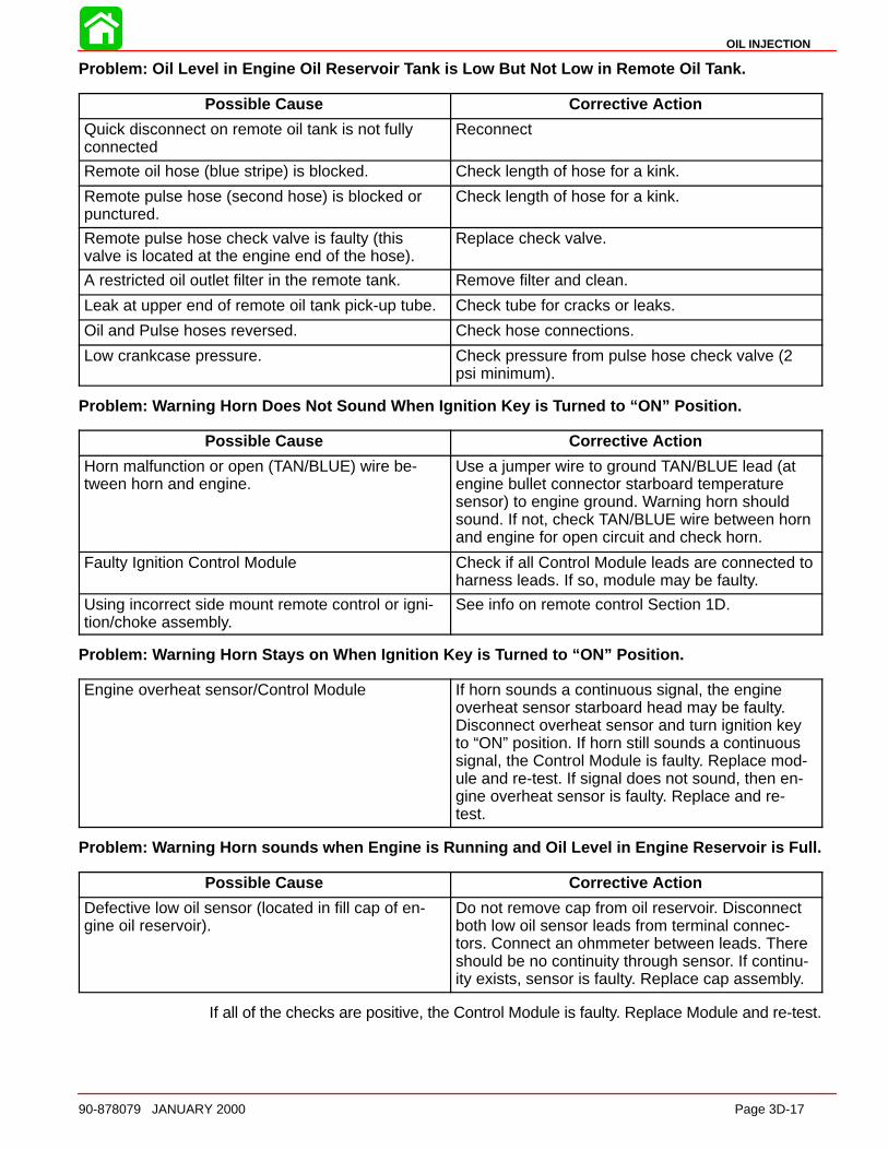
OIL INJECTION
90-878079 JANUARY 2000 Page 3D-17
Problem: Oil Level in Engine Oil Reservoir Tank is Low But Not Low in Remote Oil Tank.
Possible Cause Corrective Action
Quick disconnect on remote oil tank is not fullyconnected
Reconnect
Remote oil hose (blue stripe) is blocked. Check length of hose for a kink.
Remote pulse hose (second hose) is blocked orpunctured.
Check length of hose for a kink.
Remote pulse hose check valve is faulty (thisvalve is located at the engine end of the hose).
Replace check valve.
A restricted oil outlet filter in the remote tank. Remove filter and clean.
Leak at upper end of remote oil tank pick-up tube. Check tube for cracks or leaks.
Oil and Pulse hoses reversed. Check hose connections.
Low crankcase pressure. Check pressure from pulse hose check valve (2psi minimum).
Problem: Warning Horn Does Not Sound When Ignition Key is Turned to “ON” Position.
Possible Cause Corrective Action
Horn malfunction or open (TAN/BLUE) wire be-tween horn and engine.
Use a jumper wire to ground TAN/BLUE lead (atengine bullet connector starboard temperaturesensor) to engine ground. Warning horn shouldsound. If not, check TAN/BLUE wire between hornand engine for open circuit and check horn.
Faulty Ignition Control Module Check if all Control Module leads are connected toharness leads. If so, module may be faulty.
Using incorrect side mount remote control or igni-tion/choke assembly.
See info on remote control Section 1D.
Problem: Warning Horn Stays on When Ignition Key is Turned to “ON” Position.
Engine overheat sensor/Control Module If horn sounds a continuous signal, the engineoverheat sensor starboard head may be faulty.Disconnect overheat sensor and turn ignition keyto “ON” position. If horn still sounds a continuoussignal, the Control Module is faulty. Replace mod-ule and re-test. If signal does not sound, then en-gine overheat sensor is faulty. Replace and re-test.
Problem: Warning Horn sounds when Engine is Running and Oil Level in Engine Reservoir is Full.
Possible Cause Corrective Action
Defective low oil sensor (located in fill cap of en-gine oil reservoir).
Do not remove cap from oil reservoir. Disconnectboth low oil sensor leads from terminal connec-tors. Connect an ohmmeter between leads. Thereshould be no continuity through sensor. If continu-ity exists, sensor is faulty. Replace cap assembly.
If all of the checks are positive, the Control Module is faulty. Replace Module and re-test.
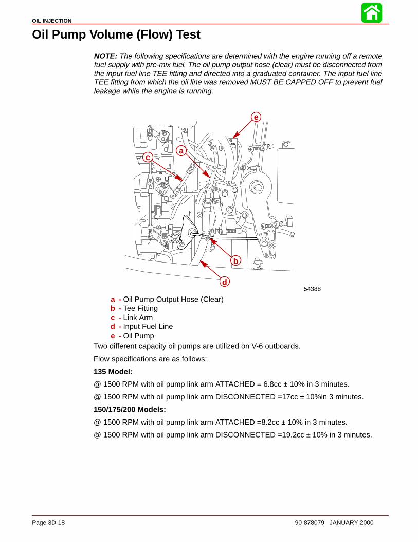
OIL INJECTION
Page 3D-18 90-878079 JANUARY 2000
Oil Pump Volume (Flow) Test
NOTE: The following specifications are determined with the engine running off a remotefuel supply with pre-mix fuel. The oil pump output hose (clear) must be disconnected fromthe input fuel line TEE fitting and directed into a graduated container. The input fuel lineTEE fitting from which the oil line was removed MUST BE CAPPED OFF to prevent fuelleakage while the engine is running.
e
b
c
d
a
54388
a - Oil Pump Output Hose (Clear)b - Tee Fittingc - Link Armd - Input Fuel Linee - Oil Pump
Two different capacity oil pumps are utilized on V-6 outboards.
Flow specifications are as follows:
135 Model:
@ 1500 RPM with oil pump link arm ATTACHED = 6.8cc ± 10% in 3 minutes.
@ 1500 RPM with oil pump link arm DISCONNECTED =17cc ± 10%in 3 minutes.
150/175/200 Models:
@ 1500 RPM with oil pump link arm ATTACHED =8.2cc ± 10% in 3 minutes.
@ 1500 RPM with oil pump link arm DISCONNECTED =19.2cc ± 10% in 3 minutes.
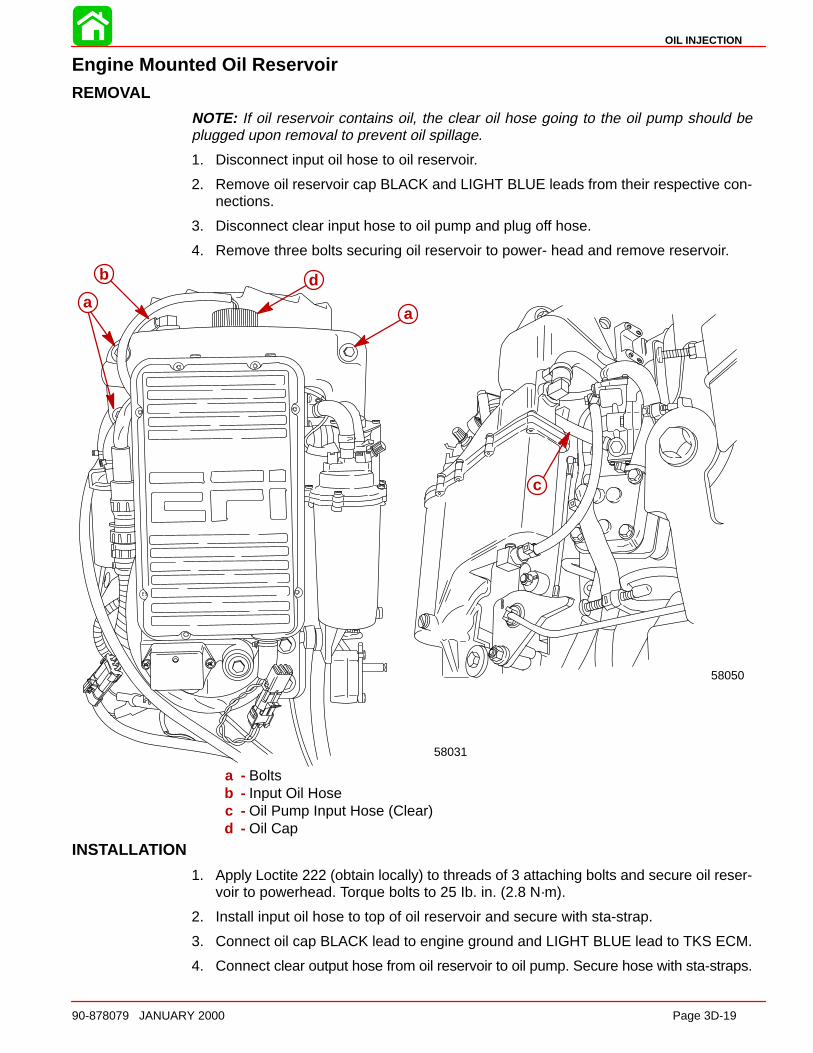
OIL INJECTION
90-878079 JANUARY 2000 Page 3D-19
Engine Mounted Oil ReservoirREMOVAL
NOTE: If oil reservoir contains oil, the clear oil hose going to the oil pump should beplugged upon removal to prevent oil spillage.
1. Disconnect input oil hose to oil reservoir.
2. Remove oil reservoir cap BLACK and LIGHT BLUE leads from their respective con-nections.
3. Disconnect clear input hose to oil pump and plug off hose.
4. Remove three bolts securing oil reservoir to power- head and remove reservoir.
58031
58050
b
aa
c
d
a - Boltsb - Input Oil Hosec - Oil Pump Input Hose (Clear)d - Oil Cap
INSTALL ATION
1. Apply Loctite 222 (obtain locally) to threads of 3 attaching bolts and secure oil reser-voir to powerhead. Torque bolts to 25 Ib. in. (2.8 N·m).
2. Install input oil hose to top of oil reservoir and secure with sta-strap.
3. Connect oil cap BLACK lead to engine ground and LIGHT BLUE lead to TKS ECM.
4. Connect clear output hose from oil reservoir to oil pump. Secure hose with sta-straps.

3E
EMISSIONS
90-878079 JANUARY 2000 Page 3E-1
FUEL SYSTEMSection 3E – Emissions
Table of Contents
Exhaust Emissions Standards 3E-1. . . . . . . . . . . . . . . . . What Are Emissions? 3E-1. . . . . . . . . . . . . . . . . . . . . . Hydrocarbons – HC 3E-1. . . . . . . . . . . . . . . . . . . . . . . . Carbon Monoxide – CO 3E-1. . . . . . . . . . . . . . . . . . . . Oxides of Nitrogen - NOx 3E-2. . . . . . . . . . . . . . . . . . . Controlling Emissions 3E-2. . . . . . . . . . . . . . . . . . . . . . Stoichiometric (14.7:1) Air/Fuel Ratio 3E-2. . . . . . . .
Outboard Hydrocarbon Emissions Reductions 3E-2. . . Stratified vs Homogenized Charge 3E-3. . . . . . . . . . . . .
Homogenized Charge 3E-3. . . . . . . . . . . . . . . . . . . . . . Stratified Charge 3E-4. . . . . . . . . . . . . . . . . . . . . . . . . .
Emissions Information 3E-4. . . . . . . . . . . . . . . . . . . . . . . . Manufacturer’s Responsibility: 3E-4. . . . . . . . . . . . . . Dealer Responsibility: 3E-5. . . . . . . . . . . . . . . . . . . . . . Owner Responsibility: 3E-5. . . . . . . . . . . . . . . . . . . . . . EPA Emission Regulations: 3E-5. . . . . . . . . . . . . . . . .
Manufacturer’s Certification Label 3E-6. . . . . . . . . . . . . . Service Replacement Certification Label 3E-7. . . . . . . .
Removal 3E-7. . . . . . . . . . . . . . . . . . . . . . . . . . . . . . . . . Date Code Identification 3E-7. . . . . . . . . . . . . . . . . . . . Installation 3E-7. . . . . . . . . . . . . . . . . . . . . . . . . . . . . . . . Decal Location: 3E-7. . . . . . . . . . . . . . . . . . . . . . . . . . .
Exhaust Emissions Standards
Through the Environmental Protection Agency (EPA), the federal government has estab-lished exhaust emissions standards for all new marine engines sold in the United States.
What Are Emissions?Emissions are what comes out of the exhaust system in the exhaust gas when the engineis running. They are formed as a result of the process of combustion or incomplete com-bustion. To understand exhaust gas emissions, remember that both air and fuel are madeof several elements. Air contains oxygen and nitrogen among other elements; gasolinecontains mainly hydrogen and carbon. These four elements combine chemically duringcombustion. If combustion were complete, the mixture of air and gasoline would result inthese emissions: water, carbon dioxide and nitrogen, which are not harmful to the environ-ment. However, combustion is not usually complete. Also, potentially harmful gases canbe formed during and after combustion.
All marine engines must reduce the emission of certain pollutants, or potentially harmfulgases, in the exhaust to conform with levels legislated by the EPA. Emissions standardsbecome more stringent each year. Standards are set primarily with regard to three emis-sions: hydrocarbons (HC), carbon monoxide (CO) and oxides of nitrogen (NOx).
Hydrocarbons – HCGasoline is a hydrocarbon fuel. The two elements of hydrogen and carbon are burnedduring combustion in combination with oxygen. But they are not totally consumed. Somepass through the combustion chamber and exit the exhaust system as unburned gasesknown as hydrocarbons.
Carbon Monoxide – COCarbon is one of the elements that make up the fuel burned in the engine along with oxy-gen during the combustion process. If the carbon in the gasoline could combine withenough oxygen (one carbon atom with two oxygen atoms), it would come out of the en-gine in the form of carbon dioxide (CO2). CO2 is a harmless gas. However, carbon oftencombines with insufficient oxygen (one carbon atom with one oxygen atom). This formscarbon monoxide, CO. Carbon monoxide is the product of incomplete combustion andis a dangerous, potentially lethal gas.

EMISSIONS
Page 3E-2 90-878079 JANUARY 2000
Oxides of Nitrogen - NOxNOx is a slightly different byproduct of combustion. Nitrogen is one of the elements thatmakes up the air going into the engine. Under extremely high temperatures it combineswith oxygen to form oxides of nitrogen (NOx). This happens in the engine’s combustionchambers when temperatures are too high. NOx itself is not harmful, but when exposedto sunlight it combines with unburned hydrocarbons to create the visible air pollutantknown as smog. Smog is a serious problem in California as well as many other heavilypopulated areas of the United States.
Controlling EmissionsThere are two principle methods of reducing emissions from a two-stroke-cycle marineengine. The first method is to control the air/fuel ratio that goes into the combustion cham-ber. The second is to control the time when this air/fuel mixture enters the combustionchamber. Timing is important, to prevent any unburned mixture from escaping out of theexhaust port.
Stoichiometric (14.7:1) Air/Fuel RatioIn the search to control pollutants and reduce exhaust emissions, engineers have discov-ered that they can be reduced effectively if a gasoline engine operates at an air/fuel ratioof 14.7:1. The technical term for this ideal ratio is stoichiometric. An air/fuel ratio of 14.7:1provides the best control of all three elements in the exhaust under almost all conditions.The HC and CO content of the exhaust gas is influenced significantly by the air/fuel ratio.At an air/fuel ratio leaner than 14.7:1, HC and CO levels are low, but with a ratio richerthan 14.7:1 they rise rapidly. It would seem that controlling HC and CO by themselvesmight not be such a difficult task; the air/fuel ratio only needs to be kept leaner than 14.7:1.However, there is also NOx to consider.
As the air/fuel ratio becomes leaner, combustion temperatures increase. Higher combus-tion temperatures raise the NOx content of the exhaust. However, enrichening the air/fuelratio to decrease combustion temperatures or reduce NOx also increases HC and CO,as well as lowering fuel economy. So the solution to controlling NOx - as well as HC andCO - is to keep the air/fuel ratio as close to 14.7:1 as possible.
Outboard Hydrocarbon Emissions Reductions8 1/3% per Year Over 9 Model Years
0
20
40
60
80
100
120
96 97 98 99 2000 01 02 03 04 05 06 07 08
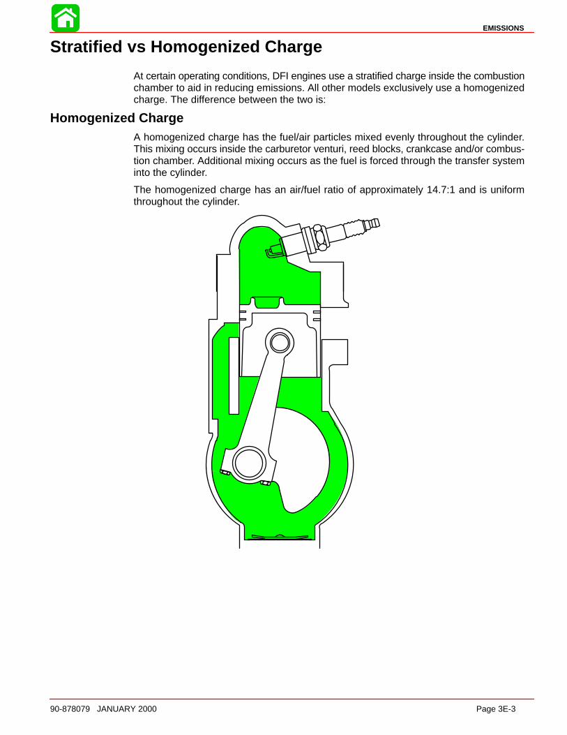
EMISSIONS
90-878079 JANUARY 2000 Page 3E-3
Stratified vs Homogenized Charge
At certain operating conditions, DFI engines use a stratified charge inside the combustionchamber to aid in reducing emissions. All other models exclusively use a homogenizedcharge. The difference between the two is:
Homogenized ChargeA homogenized charge has the fuel/air particles mixed evenly throughout the cylinder.This mixing occurs inside the carburetor venturi, reed blocks, crankcase and/or combus-tion chamber. Additional mixing occurs as the fuel is forced through the transfer systeminto the cylinder.
The homogenized charge has an air/fuel ratio of approximately 14.7:1 and is uniformthroughout the cylinder.
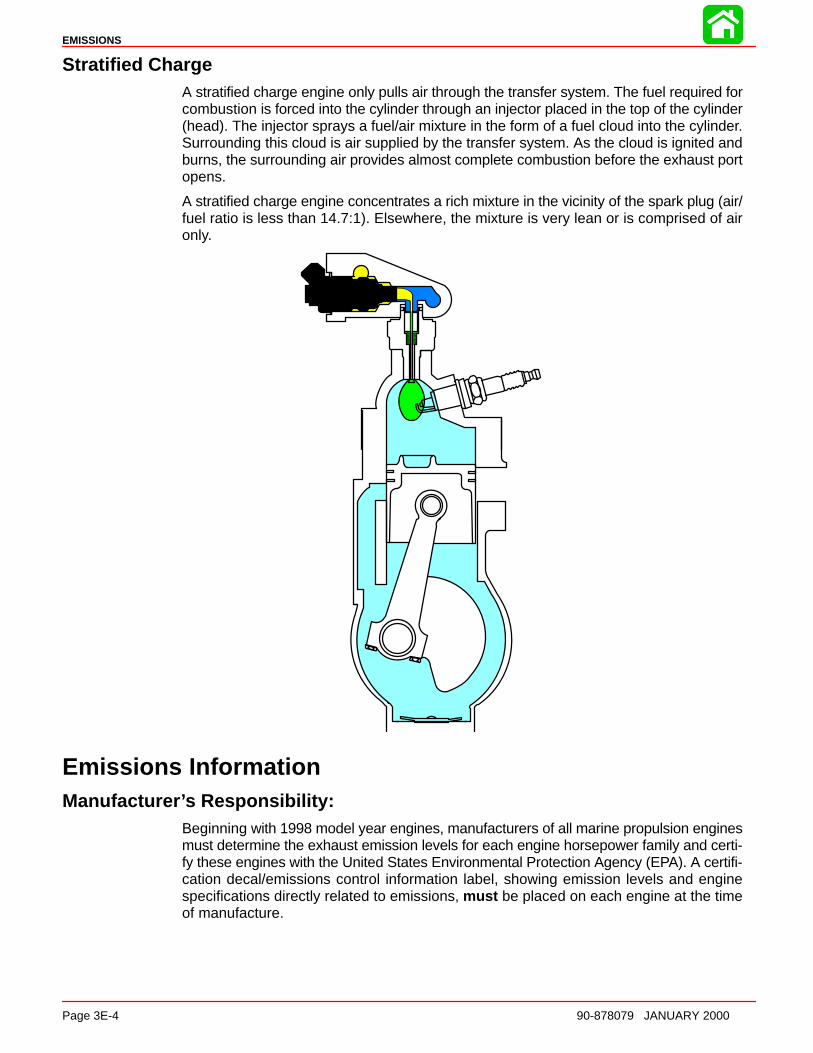
EMISSIONS
Page 3E-4 90-878079 JANUARY 2000
Stratified ChargeA stratified charge engine only pulls air through the transfer system. The fuel required forcombustion is forced into the cylinder through an injector placed in the top of the cylinder(head). The injector sprays a fuel/air mixture in the form of a fuel cloud into the cylinder.Surrounding this cloud is air supplied by the transfer system. As the cloud is ignited andburns, the surrounding air provides almost complete combustion before the exhaust portopens.
A stratified charge engine concentrates a rich mixture in the vicinity of the spark plug (air/fuel ratio is less than 14.7:1). Elsewhere, the mixture is very lean or is comprised of aironly.
Emissions InformationManufacture r’s Responsibility:
Beginning with 1998 model year engines, manufacturers of all marine propulsion enginesmust determine the exhaust emission levels for each engine horsepower family and certi-fy these engines with the United States Environmental Protection Agency (EPA). A certifi-cation decal/emissions control information label, showing emission levels and enginespecifications directly related to emissions, must be placed on each engine at the timeof manufacture.

EMISSIONS
90-878079 JANUARY 2000 Page 3E-5
Dealer Responsibility:When performing service on all 1998 and later outboards that carry a certification, atten-tion must be given to any adjustments that are made that affect emission levels.
Adjustments must be kept within published factory specifications.
Replacement or repair of any emission related component must be executed in a mannerthat maintains emission levels within the prescribed certification standards.
Dealers are not to modify the engine in any manner that would alter the horsepower orallow emission levels to exceed their predetermined factory specifications.
Exceptions include manufacturers prescribed changes, such as that for altitude adjust-ments. Also included would be factory authorized:
• Installation of performance style gear housings by Mercury Marine.
• Service replacement parts modified, changed or superceded by Mercury Marine.
Owner Responsibility:The owner/operator is required to have engine maintenance performed to maintain emis-sion levels within prescribed certification standards.
The owner/operator is not to modify the engine in any manner that would alter the horse-power or allow emissions levels to exceed their predetermined factory specifications.
Single engine exceptions may be allowed with permission from the EPA for racing andtesting.
EPA Emission Regulations:All new 1998 and later outboards manufactured by Mercury Marine are certified to theUnited States Environmental Protection Agency as conforming to the requirements of theregulations for the control of air pollution from new outboard motors. This certification iscontingent on certain adjustments being set to factory standards. For this reason, the fac-tory procedure for servicing the product must be strictly followed and, whenever practica-ble, returned to the original intent of the design.
The responsibilities listed above are general and in no way a complete listing of the rulesand regulations pertaining to the EPA laws on exhaust emissions for marine products. Formore detailed information on this subject, you may contact the following locations:
VIA U.S. POSTAL SERVICE:Office of Mobile SourcesEngine Programs and Compliance DivisionEngine Compliance Programs Group (6403J)401 M St. NWWashington, DC 20460
VIA EXPRESS or COURIER MAIL:Office of Mobile SourcesEngine Programs and Compliance DivisionEngine Compliance Programs Group (6403J)501 3rd St. NWWashington, DC 20001
EPA INTERNET WEB SITE:http:/www.epa.gov/omswww
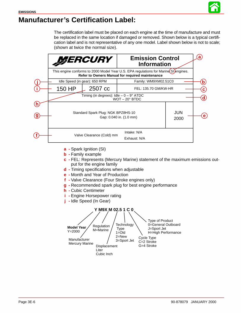
EMISSIONS
Page 3E-6 90-878079 JANUARY 2000
Manufacture r ’s Certification Label:
The certification label must be placed on each engine at the time of manufacture and mustbe replaced in the same location if damaged or removed. Shown below is a typical certifi-cation label and is not representative of any one model. Label shown below is not to scale;(shown at twice the normal size).
aEmission ControlInformation
Refer to Owners Manual for required maintenance
Family: WM9XM02.51C0Idle Speed (in gear): 650 RPM
FEL: 135.70 GM/KW-HR150 HP 2507 ccTiming (in degrees): Idle – 0 – 9° ATDC
WOT – 20° BTDC
Standard Spark Plug: NGK BPZ8HS-10Gap: 0.040 in. (1.0 mm)
Valve Clearance (Cold) mmIntake: N/A
Exhaust: N/A
This engine conforms to 2000 Model Year U.S. EPA regulations for Marine SI engines.
b
c
d
f
g
i
JUN2000
e
j
h
a - Spark Ignition (SI)b - Family examplec - FEL: Represents (Mercury Marine) statement of the maximum emissions out-
put for the engine familyd - Timing specifications when adjustablee - Month and Year of Productionf - Valve Clearance (Four Stroke engines only)g - Recommended spark plug for best engine performanceh - Cubic Centimeteri - Engine Horsepower ratingj - Idle Speed (In Gear)
Y M9X M 02.5 1 C 0
Model YearY=2000
ManufacturerMercury Marine
RegulationM=Marine
DisplacementLiterCubic Inch
Cycle TypeC=2 StrokeG=4 Stroke
Technology Type1=Old2=New3=Sport Jet
Type of Product0=General OutboardJ=Sport JetH=High Performance
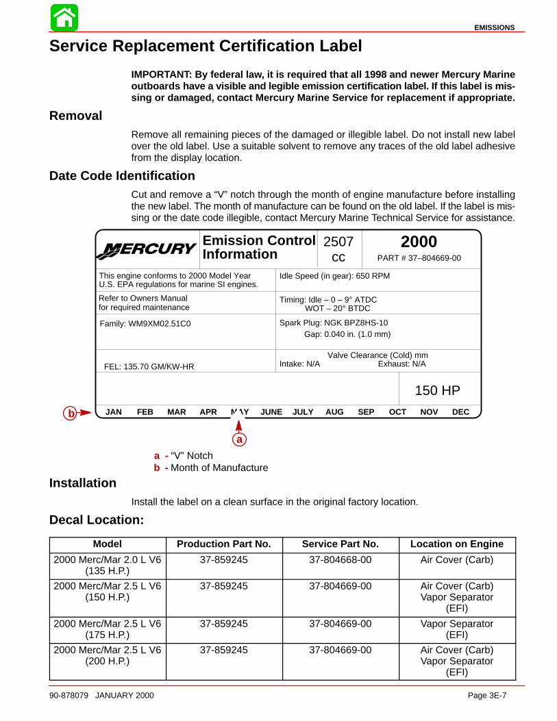
EMISSIONS
90-878079 JANUARY 2000 Page 3E-7
Service Replacement Certification Label
IMPORTANT: By federal la w, it is required that all 1998 and newer Mercury Marineoutboards have a visible and legible emission certification label. If this label is mis-sing or damaged, contact Mercury Marine Service for replacement if appropriate.
RemovalRemove all remaining pieces of the damaged or illegible label. Do not install new labelover the old label. Use a suitable solvent to remove any traces of the old label adhesivefrom the display location.
Date Code IdentificationCut and remove a “V” notch through the month of engine manufacture before installingthe new label. The month of manufacture can be found on the old label. If the label is mis-sing or the date code illegible, contact Mercury Marine Technical Service for assistance.
JAN FEB MAR APR MAY JUNE JULY AUG SEP OCT NOV DEC
Emission ControlInformation
2000PART # 37–804669-00
This engine conforms to 2000 Model Year U.S. EPA regulations for marine SI engines.
Idle Speed (in gear): 650 RPM
Timing: Idle – 0 – 9° ATDC WOT – 20° BTDC
Spark Plug: NGK BPZ8HS-10Gap: 0.040 in. (1.0 mm)
Valve Clearance (Cold) mmIntake: N/A Exhaust: N/A
Family: WM9XM02.51C0
FEL: 135.70 GM/KW-HR
2507cc
150 HP
Refer to Owners Manual for required maintenance
a
b
a - “V” Notchb - Month of Manufacture
InstallationInstall the label on a clean surface in the original factory location.
Decal Location:
Model Production Part No. Service Part No. Location on Engine
2000 Merc/Mar 2.0 L V6(135 H.P.)
37-859245 37-804668-00 Air Cover (Carb)
2000 Merc/Mar 2.5 L V6(150 H.P.)
37-859245 37-804669-00 Air Cover (Carb)Vapor Separator
(EFI)
2000 Merc/Mar 2.5 L V6(175 H.P.)
37-859245 37-804669-00 Vapor Separator(EFI)
2000 Merc/Mar 2.5 L V6(200 H.P.)
37-859245 37-804669-00 Air Cover (Carb)Vapor Separator
(EFI)

4A
POWERHEAD
90-878079 JANUARY 2000 Page 4A-1
POWERHEADSection 4A - Powerhead
Table of Contents
Powerhead Specifications(2 Liter Model 135) 4A-2. . . . . . . . . . . . . . . . . . . . . . Powerhead Specifications(2.5 Liter Model 150/175/200) 4A-3. . . . . . . . . . . . . Special Tools 4A-4. . . . . . . . . . . . . . . . . . . . . . . . . . .
Powerhead Repair Stand 4A-5. . . . . . . . . . . . . . Cylinder Block Assembly 4A-7. . . . . . . . . . . . . . . . . Exhaust Manifold and Exhaust Plate 4A-8. . . . . . . Crankshaft, Pistons and Connecting Rods 4A-10. . Reed Block and Cylinder Head 4A-12. . . . . . . . . . . . Bleed System Routing (Carburetor Models) 4A-14. Bleed System Routing (EFI Models) 4A-15. . . . . . . Torque Sequence 4A-16. . . . . . . . . . . . . . . . . . . . . . . General Information 4A-17. . . . . . . . . . . . . . . . . . . . . Powerhead Removal fromDriveshaft Housing 4A-18. . . . . . . . . . . . . . . . . . . . . .
Removing Engine Components 4A-22. . . . . . . . Powerhead Disassembly 4A-23. . . . . . . . . . . . . . . . . Cleaning and Inspection 4A-34. . . . . . . . . . . . . . . . . .
Cylinder Block and Crankcase Cover 4A-34. . . Special Service Information 4A-34. . . . . . . . . . . . Cylinder Bores 4A-35. . . . . . . . . . . . . . . . . . . . . . . Pistons and Piston Rings 4A-36. . . . . . . . . . . . . . Cylinder Heads and ExhaustDivider Plate 4A-38. . . . . . . . . . . . . . . . . . . . . . . . .
Crankshaft 4A-38. . . . . . . . . . . . . . . . . . . . . . . . . . Crankshaft (and End Cap) Bearings 4A-39. . . . Reed Block Assembly 4A-39. . . . . . . . . . . . . . . . . Reed Block Housing 4A-40. . . . . . . . . . . . . . . . . . Connecting Rods 4A-40. . . . . . . . . . . . . . . . . . . . .
Powerhead Reassembly and Installation 4A-43. . . General 4A-43. . . . . . . . . . . . . . . . . . . . . . . . . . . . . Crankshaft Installation 4A-48. . . . . . . . . . . . . . . . Piston and Connecting Rod Reassembly 4A-50Piston and Piston Ring Combinations 4A-53. . . Piston Installation 4A-53. . . . . . . . . . . . . . . . . . . . Crankcase Cover Installation 4A-57. . . . . . . . . . . Assembly of Reed Blocks toIntake Manifold 4A-59. . . . . . . . . . . . . . . . . . . . . . . Assembly of Exhaust Manifold to Block 4A-59. .
Cleaning and Inspection 4A-61. . . . . . . . . . . . . . . . . . Cylinder Block and Crankcase Cover 4A-61. . . Reinstalling Engine Components 4A-63. . . . . . .
Throttle Lever and Shift Shaft 4A-64. . . . . . . . . . . . . Powerhead Installation OnDriveshaft Housing 4A-68. . . . . . . . . . . . . . . . . . . . . . Gasoline/Oil Break-in Mixture 4A-73. . . . . . . . . . . . . Break-ln Procedure 4A-73. . . . . . . . . . . . . . . . . . . . . .

POWERHEAD
Page 4A-2 90-878079 JANUARY 2000
Powerhead Specifications (2 Liter Model 135)
BlockType 60° V, 2 Cycle. . . . . . . . . . . . . . . . . . . . . . . . . . . . . . . . . Displacement 122 cu. in. (2.0 Litre). . . . . . . . . . . . . . . . . . . . . . . . .
Reed Valve OpeningReed Stand Open (Max.) 0.020 in. (0.50 mm). . . . . . . . . . . . . . .
Cylinder BoreDia. Standard 3.125 in. (79.375 mm). . . . . . . . . . . . . . . . . . . . . . . . . Dia. 0.015 in. Oversize 3.140 in. (79.756 mm). . . . . . . . . . . . . . . . . Dia. 0.030 in. Oversize 3.155 in. (80.137 mm). . . . . . . . . . . . . . . . . Taper/Out of Round Max. 0.003 in. (0.0762 mm). . . . . . . . . . . . . . .
PistonDia. Standard 3.115 in. ± .002 in. (79.121 mm ± .051 mm). . . . . . . . . . . . . . . . . . . . . . . . . Dia. 0.015 in. Oversize 3.130 in. ± .002 in. (79.502 mm ± .051 mm). . . . . . . . . . . . . . . . . Dia. 0.030 in. Oversize 3.145 in. ± .002 in. (79.883 mm ± .051 mm). . . . . . . . . . . . . . . . .
IMPORTANT: Using a micromete r, measure dimension “B” at location shown. Dimen-sion “B” should be 0.008 in. or less than dimension “A”.
Dimension “A”at Right Angle(90°) to PistonPin
Dimension “B” ( inline with Piston Pin)
1/2 in.(12.7mm)

POWERHEAD
90-878079 JANUARY 2000 Page 4A-3
Powerhead Specifications (2.5 Liter Model 150/175/200)
BlockType 60° V, 2 Cycle. . . . . . . . . . . . . . . . . . . . . . . . . . . . . . . . . Displacement 153 cu. in. (2.5 Litre). . . . . . . . . . . . . . . . . . . . . . . . .
Reed Valve OpeningReed Stand Open (Max.) 0.020 in. (0.50 mm). . . . . . . . . . . . . . .
Cylinder BoreDia. Standard 3.501 in. (88.925 mm). . . . . . . . . . . . . . . . . . . . . . . . . Dia. 0.015 in. Oversize 3.516 in. (89.306 mm). . . . . . . . . . . . . . . . . Taper/Out of Round Max. 0.003 in. (0.0762 mm). . . . . . . . . . . . . . .
PistonDia. Standard 3.494 in. ± .001 in. (88.748 mm ± .025 mm). . . . . . . . . . . . . . . . . . . . . . . . . Dia. 0.015 in. Oversize 3.509 in. ± .001 in. (89.129 mm ± .025 mm). . . . . . . . . . . . . . . . .
IMPORTANT: Using a micromete r, measure dimension “B” at location shown. Dimen-sion “B” should be 0.008 in. or less than dimension “A”.
Dimension “A”at Right Angle(90°) to PistonPin
Dimension “B” ( inline with Piston Pin)
1/2 in.(12.7mm)
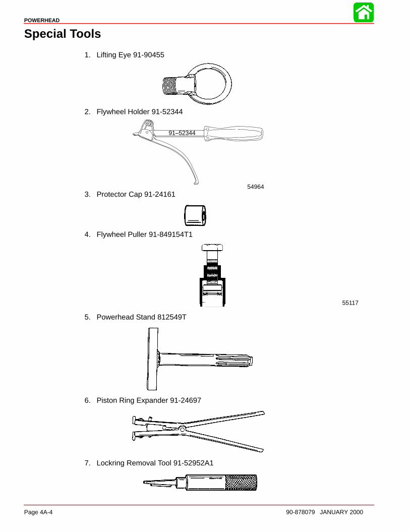
POWERHEAD
Page 4A-4 90-878079 JANUARY 2000
Special Tools
1. Lifting Eye 91-90455
2. Flywheel Holder 91-52344
91–52344
549643. Protector Cap 91-24161
4. Flywheel Puller 91-849154T1
55117
5. Powerhead Stand 812549T
6. Piston Ring Expander 91-24697
7. Lockring Removal Tool 91-52952A1
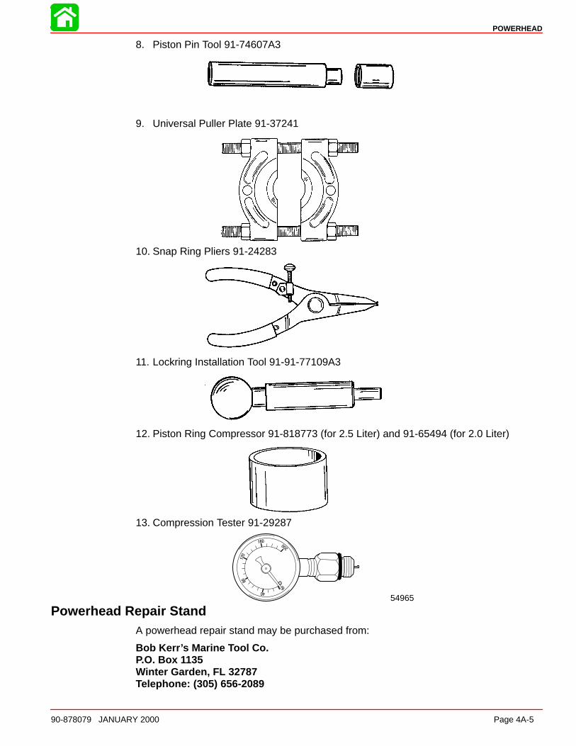
POWERHEAD
90-878079 JANUARY 2000 Page 4A-5
8. Piston Pin Tool 91-74607A3
9. Universal Puller Plate 91-37241
10. Snap Ring Pliers 91-24283
11. Lockring Installation Tool 91-91-77109A3
12. Piston Ring Compressor 91-818773 (for 2.5 Liter) and 91-65494 (for 2.0 Liter)
13. Compression Tester 91-29287
54965
Powerhead Repair StandA powerhead repair stand may be purchased from:
Bob Ker r ’s Marine Tool Co. P.O. Box 1135 Winter Garden, FL 32787 Telephone: (305) 656-2089
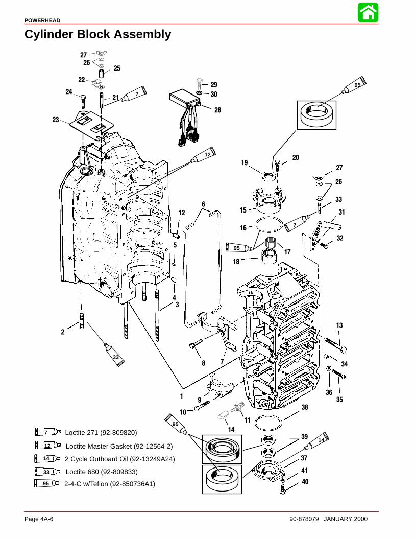
POWERHEAD
Page 4A-6 90-878079 JANUARY 2000
Cylinder Block Assembly
14 2 Cycle Outboard Oil (92-13249A24)
95 2-4-C w/Teflon (92-850736A1)
12
95
14
33
7
95
2
34
78
19
10
11
14
37
40
41
38
39
3536
6
Loctite 680 (92-809833)33
7 Loctite 271 (92-809820)
12 Loctite Master Gasket (92-12564-2)
34
13
32
31
33
26
27
2019
15
16
18
17
27
2625
22
2124
23
12
5
29
30
28
7
95
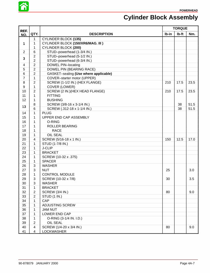
POWERHEAD
90-878079 JANUARY 2000 Page 4A-7
Cylinder Block Assembly
REFTORQUE
REF.NO. QTY. DESCRIPTION lb-in lb-ft Nm.
1 CYLINDER BLOCK (135)1 1 CYLINDER BLOCK (150/XR6/MAG. IlI )1
1 CYLINDER BLOCK (200)2 6 STUD–powerhead (1-3/4 IN.)
32 STUD–powerhead (5-1/2 IN.)
32 STUD–powerhead (6-3/4 IN.)
4 2 DOWEL PIN–locating5 2 DOWEL PIN (BEARING RACE)6 2 GASKET–sealing (Use where applicable)7 1 COVER–starter motor (UPPER)8 2 SCREW (1-1/2 IN.) (HEX FLANGE) 210 17.5 23.59 1 COVER (LOWER)10 2 SCREW (2 IN.)(HEX HEAD FLANGE) 210 17.5 23.511 1 FITTING12 1 BUSHING
138 SCREW (3/8-16 x 3-1/4 IN.) 38 51.5
136 SCREW (.312-18 x 1-1/4 IN.) 38 51.5
14 1 PLUG15 1 UPPER END CAP ASSEMBLY16 1 O-RING17 1 ROLLER BEARING18 1 RACE19 1 OIL SEAL20 4 SCREW (5/16-18 x 1 IN.) 150 12.5 17.021 1 STUD (1-7/8 IN.)22 1 J-CLIP23 1 BRACKET24 1 SCREW (10-32 x .375)25 1 SPACER26 3 WASHER27 3 NUT 25 3.028 1 CONTROL MODULE29 3 SCREW (10-32 x 7/8) 30 3.530 3 WASHER31 1 BRACKET32 2 SCREW (3/4 IN.) 80 9.033 2 STUD (1 IN.)34 1 CAP35 1 ADJUSTING SCREW36 1 JAM NUT37 1 LOWER END CAP38 1 O-RING (3-1/4 IN. I.D.)39 2 OIL SEAL40 4 SCREW (1/4-20 x 3/4 IN.) 80 9.041 4 LOCKWASHER
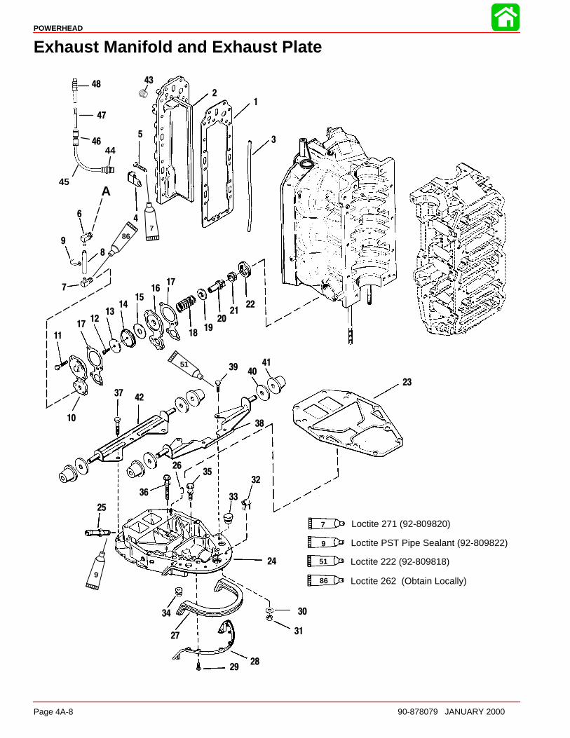
POWERHEAD
Page 4A-8 90-878079 JANUARY 2000
Exhaust Manifold and Exhaust Plate
12
3
4
5
6
7
8
9
10
11
1712
1314
1516
1819
2021
22
23
24
25
26
27
2829
30
31
32
33
34
35
36
37
38
4041
42
17
A
9
51
867
39
43
44
45
46
47
48
Loctite PST Pipe Sealant (92-809822)9
Loctite 262 (Obtain Locally)86
7 Loctite 271 (92-809820)
51 Loctite 222 (92-809818)

POWERHEAD
90-878079 JANUARY 2000 Page 4A-9
Exhaust Manifold and Exhaust Plate
REFTORQUE
REF.NO. QTY. DESCRIPTION lb-in lb-ft Nm.
1 1 GASKET2 1 DIVIDER PLATE3 1 SEAL4 4 J-CLAMP
17 SCREW (.312-18 x 1-1/2) 200 16.5 22.55 2 SCREW (.312-18 x 1) 200 16.5 22.55
1 SCREW (5/16-18 x 1-3/4) 200 16.5 22.56 1 FITTING7 1 FITTING (90 degrees)8 1 HOSE (26 IN.)9 2 STA-STRAP10 1 COVER–relief valve11 4 SCREW (.312-18 x 1-1/4 IN.) 150 12.5 17.012 1 SCREW (10-16 x 3/4 IN.) 25 3.013 1 WASHER14 1 DIAPHRAGM15 1 WATER DEFLECTOR16 1 PLATE17 2 GASKET18 1 SPRING19 1 WASHER20 1 POPPET21 1 GROMMET22 1 CARRIER23 1 GASKET24 1 EXHAUST PATE25 1 CONNECTOR (STRAIGHT)26 2 DOWEL PIN27 1 SEAL28 1 BRACKET29 8 SCREW (10-16 x 1/2 IN.)30 6 WASHER31 6 NUT 276 23 31.032 1 BUSHING
331 GROMMET (CLOSED)
33 1 GROMMET (SPLIT)34 1 GROMMET35 1 SCREW (5/16-18 x 1-1/4 IN.) 300 25 34.036 1 SCREW (5/16-18 x 2-1/2 IN.) 300 25 34.037 3 SCREW (3/8-16 x 3-1/2 IN.) 50 68.038 1 FRONT BRACKET ASSEMBLY39 4 SCREW (5/16-18 x 1/2 IN.)40 4 WASHER41 4 GROMMET42 1 REAR BRACKET ASSEMBLY43 1 PIPE PLUG44 1 FITTING45 1 TUBING (44 IN.)46 1 COUPLER47 1 ADAPTOR FITTING48 1 ADAPTOR FITTING
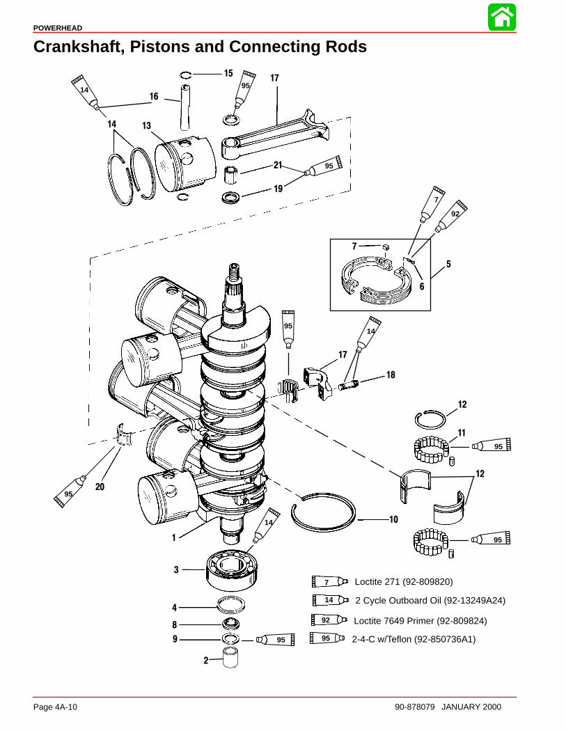
POWERHEAD
Page 4A-10 90-878079 JANUARY 2000
Crankshaft, Pistons and Connecting Rods
1
3
4
5
6
7
8
9
10
11
1314
1517
18
19
20
21
17
16
95
95
95
92
7
95
9514
14
14
12
12
95
95
14 2 Cycle Outboard Oil (92-13249A24)
95 2-4-C w/Teflon (92-850736A1)
2
92 Loctite 7649 Primer (92-809824)
7 Loctite 271 (92-809820)
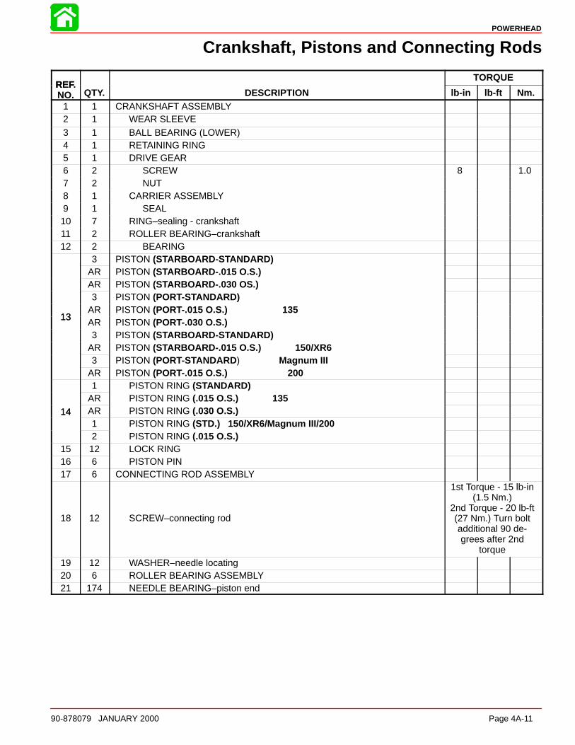
POWERHEAD
90-878079 JANUARY 2000 Page 4A-11
Crankshaft, Pistons and Connecting Rods
REFTORQUE
REF.NO. QTY. DESCRIPTION lb-in lb-ft Nm.
1 1 CRANKSHAFT ASSEMBLY2 1 WEAR SLEEVE3 1 BALL BEARING (LOWER)4 1 RETAINING RING5 1 DRIVE GEAR6 2 SCREW 8 1.07 2 NUT8 1 CARRIER ASSEMBLY9 1 SEAL10 7 RING–sealing - crankshaft11 2 ROLLER BEARING–crankshaft12 2 BEARING
3 PISTON (STARBOARD-S TANDARD)AR PISTON (STARBOARD-.015 O.S.)AR PISTON (STARBOARD-.030 OS.)3 PISTON (PORT-STANDARD)
13AR PISTON (PORT-.015 O.S.) 135
13AR PISTON (PORT-.030 O.S.)3 PISTON (STARBOARD-S TANDARD)
AR PISTON (STARBOARD-.015 O.S.) 150/XR63 PISTON (PORT-STANDARD) Magnum III
AR PISTON (PORT-.015 O.S.) 2001 PISTON RING (STANDARD)
AR PISTON RING (.015 O.S.) 13514 AR PISTON RING (.030 O.S.)14
1 PISTON RING (STD.) 150/XR6/Magnum III/2002 PISTON RING (.015 O.S.)
15 12 LOCK RING16 6 PISTON PIN17 6 CONNECTING ROD ASSEMBLY
18 12 SCREW–connecting rod
1st Torque - 15 lb-in(1.5 Nm.)
2nd Torque - 20 lb-ft(27 Nm.) Turn boltadditional 90 de-grees after 2nd
torque19 12 WASHER–needle locating20 6 ROLLER BEARING ASSEMBLY21 174 NEEDLE BEARING–piston end
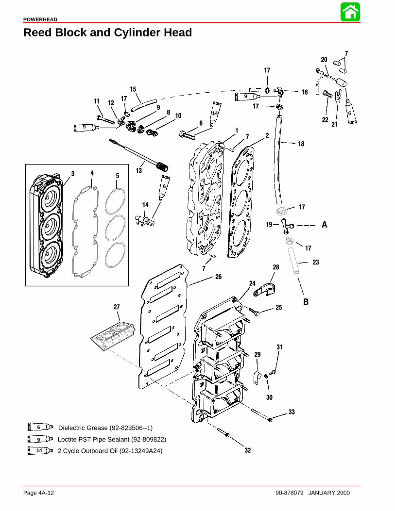
POWERHEAD
Page 4A-12 90-878079 JANUARY 2000
Reed Block and Cylinder Head
Loctite PST Pipe Sealant (92-809822)9
14 2 Cycle Outboard Oil (92-13249A24)
Dielectric Grease (92-823506--1)6
2
6
7
89
10
11 12
16
13
14
19
20
2122
24
25
26
27
28
29
30
31
32
33
15
1
17
7
7
17
17
17
17
18
23
A
B
6
9
14
9
6
3 4 5
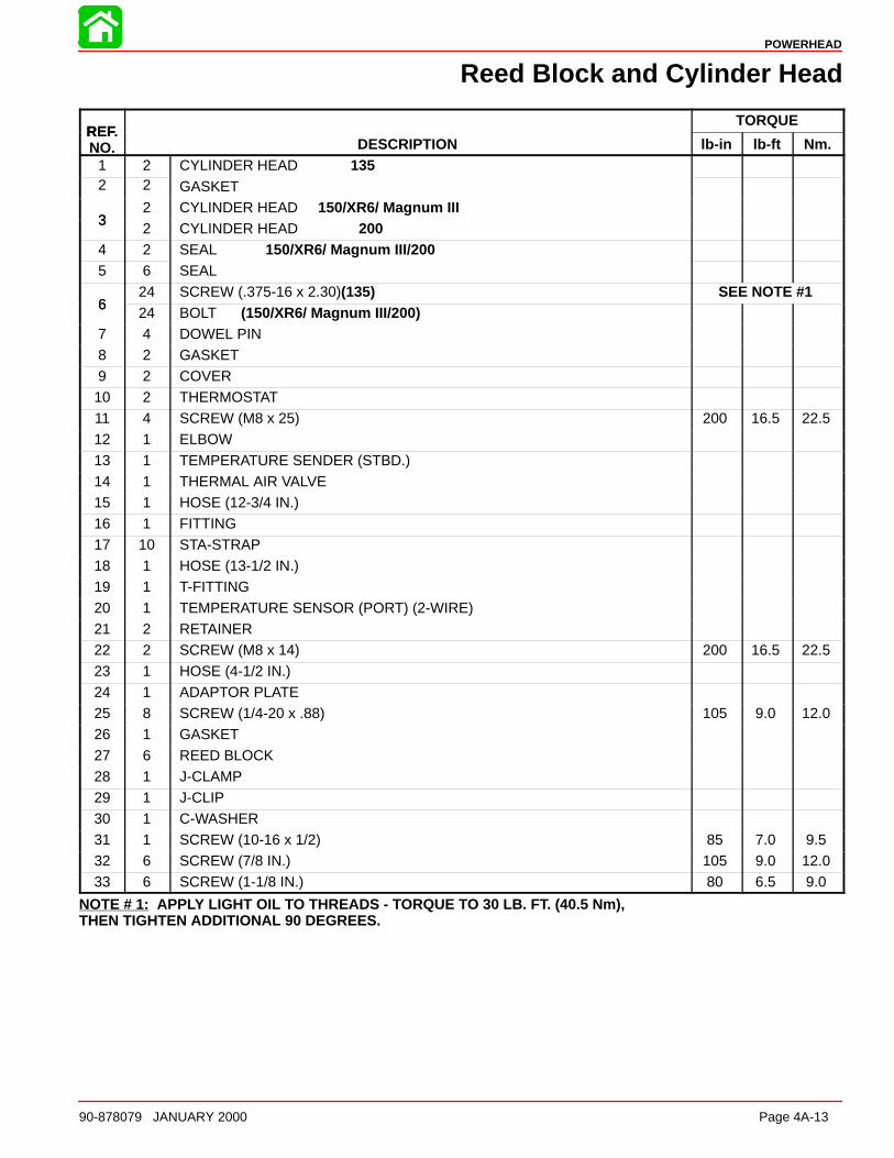
POWERHEAD
90-878079 JANUARY 2000 Page 4A-13
Reed Block and Cylinder Head
REFTORQUE
REF.NO. DESCRIPTION lb-in lb-ft Nm.
1 2 CYLINDER HEAD 1352 2 GASKET
32 CYLINDER HEAD 150/XR6/ Magnum III
32 CYLINDER HEAD 200
4 2 SEAL 150/XR6/ Magnum III/2005 6 SEAL
624 SCREW (.375-16 x 2.30)(135) SEE NOTE #1
624 BOLT (150/XR6/ Magnum III/200)
7 4 DOWEL PIN8 2 GASKET9 2 COVER10 2 THERMOSTAT11 4 SCREW (M8 x 25) 200 16.5 22.512 1 ELBOW
13 1 TEMPERATURE SENDER (STBD.)14 1 THERMAL AIR VALVE15 1 HOSE (12-3/4 IN.)16 1 FITTING17 10 STA-STRAP18 1 HOSE (13-1/2 IN.)19 1 T-FITTING
20 1 TEMPERATURE SENSOR (PORT) (2-WIRE)21 2 RETAINER22 2 SCREW (M8 x 14) 200 16.5 22.523 1 HOSE (4-1/2 IN.)24 1 ADAPTOR PLATE25 8 SCREW (1/4-20 x .88) 105 9.0 12.026 1 GASKET
27 6 REED BLOCK28 1 J-CLAMP29 1 J-CLIP30 1 C-WASHER31 1 SCREW (10-16 x 1/2) 85 7.0 9.532 6 SCREW (7/8 IN.) 105 9.0 12.033 6 SCREW (1-1/8 IN.) 80 6.5 9.0
NOTE # 1: APPLY LIGHT OIL TO THREADS - TORQUE TO 30 LB. FT. (40.5 Nm),THEN TIGHTEN ADDITIONAL 90 DEGREES.
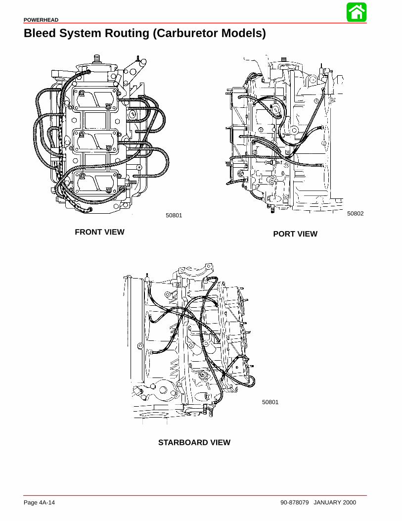
POWERHEAD
Page 4A-14 90-878079 JANUARY 2000
Bleed System Routing (Carburetor Models)
50801 50802
50801
PORT VIEW
STARBOARD VIEW
FRONT VIEW
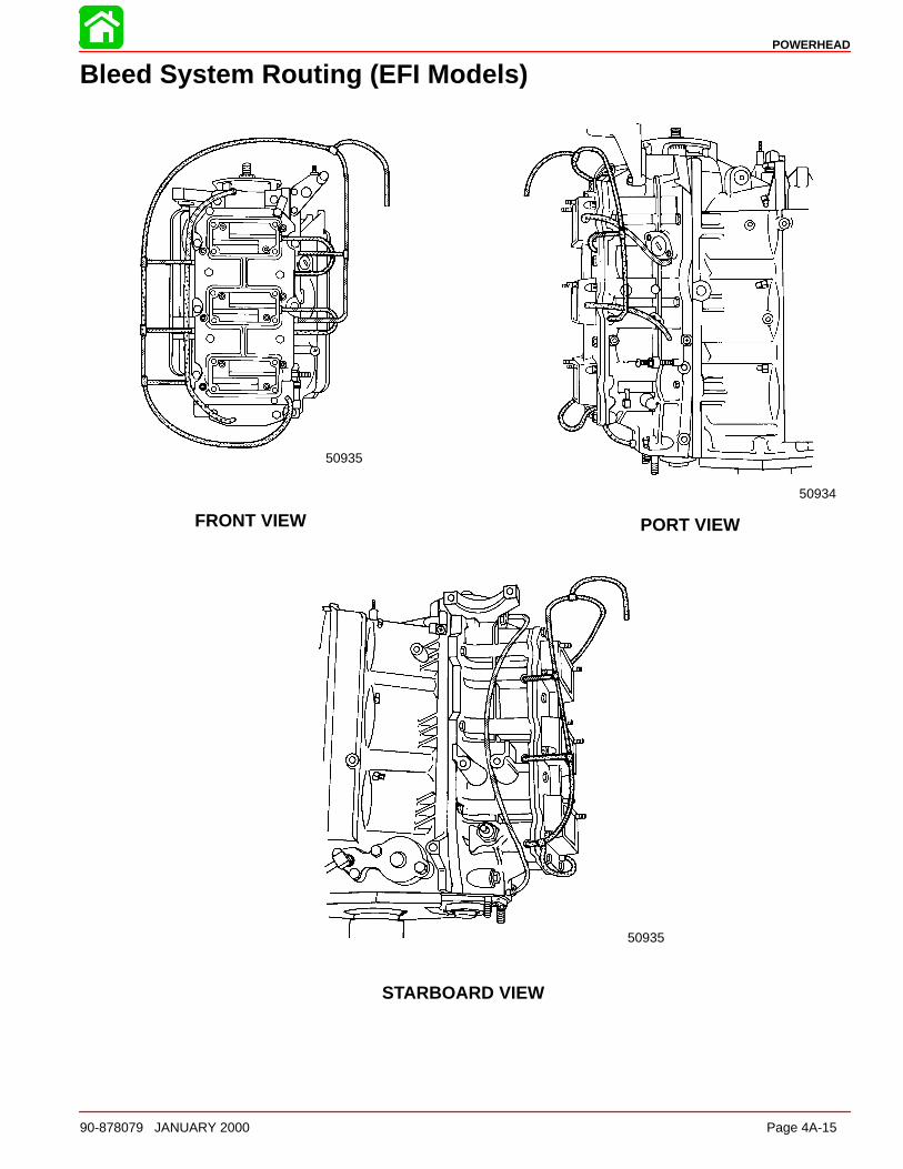
POWERHEAD
90-878079 JANUARY 2000 Page 4A-15
Bleed System Routing (EFI Models)
PORT VIEW
STARBOARD VIEW
FRONT VIEW
50935
50935
50934

POWERHEAD
Page 4A-16 90-878079 JANUARY 2000
Torque Sequence
CRANKCASE COVER BO LTS
Apply light oil tothreads and bolt face:8 Bolts (3/8 in. - 16 in.38 lb. ft. (51.5 N·m)
Bolts (5/16 in. - 18) 180 lb. in. (20.3 N·m)
1
23
4
5 6
78
EXHAUST COVER BOLTS
180 lb. in. (20 N·m) Apply light oil to threads and bolt face
50806
19
20
10
6
3
2
7
11
16 17
12
8
4
1
5
9
15
18
13 14
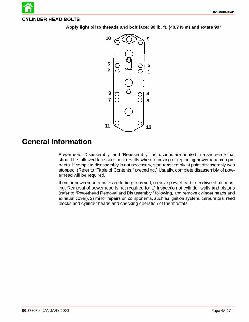
POWERHEAD
90-878079 JANUARY 2000 Page 4A-17
CYLINDER HEAD BO LTS
Apply light oil to threads and bolt face: 30 lb. ft. (40.7 N·m) and rotate 90 °
10
62
37
11 12
84
15
9
General Information
Powerhead “Disassembly” and “Reassembly” instructions are printed in a sequence thatshould be followed to assure best results when removing or replacing powerhead compo-nents. If complete disassembly is not necessary, start reassembly at point disassembly wasstopped. (Refer to “Table of Contents,” preceding.) Usually, complete disassembly of pow-erhead will be required.
If major powerhead repairs are to be performed, remove powerhead from drive shaft hous-ing. Removal of powerhead is not required for 1) inspection of cylinder walls and pistons(refer to “Powerhead Removal and Disassembly,” following, and remove cylinder heads andexhaust cover), 2) minor repairs on components, such as ignition system, carburetors, reedblocks and cylinder heads and checking operation of thermostats.
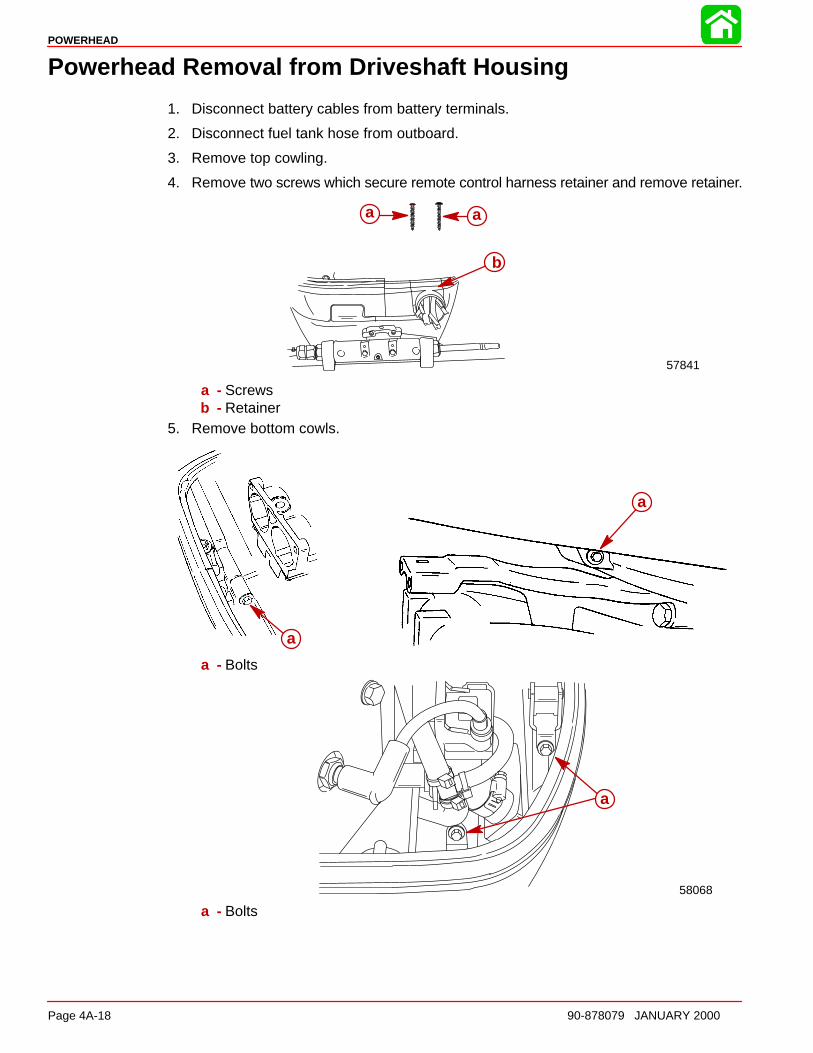
POWERHEAD
Page 4A-18 90-878079 JANUARY 2000
Powerhead Removal from Driveshaft Housing
1. Disconnect battery cables from battery terminals.
2. Disconnect fuel tank hose from outboard.
3. Remove top cowling.
4. Remove two screws which secure remote control harness retainer and remove retainer.
57841
a a
b
a - Screwsb - Retainer
5. Remove bottom cowls.
a
a
a - Bolts
58068
a
a - Bolts

POWERHEAD
90-878079 JANUARY 2000 Page 4A-19
6. Disconnect remote oil tank pressure hose and supply hose to oil reservoir.
7. Disconnect remote control harness from powerhead harness connector and power trimwires.
8. Disconnect trim relay connectors.
58027
b
a
c
d
e
a - Remote Oil Tank Pressure Hoseb - Oil Supply Hosec - Remote Control Harnessd - Power Trim Wirese - Trim Relay Connectors
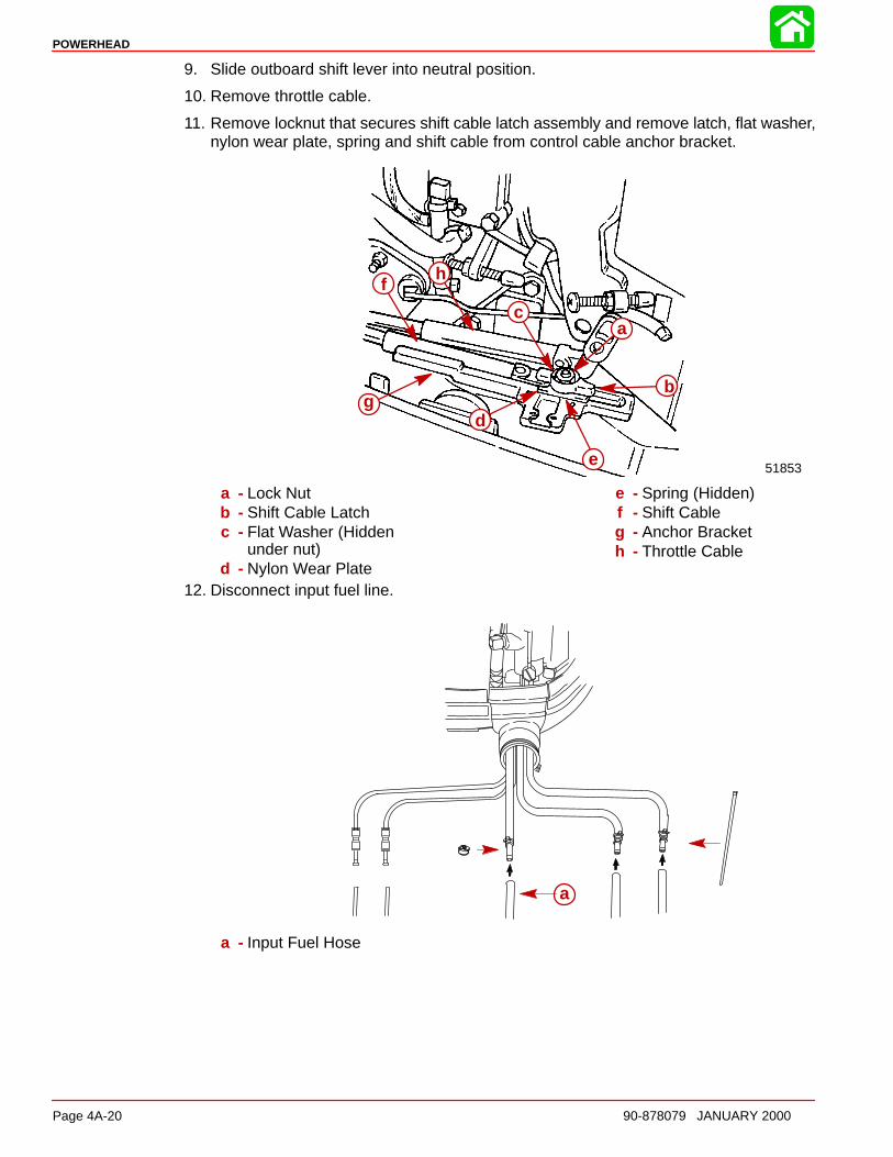
POWERHEAD
Page 4A-20 90-878079 JANUARY 2000
9. Slide outboard shift lever into neutral position.
10. Remove throttle cable.
11. Remove locknut that secures shift cable latch assembly and remove latch, flat washer,nylon wear plate, spring and shift cable from control cable anchor bracket.
51853
a
b
c
d
e
f
g
h
a - Lock Nutb - Shift Cable Latchc - Flat Washer (Hidden
under nut)d - Nylon Wear Plate
e - Spring (Hidden)f - Shift Cableg - Anchor Bracketh - Throttle Cable
12. Disconnect input fuel line.
a
a - Input Fuel Hose

POWERHEAD
90-878079 JANUARY 2000 Page 4A-21
13. Remove water hose from fitting on exhaust adaptor plate.
58069
ab
a - Water Hoseb - Fitting
14. Remove 10 nuts and 10 washers (5 each side) from powerhead base.
a
a a
a a
51846
a - Nuts and Washers (5 each side)15. Remove plastic cap from center of flywheel and install Lifting Eye 91-90455 into flywheel
at least 5 full turns. Using a hoist, lift powerhead assembly from driveshaft housing.
58070
a
a - Lifting Eye 91-90455
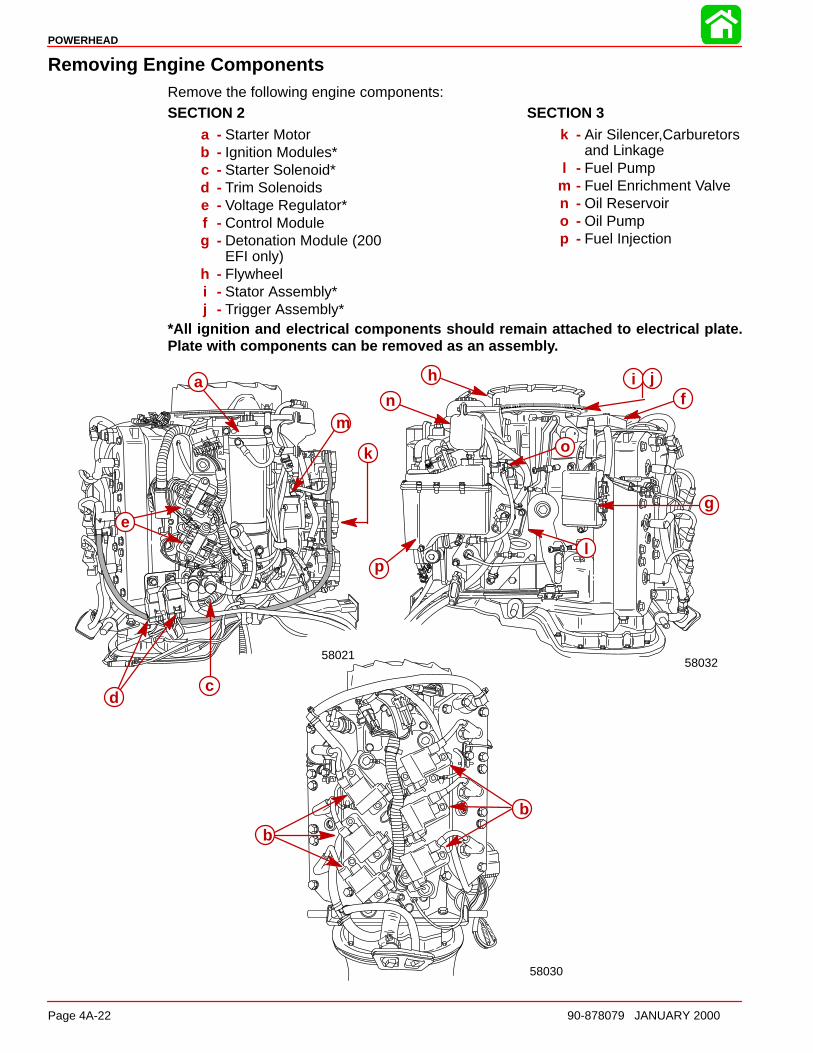
POWERHEAD
Page 4A-22 90-878079 JANUARY 2000
Removing Engine ComponentsRemove the following engine components:SECTION 2
a - Starter Motorb - Ignition Modules*c - Starter Solenoid*d - Trim Solenoidse - Voltage Regulator*f - Control Moduleg - Detonation Module (200
EFI only)h - Flywheeli - Stator Assembly*j - Trigger Assembly*
SECTION 3k - Air Silencer,Carburetors
and Linkagel - Fuel Pump
m - Fuel Enrichment Valven - Oil Reservoiro - Oil Pumpp - Fuel Injection
*All ignition and electrical components should remain attached to electrical plate.Plate with components can be removed as an assembl y.
5802158032
58030
a
b
b
cd
e
f
g
h i j
k
l
mn
o
p
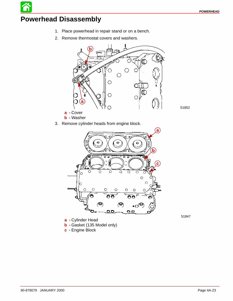
POWERHEAD
90-878079 JANUARY 2000 Page 4A-23
Powerhead Disassembly
1. Place powerhead in repair stand or on a bench.
2. Remove thermostat covers and washers.
51852
a
b
a - Coverb - Washer
3. Remove cylinder heads from engine block.
51847
a
b
c
a - Cylinder Headb - Gasket (135 Model only)c - Engine Block
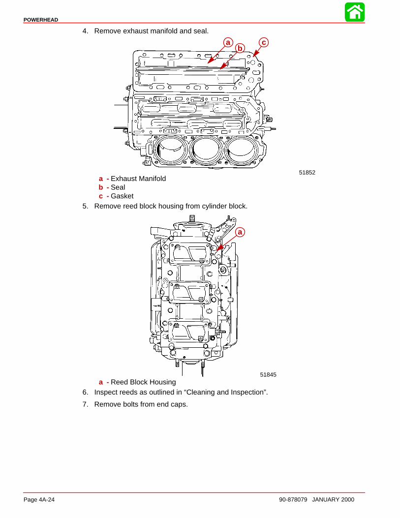
POWERHEAD
Page 4A-24 90-878079 JANUARY 2000
4. Remove exhaust manifold and seal.
51852
ab
c
a - Exhaust Manifoldb - Sealc - Gasket
5. Remove reed block housing from cylinder block.
51845
a
a - Reed Block Housing6. Inspect reeds as outlined in “Cleaning and Inspection”.
7. Remove bolts from end caps.
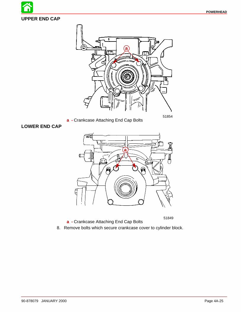
POWERHEAD
90-878079 JANUARY 2000 Page 4A-25
UPPER END CAP
51854
a
a - Crankcase Attaching End Cap Bolts
LOWER END CAP
51849
a
a - Crankcase Attaching End Cap Bolts8. Remove bolts which secure crankcase cover to cylinder block.
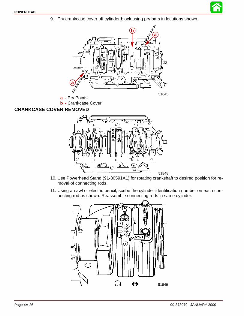
POWERHEAD
Page 4A-26 90-878079 JANUARY 2000
9. Pry crankcase cover off cylinder block using pry bars in locations shown.
51845
a
a
b
a - Pry Pointsb - Crankcase Cover
CRANKCASE COVER REMOVED
5184810. Use Powerhead Stand (91-30591A1) for rotating crankshaft to desired position for re-
moval of connecting rods.
11. Using an awl or electric pencil, scribe the cylinder identification number on each con-necting rod as shown. Reassemble connecting rods in same cylinder.
51849
ÄÄÄ
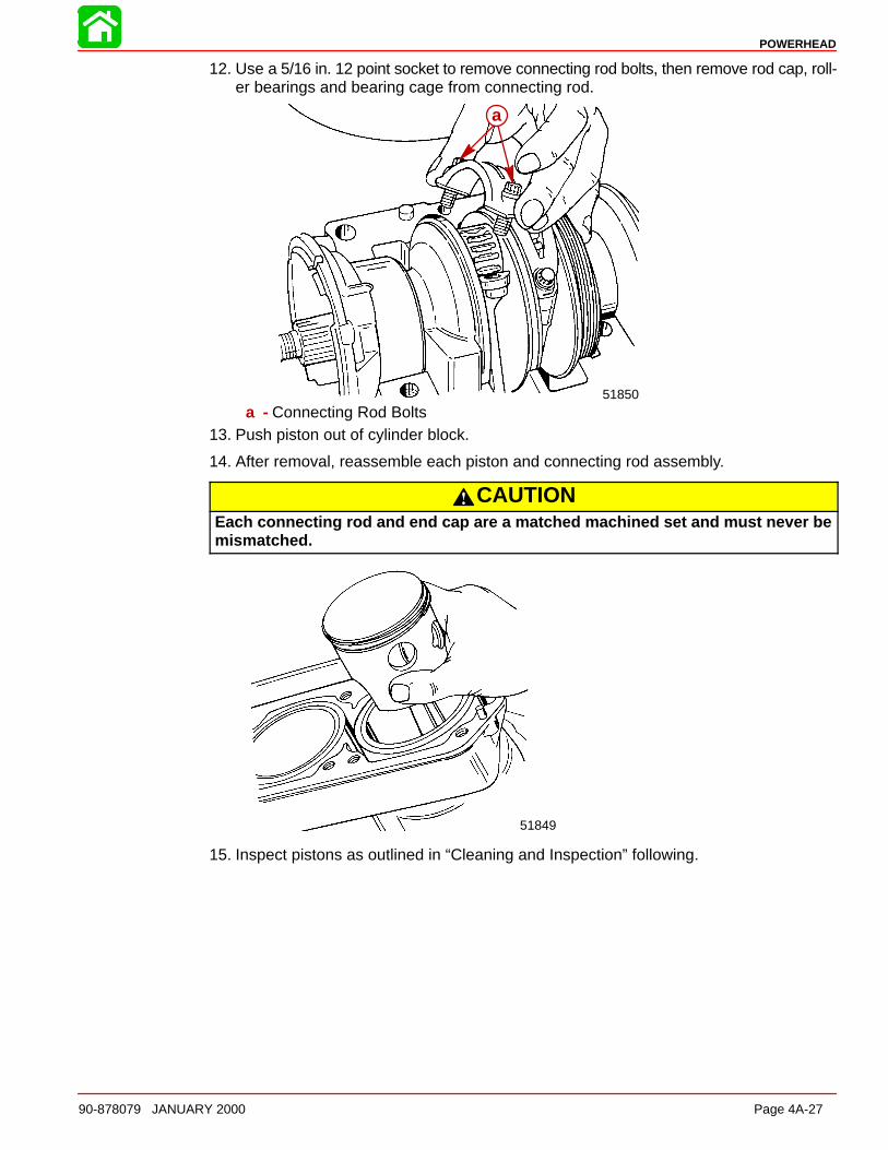
POWERHEAD
90-878079 JANUARY 2000 Page 4A-27
12. Use a 5/16 in. 12 point socket to remove connecting rod bolts, then remove rod cap, roll-er bearings and bearing cage from connecting rod.
51850
a
a - Connecting Rod Bolts13. Push piston out of cylinder block.
14. After removal, reassemble each piston and connecting rod assembly.
CAUTIONEach connecting rod and end cap are a matched machined set and must never bemismatched.
51849
15. Inspect pistons as outlined in “Cleaning and Inspection” following.
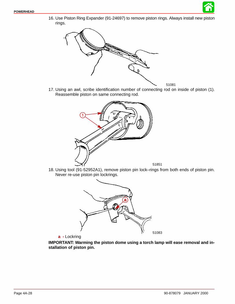
POWERHEAD
Page 4A-28 90-878079 JANUARY 2000
16. Use Piston Ring Expander (91-24697) to remove piston rings. Always install new pistonrings.
51081
17. Using an awl, scribe identification number of connecting rod on inside of piston (1).Reassemble piston on same connecting rod.
51851
1
18. Using tool (91-52952A1), remove piston pin lock–rings from both ends of piston pin.Never re-use piston pin lockrings.
51083
a
a - LockringIMPORTANT: Warming the piston dome using a torch lamp will ease removal and in-stallation of piston pin.
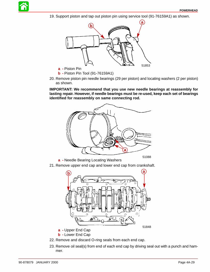
POWERHEAD
90-878079 JANUARY 2000 Page 4A-29
19. Support piston and tap out piston pin using service tool (91-76159A1) as shown.
51853
ab
a - Piston Pinb - Piston Pin Tool (91-76159A1)
20. Remove piston pin needle bearings (29 per piston) and locating washers (2 per piston)as shown.
IMPORTANT: We recommend that you use new needle bearings at reassembly forlasting repai r. Howeve r, if needle bearings must be re-used, keep each set of bearingsidentified for reassembly on same connecting rod.
51088
a
a - Needle Bearing Locating Washers21. Remove upper end cap and lower end cap from crankshaft.
51848
ab
a - Upper End Capb - Lower End Cap
22. Remove and discard O-ring seals from each end cap.
23. Remove oil seal(s) from end of each end cap by driving seal out with a punch and ham-mer.

POWERHEAD
Page 4A-30 90-878079 JANUARY 2000
24. Inspect roller bearing in upper end cap as outlined in “Cleaning and Inspection”.
NOTE: If roller bearing is damaged, replace upper end cap and roller bearings as an assem-bly.
51853a
b
a - O-Ringb - Seal
25. Remove crankshaft and place in powerhead stand.
IMPORTANT: DO NOT remove crankshaft sealing rings from crankshaft, unless re-placement of a sealing ring(s) is necessar y. Usuall y, crankshaft sealing rings do notrequire replacement, unless broken.
CAUTIONSafety glasses should be worn when removing or installing crankshaft sealingrings.
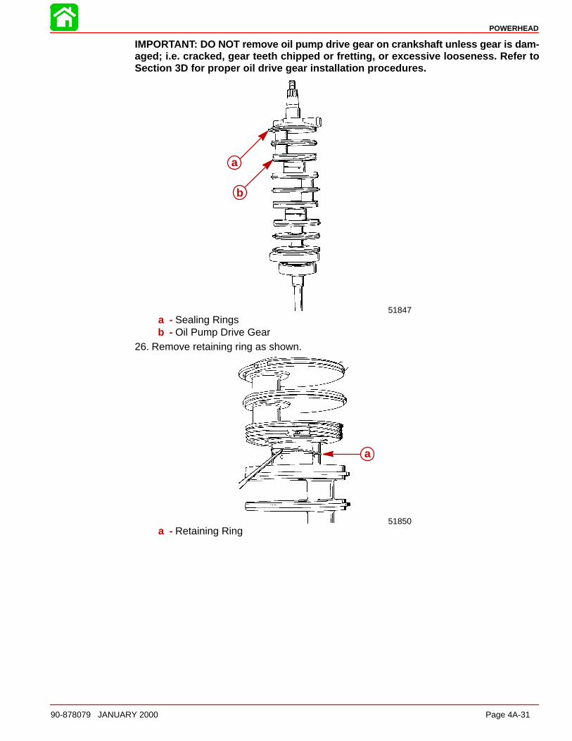
POWERHEAD
90-878079 JANUARY 2000 Page 4A-31
IMPORTANT: DO NOT remove oil pump drive gear on crankshaft unless gear is dam-aged; i.e. cracked, gear teeth chipped or fretting, or excessive looseness. Refer toSection 3D for proper oil drive gear installation procedures.
51847
a
b
a - Sealing Ringsb - Oil Pump Drive Gear
26. Remove retaining ring as shown.
51850
a
a - Retaining Ring
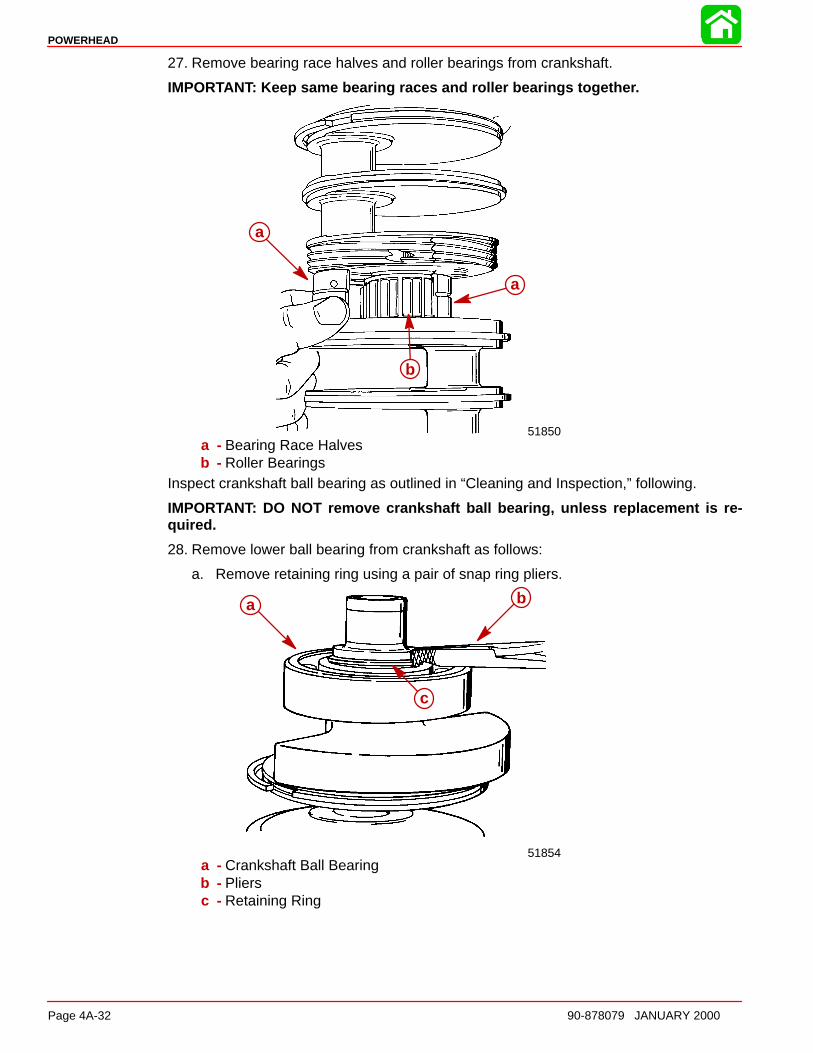
POWERHEAD
Page 4A-32 90-878079 JANUARY 2000
27. Remove bearing race halves and roller bearings from crankshaft.
IMPORTANT: Keep same bearing races and roller bearings togethe r.
51850
a
a
b
a - Bearing Race Halvesb - Roller Bearings
Inspect crankshaft ball bearing as outlined in “Cleaning and Inspection,” following.
IMPORTANT: DO NOT remove crankshaft ball bearing, unless replacement is re-quired.
28. Remove lower ball bearing from crankshaft as follows:
a. Remove retaining ring using a pair of snap ring pliers.
51854
a b
c
a - Crankshaft Ball Bearingb - Pliersc - Retaining Ring
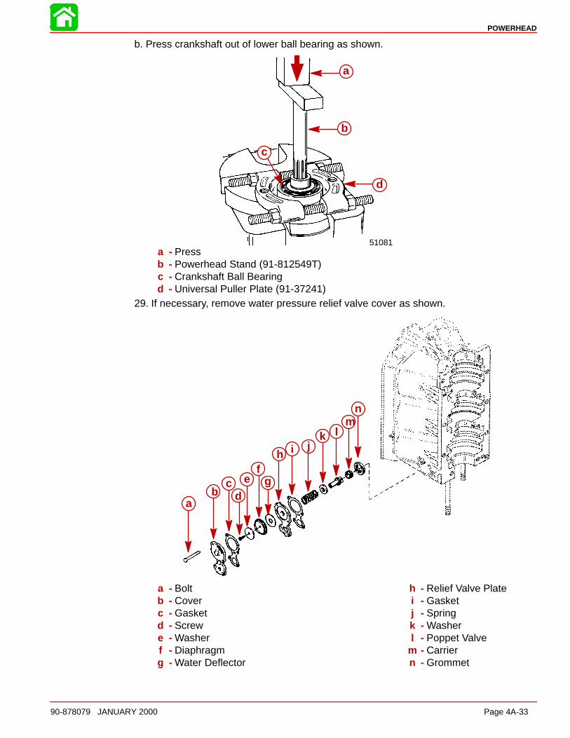
POWERHEAD
90-878079 JANUARY 2000 Page 4A-33
b. Press crankshaft out of lower ball bearing as shown.
51081
a
b
c
d
a - Pressb - Powerhead Stand (91-812549T)c - Crankshaft Ball Bearingd - Universal Puller Plate (91-37241)
29. If necessary, remove water pressure relief valve cover as shown.
ab
cd
ef
g
h i jk l
mn
a - Boltb - Coverc - Gasketd - Screwe - Washerf - Diaphragmg - Water Deflector
h - Relief Valve Platei - Gasketj - Springk - Washerl - Poppet Valve
m - Carriern - Grommet
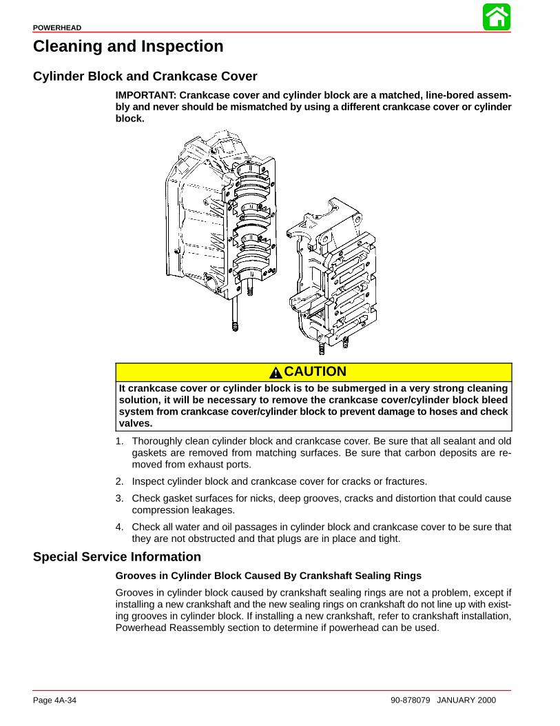
POWERHEAD
Page 4A-34 90-878079 JANUARY 2000
Cleaning and Inspection
Cylinder Block and Crankcase CoverIMPORTANT: Crankcase cover and cylinder block are a matched, line-bored assem-bly and never should be mismatched by using a different crankcase cover or cylinderblock.
CAUTIONIt crankcase cover or cylinder block is to be submerged in a very strong cleaningsolution, it will be necessary to remove the crankcase cover/cylinder block bleedsyste m from crankcase cover/cylinder block to prevent damage to hoses and checkvalves.
1. Thoroughly clean cylinder block and crankcase cover. Be sure that all sealant and oldgaskets are removed from matching surfaces. Be sure that carbon deposits are re-moved from exhaust ports.
2. Inspect cylinder block and crankcase cover for cracks or fractures.
3. Check gasket surfaces for nicks, deep grooves, cracks and distortion that could causecompression leakages.
4. Check all water and oil passages in cylinder block and crankcase cover to be sure thatthey are not obstructed and that plugs are in place and tight.
Special Service InformationGrooves in Cylinder Block Caused By Crankshaft Sealing Rings
Grooves in cylinder block caused by crankshaft sealing rings are not a problem, except ifinstalling a new crankshaft and the new sealing rings on crankshaft do not line up with exist-ing grooves in cylinder block. If installing a new crankshaft, refer to crankshaft installation,Powerhead Reassembly section to determine if powerhead can be used.
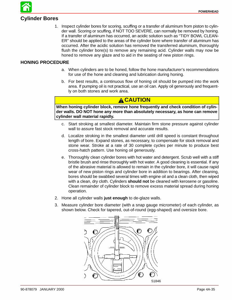
POWERHEAD
90-878079 JANUARY 2000 Page 4A-35
Cylinder Bores1. Inspect cylinder bores for scoring, scuffing or a transfer of aluminum from piston to cylin-
der wall. Scoring or scuffing, if NOT TOO SEVERE, can normally be removed by honing.If a transfer of aluminum has occurred, an acidic solution such as “TIDY BOWL CLEAN-ER” should be applied to the areas of the cylinder bore where transfer of aluminum hasoccurred. After the acidic solution has removed the transferred aluminum, thoroughlyflush the cylinder bore(s) to remove any remaining acid. Cylinder walls may now behoned to remove any glaze and to aid in the seating of new piston rings.
HONING PROCEDURE
a. When cylinders are to be honed, follow the hone manufacturer’s recommendationsfor use of the hone and cleaning and lubrication during honing.
b. For best results, a continuous flow of honing oil should be pumped into the workarea. If pumping oil is not practical, use an oil can. Apply oil generously and frequent-ly on both stones and work area.
CAUTIONWhen honing cylinder block, remove hone frequently and check condition of cylin-der walls. DO NOT hone any more than absolutely necessar y, as hone can removecylinder wall material rapidl y.
c. Start stroking at smallest diameter. Maintain firm stone pressure against cylinderwall to assure fast stock removal and accurate results.
d. Localize stroking in the smallest diameter until drill speed is constant throughoutlength of bore. Expand stones, as necessary, to compensate for stock removal andstone wear. Stroke at a rate of 30 complete cycles per minute to produce bestcross-hatch pattern. Use honing oil generously.
e. Thoroughly clean cylinder bores with hot water and detergent. Scrub well with a stiffbristle brush and rinse thoroughly with hot water. A good cleaning is essential. If anyof the abrasive material is allowed to remain in the cylinder bore, it will cause rapidwear of new piston rings and cylinder bore in addition to bearings. After cleaning,bores should be swabbed several times with engine oil and a clean cloth, then wipedwith a clean, dry cloth. Cylinders should not be cleaned with kerosene or gasoline.Clean remainder of cylinder block to remove excess material spread during honingoperation.
2. Hone all cylinder walls just enough to de-glaze walls.
3. Measure cylinder bore diameter (with a snap gauge micrometer) of each cylinder, asshown below. Check for tapered, out-of-round (egg-shaped) and oversize bore.
51846
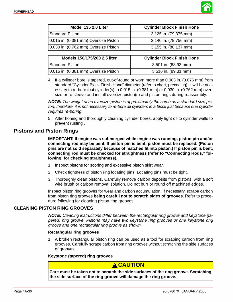
POWERHEAD
Page 4A-36 90-878079 JANUARY 2000
Model 135 2.0 Liter Cylinder Block Finish Hone
Standard Piston 3.125 in. (79.375 mm)
0.015 in. (0.381 mm) Oversize Piston 3.140 in. (79.756 mm)
0.030 in. (0.762 mm) Oversize Piston 3.155 in. (80.137 mm)
Models 150/175/200 2.5 liter Cylinder Block Finish Hone
Standard Piston 3.501 in. (88.93 mm)
0.015 in. (0.381 mm) Oversize Piston 3.516 in. (89.31 mm)
4. If a cylinder bore is tapered, out-of-round or worn more than 0.003 in. (0.076 mm) fromstandard “Cylinder Block Finish Hone” diameter (refer to chart, preceding), it will be nec-essary to re-bore that cylinder(s) to 0.015 in. (0.381 mm) or 0.030 in. (0.762 mm) over-size or re-sleeve and install oversize piston(s) and piston rings during reassembly.
NOTE: The weight of an oversize piston is approximately the same as a standard size pis-ton; therefore, it is not necessary to re-bore all cylinders in a block just because one cylinderrequires re-boring.
5. After honing and thoroughly cleaning cylinder bores, apply light oil to cylinder walls toprevent rusting .
Pistons and Piston RingsIMPORTANT: If engine was submerged while engine was running, piston pin and/orconnecting rod may be bent. If piston pin is bent, piston must be replaced. (Pistonpins are not sold separately because of matched fit into piston.) If piston pin is bent,connecting rod must be checked for straightness (refer to “Connecting Rods,” fol-lowing, for checking straightness).
1. Inspect pistons for scoring and excessive piston skirt wear.
2. Check tightness of piston ring locating pins. Locating pins must be tight.
3. Thoroughly clean pistons. Carefully remove carbon deposits from pistons, with a softwire brush or carbon removal solution. Do not burr or round off machined edges.
Inspect piston ring grooves for wear and carbon accumulation. If necessary, scrape carbonfrom piston ring grooves being careful not to scratch sides of grooves . Refer to proce-dure following for cleaning piston ring grooves.
CLEANING PISTON RING GROOVES
NOTE: Cleaning instructions differ between the rectangular ring groove and keystone (ta-pered) ring groove. Pistons may have two keystone ring grooves or one keystone ringgroove and one rectangular ring groove as shown.
Rectangular ring grooves
1. A broken rectangular piston ring can be used as a tool for scraping carbon from ringgrooves. Carefully scrape carbon from ring grooves without scratching the side surfacesof grooves.
Keystone (tapered) ring grooves
CAUTIONCare must be taken not to scratch the side surfaces of the ring groove. Scratchingthe side surface of the ring groove will damage the ring groove.
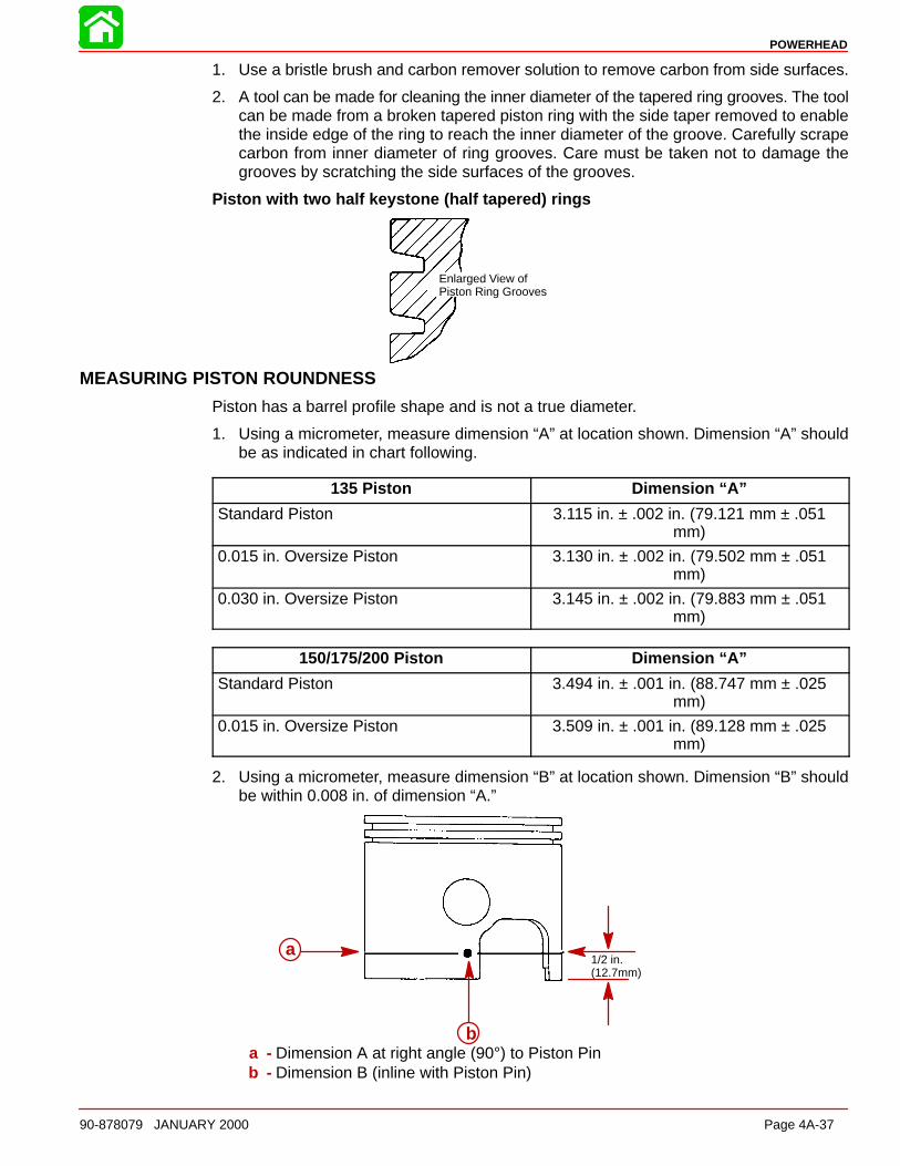
POWERHEAD
90-878079 JANUARY 2000 Page 4A-37
1. Use a bristle brush and carbon remover solution to remove carbon from side surfaces.
2. A tool can be made for cleaning the inner diameter of the tapered ring grooves. The toolcan be made from a broken tapered piston ring with the side taper removed to enablethe inside edge of the ring to reach the inner diameter of the groove. Carefully scrapecarbon from inner diameter of ring grooves. Care must be taken not to damage thegrooves by scratching the side surfaces of the grooves.
Piston with two half keystone (half tapered) rings
Enlarged View ofPiston Ring Grooves
MEASURING PISTON ROUNDNESS
Piston has a barrel profile shape and is not a true diameter.
1. Using a micrometer, measure dimension “A” at location shown. Dimension “A” shouldbe as indicated in chart following.
135 Piston Dimension “A”
Standard Piston 3.115 in. ± .002 in. (79.121 mm ± .051mm)
0.015 in. Oversize Piston 3.130 in. ± .002 in. (79.502 mm ± .051mm)
0.030 in. Oversize Piston 3.145 in. ± .002 in. (79.883 mm ± .051mm)
150/175/200 Piston Dimension “A”
Standard Piston 3.494 in. ± .001 in. (88.747 mm ± .025mm)
0.015 in. Oversize Piston 3.509 in. ± .001 in. (89.128 mm ± .025mm)
2. Using a micrometer, measure dimension “B” at location shown. Dimension “B” shouldbe within 0.008 in. of dimension “A.”
1/2 in.(12.7mm)
a
ba - Dimension A at right angle (90°) to Piston Pinb - Dimension B (inline with Piston Pin)

POWERHEAD
Page 4A-38 90-878079 JANUARY 2000
Cylinder Heads and Exhaust Divider Plate1. Inspect internal surface of cylinder heads for possible damage (as a result of piston or
foreign material striking cylinder heads).
IMPORTANT: Cylinder head warpage should not exceed 0.004 in. (0.1 mm) over theENTIRE length of the cylinder head. If measured warpage, as determined on a surfaceblock, exceeds 0.004 in. (0.1 mm) or a discontinuity of up to 0.004 in. (0.1 mm) existsin a narrow portion of the cylinder head ’s surface length, then the cylinder head maybe re-surfaced up to 0.010 in. (0.25 mm).
2. Replace cylinder head(s) as necessary.
3. Thoroughly clean gasket surfaces of exhaust divider plate.
4. Inspect exhaust divider plate for deep grooves, cracks or distortion that could causeleakage. Replace parts as necessary.
Crankshaft1. Inspect crankshaft to drive shaft splines for wear. (Replace crankshaft, if necessary.)
2. Check crankshaft for straightness – maximum runout: 0.006 in. (0.152 mm) (Replaceas necessary.)
3. Inspect crankshaft oil seal surfaces. Sealing surfaces must not be grooved, pitted orscratched. (Replace as necessary.)
4. Check all crankshaft bearing surfaces for rust, water marks, chatter marks, uneven wearand/or overheating. (Refer to “Connecting Rods”.)
5. If necessary, clean crankshaft surfaces with crocus cloth.
51847
a b
c
c
a - Crankshaft Journalsb - Crocus Clothc - Work Cloth “Back-and-Forth”
WARNINGDO NOT spin-dry crankshaft ball bearing with compressed ai r.
6. Thoroughly clean (with solvent) and dry crankshaft and crankshaft ball bearing. Re-check surfaces of crankshaft. Replace crankshaft, if surfaces cannot be properly“cleaned up.” If crankshaft will be re-used, lubricate surfaces of crankshaft with light oilto prevent rust. DO NOT lubricate crankshaft ball bearing at this time.
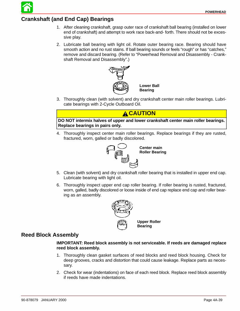
POWERHEAD
90-878079 JANUARY 2000 Page 4A-39
Crankshaft (and End Cap) Bearings1. After cleaning crankshaft, grasp outer race of crankshaft ball bearing (installed on lower
end of crankshaft) and attempt to work race back-and- forth. There should not be exces-sive play.
2. Lubricate ball bearing with light oil. Rotate outer bearing race. Bearing should havesmooth action and no rust stains. If ball bearing sounds or feels “rough” or has “catches,”remove and discard bearing. (Refer to “Powerhead Removal and Disassembly - Crank-shaft Removal and Disassembly”.)
Lower BallBearing
3. Thoroughly clean (with solvent) and dry crankshaft center main roller bearings. Lubri-cate bearings with 2-Cycle Outboard Oil.
CAUTIONDO NOT intermix halves of upper and lower crankshaft center main roller bearings.Replace bearings in pairs onl y.
4. Thoroughly inspect center main roller bearings. Replace bearings if they are rusted,fractured, worn, galled or badly discolored.
Center mainRoller Bearing
5. Clean (with solvent) and dry crankshaft roller bearing that is installed in upper end cap.Lubricate bearing with light oil.
6. Thoroughly inspect upper end cap roller bearing. If roller bearing is rusted, fractured,worn, galled, badly discolored or loose inside of end cap replace end cap and roller bear-ing as an assembly.
Upper RollerBearing
Reed Block AssemblyIMPORTANT: Reed block assembly is not serviceable. If reeds are damaged replacereed block assembl y.
1. Thoroughly clean gasket surfaces of reed blocks and reed block housing. Check fordeep grooves, cracks and distortion that could cause leakage. Replace parts as neces-sary.
2. Check for wear (indentations) on face of each reed block. Replace reed block assemblyif reeds have made indentations.

POWERHEAD
Page 4A-40 90-878079 JANUARY 2000
3. Check for chipped and broken reeds.
51851
Allowable reed opening is 0.020 in. (0.51 mm) or less. Replace reed block assembly if anyreed is standing open more than 0.020 in. (0.51 mm).
Reed Block Housing1. Check rubber bleed hoses. Replace any hose that is cracked, cut or deteriorating.
2. Check operation of bleed system check valves in reed block housing. If valves are work-ing properly, air can be drawn thru check valves “one way” only. If air can pass thru acheck valve both ways, valve is not working properly and must be replaced.
3. Check that bleed system check valves are pressed tight into reed housing.
4. Inspect passages in reed block housing to be sure that they are not obstructed.
Connecting Rods1. Check connecting rods for alignment by placing rods on a surface plate. If light can be
seen under any portion of machined surfaces, if rod has a slight wobble on plate, or ifa 0.002 in. (0.051 mm) feeler gauge can be inserted between any machined surface andsurface plate, rod is bent and must be discarded.
2. Overheating: Overheating is visible as a bluish bearing surface color that is caused byinadequate lubrication or excessive RPM.
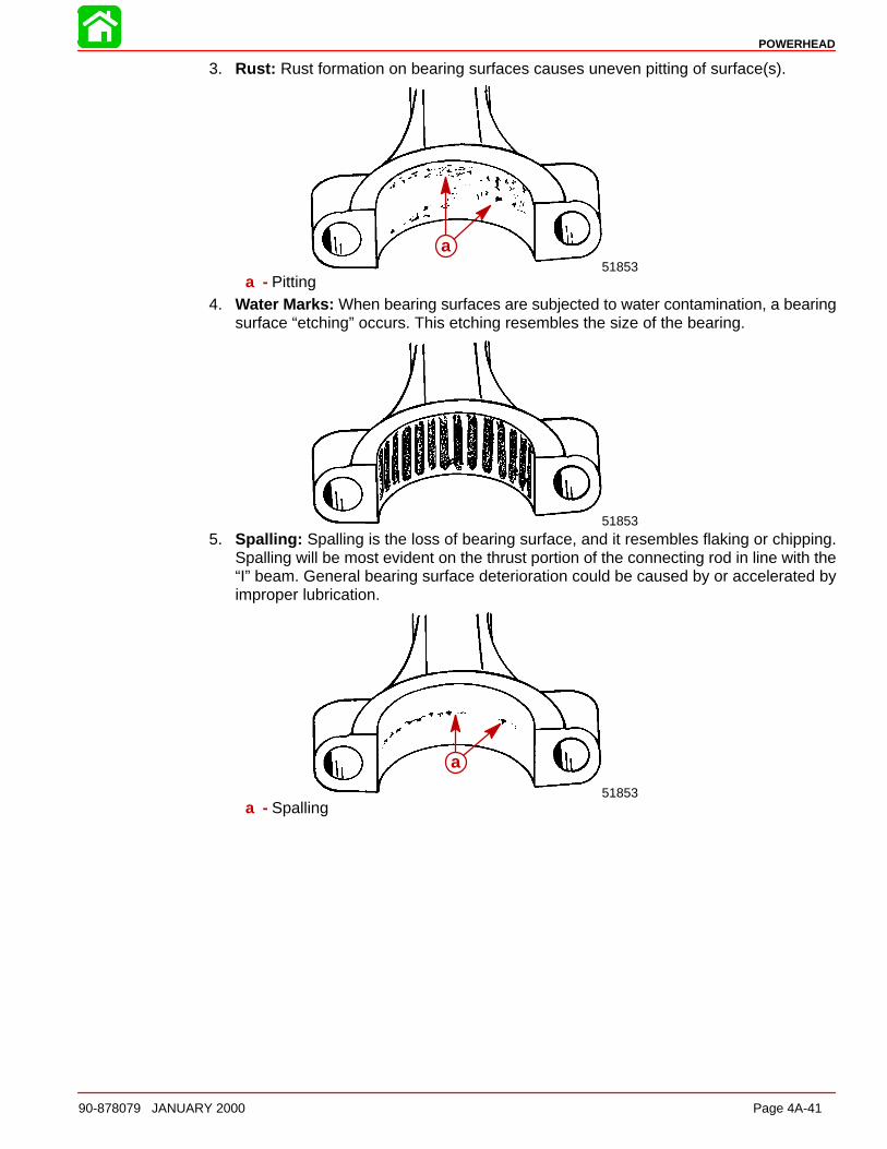
POWERHEAD
90-878079 JANUARY 2000 Page 4A-41
3. Rust: Rust formation on bearing surfaces causes uneven pitting of surface(s).
51853
a
a - Pitting4. Water Marks: When bearing surfaces are subjected to water contamination, a bearing
surface “etching” occurs. This etching resembles the size of the bearing.
51853
5. Spalling : Spalling is the loss of bearing surface, and it resembles flaking or chipping.Spalling will be most evident on the thrust portion of the connecting rod in line with the“I” beam. General bearing surface deterioration could be caused by or accelerated byimproper lubrication.
51853
a
a - Spalling

POWERHEAD
Page 4A-42 90-878079 JANUARY 2000
6. Chatter Marks: Chatter marks are the result of a combination of low speed - low load- cold water temperature operation, aggravated by inadequate lubrication and/or im-proper fuel. Under these conditions, the crankshaft journal is hammered by the connect-ing rod. As ignition occurs in the cylinder, the piston pushes the connecting rod with tre-mendous force, and this force is transferred to the connecting rod journal. Since thereis little or no load on the crankshaft, it bounces away from the connecting rod. The crank-shaft then remains immobile for a split second until the piston travel causes the connect-ing rod to catch up to the waiting crankshaft journal, then hammers it. The repetition ofthis action causes a rough bearing surface(s) which resembles a tiny washboard. Insome instances, the connecting rod crank pin bore becomes highly polished. During op-eration, the engine will emit a “whirr” and/or “chirp” sound when it is accelerated rapidlyfrom idle speed to approximately 1500 RPM, then quickly returned to idle. If the preced-ing conditions are found, replace both the crankshaft and connecting rod(s).
51853
a
a - Chatter Marks Between Arrows7. Uneven Wear: Uneven wear could be caused by a bent connecting rod.
51853a
a - Uneven Wear Between Arrows8. If necessary, clean connecting rod bearing surfaces, as follows:
a. Be sure that “etched” marks on connecting rod (crankshaft end) are perfectly alignedwith “etched” marks on connecting rod cap. Tighten connecting rod cap attachingbolts securely.
CAUTIONCrocus cloth MUST BE USED to clean bearing surface at crankshaft end of connect-ing rod. DO NOT use any other type of abrasive cloth.
b. Clean CRANKSHAFT END of connecting rod by using CROCUS CLOTH placedin a slotted 3/8 in. (9.5 mm) diameter shaft, as shown. Chuck shaft in a drill pressand operation press at high speed while keeping connecting rod at a 90 angle toslotted shaft.
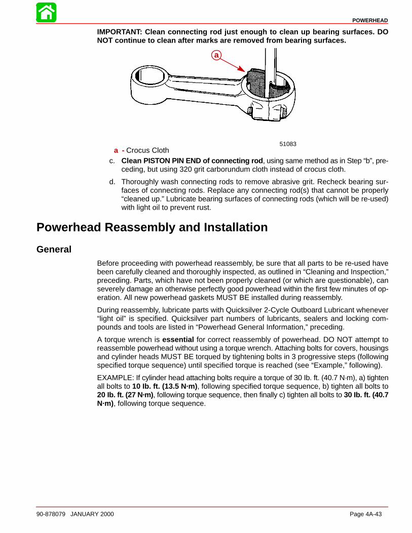
POWERHEAD
90-878079 JANUARY 2000 Page 4A-43
IMPORTANT: Clean connecting rod just enough to clean up bearing surfaces. DONOT continue to clean after marks are removed from bearing surfaces.
51083
a
a - Crocus Clothc. Clean PISTON PIN END of connecting rod , using same method as in Step “b”, pre-
ceding, but using 320 grit carborundum cloth instead of crocus cloth.
d. Thoroughly wash connecting rods to remove abrasive grit. Recheck bearing sur-faces of connecting rods. Replace any connecting rod(s) that cannot be properly“cleaned up.” Lubricate bearing surfaces of connecting rods (which will be re-used)with light oil to prevent rust.
Powerhead Reassembly and Installation
GeneralBefore proceeding with powerhead reassembly, be sure that all parts to be re-used havebeen carefully cleaned and thoroughly inspected, as outlined in “Cleaning and Inspection,”preceding. Parts, which have not been properly cleaned (or which are questionable), canseverely damage an otherwise perfectly good powerhead within the first few minutes of op-eration. All new powerhead gaskets MUST BE installed during reassembly.
During reassembly, lubricate parts with Quicksilver 2-Cycle Outboard Lubricant whenever“light oil” is specified. Quicksilver part numbers of lubricants, sealers and locking com-pounds and tools are listed in “Powerhead General Information,” preceding.
A torque wrench is essential for correct reassembly of powerhead. DO NOT attempt toreassemble powerhead without using a torque wrench. Attaching bolts for covers, housingsand cylinder heads MUST BE torqued by tightening bolts in 3 progressive steps (followingspecified torque sequence) until specified torque is reached (see “Example,” following).
EXAMPLE: If cylinder head attaching bolts require a torque of 30 Ib. ft. (40.7 N·m), a) tightenall bolts to 10 Ib. ft. (13.5 N·m) , following specified torque sequence, b) tighten all bolts to20 Ib. ft. (27 N·m) , following torque sequence, then finally c) tighten all bolts to 30 Ib. ft. (40.7N·m), following torque sequence.
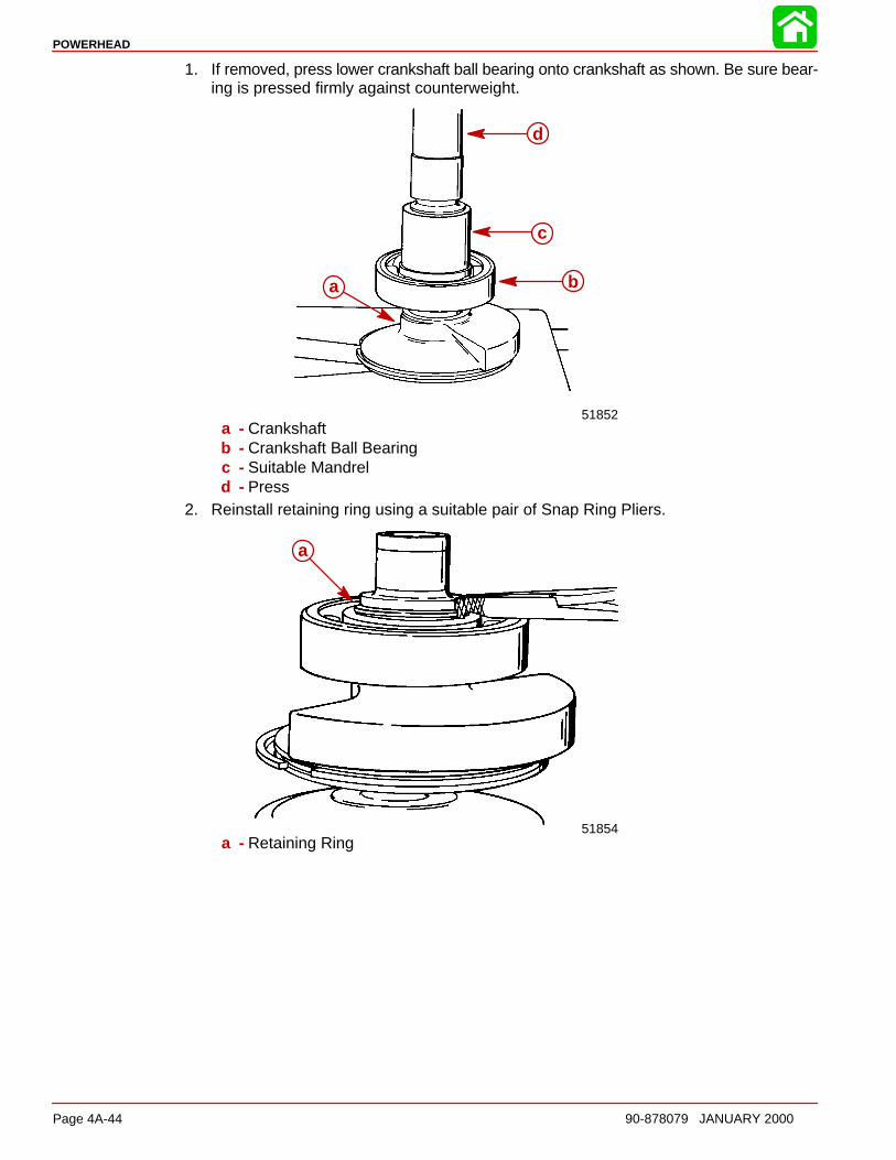
POWERHEAD
Page 4A-44 90-878079 JANUARY 2000
1. If removed, press lower crankshaft ball bearing onto crankshaft as shown. Be sure bear-ing is pressed firmly against counterweight.
51852
a b
c
d
a - Crankshaftb - Crankshaft Ball Bearingc - Suitable Mandreld - Press
2. Reinstall retaining ring using a suitable pair of Snap Ring Pliers.
51854
a
a - Retaining Ring
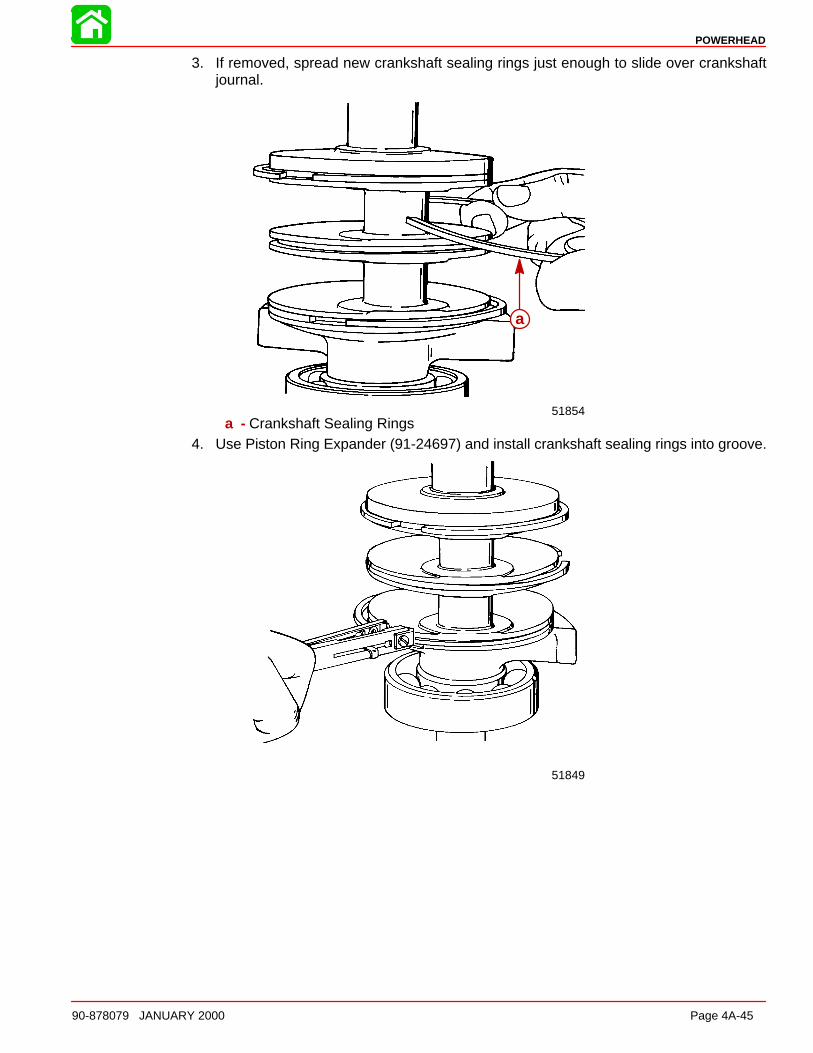
POWERHEAD
90-878079 JANUARY 2000 Page 4A-45
3. If removed, spread new crankshaft sealing rings just enough to slide over crankshaftjournal.
51854
a
a - Crankshaft Sealing Rings4. Use Piston Ring Expander (91-24697) and install crankshaft sealing rings into groove.
51849
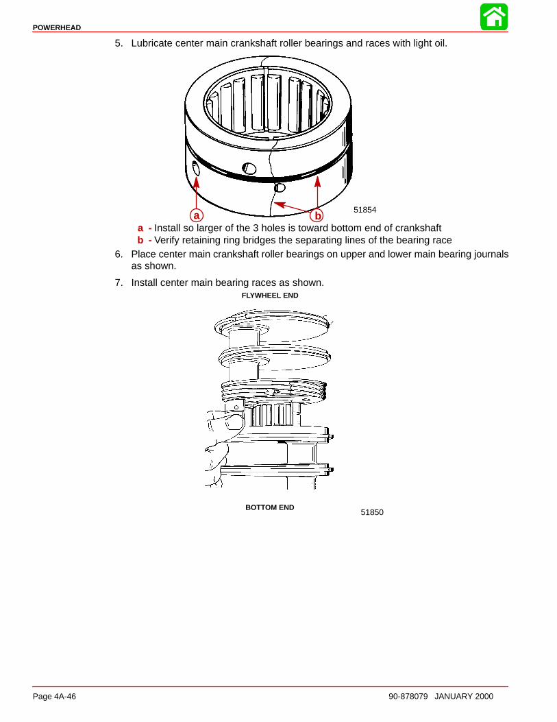
POWERHEAD
Page 4A-46 90-878079 JANUARY 2000
5. Lubricate center main crankshaft roller bearings and races with light oil.
51854a ba - Install so larger of the 3 holes is toward bottom end of crankshaftb - Verify retaining ring bridges the separating lines of the bearing race
6. Place center main crankshaft roller bearings on upper and lower main bearing journalsas shown.
7. Install center main bearing races as shown.
51850
FLYWHEEL END
BOTTOM END
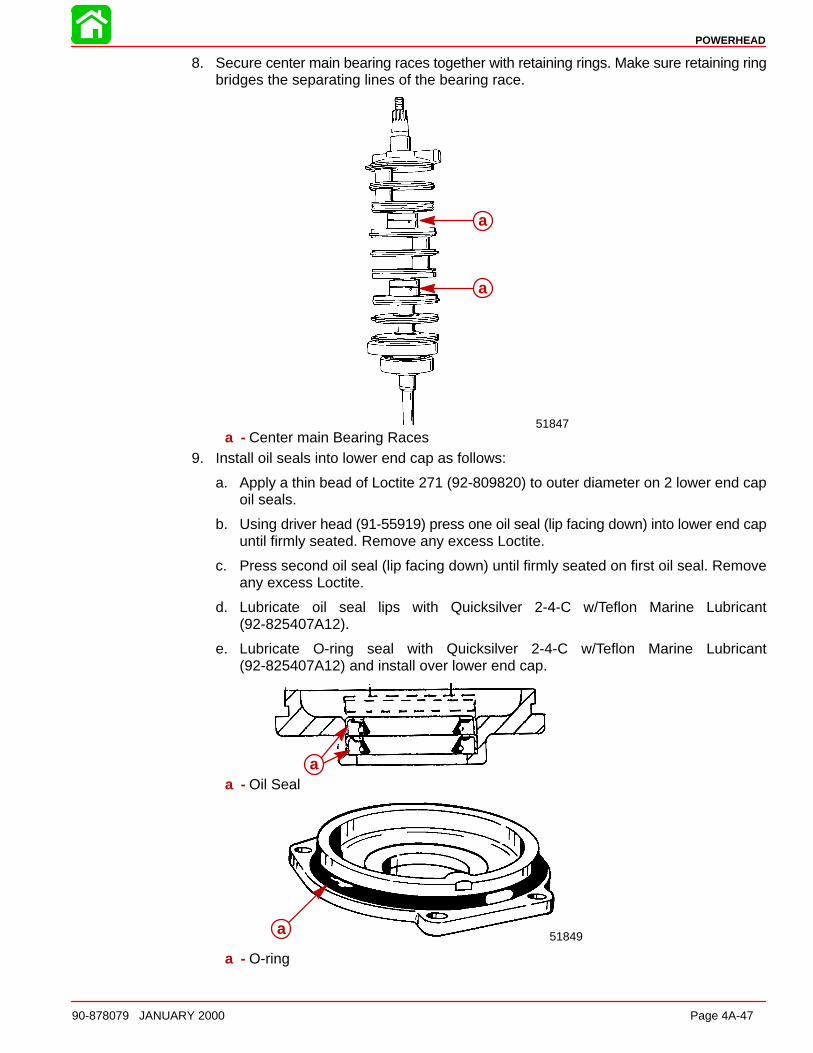
POWERHEAD
90-878079 JANUARY 2000 Page 4A-47
8. Secure center main bearing races together with retaining rings. Make sure retaining ringbridges the separating lines of the bearing race.
51847
a
a
a - Center main Bearing Races9. Install oil seals into lower end cap as follows:
a. Apply a thin bead of Loctite 271 (92-809820) to outer diameter on 2 lower end capoil seals.
b. Using driver head (91-55919) press one oil seal (lip facing down) into lower end capuntil firmly seated. Remove any excess Loctite.
c. Press second oil seal (lip facing down) until firmly seated on first oil seal. Removeany excess Loctite.
d. Lubricate oil seal lips with Quicksilver 2-4-C w/Teflon Marine Lubricant(92-825407A12).
e. Lubricate O-ring seal with Quicksilver 2-4-C w/Teflon Marine Lubricant(92-825407A12) and install over lower end cap.
aa - Oil Seal
51849a
a - O-ring
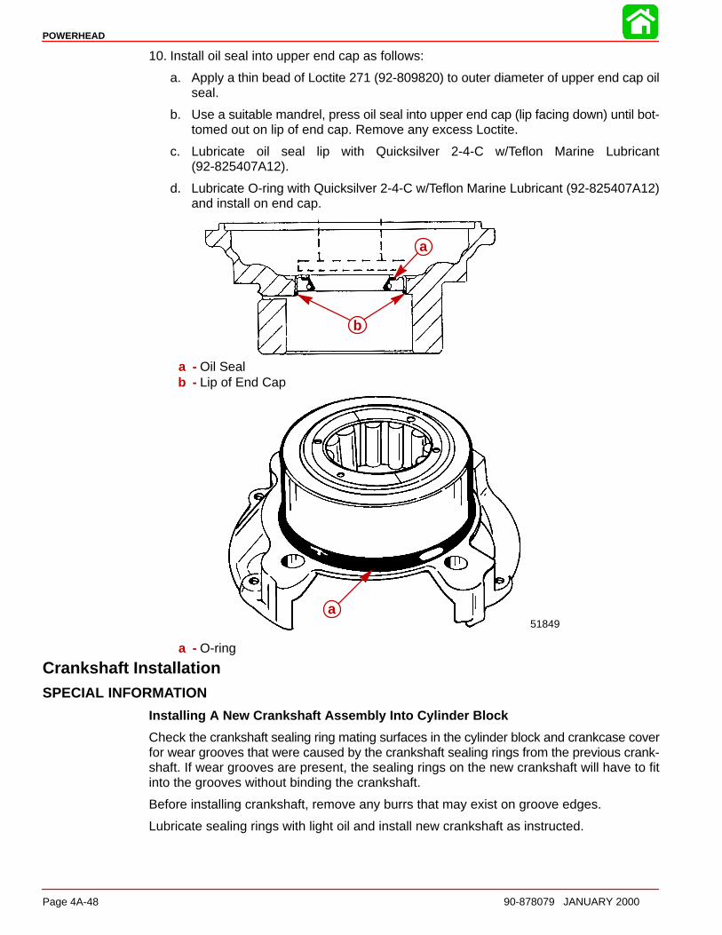
POWERHEAD
Page 4A-48 90-878079 JANUARY 2000
10. Install oil seal into upper end cap as follows:
a. Apply a thin bead of Loctite 271 (92-809820) to outer diameter of upper end cap oilseal.
b. Use a suitable mandrel, press oil seal into upper end cap (lip facing down) until bot-tomed out on lip of end cap. Remove any excess Loctite.
c. Lubricate oil seal lip with Quicksilver 2-4-C w/Teflon Marine Lubricant(92-825407A12).
d. Lubricate O-ring with Quicksilver 2-4-C w/Teflon Marine Lubricant (92-825407A12)and install on end cap.
a
b
a - Oil Sealb - Lip of End Cap
51849a
a - O-ring
Crankshaft InstallationSPECIAL INFORMATION
Installing A New Crankshaft Assembly Into Cylinder Block
Check the crankshaft sealing ring mating surfaces in the cylinder block and crankcase coverfor wear grooves that were caused by the crankshaft sealing rings from the previous crank-shaft. If wear grooves are present, the sealing rings on the new crankshaft will have to fitinto the grooves without binding the crankshaft.
Before installing crankshaft, remove any burrs that may exist on groove edges.
Lubricate sealing rings with light oil and install new crankshaft as instructed.

POWERHEAD
90-878079 JANUARY 2000 Page 4A-49
Install upper and lower end caps and then inspect fit between sealing rings and grooves.Temporarily install crankcase cover and rotate crankshaft several times to check if sealingrings are binding against crankshaft. (You will feel a drag on the crankshaft.) If sealing ringsare binding, recheck grooves for burrs. If this does not correct the problem, it is recom-mended that the cylinder block be replaced.
Install crankshaft as follows:
1. Lubricate crankshaft sealing rings with light oil.
2. Check cylinder block to be sure that dowel pins are in place.
51848
a
a - Dowel Pins3. Position all crankshaft seal ring gaps straight up.
4. Align hole in each center main bearing race with dowel pin.
5. Gently push crankshaft down into position making sure that the dowel pins are lined upwith the holes in center main bearings and crankshaft seal rings are in place.
51848a
a - Dowel Pin
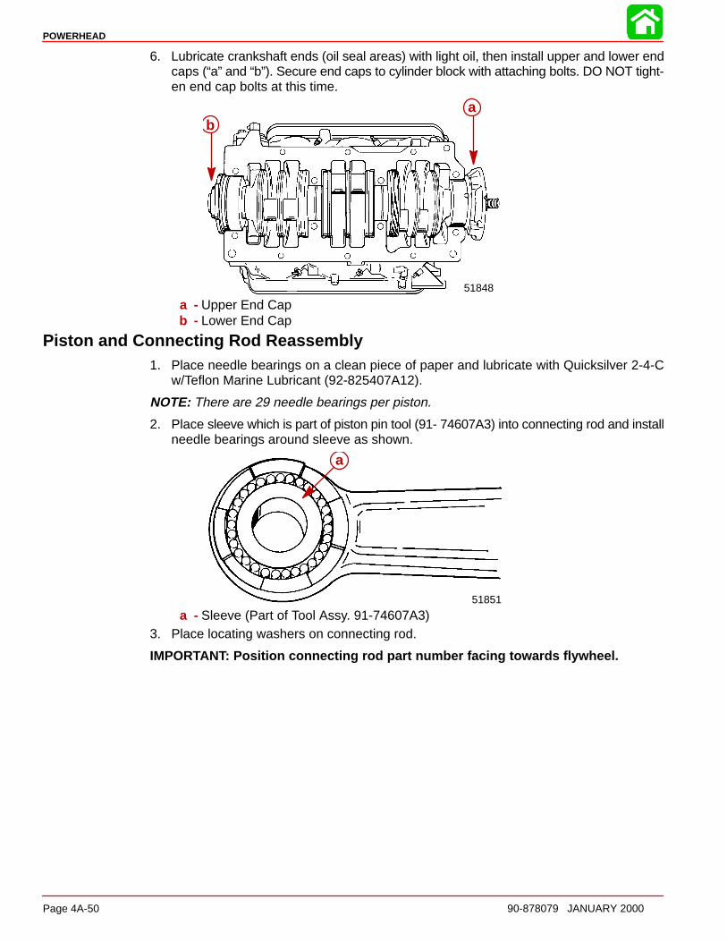
POWERHEAD
Page 4A-50 90-878079 JANUARY 2000
6. Lubricate crankshaft ends (oil seal areas) with light oil, then install upper and lower endcaps (“a” and “b”). Secure end caps to cylinder block with attaching bolts. DO NOT tight-en end cap bolts at this time.
51848
ab
a - Upper End Capb - Lower End Cap
Piston and Connecting Rod Reassembly1. Place needle bearings on a clean piece of paper and lubricate with Quicksilver 2-4-C
w/Teflon Marine Lubricant (92-825407A12).
NOTE: There are 29 needle bearings per piston.
2. Place sleeve which is part of piston pin tool (91- 74607A3) into connecting rod and installneedle bearings around sleeve as shown.
51851
a
a - Sleeve (Part of Tool Assy. 91-74607A3)3. Place locating washers on connecting rod.
IMPORTANT: Position connecting rod part number facing towards flywheel.
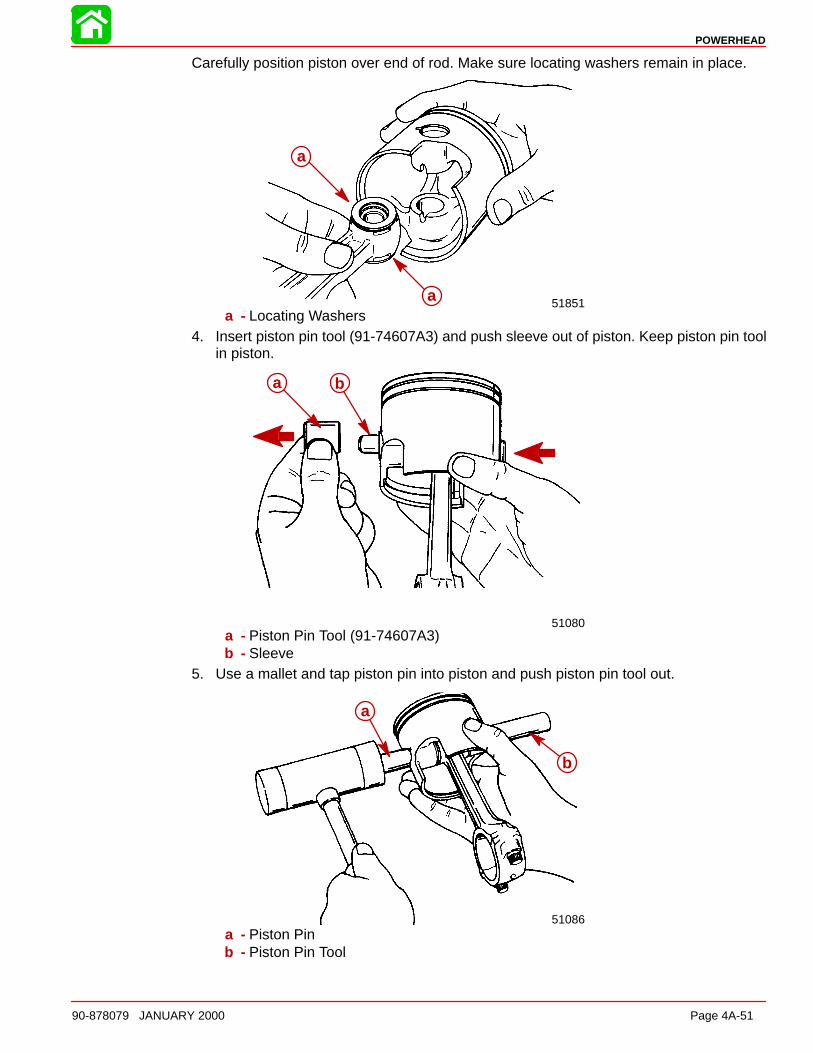
POWERHEAD
90-878079 JANUARY 2000 Page 4A-51
Carefully position piston over end of rod. Make sure locating washers remain in place.
51851
a
aa - Locating Washers
4. Insert piston pin tool (91-74607A3) and push sleeve out of piston. Keep piston pin toolin piston.
51080
a b
a - Piston Pin Tool (91-74607A3)b - Sleeve
5. Use a mallet and tap piston pin into piston and push piston pin tool out.
51086
a
b
a - Piston Pinb - Piston Pin Tool
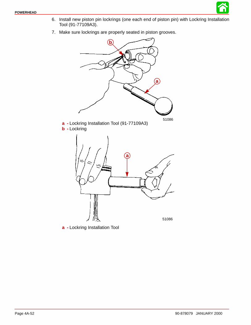
POWERHEAD
Page 4A-52 90-878079 JANUARY 2000
6. Install new piston pin lockrings (one each end of piston pin) with Lockring InstallationTool (91-77109A3).
7. Make sure lockrings are properly seated in piston grooves.
51086
a
b
a - Lockring Installation Tool (91-77109A3)b - Lockring
51086
a
a - Lockring Installation Tool
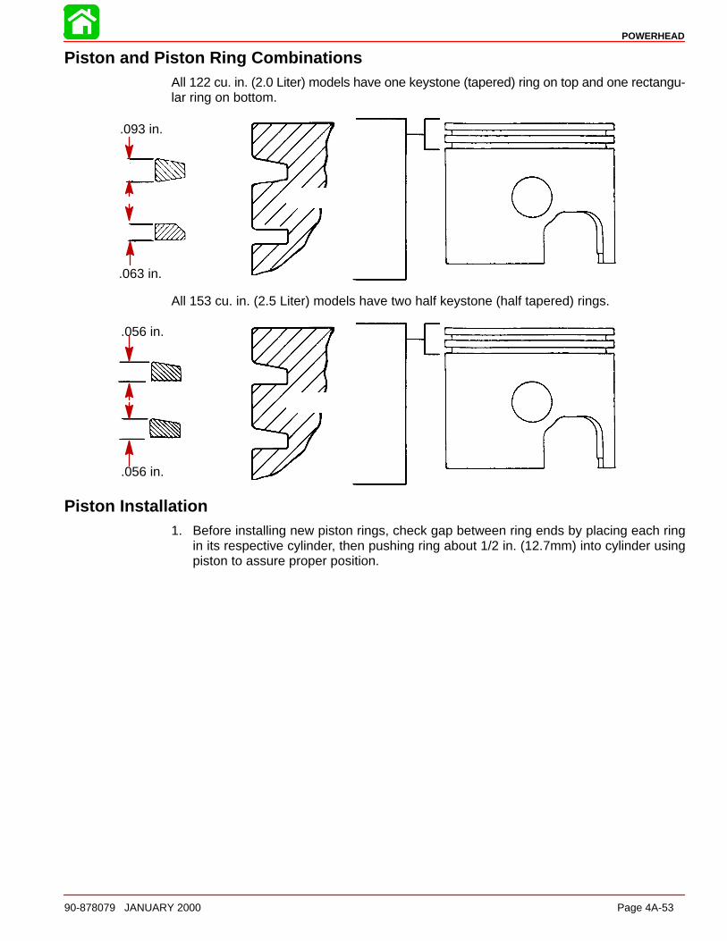
POWERHEAD
90-878079 JANUARY 2000 Page 4A-53
Piston and Piston Ring CombinationsAll 122 cu. in. (2.0 Liter) models have one keystone (tapered) ring on top and one rectangu-lar ring on bottom.
.093 in.
.063 in.
All 153 cu. in. (2.5 Liter) models have two half keystone (half tapered) rings.
.056 in.
.056 in.
Piston Installation1. Before installing new piston rings, check gap between ring ends by placing each ring
in its respective cylinder, then pushing ring about 1/2 in. (12.7mm) into cylinder usingpiston to assure proper position.
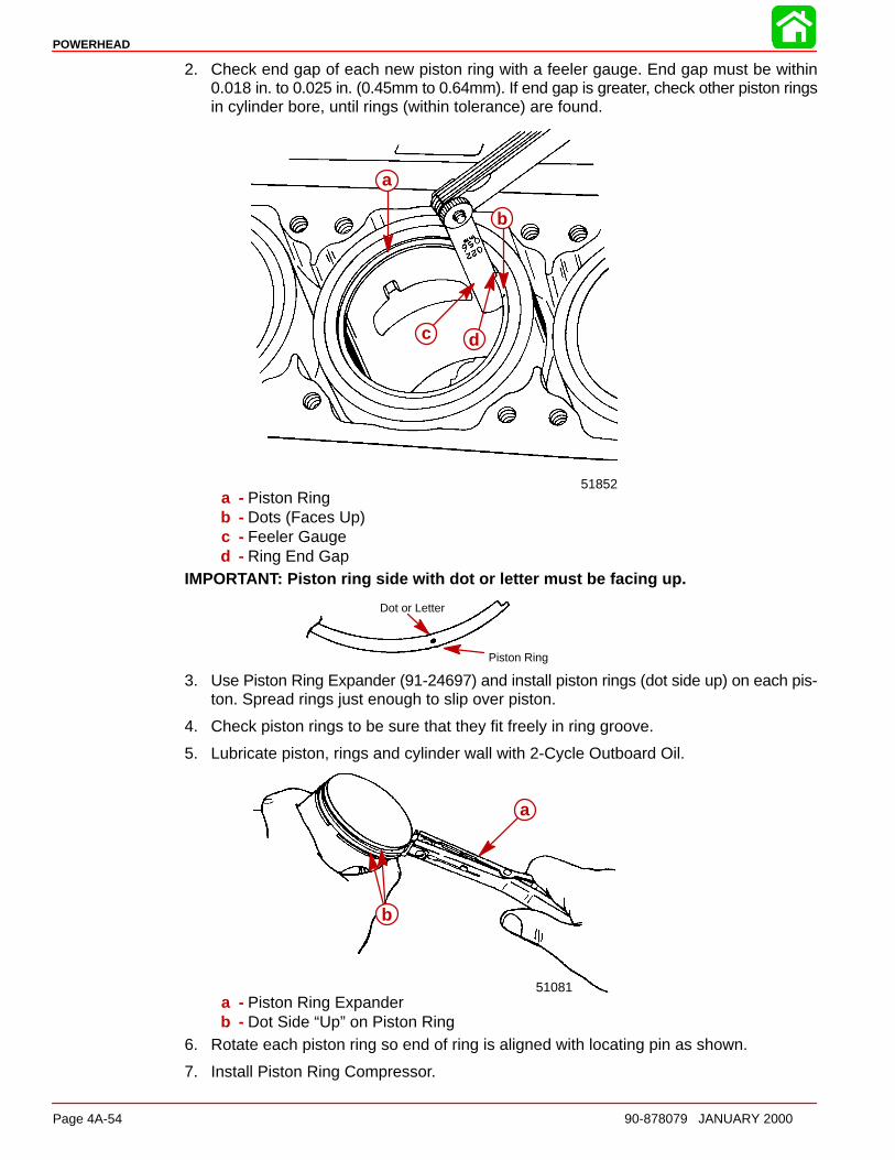
POWERHEAD
Page 4A-54 90-878079 JANUARY 2000
2. Check end gap of each new piston ring with a feeler gauge. End gap must be within0.018 in. to 0.025 in. (0.45mm to 0.64mm). If end gap is greater, check other piston ringsin cylinder bore, until rings (within tolerance) are found.
51852
a
b
c d
a - Piston Ringb - Dots (Faces Up)c - Feeler Gauged - Ring End Gap
IMPORTANT: Piston ring side with dot or letter must be facing up.
Dot or Letter
Piston Ring
3. Use Piston Ring Expander (91-24697) and install piston rings (dot side up) on each pis-ton. Spread rings just enough to slip over piston.
4. Check piston rings to be sure that they fit freely in ring groove.
5. Lubricate piston, rings and cylinder wall with 2-Cycle Outboard Oil.
51081
b
a
a - Piston Ring Expanderb - Dot Side “Up” on Piston Ring
6. Rotate each piston ring so end of ring is aligned with locating pin as shown.
7. Install Piston Ring Compressor.
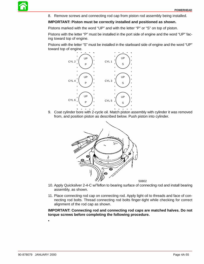
POWERHEAD
90-878079 JANUARY 2000 Page 4A-55
8. Remove screws and connecting rod cap from piston rod assembly being installed.
IMPORTANT: Piston must be correctly installed and positioned as shown.
Pistons marked with the word “UP” and with the letter “P” or “S” on top of piston.
Pistons with the letter “P” must be installed in the port side of engine and the word “UP” fac-ing toward top of engine.
Pistons with the letter “S” must be installed in the starboard side of engine and the word “UP”toward top of engine.
CYL 2
CYL 4
CYL 6
CYL 1
CYL 3
CYL 5
UP
P
UP
P
UP
P
UP
S
UP
S
UP
S
9. Coat cylinder bore with 2-cycle oil. Match piston assembly with cylinder it was removedfrom, and position piston as described below. Push piston into cylinder.
50802
10. Apply Quicksilver 2-4-C w/Teflon to bearing surface of connecting rod and install bearingassembly, as shown.
11. Place connecting rod cap on connecting rod. Apply light oil to threads and face of con-necting rod bolts. Thread connecting rod bolts finger-tight while checking for correctalignment of the rod cap as shown.
IMPORTANT: Connecting rod and connecting rod caps are matched halves. Do nottorque screws before completing the following procedure.
• Run a pencil lightly over ground area.
• If pencil stops at fracture point, loosen bolts, retighten, and check again.
NOTE: If you still feel the fracture point, discard the rod.
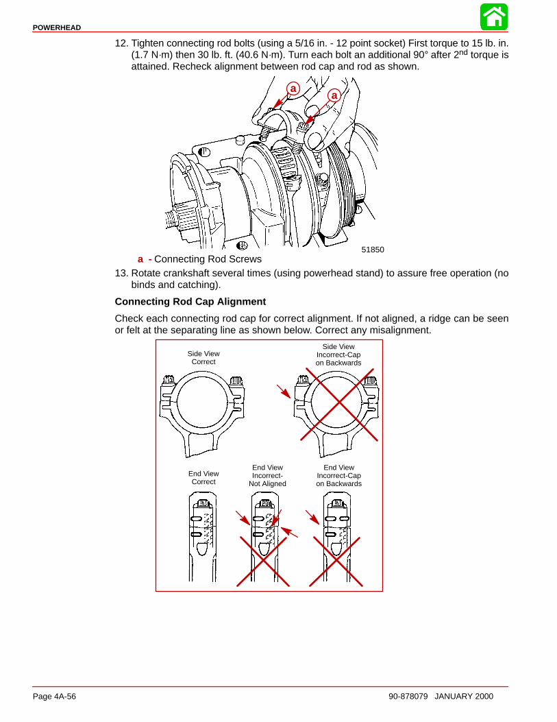
POWERHEAD
Page 4A-56 90-878079 JANUARY 2000
12. Tighten connecting rod bolts (using a 5/16 in. - 12 point socket) First torque to 15 lb. in.(1.7 N·m) then 30 lb. ft. (40.6 N·m). Turn each bolt an additional 90° after 2nd torque isattained. Recheck alignment between rod cap and rod as shown.
51850
aa
a - Connecting Rod Screws13. Rotate crankshaft several times (using powerhead stand) to assure free operation (no
binds and catching).
Connecting Rod Cap Alignment
Check each connecting rod cap for correct alignment. If not aligned, a ridge can be seenor felt at the separating line as shown below. Correct any misalignment.
ÄÄ
ÄÄÄÄÄÄ
Side ViewCorrect
End ViewCorrect
Side ViewIncorrect-Capon Backwards
End ViewIncorrect-Capon Backwards
ÄÄÄ
End ViewIncorrect-
Not Aligned
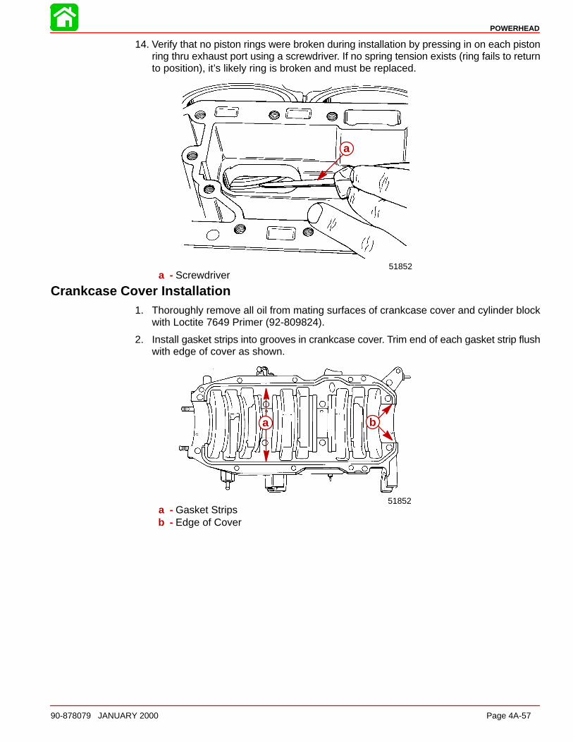
POWERHEAD
90-878079 JANUARY 2000 Page 4A-57
14. Verify that no piston rings were broken during installation by pressing in on each pistonring thru exhaust port using a screwdriver. If no spring tension exists (ring fails to returnto position), it’s likely ring is broken and must be replaced.
51852
a
a - Screwdriver
Crankcase Cover Installation1. Thoroughly remove all oil from mating surfaces of crankcase cover and cylinder block
with Loctite 7649 Primer (92-809824).
2. Install gasket strips into grooves in crankcase cover. Trim end of each gasket strip flushwith edge of cover as shown.
51852
a b
a - Gasket Stripsb - Edge of Cover
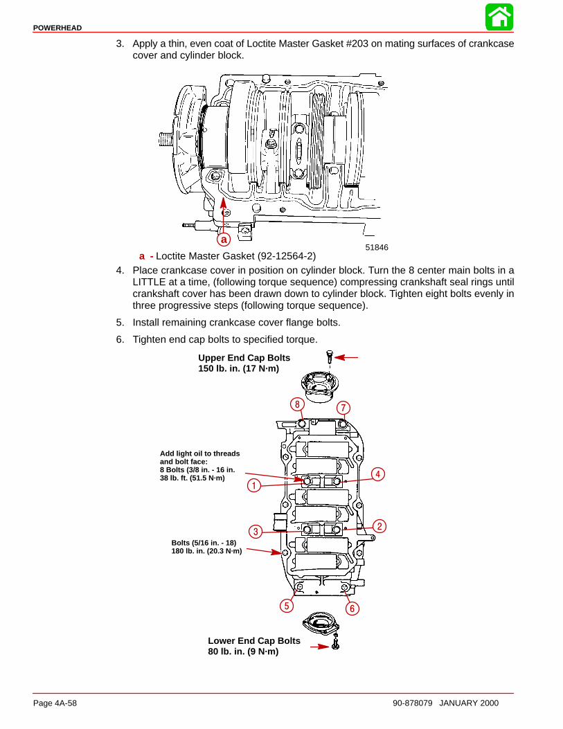
POWERHEAD
Page 4A-58 90-878079 JANUARY 2000
3. Apply a thin, even coat of Loctite Master Gasket #203 on mating surfaces of crankcasecover and cylinder block.
51846a
a - Loctite Master Gasket (92-12564-2)4. Place crankcase cover in position on cylinder block. Turn the 8 center main bolts in a
LITTLE at a time, (following torque sequence) compressing crankshaft seal rings untilcrankshaft cover has been drawn down to cylinder block. Tighten eight bolts evenly inthree progressive steps (following torque sequence).
5. Install remaining crankcase cover flange bolts.
6. Tighten end cap bolts to specified torque.
Add light oil to threadsand bolt face:8 Bolts (3/8 in. - 16 in.38 lb. ft. (51.5 N·m)
Bolts (5/16 in. - 18) 180 lb. in. (20.3 N·m)
Lower End Cap Bolts80 lb. in. (9 N·m)
Upper End Cap Bolts150 lb. in. (17 N·m)
1
23
4
5 6
78
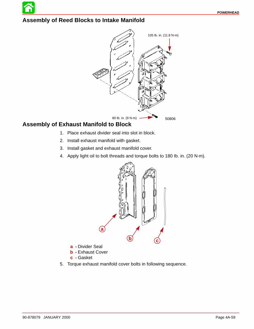
POWERHEAD
90-878079 JANUARY 2000 Page 4A-59
Assembly of Reed Blocks to Intake Manifold
5080680 lb. in. (9 N·m)
105 lb. in. (11.8 N·m)
Assembly of Exhaust Manifold to Block1. Place exhaust divider seal into slot in block.
2. Install exhaust manifold with gasket.
3. Install gasket and exhaust manifold cover.
4. Apply light oil to bolt threads and torque bolts to 180 Ib. in. (20 N·m).
a
b ca - Divider Sealb - Exhaust Coverc - Gasket
5. Torque exhaust manifold cover bolts in following sequence.
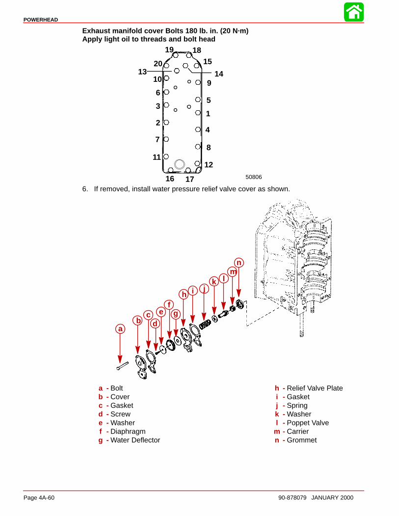
POWERHEAD
Page 4A-60 90-878079 JANUARY 2000
Exhaust manifold cover Bolts 180 lb. in. (20 N·m)Apply light oil to threads and bolt head
50806
19
20
10
6
3
2
7
11
16 17
12
8
4
1
5
9
1518
13 14
6. If removed, install water pressure relief valve cover as shown.
ab
cd
ef
g
h i jk l
mn
a - Boltb - Coverc - Gasketd - Screwe - Washerf - Diaphragmg - Water Deflector
h - Relief Valve Platei - Gasketj - Springk - Washerl - Poppet Valve
m - Carriern - Grommet

POWERHEAD
90-878079 JANUARY 2000 Page 4A-61
Cleaning and Inspection
Cylinder Block and Crankcase CoverIMPORTANT: Crankcase cover and cylinder block is a matched, line-bored assemblyand should never be mismatched by using a different crankcase cover or cylinderblock.
CAUTIONIt crankcase cover or cylinder block is to be submerged in a very strong cleaningsolution, it will be necessary to remove the crankcase cover/cylinder block bleedsyste m from crankcase cover/cylinder block to prevent damage to hoses and checkvalves.
1. Thoroughly clean cylinder block and crankcase cover. Be sure that all sealant and oldgaskets are removed from matching surfaces. Be sure that carbon deposits are re-moved from exhaust ports.
2. Inspect cylinder block and crankcase cover for cracks or fractures.
3. Check gasket surfaces for nicks, deep grooves, cracks and distortion that could causecompression leakages.
4. Check all water and oil passages in cylinder block and crankcase cover to be sure thatthey are not obstructed and that plugs are in place and tight.
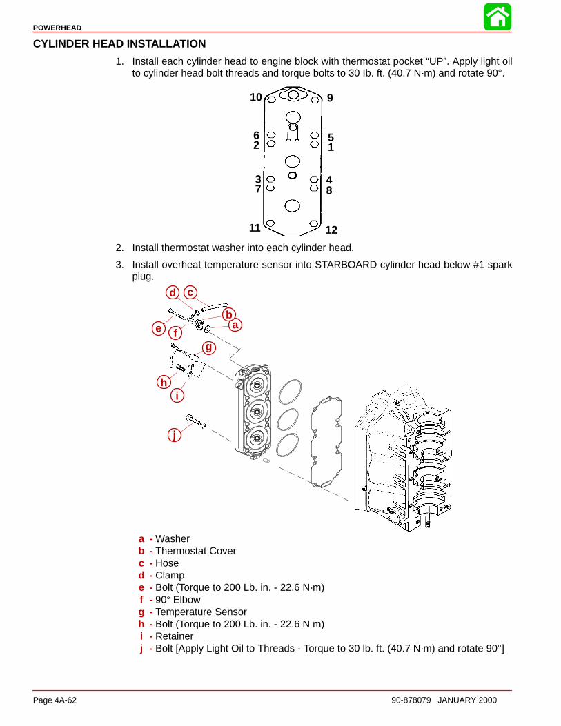
POWERHEAD
Page 4A-62 90-878079 JANUARY 2000
CYLINDER HEAD INSTALL ATION
1. Install each cylinder head to engine block with thermostat pocket “UP”. Apply light oilto cylinder head bolt threads and torque bolts to 30 Ib. ft. (40.7 N·m) and rotate 90°.
10
62
37
11 12
84
15
9
2. Install thermostat washer into each cylinder head.
3. Install overheat temperature sensor into STARBOARD cylinder head below #1 sparkplug.
ab
cd
e fg
hi
j
a - Washerb - Thermostat Coverc - Hosed - Clampe - Bolt (Torque to 200 Lb. in. - 22.6 N·m)f - 90° Elbowg - Temperature Sensorh - Bolt (Torque to 200 Lb. in. - 22.6 N m)i - Retainerj - Bolt [Apply Light Oil to Threads - Torque to 30 lb. ft. (40.7 N·m) and rotate 90°]
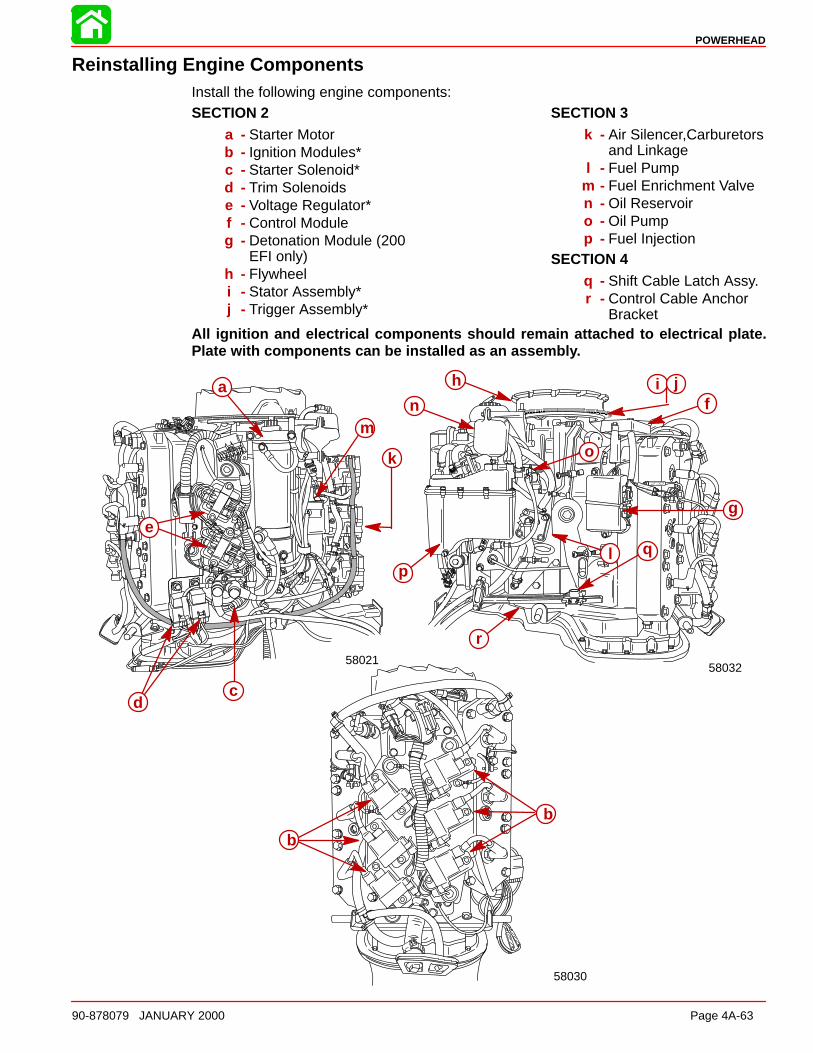
POWERHEAD
90-878079 JANUARY 2000 Page 4A-63
Reinstalling Engine ComponentsInstall the following engine components:SECTION 2
a - Starter Motorb - Ignition Modules*c - Starter Solenoid*d - Trim Solenoidse - Voltage Regulator*f - Control Moduleg - Detonation Module (200
EFI only)h - Flywheeli - Stator Assembly*j - Trigger Assembly*
SECTION 3k - Air Silencer,Carburetors
and Linkagel - Fuel Pump
m - Fuel Enrichment Valven - Oil Reservoiro - Oil Pumpp - Fuel Injection
SECTION 4q - Shift Cable Latch Assy.r - Control Cable Anchor
BracketAll ignition and electrical components should remain attached to electrical plate.Plate with components can be installed as an assembl y.
5802158032
58030
a
b
b
cd
e
f
g
h i j
k
l
mn
o
pq
r
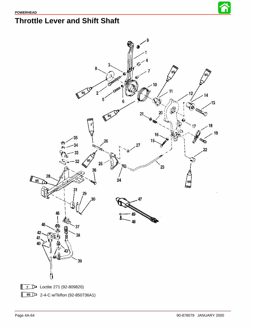
POWERHEAD
Page 4A-64 90-878079 JANUARY 2000
Throttle Lever and Shift Shaft
95 2-4-C w/Teflon (92-850736A1)
7 Loctite 271 (92-809820)
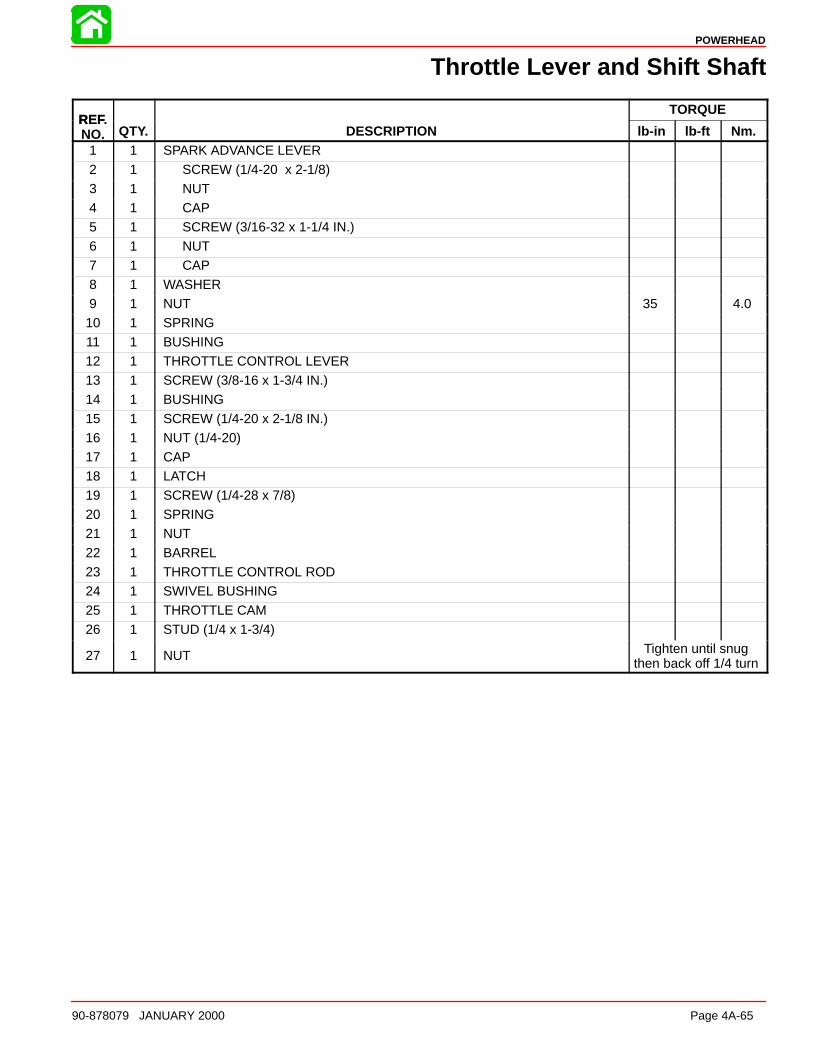
POWERHEAD
90-878079 JANUARY 2000 Page 4A-65
Throttle Lever and Shift Shaft
REFTORQUE
REF.NO. QTY. DESCRIPTION lb-in lb-ft Nm.
1 1 SPARK ADVANCE LEVER
2 1 SCREW (1/4-20 x 2-1/8)3 1 NUT4 1 CAP5 1 SCREW (3/16-32 x 1-1/4 IN.)6 1 NUT7 1 CAP
8 1 WASHER9 1 NUT 35 4.010 1 SPRING11 1 BUSHING12 1 THROTTLE CONTROL LEVER13 1 SCREW (3/8-16 x 1-3/4 IN.)14 1 BUSHING
15 1 SCREW (1/4-20 x 2-1/8 IN.)16 1 NUT (1/4-20)17 1 CAP18 1 LATCH19 1 SCREW (1/4-28 x 7/8)20 1 SPRING21 1 NUT
22 1 BARREL23 1 THROTTLE CONTROL ROD24 1 SWIVEL BUSHING25 1 THROTTLE CAM26 1 STUD (1/4 x 1-3/4)
27 1 NUT Tighten until snugthen back off 1/4 turn

POWERHEAD
Page 4A-66 90-878079 JANUARY 2000
Throttle Lever and Shift Shaft
95 2-4-C w/Teflon (92-850736A1)
7 Loctite 271 (92-809820)
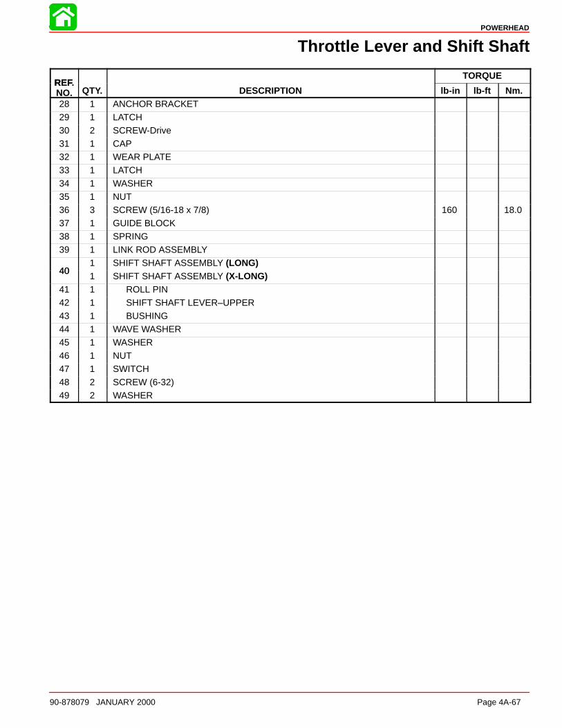
POWERHEAD
90-878079 JANUARY 2000 Page 4A-67
Throttle Lever and Shift Shaft
REFTORQUE
REF.NO. QTY. DESCRIPTION lb-in lb-ft Nm.28 1 ANCHOR BRACKET
29 1 LATCH30 2 SCREW-Drive31 1 CAP32 1 WEAR PLATE33 1 LATCH34 1 WASHER
35 1 NUT36 3 SCREW (5/16-18 x 7/8) 160 18.037 1 GUIDE BLOCK38 1 SPRING39 1 LINK ROD ASSEMBLY
401 SHIFT SHAFT ASSEMBLY (LONG)
401 SHIFT SHAFT ASSEMBLY (X-LONG)
41 1 ROLL PIN42 1 SHIFT SHAFT LEVER–UPPER43 1 BUSHING44 1 WAVE WASHER45 1 WASHER46 1 NUT47 1 SWITCH
48 2 SCREW (6-32)49 2 WASHER
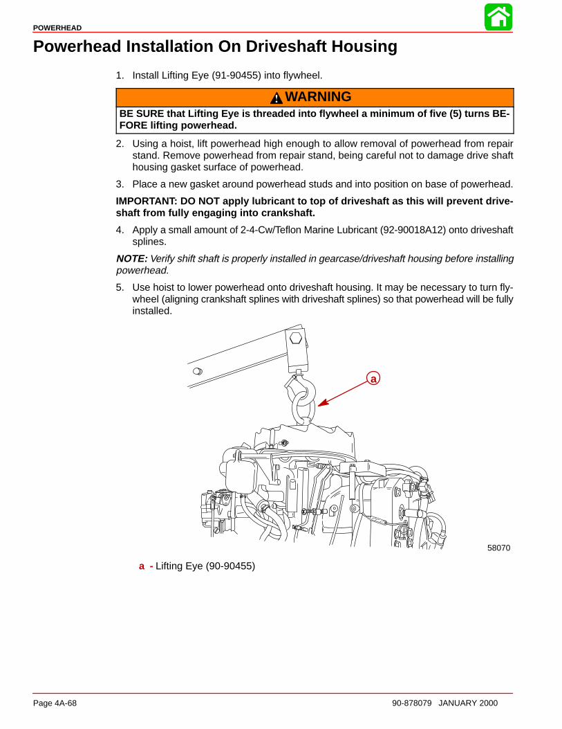
POWERHEAD
Page 4A-68 90-878079 JANUARY 2000
Powerhead Installation On Driveshaft Housing
1. Install Lifting Eye (91-90455) into flywheel.
WARNINGBE SURE that Lifting Eye is threaded into flywheel a minimum of five (5) turns BE-FORE lifting powerhead.
2. Using a hoist, lift powerhead high enough to allow removal of powerhead from repairstand. Remove powerhead from repair stand, being careful not to damage drive shafthousing gasket surface of powerhead.
3. Place a new gasket around powerhead studs and into position on base of powerhead.
IMPORTANT: DO NOT apply lubricant to top of driveshaft as this will prevent drive-shaft from fully engaging into crankshaft.
4. Apply a small amount of 2-4-Cw/Teflon Marine Lubricant (92-90018A12) onto driveshaftsplines.
NOTE: Verify shift shaft is properly installed in gearcase/driveshaft housing before installingpowerhead.
5. Use hoist to lower powerhead onto driveshaft housing. It may be necessary to turn fly-wheel (aligning crankshaft splines with driveshaft splines) so that powerhead will be fullyinstalled.
58070
a
a - Lifting Eye (90-90455)
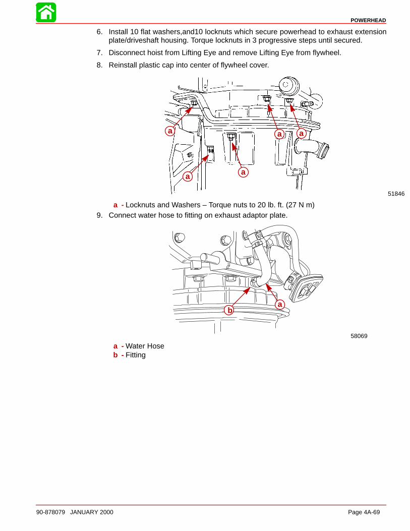
POWERHEAD
90-878079 JANUARY 2000 Page 4A-69
6. Install 10 flat washers,and10 locknuts which secure powerhead to exhaust extensionplate/driveshaft housing. Torque locknuts in 3 progressive steps until secured.
7. Disconnect hoist from Lifting Eye and remove Lifting Eye from flywheel.
8. Reinstall plastic cap into center of flywheel cover.
51846
a
a a
a a
a - Locknuts and Washers – Torque nuts to 20 lb. ft. (27 N m)9. Connect water hose to fitting on exhaust adaptor plate.
58069
ab
a - Water Hoseb - Fitting
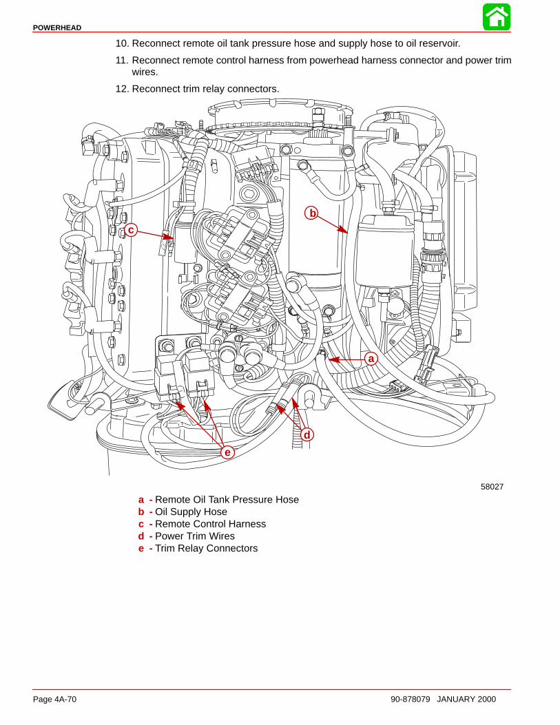
POWERHEAD
Page 4A-70 90-878079 JANUARY 2000
10. Reconnect remote oil tank pressure hose and supply hose to oil reservoir.
11. Reconnect remote control harness from powerhead harness connector and power trimwires.
12. Reconnect trim relay connectors.
58027
b
a
c
d
e
a - Remote Oil Tank Pressure Hoseb - Oil Supply Hosec - Remote Control Harnessd - Power Trim Wirese - Trim Relay Connectors
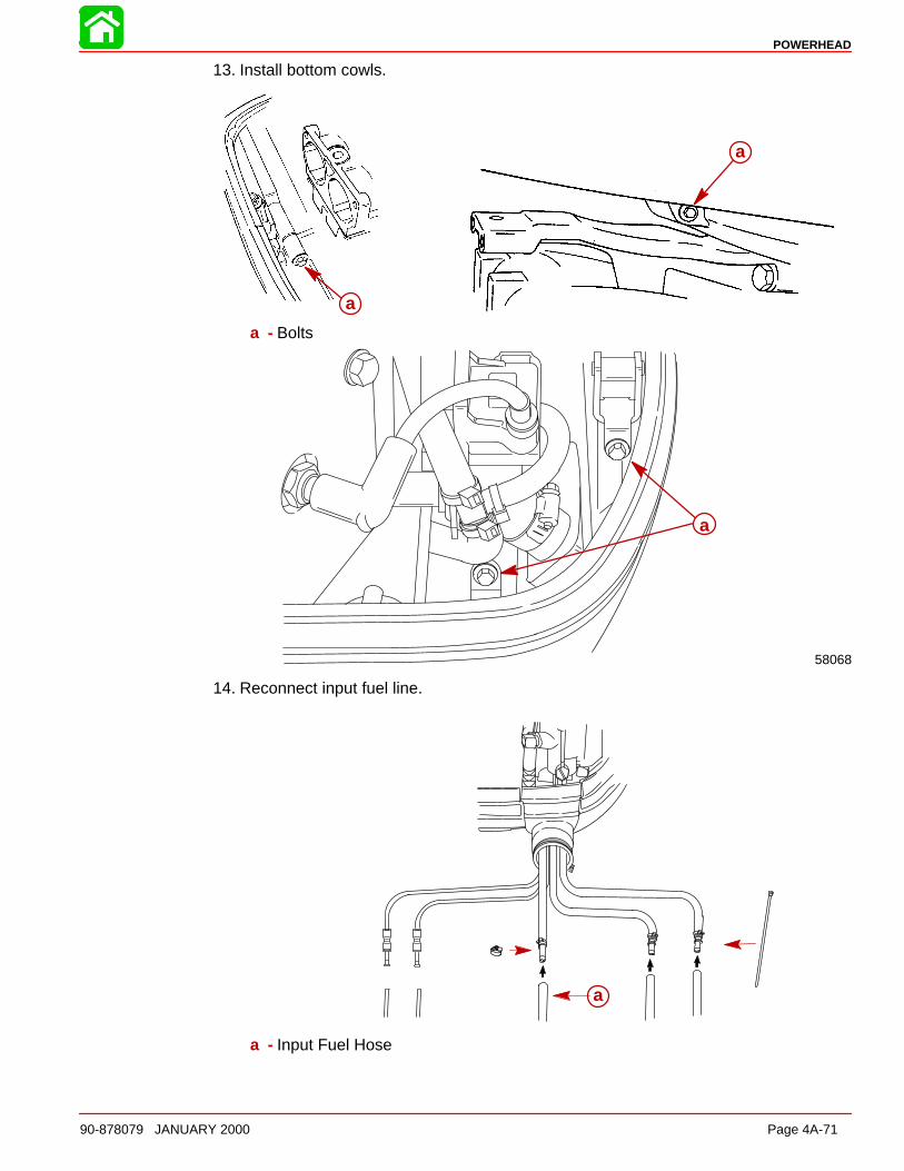
POWERHEAD
90-878079 JANUARY 2000 Page 4A-71
13. Install bottom cowls.
a
a
a - Bolts
58068
a
14. Reconnect input fuel line.
a
a - Input Fuel Hose
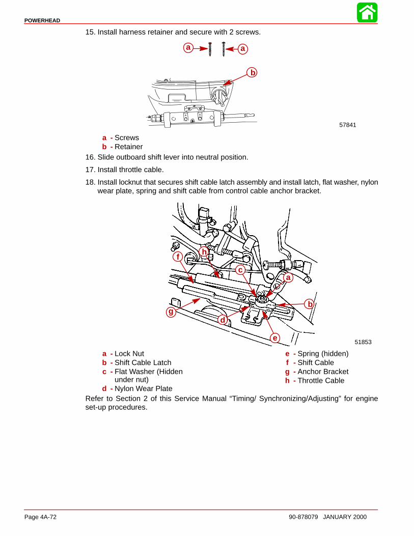
POWERHEAD
Page 4A-72 90-878079 JANUARY 2000
15. Install harness retainer and secure with 2 screws.
57841
a a
b
a - Screwsb - Retainer
16. Slide outboard shift lever into neutral position.
17. Install throttle cable.
18. Install locknut that secures shift cable latch assembly and install latch, flat washer, nylonwear plate, spring and shift cable from control cable anchor bracket.
51853
a
b
c
d
e
f
g
h
a - Lock Nutb - Shift Cable Latchc - Flat Washer (Hidden
under nut)d - Nylon Wear Plate
e - Spring (hidden)f - Shift Cableg - Anchor Bracketh - Throttle Cable
Refer to Section 2 of this Service Manual “Timing/ Synchronizing/Adjusting” for engineset-up procedures.

POWERHEAD
90-878079 JANUARY 2000 Page 4A-73
Gasoline/Oil Break-in Mixture
During Break-in, use a 50:1 (2% oil) gasoline/oil mixture in the first tank of fuel. Follow thetable below for mixing ratios. Use of this fuel mixture combined with oil from the oil injectionsystem will supply adequate lubrication during engine break-in.
After the break-in fuel mixture is used up, it is no longer necessary to add oil with the gaso-line.
NOTE: At the end of the break-in period, visually check to see if the oil level in the oil injectiontank has dropped. Oil usage indicates the oil injection system is functioning correctly.
NOTE: Mixing Gasoline/Oil for Break-in – Using a funnel, pour the correct amount of oilslowly with the gasoline as tank is filled.
GASOLINE/OIL MIXING R ATIO CHART
Gas/OilRatio
1 Gallon Gas(3.8 Liters)
3 Gallons Gas(11.5 Liters)
6 Gallons Gas(23 Liters)
50:1(2%)
3 fl. oz.(89 ml) Oil
8 fl. oz.(237 ml) Oil
16 fl. oz.(473 ml) Oil
Break-ln Procedure
CAUTIONSevere damage to the engine can result by not complying with the Engine Break-InProcedure.
Vary the throttle setting during the first hour of operation. During the first hour of operation,avoid remaining at a constant speed for more than two minutes and avoid sustained wideopen throttle.

4B
COOLING
90-878079 JANUARY 2000 Page 4B-1
POWERHEADSection 4B - Cooling
Table of Contents
Specifications 4B-1. . . . . . . . . . . . . . . . . . . . . . . . . . . . . . . . Water Pressure 4B-1. . . . . . . . . . . . . . . . . . . . . . . . . . . Thermostat 4B-1. . . . . . . . . . . . . . . . . . . . . . . . . . . . . . . Temperature Sensor 4B-1. . . . . . . . . . . . . . . . . . . . . . .
Special Tools 4B-2. . . . . . . . . . . . . . . . . . . . . . . . . . . . . . . . Temperature Sensor 4B-3. . . . . . . . . . . . . . . . . . . . . . .
Water Flow 4B-3. . . . . . . . . . . . . . . . . . . . . . . . . . . . . . . . . . Description 4B-3. . . . . . . . . . . . . . . . . . . . . . . . . . . . . . .
Water Flow Diagram 4B-5. . . . . . . . . . . . . . . . . . . . . . . . . . Troubleshooting 4B-7. . . . . . . . . . . . . . . . . . . . . . . . . . . . . . Thermostat Test 4B-8. . . . . . . . . . . . . . . . . . . . . . . . . . . . . . Water Pressure Check 4B-8. . . . . . . . . . . . . . . . . . . . . . . . Water Pump Cleaning and Inspection 4B-9. . . . . . . . . . . Problem Diagnosis 4B-10. . . . . . . . . . . . . . . . . . . . . . . . . .
Specifications
Thermostat 143°F (61.7°C). . . . . . . . . . .
Water Pressure
Idle 1.0 – 3.0 PSI(6.8 – 20.5 kPa)
Poppet Valve Opening 4 – 9 PSI(27.4 – 61.6 kPa)
W.O.T. 12.0 PSI (82.1 kPa)Minimum
Temperature Sensor
Temperature Sensor(s)Between Black andeach TAN/BLK wire.
NoContinuity
Between each lead andground
NoContinuity
a cdb
a - Temperature Sensor (EFI Models)and optional gauge sender
b - Temperature Sensor for WarningHorn (EFI Models)
c - Temperature Sensor for optional gauge(Carb Models)
d - Temperature Sensor for Warning Horn(Carb Models)

COOLING
Page 4B-2 90-878079 JANUARY 2000
Special Tools
1. DMT 2000 Digital Tachometer Multimeter P/N 91-854009A1
2. Water Pressure Gauge 91-79250A2
56725
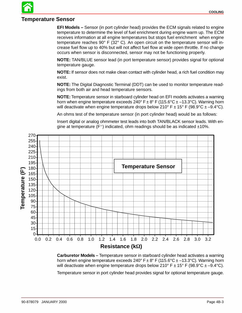
COOLING
90-878079 JANUARY 2000 Page 4B-3
Temperature SensorEFI Models – Sensor (in port cylinder head) provides the ECM signals related to enginetemperature to determine the level of fuel enrichment during engine warm up. The ECMreceives information at all engine temperatures but stops fuel enrichment when enginetemperature reaches 90° F (32° C). An open circuit on the temperature sensor will in-crease fuel flow up to 40% but will not affect fuel flow at wide open throttle. If no changeoccurs when sensor is disconnected, sensor may not be functioning properly.
NOTE: TAN/BLUE sensor lead (in port temperature sensor) provides signal for optionaltemperature gauge.
NOTE: If sensor does not make clean contact with cylinder head, a rich fuel condition mayexist.
NOTE: The Digital Diagnostic Terminal (DDT) can be used to monitor temperature read-ings from both air and head temperature sensors.
NOTE: Temperature sensor in starboard cylinder head on EFI models activates a warninghorn when engine temperature exceeds 240° F ± 8° F (115.6°C ± –13.3°C). Warning hornwill deactivate when engine temperature drops below 210° F ± 15° F (98.9°C ± –9.4°C).
An ohms test of the temperature sensor (in port cylinder head) would be as follows:
Insert digital or analog ohmmeter test leads into both TAN/BLACK sensor leads. With en-gine at temperature (F) indicated, ohm readings should be as indicated ±10%.
0153045607590
105120135150165180195210225240255270
0.0 0.2 0.4 0.6 0.8 1.0 1.2 1.4 1.6 1.8 2.0 2.2 2.4 2.6 2.8 3.0 3.2
Resistance (k )
Tem
pera
ture
(F) Temperature Sensor
Carburetor Models – Temperature sensor in starboard cylinder head activates a warninghorn when engine temperature exceeds 240° F ± 8° F (115.6°C ± –13.3°C). Warning hornwill deactivate when engine temperature drops below 210° F ± 15° F (98.9°C ± –9.4°C).
Temperature sensor in port cylinder head provides signal for optional temperature gauge.
COOLING
Page 4B-4 90-878079 JANUARY 2000
Water Flow
DescriptionCooling water enters the cooling system through the lower unit water inlets. The pumpassembly forces water through the water tube and exhaust adapter plate passages fillingthe power head central water chamber (located behind the exhaust cavity). Water entersthe exhaust cover cavity through 2 holes near the top of the exhaust cover.
Water exits the exhaust cover cavity through 4 slots (2 each side) filling the water pas-sages around the cylinders. Water flows around each bank of cylinders to the top of thecylinder block.
Water flow exiting the cylinder block is controlled by the thermostats (1 in each cylinderhead) and the poppet valve (located at the bottom starboard side of powerhead). At lowRPM (below 1500 RPM), the thermostats control water flow depending upon engine tem-perature. When the thermostats are open, water passes through the cylinder heads andexits to the drive shaft housing. At higher RPM (above 1500 RPM) the poppet valve willcontrol the water flow.
Water that passes through the poppet valve enters water passages in the adaptor plates.Water passes through the adaptor plates into the driveshaft housing.
Water dumped into the drive shaft housing builds up a wall of water around the exhausttube. This performs 2 functions:
• Helps silence the exhaust
• Prevents air from being drawn into the pump
Water exits the engine in 3 locations:
• Excess water from the wall of water exits around anodes on the gear housing.
• A portion of the water that passes through the thermostats exits out the tell tail.
• Water exits through two 1/8 in. (3.175 mm) holes in the lower adaptor plate into theexhaust.
To allow complete passage filling and to prevent steam pockets, all cooling passages areinterconnected. Small passages are incorporated to allow the cooling system to drain.
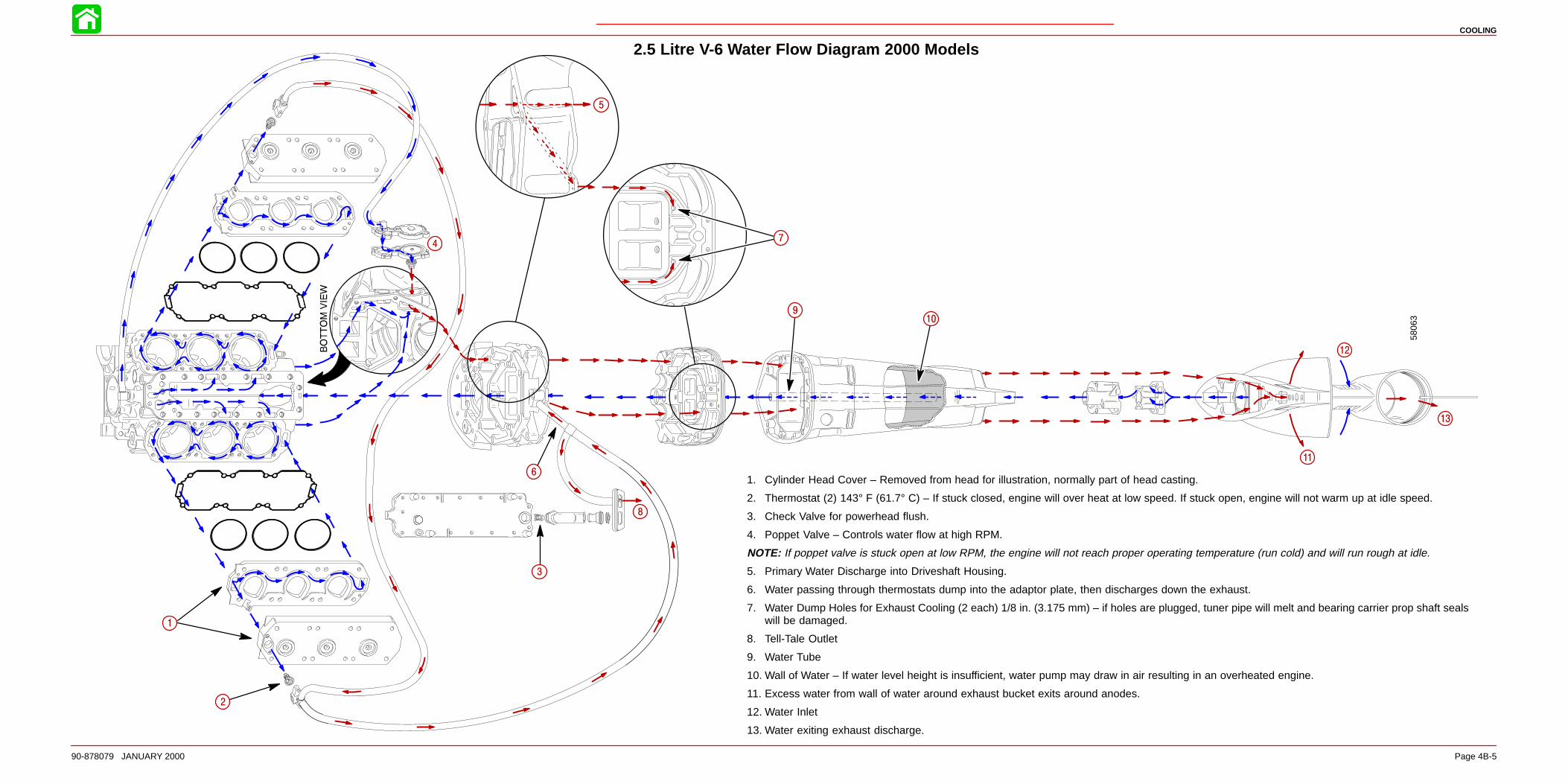
COOLING
90-878079 JANUARY 2000 Page 4B-5
5806
3
1
2
3
4
5
6
7
8
910
11
12
13
2.5 Litre V-6 Water Flow Diagram 2000 Models
1. Cylinder Head Cover – Removed from head for illustration, normally part of head casting.
2. Thermostat (2) 143° F (61.7° C) – If stuck closed, engine will over heat at low speed. If stuck open, engine will not warm up at idle speed.
3. Check Valve for powerhead flush.
4. Poppet Valve – Controls water flow at high RPM.
NOTE: If poppet valve is stuck open at low RPM, the engine will not reach proper operating temperature (run cold) and will run rough at idle.
5. Primary Water Discharge into Driveshaft Housing.
6. Water passing through thermostats dump into the adaptor plate, then discharges down the exhaust.
7. Water Dump Holes for Exhaust Cooling (2 each) 1/8 in. (3.175 mm) – if holes are plugged, tuner pipe will melt and bearing carrier prop shaft sealswill be damaged.
8. Tell-Tale Outlet
9. Water Tube
10. Wall of Water – If water level height is insufficient, water pump may draw in air resulting in an overheated engine.
11. Excess water from wall of water around exhaust bucket exits around anodes.
12. Water Inlet
13. Water exiting exhaust discharge.

COOLING
Page 4B-6 90-878079 JANUARY 2000Page 4B-6
Notes:
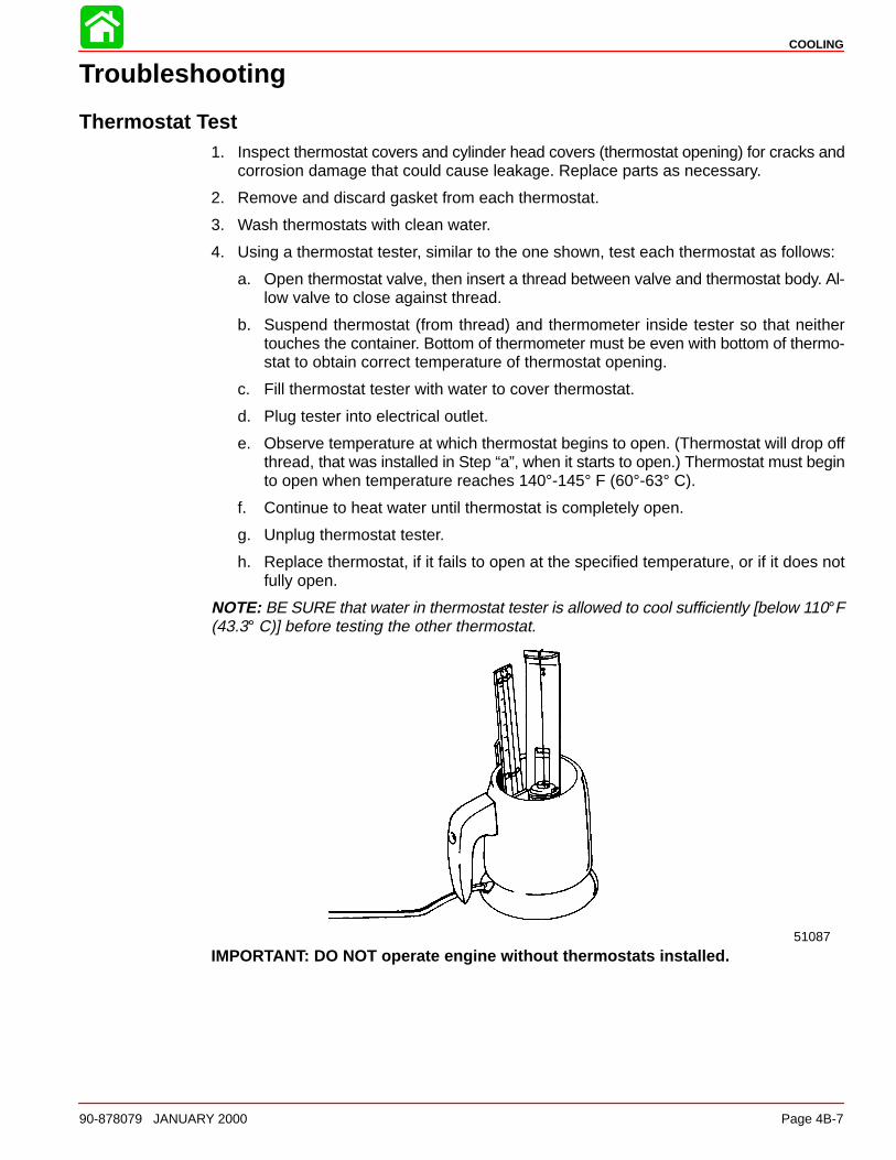
COOLING
90-878079 JANUARY 2000 Page 4B-7
Troubleshooting
Thermostat Test1. Inspect thermostat covers and cylinder head covers (thermostat opening) for cracks and
corrosion damage that could cause leakage. Replace parts as necessary.
2. Remove and discard gasket from each thermostat.
3. Wash thermostats with clean water.
4. Using a thermostat tester, similar to the one shown, test each thermostat as follows:
a. Open thermostat valve, then insert a thread between valve and thermostat body. Al-low valve to close against thread.
b. Suspend thermostat (from thread) and thermometer inside tester so that neithertouches the container. Bottom of thermometer must be even with bottom of thermo-stat to obtain correct temperature of thermostat opening.
c. Fill thermostat tester with water to cover thermostat.
d. Plug tester into electrical outlet.
e. Observe temperature at which thermostat begins to open. (Thermostat will drop offthread, that was installed in Step “a”, when it starts to open.) Thermostat must beginto open when temperature reaches 140°-145° F (60°-63° C).
f. Continue to heat water until thermostat is completely open.
g. Unplug thermostat tester.
h. Replace thermostat, if it fails to open at the specified temperature, or if it does notfully open.
NOTE: BE SURE that water in thermostat tester is allowed to cool sufficiently [below 110°F(43.3° C)] before testing the other thermostat.
51087
IMPORTANT: DO NOT operate engine without thermostats installed.
COOLING
Page 4B-8 90-878079 JANUARY 2000
Water Pressure CheckWater pressure may be checked by attaching a test pressure gauge to the top of the engineblock.
A water pressure line (GRAY colored) is provided that exits at the front of the lower cowl.A dash style gauge may be connected to this line to register water pressure.
WARNINGShut off engine and refer to troubleshooting chart if water pressure is not withinspecification. DO NOT exceed 3000 RPM in neutral.
Idle 1.0 – 3.0 PSI(6.8 – 20.5 kPa)
Poppet Valve Opening 4 – 9 PSI(27.4 – 61.6 kPa)
W.O.T. 12.0 PSI (82.1 kPa)Minimum

COOLING
90-878079 JANUARY 2000 Page 4B-9
Water Pump Cleaning and Inspection1. Inspect the water tube coupling for wear or damage. If necessary replace..
a
a - Water Tube Coupling
2. Inspect the water pump impeller for wear on the end, top and bottom of the impellerblades. Replace the impeller if this condition is found.
3. Inspect for proper bonding between the hub and the impeller. Replace the impeller if im-proper bonding is found.
a b
a - Hubb - Impeller
4. Inspect the impeller blades to see if they are cracked, burnt, hard or deformed. Replacethe impeller if the blades are in this condition.
IMPORTANT: The circular groove formed by the impeller sealing bead should be dis-regarded when inspecting co ver and plate. The depth of the groove will not affect wa-ter pump output.
5. Replace cover if plastic is melted from excessive heat (lack of water). Replace stainlessinsert and/or face plate if grooves (other than impeller sealing bead groove) are morethan 0.010 in. (0.254 mm) deep.
57408
a
b
c
d
a - Water Pump Face Plateb - Sealing Groove (disregard)c - Water Pump Coverd - Stainless Insert [discard if grooves exceed 0.010 in. (0.254 mm)]
IMPORTANT: It is recommended that all seals and gaskets be replaced (as a normalrepair procedure) to assure effective repair.
IMPORTANT: It is recommended that the water pump impeller be replaced wheneverthe gearcase is removed for maintenance. However, if it is necessary to re-use theimpeller, DO NOT install in reverse to original rotation as premature impeller failurewill occur.
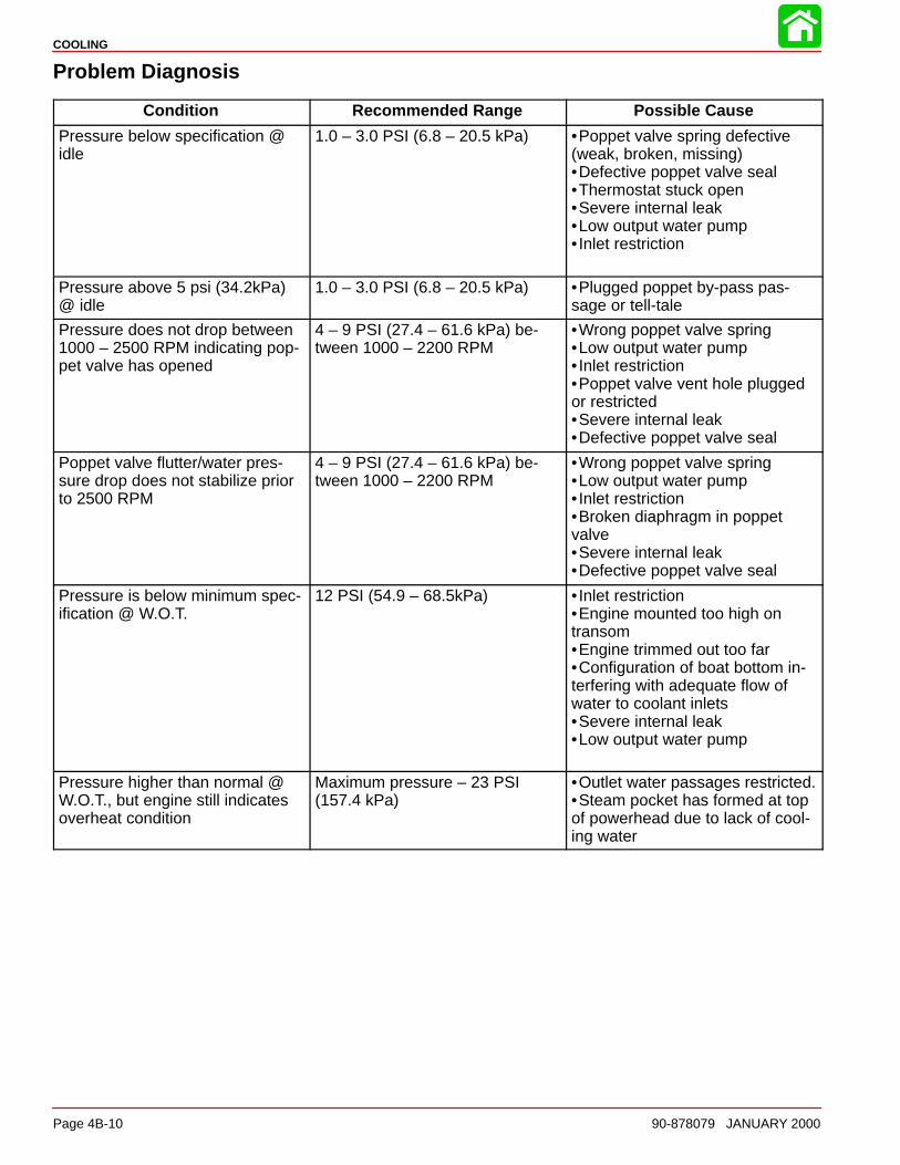
COOLING
Page 4B-10 90-878079 JANUARY 2000
Problem Diagnosis
Condition Recommended Range Possible Cause
Pressure below specification @idle
1.0 – 3.0 PSI (6.8 – 20.5 kPa) •Poppet valve spring defective(weak, broken, missing)•Defective poppet valve seal•Thermostat stuck open•Severe internal leak•Low output water pump• Inlet restriction
Pressure above 5 psi (34.2kPa)@ idle
1.0 – 3.0 PSI (6.8 – 20.5 kPa) •Plugged poppet by-pass pas-sage or tell-tale
Pressure does not drop between1000 – 2500 RPM indicating pop-pet valve has opened
4 – 9 PSI (27.4 – 61.6 kPa) be-tween 1000 – 2200 RPM
•Wrong poppet valve spring•Low output water pump• Inlet restriction•Poppet valve vent hole pluggedor restricted•Severe internal leak•Defective poppet valve seal
Poppet valve flutter/water pres-sure drop does not stabilize priorto 2500 RPM
4 – 9 PSI (27.4 – 61.6 kPa) be-tween 1000 – 2200 RPM
•Wrong poppet valve spring•Low output water pump• Inlet restriction•Broken diaphragm in poppetvalve•Severe internal leak•Defective poppet valve seal
Pressure is below minimum spec-ification @ W.O.T.
12 PSI (54.9 – 68.5kPa) • Inlet restriction•Engine mounted too high ontransom•Engine trimmed out too far•Configuration of boat bottom in-terfering with adequate flow ofwater to coolant inlets•Severe internal leak•Low output water pump
Pressure higher than normal @W.O.T., but engine still indicatesoverheat condition
Maximum pressure – 23 PSI(157.4 kPa)
•Outlet water passages restricted.•Steam pocket has formed at topof powerhead due to lack of cool-ing water

5A
CLAMP/SWIVEL BRACKETS & DRIVESHAFT HOUSING
90-878079 JANUARY 2000 Page 5A-1
MID-SECTIONSection 5A – Clamp/Swivel Brackets & Driveshaft Housing
Table of Contents
Swivel Bracket and Steering Arm 5A-2. . . . . . . . . . . . Transom Brackets 5A-4. . . . . . . . . . . . . . . . . . . . . . . . . Drive Shaft Housing and Exhaust Tube 5A-6. . . . . .
Drive Shaft Housing and Dyna-FloatSuspension 5A-8. . . . . . . . . . . . . . . . . . . . . . . . . . . . . . .
Removal and Disassembly 5A-8. . . . . . . . . . . . . . Reassembly and Installation 5A-11. . . . . . . . . . . .
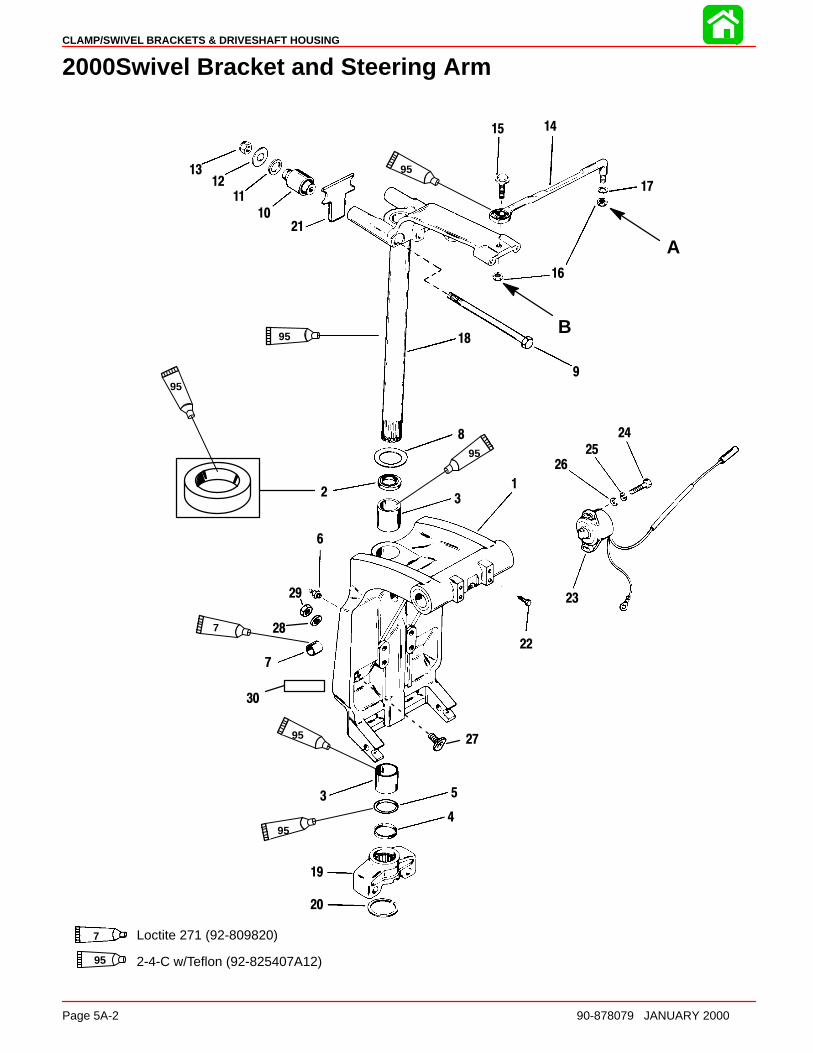
CLAMP/SWIVEL BRACKETS & DRIVESHAFT HOUSING
Page 5A-2 90-878079 JANUARY 2000
2000Swivel Bracket and Steering Arm
2
7
19
20
3
27
29
28
30
95
95
95
7
95
95
95
B
95 2-4-C w/Teflon (92-825407A12)
A
7 Loctite 271 (92-809820)
1
3
6
8
9
10
11
1213
1415
16
17
18
21
22
23
24
25
26
4
5
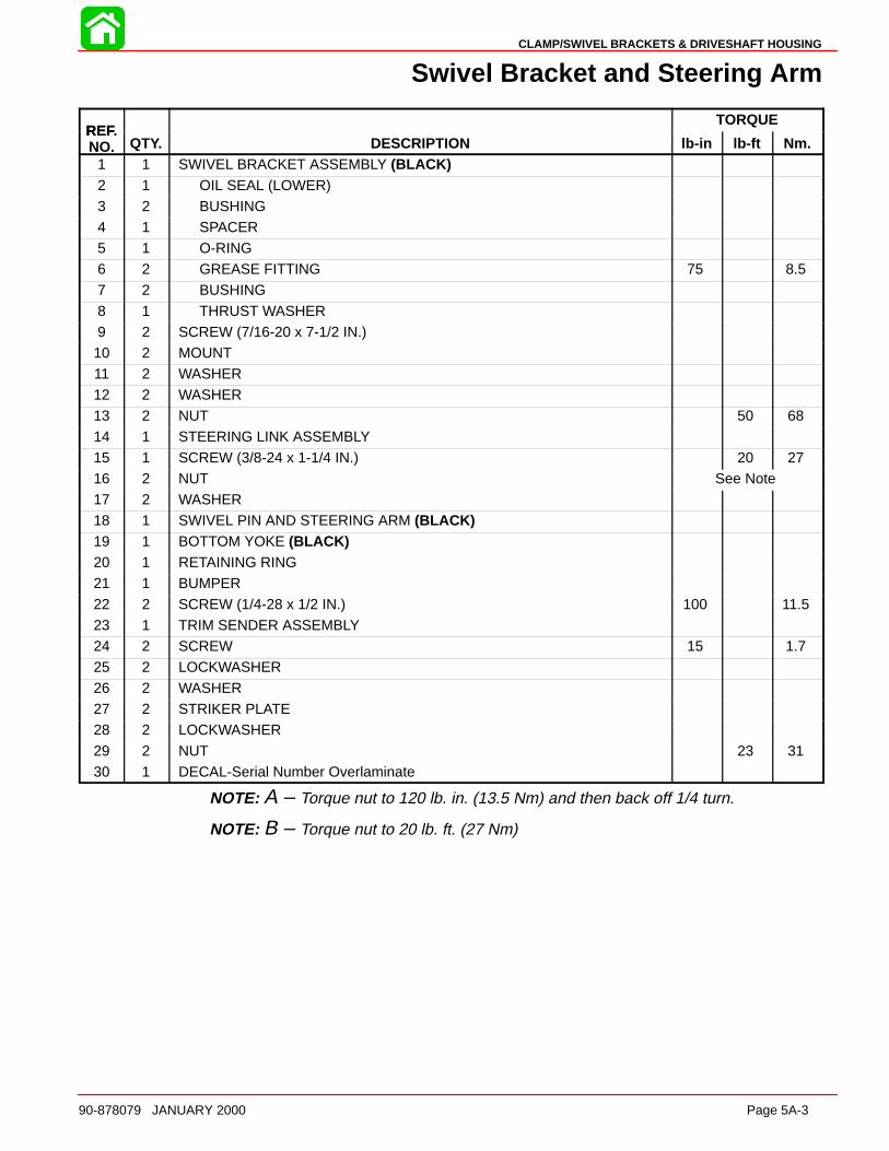
CLAMP/SWIVEL BRACKETS & DRIVESHAFT HOUSING
90-878079 JANUARY 2000 Page 5A-3
Swivel Bracket and Steering Arm
REFTORQUE
REF.NO. QTY. DESCRIPTION lb-in lb-ft Nm.
1 1 SWIVEL BRACKET ASSEMBLY (BLACK)2 1 OIL SEAL (LOWER)3 2 BUSHING4 1 SPACER5 1 O-RING6 2 GREASE FITTING 75 8.57 2 BUSHING
8 1 THRUST WASHER9 2 SCREW (7/16-20 x 7-1/2 IN.)10 2 MOUNT11 2 WASHER12 2 WASHER13 2 NUT 50 6814 1 STEERING LINK ASSEMBLY
15 1 SCREW (3/8-24 x 1-1/4 IN.) 20 2716 2 NUT See Note17 2 WASHER18 1 SWIVEL PIN AND STEERING ARM (BLACK)19 1 BOTTOM YOKE (BLACK)20 1 RETAINING RING21 1 BUMPER
22 2 SCREW (1/4-28 x 1/2 IN.) 100 11.523 1 TRIM SENDER ASSEMBLY24 2 SCREW 15 1.725 2 LOCKWASHER26 2 WASHER27 2 STRIKER PLATE28 2 LOCKWASHER
29 2 NUT 23 3130 1 DECAL-Serial Number Overlaminate
NOTE: A – Torque nut to 120 lb. in. (13.5 Nm) and then back off 1/4 turn.
NOTE: B – Torque nut to 20 lb. ft. (27 Nm)
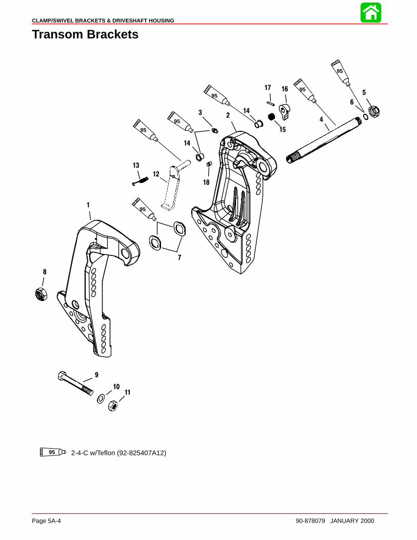
CLAMP/SWIVEL BRACKETS & DRIVESHAFT HOUSING
Page 5A-4 90-878079 JANUARY 2000
Transom Brackets
1
23
5
6
7
8
12
13
15
1617
18
14
14
95
9595
95
95
95
95 2-4-C w/Teflon (92-825407A12)
4
9
1011

CLAMP/SWIVEL BRACKETS & DRIVESHAFT HOUSING
90-878079 JANUARY 2000 Page 5A-5
Transom Brackets
REFTORQUE
REF.NO. QTY. DESCRIPTION lb-in lb-ft Nm.
1 1 TRANSOM BRACKET (STARBOARD)(BLACK)2 1 TRANSOM BRACKET (PORT) (BLACK)3 1 GREASE FITTING (PORT) 80 94 1 TILT TUBE5 1 NUT (1 IN.-14) 45 616 1 O-RING7 2 WAVE WASHER
8 1 NUT (7/8-14) 45 619 4 BOLT10 4 WASHER11 4 NUT12 1 TILT LOCK LEVER ASSEMBLY13 1 SPRING14 2 BUSHING
15 1 SPRING16 1 KNOB17 1 GROOVE PIN18 1 PIN
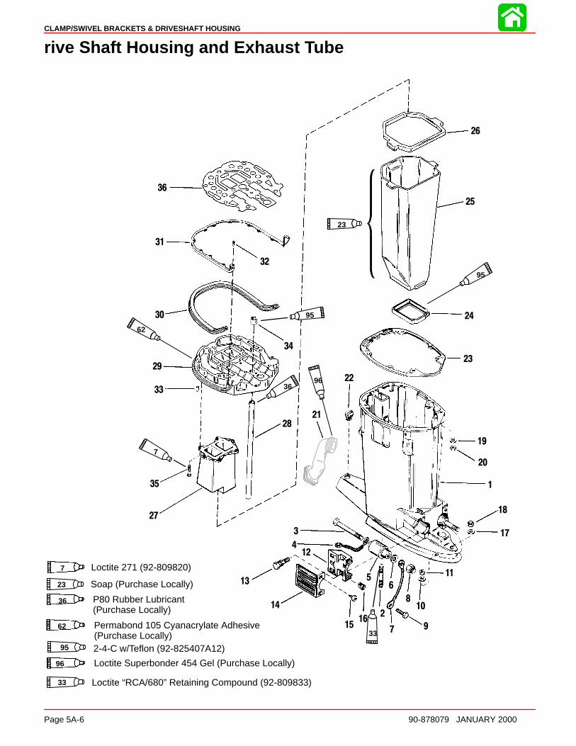
CLAMP/SWIVEL BRACKETS & DRIVESHAFT HOUSING
Page 5A-6 90-878079 JANUARY 2000
rive Shaft Housing and Exhaust Tube
P80 Rubber Lubricant(Purchase Locally)
36
Loctite Superbonder 454 Gel (Purchase Locally)96
Permabond 105 Cyanacrylate Adhesive(Purchase Locally)
62
Soap (Purchase Locally)23
Loctite “RCA/680” Retaining Compound (92-809833)33
95 2-4-C w/Teflon (92-825407A12)
7 Loctite 271 (92-809820)
23
7
96
33
95
95
36
62
1
3
4
5
7
8
9
10
11
12
13
14
1516
17
18
19
20
21
22
23
24
25
26
27
28
29
30
31
32
33
34
35
36
2
6
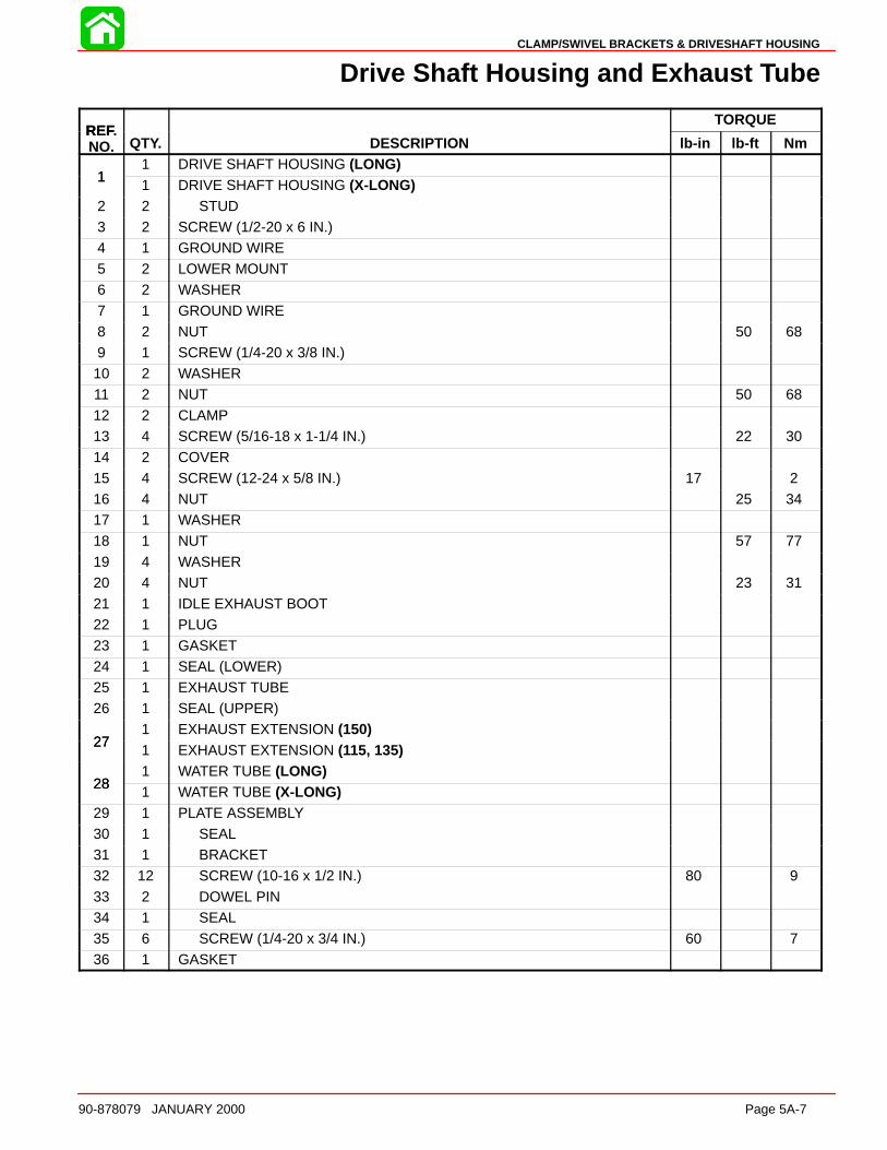
CLAMP/SWIVEL BRACKETS & DRIVESHAFT HOUSING
90-878079 JANUARY 2000 Page 5A-7
Drive Shaft Housing and Exhaust Tube
REFTORQUE
REF.NO. QTY. DESCRIPTION lb-in lb-ft Nm
11 DRIVE SHAFT HOUSING (LONG)
11 DRIVE SHAFT HOUSING (X-LONG)
2 2 STUD3 2 SCREW (1/2-20 x 6 IN.)4 1 GROUND WIRE5 2 LOWER MOUNT6 2 WASHER
7 1 GROUND WIRE8 2 NUT 50 689 1 SCREW (1/4-20 x 3/8 IN.)10 2 WASHER11 2 NUT 50 6812 2 CLAMP13 4 SCREW (5/16-18 x 1-1/4 IN.) 22 30
14 2 COVER15 4 SCREW (12-24 x 5/8 IN.) 17 216 4 NUT 25 3417 1 WASHER18 1 NUT 57 7719 4 WASHER20 4 NUT 23 31
21 1 IDLE EXHAUST BOOT22 1 PLUG23 1 GASKET24 1 SEAL (LOWER)25 1 EXHAUST TUBE26 1 SEAL (UPPER)
271 EXHAUST EXTENSION (150)
271 EXHAUST EXTENSION (115, 135)
281 WATER TUBE (LONG)
281 WATER TUBE (X-LONG)
29 1 PLATE ASSEMBLY30 1 SEAL31 1 BRACKET32 12 SCREW (10-16 x 1/2 IN.) 80 9
33 2 DOWEL PIN34 1 SEAL35 6 SCREW (1/4-20 x 3/4 IN.) 60 736 1 GASKET
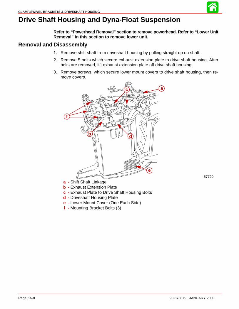
CLAMP/SWIVEL BRACKETS & DRIVESHAFT HOUSING
Page 5A-8 90-878079 JANUARY 2000
Drive Shaft Housing and Dyna-Float Suspension
Refer to “Powerhead Removal” section to remove powerhead. Refer to “Lower UnitRemoval” in this section to remove lower unit.
Removal and Disassembly1. Remove shift shaft from driveshaft housing by pulling straight up on shaft.
2. Remove 5 bolts which secure exhaust extension plate to drive shaft housing. Afterbolts are removed, lift exhaust extension plate off drive shaft housing.
3. Remove screws, which secure lower mount covers to drive shaft housing, then re-move covers.
57729
c
ff
e
ddbb
a
a - Shift Shaft Linkageb - Exhaust Extension Platec - Exhaust Plate to Drive Shaft Housing Boltsd - Driveshaft Housing Platee - Lower Mount Cover (One Each Side)f - Mounting Bracket Bolts (3)
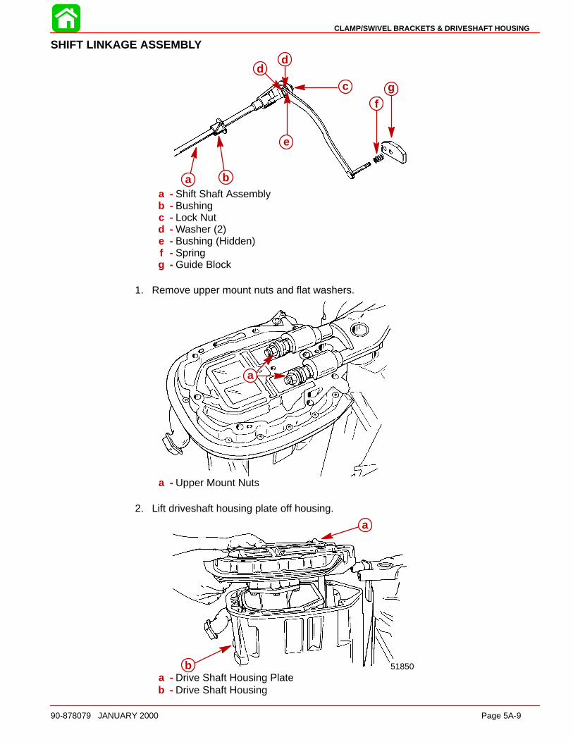
CLAMP/SWIVEL BRACKETS & DRIVESHAFT HOUSING
90-878079 JANUARY 2000 Page 5A-9
SHIFT LINKAGE ASSEMB LY
a b
c
dd
fg
e
a b
c
dd
e
fg
a - Shift Shaft Assemblyb - Bushingc - Lock Nutd - Washer (2)e - Bushing (Hidden)f - Springg - Guide Block
1. Remove upper mount nuts and flat washers.
aa
a - Upper Mount Nuts
2. Lift driveshaft housing plate off housing.
a
b 51850
a
ba - Drive Shaft Housing Plateb - Drive Shaft Housing
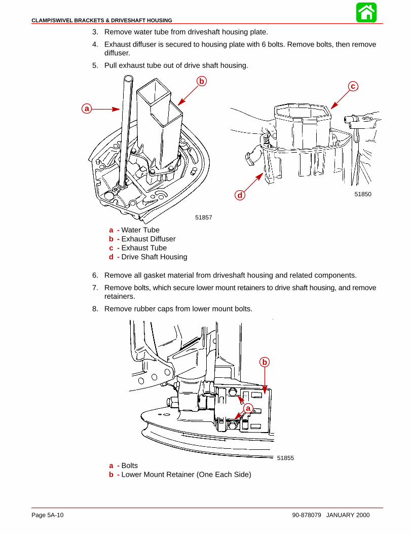
CLAMP/SWIVEL BRACKETS & DRIVESHAFT HOUSING
Page 5A-10 90-878079 JANUARY 2000
3. Remove water tube from driveshaft housing plate.
4. Exhaust diffuser is secured to housing plate with 6 bolts. Remove bolts, then removediffuser.
5. Pull exhaust tube out of drive shaft housing.
a
b 51850
b
a
51857
c
d
a
b
a - Water Tubeb - Exhaust Diffuserc - Exhaust Tubed - Drive Shaft Housing
6. Remove all gasket material from driveshaft housing and related components.
7. Remove bolts, which secure lower mount retainers to drive shaft housing, and removeretainers.
8. Remove rubber caps from lower mount bolts.
51855
b
aa
b
a - Boltsb - Lower Mount Retainer (One Each Side)

CLAMP/SWIVEL BRACKETS & DRIVESHAFT HOUSING
90-878079 JANUARY 2000 Page 5A-11
9. Remove lower mount nuts.
b
a
51855
a
b
a - Lower Mount Nutsb - Lower Mount (1 each side)
10. Remove driveshaft housing from swivel bracket by pulling alternately from top to bot-tom on housing.
11. Remove upper and lower mounts by lifting them out of driveshaft housing.
Reassembly and Installation1. Apply a thin coat of 2-4-C w/Teflon Marine Lubricant onto inside portion of exhaust
tube seal.
2. Install exhaust tube seal into driveshaft housing with tapered side of seal facing up.
b
a
51856
a
b
a - Exhaust Tube Sealb - Driveshaft Housing
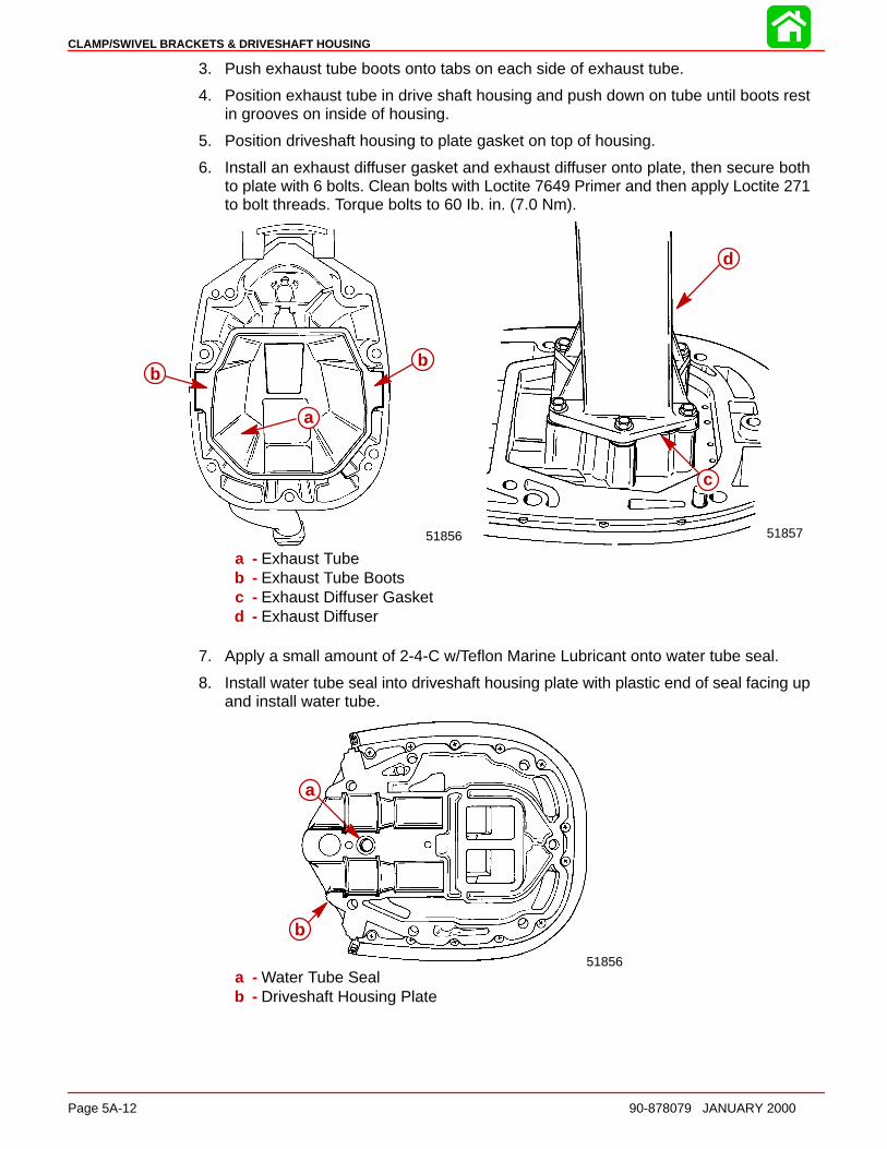
CLAMP/SWIVEL BRACKETS & DRIVESHAFT HOUSING
Page 5A-12 90-878079 JANUARY 2000
3. Push exhaust tube boots onto tabs on each side of exhaust tube.
4. Position exhaust tube in drive shaft housing and push down on tube until boots restin grooves on inside of housing.
5. Position driveshaft housing to plate gasket on top of housing.
6. Install an exhaust diffuser gasket and exhaust diffuser onto plate, then secure bothto plate with 6 bolts. Clean bolts with Loctite 7649 Primer and then apply Loctite 271to bolt threads. Torque bolts to 60 Ib. in. (7.0 Nm).
51857
ac
d
51856
bb
aa
bb
a - Exhaust Tubeb - Exhaust Tube Bootsc - Exhaust Diffuser Gasketd - Exhaust Diffuser
7. Apply a small amount of 2-4-C w/Teflon Marine Lubricant onto water tube seal.
8. Install water tube seal into driveshaft housing plate with plastic end of seal facing upand install water tube.
a
b
51856
a
b
a - Water Tube Sealb - Driveshaft Housing Plate
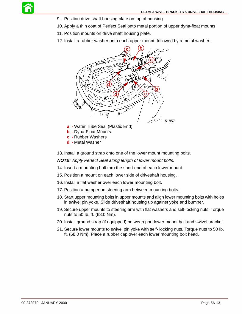
CLAMP/SWIVEL BRACKETS & DRIVESHAFT HOUSING
90-878079 JANUARY 2000 Page 5A-13
9. Position drive shaft housing plate on top of housing.
10. Apply a thin coat of Perfect Seal onto metal portion of upper dyna-float mounts.
11. Position mounts on drive shaft housing plate.
12. Install a rubber washer onto each upper mount, followed by a metal washer.
51857
c b
a
bcd
d
a
bcd
d
bc
a - Water Tube Seal (Plastic End)b - Dyna-Float Mountsc - Rubber Washersd - Metal Washer
13. Install a ground strap onto one of the lower mount mounting bolts.
NOTE: Apply Perfect Seal along length of lower mount bolts.
14. Insert a mounting bolt thru the short end of each lower mount.
15. Position a mount on each lower side of driveshaft housing.
16. Install a flat washer over each lower mounting bolt.
17. Position a bumper on steering arm between mounting bolts.
18. Start upper mounting bolts in upper mounts and align lower mounting bolts with holesin swivel pin yoke. Slide driveshaft housing up against yoke and bumper.
19. Secure upper mounts to steering arm with flat washers and self-locking nuts. Torquenuts to 50 Ib. ft. (68.0 Nm).
20. Install ground strap (if equipped) between port lower mount bolt and swivel bracket.
21. Secure lower mounts to swivel pin yoke with self- locking nuts. Torque nuts to 50 Ib.ft. (68.0 Nm). Place a rubber cap over each lower mounting bolt head.

CLAMP/SWIVEL BRACKETS & DRIVESHAFT HOUSING
Page 5A-14 90-878079 JANUARY 2000
22. Install lower mount retainers and secure each retainer with 2 bolts. (Secure groundstrap with the nearest retainer bolt.) Torque bolts to 160 Ib. in. (18.0 Nm).
51855
b
a
c
b51855
a
b
d
c
e
f
f
g
a
b
c
d
a - Lower Mountb - Nut (2) [Torque to 50 lb. ft. (68.0 Nm)]c - Rubber Capd - Ground Strap (only one side)e - Lower Mount Retainerf - Bolts (2) [Torque to 160 lb. in. (18.0 Nm)]g - Ground Strap
23. Install lower mount covers and secure each cover with 2 screws.
24. Install exhaust extension plate on driveshaft housing with shift shaft assembly. Secureextension plate to drive shaft housing with 5 bolts.
51855
a
b
a
b
c
d
g
f
e
h
a - Cover (One Each Side)b - Screws (Two for Each Cover)c - Shift Shaft Linkaged - Exhaust Extension Platee - Exhaust Plate to Driveshaft Housing Bolts, Torque to 25 Ib. ft. (34 Nm)f - Drive Shaft Housing Plateg - Lower Mount Cover (One Each Side)h - Mounting Bracket Bolts, Torque to 40 Ib. ft. (54 Nm)
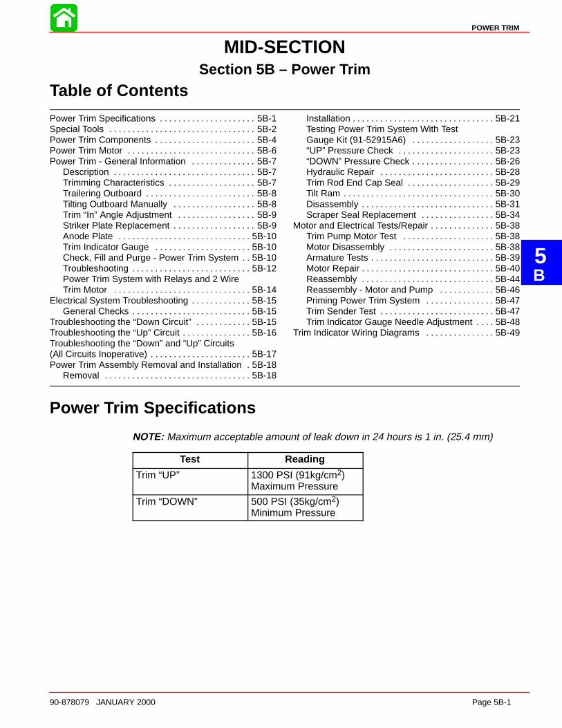
5B
POWER TRIM
90-878079 JANUARY 2000 Page 5B-1
MID-SECTIONSection 5B – Power Trim
Table of Contents
Power Trim Specifications 5B-1. . . . . . . . . . . . . . . . . . . . . Special Tools 5B-2. . . . . . . . . . . . . . . . . . . . . . . . . . . . . . . . Power Trim Components 5B-4. . . . . . . . . . . . . . . . . . . . . . Power Trim Motor 5B-6. . . . . . . . . . . . . . . . . . . . . . . . . . . . Power Trim - General Information 5B-7. . . . . . . . . . . . . .
Description 5B-7. . . . . . . . . . . . . . . . . . . . . . . . . . . . . . . Trimming Characteristics 5B-7. . . . . . . . . . . . . . . . . . . Trailering Outboard 5B-8. . . . . . . . . . . . . . . . . . . . . . . . Tilting Outboard Manually 5B-8. . . . . . . . . . . . . . . . . . Trim “In” Angle Adjustment 5B-9. . . . . . . . . . . . . . . . . Striker Plate Replacement 5B-9. . . . . . . . . . . . . . . . . . Anode Plate 5B-10. . . . . . . . . . . . . . . . . . . . . . . . . . . . . Trim Indicator Gauge 5B-10. . . . . . . . . . . . . . . . . . . . . Check, Fill and Purge - Power Trim System 5B-10. . Troubleshooting 5B-12. . . . . . . . . . . . . . . . . . . . . . . . . . Power Trim System with Relays and 2 WireTrim Motor 5B-14. . . . . . . . . . . . . . . . . . . . . . . . . . . . . .
Electrical System Troubleshooting 5B-15. . . . . . . . . . . . . General Checks 5B-15. . . . . . . . . . . . . . . . . . . . . . . . . .
Troubleshooting the “Down Circuit” 5B-15. . . . . . . . . . . . Troubleshooting the “Up” Circuit 5B-16. . . . . . . . . . . . . . . Troubleshooting the “Down” and “Up” Circuits(All Circuits Inoperative) 5B-17. . . . . . . . . . . . . . . . . . . . . . Power Trim Assembly Removal and Installation 5B-18.
Removal 5B-18. . . . . . . . . . . . . . . . . . . . . . . . . . . . . . . .
Installation 5B-21. . . . . . . . . . . . . . . . . . . . . . . . . . . . . . . Testing Power Trim System With TestGauge Kit (91-52915A6) 5B-23. . . . . . . . . . . . . . . . . . “UP” Pressure Check 5B-23. . . . . . . . . . . . . . . . . . . . . “DOWN” Pressure Check 5B-26. . . . . . . . . . . . . . . . . . Hydraulic Repair 5B-28. . . . . . . . . . . . . . . . . . . . . . . . . Trim Rod End Cap Seal 5B-29. . . . . . . . . . . . . . . . . . . Tilt Ram 5B-30. . . . . . . . . . . . . . . . . . . . . . . . . . . . . . . . . Disassembly 5B-31. . . . . . . . . . . . . . . . . . . . . . . . . . . . . Scraper Seal Replacement 5B-34. . . . . . . . . . . . . . . .
Motor and Electrical Tests/Repair 5B-38. . . . . . . . . . . . . . Trim Pump Motor Test 5B-38. . . . . . . . . . . . . . . . . . . . Motor Disassembly 5B-38. . . . . . . . . . . . . . . . . . . . . . . Armature Tests 5B-39. . . . . . . . . . . . . . . . . . . . . . . . . . . Motor Repair 5B-40. . . . . . . . . . . . . . . . . . . . . . . . . . . . . Reassembly 5B-44. . . . . . . . . . . . . . . . . . . . . . . . . . . . . Reassembly - Motor and Pump 5B-46. . . . . . . . . . . . Priming Power Trim System 5B-47. . . . . . . . . . . . . . . Trim Sender Test 5B-47. . . . . . . . . . . . . . . . . . . . . . . . . Trim Indicator Gauge Needle Adjustment 5B-48. . . .
Trim Indicator Wiring Diagrams 5B-49. . . . . . . . . . . . . . .
Power Trim Specifications
NOTE: Maximum acceptable amount of leak down in 24 hours is 1 in. (25.4 mm)
Test Reading
Trim “UP” 1300 PSI (91kg/cm2)Maximum Pressure
Trim “DOWN” 500 PSI (35kg/cm2)Minimum Pressure
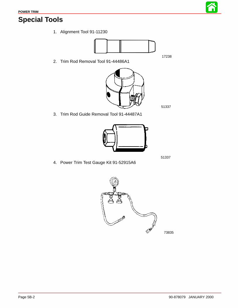
POWER TRIM
Page 5B-2 90-878079 JANUARY 2000
Special Tools
1. Alignment Tool 91-11230
17238
2. Trim Rod Removal Tool 91-44486A1
51337
3. Trim Rod Guide Removal Tool 91-44487A1
51337
4. Power Trim Test Gauge Kit 91-52915A6
73835
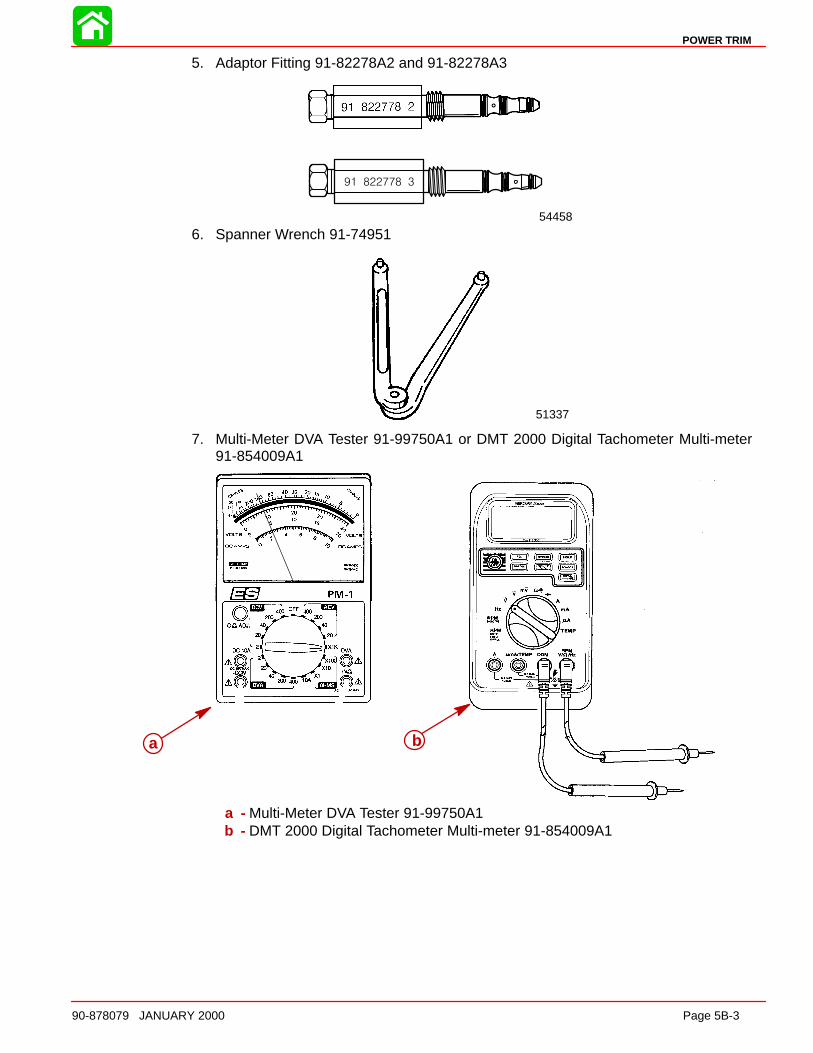
POWER TRIM
90-878079 JANUARY 2000 Page 5B-3
5. Adaptor Fitting 91-82278A2 and 91-82278A3
54458
6. Spanner Wrench 91-74951
51337
7. Multi-Meter DVA Tester 91-99750A1 or DMT 2000 Digital Tachometer Multi-meter91-854009A1
a b
a - Multi-Meter DVA Tester 91-99750A1b - DMT 2000 Digital Tachometer Multi-meter 91-854009A1
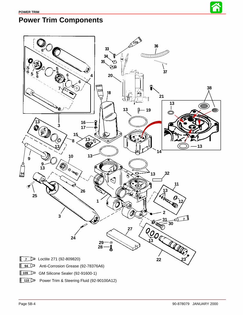
POWER TRIM
Page 5B-4 90-878079 JANUARY 2000
Power Trim Components
1
2
3
4
5
6
7
8
9 10
11
12
13
14
15
1617
19
20
21
22 23
24
2526
27
2829
3031
32
55
66
66 5
13
13
13
13
13
13
13
9
3
6
18
33
34
35
94
7
109
94 Anti-Corrosion Grease (92-78376A6)
109 GM Silicone Sealer (92-91600-1)
36
37
1313
13
7 Loctite 271 (92-809820)
Power Trim & Steering Fluid (92-90100A12)
11038
110

POWER TRIM
90-878079 JANUARY 2000 Page 5B-5
Power Trim Components
REFTORQUE
REF.NO. QTY. DESCRIPTION lb-in lb-ft Nm.
– 1 POWER TRIM ASSEMBLY–Complete
1 1 MANIFOLD ASSEMBLY2 9 PIPE PLUG3 1 TILT CYLINDER ASSEMBLY4 1 PISTON ROD5 1 GUIDE KIT6 1 REPAIR KIT
7 1 CHECK VALVE KIT8 2 GUIDE ASSEMBLY
91 PISTON/ROD ASSEMBLY (PORT)
91 PISTON/ROD ASSEMBLY (STBD.)
10 1 TRIM FILTER ASSEMBLY11 1 VALVE ASSEMBLY12 1 E RING
13 1 O RING KIT14 1 PUMP15 1 PLUG ASSEMBLY16 4 SCREW17 4 WASHER18 1 COVER19 1 DRIVE SHAFT
20 1 TRIM MOTOR(Breakdown on Power Trim Motor)
212 SCREW (LONG) 80 9
212 SCREW (SHORT) 80 9
22 1 SHAFT ASSEMBLY
23 2 PIPE PLUG24 1 GROOVE PIN25 1 GROOVE PIN26 1 SHAFT27 1 ANODE ASSEMBLY28 2 SCREW (M6 x 1 x 25) 70 829 2 WASHER
30 6 SCREW (M10 x 1.5 x 30) 45 6131 6 WASHER32 1 DECAL-Caution power trim33 1 SCREW (10-16 x 3/5 IN.)34 1 C WASHER35 2 CLAMP36 1 TUBING
37 1 STA-STRAP38 2 FILTER SCREENS
NOTE: Lubricate all o-rings with Power Trim and Steering Fluid.

POWER TRIM
Page 5B-6 90-878079 JANUARY 2000
Power Trim Motor
1
2
3
3
REFTORQUE
REF.NO. QTY. DESCRIPTION lb.in. lb.ft. N·m
– 1 POWER TRIM MOTOR
1 1 BRUSH AND SEAL KIT2 1 ARMATURE KIT3 1 END FRAME (Complete)
POWER TRIM
90-878079 JANUARY 2000 Page 5B-7
Power Trim - General Information
DescriptionThe Power Trim System consists of an electric motor, pressurized fluid reservoir, pump,tilt cylinder, and two trim rams.
The remote control (or trim panel) has switches that trim the outboard “Up” or “Down” andtilt the engine for “Trailering”. The outboard can be trimmed and tilted under power orwhen the outboard is not running.
Trimming CharacteristicsNOTE: Because hull designs react differently in varying water conditions, varying the trimposition will often improve the ride and boat handling. When trimming from a mid-trim po-sition (with outboard trim tab in a straight fore and aft position), expect the following:
TRIMMING OUTBOARD “UP” (OUT):
WARNINGExcessive trim “Out” may reduce the stability of some high speed hulls. To cor-rect instabilit y, reduce the power gradually and trim the outboard “In” slightly be-fore resuming high speed operation. A rapid reduction in power will result in asudden change of steering torque and may cause additional boat instabilit y.
Will lift boat bow, increasing top speed.
Transfers steering torque harder to port (left) on installations below 23 in. (584.2 mm) tran-som height.
Increases gearcase clearance over submerged objects.
Excess trim can cause “porpoising” and/or ventilation.
WARNINGExcessiv e outboard trim angle will result in insufficient water supply causin g wa-ter pump and/or powerhead overheating damage. Insure water level is above wa-ter intake holes whenever outboard is running.
The “Up” circuit actuates the up solenoid (under outboard cowl) and closes the motor cir-cuit. The electric motor drives the pump, forcing fluid thru passageways into the up sideof the trim cylinders.
The trim cylinders position the outboard at the desired trim angle in the 20 degree maxi-mum trim range. The system will not allow the outboard to be trimmed above the 20 de-gree trim range as long as the engine RPM is above approximately 2000 RPM.
The outboard can be trimmed above the 20 degree maximum trim angle (for shallow wa-ter operation, etc.), by keeping the engine RPM below 2000. If the RPM increases over2000, propeller thrust (if propeller is deep enough) will cause the trim system to return theoutboard to the 20 degree maximum trim position.
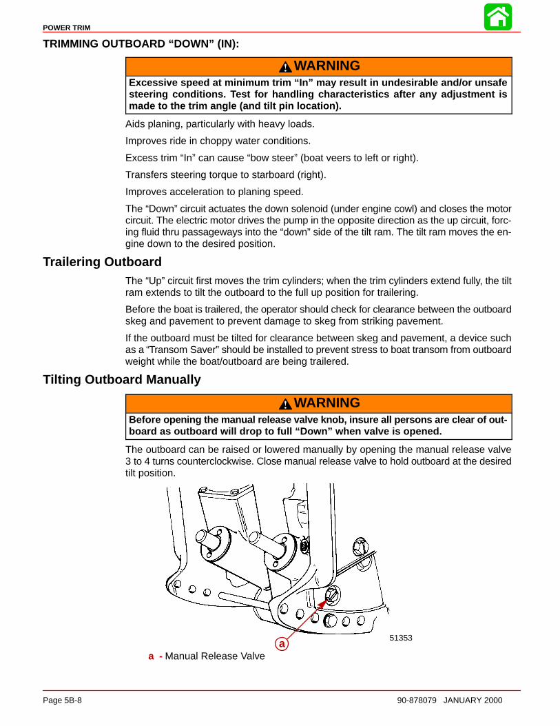
POWER TRIM
Page 5B-8 90-878079 JANUARY 2000
TRIMMING OUTBOARD “DOWN” (IN):
WARNINGExcessive speed at minimum trim “In” may result in undesirable and/or unsafesteering conditions. Test for handling characteristics after any adjustmen t ismade to the trim angle (and tilt pin location).
Aids planing, particularly with heavy loads.
Improves ride in choppy water conditions.
Excess trim “In” can cause “bow steer” (boat veers to left or right).
Transfers steering torque to starboard (right).
Improves acceleration to planing speed.
The “Down” circuit actuates the down solenoid (under engine cowl) and closes the motorcircuit. The electric motor drives the pump in the opposite direction as the up circuit, forc-ing fluid thru passageways into the “down” side of the tilt ram. The tilt ram moves the en-gine down to the desired position.
Trailering OutboardThe “Up” circuit first moves the trim cylinders; when the trim cylinders extend fully, the tiltram extends to tilt the outboard to the full up position for trailering.
Before the boat is trailered, the operator should check for clearance between the outboardskeg and pavement to prevent damage to skeg from striking pavement.
If the outboard must be tilted for clearance between skeg and pavement, a device suchas a “Transom Saver” should be installed to prevent stress to boat transom from outboardweight while the boat/outboard are being trailered.
Tilting Outboard Manually
WARNINGBefor e opening the manual release valve knob, insure all persons are clear of out-board as outboard will drop to full “Down” when valve is opened.
The outboard can be raised or lowered manually by opening the manual release valve3 to 4 turns counterclockwise. Close manual release valve to hold outboard at the desiredtilt position.
51353aa
a - Manual Release Valve

POWER TRIM
90-878079 JANUARY 2000 Page 5B-9
Trim “In” Angle Adjustment
WARNINGBoat operation with outboard trimmed to the full “In” trim angle [not using thetrim angle adjustment bolt (a)] at planing speed may result in undesirable and/orunsafe steering conditions. A water test for handling/steering conditions is re-quired after any trim angle adjustments.
IMPORTANT: Some boat/motor combinations not using the trim angle adjustmentpin (a) and trimmed to the full “In” trim angle position may not exhibit any undesir-able and/or unsafe handling and/or steering characteristics at planing speed. If so,not using the trim angle adjustment bolt may be advantageous to acceleration andplaning. A water test is required to determine if these characteristics apply to a par-ticular boat/motor combination.
51353
aaa - Trim Angle Adjustment Bolt
Striker Plate ReplacementVisually inspect striker plates and replace if worn excessively.
27930
a
b
c
a
b
c
a - Striker Plate (2)b - Lockwasherc - Locknut. Torque to 80 lb. in. (9 Nm)

POWER TRIM
Page 5B-10 90-878079 JANUARY 2000
Anode PlateAnode plate is a self-sacrificing alloy plate that is consumed gradually by corrosion whileproviding protection to the midsection and power trim from galvanic corrosion. Replaceanode plate when it is 50% consumed.
27932aaa - Anode Plate
IMPORTANT: Do not paint or place protective coating on anode plate, or corrosionprotection function will be lost.
Trim Indicator GaugeA Quicksilver Trim Indicator Gauge accessory kit is available for the power trim sender(if not previously installed).
Check, Fill and Purge - Power Trim SystemTO CHECK:
CAUTIONTil t outboard to full “Up” position and engage tilt lock lever before checking fluidlevel. System is pressurized. Extend trim and tilt rams fully to depressurize sys-tem.
Remove fill plug and O-ring. System is full when oil level is present at filler hole. Tightenfill plug securely.
NOTE: Automatic Transmission Fluid (ATF) Type F, FA, Dexron II or Dexron III may beused.
51368
a
a - Tilt Lock Lever
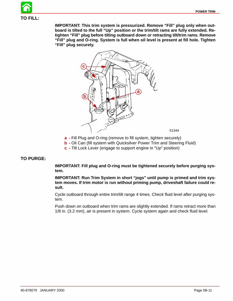
POWER TRIM
90-878079 JANUARY 2000 Page 5B-11
TO FILL:
IMPORTANT: This trim system is pressurized. Remove “Fill” plug only when out-board is tilted to the full “Up” position or the trim/tilt rams are fully extended. Re-tighten “Fill” plug before tilting outboard down or retracting tilt/trim rams. Remove“Fill” plug and O-ring. System is full when oil level is present at fill hole. Tighten“Fill” plug securel y.
51344
baa
b
c
a - Fill Plug and O-ring (remove to fill system, tighten securely)b - Oil Can (fill system with Quicksilver Power Trim and Steering Fluid)c - Tilt Lock Lever (engage to support engine in “Up” position)
TO PURGE:
IMPORTANT: Fill plug and O-ring must be tightened securely before purging sys-tem.
IMPORTANT: Run Trim System in short “jogs” until pump is primed and trim sys-tem moves. If trim motor is run without priming pump, driveshaft failure could re-sult.
Cycle outboard through entire trim/tilt range 4 times. Check fluid level after purging sys-tem.
Push down on outboard when trim rams are slightly extended. If rams retract more than1/8 in. (3.2 mm), air is present in system. Cycle system again and check fluid level.

51491
7
12
5
3
4
1
2
3
4
56
7
10
POWER TRIM
Page 5B-12 90-878079 JANUARY 2000
TroubleshootingIMPORTANT: Determine if Electrical or Hydraulic problem exists.
IMPORTANT: Acceptable power trim leak down should not exceed 1 in. (25.4 mm)(when measured at the tilt ram) in a 24 hour period.
HYDRAULIC SYSTEM TROUBLESHOOTING
IMPORTANT: Make one correction at a time. Check operation of trim system beforeproceeding to the next check.
CONDITION OF TRIM SYSTEM PROBLEM
A. Trim motor runs; trim system does not move up or down. 1, 2, 5, 10
B. Does not trim full down. Up trim OK. 2, 3, 4
C. Does not trim full up. Down trim OK. 1, 6
D. Partial or “Jerky” down/up. 1, 3
E. “Thump” noise when shifting. 2, 3, 6, 7
F. Does not trim under load. 5,8, 9,10
G. Does not hold trim position under load. 2, 5, 6
H. Trail out when backing off from high speed. 3, 4
I. Leaks down and does not hold trim. 2, 5, 7
J. Trim motor working hard and trims slow up and down. 8, 9
K. Trims up very slow. 1, 2, 8, 9
L. Starts to trim up from full down position when “IN” trim button is depressed. 3, 4
M. Trim position will not hold in reverse. 3, 4
PROBLEM1. Low oil level.
2. Pump assembly faulty.
3. Tilt ram piston ball not seated (displaced, dirt, nickel seat).
4. Tilt ram piston O-ring leaking or cut.
5. Manual release valve leaking (check condition of O-rings) (Valve not fully closed).
6. Lower check valve not seating in port side trim ram.
7. Upper check valve not seating in port side trim ram.
8. Check condition of battery.
9. Replace motor assembly.
10. Broken motor/pump drive shaft.
External Mounted Hydraulic System
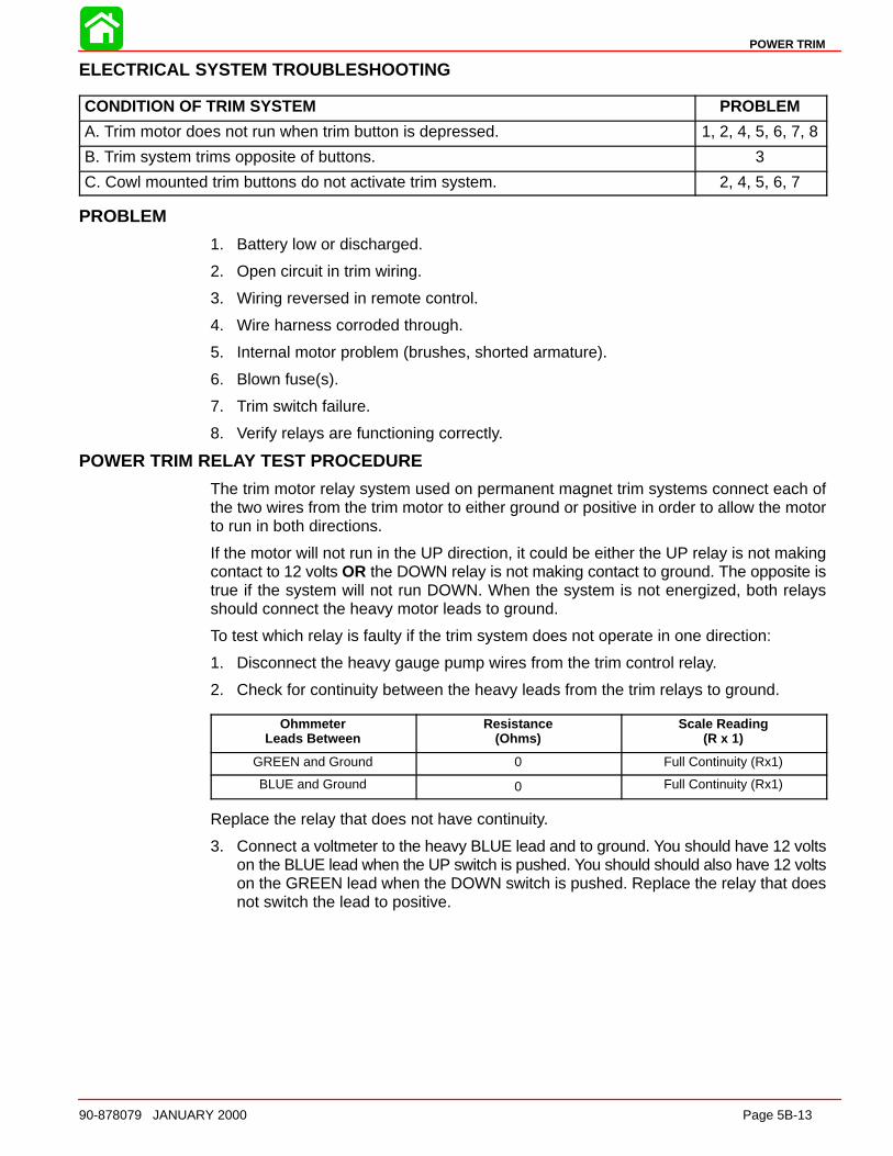
POWER TRIM
90-878079 JANUARY 2000 Page 5B-13
ELECTRICAL SYSTEM TROUBLESHOOTING
CONDITION OF TRIM SYSTEM PROBLEM
A. Trim motor does not run when trim button is depressed. 1, 2, 4, 5, 6, 7, 8
B. Trim system trims opposite of buttons. 3
C. Cowl mounted trim buttons do not activate trim system. 2, 4, 5, 6, 7
PROBLEM
1. Battery low or discharged.
2. Open circuit in trim wiring.
3. Wiring reversed in remote control.
4. Wire harness corroded through.
5. Internal motor problem (brushes, shorted armature).
6. Blown fuse(s).
7. Trim switch failure.
8. Verify relays are functioning correctly.
POWER TRIM RELAY TEST PROCEDURE
The trim motor relay system used on permanent magnet trim systems connect each ofthe two wires from the trim motor to either ground or positive in order to allow the motorto run in both directions.
If the motor will not run in the UP direction, it could be either the UP relay is not makingcontact to 12 volts OR the DOWN relay is not making contact to ground. The opposite istrue if the system will not run DOWN. When the system is not energized, both relaysshould connect the heavy motor leads to ground.
To test which relay is faulty if the trim system does not operate in one direction:
1. Disconnect the heavy gauge pump wires from the trim control relay.
2. Check for continuity between the heavy leads from the trim relays to ground.
OhmmeterLeads Between
Resistance(Ohms)
Scale Reading(R x 1)
GREEN and Ground 0 Full Continuity (Rx1)
BLUE and Ground 0 Full Continuity (Rx1)
Replace the relay that does not have continuity.
3. Connect a voltmeter to the heavy BLUE lead and to ground. You should have 12 voltson the BLUE lead when the UP switch is pushed. You should should also have 12 voltson the GREEN lead when the DOWN switch is pushed. Replace the relay that doesnot switch the lead to positive.

POWER TRIM
Page 5B-14 90-878079 JANUARY 2000
Power Trim System with Relays and 2 Wire Trim Motor
BLK = BlackBLU = Blue
GRN = GreenRED = RedWHT = White
DOWN RelayUP Relay53794
1
2
3
4
5
6
7
8
9
10
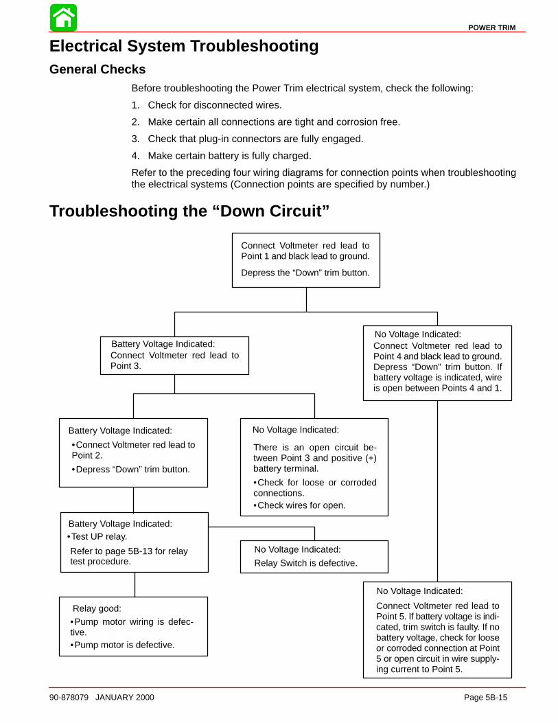
POWER TRIM
90-878079 JANUARY 2000 Page 5B-15
Electrical System TroubleshootingGeneral Checks
Before troubleshooting the Power Trim electrical system, check the following:
1. Check for disconnected wires.
2. Make certain all connections are tight and corrosion free.
3. Check that plug-in connectors are fully engaged.
4. Make certain battery is fully charged.
Refer to the preceding four wiring diagrams for connection points when troubleshootingthe electrical systems (Connection points are specified by number.)
Troubleshooting the “Down Circuit”
Battery Voltage Indicated:
Battery Voltage Indicated:
Relay good:
No Voltage Indicated:
No Voltage Indicated:
No Voltage Indicated:
No Voltage Indicated:
Connect Voltmeter red lead toPoint 5. If battery voltage is indi-cated, trim switch is faulty. If nobattery voltage, check for looseor corroded connection at Point5 or open circuit in wire supply-ing current to Point 5.
Relay Switch is defective.
There is an open circuit be-tween Point 3 and positive (+)battery terminal.
•Connect Voltmeter red lead toPoint 2.
Connect Voltmeter red lead toPoint 3.
Connect Voltmeter red lead toPoint 4 and black lead to ground.Depress “Down” trim button. Ifbattery voltage is indicated, wireis open between Points 4 and 1.
Connect Voltmeter red lead toPoint 1 and black lead to ground.
Depress the “Down” trim button.
•Depress “Down” trim button.
•Pump motor wiring is defec-tive.•Pump motor is defective.
•Check for loose or corrodedconnections.•Check wires for open.
Battery Voltage Indicated:•Test UP relay.
Refer to page 5B-13 for relaytest procedure.

POWER TRIM
Page 5B-16 90-878079 JANUARY 2000
Troubleshooting the “Up” Circuit
Battery Voltage Indicated:
Battery Voltage Indicated:
No Voltage Indicated:
No Voltage Indicated:
No Voltage Indicated:
No Voltage Indicated:
Connect Voltmeter red lead toPoint 5. If battery voltage is indi-cated, trim switch is faulty. If nobattery voltage, check for looseor corroded connection at Point5 or open circuit in wire supply-ing current to Point 5.
Relay Switch is defective.
There is an open circuit be-tween Point 9 and positive (+)battery terminal.
•Connect Voltmeter red lead toPoint 6.
Connect Voltmeter red lead toPoint 9.
Connect Voltmeter red lead toPoint 7 and black lead to ground.Depress “Up” trim button. If bat-tery voltage is indicated, wire isopen between Points 7 and 8.
Connect Voltmeter red lead toPoint 8 and black lead to ground.
Depress the “Up” trim button.
•Depress “Up” trim button.
•Pump motor wiring is defec-tive.
•Pump motor is defective.
•Check for loose or corrodedconnections.•Check wires for open.
Battery Voltage Indicated:•Test DOWN relay.
Refer to page 5B-13 for relaytest procedure.
Relay good:
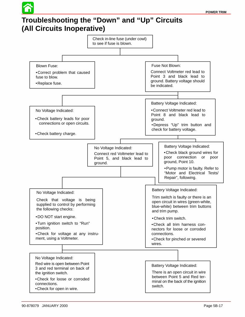
POWER TRIM
90-878079 JANUARY 2000 Page 5B-17
Troubleshooting the “Down” and “Up” Circuits(All Circuits Inoperative)
Battery Voltage Indicated:
No Voltage Indicated:
Battery Voltage Indicated:
Battery Voltage Indicated:
Battery Voltage Indicated:
No Voltage Indicated:
No Voltage Indicated:
No Voltage Indicated:
Blown Fuse: Fuse Not Blown:
Check in-line fuse (under cowl)to see if fuse is blown.
•Correct problem that causedfuse to blow.
•Replace fuse.
•Check battery leads for poorconnections or open circuits.
•Check battery charge.
•Connect Voltmeter red lead toPoint 8 and black lead toground.•Depress “Up” trim button andcheck for battery voltage.
•Check black ground wires forpoor connection or poorground, Point 10.
•Pump motor is faulty. Refer to“Motor and Electrical Tests/Repair”, following.
•Check for open in wire.
•Check for loose or corrodedconnections.
•Check for voltage at any instru-ment, using a Voltmeter.
•Turn ignition switch to “Run”position.
•DO NOT start engine.
•Check for pinched or severedwires.
•Check all trim harness con-nectors for loose or corrodedconnections.
•Check trim switch.
Connect Voltmeter red lead toPoint 3 and black lead toground. Battery voltage shouldbe indicated.
There is an open circuit in wirebetween Point 5 and Red ter-minal on the back of the ignitionswitch.
Red wire is open between Point3 and red terminal on back ofthe ignition switch.
Check that voltage is beingsupplied to control by performingthe following checks:
Connect red Voltmeter lead toPoint 5, and black lead toground.
Trim switch is faulty or there is anopen circuit in wires (green-white,blue-white) between trim buttonsand trim pump.
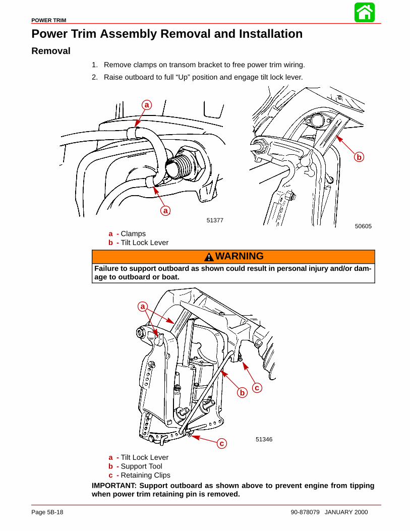
POWER TRIM
Page 5B-18 90-878079 JANUARY 2000
Power Trim Assembly Removal and InstallationRemoval
1. Remove clamps on transom bracket to free power trim wiring.
2. Raise outboard to full “Up” position and engage tilt lock lever.
50605
ab
51377a
a
a
a - Clampsb - Tilt Lock Lever
WARNINGFailure to support outboard as shown could result in personal injury and/or dam-age to outboard or boat.
51346
b c
c
bc
c
a
a - Tilt Lock Leverb - Support Toolc - Retaining Clips
IMPORTANT: Support outboard as shown above to prevent engine from tippingwhen power trim retaining pin is removed.
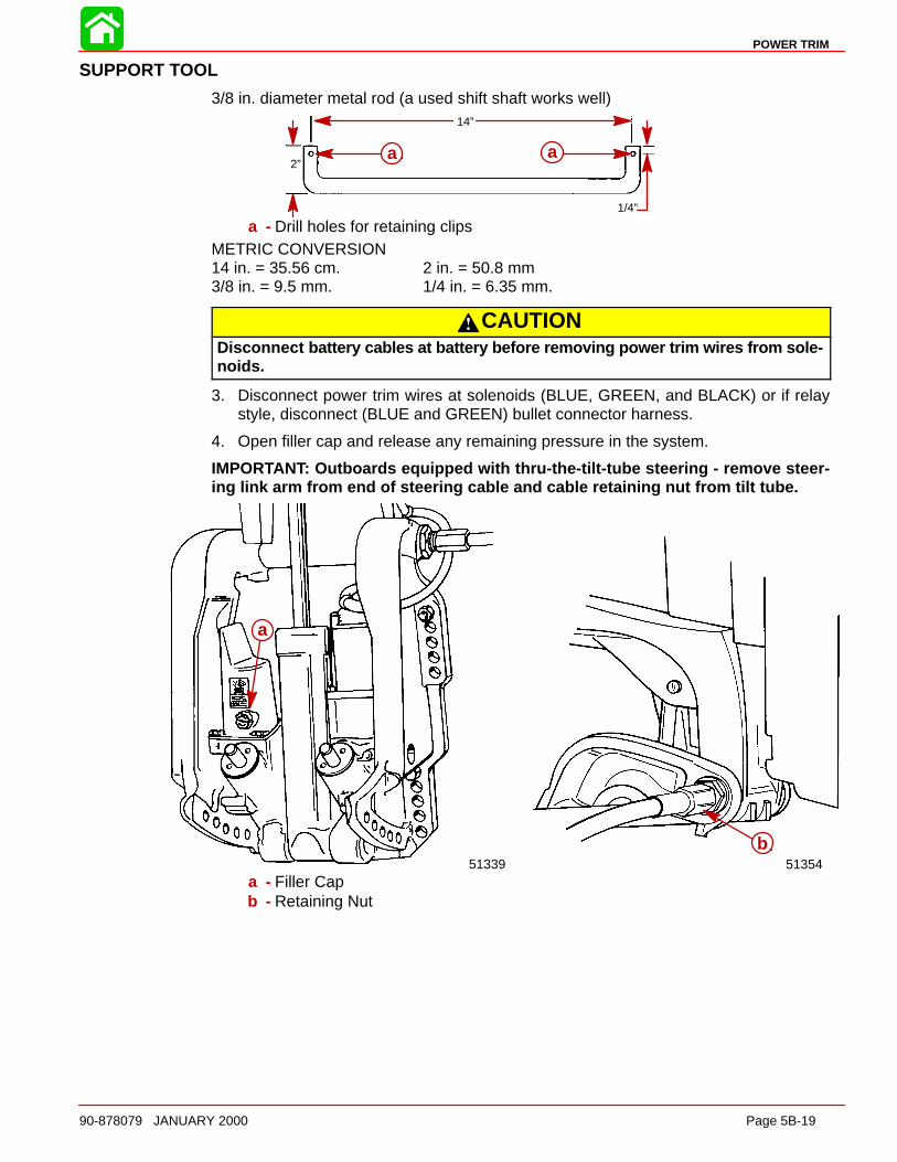
POWER TRIM
90-878079 JANUARY 2000 Page 5B-19
SUPPORT TOOL
3/8 in. diameter metal rod (a used shift shaft works well)14”
2”
1/4”
a aa a
a - Drill holes for retaining clipsMETRIC CONVERSION14 in. = 35.56 cm. 2 in. = 50.8 mm3/8 in. = 9.5 mm. 1/4 in. = 6.35 mm.
CAUTIONDisconnect battery cables at battery before removing power trim wires from sole-noids.
3. Disconnect power trim wires at solenoids (BLUE, GREEN, and BLACK) or if relaystyle, disconnect (BLUE and GREEN) bullet connector harness.
4. Open filler cap and release any remaining pressure in the system.
IMPORTANT: Outboards equipped with thru-the-tilt-tube steering - remove steer-ing link arm from end of steering cable and cable retaining nut from tilt tube.
51339
a
51354ab
a
a - Filler Capb - Retaining Nut

POWER TRIM
Page 5B-20 90-878079 JANUARY 2000
5. Remove outboard transom mounting bolts, and loosen tilt tube nut until nut is flushwith end of tilt tube thread.
6. Remove 3 screws and washers and move starboard transom bracket.
5137551375
b
a
a
c d
a
b
a
a - Transom Mount Bolts (2)b - Tilt Tube Nut (flush with end of thread)c - Screws (3)d - Washers (3)
IMPORTANT: Cross pin (a) should not be reused. Replace with new cross pin.
7. Drive out cross pin, push out upper swivel pin, and remove 3 screws and washers re-taining trim system. Remove system from outboard.
51339
a b
c
ab
c
a - Cross Pinb - Upper Swivel Pinc - Port Transom Bracket Screws and Washers (3). Remove to Release Trim
System from Outboard.
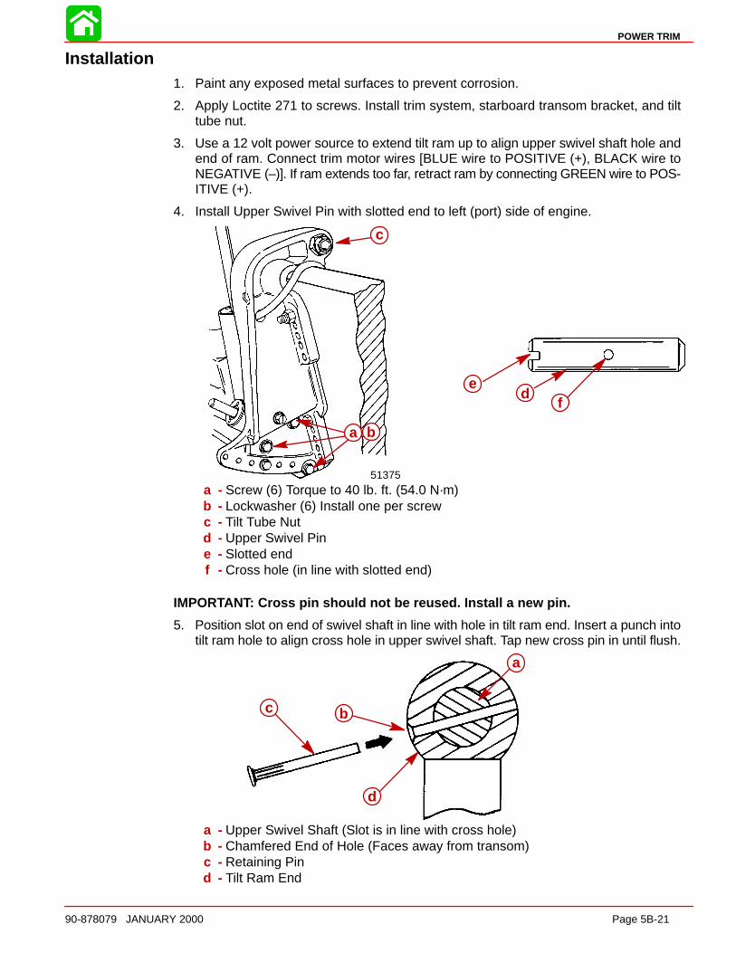
POWER TRIM
90-878079 JANUARY 2000 Page 5B-21
Installation1. Paint any exposed metal surfaces to prevent corrosion.
2. Apply Loctite 271 to screws. Install trim system, starboard transom bracket, and tilttube nut.
3. Use a 12 volt power source to extend tilt ram up to align upper swivel shaft hole andend of ram. Connect trim motor wires [BLUE wire to POSITIVE (+), BLACK wire toNEGATIVE (–)]. If ram extends too far, retract ram by connecting GREEN wire to POS-ITIVE (+).
4. Install Upper Swivel Pin with slotted end to left (port) side of engine.
b ac
de
f
51375
c
a b
c
a - Screw (6) Torque to 40 lb. ft. (54.0 N·m)b - Lockwasher (6) Install one per screwc - Tilt Tube Nutd - Upper Swivel Pine - Slotted endf - Cross hole (in line with slotted end)
IMPORTANT: Cross pin should not be reused. Install a new pin.
5. Position slot on end of swivel shaft in line with hole in tilt ram end. Insert a punch intotilt ram hole to align cross hole in upper swivel shaft. Tap new cross pin in until flush.
c b
d
aa
bc
d
a - Upper Swivel Shaft (Slot is in line with cross hole)b - Chamfered End of Hole (Faces away from transom)c - Retaining Pind - Tilt Ram End

POWER TRIM
Page 5B-22 90-878079 JANUARY 2000
6. Connect trim motor wires to solenoids. Refer to Wiring Diagrams in this manual. Routetrim wires as specified in this manual.
NOTE: The 2 power leads going to the trim motor should be encapsulated with conduittubing. If tubing has not been previously installed, order 32-828547-353 and cut to ap-propriate length.
56921 56922
a
a - Conduit Tubing
7. Apply marine sealer to shanks of mount bolts and install transom mount bolts.
IMPORTANT: Do not use an impact driver to tighten transom mount bolts.
Apply marine sealer to threads of mount bolts. Secure with flat washers and locknuts. Besure installation is watertight.
8. Tighten tilt tube nut securely.
IMPORTANT: Outboards equipped with thru-the-tilt-tube steering: Tighten steeringcable retaining nut securely to tilt tube.
51354aaa - Steering Cable Retaining Nut
9. Apply Quicksilver Liquid Neoprene (91-25511--2) on all electrical connections.
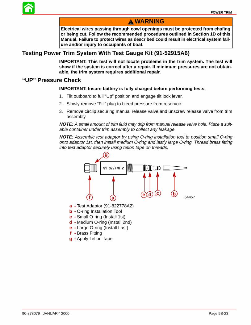
POWER TRIM
90-878079 JANUARY 2000 Page 5B-23
WARNINGElectrical wires passing through cowl openings must be protected from chafingor being cut. Follow the recommended procedures outlined in Section 1D of thisManual. Failure to protect wires as described could result in electrical system fail-ure and/or injury to occupants of boat.
Testing Power Trim System With Test Gauge Kit (91-52915A6)IMPORTANT: This test will not locate problems in the trim system. The test willshow if the system is correct after a repai r. If minimum pressures are not obtain-able, the trim system requires additional repai r.
“UP” Pressure CheckIMPORTANT: Insure battery is fully charged before performing tests.
1. Tilt outboard to full “Up” position and engage tilt lock lever.
2. Slowly remove “Fill” plug to bleed pressure from reservoir.
3. Remove circlip securing manual release valve and unscrew release valve from trimassembly.
NOTE: A small amount of trim fluid may drip from manual release valve hole. Place a suit-able container under trim assembly to collect any leakage.
NOTE: Assemble test adaptor by using O-ring installation tool to position small O-ringonto adaptor 1st, then install medium O-ring and lastly large O-ring. Thread brass fittinginto test adaptor securely using teflon tape on threads.
f e d c ba 54457
g
abcdef
g
a - Test Adaptor (91-822778A2)b - O-ring Installation Toolc - Small O-ring (Install 1st)d - Medium O-ring (Install 2nd)e - Large O-ring (Install Last)f - Brass Fittingg - Apply Teflon Tape
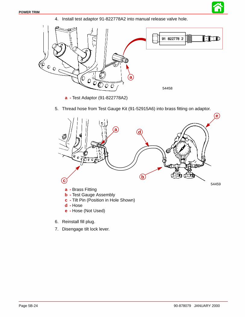
POWER TRIM
Page 5B-24 90-878079 JANUARY 2000
4. Install test adaptor 91-822778A2 into manual release valve hole.
54458
aa
a - Test Adaptor (91-822778A2)
5. Thread hose from Test Gauge Kit (91-52915A6) into brass fitting on adaptor.
54459
e
b
d
c
aa
bc
d
e
a - Brass Fittingb - Test Gauge Assemblyc - Tilt Pin (Position in Hole Shown)d - Hosee - Hose (Not Used)
6. Reinstall fill plug.
7. Disengage tilt lock lever.
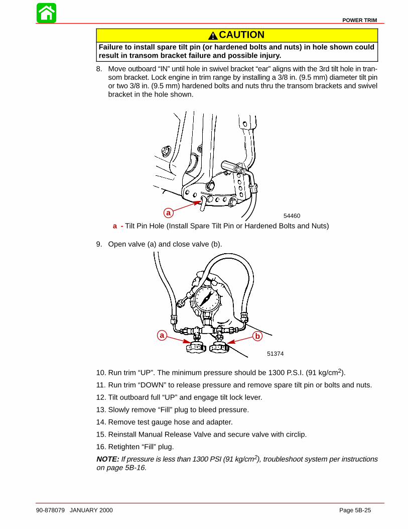
POWER TRIM
90-878079 JANUARY 2000 Page 5B-25
CAUTIONFailure to install spare tilt pin (or hardened bolts and nuts) in hole shown couldresult in transom bracket failure and possible injur y.
8. Move outboard “IN” until hole in swivel bracket “ear” aligns with the 3rd tilt hole in tran-som bracket. Lock engine in trim range by installing a 3/8 in. (9.5 mm) diameter tilt pinor two 3/8 in. (9.5 mm) hardened bolts and nuts thru the transom brackets and swivelbracket in the hole shown.
a 54460a
a - Tilt Pin Hole (Install Spare Tilt Pin or Hardened Bolts and Nuts)
9. Open valve (a) and close valve (b).
51374
a ba b
10. Run trim “UP”. The minimum pressure should be 1300 P.S.I. (91 kg/cm2).
11. Run trim “DOWN” to release pressure and remove spare tilt pin or bolts and nuts.
12. Tilt outboard full “UP” and engage tilt lock lever.
13. Slowly remove “Fill” plug to bleed pressure.
14. Remove test gauge hose and adapter.
15. Reinstall Manual Release Valve and secure valve with circlip.
16. Retighten “Fill” plug.
NOTE: If pressure is less than 1300 PSI (91 kg/cm2), troubleshoot system per instructionson page 5B-16.

POWER TRIM
Page 5B-26 90-878079 JANUARY 2000
“DOWN” Pressure CheckIMPORTANT: Insure battery is fully charged before performing tests.
1. Tilt outboard to full “Up” position and engage tilt lock lever.
2. Slowly remove “Fill” plug to bleed pressure from reservoir.
3. Remove circlip securing manual release valve and unscrew release valve from trimassembly.
NOTE: A small amount of trim fluid may drip from manual release valve hole. Place a suit-able container under trim assembly to collect any leakage.
NOTE: Assemble test adaptor by using O-ring installation tool to position small O-ringonto adaptor 1st, then install medium O-ring and lastly large O-ring. Thread brass fittinginto test adaptor securely using teflon tape on threads.
54457
3
f a e d c b
g
a - Test Adaptor (91-822778A3)b - O-ring Installation Toolc - Small O-ring (Install 1st)d - Medium O-ring (Install 2nd)e - Large O-ring (Install Last)f - Brass Fittingg - Apply Teflon Tape
4. Install test adaptor 91-822778A3 into manual release valve hole.
54458
aa
a - Test Adaptor (91-822778A3)
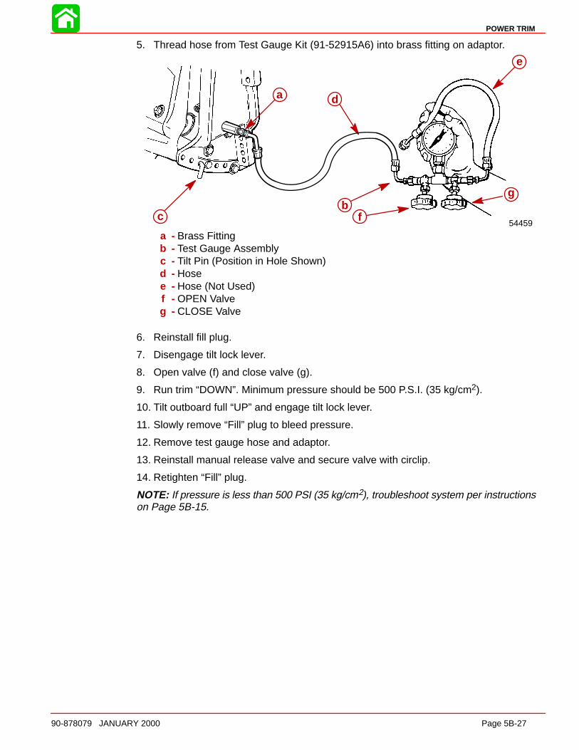
POWER TRIM
90-878079 JANUARY 2000 Page 5B-27
5. Thread hose from Test Gauge Kit (91-52915A6) into brass fitting on adaptor.
54459
e
b
d
c
a
f
g
a
bc
d
e
f
g
a - Brass Fittingb - Test Gauge Assemblyc - Tilt Pin (Position in Hole Shown)d - Hosee - Hose (Not Used)f - OPEN Valveg - CLOSE Valve
6. Reinstall fill plug.
7. Disengage tilt lock lever.
8. Open valve (f) and close valve (g).
9. Run trim “DOWN”. Minimum pressure should be 500 P.S.I. (35 kg/cm2).
10. Tilt outboard full “UP” and engage tilt lock lever.
11. Slowly remove “Fill” plug to bleed pressure.
12. Remove test gauge hose and adaptor.
13. Reinstall manual release valve and secure valve with circlip.
14. Retighten “Fill” plug.
NOTE: If pressure is less than 500 PSI (35 kg/cm2), troubleshoot system per instructionson Page 5B-15.
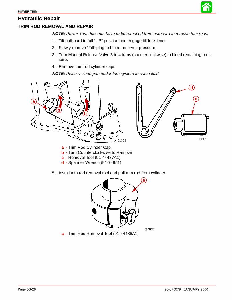
POWER TRIM
Page 5B-28 90-878079 JANUARY 2000
Hydraulic RepairTRIM ROD REMOVAL AND RE PAIR
NOTE: Power Trim does not have to be removed from outboard to remove trim rods.
1. Tilt outboard to full “UP” position and engage tilt lock lever.
2. Slowly remove “Fill” plug to bleed reservoir pressure.
3. Turn Manual Release Valve 3 to 4 turns (counterclockwise) to bleed remaining pres-sure.
4. Remove trim rod cylinder caps.
NOTE: Place a clean pan under trim system to catch fluid.
51337
b
a
51353
b
a
b
c
d
a
bb
a - Trim Rod Cylinder Capb - Turn Counterclockwise to Removec - Removal Tool (91-44487A1)d - Spanner Wrench (91-74951)
5. Install trim rod removal tool and pull trim rod from cylinder.
27933
aa
a - Trim Rod Removal Tool (91-44486A1)
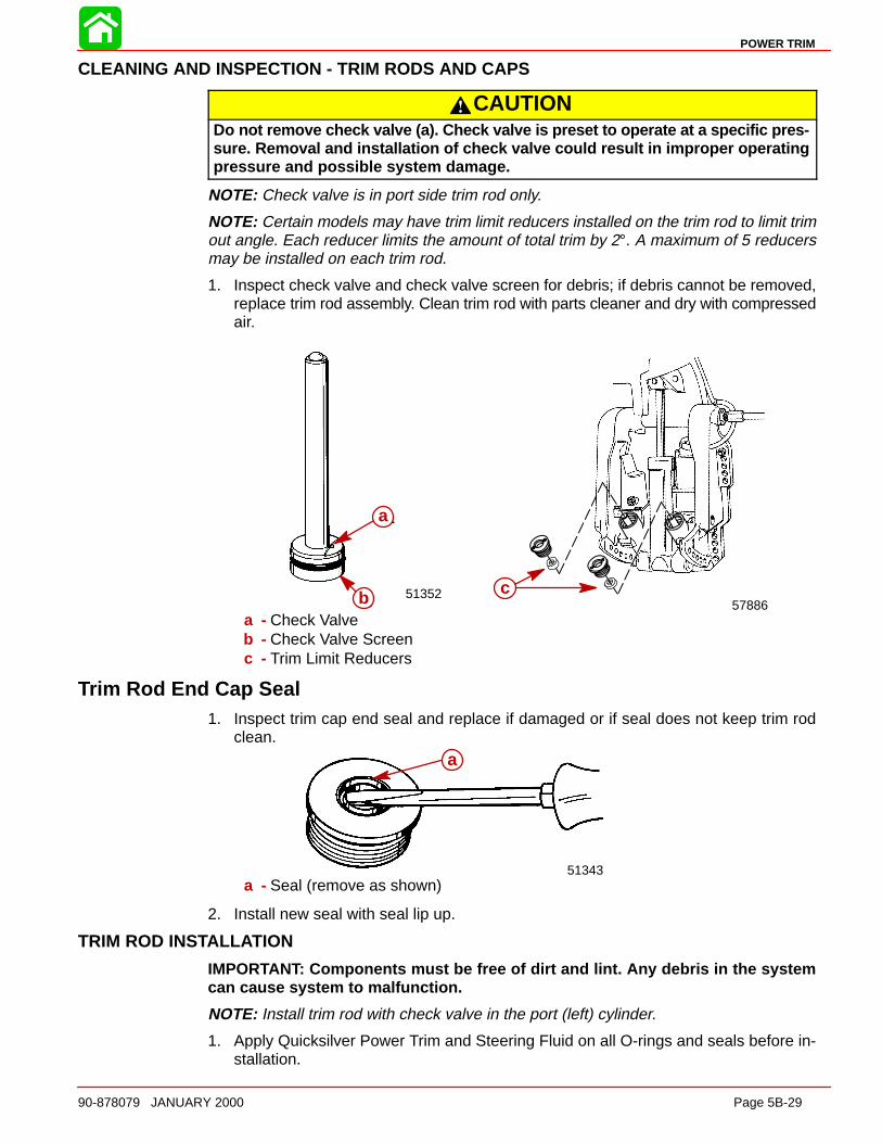
POWER TRIM
90-878079 JANUARY 2000 Page 5B-29
CLEANING AND INSPECTION - TRIM RODS AND CAPS
CAUTIONDo not remove check valve (a). Check valve is preset to operate at a specific pres-sure. Removal and installation of check valve could result in improper operatingpressure and possible system damage.
NOTE: Check valve is in port side trim rod only.
NOTE: Certain models may have trim limit reducers installed on the trim rod to limit trimout angle. Each reducer limits the amount of total trim by 2°. A maximum of 5 reducersmay be installed on each trim rod.
1. Inspect check valve and check valve screen for debris; if debris cannot be removed,replace trim rod assembly. Clean trim rod with parts cleaner and dry with compressedair.
51352
a
b
a
b 57886c
a - Check Valveb - Check Valve Screenc - Trim Limit Reducers
Trim Rod End Cap Seal1. Inspect trim cap end seal and replace if damaged or if seal does not keep trim rod
clean.
51343
aa
a - Seal (remove as shown)
2. Install new seal with seal lip up.
TRIM ROD INSTALL ATION
IMPORTANT: Components must be free of dirt and lint. Any debris in the systemcan cause system to malfunction.
NOTE: Install trim rod with check valve in the port (left) cylinder.
1. Apply Quicksilver Power Trim and Steering Fluid on all O-rings and seals before in-stallation.

POWER TRIM
Page 5B-30 90-878079 JANUARY 2000
2. Install trim rods and caps. Use installation tool (91-44487A1) or spanner wrench(91-74951) to tighten caps securely.
51353
a
ca
c
b b
aa
b b
c c
a - Trim Rodsb - Cylinder End Capsc - Rod End Rollers (lubricate with Quicksilver Anti-Corrosion Grease or
Special Lubricant 101)
Tilt RamREMOVAL - TILT ROD ASSEMBLY ONLY
NOTE: Tilt Rod Assembly can be removed from cylinder without removing entire powertrim system from outboard.
TILT RAM COMPONENTS
1
3
42
2
5
22
67
8 9
2
51372
1
2
3
4
22
5
2
2
6
7
89
10
11
1 - Housing - Tilt Ram2 - O-ring* (5)3 - Memory Piston**4 - Washer5 - Piston Assembly6 - End Cap
7 - Oil Seal8 - Bolt (Design 1)9 - Nut (Design 2)
10 - Tilt Rod (Design 1)11 - Tilt Rod (Design 2)
*O-ring Repair Kit Available, P.N. 811607A1 (Includes item 7, Oil Seal)
**Memory piston (3) for tilt rods (10 and 11) are different and must be used with correcttilt rod/cylinder assembly. Memory piston for Design 1 tilt rod is flat, Design 2 is dishedto clear nut and thread.

POWER TRIM
90-878079 JANUARY 2000 Page 5B-31
TILT RAM REMOVAL - POWER TRIM SYSTEM REMOVED FROM OUTBOARD
CAUTIONInsure trim system is depressurized prior to tilt ram removal.
1. Remove cross pin.
2. Remove lower swivel pin.
51355
a
51366a
b
a
a - Cross Pin (Remove as shown)b - Lower Swivel Pin (Remove as shown)
Disassembly1. Secure tilt ram in a soft jawed vise. Remove tilt rod and cap.
51364
51337
91-74951
a
c
b
a
b
c
a - Cap (Turn Counterclockwise to Remove)b - Spanner Wrench (91-74951)c - Tilt Rod - Pull to Remove
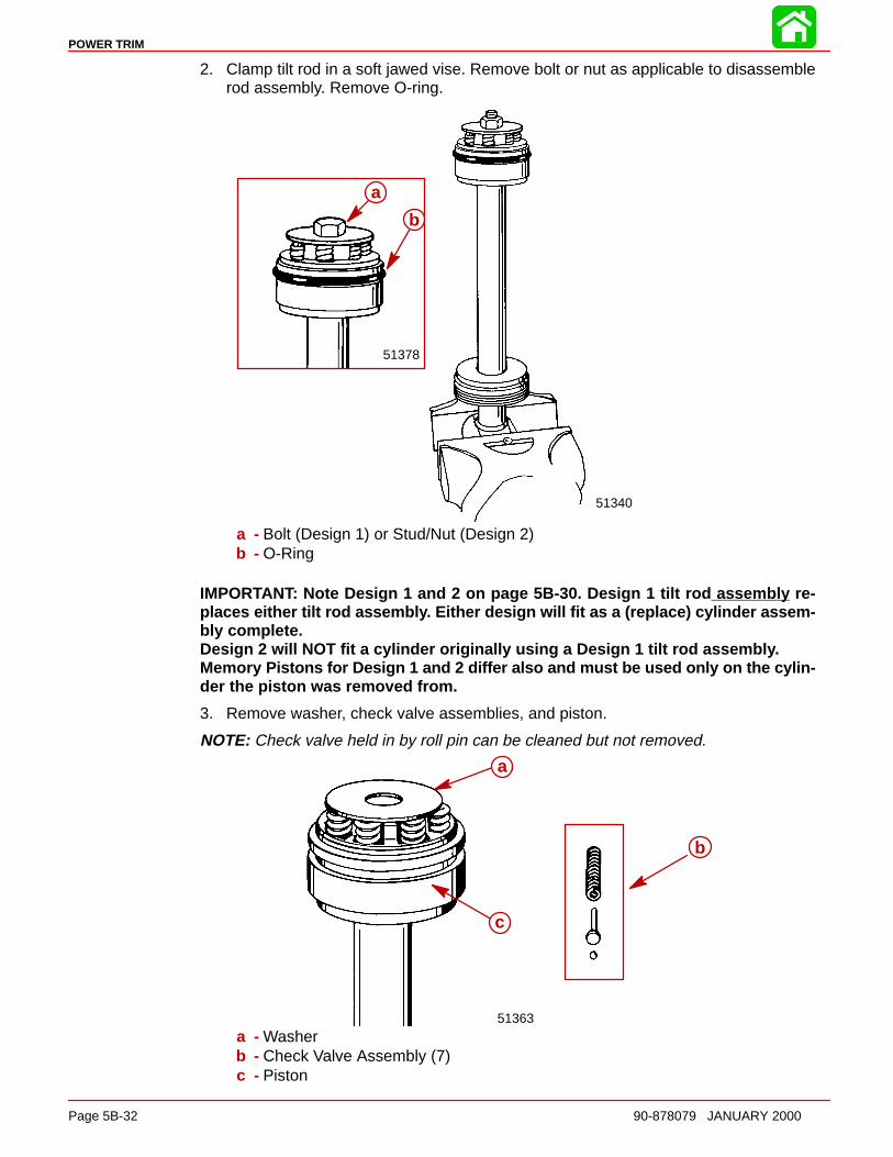
POWER TRIM
Page 5B-32 90-878079 JANUARY 2000
2. Clamp tilt rod in a soft jawed vise. Remove bolt or nut as applicable to disassemblerod assembly. Remove O-ring.
51378
51340
a
b
a
b
a - Bolt (Design 1) or Stud/Nut (Design 2)b - O-Ring
IMPORTANT: Note Design 1 and 2 on page 5B-30. Design 1 tilt rod assembly re-places either tilt rod assembl y. Either design will fit as a (replace) cylinder assem-bly complete.Design 2 will NOT fit a cylinder originally using a Design 1 tilt rod assembl y.Memory Pistons for Design 1 and 2 differ also and must be used only on the cylin-der the piston was removed from.
3. Remove washer, check valve assemblies, and piston.
NOTE: Check valve held in by roll pin can be cleaned but not removed.
51363
b
a
c
a
b
c
a - Washerb - Check Valve Assembly (7)c - Piston
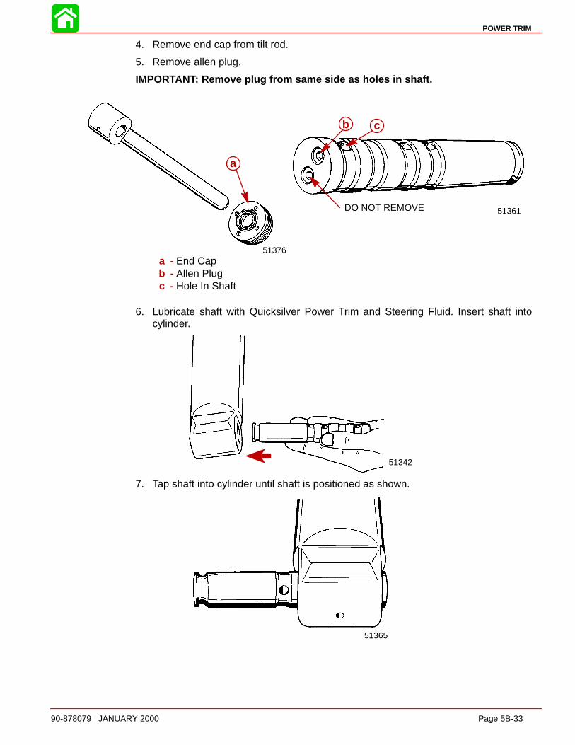
POWER TRIM
90-878079 JANUARY 2000 Page 5B-33
4. Remove end cap from tilt rod.
5. Remove allen plug.
IMPORTANT: Remove plug from same side as holes in shaft.
51361DO NOT REMOVE
51376
aa
b c
a - End Capb - Allen Plugc - Hole In Shaft
6. Lubricate shaft with Quicksilver Power Trim and Steering Fluid. Insert shaft intocylinder.
51342
7. Tap shaft into cylinder until shaft is positioned as shown.
51365
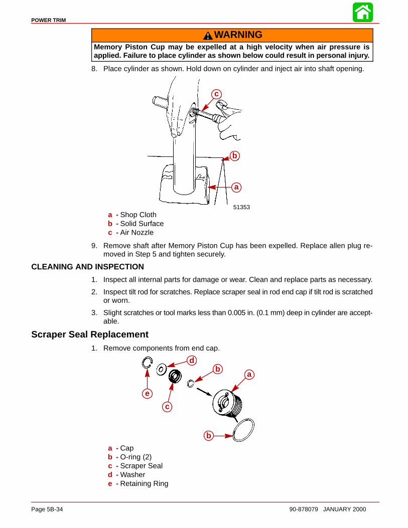
POWER TRIM
Page 5B-34 90-878079 JANUARY 2000
WARNINGMemory Piston Cup may be expelled at a high velocity when air pressure isapplied. Failure to place cylinder as shown below could result in personal injur y.
8. Place cylinder as shown. Hold down on cylinder and inject air into shaft opening.
51353
c
b
a
c
b
a
a - Shop Clothb - Solid Surfacec - Air Nozzle
9. Remove shaft after Memory Piston Cup has been expelled. Replace allen plug re-moved in Step 5 and tighten securely.
CLEANING AND INSPECTION
1. Inspect all internal parts for damage or wear. Clean and replace parts as necessary.
2. Inspect tilt rod for scratches. Replace scraper seal in rod end cap if tilt rod is scratchedor worn.
3. Slight scratches or tool marks less than 0.005 in. (0.1 mm) deep in cylinder are accept-able.
Scraper Seal Replacement1. Remove components from end cap.
e
c
b
db aa
b
b
c
d
e
a - Capb - O-ring (2)c - Scraper Seald - Washere - Retaining Ring
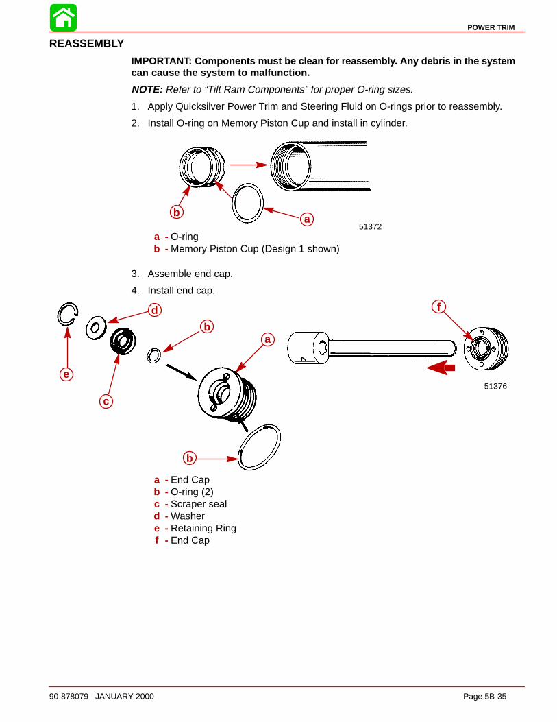
POWER TRIM
90-878079 JANUARY 2000 Page 5B-35
REASSEMBLY
IMPORTANT: Components must be clean for reassembl y. Any debris in the systemcan cause the system to malfunction.
NOTE: Refer to “Tilt Ram Components” for proper O-ring sizes.
1. Apply Quicksilver Power Trim and Steering Fluid on O-rings prior to reassembly.
2. Install O-ring on Memory Piston Cup and install in cylinder.
51372
b aab
a - O-ringb - Memory Piston Cup (Design 1 shown)
3. Assemble end cap.
4. Install end cap.
51376
afd
e
c
ba
b
a
b
b
c
d
e
a - End Capb - O-ring (2)c - Scraper seald - Washere - Retaining Ringf - End Cap
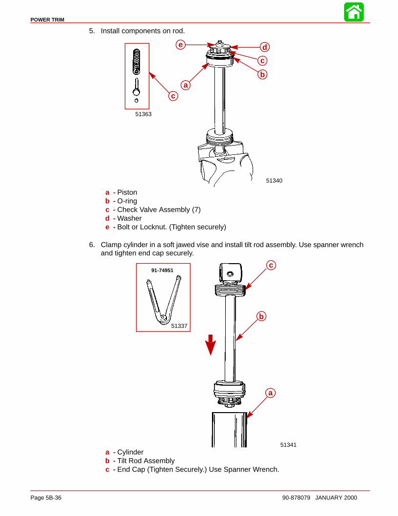
POWER TRIM
Page 5B-36 90-878079 JANUARY 2000
5. Install components on rod.
51340
51363
e
ac
d
c
ba
b
c
c
de
a - Pistonb - O-ringc - Check Valve Assembly (7)d - Washere - Bolt or Locknut. (Tighten securely)
6. Clamp cylinder in a soft jawed vise and install tilt rod assembly. Use spanner wrenchand tighten end cap securely.
51341
51337
91-74951c
b
aa
b
c
a - Cylinderb - Tilt Rod Assemblyc - End Cap (Tighten Securely.) Use Spanner Wrench.

POWER TRIM
90-878079 JANUARY 2000 Page 5B-37
TILT RAM ASSEMB LY INSTALL ATION
1. Lubricate alignment tool (91-11230) and shaft. Use Quicksilver Power Trim and Steer-ing Fluid.
51369a
b
a
b
a - Alignment Tool (91-11230)b - Shaft
2. Align tilt ram and housing using alignment tool.
3. Install shaft.
51352
a
cb51348
ab
cd
a
a - Alignment Tool (91-11230)b - Shaftc - Grooved - Hole [Groove (c) will Align with this Hole]
4. Drive pin in until flush.
51356
aa
a - Pin (Drive Against Knurled End)

POWER TRIM
Page 5B-38 90-878079 JANUARY 2000
Motor and Electrical Tests/Repair
Trim Pump Motor Test
WARNINGDo not perform this test near flammable materials, as a spark may occur whilemaking electrical connections.
1. Connect a 12 volt power supply to motor wires; one motor lead to POSITIVE (+) bat-tery terminal and the other motor lead to the NEGATIVE (–) battery terminal. Motorshould run. Reverse motor leads between battery terminals. Motor should run.
53774
2. If motor does not run, disassemble and check components.
Motor Disassembly1. Remove 2 screws.
53774
a aa a
a - Screw (2)
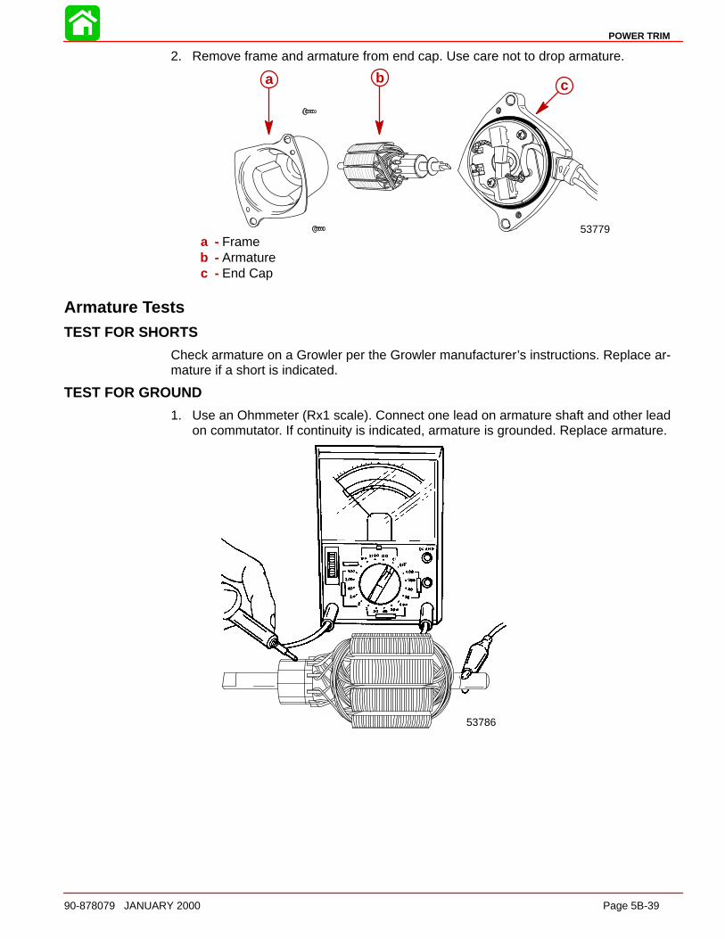
POWER TRIM
90-878079 JANUARY 2000 Page 5B-39
2. Remove frame and armature from end cap. Use care not to drop armature.
53779
a bca b c
a - Frameb - Armaturec - End Cap
Armature TestsTEST FOR SHORTS
Check armature on a Growler per the Growler manufacturer’s instructions. Replace ar-mature if a short is indicated.
TEST FOR GROUND
1. Use an Ohmmeter (Rx1 scale). Connect one lead on armature shaft and other leadon commutator. If continuity is indicated, armature is grounded. Replace armature.
53786
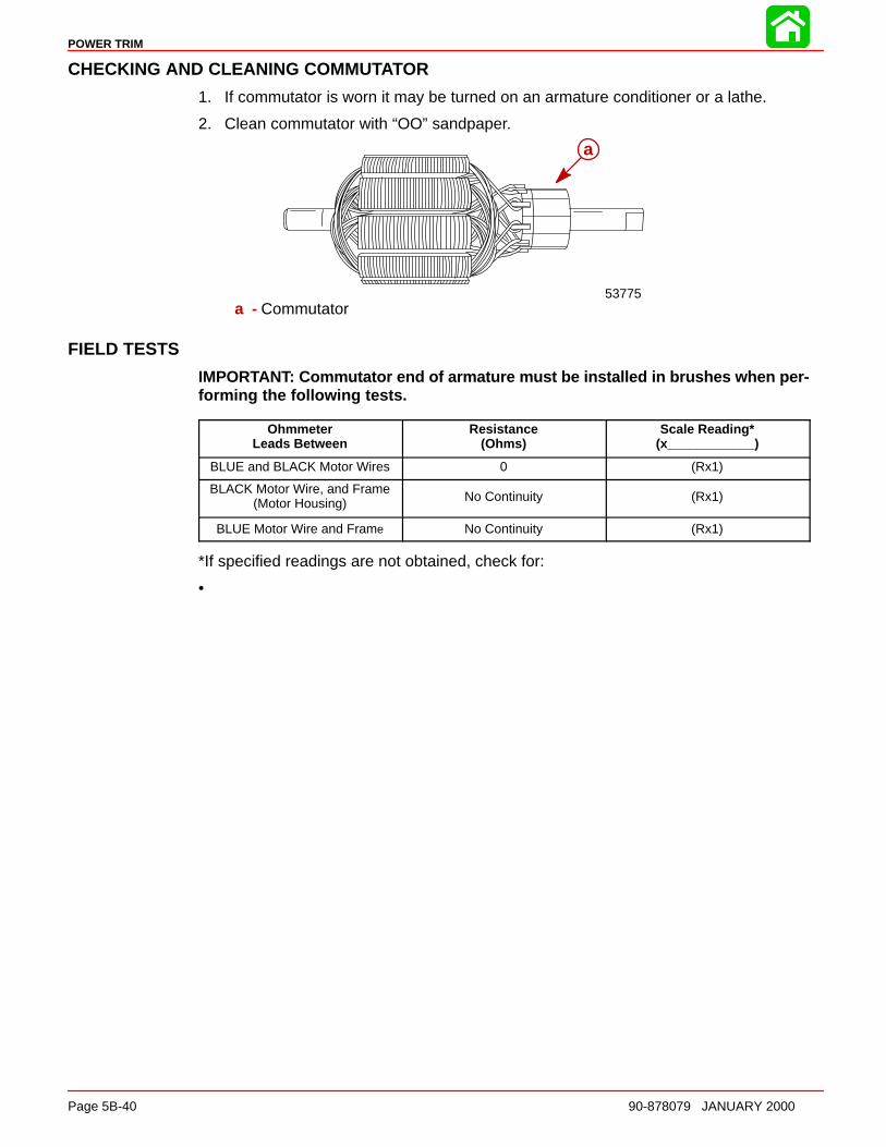
POWER TRIM
Page 5B-40 90-878079 JANUARY 2000
CHECKING AND CLEANING COMMU TATOR
1. If commutator is worn it may be turned on an armature conditioner or a lathe.
2. Clean commutator with “OO” sandpaper.
53775
aa
a - Commutator
FIELD TESTS
IMPORTANT: Commutator end of armature must be installed in brushes when per-forming the following tests.
OhmmeterLeads Between
Resistance(Ohms)
Scale Reading*(x____________)
BLUE and BLACK Motor Wires 0 (Rx1)
BLACK Motor Wire, and Frame(Motor Housing) No Continuity (Rx1)
BLUE Motor Wire and Frame No Continuity (Rx1)
*If specified readings are not obtained, check for:
• defective armature
• dirty or worn brushes
• dirty or worn commutator
If defective components are found, repair or replace component(s) and retest.
Motor RepairREMOVAL
NOTE: Power Trim System does not have to be removed from outboard to repair/replacemotor.
DISASSEMBLY
Refer to “Motor Disassembly” on page 5B-38 to disassemble motor from pump.
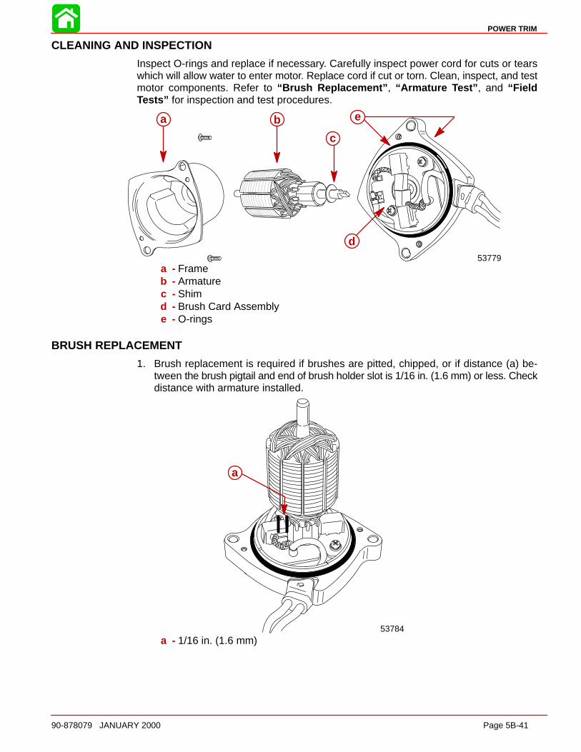
POWER TRIM
90-878079 JANUARY 2000 Page 5B-41
CLEANING AND INSPECTION
Inspect O-rings and replace if necessary. Carefully inspect power cord for cuts or tearswhich will allow water to enter motor. Replace cord if cut or torn. Clean, inspect, and testmotor components. Refer to “Brush Replacement” , “Armature Test” , and “FieldTests ” for inspection and test procedures.
53779
a b
c
d
ea b
c
d
e
a - Frameb - Armaturec - Shimd - Brush Card Assemblye - O-rings
BRUSH REPLACEMENT
1. Brush replacement is required if brushes are pitted, chipped, or if distance (a) be-tween the brush pigtail and end of brush holder slot is 1/16 in. (1.6 mm) or less. Checkdistance with armature installed.
53784
aa
a - 1/16 in. (1.6 mm)
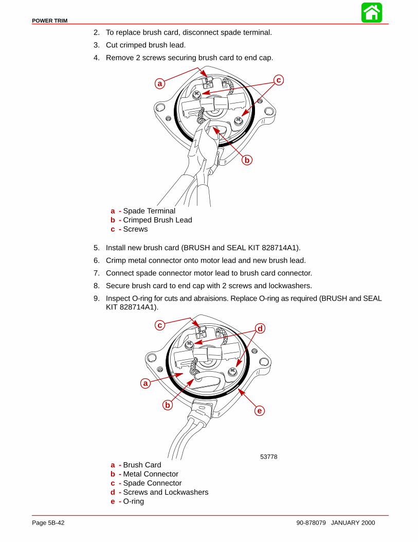
POWER TRIM
Page 5B-42 90-878079 JANUARY 2000
2. To replace brush card, disconnect spade terminal.
3. Cut crimped brush lead.
4. Remove 2 screws securing brush card to end cap.
a
b
ca
b
c
a - Spade Terminalb - Crimped Brush Leadc - Screws
5. Install new brush card (BRUSH and SEAL KIT 828714A1).
6. Crimp metal connector onto motor lead and new brush lead.
7. Connect spade connector motor lead to brush card connector.
8. Secure brush card to end cap with 2 screws and lockwashers.
9. Inspect O-ring for cuts and abraisions. Replace O-ring as required (BRUSH and SEALKIT 828714A1).
53778
c d
eb
aa
b
c d
e
a - Brush Cardb - Metal Connectorc - Spade Connectord - Screws and Lockwasherse - O-ring
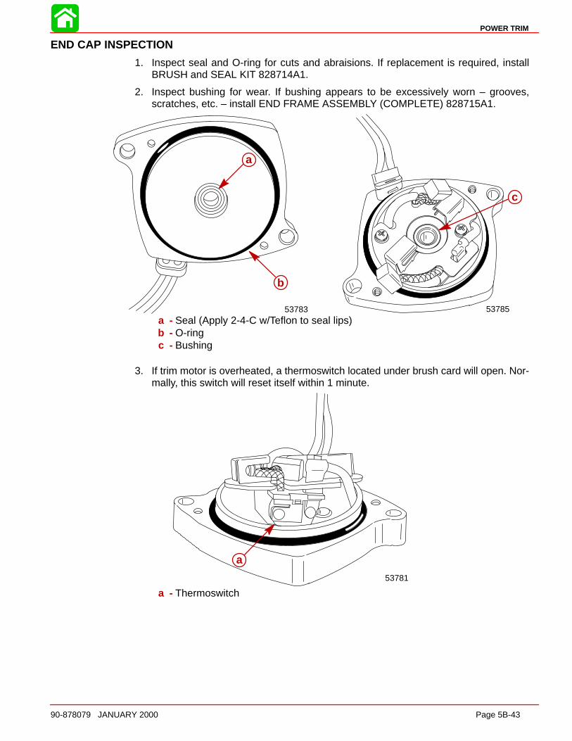
POWER TRIM
90-878079 JANUARY 2000 Page 5B-43
END CAP INSPECTION
1. Inspect seal and O-ring for cuts and abraisions. If replacement is required, installBRUSH and SEAL KIT 828714A1.
2. Inspect bushing for wear. If bushing appears to be excessively worn – grooves,scratches, etc. – install END FRAME ASSEMBLY (COMPLETE) 828715A1.
53785
c
53783
a
b
a
b
a - Seal (Apply 2-4-C w/Teflon to seal lips)b - O-ringc - Bushing
3. If trim motor is overheated, a thermoswitch located under brush card will open. Nor-mally, this switch will reset itself within 1 minute.
53781
aa
a - Thermoswitch
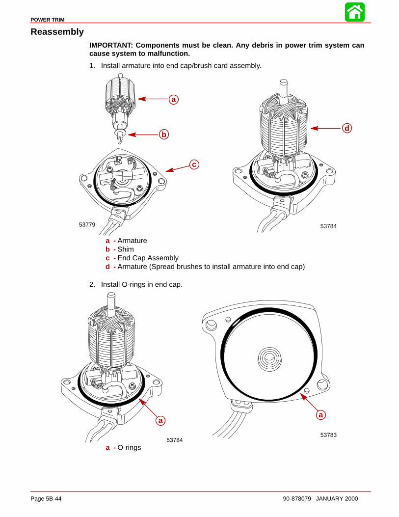
POWER TRIM
Page 5B-44 90-878079 JANUARY 2000
ReassemblyIMPORTANT: Components must be clean. Any debris in power trim system cancause system to malfunction.
1. Install armature into end cap/brush card assembly.
53779
a
b
c
53784
d
a
b
c
d
a - Armatureb - Shimc - End Cap Assemblyd - Armature (Spread brushes to install armature into end cap)
2. Install O-rings in end cap.
53784
a
53783
aa
a
a - O-rings

POWER TRIM
90-878079 JANUARY 2000 Page 5B-45
IMPORTANT: Attach Vise Grip pliers to armature shaft before installing frame as-sembly. The Vise Grip pliers will prevent the armature from being drawn out of thebrush card assembly by the frame magnets while installing the frame assembl y.
3. Install Vise Grip pliers on armature shaft.
4. Carefully install frame assembly over armature.
5. Position harness retainer hole over tab in end cap.
6. Secure frame assembly to end cap with 2 screws.
53776
i
g
c
b
a
d
if e
h
a
b
cd
ef
g
h
ii
a - Vise Grip Pliersb - Armature Shaftc - O-ringd - End Cape - Harness Retainerf - Retainer Holeg - O-ringh - Frame Assemblyi - Screws
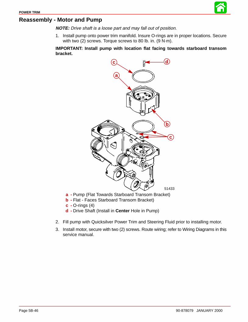
POWER TRIM
Page 5B-46 90-878079 JANUARY 2000
Reassembly - Motor and PumpNOTE: Drive shaft is a loose part and may fall out of position.
1. Install pump onto power trim manifold. Insure O-rings are in proper locations. Securewith two (2) screws. Torque screws to 80 lb. in. (9 N·m).
IMPORTANT: Install pump with location flat facing towards starboard transombracket.
51433
dc
a
b
c
a
b
c
dc
a - Pump (Flat Towards Starboard Transom Bracket)b - Flat - Faces Starboard Transom Bracket)c - O-rings (4)d - Drive Shaft (Install in Center Hole in Pump)
2. Fill pump with Quicksilver Power Trim and Steering Fluid prior to installing motor.
3. Install motor, secure with two (2) screws. Route wiring; refer to Wiring Diagrams in thisservice manual.
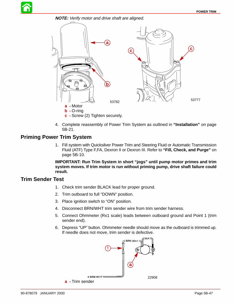
POWER TRIM
90-878079 JANUARY 2000 Page 5B-47
NOTE: Verify motor and drive shaft are aligned.
53782
a
b
53777
cc
a
b
c c
a - Motorb - O-ringc - Screw (2) Tighten securely.
4. Complete reassembly of Power Trim System as outlined in “Installation” on page5B-21.
Priming Power Trim System1. Fill system with Quicksilver Power Trim and Steering Fluid or Automatic Transmission
Fluid (ATF) Type F,FA, Dexron II or Dexron III. Refer to “Fill, Check, and Purge” onpage 5B-10.
IMPORTANT: Run Trim System in short “jogs” until pump motor primes an d trimsyste m moves. If trim motor is run without priming pump, drive shaft failure couldresult.
Trim Sender Test1. Check trim sender BLACK lead for proper ground.
2. Trim outboard to full “DOWN” position.
3. Place ignition switch to “ON” position.
4. Disconnect BRN/WHT trim sender wire from trim sender harness.
5. Connect Ohmmeter (Rx1 scale) leads between outboard ground and Point 1 (trimsender end).
6. Depress “UP” button. Ohmmeter needle should move as the outboard is trimmed up.If needle does not move, trim sender is defective.
22908
a
1
a
1
a - Trim sender
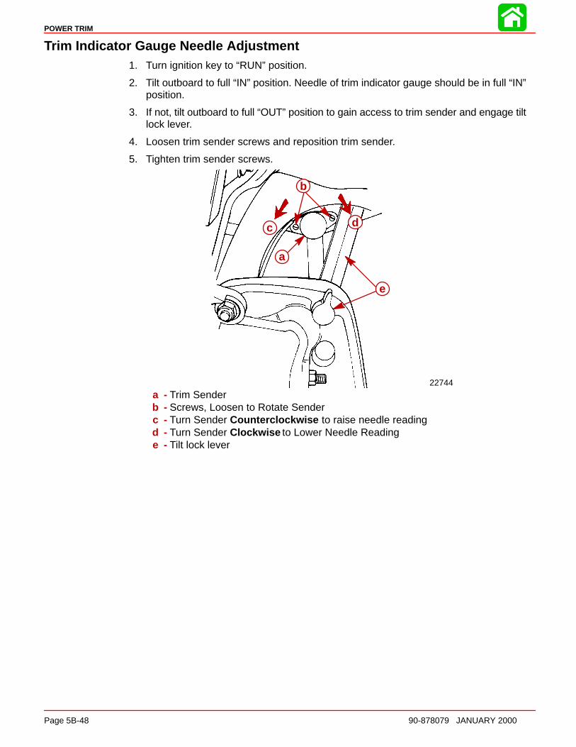
POWER TRIM
Page 5B-48 90-878079 JANUARY 2000
Trim Indicator Gauge Needle Adjustment1. Turn ignition key to “RUN” position.
2. Tilt outboard to full “IN” position. Needle of trim indicator gauge should be in full “IN”position.
3. If not, tilt outboard to full “OUT” position to gain access to trim sender and engage tiltlock lever.
4. Loosen trim sender screws and reposition trim sender.
5. Tighten trim sender screws.
c
b
a
d
a
b
c d
e
22744
a - Trim Senderb - Screws, Loosen to Rotate Senderc - Turn Sender Counterclockwise to raise needle readingd - Turn Sender Clockwise to Lower Needle Readinge - Tilt lock lever
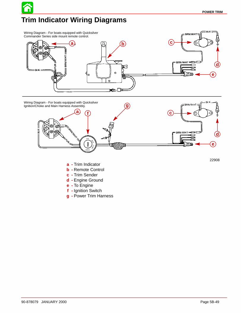
POWER TRIM
90-878079 JANUARY 2000 Page 5B-49
Trim Indicator Wiring Diagrams
22908
Wiring Diagram - For boats equipped with QuicksilverCommander Series side mount remote control.
Wiring Diagram - For boats equipped with QuicksilverIgnition/Choke and Main Harness Assembly.
a b c
a fg
c
a b c
e
d
a f
g
c
e
d
a - Trim Indicatorb - Remote Controlc - Trim Senderd - Engine Grounde - To Enginef - Ignition Switchg - Power Trim Harness

6A
RIGHT HAND NON-RATCHETING
90-878079 JANUARY 2000 Page 6A-1
LOWER UNITSection 6A – Right Hand Non-Ratcheting
Table of Contents
Gear Housing Specifications (Standard Rotation) 6A-1. Special Tools 6A-2. . . . . . . . . . . . . . . . . . . . . . . . . . . . . . . . Notes: 6A-5. . . . . . . . . . . . . . . . . . . . . . . . . . . . . . . . . . . . . . Gear Housing (Drive Shaft)(Standard Rotation) 6A-6. . Gear Housing (Prop Shaft)(Standard Rotation) 6A-8. . . General Service Recommendations 6A-10. . . . . . . . . . . Removal, Disassembly, Cleaning and Inspection– Standard Rotation 6A-11. . . . . . . . . . . . . . . . . . . . . . . . .
Removal 6A-11. . . . . . . . . . . . . . . . . . . . . . . . . . . . . . . . Draining and Inspecting Gear HousingLubricant 6A-12. . . . . . . . . . . . . . . . . . . . . . . . . . . . . . . . Water Pump 6A-13. . . . . . . . . . . . . . . . . . . . . . . . . . . . . Bearing Carrier and Propeller Shaft Removal 6A-16Shift Shaft 6A-18. . . . . . . . . . . . . . . . . . . . . . . . . . . . . . . Propeller Shaft 6A-20. . . . . . . . . . . . . . . . . . . . . . . . . . . Clutch Actuator Rod 6A-22. . . . . . . . . . . . . . . . . . . . . . Pinion Gear and Driveshaft 6A-22. . . . . . . . . . . . . . . . Forward Gear 6A-25. . . . . . . . . . . . . . . . . . . . . . . . . . . .
Gear Housing 6A-26. . . . . . . . . . . . . . . . . . . . . . . . . . . . Reassembly and Installation Standard Rotation 6A-26.
Driveshaft Needle Bearing 6A-26. . . . . . . . . . . . . . . . . Bearing Carrier 6A-27. . . . . . . . . . . . . . . . . . . . . . . . . . . Forward Gear 6A-30. . . . . . . . . . . . . . . . . . . . . . . . . . . . Forward Gear Bearing Race 6A-31. . . . . . . . . . . . . . . Driveshaft and Pinion Gear 6A-32. . . . . . . . . . . . . . . . Pinion Gear Depth/Forward GearBacklash/Reverse Gear Backlash 6A-34. . . . . . . . . . Clutch Actuator Rod 6A-38. . . . . . . . . . . . . . . . . . . . . . Shift Shaft Bushing 6A-38. . . . . . . . . . . . . . . . . . . . . . . Propeller Shaft 6A-39. . . . . . . . . . . . . . . . . . . . . . . . . . . Water Pump 6A-42. . . . . . . . . . . . . . . . . . . . . . . . . . . . . Gear Lubricant Filling Instructions 6A-45. . . . . . . . . . Installing Gear Housing to Driveshaft Housing 6A-45Propeller Installation 6A-47. . . . . . . . . . . . . . . . . . . . . . Speedometer Tube Installation 6A-48. . . . . . . . . . . . .
Gear Housing Specifications (Standard Rotation)
Ratio Pinion Depth Forward GearBacklash
Reverse GearBacklash
1.87:10.025 in. (0.635 mm) With Tool91-12349A2 using Disc #2 and
Flat #7
0.018 in. to 0.027 in. (0.460 mmto 0.686 mm) Pointer on line
mark #1
0.030 in. to 0.050 in.(0.762 mm to 1.27 mm)
2.00:10.025 in. (0.635 mm)With Tool91-12349A2 using Disc #2 and
Flat #7
0.015 in. to 0.022 in. (0.38 mm to0.56 mm) Pointer on line mark #2
0.030 in. to 0.050 in.(0.762 mm to 1.27 mm)
2.30:10.025 in. (0.635 mm)With Tool91-12349A2 using Disc #2 and
Flat #7
0.018 in. to 0.023 in. (0.46 mm to0.58 mm) Pointer on line mark #4
0.030 in. to 0.050 in.(0.762 mm to 1.27 mm)
Gearcase Lubricant Capacity
All Ratios 22.5 fl. oz. (665.4 ml)
Gear Ratio Teeth on Pinion Gear Teeth on Forward and ReverseGear
1.87:1 15 28
2.00:1 12 24
2.30:1 13 30
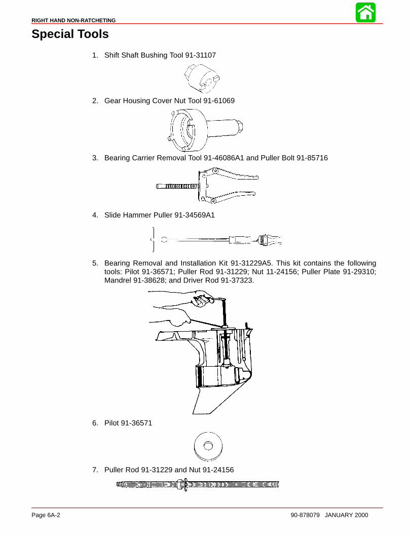
RIGHT HAND NON-RATCHETING
Page 6A-2 90-878079 JANUARY 2000
Special Tools
1. Shift Shaft Bushing Tool 91-31107
2. Gear Housing Cover Nut Tool 91-61069
3. Bearing Carrier Removal Tool 91-46086A1 and Puller Bolt 91-85716
4. Slide Hammer Puller 91-34569A1
5. Bearing Removal and Installation Kit 91-31229A5. This kit contains the followingtools: Pilot 91-36571; Puller Rod 91-31229; Nut 11-24156; Puller Plate 91-29310;Mandrel 91-38628; and Driver Rod 91-37323.
6. Pilot 91-36571
7. Puller Rod 91-31229 and Nut 91-24156
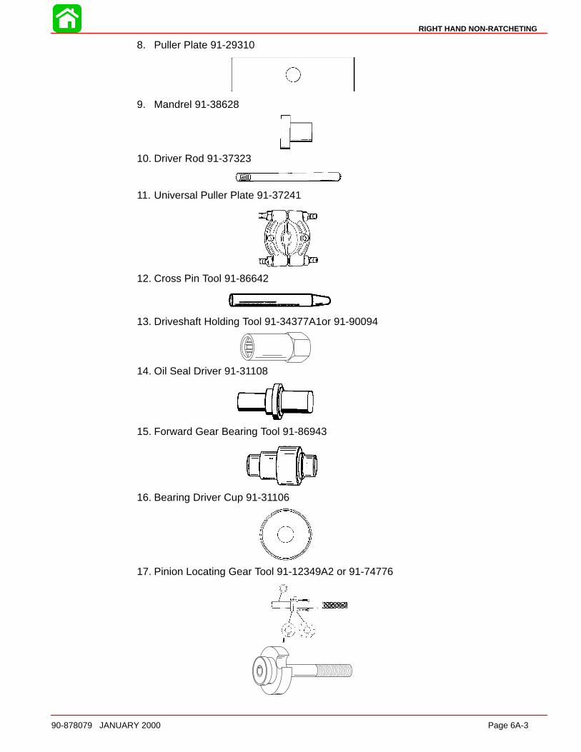
RIGHT HAND NON-RATCHETING
90-878079 JANUARY 2000 Page 6A-3
8. Puller Plate 91-29310
9. Mandrel 91-38628
10. Driver Rod 91-37323
11. Universal Puller Plate 91-37241
12. Cross Pin Tool 91-86642
13. Driveshaft Holding Tool 91-34377A1or 91-90094
14. Oil Seal Driver 91-31108
15. Forward Gear Bearing Tool 91-86943
16. Bearing Driver Cup 91-31106
17. Pinion Locating Gear Tool 91-12349A2 or 91-74776
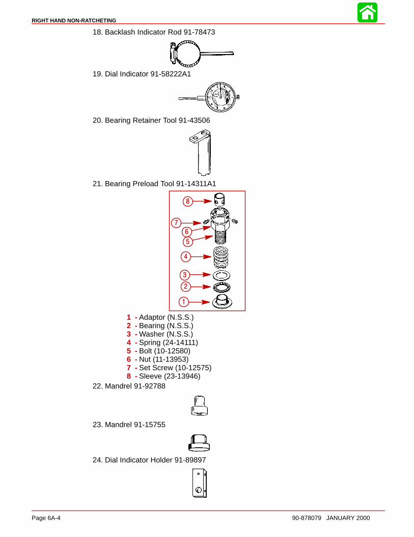
RIGHT HAND NON-RATCHETING
Page 6A-4 90-878079 JANUARY 2000
18. Backlash Indicator Rod 91-78473
19. Dial Indicator 91-58222A1
20. Bearing Retainer Tool 91-43506
21. Bearing Preload Tool 91-14311A1
a
bc
d
ef
g
h
1
2
3
4
5
6
7
8
1 - Adaptor (N.S.S.)2 - Bearing (N.S.S.)3 - Washer (N.S.S.)4 - Spring (24-14111)5 - Bolt (10-12580)6 - Nut (11-13953)7 - Set Screw (10-12575)8 - Sleeve (23-13946)
22. Mandrel 91-92788
23. Mandrel 91-15755
24. Dial Indicator Holder 91-89897

RIGHT HAND NON-RATCHETING
90-878079 JANUARY 2000 Page 6A-5
Notes:
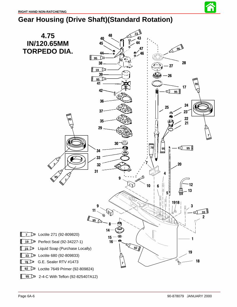
RIGHT HAND NON-RATCHETING
Page 6A-6 90-878079 JANUARY 2000
Gear Housing (Drive Shaft)(Standard Rotation)
19
1
12
2
3
4
5
6
7
9
11
14
15
16
17
18
19
20
21
22
23
2425
26
28
29
35
36
37
38
39
40
41
42
43
4445
46
47
48
10
13
9
44
27
30
Liquid Soap (Purchase Locally)
G.E. Sealer RTV #1473
23
95
95
7
95
95
95
33
795
95
7
95
19
95
78
23
78
895
4.75IN/120.65MM
TORPEDO DIA.
18
Perfect Seal (92-34227-1)19
7 Loctite 271 (92-809820)
Loctite 680 (92-809833)33
95 2-4-C With Teflon (92-825407A12)
92 Loctite 7649 Primer (92-809824)
92
7
31
32
33
34

RIGHT HAND NON-RATCHETING
90-878079 JANUARY 2000 Page 6A-7
Gear Housing (Drive Shaft)(Standard Rotation)
REFTORQUE
REF.NO. QTY. DESCRIPTION lb-in lb-ft Nm
1 1 GEAR HOUSING (BLACK)(BASIC)2 2 DOWEL PIN
31 STUD (3-1/8 IN.) (LONG)
3 1 STUD (3-11/16 IN.) (X-LONG)4 2 STUD (2-1/16 IN.)5 1 STUD (3-3/8 IN.)6 2 STUD (3-1/8 IN.)7 1 FILLER BLOCK8 1 ROLLER BEARING9 2 ANODE10 1 SCREW (M6 x 40)11 1 NUT 60 7
121 HOSE (10 IN. - LONG)
12 1 HOSE (12 IN. - X-LONG)13 1 FITTING
141 PINION GEAR (1.87:1- 15 TEETH)(150)
14 1 PINION GEAR (2:1 - 14 TEETH)(115/135)15 1 WASHER16 1 NUT 75 10117 AR SHIM (006 thru 048)18 2 SCREW–drain 60 719 2 WASHER20 1 SHIFT SHAFT21 1 O-RING22 1 BUSHING ASSEMBLY 50 6823 1 OIL SEAL24 1 WASHER–rubber
251 DRIVE SHAFT (LONG)
25 1 DRIVE SHAFT (X-LONG)26 1 ROLLER BEARING27 1 CUP28 1 RETAINER 100 13529 1 WATER PUMP BASE30 1 RETAINER31 1 GASKET32 1 O-RING33 1 OIL SEAL34 1 OIL SEAL35 1 GASKET–lower36 1 GASKET–upper37 1 FACE PLATE38 1 WATER PUMP BODY ASSEMBLY39 1 INSERT40 1 SEAL–rubber41 1 lMPELLER42 1 KEY43 1 SCREW (#14-8 x 2-1/4 IN.) 35 444 2 WASHER45 2 NUT 50 5.546 1 WASHER47 1 NUT 50 5.548 1 SLEEVE
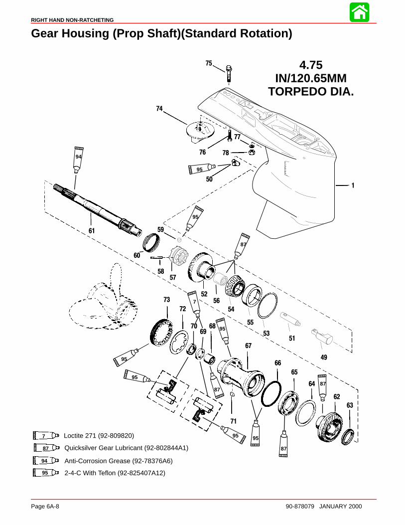
RIGHT HAND NON-RATCHETING
Page 6A-8 90-878079 JANUARY 2000
Gear Housing (Prop Shaft)(Standard Rotation)
1
49
50
51
52
53
54
56
5758
59
60
61
62
63
64
65
66
67
6869
70
71
72
73
74
75
76
77
78
55
95
95
87
95
95
87
87
95
95
95
87
7
94
4.75IN/120.65MM
TORPEDO DIA.
7 Loctite 271 (92-809820)
94 Anti-Corrosion Grease (92-78376A6)
95 2-4-C With Teflon (92-825407A12)
87 Quicksilver Gear Lubricant (92-802844A1)
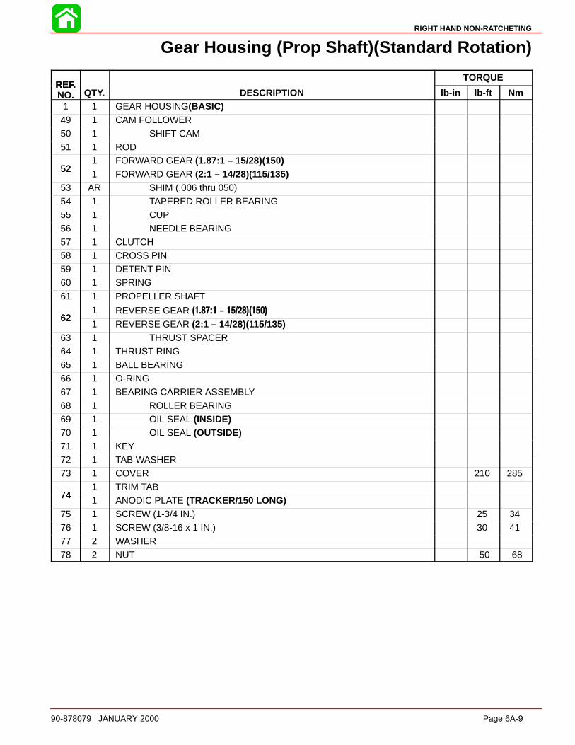
RIGHT HAND NON-RATCHETING
90-878079 JANUARY 2000 Page 6A-9
Gear Housing (Prop Shaft)(Standard Rotation)
REFTORQUE
REF.NO. QTY. DESCRIPTION lb-in lb-ft Nm
1 1 GEAR HOUSING(BASIC)49 1 CAM FOLLOWER50 1 SHIFT CAM51 1 ROD
521 FORWARD GEAR (1.87:1 – 15/28)(150)
521 FORWARD GEAR (2:1 – 14/28)(115/135)
53 AR SHIM (.006 thru 050)
54 1 TAPERED ROLLER BEARING55 1 CUP56 1 NEEDLE BEARING57 1 CLUTCH58 1 CROSS PIN59 1 DETENT PIN60 1 SPRING
61 1 PROPELLER SHAFT
621 REVERSE GEAR (1.87:1 - 15/28)(150)
621 REVERSE GEAR (2:1 – 14/28)(115/135)
63 1 THRUST SPACER64 1 THRUST RING65 1 BALL BEARING66 1 O-RING
67 1 BEARING CARRIER ASSEMBLY68 1 ROLLER BEARING69 1 OIL SEAL (INSIDE)70 1 OIL SEAL (OUTSIDE)71 1 KEY72 1 TAB WASHER73 1 COVER 210 285
741 TRIM TAB
741 ANODIC PLATE (TRACKER/150 LONG)
75 1 SCREW (1-3/4 IN.) 25 3476 1 SCREW (3/8-16 x 1 IN.) 30 4177 2 WASHER78 2 NUT 50 68
RIGHT HAND NON-RATCHETING
Page 6A-10 90-878079 JANUARY 2000
General Service Recommendations
There may be more than one way to “disassemble” or “reassemble” a particular part(s),therefore, it is recommended that the entire procedure be read prior to repair.
IMPORTANT: Read the following before attempting any repairs.
In many cases, disassembly of a sub-assembly may not be necessary until cleaning andinspection reveals that disassembly is required for replacement of one or more compo-nents.
Service procedure order in this section is a normal disassembly-reassembly sequence.It is suggested that the sequence be followed without deviation to assure proper repairs.When performing partial repairs, follow the instructions to the point where the desiredcomponent can be replaced, then proceed to “reassembly and installation” of that compo-nent in the reassembly part of this section. Use the “Table of Contents” (on back of sectiondivider) to find correct page number.
Threaded parts are right hand (RH), unless otherwise indicated.
When holding, pressing or driving is required, use soft metal vise jaw protectors or woodfor protection of parts. Use a suitable mandrel (one that will contact only the bearing race)when pressing or driving bearings.
Whenever compressed air is used to dry a part, be sure that no water is present in air line.
BEARINGS
Upon disassembly of gear housing, all bearings must be cleaned and inspected. Cleanbearings with solvent and dry with compressed air. Air should be directed at the bearingso that it passes thru the bearing. DO NOT spin bearing with compressed air, as this maycause bearing to score from lack of lubrication. After cleaning, lubricate bearings withQuicksilver Gear Lubricant. DO NOT lubricate tapered bearing cups until after inspection.
Inspect all bearings for roughness, catches and bearing race side wear. Work inner bear-ing race in-and-out, while holding outer race, to check for side wear.
When inspecting tapered bearings, determine condition of rollers and inner bearing raceby inspecting bearing cup for pitting, scoring, grooves, uneven wear, imbedded particlesand/or discoloration from overheating. Always replace tapered bearing and race as a set.
Roller bearing condition is determined by inspecting the bearing surface of the shaft thatthe roller bearing supports. Check shaft surface for pitting, scoring, grooving, imbeddedparticles, uneven wear and/or discoloration from overheating. The shaft and bearing mustbe replaced, if the conditions described are found.
SHIMS
Keep a record of all shim amounts and location during disassembly to aid in reassembly.Be sure to follow shimming instructions during reassembly, as gears must be installed tocorrect depth and have the correct amount of backlash to avoid noisy operation and pre-mature gear failure.
SEALS
As a normal procedure, all O-rings and oil seals SHOULD BE REPLACED without regardto appearance. To prevent leakage around oil seals, apply Loctite 271 to outer diameterof all metal case oil seals. When using Loctite on seals or threads, surfaces must be cleanand dry. To ease installation, apply Quicksilver 2-4-C w/Teflon Marine Lubricant on allO-rings. To prevent wear, apply Quicksilver 2-4-C w/Teflon Marine Lubricant on l.D. of oilseals.

RIGHT HAND NON-RATCHETING
90-878079 JANUARY 2000 Page 6A-11
To prevent corrosion damage after reassembly, apply Quicksilver 2-4-C w/Teflon MarineLubricant to external surfaces of bearing carrier and cover nut threads prior to installation.
Removal, Disassembl y, Cleaning and Inspection – StandardRotation
Removal
WARNINGDisconnect high tension leads from spark plugs and remove spark plugs fromengine before removing gear housing from driveshaft housing.
1. Disconnect high tension leads from spark plugs and remove spark plugs from engine.
CAUTIONGear housing MUST BE in NEUTRAL position and shift shaft MUST BE removedfrom gear housing BEFORE propeller shaft can be removed from gear housing.
2. Shift engine into NEUTRAL position.
3. Tilt engine to full up position and engage tilt lock lever.
4. Bend tabs of propeller tab washer away from thrust hub (rear), then remove propellerlocknut, tab washer, thrust hub (rear), propeller and thrust hub (forward) from propel-ler shaft.
5. Mark gear housing and trim tab so that trim tab can be reinstalled in the same position.Remove plastic cap at rear edge of driveshaft housing. Remove bolt that secures trimtab and remove tab from gear housing.
6. Once trim tab is removed, remove bolt from inside of trim tab cavity.
7. Remove 2 locknuts from bottom middle of anti-cavitation plate.
5186651916 51912
a
b
c
d
e
f
g
h
i
a - Tab Washerb - Propeller Nutc - Rear Thrust Hubd - Continuity Washer (if
equipped)
e - Propeller Shaftf - Thrust Hub (forward)g - Bolt (secures trim tab)h - Bolt (inside trim tab cavity)i - Locknuts and Washers

RIGHT HAND NON-RATCHETING
Page 6A-12 90-878079 JANUARY 2000
8. While pressing in on speedometer hose junction, pull out on hose to disconnect.
57735
a
b
a - Press in on Junctionb - Pull out on Hose
9. Remove locknut from the front gear housing mounting stud.
10. Loosen the side mounting locknuts. (DO NOT attempt to remove one nut before oppo-site side is loosened sufficiently, or driveshaft housing could be damaged.)
51873
ab
ab
a - Front Mounting Locknutb - Side Mounting Locknut (One Each Side)
11. Pull gear housing away from driveshaft housing as far as the loosened nuts (in Step9) will allow, then remove loosened nuts. (DO NOT allow gear housing to fall, as it nowis free.)
12. Pull gear housing from driveshaft housing.
Draining and Inspecting Gear Housing Lubricant1. Place gear housing in a suitable holding fixture or vise with the driveshaft in a vertical
position.
NOTE: Drain and Fill screws may be located on the starboard side of gearcase on latermodels.
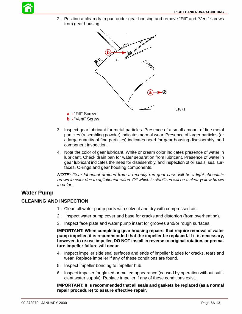
RIGHT HAND NON-RATCHETING
90-878079 JANUARY 2000 Page 6A-13
2. Position a clean drain pan under gear housing and remove “Fill” and “Vent” screwsfrom gear housing.
b
51871
b
a
a - “Fill” Screwb - “Vent” Screw
3. Inspect gear lubricant for metal particles. Presence of a small amount of fine metalparticles (resembling powder) indicates normal wear. Presence of larger particles (ora large quantity of fine particles) indicates need for gear housing disassembly, andcomponent inspection.
4. Note the color of gear lubricant. White or cream color indicates presence of water inlubricant. Check drain pan for water separation from lubricant. Presence of water ingear lubricant indicates the need for disassembly, and inspection of oil seals, seal sur-faces, O-rings and gear housing components.
NOTE: Gear lubricant drained from a recently run gear case will be a light chocolatebrown in color due to agitation/aeration. Oil which is stabilized will be a clear yellow brownin color.
Water PumpCLEANING AND INSPECTION
1. Clean all water pump parts with solvent and dry with compressed air.
2. Inspect water pump cover and base for cracks and distortion (from overheating).
3. Inspect face plate and water pump insert for grooves and/or rough surfaces.
IMPORTANT: When completing gear housing repairs, that require removal of waterpump impelle r, it is recommended that the impeller be replaced. If it is necessar y,howeve r, to re-use impelle r, DO NOT install in reverse to original rotation, or prema-ture impeller failure will occu r.
4. Inspect impeller side seal surfaces and ends of impeller blades for cracks, tears andwear. Replace impeller if any of these conditions are found.
5. Inspect impeller bonding to impeller hub.
6. Inspect impeller for glazed or melted appearance (caused by operation without suffi-cient water supply). Replace impeller if any of these conditions exist.
IMPORTANT: It is recommended that all seals and gaskets be replaced (as a normalrepair procedure) to assure effective repai r.
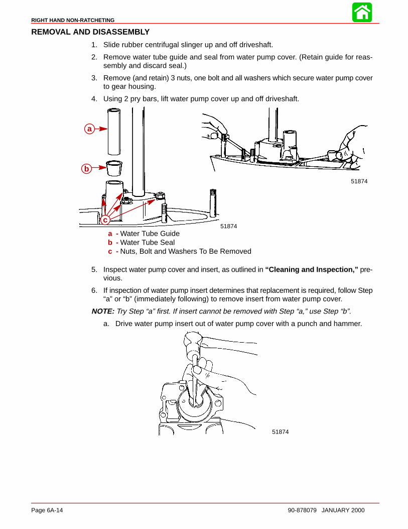
RIGHT HAND NON-RATCHETING
Page 6A-14 90-878079 JANUARY 2000
REMOVAL AND DISASSEMB LY
1. Slide rubber centrifugal slinger up and off driveshaft.
2. Remove water tube guide and seal from water pump cover. (Retain guide for reas-sembly and discard seal.)
3. Remove (and retain) 3 nuts, one bolt and all washers which secure water pump coverto gear housing.
4. Using 2 pry bars, lift water pump cover up and off driveshaft.
51874
b
a
51874
a
b
c
a - Water Tube Guideb - Water Tube Sealc - Nuts, Bolt and Washers To Be Removed
5. Inspect water pump cover and insert, as outlined in “Cleaning and Inspection,” pre-vious.
6. If inspection of water pump insert determines that replacement is required, follow Step“a” or “b” (immediately following) to remove insert from water pump cover.
NOTE: Try Step “a” first. If insert cannot be removed with Step “a,” use Step “b”.
a. Drive water pump insert out of water pump cover with a punch and hammer.
51874
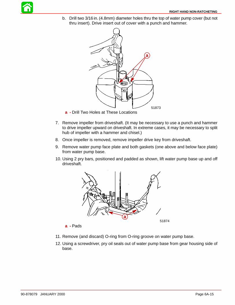
RIGHT HAND NON-RATCHETING
90-878079 JANUARY 2000 Page 6A-15
b. Drill two 3/16 in. (4.8mm) diameter holes thru the top of water pump cover (but notthru insert). Drive insert out of cover with a punch and hammer.
a
51873
a
a - Drill Two Holes at These Locations
7. Remove impeller from driveshaft. (It may be necessary to use a punch and hammerto drive impeller upward on driveshaft. In extreme cases, it may be necessary to splithub of impeller with a hammer and chisel.)
8. Once impeller is removed, remove impeller drive key from driveshaft.
9. Remove water pump face plate and both gaskets (one above and below face plate)from water pump base.
10. Using 2 pry bars, positioned and padded as shown, lift water pump base up and offdriveshaft.
51874a
a - Pads
11. Remove (and discard) O-ring from O-ring groove on water pump base.
12. Using a screwdriver, pry oil seals out of water pump base from gear housing side ofbase.
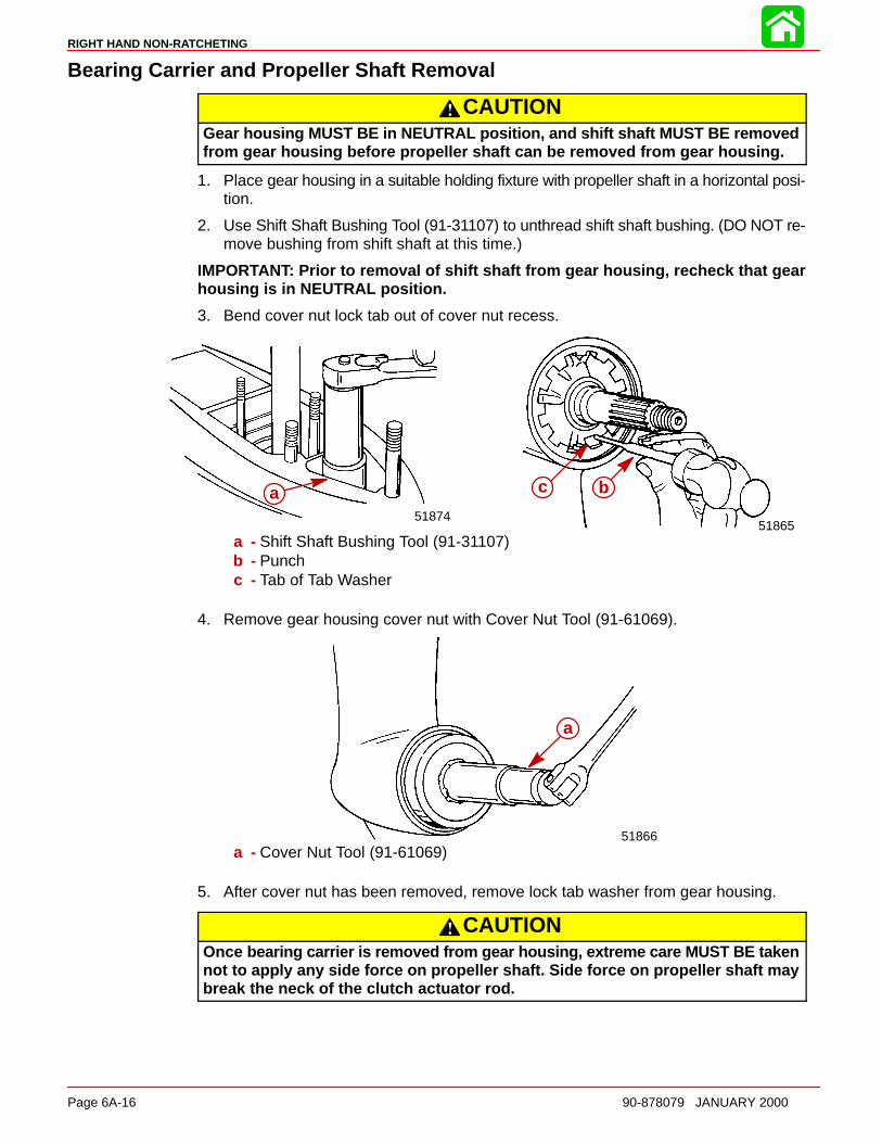
RIGHT HAND NON-RATCHETING
Page 6A-16 90-878079 JANUARY 2000
Bearing Carrier and Propeller Shaft Removal
CAUTIONGear housing MUST BE in NEUTRAL position, and shift shaft MUST BE removedfrom gear housing before propeller shaft can be removed from gear housing.
1. Place gear housing in a suitable holding fixture with propeller shaft in a horizontal posi-tion.
2. Use Shift Shaft Bushing Tool (91-31107) to unthread shift shaft bushing. (DO NOT re-move bushing from shift shaft at this time.)
IMPORTANT: Prior to removal of shift shaft from gear housing, recheck that gearhousing is in NEUTRAL position.
3. Bend cover nut lock tab out of cover nut recess.
b a
51865
bca51874
a
a - Shift Shaft Bushing Tool (91-31107)b - Punchc - Tab of Tab Washer
4. Remove gear housing cover nut with Cover Nut Tool (91-61069).
a
51866
a
a - Cover Nut Tool (91-61069)
5. After cover nut has been removed, remove lock tab washer from gear housing.
CAUTIONOnce bearing carrier is removed from gear housing, extreme care MUST BE takennot to apply any side force on propeller shaft. Side force on propeller shaft maybreak the neck of the clutch actuator rod.
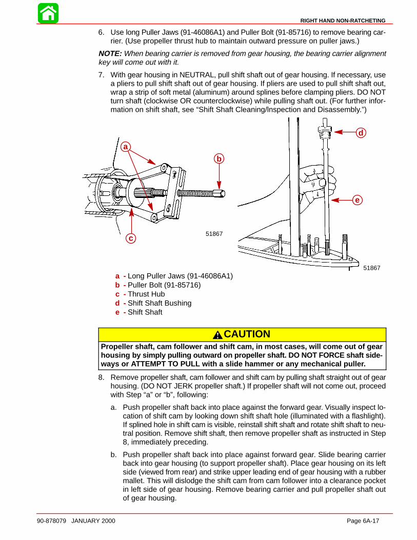
RIGHT HAND NON-RATCHETING
90-878079 JANUARY 2000 Page 6A-17
6. Use long Puller Jaws (91-46086A1) and Puller Bolt (91-85716) to remove bearing car-rier. (Use propeller thrust hub to maintain outward pressure on puller jaws.)
NOTE: When bearing carrier is removed from gear housing, the bearing carrier alignmentkey will come out with it.
7. With gear housing in NEUTRAL, pull shift shaft out of gear housing. If necessary, usea pliers to pull shift shaft out of gear housing. If pliers are used to pull shift shaft out,wrap a strip of soft metal (aluminum) around splines before clamping pliers. DO NOTturn shaft (clockwise OR counterclockwise) while pulling shaft out. (For further infor-mation on shift shaft, see “Shift Shaft Cleaning/lnspection and Disassembly.”)
a
b
51867
a
b
c51867
d
e
a
b
c
a - Long Puller Jaws (91-46086A1)b - Puller Bolt (91-85716)c - Thrust Hubd - Shift Shaft Bushinge - Shift Shaft
CAUTIONPropeller shaft, cam follower and shift cam, in most cases, will come out of gearhousing by simply pulling outward on propeller shaft. DO NOT FORCE shaft side-ways or ATTEMPT TO PULL with a slide hammer or any mechanical pulle r.
8. Remove propeller shaft, cam follower and shift cam by pulling shaft straight out of gearhousing. (DO NOT JERK propeller shaft.) If propeller shaft will not come out, proceedwith Step “a” or “b”, following:
a. Push propeller shaft back into place against the forward gear. Visually inspect lo-cation of shift cam by looking down shift shaft hole (illuminated with a flashlight).If splined hole in shift cam is visible, reinstall shift shaft and rotate shift shaft to neu-tral position. Remove shift shaft, then remove propeller shaft as instructed in Step8, immediately preceding.
b. Push propeller shaft back into place against forward gear. Slide bearing carrierback into gear housing (to support propeller shaft). Place gear housing on its leftside (viewed from rear) and strike upper leading end of gear housing with a rubbermallet. This will dislodge the shift cam from cam follower into a clearance pocketin left side of gear housing. Remove bearing carrier and pull propeller shaft outof gear housing.
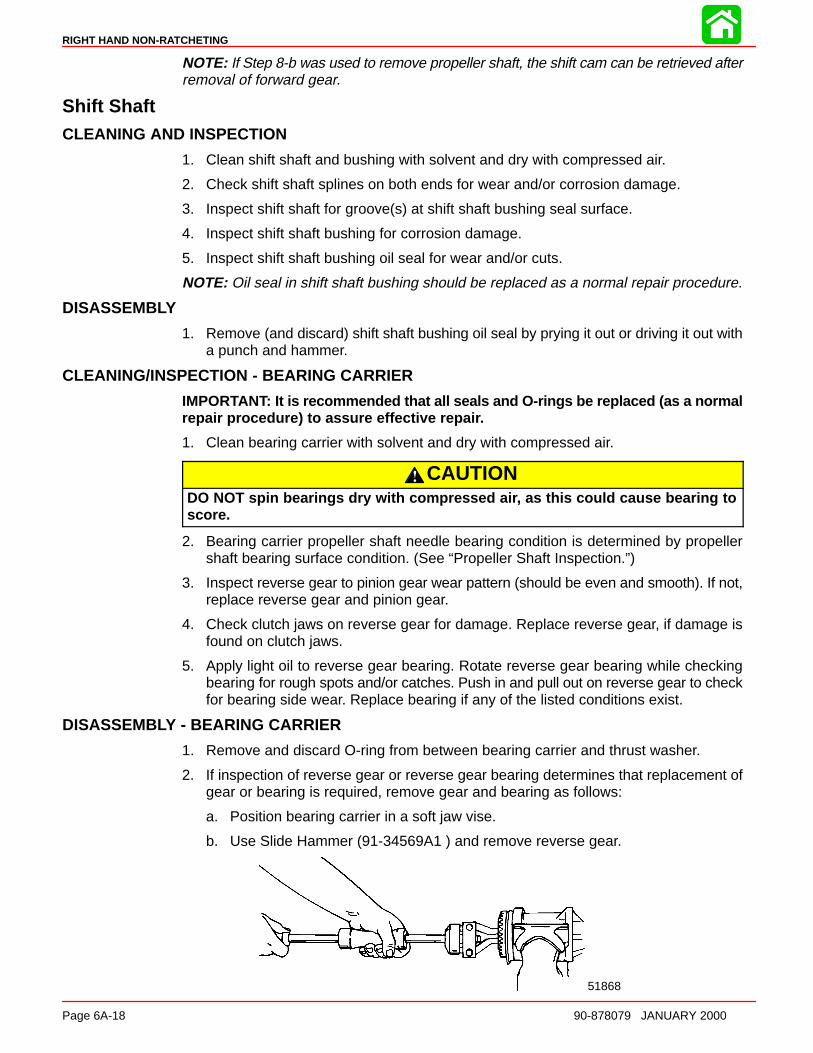
RIGHT HAND NON-RATCHETING
Page 6A-18 90-878079 JANUARY 2000
NOTE: If Step 8-b was used to remove propeller shaft, the shift cam can be retrieved afterremoval of forward gear.
Shift ShaftCLEANING AND INSPECTION
1. Clean shift shaft and bushing with solvent and dry with compressed air.
2. Check shift shaft splines on both ends for wear and/or corrosion damage.
3. Inspect shift shaft for groove(s) at shift shaft bushing seal surface.
4. Inspect shift shaft bushing for corrosion damage.
5. Inspect shift shaft bushing oil seal for wear and/or cuts.
NOTE: Oil seal in shift shaft bushing should be replaced as a normal repair procedure.
DISASSEMBLY
1. Remove (and discard) shift shaft bushing oil seal by prying it out or driving it out witha punch and hammer.
CLEANING/INSPECTION - BEARING CARRIER
IMPORTANT: It is recommended that all seals and O-rings be replaced (as a normalrepair procedure) to assure effective repai r.
1. Clean bearing carrier with solvent and dry with compressed air.
CAUTIONDO NOT spin bearings dry with compressed ai r, as this could cause bearing toscore.
2. Bearing carrier propeller shaft needle bearing condition is determined by propellershaft bearing surface condition. (See “Propeller Shaft Inspection.”)
3. Inspect reverse gear to pinion gear wear pattern (should be even and smooth). If not,replace reverse gear and pinion gear.
4. Check clutch jaws on reverse gear for damage. Replace reverse gear, if damage isfound on clutch jaws.
5. Apply light oil to reverse gear bearing. Rotate reverse gear bearing while checkingbearing for rough spots and/or catches. Push in and pull out on reverse gear to checkfor bearing side wear. Replace bearing if any of the listed conditions exist.
DISASSEMBLY - BEARING CARRIER
1. Remove and discard O-ring from between bearing carrier and thrust washer.
2. If inspection of reverse gear or reverse gear bearing determines that replacement ofgear or bearing is required, remove gear and bearing as follows:
a. Position bearing carrier in a soft jaw vise.
b. Use Slide Hammer (91-34569A1 ) and remove reverse gear.
51868
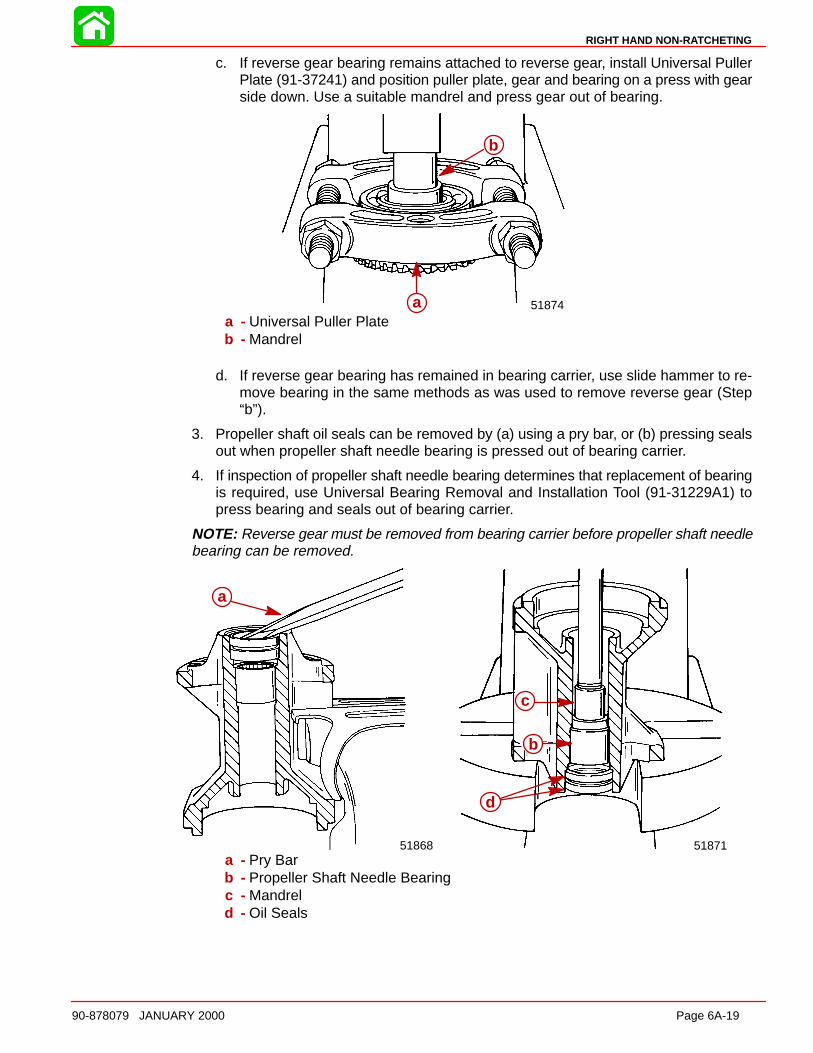
RIGHT HAND NON-RATCHETING
90-878079 JANUARY 2000 Page 6A-19
c. If reverse gear bearing remains attached to reverse gear, install Universal PullerPlate (91-37241) and position puller plate, gear and bearing on a press with gearside down. Use a suitable mandrel and press gear out of bearing.
b
a 51874a
b
a - Universal Puller Plateb - Mandrel
d. If reverse gear bearing has remained in bearing carrier, use slide hammer to re-move bearing in the same methods as was used to remove reverse gear (Step“b”).
3. Propeller shaft oil seals can be removed by (a) using a pry bar, or (b) pressing sealsout when propeller shaft needle bearing is pressed out of bearing carrier.
4. If inspection of propeller shaft needle bearing determines that replacement of bearingis required, use Universal Bearing Removal and Installation Tool (91-31229A1) topress bearing and seals out of bearing carrier.
NOTE: Reverse gear must be removed from bearing carrier before propeller shaft needlebearing can be removed.
b
c
a
51871
b
c
d
a
51868
a
a - Pry Barb - Propeller Shaft Needle Bearingc - Mandreld - Oil Seals
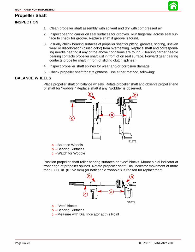
RIGHT HAND NON-RATCHETING
Page 6A-20 90-878079 JANUARY 2000
Propeller ShaftINSPECTION
1. Clean propeller shaft assembly with solvent and dry with compressed air.
2. Inspect bearing carrier oil seal surfaces for grooves. Run fingernail across seal sur-face to check for groove. Replace shaft if groove is found.
3. Visually check bearing surfaces of propeller shaft for pitting, grooves, scoring, unevenwear or discoloration (bluish color) from overheating. Replace shaft and correspond-ing needle bearing if any of the above conditions are found. (Bearing carrier needlebearing contacts propeller shaft just in front of oil seal surface. Forward gear bearingcontacts propeller shaft in front of sliding clutch splines.)
4. Inspect propeller shaft splines for wear and/or corrosion damage.
5. Check propeller shaft for straightness. Use either method, following:
BALANCE WHEELS
Place propeller shaft on balance wheels. Rotate propeller shaft and observe propeller endof shaft for “wobble.” Replace shaft if any “wobble” is observed.
b
a
b
c
51872
a
b b
c
a - Balance Wheelsb - Bearing Surfacesc - Watch for Wobble
Position propeller shaft roller bearing surfaces on “vee” blocks. Mount a dial indicator atfront edge of propeller splines. Rotate propeller shaft. Dial indicator movement of morethan 0.006 in. (0.152 mm) (or noticeable “wobble”) is reason for replacement.
51872
b
ca
b
a
bb
c
a - “Vee” Blocksb - Bearing Surfacesc - Measure with Dial Indicator at this Point
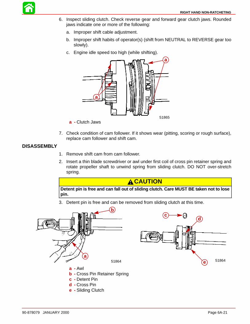
RIGHT HAND NON-RATCHETING
90-878079 JANUARY 2000 Page 6A-21
6. Inspect sliding clutch. Check reverse gear and forward gear clutch jaws. Roundedjaws indicate one or more of the following:
a. Improper shift cable adjustment.
b. Improper shift habits of operator(s) (shift from NEUTRAL to REVERSE gear tooslowly).
c. Engine idle speed too high (while shifting).
a
51865
aa
a
a - Clutch Jaws
7. Check condition of cam follower. If it shows wear (pitting, scoring or rough surface),replace cam follower and shift cam.
DISASSEMBLY
1. Remove shift cam from cam follower.
2. Insert a thin blade screwdriver or awl under first coil of cross pin retainer spring androtate propeller shaft to unwind spring from sliding clutch. DO NOT over-stretchspring.
CAUTIONDetent pin is free and can fall out of sliding clutch. Care MUST BE taken not to losepin.
3. Detent pin is free and can be removed from sliding clutch at this time.
a
c
b
51864
cd
e
b
a51864
a
b
a - Awlb - Cross Pin Retainer Springc - Detent Pind - Cross Pine - Sliding Clutch
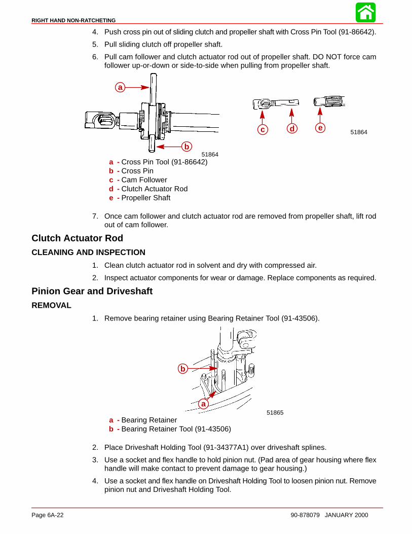
RIGHT HAND NON-RATCHETING
Page 6A-22 90-878079 JANUARY 2000
4. Push cross pin out of sliding clutch and propeller shaft with Cross Pin Tool (91-86642).
5. Pull sliding clutch off propeller shaft.
6. Pull cam follower and clutch actuator rod out of propeller shaft. DO NOT force camfollower up-or-down or side-to-side when pulling from propeller shaft.
a b c 51864
a
b51864
c d e
a
b
a - Cross Pin Tool (91-86642)b - Cross Pinc - Cam Followerd - Clutch Actuator Rode - Propeller Shaft
7. Once cam follower and clutch actuator rod are removed from propeller shaft, lift rodout of cam follower.
Clutch Actuator RodCLEANING AND INSPECTION
1. Clean clutch actuator rod in solvent and dry with compressed air.
2. Inspect actuator components for wear or damage. Replace components as required.
Pinion Gear and DriveshaftREMOVAL
1. Remove bearing retainer using Bearing Retainer Tool (91-43506).
51865a
b
a
b
a - Bearing Retainerb - Bearing Retainer Tool (91-43506)
2. Place Driveshaft Holding Tool (91-34377A1) over driveshaft splines.
3. Use a socket and flex handle to hold pinion nut. (Pad area of gear housing where flexhandle will make contact to prevent damage to gear housing.)
4. Use a socket and flex handle on Driveshaft Holding Tool to loosen pinion nut. Removepinion nut and Driveshaft Holding Tool.
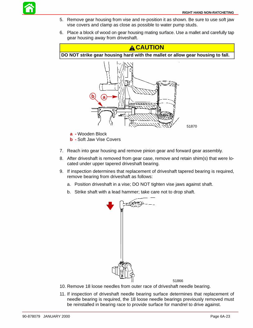
RIGHT HAND NON-RATCHETING
90-878079 JANUARY 2000 Page 6A-23
5. Remove gear housing from vise and re-position it as shown. Be sure to use soft jawvise covers and clamp as close as possible to water pump studs.
6. Place a block of wood on gear housing mating surface. Use a mallet and carefully tapgear housing away from driveshaft.
CAUTIONDO NOT strike gear housing hard with the mallet or allow gear housing to fall.
b a
51870
ab
a - Wooden Blockb - Soft Jaw Vise Covers
7. Reach into gear housing and remove pinion gear and forward gear assembly.
8. After driveshaft is removed from gear case, remove and retain shim(s) that were lo-cated under upper tapered driveshaft bearing.
9. If inspection determines that replacement of driveshaft tapered bearing is required,remove bearing from driveshaft as follows:
a. Position driveshaft in a vise; DO NOT tighten vise jaws against shaft.
b. Strike shaft with a lead hammer; take care not to drop shaft.
51866
10. Remove 18 loose needles from outer race of driveshaft needle bearing.
11. If inspection of driveshaft needle bearing surface determines that replacement ofneedle bearing is required, the 18 loose needle bearings previously removed mustbe reinstalled in bearing race to provide surface for mandrel to drive against.
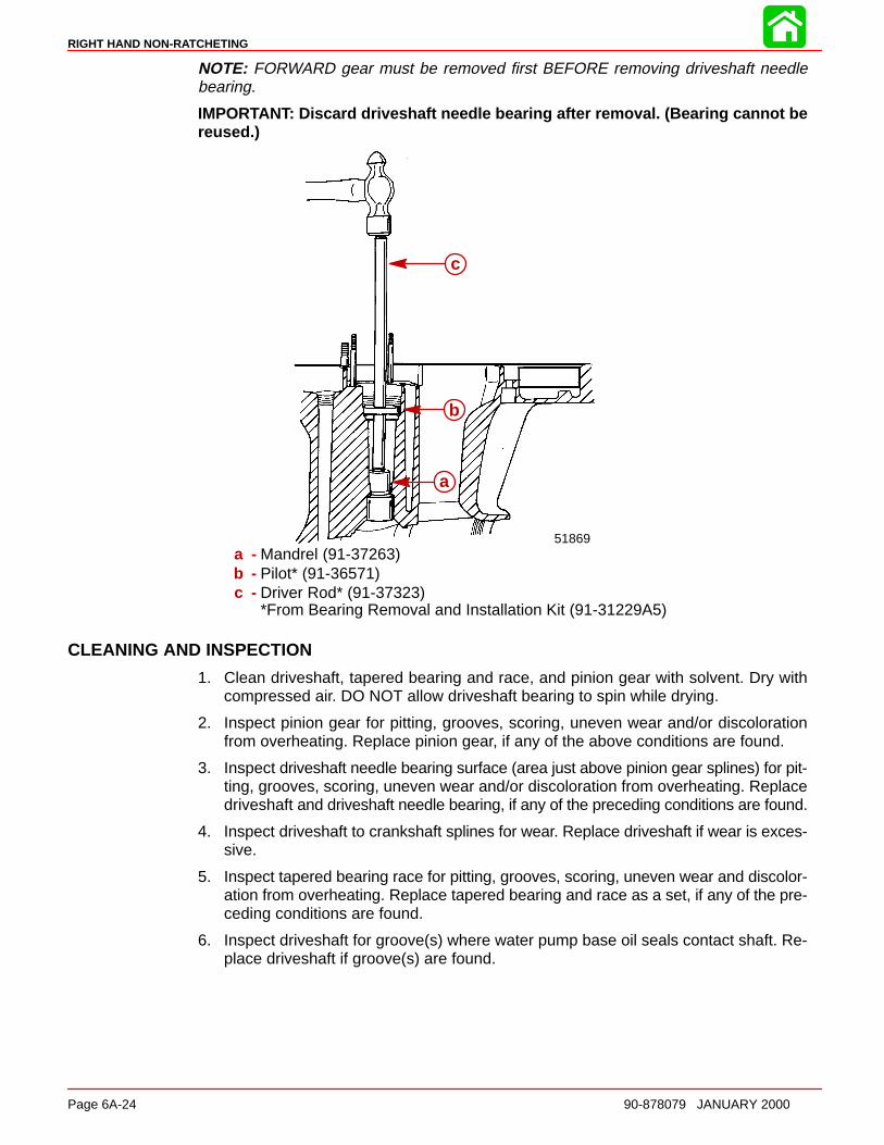
RIGHT HAND NON-RATCHETING
Page 6A-24 90-878079 JANUARY 2000
NOTE: FORWARD gear must be removed first BEFORE removing driveshaft needlebearing.
IMPORTANT: Discard driveshaft needle bearing after removal. (Bearing cannot bereused.)
c
b
a
51869
a
b
c
a - Mandrel (91-37263)b - Pilot* (91-36571)c - Driver Rod* (91-37323)
*From Bearing Removal and Installation Kit (91-31229A5)
CLEANING AND INSPECTION
1. Clean driveshaft, tapered bearing and race, and pinion gear with solvent. Dry withcompressed air. DO NOT allow driveshaft bearing to spin while drying.
2. Inspect pinion gear for pitting, grooves, scoring, uneven wear and/or discolorationfrom overheating. Replace pinion gear, if any of the above conditions are found.
3. Inspect driveshaft needle bearing surface (area just above pinion gear splines) for pit-ting, grooves, scoring, uneven wear and/or discoloration from overheating. Replacedriveshaft and driveshaft needle bearing, if any of the preceding conditions are found.
4. Inspect driveshaft to crankshaft splines for wear. Replace driveshaft if wear is exces-sive.
5. Inspect tapered bearing race for pitting, grooves, scoring, uneven wear and discolor-ation from overheating. Replace tapered bearing and race as a set, if any of the pre-ceding conditions are found.
6. Inspect driveshaft for groove(s) where water pump base oil seals contact shaft. Re-place driveshaft if groove(s) are found.
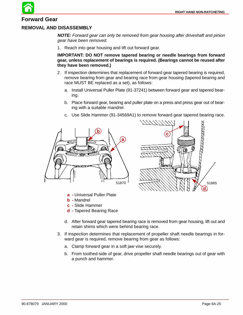
RIGHT HAND NON-RATCHETING
90-878079 JANUARY 2000 Page 6A-25
Forward GearREMOVAL AND DISASSEMB LY
NOTE: Forward gear can only be removed from gear housing after driveshaft and piniongear have been removed.
1. Reach into gear housing and lift out forward gear.
IMPORTANT: DO NOT remove tapered bearing or needle bearings from forwardgear, unless replacement of bearings is required. (Bearings cannot be reused afterthey have been removed.)
2. If inspection determines that replacement of forward gear tapered bearing is required,remove bearing from gear and bearing race from gear housing (tapered bearing andrace MUST BE replaced as a set), as follows:
a. Install Universal Puller Plate (91-37241) between forward gear and tapered bear-ing.
b. Place forward gear, bearing and puller plate on a press and press gear out of bear-ing with a suitable mandrel.
c. Use Slide Hammer (91-34569A1) to remove forward gear tapered bearing race.
a
b51865
b
a
51870
c
d
a
b
a - Universal Puller Plateb - Mandrelc - Slide Hammerd - Tapered Bearing Race
d. After forward gear tapered bearing race is removed from gear housing, lift out andretain shims which were behind bearing race.
3. If inspection determines that replacement of propeller shaft needle bearings in for-ward gear is required, remove bearing from gear as follows:
a. Clamp forward gear in a soft jaw vise securely.
b. From toothed-side of gear, drive propeller shaft needle bearings out of gear witha punch and hammer.
RIGHT HAND NON-RATCHETING
Page 6A-26 90-878079 JANUARY 2000
CLEANING AND INSPECTION
CAUTIONDO NOT spin bearings dry with compressed ai r, as this could cause bearing toscore.
1. Clean forward gear and bearings with solvent and dry with compressed air.
2. Inspect gear teeth for pitting, grooves, scoring, uneven wear and for discoloration(from overheating). Replace gear if any of these conditions are found.
3. Check clutch jaws on forward gear for damage. Replace forward gear if damage isfound.
4. Inspect tapered bearing race for pitting, grooves, scoring, uneven wear and discolor-ation (from overheating). Replace tapered bearing (on forward gear) and race if anyof these conditions are found. (Always replace tapered bearing and race as a set.)
5. To determine condition of propeller shaft needle bearings (in forward gear), inspectpropeller shaft forward gear needle bearing surface as outlined in “Propeller Shaft In-spection.”
Gear HousingCLEANING AND INSPECTION
1. Clean gear housing with solvent and dry with compressed air.
2. Check gear housing carefully for impact damage.
3. Check for loose fitting bearing cups and needle bearings.
4. Inspect bearing carrier cover nut retainer threads in gear housing for corrosion dam-age and/or stripped threads.
Reassembly and Installation Standard Rotation
Driveshaft Needle BearingREASSEMBLY/INSTALL ATION
CAUTIONIf driveshaft needle bearing failure has occurred, and original bearing race hasturned in the gear housing, gear housing MUST be replaced. Loose fitting needlebearing will move out of position and cause repeated failures.
1. Apply a thin coat of Quicksilver 2-4-Cw/Teflon Lubricant to driveshaft needle bearingbore in gear housing.
2. By way of propeller shaft cavity, place needle bearing in driveshaft bore with num-bered side of bearing facing up driveshaft bore.
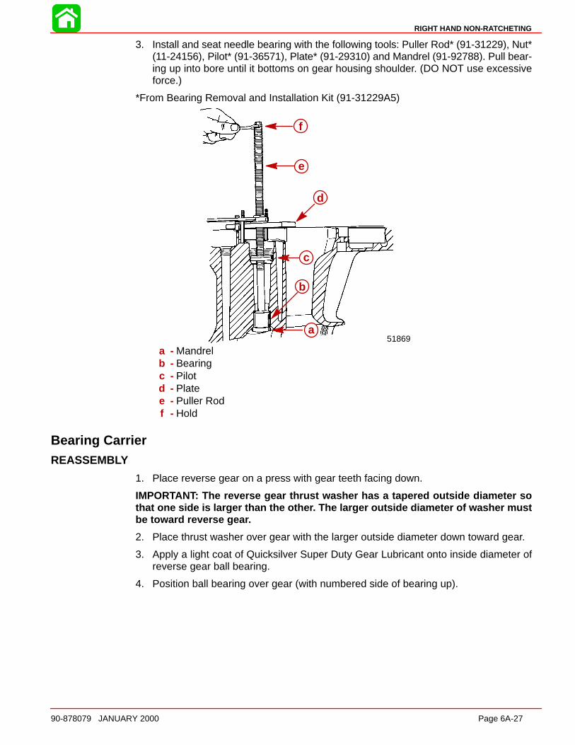
RIGHT HAND NON-RATCHETING
90-878079 JANUARY 2000 Page 6A-27
3. Install and seat needle bearing with the following tools: Puller Rod* (91-31229), Nut*(11-24156), Pilot* (91-36571), Plate* (91-29310) and Mandrel (91-92788). Pull bear-ing up into bore until it bottoms on gear housing shoulder. (DO NOT use excessiveforce.)
*From Bearing Removal and Installation Kit (91-31229A5)
f
e
d
c
b
a51869
a
b
c
d
e
f
a - Mandrelb - Bearingc - Pilotd - Platee - Puller Rodf - Hold
Bearing CarrierREASSEMBLY
1. Place reverse gear on a press with gear teeth facing down.
IMPORTANT: The reverse gear thrust washer has a tapered outside diameter sothat one side is larger than the othe r. The larger outside diameter of washer mustbe toward reverse gea r.
2. Place thrust washer over gear with the larger outside diameter down toward gear.
3. Apply a light coat of Quicksilver Super Duty Gear Lubricant onto inside diameter ofreverse gear ball bearing.
4. Position ball bearing over gear (with numbered side of bearing up).
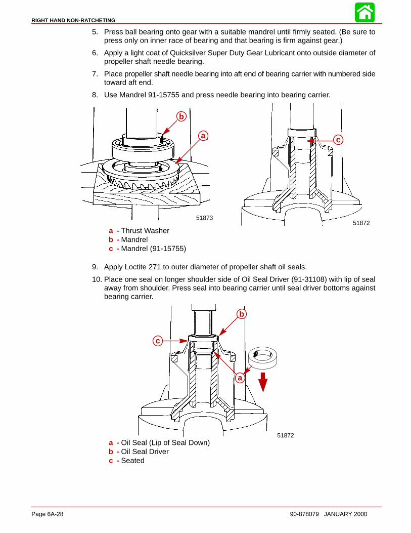
RIGHT HAND NON-RATCHETING
Page 6A-28 90-878079 JANUARY 2000
5. Press ball bearing onto gear with a suitable mandrel until firmly seated. (Be sure topress only on inner race of bearing and that bearing is firm against gear.)
6. Apply a light coat of Quicksilver Super Duty Gear Lubricant onto outside diameter ofpropeller shaft needle bearing.
7. Place propeller shaft needle bearing into aft end of bearing carrier with numbered sidetoward aft end.
8. Use Mandrel 91-15755 and press needle bearing into bearing carrier.
a
51872
b
a
51873
a
b
c
a - Thrust Washerb - Mandrelc - Mandrel (91-15755)
9. Apply Loctite 271 to outer diameter of propeller shaft oil seals.
10. Place one seal on longer shoulder side of Oil Seal Driver (91-31108) with lip of sealaway from shoulder. Press seal into bearing carrier until seal driver bottoms againstbearing carrier.
c
b
a
51872
a
b
c
a - Oil Seal (Lip of Seal Down)b - Oil Seal Driverc - Seated

RIGHT HAND NON-RATCHETING
90-878079 JANUARY 2000 Page 6A-29
11. Place second seal on short shoulder side of seal driver with lip of seal toward shoulder.Press seal into bearing carrier until seal driver bottoms against bearing carrier.
c
b
a
51872
a
b
c
a - Oil Seal (Lip of Seal Up)b - Oil Seal Driverc - Seated
12. Wipe off excess Loctite.
13. Apply a light coat of Quicksilver Super Duty Gear Lubricant onto the outside diameterof reverse gear ball bearing.
14. Place bearing carrier over reverse gear and bearing assembly. Press bearing carrieronto bearing.
a
51870
a
b
a - Mandrelb - Seated
15. Place O-ring over bearing carrier and position it between bearing carrier and thrustwasher.
16. Lubricate oil seals and O-ring with Quicksilver 2-4-C w/Teflon Marine Lubricant.
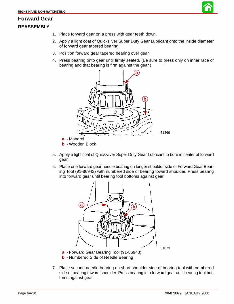
RIGHT HAND NON-RATCHETING
Page 6A-30 90-878079 JANUARY 2000
Forward GearREASSEMBLY
1. Place forward gear on a press with gear teeth down.
2. Apply a light coat of Quicksilver Super Duty Gear Lubricant onto the inside diameterof forward gear tapered bearing.
3. Position forward gear tapered bearing over gear.
4. Press bearing onto gear until firmly seated. (Be sure to press only on inner race ofbearing and that bearing is firm against the gear.)
a
b
51869
a
b
a - Mandrelb - Wooden Block
5. Apply a light coat of Quicksilver Super Duty Gear Lubricant to bore in center of forwardgear.
6. Place one forward gear needle bearing on longer shoulder side of Forward Gear Bear-ing Tool (91-86943) with numbered side of bearing toward shoulder. Press bearinginto forward gear until bearing tool bottoms against gear.
a b
51873
a b
a - Forward Gear Bearing Tool (91-86943)b - Numbered Side of Needle Bearing
7. Place second needle bearing on short shoulder side of bearing tool with numberedside of bearing toward shoulder. Press bearing into forward gear until bearing tool bot-toms against gear.
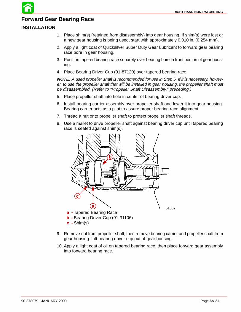
RIGHT HAND NON-RATCHETING
90-878079 JANUARY 2000 Page 6A-31
Forward Gear Bearing RaceINSTALL ATION
1. Place shim(s) (retained from disassembly) into gear housing. If shim(s) were lost ora new gear housing is being used, start with approximately 0.010 in. (0.254 mm).
2. Apply a light coat of Quicksilver Super Duty Gear Lubricant to forward gear bearingrace bore in gear housing.
3. Position tapered bearing race squarely over bearing bore in front portion of gear hous-ing.
4. Place Bearing Driver Cup (91-87120) over tapered bearing race.
NOTE: A used propeller shaft is recommended for use in Step 5. If it is necessary, howev-er, to use the propeller shaft that will be installed in gear housing, the propeller shaft mustbe disassembled. (Refer to “Propeller Shaft Disassembly,” preceding.)
5. Place propeller shaft into hole in center of bearing driver cup.
6. Install bearing carrier assembly over propeller shaft and lower it into gear housing.Bearing carrier acts as a pilot to assure proper bearing race alignment.
7. Thread a nut onto propeller shaft to protect propeller shaft threads.
8. Use a mallet to drive propeller shaft against bearing driver cup until tapered bearingrace is seated against shim(s).
a
c
b
51867a
b
c
a - Tapered Bearing Raceb - Bearing Driver Cup (91-31106)c - Shim(s)
9. Remove nut from propeller shaft, then remove bearing carrier and propeller shaft fromgear housing. Lift bearing driver cup out of gear housing.
10. Apply a light coat of oil on tapered bearing race, then place forward gear assemblyinto forward bearing race.
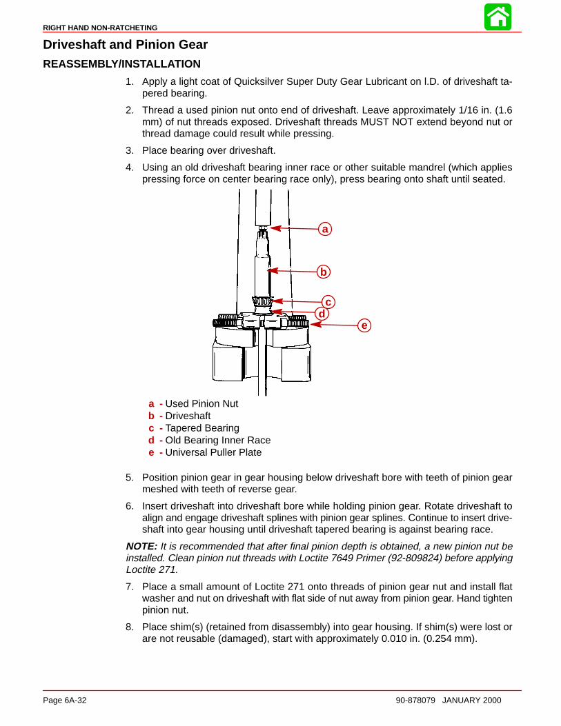
RIGHT HAND NON-RATCHETING
Page 6A-32 90-878079 JANUARY 2000
Driveshaft and Pinion GearREASSEMBLY/INSTALL ATION
1. Apply a light coat of Quicksilver Super Duty Gear Lubricant on l.D. of driveshaft ta-pered bearing.
2. Thread a used pinion nut onto end of driveshaft. Leave approximately 1/16 in. (1.6mm) of nut threads exposed. Driveshaft threads MUST NOT extend beyond nut orthread damage could result while pressing.
3. Place bearing over driveshaft.
4. Using an old driveshaft bearing inner race or other suitable mandrel (which appliespressing force on center bearing race only), press bearing onto shaft until seated.
a
b
cd
e
a - Used Pinion Nutb - Driveshaftc - Tapered Bearingd - Old Bearing Inner Racee - Universal Puller Plate
5. Position pinion gear in gear housing below driveshaft bore with teeth of pinion gearmeshed with teeth of reverse gear.
6. Insert driveshaft into driveshaft bore while holding pinion gear. Rotate driveshaft toalign and engage driveshaft splines with pinion gear splines. Continue to insert drive-shaft into gear housing until driveshaft tapered bearing is against bearing race.
NOTE: It is recommended that after final pinion depth is obtained, a new pinion nut beinstalled. Clean pinion nut threads with Loctite 7649 Primer (92-809824) before applyingLoctite 271.
7. Place a small amount of Loctite 271 onto threads of pinion gear nut and install flatwasher and nut on driveshaft with flat side of nut away from pinion gear. Hand tightenpinion nut.
8. Place shim(s) (retained from disassembly) into gear housing. If shim(s) were lost orare not reusable (damaged), start with approximately 0.010 in. (0.254 mm).
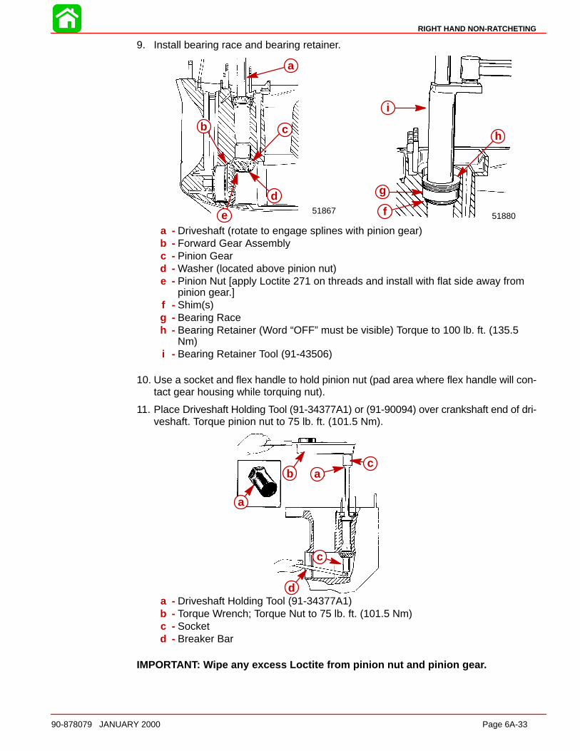
RIGHT HAND NON-RATCHETING
90-878079 JANUARY 2000 Page 6A-33
9. Install bearing race and bearing retainer.
d
b
a
c
51880
a
c
d
e
b
51867 f
g
h
i
a
b c
d
ea - Driveshaft (rotate to engage splines with pinion gear)b - Forward Gear Assemblyc - Pinion Geard - Washer (located above pinion nut)e - Pinion Nut [apply Loctite 271 on threads and install with flat side away from
pinion gear.]f - Shim(s)g - Bearing Raceh - Bearing Retainer (Word “OFF” must be visible) Torque to 100 lb. ft. (135.5
Nm)i - Bearing Retainer Tool (91-43506)
10. Use a socket and flex handle to hold pinion nut (pad area where flex handle will con-tact gear housing while torquing nut).
11. Place Driveshaft Holding Tool (91-34377A1) or (91-90094) over crankshaft end of dri-veshaft. Torque pinion nut to 75 lb. ft. (101.5 Nm).
a
b ac
c
d
a
b ac
c
da - Driveshaft Holding Tool (91-34377A1)b - Torque Wrench; Torque Nut to 75 lb. ft. (101.5 Nm)c - Socketd - Breaker Bar
IMPORTANT: Wipe any excess Loctite from pinion nut and pinion gea r.

RIGHT HAND NON-RATCHETING
Page 6A-34 90-878079 JANUARY 2000
Pinion Gear Depth/Forward Gear Backlash/Reverse Gear BacklashDETERMINING PINION GEAR DEPTH
NOTE: Read entire procedure before attempting any change in shim thickness.
IMPORTANT: Forward gear assembly must be installed in gear housing whenchecking pinion gear depth or an inaccurate measurement will be obtained.
1. Clean the gear housing bearing carrier shoulder.
2. Install Bearing Preload Tool (91-14311A1) over driveshaft in sequence shown.
NOTE: Bearing Preload Tool (91-44307A1) may also be used. Follow instructions pro-vided with tool for proper installation.
h
g g
e
f
d
c
b
aa
b
c
d
e
f
g
h
g
a - Adaptorb - Bearingc - Washerd - Springe - Nut; thread nut all the way onto boltf - Boltg - Set Screwh - Sleeve; Holes in sleeve must align with set screw
3. Align adaptor on driveshaft bearing pocket ledge.
4. With tool installed over driveshaft, tighten both set screws securely, making certainto align sleeve holes to allow set screws to pass thru.
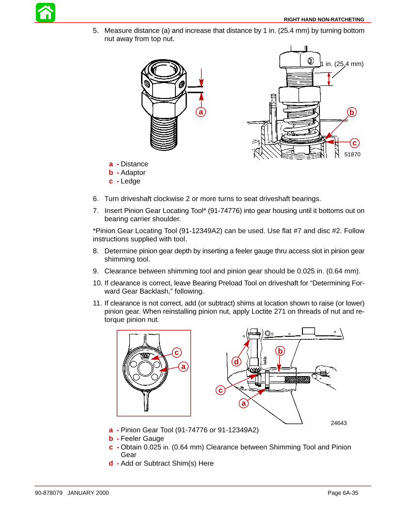
RIGHT HAND NON-RATCHETING
90-878079 JANUARY 2000 Page 6A-35
5. Measure distance (a) and increase that distance by 1 in. (25.4 mm) by turning bottomnut away from top nut.
1 in. (25.4 mm)
a
b51870
a b
c
a
a - Distanceb - Adaptorc - Ledge
6. Turn driveshaft clockwise 2 or more turns to seat driveshaft bearings.
7. Insert Pinion Gear Locating Tool* (91-74776) into gear housing until it bottoms out onbearing carrier shoulder.
*Pinion Gear Locating Tool (91-12349A2) can be used. Use flat #7 and disc #2. Followinstructions supplied with tool.
8. Determine pinion gear depth by inserting a feeler gauge thru access slot in pinion gearshimming tool.
9. Clearance between shimming tool and pinion gear should be 0.025 in. (0.64 mm).
10. If clearance is correct, leave Bearing Preload Tool on driveshaft for “Determining For-ward Gear Backlash,” following.
11. If clearance is not correct, add (or subtract) shims at location shown to raise (or lower)pinion gear. When reinstalling pinion nut, apply Loctite 271 on threads of nut and re-torque pinion nut.
c
ad
c
a
b
24643
a
b
a
c
c
d
a - Pinion Gear Tool (91-74776 or 91-12349A2)b - Feeler Gaugec - Obtain 0.025 in. (0.64 mm) Clearance between Shimming Tool and Pinion
Geard - Add or Subtract Shim(s) Here
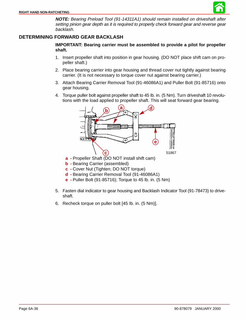
RIGHT HAND NON-RATCHETING
Page 6A-36 90-878079 JANUARY 2000
NOTE: Bearing Preload Tool (91-14311A1) should remain installed on driveshaft aftersetting pinion gear depth as it is required to properly check forward gear and reverse gearbacklash.
DETERMINING FORWARD GEAR BACKLASH
IMPORTANT: Bearing carrier must be assembled to provide a pilot for propellershaft.
1. Insert propeller shaft into position in gear housing. (DO NOT place shift cam on pro-peller shaft.)
2. Place bearing carrier into gear housing and thread cover nut tightly against bearingcarrier. (It is not necessary to torque cover nut against bearing carrier.)
3. Attach Bearing Carrier Removal Tool (91-46086A1) and Puller Bolt (91-85716) ontogear housing.
4. Torque puller bolt against propeller shaft to 45 Ib. in. (5 Nm). Turn driveshaft 10 revolu-tions with the load applied to propeller shaft. This will seat forward gear bearing.
ba d
e
c 51867
ab
c
d
e
a - Propeller Shaft (DO NOT install shift cam)b - Bearing Carrier (assembled)c - Cover Nut (Tighten; DO NOT torque)d - Bearing Carrier Removal Tool (91-46086A1)e - Puller Bolt (91-85716); Torque to 45 lb. in. (5 Nm)
5. Fasten dial indicator to gear housing and Backlash Indicator Tool (91-78473) to drive-shaft.
6. Recheck torque on puller bolt [45 Ib. in. (5 Nm)].
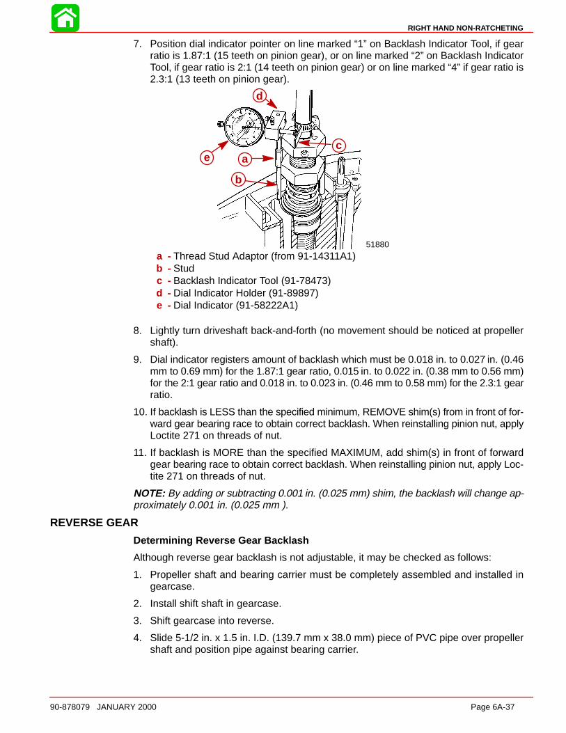
RIGHT HAND NON-RATCHETING
90-878079 JANUARY 2000 Page 6A-37
7. Position dial indicator pointer on line marked “1” on Backlash Indicator Tool, if gearratio is 1.87:1 (15 teeth on pinion gear), or on line marked “2” on Backlash IndicatorTool, if gear ratio is 2:1 (14 teeth on pinion gear) or on line marked “4” if gear ratio is2.3:1 (13 teeth on pinion gear).
51880
d
e a
b
ca
b
c
d
e
a - Thread Stud Adaptor (from 91-14311A1)b - Studc - Backlash Indicator Tool (91-78473)d - Dial Indicator Holder (91-89897)e - Dial Indicator (91-58222A1)
8. Lightly turn driveshaft back-and-forth (no movement should be noticed at propellershaft).
9. Dial indicator registers amount of backlash which must be 0.018 in. to 0.027 in. (0.46mm to 0.69 mm) for the 1.87:1 gear ratio, 0.015 in. to 0.022 in. (0.38 mm to 0.56 mm)for the 2:1 gear ratio and 0.018 in. to 0.023 in. (0.46 mm to 0.58 mm) for the 2.3:1 gearratio.
10. If backlash is LESS than the specified minimum, REMOVE shim(s) from in front of for-ward gear bearing race to obtain correct backlash. When reinstalling pinion nut, applyLoctite 271 on threads of nut.
11. If backlash is MORE than the specified MAXIMUM, add shim(s) in front of forwardgear bearing race to obtain correct backlash. When reinstalling pinion nut, apply Loc-tite 271 on threads of nut.
NOTE: By adding or subtracting 0.001 in. (0.025 mm) shim, the backlash will change ap-proximately 0.001 in. (0.025 mm ).
REVERSE GEAR
Determining Reverse Gear Backlash
Although reverse gear backlash is not adjustable, it may be checked as follows:
1. Propeller shaft and bearing carrier must be completely assembled and installed ingearcase.
2. Install shift shaft in gearcase.
3. Shift gearcase into reverse.
4. Slide 5-1/2 in. x 1.5 in. I.D. (139.7 mm x 38.0 mm) piece of PVC pipe over propellershaft and position pipe against bearing carrier.
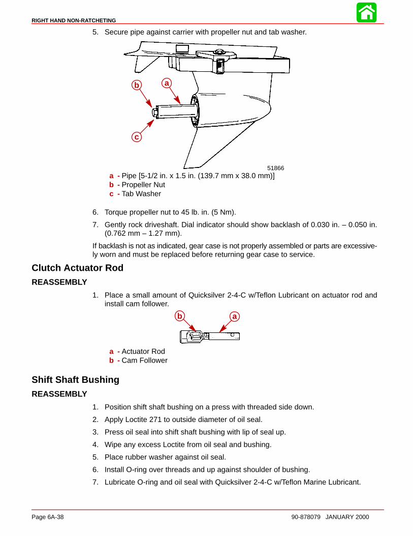
RIGHT HAND NON-RATCHETING
Page 6A-38 90-878079 JANUARY 2000
5. Secure pipe against carrier with propeller nut and tab washer.
ab
c
51866
ab
c
a - Pipe [5-1/2 in. x 1.5 in. (139.7 mm x 38.0 mm)]b - Propeller Nutc - Tab Washer
6. Torque propeller nut to 45 lb. in. (5 Nm).
7. Gently rock driveshaft. Dial indicator should show backlash of 0.030 in. – 0.050 in.(0.762 mm – 1.27 mm).
If backlash is not as indicated, gear case is not properly assembled or parts are excessive-ly worn and must be replaced before returning gear case to service.
Clutch Actuator RodREASSEMBLY
1. Place a small amount of Quicksilver 2-4-C w/Teflon Lubricant on actuator rod andinstall cam follower.
b aab
a - Actuator Rodb - Cam Follower
Shift Shaft BushingREASSEMBLY
1. Position shift shaft bushing on a press with threaded side down.
2. Apply Loctite 271 to outside diameter of oil seal.
3. Press oil seal into shift shaft bushing with lip of seal up.
4. Wipe any excess Loctite from oil seal and bushing.
5. Place rubber washer against oil seal.
6. Install O-ring over threads and up against shoulder of bushing.
7. Lubricate O-ring and oil seal with Quicksilver 2-4-C w/Teflon Marine Lubricant.

RIGHT HAND NON-RATCHETING
90-878079 JANUARY 2000 Page 6A-39
Propeller ShaftREASSEMBLY/INSTALL ATION
1. Insert clutch actuator rod assembly into end of propeller shaft. Align cross pin slot inactuator rod with cross pin slot in propeller shaft.
2. On PRODUCTION MODEL GEAR CASES, position sliding clutch onto propeller shaftwith GROOVED RINGS (ON SLIDING CLUTCH) TOWARD PROPELLER END OFPROPELLER SHAFT. Cross pin hole and detent holes (in sliding clutch) must line upwith cross pin slot and detent notches on propeller shaft.
d
cb
ef
51864a
a 51864bc
de
f
gh
a b
a - Cam Followerb - Propeller Shaftc - Sliding Clutchd - Grooved Ringse - Cross Pin Holef - Detent Hole (Behind Finger and Thumb)g - Detent Notch (One on Each Side)h - Cross Pin Slot
3. Insert cross pin thru sliding clutch, propeller shaft and actuator rod, forcing cross pintool out.
4. Apply a small amount of 2-4-C w/Teflon Marine Lubricant on detent pin. Position a det-ent pin in detent pin hole of sliding clutch with rounded end of pin toward propellershaft.
ab
c 51864
a
51864
bc
d
a
a - Cross Pinb - Detent Pinc - Cross Pind - Sliding Clutch

RIGHT HAND NON-RATCHETING
Page 6A-40 90-878079 JANUARY 2000
5. Install cross pin retaining spring onto sliding clutch as follows:
IMPORTANT: DO NOT over-stretch retaining spring when installing onto slidingclutch.
6. Spirally wrap spring into groove on sliding clutch.
7. Place gear housing in a soft jaw vise with the driveshaft in a vertical position.
8. Coat cam pocket of cam follower with 2-4-C w/Teflon Marine Lubricant.
9. Place shift cam into cam pocket of cam follower with numbered side of cam facing up.
10. With shift cam positioned as shown, insert propeller shaft thru forward gear until shaftbottoms out.
ab
51864
de
b
55095
ab
c
a - Cam Pocketb - Cam Followerc - Shift Camd - Shift Cam (Position as Shown)e - Gear Housing

RIGHT HAND NON-RATCHETING
90-878079 JANUARY 2000 Page 6A-41
CAUTIONUntil bearing carrier is installed into gear housing, extreme care MUST BE takennot to apply any side force on propeller shaft. Side force on propeller shaft maybreak the neck of the clutch actuator rod.
11. Insert shift shaft down shift shaft hole (of gear housing) and thru shift cam and camfollower. (It may be necessary to rotate shift shaft back-and-forth slightly for it to entershift cam.)
12. Apply a light coat of Quicksilver 2-4-C w/Teflon Marine Lubricant to threads of shiftshaft bushing. (Thread bushing into position, but do not tighten down at this time)
a
b
51867
a
b
a - Shift Shaft Bushingb - Shift Shaft
13. Lubricate O-ring on bearing carrier with Quicksilver 2-4-C w/Teflon Marine Lubricant.
14. Apply a light coat of Quicksilver 2-4-C w/Teflon Marine Lubricant to outside diameterof bearing carrier (where carrier contacts gear housing).
NOTE: When performing Step 15, rotate driveshaft clockwise (viewed from top) to meshpinion gear with reverse gear.
15. Position bearing carrier over propeller shaft and slide it into gear housing. (Be sureto align bearing carrier keyway with gear housing keyway.)
16. Push bearing carrier in as far as possible by hand, then install bearing carrier key.
17. Place tab washer against bearing carrier.
18. Apply Quicksilver 2-4-C w/Teflon Marine Lubricant to threads of cover nut and installcover nut in gear housing (verify that the word “OFF” and arrow are visible).

RIGHT HAND NON-RATCHETING
Page 6A-42 90-878079 JANUARY 2000
NOTE: Before torquing bearing carrier cover nut, gear case should either be mounted ina stand specifically designed for holding gear cases or bolted to a driveshaft housing toavoid possible damage to the gear case.
19. Start cover nut a few turns by hand, then using Cover Nut Tool (91-61069) and torquewrench, torque cover nut to 210 Ib. ft. (285 Nm).
bc
a
51871
ab
c
a - O-ringb - Cover Nut Toolc - Torque Wrench
20. Bend one lock tab of tab washer into cover nut (only one will align).
21. Bend remaining tabs of tab washer toward front of gear housing.
22. Use Shift Shaft Bushing Tool (91-31107) and torque shift shaft bushing to 30 Ib. ft.(41 Nm).
Water PumpREASSEMBLY/INSTALL ATION
1. Install oil seals into water pump base, as follows:
a. Place water pump base on a press.
b. Just before installing each seal apply Loctite 271 on outside diameter of oil seal.
c. With a suitable mandrel, press the smaller diameter oil seal into pump base withlip of oil seal toward impeller side of base.
d. With a suitable mandrel, press the larger diameter oil seal into pump base with lipof oil seal toward gear housing side of base.
e. Wipe any excess Loctite from oil seals and water pump base.
2. Install O-ring into O-ring groove of water pump base. Lubricate O-ring and oil sealswith 2-4-C w/Teflon Marine Lubricant (92-90018A12).
a
bc
51869
a
bc
a - Mandrelb - Oil Seal (Smaller OD)
c - O-ring Groove
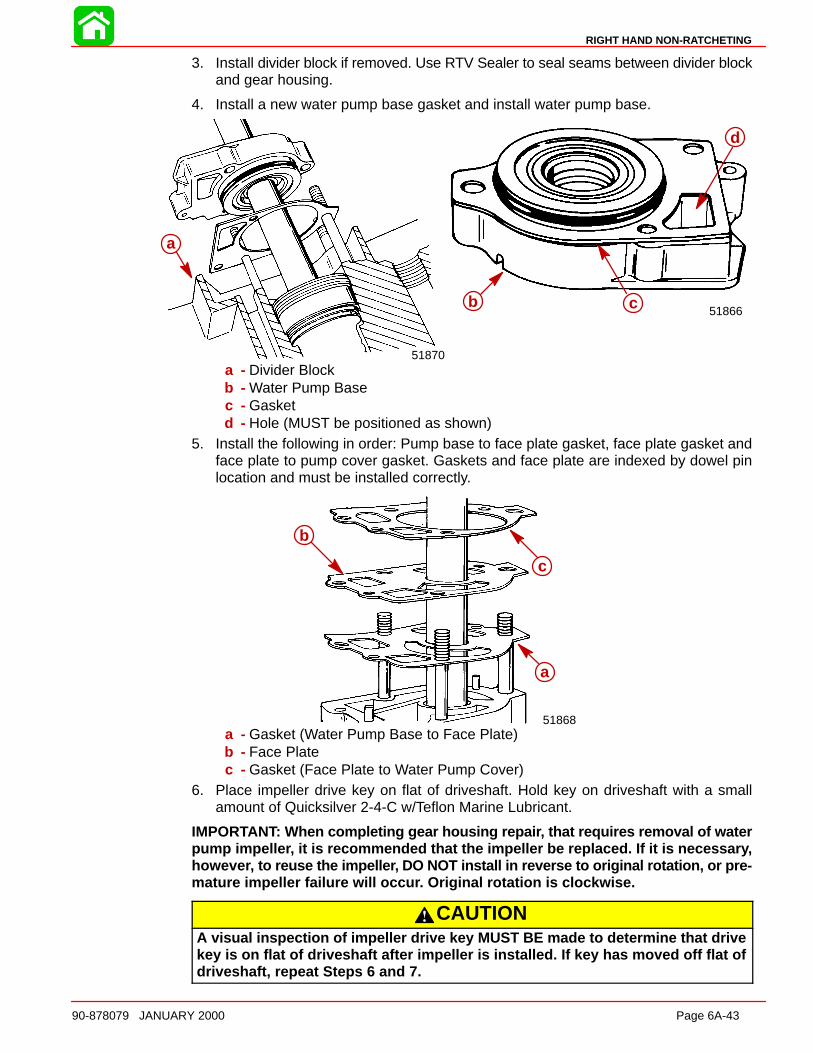
RIGHT HAND NON-RATCHETING
90-878079 JANUARY 2000 Page 6A-43
3. Install divider block if removed. Use RTV Sealer to seal seams between divider blockand gear housing.
4. Install a new water pump base gasket and install water pump base.
a b 51866
a
51870
b c
d
a
a - Divider Blockb - Water Pump Basec - Gasketd - Hole (MUST be positioned as shown)
5. Install the following in order: Pump base to face plate gasket, face plate gasket andface plate to pump cover gasket. Gaskets and face plate are indexed by dowel pinlocation and must be installed correctly.
b
c
a
51868
a
b
c
a - Gasket (Water Pump Base to Face Plate)b - Face Platec - Gasket (Face Plate to Water Pump Cover)
6. Place impeller drive key on flat of driveshaft. Hold key on driveshaft with a smallamount of Quicksilver 2-4-C w/Teflon Marine Lubricant.
IMPORTANT: When completing gear housing repai r, that requires removal of waterpump impelle r, it is recommended that the impeller be replaced. If it is necessar y,howeve r, to reuse the impelle r, DO NOT install in reverse to original rotation, or pre-mature impeller failure will occu r. Original rotation is clockwise.
CAUTIONA visual inspection of impeller drive key MUST BE made to determine that drivekey is on flat of driveshaft after impeller is installed. If key has moved off flat ofdriveshaft, repeat Steps 6 and 7.
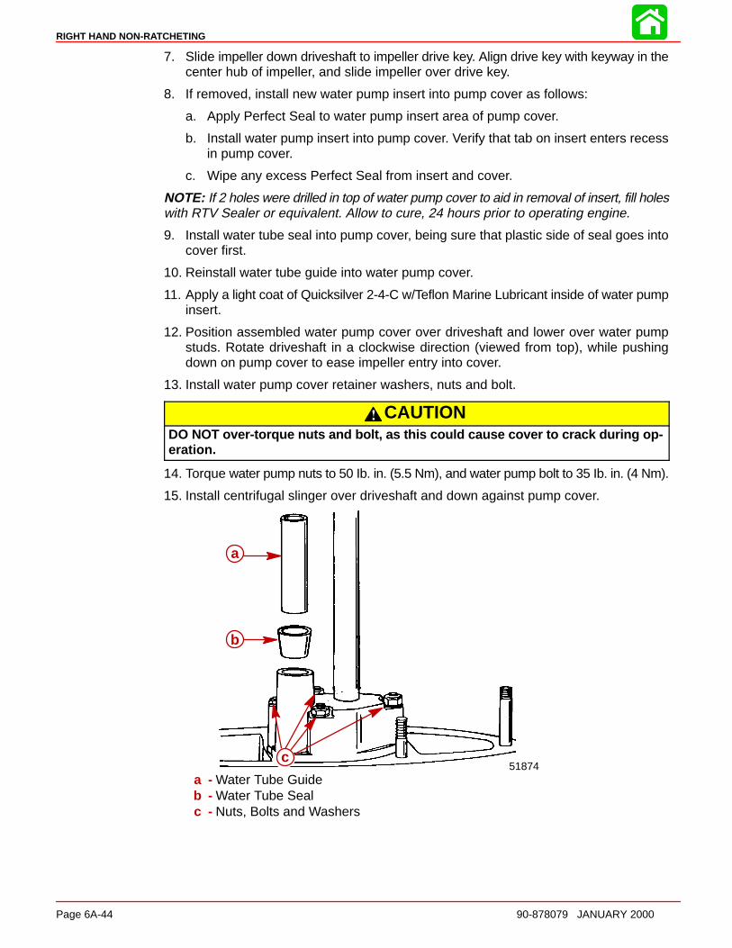
RIGHT HAND NON-RATCHETING
Page 6A-44 90-878079 JANUARY 2000
7. Slide impeller down driveshaft to impeller drive key. Align drive key with keyway in thecenter hub of impeller, and slide impeller over drive key.
8. If removed, install new water pump insert into pump cover as follows:
a. Apply Perfect Seal to water pump insert area of pump cover.
b. Install water pump insert into pump cover. Verify that tab on insert enters recessin pump cover.
c. Wipe any excess Perfect Seal from insert and cover.
NOTE: If 2 holes were drilled in top of water pump cover to aid in removal of insert, fill holeswith RTV Sealer or equivalent. Allow to cure, 24 hours prior to operating engine.
9. Install water tube seal into pump cover, being sure that plastic side of seal goes intocover first.
10. Reinstall water tube guide into water pump cover.
11. Apply a light coat of Quicksilver 2-4-C w/Teflon Marine Lubricant inside of water pumpinsert.
12. Position assembled water pump cover over driveshaft and lower over water pumpstuds. Rotate driveshaft in a clockwise direction (viewed from top), while pushingdown on pump cover to ease impeller entry into cover.
13. Install water pump cover retainer washers, nuts and bolt.
CAUTIONDO NOT over-torque nuts and bolt, as this could cause cover to crack during op-eration.
14. Torque water pump nuts to 50 Ib. in. (5.5 Nm), and water pump bolt to 35 Ib. in. (4 Nm).
15. Install centrifugal slinger over driveshaft and down against pump cover.
b
a
51874c
a
b
c
a - Water Tube Guideb - Water Tube Sealc - Nuts, Bolts and Washers
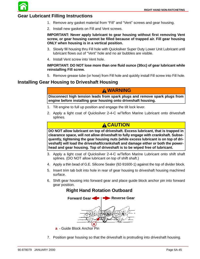
RIGHT HAND NON-RATCHETING
90-878079 JANUARY 2000 Page 6A-45
Gear Lubricant Filling Instructions1. Remove any gasket material from “Fill” and “Vent” screws and gear housing.
2. Install new gaskets on Fill and Vent screws.
IMPORTANT: Never apply lubricant to gear housing without first removin g Ventscre w, or gear housing cannot be filled because of trapped ai r. Fill gear housingONLY when housing is in a vertical position.
3. Slowly fill housing thru Fill hole with Quicksilver Super Duty Lower Unit Lubricant untillubricant flows out of “Vent” hole and no air bubbles are visible.
4. Install Vent screw into Vent hole.
IMPORTANT: DO NOT lose more than one fluid ounce (30cc) of gear lubricant whilereinstalling Fill scre w.
5. Remove grease tube (or hose) from Fill hole and quickly install Fill screw into Fill hole.
Installing Gear Housing to Driveshaft Housing
WARNINGDisconnect high tension leads from spark plugs and remove spark plugs fromengine before installing gear housing onto driveshaft housing.
1. Tilt engine to full up position and engage the tilt lock lever.
2. Apply a light coat of Quicksilver 2-4-C w/Teflon Marine Lubricant onto driveshaftsplines.
CAUTIONDO NOT allow lubricant on top of driveshaft. Excess lubricant, that is trapped inclearanc e space, will not allow driveshaft to fully engage with crankshaft. Subse-quentl y, tightening the gear housing nuts (while excess lubricant is on top of dri-veshaft) will load the driveshaft/crankshaft and damage either or both the power-head and gear housing. Top of driveshaft is to be wiped free of lubricant.
3. Apply a light coat of Quicksilver 2-4-C w/Teflon Marine Lubricant onto shift shaftsplines. (DO NOT allow lubricant on top of shift shaft.)
4. Apply a thin bead of G.E. Silicone Sealer (92-91600-1) against the top of divider block.
5. Insert trim tab bolt into hole in rear of gear housing to driveshaft housing machinedsurface.
6. Shift gear housing into forward gear and place guide block anchor pin into forwardgear position.
Forward Gear Reverse Gear
Right Hand Rotation Outboard
aa - Guide Block Anchor Pin
7. Position gear housing so that the driveshaft is protruding into driveshaft housing.
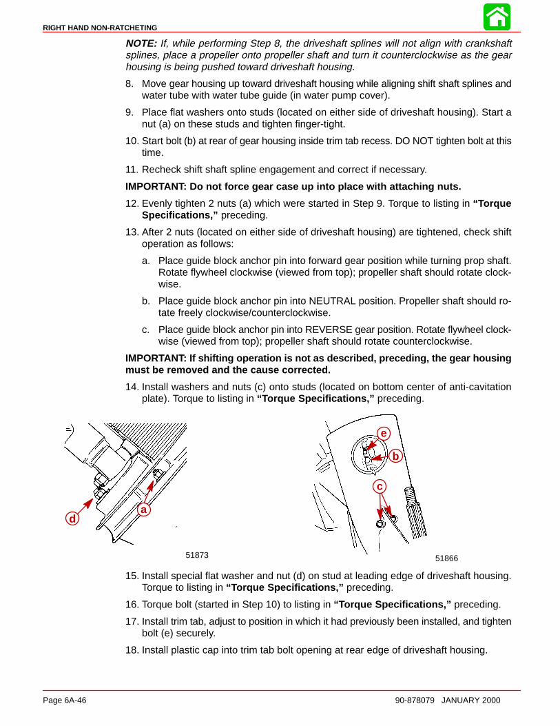
RIGHT HAND NON-RATCHETING
Page 6A-46 90-878079 JANUARY 2000
NOTE: If, while performing Step 8, the driveshaft splines will not align with crankshaftsplines, place a propeller onto propeller shaft and turn it counterclockwise as the gearhousing is being pushed toward driveshaft housing.
8. Move gear housing up toward driveshaft housing while aligning shift shaft splines andwater tube with water tube guide (in water pump cover).
9. Place flat washers onto studs (located on either side of driveshaft housing). Start anut (a) on these studs and tighten finger-tight.
10. Start bolt (b) at rear of gear housing inside trim tab recess. DO NOT tighten bolt at thistime.
11. Recheck shift shaft spline engagement and correct if necessary.
IMPORTANT: Do not force gear case up into place with attaching nuts.
12. Evenly tighten 2 nuts (a) which were started in Step 9. Torque to listing in “ TorqueSpecifications,” preceding.
13. After 2 nuts (located on either side of driveshaft housing) are tightened, check shiftoperation as follows:
a. Place guide block anchor pin into forward gear position while turning prop shaft.Rotate flywheel clockwise (viewed from top); propeller shaft should rotate clock-wise.
b. Place guide block anchor pin into NEUTRAL position. Propeller shaft should ro-tate freely clockwise/counterclockwise.
c. Place guide block anchor pin into REVERSE gear position. Rotate flywheel clock-wise (viewed from top); propeller shaft should rotate counterclockwise.
IMPORTANT: If shifting operation is not as described, preceding, the gear housingmust be removed and the cause corrected.
14. Install washers and nuts (c) onto studs (located on bottom center of anti-cavitationplate). Torque to listing in “ Torque Specifications,” preceding.
51866
c
51873
a
b
d
e
15. Install special flat washer and nut (d) on stud at leading edge of driveshaft housing.Torque to listing in “ Torque Specifications,” preceding.
16. Torque bolt (started in Step 10) to listing in “ Torque Specifications,” preceding.
17. Install trim tab, adjust to position in which it had previously been installed, and tightenbolt (e) securely.
18. Install plastic cap into trim tab bolt opening at rear edge of driveshaft housing.
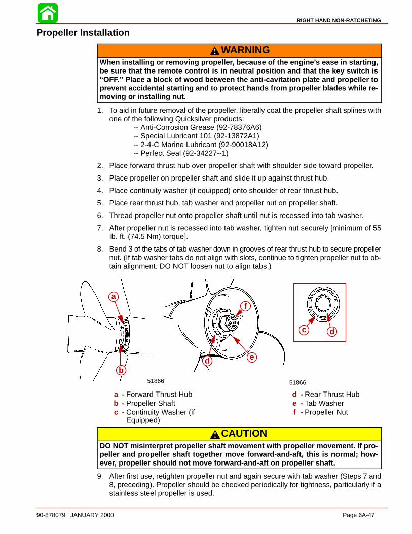
RIGHT HAND NON-RATCHETING
90-878079 JANUARY 2000 Page 6A-47
Propeller Installation
WARNINGWhen installing or removing propelle r, because of the engine ’s ease in starting,be sure that the remote control is in neutral position and that the key switch is“OF F.” Place a block of wood between the anti-cavitation plate and propeller toprevent accidental starting and to protect hands from propeller blades while re-moving or installing nut.
1. To aid in future removal of the propeller, liberally coat the propeller shaft splines withone of the following Quicksilver products:
-- Anti-Corrosion Grease (92-78376A6)-- Special Lubricant 101 (92-13872A1)-- 2-4-C Marine Lubricant (92-90018A12)-- Perfect Seal (92-34227--1)
2. Place forward thrust hub over propeller shaft with shoulder side toward propeller.
3. Place propeller on propeller shaft and slide it up against thrust hub.
4. Place continuity washer (if equipped) onto shoulder of rear thrust hub.
5. Place rear thrust hub, tab washer and propeller nut on propeller shaft.
6. Thread propeller nut onto propeller shaft until nut is recessed into tab washer.
7. After propeller nut is recessed into tab washer, tighten nut securely [minimum of 55Ib. ft. (74.5 Nm) torque].
8. Bend 3 of the tabs of tab washer down in grooves of rear thrust hub to secure propellernut. (If tab washer tabs do not align with slots, continue to tighten propeller nut to ob-tain alignment. DO NOT loosen nut to align tabs.)
a
51866
a
51866
c d
e
f
db
a - Forward Thrust Hubb - Propeller Shaftc - Continuity Washer (if
Equipped)
d - Rear Thrust Hube - Tab Washerf - Propeller Nut
CAUTIONDO NOT misinterpret propeller shaft movement with propeller movement. If pro-peller and propeller shaft together move forward-and-aft, this is normal; how-ever, propeller should not move forward-and-aft on propeller shaft.
9. After first use, retighten propeller nut and again secure with tab washer (Steps 7 and8, preceding). Propeller should be checked periodically for tightness, particularly if astainless steel propeller is used.
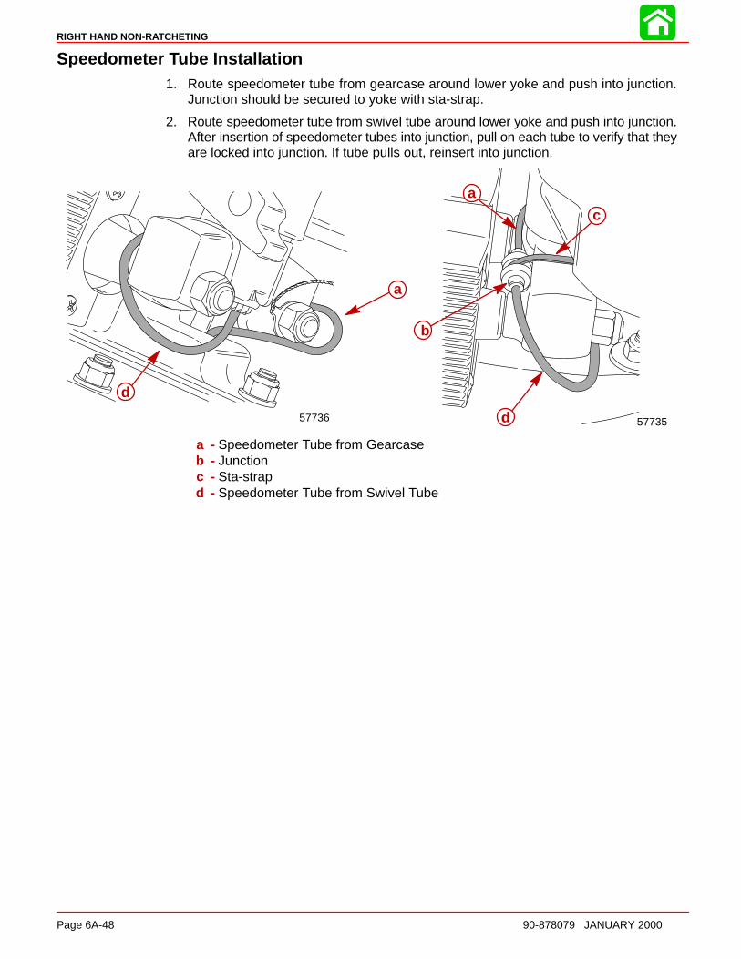
RIGHT HAND NON-RATCHETING
Page 6A-48 90-878079 JANUARY 2000
Speedometer Tube Installation1. Route speedometer tube from gearcase around lower yoke and push into junction.
Junction should be secured to yoke with sta-strap.
2. Route speedometer tube from swivel tube around lower yoke and push into junction.After insertion of speedometer tubes into junction, pull on each tube to verify that theyare locked into junction. If tube pulls out, reinsert into junction.
5773557736
a
d
a
c
b
d
a - Speedometer Tube from Gearcaseb - Junctionc - Sta-strapd - Speedometer Tube from Swivel Tube
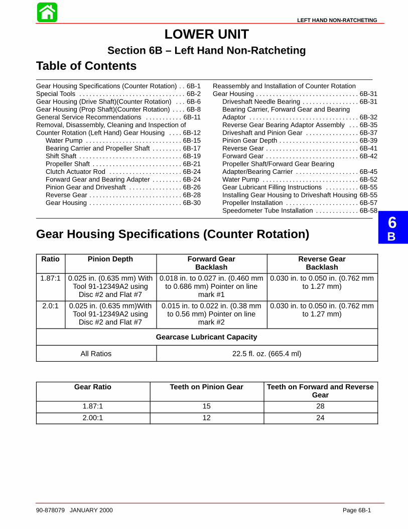
6B
LEFT HAND NON-RATCHETING
90-878079 JANUARY 2000 Page 6B-1
LOWER UNITSection 6B – Left Hand Non-Ratcheting
Table of Contents
Gear Housing Specifications (Counter Rotation) 6B-1. . Special Tools 6B-2. . . . . . . . . . . . . . . . . . . . . . . . . . . . . . . . Gear Housing (Drive Shaft)(Counter Rotation) 6B-6. . . Gear Housing (Prop Shaft)(Counter Rotation) 6B-8. . . . General Service Recommendations 6B-11. . . . . . . . . . . Removal, Disassembly, Cleaning and Inspection ofCounter Rotation (Left Hand) Gear Housing 6B-12. . . .
Water Pump 6B-15. . . . . . . . . . . . . . . . . . . . . . . . . . . . . Bearing Carrier and Propeller Shaft 6B-17. . . . . . . . . Shift Shaft 6B-19. . . . . . . . . . . . . . . . . . . . . . . . . . . . . . . Propeller Shaft 6B-21. . . . . . . . . . . . . . . . . . . . . . . . . . . Clutch Actuator Rod 6B-24. . . . . . . . . . . . . . . . . . . . . . Forward Gear and Bearing Adapter 6B-24. . . . . . . . . Pinion Gear and Driveshaft 6B-26. . . . . . . . . . . . . . . . Reverse Gear 6B-28. . . . . . . . . . . . . . . . . . . . . . . . . . . . Gear Housing 6B-30. . . . . . . . . . . . . . . . . . . . . . . . . . . .
Reassembly and Installation of Counter RotationGear Housing 6B-31. . . . . . . . . . . . . . . . . . . . . . . . . . . . . . .
Driveshaft Needle Bearing 6B-31. . . . . . . . . . . . . . . . . Bearing Carrier, Forward Gear and BearingAdaptor 6B-32. . . . . . . . . . . . . . . . . . . . . . . . . . . . . . . . . Reverse Gear Bearing Adaptor Assembly 6B-35. . . Driveshaft and Pinion Gear 6B-37. . . . . . . . . . . . . . . . Pinion Gear Depth 6B-39. . . . . . . . . . . . . . . . . . . . . . . . Reverse Gear 6B-41. . . . . . . . . . . . . . . . . . . . . . . . . . . . Forward Gear 6B-42. . . . . . . . . . . . . . . . . . . . . . . . . . . . Propeller Shaft/Forward Gear BearingAdapter/Bearing Carrier 6B-45. . . . . . . . . . . . . . . . . . . Water Pump 6B-52. . . . . . . . . . . . . . . . . . . . . . . . . . . . . Gear Lubricant Filling Instructions 6B-55. . . . . . . . . . Installing Gear Housing to Driveshaft Housing 6B-55Propeller Installation 6B-57. . . . . . . . . . . . . . . . . . . . . . Speedometer Tube Installation 6B-58. . . . . . . . . . . . .
Gear Housing Specifications (Counter Rotation)
Ratio Pinion Depth Forward GearBacklash
Reverse GearBacklash
1.87:1 0.025 in. (0.635 mm) WithTool 91-12349A2 using
Disc #2 and Flat #7
0.018 in. to 0.027 in. (0.460 mmto 0.686 mm) Pointer on line
mark #1
0.030 in. to 0.050 in. (0.762 mmto 1.27 mm)
2.0:1 0.025 in. (0.635 mm)WithTool 91-12349A2 using
Disc #2 and Flat #7
0.015 in. to 0.022 in. (0.38 mmto 0.56 mm) Pointer on line
mark #2
0.030 in. to 0.050 in. (0.762 mmto 1.27 mm)
Gearcase Lubricant Capacity
All Ratios 22.5 fl. oz. (665.4 ml)
Gear Ratio Teeth on Pinion Gear Teeth on Forward and ReverseGear
1.87:1 15 28
2.00:1 12 24

LEFT HAND NON-RATCHETING
Page 6B-2 90-878079 JANUARY 2000
Special Tools
1. Shift Shaft Bushing Tool 91-31107T
2. Gear Housing Cover Nut Tool 91-61069
3. Bearing Carrier Removal Tool 91-46086A1 and Puller Bolt 91-85716
4. Slide Hammer Puller 91-34569A1
5. Bearing Removal and Installation Kit 91-31229A5. This kit contains the followingtools: Pilot 91-36571; Puller Rod 91-31229; Nut 11-24156; Puller Plate 91-29310;Mandrel 91-38628; and Driver Rod 91-37323.
6. Pilot 91-36571
7. Puller Rod 91-31229 and Nut 91-24156

LEFT HAND NON-RATCHETING
90-878079 JANUARY 2000 Page 6B-3
8. Puller Plate 91-29310
9. Mandrel 91-38628
10. Driver Rod 91-37323
11. Universal Puller Plate 91-37241
12. Driveshaft Holding Tool 91-34377A1 or91-90094
13. Oil Seal Driver 91-31108
14. Forward Gear Bearing Tool 91-86943
15. Pinion Locating Gear Tool 91-12349A2 or 91-74776
16. Backlash Indicator Rod 91-78473
17. Dial Indicator 91-58222A1
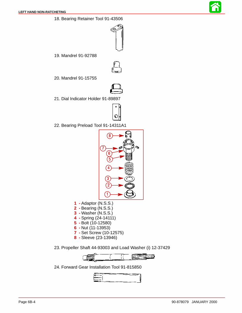
LEFT HAND NON-RATCHETING
Page 6B-4 90-878079 JANUARY 2000
18. Bearing Retainer Tool 91-43506
19. Mandrel 91-92788
20. Mandrel 91-15755
21. Dial Indicator Holder 91-89897
22. Bearing Preload Tool 91-14311A1
a
bc
d
ef
g
h
1
2
3
4
5
6
7
8
1 - Adaptor (N.S.S.)2 - Bearing (N.S.S.)3 - Washer (N.S.S.)4 - Spring (24-14111)5 - Bolt (10-12580)6 - Nut (11-13953)7 - Set Screw (10-12575)8 - Sleeve (23-13946)
23. Propeller Shaft 44-93003 and Load Washer (i) 12-37429
24. Forward Gear Installation Tool 91-815850
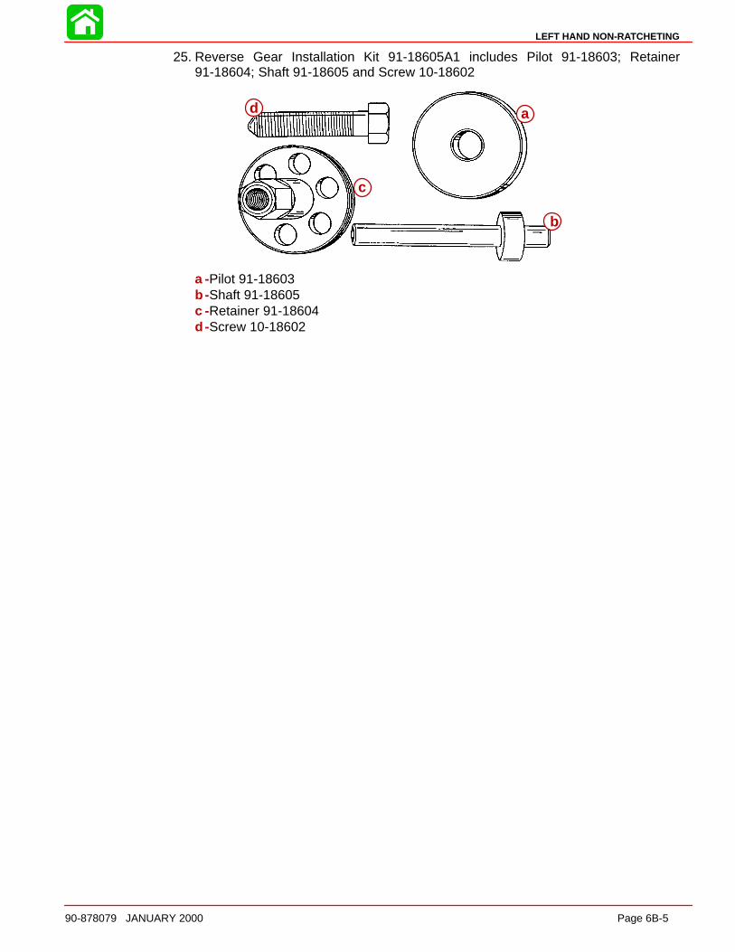
LEFT HAND NON-RATCHETING
90-878079 JANUARY 2000 Page 6B-5
25. Reverse Gear Installation Kit 91-18605A1 includes Pilot 91-18603; Retainer91-18604; Shaft 91-18605 and Screw 10-18602
a
b
c
d
a -Pilot 91-18603b -Shaft 91-18605c -Retainer 91-18604d -Screw 10-18602
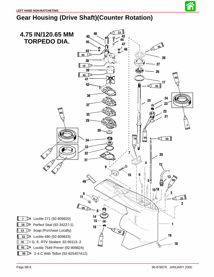
LEFT HAND NON-RATCHETING
Page 6B-6 90-878079 JANUARY 2000
Gear Housing (Drive Shaft)(Counter Rotation)
Soap (Purchase Locally)23
4.75 IN/120.65 MMTORPEDO DIA.
7 Loctite 271 (92-809820)
Perfect Seal (92-34227-1)19
Loctite 680 (92-809833)33
95 2-4-C With Teflon (92-825407A12)
34
33
1
12
2
3
4
5
7
8
9
10
11
14
15
16
18
19
20
21
22
23
2425
26
28
29
31
32
35
36
37
38
39
40
41
42
43
45
46
47
48
6
17
44
19
9
44
27
30
49
23
95
95
7
95
95
95
33
795
95
7
95
19
95
78
95
18
92 Loctite 7649 Primer (92-809824)
92
7 G. E. RTV Sealant 92-90113--278
9813
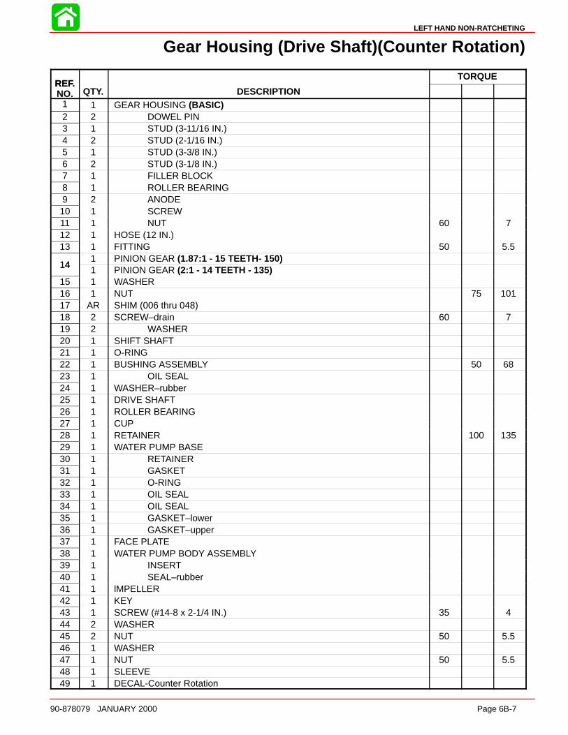
LEFT HAND NON-RATCHETING
90-878079 JANUARY 2000 Page 6B-7
Gear Housing (Drive Shaft)(Counter Rotation)
REFTORQUE
REF.NO. QTY. DESCRIPTION
1 1 GEAR HOUSING (BASIC)2 2 DOWEL PIN3 1 STUD (3-11/16 IN.)4 2 STUD (2-1/16 IN.)5 1 STUD (3-3/8 IN.)6 2 STUD (3-1/8 IN.)7 1 FILLER BLOCK8 1 ROLLER BEARING9 2 ANODE10 1 SCREW11 1 NUT 60 712 1 HOSE (12 IN.)13 1 FITTING 50 5.5
141 PINION GEAR (1.87:1 - 15 TEETH- 150)
141 PINION GEAR (2:1 - 14 TEETH - 135)
15 1 WASHER16 1 NUT 75 10117 AR SHIM (006 thru 048)18 2 SCREW–drain 60 719 2 WASHER20 1 SHIFT SHAFT21 1 O-RING22 1 BUSHING ASSEMBLY 50 6823 1 OIL SEAL24 1 WASHER–rubber25 1 DRIVE SHAFT26 1 ROLLER BEARING27 1 CUP28 1 RETAINER 100 13529 1 WATER PUMP BASE30 1 RETAINER31 1 GASKET32 1 O-RING33 1 OIL SEAL34 1 OIL SEAL35 1 GASKET–lower36 1 GASKET–upper37 1 FACE PLATE38 1 WATER PUMP BODY ASSEMBLY39 1 INSERT40 1 SEAL–rubber41 1 lMPELLER42 1 KEY43 1 SCREW (#14-8 x 2-1/4 IN.) 35 444 2 WASHER45 2 NUT 50 5.546 1 WASHER47 1 NUT 50 5.548 1 SLEEVE49 1 DECAL-Counter Rotation
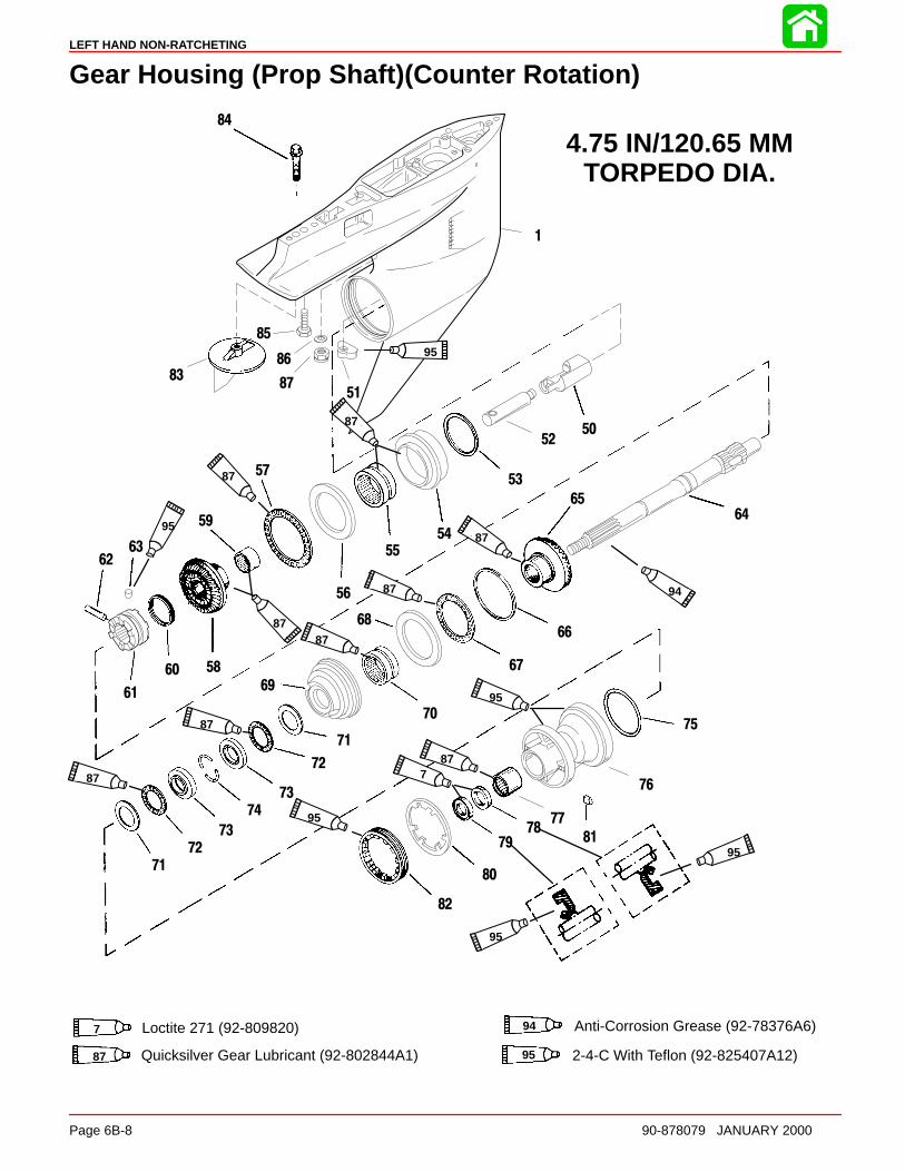
LEFT HAND NON-RATCHETING
Page 6B-8 90-878079 JANUARY 2000
Gear Housing (Prop Shaft)(Counter Rotation)
1
67
68
69
70
71
72
73
74
75
76
7778
79
80
81
82
83
84
85
86
87
73
72
71
95
87
87
95
8787
87
87
94
95
877
95
95
95
87
87
4.75 IN/120.65 MMTORPEDO DIA.
7 Loctite 271 (92-809820) 94 Anti-Corrosion Grease (92-78376A6)
95 2-4-C With Teflon (92-825407A12)
50
51
52
53
54
55
56
57
58
59
60
61
6263
64
65
66
87 Quicksilver Gear Lubricant (92-802844A1)

LEFT HAND NON-RATCHETING
90-878079 JANUARY 2000 Page 6B-9
Gear Housing (Prop Shaft)(Counter Rotation)
REFTORQUE
REF.NO. QTY. DESCRIPTION lb-in lb-ft Nm.
1 1 GEAR HOUSING (BLACK)(BASIC)50 1 CAM FOLLOWER51 1 SHIFT CAM52 1 ROD53 AR SHIM SET54 1 BEARING ADAPTOR ASSEMBLY55 1 ROLLER BEARING
56 1 THRUST WASHER57 1 THRUST BEARING
581 REVERSE GEAR (1.87:1 – 15/28)(150)
581 REVERSE GEAR (2:1 – 14/28)-(135)
59 1 ROLLER BEARING60 1 SPRING61 1 SLIDING CLUTCH
62 1 CROSS PIN63 1 DETENT PIN64 1 PROPELLER SHAFT
651 FORWARD GEAR (1.87:1 – 15/28)(150)
651 FORWARD GEAR (2:1 – 14/28)-(135)
AR SPACER SHIM .206 IN.AR SPACER SHIM .208 IN.
AR SPACER SHIM .210 IN.AR SPACER SHIM .212 IN.AR SPACER SHIM .214 IN.AR SPACER SHIM .216 IN.
66 AR SPACER SHIM .218 IN.AR SPACER SHIM .220 IN.AR SPACER SHIM .222 IN.
AR SPACER SHIM .224 IN.AR SPACER SHIM .226 IN.AR SPACER SHIM .228 IN.AR SPACER SHIM .230 IN.
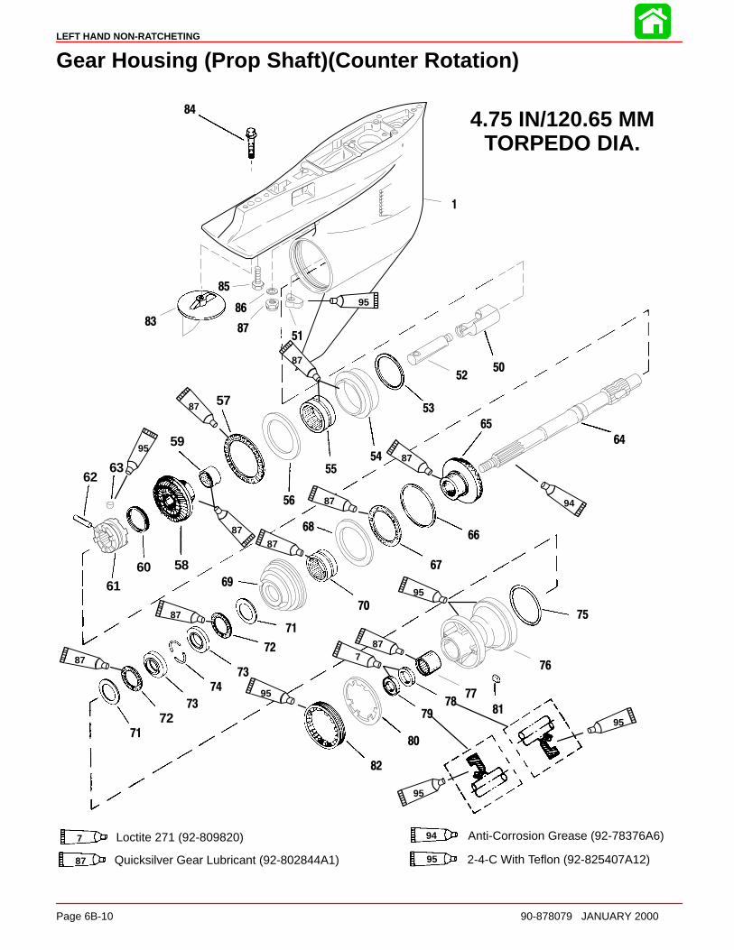
LEFT HAND NON-RATCHETING
Page 6B-10 90-878079 JANUARY 2000
Gear Housing (Prop Shaft)(Counter Rotation)
1
67
68
69
70
71
72
73
74
75
76
7778
79
80
81
82
83
84
85
86
87
73
7271
95
87
87
95
8787
87
87
94
95
877
95
95
95
87
87
4.75 IN/120.65 MMTORPEDO DIA.
7 Loctite 271 (92-809820) 94 Anti-Corrosion Grease (92-78376A6)
95 2-4-C With Teflon (92-825407A12)
50
51
52
53
54
55
56
57
58
59
6061
6263
64
65
66
87 Quicksilver Gear Lubricant (92-802844A1)
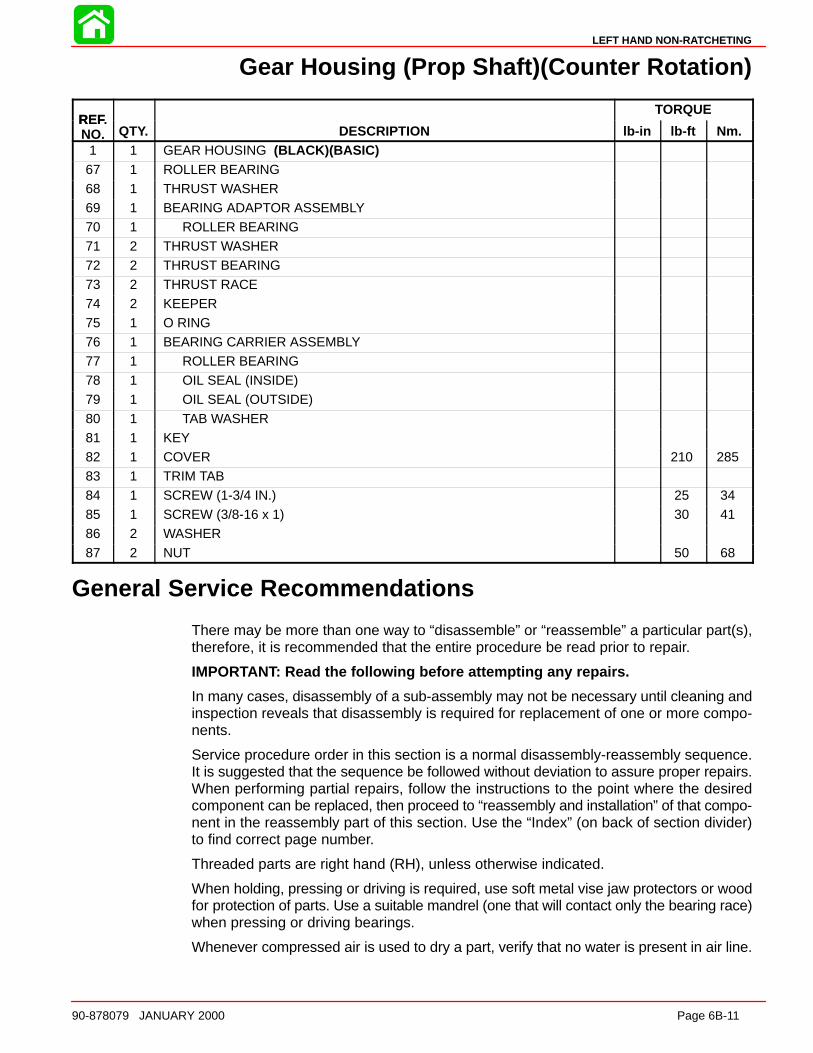
LEFT HAND NON-RATCHETING
90-878079 JANUARY 2000 Page 6B-11
Gear Housing (Prop Shaft)(Counter Rotation)
REFTORQUE
REF.NO. QTY. DESCRIPTION lb-in lb-ft Nm.
1 1 GEAR HOUSING (BLACK)(BASIC)67 1 ROLLER BEARING68 1 THRUST WASHER69 1 BEARING ADAPTOR ASSEMBLY70 1 ROLLER BEARING71 2 THRUST WASHER72 2 THRUST BEARING
73 2 THRUST RACE74 2 KEEPER75 1 O RING76 1 BEARING CARRIER ASSEMBLY77 1 ROLLER BEARING78 1 OIL SEAL (INSIDE)79 1 OIL SEAL (OUTSIDE)
80 1 TAB WASHER81 1 KEY82 1 COVER 210 28583 1 TRIM TAB84 1 SCREW (1-3/4 IN.) 25 3485 1 SCREW (3/8-16 x 1) 30 4186 2 WASHER
87 2 NUT 50 68
General Service Recommendations
There may be more than one way to “disassemble” or “reassemble” a particular part(s),therefore, it is recommended that the entire procedure be read prior to repair.
IMPORTANT: Read the following before attempting any repairs.
In many cases, disassembly of a sub-assembly may not be necessary until cleaning andinspection reveals that disassembly is required for replacement of one or more compo-nents.
Service procedure order in this section is a normal disassembly-reassembly sequence.It is suggested that the sequence be followed without deviation to assure proper repairs.When performing partial repairs, follow the instructions to the point where the desiredcomponent can be replaced, then proceed to “reassembly and installation” of that compo-nent in the reassembly part of this section. Use the “Index” (on back of section divider)to find correct page number.
Threaded parts are right hand (RH), unless otherwise indicated.
When holding, pressing or driving is required, use soft metal vise jaw protectors or woodfor protection of parts. Use a suitable mandrel (one that will contact only the bearing race)when pressing or driving bearings.
Whenever compressed air is used to dry a part, verify that no water is present in air line.
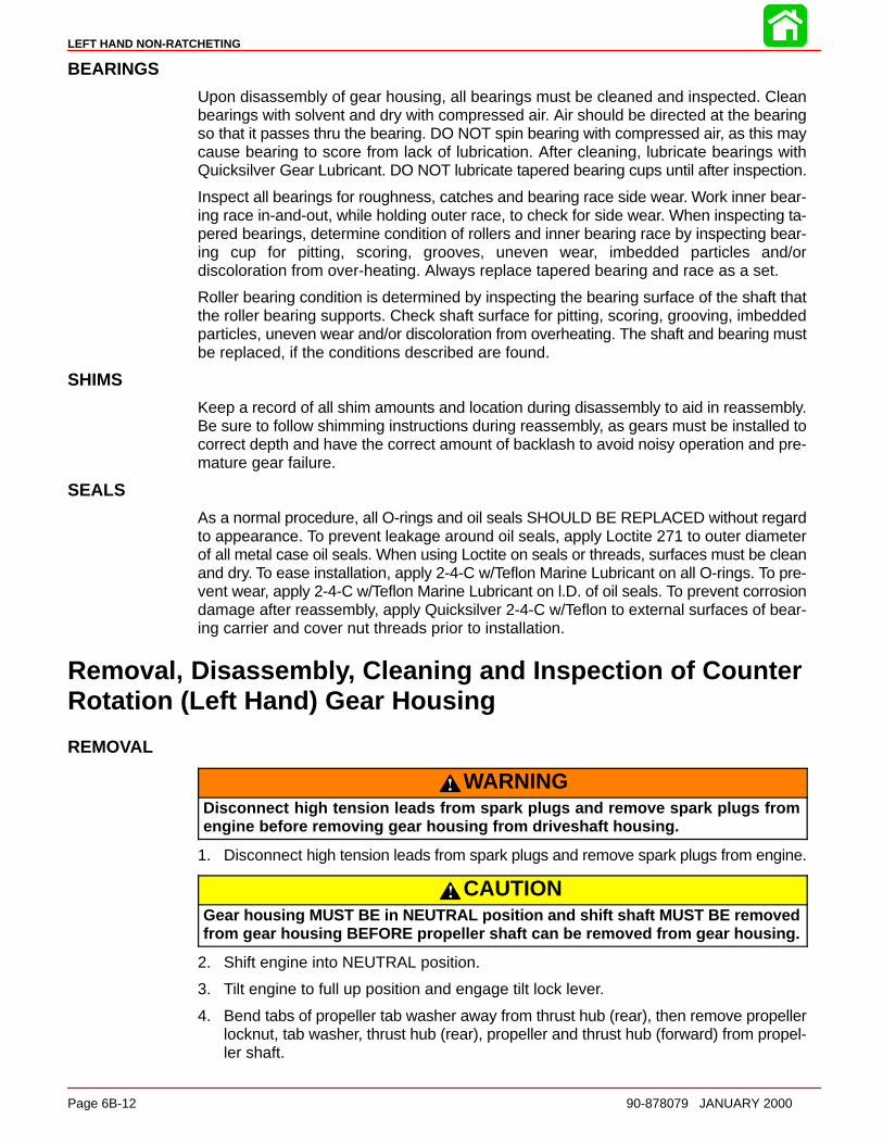
LEFT HAND NON-RATCHETING
Page 6B-12 90-878079 JANUARY 2000
BEARINGS
Upon disassembly of gear housing, all bearings must be cleaned and inspected. Cleanbearings with solvent and dry with compressed air. Air should be directed at the bearingso that it passes thru the bearing. DO NOT spin bearing with compressed air, as this maycause bearing to score from lack of lubrication. After cleaning, lubricate bearings withQuicksilver Gear Lubricant. DO NOT lubricate tapered bearing cups until after inspection.
Inspect all bearings for roughness, catches and bearing race side wear. Work inner bear-ing race in-and-out, while holding outer race, to check for side wear. When inspecting ta-pered bearings, determine condition of rollers and inner bearing race by inspecting bear-ing cup for pitting, scoring, grooves, uneven wear, imbedded particles and/ordiscoloration from over-heating. Always replace tapered bearing and race as a set.
Roller bearing condition is determined by inspecting the bearing surface of the shaft thatthe roller bearing supports. Check shaft surface for pitting, scoring, grooving, imbeddedparticles, uneven wear and/or discoloration from overheating. The shaft and bearing mustbe replaced, if the conditions described are found.
SHIMS
Keep a record of all shim amounts and location during disassembly to aid in reassembly.Be sure to follow shimming instructions during reassembly, as gears must be installed tocorrect depth and have the correct amount of backlash to avoid noisy operation and pre-mature gear failure.
SEALS
As a normal procedure, all O-rings and oil seals SHOULD BE REPLACED without regardto appearance. To prevent leakage around oil seals, apply Loctite 271 to outer diameterof all metal case oil seals. When using Loctite on seals or threads, surfaces must be cleanand dry. To ease installation, apply 2-4-C w/Teflon Marine Lubricant on all O-rings. To pre-vent wear, apply 2-4-C w/Teflon Marine Lubricant on l.D. of oil seals. To prevent corrosiondamage after reassembly, apply Quicksilver 2-4-C w/Teflon to external surfaces of bear-ing carrier and cover nut threads prior to installation.
Removal, Disassembl y, Cleaning and Inspection of CounterRotation (Left Hand) Gear Housing
REMOVAL
WARNINGDisconnect high tension leads from spark plugs and remove spark plugs fromengine before removing gear housing from driveshaft housing.
1. Disconnect high tension leads from spark plugs and remove spark plugs from engine.
CAUTIONGear housing MUST BE in NEUTRAL position and shift shaft MUST BE removedfrom gear housing BEFORE propeller shaft can be removed from gear housing.
2. Shift engine into NEUTRAL position.
3. Tilt engine to full up position and engage tilt lock lever.
4. Bend tabs of propeller tab washer away from thrust hub (rear), then remove propellerlocknut, tab washer, thrust hub (rear), propeller and thrust hub (forward) from propel-ler shaft.
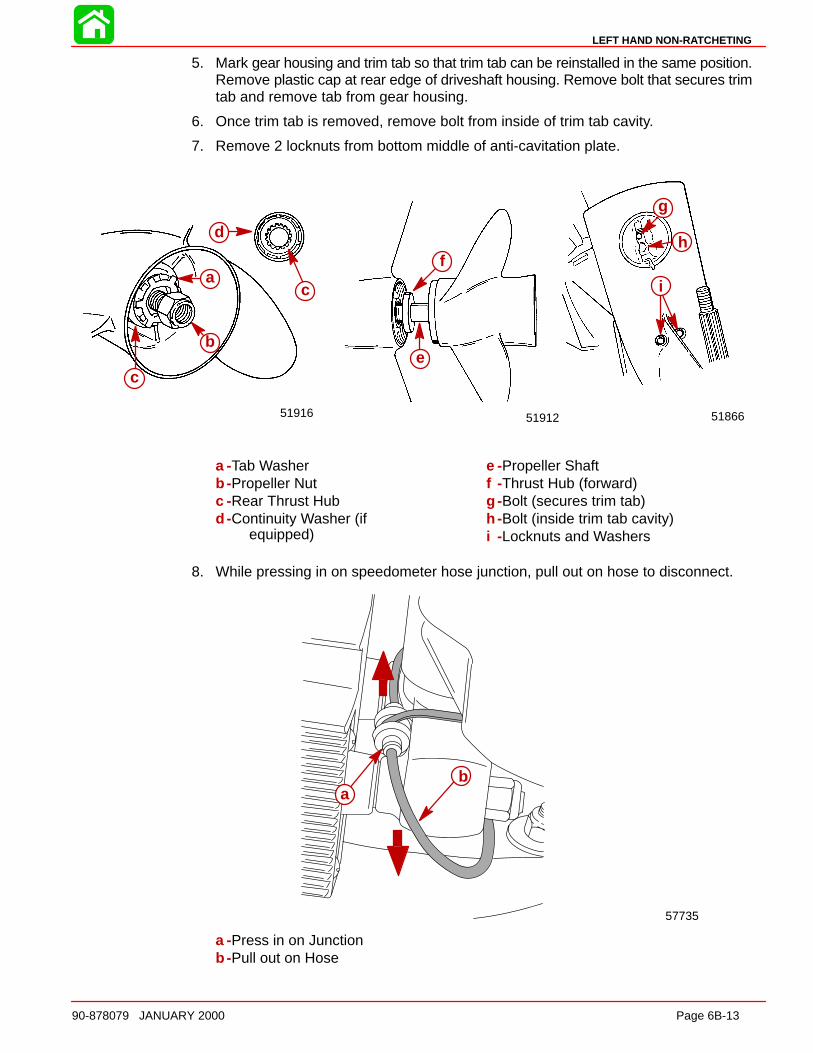
LEFT HAND NON-RATCHETING
90-878079 JANUARY 2000 Page 6B-13
5. Mark gear housing and trim tab so that trim tab can be reinstalled in the same position.Remove plastic cap at rear edge of driveshaft housing. Remove bolt that secures trimtab and remove tab from gear housing.
6. Once trim tab is removed, remove bolt from inside of trim tab cavity.
7. Remove 2 locknuts from bottom middle of anti-cavitation plate.
5186651916 51912
a
b
c
d
e
f
g
h
ic
a -Tab Washerb -Propeller Nutc -Rear Thrust Hubd -Continuity Washer (if
equipped)
e -Propeller Shaftf -Thrust Hub (forward)g -Bolt (secures trim tab)h -Bolt (inside trim tab cavity)i -Locknuts and Washers
8. While pressing in on speedometer hose junction, pull out on hose to disconnect.
57735
ab
a -Press in on Junctionb -Pull out on Hose
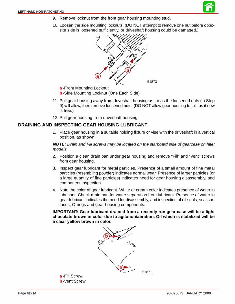
LEFT HAND NON-RATCHETING
Page 6B-14 90-878079 JANUARY 2000
9. Remove locknut from the front gear housing mounting stud.
10. Loosen the side mounting locknuts. (DO NOT attempt to remove one nut before oppo-site side is loosened sufficiently, or driveshaft housing could be damaged.)
51873
ab
ab
a -Front Mounting Locknutb -Side Mounting Locknut (One Each Side)
11. Pull gear housing away from driveshaft housing as far as the loosened nuts (in Step9) will allow, then remove loosened nuts. (DO NOT allow gear housing to fall, as it nowis free.)
12. Pull gear housing from driveshaft housing.
DRAINING AND INSPECTING GEAR HOUSING LUBRICANT
1. Place gear housing in a suitable holding fixture or vise with the driveshaft in a verticalposition, as shown.
NOTE: Drain and Fill screws may be located on the starboard side of gearcase on latermodels.
2. Position a clean drain pan under gear housing and remove “Fill” and “Vent” screwsfrom gear housing.
3. Inspect gear lubricant for metal particles. Presence of a small amount of fine metalparticles (resembling powder) indicates normal wear. Presence of larger particles (ora large quantity of fine particles) indicates need for gear housing disassembly, andcomponent inspection.
4. Note the color of gear lubricant. White or cream color indicates presence of water inlubricant. Check drain pan for water separation from lubricant. Presence of water ingear lubricant indicates the need for disassembly, and inspection of oil seals, seal sur-faces, O-rings and gear housing components.
IMPORTANT: Gear lubricant drained from a recently run gear case will be a lightchocolate brown in color due to agitation/aeration. Oil which is stabilized will bea clear yellow brown in colo r.
b
a51871
a
b
a -Fill Screwb -Vent Screw
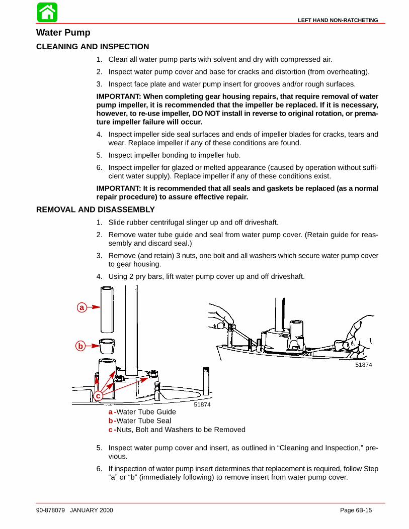
LEFT HAND NON-RATCHETING
90-878079 JANUARY 2000 Page 6B-15
Water PumpCLEANING AND INSPECTION
1. Clean all water pump parts with solvent and dry with compressed air.
2. Inspect water pump cover and base for cracks and distortion (from overheating).
3. Inspect face plate and water pump insert for grooves and/or rough surfaces.
IMPORTANT: When completing gear housing repairs, that require removal of waterpump impelle r, it is recommended that the impeller be replaced. If it is necessar y,howeve r, to re-use impelle r, DO NOT install in reverse to original rotation, or prema-ture impeller failure will occu r.
4. Inspect impeller side seal surfaces and ends of impeller blades for cracks, tears andwear. Replace impeller if any of these conditions are found.
5. Inspect impeller bonding to impeller hub.
6. Inspect impeller for glazed or melted appearance (caused by operation without suffi-cient water supply). Replace impeller if any of these conditions exist.
IMPORTANT: It is recommended that all seals and gaskets be replaced (as a normalrepair procedure) to assure effective repai r.
REMOVAL AND DISASSEMB LY
1. Slide rubber centrifugal slinger up and off driveshaft.
2. Remove water tube guide and seal from water pump cover. (Retain guide for reas-sembly and discard seal.)
3. Remove (and retain) 3 nuts, one bolt and all washers which secure water pump coverto gear housing.
4. Using 2 pry bars, lift water pump cover up and off driveshaft.
51874
b
a
51874
a
b
c
a -Water Tube Guideb -Water Tube Sealc -Nuts, Bolt and Washers to be Removed
5. Inspect water pump cover and insert, as outlined in “Cleaning and Inspection,” pre-vious.
6. If inspection of water pump insert determines that replacement is required, follow Step“a” or “b” (immediately following) to remove insert from water pump cover.

LEFT HAND NON-RATCHETING
Page 6B-16 90-878079 JANUARY 2000
NOTE: Try Step “a” first. If insert cannot be removed with Step “a,” use Step “b.”
a. Drive water pump insert out of water pump cover with a punch and hammer.
b. Drill two 3/16 in. (4.8 mm) diameter holes thru the top of water pump cover (butnot thru insert). Drive insert out of cover with a punch and hammer.
a
51873
51874
a
a -Drill Two Holes at These Locations
7. Remove impeller from driveshaft. (It may be necessary to use a punch and hammerto drive impeller upward on driveshaft. In extreme cases, it may be necessary to splithub of impeller with a hammer and chisel.)
8. Once impeller is removed, remove impeller drive key from driveshaft.
9. Remove water pump face plate and both gaskets (one above and below face plate)from water pump base.
10. Using 2 pry bars, positioned and padded as shown, lift water pump base up and offdriveshaft.
51874
a
a -Pads
11. Remove (and discard) O-ring from O-ring groove on water pump base.
12. Using a screwdriver, pry oil seals out of water pump base from gear housing side ofbase.
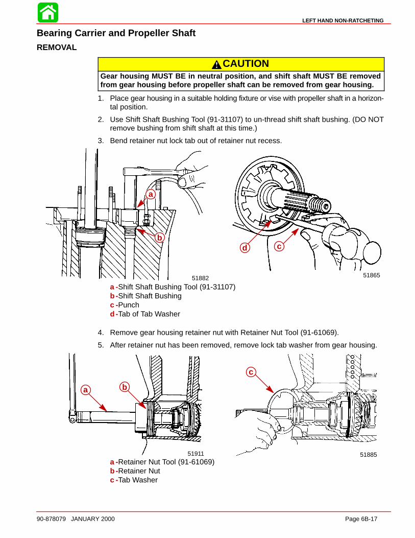
LEFT HAND NON-RATCHETING
90-878079 JANUARY 2000 Page 6B-17
Bearing Carrier and Propeller ShaftREMOVAL
CAUTIONGear housing MUST BE in neutral position, and shift shaft MUST BE removedfrom gear housing before propeller shaft can be removed from gear housing.
1. Place gear housing in a suitable holding fixture or vise with propeller shaft in a horizon-tal position.
2. Use Shift Shaft Bushing Tool (91-31107) to un-thread shift shaft bushing. (DO NOTremove bushing from shift shaft at this time.)
3. Bend retainer nut lock tab out of retainer nut recess.
b a
51865
cd
51882
a
b
a
b
a -Shift Shaft Bushing Tool (91-31107)b -Shift Shaft Bushingc -Punchd -Tab of Tab Washer
4. Remove gear housing retainer nut with Retainer Nut Tool (91-61069).
5. After retainer nut has been removed, remove lock tab washer from gear housing.
51885
a
a b
51911
c
a b
a -Retainer Nut Tool (91-61069)b -Retainer Nutc -Tab Washer
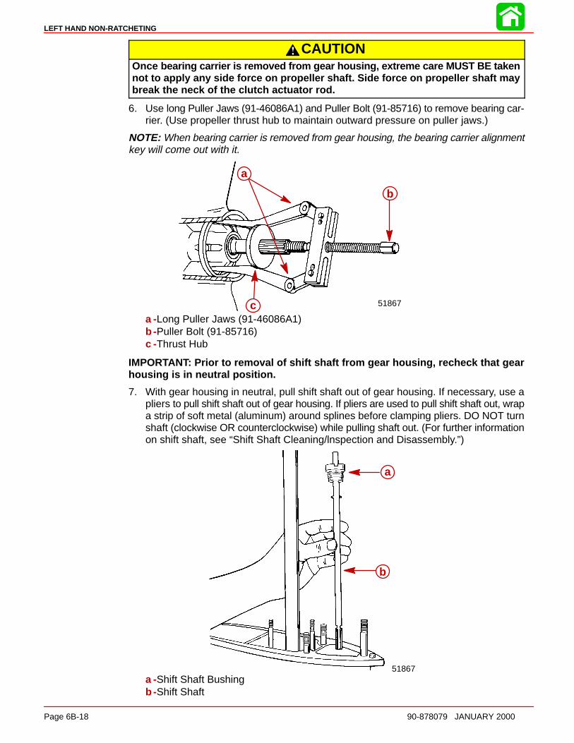
LEFT HAND NON-RATCHETING
Page 6B-18 90-878079 JANUARY 2000
CAUTIONOnce bearing carrier is removed from gear housing, extreme care MUST BE takennot to apply any side force on propeller shaft. Side force on propeller shaft maybreak the neck of the clutch actuator rod.
6. Use long Puller Jaws (91-46086A1) and Puller Bolt (91-85716) to remove bearing car-rier. (Use propeller thrust hub to maintain outward pressure on puller jaws.)
NOTE: When bearing carrier is removed from gear housing, the bearing carrier alignmentkey will come out with it.
a
b
c 51867
a
b
ca -Long Puller Jaws (91-46086A1)b -Puller Bolt (91-85716)c -Thrust Hub
IMPORTANT: Prior to removal of shift shaft from gear housing, recheck that gearhousing is in neutral position.
7. With gear housing in neutral, pull shift shaft out of gear housing. If necessary, use apliers to pull shift shaft out of gear housing. If pliers are used to pull shift shaft out, wrapa strip of soft metal (aluminum) around splines before clamping pliers. DO NOT turnshaft (clockwise OR counterclockwise) while pulling shaft out. (For further informationon shift shaft, see “Shift Shaft Cleaning/lnspection and Disassembly.”)
a
b
51867
a
b
a -Shift Shaft Bushingb -Shift Shaft
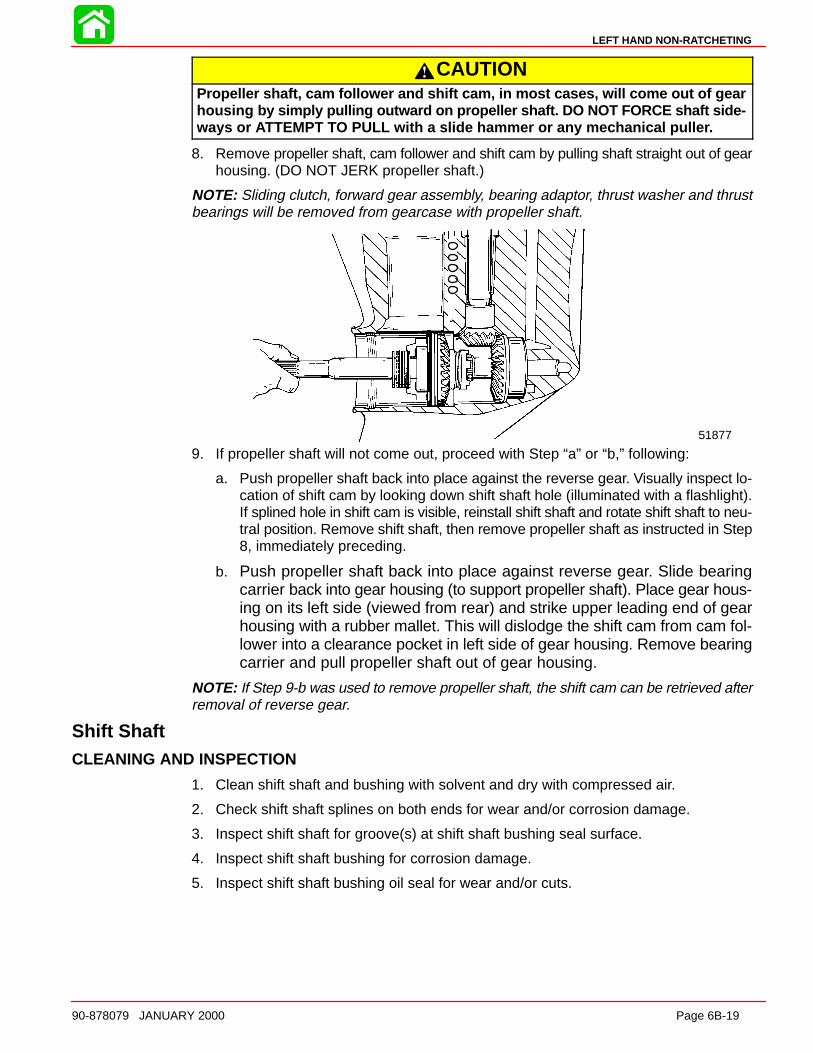
LEFT HAND NON-RATCHETING
90-878079 JANUARY 2000 Page 6B-19
CAUTIONPropeller shaft, cam follower and shift cam, in most cases, will come out of gearhousing by simply pulling outward on propeller shaft. DO NOT FORCE shaft side-ways or ATTEMPT TO PULL with a slide hammer or any mechanical pulle r.
8. Remove propeller shaft, cam follower and shift cam by pulling shaft straight out of gearhousing. (DO NOT JERK propeller shaft.)
NOTE: Sliding clutch, forward gear assembly, bearing adaptor, thrust washer and thrustbearings will be removed from gearcase with propeller shaft.
51877
9. If propeller shaft will not come out, proceed with Step “a” or “b,” following:
a. Push propeller shaft back into place against the reverse gear. Visually inspect lo-cation of shift cam by looking down shift shaft hole (illuminated with a flashlight).If splined hole in shift cam is visible, reinstall shift shaft and rotate shift shaft to neu-tral position. Remove shift shaft, then remove propeller shaft as instructed in Step8, immediately preceding.
b. Push propeller shaft back into place against reverse gear. Slide bearingcarrier back into gear housing (to support propeller shaft). Place gear hous-ing on its left side (viewed from rear) and strike upper leading end of gearhousing with a rubber mallet. This will dislodge the shift cam from cam fol-lower into a clearance pocket in left side of gear housing. Remove bearingcarrier and pull propeller shaft out of gear housing.
NOTE: If Step 9-b was used to remove propeller shaft, the shift cam can be retrieved afterremoval of reverse gear.
Shift ShaftCLEANING AND INSPECTION
1. Clean shift shaft and bushing with solvent and dry with compressed air.
2. Check shift shaft splines on both ends for wear and/or corrosion damage.
3. Inspect shift shaft for groove(s) at shift shaft bushing seal surface.
4. Inspect shift shaft bushing for corrosion damage.
5. Inspect shift shaft bushing oil seal for wear and/or cuts.
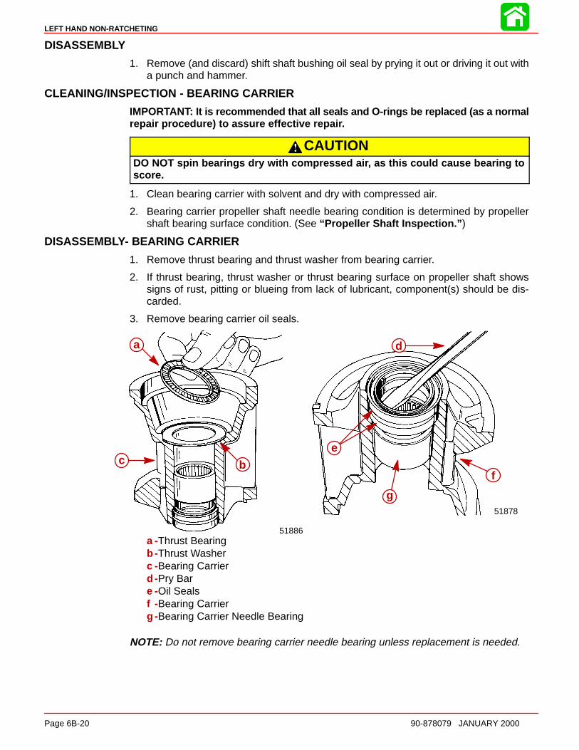
LEFT HAND NON-RATCHETING
Page 6B-20 90-878079 JANUARY 2000
DISASSEMBLY
1. Remove (and discard) shift shaft bushing oil seal by prying it out or driving it out witha punch and hammer.
CLEANING/INSPECTION - BEARING CARRIER
IMPORTANT: It is recommended that all seals and O-rings be replaced (as a normalrepair procedure) to assure effective repai r.
CAUTIONDO NOT spin bearings dry with compressed ai r, as this could cause bearing toscore.
1. Clean bearing carrier with solvent and dry with compressed air.
2. Bearing carrier propeller shaft needle bearing condition is determined by propellershaft bearing surface condition. (See “Propeller Shaft Inspection.” )
DISASSEMBLY- BEARING CARRIER
1. Remove thrust bearing and thrust washer from bearing carrier.
2. If thrust bearing, thrust washer or thrust bearing surface on propeller shaft showssigns of rust, pitting or blueing from lack of lubricant, component(s) should be dis-carded.
3. Remove bearing carrier oil seals.
51878
c
b
a
d
a
c b
51886
d
e
f
g
a
bc
a -Thrust Bearingb -Thrust Washerc -Bearing Carrierd -Pry Bare -Oil Sealsf -Bearing Carrierg -Bearing Carrier Needle Bearing
NOTE: Do not remove bearing carrier needle bearing unless replacement is needed.
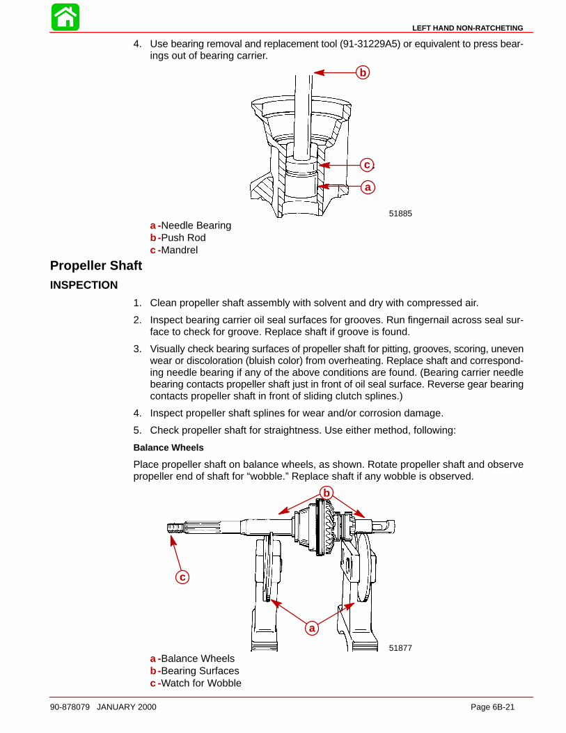
LEFT HAND NON-RATCHETING
90-878079 JANUARY 2000 Page 6B-21
4. Use bearing removal and replacement tool (91-31229A5) or equivalent to press bear-ings out of bearing carrier.
b
c
a
51885
a
b
c
a -Needle Bearingb -Push Rodc -Mandrel
Propeller ShaftINSPECTION
1. Clean propeller shaft assembly with solvent and dry with compressed air.
2. Inspect bearing carrier oil seal surfaces for grooves. Run fingernail across seal sur-face to check for groove. Replace shaft if groove is found.
3. Visually check bearing surfaces of propeller shaft for pitting, grooves, scoring, unevenwear or discoloration (bluish color) from overheating. Replace shaft and correspond-ing needle bearing if any of the above conditions are found. (Bearing carrier needlebearing contacts propeller shaft just in front of oil seal surface. Reverse gear bearingcontacts propeller shaft in front of sliding clutch splines.)
4. Inspect propeller shaft splines for wear and/or corrosion damage.
5. Check propeller shaft for straightness. Use either method, following:
Balance Wheels
Place propeller shaft on balance wheels, as shown. Rotate propeller shaft and observepropeller end of shaft for “wobble.” Replace shaft if any wobble is observed.
51877
b
a
c
a -Balance Wheelsb -Bearing Surfacesc -Watch for Wobble
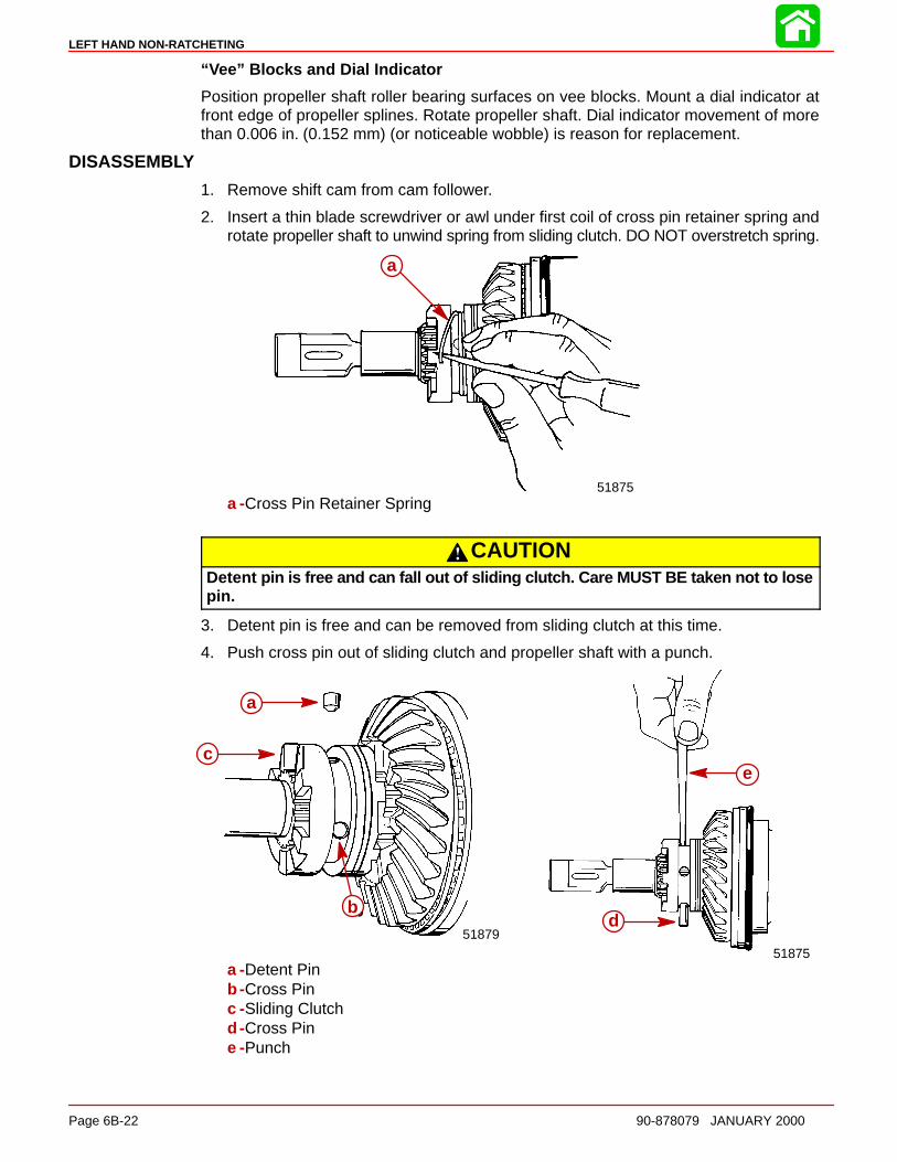
LEFT HAND NON-RATCHETING
Page 6B-22 90-878079 JANUARY 2000
“ Vee” Blocks and Dial Indicator
Position propeller shaft roller bearing surfaces on vee blocks. Mount a dial indicator atfront edge of propeller splines. Rotate propeller shaft. Dial indicator movement of morethan 0.006 in. (0.152 mm) (or noticeable wobble) is reason for replacement.
DISASSEMBLY
1. Remove shift cam from cam follower.
2. Insert a thin blade screwdriver or awl under first coil of cross pin retainer spring androtate propeller shaft to unwind spring from sliding clutch. DO NOT overstretch spring.
a
51875
a
a -Cross Pin Retainer Spring
CAUTIONDetent pin is free and can fall out of sliding clutch. Care MUST BE taken not to losepin.
3. Detent pin is free and can be removed from sliding clutch at this time.
4. Push cross pin out of sliding clutch and propeller shaft with a punch.
51875
d
e
a
c
b51879
a
b
c
a -Detent Pinb -Cross Pinc -Sliding Clutchd -Cross Pine -Punch
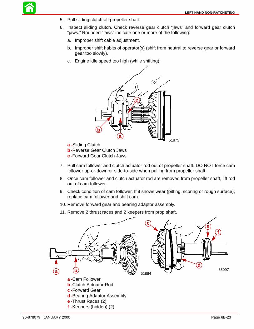
LEFT HAND NON-RATCHETING
90-878079 JANUARY 2000 Page 6B-23
5. Pull sliding clutch off propeller shaft.
6. Inspect sliding clutch. Check reverse gear clutch “jaws” and forward gear clutch“jaws.” Rounded “jaws” indicate one or more of the following:
a. Improper shift cable adjustment.
b. Improper shift habits of operator(s) (shift from neutral to reverse gear or forwardgear too slowly).
c. Engine idle speed too high (while shifting).
51875
ba
c
ab
c
a -Sliding Clutchb -Reverse Gear Clutch Jawsc -Forward Gear Clutch Jaws
7. Pull cam follower and clutch actuator rod out of propeller shaft. DO NOT force camfollower up-or-down or side-to-side when pulling from propeller shaft.
8. Once cam follower and clutch actuator rod are removed from propeller shaft, lift rodout of cam follower.
9. Check condition of cam follower. If it shows wear (pitting, scoring or rough surface),replace cam follower and shift cam.
10. Remove forward gear and bearing adaptor assembly.
11. Remove 2 thrust races and 2 keepers from prop shaft.
a
b55097
cd
51884ba
c
d
ef
a b
a -Cam Followerb -Clutch Actuator Rodc -Forward Geard -Bearing Adaptor Assemblye -Thrust Races (2)f -Keepers (hidden) (2)
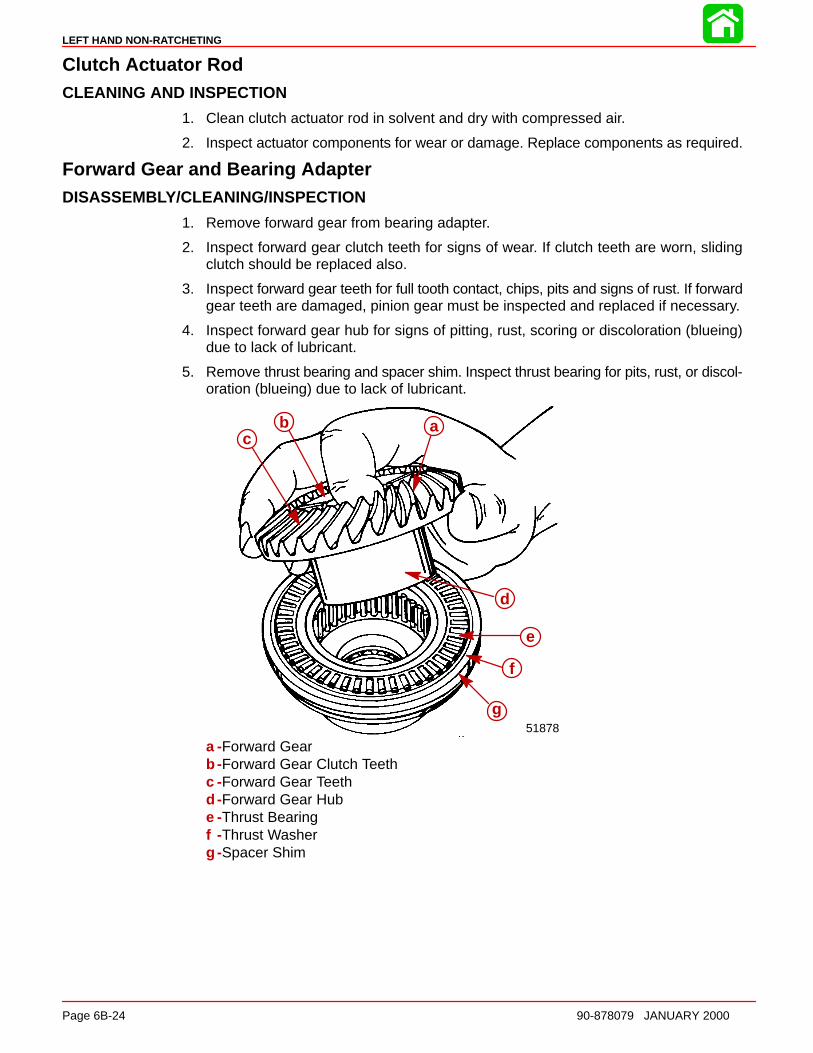
LEFT HAND NON-RATCHETING
Page 6B-24 90-878079 JANUARY 2000
Clutch Actuator RodCLEANING AND INSPECTION
1. Clean clutch actuator rod in solvent and dry with compressed air.
2. Inspect actuator components for wear or damage. Replace components as required.
Forward Gear and Bearing AdapterDISASSEMBLY/CLEANING/INSPECTION
1. Remove forward gear from bearing adapter.
2. Inspect forward gear clutch teeth for signs of wear. If clutch teeth are worn, slidingclutch should be replaced also.
3. Inspect forward gear teeth for full tooth contact, chips, pits and signs of rust. If forwardgear teeth are damaged, pinion gear must be inspected and replaced if necessary.
4. Inspect forward gear hub for signs of pitting, rust, scoring or discoloration (blueing)due to lack of lubricant.
5. Remove thrust bearing and spacer shim. Inspect thrust bearing for pits, rust, or discol-oration (blueing) due to lack of lubricant.
cb a
d
e
f
51878g
abc
d
e
f
g
a -Forward Gearb -Forward Gear Clutch Teethc -Forward Gear Teethd -Forward Gear Hube -Thrust Bearingf -Thrust Washerg -Spacer Shim
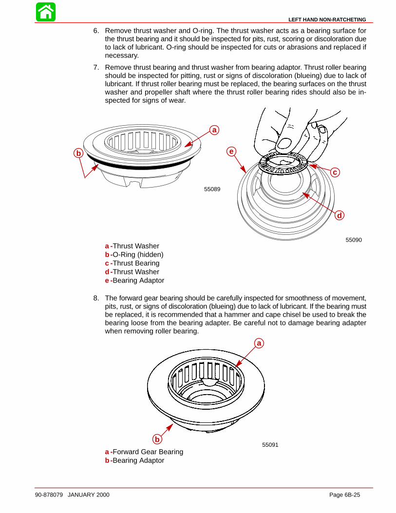
LEFT HAND NON-RATCHETING
90-878079 JANUARY 2000 Page 6B-25
6. Remove thrust washer and O-ring. The thrust washer acts as a bearing surface forthe thrust bearing and it should be inspected for pits, rust, scoring or discoloration dueto lack of lubricant. O-ring should be inspected for cuts or abrasions and replaced ifnecessary.
7. Remove thrust bearing and thrust washer from bearing adaptor. Thrust roller bearingshould be inspected for pitting, rust or signs of discoloration (blueing) due to lack oflubricant. If thrust roller bearing must be replaced, the bearing surfaces on the thrustwasher and propeller shaft where the thrust roller bearing rides should also be in-spected for signs of wear.
c
b
a
55090
eb
a
55089
a
b
c
d
a -Thrust Washerb -O-Ring (hidden)c -Thrust Bearingd -Thrust Washere -Bearing Adaptor
8. The forward gear bearing should be carefully inspected for smoothness of movement,pits, rust, or signs of discoloration (blueing) due to lack of lubricant. If the bearing mustbe replaced, it is recommended that a hammer and cape chisel be used to break thebearing loose from the bearing adapter. Be careful not to damage bearing adapterwhen removing roller bearing.
a
b55091
a
b
a -Forward Gear Bearingb -Bearing Adaptor
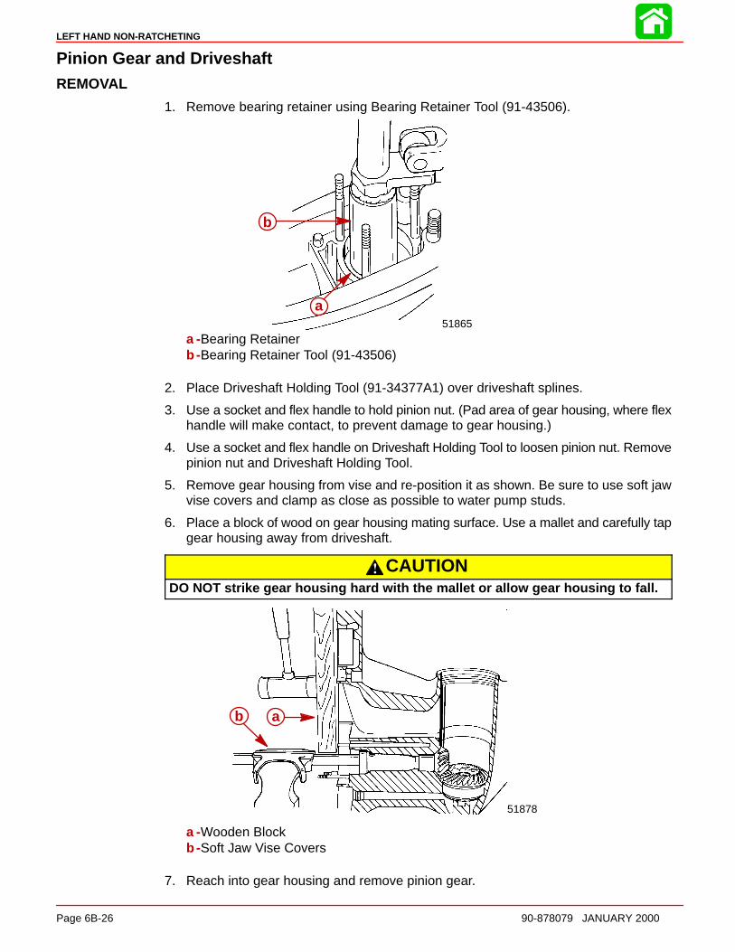
LEFT HAND NON-RATCHETING
Page 6B-26 90-878079 JANUARY 2000
Pinion Gear and DriveshaftREMOVAL
1. Remove bearing retainer using Bearing Retainer Tool (91-43506).
51865
b
aa
b
a -Bearing Retainerb -Bearing Retainer Tool (91-43506)
2. Place Driveshaft Holding Tool (91-34377A1) over driveshaft splines.
3. Use a socket and flex handle to hold pinion nut. (Pad area of gear housing, where flexhandle will make contact, to prevent damage to gear housing.)
4. Use a socket and flex handle on Driveshaft Holding Tool to loosen pinion nut. Removepinion nut and Driveshaft Holding Tool.
5. Remove gear housing from vise and re-position it as shown. Be sure to use soft jawvise covers and clamp as close as possible to water pump studs.
6. Place a block of wood on gear housing mating surface. Use a mallet and carefully tapgear housing away from driveshaft.
CAUTIONDO NOT strike gear housing hard with the mallet or allow gear housing to fall.
51878
ab ab
a -Wooden Blockb -Soft Jaw Vise Covers
7. Reach into gear housing and remove pinion gear.
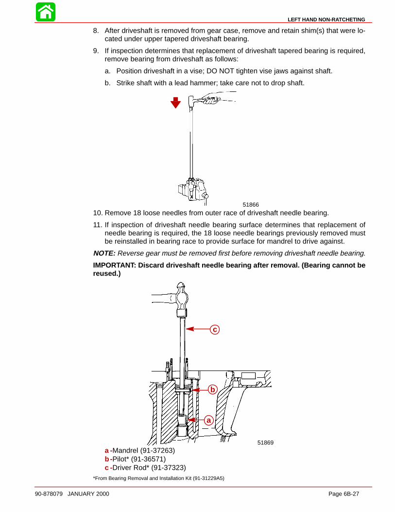
LEFT HAND NON-RATCHETING
90-878079 JANUARY 2000 Page 6B-27
8. After driveshaft is removed from gear case, remove and retain shim(s) that were lo-cated under upper tapered driveshaft bearing.
9. If inspection determines that replacement of driveshaft tapered bearing is required,remove bearing from driveshaft as follows:
a. Position driveshaft in a vise; DO NOT tighten vise jaws against shaft.
b. Strike shaft with a lead hammer; take care not to drop shaft.
51866
10. Remove 18 loose needles from outer race of driveshaft needle bearing.
11. If inspection of driveshaft needle bearing surface determines that replacement ofneedle bearing is required, the 18 loose needle bearings previously removed mustbe reinstalled in bearing race to provide surface for mandrel to drive against.
NOTE: Reverse gear must be removed first before removing driveshaft needle bearing.
IMPORTANT: Discard driveshaft needle bearing after removal. (Bearing cannot bereused.)
51869
c
b
aa
b
c
a -Mandrel (91-37263)b -Pilot* (91-36571)c -Driver Rod* (91-37323)
*From Bearing Removal and Installation Kit (91-31229A5)

LEFT HAND NON-RATCHETING
Page 6B-28 90-878079 JANUARY 2000
CLEANING AND INSPECTION
1. Clean driveshaft, tapered bearing and race, and pinion gear with solvent. Dry withcompressed air. DO NOT allow driveshaft bearing to spin while drying.
2. Inspect pinion gear for pitting, grooves, scoring, uneven wear and/or discolorationfrom overheating. Replace pinion gear, if any of the above conditions are found.
3. Inspect driveshaft needle bearing surface (area just above pinion gear splines) for pit-ting, grooves, scoring, uneven wear and/or discoloration from overheating. Replacedriveshaft and driveshaft needle bearing, if any of the preceding conditions are found.
4. Inspect driveshaft to crankshaft splines for wear. Replace driveshaft if wear is exces-sive.
5. Inspect tapered bearing race for pitting, grooves, scoring, uneven wear and discolor-ation from overheating. Replace tapered bearing and race as a set, if any of the pre-ceding conditions are found.
6. Inspect driveshaft for groove(s) where water pump base oil seals contact shaft. Re-place driveshaft if groove(s) are found.
Reverse GearREMOVAL AND DISASSEMB LY
NOTE: Reverse gear can be removed from gear housing only after driveshaft and piniongear have been removed.
NOTE: Cautiously applying heat to both sides of gearcase where reverse gear assemblyis located will aid in removal of bearing cup adapter.
1. Remove reverse gear by hand.
50884
aa
a -Reverse Gear
IMPORTANT: DO NOT remove needle bearing from reverse gear unless replace-ment of bearing is required. Bearing cannot be reused after it has been removed.
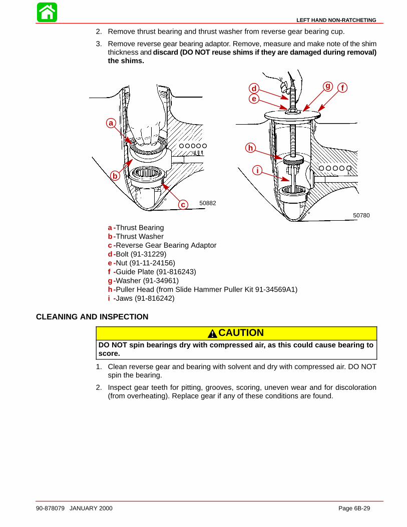
LEFT HAND NON-RATCHETING
90-878079 JANUARY 2000 Page 6B-29
2. Remove thrust bearing and thrust washer from reverse gear bearing cup.
3. Remove reverse gear bearing adaptor. Remove, measure and make note of the shimthickness and discard (DO NOT reuse shims if they are damaged during removal)the shims.
50780
ab
cd
e
f
50882
a
b
c
de
fg
h
i
a
b
c
a -Thrust Bearingb -Thrust Washerc -Reverse Gear Bearing Adaptord -Bolt (91-31229)e -Nut (91-11-24156)f -Guide Plate (91-816243)g -Washer (91-34961)h -Puller Head (from Slide Hammer Puller Kit 91-34569A1)i -Jaws (91-816242)
CLEANING AND INSPECTION
CAUTIONDO NOT spin bearings dry with compressed ai r, as this could cause bearing toscore.
1. Clean reverse gear and bearing with solvent and dry with compressed air. DO NOTspin the bearing.
2. Inspect gear teeth for pitting, grooves, scoring, uneven wear and for discoloration(from overheating). Replace gear if any of these conditions are found.

LEFT HAND NON-RATCHETING
Page 6B-30 90-878079 JANUARY 2000
3. Check clutch jaws on reverse gear for damage. Replace reverse gear if damage isfound.
23351
a
b
a
a -Reverse Gear Teethb -Clutch Jaws
NOTE: The needle bearings in the reverse gear should not be removed unless damagehas been found. Inspect to ensure that all of the needles are present and in position.Needles that have been dislodged may be snapped back into place as long as no damagehas occurred to the bearing cage.
4. Inspect the needle bearings on the inside of the reverse gear and the bearing surfaceon the propeller shaft. If either the needle bearings or the bearing surface of the pro-peller shaft is pitted grooved, worn unevenly, discolored from overheating or has em-bedded particles, replace the propeller shaft and needle bearing in the reverse gear.
aa
a -Reverse Gear Needle Bearing Contact Area
5. If reverse gear needle bearing is found to be damaged, place reverse gear in a pressand use mandrel 91-63569 to press bearing out of gear.
50778
aa
a -Bearing
Gear HousingCLEANING AND INSPECTION
1. Clean gear housing with solvent and dry with compressed air.
2. Check gear housing carefully for impact damage.
3. Check for loose fitting bearing adaptors and needle bearings.
NOTE: If bearing adaptors have spun in gear case, gear housing must be replaced.
4. Inspect bearing carrier cover nut retainer threads in gear housing for corrosion dam-age and/or stripped threads.
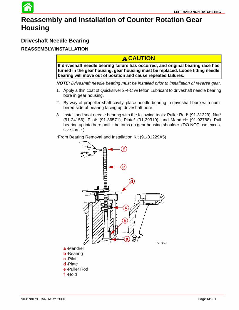
LEFT HAND NON-RATCHETING
90-878079 JANUARY 2000 Page 6B-31
Reassembly and Installation of Counter Rotation GearHousing
Driveshaft Needle BearingREASSEMBLY/INSTALL ATION
CAUTIONIf driveshaft needle bearing failure has occurred, and original bearing race hasturned in the gear housing, gear housing must be replaced. Loose fitting needlebearing will move out of position and cause repeated failures.
NOTE: Driveshaft needle bearing must be installed prior to installation of reverse gear.
1. Apply a thin coat of Quicksilver 2-4-C w/Teflon Lubricant to driveshaft needle bearingbore in gear housing.
2. By way of propeller shaft cavity, place needle bearing in driveshaft bore with num-bered side of bearing facing up driveshaft bore.
3. Install and seat needle bearing with the following tools: Puller Rod* (91-31229), Nut*(91-24156), Pilot* (91-36571), Plate* (91-29310), and Mandrel* (91-92788). Pullbearing up into bore until it bottoms on gear housing shoulder. (DO NOT use exces-sive force.)
*From Bearing Removal and Installation Kit (91-31229A5)
51869
f
e
d
c
b
aa
b
c
d
e
f
a -Mandrelb -Bearingc -Pilotd -Platee -Puller Rodf -Hold

LEFT HAND NON-RATCHETING
Page 6B-32 90-878079 JANUARY 2000
Bearing Carrie r, Forward Gear and Bearing AdaptorREASSEMBLY
1. Using suitable mandrel, press forward gear bearing into bearing adaptor until bearingis flush with lip of adaptor.
ab
c
ab
c
a -Suitable Mandrelb -Forward Gear Bearingc -Bearing Adaptor
PROPELLER SHAFT NEEDLE ROLLER BEARING AND OIL SEAL INS TALL ATION
1. Using mandrel 91-15755, press bearing carrier needle bearing (number side up) intobearing carrier until mandrel shoulder contacts bearing carrier.
a
b
d
c
51881
a
bc
d
a -Mandrel (91-15755)b -Bearing Carrier Needle Bearingc -Bearing Carrierd -Shoulder
2. Apply Loctite 271 (92-809820) to outside diameter of oil seals.
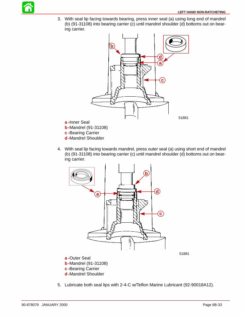
LEFT HAND NON-RATCHETING
90-878079 JANUARY 2000 Page 6B-33
3. With seal lip facing towards bearing, press inner seal (a) using long end of mandrel(b) (91-31108) into bearing carrier (c) until mandrel shoulder (d) bottoms out on bear-ing carrier.
d
c
b
a
51881
a
b
c
d
a -Inner Sealb -Mandrel (91-31108)c -Bearing Carrierd -Mandrel Shoulder
4. With seal lip facing towards mandrel, press outer seal (a) using short end of mandrel(b) (91-31108) into bearing carrier (c) until mandrel shoulder (d) bottoms out on bear-ing carrier.
d
c
a
b
51881
a
b
c
d
a -Outer Sealb -Mandrel (91-31108)c -Bearing Carrierd -Mandrel Shoulder
5. Lubricate both seal lips with 2-4-C w/Teflon Marine Lubricant (92-90018A12).

LEFT HAND NON-RATCHETING
Page 6B-34 90-878079 JANUARY 2000
REVERSE GEAR AND BEARING CUP ADAP TOR REASSEMBLY
1. With reverse gear teeth facing down, use mandrel (91-86943) to press propeller shaftneedle bearing (NUMBERS/LETTERS UP) into reverse gear until short shoulder onmandrel bottoms on reverse gear.
NOTE: If gear housing has been replaced or inspection determines that reverse gearbearing adapter must be replaced, assemble and install as follows:
2. Place reverse gear roller bearing (NUMBER/LETTERS UP) in press. Using suitablemandrel, press bearing cup adapter onto reverse gear bearing.
a
b
ca
cd
b
51883
e
f
ga
b
cd
a -Reverse Gear Teethb -Mandrel (91-86943)c -Propeller Shaft Needle Bearingd -Shouldere -Mandrelf -Bearing Cup Adapterg -Reverse Gear Roller Bearing
IMPORTANT: The appearance of the forward and reverse gear is almost identical.There are two ways to distinguish between the reverse and forward gears. The re-verse gear has a shorter hub and it has a smaller inner diameter needle bearingbore.
50885
d
a b
c
a b
c
d
a -Reverse Gearb -Forward Gearc -Shorter Length Hubd -Smaller Diameter Bearing Bore

LEFT HAND NON-RATCHETING
90-878079 JANUARY 2000 Page 6B-35
Reverse Gear Bearing Adaptor AssemblyINSTALL ATION
NOTE: If the reverse gear, reverse gear adaptor, large thrust bearing, or bearing race inthe gear housing were not replaced, install the same shim(s) (or the same thickness ofshim(s)) that were taken out when adaptor was removed. If the reverse gear, reverse gearadaptor, large thrust bearing, bearing race, or gear housing were replaced, install 0.008in. (0.51 mm) of shims.
NOTE: If backlash has already been checked and it has determined that it needs to beadjusted, (see Checking Reverse Gear Backlash), adding 0.001 in. (0.025 mm) shims willreduce the gear backlash by approximately 0.001 in. (0.025 mm). Subtracting 0.001 in.(0.025 mm) shims will increase backlash by approximately the same amount.
Example 1 (if backlash is too high)
Backlash checks:
(subtract) middleof
specification:
You get:
add this quantity of shims:
0.045 in.
0.025 in.
0.020 in.
(1.14 mm)
(0.64 mm)
(0.51 mm)
Example 2 (if backlash is too low)
Backlash checks:
middle of specification:
(subtract) You get:
subtract this quantity of shims:
0.025 in.
0.009 in.
0.016 in.
(0.64 mm)
(0.23 mm)
(0.41 mm)
1. Lubricate the bore into which the reverse gear bearing adaptor is to be installed withQuicksilver Super Duty Gear Lubricant.
2. Place the shim(s) into reverse bore of gear housing.
3. Position the bearing adaptor in the gear housing.
a
b
55099
a
b
a -Bearing Adaptorb -Shims

LEFT HAND NON-RATCHETING
Page 6B-36 90-878079 JANUARY 2000
4. Position the reverse gear (without the thrust race or thrust bearing) into the gear hous-ing and into the adaptor.
5. Install PILOT RING (91-18603) over DRIVER TOOL (91-18605) and seat pilot ring ingearcase against inner ledge. Thread RETAINER (91-18604) into bearing carrierthreads. Install SCREW (10-18602) into retainer and gently tighten screw againstdriver tool while holding retainer securely. Continue to apply pressure against driverrod until reverse gear/bearing cup adaptor JUST SEATS in gearcase. DO NOTOVER-SEAT the adaptor as the reverse gear bearing will be damaged. As bearingadaptor begins to seat, the effort required to turn screw will increase considerably.
d a
cbe
a
55100
a
b
c
d
e
f
a -Reverse Gearb -Pilot Ring (91-18603)c -Driver Tool (91-18605)d -Inner Ledgee -Retainer (91-18604)f -Screw (10-18602)
6. After reverse bearing adaptor is seated, remove screw, retainer, driver tool, pilot ringand reverse gear. Apply Quicksilver Super Duty Gear Lubricant to thrust bearing andinstall thrust race and bearing onto bearing adaptor.
7. Reinstall reverse gear into bearing adaptor.
55102
d
ef
g55101
a
b
c
a -Thrust Bearingb -Thrust Washerc -Bearing Adaptord -Reverse Geare -Thrust Bearingf -Thrust Washer (under thrust bearing)g -Bearing Adaptor

LEFT HAND NON-RATCHETING
90-878079 JANUARY 2000 Page 6B-37
Driveshaft and Pinion GearREASSEMBLY/INSTALL ATION
1. Apply a light coat of Quicksilver Super Duty Gear Lubricant on l.D. of driveshaft ta-pered bearing.
2. Thread a used pinion nut onto end of driveshaft. Leave approximately 1/16 in. (1.6mm) of nut threads exposed. Driveshaft threads MUST NOT extend beyond nut orthread damage could result while pressing.
3. Place bearing over driveshaft.
4. Using an old driveshaft bearing inner race or other suitable mandrel (which appliespressing force on center bearing race only), press bearing onto shaft until seated.
50064
a
b
cd
e
a
b
cd
e
a -Used Pinion Nutb -Driveshaftc -Tapered Bearingd -Old Bearing Inner Racee -Universal Puller Plate
5. Position pinion gear in gear housing below driveshaft bore with teeth of pinion gearmeshed with teeth of reverse gear.
6. Insert driveshaft into driveshaft bore while holding pinion gear. Rotate driveshaft toalign and engage driveshaft splines with pinion gear splines. Continue to insert drive-shaft into gear housing until driveshaft tapered bearing is against bearing race.
7. Apply Loctite 271 to threads of pinion gear nut and install flat washer and nut on drive-shaft with flat side of nut away from pinion gear.
8. Place shim(s) (retained from disassembly) into gear housing. If shim(s) were lost orare not reusable (damaged), start with approximately 0.010 in. (0.254 mm).

LEFT HAND NON-RATCHETING
Page 6B-38 90-878079 JANUARY 2000
9. Install bearing race and bearing retainer.
d
b
a
c
51880a
b
c
d
a -Shim(s)b -Bearing Racec -Bearing Retainer (Word “OFF” must be visible); Torque to 100 lb. ft.
(135.5 Nm)d -Bearing Retainer Tool (91-43506)
10. Use a socket and breaker bar to hold pinion nut (pad area where flex handle will con-tact gear housing while torquing nut).
11. Place Driveshaft Holding Tool (91-34377A1) over crankshaft end of driveshaft.Torque pinion nut to 75 Ib. ft. (101.5 Nm).
a
b ac
c
d
a
b ac
c
da -Driveshaft Holding Tool (91-34377A1)b -Torque Wrench; Torque Nut to 75 lb. ft. (101.5 Nm)c -Socketd -Breaker Bar
IMPORTANT: Wipe any excess Loctite from pinion nut and pinion gea r.

LEFT HAND NON-RATCHETING
90-878079 JANUARY 2000 Page 6B-39
Pinion Gear DepthDETERMINING PINION GEAR DEPTH
NOTE: Read entire procedure before attempting any change in shim thickness.
IMPORTANT: Reverse gear assembly must be installed in gear housing whenchecking pinion gear depth or an inaccurate measurement will be obtained.
1. Clean gear housing bearing carrier shoulder.
2. Install Bearing Preload Tool (91-14311A1) over driveshaft in sequence shown.
NOTE: Bearing Preload Tool (91-44307A1) may also be used. Follow instructions pro-vided with tool for proper installation.
h
g g
e
f
d
c
b
aa
b
c
d
e
f
g
h
g
a -Adaptorb -Bearingc -Washerd -Springe -Nut; thread nut all the way onto boltf -Boltg -Set Screwh -Sleeve; holes in sleeve must align with set screws
3. Align adaptor on driveshaft bearing pocket ledge.
4. With tool installed over driveshaft, tighten both set screws securely, making certainto align sleeve holes to allow set screws to pass thru.

LEFT HAND NON-RATCHETING
Page 6B-40 90-878079 JANUARY 2000
5. Measure distance (a) and increase that distance by 1 in. (25.4 mm) by turning bottomnut away from top nut.
1 in. (25.4 mm)
a
b51870
a b
c
a
a -Distanceb -Adaptorc -Ledge
6. Turn driveshaft clockwise 2 or more turns to seat driveshaft bearings.
7. Insert Pinion Gear Locating Tool* (91-74776) into gear housing until it bottoms out onbearing carrier Shoulder.
*Pinion Gear Locating Tool (91-12349A2) can be used. Use flat #7 and disc #2. Followinstructions supplied with tool.
8. Determine pinion gear depth by inserting a feeler gauge thru access slot in pinion gearshimming tool.
9. Clearance between shimming tool and pinion gear should be 0.025 in. (0.64 mm).
10. If clearance is correct, leave Bearing Preload Tool on driveshaft for “DeterminingForward Gear Backlash,” following.
11. If clearance is not correct, add (or subtract) shims at location shown to raise (or lower)pinion gear.When reinstalling pinion nut, apply Loctite 271 on threads of nut and retorque pinionnut.
c
ad
c
a
b
24643
a
b
a
c
c
d
a -Pinion Gear Shimming Tool (91-74776 or 91-12349A2)b -Feeler Gaugec -Obtain 0.025 in. (0.64 mm) Clearance between Shimming Tool and Pinion Geard -Add or Subtract Shim(s) Here
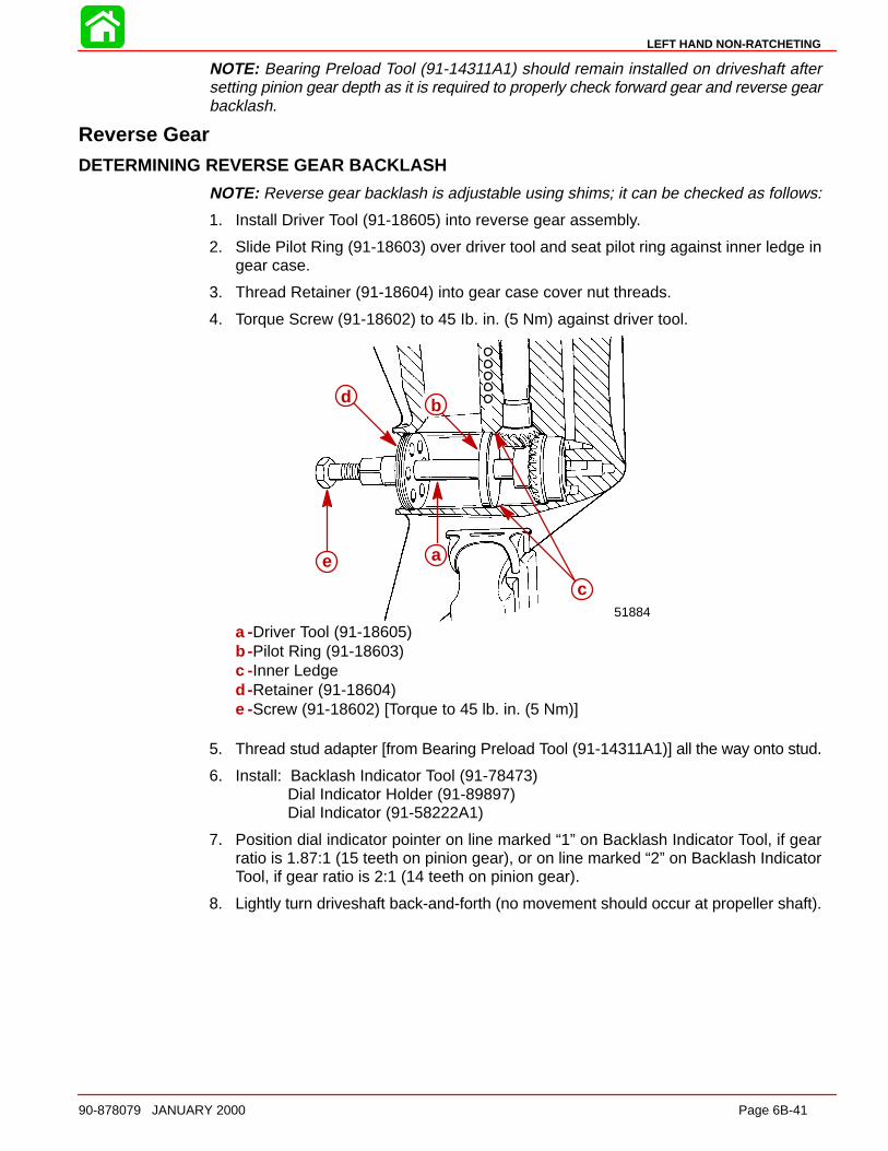
LEFT HAND NON-RATCHETING
90-878079 JANUARY 2000 Page 6B-41
NOTE: Bearing Preload Tool (91-14311A1) should remain installed on driveshaft aftersetting pinion gear depth as it is required to properly check forward gear and reverse gearbacklash.
Reverse GearDETERMINING REVERSE GEAR BACKLASH
NOTE: Reverse gear backlash is adjustable using shims; it can be checked as follows:
1. Install Driver Tool (91-18605) into reverse gear assembly.
2. Slide Pilot Ring (91-18603) over driver tool and seat pilot ring against inner ledge ingear case.
3. Thread Retainer (91-18604) into gear case cover nut threads.
4. Torque Screw (91-18602) to 45 Ib. in. (5 Nm) against driver tool.
d
e
c51884
b
aa
b
c
d
e
a -Driver Tool (91-18605)b -Pilot Ring (91-18603)c -Inner Ledged -Retainer (91-18604)e -Screw (91-18602) [Torque to 45 lb. in. (5 Nm)]
5. Thread stud adapter [from Bearing Preload Tool (91-14311A1)] all the way onto stud.
6. Install: Backlash Indicator Tool (91-78473)Dial Indicator Holder (91-89897)Dial Indicator (91-58222A1)
7. Position dial indicator pointer on line marked “1” on Backlash Indicator Tool, if gearratio is 1.87:1 (15 teeth on pinion gear), or on line marked “2” on Backlash IndicatorTool, if gear ratio is 2:1 (14 teeth on pinion gear).
8. Lightly turn driveshaft back-and-forth (no movement should occur at propeller shaft).
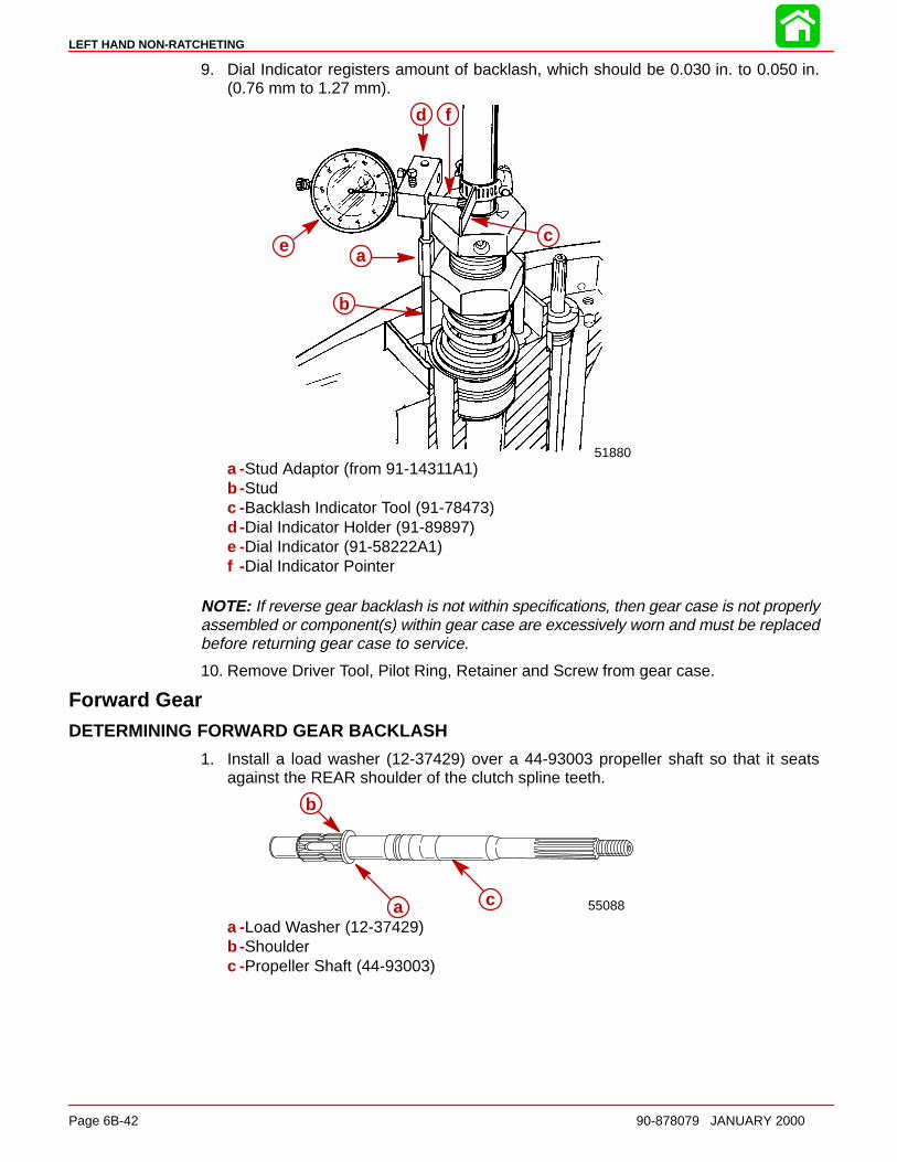
LEFT HAND NON-RATCHETING
Page 6B-42 90-878079 JANUARY 2000
9. Dial Indicator registers amount of backlash, which should be 0.030 in. to 0.050 in.(0.76 mm to 1.27 mm).
d f
ea
b
c
51880
a
b
c
d
e
f
a -Stud Adaptor (from 91-14311A1)b -Studc -Backlash Indicator Tool (91-78473)d -Dial Indicator Holder (91-89897)e -Dial Indicator (91-58222A1)f -Dial Indicator Pointer
NOTE: If reverse gear backlash is not within specifications, then gear case is not properlyassembled or component(s) within gear case are excessively worn and must be replacedbefore returning gear case to service.
10. Remove Driver Tool, Pilot Ring, Retainer and Screw from gear case.
Forward GearDETERMINING FORWARD GEAR BACKLASH
1. Install a load washer (12-37429) over a 44-93003 propeller shaft so that it seatsagainst the REAR shoulder of the clutch spline teeth.
b
ac 55088a
b
c
a -Load Washer (12-37429)b -Shoulderc -Propeller Shaft (44-93003)
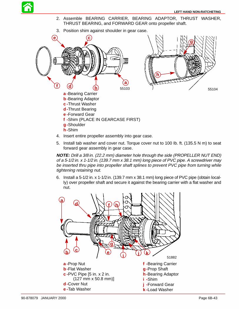
LEFT HAND NON-RATCHETING
90-878079 JANUARY 2000 Page 6B-43
2. Assemble BEARING CARRIER, BEARING ADAPTOR, THRUST WASHER,THRUST BEARING, and FORWARD GEAR onto propeller shaft.
3. Position shim against shoulder in gear case.
b
a
5510455103
g
h
b
c
d
e
fa
a -Bearing Carrierb -Bearing Adaptorc -Thrust Washerd -Thrust Bearinge -Forward Gearf -Shim (PLACE IN GEARCASE FIRST)g -Shoulderh -Shim
4. Insert entire propeller assembly into gear case.
5. Install tab washer and cover nut. Torque cover nut to 100 Ib. ft. (135.5 N m) to seatforward gear assembly in gear case.
NOTE: Drill a 3/8 in. (22.2 mm) diameter hole through the side (PROPELLER NUT END)of a 5-1/2 in. x 1-1/2 in. (139.7 mm x 38.1 mm) long piece of PVC pipe. A screwdriver maybe inserted thru pipe into propeller shaft splines to prevent PVC pipe from turning whiletightening retaining nut.
6. Install a 5-1/2 in. x 1-1/2 in. (139.7 mm x 38.1 mm) long piece of PVC pipe (obtain local-ly) over propeller shaft and secure it against the bearing carrier with a flat washer andnut.
51882
cb e
g
ad f h
i j k
a -Prop Nutb -Flat Washerc -PVC Pipe [5 in. x 2 in.
(127 mm x 50.8 mm)]d -Cover Nute -Tab Washer
f -Bearing Carrierg -Prop Shafth -Bearing Adaptori -Shimj -Forward Geark -Load Washer
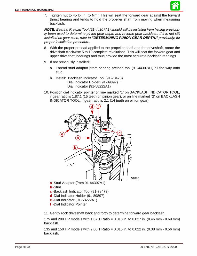
LEFT HAND NON-RATCHETING
Page 6B-44 90-878079 JANUARY 2000
7. Tighten nut to 45 lb. in. (5 Nm). This will seat the forward gear against the forwardthrust bearing and tends to hold the propeller shaft from moving when measuringbacklash.
NOTE: Bearing Preload Tool (91-44307A1) should still be installed from having previous-ly been used to determine pinion gear depth and reverse gear backlash. If it is not stillinstalled on gear case, refer to “DETERMINING PINION GEAR DEPTH,” previously, forproper installation procedure.
8. With the proper preload applied to the propeller shaft and the driveshaft, rotate thedriveshaft clockwise 5 to 10 complete revolutions. This will seat the forward gear andupper driveshaft bearings and thus provide the most accurate backlash readings.
9. If not previously installed:
a. Thread stud adaptor [from bearing preload tool (91-44307A1) all the way ontostud.
b. Install: Backlash Indicator Tool (91-78473)Dial Indicator Holder (91-89897)Dial Indicator (91-58222A1)
10. Position dial indicator pointer on line marked “1” on BACKLASH INDICATOR TOOL,if gear ratio is 1.87:1 (15 teeth on pinion gear), or on line marked “2” on BACKLASHINDICATOR TOOL, if gear ratio is 2:1 (14 teeth on pinion gear).
d f
ea
b
c
51880
a
b
c
d
e
f
a -Stud Adaptor (from 91-44307A1)b -Studc -Backlash Indicator Tool (91-78473)d -Dial Indicator Holder (91-89897)e -Dial Indicator (91-58222A1)f -Dial Indicator Pointer
11. Gently rock driveshaft back and forth to determine forward gear backlash.
175 and 200 HP models with 1.87:1 Ratio = 0.018 in. to 0.027 in. (0.46 mm - 0.69 mm)backlash.
135 and 150 HP models with 2.00:1 Ratio = 0.015 in. to 0.022 in. (0.38 mm - 0.56 mm)backlash.

LEFT HAND NON-RATCHETING
90-878079 JANUARY 2000 Page 6B-45
12. If backlash is less than the specifications, then a larger shim should be installed. Con-versely, if the backlash indicated is greater than specifications, then a smaller shimshould be installed.
NOTE: By adding or subtracting 0.002 in. (0.051 mm) shim, the backlash will change ap-proximately 0.002 in. (0.051 mm).
a
51882
a
a -Shim
13. If forward gear backlash is within specifications, then Bearing Preload Tool, Dial Indi-cator, Backlash Indicator Tool/Dial Indicator Holder, PVC pipe, forward gear assem-bly, bearing adaptor, bearing carrier and test propeller shaft can all be removed fromthe gear case.
Propeller Shaft/Forward Gear Bearing Adapter/Bearing CarrierREASSEMBLY
1. Position sliding clutch onto propeller shaft. “GROOVED RINGS” are for manufactur-ing purposes only and may be positioned towards either gear. Cross pin hole and det-ent hole in sliding clutch must line up with cross pin slot and detent notch in propellershaft.
d
g 51913
d
g
af
be
c
a -Sliding Clutchb -Propeller Shaftc -Grooved Ringsd -Cross Pin Holee -Detent Holef -Cross Pin Slotg -Detent Notches
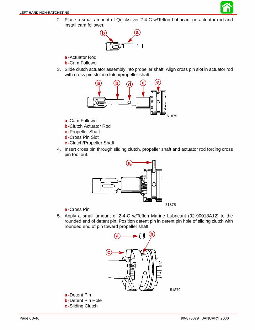
LEFT HAND NON-RATCHETING
Page 6B-46 90-878079 JANUARY 2000
2. Place a small amount of Quicksilver 2-4-C w/Teflon Lubricant on actuator rod andinstall cam follower.
b aab
a -Actuator Rodb -Cam Follower
3. Slide clutch actuator assembly into propeller shaft. Align cross pin slot in actuator rodwith cross pin slot in clutch/propeller shaft.
a b d c e
51875
a b cd e
a -Cam Followerb -Clutch Actuator Rodc -Propeller Shaftd -Cross Pin Slote -Clutch/Propeller Shaft
4. Insert cross pin through sliding clutch, propeller shaft and actuator rod forcing crosspin tool out.
51875
aa
a -Cross Pin5. Apply a small amount of 2-4-C w/Teflon Marine Lubricant (92-90018A12) to the
rounded end of detent pin. Position detent pin in detent pin hole of sliding clutch withrounded end of pin toward propeller shaft.
a
c
b
51879
a b
c
a -Detent Pinb -Detent Pin Holec -Sliding Clutch
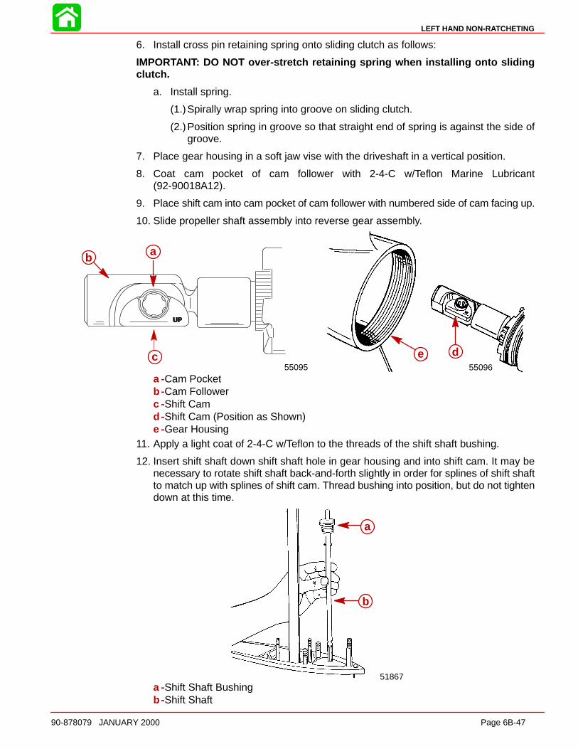
LEFT HAND NON-RATCHETING
90-878079 JANUARY 2000 Page 6B-47
6. Install cross pin retaining spring onto sliding clutch as follows:
IMPORTANT: DO NOT over-stretch retaining spring when installing onto slidingclutch.
a. Install spring.
(1.)Spirally wrap spring into groove on sliding clutch.
(2.)Position spring in groove so that straight end of spring is against the side ofgroove.
7. Place gear housing in a soft jaw vise with the driveshaft in a vertical position.
8. Coat cam pocket of cam follower with 2-4-C w/Teflon Marine Lubricant(92-90018A12).
9. Place shift cam into cam pocket of cam follower with numbered side of cam facing up.
10. Slide propeller shaft assembly into reverse gear assembly.
b a
b a
c55095
ab
c55096
de
a -Cam Pocketb -Cam Followerc -Shift Camd -Shift Cam (Position as Shown)e -Gear Housing
11. Apply a light coat of 2-4-C w/Teflon to the threads of the shift shaft bushing.
12. Insert shift shaft down shift shaft hole in gear housing and into shift cam. It may benecessary to rotate shift shaft back-and-forth slightly in order for splines of shift shaftto match up with splines of shift cam. Thread bushing into position, but do not tightendown at this time.
51867
a
b
a
b
a -Shift Shaft Bushingb -Shift Shaft

LEFT HAND NON-RATCHETING
Page 6B-48 90-878079 JANUARY 2000
13. Install appropriate spacer shim into the gear housing.
14. Apply Quicksilver Super Duty Gear Lubricant to to thrust bearing and install thrustbearing and thrust race onto forward gear bearing adaptor.
c
b
a
55220
50782
a
b
c
d
a
a -Shimb -Bearing Adaptorc -Thrust Washerd -Thrust Bearing
15. Insert Forward Gear Installation Tool (91-815850) into forward gear/bearing adaptorassembly.
16. Install tool with adaptor assembly over propeller shaft and into gear housing. Applyingdownward pressure to bearing adaptor, remove installation tool from assembly.
55202
a
a
b
55221
a
b
c
a -Forward Gear Installation Tool (91-815850)b -Forward Gear/Bearing Adaptor Assemblyc -Forward Gear Bearing Adaptor

LEFT HAND NON-RATCHETING
90-878079 JANUARY 2000 Page 6B-49
17. Install thrust race on top of bearing adaptor.
18. Apply Quicksilver Super Duty Gear Lubricant to small thrust bearing and install bear-ing on thrust race.
a
55108
a
55107
a
b
a -Thrust Raceb -Thrust Bearing
19. Install thrust collar with its STEPPED SIDE DOWN toward the small thrust bearing.
20. Pull up slightly on the propeller shaft to gain access to the groove on the shaft for thekeepers. Install the 2 keepers into the groove and lower the propeller shaft.
a
c
b
5511055109
c
d
ea
b
a
b
a -Thrust Collarb -Thrust Bearingc -Propeller Shaftd -Keepers (2)e -Thrust Collar
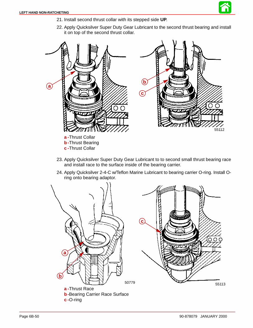
LEFT HAND NON-RATCHETING
Page 6B-50 90-878079 JANUARY 2000
21. Install second thrust collar with its stepped side UP.
22. Apply Quicksilver Super Duty Gear Lubricant to the second thrust bearing and installit on top of the second thrust collar.
a
b
55112
aab
c
a -Thrust Collarb -Thrust Bearingc -Thrust Collar
23. Apply Quicksilver Super Duty Gear Lubricant to to second small thrust bearing raceand install race to the surface inside of the bearing carrier.
24. Apply Quicksilver 2-4-C w/Teflon Marine Lubricant to bearing carrier O-ring. Install O-ring onto bearing adaptor.
a
55113
a
b50779
a
b
c
a -Thrust Raceb -Bearing Carrier Race Surfacec -O-ring

LEFT HAND NON-RATCHETING
90-878079 JANUARY 2000 Page 6B-51
25. Apply Quicksilver 2-4-C w/Teflon Marine Lubricant to:
a. Outer diameter of bearing carrier which contacts gear case.
b. Space between carrier oil seals.
26. Apply Quicksilver Super Duty Gear Lubricant to bearing carrier needle bearing.
27. Install bearing carrier into gear housing.
28. Verify bearing carrier keyway is aligned with gear housing keyway and install bearingcarrier key.
29. Place tab washer against bearing carrier.
51885
a
a
55114
ab
a -Bearing Carrierb -Tab Washer
30. Apply 2-4-C w/Teflon to threads of cover nut and install cover nut in gear housing.Verify that the word “OFF” and arrow are visible.
NOTE: Before torquing bearing carrier cover nut, gear case should either be mounted ina stand specifically designed for holding gear cases or bolted to a driveshaft housing toavoid possible damage to the gear case.
31. Using Cover Nut Tool (91-61069), torque cover nut to 210 Ib. ft. (285 Nm).
a b
51911
a b
a -Retainer Nut Tool (91-61069)b -Retainer Nut
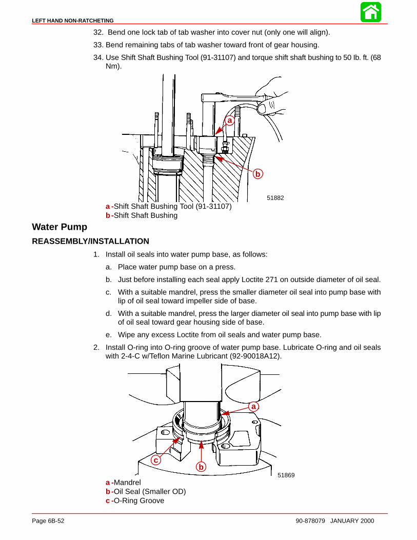
LEFT HAND NON-RATCHETING
Page 6B-52 90-878079 JANUARY 2000
32. Bend one lock tab of tab washer into cover nut (only one will align).
33. Bend remaining tabs of tab washer toward front of gear housing.
34. Use Shift Shaft Bushing Tool (91-31107) and torque shift shaft bushing to 50 Ib. ft. (68Nm).
b
a
51882
a
b
a -Shift Shaft Bushing Tool (91-31107)b -Shift Shaft Bushing
Water PumpREASSEMBLY/INSTALL ATION
1. Install oil seals into water pump base, as follows:
a. Place water pump base on a press.
b. Just before installing each seal apply Loctite 271 on outside diameter of oil seal.
c. With a suitable mandrel, press the smaller diameter oil seal into pump base withlip of oil seal toward impeller side of base.
d. With a suitable mandrel, press the larger diameter oil seal into pump base with lipof oil seal toward gear housing side of base.
e. Wipe any excess Loctite from oil seals and water pump base.
2. Install O-ring into O-ring groove of water pump base. Lubricate O-ring and oil sealswith 2-4-C w/Teflon Marine Lubricant (92-90018A12).
a
bc
51869
a
bc
a -Mandrelb -Oil Seal (Smaller OD)c -O-Ring Groove
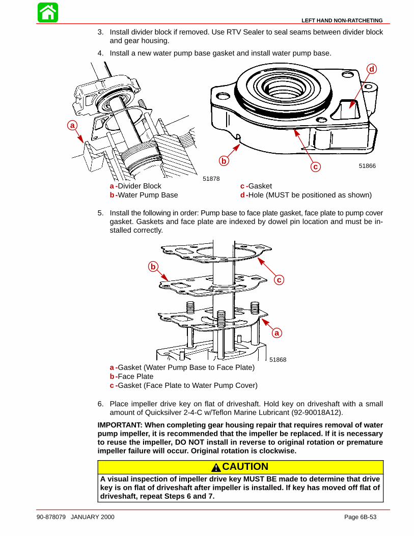
LEFT HAND NON-RATCHETING
90-878079 JANUARY 2000 Page 6B-53
3. Install divider block if removed. Use RTV Sealer to seal seams between divider blockand gear housing.
4. Install a new water pump base gasket and install water pump base.
c
ab 51866
a
51878
a
bc
d
a -Divider Blockb -Water Pump Base
c -Gasketd -Hole (MUST be positioned as shown)
5. Install the following in order: Pump base to face plate gasket, face plate to pump covergasket. Gaskets and face plate are indexed by dowel pin location and must be in-stalled correctly.
b
c
a
51868
a
b
c
a -Gasket (Water Pump Base to Face Plate)b -Face Platec -Gasket (Face Plate to Water Pump Cover)
6. Place impeller drive key on flat of driveshaft. Hold key on driveshaft with a smallamount of Quicksilver 2-4-C w/Teflon Marine Lubricant (92-90018A12).
IMPORTANT: When completing gear housing repair that requires removal of waterpump impelle r, it is recommended that the impeller be replaced. If it is necessaryto reuse the impelle r, DO NOT install in reverse to original rotation or prematureimpeller failure will occu r. Original rotation is clockwise.
CAUTIONA visual inspection of impeller drive key MUST BE made to determine that drivekey is on flat of driveshaft after impeller is installed. If key has moved off flat ofdriveshaft, repeat Steps 6 and 7.
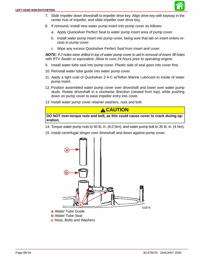
LEFT HAND NON-RATCHETING
Page 6B-54 90-878079 JANUARY 2000
7. Slide impeller down driveshaft to impeller drive key. Align drive key with keyway in thecenter hub of impeller, and slide impeller over drive key.
8. If removed, install new water pump insert into pump cover as follows:
a. Apply Quicksilver Perfect Seal to water pump insert area of pump cover.
b. Install water pump insert into pump cover, being sure that tab on insert enters re-cess in pump cover.
c. Wipe any excess Quicksilver Perfect Seal from insert and cover.
NOTE: If 2 holes were drilled in top of water pump cover to aid in removal of insert, fill holeswith RTV Sealer or equivalent. Allow to cure 24 hours prior to operating engine.
9. Install water tube seal into pump cover. Plastic side of seal goes into cover first.
10. Reinstall water tube guide into water pump cover.
11. Apply a light coat of Quicksilver 2-4-C w/Teflon Marine Lubricant to inside of waterpump insert.
12. Position assembled water pump cover over driveshaft and lower over water pumpstuds. Rotate driveshaft in a clockwise direction (viewed from top), while pushingdown on pump cover to ease impeller entry into cover.
13. Install water pump cover retainer washers, nuts and bolt.
CAUTIONDO NOT over-torque nuts and bolt, as this could cause cover to crack during op-eration.
14. Torque water pump nuts to 50 Ib. in. (6.0 Nm), and water pump bolt to 35 Ib. in. (4 Nm).
15. Install centrifugal slinger over driveshaft and down against pump cover.
a
b
c51874
a
b
c
a -Water Tube Guideb -Water Tube Sealc -Nuts, Bolts and Washers
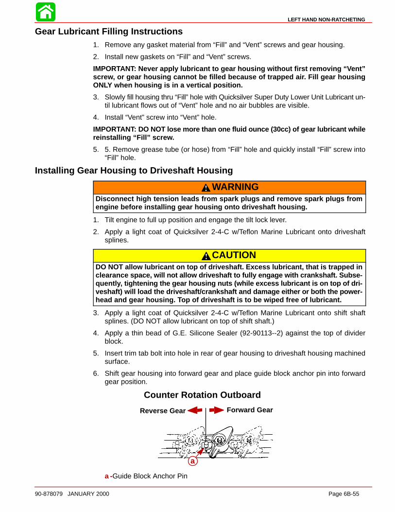
LEFT HAND NON-RATCHETING
90-878079 JANUARY 2000 Page 6B-55
Gear Lubricant Filling Instructions1. Remove any gasket material from “Fill” and “Vent” screws and gear housing.
2. Install new gaskets on “Fill” and “Vent” screws.
IMPORTANT: Never apply lubricant to gear housing without first removing “ Vent”scre w, or gear housing cannot be filled because of trapped ai r. Fill gear housingONLY when housing is in a vertical position.
3. Slowly fill housing thru “Fill” hole with Quicksilver Super Duty Lower Unit Lubricant un-til lubricant flows out of “Vent” hole and no air bubbles are visible.
4. Install “Vent” screw into “Vent” hole.
IMPORTANT: DO NOT lose more than one fluid ounce (30cc) of gear lubricant whilereinstalling “Fill” scre w.
5. 5. Remove grease tube (or hose) from “Fill” hole and quickly install “Fill” screw into“Fill” hole.
Installing Gear Housing to Driveshaft Housing
WARNINGDisconnect high tension leads from spark plugs and remove spark plugs fromengine before installing gear housing onto driveshaft housing.
1. Tilt engine to full up position and engage the tilt lock lever.
2. Apply a light coat of Quicksilver 2-4-C w/Teflon Marine Lubricant onto driveshaftsplines.
CAUTIONDO NOT allow lubricant on top of driveshaft. Excess lubricant, that is trapped inclearanc e space, will not allow driveshaft to fully engage with crankshaft. Subse-quentl y, tightening the gear housing nuts (while excess lubricant is on top of dri-veshaft) will load the driveshaft/crankshaft and damage either or both the power-head and gear housing. Top of driveshaft is to be wiped free of lubricant.
3. Apply a light coat of Quicksilver 2-4-C w/Teflon Marine Lubricant onto shift shaftsplines. (DO NOT allow lubricant on top of shift shaft.)
4. Apply a thin bead of G.E. Silicone Sealer (92-90113--2) against the top of dividerblock.
5. Insert trim tab bolt into hole in rear of gear housing to driveshaft housing machinedsurface.
6. Shift gear housing into forward gear and place guide block anchor pin into forwardgear position.
Forward GearReverse Gear
a
Counter Rotation Outboard
a -Guide Block Anchor Pin
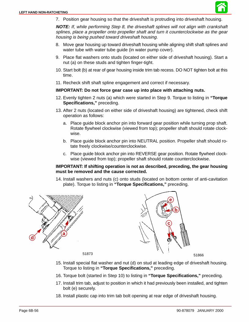
LEFT HAND NON-RATCHETING
Page 6B-56 90-878079 JANUARY 2000
7. Position gear housing so that the driveshaft is protruding into driveshaft housing.
NOTE: If, while performing Step 8, the driveshaft splines will not align with crankshaftsplines, place a propeller onto propeller shaft and turn it counterclockwise as the gearhousing is being pushed toward driveshaft housing.
8. Move gear housing up toward driveshaft housing while aligning shift shaft splines andwater tube with water tube guide (in water pump cover).
9. Place flat washers onto studs (located on either side of driveshaft housing). Start anut (a) on these studs and tighten finger-tight.
10. Start bolt (b) at rear of gear housing inside trim tab recess. DO NOT tighten bolt at thistime.
11. Recheck shift shaft spline engagement and correct if necessary.
IMPORTANT: Do not force gear case up into place with attaching nuts.
12. Evenly tighten 2 nuts (a) which were started in Step 9. Torque to listing in “ TorqueSpecifications,” preceding.
13. After 2 nuts (located on either side of driveshaft housing) are tightened, check shiftoperation as follows:
a. Place guide block anchor pin into forward gear position while turning prop shaft.Rotate flywheel clockwise (viewed from top); propeller shaft should rotate clock-wise.
b. Place guide block anchor pin into NEUTRAL position. Propeller shaft should ro-tate freely clockwise/counterclockwise.
c. Place guide block anchor pin into REVERSE gear position. Rotate flywheel clock-wise (viewed from top); propeller shaft should rotate counterclockwise.
IMPORTANT: If shifting operation is not as described, preceding, the gear housingmust be removed and the cause corrected.
14. Install washers and nuts (c) onto studs (located on bottom center of anti-cavitationplate). Torque to listing in “ Torque Specifications,” preceding.
51866
c
51873
a
b
d
e
15. Install special flat washer and nut (d) on stud at leading edge of driveshaft housing.Torque to listing in “ Torque Specifications,” preceding.
16. Torque bolt (started in Step 10) to listing in “ Torque Specifications,” preceding.
17. Install trim tab, adjust to position in which it had previously been installed, and tightenbolt (e) securely.
18. Install plastic cap into trim tab bolt opening at rear edge of driveshaft housing.
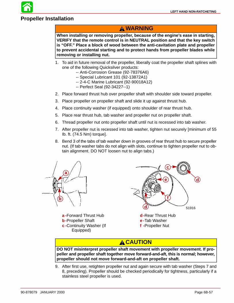
LEFT HAND NON-RATCHETING
90-878079 JANUARY 2000 Page 6B-57
Propeller Installation
WARNINGWhen installing or removing propelle r, because of the engine ’s ease in starting,VERIFY that the remote control is in NEUTRAL position and that the key switchis “OF F.” Place a block of wood between the anti-cavitation plate and propellerto prevent accidental starting and to protect hands from propeller blades whileremoving or installing nut.
1. To aid in future removal of the propeller, liberally coat the propeller shaft splines withone of the following Quicksilver products:
-- Anti-Corrosion Grease (92-78376A6)-- Special Lubricant 101 (92-13872A1)-- 2-4-C Marine Lubricant (92-90018A12)-- Perfect Seal (92-34227--1)
2. Place forward thrust hub over propeller shaft with shoulder side toward propeller.
3. Place propeller on propeller shaft and slide it up against thrust hub.
4. Place continuity washer (if equipped) onto shoulder of rear thrust hub.
5. Place rear thrust hub, tab washer and propeller nut on propeller shaft.
6. Thread propeller nut onto propeller shaft until nut is recessed into tab washer.
7. After propeller nut is recessed into tab washer, tighten nut securely [minimum of 55Ib. ft. (74.5 Nm) torque].
8. Bend 3 of the tabs of tab washer down in grooves of rear thrust hub to secure propellernut. (If tab washer tabs do not align with slots, continue to tighten propeller nut to ob-tain alignment. DO NOT loosen nut to align tabs.)
a
b
a
b
51916
c
d
e
f
d
a -Forward Thrust Hubb -Propeller Shaftc -Continuity Washer (If
Equipped)
d -Rear Thrust Hube -Tab Washerf -Propeller Nut
CAUTIONDO NOT misinterpret propeller shaft movement with propeller movement. If pro-pelle r and propeller shaft together move forward-and-aft, this is normal; howeve r,propeller should not move forward-and-aft on propeller shaft.
9. After first use, retighten propeller nut and again secure with tab washer (Steps 7 and8, preceding). Propeller should be checked periodically for tightness, particularly if astainless steel propeller is used.
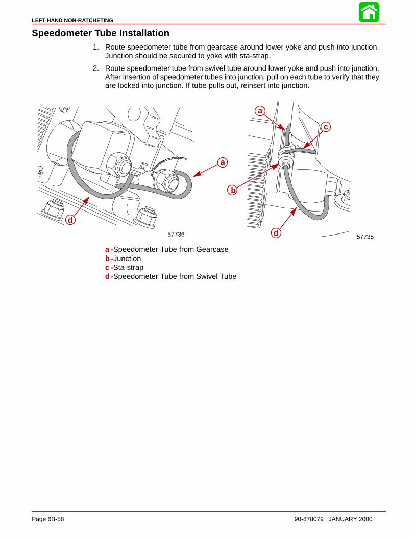
LEFT HAND NON-RATCHETING
Page 6B-58 90-878079 JANUARY 2000
Speedometer Tube Installation1. Route speedometer tube from gearcase around lower yoke and push into junction.
Junction should be secured to yoke with sta-strap.
2. Route speedometer tube from swivel tube around lower yoke and push into junction.After insertion of speedometer tubes into junction, pull on each tube to verify that theyare locked into junction. If tube pulls out, reinsert into junction.
5773557736
a
d
a
c
b
d
a -Speedometer Tube from Gearcaseb -Junctionc -Sta-strapd -Speedometer Tube from Swivel Tube

7
ATTACHMENTS / CONTROL LINKAGE
90-878079 JANUARY 2000 Page 7-1
ATTACHMENTS / CONTROL LINKAGESection 7
Table of Contents
Ride Guide Steering Cable/Attaching Kit Installation(92876A1) 7-1. . . . . . . . . . . . . . . . . . . . . . . . . . . . . . . . . . . .
Single Cable 7-1. . . . . . . . . . . . . . . . . . . . . . . . . . . . . . . Maintenance Instructions 7-2. . . . . . . . . . . . . . . . . . . .
Ride Guide Steering Cable/Attaching Kit Installation(92876A3) 7-3. . . . . . . . . . . . . . . . . . . . . . . . . . . . . . . . . . . .
Dual Cable - Single Outboard 7-3. . . . . . . . . . . . . . . . Super Ride-Guide Steering Kit Installation 7-4. . . . . Steering Cable Mounting Tube Installation 7-5. . . . . Installing Steering Cables 7-6. . . . . . . . . . . . . . . . . . . Coupler Installation 7-7. . . . . . . . . . . . . . . . . . . . . . . . . Installing Link Rod 7-7. . . . . . . . . . . . . . . . . . . . . . . . . . Maintenance Instructions 7-9. . . . . . . . . . . . . . . . . . . .
Ride Guide Steering Cable/Attaching Kit Installation(92876A6) 7-10. . . . . . . . . . . . . . . . . . . . . . . . . . . . . . . . . . .
Dual Cable - Dual Outboard 7-10. . . . . . . . . . . . . . . .
Installation Requirements 7-10. . . . . . . . . . . . . . . . . . . Parallel Routed Steering Cables and AttachingKit Installation 7-11. . . . . . . . . . . . . . . . . . . . . . . . . . . . . Opposite Side Routed Steering Cables andAttaching Kit Installation 7-18. . . . . . . . . . . . . . . . . . . . Trim Tab Adjustment 7-25. . . . . . . . . . . . . . . . . . . . . . . Ride Guide Steering Attachment ExtensionCouplers 7-25. . . . . . . . . . . . . . . . . . . . . . . . . . . . . . . . . Maintenance Instructions 7-26. . . . . . . . . . . . . . . . . . .
Transom Mounted Ride Guide Attaching KitInstallation (73770A1) 7-28. . . . . . . . . . . . . . . . . . . . . . . . .
Attaching Kit Installation 7-28. . . . . . . . . . . . . . . . . . . . Maintenance Instructions 7-31. . . . . . . . . . . . . . . . . . .
Clevis Attaching Kit Installation (A-70599A2) 7-32. . . . . Installation Instructions 7-32. . . . . . . . . . . . . . . . . . . . . Maintenance Instructions 7-32. . . . . . . . . . . . . . . . . . .
Ride Guide Steering Cable/Attaching Kit Installation(92876A1)Single Cable
Refer to “Quicksilver Accessories Guide” to determine correct length of steeringcable and remote control cables.
IMPORTANT: Steering cable and remote control cables must be the correct length,sharp bends on too-short cables result in “kinks”; too-long cables require unnec-essary bends and/or loops. Both conditions place extra stress on the cables andwill reduce the performance of the steering system.
INSTALLING RIDE GUIDE CABLE TO OUTBOARD TILT TUBE
IMPORTANT: Before installing steering cable in tilt tube, lubricate entire cable endwith Quicksilver 2-4-C w/ Teflon.
NOTE: Ride Guide steering cable is lubricated at the factory and requires no additionallubrication at initial installation.
1. Lubricate seal (a) inside of outboard tilt tube and entire cable end (b) with Quicksilver2-4-C w/Teflon.
2. Insert steering cable end thru outboard tilt tube and secure steering cable to tilt tubewith steering cable attaching nut (c), as shown. Torque nut to 35 lb. ft. (47.5 N·m).
28160
aa
cb
57833
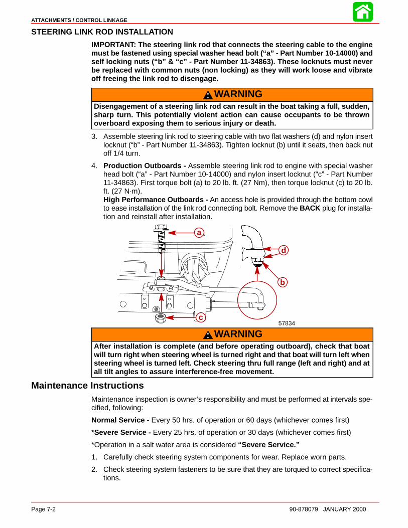
ATTACHMENTS / CONTROL LINKAGE
Page 7-2 90-878079 JANUARY 2000
STEERING LINK ROD INSTALL ATION
IMPORTANT: The steering link rod that connects the steering cable to the enginemust be fastened using special washer head bolt (“a” - Part Number 10-14000) andself locking nuts (“b” & “c” - Part Number 11-34863). These locknuts must neverbe replaced with common nuts (non locking) as they will work loose and vibrateoff freeing the link rod to disengage.
WARNINGDisengagement of a steering link rod can result in the boat taking a full, sudden,sharp turn. This potentially violent action can cause occupants to be thrownoverboard exposing them to serious injury or death.
3. Assemble steering link rod to steering cable with two flat washers (d) and nylon insertlocknut (“b” - Part Number 11-34863). Tighten locknut (b) until it seats, then back nutoff 1/4 turn.
4. Production Outboards - Assemble steering link rod to engine with special washerhead bolt (“a” - Part Number 10-14000) and nylon insert locknut (“c” - Part Number11-34863). First torque bolt (a) to 20 lb. ft. (27 Nm), then torque locknut (c) to 20 lb.ft. (27 N·m).High Performance Outboards - An access hole is provided through the bottom cowlto ease installation of the link rod connecting bolt. Remove the BACK plug for installa-tion and reinstall after installation.
a
b
a
b
d
c57834
WARNINGAfter installation is complete (and before operating outboard), check that boatwil l turn right when steering wheel is turned right and that boat will turn left whensteering wheel is turned left. Check steering thru full range (left and right) and atall tilt angles to assure interference-free movement.
Maintenance InstructionsMaintenance inspection is owner’s responsibility and must be performed at intervals spe-cified, following:
Normal Service - Every 50 hrs. of operation or 60 days (whichever comes first)
*Severe Service - Every 25 hrs. of operation or 30 days (whichever comes first)
*Operation in a salt water area is considered “Severe Service.”
1. Carefully check steering system components for wear. Replace worn parts.
2. Check steering system fasteners to be sure that they are torqued to correct specifica-tions.

ATTACHMENTS / CONTROL LINKAGE
90-878079 JANUARY 2000 Page 7-3
NOTE: Ride-Guide Steering Cables are lubricated at the factory and require no additionallubrication at initial installation.
WARNINGCore of each steering cable (transom end) must be fully retracted into cable hous-ing before lubricating cable. If cable is lubricated while extended, hydraulic lockof cable could occu r.
3. With core of Ride-Guide Steering Cable (transom end) fully retracted, lubricate tran-som end of steering cables thru grease fittings (a) with 2-4-C w/Teflon(92-825407A12). Lubricate exposed portion of cable end (b) with 2-4-C w/Teflon.
4. Lubricate pivot point (c) of steering link rod and ball joint (d) of link rod with SAE 30Weight Oil.
5. Inspection and lubrication of steering head assembly (rotary or straight rack) shouldbe performed once each year (by your Authorized Dealer) or whenever steeringmount and/or steering head are disassembled, or if steering effort has increased. Lu-bricate with 2-4-C w/Teflon.
d
cb
aa
5783357834
Ride Guide Steering Cable/Attaching Kit Installation(92876A3)
Dual Cable - Single Outboard
WARNINGQuicksilve r Super Ride-Guide Steering (dual cables) MUST BE USED with this at-taching kit. Failure to adhere to this requirement could result in steering systemfailure.
Refer to “Quicksilver Accessories Guide” to determine correct length of steeringcables and remote control cables.
IMPORTANT: Steering cables and remote control cables MUST BE THE CORRECTLENGTH, sharp bends on too-short cables result in “kinks”; too-long cables re-quire unnecessary bends and/or loops. Both conditions place extra stress on thecables and will reduce the performance of the steering system.
CAUTIONWith this kit installed, the upper (outboard) mounting bolts MUST BE installed sothat hex head end of bolts is on the inside of boat transom, as illustrated. Failureto install upper mounting bolts, as shown in illustration, could result in interfer-ence between steering cable nut and ends of mounting bolts when outboard istilted up.
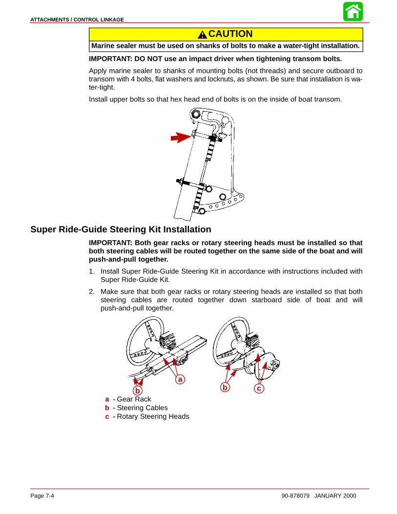
ATTACHMENTS / CONTROL LINKAGE
Page 7-4 90-878079 JANUARY 2000
CAUTIONMarin e sealer must be used on shanks of bolts to make a water-tight installation.
IMPORTANT: DO NOT use an impact driver when tightening transom bolts.
Apply marine sealer to shanks of mounting bolts (not threads) and secure outboard totransom with 4 bolts, flat washers and locknuts, as shown. Be sure that installation is wa-ter-tight.
Install upper bolts so that hex head end of bolts is on the inside of boat transom.
Super Ride-Guide Steering Kit InstallationIMPORTANT: Both gear racks or rotary steering heads must be installed so thatboth steering cables will be routed together on the same side of the boat and willpush-and-pull togethe r.
1. Install Super Ride-Guide Steering Kit in accordance with instructions included withSuper Ride-Guide Kit.
2. Make sure that both gear racks or rotary steering heads are installed so that bothsteering cables are routed together down starboard side of boat and willpush-and-pull together.
ba
b ca
b b ca - Gear Rackb - Steering Cablesc - Rotary Steering Heads
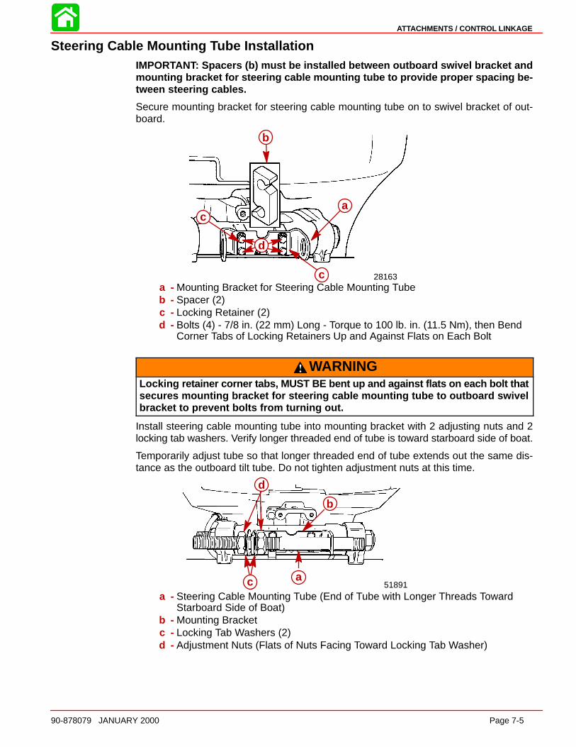
ATTACHMENTS / CONTROL LINKAGE
90-878079 JANUARY 2000 Page 7-5
Steering Cable Mounting Tube InstallationIMPORTANT: Spacers (b) must be installed between outboard swivel bracket andmounting bracket for steering cable mounting tube to provide proper spacing be-tween steering cables.
Secure mounting bracket for steering cable mounting tube on to swivel bracket of out-board.
a
28163
c
d
a
c
c
d
b
a - Mounting Bracket for Steering Cable Mounting Tubeb - Spacer (2)c - Locking Retainer (2)d - Bolts (4) - 7/8 in. (22 mm) Long - Torque to 100 lb. in. (11.5 Nm), then Bend
Corner Tabs of Locking Retainers Up and Against Flats on Each Bolt
WARNINGLocking retainer corner tabs, MUST BE bent up and against flats on each bolt thatsecures mounting bracket for steering cable mounting tube to outboard swivelbracket to prevent bolts from turning out.
Install steering cable mounting tube into mounting bracket with 2 adjusting nuts and 2locking tab washers. Verify longer threaded end of tube is toward starboard side of boat.
Temporarily adjust tube so that longer threaded end of tube extends out the same dis-tance as the outboard tilt tube. Do not tighten adjustment nuts at this time.
d
ca
b
51891a
b
c
d
a - Steering Cable Mounting Tube (End of Tube with Longer Threads TowardStarboard Side of Boat)
b - Mounting Bracketc - Locking Tab Washers (2)d - Adjustment Nuts (Flats of Nuts Facing Toward Locking Tab Washer)

ATTACHMENTS / CONTROL LINKAGE
Page 7-6 90-878079 JANUARY 2000
Installing Steering CablesIMPORTANT: Lubricate inside of outboard tilt tube, inside of steering cable mount-ing tube and rubber O-ring seal (located in outboard tilt tube) with Quicksilver 2-4-Cw/Teflon before installing steering cables.
Lubricate inside of outboard tilt tube and inside of steering cable mounting tube withQuicksilver 2-4-C w/Teflon. Verify rubber O-ring seal (a) (located in outboard tilt tube) islubricated.
a
51890
a
Insert steering cable ends (a) thru outboard tilt tube (b) and cable mounting tube (c).Thread steering cable attaching nuts (d) on to tubes hand tight.
NOTE: Torque steering cable attaching nuts only after final steering adjustments havebeen made.
51891
ab
d
c
Place a mark (a) on steering cable mounting tube (b) 5/8 in. (16 mm) from end of mountingtube. Slide plastic spacer (c), O-ring (d) and cap (e) over steering cable.
5/8″(16 mm)
51890a
b
c d eThread cap (e) onto steering cable mounting tube, up to mark (a).
51890a e
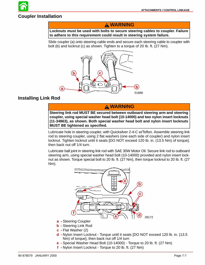
ATTACHMENTS / CONTROL LINKAGE
90-878079 JANUARY 2000 Page 7-7
Coupler Installation
WARNINGLocknuts must be used with bolts to secure steering cables to couple r. Failureto adhere to this requirement could result in steering system failure.
Slide coupler (a) onto steering cable ends and secure each steering cable to coupler withbolt (b) and locknut (c) as shown. Tighten to a torque of 20 Ib. ft. (27 Nm).
51888
b c
a ba
b c
b
Installing Link Rod
WARNINGSteering link rod MUST BE secured between outboard steering arm and steeringcouple r, using special washer head bolt (10-14000) and two nylon insert locknuts(11-34863), as shown. Both special washer head bolt and nylon insert locknutsMUST BE tightened as specified.
Lubricate hole in steering coupler, with Quicksilver 2-4-C w/Teflon. Assemble steering linkrod to steering coupler, using 2 flat washers (one each side of coupler) and nylon insertlocknut. Tighten locknut until it seats [DO NOT exceed 120 Ib. in. (13.5 Nm) of torque],then back nut off 1/4 turn.
Lubricate ball joint in steering link rod with SAE 30W Motor Oil. Secure link rod to outboardsteering arm, using special washer head bolt (10-14000) provided and nylon insert lock-nut as shown. Torque special bolt to 20 Ib. ft. (27 Nm), then torque locknut to 20 Ib. ft. (27Nm).
28172
eb
c
f a df
b
c
e
a - Steering Couplerb - Steering Link Rodc - Flat Washer (2)d - Nylon Insert Locknut - Torque until it seats [DO NOT exceed 120 lb. in. (13.5
Nm) of torque], then back nut off 1/4 turne - Special Washer Head Bolt (10-14000) - Torque to 20 lb. ft. (27 Nm)f - Nylon Insert Locknut - Torque to 20 lb. ft. (27 Nm)
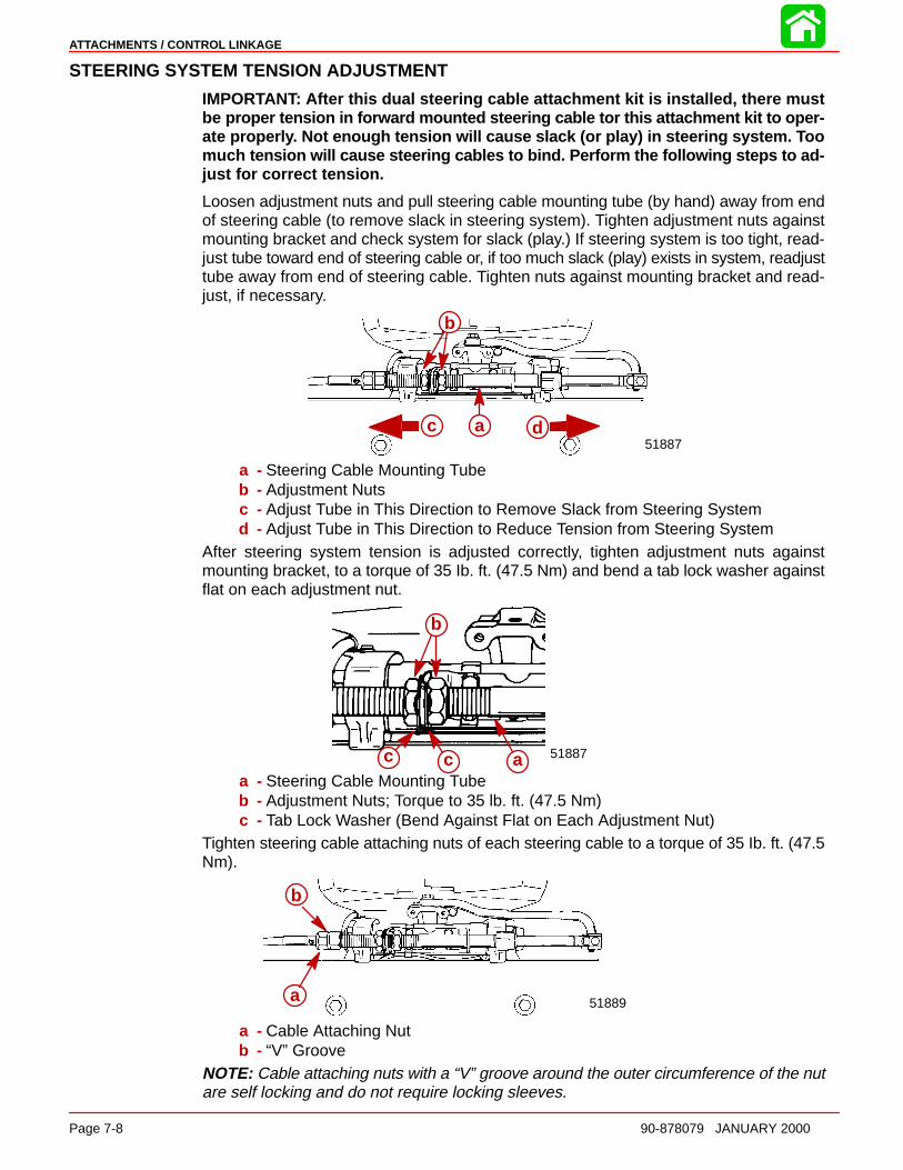
ATTACHMENTS / CONTROL LINKAGE
Page 7-8 90-878079 JANUARY 2000
STEERING SYSTEM TENSION ADJUSTMENT
IMPORTANT: After this dual steering cable attachment kit is installed, there mustbe proper tension in forward mounted steering cable tor this attachment kit to oper-ate properl y. Not enough tension will cause slack (or play) in steering system. Toomuch tension will cause steering cables to bind. Perform the following steps to ad-just for correct tension.
Loosen adjustment nuts and pull steering cable mounting tube (by hand) away from endof steering cable (to remove slack in steering system). Tighten adjustment nuts againstmounting bracket and check system for slack (play.) If steering system is too tight, read-just tube toward end of steering cable or, if too much slack (play) exists in system, readjusttube away from end of steering cable. Tighten nuts against mounting bracket and read-just, if necessary.
51887a dc
b
ac d
a - Steering Cable Mounting Tubeb - Adjustment Nutsc - Adjust Tube in This Direction to Remove Slack from Steering Systemd - Adjust Tube in This Direction to Reduce Tension from Steering System
After steering system tension is adjusted correctly, tighten adjustment nuts againstmounting bracket, to a torque of 35 Ib. ft. (47.5 Nm) and bend a tab lock washer againstflat on each adjustment nut.
51887acc
b
a - Steering Cable Mounting Tubeb - Adjustment Nuts; Torque to 35 lb. ft. (47.5 Nm)c - Tab Lock Washer (Bend Against Flat on Each Adjustment Nut)
Tighten steering cable attaching nuts of each steering cable to a torque of 35 Ib. ft. (47.5Nm).
51889
b
aa
b
a - Cable Attaching Nutb - “V” Groove
NOTE: Cable attaching nuts with a “V” groove around the outer circumference of the nutare self locking and do not require locking sleeves.

ATTACHMENTS / CONTROL LINKAGE
90-878079 JANUARY 2000 Page 7-9
WARNINGAfter installation is complete [and before operating outboard(s)], check that boatwill turn right when steering wheel is turned right and that boat will turn left whensteering wheel is turned left. Check steering thru full range (left and right) at alltilt angles to assure interference-free movement.
Maintenance InstructionsMaintenance inspection is owner’s responsibility and must be performed at intervals spe-cified, following:
Normal Service - Every 50 hrs. of operation or 60 days (whichever comes first)*Severe Service - Every 25 hrs. of operation or 30 days (whichever comes first)
*Operation in a salt water area is considered “Severe Service.”
1. Carefully check steering system components for wear. Replace worn parts.
2. Check steering system fasteners to be sure that they are torqued to correct specifica-tions.
NOTE: Ride-Guide Steering Cables are lubricated at the factory and require no additionallubrication at initial installation.
WARNINGCore of each steering cable (transom end) must be fully retracted into cable hous-ing before lubricating cable. If cable is lubricated while extended, hydraulic lockcould occu r.
3. With core of Ride-Guide Steering Cable (transom end) fully retracted, lubricate tran-som end of steering cables thru grease fittings (a) with 2-4-C w/Teflon (92-825407A2).Lubricate exposed portion of cable ends (b) with 2-4-C w/Teflon.
4. Lubricate pivot point (c) of steering link rod and ball joint (d) of link rod/steering couplerwith SAE 30W Motor Oil.
5. Inspection and lubrication of steering head assembly (rotary or straight rack) shouldbe performed once each year (by your Authorized Dealer) or whenever steeringmount and/or steering head are disassembled, or if steering effort has increased. Lu-bricate with 2-4-C w/Teflon.
28170
db
c
aa
bc
d
a
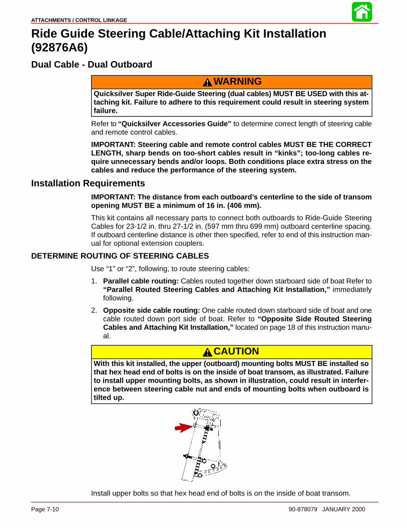
ATTACHMENTS / CONTROL LINKAGE
Page 7-10 90-878079 JANUARY 2000
Ride Guide Steering Cable/Attaching Kit Installation(92876A6)Dual Cable - Dual Outboard
WARNINGQuicksilve r Super Ride-Guide Steering (dual cables) MUST BE USED with this at-taching kit. Failure to adhere to this requirement could result in steering systemfailure.
Refer to “Quicksilver Accessories Guide” to determine correct length of steering cableand remote control cables.
IMPORTANT: Steering cable and remote control cables MUST BE THE CORRECTLENGTH, sharp bends on too-short cables result in “kinks”; too-long cables re-quire unnecessary bends and/or loops. Both conditions place extra stress on thecables and reduce the performance of the steering system.
Installation RequirementsIMPORTANT: The distance from each outboard ’s centerline to the side of transomopening MUST BE a minimum of 16 in. (406 mm).
This kit contains all necessary parts to connect both outboards to Ride-Guide SteeringCables for 23-1/2 in. thru 27-1/2 in. (597 mm thru 699 mm) outboard centerline spacing.If outboard centerline distance is other then specified, refer to end of this instruction man-ual for optional extension couplers.
DETERMINE ROUTING OF STEERING CABLES
Use “1” or “2”, following, to route steering cables:
1. Parallel cable routing: Cables routed together down starboard side of boat Refer to“Parallel Routed Steering Cables and Attaching Kit Installation,” immediatelyfollowing.
2. Opposite side cable routing: One cable routed down starboard side of boat and onecable routed down port side of boat. Refer to “Opposite Side Routed SteeringCables and Attaching Kit Installation,” located on page 18 of this instruction manu-al.
CAUTIONWith this kit installed, the upper (outboard) mounting bolts MUST BE installed sothat hex head end of bolts is on the inside of boat transom, as illustrated. Failureto install upper mounting bolts, as shown in illustration, could result in interfer-ence between steering cable nut and ends of mounting bolts when outboard istilted up.
Install upper bolts so that hex head end of bolts is on the inside of boat transom.
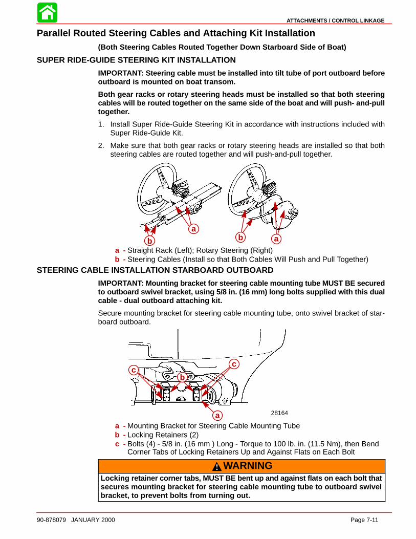
ATTACHMENTS / CONTROL LINKAGE
90-878079 JANUARY 2000 Page 7-11
Parallel Routed Steering Cables and Attaching Kit Installation(Both Steering Cables Routed Together Down Starboard Side of Boat)
SUPER RIDE-GUIDE STEERING KIT INSTALL ATION
IMPORTANT: Steering cable must be installed into tilt tube of port outboard beforeoutboard is mounted on boat transom.
Both gear racks or rotary steering heads must be installed so that both steeringcables will be routed together on the same side of the boat and will push- and-pulltogethe r.
1. Install Super Ride-Guide Steering Kit in accordance with instructions included withSuper Ride-Guide Kit.
2. Make sure that both gear racks or rotary steering heads are installed so that bothsteering cables are routed together and will push-and-pull together.
ba
ba
b b aa - Straight Rack (Left); Rotary Steering (Right)b - Steering Cables (Install so that Both Cables Will Push and Pull Together)
STEERING CABLE INS TALL ATION STARBOAR D OUTBOARD
IMPORTANT: Mounting bracket for steering cable mounting tube MUST BE securedto outboard swivel bracket, using 5/8 in. (16 mm) long bolts supplied with this dualcable - dual outboard attaching kit.
Secure mounting bracket for steering cable mounting tube, onto swivel bracket of star-board outboard.
a28164
bc
c
a
b
cc
a - Mounting Bracket for Steering Cable Mounting Tubeb - Locking Retainers (2)c - Bolts (4) - 5/8 in. (16 mm ) Long - Torque to 100 lb. in. (11.5 Nm), then Bend
Corner Tabs of Locking Retainers Up and Against Flats on Each Bolt
WARNINGLocking retainer corner tabs, MUST BE bent up and against flats on each bolt thatsecures mounting bracket for steering cable mounting tube to outboard swivelbracket, to prevent bolts from turning out.
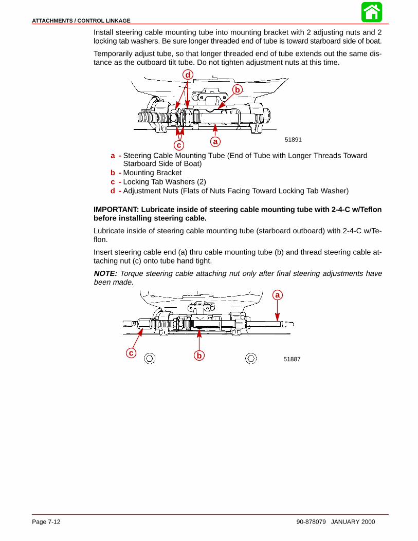
ATTACHMENTS / CONTROL LINKAGE
Page 7-12 90-878079 JANUARY 2000
Install steering cable mounting tube into mounting bracket with 2 adjusting nuts and 2locking tab washers. Be sure longer threaded end of tube is toward starboard side of boat.
Temporarily adjust tube, so that longer threaded end of tube extends out the same dis-tance as the outboard tilt tube. Do not tighten adjustment nuts at this time.
d
b
ac
51891a
b
c
d
a - Steering Cable Mounting Tube (End of Tube with Longer Threads TowardStarboard Side of Boat)
b - Mounting Bracketc - Locking Tab Washers (2)d - Adjustment Nuts (Flats of Nuts Facing Toward Locking Tab Washer)
IMPORTANT: Lubricate inside of steering cable mounting tube with 2-4-C w/ Teflonbefore installing steering cable.
Lubricate inside of steering cable mounting tube (starboard outboard) with 2-4-C w/Te-flon.
Insert steering cable end (a) thru cable mounting tube (b) and thread steering cable at-taching nut (c) onto tube hand tight.
NOTE: Torque steering cable attaching nut only after final steering adjustments havebeen made.
51887
a
bc
a
bc
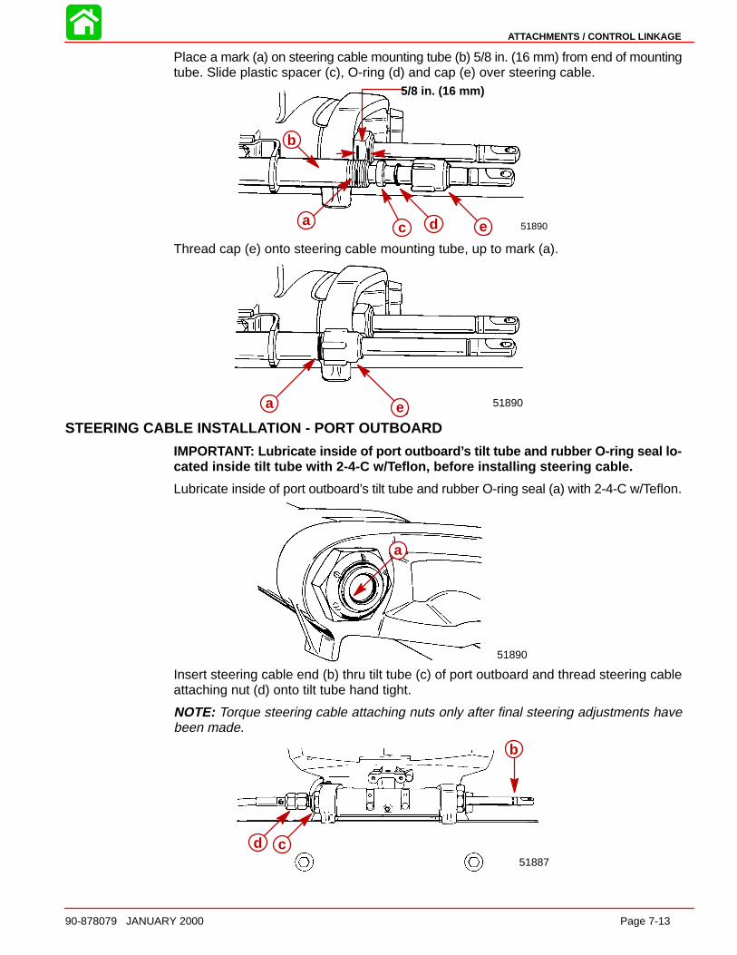
ATTACHMENTS / CONTROL LINKAGE
90-878079 JANUARY 2000 Page 7-13
Place a mark (a) on steering cable mounting tube (b) 5/8 in. (16 mm) from end of mountingtube. Slide plastic spacer (c), O-ring (d) and cap (e) over steering cable.
51890
5/8 in. (16 mm)
b
a c d ea
b
c d e
Thread cap (e) onto steering cable mounting tube, up to mark (a).
a e 51890a eSTEERING CABLE INS TALL ATION - PORT OUTBOARD
IMPORTANT: Lubricate inside of port outboard ’s tilt tube and rubber O-ring seal lo-cated inside tilt tube with 2-4-C w/ Teflon, before installing steering cable.
Lubricate inside of port outboard’s tilt tube and rubber O-ring seal (a) with 2-4-C w/Teflon.
a
51890
a
Insert steering cable end (b) thru tilt tube (c) of port outboard and thread steering cableattaching nut (d) onto tilt tube hand tight.
NOTE: Torque steering cable attaching nuts only after final steering adjustments havebeen made.
b
d c51887
b
cd
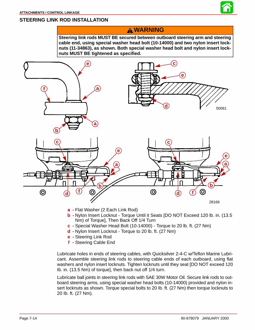
ATTACHMENTS / CONTROL LINKAGE
Page 7-14 90-878079 JANUARY 2000
STEERING LINK ROD INSTALL ATION
WARNINGSteering link rods MUST BE secured between outboard steering arm and steeringcable end, using special washer head bolt (10-14000) and two nylon insert lock-nuts (11-34863), as shown. Both special washer head bolt and nylon insert lock-nuts MUST BE tightened as specified.
50061
c
e
d
e
a
a
f
28166
c
e
fd d f
b
c
b
e
a
bfd
c
e
a
bfd
c
ab
f
e
a
c
e
d
a - Flat Washer (2 Each Link Rod)b - Nylon Insert Locknut - Torque Until it Seats [DO NOT Exceed 120 lb. in. (13.5
Nm) of Torque], Then Back Off 1/4 Turnc - Special Washer Head Bolt (10-14000) - Torque to 20 lb. ft. (27 Nm)d - Nylon Insert Locknut - Torque to 20 lb. ft. (27 Nm)e - Steering Link Rodf - Steering Cable End
Lubricate holes in ends of steering cables, with Quicksilver 2-4-C w/Teflon Marine Lubri-cant. Assemble steering link rods to steering cable ends of each outboard, using flatwashers and nylon insert locknuts. Tighten locknuts until they seat [DO NOT exceed 120Ib. in. (13.5 Nm) of torque], then back nut off 1/4 turn.
Lubricate ball joints in steering link rods with SAE 30W Motor Oil. Secure link rods to out-board steering arms, using special washer head bolts (10-14000) provided and nylon in-sert locknuts as shown. Torque special bolts to 20 Ib. ft. (27 Nm) then torque locknuts to20 Ib. ft. (27 Nm).
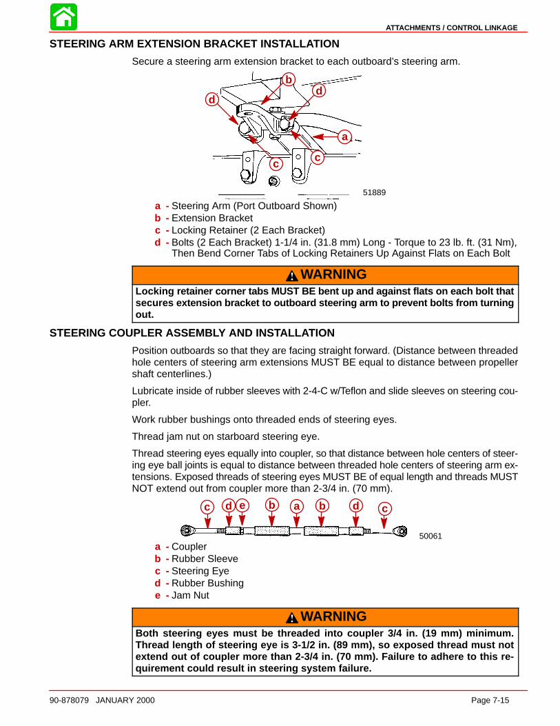
ATTACHMENTS / CONTROL LINKAGE
90-878079 JANUARY 2000 Page 7-15
STEERING ARM EXTENSION BRACKET INS TALL ATION
Secure a steering arm extension bracket to each outboard’s steering arm.
51889
c
db
a
d
c
a
b
cc
dd
a - Steering Arm (Port Outboard Shown)b - Extension Bracketc - Locking Retainer (2 Each Bracket)d - Bolts (2 Each Bracket) 1-1/4 in. (31.8 mm) Long - Torque to 23 lb. ft. (31 Nm),
Then Bend Corner Tabs of Locking Retainers Up Against Flats on Each Bolt
WARNINGLocking retainer corner tabs MUST BE bent up and against flats on each bolt thatsecure s extension bracket to outboard steering arm to prevent bolts from turningout.
STEERING COUPLER ASSEMB LY AND INSTALL ATION
Position outboards so that they are facing straight forward. (Distance between threadedhole centers of steering arm extensions MUST BE equal to distance between propellershaft centerlines.)
Lubricate inside of rubber sleeves with 2-4-C w/Teflon and slide sleeves on steering cou-pler.
Work rubber bushings onto threaded ends of steering eyes.
Thread jam nut on starboard steering eye.
Thread steering eyes equally into coupler, so that distance between hole centers of steer-ing eye ball joints is equal to distance between threaded hole centers of steering arm ex-tensions. Exposed threads of steering eyes MUST BE of equal length and threads MUSTNOT extend out from coupler more than 2-3/4 in. (70 mm).
50061
c d e b a b d c
a - Couplerb - Rubber Sleevec - Steering Eyed - Rubber Bushinge - Jam Nut
WARNINGBoth steering eyes must be threaded into coupler 3/4 in. (19 mm) minimum.Thread length of steering eye is 3-1/2 in. (89 mm), so exposed thread must notextend out of coupler more than 2-3/4 in. (70 mm). Failure to adhere to this re-quirement could result in steering system failure.
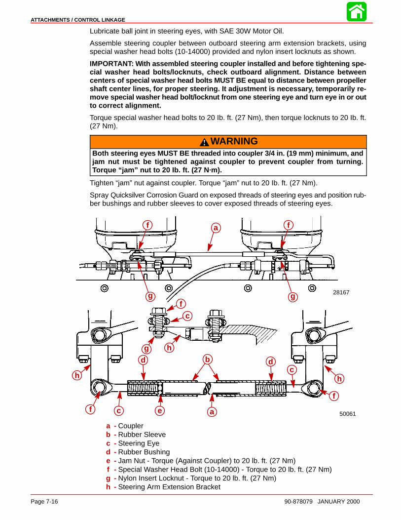
ATTACHMENTS / CONTROL LINKAGE
Page 7-16 90-878079 JANUARY 2000
Lubricate ball joint in steering eyes, with SAE 30W Motor Oil.
Assemble steering coupler between outboard steering arm extension brackets, usingspecial washer head bolts (10-14000) provided and nylon insert locknuts as shown.
IMPORTANT: With assembled steering coupler installed and before tightening spe-cial washer head bolts/locknuts, check outboard alignment. Distance betweencenters of special washer head bolts MUST BE equal to distance between propellershaft center lines, for proper steering. It adjustment is necessar y, temporarily re-move special washer head bolt/locknut from one steering eye and turn eye in or outto correct alignment.
Torque special washer head bolts to 20 Ib. ft. (27 Nm), then torque locknuts to 20 Ib. ft.(27 Nm).
WARNINGBoth steering eyes MUST BE threaded into coupler 3/4 in. (19 mm) minimum, andjam nut must be tightened against coupler to prevent coupler from turning.Torque “jam” nut to 20 Ib. ft. (27 N·m).
Tighten “jam” nut against coupler. Torque “jam” nut to 20 Ib. ft. (27 Nm).
Spray Quicksilver Corrosion Guard on exposed threads of steering eyes and position rub-ber bushings and rubber sleeves to cover exposed threads of steering eyes.
50061
28167gg
h
f c e a
f
hc
dbd
fc
hg
f a f
g gf
c
g h
d b
h
f c e a
dc
h
f
a - Couplerb - Rubber Sleevec - Steering Eyed - Rubber Bushinge - Jam Nut - Torque (Against Coupler) to 20 lb. ft. (27 Nm)f - Special Washer Head Bolt (10-14000) - Torque to 20 lb. ft. (27 Nm)g - Nylon Insert Locknut - Torque to 20 lb. ft. (27 Nm)h - Steering Arm Extension Bracket
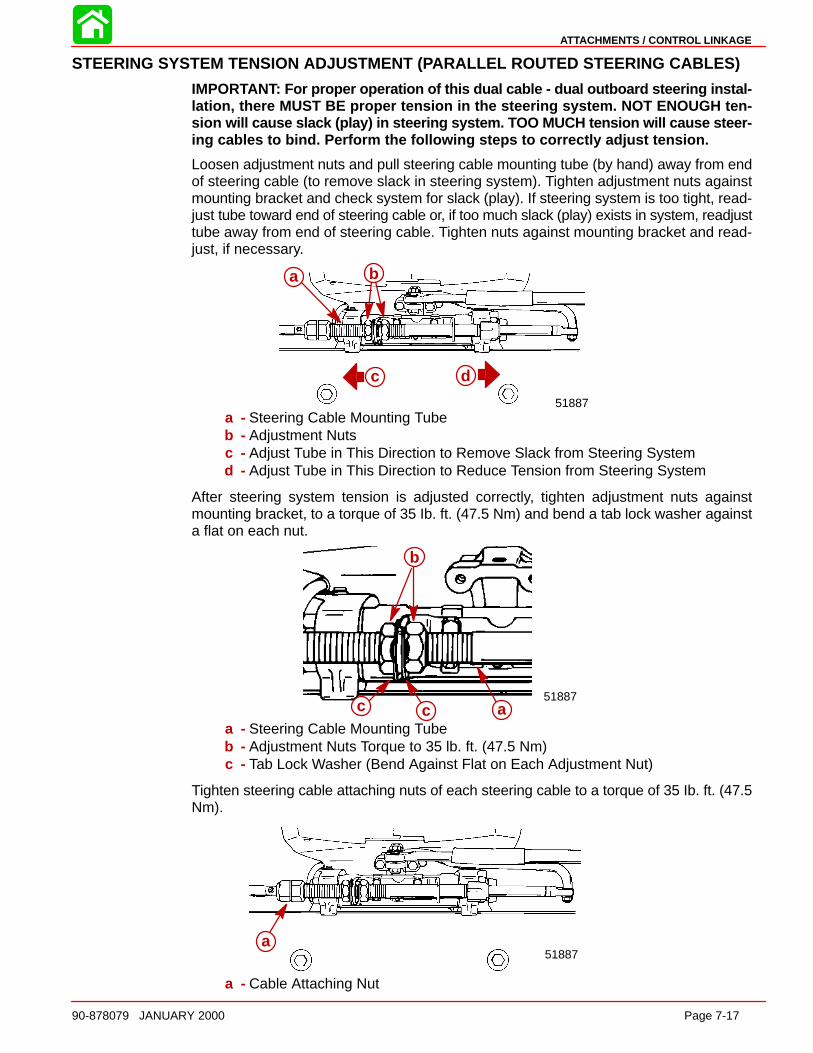
ATTACHMENTS / CONTROL LINKAGE
90-878079 JANUARY 2000 Page 7-17
STEERING SYSTEM TENSION ADJUSTMENT (PARALLEL ROUTED STEERING CABLES)
IMPORTANT: For proper operation of this dual cable - dual outboard steering instal-lation, there MUST BE proper tension in the steering system. NOT ENOUGH ten-sion will cause slack (play) in steering system. TOO MUCH tension will cause steer-ing cables to bind. Perform the following steps to correctly adjust tension.
Loosen adjustment nuts and pull steering cable mounting tube (by hand) away from endof steering cable (to remove slack in steering system). Tighten adjustment nuts againstmounting bracket and check system for slack (play). If steering system is too tight, read-just tube toward end of steering cable or, if too much slack (play) exists in system, readjusttube away from end of steering cable. Tighten nuts against mounting bracket and read-just, if necessary.
a
c d
51887
ba
c d
a - Steering Cable Mounting Tubeb - Adjustment Nutsc - Adjust Tube in This Direction to Remove Slack from Steering Systemd - Adjust Tube in This Direction to Reduce Tension from Steering System
After steering system tension is adjusted correctly, tighten adjustment nuts againstmounting bracket, to a torque of 35 Ib. ft. (47.5 Nm) and bend a tab lock washer againsta flat on each nut.
b
51887c c a
b
a - Steering Cable Mounting Tubeb - Adjustment Nuts Torque to 35 lb. ft. (47.5 Nm)c - Tab Lock Washer (Bend Against Flat on Each Adjustment Nut)
Tighten steering cable attaching nuts of each steering cable to a torque of 35 Ib. ft. (47.5Nm).
a51887
a
a - Cable Attaching Nut

ATTACHMENTS / CONTROL LINKAGE
Page 7-18 90-878079 JANUARY 2000
WARNINGAfter installation is complete (and before operating outboard(s), check that boatwil l turn right when steering wheel is turned right and that boat will turn left whensteering wheel is turned left. Check steering thru full range (left and right) at alltilt angles to assure interference-free movement.
Adjust trim tabs of both outboards, as outlined in “ Trim Tab Adjustment” , following.
Opposite Side Routed Steering Cables and Attaching Kit Installation(One Cable Routed down Starboard Side of Boat and One Cable Routed down PortSide of Boat)
SUPER RIDE-GUIDE STEERING KIT INSTALL ATION
IMPORTANT: Steering cable must be installed into tilt tube of port outboard beforeoutboard is mounted on boat transom.
Install Super Ride-Guide Steering Kit in accordance with instructions included with SuperRide-Guide Kit.
STEERING CABLE INS TALL ATION - STARBOAR D OUTBOARD
IMPORTANT: Mounting bracket for steering cable mounting tube MUST BE securedto outboard swivel bracket, using 5/8 in. (16 mm) long bolts supplied with this dualcable - dual outboard attaching kit.
Secure mounting bracket for steering cable mounting tube, onto swivel bracket of star-board outboard.
28164
d d
a
c
b ab
cd
d
a - Mounting Bracket for Steering Cable Mounting Tubeb - “J” Clip - Supplied with Outboardc - Locking Retainers (2)d - Bolts (4) - 5/8 in. (16 mm) Long - Torque to 100 lb. in. (11.5 Nm), Then Bend
Corner Tabs of Locking Retainers Up and Against Flats on Each Bolt.
WARNINGLocking retainer corner tabs MUST BE bent up and against flats on each bolt thatsecures mounting bracket for steering cable mounting tube, to prevent boltsfrom turning out.
Install Steering Cable mounting tube into mounting bracket with 2 adjusting nuts and 2locking tab washers. Verify longer threaded end of tube is toward center of boat transom.
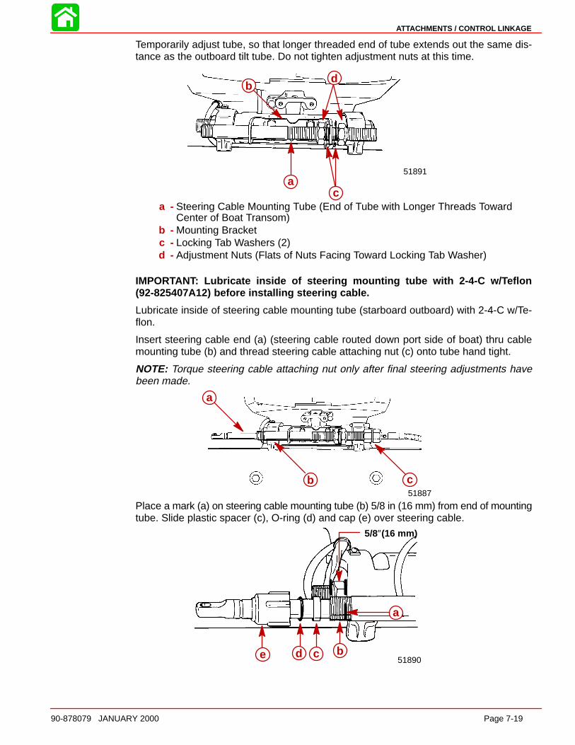
ATTACHMENTS / CONTROL LINKAGE
90-878079 JANUARY 2000 Page 7-19
Temporarily adjust tube, so that longer threaded end of tube extends out the same dis-tance as the outboard tilt tube. Do not tighten adjustment nuts at this time.
ac
db
51891a
b
c
d
a - Steering Cable Mounting Tube (End of Tube with Longer Threads TowardCenter of Boat Transom)
b - Mounting Bracketc - Locking Tab Washers (2)d - Adjustment Nuts (Flats of Nuts Facing Toward Locking Tab Washer)
IMPORTANT: Lubricate inside of steering mounting tube with 2-4-C w/ Teflon(92-825407A12) before installing steering cable.
Lubricate inside of steering cable mounting tube (starboard outboard) with 2-4-C w/Te-flon.
Insert steering cable end (a) (steering cable routed down port side of boat) thru cablemounting tube (b) and thread steering cable attaching nut (c) onto tube hand tight.
NOTE: Torque steering cable attaching nut only after final steering adjustments havebeen made.
a
b c51887
a
b c
Place a mark (a) on steering cable mounting tube (b) 5/8 in (16 mm) from end of mountingtube. Slide plastic spacer (c), O-ring (d) and cap (e) over steering cable.
5/8″(16 mm)
e d c b
a
51890
a
bcde
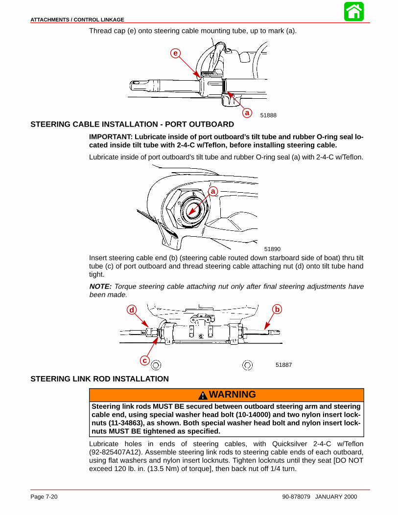
ATTACHMENTS / CONTROL LINKAGE
Page 7-20 90-878079 JANUARY 2000
Thread cap (e) onto steering cable mounting tube, up to mark (a).
51888
e
aa
e
STEERING CABLE INS TALL ATION - PORT OUTBOARD
IMPORTANT: Lubricate inside of port outboard ’s tilt tube and rubber O-ring seal lo-cated inside tilt tube with 2-4-C w/ Teflon, before installing steering cable.
Lubricate inside of port outboard’s tilt tube and rubber O-ring seal (a) with 2-4-C w/Teflon.
51890
aa
Insert steering cable end (b) (steering cable routed down starboard side of boat) thru tilttube (c) of port outboard and thread steering cable attaching nut (d) onto tilt tube handtight.
NOTE: Torque steering cable attaching nut only after final steering adjustments havebeen made.
51887
b
c
d b
c
d
STEERING LINK ROD INSTALL ATION
WARNINGSteering link rods MUST BE secured between outboard steering arm and steeringcable end, using special washer head bolt (10-14000) and two nylon insert lock-nuts (11-34863), as shown. Both special washer head bolt and nylon insert lock-nuts MUST BE tightened as specified.
Lubricate holes in ends of steering cables, with Quicksilver 2-4-C w/Teflon(92-825407A12). Assemble steering link rods to steering cable ends of each outboard,using flat washers and nylon insert locknuts. Tighten locknuts until they seat [DO NOTexceed 120 lb. in. (13.5 Nm) of torque], then back nut off 1/4 turn.
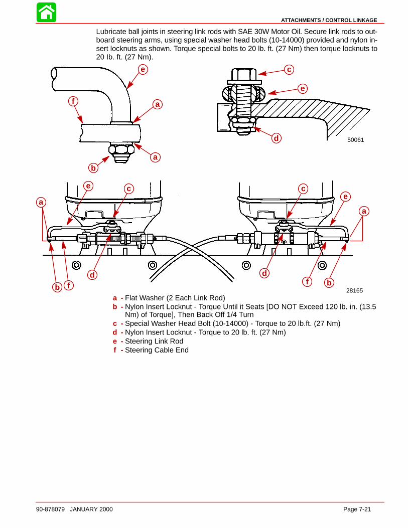
ATTACHMENTS / CONTROL LINKAGE
90-878079 JANUARY 2000 Page 7-21
Lubricate ball joints in steering link rods with SAE 30W Motor Oil. Secure link rods to out-board steering arms, using special washer head bolts (10-14000) provided and nylon in-sert locknuts as shown. Torque special bolts to 20 lb. ft. (27 Nm) then torque locknuts to20 Ib. ft. (27 Nm).
50061
c
e
b
e
a
a
28165
a
e c
dfb
df b
a
ec
c
e
d
a
f
ab
f
e
a
c
e
d
aa
b
c
d
e
f bfd
ce
a - Flat Washer (2 Each Link Rod)b - Nylon Insert Locknut - Torque Until it Seats [DO NOT Exceed 120 lb. in. (13.5
Nm) of Torque], Then Back Off 1/4 Turnc - Special Washer Head Bolt (10-14000) - Torque to 20 lb.ft. (27 Nm)d - Nylon Insert Locknut - Torque to 20 lb. ft. (27 Nm)e - Steering Link Rodf - Steering Cable End
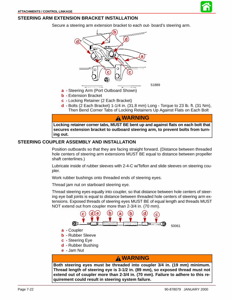
ATTACHMENTS / CONTROL LINKAGE
Page 7-22 90-878079 JANUARY 2000
STEERING ARM EXTENSION BRACKET INS TALL ATION
Secure a steering arm extension bracket to each out- board’s steering arm.
51889
d
a
cc
d
b
a
cc
d d
a - Steering Arm (Port Outboard Shown)b - Extension Bracketc - Locking Retainer (2 Each Bracket)d - Bolts (2 Each Bracket) 1-1/4 in. (31.8 mm) Long - Torque to 23 lb. ft. (31 Nm),
Then Bend Corner Tabs of Locking Retainers Up Against Flats on Each Bolt
WARNINGLocking retainer corner tabs, MUST BE bent up and against flats on each bolt thatsecures extension bracket to outboard steering arm, to prevent bolts from turn-ing out.
STEERING COUPLER ASSEMB LY AND INSTALL ATION
Position outboards so that they are facing straight forward. (Distance between threadedhole centers of steering arm extensions MUST BE equal to distance between propellershaft centerlines.)
Lubricate inside of rubber sleeves with 2-4-C w/Teflon and slide sleeves on steering cou-pler.
Work rubber bushings onto threaded ends of steering eyes.
Thread jam nut on starboard steering eye.
Thread steering eyes equally into coupler, so that distance between hole centers of steer-ing eye ball joints is equal to distance between threaded hole centers of steering arm ex-tensions. Exposed threads of steering eyes MUST BE of equal length and threads MUSTNOT extend out from coupler more than 2-3/4 in. (70 mm).
50061
c d e b a b d c
a - Couplerb - Rubber Sleevec - Steering Eyed - Rubber Bushinge - Jam Nut
WARNINGBoth steering eyes must be threaded into coupler 3/4 in. (19 mm) minimum.Thread length of steering eye is 3-1/2 in. (89 mm), so exposed thread must notextend out of coupler more than 2-3/4 in. (70 mm). Failure to adhere to this re-quirement could result in steering system failure.
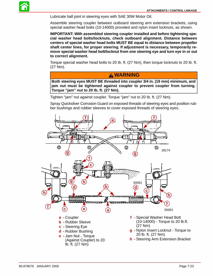
ATTACHMENTS / CONTROL LINKAGE
90-878079 JANUARY 2000 Page 7-23
Lubricate ball joint in steering eyes with SAE 30W Motor Oil.
Assemble steering coupler between outboard steering arm extension brackets, usingspecial washer head bolts (10-14000) provided and nylon insert locknuts, as shown.
IMPORTANT: With assembled steering coupler installed and before tightening spe-cial washer head bolts/locknuts, check outboard alignment. Distance betweencenters of special washer head bolts MUST BE equal to distance between propellershaft center lines, for proper steering. If adjustment is necessar y, temporarily re-move special washer head bolt/locknut from one steering eye and turn eye in or outto correct alignment.
Torque special washer head bolts to 20 Ib. ft. (27 Nm), then torque locknuts to 20 Ib. ft.(27 Nm).
WARNINGBoth steering eyes MUST BE threaded into coupler 3/4 in. (19 mm) minimum, andjam nut must be tightened against coupler to prevent coupler from turning.Torque “jam” nut to 20 Ib. ft. (27 Nm).
Tighten “jam” nut against coupler. Torque “jam” nut to 20 Ib. ft. (27 Nm).
Spray Quicksilver Corrosion Guard on exposed threads of steering eyes and position rub-ber bushings and rubber sleeves to cover exposed threads of steering eyes.
50061
50061
28174
f a
gg
f
h
f c e a
bd dc
f
h
fc
af f
g g
a
bd dc
c ef
h
f
h
g h
c
f
a - Couplerb - Rubber Sleevec - Steering Eyed - Rubber Bushinge - Jam Nut - Torque
(Against Coupler) to 20lb. ft. (27 Nm)
f - Special Washer Head Bolt(10-14000) - Torque to 20 lb.ft. (27 Nm)
g - Nylon Insert Locknut - Torque to 20 lb. ft. (27 Nm)
h - Steering Arm Extension Bracket
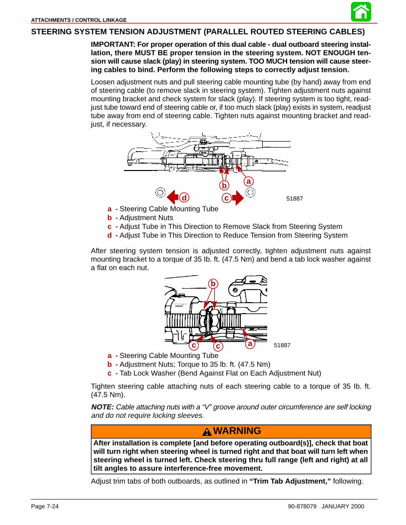
ATTACHMENTS / CONTROL LINKAGE
Page 7-24 90-878079 JANUARY 2000
STEERING SYSTEM TENSION ADJUSTMENT (PARALLEL ROUTED STEERING CABLES)
IMPORTANT: For proper operation of this dual cable - dual outboard steering instal-lation, there MUST BE proper tension in the steering system. NOT ENOUGH ten-sion will cause slack (play) in steering system. TOO MUCH tension will cause steer-ing cables to bind. Perform the following steps to correctly adjust tension.
Loosen adjustment nuts and pull steering cable mounting tube (by hand) away from endof steering cable (to remove slack in steering system). Tighten adjustment nuts againstmounting bracket and check system for slack (play). If steering system is too tight, read-just tube toward end of steering cable or, if too much slack (play) exists in system, readjusttube away from end of steering cable. Tighten nuts against mounting bracket and read-just, if necessary.
51887
a
c
ab
cda - Steering Cable Mounting Tubeb - Adjustment Nutsc - Adjust Tube in This Direction to Remove Slack from Steering Systemd - Adjust Tube in This Direction to Reduce Tension from Steering System
After steering system tension is adjusted correctly, tighten adjustment nuts againstmounting bracket to a torque of 35 Ib. ft. (47.5 Nm) and bend a tab lock washer againsta flat on each nut.
51887c c a
b
a - Steering Cable Mounting Tubeb - Adjustment Nuts; Torque to 35 lb. ft. (47.5 Nm)c - Tab Lock Washer (Bend Against Flat on Each Adjustment Nut)
Tighten steering cable attaching nuts of each steering cable to a torque of 35 Ib. ft.(47.5 Nm).
NOTE: Cable attaching nuts with a “V” groove around outer circumference are self lockingand do not require locking sleeves.
WARNINGAfter installation is complete [and before operating outboard(s)], check that boatwill turn right when steering wheel is turned right and that boat will turn left whensteering wheel is turned left. Check steering thru full range (left and right) at alltilt angles to assure interference-free movement.
Adjust trim tabs of both outboards, as outlined in “ Trim Tab Adjustment,” following.
ATTACHMENTS / CONTROL LINKAGE
90-878079 JANUARY 2000 Page 7-25
Trim Tab AdjustmentDUAL OUTBOARD - COUNTER RO TATION INSTALL ATION
1. Shift outboard into neutral and make sure ignition key is at “OFF” position.
2. Remove plastic cap from rear of driveshaft housing and loosen bolt and trim tab.
3. Position trim tabs of both outboards straight to rear of outboard, so that tabs arealigned with gear housing centerline.
4. Tighten both trim tab bolts securely and replace plastic caps. No further adjustmentwill be required.
DUAL OUTBOARD - NON COUNTER RO TATION INSTALL ATION
1. Check trim tab position as follows:
IMPORTANT: Initial trim tab setting for both outboards should be straight to rearof outboard, so that tabs are aligned with gear housing center line. Refer to “If nec-essar y, adjust trim tab as follows,” following.
a. Operate boat at normal cruise throttle setting and adjust trim to optimum setting.
b. If boat pulls to the right (starboard), trailing edge of trim tab must be moved to theright (when viewing outboard from behind). If boat pulls to the left (port), trailingedge of trim tab must be moved to the left.
2. If necessary, adjust trim tab as follows:
a. Shift outboard into NEUTRAL and make sure ignition key is at “OFF” position.
b. Remove plastic cap from rear of driveshaft housing and loosen bolt and trim tab.
IMPORTANT: Trim tabs MUST BE set in the same position on both outboards.
c. If boat pulls to the right, adjust trailing edges of both trim tabs to the right. If boatpulls to the left, adjust trailing edges of both trim tabs to the left.
d. Tighten both trim tab bolts securely and replace plastic caps.
e. Operate boat per “Check trim tab position as follows,” preceding, to check trimtab setting. Readjust trim tabs, if necessary.
Ride Guide Steering Attachment Extension CouplersListed below are typical couplers available. Refer to the current Quicksilver AccessoryGuide for specific coupler lengths and part numbers.
Outboard Center Line Distance Required Coupler(s) Between Steering Eyes
22-1/2 in. thru 24-1/2 in. 12″ (305 mm) Coupler(572 mm thru 622 mm)
23-1/2 in. thru 27-1/2 in. 15″ (381 mm) Coupler (Supplied with this kit)(597 mm thru 699 mm)
26-1/2 in. thru 30-1/2 in. 18″ (457 mm) Coupler(673 mm thru 755 mm)
30 in. thru 34 in. 9″ (229 mm) Coupler and 12″ (305 mm) Coupler(763 mm thru 864 mm) (Connected together with coupler link rod)
33 in. thru 37 in. 12″ (305 mm) Coupler and 12″ (305 mm) Coupler(838 mm thru 940 mm) (Connected together with coupler link rod)
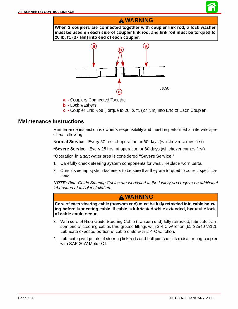
ATTACHMENTS / CONTROL LINKAGE
Page 7-26 90-878079 JANUARY 2000
WARNINGWhen 2 couplers are connected together with coupler link rod, a lock washermust be used on each side of coupler link rod, and link rod must be torqued to20 Ib. ft. (27 Nm) into end of each couple r.
a a
c51890
ab
a
c
a - Couplers Connected Togetherb - Lock washersc - Coupler Link Rod [Torque to 20 lb. ft. (27 Nm) into End of Each Coupler]
Maintenance InstructionsMaintenance inspection is owner’s responsibility and must be performed at intervals spe-cified, following:
Normal Service - Every 50 hrs. of operation or 60 days (whichever comes first)
*Severe Service - Every 25 hrs. of operation or 30 days (whichever comes first)
*Operation in a salt water area is considered “Severe Service.”
1. Carefully check steering system components for wear. Replace worn parts.
2. Check steering system fasteners to be sure that they are torqued to correct specifica-tions.
NOTE: Ride-Guide Steering Cables are lubricated at the factory and require no additionallubrication at initial installation.
WARNINGCore of each steering cable (transom end) must be fully retracted into cable hous-ing before lubricating cable. If cable is lubricated while extended, hydraulic lockof cable could occu r.
3. With core of Ride-Guide Steering Cable (transom end) fully retracted, lubricate tran-som end of steering cables thru grease fittings with 2-4-C w/Teflon (92-825407A12).Lubricate exposed portion of cable ends with 2-4-C w/Teflon.
4. Lubricate pivot points of steering link rods and ball joints of link rods/steering couplerwith SAE 30W Motor Oil.
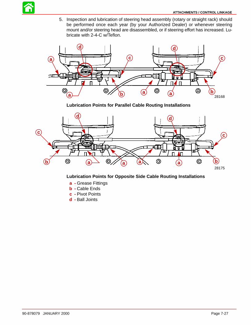
ATTACHMENTS / CONTROL LINKAGE
90-878079 JANUARY 2000 Page 7-27
5. Inspection and lubrication of steering head assembly (rotary or straight rack) shouldbe performed once each year (by your Authorized Dealer) or whenever steeringmount and/or steering head are disassembled, or if steering effort has increased. Lu-bricate with 2-4-C w/Teflon.
28168
d
c
ba a b
c
d
a b
c
d
a a b
c
d
a
Lubrication Points for Parallel Cable Routing Installations
28175
c
d
b a a
c
d
a a a a
c
d
b
c
d
b
Lubrication Points for Opposite Side Cable Routing Installationsa - Grease Fittingsb - Cable Endsc - Pivot Pointsd - Ball Joints

ATTACHMENTS / CONTROL LINKAGE
Page 7-28 90-878079 JANUARY 2000
Transom Mounted Ride Guide Attaching Kit Installation(73770A1)
Attaching Kit Installation1. Lubricate both holes in pivot block (Figure 1) with Quicksilver 2-4-C w/Teflon.
2. Place pivot block on pivot spacer and secure to transom bracket with 3/8 in. x 2-1/2in. (9.5 mm x 63.5 mm) bolt, flat washer and locknut, as shown in Figure 1. Torquelocknut to 20 Ib. ft. (27 Nm).
a b
fk
d
j
l
c g
e
i ha b
cd
e
fg
hi
j
k
l
Figure 1a - Ride-Guide Cableb - Ride-Guide Yokec - Pivot Blockd - Pivot Spacere - 15 in. (381 mm) (Centerline of Attaching Kit Pivot to Centerline of Outboard)f - Pivot Attaching Locknut [Torque to 20 lb. ft. (27 Nm)]g - Outboard Steering Armh - “Clevis Kit”i - Ride-Guide Cable Attaching Locknut [Torque to 10 lb. ft. (13.5 Nm)]j - Bolt [3/8 in. x 2-1/2 in. (9.5 mm x 63.5 mm)]k - Flat Washerl - Transom Bracket

ATTACHMENTS / CONTROL LINKAGE
90-878079 JANUARY 2000 Page 7-29
3. Place Ride-Guide yoke on pivot block and secure with 7/16 in. x 1-3/4 in.(11.1 mm x 44.5 mm) bolt and locknut, as shown in Figures 1 and 2. Torquelocknut to 10 Ib. ft. (13.5 Nm), then back off 1/4-turn.
fg
d
bc
e
aa
bc
d
e
fg
Figure 2a - Transom Backing Plateb - Bolt [5/16 in. x 3-1/4 in. (7.9 mm x 82.5 mm)]c - Locknut [Torque to 10 lb. ft. (13.5 Nm)]d - Ride-Guide Yoke Attaching Locknut [Torque to 10 lb. ft. (13.5 Nm)] Then
Back Off 1/4- Turne - 2-3/8 in. (60.3 mm) Maximum Transom Thicknessf - Bolt [7/16 in. x 1-3/4 in. (11.1 mm x 44.5 mm)]g - Ride-Guide Yoke
4. Install one cable tube jam nut onto steering cable tube. Place tab washer overRide-Guide yoke, then insert cable tube thru tab washer and yoke. Install secondcable tube jam nut onto cable tube but do not tighten at this time. (Figure 3)
5. Position transom attaching kit on transom as shown:
a. Determine centerline of outboard, then measure 15 in. (38.1 cm) over from thiscenterline and draw a vertical line on transom. (Figure 1)
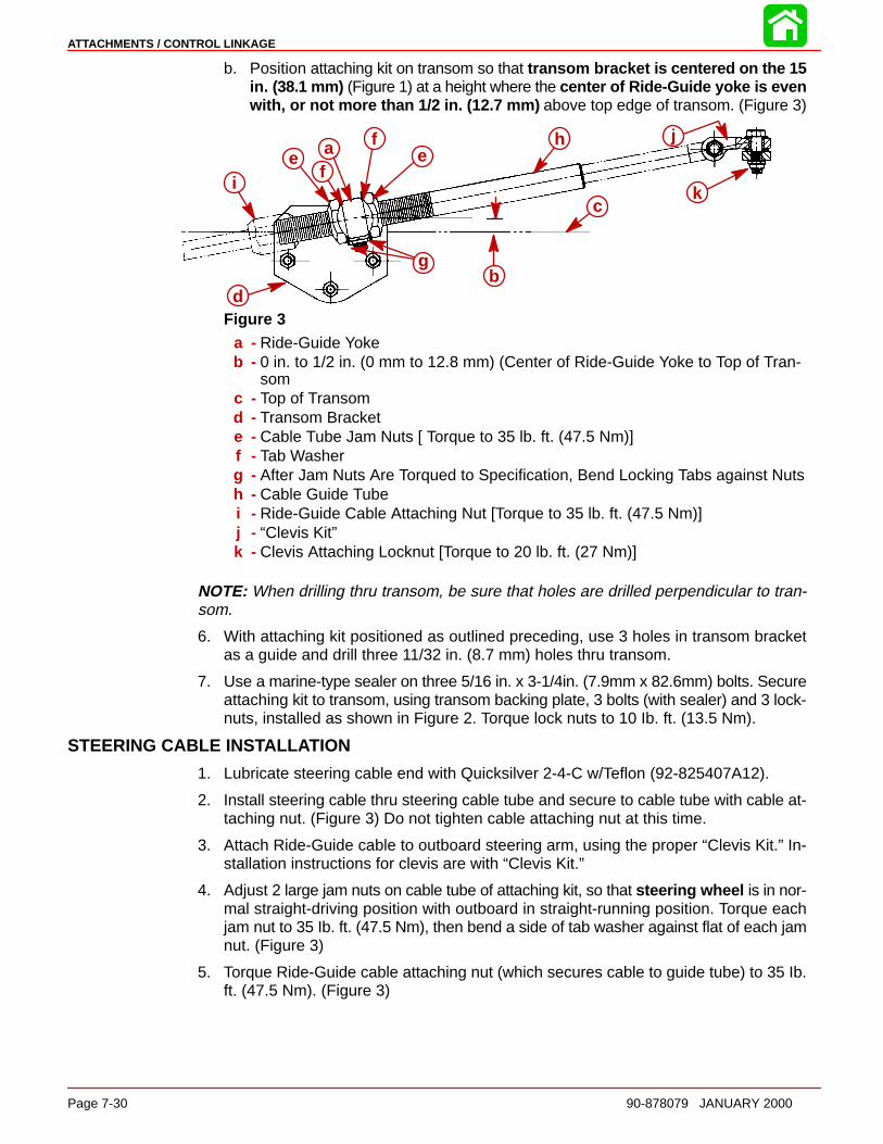
ATTACHMENTS / CONTROL LINKAGE
Page 7-30 90-878079 JANUARY 2000
b. Position attaching kit on transom so that transom bracke t is centered on the 15in. (38.1 mm) (Figure 1) at a height where the center of Ride-Guide yoke is evenwith, or not more than 1/2 in. (12.7 mm ) above top edge of transom. (Figure 3)
ie a
f
fe
h
ck
j
g
d
a
b
c
d
ef
fe
g
h
i
j
k
Figure 3a - Ride-Guide Yokeb - 0 in. to 1/2 in. (0 mm to 12.8 mm) (Center of Ride-Guide Yoke to Top of Tran-
somc - Top of Transomd - Transom Brackete - Cable Tube Jam Nuts [ Torque to 35 lb. ft. (47.5 Nm)]f - Tab Washerg - After Jam Nuts Are Torqued to Specification, Bend Locking Tabs against Nutsh - Cable Guide Tubei - Ride-Guide Cable Attaching Nut [Torque to 35 lb. ft. (47.5 Nm)]j - “Clevis Kit”k - Clevis Attaching Locknut [Torque to 20 lb. ft. (27 Nm)]
NOTE: When drilling thru transom, be sure that holes are drilled perpendicular to tran-som.
6. With attaching kit positioned as outlined preceding, use 3 holes in transom bracketas a guide and drill three 11/32 in. (8.7 mm) holes thru transom.
7. Use a marine-type sealer on three 5/16 in. x 3-1/4in. (7.9mm x 82.6mm) bolts. Secureattaching kit to transom, using transom backing plate, 3 bolts (with sealer) and 3 lock-nuts, installed as shown in Figure 2. Torque lock nuts to 10 Ib. ft. (13.5 Nm).
STEERING CABLE INS TALL ATION
1. Lubricate steering cable end with Quicksilver 2-4-C w/Teflon (92-825407A12).
2. Install steering cable thru steering cable tube and secure to cable tube with cable at-taching nut. (Figure 3) Do not tighten cable attaching nut at this time.
3. Attach Ride-Guide cable to outboard steering arm, using the proper “Clevis Kit.” In-stallation instructions for clevis are with “Clevis Kit.”
4. Adjust 2 large jam nuts on cable tube of attaching kit, so that steering wheel is in nor-mal straight-driving position with outboard in straight-running position. Torque eachjam nut to 35 Ib. ft. (47.5 Nm), then bend a side of tab washer against flat of each jamnut. (Figure 3)
5. Torque Ride-Guide cable attaching nut (which secures cable to guide tube) to 35 Ib.ft. (47.5 Nm). (Figure 3)

ATTACHMENTS / CONTROL LINKAGE
90-878079 JANUARY 2000 Page 7-31
WARNINGAfter installation is completed (and before operating outboard), check that boatwil l turn right when steering wheel is turned right and that boat will turn left whensteering wheel is turned left. Check steering thru full range (left and right) at alltilt angles to assure interference-free movement.
Maintenance InstructionsLubrication and maintenance inspection is owner’s responsibility and must be performedat intervals specified, following:
Normal Service - Every 50 hrs. of operation or 60 days (whichever comes first)
*Severe Service - Every 25 hrs. of operation or 30 days (whichever comes first)
*Operation in a salt water area is considered “Severe Service. ”
CAUTIONCore of steering cable must be fully retracted into cable housing when lubricatingcable. If cable is lubricated while extended, hydraulic lock of cable could occu r.
1. Lubricate outboard end of Ride-Guide steering cable (thru grease fitting - if equipped- next to cable attaching nut) with Quicksilver 2-4-C w/Teflon.
NOTE: Ride-Guide steering cable is lubricated at the factory and requires no additionallubrication at initial installation.
2. Lubricate all steering system pivot points (and exposed portion of steering cable core)with Quicksilver 2-4-C w/Teflon. Lubricate at intervals specified preceding.
3. Carefully check steering system components for wear (at intervals specified, preced-ing). Replace worn parts.
4. Check steering system fasteners (at intervals specified, preceding) to be sure thatthey are torqued to correct specifications. (Figures 1, 2 and 3)
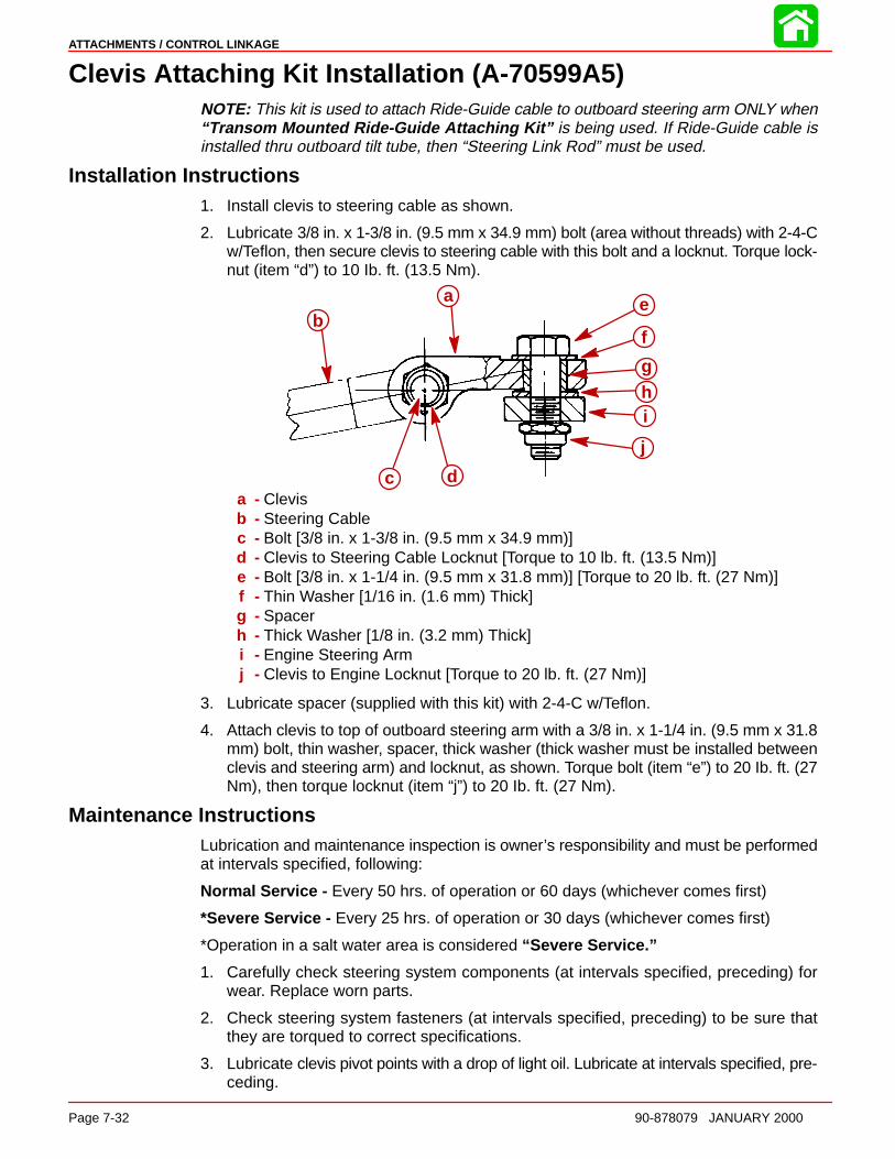
ATTACHMENTS / CONTROL LINKAGE
Page 7-32 90-878079 JANUARY 2000
Clevis Attaching Kit Installation (A-70599A5)NOTE: This kit is used to attach Ride-Guide cable to outboard steering arm ONLY when“Transom Mounted Ride-Guide Attaching Kit” is being used. If Ride-Guide cable isinstalled thru outboard tilt tube, then “Steering Link Rod” must be used.
Installation Instructions1. Install clevis to steering cable as shown.
2. Lubricate 3/8 in. x 1-3/8 in. (9.5 mm x 34.9 mm) bolt (area without threads) with 2-4-Cw/Teflon, then secure clevis to steering cable with this bolt and a locknut. Torque lock-nut (item “d”) to 10 Ib. ft. (13.5 Nm).
b
ae
f
ghi
j
dc
ab
c d
e
f
ghi
j
a - Clevisb - Steering Cablec - Bolt [3/8 in. x 1-3/8 in. (9.5 mm x 34.9 mm)]d - Clevis to Steering Cable Locknut [Torque to 10 lb. ft. (13.5 Nm)]e - Bolt [3/8 in. x 1-1/4 in. (9.5 mm x 31.8 mm)] [Torque to 20 lb. ft. (27 Nm)]f - Thin Washer [1/16 in. (1.6 mm) Thick]g - Spacerh - Thick Washer [1/8 in. (3.2 mm) Thick]i - Engine Steering Armj - Clevis to Engine Locknut [Torque to 20 lb. ft. (27 Nm)]
3. Lubricate spacer (supplied with this kit) with 2-4-C w/Teflon.
4. Attach clevis to top of outboard steering arm with a 3/8 in. x 1-1/4 in. (9.5 mm x 31.8mm) bolt, thin washer, spacer, thick washer (thick washer must be installed betweenclevis and steering arm) and locknut, as shown. Torque bolt (item “e”) to 20 Ib. ft. (27Nm), then torque locknut (item “j”) to 20 Ib. ft. (27 Nm).
Maintenance InstructionsLubrication and maintenance inspection is owner’s responsibility and must be performedat intervals specified, following:
Normal Service - Every 50 hrs. of operation or 60 days (whichever comes first)
*Severe Service - Every 25 hrs. of operation or 30 days (whichever comes first)
*Operation in a salt water area is considered “Severe Service.”
1. Carefully check steering system components (at intervals specified, preceding) forwear. Replace worn parts.
2. Check steering system fasteners (at intervals specified, preceding) to be sure thatthey are torqued to correct specifications.
3. Lubricate clevis pivot points with a drop of light oil. Lubricate at intervals specified, pre-ceding.

8
COLOR DIAGRAMS
Page 8-190-878079 JANUARY 2000
COLOR DIAGRAMS
Table of Contents
2.5 Litre V-6 Carburetor Wiring Diagram 2000 Models 8-3. . . . . . . . . . . . . . . 2.5 Litre V-6 150/175 EFI Wiring Diagram 2000 Models 8-5. . . . . . . . . . . . . . .
2.5 Litre V-6 Water Flow Diagram 2000 Models 8-9. . . . . . . . . . .
2.5 Litre V-6 200 EFI Wiring Diagram 2000 Models 8-7. . . . . . . . . . . . . . .

COLOR DIAGRAMS
Page 8-2 90-878079 JANUARY 2000

COLOR DIAGRAMS
Page 8-390-878079 JANUARY 2000
2.5 LITER V-6 CARBURETORCOLOR WIRING DIAGRAM
2000 MODELS

1. Trigger
2. Control Module
3. Temperature Sensor
4. Shift Switch
5. Low Oil Switch
6. Fuel Enrichment Solenoid
7. Temperature Switch
8. Stator
9. 20 Ampere Fuse Lower Voltage Regulator
10. 20 Ampere Fuse Upper Voltage Regulator
11. 20 Ampere Fuse Accessories and Starting Circuit
12. Starter
13. Start Solenoid
14. To Trim Motor
15. Trim Down Relay
16. Trim Up Relay
17. To 12 Volt Battery
18. To Remote Control Trim Switch
19. Cowl Mounted Trim Switch
20. To Remote Control
21. Auxiliary Power
22. To Temperature Gauge
23. Lower Voltage Regulator
24. Upper Voltage Regulator
25. Tachometer Signal
26. CDM #5
27. CDM #3
28. CDM #1
29. CDM #6
30. CDM #4
31. CDM #2
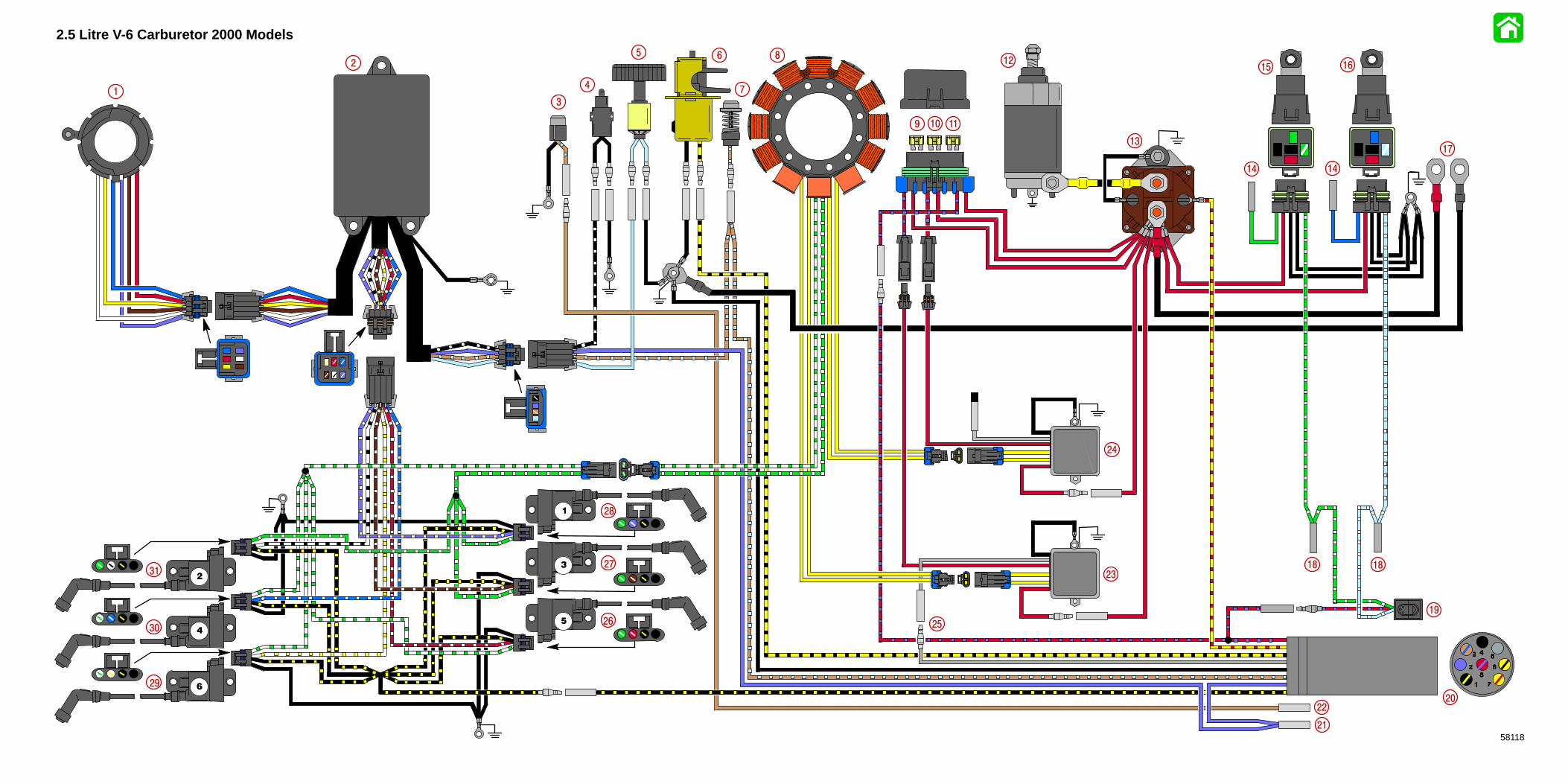
2.5 Litre V-6 Carburetor 2000 Models
58118
1
2
3
4
5 6
7
8
9 10 11
12
13
14
15 16
17
18
19
20
14
23
24
2526
27
28
29
30
31
22
21
18

COLOR DIAGRAMS
Page 8-590-878079 JANUARY 2000
2.5 LITER V-6 150/175 EFICOLOR WIRING DIAGRAM
2000 MODELS
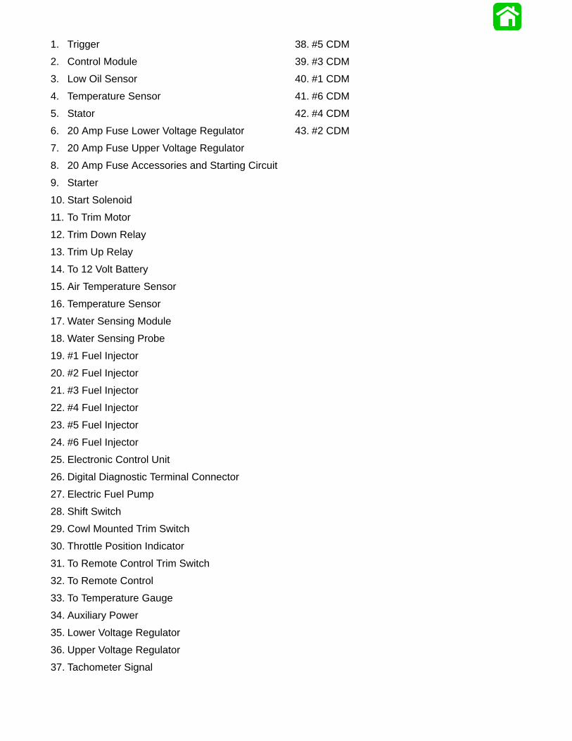
1. Trigger
2. Control Module
3. Low Oil Sensor
4. Temperature Sensor
5. Stator
6. 20 Amp Fuse Lower Voltage Regulator
7. 20 Amp Fuse Upper Voltage Regulator
8. 20 Amp Fuse Accessories and Starting Circuit
9. Starter
10. Start Solenoid
11. To Trim Motor
12. Trim Down Relay
13. Trim Up Relay
14. To 12 Volt Battery
15. Air Temperature Sensor
16. Temperature Sensor
17. Water Sensing Module
18. Water Sensing Probe
19. #1 Fuel Injector
20. #2 Fuel Injector
21. #3 Fuel Injector
22. #4 Fuel Injector
23. #5 Fuel Injector
24. #6 Fuel Injector
25. Electronic Control Unit
26. Digital Diagnostic Terminal Connector
27. Electric Fuel Pump
28. Shift Switch
29. Cowl Mounted Trim Switch
30. Throttle Position Indicator
31. To Remote Control Trim Switch
32. To Remote Control
33. To Temperature Gauge
34. Auxiliary Power
35. Lower Voltage Regulator
36. Upper Voltage Regulator
37. Tachometer Signal
38. #5 CDM
39. #3 CDM
40. #1 CDM
41. #6 CDM
42. #4 CDM
43. #2 CDM
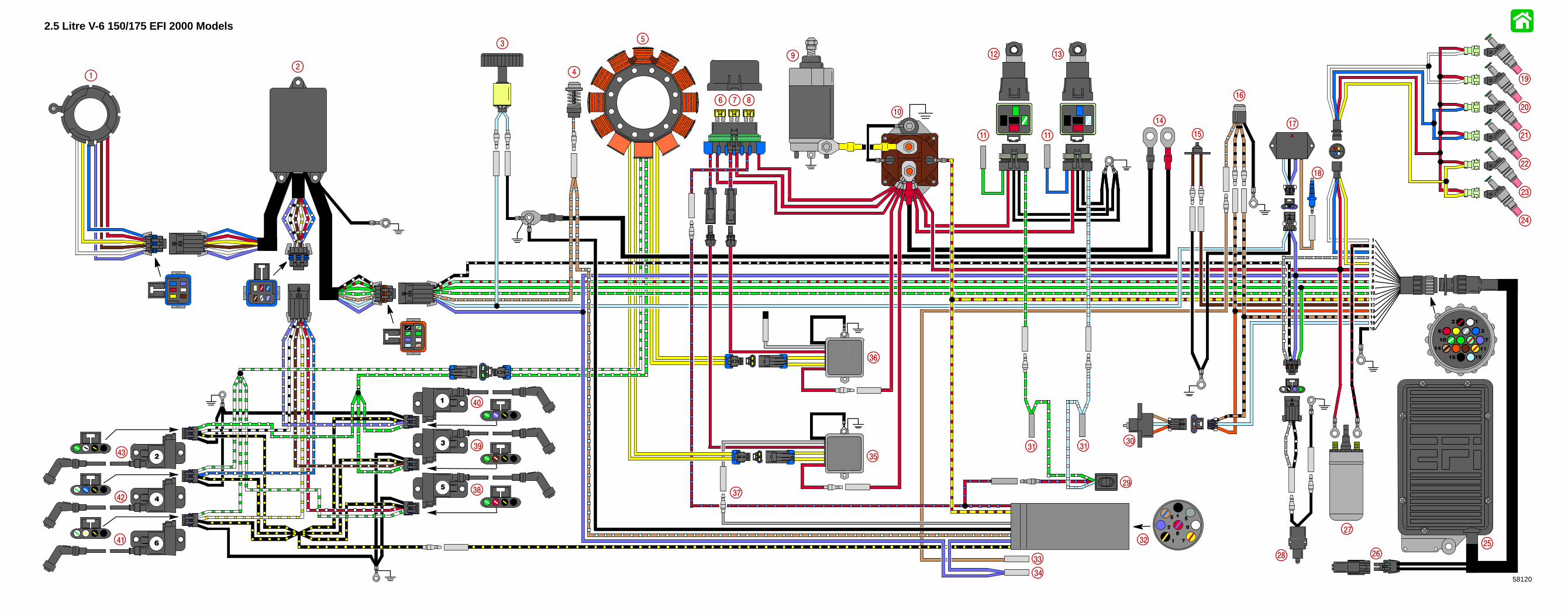
2.5 Litre V-6 150/175 EFI 2000 Models
58120
1
2
3
4
5
6 7 8
9
10
11
12 13
14
15
16
17
18
19
20
11 21
22
23
24
25
26
27
28
29
3031
35
36
3738
39
40
41
43
32
31
33
34
42

COLOR DIAGRAMS
Page 8-790-878079 JANUARY 2000
2.5 LITER V-6 200 EFICOLOR WIRING DIAGRAM
2000 MODELS
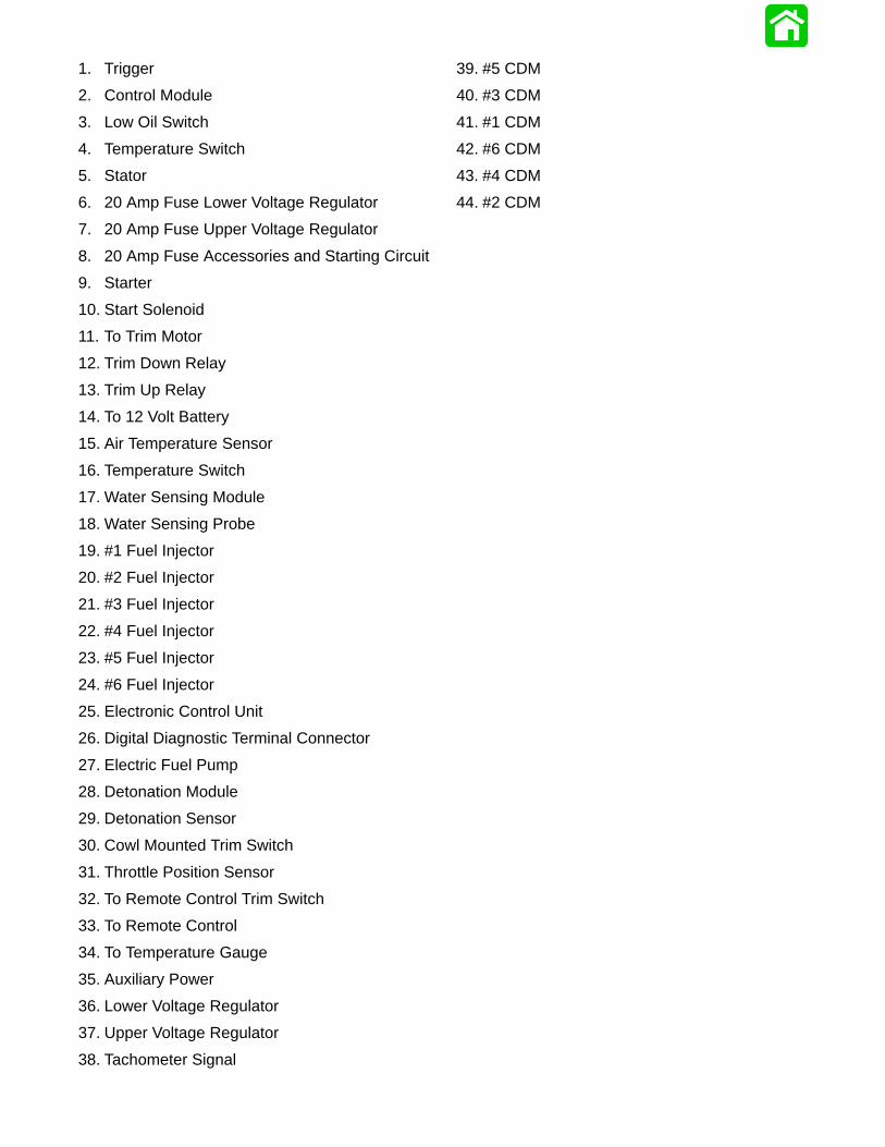
1. Trigger
2. Control Module
3. Low Oil Switch
4. Temperature Switch
5. Stator
6. 20 Amp Fuse Lower Voltage Regulator
7. 20 Amp Fuse Upper Voltage Regulator
8. 20 Amp Fuse Accessories and Starting Circuit
9. Starter
10. Start Solenoid
11. To Trim Motor
12. Trim Down Relay
13. Trim Up Relay
14. To 12 Volt Battery
15. Air Temperature Sensor
16. Temperature Switch
17. Water Sensing Module
18. Water Sensing Probe
19. #1 Fuel Injector
20. #2 Fuel Injector
21. #3 Fuel Injector
22. #4 Fuel Injector
23. #5 Fuel Injector
24. #6 Fuel Injector
25. Electronic Control Unit
26. Digital Diagnostic Terminal Connector
27. Electric Fuel Pump
28. Detonation Module
29. Detonation Sensor
30. Cowl Mounted Trim Switch
31. Throttle Position Sensor
32. To Remote Control Trim Switch
33. To Remote Control
34. To Temperature Gauge
35. Auxiliary Power
36. Lower Voltage Regulator
37. Upper Voltage Regulator
38. Tachometer Signal
39. #5 CDM
40. #3 CDM
41. #1 CDM
42. #6 CDM
43. #4 CDM
44. #2 CDM
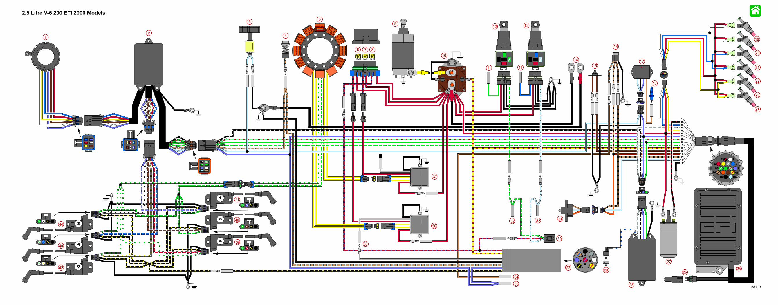
2.5 Litre V-6 200 EFI 2000 Models
58119
1
2
3
4
5
6 7 8
9
10
11
12 13
14
15
16
17
18
19
11
20
21
22
23
24
2526
27
28
30
3132
35
36
37
3839
40
41
42
43
3329
32
34
44

COLOR DIAGRAMS
Page 8-990-878079 JANUARY 2000
2.5 LITER V-6 COLOR WATER FLOW DIAGRAM
2000 MODELS
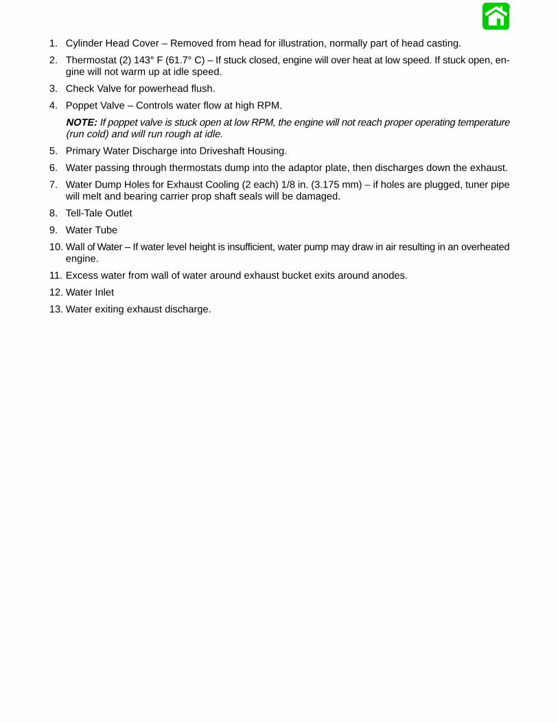
1. Cylinder Head Cover – Removed from head for illustration, normally part of head casting.
2. Thermostat (2) 143° F (61.7° C) – If stuck closed, engine will over heat at low speed. If stuck open, en-gine will not warm up at idle speed.
3. Check Valve for powerhead flush.
4. Poppet Valve – Controls water flow at high RPM.
NOTE: If poppet valve is stuck open at low RPM, the engine will not reach proper operating temperature(run cold) and will run rough at idle.
5. Primary Water Discharge into Driveshaft Housing.
6. Water passing through thermostats dump into the adaptor plate, then discharges down the exhaust.
7. Water Dump Holes for Exhaust Cooling (2 each) 1/8 in. (3.175 mm) – if holes are plugged, tuner pipewill melt and bearing carrier prop shaft seals will be damaged.
8. Tell-Tale Outlet
9. Water Tube
10. Wall of Water – If water level height is insufficient, water pump may draw in air resulting in an overheatedengine.
11. Excess water from wall of water around exhaust bucket exits around anodes.
12. Water Inlet
13. Water exiting exhaust discharge.

2.5 Litre V-6 Water Flow Diagram 2000 Models
5806
3
1
2
3
4
5
6
7
8
9
10
11
12
13