Schneider Electric DIGEST 175 - Steven Engineering
148
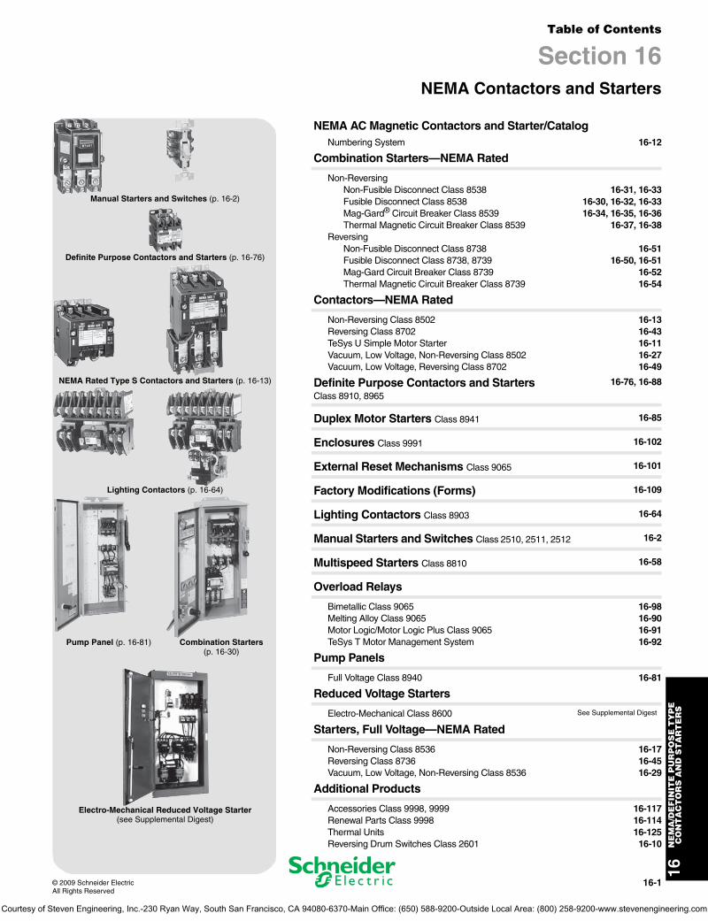
16-1 © 2009 Schneider Electric All Rights Reserved 16 NEMA/DEFINITE PURPOSE TYPE CONTACTORS AND STARTERS Table of Contents Section 16 NEMA Contactors and Starters Manual Starters and Switches (p. 16-2) Definite Purpose Contactors and Starters (p. 16-76) NEMA Rated Type S Contactors and Starters (p. 16-13) Lighting Contactors (p. 16-64) Pump Panel (p. 16-81) Combination Starters (p. 16-30) Electro-Mechanical Reduced Voltage Starter (see Supplemental Digest) NEMA AC Magnetic Contactors and Starter/Catalog Numbering System 16-12 Combination Starters—NEMA Rated Non-Reversing Non-Fusible Disconnect Class 8538 16-31, 16-33 Fusible Disconnect Class 8538 16-30, 16-32, 16-33 Mag-Gard ® Circuit Breaker Class 8539 16-34, 16-35, 16-36 Thermal Magnetic Circuit Breaker Class 8539 16-37, 16-38 Reversing Non-Fusible Disconnect Class 8738 16-51 Fusible Disconnect Class 8738, 8739 16-50, 16-51 Mag-Gard Circuit Breaker Class 8739 16-52 Thermal Magnetic Circuit Breaker Class 8739 16-54 Contactors—NEMA Rated Non-Reversing Class 8502 16-13 Reversing Class 8702 16-43 TeSys U Simple Motor Starter 16-11 Vacuum, Low Voltage, Non-Reversing Class 8502 16-27 Vacuum, Low Voltage, Reversing Class 8702 16-49 Definite Purpose Contactors and Starters Class 8910, 8965 16-76, 16-88 Duplex Motor Starters Class 8941 16-85 Enclosures Class 9991 16-102 External Reset Mechanisms Class 9065 16-101 Factory Modifications (Forms) 16-109 Lighting Contactors Class 8903 16-64 Manual Starters and Switches Class 2510, 2511, 2512 16-2 Multispeed Starters Class 8810 16-58 Overload Relays Bimetallic Class 9065 16-98 Melting Alloy Class 9065 16-90 Motor Logic/Motor Logic Plus Class 9065 16-91 TeSys T Motor Management System 16-92 Pump Panels Full Voltage Class 8940 16-81 Reduced Voltage Starters Electro-Mechanical Class 8600 See Supplemental Digest Starters, Full Voltage—NEMA Rated Non-Reversing Class 8536 16-17 Reversing Class 8736 16-45 Vacuum, Low Voltage, Non-Reversing Class 8536 16-29 Additional Products Accessories Class 9998, 9999 16-117 Renewal Parts Class 9998 16-114 Thermal Units 16-125 Reversing Drum Switches Class 2601 16-10 Courtesy of Steven Engineering, Inc.-230 Ryan Way, South San Francisco, CA 94080-6370-Main Office: (650) 588-9200-Outside Local Area: (800) 258-9200-www.stevenengineering.com
-
Upload
khangminh22 -
Category
Documents
-
view
1 -
download
0
Transcript of Schneider Electric DIGEST 175 - Steven Engineering
16-1© 2009 Schneider ElectricAll Rights Reserved
16N
EM
A/D
EF
INIT
E P
UR
PO
SE
TY
PE
CO
NT
AC
TO
RS
AN
D S
TA
RT
ER
S
Table of Contents
Section 16NEMA Contactors and Starters
Manual Starters and Switches (p. 16-2)
Definite Purpose Contactors and Starters (p. 16-76)
NEMA Rated Type S Contactors and Starters (p. 16-13)
Lighting Contactors (p. 16-64)
Pump Panel (p. 16-81) Combination Starters (p. 16-30)
Electro-Mechanical Reduced Voltage Starter(see Supplemental Digest)
NEMA AC Magnetic Contactors and Starter/CatalogNumbering System 16-12
Combination Starters—NEMA Rated
Non-ReversingNon-Fusible Disconnect Class 8538 16-31, 16-33Fusible Disconnect Class 8538 16-30, 16-32, 16-33Mag-Gard® Circuit Breaker Class 8539 16-34, 16-35, 16-36Thermal Magnetic Circuit Breaker Class 8539 16-37, 16-38
ReversingNon-Fusible Disconnect Class 8738 16-51Fusible Disconnect Class 8738, 8739 16-50, 16-51Mag-Gard Circuit Breaker Class 8739 16-52Thermal Magnetic Circuit Breaker Class 8739 16-54
Contactors—NEMA Rated
Non-Reversing Class 8502 16-13Reversing Class 8702 16-43TeSys U Simple Motor Starter 16-11Vacuum, Low Voltage, Non-Reversing Class 8502 16-27Vacuum, Low Voltage, Reversing Class 8702 16-49
Definite Purpose Contactors and Starters Class 8910, 8965
16-76, 16-88
Duplex Motor Starters Class 8941 16-85
Enclosures Class 9991 16-102
External Reset Mechanisms Class 9065 16-101
Factory Modifications (Forms) 16-109
Lighting Contactors Class 8903 16-64
Manual Starters and Switches Class 2510, 2511, 2512 16-2
Multispeed Starters Class 8810 16-58
Overload Relays
Bimetallic Class 9065 16-98Melting Alloy Class 9065 16-90Motor Logic/Motor Logic Plus Class 9065 16-91TeSys T Motor Management System 16-92
Pump Panels
Full Voltage Class 8940 16-81
Reduced Voltage Starters
Electro-Mechanical Class 8600 See Supplemental Digest
Starters, Full Voltage—NEMA Rated
Non-Reversing Class 8536 16-17Reversing Class 8736 16-45Vacuum, Low Voltage, Non-Reversing Class 8536 16-29
Additional Products
Accessories Class 9998, 9999 16-117Renewal Parts Class 9998 16-114Thermal Units 16-125Reversing Drum Switches Class 2601 16-10
Courtesy of Steven Engineering, Inc.-230 Ryan Way, South San Francisco, CA 94080-6370-Main Office: (650) 588-9200-Outside Local Area: (800) 258-9200-www.stevenengineering.com
www.schneider-electric.us
16N
EM
A D
EF
INIT
E P
UR
PO
SE
TY
PE
C
ON
TA
CT
OR
S A
ND
ST
AR
TE
RS
16-2 © 2009 Schneider ElectricAll Rights Reserved
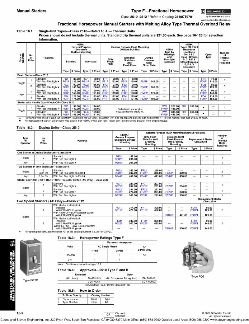
Manual Starters Type F—Fractional HorsepowerClass 2510, 2512 / Refer to Catalog 2510CT9701
Fractional Horsepower Manual Starters with Melting Alloy Type Thermal Overload Relay
Note: Continuous current rating—16 A.
Type FG2P
Table 16.1: Single-Unit Types—Class 2510—Rated 16 A — Thermal Units Prices shown do not include thermal units. Standard trip thermal units are $21.50 each. See page 16-125 for selection information.
Type
of
Ope
rato
r
No.of
PolesFeatures
NEMA 1General Purpose
EnclosureSurface Mounting
General Purpose Flush Mounting(Without Pull Box) NEMA
Type 4aWatertight
andDusttightEnclosure
NEMATypes 3R, 7 & 9
Hazardous Locations Div. 1 & 2
Class I GroupsB, C, & D &
Class II GroupsE, F & G
Enclosure
OpenType
Numberof
ThermalUnits
RequiredStandard OversizedGrayFlushPlate
StandardStainless
SteelFlush Plate
JumboStainless
SteelFlush Plate
Type $ Price Type $ Price Type $ Price Type $ Price Type $ Price Type $ Price Type $ Price Type $ Price
Basic Starter—Class 2510
Toggle1 Standard
With Red Pilot LightcFG1
FG1P 86.00129.00
FGJ1FGJ1P
99.00143.00
FF1FF1P
78.00122.00
FS1FS1P
83.00129.00
—FSJ1P
—149.00
——
——
——
——
FO1FO1P
71.00116.00 1
2 StandardWith Red Pilot Lightc
FG2FG2P
99.00143.00
FGJ2FGJ2P
116.00158.00
FF2FF2P
93.00120.00
FS2FS2P
99.00143.00
—FSJ2P
—165.00
——
——
——
——
FO2FO2P
86.00129.00 1
Key1 Standard
With Red Pilot LightcFG3
FG3P116.00158.00
FGJ3FGJ3P
129.00171.00
FF3FF3P
107.00149.00
FS3FS3P
114.00158.00
—FSJ3P
—179.00
——
——
——
——
FO3FO3P
99.00143.00 1
2 StandardWith Red Pilot Lightc
FG4FG4P
129.00171.00
FGJ4FGJ4P
143.00185.00
FF4FF4P
122.00165.00
FS4FS4P
129.00171.00
—FSJ4P
—192.00
——
——
——
——
FO4FO4P
114.00158.00 1
Starter with Handle Guard/Lock-Off—Class 2510
Toggle1 Standard
With Red Pilot Light cFG5
FG5P99.00
143.00FGJ5
FGJ5P114.00158.00 Order basic starter plus
separate handle guard kit.
FW1FW1P
320.00435.00
FR1—
350.00— b
—— 1
2 StandardWith Red Pilot Lightc
FG6FG6P
116.00158.00
FGJ6FGJ6P
129.00171.00
FW2FW2P
336.00449.00
FR2—
363.00— b
—— 1
a Furnished with one 3/4" pipe tap in bottom (reversible for top feed). To obtain 3/4" pipe tap top and bottom, add suffix letter “H” to type number and add $19.10 to price.b For replacement starter, order open type above. For NEMA 4 with pilot light, retain pilot light mounting bracket from original device.
Type FO2
Table 16.2: Duplex Units—Class 2510
Typeof
Operator
No.of
PolesFeatures
NEMA 1General Purpose
Enclosure SurfaceMounting
General Purpose Flush Mounting (Without Pull Box)Number
ofThermal
UnitsRequired
Gray FlushPlate for Wall
or CavityMounting
Stainless SteelFlush Plate forWall or Cavity
Mounting
Replacement StarterClass 2510
Type $ Price Type $ Price Type $ Price Type $ Price
One Starter in Duplex Enclosure—Class 2510
Toggle 2Standard FG02 158.00 — — — — — —
1With Red Pilot Light c FG02P 201.00 — — — — — —
Key 2 With Red Pilot Light c FG04P 201.00 — — — — — — 1
Two Starters in One Enclosure—Class 2510
Toggle 2Each Str.
Standard FG22 243.00 FF22 228.00 — — — — 2With Red Pilot Light on Eachc FG22P 399.00 FF22P 386.00 FS22P 399.00 — —Key 2 Ea. Str. With Red Pilot Light on Eachc FG44P 458.00 FF44P 441.00 FS44P 458.00 — — 2
Starter and “AUTO-OFF-HAND” SPDT Selector Switch (AC Only)—Class 2510
Toggle1 Standard FG71 221.00 FF71 207.00 — — — — 1With Red Pilot Light c FG71P 264.00 FF71P 251.00 FS71P 264.00 — —
2 Standard FG72 234.00 FF72 221.00 — — — — 1With Red Pilot Lightc FG72P 278.00 FF72P 264.00 FS72P 278.00 — —Key 2 With Red Pilot Lightc FG74P 306.00 FF74P 293.00 FS74P 306.00 — — 1
Two Speed Starters (AC Only)—Class 2512Replacement Starter
Class 2510
Toggle
1
With Mechanical Interlock:
2Standard FG11 314.00 FF11 300.00 — — FO1T 86.00
With 2 Red Pilot Lightsc FG11P 471.00 FF11P 458.00 — — FO1PT 129.00With HIGH-OFF-LOW Selector Switch:
With 2 Red Pilot Lightsc — — — — FS101P 471.00 FO1PT 129.00
2
With Mechanical Interlock:
2Standard FG22 342.00 FF22 329.00 — — FO2T 99.00With 2 Red Pilot Lightsc FG22P 500.00 FF22P 485.00 — — FO2PT 143.00
With HIGH-OFF-LOW Selector Switch:With 2 Red Pilot Lightsc — — — — FS202P 500.00 FO2PT 143.00
c For green pilot light, add the letter “G” to the catalog number (i.e. 2510FG2PG).
Table 16.3: Horsepower Ratings Type F
Volts
Maximum Horsepower
AC Single Phase DC 2-Pole Only1-Pole 2-Pole
115–230 1 1 3/4
277 1 1 —
Table 16.4: Approvals—2510 Type F and KEnclosed Open
(UL Listed) File E42243 (UL Component Recognized) File E42243CCN NLRV CCN NLRV2
CSA Certified File LR25490 Class 3211-05
Table 16.5: How to OrderTo Order Specify: Catalog Number
• Class Number• Type Number
Class Type2510 FG1
CP1 Discount Schedule
Courtesy of Steven Engineering, Inc.-230 Ryan Way, South San Francisco, CA 94080-6370-Main Office: (650) 588-9200-Outside Local Area: (800) 258-9200-www.stevenengineering.com
www.schneider-electric.us
16N
EM
A/D
EF
INIT
E P
UR
PO
SE
TY
PE
CO
NT
AC
TO
RS
AN
D S
TA
RT
ER
S
© 2009 Schneider ElectricAll Rights Reserved
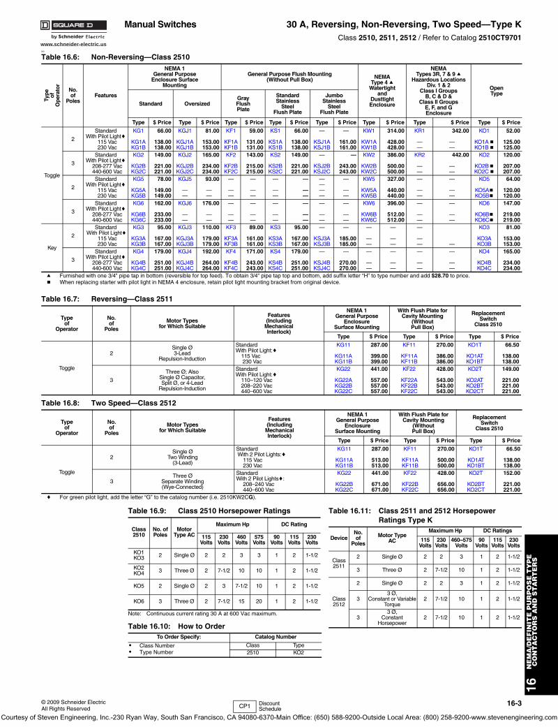
16-3
Manual Switches 30 A, Reversing, Non-Reversing, Two Speed—Type KClass 2510, 2511, 2512 / Refer to Catalog 2510CT9701
000
Note: Continuous current rating 30 A at 600 Vac maximum.
Table 16.6: Non-Reversing—Class 2510
Type of
Ope
rato
r
No.of
PolesFeatures
NEMA 1General Purpose
Enclosure SurfaceMounting
General Purpose Flush Mounting(Without Pull Box) NEMA
Type 4 aWatertight
andDusttightEnclosure
NEMATypes 3R, 7 & 9 a
Hazardous Locations Div. 1 & 2
Class I GroupsB, C & D &
Class II GroupsE, F, and GEnclosure
OpenType
Standard OversizedGrayFlushPlate
StandardStainless
SteelFlush Plate
JumboStainless
SteelFlush Plate
Type $ Price Type $ Price Type $ Price Type $ Price Type $ Price Type $ Price Type $ Price Type $ Price
Toggle
2
Standard KG1 66.00 KGJ1 81.00 KF1 59.00 KS1 66.00 — — KW1 314.00 KR1 342.00 KO1 52.00With Pilot Lightc
115 Vac KG1A 138.00 KGJ1A 153.00 KF1A 131.00 KS1A 138.00 KSJ1A 161.00 KW1A 428.00 — — KO1Ab 125.00230 Vac KG1B 138.00 KGJ1B 153.00 KF1B 131.00 KS1B 138.00 KSJ1B 161.00 KW1B 428.00 — — KO1Bb 125.00
3
Standard KG2 149.00 KGJ2 165.00 KF2 143.00 KS2 149.00 — — KW2 386.00 KR2 442.00 KO2 120.00With Pilot Lightc
208-277 Vac KG2B 221.00 KGJ2B 234.00 KF2B 215.00 KS2B 221.00 KSJ2B 243.00 KW2B 500.00 — — KO2Bb 207.00440-600 Vac KG2C 221.00 KGJ2C 234.00 KF2C 215.00 KS2C 221.00 KSJ2C 243.00 KW2C 500.00 — — KO2Cb 207.00
2
Standard KG5 78.00 KGJ5 93.00 — — — — — — KW5 327.00 — — KO5 64.00With Pilot Lightc —
115 Vac KG5A 149.00 — — — — — — — — KW5A 440.00 — — KO5Ab 120.00230 Vac KG5B 149.00 — — — — — — — — KW5B 440.00 — — KO5Bb 120.00
3
Standard KG6 162.00 KGJ6 176.00 — — — — — — KW6 396.00 — — KO6 147.00With Pilot Lightc
208-277 Vac KG6B 233.00 — — — — — — — — KW6B 512.00 — — KO6Bb 219.00440-600 Vac KG6C 233.00 — — — — — — — — KW6C 512.00 — — KO6Cb 219.00
Key
2
Standard KG3 95.00 KGJ3 110.00 KF3 89.00 KS3 95.00 — — — — — KO3 81.00 With Pilot Lightc
115 Vac KG3A 167.00 KGJ3A 179.00 KF3A 161.00 KS3A 167.00 KSJ3A 185.00 — — — KO3A 153.00230 Vac KG3B 167.00 KGJ3B 179.00 KF3B 161.00 KS3B 167.00 KSJ3B 185.00 — — — — KO3B 153.00
3
Standard KG4 179.00 KGJ4 192.00 KF4 171.00 KS4 179.00 — — — — — — KO4 165.00With Pilot Lightc
208-277 Vac KG4B 251.00 KGJ4B 264.00 KF4B 243.00 KS4B 251.00 KSJ4B 270.00 — — — — KO4B 234.00440-600 Vac KG4C 251.00 KGJ4C 264.00 KF4C 243.00 KS4C 251.00 KSJ4C 270.00 — — — — KO4C 234.00
a Furnished with one 3/4" pipe tap in bottom (reversible for top feed). To obtain 3/4" pipe tap top and bottom, add suffix letter “H” to type number and add $28.70 to price.b When replacing starter with pilot light in NEMA 4 enclosure, retain pilot light mounting bracket from original device.
Table 16.7: Reversing—Class 2511
Typeof
Operator
No.of
Poles
Motor Typesfor Which Suitable
Features(Including
MechanicalInterlock)
NEMA 1General Purpose
EnclosureSurface Mounting
With Flush Plate forCavity Mounting
(WithoutPull Box)
ReplacementSwitch
Class 2510
Type $ Price Type $ Price Type $ Price
Toggle
2Single Ø3-Lead
Repulsion-Induction
Standard KG11 287.00 KF11 270.00 KO1T 66.50With Pilot Light:c
115 Vac KG11A 399.00 KF11A 386.00 KO1AT 138.00 230 Vac KG11B 399.00 KF11B 386.00 KO1BT 138.00
3
Three Ø; AlsoSingle Ø Capacitor,Split Ø, or 4-Lead
Repulsion-Induction
Standard KG22 441.00 KF22 428.00 KO2T 149.00With Pilot Light:c
110–120 Vac KG22A 557.00 KF22A 543.00 KO2AT 221.00208–220 Vac KG22B 557.00 KF22B 543.00 KO2BT 221.00440–600 Vac KG22C 557.00 KF22C 543.00 KO2CT 221.00
Table 16.8: Two Speed—Class 2512
Typeof
Operator
No.of
Poles
Motor Typesfor Which Suitable
Features(Including
MechanicalInterlock)
NEMA 1General Purpose
EnclosureSurface Mounting
With Flush Plate forCavity Mounting
(WithoutPull Box)
ReplacementSwitch
Class 2510
Type $ Price Type $ Price Type $ Price
Toggle
2Single Ø
Two Winding(3-Lead)
Standard KG11 287.00 KF11 270.00 KO1T 66.50 With 2 Pilot Lights:c 115 Vac KG11A 513.00 KF11A 500.00 KO1AT 138.00 230 Vac KG11B 513.00 KF11B 500.00 KO1BT 138.00
3Three Ø
Separate Winding(Wye-Connected)
Standard KG22 441.00 KF22 428.00 KO2T 152.00With 2 Pilot Lightsc:
208–240 Vac KG22B 671.00 KF22B 656.00 KO2BT 221.00 440–600 Vac KG22C 671.00 KF22C 656.00 KO2CT 221.00
c For green pilot light, add the letter “G” to the catalog number (i.e. 2510KW2CG).
Table 16.9: Class 2510 Horsepower Ratings
Class 2510
No. of Poles
Motor Type AC
Maximum Hp DC Rating
115 Volts
230 Volts
460 Volts
575 Volts
90Volts
115 Volts
230 Volts
KO1KO3 2 Single Ø 2 2 3 3 1 2 1-1/2
KO2KO4 3 Three Ø 2 7-1/2 10 10 1 2 1-1/2
KO5 2 Single Ø 2 3 7-1/2 10 1 2 1-1/2
KO6 3 Three Ø 2 7-1/2 15 20 1 2 1-1/2
Table 16.10: How to OrderTo Order Specify: Catalog Number
• Class Number• Type Number
Class Type2510 KO2
Table 16.11: Class 2511 and 2512 Horsepower Ratings Type K
DeviceNo.of
Poles
Motor TypeAC
Maximum Hp DC Ratings
115Volts
230Volts
460–575Volts
90Volts
115Volts
230Volts
Class2511
2 Single Ø 2 2 3 1 2 1-1/2
3 Three Ø 2 7-1/2 10 1 2 1-1/2
Class2512
2 Single Ø 2 2 3 1 2 1-1/2
33 Ø,
Constant or VariableTorque
2 7-1/2 10 1 2 1-1/2
33 Ø,
ConstantHorsepower
2 7-1/2 10 1 2 1-1/2
CP1 Discount Schedule
Courtesy of Steven Engineering, Inc.-230 Ryan Way, South San Francisco, CA 94080-6370-Main Office: (650) 588-9200-Outside Local Area: (800) 258-9200-www.stevenengineering.com
www.schneider-electric.us
16N
EM
A/D
EF
INIT
E P
UR
PO
SE
TY
PE
CO
NT
AC
TO
RS
AN
D S
TA
RT
ER
S
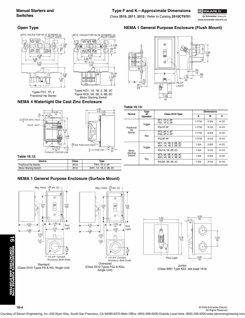
16-4 © 2009 Schneider ElectricAll Rights Reserved
Manual Starters and Switches
Type F and K—Approximate DimensionsClass 2510, 2511, 2512 / Refer to Catalog 2510CT9701
Open Type
NEMA 4 Watertight Die Cast Zinc Enclosure
NEMA 1 General Purpose Enclosure (Surface Mount)
NEMA 1 General Purpose Enclosure (Flush Mount)
Table 16.12: Device Class Type
Fractional Hp Starter 2510 FW1, 1P, 2, 2PMotor Starting Switch 2510 KW1, 1A, 1B, 2, 2B, 2C
2.2256
1.5940
.8421
1.6943
4.13105
3.2883
2.3860
MTG. HOLES FOR #6-32 SCREWS (2)PILOT LIGHT
OFF
1.7043
2.3460
2.38603.28
83 4.13105
1.6943.84
21
OFF
MTG. HOLES FOR #6-32 SCREWS (2)PILOT LIGHT
Types FO1, 1P, 2Fractional Hp Starter
Types KO1, 1A, 1B, 2, 2B, 2CTypes KO5, 5A, 5B, 6, 6B, 6C
Motor Starting Switch
CONDUIT CENTER LINE
376
1.1329
.256
2.7570
(2) DIA. MTG. HOLE.226
PILOT LIGHT
ON
OFF
.318
1.1329
4.38111
3.7595
4.25108
4.56116
3"4 14 PIPE TAP
.287
.7820
DIA. PADLOCK HOLE
2.7570
2.8873
4.25108
1.6341
0.5614
0.6917
1.0627
3.0076
OFF
2.8873
1/2-3/4" ConduitKnockout, Both Ends
Pilot Light
Mtg. Holes dia. (2).256
Oversized(Class 2510 Types FGJ & KGJ,
Single Unit)
2.7570
2.8873
4.25108
1.6341
0.5614
0.4110
1.0627
3.0076
OFF
2.4462
1/2-3/4" ConduitKnockout, Both Ends
Pilot Light
Mtg. Holes dia. (2).256
Standard(Class 2510 Types FG & KG, Single Unit)
OFF
Pilot Light
4.86123 0.71
18
3.2883
3.0978
2.2056
4.35110
Jumbo(Class 9991 Type KE2; see page 16-9)
Table 16.13:
DeviceType
ofOperator
Class 2510 TypeDimensions
A B C
FractionalHp
Starter
Toggle
FF1, 1P, 2, 2PFS1, 1P, 2, 2P 1-7/16 2-3/4 4-1/2
FSJ1P, 2P 1-7/16 3-1/2 5-1/4
Key
FF3, 3P, 4, 4PFS3, 3P, 4, 4P 1-7/16 2-3/4 4-1/2
FSJ3P, 4P 1-7/16 3-1/2 5-1/4
MotorStartingSwitch
Toggle
KF1, 1A, 1B, 2, 2B, 2CKS1, 1A, 1B, 2, 2B, 2C 1-3/4 2-3/4 4-1/2
KSJ1A, 1B, 2B, 2C 1-3/4 3-1/2 5-1/4
Key
KF3, 3A, 3B, 4, 4B, 4CKS3, 3A, 3B, 4, 4B, 4C 1-3/4 2-3/4 4-1/2
KSJ3A, 3B, 4B, 4C 1-3/4 3-1/2 5-1/4
.7519.91
23
A
OFF
PILOTLIGHT
D
D
1.6943
1.7845
.6617
.5013
2.5665
B
C
Courtesy of Steven Engineering, Inc.-230 Ryan Way, South San Francisco, CA 94080-6370-Main Office: (650) 588-9200-Outside Local Area: (800) 258-9200-www.stevenengineering.com
www.schneider-electric.us
16N
EM
A/D
EF
INIT
E P
UR
PO
SE
TY
PE
CO
NT
AC
TO
RS
AN
D S
TA
RT
ER
S
© 2009 Schneider ElectricAll Rights Reserved
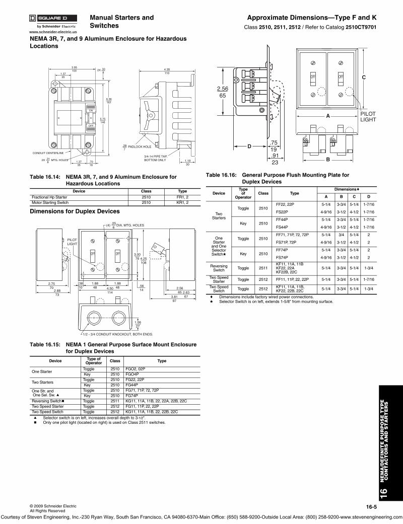
16-5
NEMA 3R, 7, and 9 Aluminum Enclosure for Hazardous Locations
Dimensions for Duplex Devices
a Selector switch is on left, increases overall depth to 3-1/2".b Only one pilot light (located on right) is used on Class 2511 switches.
c Dimensions include factory wired power connections.d Selector Switch is on left, extends 1-5/8" from mounting surface.
Table 16.14: NEMA 3R, 7, and 9 Aluminum Enclosure for Hazardous Locations
Device Class Type
Fractional Hp Starter 2510 FR1, 2Motor Starting Switch 2510 KR1, 2
Table 16.15: NEMA 1 General Purpose Surface Mount Enclosure for Duplex Devices
Device Type ofOperator Class Type
One Starter Toggle 2510 FGO2, 02P Key 2510 FGO4P
Two Starters Toggle 2510 FG22, 22P Key 2510 FG44P
One Str. and One Sel. Sw. a
Toggle 2510 FG71, 71P, 72, 72P Key 2510 FG74P
Reversing Switchb Toggle 2511 KG11, 11A, 11B, 22, 22A, 22B, 22CTwo Speed Starter Toggle 2512 FG11, 11P, 22, 22PTwo Speed Switch Toggle 2512 KG11, 11A, 11B, 22, 22B, 22C
1.3735
.7018
5.75146
.3081.37
35
6.36161
3.95100
ON
OFF
CONDUIT CENTERLINE
2X .318
MTG. HOLES
2X 4.35110
1.1930
3/4-14 PIPE TAP,BOTTOM ONLY
.287
PADLOCK HOLE
2.7570
2.8873
PILOTLIGHT
OFF OFF
(4) .256
3.0076 4.25
108
DIA. MTG. HOLES
.5614
1.8848 4.50
114
1.0627
.3810
1.8848
1/2 - 3/4 CONDUIT KNOCKOUT, BOTH ENDS.
2.5665 2.63
673.8197
Table 16.16: General Purpose Flush Mounting Plate for Duplex Devices
DeviceType
ofOperator
Class TypeDimensionsc
A B C D
TwoStarters
Toggle 2510FF22, 22P 5-1/4 3-3/4 5-1/4 1-7/16
FS22P 4-9/16 3-1/2 4-1/2 1-7/16
Key 2510FF44P 5-1/4 3-3/4 5-1/4 1-7/16
FS44P 4-9/16 3-1/2 4-1/2 1-7/16
OneStarter
and OneSelectorSwitchd
Toggle 2510FF71, 71P, 72, 72P 5-1/4 3/4 5-1/4 2
FS71P, 72P 4-9/16 3-1/2 4-1/2 2
Key 2510FF74P 5-1/4 3-3/4 5-1/4 2
FS74P 4-9/16 3-1/2 4-1/2 2
ReversingSwitch Toggle 2511
KF11, 11A, 11BKF22, 22AKF22B, 22C
5-1/4 3-3/4 5-1/4 1-3/4
Two SpeedStarter Toggle 2512 FF11, 11P, 22, 22P 5-1/4 3-3/4 5-1/4 1-7/16
Two SpeedSwitch Toggle 2512 KF11, 11A, 11B,
KF22, 22B, 22C 5-1/4 3-3/4 5-1/4 1-3/4
.7519
2.5665
.9123
D
OFFOFF
PILOTLIGHT
A
B
C
Manual Starters and Switches
Approximate Dimensions—Type F and KClass 2510, 2511, 2512 / Refer to Catalog 2510CT9701
Courtesy of Steven Engineering, Inc.-230 Ryan Way, South San Francisco, CA 94080-6370-Main Office: (650) 588-9200-Outside Local Area: (800) 258-9200-www.stevenengineering.com
www.schneider-electric.us
16N
EM
A/D
EF
INIT
E P
UR
PO
SE
TY
PE
CO
NT
AC
TO
RS
AN
D S
TA
RT
ER
S
16-6 © 2009 Schneider ElectricAll Rights Reserved
Manual Starters Type M and T—Integral HorsepowerClass 2510, 2511, 2512 / Refer to Catalog 2510CT9701
All Except NEMA 7 & 9
NEMA 7 & 9 Only
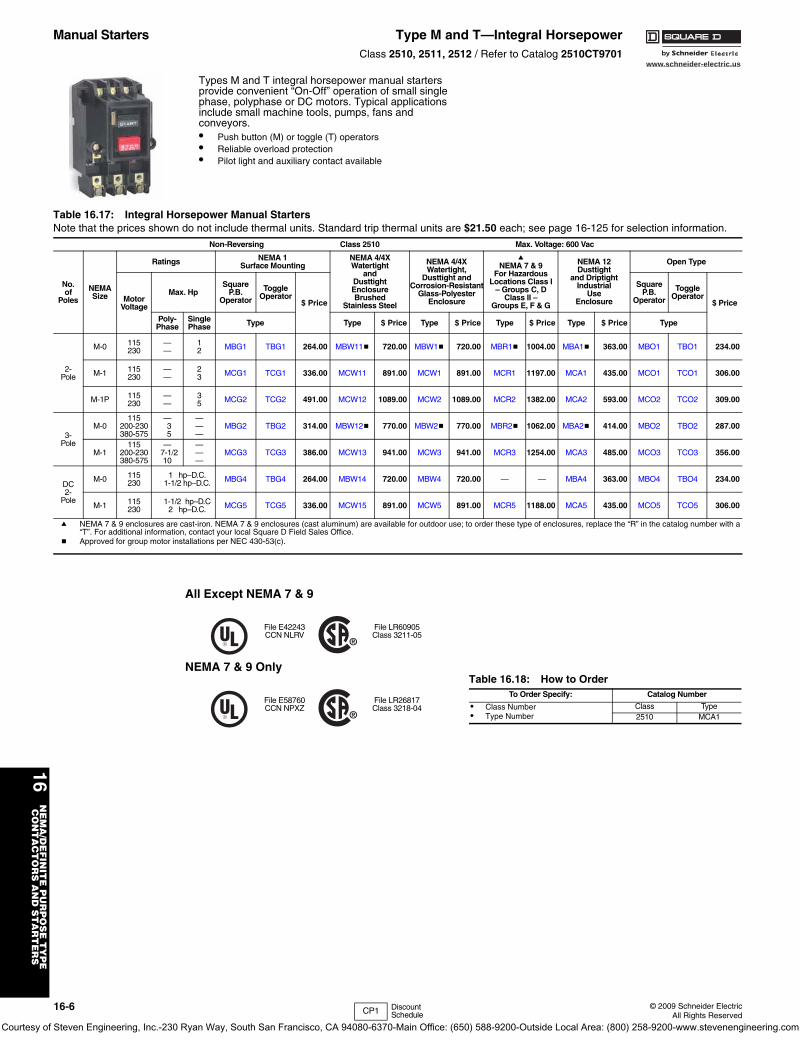
Types M and T integral horsepower manual starters provide convenient “On-Off” operation of small single phase, polyphase or DC motors. Typical applications include small machine tools, pumps, fans and conveyors.• Push button (M) or toggle (T) operators• Reliable overload protection• Pilot light and auxiliary contact available
Table 16.17: Integral Horsepower Manual StartersNote that the prices shown do not include thermal units. Standard trip thermal units are $21.50 each; see page 16-125 for selection information.
Non-Reversing Class 2510 Max. Voltage: 600 Vac
No.of
Poles
NEMASize
Ratings NEMA 1Surface Mounting
NEMA 4/4XWatertight
andDusttightEnclosureBrushed
Stainless Steel
NEMA 4/4XWatertight,
Dusttight andCorrosion-Resistant
Glass-PolyesterEnclosure
aNEMA 7 & 9
For HazardousLocations Class I
– Groups C, DClass II –
Groups E, F & G
NEMA 12Dusttight
and DriptightIndustrial
UseEnclosure
Open Type
MotorVoltage
Max. HpSquare
P.B.Operator
ToggleOperator
$ Price
SquareP.B.
Operator
ToggleOperator
$ Price
Poly-Phase
SinglePhase Type Type $ Price Type $ Price Type $ Price Type $ Price Type
2-Pole
M-0 115230
——
12 MBG1 TBG1 264.00 MBW11b 720.00 MBW1b 720.00 MBR1b 1004.00 MBA1b 363.00 MBO1 TBO1 234.00
M-1 115230
——
23 MCG1 TCG1 336.00 MCW11 891.00 MCW1 891.00 MCR1 1197.00 MCA1 435.00 MCO1 TCO1 306.00
M-1P 115230
——
35 MCG2 TCG2 491.00 MCW12 1089.00 MCW2 1089.00 MCR2 1382.00 MCA2 593.00 MCO2 TCO2 309.00
3-Pole
M-0115
200-230380-575
—35
———
MBG2 TBG2 314.00 MBW12b 770.00 MBW2b 770.00 MBR2b 1062.00 MBA2b 414.00 MBO2 TBO2 287.00
M-1115
200-230380-575
—7-1/210
———
MCG3 TCG3 386.00 MCW13 941.00 MCW3 941.00 MCR3 1254.00 MCA3 485.00 MCO3 TCO3 356.00
DC2-
Pole
M-0 115230
1 hp–D.C.1-1/2 hp–D.C. MBG4 TBG4 264.00 MBW14 720.00 MBW4 720.00 — — MBA4 363.00 MBO4 TBO4 234.00
M-1 115230
1-1/2 hp–D.C2 hp–D.C. MCG5 TCG5 336.00 MCW15 891.00 MCW5 891.00 MCR5 1188.00 MCA5 435.00 MCO5 TCO5 306.00
a NEMA 7 & 9 enclosures are cast-iron. NEMA 7 & 9 enclosures (cast aluminum) are available for outdoor use; to order these type of enclosures, replace the “R” in the catalog number with a “T”. For additional information, contact your local Square D Field Sales Office.
b Approved for group motor installations per NEC 430-53(c).
File E42243CCN NLRV
File LR60905Class 3211-05
File E58760CCN NPXZ
File LR26817Class 3218-04
Table 16.18: How to OrderTo Order Specify: Catalog Number
• Class Number• Type Number
Class Type2510 MCA1
CP1 Discount Schedule
Courtesy of Steven Engineering, Inc.-230 Ryan Way, South San Francisco, CA 94080-6370-Main Office: (650) 588-9200-Outside Local Area: (800) 258-9200-www.stevenengineering.com
www.schneider-electric.us
16N
EM
A/D
EF
INIT
E P
UR
PO
SE
TY
PE
CO
NT
AC
TO
RS
AN
D S
TA
RT
ER
S
© 2009 Schneider ElectricAll Rights Reserved
16-7
Manual Starters Integral Horsepower—Type M and TClass 2510, 2511, 2512 / Refer to Catalog 2510CT9701
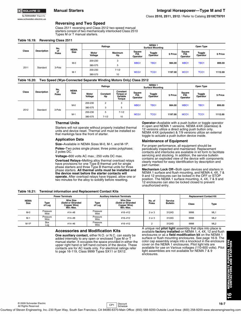
Reversing and Two SpeedClass 2511 reversing and Class 2512 two-speed manual starters consist of two mechanically interlocked Class 2510 Types M or T manual starters.
.
Thermal UnitsStarters will not operate without properly installed thermal units and device reset. Thermal unit must be installed so that markings face the front of starter.
Application DataSize–Available in NEMA Sizes M-0, M-1, and M-1P.Poles–Two poles single phase; three poles polyphase; 2 poles DC.Voltage–600 volts AC max.; 250 volts DC max.Overload Relays–Melting alloy thermal overload relays have provisions for one Type B thermal unit for single phase starters and three Type B thermal units for three phase starters. All thermal units must be installed and the device reset before the starter contacts will operate. After overload relays have tripped, allow one or two minutes for the alloy to solidify before resetting.
Operator–Available with a push button or toggle operator in open and NEMA 1 versions. NEMA 4/4X (stainless) & 12 versions utilize a direct acting push button only. NEMA 4/4X (polyester) & 7/9 versions utilize an external toggle to actuate a push button device inside.
Maintenance of EquipmentFor proper performance, all equipment should be periodically inspected and maintained. Replacement contacts and interlocks are available in kit form to facilitate servicing and stocking. In addition, the service bulletin contains an exploded view of the device with components clearly marked for easy identification by description and part number.Mechanism Lock Off–Both open devices and starters in NEMA 1 surface and flush mounting, and NEMA 4, 4X, 7 & 9 and 12 enclosures can be locked in the OFF or STOP position. The NEMA 1 surface mounting, 4, 4X, 7 & 9 and 12 enclosures can also be locked closed to prevent unauthorized entry.
Accessories and Modification KitsOne auxiliary contact, either N.O. or N.C. can easily be added internally to any open or enclosed Type M or T manual starter. It occupies the space provided in either the upper right hand or left hand corners of the device. These contacts are for AC loads only. For electrical ratings refer to page 16-119, Class 9999 Types SX11 or SX12.
A unique red pilot light assembly that clips into place is available factory installed on NEMA 1, 4, 4X, 12 and flush enclosures or as a field modification kit on the NEMA 1 surface or flush mounting enclosures. See page 16-9. The color cap assembly snaps into a knockout in the enclosure cover on the NEMA 1 enclosures. Pilot light kits are available for use on Various voltages (110-600 volts). Pilot light assemblies are not available for NEMA 7 & 9 enclosures.
Table 16.19: Reversing Class 2511
Class DescriptionNo.of
Poles
NEMASize
Ratings NEMA 1Surface Mounting Open Type
MotorVoltage
MaximumHp
SquareP.B.
Operator
ToggleOperator $ Price
SquareP.B.
Operator
ToggleOperator $ Price
2511 Standard 3-Pole
M-0200-230 3
MBG1 TBG1 984.00 MBO1 TBO1 899.00380-575 5
M-1200-230 7-1/2
MCG1 TCG1 1197.00 MCO1 TCO1 1112.00380-575 10
Table 16.20: Two Speed (Wye-Connected Separate Winding Motors Only) Class 2512
Class DescriptionNo.of
Poles
NEMASize
Ratings NEMA 1Surface Mounting Open Type
MotorVoltage
ConstantHp
Constant Torque or Variable Torque
SquareP.B.
Operator
ToggleOperator $ Price
SquareP.B.
Operator
ToggleOperator $ Price
2512 Standard 3-Pole
M-0200-230 2 3
MBG1 TBG1 984.00 MBO1 TBO1 899.00380-575 3 5
M-1200-230 5 7-1/2
MCG1 TCG1 1197.00 MCO1 TCO1 1112.00380-575 7-1/2 10
Table 16.21: Terminal information and Replacement Contact Kits
NEMASize
Power Terminals Auxiliary Interlock Terminals
No. ofPoles
Service Bulletin
Replacement Contact Kit
Typeof Lug
Wire Size(Solid or Stranded
Copper Wire)Min.-Max.
Typeof Lug
Wire Size(Solid or Stranded
Copper Wire)Min.-Max.
Class Type
M-0 PressureWire #14–#8 Pressure
Wire #16–#12 2 or 3 312AS 9998 ML1
M-1 PressureWire #14–#8 Pressure
Wire #16–#12 2 or 3 312AS 9998 ML2
M-1P BoxLug #14–#6 Pressure
Wire #16–#12 2 312AS 9998 ML2
CP1 Discount Schedule
Courtesy of Steven Engineering, Inc.-230 Ryan Way, South San Francisco, CA 94080-6370-Main Office: (650) 588-9200-Outside Local Area: (800) 258-9200-www.stevenengineering.com
www.schneider-electric.us
16N
EM
A/D
EF
INIT
E P
UR
PO
SE
TY
PE
C
ON
TA
CT
OR
S A
ND
ST
AR
TE
RS
16-8 © 2009 Schneider ElectricAll Rights Reserved
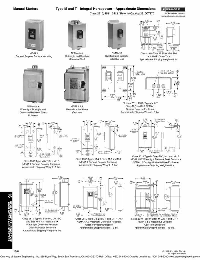
Manual Starters Type M and T—Integral Horsepower—Approximate DimensionsClass 2510, 2511, 2512 / Refer to Catalog 2510CT9701
NEMA 1General Purpose Surface Mounting
NEMA 4/4XWatertight and Dusttight
Stainless Steel
NEMA 12Dusttight and Driptight
Industrial Use
NEMA 4/4XWatertight, Dusttight and
Corrosion Resistant GlassPolyester
NEMA 7 & 9Hazardous Locations
Cast Iron
START
STOP
RESET
START
STOP
RESET
8.94227
7.25184
9.34237
7.88200
.8421
.7519
.28 Dia.Mtg. Holes
3.3886
1.6943
4.25108
1.2833
.226
(3) .5 -.75 K.O.Top and Bottom
Classes 2511, 2512, Types M & TSizes M-0 and M-1 NEMA 1General Purpose Enclosure
Approximate Shipping Weight—9 lbs.
START
STOP
RESET
6.00152
4.13105
3.3886
.9424
10.00254
8.13207
1.0025
.8822
.226
1.6943
.9424
5.00127
1.0627
1.0025
1.0025
1.0627
.50 - .75 K.O.(2) Top Back
.50 - .75 K.O. (2) Each Side
(1) .50 - .75 K.O.(2) .75 - 1.00 K.O.Top and Bottom
.22 Dia.(3) Mounting
Holes
Class 2510 Type M & T Size M-1PNEMA 1 General Purpose EnclosureApproximate Shipping Weight—5 lbs.
START
STOP
RESET
5.00127
3.0076
2.1354
1.0025
8.63219
5.75146
1.4437
.226
1.0627
3.9199
1.0226
1.1429
1.0226
(2) .50 - .75 K.O.Top and Bottom
.22 Dia.(4) Mounting
Holes
.50 - .75 K.O. Each Side
Class 2510 Types M & T Sizes M-0 and M-1NEMA 1 General Purpose EnclosureApproximate Shipping Weight—5 lbs.
START
STOPRESET
10.75273
2.8973
3.2583
1.2732
10.00254
.3810
10.92277
(2) .31 Wide Slots NEMA 4 Only
5.76146
5.78147
.75 Conduit Hub Top and Bottom 1.31
33
.4712
.31 Dia.(2) Mounting
Holes
Class 2510 Type M Sizes M-0, M-1 and M-1PNEMA 4/4X Watertight Stainless Steel Enclosure
NEMA 12 Dusttight Industrial Use EnclosureApproximate Shipping Weight—9 lbs.
5.78147
3.6994
5.13130
1.4136
7.31186
.7218 .81
21
8.75222
10.34263
(2) .31 Dia.Mtg. Holes
ONRESET
OFF
.75 Conduit HubTop and Bottom
.7218
Class 2510 Type M Size M-0 (AC–DC)and Size M-1 (DC) NEMA 4/4XWatertight Corrosion-Resistant
Glass Polyester EnclosureApproximate Shipping Weight—6 lbs.
8.75222
.7519
1.6943
1.6943
.7519
12.13308
(2) .31 Dia. Mtg. Holes
.75 Conduit HubIn Top and Bottom
5.00127
2.1956
6.50165
6.41163
1.2833
ONRESET
OFF
Class 2510 Type M Sizes M-1 and M-1P (AC)NEMA 4/4X Watertight Corrosion-Resistant
Glass Polyester EnclosureApproximate Shipping Weight—6 lbs.
10.50267
.349
9.94252
(4) .13 WideMtg. Slots
(1) .75 Conduit Top and Bottom (Std.)(1) 1.50 Conduit Top and Bottom (Max.)
6.001524.69119
2.3459
.6617
6.13156
ONRESET
OFF
Class 2510 Type M Sizes M-0, M-1 and M-1PNEMA 7 & 9 Hazardous Location
Cast Iron EnclosureApproximate Shipping Weight—18 lbs.
START
STOP
RESET
3.5089
5.72145
5.13130
1.2532
.287
1.1329
1.7544
.6918
.44 Travel to 11 Reset1.13
29 3.97101
4.03102
Prov. for(3) #10
MountingScrews
Class 2510 Type M Sizes M-0, M-1and M-1P, Open Type
Approximate Shipping Weight—3 lbs.
Courtesy of Steven Engineering, Inc.-230 Ryan Way, South San Francisco, CA 94080-6370-Main Office: (650) 588-9200-Outside Local Area: (800) 258-9200-www.stevenengineering.com
www.schneider-electric.us
16N
EM
A/D
EF
INIT
E P
UR
PO
SE
TY
PE
CO
NT
AC
TO
RS
AN
D S
TA
RT
ER
S
© 2009 Schneider ElectricAll Rights Reserved
16-9
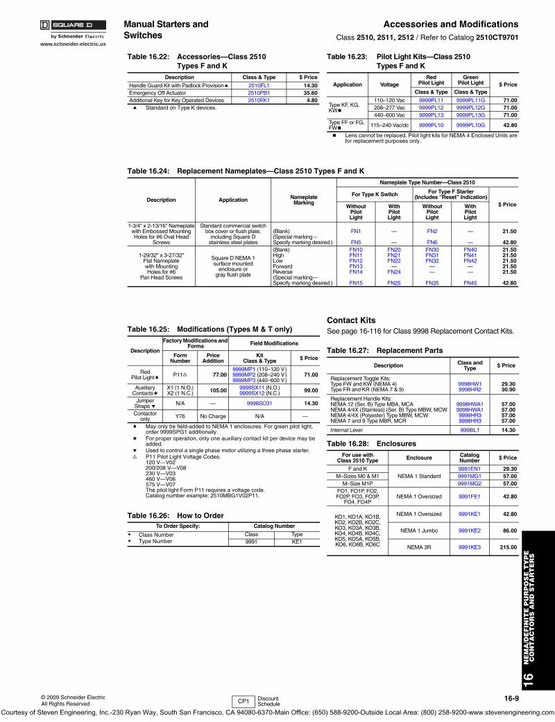
Manual Starters and Switches
Accessories and ModificationsClass 2510, 2511, 2512 / Refer to Catalog 2510CT9701
a Standard on Type K devices.
b Lens cannot be replaced. Pilot light kits for NEMA 4 Enclosed Units are for replacement purposes only.
c May only be field-added to NEMA 1 enclosures. For green pilot light, order 9999SPG1 additionally.
d For proper operation, only one auxiliary contact kit per device may be added.
e Used to control a single phase motor utilizing a three phase starter.f P11 Pilot Light Voltage Codes:
120 V—V02200/208 V—V08230 V—V03460 V—V06575 V—V07The pilot light Form P11 requires a voltage code. Catalog number example: 2510MBG1V02P11.
Contact KitsSee page 16-116 for Class 9998 Replacement Contact Kits.
Table 16.22: Accessories—Class 2510 Types F and K
Description Class & Type $ Price
Handle Guard Kit with Padlock Provisiona 2510FL1 14.30Emergency Off Actuator 2510PB1 35.60Additional Key for Key Operated Devices 2510FK1 4.80
Table 16.23: Pilot Light Kits—Class 2510 Types F and K
Application VoltageRed
Pilot LightGreen
Pilot Light $ PriceClass & Type Class & Type
Type KF, KG, KWb
110–120 Vac 9999PL11 9999PL11G 71.00208–277 Vac 9999PL12 9999PL12G 71.00440–600 Vac 9999PL13 9999PL13G 71.00
Type FF or FG, FWb
115–240 Vac/dc 9999PL10 9999PL10G 42.80
Table 16.24: Replacement Nameplates—Class 2510 Types F and K
Description Application NameplateMarking
Nameplate Type Number—Class 2510
For Type K Switch For Type F Starter(Includes “Reset” Indication)
$ PriceWithoutPilotLight
WithPilotLight
WithoutPilotLight
WithPilotLight
1-3/4" x 2-13/16" Nameplatewith Embossed MountingHoles for #6 Oval Head
Screws
Standard commercial switchbox cover or flush plate,
including Square Dstainless steel plates
(Blank)(Special marking –Specify marking desired.)
FN1
FN5
—
—
FN2
FN6
—
—
21.50
42.80
1-29/32" x 3-27/32"Flat Nameplatewith MountingHoles for #6
Pan Head Screws
Square D NEMA 1surface mounted
enclosure orgray flush plate
(Blank) High Low Forward Reverse (Special marking—Specify marking desired.)
FN10FN11FN12FN13FN14
FN15
FN20FN21FN22
—FN24
FN25
FN30FN31FN32
——
FN35
FN40FN41FN42
——
FN45
21.5021.5021.5021.5021.50
42.80
Table 16.25: Modifications (Types M & T only)
Description
Factory Modifications and Forms Field Modifications
FormNumber
PriceAddition
KitClass & Type $ Price
RedPilot Lightc P11f 77.00
9999MP1 (110–120 V)9999MP2 (208–240 V)9999MP3 (440–600 V)
71.00
AuxiliaryContactsd
X1 (1 N.O.)X2 (1 N.C.) 105.00 9999SX11 (N.O.)
9999SX12 (N.C.) 99.00
JumperStraps e N/A — 9998SO31 14.30
Contactoronly Y76 No Charge N/A —
Table 16.26: How to OrderTo Order Specify: Catalog Number
• Class Number• Type Number
Class Type9991 KE1
Table 16.27: Replacement Parts
Description Class and Type $ Price
Replacement Toggle Kits:Type FW and KW (NEMA 4) Type FR and KR (NEMA 7 & 9)
9998HW19998HR2
29.3030.90
Replacement Handle Kits:NEMA 12 (Ser. B) Type MBA, MCANEMA 4/4X (Stainless) (Ser. B) Type MBW, MCWNEMA 4/4X (Polyester) Type MBW, MCWNEMA 7 and 9 Type MBR, MCR
9998HWA19998HWA19998HR39998HR3
57.0057.0057.0057.00
Internal Lever 9998IL1 14.30
Table 16.28: EnclosuresFor use with
Class 2510 Type Enclosure Catalog Number $ Price
F and KNEMA 1 Standard
9991EN1 29.30M–Sizes M0 & M1 9991MG1 57.00
M–Size M1P 9991MG2 57.00FO1, FO1P, FO2, FO2P, FO3, FO3P,
FO4, FO4PNEMA 1 Oversized 9991FE1 42.80
KO1, KO1A, KO1B, KO2, KO2B, KO2C, KO3, KO3A, KO3B, KO4, KO4B, KO4C, KO5, KO5A, KO5B, KO6, KO6B, KO6C
NEMA 1 Oversized 9991KE1 42.80
NEMA 1 Jumbo 9991KE2 86.00
NEMA 3R 9991KE3 215.00
CP1 Discount Schedule
Courtesy of Steven Engineering, Inc.-230 Ryan Way, South San Francisco, CA 94080-6370-Main Office: (650) 588-9200-Outside Local Area: (800) 258-9200-www.stevenengineering.com
16-10 © 2009 Schneider ElectricAll Rights Reserved
www.schneider-electric.us
16N
EM
A/D
EF
INIT
E P
UR
PO
SE
TY
PE
C
ON
TA
CT
OR
S A
ND
ST
AR
TE
RS
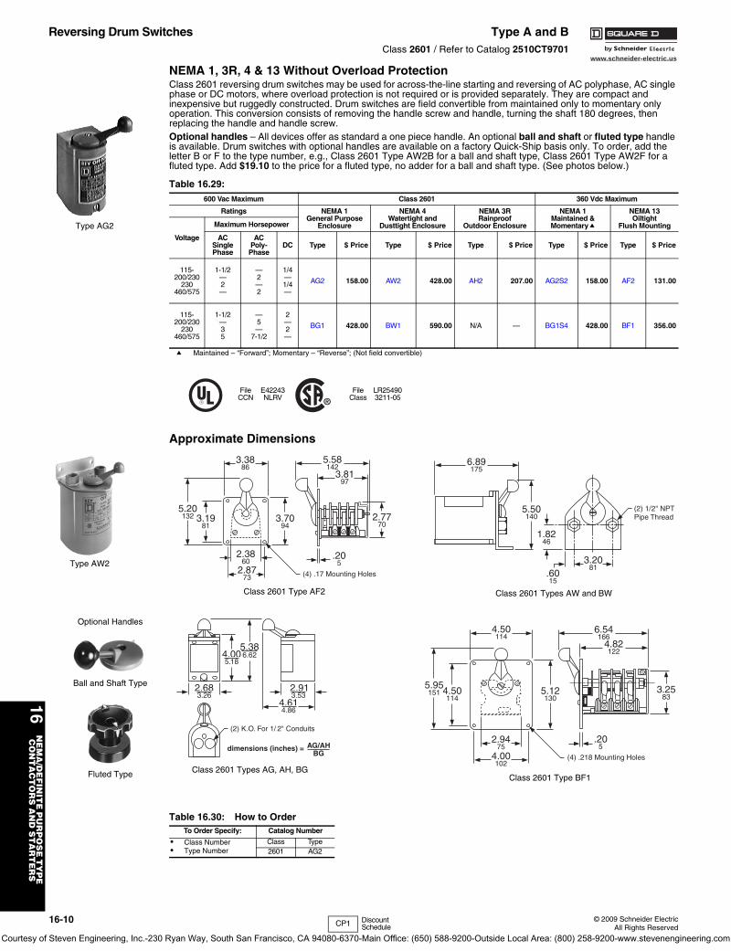
Reversing Drum Switches Type A and BClass 2601 / Refer to Catalog 2510CT9701
NEMA 1, 3R, 4 & 13 Without Overload ProtectionClass 2601 reversing drum switches may be used for across-the-line starting and reversing of AC polyphase, AC single phase or DC motors, where overload protection is not required or is provided separately. They are compact and inexpensive but ruggedly constructed. Drum switches are field convertible from maintained only to momentary only operation. This conversion consists of removing the handle screw and handle, turning the shaft 180 degrees, then replacing the handle and handle screw.Optional handles – All devices offer as standard a one piece handle. An optional ball and shaft or fluted type handle is available. Drum switches with optional handles are available on a factory Quick-Ship basis only. To order, add the letter B or F to the type number, e.g., Class 2601 Type AW2B for a ball and shaft type, Class 2601 Type AW2F for a fluted type. Add $19.10 to the price for a fluted type, no adder for a ball and shaft type. (See photos below.)
a Maintained – “Forward”; Momentary – “Reverse”; (Not field convertible)
Approximate Dimensions
Table 16.29: 600 Vac Maximum Class 2601 360 Vdc Maximum
Ratings NEMA 1General Purpose
Enclosure
NEMA 4Watertight and
Dusttight Enclosure
NEMA 3RRainproof
Outdoor Enclosure
NEMA 1Maintained &Momentarya
NEMA 13Oiltight
Flush Mounting
Voltage
Maximum Horsepower
ACSinglePhase
ACPoly-
PhaseDC Type $ Price Type $ Price Type $ Price Type $ Price Type $ Price
115-200/230
230460/575
1-1/2—2—
—2—2
1/4—1/4—
AG2 158.00 AW2 428.00 AH2 207.00 AG2S2 158.00 AF2 131.00
115-200/230
230460/575
1-1/2—35
—5—
7-1/2
2—2—
BG1 428.00 BW1 590.00 N/A — BG1S4 428.00 BF1 356.00
FileCCN
E42243NLRV
FileClass
LR254903211-05
Table 16.30: How to OrderTo Order Specify: Catalog Number
• Class Number• Type Number
Class Type2601 AG2
Type AG2
Type AW2
3.3886
5.20132 3.19
813.70
94
.205
2.3860
2.8773
2.7770
3.8197
5.58142
(4) .17 Mounting Holes
Class 2601 Type AF2 Class 2601 Types AW and BW
(2) 1/2" NPTPipe Thread
.6015
1.8246
5.50140
6.89175
3.2081
Ball and Shaft Type
Optional Handles
Fluted Type
4.005.18
2.683.26
5.386.62
dimensions (inches) =
4.614.86
AG/AHBG
(2) K.O. For 1/ 2" Conduits
2.913.53
Class 2601 Types AG, AH, BG
4.50114
4.50114
2.9475
4.00102
(4) .218 Mounting Holes
.205
5.12130
3.2583
6.54166
4.82122
5.95151
Class 2601 Type BF1
CP1 Discount Schedule
Courtesy of Steven Engineering, Inc.-230 Ryan Way, South San Francisco, CA 94080-6370-Main Office: (650) 588-9200-Outside Local Area: (800) 258-9200-www.stevenengineering.com
www.schneider-electric.us
16N
EM
A D
EF
INIT
E P
UR
PO
SE
TY
PE
C
ON
TA
CT
OR
S A
ND
ST
AR
TE
RS
© 2009 Schneider ElectricAll Rights Reserved
16-11
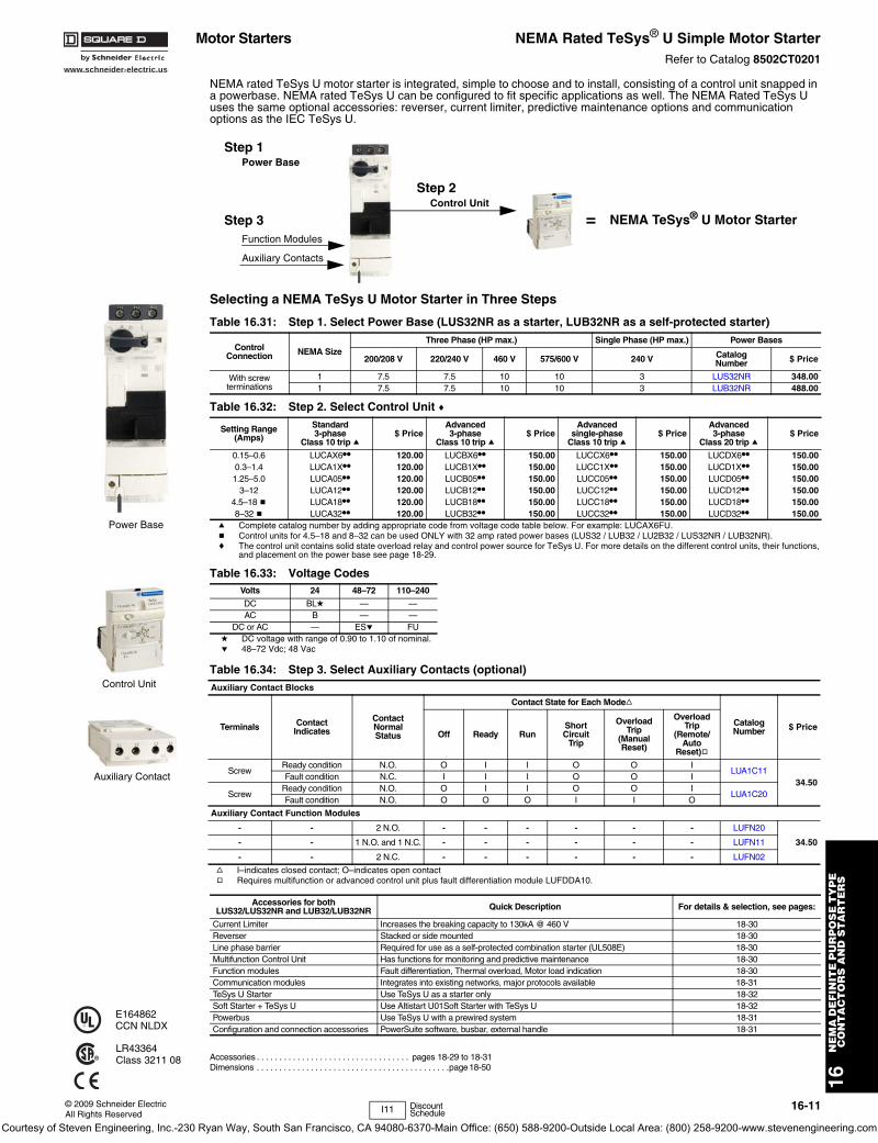
Motor Starters NEMA Rated TeSys® U Simple Motor StarterRefer to Catalog 8502CT0201
NEMA rated TeSys U motor starter is integrated, simple to choose and to install, consisting of a control unit snapped in a powerbase. NEMA rated TeSys U can be configured to fit specific applications as well. The NEMA Rated TeSys U uses the same optional accessories: reverser, current limiter, predictive maintenance options and communication options as the IEC TeSys U.
Selecting a NEMA TeSys U Motor Starter in Three Steps
Accessories . . . . . . . . . . . . . . . . . . . . . . . . . . . . . . . . . . pages 18-29 to 18-31Dimensions . . . . . . . . . . . . . . . . . . . . . . . . . . . . . . . . . . . . . . . . . . .page 18-50
Table 16.31: Step 1. Select Power Base (LUS32NR as a starter, LUB32NR as a self-protected starter)
ControlConnection NEMA Size
Three Phase (HP max.) Single Phase (HP max.) Power Bases
200/208 V 220/240 V 460 V 575/600 V 240 V CatalogNumber $ Price
With screw terminations
1 7.5 7.5 10 10 3 LUS32NR 348.001 7.5 7.5 10 10 3 LUB32NR 488.00
Table 16.32: Step 2. Select Control Unit c
Setting Range(Amps)
Standard 3-phase
Class 10 trip a$ Price
Advanced 3-phase
Class 10 trip a$ Price
Advanced single-phase
Class 10 trip a$ Price
Advanced 3-phase
Class 20 trip a$ Price
0.15–0.6 LUCAX6•• 120.00 LUCBX6•• 150.00 LUCCX6•• 150.00 LUCDX6•• 150.000.3–1.4 LUCA1X•• 120.00 LUCB1X•• 150.00 LUCC1X•• 150.00 LUCD1X•• 150.001.25–5.0 LUCA05•• 120.00 LUCB05•• 150.00 LUCC05•• 150.00 LUCD05•• 150.00
3–12 LUCA12•• 120.00 LUCB12•• 150.00 LUCC12•• 150.00 LUCD12•• 150.004.5–18 b LUCA18•• 120.00 LUCB18•• 150.00 LUCC18•• 150.00 LUCD18•• 150.008–32 b LUCA32•• 120.00 LUCB32•• 150.00 LUCC32•• 150.00 LUCD32•• 150.00
a Complete catalog number by adding appropriate code from voltage code table below. For example: LUCAX6FU.b Control units for 4.5–18 and 8–32 can be used ONLY with 32 amp rated power bases (LUS32 / LUB32 / LU2B32 / LUS32NR / LUB32NR).c The control unit contains solid state overload relay and control power source for TeSys U. For more details on the different control units, their functions,
and placement on the power base see page 18-29.
Table 16.33: Voltage CodesVolts 24 48–72 110–240
DC BLd — —AC B — —
DC or AC — ESe FUd DC voltage with range of 0.90 to 1.10 of nominal.e 48–72 Vdc; 48 Vac
Table 16.34: Step 3. Select Auxiliary Contacts (optional)Auxiliary Contact Blocks
Terminals Contact Indicates
Contact Normal Status
Contact State for Each Modef
CatalogNumber $ Price
Off Ready RunShort Circuit
Trip
Overload Trip
(Manual Reset)
Overload Trip
(Remote/Auto
Reset)g
ScrewReady condition N.O. O I I O O I
LUA1C1134.50
Fault condition N.C. I I I O O I
ScrewReady condition N.O. O I I O O I
LUA1C20Fault condition N.O. O O O I I O
Auxiliary Contact Function Modules
- - 2 N.O. - - - - - - LUFN20
34.50- - 1 N.O. and 1 N.C. - - - - - - LUFN11
- - 2 N.C. - - - - - - LUFN02
f I–indicates closed contact; O–indicates open contactg Requires multifunction or advanced control unit plus fault differentiation module LUFDDA10.
Accessories for both LUS32/LUS32NR and LUB32/LUB32NR Quick Description For details & selection, see pages:
Current Limiter Increases the breaking capacity to 130kA @ 460 V 18-30Reverser Stacked or side mounted 18-30Line phase barrier Required for use as a self-protected combination starter (UL508E) 18-30Multifunction Control Unit Has functions for monitoring and predictive maintenance 18-30Function modules Fault differentiation, Thermal overload, Motor load indication 18-30Communication modules Integrates into existing networks, major protocols available 18-31TeSys U Starter Use TeSys U as a starter only 18-32Soft Starter + TeSys U Use Altistart U01Soft Starter with TeSys U 18-32Powerbus Use TeSys U with a prewired system 18-31Configuration and connection accessories PowerSuite software, busbar, external handle 18-31
Control Unit
Function Modules
Auxiliary Contacts
Power Base
NEMA TeSys® U Motor Starter=
Step 1
Step 2
Step 3
Power Base
Control Unit
Auxiliary Contact
E164862CCN NLDX
LR43364Class 3211 08
I11 Discount Schedule
Courtesy of Steven Engineering, Inc.-230 Ryan Way, South San Francisco, CA 94080-6370-Main Office: (650) 588-9200-Outside Local Area: (800) 258-9200-www.stevenengineering.com
www.schneider-electric.us
16-12 © 2009 Schneider ElectricAll Rights Reserved
16N
EM
A/D
EF
INIT
E P
UR
PO
SE
TY
PE
C
ON
TA
CT
OR
S A
ND
ST
AR
TE
RS
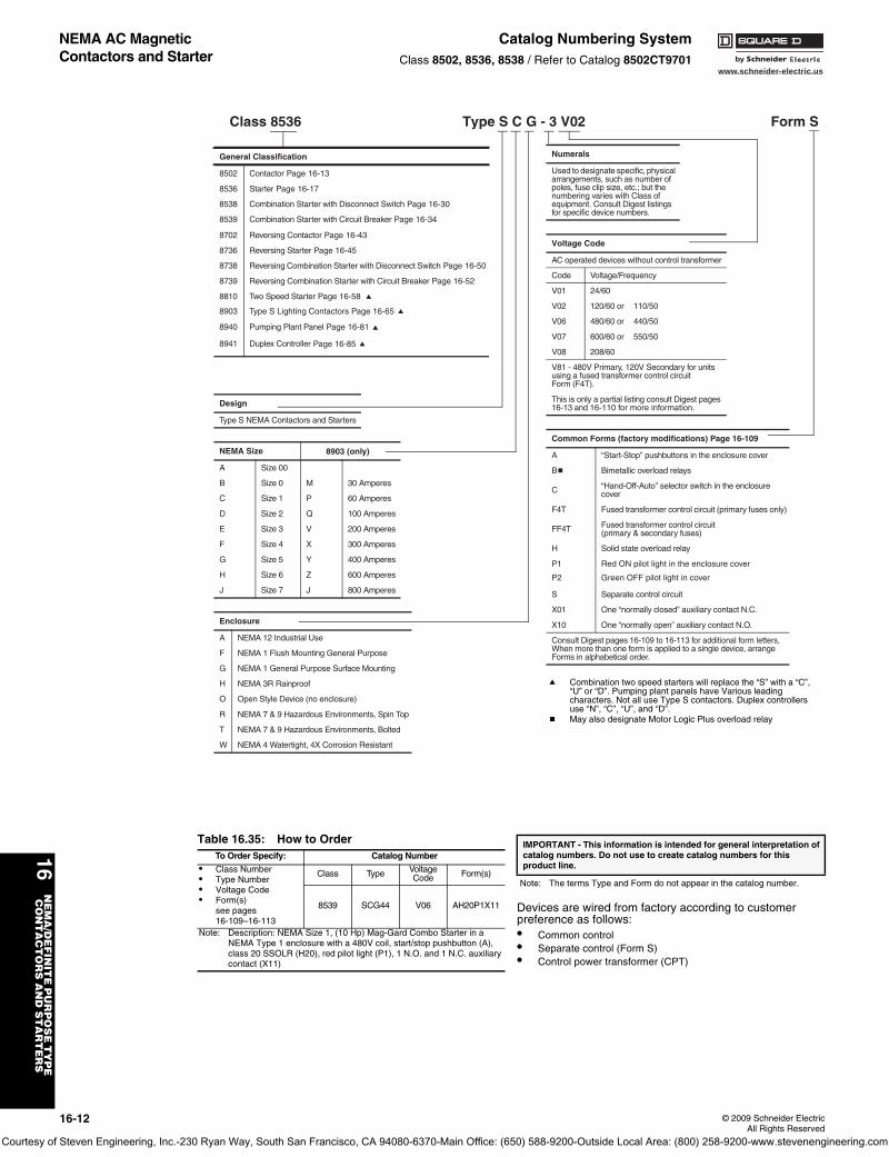
NEMA AC Magnetic Contactors and Starter
Catalog Numbering SystemClass 8502, 8536, 8538 / Refer to Catalog 8502CT9701
Devices are wired from factory according to customer preference as follows:• Common control• Separate control (Form S)• Control power transformer (CPT)
General Classification
8502 Contactor Page 16-13
8536 Starter Page 16-17
8538 Combination Starter with Disconnect Switch Page 16-30
8539 Combination Starter with Circuit Breaker Page 16-34
8702 Reversing Contactor Page 16-43
8736 Reversing Starter Page 16-45
8738 Reversing Combination Starter with Disconnect Switch Page 16-50
8739 Reversing Combination Starter with Circuit Breaker Page 16-52
8810 Two Speed Starter Page 16-58 a
8940 Pumping Plant Panel Page 16-81 a
8903 Type S Lighting Contactors Page 16-65 a
8941 Duplex Controller Page 16-85 a
Design
Type S NEMA Contactors and Starters
NEMA Size 8903 (only)
A Size 00
M 30 AmperesB Size 0
P 60 AmperesC Size 1
Q 100 AmperesD Size 2
V 200 AmperesE Size 3
X 300 AmperesF Size 4
Y 400 AmperesG Size 5
Z 600 AmperesH Size 6
J 800 AmperesJ Size 7
Enclosure
A NEMA 12 Industrial Use
F NEMA 1 Flush Mounting General Purpose
G NEMA 1 General Purpose Surface Mounting
H NEMA 3R Rainproof
O Open Style Device (no enclosure)
R NEMA 7 & 9 Hazardous Environments, Spin Top
T NEMA 7 & 9 Hazardous Environments, Bolted
W NEMA 4 Watertight, 4X Corrosion Resistant
Class 8536 Type S C G - 3 V02 Form S
Numerals
Used to designate specific, physical arrangements, such as number of poles, fuse clip size, etc.; but the numbering varies with Class of equipment. Consult Digest listings for specific device numbers.
Voltage Code
AC operated devices without control transformer
Code Voltage/Frequency
V01 24/60
V02 120/60 or 110/50
V06 480/60 or 440/50
V07 600/60 or 550/50
V08 208/60
V81 - 480V Primary, 120V Secondary for units using a fused transformer control circuit Form (F4T).
This is only a partial listing consult Digest pages 16-13 and 16-110 for more information.
Common Forms (factory modifications) Page 16-109
A “Start-Stop” pushbuttons in the enclosure cover
Bb Bimetallic overload relays
C “Hand-Off-Auto” selector switch in the enclosure cover
F4T Fused transformer control circuit (primary fuses only)
FF4T Fused transformer control circuit (primary & secondary fuses)
H Solid state overload relay
P1 Red ON pilot light in the enclosure cover
S Separate control circuit
X01 One “normally closed” auxiliary contact N.C.
X10 One “normally open” auxiliary contact N.O.
Consult Digest pages 16-109 to 16-113 for additional form letters,When more than one form is applied to a single device, arrange Forms in alphabetical order.
P2 Green OFF pilot light in cover
a Combination two speed starters will replace the “S” with a “C”, “U” or “D”. Pumping plant panels have Various leading characters. Not all use Type S contactors. Duplex controllers use “N”, “C”, “U”, and “D”.
b May also designate Motor Logic Plus overload relay
Table 16.35: How to OrderTo Order Specify: Catalog Number
• Class Number• Type Number• Voltage Code• Form(s)
see pages 16-109–16-113
Class Type Voltage Code Form(s)
8539 SCG44 V06 AH20P1X11
Note: Description: NEMA Size 1, (10 Hp) Mag-Gard Combo Starter in a NEMA Type 1 enclosure with a 480V coil, start/stop pushbutton (A), class 20 SSOLR (H20), red pilot light (P1), 1 N.O. and 1 N.C. auxiliary contact (X11)
IMPORTANT - This information is intended for general interpretation of catalog numbers. Do not use to create catalog numbers for this product line.
Note: The terms Type and Form do not appear in the catalog number.
Courtesy of Steven Engineering, Inc.-230 Ryan Way, South San Francisco, CA 94080-6370-Main Office: (650) 588-9200-Outside Local Area: (800) 258-9200-www.stevenengineering.com
www.schneider-electric.us
16N
EM
A/D
EF
INIT
E P
UR
PO
SE
TY
PE
C
ON
TA
CT
OR
S A
ND
ST
AR
TE
RS
© 2009 Schneider ElectricAll Rights Reserved
16-13
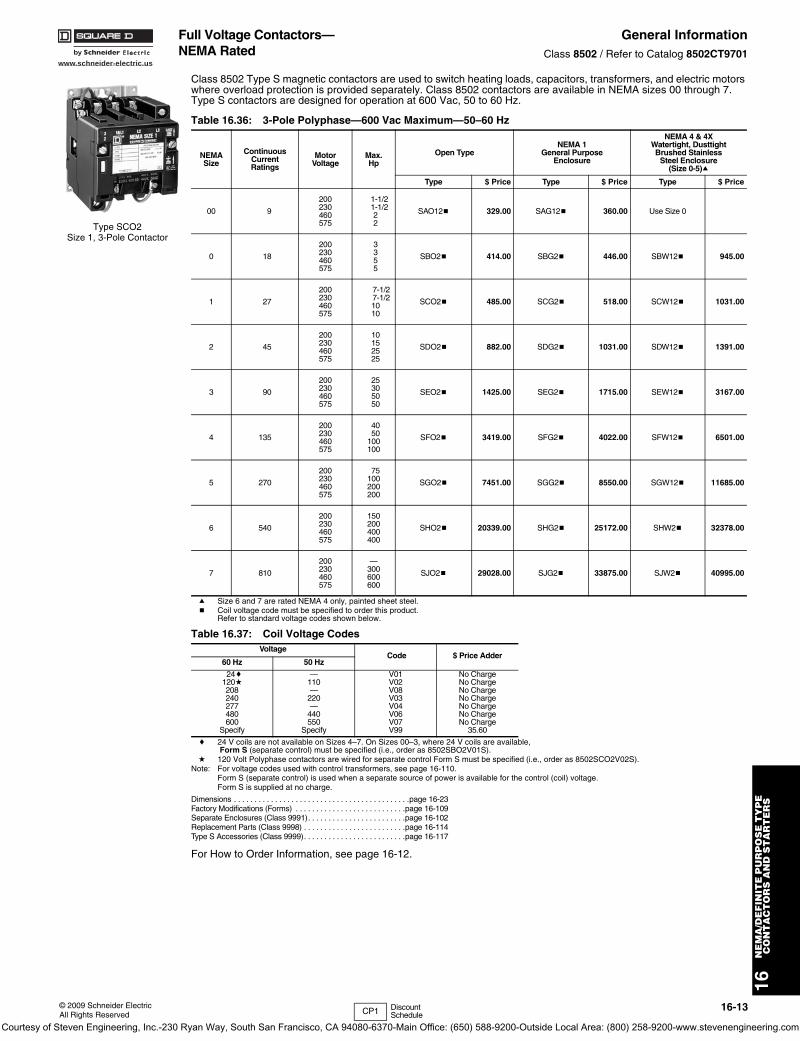
Full Voltage Contactors—NEMA Rated
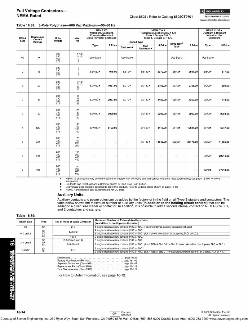
General InformationClass 8502 / Refer to Catalog 8502CT9701
Class 8502 Type S magnetic contactors are used to switch heating loads, capacitors, transformers, and electric motors where overload protection is provided separately. Class 8502 contactors are available in NEMA sizes 00 through 7. Type S contactors are designed for operation at 600 Vac, 50 to 60 Hz.
a Size 6 and 7 are rated NEMA 4 only, painted sheet steel.b Coil voltage code must be specified to order this product.
Refer to standard voltage codes shown below.
c 24 V coils are not available on Sizes 4–7. On Sizes 00–3, where 24 V coils are available, Form S (separate control) must be specified (i.e., order as 8502SBO2V01S).
d 120 Volt Polyphase contactors are wired for separate control Form S must be specified (i.e., order as 8502SCO2V02S).Note: For voltage codes used with control transformers, see page 16-110.
Form S (separate control) is used when a separate source of power is available for the control (coil) voltage. Form S is supplied at no charge.
Dimensions . . . . . . . . . . . . . . . . . . . . . . . . . . . . . . . . . . . . . . . . . . .page 16-23Factory Modifications (Forms) . . . . . . . . . . . . . . . . . . . . . . . . . . .page 16-109Separate Enclosures (Class 9991). . . . . . . . . . . . . . . . . . . . . . . .page 16-102Replacement Parts (Class 9998) . . . . . . . . . . . . . . . . . . . . . . . . .page 16-114Type S Accessories (Class 9999). . . . . . . . . . . . . . . . . . . . . . . . .page 16-117
For How to Order Information, see page 16-12.
Table 16.36: 3-Pole Polyphase—600 Vac Maximum—50–60 Hz
NEMASize
ContinuousCurrentRatings
MotorVoltage
Max.Hp
Open TypeNEMA 1
General PurposeEnclosure
NEMA 4 & 4XWatertight, DusttightBrushed Stainless
Steel Enclosure(Size 0-5)a
Type $ Price Type $ Price Type $ Price
00 9
200230460575
1-1/21-1/222
SAO12b 329.00 SAG12b 360.00 Use Size 0
0 18
200230460575
3355
SBO2b 414.00 SBG2b 446.00 SBW12b 945.00
1 27
200230460575
7-1/27-1/21010
SCO2b 485.00 SCG2b 518.00 SCW12b 1031.00
2 45
200230460575
10152525
SDO2b 882.00 SDG2b 1031.00 SDW12b 1391.00
3 90
200230460575
25305050
SEO2b 1425.00 SEG2b 1715.00 SEW12b 3167.00
4 135
200230460575
4050
100100
SFO2b 3419.00 SFG2b 4022.00 SFW12b 6501.00
5 270
200230460575
75100200200
SGO2b 7451.00 SGG2b 8550.00 SGW12b 11685.00
6 540
200230460575
150200400400
SHO2b 20339.00 SHG2b 25172.00 SHW2b 32378.00
7 810
200230460575
—300600600
SJO2b 29028.00 SJG2b 33875.00 SJW2b 40995.00
Table 16.37: Coil Voltage CodesVoltage
Code $ Price Adder60 Hz 50 Hz
24c120d208240277480600
Specify
—110—
220—
440550
Specify
V01V02V08V03V04V06V07V99
No ChargeNo ChargeNo ChargeNo ChargeNo ChargeNo ChargeNo Charge
35.60
Type SCO2Size 1, 3-Pole Contactor
CP1 Discount Schedule
Courtesy of Steven Engineering, Inc.-230 Ryan Way, South San Francisco, CA 94080-6370-Main Office: (650) 588-9200-Outside Local Area: (800) 258-9200-www.stevenengineering.com
www.schneider-electric.us
16N
EM
A/D
EF
INIT
E P
UR
PO
SE
TY
PE
C
ON
TA
CT
OR
S A
ND
ST
AR
TE
RS
16-14 © 2009 Schneider ElectricAll Rights Reserved
Full Voltage Contactors—NEMA Rated Class 8502 / Refer to Catalog 8502CT9701
a NEMA 12 enclosures may be field modified for outdoor non-corrosive and non-service-entrance-rated applications; see page 16-104 for more information.
b Limited to one Pilot Light and a Selector Switch or Start-Stop Push Button.c Coil voltage code must be specified to order this product. Refer to voltage codes shown on page 16-13.d NEMA 7 and 9 bolted cast aluminum are not UL listed.
Auxiliary UnitsAuxiliary contacts and power poles can be added by the factory or in the field on all Type S starters and contactors. The table below shows the maximum number of auxiliary units (in addition to the holding circuit contact) that can be added to a given size starter or contactor. In addition, it is possible to add a second internal contact on NEMA Size 0, 1, and 2 contactors and starters.
Dimensions. . . . . . . . . . . . . . . . . . . . . . . . . . . . . . . . . . . . . . . . . . . page 16-23Factory Modifications (Forms) . . . . . . . . . . . . . . . . . . . . . . . . . . . page 16-109Separate Enclosures (Class 9991) . . . . . . . . . . . . . . . . . . . . . . . page 16-102Replacement Parts (Class 9998). . . . . . . . . . . . . . . . . . . . . . . . . page 16-114Type S Accessories (Class 9999) . . . . . . . . . . . . . . . . . . . . . . . . page 16-117
For How to Order Information, see page 16-12.
Table 16.38: 3-Pole Polyphase—600 Vac Maximum—50–60 Hz
NEMASize
ContinuousCurrentRatings
MotorVoltage
Max.Hp
NEMA 4XWatertight, Dusttight,Corrosion-Resistant
Glass-Polyester Enclosure
NEMA 7 & 9Hazardous Locations Div. 1 & 2
Class I, Groups C & DClass II, Groups E, F, & G
NEMA 12/3RaDusttight & Driptight
Industrial UseEnclosure
Type $ PriceBolted Type
$ Price SPIN TOP® Type $ Price Type $ Price
Cast Ironb Cast Aluminumd
00 9
200230460575
1-1/21-1/222
Use Size 0 Use Size 0 Use Size 0 Use Size 0
0 18
200230460575
3355
SBW22c 945.00 SBT2c SBT42c 2070.00 SBR2c 2591.00 SBA2c 617.00
1 27
200230460575
7-1/27-1/21010
SCW22c 1031.00 SCT2c SCT42c 2163.00 SCR2c 2705.00 SCA2c 689.00
2 45
200230460575
10152525
SDW22c 2057.00 SDT2c SDT42c 3482.00 SDR2c 4350.00 SDA2c 1344.00
3 90
200230460575
25305050
SEW22c 3959.00 — SET42c 5205.00 SER2c 2007.00 SEA2c 2084.00
4 135
200230460575
4050
100100
SFW22c 8123.00 — SFT42c 8415.00 SFR2c 10524.00 SFA2c 5247.00
5 270
200230460575
75100200200
— — — SGT42c 18542.00 SGR2c 23178.00 SGA2c 11685.00
6 540
200230460575
150200400400
— — — — — — — SHA2c 29016.00
7 810
200230460575
–300600600
— — — — — — — SJA2c 37719.00
Table 16.39:
NEMA Size Type No. of Poles of Basic Contactor Maximum Number of External Auxiliary Units (In addition to holding circuit contact)
00 SA 2–3 4 single circuit auxiliary contacts (N.O. or N.C.) if second internal auxiliary contact is not used.
0, 1 and 2SBSCSD
1, 2 or 34 single circuit auxiliary contacts (N.O. or N.C.)2 single circuit auxiliary contacts (N.O. or N.C.) plus 1 power pole adder (1 or 2 poles, N.O. or N.C.).
4 or 5 2 single circuit auxiliary contacts (N.O. or N.C.)
3, 4 and 5SESFSG
2–5 (Size 3 and 4) 3 single circuit auxiliary contacts (N.O. or N.C.)
2–3 (Size 5) 2 single circuit auxiliary contacts (N.O. or N.C.) plus 1 NEMA Size 0-1 or Size 2 power pole adder (1 or 2 poles, N.O. or N.C.)
6 and 7 SHSJ 2–3
3 single circuit auxiliary contacts (N.O. or N.C.)2 single circuit auxiliary contacts (N.O. or N.C.) plus 1 NEMA Size 0–1 or Size 2 power pole adder (1 or 2 poles, N.O. or N.C.)
CP1 Discount Schedule
Courtesy of Steven Engineering, Inc.-230 Ryan Way, South San Francisco, CA 94080-6370-Main Office: (650) 588-9200-Outside Local Area: (800) 258-9200-www.stevenengineering.com
www.schneider-electric.us
16N
EM
A/D
EF
INIT
E P
UR
PO
SE
TY
PE
C
ON
TA
CT
OR
S A
ND
ST
AR
TE
RS
© 2009 Schneider ElectricAll Rights Reserved
16-15
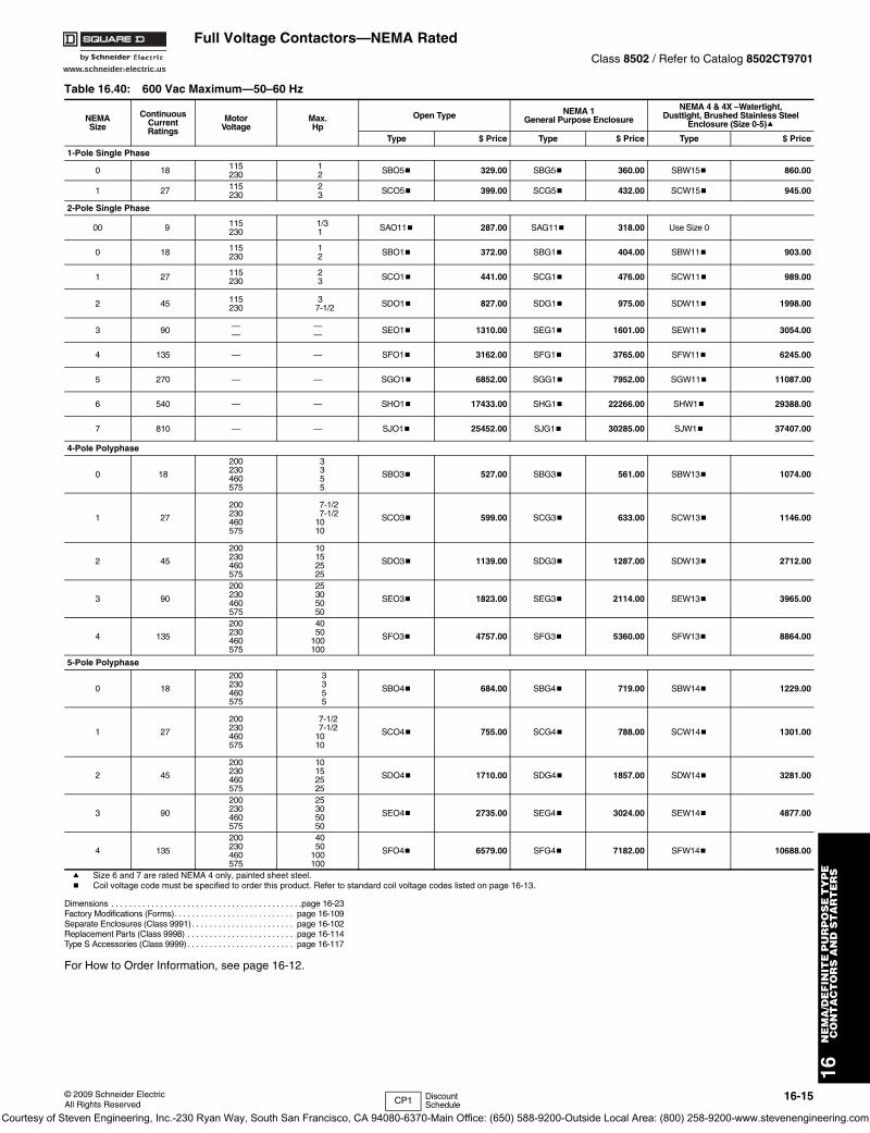
Full Voltage Contactors—NEMA RatedClass 8502 / Refer to Catalog 8502CT9701
a Size 6 and 7 are rated NEMA 4 only, painted sheet steel.b Coil voltage code must be specified to order this product. Refer to standard coil voltage codes listed on page 16-13.
Dimensions . . . . . . . . . . . . . . . . . . . . . . . . . . . . . . . . . . . . . . . . . . .page 16-23Factory Modifications (Forms). . . . . . . . . . . . . . . . . . . . . . . . . . . page 16-109Separate Enclosures (Class 9991). . . . . . . . . . . . . . . . . . . . . . . page 16-102Replacement Parts (Class 9998) . . . . . . . . . . . . . . . . . . . . . . . . page 16-114Type S Accessories (Class 9999). . . . . . . . . . . . . . . . . . . . . . . . page 16-117
For How to Order Information, see page 16-12.
Table 16.40: 600 Vac Maximum—50–60 Hz
NEMASize
ContinuousCurrentRatings
MotorVoltage
Max.Hp
Open Type NEMA 1General Purpose Enclosure
NEMA 4 & 4X –Watertight, Dusttight, Brushed Stainless Steel
Enclosure (Size 0-5)a
Type $ Price Type $ Price Type $ Price
1-Pole Single Phase
0 18 115230
12 SBO5b 329.00 SBG5b 360.00 SBW15b 860.00
1 27 115230
23 SCO5b 399.00 SCG5b 432.00 SCW15b 945.00
2-Pole Single Phase
00 9 115230
1/31 SAO11b 287.00 SAG11b 318.00 Use Size 0
0 18 115230
12 SBO1b 372.00 SBG1b 404.00 SBW11b 903.00
1 27 115230
23 SCO1b 441.00 SCG1b 476.00 SCW11b 989.00
2 45 115230
37-1/2 SDO1b 827.00 SDG1b 975.00 SDW11b 1998.00
3 90 ——
—— SEO1b 1310.00 SEG1b 1601.00 SEW11b 3054.00
4 135 — — SFO1b 3162.00 SFG1b 3765.00 SFW11b 6245.00
5 270 — — SGO1b 6852.00 SGG1b 7952.00 SGW11b 11087.00
6 540 — — SHO1b 17433.00 SHG1b 22266.00 SHW1b 29388.00
7 810 — — SJO1b 25452.00 SJG1b 30285.00 SJW1b 37407.00
4-Pole Polyphase
0 18
200230460575
3355
SBO3b 527.00 SBG3b 561.00 SBW13b 1074.00
1 27
200230460575
7-1/27-1/2
1010
SCO3b 599.00 SCG3b 633.00 SCW13b 1146.00
2 45
200230460575
10152525
SDO3b 1139.00 SDG3b 1287.00 SDW13b 2712.00
3 90
200230460575
25305050
SEO3b 1823.00 SEG3b 2114.00 SEW13b 3965.00
4 135
200230460575
40 50100100
SFO3b 4757.00 SFG3b 5360.00 SFW13b 8864.00
5-Pole Polyphase
0 18
200230460575
3355
SBO4b 684.00 SBG4b 719.00 SBW14b 1229.00
1 27
200230460575
7-1/27-1/2
1010
SCO4b 755.00 SCG4b 788.00 SCW14b 1301.00
2 45
200230460575
10152525
SDO4b 1710.00 SDG4b 1857.00 SDW14b 3281.00
3 90
200230460575
25305050
SEO4b 2735.00 SEG4b 3024.00 SEW14b 4877.00
4 135
200230460575
40 50100100
SFO4b 6579.00 SFG4b 7182.00 SFW14b 10688.00
CP1 Discount Schedule
Courtesy of Steven Engineering, Inc.-230 Ryan Way, South San Francisco, CA 94080-6370-Main Office: (650) 588-9200-Outside Local Area: (800) 258-9200-www.stevenengineering.com
www.schneider-electric.us
16N
EM
A/D
EF
INIT
E P
UR
PO
SE
TY
PE
C
ON
TA
CT
OR
S A
ND
ST
AR
TE
RS
16-16 © 2009 Schneider ElectricAll Rights Reserved
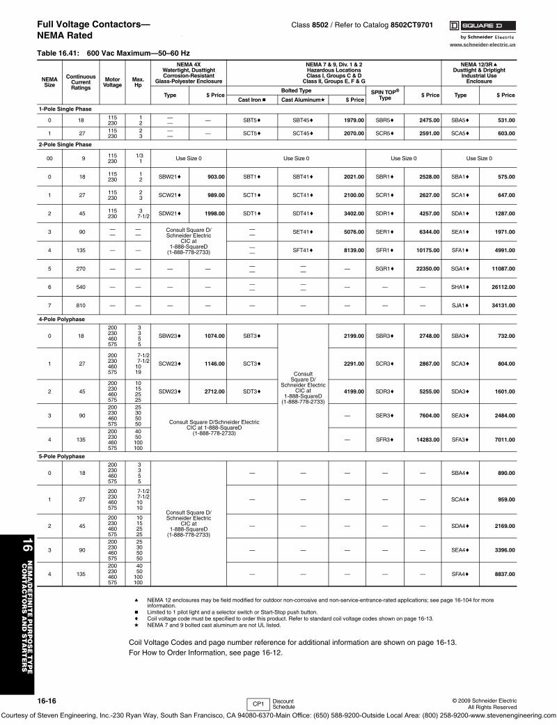
Full Voltage Contactors—NEMA Rated
Class 8502 / Refer to Catalog 8502CT9701\
a NEMA 12 enclosures may be field modified for outdoor non-corrosive and non-service-entrance-rated applications; see page 16-104 for more information.
b Limited to 1 pilot light and a selector switch or Start-Stop push button.c Coil voltage code must be specified to order this product. Refer to standard coil voltage codes shown on page 16-13.d NEMA 7 and 9 bolted cast aluminum are not UL listed.
Coil Voltage Codes and page number reference for additional information are shown on page 16-13.For How to Order Information, see page 16-12.
Table 16.41: 600 Vac Maximum—50–60 Hz
NEMASize
ContinuousCurrentRatings
MotorVoltage
Max.Hp
NEMA 4XWatertight, DusttightCorrosion-Resistant
Glass-Polyester Enclosure
NEMA 7 & 9, Div. 1 & 2Hazardous LocationsClass I, Groups C & D
Class II, Groups E, F & G
NEMA 12/3RaDusttight & Driptight
Industrial UseEnclosure
Type $ PriceBolted Type SPIN TOP®
Type $ Price Type $ PriceCast Ironb Cast Aluminumd $ Price
1-Pole Single Phase
0 18 115230
12
—— — SBT5c SBT45c 1979.00 SBR5c 2475.00 SBA5c 531.00
1 27 115230
23
—— — SCT5c SCT45c 2070.00 SCR5c 2591.00 SCA5c 603.00
2-Pole Single Phase
00 9 115230
1/31 Use Size 0 Use Size 0 Use Size 0 Use Size 0
0 18 115230
12 SBW21c 903.00 SBT1c SBT41c 2021.00 SBR1c 2528.00 SBA1c 575.00
1 27 115230
23 SCW21c 989.00 SCT1c SCT41c 2100.00 SCR1c 2627.00 SCA1c 647.00
2 45 115230
37-1/2 SDW21c 1998.00 SDT1c SDT41c 3402.00 SDR1c 4257.00 SDA1c 1287.00
3 90 ——
——
Consult Square D/Schneider Electric
CIC at 1-888-SquareD
(1-888-778-2733)
—— SET41c 5076.00 SER1c 6344.00 SEA1c 1971.00
4 135 — — —— SFT41c 8139.00 SFR1c 10175.00 SFA1c 4991.00
5 270 — — — — ——
—— — SGR1c 22350.00 SGA1c 11087.00
6 540 — — — — ——
—— — — — SHA1c 26112.00
7 810 — — — — — — — — — SJA1c 34131.00
4-Pole Polyphase
0 18
200230460575
3355
SBW23c 1074.00 SBT3c
Consult Square D/
Schneider Electric CIC at
1-888-SquareD(1-888-778-2733)
2199.00 SBR3c 2748.00 SBA3c 732.00
1 27
200230460575
7-1/27-1/2
1019
SCW23c 1146.00 SCT3c 2291.00 SCR3c 2867.00 SCA3c 804.00
2 45
200230460575
10152525
SDW23c 2712.00 SDT3c 4199.00 SDR3c 5255.00 SDA3c 1601.00
3 90
200230460575
25305050 Consult Square D/Schneider Electric
CIC at 1-888-SquareD(1-888-778-2733)
— SER3c 7604.00 SEA3c 2484.00
4 135
200230460575
4050100100
— SFR3c 14283.00 SFA3c 7011.00
5-Pole Polyphase
0 18
200230460575
3355
Consult Square D/Schneider Electric
CIC at 1-888-SquareD
(1-888-778-2733)
— — — — — SBA4c 890.00
1 27
200230460575
7-1/27-1/21010
— — — — — SCA4c 959.00
2 45
200230460575
10152525
— — — — — SDA4c 2169.00
3 90
200230460575
25305050
— — — — — SEA4c 3396.00
4 135
200230460575
4050
100100
— — — — — SFA4c 8837.00
CP1 Discount Schedule
Courtesy of Steven Engineering, Inc.-230 Ryan Way, South San Francisco, CA 94080-6370-Main Office: (650) 588-9200-Outside Local Area: (800) 258-9200-www.stevenengineering.com
www.schneider-electric.us
16N
EM
A/D
EF
INIT
E P
UR
PO
SE
TY
PE
C
ON
TA
CT
OR
S A
ND
ST
AR
TE
RS
© 2009 Schneider ElectricAll Rights Reserved
16-17
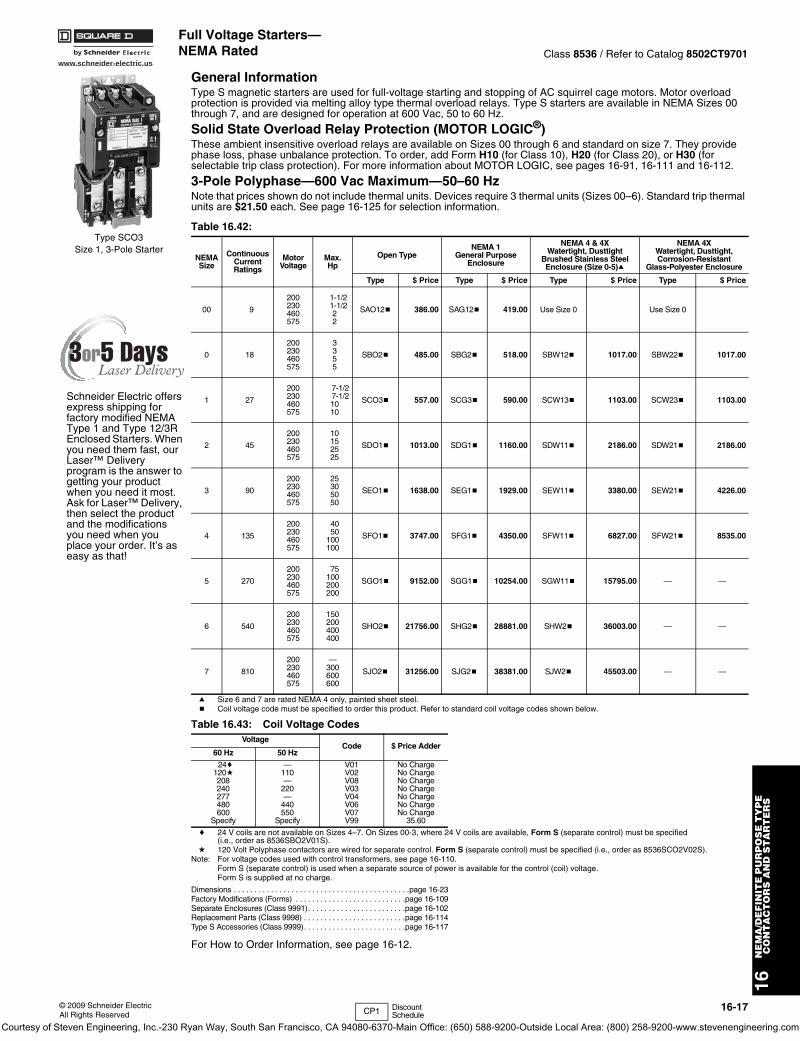
Full Voltage Starters—NEMA Rated Class 8536 / Refer to Catalog 8502CT9701
General InformationType S magnetic starters are used for full-voltage starting and stopping of AC squirrel cage motors. Motor overload protection is provided via melting alloy type thermal overload relays. Type S starters are available in NEMA Sizes 00 through 7, and are designed for operation at 600 Vac, 50 to 60 Hz.
Solid State Overload Relay Protection (MOTOR LOGIC®)These ambient insensitive overload relays are available on Sizes 00 through 6 and standard on size 7. They provide phase loss, phase unbalance protection. To order, add Form H10 (for Class 10), H20 (for Class 20), or H30 (for selectable trip class protection). For more information about MOTOR LOGIC, see pages 16-91, 16-111 and 16-112.
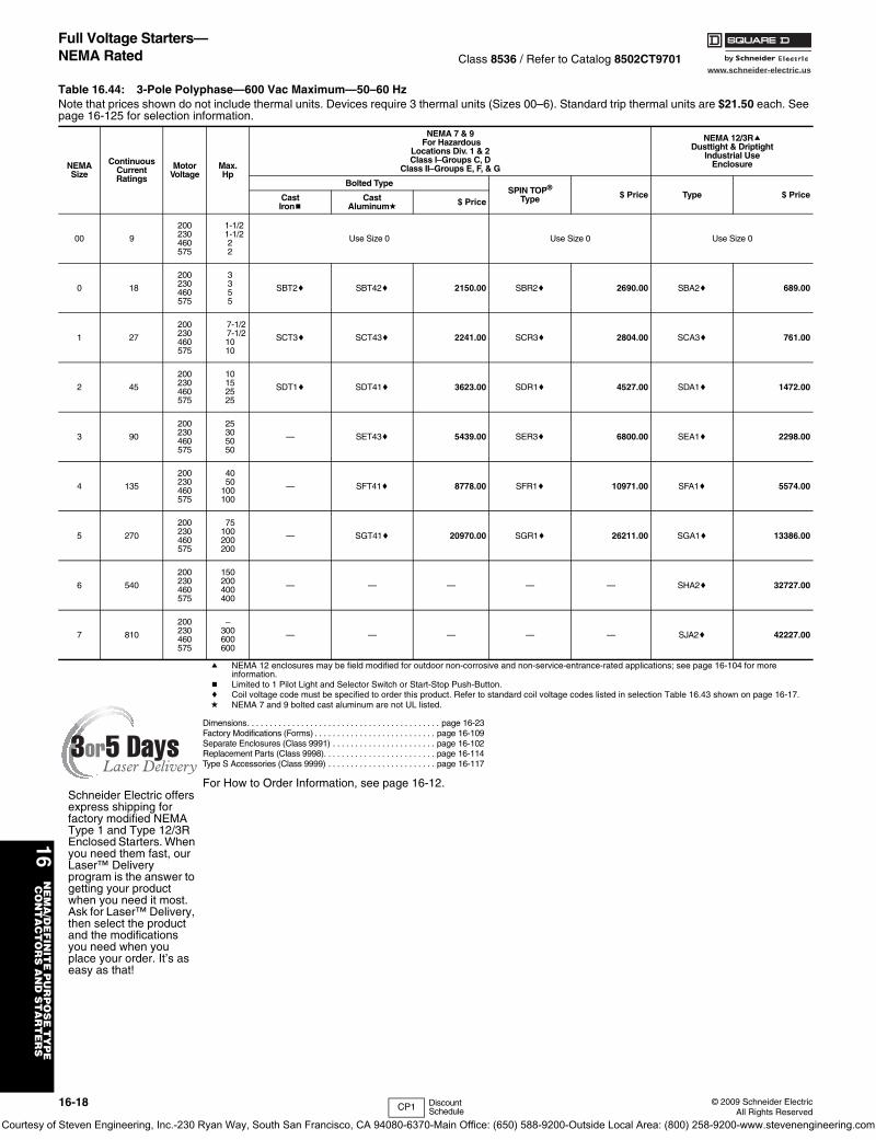
3-Pole Polyphase—600 Vac Maximum—50–60 HzNote that prices shown do not include thermal units. Devices require 3 thermal units (Sizes 00–6). Standard trip thermal units are $21.50 each. See page 16-125 for selection information.
a Size 6 and 7 are rated NEMA 4 only, painted sheet steel.b Coil voltage code must be specified to order this product. Refer to standard coil voltage codes shown below.
c 24 V coils are not available on Sizes 4–7. On Sizes 00-3, where 24 V coils are available, Form S (separate control) must be specified (i.e., order as 8536SBO2V01S).
d 120 Volt Polyphase contactors are wired for separate control. Form S (separate control) must be specified (i.e., order as 8536SCO2V02S).Note: For voltage codes used with control transformers, see page 16-110.
Form S (separate control) is used when a separate source of power is available for the control (coil) voltage. Form S is supplied at no charge.
Dimensions . . . . . . . . . . . . . . . . . . . . . . . . . . . . . . . . . . . . . . . . . . .page 16-23Factory Modifications (Forms) . . . . . . . . . . . . . . . . . . . . . . . . . . .page 16-109Separate Enclosures (Class 9991). . . . . . . . . . . . . . . . . . . . . . . .page 16-102Replacement Parts (Class 9998) . . . . . . . . . . . . . . . . . . . . . . . . .page 16-114Type S Accessories (Class 9999). . . . . . . . . . . . . . . . . . . . . . . . .page 16-117
For How to Order Information, see page 16-12.
Table 16.42:
NEMASize
ContinuousCurrentRatings
MotorVoltage
Max.Hp
Open TypeNEMA 1
General PurposeEnclosure
NEMA 4 & 4XWatertight, Dusttight
Brushed Stainless SteelEnclosure (Size 0-5)a
NEMA 4XWatertight, Dusttight,Corrosion-Resistant
Glass-Polyester Enclosure
Type $ Price Type $ Price Type $ Price Type $ Price
00 9
200230460575
1-1/21-1/2 22
SAO12b 386.00 SAG12b 419.00 Use Size 0 Use Size 0
0 18
200230460575
3355
SBO2b 485.00 SBG2b 518.00 SBW12b 1017.00 SBW22b 1017.00
1 27
200230460575
7-1/27-1/21010
SCO3b 557.00 SCG3b 590.00 SCW13b 1103.00 SCW23b 1103.00
2 45
200230460575
10152525
SDO1b 1013.00 SDG1b 1160.00 SDW11b 2186.00 SDW21b 2186.00
3 90
200230460575
25305050
SEO1b 1638.00 SEG1b 1929.00 SEW11b 3380.00 SEW21b 4226.00
4 135
200230460575
40 50100100
SFO1b 3747.00 SFG1b 4350.00 SFW11b 6827.00 SFW21b 8535.00
5 270
200230460575
75100200200
SGO1b 9152.00 SGG1b 10254.00 SGW11b 15795.00 — —
6 540
200230460575
150200400400
SHO2b 21756.00 SHG2b 28881.00 SHW2b 36003.00 — —
7 810
200230460575
—300600600
SJO2b 31256.00 SJG2b 38381.00 SJW2b 45503.00 — —
Table 16.43: Coil Voltage CodesVoltage
Code $ Price Adder60 Hz 50 Hz
24c120d208240277480600
Specify
—110—
220—
440550
Specify
V01V02V08V03V04V06V07V99
No ChargeNo ChargeNo ChargeNo ChargeNo ChargeNo ChargeNo Charge
35.60
Type SCO3Size 1, 3-Pole Starter
Schneider Electric offers express shipping for factory modified NEMA Type 1 and Type 12/3R Enclosed Starters. When you need them fast, our Laser™ Delivery program is the answer to getting your product when you need it most. Ask for Laser™ Delivery, then select the product and the modifications you need when you place your order. It’s as easy as that!
CP1 Discount Schedule
Courtesy of Steven Engineering, Inc.-230 Ryan Way, South San Francisco, CA 94080-6370-Main Office: (650) 588-9200-Outside Local Area: (800) 258-9200-www.stevenengineering.com
www.schneider-electric.us
16N
EM
A/D
EF
INIT
E P
UR
PO
SE
TY
PE
C
ON
TA
CT
OR
S A
ND
ST
AR
TE
RS
16-18 © 2009 Schneider ElectricAll Rights Reserved
Full Voltage Starters—NEMA Rated Class 8536 / Refer to Catalog 8502CT9701
a NEMA 12 enclosures may be field modified for outdoor non-corrosive and non-service-entrance-rated applications; see page 16-104 for more information.
b Limited to 1 Pilot Light and Selector Switch or Start-Stop Push-Button.c Coil voltage code must be specified to order this product. Refer to standard coil voltage codes listed in selection Table 16.43 shown on page 16-17.d NEMA 7 and 9 bolted cast aluminum are not UL listed.
Dimensions. . . . . . . . . . . . . . . . . . . . . . . . . . . . . . . . . . . . . . . . . . . page 16-23Factory Modifications (Forms) . . . . . . . . . . . . . . . . . . . . . . . . . . . page 16-109Separate Enclosures (Class 9991) . . . . . . . . . . . . . . . . . . . . . . . page 16-102Replacement Parts (Class 9998). . . . . . . . . . . . . . . . . . . . . . . . . page 16-114Type S Accessories (Class 9999) . . . . . . . . . . . . . . . . . . . . . . . . page 16-117
For How to Order Information, see page 16-12.
Table 16.44: 3-Pole Polyphase—600 Vac Maximum—50–60 Hz Note that prices shown do not include thermal units. Devices require 3 thermal units (Sizes 00–6). Standard trip thermal units are $21.50 each. See page 16-125 for selection information.
NEMASize
ContinuousCurrentRatings
MotorVoltage
Max.Hp
NEMA 7 & 9 For Hazardous
Locations Div. 1 & 2Class I–Groups C, D
Class II–Groups E, F, & G
NEMA 12/3RaDusttight & Driptight
Industrial UseEnclosure
Bolted TypeSPIN TOP®
Type $ Price Type $ PriceCast Ironb
Cast Aluminumd
$ Price
00 9
200230460575
1-1/21-1/222
Use Size 0 Use Size 0 Use Size 0
0 18
200230460575
3355
SBT2c SBT42c 2150.00 SBR2c 2690.00 SBA2c 689.00
1 27
200230460575
7-1/27-1/21010
SCT3c SCT43c 2241.00 SCR3c 2804.00 SCA3c 761.00
2 45
200230460575
10152525
SDT1c SDT41c 3623.00 SDR1c 4527.00 SDA1c 1472.00
3 90
200230460575
25305050
— SET43c 5439.00 SER3c 6800.00 SEA1c 2298.00
4 135
200230460575
40 50100100
— SFT41c 8778.00 SFR1c 10971.00 SFA1c 5574.00
5 270
200230460575
75100200200
— SGT41c 20970.00 SGR1c 26211.00 SGA1c 13386.00
6 540
200230460575
150200400400
— — — — — SHA2c 32727.00
7 810
200230460575
–300600600
— — — — — SJA2c 42227.00
Schneider Electric offers express shipping for factory modified NEMA Type 1 and Type 12/3R Enclosed Starters. When you need them fast, our Laser™ Delivery program is the answer to getting your product when you need it most. Ask for Laser™ Delivery, then select the product and the modifications you need when you place your order. It’s as easy as that!
CP1 Discount Schedule
Courtesy of Steven Engineering, Inc.-230 Ryan Way, South San Francisco, CA 94080-6370-Main Office: (650) 588-9200-Outside Local Area: (800) 258-9200-www.stevenengineering.com
www.schneider-electric.us
16N
EM
A/D
EF
INIT
E P
UR
PO
SE
TY
PE
C
ON
TA
CT
OR
S A
ND
ST
AR
TE
RS
© 2009 Schneider ElectricAll Rights Reserved
16-19
Full Voltage StartersClass 8536 / Refer to Catalog 8502CT9701
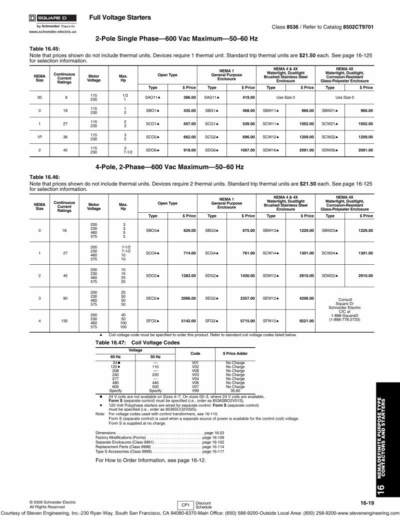
2-Pole Single Phase—600 Vac Maximum—50–60 Hz
4-Pole, 2-Phase—600 Vac Maximum—50–60 Hz
a Coil voltage code must be specified to order this product. Refer to standard coil voltage codes listed below.
b 24 V coils are not available on Sizes 4–7. On sizes 00–3, where 24 V coils are available, Form S (separate control) must be specified (i.e., order as 8536SBO2V01S).
c 120 Volt Polyphase starters are wired for separate control. Form S (separate control) must be specified (i.e., order as 8536SCO2V02S).
Note: For voltage codes used with control transformers, see 16-110.Form S (separate control) is used when a separate source of power is available for the control (coil) voltage. Form S is supplied at no charge.
Dimensions . . . . . . . . . . . . . . . . . . . . . . . . . . . . . . . . . . . . . . . . . . .page 16-23Factory Modifications (Forms) . . . . . . . . . . . . . . . . . . . . . . . . . . .page 16-109Separate Enclosures (Class 9991). . . . . . . . . . . . . . . . . . . . . . . .page 16-102Replacement Parts (Class 9998) . . . . . . . . . . . . . . . . . . . . . . . . .page 16-114Type S Accessories (Class 9999). . . . . . . . . . . . . . . . . . . . . . . . .page 16-117
For How to Order Information, see page 16-12.
Table 16.45: Note that prices shown do not include thermal units. Devices require 1 thermal unit. Standard trip thermal units are $21.50 each. See page 16-125 for selection information.
NEMASize
ContinuousCurrentRatings
MotorVoltage
Max.Hp
Open TypeNEMA 1
General PurposeEnclosure
NEMA 4 & 4XWatertight, Dusttight
Brushed Stainless SteelEnclosure
NEMA 4XWatertight, Dusttight,Corrosion-Resistant
Glass-Polyester Enclosure
Type $ Price Type $ Price Type $ Price Type $ Price
00 9 115230
1/3 1 SAO11a 386.00 SAG11a 419.00 Use Size 0 Use Size 0
0 18 115230
12 SBO1a 435.00 SBG1a 468.00 SBW11a 966.00 SBW21a 966.00
1 27 115230
23 SCO1a 507.00 SCG1a 539.00 SCW11a 1052.00 SCW21a 1052.00
1P 36 115230
35 SCO2a 662.00 SCG2a 696.00 SCW12a 1209.00 SCW22a 1209.00
2 45 115230
37-1/2 SDO6a 918.00 SDG6a 1067.00 SDW16a 2091.00 SDW26a 2091.00
Table 16.46: Note that prices shown do not include thermal units. Devices require 2 thermal units. Standard trip thermal units are $21.50 each. See page 16-125 for selection information.
NEMASize
ContinuousCurrentRatings
MotorVoltage
Max.Hp
Open TypeNEMA 1
General PurposeEnclosure
NEMA 4 & 4XWatertight, Dusttight
Brushed Stainless SteelEnclosure
NEMA 4XWatertight, Dusttight,Corrosion-Resistant
Glass-Polyester Enclosure
Type $ Price Type $ Price Type $ Price Type $ Price
0 18
200230460575
3355
SBO3a 629.00 SBG3a 675.00 SBW13a 1229.00 SBW23a 1229.00
1 27
200230460575
7-1/27-1/21010
SCO4a 714.00 SCG4a 761.00 SCW14a 1301.00 SCW24a 1301.00
2 45
200230460575
10152525
SDO2a 1283.00 SDG2a 1430.00 SDW12a 2910.00 SDW22a 2910.00
3 90
200230460575
25305050
SEO2a 2096.00 SEG2a 2357.00 SEW12a 4206.00 Consult Square D/
Schneider Electric CIC at
1-888-SquareD(1-888-778-2733)4 135
200230460575
4050100100
SFO2a 5142.00 SFG2a 5715.00 SFW12a 9221.00
Table 16.47: Coil Voltage CodesVoltage
Code $ Price Adder60 Hz 50 Hz
24b120c208240277480600
Specify
—110—
220—
440550
Specify
V01V02V08V03V04V06V07V99
No ChargeNo ChargeNo ChargeNo ChargeNo ChargeNo ChargeNo Charge
35.60
CP1 Discount Schedule
Courtesy of Steven Engineering, Inc.-230 Ryan Way, South San Francisco, CA 94080-6370-Main Office: (650) 588-9200-Outside Local Area: (800) 258-9200-www.stevenengineering.com
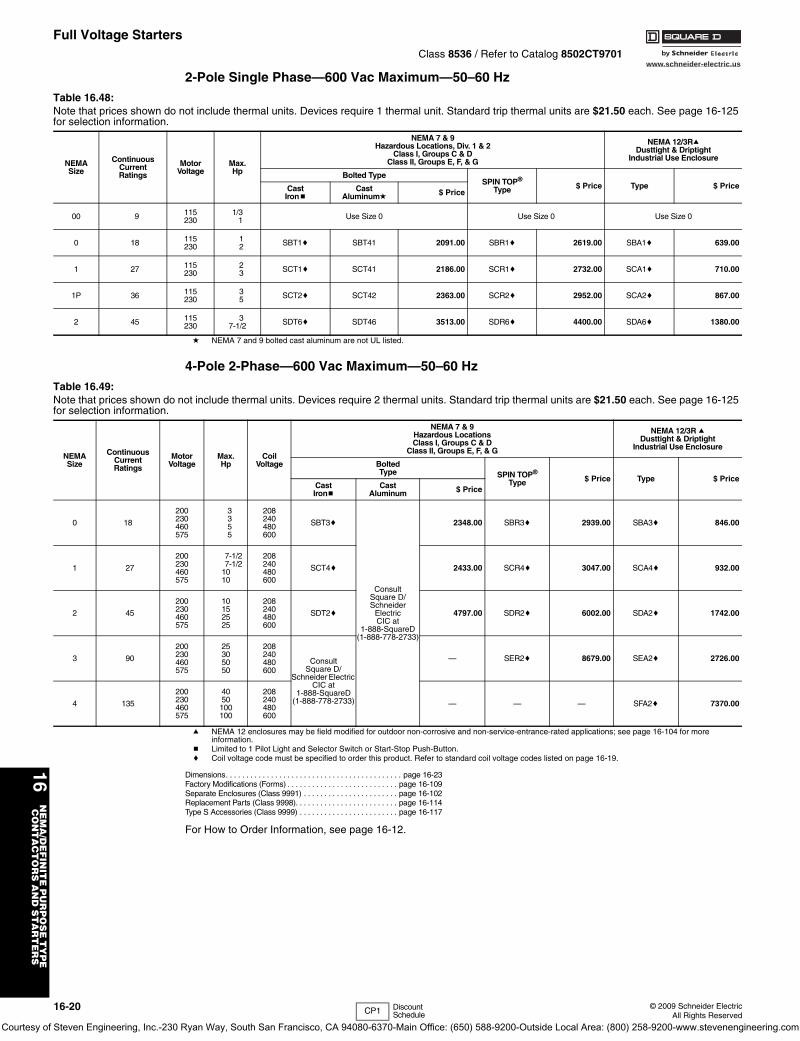
www.schneider-electric.us
16N
EM
A/D
EF
INIT
E P
UR
PO
SE
TY
PE
C
ON
TA
CT
OR
S A
ND
ST
AR
TE
RS
16-20 © 2009 Schneider ElectricAll Rights Reserved
Full Voltage StartersClass 8536 / Refer to Catalog 8502CT9701
2-Pole Single Phase—600 Vac Maximum—50–60 Hz
d NEMA 7 and 9 bolted cast aluminum are not UL listed.
4-Pole 2-Phase—600 Vac Maximum—50–60 Hz
a NEMA 12 enclosures may be field modified for outdoor non-corrosive and non-service-entrance-rated applications; see page 16-104 for more information.
b Limited to 1 Pilot Light and Selector Switch or Start-Stop Push-Button.c Coil voltage code must be specified to order this product. Refer to standard coil voltage codes listed on page 16-19.
Dimensions. . . . . . . . . . . . . . . . . . . . . . . . . . . . . . . . . . . . . . . . . . . page 16-23Factory Modifications (Forms) . . . . . . . . . . . . . . . . . . . . . . . . . . . page 16-109Separate Enclosures (Class 9991) . . . . . . . . . . . . . . . . . . . . . . . page 16-102Replacement Parts (Class 9998). . . . . . . . . . . . . . . . . . . . . . . . . page 16-114Type S Accessories (Class 9999) . . . . . . . . . . . . . . . . . . . . . . . . page 16-117
For How to Order Information, see page 16-12.
Table 16.48: Note that prices shown do not include thermal units. Devices require 1 thermal unit. Standard trip thermal units are $21.50 each. See page 16-125 for selection information.
NEMASize
ContinuousCurrentRatings
MotorVoltage
Max.Hp
NEMA 7 & 9Hazardous Locations, Div. 1 & 2
Class I, Groups C & DClass II, Groups E, F, & G
NEMA 12/3RaDusttight & Driptight
Industrial Use Enclosure
Bolted TypeSPIN TOP®
Type $ Price Type $ PriceCast Ironb
Cast Aluminumd
$ Price
00 9 115230
1/3 1 Use Size 0 Use Size 0 Use Size 0
0 18 115230
12 SBT1c SBT41 2091.00 SBR1c 2619.00 SBA1c 639.00
1 27 115230
23 SCT1c SCT41 2186.00 SCR1c 2732.00 SCA1c 710.00
1P 36 115230
35 SCT2c SCT42 2363.00 SCR2c 2952.00 SCA2c 867.00
2 45 115230
37-1/2 SDT6c SDT46 3513.00 SDR6c 4400.00 SDA6c 1380.00
Table 16.49: Note that prices shown do not include thermal units. Devices require 2 thermal units. Standard trip thermal units are $21.50 each. See page 16-125 for selection information.
NEMASize
ContinuousCurrentRatings
MotorVoltage
Max.Hp
CoilVoltage
NEMA 7 & 9Hazardous LocationsClass I, Groups C & D
Class II, Groups E, F, & G
NEMA 12/3R aDusttight & Driptight
Industrial Use Enclosure
BoltedType SPIN TOP®
Type $ Price Type $ PriceCast Ironb
Cast Aluminum $ Price
0 18
200230460575
3355
208240480600
SBT3c
Consult Square D/Schneider
Electric CIC at
1-888-SquareD(1-888-778-2733)
2348.00 SBR3c 2939.00 SBA3c 846.00
1 27
200230460575
7-1/27-1/2
1010
208240480600
SCT4c 2433.00 SCR4c 3047.00 SCA4c 932.00
2 45
200230460575
10152525
208240480600
SDT2c 4797.00 SDR2c 6002.00 SDA2c 1742.00
3 90
200230460575
25305050
208240480600
Consult Square D/
Schneider Electric CIC at
1-888-SquareD(1-888-778-2733)
— SER2c 8679.00 SEA2c 2726.00
4 135
200230460575
4050100100
208240480600
— — — SFA2c 7370.00
CP1 Discount Schedule
Courtesy of Steven Engineering, Inc.-230 Ryan Way, South San Francisco, CA 94080-6370-Main Office: (650) 588-9200-Outside Local Area: (800) 258-9200-www.stevenengineering.com
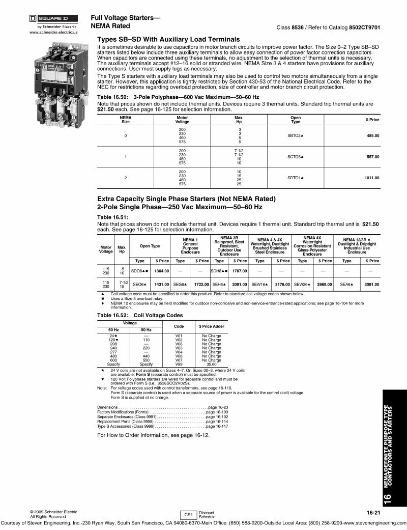
www.schneider-electric.us
16N
EM
A/D
EF
INIT
E P
UR
PO
SE
TY
PE
C
ON
TA
CT
OR
S A
ND
ST
AR
TE
RS
© 2009 Schneider ElectricAll Rights Reserved
16-21
Full Voltage Starters—NEMA Rated Class 8536 / Refer to Catalog 8502CT9701
Types SB–SD With Auxiliary Load TerminalsIt is sometimes desirable to use capacitors in motor branch circuits to improve power factor. The Size 0–2 Type SB–SD starters listed below include three auxiliary terminals to allow easy connection of power factor correction capacitors. When capacitors are connected using these terminals, no adjustment to the selection of thermal units is necessary. The auxiliary terminals accept #12–16 solid or stranded wire. NEMA Size 3 & 4 starters have provisions for auxiliary connections. User must supply lugs as necessary.The Type S starters with auxiliary load terminals may also be used to control two motors simultaneously from a single starter. However, this application is tightly restricted by Section 430-53 of the National Electrical Code. Refer to the NEC for restrictions regarding overload protection, size of controller and motor branch circuit protection.
Extra Capacity Single Phase Starters (Not NEMA Rated)2-Pole Single Phase—250 Vac Maximum—50–60 Hz
a Coil voltage code must be specified to order this product. Refer to standard coil voltage codes shown below.b Uses a Size 3 overload relay.c NEMA 12 enclosures may be field modified for outdoor non-corrosive and non-service-entrance-rated applications; see page 16-104 for more
information.
d 24 V coils are not available on Sizes 4–7. On Sizes 00–3, where 24 V coils are available, Form S (separate control) must be specified.
e 120 Volt Polyphase starters are wired for separate control and must be ordered with Form S (i.e., 8536SCO2V02S).
Note: For voltage codes used with control transformers, see page 16-110.Form S (separate control) is used when a separate source of power is available for the control (coil) voltage. Form S is supplied at no charge.
Dimensions . . . . . . . . . . . . . . . . . . . . . . . . . . . . . . . . . . . . . . . . . . .page 16-23Factory Modifications (Forms) . . . . . . . . . . . . . . . . . . . . . . . . . . .page 16-109Separate Enclosures (Class 9991). . . . . . . . . . . . . . . . . . . . . . . .page 16-102Replacement Parts (Class 9998) . . . . . . . . . . . . . . . . . . . . . . . . .page 16-114Type S Accessories (Class 9999). . . . . . . . . . . . . . . . . . . . . . . . .page 16-117
For How to Order Information, see page 16-12.
Table 16.50: 3-Pole Polyphase—600 Vac Maximum—50–60 HzNote that prices shown do not include thermal units. Devices require 3 thermal units. Standard trip thermal units are $21.50 each. See page 16-125 for selection information.
NEMASize
MotorVoltage
Max.Hp
OpenType $ Price
0
200230460575
3355
SBTO2a 485.00
1
200230460575
7-1/27-1/2
1010
SCTO3a 557.00
2
200230460575
10152525
SDTO1a 1011.00
Table 16.51: Note that prices shown do not include thermal unit. Devices require 1 thermal unit. Standard trip thermal unit is $21.50 each. See page 16-125 for selection information.
MotorVoltage
Max.Hp
Open Type
NEMA 1GeneralPurpose
Enclosure
NEMA 3RRainproof, Sleet
Resistant, Outdoor Use
Enclosure
NEMA 4 & 4XWatertight, DusttightBrushed Stainless
Steel Enclosure
NEMA 4XWatertight
Corrosion Resistant Glass-Polyester
Enclosure
NEMA 12/3R cDusttight & Driptight
Industrial Use Enclosure
Type $ Price Type $ Price Type $ Price Type $ Price Type $ Price Type $ Price
115230
510 SDO8ab 1304.00 — — SDH8ab 1787.00 — — — — — —
115230
7-1/215 SEO6a 1431.00 SEG6a 1722.00 SEH6a 2091.00 SEW16a 3176.00 SEW26a 3969.00 SEA6a 2091.00
Table 16.52: Coil Voltage CodesVoltage
Code $ Price Adder60 Hz 50 Hz
24d120e208240277480600
Specify
—110—
220—
440550
Specify
V01V02V08V03V04V06V07V99
No ChargeNo ChargeNo ChargeNo ChargeNo ChargeNo ChargeNo Charge
35.60
CP1 Discount Schedule
Courtesy of Steven Engineering, Inc.-230 Ryan Way, South San Francisco, CA 94080-6370-Main Office: (650) 588-9200-Outside Local Area: (800) 258-9200-www.stevenengineering.com
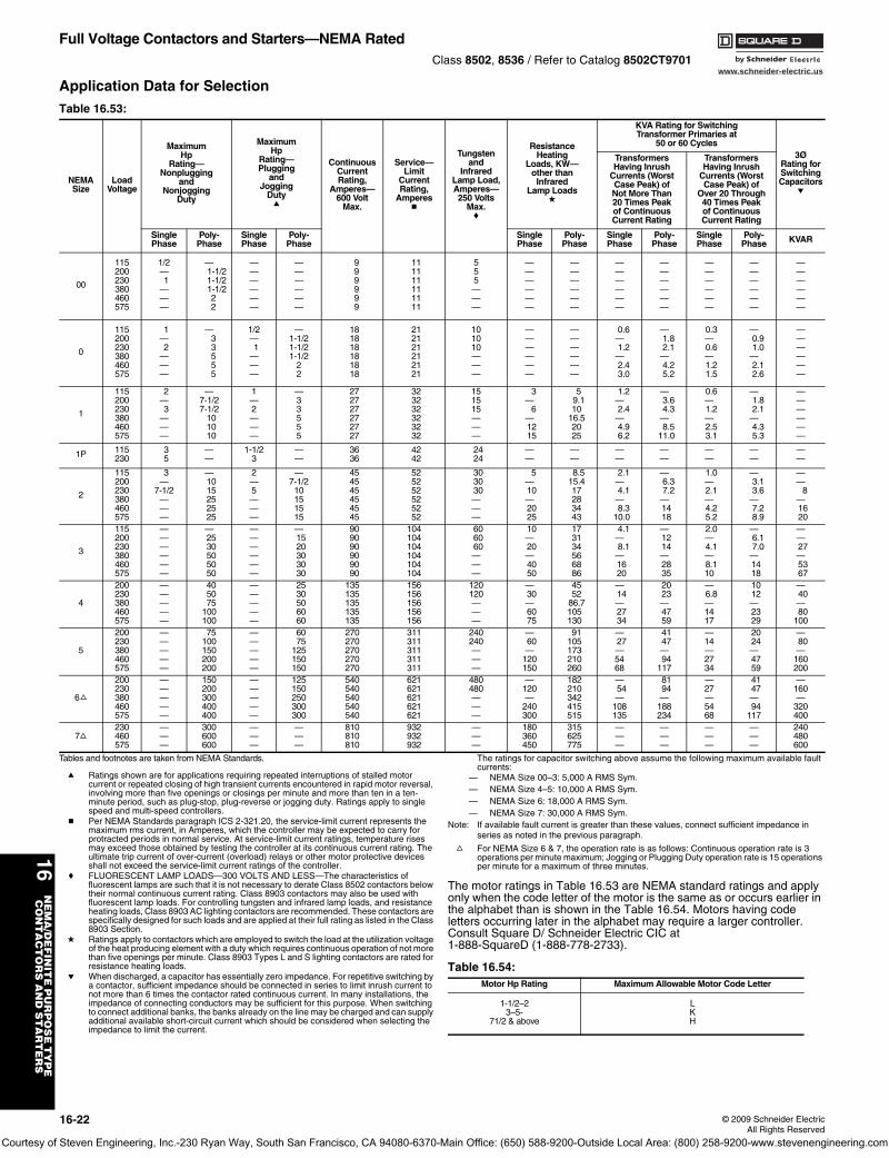
www.schneider-electric.us
16N
EM
A/D
EF
INIT
E P
UR
PO
SE
TY
PE
C
ON
TA
CT
OR
S A
ND
ST
AR
TE
RS
16-22 © 2009 Schneider ElectricAll Rights Reserved
Full Voltage Contactors and Starters—NEMA RatedClass 8502, 8536 / Refer to Catalog 8502CT9701
Application Data for Selection
Tables and footnotes are taken from NEMA Standards.
a Ratings shown are for applications requiring repeated interruptions of stalled motor current or repeated closing of high transient currents encountered in rapid motor reversal, involving more than five openings or closings per minute and more than ten in a ten-minute period, such as plug-stop, plug-reverse or jogging duty. Ratings apply to single speed and multi-speed controllers.
b Per NEMA Standards paragraph ICS 2-321.20, the service-limit current represents the maximum rms current, in Amperes, which the controller may be expected to carry for protracted periods in normal service. At service-limit current ratings, temperature rises may exceed those obtained by testing the controller at its continuous current rating. The ultimate trip current of over-current (overload) relays or other motor protective devices shall not exceed the service-limit current ratings of the controller.
c FLUORESCENT LAMP LOADS—300 VOLTS AND LESS—The characteristics of fluorescent lamps are such that it is not necessary to derate Class 8502 contactors below their normal continuous current rating. Class 8903 contactors may also be used with fluorescent lamp loads. For controlling tungsten and infrared lamp loads, and resistance heating loads, Class 8903 AC lighting contactors are recommended. These contactors are specifically designed for such loads and are applied at their full rating as listed in the Class 8903 Section.
d Ratings apply to contactors which are employed to switch the load at the utilization voltage of the heat producing element with a duty which requires continuous operation of not more than five openings per minute. Class 8903 Types L and S lighting contactors are rated for resistance heating loads.
e When discharged, a capacitor has essentially zero impedance. For repetitive switching by a contactor, sufficient impedance should be connected in series to limit inrush current to not more than 6 times the contactor rated continuous current. In many installations, the impedance of connecting conductors may be sufficient for this purpose. When switching to connect additional banks, the banks already on the line may be charged and can supply additional available short-circuit current which should be considered when selecting the impedance to limit the current.
The ratings for capacitor switching above assume the following maximum available fault currents:
— NEMA Size 00–3: 5,000 A RMS Sym.— NEMA Size 4–5: 10,000 A RMS Sym.— NEMA Size 6: 18,000 A RMS Sym.— NEMA Size 7: 30,000 A RMS Sym.
Note: If available fault current is greater than these values, connect sufficient impedance in series as noted in the previous paragraph.
f For NEMA Size 6 & 7, the operation rate is as follows: Continuous operation rate is 3 operations per minute maximum; Jogging or Plugging Duty operation rate is 15 operations per minute for a maximum of three minutes.
The motor ratings in Table 16.53 are NEMA standard ratings and apply only when the code letter of the motor is the same as or occurs earlier in the alphabet than is shown in the Table 16.54. Motors having code letters occurring later in the alphabet may require a larger controller. Consult Square D/ Schneider Electric CIC at 1-888-SquareD (1-888-778-2733).
Table 16.53:
NEMASize
LoadVoltage
MaximumHp
Rating—Nonplugging
andNonjogging
Duty
MaximumHp
Rating—Plugging
andJogging
Dutya
ContinuousCurrentRating,
Amperes—600 Volt
Max.
Service—Limit
CurrentRating,
Amperesb
Tungstenand
InfraredLamp Load,Amperes—250 Volts
Max.c
ResistanceHeating
Loads, KW—other than
InfraredLamp Loads
d
KVA Rating for SwitchingTransformer Primaries at
50 or 60 Cycles3Ø
Rating forSwitchingCapacitors
e
TransformersHaving Inrush
Currents (WorstCase Peak) ofNot More Than20 Times Peakof ContinuousCurrent Rating
TransformersHaving Inrush
Currents (WorstCase Peak) of
Over 20 Through40 Times Peakof ContinuousCurrent Rating
SinglePhase
Poly-Phase
SinglePhase
Poly-Phase
SinglePhase
Poly-Phase
SinglePhase
Poly-Phase
SinglePhase
Poly-Phase KVAR
00
115200230380460575
1/2—1
———
— 1-1/2
1-1/2 1-1/2
22
——————
——————
999999
111111111111
555———
——————
——————
——————
——————
——————
——————
——————
0
115200230380460575
1—2
———
—33555
1/2—1
———
—1-1/21-1/21-1/2
22
181818181818
212121212121
101010———
——————
——————
0.6—1.2
—2.43.0
—1.82.1
—4.25.2
0.3—0.6—1.21.5
—0.91.0
—2.12.6
——————
1
115200230380460575
2—3
———
—7-1/27-1/2
101010
1—2———
—33555
272727272727
323232323232
151515———
3—
6—1215
59.110
16.52025
1.2—2.4
—4.96.2
—3.64.3
—8.5
11.0
0.6—1.2—2.53.1
—1.82.1
—4.35.3
——————
1P 115230
35
——
1-1/23
——
3636
4242
2424
——
——
——
——
——
——
——
2
115200230380460575
3—
7-1/2———
—1015252525
2—5———
—7-1/2
10151515
454545454545
525252525252
303030———
5—10—2025
8.515.417283443
2.1—4.1
—8.3
10.0
—6.37.2
—1418
1.0—2.1—4.25.2
—3.13.6
—7.28.9
——
8—1620
3
115200230380460575
——————
—2530505050
——————
—1520303030
909090909090
104104104104104104
606060———
10—20—4050
173134566886
4.1—8.1
—1620
—1214—2835
2.0—4.1—8.110
—6.17.0
—1418
——27—5367
4
200230380460575
—————
405075
100100
—————
2530506060
135135135135135
156156156156156
120120———
—30—6075
4552
86.7105130
—14—2734
2023—4759
—6.8—1417
1012—2329
—40—80
100
5
200230380460575
—————
75100150200200
—————
6075
125150150
270270270270270
311311311311311
240240———
—60—
120150
91105173210260
—27—5468
4147—94
117
—14—2734
2024—4759
—80—
160200
6f
200230380460575
—————
150200300400400
—————
125150250300300
540540540540540
621621621621621
480480———
—120—
240300
182210342415515
—54—
108135
8194—
188234
—27—5468
4147—94
117
—160—
320400
7f230460575
———
300600600
———
———
810810810
932932932
———
180360450
315625775
———
———
———
———
240480600
Table 16.54: Motor Hp Rating Maximum Allowable Motor Code Letter
1-1/2–23–5-
71/2 & above
LKH
Courtesy of Steven Engineering, Inc.-230 Ryan Way, South San Francisco, CA 94080-6370-Main Office: (650) 588-9200-Outside Local Area: (800) 258-9200-www.stevenengineering.com
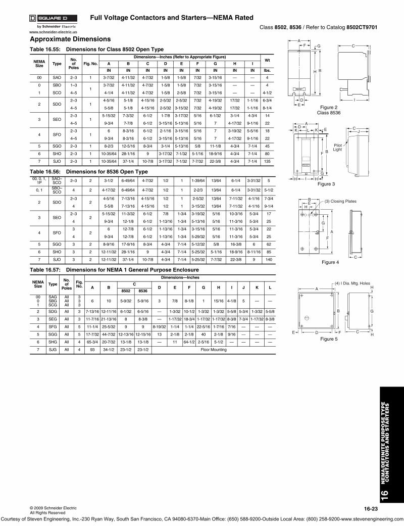
www.schneider-electric.us
16N
EM
A/D
EF
INIT
E P
UR
PO
SE
TY
PE
C
ON
TA
CT
OR
S A
ND
ST
AR
TE
RS
© 2009 Schneider ElectricAll Rights Reserved
16-23
Full Voltage Contactors and Starters—NEMA RatedClass 8502, 8536 / Refer to Catalog 8502CT9701
Approximate Dimensions
Table 16.55: Dimensions for Class 8502 Open Type
NEMASize Type
No. of
PolesFig. No.
Dimensions—Inches (Refer to Appropriate Figure)Wt
A B C D E F G H I
IN IN IN IN IN IN IN IN IN lbs.
00 SAO 2–3 1 3-7/32 4-11/32 4-7/32 1-5/8 1-5/8 7/32 3-15/16 — — 4
0 SBO 1–31
3-7/32 4-11/32 4-7/32 1-5/8 1-5/8 7/32 3-15/16 — — 4
1 SCO 4–5 4-1/4 4-11/32 4-7/32 1-5/8 2-5/8 7/32 3-15/16 — — 4-1/2
2 SDO2–3
14-5/16 5-1/8 4-15/16 2-5/32 2-5/32 7/32 4-19/32 17/32 1-1/16 6-3/4
4–5 5-5/8 5-1/8 4-15/16 2-5/32 3-15/32 7/32 4-19/32 17/32 1-1/16 8-1/4
3 SEO2–3
15-15/32 7-3/32 6-1/2 1-7/8 3-17/32 5/16 6-1/32 3-1/4 4-3/4 14
4–5 9-3/4 7-7/8 6-1/2 3-15/16 5-13/16 5/16 7 4-17/32 9-1/16 22
4 SFO2–3
16 8-3/16 6-1/2 2-1/16 3-15/16 5/16 7 3-19/32 5-5/16 18
4–5 9-3/4 8-3/16 6-1/2 3-15/16 5-13/16 5/16 7 4-17/32 9-1/16 22
5 SGO 2–3 1 8-2/3 12-5/16 8-3/4 3-1/4 5-13/16 5/8 11-1/8 4-3/4 7-1/4 45
6 SHO 2–3 1 10-35/64 28-1/16 9 3-17/32 7-1/32 5-1/16 18-9/16 4-3/4 7-1/4 80
7 SJO 2–3 1 10-35/64 37-1/4 10-7/8 3-17/32 7-1/32 7-7/32 22-3/8 4-3/4 7-1/4 135
Table 16.56: Dimensions for 8536 Open Type00, 0, 1,
1PSAO–SCO 2–3 2 3-1/2 6-49/64 4-7/32 1/2 1 1-39/64 13/64 6-1/4 3-31/32 5
0, 1 SBO–SCO 4 2 4-17/32 6-49/64 4-7/32 1/2 1 2-2/3 13/64 6-1/4 3-31/32 5-1/2
2 SDO2–3
24-5/16 7-13/16 4-15/16 1/2 1 2-5/32 13/64 7-11/32 4-1/16 7-3/4
4 5-5/8 7-13/16 4-15/16 1/2 1 3-15/32 13/64 7-11/32 4-1/16 9-1/4
3 SEO2–3
25-15/32 11-3/32 6-1/2 7/8 1-3/4 3-19/32 5/16 10-3/16 5-3/4 17
4 9-3/4 12-1/8 6-1/2 1-13/16 1-3/4 5-13/16 5/16 11-3/16 5-3/4 25
4 SFO3
26 12-7/8 6-1/2 1-13/16 1-3/4 3-15/16 5/16 11-3/16 5-3/4 22
4 9-3/4 12-7/8 6-1/2 1-13/16 1-3/4 5-29/32 5/16 11-3/16 5-3/4 25
5 SGO 3 2 8-9/16 17-9/16 8-3/4 4-3/4 7-1/4 5-12/32 5/8 16-3/8 6 62
6 SHO 3 2 12-11/32 28-1/16 9 4-3/4 7-1/4 5-25/32 5-1/16 18-9/16 8-11/16 85
7 SJO 3 2 12-11/32 37-1/4 10-7/8 4-3/4 7-1/4 5-25/32 7-7/32 22-3/8 9 140
Table 16.57: Dimensions for NEMA 1 General Purpose Enclosure
NEMASize Type
No.of
Poles
Fig.No.
Dimensions—Inches
A BC
D E F G H I J K L8502 8536
0001
SAGSBGSCG
AllAllAll
333
6 10 5-9/32 5-9/16 3 7/8 8-1/8 1 15/16 4-1/8 5 — —
2 SDG All 3 7-13/16 12-11/16 6-1/32 6-5/16 — 1-3/32 10-1/2 1-3/32 1-3/32 5-5/8 5-3/4 1-3/32 5-5/8
3 SEG All 3 11-7/16 21-13/16 8 8-3/8 — 1-17/32 18-3/4 1-17/32 1-17/32 8-3/8 7-3/4 1-17/32 8-3/8
4 SFG All 5 11-1/4 25-5/32 9 9 8-19/32 1-1/4 1-1/4 22-5/16 1-7/16 7/16 — — —
5 SGG All 5 17-7/32 44-7/32 12-13/16 12-15/16 13 2-1/8 2-1/8 40 2-1/8 9/16 — — —
6 SHG All 4 65-3/4 20-7/32 13-1/8 13-1/8 — 11 64-1/2 2-5/16 5-1/2 — — — —
7 SJG All 4 93 34-1/2 23-1/2 23-1/2 Floor Mounting
A
B
C
IH
E F
G
D
Figure 1Class 8502
A
B
C
ED
F G
H
I
RESET
Figure 2Class 8536
K KD
A
L E
F B
RESET
CJ
PilotLight
GHH I
Figure 3
H
BE (3) Closing Plates
G
A
F
CFigure 4
RESET
A(4) I Dia. Mtg. Holes
B
H
HCFDE
G
Figure 5
Courtesy of Steven Engineering, Inc.-230 Ryan Way, South San Francisco, CA 94080-6370-Main Office: (650) 588-9200-Outside Local Area: (800) 258-9200-www.stevenengineering.com
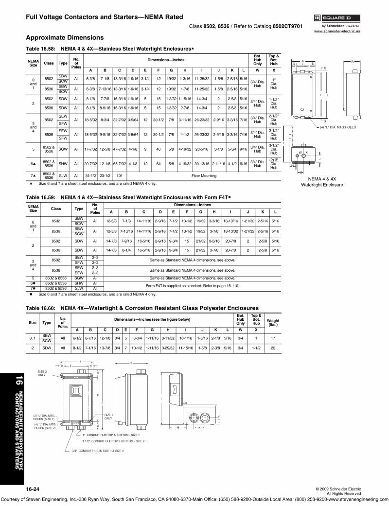
www.schneider-electric.us
16N
EM
A/D
EF
INIT
E P
UR
PO
SE
TY
PE
C
ON
TA
CT
OR
S A
ND
ST
AR
TE
RS
16-24 © 2009 Schneider ElectricAll Rights Reserved
Full Voltage Contactors and Starters—NEMA RatedClass 8502, 8536 / Refer to Catalog 8502CT9701
Approximate Dimensions
a Size 6 and 7 are sheet steel enclosures, and are rated NEMA 4 only.
b Size 6 and 7 are sheet steel enclosures, and are rated NEMA 4 only.
Table 16.58: NEMA 4 & 4X—Stainless Steel Watertight Enclosuresa
NEMASize Class Type
No.of
Poles
Dimensions—InchesBot.HubOnly
Top &Bot.Hub
A B C D E F G H I J K L W X
0and1
8502SBW
All 6-3/8 7-1/8 13-3/16 1-9/16 3-1/4 12 19/32 1-3/16 11-25/32 1-5/8 2-5/16 5/163/4'' Dia.
Hub
1''Dia.Hub
SCW
8536SBW
All 6-3/8 7-13/16 13-3/16 1-9/16 3-1/4 12 19/32 1-7/8 11-25/32 1-5/8 2-5/16 5/16SCW
28502 SDW All 8-1/8 7-7/8 16-3/16 1-9/16 5 15 1-3/32 1-15/16 14-3/4 2 2-5/8 5/16
3/4'' Dia.Hub
1-1/2''Dia.Hub8536 SDW All 8-1/8 8-9/16 16-3/16 1-9/16 5 15 1-3/32 2-7/8 14-3/4 2 2-5/8 5/16
3and4
8502SEW
All 18-5/32 8-3/4 32-7/32 3-5/64 12 30-1/2 7/8 3-11/16 26-23/32 2-9/16 3-3/16 7/16 3/4'' Dia.Hub
2-1/2''Dia.HubSFW
8536SEW
All 18-5/32 9-9/16 32-7/32 3-5/64 12 30-1/2 7/8 4-1/2 26-23/32 2-9/16 3-3/16 7/16 3/4" Dia.Hub
2-1/2"Dia.HubSFW
5 8502 & 8536 SGW All 17-7/32 12-5/8 47-7/32 4-1/8 9 46 5/8 4-19/32 28-5/16 3-1/8 5-3/4 9/16 3/4" Dia.
Hub
3-1/2"Dia.Hub
6a 8502 & 8536 SHW All 20-7/32 12-1/8 65-7/32 4-1/8 12 64 5/8 4-19/32 30-13/16 2-11/16 4-1/2 9/16 3/4" Dia.
Hub
(2) 3"Dia.Hub
7a 8502 & 8536 SJW All 34-1/2 23-1/2 101 Floor Mounting
Table 16.59: NEMA 4 & 4X—Stainless Steel Watertight Enclosures with Form F4Tb
NEMASize Class Type
No.of
Poles
Dimensions—Inches
A B C D E F G H I J K L
0and1
8502SBW
All 12-5/8 7-1/8 14-11/16 2-9/16 7-1/2 13-1/2 19/32 3-3/16 18-13/16 1-21/32 2-5/16 5/16SCW
8536SBW
All 12-5/8 7-13/16 14-11/16 2-9/16 7-1/2 13-1/2 19/32 3-7/8 18-13/32 1-21/32 2-5/16 5/16SCW
28502 SDW All 14-7/8 7-9/16 16-5/16 2-9/16 9-3/4 15 21/32 3-3/16 20-7/8 2 2-5/8 5/16
8536 SDW All 14-7/8 8-1/4 16-5/16 2-9/16 9-3/4 15 21/32 3-7/8 20-7/8 2 2-5/8 5/16
3and4
8502SEW 2–3
Same as Standard NEMA 4 dimensions, see above.SFW 2–3
8536SEW 2–3
Same as Standard NEMA 4 dimensions, see above.SFW 2–3
5 8502 & 8536 SGW All Same as Standard NEMA 4 dimensions, see above.6b 8502 & 8536 SHW All
Form F4T is supplied as standard. Refer to page 16-110.7b 8502 & 8536 SJW All
Table 16.60: NEMA 4X—Watertight & Corrosion Resistant Glass Polyester Enclosures
Size TypeNo.of
Poles
Dimensions—Inches (see the figure below)Bot.HubOnly
Top &Bot.Hub
Weight(lbs.)
A B C D E F G H I J K L W X
0, 1SBW
All 6-1/2 6-7/16 12-1/8 3/4 5 8-3/4 1-11/16 3-11/32 10-1/16 1-5/16 2-1/8 5/16 3/4 1 17SCW
2 SDW All 8-1/2 7-1/16 13-7/8 3/4 7 10-1/2 1-11/16 3-29/32 11-15/16 1-5/8 2-3/8 5/16 3/4 1-1/2 22
B
C
EA
(4) "L" DIA. MTG.HOLES
I
W X
H
DD
K
J
F
G
G
NEMA 4 & 4XWatertight Enclosure
RESET
AD E D
G
F
C
SIZE 2 ONLY
(2) "L" DIA. MTG. HOLES (SIZE 1)
(4) "L" DIA. MTG. HOLES (SIZE 2)
G
SIZE 2ONLY
1" CONDUIT HUB TOP & BOTTOM - SIZE 1 1 1/2" CONDUIT HUB TOP & BOTTOM - SIZE 2
B
3/4" CONDUIT HUB IN SIZE 1 & SIZE 2
H K
J
I
Courtesy of Steven Engineering, Inc.-230 Ryan Way, South San Francisco, CA 94080-6370-Main Office: (650) 588-9200-Outside Local Area: (800) 258-9200-www.stevenengineering.com
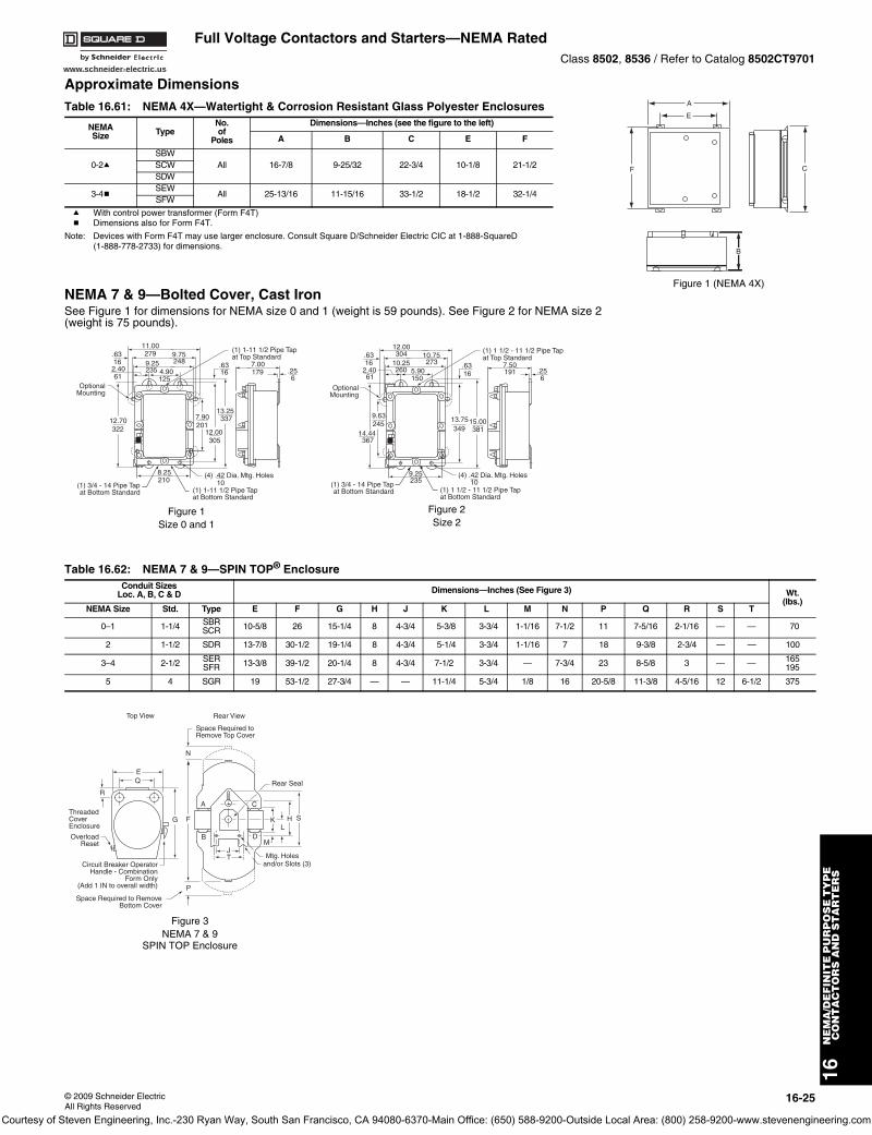
www.schneider-electric.us
16N
EM
A/D
EF
INIT
E P
UR
PO
SE
TY
PE
C
ON
TA
CT
OR
S A
ND
ST
AR
TE
RS
© 2009 Schneider ElectricAll Rights Reserved
16-25
Full Voltage Contactors and Starters—NEMA RatedClass 8502, 8536 / Refer to Catalog 8502CT9701
Approximate Dimensions
a With control power transformer (Form F4T)b Dimensions also for Form F4T.
Note: Devices with Form F4T may use larger enclosure. Consult Square D/Schneider Electric CIC at 1-888-SquareD(1-888-778-2733) for dimensions.
NEMA 7 & 9—Bolted Cover, Cast IronSee Figure 1 for dimensions for NEMA size 0 and 1 (weight is 59 pounds). See Figure 2 for NEMA size 2 (weight is 75 pounds).
Table 16.61: NEMA 4X—Watertight & Corrosion Resistant Glass Polyester Enclosures
NEMASize Type
No.of
Poles
Dimensions—Inches (see the figure to the left)
A B C E F
0-2aSBW
All 16-7/8 9-25/32 22-3/4 10-1/8 21-1/2SCWSDW
3-4bSEW
All 25-13/16 11-15/16 33-1/2 18-1/2 32-1/4SFW
Table 16.62: NEMA 7 & 9—SPIN TOP® Enclosure Conduit Sizes
Loc. A, B, C & D Dimensions—Inches (See Figure 3) Wt.(lbs.)
NEMA Size Std. Type E F G H J K L M N P Q R S T
0–1 1-1/4 SBRSCR 10-5/8 26 15-1/4 8 4-3/4 5-3/8 3-3/4 1-1/16 7-1/2 11 7-5/16 2-1/16 — — 70
2 1-1/2 SDR 13-7/8 30-1/2 19-1/4 8 4-3/4 5-1/4 3-3/4 1-1/16 7 18 9-3/8 2-3/4 — — 100
3–4 2-1/2 SERSFR 13-3/8 39-1/2 20-1/4 8 4-3/4 7-1/2 3-3/4 — 7-3/4 23 8-5/8 3 — — 165
195
5 4 SGR 19 53-1/2 27-3/4 — — 11-1/4 5-3/4 1/8 16 20-5/8 11-3/8 4-5/16 12 6-1/2 375
A
E
F C
B
Figure 1 (NEMA 4X)
(4) .42 Dia. Mtg. Holes
.6316
11.00279 9.75
2489.252352.40
614.90125
.6316
OptionalMounting
(1) 1-11 1/2 Pipe Tapat Top Standard
(1) 1-11 1/2 Pipe Tapat Bottom Standard
(1) 3/4 - 14 Pipe Tapat Bottom Standard
12.00305
7.90201
13.25337
10
8.25210
12.70322
7.00.256
179
Figure 1Size 0 and 1
(4) .42 Dia. Mtg. Holes
.6316
12.00304 10.75
27310.252602.40
615.90150
.6316
OptionalMounting
(1) 1 1/2 - 11 1/2 Pipe Tapat Top Standard
(1) 1 1/2 - 11 1/2 Pipe Tapat Bottom Standard
(1) 3/4 - 14 Pipe Tapat Bottom Standard
13.75349
15.00381
109.25235
14.44367
9.63245
7.50.256
191
Figure 2Size 2
N
A
B D
C
J
P
F
M
K H
Mtg. Holesand/or Slots (3)
Rear View
Space Required to RemoveBottom Cover
Space Required toRemove Top Cover
OverloadReset
ThreadedCoverEnclosure
EQ
R
G
Top View
T
L
Rear Seal
S
Circuit Breaker OperatorHandle - Combination
Form Only(Add 1 IN to overall width)
Figure 3NEMA 7 & 9
SPIN TOP Enclosure
Courtesy of Steven Engineering, Inc.-230 Ryan Way, South San Francisco, CA 94080-6370-Main Office: (650) 588-9200-Outside Local Area: (800) 258-9200-www.stevenengineering.com
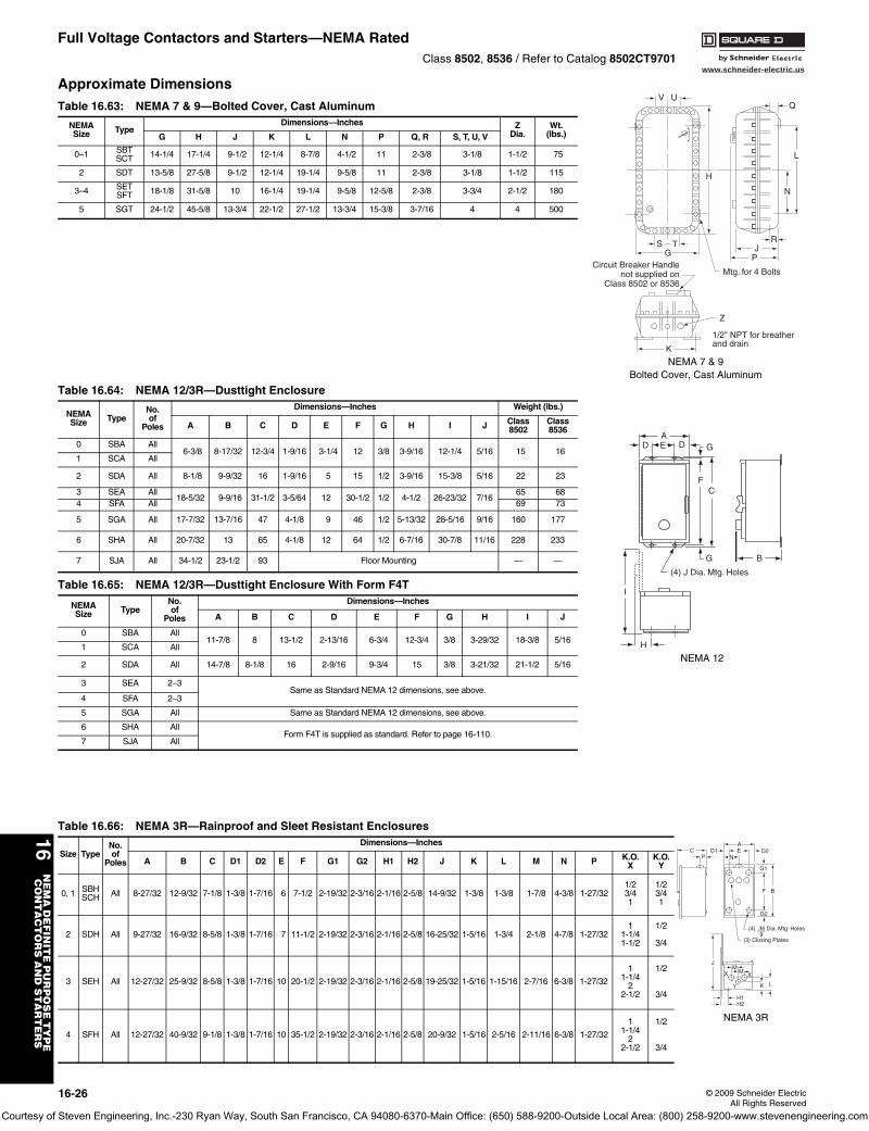
www.schneider-electric.us
16N
EM
A D
EF
INIT
E P
UR
PO
SE
TY
PE
C
ON
TA
CT
OR
S A
ND
ST
AR
TE
RS
16-26 © 2009 Schneider ElectricAll Rights Reserved
Full Voltage Contactors and Starters—NEMA RatedClass 8502, 8536 / Refer to Catalog 8502CT9701
Approximate Dimensions
Table 16.63: NEMA 7 & 9—Bolted Cover, Cast Aluminum
NEMASize Type
Dimensions—Inches ZDia.
Wt.(lbs.)G H J K L N P Q, R S, T, U, V
0–1 SBTSCT 14-1/4 17-1/4 9-1/2 12-1/4 8-7/8 4-1/2 11 2-3/8 3-1/8 1-1/2 75
2 SDT 13-5/8 27-5/8 9-1/2 12-1/4 19-1/4 9-5/8 11 2-3/8 3-1/8 1-1/2 115
3–4 SETSFT 18-1/8 31-5/8 10 16-1/4 19-1/4 9-5/8 12-5/8 2-3/8 3-3/4 2-1/2 180
5 SGT 24-1/2 45-5/8 13-3/4 22-1/2 27-1/2 13-3/4 15-3/8 3-7/16 4 4 500
Table 16.64: NEMA 12/3R—Dusttight Enclosure
NEMASize Type
No.of
Poles
Dimensions—Inches Weight (lbs.)
A B C D E F G H I J Class8502
Class8536
0 SBA All6-3/8 8-17/32 12-3/4 1-9/16 3-1/4 12 3/8 3-9/16 12-1/4 5/16 15 16
1 SCA All
2 SDA All 8-1/8 9-9/32 16 1-9/16 5 15 1/2 3-9/16 15-3/8 5/16 22 23
3 SEA All18-5/32 9-9/16 31-1/2 3-5/64 12 30-1/2 1/2 4-1/2 26-23/32 7/16
65 684 SFA All 69 73
5 SGA All 17-7/32 13-7/16 47 4-1/8 9 46 1/2 5-13/32 28-5/16 9/16 160 177
6 SHA All 20-7/32 13 65 4-1/8 12 64 1/2 6-7/16 30-7/8 11/16 228 233
7 SJA All 34-1/2 23-1/2 93 Floor Mounting — —
Table 16.65: NEMA 12/3R—Dusttight Enclosure With Form F4T
NEMASize Type
No.of
Poles
Dimensions—Inches
A B C D E F G H I J
0 SBA All11-7/8 8 13-1/2 2-13/16 6-3/4 12-3/4 3/8 3-29/32 18-3/8 5/16
1 SCA All
2 SDA All 14-7/8 8-1/8 16 2-9/16 9-3/4 15 3/8 3-21/32 21-1/2 5/16
3 SEA 2–3Same as Standard NEMA 12 dimensions, see above.
4 SFA 2–3
5 SGA All Same as Standard NEMA 12 dimensions, see above.
6 SHA AllForm F4T is supplied as standard. Refer to page 16-110.
7 SJA All
Table 16.66: NEMA 3R—Rainproof and Sleet Resistant Enclosures
Size TypeNo.of
Poles
Dimensions—Inches
A B C D1 D2 E F G1 G2 H1 H2 J K L M N P K.O.X
K.O.Y
0, 1 SBHSCH All 8-27/32 12-9/32 7-1/8 1-3/8 1-7/16 6 7-1/2 2-19/32 2-3/16 2-1/16 2-5/8 14-9/32 1-3/8 1-3/8 1-7/8 4-3/8 1-27/32
1/23/41
1/23/41
2 SDH All 9-27/32 16-9/32 8-5/8 1-3/8 1-7/16 7 11-1/2 2-19/32 2-3/16 2-1/16 2-5/8 16-25/32 1-5/16 1-3/4 2-1/8 4-7/8 1-27/321
1-1/41-1/2
1/2
3/4
3 SEH All 12-27/32 25-9/32 8-5/8 1-3/8 1-7/16 10 20-1/2 2-19/32 2-3/16 2-1/16 2-5/8 19-25/32 1-5/16 1-15/16 2-7/16 6-3/8 1-27/32
11-1/4
22-1/2
1/2
3/4
4 SFH All 12-27/32 40-9/32 9-1/8 1-3/8 1-7/16 10 35-1/2 2-19/32 2-3/16 2-1/16 2-5/8 20-9/32 1-5/16 2-5/16 2-11/16 6-3/8 1-27/32
11-1/4
22-1/2
1/2
3/4
S TG
K
V U
H
Mtg. for 4 Bolts
J
Z
P
N
L
1/2" NPT for breatherand drain
R
Q
Circuit Breaker Handlenot supplied on
Class 8502 or 8536
NEMA 7 & 9Bolted Cover, Cast Aluminum
DAE G
F
BG
D
(4) J Dia. Mtg. Holes
I
H
C
NEMA 12
AD1 E D2
N
G1
F B
G2
(4) .36 Dia. Mtg. Holes9
(3) Closing Plates
CP
J
X XM
M
Y K L
H1H2
NEMA 3R
Courtesy of Steven Engineering, Inc.-230 Ryan Way, South San Francisco, CA 94080-6370-Main Office: (650) 588-9200-Outside Local Area: (800) 258-9200-www.stevenengineering.com
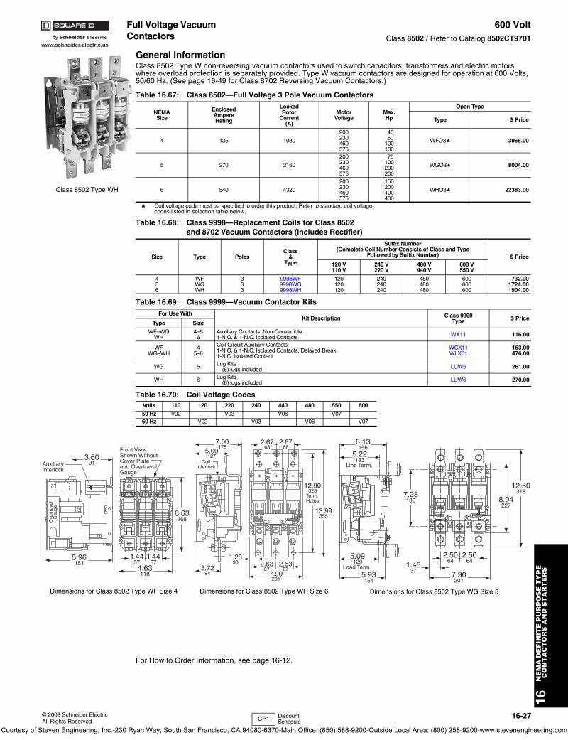
www.schneider-electric.us
16N
EM
A D
EF
INIT
E P
UR
PO
SE
TY
PE
C
ON
TA
CT
OR
S A
ND
ST
AR
TE
RS
© 2009 Schneider ElectricAll Rights Reserved
16-27
Full Voltage Vacuum Contactors
600 VoltClass 8502 / Refer to Catalog 8502CT9701
General InformationClass 8502 Type W non-reversing vacuum contactors used to switch capacitors, transformers and electric motors where overload protection is separately provided. Type W vacuum contactors are designed for operation at 600 Volts, 50/60 Hz. (See page 16-49 for Class 8702 Reversing Vacuum Contactors.)
a Coil voltage code must be specified to order this product. Refer to standard coil voltage codes listed in selection table below.
For How to Order Information, see page 16-12.
Table 16.67: Class 8502—Full Voltage 3 Pole Vacuum Contactors
NEMASize
EnclosedAmpereRating
LockedRotor
Current(A)
MotorVoltage
Max.Hp
Open Type
Type $ Price
4 135 1080
200230460575
4050
100100
WFO3a 3965.00
5 270 2160
200230460575
75100200200
WGO3a 8004.00
6 540 4320
200230460575
150200400400
WHO3a 22383.00
Table 16.68: Class 9998—Replacement Coils for Class 8502and 8702 Vacuum Contactors (Includes Rectifier)
Size Type PolesClass
&Type
Suffix Number(Complete Coil Number Consists of Class and Type
Followed by Suffix Number) $ Price120 V110 V
240 V220 V
480 V440 V
600 V550 V
456
WFWGWH
333
9998WF9998WG9998WH
120120120
240240240
480480480
600600600
732.001724.001904.00
Table 16.69: Class 9999—Vacuum Contactor KitsFor Use With
Kit Description Class 9999Type $ Price
Type Size
WF–WGWH
4–56
Auxiliary Contacts, Non-Convertible1-N.O. & 1-N.C. Isolated Contacts WX11 116.00
WFWG–WH
45–6
Coil Circuit Auxiliary Contacts1-N.O. & 1-N.C. Isolated Contacts, Delayed Break1-N.C. Isolated Contact
WCX11WLX01
153.00476.00
WG 5 Lug Kits(6) lugs included LUW5 261.00
WH 6 Lug Kits(6) lugs included LUW6 270.00
Table 16.70: Coil Voltage CodesVolts 110 120 220 240 440 480 550 600
50 Hz V02 V03 V06 V0760 Hz V02 V03 V06 V07
Class 8502 Type WH
6.13156
5.22133
Line Term.
5.93151
5.09129
Load Term. 1.4537
7.28185 8.94
227
7.90201
2.5064
2.5064
12.50318
Dimensions for Class 8502 Type WG Size 5
3.7294
7.00178
5.00127
7.90201
2.6367
2.6367
2.6768
2.6768
12.90328
Term.Holes
13.99355
1.2833
CoilInterlock
Dimensions for Class 8502 Type WH Size 6
4.63118
6.63168
3.6091
1.4437
1.4437
5.96151
Front ViewShown WithoutCover Plateand OvertravelGauge
AuxiliaryInterlock
Ove
rtra
vel
Gau
ge
Dimensions for Class 8502 Type WF Size 4
CP1 Discount Schedule
Courtesy of Steven Engineering, Inc.-230 Ryan Way, South San Francisco, CA 94080-6370-Main Office: (650) 588-9200-Outside Local Area: (800) 258-9200-www.stevenengineering.com
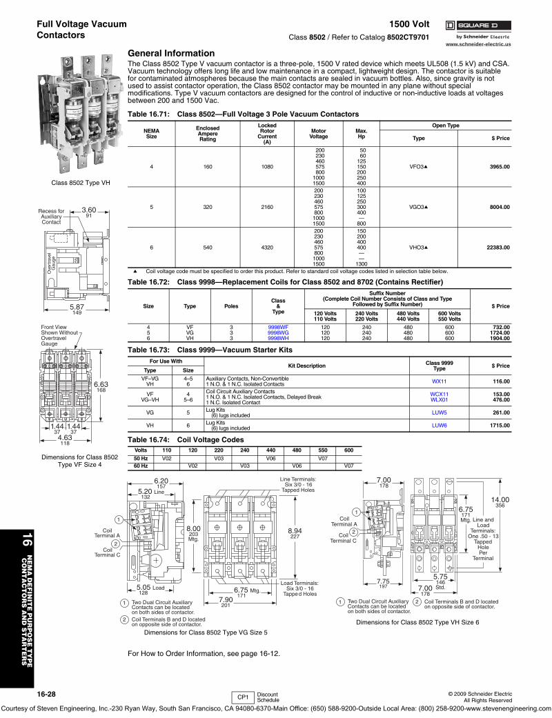
16-28 © 2009 Schneider ElectricAll Rights Reserved
www.schneider-electric.us
16N
EM
A D
EF
INIT
E P
UR
PO
SE
TY
PE
C
ON
TA
CT
OR
S A
ND
ST
AR
TE
RS
Full Voltage Vacuum Contactors
1500 VoltClass 8502 / Refer to Catalog 8502CT9701
General InformationThe Class 8502 Type V vacuum contactor is a three-pole, 1500 V rated device which meets UL508 (1.5 kV) and CSA. Vacuum technology offers long life and low maintenance in a compact, lightweight design. The contactor is suitable for contaminated atmospheres because the main contacts are sealed in vacuum bottles. Also, since gravity is not used to assist contactor operation, the Class 8502 contactor may be mounted in any plane without special modifications. Type V vacuum contactors are designed for the control of inductive or non-inductive loads at voltages between 200 and 1500 Vac.
a Coil voltage code must be specified to order this product. Refer to standard coil voltage codes listed in selection table below.
For How to Order Information, see page 16-12.
Table 16.71: Class 8502—Full Voltage 3 Pole Vacuum Contactors
NEMASize
EnclosedAmpereRating
LockedRotor
Current(A)
MotorVoltage
Max.Hp
Open Type
Type $ Price
4 160 1080
200 50
VFO3a 3965.00
230 60460 125575 150800 200
1000 2501500 400
5 320 2160
200 100
VGO3a 8004.00
230 125460 250575 300800 4001000 —1500 800
6 540 4320
200 150
VHO3a 22383.00
230 200460 400575 400800 —1000 —1500 1300
Table 16.72: Class 9998—Replacement Coils for Class 8502 and 8702 (Contains Rectifier)
Size Type PolesClass
&Type
Suffix Number(Complete Coil Number Consists of Class and Type
Followed by Suffix Number) $ Price120 Volts110 Volts
240 Volts220 Volts
480 Volts440 Volts
600 Volts550 Volts
456
VFVGVH
333
9998WF9998WG9998WH
120120120
240240240
480480480
600600600
732.001724.001904.00
Table 16.73: Class 9999—Vacuum Starter Kits For Use With
Kit Description Class 9999Type $ Price
Type Size
VF–VGVH
4–56
Auxiliary Contacts, Non-Convertible1 N.O. & 1 N.C. Isolated Contacts WX11 116.00
VFVG–VH
45–6
Coil Circuit Auxiliary Contacts1 N.O. & 1 N.C. Isolated Contacts, Delayed Break1 N.C. Isolated Contact
WCX11WLX01
153.00476.00
VG 5 Lug Kits(6) lugs included LUW5 261.00
VH 6 Lug Kits(6) lugs included LUW6 1715.00
Table 16.74: Coil Voltage CodesVolts 110 120 220 240 440 480 550 600
50 Hz V02 V03 V06 V0760 Hz V02 V03 V06 V07
Class 8502 Type VH
3.6091
5.87149
Recess forAuxiliaryContact
Ove
rtra
vel
Gau
ge
4.63118
6.63168
1.4437
1.4437
Front ViewShown WithoutOvertravelGauge
Dimensions for Class 8502 Type VF Size 4
7.75197
7.00178
7.00178
5.75146Std.
6.75171Mtg.
14.00356
Line andLoad
Terminals:One .50 - 13
TappedHolePer
Terminal
1
2
1 2
CoilTerminal A
CoilTerminal C
Two Dual Circuit AuxiliaryContacts can be locatedon both sides of contactor.
Coil Terminals B and D locatedon opposite side of contactor.
Dimensions for Class 8502 Type VH Size 6
8.94227
8.00203Mtg.
6.75 Mtg. 171
6.20157
5.20 Line 132
5.05 Load 128
7.90201
Line Terminals:Six 3/0 - 16
Tapped Holes
Load Terminals:Six 3/0 - 16
Tapped Holes
1
1
2
2
CoilTerminal A
CoilTerminal C
Two Dual Circuit AuxiliaryContacts can be locatedon both sides of contactor.Coil Terminals B and D locatedon opposite side of contactor.
Dimensions for Class 8502 Type VG Size 5
CP1 Discount Schedule
Courtesy of Steven Engineering, Inc.-230 Ryan Way, South San Francisco, CA 94080-6370-Main Office: (650) 588-9200-Outside Local Area: (800) 258-9200-www.stevenengineering.com
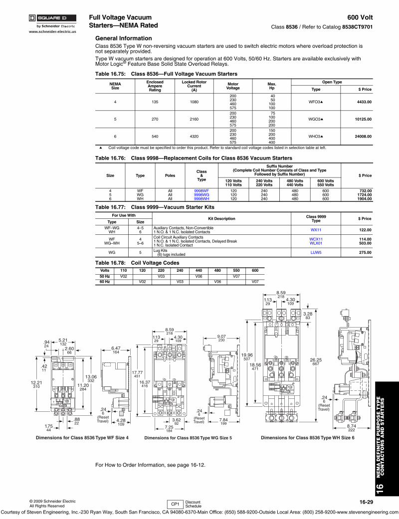
www.schneider-electric.us
16N
EM
A D
EF
INIT
E P
UR
PO
SE
TY
PE
C
ON
TA
CT
OR
S A
ND
ST
AR
TE
RS
© 2009 Schneider ElectricAll Rights Reserved
16-29
Full Voltage Vacuum Starters—NEMA Rated
600 VoltClass 8536 / Refer to Catalog 8538CT9701
General InformationClass 8536 Type W non-reversing vacuum starters are used to switch electric motors where overload protection is not separately provided. Type W vacuum starters are designed for operation at 600 Volts, 50/60 Hz. Starters are available exclusively with Motor Logic® Feature Base Solid State Overload Relays.
a Coil voltage code must be specified to order this product. Refer to standard coil voltage codes listed in selection table at left.
For How to Order Information, see page 16-12.
Table 16.75: Class 8536—Full Voltage Vacuum Starters
NEMASize
EnclosedAmpereRating
Locked RotorCurrent
(A)
MotorVoltage
Max.Hp
Open Type
Type $ Price
4 135 1080
200230460575
4050
100100
WFO3a 4433.00
5 270 2160
200230460575
75100200200
WGO3a 10125.00
6 540 4320
200230460575
150200400400
WHO3a 24008.00
Table 16.76: Class 9998—Replacement Coils for Class 8536 Vacuum Starters
Size Type PolesClass
&Type
Suffix Number(Complete Coil Number Consists of Class and Type
Followed by Suffix Number) $ Price120 Volts110 Volts
240 Volts220 Volts
480 Volts440 Volts
600 Volts550 Volts
456
WFWGWH
AllAllAll
9998WF9998WG9998WH
120120120
240240240
480480480
600600600
732.001724.001904.00
Table 16.77: Class 9999—Vacuum Starter KitsFor Use With
Kit Description Class 9999Type $ Price
Type Size
WF–WGWH
4–56
Auxiliary Contacts, Non-Convertible1 N.O. & 1 N.C. Isolated Contacts WX11 122.00
WFWG–WH
45–6
Coil Circuit Auxiliary Contacts1 N.O. & 1 N.C. Isolated Contacts, Delayed Break1 N.C. Isolated Contact
WCX11WLX01
114.00503.00
WG 5 Lug Kits(6) lugs included LUW5 275.00
Table 16.78: Coil Voltage CodesVolts 110 120 220 240 440 480 550 600
50 Hz V02 V03 V06 V0760 Hz V02 V03 V06 V07
11.20284
12.21310
.8822
1.7544
13.06332
2.6066
6.47164
4.28109
.246
(ResetTravel)
.9424
.4211
5.21132
Reset
Dimensions for Class 8536 Type WF Size 4
16.37416
17.77451
3.6292
7.25184
4.30109
9.07230
7.84199
.246
(ResetTravel)
1.1329
8.59218
Dimensions for Class 8536 Type WG Size 5
Reset
26.25667
3.2883
18.56471
4.30109
1.1329
8.74222
.246
(ResetTravel)
8.59218
Dimensions for Class 8536 Type WH Size 6
19.96507
CP1 Discount Schedule
Courtesy of Steven Engineering, Inc.-230 Ryan Way, South San Francisco, CA 94080-6370-Main Office: (650) 588-9200-Outside Local Area: (800) 258-9200-www.stevenengineering.com
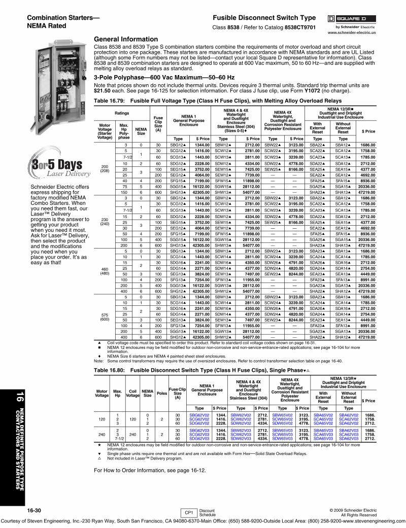
16-30 © 2009 Schneider ElectricAll Rights Reserved
www.schneider-electric.us
16N
EM
A D
EF
INIT
E P
UR
PO
SE
TY
PE
C
ON
TA
CT
OR
S A
ND
ST
AR
TE
RS
Combination Starters—NEMA Rated
Fusible Disconnect Switch TypeClass 8538 / Refer to Catalog 8538CT9701
General InformationClass 8538 and 8539 Type S combination starters combine the requirements of motor overload and short circuit protection into one package. These starters are manufactured in accordance with NEMA standards and are UL Listed (although some Form numbers may not be listed—contact your local Square D representative for information). Class 8538 and 8539 combination starters are designed to operate at 600 Vac maximum, 50 to 60 Hz—and are supplied with melting alloy overload relays as standard.
3-Pole Polyphase—600 Vac Maximum—50–60 HzNote that prices shown do not include thermal units. Devices require 3 thermal units. Standard trip thermal units are $21.50 each. See page 16-125 for selection information. For class J fuse clip, use Form Y1072 (no charge).
a Coil voltage code must be specified to order this product. Refer to standard coil voltage codes shown on page 16-31.b NEMA 12 enclosures may be field modified for outdoor non-corrosive and non-service-entrance-rated applications; see page 16-104 for more
information.c NEMA Size 6 starters are NEMA 4 painted sheet steel enclosures.
Note: Some control transformers may require the use of oversized enclosures. Refer to control transformer selection table on page 16-40.
d NEMA 12 enclosures may be field modified for outdoor non-corrosive and non-service-entrance-rated applications; see page 16-104 for more information.
e Single phase units require one thermal unit and are not available with Form Hxx—Solid State Overload Relays.f Not included in Laser™ Delivery program.
For How to Order Information, see page 16-12.
Table 16.79: Fusible Full Voltage Type (Class H Fuse Clips), with Melting Alloy Overload Relays
RatingsFuseClipSize(A)
NEMA 1General Purpose
Enclosure
NEMA 4 & 4XWatertight
and DusttightEnclosure
Stainless Steel (304)(Sizes 0-5)c
NEMA 4XWatertight,
Dusttight andCorrosion ResistantPolyester Enclosure
NEMA 12/3RbDusttight and Driptight
Industrial Use Enclosure
MotorVoltage(StarterVoltage)
Max.Hp
Poly-phase
NEMASize
WithExternal
Reset
WithoutExternal
Reset $ Price
Type $ Price Type $ Price Type $ Price Type Type
200(208)
3 0 30 SBG12a 1344.00 SBW12a 2712.00 SBW22a 3123.00 SBA22a SBA12a 1686.005
130 SCG12a 1416.00 SCW12a 2781.00 SCW22a 3195.00 SCA22a SCA12a 1758.00
7-1/2 60 SCG13a 1443.00 SCW13a 2811.00 SCW23a 3239.00 SCA23a SCA13a 1785.00
10 2 60 SDG12a 2228.00 SDW12a 4334.00 SDW22a 4778.00 SDA22a SDA12a 2712.0020
3100 SEG15a 3752.00 SEW15a 7425.00 SEW25a 8166.00 SEA25a SEA15a 4377.00
25 200 SEG12a 4064.00 SEW12a 7739.00 — — SEA22a SEA12a 4692.0040 4 200 SFG15a 7199.00 SFW15a 11898.00 — — SFA25a SFA15a 8936.0075 5 400 SGG15a 16122.00 SGW15a 28112.00 — — SGA25a SGA15a 20336.00
150 6 600 SHG13a 42305.00 SHW13a 54077.00 — — SHA23a SHA13a 47219.00
230(240)
3 0 30 SBG12a 1344.00 SBW12a 2712.00 SBW22a 3123.00 SBA22a SBA12a 1686.005
130 SCG12a 1416.00 SCW12a 2781.00 SCW22a 3195.00 SCA22a SCA12a 1758.00
7-1/2 60 SCG13a 1443.00 SCW13a 2811.00 SCW23a 3239.00 SCA23a SCA13a 1785.00
15 2 60 SDG12a 2228.00 SDW12a 4334.00 SDW22a 4778.00 SDA22a SDA12a 2712.0025
3100 SEG15a 3752.00 SEW15a 7425.00 SEW25a 8166.00 SEA25a SEA15a 4377.00
30 200 SEG12a 4064.00 SEW12a 7739.00 — — SEA22a SEA12a 4692.0050 4 200 SFG15a 7199.00 SFW15a 11898.00 — — SFA25a SFA15a 8936.00
100 5 400 SGG15a 16122.00 SGW15a 28112.00 — — SGA25a SGA15a 20336.00200 6 600 SHG13a 42305.00 SHW13a 54077.00 — — SHA23a SHA13a 47219.00
460(480)
5 0 30 SBG13a 1344.00 SBW13a 2712.00 SBW23a 3123.00 SBA23a SBA13a 1686.0010 1 30 SCG14a 1443.00 SCW14a 2811.00 SCW24a 3239.00 SCA24a SCA14a 1785.0015
230 SDG16a 2241.00 SDW16a 4350.00 SDW26a 4791.00 SDA26a SDA16a 2712.00
25 60 SDG14a 2271.00 SDW14a 4377.00 SDW24a 4820.00 SDA24a SDA14a 2754.0050 3 100 SEG13a 3824.00 SEW13a 7497.00 SEW23a 8244.00 SEA23a SEA13a 4449.00
100 4 200 SFG13a 7254.00 SFW13a 11955.00 — — SFA23a SFA13a 8991.00200 5 400 SGG13a 16122.00 SGW13a 28112.00 — — SGA23a SGA13a 20336.00400 6 600 SHG12a 42305.00 SHW12a 54077.00 — — SHA22a SHA12a 47219.00
575(600)
5 0 30 SBG13a 1344.00 SBW13a 2712.00 SBW23a 3123.00 SBA23a SBA13a 1686.0010 1 30 SCG14a 1443.00 SCW14a 2811.00 SCW24a 3239.00 SCA24a SCA14a 1785.0015
230 SDG16a 2241.00 SDW16a 4350.00 SDW26a 4791.00 SDA26a SDA16a 2712.00
25 60 SDG14a 2271.00 SDW14a 4377.00 SDW24a 4820.00 SDA24a SDA14a 2754.0050 3 100 SEG13a 3824.00 SEW13a 7497.00 SEW23a 8244.00 SEA23a SEA13a 4449.00
100 4 200 SFG13a 7254.00 SFW13a 11955.00 — — SFA23a SFA13a 8991.00200 5 400 SGG13a 16122.00 SGW13a 28112.00 — — SGA23a SGA13a 20336.00400 6 600 SHG12a 42305.00 SHW12a 54077.00 — — SHA22a SHA12a 47219.00
Table 16.80: Fusible Disconnect Switch Type (Class H Fuse Clips), Single Phaseef
MotorVoltage
Max.Hp
CoilVoltage
NEMASize Poles
Fuse Clip Size(A)
NEMA 1General Purpose
Enclosure
NEMA 4 & 4XWatertight
and DusttightEnclosure
Stainless Steel (304)
NEMA 4XWatertight,
Dusttight and Corrosion Resistant
Polyester Enclosure
NEMA 12/3RdDusttight and Driptight
Industrial Use Enclosure
WithExternal
Reset
WithoutExternal
Reset $ Price
Type $ Price Type $ Price Type $ Price Type Type
120123
120012
2303060
SBG62V02SCG62V02SDG62V02
1344.1416.2228.
SBW62V02SCW62V02SDW62V02
2712.2781.4334.
SBW65V02SCW65V02SDW65V02
3123.3195.4778.
SBA65V02SCA65V02SDA65V02
SBA62V02SCA62V02SDA62V02
1686.1758.2712.
24023
7-1/2240
012
2303060
SBG62V03SCG62V03SDG62V03
1344.1416.2228.
SBW62V03SCW62V03SDW62V03
2712.2781.4334.
SBW65V03SCW65V03SDW65V03
3123.3195.4778.
SBA65V03SCA65V03SDA65V03
SBA62V03SCA62V03SDA62V03
1686.1758.2712.
Schneider Electric offers express shipping for factory modified NEMA Combo Starters. When you need them fast, our Laser™ Delivery program is the answer to getting your product when you need it most. Ask for Laser™ Delivery, then select the product and the modifications you need when you place your order. It’s as easy as that!
CP1 Discount Schedule
Courtesy of Steven Engineering, Inc.-230 Ryan Way, South San Francisco, CA 94080-6370-Main Office: (650) 588-9200-Outside Local Area: (800) 258-9200-www.stevenengineering.com
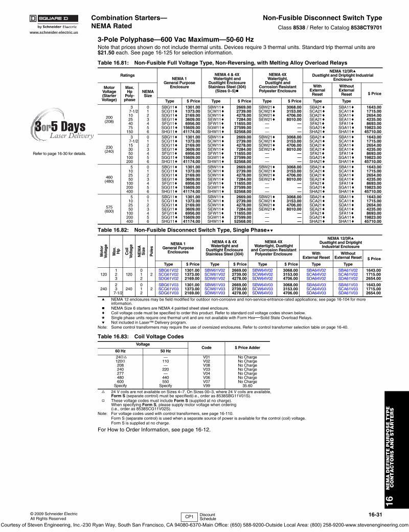
www.schneider-electric.us
16N
EM
A D
EF
INIT
E P
UR
PO
SE
TY
PE
C
ON
TA
CT
OR
S A
ND
ST
AR
TE
RS
© 2009 Schneider ElectricAll Rights Reserved
16-31
Combination Starters—NEMA Rated
Non-Fusible Disconnect Switch TypeClass 8538 / Refer to Catalog 8538CT9701
3-Pole Polyphase—600 Vac Maximum—50-60 HzNote that prices shown do not include thermal units. Devices require 3 thermal units. Standard trip thermal units are $21.50 each. See page 16-125 for selection information.
a NEMA 12 enclosures may be field modified for outdoor non-corrosive and non-service-entrance-rated applications; see page 16-104 for more information.
b NEMA Size 6 starters are NEMA 4 painted sheet steel enclosure.c Coil voltage code must be specified to order this product. Refer to standard coil voltage codes shown below.d Single phase units require one thermal unit and are not available with Form Hxx—Solid State Overload Relays.e Not included in Laser™ Delivery program.
Note: Some control transformers may require the use of oversized enclosures. Refer to control transformer selection table on page 16-40.
f 24 V coils are not available on Sizes 4–7. On Sizes 00–3, where 24 V coils are available, Form S (separate control) must be specified(i.e., order as 8538SBG11V01S).
g These voltage codes must include Form S (supplied at no charge). When specifying Form S, please supply motor voltage when ordering (i.e., order as 8538SCG11V02S).
Note: For voltage codes used with control transformers, see page 16-110.Form S (separate control) is used when a separate source of power is available for the control (coil) voltage. Form S is supplied at no charge.
For How to Order Information, see page 16-12.
Table 16.81: Non-Fusible Full Voltage Type, Non-Reversing, with Melting Alloy Overload Relays
RatingsNEMA 1
General PurposeEnclosure
NEMA 4 & 4XWatertight and
Dusttight EnclosureStainless Steel (304)
(Sizes 0–5)b
NEMA 4XWatertight,
Dusttight andCorrosion ResistantPolyester Enclosure
NEMA 12/3Ra Dusttight and Driptight Industrial
Enclosure
MotorVoltage(StarterVoltage)
Max.Hp
Poly-phase
NEMASize
WithExternal
Reset
WithoutExternal
Reset $ Price
Type $ Price Type $ Price Type $ Price Type Type
200(208)
37-1/210254075
150
0123456
SBG11cSCG11cSDG11cSEG11cSFG11cSGG11cSHG11c
1301.001373.002169.003609.006956.00
15609.0041174.00
SBW11cSCW11cSDW11cSEW11cSFW11cSGW11cSHW11c
2669.002739.004278.007284.00
11655.0027599.0052568.00
SBW21cSCW21cSDW21cSEW21c
———
3068.003153.004706.008010.00
———
SBA21cSCA21cSDA21cSEA21cSFA21cSGA21cSHA21c
SBA11cSCA11cSDA11cSEA11cSFA11cSGA11cSHA11c
1643.001715.002654.004235.008693.00
19823.0045710.00
230(240)
37-1/2153050
100200
0123456
SBG11cSCG11cSDG11cSEG11cSFG11cSGG11cSHG11c
1301.001373.002169.003609.006956.00
15609.0041174.00
SBW11cSCW11cSDW11cSEW11cSFW11cSGW11cSHW11c
2669.002739.004278.007284.00
11655.0027599.0052568.00
SBW21cSCW21cSDW21cSEW21c
———
3068.003153.004706.008010.00
———
SBA21cSCA21cSDA21cSEA21cSFA21cSGA21cSHA21c
SBA11cSCA11cSDA11cSEA11cSFA11cSGA11cSHA11c
1643.001715.002654.004235.008693.00
19823.0045710.00
460(480)
5102550
100200400
0123456
SBG11cSCG11cSDG11cSEG11cSFG11cSGG11cSHG11c
1301.001373.002169.003609.006956.00
15609.0041174.00
SBW11cSCW11cSDW11cSEW11cSFW11cSGW11cSHW11c
2669.002739.004278.007284.00
11655.0027599.0052568.00
SBW21cSCW21cSDW21cSEW21c
———
3068.003153.004706.008010.00
———
SBA21cSCA21cSDA21cSEA21cSFA21cSGA21cSHA21c
SBA11cSCA11cSDA11cSEA11cSFA11cSGA11cSHA11c
1643.001715.002654.004235.008693.00
19823.0045710.00
575(600)
5102550
100200400
0123456
SBG11cSCG11cSDG11cSEG11cSFG11cSGG11cSHG11c
1301.001373.002169.003609.006956.00
15609.0041174.00
SBW11cSCW11cSDW11cSEW11cSFW11cSGW11cSHW11c
2669.002739.004278.007284.00
11655.0027599.0052568.00
SBW21cSCW21cSDW21cSEW21c
———
3068.003153.004706.008010.00
———
SBA21cSCA21cSDA21cSEA21cSFA21cSGA21cSHA21c
SBA11cSCA11cSDA11cSEA11cSFA11cSGA11cSHA11c
1643.001715.002654.004235.008693.00
19823.0045710.00
Table 16.82: Non-Fusible Disconnect Switch Type, Single Phasede
Mot
orVo
ltag
e
Max
.H
p
Coi
lVo
ltag
e
NE
MA
Siz
e
Pol
es
NEMA 1General Purpose
Enclosures
NEMA 4 & 4XWatertight and
Dusttight EnclosureStainless Steel (304)
NEMA 4XWatertight, Dusttight
and Corrosion ResistantPolyester Enclosure
NEMA 12/3RaDusttight and Driptight
Industrial Enclosure
WithExternal Reset
WithoutExternal Reset $ Price
Type $ Price Type $ Price Type $ Price Type Type
120123
120012
2SBG61V02SCG61V02SDG61V02
1301.001373.002169.00
SBW61V02SCW61V02SDW61V02
2669.002739.004278.00
SBW64V02SCW64V02SDW64V02
3068.003153.004706.00
SBA64V02SCA64V02SDA64V02
SBA61V02SCA61V02SDA61V02
1643.001715.002654.00
24023
7-1/2240
012
2SBG61V03SCG61V03SDG61V03
1301.001373.002169.00
SBW61V03SCW61V03SDW61V03
2669.002739.004278.00
SBW64V03SCW64V03SDW64V03
3068.003153.004706.00
SBA64V03SCA64V03SDA64V03
SBA61V03SCA61V03SDA61V03
1643.001715.002654.00
Table 16.83: Coil Voltage CodesVoltage
Code $ Price Adder60 Hz 50 Hz
24gf120g208240277480600
Specify
—110—
220—
440550
Specify
V01V02V08V03V04V06V07V99
No ChargeNo ChargeNo ChargeNo ChargeNo ChargeNo ChargeNo Charge
35.60
Refer to page 16-30 for details.
CP1 Discount Schedule
Courtesy of Steven Engineering, Inc.-230 Ryan Way, South San Francisco, CA 94080-6370-Main Office: (650) 588-9200-Outside Local Area: (800) 258-9200-www.stevenengineering.com
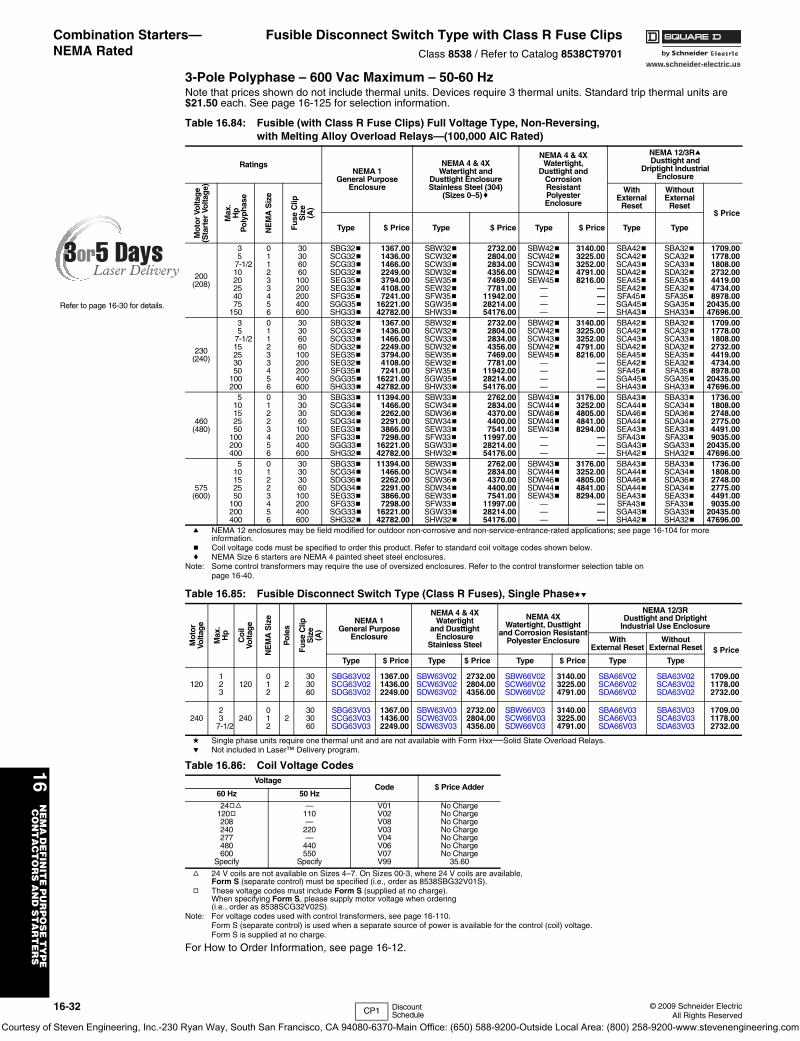
16-32 © 2009 Schneider ElectricAll Rights Reserved
www.schneider-electric.us
16N
EM
A D
EF
INIT
E P
UR
PO
SE
TY
PE
C
ON
TA
CT
OR
S A
ND
ST
AR
TE
RS
Combination Starters—NEMA Rated
Fusible Disconnect Switch Type with Class R Fuse ClipsClass 8538 / Refer to Catalog 8538CT9701
3-Pole Polyphase – 600 Vac Maximum – 50-60 HzNote that prices shown do not include thermal units. Devices require 3 thermal units. Standard trip thermal units are $21.50 each. See page 16-125 for selection information.
a NEMA 12 enclosures may be field modified for outdoor non-corrosive and non-service-entrance-rated applications; see page 16-104 for more information.
b Coil voltage code must be specified to order this product. Refer to standard coil voltage codes shown below.c NEMA Size 6 starters are NEMA 4 painted sheet steel enclosures.
Note: Some control transformers may require the use of oversized enclosures. Refer to the control transformer selection table on page 16-40.
d Single phase units require one thermal unit and are not available with Form Hxx—Solid State Overload Relays.e Not included in Laser™ Delivery program.
f 24 V coils are not available on Sizes 4–7. On Sizes 00-3, where 24 V coils are available, Form S (separate control) must be specified (i.e., order as 8538SBG32V01S).
g These voltage codes must include Form S (supplied at no charge). When specifying Form S, please supply motor voltage when ordering(i.e., order as 8538SCG32V02S).
Note: For voltage codes used with control transformers, see page 16-110.Form S (separate control) is used when a separate source of power is available for the control (coil) voltage. Form S is supplied at no charge.
For How to Order Information, see page 16-12.
Table 16.84: Fusible (with Class R Fuse Clips) Full Voltage Type, Non-Reversing,with Melting Alloy Overload Relays—(100,000 AIC Rated)
RatingsNEMA 1
General PurposeEnclosure
NEMA 4 & 4XWatertight and
Dusttight EnclosureStainless Steel (304)
(Sizes 0–5)c
NEMA 4 & 4XWatertight,
Dusttight andCorrosion ResistantPolyester Enclosure
NEMA 12/3RaDusttight and
Driptight IndustrialEnclosure
Mot
or V
olta
ge
(Sta
rter
Vol
tag
e)
Max
.H
pP
olyp
hase
NE
MA
Siz
e
Fuse
Clip
Siz
e(A
)
WithExternal
Reset
WithoutExternal
Reset $ Price
Type $ Price Type $ Price Type $ Price Type Type
200(208)
35
7-1/21020254075
150
011233456
30306060100200200400600
SBG32bSCG32bSCG33bSDG32bSEG35bSEG32bSFG35bSGG35bSHG33b
1367.001436.001466.002249.003794.004108.007241.00
16221.0042782.00
SBW32bSCW32bSCW33bSDW32bSEW35bSEW32bSFW35bSGW35bSHW33b
2732.002804.002834.004356.007469.007781.00
11942.0028214.0054176.00
SBW42bSCW42bSCW43bSDW42bSEW45b
————
3140.003225.003252.004791.008216.00
————
SBA42bSCA42bSCA43bSDA42bSEA45bSEA42bSFA45bSGA45bSHA43b
SBA32bSCA32bSCA33bSDA32bSEA35bSEA32bSFA35bSGA35bSHA33b
1709.001778.001808.002732.004419.004734.008978.00
20435.0047696.00
230(240)
35
7-1/215253050
100200
011233456
30306060100200200400600
SBG32bSCG32bSCG33bSDG32bSEG35bSEG32bSFG35bSGG35bSHG33b
1367.001436.001466.002249.003794.004108.007241.00
16221.0042782.00
SBW32bSCW32bSCW33bSDW32bSEW35bSEW32bSFW35bSGW35bSHW33b
2732.002804.002834.004356.007469.007781.00
11942.0028214.0054176.00
SBW42bSCW42bSCW43bSDW42bSEW45b
————
3140.003225.003252.004791.008216.00
————
SBA42bSCA42bSCA43bSDA42bSEA45bSEA42bSFA45bSGA45bSHA43b
SBA32bSCA32bSCA33bSDA32bSEA35bSEA32bSFA35bSGA35bSHA33b
1709.001778.001808.002732.004419.004734.008978.00
20435.0047696.00
460(480)
510152550
100200400
01223456
30303060100200400600
SBG33bSCG34bSDG36bSDG34bSEG33bSFG33bSGG33bSHG32b
11394.001466.002262.002291.003866.007298.00
16221.0042782.00
SBW33bSCW34bSDW36bSDW34bSEW33bSFW33bSGW33bSHW32b
2762.002834.004370.004400.007541.00
11997.0028214.0054176.00
SBW43bSCW44bSDW46bSDW44bSEW43b
———
3176.003252.004805.004841.008294.00
———
SBA43bSCA44bSDA46bSDA44bSEA43bSFA43bSGA43bSHA42b
SBA33bSCA34bSDA36bSDA34bSEA33bSFA33bSGA33bSHA32b
1736.001808.002748.002775.004491.009035.00
20435.0047696.00
575(600)
510152550
100200400
01223456
30303060100200400600
SBG33bSCG34bSDG36bSDG34bSEG33bSFG33bSGG33bSHG32b
11394.001466.002262.002291.003866.007298.00
16221.0042782.00
SBW33bSCW34bSDW36bSDW34bSEW33bSFW33bSGW33bSHW32b
2762.002834.004370.004400.007541.00
11997.0028214.0054176.00
SBW43bSCW44bSDW46bSDW44bSEW43b
———
3176.003252.004805.004841.008294.00
———
SBA43bSCA44bSDA46bSDA44bSEA43bSFA43bSGA43bSHA42b
SBA33bSCA34bSDA36bSDA34bSEA33bSFA33bSGA33bSHA32b
1736.001808.002748.002775.004491.009035.00
20435.0047696.00
Table 16.85: Fusible Disconnect Switch Type (Class R Fuses), Single Phasede
Mot
orVo
ltag
e
Max
.H
p
Co
ilVo
ltag
e
NE
MA
Siz
e
Pol
es
Fuse
Clip
S
ize
(A)
NEMA 1General Purpose
Enclosure
NEMA 4 & 4XWatertight
and DusttightEnclosure
Stainless Steel
NEMA 4XWatertight, Dusttight
and Corrosion ResistantPolyester Enclosure
NEMA 12/3RDusttight and Driptight
Industrial Use Enclosure
WithExternal Reset
WithoutExternal Reset $ Price
Type $ Price Type $ Price Type $ Price Type Type
120123
120012
2303060
SBG63V02SCG63V02SDG63V02
1367.001436.002249.00
SBW63V02SCW63V02SDW63V02
2732.002804.004356.00
SBW66V02SCW66V02SDW66V02
3140.003225.004791.00
SBA66V02SCA66V02SDA66V02
SBA63V02SCA63V02SDA63V02
1709.001178.002732.00
24023
7-1/2240
012
2303060
SBG63V03SCG63V03SDG63V03
1367.001436.002249.00
SBW63V03SCW63V03SDW63V03
2732.002804.004356.00
SBW66V03SCW66V03SDW66V03
3140.003225.004791.00
SBA66V03SCA66V03SDA66V03
SBA63V03SCA63V03SDA63V03
1709.001178.002732.00
Table 16.86: Coil Voltage CodesVoltage
Code $ Price Adder60 Hz 50 Hz
24gf120g208240277480600
Specify
—110—
220—
440550
Specify
V01V02V08V03V04V06V07V99
No ChargeNo ChargeNo ChargeNo ChargeNo ChargeNo ChargeNo Charge
35.60
Refer to page 16-30 for details.
CP1 Discount Schedule
Courtesy of Steven Engineering, Inc.-230 Ryan Way, South San Francisco, CA 94080-6370-Main Office: (650) 588-9200-Outside Local Area: (800) 258-9200-www.stevenengineering.com
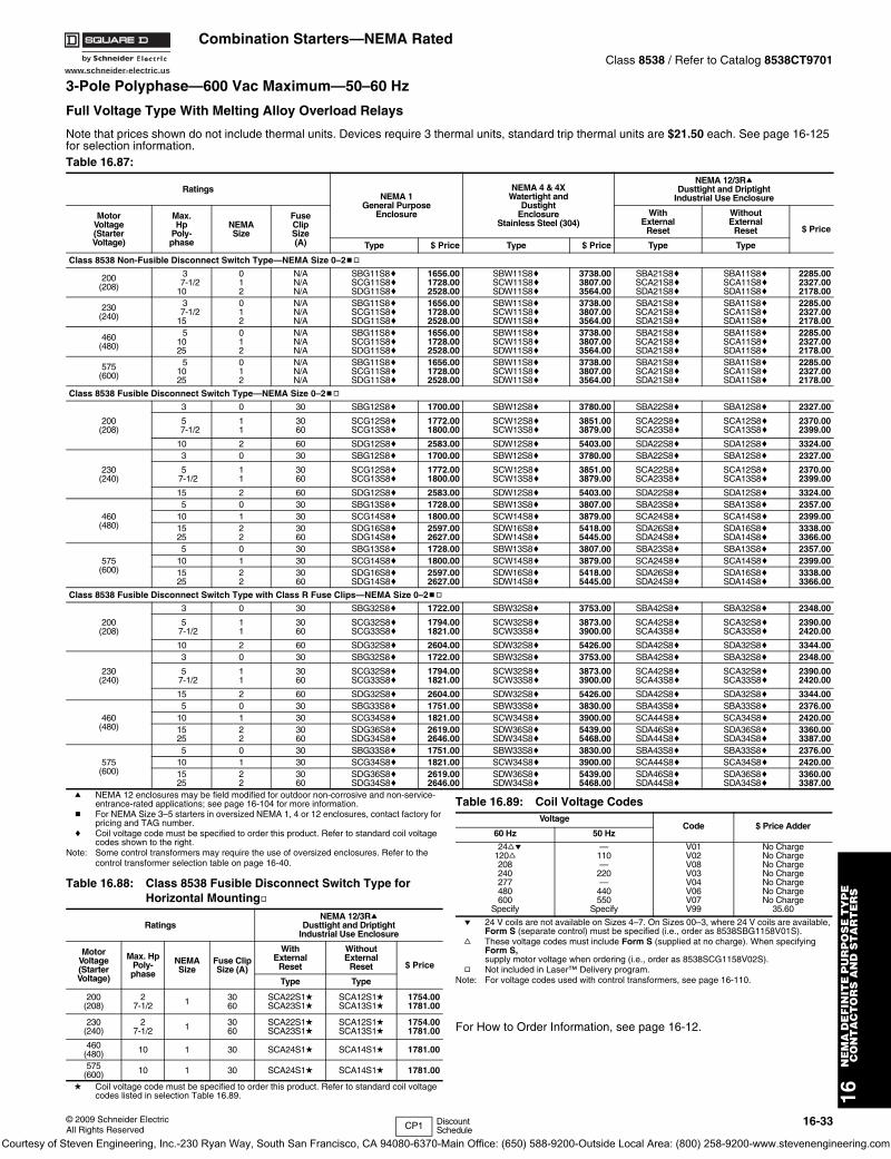
www.schneider-electric.us
16N
EM
A D
EF
INIT
E P
UR
PO
SE
TY
PE
C
ON
TA
CT
OR
S A
ND
ST
AR
TE
RS
© 2009 Schneider ElectricAll Rights Reserved
16-33
Combination Starters—NEMA RatedClass 8538 / Refer to Catalog 8538CT9701
3-Pole Polyphase—600 Vac Maximum—50–60 Hz
Full Voltage Type With Melting Alloy Overload Relays
a NEMA 12 enclosures may be field modified for outdoor non-corrosive and non-service-entrance-rated applications; see page 16-104 for more information.
b For NEMA Size 3–5 starters in oversized NEMA 1, 4 or 12 enclosures, contact factory for pricing and TAG number.
c Coil voltage code must be specified to order this product. Refer to standard coil voltage codes shown to the right.
Note: Some control transformers may require the use of oversized enclosures. Refer to the control transformer selection table on page 16-40.
d Coil voltage code must be specified to order this product. Refer to standard coil voltage codes listed in selection Table 16.89.
.
e 24 V coils are not available on Sizes 4–7. On Sizes 00–3, where 24 V coils are available, Form S (separate control) must be specified (i.e., order as 8538SBG1158V01S).
f These voltage codes must include Form S (supplied at no charge). When specifying Form S, supply motor voltage when ordering (i.e., order as 8538SCG1158V02S).
g Not included in Laser™ Delivery program.Note: For voltage codes used with control transformers, see page 16-110.
For How to Order Information, see page 16-12.
Note that prices shown do not include thermal units. Devices require 3 thermal units, standard trip thermal units are $21.50 each. See page 16-125 for selection information.Table 16.87:
RatingsNEMA 1
General PurposeEnclosure
NEMA 4 & 4XWatertight and
DustightEnclosure
Stainless Steel (304)
NEMA 12/3RaDusttight and Driptight
Industrial Use Enclosure
MotorVoltage(StarterVoltage)
Max.Hp
Poly-phase
NEMASize
FuseClipSize(A)
WithExternal
Reset
WithoutExternal
Reset $ Price
Type $ Price Type $ Price Type Type
Class 8538 Non-Fusible Disconnect Switch Type—NEMA Size 0–2bg
200(208)
37-1/2
10
012
N/AN/AN/A
SBG11S8cSCG11S8cSDG11S8c
1656.001728.002528.00
SBW11S8cSCW11S8cSDW11S8c
3738.003807.003564.00
SBA21S8cSCA21S8cSDA21S8c
SBA11S8cSCA11S8cSDA11S8c
2285.002327.002178.00
230(240)
37-1/2
15
012
N/AN/AN/A
SBG11S8cSCG11S8cSDG11S8c
1656.001728.002528.00
SBW11S8cSCW11S8cSDW11S8c
3738.003807.003564.00
SBA21S8cSCA21S8cSDA21S8c
SBA11S8cSCA11S8cSDA11S8c
2285.002327.002178.00
460(480)
51025
012
N/AN/AN/A
SBG11S8cSCG11S8cSDG11S8c
1656.001728.002528.00
SBW11S8cSCW11S8cSDW11S8c
3738.003807.003564.00
SBA21S8cSCA21S8cSDA21S8c
SBA11S8cSCA11S8cSDA11S8c
2285.002327.002178.00
575(600)
51025
012
N/AN/AN/A
SBG11S8cSCG11S8cSDG11S8c
1656.001728.002528.00
SBW11S8cSCW11S8cSDW11S8c
3738.003807.003564.00
SBA21S8cSCA21S8cSDA21S8c
SBA11S8cSCA11S8cSDA11S8c
2285.002327.002178.00
Class 8538 Fusible Disconnect Switch Type—NEMA Size 0–2bg
200(208)
3 0 30 SBG12S8c 1700.00 SBW12S8c 3780.00 SBA22S8c SBA12S8c 2327.00
57-1/2
11
3060
SCG12S8cSCG13S8c
1772.001800.00
SCW12S8cSCW13S8c
3851.003879.00
SCA22S8cSCA23S8c
SCA12S8cSCA13S8c
2370.002399.00
10 2 60 SDG12S8c 2583.00 SDW12S8c 5403.00 SDA22S8c SDA12S8c 3324.00
230(240)
3 0 30 SBG12S8c 1700.00 SBW12S8c 3780.00 SBA22S8c SBA12S8c 2327.00
57-1/2
11
3060
SCG12S8cSCG13S8c
1772.001800.00
SCW12S8cSCW13S8c
3851.003879.00
SCA22S8cSCA23S8c
SCA12S8cSCA13S8c
2370.002399.00
15 2 60 SDG12S8c 2583.00 SDW12S8c 5403.00 SDA22S8c SDA12S8c 3324.00
460(480)
5 0 30 SBG13S8c 1728.00 SBW13S8c 3807.00 SBA23S8c SBA13S8c 2357.0010 1 30 SCG14S8c 1800.00 SCW14S8c 3879.00 SCA24S8c SCA14S8c 2399.001525
22
3060
SDG16S8cSDG14S8c
2597.002627.00
SDW16S8cSDW14S8c
5418.005445.00
SDA26S8cSDA24S8c
SDA16S8cSDA14S8c
3338.003366.00
575(600)
5 0 30 SBG13S8c 1728.00 SBW13S8c 3807.00 SBA23S8c SBA13S8c 2357.0010 1 30 SCG14S8c 1800.00 SCW14S8c 3879.00 SCA24S8c SCA14S8c 2399.001525
22
3060
SDG16S8cSDG14S8c
2597.002627.00
SDW16S8cSDW14S8c
5418.005445.00
SDA26S8cSDA24S8c
SDA16S8cSDA14S8c
3338.003366.00
Class 8538 Fusible Disconnect Switch Type with Class R Fuse Clips—NEMA Size 0–2bg
200(208)
3 0 30 SBG32S8c 1722.00 SBW32S8c 3753.00 SBA42S8c SBA32S8c 2348.00
57-1/2
11
3060
SCG32S8cSCG33S8c
1794.001821.00
SCW32S8cSCW33S8c
3873.003900.00
SCA42S8cSCA43S8c
SCA32S8cSCA33S8c
2390.002420.00
10 2 60 SDG32S8c 2604.00 SDW32S8c 5426.00 SDA42S8c SDA32S8c 3344.00
230(240)
3 0 30 SBG32S8c 1722.00 SBW32S8c 3753.00 SBA42S8c SBA32S8c 2348.00
57-1/2
11
3060
SCG32S8cSCG33S8c
1794.001821.00
SCW32S8cSCW33S8c
3873.003900.00
SCA42S8cSCA43S8c
SCA32S8cSCA33S8c
2390.002420.00
15 2 60 SDG32S8c 2604.00 SDW32S8c 5426.00 SDA42S8c SDA32S8c 3344.00
460(480)
5 0 30 SBG33S8c 1751.00 SBW33S8c 3830.00 SBA43S8c SBA33S8c 2376.0010 1 30 SCG34S8c 1821.00 SCW34S8c 3900.00 SCA44S8c SCA34S8c 2420.001525
22
3060
SDG36S8cSDG34S8c
2619.002646.00
SDW36S8cSDW34S8c
5439.005468.00
SDA46S8cSDA44S8c
SDA36S8cSDA34S8c
3360.003387.00
575(600)
5 0 30 SBG33S8c 1751.00 SBW33S8c 3830.00 SBA43S8c SBA33S8c 2376.0010 1 30 SCG34S8c 1821.00 SCW34S8c 3900.00 SCA44S8c SCA34S8c 2420.001525
22
3060
SDG36S8cSDG34S8c
2619.002646.00
SDW36S8cSDW34S8c
5439.005468.00
SDA46S8cSDA44S8c
SDA36S8cSDA34S8c
3360.003387.00
Table 16.88: Class 8538 Fusible Disconnect Switch Type for Horizontal Mountingg
RatingsNEMA 12/3Ra
Dusttight and DriptightIndustrial Use Enclosure
MotorVoltage(StarterVoltage)
Max. HpPoly- phase
NEMASize
Fuse ClipSize (A)
WithExternal
Reset
WithoutExternal
Reset $ Price
Type Type
200(208)
27-1/2 1 30
60SCA22S1dSCA23S1d
SCA12S1dSCA13S1d
1754.001781.00
230(240)
27-1/2 1 30
60SCA22S1dSCA23S1d
SCA12S1dSCA13S1d
1754.001781.00
460(480) 10 1 30 SCA24S1d SCA14S1d 1781.00
575(600) 10 1 30 SCA24S1d SCA14S1d 1781.00
Table 16.89: Coil Voltage CodesVoltage
Code $ Price Adder60 Hz 50 Hz
24fe120f208240277480600
Specify
—110—
220—
440550
Specify
V01V02V08V03V04V06V07V99
No ChargeNo ChargeNo ChargeNo ChargeNo ChargeNo ChargeNo Charge
35.60
CP1 Discount Schedule
Courtesy of Steven Engineering, Inc.-230 Ryan Way, South San Francisco, CA 94080-6370-Main Office: (650) 588-9200-Outside Local Area: (800) 258-9200-www.stevenengineering.com
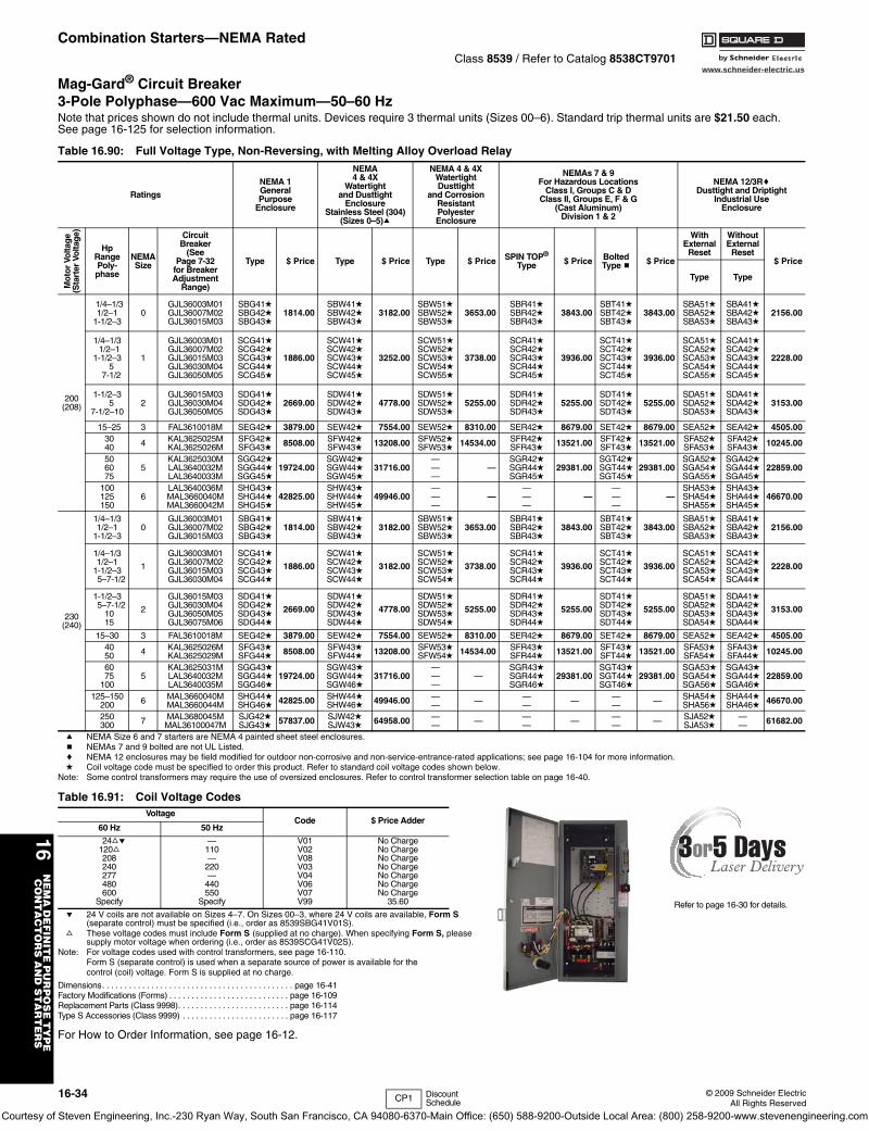
www.schneider-electric.us
16N
EM
A D
EF
INIT
E P
UR
PO
SE
TY
PE
C
ON
TA
CT
OR
S A
ND
ST
AR
TE
RS
16-34 © 2009 Schneider ElectricAll Rights Reserved
Combination Starters—NEMA RatedClass 8539 / Refer to Catalog 8538CT9701
Mag-Gard® Circuit Breaker3-Pole Polyphase—600 Vac Maximum—50–60 HzNote that prices shown do not include thermal units. Devices require 3 thermal units (Sizes 00–6). Standard trip thermal units are $21.50 each. See page 16-125 for selection information.
a NEMA Size 6 and 7 starters are NEMA 4 painted sheet steel enclosures.b NEMAs 7 and 9 bolted are not UL Listed.c NEMA 12 enclosures may be field modified for outdoor non-corrosive and non-service-entrance-rated applications; see page 16-104 for more information.d Coil voltage code must be specified to order this product. Refer to standard coil voltage codes shown below.
Note: Some control transformers may require the use of oversized enclosures. Refer to control transformer selection table on page 16-40.
e 24 V coils are not available on Sizes 4–7. On Sizes 00–3, where 24 V coils are available, Form S (separate control) must be specified (i.e., order as 8539SBG41V01S).
f These voltage codes must include Form S (supplied at no charge). When specifying Form S, please supply motor voltage when ordering (i.e., order as 8539SCG41V02S).
Note: For voltage codes used with control transformers, see page 16-110.Form S (separate control) is used when a separate source of power is available for the control (coil) voltage. Form S is supplied at no charge.
Dimensions. . . . . . . . . . . . . . . . . . . . . . . . . . . . . . . . . . . . . . . . . . . page 16-41Factory Modifications (Forms) . . . . . . . . . . . . . . . . . . . . . . . . . . . page 16-109Replacement Parts (Class 9998). . . . . . . . . . . . . . . . . . . . . . . . . page 16-114Type S Accessories (Class 9999) . . . . . . . . . . . . . . . . . . . . . . . . page 16-117
For How to Order Information, see page 16-12.
Table 16.90: Full Voltage Type, Non-Reversing, with Melting Alloy Overload Relay
Ratings
NEMA 1GeneralPurpose
Enclosure
NEMA4 & 4X
Watertightand Dusttight
EnclosureStainless Steel (304)
(Sizes 0–5)a
NEMA 4 & 4XWatertightDusttight
and CorrosionResistantPolyesterEnclosure
NEMAs 7 & 9For Hazardous Locations
Class I, Groups C & DClass II, Groups E, F & G
(Cast Aluminum)Division 1 & 2
NEMA 12/3RcDusttight and Driptight
Industrial UseEnclosure
Mo
tor
Volta
ge
(Sta
rter
Vol
tag
e)
Hp RangePoly-phase
NEMA Size
Circuit Breaker
(See Page 7-32
for BreakerAdjustment
Range)
Type $ Price Type $ Price Type $ Price SPIN TOP®
Type $ Price Bolted Type b $ Price
WithExternal
Reset
WithoutExternal
Reset$ Price
Type Type
200(208)
1/4–1/31/2–1
1-1/2–30
GJL36003M01GJL36007M02GJL36015M03
SBG41dSBG42dSBG43d
1814.00SBW41dSBW42dSBW43d
3182.00SBW51dSBW52dSBW53d
3653.00SBR41dSBR42dSBR43d
3843.00SBT41dSBT42dSBT43d
3843.00SBA51dSBA52dSBA53d
SBA41dSBA42dSBA43d
2156.00
1/4–1/31/2–1
1-1/2–35
7-1/2
1
GJL36003M01GJL36007M02GJL36015M03GJL36030M04GJL36050M05
SCG41dSCG42dSCG43dSCG44dSCG45d
1886.00
SCW41dSCW42dSCW43dSCW44dSCW45d
3252.00
SCW51dSCW52dSCW53dSCW54dSCW55d
3738.00
SCR41dSCR42dSCR43dSCR44dSCR45d
3936.00
SCT41dSCT42dSCT43dSCT44dSCT45d
3936.00
SCA51dSCA52dSCA53dSCA54dSCA55d
SCA41dSCA42dSCA43dSCA44dSCA45d
2228.00
1-1/2–35
7-1/2–102
GJL36015M03GJL36030M04GJL36050M05
SDG41dSDG42dSDG43d
2669.00SDW41dSDW42dSDW43d
4778.00SDW51dSDW52dSDW53d
5255.00SDR41dSDR42dSDR43d
5255.00SDT41dSDT42dSDT43d
5255.00SDA51dSDA52dSDA53d
SDA41dSDA42dSDA43d
3153.00
15–25 3 FAL3610018M SEG42d 3879.00 SEW42d 7554.00 SEW52d 8310.00 SER42d 8679.00 SET42d 8679.00 SEA52d SEA42d 4505.003040 4 KAL3625025M
KAL3625026MSFG42dSFG43d 8508.00 SFW42d
SFW43d 13208.00 SFW52dSFW53d 14534.00 SFR42d
SFR43d 13521.00 SFT42dSFT43d 13521.00 SFA52d
SFA53dSFA42dSFA43d 10245.00
506075
5KAL3625030MLAL3640032MLAL3640033M
SGG42dSGG44dSGG45d
19724.00SGW42dSGW44dSGW45d
31716.00———
—SGR42dSGR44dSGR45d
29381.00SGT42dSGT44dSGT45d
29381.00SGA52dSGA54dSGA55d
SGA42dSGA44dSGA45d
22859.00
100125150
6LAL3640036MMAL3660040MMAL3660042M
SHG43dSHG44dSHG45d
42825.00SHW43dSHW44dSHW45d
49946.00———
————
————
—SHA53dSHA54dSHA55d
SHA43dSHA44dSHA45d
46670.00
230(240)
1/4–1/31/2–1
1-1/2–30
GJL36003M01GJL36007M02GJL36015M03
SBG41dSBG42dSBG43d
1814.00SBW41dSBW42dSBW43d
3182.00SBW51dSBW52dSBW53d
3653.00SBR41dSBR42dSBR43d
3843.00SBT41dSBT42dSBT43d
3843.00SBA51dSBA52dSBA53d
SBA41dSBA42dSBA43d
2156.00
1/4–1/31/2–1
1-1/2–35–7-1/2
1
GJL36003M01GJL36007M02GJL36015M03GJL36030M04
SCG41dSCG42dSCG43dSCG44d
1886.00
SCW41dSCW42dSCW43dSCW44d
3182.00
SCW51dSCW52dSCW53dSCW54d
3738.00
SCR41dSCR42dSCR43dSCR44d
3936.00
SCT41dSCT42dSCT43dSCT44d
3936.00
SCA51dSCA52dSCA53dSCA54d
SCA41dSCA42dSCA43dSCA44d
2228.00
1-1/2–35–7-1/2
1015
2
GJL36015M03GJL36030M04GJL36050M05GJL36075M06
SDG41dSDG42dSDG43dSDG44d
2669.00
SDW41dSDW42dSDW43dSDW44d
4778.00
SDW51dSDW52dSDW53dSDW54d
5255.00
SDR41dSDR42dSDR43dSDR44d
5255.00
SDT41dSDT42dSDT43dSDT44d
5255.00
SDA51dSDA52dSDA53dSDA54d
SDA41dSDA42dSDA43dSDA44d
3153.00
15–30 3 FAL3610018M SEG42d 3879.00 SEW42d 7554.00 SEW52d 8310.00 SER42d 8679.00 SET42d 8679.00 SEA52d SEA42d 4505.004050 4 KAL3625026M
KAL3625029MSFG43dSFG44d 8508.00 SFW43d
SFW44d 13208.00 SFW53dSFW54d 14534.00 SFR43d
SFR44d 13521.00 SFT43dSFT44d 13521.00 SFA53d
SFA54dSFA43dSFA44d 10245.00
6075
1005
KAL3625031MLAL3640032MLAL3640035M
SGG43dSGG44dSGG46d
19724.00SGW43dSGW44dSGW46d
31716.00———
—SGR43dSGR44dSGR46d
29381.00SGT43dSGT44dSGT46d
29381.00SGA53dSGA54dSGA56d
SGA43dSGA44dSGA46d
22859.00
125–150200 6 MAL3660040M
MAL3660044MSHG44dSHG46d 42825.00 SHW44d
SHW46d 49946.00 —— — —
— — —— — SHA54d
SHA56dSHA44dSHA46d 46670.00
250300 7 MAL3680045M
MAL36100047MSJG42dSJG43d 57837.00 SJW42d
SJW43d 64958.00 —— — —
— — —— — SJA52d
SJA53d—— 61682.00
Table 16.91: Coil Voltage CodesVoltage
Code $ Price Adder60 Hz 50 Hz
24fe120f208240277480600
Specify
—110—
220—
440550
Specify
V01V02V08V03V04V06V07V99
No ChargeNo ChargeNo ChargeNo ChargeNo ChargeNo ChargeNo Charge
35.60 Refer to page 16-30 for details.
CP1 Discount Schedule
Courtesy of Steven Engineering, Inc.-230 Ryan Way, South San Francisco, CA 94080-6370-Main Office: (650) 588-9200-Outside Local Area: (800) 258-9200-www.stevenengineering.com
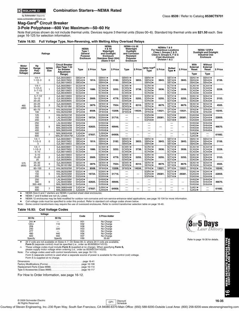
www.schneider-electric.us
16N
EM
A D
EF
INIT
E P
UR
PO
SE
TY
PE
C
ON
TA
CT
OR
S A
ND
ST
AR
TE
RS
© 2009 Schneider ElectricAll Rights Reserved
16-35
Combination Starters—NEMA RatedClass 8539 / Refer to Catalog 8538CT9701
Mag-Gard® Circuit Breaker3-Pole Polyphase—600 Vac Maximum—50–60 HzNote that prices shown do not include thermal units. Devices require 3 thermal units (Sizes 00–6). Standard trip thermal units are $21.50 each. See page 16-125 for selection information.
a NEMA Size 6 and 7 starters are NEMA 4 painted sheet steel enclosures.b NEMA 7 and 9 bolted are not UL Listed.c NEMA 12 enclosures may be field modified for outdoor non-corrosive and non-service-entrance-rated applications; see page 16-104 for more information.d Coil voltage code must be specified to order this product. Refer to standard coil voltage codes shown below.
Note: Some control transformers may require the use of oversized enclosures. Refer to control transformer selection table on page 16-40.
e 24 V coils are not available on Sizes 4–7. On Sizes 00–3, where 24 V coils are available, Form S (separate control) must be specified (i.e., order as 8539SBG41V01S).
f These voltage codes must include Form S (supplied at no charge). When specifying Form S, please supply motor voltage when ordering (i.e., order as 8539SCG41V02S).
Note: For voltage codes used with control transformers, see page 16-110.Form S (separate control) is used when a separate source of power is available for the control (coil) voltage. Form S is supplied at no charge.
Dimensions . . . . . . . . . . . . . . . . . . . . . . . . . . . . . . . . . . . . . . . . . . .page 16-41Factory Modifications (Forms). . . . . . . . . . . . . . . . . . . . . . . . . . . page 16-109Replacement Parts (Class 9998) . . . . . . . . . . . . . . . . . . . . . . . . page 16-114Type S Accessories (Class 9999). . . . . . . . . . . . . . . . . . . . . . . . page 16-117
For How to Order Information, see page 16-12.
Table 16.92: Full Voltage Type, Non-Reversing, with Melting Alloy Overload Relays
Ratings
NEMAType 1
GeneralPurpose
Enclosure
NEMA4 & 4X
Watertightand Dusttight
EnclosureStainless Steel (304)
(Sizes 0–5)a
NEMA 4 & 4XWatertightDusttight
and CorrosionResistantPolyesterEnclosure
NEMAs 7 & 9For Hazardous Locations
Class I, Groups C & DClass II, Groups E, F & G
(Cast Aluminum)Division 1 & 2
NEMA 12/3RcDusttight and Driptight
Industrial UseEnclosure
MotorVoltage(StarterVoltage)
HpRangePoly-phase
NEMASize
Circuit Breaker(See Page 7-32
for BreakerAdjustment
Range)
Type $ Price Type $ Price Type $ Price SPIN TOP®
Type $ Price BoltedType b $ Price
WithExternal
Reset
WithoutExternal
Reset $ Price
Type Type
460(480)
1/4–11-1/2–3
50
GJL36003M01GJL36007M02GJL36015M03
SBG41dSBG42dSBG43d
1814.SBW41dSBW42dSBW43d
3182.SBW51dSBW52dSBW53d
3653.SBR41dSBR42dSBR43d
3843.SBT41dSBT42dSBT43d
3843.SBA51dSBA52dSBA53d
SBA41dSBA42dSBA43d
2156.
1/4–11-1/2–35–7-1/2
10
1
GJL36003M01GJL36007M02GJL36015M03GJL36030M04
SCG41dSCG42dSCG43dSCG44d
1886.
SCW41dSCW42dSCW43dSCW44d
3252.
SCW51dSCW52dSCW53dSCW54d
3738.
SCR41dSCR42dSCR43dSCR44d
3936.
SCT41dSCT42dSCT43dSCT44d
3936.
SCA51dSCA52dSCA53dSCA54d
SCA41dSCA42dSCA43dSCA44d
2228.
5–7-1/210–1520–25
2GJL36015M03GJL36030M04GJL36050M05
SDG41dSDG42dSDG43d
2669.SDW41dSDW42dSDW43d
4778.SDW51dSDW52dSDW53d
5255.SDR41dSDR42dSDR43d
5255.SDT41dSDT42dSDT43d
5255.SDA51dSDA52dSDA53d
SDA41dSDA42dSDA43d
3153.
20–2530–50 3 GJL36050M05
FAL3610018MSEG41dSEG42d 3879. SEW41d
SEW42d 7554. SEW51dSEW52d 8310. SER41d
SER42d 8679. SET41dSET42d 8679. SEA51d
SEA52dSEA41dSEA42d 4505.
60–75100 4 KAL3625025M
KAL3625029MSFG42dSFG44d 8508. SFW42d
SFW44d 13208. SFW52dSFW54d 14534. SFR42d
SFR44d 13521. SFT42dSFT44d 13521. SFA52d
SFA54dSFA42dSFA44d 10245.
125150200
5KAL3625031MLAL3640032MLAL3640033M
SGG43dSGG44dSGG46d
19724.SGW43dSGW44dSGW46d
31716.———
—SGR43dSGR44dSGR46d
29381.SGT43dSGT44dSGT46d
29381.SGA53dSGA54dSGA56d
SGA43dSGA44dSGA46d
22859.
250300350400
6
LAL3640036MMAL3660040MMAL3660042MMAL3660044M
SHG43dSHG44dSHG45dSHG46d
42825.
SHW43dSHW44dSHW45dSHW46d
49946.
————
—
————
—
————
—
SHA53dSHA54dSHA55dSHA56d
SHA43dSHA44dSHA45dSHA46d
46670.
500600 7 MAL3690045M
MAL36100047MSJG42dSJG43d 57837. SJW42d
SJW43d 64958. —— — —
— — —— — SJA52d
SJA53d—— 61682.
575(600)
1/4–11-1/2–3
50
GJL36003M01GJL36007M02GJL36015M03
SBG41dSBG42dSBG43d
1814.SBW41dSBW42dSBW43d
3182.SBW51dSBW52dSBW53d
3653.SBR41dSBR42dSBR43d
3843.SBT41dSBT42dSBT43d
3843.SBA51dSBA52dSBA53d
SBA41dSBA42dSBA43d
2156.
1/4–11-1/2–3
5–101
GJL36003M01GJL36007M02GJL36015M03
SCG41dSCG42dSCG43d
1886.SCW41dSCW42dSCW43d
3252.SCW51dSCW52dSCW53d
3738.SCR41dSCR42dSCR43d
3936.SCT41dSCT42dSCT43d
3936.SCA51dSCA52dSCA53d
SCA41dSCA42dSCA43d
2228.
5–1015–20
252
GJL36015M03GJL36030M04GJL36050M05
SDG41dSDG42dSDG43d
2669.SDW41dSDW42dSDW43d
4778.SDW51dSDW52dSDW53d
5255.SDR41dSDR42dSDR43d
5255.SDT41dSDT42dSDT43d
5255.SDA51dSDA52dSDA53d
SDA41dSDA42dSDA43d
3153.
25–3040–50 3 GJL36050M05
FAL3610018MSEG41dSEG42d 3879. SEW41d
SEW42d 7554. SEW51dSEW52d 8310. SER41d
SER42d 8679. SET41dSET42d 8679. SEA51d
SEA52dSEA41dSEA42d 4505.
60–100 4 KAL3625025M SFG42d 8508. SFW42d 13208. SFW52d 14534. SFR42d 13521. SFT42d 13521. SFA52d SFA42d 10245.125150200
5KAL3625029MKAL3625030MLAL3640032M
SGG41dSGG42dSGG44d
19724.SGW41dSGW42dSGW44d
31716.———
—SGR41dSGR42dSGR44d
29381.SGT41dSGT42dSGT44d
29381.SGA51dSGA52dSGA54d
SGA41dSGA42dSGA44d
22859.
250300
350–4006
LAL3640035MLAL3640036MMAL3660040M
SHG42dSHG43dSHG44d
42825.SHW42dSHW43dSHW44d
49946.———
————
————
—SHA52dSHA53dSHA54d
SHA42dSHA43dSHA44d
46670.
500600 7 MAL3680044M
MAL3680045MSJG41dSJG42d 57837. SJW41d
SJW42d 64958. —— — —
— — —— — SJA51d
SJA52d—— 61682.
Table 16.93: Coil Voltage CodesVoltage
Code $ Price Adder60 Hz 50 Hz
24fe120f208240277480600
Specify
—110—
220—
440550
Specify
V01V02V08V03V04V06V07V99
No ChargeNo ChargeNo ChargeNo ChargeNo ChargeNo ChargeNo Charge
35.60 Refer to page 16-30 for details.
CP1 Discount Schedule
Courtesy of Steven Engineering, Inc.-230 Ryan Way, South San Francisco, CA 94080-6370-Main Office: (650) 588-9200-Outside Local Area: (800) 258-9200-www.stevenengineering.com
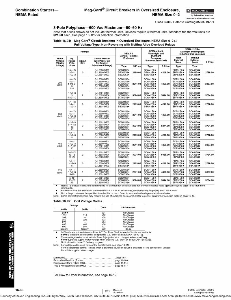
16-36 © 2009 Schneider ElectricAll Rights Reserved
www.schneider-electric.us
16N
EM
A D
EF
INIT
E P
UR
PO
SE
TY
PE
C
ON
TA
CT
OR
S A
ND
ST
AR
TE
RS
Combination Starters—NEMA Rated
Mag-Gard® Circuit Breakers in Oversized Enclosure,NEMA Size 0–2
Class 8539 / Refer to Catalog 8538CT9701
3-Pole Polyphase—600 Vac Maximum—50–60 HzNote that prices shown do not include thermal units. Devices require 3 thermal units. Standard trip thermal units are $21.50 each. See page 16-125 for selection information.
a NEMA 12 enclosures may be field modified for outdoor non-corrosive and non-service-entrance-rated applications; see page 16-104 for more information.
b For NEMA Size 3–5 starters in oversized NEMA 1, 4 or 12 enclosures, contact factory for pricing and TAG number.c Coil voltage code must be specified to order this product. Refer to standard coil voltage codes shown below.
Note: Some control transformers may require the use of oversized enclosures. Refer to control transformer selection table on page 16-40.
d 24 V coils are not available on Sizes 4–7. On Sizes 00–3, where 24 V coils are available, Form S (separate control) must be specified (i.e., order as 8539SBG41S8V01S).
e These voltage codes must include Form S (supplied at no charge). When specifying Form S, please supply motor voltage when ordering (i.e., order as 8539SCG41S8V02S).
f Not included in Laser™ Delivery program.Note: For voltage codes used with control transformers, see page 16-110.
Form S (separate control) is used when a separate source of power is available for the control (coil) voltage. Form S is supplied at no charge.
Dimensions. . . . . . . . . . . . . . . . . . . . . . . . . . . . . . . . . . . . . . . . . . . page 16-41Factory Modifications (Forms) . . . . . . . . . . . . . . . . . . . . . . . . . . . page 16-109Replacement Parts (Class 9998). . . . . . . . . . . . . . . . . . . . . . . . . page 16-114Type S Accessories (Class 9999) . . . . . . . . . . . . . . . . . . . . . . . . page 16-117
For How to Order Information, see page 16-12.
Table 16.94: Mag-Gard® Circuit Breakers in Oversized Enclosure, NEMA Size 0–2bfFull Voltage Type, Non-Reversing with Melting Alloy Overload Relays
RatingsNEMA 1
General PurposeEnclosure
NEMA 4 & 4XWatertight and
DusttightEnclosure
Stainless Steel (304)
NEMA 12/3RaDusttight and Driptight
Industrial Use Enclosure
MotorVoltage(StarterVoltage)
HpRangePoly-phase
NEMASize
Circuit Breaker(See Page 7-32
for BreakerAdjustment Range)
WithExternal
Reset
WithoutExternal
Reset $ Price
Type $ Price Type $ Price Type Type
200(208)
1/4–1/31/2–1
1-1/2–30
GJL36003M01GJL36007M02GJL36015M03
SBG41S8cSBG42S8cSBG43S8c
2169.00SBW41S8cSBW42S8cSBW43S8c
4248.00SBA51S8cSBA52S8cSBA53S8c
SBA41S8cSBA42S8cSBA43S8c
2798.00
1/4–1/31/2–1
1-1/2–3-5
71/2
1
GJL36003M01GJL36007M02GJL36015M03GJL36030M04GJL36050M05
SCG41S8cSCG42S8cSCG43S8cSCG44S8cSCG45S8c
2241.00
SCW41S8cSCW42S8cSCW43S8cSCW44S8cSCW45S8c
4320.00
SCA51S8cSCA52S8cSCA53S8cSCA54S8cSCA55S8c
SCA41S8cSCA42S8cSCA43S8cSCA44S8cSCA45S8c
2867.00
1-1/2–35
71/2–102
GJL36015M03GJL36030M04GJL36050M05
SDG41S8cSDG42S8cSDG43S8c
3024.00SDW41S8cSDW42S8cSDW43S8c
5844.00SDA51S8cSDA52S8cSDA53S8c
SDA41S8cSDA42S8cSDA43S8c
3794.00
230(240)
1/4–1/31/2–1
1-1/2–30
GJL36003M01GJL36007M02GJL36015M03
SBG41S8cSBG42S8cSBG43S8c
2169.00SBW41S8cSBW42S8cSBW43S8c
4248.00SBA51S8cSBA52S8cSBA53S8c
SBA41S8cSBA42S8cSBA43S8c
2798.00
1/4–1/31/2–1
1-1/2–35–7-1/2
1
GJL36003M01GJL36007M02GJL36015M03GJL36030M04
SCG41S8cSCG42S8cSCG43S8cSCG44S8c
2241.00
SCW41S8cSCW42S8cSCW43S8cSCW44S8c
4320.00
SCA51S8cSCA52S8cSCA53S8cSCA54S8c
SCA41S8cSCA42S8cSCA43S8cSCA44S8c
3867.00
1-1/2–35–7-1/2
1015
2
GJL36015M03GJL36030M04GJL36050M05GJL36075M06
SDG41S8cSDG42S8cSDG43S8cSDG44S8c
3024.00
SDW41S8cSDW42S8cSDW43S8cSDW44S8c
5844.00
SDA51S8cSDA52S8cSDA53S8cSDA54S8c
SDA41S8cSDA42S8cSDA43S8cSDA44S8c
3794.00
460(480)
1/4–11-1/2–3
50
GJL36003M01GJL36007M02GJL36015M03
SBG41S8cSBG42S8cSBG43S8c
2169.00SBW41S8cSBW42S8cSBW43S8c
4248.00SBA51S8cSBA52S8cSBA53S8c
SBA41S8cSBA42S8cSBA43S8c
2798.00
1/4–11-1/2–35–7-1/2
10
1
GJL36003M01GJL36007M02GJL36015M03GJL36030M04
SCG41S8cSCG42S8cSCG43S8cSCG44S8c
2241.00
SCW41S8cSCW42S8cSCW43S8cSCW44S8c
4320.00
SCA51S8cSCA52S8cSCA53S8cSCA54S8c
SCA41S8cSCA42S8cSCA43S8cSCA44S8c
2867.00
5–7-1/210–1520–25
2GJL36015M03GJL36030M04GJL36050M05
SDG41S8cSDG42S8cSDG43S8c
3024.00SDW41S8cSDW42S8cSDW43S8c
5855.00SDA51S8cSDA52S8cSDA53S8c
SDA41S8cSDA42S8cSDA43S8c
3794.00
575(600)
1/4–11-1/2–3
50
GJL36003M01GJL36007M02GJL36015M03
SBG41S8cSBG42S8cSBG43S8c
2169.00SBW41S8cSBW42S8cSBW43S8c
4248.00SBA51S8cSBA52S8cSBA53S8c
SBA41S8cSBA42S8cSBA43S8c
2798.00
1/4–11-1/2–3
5–101
GJL36003M01GJL36007M02GJL36015M03
SCG41S8cSCG42S8cSCG43S8c
2241.00SCW41S8cSCW42S8cSCW43S8c
4320.00SCA51S8cSCA52S8cSCA53S8c
SCA41S8cSCA42S8cSCA43S8c
3867.00
5–1015–20
252
GJL36015M03GJL36030M04GJL36050M05
SDG41S8cSDG42S8cSDG43S8c
3024.00SDW41S8cSDW42S8cSDW43S8c
5844.00SDA51S8cSDA52S8cSDA53S8c
SDA41S8cSDA42S8cSDA43S8c
3794.00
Table 16.95: Coil Voltage CodesVoltage
Code $ Price Adder60 Hz 50 Hz
24ed120e208240277480600
Specify
—110—
220—
440550
Specify
V01V02V08V03V04V06V07V99
No ChargeNo ChargeNo ChargeNo ChargeNo ChargeNo ChargeNo Charge
35.60
CP1 Discount Schedule
Courtesy of Steven Engineering, Inc.-230 Ryan Way, South San Francisco, CA 94080-6370-Main Office: (650) 588-9200-Outside Local Area: (800) 258-9200-www.stevenengineering.com
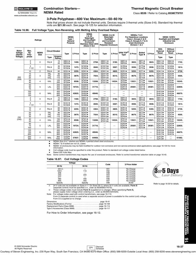
www.schneider-electric.us
16N
EM
A D
EF
INIT
E P
UR
PO
SE
TY
PE
C
ON
TA
CT
OR
S A
ND
ST
AR
TE
RS
© 2009 Schneider ElectricAll Rights Reserved
16-37
Combination Starters—NEMA Rated
Thermal Magnetic Circuit BreakerClass 8539 / Refer to Catalog 8538CT9701
3-Pole Polyphase—600 Vac Maximum—50–60 HzNote that prices shown do not include thermal units. Devices require 3 thermal units (Sizes 0-6). Standard trip thermal units are $21.50 each. See page 16-125 for selection information.
a NEMA Size 6 & 7 starters are NEMA 4 painted sheet steel enclosures.b NEMA 7 & 9 bolted are not UL Listed.c NEMA 12 enclosures may be field modified for outdoor non-corrosive and non-service-entrance-rated applications; see page 16-104 for more
information.d Coil voltage code must be specified to order this product. Refer to standard coil voltage codes listed below.e Rated 250 Volts Max.
Note: Some control transformers may require the use of oversized enclosures. Refer to control transformer selection table on page 16-40.
f 24 V coils are not available on Sizes 4–7. On Sizes 00–3, where 24 V coils are available, Form S (separate control) must be specified (i.e., order as 8539SBG1V01S).
g These voltage codes must include Form S (supplied at no charge). When specifying Form S, please supply motor voltage when ordering (i.e., order as 8539SCG5V02S).
Note: For voltage codes used with control transformers, see page 16-110.Form S (separate control) is used when a separate source of power is available for the control (coil) voltage. Form S is supplied at no charge.
Dimensions . . . . . . . . . . . . . . . . . . . . . . . . . . . . . . . . . . . . . . . . . . .page 16-41Factory Modifications (Forms) . . . . . . . . . . . . . . . . . . . . . . . . . . .page 16-109Replacement Parts (Class 9998) . . . . . . . . . . . . . . . . . . . . . . . . .page 16-114Type S Accessories (Class 9999). . . . . . . . . . . . . . . . . . . . . . . . .page 16-117
For How to Order Information, see page 16-12.
Table 16.96: Full Voltage Type, Non-Reversing, with Melting Alloy Overload Relays
Ratings
NEMAType 1
GeneralPurpose
NEMA4 & 4X
Watertightand Dusttight
EnclosureStainless Steel (304)
(Sizes 0–5)a
NEMA 4 & 4XWatertightDusttight
and CorrosionResistant
Polyester Enclosure
NEMAs 7 & 9For Hazardous Locations
Class I, Groups C & DClass II, Groups E, F & G
(Cast Aluminum)Division 1 & 2
NEMA 12/3RcDusttight and Driptight
Industrial UseEnclosure
MotorVoltage(StarterVoltage)
Max.Hp
Poly-phase
NEMASize
Circuit BreakerType $ Price Type $ Price Type $ Price SPIN TOP®
Type $ Price BoltedType b $ Price
WithExternal
Reset
WithoutExternal
Reset $ Price
Type AmpereRating Type Type
200(208)
23 0 FALe 15
20SBG1dSBG3d 1400. SBW1d
SBW3d 2768. SBW11dSBW13d 3182. SBR1d
SBR3d 3843. SBT1dSBT3d 3843. SBA11d
SBA13dSBA1dSBA3d 1742.
57-1/2 1 FALe 35
50SCG5dSCG2d 1472. SCW5d
SCW2d 2840. SCW15dSCW12d 3267. SCR5d
SCR2d 3936. SCT5dSCT2d 3936. SCA15d
SCA12dSCA5dSCA2d 1814.
10 2 FALe 60 SDG1d 2255. SDW1d 4364. SDW11d 4805. SDR1d 5255. SDT1d 5255. SDA11d SDA1d 2739.152025
3FALFALKAL
90100110
SEG3dSEG1dSEG5d
3879.SEW3dSEW1dSEW5d
7554.SEW13dSEW11dSEW15d
8310.SER3dSER1dSER5d
8679.SET3dSET1dSET5d
8679.SEA13dSEA11dSEA15d
SEA3dSEA1dSEA5d
4505.
3040 4 KAL 125
200SFG3dSFG4d 8508. SFW3d
SFW4d 13208. SFW13dSFW14d 14534. SFR3d
SFR4d 13521. SFT3dSFT4d 13521. SFA13d
SFA14dSFA3dSFA4d 10245.
506075
5 LAL200250300
SGG6dSGG1dSGG4d
19724.SGW6dSGW1dSGW4d
31716.———
—SGR6dSGR1dSGR4d
29381.SGT6dSGT1dSGT4d
29381.SGA16dSGA11dSGA14d
SGA6dSGA1dSGA4d
22859.
100125150
6 MAL450600600
SHG4dSHG3dSHG5d
42825.SHW4dSHW3dSHW5d
49946.———
————
————
—SHA14dSHA13dSHA15d
SHA4dSHA3dSHA5d
46670.
230(240)
23 0 FALe 15
20SBG1dSBG3d 1400. SBW1d
SBW3d 2768. SBW11dSBW13d 3182. SBR1d
SBR3d 3843. SBT1dSBT3d 3843. SBA11d
SBA13dSBA1dSBA3d 1742.
57-1/2 1 FALe 30
45SCG1dSCG6d 1472. SCW1d
SCW6d 2840. SCW11dSCW16d 3267. SCR1d
SCR6d 3936. SCT1dSCT6d 3936. SCA11d
SCA16dSCA1dSCA6d 1814.
1015 2 FALe 60
80SDG1dSDG7d 2255. SDW1d
SDW7d 4364. SDW11dSDW17d 4805. SDR1d
SDR7d 5255. SDT1dSDT7d 5355. SDA11d
SDA17dSDA1dSDA7d 2739.
202530
3FALFALKAL
90100110
SEG3dSEG1dSEG5d
3879.SEW3dSEW1dSEW5d
7554.SEW13dSEW11dSEW15d
8310.SER3dSER1dSER5d
8679.SET3dSET1dSET5d
8679.SEA13dSEA11dSEA15d
SEA3dSEA1dSEA5d
4505.
4050 4 KAL 150
200SFG1dSFG4d 8508. SFW1d
SFW4d 13208. SFW11dSFW14d 14534. SFR1d
SFR4d 13521. SFT1dSFT4d 13521. SFA11d
SFA14dSFA1dSFA4d 10245.
6075
1005 LAL
225250350
SGG3dSGG1dSGG2d
19724.SGW3dSGW1dSGW2d
31716.———
—SGR3dSGR1dSGR2d
29381.SGT3dSGT1dSGT2d
29381.SGA13dSGA11dSGA12d
SGA3dSGA1dSGA2d
22859.
125150200
6 MAL450600800
SHG4dSHG3dSHG7d
42825.SHW4dSHW3dSHW7d
49946.———
————
————
—SHA14dSHA13dSHA17d
SHA4dSHA3dSHA7d
46670.
250300 7 MAL 900
1000SJG2dSJG3d 57837. SJW2d
SJW3d 64958. —— — —
— — —— — SJA12d
SJA13d—— 61682.
Table 16.97: Coil Voltage CodesVoltage
Code $ Price Adder60 Hz 50 Hz
24gf120g208240277480600
Specify
—110—
220—
440550
Specify
V01V02V08V03V04V06V07V99
No ChargeNo ChargeNo ChargeNo ChargeNo ChargeNo ChargeNo Charge
35.60 Refer to page 16-30 for details.
CP1 Discount Schedule
Courtesy of Steven Engineering, Inc.-230 Ryan Way, South San Francisco, CA 94080-6370-Main Office: (650) 588-9200-Outside Local Area: (800) 258-9200-www.stevenengineering.com
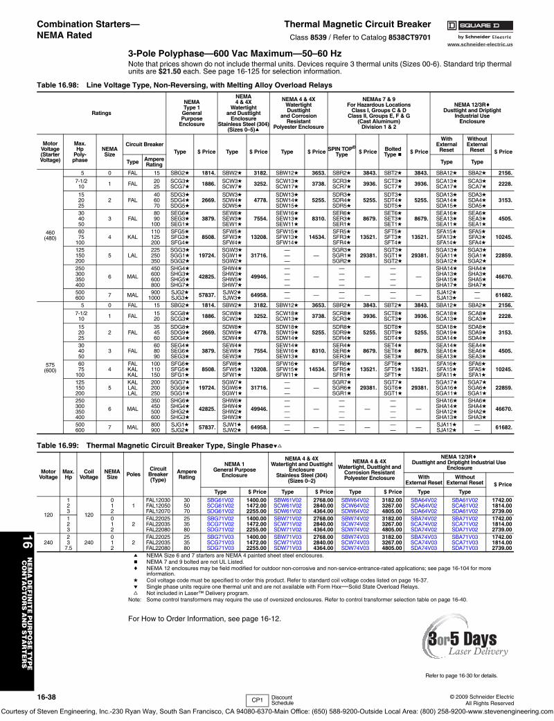
www.schneider-electric.us
16N
EM
A D
EF
INIT
E P
UR
PO
SE
TY
PE
C
ON
TA
CT
OR
S A
ND
ST
AR
TE
RS
16-38 © 2009 Schneider ElectricAll Rights Reserved
Combination Starters—NEMA Rated
Thermal Magnetic Circuit BreakerClass 8539 / Refer to Catalog 8538CT9701
3-Pole Polyphase—600 Vac Maximum—50–60 HzNote that prices shown do not include thermal units. Devices require 3 thermal units (Sizes 00-6). Standard trip thermal units are $21.50 each. See page 16-125 for selection information.
a NEMA Size 6 and 7 starters are NEMA 4 painted sheet steel enclosures. b NEMA 7 and 9 bolted are not UL Listed.c NEMA 12 enclosures may be field modified for outdoor non-corrosive and non-service-entrance-rated applications; see page 16-104 for more
information.d Coil voltage code must be specified to order this product. Refer to standard coil voltage codes listed on page 16-37.e Single phase units require one thermal unit and are not available with Form Hxx—Solid State Overload Relays.f Not included in Laser™ Delivery program.
Note: Some control transformers may require the use of oversized enclosures. Refer to control transformer selection table on page 16-40.
For How to Order Information, see page 16-12.
Table 16.98: Line Voltage Type, Non-Reversing, with Melting Alloy Overload Relays
Ratings
NEMAType 1
GeneralPurpose
Enclosure
NEMA4 & 4X
Watertightand Dusttight
EnclosureStainless Steel (304)
(Sizes 0–5)a
NEMA 4 & 4XWatertightDusttight
and CorrosionResistant
Polyester Enclosure
NEMAs 7 & 9For Hazardous Locations
Class I, Groups C & DClass II, Groups E, F & G
(Cast Aluminum)Division 1 & 2
NEMA 12/3RcDusttight and Driptight
Industrial UseEnclosure
MotorVoltage(StarterVoltage)
Max.Hp
Poly-phase
NEMASize
Circuit BreakerType $ Price Type $ Price Type $ Price SPIN TOP®
Type $ Price BoltedType b $ Price
WithExternal
Reset
WithoutExternal
Reset $ Price
Type AmpereRating Type Type
460(480)
5 0 FAL 15 SBG2d 1814. SBW2d 3182. SBW12d 3653. SBR2d 3843. SBT2d 3843. SBA12d SBA2d 2156.7-1/2
10 1 FAL 2025
SCG3dSCG7d 1886. SCW3d
SCW7d 3252. SCW13dSCW17d 3738. SCR3d
SCR7d 3936. SCT3dSCT7d 3936. SCA13d
SCA17dSCA3dSCA7d 2228.
152025
2 FAL406070
SDG3dSDG4dSDG5d
2669.SDW3dSDW4dSDW5d
4778.SDW13dSDW14dSDW15d
5255.SDR3dSDR4dSDR5d
5255.SDT3dSDT4dSDT5d
5255.SDA13dSDA14dSDA15d
SDA3dSDA4dSDA5d
3153.
304050
3 FAL8090
100
SEG6dSEG3dSEG1d
3879.SEW6dSEW3dSEW1d
7554.SEW16dSEW13dSEW11d
8310.SER6dSER3dSER1d
8679.SET6dSET3dSET1d
8679.SEA16dSEA13dSEA11d
SEA6dSEA3dSEA1d
4505.
6075
1004 KAL
110125200
SFG5dSFG3dSFG4d
8508.SFW5dSFW3dSFW4d
13208.SFW15dSFW13dSFW14d
14534.SFR5dSFR3dSFR4d
13521.SFT5dSFT3dSFT4d
13521.SFA15dSFA13dSFA14d
SFA5dSFA3dSFA4d
10245.
125150200
5 LAL225250350
SGG3dSGG1dSGG2d
19724.SGW3dSGW1dSGW2d
31716.———
—SGR3dSGR1dSGR2d
29381.SGT3dSGT1dSGT2d
29381.SGA13dSGA11dSGA12d
SGA3dSGA1dSGA2d
22859.
250300350400
6 MAL
450600600800
SHG4dSHG3dSHG5dSHG7d
42825.
SHW4dSHW3dSHW5dSHW7d
49946.
————
—
————
—
————
—
SHA14dSHA13dSHA15dSHA17d
SHA4dSHA3dSHA5dSHA7d
46670.
500600 7 MAL 900
1000SJG2dSJG3d 57837. SJW2d
SJW3d 64958. —— — —
— — —— — SJA12d
SJA13d—— 61682.
575(600)
5 0 FAL 15 SBG2d 1814. SBW2d 3182. SBW12d 3653. SBR2d 3843. SBT2d 3843. SBA12d SBA2d 2156.7-1/2
10 1 FAL 1520
SCG8dSCG3d 1886. SCW8d
SCW3d 3252. SCW18dSCW13d 3738. SCR8d
SCR3d 3936. SCT8dSCT3d 3936. SCA18d
SCA13dSCA8dSCA3d 2228.
152025
2 FAL354560
SDG8dSDG9dSDG4d
2669.SDW8dSDW9dSDW4d
4778.SDW18dSDW19dSDW14d
5255.SDR8dSDR9dSDR4d
5255.SDT8dSDT9dSDT4d
5255.SDA18dSDA19dSDA14d
SDA8dSDA9dSDA4d
3153.
304050
3 FAL608090
SEG4dSEG6dSEG3d
3879.SEW4dSEW6dSEW3d
7554.SEW14dSEW16dSEW13d
8310.SER4dSER6dSER3d
8679.SET4dSET6dSET3d
8679.SEA14dSEA16dSEA13d
SEA4dSEA6dSEA3d
4505.
6075
1004
FALKALKAL
100110150
SFG6dSFG5dSFG1d
8508.SFW6dSFW5dSFW1d
13208.SFW16dSFW15dSFW11d
14534.SFR6dSFR5dSFR1d
13521.SFT6dSFT5dSFT1d
13521.SFA16dSFA15dSFA11d
SFA6dSFA5dSFA1d
10245.
125150200
5KALLALLAL
200200250
SGG7dSGG6dSGG1d
19724.SGW7dSGW6dSGW1d
31716.———
—SGR7dSGR6dSGR1d
29381.SGT7dSGT6dSGT1d
29381.SGA17dSGA16dSGA11d
SGA7dSGA6dSGA1d
22859.
250300350400
6 MAL
350450500600
SHG6dSHG4dSHG2dSHG3d
42825.
SHW6dSHW4dSHW2dSHW3d
49946.
————
—
————
—
————
—
SHA16dSHA14dSHA12dSHA13d
SHA6dSHA4dSHA2dSHA3d
46670.
500600 7 MAL 800
900SJG1dSJG2d 57837. SJW1d
SJW2d 64958. —— — —
— — —— — SJA11d
SJA12d—— 61682.
Table 16.99: Thermal Magnetic Circuit Breaker Type, Single Phaseef
MotorVoltage
Max.Hp
CoilVoltage
NEMASize Poles
Circuit Breaker(Type)
Ampere Rating
NEMA 1General Purpose
Enclosure
NEMA 4 & 4XWatertight and Dusttight
EnclosureStainless Steel (304)
(Sizes 0–2)
NEMA 4 & 4XWatertight, Dusttight and
Corrosion ResistantPolyester Enclosure
NEMA 12/3RcDusttight and Driptight Industrial Use
Enclosure
WithExternal Reset
WithoutExternal Reset $ Price
Type $ Price Type $ Price Type $ Price Type Type
120
123
120
012
1FAL12030FAL12050FAL12070
305070
SBG61V02SCG61V02SDG61V02
1400.001472.002255.00
SBW61V02SCW61V02SDW61V02
2768.002840.004364.00
SBW64V02SCW64V02SDW64V02
3182.003267.004805.00
SBA64V02SCA64V02SDA64V02
SBA61V02SCA61V02SDA61V02
1742.001814.002739.00
123
012
2FAL22025FAL22035FAL22080
253580
SBG71V02SCG71V02SDG71V02
1400.001472.002255.00
SBW71V02SCW71V02SDW71V02
2768.002840.004364.00
SBW74V02SCW74V02SDW74V02
3182.003267.004805.00
SBA74V02SCA74V02SDA74V02
SBA71V02SCA71V02SDA71V02
1742.001814.002739.00
24023
7.5240
012
2FAL22025FAL22035FAL22080
253580
SBG71V03SCG71V03SDG71V03
1400.001472.002255.00
SBW71V03SCW71V03SDW71V03
2768.002840.004364.00
SBW74V03SCW74V03SDW74V03
3182.003267.004805.00
SBA74V03SCA74V03SDA74V03
SBA71V03SCA71V03SDA71V03
1742.001814.002739.00
Refer to page 16-30 for details.
CP1 Discount Schedule
Courtesy of Steven Engineering, Inc.-230 Ryan Way, South San Francisco, CA 94080-6370-Main Office: (650) 588-9200-Outside Local Area: (800) 258-9200-www.stevenengineering.com
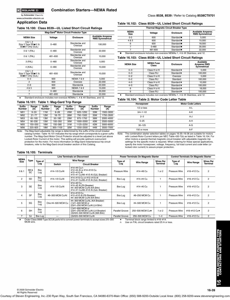
www.schneider-electric.us
16N
EM
A D
EF
INIT
E P
UR
PO
SE
TY
PE
C
ON
TA
CT
OR
S A
ND
ST
AR
TE
RS
© 2009 Schneider ElectricAll Rights Reserved
16-39
Combination Starters—NEMA RatedClass 8538, 8539 / Refer to Catalog 8538CT9701
Application Data
a Standard enclosure includes non-oversize NEMAs 1, 4 & 4X Stainless, and 12.
Note: The Mag-Gard adjustable trip range is determined by the suffix of the circuit breaker catalog number. Table 16.101 indicates the trip range which corresponds to a given suffix number. The Mag-Gard Motor Circuit Protector should be adjusted to a level just above Locked-Rotor Current of the motor. This setting will provide optimum overcurrent protection for the motor. For more information on Mag-Gard instantaneous trip circuit breakers, refer to the Mag-Gard circuit breaker section of this Catalog.
b Standard enclosure includes non-oversize NEMAs 1, 4 & 4X Stainless, and 12.
c Standard enclosure includes non-oversize NEMAs 1, 4 & 4X Stainless, and 12.
Note: The combination starter selection tables on pages 16-35–16-36 are suitable for motors with Locked-Rotor Current letters per NEC Table 430-7(b) as listed in Table 16.104. For other motors a special thermal magnetic circuit breaker with adjustable magnetic trip settings for the specific motor is required. When ordering for these special applications, specify the motor horsepower, voltage, frequency, full load current and code letter (or locked rotor current) to assure proper protection.
d Order Class 9999 Type SCU6 parts kit to convert power terminals to accept sizes 2/0–300 MCM wire.
e Terminal block range limited to #16–#14.f Use on FAL circuit breakers rated 25 A or less.
Table 16.100: Class 8539—UL Listed Short Circuit RatingsMag-Gard® Motor Circuit Protector Type
NEMA Size Voltage Enclosure Available AmperesRMS Symmetrical
0 & 1, 2Size 3 Type SE●41 &
SE●51 Only (GJL)0–480 Standarda and
Oversize 100,000
0 & 1 (FAL) 0–480 Standarda andOversize 22,000
0 & 1 (FAL) 481–600 Standarda andOversize 10,000
3 (FAL) 0–480 Standarda andOversize 5,000
4 (KAL) 0–480 Standarda andOversize 10,000
0 & 1, 2Size 3 Type SE●41 &
SE●51 Only (GJL)481–600 Standarda and
Oversize 10,000
0–3 600 NEMA 7 & 9 5,0002 600 Oversize 22,000
2–6 600 Standarda 22,0004 & 5 600 NEMA 7 & 9 10,000
7 0–480 Standarda 30,0007 481–600 Standarda 22,000
Table 16.101: Table 1: Mag-Gard Trip RangeSuffix
NumberRange
(A)Suffix
NumberRange
(A)Suffix
NumberRange
(A)Suffix
NumberRange
(A)
M01 9–33 11M 8–28 25M 625–1250 33M 1500–3000M02 21–77 12M 18–70 26M 750–1500 35M 1750–3500M03 45–165 13M 50–180 29M 875–1750 36M 2000–4000M04 90–330 15M 100–350 30M 1000–2000 40M 2500–5000M05 150–550 16M 150–580 31M 1125–2250 42M 3000–6000M06 225–825 18M 300–1100 32M 1250–2500 44M 3500–7000
Table 16.102: Class 8539—UL Listed Short Circuit RatingsThermal Magnetic Circuit Breaker Type
NEMASize Voltage Enclosure Available Amperes
RMS Symmetrical
0-3 600 Standardb 5,0004 & 5 600 Standardb 10,000
6 600 Standardb 18,0007 0-480 Standardb 30,0007 481-600 Standardb 22,000
Table 16.103: Class 8538—UL Listed Short Circuit Ratings
NEMA Size NEMA FuseClass Enclosure
AvailableAmperes RMSSymmetrical
0–3 Class H or K Standardc 5,0000–3 Class R/J Standardc 100,0000–2 Class H or K Oversize 5,0000–2 Class R/J Standard 100,0004–5 Class H or K Standardc 10,0004–5 Class R/J Standardc 100,0006 Class H or K Standardc 18,0006 Class R/J Standardc 100,000
Table 16.104: Table 2: Motor Code Letter TableHorsepower Motor Code Letters
1/2 or less A-L
3/4–1-1/2 A-K
2–3 A-J
5–25 A-H
30–125 A-G
150 or more A-F
Table 16.105: Terminals
NEMASize Type
Line Terminals on Disconnect Power Terminals On Magnetic Starter Control Terminals On Magnetic Starter
Type ofLug
Wire Range Type ofLug Wire Range Wires Per
TerminalType of
Lug Wire Range Wires PerTerminalSwitch Circuit Breaker
0 & 1 SB & SC
Box Lug #14–1/0 Cu/Al
#14–#4 Cuf#12–#4 Al or #14–#1/0 Cu#12–#1/0 Al#14–#1 Cu/#8–#1/0 Al (GJL Breaker)
Pressure Wire #14–#8 Cu 1 or 2 Pressure Wire #16–#12 Cu 2
2 SD Box Lug #14–1/0 Cu/Al #14–#1/0 Cu or #12–#1/0 Al
#14–#1 Cu/#8–#1/0 Al (GJL Breaker) Box Lug #14–#4 Cu 1 Pressure Wire #16–#12 Cu 2
3 SE Box Lug #14–1/0 Cu/Al
#14–#2 Cu#10–#2 Al (FA Breaker)#4–300 MCM Cu/Al (KA Brkr)#14–#1 Cu/#8–#1/0 Al (GJL Breaker)
Box Lug #14–#0 Cu 1 Pressure Wire #16–#12 Cu 2
4 SF BoxLug #6–300 MCM Cu/Al
#14–#1/0 Cu#12–#1/0 Al (FA Breaker)#4–300 MCM Cu/Al (KA Brkr)
Box Lug #8–250 MCM Cu 1 Pressure Wire #16–#12 Cu 2
5 SG BoxLug One #4–500 MCM Cu
#4–300 MCM Cu/AL (KA Breaker)(1)#1–600 MCM or(2)#1–250 MCM Cu/Al (LA Brkr)
Box Lug #4–500 MCM Cu 1 Pressure Wire #16–#12 Cu 2
6 SH Box Lug —
(1)#1–600 MCM or(2)#1–250 MCM Cu/Al (LA Breaker)(3)#3/0–500 MCM Cu/Al (MA Brkr)
Parallel Groove 250–500 MCM Cud 1 or 2 Pressure Wire #16–#12 Cue 2
7 SJ Box Lug — (3)#3/0–500 MCM Cu/Al Parallel Groove 250–500 MCM Cu 1–4 Pressure Wire #16–#12 Cu 2
Courtesy of Steven Engineering, Inc.-230 Ryan Way, South San Francisco, CA 94080-6370-Main Office: (650) 588-9200-Outside Local Area: (800) 258-9200-www.stevenengineering.com
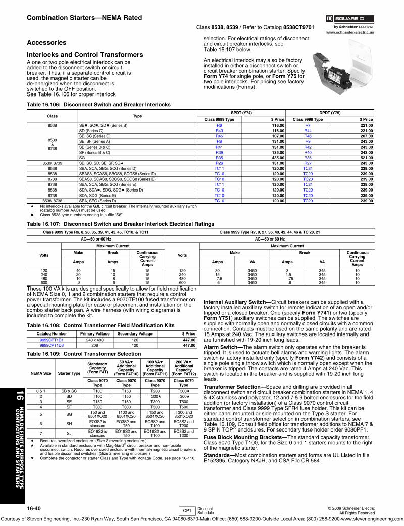
www.schneider-electric.us
16N
EM
A D
EF
INIT
E P
UR
PO
SE
TY
PE
C
ON
TA
CT
OR
S A
ND
ST
AR
TE
RS
16-40 © 2009 Schneider ElectricAll Rights Reserved
Combination Starters—NEMA RatedClass 8538, 8539 / Refer to Catalog 8538CT9701
Accessories
Interlocks and Control TransformersA one or two pole electrical interlock can be added to the disconnect switch or circuit breaker. Thus, if a separate control circuit is used, the magnetic starter can be de-energized when the disconnect is switched to the OFF position. See Table 16.106 for proper interlock
selection. For electrical ratings of disconnect and circuit breaker interlocks, see Table 16.107 below.
An electrical interlock may also be factory installed in either a disconnect switch or circuit breaker combination starter. Specify Form Y74 for single pole, or Form Y75 for two pole interlocks. For pricing see factory modifications (Forms).
a No interlocks available for the GJL circuit breaker. The internally mounted auxiliary switch (catalog number AAC) must be used.
b Class 8538 type numbers ending in suffix “S8”.
These 100 VA kits are designed specifically to allow for field modification of NEMA Size 0, 1 and 2 combination starters that require a control power transformer. The kit includes a 9070TF100 fused transformer on a special mounting plate for ease of placement and installation on the combo starter back pan. A wire harness (with wiring diagrams) is included to complete the kit.
c Requires oversized enclosure. (Size 2 reversing enclosure.)d Available in standard enclosure with Mag-Gard® circuit breaker and non-fusible
disconnect switch. Requires oversized enclosure with thermal-magnetic circuit breakers and fusible disconnect switches. (Size 2 reversing enclosure.)
e Complete the contactor or starter Class and Type with Voltage Code, see page 16-110.
Internal Auxiliary Switch—Circuit breakers can be supplied with a factory installed auxiliary switch for remote indication of an open and/or tripped or a closed breaker. One (specify Form Y741) or two (specify Form Y751) auxiliary switches can be supplied. The switches are supplied with normally open and normally closed circuits with a common connection. Contacts must be used on the same polarity and are rated 15 Amps at 240 Vac. The auxiliary switches are located internally and are furnished with 19-20 inch long leads.Alarm Switch—The alarm switch only operates when the breaker is tripped. It is used to actuate bell alarms and warning lights. The alarm switch is factory installed only (specify Form Y742) and consists of a single pole single throw switch which is normally open except when the breaker is tripped. The contacts are rated 4 Amps at 240 Vac. This switch is located in the breaker and is supplied with 19-20 inch long leads.Transformer Selection—Space and drilling are provided in all disconnect switch and circuit breaker combination starters in NEMA 1, 4 & 4X stainless and polyester, 12 and 7 & 9 bolted enclosures for the field addition (or factory installation) of a Class 9070 control circuit transformer and Class 9999 Type SFR4 fuse holder. This kit can be either panel mounted or side mounted on the Type S starter. For standard control transformer selection in combination starters, see Table 16.109. Consult field office for transformer additions to NEMA 7 & 9 SPIN TOP® enclosures. For secondary fuse holder order 9080PF1.Fuse Block Mounting Brackets—The standard capacity transformer, Class 9070 Type T100, for the Size 0 and 1 starters mounts to the right of the magnetic starter.Standards—Most combination starters and forms are UL Listed in file E152395, Category NKJH, and CSA File CR 584.
Table 16.106: Disconnect Switch and Breaker Interlocks
Class TypeSPDT (Y74) DPDT (Y75)
Class 9999 Type $ Price Class 9999 Type $ Price
8538 SBb, SCb, SDb (Series B) R6 116.00 R7 221.00
8538&
8738
SD (Series C) R43 116.00 R44 221.00SB, SC (Series C) R45 107.00 R46 207.00SE, SF (Series A) R8 131.00 R9 243.00SE (Series B & C) R41 131.00 R42 243.00SF (Series B & C) R39 135.00 R40 243.00SG R35 435.00 R36 521.00
8539, 8739 SB, SC, SD, SE, SF, SGa R26 131.00 R27 243.008538 SBA, SCA, SBG, SCG (Series D) TC11 120.00 TC21 239.008538 SBAS8, SCAS8, SBGS8, SCGS8 (Series D) TC10 120.00 TC20 239.008738 SBAS8, SCAS8, SBGS8, SCGS8 (Series E) TC10 120.00 TC20 239.008738 SBA, SCA, SBG, SCG (Series E) TC11 120.00 TC21 239.008538 SDA, SDAb, SDG, SDGb (Series D) TC10 120.00 TC20 239.008738 SDA, SDG (Series E) TC10 120.00 TC20 239.00
8538, 8738 SEA, SEG (Series D) TC10 120.00 TC20 239.00
Table 16.107: Disconnect Switch and Breaker Interlock Electrical RatingsClass 9999 Type R6, 8, 26, 35, 39, 41, 43, 45, TC10, & TC11 Class 9999 Type R7, 9, 27, 36, 40, 42, 44, 46 & TC 20, 21
AC—50 or 60 Hz AC—50 or 60 Hz
Volts
Maximum Current
Volts
Maximum Current
Make Break ContinuousCarrying CurrentAmps
Make Break ContinuousCarryingCurrentAmps
Amps Amps Amps VA Amps VA
120240480600
4020108
151086
15151515
120240480600
30157.56
3450345034503450
3 1.5
.75.6
345345345345
10101010
Table 16.108: Control Transformer Field Modification Kits Catalog Number Primary Voltage Secondary Voltage $ Price
9999CPT1D1 240 x 480 120 447.009999CPT1D3 208 120 447.00
Table 16.109: Control Transformer Selection
NEMA Size Starter Type
Standarde Capacity
(Form F4T)
50 VAe Additional Capacity
(Form F4T10)
100 VAeAdditional Capacity
(Form F4T11)
200 VAeAdditional Capacity
(Form F4T12)
Class 9070Type
Class 9070Type
Class 9070Type
Class 9070Type
0 & 1 SB & SC T100 T150 T200 T300c2 SD T100 T150 T300d T300d3 SE T150 T150 T300 T5004 SF T300 T300 T500 T500
5 SG T50 and8501XO20
T100 and8501XO20
T150 and8501XO20
T300 and8501XO20
6 SH EO3S2 isstandard
EO3S2 andT50
EO3S2 andT100
EO3S2 andT200
7 SJ EO19S2 isstandard
EO19S2 andT50
EO19S2 andT100
EO3S2 andT200
CP1 Discount Schedule
Courtesy of Steven Engineering, Inc.-230 Ryan Way, South San Francisco, CA 94080-6370-Main Office: (650) 588-9200-Outside Local Area: (800) 258-9200-www.stevenengineering.com
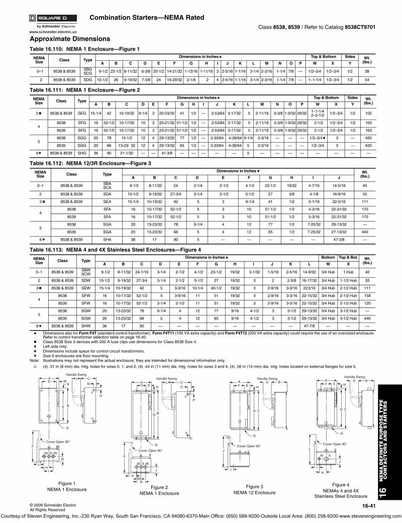
www.schneider-electric.us
16N
EM
A D
EF
INIT
E P
UR
PO
SE
TY
PE
C
ON
TA
CT
OR
S A
ND
ST
AR
TE
RS
© 2009 Schneider ElectricAll Rights Reserved
16-41
Combination Starters—NEMA RatedClass 8538, 8539 / Refer to Catalog 8538CT9701
Approximate Dimensions
a Dimensions also for Form F4T (standard control transformer). Form F4T11 (100 VA extra capacity) and Form F4T12 (200 VA extra capacity) could require the use of an oversized enclosure. Refer to control transformer selection table on page 16-40.
b Class 8538 Size 3 devices with 200 A fuse clips use dimensions for Class 8538 Size 4.c Left side only.d Dimensions include space for control circuit transformers.e Size 6 enclosures are floor mounting.
Note: Illustrations may not represent the actual enclosure; they are intended for dimensional information only.
f (4) .31 in (8 mm) dia. mtg. holes for sizes 0, 1, and 2, (4) .44 in (11 mm) dia. mtg. holes for sizes 3 and 4, (4) .56 in (14 mm) dia. mtg. holes located on external flanges for size 5.
Table 16.110: NEMA 1 Enclosure—Figure 1
NEMASize Class Type
Dimensions in Inchesa Top & Bottom Sides Wt.(lbs.)A B C D E F G H I J K L M N O P W X Y
0–1 8538 & 8539 SBGSCG 9-1/2 22-1/2 8-11/32 6-3/8 20-1/2 14-21/32 1-13/16 1-11/16 3 2-5/16 1-1/16 3-1/4 2-3/16 1-1/4 7/8 — 1/2–3/4 1/2–3/4 1/2 38
2 8538 & 8539 SDG 10-1/2 26 9-19/32 7-3/8 24 16-29/32 2-1/8 2 4 2-5/16 1-1/16 3-1/4 2-3/16 1-1/4 7/8 — 1–1-1/4 1/2–3/4 1/2 54
Table 16.111: NEMA 1 Enclosure—Figure 2
NEMASize Class Type
Dimensions in Inchesa Top & Bottom Sides Wt.(lbs.)A B C D E F G H I J K L M N O P W X Y
3b 8538 & 8539 SEG 15-1/4 42 10-19/32 9-1/4 3 22-23/32 41 1/2 — 2-53/64 3-17/32 5 2-11/16 5-3/8 1-9/32 29/32 1–1-1/42–2-1/2 1/2–3/4 1/2 102
48538 SFG 16 52-1/2 10-17/32 10 3 23-21/32 51-1/2 1/2 — 2-53/64 3-17/32 5 2-11/16 5-3/8 1-9/32 29/32 2-1/2 1/2–3/4 1/2 163
8539 SFG 16 52-1/2 10-17/32 10 3 23-21/32 51-1/2 1/2 — 2-53/64 3-17/32 5 2-11/16 5-3/8 1-9/32 29/32 2-1/2 1/2–3/4 1/2 163
58538 SGG 20 78 15-1/2 12 4 29-13/32 77 1/2 — 3-33/64 4-39/64 9-1/4 3-3/16 — — — 1/2–3/4c 3 — 450
8539 SGG 20 66 13-23⁄ 32 12 4 29-13/32 65 1/2 — 3-33/64 4-39/64 5 3-3/16 — — — 1/2–3/4 3 — 420
6e 8538 & 8539 SHG 36 90 21-1/32 — — 41-3/8 — — — — — 5 — — — — — — — —
Table 16.112: NEMA 12/3R Enclosure—Figure 3
NEMASize Class Type
Dimensions in Inchesd Wt.(lbs.)A B C D E F G H I J
0–1 8538 & 8539 SBASCA 9-1/2 8-11/32 24 3-1/4 2-1/2 4-1/2 23-1/2 19/32 4-7/16 14-5/16 40
2 8538 & 8539 SDA 10-1/2 9-19/32 27-3/4 3-1/4 2-1/2 5-1/2 27 3/8 4-1/8 16-9/16 55
3b 8538 & 8539 SEA 15-1/4 10-19/32 42 5 3 9-1/4 41 1/2 5-1/16 22-5/16 111
48538 SFA 16 10-17/32 52-1/2 5 3 10 51-1/2 1/2 4-3/16 22-31/32 170
8539 SFA 16 10-17/32 52-1/2 5 3 10 51-1/2 1/2 5-3/16 22-31/32 170
58538 SGA 20 13-23/32 78 9-1/4 4 12 77 1/2 7-25/32 29-13/32 —
8539 SGA 20 13-23/32 66 5 4 12 65 1/2 7-25/32 27-13/32 440
6e 8538 & 8539 SHA 36 17 90 5 — — — — — 47-3/8 —
Table 16.113: NEMA 4 and 4X Stainless Steel Enclosures—Figure 4
NEMASize Class Type
Dimensions in Inchesa Bottom Top & Bot. Wt.(lbs.)A B C D E F G H I J K L W X
0–1 8538 & 8539 SBWSCW 9-1/2 8-11/32 24-1/16 3-1/4 2-1/2 4-1/2 23-1/2 19/32 3-1/32 1-5/16 2-5/16 14-9/32 3/4 Hub 1 Hub 40
2 8538 & 8539 SDW 10-1/2 9-19/32 27-3/4 3-1/4 2-1/2 5-1/2 27 19/32 3 2 2-5/8 16-17/32 3/4 Hub 1-1/2 Hub 55
3b 8538 & 8539 SEW 15-1/4 10-19/32 42 5 3-3/16 10-1/4 40-1/2 19/32 3 2-9/16 3-3/16 223/16 3/4 Hub 2-1/2 Hub 111
48538 SFW 16 10-17/32 52-1/2 5 3-9/16 11 51 19/32 3 2-9/16 3-3/16 22-15/32 3/4 Hub 2-1/2 Hub 158
8539 SFW 16 10-17/32 52-1/2 3-1/4 2-1/2 11 51 19/32 3 2-9/16 3-3/16 22-15/32 3/4 Hub 2-1/2 Hub 120
58538 SGW 20 13-23/32 78 9-1/4 4 12 77 9/16 4-1/2 3 3-1/2 29-13/32 3/4 Hub 3-1/2 Hub —
8539 SGW 20 13-23/32 66 5 4 12 65 9/16 4-1/2 3 3-1/2 29-13/32 3/4 Hub 3-1/2 Hub 440
6e 8538 & 8539 SHW 36 17 90 — — — — — — — — 47-7/8 — — —
YO
N
CHandle Swing
E B
KMD
A
Y
F
W X W
G
JH
I
L
Cover Open 90°
f
Figure 1NEMA 1 Enclosure
Handle Swing
DA
E HL C
P
O
Y
BG
Y
J
NM
K
W X W
F
Cover Open 90°
Figure 2NEMA 1 Enclosure
f
Handle Swing
Cover Open 90°
B
C
FA
J
I
DE
G
H
f
Figure 3NEMA 12 Enclosure
Handle Swing
Cover Open 90°
B
C
FA
L
W X
I
DE
K
J
G
H
Figure 4NEMAs 4 and 4X
Stainless Steel Enclosure
f
Courtesy of Steven Engineering, Inc.-230 Ryan Way, South San Francisco, CA 94080-6370-Main Office: (650) 588-9200-Outside Local Area: (800) 258-9200-www.stevenengineering.com
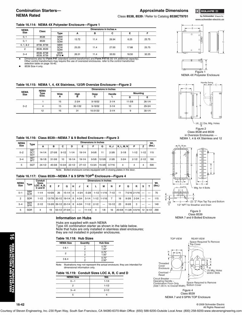
16-42 © 2009 Schneider ElectricAll Rights Reserved
www.schneider-electric.us
16N
EM
A D
EF
INIT
E P
UR
PO
SE
TY
PE
C
ON
TA
CT
OR
S A
ND
ST
AR
TE
RS
Combination Starters—NEMA Rated
Approximate DimensionsClass 8538, 8539 / Refer to Catalog 8538CT9701
Note: Bolted enclosure comes equipped with 3 closing plates in the door.
Information on HubsHubs are supplied with each NEMA Type 4X combination starter as shown in the table below. Note that hubs are only installed in stainless steel enclosures; they are not installed in polyester enclosures.
Note: Illustrations may not represent the actual enclosure; they are intended for dimensional information only.
Table 16.114: NEMA 4X Polyester Enclosure—Figure 1
NEMASize Class
Dimensions in Inchesa
Type A B C E F
0, 1 8538 SBWSCWSDW
13.72 11.4 26.94 6.25 25.750, 1 8539
0, 1, & 2 8738, 8739 SBWSCWSDW
25.25 11.4 27.00 17.88 25.752 8538, 8539
3–4 8538, 87388539, 8739
SEWSFWb
26.31 11.4 33.50 18.50 32.25
a Dimensions also for Form F4T (standard control transformer) and Form F4T10 (50 VA additional capacity). Other control transformers may require the use of oversized enclosures. refer to the control transformer selection table on page 16-40.
b 8539 Size 4 only.
A
E
F C
B
Figure 1NEMA 4X Polyester Enclosure
Table 16.115: NEMA 1, 4, 4X Stainless, 12/3R Oversize Enclosure—Figure 2
NEMASize
NEMATypeEncl.
Dimensions in Inches
WideA
HighB
DeepC
HandleL
Mounting
D E
0–2
1 15 2-3/4 9-19/32 3-1/4 11-5/8 26-1/4
4 15 30-1/32 9-19/32 3-1/4 10 29-3/4
12 15 31 10-31/32 3-1/4 9 30-1/4
CHandle Swing
E B
D
A
(4) .31 Dia. Mtg. Holes 8
L
Figure 2Class 8538 and 8539
in Oversize Enclosures —NEMA 1, 4 & 4X Stainless and 12Table 16.116: Class 8539—NEMA 7 & 9 Bolted Enclosure—Figure 3
NEMASize Type
Dimensions in Inches Wt.(lbs.)A B C D E F G H, J K, L, M, N P Z
0–2SBTSCTSDT
14-1/4 27-5/8 9-1/2 1-1/4 19-1/4 9-5/8 11 2-3/8 3-1/8 1-1/2 1-1/2 115
3–4 SETSFT 18-1/8 31-5/8 10 16-1/4 19-1/4 9-5/8 12-5/8 2-3/8 3-3/4 2-1/2 2-1/2 180
5 SGT 24-1/2 45-5/8 13-3/4 22-1/2 27-1/2 13-3/4 15-3/8 3-7/16 4 4 4 500
Table 16.117: Class 8539—NEMA 7 & 9 SPIN TOP® Enclosure—Figure 4
NEMASize Type
Conduit Sizes
LOC. A, B, C and D
Dimensions in InchesWt.
(lbs.)E F G H J K L M N P Q R S T
0–1 SBRSCR 1-1/4 10-5/8 26 15-1/4 8 4-3/4 5-3/8 1-1/2 1-1/16 7-1/2 11 7-5/16 2-1/16 — — 70
2 SDR 1-1/2 13-7/8 30-1/2 19-1/4 8 4-3/4 5-1/4 1-1/2 1-1/16 7 18 9-3/8 2-3/4 — — 115
3–4 SERSFR 2-1/2 13-3/8 39-1/2 20-1/4 8 4-3/4 7-1/2 2-1/2 — 10-1/2 23 8-5/8 3 — — 140
5 SGR 4 19 53-1/2 27-3/4 — — 11-1/4 4 1/8 16 20-5/8 11-3/8 4-5/16 12 6-1/2 290
K
H
LA
N M
B
Mtg. for 4 Bolts
CG
F
E
D
J
.195
(2) "Z" Pipe Tap Top and Bottom1/2" NPT for Breather and Drain
Figure 3Class 8539
NEMA 7 and 9 Bolted Enclosure
Table 16.118: Hub SizesNEMA Size Quantity Hub Size
0 & 1 12
0.75"1.00"
2 12
0.75"1.50"
3 & 4 12
0.75"2.50"
Table 16.119: Conduit Sizes LOC A, B, C and DNEMA Size Std.
0—1 1-1/4
2 1-1/2
3—4 2-1/2
5 4
N
A
B D
C
J
P
F
M
HK
(3) Mtg. Holesand/or Slots
Space Required To RemoveTop Cover
REAR VIEW
Space Required to RemoveBottom Cover
Circuit Breaker Operating Handle –Combination Form Only(Add 1.00 In. to Overall Width)
OverloadReset
ThreadedCover Enclosure
EQR
G
TOP VIEW
Figure 4Class 8539
NEMA 7 and 9 SPIN TOP Enclosure
Courtesy of Steven Engineering, Inc.-230 Ryan Way, South San Francisco, CA 94080-6370-Main Office: (650) 588-9200-Outside Local Area: (800) 258-9200-www.stevenengineering.com
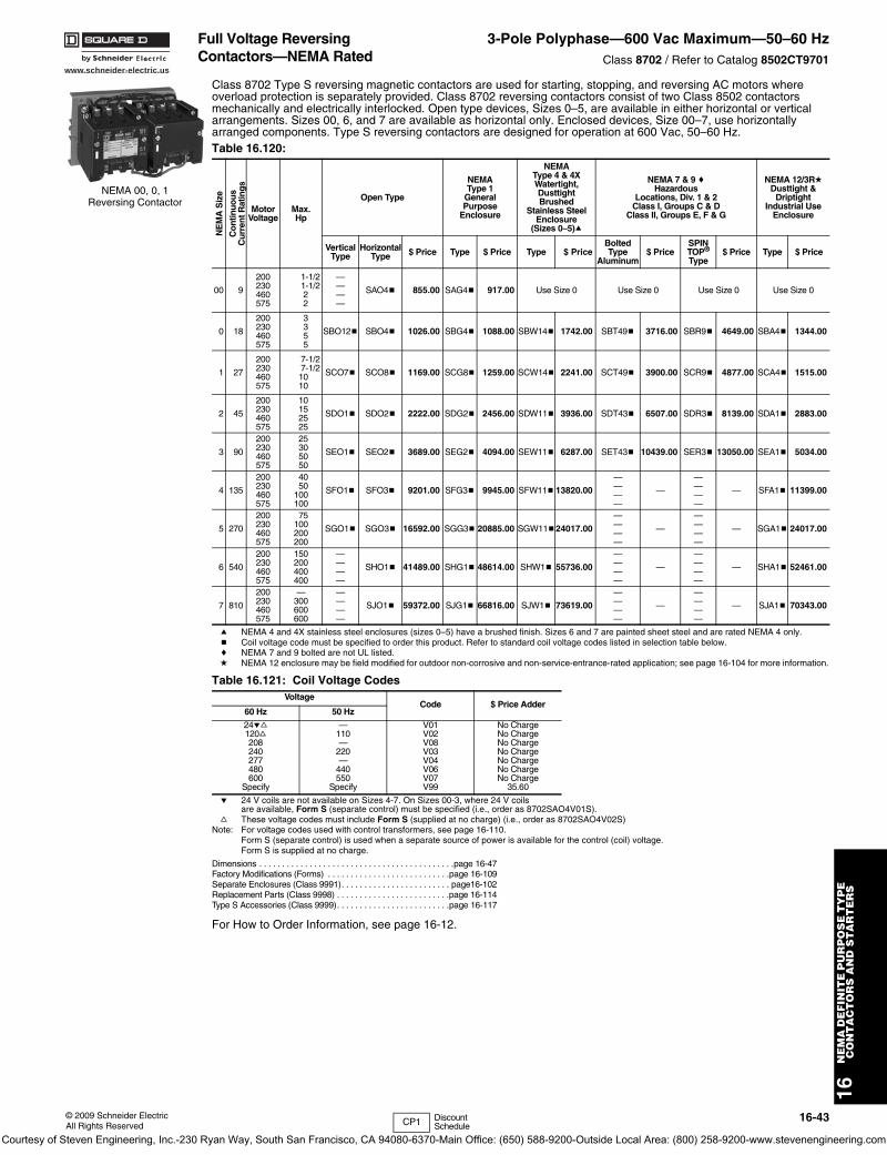
www.schneider-electric.us
16N
EM
A D
EF
INIT
E P
UR
PO
SE
TY
PE
C
ON
TA
CT
OR
S A
ND
ST
AR
TE
RS
© 2009 Schneider ElectricAll Rights Reserved
16-43
Full Voltage Reversing Contactors—NEMA Rated
3-Pole Polyphase—600 Vac Maximum—50–60 HzClass 8702 / Refer to Catalog 8502CT9701
Class 8702 Type S reversing magnetic contactors are used for starting, stopping, and reversing AC motors where overload protection is separately provided. Class 8702 reversing contactors consist of two Class 8502 contactors mechanically and electrically interlocked. Open type devices, Sizes 0–5, are available in either horizontal or vertical arrangements. Sizes 00, 6, and 7 are available as horizontal only. Enclosed devices, Size 00–7, use horizontally arranged components. Type S reversing contactors are designed for operation at 600 Vac, 50–60 Hz.
a NEMA 4 and 4X stainless steel enclosures (sizes 0–5) have a brushed finish. Sizes 6 and 7 are painted sheet steel and are rated NEMA 4 only.b Coil voltage code must be specified to order this product. Refer to standard coil voltage codes listed in selection table below.c NEMA 7 and 9 bolted are not UL listed.d NEMA 12 enclosure may be field modified for outdoor non-corrosive and non-service-entrance-rated application; see page 16-104 for more information.
e 24 V coils are not available on Sizes 4-7. On Sizes 00-3, where 24 V coils are available, Form S (separate control) must be specified (i.e., order as 8702SAO4V01S).
f These voltage codes must include Form S (supplied at no charge) (i.e., order as 8702SAO4V02S)Note: For voltage codes used with control transformers, see page 16-110.
Form S (separate control) is used when a separate source of power is available for the control (coil) voltage. Form S is supplied at no charge.
Dimensions . . . . . . . . . . . . . . . . . . . . . . . . . . . . . . . . . . . . . . . . . . .page 16-47Factory Modifications (Forms) . . . . . . . . . . . . . . . . . . . . . . . . . . .page 16-109Separate Enclosures (Class 9991). . . . . . . . . . . . . . . . . . . . . . . . page16-102Replacement Parts (Class 9998) . . . . . . . . . . . . . . . . . . . . . . . . .page 16-114Type S Accessories (Class 9999). . . . . . . . . . . . . . . . . . . . . . . . .page 16-117
For How to Order Information, see page 16-12.
Table 16.120:
NE
MA
Siz
e
Con
tinuo
usC
urr
ent R
atin
gs
MotorVoltage
Max.Hp
Open Type
NEMA Type 1
GeneralPurpose
Enclosure
NEMA Type 4 & 4XWatertight, DusttightBrushed
Stainless Steel Enclosure
(Sizes 0–5)a
NEMA 7 & 9 cHazardous
Locations, Div. 1 & 2Class I, Groups C & D
Class II, Groups E, F & G
NEMA 12/3RdDusttight &
DriptightIndustrial Use
Enclosure
VerticalType
HorizontalType $ Price Type $ Price Type $ Price
BoltedType
Aluminum$ Price
SPIN TOP®
Type$ Price Type $ Price
00 9
200230460575
1-1/21-1/222
————
SAO4b 855.00 SAG4b 917.00 Use Size 0 Use Size 0 Use Size 0 Use Size 0
0 18
200230460575
3355
SBO12b SBO4b 1026.00 SBG4b 1088.00 SBW14b 1742.00 SBT49b 3716.00 SBR9b 4649.00 SBA4b 1344.00
1 27
200230460575
7-1/27-1/21010
SCO7b SCO8b 1169.00 SCG8b 1259.00 SCW14b 2241.00 SCT49b 3900.00 SCR9b 4877.00 SCA4b 1515.00
2 45
200230460575
10152525
SDO1b SDO2b 2222.00 SDG2b 2456.00 SDW11b 3936.00 SDT43b 6507.00 SDR3b 8139.00 SDA1b 2883.00
3 90
200230460575
25305050
SEO1b SEO2b 3689.00 SEG2b 4094.00 SEW11b 6287.00 SET43b 10439.00 SER3b 13050.00 SEA1b 5034.00
4 135
200230460575
4050
100100
SFO1b SFO3b 9201.00 SFG3b 9945.00 SFW11b 13820.00
————
—
————
— SFA1b 11399.00
5 270
200230460575
75100200200
SGO1b SGO3b 16592.00 SGG3b 20885.00 SGW11b24017.00
————
—
————
— SGA1b 24017.00
6 540
200230460575
150200400400
————
SHO1b 41489.00 SHG1b 48614.00 SHW1b 55736.00
————
—
————
— SHA1b 52461.00
7 810
200230460575
—300600600
————
SJO1b 59372.00 SJG1b 66816.00 SJW1b 73619.00
————
—
————
— SJA1b 70343.00
Table 16.121: Coil Voltage CodesVoltage
Code $ Price Adder60 Hz 50 Hz
24ef120f208240277480600
Specify
—110—
220—
440550
Specify
V01V02V08V03V04V06V07V99
No ChargeNo ChargeNo ChargeNo ChargeNo ChargeNo ChargeNo Charge
35.60
NEMA 00, 0, 1Reversing Contactor
CP1 Discount Schedule
Courtesy of Steven Engineering, Inc.-230 Ryan Way, South San Francisco, CA 94080-6370-Main Office: (650) 588-9200-Outside Local Area: (800) 258-9200-www.stevenengineering.com
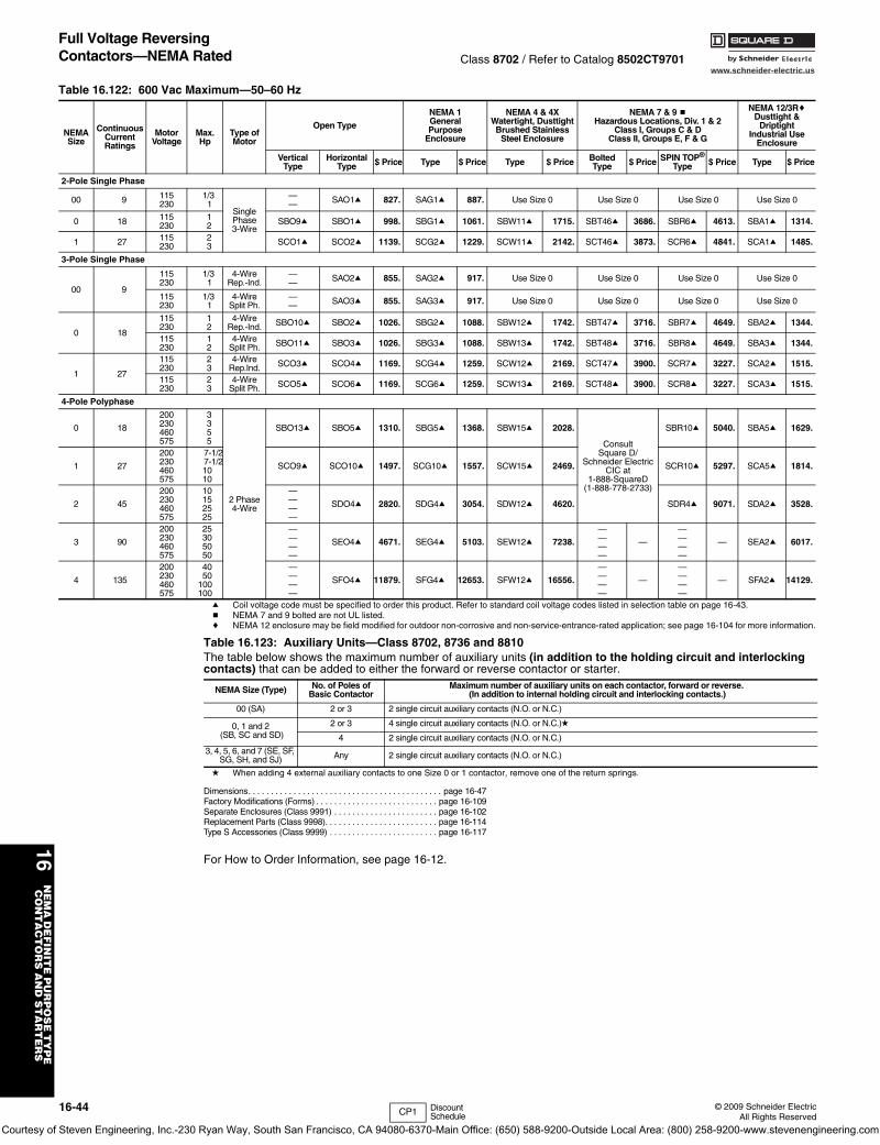
16-44 © 2009 Schneider ElectricAll Rights Reserved
www.schneider-electric.us
16N
EM
A D
EF
INIT
E P
UR
PO
SE
TY
PE
C
ON
TA
CT
OR
S A
ND
ST
AR
TE
RS
Full Voltage Reversing Contactors—NEMA Rated Class 8702 / Refer to Catalog 8502CT9701
a Coil voltage code must be specified to order this product. Refer to standard coil voltage codes listed in selection table on page 16-43.b NEMA 7 and 9 bolted are not UL listed.c NEMA 12 enclosure may be field modified for outdoor non-corrosive and non-service-entrance-rated application; see page 16-104 for more information.
d When adding 4 external auxiliary contacts to one Size 0 or 1 contactor, remove one of the return springs.
Dimensions. . . . . . . . . . . . . . . . . . . . . . . . . . . . . . . . . . . . . . . . . . . page 16-47Factory Modifications (Forms) . . . . . . . . . . . . . . . . . . . . . . . . . . . page 16-109Separate Enclosures (Class 9991) . . . . . . . . . . . . . . . . . . . . . . . page 16-102Replacement Parts (Class 9998). . . . . . . . . . . . . . . . . . . . . . . . . page 16-114Type S Accessories (Class 9999) . . . . . . . . . . . . . . . . . . . . . . . . page 16-117
For How to Order Information, see page 16-12.
Table 16.122: 600 Vac Maximum—50–60 Hz
NEMASize
ContinuousCurrentRatings
MotorVoltage
Max.Hp
Type ofMotor
Open Type
NEMA 1GeneralPurpose
Enclosure
NEMA 4 & 4XWatertight, DusttightBrushed Stainless
Steel Enclosure
NEMA 7 & 9 bHazardous Locations, Div. 1 & 2
Class I, Groups C & DClass II, Groups E, F & G
NEMA 12/3RcDusttight &
DriptightIndustrial Use
Enclosure
VerticalType
HorizontalType $ Price Type $ Price Type $ Price Bolted
Type $ Price SPIN TOP®
Type $ Price Type $ Price
2-Pole Single Phase
00 9 115230
1/3 1
SinglePhase3-Wire
—— SAO1a 827. SAG1a 887. Use Size 0 Use Size 0 Use Size 0 Use Size 0
0 18 115230
12 SBO9a SBO1a 998. SBG1a 1061. SBW11a 1715. SBT46a 3686. SBR6a 4613. SBA1a 1314.
1 27 115230
23 SCO1a SCO2a 1139. SCG2a 1229. SCW11a 2142. SCT46a 3873. SCR6a 4841. SCA1a 1485.
3-Pole Single Phase
00 9
115230
1/3 1
4-WireRep.-Ind.
—— SAO2a 855. SAG2a 917. Use Size 0 Use Size 0 Use Size 0 Use Size 0
115230
1/3 1
4-WireSplit Ph.
—— SAO3a 855. SAG3a 917. Use Size 0 Use Size 0 Use Size 0 Use Size 0
0 18
115230
12
4-WireRep.-Ind. SBO10a SBO2a 1026. SBG2a 1088. SBW12a 1742. SBT47a 3716. SBR7a 4649. SBA2a 1344.
115230
12
4-WireSplit Ph. SBO11a SBO3a 1026. SBG3a 1088. SBW13a 1742. SBT48a 3716. SBR8a 4649. SBA3a 1344.
1 27
115230
23
4-WireRep.Ind. SCO3a SCO4a 1169. SCG4a 1259. SCW12a 2169. SCT47a 3900. SCR7a 3227. SCA2a 1515.
115230
23
4-WireSplit Ph. SCO5a SCO6a 1169. SCG6a 1259. SCW13a 2169. SCT48a 3900. SCR8a 3227. SCA3a 1515.
4-Pole Polyphase
0 18
200230460575
3355
2 Phase4-Wire
SBO13a SBO5a 1310. SBG5a 1368. SBW15a 2028.
Consult Square D/
Schneider Electric CIC at
1-888-SquareD(1-888-778-2733)
SBR10a 5040. SBA5a 1629.
1 27
200230460575
7-1/27-1/21010
SCO9a SCO10a 1497. SCG10a 1557. SCW15a 2469. SCR10a 5297. SCA5a 1814.
2 45
200230460575
10152525
————
SDO4a 2820. SDG4a 3054. SDW12a 4620. SDR4a 9071. SDA2a 3528.
3 90
200230460575
25305050
————
SEO4a 4671. SEG4a 5103. SEW12a 7238.
————
—
————
— SEA2a 6017.
4 135
200230460575
4050
100100
————
SFO4a 11879. SFG4a 12653. SFW12a 16556.
————
—
————
— SFA2a 14129.
Table 16.123: Auxiliary Units—Class 8702, 8736 and 8810 The table below shows the maximum number of auxiliary units (in addition to the holding circuit and interlocking contacts) that can be added to either the forward or reverse contactor or starter.
NEMA Size (Type) No. of Poles of Basic Contactor
Maximum number of auxiliary units on each contactor, forward or reverse. (In addition to internal holding circuit and interlocking contacts.)
00 (SA) 2 or 3 2 single circuit auxiliary contacts (N.O. or N.C.)
0, 1 and 2 (SB, SC and SD)
2 or 3 4 single circuit auxiliary contacts (N.O. or N.C.)d
4 2 single circuit auxiliary contacts (N.O. or N.C.)
3, 4, 5, 6, and 7 (SE, SF, SG, SH, and SJ) Any 2 single circuit auxiliary contacts (N.O. or N.C.)
CP1 Discount Schedule
Courtesy of Steven Engineering, Inc.-230 Ryan Way, South San Francisco, CA 94080-6370-Main Office: (650) 588-9200-Outside Local Area: (800) 258-9200-www.stevenengineering.com
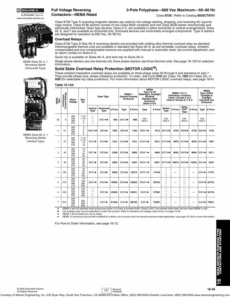
www.schneider-electric.us
16N
EM
A D
EF
INIT
E P
UR
PO
SE
TY
PE
C
ON
TA
CT
OR
S A
ND
ST
AR
TE
RS
© 2009 Schneider ElectricAll Rights Reserved
16-45
Full Voltage Reversing Contactors—NEMA Rated
3-Pole Polyphase—600 Vac Maximum—50–60 HzClass 8736 / Refer to Catalog 8502CT9701
Class 8736 Type S reversing magnetic starters are used for full-voltage starting, stopping, and reversing AC squirrel cage motors. Class 8736 starters consist of one Class 8502 contactor and one Class 8536 starter mechanically and electrically interlocked. Open type devices, Sizes 0–5, are available in either horizontal or vertical arrangements. Sizes 00, 6, and 7 are available as horizontal only. Enclosed devices use horizontally arranged components. Type S starters are designed for operation at 600 Vac, 50–60 Hz.
Overload RelaysClass 8736 Type S Size 00–6 reversing starters are provided with melting alloy thermal overload relay as standard. Interchangeable thermal units are available in standard trip Sizes 00–6, as are bimetallic overload relays. Ambient compensated and non-compensated versions are supplied with manual or automatic reset, trip current adjustment, and an alarm contact on Sizes 0–2.Quick trip is available on Sizes 00–4, and slow trip on Sizes 00–3. Single phase starters use one thermal unit; three phase starters use three thermal units. See page 16-125 for selection information.
Solid State Overload Relay Protection (MOTOR LOGIC®)These ambient insensitive overload relays are available on three phase sizes 00 through 6 and standard on size 7. They provide phase loss, phase unbalance protection. To order, add Form H10 (for Class 10), H20 (for Class 20), or H30 (for selectable trip class protection). For more information about MOTOR LOGIC overload relays, see page 16-91.
a NEMA 4 and 4X stainless steel enclosures (sizes 0–5) have a brushed finish. Sizes 6 and 7 are painted sheet steel and are rated NEMA 4 only.b Coil voltage code must be specified to order this product. Refer to standard coil voltage codes shown on page 16-46.c NEMA 7 and 9 bolted are not UL listed.d NEMA 12 enclosure may be field modified for outdoor non-corrosive and non-service-entrance-rated application; see page 16-104 for more information.
For How to Order Information, see page 16-12.
Table 16.124:
NE
MA
Siz
e
Con
tinuo
usC
urre
nt R
atin
gs
MotorVoltage
Max.Hp
Open TypeNEMA 1
General PurposeEnclosure
NEMA Type 4 & 4X
Watertight, DusttightBrushed
Stainless SteelEnclosure
(Sizes 0–5)a
NEMA 7 & 9 cHazardous LocationsClass I, Groups C & D
Class II, Groups E, F & G
NEMA Type 12/3RdDusttight &
DriptightIndustrial Use
Enclosure
VerticalType
HorizontalType $ Price Type $ Price Type $ Price Bolted
Type $ PriceSPIN-TOP®
Type$ Price Type $ Price
00 9
200230460575
1-1/21-1/2
22
————
SAO16b 926. SAG16b 989. Use Size 0
UseSize 0
Use Size 0
Use Size 0
0 18
200230460575
3355
SBO10b SBO4b 1097. SBG4b 1160. SBW14b 1814. SBT49b 3794. SBR9b 4742. SBA4b 1416.
1 27
200230460575
7-1/27-1/2
1010
SCO7b SCO8b 1241. SCG8b 1331. SCW14b 2241. SCT49b 3978. SCR9b 4976. SCA4b 1587.
2 45
200230460575
10152525
SDO1b SDO2b 2349. SDG2b 2583. SDW11b 4064. SDT43b 6642. SDR3b 8064. SDA1b 3011.
3 90
200230460575
25305050
SEO1b SEO2b 3902. SEG2b 4307. SEW11b 6501. SET43b 10673. SER3b 13343. SEA1b 5247.
4 135
200230460575
4050
100100
SFO1b SFO3b 9530. SFG3b 10274. SFW11b 14148.
————
—
————
— SFA1b 11727.
5 270
200230460575
75100200200
SGO1b SGO3b 18309. SGG3b 22602. SGW11b 25734.
————
—
————
— SGA1b 25734.
6 540
200230460575
150200400400
————
SHO1b 43205. SHG1b 50331. SHW1b 57452.
————
—
————
— SHA1b 54176.
7 810
200230460575
–300600600
————
SJO1b 61250. SJG1b 68736. SJW1b 75497.
————
—
————
— SJA1b 72221.
NEMA Sizes 00, 0, 1Reversing Starter(Horizontal Type)
NEMA Sizes 00, 0, 1Reversing Starter
(Vertical Type)
CP1 Discount Schedule
Courtesy of Steven Engineering, Inc.-230 Ryan Way, South San Francisco, CA 94080-6370-Main Office: (650) 588-9200-Outside Local Area: (800) 258-9200-www.stevenengineering.com
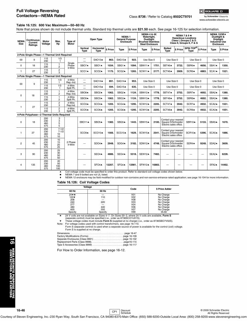
www.schneider-electric.us
16N
EM
A D
EF
INIT
E P
UR
PO
SE
TY
PE
C
ON
TA
CT
OR
S A
ND
ST
AR
TE
RS
16-46 © 2009 Schneider ElectricAll Rights Reserved
Full Voltage Reversing Contactors—NEMA Rated Class 8736 / Refer to Catalog 8502CT9701
a Coil voltage code must be specified to order this product. Refer to standard coil voltage codes shown below.b NEMA 7 and 9 bolted are not UL listed.c NEMA 12 enclosure may be field modified for outdoor non-corrosive and non-service-entrance-rated application; see page 16-104 for more information.
d 24 V coils are not available on Sizes 4–7. On Sizes 00–3, where 24 V coils are available, Form S(separate control) must be specified (i.e., order as 8736SCO1U01S).
e These voltage codes must include Form S (supplied at no charge) (i.e., order as 8736SBO7V02S).Note: For voltage codes used with control transformers, see page 16-110.
Form S (separate control) is used when a separate source of power is available for the control (coil) voltage. Form S is supplied at no charge.
Dimensions. . . . . . . . . . . . . . . . . . . . . . . . . . . . . . . . . . . . . . . . . . . page 16-47Factory Modifications (Forms) . . . . . . . . . . . . . . . . . . . . . . . . . . . page 16-109Separate Enclosures (Class 9991) . . . . . . . . . . . . . . . . . . . . . . . page 16-102Replacement Parts (Class 9998). . . . . . . . . . . . . . . . . . . . . . . . . .page16-114Type S Accessories (Class 9999) . . . . . . . . . . . . . . . . . . . . . . . . page 16-117
For How to Order Information, see page 16-12.
Table 16.125: 600 Vac Maximum—50–60 HzNote that prices shown do not include thermal units. Standard trip thermal units are $21.50 each. See page 16-125 for selection information.
NEMASize
ContinuousCurrentRatings
MotorVoltage
Max.Hp
Type ofMotor
Open TypeNEMA 1
General PurposeEnclosure
NEMA 4 & 4XWatertight, Dusttight
Brushed StainlessSteel Enclosure
NEMA 7 & 9 b Hazardous LocationsClass I, Groups C & D
Class II, Groups E, F & G
NEMA 12/3RcDusttight &
DriptightIndustrial Use
Enclosure
VerticalType
HorizontalType $ Price Type $ Price Type $ Price Bolted
Type $ Price SPIN TOP®
Type $ Price Type $ Price
2-Pole Single Phase—1 Thermal Unit Required
00 9 115230
1/3 1
Single Phase3-Wire
—— SAO13a 863. SAG13a 923. Use Size 0 Use Size 0 Use Size 0 Use Size 0
0 18 115230
12 SBO7a SBO1a 1034. SBG1a 1094. SBW11a 1751. SBT46a 3722. SBR6a 4656. SBA1a 1350.
1 27 115230
23 SCO1a SCO2a 1175. SCG2a 1265. SCW11a 2177. SCT46a 3909. SCR6a 4883. SCA1a 1521.
3-Pole Single Phase—1 Thermal Unit Required
00 9
115230
1/31
4-WireRep.-Ind.
—— SAO14a 891. SAG14a 953. Use Size 0 Use Size 0 Use Size 0 Use Size 0
115230
1/3 1
4-WireSplit Ph.
—— SAO15a 594. SAG15a 635. Use Size 0 Use Size 0 Use Size 0 Use Size 0
0 18
115230
12
4-WireRep.-Ind. SBO8a SBO2a 1062. SBG2a 1124. SBW12a 1778. SBT47a 3752. SBR7a 4692. SBA2a 1380.
115230
12
4-WireSplit Ph. SBO9a SBO3a 1062. SBG3a 1124. SBW13a 1778. SBT48a 3752. SBR8a 4692. SBA3a 1380.
1 27
115230
23
4-WireRep.Ind. SCO3a SCO4a 1205. SCG4a 1295. SCW12a 2205. SCT47a 3942. SCR7a 4932. SCA2a 1551.
115230
23
4-WireSplit Ph. SCO5a SCO6a 1205. SCG6a 1295. SCW13a 2205. SCT48a 3942. SCR8a 4932. SCA3a 1551.
4-Pole Polyphase—2 Thermal Units Required
0 18
200230460575
3355
2 Phase4-Wire
SBO11a SBO5a 1382. SBG5a 1443. SBW15a 2100.Contact your nearest Square D/Schneider Electric sales office.
SBR10a 5133. SBA5a 1670.
1 27
200230460575
7-1/27-1/2
1010
SCO9a SCO10a 1566. SCG10a 1629. SCW15a 2541.Contact your nearest Square D/Schneider Electric sales office.
SCR10a 5396. SCA5a 1886.
2 45
200230460575
10152525
— SDO4a 2948. SDG4a 3182. SDW12a 4748.Contact your nearest Square D/Schneider Electric sales office.
SDR4a 9248. SDA2a 3609.
3 90
200230460575
25305050
— SEO4a 4886. SEG4a 5318. SEW12a 7482. — — — — SEA2a 6228.
4 135
200230460575
4050
100100
— SFO4a 12207. SFG4a 12981. SFW12a 16883. — — — — SFA2a 14462.
Table 16.126: Coil Voltage CodesVoltage
Code $ Price Adder60 Hz 50 Hz
24ed120e208240277480600
Specify
—110—
220—
440550
Specify
V01V02V08V03V04V06V07V99
No ChargeNo ChargeNo ChargeNo ChargeNo ChargeNo ChargeNo Charge
35.60
CP1 Discount Schedule
Courtesy of Steven Engineering, Inc.-230 Ryan Way, South San Francisco, CA 94080-6370-Main Office: (650) 588-9200-Outside Local Area: (800) 258-9200-www.stevenengineering.com
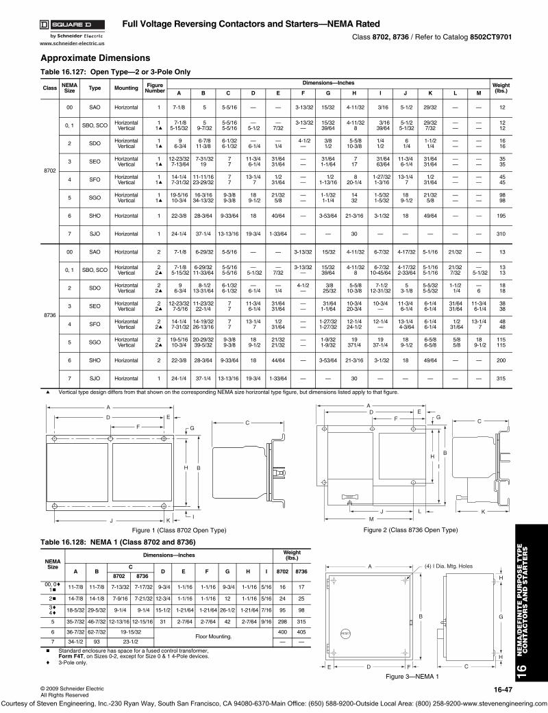
www.schneider-electric.us
16N
EM
A/D
EF
INIT
E P
UR
PO
SE
TY
PE
CO
NT
AC
TO
RS
AN
D S
TA
RT
ER
S
© 2009 Schneider ElectricAll Rights Reserved
16-47
Full Voltage Reversing Contactors and Starters—NEMA RatedClass 8702, 8736 / Refer to Catalog 8502CT9701
Approximate Dimensions
a Vertical type design differs from that shown on the corresponding NEMA size horizontal type figure, but dimensions listed apply to that figure.
b Standard enclosure has space for a fused control transformer,Form F4T, on Sizes 0-2, except for Size 0 & 1 4-Pole devices.
c 3-Pole only.
Table 16.127: Open Type—2 or 3-Pole Only
Class NEMASize Type Mounting Figure
NumberDimensions—Inches Weight
(lbs.)A B C D E F G H I J K L M
8702
00 SAO Horizontal 1 7-1/8 5 5-5/16 — — 3-13/32 15/32 4-11/32 3/16 5-1/2 29/32 — — 12
0, 1 SBO, SCO HorizontalVertical
11a
7-1/85-15/32
59-7/32
5-5/165-5/16
— 5-1/2
—7/32
3-13/32—
15/3239/64
4-11/328
3/16 39/64
5-1/25-1/32
29/327/32
——
——
1212
2 SDO HorizontalVertical
11a
96-3/4
6-7/811-3/8
6-1/326-1/32
—6-1/4
—1/4
4-1/2—
3/81/2
5-5/810-3/8
1/41/2
61/4
1-1/21/4
——
——
1616
3 SEO HorizontalVertical
11a
12-23/327-13/64
7-31/3219
77
11-3/46-1/4
31/6431/64
——
31/641-1/64
717
31/64 63/64
11-3/46-1/4
31/6431/64
——
——
3535
4 SFO HorizontalVertical
11a
14-1/47-31/32
11-11/1623-29/32
77
13-1/47
1/231/64
——
1/21-13/16
820-1/4
1-27/321-3/16
13-1/47
1/231/64
——
——
4545
5 SGO HorizontalVertical
11a
19-5/1610-3/4
16-3/1634-13/32
9-3/89-3/8
189-1/2
21/325/8
——
1-1/321-1/4
1432
1-5/321-5/32
189-1/2
21/325/8
——
——
9898
6 SHO Horizontal 1 22-3/8 28-3/64 9-33/64 18 40/64 — 3-53/64 21-3/16 3-1/32 18 49/64 — — 195
7 SJO Horizontal 1 24-1/4 37-1/4 13-13/16 19-3/4 1-33/64 — — 30 — — — — — 310
8736
00 SAO Horizontal 2 7-1/8 6-29/32 5-5/16 — — 3-13/32 15/32 4-11/32 6-7/32 4-17/32 5-1/16 21/32 — 13
0, 1 SBO, SCO HorizontalVertical
22a
7-1/85-15/32
6-29/3211-33/64
5-5/165-5/16
—5-1/32
—7/32
3-13/32—
15/3239/64
4-11/328
6-7/3210-45/64
4-17/322-33/64
5-1/165-1/16
21/327/32
—5-1/32
1313
2 SDO HorizontalVertical
22a
96-3/4
8-1/213-31/64
6-1/326-1/32
—6-1/4
—1/4
4-1/2—
3/8 25/32
5-5/810-3/8
7-1/212-31/32
53-1/8
5-5/325-5/32
1-1/2 1/4
—6
1818
3 SEO HorizontalVertical
22a
12-23/327-5/16
11-23/3222-1/4
77
11-3/46-1/4
31/6431/64
——
31/641-1/64
10-3/420-3/4
10-3/4—
11-3/46-1/4
6-1/46-1/4
31/64 31/64
11-3/46-1/4
3838
4 SFO HorizontalVertical
22a
14-1/47-31/32
14-19/3226-13/16
77
13-1/47
1/231/64
——
1-27/321-27/32
12-1/424-1/2
12-1/4—
13-1/44-3/64
6-1/46-1/4
1/2 31/64
13-1/47
4848
5 SGO HorizontalVertical
22a
19-5/1610-3/4
20-29/3239-5/32
9-3/89-3/8
189-1/2
21/3221/32
——
1-9/321-9/32
19371/4
1937-1/4
189-1/2
6-5/86-5/8
5/8 5/8
189-1/2
115115
6 SHO Horizontal 2 22-3/8 28-3/64 9-33/64 18 44/64 — 3-53/64 21-3/16 3-1/32 18 49/64 — — 200
7 SJO Horizontal 1 24-1/4 37-1/4 13-13/16 19-3/4 1-33/64 — — 30 — — — — — 315
Table 16.128: NEMA 1 (Class 8702 and 8736)
NEMASize
Dimensions—Inches Weight(lbs.)
A BC
D E F G H I 8702 87368702 8736
00, 0c1b 11-7/8 11-7/8 7-13/32 7-17/32 9-3/4 1-1/16 1-1/16 9-3/4 1-1/16 5/16 16 17
2b 14-7/8 14-1/8 7-9/16 7-21/32 12-3/4 1-1/16 1-1/16 12 1-1/16 5/16 24 25
3c4c 18-5/32 29-5/32 9-1/4 9-1/4 15-1/2 1-21/64 1-21/64 26-1/2 1-21/64 7/16 95 98
5 35-7/32 46-7/32 12-13/16 12-15/16 31 2-7/64 2-7/64 42 2-7/64 9/16 298 315
6 36-7/32 62-7/32 19-15/32Floor Mounting.
400 405
7 34-1/2 93 23-1/2 — —
D
F
E
J K
G
H B
I
A
C
Figure 1 (Class 8702 Open Type)
C
RESET
MJ L
H
I
B
GE
FD
A
K
Figure 2 (Class 8736 Open Type)
RESET
A
B
H
H
CFDE
G
(4) I Dia. Mtg. Holes
Figure 3—NEMA 1
Courtesy of Steven Engineering, Inc.-230 Ryan Way, South San Francisco, CA 94080-6370-Main Office: (650) 588-9200-Outside Local Area: (800) 258-9200-www.stevenengineering.com
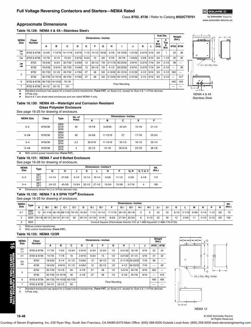
www.schneider-electric.us
16N
EM
A/D
EF
INIT
E P
UR
PO
SE
TY
PE
CO
NT
AC
TO
RS
AN
D S
TA
RT
ER
S
16-48 © 2009 Schneider ElectricAll Rights Reserved
Full Voltage Reversing Contactors and Starters—NEMA RatedClass 8702, 8736 / Refer to Catalog 8502CT9701
Approximate Dimensions
a Standard enclosure has space for a fused control transformer, Form F4T, on Sizes 0-2, except for Size 0 & 1 4-Pole devices.b 3-Pole only.c Size 6 & 7 are sheet steel enclosures and are rated NEMA 4 only.
d With control power transformer (Form F4T).
e Dimensions shown for 2 or 3-Pole devices only.
f Without control transformer. g With control transformer (Form F4T).
h Standard enclosure has space for a fused control transformer, Form F4T, on Sizes 0-2, except for Size 0 & 1 4-Pole devices.i 3-Pole only.
Table 16.129: NEMA 4 & 4X—Stainless Steelc
NEMASize
ClassNumber
Dimensions—InchesHub Dia. Weight
(lbs.)W
Bot.Only
XTop&
Bot.A B C D E F G H I J K L 8702 8736
0a1a 8702 & 8736 12-5/8 7-13/16 14-11/16 2-9/16 7-1/2 13-1/2 19/32 3-7/8 18-13/32 1-21/32 2-5/16 5/16 3/4 1 25 26
2a 8702 & 8736 14-7/8 8-1/4 15-3/4 2-9/16 9-3/4 15 3/8 3-7/8 20-7/8 1-23/32 2-5/8 5/16 3/4 1-1/2 33 35
3b4b
8702 18-5/32 8-3/4 32-7/32 3-5/64 12 30-1/2 7/8 3-11/16 26-23/32 2-9/16 3-3/16 7/16 3/4 2-1/2 96 —
8736 18-5/32 9-9/16 32-7/32 3-5/64 12 30-1/2 7/8 4-1/2 26-23/32 2-9/16 3-3/16 7/16 3/4 2-1/2 — 99
58702 35-7/32 12-1/8 49-7/32 4-7/64 27 48 5/8 4-19/32 45-13/16 2-31/32 3-1/2 9/16 3/4 3-1/2 300 —
8736 35-7/32 12-15/16 49-7/32 4-7/64 27 48 5/8 5-13/32 45-13/16 2-31/32 3-1/2 9/16 3/4 3-1/2 — 317
6 8702 & 8736 36-7/32 19-15/32 70-1/8Floor Mounting
500 505
7 8702 & 8736 34-1/2 23-1/2 101 — —
Table 16.130: NEMA 4X—Watertight and Corrosion Resistant Glass Polyester Enclosure
See page 16-25 for drawing of enclosure.
NEMA Size Class Type No. ofPoles
Dimensions—Inches
A B C E F
0–2 8702/36SBWSCWSDW
All 16-7/8 9-25/32 22-3/4 10-1/8 21-1/2
0–2d 8702/36SBWSCWSDW
All 24-5/8 11-15/16 27 17-7/8 25-3/4
3–4 8702/36 SEWSFW 2,3 26-5/16 11-15/16 33-1/2 18-1/2 32-1/4
3–4d 8702/36 SEWSFW 4 32-1/2 12-1/8 39-5/16 23-7/8 38-1/8
Table 16.131: NEMA 7 and 9 Bolted EnclosureSee page 16-26 for drawing of enclosure.
NEMASize Type
Dimensions—Inchese Wt.(lbs.)G H J K L N P Q, R S, T, U, V
0–2SBTSCTSDT
14-1/4 27-5/8 9-1/2 12-1/4 19-1/4 9-5/8 11-1/2 2-3/8 3-1/8 115
3–4 SETSFT 24-1/2 45-5/8 13-3/4 22-1/2 27-1/2 13-3/4 15-3/8 3-7/16 4 180
Table 16.132: NEMA 7 & 9 SPIN TOP® Enclosure See page 16-25 for drawing of enclosure.
NEMASize Type
Dimensions—Inches Wt.(lbs.)A Bf Bg Cf Cg D Ef Eg F Gf Gg Hf Hg Jf Jg K L M N P R
0-1 SBRSCR 12 41-1/16 46-1/8 68-1/16 79-1/8 16-3/4 7-1/4 12-1/4 7-11/16 26-1/8 26-1/8 3 9 24 24 8-1/2 2-1/16 9-3/8 5-1/4 1-1/2 3/8 70
2 SDR 16-1/8 48-1/2 50-1/2 81-1/2 85 20-1/4 12-1/8 9-1/8 8-5/8 27-3/4 32-3/4 8 4-1/2 25 30 12 2-5/8 11 5-1/2 2-1/2 3/8 100
3 SER Consult Square D/Schneider Electric CIC at 1-888-SquareD (1-888-778-2733)
Table 16.133: NEMA 12/3R
NEMASize
ClassNumber
Dimensions—Inches Weight(lbs.)
A B C D E F G H I J 8702 8736
0h1h 8702 & 8736 11-7/8 7-3/4 13-3/4 2-9/16 6-3/4 12-3/4 1/2 3-21/32 18-1/8 5/16 23 24
2h 8702 & 8736 14-7/8 7-7/8 16 2-9/16 9-3/4 15 1/2 3-21/32 21-1/4 5/16 31 32
3i4i
8702 18-5/32 9-1/4 31-1/2 3-5/64 12 30-1/2 1/2 3-11/16 26-23/32 7/16 96 —
8736 18-5/32 9-9/16 31-1/2 3-5/64 12 30-1/2 1/2 4-1/2 26-23/32 7/16 — 99
58702 35-7/32 13-1/8 49 4-1/8 27 48 1/2 5-5/16 45-7/8 9/16 302 —
8736 35-7/32 13-15/16 49 4-1/8 27 48 1/2 6-1/8 45-7/8 9/16 — 319
6 8702 & 8736 36-7/32 19-15/32 62-7/32Floor Mounting
490 495
7 8702 & 8736 34-1/2 23-1/2 93 — —
(4) L Dia. Mtg. Holes
GDEDA
CF
B
J
HK
W X
I
G
NEMA 4 & 4XStainless Steel
AD D G
F C
E
G
I
H
(4) J Dia. Mtg. Holes
B
NEMA 12
Courtesy of Steven Engineering, Inc.-230 Ryan Way, South San Francisco, CA 94080-6370-Main Office: (650) 588-9200-Outside Local Area: (800) 258-9200-www.stevenengineering.com
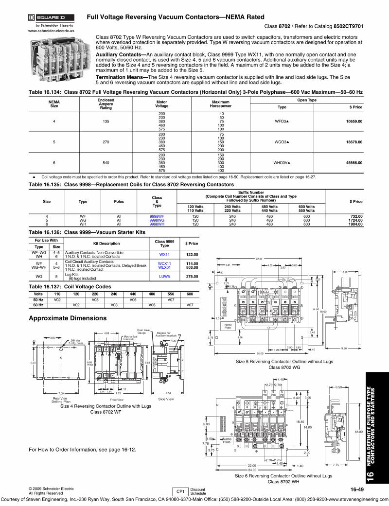
www.schneider-electric.us
16N
EM
A D
EF
INIT
E P
UR
PO
SE
TY
PE
C
ON
TA
CT
OR
S A
ND
ST
AR
TE
RS
© 2009 Schneider ElectricAll Rights Reserved
16-49
Full Voltage Reversing Vacuum Contactors—NEMA RatedClass 8702 / Refer to Catalog 8502CT9701
Class 8702 Type W Reversing Vacuum Contactors are used to switch capacitors, transformers and electric motors where overload protection is separately provided. Type W reversing vacuum contactors are designed for operation at 600 Volts, 50/60 Hz.Auxiliary Contacts—An auxiliary contact block, Class 9999 Type WX11, with one normally open contact and one normally closed contact, is used with Size 4, 5 and 6 vacuum contactors. Additional auxiliary contact units may be added to the Size 4 and 5 reversing contactors in the field. A maximum of 2 units may be added to the Size 4; a maximum of 1 unit may be added to the Size 5.Termination Means—The Size 4 reversing vacuum contactor is supplied with line and load side lugs. The Size 5 and 6 reversing vacuum contactors are supplied without line and load side lugs.
a Coil voltage code must be specified to order this product. Refer to standard coil voltage codes listed on page 16-50. Replacement coils are listed on page 16-27.
Approximate Dimensions
For How to Order Information, see page 16-12.
Table 16.134: Class 8702 Full Voltage Reversing Vacuum Contactors (Horizontal Only) 3-Pole Polyphase—600 Vac Maximum—50–60 Hz
NEMASize
EnclosedAmpereRating
MotorVoltage
MaximumHorsepower
Open Type
Type $ Price
4 135
200230380460575
405075
100100
WFO3a 10659.00
5 270
200230380460575
75100150200200
WGO3a 18678.00
6 540
200230380460575
150200300400400
WHO3Va 45666.00
Table 16.135: Class 9998—Replacement Coils for Class 8702 Reversing Contactors
Size Type PolesClass
&Type
Suffix Number(Complete Coil Number Consists of Class and Type
Followed by Suffix Number) $ Price120 Volts110 Volts
240 Volts220 Volts
480 Volts440 Volts
600 Volts550 Volts
456
WFWGWH
AllAllAll
9998WF9998WG9998WH
120120120
240240240
480480480
600600600
732.001724.001904.00
Table 16.136: Class 9999—Vacuum Starter KitsFor Use With
Kit Description Class 9999Type $ Price
Type Size
WF–WGWH
4–56
Auxiliary Contacts, Non-Convertible1 N.O. & 1 N.C. Isolated Contacts WX11 122.00
WFWG–WH
45–6
Coil Circuit Auxiliary Contacts1 N.O. & 1 N.C. Isolated Contacts, Delayed Break1 N.C. Isolated Contact
WCX11WLX01
114.00503.00
WG 5 Lug Kits(6) lugs included LUW5 275.00
Table 16.137: Coil Voltage CodesVolts 110 120 220 240 440 480 550 600
50 Hz V02 V03 V06 V0760 Hz V02 V03 V06 V07
PlateName
1.5
1.76 0.382.75
.60
5.81
22.00
4.002.50
3.65
2.00.86
6.90
14.0018.00
9.564.26
2.48
2.50 1.891.40
24.00
3.983.75
123
456
012
789
Size 5 Reversing Contactor Outline without LugsClass 8702 WG
3.50
3 mtg. holes.281 dia Interlock
Auxiliary InterlockGauge
MechanicalRecess For
Over travel
.44
gaug
eov
ertra
vel
4.20
6.88
4.88
6.549.75
1.131.441.44
Rear View Front View Side ViewDrilling Plan
max8.80
7.00
6.00
Size 4 Reversing Contactor Outline with LugsClass 8702 WF
2.70 2.70
4.40
3.40 3.90
6.50
16.40
14.0018.00
7.751.404.40
2.00
2.70 2.70
22.0024.00
PlateName
5.00
1.50
7.75
3.75
Size 6 Reversing Contactor Outline without LugsClass 8702 WH
CP1 Discount Schedule
Courtesy of Steven Engineering, Inc.-230 Ryan Way, South San Francisco, CA 94080-6370-Main Office: (650) 588-9200-Outside Local Area: (800) 258-9200-www.stevenengineering.com
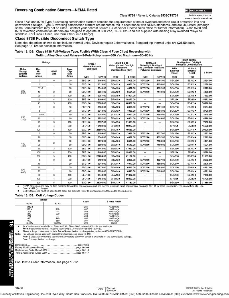
www.schneider-electric.us
16N
EM
A/D
EF
INIT
E P
UR
PO
SE
TY
PE
CO
NT
AC
TO
RS
AN
D S
TA
RT
ER
S
16-50 © 2009 Schneider ElectricAll Rights Reserved
Reversing Combination Starters—NEMA RatedClass 8738 / Refer to Catalog 8538CT9701
Class 8738 and 8739 Type S reversing combination starters combine the requirements of motor overload and short circuit protection into one convenient package. Type S reversing combination starters are manufactured in accordance with NEMA standards, and are UL Listed (although some Form numbers may not be listed—contact your nearest Square D/Schneider Electric sales office for further information). Class 8738 and 8739 reversing combination starters are designed to operate at 600 Vac, 50–60 Hz—and are supplied with melting alloy overload relays as standard. For Class J fuses, use form Y1072 (No Charge).
Class 8738 Fusible Disconnect Switch TypeNote: that the prices shown do not include thermal units. Devices require 3 thermal units. Standard trip thermal units are $21.50 each. See page 16-125 for selection information. 00
a NEMA 12 enclosures may be field modified for outdoor non-corrosive and non-service-entrance-rated applications; see page 16-104 for more information. For class J fuse clip, use Form Y1072 (no charge).
b Coil voltage code must be specified to order this product. Refer to standard coil voltage codes shown below.
c 24 V coils are not available on Sizes 4–7. On Sizes 00–3, where 24 V coils are available, Form S (separate control) must be specified (i.e., order as 8738SBG12V01S).
d These voltage codes must include Form S (supplied at no charge) (i.e., order as 8738SC13V02S).Note: For voltage codes used with control transformers, see page 16-110.
Form S (separate control) is used when a separate source of power is available for the control (coil) voltage. Form S is supplied at no charge.
Dimensions. . . . . . . . . . . . . . . . . . . . . . . . . . . . . . . . . . . . . . . . . . . page 16-56Factory Modifications (Forms) . . . . . . . . . . . . . . . . . . . . . . . . . . . page 16-109Replacement Parts (Class 9998). . . . . . . . . . . . . . . . . . . . . . . . . page 16-114Type S Accessories (Class 9999) . . . . . . . . . . . . . . . . . . . . . . . . page 16-117
For How to Order Information, see page 16-12.
Table 16.138: Class 8738 Full-Voltage Type, Fusible (With Class H Fuse Clips) Reversing with Melting Alloy Overload Relays—3-Pole Polyphase—600 Vac Maximum—50–60 Hz
RatingsNEMA 1
General PurposeEnclosure
NEMA 4 & 4XWatertight and Dusttight
EnclosureStainless Steel (304)
NEMA 4XWatertight, Dusttight
and Corrosion ResistantPolyester Enclosure
NEMA 12/3RaDusttight and Driptight
Industrial Use Enclosure
MotorVoltage(StarterVoltage)
Max.Hp
Poly-phase
NEMASize
FuseClipSize
Amps
WithExternal
Reset
WithoutExternal
Reset $ Price
Type $ Price Type $ Price Type $ Price Type Type
200(208)
3 0 30 SBG12b 2169.00 SBW12b 3909.00 SBW22b 4491.00 SBA22b SBA12b 2654.00
51
30 SCG12b 2313.00 SCW12b 4050.00 SCW22b 4656.00 SCA22b SCA12b 2798.00
7-1/2 60 SCG13b 2340.00 SCW13b 4077.00 SCW23b 4692.00 SCA23b SCA13b 2825.00
10 2 60 SDG12b 3851.00 SDW12b 6501.00 SDW22b 7149.00 SDA22b SDA12b 4478.00
20 3 100 SEG15b 6357.00 SEW15b 11001.00 — — SEA25b SEA15b 7182.00
40 4 200 SFG15b 13409.00 SFW15b 19277.00 — — SFA25b SFA15b 15672.00
75 5 400 SGG15b 25605.00 SGW15b 40589.00 — — SGA25b SGA15b 30990.00
230(240)
3 0 30 SBG12b 2169.00 SBW12b 3909.00 SBW22b 4491.00 SBA22b SBA12b 2654.00
51
30 SCG12b 2313.00 SCW12b 4050.00 SCW22b 4656.00 SCA22b SCA12b 2798.00
7-1/2 60 SCG13b 2340.00 SCW13b 4077.00 SCW23b 4692.00 SCA23b SCA13b 2825.00
15 2 60 SDG12b 3851.00 SDW12b 6501.00 SDW22b 7149.00 SDA22b SDA12b 4478.00
25 3 100 SEG15b 6357.00 SEW15b 11001.00 — — SEA25b SEA15b 7182.00
50 4 200 SFG15b 13409.00 SFW15b 19277.00 — — SFA25b SFA15b 15672.00
100 5 400 SGG15b 25605.00 SGW15b 40589.00 — — SGA25b SGA15b 30990.00
460(480)
5 0 30 SBG13b 2199.00 SBW13b 3936.00 SBW23b 4527.00 SBA23b SBA13b 2682.00
10 1 30 SCG14b 2340.00 SCW14b 4077.00 SCW24b 4692.00 SCA24b SCA14b 2825.00
152
30 SDG16b 3873.00 SDW16b 6515.00 SDW26b 7163.00 SDA26b SDA16b 4491.00
25 60 SDG14b 3893.00 SDW14b 6543.00 SDW24b 7199.00 SDA24b SDA14b 4521.00
50 3 100 SEG13b 6443.00 SEW13b 11087.00 — — SEA23b SEA13b 7268.00
100 4 200 SFG13b 13464.00 SFW13b 19332.00 — — SFA23b SFA13b 15728.00
200 5 400 SGG13b 26204.00 SGW13b 41187.00 — — SGA23b SGA13b 31589.00
575(600)
5 0 30 SBG13b 2199.00 SBW13b 3936.00 SBW23b 4527.00 SBA23b SBA13b 2682.00
10 1 30 SCG14b 2340.00 SCW14b 4077.00 SCW24b 4692.00 SCA24b SCA14b 2825.00
152
30 SDG16b 3873.00 SDW16b 6515.00 SDW26b 7163.00 SDA26b SDA16b 4491.00
25 60 SDG14b 3893.00 SDW14b 6543.00 SDW24b 7199.00 SDA24b SDA14b 4521.00
50 3 100 SEG13b 6443.00 SEW13b 11087.00 — — SEA23b SEA13b 7268.00
100 4 200 SFG13b 13464.00 SFW13b 19332.00 — — SFA23b SFA13b 15728.00
200 5 400 SGG13b 26204.00 SGW13b 41187.00 — — SGA23b SGA13b 31589.00
Table 16.139: Coil Voltage CodesVoltage
Code $ Price Adder60 Hz 50 Hz
24dc120d208240277480600
Specify
—110—
220—
440550
Specify
V01V02V08V03V04V06V07V99
No ChargeNo ChargeNo ChargeNo ChargeNo ChargeNo ChargeNo Charge
35.60
CP1 Discount Schedule
Courtesy of Steven Engineering, Inc.-230 Ryan Way, South San Francisco, CA 94080-6370-Main Office: (650) 588-9200-Outside Local Area: (800) 258-9200-www.stevenengineering.com
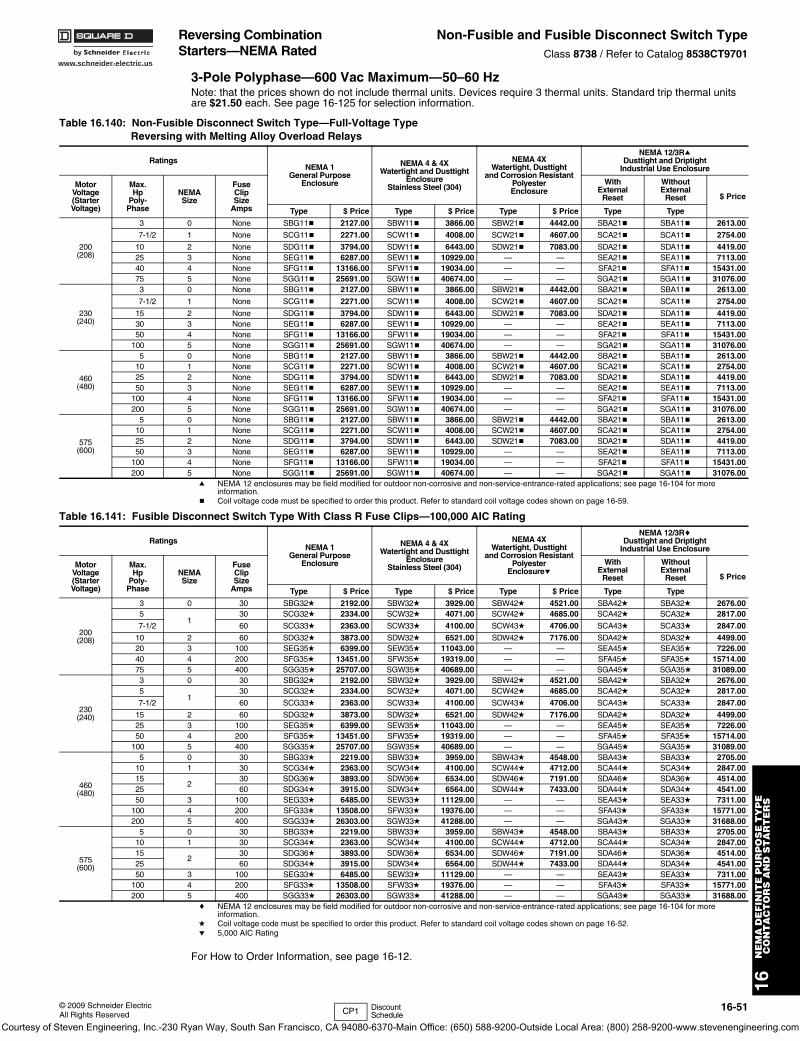
www.schneider-electric.us
16N
EM
A D
EF
INIT
E P
UR
PO
SE
TY
PE
C
ON
TA
CT
OR
S A
ND
ST
AR
TE
RS
© 2009 Schneider ElectricAll Rights Reserved
16-51
Reversing Combination Starters—NEMA Rated
Non-Fusible and Fusible Disconnect Switch TypeClass 8738 / Refer to Catalog 8538CT9701
3-Pole Polyphase—600 Vac Maximum—50–60 HzNote: that the prices shown do not include thermal units. Devices require 3 thermal units. Standard trip thermal units are $21.50 each. See page 16-125 for selection information.
a NEMA 12 enclosures may be field modified for outdoor non-corrosive and non-service-entrance-rated applications; see page 16-104 for more information.
b Coil voltage code must be specified to order this product. Refer to standard coil voltage codes shown on page 16-59.
c NEMA 12 enclosures may be field modified for outdoor non-corrosive and non-service-entrance-rated applications; see page 16-104 for more information.
d Coil voltage code must be specified to order this product. Refer to standard coil voltage codes shown on page 16-52.e 5,000 AIC Rating
For How to Order Information, see page 16-12.
Table 16.140: Non-Fusible Disconnect Switch Type—Full-Voltage TypeReversing with Melting Alloy Overload Relays
RatingsNEMA 1
General PurposeEnclosure
NEMA 4 & 4XWatertight and Dusttight
EnclosureStainless Steel (304)
NEMA 4XWatertight, Dusttight
and Corrosion ResistantPolyesterEnclosure
NEMA 12/3RaDusttight and Driptight
Industrial Use Enclosure
MotorVoltage(StarterVoltage)
Max.Hp
Poly-Phase
NEMASize
FuseClipSize
Amps
WithExternal
Reset
WithoutExternal
Reset $ Price
Type $ Price Type $ Price Type $ Price Type Type
200(208)
3 0 None SBG11b 2127.00 SBW11b 3866.00 SBW21b 4442.00 SBA21b SBA11b 2613.00
7-1/2 1 None SCG11b 2271.00 SCW11b 4008.00 SCW21b 4607.00 SCA21b SCA11b 2754.00
10 2 None SDG11b 3794.00 SDW11b 6443.00 SDW21b 7083.00 SDA21b SDA11b 4419.0025 3 None SEG11b 6287.00 SEW11b 10929.00 — — SEA21b SEA11b 7113.0040 4 None SFG11b 13166.00 SFW11b 19034.00 — — SFA21b SFA11b 15431.0075 5 None SGG11b 25691.00 SGW11b 40674.00 — — SGA21b SGA11b 31076.00
230(240)
3 0 None SBG11b 2127.00 SBW11b 3866.00 SBW21b 4442.00 SBA21b SBA11b 2613.00
7-1/2 1 None SCG11b 2271.00 SCW11b 4008.00 SCW21b 4607.00 SCA21b SCA11b 2754.00
15 2 None SDG11b 3794.00 SDW11b 6443.00 SDW21b 7083.00 SDA21b SDA11b 4419.0030 3 None SEG11b 6287.00 SEW11b 10929.00 — — SEA21b SEA11b 7113.0050 4 None SFG11b 13166.00 SFW11b 19034.00 — — SFA21b SFA11b 15431.00
100 5 None SGG11b 25691.00 SGW11b 40674.00 — — SGA21b SGA11b 31076.00
460(480)
5 0 None SBG11b 2127.00 SBW11b 3866.00 SBW21b 4442.00 SBA21b SBA11b 2613.0010 1 None SCG11b 2271.00 SCW11b 4008.00 SCW21b 4607.00 SCA21b SCA11b 2754.0025 2 None SDG11b 3794.00 SDW11b 6443.00 SDW21b 7083.00 SDA21b SDA11b 4419.0050 3 None SEG11b 6287.00 SEW11b 10929.00 — — SEA21b SEA11b 7113.00
100 4 None SFG11b 13166.00 SFW11b 19034.00 — — SFA21b SFA11b 15431.00200 5 None SGG11b 25691.00 SGW11b 40674.00 — — SGA21b SGA11b 31076.00
575(600)
5 0 None SBG11b 2127.00 SBW11b 3866.00 SBW21b 4442.00 SBA21b SBA11b 2613.0010 1 None SCG11b 2271.00 SCW11b 4008.00 SCW21b 4607.00 SCA21b SCA11b 2754.0025 2 None SDG11b 3794.00 SDW11b 6443.00 SDW21b 7083.00 SDA21b SDA11b 4419.0050 3 None SEG11b 6287.00 SEW11b 10929.00 — — SEA21b SEA11b 7113.00
100 4 None SFG11b 13166.00 SFW11b 19034.00 — — SFA21b SFA11b 15431.00200 5 None SGG11b 25691.00 SGW11b 40674.00 — — SGA21b SGA11b 31076.00
Table 16.141: Fusible Disconnect Switch Type With Class R Fuse Clips—100,000 AIC Rating
RatingsNEMA 1
General PurposeEnclosure
NEMA 4 & 4XWatertight and Dusttight
EnclosureStainless Steel (304)
NEMA 4XWatertight, Dusttight
and Corrosion ResistantPolyester
Enclosuree
NEMA 12/3RcDusttight and Driptight
Industrial Use Enclosure
MotorVoltage(StarterVoltage)
Max.Hp
Poly-Phase
NEMASize
FuseClipSize
Amps
WithExternal
Reset
WithoutExternal
Reset $ Price
Type $ Price Type $ Price Type $ Price Type Type
200(208)
3 0 30 SBG32d 2192.00 SBW32d 3929.00 SBW42d 4521.00 SBA42d SBA32d 2676.005
130 SCG32d 2334.00 SCW32d 4071.00 SCW42d 4685.00 SCA42d SCA32d 2817.00
7-1/2 60 SCG33d 2363.00 SCW33d 4100.00 SCW43d 4706.00 SCA43d SCA33d 2847.00
10 2 60 SDG32d 3873.00 SDW32d 6521.00 SDW42d 7176.00 SDA42d SDA32d 4499.0020 3 100 SEG35d 6399.00 SEW35d 11043.00 — — SEA45d SEA35d 7226.0040 4 200 SFG35d 13451.00 SFW35d 19319.00 — — SFA45d SFA35d 15714.0075 5 400 SGG35d 25707.00 SGW35d 40689.00 — — SGA45d SGA35d 31089.00
230(240)
3 0 30 SBG32d 2192.00 SBW32d 3929.00 SBW42d 4521.00 SBA42d SBA32d 2676.005
130 SCG32d 2334.00 SCW32d 4071.00 SCW42d 4685.00 SCA42d SCA32d 2817.00
7-1/2 60 SCG33d 2363.00 SCW33d 4100.00 SCW43d 4706.00 SCA43d SCA33d 2847.00
15 2 60 SDG32d 3873.00 SDW32d 6521.00 SDW42d 7176.00 SDA42d SDA32d 4499.0025 3 100 SEG35d 6399.00 SEW35d 11043.00 — — SEA45d SEA35d 7226.0050 4 200 SFG35d 13451.00 SFW35d 19319.00 — — SFA45d SFA35d 15714.00
100 5 400 SGG35d 25707.00 SGW35d 40689.00 — — SGA45d SGA35d 31089.00
460(480)
5 0 30 SBG33d 2219.00 SBW33d 3959.00 SBW43d 4548.00 SBA43d SBA33d 2705.0010 1 30 SCG34d 2363.00 SCW34d 4100.00 SCW44d 4712.00 SCA44d SCA34d 2847.0015
230 SDG36d 3893.00 SDW36d 6534.00 SDW46d 7191.00 SDA46d SDA36d 4514.00
25 60 SDG34d 3915.00 SDW34d 6564.00 SDW44d 7433.00 SDA44d SDA34d 4541.0050 3 100 SEG33d 6485.00 SEW33d 11129.00 — — SEA43d SEA33d 7311.00
100 4 200 SFG33d 13508.00 SFW33d 19376.00 — — SFA43d SFA33d 15771.00200 5 400 SGG33d 26303.00 SGW33d 41288.00 — — SGA43d SGA33d 31688.00
575(600)
5 0 30 SBG33d 2219.00 SBW33d 3959.00 SBW43d 4548.00 SBA43d SBA33d 2705.0010 1 30 SCG34d 2363.00 SCW34d 4100.00 SCW44d 4712.00 SCA44d SCA34d 2847.0015
230 SDG36d 3893.00 SDW36d 6534.00 SDW46d 7191.00 SDA46d SDA36d 4514.00
25 60 SDG34d 3915.00 SDW34d 6564.00 SDW44d 7433.00 SDA44d SDA34d 4541.0050 3 100 SEG33d 6485.00 SEW33d 11129.00 — — SEA43d SEA33d 7311.00
100 4 200 SFG33d 13508.00 SFW33d 19376.00 — — SFA43d SFA33d 15771.00200 5 400 SGG33d 26303.00 SGW33d 41288.00 — — SGA43d SGA33d 31688.00
CP1 Discount Schedule
Courtesy of Steven Engineering, Inc.-230 Ryan Way, South San Francisco, CA 94080-6370-Main Office: (650) 588-9200-Outside Local Area: (800) 258-9200-www.stevenengineering.com
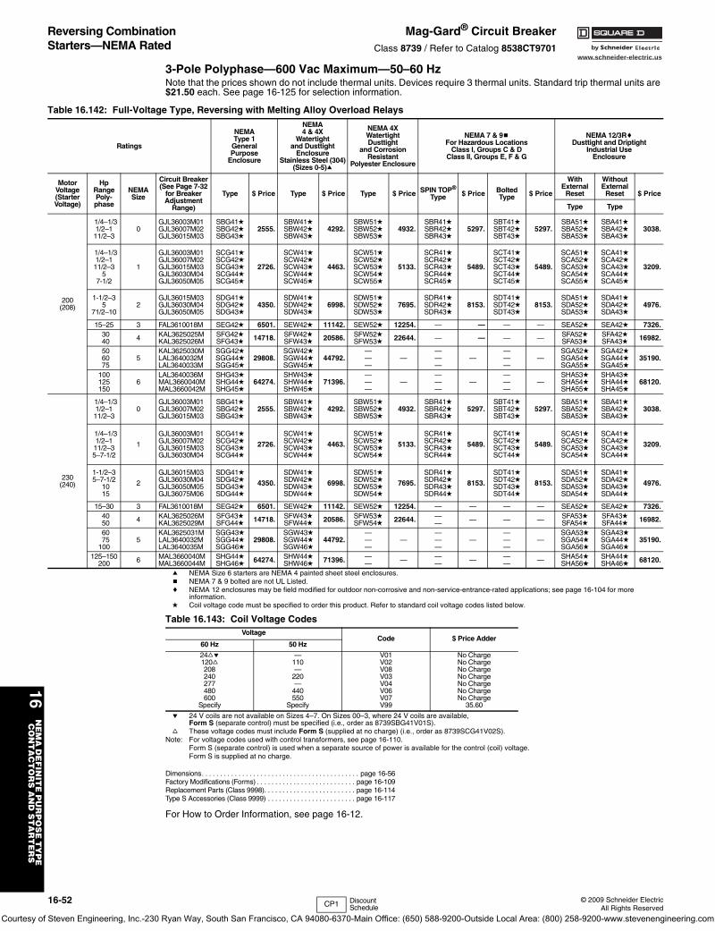
www.schneider-electric.us
16N
EM
A D
EF
INIT
E P
UR
PO
SE
TY
PE
C
ON
TA
CT
OR
S A
ND
ST
AR
TE
RS
16-52 © 2009 Schneider ElectricAll Rights Reserved
Reversing Combination Starters—NEMA Rated
Mag-Gard® Circuit BreakerClass 8739 / Refer to Catalog 8538CT9701
3-Pole Polyphase—600 Vac Maximum—50–60 HzNote that the prices shown do not include thermal units. Devices require 3 thermal units. Standard trip thermal units are $21.50 each. See page 16-125 for selection information.
a NEMA Size 6 starters are NEMA 4 painted sheet steel enclosures.b NEMA 7 & 9 bolted are not UL Listed.c NEMA 12 enclosures may be field modified for outdoor non-corrosive and non-service-entrance-rated applications; see page 16-104 for more
information.d Coil voltage code must be specified to order this product. Refer to standard coil voltage codes listed below.
e 24 V coils are not available on Sizes 4–7. On Sizes 00–3, where 24 V coils are available, Form S (separate control) must be specified (i.e., order as 8739SBG41V01S).
f These voltage codes must include Form S (supplied at no charge) (i.e., order as 8739SCG41V02S).Note: For voltage codes used with control transformers, see page 16-110.
Form S (separate control) is used when a separate source of power is available for the control (coil) voltage. Form S is supplied at no charge.
Dimensions. . . . . . . . . . . . . . . . . . . . . . . . . . . . . . . . . . . . . . . . . . . page 16-56Factory Modifications (Forms) . . . . . . . . . . . . . . . . . . . . . . . . . . . page 16-109Replacement Parts (Class 9998). . . . . . . . . . . . . . . . . . . . . . . . . page 16-114Type S Accessories (Class 9999) . . . . . . . . . . . . . . . . . . . . . . . . page 16-117
For How to Order Information, see page 16-12.
Table 16.142: Full-Voltage Type, Reversing with Melting Alloy Overload Relays
Ratings
NEMAType 1
GeneralPurpose
Enclosure
NEMA4 & 4X
Watertightand Dusttight
EnclosureStainless Steel (304)
(Sizes 0-5)a
NEMA 4XWatertightDusttight
and CorrosionResistant
Polyester Enclosure
NEMA 7 & 9bFor Hazardous Locations
Class I, Groups C & DClass II, Groups E, F & G
NEMA 12/3RcDusttight and Driptight
Industrial UseEnclosure
MotorVoltage(StarterVoltage)
HpRangePoly-phase
NEMASize
Circuit Breaker(See Page 7-32
for BreakerAdjustment
Range)
Type $ Price Type $ Price Type $ Price SPIN TOP®
Type $ Price BoltedType $ Price
WithExternal
Reset
WithoutExternal
Reset $ Price
Type Type
200(208)
1/4–1/31/2–111/2–3
0GJL36003M01GJL36007M02GJL36015M03
SBG41dSBG42dSBG43d
2555.SBW41dSBW42dSBW43d
4292.SBW51dSBW52dSBW53d
4932.SBR41dSBR42dSBR43d
5297.SBT41dSBT42dSBT43d
5297.SBA51dSBA52dSBA53d
SBA41dSBA42dSBA43d
3038.
1/4–1/31/2–111/2–3
57-1/2
1
GJL36003M01GJL36007M02GJL36015M03GJL36030M04GJL36050M05
SCG41dSCG42dSCG43dSCG44dSCG45d
2726.
SCW41dSCW42dSCW43dSCW44dSCW45d
4463.
SCW51dSCW52dSCW53dSCW54dSCW55d
5133.
SCR41dSCR42dSCR43dSCR44dSCR45d
5489.
SCT41dSCT42dSCT43dSCT44dSCT45d
5489.
SCA51dSCA52dSCA53dSCA54dSCA55d
SCA41dSCA42dSCA43dSCA44dSCA45d
3209.
1-1/2–35
71/2–102
GJL36015M03GJL36030M04GJL36050M05
SDG41dSDG42dSDG43d
4350.SDW41dSDW42dSDW43d
6998.SDW51dSDW52dSDW53d
7695.SDR41dSDR42dSDR43d
8153.SDT41dSDT42dSDT43d
8153.SDA51dSDA52dSDA53d
SDA41dSDA42dSDA43d
4976.
15–25 3 FAL3610018M SEG42d 6501. SEW42d 11142. SEW52d 12254. — — — — SEA52d SEA42d 7326.3040 4 KAL3625025M
KAL3625026MSFG42dSFG43d 14718. SFW42d
SFW43d 20586. SFW52dSFW53d 22644. — — — — SFA52d
SFA53dSFA42dSFA43d 16982.
506075
5KAL3625030MLAL3640032MLAL3640033M
SGG42dSGG44dSGG45d
29808.SGW42dSGW44dSGW45d
44792.———
————
————
—SGA52dSGA54dSGA55d
SGA42dSGA44dSGA45d
35190.
100125150
6LAL3640036MMAL3660040MMAL3660042M
SHG43dSHG44dSHG45d
64274.SHW43dSHW44dSHW45d
71396.———
————
————
—SHA53dSHA54dSHA55d
SHA43dSHA44dSHA45d
68120.
230(240)
1/4–1/31/2–111/2–3
0GJL36003M01GJL36007M02GJL36015M03
SBG41dSBG42dSBG43d
2555.SBW41dSBW42dSBW43d
4292.SBW51dSBW52dSBW53d
4932.SBR41dSBR42dSBR43d
5297.SBT41dSBT42dSBT43d
5297.SBA51dSBA52dSBA53d
SBA41dSBA42dSBA43d
3038.
1/4–1/31/2–111/2–35–7-1/2
1
GJL36003M01GJL36007M02GJL36015M03GJL36030M04
SCG41dSCG42dSCG43dSCG44d
2726.
SCW41dSCW42dSCW43dSCW44d
4463.
SCW51dSCW52dSCW53dSCW54d
5133.
SCR41dSCR42dSCR43dSCR44d
5489.
SCT41dSCT42dSCT43dSCT44d
5489.
SCA51dSCA52dSCA53dSCA54d
SCA41dSCA42dSCA43dSCA44d
3209.
1-1/2–35–7-1/2
1015
2
GJL36015M03GJL36030M04GJL36050M05GJL36075M06
SDG41dSDG42dSDG43dSDG44d
4350.
SDW41dSDW42dSDW43dSDW44d
6998.
SDW51dSDW52dSDW53dSDW54d
7695.
SDR41dSDR42dSDR43dSDR44d
8153.
SDT41dSDT42dSDT43dSDT44d
8153.
SDA51dSDA52dSDA53dSDA54d
SDA41dSDA42dSDA43dSDA44d
4976.
15–30 3 FAL3610018M SEG42d 6501. SEW42d 11142. SEW52d 12254. — — — — SEA52d SEA42d 7326.4050 4 KAL3625026M
KAL3625029MSFG43dSFG44d 14718. SFW43d
SFW44d 20586. SFW53dSFW54d 22644. —
— — — — SFA53dSFA54d
SFA43dSFA44d 16982.
6075
1005
KAL3625031MLAL3640032MLAL3640035M
SGG43dSGG44dSGG46d
29808.SGW43dSGW44dSGW46d
44792.———
————
————
—SGA53dSGA54dSGA56d
SGA43dSGA44dSGA46d
35190.
125–150200 6 MAL3660040M
MAL3660044MSHG44dSHG46d 64274. SHW44d
SHW46d 71396. —— — —
— — —— — SHA54d
SHA56dSHA44dSHA46d 68120.
Table 16.143: Coil Voltage CodesVoltage
Code $ Price Adder60 Hz 50 Hz
24fe120f208240277480600
Specify
—110—
220—
440550
Specify
V01V02V08V03V04V06V07V99
No ChargeNo ChargeNo ChargeNo ChargeNo ChargeNo ChargeNo Charge
35.60
CP1 Discount Schedule
Courtesy of Steven Engineering, Inc.-230 Ryan Way, South San Francisco, CA 94080-6370-Main Office: (650) 588-9200-Outside Local Area: (800) 258-9200-www.stevenengineering.com
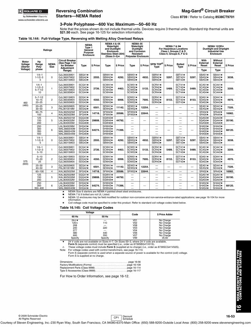
www.schneider-electric.us
16N
EM
A D
EF
INIT
E P
UR
PO
SE
TY
PE
C
ON
TA
CT
OR
S A
ND
ST
AR
TE
RS
© 2009 Schneider ElectricAll Rights Reserved
16-53
Reversing Combination Starters—NEMA Rated
Mag-Gard® Circuit BreakerClass 8739 / Refer to Catalog 8538CT9701
3-Pole Polyphase—600 Vac Maximum—50–60 HzNote that the prices shown do not include thermal units. Devices require 3 thermal units. Standard trip thermal units are $21.50 each. See page 16-125 for selection information.
a NEMA Size 6 starters are NEMA 4 painted sheet steel enclosures.b NEMA 7 & 9 bolted are not UL Listed.c NEMA 12 enclosures may be field modified for outdoor non-corrosive and non-service-entrance-rated applications; see page 16-104 for more
information.d Coil voltage code must be specified to order this product. Refer to standard coil voltage codes listed below.
e 24 V coils are not available on Sizes 4–7. On Sizes 00–3, where 24 V coils are available, Form S (separate control) must be specified (i.e., order as 8739SBG41V01S).
f These voltage codes must include Form S (supplied at no charge) (i.e., order as 8739SCG41V02S).Note: For voltage codes used with control transformers, see page 16-110.
Form S (separate control) is used when a separate source of power is available for the control (coil) voltage. Form S is supplied at no charge.
Dimensions . . . . . . . . . . . . . . . . . . . . . . . . . . . . . . . . . . . . . . . . . . .page 16-56Factory Modifications (Forms) . . . . . . . . . . . . . . . . . . . . . . . . . . .page 16-109Replacement Parts (Class 9998) . . . . . . . . . . . . . . . . . . . . . . . . .page 16-114Type S Accessories (Class 9999). . . . . . . . . . . . . . . . . . . . . . . . .page 16-117
For How to Order Information, see page 16-12.
Table 16.144: Full-Voltage Type, Reversing with Melting Alloy Overload Relays
Ratings
NEMAType 1
GeneralPurpose
Enclosure
NEMA 4 & 4XWatertight
and DusttightEnclosure
Stainless Steel (304)(Sizes 0–5)a
NEMA 4XWatertightDusttight
and CorrosionResistant
Polyester Enclosure
NEMA 7 & 9bFor Hazardous Locations
Class I, Groups C & DClass II, Groups E, F & G
NEMA 12/3RcDusttight and Driptight
Industrial UseEnclosure
MotorVoltage(StarterVoltage)
HpRangePoly-phase
NEMASize
Circuit Breaker (See Page 7-32
for Breaker Adjustment
Range)
Type $ Price Type $ Price Type $ Price SPIN TOP®
Type $ Price BoltedType $ Price
WithExternal
Reset
Without External
Reset $ Price
Type Type
460(480)
1/4–11-1/2–3
50
GJL36003M01GJL36007M02GJL36015M03
SBG41dSBG42dSBG43d
2555.SBW41dSBW42dSBW43d
4292.SBW51dSBW52dSBW53d
4932.SBR41dSBR42dSBR43d
5297.SBT41dSBT42vSBT43d
5297.SBA51dSBA52dSBA53d
SBA41dSBA42dSBA43d
3038.
1/4–11-1/2–35–7-1/2
10
1
GJL36003M01GJL36007M02GJL36015M03GJL36030M04
SCG41dSCG42dSCG43dSCG44d
2726.
SCW41dSCW42dSCW43dSCW44d
4463.
SCW51dSCW52dSCW53dSCW54d
5133.
SCR41dSCR42dSCR43dSCR44d
5489.
SCT41dSCT42dSCT43dSCT44d
5489.
SCA51dSCA52dSCA53dSCA54d
SCA41dSCA42dSCA43dSCA44d
3209.
5–7-1/210–1520–25
2GJL36015M03GJL36030M04GJL36050M05
SDG41dSDG42dSDG43d
4350.SDW41dSDW42dSDW43d
6998.SDW51dSDW52dSDW53d
7695.SDR41dSDR42dSDR43d
8153.SDT41dSDT42dSDT43d
8153.SDA51dSDA52dSDA53d
SDA41dSDA42dSDA43d
4976.
20–2530–50 3 GJL36050M05
FAL3610018MSEG41dSEG42d 6501. SEW41d
SEW42d 11142. SEW51dSEW52d 12254. — — — — SEA51d
SEA52dSEA41dSEA42d 7326.
60–75100 4 KAL3625025M
KAL3625029MSFG42dSFG44d 14718. SFW42d
SFW44d 20586. SFW52dSFW54d 22644. —
— — — — SFA52dSFA54d
SFA42dSFA44d 16982.
125150200
5KAL3625031MLAL3640032MLAL3640035M
SGG43dSGG44dSGG46d
29808.SGW43dSGW44dSGW46d
44792.———
————
————
—SGA53dSGA54dSGA56d
SGA43dSGA44dSGA46d
35190.
250300350400
6
LAL3640036MMAL3660040MMAL3660042MMAL3660044M
SHG43dSHG44dSHG45dSHG46d
64274.
SHW43dSHW44dSHW45dSHW46d
71396.
————
—
————
—
————
—
SHA53dSHA54dSHA55dSHA56d
SHA43dSHA44dSHA45dSHA46d
68120.
575(600)
1/4–11-1/2–3
50
GJL36003M01GJL36007M02GJL36015M03
SBG41dSBG42dSBG43d
2555.SBW41dSBW42dSBW43d
4292.SBW51dSBW52dSBW53d
4932.SBR41dSBR42dSBR43d
5297.SBT41dSBT42dSBT43d
5297.SBA51dSBA52dSBA53d
SBA41dSBA42dSBA43d
3038.
1/4–11-1/2–3
5–101
GJL36003M01GJL36007M02GJL36015M03
SCG41dSCG42dSCG43d
2726.SCW41dSCW42dSCW43d
4463.SCW51dSCW52dSCW53d
5133.SCR41dSCR42dSCR43d
5489.SCT41dSCT42dSCT43d
5489.SCA51dSCA52dSCA53d
SCA41dSCA42dSCA43d
3209.
5–1015–20
252
GJL36015M03GJL36030M04GJL36050M05
SDG41dSDG42dSDG43d
4350.SDW41dSDW42dSDW43d
6998.SDW51dSDW52dSDW53d
7695.SDR41dSDR42dSDR43d
8153.SDT41dSDT42dSDT43d
8153.SDA51dSDA52dSDA53d
SDA41dSDA42dSDA43d
4976.
25–3040–50 3 GJL36050M05
FAL3610018MSEG41dSEG42d 6501. SEW41d
SEW42d 11142. SEW51dSEW52d 12254. —
— — — — SEA51dSEA52d
SEA41dSEA42d 7326.
60–100 4 KAL3625025M SFG42d 14718. SFW42d 20586. SFW52d 22644. — — — — SFA52d SFA42d 16982.125150200
5KAL3625029MKAL3625030MLAL3640032M
SGG41dSGG42dSGG44d
29808.SGW41dSGW42dSGW44d
44792.———
————
————
—SGA51dSGA52dSGA54d
SGA41dSGA42dSGA44d
35190.
250300
350–4006
LAL3640035MLAL3640036MMAL3660040M
SHG42dSHG43dSHG44d
64274.SHW42dSHW43dSHW44d
71396.———
————
————
—SHA52dSHA53dSHA54d
SHA42dSHA43dSHA44d
68120.
Table 16.145: Coil Voltage CodesVoltage
Code $ Price Adder60 Hz 50 Hz
24fe120f208240277480600
Specify
—110—
220—
440550
Specify
V01V02V08V03V04V06V07V99
No ChargeNo ChargeNo ChargeNo ChargeNo ChargeNo ChargeNo Charge
35.60
CP1 Discount Schedule
Courtesy of Steven Engineering, Inc.-230 Ryan Way, South San Francisco, CA 94080-6370-Main Office: (650) 588-9200-Outside Local Area: (800) 258-9200-www.stevenengineering.com
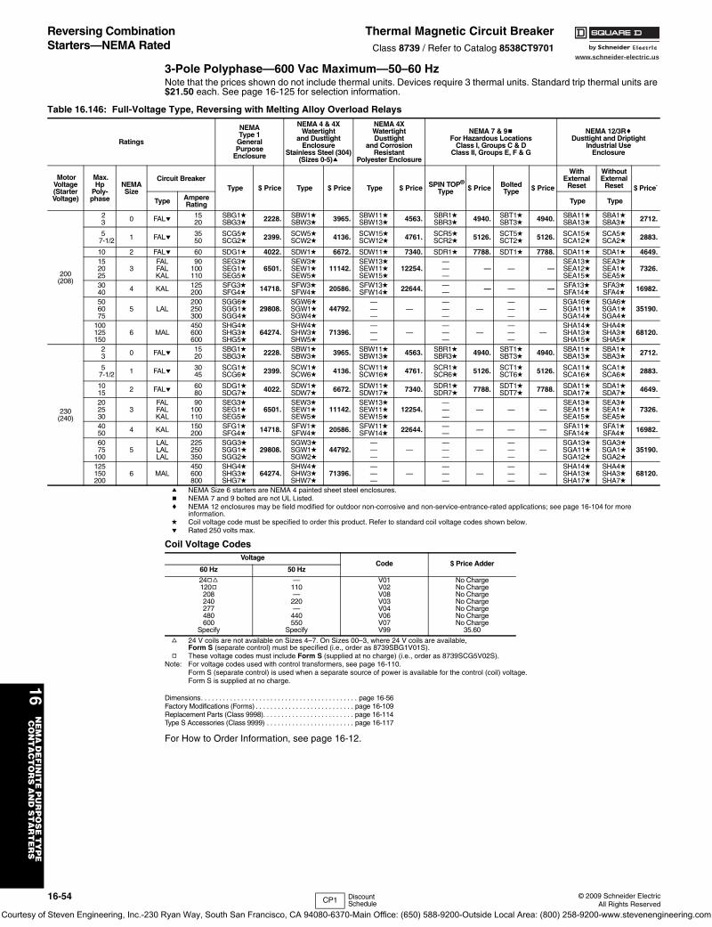
www.schneider-electric.us
16N
EM
A D
EF
INIT
E P
UR
PO
SE
TY
PE
C
ON
TA
CT
OR
S A
ND
ST
AR
TE
RS
16-54 © 2009 Schneider ElectricAll Rights Reserved
Reversing Combination Starters—NEMA Rated
Thermal Magnetic Circuit BreakerClass 8739 / Refer to Catalog 8538CT9701
3-Pole Polyphase—600 Vac Maximum—50–60 HzNote that the prices shown do not include thermal units. Devices require 3 thermal units. Standard trip thermal units are $21.50 each. See page 16-125 for selection information.
a NEMA Size 6 starters are NEMA 4 painted sheet steel enclosures.b NEMA 7 and 9 bolted are not UL Listed.c NEMA 12 enclosures may be field modified for outdoor non-corrosive and non-service-entrance-rated applications; see page 16-104 for more
information.d Coil voltage code must be specified to order this product. Refer to standard coil voltage codes shown below.e Rated 250 volts max.
f 24 V coils are not available on Sizes 4–7. On Sizes 00–3, where 24 V coils are available, Form S (separate control) must be specified (i.e., order as 8739SBG1V01S).
g These voltage codes must include Form S (supplied at no charge) (i.e., order as 8739SCG5V02S).Note: For voltage codes used with control transformers, see page 16-110.
Form S (separate control) is used when a separate source of power is available for the control (coil) voltage. Form S is supplied at no charge.
Dimensions. . . . . . . . . . . . . . . . . . . . . . . . . . . . . . . . . . . . . . . . . . . page 16-56Factory Modifications (Forms) . . . . . . . . . . . . . . . . . . . . . . . . . . . page 16-109Replacement Parts (Class 9998). . . . . . . . . . . . . . . . . . . . . . . . . page 16-114Type S Accessories (Class 9999) . . . . . . . . . . . . . . . . . . . . . . . . page 16-117
For How to Order Information, see page 16-12.
Table 16.146: Full-Voltage Type, Reversing with Melting Alloy Overload Relays
Ratings
NEMAType 1
GeneralPurpose
Enclosure
NEMA 4 & 4XWatertight
and DusttightEnclosure
Stainless Steel (304)(Sizes 0-5)a
NEMA 4XWatertightDusttight
and CorrosionResistant
Polyester Enclosure
NEMA 7 & 9bFor Hazardous Locations
Class I, Groups C & DClass II, Groups E, F & G
NEMA 12/3RcDusttight and Driptight
Industrial UseEnclosure
MotorVoltage(StarterVoltage)
Max.Hp
Poly-phase
NEMASize
Circuit Breaker Type $ Price Type $ Price Type $ Price SPIN TOP®
Type $ Price BoltedType $ Price
WithExternal
Reset
WithoutExternal
Reset $ Price`
Type AmpereRating Type Type
200(208)
23 0 FALe 15
20SBG1dSBG3d 2228. SBW1d
SBW3d 3965. SBW11dSBW13d 4563. SBR1d
SBR3d 4940. SBT1dSBT3d 4940. SBA11d
SBA13dSBA1dSBA3d 2712.
57-1/2 1 FALe 35
50SCG5dSCG2d 2399. SCW5d
SCW2d 4136. SCW15dSCW12d 4761. SCR5d
SCR2d 5126. SCT5dSCT2d 5126. SCA15d
SCA12dSCA5dSCA2d 2883.
10 2 FALe 60 SDG1d 4022. SDW1d 6672. SDW11d 7340. SDR1d 7788. SDT1d 7788. SDA11d SDA1d 4649.152025
3FALFALKAL
90100110
SEG3dSEG1dSEG5d
6501.SEW3dSEW1dSEW5d
11142.SEW13dSEW11dSEW15d
12254.———
— — —SEA13dSEA12dSEA15d
SEA3dSEA1dSEA5d
7326.
3040 4 KAL 125
200SFG3dSFG4d 14718. SFW3d
SFW4d 20586. SFW13dSFW14d 22644. —
— — — — SFA13dSFA14d
SFA3dSFA4d 16982.
506075
5 LAL200250300
SGG6dSGG1dSGG4d
29808.SGW6dSGW1dSGW4d
44792.———
————
————
—SGA16dSGA11dSGA14d
SGA6dSGA1dSGA4d
35190.
100125150
6 MAL450600600
SHG4dSHG3dSHG5d
64274.SHW4dSHW3dSHW5d
71396.———
————
————
—SHA14dSHA13dSHA15d
SHA4dSHA3dSHA5d
68120.
230(240)
23 0 FALe 15
20SBG1dSBG3d 2228. SBW1d
SBW3d 3965. SBW11dSBW13d 4563. SBR1d
SBR3d 4940. SBT1dSBT3d 4940. SBA11d
SBA13dSBA1dSBA3d 2712.
57-1/2 1 FALe 30
45SCG1dSCG6d 2399. SCW1d
SCW6d 4136. SCW11dSCW16d 4761. SCR1d
SCR6d 5126. SCT1dSCT6d 5126. SCA11d
SCA16dSCA1dSCA6d 2883.
1015 2 FALe 60
80SDG1dSDG7d 4022. SDW1d
SDW7d 6672. SDW11dSDW17d 7340. SDR1d
SDR7d 7788. SDT1dSDT7d 7788. SDA11d
SDA17dSDA1dSDA7d 4649.
202530
3FALFALKAL
90100110
SEG3dSEG1dSEG5d
6501.SEW3dSEW1dSEW5d
11142.SEW13dSEW11dSEW15d
12254.———
— — —SEA13dSEA11dSEA15d
SEA3dSEA1dSEA5d
7326.
4050 4 KAL 150
200SFG1dSFG4d 14718. SFW1d
SFW4d 20586. SFW11dSFW14d 22644. —
— — — — SFA11dSFA14d
SFA1dSFA4d 16982.
6075
1005
LALLALLAL
225250350
SGG3dSGG1dSGG2d
29808.SGW3dSGW1dSGW2d
44792.———
————
————
—SGA13dSGA11dSGA12d
SGA3dSGA1dSGA2d
35190.
125150200
6 MAL450600800
SHG4dSHG3dSHG7d
64274.SHW4dSHW3dSHW7d
71396.———
————
————
—SHA14dSHA13dSHA17d
SHA4dSHA3dSHA7d
68120.
Coil Voltage CodesVoltage
Code $ Price Adder60 Hz 50 Hz
24gf120g208240277480600
Specify
—110—
220—
440550
Specify
V01V02V08V03V04V06V07V99
No ChargeNo ChargeNo ChargeNo ChargeNo ChargeNo ChargeNo Charge
35.60
CP1 Discount Schedule
Courtesy of Steven Engineering, Inc.-230 Ryan Way, South San Francisco, CA 94080-6370-Main Office: (650) 588-9200-Outside Local Area: (800) 258-9200-www.stevenengineering.com
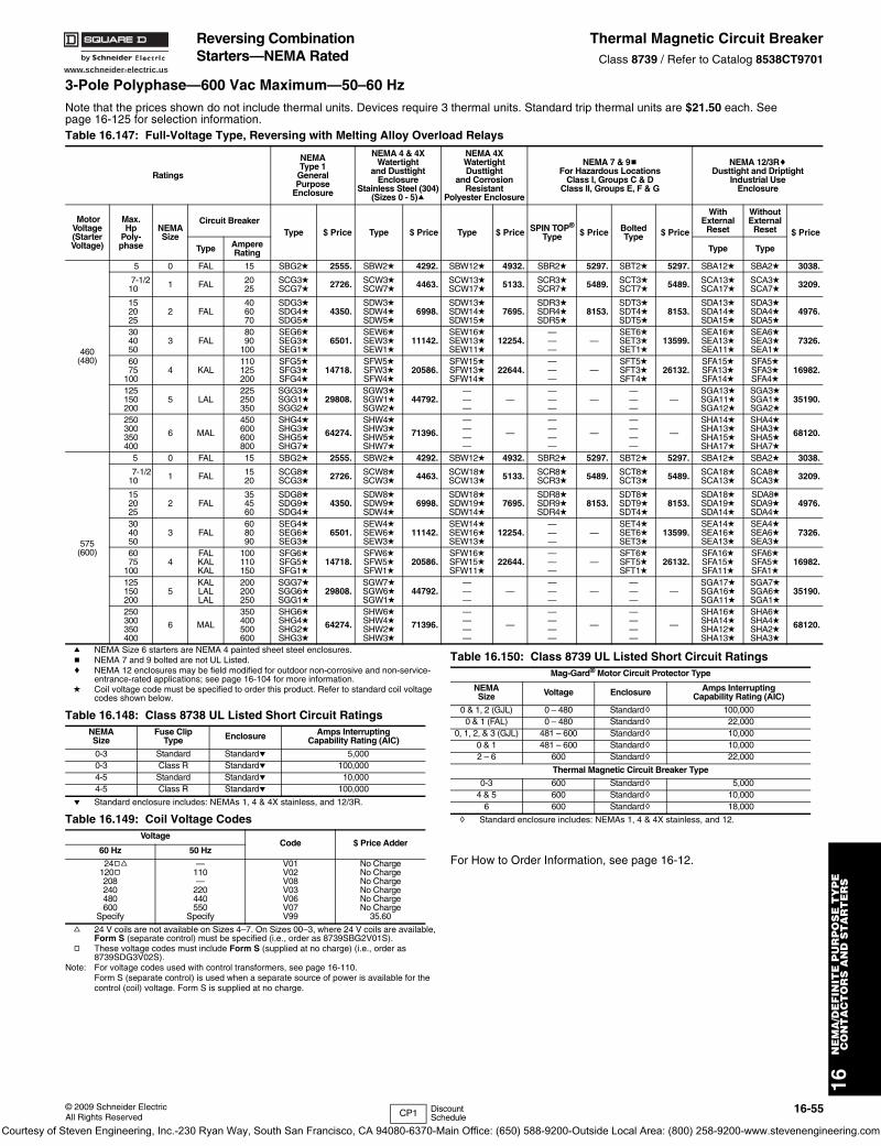
www.schneider-electric.us
© 2009 Schneider ElectricAll Rights Reserved
16-55
16N
EM
A/D
EF
INIT
E P
UR
PO
SE
TY
PE
CO
NT
AC
TO
RS
AN
D S
TA
RT
ER
S
3-Pole Polyphase—600 Vac Maximum—50–60 Hz
a NEMA Size 6 starters are NEMA 4 painted sheet steel enclosures.b NEMA 7 and 9 bolted are not UL Listed.c NEMA 12 enclosures may be field modified for outdoor non-corrosive and non-service-
entrance-rated applications; see page 16-104 for more information.d Coil voltage code must be specified to order this product. Refer to standard coil voltage
codes shown below.
e Standard enclosure includes: NEMAs 1, 4 & 4X stainless, and 12/3R.
f 24 V coils are not available on Sizes 4–7. On Sizes 00–3, where 24 V coils are available, Form S (separate control) must be specified (i.e., order as 8739SBG2V01S).
g These voltage codes must include Form S (supplied at no charge) (i.e., order as 8739SDG3V02S).
Note: For voltage codes used with control transformers, see page 16-110.Form S (separate control) is used when a separate source of power is available for the control (coil) voltage. Form S is supplied at no charge.
h Standard enclosure includes: NEMAs 1, 4 & 4X stainless, and 12.
For How to Order Information, see page 16-12.
Note that the prices shown do not include thermal units. Devices require 3 thermal units. Standard trip thermal units are $21.50 each. See page 16-125 for selection information.Table 16.147: Full-Voltage Type, Reversing with Melting Alloy Overload Relays
Ratings
NEMAType 1
GeneralPurpose
Enclosure
NEMA 4 & 4XWatertight
and DusttightEnclosure
Stainless Steel (304)(Sizes 0 - 5)a
NEMA 4XWatertightDusttight
and CorrosionResistant
Polyester Enclosure
NEMA 7 & 9bFor Hazardous Locations
Class I, Groups C & DClass II, Groups E, F & G
NEMA 12/3RcDusttight and Driptight
Industrial UseEnclosure
MotorVoltage(StarterVoltage)
Max.Hp
Poly-phase
NEMASize
Circuit BreakerType $ Price Type $ Price Type $ Price SPIN TOP®
Type $ Price BoltedType $ Price
WithExternal
Reset
WithoutExternal
Reset $ Price
Type AmpereRating Type Type
460(480)
5 0 FAL 15 SBG2d 2555. SBW2d 4292. SBW12d 4932. SBR2d 5297. SBT2d 5297. SBA12d SBA2d 3038.
7-1/210 1 FAL 20
25SCG3dSCG7d 2726. SCW3d
SCW7d 4463. SCW13dSCW17d 5133. SCR3d
SCR7d 5489. SCT3dSCT7d 5489. SCA13d
SCA17dSCA3dSCA7d 3209.
152025
2 FAL406070
SDG3dSDG4dSDG5d
4350.SDW3dSDW4dSDW5d
6998.SDW13dSDW14dSDW15d
7695.SDR3dSDR4dSDR5d
8153.SDT3dSDT4dSDT5d
8153.SDA13dSDA14dSDA15d
SDA3dSDA4dSDA5d
4976.
304050
3 FAL8090
100
SEG6dSEG3dSEG1d
6501.SEW6dSEW3dSEW1d
11142.SEW16dSEW13dSEW11d
12254.———
—SET6dSET3dSET1d
13599.SEA16dSEA13dSEA11d
SEA6dSEA3dSEA1d
7326.
6075
1004 KAL
110125200
SFG5dSFG3dSFG4d
14718.SFW5dSFW3dSFW4d
20586.SFW15dSFW13dSFW14d
22644.———
—SFT5dSFT3dSFT4d
26132.SFA15dSFA13dSFA14d
SFA5dSFA3dSFA4d
16982.
125150200
5 LAL225250350
SGG3dSGG1dSGG2d
29808.SGW3dSGW1dSGW2d
44792.———
————
————
—SGA13dSGA11dSGA12d
SGA3dSGA1dSGA2d
35190.
250300350400
6 MAL
450600600800
SHG4dSHG3dSHG5dSHG7d
64274.
SHW4dSHW3dSHW5dSHW7d
71396.
————
—
————
—
————
—
SHA14dSHA13dSHA15dSHA17d
SHA4dSHA3dSHA5dSHA7d
68120.
575(600)
5 0 FAL 15 SBG2d 2555. SBW2d 4292. SBW12d 4932. SBR2d 5297. SBT2d 5297. SBA12d SBA2d 3038.
7-1/210 1 FAL 15
20SCG8dSCG3d 2726. SCW8d
SCW3d 4463. SCW18dSCW13d 5133. SCR8d
SCR3d 5489. SCT8dSCT3d 5489. SCA18d
SCA13dSCA8dSCA3d 3209.
152025
2 FAL354560
SDG8dSDG9dSDG4d
4350.SDW8dSDW9dSDW4d
6998.SDW18dSDW19dSDW14d
7695.SDR8dSDR9dSDR4d
8153.SDT8dSDT9dSDT4d
8153.SDA18dSDA19dSDA14d
SDA8tSDA9dSDA4d
4976.
304050
3 FAL608090
SEG4dSEG6dSEG3d
6501.SEW4dSEW6dSEW3d
11142.SEW14dSEW16dSEW13d
12254.———
—SET4dSET6dSET3d
13599.SEA14dSEA16dSEA13d
SEA4dSEA6dSEA3d
7326.
6075
1004
FALKALKAL
100110150
SFG6dSFG5dSFG1d
14718.SFW6dSFW5dSFW1d
20586.SFW16dSFW15dSFW11d
22644.———
—SFT6dSFT5dSFT1d
26132.SFA16dSFA15dSFA11d
SFA6dSFA5dSFA1d
16982.
125150200
5KALLALLAL
200200250
SGG7dSGG6dSGG1d
29808.SGW7dSGW6dSGW1d
44792.———
————
————
—SGA17dSGA16dSGA11d
SGA7dSGA6dSGA1d
35190.
250300350400
6 MAL
350400500600
SHG6dSHG4dSHG2dSHG3d
64274.
SHW6dSHW4dSHW2dSHW3d
71396.
————
—
————
—
————
—
SHA16dSHA14dSHA12dSHA13d
SHA6dSHA4dSHA2dSHA3d
68120.
Table 16.148: Class 8738 UL Listed Short Circuit RatingsNEMASize
Fuse ClipType Enclosure Amps Interrupting
Capability Rating (AIC)
0-3 Standard Standarde 5,0000-3 Class R Standarde 100,0004-5 Standard Standarde 10,0004-5 Class R Standarde 100,000
Table 16.149: Coil Voltage CodesVoltage
Code $ Price Adder60 Hz 50 Hz
24gf120g208240480600
Specify
—110—
220440550
Specify
V01V02V08V03V06V07V99
No ChargeNo ChargeNo ChargeNo ChargeNo ChargeNo Charge
35.60
Table 16.150: Class 8739 UL Listed Short Circuit RatingsMag-Gard® Motor Circuit Protector Type
NEMASize Voltage Enclosure Amps Interrupting
Capability Rating (AIC)
0 & 1, 2 (GJL) 0 – 480 Standardh 100,0000 & 1 (FAL) 0 – 480 Standardh 22,000
0, 1, 2, & 3 (GJL) 481 – 600 Standardh 10,0000 & 1 481 – 600 Standardh 10,0002 – 6 600 Standardh 22,000
Thermal Magnetic Circuit Breaker Type
0-3 600 Standardh 5,0004 & 5 600 Standardh 10,000
6 600 Standardh 18,000
CP1 Discount Schedule
Reversing Combination Starters—NEMA Rated
Thermal Magnetic Circuit BreakerClass 8739 / Refer to Catalog 8538CT9701
Courtesy of Steven Engineering, Inc.-230 Ryan Way, South San Francisco, CA 94080-6370-Main Office: (650) 588-9200-Outside Local Area: (800) 258-9200-www.stevenengineering.com
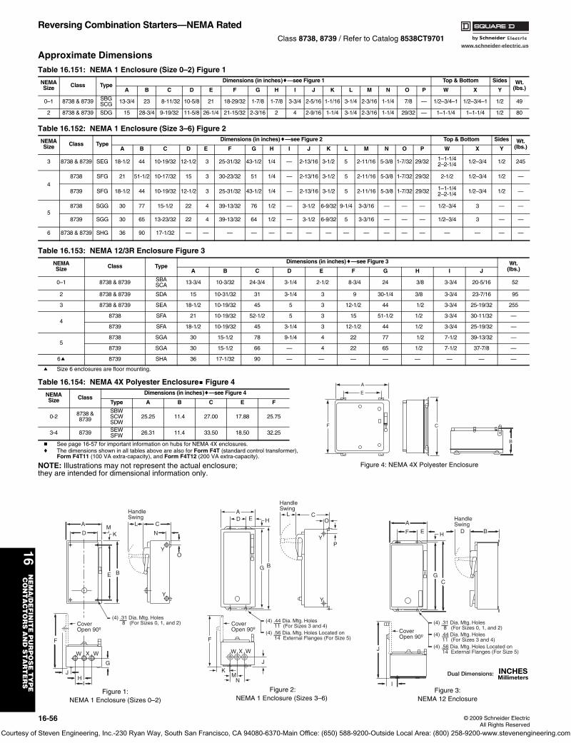
www.schneider-electric.us
16N
EM
A/D
EF
INIT
E P
UR
PO
SE
TY
PE
CO
NT
AC
TO
RS
AN
D S
TA
RT
ER
S
16-56 © 2009 Schneider ElectricAll Rights Reserved
Reversing Combination Starters—NEMA RatedClass 8738, 8739 / Refer to Catalog 8538CT9701
Approximate Dimensions
a Size 6 enclosures are floor mounting.
b See page 16-57 for important information on hubs for NEMA 4X enclosures.c The dimensions shown in all tables above are also for Form F4T (standard control transformer),
Form F4T11 (100 VA extra-capacity), and Form F4T12 (200 VA extra-capacity).
NOTE: Illustrations may not represent the actual enclosure; they are intended for dimensional information only.
Table 16.151: NEMA 1 Enclosure (Size 0–2) Figure 1
NEMASize Class Type
Dimensions (in inches)c—see Figure 1 Top & Bottom Sides Wt.(lbs.)A B C D E F G H I J K L M N O P W X Y
0–1 8738 & 8739 SBGSCG 13-3/4 23 8-11/32 10-5/8 21 18-29/32 1-7/8 1-7/8 3-3/4 2-5/16 1-1/16 3-1/4 2-3/16 1-1/4 7/8 — 1/2–3/4–1 1/2–3/4–1 1/2 49
2 8738 & 8739 SDG 15 28-3/4 9-19/32 11-5/8 26-1/4 21-15/32 2-3/16 2 4 2-9/16 1-1/4 3-1/4 2-3/16 1-1/4 29/32 — 1–1-1/4 1–1-1/4 1/2 80
Table 16.152: NEMA 1 Enclosure (Size 3–6) Figure 2
NEMASize Class Type
Dimensions (in inches)c—see Figure 2 Top & Bottom Sides Wt.(lbs.)A B C D E F G H I J K L M N O P W X Y
3 8738 & 8739 SEG 18-1/2 44 10-19/32 12-1/2 3 25-31/32 43-1/2 1/4 — 2-13/16 3-1/2 5 2-11/16 5-3/8 1-7/32 29/32 1–1-1/42–2-1/4 1/2–3/4 1/2 245
48738 SFG 21 51-1/2 10-17/32 15 3 30-23/32 51 1/4 — 2-13/16 3-1/2 5 2-11/16 5-3/8 1-7/32 29/32 2-1/2 1/2–3/4 1/2 —
8739 SFG 18-1/2 44 10-19/32 12-1/2 3 25-31/32 43-1/2 1/4 — 2-13/16 3-1/2 5 2-11/16 5-3/8 1-7/32 29/32 1–1-1/42–2-1/4 1/2–3/4 1/2 —
58738 SGG 30 77 15-1/2 22 4 39-13/32 76 1/2 — 3-1/2 6-9/32 9-1/4 3-3/16 — — — 1/2–3/4 3 — —
8739 SGG 30 65 13-23/32 22 4 39-13/32 64 1/2 — 3-1/2 6-9/32 5 3-3/16 — — — 1/2–3/4 3 — —
6 8738 & 8739 SHG 36 90 17-1/32 — — — — — — — — — — — — — — — — —
Table 16.153: NEMA 12/3R Enclosure Figure 3
NEMASize Class Type
Dimensions (in inches)c—see Figure 3 Wt.(lbs.)A B C D E F G H I J
0–1 8738 & 8739 SBASCA 13-3/4 10-3/32 24-3/4 3-1/4 2-1/2 8-3/4 24 3/8 3-3/4 20-5/16 52
2 8738 & 8739 SDA 15 10-31/32 31 3-1/4 3 9 30-1/4 3/8 3-3/4 23-7/16 95
3 8738 & 8739 SEA 18-1/2 10-19/32 45 5 3 12-1/2 44 1/2 3-3/4 25-19/32 255
48738 SFA 21 10-19/32 52-1/2 5 3 15 51-1/2 1/2 3-3/4 30-11/32 —
8739 SFA 18-1/2 10-19/32 45 3-1/4 3 12-1/2 44 1/2 3-3/4 25-19/32 —
58738 SGA 30 15-1/2 78 9-1/4 4 22 77 1/2 7-1/2 39-13/32 —
8739 SGA 30 15-1/2 66 — 4 22 65 1/2 7-1/2 37-7/8 —
6a 8739 SHA 36 17-1/32 90 — — — — — — — —
Table 16.154: NEMA 4X Polyester Enclosureb Figure 4
NEMASize Class
Dimensions (in inches)c—see Figure 4
Type A B C E F
0-2 8738 &8739
SBWSCWSDW
25.25 11.4 27.00 17.88 25.75
3-4 8739 SEWSFW 26.31 11.4 33.50 18.50 32.25
YO
N
C
E B
KM
D
A
Y
F
W X W
G
JH
I
L
HandleSwing
CoverOpen 90º
(4) .31 Dia. Mtg. Holes 8 (For Sizes 0, 1, and 2)
Figure 1:NEMA 1 Enclosure (Sizes 0–2)
DA
E HL C
P
O
Y
BG
Y
J
NM
K
W X W
F
CoverOpen 90º
HandleSwing
(4) .44 Dia. Mtg. Holes 11 (For Sizes 3 and 4)(4) .56 Dia. Mtg. Holes Located on 14 External Flanges (For Size 5)
Figure 2:NEMA 1 Enclosure (Sizes 3–6)
B
HandleSwing
C
F
A
J
I
DE
G
H
(4) .31 Dia. Mtg. Holes 8 (For Sizes 0, 1, and 2)(4) .44 Dia. Mtg. Holes 11 (For Sizes 3 and 4)(4) .56 Dia. Mtg. Holes Located on 14 External Flanges (For Size 5)
CoverOpen 90º
Figure 3:NEMA 12 Enclosure
A
E
F C
B
Figure 4: NEMA 4X Polyester Enclosure
Courtesy of Steven Engineering, Inc.-230 Ryan Way, South San Francisco, CA 94080-6370-Main Office: (650) 588-9200-Outside Local Area: (800) 258-9200-www.stevenengineering.com
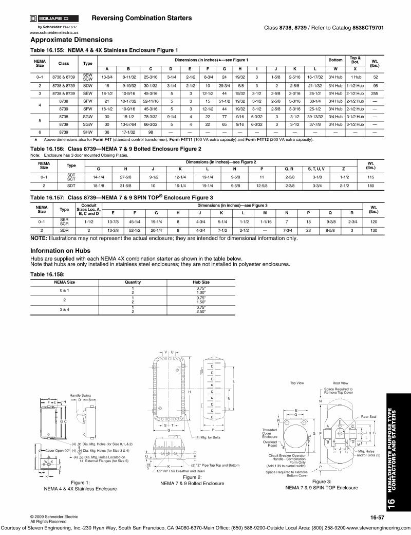
www.schneider-electric.us
16N
EM
A/D
EF
INIT
E P
UR
PO
SE
TY
PE
CO
NT
AC
TO
RS
AN
D S
TA
RT
ER
S
© 2009 Schneider ElectricAll Rights Reserved
16-57
Reversing Combination StartersClass 8738, 8739 / Refer to Catalog 8538CT9701
Approximate Dimensions
a Above dimensions also for Form F4T (standard control transformer), Form F4T11 (100 VA extra capacity) and Form F4T12 (200 VA extra capacity).
NOTE: Illustrations may not represent the actual enclosure; they are intended for dimensional information only.
Information on HubsHubs are supplied with each NEMA 4X combination starter as shown in the table below. Note that hubs are only installed in stainless steel enclosures; they are not installed in polyester enclosures.
Table 16.155: NEMA 4 & 4X Stainless Enclosure Figure 1
NEMASize Class Type
Dimensions (in inches)a—see Figure 1 Bottom Top & Bot. Wt.
(lbs.)A B C D E F G H I J K L W X
0–1 8738 & 8739 SBWSCW 13-3/4 8-11/32 25-3/16 3-1/4 2-1/2 8-3/4 24 19/32 3 1-5/8 2-5/16 18-17/32 3/4 Hub 1 Hub 52
2 8738 & 8739 SDW 15 9-19/32 30-1/32 3-1/4 2-1/2 10 29-3/4 5/8 3 2 2-5/8 21-1/32 3/4 Hub 1-1/2 Hub 95
3 8738 & 8739 SEW 18-1/2 10-9/16 45-3/16 5 3 12-1/2 44 19/32 3-1/2 2-5/8 3-3/16 25-1/2 3/4 Hub 2-1/2 Hub 255
48738 SFW 21 10-17/32 52-11/16 5 3 15 51-1/2 19/32 3-1/2 2-5/8 3-3/16 30-1/4 3/4 Hub 2-1/2 Hub —
8739 SFW 18-1/2 10-9/16 45-3/16 5 3 12-1/2 44 19/32 3-1/2 2-5/8 3-3/16 25-1/2 3/4 Hub 2-1/2 Hub —
58738 SGW 30 15-1/2 78-3/32 9-1/4 4 22 77 9/16 6-3/32 3 3-1/2 39-13/32 3/4 Hub 3-1/2 Hub —
8739 SGW 30 13-57/64 66-3/32 5 4 22 65 9/16 6-3/32 3 3-1/2 37-7/8 3/4 Hub 3-1/2 Hub —
6 8739 SHW 36 17-1/32 98 — — — — — — — — — — — —
Table 16.156: Class 8739—NEMA 7 & 9 Bolted Enclosure Figure 2Note: Enclosure has 3 door mounted Closing Plates.
NEMASize Type
Dimensions (in inches)—see Figure 2 Wt.(lbs.)G H J K L N P Q, R S, T, U, V Z
0–1 SBTSCT 14-1/4 27-5/8 9-1/2 12-1/4 19-1/4 9-5/8 11 2-3/8 3-1/8 1-1/2 115
2 SDT 18-1/8 31-5/8 10 16-1/4 19-1/4 9-5/8 12-5/8 2-3/8 3-3/4 2-1/2 180
Table 16.157: Class 8739—NEMA 7 & 9 SPIN TOP® Enclosure Figure 3
NEMASize Type
Conduit Sizes Loc. A, B, C and D
Dimensions (in inches)—see Figure 3 Wt.(lbs.)E F G H J K L M N P Q R
0–1 SBRSCR 1-1/2 13-7/8 45-1/4 19-1/4 8 4-3/4 5-1/4 1-1/2 1-1/16 7 18 9-3/8 2-3/4 120
2 SDR 2 13-3/8 52-1/2 20-1/4 8 4-3/4 7-1/2 2-1/2 — 7-3/4 23 8-5/8 3 130
Table 16.158: NEMA Size Quantity Hub Size
0 & 1 12
0.75"1.00"
2 12
0.75"1.50"
3 & 4 12
0.75"2.50"
B
C
FA
(4) .31 Dia. Mtg. Holes (for Size 0, 1, & 2)8
(4) .44 Dia. Mtg. Holes (for Size 3 & 4)11
(4) .56 Dia. Mtg. Holes Located on14 External Flanges (for Size 5)
L
W X
I
Cover Open 90º
DE
K
J
G
H
Handle Swing
Figure 1:NEMA 4 & 4X Stainless Enclosure
S T
G
V U
H
(4) Mtg. for Bolts
J
P
N
L
K
Q R
.195
(2) "Z" Pipe Tap Top and Bottom
1/2" NPT for Breather and Drain
Figure 2:NEMA 7 & 9 Bolted Enclosure
N
A
B D
C
J
P
F
M
K H
Mtg. Holesand/or Slots (3)
Rear View
Space Required to RemoveBottom Cover
Space Required toRemove Top Cover
OverloadReset
ThreadedCoverEnclosure
EQ
R
G
Top View
T
L
Rear Seal
S
Circuit Breaker OperatorHandle - Combination
Form Only(Add 1 IN to overall width)
Figure 3:NEMA 7 & 9 SPIN TOP Enclosure
Courtesy of Steven Engineering, Inc.-230 Ryan Way, South San Francisco, CA 94080-6370-Main Office: (650) 588-9200-Outside Local Area: (800) 258-9200-www.stevenengineering.com
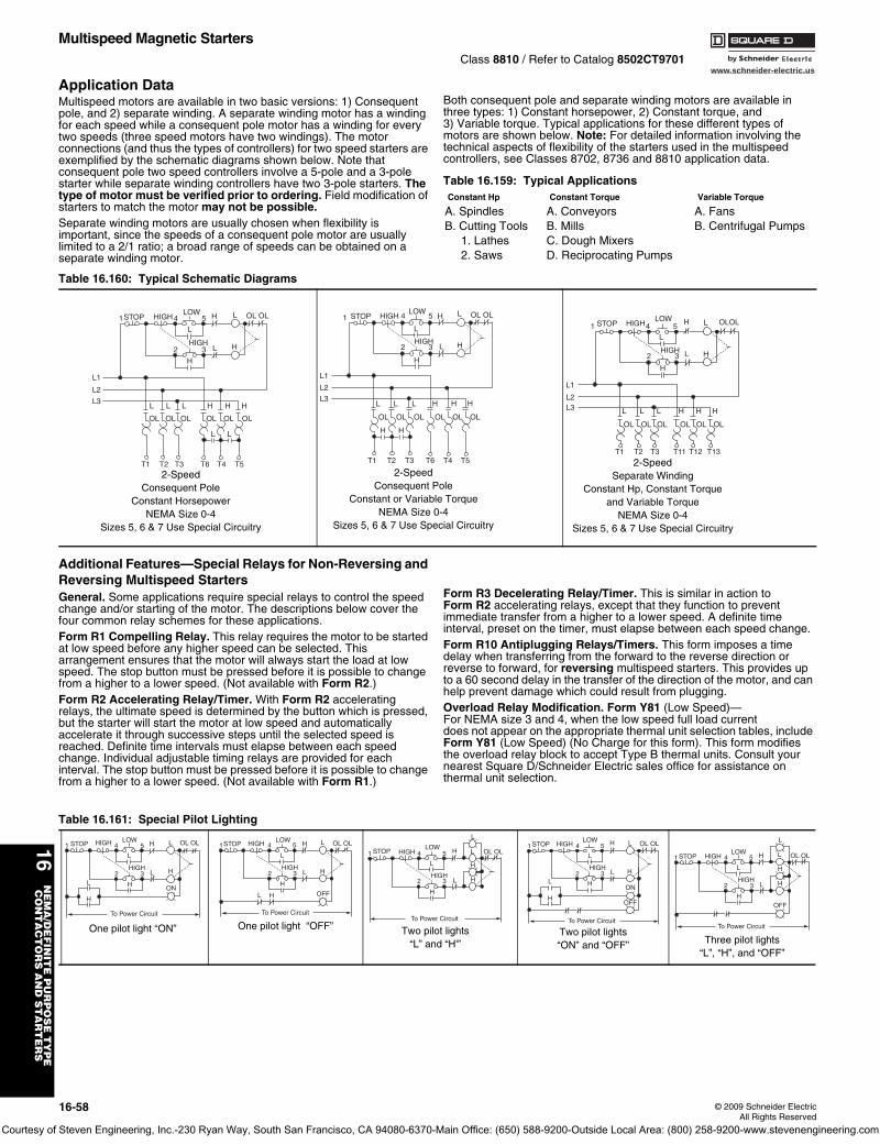
www.schneider-electric.us
16N
EM
A/D
EF
INIT
E P
UR
PO
SE
TY
PE
CO
NT
AC
TO
RS
AN
D S
TA
RT
ER
S
16-58 © 2009 Schneider ElectricAll Rights Reserved
Multispeed Magnetic StartersClass 8810 / Refer to Catalog 8502CT9701
Application DataMultispeed motors are available in two basic versions: 1) Consequent pole, and 2) separate winding. A separate winding motor has a winding for each speed while a consequent pole motor has a winding for every two speeds (three speed motors have two windings). The motor connections (and thus the types of controllers) for two speed starters are exemplified by the schematic diagrams shown below. Note that consequent pole two speed controllers involve a 5-pole and a 3-pole starter while separate winding controllers have two 3-pole starters. The type of motor must be verified prior to ordering. Field modification of starters to match the motor may not be possible.Separate winding motors are usually chosen when flexibility is important, since the speeds of a consequent pole motor are usually limited to a 2/1 ratio; a broad range of speeds can be obtained on a separate winding motor.
Both consequent pole and separate winding motors are available in three types: 1) Constant horsepower, 2) Constant torque, and 3) Variable torque. Typical applications for these different types of motors are shown below. Note: For detailed information involving the technical aspects of flexibility of the starters used in the multispeed controllers, see Classes 8702, 8736 and 8810 application data.
Additional Features—Special Relays for Non-Reversing and Reversing Multispeed StartersGeneral. Some applications require special relays to control the speed change and/or starting of the motor. The descriptions below cover the four common relay schemes for these applications.Form R1 Compelling Relay. This relay requires the motor to be started at low speed before any higher speed can be selected. This arrangement ensures that the motor will always start the load at low speed. The stop button must be pressed before it is possible to change from a higher to a lower speed. (Not available with Form R2.)Form R2 Accelerating Relay/Timer. With Form R2 accelerating relays, the ultimate speed is determined by the button which is pressed, but the starter will start the motor at low speed and automatically accelerate it through successive steps until the selected speed is reached. Definite time intervals must elapse between each speed change. Individual adjustable timing relays are provided for each interval. The stop button must be pressed before it is possible to change from a higher to a lower speed. (Not available with Form R1.)
Form R3 Decelerating Relay/Timer. This is similar in action to Form R2 accelerating relays, except that they function to prevent immediate transfer from a higher to a lower speed. A definite time interval, preset on the timer, must elapse between each speed change.Form R10 Antiplugging Relays/Timers. This form imposes a time delay when transferring from the forward to the reverse direction or reverse to forward, for reversing multispeed starters. This provides up to a 60 second delay in the transfer of the direction of the motor, and can help prevent damage which could result from plugging.Overload Relay Modification. Form Y81 (Low Speed)—For NEMA size 3 and 4, when the low speed full load current does not appear on the appropriate thermal unit selection tables, include Form Y81 (Low Speed) (No Charge for this form). This form modifies the overload relay block to accept Type B thermal units. Consult your nearest Square D/Schneider Electric sales office for assistance on thermal unit selection.
Table 16.159: Typical ApplicationsConstant Hp Constant Torque Variable Torque
A. Spindles A. Conveyors A. FansB. Cutting Tools B. Mills B. Centrifugal Pumps
1. Lathes C. Dough Mixers2. Saws D. Reciprocating Pumps
Table 16.160: Typical Schematic Diagrams
STOP HIGH 4LOW
5 H
HIGH
L
2
H
3 L
L L
L LL
L1
L2
L3
L OL OL
H
H
HH
OL OL OL OL OL OL
T1 T2 T3 T6 T4 T5
1
2-SpeedConsequent Pole
Constant HorsepowerNEMA Size 0-4
Sizes 5, 6 & 7 Use Special Circuitry
STOP HIGH 4LOW
5 H
HIGH
L
2
H
3 L
L LL
L1
L2
L3
L OL OL
H
H
HH
H H
OL OL OL OL OL OL
T1 T2 T3 T6 T4 T5
1
2-SpeedConsequent Pole
Constant or Variable TorqueNEMA Size 0-4
Sizes 5, 6 & 7 Use Special Circuitry
STOP HIGH4LOW
5 H
HIGH
L
2
H
3 L
L LL
L1
L2L3
L OLOL
H
H
HH
OL OL OL OL OL OL
T1 T2 T3 T11 T12 T13
1
2-SpeedSeparate Winding
Constant Hp, Constant Torqueand Variable Torque
NEMA Size 0-4Sizes 5, 6 & 7 Use Special Circuitry
Table 16.161: Special Pilot Lighting
STOP HIGH 4LOW
5 H
HIGH
L
2
HL
H
3 L
L OL OL
H
ON
To Power Circuit
1
One pilot light “ON”
STOP HIGH 4LOW
5 H
HIGH
L
2
H
L H
3 L
L OL OL
H
OFF
To Power Circuit
1
One pilot light “OFF”
STOP HIGH 4LOW
5 H
HIGH
L
2
H
3 L
L
L
OL OL
H
H
To Power Circuit
1
Two pilot lights“L” and “H'”
STOP HIGH 4LOW
5 H
HIGH
L
2
HL
H
3 L
L OL OL
H
ON
To Power Circuit
OFF
1
Two pilot lights“ON” and “OFF”
STOP HIGH 4LOW
5 H
HIGH
L
2
H
3 L
L
L
OL OL
H
H
To Power Circuit
OFF
1
Three pilot lights“L”, “H”, and “OFF”
Courtesy of Steven Engineering, Inc.-230 Ryan Way, South San Francisco, CA 94080-6370-Main Office: (650) 588-9200-Outside Local Area: (800) 258-9200-www.stevenengineering.com
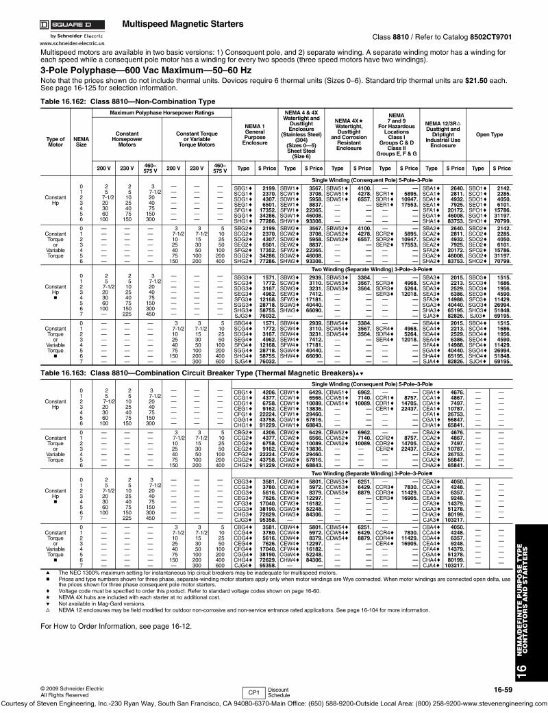
www.schneider-electric.us
16N
EM
A/D
EF
INIT
E P
UR
PO
SE
TY
PE
CO
NT
AC
TO
RS
AN
D S
TA
RT
ER
S
© 2009 Schneider ElectricAll Rights Reserved
16-59
Multispeed Magnetic StartersClass 8810 / Refer to Catalog 8502CT9701
Multispeed motors are available in two basic versions: 1) Consequent pole, and 2) separate winding. A separate winding motor has a winding for each speed while a consequent pole motor has a winding for every two speeds (three speed motors have two windings).
3-Pole Polyphase—600 Vac Maximum—50–60 HzNote that the prices shown do not include thermal units. Devices require 6 thermal units (Sizes 0–6). Standard trip thermal units are $21.50 each. See page 16-125 for selection information.
a The NEC 1300% maximum setting for instantaneous trip circuit breakers may be inadequate for multispeed motors.b Prices and type numbers shown for three phase, separate-winding motor starters apply only when motor windings are Wye connected. When motor windings are connected open delta, use
the prices shown for three phase consequent pole motor starters.c Voltage code must be specified to order this product. Refer to standard voltage codes shown on page 16-60.d NEMA 4X hubs are included with each starter at no additional cost.e Not available in Mag-Gard versions.f NEMA 12 enclosures may be field modified for outdoor non-corrosive and non-service entrance rated applications. See page 16-104 for more information.
For How to Order Information, see page 16-12.
Table 16.162: Class 8810—Non-Combination Type
Type ofMotor
NEMASize
Maximum Polyphase Horsepower Ratings
NEMA 1GeneralPurpose
Enclosure
NEMA 4 & 4XWatertight and
Dusttight Enclosure
(Stainless Steel) (304)
(Sizes 0—5)Sheet Steel
(Size 6)
NEMA 4XdWatertight,Dusttight
and CorrosionResistantEnclosure
NEMA7 and 9
For HazardousLocations
Class IGroups C & D
Class IIGroups E, F & G
NEMA 12/3RfDusttight and
DriptightIndustrial Use
Enclosure
Open TypeConstantHorsepower
Motors
Constant Torqueor Variable
Torque Motors
200 V 230 V 460–575 V 200 V 230 V 460–
575 V Type $ Price Type $ Price Type $ Price Type $ Price Type $ Price Type $ Price
ConstantHp
0123456
25
7-1/2203060
100
25
10254075
150
3 7-1/2
204075
150300
———————
———————
———————
Single Winding (Consequent Pole) 5-Pole–3-Pole
SBG1cSCG1cSDG1cSEG1cSFG1cSGG1cSHG1c
2199.2370.4307.6501.
17352.34286.77286.
SBW1cSCW1cSDW1cSEW1cSFW1cSGW1cSHW1c
3567.3708.5958.8837.
22365.46008.93308.
SBW51cSCW51cSDW51c
————
4100.4278.6557.
————
—SCR1cSDR1cSER1c
———
—5895.
10947.17553.
———
SBA1cSCA1cSDA1cSEA1cSFA1cSGA1cSHA1c
2640.2811.4932.7925.
20172.46008.83753.
SBO1cSCO1cSDO1cSEO1cSFO1cSGO1cSHO1c
2142.2285.4050.6101.
15786.31197.70799.
ConstantTorque
orVariableTorque
0123456
———————
———————
———————
3 7-1/2
10254075
150
3 7-1/2
153050
100200
5102550
100200400
SBG2cSCG2cSDG2cSEG2cSFG2cSGG2cSHG2c
2199.2370.4307.6501.
17352.34286.77286.
SBW2cSCW2cSDW2cSEW2cSFW2cSGW2cSHW2c
3567.3708.5958.8837.
22365.46008.93308.
SBW52cSCW52cSDW52c
————
4100.4278.6557.
————
—SCR2cSDR2cSER2c
———
—5895.
10947.17553.
———
SBA2cSCA2cSDA2cSEA2cSFA2cSGA2cSHA2c
2640.2811.4932.7925.
20172.46008.83753.
SBO2cSCO2cSDO2cSEO2cSFO2cSGO2cSHO2c
2142.2285.4050.6101.
15786.31197.70799.
ConstantHpb
01234567
25
7-1/2203060
100—
25
10254075
150225
3 7-1/2
204075
150300450
————————
————————
————————
Two Winding (Separate Winding) 3-Pole–3-Poleb
SBG3cSCG3cSDG3cSEG3cSFG3cSGG3cSHG3cSJG3c
1571.1772.3167.4962.
12168.28718.58755.76032.
SBW3cSCW3cSDW3cSEW3cSFW3cSGW3cSHW3c
—
2939.3110.3231.7412.
17181.40440.66090.
—
SBW53cSCW53cSDW53c
—————
3384.3567.3564.
—————
—SCR3cSDR3cSER3c
————
—4968.5264.
12018.————
SBA3cSCA3cSDA3cSEA3cSFA3cSGA3cSHA3cSJA3c
2015.2213.2529.6386.
14988.40440.65195.82826.
SBO3cSCO3cSDO3cSEO3cSFO3cSGO3cSHO3cSJ03c
1515.1686.1956.4590.
11429.26994.51848.69195.
ConstantTorque
orVariableTorqueb
01234567
————————
————————
————————
3 7-1/2
10254075
150—
3 7-1/2
153050
100200300
5102550
100200400600
SBG4cSCG4cSDG4cSEG4cSFG4cSGG4cSHG4cSJG4c
1571.1772.3167.4962.
12168.28718.58755.76032.
SBW4cSCW4cSDW4cSEW4cSFW4cSGW4cSHW4c
—
2939.3110.3231.7412.
17181.40440.66090.
—
SBW54cSCW54cSDW54c
—————
3384.3567.3564.
—————
—SCR4cSDR4cSER4c
————
—4968.5264.
12018.————
SBA4cSCA4cSDA4cSEA4cSFA4cSGA4cSHA4cSJA4c
2015.2213.2529.6386.
14988.40440.65195.82826.
SBO4cSCO4cSDO4cSEO4cSFO4cSGO4cSHO4cSJO4c
1515.1686.1956.4590.
11429.26994.51848.69195.
Table 16.163: Class 8810—Combination Circuit Breaker Type (Thermal Magnetic Breakers)ae
ConstantHp
0123456
25
7-1/2203060
100
25
10254075
150
3 7-1/2204075
150300
———————
———————
———————
Single Winding (Consequent Pole) 5-Pole–3-Pole
CBG1cCCG1cCDG1cCEG1cCFG1cCGG1cCHG1c
4206.4377.6758.9162.
22224.43758.91229.
CBW1cCCW1cCDW1cCEW1cCFW1cCGW1cCHW1c
6429.6566.
10089.13836.29460.57816.68843.
CBW51cCCW51cCDW51c
————
6962.7140.
10089.————
—CCR1cCDR1cCER1c
———
—8757.
14705.22437.
———
CBA1cCCA1cCDA1cCEA1cCFA1cCGA1cCHA1c
4676.4867.7497.
10787.26753.56847.65841.
———————
———————
ConstantTorque
orVariableTorque
0123456
———————
———————
———————
37-1/210254075
150
3 7-1/2
153050
100200
5102550
100200400
CBG2cCCG2cCDG2cCEG2cCFG2cCGG2cCHG2c
4206.4377.6758.9162.
22224.43758.91229.
CBW2cCCW2cCDW2cCEW2cCFW2cCGW2cCHW2c
6429.6566.
10089.13836.29460.57816.68843.
CBW52cCCW52cCDW52c
————
6962.7140.
10089.————
—CCR2cCDR2cCER2c
———
—8757.
14705.22437.
———
CBA2cCCA2cCDA2cCEA2cCFA2cCGA2cCHA2c
4676.4867.7497.
10787.26753.56847.65841.
———————
———————
ConstantHpb
01234567
25
7-1/2203060
100—
25
10254075
150225
3 7-1/2
204075
150300450
————————
————————
————————
Two Winding (Separate Winding) 3-Pole–3-Poleb
CBG3cCCG3cCDG3cCEG3cCFG3cCGG3cCHG3cCJG3c
3581.3780.5616.7626.
17040.38190.72629.95358.
CBW3cCCW3cCDW3cCEW3cCFW3cCGW3cCHW3c
—
5801.5972.8379.
12297.16182.52248.84306.
—
CBW53cCCW53cCDW53c
—————
6251.6429.8879.
—————
—CCR3cCDR3cCER3c
————
—7830.
11429.16905.
————
CBA3cCCA3cCDA3cCEA3cCFA3cCGA3cCHA3cCJA3c
4050.4248.6357.9248.
14379.51278.80199.
103217.
———————
———————
ConstantTorque
orVariableTorqueb
01234567
————————
————————
————————
3 7-1/2
10254075
150—
3 7-1/2
153050
100200300
5102550
100200400600
CBG4cCCG4cCDG4cCEG4cCFG4cCGG4cCHG4cCJG4c
3581.3780.5616.7626.
17040.38190.72629.95358.
CBW4cCCW4cCDW4cCEW4cCFW4cCGW4cCHW4c
—
5801.5972.8379.
12297.16182.52248.84306.
—
CBW54cCCW54cCDW54c
—————
6251.6429.8879.
—————
—CCR4cCDR4cCER4c
————
—7830.
11429.16905.
————
CBA4cCCA4cCDA4cCEA4cCFA4cCGA4cCHA4cCJA4c
4050.4248.6357.9248.
14379.51278.80199.
103217.
———————
———————
CP1 Discount Schedule
Courtesy of Steven Engineering, Inc.-230 Ryan Way, South San Francisco, CA 94080-6370-Main Office: (650) 588-9200-Outside Local Area: (800) 258-9200-www.stevenengineering.com
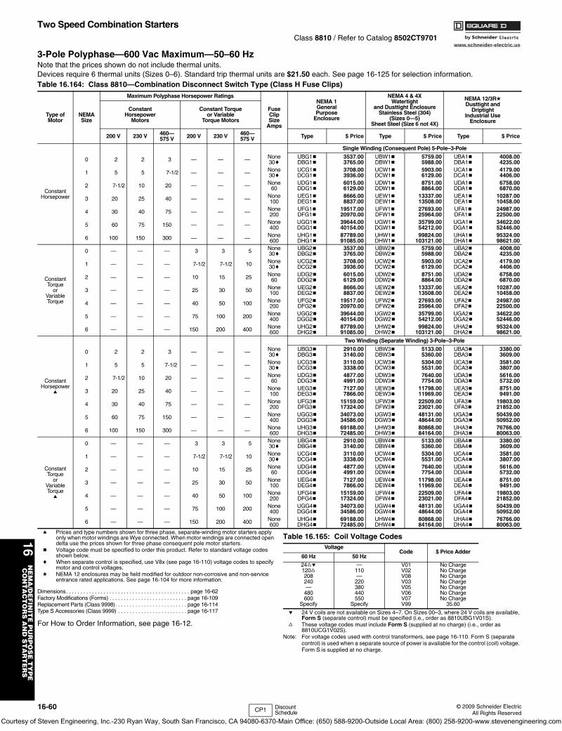
www.schneider-electric.us
16N
EM
A/D
EF
INIT
E P
UR
PO
SE
TY
PE
CO
NT
AC
TO
RS
AN
D S
TA
RT
ER
S
16-60 © 2009 Schneider ElectricAll Rights Reserved
Two Speed Combination StartersClass 8810 / Refer to Catalog 8502CT9701
3-Pole Polyphase—600 Vac Maximum—50–60 HzNote that the prices shown do not include thermal units.
a Prices and type numbers shown for three phase, separate-winding motor starters apply only when motor windings are Wye connected. When motor windings are connected open delta use the prices shown for three phase consequent pole motor starters.
b Voltage code must be specified to order this product. Refer to standard voltage codes shown below.
c When separate control is specified, use V8x (see page 16-110) voltage codes to specify motor and control voltages.
d NEMA 12 enclosures may be field modified for outdoor non-corrosive and non-service entrance rated applications. See page 16-104 for more information.
Dimensions. . . . . . . . . . . . . . . . . . . . . . . . . . . . . . . . . . . . . . . . . . . page 16-62Factory Modifications (Forms) . . . . . . . . . . . . . . . . . . . . . . . . . . . page 16-109Replacement Parts (Class 9998). . . . . . . . . . . . . . . . . . . . . . . . . page 16-114Type S Accessories (Class 9999) . . . . . . . . . . . . . . . . . . . . . . . . page 16-117
For How to Order Information, see page 16-12.
e 24 V coils are not available on Sizes 4–7. On Sizes 00–3, where 24 V coils are available, Form S (separate control) must be specified (i.e., order as 8810UBG1V01S).
f These voltage codes must include Form S (supplied at no charge) (i.e., order as 8810UCG1V02S).
Note: For voltage codes used with control transformers, see page 16-110. Form S (separate control) is used when a separate source of power is available for the control (coil) voltage. Form S is supplied at no charge.
Devices require 6 thermal units (Sizes 0–6). Standard trip thermal units are $21.50 each. See page 16-125 for selection information.Table 16.164: Class 8810—Combination Disconnect Switch Type (Class H Fuse Clips)
Type ofMotor
NEMASize
Maximum Polyphase Horsepower Ratings
FuseClipSize
Amps
NEMA 1GeneralPurpose
Enclosure
NEMA 4 & 4XWatertight
and Dusttight EnclosureStainless Steel (304)
(Sizes 0—5)Sheet Steel (Size 6 not 4X)
NEMA 12/3RdDusttight and
DriptightIndustrial Use
Enclosure
ConstantHorsepower
Motors
Constant Torqueor Variable
Torque Motors
200 V 230 V 460—575 V 200 V 230 V 460—
575 V Type $ Price Type $ Price Type $ Price
ConstantHorsepower
Single Winding (Consequent Pole) 5-Pole–3-Pole
0 2 2 3 — — — None30c
UBG1bDBG1b
3537.003765.00
UBW1bDBW1b
5759.005988.00
UBA1bDBA1b
4008.004235.00
1 5 5 7-1/2 — — — None30c
UCG1bDCG1b
3708.003936.00
UCW1bDCW1b
5903.006129.00
UCA1bDCA1b
4179.004406.00
2 7-1/2 10 20 — — — None60
UDG1bDDG1b
6015.006129.00
UDW1bDDW1b
8751.008864.00
UDA1bDDA1b
6758.006870.00
3 20 25 40 — — — None100
UEG1bDEG1b
8666.008837.00
UEW1bDEW1b
13337.0013508.00
UEA1bDEA1b
10287.0010458.00
4 30 40 75 — — — None200
UFG1bDFG1b
19517.0020970.00
UFW1bDFW1b
27693.0025964.00
UFA1bDFA1b
24987.0022500.00
5 60 75 150 — — — None400
UGG1bDGG1b
39644.0040154.00
UGW1bDGW1b
35799.0054212.00
UGA1bDGA1b
34622.0052446.00
6 100 150 300 — — — None600
UHG1bDHG1b
87789.0091085.00
UHW1bDHW1b
99824.00103121.00
UHA1bDHA1b
95324.0098621.00
ConstantTorque
orVariableTorque
0 — — — 3 3 5 None30c
UBG2bDBG2b
3537.003765.00
UBW2bDBW2b
5759.005988.00
UBA2bDBA2b
4008.004235.00
1 — — — 7-1/2 7-1/2 10 None30c
UCG2bDCG2b
3708.003936.00
UCW2bDCW2b
5903.006129.00
UCA2bDCA2b
4179.004406.00
2 — — — 10 15 25 None60
UDG2bDDG2b
6015.006129.00
UDW2bDDW2b
8751.008864.00
UDA2bDDA2b
6758.006870.00
3 — — — 25 30 50 None100
UEG2bDEG2b
8666.008837.00
UEW2bDEW2b
13337.0013508.00
UEA2bDEA2b
10287.0010458.00
4 — — — 40 50 100 None200
UFG2bDFG2b
19517.0020970.00
UFW2bDFW2b
27693.0025964.00
UFA2bDFA2b
24987.0022500.00
5 — — — 75 100 200 None400
UGG2bDGG2b
39644.0040154.00
UGW2bDGW2b
35799.0054212.00
UGA2bDGA2b
34622.0052446.00
6 — — — 150 200 400 None600
UHG2bDHG2b
87789.0091085.00
UHW2bDHW2b
99824.00103121.00
UHA2bDHA2b
95324.0098621.00
ConstantHorsepower
a
Two Winding (Separate Winding) 3-Pole–3-Pole
0 2 2 3 — — — None30c
UBG3bDBG3b
2910.003140.00
UBW3bDBW3b
5133.005360.00
UBA3bDBA3b
3380.003609.00
1 5 5 7-1/2 — — — None30c
UCG3bDCG3b
3110.003338.00
UCW3bDCW3b
5304.005531.00
UCA3bDCA3b
3581.003807.00
2 7-1/2 10 20 — — — None60
UDG3bDDG3b
4877.004991.00
UDW3bDDW3b
7640.007754.00
UDA3bDDA3b
5616.005732.00
3 20 25 40 — — — None100
UEG3bDEG3b
7127.007866.00
UEW3bDEW3b
11798.0011969.00
UEA3bDEA3b
8751.009491.00
4 30 40 75 — — — None200
UFG3bDFG3b
15159.0017324.00
UFW3bDFW3b
22509.0023021.00
UFA3bDFA3b
19803.0021852.00
5 60 75 150 — — — None400
UGG3bDGG3b
34073.0034586.00
UGW3bDGW3b
48131.0048644.00
UGA3bDGA3b
50439.0050952.00
6 100 150 300 — — — None600
UHG3bDHG3b
69188.0072485.00
UHW3bDHW3b
80868.0084164.00
UHA3bDHA3b
76766.0080063.00
ConstantTorque
orVariableTorquea
0 — — — 3 3 5 None30c
UBG4bDBG4b
2910.003140.00
UBW4bDBW4b
5133.005360.00
UBA4bDBA4b
3380.003609.00
1 — — — 7-1/2 7-1/2 10 None30c
UCG4bDCG4b
3110.003338.00
UCW4bDCW4b
5304.005531.00
UCA4bDCA4b
3581.003807.00
2 — — — 10 15 25 None60
UDG4bDDG4b
4877.004991.00
UDW4bDDW4b
7640.007754.00
UDA4bDDA4b
5616.005732.00
3 — — — 25 30 50 None100
UEG4bDEG4b
7127.007866.00
UEW4bDEW4b
11798.0011969.00
UEA4bDEA4b
8751.009491.00
4 — — — 40 50 100 None200
UFG4bDFG4b
15159.0017324.00
UFW4bDFW4b
22509.0023021.00
UFA4bDFA4b
19803.0021852.00
5 — — — 75 100 200 None400
UGG4bDGG4b
34073.0034586.00
UGW4bDGW4b
48131.0048644.00
UGA4bDGA4b
50439.0050952.00
6 — — — 150 200 400 None600
UHG4bDHG4b
69188.0072485.00
UHW4bDHW4b
80868.0084164.00
UHA4bDHA4b
76766.0080063.00
Table 16.165: Coil Voltage CodesVoltage
Code $ Price Adder60 Hz 50 Hz
24fe120f208240—
480600
Specify
—110—
220380440550
Specify
V01V02V08V03V05V06V07V99
No ChargeNo ChargeNo ChargeNo ChargeNo ChargeNo ChargeNo Charge
35.60
CP1 Discount Schedule
Courtesy of Steven Engineering, Inc.-230 Ryan Way, South San Francisco, CA 94080-6370-Main Office: (650) 588-9200-Outside Local Area: (800) 258-9200-www.stevenengineering.com
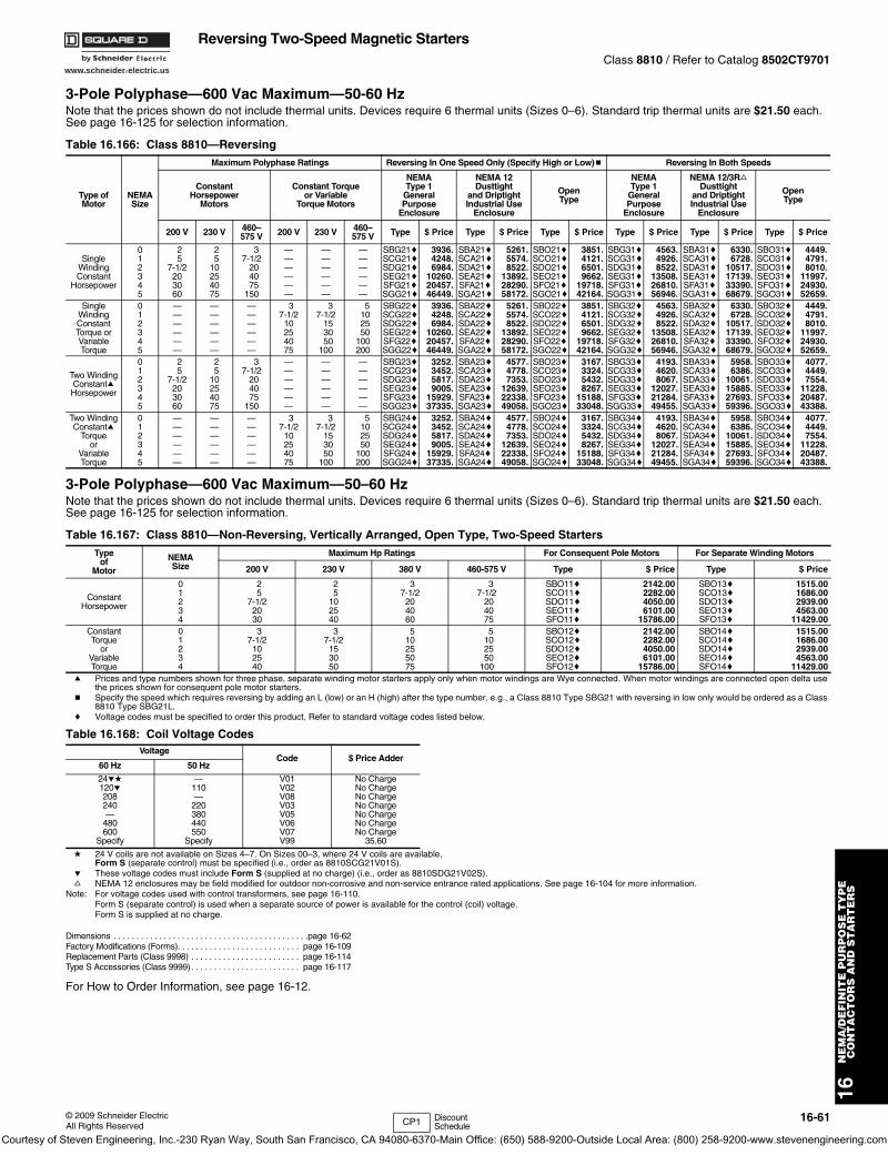
www.schneider-electric.us
© 2009 Schneider ElectricAll Rights Reserved
16-61
16N
EM
A/D
EF
INIT
E P
UR
PO
SE
TY
PE
CO
NT
AC
TO
RS
AN
D S
TA
RT
ER
S
Reversing Two-Speed Magnetic StartersClass 8810 / Refer to Catalog 8502CT9701
3-Pole Polyphase—600 Vac Maximum—50-60 HzNote that the prices shown do not include thermal units. Devices require 6 thermal units (Sizes 0–6). Standard trip thermal units are $21.50 each. See page 16-125 for selection information.
3-Pole Polyphase—600 Vac Maximum—50–60 HzNote that the prices shown do not include thermal units. Devices require 6 thermal units (Sizes 0–6). Standard trip thermal units are $21.50 each. See page 16-125 for selection information.
a Prices and type numbers shown for three phase, separate winding motor starters apply only when motor windings are Wye connected. When motor windings are connected open delta use the prices shown for consequent pole motor starters.
b Specify the speed which requires reversing by adding an L (low) or an H (high) after the type number, e.g., a Class 8810 Type SBG21 with reversing in low only would be ordered as a Class 8810 Type SBG21L.
c Voltage codes must be specified to order this product. Refer to standard voltage codes listed below.
d 24 V coils are not available on Sizes 4–7. On Sizes 00–3, where 24 V coils are available, Form S (separate control) must be specified (i.e., order as 8810SCG21V01S).
e These voltage codes must include Form S (supplied at no charge) (i.e., order as 8810SDG21V02S).f NEMA 12 enclosures may be field modified for outdoor non-corrosive and non-service entrance rated applications. See page 16-104 for more information.
Note: For voltage codes used with control transformers, see page 16-110.Form S (separate control) is used when a separate source of power is available for the control (coil) voltage. Form S is supplied at no charge.
Dimensions . . . . . . . . . . . . . . . . . . . . . . . . . . . . . . . . . . . . . . . . . . .page 16-62Factory Modifications (Forms). . . . . . . . . . . . . . . . . . . . . . . . . . . page 16-109Replacement Parts (Class 9998) . . . . . . . . . . . . . . . . . . . . . . . . page 16-114Type S Accessories (Class 9999). . . . . . . . . . . . . . . . . . . . . . . . page 16-117
For How to Order Information, see page 16-12.
Table 16.166: Class 8810—Reversing
Type ofMotor
NEMASize
Maximum Polyphase Ratings Reversing In One Speed Only (Specify High or Low)b Reversing In Both Speeds
ConstantHorsepower
Motors
Constant Torqueor Variable
Torque Motors
NEMAType 1
GeneralPurpose
Enclosure
NEMA 12Dusttight
and DriptightIndustrial Use
Enclosure
OpenType
NEMAType 1
GeneralPurpose
Enclosure
NEMA 12/3RfDusttight
and DriptightIndustrial Use
Enclosure
OpenType
200 V 230 V 460–575 V 200 V 230 V 460–
575 V Type $ Price Type $ Price Type $ Price Type $ Price Type $ Price Type $ Price
SingleWindingConstant
Horsepower
012345
25
7-1/2203060
25
10254075
37-1/2
204075
150
——————
——————
——————
SBG21cSCG21cSDG21cSEG21cSFG21cSGG21c
3936.4248.6984.
10260.20457.46449.
SBA21cSCA21cSDA21cSEA21cSFA21cSGA21c
5261.5574.8522.
13892.28290.58172.
SBO21cSCO21cSDO21cSEO21cSFO21cSGO21c
3851.4121.6501.9662.
19718.42164.
SBG31cSCG31cSDG31cSEG31cSFG31cSGG31c
4563.4926.8522.
13508.26810.56946.
SBA31cSCA31cSDA31cSEA31cSFA31cSGA31c
6330.6728.
10517.17139.33390.68679.
SBO31cSCO31cSDO31cSEO31cSFO31cSGO31c
4449.4791.8010.
11997.24930.52659.
SingleWindingConstantTorque orVariableTorque
012345
——————
——————
——————
37-1/210254075
37-1/2
153050
100
5102550
100200
SBG22cSCG22cSDG22cSEG22cSFG22cSGG22c
3936.4248.6984.
10260.20457.46449.
SBA22cSCA22cSDA22cSEA22cSFA22cSGA22c
5261.5574.8522.
13892.28290.58172.
SBO22cSCO22cSDO22cSEO22cSFO22cSGO22c
3851.4121.6501.9662.
19718.42164.
SBG32cSCG32cSDG32cSEG32cSFG32cSGG32c
4563.4926.8522.
13508.26810.56946.
SBA32cSCA32cSDA32cSEA32cSFA32cSGA32c
6330.6728.
10517.17139.33390.68679.
SBO32cSCO32cSDO32cSEO32cSFO32cSGO32c
4449.4791.8010.
11997.24930.52659.
Two Winding ConstantaHorsepower
012345
25
7-1/2203060
25
10254075
37-1/2
204075
150
——————
——————
——————
SBG23cSCG23cSDG23cSEG23cSFG23cSGG23c
3252.3452.5817.9005.
15929.37335.
SBA23cSCA23cSDA23cSEA23cSFA23cSGA23c
4577.4778.7353.
12639.22338.49058.
SBO23cSCO23cSDO23cSEO23cSFO23cSGO23c
3167.3324.5432.8267.
15188.33048.
SBG33cSCG33cSDG33cSEG33cSFG33cSGG33c
4193.4620.8067.
12027.21284.49455.
SBA33cSCA33cSDA33cSEA33cSFA33cSGA33c
5958.6386.
10061.15885.27693.59396.
SBO33cSCO33cSDO33cSEO33cSFO33cSGO33c
4077.4449.7554.
11228.20487.43388.
Two Winding Constanta
Torqueor
VariableTorque
012345
——————
——————
——————
37-1/210254075
37-1/2
153050
100
5102550
100200
SBG24cSCG24cSDG24cSEG24cSFG24cSGG24c
3252.3452.5817.9005.
15929.37335.
SBA24cSCA24cSDA24cSEA24cSFA24cSGA24c
4577.4778.7353.
12639.22338.49058.
SBO24cSCO24cSDO24cSEO24cSFO24cSGO24c
3167.3324.5432.8267.
15188.33048.
SBG34cSCG34cSDG34cSEG34cSFG34cSGG34c
4193.4620.8067.
12027.21284.49455.
SBA34cSCA34cSDA34cSEA34cSFA34cSGA34c
5958.6386.
10061.15885.27693.59396.
SBO34cSCO34cSDO34cSEO34cSFO34cSGO34c
4077.4449.7554.
11228.20487.43388.
Table 16.167: Class 8810—Non-Reversing, Vertically Arranged, Open Type, Two-Speed StartersType
ofMotor
NEMASize
Maximum Hp Ratings For Consequent Pole Motors For Separate Winding Motors
200 V 230 V 380 V 460-575 V Type $ Price Type $ Price
ConstantHorsepower
01234
25
7-1/22030
25
102540
37-1/2
204060
37-1/2
204075
SBO11cSCO11cSDO11cSEO11cSFO11c
2142.002282.004050.006101.00
15786.00
SBO13cSCO13cSDO13cSEO13cSFO13c
1515.001686.002939.004563.00
11429.00ConstantTorque
orVariableTorque
01234
37-1/2102540
37-1/2153050
510255075
5102550
100
SBO12cSCO12cSDO12cSEO12cSFO12c
2142.002282.004050.006101.00
15786.00
SBO14cSCO14cSDO14cSEO14cSFO14c
1515.001686.002939.004563.00
11429.00
Table 16.168: Coil Voltage CodesVoltage
Code $ Price Adder60 Hz 50 Hz
24ed120e208240—
480600
Specify
—110—
220380440550
Specify
V01V02V08V03V05V06V07V99
No ChargeNo ChargeNo ChargeNo ChargeNo ChargeNo ChargeNo Charge
35.60
CP1 Discount Schedule
Courtesy of Steven Engineering, Inc.-230 Ryan Way, South San Francisco, CA 94080-6370-Main Office: (650) 588-9200-Outside Local Area: (800) 258-9200-www.stevenengineering.com
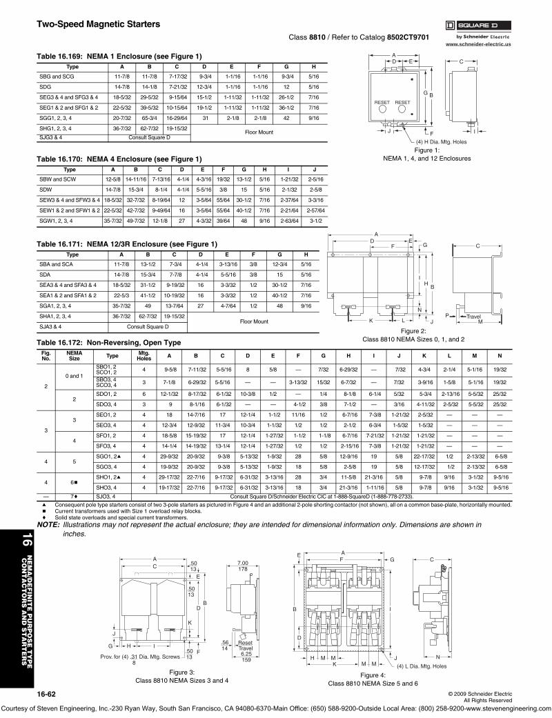
www.schneider-electric.us
16N
EM
A/D
EF
INIT
E P
UR
PO
SE
TY
PE
CO
NT
AC
TO
RS
AN
D S
TA
RT
ER
S
16-62 © 2009 Schneider ElectricAll Rights Reserved
Two-Speed Magnetic StartersClass 8810 / Refer to Catalog 8502CT9701
a Consequent pole type starters consist of two 3-pole starters as pictured in Figure 4 and an additional 2-pole shorting contactor (not shown), all on a common base-plate, horizontally mounted.b Current transformers used with Size 1 overload relay blocks.c Solid state overloads and special current transformers.
NOTE: Illustrations may not represent the actual enclosure; they are intended for dimensional information only. Dimensions are shown in inches.
Table 16.169: NEMA 1 Enclosure (see Figure 1)Type A B C D E F G H
SBG and SCG 11-7/8 11-7/8 7-17/32 9-3/4 1-1/16 1-1/16 9-3/4 5/16
SDG 14-7/8 14-1/8 7-21/32 12-3/4 1-1/16 1-1/16 12 5/16
SEG3 & 4 and SFG3 & 4 18-5/32 29-5/32 9-15/64 15-1/2 1-11/32 1-11/32 26-1/2 7/16
SEG1 & 2 and SFG1 & 2 22-5/32 39-5/32 10-15/64 19-1/2 1-11/32 1-11/32 36-1/2 7/16
SGG1, 2, 3, 4 20-7/32 65-3/4 16-29/64 31 2-1/8 2-1/8 42 9/16
SHG1, 2, 3, 4 36-7/32 62-7/32 19-15/32Floor Mount
SJG3 & 4 Consult Square D
Table 16.170: NEMA 4 Enclosure (see Figure 1)Type A B C D E F G H I J
SBW and SCW 12-5/8 14-11/16 7-13/16 4-1/4 4-3/16 19/32 13-1/2 5/16 1-21/32 2-5/16
SDW 14-7/8 15-3/4 8-1/4 4-1/4 5-5/16 3/8 15 5/16 2-1/32 2-5/8
SEW3 & 4 and SFW3 & 4 18-5/32 32-7/32 8-19/64 12 3-5/64 55/64 30-1/2 7/16 2-37/64 3-3/16
SEW1 & 2 and SFW1 & 2 22-5/32 42-7/32 9-49/64 16 3-5/64 55/64 40-1/2 7/16 2-21/64 2-57/64
SGW1, 2, 3, 4 35-7/32 49-7/32 12-1/8 27 4-3/32 39/64 48 9/16 2-63/64 3-1/2
Table 16.171: NEMA 12/3R Enclosure (see Figure 1)Type A B C D E F G H
SBA and SCA 11-7/8 13-1/2 7-3/4 4-1/4 3-13/16 3/8 12-3/4 5/16
SDA 14-7/8 15-3/4 7-7/8 4-1/4 5-5/16 3/8 15 5/16
SEA3 & 4 and SFA3 & 4 18-5/32 31-1/2 9-19/32 16 3-3/32 1/2 30-1/2 7/16
SEA1 & 2 and SFA1 & 2 22-5/3 41-1/2 10-19/32 16 3-3/32 1/2 40-1/2 7/16
SGA1, 2, 3, 4 35-7/32 49 13-7/64 27 4-7/64 1/2 48 9/16
SHA1, 2, 3, 4 36-7/32 62-7/32 19-15/32 Floor Mount
SJA3 & 4 Consult Square D
Table 16.172: Non-Reversing, Open TypeFig.No.
NEMASize Type Mtg.
Holes A B C D E F G H I J K L M N
2
0 and 1
SBO1, 2SCO1, 2 4 9-5/8 7-11/32 5-5/16 8 5/8 — 7/32 6-29/32 — 7/32 4-3/4 2-1/4 5-1/16 19/32
SBO3, 4SCO3, 4 3 7-1/8 6-29/32 5-5/16 — — 3-13/32 15/32 6-7/32 — 7/32 3-9/16 1-5/8 5-1/16 19/32
2SDO1, 2 6 12-1/32 8-17/32 6-1/32 10-3/8 1/2 — 1/4 8-1/8 6-1/4 5/32 5-3/4 2-13/16 5-5/32 25/32
SDO3, 4 3 9 8-1/16 6-1/32 — — 4-1/2 3/8 7-1/2 — 3/16 4-11/32 2-5/32 5-5/32 25/32
3
3SEO1, 2 4 18 14-7/16 17 12-1/4 1-1/2 11/16 1/2 6-7/16 7-3/8 1-21/32 2-5/32 — — —
SEO3, 4 4 12-3/4 12-9/32 11-3/4 10-3/4 1-1/32 1/2 1/2 2-1/2 6-3/4 1-5/32 1-5/32 — — —
4SFO1, 2 4 18-5/8 15-19/32 17 12-1/4 1-27/32 1-1/2 1-1/8 6-7/16 7-21/32 1-21/32 1-21/32 — — —
SFO3, 4 4 14-1/4 14-19/32 13-1/4 12-1/4 1-27/32 1/2 1/2 2-15/16 7-3/8 1-21/32 1-21/32 — — —
4 5SGO1, 2a 4 29-9/32 20-9/32 9-3/8 5-13/32 1-9/32 28 5/8 12-9/16 19 5/8 22-17/32 1/2 2-13/32 6-5/8
SGO3, 4 4 19-9/32 20-9/32 9-3/8 5-13/32 1-9/32 18 5/8 2-5/8 19 5/8 12-17/32 1/2 2-13/32 6-5/8
4 6bSHO1, 2a 4 29-17/32 22-7/16 9-17/32 6-31/32 3-13/16 28 3/4 11-5/8 21-3/16 5/8 9-7/8 9/16 3-1/32 9-5/16
SHO3, 4 4 19-17/32 22-7/16 9-17/32 6-31/32 3-13/16 18 3/4 21-3/16 1-11/16 5/8 9-7/8 9/16 3-1/32 9-5/16
— 7c SJO3, 4 Consult Square D/Schneider Electric CIC at 1-888-SquareD (1-888-778-2733).
(4) H Dia. Mtg. Holes
G
D EA
B
F
C
J I
RESET RESET
Figure 1:NEMA 1, 4, and 12 Enclosures
RESET RESET
AD
FE
G
IH
B
N
JLK
C
PM
Travel
Figure 2:Class 8810 NEMA Sizes 0, 1, and 2
RESETRESET
J
G H I
DB
K
FProv. for (4) .31 Dia. Mtg. Screws 8
.5013
.5013
.5013
CA
E
.5614
6.25159
ResetTravel
7.00178
Figure 3:Class 8810 NEMA Sizes 3 and 4
GFAE
B
D
M MMH M
KJ
(4) L Dia. Mtg. Holes
C
I
N
Figure 4:Class 8810 NEMA Size 5 and 6
Courtesy of Steven Engineering, Inc.-230 Ryan Way, South San Francisco, CA 94080-6370-Main Office: (650) 588-9200-Outside Local Area: (800) 258-9200-www.stevenengineering.com
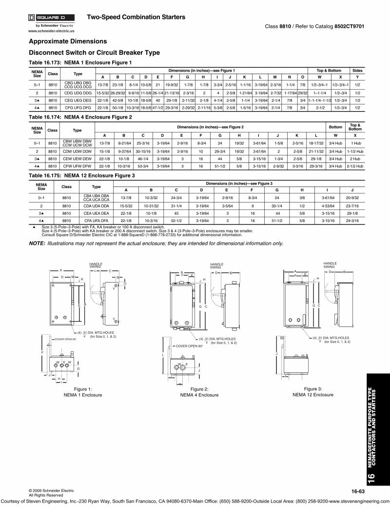
www.schneider-electric.us
16N
EM
A/D
EF
INIT
E P
UR
PO
SE
TY
PE
CO
NT
AC
TO
RS
AN
D S
TA
RT
ER
S
© 2009 Schneider ElectricAll Rights Reserved
16-63
Two-Speed Combination StartersClass 8810 / Refer to Catalog 8502CT9701
Approximate Dimensions
Disconnect Switch or Circuit Breaker Type
a Size 3 (5-Pole–3-Pole) with FA, KA breaker or 100 A disconnect switch.Size 4 (5-Pole–3-Pole) with KA breaker or 200 A disconnect switch. Size 3 & 4 (3-Pole–3-Pole) enclosures may be smaller. Consult Square D/Schneider Electric CIC at 1-888-SquareD (1-888-778-2733) for additional dimensional information.
NOTE: Illustrations may not represent the actual enclosure; they are intended for dimensional information only.
Table 16.173: NEMA 1 Enclosure Figure 1
NEMASize Class Type
Dimensions (in inches)—see Figure 1 Top & Bottom Sides
A B C D E F G H I J K L M N O W X Y
0–1 8810 CBG UBG DBGCCG UCG DCG 13-7/8 23-1/8 8-1/4 10-5/8 21 19-9/32 1-7/8 1-7/8 3-3/4 2-5/16 1-1/16 3-19/64 2-3/16 1-1/4 7/8 1/2–3/4–1 1/2–3/4–1 1/2
2 8810 CDG UDG DDG 15-5/32 28-29/32 9-9/16 11-5/8 26-1/4 21-13/16 2-3/16 2 4 2-5/8 1-21/64 3-19/64 2-7/32 1-17/64 29/32 1–1-1/4 1/2–3/4 1/2
3a 8810 CEG UEG DEG 22-1/8 42-5/8 10-1/8 18-5/8 40 29-1/8 2-11/32 2-1/8 4-1/4 2-5/8 1-1/4 3-19/64 2-1/4 7/8 3/4 1–1-1/4–1-1/2 1/2–3/4 1/2
4a 8810 CFG UFG DFG 22-1/8 50-1/8 10-3/16 18-5/8 47-1/2 29-3/16 2-29/32 2-11/16 5-3/8 2-5/8 1-5/16 3-19/64 2-1/4 7/8 3/4 2-1/2 1/2–3/4 1/2
Table 16.174: NEMA 4 Enclosure Figure 2
NEMASize Class Type
Dimensions (in inches)—see Figure 2 Bottom Top & Bottom
A B C D E F G H I J K L W X
0–1 8810 CBW UBW DBWCCW UCW DCW 13-7/8 8-21/64 25-3/16 3-19/64 2-9/16 8-3/4 24 19/32 3-61/64 1-5/8 2-5/16 18-17/32 3/4 Hub 1 Hub
2 8810 CDW UDW DDW 15-1/8 9-37/64 30-15/16 3-19/64 2-9/16 10 29-3/4 19/32 3-61/64 2 2-5/8 21-11/32 3/4 Hub 1-1/2 Hub
3a 8810 CEW UEW DEW 22-1/8 10-1/8 46-1/4 3-19/64 3 16 44 5/8 3-15/16 1-3/4 2-5/8 29-1/8 3/4 Hub 2 Hub
4a 8810 CFW UFW DFW 22-1/8 10-3/16 53-3/4 3-19/64 3 16 51-1/2 5/8 3-15/16 2-9/32 3-3/16 29-3/16 3/4 Hub 2-1/2 Hub
Table 16.175: NEMA 12 Enclosure Figure 3
NEMASize Class Type
Dimensions (in inches)—see Figure 3
A B C D E F G H I J
0–1 8810 CBA UBA DBACCA UCA DCA 13-7/8 10-3/32 24-3/4 3-19/64 2-9/16 8-3/4 24 3/8 3-61/64 20-9/32
2 8810 CDA UDA DDA 15-5/32 10-31/32 31-1/4 3-19/64 3-5/64 9 30-1/4 1/2 4-53/64 23-7/16
3a 8810 CEA UEA DEA 22-1/8 10-1/8 45 3-19/64 3 16 44 5/8 3-15/16 29-1/8
4a 8810 CFA UFA DFA 22-1/8 10-3/16 52-1/2 3-19/64 3 16 51-1/2 5/8 3-15/16 29-3/16
O
N
C
HANDLESWING
E B
KMD
A
Y
(4) .31 DIA. MTG.HOLES (for Size 0, 1, & 2)8
F
W X W
G
JH
I
COVER OPEN 90°
L
Y
Figure 1:NEMA 1 Enclosure
B
HANDLESWING
C
FA
(4) .31 DIA. MTG.HOLES (for Size 0, 1, & 2)8
L
W X
I
COVER OPEN 90°
DE
K
J
G
H
Figure 2:NEMA 4 Enclosure
B
HANDLESWING
C
FA
(4) .31 DIA. MTG.HOLES (for Size 0, 1, & 2)8
J
I
DE
G
H
Figure 3:NEMA 12 Enclosure
Courtesy of Steven Engineering, Inc.-230 Ryan Way, South San Francisco, CA 94080-6370-Main Office: (650) 588-9200-Outside Local Area: (800) 258-9200-www.stevenengineering.com
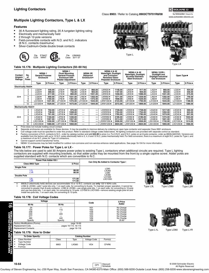
www.schneider-electric.us
16-64 © 2009 Schneider ElectricAll Rights Reserved
16N
EM
A/D
EF
INIT
E P
UR
PO
SE
TY
PE
CO
NT
AC
TO
RS
AN
D S
TA
RT
ER
S
Lighting ContactorsClass 8903 / Refer to Catalog 8903CT9701R8/08
Multipole Lighting Contactors, Type L & LX
Features• 30 A fluorescent lighting rating, 20 A tungsten lighting rating• Electrically and mechanically held• 2 through 12-pole versions• Field-convertible contacts with N.O. and N.C. indicators
(8 N.C. contacts maximumd)• Silver-Cadmium-Oxide double break contacts
a Price does not include holding circuit contact.b Separate enclosures are available for these devices. It may be possible to improve delivery by ordering an open type contactor and separate Class 9991 enclosure.c Coil voltage code must be specified to order this product. Refer to standard voltage codes listed below. All lighting contactors are provided with separate control as standard.d Factory conversion of N.O. contacts to N.C., order by catalog number and add $42.80 to price (i.e. For 6 N.O. and 2 N.C. poles on an 8 pole contactor, order as 8903LG62V02). Versions are
available from the factory with up to 12 N.C. poles electrically held or 2, 4, 6 and 12 N.C. poles mechanically held. For field conversion, there is a maximum of eight N.C. poles for Type L and a maximum of six N.C. poles for Type LX contactors.
e Cannot support control transformer forms.f NEMA 12 enclosures may be field modified for outdoor non-corrosive and non-service entrance rated applications. See page 16-104 for more information.
Factory Modifications (Forms) . . . . . . . . . . . . . . . . . . . . . . . . . . . . page 16-69Replacement Coils . . . . . . . . . . . . . . . . . . . . . . . . . . . . pages 16-114, 16-115Replacement Contacts. . . . . . . . . . . . . . . . . . . . . . . . . . . . . . . . . page 16-116
FileCCN
E78427NRNT
FileClass
LR609053211 07
Table 16.176: Multipole Lighting Contactors (50–60 Hz)
ContactAmpereRatings
No.of
Poles
NEMA 1General Purpose
Enclosure
NEMA 1Flush MountingGeneral PurposeEnclosure with
Plaster Adjustment
NEMA 3RRainproof
Enclosuree
NEMA 4 & 4XWatertight, Dusttight
and Corrosion-Resistant Glass-
Polyester Enclosure
NEMA 4 & 4XWatertight, DusttightBrushed Stainless
Steel Enclosure
NEMA 12/3RfDusttight and
Driptight IndustrialUse Enclosure
Open Typeb
Type $ Pricea Type $ Pricea Type $ Pricea Type $ Pricea Type $ Pricea Type $ Pricea Type $ Pricea
Electrically Heldd
30c
234
LG20cLG30cLG40c
446.00489.00617.00
LF20cLF30cLF40c
689.00732.00860.00
LH20cLH30cLH40c
860.00903.00
1031.00
LWW20cLWW30cLWW40c
1146.001197.001358.00
LW20cLW30cLW40c
917.00959.00
1088.00
LA20cLA30cLA40c
860.00903.00
1031.00
LO20cLO30cLO40c
404.00446.00575.00
68
10
LG60cLG80c
LG1000c
890.001160.001331.00
LF60cLF80c
LF1000c
1031.001301.001472.00
LH60cLH80c
LH1000c
1202.001472.001643.00
LWW60cLWW80c
LWW1000c
1571.001908.002123.00
LW60cLW80c
LW1000c
1259.001529.001700.00
LA60cLA80c
LA1000c
1202.001472.001643.00
LO60cLO80c
LO1000c
746.001017.001188.00
12 LG1200c 1529.00 LF1200c 1673.00 LH1200c 1844.00 LWW1200c 2372.00 LW1200c 1899.00 LA1200c 1844.00 LO1200c 1386.00
Mechanically Helde
30c
234
LXG20cLXG30cLXG40c
702.00738.00761.00
LXF20cLXF30cLXF40c
975.001008.001031.00
———
———
LXWW20cLXWW30cLXWW40c
1728.001764.001785.00
LXW20cLXW30cLXW40c
1728.001764.001785.00
LXA20cLXA30cLXA40c
1017.001052.001074.00
LXO20cLXO30cLXO40c
590.00624.00647.00
68
10
LXG60cLXG80c
LXG1000c
1160.001287.001430.00
LXF60cLXF80c
LXF1000c
1430.001557.001700.00
———
———
LXWW60cLXWW80c
LXWW1000c
2186.002313.002456.00
LXW60cLXW80c
LXW1000c
2186.002313.002456.00
LXA60cLXA80c
LXA1000c
1472.001601.001742.00
LXO60cLXO80c
LXO1000c
1044.001173.001314.00
12 LXG1200c 1580.00 LXF1200c 1850.00 — — LXWW1200c 2604.00 LXW1200c 2604.00 LXA1200c 1893.00 LXO1200c 1466.00
Table 16.177: Power Poles for Type L or LX - The kits below are used to add 30 Ampere power poles to existing Type L contactors when additional circuits are required. Type L lighting contactors are supplied with mounting brackets, so that adder poles may be mounted from the front by a single captive screw. Adder poles are supplied standard with N.O. contacts which are convertible to N.C.
Power Pole Adder KitgCan Only Be Added to Contactor Typeh
Class 8903 Type $ Price
Single PoleLO60
LXO60LO80
LXO80LO1000
LXO1000
L1L 86.00L1R 86.00
Double Pole
L3L 171.00L3R 171.00
g 8903LO (electrically held) devices can accommodate 10 or 12 N.C. contacts use only 120 V 60Hz coils. h LO60 & LXO60—add 1-pole kits only, 1 on each side, for converting to 8-pole. To maintain proper operation, it cannot be
converted to greater than 8-pole contactor. LO80 & LXO80—use single-pole kits, 1 on each side, for converting to 10-pole and use two-pole kits, 1 on each side, for converting to 12-pole. LO1000 & LXO1000—remove existing single pole kit and install two-pole kits, 1 on each side, for converting to 12-pole.
Table 16.178: Coil Voltage CodesVoltage
Code $ PriceAdder60 Hz 50 Hz
24120208240277480
Specify
—110—
220—
440Specify
V01V02V08V03V04V06V99
No ChargeNo ChargeNo ChargeNo ChargeNo ChargeNo Charge
35.60
Table 16.179: How to OrderTo Order Specify: Catalog Number
• Class Number• Type Number• Voltage Code• Form(s)
Class Type Voltage Code Form(s)
8903 LXG60 VO4 CF4R6
Type L
Type LX
Type L3L Type LO80 Type L3R
Type L1L Type LO60 Type L1R
CP1 Discount Schedule
Courtesy of Steven Engineering, Inc.-230 Ryan Way, South San Francisco, CA 94080-6370-Main Office: (650) 588-9200-Outside Local Area: (800) 258-9200-www.stevenengineering.com
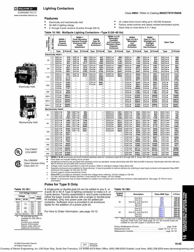
www.schneider-electric.us
16N
EM
A/D
EF
INIT
E P
UR
PO
SE
TY
PE
CO
NT
AC
TO
RS
AN
D S
TA
RT
ER
S
© 2009 Schneider ElectricAll Rights Reserved
16-65
Lighting ContactorsClass 8903 / Refer to Catalog 8903CT9701R8/08
Features• Electrically and mechanically held• 30–800 A lighting ratings• 2- through 5-pole versions (5-poles through 200 A)
• UL Listed short-circuit rating up to 100,000 Amperes• Factory wired controls and clearly marked termination points• Quick ship on most items in 5–7 days
Poles for Type S OnlyA single-pole or double-pole kit can be added to any 2- or 3-pole 30 or 60 A Type S lighting contactor to make a 4- or 5-pole device. Factory assembled 4- and 5-pole contactors utilize the basic 3-pole device with a single or double-pole kit installed. Only one power pole can be added per contactor. Sufficient room is provided in all enclosure styles for the addition of a power pole kit.
For How to Order Information, see page 16-12.
j When power pole is added to 60 Ampere contactor, a 4-pole coil is also required. Order from Coil Table page 16-115. 60 A power poles are suitable for use with copper or aluminum wire.
Factory Modifications (Forms) . . . . . . . . . . . . . . . . . . . . . . . . . . . .page 16-69Replacement Coils . . . . . . . . . . . . . . . . . . . . . . . . . . . . pages 16-114, 16-115Replacement Contacts . . . . . . . . . . . . . . . . . . . . . . . . . . . . . . . . .page 16-116
Mechanically Held
Electrically Held
File LR60905(Open Devices Only) Class 3231 01
File E78427CCN NRNT
Table 16.180: Multipole Lighting Contactors—Type S (50–60 Hz)
Con
tact
Am
pere
Rat
ings
No.
of P
oles NEMA 1
General Purpose
Enclosure
NEMA 1Flush MountingGeneral PurposeEnclosure with
Plaster Adjustment
NEMA Type 3R
RainproofEnclosuref
NEMA 4 & 4XWatertight, Dusttight
and Corrosion-Resistant Glass-
Polyester Enclosure
NEMA Type 4 & 4Xa
Watertight and
Dusttight Enclosure
NEMA Type 12 / 3RhDusttight and
Driptight Industrial
Use Enclosure
Open Type
Type $ Priceb Type $ Priceb Type $ Priceb Type $ Priceb Type $ Priceb Type $ Priceb Type $ Priceb
Electrically Heldc
30
2345
SMG1dSMG2dSMG3dSMG4d
476.518.633.831.
SMF1dSMF2dSMF3dSMF4d
660.689.818.
1017.
SMH1dSMH2dSMH3dSMH4d
647.689.804.
1002.
SMW21dSMW22dSMW23dSMW24d
989.1031.1146.1344.
SMW1dSMW2dSMW3dSMW4d
989.1031.1146.1344.
SMA1dSMA2dSMA3dSMA4d
647.810.804.
1002.
SMO1deSMO2deSMO3deSMO4de
446.488.603.534.
60
2345
SPG1dSPG2dSPG3dSPG4d
975.1031.1287.1857.
SPF1dSPF2dSPF3dSPF4d
1215.1272.1529.2100.
SPH1dSPH2dSPH3dSPH4d
1287.1344.1601.2142.
SPW21dSPW22dSPW23dSPW24d
1998.2057.2712.3281.
SPW1dSPW2dSPW3dSPW4d
1998.2057.2712.3281.
SPA1dSPA2dSPA3dSPA4d
1287.1344.1601.2142.
SPO1deSPO2deSPO3deSPO4de
831.890.
1146.1715.
100
2345
SQG1dSQG2dSQG3dSQG4d
1601.1715.2114.3024.
SQF1dSQF2d
——
2015.2127.
——
SQH1dSQH2dSQH3dSQH4d
1971.2084.2484.3396.
SQW21dSQW22d
——
3815.3959.
——
SQW1dSQW2dSQW3dSQW4d
3054.3167.3965.4877.
SQA1dSQA2dSQA3dSQA4d
1971.2084.2484.3396.
SQO1deSQO2deSQO3deSQO4de
1314.1430.1827.2739.
200
2345
SVG1dSVG2dSVG3dSVG4d
3765.4022.5285.7127.
————
————
SVH1dSVH2d
——
4991.5247.
——
————
————
SVW1dSVW2dSVW3dSVW4d
6245.6501.8864.
10646.
SVA1dSVA2dSVA3dSVA4d
4991.5247.7011.8793.
SVO1dSVO2dSVO3dSVO4d
3167.3423.4761.6543.
300 23
SXG1dSXG2d
7952.8550.
——
——
——
——
——
——
SXW1dSXW2d
11087.11685.
SXA1dSXA2d
11087.11685.
SXO1dSXO2d
6857.7455.
400g 23
SYG1dSYG2d
20813.23534.
——
——
——
——
——
——
SYW1dSYW2d
27935.30654.
SYA1dSYA2d
24659.27378.
SYO1dSYO2d
16299.19020.
600g 23
SZG1dSZG2d
25550.28704.
——
——
——
——
——
——
SZW1dSZW2d
32670.35825.
SZA1dSZA2d
29394.32549.
SZO1dSZO2d
20879.24026.
800g 23
SJG1dSJG2d
30285.33875.
——
——
——
——
——
——
SJW1dSJW2d
37535.40995.
SJA1dSJA2d
33845.37719.
SJO1dSJO2d
25457.29033.
Mechanically Heldc
30
2345
SMG10dSMG11dSMG12dSMG13d
738.782.824.
1025.
SMF10dSMF11dSMF12dSMF13d
923.966.
1008.1209.
————
————
SMW31dSMW32dSMW33dSMW34d
1251.1295.1337.1538.
SMW10dSMW11dSMW12dSMW13d
1251.1295.1337.1538.
SMA10dSMA11dSMA12dSMA13d
912.953.995.
1196.
SMO10deSMO11deSMO12deSMO13de
710.752.795.995.
60
2345
SPG10dSPG11dSPG12dSPG13d
1485.1544.1827.2399.
SPF10dSPF11dSPF12dSPF13d
1758.1814.2100.2669.
————
————
SPW31dSPW32dSPW33dSPW34d
2511.2570.3252.3824.
SPW10dSPW11dSPW12dSPW13d
2511.2570.3252.3824.
SPA10dSPA11dSPA12dSPA13d
1800.1857.2142.2712.
SPO10deSPO11deSPO12deSPO13de
1373.1430.1715.2285.
100
2345
SQG10dSQG11dSQG12dSQG13d
2084.2199.2627.3537.
SQF10dSQF11d
——
2241.2357.
——
————
————
SQW31dSQW32d
——
4419.4563.
——
SQW10dSQW11dSQW12dSQW13d
3537.3653.4478.5390.
SQA10dSQA11dSQA12dSQA13d
2456.2570.2996.3909.
SQO10deSQO11deSQO12deSQO13de
1827.1943.2370.3281.
200234
SVG10dSVG11dSVG12d
5333.6015.7353.
———
———
———
———
———
———
SVW10dSVW11dSVW12d
7811.8495.
10859.
SVA10dSVA11dSVA12d
6557.7241.9008.
SVO10dSVO11dSVO12d
4505.4877.6215.
300 23
SXG13dSXG14d
9320.10232.
——
——
——
——
——
——
SXW13dSXW14d
12455.13365.
SXA13dSXA14d
12455.13365.
SXO13dSXO14d
7554.7811.
400 23
SYG16dSYG17d
22593.25316.
——
——
——
——
——
——
SYW16dSYW17d
29714.32436.
SYA16dSYA17d
26441.29160.
SYO16dSYO17d
18080.20799.
600 23
SZG18dSZG19d
27329.30483.
——
——
——
——
——
——
SZW18dSZW19d
34451.37605.
SZA18dSZA19d
31175.34329.
SZO18dSZO19d
22658.25806.
a NEMA 4 & 4X enclosures are brush finished stainless steel for contactors sized 30 A through 300 A. Sizes 400–800 A are painted sheet steel. b Price does not include holding circuit contact.c All lighting contactors are provided with separate control as standard, except electrically held 400, 600 and 800 A devices. Electrically held 400, 600 and
800 A devices are provided with common control. d Voltage code must be specified to order this product. Refer to standard voltage codes above left.e Separate enclosures are available for these devices. It may be possible to improve delivery by ordering an open type contactor and separate Class 9991
enclosure from pages 16-102 and 16-103.f Cannot support control transformer forms.g Form F4T is provided as standard; include line voltage when ordering. Control voltage is 120–60.
For 400, 600 and 800 ampere devices—must specify line voltage, not coil voltage.h NEMA 12 enclosures may be field modified for outdoor non-corrosive and non-service entrance rated applications. See page 16-104 for more
information.
Table 16.181: Coil Voltage Codesc
VoltageCode Price
Adder60 Hz 50 Hz
24i120208240277480
Specify
—110—
220—
440Specify
V01V02V08V03V04V06V99
N/CN/CN/CN/CN/CN/C35.60
i 24 volt coils are not available for 200–800 A devices. Contact your nearest Square D/Schneider Electric sales office for additional information.
Table 16.182: AmpereRating Description Class 9999 Type $ Price
30
One N.O.One N.C.
One N.O. and One N.C.Two N.O.Two N.C.
SB6SB7SB8SB9SB10
158.00158.00365.00365.00365.00
60
One N.O.One N.C.
One N.O. and One N.C.Two N.O.Two N.C.
SB21jSB22jSB23jSB24jSB25j
306.00306.00656.00656.00656.00
CP1 Discount Schedule
Courtesy of Steven Engineering, Inc.-230 Ryan Way, South San Francisco, CA 94080-6370-Main Office: (650) 588-9200-Outside Local Area: (800) 258-9200-www.stevenengineering.com
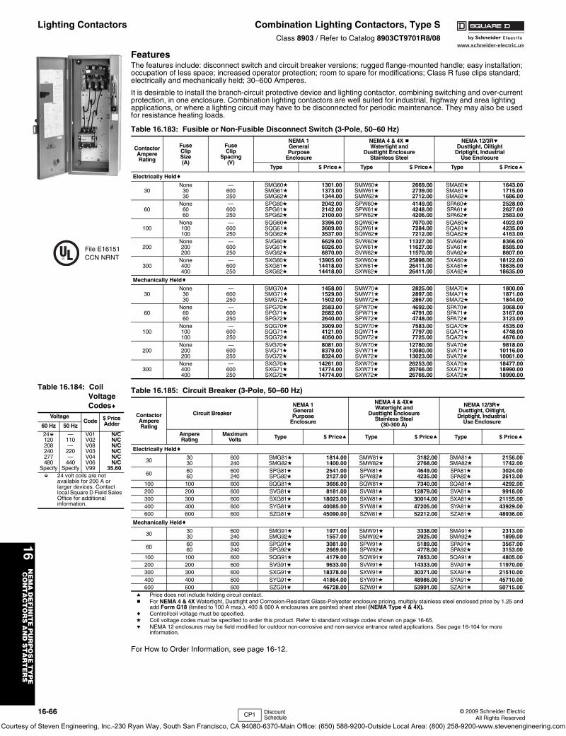
16-66 © 2009 Schneider ElectricAll Rights Reserved
www.schneider-electric.us
16N
EM
A D
EF
INIT
E P
UR
PO
SE
TY
PE
C
ON
TA
CT
OR
S A
ND
ST
AR
TE
RS
Lighting Contactors Combination Lighting Contactors, Type SClass 8903 / Refer to Catalog 8903CT9701R8/08
FeaturesThe features include: disconnect switch and circuit breaker versions; rugged flange-mounted handle; easy installation; occupation of less space; increased operator protection; room to spare for modifications; Class R fuse clips standard; electrically and mechanically held; 30–600 Amperes.
It is desirable to install the branch-circuit protective device and lighting contactor, combining switching and over-current protection, in one enclosure. Combination lighting contactors are well suited for industrial, highway and area lighting applications, or where a lighting circuit may have to be disconnected for periodic maintenance. They may also be used for resistance heating loads.
a Price does not include holding circuit contact.b For NEMA 4 & 4X Watertight, Dusttight and Corrosion-Resistant Glass-Polyester enclosure pricing, multiply stainless steel enclosed price by 1.25 and
add Form G18 (limited to 100 A max.). 400 & 600 A enclosures are painted sheet steel (NEMA Type 4 & 4X).c Control/coil voltage must be specified.d Coil voltage codes must be specified to order this product. Refer to standard voltage codes shown on page 16-65.e NEMA 12 enclosures may be field modified for outdoor non-corrosive and non-service entrance rated applications. See page 16-104 for more
information.
For How to Order Information, see page 16-12.
Table 16.183: Fusible or Non-Fusible Disconnect Switch (3-Pole, 50–60 Hz)
ContactorAmpereRating
FuseClipSize(A)
FuseClip
Spacing(V)
NEMA 1GeneralPurpose
Enclosure
NEMA 4 & 4X bWatertight and
Dusttight EnclosureStainless Steel
NEMA 12/3ReDusttight, Oiltight
Driptight, IndustrialUse Enclosure
Type $ Pricea Type $ Pricea Type $ Pricea
Electrically Heldc
30None
3030
—600250
SMG60dSMG61dSMG62d
1301.001373.001344.00
SMW60dSMW61d SMW62d
2669.002739.002712.00
SMA60dSMA61dSMA62d
1643.001715.001686.00
60None
6060
—600250
SPG60dSPG61dSPG62d
2042.002142.002100.00
SPW60dSPW61dSPW62d
4149.004248.004206.00
SPA60dSPA61dSPA62d
2528.002627.002583.00
100None100100
—600250
SQG60dSQG61dSQG62d
3396.003609.003537.00
SQW60dSQW61dSQW62d
7070.007284.007212.00
SQA60dSQA61dSQA62d
4022.004235.004163.00
200None200200
—600250
SVG60dSVG61dSVG62d
6629.006926.006870.00
SVW60dSVW61dSVW62d
11327.0011627.0011570.00
SVA60dSVA61dSVA62d
8366.008585.008607.00
300None400400
—600250
SXG60dSXG61dSXG62d
13905.0014418.0014418.00
SXW60dSXW61dSXW62d
25898.0026411.0026411.00
SXA60dSXA61dSXA62d
18122.0018635.0018635.00
Mechanically Heldc
30None
3030
—600250
SMG70dSMG71dSMG72d
1458.001529.001502.00
SMW70dSMW71dSMW72d
2825.002897.002867.00
SMA70dSMA71dSMA72d
1800.001871.001844.00
60None
6060
—600250
SPG70dSPG71dSPG72d
2583.002682.002640.00
SPW70dSPW71dSPW72d
4692.004791.004748.00
SPA70dSPA71dSPA72d
3068.003167.003123.00
100None100100
—600250
SQG70dSQG71dSQG72d
3909.004121.004050.00
SQW70dSQW71dSQW72d
7583.007797.007725.00
SQA70dSQA71dSQA72d
4535.004748.004676.00
200None200200
—600250
SVG70dSVG71dSVG72d
8081.008379.008324.00
SVW70dSVW71dSVW72d
12780.0013080.0013023.00
SVA70dSVA71dSVA72d
9818.0010116.0010061.00
300None400400
—600250
SXG70dSXG71dSXG72d
14261.0014774.0014774.00
SXW70dSXW71dSXW72d
26253.0026766.0026766.00
SXA70dSXA71dSXA72d
18477.0018990.0018990.00
File E16151CCN NRNT
Table 16.184: Coil Voltage Codesc
VoltageCode $ Price
Adder60 Hz 50 Hz
24k120208240277480
Specify
—110—
220—
440Specify
V01V02V08V03V04V06V99
N/CN/CN/CN/CN/CN/C
35.60k 24 volt coils are not
available for 200 A or larger devices. Contact local Square D Field Sales Office for additional information.
Table 16.185: Circuit Breaker (3-Pole, 50–60 Hz)
ContactorAmpereRating
Circuit Breaker
NEMA 1GeneralPurpose
Enclosure
NEMA 4 & 4XbWatertight and
Dusttight EnclosureStainless Steel
(30-300 A)
NEMA 12/3ReDusttight, Oiltight,Driptight, Industrial
Use Enclosure
AmpereRating
MaximumVolts Type $ Pricea Type $ Pricea Type $ Pricea
Electrically Heldc
30 3030
600240
SMG81dSMG82d
1814.001400.00
SMW81dSMW82d
3182.002768.00
SMA81dSMA82d
2156.001742.00
60 6060
600240
SPG81dSPG82d
2541.002127.00
SPW81dSPW82d
4649.004235.00
SPA81dSPA82d
3024.002613.00
100 100 600 SQG81d 3666.00 SQW81d 7340.00 SQA81d 4292.00200 200 600 SVG81d 8181.00 SVW81d 12879.00 SVA81d 9918.00300 300 600 SXG81d 18023.00 SXW81d 30014.00 SXA81d 21155.00400 400 600 SYG81d 40085.00 SYW81d 47205.00 SYA81d 43929.00600 600 600 SZG81d 45090.00 SZW81d 52212.00 SZA81d 48936.00
Mechanically Heldc
30 3030
600240
SMG91dSMG92d
1971.001557.00
SMW91dSMW92d
3338.002925.00
SMA91dSMA92d
2313.001899.00
60 6060
600240
SPG91dSPG92d
3081.002669.00
SPW91dSPW92d
5189.004778.00
SPA91dSPA92d
3567.003153.00
100 100 600 SQG91d 4179.00 SQW91d 7853.00 SQA91d 4805.00200 200 600 SVG91d 9633.00 SVW91d 14333.00 SVA91d 11970.00300 300 600 SXG91d 18378.00 SXW91d 30371.00 SXA91d 21510.00400 400 600 SYG91d 41864.00 SYW91d 48986.00 SYA91d 45710.00600 600 600 SZG91d 46728.00 SZW91d 53991.00 SZA91d 50715.00
CP1 Discount Schedule
Courtesy of Steven Engineering, Inc.-230 Ryan Way, South San Francisco, CA 94080-6370-Main Office: (650) 588-9200-Outside Local Area: (800) 258-9200-www.stevenengineering.com
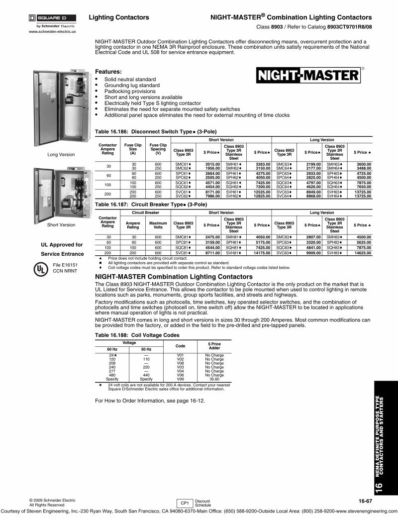
www.schneider-electric.us
16N
EM
A D
EF
INIT
E P
UR
PO
SE
TY
PE
C
ON
TA
CT
OR
S A
ND
ST
AR
TE
RS
© 2009 Schneider ElectricAll Rights Reserved
16-67
Lighting Contactors NIGHT-MASTER® Combination Lighting ContactorsClass 8903 / Refer to Catalog 8903CT9701R8/08
NIGHT-MASTER Outdoor Combination Lighting Contactors offer disconnecting means, overcurrent protection and a lighting contactor in one NEMA 3R Rainproof enclosure. These combination units satisfy requirements of the National Electrical Code and UL 508 for service entrance equipment.
Features:• Solid neutral standard• Grounding lug standard• Padlocking provisions• Short and long versions available• Electrically held Type S lighting contactor• Eliminates the need for separate mounted safety switches• Additional panel space eliminates the need for external mounting of time clocks
a Price does not include holding circuit contact.b All lighting contactors are provided with separate control as standard.c Coil voltage codes must be specified to order this product. Refer to standard voltage codes listed below.
NIGHT-MASTER Combination Lighting ContactorsThe Class 8903 NIGHT-MASTER Outdoor Combination Lighting Contactor is the only product on the market that isUL Listed for Service Entrance. This allows the contactor to be pole mounted when used to control lighting in remote locations such as parks, monuments, group sports facilities, and streets and highways.Factory modifications such as photocells, time switches, key operated selector switches, and the combination of photocells and time switches (photocell on, time switch off) allow the NIGHT-MASTER to be located in applications where manual operation of lights is not practical.NIGHT-MASTER comes in long and short versions in sizes 30 through 200 Amperes. Most common modifications can be provided from the factory, or added in the field to the pre-drilled and pre-tapped panels.
d 24 volt coils are not available for 200 A devices. Contact your nearest Square D/Schneider Electric sales office for additional information.
For How to Order Information, see page 16-12.
Table 16.186: Disconnect Switch Typeb (3-Pole)
ContactorAmpereRating
Fuse ClipSize(A)
Fuse ClipSpacing
(V)
Short Version Long Version
Class 8903Type 3R $ Pricea
Class 8903Type 3R Stainless
Steel
$ Pricea Class 8903Type 3R $ Pricea
Class 8903Type 3R Stainless
Steel
$ Price a
30 3030
600250
SMC61cSMC62c
2015.001956.00
SMH61cSMH62c
3263.003150.00
SMC63cSMC64c
2199.002177.00
SMH63cSMH64c
3600.003488.00
60 6060
600250
SPC61cSPC62c
2664.002505.00
SPH61cSPH62c
4275.004050.00
SPC63cSPC64c
2933.002825.00
SPH63cSPH64c
4725.004500.00
100 100100
600250
SQC61cSQC62c
4571.004454.00
SQH61cSQH62c
7425.007200.00
SQC63cSQC64c
4797.004626.00
SQH63cSQH64c
7875.007650.00
200 200200
600250
SVC61cSVC62c
8171.007986.00
SVH61cSVH62c
12525.0012825.00
SVC63cSVC64c
8949.008868.00
SVH63cSVH64c
13725.0013725.00
Table 16.187: Circuit Breaker Typeb (3-Pole)
ContactorAmpereRating
Circuit Breaker Short Version Long Version
AmpereRating
MaximumVolts
Class 8903Type 3R $ Pricea
Class 8903Type 3R Stainless
Steel
$ Pricea Class 8903Type 3R $ Pricea
Class 8903Type 3R Stainless
Steel
$ Price a
30 30 600 SMC81c 2475.00 SMH81c 4050.00 SMC83c 2807.00 SMH83c 4500.0060 60 600 SPC81c 3159.00 SPH81c 5175.00 SPC83c 3320.00 SPH83c 5625.00
100 100 600 SQC81c 4544.00 SQH81c 7425.00 SQC83c 4841.00 SQH83c 7875.00200 200 600 SVC81c 8711.00 SVH81c 14175.00 SVC83c 9909.00 SVH83c 14625.00
Table 16.188: Coil Voltage CodesVoltage
Code $ PriceAdder60 Hz 50 Hz
24d120208240277480
Specify
—110—
220—
440Specify
V01V02V08V03V04V06V99
No ChargeNo ChargeNo ChargeNo ChargeNo ChargeNo Charge
35.60
UL Approved for
Service Entrance
File E16151CCN NRNT
Long Version
Short Version
CP1 Discount Schedule
Courtesy of Steven Engineering, Inc.-230 Ryan Way, South San Francisco, CA 94080-6370-Main Office: (650) 588-9200-Outside Local Area: (800) 258-9200-www.stevenengineering.com
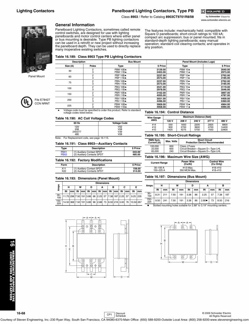
www.schneider-electric.us
16N
EM
A/D
EF
INIT
E P
UR
PO
SE
TY
PE
CO
NT
AC
TO
RS
AN
D S
TA
RT
ER
S
16-68 © 2009 Schneider ElectricAll Rights Reserved
Lighting Contactors Panelboard Lighting Contactors, Type PBClass 8903 / Refer to Catalog 8903CT9701R8/08
General InformationPanelboard Lighting Contactors, sometimes called remote control switches, are designed for use with lighting panelboards and motor control centers where either panel or bus mounting is desirable. Type PB lighting contactors can be used in a retrofit or new project without increasing the panelboard depth. They can be used to directly replace many inoperative existing switches.
The features include: mechanically held; compatible with Square D panelboards; short-circuit ratings to 100 kA; compact arc suppression; bus or panel mounted; fits in standard-depth lighting panelboards; easy manual operation; standard coil clearing contacts; and operates in any position.
a Voltage code must be specified to order this product. Refer to standard voltage codes listed below.
Note: For Replacement coils, see page 16-115.
b Slotted mounting holes suitable for 2.88" to 3.19" mounting centers.
Panel Mount
Table 16.189: Class 8903 Type PB Lighting ContactorsDescription Bus Mount Panel Mount (Includes Lugs)
Size (A) Poles Type $ Price Type $ Price
30 23
PBM 10BaPBM 11Ba
2129.002403.00
PBM 10aPBM 11a
2640.002973.00
60 23
PBP 10BaPBP 11Ba
2237.002573.00
PBP 10aPBP 11a
2762.003185.00
75 23
PBN 10BaPBN 11Ba
2237.002573.00
PBN 10aPBN 11a
2762.003185.00
100 23
PBQ 10BaPBQ 11Ba
2541.002978.00
PBQ 10aPBQ 11a
3119.003546.00
150 23
PBR 10BaPBR 11Ba
3162.004055.00
PBR 10aPBR 11a
3897.004787.00
200 23
PBV 10BaPBV 11Ba
3551.004496.00
PBV 10aPBV 11a
4409.005360.00
225 23
PBW 10BaPBW 11Ba
3909.004958.00
PBW 10aPBW 11a
4964.005990.00
Table 16.190: AC Coil Voltage Codes60 Hz Voltage Code
120/ V02208 V08
240/277 V39480 V28
Table 16.191: Class 8903—Auxiliary ContactsType Description $ Price
PBX1PBX2
(1) Auxiliary Contact SPDT(2) Auxiliary Contacts SPDT
243.00485.00
Table 16.192: Factory ModificationsForm Description $ Price
X11X22
(1) Auxiliary Contact SPDT(2) Auxiliary Contacts SPDT
158.00314.00
Table 16.193: Dimensions (Panel Mount)
Am
ps
Dimensions
H W D A B C E
IN mm IN mm IN mm IN mm IN mm IN mm IN mm
30–100 11.75 298 7.50 191 3.88 98 2.25 57 7.38 187 2.25 57 9.25 235
150–225 14.50 368 7.50 191 3.88 98 2.88 73 8.50 216 3.00 76 10.50 267
File E78427CCN NRNT
B
C
A A
W D
EH
Table 16.194: Control Distance
Wire GaugeAWG
Maximum Distance (feet)
120 V 208 V 240 V 277 V 480 V
#14#12#10
550900
1425
165027004275
220036005700
292547007550
88001440022800
Table 16.195: Short-Circuit RatingsRMS Sym.Current (A) Max. Volts Short Circuit
Protection Device Recommended
100,00022,00065,000
600600240
Class J FusesCircuit Breaker—Square D—Type LHLCircuit Breaker—Square D—Type LHL
Table 16.196: Maximum Wire Size (AWG)
Current Range Power Wire(Cu/Al)
Control Wire(Cu Only)
30–100 A150–225 A
#1/0 Max.350 MCM Max.
#18–#10#18–#10
Table 16.197: Dimensions (Bus Mount)
Amps
Dimensions
H W D A B
IN mm IN mm IN mm IN mm IN mm
30–100 8.31 211 7.50 191 3.38 86 2.25 57 7.38 187
150–225 9.50 241 7.50 191 3.38 86 2.88b 73 8.50 216
B
A A
W D
H
CP1 Discount Schedule
Courtesy of Steven Engineering, Inc.-230 Ryan Way, South San Francisco, CA 94080-6370-Main Office: (650) 588-9200-Outside Local Area: (800) 258-9200-www.stevenengineering.com
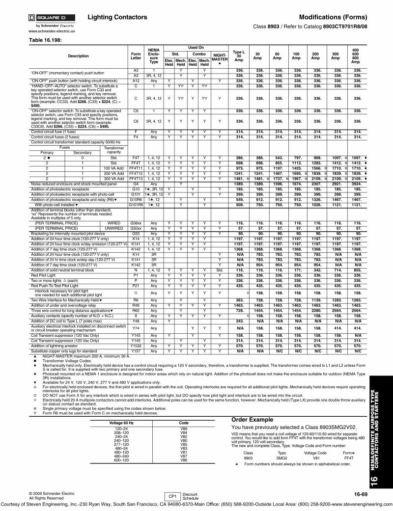
www.schneider-electric.us
16N
EM
A/D
EF
INIT
E P
UR
PO
SE
TY
PE
CO
NT
AC
TO
RS
AN
D S
TA
RT
ER
S
© 2009 Schneider ElectricAll Rights Reserved
16-69
Lighting Contactors Modifications (Forms)Class 8903 / Refer to Catalog 8903CT9701R8/08
Order ExampleYou have previously selected a Class 8903SMG2V02. V02 means that you need a coil voltage of 120-60/110-50 wired for separate control. You would like to add form FF4T with the transformer voltages being 480 volt primary, 120 volt secondary.The new and complete Class, Type, Voltage Code and Form number:
k Form numbers should always be shown in alphabetical order.
Table 16.198:
Description FormLetter
NEMAEnclo-sureType
Used OnType L
30Amp
30Amp
60Amp
100Amp
200Amp
300Amp
400600800
Amp
Std. Combo NIGHT-MASTER
aElec.Held
Mech.Held
Elec.Held
Mech.Held
“ON-OFF” (momentary contact) push buttonA3 1 Y Y 336. 336. 336. 336. 336. 336. 336.A3 3R, 4, 12 Y Y 336. 336. 336. 336. 336. 336. 336.
“ON-OFF” push button (with holding circuit interlock) A12 Any Y Y Y 336. 336. 336. 336. 336. 336. 336.“HAND–OFF–AUTO” selector switch. To substitute a key operated selector switch, use Form C33 and specify positions, legend marking, and key removal. This form must be used with another selector switch form (example: CC33). Add $266. (C33) + $224. (C) = $490.
C 1 Y Yj Y Yj 336. 336. 336. 336. 336. 336. 336.
C 3R, 4, 12 Y Yj Y Yj Y 336. 336. 336. 336. 336. 336. 336.
“ON-OFF” selector switch. To substitute a key operated selector switch, use Form C33 and specify positions, legend marking, and key removal. This form must be used with another selector switch form (example: C33C6). Add $266. (C33) + $224. (C6) = $490.
C6 1 Y Y Y Y 336. 336. 336. 336. 336. 336. 336.
C6 3R, 4, 12 Y Y Y Y Y 336. 336. 336. 336. 336. 336. 336.
Control circuit fuse (1 fuse) F Any Y Y Y Y Y 314. 314. 314. 314. 314. 314. 314.Control circuit fuses (2 fuses) F4 Any Y Y Y Y Y 314. 314. 314. 314. 314. 314. 314.Control circuit transformer standard capacity 50/60 Hz
Fuses Transformer capacityPrimary Secondary
2 b 0 Std. F4T 1, 4, 12 Y Y Y Y Y 386. 386. 543. 797. 968. 1097. i 1097. c
2 1 Std. FF4T 1, 4, 12 Y Y Y Y Y 698. 698. 855. 1112. 1283. 1412. i 1412. c
2 1 100 VA Add. FF4T11 1, 4, 12 Y Y Y Y Y 975. 975. 1197. 1425. 1566. i 1710. i 1710. c
2 1 200 VA Add FF4T12 1, 4, 12 Y Y Y Y Y 1241. 1241. 1467. 1695. i 1839. i 1839. i 1839. c
2 1 300 VA Add FF4T13 1, 4, 12 Y Y Y Y Y 1481. i 1481. i 1737. i 1967. i 2109. i 2109. i 2109. c
Noise reduced enclosure and shock mounted panel G4 Any Y 1389. 1389. 1596. 1674. 2307. 2921. 3924.Addition of photoelectric receptacle G10 1d, 3R, 12 Y Y Y 185. 185. 185. 185. 185. 185. 185.Addition of photoelectric receptacle with photo-cell G101 1d, 3R, 12 Y Y Y 399. 399. 399. 399. 399. 399. 399.Addition of photoelectric receptacle and relay (R6)e G10R6 1d, 12 Y Y 549. 912. 912. 912. 1326. 1467. 1467.
With photo-cell installede G101R6 1d, 12 Y Y 509. 750. 750. 750. 1026. 1121. 1121.Addition of terminal blocks (other than standard). “xx” Represents the number of terminals needed. Available in multiples of 5 only.
(PER TERMINAL PRICE) WIRED G56xx Any Y Y Y Y Y 116. 116. 116. 116. 116. 116. 116.(PER TERMINAL PRICE) UNWIRED G50xx Any Y Y Y Y Y 57. 57. 57. 57. 57. 57. 57.
Bracketing for internally mounted pilot device G53 Any Y Y Y Y Y 90. 90. 90. 90. 90. 90. 90.Addition of 24 hour time clock (120-277 V only) K14 1, 4, 12 Y Y Y Y 1197. 1197. 1197. 1197. 1197. 1197. 1197.Addition of 24 hour time clock w/day omission (120-277 V) K141 1, 4, 12 Y Y Y Y 1197. 1197. 1197. 1197. 1197. 1197. 1197.Addition of 7 day time clock (120-277 V) K142 1, 4, 12 Y Y Y Y 1368. 1368. 1368. 1368. 1368. 1368. 1368.Addition of 24 hour time clock (120-277 V only) K14 3R Y N/A 783. 783. 783. 783. N/A N/AAddition of 24 hr time clock w/skip day (120-277 V) K141 3R Y N/A 783. 783. 783. 783. N/A N/AAddition of 7 day time clock (120-277 V) K142 3R Y N/A 954. 954. 954. 954. N/A N/AAddition of solid neutral terminal block N 1, 4, 12 Y Y Y Y Std. 116. 116. 116. 171. 342. 714. 855.Red Pilot Light P1 Any Y Y Y Y Y 336. 336. 336. 336. 336. 336. 336.Two or more lights f (each) P Any Y Y Y Y Y 336. 336. 336. 336. 336. 336. 336.Red Push-To-Test Pilot Light P21 Any Y Y Y Y Y 435. 435. 435. 435. 435. 435. 435.
Interlock necessary for pilot lightone needed for each additional pilot light g Any Y Y Y Y Y h 158. 158. 158. 158. 158. 158.
Two Wire Interface for Mechanically Helde R6 Any Y Y 363. 728. 728. 728. 1139. 1283. 1283.Addition of under and overvoltage relay R46 Any Y Y Y Y Y 1463. 1463. 1463. 1463. 1463. 1463. 1463.Three wire control for long distance applicationse R62 Any Y Y 728. 1454. 1454. 1454. 2280. 2564. 2564.Auxiliary contacts (specify number of N.O. + N.C.) X Any Y Y Y Y Y h 158. 158. 158. 158. 158. 158.Addition of DC coil to Type L (7 poles max) Y48 Any Y 243. N/A N/A N/A N/A N/A N/AAuxiliary electrical interlock installed on disconnect switch or circuit breaker operating mechanism Y74 Any Y Y Y N/A 158. 158. 158. 158. 414. 414.
Coil Transient suppressor (120 Vac Only) Y145 Any Y Y Y 158. 158. 158. 158. 158. 158. N/ACoil Transient suppressor (120 Vac Only) Y145 Any Y Y 314. 314. 314. 314. 314. 314. 314.Addition of lightning arrestor Y1532 Any Y Y Y Y Y 570. 570. 570. 570. 570. 570. 570.Substitute copper only lugs for standard Y157 Any Y Y Y Y Y N/A N/A N/C N/C N/C N/C N/Ca NIGHT-MASTER maximum 200 A, minimum 30 A.b Transformer Voltage Codes.c Mechanically held only. Electrically held device has a control circuit requiring a 120 V secondary, therefore, a transformer is supplied. The transformer comes wired to L1 and L2 unless Form
S is called for. It is supplied with two primary and one secondary fuse.d Photocell mounted on a NEMA 1 enclosure is designed for indoor areas which rely on natural light. Addition of the photocell does not make the enclosure suitable for outdoor (NEMA Type
3R) installations.e Available for 24 V, 120 V, 240 V, 277 V and 480 V applications only.f For electrically held enclosed devices, the first pilot is wired in parallel with the coil. Operating interlocks are required for all additional pilot lights. Mechanically held devices require operating
interlocks for all pilot lights.g DO NOT use Form X for any interlock which is wired in series with pilot light, but DO specify how pilot light and interlock are to be wired into the circuit.h Electrically held 20 A multipole contactors cannot add interlocks. Additional poles can be used for the same function, however. Mechanically held (Type LX) provide one double throw auxiliary
(or status) contact as standard.i Single primary voltage must be specified using the codes shown below:j Form R6 must be used with Form C on mechanically held devices.
Voltage 60 Hz Code
120–24208–120240–24240–120277–120480–24480–120480–240600–120
V89V84V82V80V85V83V81V87V86
Class Type Voltage Code Formk
8903 SMG2 V81 FF4T
CP1 Discount Schedule
Courtesy of Steven Engineering, Inc.-230 Ryan Way, South San Francisco, CA 94080-6370-Main Office: (650) 588-9200-Outside Local Area: (800) 258-9200-www.stevenengineering.com
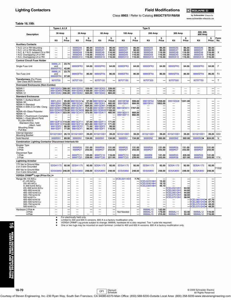
www.schneider-electric.us
16N
EM
A D
EF
INIT
E P
UR
PO
SE
TY
PE
C
ON
TA
CT
OR
S A
ND
ST
AR
TE
RS
16-70 © 2009 Schneider ElectricAll Rights Reserved
Lighting Contactors Field ModificationsClass 8903 / Refer to Catalog 8903CT9701R8/08
a For electrically held only.b Limited to 400 and 600 A versions. 800 A is a factory modification only.c VERSA CRIMP Lug prices subject to change. 9999AL hardware kit is also required. Two 1-pole kits required.d One or two lugs may be mounted on each terminal. Limited to 400 and 600 A versions. 800 A is factory modification only.
Table 16.199:
Description
Types L & LX Type S
30 Amp 30 Amp 60 Amp 100 Amp 200 Amp 300 Amp 400, 600,800 Amp
FormNo.Kit
$Price Kit
$Price Kit
$Price Kit
$Price Kit
$Price Kit
$Price Kit
$Price
Auxiliary Contacts
1 N.O. LH or RH Mounting1 N.C. LH or RH Mounting1 N.C. & 1 N.O. Isolated LH or RH1 N.O. Overlapping LH or RH1 N.C. Overlapping LH or RH
—————
—————
9999SX69999SX79999SX89999SX99999SX10
86.0086.00
116.00116.00116.00
9999SX69999SX79999SX89999SX99999SX10
86.0086.00
116.00116.00116.00
9999SX69999SX79999SX89999SX99999SX10
86.0086.00
116.00116.00116.00
9999SX69999SX79999SX89999SX99999SX10
86.0086.00
116.00116.00116.00
9999SX69999SX79999SX89999SX99999SX10
86.0086.00
116.00116.00116.00
9999SX69999SX79999SX89999SX99999SX10
86.0086.00
116.00116.00116.00
X
Control Circuit Fuse Holder
Single Fuse Unit9999LLX
and9999SFR3
23.70
42.809999SFR3 64.00 9999SFR3 64.00 9999SFR3 64.00 9999SFR3 64.00 9999SFR3 64.00 9999SFR3 64.00 F
Two Fuse Unit9999LLX
and9999SFR4
23.70
57.009999SFR4 86.00 9999SFR4 86.00 9999SFR4 86.00 9999SFR4 86.00 9999SFR4 86.00 9999SFR4 86.00 F4
Transformers (For PricesSee Class 9070 Section) 9070T50 — 9070T100 — 9070T100 — 9070T150 — 9070T300 — 9070T500 — 9070T750 — T
Oversized Enclosures (Non-Combo)
NEMA 1NEMA 4NEMA 12
9991SDG39991SDW39991SDA3
266.00779.00456.00
9991SDG39991SDW39991SDA3
339.001169.00
684.00
9991SDG39991SDW39991SDA3
339.001169.00
684.00
———
———
———
———
———
———
———
———
———
Standard Enclosures
NEMA 1–Surface MountNEMA 3RNEMA 4–StandardNEMA 4–With 2 Cvr Mtd. Clsng PltsNEMA 4X–Glass PolyesterNEMA 12NEMA 1–Flushmount–CompleteNEMA 1–Flush Mount Parts
FLUSH PARTSStandard–Elec. heldStandard–Mech. held
Mounting StrapPull Box
9991LXG19991SDH19991SDW19991SDW119991SDW209991SDA11
———
9991SDF139991SDF139991SDF29991SDF1
95.00323.00779.00798.00779.00323.00
———
114.00114.00
66.0077.00
9991SCG7a9991SCH29991SCW19991SCW119991SCW209991SCA11
———
9991SCF119991SCF139991SCF29991SCF1
57.00372.00684.00714.00684.00372.00
———
57.00201.0071.0086.00
9991SDG7a9991SDH19991SDW19991SDW119991SDW209991SDA11
———
9991SDF119991SDF139991SDF29991SDF1
143.00485.00
1169.001197.001169.00
485.00———
171.00171.00
99.00116.00
9991SFG89991SEH1
—9991SEW11
—9991SEA119991SEF11
——————
599.00684.00
—1767.00
—684.00882.00
——————
9991SFG49991SFH1
———————————
1259.001853.00
———————————
9991SGG8————————————
1241.00————————————
—————————————
—————————————
—————————————
Internal Operator Mounting Bracket 3010215901 26.10 3010215901 39.20 3010215901 39.20 3010215901 39.20 3010215901 39.20 3010215901 39.20 3010215901 39.20 G53
Solid Neutral 9999SN1 89.00 9999SN1 134.00 9999SN1 134.00 9999SN1 134.00 9999SN2 392.00 9999SN2 392.00 9999SN3b 624.00 N
Combination Lighting Contactor Disconnect Interlock Kit
Breaker Type1-Pole2-Pole
——
——
9999R269999R27
131.00243.00
9999R269999R27
131.00243.00
9999R269999R27
131.00243.00
9999R269999R27
131.00243.00
9999R269999R27
131.00243.00
9999R269999R27
131.00243.00
Y74
Disconnect Type1-Pole2-Pole
——
——
9999TC119999TC21
120.00239.00
9999TC109999TC20
116.00221.00
9999TC109999TC20
120.00239.00
9999R89999R9
131.00243.00
9999R359999R36
435.00521.00
9999R269999R27
131.00243.00
Lightning Arrestor
175 Vac to Ground Max 2 or 3 wire Grounded SDSA1175 92.00 SDSA1175 92.00 SDSA1175 92.00 SDSA1175 92.00 SDSA1175 92.00 SDSA1175 92.00 SDSA1175 92.00
Y1532650 Vac to Ground Max3 or 4 wire Grounded SDSA3650 248.00 SDSA3650 248.00 SDSA3650 248.00 SDSA3650 248.00 SDSA3650 248.00 SDSA3650 248.00 SDSA3650 248.00
VERSA CRIMP® Lugs (Price Ea.)c
Range #8–1/0 Al/Cu#1–2/0 Al/Cu 2/0–4/0 Al/Cu 4–300 kcmil Al/Cu 2/0–500 kcmil Al/Cu 400–600 kcmil Al 400–500 kcmil Cu 500–750 kcmil Al 500 kcmil Cu 400–600 kcmil Al 400–500 kcmil Cu 500–750 kcmil Al 500 kcmil Cu
—————————————
—————————————
—————————————
—————————————
—————————————
—————————————
VCEL02114S1————————————
7.70————————————
—VCEL022516H1VCEL024516H1VCEL030516H1
—————————
—12.2016.1049.10
—————————
————
VCEL05012H1VCEL06012H1VCEL06012H1VCEL07512H1VCEL07512H1
————
————
64.0044.6044.6058.0058.00
————
—————————
VCEL06012H2dVCEL06012H2dVCEL07512H2dVCEL07512H2d
—————————
47.7047.7048.2048.20
Hardware 2-PolecHardware 3-PoleHardware 4-Pole
———
———
———
——
—
———
———
Not Needed———
9999AL139999AL149999AL15
143.00179.00215.00
9999AL119999AL11
53.4053.40
9999AL129999AL12
116.00116.00
CP1 Discount Schedule
Courtesy of Steven Engineering, Inc.-230 Ryan Way, South San Francisco, CA 94080-6370-Main Office: (650) 588-9200-Outside Local Area: (800) 258-9200-www.stevenengineering.com
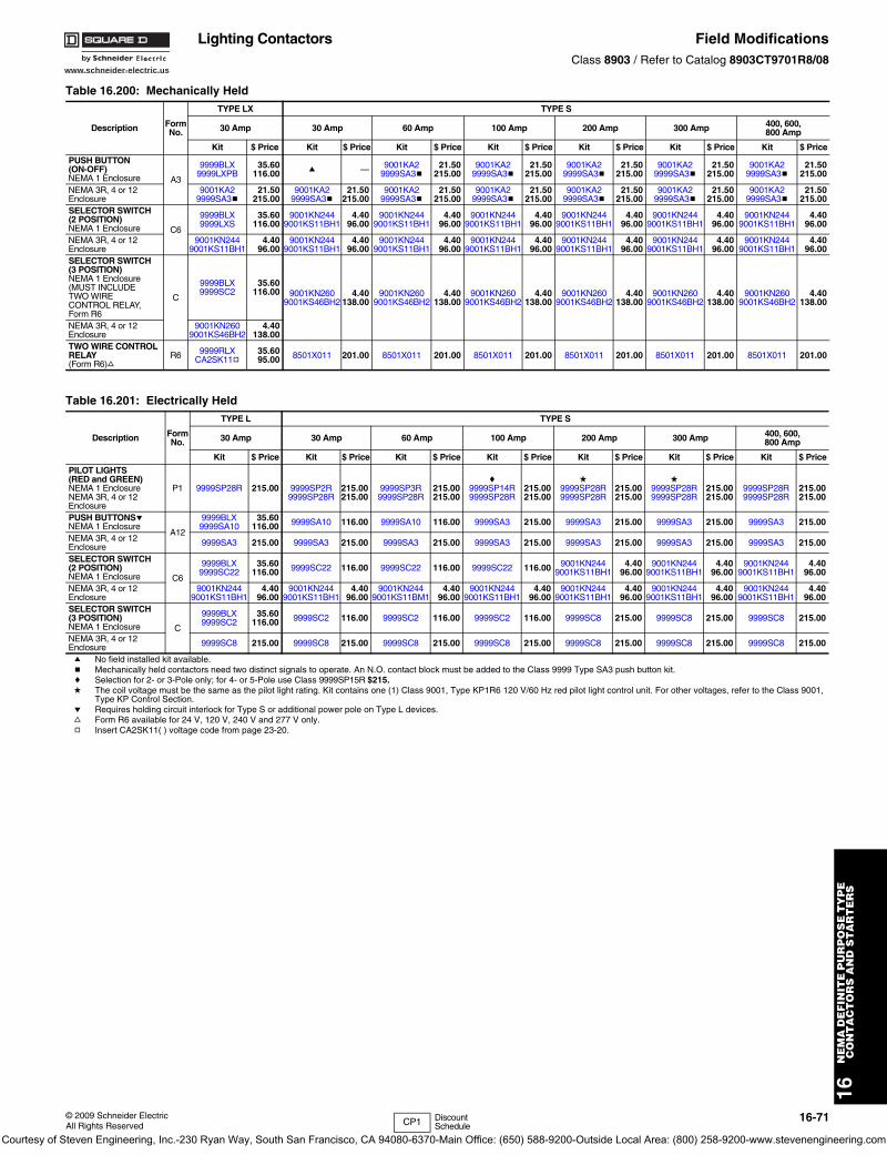
www.schneider-electric.us
16N
EM
A D
EF
INIT
E P
UR
PO
SE
TY
PE
C
ON
TA
CT
OR
S A
ND
ST
AR
TE
RS
© 2009 Schneider ElectricAll Rights Reserved
16-71
Lighting Contactors Field ModificationsClass 8903 / Refer to Catalog 8903CT9701R8/08
Table 16.200: Mechanically Held
Description FormNo.
TYPE LX TYPE S
30 Amp 30 Amp 60 Amp 100 Amp 200 Amp 300 Amp 400, 600,800 Amp
Kit $ Price Kit $ Price Kit $ Price Kit $ Price Kit $ Price Kit $ Price Kit $ Price
PUSH BUTTON(ON-OFF)NEMA 1 Enclosure A3
9999BLX9999LXPB
35.60116.00 a — 9001KA2
9999SA3b21.50
215.009001KA2
9999SA3b21.50
215.009001KA2
9999SA3b21.50
215.009001KA2
9999SA3b21.50
215.009001KA2
9999SA3b21.50
215.00
NEMA 3R, 4 or 12Enclosure
9001KA29999SA3b
21.50215.00
9001KA29999SA3b
21.50215.00
9001KA29999SA3b
21.50215.00
9001KA29999SA3b
21.50215.00
9001KA29999SA3b
21.50215.00
9001KA29999SA3b
21.50215.00
9001KA29999SA3b
21.50215.00
SELECTOR SWITCH(2 POSITION)NEMA 1 Enclosure C6
9999BLX9999LXS
35.60116.00
9001KN2449001KS11BH1
4.4096.00
9001KN2449001KS11BH1
4.4096.00
9001KN2449001KS11BH1
4.4096.00
9001KN2449001KS11BH1
4.4096.00
9001KN2449001KS11BH1
4.4096.00
9001KN2449001KS11BH1
4.4096.00
NEMA 3R, 4 or 12Enclosure
9001KN2449001KS11BH1
4.4096.00
9001KN2449001KS11BH1
4.4096.00
9001KN2449001KS11BH1
4.4096.00
9001KN2449001KS11BH1
4.4096.00
9001KN2449001KS11BH1
4.4096.00
9001KN2449001KS11BH1
4.4096.00
9001KN2449001KS11BH1
4.4096.00
SELECTOR SWITCH(3 POSITION)NEMA 1 Enclosure(MUST INCLUDE TWO WIRECONTROL RELAY, Form R6
C
9999BLX9999SC2
35.60116.00 9001KN260
9001KS46BH24.40
138.009001KN260
9001KS46BH24.40
138.009001KN260
9001KS46BH24.40
138.009001KN260
9001KS46BH24.40
138.009001KN260
9001KS46BH24.40
138.009001KN260
9001KS46BH24.40
138.00
NEMA 3R, 4 or 12Enclosure
9001KN2609001KS46BH2
4.40138.00
TWO WIRE CONTROL RELAY(Form R6)f
R6 9999RLXCA2SK11g
35.6095.00 8501X011 201.00 8501X011 201.00 8501X011 201.00 8501X011 201.00 8501X011 201.00 8501X011 201.00
Table 16.201: Electrically Held
Description FormNo.
TYPE L TYPE S
30 Amp 30 Amp 60 Amp 100 Amp 200 Amp 300 Amp 400, 600,800 Amp
Kit $ Price Kit $ Price Kit $ Price Kit $ Price Kit $ Price Kit $ Price Kit $ Price
PILOT LIGHTS (RED and GREEN) NEMA 1 EnclosureNEMA 3R, 4 or 12Enclosure
P1 9999SP28R 215.00 9999SP2R9999SP28R
215.00215.00
9999SP3R9999SP28R
215.00215.00
c9999SP14R9999SP28R
215.00215.00
d9999SP28R9999SP28R
215.00215.00
d9999SP28R9999SP28R
215.00215.00
9999SP28R9999SP28R
215.00215.00
PUSH BUTTONSeNEMA 1 Enclosure
A12
9999BLX9999SA10
35.60116.00 9999SA10 116.00 9999SA10 116.00 9999SA3 215.00 9999SA3 215.00 9999SA3 215.00 9999SA3 215.00
NEMA 3R, 4 or 12Enclosure 9999SA3 215.00 9999SA3 215.00 9999SA3 215.00 9999SA3 215.00 9999SA3 215.00 9999SA3 215.00 9999SA3 215.00
SELECTOR SWITCH(2 POSITION)NEMA 1 Enclosure C6
9999BLX9999SC22
35.60116.00 9999SC22 116.00 9999SC22 116.00 9999SC22 116.00 9001KN244
9001KS11BH14.40
96.009001KN244
9001KS11BH14.40
96.009001KN244
9001KS11BH14.40
96.00
NEMA 3R, 4 or 12Enclosure
9001KN2449001KS11BH1
4.4096.00
9001KN2449001KS11BH1
4.4096.00
9001KN2449001KS11BM1
4.4096.00
9001KN2449001KS11BH1
4.4096.00
9001KN2449001KS11BH1
4.4096.00
9001KN2449001KS11BH1
4.4096.00
9001KN2449001KS11BH1
4.4096.00
SELECTOR SWITCH(3 POSITION)NEMA 1 Enclosure C
9999BLX9999SC2
35.60116.00 9999SC2 116.00 9999SC2 116.00 9999SC2 116.00 9999SC8 215.00 9999SC8 215.00 9999SC8 215.00
NEMA 3R, 4 or 12Enclosure 9999SC8 215.00 9999SC8 215.00 9999SC8 215.00 9999SC8 215.00 9999SC8 215.00 9999SC8 215.00 9999SC8 215.00
a No field installed kit available.b Mechanically held contactors need two distinct signals to operate. An N.O. contact block must be added to the Class 9999 Type SA3 push button kit.c Selection for 2- or 3-Pole only; for 4- or 5-Pole use Class 9999SP15R $215.d The coil voltage must be the same as the pilot light rating. Kit contains one (1) Class 9001, Type KP1R6 120 V/60 Hz red pilot light control unit. For other voltages, refer to the Class 9001,
Type KP Control Section.e Requires holding circuit interlock for Type S or additional power pole on Type L devices.f Form R6 available for 24 V, 120 V, 240 V and 277 V only.g Insert CA2SK11( ) voltage code from page 23-20.
CP1 Discount Schedule
Courtesy of Steven Engineering, Inc.-230 Ryan Way, South San Francisco, CA 94080-6370-Main Office: (650) 588-9200-Outside Local Area: (800) 258-9200-www.stevenengineering.com
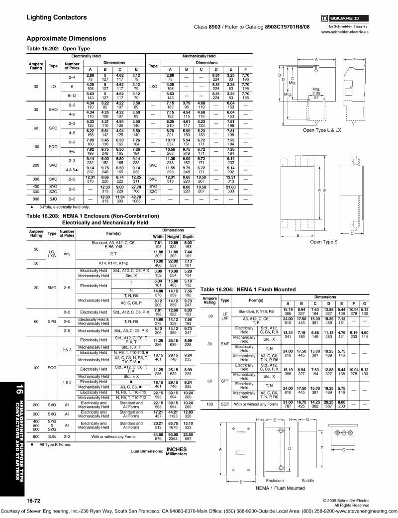
www.schneider-electric.us
16N
EM
A/D
EF
INIT
E P
UR
PO
SE
TY
PE
CO
NT
AC
TO
RS
AN
D S
TA
RT
ER
S
16-72 © 2009 Schneider ElectricAll Rights Reserved
Lighting ContactorsClass 8903 / Refer to Catalog 8903CT9701R8/08
Approximate Dimensions
a 5-Pole, electrically held only.
b All Type K Forms.
Table 16.202: Open TypeElectrically Held Mechanically Held
AmpereRating Type Number
of PolesDimensions
TypeDimensions
A B C E A B C D E F
30 LO
2–4 2.8873
5127
4.62117
3.1279
LXO
2.8873 — — 8.81
2243.2583
7.70196
6 4.25108
5127
4.62117
3.1279
4.25108 — — 8.81
2243.2583
7.70196
8–12 5.63143
5127
4.62117
3.1279
5.63143 — — 8.81
2243.2583
7.70196
30 SMO2–3 4.34
1103.2282
4.22107
3.5089 — 7.15
1823.7996
4.68119 — 6.04
153 —
4–5 4.34110
4.25108
4.22107
3.5089 — 7.15
1824.54115
4.68119 — 6.04
153 —
60 SPO2–3 5.33
1354.31110
4.94125
5.50140 — 8.25
2104.61117
5.23133 — 7.81
198 —
4–5 6.22158
5.61142
4.94125
5.50140 — 8.70
2215.90150
5.23133 — 7.81
198 —
100 SQO2–3 7.09
1805.45138
6.50165
7.26184 — 10.13
2575.94151
6.72171 — 7.26
184 —
4–5 7.82199
9.75248
6.50165
7.26184 — 10.56
2689.75248
6.72171 — 7.26
184 —
200 SVO2–3 9.14
2326.00152
6.50165
9.14232
SVO
11.35288
6.00152
6.72171 — 9.14
232 —
4 & 5a 9.14232
9.75248
6.50165
9.14232
11.55293
9.75248
6.72171 — 9.14
232 —
300 SXO 2–3 12.31313
8.66220
8.74222
12.25311 SXO 12.31
3138.66220
10.50267 — 12.31
313 —
400 SYO2–3 — 12.33
3139.00229
27.78706
SYO— 8.66
22010.50267 — 21.00
533 —600 SZO SZO
800 SJO 2–3 — 12.33313
11.94303
42.701085 — — — — — — —
A
Mtg.2.2557
B
FMtg.
CMtg.
D
E
Open Type L & LX
Table 16.203: NEMA 1 Enclosure (Non-Combination)Electrically and Mechanically Held
AmpereRating Type Number
of Poles Form(s)Dimensions
Width Height Depth
30LG,LXG Any
Standard, A3, A12, C, C6,F, R6, Y48
7.81198
12.69322
6.03153
P, T 11.88302
11.88302
7.44189
30 K14, K141, K142 16.00406
22.00559
7.13181
30 SMG 2–5
Electrically Held Std., A12, C, C6, P, X 6.00152
10.00254
5.28134Mechanically Held Std., X
Electrically HeldT 6.34
16115.88403
5.19132
N 14.88378
14.12359
7.56192
Mechanically HeldT, N, R6
A3, C, C6, P 8.12206
14.12359
9.73247
60 SPG
2–5 Electrically Held Std., A12, C, C6, P, X 7.81198
12.69322
6.03153
2–5 Electrically Held &Mechanically Held T, N, R6 14.88
37814.12359
7.56192
2–5 Mechanically Held Std., A3, C, C6, P, X 8.12206
14.12359
9.73247
100 SQG
2 & 3
Electrically Held Std., A12, C, C6, F,P, X, T 11.25
28625.15639
8.99228
Mechanically Held Std., F, X, TElectrically Held N, R6, T, T10-T13,b
18.15461
29.15740
9.24235Mechanically Held A3, C, C6, N, R6, T,
T10-T13,b
4 & 5
Electrically Held Std., A12, C, C6, F,P, X 11.25
28625.15639
8.99228
Mechanically Held Std., F, XElectrically Held b 18.15
46129.15740
9.24235Mechanically Held A3, C, C6, b
Electrically Held N, R6, T, T10-T13 22.15563
39.15994
10.24260Mechanically Held N, R6, T, T10-T13
200 SVG All Electrically andMechanically Held
Standard andAll Forms
22.15563
39.15994
10.24260
300 SXG All Electrically andMechanically Held
Standard andAll Forms
17.21437
44.211123
12.83326
400and600
SYG&
SZGAll Electrically and
Mechanically HeldStandard and
All Forms20.21513
65.751670
13.10333
800 SJG 2–3 With or without any Forms 34.50876
93.002362
23.50597
B
A E
C
Open Type S
A
B
H E
D
H G
F C
Enclosure Saddle
NEMA 1 Flush Mounted
Table 16.204: NEMA 1 Flush Mounted
AmpereRating Type Form(s)
Dimensions
A B C D E F G
30 LFLXF
Standard, F, Y48, R6 15.19386
8.94227
7.63194
12.88327
5.44138
10.94278
5.13130
A3, A12, C, C6,T, P
24.00610
17.50445
15.00381
19.25489
7.12181 — —
30 SMF
ElectricallyHeld
Std., A12,C, C6, P, X 13.44
3417.19183
5.88149
11.13283
4.75121
9.19233
4.50114Mechanically
Held Std., X
ElectricallyHeld T, N
24.00610
17.50445
15.00381
19.25489
5.75146 — —
MechanicallyHeld
A3, C, C6,T, N, P, R6
60 SPF
ElectricallyHeld
Std., A12,C, C6, P, X 15.19
3868.94227
7.63194
12.88327
5.44138
10.94278
5.13130Mechanically
Held Std., X
ElectricallyHeld T, N
24.00610
17.50445
15.00381
19.25489
5.75146 — —
MechanicallyHeld
A3, C, C6,T, N, P, R6
100 SQF With or without any Forms 31.00787
16.75425
14.25362
26.25667
8.00203 — —
Courtesy of Steven Engineering, Inc.-230 Ryan Way, South San Francisco, CA 94080-6370-Main Office: (650) 588-9200-Outside Local Area: (800) 258-9200-www.stevenengineering.com
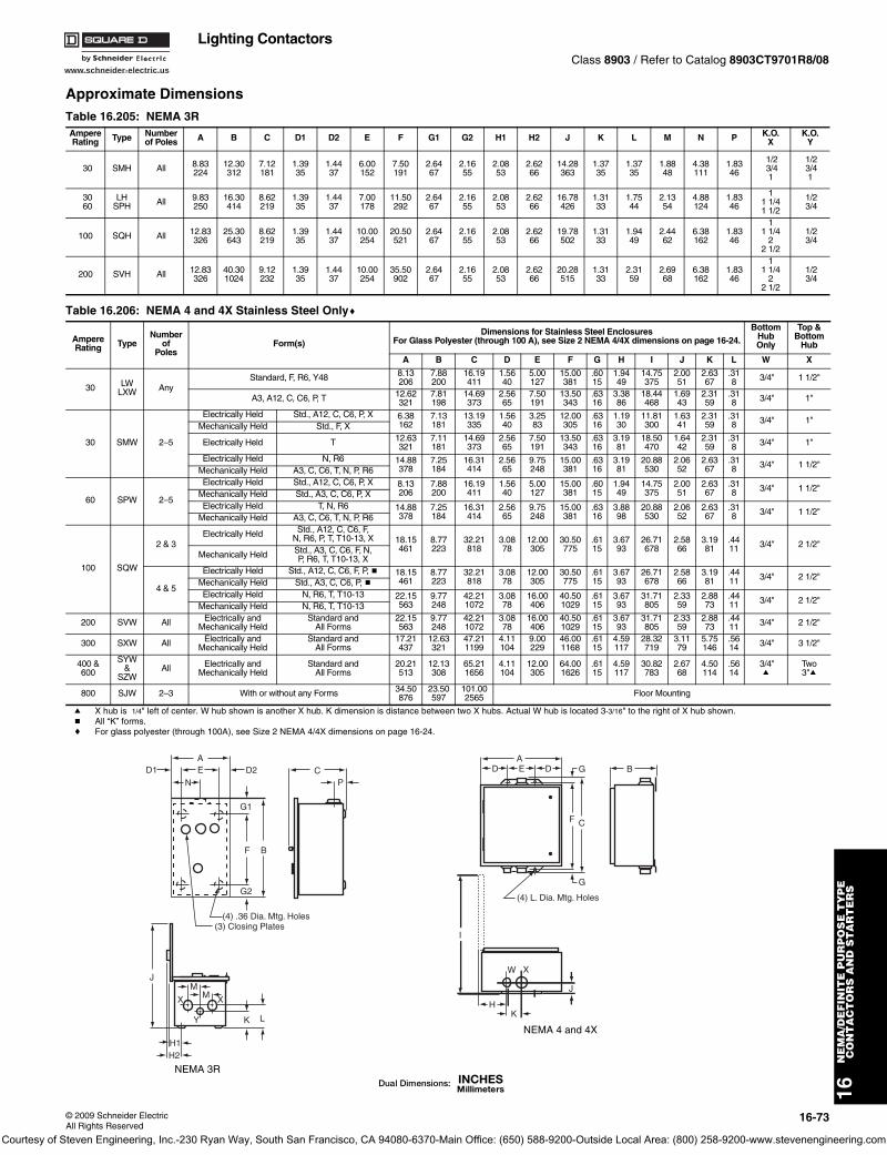
www.schneider-electric.us
16N
EM
A/D
EF
INIT
E P
UR
PO
SE
TY
PE
CO
NT
AC
TO
RS
AN
D S
TA
RT
ER
S
© 2009 Schneider ElectricAll Rights Reserved
16-73
Lighting ContactorsClass 8903 / Refer to Catalog 8903CT9701R8/08
Approximate Dimensions
a X hub is 1/4" left of center. W hub shown is another X hub. K dimension is distance between two X hubs. Actual W hub is located 3-3/16" to the right of X hub shown.b All “K” forms.c For glass polyester (through 100A), see Size 2 NEMA 4/4X dimensions on page 16-24.
Table 16.205: NEMA 3RAmpereRating Type Number
of Poles A B C D1 D2 E F G1 G2 H1 H2 J K L M N P K.O.X
K.O.Y
30 SMH All 8.83224
12.30312
7.12181
1.3935
1.4437
6.00152
7.50191
2.6467
2.1655
2.0853
2.6266
14.28363
1.3735
1.3735
1.8848
4.38111
1.8346
1/23/41
1/23/41
3060
LHSPH All 9.83
25016.30414
8.62219
1.3935
1.4437
7.00178
11.50292
2.6467
2.1655
2.0853
2.6266
16.78426
1.3133
1.7544
2.1354
4.88124
1.8346
11 1/41 1/2
1/23/4
100 SQH All 12.83326
25.30643
8.62219
1.3935
1.4437
10.00254
20.50521
2.6467
2.1655
2.0853
2.6266
19.78502
1.3133
1.9449
2.4462
6.38162
1.8346
11 1/4
22 1/2
1/23/4
200 SVH All 12.83326
40.301024
9.12232
1.3935
1.4437
10.00254
35.50902
2.6467
2.1655
2.0853
2.6266
20.28515
1.3133
2.3159
2.6968
6.38162
1.8346
11 1/4
22 1/2
1/23/4
Table 16.206: NEMA 4 and 4X Stainless Steel Onlyc
AmpereRating Type
Numberof
PolesForm(s)
Dimensions for Stainless Steel EnclosuresFor Glass Polyester (through 100 A), see Size 2 NEMA 4/4X dimensions on page 16-24.
BottomHubOnly
Top &Bottom
Hub
A B C D E F G H I J K L W X
30 LWLXW Any
Standard, F, R6, Y48 8.13206
7.88200
16.19411
1.5640
5.00127
15.00381
.6015
1.9449
14.75375
2.0051
2.6367
.318 3/4" 1 1/2"
A3, A12, C, C6, P, T 12.62321
7.81198
14.69373
2.5665
7.50191
13.50343
.6316
3.3886
18.44468
1.6943
2.3159
.318 3/4" 1"
30 SMW 2–5
Electrically Held Std., A12, C, C6, P, X 6.38162
7.13181
13.19335
1.5640
3.2583
12.00305
.6316
1.1930
11.81300
1.6341
2.3159
.318 3/4" 1"
Mechanically Held Std., F, X
Electrically Held T 12.63321
7.11181
14.69373
2.5665
7.50191
13.50343
.6316
3.1981
18.50470
1.6442
2.3159
.318 3/4" 1"
Electrically Held N, R6 14.88378
7.25184
16.31414
2.5665
9.75248
15.00381
.6316
3.1981
20.88530
2.0652
2.6367
.318 3/4" 1 1/2"
Mechanically Held A3, C, C6, T, N, P, R6
60 SPW 2–5
Electrically Held Std., A12, C, C6, P, X 8.13206
7.88200
16.19411
1.5640
5.00127
15.00381
.6015
1.9449
14.75375
2.0051
2.6367
.318 3/4" 1 1/2"
Mechanically Held Std., A3, C, C6, P, XElectrically Held T, N, R6 14.88
3787.25184
16.31414
2.5665
9.75248
15.00381
.6316
3.8898
20.88530
2.0652
2.6367
.318 3/4" 1 1/2"
Mechanically Held A3, C, C6, T, N, P, R6
100 SQW
2 & 3Electrically Held Std., A12, C, C6, F,
N, R6, P, T, T10-13, X 18.15461
8.77223
32.21818
3.0878
12.00305
30.50775
.6115
3.6793
26.71678
2.5866
3.1981
.4411 3/4" 2 1/2"
Mechanically Held Std., A3, C, C6, F, N,P, R6, T, T10-13, X
4 & 5
Electrically Held Std., A12, C, C6, F, P, b 18.15461
8.77223
32.21818
3.0878
12.00305
30.50775
.6115
3.6793
26.71678
2.5866
3.1981
.4411 3/4" 2 1/2"
Mechanically Held Std., A3, C, C6, P, bElectrically Held N, R6, T, T10-13 22.15
5639.77248
42.211072
3.0878
16.00406
40.501029
.6115
3.6793
31.71805
2.3359
2.8873
.4411 3/4" 2 1/2"
Mechanically Held N, R6, T, T10-13
200 SVW All Electrically andMechanically Held
Standard andAll Forms
22.15563
9.77248
42.211072
3.0878
16.00406
40.501029
.6115
3.6793
31.71805
2.3359
2.8873
.4411 3/4" 2 1/2"
300 SXW All Electrically andMechanically Held
Standard andAll Forms
17.21437
12.63321
47.211199
4.11104
9.00229
46.001168
.6115
4.59117
28.32719
3.1179
5.75146
.5614 3/4" 3 1/2"
400 &600
SYW&
SZWAll Electrically and
Mechanically HeldStandard and
All Forms20.21513
12.13308
65.211656
4.11104
12.00305
64.001626
.6115
4.59117
30.82783
2.6768
4.50114
.5614
3/4"a
Two3"a
800 SJW 2–3 With or without any Forms 34.50876
23.50597
101.002565 Floor Mounting
AD2 C
P
G1
F
G2
B
EN
D1
D30060-118-D
(3) Closing Plates(4) .36 Dia. Mtg. Holes
K
MM XX
Y
J
H1H2
L
NEMA 3R
(4) L. Dia. Mtg. Holes
GDEDA
CF
B
C30054-260-A
J
HK
W X
I
G
NEMA 4 and 4X
Courtesy of Steven Engineering, Inc.-230 Ryan Way, South San Francisco, CA 94080-6370-Main Office: (650) 588-9200-Outside Local Area: (800) 258-9200-www.stevenengineering.com
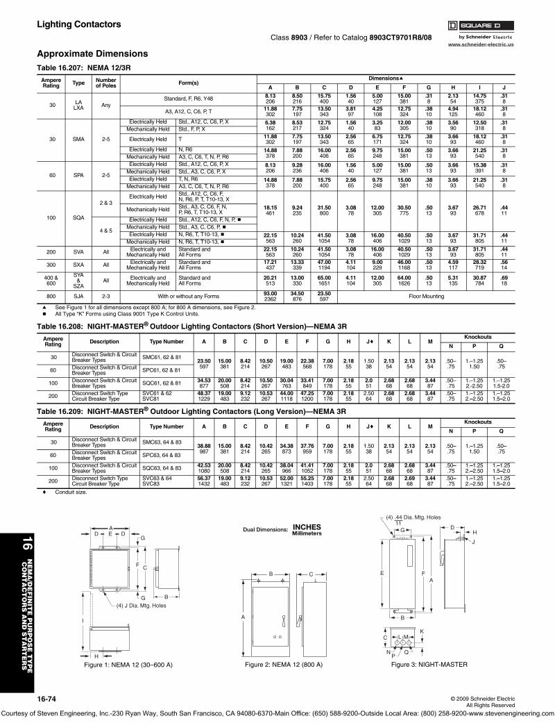
www.schneider-electric.us
16N
EM
A/D
EF
INIT
E P
UR
PO
SE
TY
PE
CO
NT
AC
TO
RS
AN
D S
TA
RT
ER
S
16-74 © 2009 Schneider ElectricAll Rights Reserved
Lighting ContactorsClass 8903 / Refer to Catalog 8903CT9701R8/08
Approximate Dimensions
a See Figure 1 for all dimensions except 800 A; for 800 A dimensions, see Figure 2.b All Type “K” Forms using Class 9001 Type K Control Units.
c Conduit size.
Table 16.207: NEMA 12/3R
AmpereRating Type Number
of Poles Form(s)Dimensionsa
A B C D E F G H I J
30 LALXA Any
Standard, F, R6, Y48 8.13206
8.50216
15.75400
1.5640
5.00127
15.00381
.318
2.1354
14.75375
.318
A3, A12, C, C6, P, T 11.88302
7.75197
13.50343
3.8197
4.25108
12.75324
.3810
4.94125
18.12460
.318
30 SMA 2-5
Electrically Held Std., A12, C, C6, P, X 6.38162
8.53217
12.75324
1.5640
3.2583
12.00305
.3810
3.5690
12.50318
.318Mechanically Held Std., F, P, X
Electrically Held T 11.88302
7.75197
13.50343
2.5665
6.75171
12.75324
.3810
3.6693
18.12460
.318
Electrically Held N, R6 14.88378
7.88200
16.00406
2.5665
9.75248
15.00381
.5013
3.6693
21.25540
.318Mechanically Held A3, C, C6, T, N, P, R6
60 SPA 2-5
Electrically Held Std., A12, C, C6, P, X 8.13206
9.28236
16.00406
1.5640
5.00127
15.00381
.5013
3.6693
15.38391
.318Mechanically Held Std., A3, C, C6, P, X
Electrically Held T, N, R6 14.88378
7.88200
15.75400
2.5665
9.75248
15.00381
.3810
3.6693
21.25540
.318Mechanically Held A3, C, C6, T, N, P, R6
100 SQA
2 & 3Electrically Held Std., A12, C, C6, F,
N, R6, P, T, T10-13, X
18.15461
9.24235
31.50800
3.0878
12.00305
30.50775
.5013
3.6793
26.71678
.4411
Mechanically Held Std., A3, C, C6, F, N,P, R6, T, T10-13, X
4 & 5
Electrically Held Std., A12, C, C6, F, N, P, bMechanically Held Std., A3, C, C6, P, bElectrically Held N, R6, T, T10-13, b 22.15
56310.24260
41.501054
3.0878
16.00406
40.501029
.5013
3.6793
31.71805
.4411Mechanically Held N, R6, T, T10-13, b
200 SVA All Electrically andMechanically Held
Standard andAll Forms
22.15563
10.24260
41.501054
3.0878
16.00406
40.501029
.5013
3.6793
31.71805
.4411
300 SXA All Electrically andMechanically Held
Standard andAll Forms
17.21437
13.33339
47.001194
4.11104
9.00229
46.001168
.5013
4.59117
28.32719
.5614
400 &600
SYA&
SZAAll Electrically and
Mechanically HeldStandard andAll Forms
20.21513
13.00330
65.001651
4.11104
12.00305
64.001626
.5013
5.31135
30.87784
.6918
800 SJA 2-3 With or without any Forms 93.002362
34.50876
23.50597 Floor Mounting
Table 16.208: NIGHT-MASTER® Outdoor Lighting Contactors (Short Version)—NEMA 3R
AmpereRating Description Type Number A B C D E F G H Jc K L M
Knockouts
N P Q
30 Disconnect Switch & Circuit Breaker Types SMC61, 62 & 81
23.50597
15.00381
8.42214
10.50267
19.00483
22.38568
7.00178
2.1855
1.5038
2.1354
2.1354
2.1354
.50–.75
1.–1.251.50
.50–.75
60 Disconnect Switch & Circuit Breaker Types SPC61, 62 & 81
100 Disconnect Switch & Circuit Breaker Types SQC61, 62 & 81 34.53
87720.00508
8.42214
10.50267
30.04763
33.41849
7.00178
2.1855
2.051
2.6868
2.6868
3.4487
.50–.75
1.–1.252.-2.50
1.–1.251.5-2.0
200 Disconnect Switch TypeCircuit Breaker Type
SVC61 & 62SVC81
48.371229
19.00483
9.12232
10.53267
44.001118
47.251200
7.00178
2.1855
2.5064
2.6868
2.6868
3.4487
.50–.75
1.–1.252.–2.50
1.–1.251.5–2.0
Table 16.209: NIGHT-MASTER® Outdoor Lighting Contactors (Long Version)—NEMA 3R
AmpereRating Description Type Number A B C D E F G H Jc K L M
Knockouts
N P Q
30 Disconnect Switch & Circuit Breaker Types SMC63, 64 & 83
38.88987
15.00381
8.42214
10.42265
34.38873
37.76959
7.00178
2.1855
1.5038
2.1354
2.1354
2.1354
.50–.75
1.–1.251.50
.50–.75
60 Disconnect Switch & Circuit Breaker Types SPC63, 64 & 83
100 Disconnect Switch & Circuit Breaker Types SQC63, 64 & 83 42.53
108020.00508
8.42214
10.42265
38.04966
41.411052
7.00178
2.1855
2.051
2.6868
2.6868
3.4487
.50–.75
1.–1.252.–2.50
1.–1.251.5–2.0
200 Disconnect Switch TypeCircuit Breaker Type
SVC63 & 64SVC83
56.371432
19.00483
9.12232
10.53267
52.001321
55.251403
7.00178
2.1855
2.5064
2.6868
2.6968
3.4487
.50–.75
1.–1.252.–2.50
1.–1.251.5–2.0
AD D
G
F C
E
G
I
H
(4) J Dia. Mtg. Holes
B
Figure 1: NEMA 12 (30–600 A)
B
A
C
Figure 2: NEMA 12 (800 A)
B
FEA
G
(4) .44 Dia. Mtg. Holes 11
D
J
H
L MK
NP
Q
C
Figure 3: NIGHT-MASTER
Courtesy of Steven Engineering, Inc.-230 Ryan Way, South San Francisco, CA 94080-6370-Main Office: (650) 588-9200-Outside Local Area: (800) 258-9200-www.stevenengineering.com
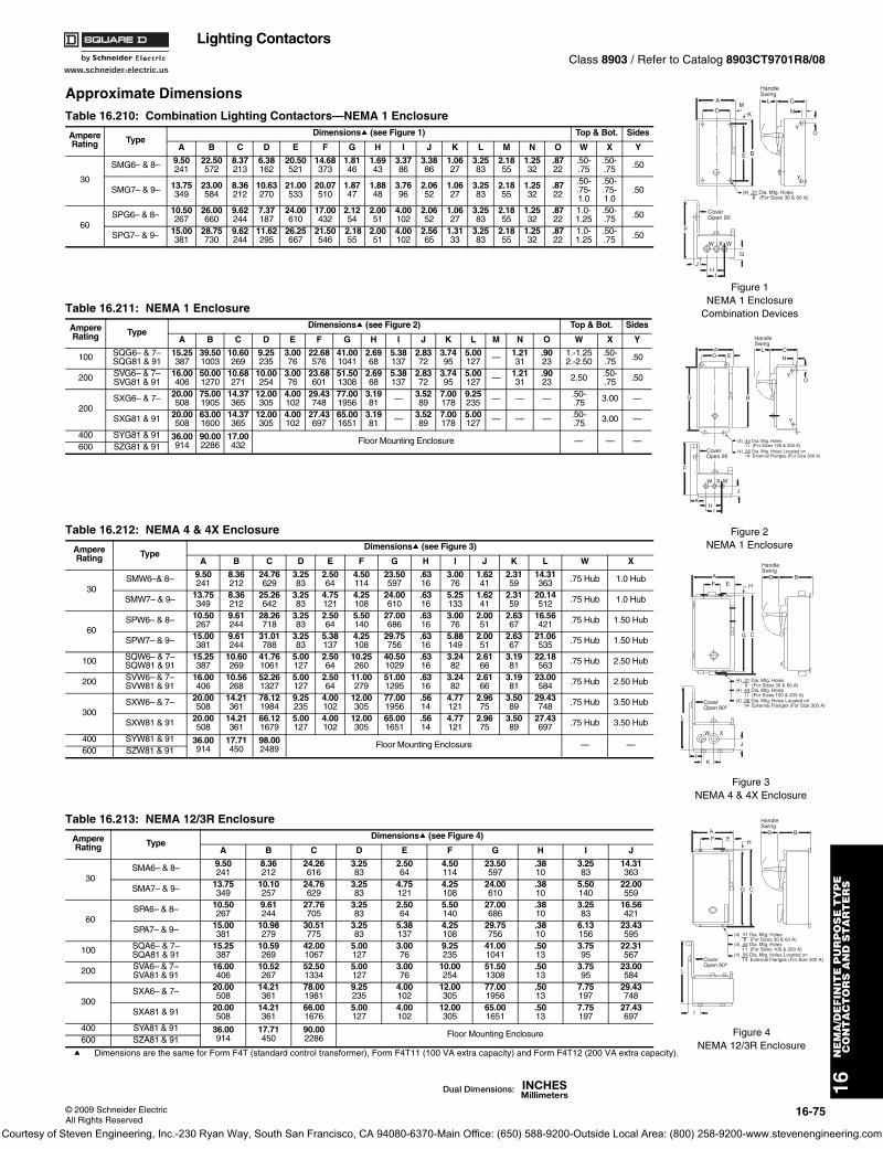
www.schneider-electric.us
16N
EM
A/D
EF
INIT
E P
UR
PO
SE
TY
PE
CO
NT
AC
TO
RS
AN
D S
TA
RT
ER
S
© 2009 Schneider ElectricAll Rights Reserved
16-75
Lighting ContactorsClass 8903 / Refer to Catalog 8903CT9701R8/08
Approximate Dimensions
a Dimensions are the same for Form F4T (standard control transformer), Form F4T11 (100 VA extra capacity) and Form F4T12 (200 VA extra capacity).
Table 16.210: Combination Lighting Contactors—NEMA 1 Enclosure
Ampere Rating Type
Dimensionsa (see Figure 1) Top & Bot. Sides
A B C D E F G H I J K L M N O W X Y
30
SMG6– & 8– 9.50241
22.50572
8.37213
6.38162
20.50521
14.68373
1.8146
1.6943
3.3786
3.3886
1.0627
3.2583
2.1855
1.2532
.8722
.50-.75
.50-.75 .50
SMG7– & 9– 13.75349
23.00584
8.36212
10.63270
21.00533
20.07510
1.8747
1.8848
3.7696
2.0652
1.0627
3.2583
2.1855
1.2532
.8722
.50-
.75-1.0
.50-
.75-1.0
.50
60SPG6– & 8– 10.50
26726.00660
9.62244
7.37187
24.00610
17.00432
2.1254
2.0051
4.00102
2.0652
1.0627
3.2583
2.1855
1.2532
.8722
1.0-1.25
.50-.75 .50
SPG7– & 9– 15.00381
28.75730
9.62244
11.62295
26.25667
21.50546
2.1855
2.0051
4.00102
2.5665
1.3133
3.2583
2.1855
1.2532
.8722
1.0-1.25
.50-.75 .50
Table 16.211: NEMA 1 Enclosure
Ampere Rating Type
Dimensionsa (see Figure 2) Top & Bot. Sides
A B C D E F G H I J K L M N O W X Y
100 SQG6– & 7–SQG81 & 91
15.25387
39.501003
10.60269
9.25235
3.0076
22.68576
41.001041
2.6968
5.38137
2.8372
3.7495
5.00127 — 1.21
31.9023
1.-1.252.-2.50
.50-.75 .50
200 SVG6– & 7–SVG81 & 91
16.00406
50.001270
10.68271
10.00254
3.0076
23.68601
51.501308
2.6968
5.38137
2.8372
3.7495
5.00127 — 1.21
31.9023 2.50 .50-
.75 .50
200SXG6– & 7– 20.00
50875.001905
14.37365
12.00305
4.00102
29.43748
77.001956
3.1981 — 3.52
897.00178
9.25235 — — — .50-
.75 3.00 —
SXG81 & 91 20.00508
63.001600
14.37365
12.00305
4.00102
27.43697
65.001651
3.1981 — 3.52
897.00178
5.00127 — — — .50-
.75 3.00 —
400 SYG81 & 91 36.00914
90.002286
17.00432 Floor Mounting Enclosure — — —
600 SZG81 & 91
Table 16.212: NEMA 4 & 4X Enclosure
Ampere Rating Type
Dimensionsa (see Figure 3)
A B C D E F G H I J K L W X
30SMW6–& 8– 9.50
2418.36212
24.76629
3.2583
2.5064
4.50114
23.50597
.6316
3.0076
1.6241
2.3159
14.31363 .75 Hub 1.0 Hub
SMW7– & 9– 13.75349
8.36212
25.26642
3.2583
4.75121
4.25108
24.00610
.6316
5.25133
1.6241
2.3159
20.14512 .75 Hub 1.0 Hub
60SPW6– & 8– 10.50
2679.61244
28.26718
3.2583
2.5064
5.50140
27.00686
.6316
3.0076
2.0051
2.6367
16.56421 .75 Hub 1.50 Hub
SPW7– & 9– 15.00381
9.61244
31.01788
3.2583
5.38137
4.25108
29.75756
.6316
5.88149
2.0051
2.6367
21.06535 .75 Hub 1.50 Hub
100 SQW6– & 7–SQW81 & 91
15.25387
10.60269
41.761061
5.00127
2.5064
10.25260
40.501029
.6316
3.2482
2.6166
3.1981
22.18563 .75 Hub 2.50 Hub
200 SVW6– & 7–SVW81 & 91
16.00406
10.56268
52.261327
5.00127
2.5064
11.00279
51.001295
.6316
3.2482
2.6166
3.1981
23.00584 .75 Hub 2.50 Hub
300SXW6– & 7– 20.00
50814.21361
78.121984
9.25235
4.00102
12.00305
77.001956
.5614
4.77121
2.9675
3.5089
29.43748 .75 Hub 3.50 Hub
SXW81 & 91 20.00508
14.21361
66.121679
5.00127
4.00102
12.00305
65.001651
.5614
4.77121
2.9675
3.5089
27.43697 .75 Hub 3.50 Hub
400 SYW81 & 91 36.00914
17.71450
98.002489 Floor Mounting Enclosure — —
600 SZW81 & 91
Table 16.213: NEMA 12/3R Enclosure
Ampere Rating Type
Dimensionsa (see Figure 4)
A B C D E F G H I J
30SMA6– & 8– 9.50
2418.36212
24.26616
3.2583
2.5064
4.50114
23.50597
.3810
3.2583
14.31363
SMA7– & 9– 13.75349
10.10257
24.76629
3.2583
4.75121
4.25108
24.00610
.3810
5.50140
22.00559
60SPA6– & 8– 10.50
2679.61244
27.76705
3.2583
2.5064
5.50140
27.00686
.3810
3.2583
16.56421
SPA7– & 9– 15.00381
10.98279
30.51775
3.2583
5.38137
4.25108
29.75756
.3810
6.13156
23.43595
100 SQA6– & 7–SQA81 & 91
15.25387
10.59269
42.001067
5.00127
3.0076
9.25235
41.001041
.5013
3.7595
22.31567
200 SVA6– & 7–SVA81 & 91
16.00406
10.52267
52.501334
5.00127
3.0076
10.00254
51.501308
.5013
3.7595
23.00584
300SXA6– & 7– 20.00
50814.21361
78.001981
9.25235
4.00102
12.00305
77.001956
.5013
7.75197
29.43748
SXA81 & 91 20.00508
14.21361
66.001676
5.00127
4.00102
12.00305
65.001651
.5013
7.75197
27.43697
400 SYA81 & 91 36.00914
17.71450
90.002286 Floor Mounting Enclosure
600 SZA81 & 91
YO
N
C
E B
K
MD
A
Y
F
W X W
G
JH
I
CoverOpen 90
L
(4) .31 Dia. Mtg. Holes 8 (For Sizes 30 & 60 A)
HandleSwing
Figure 1NEMA 1 Enclosure
Combination Devices
YO
N
C
B
DA
Y
F
W X W
HI
CoverOpen 90
LE
K
J
G
(4) .44 Dia. Mtg. Holes 11 (For Sizes 100 & 200 A)(4) .56 Dia. Mtg. Holes Located on 14 External Flanges (For Size 300 A)
HandleSwing
Figure 2NEMA 1 Enclosure
B
HandleSwing
C
FA
L
W X
CoverOpen 90º
DE
KI
J
G
H
(4) .31 Dia. Mtg. Holes 8 (For Sizes 30 & 60 A)(4) .44 Dia. Mtg. Holes 11 (For Sizes 100 & 200 A)(4) .56 Dia. Mtg. Holes Located on 14 External Flanges (For Size 300 A)
Figure 3NEMA 4 & 4X Enclosure
B
HandleSwing
C
FA
(4) .31 Dia. Mtg. Holes 8 (For Sizes 30 & 60 A)(4) .44 Dia. Mtg. Holes 11 (For Sizes 100 & 200 A)(4) .56 Dia. Mtg. Holes Located on 14 External Flanges (For Size 300 A)
L
I
DE
G
H
CoverOpen 90º
Figure 4NEMA 12/3R Enclosure
Courtesy of Steven Engineering, Inc.-230 Ryan Way, South San Francisco, CA 94080-6370-Main Office: (650) 588-9200-Outside Local Area: (800) 258-9200-www.stevenengineering.com
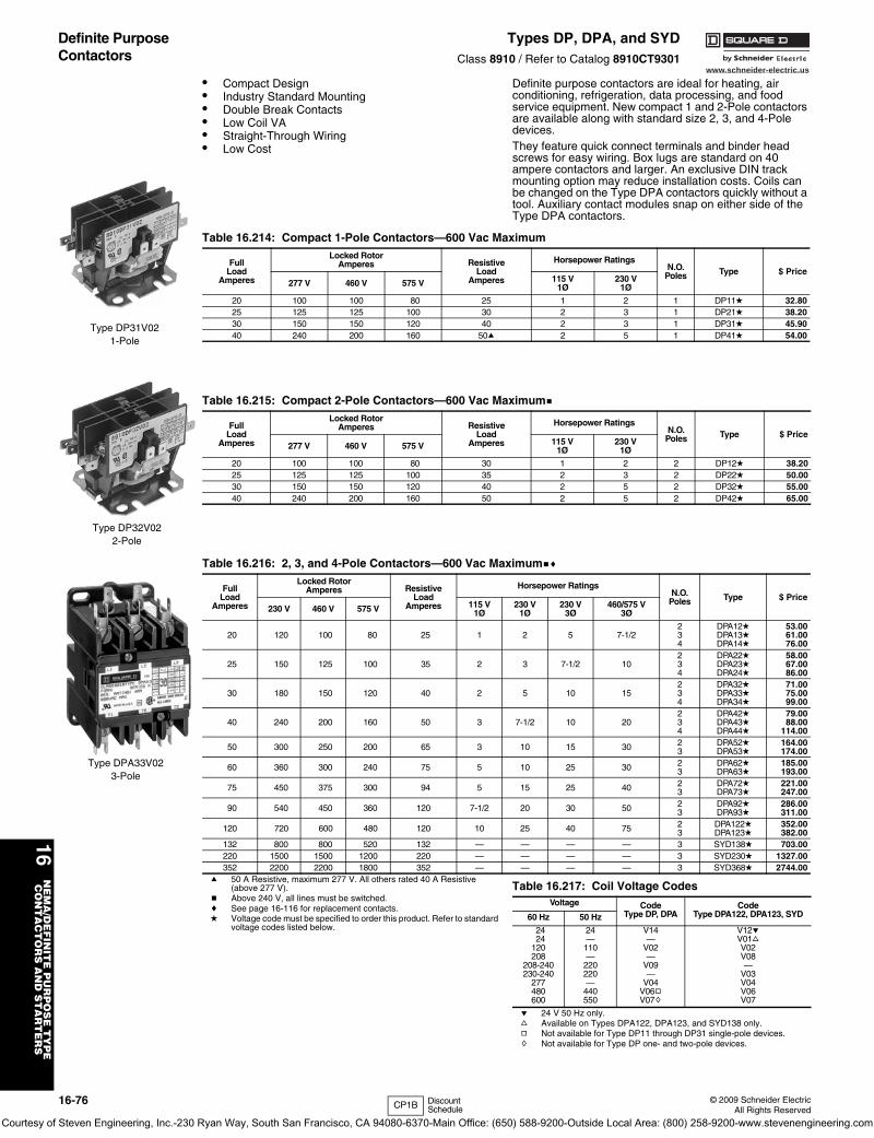
www.schneider-electric.us
16N
EM
A/D
EF
INIT
E P
UR
PO
SE
TY
PE
CO
NT
AC
TO
RS
AN
D S
TA
RT
ER
S
16-76 © 2009 Schneider ElectricAll Rights Reserved
Definite Purpose Contactors
Types DP, DPA, and SYDClass 8910 / Refer to Catalog 8910CT9301
• Compact Design• Industry Standard Mounting• Double Break Contacts• Low Coil VA• Straight-Through Wiring• Low Cost
Definite purpose contactors are ideal for heating, air conditioning, refrigeration, data processing, and food service equipment. New compact 1 and 2-Pole contactors are available along with standard size 2, 3, and 4-Pole devices.They feature quick connect terminals and binder head screws for easy wiring. Box lugs are standard on 40 ampere contactors and larger. An exclusive DIN track mounting option may reduce installation costs. Coils can be changed on the Type DPA contactors quickly without a tool. Auxiliary contact modules snap on either side of the Type DPA contactors.
a 50 A Resistive, maximum 277 V. All others rated 40 A Resistive (above 277 V).
b Above 240 V, all lines must be switched.c See page 16-116 for replacement contacts.d Voltage code must be specified to order this product. Refer to standard
voltage codes listed below.
e 24 V 50 Hz only.f Available on Types DPA122, DPA123, and SYD138 only.g Not available for Type DP11 through DP31 single-pole devices.h Not available for Type DP one- and two-pole devices.
Table 16.214: Compact 1-Pole Contactors—600 Vac Maximum
FullLoad
Amperes
Locked RotorAmperes Resistive
LoadAmperes
Horsepower RatingsN.O.
Poles Type $ Price277 V 460 V 575 V 115 V
1Ø230 V
1Ø
20 100 100 80 25 1 2 1 DP11d 32.8025 125 125 100 30 2 3 1 DP21d 38.2030 150 150 120 40 2 3 1 DP31d 45.9040 240 200 160 50a 2 5 1 DP41d 54.00
Type DP31V021-Pole
Table 16.215: Compact 2-Pole Contactors—600 Vac Maximumb
FullLoad
Amperes
Locked RotorAmperes Resistive
LoadAmperes
Horsepower RatingsN.O.
Poles Type $ Price277 V 460 V 575 V 115 V
1Ø230 V
1Ø
20 100 100 80 30 1 2 2 DP12d 38.2025 125 125 100 35 2 3 2 DP22d 50.0030 150 150 120 40 2 5 2 DP32d 55.0040 240 200 160 50 2 5 2 DP42d 65.00
Type DP32V022-Pole
Table 16.216: 2, 3, and 4-Pole Contactors—600 Vac Maximumbc
FullLoad
Amperes
Locked RotorAmperes Resistive
LoadAmperes
Horsepower RatingsN.O.
Poles Type $ Price230 V 460 V 575 V 115 V
1Ø230 V
1Ø230 V
3Ø460/575 V
3Ø
20 120 100 80 25 1 2 5 7-1/2234
DPA12dDPA13dDPA14d
53.0061.0076.00
25 150 125 100 35 2 3 7-1/2 10234
DPA22dDPA23dDPA24d
58.0067.0086.00
30 180 150 120 40 2 5 10 15234
DPA32dDPA33dDPA34d
71.0075.0099.00
40 240 200 160 50 3 7-1/2 10 20234
DPA42dDPA43dDPA44d
79.0088.00
114.00
50 300 250 200 65 3 10 15 30 23
DPA52dDPA53d
164.00174.00
60 360 300 240 75 5 10 25 30 23
DPA62dDPA63d
185.00193.00
75 450 375 300 94 5 15 25 40 23
DPA72dDPA73d
221.00247.00
90 540 450 360 120 7-1/2 20 30 50 23
DPA92dDPA93d
286.00311.00
120 720 600 480 120 10 25 40 75 23
DPA122dDPA123d
352.00382.00
132 800 800 520 132 — — — — 3 SYD138d 703.00220 1500 1500 1200 220 — — — — 3 SYD230d 1327.00352 2200 2200 1800 352 — — — — 3 SYD368d 2744.00
Type DPA33V023-Pole
Table 16.217: Coil Voltage CodesVoltage Code
Type DP, DPACode
Type DPA122, DPA123, SYD60 Hz 50 Hz
2424
120208
208-240230-240
277480600
24—
110—
220220—
440550
V14—
V02—
V09—
V04V06gV07h
V12eV01fV02V08—
V03V04V06V07
CP1B Discount Schedule
Courtesy of Steven Engineering, Inc.-230 Ryan Way, South San Francisco, CA 94080-6370-Main Office: (650) 588-9200-Outside Local Area: (800) 258-9200-www.stevenengineering.com
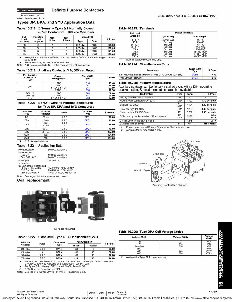
www.schneider-electric.us
16N
EM
A/D
EF
INIT
E P
UR
PO
SE
TY
PE
CO
NT
AC
TO
RS
AN
D S
TA
RT
ER
S
© 2009 Schneider ElectricAll Rights Reserved
16-77
Definite Purpose ContactorsClass 8910 / Refer to Catalog 8910CT9301
Types DP, DPA, and SYD Application Data
a Voltage code must be specified to order this product. Refer to standard voltage codes on page 16-88.
b Above 240 volts, all lines must be switched.Note: N.C. poles on outside. N.C. poles open before N.O. poles close.
c CP1 discount schedule.
Note: See page 16-116 for replacement contacts.
Coil Replacement
d Replace diamond with suffix from DPA Coil Table 16.226. Example: Coil for Class 8910 DPA33V02 120 V 60 Hz would be a Class 9998 Type DA1V02.
e For Types DP11 through DP32: Inrush 30 VA; Sealed 5 VA.f CP10 Discount Schedule, not CP1.
Note: See page 16-133 for DPA12_ and SYD Replacement Coils.
g Solid or stranded copper wire only.
h Contact your nearest Square D/Schneider Electric sales office.i Available for 20 through 60 A only.
j Available for Type DPA contactors only.
Table 16.218: 2 Normally Open & 2 Normally Closed4-Pole Contactors—600 Vac Maximum
FullLoad
Amperes
ResistiveLoad
Amperes
N.O.Poles
N.C.Polesb
Class 8910$ Price
Type Form
20 25 2 2 DPA14a Y392 148.0025 35 2 2 DPA24a Y392 159.0030 40 2 2 DPA34a Y392 171.0040 50 2 2 DPA44a Y392 186.00
Table 16.219: Auxiliary Contacts, 5 A, 600 Vac RatedFor Use WithClass 8910
Type
ContactArrangement
Class 9999Type $ Price
DPA
1 N.O.1 N.C.
1 N.O. & 1 N.C.2 N.O.
D10D01D11D20
16.4016.4029.5029.50
DPA122DPA123
SYD
1 N.O.1 N.C.
1 N.O. & 1 N.C.
SX6SX7SX8
57.0057.0077.00
Table 16.220: NEMA 1 General Purpose Enclosuresfor Type DP, DPA and SYD Contactors
Class 8910Type
Full LoadAmperes Poles Class 9991
Type $ Pricec
DP 20–40 1 & 2 DPG1 78.00DPA 20–40 2 & 3 DPG1 78.00
DPA 5020–40
2 & 34 DPG2 99.00
DPA 60–75 2 & 3 DPG3 143.00DPA 90–120 2 & 3 DPG4 287.00SYD 132 2 & 3 DPG5 464.00SYD 220 2 & 3 DPG6 464.00
Table 16.221: Application DataMechanical Life: 500,000 operationsElectrical Life:
Type DPType DPA, SYD
100,000 operations200,000 operations
Duty Cycle: ContinuousApprovals:UL Component Recognized
UL Listed (Form U1)CSA CertifiedDPA is CE marked
File E78351, CCN NLDX2File E78351, CCN NLDXFile LR25490, Class 321104
Table 16.222: Class 8910 Type DPA Replacement Coils
Full LoadAmperes Poles Class 9998
TypeVolt-Amperese
$ PricefInrush Sealed
20–40 A 2 & 3 DA1d 56 6 68.0020–40 A 4 DA2d 109 10 92.0050–60 A 2 & 3 DA2d 109 10 92.0075–90 A 2 & 3 DA3d 214 19 114.00
No tools required
Table 16.223: Terminals
Full LoadAmperes
Power Terminals
Type of Lug Wire Rangeg
20–30 A40 A
50–60 A75–90 A120 A132 A220 A352 A
Binder HeadBox LugBox LugBox LugBox LugBox LugBox LugBox Lug
#14–#8#14–#6#14–#2
#14–#I/O#14–#I/O
#8–350 MCM#8–350 MCM#4–500 MCM
Table 16.224: Miscellaneous Parts
Description Class 9999Type $ Price
DIN mounting bracket attachment (Type DPA, 20 A to 60 A only) DMB1 7.70Type DP Series B Cover DPC1 2.10
Table 16.225: Factory ModificationsAuxiliary contacts can be factory installed along with a DIN mounting bracket option. Special terminations are also available.
Modification Type Form $ Price
Factory installed auxiliary contacts — h h
Pressure wire connectors (20–30 A) DPA Y122 1.70 per pole
Box lugs (20–30 A) DPDPA Y124 3.30 per pole
Cu/Al box lugs (20–40 A) DPA Y239 3.30 per poleCu/Al box lugs (20, 25 & 30 A) DP Y239 3.30 per pole
DIN mounting bracket attached (35 mm style)i DPDPA Y135 3.30
8.70Contact cover for Type DP Series B — Y248 2.10UL Listed label on device DP U1 No Charge
Table 16.226: Type DPA Coil Voltage Codes
Voltage, 60 Hz Voltage, 50 Hz VoltageCode
24120
208–240277480600
24110220—
440550
V14V02V09V04
V06jV07j
Bottom Tabs
Top Hooks
Operating Tab
Contactor
Auxiliary Contact Installation
CP1B CP1 CP10 Discount Schedule
Courtesy of Steven Engineering, Inc.-230 Ryan Way, South San Francisco, CA 94080-6370-Main Office: (650) 588-9200-Outside Local Area: (800) 258-9200-www.stevenengineering.com
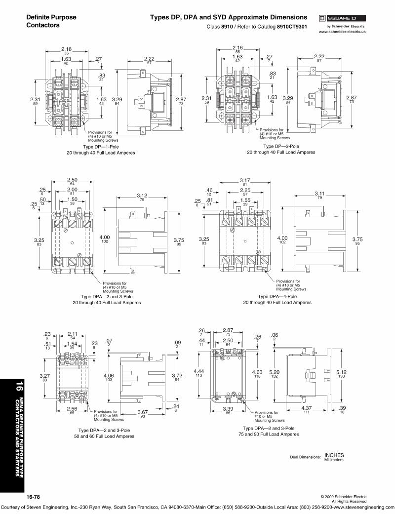
www.schneider-electric.us
16N
EM
A D
EF
INIT
E P
UR
PO
SE
TY
PE
C
ON
TA
CT
OR
S A
ND
ST
AR
TE
RS
16-78 © 2009 Schneider ElectricAll Rights Reserved
Definite Purpose Contactors
Types DP, DPA and SYD Approximate DimensionsClass 8910 / Refer to Catalog 8910CT9301
2.8773
3.2984
1.6342
2.3159
.8321
.277
2.1655
1.6342
2.2257
Provisions for(4) #10 or M5Mounting Screws
Type DP—1-Pole20 through 40 Full Load Amperes
2.5064
2.0051
1.5038
.5013
Provisions for(4) #10 or M5Mounting Screws
3.1279
.256
.256
3.2583
4.00102 3.75
95
Type DPA—2 and 3-Pole20 through 40 Full Load Amperes
3.1781
2.2557
.4612
.8121
3.2583
.256
1.5539
Provisions for(4) #10 or M5Mounting Screws
3.1179
4.00102
3.7595
Type DPA—4-Pole20 through 40 Full Load Amperes
.246
2.1154
1.5439
4.06103
3.2783
2.5665
.236
.236
.5113
Provisions for(4) #10 or M5Mounting Screws
.072 .09
2
3.7294
3.6793
Type DPA—2 and 3-Pole50 and 60 Full Load Amperes
2.8773
2.5064
Provisions for#10 or M5Mounting Screws
3.3986
4.44113
4.37111
.3910
4.63118
5.20132
.062
5.12130
.4411
.267 .26
7
Type DPA—2 and 3-Pole75 and 90 Full Load Amperes
2.8773
3.2984
1.6342
2.3159
.8321
.277
2.1655
1.6342
2.2257
Provisions for(4) #10 or M5Mounting Screws
Type DP—2-Pole20 through 40 Full Load Amperes
Courtesy of Steven Engineering, Inc.-230 Ryan Way, South San Francisco, CA 94080-6370-Main Office: (650) 588-9200-Outside Local Area: (800) 258-9200-www.stevenengineering.com
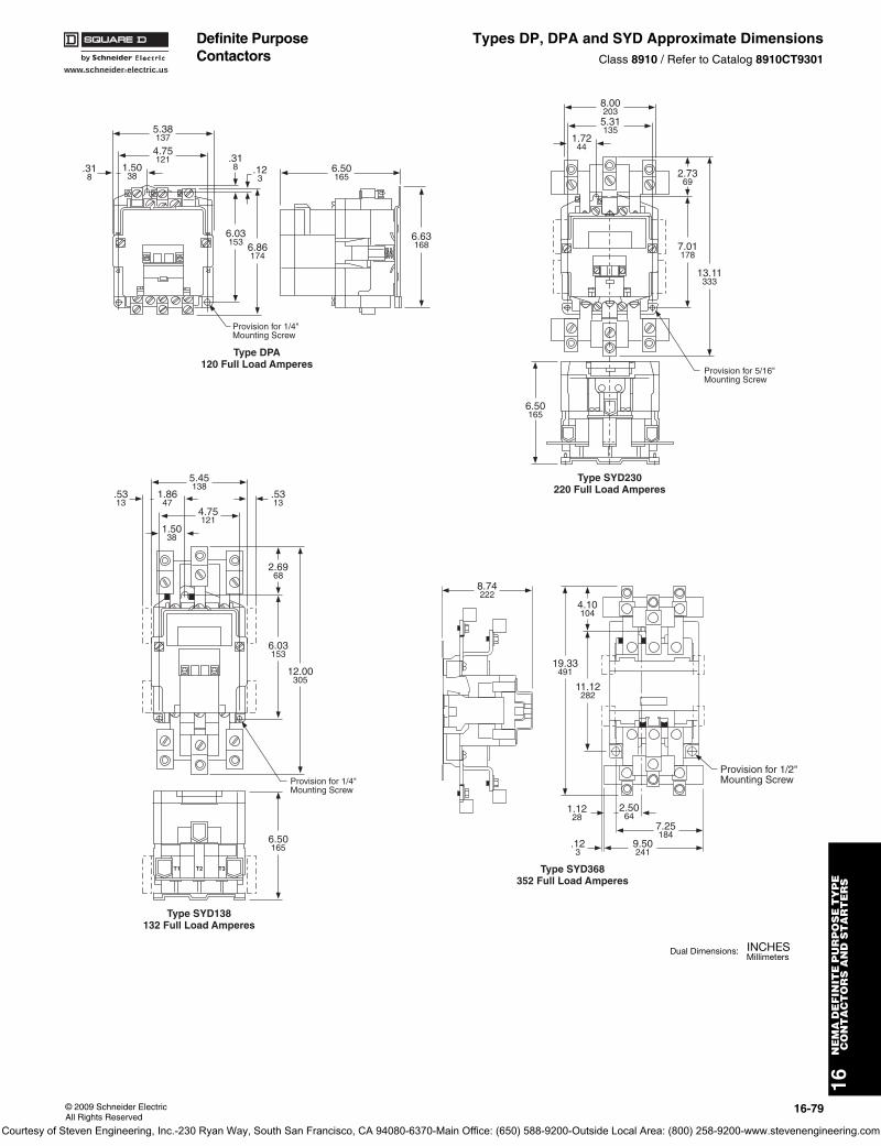
www.schneider-electric.us
16N
EM
A D
EF
INIT
E P
UR
PO
SE
TY
PE
C
ON
TA
CT
OR
S A
ND
ST
AR
TE
RS
© 2009 Schneider ElectricAll Rights Reserved
16-79
Definite Purpose Contactors
Types DP, DPA and SYD Approximate DimensionsClass 8910 / Refer to Catalog 8910CT9301
.318 .12
3
Provision for 1/4"Mounting Screw
5.38137
6.50165
6.63168
4.75121
6.03153 6.86
174
1.5038
.318
Type DPA120 Full Load Amperes
8.00203
1.7244
2.7369
7.01178
6.50165
13.11333
5.31135
Provision for 5/16"Mounting Screw
Type SYD230220 Full Load Amperes
T1 T2 T3
5.45138
1.8647
.5313
1.5038
.5313
2.6968
6.03153
6.50165
12.00305
4.75121
Provision for 1/4"Mounting Screw
Type SYD138132 Full Load Amperes
8.74222
19.33491
11.12282
1.1228
2.5064
9.50241
7.25184
4.10104
.123
Provision for 1/2"Mounting Screw
Type SYD368352 Full Load Amperes
Courtesy of Steven Engineering, Inc.-230 Ryan Way, South San Francisco, CA 94080-6370-Main Office: (650) 588-9200-Outside Local Area: (800) 258-9200-www.stevenengineering.com
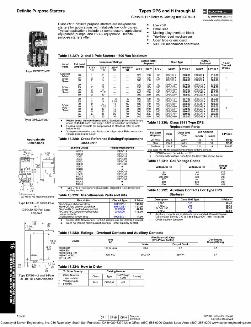
www.schneider-electric.us
16N
EM
A/D
EF
INIT
E P
UR
PO
SE
TY
PE
CO
NT
AC
TO
RS
AN
D S
TA
RT
ER
S
16-80 © 2009 Schneider ElectricAll Rights Reserved
Definite Purpose Starters Types DPS and H through MClass 8911 / Refer to Catalog 8910CT9301
Class 8911 definite purpose starters are inexpensive starters for applications with relatively low duty cycles. Typical applications include air compressors, agricultural equipment, pumps, and HVAC equipment. Definite purpose starters offer:
• Low cost• Small size• Melting alloy overload block• Trip-free reset mechanism• Open type or enclosed• 500,000 mechanical operations
a Prices do not include thermal units. Standard trip thermal units are priced at $14.30 each. See page 16-125 for selection information.
b Holding circuit contacts are not provided as standard; refer to table below for kit.
c Voltage code must be specified to order this product. Refer to standard voltage codes listed below.
d Type DPS 4-Pole starter not available. Suggest 3-Pole device with auxiliary contact.
e Use for 20 to 40 A starters. For 50 A starters, use the 9999BLX bracket.f Does not include holding circuit interlock—order auxiliary contact.
g CP10 Discount Schedule, not CP1.h Replace with Voltage Code from the Coil Table shown below.
i Auxiliary contacts are available factory installed. Consult Square D/Schneider Electric CIC at 1-888-SquareD (1-888-778-2733).
j CP1B discount schedule.
Type DPSO23V02
Type DPSG23V02
Provisions for(3) #10 or M5 Mounting Screws
Reset
3.5089
1.6041
6.20157
7.00178
0.513
1.5038
4.00102
Type DPSO—2 and 3-Pole and
DSO 20–50 Full Load Amperes
Approximate Dimensions
Reset
6.00152
10.00254
1.0025
4.13105
.9424
.9424
8.13207
3.0076
.8822
Type DPSG—2 and 3-Pole20–40 Full Load Amperes
Table 16.227: 2- and 3-Pole Starters—600 Vac Maximum
No. ofPoles
Full LoadAmperes
Horsepower Ratings Locked Rotor Amperes Open Type NEMA 1
Enclosed No. ofThermalUnitsa115 V
1Ø230 V
1Ø230 V
3Ø460/575 V
3Ø 230 V 460 V 575 V Typeb $ Pricea Typeb $ Pricea
Compact2-PoleSinglePhase
202530
122
235
———
———
120150180
100125150
80100120
DSO12cDSO22cDSO32c
260.00284.00320.00
DSG12cDSG22cDSG32c
318.00342.00381.00
1
2-PoleSinglePhase
2025304050
12233
235
7 1/210
—————
—————
120150180240300
100125150200250
80100120160200
DPSO12cDPSO22cDPSO32cDPSO42cDPSO52c
270.00296.00333.00365.00482.00
DPSG12cDPSG22cDPSG32cDPSG42cDPSG52c
332.00354.00392.00426.00539.00
1
3-PolePoly-
Phase
2025304050607590
1223355
7 1/2
235
7 1/210101520
37 1/2101015252530
510152030304050
120150180240300360450540
100125150200250300375450
80100120160200240300360
DPSO13cDPSO23cDPSO33cDPSO43cDPSO53cDPSO63cDPSO73cDPSO93c
297.00320.00363.00399.00638.00680.00809.00
1092.00
DPSG13cDPSG23cDPSG33cDPSG43cDPSG53cDPSG63cDPSG73cDPSG93c
356.00381.00423.00459.00696.00797.00926.00
1211.00
3
Table 16.228: Cross Reference Existing/Replacement Class 8911
Existing Device Replacement Device
HO33HG33JO33JG33KO33KG33KO43KG43LO33LG33MO33MG33MO43MG43
DPSO13DPSG13DPSO23DPSG23DPSO33DPSG33
dd
DPSO43DPSG43DPSO53DPSG53
dd
Table 16.229: Miscellaneous Parts and KitsDescription Class & Type $ Price
Start-Stop push button kitefHand-Off-Auto selector switch kiteStandard N.C. overload relay contactN.C. and N.O. isolated overload relay alarm contacts
Overload relay jumper strap
8911DPB18911DSS19998SO19999SO4
9998SO31
134.00134.0042.80
116.00
14.30
Table 16.230: Class 8911 Type DPS Replacement Parts
Full LoadAmperes Poles Class 9998
TypeVolt Amperes
$ PricegInrush Sealed
20–40 A 2 & 3 DA1h 56 6 68.0050 A 2 & 3 DA2h 109 10 92.00
60–90 A 2 & 3 DA3h 214 19 114.00See page 16-116 for replacement contacts for DPS devices.
Table 16.231: Coil Voltage Codes
Voltage, 60 Hz Voltage, 50 Hz VoltageCode
24120
208–240277480600
24110220—
440550
V14V02V09V04V06V07
Table 16.232: Auxiliary Contacts For Type DPS Startersi
Description Class 9999 Type $ Pricej
1 N.O.1 N.C.
1 N.O./1 N.C.2 N.O.
D10D01D11D20
16.4016.4029.5029.50
Table 16.233: Ratings—Overload Contacts and Auxiliary Contacts
Device VoltsAC
Pilot Duty – AC Only(35% Power Factor) Continuous
Current RatingMake Carry & Break
9998 SO19999 SO49999 R20 & R219999 D10, D01,D11 & D20
120 or Less 30 A 3 A 5 A
120–600 3600 VA 360 VA 5 A
Table 16.234: How to OrderTo Order Specify: Catalog Number
• Class Number• Type Number• Voltage Code• Form(s)
Class Type Coil Voltage Code Form(s)
8911 DPSG33 V02
CP1 CP1B CP10 Discount Schedule
Courtesy of Steven Engineering, Inc.-230 Ryan Way, South San Francisco, CA 94080-6370-Main Office: (650) 588-9200-Outside Local Area: (800) 258-9200-www.stevenengineering.com
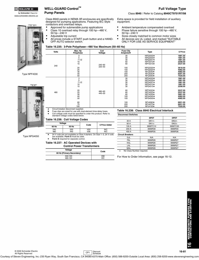
www.schneider-electric.us
16N
EM
A/D
EF
INIT
E P
UR
PO
SE
TY
PE
CO
NT
AC
TO
RS
AN
D S
TA
RT
ER
S
© 2009 Schneider ElectricAll Rights Reserved
16-81
WELL-GUARD Control™ Pump Panels
Full Voltage TypeClass 8940 / Refer to Catalog 8940CT9701R7/08
Class 8940 panels in NEMA 3R enclosures are specifically designed for pumping applications. Featuring IEC Style contactors and overload relays.
Extra space is provided for field installation of auxiliary equipment.
a Circuit breaker disconnect supplied.b Fuse clips are sized for use with dual-element time-delay fuses.c Coil voltage code must be specified to order this product. Refer to
standard voltage codes listed below.
d 24 V coils are not available on Size 4 starters. On Size 1–3, 24 V coils are available. Form S must be used.
e Form S required for separate control.
f No Class Number required.
For How to Order Information, see page 16-12.
• Approved for submersible pump applications• Class 10 overload relay through 100 hp—480 V,
50 hp—240 V• Adjustable trip current• All prices include a START push button and a HAND-
OFF-AUTO selector switch.
• Ambient temperature compensated overload• Phase failure sensitive through 100 hp—480 V,
50 hp—240 V• Sizes closely matched to common motor sizes• All devices are UL Listed, and marked “SUITABLE
ONLY FOR USE AS SERVICE EQUIPMENT”
Type NPF4030
Type NPG4050
Table 16.235: 3-Pole Polyphase—480 Vac Maximum (50–60 Hz)
Volts Max. HpPolyphase
CoilVoltage
Fuse ClipAmperesb Type $ Price
240
35
7-1/21015
2025304050
240–60220–50
3030306060
100100100200200
NPD2003cNPE2005cNPE2007cNPF2010cNPF2015c
NPG2020cNPG2025cNPJ2030cNPJ2040cNPJ2050c
1881.001881.001881.002208.002537.00
3618.004082.004082.006591.007520.00
480
35
7-1/21015
2025304050
6075
100
480–60440–50
3030303030
606060
100100
100200200
NPD4003cNPD4005cNPD4007cNPE4010cNPE4015c
NPF4020cNPF4025cNPF4030cNPG4040cNPG4050c
NPJ4060cNPJ4075cNPJ4100c
1881.001881.001881.001881.002208.00
2537.002537.003681.004082.004082.00
6651.006651.007520.00
Table 16.236: Coil Voltage CodesVoltage
Code $ Price Adder60 Hz 50 Hz
240480
220440
V03V06
N/CN/C
Table 16.237: AC Operated Devices with Control Power Transformers
VoltageCode
60 Hz (Primary-Secondary)
240-120480-120
V80V81
Table 16.238: Class 8940 Electrical InterlockDisconnect Switches
SPDT DPDT
30 A ElK1f ElK2f60 A ElK1f ElK2f100 A 9999TC10 9999TC20200 A 9999R39 9999R40400 A 9999R35 9999R36
Circuit Breakers
GJL N/A N/AFAL 9999R26 9999R27KAL 9999R26 9999R27LAL 9999R26 9999R27MAL 9999R26 9999R27
CP1 Discount Schedule
Courtesy of Steven Engineering, Inc.-230 Ryan Way, South San Francisco, CA 94080-6370-Main Office: (650) 588-9200-Outside Local Area: (800) 258-9200-www.stevenengineering.com
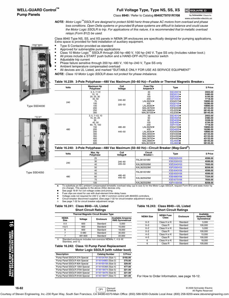
16-82 © 2009 Schneider ElectricAll Rights Reserved
www.schneider-electric.us
16N
EM
A D
EF
INIT
E P
UR
PO
SE
TY
PE
C
ON
TA
CT
OR
S A
ND
ST
AR
TE
RS
WELL-GUARD Control™
Pump PanelsFull Voltage Type, Type NS, SS, XS
Class 8940 / Refer to Catalog 8940CT9701R7/08
NOTE: Motor Logic™SSOLR are designed to protect 50/60 hertz three-phase AC motors from overload and phase loss conditions. Open Delta systems or grounded B-phase systems are difficult to balance and could cause the Motor Logic SSOLR to trip. For applications of this nature, it is recommended that bi-metallic overload relays (Form B12) be used.
Class 8940 Type NS, SS, and XS panels in NEMA 3R enclosures are specifically designed for pumping applications. Extra space is provided for field installation of auxiliary equipment. • Type S Contactor provided as standard• Approved for submersible pump applications• Class 10 Motor Logic™ SSOLR through 200 hp–480 V, 100 hp–240 V, Type SS only (Includes rubber boot.)• All prices include a START push button and a HAND-OFF-AUTO selector switch• Adjustable trip current• Phase failure sensitive through 200 hp–480 V, 100 hp–240 V, Type SS only• Ambient temperature compensated overload• All devices are UL Listed, and marked “SUITABLE ONLY FOR USE AS SERVICE EQUIPMENT”NOTE: Class 10 Motor Logic SSOLR does not protect for phase imbalance.
a To substitute an IEC ambient compensated bimetallic overload relay (up to size 5) for the Motor Logic SSOLR, request Form B12 and state motor hp (no charge). This applies to the above (SSx) devices only.
b See page 16-81 for coil voltage codes and pricing.c Fuse clips are sized for use with dual-element time-delay fuses. d Voltage code not required for 240 V or 480 V common control with 8940SS controllers.e Circuit breaker disconnect supplied. (See page 7-32 for circuit breaker adjustment range.)f See page 7-32 for circuit breaker adjustment range.
Table 16.239: 3-Pole Polyphase—480 Vac Maximum (50–60 Hz)—Fusible or Thermal Magnetic Breakera
Volts Maximum HpPolyphase
CoilVoltage
Fuse ClipAmperesc Type $ Price
240
3, 5, 7-1/210, 15
20, 25, 3040, 50
75100100200250300
240–60
220–50
30 60100200
LAL36250e400
LAL36350eMAL36700eMAL36800eMAL361000e
SSC2007dSSD2015dSSE2030dSSF2050dXSG2075bSSG2100dXSG2100bXSH2200bXSJ2250bXSJ2300b
2003.002480.004194.007718.00
19890.0016286.0019890.0043133.0058145.0058145.00
480
3, 5, 7-1/2, 1015, 20, 25
3040, 50
60, 75, 100150200200300350400500600
480–60
440–50
30 6060100200
LAL36250e400
LAL36350eMAL36500eMAL36600eMAL36700eMAL36800eMAL361000e
SSC4010dSSD4025dSSD4030dSSE4050dSSF4100dXSG4150bSSG4200dXSG4200bXSH4300bXSH4350bXSH4400bXSJ4500bXSJ4600b
2003.002480.003338.004194.007718.00
19890.0016286.0019890.0043133.0043133.0043133.0058145.0058145.00
Table 16.240: 3-Pole Polyphase—480 Vac Maximum (50–60 Hz)—Circuit Breaker (Mag-Gard®)
Volts Max. HpPolyphase
CoilVoltageb
CircuitBreakerf Type $ Price
240
25
240–60220–50
FAL3610018MXSE2025V03 4599.00
30 XSE2030V03 4599.0040 KAL3625026M XSE2040V03 7650.0050 KAL3625029M XSF2050V03 8258.00
480
40
480–60440–50
FAL3610018MXSE4040V06 4599.00
50 XSE4050V06 4599.0060
KAL3625025MXSE4060V06 7334.00
75 XSE4075V06 7650.00100 KAL3625029M XSF4100V06 8258.00
Type SSD4030
Type SSE4050
CP1 Discount Schedule
g Standard enclosure includes non-oversize NEMAs 1, 4 & 4X Stainless, and 12.
For How to Order Information, see page 16-12.
Table 16.241: Class 8940—UL Listed Short Circuit Ratings
Thermal Magnetic Circuit Breaker Type
NEMASize Voltage Enclosure Available Amperes
RMS Symmetrical
0-3 600 Standard 5,0004 & 5 600 Standard 10,000
6 600 Standard 18,0007 0-480 Standard 30,0007 481-600 Standard 22,000
Table 16.242: Class 10 Pump Panel Replacement Motor Logic SSOLR (with rubber boot)
Description Catalog Number $ Price
Pump Panel SSOLR 27A Special 3116154764 (Size 1) $192.00Pump Panel SSOLR 45A Special 3116154883 (Size 2) 270.00Pump Panel SSOLR 90A Special 3116155158 (Size 3) 329.00Pump Panel SSOLR 135A Special 3116155368 (Size 4) 477.00Pump Panel SSOLR 270A Special 3116118474 (Size 5) 221.00Pump Panel SSOLR 540A Special 3116118476 (Size 6) 221.00Pump Panel SSOLR 810A Special 3116118477 (Size 7) 221.00
Table 16.243: Class 8940—UL Listed Short Circuit Ratings
NEMA Size NEMA FuseClass Enclosure
AvailableAmperes RMSSymmetrical
0–3 Class H or K Standard 5,0000–3 Class R Standard 100,0000–2 Class H or K Standard 5,0000–2 Class R Standard 100,0004–5 Class H or K Standard 10,0004–5 Class R Standard 100,0006 Class H or K Standard 18,0006 Class R Standard 100,000
Courtesy of Steven Engineering, Inc.-230 Ryan Way, South San Francisco, CA 94080-6370-Main Office: (650) 588-9200-Outside Local Area: (800) 258-9200-www.stevenengineering.com
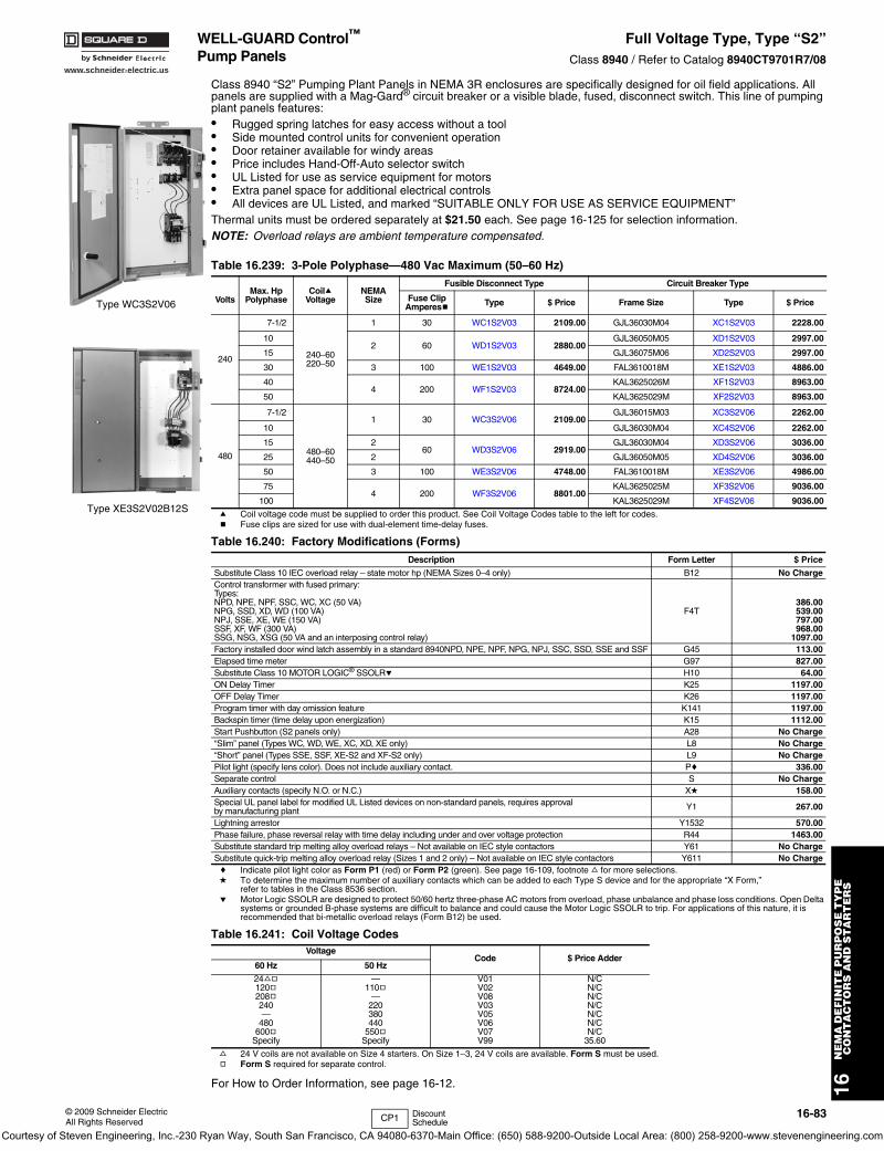
www.schneider-electric.us
16N
EM
A D
EF
INIT
E P
UR
PO
SE
TY
PE
C
ON
TA
CT
OR
S A
ND
ST
AR
TE
RS
© 2009 Schneider ElectricAll Rights Reserved
16-83
WELL-GUARD Control™
Pump PanelsFull Voltage Type, Type “S2”
Class 8940 / Refer to Catalog 8940CT9701R7/08
Class 8940 “S2” Pumping Plant Panels in NEMA 3R enclosures are specifically designed for oil field applications. All panels are supplied with a Mag-Gard® circuit breaker or a visible blade, fused, disconnect switch. This line of pumping plant panels features:• Rugged spring latches for easy access without a tool• Side mounted control units for convenient operation• Door retainer available for windy areas• Price includes Hand-Off-Auto selector switch• UL Listed for use as service equipment for motors• Extra panel space for additional electrical controls• All devices are UL Listed, and marked “SUITABLE ONLY FOR USE AS SERVICE EQUIPMENT”Thermal units must be ordered separately at $21.50 each. See page 16-125 for selection information. NOTE: Overload relays are ambient temperature compensated.
a Coil voltage code must be supplied to order this product. See Coil Voltage Codes table to the left for codes.b Fuse clips are sized for use with dual-element time-delay fuses.
c Indicate pilot light color as Form P1 (red) or Form P2 (green). See page 16-109, footnote f for more selections.d To determine the maximum number of auxiliary contacts which can be added to each Type S device and for the appropriate “X Form,”
refer to tables in the Class 8536 section.e Motor Logic SSOLR are designed to protect 50/60 hertz three-phase AC motors from overload, phase unbalance and phase loss conditions. Open Delta
systems or grounded B-phase systems are difficult to balance and could cause the Motor Logic SSOLR to trip. For applications of this nature, it is recommended that bi-metallic overload relays (Form B12) be used.
f 24 V coils are not available on Size 4 starters. On Size 1–3, 24 V coils are available. Form S must be used.g Form S required for separate control.
For How to Order Information, see page 16-12.
Table 16.239: 3-Pole Polyphase—480 Vac Maximum (50–60 Hz)
VoltsMax. Hp
PolyphaseCoila
VoltageNEMASize
Fusible Disconnect Type Circuit Breaker Type
Fuse ClipAmperesb Type $ Price Frame Size Type $ Price
240
7-1/2
240–60220–50
1 30 WC1S2V03 2109.00 GJL36030M04 XC1S2V03 2228.00
102 60 WD1S2V03 2880.00
GJL36050M05 XD1S2V03 2997.00
15 GJL36075M06 XD2S2V03 2997.00
30 3 100 WE1S2V03 4649.00 FAL3610018M XE1S2V03 4886.00
404 200 WF1S2V03 8724.00
KAL3625026M XF1S2V03 8963.00
50 KAL3625029M XF2S2V03 8963.00
480
7-1/2
480–60440–50
1 30 WC3S2V06 2109.00GJL36015M03 XC3S2V06 2262.00
10 GJL36030M04 XC4S2V06 2262.00
15 260 WD3S2V06 2919.00
GJL36030M04 XD3S2V06 3036.00
25 2 GJL36050M05 XD4S2V06 3036.00
50 3 100 WE3S2V06 4748.00 FAL3610018M XE3S2V06 4986.00
754 200 WF3S2V06 8801.00
KAL3625025M XF3S2V06 9036.00
100 KAL3625029M XF4S2V06 9036.00
Table 16.240: Factory Modifications (Forms)Description Form Letter $ Price
Substitute Class 10 IEC overload relay – state motor hp (NEMA Sizes 0–4 only) B12 No ChargeControl transformer with fused primary: Types: NPD, NPE, NPF, SSC, WC, XC (50 VA)NPG, SSD, XD, WD (100 VA)NPJ, SSE, XE, WE (150 VA)SSF, XF, WF (300 VA)SSG, NSG, XSG (50 VA and an interposing control relay)
F4T386.00539.00797.00968.00
1097.00Factory installed door wind latch assembly in a standard 8940NPD, NPE, NPF, NPG, NPJ, SSC, SSD, SSE and SSF G45 113.00Elapsed time meter G97 827.00Substitute Class 10 MOTOR LOGIC® SSOLRe H10 64.00ON Delay Timer K25 1197.00OFF Delay Timer K26 1197.00Program timer with day omission feature K141 1197.00Backspin timer (time delay upon energization) K15 1112.00Start Pushbutton (S2 panels only) A28 No Charge“Slim” panel (Types WC, WD, WE, XC, XD, XE only) L8 No Charge“Short” panel (Types SSE, SSF, XE-S2 and XF-S2 only) L9 No ChargePilot light (specify lens color). Does not include auxiliary contact. Pc 336.00Separate control S No ChargeAuxiliary contacts (specify N.O. or N.C.) Xd 158.00Special UL panel label for modified UL Listed devices on non-standard panels, requires approval by manufacturing plant Y1 267.00
Lightning arrestor Y1532 570.00Phase failure, phase reversal relay with time delay including under and over voltage protection R44 1463.00Substitute standard trip melting alloy overload relays – Not available on IEC style contactors Y61 No ChargeSubstitute quick-trip melting alloy overload relay (Sizes 1 and 2 only) – Not available on IEC style contactors Y611 No Charge
Table 16.241: Coil Voltage CodesVoltage
Code $ Price Adder60 Hz 50 Hz
24fg120g208g240—
480600g
Specify
—110g
—220380440
550gSpecify
V01V02V08V03V05V06V07V99
N/CN/CN/CN/CN/CN/CN/C
35.60
Type WC3S2V06
Type XE3S2V02B12S
CP1 Discount Schedule
Courtesy of Steven Engineering, Inc.-230 Ryan Way, South San Francisco, CA 94080-6370-Main Office: (650) 588-9200-Outside Local Area: (800) 258-9200-www.stevenengineering.com
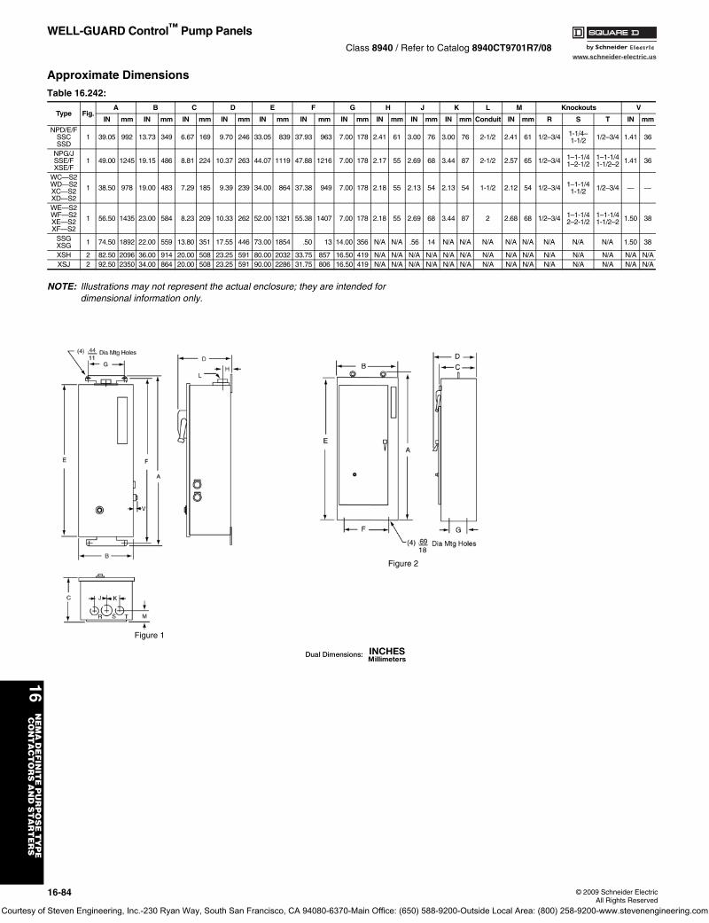
www.schneider-electric.us
16N
EM
A D
EF
INIT
E P
UR
PO
SE
TY
PE
C
ON
TA
CT
OR
S A
ND
ST
AR
TE
RS
16-84 © 2009 Schneider ElectricAll Rights Reserved
WELL-GUARD Control™ Pump PanelsClass 8940 / Refer to Catalog 8940CT9701R7/08
Approximate Dimensions
NOTE: Illustrations may not represent the actual enclosure; they are intended for dimensional information only.
Table 16.242:
Type Fig.A B C D E F G H J K L M Knockouts V
IN mm IN mm IN mm IN mm IN mm IN mm IN mm IN mm IN mm IN mm Conduit IN mm R S T IN mm
NPD/E/FSSCSSD
1 39.05 992 13.73 349 6.67 169 9.70 246 33.05 839 37.93 963 7.00 178 2.41 61 3.00 76 3.00 76 2-1/2 2.41 61 1/2–3/4 1-1/4–1-1/2 1/2–3/4 1.41 36
NPG/JSSE/FXSE/F
1 49.00 1245 19.15 486 8.81 224 10.37 263 44.07 1119 47.88 1216 7.00 178 2.17 55 2.69 68 3.44 87 2-1/2 2.57 65 1/2–3/4 1–1-1/41–2-1/2
1–1-1/41-1/2–2 1.41 36
WC—S2WD—S2XC—S2XD—S2
1 38.50 978 19.00 483 7.29 185 9.39 239 34.00 864 37.38 949 7.00 178 2.18 55 2.13 54 2.13 54 1-1/2 2.12 54 1/2–3/4 1–1-1/41-1/2 1/2–3/4 — —
WE—S2WF—S2XE—S2XF—S2
1 56.50 1435 23.00 584 8.23 209 10.33 262 52.00 1321 55.38 1407 7.00 178 2.18 55 2.69 68 3.44 87 2 2.68 68 1/2–3/4 1–1-1/42–2-1/2
1–1-1/41-1/2–2 1.50 38
SSGXSG 1 74.50 1892 22.00 559 13.80 351 17.55 446 73.00 1854 .50 13 14.00 356 N/A N/A .56 14 N/A N/A N/A N/A N/A N/A N/A N/A 1.50 38
XSH 2 82.50 2096 36.00 914 20.00 508 23.25 591 80.00 2032 33.75 857 16.50 419 N/A N/A N/A N/A N/A N/A N/A N/A N/A N/A N/A N/A N/A N/AXSJ 2 92.50 2350 34.00 864 20.00 508 23.25 591 90.00 2286 31.75 806 16.50 419 N/A N/A N/A N/A N/A N/A N/A N/A N/A N/A N/A N/A N/A N/A
Figure 2
Figure 1
Courtesy of Steven Engineering, Inc.-230 Ryan Way, South San Francisco, CA 94080-6370-Main Office: (650) 588-9200-Outside Local Area: (800) 258-9200-www.stevenengineering.com
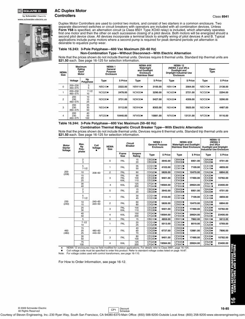
www.schneider-electric.us
16N
EM
A D
EF
INIT
E P
UR
PO
SE
TY
PE
C
ON
TA
CT
OR
S A
ND
ST
AR
TE
RS
© 2009 Schneider ElectricAll Rights Reserved
16-85
AC Duplex Motor Controllers Class 8941
Duplex Motor Controllers are used to control two motors, and consist of two starters in a common enclosure. Two separate disconnect switches or circuit breakers with operators are included with all combination devices. Unless Form Y68 is specified, an alternation circuit (a Class 8501 Type XO40 relay) is included, which alternately operates first one motor and then the other on each successive closing of a pilot device. Both motors will be energized should a second pilot device close. All devices incorporate a terminal block to simplify wiring of pilot devices A and B. Typical applications include pump motors where a second pump is required for peak demand periods yet alternation is desirable to equalize pump wear.
a NEMA 12 enclosures may be field modified for outdoor applications. For details refer to Class 9991, page 16-104.b Coil voltage code must be specified to order this product. Refer to standard voltage codes listed on page 16-87.
Note: For voltage codes used with control transformers, see page 16-110.
For How to Order Information, see page 16-12.
Table 16.243: 3-Pole Polyphase—600 Vac Maximum (50–60 Hz)Non-Combination Type—Without Disconnect—With Electric Alternation
Note that the prices shown do not include thermal units. Devices require 6 thermal units. Standard trip thermal units are $21.50 each. See page 16-125 for selection information.
NEMASize
MaximumRatingEachMotor
NEMA 1GeneralPurpose
Enclosure
NEMA 4/4XWatertight
and DusttightEnclosure
Stainless Steel
NEMA 12(NEMA 3 and 3R)a
Dusttight andDriptight Industrial Use
Enclosure
OpenType
Voltage HpPolyphase Type $ Price Type $ Price Type $ Price Type $ Price
0 200–230460–575
35 NBG10b 2322.00 NBW10b 3105.00 NBA10b 2564.00 NBO10b 2138.00
1 200–230460–575
7-1/210 NCG20b 2478.00 NCW20b 3290.00 NCA20b 2721.00 NCO20b 2294.00
2200230
460–575
101525
NDG30b 3731.00 NDW30b 5427.00 NDA30b 4359.00 NDO30b 3290.00
3200230
460–575
253050
NEG40b 5112.00 NEW40b 8303.00 NEA40b 5925.00 NEO40b 4487.00
4 200230
460–575
4050
100 NFG50b 10440.00 NFW50b 15881.00 NFA50b 13131.00 NFO50b 9116.00
Table 16.244: 3-Pole Polyphase—600 Vac Maximum (50–60 Hz)Combination Thermal Magnetic Circuit Breaker Type—With Electric Alternation
Note that the prices shown do not include thermal units. Devices require 6 thermal units. Standard trip thermal units are $21.50 each. See page 16-125 for selection information.
MotorStarterVoltage
Max.Hp
Poly-phase
CoilVoltage
b
NEMASize
CircuitBreaker
NEMA 1General Purpose
Enclosure
NEMA 4/4XWatertight and DusttightStainless Steel Enclosure
NEMA 12(NEMA 3 and 3R)a
Dusttight and DriptightIndustrial Use Enclosure
FrameSize
AmpereRating Type $ Price Type $ Price Type $ Price
200(208)
23
208–60
0 FAL 1520
CBG06bCBG08b 3945.00 CBW06b
CBW08b 6951.00 CBA06bCBA08b 4701.00
5 7-1/2 1 FAL 35
50CCG12bCCG15b 4103.00 CCW12b
CCW15b 7109.00 CCA12bCCA15b 4859.00
10 2 FAL 60 CDG22b 5826.00 CDW22b 10470.00 CDA22b 6894.00152025
3FALFALKAL
90100110
CEG32bCEG36bCEG38b
9401.00CEW32bCEW36bCEW38b
17490.00CEA32bCEA36bCEA38b
10782.00
3040 4 KAL 125
200CFG41bCFG44b 19584.00 CFW41b
CFW44b 29924.00 CFA41bCFA44 b 23400.00
230(240)
23
240–60220–50
0 FAL 1520
CBG06bCBG08b 3945.00 CBW06b
CBW08b 6951.00 CBA06bCBA08b 4701.00
5 7-1/2 1 FAL 30
45CCG14bCCG16b 4103.00 CCW14b
CCW16b 7109.00 CCA14bCCA16b 4859.00
1015 2 FAL 60
80CDG22bCDG24b 5826.00 CDW22b
CDW24b 10470.00 CDA22bCDA24b 6894.00
2530 3 FAL
KAL100110
CEG36bCEG38b 9401.00 CEW36b
CEW38b 17490.00 CEA36bCEA38b 10782.00
4050 4 KAL 150
200CFG43bCFG44b 19584.00 CFW43b
CFW44b 29924.00 CFA43bCFA44b 23400.00
460(480)
5
480–60440–50
0 FAL 15 CBG10b 4859.00 CBW10b 7862.00 CBA10b 5612.00 7-1/2
10 1 FAL 2025
CCG18bCCG20b 5013.00 CCW18b
CCW20b 8019.00 CCA18bCCA20b 5769.00
152025
2 FAL406070
CDG26bCDG28bCDG30b
6737.00CDW26bCDW28bCDW30b
12881.00CDA26bCDA28bCDA30b
7806.00
3050 3 FAL 80
100CEG39bCEG40b 9401.00 CEW39b
CEW40b 17490.00 CEA39bCEA40b 10782.00
75100 4 KAL 125
200CFG45bCFG47b 19584.00 CFW45b
CFW47b 29924.00 CFA45bCFA47b 23400.00
CP1 Discount Schedule
Courtesy of Steven Engineering, Inc.-230 Ryan Way, South San Francisco, CA 94080-6370-Main Office: (650) 588-9200-Outside Local Area: (800) 258-9200-www.stevenengineering.com
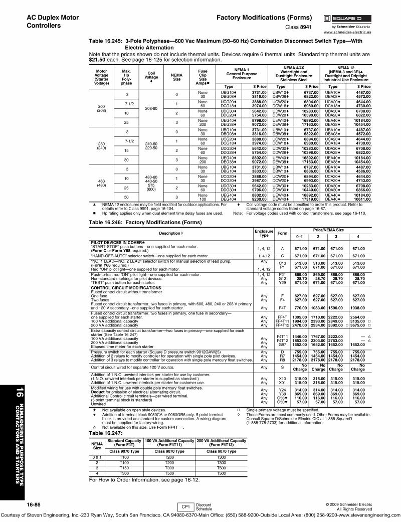
www.schneider-electric.us
16N
EM
A/D
EF
INIT
E P
UR
PO
SE
TY
PE
CO
NT
AC
TO
RS
AN
D S
TA
RT
ER
S
16-86 © 2009 Schneider ElectricAll Rights Reserved
AC Duplex Motor Controllers
Factory Modifications (Forms)Class 8941
a NEMA 12 enclosures may be field modified for outdoor applications. For details refer to Class 9991, page 16-104.
b Hp rating applies only when dual element time delay fuses are used.
c Coil voltage code must be specified to order this product. Refer to standard voltage codes listed on page 16-87.
Note: For voltage codes used with control transformers, see page 16-110.
d Not available on open style devices.e Addition of terminal block 9080CA or 9080GR6 only. 5 point terminal
block is provided as standard for custom connection. A wiring diagram must be supplied for factory wiring.
f Not available on this size. Use Form FF4T_ _.
g Single primary voltage must be specified.h These Forms are most commonly used. Other Forms may be available.
Consult Square D/Schneider Electric CIC at 1-888-SquareD (1-888-778-2733) for additional information.
For How to Order Information, see page 16-12.
Table 16.245: 3-Pole Polyphase—600 Vac Maximum (50–60 Hz) Combination Disconnect Switch Type—With Electric Alternation
Note that the prices shown do not include thermal units. Devices require 6 thermal units. Standard trip thermal units are $21.50 each. See page 16-125 for selection information.
MotorVoltage(StarterVoltage)
Max.Hp
Poly-phase
CoilVoltage
c
NEMASize
FuseClipSize
Ampsb
NEMA 1General Purpose
Enclosure
NEMA 4/4XWatertight and
Dusttight EnclosureStainless Steel
NEMA 12(NEMA 3 and 3R)a
Dusttight and DriptightIndustrial Use Enclosure
Type $ Price Type $ Price Type $ Price
200(208)
3
208-60
0 None30
UBG10cDBG08c
3731.003816.00
UBW10cDBW08c
6737.006822.00
UBA10cDBA08c
4487.004572.00
7-1/2 1 None60
UCG20cDCG18c
3888.003974.00
UCW20cDCW18c
6894.006980.00
UCA20cDCA18c
4644.004730.00
10 2 None60
UDG30cDDG28c
5642.005754.00
UDW30cDDW28c
10283.0010398.00
UDA30cDDA28c
6708.006822.00
25 3 None200
UEG40cDEG38c
8798.009072.00
UEW40cDEW38c
16892.0017163.00
UEA40cDEA38c
10184.0010454.00
230(240)
3
240-60220-50
0 None30
UBG10cDBG08c
3731.003816.00
UBW10cDBW08c
6737.006822.00
UBA10cDBA08c
4487.004572.00
7-1/2 1 None60
UCG20cDCG18c
3888.003974.00
UCW20cDCW18c
6894.006980.00
UCA20cDCA18c
4644.004730.00
15 2 None60
UDG30cDDG28c
5642.005754.00
UDW30cDDW28c
10283.0010398.00
UDA30cDDA28c
6708.006822.00
30 3 None200
UEG40cDEG38c
8802.009072.00
UEW40cDEW38c
16892.0017163.00
UEA40cDEA38c
10184.0010454.00
460(480)
5
480-60440-50
575(600)
0 None30
UBG10cDBG10c
3731.003833.00
UBW10cDBW10c
6737.006836.00
UBA10cDBA10c
4487.004586.00
10 1 None30
UCG20cDCG20c
3888.003987.00
UCW20cDCW20c
6894.006993.00
UCA20cDCA20c
4644.004743.00
25 2 None60
UDG30cDDG30c
5642.005796.00
UDW30cDDW30c
10283.0010440.00
UDA30cDDA30c
6708.006866.00
50 3 None100
UEG40cDEG40c
8802.009230.00
UEW40cDEW40c
16892.0017319.00
UEA40cDEA40c
10184.0010611.00
Table 16.246: Factory Modifications (Forms)
Descriptionh EnclosureType Form
Price/NEMA Size
0–1 2 3 4
PILOT DEVICES IN COVERd“START-STOP” push buttons—one supplied for each motor. (Form C or Form Y68 required.) 1, 4, 12 A 671.00 671.00 671.00 671.00
“HAND-OFF-AUTO” selector switch—one supplied for each motor. 1, 4,12 C 671.00 671.00 671.00 671.00“NO. 1 LEAD—NO. 2 LEAD” selector switch for manual selection of lead pump. (Form Y68 required.) Red "ON" pilot light—one supplied for each motor.
Any
1, 4, 12
C13P1
513.00671.00
513.00671.00
513.00671.00
513.00671.00
Push-to-test red “ON” pilot light—one supplied for each motor. Non-standard markings for pilot devices.“TEST” push button for each starter.
1, 4, 12AnyAny
P21G12Y29
869.0028.70
671.00
869.0028.70
671.00
869.0028.70
671.00
869.0028.70
671.00CONTROL CIRCUIT MODIFICATIONSFused control circuit without transformerOne fuseTwo fusesFused control circuit transformer, two fuses in primary, with 600, 480, 240 or 208 V primary and 120 V secondary –one supplied for each starter.
AnyAny
Any
FF4
F4T
627.00627.00
770.00
627.00627.00
1083.00
627.00627.00
1596.00
627.00627.00
1938.00Fused control circuit transformer, two fuses in primary, one fuse in secondary—one supplied for each starter.100 VA additional capacity200 VA additional capacity
AnyAnyAny
FF4TFF4T11FF4T12
1395.001994.002478.00
1710.002393.002934.00
2222.002849.003392.00 g
2564.003135.003675.00
gg
Extra capacity control circuit transformer—two fuses in primary—one supplied for each starter (See Table 16.247)100 VA additional capacity200 VA additional capacity Elapsed time meter for each starter
AnyAnyAny
F4T11F4T12G97
1446.001853.001652.00
1767.002303.001652.00
2222.002763.001652.00
——
1652.00
ff
Pressure switch for each starter (Square D pressure switch 9012GAW25)Addition of 2 relays to modify controller for operation with single pole pilot devices.Addition of 3 relays to modify controller for operation with single pole mercury float switches.
AnyAnyAny
DR7R8
755.001454.002178.00
755.001454.002178.00
755.001454.002178.00
755.001454.002178.00
Control circuit wired for separate 120 V source. Any S NoCharge
NoCharge
NoCharge
NoCharge
Addition of 1 N.O. unwired interlock per starter for use by customer. (1 N.O. unwired interlock per starter is supplied as standard.) Addition of 1 N.C. unwired interlock per starter for customer use.
AnyAny
X10X01
315.00315.00
315.00315.00
315.00315.00
315.00315.00
Modified wiring for use with double pole mercury float switches.Deduct for omission of electrical alternating circuit.Additional Control circuit terminals—per wired terminal. (5 point terminal block is standard)Unwired
AnyAnyAnyAny
Y24Y68
G56eG50e
314.00869.00116.0057.00
314.00869.00116.00
57.00
314.00869.00116.00
57.00
314.00869.00116.0057.00
Table 16.247:
NEMASize
Standard Capacity(Form F4T)
100 VA Additional Capacity(Form F4T11)
200 VA Additional Capacity(Form F4T12)
Class 9070 Type Class 9070 Type Class 9070 Type
0 & 1 T100 T200 T3002 T100 T200 T3003 T150 T300 T5004 T300 T500 T500
CP1 Discount Schedule
Courtesy of Steven Engineering, Inc.-230 Ryan Way, South San Francisco, CA 94080-6370-Main Office: (650) 588-9200-Outside Local Area: (800) 258-9200-www.stevenengineering.com
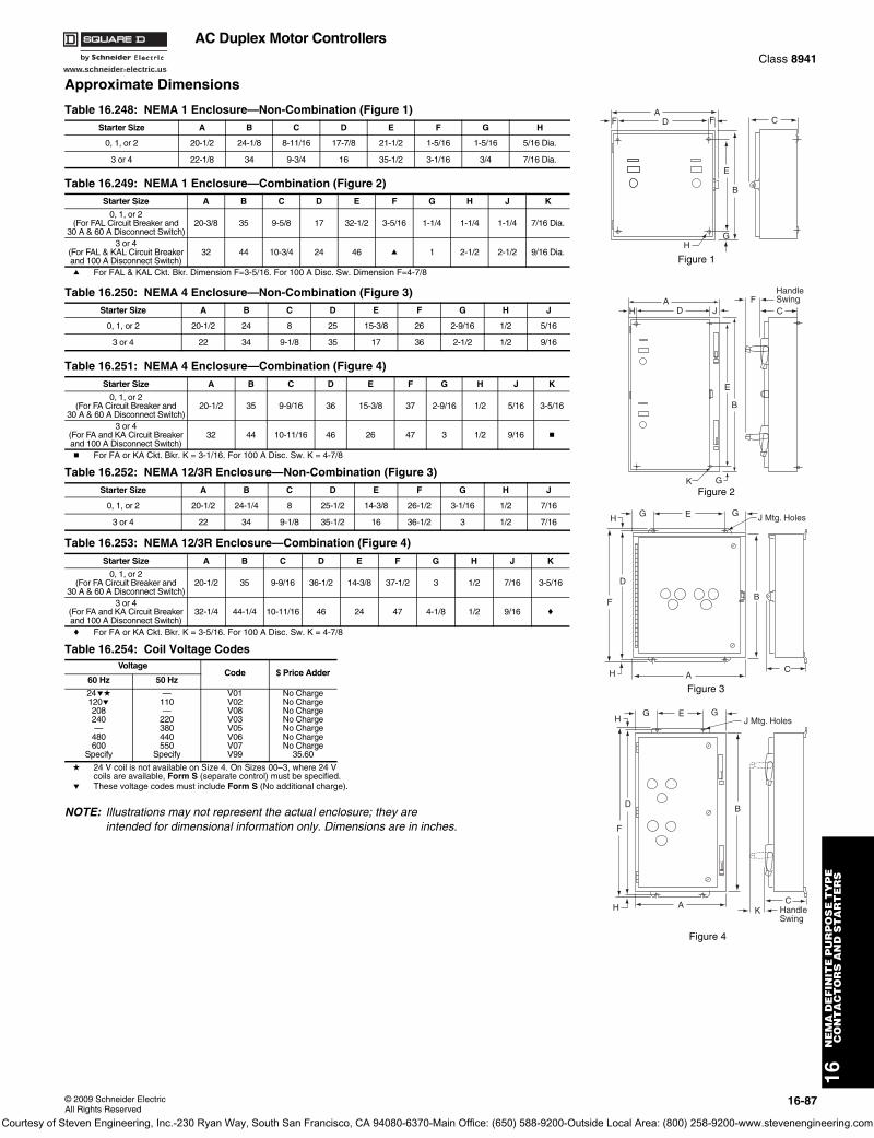
www.schneider-electric.us
16N
EM
A D
EF
INIT
E P
UR
PO
SE
TY
PE
C
ON
TA
CT
OR
S A
ND
ST
AR
TE
RS
© 2009 Schneider ElectricAll Rights Reserved
16-87
AC Duplex Motor ControllersClass 8941
Approximate Dimensions
a For FAL & KAL Ckt. Bkr. Dimension F=3-5/16. For 100 A Disc. Sw. Dimension F=4-7/8
b For FA or KA Ckt. Bkr. K = 3-1/16. For 100 A Disc. Sw. K = 4-7/8
c For FA or KA Ckt. Bkr. K = 3-5/16. For 100 A Disc. Sw. K = 4-7/8
d 24 V coil is not available on Size 4. On Sizes 00–3, where 24 V coils are available, Form S (separate control) must be specified.
e These voltage codes must include Form S (No additional charge).
NOTE: Illustrations may not represent the actual enclosure; they are intended for dimensional information only. Dimensions are in inches.
Table 16.248: NEMA 1 Enclosure—Non-Combination (Figure 1)Starter Size A B C D E F G H
0, 1, or 2 20-1/2 24-1/8 8-11/16 17-7/8 21-1/2 1-5/16 1-5/16 5/16 Dia.
3 or 4 22-1/8 34 9-3/4 16 35-1/2 3-1/16 3/4 7/16 Dia.
Table 16.249: NEMA 1 Enclosure—Combination (Figure 2)Starter Size A B C D E F G H J K
0, 1, or 2(For FAL Circuit Breaker and
30 A & 60 A Disconnect Switch)20-3/8 35 9-5/8 17 32-1/2 3-5/16 1-1/4 1-1/4 1-1/4 7/16 Dia.
3 or 4(For FAL & KAL Circuit Breaker and 100 A Disconnect Switch)
32 44 10-3/4 24 46 a 1 2-1/2 2-1/2 9/16 Dia.
Table 16.250: NEMA 4 Enclosure—Non-Combination (Figure 3)Starter Size A B C D E F G H J
0, 1, or 2 20-1/2 24 8 25 15-3/8 26 2-9/16 1/2 5/16
3 or 4 22 34 9-1/8 35 17 36 2-1/2 1/2 9/16
Table 16.251: NEMA 4 Enclosure—Combination (Figure 4)Starter Size A B C D E F G H J K
0, 1, or 2(For FA Circuit Breaker and
30 A & 60 A Disconnect Switch)20-1/2 35 9-9/16 36 15-3/8 37 2-9/16 1/2 5/16 3-5/16
3 or 4(For FA and KA Circuit Breaker and 100 A Disconnect Switch)
32 44 10-11/16 46 26 47 3 1/2 9/16 b
Table 16.252: NEMA 12/3R Enclosure—Non-Combination (Figure 3)Starter Size A B C D E F G H J
0, 1, or 2 20-1/2 24-1/4 8 25-1/2 14-3/8 26-1/2 3-1/16 1/2 7/16
3 or 4 22 34 9-1/8 35-1/2 16 36-1/2 3 1/2 7/16
Table 16.253: NEMA 12/3R Enclosure—Combination (Figure 4)Starter Size A B C D E F G H J K
0, 1, or 2(For FA Circuit Breaker and
30 A & 60 A Disconnect Switch)20-1/2 35 9-9/16 36-1/2 14-3/8 37-1/2 3 1/2 7/16 3-5/16
3 or 4(For FA and KA Circuit Breaker and 100 A Disconnect Switch)
32-1/4 44-1/4 10-11/16 46 24 47 4-1/8 1/2 9/16 c
Table 16.254: Coil Voltage CodesVoltage
Code $ Price Adder60 Hz 50 Hz
24ed120e208240—
480600
Specify
—110—
220380440550
Specify
V01V02V08V03V05V06V07V99
No ChargeNo ChargeNo ChargeNo ChargeNo ChargeNo ChargeNo Charge
35.60
ADF F
E
B
GH
C
Figure 1
ADH J
E
B
K G
FC
HandleSwing
Figure 2
EGH
H
F
D
G
B
AC
J Mtg. Holes
Figure 3
GH
H
F
D
AK
C
B
GJ Mtg. Holes
HandleSwing
E
Figure 4
Courtesy of Steven Engineering, Inc.-230 Ryan Way, South San Francisco, CA 94080-6370-Main Office: (650) 588-9200-Outside Local Area: (800) 258-9200-www.stevenengineering.com
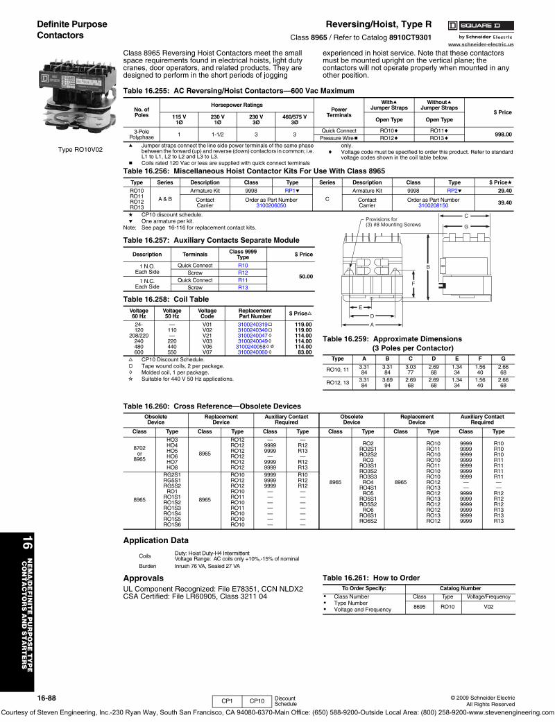
www.schneider-electric.us
16N
EM
A/D
EF
INIT
E P
UR
PO
SE
TY
PE
CO
NT
AC
TO
RS
AN
D S
TA
RT
ER
S
16-88 © 2009 Schneider ElectricAll Rights Reserved
Definite Purpose Contactors
Reversing/Hoist, Type RClass 8965 / Refer to Catalog 8910CT9301
Class 8965 Reversing Hoist Contactors meet the small space requirements found in electrical hoists, light duty cranes, door operators, and related products. They are designed to perform in the short periods of jogging
experienced in hoist service. Note that these contactors must be mounted upright on the vertical plane; the contactors will not operate properly when mounted in any other position.
a Jumper straps connect the line side power terminals of the same phase between the forward (up) and reverse (down) contactors in common; i.e. L1 to L1, L2 to L2 and L3 to L3.
b Coils rated 120 Vac or less are supplied with quick connect terminals
only.c Voltage code must be specified to order this product. Refer to standard
voltage codes shown in the coil table below.
d CP10 discount schedule.e One armature per kit.
Note: See page 16-116 for replacement contact kits.
f CP10 Discount Schedule.g Tape wound coils, 2 per package.h Molded coil, 1 per package.i Suitable for 440 V 50 Hz applications.
Application Data
ApprovalsUL Component Recognized: File E78351, CCN NLDX2CSA Certified: File LR60905, Class 3211 04
Type RO10V02
Table 16.255: AC Reversing/Hoist Contactors—600 Vac Maximum
No. ofPoles
Horsepower RatingsPower
Terminals
WithaJumper Straps
Withouta Jumper Straps
$ Price115 V
1Ø230 V
1Ø230 V
3Ø460/575 V
3Ø Open Type Open Type
3-PolePolyphase 1 1-1/2 3 3
Quick Connect RO10c RO11c998.00
Pressure Wireb RO12c RO13c
Table 16.256: Miscellaneous Hoist Contactor Kits For Use With Class 8965Type Series Description Class Type Series Description Class Type $ Priced
RO10RO11RO12RO13
A & B
Armature Kit 9998 RP1e
C
Armature Kit 9998 RP2e 29.40
ContactCarrier
Order as Part Number3100206050
ContactCarrier
Order as Part Number3100208150 39.40
Table 16.257: Auxiliary Contacts Separate Module
Description Terminals Class 9999Type $ Price
1 N.O.Each Side
Quick Connect R10
50.00Screw R12
1 N.C.Each Side
Quick Connect R11Screw R13
Table 16.258: Coil TableVoltage60 Hz
Voltage50 Hz
VoltageCode
ReplacementPart Number $ Pricef
24-120
208/220240480600
—110—
220440550
V01V02V21V03V06V07
3100240319g3100240340g3100240047h3100240049h
3100240058hi3100240060h
119.00119.00114.00114.00114.0083.00
Table 16.259: Approximate Dimensions (3 Poles per Contactor)
Type A B C D E F G
RO10, 11 3.3184
3.3184
3.0377
2.6968
1.3434
1.5640
2.6668
RO12, 13 3.3184
3.6994
2.6968
2.6968
1.3434
1.5640
2.6668
A
D
E
F
B
G
CProvisions for(3) #8 Mounting Screws
Table 16.260: Cross Reference—Obsolete DevicesObsoleteDevice
ReplacementDevice
Auxiliary ContactRequired
ObsoleteDevice
ReplacementDevice
Auxiliary ContactRequired
Class Type Class Type Class Type Class Type Class Type Class Type
8702or
8965
HO3HO4HO5HO6HO7HO8
8965
RO12RO12RO12RO12RO12RO12
—99999999
—99999999
—R12R13—
R12R13
8965
RO2RO2S1RO2S2
RO3RO3S1RO3S2RO3S3
RO4RO4S1
RO5RO5S1RO5S2
RO6RO6S1RO6S2
8965
RO10RO11RO10RO10RO11RO10RO10RO12RO13RO12RO13RO12RO12RO13RO12
9999999999999999999999999999
——
999999999999999999999999
R10R10R10R11R11R11R11——
R12R12R12R13R13R13
8965
RG2S1RG5S1RG5S2
RO1RO1S1RO1S2RO1S3RO1S4RO1S5RO1S6
8965
RO10RO12RO12RO10RO11RO10RO11RO10RO10RO10
999999999999
———————
R10R12R12———————
Coils Duty: Hoist Duty-H4 IntermittentVoltage Range: AC coils only +10%,-15% of nominal
Burden Inrush 76 VA, Sealed 27 VA
Table 16.261: How to OrderTo Order Specify: Catalog Number
• Class Number• Type Number• Voltage and Frequency
Class Type Voltage/Frequency
8695 RO10 V02
CP1 CP10 Discount Schedule
Courtesy of Steven Engineering, Inc.-230 Ryan Way, South San Francisco, CA 94080-6370-Main Office: (650) 588-9200-Outside Local Area: (800) 258-9200-www.stevenengineering.com
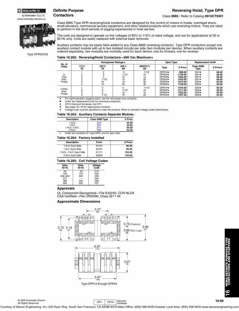
www.schneider-electric.us
16N
EM
A D
EF
INIT
E P
UR
PO
SE
TY
PE
C
ON
TA
CT
OR
S A
ND
ST
AR
TE
RS
© 2009 Schneider ElectricAll Rights Reserved
16-89
Definite Purpose Contactors
Reversing Hoist, Type DPRClass 8965 / Refer to Catalog 8910CT9301
Class 8965 Type DPR reversing/hoist contactors are designed for the control of motors in hoists, overhead doors, small elevators, commercial laundry equipment, and other related products which use reversing motors. They are rated to perform in the short periods of jogging experienced in hoist service.
The coils are designed to operate on line voltages of 85% to 110% of rated voltage, and are for applications at 50 or 60 Hz only. Coils are easily replaced with external base removed.
Auxiliary contacts may be easily field–added to any Class 8965 reversing contactor. Type DPR contactors accept one auxiliary contact module with up to two isolated circuits per side (two modules per device). When auxiliary contacts are ordered separately, two modules are normally used for each device; one for forward, one for reverse.
a For rapid operation (jogging duty), use the next larger size contactor.b Order two replacement coils for reversing contactors.c CP10 Discount Schedule, not CP1.d See page 16-116 for replacement contacts.e Voltage code must be specified to order this product. Refer to standard voltage codes listed below.
f Order two modules for Type DPR, one for each side.
ApprovalsUL Component Recognized—File E42240, CCN NLDXCSA Certified—File LR25490, Class 3211 04
Approximate Dimensions
Table 16.262: Reversing/Hoist Contactors—600 Vac Maximumd
No. ofPoles
Horsepower Ratingsa Open Type Replacement Coilb
115 V1Ø
230 V 1Ø
230 V3Ø
460/575 V3Ø Type $ Price Class 9998
Type $ Pricec
3-PolePoly-
Phase
122335
235
7-1/21010
57-1/210151525
7-1/21015203030
DPR13eDPR23eDPR33eDPR43eDPR53eDPR63e
998.001139.001283.001425.001614.001758.00
DA1eDA1eDA1eDA1eDA2eDA2e
68.0068.0068.0068.0092.0092.00
4-PolePoly-
Phase
1223
235
7-1/2
57-1/21010
7-1/2101520
DPR14eDPR24eDPR34eDPR44e
1070.001211.001353.001497.00
DA2eDA2eDA2eDA2e
92.0092.0092.0092.00
Table 16.263: Auxiliary Contacts Separate ModulefDescription Class 9999 Type $ Price
1 N.O.1 N.C.
1 N.O.–1 N.C.2 N.O.
D10D01D11D20
35.6024.6064.0044.30
Table 16.264: Factory InstalledDescription Form $ Price
1 N.O. Each Side X1010 95.001 N.C. Each Side X0101 95.00
1 N.O.–1 N.C. Each Side X1111 153.002 N.O. Each Side X2020 153.00
Table 16.265: Coil Voltage CodesVolts, 60 Hz
Volts, 50 Hz
VoltageCode
24120
208–240277480600
24110220—
440550
V14V02V09V04V06V07
Type DPR23V02
3.3786
3.1981
3.0778
3.98101
3.76 (Fastons) 96
3.86 (Box Lugs) 98
3.7295
6.87174
5.87149
Type DPR13 through DPR43
CP1 CP10 Discount Schedule
Courtesy of Steven Engineering, Inc.-230 Ryan Way, South San Francisco, CA 94080-6370-Main Office: (650) 588-9200-Outside Local Area: (800) 258-9200-www.stevenengineering.com
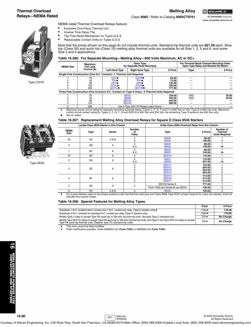
16-90 © 2009 Schneider ElectricAll Rights Reserved
www.schneider-electric.us
16N
EM
A D
EF
INIT
E P
UR
PO
SE
TY
PE
C
ON
TA
CT
OR
S A
ND
ST
AR
TE
RS
Thermal Overload Relays—NEMA Rated
Melting AlloyClass 9065 / Refer to Catalog 9065CT9701
NEMA-rated Thermal Overload Relays feature:• Exclusive One-Piece Thermal Unit• Inverse Time Delay Trip• Trip Free Reset Mechanism on Types G & S• Replaceable Contact Units on Types G & S
Note that the prices shown on this page do not include thermal units. Standard trip thermal units are $21.50 each. Slow trip (Class 30) and quick trip (Class 10) melting alloy thermal units are available for all Size 1, 2, 5 and 6, and some Size 3 and 4 applications.
a Maximum power circuit rating for separate mounting overload relays, Types C, F, G, T and U, is 600 Vac or Vdc; Type S is 600 Vac only. Maximum control circuit contact rating for Types C, F, G, T, U and SDO18 is 600 Vac and 250 Vdc; the remaining Type S versions are 600 Vac only
b Not UL listed.
c For 4-pole starters used on two phase systems order two thermal units plus one Class 9998 Type SO31 jumper strap kit for every two starters. Each kit includes two jumper straps.
d This form cannot be field modified.e Field modification possible. Order 9999S04 (for Form Y342) or 9999S05 (for Form Y344).
Table 16.266: For Separate Mounting—Melting Alloy—600 Volts Maximum, AC or DCa
NEMA SizeMaximumFull Load
Current (A)
Open Typefor Separate Panel Mounting
For Terminal Block Channel Mounting OrderOpen Type Relay and Bracket Kit Below
Left Hand Type Right Hand Type $ Price Type $ Price
Single Pole Construction (One N.C. Contact)—1 Thermal Unit Required
12345
254586
133266
CO1bTO1bUO1bFO1Lb
GO11Lb
CO1RbTO1bUO1b
FO1RbGO11Rb
64.0072.00
122.00192.00777.00
—————
—————
Three Pole Construction (One Common N.C. Contact on Type S Only)—3 Thermal Units Required
1234
254586
133
SEO5SEO8SEO12SEO15
129.00185.00243.00386.00
SM2SM2——
35.6035.60
——
5 266 Use 3 Type GO11R Relays Listed Above — —
Table 16.267: Replacement Melting Alloy Overload Relays for Square D Class 8536 StartersLocate Class 8536 Starter in this Column Order Class 9065 Overload Relay from this Column
NEMASize Type Series
Numberof
PolesType $ Price
Number ofThermal
Units Required
00 SA A & B 23
SDO4SDO5
86.00149.00
13
0 SB A 23–5
SDO4SDO5
86.00149.00
13c
1 SC A 23–5
SDO4SDO5
86.00149.00
13c
1P SC A 2 SDO10 116.00 1
2 SD A 23–5
SDO7SDO8
116.00207.00
13c
3 SE A
2345
SDO11SDO12SDO13SDO14
143.00264.00264.00264.00
1323
4 SF A345
SDO15SDO16SDO17
414.00414.00414.00
323
5 SG A 3SDO18 Series A 777.00 1
Form Y500 and Series B use SEO5 129.00 36 SH A & B 3 SEO5 129.00 3
Table 16.268: Special Features for Melting Alloy Types Form $ Price
Substitute 1-N.O. isolated alarm contact and 1-N.C. contact per relay. (Type S starters only)e Y342e 179.00Substitute 2-N.C. contacts for standard N.C. contact per relay. (Type S starters only) Y344e 179.00Modify Type U relay to accept Type FB quick trip or SB slow trip thermal units. (Accepts Type C standard trip) Y21d No ChargeModify Type SDO12 relays to accept Type FB quick trip or SB slow trip thermal units, and Type F and Type SDO15 relays to accept Type FB quick trip thermal units. (Rejects Type CC standard trip units) Y81d No Charge
Type CO1R
Type SE05
CP1 Discount Schedule
Courtesy of Steven Engineering, Inc.-230 Ryan Way, South San Francisco, CA 94080-6370-Main Office: (650) 588-9200-Outside Local Area: (800) 258-9200-www.stevenengineering.com
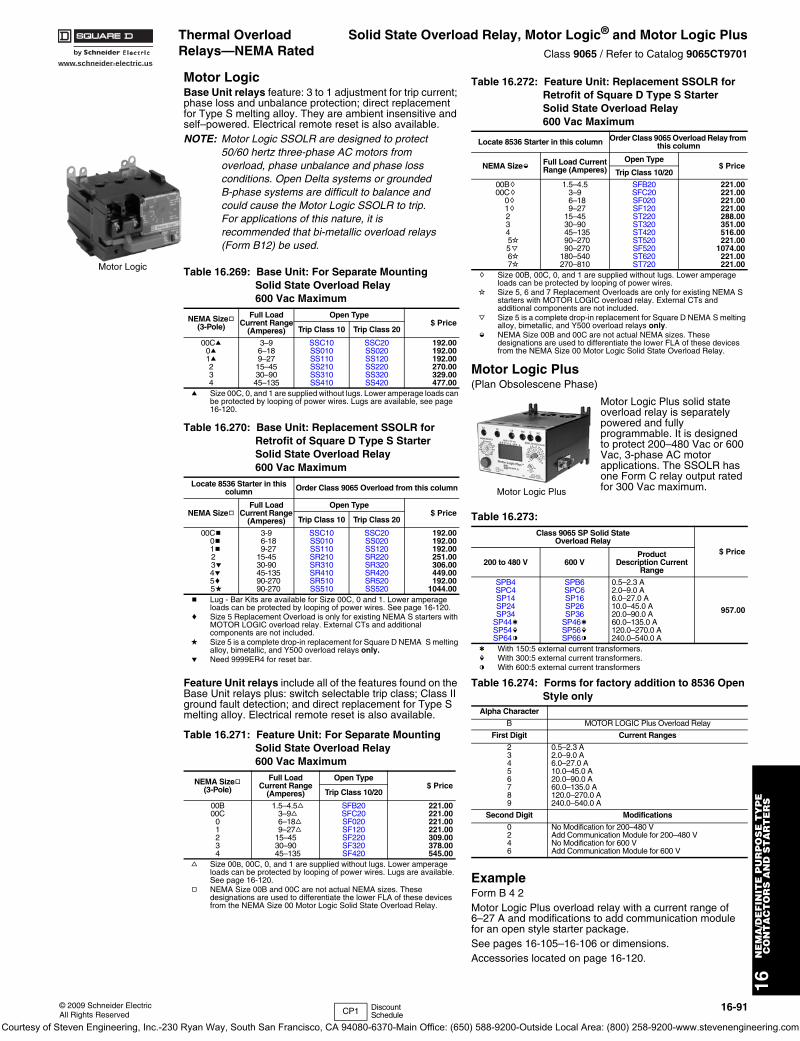
www.schneider-electric.us
16N
EM
A/D
EF
INIT
E P
UR
PO
SE
TY
PE
CO
NT
AC
TO
RS
AN
D S
TA
RT
ER
S
© 2009 Schneider ElectricAll Rights Reserved
16-91
Thermal Overload Relays—NEMA Rated
Solid State Overload Relay, Motor Logic® and Motor Logic PlusClass 9065 / Refer to Catalog 9065CT9701
Motor LogicBase Unit relays feature: 3 to 1 adjustment for trip current; phase loss and unbalance protection; direct replacement for Type S melting alloy. They are ambient insensitive and self–powered. Electrical remote reset is also available.NOTE: Motor Logic SSOLR are designed to protect
50/60 hertz three-phase AC motors from overload, phase unbalance and phase loss conditions. Open Delta systems or grounded B-phase systems are difficult to balance and could cause the Motor Logic SSOLR to trip. For applications of this nature, it is recommended that bi-metallic overload relays (Form B12) be used.
a Size 00C, 0, and 1 are supplied without lugs. Lower amperage loads can be protected by looping of power wires. Lugs are available, see page 16-120.
b Lug - Bar Kits are available for Size 00C, 0 and 1. Lower amperage loads can be protected by looping of power wires. See page 16-120.
c Size 5 Replacement Overload is only for existing NEMA S starters with MOTOR LOGIC overload relay. External CTs and additional components are not included.
d Size 5 is a complete drop-in replacement for Square D NEMA S melting alloy, bimetallic, and Y500 overload relays only.
e Need 9999ER4 for reset bar.
Feature Unit relays include all of the features found on the Base Unit relays plus: switch selectable trip class; Class II ground fault detection; and direct replacement for Type S melting alloy. Electrical remote reset is also available.
f Size 00B, 00C, 0, and 1 are supplied without lugs. Lower amperage loads can be protected by looping of power wires. Lugs are available. See page 16-120.
g NEMA Size 00B and 00C are not actual NEMA sizes. These designations are used to differentiate the lower FLA of these devices from the NEMA Size 00 Motor Logic Solid State Overload Relay.
h Size 00B, 00C, 0, and 1 are supplied without lugs. Lower amperage loads can be protected by looping of power wires.
i Size 5, 6 and 7 Replacement Overloads are only for existing NEMA S starters with MOTOR LOGIC overload relay. External CTs and additional components are not included.
j Size 5 is a complete drop-in replacement for Square D NEMA S melting alloy, bimetallic, and Y500 overload relays only.
k NEMA Size 00B and 00C are not actual NEMA sizes. These designations are used to differentiate the lower FLA of these devices from the NEMA Size 00 Motor Logic Solid State Overload Relay.
Motor Logic Plus (Plan Obsolescene Phase)
Motor Logic Plus solid state overload relay is separately powered and fully programmable. It is designed to protect 200–480 Vac or 600 Vac, 3-phase AC motor applications. The SSOLR has one Form C relay output rated for 300 Vac maximum.
l With 150:5 external current transformers.m With 300:5 external current transformers.n With 600:5 external current transformers
ExampleForm B 4 2Motor Logic Plus overload relay with a current range of 6–27 A and modifications to add communication module for an open style starter package.See pages 16-105–16-106 or dimensions.Accessories located on page 16-120.
Table 16.269: Base Unit: For Separate Mounting Solid State Overload Relay 600 Vac Maximum
NEMA Sizeg(3-Pole)
Full LoadCurrent Range
(Amperes)
Open Type$ Price
Trip Class 10 Trip Class 20
00Ca0a1a234
3–96–189–2715–4530–9045–135
SSC10SS010SS110SS210SS310SS410
SSC20SS020SS120SS220SS320SS420
192.00192.00192.00270.00329.00477.00
Table 16.270: Base Unit: Replacement SSOLR for Retrofit of Square D Type S StarterSolid State Overload Relay 600 Vac Maximum
Locate 8536 Starter in this column Order Class 9065 Overload from this column
NEMA SizegFull Load
Current Range (Amperes)
Open Type$ Price
Trip Class 10 Trip Class 20
00Cb0b1b2
3e 4e
5c5d
3-96-189-27
15-4530-9045-13590-27090-270
SSC10SS010SS110SR210SR310SR410SR510SS510
SSC20SS020SS120SR220SR320SR420SR520SS520
192.00192.00192.00251.00306.00449.00192.00
1044.00
Table 16.271: Feature Unit: For Separate Mounting Solid State Overload Relay600 Vac Maximum
NEMA Sizeg(3-Pole)
Full LoadCurrent Range
(Amperes)
Open Type$ Price
Trip Class 10/20
00B00C
01234
1.5–4.5f3–9f6–18f9–27f
15–4530–9045–135
SFB20SFC20SF020SF120SF220SF320SF420
221.00221.00221.00221.00309.00378.00545.00
Motor Logic
Table 16.272: Feature Unit: Replacement SSOLR for Retrofit of Square D Type S StarterSolid State Overload Relay600 Vac Maximum
Locate 8536 Starter in this column Order Class 9065 Overload Relay from this column
NEMA Sizek Full Load Current Range (Amperes)
Open Type$ Price
Trip Class 10/20
00Bh00Ch
0h1h2345i5j6i7i
1.5–4.53–96–189–27
15–4530–9045–13590–27090–270
180–540270–810
SFB20SFC20SF020SF120ST220ST320ST420ST520SF520ST620ST720
221.00221.00221.00221.00288.00351.00516.00221.00
1074.00221.00221.00
Table 16.273: Class 9065 SP Solid State
Overload Relay$ Price
200 to 480 V 600 VProduct
Description Current Range
SPB4SPC4SP14SP24SP34
SP44lSP54mSP64n
SPB6SPC6SP16SP26SP36
SP46lSP56mSP66n
0.5–2.3 A2.0–9.0 A6.0–27.0 A10.0–45.0 A20.0–90.0 A60.0–135.0 A120.0–270.0 A240.0–540.0 A
957.00
Table 16.274: Forms for factory addition to 8536 Open Style only
Alpha Character
B MOTOR LOGIC Plus Overload Relay
First Digit Current Ranges
23456789
0.5–2.3 A2.0–9.0 A6.0–27.0 A10.0–45.0 A20.0–90.0 A60.0–135.0 A120.0–270.0 A240.0–540.0 A
Second Digit Modifications
0246
No Modification for 200–480 VAdd Communication Module for 200–480 VNo Modification for 600 VAdd Communication Module for 600 V
Motor Logic Plus
CP1 Discount Schedule
Courtesy of Steven Engineering, Inc.-230 Ryan Way, South San Francisco, CA 94080-6370-Main Office: (650) 588-9200-Outside Local Area: (800) 258-9200-www.stevenengineering.com
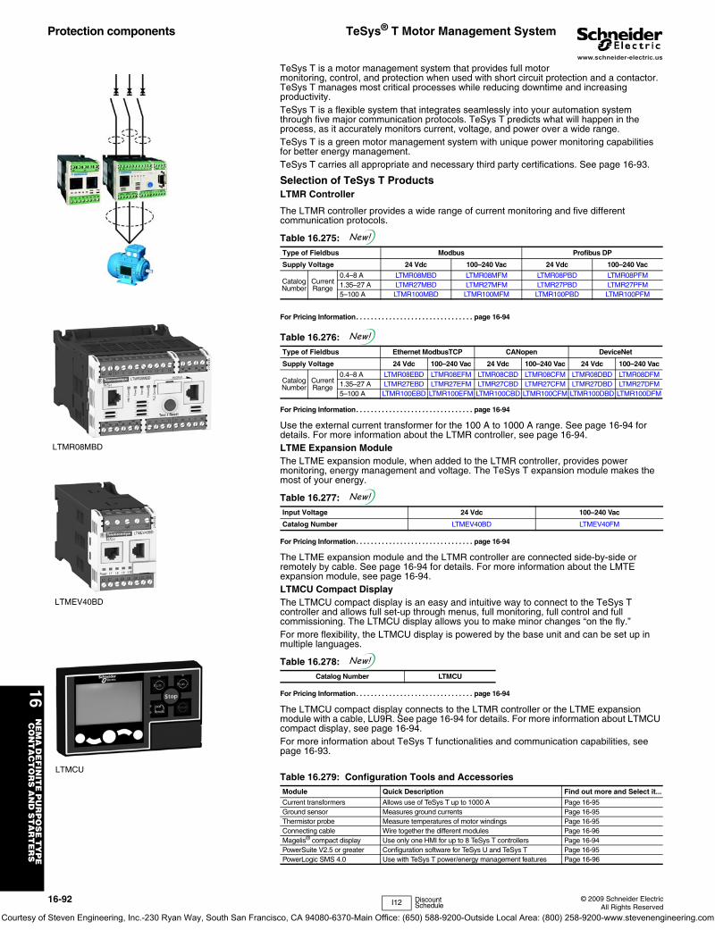
16N
EM
A D
EF
INIT
E P
UR
PO
SE
TY
PE
C
ON
TA
CT
OR
S A
ND
ST
AR
TE
RS
16-92 © 2009 Schneider ElectricAll Rights Reserved
www.schneider-electric.us
Protection components TeSys® T Motor Management System
TeSys T is a motor management system that provides full motor monitoring, control, and protection when used with short circuit protection and a contactor. TeSys T manages most critical processes while reducing downtime and increasing productivity. TeSys T is a flexible system that integrates seamlessly into your automation system through five major communication protocols. TeSys T predicts what will happen in the process, as it accurately monitors current, voltage, and power over a wide range.TeSys T is a green motor management system with unique power monitoring capabilities for better energy management.TeSys T carries all appropriate and necessary third party certifications. See page 16-93.
Selection of TeSys T ProductsLTMR Controller
The LTMR controller provides a wide range of current monitoring and five different communication protocols.
For Pricing Information. . . . . . . . . . . . . . . . . . . . . . . . . . . . . . . . page 16-94
For Pricing Information. . . . . . . . . . . . . . . . . . . . . . . . . . . . . . . . page 16-94
Use the external current transformer for the 100 A to 1000 A range. See page 16-94 for details. For more information about the LTMR controller, see page 16-94.LTME Expansion ModuleThe LTME expansion module, when added to the LTMR controller, provides power monitoring, energy management and voltage. The TeSys T expansion module makes the most of your energy.
For Pricing Information. . . . . . . . . . . . . . . . . . . . . . . . . . . . . . . . page 16-94
The LTME expansion module and the LTMR controller are connected side-by-side or remotely by cable. See page 16-94 for details. For more information about the LMTE expansion module, see page 16-94. LTMCU Compact DisplayThe LTMCU compact display is an easy and intuitive way to connect to the TeSys T controller and allows full set-up through menus, full monitoring, full control and full commissioning. The LTMCU display allows you to make minor changes “on the fly.”For more flexibility, the LTMCU display is powered by the base unit and can be set up in multiple languages.
For Pricing Information. . . . . . . . . . . . . . . . . . . . . . . . . . . . . . . . page 16-94
The LTMCU compact display connects to the LTMR controller or the LTME expansion module with a cable, LU9R. See page 16-94 for details. For more information about LTMCU compact display, see page 16-94.For more information about TeSys T functionalities and communication capabilities, see page 16-93.
Table 16.275: Type of Fieldbus Modbus Profibus DP
Supply Voltage 24 Vdc 100–240 Vac 24 Vdc 100–240 Vac
Catalog Number
Current Range
0.4–8 A LTMR08MBD LTMR08MFM LTMR08PBD LTMR08PFM1.35–27 A LTMR27MBD LTMR27MFM LTMR27PBD LTMR27PFM5–100 A LTMR100MBD LTMR100MFM LTMR100PBD LTMR100PFM
Table 16.276: Type of Fieldbus Ethernet ModbusTCP CANopen DeviceNet
Supply Voltage 24 Vdc 100–240 Vac 24 Vdc 100–240 Vac 24 Vdc 100–240 Vac
Catalog Number
Current Range
0.4–8 A LTMR08EBD LTMR08EFM LTMR08CBD LTMR08CFM LTMR08DBD LTMR08DFM1.35–27 A LTMR27EBD LTMR27EFM LTMR27CBD LTMR27CFM LTMR27DBD LTMR27DFM5–100 A LTMR100EBD LTMR100EFM LTMR100CBD LTMR100CFM LTMR100DBD LTMR100DFM
Table 16.277: Input Voltage 24 Vdc 100–240 Vac
Catalog Number LTMEV40BD LTMEV40FM
Table 16.278: Catalog Number LTMCU
Table 16.279: Configuration Tools and AccessoriesModule Quick Description Find out more and Select it...
Current transformers Allows use of TeSys T up to 1000 A Page 16-95Ground sensor Measures ground currents Page 16-95Thermistor probe Measure temperatures of motor windings Page 16-95Connecting cable Wire together the different modules Page 16-96Magelis® compact display Use only one HMI for up to 8 TeSys T controllers Page 16-94PowerSuite V2.5 or greater Configuration software for TeSys U and TeSys T Page 16-95PowerLogic SMS 4.0 Use with TeSys T power/energy management features Page 16-96
LTMR08MBD
LTMEV40BD
LTMCU
New!
New!
New!
New!
I12 Discount Schedule
Courtesy of Steven Engineering, Inc.-230 Ryan Way, South San Francisco, CA 94080-6370-Main Office: (650) 588-9200-Outside Local Area: (800) 258-9200-www.stevenengineering.com
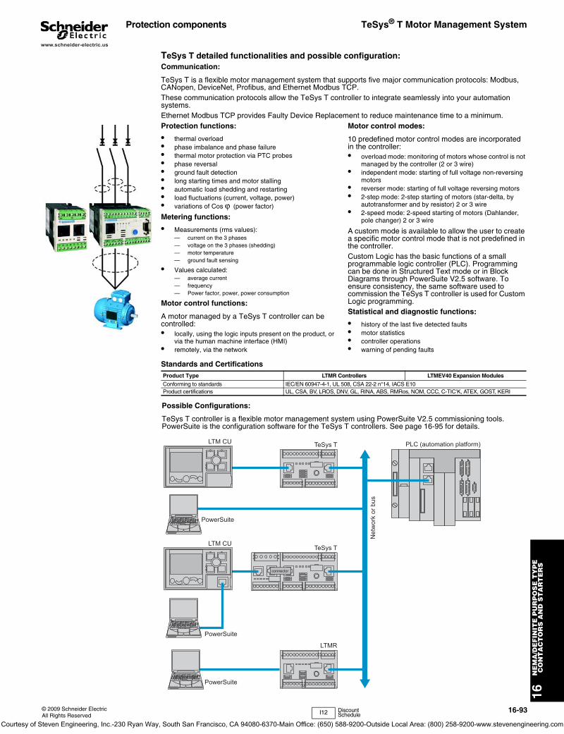
16N
EM
A/D
EF
INIT
E P
UR
PO
SE
TY
PE
CO
NT
AC
TO
RS
AN
D S
TA
RT
ER
S
© 2009 Schneider ElectricAll Rights Reserved
16-93
www.schneider-electric.us
Protection components TeSys® T Motor Management System
Protection functions:
• thermal overload• phase imbalance and phase failure• thermal motor protection via PTC probes• phase reversal• ground fault detection• long starting times and motor stalling• automatic load shedding and restarting• load fluctuations (current, voltage, power)• variations of Cos ϕ (power factor)
Metering functions:
• Measurements (rms values):— current on the 3 phases— voltage on the 3 phases (shedding)— motor temperature— ground fault sensing
• Values calculated:— average current— frequency— Power factor, power, power consumption
Motor control functions:
A motor managed by a TeSys T controller can be controlled:• locally, using the logic inputs present on the product, or
via the human machine interface (HMI)• remotely, via the network
Motor control modes:
10 predefined motor control modes are incorporated in the controller:• overload mode: monitoring of motors whose control is not
managed by the controller (2 or 3 wire)• independent mode: starting of full voltage non-reversing
motors• reverser mode: starting of full voltage reversing motors• 2-step mode: 2-step starting of motors (star-delta, by
autotransformer and by resistor) 2 or 3 wire• 2-speed mode: 2-speed starting of motors (Dahlander,
pole changer) 2 or 3 wire
A custom mode is available to allow the user to create a specific motor control mode that is not predefined in the controller.Custom Logic has the basic functions of a small programmable logic controller (PLC). Programming can be done in Structured Text mode or in Block Diagrams through PowerSuite V2.5 software. To ensure consistency, the same software used to commission the TeSys T controller is used for Custom Logic programming.Statistical and diagnostic functions:
• history of the last five detected faults• motor statistics• controller operations• warning of pending faults
Standards and CertificationsProduct Type LTMR Controllers LTMEV40 Expansion Modules
Conforming to standards IEC/EN 60947-4-1, UL 508, CSA 22-2 n°14, IACS E10Product certifications UL, CSA, BV, LROS, DNV, GL, RINA, ABS, RMRos, NOM, CCC, C-TIC’K, ATEX, GOST, KERI
I12 Discount Schedule
TeSys T detailed functionalities and possible configuration:Communication:
TeSys T is a flexible motor management system that supports five major communication protocols: Modbus, CANopen, DeviceNet, Profibus, and Ethernet Modbus TCP.These communication protocols allow the TeSys T controller to integrate seamlessly into your automation systems.Ethernet Modbus TCP provides Faulty Device Replacement to reduce maintenance time to a minimum.
Possible Configurations:
TeSys T controller is a flexible motor management system using PowerSuite V2.5 commissioning tools. PowerSuite is the configuration software for the TeSys T controllers. See page 16-95 for details.
LTM CU TeSys T
TeSys T
LTMR
PowerSuite
LTM CU
PowerSuite
PowerSuite
connector
PLC (automation platform)
Net
wor
k or
bus
Courtesy of Steven Engineering, Inc.-230 Ryan Way, South San Francisco, CA 94080-6370-Main Office: (650) 588-9200-Outside Local Area: (800) 258-9200-www.stevenengineering.com
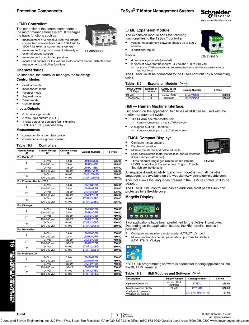
16N
EM
A/D
EF
INIT
E P
UR
PO
SE
TY
PE
CO
NT
AC
TO
RS
AN
D S
TA
RT
ER
S
16-94 © 2009 Schneider ElectricAll Rights Reserved
www.schneider-electric.us
LTMR Controller:The controller is the central component in the motor management system. It manages the basic functions such as:• measurement of 3-phase current via integral
current transformers from 0.4 to 100 A (up to 1000 A by external current transformers)
• measurement of ground current internally or external ground sensors
• measurement of motor temperature • inputs and outputs for the various motor control modes, detected fault
management, and other functions
CharacteristicsAs standard, the controller manages the following:Control Modes
• overload mode• independent mode• reverser mode• 2-speed mode• 2-step mode• Custom mode
Inputs/Outputs
• 6 discrete logic inputs• 3 relay logic outputs (1 N.O.)• 1 relay output for detected fault signalling
(1 N.O. + 1 N.C.) overload relay
Measurements
• connection for a thermistor probe• connections for a ground sensor
LTME Expansion Module:The expansion module adds the following functionalities to the TeSys T controller:• voltage measurement between phases up to 690 V
nominal• 4 additional inputs
Inputs
• 4 discrete logic inputs (isolated)• 2 types of power for the inputs: 24 Vdc and 100 to 240 Vac
— A 24 Vdc LTMR controller can be assembled with a 240 Vac expansion module and vice versa
The LTMVE must be connected to the LTMR controller by a connecting cable.
HMI — Human Machine Interface:Depending on the application, two types of HMI can be used with the motor management system.• The LTMCU operator control unit:
— Control/monitoring of a 1 to 1 LTMR controller
• A Magelis XBTN410 terminal— Control/monitoring of 1 to 8 LTMR controllers
LTMCU Compact Display:• Configure the parameters• Display information• Monitor the alarms and detected faults• Local control of the motor via the local control interface
(keys can be customized)• Three different languages can be loaded into the
LTMCU controller at the same time: English, French, Spanish are the defaults.
A language download utility (LangTool), together with all the other languages, are available on the website www.schneider-electric.com.This tool allows the languages present in the LTMCU control until to be adapted.The LTMCU HMI control unit has an additional front panel RJ45 port, protected by a flexible cover.
Magelis Display:
Two applications have been predefined for the TeSys T controller. Depending on the application loaded, the HMI terminal makes it possible to:• Configure and monitor a motor starter (LTM_1T1_V1.dop)• Monitor and modify certain parameters up to 8 motor starters
(LTM_1T8_X_V1.dop)
XBTL1000 programming software is needed for loading applications into the XBT HMI terminal.
Table 16.1: ControllersSetting Range
(A)Control Voltage
(V)Current Range
(A) Catalog Number $ Price
For Modbus®
824 Vdc 0.4–8 LTMR08MBD 675.00
100–240 Vac 0.4–8 LTMR08MFM 675.00
2724 Vdc 1.35–27 LTMR27MBD 675.00
100–240 Vac 1.35–27 LTMR27MFM 675.00
10024 Vdc 5–100 LTMR100MBD 765.00
100–240 Vac 5–100 LTMR100MFM 765.00
For EtherNet Modbus TCP
824 Vdc 0.4–8 LTMR08EBD 825.00
100–240 Vac 0.4–8 LTMR08EFM 825.00
2724 Vdc 1.35–27 LTMR27EBD 825.00
100–240 Vac 1.35–27 LTMR27EFM 825.00
10024 Vdc 5–100 LTMR100EBD 935.00
100–240 Vac 5–100 LTMR100EFM 935.00
For CANopen
824 Vdc 0.4–8 LTMR08CBD 750.00
100–240 Vac 0.4–8 LTMR08CFM 750.00
2724 Vdc 1.35–27 LTMR27CBD 750.00
100–240 Vac 1.35–27 LTMR27CFM 750.00
10024 Vdc 5–100 LTMR100CBD 850.00
100–240 Vac 5–100 LTMR100CFM 850.00
For DeviceNet
824 Vdc 0.4–8 LTMR08DBD 750.00
100–240 Vac 0.4–8 LTMR08DFM 750.00
2724 Vdc 1.35–27 LTMR27DBD 750.00
100–240 Vac 1.35–27 LTMR27DFM 750.00
10024 Vdc 5–100 LTMR100DBD 850.00
100–240 Vac 5–100 LTMR100DFM 850.00
For Probibus DP
824 Vdc 0.4–8 LTMR08PBD 750.00
100–240 Vac 0.4–8 LTMR08PFM 750.00
2724 Vdc 1.35–27 LTMR27PBD 750.00
100–240 Vac 1.35–27 LTMR27PFM 750.00
10024 Vdc 5–100 LTMR100PBD 850.00
100–240 Vac 5–100 LTMR100PFM 850.00
LTMR08MBD
Table 16.2: Expansion Module Input Control
VoltageNumber of
InputsSupply to the Electronics Catalog Number $ Price
24 Vdc 4 via the LTMR controller
LTMEV40BD 300.00100–240 Vac 4 LTMEV40FM 300.00
Table 16.3: HMI Modules and Software Description Supply Voltage Catalog Number $ Price
Operator Control unit via the LTMR controller LTMCU 265.00
Magelis compact display 24 Vdc XBTN410 300.00Configuration software Windows 99, 2000, XP VJD SND TMS V11M 161.00
LTMEV40BD
New!
LTMCU
New!
I12 Discount Schedule
Protection Components TeSys® T Motor Management System
Courtesy of Steven Engineering, Inc.-230 Ryan Way, South San Francisco, CA 94080-6370-Main Office: (650) 588-9200-Outside Local Area: (800) 258-9200-www.stevenengineering.com
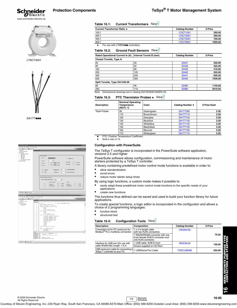
16N
EM
A D
EF
INIT
E P
UR
PO
SE
TY
PE
C
ON
TA
CT
OR
S A
ND
ST
AR
TE
RS
© 2009 Schneider ElectricAll Rights Reserved
16-95
www.schneider-electric.us
Protection Components TeSys® T Motor Management System
a For use with LTMR08●● controllers.
Note: Dimensional drawings are in catalog DIA1ED2061002EN-US.
b PTC: Positive Temperature Coefficient.c Sold in lots of 10.
Configuration with PowerSuite
The TeSys T configurator is incorporated in the PowerSuite software application, versions 2.5 and higher.PowerSuite software allows configuration, commissioning and maintenance of motor starters protected by a TeSys T controller. A library containing predefined motor control mode functions is available in order to:• allow standardization• avoid errors• reduce motor starter setup times
By using logic functions, a custom mode makes it possible to:• easily adapt these predefined motor control mode functions to the specific needs of your
applications• create new functions
The functions thus defined can be saved and used to build your function library for future applications.To create special functions, a logic editor is incorporated in the configurator and allows a choice of 2 programming languages:• function block• structured textA
Table 16.1: Current Transformers Current Transformer Ratio a Catalog Number $ Price
100:1 LT6CT1001 300.00200:1 LT6CT2001 300.00400:1 LT6CT4001 700.00800:1 LT6CT8001 1000.00
Table 16.2: Ground Fault Sensors Rated Operational Current le (A) Internal Toroid Ø (mm) Catalog Number $ Price
Closed Toroids, Type A
65 30 50437 250.0085 50 50438 325.00160 80 50439 410.00250 120 50440 555.00400 200 50441 835.00630 300 50442 1530.00
Split Toroids, Type OA1530.00
85 46 50485 1145.00250 110 50486 2010.00
Table 16.3: PTC Thermistor Probes b
DescriptionNominal Operating Temperature (NOT) °C
Color Catalog Number c $ Price Each
Triple Probes 90 Green/green DA1TT090 3.30110 Brown/brown DA1TT110 3.30120 Grey/grey DA1TT120 3.30130 Blue/blue DA1TT130 3.30140 White/blue DA1TT140 3.30150 Black/black DA1TT150 3.30160 Blue/red DA1TT160 3.30170 White/green DA1TT170 3.30
Table 16.4: Configuration Tools Description Composition Catalog Number $ Price
Connection kit for PC serial port for Modbus® PLC multidrop connection
1 x 3 m length cable with two RJ45 connectors
VW3A8106
75.001 RS232/RS485 converter with one 9-pin female SUB-D connector and one RJ45 connector.
Interface for USB port (for use with cable W3A8106) Length: 1.8 m
1 USB cable, SUB-D 9-pin SR2CBL06 156.00Drivers supplied on CD-Rom
USB serial port cable for connecting a TeSys T controller to your PC 1 USB/Serial Port Cable TXSCUSB485 250.00
LT6CT4001
DA1TT●●●
New!
New!
New!
New!
I12 Discount Schedule
Courtesy of Steven Engineering, Inc.-230 Ryan Way, South San Francisco, CA 94080-6370-Main Office: (650) 588-9200-Outside Local Area: (800) 258-9200-www.stevenengineering.com
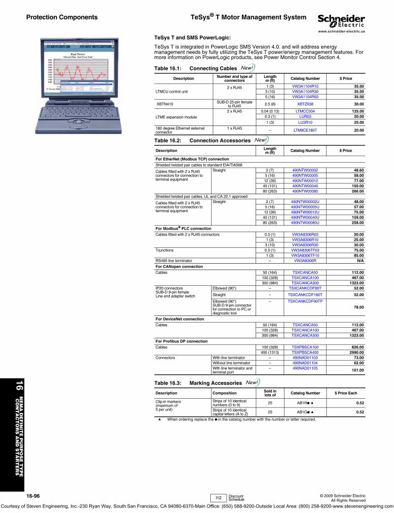
16N
EM
A D
EF
INIT
E P
UR
PO
SE
TY
PE
C
ON
TA
CT
OR
S A
ND
ST
AR
TE
RS
16-96 © 2009 Schneider ElectricAll Rights Reserved
www.schneider-electric.us
Protection Components TeSys® T Motor Management System
TeSys T and SMS PowerLogic:
TeSys T is integrated in PowerLogic SMS Version 4.0. and will address energy management needs by fully utilizing the TeSys T power/energy management features. For more information on PowerLogic products, see Power Monitor Control Section 4.
a When ordering replace the ● in the catalog number with the number or letter required.
Table 16.1: Connecting Cables
Description Number and type of connectors
Length m (ft) Catalog Number $ Price
LTMCU control unit2 x RJ45 1 (3) VW3A1104R10 35.00
3 (10) VW3A1104R30 35.005 (16) VW3A1104R50 35.00
XBTN410 SUB-D 25-pin femaleto RJ45 2.5 (8) XBTZ938 30.00
LTME expansion module
2 x RJ45 0.04 (0.13) LTMCC004 125.000.3 (1) LUR03 20.00
1 (3) LU3R10 25.00
180 degree Ethernet external connector
1 x RJ45 – LTM9CE180T 20.00
Table 16.2: Connection Accessories
Description Length m (ft) Catalog Number $ Price
For EtherNet (Modbus TCP) connection
Shielded twisted pair cables to standard EIA/TIA568
Cables fitted with 2 x RJ45 connectors for connection to terminal equipment
Straight 2 (7) 490NTW00002 48.605 (16) 490NTW00005 58.0012 (39) 490NTW00012 77.0040 (131) 490NTW00040 150.0080 (263) 490NTW00080 266.00
Shielded twisted pair cables, UL and CA 22.1 approved
Cables fitted with 2 x RJ45 connectors for connection to terminal equipment
Straight 2 (7) 490NTW00002U 48.005 (16) 490NTW00005U 57.0012 (39) 490NTW00012U 75.0040 (131) 490NTW00040U 159.0080 (263) 490NTW00080U 258.00
For Modbus® PLC connection
Cables fitted with 2 x RJ45 connectors 0.3 (1) VW3A8306R03 20.001 (3) VW3A8306R10 25.003 (10) VW3A8306R30 30.00
T-junctions 0.3 (1) VW3A8306TF03 75.001 (3) VW3A8306TF10 85.00
RS485 line terminator – VW3A8306R N/A
For CANopen connection
Cables 50 (164) TSXCANCA50 112.00100 (328) TSXCANCA100 467.00300 (984) TSXCANCA300 1323.00
IP20 connectors SUB-D 9-pin female Line end adapter switch
Elbowed (90°) – TSXCANKCDF90T 52.00
Straight – TSXCANKCDF180T 52.00
Elbowed (90°) SUB-D 9-pin connector for connection to PC or diagnostic tool
– TSXCANKCDF90TP
78.00
For DeviceNet connection
Cables 50 (164) TSXCANCA50 112.00100 (328) TSXCANCA100 467.00300 (984) TSXCANCA300 1323.00
For Profibus DP connection
Cables 100 (328) TSXPBSCA100 826.00400 (1313) TSXPBSCA400 2990.00
Connectors With line terminator – 490NAD01103 73.00Without line terminator – 490NAD01104 62.00With line terminator and terminal port
– 490NAD01105 101.00
Table 16.3: Marking Accessories
Description Composition Sold in lots of Catalog Number $ Price Each
Clip-in markers(maximum of5 per unit)
Strips of 10 identical numbers (0 to 9) 25 AB1R● a 0.52
Strips of 10 identical capital letters (A to Z) 25 AB1G● a 0.52
New!
New!
New!
I12 Discount Schedule
Courtesy of Steven Engineering, Inc.-230 Ryan Way, South San Francisco, CA 94080-6370-Main Office: (650) 588-9200-Outside Local Area: (800) 258-9200-www.stevenengineering.com
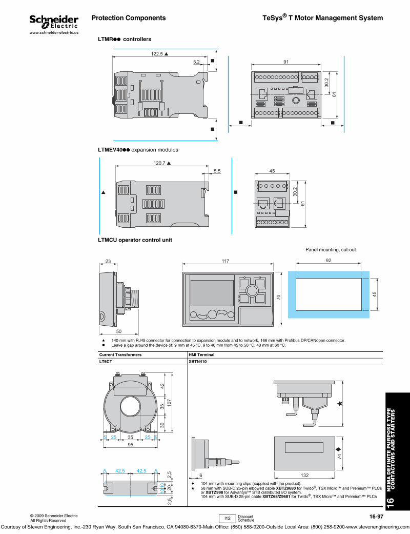
16N
EM
A D
EF
INIT
E P
UR
PO
SE
TY
PE
C
ON
TA
CT
OR
S A
ND
ST
AR
TE
RS
© 2009 Schneider ElectricAll Rights Reserved
16-97
www.schneider-electric.us
Protection Components TeSys® T Motor Management System
LTMR●● controllers
LTMEV40●● expansion modules
LTMCU operator control unit
a 140 mm with RJ45 connector for connection to expansion module and to network, 166 mm with Profibus DP/CANopen connector.b Leave a gap around the device of: 9 mm at 45 °C, 9 to 40 mm from 45 to 50 °C, 40 mm at 60 °C.
Current Transformers HMI Terminal
LT6CT XBTN410
c 104 mm with mounting clips (supplied with the product).d 58 mm with SUB-D 25-pin elbowed cable XBTZ9680 for Twido®, TSX Micro™ and Premium™ PLCs
or XBTZ998 for Advantys™ STB distributed I/O system. 104 mm with SUB-D 25-pin cable XBTZ68/Z9681 for Twido®, TSX Micro™ and Premium™ PLCs
5.2 91122.5 ▲
6130
.2
■
■
■ ■
5.5 45120.7 ▲
6130
.2
▲ ■
23
50
117
70
92
45
Panel mounting, cut-out
2,5
35255 52595
35 107
3042
1010
2,5
20
42,5 42,55 5132
74 c
6
d
I12 Discount Schedule
Courtesy of Steven Engineering, Inc.-230 Ryan Way, South San Francisco, CA 94080-6370-Main Office: (650) 588-9200-Outside Local Area: (800) 258-9200-www.stevenengineering.com
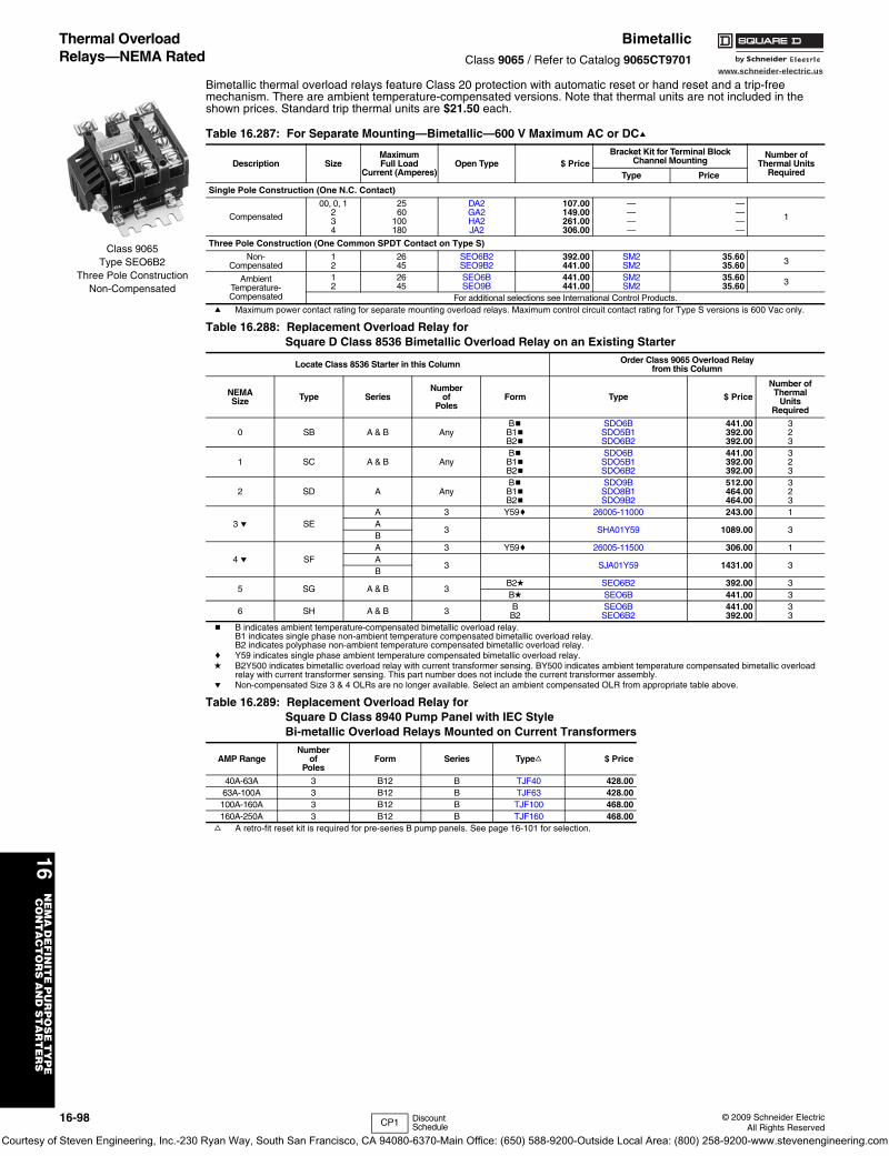
16-98 © 2009 Schneider ElectricAll Rights Reserved
www.schneider-electric.us
16N
EM
A D
EF
INIT
E P
UR
PO
SE
TY
PE
C
ON
TA
CT
OR
S A
ND
ST
AR
TE
RS
Thermal Overload Relays—NEMA Rated
BimetallicClass 9065 / Refer to Catalog 9065CT9701
Bimetallic thermal overload relays feature Class 20 protection with automatic reset or hand reset and a trip-free mechanism. There are ambient temperature-compensated versions. Note that thermal units are not included in the shown prices. Standard trip thermal units are $21.50 each.
a Maximum power contact rating for separate mounting overload relays. Maximum control circuit contact rating for Type S versions is 600 Vac only.
b B indicates ambient temperature-compensated bimetallic overload relay.B1 indicates single phase non-ambient temperature compensated bimetallic overload relay.B2 indicates polyphase non-ambient temperature compensated bimetallic overload relay.
c Y59 indicates single phase ambient temperature compensated bimetallic overload relay.d B2Y500 indicates bimetallic overload relay with current transformer sensing. BY500 indicates ambient temperature compensated bimetallic overload
relay with current transformer sensing. This part number does not include the current transformer assembly.e Non-compensated Size 3 & 4 OLRs are no longer available. Select an ambient compensated OLR from appropriate table above.
f A retro-fit reset kit is required for pre-series B pump panels. See page 16-101 for selection.
Table 16.287: For Separate Mounting—Bimetallic—600 V Maximum AC or DCa
Description SizeMaximumFull Load
Current (Amperes)Open Type $ Price
Bracket Kit for Terminal Block Channel Mounting
Number ofThermal Units
RequiredType Price
Single Pole Construction (One N.C. Contact)
Compensated
00, 0, 1 25 DA2 107.00 — —
12 60 GA2 149.00 — —3 100 HA2 261.00 — —4 180 JA2 306.00 — —
Three Pole Construction (One Common SPDT Contact on Type S)
Non-Compensated
12
2645
SEO6B2SEO9B2
392.00441.00
SM2SM2
35.6035.60 3
AmbientTemperature-Compensated
12
2645
SEO6BSEO9B
441.00441.00
SM2SM2
35.6035.60 3
For additional selections see International Control Products.
Table 16.288: Replacement Overload Relay forSquare D Class 8536 Bimetallic Overload Relay on an Existing Starter
Locate Class 8536 Starter in this Column Order Class 9065 Overload Relayfrom this Column
NEMASize Type Series
Numberof
PolesForm Type $ Price
Number ofThermal
UnitsRequired
0 SB A & B AnyBbB1bB2b
SDO6BSDO5B1SDO6B2
441.00392.00392.00
323
1 SC A & B AnyBbB1bB2b
SDO6BSDO5B1SDO6B2
441.00392.00392.00
323
2 SD A AnyBbB1bB2b
SDO9BSDO8B1SDO9B2
512.00464.00464.00
323
3 e SEA 3 Y59c 26005-11000 243.00 1A
3 SHA01Y59 1089.00 3B
4 e SFA 3 Y59c 26005-11500 306.00 1A
3 SJA01Y59 1431.00 3B
5 SG A & B 3B2d SEO6B2 392.00 3Bd SEO6B 441.00 3
6 SH A & B 3 BB2
SEO6BSEO6B2
441.00392.00
33
Table 16.289: Replacement Overload Relay forSquare D Class 8940 Pump Panel with IEC Style Bi-metallic Overload Relays Mounted on Current Transformers
AMP RangeNumber
ofPoles
Form Series Typef $ Price
40A-63A 3 B12 B TJF40 428.0063A-100A 3 B12 B TJF63 428.00100A-160A 3 B12 B TJF100 468.00160A-250A 3 B12 B TJF160 468.00
Class 9065Type SEO6B2
Three Pole ConstructionNon-Compensated
CP1 Discount Schedule
Courtesy of Steven Engineering, Inc.-230 Ryan Way, South San Francisco, CA 94080-6370-Main Office: (650) 588-9200-Outside Local Area: (800) 258-9200-www.stevenengineering.com
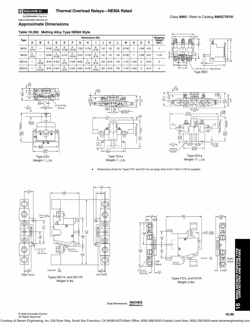
www.schneider-electric.us
16N
EM
A D
EF
INIT
E P
UR
PO
SE
TY
PE
C
ON
TA
CT
OR
S A
ND
ST
AR
TE
RS
© 2009 Schneider ElectricAll Rights Reserved
16-99
Thermal Overload Relays—NEMA RatedClass 9065 / Refer to Catalog 9065CT9701
Approximate Dimensions
Table 16.290: Melting Alloy Type NEMA Style
TypeDimensions (IN) Shipping
Weight(lbs.)A B C D E F G H I J K L M N O P
SEO5 3-5/16 — 15/32 3-
31/323-
17/322-
13/16 7/32 11/16 2-5/16 1/2 1/2 1/2 27/32 1 1-3/8 #10 1
SEO8 3-5/16 — 15/32 3-
31/32 3-1/2 2-13/16 3/16 11/16 2-
5/16 1/2 1/2 1/8 27/32 1 1-3/8 #10 1-1/4
SEO12 — 5-19/32 9/16 5-3/4 5-
5/16 4-3/4 9/32 1-7/16
3-9/16 3/4 9/16 7/8 1-1/2 1-3/4 2 #1/4 3
SEO15 — 6-31/32 9/16 5-3/4 5-
5/16 4-3/4 9/32 2-1/8 3-9/16 3/4 9/16 7/8 1-1/2 1-3/4 2 #1/4 4
EF G
K
H
I
J
ML
N
O
CD
A
B
Prov for (4) - p - Mtg Screws
Type SEO
.287.1
.6917.5
1.3434
.256.4
0.512.7
(2) 8-32 Mtg Screws
.4110.4
3.2582.5
ResetTravel
Trip
ped
2.7569.8
2.9374.4
Type CO1Weight–1⁄ 2 Lb.
0.317.9
0.6616.8
RESET
0.225.6 .44
11
1.38
35
Ove
r The
rmal
Uni
t
(2) 3/16 DiaMtg Holes
4.75
120.7
0.389.7
3.2582.5
Trip
ped
Res
et T
rave
l
0.94
23.9
2.7569.8
Type TO1aWeight–1⁄ 2 Lb.
.276.86
.7519.77
19.6
RESET
.287
.615.2
6.19157.23
0.225.59
2.050.8
Ove
r The
rmal
U
nit
0.389.65
3.2582.5
Res
et T
rave
l
Trip
ped
0.1253.18
1.0 1.025.4 25.4
2.7569.85
0.9423.8
(2) 516
Dia
Locating
Dowels
Type UO1aWeight–11⁄ 2 Lb.
1.0627 4.06
103
0.4411
ResetTravel
3.13
79
1.5640
1.0025
Right Hand
Prov for (3) 1/4 - 20Mtg Screws 2.63
67
3.8898
9.13232
Alarm O.L. Com.
TerminalConnections
1.00
25
2.1354
1.0627
Left Hand
Dual DimIn.mm
Types GO11L and GO11RWeight–5 lbs.
1.4136
0.3810
3.0276
6.03153
1.8146
1.8146
RESET
0.4712
Prov for(3)#10-24Mtg Screws
LeftHand
TerminalConnections
0.4411
ResetTravel
Dual DimIn
mmCom O.L.
Alarm
RESET
0.4712
RightHand
1.4136
4.94125
Types FO1L and FO1RWeight–2 lbs.
a Dimensions shown for Types TO1 and UO1 do not apply when Form Y342 or Y34 is supplied.
Courtesy of Steven Engineering, Inc.-230 Ryan Way, South San Francisco, CA 94080-6370-Main Office: (650) 588-9200-Outside Local Area: (800) 258-9200-www.stevenengineering.com

www.schneider-electric.us
16N
EM
A D
EF
INIT
E P
UR
PO
SE
TY
PE
C
ON
TA
CT
OR
S A
ND
ST
AR
TE
RS
16-100 © 2009 Schneider ElectricAll Rights Reserved
Thermal Overload Relays—NEMA RatedClass 9065 / Refer to Catalog 9065CT9701
Approximate Dimensions
Bimetallic Overload Relays
Note: Dimensions shown in inches.
Motor Logic® Solid State Overload Relay
Table 16.291:
Class9065
AmpereRating
Outline Dimensions Mtg. Dimensions
Reset Dimensions
Mtg. Screw Max. Wire Size
Approx. Shipping
Weight (lbs)A B C D E K L G
DA 25 3-1/2 7/8 3-3/16 3 1/2 3/8 1/8 10 8 2
GA 60 4-7/8 7/8 3-3/16 3 1/2 3/8 1/8 10 1 2
HA 100 4-7/8 1-1/4 3-3/16 3-1/2 1/16 1/2 1/8 10 00 3
JA 180 5-15/16 1-1/4 3-3/16 3-1/2 1/2 3/16 1/8 10 250 MCM 4
3.7595 2.81
71.5013
3.5991
2.3058
.062
1.0025
.8923
3.94100Prov. for (4)
#10 Mtg. Screws
Reset
.318
Reset Travel.318
.8020
Types SEO6B and SEO6B2Weight—1 Lb.
Reset
3.5089 2.81
71.5013
.062
1.0025
.8923 Prov. for (4)
#10 Mtg. Screws
3.94100
.318
Reset Travel
3.3485
2.3058
.318
.8020
Types SEO9B and SEO9B2Weight—11⁄ 4 Lb.
C
J
A D
LReset Travel
G(2 Holes)
KE
B
RESET
(2) Holes and (2) Slotsfor 8-32 Mtg. Screws
.246
Reset Travel3.9099
2.6968
2.2357
1.0025
3.2683
1.5940
.369
.8923
.318
.277 .28
7
2.8171
NEMA Size 00B, 00C, 0, and 1 DevicesNote: NEMA Size 00B and 00C are not actual NEMA sizes. These designations are used to differentiate the lower FLA of these devices from the NEMA size 00 Motor Logic Solid State Overload Relay.
RESET
4.28109
1.7043
1.8447
2.1956
3.2482
3.5189
1.2431
1.2431
3.9199
.246
Reset Travel
Size 2 Devices
RESET
3.5690
2.2657
1.0827
.308
1.5740
1.5740
5.33135
.3810
2.9675
1.5038
.297
3.2583
4.74120
5.32135
.328
3.8097
4.16106
5.02128
4.45113
.318
.246
Reset Travel
Size 3 Devices
RESET
.328
3.8097
4.16106
5.92150
4.53115
.318
3.5690
2.2657
1.0827
.308
5.33135
1.5740
1.5740
.3810
2.9675
1.5038
.297
3.2583
4.74120
5.32135
.246
Reset Travel
Size 4 Devices
Courtesy of Steven Engineering, Inc.-230 Ryan Way, South San Francisco, CA 94080-6370-Main Office: (650) 588-9200-Outside Local Area: (800) 258-9200-www.stevenengineering.com
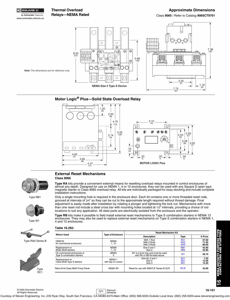
www.schneider-electric.us
16N
EM
A D
EF
INIT
E P
UR
PO
SE
TY
PE
C
ON
TA
CT
OR
S A
ND
ST
AR
TE
RS
© 2009 Schneider ElectricAll Rights Reserved
16-101
Thermal Overload Relays—NEMA Rated
Approximate DimensionsClass 9065 / Refer to Catalog 9065CT9701
Motor Logic® Plus—Solid State Overload Relay
External Reset MechanismsClass 9066
Type RA kits provide a convenient external means for resetting overload relays mounted in control enclosures of almost any depth. Designed for use on NEMA 1, 4 or 12 enclosures, they can be used with any Square D open type magnetic starter or Class 9065 overload relay. All kits are individually packaged for easy stocking and include complete installation instructions.Only a single mounting hole is required in the enclosure door. Each kit contains one or more threaded reset rods, grooved at intervals of 3/4" so they can be cut to the approximate length required without thread damage. Final adjustment is easily made after installation by rotating a plunger and tightening the lock nut. Mechanisms with more than one reset rod include a steel cross bar with mounting holes located at 1/2" intervals, providing a choice of rod locations to suit any application. All steel parts are electrically isolated from the enclosure and the operator.
Type RB kits make it possible to field install external reset mechanisms to Type S combination starters in NEMA 12 enclosures. They may also be used to replace external reset mechanisms on Type S combination starters in NEMA 1, 4 and 12 enclosures.
LISTEDIND.CONT.EQ.A159
TRIP=125%
CLASS10
FLA
31161-184-51SERIES B
90
120150
180
A600P300
AC 3 Ph
50-60HZ
TRIP
PWR
210
270
MADE IN USA
SQUARE D COMPANY
8.25
2105.88
149
7.38
187
2.25
571.18
307.75
197
NEMA Size 5 Type S Device
Note: The dimensions are for reference only.
1.2030
2.2056
2.1454
3.1079
2.0352
2.2858
2.6567
3.0577
.7018
.256
3.6091
3.8598
4.37111
4.70119
5.05128
.205
.349
MOTOR LOGIC Plus
Table 16.292:
Where Used Type of EnclosureReset Mechanism Kit
Description Type $ Price
OEM Kitfor commercial enclosures
NEMA1, 12
With 1 RodWith 2 RodsWith 3 Rods
RA1RA2RA3
57.0071.0086.00
Replacement on8538, 8539 starters
NEMA1, 12
Size 0 and 1Size 2
RB1RB2
42.8042.80
On commercial enclosures orType S combination starters
NEMA4
W1 is a boot only and must be used with RA or RB Kit listed above W1 28.70
Replacement onClass 8536 Type S starters
NEMA 1with slip-on covers
Size 00, 0 and 1Size 2Size 3
SC1SD1SE1
7.2012.0014.30
Retro-fit kit Class 8940 Pump Panel NEMA 3R Reset for use with 9065TJF Series B OLR RTJF 42.80
Type RB1
Type W1
Type RA2 Series B
Type SC1
CP1 Discount Schedule
Courtesy of Steven Engineering, Inc.-230 Ryan Way, South San Francisco, CA 94080-6370-Main Office: (650) 588-9200-Outside Local Area: (800) 258-9200-www.stevenengineering.com
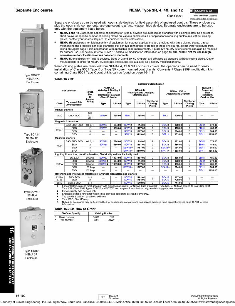
16-102 © 2009 Schneider ElectricAll Rights Reserved
www.schneider-electric.us
16N
EM
A D
EF
INIT
E P
UR
PO
SE
TY
PE
C
ON
TA
CT
OR
S A
ND
ST
AR
TE
RS
Separate Enclosures NEMA Type 3R, 4, 4X, and 12Class 9991
Separate enclosures can be used with open style devices for field assembly of enclosed controls. These enclosures, plus the open style components, are equivalent to a factory-assembled device. Separate enclosures are to be used only with the equipment listed below:• NEMA 4 and 12 Class 9991 separate enclosures for Type S devices are supplied as standard with closing plates. See selection
chart below for specific number of closing plates on Various enclosures. For applications requiring enclosures without closing plates, contact your nearest Square D/Schneider Electric sales office.
• NEMA 3R enclosures for field assembly of equipment for outdoor applications are provided with three closing plates, a reset mechanism and predrilled panel as standard. For conduit connection to the top of these enclosures, select watertight hubs from listing on Digest page 3-9 in accordance with applicable code requirements. Square D’s NEMA 12 enclosures can also be modified for outdoor use. For details, refer to NEMA 12 enclosure modification information on page 16-104. NOTE: Not for use in high-corrosive outdoor locations or sea coast environments.
• NEMA 4X enclosures for Type S devices, Sizes 0–2 and 30–60 Ampere, are provided as standard without closing plates. Cover mounted control units for NEMA 4X separate enclosures are available as a factory modification only.
When closing plates are removed from NEMAs 4, 12 & 3R enclosure covers, the openings can be used for easy installation of Class 9001 Type K or Type SK cover mounted control units. Convenient Class 9999 modification kits containing Class 9001 Type K control kits can be found on page 16-118.
a For contactors, replace reset assembly with proper closing plate; for NEMA 4 use Class 9001 Type K52, for NEMAs 3R and 12 use Class 9001 Type K51. Class 9991 Types SCW20 and SDW20 are designed for contactors only, reset closing plates not required.
b For electrically held devices only.c Enclosure suitable for starter with melting alloy and solid state overload relays only.d The standard cabinet has a brushed finish.e Type MBO, Size MO only.f NEMA 12 enclosures may be field modified for outdoor non-corrosive and non-service-entrance-rated applications; see page 16-104 for more
information.
Table 16.293:
For Use With
Enclosure Classification
NEMASizeor
AmpereRating
NEMA 4XWatertight, Dusttight
and Corrosion-Resistant
Glass-Polyester
NEMA 4dWatertight and Dusttight
Stainless Steel
NEMA 12/3R fDusttight and Driptight
NEMA 3RRainproof,
SleetResistant,
Outdoor Use
Class Types (All Pole Arrangements) Type $ Price Type $ Price
Number ofClosing Plates
Type $ PriceNumber of
Closing Plates
Type $ Price
Manual Starters
2510 MBO, MCOMOM1
M1PMW1e 485.00 MW11 485.00 — MA1 129.00 — — —
Magnetic Contactors
8502a
SAO, SBO, SCO 00, 0, 1 SCW20 684.00 SCW11 714.00 2 SCA11 372.00 2 SCH2 372.00SDO 2 SDW20 1169.00 SDW11 1197.00 2 SDA11 485.00 2 SDH1 485.00SEO 3 — — SEW11 1767.00 3 SEA11 684.00 3 SEH1 684.00SFO 4 — — SFW11 3119.00 3 SFA11 1853.00 3 SFH1 1853.00
Magnetic Starters
8536
SAO, SBO, SCO 00, 0, 1 SCW21 684.00 SCW11 714.00 2 SCA11 372.00 2 SCH2 372.00SDO 2 SDW21 1169.00 SDW11 1197.00 2 SDA11 485.00 2 SDH1 485.00SEO 3 — — SEW11c 1767.00 3 SEA11c 684.00 3 SEH1 684.00SFO 4 — — SFW11c 3119.00 3 SFA11c 1853.00 3 SFH1 1853.00
Lighting Contactors, Non-Combination, Electrically and Mechanically Held
8903a
LO, LXO 20 Amp SDW20 1107.00 SDW11 1197.00 2 SDA11 485.00 2 SDH1 485.00SMO 30 Amp SCW20b 684.00 SCW11 714.00 2 SCA11 372.00 2 SCH2 372.00SPO 60 Amp SCW20b 1169.00 SDW11 1197.00 2 SDA11 485.00 2 SDH1 485.00SQO 100 Amp — — SEW11c 1767.00 3 SEA11c 684.00 3 SEH1 684.00SVO 200 Amp — — — — — — — — SFH1 1853.00
Reversing and Two Speed Horizontally Arranged Contactors and Starters
8702a8736
SBO, SCOSDO
0, 12 — —
—SCW12SDW12
1182.001754.00 3 SCA12
SDA12527.00728.00 3 —
———
8810 SBO & SCO 0, 1 — — SCW13 1610.00 3 SCA13 714.00 3 — —
Table 16.294: How to OrderTo Order Specify: Catalog Number
• Class Number• Type Number
Class Type9991 SCW11
Type SCW21NEMA 4XEnclosure
Type SCA11NEMA 12Enclosure
Type SCW11NEMA 4
Enclosure
Type SCH2NEMA 3REnclosure
CP1 Discount Schedule
Courtesy of Steven Engineering, Inc.-230 Ryan Way, South San Francisco, CA 94080-6370-Main Office: (650) 588-9200-Outside Local Area: (800) 258-9200-www.stevenengineering.com
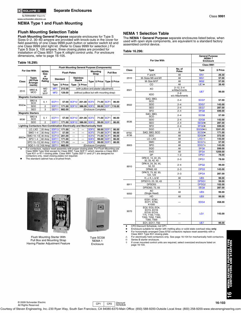
www.schneider-electric.us
16N
EM
A D
EF
INIT
E P
UR
PO
SE
TY
PE
C
ON
TA
CT
OR
S A
ND
ST
AR
TE
RS
© 2009 Schneider ElectricAll Rights Reserved
16-103
Separate EnclosuresClass 9991
NEMA Type 1 and Flush Mounting
Flush Mounting Selection TableFlush Mounting General Purpose separate enclosures for Type S Sizes 0–2, 30–60 ampere are provided with knock-outs in the cover for field assembly of one Class 9999 push button or selector switch kit and one Class 9999 pilot light kit. (Refer to Class 9999 for selection.) For Type S Size 3, 100 ampere, three closing plates are provided for installation of Class 9001 Type K oiltight control units. For enclosure dimensions, refer to page 16-105.
a For contactors, replace reset assembly with proper closing plate. For Flush Mounting use Class 9999 Type SG2 except for Class 9991 Type SDF11 which requires a Class 9001 Type K51 or K11 closing plate. Class 9991 Types SEF11 and LF1 are designed for contactors only, reset closing plates not required.
b The standard cabinet has a brushed finish.
NEMA 1 Selection TableThe NEMA 1 General Purpose separate enclosures listed below, when used with open style components, are equivalent to a standard factory assembled control device.
c CP2 Discount Schedule, not CP1.d Enclosure suitable for starter with melting alloy or solid state overload relay only.e For horizontally arranged Class 8702 contactors replace reset assembly with a
Class 9001 Type K51 closing plate.f For electrically held contactors only. See page 16-104 for mechanically held contactors.g Series B starter enclosure.h If cover mounted control units are required, select oversized enclosure listed on
page 16-104.
Table 16.295:
For Use With NEMASizeor
AmpRating
Flush Mounting General Purpose (Components)
Flush Plates MountingStrap Pull Box
Class
Types(All PoleArrange-ments)
Standard Stainless Steelb Type $ Price Type $ Price
Type $ Price Type $ Price
2510 MBO & MCO
MOM1
M1P
MF1 215.00 (with pullbox and plaster adjustment)
MF2 129.00 (without pullbox but with mounting strap)
Magnetic Contactors
8502a
SBO & SCO 0, 1 SCF11 57.00 SCF12 201.00 SCF2 71.00 SCF1 86.00
SDO 2 SDF11 171.00 SDF12 386.00 SDF2 99.00 SDF1 116.00SEO 3 SEF11 882.00 (Enclosure Complete)
Magnetic Starters
8536SBO & SCO 0, 1 SCF11 57.00 SCF12 201.00 SCF2 71.00 SCF1 86.00
SDO 2 SDF11 171.00 SDF12 386.00 SDF2 99.00 SDF1 86.00
Lighting Contactors Non-Combination Electrically and Mechanically Held
8903a
LO, LXO 20 Amp SDF13 171.00 — — SDF2 99.00 SDF1 86.00SMO 1–4 30 Amp SCF11 57.00 — — SCF2 71.00 SCF1 86.00
SMO 10–13 30 Amp SCF13 201.00 — — SCF2 71.00 SCF1 86.00SPO 1–4 60 Amp SDF11 171.00 — — SDF2 99.00 SDF1 86.00
SPO 10–13 60 Amp SDF13 171.00 — — SDF2 99.00 SDF1 86.00SQO 1–13 100 Amp SEF11 882.00 (Enclosure Complete)
Flush Mounting Starter WithPull Box and Mounting Strap
Having Plaster Adjustment Feature
Table 16.296:
For Use With
General PurposeNEMA 1
Enclosure
Class 9991
Class Type No. ofPoles Type $ Price
2510F and K All EN1 29.30
M–Sizes M0 and M1 All MG1 57.00M–Size M1P All MG2 57.00
8501
CO All UE1c 39.40
XO 2–12, 2–4 w/Attachments
UE7 99.00XDO 2–8
w/o Attachments
8502
SAO, SBO,SCO 2–4 SCG7 57.00
SDO 2–4 SDG7 143.00SEO 2–4 SEG7 287.00SFO 2–4 SFG8 599.00
8536
SAO, SBO,SCO 2–4 SCG8 57.00
SDO 2–4 SDG8 143.00SEO 2–4 SEG8d 287.00SFO 2–4 SFG8d 599.00SGO 3 SGG8dg 1241.00
8702,8736
SAO, SBO, SCO All SCG9e 171.00SDO All SDG9e 372.00
8903
LO, LXO All LXG1h 143.00SMO All SCG7f 57.00SPO All SDG7f 143.00SQO All SFG8 599.00SVO All SFG4 1259.00
8910
DP 1–2 DPG1 78.00DPA12, 13, 22, 23,
32, 33, 42, 43 2–3 DPG1 78.00
DPA14, 24, 34, 44,52, 53 2–4 DPG2 99.00
DPA62, 63 2–3 DPG3 143.00DPA72, 73, 92, 93,
122, 123 2–3 DPG4 287.00
H, J, K, L & M All UE6 99.00
8911DPSO13, 23, 33, 43 3 DPSG1 59.00
DPSO53 3 DPSG2 102.00DPSO63, 73, 93 3 SEG8 287.00
9050AO
(Single Head) All UE6 99.00
HO All UE6 99.00
9070
EO51, EO61,EO71, K750,
K1000— SDG4 458.00
EO2, EO3, EO4,EO15, EO16EO18, EO19,
T75, T100, T150,T200, T250, T300,
T350, T500
— LG1 143.00
EO1, EO17, T50 — UE7 99.00
Type SCG8NEMA 1
Enclosure
CP1 CP2 Discount Schedule
Courtesy of Steven Engineering, Inc.-230 Ryan Way, South San Francisco, CA 94080-6370-Main Office: (650) 588-9200-Outside Local Area: (800) 258-9200-www.stevenengineering.com
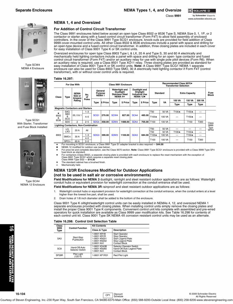
16-104 © 2009 Schneider ElectricAll Rights Reserved
www.schneider-electric.us
16N
EM
A D
EF
INIT
E P
UR
PO
SE
TY
PE
C
ON
TA
CT
OR
S A
ND
ST
AR
TE
RS
Separate Enclosures NEMA Types 1, 4, and OversizeClass 9991
NEMA 1, 4 and Oversized
For Addition of Control Circuit TransformerThe Class 9991 enclosures listed below accept an open type Class 8502 or 8536 Type S, NEMA Size 0, 1, 1P, or 2 contactor or starter along with a fused control circuit transformer (Form F4T) to allow field assembly of enclosed controllers. In the cover of the Class 9991 Type SCG1 enclosure, knock-outs are provided for field addition of Class 9999 cover-mounted control units. All other Class 8502 & 8536 enclosures include a panel with space and drilling for an open-type device and a fused control circuit transformer. In addition, three closing plates are included in each cover for easy installation of Class 9001 Type K or SK control units.Oversized enclosures for open type Class 8903 Type L & LX, 20 A and Type S, 30 and 60 A electrically and mechanically held lighting contactors include a panel with space and drilling for an open- type contactor and fused control circuit transformer (Form F4T) and/or an auxiliary relay for use with single pole pilot devices (Form R6). When an auxiliary relay is required, use a Class 8501 Type XO11 relay. Three closing plates are provided as standard for easy installation of Class 9001 Type K or SK control units. Note: A Class 9991 Type SCG1 NEMA 1 separate enclosure can also be used for Class 8903 Type SMO, 30 A electrically held lighting contactor if Form F4T (control transformer), with or without cover control units is required.
a For mounting in SCG1 enclosure, a Class 9991 Type S1 adapter bracket is also required — $44.00b NEMA 12 modified for outdoor use (see below).c For price list and complete description, see the Class 9070 section. Note: Class 9991 Type SCG1 enclosure is provided with a Class 9999 Type SF4
fuse block as standard.d For contactors (Class 8502), a separate closing plate is provided with each enclosure to replace the reset mechanism with the exception of
Class 9991 Type SCG1 which requires a separate reset closing plate Class 9999 Type SG2 — $14.30
e The standard cabinet has a brushed finish.f Mechanically held.
NEMA 12/3R Enclosures Modified for Outdoor Applications(not to be used in salt air or corrosive environments)Field Modifications for NEMA 3 dusttight, raintight and sleet resistant outdoor applications are as follows: Watertight conduit hubs or equivalent provision for watertight connection at the conduit entrance shall be used.Field Modifications for NEMA 3R rainproof and sleet resistant outdoor applications are as follows:1. Watertight conduit hubs or equivalent provision for watertight connection at the conduit entrance, when the conduit enters at a level
higher than the lowest live part, shall be used.2. Drain holes of 1/8 inch diameter shall be added to the bottom of the enclosure.
Class 9001 Type K oiltight/watertight control units can be easily installed in NEMAs 4, 12, and oversized NEMA 1 separate enclosures provided with closing plates. When installing control units simply remove the closing plates and install the proper Class 9001 Type K components. Convenient control unit kits complete with assembled and pre-wired operators for quick installation are available as Class 9999 user modification kits. See Table 16.298 for contents of each control unit kit. Class 9001 Type SK NEMA 4X corrosion resistant control units may be used as an alternate.
Table 16.297:
For Use With Class 9991 Enclosure Recommended Class 9070cTransformer Selection
FuseBlock
Class Type
NEMASize orAmpereRating
No.of
Poles
GeneralPurposeNEMA 1
Watertight andDusttight
Stainless SteelNEMA 4e
Dusttight andDriptight
Industrial UseNEMA 12b
Standard Extra Capacity
Type $ Price Type $ Price Type $ Price Type VA100 VA 150 VA 300 VA
Type Type Type
Magnetic Contactors and Starters
d8502
&8536
SAO,SBO
&SCO
00, 0 & 1
1–3
SCG1 270.00 SCW4 827.00 SCA4 485.00
T50 50 VA T100a T150a —
Class9999TypeSFR4
4–5 T100a 100 VA — T150a —
SDO 2 2–5 SDG4 458.00 SDW4 1488.00 SDA4 705.00 T100 100 VA — T150 T300
Lighting Contactors, Non-Combination
8903
LO,LXO 20 A All
SDG3 399.00 SDW3 1169.00 SDA3 684.00
T50 50 VA — — —T50 50 VA T100a T150a —
SMOf 30 A1–3 T100a 100 VA — T150a —4–5
T100 100 VA — T150 T300SPOf 60 A 2–5
Table 16.298: Control Unit Selection TableClass 9999Type
Control FunctionKit Contents
Class & Type Description
SA3 Start-StopPushbutton
1-9001 KR1B1-9001 KR1R1-9001 KN2011-9001 KN2022-9001 KA1
Start OperatorStop OperatorStart Legend PlateStop Legend PlateContact Block
SC8 Hand-Off-AutoSelector Switch
1-9001 KS43B1-9001 KN2601-9001 KA1
Selector Operator SwitchHand-Off-Auto Legend PlateContact Block
SP28R Pilot Light(120 V) 1-9001 KP1R31 Red Pilot Light
Type SCW4NEMA 4 Enclosure
Type SCG1With Starter, Transformerand Fuse Block Installed
Type SCA4NEMA 12 Enclosure
CP1 Discount Schedule
Courtesy of Steven Engineering, Inc.-230 Ryan Way, South San Francisco, CA 94080-6370-Main Office: (650) 588-9200-Outside Local Area: (800) 258-9200-www.stevenengineering.com
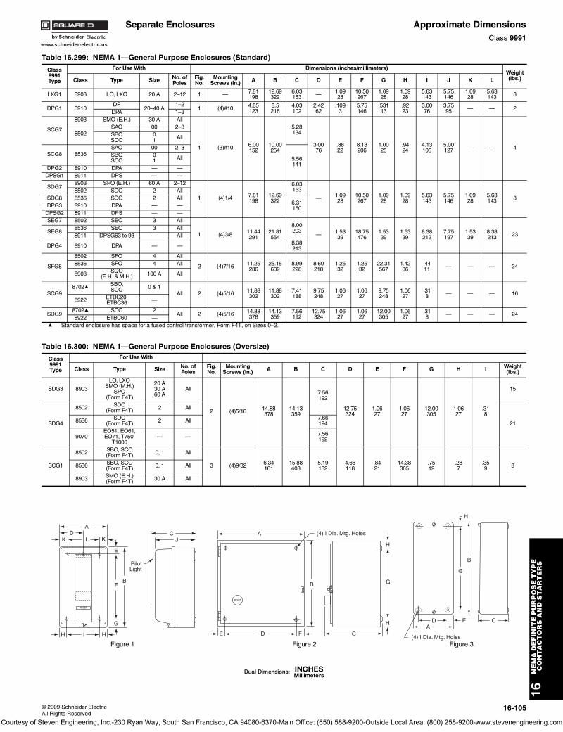
www.schneider-electric.us
16N
EM
A D
EF
INIT
E P
UR
PO
SE
TY
PE
C
ON
TA
CT
OR
S A
ND
ST
AR
TE
RS
© 2009 Schneider ElectricAll Rights Reserved
16-105
Separate Enclosures Approximate DimensionsClass 9991
Table 16.299: NEMA 1—General Purpose Enclosures (Standard)
Class9991Type
For Use With Dimensions (inches/millimeters)Weight(lbs.)Class Type Size No. of
PolesFig.No.
MountingScrews (in.) A B C D E F G H I J K L
LXG1 8903 LO, LXO 20 A 2–12 1 — 7.81198
12.69322
6.03153 — 1.09
2810.50267
1.0928
1.0928
5.63143
5.75146
1.0928
5.63143 8
DPG1 8910DP
20–40 A1–2
1 (4)#10 4.85123
8.5216
4.03102
2.4262
.1093
5.75146
.53113
.9223
3.0076
3.7595 — — 2
DPA 1–3
SCG7
8903 SMO (E.H.) 30 A All
1 (3)#10 6.00152
10.00254
5.28134
3.0076
.8822
8.13206
1.0025
.9424
4.13105
5.00127 — — 4
8502SAO 00 2–3SBOSCO
01 All
SCG8 8536SAO 00 2–3
5.56141
SBOSCO
01 All
DPG2 8910 DPA — —DPSG1 8911 DPS — —
SDG78903 SPO (E.H.) 60 A 2–12
1 (4)1/4 7.81198
12.69322
6.03153
— 1.0928
10.50267
1.0928
1.0928
5.63143
5.75146
1.0928
5.63143 8
8502 SDO 2 AllSDG8 8536 SDO 2 All
6.31160DPG3 8910 DPA — —
DPSG2 8911 DPS — —SEG7 8502 SEO 3 All
1 (4)3/8 11.44291
21.81554
8.00203
— 1.5339
18.75476
1.5339
1.5339
8.38213
7.75197
1.5339
8.38213 23SEG8
8536 SEO 3 All8911 DPSG63 to 93 — All
DPG4 8910 DPA — — 8.38213
SFG8
8502 SFO 4 All
2 (4)7/16 11.25286
25.15639
8.99228
8.60218
1.2532
1.2532
22.31567
1.4236
.4411 — — — 348536 SFO 4 All
8903 SQO(E.H. & M.H.) 100 A All
SCG98702a SBO,
SCO 0 & 1All 2 (4)5/16 11.88
30211.88302
7.41188
9.75248
1.0627
1.0627
9.75248
1.0627
.318 — — — 16
8922 ETBC20,ETBC36 —
SDG98702a SCO 2
All 2 (4)5/16 14.88378
14.13359
7.56192
12.75324
1.0627
1.0627
12.00305
1.0627
.318 — — — 24
8922 ETBC60 —a Standard enclosure has space for a fused control transformer, Form F4T, on Sizes 0–2.
Table 16.300: NEMA 1—General Purpose Enclosures (Oversize)
Class9991Type
For Use With
Class Type Size No. ofPoles
Fig.No.
MountingScrews (in.) A B C D E F G H I Weight
(lbs.)
SDG3 8903
LO, LXOSMO (M.H.)
SPO(Form F4T)
20 A30 A60 A
All
2 (4)5/16 14.88378
14.13359
7.56192
12.75324
1.0627
1.0627
12.00305
1.0627
.318
15
SDG4
8502 SDO(Form F4T) 2 All
218536 SDO(Form F4T) 2 All 7.66
194
9070EO51, EO61,EO71, T750,
T1000— — 7.56
192
SCG1
8502 SBO, SCO(Form F4T) 0, 1 All
3 (4)9/32 6.34161
15.88403
5.19132
4.66118
.8421
14.38365
.7519
.287
.359 88536 SBO, SCO
(Form F4T) 0, 1 All
8903 SMO (E.H.)(Form F4T) 30 A All
AD
K L K
E
BF
H I H
G
RESET
CJ
PilotLight
A
B
E D F
RESET
C
H
G
H
(4) I Dia. Mtg. Holes
H
B
G
CEDA
(4) I Dia. Mtg. HolesFigure 1 Figure 2 Figure 3
Courtesy of Steven Engineering, Inc.-230 Ryan Way, South San Francisco, CA 94080-6370-Main Office: (650) 588-9200-Outside Local Area: (800) 258-9200-www.stevenengineering.com
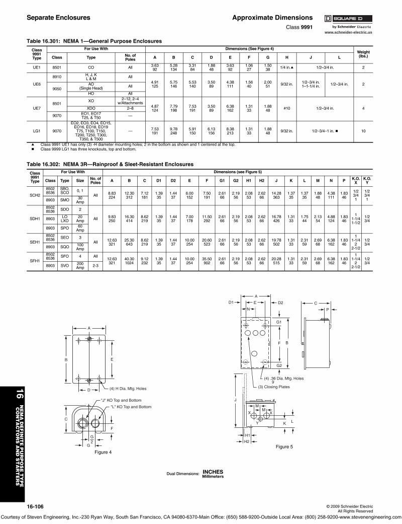
www.schneider-electric.us
16N
EM
A D
EF
INIT
E P
UR
PO
SE
TY
PE
C
ON
TA
CT
OR
S A
ND
ST
AR
TE
RS
16-106 © 2009 Schneider ElectricAll Rights Reserved
Separate Enclosures Approximate DimensionsClass 9991
Table 16.301: NEMA 1—General Purpose Enclosures
Class9991Type
For Use With Dimensions (See Figure 4)Weight(lbs.)Class Type No. of
Poles A B C D E F G H J L
UE1 8501 CO All 3.6392
5.28134
3.3184
1.8848
3.6392
1.0627
1.5038 1/4 in.a 1/2–3/4 in. 2
UE6
8910 H, J, KL & M All
4.91125
5.75146
5.53140
3.5089
4.38111
1.5640
2.0051 9/32 in. 1/2–3/4 in.
1–1-1/4 in. 1/2–3/4 in. 29050
AO(Single Head) All
HO All
UE78501
XO 2–12, 2–4 w/Attachments
4.87124
7.79198
7.53191
3.5089
6.38162
1.3133
1.8848 #10 1/2–3/4 in. 4XDO 2–8
9070 EO1, EO17T25, & T50 —
LG1 9070
EO2, EO3, EO4, EO15, EO16, EO18, EO19
T75, T100, T150,T200, T250, T300,
T350, & T500
— 7.53191
9.78248
5.91150
6.13156
8.38213
1.3133
1.8848 9/32 in. 1/2–3/4–1 in. b 10
a Class 9991 UE1 has only (3) -H diameter mounting holes; 2 in the bottom as shown and 1 centered at the top.b Class 9999 LG1 has three knockouts, top and bottom.
A
EB
D
C
G2
G
F
(4) H Dia. Mtg. Holes
"J" KO Top and Bottom
"L" KO Top and Bottom
Figure 4
Table 16.302: NEMA 3R—Rainproof & Sleet-Resistant Enclosures
Class9991Type
For Use With Dimensions (see Figure 5)
Class Type Size No. ofPoles A B C D1 D2 E F G1 G2 H1 H2 J K L M N P K.O.
XK.O.
Y
SCH2
85028536
SBO,SCO 0, 1
All 8.83224
12.30312
7.12181
1.3935
1.4437
6.00152
7.50191
2.6166
2.1956
2.0853
2.6266
14.28363
1.3735
1.3735
1.8848
4.38111
1.8346
1/23/41
1/23/418903 SMO 30
Amp
SDH1
85028536 SDO 2
All 9.83250
16.30414
8.62219
1.3935
1.4437
7.00178
11.50292
2.6166
2.1956
2.0853
2.6266
16.78426
1.3133
1.7544
2.1354
4.88124
1.8346
11-1/41-1/2
1/23/48903 LO
LXO20
Amp
8903 SPO 60Amp
SEH1
85028536 SEO 3
All 12.63321
25.30643
8.62219
1.3935
1.4437
10.00254
20.60523
2.6166
2.1956
2.0853
2.6266
19.78502
1.3133
2.3159
2.6968
6.38162
1.8346
11-1/4
22-1/2
1/23/4
8903 SQO 100Amp
SFH1
85028536 SFO 4 All
12.63321
40.301024
9.12232
1.3935
1.4437
10.00254
35.50902
2.6166
2.1956
2.0853
2.6266
20.28515
1.3133
2.3159
2.6968
6.38162
1.8346
11-1/4
22-1/2
1/23/4
8903 SVO 200Amp 2-3
A
ED1 D2
N
G1
G2
F B
C
P
J
LK
H1
H2
MM
X X
Y
(4) .36 Dia. Mtg. Holes 9
(3) Closing Plates
Figure 5
Courtesy of Steven Engineering, Inc.-230 Ryan Way, South San Francisco, CA 94080-6370-Main Office: (650) 588-9200-Outside Local Area: (800) 258-9200-www.stevenengineering.com
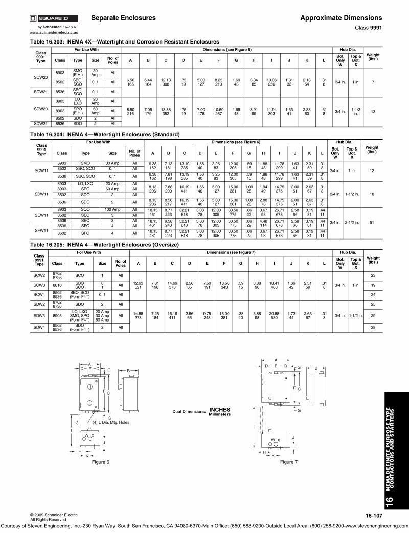
www.schneider-electric.us
16N
EM
A D
EF
INIT
E P
UR
PO
SE
TY
PE
C
ON
TA
CT
OR
S A
ND
ST
AR
TE
RS
© 2009 Schneider ElectricAll Rights Reserved
16-107
Separate Enclosures Approximate DimensionsClass 9991
Table 16.303: NEMA 4X—Watertight and Corrosion Resistant Enclosures
Class9991Type
For Use With Dimensions (see Figure 6) Hub Dia.Weight(lbs.)Class Type Size No. of
Poles A B C D E F G H I J K LBot.Only
W
Top &Bot.
X
SCW208903 SMO
(E.H.)30
Amp All
6.50165
6.44164
12.13308
.7519
5.00127
8.25210
1.6943
3.3485
10.06256
1.3133
2.1354
.318 3/4 in. 1 in. 78502 SBO,
SCO 0, 1 All
SCW21 8536 SBO,SCO 0, 1 All
SDW20
8903 LO,LXO
20Amp All
8.50216
7.06179
13.88352
.7519
7.00178
10.50267
1.6943
3.9199
11.94303
1.6341
2.3860
.318 3/4 in. 1-1/2
in. 138903 SPO(E.H.)
60Amp All
8502 SDO 2 AllSDW21 8536 SDO 2 All
AD E D G
G
B
CF
IW X
J
HK
(4) L Dia. Mtg. Holes
Figure 6
Table 16.304: NEMA 4—Watertight Enclosures (Standard)
Class9991Type
For Use With Dimensions (see Figure 6) Hub Dia.Weight(lbs.)Class Type Size No. of
Poles A B C D E F G H I J K LBot.Only
W
Top &Bot.
X
SCW11
8903 SMO 30 Amp All 6.38162
7.13181
13.19335
1.5640
3.2583
12.00305
.5915
1.8848
11.78299
1.6341
2.3159
.318
3/4 in. 1 in. 128502 SBO, SCO 0, 1 All
8536 SBO, SCO 0, 1 All 6.38162
7.81198
13.19335
1.5640
3.2583
12.00305
.5915
1.8848
11.78299
1.6341
2.3159
.318
SDW11
8903 LO, LXO 20 Amp All8.13206
7.88200
16.19411
1.5640
5.00127
15.00381
1.0928
1.9449
14.75375
2.0051
2.6367
.318
3/4 in. 1-1/2 in. 188903 SPO 60 Amp All8502 SDO 2 All
8536 SDO 2 All 8.13206
8.56217
16.19411
1.5640
5.00127
15.00381
1.0928
2.8873
14.75375
2.0051
2.6367
.318
SEW118903 SQO 100 Amp All 18.15
4618.77223
32.21818
3.0878
12.00305
30.50775
.8622
3.6793
26.71678
2.5866
3.1981
.4411
3/4 in. 2-1/2 in. 51
8502 SEO 3 All8536 SEO 3 All 18.15
4619.58243
32.21818
3.0878
12.00305
30.50775
.8622
4.48114
26.71678
2.5866
3.1981
.4411
SFW118536 SFO 4 All
8502 SFO 4 All 18.15461
8.77223
32.21818
3.0878
12.00305
30.50775
.8622
3.6793
26.71678
2.5866
3.1981
.4411
Table 16.305: NEMA 4—Watertight Enclosures (Oversize)
Class9991Type
For Use With Dimensions (see Figure 7) Hub Dia.Weight(lbs.)Class Type Size No. of
Poles A B C D E F G H I J K LBot.Only
W
Top &Bot.
X
SCW2 87028736 SCO 1 All
12.63321
7.81198
14.69373
2.5665
7.50191
13.50343
.5915
3.8898
18.41468
1.6642
2.3159
.318 3/4 in. 1 in.
23
SCW3 8810 SBOSCO
01 All 19
SCW4 85028536
SBO, SCO(Form F4T) 0, 1 All 24
SDW2 87028736 SDO 2 All
14.88378
7.25184
16.19411
2.5665
9.75248
15.00381
.3810
3.8898
20.88530
1.7244
2.6367
.318 3/4 in. 1-1/2 in.
25
SDW3 8903LO, LXO
SMO, SPO(Form F4T)
20 Amp30 Amp60 Amp
All 29
SDW4 85028536
SDO(Form F4T) 2 All 28
AD DE G
G
F C
J
KH
I
W X
B
Figure 7
Courtesy of Steven Engineering, Inc.-230 Ryan Way, South San Francisco, CA 94080-6370-Main Office: (650) 588-9200-Outside Local Area: (800) 258-9200-www.stevenengineering.com
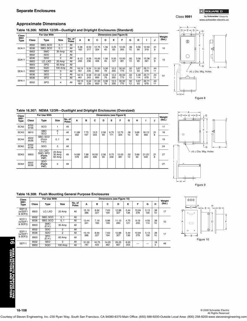
www.schneider-electric.us
16N
EM
A D
EF
INIT
E P
UR
PO
SE
TY
PE
C
ON
TA
CT
OR
S A
ND
ST
AR
TE
RS
16-108 © 2009 Schneider ElectricAll Rights Reserved
Separate EnclosuresClass 9991
Approximate DimensionsTable 16.306: NEMA 12/3R—Dusttight and Driptight Enclosures (Standard)
Class9991Type
For Use With Dimensions (see Figure 8)Weight(lbs.)Class Type Size No. of
Poles A B C D E F G H I J
SCA118502 SBO, SCO 0, 1 All
6.38162
8.53217
12.75324
1.5640
3.2583
12.00305
.3810
3.5690
12.50318
.318 108536 SBO, SCO 0, 1 All
8903 SMO 30 Amp All
SDA11
8502 SDO 2 All
8.13206
9.28236
16.00406
1.5640
5.00127
15.00381
.5013
3.5690
15.38391
.318 15
8536 SDO 2 All8903 LO, LXO 20 Amp All8903 SPO 60 Amp All
SEA118903 SQO 100 Amp All 18.15
4619.24235
31.50800
3.0878
12.0305
30.50775
.5013
3.6793
26.71678
.4411
51
8502 SEO 3 All8536 SEO 3 All 18.15
4619.58243
31.50800
3.0878
12.0305
30.50775
.5013
4.48114
26.71678
.4411
SFA118536 SFO 4 All
8502 SFO 4 All 18.15461
9.24235
31.50800
3.0878
12.0305
30.50775
.5013
3.6793
26.71678
.4411
Table 16.307: NEMA 12/3R—Dusttight and Driptight Enclosures (Oversized)
Class9991Type
For Use With Dimensions (see Figure 9)Weight(lbs.)Class Type Size No. of
Poles A B C D E F G H I J
SCA2 87028736 SCO 1 All
11.88302
7.75197
13.5343
2.5665
6.75171
12.75324
.3810
3.6693
18.13460
.318
17
SCA3 8810 SBOSCO
01 All 18
SCA4 85028536
SBO, SCO(FormF4T)
0, 1 All 19
SDA2 87028736 SDO 2 All
14.88378
7.88200
16.00406
2.5665
9.75248
15.00381
.5013
3.6693
21.25540
.318
24
SDA3 8903
LO, LXOSMO, SPO
(FormF4T)
20 Amp30 Amp60 Amp
All 27
SDA4 85028536
SDO(FormF4T)
2 All 27
Table 16.308: Flush Mounting General Purpose Enclosures
Class9991Type
For Use With Dimensions (see Figure 10)Weight(lbs.)Class Type Size No. of
Poles A B C D E F G H
SDF13(w/SDF1& SDF2)
8903 LO, LXO 20 Amp All 15.19386
8.94227
7.63194
12.88327
5.44138
10.94278
5.13130
.3810 17
SCF11(w/SDF1& SDF2)
8502 SBO, SCO 0, 1 All13.44341
7.19183
5.88149
11.13283
4.75121
9.19233
4.50114
.3810 108536 SBO, SCO 0, 1 All
8903 SMO(E.H.) 30 Amp All
SDF11(w/SDF1& SDF2)
8502 SDO 2 All15.19386
8.94227
7.63194
12.88327
5.44138
10.94278
5.13130
.3810 178536 SDO 2 All
8903 SPO(E.H.) 60 Amp All
SEF118502 SEO 3 All 31.00
78716.75425
14.25362
26.25667
8.00203 — — .18
5 488903 SQO 100 Amp All
AD E D G
FC
G B
H
I
(4) J Dia. Mtg. Holes
Figure 8
AE DD G
FC
G B
I
H
(4) J Dia. Mtg. Holes
Figure 9
C
A
B
H HE G
D F
Figure 10
Courtesy of Steven Engineering, Inc.-230 Ryan Way, South San Francisco, CA 94080-6370-Main Office: (650) 588-9200-Outside Local Area: (800) 258-9200-www.stevenengineering.com
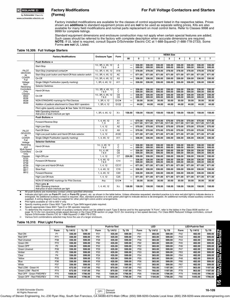
www.schneider-electric.us
16N
EM
A D
EF
INIT
E P
UR
PO
SE
TY
PE
C
ON
TA
CT
OR
S A
ND
ST
AR
TE
RS
© 2009 Schneider ElectricAll Rights Reserved
16-109
Factory Modifications (Forms)
For Full Voltage Contactors and Starters
Factory installed modifications are available for the classes of control equipment listed in the respective tables. Prices shown are additions to standard equipment prices and are not to be used as separate selling prices. Kits are also available for many field modifications and normal parts replacement on most control items. Refer to Classes 9998 and 9999 for complete listings. Standard equipment dimensions and enclosure construction may not apply when certain special features are added. Such cases should be referred to the factory with complete description when accurate dimensions are required.NOTE: If UL label is required, consult Square D/Schneider Electric CIC at 1-888-SquareD (1-888-778-2733). Some Forms are not UL Listed.
Table 16.309: Full Voltage Starters
Factory Modifications Enclosure Type FormNEMA Size
00 0 1 2 3 4 5 6 7
PILOTDEVICES
INCOVER
FullVoltageNon-
ReversingControllers
OnlyClasses
8502853685388539
Push Buttons a
Start-Stop 1g, 3R, 4, 4X, 127 & 9
AA
——
336.00599.00
336.00599.00
336.00599.00
336.00599.00
336.00599.00
336.00599.00
336.00599.00
336.00599.00
Start-Stop (maintained contact)e 1g, 3R, 4, 4X, 12 A16 — 378.00 378.00 378.00 378.00 378.00 378.00 378.00 378.00
Start-Stop push button and Hand-Off-Auto selector switch 1g, 3R, 4, 4X, 12 AC — 671.00 671.00 671.00 671.00 671.00 671.00 671.00 671.00
On-Off 1g, 3R, 4, 4X, 12 A3 — 336.00 336.00 336.00 336.00 336.00 336.00 336.00 336.00
Single Oiltight Pushbutton (specify marking) 1, 3R, 4, 4X, 12 A11 — 336.00 336.00 336.00 336.00 336.00 336.00 336.00 336.00
Selector Switches
Hand-Off-Auto 1g, 3R, 4, 4X, 127 & 9
CC
——
336.00599.00
336.00599.00
336.00599.00
336.00599.00
336.00599.00
336.00599.00
336.00599.00
336.00599.00
On-Off 1g, 3R, 4, 4X, 127 & 9
C6C6
——
336.00599.00
336.00599.00
336.00599.00
336.00599.00
336.00599.00
336.00599.00
336.00599.00
336.00599.00
NON-STANDARD markings for Pilot Devices 1, 3R, 4, 12 G12d — 30.00 30.00 30.00 30.00 30.00 30.00 30.00 30.00
Addition of padlock attachment to Class 9001 operators 1, 3R, 4, 12 G122 — 44.00 44.00 44.00 44.00 44.00 44.00 44.00 44.00
Pilot Lights (specify color/type) b See Table 16.310 below.
With Operating Interlock:Add price of each interlock per light 1, 3R, 4, 4X, 12 Xf 158.00 158.00 158.00 158.00 158.00 158.00 158.00 158.00 158.00
PILOTDEVICES
INCOVER
FullVoltage
Reversingand
Multi-SpeedControllers
OnlyClasses
8702873687388739881088118812
Push Buttons a
Forward-Reverse-Stop 1, 4, 4X, 127, 9
A1A1
——
570.001017.00
570.001017.00
570.001017.00
570.001017.00
570.001017.00
570.001017.00
570.001017.00
570.001017.00
High-Low-Stop 1, 4, 12 A2 — 570.00 570.00 570.00 570.00 570.00 570.00 570.00 570.00
Fast-Off-Slow 1, 4, 12 A9 — 570.00 570.00 570.00 570.00 570.00 570.00 570.00 570.00
High-Low push button and Hand-Off-Auto selector 1, 4, 12 A10C — 671.00 671.00 671.00 671.00 671.00 671.00 671.00 671.00
Single Oiltight Pushbutton (specify marking) 1, 4, 4X, 12 A11 — 336.00 336.00 336.00 336.00 336.00 336.00 336.00 336.00
Selector Switches
Hand-Off-Auto 1g, 4, 4X, 127 & 9
CC
——
336.00599.00
336.00599.00
336.00599.00
336.00599.00
336.00599.00
336.00599.00
336.00599.00
336.00599.00
On-Off 1g, 4, 4X7 & 9
C6C6
——
336.00599.00
336.00599.00
336.00599.00
336.00599.00
336.00599.00
336.00599.00
336.00599.00
336.00599.00
High-Off-Low 1, 4, 12 C7 224.00 336.00 336.00 336.00 336.00 336.00 336.00 336.00 336.00
Forward-Off-Reverse 1, 4, 4X, 127 & 9 C14 — 336.00
599.00336.00599.00
336.00599.00
336.00599.00
336.00599.00
336.00599.00
336.00599.00
336.00599.00
High-Low and Hand-Off-Auto 1, 4, 12 CC17 — 671.00 671.00 671.00 671.00 671.00 671.00 671.00 671.00
Slow-Fast 1, 4, 4X, 12 C19 — 336.00 336.00 336.00 336.00 336.00 336.00 336.00 336.00
Forward-Reverse 1, 4, 4X, 12 C20 — 336.00 336.00 336.00 336.00 336.00 336.00 336.00 336.00
High-Low-Off-Auto 1, 4, 12 C25 — 671.00 671.00 671.00 671.00 671.00 671.00 671.00 671.00
NON-STANDARD markings for Pilot Devices Any G12d — 30.00 30.00 30.00 30.00 30.00 30.00 30.00 30.00
Pilot Lights bWith Operating Interlock:Add price of each interlock per light
1, 4, 4X, 12 Xf 158.00 158.00 158.00 158.00 158.00 158.00 158.00 158.00 158.00
a All push buttons are momentary contact unless specified otherwise.b Indicate pilot light color as Form P1 (red) or Form P2 (green), etc. as shown in the table below. Unless otherwise requested, standard practice is to wire red pilot light to indicate device is
energized. No additional auxiliary contact is required. Also, standard practice is to wire green pilot light to indicate device is de-energized. An additional normally closed auxiliary contact is supplied. A wiring diagram must be supplied for other pilot light colors and/or arrangements.
c Pilot lights available at 120 to 600 V only.d Specify marking and/or Class 9001 Type KN or Type SKN legend plate required.e Specify appropriate Class 9001 Type K or SK operator required.f To determine the maximum number of auxiliary contacts which can be added to each Type S device and for the appropriate “X Form”, refer to the tables in the Class 8536 section on
page 16-14 (for non-reversing single-speed devices) or the Class 8736 section on page 16-51 (for reversing or two-speed devices). For Class 8600 Reduced Voltage controllers, consult Square D/Schneider Electric CIC at 1-888-SquareD (1-888-778-2733).
g Various form combinations selected may force the use of a larger enclosure.
Table 16.310: Pilot Light FormsStandard Push-to-Test LED LED-Push-to-Test
Form Ty 1/4/12 Ty 7/9 Form Ty 1/4/12 Ty 7/9 Form Ty 1/4/12 Ty 7/9 Form Ty 1/4/12 Ty 7/9
Red ON P1 336.00 599.00 P21 435.00 599.00 P51 383.00 599.00 P42 482.00 599.00Red OFF P71 336.00 599.00 P81 435.00 599.00 P91 383.00 599.00 P43 482.00 599.00Red Unwired P38 336.00 599.00 P28 435.00 599.00 P58 383.00 599.00 P44 482.00 599.00Green ON P72 336.00 599.00 P82 435.00 599.00 P92 383.00 599.00 P45 482.00 599.00Green OFF P2 336.00 599.00 P22 435.00 599.00 P52 383.00 599.00 P46 482.00 599.00Green Unwired P39 336.00 599.00 P29 435.00 599.00 P59 383.00 599.00 P47 482.00 599.00Amber P3 336.00 599.00 P23 435.00 599.00 P53 383.00 599.00 P63 482.00 599.00Clear P4 336.00 599.00 P24 435.00 599.00 P54 383.00 599.00 P64 482.00 599.00Yellow P35 336.00 599.00 P25 435.00 599.00 P55 383.00 599.00 P48 482.00 599.00Blue P36 336.00 599.00 P26 435.00 599.00 P56 383.00 599.00 P66 482.00 599.00White P37 336.00 599.00 P27 435.00 599.00 P57 383.00 599.00 P67 482.00 599.00Red LOW - Green HI P73 672.00 1197.00 P83 870.00 1197.00 P93 765.00 1197.00 P77 963.00 1197.00Green LOW - Red HI P74 672.00 1197.00 P84 870.00 1197.00 P94 765.00 1197.00 P78 963.00 1197.00Red OFF - Green FWD/REV P75 1008.00 1796.00 P85 1305.00 1796.00 P95 1184.00 1796.00 P79 1445.00 1796.00Green OFF - Red FWD/REV P76 1008.00 1796.00 P86 1305.00 1796.00 P96 1184.00 1796.00 P80 1445.00 1796.00
CP1 Discount Schedule
Courtesy of Steven Engineering, Inc.-230 Ryan Way, South San Francisco, CA 94080-6370-Main Office: (650) 588-9200-Outside Local Area: (800) 258-9200-www.stevenengineering.com
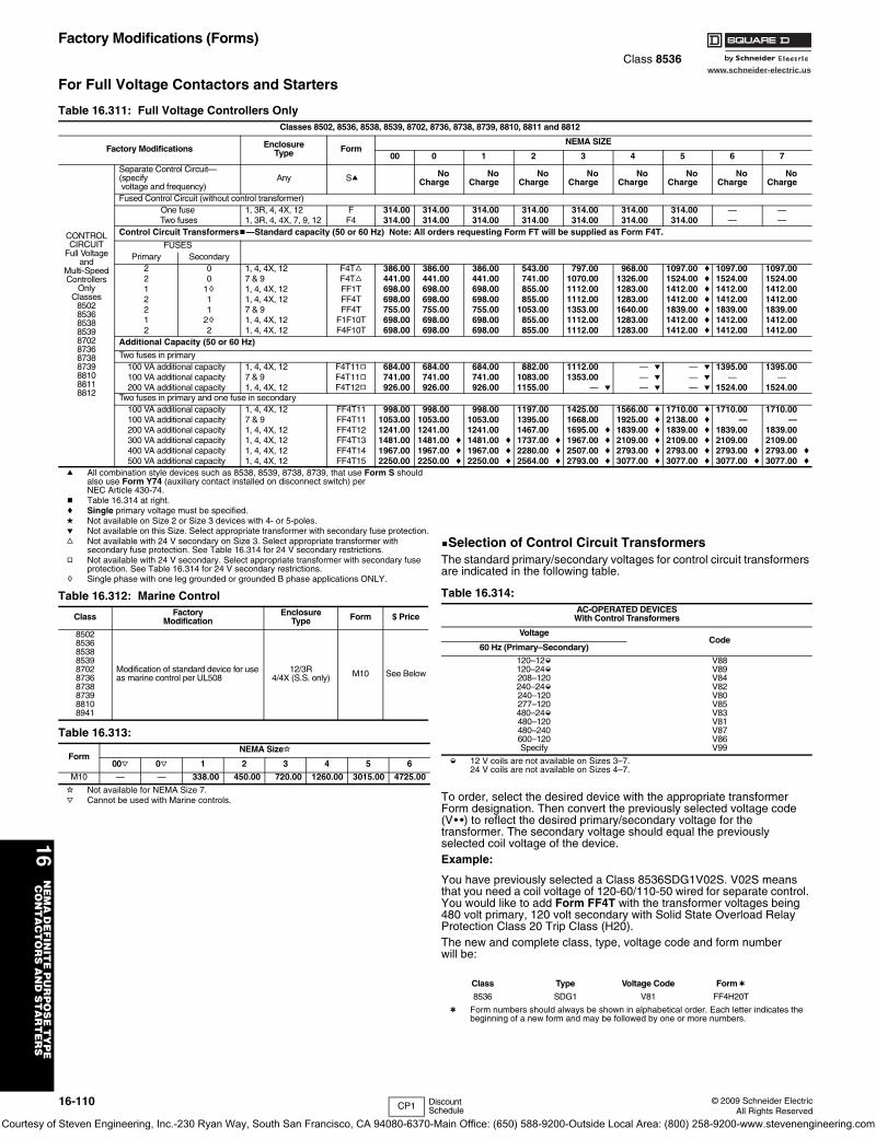
www.schneider-electric.us
16N
EM
A D
EF
INIT
E P
UR
PO
SE
TY
PE
C
ON
TA
CT
OR
S A
ND
ST
AR
TE
RS
16-110 © 2009 Schneider ElectricAll Rights Reserved
Factory Modifications (Forms)Class 8536
For Full Voltage Contactors and Starters
a All combination style devices such as 8538, 8539, 8738, 8739, that use Form S should also use Form Y74 (auxiliary contact installed on disconnect switch) per NEC Article 430-74.
b Table 16.314 at right.c Single primary voltage must be specified.d Not available on Size 2 or Size 3 devices with 4- or 5-poles.e Not available on this Size. Select appropriate transformer with secondary fuse protection.f Not available with 24 V secondary on Size 3. Select appropriate transformer with
secondary fuse protection. See Table 16.314 for 24 V secondary restrictions.g Not available with 24 V secondary. Select appropriate transformer with secondary fuse
protection. See Table 16.314 for 24 V secondary restrictions.h Single phase with one leg grounded or grounded B phase applications ONLY.
i Not available for NEMA Size 7.j Cannot be used with Marine controls.
bSelection of Control Circuit TransformersThe standard primary/secondary voltages for control circuit transformers are indicated in the following table.
k 12 V coils are not available on Sizes 3–7.24 V coils are not available on Sizes 4–7.
To order, select the desired device with the appropriate transformer Form designation. Then convert the previously selected voltage code (V• •) to reflect the desired primary/secondary voltage for the transformer. The secondary voltage should equal the previously selected coil voltage of the device.Example:
You have previously selected a Class 8536SDG1V02S. V02S means that you need a coil voltage of 120-60/110-50 wired for separate control. You would like to add Form FF4T with the transformer voltages being 480 volt primary, 120 volt secondary with Solid State Overload Relay Protection Class 20 Trip Class (H20).The new and complete class, type, voltage code and form numberwill be:
l Form numbers should always be shown in alphabetical order. Each letter indicates the beginning of a new form and may be followed by one or more numbers.
Table 16.311: Full Voltage Controllers OnlyClasses 8502, 8536, 8538, 8539, 8702, 8736, 8738, 8739, 8810, 8811 and 8812
Factory Modifications EnclosureType Form
NEMA SIZE
00 0 1 2 3 4 5 6 7
CONTROLCIRCUIT
Full Voltageand
Multi-SpeedControllers
OnlyClasses
85028536853885398702873687388739881088118812
Separate Control Circuit—(specify voltage and frequency)
Any Sa NoCharge
NoCharge
NoCharge
NoCharge
NoCharge
NoCharge
NoCharge
NoCharge
Fused Control Circuit (without control transformer) One fuse 1, 3R, 4, 4X, 12 F 314.00 314.00 314.00 314.00 314.00 314.00 314.00 — —
Two fuses 1, 3R, 4, 4X, 7, 9, 12 F4 314.00 314.00 314.00 314.00 314.00 314.00 314.00 — —Control Circuit Transformersb—Standard capacity (50 or 60 Hz) Note: All orders requesting Form FT will be supplied as Form F4T.
FUSESPrimary Secondary
2 0 1, 4, 4X, 12 F4Tf 386.00 386.00 386.00 543.00 797.00 968.00 1097.00 c 1097.00 1097.002 0 7 & 9 F4Tf 441.00 441.00 441.00 741.00 1070.00 1326.00 1524.00 c 1524.00 1524.001 1h 1, 4, 4X, 12 FF1T 698.00 698.00 698.00 855.00 1112.00 1283.00 1412.00 c 1412.00 1412.002 1 1, 4, 4X, 12 FF4T 698.00 698.00 698.00 855.00 1112.00 1283.00 1412.00 c 1412.00 1412.002 1 7 & 9 FF4T 755.00 755.00 755.00 1053.00 1353.00 1640.00 1839.00 c 1839.00 1839.001 2h 1, 4, 4X, 12 F1F10T 698.00 698.00 698.00 855.00 1112.00 1283.00 1412.00 c 1412.00 1412.002 2 1, 4, 4X, 12 F4F10T 698.00 698.00 698.00 855.00 1112.00 1283.00 1412.00 c 1412.00 1412.00
Additional Capacity (50 or 60 Hz)
Two fuses in primary100 VA additional capacity 1, 4, 4X, 12 F4T11g 684.00 684.00 684.00 882.00 1112.00 — e — e 1395.00 1395.00100 VA additional capacity 7 & 9 F4T11g 741.00 741.00 741.00 1083.00 1353.00 — e — e — —200 VA additional capacity 1, 4, 4X, 12 F4T12g 926.00 926.00 926.00 1155.00 — e — e — e 1524.00 1524.00
Two fuses in primary and one fuse in secondary100 VA additional capacity 1, 4, 4X, 12 FF4T11 998.00 998.00 998.00 1197.00 1425.00 1566.00 c 1710.00 c 1710.00 1710.00100 VA additional capacity 7 & 9 FF4T11 1053.00 1053.00 1053.00 1395.00 1668.00 1925.00 c 2138.00 c — —200 VA additional capacity 1, 4, 4X, 12 FF4T12 1241.00 1241.00 1241.00 1467.00 1695.00 c 1839.00 c 1839.00 c 1839.00 1839.00300 VA additional capacity 1, 4, 4X, 12 FF4T13 1481.00 1481.00 c 1481.00 c 1737.00 c 1967.00 c 2109.00 c 2109.00 c 2109.00 2109.00400 VA additional capacity 1, 4, 4X, 12 FF4T14 1967.00 1967.00 c 1967.00 c 2280.00 c 2507.00 c 2793.00 c 2793.00 c 2793.00 c 2793.00 c500 VA additional capacity 1, 4, 4X, 12 FF4T15 2250.00 2250.00 c 2250.00 c 2564.00 c 2793.00 c 3077.00 c 3077.00 c 3077.00 c 3077.00 c
Table 16.312: Marine Control
Class FactoryModification
EnclosureType Form $ Price
8502853685388539870287368738873988108941
Modification of standard device for use as marine control per UL508
12/3R4/4X (S.S. only) M10 See Below
Table 16.313:
FormNEMA Sizei
00j 0j 1 2 3 4 5 6
M10 — — 338.00 450.00 720.00 1260.00 3015.00 4725.00
Table 16.314: AC-OPERATED DEVICES
With Control Transformers
VoltageCode
60 Hz (Primary–Secondary)
120–12k120–24k208–120240–24k240–120277–120480–24k480–120480–240600–120Specify
V88V89V84V82V80V85V83V81V87V86V99
Class Type Voltage Code Forml
8536 SDG1 V81 FF4H20T
CP1 Discount Schedule
Courtesy of Steven Engineering, Inc.-230 Ryan Way, South San Francisco, CA 94080-6370-Main Office: (650) 588-9200-Outside Local Area: (800) 258-9200-www.stevenengineering.com
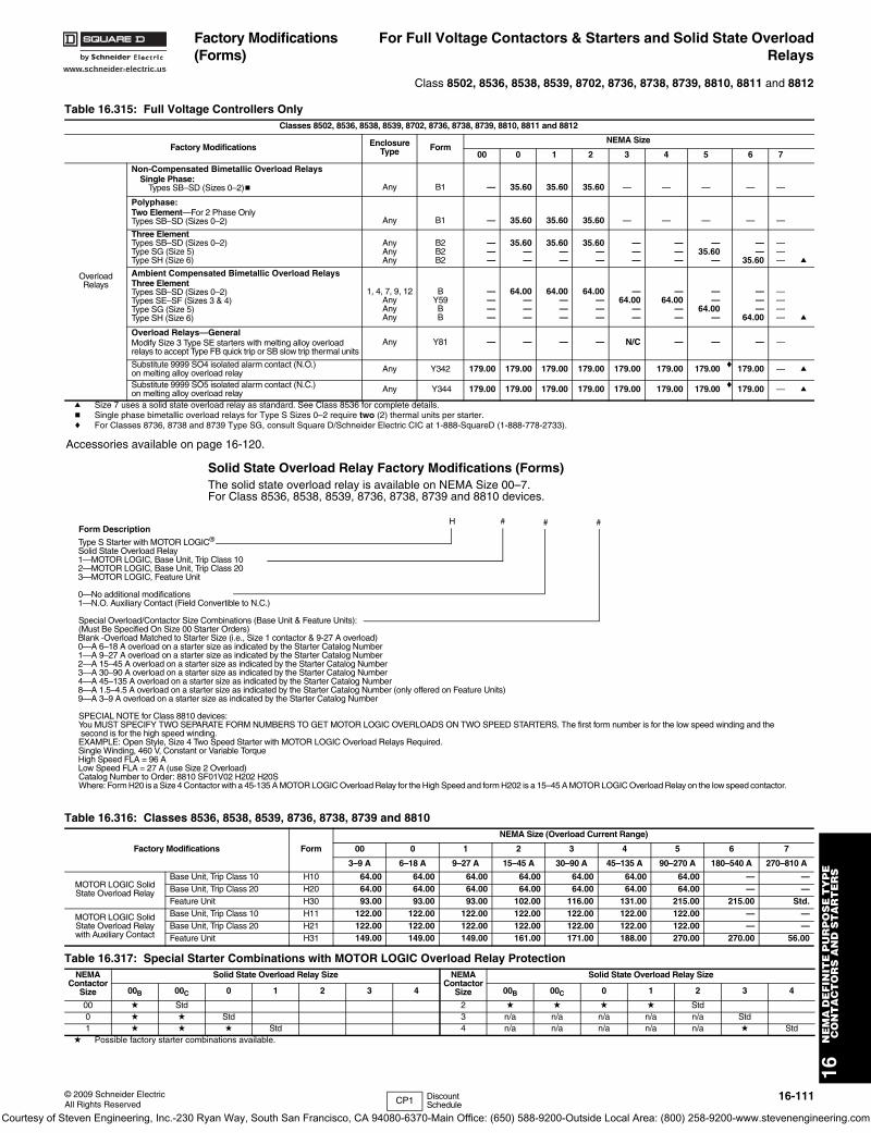
www.schneider-electric.us
16N
EM
A D
EF
INIT
E P
UR
PO
SE
TY
PE
C
ON
TA
CT
OR
S A
ND
ST
AR
TE
RS
© 2009 Schneider ElectricAll Rights Reserved
16-111
Factory Modifications (Forms)
For Full Voltage Contactors & Starters and Solid State OverloadRelays
Class 8502, 8536, 8538, 8539, 8702, 8736, 8738, 8739, 8810, 8811 and 8812
Solid State Overload Relay Factory Modifications (Forms)The solid state overload relay is available on NEMA Size 00–7.For Class 8536, 8538, 8539, 8736, 8738, 8739 and 8810 devices.
Table 16.315: Full Voltage Controllers OnlyClasses 8502, 8536, 8538, 8539, 8702, 8736, 8738, 8739, 8810, 8811 and 8812
Factory Modifications EnclosureType Form
NEMA Size
00 0 1 2 3 4 5 6 7
OverloadRelays
Non-Compensated Bimetallic Overload RelaysSingle Phase:
Types SB–SD (Sizes 0–2)b Any B1 — 35.60 35.60 35.60 — — — — —
Polyphase:Two Element—For 2 Phase OnlyTypes SB–SD (Sizes 0–2) Any B1 — 35.60 35.60 35.60 — — — — —
Three ElementTypes SB–SD (Sizes 0–2)Type SG (Size 5)Type SH (Size 6)
AnyAnyAny
B2B2B2
———
35.60——
35.60——
35.60——
———
———
—35.60
—
——
35.60
——— a
Ambient Compensated Bimetallic Overload RelaysThree ElementTypes SB–SD (Sizes 0–2)Types SE–SF (Sizes 3 & 4)Type SG (Size 5)Type SH (Size 6)
1, 4, 7, 9, 12AnyAnyAny
BY59BB
————
64.00———
64.00———
64.00———
—64.00
——
—64.00
——
——
64.00—
———
64.00
———— a
Overload Relays—GeneralModify Size 3 Type SE starters with melting alloy overload relays to accept Type FB quick trip or SB slow trip thermal units
Any Y81 — — — — N/C — — — —
Substitute 9999 SO4 isolated alarm contact (N.O.) on melting alloy overload relay Any Y342 179.00 179.00 179.00 179.00 179.00 179.00 179.00 c 179.00 — a
Substitute 9999 SO5 isolated alarm contact (N.C.) on melting alloy overload relay Any Y344 179.00 179.00 179.00 179.00 179.00 179.00 179.00 c 179.00 — a
a Size 7 uses a solid state overload relay as standard. See Class 8536 for complete details.b Single phase bimetallic overload relays for Type S Sizes 0–2 require two (2) thermal units per starter.c For Classes 8736, 8738 and 8739 Type SG, consult Square D/Schneider Electric CIC at 1-888-SquareD (1-888-778-2733).
Accessories available on page 16-120.
Form Description
Type S Starter with MOTOR LOGIC®
Solid State Overload Relay1—MOTOR LOGIC, Base Unit, Trip Class 102—MOTOR LOGIC, Base Unit, Trip Class 203—MOTOR LOGIC, Feature Unit
0—No additional modifications1—N.O. Auxiliary Contact (Field Convertible to N.C.)
Special Overload/Contactor Size Combinations (Base Unit & Feature Units):(Must Be Specified On Size 00 Starter Orders)Blank -Overload Matched to Starter Size (i.e., Size 1 contactor & 9-27 A overload)0—A 6–18 A overload on a starter size as indicated by the Starter Catalog Number1—A 9–27 A overload on a starter size as indicated by the Starter Catalog Number2—A 15–45 A overload on a starter size as indicated by the Starter Catalog Number3—A 30–90 A overload on a starter size as indicated by the Starter Catalog Number4—A 45–135 A overload on a starter size as indicated by the Starter Catalog Number8—A 1.5–4.5 A overload on a starter size as indicated by the Starter Catalog Number (only offered on Feature Units)9—A 3–9 A overload on a starter size as indicated by the Starter Catalog Number
SPECIAL NOTE for Class 8810 devices:You MUST SPECIFY TWO SEPARATE FORM NUMBERS TO GET MOTOR LOGIC OVERLOADS ON TWO SPEED STARTERS. The first form number is for the low speed winding and the second is for the high speed winding.EXAMPLE: Open Style, Size 4 Two Speed Starter with MOTOR LOGIC Overload Relays Required.Single Winding, 460 V, Constant or Variable TorqueHigh Speed FLA = 96 ALow Speed FLA = 27 A (use Size 2 Overload)Catalog Number to Order: 8810 SF01V02 H202 H20SWhere: Form H20 is a Size 4 Contactor with a 45-135 A MOTOR LOGIC Overload Relay for the High Speed and form H202 is a 15–45 A MOTOR LOGIC Overload Relay on the low speed contactor.
H # # #
Table 16.316: Classes 8536, 8538, 8539, 8736, 8738, 8739 and 8810
Factory Modifications Form
NEMA Size (Overload Current Range)
00 0 1 2 3 4 5 6 7
3–9 A 6–18 A 9–27 A 15–45 A 30–90 A 45–135 A 90–270 A 180–540 A 270–810 A
MOTOR LOGIC SolidState Overload Relay
Base Unit, Trip Class 10 H10 64.00 64.00 64.00 64.00 64.00 64.00 64.00 — —Base Unit, Trip Class 20 H20 64.00 64.00 64.00 64.00 64.00 64.00 64.00 — —Feature Unit H30 93.00 93.00 93.00 102.00 116.00 131.00 215.00 215.00 Std.
MOTOR LOGIC SolidState Overload Relaywith Auxiliary Contact
Base Unit, Trip Class 10 H11 122.00 122.00 122.00 122.00 122.00 122.00 122.00 — —Base Unit, Trip Class 20 H21 122.00 122.00 122.00 122.00 122.00 122.00 122.00 — —Feature Unit H31 149.00 149.00 149.00 161.00 171.00 188.00 270.00 270.00 56.00
Table 16.317: Special Starter Combinations with MOTOR LOGIC Overload Relay ProtectionNEMA
Contactor Size
Solid State Overload Relay Size NEMA Contactor
Size
Solid State Overload Relay Size
00B 00C 0 1 2 3 4 00B 00C 0 1 2 3 4
00 d Std 2 d d d d Std0 d d Std 3 n/a n/a n/a n/a n/a Std1 d d d Std 4 n/a n/a n/a n/a n/a d Std
d Possible factory starter combinations available.
CP1 Discount Schedule
Courtesy of Steven Engineering, Inc.-230 Ryan Way, South San Francisco, CA 94080-6370-Main Office: (650) 588-9200-Outside Local Area: (800) 258-9200-www.stevenengineering.com
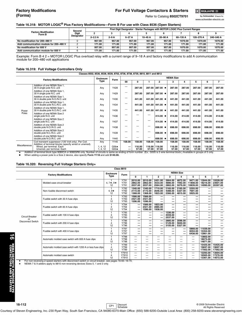
www.schneider-electric.us
16N
EM
A D
EF
INIT
E P
UR
PO
SE
TY
PE
C
ON
TA
CT
OR
S A
ND
ST
AR
TE
RS
16-112 © 2009 Schneider ElectricAll Rights Reserved
Factory Modifications (Forms)
For Full Voltage Contactors & StartersRefer to Catalog 8502CT9701
Table 16.318: MOTOR LOGIC® Plus Factory Modifications—Form B For use with Class 8536 (Open Starters)
Factory ModificationForm B
SecondDigit
Designator
First Digit Designator - Starter Packages with MOTOR LOGIC Plus Current Ranges
2 3 4 5 6 7 8 9
.5–2.3 A 2–9 A 6–27 A 10–45 A 20–90 A 60–135 A 120–270 A 240–540 A
No modification for 200–480 V 0 957.00 957.00 957.00 957.00 957.00 1070.00 1070.00 1070.00Add communication module for 200–480 V 2 171.00 171.00 171.00 171.00 171.00 171.00 171.00 171.00No modification for 600 V 4 957.00 957.00 957.00 957.00 957.00 1070.00 1070.00 1070.00Add communication module for 600 V 6 171.00 171.00 171.00 171.00 171.00 171.00 171.00 171.00
Example: Form B 4 2 = MOTOR LOGIC Plus overload relay with a current range of 9–18 A and factory modifications to add A communication module for 200–480 volt applications
Table 16.319: Full Voltage Controllers OnlyClasses 8502, 8536, 8538, 8539, 8702, 8736, 8738, 8739, 8810, 8811 and 8812
Factory Modifications EnclosureType Form
NEMA Size
00 0 1 2 3 4 5 6 7
PowerPoles
Addition of one NEMA Size 1,30 A single pole N.O. unit
Any Y428 — 287.00 287.00 287.00 b 287.00 287.00 287.00 287.00 287.00
Addition of one NEMA Size 1,30 A single pole N.C. unit
Any Y429 — 287.00 287.00 287.00 b 287.00 287.00 287.00 287.00 287.00
Addition of one NEMA Size 1,30 A double pole N.O./N.O. unit
Any Y430 — 441.00 441.00 441.00 b 441.00 441.00 441.00 441.00 441.00
Addition of one NEMA Size 1,30 A double pole N.C./N.C. unit
Any Y434 — 441.00 441.00 441.00 b 441.00 441.00 441.00 441.00 441.00
Addition of one NEMA Size 1,30 A double pole N.O./N.C. unit
Any Y435 — 441.00 441.00 441.00 b 441.00 441.00 441.00 441.00 441.00
Addition of one NEMA Size 2single pole N.O. unit
Any Y436 — — — 414.00 b 414.00 414.00 414.00 414.00 414.00
Addition of one NEMA Size 2single pole N.C. unit
Any Y437 — — — 414.00 b 414.00 414.00 414.00 414.00 414.00
Addition of one NEMA Size 2double pole N.O./N.O. unit
Any Y438 — — — 698.00 b 698.00 698.00 698.00 698.00 698.00
Addition of one NEMA Size 2double pole N.C./N.C. unit
Any Y439 — — — 698.00 b 698.00 698.00 698.00 698.00 698.00
Addition of one NEMA Size 2double pole N.O./N.C. unit
Any Y440 — — — 698.00 b 698.00 698.00 698.00 698.00 698.00
Miscellaneous
Coil transient suppressor (120 Volt only). Per Coil.Addition of terminal blocks (specify wired or unwired).
Wired, per terminal. EachUnwired, per terminal. Each
Any
1, 4, 121, 4, 12
Y145
G56aG50a
158.00
——
158.00
116.0057.00
158.00
116.0057.00
158.00
116.0057.00
158.00
116.0057.00
158.00
116.0057.00
158.00
116.0057.00
158.00
116.0057.00
158.00
116.0057.00
a Addition of terminal block type 9080CA or 9080GR6 only. Number of circuits is same as ending of form number. (Ex.: G505 is 5 wire terminal block.) Available in groups of 5 only. b When adding a power pole to a Size 2 device, also specify Form Y118 and add $140.00.
Table 16.320: Reversing Full Voltage Starters OnlycClass 8810
Factory Modifications EnclosureType Form
NEMA Size
0 1 2 3 4 5 6 7
Circuit Breakeror
Disconnect Switch
Molded case circuit breaker 1
4, 7d, 9d12
Y791Y791Y791
2010.002862.002037.00
2010.002862.002037.00
2451.003533.002564.00
2664.004886.002862.00
4872.007092.005079.00
9471.0011808.0010839.00
13944.0018216.0014990.00
19328.0023601.0020397.00
Non–fusible disconnect switch1
4, 9d12
Y792Y792Y792
1340.002172.001368.00
1340.002172.001368.00
1710.002646.001823.00
2165.004388.002366.00
2165.005327.004815.00
5355.007691.005925.00
———
———
Fusible switch with 30 A fuse clips1412
Y793Y793Y793
1566.002421.001596.00
1566.002421.001596.00
———
———
———
———
———
———
Fusible switch with 60 A fuse clips1412
Y794Y794Y794
———
1566.002421.001596.00
1823.002885.001938.00
———
———
———
———
———
Fusible switch with 100 A fuse clips1412
Y795Y795Y795
———
———
———
1336.004559.002537.00
———
———
———
———
Fusible switch with 200 A fuse clips1412
Y796Y796Y796
———
———
———
2885.005129.003105.00
3596.005840.005327.00
———
———
———
Fusible switch with 400 A fuse clips1412
Y797Y797Y797
———
———
———
———
———
5868.008204.006438.00
11039.0015354.0012861.00
———
Automatic molded case switch with 600 A fuse clips1412
Y798Y798Y798
———
———
———
———
———
———
13802.0018075.0014871.00
———
Automatic molded case switch with 1200 A or less fuse clips1412
Y799Y799Y799
———
———
———
———
———
———
15425.0019697.0017562.00
15425.0019697.0017562.00
Automatic molded case switch1412
Y7910Y7910Y7910
———
———
———
———
———
———
12293.0016565.0013361.00
13004.0017276.0014072.00
c For non-reversing 2-speed starters with disconnect switch or circuit breaker, see pages 16-65–16-70.d NEMA 7 & 9 adders apply to 8810 non-reversing devices Sizes 0, 1 and 2 only.
CP1 DiscountSchedule
Courtesy of Steven Engineering, Inc.-230 Ryan Way, South San Francisco, CA 94080-6370-Main Office: (650) 588-9200-Outside Local Area: (800) 258-9200-www.stevenengineering.com
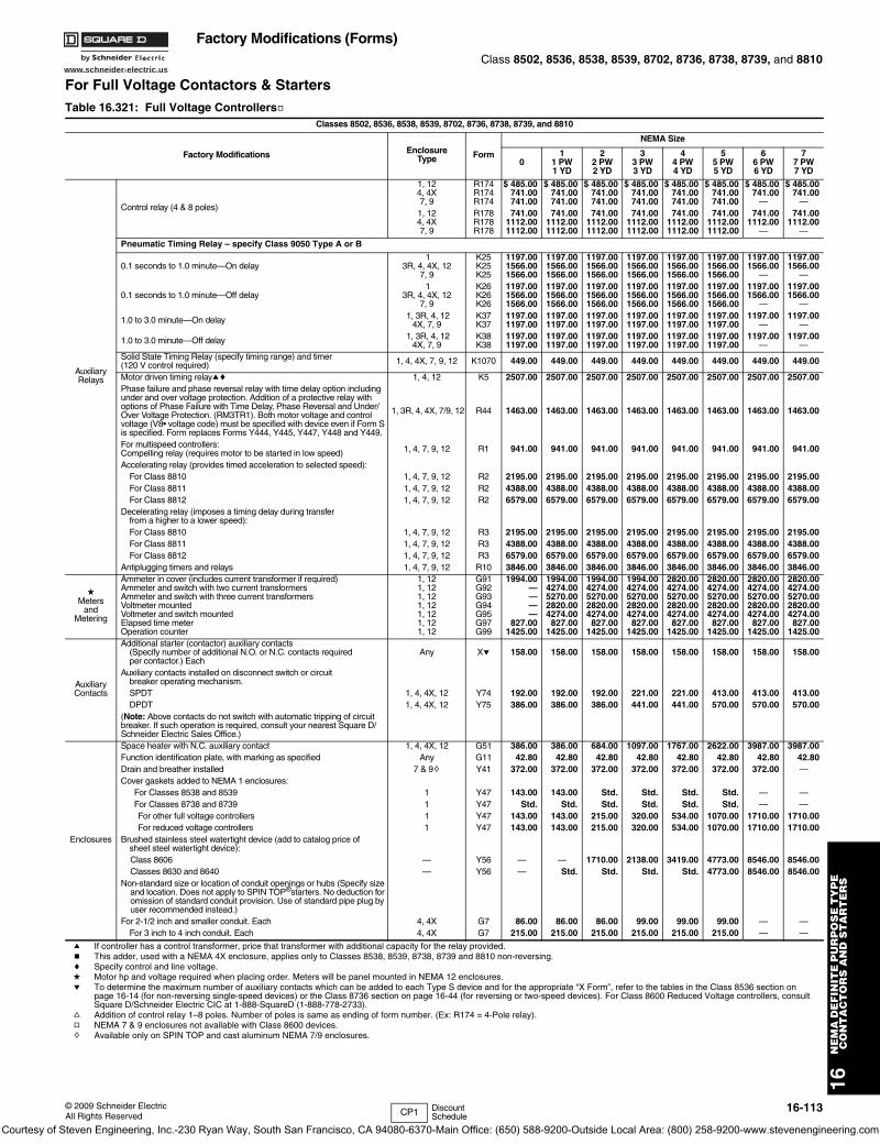
www.schneider-electric.us
16N
EM
A D
EF
INIT
E P
UR
PO
SE
TY
PE
C
ON
TA
CT
OR
S A
ND
ST
AR
TE
RS
© 2009 Schneider ElectricAll Rights Reserved
16-113
Factory Modifications (Forms)Class 8502, 8536, 8538, 8539, 8702, 8736, 8738, 8739, and 8810
For Full Voltage Contactors & Starters
a If controller has a control transformer, price that transformer with additional capacity for the relay provided.b This adder, used with a NEMA 4X enclosure, applies only to Classes 8538, 8539, 8738, 8739 and 8810 non-reversing.c Specify control and line voltage.d Motor hp and voltage required when placing order. Meters will be panel mounted in NEMA 12 enclosures.e To determine the maximum number of auxiliary contacts which can be added to each Type S device and for the appropriate “X Form”, refer to the tables in the Class 8536 section on
page 16-14 (for non-reversing single-speed devices) or the Class 8736 section on page 16-44 (for reversing or two-speed devices). For Class 8600 Reduced Voltage controllers, consult Square D/Schneider Electric CIC at 1-888-SquareD (1-888-778-2733).
f Addition of control relay 1–8 poles. Number of poles is same as ending of form number. (Ex: R174 = 4-Pole relay).g NEMA 7 & 9 enclosures not available with Class 8600 devices.h Available only on SPIN TOP and cast aluminum NEMA 7/9 enclosures.
Table 16.321: Full Voltage ControllersgClasses 8502, 8536, 8538, 8539, 8702, 8736, 8738, 8739, and 8810
Factory Modifications EnclosureType Form
NEMA Size
01
1 PW1 YD
22 PW2 YD
33 PW3 YD
44 PW4 YD
55 PW5 YD
66 PW6 YD
77 PW7 YD
AuxiliaryRelays
Control relay (4 & 8 poles)
1, 12 R174 $ 485.00 $ 485.00 $ 485.00 $ 485.00 $ 485.00 $ 485.00 $ 485.00 $ 485.004, 4X R174 741.00 741.00 741.00 741.00 741.00 741.00 741.00 741.007, 9 R174 741.00 741.00 741.00 741.00 741.00 741.00 — —1, 12 R178 741.00 741.00 741.00 741.00 741.00 741.00 741.00 741.004, 4X R178 1112.00 1112.00 1112.00 1112.00 1112.00 1112.00 1112.00 1112.007, 9 R178 1112.00 1112.00 1112.00 1112.00 1112.00 1112.00 — —
Pneumatic Timing Relay – specify Class 9050 Type A or B
0.1 seconds to 1.0 minute—On delay 1 K25 1197.00 1197.00 1197.00 1197.00 1197.00 1197.00 1197.00 1197.00
3R, 4, 4X, 12 K25 1566.00 1566.00 1566.00 1566.00 1566.00 1566.00 1566.00 1566.007, 9 K25 1566.00 1566.00 1566.00 1566.00 1566.00 1566.00 — —
0.1 seconds to 1.0 minute—Off delay 1 K26 1197.00 1197.00 1197.00 1197.00 1197.00 1197.00 1197.00 1197.00
3R, 4, 4X, 12 K26 1566.00 1566.00 1566.00 1566.00 1566.00 1566.00 1566.00 1566.007, 9 K26 1566.00 1566.00 1566.00 1566.00 1566.00 1566.00 — —
1.0 to 3.0 minute—On delay 1, 3R, 4, 12 K37 1197.00 1197.00 1197.00 1197.00 1197.00 1197.00 1197.00 1197.004X, 7, 9 K37 1197.00 1197.00 1197.00 1197.00 1197.00 1197.00 — —
1.0 to 3.0 minute—Off delay 1, 3R, 4, 12 K38 1197.00 1197.00 1197.00 1197.00 1197.00 1197.00 1197.00 1197.004X, 7, 9 K38 1197.00 1197.00 1197.00 1197.00 1197.00 1197.00 — —
Solid State Timing Relay (specify timing range) and timer (120 V control required) 1, 4, 4X, 7, 9, 12 K1070 449.00 449.00 449.00 449.00 449.00 449.00 449.00 449.00
Motor driven timing relayac 1, 4, 12 K5 2507.00 2507.00 2507.00 2507.00 2507.00 2507.00 2507.00 2507.00Phase failure and phase reversal relay with time delay option including under and over voltage protection. Addition of a protective relay with options of Phase Failure with Time Delay, Phase Reversal and Under/Over Voltage Protection. (RM3TR1). Both motor voltage and control voltage (V8• voltage code) must be specified with device even if Form S is specified. Form replaces Forms Y444, Y445, Y447, Y448 and Y449.
1, 3R, 4, 4X, 7/9, 12 R44 1463.00 1463.00 1463.00 1463.00 1463.00 1463.00 1463.00 1463.00
For multispeed controllers:Compelling relay (requires motor to be started in low speed) 1, 4, 7, 9, 12 R1 941.00 941.00 941.00 941.00 941.00 941.00 941.00 941.00
Accelerating relay (provides timed acceleration to selected speed):For Class 8810 1, 4, 7, 9, 12 R2 2195.00 2195.00 2195.00 2195.00 2195.00 2195.00 2195.00 2195.00For Class 8811 1, 4, 7, 9, 12 R2 4388.00 4388.00 4388.00 4388.00 4388.00 4388.00 4388.00 4388.00For Class 8812 1, 4, 7, 9, 12 R2 6579.00 6579.00 6579.00 6579.00 6579.00 6579.00 6579.00 6579.00
Decelerating relay (imposes a timing delay during transferfrom a higher to a lower speed):For Class 8810 1, 4, 7, 9, 12 R3 2195.00 2195.00 2195.00 2195.00 2195.00 2195.00 2195.00 2195.00For Class 8811 1, 4, 7, 9, 12 R3 4388.00 4388.00 4388.00 4388.00 4388.00 4388.00 4388.00 4388.00For Class 8812 1, 4, 7, 9, 12 R3 6579.00 6579.00 6579.00 6579.00 6579.00 6579.00 6579.00 6579.00
Antiplugging timers and relays 1, 4, 7, 9, 12 R10 3846.00 3846.00 3846.00 3846.00 3846.00 3846.00 3846.00 3846.00
dMeters
andMetering
Ammeter in cover (includes current transformer if required) Ammeter and switch with two current transformers Ammeter and switch with three current transformers Voltmeter mounted Voltmeter and switch mounted Elapsed time meterOperation counter
1, 121, 121, 121, 121, 121, 121, 12
G91G92G93G94G95G97G99
1994.00————
827.001425.00
1994.004274.005270.002820.004274.00
827.001425.00
1994.004274.005270.002820.004274.00
827.001425.00
1994.004274.005270.002820.004274.00
827.001425.00
2820.004274.005270.002820.004274.00827.00
1425.00
2820.004274.005270.002820.004274.00827.00
1425.00
2820.004274.005270.002820.004274.00
827.001425.00
2820.004274.005270.002820.004274.00
827.001425.00
AuxiliaryContacts
Additional starter (contactor) auxiliary contacts(Specify number of additional N.O. or N.C. contacts required per contactor.) Each
Any Xe 158.00 158.00 158.00 158.00 158.00 158.00 158.00 158.00
Auxiliary contacts installed on disconnect switch or circuitbreaker operating mechanism.SPDT 1, 4, 4X, 12 Y74 192.00 192.00 192.00 221.00 221.00 413.00 413.00 413.00DPDT 1, 4, 4X, 12 Y75 386.00 386.00 386.00 441.00 441.00 570.00 570.00 570.00
(Note: Above contacts do not switch with automatic tripping of circuit breaker. If such operation is required, consult your nearest Square D/Schneider Electric Sales Office.)
Enclosures
Space heater with N.C. auxiliary contact 1, 4, 4X, 12 G51 386.00 386.00 684.00 1097.00 1767.00 2622.00 3987.00 3987.00Function identification plate, with marking as specified Any G11 42.80 42.80 42.80 42.80 42.80 42.80 42.80 42.80Drain and breather installed 7 & 9h Y41 372.00 372.00 372.00 372.00 372.00 372.00 372.00 —Cover gaskets added to NEMA 1 enclosures:
For Classes 8538 and 8539 1 Y47 143.00 143.00 Std. Std. Std. Std. — —For Classes 8738 and 8739 1 Y47 Std. Std. Std. Std. Std. Std. — —For other full voltage controllers 1 Y47 143.00 143.00 215.00 320.00 534.00 1070.00 1710.00 1710.00For reduced voltage controllers 1 Y47 143.00 143.00 215.00 320.00 534.00 1070.00 1710.00 1710.00
Brushed stainless steel watertight device (add to catalog price ofsheet steel watertight device):Class 8606 — Y56 — — 1710.00 2138.00 3419.00 4773.00 8546.00 8546.00Classes 8630 and 8640 — Y56 — Std. Std. Std. Std. 4773.00 8546.00 8546.00
Non-standard size or location of conduit openings or hubs (Specify size and location. Does not apply to SPIN TOP®starters. No deduction for omission of standard conduit provision. Use of standard pipe plug by user recommended instead.)
For 2-1/2 inch and smaller conduit. Each 4, 4X G7 86.00 86.00 86.00 99.00 99.00 99.00 — —For 3 inch to 4 inch conduit. Each 4, 4X G7 215.00 215.00 215.00 215.00 215.00 215.00 — —
CP1 Discount Schedule
Courtesy of Steven Engineering, Inc.-230 Ryan Way, South San Francisco, CA 94080-6370-Main Office: (650) 588-9200-Outside Local Area: (800) 258-9200-www.stevenengineering.com
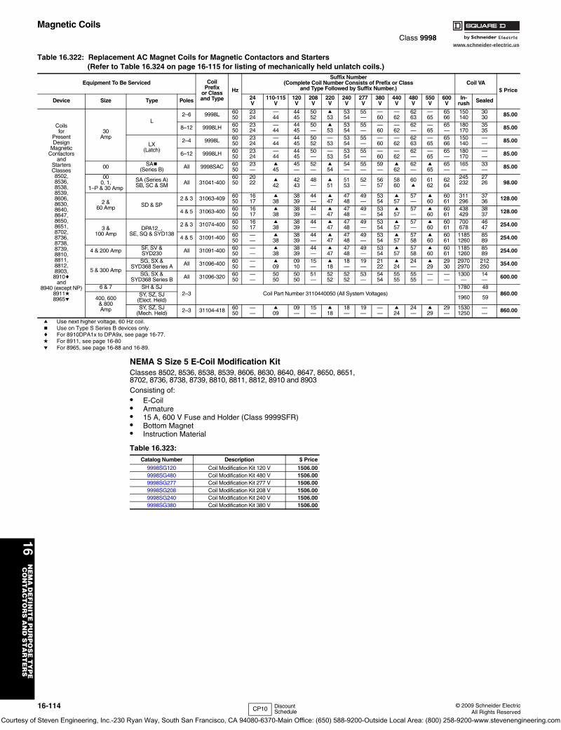
www.schneider-electric.us
16N
EM
A D
EF
INIT
E P
UR
PO
SE
TY
PE
C
ON
TA
CT
OR
S A
ND
ST
AR
TE
RS
16-114 © 2009 Schneider ElectricAll Rights Reserved
Magnetic CoilsClass 9998
NEMA S Size 5 E-Coil Modification KitClasses 8502, 8536, 8538, 8539, 8606, 8630, 8640, 8647, 8650, 8651, 8702, 8736, 8738, 8739, 8810, 8811, 8812, 8910 and 8903Consisting of:• E-Coil• Armature• 15 A, 600 V Fuse and Holder (Class 9999SFR)• Bottom Magnet• Instruction Material
Table 16.322: Replacement AC Magnet Coils for Magnetic Contactors and Starters(Refer to Table 16.324 on page 16-115 for listing of mechanically held unlatch coils.)
Equipment To Be Serviced CoilPrefix
or Classand Type
Hz
Suffix Number(Complete Coil Number Consists of Prefix or Class
and Type Followed by Suffix Number.)Coil VA
$ Price
Device Size Type Poles 24V
110-115V
120V
208V
220V
240V
277V
380V
440V
480V
550V
600V
In-rush Sealed
Coilsfor
PresentDesign
MagneticContactors
andStartersClasses8502,8536,8538,8539,8606,8630,8640,8647,8650,8651,8702,8736,8738,8739,8810,8811,8812,8903,8910c
and8940 (except NP)
8911d8965e
30Amp
L2–6 9998L 60
502324
—44
4445
5052
a53
5354
55—
—60
—62
6263
—65
6566
150140
3030 85.00
8–12 9998LH 6050
2324
—44
4445
50—
a53
5354
55—
—60
—62
62—
—65
65—
180170
3535 85.00
LX(Latch)
2–4 9998L 6050
2324
—44
4445
5052
—53
5354
55—
—60
—62
6263
—65
6566
150140
—— 85.00
6–12 9998LH 6050
2324
—44
4445
50—
—53
5354
55—
—60
—62
62—
—65
65—
180170
—— 85.00
00 SAb(Series B) All 9998SAC 60
5023—
a45
45—
52—
a54
54—
55—
59—
a62
62—
a65
65—
165—
33— 85.00
000, 1,
1–P & 30 Amp
SA (Series A)SB, SC & SM All 31041-400
6050
2022
a42
4243
48—
a51
5153
52—
5657
5860
60a
6162
6264
245232
2726
98.00
2 &60 Amp SD & SP
2 & 3 31063-409 6050
1617
a38
3839
44—
a47
4748
49—
5354
a57
57—
a60
6061
311296
3736 128.00
4 & 5 31063-400 6050
1617
a38
3839
44—
a47
4748
49—
5354
a57
57—
a60
6061
438429
3837 128.00
3 &100 Amp
DPA12_,SE, SQ & SYD138
2 & 3 31074-400 6050
1617
a38
3839
44—
a47
4748
49—
5354
a57
57—
a60
6061
700678
4647 254.00
4 & 5 31091-400 6050
——
a38
3839
44—
a47
4748
49—
5354
a57
5758
a60
6061
11851260
8589 254.00
4 & 200 Amp SF, SV & SYD230 All 31091-400 60
50——
a38
3839
44—
a47
4748
49—
5354
a57
5758
a60
6061
11851260
8589 254.00
5 & 300 Amp
SG, SX &SYD368 Series A All 31096-400 60
50——
a09
0910
15—
a18
18—
19—
2122
a24
24—
a29
2930
29702970
212250 354.00
SG, SX &SYD368 Series B All 31096-320 60
50——
5050
5050
51—
5252
5252
53—
5454
5555
5555
——
——
1300—
14— 600.00
6 & 7 SH & SJ2–3 Coil Part Number 3110440050 (All System Voltages)
1780 48860.00
400, 600& 800Amp
SY, SZ, SJ(Elect. Held) 1960 59
SY, SZ, SJ(Mech. Held) 2–3 31104-418 60
50——
a09
09—
15—
a18
18—
19—
——
a24
24—
a29
29—
15301250
—— 860.00
a Use next higher voltage, 60 Hz coil.b Use on Type S Series B devices only.c For 8910DPA1x to DPA9x, see page 16-77.d For 8911, see page 16-80e For 8965, see page 16-88 and 16-89.
Table 16.323: Catalog Number Description $ Price
9998SG120 Coil Modification Kit 120 V 1506.009998SG480 Coil Modification Kit 480 V 1506.009998SG277 Coil Modification Kit 277 V 1506.009998SG208 Coil Modification Kit 208 V 1506.009998SG240 Coil Modification Kit 240 V 1506.009998SG380 Coil Modification Kit 380 V 1506.00
CP10 Discount Schedule
Courtesy of Steven Engineering, Inc.-230 Ryan Way, South San Francisco, CA 94080-6370-Main Office: (650) 588-9200-Outside Local Area: (800) 258-9200-www.stevenengineering.com
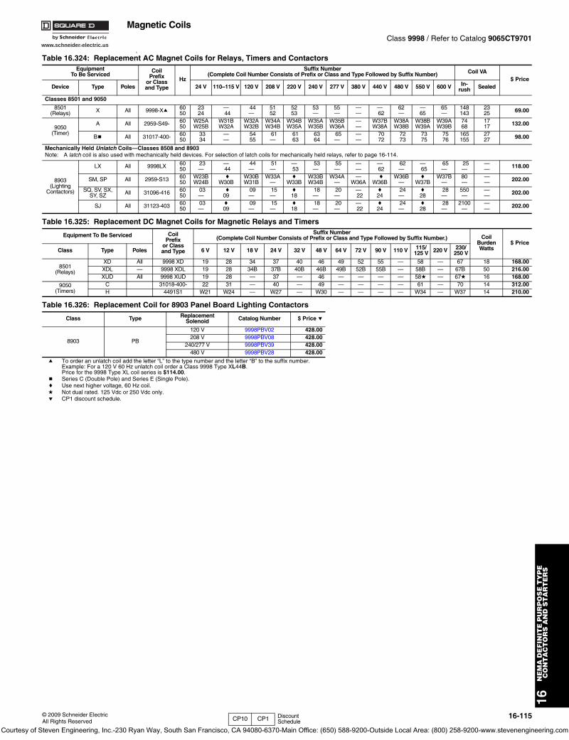
www.schneider-electric.us
16N
EM
A D
EF
INIT
E P
UR
PO
SE
TY
PE
C
ON
TA
CT
OR
S A
ND
ST
AR
TE
RS
© 2009 Schneider ElectricAll Rights Reserved
16-115
Magnetic CoilsClass 9998 / Refer to Catalog 9065CT9701
0
Table 16.324: Replacement AC Magnet Coils for Relays, Timers and ContactorsEquipment
To Be ServicedCoil
Prefixor Classand Type
Hz
Suffix Number(Complete Coil Number Consists of Prefix or Class and Type Followed by Suffix Number) Coil VA
$ PriceDevice Type Poles 24 V 110–115 V 120 V 208 V 220 V 240 V 277 V 380 V 440 V 480 V 550 V 600 V In-
rush Sealed
Classes 8501 and 9050
8501(Relays) X All 9998-Xa 60
502324
—44
44—
5152
5253
53—
55—
——
—62
62—
—65
65—
148143
2325 69.00
9050(Timer)
A All 2959-S49- 6050
W25AW25B
W31BW32A
W32AW32B
W34AW34B
W34BW35A
W35AW35B
W35BW36A
——
W37BW38A
W38AW38B
W38BW39A
W39AW39B
7468
1717 132.00
Bb All 31017-400- 6050
3334
——
5455
61—
6163
6364
65—
——
7072
7273
7375
7576
165155
2727 98.00
Mechanically Held Unlatch Coils—Classes 8508 and 8903Note: A latch coil is also used with mechanically held devices. For selection of latch coils for mechanically held relays, refer to page 16-114.
8903(Lighting
Contactors)
LX All 9998LX 6050
23—
—44
44—
51—
—53
53—
55—
——
—62
62—
—65
65—
25—
—— 118.00
SM, SP All 2959-S13 6050
W23BW24B
cW30B
W30BW31B
W33A—
cW33B
W33BW34B
W34A—
—W36A
cW36B
W36B—
cW37B
W37B—
80—
—— 202.00
SQ, SV, SX,SY, SZ All 31096-416 60
5003—
c09
09—
15—
c18
18—
20—
—22
c24
24—
c28
28—
550—
—— 202.00
SJ All 31123-403 6050
03—
c09
09—
15—
c18
18—
20—
—22
c24
24—
c28
28—
2100—
—— 202.00
Table 16.325: Replacement DC Magnet Coils for Magnetic Relays and Timers
Equipment To Be Serviced CoilPrefix
or Classand Type
Suffix Number(Complete Coil Number Consists of Prefix or Class and Type Followed by Suffix Number.) Coil
BurdenWatts
$ PriceClass Type Poles 6 V 12 V 18 V 24 V 32 V 48 V 64 V 72 V 90 V 110 V 115/
125 V 220 V 230/ 250 V
8501(Relays)
XD All 9998 XD 19 28 34 37 40 46 49 52 55 — 58 — 67 18 168.00XDL — 9998 XDL 19 28 34B 37B 40B 46B 49B 52B 55B — 58B — 67B 50 216.00XUD All 9998 XUD 19 28 — 37 — 46 — — — — 58d — 67d 16 168.00
9050(Timers)
C 31018-400- 22 31 — 40 — 49 — — — — 61 — 70 14 312.00H 4491S1 W21 W24 — W27 — W30 — — — — W34 — W37 14 210.00
Table 16.326: Replacement Coil for 8903 Panel Board Lighting Contactors
Class Type ReplacementSolenoid Catalog Number $ Price e
8903 PB
120 V 9998PBV02 428.00208 V 9998PBV08 428.00
240/277 V 9998PBV39 428.00480 V 9998PBV28 428.00
a To order an unlatch coil add the letter “L” to the type number and the letter “B” to the suffix number.Example: For a 120 V 60 Hz unlatch coil order a Class 9998 Type XL44B. Price for the 9998 Type XL coil series is $114.00.
b Series C (Double Pole) and Series E (Single Pole).c Use next higher voltage, 60 Hz coil.d Not dual rated. 125 Vdc or 250 Vdc only.e CP1 discount schedule.
CP10 CP1 Discount Schedule
Courtesy of Steven Engineering, Inc.-230 Ryan Way, South San Francisco, CA 94080-6370-Main Office: (650) 588-9200-Outside Local Area: (800) 258-9200-www.stevenengineering.com
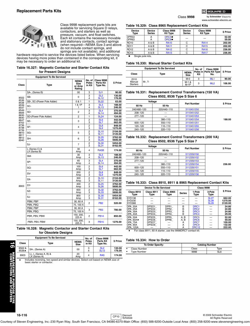
www.schneider-electric.us
16N
EM
A/D
EF
INIT
E P
UR
PO
SE
TY
PE
CO
NT
AC
TO
RS
AN
D S
TA
RT
ER
S
16-116 © 2009 Schneider ElectricAll Rights Reserved
Replacement Parts KitsClass 9998
Class 9998 replacement parts kits are available for servicing Square D relays, contactors, and starters as well as pressure, vacuum, and float switches. Each kit contains the necessary movable and stationary contacts, contact springs (when required—NEMA Size 3 and above do not include contact springs, and springs are not available), and additional
hardware required to service the devices listed below. When servicing devices having more poles than contained in the corresponding kit, it may be necessary to order an additional kit.
a Includes reversing, two speed and similar devices. Select coil based on NEMA size of basic starter or contactor.
b Single pole kits.
c For class 8911, 60 A starter, use the 9998DRC7 contact kit.
Table 16.327: Magnetic Contactor and Starter Contact Kitsfor Present Designs
Equipment To Be ServicedNo. ofPolesin Kit
Class 9998Parts KitType No.
$ PriceClass Type
NEMASize
or AmpRating
850285368538853985478549860686308640864787028736873887398810881188128940
SA-, (Series B) 00 3 SJ1 90.00
SB- 0 34
SL2SL12
130.00176.00
SB-, SC-(Power Pole Adder) 0 & 1 1 SL22 63.00
SC- 1 & 1P1
34
SL3SL13
188.00246.00
SD- 2 34
SL4SL14
370.00494.00
SD-(Power Pole Adder) 2 1 SL24 124.00
SE- 3 23
SL6SL7
442.00662.00
SF- 4 23
SL8SL9
848.001270.00
SG- 5 23
SL10SL11
2104.003120.00
SH- 6 23
SL25SL26
3762.005606.00
SJ- 7 23
SL30SL31
5454.008162.00
8903
L (Series C) &LX (Series B)
30Amp 4 RA5B 174.00
SM- 30Amp
34
SL3SL13
188.00246.00
SP- 60Amp
34
SL4SL14
370.00494.00
SQ- 100Amp
23
SL6SL7
442.00662.00
SV- 200Amp
23
SL8SL9
848.001270.00
SX- 300Amp
23
SL10SL11
2104.003120.00
SY- 400Amp
23
SL25SL26
3762.005606.00
SZ- 600Amp
23
SL32SL33
3762.005606.00
SJ- 800Amp
23
SL30SL31
5454.008162.00
PBM, PBP 30, 60 A2 PB2 520.00
PBN, PBQ 75, 100 APBM, PBP 30, 60 A
3 PB3 780.00PBN, PBQ 75, 100 A
PBR, PBV, PBW 150, 200, 225 A 2 PB14 850.00
PBR, PBV, PBW 150, 200, 225 A 3 PB15 1276.00
Table 16.328: Magnetic Contactor and Starter Contact Kitsfor Obsolete Designs
Equipment To Be Serviced No. ofPolesin Kit
Class 9998Parts KitType No.
$ PriceClass Type NEMA
Size
8502 &8536a SA-, (Series A) 00 3
4SL2SL12
130.00176.00
8903 LL, L (Series A, B) &LX (Series A)
20Amp 4 RA5 174.00
Table 16.329: Class 8965 Replacement Contact KitsDeviceType
DeviceSeries
Class 9998Kit Type
DeviceSeries
Class 9998Kit Type $ Price
DPR53DPR63
AA
DRC5bDRC6b — — 52.00
59.00RO10 A & B RA10 C RA14 202.00RO11 A & B RA11 C RA15 202.00RO12 A & B RA12 C RA16 236.00RO13 A & B RA13 C RA17 236.00
Table 16.330: Manual Starter Contact KitsEquipment To Be Serviced No. of
Poles in Kit
Class 9998 Parts Kit Type
No.$ Price
Class Type NEMASize
2510ManualStarters
M-, T- M-0 3 ML1 90.00
M-1 &M-1P 3 ML2 106.00
Table 16.331: Replacement Control Transformers (150 VA)Class 8502, 8536 Type S Size 6Voltage
Part Number $ Price60 Hz 50 Hz
240/480–120 220/440–110 3110451250
188.00
208–120 — 3110451252277–120 — 3110451253
— 380–110 3110451254600–120 550–110 3110451251120–120 110–110 3110451255240–120 220–110 3110451256
Table 16.332: Replacement Control Transformers (200 VA)Class 8502, 8536 Type S Size 7Voltage
Part Number $ Price60 Hz 50 Hz
240/480–120 220/440–110 3112350150
236.00
208–120 — 3112350152277–120 — 3112350153
— 380–110 3112350154600–120 550–110 3112350151120–120 110–110 3112350155240–120 220–110 3112350156
Table 16.333: Class 8910, 8911 & 8965 Replacement Contact KitsDevice To Be Serviced Class 9998
$ Price1-PoleType
3-PoleType
Class 8910Type
Class 8911Type
Class 8965Type Series
SYD138SYD230SYD368
———
———
———
———
SL27SL28SL29
662.001270.003120.00
DPA_20ADPA_25ADPA_30ADPA_40A
DPSO1_DPSO2_DPSO3_DPSO4_
DPR1_DPR2_DPR3_DPR4_
BBBB
DRC1DRC2DRC3DRC4
————
24.8022.8024.8029.00
DPA_50ADPA_60AcDPA_75ADPA_90ADPA_120A
DPSO5_DPSO6_DPSO7_DPSO9_
—
DPR5_DPR6_
———
A, BA, B
AAA
DRC5DRC6DRC7DRC9DRC12
—————
52.0059.00
100.00132.00222.00
Table 16.334: How to OrderTo Order Specify: Catalog Number
• Class Number• Type Number
Class Type9998 SL6
CP10 Discount Schedule
Courtesy of Steven Engineering, Inc.-230 Ryan Way, South San Francisco, CA 94080-6370-Main Office: (650) 588-9200-Outside Local Area: (800) 258-9200-www.stevenengineering.com
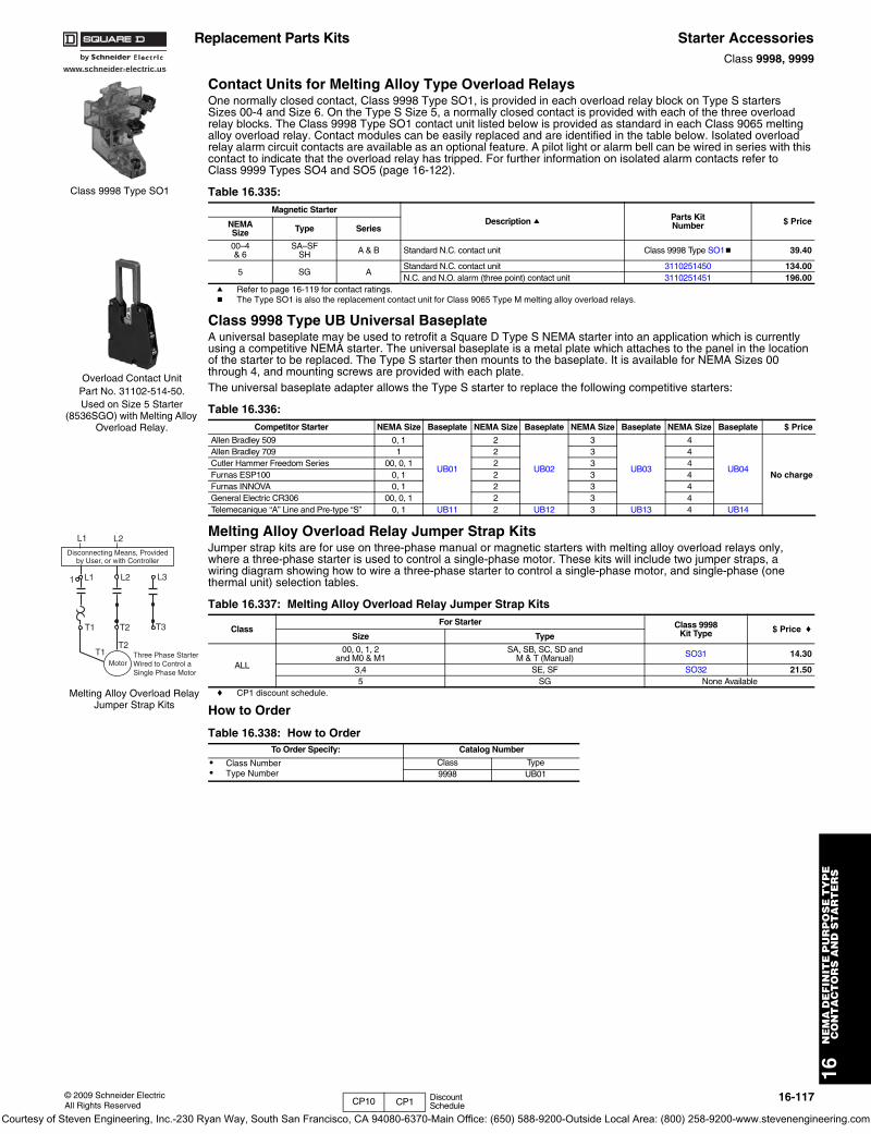
www.schneider-electric.us
16N
EM
A D
EF
INIT
E P
UR
PO
SE
TY
PE
C
ON
TA
CT
OR
S A
ND
ST
AR
TE
RS
© 2009 Schneider ElectricAll Rights Reserved
16-117
Replacement Parts Kits Starter AccessoriesClass 9998, 9999
Contact Units for Melting Alloy Type Overload RelaysOne normally closed contact, Class 9998 Type SO1, is provided in each overload relay block on Type S starters Sizes 00-4 and Size 6. On the Type S Size 5, a normally closed contact is provided with each of the three overload relay blocks. The Class 9998 Type SO1 contact unit listed below is provided as standard in each Class 9065 melting alloy overload relay. Contact modules can be easily replaced and are identified in the table below. Isolated overload relay alarm circuit contacts are available as an optional feature. A pilot light or alarm bell can be wired in series with this contact to indicate that the overload relay has tripped. For further information on isolated alarm contacts refer toClass 9999 Types SO4 and SO5 (page 16-122).
a Refer to page 16-119 for contact ratings.b The Type SO1 is also the replacement contact unit for Class 9065 Type M melting alloy overload relays.
Class 9998 Type UB Universal BaseplateA universal baseplate may be used to retrofit a Square D Type S NEMA starter into an application which is currently using a competitive NEMA starter. The universal baseplate is a metal plate which attaches to the panel in the location of the starter to be replaced. The Type S starter then mounts to the baseplate. It is available for NEMA Sizes 00 through 4, and mounting screws are provided with each plate.The universal baseplate adapter allows the Type S starter to replace the following competitive starters:
Melting Alloy Overload Relay Jumper Strap KitsJumper strap kits are for use on three-phase manual or magnetic starters with melting alloy overload relays only, where a three-phase starter is used to control a single-phase motor. These kits will include two jumper straps, a wiring diagram showing how to wire a three-phase starter to control a single-phase motor, and single-phase (one thermal unit) selection tables.
c CP1 discount schedule.
How to Order
Table 16.335: Magnetic Starter
Description a Parts KitNumber $ PriceNEMA
Size Type Series
00–4& 6
SA–SFSH A & B Standard N.C. contact unit Class 9998 Type SO1b 39.40
5 SG AStandard N.C. contact unit 3110251450 134.00N.C. and N.O. alarm (three point) contact unit 3110251451 196.00
Table 16.336: Competitor Starter NEMA Size Baseplate NEMA Size Baseplate NEMA Size Baseplate NEMA Size Baseplate $ Price
Allen Bradley 509 0, 1
UB01
2
UB02
3
UB03
4
UB04No charge
Allen Bradley 709 1 2 3 4Cutler Hammer Freedom Series 00, 0, 1 2 3 4Furnas ESP100 0, 1 2 3 4Furnas INNOVA 0, 1 2 3 4General Electric CR306 00, 0, 1 2 3 4Telemecanique “A” Line and Pre-type “S” 0, 1 UB11 2 UB12 3 UB13 4 UB14
Table 16.337: Melting Alloy Overload Relay Jumper Strap Kits
ClassFor Starter Class 9998
Kit Type $ Price cSize Type
ALL
00, 0, 1, 2and M0 & M1
SA, SB, SC, SD andM & T (Manual) SO31 14.30
3,4 SE, SF SO32 21.505 SG None Available
Table 16.338: How to OrderTo Order Specify: Catalog Number
• Class Number• Type Number
Class Type9998 UB01
Class 9998 Type SO1
Overload Contact Unit Part No. 31102-514-50.Used on Size 5 Starter
(8536SGO) with Melting Alloy Overload Relay.
L1 L2
1 L1 L2 L3
T1
T1
T2
T2
T3
MotorThree Phase StarterWired to Control aSingle Phase Motor
Disconnecting Means, Providedby User, or with Controller
Melting Alloy Overload Relay Jumper Strap Kits
CP10 CP1 Discount Schedule
Courtesy of Steven Engineering, Inc.-230 Ryan Way, South San Francisco, CA 94080-6370-Main Office: (650) 588-9200-Outside Local Area: (800) 258-9200-www.stevenengineering.com
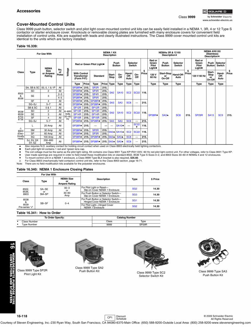
www.schneider-electric.us
16N
EM
A/D
EF
INIT
E P
UR
PO
SE
TY
PE
CO
NT
AC
TO
RS
AN
D S
TA
RT
ER
S
16-118 © 2009 Schneider ElectricAll Rights Reserved
AccessoriesClass 9999
Cover-Mounted Control UnitsClass 9999 push button, selector switch and pilot light cover-mounted control unit kits can be easily field installed in a NEMA 1, 3R, 4 or 12 Type S contactor or starter enclosure cover. Knockouts or removable closing plates are furnished with many enclosure covers for convenient field installation of control units. Kits are supplied with leads and clearly illustrated instructions. The Class 9999 cover mounted control unit kits are identical to the units which are factory installed.
a Also requires N.O. auxiliary contact for holding circuit contact when used on Class 8903 electrically held lighting contactors.b Each pilot light kit contains 1 red and 1green lens cap.c The coil voltage must be the same as the pilot light rating. Kit contains one Class 9001 Type KP1R31120V, 60 Hz red pilot light control unit. For other voltages, refer to Class 9001 Type KP.d User made openings are required in order to field install these modification kits on standard 8502, 8536 Type S Sizes 0–2, and 8903 Sizes 30–60 A NEMAs 4 and 12 enclosures.e To mount control unit in a NEMA 1 enclosure, a Class 9999 Type BLX bracket is also required, $35.60.f For Class 8903 (mechanically held contactor) control unit kits, refer to the Class 8903 section, page 16-71.
Note: There are no field modification kits available for the polyester enclosures.
Table 16.339:
For Use With NEMA 1 Kit Description
NEMAs 3R & 12 Kit Descriptiond
NEMA 4/4X Kit (Stainless)
Descriptiond
Class Type
NEMASize
or AmpereRating
No.of
Poles Volta
ge
Red or Green Pilot Lightb Push Button
Selector Switch
$ Price
Red or GreenPilot
Lightb
PushButton
SelectorSwitch
$ Price
Red or GreenPilot
Lightb
PushButton
SelectorSwitch
$ PriceWith Control
Transformer(Form F4T)
Standard Start-Stop
On-Off
Hand-Off-Auto
On-Off
120 V 60 Hz
Start-Stopor
On-Off
Hand-Off-Auto 120 V 60 Hz
Start-Stop
orOn-Off
Hand-Off-Auto
Type Price Type Price Type Type Type Type Type Type Type Type Type Type
8502&
8536
SA, SB & SC 00, 0, 1 & 1P All
6–600Volts
50–60Hz
SP28Rc 215. SP2R 215.
SA2 SA10 SC2 SC22 116.
SP28Rc SA3a SC8 215. SP29R SA13 SC9 215.
SD 2 All SP28Rc 215. SP3R 215.
SE 32–3 SP28Rc 215. SP4R 215.4–5 SP28Rc 215. SP5R 215.
SF 4 All SP28Rc 215. SP28Rc 215.SA3 SA3 SC8 — 215.
SG–SJ 5–7 All SP28Rc 215. SP28Rc 215.
8538853987028736
SB & SC 0 & 1 All SP12R 215. SP12R 215.
SA2 SA10 SC2 SC22 116.SD 2 All SP13R 215. SP13R 215.SE 3 All SP14R 215. SP14R 215.SF 4 All SP15R 215. SP15R 215.
SG–SJ 5–7 All SP28Rc 215. SP28Rc 215. SA3 SA3 SC8 — 215.
f8903(Elec-tricallyHeld)
L 20 Amp All SP28Rc 215. — — — SA10e — SC22e
116.
SM 30 Amp All SP28Rc 215. SP2R 215.SA2a SA10a SC2 SC22 116.
SP 60 Amp All SP28Rc 215. SP3R 215.SQ 100 Amp All SP28Rc 215. SP28Rc 215. SA3a SA3a SC8 — 215.
SJ, SV, SXSY, SZ
200–800Amp All SP28Rc 215. SP28Rc 215. SA3a SA3a SC8 — 215.
Table 16.340: NEMA 1 Enclosure Closing PlatesFor Use With
Description Type $ PriceClass Type
NEMA Sizeor
Ampere Rating
8502,8536,8903
SA–SEor
SM–SP
00–3or
30–60Amp
For Pilot Light or Reset—Slip-on Cover NEMA 1 Enclosure SG2 14.30
For Push Button or Selector Switch—Slip-on Cover NEMA 1 Enclosure SG3 14.30
8538&
8539Pre-series “J”
SB–SF 0–4
For Push Button or Selector Switch—Hinged Cover NEMA 1 Enclosure SG1 14.30
For Pilot Light—Hinged CoverNEMA 1 Enclosure SG2 14.30
Table 16.341: How to OrderTo Order Specify: Catalog Number
• Class Number• Type Number
Class Type9999 SP29R
Class 9999 Type SP2R Pilot Light Kit
Class 9999 Type SA2Push Button Kit Class 9999 Type SC2
Selector Switch Kit
Class 9999 Type SA3 Push Button Kit
CP1 Discount Schedule
Courtesy of Steven Engineering, Inc.-230 Ryan Way, South San Francisco, CA 94080-6370-Main Office: (650) 588-9200-Outside Local Area: (800) 258-9200-www.stevenengineering.com
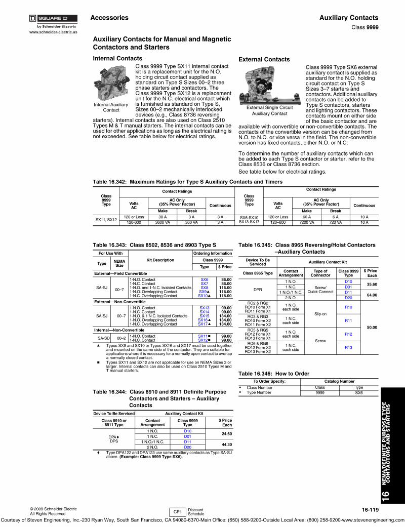
www.schneider-electric.us
16N
EM
A/D
EF
INIT
E P
UR
PO
SE
TY
PE
CO
NT
AC
TO
RS
AN
D S
TA
RT
ER
S
© 2009 Schneider ElectricAll Rights Reserved
16-119
Accessories Auxiliary ContactsClass 9999
Auxiliary Contacts for Manual and Magnetic Contactors and Starters
Internal ContactsClass 9999 Type SX11 internal contact kit is a replacement unit for the N.O. holding circuit contact supplied as standard on Type S Sizes 00–2 three phase starters and contactors. The Class 9999 Type SX12 is a replacement unit for the N.C. electrical contact which is furnished as standard on Type S, Sizes 00–2 mechanically interlocked devices (e.g., Class 8736 reversing
starters). Internal contacts are also used on Class 2510 Types M & T manual starters. The internal contacts can be used for other applications as long as the electrical rating is not exceeded. See table below for electrical ratings.
External ContactsClass 9999 Type SX6 external auxiliary contact is supplied as standard for the N.O. holding circuit contact on Type S Sizes 3–7 starters and contactors. Additional auxiliary contacts can be added to Type S contactors, starters and lighting contactors. These contacts mount on either side of the basic contactor and are
available with convertible or non-convertible contacts. The contacts of the convertible version can be changed from N.O. to N.C. or vice versa in the field. The non-convertible version has fixed contacts, either N.O. or N.C.
To determine the number of auxiliary contacts which can be added to each Type S contactor or starter, refer to the Class 8536 or Class 8736 section.See table below for electrical ratings.
a Types SX9 and SX10 or Types SX16 and SX17 must be used together and mounted on the same side of the contactor. They are suitable for applications where it is necessary for a normally open contact to overlap a normally closed contact.
b Types SX11 and SX12 are not applicable for use on NEMA Sizes 3 or larger. Internal contacts can also be used on Class 2510 Types M and T manual starters.
c Type DPA122 and DPA123 use same auxiliary contacts as Type SA-SJ above. (Example: Class 9999 Type SX6).
Internal Auxiliary Contact External Single Circuit
Auxiliary Contact
Table 16.342: Maximum Ratings for Type S Auxiliary Contacts and Timers
Class9999Type
Contact RatingsClass9999Type
Contact Ratings
VoltsAC
AC Only(35% Power Factor) Continuous Volts
AC
AC Only(35% Power Factor) Continuous
Make Break Make Break
SX11, SX12120 or Less 30 A 3 A 3 A SX6-SX10
SX13-SX17120 or Less 60 A 6 A 10 A
120-600 3600 VA 360 VA 3 A 120–600 7200 VA 720 VA 10 A
Table 16.343: Class 8502, 8536 and 8903 Type SFor Use With
Kit Description
Ordering Information
Type NEMASize
Class 9999
Type $ Price
External—Field Convertible
SA-SJ 00–7
1-N.O. Contact1-N.C. Contact1-N.O. and 1-N.C. Isolated Contacts1-N.O. Overlapping Contact1-N.C. Overlapping Contact
SX6SX7SX8
SX9aSX10a
86.0086.00
116.00116.00116.00
External—Non-Convertible
SA-SJ 00–7
1-N.O. Contact1-N.C. Contact1-N.O. & 1 N.C. Isolated Contacts1-N.O. Overlapping Contact1-N.C. Overlapping Contact
SX13SX14SX15
SX16aSX17a
99.0099.00
134.00134.00134.00
Internal—Non-Convertible
SA-SD 00–2 1-N.O. Contact 1-N.C. Contact
SX11bSX12b
99.0099.00
Table 16.344: Class 8910 and 8911 Definite Purpose Contactors and Starters – Auxiliary Contacts
Device To Be Serviced Auxiliary Contact Kit
Class 8910 or8911 Type
ContactArrangement
Class 9999Type
$ PriceEach
DPAcDPS
1 N.O. D1024.60
1 N.C. D011 N.O./1 N.C. D11
44.302 N.O. D20
Table 16.345: Class 8965 Reversing/Hoist Contactors –Auxiliary Contacts
Device To Be Serviced Auxiliary Contact Kit
Class 8965 Type ContactArrangement
Type ofConnector
Class 9999Type
$ PriceEach
DPR
1 N.O.
Screw/Quick-Connect
D1035.60
1 N.C. D011 N.O./1 N.C. D11
64.002 N.O. D20
RO2 & RG2RO10 Form X1RO11 Form X1
1 N.O.each side
Slip-on
R10
50.00
RO3 & RG3RO10 Form X2RO11 Form X2
1 N.C.each side R11
RO5 & RG5RO12 Form X1RO13 Form X1
1 N.O.each side
Screw
R12
RO6 & RG6RO12 Form X2RO13 Form X2
1 N.C.each side R13
Table 16.346: How to OrderTo Order Specify: Catalog Number
• Class Number• Type Number
Class Type9999 SX6
CP1 Discount Schedule
Courtesy of Steven Engineering, Inc.-230 Ryan Way, South San Francisco, CA 94080-6370-Main Office: (650) 588-9200-Outside Local Area: (800) 258-9200-www.stevenengineering.com
www.schneider-electric.us
16N
EM
A/D
EF
INIT
E P
UR
PO
SE
TY
PE
CO
NT
AC
TO
RS
AN
D S
TA
RT
ER
S
16-120 © 2009 Schneider ElectricAll Rights Reserved
Accessories Solid State Overload Relay, Motor Logic® and Motor Logic PlusClass 9999, 9065 / Refer to Catalog 9065CT9701
Motor Logic—Class 9999
Isolated Auxiliary Contacts for Motor Logic Overload RelaysOverload relay auxiliary contacts are available factory installed or in kit form for field installation on MOTOR LOGIC overload relays. These contacts may be used for isolated alarm contact applications.
DIN AdapterThe DIN adapter provides a method to mount the MOTOR LOGIC overload relay to a 35 mm DIN rail.
Lug-Lug and Lug-Extender KitsA Class 9999 LL0 Lug-Lug Kit can be field installed on separately mounted overload relays. The standard Size 00B, 00C, 0, and 1 Class 9065 Type SS and SF overload relays are supplied without lugs. A Class 9999 LB0 Lug-Extender Kit is designed for Size 00B, 00C, 0, and 1 Retrofit Starter Applications. This kit allows the lugs to be in the same location as the Class 9065 melting alloy overload relay, eliminating the need for additional wire length.
Remote Reset ModuleThe Remote Reset Module can be easily field installed on solid state overload relays. This module will allow the overload relay to be reset from a remote location.
a To be used to mount the remote reset module on the top of the overload relay.
b 120 Vac power required.c NEMA Size 00B and 00C are not actual NEMA sizes. These
designations are used to differentiate the lower FLA of these devices from the NEMA size 00 Motor Logic Solid State Overload Relay.
Motor Logic Plus—Class 9065
Lug-Lug KitThis kit can be field installed on separately mounted Motor Logic Plus overload relays.
Software KitSolutions software program allows an IBM PC compatible computer (with Windows 95 or greater) to communicate with a Motor Logic Plus overload relay connected to an RS-485 network using Modbus protocol.
Communication ModuleThis module allows the Motor Logic Plus overload relay to support RS-485 electrical communications standards. Up to 99 Motor Logic Plus overload relays can be controlled and monitored from one remote personal computer.
Table 16.347: For Use With Parts Kit
DescriptionClass 9999
Type $ PriceClass & Type NEMA Sizec
8536 SA-SJ 00B through 7 N.O. or N.C. Auxiliary Contact
(Field Convertible)
AC04 57.009065 SS, SR, SF, ST 00B through 7
Table 16.348: For Use With Parts Kit
DescriptionClass 9999
Type $ PriceClass & Type NEMA Sizec
9065 SS or SF 00B, 00C, 0, and 1 DIN Adapter DA01 23.90
Table 16.349: For Use With Parts Kit
DescriptionClass 9999
Type $ PriceClass & Type NEMA Sizec
9065 SS or SF 00B, 00C, 0, and 1 Lug-Lug Kit for separate mounting LL0 42.80
9065 SS or SF 00B, 00C, 0, and 1Lug-Extender Kit for retrofitting existing NEMA S starters
LB0 35.60
Table 16.350: For Use With Parts Kit
DescriptionClass 9999
Type $ PriceClass and Type NEMA Sizec
536 SA-SJ 00B through 7 Remote Reset Module RR04b 162.00
9065 SS, SR, SF, ST 00B through 78536 SE-SF 3 and 4 Top Mounting
Bracket RB34ab 35.609065 SS, SR, SF, ST 3 and 4
Table 16.351: For Use With Parts Kit
DescriptionClass 9999
Type $ PriceClass & Type NEMA Size
8536 SA-SH 1–6 Lug-Lug Kit MLPL 80.00
9065 SP 1–6
Table 16.352: For Use With Parts Kit
DescriptionClass 9999
Type $ PriceClass & Type NEMA Size
8536 SA-SH 1–6 Software Kit MLPS 1295.00
9065 SP 1–6
Table 16.353: For Use With Parts Kit
DescriptionClass 9999
Type $ PriceClass & Type NEMA Size
8536 SA-SH 1–6 Modbus Communication
ModuleMB22 171.00
9065 SP 1–6
Table 16.354: How to OrderTo Order Specify: Catalog Number
• Class Number• Type Number
Class Type9999 AC04
CP1 Discount Schedule
Courtesy of Steven Engineering, Inc.-230 Ryan Way, South San Francisco, CA 94080-6370-Main Office: (650) 588-9200-Outside Local Area: (800) 258-9200-www.stevenengineering.com
www.schneider-electric.us
16N
EM
A/D
EF
INIT
E P
UR
PO
SE
TY
PE
CO
NT
AC
TO
RS
AN
D S
TA
RT
ER
S
© 2009 Schneider ElectricAll Rights Reserved
16-121
AccessoriesClass 9999
Power Pole AddersOne single or double circuit power pole kit may be field added to a basic 2 or 3-Pole Type S contactor or starter Sizes 0, 1 and 2, or 30–60 A lighting contactors. See table below for selection. The ratings for these power pole adders correspond to the NEMA contact ratings found on page 16-114. A two or three pole contactor or starter accepts only one single or double circuit unit. A power pole cannot be used on four or five pole devices or devices which are mechanically interlocked.
To add a power pole to a Size 0 and 1 device, remove return springs.
When adding a power pole to a Size 2 or 60 A device, a coil change is required. Select a 4- and 5-Pole coil from the coil selection table on page 16-114, or specify Form Y118 as noted in the footnote below.
When adding Sizes 0–2 power pole kits to a Size 3–7 or 100–800 A device, an adapter bracket (9999 SBT1) is required. The Class 9999 Types SB6 through SB15 power pole kits are suitable for copper wire only. Types SB21 through 25 are supplied with lugs suitable for copper and aluminum wire.
a To order a Size 2 or 60 A power pole kit complete with a new starter coil, specify Form Y118, voltage and frequency and add $140.00 to the price of the kit (e.g., Class 9999 Type SB11 Form Y118, 120 volts, 60 cycles. Priced at $426.00).
Control Circuit Fuse HolderThe control circuit fuse holder is designed to be used on Type S contactors and starters, Sizes 00–7, when either one or two control circuit fuses, 600 V maximum, are required. The Type SF3 and SF4 fuse holders will accept standard 600 V Bussmann Type KTK or equivalent fuses (13/32" x 1-1/2"); 6 Amperes maximum. The SFR3 and SFR4 will accept Class CC 600 V Bussmann Type KTK-R or equivalent fuses only.
b Fuses not included.
Transient Suppression ModuleThe transient suppression module is designed to be used where the transient voltage, generated when opening the coil circuit, interferes with the proper operation of nearby integrated or solid state control circuits. The module consists of an RC circuit and is designed to suppress the coil voltage transients to approximately 200% of peak coil supply voltage. The module is wired across the coil for Type S, Sizes 00–5 and is designed for coil voltages of 120 volts only.
Table 16.355: For Use With Power Pole Adder Kit
Type Size Description Class 9999 Type $ Price
SB, SC & SM 0, 1 & 30 AOne N.O. power pole
adder
SB6 158.00SD 2 SB11a
287.00SP 60 A SB21a
SB, SC & SM 0, 1 & 30 AOne N.C. power pole
adder
SB7 158.00SD 2 SB12a
287.00SP 60 A SB22a
SB, SC & SM 0, 1 & 30 AOne N.O. and one N.C.
power pole adder
SB8 365.00SD 2 SB13a
656.00SP 60 A SB23a
SB, SC & SM 0, 1 & 30 ATwo N.O. power pole
adders
SB9 365.00SD 2 SB14a
656.00SP 60 A SB24a
SB, SC & SM 0, 1 & 30 ATwo N.C. power pole
adders
SB10 365.00SD 2 SB15a
656.00SP 60 A SB25a
SE-SJ&
SQ-SZ & SJ
3-7&
100-800 AAdapter Bracket SBT1 26.10
Class 9999 Type SB6 Single Power
Pole Adder
Class 9999 Type SB9 Double
Power Pole Adder
Class 9999 Type SB9 Double
Power Pole Adder
Table 16.356:
DescriptionbClass 9999
Type $ Price
Single Fuse Unit SF3 64.00Single Fuse Unit for Class CC Fuse SFR3 64.00Two Fuse Unit SF4 86.00Two Fuse Unit for Class CC Fuses SFR4 86.00
Table 16.357:
DescriptionClass 9999
Type $ Price
For Sizes 00-2 ST1 62.00For Sizes 3-5 ST2 62.00
Table 16.358: How to OrderTo Order Specify: Catalog Number
• Class Number• Type Number
Class Type9999 SM1
Class 9999 Type SF4Fuse Kit
Class 9999 Type ST1Transient Suppression Module
CP1 Discount Schedule
Courtesy of Steven Engineering, Inc.-230 Ryan Way, South San Francisco, CA 94080-6370-Main Office: (650) 588-9200-Outside Local Area: (800) 258-9200-www.stevenengineering.com
16-122 © 2009 Schneider ElectricAll Rights Reserved
www.schneider-electric.us
16N
EM
A D
EF
INIT
E P
UR
PO
SE
TY
PE
C
ON
TA
CT
OR
S A
ND
ST
AR
TE
RS
AccessoriesClass 9999
Isolated Alarm Contacts For Melting Alloy Overload RelaysIsolated overload relay alarm contacts are available factory installed or in kit form for field installation in Type S, NEMA Size 00–6a starters and Class 9065 Types M and S melting alloy overload relays. Type S, NEMA Size 7, utilizes a solid state overload relay which has isolated alarm contacts as a standard feature. The alarm contacts allow the starter to be used in applications which require isolated contacts, such as inputs to a computer.
Class 9999 Types SO4 and SO5 modules are interchangeable with the standard module (Class 9998 Type SO1) and may be installed on starters already in service. The case is made of clear plastic (polycarbonate) to allow for visual inspection of contacts.
a Isolated alarm contacts cannot be added in the field to the Type S Size 5 starter. Current transformers and a Size 1 overload block must be used. For factory installation specify Form Y342.
Compression LugsA Class 9999 Type AL hardware kit is required to install Square D Versa-Crimp® compression lugs on Class 8903 Type S, 100–800 A lighting contactors. The lugs are suitable for both copper and aluminum wire.
One VCEL lug is required for each line or load terminal. Each Class 9999 Type AL hardware kit includes mounting hardware for 3 terminals, line or load side.
EXAMPLE: To install compression lugs on a 300 A 3-Pole device, line and load sides, order six VCEL06012H1 lugs and two Class 9999 Type AL11 hardware kits.
b One or two lugs may be mounted on each terminal.
Solid NeutralThe Class 9999 Type SN kit can be used on Class 8903 Type S lighting contactors and other controllers where field addition of a solid neutral is required. Each kit has lugs suitable for both copper and aluminum wire, and mounts with two screws.
Tie Point Terminal BlockThe tie point terminal block provides easy wiring of a Hand-Off-Auto selector switch or Start-Stop push buttons with separate control. The T7 terminal block requires no panel space. It simply snaps on Type S Sizes 00–4 contactors and starters by two tabs and is secured to the left hand coil terminal.
Table 16.359: Contact Unit For Melting Alloy Overload RelaysMagnetic Starter
Parts Kit Description Class 9999Type $ PriceNEMA
Size Type
00-6a SA-SH
N.O. Isolated Alarm Contact PlusStandard N.C. Overload Contact SO4
116.00N.C. Isolated Alarm Contact PlusStandard N.C. Overload Contact SO5
Table 16.360: For Use With
VERSA-CRIMPCatalog Number Wire Range
Hardware KitClass 9999
Type$ Price
Rating Class 8903Type
100 Amp SQ VCEL02114S1 8–1/0 Al/Cu None Required —
200 Amp SVVCEL022516H1 2-Pole 1–2/0 Al/Cu AL13—2-pole
AL14—3-poleAL15—4-pole
143.00179.00215.00
VCEL024516H1 3-Pole 2/0–4/0 Al/CuVCEL030516H1 4-Pole 4–300 kcmil Al/Cu
300 Amp SX
VCEL05012H1 2/0–500 kcmil Al/Cu
AL11 55.00VCEL06012H1 400–600 kcmil Al400–500 kcmil Cu
VCEL07512H1 500–750 kcmil Al500 kcmil Cu
400 Ampor
600 Amp
SYorSZ
VCEL06012H2b 400–600 kcmil Al400–500 kcmil Cu
AL12 107.00VCEL07512H2b 500–750 kcmil Al
500 kcmil Cu
Table 16.361:
No. ofLugs
Wire CapacityPer Lug (Cu/Al)
Class 9999
Type $ Price
4 14–2/0 SN1 134.003 (1) 4–600 MCM or
(2) 1/0–250 MCM SN2 392.00
3 (Dual) (2) 2–600 MCM SN3 624.002 (Dual) (2) 6–350 MCM SN4 392.00
Table 16.362: Magnetic
Contactor or Starter Class 9999Type $ Price
NEMA Size Type
00–4 SA-SF T7 33.30
Table 16.363: How to OrderTo Order Specify: Catalog Number
• Class Number• Type Number
Class Type9999 SO4
Type SO4
Class 8903With Compression
Lugs Installed
Tie Point Terminal Block
CP1 Discount Schedule
Courtesy of Steven Engineering, Inc.-230 Ryan Way, South San Francisco, CA 94080-6370-Main Office: (650) 588-9200-Outside Local Area: (800) 258-9200-www.stevenengineering.com
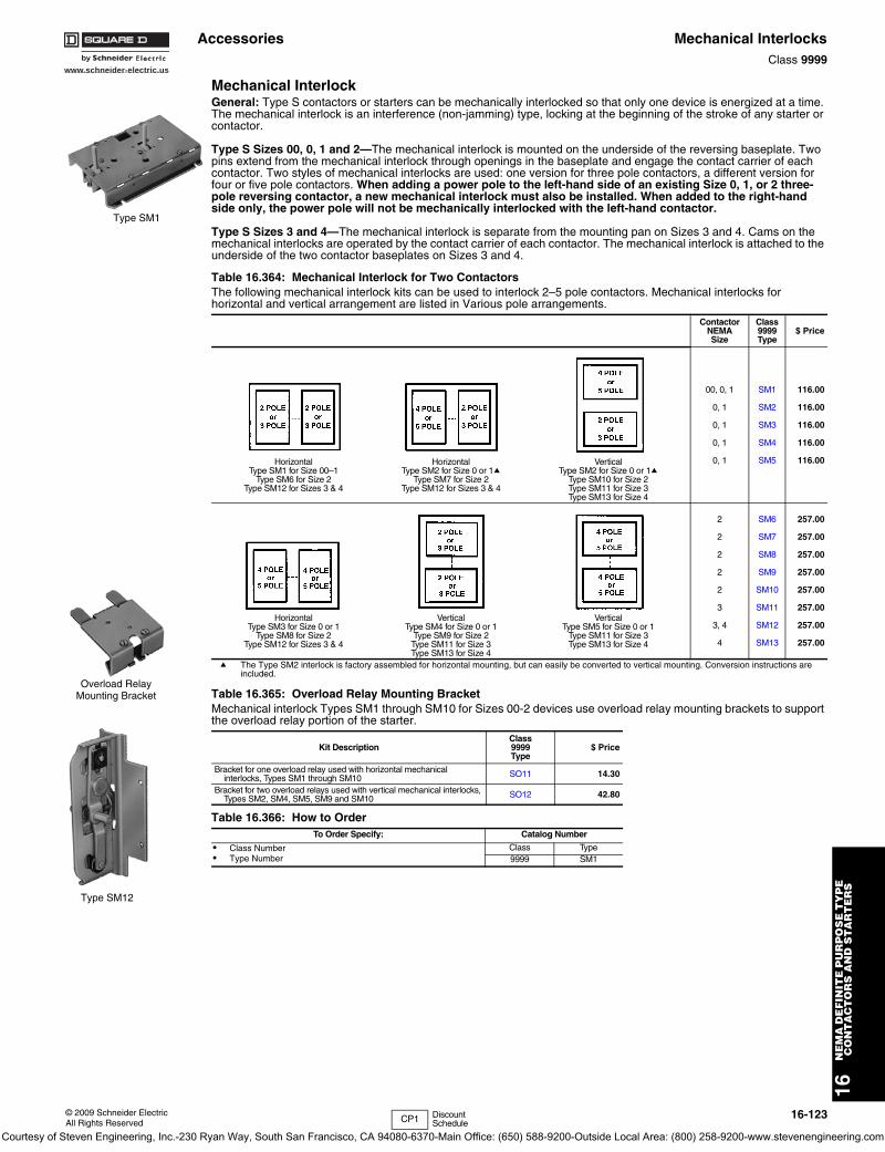
www.schneider-electric.us
16N
EM
A D
EF
INIT
E P
UR
PO
SE
TY
PE
C
ON
TA
CT
OR
S A
ND
ST
AR
TE
RS
© 2009 Schneider ElectricAll Rights Reserved
16-123
Accessories Mechanical InterlocksClass 9999
Mechanical InterlockGeneral: Type S contactors or starters can be mechanically interlocked so that only one device is energized at a time. The mechanical interlock is an interference (non-jamming) type, locking at the beginning of the stroke of any starter or contactor.
Type S Sizes 00, 0, 1 and 2—The mechanical interlock is mounted on the underside of the reversing baseplate. Two pins extend from the mechanical interlock through openings in the baseplate and engage the contact carrier of each contactor. Two styles of mechanical interlocks are used: one version for three pole contactors, a different version for four or five pole contactors. When adding a power pole to the left-hand side of an existing Size 0, 1, or 2 three-pole reversing contactor, a new mechanical interlock must also be installed. When added to the right-hand side only, the power pole will not be mechanically interlocked with the left-hand contactor.
Type S Sizes 3 and 4—The mechanical interlock is separate from the mounting pan on Sizes 3 and 4. Cams on the mechanical interlocks are operated by the contact carrier of each contactor. The mechanical interlock is attached to the underside of the two contactor baseplates on Sizes 3 and 4.
a The Type SM2 interlock is factory assembled for horizontal mounting, but can easily be converted to vertical mounting. Conversion instructions are included.
Table 16.364: Mechanical Interlock for Two Contactors The following mechanical interlock kits can be used to interlock 2–5 pole contactors. Mechanical interlocks for horizontal and vertical arrangement are listed in Various pole arrangements.
ContactorNEMASize
Class9999Type
$ Price
HorizontalType SM1 for Size 00–1
Type SM6 for Size 2Type SM12 for Sizes 3 & 4
HorizontalType SM2 for Size 0 or 1a
Type SM7 for Size 2Type SM12 for Sizes 3 & 4
VerticalType SM2 for Size 0 or 1a
Type SM10 for Size 2Type SM11 for Size 3Type SM13 for Size 4
00, 0, 1
0, 1
0, 1
0, 1
0, 1
SM1
SM2
SM3
SM4
SM5
116.00
116.00
116.00
116.00
116.00
HorizontalType SM3 for Size 0 or 1
Type SM8 for Size 2Type SM12 for Sizes 3 & 4
VerticalType SM4 for Size 0 or 1
Type SM9 for Size 2Type SM11 for Size 3Type SM13 for Size 4
VerticalType SM5 for Size 0 or 1
Type SM11 for Size 3Type SM13 for Size 4
2
2
2
2
2
3
3, 4
4
SM6
SM7
SM8
SM9
SM10
SM11
SM12
SM13
257.00
257.00
257.00
257.00
257.00
257.00
257.00
257.00
Table 16.365: Overload Relay Mounting Bracket Mechanical interlock Types SM1 through SM10 for Sizes 00-2 devices use overload relay mounting brackets to support the overload relay portion of the starter.
Kit DescriptionClass9999Type
$ Price
Bracket for one overload relay used with horizontal mechanical interlocks, Types SM1 through SM10 SO11 14.30
Bracket for two overload relays used with vertical mechanical interlocks,Types SM2, SM4, SM5, SM9 and SM10 SO12 42.80
Table 16.366: How to OrderTo Order Specify: Catalog Number
• Class Number• Type Number
Class Type9999 SM1
Type SM1
Overload Relay Mounting Bracket
Type SM12
CP1 Discount Schedule
Courtesy of Steven Engineering, Inc.-230 Ryan Way, South San Francisco, CA 94080-6370-Main Office: (650) 588-9200-Outside Local Area: (800) 258-9200-www.stevenengineering.com
16-124 © 2009 Schneider ElectricAll Rights Reserved
www.schneider-electric.us
16N
EM
A D
EF
INIT
E P
UR
PO
SE
TY
PE
C
ON
TA
CT
OR
S A
ND
ST
AR
TE
RS
Accessories Fuse Block Replacement Parts KitsClass 9422, 9999 / Refer to Catalog 9420CT9701
Class 8538 (Series D and newer), Class 8738 (Series E and newer), and Class 8903 (Series C and newer) Type S non-fusible combination starters and lighting contactors (sizes 0–2, 30 to 60 amps) can be converted to the fusible type by installing a Class 9422 Fuse Clip Kit. Both fusible and non-fusible combination devices have the same size enclosure in NEMAs 1, 4, and 12 construction, which permits this conversion. The 9422 Fuse Clip Kits contain line and load fuse clips, load base, and fuse pullers.
a When using with a 9422FTCN or FTCF disconnect switch in 8538 or 8738 combination starters, remove and discard metal base plate.b No Class Number required Discount Schedule DE1.
c Fuse clips are not provided in the Type SR4 and SR5 kits. On new installations Class 9999 Type S fuse clips must also be purchased. Three non-removable pins are supplied and can be installed only in the latest production devices, which have a hole in the lower fuse clips.
d Cannot be used in Series B or newer 8538 devices.
e Class 8538 type numbers ending in suffix “S8”.
NOTE: No external auxiliary contacts are available for the following circuit breakers: GJL circuit breaker must use internal Catalog No. AAC. PowerPactTM D, H and J circuit breaker must use internal Catalog No. AAC.
Table 16.367: Class 9422 Replacement Fuse Clip Kits
DeviceUsed on Disconnect
AmpereRating
NEMA Class H, K, J, R Fuses
$ Price Class RFuse Clip Kits $ Price
Fuse ClipRatings—Amperes
Class & TypeSize or
Ampere Rating250 VMax.
600 VMax.
0, 1 & 30 A 30 0–30 — 9422TC30a 42.80 RFK03b 32.600, 1 & 30 A 30 31–60 0–30 9422TC33a 71.00 RFK06b 34.002 & 60 A 60 31–60 0–30 9422TC33 71.00 RFK06b 36.502 & 60 A 60 — 31–60 9422TD63 99.00 RFK06Hb 34.00
Table 16.368: Class 9999 Replacement Fuse Clip Kits (8538 Pre-Series D, 8738 Pre-Series E)
DeviceUsed on Disconnect
AmpereRating
NEMA Class H Fuses NEMA Class R Fuses NEMA Class J Fuses
Fuse ClipRatings—Amperes
Type $ Price
Fuse ClipRatings—Amperes
Type $ Price
Fuse ClipRatings—Amperes
600 VMax.
Type $ PriceSize or
Ampere Rating250 VMax.
600 VMax.
250 VMax.
600 VMax.
0, 1 & 30 A 300–30—
31–60
—0–300–30
S1S2S2
21.5035.6035.60
0–30—
31–60
—0–300–30
SR1SR2SR2
35.6047.6047.60
—0–300–30
—SJ2SJ2
—105.00105.00
2 & 60 A 60 31–60—
0–3031–60
S2S3
35.6050.00
31–60—
0–3031–60
SR2SR3
47.6064.00
0–3031–60
SJ2SJ3
105.00125.00
3 & 100 A 100 61–100101–200
61–100—
S4dS5d
144.00270.00
61–100101–200
61–100—
SR4cSR4c
47.6047.60
61–100—
SJ4—
201.00—
4 & 200 A 200 101–200 101–200 S5d 270.00 101–200 101–200 SR4c 47.60 — — —5 & 300 A 400 — — — — 201–400 201–400 SR5c 107.00 — — —
6 & 400, 600 A 600 — — — — 401–600 401–600 SR5c 107.00 — — —
Table 16.369: Class 9999 Auxiliary Contact Kits for Disconnect Switches and Circuit Breakers
Class TypeSPDT DPDT
Class TypeSPDT DPDT
Type $ Price Type $ Price Type $ Price Type $ Price
8538, 8738 SB, SC (Series C) R45 71.00 R46 207.00 Disconnect Switches
8539, 8739 SB, SC, SD, SE, SF, SG R26 131.00 R27 243.00 9422 BTCF, BTCN, BTDF, BTEF, BTEN TC11 120.00 TC21 239.00
8538 SBA, SCA, SBG, SCG (Series D) TC11 120.00 TC21 239.00 9422 TCF, TCN, TDF, TDN, TEF, TEN TC10 120.00 TC11 239.008738 SBA, SCA, SBG, SCG (Series E) TC10 120.00 TC20 239.00 9422 TF R8 87.00 R9 243.00
8538 SBe, SCe, SDe (Series B) R6 113.00 R7 221.00 Circuit Breaker Op. Mechs.
8538 SBAS8, SCAS8, SBGS8, SCGS8, (Series D) TC10 120.00 TC20 239.00 9421 LF, LK, LL, LM, LN, LP, LR, LT,
LW R47 131.00 R48 221.00
8538, 8738 SD (Series C) R43 116.00 R44 221.00 9422 RM, RN, RP, RQ, RR, RT R26 131.00 R27 243.00
8538 SDA, SDAe, SDG, SDGe (Series D) TC10 120.00 TC20 239.00 9422 CFA, CKA, CLA, CSF, CMP R26 131.00 R27 243.00
8738 SDA, SDG (Series E) TC10 120.00 TC20 239.008538, 8738 SE (Series B & C) R41 131.00 R42 243.008538, 8738 SE, SF (Series A) R8 131.00 R9 243.008538, 8738 SF (Series B & C) R39 135.00 R40 243.008538, 8738 SG R35 435.00 R36 521.00
Table 16.370: How to OrderTo Order Specify: Catalog Number
• Class Number• Type Number
Class Type9999 R6
Class 9422 TC33Fuse Block
Class 9999 Type S2Interchangeable Fuse Clips
Class 9999 Type TC10
CP1 DE1 Discount Schedule
Courtesy of Steven Engineering, Inc.-230 Ryan Way, South San Francisco, CA 94080-6370-Main Office: (650) 588-9200-Outside Local Area: (800) 258-9200-www.stevenengineering.com
www.schneider-electric.us
16N
EM
A/D
EF
INIT
E P
UR
PO
SE
TY
PE
CO
NT
AC
TO
RS
AN
D S
TA
RT
ER
S
© 2009 Schneider ElectricAll Rights Reserved
16-125
Thermal Unit Selection
GeneralAll tables are based on the operation of the motor and controller in the same ambient temperature, 40oC (104oF) or less. Always be certain the correct thermal units are installed in the starter before operating the motor. Each thermal unit shall be installed such that its catalog number is visible. See page 16-129, Figure 1 for complete thermal unit installation instructions. On melting alloy thermal units the ratchet wheel must engage the pawl assembly.
Selection Procedure
Slow Trip Thermal Unit SelectionTo select Type SB slow trip thermal units, the selection table for a standard Type B thermal unit may be used with the following modifications: For continuous rated motors having service factors of 1.15 to 1.25, select thermal units from the standard Type B table using 93% (102% for Class 8198) of the full load current shown on the motor nameplate and then substitute an SB for the B in the thermal unit type number.Example: A motor with a full load current of 12 amps controlled by an 8536SCG3 would require B22 thermal units for standard trip applications and SB19.5 thermal units for slow trip applications. The SB is selected by multiplying 12 amps times 93% for 11.16 amps and using this value to select B19.5. Then add the S prefix to arrive at SB19.5.For continuous rated motors having a service factor of 1.0, select thermal units in the same manner using 84% (93% for Class 8198) of full load current shown on the motor nameplate.NOTE: SB thermal units are used on Size 0, 1, 2 and only some
Size 3 applications. Check thermal unit tables for current ranges.
1. Determine motor data:
a. Full load current rating
b. Service factor
Note: If motor full load current (FLC) is not known, a tentative thermal unit selection could be made, based on horsepower and voltage. Refer to page 16-129.
2. Motor and controller in same ambient temperature:
a. All starter classes, except Class 8198:
1. For 1.15 to 1.25 service factor motors use 100% of motor FLC for thermal unit selection.
2. For 1.0 service factor motors use 90% of motor FLC for thermal unit selection.
b. Class 8198 only:
1. For 1.0 service factor motors use 100% of motor FLC for thermal unit selection.
2. For 1.15 to 1.25 service factor motors use 110% of motor FLC for thermal unit selection.
3. Motor and controller in different ambient temperatures:
a. Multiply motor FLC by the multiplier in Table A. Use the resultant full load current for thermal unit selection.
4. Locate proper selection table from index, pages 16-126 and 16-127.
a. The proper thermal unit number will be found adjacent, to the right of the range of full load currents in which the motor FLC or resultant full load current falls.
5. See page 16-128 for calculation of trip current rating.
Table A: Selection of Thermal Units for Special Applications
Classof
Controller
ContinuousDutyMotor
ServiceFactor
Melting Alloy andNon-CompensatedBimetallic Relays
AmbientTemp.-Comp.Relays
Ambient Temperature of Motor
Same asControllerAmbient
Constant10oC(18oF)HigherThan
ControllerAmbient
Constant10o C(18oF)LowerThan
ControllerAmbient
Constant40oC
(104oF)or less,for Any
ControllerAmbient
Full Load Current Multiplier
AllClasses,Except8198
1.15 to1.25 1.0 0.9 1.05 1.0
1.0 0.9 0.8 .95 0.9
Class8198
1.15 to1.25 1.1 1.0 1.15 1.1
1.0 1.0 0.9 1.05 1.0
Table 16.382: Thermal Unit Prices Melting Alloy Bimetallic
Type ofTrip
ThermalUnit Type $ Price Type of
TripThermal
Unit Type $ Price
Standard
A 21.50
Standard
AR 21.50B 21.50 AF 21.50C 21.50 AU 21.50
CC 21.50 E 21.50DD 21.50
Quick FB 35.60Slow SB 57.00
CP1 Discount Schedule
Courtesy of Steven Engineering, Inc.-230 Ryan Way, South San Francisco, CA 94080-6370-Main Office: (650) 588-9200-Outside Local Area: (800) 258-9200-www.stevenengineering.com
16-126 © 2009 Schneider ElectricAll Rights Reserved
www.schneider-electric.us
16N
EM
A D
EF
INIT
E P
UR
PO
SE
TY
PE
C
ON
TA
CT
OR
S A
ND
ST
AR
TE
RS
Thermal Unit Selection
NOTE: For thermal unit selection tables for other devices including obsolete devices, consult Square D/Schneider Electric CIC at 1-888-SquareD (1-888-778-2733).
Table continued on the next page; see page 16-127 for Footnotes.
NOTE: For thermal unit selection tables for other devices including obsolete devices, consult Square D/Schneider Electric CIC at 1-888-SquareD (1-888-778-2733).
Thermal Unit Prices . . . . . . . . . . . . . . . . . page 16-125.
Table 16.383: Thermal Unit Selection
ControllerThermal Unit Selection Table Number
Hand Reset Melting Alloy Bimetallic
Starter Type Class Type Seriesa Size StandardTrip (20)
Quick Trip(10)
Slow Trip(30)
Non-Compensated
Compen-sated
ManualStartersFHP
251025128908
F A FHP 43h — — — —
Manual Starters(SmallEnclosure)
2510 M, T AM–0M–1M–1P
111
727272
jjj
———
———
ManualStarters(LargeEnclosure)
2510251125128925
M, T AM–0M–1M–1P
222
737373
jjj
———
———
DCMagneticStartersEC & M Crane Control Product
7135713677357736
C, D — 1, 2 65 — j — —E — 3 9 — — — —F — 4 10 — — — —G — 5 12 — — — —
ACMagneticStarters(SmallEnclosure)
85368904b(StarterIn Own
Enclosure)
8933
89988999
(Model 3Control Center)
I-LINE®
and QMBMotorStarterCenters
A(8536only)
B, C 00 17h — — — —
SA A, B 00 13 — j — —SB A 0 13 74 j 8 33
SCA 1 13 74 j 8 33A 1P 41 — j — —
SD A 2 56 75 j 62 70
SEA 3 18 76i 134ij 63 37gB 3 — — — 142g —
SFA 4 54 77i — 11 29gB 4 — — — 144g —
SGA 5 49 — — 38 46
Bl 5 59 83 — 23 42SH A, B 6 21 — — 39 47
89988999
(Model 4Control Center)
SC A1 Fusible 66 74 —
64 331 Circuit Breaker 15 74 —
SD A2 Fusible 67 75 —
57 702 Circuit Breaker 58f 75 —
SEA
3 Small Enclosure 16 76i 134ij 51 37g3 Large Enclosure 68f 76i 133ij
B 3 — — — 141g —
SFA 4 61 77i — 35 29fB 4 — — — 143g —
SG A 5 24 — — 52 46SH A 6 20 — — 48 47
8998(Model 5 and
Model 6 MCCs)
SCk A1 109 — — — 971 COMPAC 6 104 — — — —
SDk A 2 110 — — — 98SEk A 3 111 — — — 99gSFk A 4 112 — — — 100g
SGkA 5 113 — — — 101B 5 CT 103 — — — —
SHk A 6 114 — — — 102
8911 DPSG A
20–30 A 135 — — — —40 A 145 — — — —50 A 146 — — — —60–90 A 149 — — — —
Courtesy of Steven Engineering, Inc.-230 Ryan Way, South San Francisco, CA 94080-6370-Main Office: (650) 588-9200-Outside Local Area: (800) 258-9200-www.stevenengineering.com
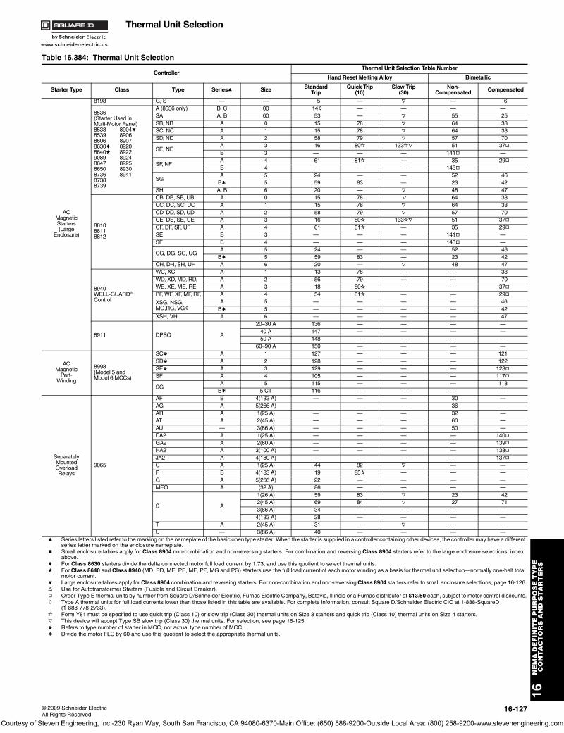
www.schneider-electric.us
16N
EM
A D
EF
INIT
E P
UR
PO
SE
TY
PE
C
ON
TA
CT
OR
S A
ND
ST
AR
TE
RS
© 2009 Schneider ElectricAll Rights Reserved
16-127
Thermal Unit Selection
Table 16.384: Thermal Unit Selection
ControllerThermal Unit Selection Table Number
Hand Reset Melting Alloy Bimetallic
Starter Type Class Type Seriesa Size StandardTrip
Quick Trip(10)
Slow Trip(30)
Non-Compensated Compensated
ACMagneticStarters(Large
Enclosure)
8198 G, S — — 5 — j — 6
8536(Starter Used inMulti-Motor Panel)8538 8904e8539 89068606 89078630c 89208640d 89229089 89248647 89258650 89308736 894187388739
A (8536 only) B, C 00 14h — — — —SA A, B 00 53 — j 55 25SB, NB A 0 15 78 j 64 33SC, NC A 1 15 78 j 64 33SD, ND A 2 58 79 j 57 70
SE, NEA 3 16 80i 133ij 51 37gB 3 — — — 141g —
SF, NFA 4 61 81i — 35 29gB 4 — — — 143g —
SGA 5 24 — — 52 46
Bl 5 59 83 — 23 42SH A, B 6 20 — j 48 47
881088118812
CB, DB, SB, UB A 0 15 78 j 64 33CC, DC, SC, UC A 1 15 78 j 64 33CD, DD, SD, UD A 2 58 79 j 57 70CE, DE, SE, UE A 3 16 80i 133ij 51 37gCF, DF, SF, UF A 4 61 81i — 35 29gSE B 3 — — — 141g —SF B 4 — — — 143g —
CG, DG, SG, UGA 5 24 — — 52 46
Bl 5 59 83 — 23 42CH, DH, SH, UH A 6 20 — j 48 47
8940WELL-GUARD® Control
WC, XC A 1 13 78 — — 33WD, XD, MD, RD, A 2 56 79 — — 70WE, XE, ME, RE, A 3 18 80i — — 37gPF, WF, XF, MF, RF, A 4 54 81i — — 29g
XSG, NSG, MG,RG, VGh
A 5 — — — — 46Bl 5 — — — — 42
XSH, VH A 6 — — — — 47
8911 DPSO A
20–30 A 136 — — — —40 A 147 — — — —50 A 148 — — — —
60–90 A 150 — — — —
ACMagnetic
Part-Winding
8998(Model 5 andModel 6 MCCs)
SCk A 1 127 — — — 121SDk A 2 128 — — — 122SEk A 3 129 — — — 123gSF A 4 105 — — — 117g
SGA 5 115 — — — 118
Bl 5 CT 116 — — — —
SeparatelyMountedOverloadRelays
9065
AF B 4(133 A) — — — 30 —AG A 5(266 A) — — — 36 —AR A 1(25 A) — — — 32 —AT A 2(45 A) — — — 60 —AU — 3(86 A) — — — 50 —DA2 A 1(25 A) — — — — 140gGA2 A 2(60 A) — — — — 139gHA2 A 3(100 A) — — — — 138gJA2 A 4(180 A) — — — — 137gC A 1(25 A) 44 82 j — —F B 4(133 A) 19 85i — — —G A 5(266 A) 22 — — — —MEO A (32 A) 86 — — — —
S A
1(26 A) 59 83 j 23 422(45 A) 69 84 j 27 713(86 A) 34 — — — —4(133 A) 28 — — — —
T A 2(45 A) 31 — j — —U — 3(86 A) 40 — — — —
a Series letters listed refer to the marking on the nameplate of the basic open type starter. When the starter is supplied in a controller containing other devices, the controller may have a different series letter marked on the enclosure nameplate.
b Small enclosure tables apply for Class 8904 non-combination and non-reversing starters. For combination and reversing Class 8904 starters refer to the large enclosure selections, index above.
c For Class 8630 starters divide the delta connected motor full load current by 1.73, and use this quotient to select thermal units.d For Class 8640 and Class 8940 (MD, PD, ME, PE, MF, PF, MG and PG) starters use the full load current of each motor winding as a basis for thermal unit selection—normally one-half total
motor current.e Large enclosure tables apply for Class 8904 combination and reversing starters. For non-combination and non-reversing Class 8904 starters refer to small enclosure selections, page 16-126.f Use for Autotransformer Starters (Fusible and Circuit Breaker).g Order Type E thermal units by number from Square D/Schneider Electric, Furnas Electric Company, Batavia, Illinois or a Furnas distributor at $13.50 each, subject to motor control discounts.h Type A thermal units for full load currents lower than those listed in this table are available. For complete information, consult Square D/Schneider Electric CIC at 1-888-SquareD
(1-888-778-2733).i Form Y81 must be specified to use quick trip (Class 10) or slow trip (Class 30) thermal units on Size 3 starters and quick trip (Class 10) thermal units on Size 4 starters.j This device will accept Type SB slow trip (Class 30) thermal units. For selection, see page 16-125.k Refers to type number of starter in MCC, not actual type number of MCC.l Divide the motor FLC by 60 and use this quotient to select the appropriate thermal units.
Courtesy of Steven Engineering, Inc.-230 Ryan Way, South San Francisco, CA 94080-6370-Main Office: (650) 588-9200-Outside Local Area: (800) 258-9200-www.stevenengineering.com
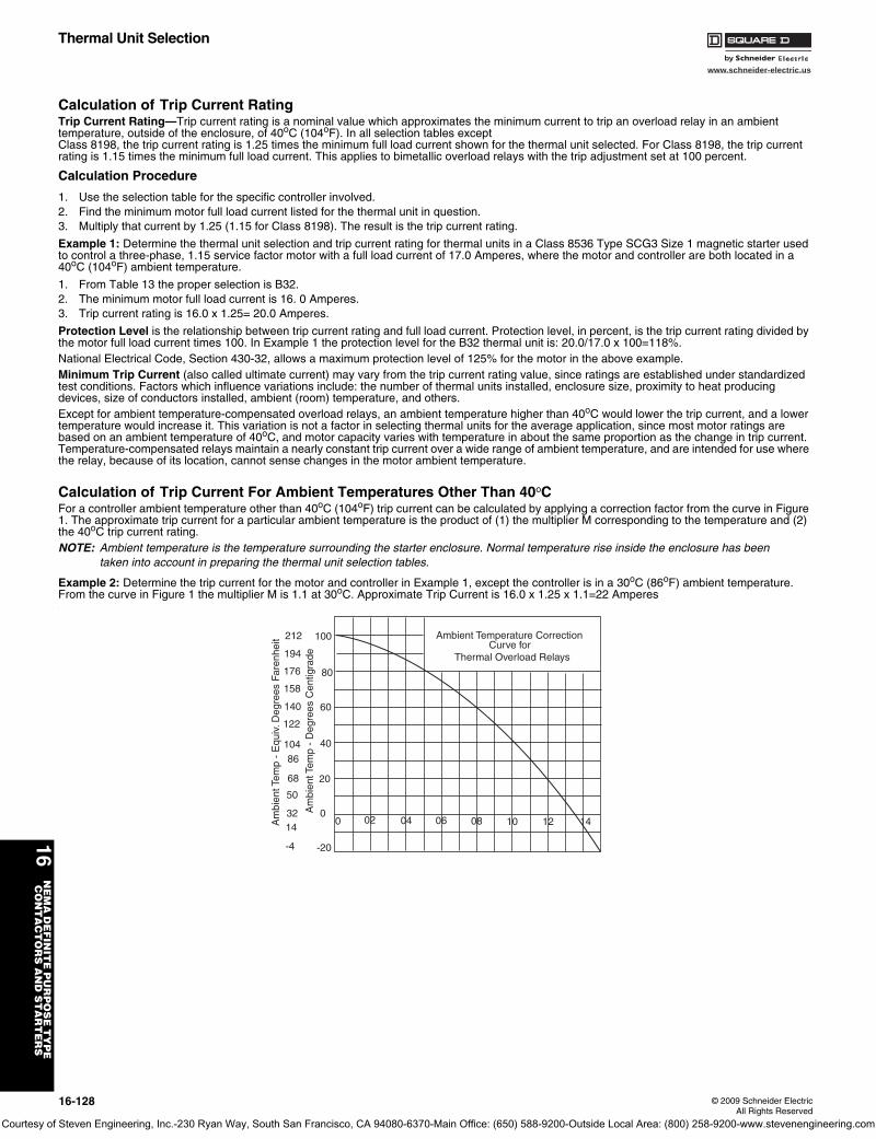
16-128 © 2009 Schneider ElectricAll Rights Reserved
www.schneider-electric.us
16N
EM
A D
EF
INIT
E P
UR
PO
SE
TY
PE
C
ON
TA
CT
OR
S A
ND
ST
AR
TE
RS
Thermal Unit Selection
Calculation of Trip Current RatingTrip Current Rating—Trip current rating is a nominal value which approximates the minimum current to trip an overload relay in an ambient temperature, outside of the enclosure, of 40oC (104oF). In all selection tables except Class 8198, the trip current rating is 1.25 times the minimum full load current shown for the thermal unit selected. For Class 8198, the trip current rating is 1.15 times the minimum full load current. This applies to bimetallic overload relays with the trip adjustment set at 100 percent.
Calculation Procedure
1. Use the selection table for the specific controller involved.2. Find the minimum motor full load current listed for the thermal unit in question.3. Multiply that current by 1.25 (1.15 for Class 8198). The result is the trip current rating.
Example 1: Determine the thermal unit selection and trip current rating for thermal units in a Class 8536 Type SCG3 Size 1 magnetic starter used to control a three-phase, 1.15 service factor motor with a full load current of 17.0 Amperes, where the motor and controller are both located in a 40oC (104oF) ambient temperature.
1. From Table 13 the proper selection is B32.2. The minimum motor full load current is 16. 0 Amperes.3. Trip current rating is 16.0 x 1.25= 20.0 Amperes.
Protection Level is the relationship between trip current rating and full load current. Protection level, in percent, is the trip current rating divided by the motor full load current times 100. In Example 1 the protection level for the B32 thermal unit is: 20.0/17.0 x 100=118%.National Electrical Code, Section 430-32, allows a maximum protection level of 125% for the motor in the above example.Minimum Trip Current (also called ultimate current) may vary from the trip current rating value, since ratings are established under standardized test conditions. Factors which influence variations include: the number of thermal units installed, enclosure size, proximity to heat producing devices, size of conductors installed, ambient (room) temperature, and others.Except for ambient temperature-compensated overload relays, an ambient temperature higher than 40oC would lower the trip current, and a lower temperature would increase it. This variation is not a factor in selecting thermal units for the average application, since most motor ratings are based on an ambient temperature of 40oC, and motor capacity varies with temperature in about the same proportion as the change in trip current. Temperature-compensated relays maintain a nearly constant trip current over a wide range of ambient temperature, and are intended for use where the relay, because of its location, cannot sense changes in the motor ambient temperature.
Calculation of Trip Current For Ambient Temperatures Other Than 40oCFor a controller ambient temperature other than 40oC (104oF) trip current can be calculated by applying a correction factor from the curve in Figure 1. The approximate trip current for a particular ambient temperature is the product of (1) the multiplier M corresponding to the temperature and (2) the 40oC trip current rating.NOTE: Ambient temperature is the temperature surrounding the starter enclosure. Normal temperature rise inside the enclosure has been
taken into account in preparing the thermal unit selection tables.
Example 2: Determine the trip current for the motor and controller in Example 1, except the controller is in a 30oC (86oF) ambient temperature. From the curve in Figure 1 the multiplier M is 1.1 at 30oC. Approximate Trip Current is 16.0 x 1.25 x 1.1=22 Amperes.
100
80
60
40
20
0
-20
212
194
176
158
140
122
10486
68
50
3214
-4
0 02 04 06 08 10 12 14
Ambient Temperature CorrectionCurve for
Thermal Overload Relays
Am
bien
t Tem
p -
Equ
iv. D
egre
es F
aren
heit
Am
bien
t Tem
p -
Deg
rees
Cen
tigra
de
Courtesy of Steven Engineering, Inc.-230 Ryan Way, South San Francisco, CA 94080-6370-Main Office: (650) 588-9200-Outside Local Area: (800) 258-9200-www.stevenengineering.com
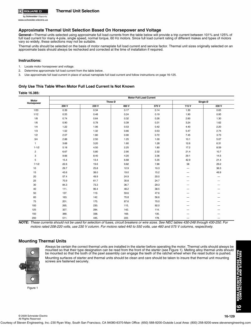
www.schneider-electric.us
16N
EM
A D
EF
INIT
E P
UR
PO
SE
TY
PE
C
ON
TA
CT
OR
S A
ND
ST
AR
TE
RS
© 2009 Schneider ElectricAll Rights Reserved
16-129
Thermal Unit Selection
Approximate Thermal Unit Selection Based On Horsepower and VoltageGeneral—Thermal units selected using approximate full load currents from the table below will provide a trip current between 101% and 125% of full load current for many 4-pole, single speed, normal torque, 60 Hz motors. Since full load current rating of different makes and types of motors vary so widely, these selections may not be suitable.Thermal units should be selected on the basis of motor nameplate full load current and service factor. Thermal unit sizes originally selected on an approximate basis should always be rechecked and corrected at the time of installation if required.
Instructions:
1. Locate motor horsepower and voltage.2. Determine approximate full load current from the table below.3. Use approximate full load current in place of actual nameplate full load current and follow instructions on page 16-125.
Only Use This Table When Motor Full Load Current Is Not Known
NOTE: These currents should not be used for selection of fuses, circuit breakers or wire sizes. See NEC tables 430-248 through 430-250. For motors rated 208-220 volts, use 230 V column. For motors rated 440 to 550 volts, use 460 and 575 V columns, respectively.
Mounting Thermal UnitsAlways be certain the correct thermal units are installed in the starter before operating the motor. Thermal units should always be mounted so that their type designation can be read from the front of the starter (see Figure 1). Melting alloy thermal units should be mounted so that the tooth of the pawl assembly can engage the teeth of the ratchet wheel when the reset button is pushed.Mounting surfaces of starter and thermal units should be clean and care should be taken to insure that thermal unit mounting screws are fastened securely.
Table 16.385:
MotorHorsepower
Motor Full Load Current
Three Ø Single Ø
200 V 230 V 460 V 575 V 115 V 230 V
1/20 0.39 0.34 0.17 0.14 1.30 0.65
1/12 0.55 0.48 0.24 0.19 1.90 0.95
1/8 0.74 0.64 0.32 0.26 2.60 1.30
1/6 0.90 0.78 0.39 0.31 3.24 1.62
1/4 1.22 1.06 0.53 0.42 4.40 2.20
1/3 1.52 1.32 0.66 0.53 5.47 2.74
1/2 2.07 1.80 0.90 0.72 7.45 3.73
3/4 2.88 2.50 1.25 1.00 10.1 5.07
1 3.68 3.20 1.60 1.28 12.6 6.31
1-1/2 5.18 4.50 2.25 1.80 17.2 8.59
2 6.67 5.80 2.90 2.32 21.4 10.7
3 9.66 8.40 4.20 3.36 29.1 14.5
5 15.4 13.4 6.68 5.35 42.9 21.4
7-1/2 22.6 19.6 9.82 7.86 58 29.2
10 29.7 25.8 12.9 10.3 — 36.3
15 43.6 38.0 19.0 15.2 — 49.9
20 57.4 49.9 24.9 20.0 — —
25 70.9 61.7 30.8 24.7 — —
30 84.3 73.3 36.7 29.3 — —
40 111. 96.4 48.2 38.5 — —
50 137. 119. 59.6 47.6 — —
60 163. 142. 70.8 56.6 — —
75 201. 175. 87.6 70.0 — —
100 265. 230. 115. 92.0 — —
125 327. 284. 142. 114. — —
150 389. 338. 169. 135. — —
200 511. 445. 222. 178. — —
Figure 1
Courtesy of Steven Engineering, Inc.-230 Ryan Way, South San Francisco, CA 94080-6370-Main Office: (650) 588-9200-Outside Local Area: (800) 258-9200-www.stevenengineering.com
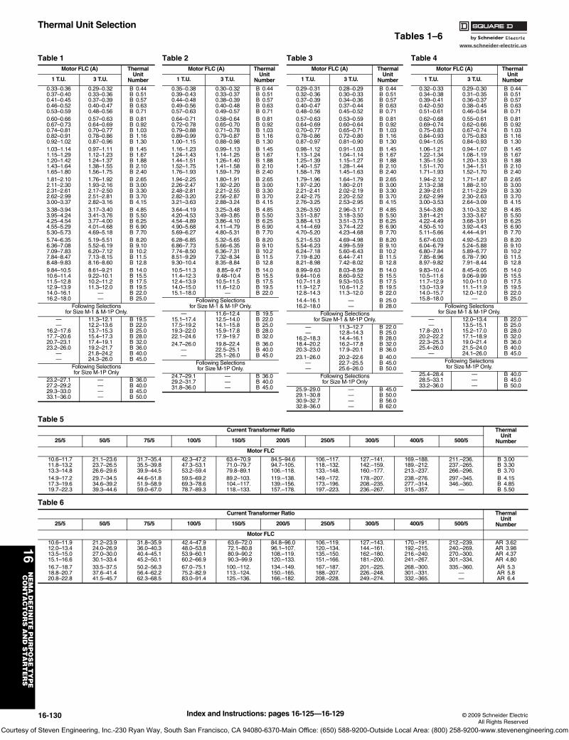
www.schneider-electric.us
16N
EM
A D
EF
INIT
E P
UR
PO
SE
TY
PE
C
ON
TA
CT
OR
S A
ND
ST
AR
TE
RS
16-130 © 2009 Schneider ElectricAll Rights Reserved
Thermal Unit SelectionTables 1–6
Table 1Motor FLC (A) Thermal
Unit Number1 T.U. 3 T.U.
0.33–0.360.37–0.400.41–0.450.46–0.520.53–0.59
0.29–0.320.33–0.360.37–0.390.40–0.470.48–0.56
B 0.44B 0.51B 0.57B 0.63B 0.71
0.60–0.660.67–0.730.74–0.810.82–0.910.92–1.02
0.57–0.630.64–0.690.70–0.770.78–0.860.87–0.96
B 0.81B 0.92B 1.03B 1.16B 1.30
1.03–1.141.15–1.291.20–1.421.43–1.641.65–1.80
0.97–1.111.12–1.231.24–1.371.38–1.551.56–1.75
B 1.45B 1.67B 1.88B 2.10B 2.40
1.81–2.102.11–2.302.31–2.612.62–2.993.00–3.37
1.76–1.921.93–2.162.17–2.502.51–2.812.82–3.16
B 2.65B 3.00B 3.30B 3.70B 4.15
3.38–3.943.95–4.244.25–4.544.55–5.295.30–5.73
3.17–3.403.41–3.763.77–4.004.01–4.684.69–5.18
B 4.85B 5.50B 6.25B 6.90B 7.70
5.74–6.356.36–7.087.09–7.837.84–8.478.48–9.83
5.19–5.515.52–6.196.20–7.127.13–8.158.16–8.60
B 8.20B 9.10B 10.2B 11.5B 12.8
9.84–10.510.6–11.411.5–12.812.9–13.914.0–16.116.2–18.0
8.61–9.219.22–10.110.2–11.211.3–12.0
——
B 14.0B 15.5B 17.5B 19.5B 22.0B 25.0
Following Selectionsfor Size M-1 & M-1P Only.
——
16.2–17.617.7–20.620.7–23.123.2–26.0
——
11.3–12.112.2–13.613.7–15.315.4–17.317.4–19.119.2–21.721.8–24.224.3–26.0
B 19.5B 22.0B 25.0B 28.0B 32.0B 36.0B 40.0B 45.0
Following Selectionsfor Size M-1P Only
23.2–27.127.2–29.229.3–33.033.1–36.0
————
B 36.0B 40.0B 45.0B 50.0
Table 2Motor FLC (A) Thermal
Unit Number1 T.U. 3 T.U.
0.35–0.380.39–0.430.44–0.480.49–0.560.57–0.63
0.30–0.320.33–0.370.38–0.390.40–0.480.49–0.57
B 0.44B 0.51B 0.57B 0.63B 0.71
0.64–0.710.72–0.780.79–0.880.89–0.991.00–1.15
0.58–0.640.65–0.700.71–0.780.79–0.870.88–0.98
B 0.81B 0.92B 1.03B 1.16B 1.30
1.16–1.231.24–1.431.44–1.511.52–1.751.76–1.93
0.99–1.131.14–1.251.26–1.401.41–1.581.59–1.79
B 1.45B 1.67B 1.88B 2.10B 2.40
1.94–2.252.26–2.472.48–2.812.82–3.203.21–3.63
1.80–1.911.92–2.202.21–2.552.56–2.872.88–3.24
B 2.65B 3.00B 3.30B 3.70B 4.15
3.64–4.194.20–4.534.54–4.894.90–5.685.69–6.27
3.25–3.483.49–3.853.86–4.104.11–4.794.80–5.31
B 4.85B 5.50B 6.25B 6.90B 7.70
6.28–6.856.86–7.737.74–8.508.51–9.299.30–10.4
5.32–5.655.66–6.356.36–7.317.32–8.348.35–8.84
B 8.20B 9.10B 10.2B 11.5B 12.8
10.5–11.311.4–12.312.4–13.914.0–15.015.1–18.0
8.85–9.47 9.48–10.410.5–11.511.6–12.0
—
B 14.0B 15.5B 17.5B 19.5B 22.0
Following Selectionsfor Size M-1 & M-1P Only.
—15.1–17.417.5–19.219.3–22.022.1–24.6
11.6–12.412.5–14.014.1–15.815.9–17.817.9–19.7
B 19.5B 22.0B 25.0B 28.0B 32.0
24.7–26.0——
19.8–22.422.5–25.125.1–26.0
B 36.0B 40.0B 45.0
Following Selectionsfor Size M-1P Only.
24.7–29.129.2–31.731.8–36.0
———
B 36.0B 40.0B 45.0
Table 3Motor FLC (A) Thermal
Unit Number1 T.U. 3 T.U.
0.29–0.310.32–0.360.37–0.390.40–0.470.48–0.56
0.28–0.290.30–0.330.34–0.360.37–0.440.45–0.52
B 0.44B 0.51B 0.57B 0.63B 0.71
0.57–0.630.64–0.690.70–0.770.78–0.860.87–0.97
0.53–0.590.60–0.640.65–0.710.72–0.800.81–0.90
B 0.81B 0.92B 1.03B 1.16B 1.30
0.98–1.121.13–1.241.25–1.391.40–1.571.58–1.78
0.91–1.031.04–1.141.15–1.271.28–1.441.45–1.63
B 1.45B 1.67B 1.88B 2.10B 2.40
1.79–1.961.97–2.202.21–2.412.42–2.752.76–3.25
1.64–1.791.80–2.012.02–2.192.20–2.522.53–2.95
B 2.65B 3.00B 3.30B 3.70B 4.15
3.26–3.503.51–3.873.88–4.134.14–4.694.70–5.20
2.96–3.173.18–3.503.51–3.733.74–4.224.23–4.68
B 4.85B 5.50B 6.25B 6.90B 7.70
5.21–5.535.54–6.236.24–7.187.19–8.208.21–8.98
4.69–4.984.99–5.595.60–6.436.44–7.417.42–8.02
B 8.20B 9.10B 10.2B 11.5B 12.8
8.99–9.639.64–10.610.7–11.811.9–12.712.8–14.3
8.03–8.598.60–9.529.53–10.510.6–11.211.3–12.0
B 14.0B 15.5B 17.5B 19.5B 22.0
14.4–16.116.2–18.0
——
B 25.0B 28.0
Following Selectionsfor Size M-1 & M-1P Only.
——
16.2–18.318.4–20.220.3–23.0
11.3–12.712.8–14.314.4–16.116.2–17.817.9–20.1
B 22.0B 25.0B 28.0B 32.0B 36.0
23.1–26.0——
20.2–22.622.7–25.525.6–26.0
B 40.0B 45.0B 50.0
Following Selectionsfor Size M-1P Only
25.9–29.029.1–30.830.9–32.732.8–36.0
————
B 45.0B 50.0B 56.0B 62.0
Table 4Motor FLC (A) Thermal
UnitNumber1 T.U. 3 T.U.
0.32–0.330.34–0.380.39–0.410.42–0.500.51–0.61
0.29–0.300.31–0.350.36–0.370.38–0.450.46–0.54
B 0.44B 0.51B 0.57B 0.63B 0.71
0.62–0.680.69–0.740.75–0.830.84–0.930.94–1.05
0.55–0.610.62–0.660.67–0.740.75–0.830.84–0.93
B 0.81B 0.92B 1.03B 1.16B 1.30
1.06–1.211.22–1.341.35–1.501.51–1.701.71–1.93
0.94–1.071.08–1.191.20–1.331.34–1.511.52–1.70
B 1.45B 1.67B 1.88B 2.10B 2.40
1.94–2.122.13–2.382.39–2.612.62–2.993.00–3.53
1.71–1.871.88–2.102.11–2.292.30–2.632.64–3.09
B 2.65B 3.00B 3.30B 3.70B 4.15
3.54–3.803.81–4.214.22–4.494.50–5.105.11–5.66
3.10–3.323.33–3.673.68–3.913.92–4.434.44–4.91
B 4.85B 5.50B 6.25B 6.90B 7.70
5.67–6.036.04–6.796.80–7.847.85–8.968.97–9.82
4.92–5.235.24–5.885.89–6.776.78–7.907.91–8.44
B 8.20B 9.10B 10.2B 11.5B 12.8
9.83–10.410.5–11.611.7–12.913.0–13.914.0–15.715.8–18.0
8.45–9.059.06–9.9910.0–11.011.1–11.912.0–12.0
—
B 14.0B 15.5B 17.5B 19.5B 22.0B 25.0
Following Selectionsfor Size M-1 & M-1P Only.
——
17.8–20.120.2–22.222.3–25.325.4–26.0
—
12.0–13.413.5–15.115.2–17.017.1–18.919.0–21.421.5–24.024.1–26.0
B 22.0B 25.0B 28.0B 32.0B 36.0B 40.0B 45.0
Following Selectionsfor Size M-1P Only.
25.4–28.428.5–33.133.2–36.0
———
B 40.0B 45.0B 50.0
Table 5Current Transformer Ratio Thermal
UnitNumber25/5 50/5 75/5 100/5 150/5 200/5 250/5 300/5 400/5 500/5
Motor FLC
10.6–11.711.8–13.213.3–14.8
21.1–23.623.7–26.526.6–29.6
31.7–35.435.5–39.839.9–44.5
42.3–47.247.3–53.153.2–59.4
63.4–70.971.0–79.779.8–89.1
84.5–94.694.7–105.106.–118.
106.–117.118.–132.133.–148.
127.–141.142.–159.160.–177.
169.–188.189.–212.213.–237.
211.–236.237.–265.266.–296.
B 3.00B 3.30B 3.70
14.9–17.217.3–19.619.7–22.3
29.7–34.534.6–39.239.3–44.6
44.6–51.851.9–58.959.0–67.0
59.5–69.269.3–78.678.7–89.3
89.2–103.104.–117.118.–133.
119.–138.139.–156.157.–178.
149.–172.173.–196.197.–223.
178.–207.208.–235.236.–267.
238.–276.277.–314.315.–357.
297.–345.346.–360.
—
B 4.15B 4.85B 5.50
Table 6Current Transformer Ratio Thermal
UnitNumber25/5 50/5 75/5 100/5 150/5 200/5 250/5 300/5 400/5 500/5
Motor FLC
10.6–11.912.0–13.413.5–15.015.1–16.6
21.2–23.924.0–26.927.0–30.030.1–33.4
31.8–35.936.0–40.340.4–45.145.2–50.1
42.4–47.948.0–53.853.9–60.160.2–66.9
63.6–72.072.1–80.880.9–90.290.3–99.9
84.8–96.096.1–107.108.–119.120.–133.
106.–119.120.–134.135.–150.151.–166.
127.–143.144.–161.162.–180.181.–200.
170.–191.192.–215.216.–240.241.–267.
212.–239.240.–269.270.–300.301.–334.
AR 3.62AR 3.98AR 4.37AR 4.80
16.7–18.718.8–20.720.8–22.8
33.5–37.537.6–41.441.5–45.7
50.2–56.356.4–62.262.3–68.5
67.0–75.175.2–82.983.0–91.4
100.–112.113.–124.125.–136.
134.–149.150.–165.166.–182.
167.–187.188.–207.208.–228.
201.–225.226.–248.249.–274.
268.–300.301.–331.332.–365.
335.–360.——
AR 5.3AR 5.8AR 6.4
Index and Instructions: pages 16-125—16-129
Courtesy of Steven Engineering, Inc.-230 Ryan Way, South San Francisco, CA 94080-6370-Main Office: (650) 588-9200-Outside Local Area: (800) 258-9200-www.stevenengineering.com
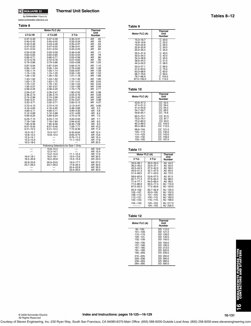
www.schneider-electric.us
16N
EM
A/D
EF
INIT
E P
UR
PO
SE
TY
PE
CO
NT
AC
TO
RS
AN
D S
TA
RT
ER
S
© 2009 Schneider ElectricAll Rights Reserved
16-131
Thermal Unit SelectionTables 8–12
Table 8Motor FLC (A) Thermal
UnitNumber2.T.U.1Ø 2 T.U.2Ø 3 T.U.
0.37–0.390.40–0.420.43–0.460.47–0.500.51–0.54
0.37–0.390.40–0.420.43–0.460.47–0.500.51–0.54
0.30–0.310.32–0.340.35–0.370.38–0.410.42–0.45
AR .45AR .49AR .54AR .59AR .65
0.55–0.590.60–0.650.66–0.710.72–0.780.79–0.86
0.55–0.590.60–0.650.66–0.710.72–0.780.79–0.86
0.46–0.490.50–0.540.55–0.560.57–0.620.63–0.68
AR .71AR .78AR .86AR .95AR 1.05
0.87–0.940.95–1.041.05–1.141.15–1.251.26–1.42
0.87–0.940.95–1.041.05–1.141.15–1.251.26–1.42
0.69–0.750.76–0.820.83–0.910.92–1.001.01–1.18
AR 1.15AR 1.26AR 1.39AR 1.53AR 1.68
1.43–1.621.63–1.751.76–1.911.92–2.072.08–2.25
1.43–1.621.63–1.751.76–1.911.92–2.072.08–2.25
1.19–1.301.31–1.411.42–1.531.54–1.691.70–1.79
AR 1.85AR 2.04AR 2.24AR 2.46AR 2.71
2.26–2.472.48–2.732.74–2.993.00–3.313.32–3.71
2.26–2.472.48–2.732.74–2.993.00–3.313.32–3.71
1.80–2.022.03–2.192.20–2.432.44–2.812.82–3.12
AR 2.98AR 3.28AR 3.62AR 3.98AR 4.37
3.72–4.154.16–4.654.66–5.115.12–5.685.69–6.24
3.72–4.154.16–4.654.66–5.115.12–5.685.69–6.24
3.13–3.473.48–3.893.90–4.304.31–4.694.70–5.19
AR 4.80AR 5.3AR 5.8AR 6.4AR 7.0
6.25–7.157.16–7.847.85–8.568.57–9.409.41–10.2
6.25–7.157.16–7.847.85–8.568.57–9.409.41–10.2
5.20–5.935.94–6.456.46–7.087.09–7.717.72–8.39
AR 7.7AR 8.5AR 9.3AR 10.2AR 11.2
10.3–10.710.8–12.212.3–14.114.2–15.916.0–18.0
10.3–10.710.8–12.2
— — —
8.40–8.648.65–9.749.75–11.011.1–12.0
—
AR 12.4AR 13.6AR 15.4AR 17.6AR 20.5
Following Selections for Size 1 Only — — —
16.0–18.118.2–20.8
10.8–12.212.3–14.114.2–15.916.0–18.118.2–20.8
— —
11.1–12.412.5–13.914.0–15.9
AR 13.6AR 15.4AR 17.6AR 20.5AR 23.0
20.9–23.623.7–26.0
— —
20.9–23.623.7–26.0
— —
16.0–17.717.8–20.320.4–22.822.9–26.0
AR 27.0AR 30.0AR 35.0AR 40.0
Table 9
Motor FLC (A)Thermal
UnitNumber
15.3–16.716.8–19.819.9–22.822.9–25.825.9–30.4
C 20.0C 22.0C 26.0C 30.0C 34.0
30.5–31.932.0–34.234.3–38.838.9–44.244.3–50.2
C 40.0C 42.0C 45.0C 51.0C 58.0
50.3–57.157.2–63.263.3–68.668.7–78.678.7–86.987.0–100.0
C 66.0C 75.0C 83.0C 90.0C 103.0C 114.0
Table 10
Motor FLC (A)Thermal
UnitNumber
43.6–47.347.4–51.351.4–54.654.7–59.759.8–65.1
CC 54.5CC 59.4CC 64.3CC 68.5CC 74.6
65.2–70.170.2–75.175.2–82.282.3–89.289.3–96.5
CC 81.5 CC 87.7 CC 94.0CC 103.0CC 112.0
96.6–104.105.–113.114.–123.124.–132.133.–150.
CC 121.0CC 132.0CC 143.0CC 156.0CC 167.0
Table 11Motor FLC (A) Thermal
UnitNumber2 T.U. 3 T.U.
33.0–36.136.2–40.240.3–44.545.6–51.351.4–58.5
30.5–33.433.5–37.137.2–42.042.1–47.047.1–53.5
AU 44.0AU 50.0AU 56.0AU 64.0AU 72.0
58.6–62.662.7–71.371.4–77.177.2–86.987.0–93.3
53.6–57.557.6–64.464.5–69.469.5–77.477.5–83.6
AU 81.0AU 88.0AU 99.0AU 110.0AU 123.0
93.4–102.103.–107.108.–112.113.–121.122.–123.
83.7–92.993.0–100.101.–104.105.–115.116.–119.
AU 135.0AU 152.0AU 169.0AU 183.0AU 198.0
124.–133.———
120.–123.124.–133.
AU 217.0AU 235.0
Table 12
Motor FLC (A)Thermal
UnitNumber
92.–100.101.–109.110.–119.120.–131.132.–139.
DD 112.0DD 121.0DD 128.0DD 140.0DD 150.0
140.–156.157.–166.167.–180.181.–189.190.–209.
DD 160.0DD 185.0DD 213.0DD 220.0DD 230.0
210.–225.226.–238.239.–263.264.–300.
DD 250.0DD 265.0DD 280.0DD 300.0
Index and Instructions: pages 16-125—16-129
Courtesy of Steven Engineering, Inc.-230 Ryan Way, South San Francisco, CA 94080-6370-Main Office: (650) 588-9200-Outside Local Area: (800) 258-9200-www.stevenengineering.com
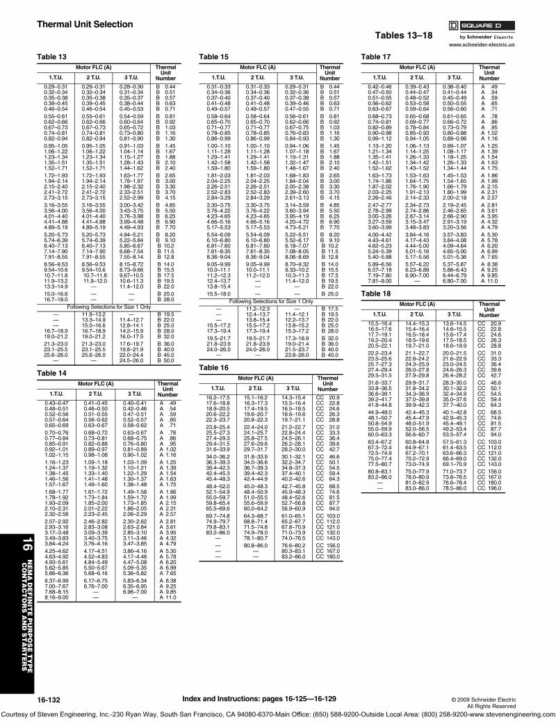
www.schneider-electric.us
16N
EM
A D
EF
INIT
E P
UR
PO
SE
TY
PE
C
ON
TA
CT
OR
S A
ND
ST
AR
TE
RS
16-132 © 2009 Schneider ElectricAll Rights Reserved
Thermal Unit SelectionTables 13–18
Table 13Motor FLC (A) Thermal
UnitNumber1.T.U. 2 T.U. 3 T.U.
0.29–0.310.32–0.340.35–0.380.39–0.450.46–0.54
0.29–0.310.32–0.340.35–0.380.39–0.450.46–0.54
0.28–0.300.31–0.340.35–0.370.38–0.440.45–0.53
B 0.44B 0.51B 0.57B 0.63B 0.71
0.55–0.610.62–0.660.67–0.730.74–0.810.82–0.94
0.55–0.610.62–0.660.67–0.730.74–0.810.82–0.94
0.54–0.590.60–0.640.65–0.720.73–0.800.81–0.90
B 0.81B 0.92B 1.03B 1.16B 1.30
0.95–1.051.06–1.221.23–1.341.35–1.511.52–1.71
0.95–1.051.06–1.221.23–1.341.35–1.511.52–1.71
0.91–1.031.04–1.141.15–1.271.28–1.431.44–1.62
B 1.45B 1.67B 1.88B 2.10B 2.40
1.72–1.931.94–2.142.15–2.402.41–2.722.73–3.15
1.72–1.931.94–2.142.15–2.402.41–2.722.73–3.15
1.63–1.771.78–1.971.98–2.322.33–2.512.52–2.99
B 2.65B 3.00B 3.30B 3.70B 4.15
3.16–3.553.56–4.004.01–4.404.41–4.884.89–5.19
3.16–3.553.56–4.004.01–4.404.41–4.884.89–5.19
3.00–3.423.43–3.753.76–3.983.99–4.484.49–4.93
B 4.85B 5.50B 6.25B 6.90B 7.70
5.20–5.735.74–6.396.40–7.137.14–7.907.91–8.55
5.20–5.735.74–6.396.40–7.137.14–7.907.91–8.55
4.94–5.215.22–5.845.85–6.676.68–7.547.55–8.14
B 8.20B 9.10B 10.2B 11.5B 12.8
8.56–9.539.54–10.610.7–11.811.9–13.213.3–14.9
8.56–9.539.54–10.6 10.7–11.8 11.9–12.0
—
8.15–8.728.73–9.669.67–10.510.6–11.311.4–12.0
B 14.0B 15.5B 17.5B 19.5B 22.0
15.0–16.616.7–18.0
——
——
B 25.0B 28.0
Following Selections for Size 1 Only———
16.7–18.919.0–21.2
11.9–13.213.3–14.915.0–16.616.7–18.919.0–21.2
—11.4–12.712.8–14.114.2–15.916.0–17.5
B 19.5B 22.0B 25.0B 28.0B 32.0
21.3–23.023.1–25.525.6–26.0
—
21.3–23.023.1–25.525.6–26.0
—
17.6–19.719.8–21.922.0–24.424.5–26.0
B 36.0B 40.0B 45.0B 50.0
Table 14Motor FLC (A) Thermal
UnitNumber1.T.U. 2 T.U. 3 T.U.
0.43–0.470.48–0.510.52–0.560.57–0.640.65–0.69
0.41–0.450.46–0.500.51–0.550.56–0.620.63–0.67
0.40–0.410.42–0.460.47–0.510.52–0.570.58–0.62
A .49A .54A .59A .65A .71
0.70–0.760.77–0.840.85–0.910.92–1.011.02–1.15
0.68–0.720.73–0.810.82–0.880.89–0.970.98–1.08
0.63–0.670.68–0.750.76–0.800.81–0.890.90–1.02
A .78A .86A .95A 1.02A 1.16
1.16–1.231.24–1.371.38–1.451.46–1.561.57–1.67
1.09–1.181.19–1.321.33–1.401.41–1.481.49–1.60
1.03–1.091.10–1.211.22–1.291.30–1.371.38–1.48
A 1.25A 1.39A 1.54A 1.63A 1.75
1.68–1.771.78–1.921.93–2.092.10–2.312.32–2.56
1.61–1.721.73–1.841.85–2.002.01–2.222.23–2.45
1.49–1.581.59–1.721.73–1.851.86–2.052.06–2.29
A 1.86A 1.99A 2.15A 2.31A 2.57
2.57–2.922.93–3.163.17–3.483.49–3.833.84–4.24
2.46–2.822.83–3.083.09–3.393.40–3.753.76–4.16
2.30–2.622.63–2.842.85–3.103.11–3.463.47–3.85
A 2.81A 3.61A 3.95A 4.32A 4.79
4.25–4.624.63–4.924.93–5.615.62–5.855.86–6.36
4.17–4.514.52–4.834.84–5.495.50–5.675.68–6.16
3.86–4.164.17–4.464.47–5.085.09–5.355.36–5.82
A 5.30A 5.78A 6.20A 6.99A 7.65
6.37–6.997.00–7.677.68–8.158.16–9.00
6.17–6.756.76–7.00
——
5.83–6.346.35–6.956.96–7.00
—
A 8.38A 9.25A 9.85A 11.0
Table 15Motor FLC (A) Thermal
UnitNumber1.T.U. 2 T.U. 3 T.U.
0.31–0.330.34–0.360.37–0.400.41–0.480.49–0.57
0.31–0.330.34–0.360.37–0.400.41–0.480.49–0.57
0.29–0.310.32–0.360.37–0.380.39–0.460.47–0.55
B 0.44B 0.51B 0.57B 0.63B 0.71
0.58–0.640.65–0.700.71–0.770.78–0.850.86–0.99
0.58–0.640.65–0.700.71–0.770.78–0.850.86–0.99
0.56–0.610.62–0.660.67–0.750.76–0.830.84–0.93
B 0.81B 0.92B 1.03B 1.16B 1.30
1.00–1.101.11–1.281.29–1.411.42–1.581.59–1.80
1.00–1.101.11–1.281.29–1.411.42–1.581.59–1.80
0.94–1.061.07–1.181.19–1.311.32–1.471.48–1.67
B 1.45B 1.67B 1.88B 2.10B 2.40
1.81–2.032.04–2.252.26–2.512.52–2.832.84–3.29
1.81–2.032.04–2.252.26–2.512.52–2.832.84–3.29
1.68–1.831.84–2.042.05–2.382.39–2.602.61–3.13
B 2.65B 3.00B 3.30B 3.70B 4.15
3.30–3.753.76–4.224.23–4.654.66–5.165.17–5.53
3.30–3.753.76–4.224.23–4.654.66–5.165.17–5.53
3.14–3.593.60–3.943.95–4.194.20–4.724.73–5.21
B 4.85B 5.50B 6.25B 6.90B 7.70
5.54–6.096.10–6.806.81–7.607.61–8.358.36–9.04
5.54–6.096.10–6.806.81–7.607.61–8.358.36–9.04
5.22–5.515.52–6.176.18–7.077.08–8.058.06–8.69
B 8.20B 9.10B 10.2B 11.5B 12.8
9.05–9.9910.0–11.111.2–12.312.4–13.713.8–15.4
9.05–9.9910.0–11.111.2–12.0
——
8.70–9.329.33–10.210.3–11.311.4–12.0
—
B 14.0B 15.5B 17.5B 19.5B 22.0
15.5–18.0 — — B 25.0Following Selections for Size 1 Only
———
15.5–17.217.3–19.4
11.2–12.312.4–13.713.8–15.415.5–17.217.3–19.4
—11.4–12.112.2–13.713.8–15.215.3–17.2
B 17.5B 19.5B 22.0B 25.0B 28.0
19.5–21.721.8–23.924.0–26.0
—
19.5–21.721.8–23.924.0–26.0
—
17.3–18.919.0–21.421.5–23.723.8–26.0
B 32.0B 36.0B 40.0B 45.0
Table 16Motor FLC (A) Thermal
UnitNumber1.T.U. 2 T.U. 3 T.U.
16.2–17.517.6–18.818.9–20.520.6–22.222.3–23.7
15.1–16.216.3–17.317.4–19.519.6–20.720.8–22.3
14.3–15.415.5–16.416.5–18.518.6–19.619.7–21.1
CC 20.9CC 22.8CC 24.6CC 26.3CC 28.8
23.8–25.425.5–27.327.4–29.329.4–31.531.6–33.9
22.4–24.024.1–25.725.8–27.527.6–29.629.7–31.7
21.2–22.722.8–24.424.5–26.126.2–28.128.2–30.0
CC 31.0CC 33.3CC 36.4CC 39.6CC 42.7
34.0–36.236.3–39.339.4–42.342.4–45.345.4–48.3
31.8–33.934.0–36.636.7–39.339.4–42.342.4–44.9
30.1–32.132.2–34.734.8–37.337.4–40.140.2–42.6
CC 46.6CC 50.1CC 54.5CC 59.4CC 64.3
48.4–52.052.1–54.955.0–59.759.8–65.465.5–69.6
45.0–48.348.4–50.951.0–55.555.6–59.960.0–64.2
42.7–45.845.9–48.348.4–52.652.7–56.856.9–60.9
CC 68.5CC 74.6CC 81.5CC 87.7CC 94.0
69.7–74.874.9–79.779.8–83.183.2–86.0
—
64.3–68.768.8–71.471.5–74.874.9–78.078.1–80.7
61.0–65.165.2–67.767.8–70.971.0–73.974.0–76.5
CC 103.0CC 112.0CC 121.0CC 132.0CC 143.0
———
80.8–86.0——
76.6–80.280.3–83.183.2–86.0
CC 156.0CC 167.0CC 180.0
Table 17Motor FLC (A) Thermal
UnitNumber1.T.U. 2 T.U. 3 T.U.
0.42–0.460.47–0.500.51–0.550.56–0.620.63–0.67
0.39–0.430.44–0.470.48–0.520.53–0.580.59–0.64
0.38–0.400.41–0.440.45–0.490.50–0.550.56–0.60
A .49A .54A .59A .65A .71
0.68–0.730.74–0.810.82–0.890.90–0.980.99–1.12
0.65–0.680.69–0.770.78–0.840.85–0.930.94–1.05
0.61–0.650.66–0.720.73–0.790.80–0.880.89–0.98
A .78A .86A .95A 1.02A 1.16
1.13–1.201.21–1.341.35–1.411.42–1.511.52–1.62
1.06–1.131.14–1.251.26–1.331.34–1.421.43–1.52
0.99–1.071.08–1.171.18–1.251.26–1.331.34–1.44
A 1.25A 1.39A 1.54A 1.63A 1.75
1.63–1.731.74–1.861.87–2.022.03–2.252.26–2.46
1.53–1.631.64–1.751.76–1.901.91–2.132.14–2.33
1.45–1.531.54–1.651.66–1.791.80–1.992.00–2.18
A 1.86A 1.99A 2.15A 2.31A 2.57
2.47–2.772.78–2.993.00–3.263.27–3.593.60–3.99
2.34–2.732.74–2.862.87–3.143.15–3.473.48–3.83
2.19–2.452.46–2.652.66–2.902.91–3.193.20–3.56
A 2.81A 3.61A 3.95A 4.32A 4.79
4.00–4.424.43–4.614.62–5.235.24–5.395.40–5.88
3.84–4.164.17–4.434.44–5.005.01–5.165.17–5.56
3.57–3.833.84–4.084.09–4.644.65–5.005.01–5.36
A 5.30A 5.78A 6.20A 6.99A 7.65
5.89–6.566.57–7.187.19–7.807.81–9.00
5.57–6.226.23–6.896.90–7.00
—
5.37–5.875.88–6.436.44–6.796.80–7.00
A 8.38A 9.25A 9.85A 11.0
Table 18Motor FLC (A) Thermal
UnitNumber1.T.U. 2 T.U. 3 T.U.
15.5–16.416.5–17.617.7–19.119.2–20.420.5–22.1
14.4–15.315.4–16.416.5–18.418.5–19.619.7–21.0
13.6–14.514.6–15.515.6–17.417.5–18.518.6–19.9
CC 20.9CC 22.8CC 24.6CC 26.3CC 28.8
22.2–23.423.5–25.625.7–27.327.4–29.429.5–31.5
21.1–22.722.8–24.224.3–25.926.0–27.827.9–29.8
20.0–21.521.6–22.923.0–24.524.6–26.326.4–28.2
CC 31.0CC 33.3CC 36.4CC 39.6CC 42.7
31.6–33.733.8–36.536.6–39.139.2–41.741.8–44.8
29.9–31.731.8–34.234.3–36.937.0–39.839.9–42.3
28.3–30.030.1–32.332.4–34.935.0–37.637.7–40.0
CC 46.6CC 50.1CC 54.5CC 59.4CC 64.3
44.9–48.048.1–50.750.8–54.955.0–59.960.0–63.3
42.4–45.345.4–47.948.0–51.952.0–56.556.6–60.7
40.1–42.842.9–45.345.4–49.149.2–53.453.5–57.4
CC 68.5CC 74.6CC 81.5CC 87.7CC 94.0
63.4–67.267.3–72.472.5–74.975.0–77.477.5–80.7
60.8–64.864.9–67.167.2–70.170.2–72.973.0–74.9
57.5–61.361.4–63.563.6–66.366.4–69.069.1–70.9
CC 103.0CC 112.0CC 121.0CC 132.0CC 143.0
80.8–83.183.2–86.0
——
75.0–77.978.0–80.981.0–82.983.0–86.0
71.0–73.773.8–76.576.6–78.478.5–86.0
CC 156.0CC 167.0CC 180.0CC 196.0
Index and Instructions: pages 16-125—16-129
Courtesy of Steven Engineering, Inc.-230 Ryan Way, South San Francisco, CA 94080-6370-Main Office: (650) 588-9200-Outside Local Area: (800) 258-9200-www.stevenengineering.com
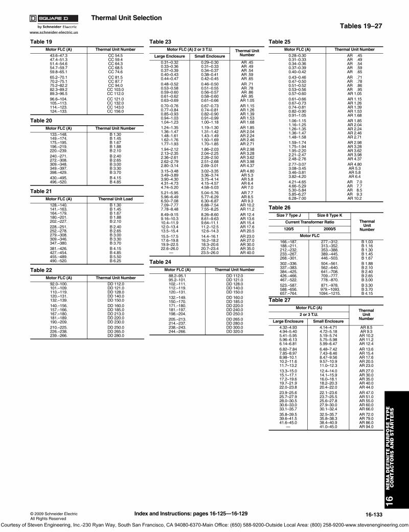
www.schneider-electric.us
16N
EM
A D
EF
INIT
E P
UR
PO
SE
TY
PE
C
ON
TA
CT
OR
S A
ND
ST
AR
TE
RS
© 2009 Schneider ElectricAll Rights Reserved
16-133
Thermal Unit SelectionTables 19–27
Table 19Motor FLC (A) Thermal Unit Number
43.6–47.347.4–51.351.4–54.654.7–59.759.8–65.1
CC 54.5CC 59.4CC 64.3CC 68.5CC 74.6
65.2–70.170.2–75.175.2–82.282.3–89.289.3–96.5
CC 81.5CC 87.7CC 94.0CC 103.0CC 112.0
96.6–104.105.–113.114.–123.124.–133.
CC 121.0CC 132.0CC 143.0CC 156.0
Table 20Motor FLC (A) Thermal Unit Number
133.–148.149.–174.175.–195.196.–219.220.–239.
B 1.30B 1.45B 1.67B 1.88B 2.10
240.–271.272.–308.309.–348.349.–397.398.–429.
B 2.40B 2.65B 3.00B 3.30B 3.70
430.–495.496.–520.
B 4.15B 4.85
Table 21Motor FLC (A) Thermal Unit Load
128.–140.141.–163.164.–179.180.–201.202.–227.
B 1.30B 1.45B 1.67B 1.88B 2.10
228.–251.252.–278.279.–308.309.–346.347.–380.
B 2.40B 2.65B 3.00B 3.30B 3.70
381.–426.427.–454.455.–489.490.–520.
B 4.15B 4.85B 5.50B 6.25
Table 22Motor FLC (A) Thermal Unit Number
92.0–100.101.–109.110.–119.120.–131.132.–139.
DD 112.0DD 121.0DD 128.0DD 140.0DD 150.0
140.–156.157.–166.167.–180.181.–189.190.–209.
DD 160.0DD 185.0DD 213.0DD 220.0DD 230.0
210.–225.226.–238.239.–266.
DD 250.0DD 265.0DD 280.0
Table 23Motor FLC (A) 2 or 3 T.U. Thermal Unit
NumberLarge Enclosure Small Enclosure
0.31–0.320.33–0.360.37–0.390.40–0.430.44–0.47
0.29–0.300.31–0.330.34–0.370.38–0.410.42–0.45
AR .45AR .49AR .54AR .59AR .65
0.48–0.520.53–0.580.59–0.600.61–0.620.63–0.69
0.46–0.500.51–0.550.56–0.570.58–0.600.61–0.66
AR .71AR .78AR .86AR .95AR 1.05
0.70–0.760.77–0.840.85–0.930.94–1.031.04–1.23
0.67–0.730.74–0.810.82–0.900.91–0.991.00–1.18
AR 1.15AR 1.26AR 1.39AR 1.53AR 1.68
1.24–1.351.36–1.471.48–1.611.62–1.761.77–1.93
1.19–1.301.31–1.421.43–1.491.50–1.691.70–1.85
AR 1.85AR 2.04AR 2.24AR 2.46AR 2.71
1.94–2.122.13–2.352.36–2.612.62–2.792.80–3.14
1.86–2.032.04–2.252.26–2.502.51–2.682.69–3.01
AR 2.98AR 3.28AR 3.62AR 3.98AR 4.37
3.15–3.483.49–3.893.90–4.304.31–4.734.74–5.20
3.02–3.353.36–3.743.75–4.144.15–4.574.58–5.03
AR 4.80AR 5.3AR 5.8AR 6.4AR 7.0
5.21–5.955.96–6.496.50–7.087.09–7.777.78–8.48
5.04–5.765.77–6.296.30–6.876.88–7.547.55–8.25
AR 7.7AR 8.5AR 9.3AR 10.2AR 11.2
8.49–9.159.16–10.310.4–11.912.0–13.413.5–15.4
8.26–8.608.61–9.639.64–11.111.2–12.512.6–14.3
AR 12.4AR 13.6AR 15.4AR 17.6AR 20.5
15.5–17.517.6–19.819.9–22.522.6–26.0
—
14.4–16.116.2–18.218.3–20.620.7–23.423.5–26.0
AR 23.0AR 27.0AR 30.0AR 35.0AR 40.0
Table 24Motor FLC (A) Thermal Unit Number
88.2–95.195.2–101.102.–111.112.–119.120.–131.
DD 112.0DD 121.0DD 128.0DD 140.0DD 150.0
132.–149.150.–170.171.–180.181.–197.198.–204.
DD 160.0DD 185.0DD 220.0DD 240.0DD 250.0
205.–213.214.–237.238.–243.244.–266.
DD 265.0DD 280.0DD 300.0DD 320.0
Table 25Motor FLC (A) Thermal Unit Number
0.28–0.300.31–0.330.34–0.360.37–0.390.40–0.42
AR .45AR .49AR .54AR .59AR .65
0.43–0.460.47–0.500.51–0.520.53–0.560.57–0.60
AR .71AR .78AR .86AR .95AR 1.05
0.61–0.660.67–0.730.74–0.810.82–0.900.91–1.05
AR 1.15AR 1.26AR 1.39AR 1.53AR 1.68
1.06–1.151.16–1.251.26–1.351.36–1.471.48–1.58
AR 1.85AR 2.04AR 2.24AR 2.46AR 2.71
1.59–1.741.75–1.941.95–2.202.21–2.472.48–2.76
AR 2.98AR 3.28AR 3.62AR 3.98AR 4.37
2.77–3.073.08–3.453.46–3.813.82–4.20
AR 4.80AR 5.3AR 5.8AR 6.4
4.21–4.654.66–5.295.30–5.845.85–6.276.28–7.00
AR 7.0AR 7.7AR 8.5AR 9.3AR 10.2
Table 26Size 7 Type J Size 8 Type K
ThermalUnit
Number
Current Transformer Ratio
120/5 2000/5
Motor FLC
166.–187.188.–211.212.–232.233.–267.268.–301.
277.–312.313.–352.353.–388.389.–445.446.–503.
B 1.03B 1.16B 1.30B 1.45B 1.67
302.–336.337.–383.384.–425.426.–466.467.–522.
504.–561.562.–640.641.–708.709.–777.778.–870.
B 1.88B 2.10B 2.40B 2.65B 3.00
523.–587.588.–656.657.–764.
871.–978. 979.–1093.1094.–1215.
B 3.30B 3.70B 4.15
Table 27Motor FLC (A)
ThermalUnit
Number2 or 3 T.U.
Large Enclosure Small Enclosure
4.32–4.934.94–5.405.41–5.955.96–6.136.14–6.81
4.14–4.714.72–5.185.19–5.745.75–5.985.99–6.47
AR 8.5AR 9.3AR 10.2AR 11.2AR 12.4
6.82–7.847.85–8.978.98–10.110.2–11.611.7–13.2
6.48–7.427.43–8.468.47–9.569.57–10.911.0–12.3
AR 13.6AR 15.4AR 17.6AR 20.5AR 23.0
13.3–15.015.1–17.117.2–19.619.7–21.922.0–23.8
12.4–14.014.1–15.916.0–18.118.2–20.320.4–22.0
AR 27.0AR 30.0AR 35.0AR 40.0AR 44.0
23.9–25.625.7–27.928.0–30.530.6–33.033.1–35.7
22.1–23.623.7–25.525.6–27.827.9–30.030.1–32.4
AR 47.0AR 51.0AR 55.0AR 60.0AR 66.0
35.8–39.539.6–41.541.6–45.0
—
32.5–35.735.8–38.338.4–40.941.0–45.0
AR 72.0AR 79.0AR 86.0AR 94.0
Index and Instructions: pages 16-125—16-129
Courtesy of Steven Engineering, Inc.-230 Ryan Way, South San Francisco, CA 94080-6370-Main Office: (650) 588-9200-Outside Local Area: (800) 258-9200-www.stevenengineering.com
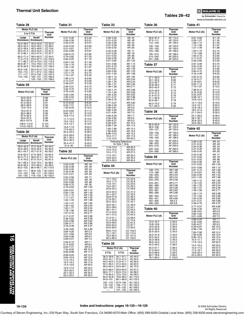
www.schneider-electric.us
16N
EM
A D
EF
INIT
E P
UR
PO
SE
TY
PE
C
ON
TA
CT
OR
S A
ND
ST
AR
TE
RS
16-134 © 2009 Schneider ElectricAll Rights Reserved
Thermal Unit SelectionTables 28–42
Table 28Motor FLC (A)
ThermalUnit
Number
2 or 3 T.U.
LargeEnclosure
SmallEnclosure
45.3–48.248.3–52.452.5–56.456.5–61.261.3–66.1
40.3–42.842.9–46.246.3–49.849.9–54.955.0–57.9
CC 64.3CC 68.5CC 74.6CC 81.5CC 87.7
66.2–71.471.5–77.077.1–80.780.8–87.787.8–94.9
58.0–62.562.6–67.367.4–73.473.5–78.979.0–84.9
CC 94.0CC 103.0CC 112.0CC 121.0CC 132.0
95.0–102.103.–110.111.–117.118.–133.
—
85.0–91.091.1–97.297.3–104.105.–121.122.–133.
CC 143.0CC 156.0CC 167.0CC 180.0CC 196.0
Table 29
Motor FLC (A)Thermal
UnitNumber
50.0–55.956.0–60.961.0–65.966.0–69.970.0–75.9
E 88E 89E 91E 92E 93
76.0–81.982.0–86.987.0–92.993.0–97.998.0–107.9
E 94E 96E 97E 98E 99
108.0–113.9114.0–125.9
E 101E 102
Table 30Motor FLC (A) Thermal
UnitNumber
LargeEnclosure
Small Enclosure
39.0–42.943.0–48.048.1–54.7
37.0–40.840.9–45.645.7–51.8
AU 44.0AU 50.0AU 56.0
54.8–62.262.3–71.371.4–76.0
51.9–58.858.9–67.467.5–70.4
AU 64.0AU 72.0AU 81.0
76.1–85.585.6–92.492.5–103.
70.5–79.479.5–86.386.4–96.7
AU 88.0AU 99.0AU 110.0
104.–111.112.–123.124.–133.
96.8–105.106.–117.118.–133.
AU 123.0AU 135.0AU 152.0
Table 31
Motor FLC (A)Thermal
UnitNumber
0.31–0.350.36–0.390.40–0.44
B 0.44B 0.51B 0.57
0.45–0.500.51–0.610.62–0.68
B 0.63B 0.71B 0.81
0.69–0.730.74–0.820.83–0.92
B 0.92B 1.03B 1.16
0.93–1.031.04–1.191.20–1.34
B 1.30B 1.45B 1.67
1.35–1.501.51–1.741.75–1.97
B 1.88B 2.10B 2.40
1.98–2.142.15–2.472.48–2.91
B 2.65B 3.00B 3.30
2.92–3.313.32–3.753.76–4.05
B 3.70B 4.15B 4.85
4.06–4.944.95–5.525.53–6.11
B 6.25B 6.90B 7.70
6.12–6.526.53–7.317.32–8.43
B 8.20B 9.10B 10.2
8.44–9.839.84–10.710.8–11.6
B 11.5B 12.8B 14.0
11.7–12.913.0–14.314.4–15.7
B 15.5B 17.5B 19.5
15.8–17.817.9–20.320.4–23.3
B 22.0B 25.0B 28.0
23.4–26.626.7–30.330.4–35.3
B 32.0B 36.0B 40.0
35.4–41.541.6–45
B 45.0B 50.0
Table 32
Motor FLC (A)Thermal
UnitNumber
0.33–0.350.36–0.390.40–0.420.43–0.460.47–0.51
AR .45AR .49AR .54AR .59AR .65
0.52–0.560.57–0.620.63–0.680.69–0.750.76–0.83
AR .71AR .78AR .86AR .95AR 1.05
0.84–0.910.92–1.001.01–1.101.11–1.211.22–1.33
AR 1.15AR 1.26AR 1.39AR 1.53AR 1.68
1.34–1.471.48–1.621.63–1.771.78–1.961.97–2.16
AR 1.85AR 2.04AR 2.24AR 2.46AR 2.71
2.17–2.372.38–2.622.63–2.882.89–3.173.18–3.48
AR 2.98AR 3.28AR 3.62AR 3.98AR 4.37
3.49–3.833.84–4.204.21–4.624.63–5.085.09–5.57
AR 4.80AR 5.3AR 5.8AR 6.4AR 7.0
5.58–6.136.14–6.836.84–7.417.42–8.058.06–8.98
AR 7.7AR 8.5AR 9.3AR 10.2AR 11.2
8.99–9.939.94–10.911.0–12.412.5–14.314.4–15.8
AR 12.4AR 13.6AR 15.4AR 17.6AR 20.5
15.9–17.918.0–20.020.1–22.422.5–25.0
AR 23.0AR 27.0AR 30.0AR 35.0
Table 33
Motor FLC (A)Thermal
UnitNumber
0.28–0.300.31–0.330.34–0.360.37–0.390.40–0.42
AR .45AR .49AR .54AR .59AR .65
0.43–0.460.47–0.500.51–0.520.53–0.560.57–0.60
AR .71AR .78AR .86AR .95AR 1.05
0.61–0.660.67–0.730.74–0.810.82–0.900.91–1.05
AR 1.15AR 1.26AR 1.39AR 1.53AR 1.68
1.06–1.151.16–1.251.26–1.351.36–1.471.48–1.58
AR 1.85AR 2.04AR 2.24AR 2.46AR 2.71
1.59–1.741.75–1.941.95–2.202.21–2.472.48–2.76
AR 2.98AR 3.28AR 3.62AR 3.98AR 4.37
2.77–3.073.08–3.453.46–3.813.82–4.204.21–4.65
AR 4.80AR 5.3AR 5.8AR 6.4AR 7.0
4.66–5.295.30–5.845.85–6.276.28–6.976.98–7.59
AR 7.7AR 8.5AR 9.3AR 10.2AR 11.2
7.60–7.897.90–8.958.96–10.310.4–11.711.8–12.0
AR 12.4AR 13.6AR 15.4AR 17.6AR 20.5
Following Selectionsfor Size 1 Only
11.8–13.313.4–15.215.3–17.2
AR 20.5AR 23.0AR 27.0
17.3–19.719.8–22.422.5–26.0
AR 30.0AR 35.0AR 40.0
Table 34
Motor FLC (A)Thermal
UnitNumber
15.1–16.216.3–17.517.6–19.119.2–20.720.8–22.2
CC 20.9CC 22.8CC 24.6CC 26.3CC 28.8
22.3–24.024.1–25.725.8–27.827.9–30.130.2–32.5
CC 31.0CC 33.3CC 36.4CC 39.6CC 42.7
32.6–35.135.2–38.038.1–41.141.2–44.044.1–47.2
CC 46.6CC 50.1CC 54.5CC 59.4CC 64.3
47.3–51.151.2–55.855.9–59.559.6–64.564.6–69.5
CC 68.5CC 74.6CC 81.5CC 87.7CC 94.0
69.6–75.075.1–78.178.2–82.382.4–86.0
CC 103.0CC 112.0CC 121.0CC 132.0
Table 35Motor FLC (A) Thermal
UnitNumber2 T.U. 3 T.U.
36.3–39.940.0–44.144.2–50.050.1–56.456.5–64.4
34.7–37.137.2–41.541.6–47.147.2–53.453.5–60.7
AU 44.0AU 50.0AU 56.0AU 64.0AU 72.0
64.5–68.468.5–77.777.8–84.284.3–94.894.9–101.
60.8–64.965.0–73.473.5–79.579.6–89.089.1–96.9
AU 81.0AU 88.0AU 99.0AU 110.0AU 123.0
102.–115.116.–122.123.–133.
—
97.0–108.109.–115.116.–120.121.–133.
AU 135.0AU 152.0AU 169.0AU 183.0
Table 36
Motor FLC (A)Thermal
UnitNumber
90.6–97.497.5–111.112.–129.
AF 110.0AF 123.0AF 135.0
130.–149.150.–163.164.–189.
AF 150.0AF 159.0AF 168.0
190.–213.214.–240.241.–266.
AF 188.0AF 205.0AF 220.0
Table 37
Motor FLC (A)Thermal
UnitNumber
27.1–30.030.1–33.233.3–35.735.8–39.439.5–43.4
E 67E 69E 70E 71E 72
43.5–46.947.0–51.551.6–57.057.1–62.862.9–69.1
E 73E 74E 76E 77E 78
69.2–75.075.1–83.3
E 79E 80
Table 38
Motor FLC (A)Thermal
UnitNumber
85.0–95.996.0–108.109.–127.
AF 123.0AF 135.0AF 150.0
128.–136.137.–147.148.–162.
AF 159.0AF 168.0AF 188.0
163.–185.186.–202.203.–219.
AF 205.0AF 220.0AF 240.0
220.–233.234.–266.
AF 260.0AF 308.0
Table 39
Motor FLC (A)Thermal
UnitNumber
148.–173.174.–189.190.–205.206.–222.223.–243.
AR 1.68AR 1.85AR 2.04AR 2.24AR 2.46
244.–261.262.–289.290.–324.325.–367.368.–389.
AR 2.71AR 2.98AR 3.28AR 3.62AR 3.98
390.–404.405.–451.452.–495.496.–520.
AR 4.37AR 4.80AR 5.3AR 5.8
Table 40
Motor FLC (A)Thermal
UnitNumber
15.3–16.716.8–19.819.9–22.822.9–25.825.9–30.4
C 20.0C 22.0C 26.0C 30.0C 34.0
30.5–31.932.0–34.234.3–38.838.9–44.244.3–50.2
C 40.0C 42.0C 45.0C 51.0C 58.0
50.3–57.157.2–63.263.3–68.668.7–78.678.7–86.0
C 66.0C 75.0C 83.0C 90.0C 103.0
Table 41
Motor FLC (A)Thermal
UnitNumber
0.81–0.920.93–1.071.08–1.141.15–1.261.27–1.49
B 1.16B 1.30B 1.45B 1.67B 1.88
1.50–1.731.74–1.891.90–2.162.17–2.372.38–2.66
B 2.10B 2.40B 2.65B 3.00B 3.30
2.67–2.993.00–3.403.41–3.943.95–4.154.16–4.49
B 3.70B 4.15B 4.85B 5.50B 6.25
4.50–5.155.16–5.775.78–6.616.62–7.147.15–7.97
B 6.90B 7.70B 8.20B 9.10B 10.2
7.98–8.158.16–9.329.33–9.979.98–10.710.8–12.0
B 11.5B 12.8B 14.0B 15.5B 17.5
12.1–13.914.0–15.715.8–18.418.5–21.621.7–24.0
B 19.5B 22.0B 25.0B 28.0B 32.0
24.1–28.628.7–30.730.8–33.533.6–36.0
B 36.0B 40.0B 45.0B 50.0
Table 42
Motor FLC (A)Thermal
UnitNumber
0.28–0.300.31–0.330.34–0.360.37–0.390.40–0.42
AR .45AR .49AR .54AR .59AR .65
0.43–0.460.47–0.500.51–0.520.53–0.560.57–0.60
AR .71AR .78AR .86AR .95AR 1.05
0.61–0.660.67–0.730.74–0.810.82–0.900.91–1.05
AR 1.15AR 1.26AR 1.39AR 1.53AR 1.68
1.06–1.151.16–1.251.26–1.351.36–1.471.48–1.58
AR 1.85AR 2.04AR 2.24AR 2.46AR 2.71
1.59–1.741.75–1.941.95–2.202.21–2.472.48–2.76
AR 2.98AR 3.28AR 3.62AR 3.98AR 4.37
2.77–3.073.08–3.453.46–3.813.82–4.204.21–4.65
AR 4.80AR 5.3AR 5.8AR 6.4AR 7.0
4.66–5.295.30–5.845.85–6.276.28–6.976.98–7.59
AR 7.7AR 8.5AR 9.3AR 10.2AR 11.2
7.60–7.897.90–8.958.96–10.310.4–11.711.8–13.3
AR 12.4AR 13.6AR 15.4AR 17.6AR 20.5
13.4–15.215.3–17.217.3–19.719.8–22.422.5–26.0
AR 23.0AR 27.0AR 30.0AR 35.0AR 40.0
Index and Instructions: pages 16-125—16-129
Courtesy of Steven Engineering, Inc.-230 Ryan Way, South San Francisco, CA 94080-6370-Main Office: (650) 588-9200-Outside Local Area: (800) 258-9200-www.stevenengineering.com
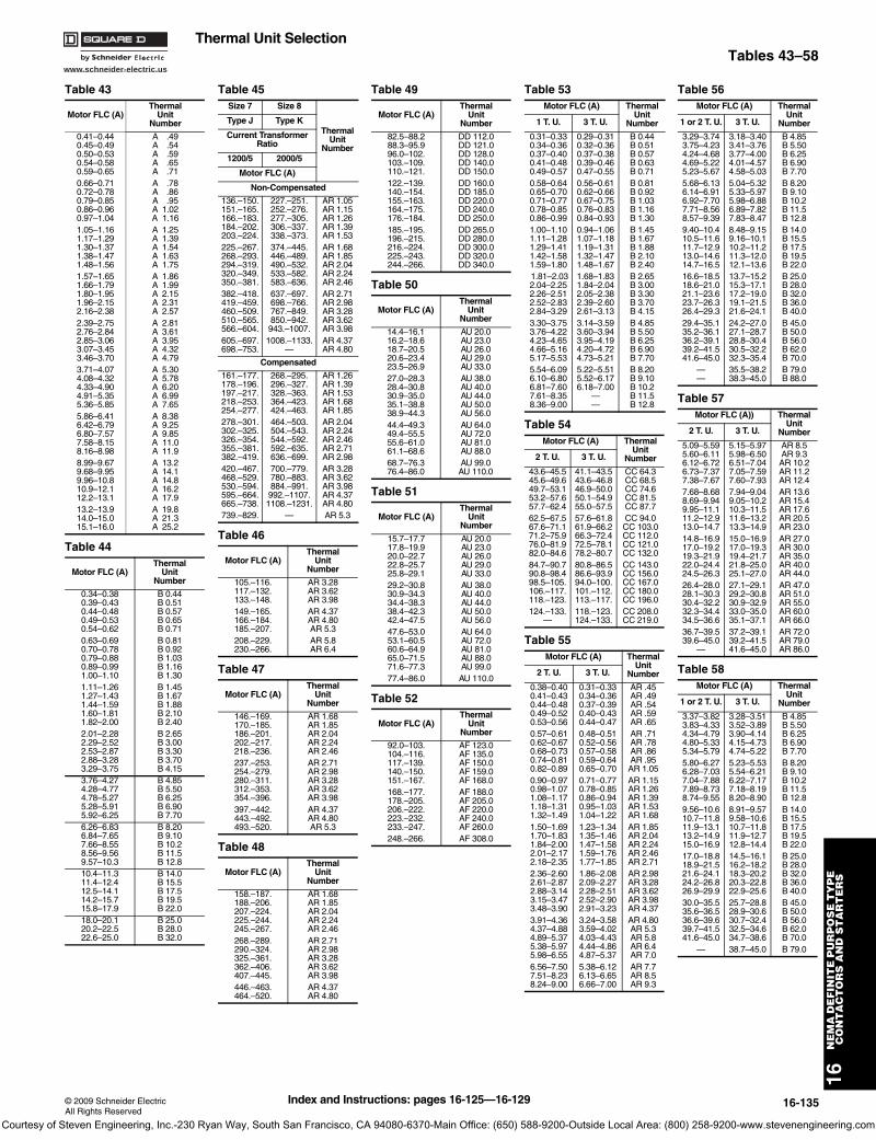
www.schneider-electric.us
16N
EM
A D
EF
INIT
E P
UR
PO
SE
TY
PE
C
ON
TA
CT
OR
S A
ND
ST
AR
TE
RS
© 2009 Schneider ElectricAll Rights Reserved
16-135
Thermal Unit SelectionTables 43–58
Table 43
Motor FLC (A)Thermal
Unit Number
0.41–0.440.45–0.490.50–0.530.54–0.580.59–0.65
A .49A .54A .59A .65A .71
0.66–0.710.72–0.780.79–0.850.86–0.960.97–1.04
A .78A .86A .95A 1.02A 1.16
1.05–1.161.17–1.291.30–1.371.38–1.471.48–1.56
A 1.25A 1.39A 1.54A 1.63A 1.75
1.57–1.651.66–1.791.80–1.951.96–2.152.16–2.38
A 1.86A 1.99A 2.15A 2.31A 2.57
2.39–2.752.76–2.842.85–3.063.07–3.453.46–3.70
A 2.81A 3.61A 3.95A 4.32A 4.79
3.71–4.074.08–4.324.33–4.904.91–5.355.36–5.85
A 5.30A 5.78A 6.20A 6.99A 7.65
5.86–6.416.42–6.796.80–7.577.58–8.158.16–8.98
A 8.38A 9.25A 9.85A 11.0A 11.9
8.99–9.679.68–9.959.96–10.810.9–12.112.2–13.1
A 13.2A 14.1A 14.8A 16.2A 17.9
13.2–13.914.0–15.015.1–16.0
A 19.8A 21.3A 25.2
Table 44
Motor FLC (A)Thermal
UnitNumber
0.34–0.380.39–0.430.44–0.480.49–0.530.54–0.62
B 0.44B 0.51B 0.57B 0.65B 0.71
0.63–0.690.70–0.780.79–0.880.89–0.991.00–1.10
B 0.81B 0.92B 1.03B 1.16B 1.30
1.11–1.261.27–1.431.44–1.591.60–1.811.82–2.00
B 1.45B 1.67B 1.88B 2.10B 2.40
2.01–2.282.29–2.522.53–2.872.88–3.283.29–3.75
B 2.65B 3.00B 3.30B 3.70B 4.15
3.76–4.274.28–4.774.78–5.275.28–5.915.92–6.25
B 4.85B 5.50B 6.25B 6.90B 7.70
6.26–6.836.84–7.657.66–8.558.56–9.569.57–10.3
B 8.20B 9.10B 10.2B 11.5B 12.8
10.4–11.311.4–12.412.5–14.114.2–15.715.8–17.9
B 14.0B 15.5B 17.5B 19.5B 22.0
18.0–20.120.2–22.522.6–25.0
B 25.0B 28.0B 32.0
Table 45Size 7 Size 8
ThermalUnit
Number
Type J Type K
Current Transformer Ratio
1200/5 2000/5
Motor FLC (A)
Non-Compensated
136.–150.151.–165.166.–183.184.–202.203.–224.
227.–251.252.–276.277.–305.306.–337.338.–373.
AR 1.05AR 1.15AR 1.26AR 1.39AR 1.53
225.–267.268.–293.294.–319.320.–349.350.–381.
374.–445.446.–489.490.–532.533.–582.583.–636.
AR 1.68AR 1.85AR 2.04AR 2.24AR 2.46
382.–418.419.–459.460.–509.510.–565.566.–604.
637.–697.698.–766.767.–849.850.–942.943.–1007.
AR 2.71AR 2.98AR 3.28AR 3.62AR 3.98
605.–697.698.–753.
1008.–1133.—
AR 4.37AR 4.80
Compensated
161.–177.178.–196.197.–217.218.–253.254.–277.
268.–295.296.–327.328.–363.364.–423.424.–463.
AR 1.26AR 1.39AR 1.53AR 1.68AR 1.85
278.–301.302.–325.326.–354.355.–381.382.–419.
464.–503.504.–543.544.–592.592.–635.636.–699.
AR 2.04AR 2.24AR 2.46AR 2.71AR 2.98
420.–467.468.–529.530.–594.595.–664.665.–738.
700.–779.780.–883.884.–991.992.–1107.1108.–1231.
AR 3.28AR 3.62AR 3.98AR 4.37AR 4.80
739.–829. — AR 5.3
Table 46
Motor FLC (A)Thermal
UnitNumber
105.–116.117.–132.133.–148.
AR 3.28AR 3.62AR 3.98
149.–165.166.–184.185.–207.
AR 4.37AR 4.80AR 5.3
208.–229.230.–266.
AR 5.8AR 6.4
Table 47
Motor FLC (A)Thermal
UnitNumber
146.–169.170.–185.186.–201.202.–217.218.–236.
AR 1.68AR 1.85AR 2.04AR 2.24AR 2.46
237.–253.254.–279.280.–311.312.–353.354.–396.
AR 2.71AR 2.98AR 3.28AR 3.62AR 3.98
397.–442.443.–492.493.–520.
AR 4.37AR 4.80AR 5.3
Table 48
Motor FLC (A)Thermal
UnitNumber
158.–187.188.–206.207.–224.225.–244.245.–267.
AR 1.68AR 1.85AR 2.04AR 2.24AR 2.46
268.–289.290.–324.325.–361.362.–406.407.–445.
AR 2.71AR 2.98AR 3.28AR 3.62AR 3.98
446.–463.464.–520.
AR 4.37AR 4.80
Table 49
Motor FLC (A)Thermal
UnitNumber
82.5–88.288.3–95.996.0–102.103.–109.110.–121.
DD 112.0DD 121.0DD 128.0DD 140.0DD 150.0
122.–139.140.–154.155.–163.164.–175.176.–184.
DD 160.0DD 185.0DD 220.0DD 240.0DD 250.0
185.–195.196.–215.216.–224.225.–243.244.–266.
DD 265.0DD 280.0DD 300.0DD 320.0DD 340.0
Table 50
Motor FLC (A)Thermal
UnitNumber
14.4–16.116.2–18.618.7–20.520.6–23.423.5–26.9
AU 20.0AU 23.0AU 26.0AU 29.0AU 33.0
27.0–28.328.4–30.830.9–35.035.1–38.838.9–44.3
AU 38.0AU 40.0AU 44.0AU 50.0AU 56.0
44.4–49.349.4–55.555.6–61.061.1–68.6
AU 64.0AU 72.0AU 81.0AU 88.0
68.7–76.376.4–86.0
AU 99.0AU 110.0
Table 51
Motor FLC (A)Thermal
UnitNumber
15.7–17.717.8–19.920.0–22.722.8–25.725.8–29.1
AU 20.0AU 23.0AU 26.0AU 29.0AU 33.0
29.2–30.830.9–34.334.4–38.338.4–42.342.4–47.5
AU 38.0AU 40.0AU 44.0AU 50.0AU 56.0
47.6–53.053.1–60.560.6–64.965.0–71.571.6–77.3
AU 64.0AU 72.0AU 81.0AU 88.0AU 99.0
77.4–86.0 AU 110.0
Table 52
Motor FLC (A)Thermal
UnitNumber
92.0–103.104.–116.117.–139.140.–150.151.–167.
AF 123.0AF 135.0AF 150.0AF 159.0AF 168.0
168.–177.178.–205.206.–222.223.–232.233.–247.
AF 188.0AF 205.0AF 220.0AF 240.0AF 260.0
248.–266. AF 308.0
Table 53Motor FLC (A) Thermal
Unit Number1 T. U. 3 T. U.
0.31–0.330.34–0.360.37–0.400.41–0.480.49–0.57
0.29–0.310.32–0.360.37–0.380.39–0.460.47–0.55
B 0.44B 0.51B 0.57B 0.63B 0.71
0.58–0.640.65–0.700.71–0.770.78–0.850.86–0.99
0.56–0.610.62–0.660.67–0.750.76–0.830.84–0.93
B 0.81B 0.92B 1.03B 1.16B 1.30
1.00–1.101.11–1.281.29–1.411.42–1.581.59–1.80
0.94–1.061.07–1.181.19–1.311.32–1.471.48–1.67
B 1.45B 1.67B 1.88B 2.10B 2.40
1.81–2.032.04–2.252.26–2.512.52–2.832.84–3.29
1.68–1.831.84–2.042.05–2.382.39–2.602.61–3.13
B 2.65B 3.00B 3.30B 3.70B 4.15
3.30–3.753.76–4.224.23–4.654.66–5.165.17–5.53
3.14–3.593.60–3.943.95–4.194.20–4.724.73–5.21
B 4.85B 5.50B 6.25B 6.90B 7.70
5.54–6.096.10–6.806.81–7.607.61–8.358.36–9.00
5.22–5.515.52–6.176.18–7.00
——
B 8.20B 9.10B 10.2B 11.5B 12.8
Table 54Motor FLC (A) Thermal
Unit Number2 T. U. 3 T. U.
43.6–45.545.6–49.649.7–53.153.2–57.657.7–62.4
41.1–43.543.6–46.846.9–50.050.1–54.955.0–57.5
CC 64.3CC 68.5CC 74.6CC 81.5CC 87.7
62.5–67.567.6–71.171.2–75.976.0–81.982.0–84.6
57.6–61.861.9–66.266.3–72.472.5–78.178.2–80.7
CC 94.0CC 103.0CC 112.0CC 121.0CC 132.0
84.7–90.790.8–98.498.5–105.106.–117.118.–123.
80.8–86.586.6–93.994.0–100.101.–112.113.–117.
CC 143.0CC 156.0CC 167.0CC 180.0CC 196.0
124.–133.—
118.–123.124.–133.
CC 208.0CC 219.0
Table 55Motor FLC (A) Thermal
Unit Number2 T. U. 3 T. U.
0.38–0.400.41–0.430.44–0.480.49–0.520.53–0.56
0.31–0.330.34–0.360.37–0.390.40–0.430.44–0.47
AR .45AR .49AR .54AR .59AR .65
0.57–0.610.62–0.670.68–0.730.74–0.810.82–0.89
0.48–0.510.52–0.560.57–0.580.59–0.640.65–0.70
AR .71AR .78AR .86AR .95AR 1.05
0.90–0.970.98–1.071.08–1.171.18–1.311.32–1.49
0.71–0.770.78–0.850.86–0.940.95–1.031.04–1.22
AR 1.15AR 1.26AR 1.39AR 1.53AR 1.68
1.50–1.691.70–1.831.84–2.002.01–2.172.18–2.35
1.23–1.341.35–1.461.47–1.581.59–1.761.77–1.85
AR 1.85AR 2.04AR 2.24AR 2.46AR 2.71
2.36–2.602.61–2.872.88–3.143.15–3.473.48–3.90
1.86–2.082.09–2.272.28–2.512.52–2.902.91–3.23
AR 2.98AR 3.28AR 3.62AR 3.98AR 4.37
3.91–4.364.37–4.884.89–5.375.38–5.975.98–6.55
3.24–3.583.59–4.024.03–4.434.44–4.864.87–5.37
AR 4.80AR 5.3AR 5.8AR 6.4AR 7.0
6.56–7.507.51–8.238.24–9.00
5.38–6.126.13–6.656.66–7.00
AR 7.7AR 8.5AR 9.3
Table 56Motor FLC (A) Thermal
Unit Number1 or 2 T. U. 3 T. U.
3.29–3.743.75–4.234.24–4.684.69–5.225.23–5.67
3.18–3.403.41–3.763.77–4.004.01–4.574.58–5.03
B 4.85B 5.50B 6.25B 6.90B 7.70
5.68–6.136.14–6.916.92–7.707.71–8.568.57–9.39
5.04–5.325.33–5.975.98–6.886.89–7.827.83–8.47
B 8.20B 9.10B 10.2B 11.5B 12.8
9.40–10.410.5–11.611.7–12.913.0–14.614.7–16.5
8.48–9.159.16–10.110.2–11.211.3–12.012.1–13.6
B 14.0B 15.5B 17.5B 19.5B 22.0
16.6–18.518.6–21.021.1–23.623.7–26.326.4–29.3
13.7–15.215.3–17.117.2–19.019.1–21.521.6–24.1
B 25.0B 28.0B 32.0B 36.0B 40.0
29.4–35.135.2–36.136.2–39.139.2–41.541.6–45.0
24.2–27.027.1–28.728.8–30.430.5–32.232.3–35.4
B 45.0B 50.0B 56.0B 62.0B 70.0
——
35.5–38.238.3–45.0
B 79.0B 88.0
Table 57Motor FLC (A)) Thermal
Unit Number2 T. U. 3 T. U.
5.09–5.595.60–6.116.12–6.726.73–7.377.38–7.67
5.15–5.975.98–6.506.51–7.047.05–7.597.60–7.93
AR 8.5AR 9.3AR 10.2AR 11.2AR 12.4
7.68–8.688.69–9.949.95–11.111.2–12.913.0–14.7
7.94–9.049.05–10.210.3–11.511.6–13.213.3–14.9
AR 13.6AR 15.4AR 17.6AR 20.5AR 23.0
14.8–16.917.0–19.219.3–21.922.0–24.424.5–26.3
15.0–16.917.0–19.319.4–21.721.8–25.025.1–27.0
AR 27.0AR 30.0AR 35.0AR 40.0AR 44.0
26.4–28.028.1–30.330.4–32.232.3–34.434.5–36.6
27.1–29.129.2–30.830.9–32.933.0–35.035.1–37.1
AR 47.0AR 51.0AR 55.0AR 60.0AR 66.0
36.7–39.539.6–45.0
—
37.2–39.139.2–41.541.6–45.0
AR 72.0AR 79.0AR 86.0
Table 58Motor FLC (A) Thermal
Unit Number1 or 2 T. U. 3 T. U.
3.37–3.823.83–4.334.34–4.794.80–5.335.34–5.79
3.28–3.513.52–3.893.90–4.144.15–4.734.74–5.22
B 4.85B 5.50B 6.25B 6.90B 7.70
5.80–6.276.28–7.037.04–7.887.89–8.738.74–9.55
5.23–5.535.54–6.216.22–7.177.18–8.198.20–8.90
B 8.20B 9.10B 10.2B 11.5B 12.8
9.56–10.610.7–11.811.9–13.113.2–14.915.0–16.9
8.91–9.579.58–10.610.7–11.811.9–12.712.8–14.4
B 14.0B 15.5B 17.5B 19.5B 22.0
17.0–18.818.9–21.521.6–24.124.2–26.826.9–29.9
14.5–16.116.2–18.218.3–20.220.3–22.822.9–25.6
B 25.0B 28.0B 32.0B 36.0B 40.0
30.0–35.535.6–36.536.6–39.639.7–41.541.6–45.0
25.7–28.828.9–30.630.7–32.432.5–34.634.7–38.6
B 45.0B 50.0B 56.0B 62.0B 70.0
— 38.7–45.0 B 79.0
Index and Instructions: pages 16-125—16-129
Courtesy of Steven Engineering, Inc.-230 Ryan Way, South San Francisco, CA 94080-6370-Main Office: (650) 588-9200-Outside Local Area: (800) 258-9200-www.stevenengineering.com
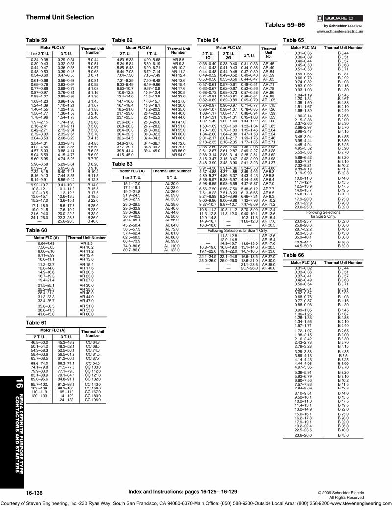
www.schneider-electric.us
16N
EM
A D
EF
INIT
E P
UR
PO
SE
TY
PE
C
ON
TA
CT
OR
S A
ND
ST
AR
TE
RS
16-136 © 2009 Schneider ElectricAll Rights Reserved
Thermal Unit SelectionTables 59–66
Table 59Motor FLC (A) Thermal Unit
Number1 or 2 T. U. 3 T. U.
0.34–0.380.39–0.430.44–0.470.48–0.530.54–0.60
0.29–0.310.32–0.350.36–0.380.39–0.460.47–0.55
B 0.44B 0.51B 0.57B 0.63B 0.71
0.61–0.680.69–0.760.77–0.860.87–0.970.98–1.07
0.56–0.620.63–0.670.68–0.750.76–0.840.85–0.95
B 0.81B 0.92B 1.03B 1.16B 1.30
1.08–1.231.24–1.391.40–1.551.56–1.771.78–1.96
0.96–1.091.10–1.211.22–1.351.36–1.531.54–1.73
B 1.45B 1.67B 1.88B 2.10B 2.40
1.97–2.152.16–2.412.42–2.712.72–3.033.04–3.53
1.74–1.901.91–2.142.15–2.342.35–2.672.68–3.22
B 2.65B 3.00B 3.30B 3.70B 4.15
3.54–4.014.02–4.564.57–5.035.04–5.595.60–5.95
3.23–3.483.49–3.873.88–4.144.15–4.734.74–5.28
B 4.85B 5.50B 6.25B 6.90B 7.70
5.96–6.586.59–7.317.32–8.158.16–9.139.14–9.91
5.29–5.645.65–6.396.40–7.437.44–8.558.56–9.40
B 8.20B 9.10B 10.2B 11.5B 12.8
9.92–10.710.8–12.112.2–13.513.6–15.115.2–17.0
9.41–10.010.1–11.211.3–12.512.6–13.513.6–15.4
B 14.0B 15.5B 17.5B 19.5B 22.0
17.1–18.919.0–21.521.6–24.024.1–26.0
—
15.5–17.517.6–19.920.0–22.222.3–25.525.6–26.0
B 25.0B 28.0B 32.0B 36.0B 40.0
Table 60Motor FLC (A) Thermal Unit Number
6.84–7.497.50–8.058.06–9.109.11–9.9910.0–11.1
AR 9.3AR 10.2AR 11.2AR 12.4AR 13.6
11.2–12.712.8–14.814.9–16.616.7–19.319.4–21.4
AR 15.4AR 17.6AR 20.5AR 23.0AR 27.0
21.5–25.125.2–28.328.4–31.231.3–33.333.4–35.7
AR 30.0AR 35.0AR 40.0AR 44.0AR 47.0
35.8–38.538.6–41.541.6–45.0
AR 51.0AR 55.0AR 60.0
Table 61Motor FLC (A) Thermal Unit
Number2 T. U. 3 T. U.
46.8–50.050.1–54.254.3–58.358.4–63.663.7–68.5
45.3–48.248.3–52.452.5–56.456.5–61.261.3–66.1
CC 64.3CC 68.5CC 74.6CC 81.5CC 87.7
68.6–74.074.1–79.879.9–83.083.1–88.989.0–95.6
66.2–71.471.5–77.077.1–79.079.1–84.784.8–91.1
CC 94.0CC 103.0CC 112.0CC 121.0CC 132.0
95.7–102.103.–109.110.–119.120.–133.
—
91.2–98.198.2–104.105.–113.114.–123.124.–133.
CC 143.0CC 156.0CC 167.0CC 180.0CC 196.0
Table 62Motor FLC (A) Thermal Unit
Number2 T. U. 3 T. U.
4.83–5.335.34–5.845.85–6.436.44–7.037.04–7.30
4.90–5.685.69–6.196.20–6.716.72–7.147.15–7.49
AR 8.5AR 9.3AR 10.2AR 11.2AR 12.4
7.31–8.298.30–9.499.50–10.710.8–12.312.4–14.0
7.50–8.488.49–9.669.67–10.810.9–12.412.5–13.9
AR 13.6AR 15.4AR 17.6AR 20.5AR 23.0
14.1–16.016.1–18.418.5–21.021.1–23.023.1–25.5
14.0–15.715.8–18.118.2–20.320.4–23.023.1–25.2
AR 27.0AR 30.0AR 35.0AR 40.0AR 44.0
25.6–26.726.8–28.328.4–30.330.4–32.532.6–34.5
25.3–26.626.7–28.228.3–30.230.3–32.332.4–34.3
AR 47.0AR 51.0AR 55.0AR 60.0AR 66.0
34.6–37.637.7–39.739.8–41.441.5–45.0
34.4–36.736.8–39.339.4–45.0
—
AR 72.0AR 79.0AR 86.0AR 94.0
Table 63Motor FLC (A) Thermal Unit Number
1 or 2 T. U. 3 T. U.
15.1–17.017.1–19.119.2–21.821.9–24.524.6–27.9
AU 20.0AU 23.0AU 26.0 AU 29.0AU 33.0
28.0–29.529.6–32.933.0–36.636.7–40.340.4–45.1
AU 38.0AU 40.0AU 44.0AU 50.0AU 56.0
45.2–50.450.5–57.357.4–62.462.5–68.368.4–73.9
AU 64.0AU 72.0AU 81.0AU 88.0AU 99.0
74.0–80.680.7–86.0
AU 110.0AU 123.0
Table 64Motor FLC (A) Thermal
UnitNo.
2 T. U. 1Ø
2 T. U. 2Ø 3 T. U.
0.38–0.400.41–0.430.44–0.480.49–0.520.53–0.56
0.38–0.400.41–0.430.44–0.480.49–0.520.53–0.56
0.31–0.330.34–0.360.37–0.390.40–0.430.44–0.47
AR .45AR .49AR .54AR .59AR .65
0.57–0.610.62–0.670.68–0.730.74–0.810.82–0.89
0.57–0.610.62–0.670.68–0.730.74–0.810.82–0.89
0.48–0.510.52–0.560.57–0.580.59–0.640.65–0.70
AR .71AR .78AR .86AR .95AR 1.05
0.90–0.970.98–1.071.08–1.171.18–1.311.32–1.49
0.90–0.970.98–1.071.08–1.171.18–1.311.32–1.49
0.71–0.770.78–0.850.86–0.940.95–1.031.04–1.22
AR 1.15AR 1.26AR 1.39AR 1.53AR 1.68
1.50–1.691.70–1.831.84–2.002.01–2.172.18–2.35
1.50–1.691.70–1.831.84–2.002.01–2.172.18–2.35
1.23–1.341.35–1.461.47–1.581.59–1.761.77–1.85
AR 1.85AR 2.04AR 2.24AR 2.46AR 2.71
2.36–2.602.61–2.872.88–3.143.15–3.473.48–3.90
2.36–2.602.61–2.872.88–3.143.15–3.473.48–3.90
1.86–2.082.09–2.272.28–2.512.52–2.902.91–3.23
AR 2.98AR 3.28AR 3.62AR 3.98AR 4.37
3.91–4.364.37–4.884.89–5.375.38–5.975.98–6.55
3.91–4.364.37–4.884.89–5.375.38–5.975.98–6.55
3.24–3.583.59–4.024.03–4.434.44–4.864.87–5.37
AR 4.80AR 5.3AR 5.8AR 6.4AR 7.0
6.56–7.507.51–8.238.24–8.999.00–9.869.87–10.7
6.56–7.507.51–8.238.24–8.999.00–9.869.87–10.7
5.38–6.126.13–6.656.66–7.317.32–7.967.97–8.69
AR 7.7AR 8.5AR 9.3AR 10.2AR 11.2
10.8–11.211.3–12.812.9–14.814.9–16.716.8–18.0
10.8–11.211.3–12.0
———
8.70–8.999.00–10.110.2–11.511.6–12.0
—
AR 12.4AR 13.6AR 15.4AR 17.6AR 20.5
Following Selections for Size 1 Only.———
16.8–19.019.1–22.0
11.3–12.812.9–14.814.9–16.716.8–19.019.1–22.0
——
11.6–13.013.1–14.614.7–16.5
AR 13.6AR 15.4AR 17.6AR 20.5AR 23.0
22.1–24.925.0–26.0
——
22.1–24.925.0–26.0
——
16.6–18.518.6–21.021.1–23.623.7–26.0
AR 27.0AR 30.0AR 35.0AR 40.0
Table 65Motor FLC (A) Thermal Unit Number
0.31–0.350.36–0.390.40–0.440.45–0.500.51–0.58
B 0.44B 0.51B 0.57B 0.63B 0.71
0.59–0.650.66–0.730.74–0.820.83–0.920.93–1.03
B 0.81B 0.92B 1.03B 1.16B 1.30
1.04–1.191.20–1.341.35–1.501.51–1.671.68–1.89
B 1.45B 1.67B 1.88B 2.10B 2.40
1.90–2.142.15–2.362.37–2.652.66–2.972.98–3.47
B 2.65B 3.00B 3.30B 3.70B 4.15
3.48–3.943.95–4.444.45–4.944.95–5.525.53–5.88
B 4.85B 5.50B 6.25B 6.90B 7.70
5.89–6.526.53–7.317.32–8.218.22–9.189.19–9.90
B 8.20B 9.10B 10.2B 11.5B 12.8
10.0–11.011.1–12.412.5–13.914.0–15.715.8–17.8
B 14.0B 15.5B 17.5B 19.5B 22.0
17.9–20.020.1–22.923.0–25.0
B 25.0B 28.0B 32.0
Following Selectionsfor Size 2 Only.
23.0–25.725.8–28.628.7–32.232.3–35.835.9–40.1
B 32.0B 36.0B 40.0B 45.0B 50.0
40.2–44.444.5–50.0
B 56.0B 62.0
Table 66Motor FLC (A) Thermal Unit Number
0.31–0.320.33–0.360.37–0.410.42–0.490.50–0.54
B 0.44B 0.51B 0.57B 0.63B 0.71
0.55–0.610.62–0.670.68–0.760.77–0.870.88–0.98
B 0.81B 0.92B 1.03B 1.16B 1.30
0.99–1.051.06–1.251.26–1.331.34–1.561.57–1.71
B 1.45B 1.67B 1.88B 2.10B 2.40
1.72–1.971.98–2.152.16–2.422.43–2.782.79–3.28
B 2.65B 3.00B 3.30B 3.70B 4.15
3.29–3.883.89–4.134.14–4.434.44–4.964.97–5.35
B 4.85B 5.5B 6.25B 6.90B 7.70
5.36–5.915.92–6.796.80–7.567.57–7.837.84–8.09
B 8.20B 9.10B 10.2B 11.5B 12.8
8.10–9.519.52–10.110.2–11.311.4–13.113.2–14.9
B 14.0B 15.5B 17.5B 19.5B 22.0
15.0–16.116.2–17.817.9–19.119.2–22.422.5–23.5
B 25.0B 28.0B 32.0B 36.0B 40.0
23.6–26.0 B 45.0
Index and Instructions: pages 16-125—16-129
Courtesy of Steven Engineering, Inc.-230 Ryan Way, South San Francisco, CA 94080-6370-Main Office: (650) 588-9200-Outside Local Area: (800) 258-9200-www.stevenengineering.com
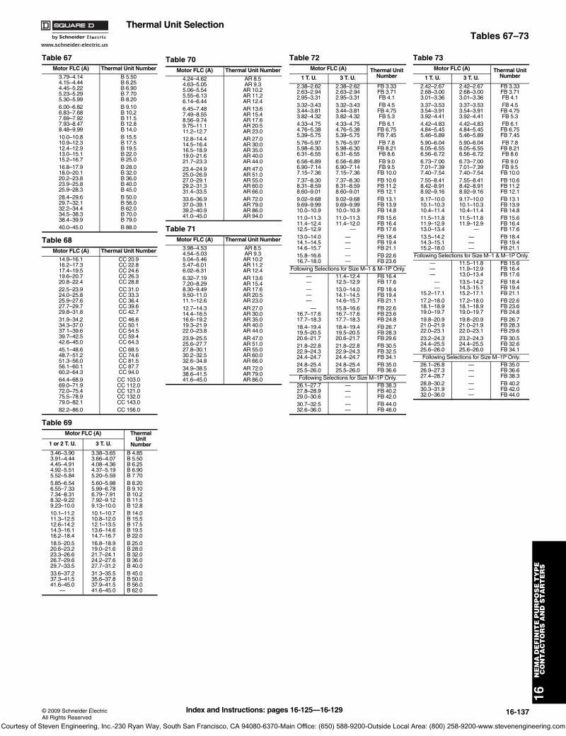
www.schneider-electric.us
16N
EM
A D
EF
INIT
E P
UR
PO
SE
TY
PE
C
ON
TA
CT
OR
S A
ND
ST
AR
TE
RS
© 2009 Schneider ElectricAll Rights Reserved
16-137
Thermal Unit SelectionTables 67–73
Table 67Motor FLC (A) Thermal Unit Number
3.79–4.144.15–4.444.45–5.225.23–5.295.30–5.99
B 5.50B 6.25B 6.90B 7.70B 8.20
6.00–6.826.83–7.687.69–7.927.93–8.478.48–9.99
B 9.10B 10.2B 11.5B 12.8B 14.0
10.0–10.810.9–12.312.4–12.913.0–15.115.2–16.7
B 15.5B 17.5B 19.5B 22.0B 25.0
16.8–17.918.0–20.120.2–23.823.9–25.825.9–28.3
B 28.0B 32.0B 36.0B 40.0B 45.0
28.4–29.629.7–32.132.2–34.434.5–38.338.4–39.9
B 50.0B 56.0B 62.0B 70.0B 79.0
40.0–45.0 B 88.0
Table 68Motor FLC (A) Thermal Unit Number
14.9–16.116.2–17.317.4–19.519.6–20.720.8–22.4
CC 20.9CC 22.8CC 24.6CC 26.3CC 28.8
22.5–23.924.0–25.825.9–27.627.7–29.729.8–31.8
CC 31.0CC 33.3CC 36.4CC 39.6CC 42.7
31.9–34.234.3–37.037.1–39.639.7–42.542.6–45.0
CC 46.6CC 50.1CC 54.5CC 59.4CC 64.3
45.1–48.648.7–51.251.3–56.056.1–60.160.2–64.3
CC 68.5CC 74.6CC 81.5CC 87.7CC 94.0
64.4–68.969.0–71.972.0–75.475.5–78.979.0–82.1
CC 103.0CC 112.0CC 121.0CC 132.0CC 143.0
82.2–86.0 CC 156.0
Table 69Motor FLC (A) Thermal
Unit Number1 or 2 T. U. 3 T. U.
3.46–3.903.91–4.444.45–4.914.92–5.515.52–5.84
3.38–3.653.66–4.074.08–4.364.37–5.195.20–5.59
B 4.85B 5.50B 6.25B 6.90B 7.70
5.85–6.546.55–7.337.34–8.318.32–9.229.23–10.0
5.60–5.985.99–6.786.79–7.917.92–9.129.13–10.0
B 8.20B 9.10B 10.2B 11.5B 12.8
10.1–11.211.3–12.512.6–14.214.3–16.116.2–18.4
10.1–10.710.8–12.012.1–13.513.6–14.614.7–16.7
B 14.0B 15.5B 17.5B 19.5B 22.0
18.5–20.520.6–23.223.3–26.626.7–29.629.7–33.5
16.8–18.919.0–21.621.7–24.124.2–27.627.7–31.2
B 25.0B 28.0B 32.0B 36.0B 40.0
33.6–37.237.3–41.541.6–45.0
—
31.3–35.535.6–37.837.9–41.541.6–45.0
B 45.0B 50.0B 56.0B 62.0
Table 70Motor FLC (A) Thermal Unit Number
4.24–4.624.63–5.055.06–5.545.55–6.136.14–6.44
AR 8.5AR 9.3AR 10.2AR 11.2AR 12.4
6.45–7.487.49–8.558.56–9.749.75–11.111.2–12.7
AR 13.6AR 15.4AR 17.6AR 20.5AR 23.0
12.8–14.414.5–16.416.5–18.919.0–21.621.7–23.3
AR 27.0AR 30.0AR 35.0AR 40.0AR 44.0
23.4–24.925.0–26.927.0–29.129.2–31.331.4–33.5
AR 47.0AR 51.0AR 55.0AR 60.0AR 66.0
33.6–36.937.0–39.139.2–40.941.0–45.0
AR 72.0AR 79.0AR 86.0AR 94.0
Table 71Motor FLC (A) Thermal Unit Number
3.98–4.534.54–5.035.04–5.465.47–6.016.02–6.31
AR 8.5AR 9.3AR 10.2AR 11.2AR 12.4
6.32–7.197.20–8.298.30–9.499.50–11.011.1–12.6
AR 13.6AR 15.4AR 17.6AR 20.5AR 23.0
12.7–14.314.4–16.516.6–19.219.3–21.922.0–23.8
AR 27.0AR 30.0AR 35.0AR 40.0AR 44.0
23.9–25.525.6–27.727.8–30.130.2–32.532.6–34.8
AR 47.0AR 51.0AR 55.0AR 60.0AR 66.0
34.9–38.538.6–41.541.6–45.0
AR 72.0AR 79.0AR 86.0
Table 72Motor FLC (A) Thermal Unit
Number1 T. U. 3 T. U.
2.38–2.622.63–2.942.95–3.31
2.38–2.622.63–2.942.95–3.31
FB 3.33FB 3.71FB 4.1
3.32–3.433.44–3.813.82–4.32
3.32–3.433.44–3.813.82–4.32
FB 4.5FB 4.75FB 5.3
4.33–4.754.76–5.385.39–5.75
4.33–4.754.76–5.385.39–5.75
FB 6.1FB 6.75FB 7.45
5.76–5.975.98–6.306.31–6.55
5.76–5.975.98–6.306.31–6.55
FB 7.8FB 8.21FB 8.6
6.56–6.896.90–7.147.15–7.36
6.56–6.896.90–7.147.15–7.36
FB 9.0FB 9.5FB 10.0
7.37–8.308.31–8.598.60–9.01
7.37–8.308.31–8.598.60–9.01
FB 10.6FB 11.2FB 12.1
9.02–9.689.69–9.9910.0–10.9
9.02–9.689.69–9.9910.0–10.9
FB 13.1FB 13.9FB 14.8
11.0–11.311.4–12.412.5–12.9
11.0–11.311.4–12.0
—
FB 15.6FB 16.4FB 17.6
13.0–14.014.1–14.514.6–15.7
———
FB 18.4FB 19.4FB 21.1
15.8–16.616.7–18.0
——
FB 22.6FB 23.6
Following Selections for Size M–1 & M–1P Only.——
11.4–12.412.5–12.9
FB 16.4FB 17.6
———
13.0–14.014.1–14.514.6–15.7
FB 18.4FB 19.4FB 21.1
—16.7–17.617.7–18.3
15.8–16.616.7–17.617.7–18.3
FB 22.6FB 23.6FB 24.8
18.4–19.419.5–20.520.6–21.7
18.4–19.419.5–20.520.6–21.7
FB 26.7FB 28.3FB 29.6
21.8–22.822.9–24.324.4–24.7
21.8–22.822.9–24.324.4–24.7
FB 30.5FB 32.5FB 34.1
24.8–25.425.5–26.0
24.8–25.425.5–26.0
FB 35.0FB 36.6
Following Selections for Size M–1P Only.26.1–27.727.8–28.929.0–30.6
———
FB 38.3FB 40.2FB 42.0
30.7–32.532.6–36.0
——
FB 44.0FB 46.0
Table 73Motor FLC (A) Thermal Unit
Number1 T. U. 3 T. U.
2.42–2.672.68–3.003.01–3.36
2.42–2.672.68–3.003.01–3.36
FB 3.33FB 3.71FB 4.1
3.37–3.533.54–3.913.92–4.41
3.37–3.533.54–3.913.92–4.41
FB 4.5FB 4.75FB 5.3
4.42–4.834.84–5.455.46–5.89
4.42–4.834.84–5.455.46–5.89
FB 6.1FB 6.75FB 7.45
5.90–6.046.05–6.556.56–6.72
5.90–6.046.05–6.556.56–6.72
FB 7.8FB 8.21FB 8.6
6.73–7.007.01–7.397.40–7.54
6.73–7.007.01–7.397.40–7.54
FB 9.0FB 9.5FB 10.0
7.55–8.418.42–8.918.92–9.16
7.55–8.418.42–8.918.92–9.16
FB 10.6FB 11.2FB 12.1
9.17–10.010.1–10.310.4–11.4
9.17–10.010.1–10.310.4–11.4
FB 13.1FB 13.9FB 14.8
11.5–11.811.9–12.913.0–13.4
11.5–11.811.9–12.9
—
FB 15.6FB 16.4FB 17.6
13.5–14.214.3–15.115.2–18.0
———
FB 18.4FB 19.4FB 21.1
Following Selections for Size M–1 & M–1P Only.———
11.5–11.811.9–12.913.0–13.4
FB 15.6FB 16.4FB 17.6
— —
15.2–17.1
13.5–14.214.3–15.115.2–17.1
FB 18.4FB 19.4FB 21.1
17.2–18.018.1–18.919.0–19.7
17.2–18.018.1–18.919.0–19.7
FB 22.6FB 23.6FB 24.8
19.8–20.921.0–21.922.0–23.1
19.8–20.921.0–21.922.0–23.1
FB 26.7FB 28.3FB 29.6
23.2–24.324.4–25.525.6–26.0
23.2–24.324.4–25.525.6–26.0
FB 30.5FB 32.6FB 34.1
Following Selections for Size M–1P Only.26.1–26.826.9–27.327.4–28.7
———
FB 35.0FB 36.6FB 38.3
28.8–30.230.3–31.932.0–36.0
———
FB 40.2FB 42.0FB 44.0
Index and Instructions: pages 16-125—16-129
Courtesy of Steven Engineering, Inc.-230 Ryan Way, South San Francisco, CA 94080-6370-Main Office: (650) 588-9200-Outside Local Area: (800) 258-9200-www.stevenengineering.com
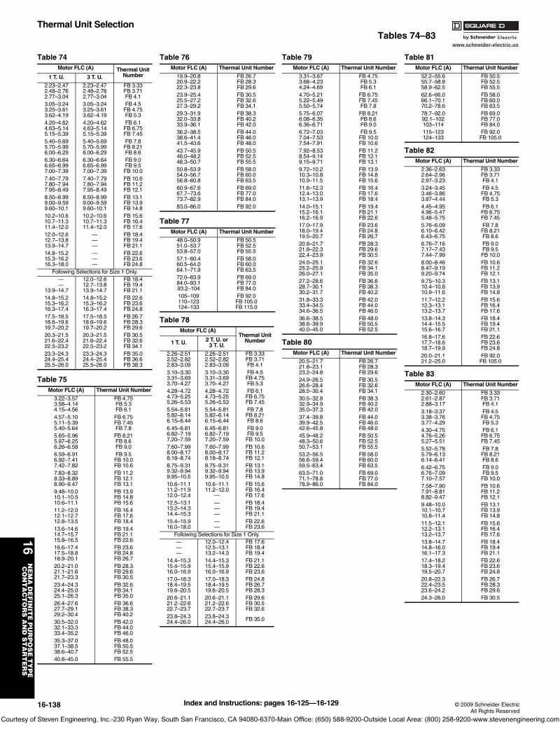
www.schneider-electric.us
16N
EM
A D
EF
INIT
E P
UR
PO
SE
TY
PE
C
ON
TA
CT
OR
S A
ND
ST
AR
TE
RS
16-138 © 2009 Schneider ElectricAll Rights Reserved
Thermal Unit SelectionTables 74–83
Table 74Motor FLC (A) Thermal Unit
Number1 T. U. 3 T. U.
2.23–2.472.48–2.762.77–3.04
2.23–2.472.48–2.762.77–3.04
FB 3.33FB 3.71FB 4.1
3.05–3.243.25–3.613.62–4.19
3.05–3.243.25–3.613.62–4.19
FB 4.5FB 4.75FB 5.3
4.20–4.624.63–5.145.15–5.39
4.20–4.624.63–5.145.15–5.39
FB 6.1FB 6.75FB 7.45
5.40–5.695.70–5.996.00–6.29
5.40–5.695.70–5.996.00–6.29
FB 7.8FB 8.21FB 8.6
6.30–6.646.65–6.997.00–7.39
6.30–6.646.65–6.997.00–7.39
FB 9.0FB 9.5FB 10.0
7.40–7.797.80–7.947.95–8.49
7.40–7.797.80–7.947.95–8.49
FB 10.6FB 11.2FB 12.1
8.50–8.999.00–9.599.60–10.1
8.50–8.999.00–9.599.60–10.1
FB 13.1FB 13.9FB 14.8
10.2–10.610.7–11.311.4–12.0
10.2–10.610.7–11.311.4–12.0
FB 15.6FB 16.4FB 17.6
12.0–12.612.7–13.813.9–14.7
———
FB 18.4FB 19.4FB 21.1
14.8–15.215.3–16.216.3–18.0
———
FB 22.6FB 23.6FB 24.8
Following Selections for Size 1 Only. — —
13.9–14.7
12.0–12.612.7–13.813.9–14.7
FB 18.4FB 19.4FB 21.1
14.8–15.215.3–16.216.3–17.4
14.8–15.215.3–16.216.3–17.4
FB 22.6FB 23.6FB 24.8
17.5–18.518.6–19.619.7–20.2
17.5–18.518.6–19.619.7–20.2
FB 26.7FB 28.3FB 29.6
20.3–21.521.6–22.422.5–23.2
20.3–21.521.6–22.422.5–23.2
FB 30.5FB 32.6FB 34.1
23.3–24.324.4–25.425.5–26.0
23.3–24.324.4–25.425.5–26.0
FB 35.0FB 36.6FB 38.3
Table 75Motor FLC (A) Thermal Unit Number
3.22–3.573.58–4.144.15–4.56
FB 4.75FB 5.3FB 6.1
4.57–5.105.11–5.395.40–5.64
FB 6.75FB 7.45FB 7.8
5.65–5.965.97–6.256.26–6.58
FB 8.21FB 8.6FB 9.0
6.59–6.916.92–7.417.42–7.82
FB 9.5FB 10.0FB 10.6
7.83–8.328.33–8.898.90–9.47
FB 11.2FB 12.1FB 13.1
9.48–10.010.1–10.510.6–11.1
FB 13.9FB 14.8FB 15.6
11.2–12.012.1–12.712.8–13.5
FB 16.4FB 17.6FB 18.4
13.6–14.614.7–15.715.8–16.5
FB 19.4FB 21.1FB 22.6
16.6–17.417.5–18.818.9–20.1
FB 23.6FB 24.8FB 26.7
20.2–21.021.1–21.621.7–23.3
FB 28.3FB 29.6FB 30.5
23.4–24.324.4–25.025.1–26.3
FB 32.6FB 34.1FB 35.0
26.4–27.627.7–29.129.2–30.4
FB 36.6FB 38.3FB 40.2
30.5–32.032.1–33.333.4–35.2
FB 42.0FB 44.0FB 46.0
35.3–37.037.1–38.538.6–40.7
FB 48.0FB 50.5FB 52.5
40.8–45.0 FB 55.5
Table 76Motor FLC (A) Thermal Unit Number
19.9–20.820.9–22.222.3–23.8
FB 26.7FB 28.3FB 29.6
23.9–25.425.5–27.227.3–29.2
FB 30.5FB 32.6FB 34.1
29.3–31.932.0–33.833.9–36.1
FB 38.3FB 40.2FB 42.0
36.2–38.538.6–41.441.5–43.6
FB 44.0FB 46.0FB 48.0
43.7–45.946.0–48.248.3–50.7
FB 50.5FB 52.5FB 55.5
50.8–53.954.0–56.756.8–60.8
FB 58.0FB 60.0FB 63.5
60.9–67.667.7–73.673.7–82.9
FB 69.0FB 77.0FB 84.0
83.0–86.0 FB 92.0
Table 77Motor FLC (A) Thermal Unit Number
48.0–50.951.0–53.753.8–57.0
FB 50.5FB 52.5FB 55.5
57.1–60.460.5–64.064.1–71.9
FB 58.0FB 60.0FB 63.5
72.0–83.984.0–93.193.2–104
FB 69.0FB 77.0FB 84.0
105–109110–123124–133
FB 92.0FB 105.0FB 115.0
Table 78Motor FLC (A)
Thermal Unit Number1 T. U. 2 T. U. or
3 T. U.
2.26–2.512.52–2.822.83–3.09
2.26–2.512.52–2.822.83–3.09
FB 3.33FB 3.71FB 4.1
3.10–3.303.31–3.693.70–4.27
3.10–3.303.31–3.693.70–4.27
FB 4.5FB 4.75FB 5.3
4.28–4.724.73–5.255.26–5.53
4.28–4.724.73–5.255.26–5.53
FB 6.1FB 6.75FB 7.45
5.54–5.815.82–6.146.15–6.44
5.54–5.815.82–6.146.15–6.44
FB 7.8FB 8.21FB 8.6
6.45–6.816.82–7.197.20–7.59
6.45–6.816.82–7.197.20–7.59
FB 9.0FB 9.5FB 10.0
7.60–7.998.00–8.178.18–8.74
7.60–7.998.00–8.178.18–8.74
FB 10.6FB 11.2FB 12.1
8.75–9.319.32–9.949.95–10.5
8.75–9.319.32–9.949.95–10.5
FB 13.1FB 13.9FB 14.8
10.6–11.111.2–11.912.0–12.4
10.6–11.111.2–12.0
—
FB 15.6FB 16.4FB 17.6
12.5–13.113.2–14.314.4–15.3
———
FB 18.4FB 19.4FB 21.1
15.4–15.916.0–18.0
——
FB 22.6FB 23.6
Following Selections for Size 1 Only.———
12.0–12.412.5–13.113.2–14.3
FB 17.6FB 18.4FB 19.4
14.4–15.315.4–15.916.0–16.9
14.4–15.315.4–15.916.0–16.9
FB 21.1FB 22.6FB 23.6
17.0–18.318.4–19.519.6–20.5
17.0–18.318.4–19.519.6–20.5
FB 24.8FB 26.7FB 28.3
20.6–21.121.2–22.622.7–23.7
20.6–21.121.2–22.622.7–23.7
FB 29.6FB 30.5FB 32.6
23.8–24.324.4–26.0
23.8–24.324.4–26.0 FB 35.0
Table 79Motor FLC (A) Thermal Unit Number
3.31–3.673.68–4.234.24–4.69
FB 4.75FB 5.3FB 6.1
4.70–5.215.22–5.495.50–5.74
FB 6.75FB 7.45FB 7.8
5.75–6.076.08–6.356.36–6.71
FB 8.21FB 8.6FB 9.0
6.72–7.037.04–7.537.54–7.91
FB 9.5FB 10.0FB 10.6
7.92–8.538.54–9.149.15–9.71
FB 11.2FB 12.1FB 13.1
9.72–10.210.3–10.810.9–11.5
FB 13.9FB 14.8FB 15.6
11.6–12.312.4–13.013.1–13.9
FB 16.4FB 17.6FB 18.4
14.0–15.115.2–16.116.2–16.9
FB 19.4FB 21.1FB 22.6
17.0–17.918.0–19.419.5–20.7
FB 23.6FB 24.8FB 26.7
20.8–21.721.8–22.322.4–23.9
FB 28.3FB 29.6FB 30.5
24.0–25.125.2–25.926.0–27.1
FB 32.6FB 34.1FB 35.0
27.2–28.628.7–30.130.2–31.7
FB 36.6FB 38.3FB 40.2
31.8–33.333.4–34.534.6–36.5
FB 42.0FB 44.0FB 46.0
36.6–38.538.6–39.940.0–45.0
FB 48.0FB 50.5FB 52.5
Table 80Motor FLC (A) Thermal Unit Number
20.5–21.721.8–23.123.2–24.8
FB 26.7FB 28.3FB 29.6
24.9–26.526.6–28.428.5–30.4
FB 30.5FB 32.6FB 34.1
30.5–32.832.9–34.935.0–37.3
FB 38.3FB 40.2FB 42.0
37.4–39.839.9–42.542.6–45.8
FB 44.0FB 46.0FB 48.0
45.9–48.248.3–50.650.7–53.1
FB 50.5FB 52.5FB 55.5
53.2–56.556.6–59.459.5–63.4
FB 58.0FB 60.0FB 63.5
63.5–71.071.1–78.878.9–86.0
FB 69.0FB 77.0FB 84.0
Table 81Motor FLC (A) Thermal Unit Number
52.2–55.655.7–58.858.9–62.5
FB 50.5FB 52.5FB 55.5
62.6–66.066.1–70.170.2–78.6
FB 58.0FB 60.0FB 63.5
78.7–92.092.1–102103–114
FB 69.0FB 77.0FB 84.0
115–123124–133
FB 92.0FB 105.0
Table 82Motor FLC (A) Thermal Unit Number
2.36–2.632.64–2.962.97–3.23
FB 3.33FB 3.71FB 4.1
3.24–3.453.46–3.863.87–4.44
FB 4.5FB 4.75FB 5.3
4.45–4.954.96–5.475.48–5.75
FB 6.1FB 6.75FB 7.45
5.76–6.096.10–6.426.43–6.75
FB 7.8FB 8.21FB 8.6
6.76–7.167.17–7.437.44–7.99
FB 9.0FB 9.5FB 10.0
8.00–8.468.47–9.199.20–9.74
FB 10.6FB 11.2FB 12.1
9.75–10.310.4–10.810.9–11.6
FB 13.1FB 13.9FB 14.8
11.7–12.212.3–13.113.2–13.7
FB 15.6FB 16.4FB 17.6
13.8–14.314.4–15.515.6–16.7
FB 18.4FB 19.4FB 21.1
16.8–17.617.7–18.618.7–19.9
FB 22.6FB 23.6FB 24.8
20.0–21.121.2–25.0
FB 92.0FB 105.0
Table 83Motor FLC (A) Thermal Unit Number
2.30–2.602.61–2.872.88–3.17
FB 3.33FB 3.71FB 4.1
3.18–3.373.38–3.763.77–4.29
FB 4.5FB 4.75FB 5.3
4.30–4.754.76–5.265.27–5.51
FB 6.1FB 6.75FB 7.45
5.52–5.785.79–6.136.14–6.41
FB 7.8FB 8.21FB 8.6
6.42–6.756.76–7.097.10–7.57
FB 9.0FB 9.5FB 10.0
7.58–7.907.91–8.818.82–9.47
FB 10.6FB 11.2FB 12.1
9.48–10.010.1–10.710.8–11.4
FB 13.1FB 13.9FB 14.8
11.5–12.112.2–13.113.2–13.7
FB 15.6FB 16.4FB 17.6
13.8–14.714.8–16.016.1–17.3
FB 18.4FB 19.4FB 21.1
17.4–18.218.3–19.419.5–20.7
FB 22.6FB 23.6FB 24.8
20.8–22.322.4–23.523.6–24.2
FB 26.7FB 28.3FB 29.6
24.3–26.0 FB 30.5
Index and Instructions: pages 16-125—16-129
Courtesy of Steven Engineering, Inc.-230 Ryan Way, South San Francisco, CA 94080-6370-Main Office: (650) 588-9200-Outside Local Area: (800) 258-9200-www.stevenengineering.com
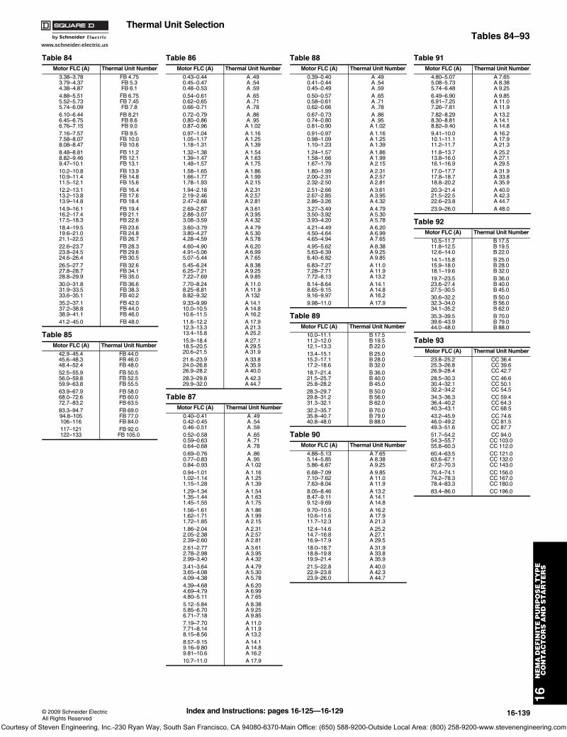
www.schneider-electric.us
16N
EM
A D
EF
INIT
E P
UR
PO
SE
TY
PE
C
ON
TA
CT
OR
S A
ND
ST
AR
TE
RS
© 2009 Schneider ElectricAll Rights Reserved
16-139
Thermal Unit SelectionTables 84–93
Table 84Motor FLC (A) Thermal Unit Number
3.38–3.783.79–4.374.38–4.87
FB 4.75FB 5.3FB 6.1
4.88–5.515.52–5.735.74–6.09
FB 6.75FB 7.45FB 7.8
6.10–6.446.45–6.756.76–7.15
FB 8.21FB 8.6FB 9.0
7.16–7.577.58–8.078.08–8.47
FB 9.5FB 10.0FB 10.6
8.48–8.818.82–9.469.47–10.1
FB 11.2FB 12.1FB 13.1
10.2–10.810.9–11.411.5–12.1
FB 13.9FB 14.8FB 15.6
12.2–13.113.2–13.813.9–14.8
FB 16.4FB 17.6FB 18.4
14.9–16.116.2–17.417.5–18.3
FB 19.4FB 21.1FB 22.6
18.4–19.519.6–21.021.1–22.5
FB 23.6FB 24.8FB 26.7
22.6–23.723.8–24.524.6–26.4
FB 28.3FB 29.6FB 30.5
26.5–27.727.8–28.728.8–29.9
FB 32.6FB 34.1FB 35.0
30.0–31.831.9–33.533.6–35.1
FB 36.6FB 38.3FB 40.2
35.2–37.137.2–38.838.9–41.1
FB 42.0FB 44.0FB 46.0
41.2–45.0 FB 48.0
Table 85Motor FLC (A) Thermal Unit Number
42.9–45.445.6–48.348.4–52.4
FB 44.0FB 46.0FB 48.0
52.5–55.956.0–59.859.9–63.8
FB 50.5FB 52.5FB 55.5
63.9–67.968.0–72.672.7–83.2
FB 58.0FB 60.0FB 63.5
83.3–94.794.8–105106–116
FB 69.0FB 77.0FB 84.0
117–121122–133
FB 92.0FB 105.0
Table 86Motor FLC (A) Thermal Unit Number
0.43–0.440.45–0.470.48–0.53
A .49A .54A .59
0.54–0.610.62–0.650.66–0.71
A .65A .71A .78
0.72–0.790.80–0.860.87–0.96
A .86A .95A 1.02
0.97–1.041.05–1.171.18–1.31
A 1.16A 1.25A 1.39
1.32–1.381.39–1.471.48–1.57
A 1.54A 1.63A 1.75
1.58–1.651.66–1.771.78–1.93
A 1.86A 1.99A 2.15
1.94–2.182.19–2.462.47–2.68
A 2.31A 2.57A 2.81
2.69–2.872.88–3.073.08–3.59
A 3.61A 3.95A 4.32
3.60–3.793.80–4.274.28–4.59
A 4.79A 5.30A 5.78
4.60–4.904.91–5.065.07–5.44
A 6.20A 6.99A 7.65
5.45–6.246.25–7.217.22–7.69
A 8.38A 9.25A 9.85
7.70–8.248.25–8.818.82–9.32
A 11.0A 11.9A 132
9.33–9.9910.0–10.510.6–11.5
A 14.1A 14.8A 16.2
11.6–12.212.3–13.313.4–15.8
A 17.9A 21.3A 25.2
15.9–18.418.5–20.520.6–21.5
A 27.1A 29.5A 31.9
21.6–23.924.0–26.826.9–28.2
A 33.8A 35.9A 40.0
28.3–29.829.9–32.0
A 42.3A 44.7
Table 87Motor FLC (A) Thermal Unit Number
0.40–0.410.42–0.450.46–0.51
A .49A .54A .59
0.52–0.580.59–0.630.64–0.68
A .65A .71A .78
0.69–0.760.77–0.830.84–0.93
A .86A .95A 1.02
0.94–1.011.02–1.141.15–1.28
A 1.16A 1.25A 1.39
1.29–1.341.35–1.441.45–1.55
A 1.54A 1.63A 1.75
1.56–1.611.62–1.711.72–1.85
A 1.86A 1.99A 2.15
1.86–2.042.05–2.382.39–2.60
A 2.31A 2.57A 2.81
2.61–2.772.78–2.982.99–3.40
A 3.61A 3.95A 4.32
3.41–3.643.65–4.084.09–4.38
A 4.79A 5.30A 5.78
4.39–4.684.69–4.794.80–5.11
A 6.20A 6.99A 7.65
5.12–5.845.85–6.706.71–7.18
A 8.38A 9.25A 9.85
7.19–7.707.71–8.148.15–8.56
A 11.0A 11.9A 13.2
8.57–9.159.16–9.809.81–10.6
A 14.1A 14.8A 16.2
10.7–11.0 A 17.9
Table 88Motor FLC (A) Thermal Unit Number
0.39–0.400.41–0.440.45–0.49
A .49A .54A .59
0.50–0.570.58–0.610.62–0.66
A .65A .71A .78
0.67–0.730.74–0.800.81–0.90
A .86A .95A 1.02
0.91–0.970.98–1.091.10–1.23
A 1.16A 1.25A 1.39
1.24–1.571.58–1.661.67–1.79
A 1.86A 1.99A 2.15
1.80–1.992.00–2.312.32–2.50
A 2.31A 2.57A 2.81
2.51–2.662.67–2.852.86–3.26
A 3.61A 3.95A 4.32
3.27–3.493.50–3.923.93–4.20
A 4.79A 5.30A 5.78
4.21–4.494.50–4.644.65–4.94
A 6.20A 6.99A 7.65
4.95–5.625.63–6.396.40–6.82
A 8.38A 9.25A 9.85
6.83–7.277.28–7.717.72–8.13
A 11.0A 11.9A 13.2
8.14–8.648.65–9.159.16–9.97
A 14.1A 14.8A 16.2
9.98–11.0 A 17.9
Table 89Motor FLC (A) Thermal Unit Number
10.0–11.111.2–12.012.1–13.3
B 17.5B 19.5B 22.0
13.4–15.115.2–17.117.2–18.6
B 25.0B 28.0B 32.0
18.7–21.421.5–25.725.8–28.2
B 36.0B 40.0B 45.0
28.3–29.729.8–31.231.3–32.1
B 50.0B 56.0B 62.0
32.2–35.735.8–40.740.8–48.0
B 70.0B 79.0B 88.0
Table 90Motor FLC (A) Thermal Unit Number
4.88–5.135.14–5.855.86–6.67
A 7.65A 8.38A 9.25
6.68–7.097.10–7.627.63–8.04
A 9.85A 11.0A 11.9
8.05–8.468.47–9.119.12–9.69
A 13.2A 14.1A 14.8
9.70–10.510.6–11.611.7–12.3
A 16.2A 17.9A 21.3
12.4–14.614.7–16.816.9–17.9
A 25.2A 27.1A 29.5
18.0–18.718.8–19.819.9–21.4
A 31.9A 33.8A 35.9
21.5–22.822.9–23.823.9–26.0
A 40.0A 42.3A 44.7
Table 91Motor FLC (A) Thermal Unit Number
4.80–5.075.08–5.735.74–6.48
A 7.65A 8.38A 9.25
6.49–6.906.91–7.257.26–7.81
A 9.85A 11.0A 11.9
7.82–8.298.30–8.818.82–9.40
A 13.2A 14.1A 14.8
9.41–10.010.1–11.111.2–11.7
A 16.2A 17.9A 21.3
11.8–13.713.8–16.016.1–16.9
A 25.2A 27.1A 29.5
17.0–17.717.8–18.718.8–20.2
A 31.9A 33.8A 35.9
20.3–21.421.5–22.522.6–23.8
A 40.0A 42.3A 44.7
23.9–26.0 A 48.0
Table 92Motor FLC (A) Thermal Unit Number
10.5–11.711.8–12.512.6–14.0
B 17.5B 19.5B 22.0
14.1–15.815.9–18.018.1–19.6
B 25.0B 28.0B 32.0
19.7–23.523.6–27.427.5–30.5
B 36.0B 40.0B 45.0
30.6–32.232.3–34.034.1–35.2
B 50.0B 56.0B 62.0
35.3–39.539.6–43.944.0–48.0
B 70.0B 79.0B 88.0
Table 93Motor FLC (A) Thermal Unit Number
23.8–25.225.3–26.826.9–28.4
CC 36.4CC 39.6CC 42.7
28.5–30.330.4–32.132.2–34.2
CC 46.6CC 50.1CC 54.5
34.3–36.336.4–40.240.3–43.1
CC 59.4CC 64.3CC 68.5
43.2–45.946.0–49.249.3–51.6
CC 74.6CC 81.5CC 87.7
51.7–54.254.3–55.755.8–60.3
CC 94.0CC 103.0CC 112.0
60.4–63.563.6–67.167.2–70.3
CC 121.0CC 132.0CC 143.0
70.4–74.174.2–78.378.4–83.3
CC 156.0CC 167.0CC 180.0
83.4–86.0 CC 196.0
Index and Instructions: pages 16-125—16-129
Courtesy of Steven Engineering, Inc.-230 Ryan Way, South San Francisco, CA 94080-6370-Main Office: (650) 588-9200-Outside Local Area: (800) 258-9200-www.stevenengineering.com
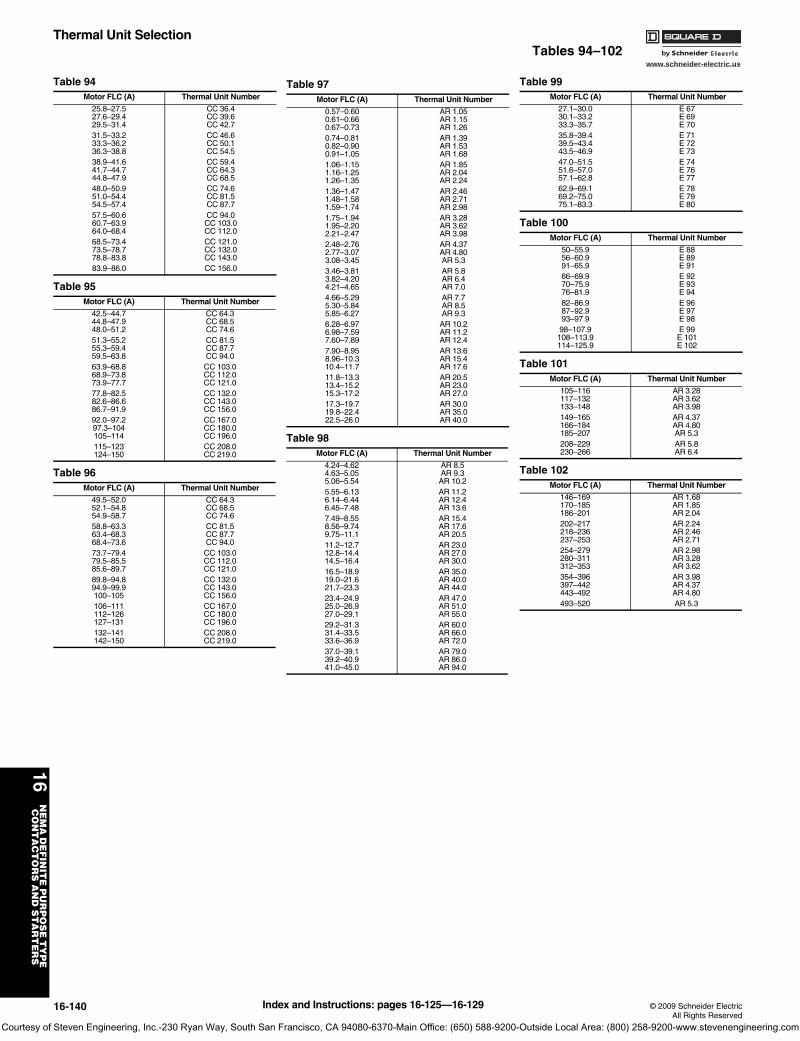
www.schneider-electric.us
16N
EM
A D
EF
INIT
E P
UR
PO
SE
TY
PE
C
ON
TA
CT
OR
S A
ND
ST
AR
TE
RS
16-140 © 2009 Schneider ElectricAll Rights Reserved
Thermal Unit SelectionTables 94–102
Table 94Motor FLC (A) Thermal Unit Number
25.8–27.527.6–29.429.5–31.4
CC 36.4CC 39.6CC 42.7
31.5–33.233.3–36.236.3–38.8
CC 46.6CC 50.1CC 54.5
38.9–41.641.7–44.744.8–47.9
CC 59.4CC 64.3CC 68.5
48.0–50.951.0–54.454.5–57.4
CC 74.6CC 81.5CC 87.7
57.5–60.660.7–63.964.0–68.4
CC 94.0CC 103.0CC 112.0
68.5–73.473.5–78.778.8–83.8
CC 121.0CC 132.0CC 143.0
83.9–86.0 CC 156.0
Table 95Motor FLC (A) Thermal Unit Number
42.5–44.744.8–47.948.0–51.2
CC 64.3CC 68.5CC 74.6
51.3–55.255.3–59.459.5–63.8
CC 81.5CC 87.7CC 94.0
63.9–68.868.9–73.873.9–77.7
CC 103.0CC 112.0CC 121.0
77.8–82.582.6–86.686.7–91.9
CC 132.0CC 143.0CC 156.0
92.0–97.297.3–104105–114
CC 167.0CC 180.0CC 196.0
115–123124–150
CC 208.0CC 219.0
Table 96Motor FLC (A) Thermal Unit Number
49.5–52.052.1–54.854.9–58.7
CC 64.3CC 68.5CC 74.6
58.8–63.363.4–68.368.4–73.6
CC 81.5CC 87.7CC 94.0
73.7–79.479.5–85.585.6–89.7
CC 103.0CC 112.0CC 121.0
89.8–94.894.9–99.9100–105
CC 132.0CC 143.0CC 156.0
106–111112–126127–131
CC 167.0CC 180.0CC 196.0
132–141142–150
CC 208.0CC 219.0
Table 97Motor FLC (A) Thermal Unit Number
0.57–0.600.61–0.660.67–0.73
AR 1.05AR 1.15AR 1.26
0.74–0.810.82–0.900.91–1.05
AR 1.39AR 1.53AR 1.68
1.06–1.151.16–1.251.26–1.35
AR 1.85AR 2.04AR 2.24
1.36–1.471.48–1.581.59–1.74
AR 2.46AR 2.71AR 2.98
1.75–1.941.95–2.202.21–2.47
AR 3.28AR 3.62AR 3.98
2.48–2.762.77–3.073.08–3.45
AR 4.37AR 4.80AR 5.3
3.46–3.813.82–4.204.21–4.65
AR 5.8AR 6.4AR 7.0
4.66–5.295.30–5.845.85–6.27
AR 7.7AR 8.5AR 9.3
6.28–6.976.98–7.597.60–7.89
AR 10.2AR 11.2AR 12.4
7.90–8.958.96–10.310.4–11.7
AR 13.6AR 15.4AR 17.6
11.8–13.313.4–15.215.3–17.2
AR 20.5AR 23.0AR 27.0
17.3–19.719.8–22.422.5–26.0
AR 30.0AR 35.0AR 40.0
Table 98Motor FLC (A) Thermal Unit Number
4.24–4.624.63–5.055.06–5.54
AR 8.5AR 9.3AR 10.2
5.55–6.136.14–6.446.45–7.48
AR 11.2AR 12.4AR 13.6
7.49–8.558.56–9.749.75–11.1
AR 15.4AR 17.6AR 20.5
11.2–12.712.8–14.414.5–16.4
AR 23.0AR 27.0AR 30.0
16.5–18.919.0–21.621.7–23.3
AR 35.0AR 40.0AR 44.0
23.4–24.925.0–26.927.0–29.1
AR 47.0AR 51.0AR 55.0
29.2–31.331.4–33.533.6–36.9
AR 60.0AR 66.0AR 72.0
37.0–39.139.2–40.941.0–45.0
AR 79.0AR 86.0AR 94.0
Table 99Motor FLC (A) Thermal Unit Number
27.1–30.030.1–33.233.3–35.7
E 67E 69E 70
35.8–39.439.5–43.443.5–46.9
E 71E 72E 73
47.0–51.551.6–57.057.1–62.8
E 74E 76E 77
62.9–69.169.2–75.075.1–83.3
E 78E 79E 80
Table 100Motor FLC (A) Thermal Unit Number
50–55.956–60.991–65.9
E 88E 89E 91
66–69.970–75.976–81.9
E 92E 93E 94
82–86.987–92.993–97.9
E 96E 97E 98
98–107.9108–113.9114–125.9
E 99E 101E 102
Table 101Motor FLC (A) Thermal Unit Number
105–116117–132133–148
AR 3.28AR 3.62AR 3.98
149–165166–184185–207
AR 4.37AR 4.80AR 5.3
208–229230–266
AR 5.8AR 6.4
Table 102Motor FLC (A) Thermal Unit Number
146–169170–185186–201
AR 1.68AR 1.85AR 2.04
202–217218–236237–253
AR 2.24AR 2.46AR 2.71
254–279280–311312–353
AR 2.98AR 3.28AR 3.62
354–396397–442443–492
AR 3.98AR 4.37AR 4.80
493–520 AR 5.3
Index and Instructions: pages 16-125—16-129
Courtesy of Steven Engineering, Inc.-230 Ryan Way, South San Francisco, CA 94080-6370-Main Office: (650) 588-9200-Outside Local Area: (800) 258-9200-www.stevenengineering.com
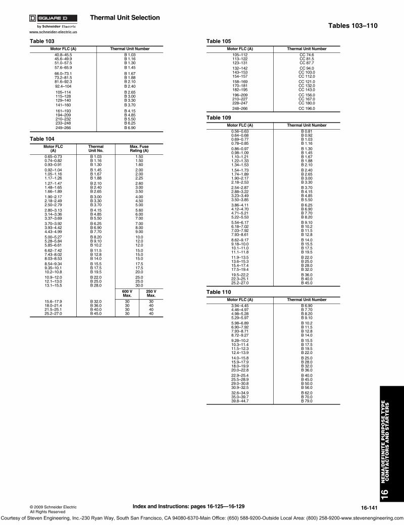
www.schneider-electric.us
16N
EM
A/D
EF
INIT
E P
UR
PO
SE
TY
PE
CO
NT
AC
TO
RS
AN
D S
TA
RT
ER
S
© 2009 Schneider ElectricAll Rights Reserved
16-141
Thermal Unit SelectionTables 103–110
Table 103Motor FLC (A) Thermal Unit Number
40.8–45.5 B 1.0345.6–49.9 B 1.1651.0–57.5 B 1.3057.6–65.9 B 1.45
66.0–73.1 B 1.6773.2–81.5 B 1.8881.6–92.3 B 2.1092.4–104 B 2.40
105–114 B 2.65115–128 B 3.00129–140 B 3.30141–160 B 3.70
161–193 B 4.15194–209 B 4.85210–232 B 5.50233–248 B 6.25249–266 B 6.90
Table 104Motor FLC
(A)Thermal Unit No.
Max. FuseRating (A)
0.65–0.73 B 1.03 1.500.74–0.82 B 1.16 1.500.93–0.91 B 1.30 1.600.92–1.04 B 1.45 2.001.05–1.16 B 1.67 2.001.17–1.26 B 1.88 2.251.27–1.47 B 2.10 2.601.48–1.65 B 2.40 3.001.66–1.89 B 2.65 3.501.90–2.17 B 3.00 4.002.18–2.49 B 3.30 4.502.50–2.79 B 3.70 5.002.80–3.13 B 4.15 5.603.14–3.36 B 4.85 6.003.37–3.69 B 5.50 7.003.70–3.92 B 6.25 7.003.93–4.42 B 6.90 8.004.43–4.99 B 7.70 9.005.00–5.27 B 8.20 10.05.28–5.84 B 9.10 12.05.85–6.61 B 10.2 12.06.62–7.42 B 11.5 15.07.43–8.02 B 12.8 15.08.03–8.53 B 14.0 15.08.54–9.34 B 15.5 17.59.35–10.1 B 17.5 17.510.2–10.8 B 19.5 20.010.9–12.0 B 22.0 25.012.1–13.0 B 25.0 25.013.1–15.5 B 28.0 30.0
600 VMax.
250 VMax.
15.6–17.9 B 32.0 30 3018.0–21.4 B 36.0 30 4021.5–25.1 B 40.0 30 4025.2–27.0 B 45.0 30 40
Table 105Motor FLC (A) Thermal Unit Number
105–112 CC 74.6113–122 CC 81.5123–131 CC 87.7132–142 CC 94.0143–153 CC 103.0154–157 CC 112.0158–169 CC 121.0170–181 CC 132.0182–195 CC 143.0196–209 CC 156.0210–227 CC 167.0228–247 CC 180.0248–266 CC 196.0
Table 109Motor FLC (A) Thermal Unit Number
0.56–0.630.64–0.680.69–0.770.78–0.85
B 0.81B 0.92B 1.03B 1.16
0.86–0.970.98–1.091.10–1.211.22–1.331.34–1.53
B 1.30B 1.45B 1.67B 1.88B 2.10
1.54–1.731.74–1.891.90–2.172.18–2.53
B 2.40B 2.65B 3.00B 3.30
2.54–2.872.88–3.223.23–3.493.50–3.85
B 3.70B 4.15B 4.85B 5.50
3.86–4.114.12–4.704.71–5.215.22–5.53
B 6.25B 6.90B 7.70B 8.20
5.54–6.176.18–7.027.03–7.927.93–8.61
B 9.10B 10.2B 11.5B 12.8
8.62–9.179.18–10.010.1–11.011.1–11.8
B 14.0B 15.5B 17.5B 19.5
11.9–13.513.6–15.315.4–17.417.5–19.4
B 22.0B 25.0B 28.0B 32.0
19.5–22.222.3–25.125.2–27.0
B 36.0B 40.0B 45.0
Table 110Motor FLC (A) Thermal Unit Number
3.94–4.454.46–4.974.98–5.285.29–5.97
B 6.90B 7.70B 8.20B 9.10
5.98–6.896.90–7.927.93–8.718.72–9.27
B 10.2B 11.5B 12.8B 14.0
9.28–10.210.3–11.411.5–12.312.4–13.9
B 15.5B 17.5B 19.5B 22.0
14.0–15.815.9–17.918.0–19.920.0–22.8
B 25.0B 28.0B 32.0B 36.0
22.9–25.425.5–28.929.0–30.830.9–32.5
B 40.0B 45.0B 50.0B 56.0
32.6–34.935.0–39.739.8–44.7
B 62.0B 70.0B 79.0
Index and Instructions: pages 16-125—16-129
Courtesy of Steven Engineering, Inc.-230 Ryan Way, South San Francisco, CA 94080-6370-Main Office: (650) 588-9200-Outside Local Area: (800) 258-9200-www.stevenengineering.com

www.schneider-electric.us
16N
EM
A D
EF
INIT
E P
UR
PO
SE
TY
PE
C
ON
TA
CT
OR
S A
ND
ST
AR
TE
RS
16-142 © 2009 Schneider ElectricAll Rights Reserved
Thermal Unit SelectionTables 111–116
Table 111Motor FLC (A) Thermal Unit Number
14.0–14.915.0–16.216.3–17.217.3–18.718.8–20.2
CC 20.9CC 22.8CC 24.6CC 26.3CC 28.8
20.3–21.721.8–23.323.4–25.225.3–27.127.2–29.4
CC 31.0CC 33.3CC 36.4CC 39.6CC 42.7
29.5–31.631.7–34.034.1–36.836.9–39.839.9–42.3
CC 46.6CC 50.1CC 54.5CC 59.4CC 64.3
42.4–45.745.8–49.249.3–52.852.9–56.856.9–61.2
CC 68.5CC 74.6CC 81.5CC 87.7CC 94.0
61.3–66.166.2–71.271.3–76.776.8–82.983.0–90.0
CC 103.0CC 112.0CC 121.0CC 132.0CC 143.0
Table 112Motor FLC (A) Thermal Unit Number
44.0–46.846.9–50.650.7–54.554.6–58.458.5–62.9
CC 64.3CC 68.5CC 74.6CC 81.5CC 87.7
63.0–67.767.8–72.973.0–78.178.2–83.984.0–91.1
CC 94.0CC 103.0CC 112.0CC 121.0CC 132.0
91.2–97.597.6–104105–113114–133
CC 143.0CC 156.0CC 167.0CC 180.0
Table 113Motor FLC (A) Thermal Unit Number
88.2–95.195.2–101102–111
DD 112.0DD 121.0DD 128.0
112–119120–131132–149
DD 140.0DD 150.0DD 160.0
150–170171–180181–197
DD 185.0DD 220.0DD 240.0
198–204205–213214–237
DD 250.0DD 265.0DD 280.0
238–243244–266
DD 300.0DD 320.0
Table 114Motor FLC (A) Thermal Unit Number
133–148149–174175–195
B 1.30B 1.45B 1.67
196–219220–239240–271
B 1.88B 2.10B 2.40
272–308309–348349–397
B 2.65B 3.00B 3.30
398–429430–495496–520
B 3.70B 4.15B 4.85
Table 115Motor FLC (A) Thermal Unit Number
176–190 DD 112.0191–203 DD 121.0203–223 DD 128.0224–239 DD 140.0240–253 DD 150.0254–299 DD 160.0300–341 DD 185.0342–361 DD 220.0362–395 DD 240.0396–409 DD 250.0410–427 DD 265.0428–475 DD 289.0476–487 DD 300.0488–532 DD 320.0
Table 116Motor FLC (A)) Thermal Unit Number
81.6–91.1 B 1.0391.2–101 B 1.16102–115 B 1.30116–131 B 1.45132–146 B 1.67147–163 B 1.88164–184 B 2.10185–209 B 2.40210–229 B 2.65230–257 B 3.00258–281 B 3.30282–321 B 3.70322–387 B 4.15388–419 B 4.35420–465 B 5.60466–497 B 6.25496–532 B 6.90
Index and Instructions: pages 16-125—16-129
Courtesy of Steven Engineering, Inc.-230 Ryan Way, South San Francisco, CA 94080-6370-Main Office: (650) 588-9200-Outside Local Area: (800) 258-9200-www.stevenengineering.com
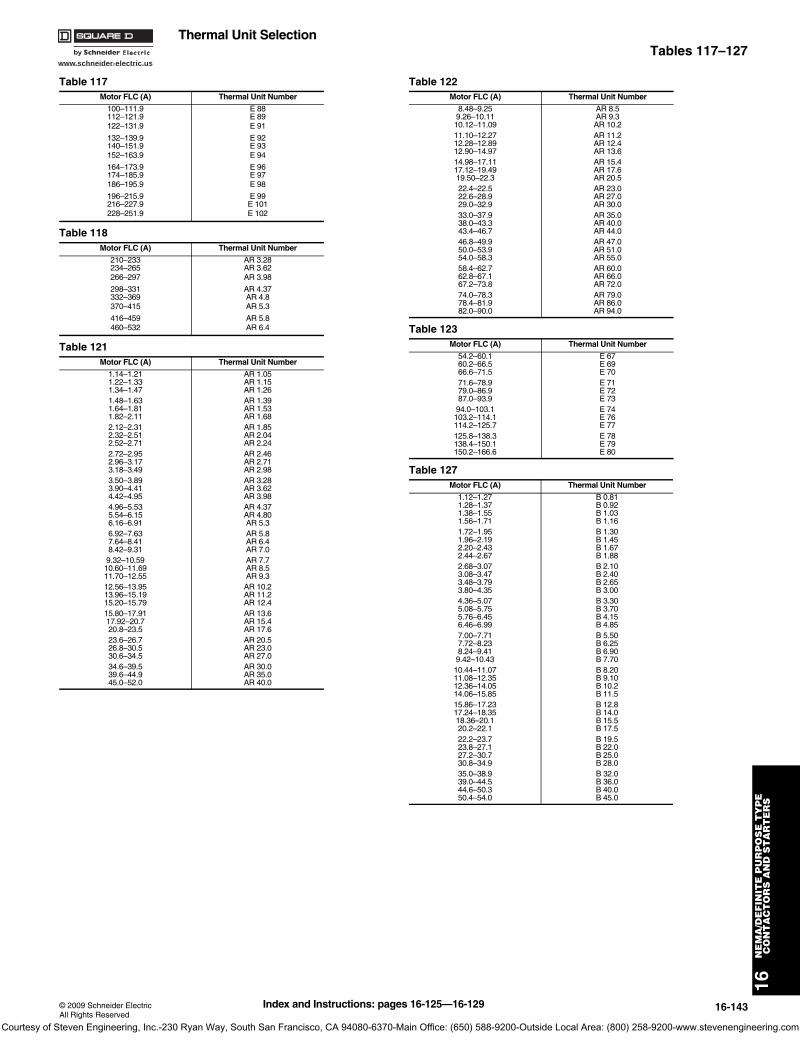
www.schneider-electric.us
16N
EM
A/D
EF
INIT
E P
UR
PO
SE
TY
PE
CO
NT
AC
TO
RS
AN
D S
TA
RT
ER
S
© 2009 Schneider ElectricAll Rights Reserved
16-143
Thermal Unit SelectionTables 117–127
Table 117Motor FLC (A) Thermal Unit Number
100–111.9 E 88112–121.9 E 89122–131.9 E 91
132–139.9 E 92140–151.9 E 93152–163.9 E 94
164–173.9 E 96174–185.9 E 97186–195.9 E 98
196–215.9 E 99216–227.9 E 101228–251.9 E 102
Table 118Motor FLC (A) Thermal Unit Number
210–233 AR 3.28234–265 AR 3.62266–297 AR 3.98
298–331 AR 4.37332–369 AR 4.8370–415 AR 5.3
416–459 AR 5.8460–532 AR 6.4
Table 121Motor FLC (A) Thermal Unit Number
1.14–1.211.22–1.331.34–1.47
AR 1.05AR 1.15AR 1.26
1.48–1.631.64–1.811.82–2.11
AR 1.39AR 1.53AR 1.68
2.12–2.312.32–2.512.52–2.71
AR 1.85AR 2.04AR 2.24
2.72–2.952.96–3.173.18–3.49
AR 2.46AR 2.71AR 2.98
3.50–3.893.90–4.414.42–4.95
AR 3.28AR 3.62AR 3.98
4.96–5.535.54–6.156.16–6.91
AR 4.37AR 4.80AR 5.3
6.92–7.637.64–8.418.42–9.31
AR 5.8AR 6.4AR 7.0
9.32–10.5910.60–11.6911.70–12.55
AR 7.7AR 8.5AR 9.3
12.56–13.9513.96–15.1915.20–15.79
AR 10.2AR 11.2AR 12.4
15.80–17.9117.92–20.720.8–23.5
AR 13.6AR 15.4AR 17.6
23.6–26.726.8–30.530.6–34.5
AR 20.5AR 23.0AR 27.0
34.6–39.539.6–44.945.0–52.0
AR 30.0AR 35.0AR 40.0
Table 122Motor FLC (A) Thermal Unit Number
8.48–9.259.26–10.1110.12–11.09
AR 8.5AR 9.3AR 10.2
11.10–12.2712.28–12.8912.90–14.97
AR 11.2AR 12.4AR 13.6
14.98–17.1117.12–19.4919.50–22.3
AR 15.4AR 17.6AR 20.5
22.4–22.522.6–28.929.0–32.9
AR 23.0AR 27.0AR 30.0
33.0–37.938.0–43.343.4–46.7
AR 35.0AR 40.0AR 44.0
46.8–49.950.0–53.954.0–58.3
AR 47.0AR 51.0AR 55.0
58.4–62.762.8–67.167.2–73.8
AR 60.0AR 66.0AR 72.0
74.0–78.378.4–81.982.0–90.0
AR 79.0AR 86.0AR 94.0
Table 123Motor FLC (A) Thermal Unit Number
54.2–60.160.2–66.566.6–71.5
E 67E 69E 70
71.6–78.979.0–86.987.0–93.9
E 71E 72E 73
94.0–103.1103.2–114.1114.2–125.7
E 74E 76E 77
125.8–138.3138.4–150.1150.2–166.6
E 78E 79E 80
Table 127Motor FLC (A) Thermal Unit Number
1.12–1.271.28–1.371.38–1.551.56–1.71
B 0.81B 0.92B 1.03B 1.16
1.72–1.951.96–2.192.20–2.432.44–2.67
B 1.30B 1.45B 1.67B 1.88
2.68–3.073.08–3.473.48–3.793.80–4.35
B 2.10B 2.40B 2.65B 3.00
4.36–5.075.08–5.755.76–6.456.46–6.99
B 3.30B 3.70B 4.15B 4.85
7.00–7.717.72–8.238.24–9.419.42–10.43
B 5.50B 6.25B 6.90B 7.70
10.44–11.0711.08–12.3512.36–14.0514.06–15.85
B 8.20B 9.10B 10.2B 11.5
15.86–17.2317.24–18.3518.36–20.120.2–22.1
B 12.8B 14.0B 15.5B 17.5
22.2–23.723.8–27.127.2–30.730.8–34.9
B 19.5B 22.0B 25.0B 28.0
35.0–38.939.0–44.544.6–50.350.4–54.0
B 32.0B 36.0B 40.0B 45.0
Index and Instructions: pages 16-125—16-129
Courtesy of Steven Engineering, Inc.-230 Ryan Way, South San Francisco, CA 94080-6370-Main Office: (650) 588-9200-Outside Local Area: (800) 258-9200-www.stevenengineering.com

www.schneider-electric.us
16N
EM
A D
EF
INIT
E P
UR
PO
SE
TY
PE
C
ON
TA
CT
OR
S A
ND
ST
AR
TE
RS
16-144 © 2009 Schneider ElectricAll Rights Reserved
Thermal Unit SelectionTables 128–134
Table 128Motor FLC (A) Thermal Unit Number
7.88–8.918.92–9.95
B 6.90B 7.70
9.96–10.5710.58–11.9511.96–13.7913.80–15.85
B 8.20B 9.10B 10.2B 11.5
15.86–17.4317.44–18.5518.56–20.520.6–22.9
B 12.8B 14.0B 15.5B 17.5
23.0–24.724.8–27.928.0–31.731.8–35.9
B 19.5B 22.0B 25.0B 28.0
36.0–39.940.0–45.745.8–50.951.0–61.7
B 32.0B 36.0B 40.0B 45.0
61.8–65.165.2–69.970.0–79.579.6–89.4
B 50.0B 56.0B 62.0B 70.0
Table 129Motor FLC (A) Thermal Unit Number
28.0–29.930.0–32.532.6–34.534.6–37.5
CC 20.9CC 22.8CC 24.6CC 26.3
37.6–40.540.6–43.543.6–46.746.8–50.5
CC 28.8CC 31.0CC 33.3CC 36.4
50.6–54.354.4–58.959.0–63.363.4–68.1
CC 39.6CC 42.7CC 46.6CC 50.1
68.2–73.773.8–79.779.8–84.784.8–91.5
CC 54.5CC 59.4CC 64.5CC 68.5
91.6–98.598.6–105.7105.8–113.7113.8–122.5
CC 74.6CC 81.5CC 87.7CC 94.0
122.6–132.3132.4–142.5142.6–153.5153.6–165.9
CC 103.0CC 112.0CC 121.0CC 132.0
166.0–180.0 CC 143.0
Table 133Motor FLC (A) Thermal Unit Number
4.60–5.235.24–5.865.87–6.25
B 6.90B 7.70B 8.20
6.26–7.097.10–8.258.26–9.49
B 9.10B 10.2B 11.5
9.50–10.310.4–11.211.3–12.5
B 12.8B 14.0B 15.5
12.6–13.813.9–15.015.1–16.9
B 17.5B 19.5B 22.0
17.0–19.119.2–22.022.1–24.4
B 25.0B 28.0B 32.0
24.5–28.028.1–31.831.9–36.0
B 36.0B 40.0B 45.0
36.1–38.538.6–41.241.3–44.4
B 50.0B 56.0B 62.0
44.5–50.350.4–56.957.0–59.0
B 70.0B 79.0B 88.0
Table 134Motor FLC (A) Thermal Unit Number
4.30–4.984.99–5.575.58–5.94
B 6.90B 7.70B 8.20
5.95–6.716.72–7.797.80–8.93
B 9.10B 10.2B 11.5
8.94–9.779.78–10.510.6–11.7
B 12.8B 14.0B 15.5
11.8–13.013.1–14.014.1–15.0
B 17.5B 19.5B 22.0
15.1–17.217.3–19.920.0–22.3
B 25.0B 28.0B 32.0
22.4–26.026.1–29.829.9–34.0
B 36.0B 40.0B 45.0
34.1–36.736.8–39.539.6–42.1
B 50.0B 56.0B 62.0
42.2–46.646.7–51.551.6–54.0
B 70.0B 79.0B 88.0
Index and Instructions: pages 16-125—16-129
Courtesy of Steven Engineering, Inc.-230 Ryan Way, South San Francisco, CA 94080-6370-Main Office: (650) 588-9200-Outside Local Area: (800) 258-9200-www.stevenengineering.com
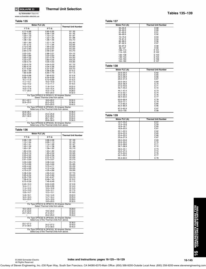
www.schneider-electric.us
16N
EM
A/D
EF
INIT
E P
UR
PO
SE
TY
PE
CO
NT
AC
TO
RS
AN
D S
TA
RT
ER
S
© 2009 Schneider ElectricAll Rights Reserved
16-145
Thermal Unit SelectionTables 135–139
Table 135Motor FLC (A)
Thermal Unit Number1 T. U. 3 T. U.
0.77–0.880.89–1.021.03–1.191.20–1.371.38–1.62
0.85–0.950.96–1.091.10–1.211.22–1.351.36–1.56
B 1.30B 1.45B 1.67B 1.88B 2.10
1.63–1.901.91–2.122.13–2.462.47–2.832.84–3.19
1.57–1.761.77–1.941.95–2.222.23–2.572.58–2.87
B 2.40B 2.65B 3.00B 3.30B 3.70
3.20–3.613.62–3.893.90–4.324.33–4.574.58–5.19
2.88–3.213.22–3.503.51–3.793.80–4.04 4.05–4.53
B 4.15B 4.85B 5.50B 6.25B 6.90
5.20–5.795.80–6.166.17–6.946.95–7.997.80–8.99
4.54–5.035.04–5.365.37–5.975.98–6.896.90–7.79
B 7.70B 8.20B 9.10B 10.2B 11.5
9.00–9.989.99–10.610.7–11.611.7–13.113.2–14.2
7.80–8.538.54–9.099.10–9.9910.0–10.911.0–11.7
B 12.8B 14.0B 15.5B 17.5B 19.5
14.3–15.415.5–17.617.7–20.0
–
11.8–13.413.5–15.415.5–17.918.0–20.0
B 22.0B 25.0B 28.0B 32.0
For Type DPSG12 & DPSG13, 20 Ampere Starter.Select Thermal Units from above.
20.1–22.722.8–25.0
–
18.0–20.220.3–23.223.3–25.0
B 32.0B 36.0B 40.0
For Type DPSG22 & DPSG23, 25 Ampere Starter.Select any of the Thermal Units from above.
22.8–26.126.2–29.629.7–30.0
––
–23.3–25.825.9–28.628.7–29.729.8–30.0
B 36.0B 40.0B 45.0B 50.0B 56.0
For Type DPSG32 & DPSG33, 30 Ampere Starter.Select any of the Thermal Units from above.
Table 136Motor FLC (A)
Thermal Unit Number1 T. U. 3 T. U.
0.98–1.091.10–1.241.25–1.411.42–1.591.60–1.81
0.88–0.980.99–1.131.14–1.261.27–1.381.39–1.62
B 1.30B 1.45B 1.67B 1.88B 2.10
1.82–2.042.05–2.192.20–2.522.53–2.902.91–3.29
1.63–1.821.83–2.042.05–2.362.37–2.722.73–3.07
B 2.40B 2.65B 3.00B 3.30B 3.70
3.30–3.693.70–3.994.00–4.424.43–4.694.70–5.37
3.08–3.443.45–3.693.70–4.114.12–4.344.35–4.89
B 4.15B 4.85B 5.50B 6.25B 6.90
5.38–5.945.95–6.346.35–7.057.06–8.148.15–9.39
4.90–5.445.45–5.805.81–6.476.48–7.457.46–8.49
B 7.70B 8.20B 9.10B 10.2B 11.5
9.40–10.310.4–11.111.2–12.212.3–13.513.6–14.7
8.50–9.299.30–9.9910.0–10.810.9–12.112.2–13.1
B 12.8B 14.0B 15.5B 17.5B 19.5
14.8–16.116.2–18.318.4–20.0
–
13.2–14.614.7–16.416.5–18.919.0–20.0
B 22.0B 25.0B 28.0B 32.0
For Type DPSO12 & DPSO13, 20 Ampere Starter.Select Thermal Units from above.
18.4–20.921.0–23.623.7–25.0
–
–19.0–20.921.0–24.124.2–25.0
B 28.0B 32.0B 36.0B 40.0
For Type DPSO22 & DPSO23, 25 Ampere Starter.Select any of the Thermal Units from above.
23.7–27.227.3–30.0
–24.2–27.227.3–30.0
B 36.0B 40.0B 45.0
For Type DPSO32 & DPSO33, 30 Ampere Starter.Select any of the Thermal Units from above.
Table 137Motor FLC (A) Thermal Unit Number
50–55.956–60.961–65.966–69.9
E 88E 89E 91E 92
70–75.976–81.982–86.987–92.9
E 93E 94E 96E 97
93–97.998–107108–113114–125
E 98E 99E 101E 102
126–138139–153154–163164–180
E 103E 104E 106E 107
Table 138Motor FLC (A) Thermal Unit Number
22.6–25.525.6–26.426.5–28.929.0–31.9
E 62E 65E 66E 67
32.0–34.534.6–36.937.0–40.640.7–44.0
E 69E 70E 71E 72
44.1–47.447.5–53.153.2–58.358.4–63.5
E 73E 74E 76E 77
63.6–69.970.0–77.177.2–83.383.4–86.9
E 78E 79E 80E 96
87.0–92.993.0–100
E 97E 98
Table 139Motor FLC (A) Thermal Unit Number
13.7–15.215.3–16.816.9–18.718.8–20.0
E 57E 59E 60E 61
20.1–22.522.6–23.323.4–25.525.6–27.9
E 62E 65E 66E 67
28.0–30.830.9–33.233.3–36.636.7–38.9
E 69E 70E 71E 72
39.0–43.143.2–47.447.5–50.050.1–55.2
E 73E 74E 76E 77
55.3–60.0 E 78
Index and Instructions: pages 16-125—16-129
Courtesy of Steven Engineering, Inc.-230 Ryan Way, South San Francisco, CA 94080-6370-Main Office: (650) 588-9200-Outside Local Area: (800) 258-9200-www.stevenengineering.com

www.schneider-electric.us
16N
EM
A D
EF
INIT
E P
UR
PO
SE
TY
PE
C
ON
TA
CT
OR
S A
ND
ST
AR
TE
RS
16-146 © 2009 Schneider ElectricAll Rights Reserved
Thermal Unit SelectionTables 140–143
Table 140Motor FLC (A) Thermal Unit Number
0.34–0.360.37–0.400.41–0.430.44–0.47
E 3E 4E 5E 6
0.48–0.510.52–0.560.57–0.620.63–0.67
E 7E 8E 9E 11
0.68–0.730.74–0.770.78–0.840.85–0.93
E 12E 13E 14E 16
0.94–1.001.01–1.081.09–1.151.16–1.27
E 17E 18E 19E 23
1.28–1.451.46–1.611.62–1.811.82–2.00
E 24E 26E 27E 28
2.01–2.122.13–2.292.30–2.432.44–2.66
E 29E 31E 32E 33
2.67–2.982.99–3.163.17–3.393.40–3.69
E 34E 36E 37E 38
3.70–4.004.01–4.484.49–5.005.01–5.44
E 39E 41E 42E 44
5.45–5.996.00–6.606.61–6.966.97–7.26
E 46E 47E 48E 49
7.27–7.998.00–8.898.90–9.749.75–10.50
E 50E 51E 52E 53
10.6–11.511.6–12.312.4–13.413.5–15.2
E 54E 55E 56E 57
15.3–17.217.3–18.418.5–20.620.7–21.3
E 60E 61E 62E 65
21.4–23.423.5–24.0
E 66E 67
Table 141Motor FLC(A)
ThermalUnit No.
Max. FuseRating (A)
12.2–14.4 E56 2514.5–17.8 E57 3017.9–18.8 E60 40
18.9–21.4 E61 4021.5–23.0 E62 4523.1–25.7 E65 5025.8–28.0 E66 5028.1–31.0 E67 6031.1–32.7 E69 6032.8–35.5 E70 7035.6–38.2 E71 8038.3–43.3 E73 8043.4–46.9 E73A 90
10047.0–50.1 E74
600 VMax.
250 VMax.
50.2–54.0 E76 100 110
54.1–58.0 E77 100 11058.1–60.0 E78 100 12560.1–67.0 E79 100 12567.1–70.5 E80 100 12570.6–75.9 E94 100 12576.0–82.0 E96 100 12582.1–86.0 E97 100 125
Table 142Motor FLC
(A)ThermalUnit No.
Max. FuseRating (A)
11.7–13.5 E56 2513.6–16.7 E57 3016.8–18.1 E60 3518.2–20.0 E61 4020.1–21.9 E62 4022.0–24.2 E65 45
24.3–26.2 E66 5026.3–29.2 E67 5029.3–32.0 E69 6032.1–34.3 E70 7034.4–36.2 E71 7036.3–39.9 E73 8040.0–43.8 E73A 90
90100
43.9–46.2 E7446.3–50.0 E76
600 VMax.
250 VMax.
50.1–53.9 E77 100 11054.0–56.0 E78 100 11056.1–61.0 E79 100 12561.1–65.9 E80 100 12566.0–72.0 E94 100 12572.1–75.9 E96 100 12576.0–79.9 E98 100 12580.0–86.0 E101 100 125
Table 143Motor FLC
(A)ThermalUnit No.
Max. FuseRating (A)
18.9–20.0 E60 4020.1–22.8 E61 4522.9–24.7 E62 5024.8–26.9 E65 5027.0–29.2 E66 6029.3–32.8 E67 6032.9–34.9 E69 7035.0–37.5 E70 7037.6–39.6 E72 8039.7–46.1 E73 8046.2–49.9 E73A 10050.0–56.3 E74 11056.4–61.0 E76 12561.1–64.0 E77 12564.1–66.0 E78 12566.1–72.4 E79 12572.5–78.2 E80 15078.3–83.9 E94 17584.0–86.0 E96 17586.1–92.8 E97 17592.9–97.9 E98 20098.0–105.0 E101 200105.1–117.0 E102 200117.1–133.0 E103 200
Index and Instructions: pages 16-125—16-129
Courtesy of Steven Engineering, Inc.-230 Ryan Way, South San Francisco, CA 94080-6370-Main Office: (650) 588-9200-Outside Local Area: (800) 258-9200-www.stevenengineering.com
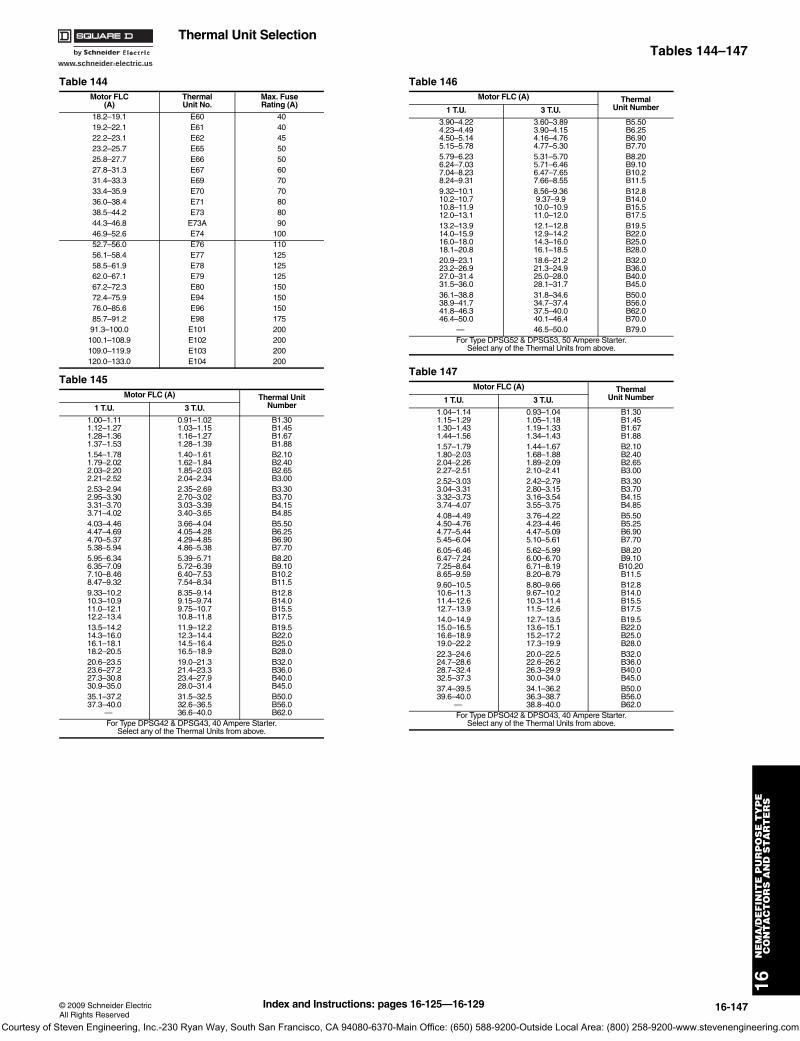
www.schneider-electric.us
16N
EM
A/D
EF
INIT
E P
UR
PO
SE
TY
PE
CO
NT
AC
TO
RS
AN
D S
TA
RT
ER
S
© 2009 Schneider ElectricAll Rights Reserved
16-147
Thermal Unit SelectionTables 144–147
Table 144Motor FLC
(A)ThermalUnit No.
Max. FuseRating (A)
18.2–19.1 E60 4019.2–22.1 E61 4022.2–23.1 E62 4523.2–25.7 E65 5025.8–27.7 E66 5027.8–31.3 E67 6031.4–33.3 E69 7033.4–35.9 E70 7036.0–38.4 E71 8038.5–44.2 E73 8044.3–46.8 E73A 9046.9–52.6 E74 10052.7–56.0 E76 11056.1–58.4 E77 12558.5–61.9 E78 12562.0–67.1 E79 12567.2–72.3 E80 15072.4–75.9 E94 15076.0–85.6 E96 15085.7–91.2 E98 17591.3–100.0 E101 200100.1–108.9 E102 200109.0–119.9 E103 200120.0–133.0 E104 200
Table 145Motor FLC (A) Thermal Unit
Number1 T.U. 3 T.U.
1.00–1.111.12–1.271.28–1.361.37–1.53
0.91–1.021.03–1.151.16–1.271.28–1.39
B1.30B1.45B1.67B1.88
1.54–1.781.79–2.022.03–2.202.21–2.52
1.40–1.611.62–1.841.85–2.032.04–2.34
B2.10B2.40B2.65B3.00
2.53–2.942.95–3.303.31–3.703.71–4.02
2.35–2.692.70–3.023.03–3.393.40–3.65
B3.30B3.70B4.15B4.85
4.03–4.464.47–4.694.70–5.375.38–5.94
3.66–4.044.05–4.284.29–4.854.86–5.38
B5.50B6.25B6.90B7.70
5.95–6.346.35–7.097.10–8.468.47–9.32
5.39–5.715.72–6.396.40–7.537.54–8.34
B8.20B9.10B10.2B11.5
9.33–10.210.3–10.911.0–12.112.2–13.4
8.35–9.149.15–9.749.75–10.710.8–11.8
B12.8B14.0B15.5B17.5
13.5–14.214.3–16.016.1–18.118.2–20.5
11.9–12.212.3–14.414.5–16.416.5–18.9
B19.5B22.0B25.0B28.0
20.6–23.523.6–27.227.3–30.830.9–35.0
19.0–21.321.4–23.323.4–27.928.0–31.4
B32.0B36.0B40.0B45.0
35.1–37.237.3–40.0
—
31.5–32.532.6–36.536.6–40.0
B50.0B56.0B62.0
For Type DPSG42 & DPSG43, 40 Ampere Starter. Select any of the Thermal Units from above.
Table 146Motor FLC (A) Thermal
Unit Number1 T.U. 3 T.U.
3.90–4.224.23–4.494.50–5.145.15–5.78
3.60–3.893.90–4.154.16–4.764.77–5.30
B5.50B6.25B6.90B7.70
5.79–6.236.24–7.037.04–8.238.24–9.31
5.31–5.705.71–6.466.47–7.657.66–8.55
B8.20B9.10B10.2B11.5
9.32–10.110.2–10.710.8–11.912.0–13.1
8.56–9.369.37–9.910.0–10.911.0–12.0
B12.8B14.0B15.5B17.5
13.2–13.914.0–15.916.0–18.018.1–20.8
12.1–12.812.9–14.214.3–16.016.1–18.5
B19.5B22.0B25.0B28.0
20.9–23.123.2–26.927.0–31.431.5–36.0
18.6–21.221.3–24.925.0–28.028.1–31.7
B32.0B36.0B40.0B45.0
36.1–38.838.9–41.741.8–46.346.4–50.0
31.8–34.634.7–37.437.5–40.040.1–46.4
B50.0B56.0B62.0B70.0
— 46.5–50.0 B79.0For Type DPSG52 & DPSG53, 50 Ampere Starter.
Select any of the Thermal Units from above.
Table 147Motor FLC (A) Thermal
Unit Number1 T.U. 3 T.U.
1.04–1.141.15–1.291.30–1.431.44–1.56
0.93–1.041.05–1.181.19–1.331.34–1.43
B1.30B1.45B1.67B1.88
1.57–1.791.80–2.032.04–2.262.27–2.51
1.44–1.671.68–1.881.89–2.092.10–2.41
B2.10B2.40B2.65B3.00
2.52–3.033.04–3.313.32–3.733.74–4.07
2.42–2.792.80–3.153.16–3.543.55–3.75
B3.30B3.70B4.15B4.85
4.08–4.494.50–4.764.77–5.445.45–6.04
3.76–4.224.23–4.464.47–5.095.10–5.61
B5.50B5.25B6.90B7.70
6.05–6.466.47–7.247.25–8.648.65–9.59
5.62–5.996.00–6.706.71–8.198.20–8.79
B8.20B9.10B10.20B11.5
9.60–10.510.6–11.311.4–12.612.7–13.9
8.80–9.669.67–10.210.3–11.411.5–12.6
B12.8B14.0B15.5B17.5
14.0–14.915.0–16.516.6–18.919.0–22.2
12.7–13.513.6–15.115.2–17.217.3–19.9
B19.5B22.0B25.0B28.0
22.3–24.624.7–28.628.7–32.432.5–37.3
20.0–22.522.6–26.226.3–29.930.0–34.0
B32.0B36.0B40.0B45.0
37.4–39.539.6–40.0
—
34.1–36.236.3–38.738.8–40.0
B50.0B56.0B62.0
For Type DPSO42 & DPSO43, 40 Ampere Starter. Select any of the Thermal Units from above.
Index and Instructions: pages 16-125—16-129
Courtesy of Steven Engineering, Inc.-230 Ryan Way, South San Francisco, CA 94080-6370-Main Office: (650) 588-9200-Outside Local Area: (800) 258-9200-www.stevenengineering.com
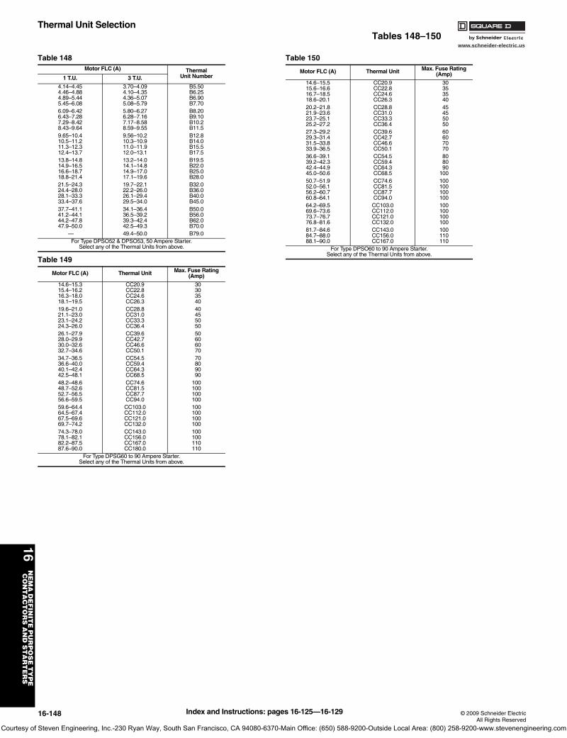
www.schneider-electric.us
16N
EM
A D
EF
INIT
E P
UR
PO
SE
TY
PE
C
ON
TA
CT
OR
S A
ND
ST
AR
TE
RS
16-148 © 2009 Schneider ElectricAll Rights Reserved
Thermal Unit SelectionTables 148–150
Table 148Motor FLC (A) Thermal
Unit Number1 T.U. 3 T.U.
4.14–4.454.46–4.884.89–5.445.45–6.08
3.70–4.094.10–4.354.36–5.075.08–5.79
B5.50B6.25B6.90B7.70
6.09–6.426.43–7.287.29–8.428.43–9.64
5.80–6.276.28–7.167.17–8.588.59–9.55
B8.20B9.10B10.2B11.5
9.65–10.410.5–11.211.3–12.312.4–13.7
9.56–10.210.3–10.911.0–11.912.0–13.1
B12.8B14.0B15.5B17.5
13.8–14.814.9–16.516.6–18.718.8–21.4
13.2–14.014.1–14.814.9–17.017.1–19.6
B19.5B22.0B25.0B28.0
21.5–24.324.4–28.028.1–33.333.4–37.6
19.7–22.122.2–26.026.1–29.429.5–34.0
B32.0B36.0B40.0B45.0
37.7–41.141.2–44.144.2–47.847.9–50.0
34.1–36.436.5–39.239.3–42.442.5–49.3
B50.0B56.0B62.0B70.0
— 49.4–50.0 B79.0For Type DPSO52 & DPSO53, 50 Ampere Starter.
Select any of the Thermal Units from above.
Table 149
Motor FLC (A) Thermal Unit Max. Fuse Rating (Amp)
14.6–15.315.4–16.216.3–18.018.1–19.5
CC20.9CC22.8CC24.6CC26.3
30303540
19.6–21.021.1–23.023.1–24.224.3–26.0
CC28.8CC31.0CC33.3CC36.4
40455050
26.1–27.928.0–29.930.0–32.632.7–34.6
CC39.6CC42.7CC46.6CC50.1
50606070
34.7–36.536.6–40.040.1–42.442.5–48.1
CC54.5CC59.4CC64.3CC68.5
70809090
48.2–48.648.7–52.652.7–56.556.6–59.5
CC74.6CC81.5CC87.7CC94.0
100100100100
59.6–64.464.5–67.467.5–69.669.7–74.2
CC103.0CC112.0CC121.0CC132.0
100100100100
74.3–78.078.1–82.182.2–87.587.6–90.0
CC143.0CC156.0CC167.0CC180.0
100100110110
For Type DPSG60 to 90 Ampere Starter. Select any of the Thermal Units from above.
Table 150
Motor FLC (A) Thermal Unit Max. Fuse Rating (Amp)
14.6–15.515.6–16.616.7–18.518.6–20.1
CC20.9CC22.8CC24.6CC26.3
30353540
20.2–21.821.9–23.623.7–25.125.2–27.2
CC28.8CC31.0CC33.3CC36.4
45455050
27.3–29.229.3–31.431.5–33.833.9–36.5
CC39.6CC42.7CC46.6CC50.1
60607070
36.6–39.139.2–42.342.4–44.945.0–50.6
CC54.5CC59.4CC64.3CC68.5
808090
10050.7–51.952.0–56.156.2–60.760.8–64.1
CC74.6CC81.5CC87.7CC94.0
100100100100
64.2–69.569.6–73.673.7–76.776.8–81.6
CC103.0CC112.0CC121.0CC132.0
100100100100
81.7–84.684.7–88.088.1–90.0
CC143.0CC156.0CC167.0
100110110
For Type DPSO60 to 90 Ampere Starter. Select any of the Thermal Units from above.
Index and Instructions: pages 16-125—16-129
Courtesy of Steven Engineering, Inc.-230 Ryan Way, South San Francisco, CA 94080-6370-Main Office: (650) 588-9200-Outside Local Area: (800) 258-9200-www.stevenengineering.com